Embed Size (px)
Citation preview
INSTALLATION, OPERATION, MAINT.
MILLENNIUM ®
ROTARY SCREW LIQUID CHILLERS
Supersedes: Nothing Form 160.47-NOM3 (599)
MODELSYS BA BA S0 THRU YS FC FB S5
STYLE D
mMetric Conversions
®MA
NU
FAC
TU
RER
CERTIFIED TO ARI AS
COM
PLY
ING
WIT
H
ARI STANDARD 550
CE
NT
RA
LST
ATION AIR-HAN
DLIN
G
UNITS• •
29039A(R)
R-22 and R-134a
2 YORK INTERNATIONAL
NOMENCLATURE
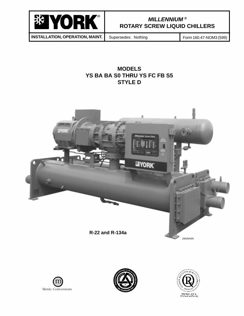
The model number denotes the following characteristics of the unit:
YS BB BA S0 – CF D S
Model Special Features
Cooler Code Design Level
Condenser Code Motor Code
Compressor Code Power Supply: – for 60 Hz 5 for 50 Hz

3
FORM 160.47-NOM3
YORK INTERNATIONAL
TABLE OF CONTENTSNomenclature ............................................................................................... 2
SECTION 1 INSTALLATION .................................................................... 5General ......................................................................................................... 5Inspection ..................................................................................................... 6Data Plate .................................................................................................... 6Location ........................................................................................................ 6Foundation .................................................................................................... 6Clearance ..................................................................................................... 6Rigging .......................................................................................................... 7Locating and Installing Isolator Pads ........................................................... 12Checking the Isolator Pad Deflection .......................................................... 12Installing Optional Spring Isolators ............................................................... 18Piping Connections ....................................................................................... 19
Check for Piping Alignment ...................................................................... 19Cooler and Condenser Water Piping ........................................................... 20
Cooling Units – Chilled Water .................................................................. 20Cooling Units – Condenser Water Circuit ................................................ 20Stop Valves ............................................................................................... 20Flow Switches (Field Installed) ................................................................ 20Drain and Vent Valves .............................................................................. 20Checking Piping Circuits and Venting Air ................................................ 20
Refrigerant Relief Piping .............................................................................. 21Unit Piping .................................................................................................... 23Control Wiring .............................................................................................. 23
Power Wiring ................................................................................................... 23Unit with Electro-Mechanical Starter ...................................................... 23Unit with Solid State Starter (Optional) .................................................... 24
Insulation ...................................................................................................... 24Insulation Check – Request for Start-Up Service ....................................... 24
SECTION 2 OPERATION .......................................................................... 27Basic Description ......................................................................................... 27Components .................................................................................................. 27
Driveline.................................................................................................... 27Oil Separator ............................................................................................ 28Condenser ................................................................................................. 28Evaporator ................................................................................................ 28
Condensing Water Temperature .................................................................. 29R-22 Refrigerant ...................................................................................... 29R-134a Refrigerant ................................................................................... 29
Oil System .................................................................................................... 29Oil Eductor Circuit ....................................................................................... 33Liquid Refrigerant Circuit ............................................................................ 34
Dual Service Chillers ................................................................................ 34Capacity Control .......................................................................................... 37
SECTION 3 MAINTENANCE ................................................................... 39General ......................................................................................................... 39Compressor Oil ............................................................................................ 39
Changing Compressor Oil ......................................................................... 39Oil Level ................................................................................................... 41
Oil Filter ........................................................................................................ 41Oil Filter Replacement ................................................................................. 41
Single Oil Filter ......................................................................................... 41Dual Oil Filters ......................................................................................... 41
PAGE

4 YORK INTERNATIONAL
TABLE OF CONTENTS PAGE
Filter Drier Replacement .............................................................................. 42Motor ............................................................................................................ 42Determining Correct Refrigerant Charge Level .......................................... 42Refrigerant Charging .................................................................................... 42Refrigerant Leak Checking .......................................................................... 43Pressure Connections .................................................................................. 43Condenser Tubes .......................................................................................... 43Condenser Water Side Tube Cleaning Procedure ....................................... 43
Chemical Cleaning Procedure .................................................................. 43Mechanical Cleaning Procedure .............................................................. 44
Evaporator Tubes ......................................................................................... 44Vibration Analysis ........................................................................................ 44
LIST OF ILLUSTRATIONSFIGURE
1 Model YS Style D Rotary Screw Liquid Chiller ................................. 52 Rigging ................................................................................................. 73 Standard Neoprene Vibration Isolator Pad Mounts ............................ 134 Overall Dimensions - English, S0 thru S3 Compressor ....................... 145 Overall Dimensions - English, S4 and S5 Compressor ....................... 156 Overall Dimensions - Std. Intl., S0 thru S3 Compressor ..................... 167 Overall Dimensions - Std. Intl., S4 and S5 Compressor ..................... 178 Spring Isolators .................................................................................... 189 Schematic of a Typical Piping Arrangement for Cooling Units .......... 20
10 Typical Refrigerant Vent Piping from Relief Valves ........................... 2111 Typical Refrigerant Vent Piping from Rupture Disk ........................... 2212 YS Motor Connections (Electro-Mechanical Starter Application) ..... 2513 Installation Check List and Request for Authorized Start-Up
Engineer ........................................................................................ 2614 Component Layout Drawing ............................................................... 2815 Oil Piping Schematic ........................................................................... 3016 Oil Separator Schematic ..................................................................... 3217 Oil Filter Location ................................................................................ 2918 Oil Pressure Transducer Location ...................................................... 3119 Eductor Block ...................................................................................... 3120 Filter Driers and Oil Eductor ............................................................... 3421 Oil Eductor Schematic ........................................................................ 3522 Refrigerant Schematic ........................................................................ 3623 Capacity Control Piping Schematic ..................................................... 3824 4-Way Directional Valve Subplate ...................................................... 3725 Oil Heater and Sight Glass .................................................................. 4126 Transducer Measurement Points ........................................................ 45
PAGE
LIST OF TABLESTABLE
1 Clearances ........................................................................................... 62 Weights - English, R-22 and R-134a Units, 50 and 60 Hz .................. 83 Weights - SI, R-22 and R-134a Units, 50 and 60 Hz .......................... 104 Refrigerant Relief Characteristics ...................................................... 235 Variable Orifice Pressure Differential Setpoints ................................. 346 York Oil Types .................................................................................... 397 Compressor Oil Limits ........................................................................ 398 Refrigerant Charge Level ................................................................... 429 Water Flow Velocities ......................................................................... 40
PAGE

5
FORM 160.47-NOM3
YORK INTERNATIONAL
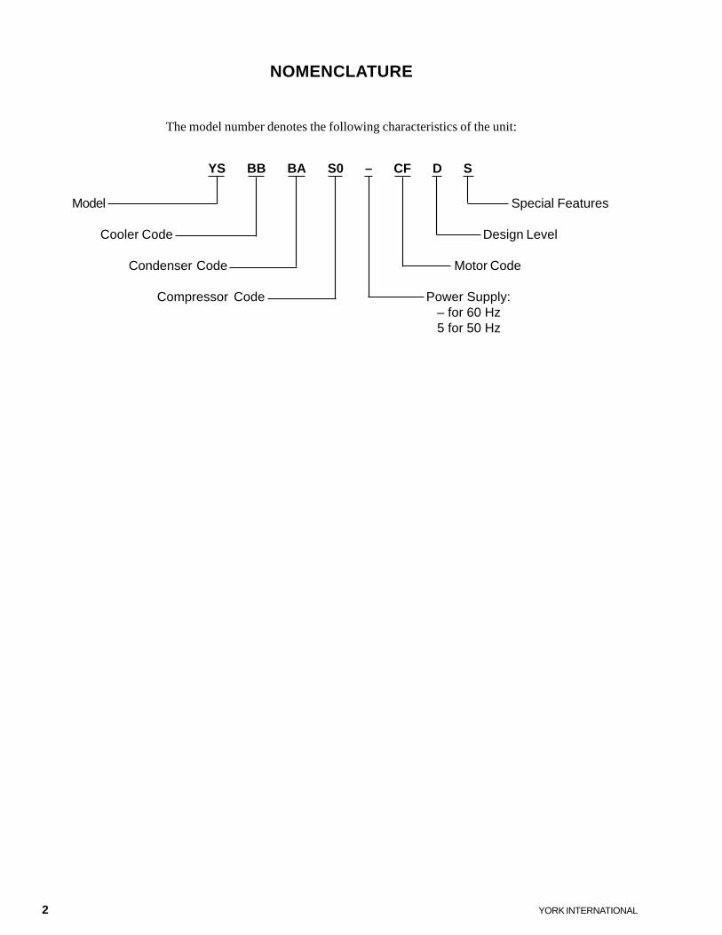
FIG. 1 – MODEL YS, STYLE D ROTARY SCREW LIQUID CHILLER
SECTION 1INSTALLATION
GENERAL
This instruction describes the installation of a Model YSRotary Screw Liquid Chiller. (See Figure 1.) This unitis shipped as a single factory assembled, piped, wiredand nitrogen or refrigerant charged package (Form 1shipment). This unit requires a minimum of field laborto make chilled water connections, condenser water con-nections, refrigerant atmospheric relief connections, andelectrical power connections.
YS units can also be shipped dismantled when requiredby rigging conditions, but generally it is more economi-cal to enlarge access openings to accommodate the fac-tory assembled unit.
The YS Chiller may be ordered and shipped in the fol-lowing forms:
Form 1 – Factory Assembled Unit, Complete withMotor and Refrigerant and Oil Charges asdiscussed in this instruction.
Form 2 – Factory Assembled (same as Form 1) ex-cept not charged with oil or refrigerant.Shipped with holding charge of nitrogen. Re-frigerant shipped in 50 and 125 lb. cylinders.
Form 3 – Driveline Separate From Shells – Shippedas three major assemblies.
Form 7 – Split Shells – Shipped as four major as-semblies.
Units shipped dismantled MUST be re-as-sembled by, or under the supervi-sion of a York representative. Refer toForm 160.47-N3.1 for detailed in-structions of Form 3 and 7 shipments.
MOTOR
MOTOR TERMINAL BOX COMPRESSORRUPTUREDISK
RELIEF VALVE
OILSEPARATOR
MICROCOMPUTERCONTROLCENTER
COOLER
SIGHT GLASS 29039A
RELIEF VALVE
CONDENSER
1
6 YORK INTERNATIONAL
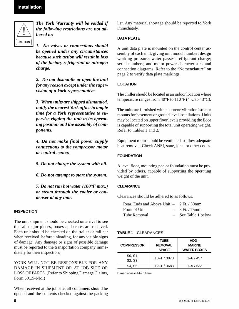
TABLE 1 – CLEARANCES
TUBE ADD –COMPRESSOR REMOVAL MARINE
SPACE WATER BOXES
S0, S1,S2, S3
10–1 / 3073 1–6 / 457
S4, S5 12–1 / 3683 1–9 / 533
Dimensions in Ft–In / mm.
INSPECTION
The unit shipment should be checked on arrival to seethat all major pieces, boxes and crates are received.Each unit should be checked on the trailer or rail carwhen received, before unloading, for any visible signsof damage. Any damage or signs of possible damagemust be reported to the transportation company imme-diately for their inspection.
YORK WILL NOT BE RESPONSIBLE FOR ANYDAMAGE IN SHIPMENT OR AT JOB SITE ORLOSS OF PARTS. (Refer to Shipping Damage Claims,Form 50.15-NM.)
When received at the job site, all containers should beopened and the contents checked against the packing
The York Warranty will be voided ifthe following restrictions are not ad-hered to:
1. No valves or connections shouldbe opened under any circumstancesbecause such action will result in lossof the factory refrigerant or nitrogencharge.
2. Do not dismantle or open the unitfor any reason except under the super-vision of a York representative.
3. When units are shipped dismantled,notify the nearest York office in ampletime for a York representative to su-pervise rigging the unit to its operat-ing position and the assembly of com-ponents.
4. Do not make final power supplyconnections to the compressor motoror control center.
5. Do not charge the system with oil.
6. Do not attempt to start the system.
7. Do not run hot water (100°F max.)or steam through the cooler or con-denser at any time.
list. Any material shortage should be reported to Yorkimmediately.
DATA PLATE
A unit data plate is mounted on the control center as-sembly of each unit, giving unit model number; designworking pressure; water passes; refrigerant charge;serial numbers; and motor power characteristics andconnection diagrams. Refer to the “Nomenclature” onpage 2 to verify data plate markings.
LOCATION
The chiller should be located in an indoor location wheretemperature ranges from 40°F to 110°F (4°C to 43°C).
The units are furnished with neoprene vibration isolatormounts for basement or ground level installations. Unitsmay be located on upper floor levels providing the flooris capable of supporting the total unit operating weight.Refer to Tables 1 and 2.
Equipment room should be ventilated to allow adequateheat removal. Check ANSI, state, local or other codes.
FOUNDATION
A level floor, mounting pad or foundation must be pro-vided by others, capable of supporting the operatingweight of the unit.
CLEARANCE
Clearances should be adhered to as follows:
Rear, Ends and Above Unit – 2 Ft. / 50mmFront of Unit – 3 Ft. / 75mmTube Removal – See Table 1 below
Installation
7
FORM 160.47-NOM3
YORK INTERNATIONAL
If necessary to rig a unit by one endto permit lifting or dropping througha vertical passageway, such as an el-evator shaft, contact York Factory forspecial rigging instructions.
The shipping and operating weights are given inTables 2 and 3. Overall dimensions are shown in Fig-ures 4 thru 7. More detailed dimensions can be found inForm 160.47-PA1.
If optional shipping skids are used, remove them beforelowering the unit to its mounting position. Rig the unit toits final location on the floor or mounting pad by liftingthe unit (or shell assembly) with an overhead lift andlower the unit to its mounting position.
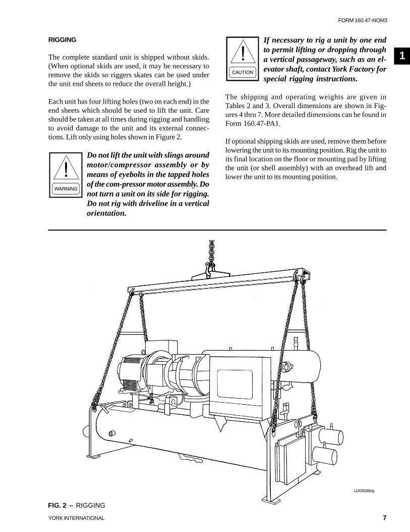
RIGGING
The complete standard unit is shipped without skids.(When optional skids are used, it may be necessary toremove the skids so riggers skates can be used underthe unit end sheets to reduce the overall height.)
Each unit has four lifting holes (two on each end) in theend sheets which should be used to lift the unit. Careshould be taken at all times during rigging and handlingto avoid damage to the unit and its external connec-tions. Lift only using holes shown in Figure 2.
Do not lift the unit with slings aroundmotor/compressor assembly or bymeans of eyebolts in the tapped holesof the com-pressor motor assembly. Donot turn a unit on its side for rigging.Do not rig with driveline in a verticalorientation.
1
FIG. 2 – RIGGING
LD03588rig
8 YORK INTERNATIONAL
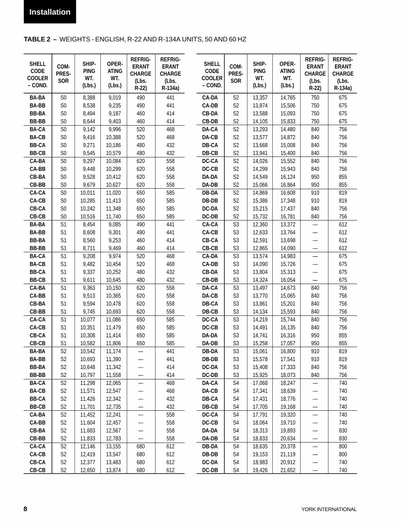
TABLE 2 – WEIGHTS - ENGLISH, R-22 AND R-134A UNITS, 50 AND 60 HZ
REFRIG- REFRIG-SHELL COM- SHIP- OPER- ERANT ERANTCODE PRES- PING ATING CHARGE CHARGE
COOLER SOR WT. WT. (Lbs. (Lbs.– COND. (Lbs.) (Lbs.) R-22) R-134a)
BA-BA S0 8,388 9,019 490 441BA-BB S0 8,538 9,235 490 441BB-BA S0 8,494 9,187 460 414BB-BB S0 8,644 9,403 460 414BA-CA S0 9,142 9,996 520 468BA-CB S0 9,416 10,388 520 468BB-CA S0 9,271 10,186 480 432BB-CB S0 9,545 10,579 480 432CA-BA S0 9,297 10,084 620 558CA-BB S0 9,448 10,299 620 558CB-BA S0 9,528 10,412 620 558CB-BB S0 9,679 10,627 620 558CA-CA S0 10,011 11,020 650 585CA-CB S0 10,285 11,413 650 585CB-CA S0 10,242 11,348 650 585CB-CB S0 10,516 11,740 650 585BA-BA S1 8,454 9,085 490 441BA-BB S1 8,608 9,301 490 441BB-BA S1 8,560 9,253 460 414BB-BB S1 8,711 9,469 460 414BA-CA S1 9,208 9,974 520 468BA-CB S1 9,482 10,454 520 468BB-CA S1 9,337 10,252 480 432BB-CB S1 9,611 10,645 480 432CA-BA S1 9,363 10,150 620 558CA-BB S1 9,513 10,365 620 558CB-BA S1 9,594 10,478 620 558CB-BB S1 9,745 10,693 620 558CA-CA S1 10,077 11,086 650 585CA-CB S1 10,351 11,479 650 585CB-CA S1 10,308 11,414 650 585CB-CB S1 10,582 11,806 650 585BA-BA S2 10,542 11,174 — 441BA-BB S2 10,693 11,390 — 441BB-BA S2 10,648 11,342 — 414BB-BB S2 10,797 11,558 — 414BA-CA S2 11,298 12,065 — 468BA-CB S2 11,571 12,547 — 468BB-CA S2 11,426 12,342 — 432BB-CB S2 11,701 12,735 — 432CA-BA S2 11,452 12,241 — 558CA-BB S2 11,604 12,457 — 558CB-BA S2 11,683 12,567 — 558CB-BB S2 11,833 12,783 — 558CA-CA S2 12,146 13,155 680 612CA-CB S2 12,419 13,547 680 612CB-CA S2 12,377 13,483 680 612CB-CB S2 12,650 13,874 680 612
REFRIG- REFRIG-SHELL COM- SHIP- OPER- ERANT ERANTCODE PRES- PING ATING CHARGE CHARGE
COOLER SOR WT. WT. (Lbs. (Lbs.– COND. (Lbs.) (Lbs.) R-22) R-134a)
CA-DA S2 13,357 14,765 750 675CA-DB S2 13,874 15,506 750 675CB-DA S2 13,588 15,093 750 675CB-DB S2 14,105 15,833 750 675DA-CA S2 13,293 14,480 840 756DA-CB S2 13,577 14,872 840 756DB-CA S2 13,668 15,008 840 756DB-CB S2 13,941 15,400 840 756DC-CA S2 14,026 15,552 840 756DC-CB S2 14,299 15,943 840 756DA-DA S2 14,549 16,124 950 855DA-DB S2 15,066 16,864 950 855DB-DA S2 14,869 16,608 910 819DB-DB S2 15,386 17,348 910 819DC-DA S2 15,215 17,437 840 756DC-DB S2 15,732 16,781 840 756CA-CA S3 12,360 13,372 — 612CA-CB S3 12,633 13,764 — 612CB-CA S3 12,591 13,698 — 612CB-CB S3 12,865 14,090 — 612CA-DA S3 13,574 14,983 — 675CA-DB S3 14,090 15,726 — 675CB-DA S3 13,804 15,313 — 675CB-DB S3 14,324 16,054 — 675DA-CA S3 13,497 14,673 840 756DA-CB S3 13,770 15,065 840 756DB-CA S3 13,861 15,201 840 756DB-CB S3 14,134 15,593 840 756DC-CA S3 14,219 15,744 840 756DC-CB S3 14,491 16,135 840 756DA-DA S3 14,741 16,316 950 855DA-DB S3 15,258 17,057 950 855DB-DA S3 15,061 16,800 910 819DB-DB S3 15,578 17,541 910 819DC-DA S3 15,408 17,333 840 756DC-DB S3 15,925 18,073 840 756DA-CA S4 17,068 18,247 — 740DA-CB S4 17,341 18,639 — 740DB-CA S4 17,431 18,776 — 740DB-CB S4 17,705 19,168 — 740DC-CA S4 17,791 19,320 — 740DC-CB S4 18,064 19,710 — 740DA-DA S4 18,313 19,893 — 830DA-DB S4 18,833 20,634 — 830DB-DA S4 18,635 20,378 — 800DB-DB S4 19,153 21,119 — 800DC-DA S4 18,983 20,912 — 740DC-DB S4 19,426 21,652 — 740
Installation
9
FORM 160.47-NOM3
YORK INTERNATIONAL
REFRIG- REFRIG-SHELL COM- SHIP- OPER- ERANT ERANTCODE PRES- PING ATING CHARGE CHARGE
COOLER SOR WT. WT. (Lbs. (Lbs.– COND. (Lbs.) (Lbs.) R-22) R-134a)
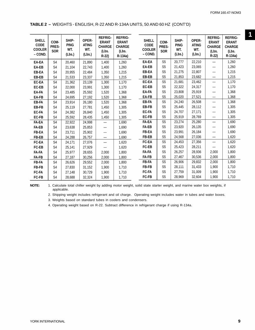
EA-EA S5 20,777 22,210 — 1,260EA-EB S5 21,423 23,065 — 1,260EB-EA S5 21,275 22,807 — 1,215EB-EB S5 21,853 23,682 — 1,215EC-EA S5 21,681 23,462 — 1,170EC-EB S5 22,322 24,317 — 1,170EA-FA S5 23,808 25,919 — 1,368EA-FB S5 25,020 27,521 — 1,368EB-FA S5 24,240 26,508 — 1,368EB-FB S5 25,445 28,112 — 1,305EC-FA S5 24,707 27,171 — 1,305EC-FB S5 25,919 28,769 — 1,305FA-EA S5 23,274 25,280 — 1,690FA-EB S5 23,920 26,135 — 1,690FB-EA S5 23,991 26,184 — 1,690FB-EB S5 24,568 27,036 — 1,620FC-EA S5 24,453 27,356 — 1,620FC-EB S5 25,423 28,211 — 1,620FA-FA S5 26,257 28,936 2,000 1,800FA-FB S5 27,467 30,536 2,000 1,800FB-FA S5 26,906 29,832 2,000 1,800FB-FB S5 28,111 31,433 1,900 1,710FC-FA S5 27,759 31,009 1,900 1,710FC-FB S5 28,969 32,604 1,900 1,710
REFRIG- REFRIG-SHELL COM- SHIP- OPER- ERANT ERANTCODE PRES- PING ATING CHARGE CHARGE
COOLER SOR WT. WT. (Lbs. (Lbs.– COND. (Lbs.) (Lbs.) R-22) R-134a)
EA-EA S4 20,460 21,890 1,400 1,260EA-EB S4 21,104 22,743 1,400 1,260EB-EA S4 20,955 22,484 1,350 1,215EB-EB S4 21,533 23,337 1,350 1,215EC-EA S4 21,362 23,139 1,300 1,170EC-EB S4 22,000 23,991 1,300 1,170EA-FA S4 23,485 25,592 1,520 1,368EA-FB S4 24,695 27,192 1,520 1,368EB-FA S4 23,914 26,180 1,520 1,368EB-FB S4 25,119 27,781 1,450 1,305EC-FA S4 24,382 26,840 1,450 1,305EC-FB S4 25,592 28,435 1,450 1,305FA-EA S4 22,922 24,998 — 1,690FA-EB S4 23,638 25,853 — 1,690FB-EA S4 23,711 25,902 — 1,690FB-EB S4 24,288 26,757 — 1,690FC-EA S4 24,171 27,076 — 1,620FC-EB S4 25,141 27,929 — 1,620FA-FA S4 25,977 28,655 2,000 1,800FA-FB S4 27,187 30,256 2,000 1,800FB-FA S4 26,626 29,552 2,000 1,800FB-FB S4 27,830 31,152 1,900 1,710FC-FA S4 27,148 30,729 1,900 1,710FC-FB S4 28,688 32,324 1,900 1,710
NOTE: 1. Calculate total chiller weight by adding motor weight, solid state starter weight, and marine water box weights, ifapplicable.
2. Shipping weight includes refrigerant and oil charge. Operating weight includes water in tubes and water boxes.
3. Weights based on standard tubes in coolers and condensers.
4. Operating weight based on R-22. Subtract difference in refrigerant charge if using R-134a.
TABLE 2 – WEIGHTS - ENGLISH, R-22 AND R-134A UNITS, 50 AND 60 HZ (CONT’D)
1

10 YORK INTERNATIONAL
TABLE 3 – WEIGHTS - SI, R-22 AND R-134A UNITS, 50 AND 60 HZ
REFRIG- REFRIG-SHELL COM- SHIP- OPER- ERANT ERANTCODE PRES- PING ATING CHARGE CHARGE
COOLER SOR WT. WT. (Kgs. (Kgs.– COND. (Kgs.) (Kgs.) R-22) R-134a)
BA-BA S0 3,805 4,091 222 200BA-BB S0 3,873 4,189 222 200BB-BA S0 3,853 4,167 209 188BB-BB S0 3,921 4,265 209 188BA-CA S0 4,147 4,534 236 212BA-CB S0 4,271 4,712 236 212BB-CA S0 4,205 4,620 218 196BB-CB S0 4,330 4,799 218 196CA-BA S0 4,217 4,574 281 253CA-BB S0 4,286 4,672 281 253CB-BA S0 4,322 4,723 281 253CB-BB S0 4,390 4,820 281 253CA-CA S0 4,541 4,999 295 265CA-CB S0 4,665 5,177 295 265CB-CA S0 4,646 5,147 295 265CB-CB S0 4,770 5,325 295 265BA-BA S1 3,835 4,121 222 200BA-BB S1 3,905 4,219 222 200BB-BA S1 3,883 4,197 209 188BB-BB S1 3,951 4,295 209 188BA-CA S1 4,177 4,524 236 212BA-CB S1 4,301 4,742 236 212BB-CA S1 4,235 4,650 218 196BB-CB S1 4,360 4,829 218 196CA-BA S1 4,247 4,604 281 253CA-BB S1 4,315 4,702 281 253CB-BA S1 4,352 4,753 281 253CB-BB S1 4,420 4,850 281 253CA-CA S1 4,571 5,029 295 265CA-CB S1 4,695 5,207 295 265CB-CA S1 4,676 5,177 295 265CB-CB S1 4,800 5,355 295 265BA-BA S2 4,782 5,069 — 200BA-BB S2 4,850 5,167 — 200BB-BA S2 4,830 5,145 — 188BB-BB S2 4,898 5,243 — 188BA-CA S2 5,125 5,473 — 212BA-CB S2 5,249 5,691 — 212BB-CA S2 5,183 5,598 — 196BB-CB S2 5,308 5,777 — 196CA-BA S2 5,195 5,553 — 253CA-BB S2 5,264 5,650 — 253CB-BA S2 5,299 5,700 — 253CB-BB S2 5,367 5,798 — 253CA-CA S2 5,509 5,967 308 278CA-CB S2 5,633 6,145 308 278CB-CA S2 5,614 6,116 308 278CB-CB S2 5,738 6,293 308 278
REFRIG- REFRIG-SHELL COM- SHIP- OPER- ERANT ERANTCODE PRES- PING ATING CHARGE CHARGE
COOLER SOR WT. WT. (Kgs. (Kgs.– COND. (Kgs.) (Kgs.) R-22) R-134a)
CA-DA S2 6,059 6,697 340 306CA-DB S2 6,293 7,034 340 306CB-DA S2 6,164 6,846 340 306CB-DB S2 6,398 7,182 340 306DA-CA S2 6,030 6,568 381 343DA-CB S2 6,159 6,746 381 343DB-CA S2 6,200 6,808 381 343DB-CB S2 6,324 6,985 381 343DC-CA S2 6,362 7,054 381 343DC-CB S2 6,486 7,232 381 343DA-DA S2 6,599 7,314 431 388DA-DB S2 6,834 7,650 431 388DB-DA S2 6,745 7,533 413 371DB-DB S2 6,979 7,869 413 371DC-DA S2 6,902 7,909 381 343DC-DB S2 7,136 7,612 381 343CA-CA S3 5,606 6,066 — 278CA-CB S3 5,730 6,243 — 278CB-CA S3 5,711 6,213 — 278CB-CB S3 5,836 6,391 — 278CA-DA S3 6,157 6,796 — 306CA-DB S3 6,391 7,133 — 306CB-DA S3 6,261 6,946 — 306CB-DB S3 6,497 7,282 — 306DA-CA S3 6,122 6,656 381 343DA-CB S3 6,246 6,833 381 343DB-CA S3 6,287 6,895 381 343DB-CB S3 6,411 7,073 381 343DC-CA S3 6,450 7,141 381 343DC-CB S3 6,573 7,319 381 343DA-DA S3 6,687 7,401 431 388DA-DB S3 6,921 7,737 431 388DB-DA S3 6,832 7,620 413 371DB-DB S3 7,066 7,957 413 371DC-DA S3 6,989 7,862 381 343DC-DB S3 7,224 8,198 381 343DA-CA S4 7,742 8,277 — 336DA-CB S4 7,866 8,455 — 336DB-CA S4 7,907 8,517 — 336DB-CB S4 8,031 8,695 — 336DC-CA S4 8,070 8,764 — 336DC-CB S4 8,194 8,940 — 336DA-DA S4 8,307 9,023 — 376DA-DB S4 8,543 9,360 — 376DB-DA S4 8,453 9,243 — 363DB-DB S4 8,688 9,580 — 363DC-DA S4 8,611 9,486 — 336DC-DB S4 8,812 9,821 — 336
Installation
11
FORM 160.47-NOM3
YORK INTERNATIONAL
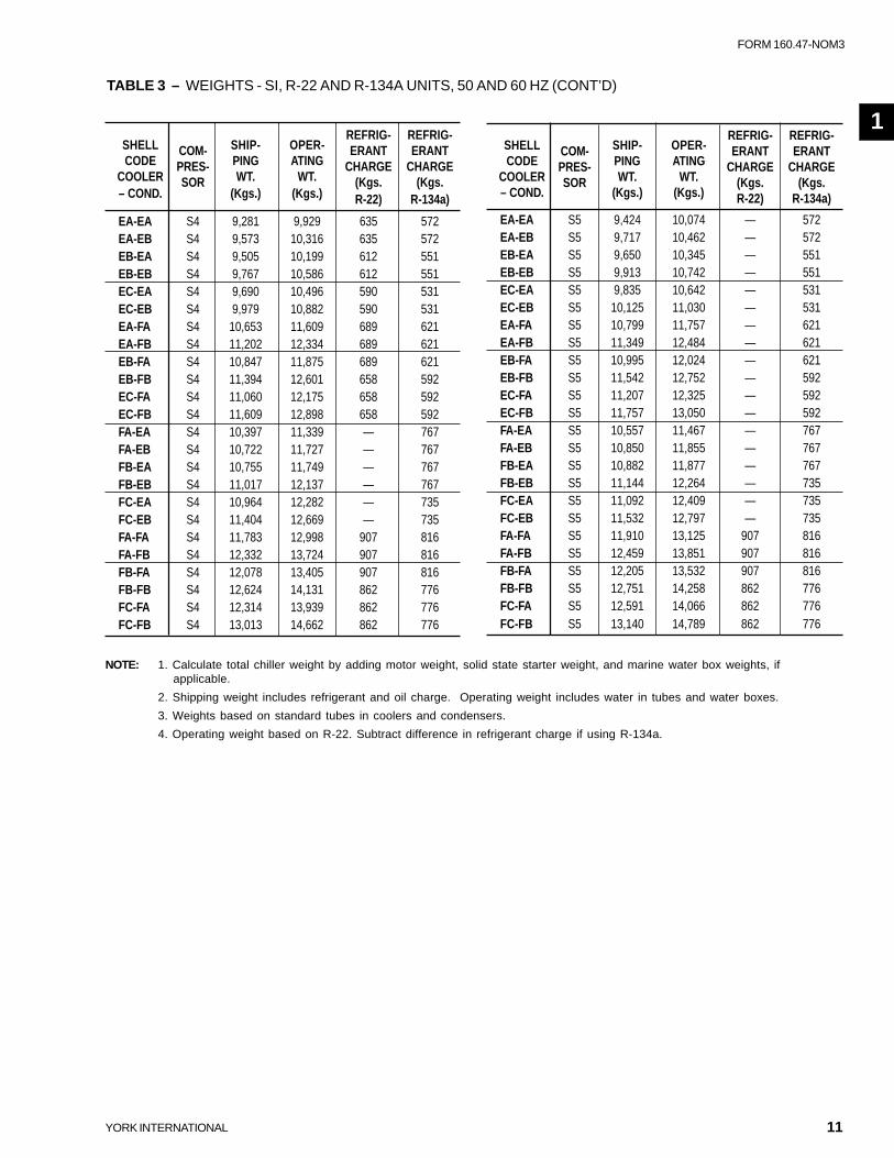
NOTE: 1. Calculate total chiller weight by adding motor weight, solid state starter weight, and marine water box weights, ifapplicable.
2. Shipping weight includes refrigerant and oil charge. Operating weight includes water in tubes and water boxes.
3. Weights based on standard tubes in coolers and condensers.
4. Operating weight based on R-22. Subtract difference in refrigerant charge if using R-134a.
REFRIG- REFRIG-SHELL COM- SHIP- OPER- ERANT ERANTCODE PRES- PING ATING CHARGE CHARGE
COOLER SOR WT. WT. (Kgs. (Kgs.– COND. (Kgs.) (Kgs.) R-22) R-134a)
EA-EA S5 9,424 10,074 — 572EA-EB S5 9,717 10,462 — 572EB-EA S5 9,650 10,345 — 551EB-EB S5 9,913 10,742 — 551EC-EA S5 9,835 10,642 — 531EC-EB S5 10,125 11,030 — 531EA-FA S5 10,799 11,757 — 621EA-FB S5 11,349 12,484 — 621EB-FA S5 10,995 12,024 — 621EB-FB S5 11,542 12,752 — 592EC-FA S5 11,207 12,325 — 592EC-FB S5 11,757 13,050 — 592FA-EA S5 10,557 11,467 — 767FA-EB S5 10,850 11,855 — 767FB-EA S5 10,882 11,877 — 767FB-EB S5 11,144 12,264 — 735FC-EA S5 11,092 12,409 — 735FC-EB S5 11,532 12,797 — 735FA-FA S5 11,910 13,125 907 816FA-FB S5 12,459 13,851 907 816FB-FA S5 12,205 13,532 907 816FB-FB S5 12,751 14,258 862 776FC-FA S5 12,591 14,066 862 776FC-FB S5 13,140 14,789 862 776
REFRIG- REFRIG-SHELL COM- SHIP- OPER- ERANT ERANTCODE PRES- PING ATING CHARGE CHARGE
COOLER SOR WT. WT. (Kgs. (Kgs.– COND. (Kgs.) (Kgs.) R-22) R-134a)
EA-EA S4 9,281 9,929 635 572EA-EB S4 9,573 10,316 635 572EB-EA S4 9,505 10,199 612 551EB-EB S4 9,767 10,586 612 551EC-EA S4 9,690 10,496 590 531EC-EB S4 9,979 10,882 590 531EA-FA S4 10,653 11,609 689 621EA-FB S4 11,202 12,334 689 621EB-FA S4 10,847 11,875 689 621EB-FB S4 11,394 12,601 658 592EC-FA S4 11,060 12,175 658 592EC-FB S4 11,609 12,898 658 592FA-EA S4 10,397 11,339 — 767FA-EB S4 10,722 11,727 — 767FB-EA S4 10,755 11,749 — 767FB-EB S4 11,017 12,137 — 767FC-EA S4 10,964 12,282 — 735FC-EB S4 11,404 12,669 — 735FA-FA S4 11,783 12,998 907 816FA-FB S4 12,332 13,724 907 816FB-FA S4 12,078 13,405 907 816FB-FB S4 12,624 14,131 862 776FC-FA S4 12,314 13,939 862 776FC-FB S4 13,013 14,662 862 776
TABLE 3 – WEIGHTS - SI, R-22 AND R-134A UNITS, 50 AND 60 HZ (CONT’D)
1
12 YORK INTERNATIONAL
Installation
RIGGING (CONT’D)
Units shipped dismantled should be as-sembled under the supervision of aYork representative.
If the cooler is to be field insulated, the insulation shouldbe applied while the unit is in the lift position, before theunit is placed in position.
LOCATING AND INSTALLING ISOLATOR PADS
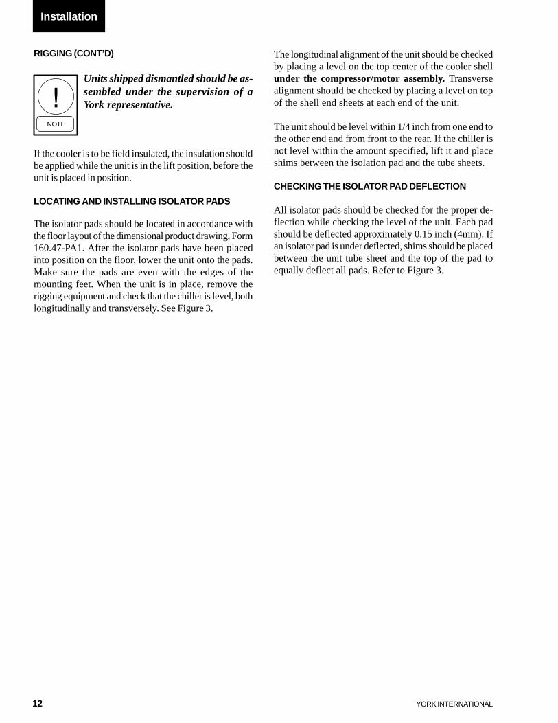
The isolator pads should be located in accordance withthe floor layout of the dimensional product drawing, Form160.47-PA1. After the isolator pads have been placedinto position on the floor, lower the unit onto the pads.Make sure the pads are even with the edges of themounting feet. When the unit is in place, remove therigging equipment and check that the chiller is level, bothlongitudinally and transversely. See Figure 3.
The longitudinal alignment of the unit should be checkedby placing a level on the top center of the cooler shellunder the compressor/motor assembly. Transversealignment should be checked by placing a level on topof the shell end sheets at each end of the unit.
The unit should be level within 1/4 inch from one end tothe other end and from front to the rear. If the chiller isnot level within the amount specified, lift it and placeshims between the isolation pad and the tube sheets.
CHECKING THE ISOLATOR PAD DEFLECTION
All isolator pads should be checked for the proper de-flection while checking the level of the unit. Each padshould be deflected approximately 0.15 inch (4mm). Ifan isolator pad is under deflected, shims should be placedbetween the unit tube sheet and the top of the pad toequally deflect all pads. Refer to Figure 3.
13
FORM 160.47-NOM3
YORK INTERNATIONAL
FIG. 3 – STANDARD NEOPRENE VIBRATION ISOLATOR PAD MOUNTS
1
LD02942
LD02944
LD02943
OPERATING WEIGHT (Lbs. / Kgs.) DETAIL
UP TO 16,365 / 7,423 A
16,636 / 7,546 to 28,835 / 13,080 B
28,836 / 13,080 to 53,530 / 24,281 C
14 YORK INTERNATIONAL
LD00068
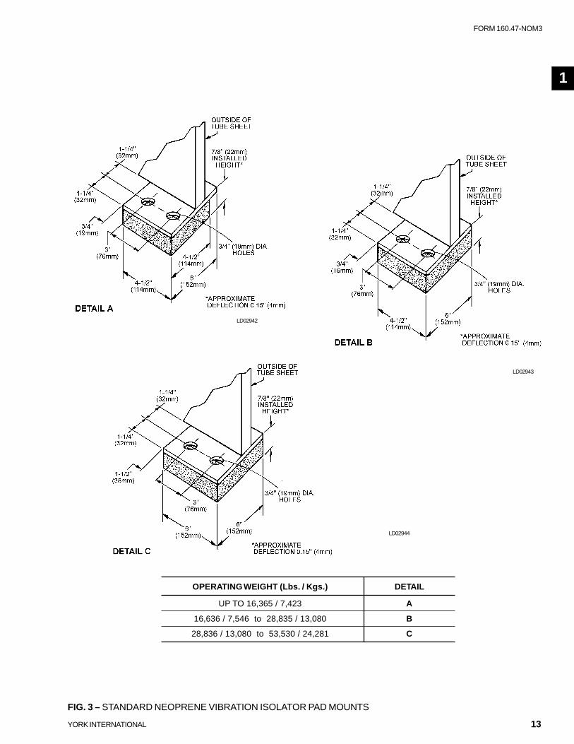
S0 and S1 COMPRESSOR S2 COMPRESSOR S2 and S3 COMPRESSOR
SHELL CODES (Cooler – Condenser)
B-B B-C C-B C-C B-B B-C C-B C-C C-D D-C D-D
A – TUBE SHEET WIDTH 4'–2-7/8" 5'–2-1/2" 5'–2-1/2"
A1 – OVERALL WIDTH 4'–6-3/4" 4'–6-1/4" 4'-6-3/4" 4'–6-1/4" 5'–3-3/4" 5'–3-3/4"
B – OVERALL HEIGHT3 5'–8-5/8" 5'–11-1/2" 5'–10-1/4" 5'–11-1/2" 5'–11-1/4" 6'–3-1/4" 6'–3-1/4" 6'–3-1/4" 6'–7-5/8" 6'–8-3/4" 6'–9-3/8"
C – COOLER C/L 1'–1-7/8" 1'–5" 1'–5"
D – CONDENSER C/L 0'–11-5/8" 1'–2-1/4" 1'–2-1/4"
FIG. 4 – OVERALL DIMENSIONS - ENGLISH, S0 THRU S3 COMPRESSOR
Installation

15
FORM 160.47-NOM3
YORK INTERNATIONAL
LD00505
S4 COMPRESSOR S4 and S5 COMPRESSOR
DIMENSION SHELL CODES (Cooler – Condenser)
D-C D-D E-E E-F F-E F-F
A TUBE SHEET WIDTH 6'–2" 6'–2" 6'–2" 6'–4-1/2" 6'–6-1/2" 6'–9"
A1 – With SSS 6'–9-7/8" 6'–9-7/8" 6'–9-7/8" 7'–0-3/8" 7'–3-5/8" 7'–2-5/8"
A2 – OVERALL WD. (less SSS) 6'–3-3/8" 6'–3-3/8" 6'–2" 6'–4-1/2" 6'–6-1/2" 6'–9"
B – OVERALL HEIGHT3 7'–9-1/8" 7'–9-1/8" 7'–9-1/8" 8'–2-1/4" 8'–2-1/4" 8'–2-1/4"
C – COOLER C/L 1'–7-3/4" 1'–7-3/4" 1'–7-3/4" 1'–7-3/4" 1'–10" 1'–10"
D – CONDENSER C/L 1'–5-1/4" 1'–5-1/4" 1'–5-1/4" 1'–6-1/2" 1'–5-1/4" 1'–6-1/2"
FIG. 5 – OVERALL DIMENSIONS - ENGLISH, S4 AND S5 COMPRESSOR
1

16 YORK INTERNATIONAL
S0 and S1 COMPRESSOR S2 COMPRESSOR S2 and S3 COMPRESSOR
SHELL CODES (Cooler – Condenser)
B-B B-C C-B C-C B-B B-C C-B C-C C-D D-C D-D
A – TUBE SHEET WIDTH 1,292 1,292 1,292 1,292 1,588 1,588 1,588 1,588 1,588 1,588 1,588
A1 – OVERALL WIDTH 1,349 1,349 1,349 1,349 1,591 1,591 1,591 1,591 1,591 1,591 1,591
B – OVERALL HEIGHT3 1,816 1,895 1,857 1,899 1,848 1,946 1,946 1,946 2,054 2,102 2,102
C – COOLER C/L 351 351 351 351 432 432 432 432 432 432 432
D – CONDENSER C/L 295 295 295 295 362 362 362 362 362 362 362
DIMENSIONS (mm)
LD00506
FIG. 6 – OVERALL DIMENSIONS - STANDARD INTERNATIONAL, S0 THRU S3 COMPRESSOR
Installation
17
FORM 160.47-NOM3
YORK INTERNATIONAL
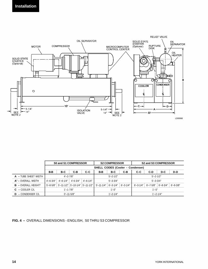
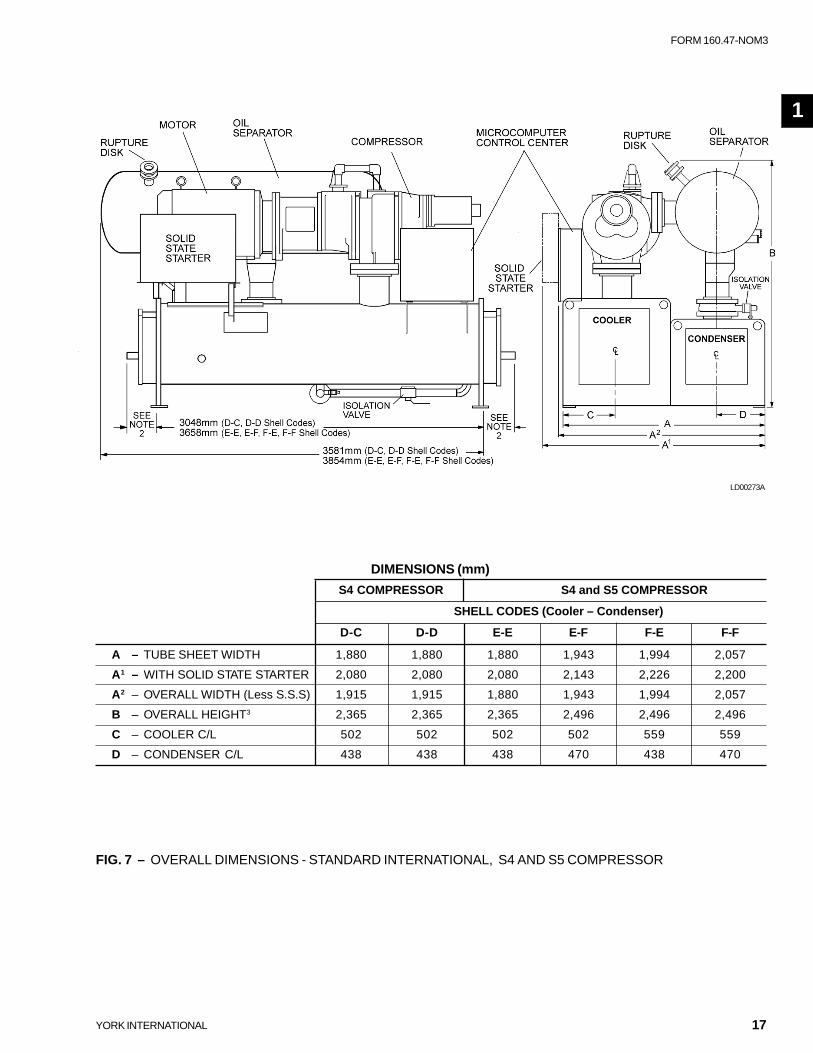
FIG. 7 – OVERALL DIMENSIONS - STANDARD INTERNATIONAL, S4 AND S5 COMPRESSOR
LD00273A
DIMENSIONS (mm)
S4 COMPRESSOR S4 and S5 COMPRESSOR
SHELL CODES (Cooler – Condenser)
D-C D-D E-E E-F F-E F-F
A – TUBE SHEET WIDTH 1,880 1,880 1,880 1,943 1,994 2,057
A1 – WITH SOLID STATE STARTER 2,080 2,080 2,080 2,143 2,226 2,200
A2 – OVERALL WIDTH (Less S.S.S) 1,915 1,915 1,880 1,943 1,994 2,057
B – OVERALL HEIGHT3 2,365 2,365 2,365 2,496 2,496 2,496
C – COOLER C/L 502 502 502 502 559 559
D – CONDENSER C/L 438 438 438 470 438 470
1
18 YORK INTERNATIONAL
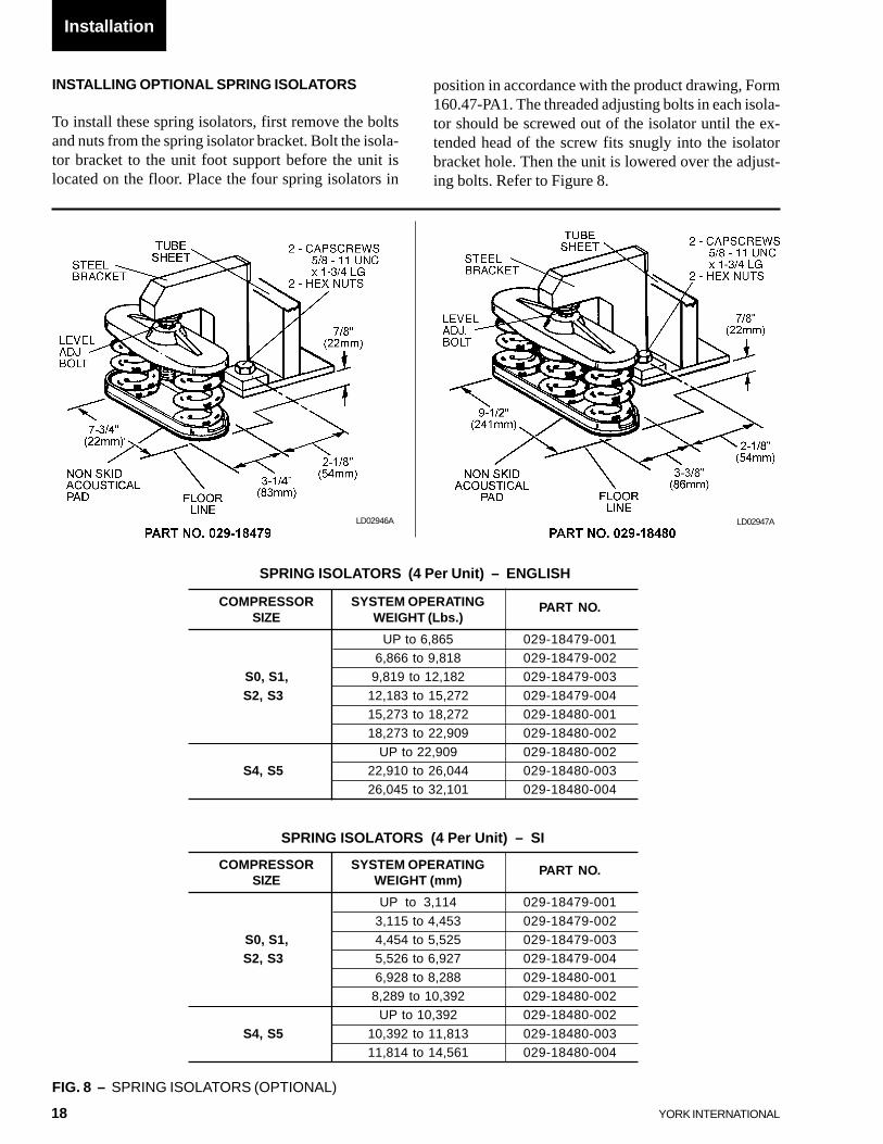
INSTALLING OPTIONAL SPRING ISOLATORS
To install these spring isolators, first remove the boltsand nuts from the spring isolator bracket. Bolt the isola-tor bracket to the unit foot support before the unit islocated on the floor. Place the four spring isolators in
position in accordance with the product drawing, Form160.47-PA1. The threaded adjusting bolts in each isola-tor should be screwed out of the isolator until the ex-tended head of the screw fits snugly into the isolatorbracket hole. Then the unit is lowered over the adjust-ing bolts. Refer to Figure 8.
FIG. 8 – SPRING ISOLATORS (OPTIONAL)
LD02946A LD02947A
SPRING ISOLATORS (4 Per Unit) – ENGLISH
COMPRESSOR SYSTEM OPERATING PART NO.SIZE WEIGHT (Lbs.)
UP to 6,865 029-18479-0016,866 to 9,818 029-18479-002
S0, S1, 9,819 to 12,182 029-18479-003
S2, S3 12,183 to 15,272 029-18479-00415,273 to 18,272 029-18480-00118,273 to 22,909 029-18480-002
UP to 22,909 029-18480-002S4, S5 22,910 to 26,044 029-18480-003
26,045 to 32,101 029-18480-004
SPRING ISOLATORS (4 Per Unit) – SI
COMPRESSOR SYSTEM OPERATING PART NO.SIZE WEIGHT (mm)
UP to 3,114 029-18479-001
3,115 to 4,453 029-18479-002S0, S1, 4,454 to 5,525 029-18479-003S2, S3 5,526 to 6,927 029-18479-004
6,928 to 8,288 029-18480-0018,289 to 10,392 029-18480-002
UP to 10,392 029-18480-002
S4, S5 10,392 to 11,813 029-18480-00311,814 to 14,561 029-18480-004
Installation
19
FORM 160.47-NOM3
YORK INTERNATIONAL
CHECK FOR PIPING ALIGNMENT
When piping is complete, check for alignment try open-ing a connection in each line, as close to the unit aspossible, by removing the flange bolts or coupling. Ifany of the bolts are bound in their holes, or if the con-nection springs are out of alignment. The misalignmentmust be corrected by properly supporting the piping orby applying heat to anneal the pipe.
It may be necessary to weld chilledwater piping directly to the water pipenozzles. Since chiller water tempera-ture sensor wells are often in closeproximity to these connection points,sensors in the wells may often see tem-peratures of several hundred degrees.We have reason to believe that somepotential exists for damaging thesesensors from the transferred heat. Anydamage will most likely show up aserror in the sensor.It is advisable to remove the sensorsfrom the wells during the welding pro-cess as a precautionary measure. If thesensor is removed, assure that it bot-toms out when it is placed back in thewell.This same precaution should also beobserved whenever condenser watertemperature sensors are present in thechiller system and condenser waterpiping is to be welded to the chiller.
If the piping is annealed to relievestress, the inside of the pipe must becleaned of scale before it is finallybolted in place.
The adjusting bolts should now be rotated one (1) turnat a time, in sequence, until the unit end sheets are about7/8 inch (22mm) off the floor or foundation, and the unitis level. Check the level of the unit both longitudinallyand transversly. If the adjusting bolts are not long enoughto level the unit due to an uneven or sloping floor orfoundation, steel shims (grouted, if necessary) must beadded beneath the isolator assemblies as necessary.
After the unit is leveled, wedge and shim under eachcorner to solidly support the unit in this position whilepiping connections are being made, pipe hangers ad-justed and connections checked for alignment. Then theunit can be filled with water and checked for leaks. Theadjusting bolts should now be finally adjusted and thewedges and shims can be removed. The unit shouldnow be in correct level position, clear of the floor orfoundation and without any effect from the weight ofthe piping. When the unit is properly supported, springisolator deflection should be approximately 1 inch(25mm).
PIPING CONNECTIONS
After the unit is leveled (and wedged in place for op-tional spring isolators) the piping connections may befabricated; chilled water, condenser water and refriger-ant relief. The piping should be arranged with offsetsfor flexibility, and adequately supported and braced in-dependently of the unit to avoid strain on the unit andvibration transmission. Hangers must allow for align-ment of pipe. Isolators (by others) in the piping and hang-ers are highly desirable, and may be required by speci-fications. This is done to effectively utilize the vibrationisolation characteristics of the isolator mounts on theunit.
1
20 YORK INTERNATIONAL
COOLER AND CONDENSER WATER PIPING
The cooler and condenser liquid heads of YS units havenozzles which are grooved, suitable for welding 150 psig(1034 kPa) DWP flanges or the use of Victaulic cou-plings.
The nozzles and water pass arrangements are furnishedin accordance with the job requirements (see ProductDrawing, Form 160.47-PA1). Standard units are designedfor 150 psig (1034 kPa) DWP on the water side. If jobrequirements are for greater than 150 psig (1034 kPa)DWP, check the unit data plate to determine if the unithas provisions for the required DWP before applyingpressure to cooler or condenser.
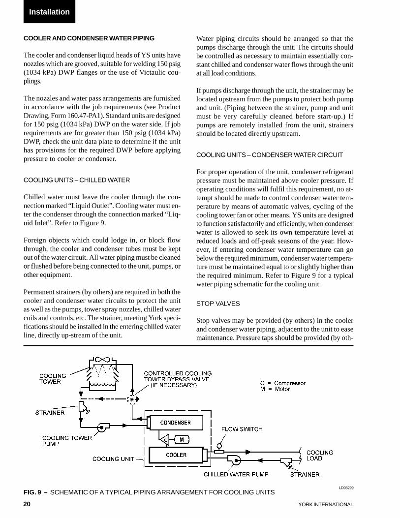
COOLING UNITS – CHILLED WATER
Chilled water must leave the cooler through the con-nection marked “Liquid Outlet”. Cooling water must en-ter the condenser through the connection marked “Liq-uid Inlet”. Refer to Figure 9.
Foreign objects which could lodge in, or block flowthrough, the cooler and condenser tubes must be keptout of the water circuit. All water piping must be cleanedor flushed before being connected to the unit, pumps, orother equipment.
Permanent strainers (by others) are required in both thecooler and condenser water circuits to protect the unitas well as the pumps, tower spray nozzles, chilled watercoils and controls, etc. The strainer, meeting York speci-fications should be installed in the entering chilled waterline, directly up-stream of the unit.
Water piping circuits should be arranged so that thepumps discharge through the unit. The circuits shouldbe controlled as necessary to maintain essentially con-stant chilled and condenser water flows through the unitat all load conditions.
If pumps discharge through the unit, the strainer may belocated upstream from the pumps to protect both pumpand unit. (Piping between the strainer, pump and unitmust be very carefully cleaned before start-up.) Ifpumps are remotely installed from the unit, strainersshould be located directly upstream.
COOLING UNITS – CONDENSER WATER CIRCUIT
For proper operation of the unit, condenser refrigerantpressure must be maintained above cooler pressure. Ifoperating conditions will fulfil this requirement, no at-tempt should be made to control condenser water tem-perature by means of automatic valves, cycling of thecooling tower fan or other means. YS units are designedto function satisfactorily and efficiently, when condenserwater is allowed to seek its own temperature level atreduced loads and off-peak seasons of the year. How-ever, if entering condenser water temperature can gobelow the required minimum, condenser water tempera-ture must be maintained equal to or slightly higher thanthe required minimum. Refer to Figure 9 for a typicalwater piping schematic for the cooling unit.
STOP VALVES
Stop valves may be provided (by others) in the coolerand condenser water piping, adjacent to the unit to easemaintenance. Pressure taps should be provided (by oth-
Installation
FIG. 9 – SCHEMATIC OF A TYPICAL PIPING ARRANGEMENT FOR COOLING UNITSLD03299
21
FORM 160.47-NOM3
YORK INTERNATIONAL
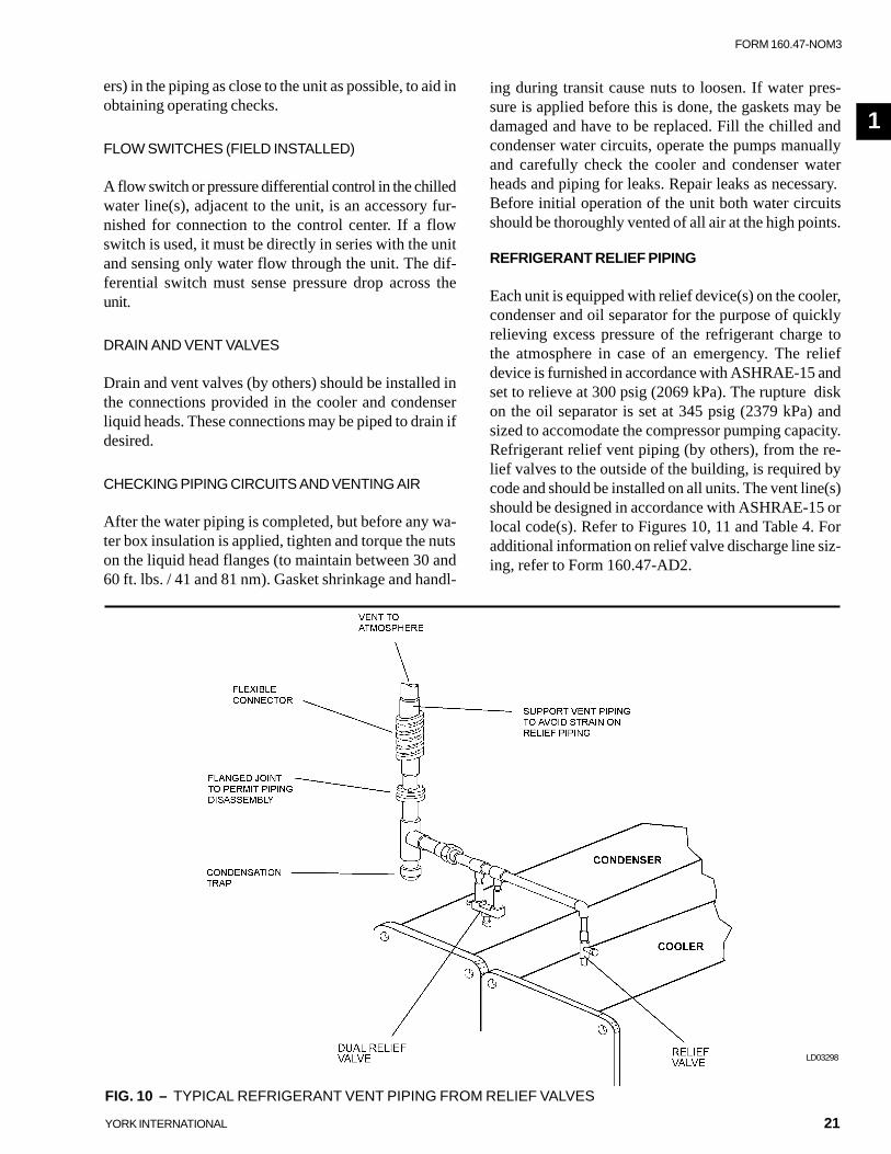
FIG. 10 – TYPICAL REFRIGERANT VENT PIPING FROM RELIEF VALVES
LD03298
ing during transit cause nuts to loosen. If water pres-sure is applied before this is done, the gaskets may bedamaged and have to be replaced. Fill the chilled andcondenser water circuits, operate the pumps manuallyand carefully check the cooler and condenser waterheads and piping for leaks. Repair leaks as necessary.Before initial operation of the unit both water circuitsshould be thoroughly vented of all air at the high points.
REFRIGERANT RELIEF PIPING
Each unit is equipped with relief device(s) on the cooler,condenser and oil separator for the purpose of quicklyrelieving excess pressure of the refrigerant charge tothe atmosphere in case of an emergency. The reliefdevice is furnished in accordance with ASHRAE-15 andset to relieve at 300 psig (2069 kPa). The rupture diskon the oil separator is set at 345 psig (2379 kPa) andsized to accomodate the compressor pumping capacity.Refrigerant relief vent piping (by others), from the re-lief valves to the outside of the building, is required bycode and should be installed on all units. The vent line(s)should be designed in accordance with ASHRAE-15 orlocal code(s). Refer to Figures 10, 11 and Table 4. Foradditional information on relief valve discharge line siz-ing, refer to Form 160.47-AD2.
1
ers) in the piping as close to the unit as possible, to aid inobtaining operating checks.
FLOW SWITCHES (FIELD INSTALLED)
A flow switch or pressure differential control in the chilledwater line(s), adjacent to the unit, is an accessory fur-nished for connection to the control center. If a flowswitch is used, it must be directly in series with the unitand sensing only water flow through the unit. The dif-ferential switch must sense pressure drop across theunit.
DRAIN AND VENT VALVES
Drain and vent valves (by others) should be installed inthe connections provided in the cooler and condenserliquid heads. These connections may be piped to drain ifdesired.
CHECKING PIPING CIRCUITS AND VENTING AIR
After the water piping is completed, but before any wa-ter box insulation is applied, tighten and torque the nutson the liquid head flanges (to maintain between 30 and60 ft. lbs. / 41 and 81 nm). Gasket shrinkage and handl-

22 YORK INTERNATIONAL
FIG. 11 – TYPICAL REFRIGERANT VENT PIPING FROM RUPTURE DISK
1. Piping should be properly sup-ported to prevent any strain on burst-ing disk mounting.
2. Be careful not to puncture burst-ing disk when thread protector is re-moved.
LD03300
Installation
23
FORM 160.47-NOM3
YORK INTERNATIONAL
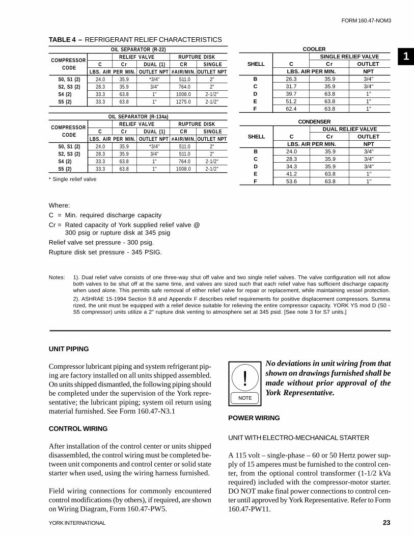
TABLE 4 – REFRIGERANT RELIEF CHARACTERISTICSCOOLER
SINGLE RELIEF VALVESHELL C Cr OUTLET
LBS. AIR PER MIN. NPTB 26.3 35.9 3/4"C 31.7 35.9 3/4"D 39.7 63.8 1"E 51.2 63.8 1"F 62.4 63.8 1"
CONDENSERDUAL RELIEF VALVE
SHELL C Cr OUTLETLBS. AIR PER MIN. NPT
B 24.0 35.9 3/4"C 28.3 35.9 3/4"D 34.3 35.9 3/4"E 41.2 63.8 1"F 53.6 63.8 1"
Notes: 1). Dual relief valve consists of one three-way shut off valve and two single relief valves. The valve configuration will not allowboth valves to be shut off at the same time, and valves are sized such that each relief valve has sufficient discharge capacitywhen used alone. This permits safe removal of either relief valve for repair or replacement, while maintaining vessel protection.
2). ASHRAE 15-1994 Section 9.8 and Appendix F describes relief requirements for positive displacement compressors. Summarized, the unit must be equipped with a relief device suitable for relieving the entire compressor capacity. YORK YS mod D (S0 -S5 compressor) units utilize a 2" rupture disk venting to atmosphere set at 345 psid. [See note 3 for S7 units.]
Where:
C = Min. required discharge capacity
Cr = Rated capacity of York supplied relief valve @300 psig or rupture disk at 345 psig
Relief valve set pressure - 300 psig.
Rupture disk set pressure - 345 PSIG.
UNIT PIPING
Compressor lubricant piping and system refrigerant pip-ing are factory installed on all units shipped assembled.On units shipped dismantled, the following piping shouldbe completed under the supervision of the York repre-sentative; the lubricant piping; system oil return usingmaterial furnished. See Form 160.47-N3.1
CONTROL WIRING
After installation of the control center or units shippeddisassembled, the control wiring must be completed be-tween unit components and control center or solid statestarter when used, using the wiring harness furnished.
Field wiring connections for commonly encounteredcontrol modifications (by others), if required, are shownon Wiring Diagram, Form 160.47-PW5.
No deviations in unit wiring from thatshown on drawings furnished shall bemade without prior approval of theYork Representative.
POWER WIRING
UNIT WITH ELECTRO-MECHANICAL STARTER
A 115 volt – single-phase – 60 or 50 Hertz power sup-ply of 15 amperes must be furnished to the control cen-ter, from the optional control transformer (1-1/2 kVarequired) included with the compressor-motor starter.DO NOT make final power connections to control cen-ter until approved by York Representative. Refer to Form160.47-PW11.
1
* Single relief valve
OIL SEPARATOR (R-22)RELIEF VALVE RUPTURE DISK
COMPRESSORC C r DUAL (1) C R SINGLE
CODELBS. AIR PER MIN. OUTLET NPT #AIR/MIN. OUTLET NPT
S0, S1 (2) 24.0 35.9 *3/4" 511.0 2"S2, S3 (2) 28.3 35.9 3/4" 764.0 2"S4 (2) 33.3 63.8 1" 1008.0 2-1/2"S5 (2) 33.3 63.8 1" 1275.0 2-1/2"
OIL SEPARATOR (R-134a)RELIEF VALVE RUPTURE DISK
COMPRESSORC C r DUAL (1) C R SINGLE
CODELBS. AIR PER MIN. OUTLET NPT #AIR/MIN. OUTLET NPT
S0, S1 (2) 24.0 35.9 *3/4" 511.0 2"S2, S3 (2) 28.3 35.9 3/4" 511.0 2"S4 (2) 33.3 63.8 1" 764.0 2-1/2"S5 (2) 33.3 63.8 1" 1008.0 2-1/2"

24 YORK INTERNATIONAL
INSTALLATION CHECK – REQUEST FORSTART-UP SERVICE
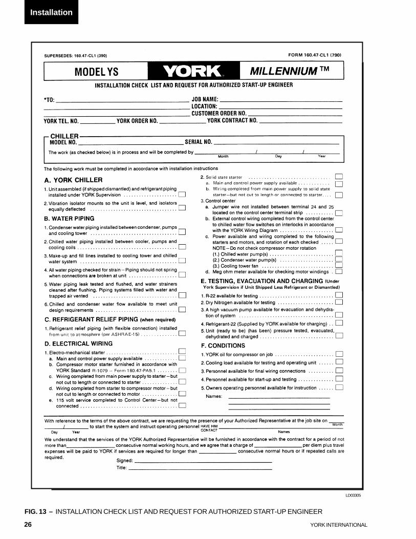
After the unit is installed, piped and wired as describedin this Instruction, but before any attempt is made tostart the unit, the York District Office should be advisedso that the start-up service, included in the contract price,can be scheduled. Notification to the York Office shouldbe by means of Installation Check List and Request,Form 160.47-CL1, in triplicate. (See Figure 13.)
The services of a York Representative will be furnishedto check the installation and supervise the initial start-up and operation on all YS units installed within the Con-tinental United States.
Remote Electro-Mechanical startersfor the YS Unit must be furnished inaccordance with York Standard R-1079.
Each YS unit is furnished for a specific electrical powersupply as stamped on the unit data plate, which alsodetails the motor connection diagrams.
To insure proper motor rotation, thestarter power input and starter to mo-tor connections must be checked witha phase sequence indicator in the pres-ence of the York Representative.
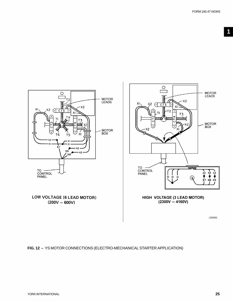
Figure 12 shows the power wiring hook-up for YS Mo-tor Connections. (Refer to Wiring Labels in Motor Ter-minal Box for hook-up to suit motor voltage and amper-age.)
Motor leads are furnished with a crimp-type connectionhaving a clearance hole for a 3/8 inch bolt, motor termi-nal lugs are not furnished.
UNIT WITH SOLID STATE STARTER (OPTIONAL)
A YS unit equipped with a Solid State Starter, does notrequire wiring to the compressor-motor. The motorpower wiring is factory connected to the Solid StateStarter (or an optional factory installed disconnectswitch). All wiring to the control panel is completed bythe factory. A control transformer is furnished with theSolid State Starter. Refer to Form 160.47-PW12.
IMPORTANT
DO NOT cut wires to final length or make finalconnections to motor terminals or starter powerinput terminals until approved by the York Repre-sentative.
INSULATION
Insulation of the type specified for the job, or minimumthickness to prevent sweating of 30°F surfaces (waterchill application), should be furnished (by others) andapplied to the cooler shell, end sheets, liquid feed line toflow chamber, compressor suction connection, and coolerliquid heads and connections. The liquid head flange in-sulation must be removable to allow head removal fortube maintenance. Details of areas to be insulated aregiven in Product Drawing, Form 160.47-PA1.
Units can be furnished, factory anti-sweat insulated, onorder at additional cost. This includes all low tempera-ture surfaces except the two cooler liquid heads.
IMPORTANTDO NOT field insulate until the unit has been leaktested under the supervision of the York Repre-sentative.
Installation
POWER WIRING (CONT’D)
25
FORM 160.47-NOM3
YORK INTERNATIONAL
FIG. 12 – YS MOTOR CONNECTIONS (ELECTRO-MECHANICAL STARTER APPLICATION)
LD03301
1
26 YORK INTERNATIONAL
FIG. 13 – INSTALLATION CHECK LIST AND REQUEST FOR AUTHORIZED START-UP ENGINEER
LD03305
Installation
27
FORM 160.47-NOM3
YORK INTERNATIONAL
SECTION 2OPERATION
BASIC DESCRIPTION
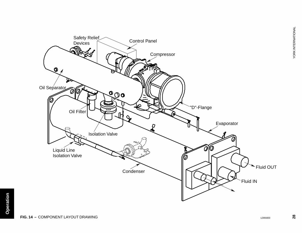
The York YS Chiller package uses a refrigerant-floodedevaporator and a liquid-cooled condenser. The compres-sor is a heavy-duty, industrial-rated rotary screw com-pressor. The package consists of four major components.Refer to the Chiller Package Component drawing, Fig-ure 14.
COMPONENTS
DRIVELINE
The driveline is made up of the compressor and a heavyduty industrial induction motor. The motor is mounted tothe compressor with a “D”-flange spacer. The “D”-flange eliminates the necessity to align the motor andcompressor.
The compressor is a positive displacement, variable vol-ume, direct drive, twin helical rotary screw compressor.The male rotor is a direct drive by the motor; the femalerotor is an idler that is driven by the male rotor. Therotors do not touch each other or the compressor hous-ing. The rotors are separated by a hydraulic oil seal,which prevents high pressure gas from leaking into lowpressure areas.
Evaporator pressure gas is drawn into the compressorand compressed by the male and female rotors as theyrotate together and reduce the volume of gas.
The compressor bearings are industrial duty rated, anti-friction rolling element bearings. No sleeve bearings areused. Oil is injected into the compressor by differentialpressure to lubricate the bearings, seal the rotors andremove the heat of compression. The oil that is injectedinto the compressor mixes with the compressed gas andis separated from the refrigerant gas in the oil separa-tor.
A slide valve is positioned between the male and femalerotors, that moves axially to match the compressor ca-pacity to that of the evaporator refrigeration load. Theslide valve is moved by differential pressure. As theslide valve moves toward the unloaded position, less suc-tion gas is pumped through the compressor. The controlpanel automatically positions the slide valve to matchthe load requirements. The slide valve can be operated
manually. When the compressor is shut off, a springreturns the slide valve to unloaded position. The com-pressor starts with the slide valve in the unloaded posi-tion.
OIL SEPARATOR
The oil separator removes the oil that was injected intothe compressor. The oil separator is a three stage de-sign. Most of the oil separates by a reduction in velocityin the first stage. The discharge gas is then directedthrough a high surface area that collects more of theoil. The final stage is a coalescer element(s) that re-moves the fine aerosol particles of oil.
The oil separator is very efficient and removes nearly100% of the oil. The very small amount of oil that doespass through the oil separator is returned to the com-pressor through a filter driers.
The oil separator is also a reservoir for the oil. A tem-perature controlled immersion heater is installed in theoil reservoir. The oil heater is interlocked with a low oillevel safety switch.
CONDENSER
Oil free refrigerant gas leaving the oil separator flowsinto the condenser. Water flowing through the condenserremoves the heat of compression and condenses therefrigerant gas into refrigerant liquid.
The liquid refrigerant then flows through the integralliquid sub-cooler located in the bottom of the condenser.The sub-cooled liquid refrigerant flows into the evapo-rator by deferential pressure.
EVAPORATOR
Condensing pressure refrigerant flows out of the liquidsub-cooler into the liquid line where the liquid refriger-ant is metered into the evaporator by an orifice. Theliquid refrigerant begins to flash (and cool) after flow-ing through the orifice plate. The refrigerant is distrib-uted in the bottom of the evaporator. Liquid refrigerantfloods the evaporator and the heat is exchanged fromthe evaporator liquid, flowing on the inside of the evapo-rator tubes, to the liquid refrigerant on the outside of thetubes.
2
28Y
OR
K IN
TE
RN
ATIO
NA
L
Compressor
Oil Separator
Condenser
Evaporator
"D"-Flange
Liquid LineIsolation Valve
Oil Filter
Isolation Valve
Safety ReliefDevices Control Panel
Fluid IN
Fluid OUT
FIG. 14 – COMPONENT LAYOUT DRAWING LD004303
Op
erat
ion
29
FORM 160.47-NOM3
YORK INTERNATIONAL
EVAPORATOR (CONT’D)
A baffle is welded into the top of the evaporator to col-lect oil that falls from the compressor, preventing oilfrom mixing with the refrigerant charge. The baffle pre-vents liquid refrigerant from damaging the compressor.
CONDENSING WATER TEMPERATURE
YS Chillers can be operated with entering condensingwater that is less than design conditions. The followingformula is used to calculate the minimum entering con-densing water temperature. Note the minimum enter-ing condensing water temperature is dependant uponthe operating load condition.
R-22 REFRIGERANT
ECW minimum = LCWT+11+[(%of load/100)(15 - de-
sign condenser deltaT)].
R-134a REFRIGERANT
ECW minimum = LCWT+16+[(%of load/100)(10 - de-
sign condenser deltaT)].
Where:
ECW minimum = Minimum Entering Condensing Water
Temperature ºF
LCWT = Leaving Chilled Water Temperature ºF
Operating below the minimum entering condensing wa-ter will not provide energy savings and will result in oil
management problems.YS chillers may be started with entering condensingwater temperatures as much as 25ºF below the leavingchilled water temperature. However, special enteringcondensing water temperature controls may be requiredwhen long condensing water circuits are used and thechiller is starting at low load conditions.
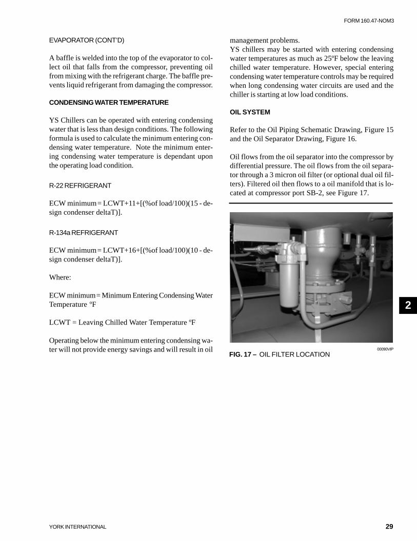
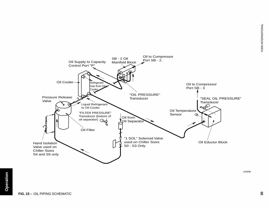
OIL SYSTEM
Refer to the Oil Piping Schematic Drawing, Figure 15and the Oil Separator Drawing, Figure 16.
Oil flows from the oil separator into the compressor bydifferential pressure. The oil flows from the oil separa-tor through a 3 micron oil filter (or optional dual oil fil-ters). Filtered oil then flows to a oil manifold that is lo-cated at compressor port SB-2, see Figure 17.
FIG. 17 – OIL FILTER LOCATION00090VIP
2
30Y
OR
K IN
TE
RN
ATIO
NA
L
"FILTER PRESSURE"Transducer (bottom ofoil separator)
"OIL PRESSURE"Transducer "SEAL OIL PRESSURE"
Transducer
Oil to CompressorPort SB - 3
Oil to CompressorPort SB - 2Oil Supply to Capacity
Control Port "P"
Oil TemperatureSensor
"1 SOL" Solenoid Valve used on Chiller Sizes S0 - S3 Only
Pressure ReleaseValve
SB - 2 Oil Manifold Block
Oil Cooler
Oil Filter
Oil Eductor BlockHand Isolation Valve used onChiller Sizes S4 and S5 only
Oil fromOil Separator
Liquid Refrigerantto Oil Cooler
RefrigerantGas from OilCooler
FIG. 15 – OIL PIPING SCHEMATIC
LD04298
Op
erat
ion
31
FORM 160.47-NOM3
YORK INTERNATIONAL
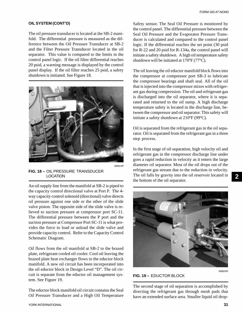
OIL SYSTEM (CONT’D)
The oil pressure transducer is located at the SB-2 mani-fold. The differential pressure is measured as the dif-ference between the Oil Pressure Transducer at SB-2and the Filter Pressure Transducer located in the oilseparator. This value is compared to the limits in thecontrol panel logic. If the oil filter differential reaches20 psid, a warning message is displayed by the controlpanel display. If the oil filter reaches 25 psid, a safetyshutdown is initiated. See Figure 18.
An oil supply line from the manifold at SB-2 is piped tothe capacity control directional valve at Port P. The 4-way capacity control solenoid (directional) valve directsoil pressure against one side or the other of the slidevalve piston. The opposite side of the slide valve is re-lieved to suction pressure at compressor port SC-11.The differential pressure between the P port and thesuction pressure at Compressor Port SC-11 is what pro-vides the force to load or unload the slide valve andprovide capacity control. Refer to the Capacity ControlSchematic Diagram.
Oil flows from the oil manifold at SB-2 to the brazedplate, refrigerant cooled oil cooler. Cool oil leaving thebrazed plate heat exchanger flows to the eductor blockmanifold. A new oil circuit has been incorporated intothe oil eductor block in Design Level “D”. The oil cir-cuit is separate from the eductor oil management sys-tem. See Figure 19.
The eductor block manifold oil circuit contains the SealOil Pressure Transducer and a High Oil Temperature
00091VIP
FIG. 18 – OIL PRESSURE TRANSDUCERLOCATION
00092VIP
FIG. 19 – EDUCTOR BLOCK
Safety sensor. The Seal Oil Pressure is monitored bythe control panel. The differential pressure between theSeal Oil Pressure and the Evaporator Pressure Trans-ducer is calculated and compared to the control panellogic. If the differential reaches the set point (30 psidfor R-22 and 20 psid for R-134a, the control panel willinitiate a safety shutdown. A high oil temperature safetyshutdown will be initiated at 170ºF (77ºC).
The oil leaving the oil eductor manifold block flows intothe compressor at compressor port SB-3 to lubricatethe compressor bearings and shaft seal. All of the oilthat is injected into the compressor mixes with refriger-ant gas during compression. The oil and refrigerant gasis discharged into the oil separator, where it is sepa-rated and returned to the oil sump. A high dischargetemperature safety is located in the discharge line, be-tween the compressor and oil separator. This safety willinitiate a safety shutdown at 210ºF (99ºC).
Oil is separated from the refrigerant gas in the oil sepa-rator. Oil is separated from the refrigerant gas in a threestep process.
In the first stage of oil separation, high velocity oil andrefrigerant gas in the compressor discharge line undergoes a rapid reduction in velocity as it enters the largediameter oil separator. Most of the oil drops out of therefrigerant gas stream due to the reduction in velocity.The oil falls by gravity into the oil reservoir located inthe bottom of the oil separator.
The second stage of oil separation is accomplished bydirecting the refrigerant gas through mesh pads thathave an extended surface area. Smaller liquid oil drop-
2

32Y
OR
K IN
TE
RN
ATIO
NA
L
FIG. 16 – OIL SEPARATOR SCHEMATIC
LD04302
First Stage of Oil SeparationReduction in Velocity
Second Stage of Oil SeparationExtended Surface Area
Third Stage of Oil SeparationCoaleser Element
Oil Out
Oil & RefrigerantGas to Eductor
6
1
2 13
4 51
1. Sight Glass2. Oil Level Switch3. Filter Pressure Transducer and Isolation Valve4. Oil Charging Valve5. Oil Heater6. Discharge Temperature Sensor
Op
erat
ion

33
FORM 160.47-NOM3
YORK INTERNATIONAL
lets are collected on the extended surface area of thewire mesh pads where the oil falls by gravity into the oilreservoir.
The third and final stage of oil separation is achieved inthe oil coalescing element section of the oil separator.The oil mixed with the refrigerant entering the coalescerelement is a very fine aerosol mist about the size ofcigarette smoke particles. These small aerosol mist par-ticles wet the coalescer element media and form largeroil droplets which fall by gravity to the bottom of thecoalescer element section. The oil collected in thecoalescer section is drained from the oil separator witha small amount of refrigerant gas. This provides thehigh pressure “gas drive” for the eductors to return oilfrom the evaporator. Refer to paragraph Oil EductorCircuit.
Three sight glasses are provided in the oil separator formonitoring the oil level and verifying performance ofthe coalescer element. Liquid oil should be visible in thetop glass of the oil separator when the chiller is off.During operation, oil may be higher or lower due to sys-tem load and operating conditions.
A low oil level safety switch is provided in the bottom ofthe oil separator. A safety shutdown will be initiated ifthe oil level is below the switch setting for 30 continu-ous seconds after the chiller has been running for 3 min-utes.
An oil drain and charging valve is located on the bottomof the oil separator. A 5/8 inch male flare connection isprovided for ease of connecting a hose to quickly drainused oil into a EPA approved recovery cylinder or tank.Oil can be added into the oil reservoir with the chiller inservice.
Do not add oil. York YS Chiller pack-ages are pre-charged with the correctamount of York oil during functionaltesting after manufacture. Refer to theOil Usage Table 6 in the MaintenanceSection.
Oil loss is most often the result of operating conditionsat loads under 10% of the chillers rated capacity andwith condensing water that is too cold for load and op-erating condition.
The oil is not “lost” but has migrated into the refrigerantcharge and is most likely in the evaporator. Excessiveamounts of oil in the evaporator will result in opera-tional problems.
Oil management problems result if the compressor dis-charge superheat is not maintained at the values listedin Table 8. Compressor discharge superheat is the dif-ference between the compressor discharge tempera-ture and the saturated condenser temperature. Com-pressor discharge superheat is used in conjunction withthe evaporator approach to determine the most efficientrefrigerant charge.
Should the control panel display EX-CESS CHARGE WARNING this ismost likely the result of excessiveamounts of oil in the evaporator. Ex-cess amounts of oil in the refrigerantwill cause foaming. The oil foam car-ries liquid refrigerant into the com-pressor. This results in lowering thecompressor discharge superheat tolow levels. If the compressor dischargesuperheat falls to within 10ºF of thesaturated condensing temperature thecontrol panel will display EXCESSCHARGE WARNING. Compressorloading will be inhibited while theEXCESS CHARGE WARNING isdisplayed. The inhibit loading will re-main in effect until the compressordischarge superheat increases to 15ºF.
OIL SYSTEM (CONT’D)
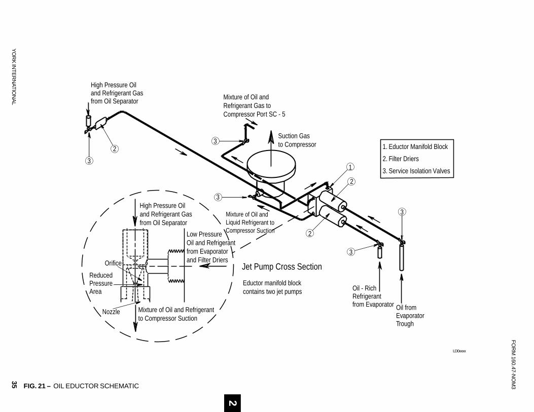
OIL EDUCTOR CIRCUIT
An oil eductor circuit is provided to properly managethe amount of oil in the refrigerant charge. A smallamount of oil is normal in the refrigerant charge andwill be found in the evaporator. If not properly man-aged the oil will accumulate and have adverse conse-quences regarding chiller performance.
The oil eductor circuit consists of three refrigerant andoil filter driers, two “jet pump” eductors and the inter-connecting piping. Refer to Figures 20 and 21.
The eductors operate using the “jet pump” principle.Discharge pressure gas and oil flows through a filterdryer located at the bottom of the oil separator. The
2

34 YORK INTERNATIONAL
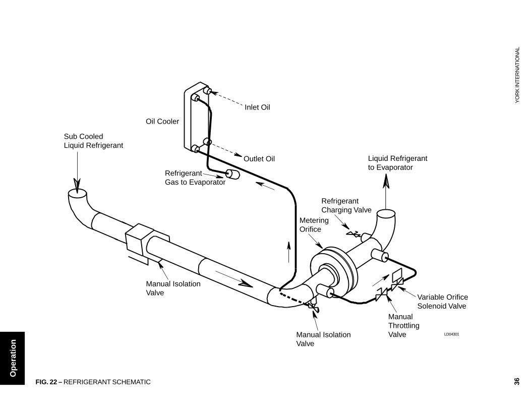
LIQUID REFRIGERANT CIRCUIT
Liquid refrigerant flows from the condenser into theevaporator by differential pressure. Sub-cooled liquidrefrigerant flows out of the condenser into the liquidline. A metering orifice is installed in the liquid line tocontrol the rate liquid refrigerant flows into the evapo-rator. The orifice is selected based upon the operatingconditions of the chiller. Refer to Figure 22.
A liquid line hand-isolation valve is located between thecondenser and the metering orifice plate. This valve, incombination with the hand isolation valve between theoil separator and the condenser, allows all of the refrig-erant charge to be stored in the condenser.
A ½ inch liquid refrigerant supply is piped from the bot-tom of the liquid line to the refrigerant cooled oil cooler.The refrigerant gas from the oil cooler is piped directlyinto the evaporator.
A liquid refrigerant-charging valve is piped into the liq-uid line between the evaporator and the metering ori-fice. A ¾ inch male flare connection is provided forconnecting hoses or transfer lines.
REFRIGERANTDIFFERENTIAL
PRESSURE RANGER-22 25 - 150 PSID
R-134A 15 - 110 PSID
TABLE 5 – VARIABLE ORIFICE PRESSUREDIFFERENTIAL SETPOINTS
discharge pressure gas and oil flows through a regulat-ing orifice and nozzle located in the eductor block. Thereduced pressure (pumping action) is created by thevelocity of the discharge pressure gas and oil flowingthrough the orifice and nozzle. This creates a reducedpressure area that allows the oil-rich refrigerant and oilto flow from the evaporator into the compressor.
Oil-rich refrigerant flows into the eductor block throughthe filter drier from the evaporator. The oil rich refrig-erant mixes with the discharge pressure gas and flowsinto the compressor suction line.
A second eductor flows oil, which may have collectedin the evaporator trough through the second filter drierlocated on the eductor block. This oil mixes with thedischarge gas in the eductor block and flows to the com-pressor at port SC-5.
The filter driers should be changed annually or whenexcessive amount of oil is indicated in the refrigerantcharge.
00089VIP
FIG. 20 – FILTER DRIERS AND OIL EDUCTOR
FILTER DRIERSPRESSURE RELEASEVALVE
EDUCTORMANIFOLD BLOCK
HIGH PRESSURE OIL AND REFRIGERANTFROM OIL SEPARATOR
YS Chillers (S0 – S5) are supplied with a variable ori-fice arrangement. In parallel with the metering orificeis a solenoid valve and hand-throttling valve. The sole-noid is energized open by the DIFFERENTIAL PRES-SURE set point that is field programmable from thepanel. The differential pressure between condensingpressure and evaporating pressure is compared to theset point value. When the differential pressure is at orless than the setpoint, the solenoid valve is energizedopen. The solenoid valve is de-energized closed whenthe differential pressure is equal to or greater than thesetpoint plus 10 psig. A hand-throttling valve is providedto adjust the refrigerant flow rate through the solenoidvalve to match the system operating conditions.
Dual Service Chillers – Ice duty and comfort coolingair conditioning applications will require the solenoidvalve to be energized open in the air conditioning modeof operation since this represents the low differentialpressure mode of operation.
The differential pressure set point is field programmablewithin the ranges specified in Table 5 for different re-frigerants and EPROM version S.01F.17 and later. SeeYork Service Bulletin 160.47-M2 (SB18) for program-ming instructions.
Operation
OIL EDUCTOR CIRCUIT (CONT’D)
35
FO
RM
160.47-NO
M3
YO
RK
INT
ER
NAT
ION
AL
1. Eductor Manifold Block
2. Filter Driers
3. Service Isolation Valves
High Pressure Oiland Refrigerant Gasfrom Oil Separator
Mixture of Oil andLiquid Refrigerant to Compressor Suction
Oil - Rich Refrigerantfrom Evaporator Oil from
EvaporatorTrough
Suction Gasto Compressor
Mixture of Oil and Refrigerant Gas to Compressor Port SC - 5
Low PressureOil and Refrigerantfrom Evaporatorand Filter Driers
High Pressure Oiland Refrigerant Gasfrom Oil Separator
Mixture of Oil and Refrigerant to Compressor Suction
3
3
2
2
1
3
3
2
3
Orifice
Nozzle
ReducedPressureArea
Jet Pump Cross Section
Eductor manifold block contains two jet pumps
FIG. 21 – OIL EDUCTOR SCHEMATIC
LD0xxxx
2
36Y
OR
K IN
TE
RN
ATIO
NA
L
Oil Cooler
Inlet Oil
Outlet Oil
RefrigerantGas to Evaporator
RefrigerantCharging Valve
Manual IsolationValve
MeteringOrifice
ManualThrottlingValve
Manual IsolationValve
Sub CooledLiquid Refrigerant
Variable OrificeSolenoid Valve
Liquid Refrigerant to Evaporator
FIG. 22 – REFRIGERANT SCHEMATIC
LD04301
Op
erat
ion
37
FORM 160.47-NOM3
YORK INTERNATIONAL
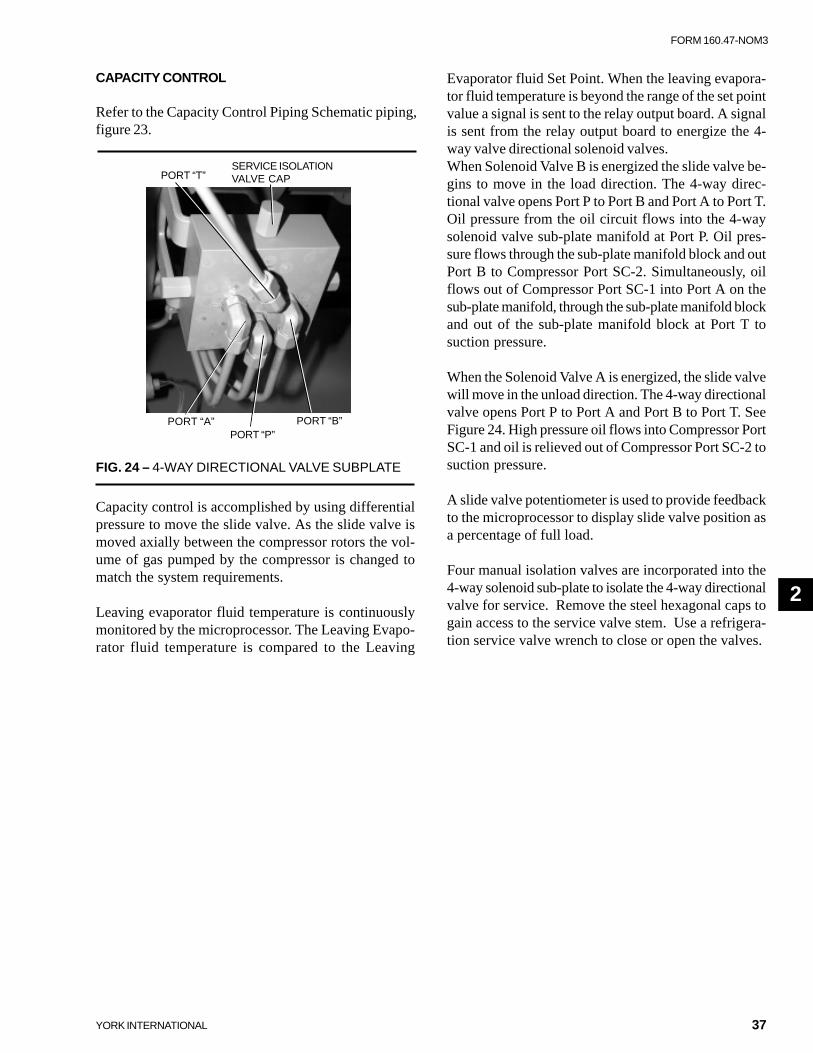
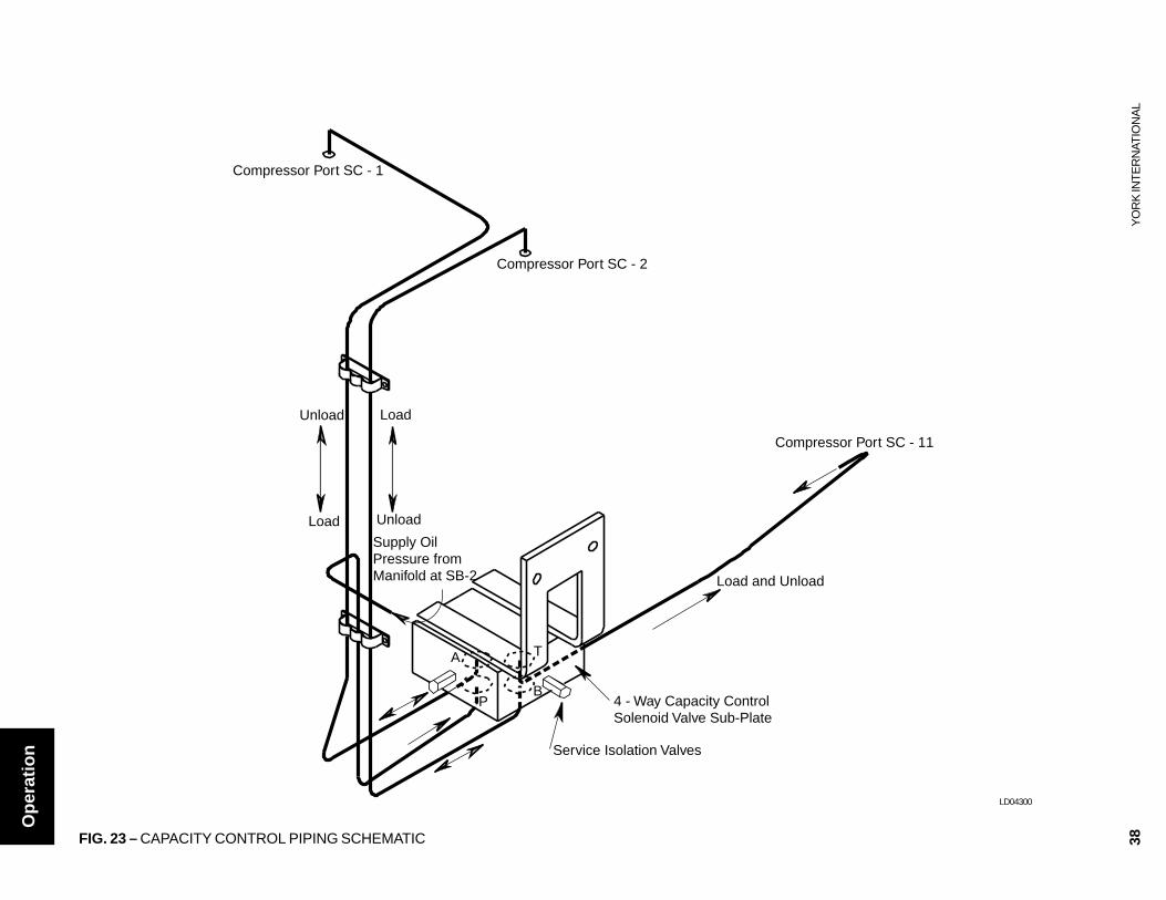
CAPACITY CONTROL
Refer to the Capacity Control Piping Schematic piping,figure 23.
Evaporator fluid Set Point. When the leaving evapora-tor fluid temperature is beyond the range of the set pointvalue a signal is sent to the relay output board. A signalis sent from the relay output board to energize the 4-way valve directional solenoid valves.When Solenoid Valve B is energized the slide valve be-gins to move in the load direction. The 4-way direc-tional valve opens Port P to Port B and Port A to Port T.Oil pressure from the oil circuit flows into the 4-waysolenoid valve sub-plate manifold at Port P. Oil pres-sure flows through the sub-plate manifold block and outPort B to Compressor Port SC-2. Simultaneously, oilflows out of Compressor Port SC-1 into Port A on thesub-plate manifold, through the sub-plate manifold blockand out of the sub-plate manifold block at Port T tosuction pressure.
When the Solenoid Valve A is energized, the slide valvewill move in the unload direction. The 4-way directionalvalve opens Port P to Port A and Port B to Port T. SeeFigure 24. High pressure oil flows into Compressor PortSC-1 and oil is relieved out of Compressor Port SC-2 tosuction pressure.
A slide valve potentiometer is used to provide feedbackto the microprocessor to display slide valve position asa percentage of full load.
Four manual isolation valves are incorporated into the4-way solenoid sub-plate to isolate the 4-way directionalvalve for service. Remove the steel hexagonal caps togain access to the service valve stem. Use a refrigera-tion service valve wrench to close or open the valves.
FIG. 24 – 4-WAY DIRECTIONAL VALVE SUBPLATE
2
Capacity control is accomplished by using differentialpressure to move the slide valve. As the slide valve ismoved axially between the compressor rotors the vol-ume of gas pumped by the compressor is changed tomatch the system requirements.
Leaving evaporator fluid temperature is continuouslymonitored by the microprocessor. The Leaving Evapo-rator fluid temperature is compared to the Leaving
SERVICE ISOLATIONVALVE CAPPORT “T”
PORT “A”PORT “P”
PORT “B”
2
38Y
OR
K IN
TE
RN
ATIO
NA
L
Compressor Port SC - 2
Compressor Port SC - 1
LoadUnload
UnloadLoad
Load and Unload
Supply Oil Pressure from Manifold at SB-2
A
BP
T
4 - Way Capacity ControlSolenoid Valve Sub-Plate
Compressor Port SC - 11
Service Isolation Valves
FIG. 23 – CAPACITY CONTROL PIPING SCHEMATIC
LD04300
Op
erat
ion
39
FORM 160.47-NOM3
YORK INTERNATIONAL
SECTION 3MAINTENANCE
GENERAL
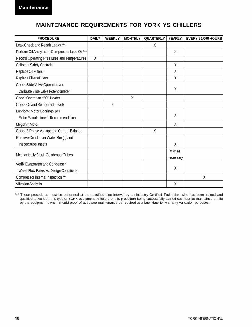
The maintenance requirements for YS Chillers is shownon the following page. The procedure is given in theleft- hand column and the frequency required is markedwith an “X” shown in the right-hand columns. Refer tothe note at the bottom of the form to maintain warrantyvalidation.
COMPRESSOR OIL
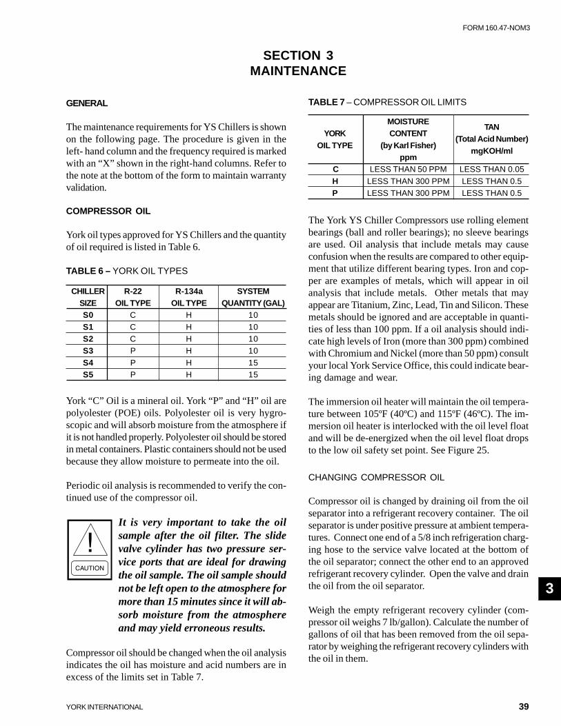
York oil types approved for YS Chillers and the quantityof oil required is listed in Table 6.
The York YS Chiller Compressors use rolling elementbearings (ball and roller bearings); no sleeve bearingsare used. Oil analysis that include metals may causeconfusion when the results are compared to other equip-ment that utilize different bearing types. Iron and cop-per are examples of metals, which will appear in oilanalysis that include metals. Other metals that mayappear are Titanium, Zinc, Lead, Tin and Silicon. Thesemetals should be ignored and are acceptable in quanti-ties of less than 100 ppm. If a oil analysis should indi-cate high levels of Iron (more than 300 ppm) combinedwith Chromium and Nickel (more than 50 ppm) consultyour local York Service Office, this could indicate bear-ing damage and wear.
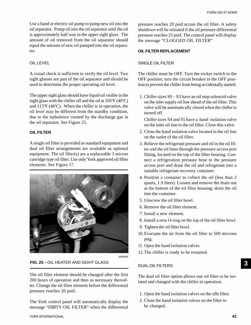
The immersion oil heater will maintain the oil tempera-ture between 105ºF (40ºC) and 115ºF (46ºC). The im-mersion oil heater is interlocked with the oil level floatand will be de-energized when the oil level float dropsto the low oil safety set point. See Figure 25.
CHANGING COMPRESSOR OIL
Compressor oil is changed by draining oil from the oilseparator into a refrigerant recovery container. The oilseparator is under positive pressure at ambient tempera-tures. Connect one end of a 5/8 inch refrigeration charg-ing hose to the service valve located at the bottom ofthe oil separator; connect the other end to an approvedrefrigerant recovery cylinder. Open the valve and drainthe oil from the oil separator.
Weigh the empty refrigerant recovery cylinder (com-pressor oil weighs 7 lb/gallon). Calculate the number ofgallons of oil that has been removed from the oil sepa-rator by weighing the refrigerant recovery cylinders withthe oil in them.
York “C” Oil is a mineral oil. York “P” and “H” oil arepolyolester (POE) oils. Polyolester oil is very hygro-scopic and will absorb moisture from the atmosphere ifit is not handled properly. Polyolester oil should be storedin metal containers. Plastic containers should not be usedbecause they allow moisture to permeate into the oil.
Periodic oil analysis is recommended to verify the con-tinued use of the compressor oil.
It is very important to take the oilsample after the oil filter. The slidevalve cylinder has two pressure ser-vice ports that are ideal for drawingthe oil sample. The oil sample shouldnot be left open to the atmosphere formore than 15 minutes since it will ab-sorb moisture from the atmosphereand may yield erroneous results.
Compressor oil should be changed when the oil analysisindicates the oil has moisture and acid numbers are inexcess of the limits set in Table 7.
TABLE 7 – COMPRESSOR OIL LIMITS
YORKMOISTURE
TAN
OIL TYPECONTENT
(Total Acid Number)(by Karl Fisher)
mgKOH/mlppm
C LESS THAN 50 PPM LESS THAN 0.05
H LESS THAN 300 PPM LESS THAN 0.5P LESS THAN 300 PPM LESS THAN 0.5
TABLE 6 – YORK OIL TYPES
CHILLER R-22 R-134a SYSTEMSIZE OIL TYPE OIL TYPE QUANTITY (GAL)S0 C H 10
S1 C H 10S2 C H 10S3 P H 10
S4 P H 15S5 P H 15
3
40 YORK INTERNATIONAL
MAINTENANCE REQUIREMENTS FOR YORK YS CHILLERS
PROCEDURE DAILY WEEKLY MONTHLY QUARTERLY YEARLY EVERY 50,000 HOURS
Leak Check and Repair Leaks *** X
Perform Oil Analysis on Compressor Lube Oil *** X
Record Operating Pressures and Temperatures X
Calibrate Safety Controls X
Replace Oil Filters X
Replace Filters/Driers X
Check Slide Valve Operation and
Calibrate Slide Valve PotentiometerX
Check Operation of Oil Heater X
Check Oil and Refrigerant Levels X
Lubricate Motor Bearings per
Motor Manufacturer’s RecommendationX
Megohm Motor X
Check 3-Phase Voltage and Current Balance X
Remove Condenser Water Box(s) and
inspect tube sheets X
Mechanically Brush Condenser TubesX or as
necessary
Verify Evaporator and Condenser
Water Flow Rates vs. Design ConditionsX
Compressor Internal Inspection *** X
Vibration Analysis X
*** These procedures must be performed at the specified time interval by an Industry Certified Technician, who has been trained andqualified to work on this type of YORK equipment. A record of this procedure being successfully carried out must be maintained on fileby the equipment owner, should proof of adequate maintenance be required at a later date for warranty validation purposes.
Maintenance
41
FORM 160.47-NOM3
YORK INTERNATIONAL
Use a hand or electric oil pump to pump new oil into theoil separator. Pump oil into the oil separator until the oilis approximately half way in the upper sight glass. Theamount of oil removed from the oil separator shouldequal the amount of new oil pumped into the oil separa-tor.
OIL LEVEL
A visual check is sufficient to verify the oil level. Twosight glasses are part of the oil separator and should beused to determine the proper operating oil level.
The upper sight glass should have liquid oil visible in thesight glass with the chiller off and the oil at 105ºF (40ºC)and 115ºF (46ºC). When the chiller is in operation, theoil level may be different from the standby condition,due to the turbulence created by the discharge gas inthe oil separator. See Figure 25.
OIL FILTER
A single oil filter is provided as standard equipment anddual oil filter arrangements are available as optionalequipment. The oil filter(s) are a replaceable 3 microncartridge type oil filter. Use only York approved oil filterelements. See Figure 17.
pressure reaches 20 psid across the oil filter. A safetyshutdown will be initiated if the oil pressure differentialpressure reaches 25 psid. The control panel will displaythe message “CLOGGED OIL FILTER”
OIL FILTER REPLACEMENT
SINGLE OIL FILTER
The chiller must be OFF. Turn the rocker switch to theOFF position; turn the circuit breaker to the OFF posi-tion to prevent the chiller from being accidentally started.
1. Chiller sizes S0 – S3 have an oil stop solenoid valveon the inlet supply oil line ahead of the oil filter. Thisvalve will be automatically closed when the chiller isturned off.
Chiller sizes S4 and S5 have a hand isolation valveon the inlet oil line to the oil filter. Close this valve.
2. Close the hand isolation valve located in the oil lineon the outlet of the oil filter.
3. Relieve the refrigerant pressure and oil in the oil fil-ter and the oil lines through the pressure access portfitting, located on the top of the filter housing. Con-nect a refrigeration pressure hose to the pressureaccess port and drain the oil and refrigerant into asuitable refrigerant recovery container.
4. Position a container to collect the oil (less than 2quarts, 1.9 liters). Loosen and remove the drain nutat the bottom of the oil filter housing; drain the oilinto the container.
5. Unscrew the oil filter bowl.
6. Remove the oil filter element.
7. Install a new element.
8. Install a new O-ring on the top of the oil filter bowl.
9. Tighten the oil filter bowl.
10. Evacuate the air from the oil filter to 500 micronspsig.
11. Open the hand isolation valves.
12. The chiller is ready to be restarted.
DUAL OIL FILTERS
The dual oil filter option allows one oil filter to be iso-lated and changed with the chiller in operation.
1. Open the hand isolation valves on the idle filter.
2. Close the hand isolation valves on the filter tobe changed.
The oil filter element should be changed after the first200 hours of operation and then as necessary thereaf-ter. Change the oil filter element before the differentialpressure reaches 20 psid.
The York control panel will automatically display themessage “DIRTY OIL FILTER” when the differential
FIG. 25 – OIL HEATER AND SIGHT GLASS
00094VIP
3
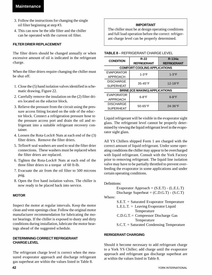
42 YORK INTERNATIONAL
Liquid refrigerant will be visible in the evaporator sightglass. The refrigerant level cannot be properly deter-mined by viewing the liquid refrigerant level in the evapo-rator sight glass.
All YS Chillers shipped Form 1 are charged with thecorrect amount of liquid refrigerant. Under some oper-ating conditions the chiller may appear to be overchargedwith liquid refrigerant. Consult with the York Factoryprior to removing refrigerant. The liquid line isolationvalve may have to be partially throttled to prevent over-feeding the evaporator in some applications and undercertain operating conditions.
Definitions:Evaporator Approach = (S.E.T) - (L.E.L.T)Discharge Superheat = (C.D.G.T) - (S.C.T)
Where:S.E.T. = Saturated Evaporator TemperatureL.E.L.T. = Leaving Evaporator Liquid
TemperatureC.D.G.T. = Compressor Discharge Gas
TemperatureS.C.T. = Saturated Condensing Temperature
RERIGERANT CHARGING
Should it become necessary to add refrigerant chargeto a York YS Chiller; add charge until the evaporatorapproach and refrigerant gas discharge superheat areat within the values listed in Table 8.
3. Follow the instructions for changing the singleoil filter beginning at step #3.
4. This can now be the idle filter and the chillercan be operated with the current oil filter.
FILTER DRIER REPLACEMENT
The filter driers should be changed annually or whenexcessive amount of oil is indicated in the refrigerantcharge.
When the filter driers require changing the chiller mustbe shut off.
1. Close the (5) hand isolation valves identified in sche-matic drawing, Figure 22.
2. Carefully remove the insulation on the (2) filter dri-ers located on the eductor block.
3. Relieve the pressure from the circuit using the pres-sure access fitting located on the side of the educ-tor block. Connect a refrigeration pressure hose tothe pressure access port and drain the oil and re-frigerant into a suitable refrigerant recovery con-tainer.
4. Loosen the Rota-Lock® Nuts at each end of the (3)filter driers. Remove the filter driers.
5. Teflon® seal washers are used to seal the filter drierconnections. These washers must be replaced whenthe filter driers are replaced.
6. Tighten the Rota-Lock® Nuts at each end of thethree filter driers to a torque of 60 ft-lb.
7. Evacuate the air from the oil filter to 500 micronspsig.
8. Open the five hand isolation valves. The chiller isnow ready to be placed back into service.
MOTOR
Inspect the motor at regular intervals. Keep the motorclean and vent openings clear. Follow the original motormanufacturer recommendation for lubricating the mo-tor bearings. If the chiller is exposed to dusty and dirtyconditions during installation, lubricate the motor bear-ings ahead of the suggested schedule.
DETERMINING CORRECT REFRIGERANTCHARGE LEVEL
The refrigerant charge level is correct when the mea-sured evaporator approach and discharge refrigerantgas superheat are within the values listed in Table 8.
IMPORTANTThe chiller must be at design operating conditionsand full load operation before the correct refriger-ant charge level can be properly determined.
Maintenance
TABLE 8 – REFRIGERANT CHARGE LEVEL
CONDITIONR-22 R-134a
REFRIGERANT REFRIGERANTCOMFORT COOLING APPLICATIONS
EVAPORATOR1-3°F 1-3°F
APPROACHDISCHARGE
35-45°F 12-18°FSUPERHEAT
BRINE (ICE MAKING) APPLICATIONSEVAPORATOR
6-8°F 6-8°FAPPROACHDISCHARGE
50-65°F 24-36°FSUPERHEAT
43
FORM 160.47-NOM3
YORK INTERNATIONAL
A charging valve is located in the liquid line below theevaporator. The size of the charging connection is ¾inch male flare. Purge air and non-condensables fromthe charging hose. Only add new refrigerant or re-claimed refrigerant that has been tested and verified tomeet ARI 700.
REFRIGERANT LEAK CHECKING
Periodic refrigerant leak checking must be part of acomprehensive maintenance program. Leak check theentire chiller using a calibrated electronic leak detector.
Confirm leaks with soap bubbles that are found usingthe electronic leak detector.
Check refrigerant relief valve piping and tube rolled jointsas part of the comprehensive refrigerant leak checkingprogram.
Repair leaks before adding refrigerant.
PRESSURE CONNECTIONS
All threaded pressure connections used on the York YSChillers are SAE straight thread, O-ring face seal typefittings or Primore Rotalock fittings.
The O-ring straight thread fittings and O-ring face sealfittings are designed and used in accordance with SAEJ1926 and J1453. Should it become necessary to re-move a fitting the O-ring(s) should be replaced. Makecertain to use only neoprene replacement O-rings. O-rings can be ordered from the local York Service Of-fice.
Pipe sealant compounds are not required with SAE typeO-ring fittings. The O-ring seal accomplishes the pres-sure sealing. Lubricate the O-ring with compressor oilprior to assembly.
All filter driers and angle shut off valves use PrimoreRotalock fittings. These fittings use a Teflon fiberseal washer. The Teflon fiber seal washers should bereplaced each time the filter driers are changed.
CONDENSER TUBES
The standard condenser tubes used in York YS Chillersare internally enhanced copper tubes.
If the equipment is located in an un-heated area that is susceptible to freez-ing, the water must be drained fromthe condenser to prevent tube failurefrom freezing.
Proper condenser water treatment can eliminate or sig-nificantly reduce the formation of scale on the water-side of the condenser tubes.
Maintain a minimum condenser water flow rate of atleast 3.33 ft/sec. Water velocity should not exceed 12ft/sec.
Condenser tubes must be maintained to provide properchiller operation. Condenser Approach Temperature isa useful tool to monitor the performance of the con-denser. By recording and logging the Condenser Ap-proach Temperature as part of the chiller maintenanceprogram, this will provide a warning that the watersidecondenser tubes are fouled and require cleaning.
Condenser Approach Temperature is the difference be-tween the Condenser Leaving Water Temperature andthe Saturated Condensing Temperature.
If the approach increases above 10ºF (5.6ºC), or duringthe annual condenser inspection and the tubes are ob-served to be fouled, the tubes will require cleaning. Forcondenser fluids other than water consult with the localYork Field Service Office for the correct condenser ap-proach.
CONDENSER WATER SIDE TUBE CLEANINGPROCEDURE
Two methods are used for waterside tube cleaning toremove the scale; chemical and mechanical cleaningprocedures. The composition of the scale will deter-mine which method will be most effective to removethe scale and dirt.
Consult with the local York Field Service Office for arecommendation of the method(s) used in the local area.
CHEMICAL CLEANING PROCEDURE
Chemical cleaning is an effective method to removescale from internally enhanced copper tubes. How-
3
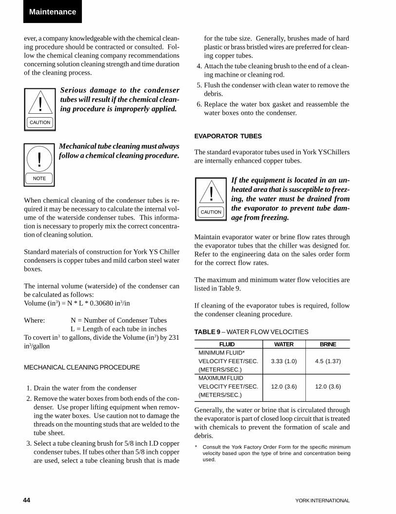
44 YORK INTERNATIONAL
* Consult the York Factory Order Form for the specific minimumvelocity based upon the type of brine and concentration beingused.
Generally, the water or brine that is circulated throughthe evaporator is part of closed loop circuit that is treatedwith chemicals to prevent the formation of scale anddebris.
TABLE 9 – WATER FLOW VELOCITIES
FLUID WATER BRINEMINIMUM FLUID*
VELOCITY FEET/SEC. 3.33 (1.0) 4.5 (1.37)(METERS/SEC.)MAXIMUM FLUID
VELOCITY FEET/SEC. 12.0 (3.6) 12.0 (3.6)(METERS/SEC.)
ever, a company knowledgeable with the chemical clean-ing procedure should be contracted or consulted. Fol-low the chemical cleaning company recommendationsconcerning solution cleaning strength and time durationof the cleaning process.
Serious damage to the condensertubes will result if the chemical clean-ing procedure is improperly applied.
Mechanical tube cleaning must alwaysfollow a chemical cleaning procedure.
When chemical cleaning of the condenser tubes is re-quired it may be necessary to calculate the internal vol-ume of the waterside condenser tubes. This informa-tion is necessary to properly mix the correct concentra-tion of cleaning solution.
Standard materials of construction for York YS Chillercondensers is copper tubes and mild carbon steel waterboxes.
The internal volume (waterside) of the condenser canbe calculated as follows:Volume (in3) = N * L * 0.30680 in3/in
Where: N = Number of Condenser TubesL = Length of each tube in inches
To covert in3 to gallons, divide the Volume (in3) by 231in3/gallon
MECHANICAL CLEANING PROCEDURE
1. Drain the water from the condenser
2. Remove the water boxes from both ends of the con-denser. Use proper lifting equipment when remov-ing the water boxes. Use caution not to damage thethreads on the mounting studs that are welded to thetube sheet.
3. Select a tube cleaning brush for 5/8 inch I.D coppercondenser tubes. If tubes other than 5/8 inch copperare used, select a tube cleaning brush that is made
for the tube size. Generally, brushes made of hardplastic or brass bristled wires are preferred for clean-ing copper tubes.
4. Attach the tube cleaning brush to the end of a clean-ing machine or cleaning rod.
5. Flush the condenser with clean water to remove thedebris.
6. Replace the water box gasket and reassemble thewater boxes onto the condenser.
Maintenance
EVAPORATOR TUBES
The standard evaporator tubes used in York YSChillersare internally enhanced copper tubes.
If the equipment is located in an un-heated area that is susceptible to freez-ing, the water must be drained fromthe evaporator to prevent tube dam-age from freezing.
Maintain evaporator water or brine flow rates throughthe evaporator tubes that the chiller was designed for.Refer to the engineering data on the sales order formfor the correct flow rates.
The maximum and minimum water flow velocities arelisted in Table 9.
If cleaning of the evaporator tubes is required, followthe condenser cleaning procedure.
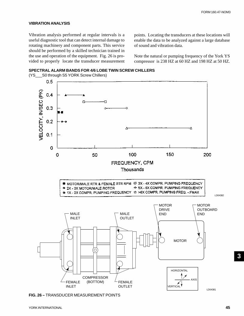
45
FORM 160.47-NOM3
YORK INTERNATIONAL
3
VIBRATION ANALYSIS
Vibration analysis performed at regular intervals is auseful diagnostic tool that can detect internal damage torotating machinery and component parts. This serviceshould be performed by a skilled technician trained inthe use and operation of the equipment. Fig. 26 is pro-vided to properly locate the transducer measurement
points. Locating the transducers at these locations willenable the data to be analyzed against a large databaseof sound and vibration data.
Note the natural or pumping frequency of the York YScompressor is 238 HZ at 60 HZ and 198 HZ at 50 HZ.
SPECTRAL ALARM BANDS FOR 4/6 LOBE TWIN SCREW CHILLERS(YS___S0 through S5 YORK Screw Chillers)
MALEINLET
MALEOUTLET
FEMALEINLET
FEMALEOUTLET
COMPRESSOR(BOTTOM)
MOTOR
MOTORDRIVEEND
MOTOROUTBOARDEND
HORIZONTAL
VERTICAL
AXIS
LD04382
LD04381
FIG. 26 – TRANSDUCER MEASUREMENT POINTS

46 YORK INTERNATIONAL
SPECTRAL ALARM BANDS FOR 4/6 LOBE TWIN SCREW CHILLERS (Cont’d)(YS___S0 through S5 YORK Screw Chillers)
Reference: Proven method for specifiying spectral band alarm levels and frequencies using today’s predictive main-tenance software systemsJames E. Berry, Technical Associates of Charlotte, Inc.
OVERALL LEVEL OA 0.500 IN/SEC (0-PK)
MTR/MALE RTR RPM MTR 3570 RPM = 59.5 Hz
4/6 LOBE RATIO LR 0.67
FEMALE ROTOR IDLE 2380 RPM = 39.7 Hz
MALE ROTOR LOBES LOB 4
PUMPING FREQUENCY BPF 14280 CPM = 238.0 Hz
FREQUENCY MAX FMAX 178500 CPM = 2,975.0 Hz
ITEM BAND 1 BAND 2 BAND 3 BAND 4 BAND 5 BAND 6
BAND LOWER FREQ., CPM 1,904 6,426 11,424 35,700 64,260 92,820
BAND UPPER FREQ., CPM 6,426 11,424 35,700 64,260 92,820 178,500
BAND LOWER FREQ., Hz 32 107 190 595 1,071 1,547
BAND UPPER FREQ., Hz 107 190 595 1,071 1,547 2,975
BAND ALARM LEVEL 0.27 0.2 0.4 0.35 0.3 0.15
DESCRIPTION OF BAND COVERAGE
BAND 1 MOTOR/MALE RTR & FEMALE RTR RPM
BAND 2 2X - 3X MOTOR/MALE ROTOR
BAND 3 1X - 2X COMPR. PUMPING FREQUENCY
BAND 4 3X - 4X COMPR. PUMPING FREQUENCY
BAND 5 5X - 6X COMPR. PUMPING FREQUENCY
BAND 6 >6X COMPR. PUMPING FREQUENCY - FMAX.
NOTES:
1. Assume measurements by accelerometer or velocity pickup as close as possible to Bearing Housing, see Fig. 26.
2. Assume machine NOT mounted on vibration isolators (for isolated machinery - set alarm levels 50% higher).
3. Set motor levels same as compressor given above.
4. Chiller must be at a consistent condition (not only motor amps) when measurements are taken. Monitor and record all performanceparameters.
5. Aerodynamic noise (pressure pulsation) sources dominate mechanical sources at pumping frequency and harmonics and does notrepresent energy transmitted through bearings.
6. Set danger levels 50% higher than alarm levels.
7. Another set of data with much higher Fmax can be used to detect additional stages of bearing failure using techniques described inPreventative Maintenance literature.

47
FORM 160.47-NOM3
YORK INTERNATIONAL
This page is intentionally left blank.

Proud Sponsorof the 2000U.S. Olympic Team
36USC380
P.O. Box 1592, York, Pennsylvania USA 17405-1592 Subject to change without notice. Printed in USACopyright © by York International Corporation 1999 ALL RIGHTS RESERVED
Form 160.47-NOM3 (599)Supersedes: Nothing