Embed Size (px)
Citation preview

SERVICE INSTRUCTIONS
MAXETM
CENTRIFUGAL LIQUID CHILLERS
Supersedes: 160.54-M1 (402) Form 160.54-M1 503)
mMetric Con ver sions
371-02264-101 (Electro-Mechanical Starter - NEMA 1)371-02486-101 (Electro-Mechanical Starter - CE)371-02448-101 (Electro-Mechanical Starter - NEMA 4/12)371-02264-102 (Solid State Starter - NEMA 1)371-02486-102 (Solid State Starter - CE)371-02448-102 (Solid State Starter - NEMA 4/12)371-02264-103 (Variable Speed Drive - NEMA 1)371-02486-103 (Variable Speed Drive - CE)371-02448-103 (Variable Speed Drive - NEMA 4/12)371-02778-101 (Electro-Mechanical Starter - NEMA 1) (P Compressors until 8/02) 371-02780-101 (Electro-Mechanical Starter - CE) (P Compressors until 8/02) 371-02779-101 (Electro-Mechanical Starter - NEMA 4/12) (P Compressors until 8/02) 371-02778-102 (MOD “B” Solid State Starter - NEMA 1)(P Compressors until 8/02) 371-02780-102 (MOD “B” Solid State Starter - CE) (P Compressors until 8/02) 371-02779-102 (MOD “B” Solid State Starter - NEMA 4/12) (P Compressors until 8/02)
MODEL YK (THROUGH STYLE F)
371-02778-103 (Variable Speed Drive - NEMA 1-4) (P Compressors until 8/02)371-02780-103 (Variable Speed Drive - CE) (P Compressors until 8/02)371-02779-103 (Variable Speed Drive - NEMA 4/12) (P Compressors until 8/02)371-04118-101 (Electro-Mechanical Starter – NEMA 1) (Style F Chillers)371-04118-102 (Style B Solid State Starter – NEMA 1) (Style F Chillers)371-04118-103 (Variable Speed Drive – NEMA 1) (Style F Chillers)371-04119-101 (Electro-Mechanical Starter – NEMA 4/12) (Style F Chillers)371-04119-102 (Mod “B” Solid State Starter - NEMA 4/12) (Style F Chillers)371-04119-103 (Variable Speed Drive – NEMA 4/12) (Style F Chillers)371-04120-101 (Electro-mechanical Starter – CE) (Style F Chillers)371-04120-102 (Mod “B” Solid State Starter – CE) (Style F Chillers)371-04120-103 (Variable Speed Drive – CE) (Style F Chillers)
OPTIVIEW™ CONTROL CENTER
00614VIP


YORK INTERNATIONAL2
FORM 160.54-M1(503)
This equipment is a relatively complicated apparatus. During installation, operation, maintenance or service, in di vid u als may be exposed to certain components or conditions including, but not limited to: refrigerants, oils, materials under pressure, rotating components, and both high and low voltage. Each of these items has the po ten tial, if misused or handled improperly, to cause bodi ly injury or death. It is the obligation and re spon -si bil i ty of operating/service per son nel to identify and rec og nize these inherent hazards, protect themselves, and pro ceed safely in completing their tasks. Failure to com ply with any of these requirements could result in se ri ous dam age to the equipment and the property in
IMPORTANT!READ BEFORE PROCEEDING!
GENERAL SAFETY GUIDELINES
which it is sit u at ed, as well as severe personal injury or death to them selves and people at the site.
This document is intended for use by owner-authorized operating/service personnel. It is expected that this in- di vid u al possesses independent training that will en able them to perform their assigned tasks properly and safe ly. It is essential that, prior to performing any task on this equipment, this individual shall have read and un der -stood this document and any referenced materials. This in di vid u al shall also be familiar with and comply with all ap pli ca ble governmental standards and regulations per tain ing to the task in question.
SAFETY SYMBOLS
The following symbols are used in this document to alert the reader to areas of potential hazard:
WARNING indicates a potentially haz ard ous sit u a tion which, if not avoid ed, could result in death or se- ri ous in ju ry.
DANGER indicates an im mi nent ly hazardous situation which, if not avoid ed, will re sult in death or se ri ous injury.
CAUTION identifi es a hazard which could lead to damage to the ma chine, damage to other equip ment and/or en vi ron men tal pollution. Usually an in struc tion will be given, together with a brief ex pla na tion.
External wiring, unless specifi ed as an optional connection in the man u fac tur er’s prod uct line, is NOT to be connected inside the micro pan el cab i net. De vic es such as re lays, switch es, transducers and controls may NOT be installed inside the mi cro pan el. NO ex ter nal wir-ing is al lowed to be run through the micro panel. All wir ing must be in ac cor dance with YORK’s pub lished spec i fi ca tions and must be per formed ONLY by qual i fi ed YORK personnel. YORK will not be re spon si ble for dam ag es/problems re sult ing from im prop er connections to the con trols or ap pli ca tion of im prop er con trol sig nals. Failure to fol low this will void the man u fac tur er’s warranty and cause serious dam age to property or injury to per sons.
NOTE is used to highlight ad di tion al information which may be helpful to you.
FORM 160.54-M1(503)
3YORK INTERNATIONAL
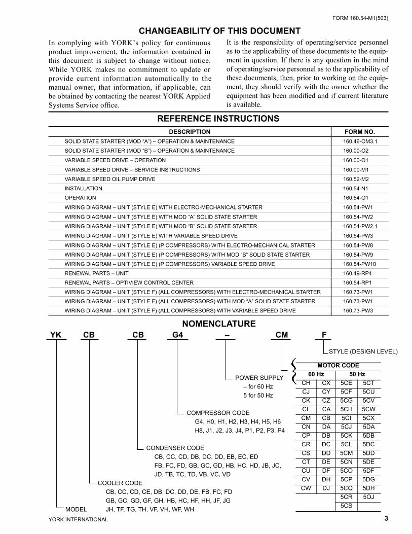
CHANGEABILITY OF THIS DOCUMENTIn complying with YORK’s policy for continuous prod uct improvement, the information contained in this doc u ment is subject to change without notice. While YORK makes no commitment to update or pro vide current in for ma tion automatically to the manual own er, that in for ma tion, if applicable, can be ob tained by con tact ing the nearest YORK Applied Systems Service offi ce.
It is the responsibility of operating/service personnel as to the applicability of these documents to the equip- ment in question. If there is any question in the mind of op er at ing/service personnel as to the applicability of these documents, then, prior to working on the equip- ment, they should verify with the owner wheth er the equipment has been modifi ed and if current lit er a ture is available.
REFERENCE INSTRUCTIONS
NOMENCLATURE
STYLE (DESIGN LEVEL)
POWER SUPPLY – for 60 Hz 5 for 50 Hz
COM PRES SOR CODE G4, H0, H1, H2, H3, H4, H5, H6 H8, J1, J2, J3, J4, P1, P2, P3, P4 CONDENSER CODE CB, CC, CD, DB, DC, DD, EB, EC, ED FB, FC, FD, GB, GC, GD, HB, HC, HD, JB, JC, JD, TB, TC, TD, VB, VC, VD COOLER CODE CB, CC, CD, CE, DB, DC, DD, DE, FB, FC, FD GB, GC, GD, GF, GH, HB, HC, HF, HH, JF, JG MODEL JH, TF, TG, TH, VF, VH, WF, WH
YK CB CB G4 – CM F
MOTOR CODE 60 Hz 50 Hz CH CX 5CE 5CT CJ CY 5CF 5CU CK CZ 5CG 5CV CL CA 5CH 5CW CM CB 5CI 5CX CN DA 5CJ 5DA CP DB 5CK 5DB CR DC 5CL 5DC CS DD 5CM 5DD CT DE 5CN 5DE CU DF 5CO 5DF CV DH 5CP 5DG CW DJ 5CQ 5DH 5CR 5OJ 5CS
DESCRIPTION FORM NO.SOLID STATE STARTER (MOD “A”) – OPERATION & MAINTENANCE 160.46-OM3.1
SOLID STATE STARTER (MOD “B”) – OPERATION & MAINTENANCE 160.00-O2
VARIABLE SPEED DRIVE – OPERATION 160.00-O1
VARIABLE SPEED DRIVE – SERVICE INSTRUCTIONS 160.00-M1
VARIABLE SPEED OIL PUMP DRIVE 160.52-M2
INSTALLATION 160.54-N1
OPERATION 160.54-O1
WIRING DIAGRAM – UNIT (STYLE E) WITH ELECTRO-MECHANICAL STARTER 160.54-PW1
WIRING DIAGRAM – UNIT (STYLE E) WITH MOD “A” SOLID STATE STARTER 160.54-PW2
WIRING DIAGRAM – UNIT (STYLE E) WITH MOD “B” SOLID STATE STARTER 160.54-PW2.1
WIRING DIAGRAM – UNIT (STYLE E) WITH VARIABLE SPEED DRIVE 160.54-PW3
WIRING DIAGRAM – UNIT (STYLE E) (P COMPRESSORS) WITH ELECTRO-MECHANICAL STARTER 160.54-PW8
WIRING DIAGRAM – UNIT (STYLE E) (P COMPRESSORS) WITH MOD “B” SOLID STATE STARTER 160.54-PW9
WIRING DIAGRAM – UNIT (STYLE E) (P COMPRESSORS) VARIABLE SPEED DRIVE 160.54-PW10
RENEWAL PARTS – UNIT 160.49-RP4
RENEWAL PARTS – OPTIVIEW CONTROL CENTER 160.54-RP1
WIRING DIAGRAM – UNIT (STYLE F) (ALL COMPRESSORS) WITH ELECTRO-MECHANICAL STARTER 160.73-PW1
WIRING DIAGRAM – UNIT (STYLE F) (ALL COMPRESSORS) WITH MOD “A” SOLID STATE STARTER 160.73-PW1
WIRING DIAGRAM – UNIT (STYLE F) (ALL COMPRESSORS) WITH VARIABLE SPEED DRIVE 160.73-PW3
YORK INTERNATIONAL4
FORM 160.54-M1(503)
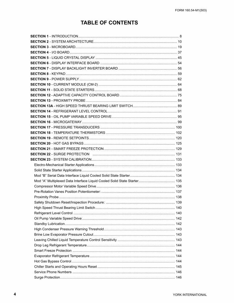
TABLE OF CONTENTS
SECTION 1 - INTRODUCTION......................................................................................................... 8SECTION 2 - SYSTEM ARCHITECTURE....................................................................................... 10SECTION 3 - MICROBOARD.......................................................................................................... 19SECTION 4 - I/O BOARD................................................................................................................ 37SECTION 5 - LIQUID CRYSTAL DISPLAY ..................................................................................... 45SECTION 6 - DISPLAY INTERFACE BOARD ................................................................................ 54SECTION 7 - DISPLAY BACKLIGHT INVERTER BOARD ............................................................. 56SECTION 8 - KEYPAD.................................................................................................................... 59SECTION 9 - POWER SUPPLY...................................................................................................... 62SECTION 10 - CURRENT MODULE (CM-2) .................................................................................. 64SECTION 11 - SOLID STATE STARTERS...................................................................................... 68SECTION 12 - ADAPTIVE CAPACITY CONTROL BOARD............................................................ 75SECTION 13 - PROXIMITY PROBE............................................................................................... 84SECTION 13A - HIGH SPEED THRUST BEARING LIMIT SWITCH.............................................. 89SECTION 14 - REFRIGERANT LEVEL CONTROL........................................................................ 91SECTION 15 - OIL PUMP VARIABLE SPEED DRIVE.................................................................... 95SECTION 16 - MICROGATEWAY................................................................................................... 99SECTION 17 - PRESSURE TRANSDUCERS .............................................................................. 100SECTION 18 - TEMPERATURE THERMISTORS ........................................................................ 102SECTION 19 - REMOTE SETPOINTS.......................................................................................... 120SECTION 20 - HOT GAS BYPASS ............................................................................................... 125SECTION 21 - SMART FREEZE PROTECTION .......................................................................... 129SECTION 22 - SURGE PROTECTION ...................................................................................... 131SECTION 23 - SYSTEM CALIBRATION....................................................................................... 133 Electro-Mechanical Starter Applications.................................................................................... 133 Solid State Starter Applications ................................................................................................. 134 Mod “B” Serial Data Interface Liquid Cooled Solid State Starter............................................... 134 Mod “A” Multiplexed Data Interface Liquid Cooled Solid State Starter...................................... 135 Compressor Motor Variable Speed Drive .................................................................................. 136 Pre-Rotation Vanes Position Potentiometer: ............................................................................. 137 Proximity Probe ......................................................................................................................... 138 Safety Shutdown Reset/Inspection Procedure: ........................................................................ 139 High Speed Thrust Bearing Limit Switch ................................................................................... 140 Refrigerant Level Control .......................................................................................................... 140 Oil Pump Variable Speed Drive ................................................................................................. 142 Standby Lubrication................................................................................................................... 142 High Condenser Pressure Warning Threshold.......................................................................... 143 Brine Low Evaporator Pressure Cutout ..................................................................................... 143 Leaving Chilled Liquid Temperature Control Sensitivity ............................................................ 143 Drop Leg Refrigerant Temperature............................................................................................ 144 Smart Freeze Protection ........................................................................................................... 144 Evaporator Refrigerant Temperature ......................................................................................... 144 Hot Gas Bypass Control ............................................................................................................ 144 Chiller Starts and Operating Hours Reset ................................................................................. 145 Service Phone Numbers ........................................................................................................... 146 Surge Protection........................................................................................................................ 146
FORM 160.54-M1(503)
5YORK INTERNATIONAL
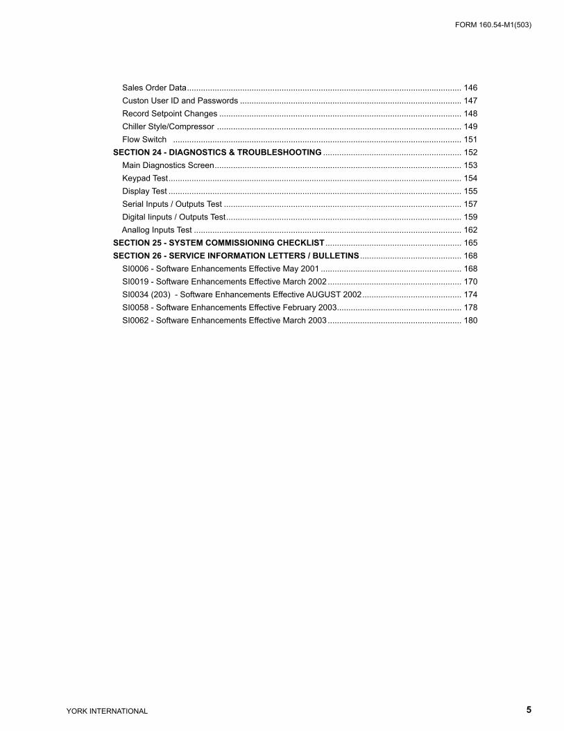
Sales Order Data....................................................................................................................... 146 Custon User ID and Passwords ................................................................................................ 147 Record Setpoint Changes ......................................................................................................... 148 Chiller Style/Compressor .......................................................................................................... 149 Flow Switch ............................................................................................................................. 151SECTION 24 - DIAGNOSTICS & TROUBLESHOOTING ............................................................ 152 Main Diagnostics Screen........................................................................................................... 153 Keypad Test............................................................................................................................... 154 Display Test ............................................................................................................................... 155 Serial Inputs / Outputs Test ....................................................................................................... 157 Digital Iinputs / Outputs Test...................................................................................................... 159 Anallog Inputs Test .................................................................................................................... 162SECTION 25 - SYSTEM COMMISSIONING CHECKLIST ........................................................... 165SECTION 26 - SERVICE INFORMATION LETTERS / BULLETINS ............................................ 168 SI0006 - Software Enhancements Effective May 2001 ............................................................. 168 SI0019 - Software Enhancements Effective March 2002.......................................................... 170 SI0034 (203) - Software Enhancements Effective AUGUST 2002........................................... 174 SI0058 - Software Enhancements Effective February 2003...................................................... 178 SI0062 - Software Enhancements Effective March 2003.......................................................... 180
YORK INTERNATIONAL6
FORM 160.54-M1(503)
LIST OF FIGURES
FIG. 1 – OPTIVIEW CONTROL CENTER - ELECTRO-MECHANICAL STARTER APPLICATIONS .............................................................................................. 13FIG. 2 – OPTIVIEW CONTROL CENTER - MOD “A” SOLID STATE STARTER APPLICATIONS . 14FIG. 3 – OPTIVIEW CONTROL CENTER - MOD “B” SOLID STATE STARTER APPLICATIONS . 15FIG. 4 – OptiView CONTROL CENTER - COMPRESSOR MOTOR VARIABLE SPEED DRIVE... 16FIG. 5 – OPERATION SEQUENCE TIMING DIAGRAM (ELECTRO-MECHANICAL & SOLID STATE STARTER APPLICATIONS) ....................... 17FIG. 6 – OPERATION SEQUENCE TIMING DIAGRAM (COMPRESSOR MOTOR VARIABLE SPEED DRIVE APPLICATIONS) ......................... 18FIG. 7 – MICROBOARD.................................................................................................................. 28FIG. 8 – FLASH MEMORY CARD................................................................................................... 29FIG. 9 – MICROBOARD.................................................................................................................. 30FIG. 10 – MICROBOARD LAMP DIMMER CIRCUIT...................................................................... 34FIG. 11 – MICROBOARD SERIAL DATA COMMUNICATIONS PORTS......................................... 35FIG. 12 – CONFIGURABLE ANALOG & REMOTE SETPOINT INPUTS ....................................... 36FIG. 13 – I/O BOARD ..................................................................................................................... 39FIG. 14 – I/O BOARD DIGITAL INPUTS ......................................................................................... 40FIG. 15 – I/O BOARD TYPICAL OPTO-COUPLER CIRCUIT......................................................... 41FIG. 16 – I/O BOARD TYPICAL FIELD CONNECTIONS ............................................................... 41FIG. 17 – I/O BOARD DIGITAL OUTPUTS ..................................................................................... 42FIG. 18 – DISPLAY, MOUNTING .................................................................................................... 48FIG. 19 – LIQUID CRYSTAL DISPLAY ASSEMBLY – SHARP LQ10D367 DISPLAY..................... 49FIG. 20 – LIQUID CRYSTAL DISPLAY ASSEMBLY – SHARP LQ10D421 DISPLAY..................... 49FIG. 21 – LIQUID CRYSTAL DISPLAY ASSEMBLY – NEC NL6448AC33-24 DISPLAY ................ 50FIG. 22 – LIQUID CRYSTAL DISPLAY ASSEMBLY - LG SEMICON LP104V2-W ......................... 51FIG. 23 – LIQUID CRYSTAL DISPLAY TYPICAL CONTROL SIGNAL TIMING.............................. 51FIG. 24 – DISPLAY (SHARP LQ10D367) LAMP REPLACEMENT................................................. 52FIG. 25 – DISPLAY (SHARP LQ10D421) LAMP REPLACEMENT................................................. 52FIG. 26 – DISPLAY (NEC NL6448AC33-24) LAMP REPLACEMENT ............................................ 53FIG. 27 – DISPLAY (LG SEMICON LP104V2-W) LAMP REPLACEMENT..................................... 53FIG. 28 – DISPLAY INTERFACE BOARD....................................................................................... 55FIG. 29 – DISPLAY BACKLIGHT INVERTER BOARD .................................................................. 57FIG. 30 – DISPLAY BACKLIGHT INVERTER BOARD .................................................................. 58FIG. 31 – DISPLAY BACKLIGHT INVERTER BOARD .................................................................. 58FIG. 32 – KEYPAD .......................................................................................................................... 60FIG. 33 – KEYPAD .......................................................................................................................... 61FIG. 34 – POWER SUPPLY............................................................................................................ 62FIG. 35 – POWER SUPPLY – DC POWER DISTRIBUTION (REFER TO OPTIVIEW CONTROL CENTER WIRING DIAGRAM FOR WIRE CONNECTIONS).......................................................................................... 63FIG. 36 – CM-2 CURRENT MODULE (ELECTRO-MECHANICAL STARTER APPLICATION)...... 66FIG. 37 – CM-2 CURRENT MODULE (ELECTRO-MECHANICAL STARTER APPLICATIONS).... 66FIG. 38 – CM-2 CURRENT MODULE – INTERFACE, CURRENT TRANSFORMERS & VARIABLE RESISTORS ................................................................................................. 67FIG. 39 – MOD “B” LIQUID COOLED SOLID STATE STARTER (LCSSS) - INTERFACE ............. 70FIG. 40 – SOLID STATE STARTER LOGIC BOARD ...................................................................... 71FIG. 41 – MOD “A” LIQUID COOLED SOLID STATE STARTER (LCSSS) - INTERFACE ............. 74
FORM 160.54-M1(503)
7YORK INTERNATIONAL
FIG. 42 – COMPRESSOR MOTOR VARIABLE SPEED DRIVE (VSD) ADAPTIVE CAPACITY CONTROL (ACC) BOARD .............................................. 81FIG. 43 – ADAPTIVE CAPACITY CONTROL (ACC) BOARD - INTERFACE ................................. 82FIG. 44 – ADAPTIVE CAPACITY CONTROL (ACC) BOARD......................................................... 83FIG. 45 – PROXIMITY PROBE - INTERFACE PROBE ................................................................. 86FIG. 46 – PROXIMITY PROBE - INTERFACE PROBE .................................................................. 86FIG. 47 – PROXIMITY PROBE - INTERFACE PROBE .................................................................. 87FIG. 48 – PROXIMITY PROBE ....................................................................................................... 88FIG. 49 – HIGH SPEED THRUST BEARING LIMIT SWITCH - INTERFACE................................. 89FIG. 50 – HIGH SPEED THRUST BEARING LIMIT SWITCH ........................................................ 90FIG. 51 – REFRIGERANT LIQUID LEVEL SENSOR ..................................................................... 93FIG. 52 – REFRIGERANT LIQUID LEVEL CONTROL - INTERFACE ........................................... 94FIG. 53 – OIL PUMP VARIABLE SPEED DRIVE (VSD) ................................................................. 97FIG. 54 – OIL PUMP VSD / OIL HEATER CONTROL – INTERFACE ............................................ 98FIG. 55 – OIL PUMP VSD SPEED CONTROL SIGNAL ................................................................. 98FIG. 56 – MICROGATEWAY INTERFACE BLOCK DIAGRAM ....................................................... 99FIG. 57 – PRESSURE TRANSDUCERS ...................................................................................... 101FIG. 58 – LEAVING CHILLED LIQUID TEMPERATURE .............................................................. 103FIG. 59 – RETURN CHILLED LIQUID TEMPERATURE ............................................................. 108FIG. 60 – RETURN AND LEAVING CONDENSING WATER......................................................... 111FIG. 61 – OIL AND DISCHARGE TEMPERATURE......................................................................114FIG. 62 – DROP LEG REFRIGERANT SENSOR ........................................................................119FIG. 63 – EVAPORATOR REFRIGERANT SENSOR...................................................................119FIG. 64 – INTERFACE, HOT GAS BYPASS ................................................................................. 128FIG. 65 – MAIN DIAGNOSTICS SCREEN.................................................................................... 153FIG. 66 – KEYPAD TEST SCREEN .............................................................................................. 154FIG. 67 – DISPLAY TEST MAIN SCREEN.................................................................................... 155FIG. 68 – BIT PATTERNS TEST SCREEN ................................................................................... 156FIG. 69 – SERIAL INPUTS / OUTPUTS TEST SCREEN ............................................................. 157FIG. 70 – MICROBOARD - COM 5 SERIAL DATA PORT............................................................. 158FIG. 71 – DIGITAL INPUTS / OUTPUTS TEST SCREEN ............................................................ 159FIG. 72 – ANALOG INPUTS TEST SCREEN ............................................................................... 162
YORK INTERNATIONAL8
FORM 160.54-M1(503)
This document explains the operation of the printed cir cuit boards and major components of the OptiView Con trol Cen ter to a level that allows a Service Tech ni cian to trou- ble shoot and locate the source of a prob lem.
The overall system architecture is described and il lus -trat ed with block diagrams. This describes the general function of each component and provides the system in- ter face and signal fl ow. The function of each com po nent and signal fl ow between components must be un der stood before effective troubleshooting can com mence.
The operation of each printed circuit board is de scribed and illustrated with a block diagram that is a simplifi ed representation of board circuitry. The expected voltage level at all inputs and outputs of each board for any operating condition is provided.
Included in this document are procedures that have to be performed at chiller commissioning or during ser- vice. They should not be performed by anyone other than a Service Technician. For example, cal i bra tion pro ce dures have to be performed or verifi ed at sys tem com mis sion ing or when a component is replaced. Cer-tain Safety shutdowns require special reset pro ce dures to be performed before the chiller can be re start ed. Since the op er at ing program sup plied in each OptiView Con trol Center is universal to all ap pli ca tions, special setpoints, pro gram jumpers and program switches are required to con fi g ure the chiller for local operating con di tions.
A System Commissioning Checklist is provided as ref er ence of items to be performed during chiller com mis sion ing.
Chillers that are equipped with “P” Compressors have certain com po nent variances. These variances are not ed in the appropriate sections of this book.
SECTION 1INTRODUCTION
In addition to this document, several levels of sup port ing documentation are required while servicing the sys tem. Field Control Modifi cations Diagram 160.54-PW7 pro- vides details of the interface to remote devices. Op er a tions Manual 160.54-O1 explains the operation of the OptiView Control Center Keypad, how to enter Setpoints and ex- plains all the messages displayed on the OptiView Control Cen ter display. The following wir ing diagrams provide the con nec tions between the print ed circuit boards and com po nents within the OptiView Control Center:
Chillers Through Style E(Except "P" Compressors):
• YORK Form 160.54-PW1 – Chillers equipped with Electro-Me chan i cal start er
• YORK Form 160.54-PW2 – Chillers equipped with Mod “A” YORK Solid State Starter
• YORK Form 160.54-PW2.1 – Chillers equipped with Mod “B” YORK Sol id State Start er
• YORK Form 160.54-PW3 – Chillers equipped with YORK Vari able Speed Drive
Chillers Through Style E("P" Compressors):
• YORK Form 160.54-PW8 – Chillers (“P” Com pres -sors) equipped with Electro-Mechanical Start er
• YORK Form 160.54-PW9 – Chillers (“P” Com pres sors) equipped with Mod “B” YORK Solid State Start er
• YORK Form 160.54-PW10 – Chillers (“P” Com- pres sors) equipped with YORK Variable Speed Drive
Style F Chillers(All Compressors):
• YORK Form 160.73-PW1 – (Electro-Mechanical Start er)
• YORK Form 160.73-PW2 – (Mod “B” YORK Solid State Start er)
• YORK Form 160.73-PW3 – (Variable Speed Drive)
Introduction
FORM 160.54-M1(503)
9YORK INTERNATIONAL
1When the chiller shuts down on a SAFETY or CY- CLING shutdown or is being prevented from starting, a mes sage is displayed providing the reason for the shut- down. This message, along with all the chiller op er at ing con di tions at the instant of the event are stored in the Microboard battery-backed memory. This history data can be displayed or printed using an optional print er. The Operations Manual 160.54-O1 provides a detailed description of this mes sage, including the con di tions re quired to produce the message and conditions required to restart the chiller.
Diagnostic Routines allow service analysis of the fol- low ing functions:
• Display • Analog inputs • Digital inputs • Digital outputs • Serial Data ports
Before beginning any troubleshooting, observe the shut- down message and retrieve the HISTORY data of that event. Refer to the Operations Manual for an ex pla na tion of the message. The conditions required to pro duce the message must be clearly understood before pro ceed ing. (If this is not heeded, much time will be wast ed). Armed with a knowledge of the overall sys tem architecture and the function of each printed cir cuit board and signal fl ow provided by this manual, pro ceed with the appropri-ate Wiring Diagram listed above to trace the problem through the system. Use the Di ag nos tic Routines where appropriate.

YORK INTERNATIONAL10
FORM 160.54-M1(503)System Ar chi tec ture
SECTION 2SYSTEM ARCHITECTURE
The OptiView Control Center performs the following functions: • Controls chiller capacity to chill liquid to the chilled
liq uid temperature setpoint. • Controls chiller solenoid valves, relays, ac tu a tors
and motor contactors per the operating program. • Displays chiller operating conditions, alarms, shut-
down messages and history data. • Accepts operator-programmed setpoints and con-
trols the chiller accordingly. • Allows manual control of chiller motor contactors
and actuators. • Monitors chiller operating conditions and shuts
down chiller when Safety or Cycling thresh olds are ex ceed ed.
• Allows local manual start/stop and accepts start/stop commands from remote devices, via contact clo sures or serial communications.
• Allows setpoints to be changed from a remote lo- ca tion via 0-10VDC, 2-10VDC, 0-20mA, 4-20mA, con tact clo sures or se ri al com mu ni ca tions.
• Provides chiller operating data and status to re mote devices via serial communications and con tact clo sures.
• Allows real-time data and history data to be print ed on an optional printer.
• Controls the compressor motor starter and con tains a printed circuit board logic that supports Electro-Mechanical Starters, Solid State Starters and YORK Vari able Speed Drive.
The OptiView Control Center is a microprocessor based control system that receives analog, digital and serial data in puts and controls analog, digital and serial data outputs per instructions in the operating program. A panel mount ed display and touch-sensitive keypad per mit lo cal operation.
System pressures are sensed by pressure transducers The out put of each transducer is a DC volt age that is anal o gous to the pressure input. System tem per a tures are sensed by thermistors. The out put of each ther mistor is a DC voltage that is analogous to the tem per a ture it is sens ing. Typical output voltage range of both is 0.5 to 4.5VDC. These are analog inputs to the OptiView Con trol Cen ter.
Digital Inputs are on/off inputs to the OptiView Con trol Center in the form of switch and relay contacts. These inputs are 115VAC when the contacts are closed and 0VAC when open. These include fl ow switches, local start/stop switch, remote cycling and high pres sure safe ty de vice, etc. Digital Outputs are on/off outputs from the OptiView Control Cen ter in the form of relay contacts and triacs. The re lay con tacts typically switch 115VAC and the triacs typ i cal ly switch a nominal 30VAC. Relay out puts include status/alarm, chill er solenoid valves, oil heater, oil pump starter and chilled and condenser wa ter pump starters, etc. Triac outputs include pre-ro ta tion vane control and vari able orifi ce control.
Serial Data is transmitted to and received from de vic es in RS-232, RS-485 and TX/RX (opto-couple) form.
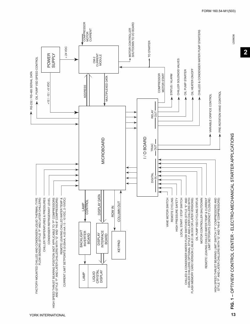
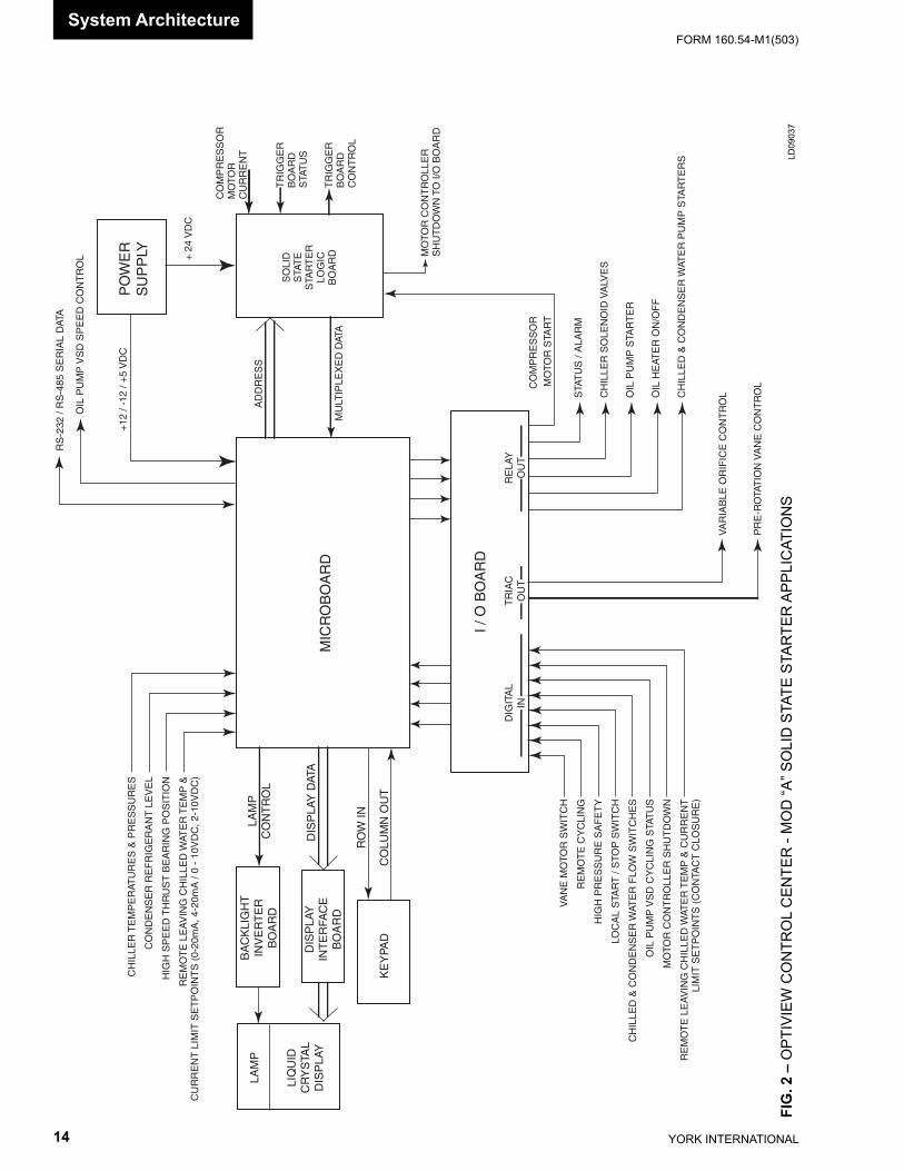
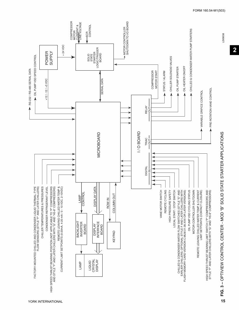
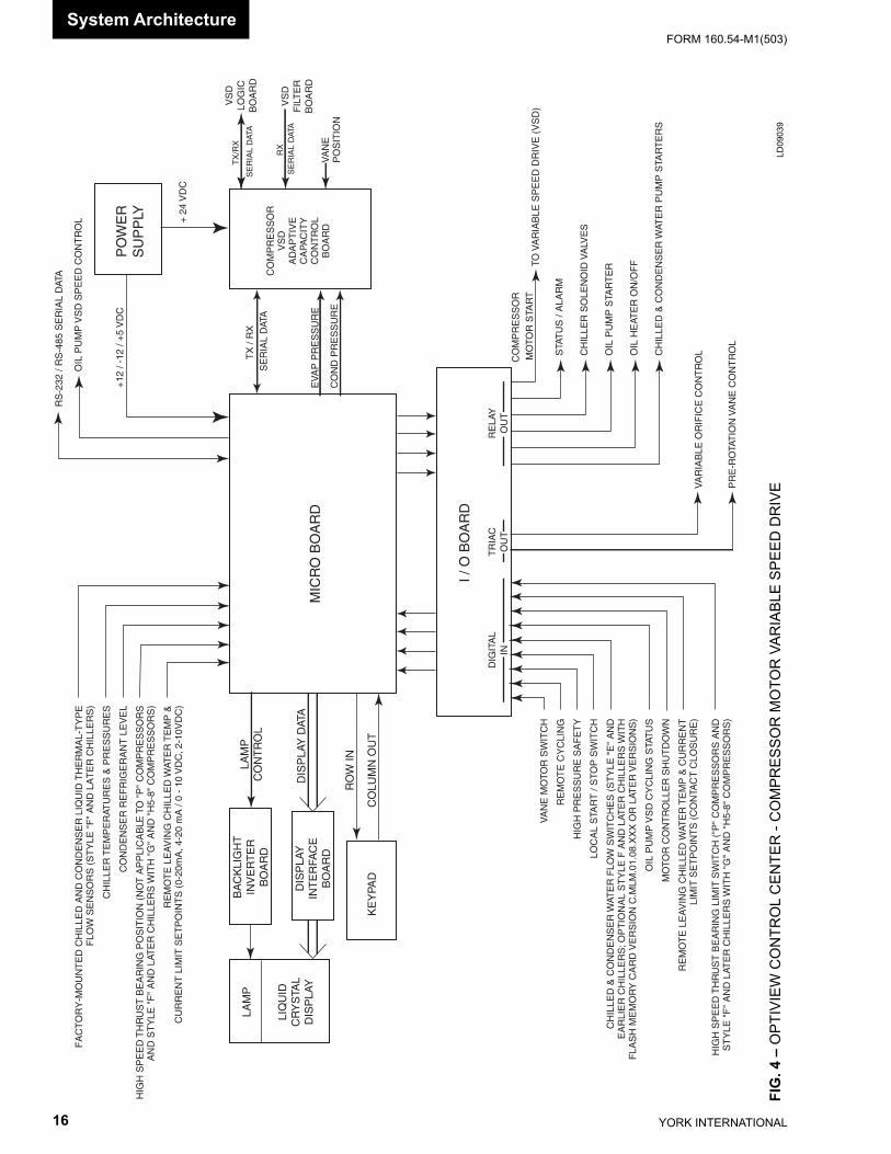
The OptiView Control Center supports three types of starters; Electro-Mechanical Starter, Solid State Start er and Vari able Speed Drive. However, all OptiView Con- trol Centers con tain the following standard com po nents, regardless of the starter type applied: • Microboard • I/O (input/output) Board • Keypad • Display • Power Supply
In addition to the standard components, the OptiView Control Center contains a printed circuit board that pro vides certain control and interface functions for the start er type applied. Each starter type requires a dif fer ent board as follows:
• Electro-Mechanical Starter - CM-2 Current Mod- ule
• Solid State Starter (Mod “A” only) - Logic Board • Variable Speed Drive - Adaptive Capacity Con trol
Board Figures 1 through 4 are OptiView Control Center block diagrams of the three starter types. On each block di- a gram, the stan dard components are shown, along with the print ed cir cuit board that supports the applied start er type. Fig ures 5 and 6 are Operation Sequence timing diagrams of the different starter applications.

FORM 160.54-M1(503)
11YORK INTERNATIONAL
2The microprocessor and all supporting logic circuits, along with the memory devices containing the op er at ing pro gram, reside on the Microboard. All chiller op er at ing de ci sions are made here. It receives analog and dig i tal in puts from the chiller and remote devices. The analog in puts are con nect ed directly to the Microboard. The dig i tal in puts are received via the I/O Board (see de scrip tion be low). Un der Program control, the Microboard op er ates the re lays and triacs that are lo cat ed on the I/O Board.
The I/O Board acts as an input/output device for the Microboard. It conditions the digital input signals for the Microboard and contains relays and triacs that are con trolled by the Microboard to control solenoids, mo tor contactors and actuators. The 115VAC digital in puts from switch and relay contacts are converted to logic level voltages by Opto-Couplers. The relays have +12VDC coils that are energized and de-energized by the Microboard. The contacts of these relays control the 115VAC system solenoids, relays and motor contactors. The triacs are turned on and off by the Microboard. The outputs of these triacs control ac tu a tors.
A front panel-mounted Keypad allows Operator and Ser vice Technician user interface. Membrane keys are used to display chiller and system parameters, enter setpoints and perform chiller and OptiView Control Center di ag nos tics. It also contains a START-RUN-STOP/RE SET Switch that is used to locally start and stop the chill er and per form manual reset functions.
A front panel mounted liquid crystal Display allows graph ic animated display of the chiller, chiller sub sys-tems and system parameters. The chiller and work ing com po nents of the chiller are displayed, along with chiller operating pressures and temperatures. The Key- pad is used to select displays showing increasing levels of de tail of chiller working components.
A self-contained Power Supply supplies the nec es sary DC volt ag es for all the components within the OptiView Control Cen ter.
Chillers equipped with “P” compressors and all style “F” and later chillers have a different Condenser High Pressure Safety Cutout Switch (HPCO) than sup plied on other compressor ap pli ca tions. This switch is mount ed
on the condenser shell but has a different wiring in-terface to the I/O Board and Motor Controller circuit. Re fer to the I/O Board section of this book. Also, “P” compressor applications and style “F” and later chillers with “G” and “H5-8” compressors are equipped with a High Speed Thrust Bearing Limit Switch instead of the Proximity Probe supplied on other com pres sors. This device detects abnormal bearing po si tion through probe contact instead of distance mea sure ment as performed with the Proximity Probe.
Style C and earlier chillers are equipped with fi xed speed oil pumps. Style D and later chillers are equipped with Variable Speed Oil Pumps.
Style F (and later) chillers require Flash Memory card version C.MLM.01.07.xxx and later and are supplied with factory-mounted Flow Sensors on the evapora-tor and condenser. These are electronic thermal-type sensors. The operating principle of the sensor is thermal conductivity. It uses the cooling effect of a fl owing liq-uid to sense fl ow. The temperature of the heated sensor tip is sensed by a thermistor located in the tip. A second thermistor, located higher in the tip in a non-heated area, is only affected by changes in liquid temperature. The temperatures sensed by the thermistors are compared. Flowing liquid carries heat away from the heated sensor tip, lowering its temperature. The lower temperature dif-ferential between the two thermistors indicates the liquid is fl owing. A higher differential indicates no fl ow. These sensors are interfaced to Microboard analog inputs. Re-fer to the SECTION 3 for a detailed explanation of this fl ow sensor and interface.
If equipped with Flash Memory Card version C.MLM.01.07.xxx (and later), the chiller Style/Com-pressor combination must be entered using the Chiller Style/Compressor Setpoint (refer to SECTION 23). Once the applicable chiller style/compressor combina-tion is entered, the program automatically bundles the functionality and chiller control per the entered chiller style/compressor requirements. The various chiller style/compressor combinations are equipped differently and have different control requirements. The variables include:
• High Speed Thrust bearing proximity sensing – Proximity Probe or Limit Switch

YORK INTERNATIONAL12
FORM 160.54-M1(503)System Ar chi tec ture
• Flow Sensor – Paddle type or Factory Mounted Thermal Type. The paddle type applies 115Vac to the I/O Board Digital inputs TB4-12 (evaporator) and TB4-11 (condenser) (refer to fi g 14). The fac-tory mounted Thermal type (available with Style F and later chillers), applies +5Vdc to the microboard Analog inputs at J7-14 (evaporator) and J7-16 (condenser)(refer to fi g 12). Flash Memory Card version C.MLM.01.07.xxx and C.MLM.01.07A.xxx automatically selects the Flow Sensor input, either digital or analog per the Chiller Style/Compressor Setpoint selection. Flash Memory Card version C.MLM.01.08.xxx and later allows use of either the Thermal-type or the Paddle-type fl ow sensors on style F and later chillers. With these versions, the actual fl ow sensor type present must be entered using the Flow Switch Setpoint (refer to SECTION 23).
• Oil Heater Outputs – Either TB1-34 or TB1-64 on I/O Board
• Refrigerant Level Control Default Period – Either 3.5 seconds or 10.0 seconds
• “Oil – Variable Speed Pump-Pressure Setpoint Not Achieved” safety shutdown threshold – Either 25 PSID or 35 PSID
When the compressor motor is driven by an Electro-Mechanical Starter, the OptiView Control center is equipped with a CM-2 Current Module. This printed circuit board pro vides cur rent overload and power fault pro tec tion for the com pres sor motor. Current Trans- form ers, lo cat ed in the com pres sor motor terminal box, along with rec ti fy ing and cal i bra tion circuitry, provide an an a log volt age rep re sent ing com pres sor motor current to the CM-2 Mod ule. This sig nal is further conditioned and pro vid ed to the Microboard.
When the compressor motor is driven by a YORK Sol id State Starter, there could be either of two dif fer ent Sol id Starters applied. Later production chillers are equipped with the Mod “B” Sol id State Start er. This start er con- tains a com bi na tion Log ic/Trig ger Board that in ter fac es the Microboard via a serial com mu ni ca tions link. Ear li er vin tage chillers are equipped with the Mod “A” Sol id State Start er. This starter con tains a Trig ger Board that in ter fac es to a Logic Board that is in stalled inside the OptiView Control Cen ter. The Logic Board in ter fac es the Microboard via a mul ti plexed data in ter face.
When the compressor motor is driven by the YORK Variable Speed Drive (VSD), the OptiView Control Center is equipped with an Adaptive Capacity Con- trol Board. This print ed cir cuit board mon i tors system pa ram e ters and controls the VSD to drive the com pres sor at the slow est speed it will op er ate with out surging, while main tain ing required chiller capacity.
Serial data interface to the YORK ISN Building Au to -ma tion System is through the optional MicroGateway. This print ed circuit board re quests the re quired data from the Microboard and makes it avail able for the ISN net work.
FORM 160.54-M1(503)
13YORK INTERNATIONAL
FIG
. 1 –
OPT
IVIE
W C
ON
TRO
L C
ENTE
R -
ELEC
TRO
-ME C
HAN
I CAL
STA
RTE
R A
PPLI
CAT
ION
SLD
0903
6
2P
OW
ER
SU
PP
LY
DIG
ITA
LIN
MIC
RO
BO
AR
D
I / O
BO
AR
D
TR
IAC
OU
TR
ELA
YO
UT
KE
YPA
D
DIS
PLA
YIN
TE
RFA
CE
BO
AR
D
LIQ
UID
CR
YS
TAL
DIS
PLA
Y
LAM
PB
AC
KLI
GH
TIN
VE
RT
ER
BO
AR
D
LAM
PC
ON
TR
OL
RO
W IN
CO
LUM
N O
UT
DIS
PLA
Y D
ATA
VA
NE
MO
TOR
SW
ITC
H
RE
MO
TE
CY
CLI
NG
HIG
H P
RE
SS
UR
E S
AF
ET
Y
LOC
AL
STA
RT
/ S
TOP
SW
ITC
H
CH
ILLE
D &
CO
ND
EN
SE
R W
ATE
R F
LOW
SW
ITC
HE
S (
ST
YLE
"E
" A
ND
EA
RLI
ER
CH
ILLE
RS
; OP
TIO
NA
L S
TY
LE F
AN
D L
ATE
R C
HIL
LER
S W
ITH
FLA
SH
ME
MO
RY
CA
RD
VE
RS
ION
C.M
LM.0
1.08
.XX
X O
R L
ATE
R V
ER
SIO
NS
)
OIL
PU
MP
VS
D C
YC
LIN
G S
TAT
US
MO
TOR
CO
NT
RO
LLE
R S
HU
TD
OW
N
RE
MO
TE
LE
AV
ING
CH
ILLE
D W
ATE
R T
EM
P &
CU
RR
EN
TLI
MIT
SE
TP
OIN
TS
(C
ON
TAC
T C
LOS
UR
E)
HIG
H S
PE
ED
TH
RU
ST
BE
AR
ING
LIM
IT S
WIT
CH
("P
" C
OM
PR
ES
SO
RS
AN
DS
TY
LE "
F"
AN
D L
ATE
R C
HIL
LER
S W
ITH
"G
" A
ND
"H
5-8"
CO
MP
RE
SS
OR
S)
VA
RIA
BLE
OR
IFIC
E C
ON
TR
OL
PR
E-R
OTA
TIO
N V
AN
E C
ON
TR
OL
STA
TU
S /
ALA
RM
CH
ILLE
R S
OLE
NO
ID V
ALV
ES
OIL
PU
MP
STA
RT
ER
OIL
HE
ATE
R O
N/O
FF
CH
ILLE
D &
CO
ND
EN
SE
R W
ATE
R P
UM
P S
TAR
TE
RS
CO
MP
RE
SS
OR
M
OTO
R S
TAR
T
TO S
TAR
TE
R
MO
TOR
CO
NT
RO
LLE
RS
HU
TD
OW
N T
O I/
O B
OA
RD
MU
LTIP
LEX
ED
DAT
A
AD
DR
ES
S
CM
-2C
UR
RE
NT
MO
DU
LE
CO
MP
RE
SS
OR
MO
TOR
C
UR
RE
NT
+ 2
4 V
DC
+12
/ -1
2 / +
5 V
DC
OIL
PU
MP
VS
D S
PE
ED
CO
NT
RO
L
RS
-232
/ R
S-4
85 S
ER
IAL
DAT
A
FA
CT
OR
Y-M
OU
NT
ED
CH
ILLE
D A
ND
CO
ND
EN
SE
R L
IQU
ID T
HE
RM
AL-
TY
PE
FLO
W S
EN
SO
RS
(S
TY
LE "
F"
AN
D L
AT
ER
CH
ILLE
RS
)
CH
ILLE
R T
EM
PE
RAT
UR
ES
& P
RE
SS
UR
ES
CO
ND
EN
SE
R R
EF
RIG
ER
AN
T L
EV
EL
HIG
H S
PE
ED
TH
RU
ST
BE
AR
ING
PO
SIT
ION
(N
OT
AP
PLI
CA
BLE
TO
"P
" C
OM
PR
ES
SO
RS
AN
D S
TY
LE "
F"
AN
D L
ATE
R C
HIL
LER
S W
ITH
"G
" A
ND
"H
5-8"
CO
MP
RE
SS
OR
S)
RE
MO
TE
LE
AV
ING
CH
ILLE
D W
ATE
R T
EM
P &
CU
RR
EN
T L
IMIT
SE
TP
OIN
TS
(0-
20m
A, 4
-20
mA
/ 0
- 10
VD
C, 2
-10V
DC
)
YORK INTERNATIONAL14
FORM 160.54-M1(503)
FIG
. 2 –
OPT
IVIE
W C
ON
TRO
L C
ENTE
R -
MO
D “A
” SO
LID
STA
TE S
TAR
TER
APP
LIC
ATIO
NS
LD09
037
System Ar chi tec ture
DIG
ITA
LIN
TR
IAC
OU
TR
ELA
YO
UT
PO
WE
RS
UP
PLY
MIC
RO
BO
AR
D
I / O
BO
AR
D
KE
YPA
D
DIS
PLA
YIN
TE
RFA
CE
BO
AR
D
LIQ
UID
CR
YS
TAL
DIS
PLA
Y
LAM
PB
AC
KLI
GH
TIN
VE
RT
ER
BO
AR
D
LAM
PC
ON
TR
OL
RO
W IN
CO
LUM
N O
UT
DIS
PLA
Y D
ATA
VA
NE
MO
TOR
SW
ITC
H
RE
MO
TE
CY
CLI
NG
HIG
H P
RE
SS
UR
E S
AF
ET
Y
LOC
AL
STA
RT
/ S
TOP
SW
ITC
H
CH
ILLE
D &
CO
ND
EN
SE
R W
ATE
R F
LOW
SW
ITC
HE
S
OIL
PU
MP
VS
D C
YC
LIN
G S
TAT
US
MO
TOR
CO
NT
RO
LLE
R S
HU
TD
OW
N
RE
MO
TE
LE
AV
ING
CH
ILLE
D W
ATE
R T
EM
P &
CU
RR
EN
TLI
MIT
SE
TP
OIN
TS
(C
ON
TAC
T C
LOS
UR
E)
VA
RIA
BLE
OR
IFIC
E C
ON
TR
OL
PR
E-R
OTA
TIO
N V
AN
E C
ON
TR
OL
STA
TU
S /
ALA
RM
CH
ILLE
R S
OLE
NO
ID V
ALV
ES
OIL
PU
MP
STA
RT
ER
OIL
HE
ATE
R O
N/O
FF
CH
ILLE
D &
CO
ND
EN
SE
R W
ATE
R P
UM
P S
TAR
TE
RS
CO
MP
RE
SS
OR
M
OTO
R S
TAR
T
MO
TOR
CO
NT
RO
LLE
RS
HU
TD
OW
N T
O I/
O B
OA
RD
MU
LTIP
LEX
ED
DAT
A
AD
DR
ES
S
SO
LID
STA
TE
STA
RT
ER
LOG
ICB
OA
RD
CO
MP
RE
SS
OR
MO
TOR
C
UR
RE
NT
+ 2
4 V
DC
+12
/ -1
2 / +
5 V
DC
OIL
PU
MP
VS
D S
PE
ED
CO
NT
RO
L
RS
-232
/ R
S-4
85 S
ER
IAL
DAT
A
CH
ILLE
R T
EM
PE
RAT
UR
ES
& P
RE
SS
UR
ES
CO
ND
EN
SE
R R
EF
RIG
ER
AN
T L
EV
EL
HIG
H S
PE
ED
TH
RU
ST
BE
AR
ING
PO
SIT
ION
RE
MO
TE
LE
AV
ING
CH
ILLE
D W
ATE
R T
EM
P &
CU
RR
EN
T L
IMIT
SE
TP
OIN
TS
(0-
20m
A, 4
-20m
A /
0 -
10V
DC
, 2-1
0VD
C)
TR
IGG
ER
BO
AR
DS
TAT
US
TR
IGG
ER
BO
AR
DC
ON
TR
OL
FORM 160.54-M1(503)
15YORK INTERNATIONAL
FIG
. 3 –
OPT
IVIE
W C
ON
TRO
L C
ENTE
R -
MO
D “B
” SO
LID
STA
TE S
TAR
TER
APP
LIC
ATIO
NS
LD09
038
2
DIG
ITA
LIN
TR
IAC
OU
TR
ELA
YO
UT
PO
WE
RS
UP
PLY
MIC
RO
BO
AR
D
I / O
BO
AR
D
KE
YPA
D
DIS
PLA
YIN
TE
RFA
CE
BO
AR
D
LIQ
UID
CR
YS
TAL
DIS
PLA
Y
LAM
PB
AC
KLI
GH
TIN
VE
RT
ER
BO
AR
D
LAM
PC
ON
TR
OL
RO
W IN
CO
LUM
N O
UT
DIS
PLA
Y D
ATA
VA
RIA
BLE
OR
IFIC
E C
ON
TR
OL
PR
E-R
OTA
TIO
N V
AN
E C
ON
TR
OL
STA
TU
S /
ALA
RM
CH
ILLE
R S
OLE
NO
ID V
ALV
ES
OIL
PU
MP
STA
RT
ER
OIL
HE
ATE
R O
N/O
FF
CH
ILLE
D &
CO
ND
EN
SE
R W
ATE
R P
UM
P S
TAR
TE
RS
CO
MP
RE
SS
OR
M
OTO
R S
TAR
T
MO
TOR
CO
NT
RO
LLE
RS
HU
TD
OW
N T
O I/
O B
OA
RD
S
ER
IAL
DAT
A
SO
LID
STA
TE
STA
RT
ER
LOG
IC/T
RIG
GE
RB
OA
RD
CO
MP
RE
SS
OR
MO
TOR
C
UR
RE
NT
&
LIN
E V
OLT
AG
E
+ 2
4 V
DC
+12
/ -1
2 / +
5 V
DC
OIL
PU
MP
VS
D S
PE
ED
CO
NT
RO
L
RS
-232
/ R
S-4
85 S
ER
IAL
DAT
A
SC
RC
ON
TR
OL
FA
CT
OR
Y-M
OU
NT
ED
CH
ILLE
D A
ND
CO
ND
EN
SE
R L
IQU
ID T
HE
RM
AL-
TY
PE
FLO
W S
EN
SO
RS
(S
TY
LE "
F"
AN
D L
AT
ER
CH
ILLE
RS
)
CH
ILLE
R T
EM
PE
RAT
UR
ES
& P
RE
SS
UR
ES
CO
ND
EN
SE
R R
EF
RIG
ER
AN
T L
EV
EL
HIG
H S
PE
ED
TH
RU
ST
BE
AR
ING
PO
SIT
ION
(N
OT
AP
PLI
CA
BLE
TO
"P
" C
OM
PR
ES
SO
RS
AN
D S
TY
LE "
F"
AN
D L
ATE
R C
HIL
LER
S W
ITH
"G
" A
ND
"H
5-8"
CO
MP
RE
SS
OR
S)
RE
MO
TE
LE
AV
ING
CH
ILLE
D W
ATE
R T
EM
P &
CU
RR
EN
T L
IMIT
SE
TP
OIN
TS
(0-
20m
A, 4
-20
mA
/ 0
- 10
VD
C, 2
-10V
DC
)
VA
NE
MO
TOR
SW
ITC
H
RE
MO
TE
CY
CLI
NG
HIG
H P
RE
SS
UR
E S
AF
ET
Y
LOC
AL
STA
RT
/ S
TOP
SW
ITC
H
CH
ILLE
D &
CO
ND
EN
SE
R W
ATE
R F
LOW
SW
ITC
HE
S (
ST
YLE
"E
" A
ND
EA
RLI
ER
CH
ILLE
RS
; OP
TIO
NA
L S
TY
LE F
AN
D L
ATE
R C
HIL
LER
S W
ITH
FLA
SH
ME
MO
RY
CA
RD
VE
RS
ION
C.M
LM.0
1.08
.XX
X O
R L
ATE
R V
ER
SIO
NS
)
OIL
PU
MP
VS
D C
YC
LIN
G S
TAT
US
MO
TOR
CO
NT
RO
LLE
R S
HU
TD
OW
N
RE
MO
TE
LE
AV
ING
CH
ILLE
D W
ATE
R T
EM
P &
CU
RR
EN
TLI
MIT
SE
TP
OIN
TS
(C
ON
TAC
T C
LOS
UR
E)
HIG
H S
PE
ED
TH
RU
ST
BE
AR
ING
LIM
IT S
WIT
CH
("P
" C
OM
PR
ES
SO
RS
AN
DS
TY
LE "
F"
AN
D L
ATE
R C
HIL
LER
S W
ITH
"G
" A
ND
"H
5-8"
CO
MP
RE
SS
OR
S)
YORK INTERNATIONAL16
FORM 160.54-M1(503)
FIG
. 4 –
OPT
IVIE
W C
ON
TRO
L C
ENTE
R -
CO
MPR
ESSO
R M
OTO
R V
ARIA
BLE
SPEE
D D
RIV
ELD
0903
9
System Ar chi tec ture
RX
S
ER
IAL
DAT
A
PO
WE
RS
UP
PLY
DIG
ITA
LIN
MIC
RO
BO
AR
D
I / O
BO
AR
D
TR
IAC
OU
TR
ELA
YO
UT
KE
YPA
D
DIS
PLA
YIN
TE
RFA
CE
BO
AR
D
LIQ
UID
CR
YS
TAL
DIS
PLA
Y
LAM
PB
AC
KLI
GH
TIN
VE
RT
ER
BO
AR
D
LAM
PC
ON
TR
OL
RO
W IN
CO
LUM
N O
UT
DIS
PLA
Y D
ATA
VA
RIA
BLE
OR
IFIC
E C
ON
TR
OL
PR
E-R
OTA
TIO
N V
AN
E C
ON
TR
OL
STA
TU
S /
ALA
RM
CH
ILLE
R S
OLE
NO
ID V
ALV
ES
OIL
PU
MP
STA
RT
ER
OIL
HE
ATE
R O
N/O
FF
CH
ILLE
D &
CO
ND
EN
SE
R W
ATE
R P
UM
P S
TAR
TE
RS
CO
MP
RE
SS
OR
M
OTO
R S
TAR
T
EV
AP
PR
ES
SU
RE
CO
ND
PR
ES
SU
RE
CO
MP
RE
SS
OR
VS
DA
DA
PT
IVE
CA
PAC
ITY
CO
NT
RO
LB
OA
RD
+ 2
4 V
DC
+12
/ -1
2 / +
5 V
DC
OIL
PU
MP
VS
D S
PE
ED
CO
NT
RO
L
RS
-232
/ R
S-4
85 S
ER
IAL
DAT
A
VA
NE
PO
SIT
ION
TO V
AR
IAB
LE S
PE
ED
DR
IVE
(V
SD
)
TX
/ R
X
SE
RIA
L D
ATA
TX
/RX
SE
RIA
L D
ATA
VS
DLO
GIC
BO
AR
D
VS
DF
ILT
ER
BO
AR
D
FA
CT
OR
Y-M
OU
NT
ED
CH
ILLE
D A
ND
CO
ND
EN
SE
R L
IQU
ID T
HE
RM
AL-
TY
PE
FLO
W S
EN
SO
RS
(S
TY
LE "
F"
AN
D L
AT
ER
CH
ILLE
RS
)
CH
ILLE
R T
EM
PE
RAT
UR
ES
& P
RE
SS
UR
ES
CO
ND
EN
SE
R R
EF
RIG
ER
AN
T L
EV
EL
HIG
H S
PE
ED
TH
RU
ST
BE
AR
ING
PO
SIT
ION
(N
OT
AP
PLI
CA
BLE
TO
"P
" C
OM
PR
ES
SO
RS
AN
D S
TY
LE "
F"
AN
D L
ATE
R C
HIL
LER
S W
ITH
"G
" A
ND
"H
5-8"
CO
MP
RE
SS
OR
S)
RE
MO
TE
LE
AV
ING
CH
ILLE
D W
ATE
R T
EM
P &
CU
RR
EN
T L
IMIT
SE
TP
OIN
TS
(0-
20m
A, 4
-20
mA
/ 0
- 10
VD
C, 2
-10V
DC
)
VA
NE
MO
TOR
SW
ITC
H
RE
MO
TE
CY
CLI
NG
HIG
H P
RE
SS
UR
E S
AF
ET
Y
LOC
AL
STA
RT
/ S
TOP
SW
ITC
H
CH
ILLE
D &
CO
ND
EN
SE
R W
ATE
R F
LOW
SW
ITC
HE
S (
ST
YLE
"E
" A
ND
EA
RLI
ER
CH
ILLE
RS
; OP
TIO
NA
L S
TY
LE F
AN
D L
ATE
R C
HIL
LER
S W
ITH
FLA
SH
ME
MO
RY
CA
RD
VE
RS
ION
C.M
LM.0
1.08
.XX
X O
R L
ATE
R V
ER
SIO
NS
)
OIL
PU
MP
VS
D C
YC
LIN
G S
TAT
US
MO
TOR
CO
NT
RO
LLE
R S
HU
TD
OW
N
RE
MO
TE
LE
AV
ING
CH
ILLE
D W
ATE
R T
EM
P &
CU
RR
EN
TLI
MIT
SE
TP
OIN
TS
(C
ON
TAC
T C
LOS
UR
E)
HIG
H S
PE
ED
TH
RU
ST
BE
AR
ING
LIM
IT S
WIT
CH
("P
" C
OM
PR
ES
SO
RS
AN
DS
TY
LE "
F"
AN
D L
ATE
R C
HIL
LER
S W
ITH
"G
" A
ND
"H
5-8"
CO
MP
RE
SS
OR
S)
FORM 160.54-M1(503)
17YORK INTERNATIONAL
0 10 13 45 50 110 (0.17) (0.22) (0.75) (0.83) (1.83)START
VANESSTART
TOCLOSE
VANESCLOSED
1800(30)
RESTART
FLOWBYPASSSWITCH
MAN. OILPUMPDISABLED
AUTO ZEROING DIFFERENTIALOIL PRESSURE TRANSDUCERS
ENERGIZE (OPEN) OIL RETURN SOLENOID & LIQUID LINESOLENOID (J COMPRESSOR ONLY)
** VANES CLOSING - TIMEDEPENDENT ON INITIAL VANE POSITION
OIL PRESSURE CHECK
OIL PUMP ON
150 SEC.(2.5 MIN)
"SYSTEMCOASTDOWN"
"SYSTEMSHUTDOWN"
TIME IN SECONDS (MINUTES)
DISPLAYMESSAGE
"SYSTEM RUN"
"SYSTEM PRELUBE"
** "VANES CLOSINGBEFORE
SHUTDOWN"
0 10 13 45 50 65 110 (0.17) (0.22) (0.75) (0.83) (1.08) (1.83)START
VANESSTART
TOCLOSE
VANESCLOSED
1800(30)
RESTART
FLOWBYPASSSWITCH
MAN. OILPUMPDISABLED
AUTO ZEROING DIFFERENTIALOIL PRESSURE TRANSDUCERS
ENERGIZE (OPEN) HIGH SPEEDTHRUST SOLENOID
ENERGIZE (OPEN) LIQUID LINE, VENT LINE& OIL RETURN SOLENOIDS
** VANES CLOSING - TIMEDEPENDENT ON INITIAL VANE POSITION
OIL PRESSURE CHECK
OIL PUMP ON
150 SEC.(2.5 MIN)
"SYSTEM RUN"
"SYSTEM PRELUBE"
** "VANES CLOSINGBEFORE
SHUTDOWN"
"SYSTEMCOASTDOWN"
"SYSTEMSHUTDOWN"
TIME IN SECONDS (MINUTES)
DISPLAYMESSAGE
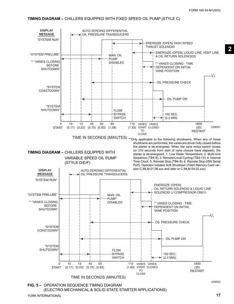
TIMING DIAGRAM – CHILLERS EQUIPPED WITH FIXED SPEED OIL PUMP (STYLE C)
TIMING DIAGRAM – CHILLERS EQUIPPED WITH VARIABLE SPEED OIL PUMP (STYLE D/E/F)
LD06501
LD06502FIG. 5 – OPERATION SEQUENCE TIMING DIAGRAM (ELECTRO-MECHANICAL & SOLID STATE STARTER APPLICATIONS)
**Only applicable to the following shutdowns. When any of these shutdowns are performed, the vanes are driv en fully closed before the starter is de-energized. When the vane motor switch clos es (or 210 seconds from start of vane clo sure have elapsed), the starter is de-energized. 1. Low Water Tem per a ture; 2. Multi-Unit Sequence (TB4-9); 3. Remote/Local Cycling (TB4-13); 4. Internal Time Clock; 5. Remote Stop (TB4-8); 6. Re mote Stop (ISN Serial Port). Operator initiated Soft Shut down (Flash Memory Card ver-sion C.MLM.01.06.xxx and lat er or C.MLM.04.02.xxx)
2
YORK INTERNATIONAL18
FORM 160.54-M1(503)
0 10 13 45 50 65 110 (0.17) (0.22) (0.75) (0.83) (1.08) (1.83)START
VANESSTART
TOCLOSE
VANESCLOSED
600(10)
RESTART(ONLY AFTER FIFTH
SUCCESSIVE RESTART)
FLOWBYPASSSWITCH
MAN. OILPUMPDISABLED
AUTO ZEROING DIFFERENTIALOIL PRESSURE TRANSDUCERS
ENERGIZE (OPEN) HIGH SPEEDTHRUST SOLENOID
ENERGIZE (OPEN) LIQUID LINE*, VENT LINE& OIL RETURN SOLENOIDS
** VANES CLOSING - TIMEDEPENDENT ON INITIAL VANE POSITION
OIL PRESSURE CHECK
OIL PUMP ON
150 SEC.(2.5 MIN)
"SYSTEMCOASTDOWN"
"SYSTEMSHUTDOWN"
TIME IN SECONDS (MINUTES)
DISPLAYMESSAGE
RESTART(IF FIVE SUCCESSIVERESTARTS HAVE NOT
OCCURED)
"SYSTEM RUN"
"SYSTEM PRELUBE"
** "VANES CLOSINGBEFORE
SHUTDOWN"
0 10 13 45 50 110 (0.17) (0.22) (0.75) (0.83) (1.83)START
VANESSTART
TOCLOSE
VANESCLOSED
FLOWBYPASSSWITCH
MAN. OILPUMPDISABLED
AUTO ZEROING DIFFERENTIALOIL PRESSURE TRANSDUCERS
ENERGIZE (OPEN) OIL RETURN SOLENOID & LIQUID LINESOLENOID (J COMPRESSORS ONLY)
** VANES CLOSING - TIMEDEPENDENT ON INITIAL VANE POSITION
OIL PRESSURE CHECK
OIL PUMP ON
150 SEC.(2.5 MIN)
"SYSTEMCOASTDOWN"
"SYSTEMSHUTDOWN"
TIME IN SECONDS (MINUTES)
DISPLAYMESSAGE
600(10)
RESTART(ONLY AFTER FIFTH
SUCCESSIVE RESTART)
RESTART(IF FIVE SUCCESSIVERESTARTS HAVE NOT
OCCURED)
"SYSTEM RUN"
"SYSTEM PRELUBE"
** "VANES CLOSINGBEFORE
SHUTDOWN"
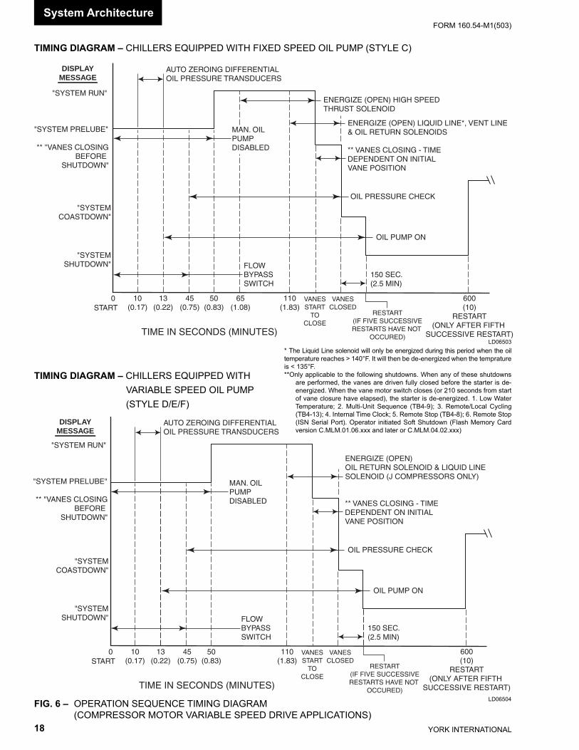
TIMING DIAGRAM – CHILLERS EQUIPPED WITH FIXED SPEED OIL PUMP (STYLE C)
TIMING DIAGRAM – CHILLERS EQUIPPED WITH VARIABLE SPEED OIL PUMP (STYLE D/E/F)
LD06503
FIG. 6 – OPERATION SEQUENCE TIMING DIAGRAM (COMPRESSOR MOTOR VARIABLE SPEED DRIVE APPLICATIONS)
* The Liquid Line solenoid will only be energized during this period when the oil temperature reaches > 140°F. It will then be de-en er gized when the temprature is < 135°F.**Only applicable to the following shutdowns. When any of these shutdowns
are performed, the vanes are driv en fully closed before the starter is de-energized. When the vane motor switch clos es (or 210 seconds from start of vane clo sure have elapsed), the starter is de-energized. 1. Low Water Tem per a ture; 2. Multi-Unit Sequence (TB4-9); 3. Remote/Local Cycling (TB4-13); 4. Internal Time Clock; 5. Remote Stop (TB4-8); 6. Remote Stop (ISN Serial Port). Operator initiated Soft Shut down (Flash Memory Card version C.MLM.01.06.xxx and lat er or C.MLM.04.02.xxx)
System Ar chi tec ture
LD06504
FORM 160.54-M1(503)
19YORK INTERNATIONAL
SECTION 3MICROBOARD
(REFER TO FIG. 7 - 12)
The Microboard contains the operating software (Pro- gram), microprocessor (Micro), and supporting cir cuits for the Micro.
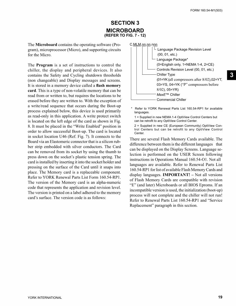
The Program is a set of instructions to control the chill er, the display and peripheral devices. It also con tains the Safety and Cycling shutdown thresholds (non change able) and Display messages and screens. It is stored in a memory device called a fl ash memory card. This is a type of non-volatile memory that can be read from or written to, but requires the locations to be erased before they are writ ten to. With the exception of a write/read se quence that occurs during the Boot-up process ex plained below, this device is used primarily as read-only in this application. A write protect switch is lo cat ed on the left edge of the card as shown in Fig. 8. It must be placed in the “Write Enabled” position in or der to allow suc cess ful Boot-up. The card is located in sock et location U46 (Ref. Fig. 7). It connects to the Board via an Elas to mer ic connector that is a silicon rub- ber strip em bed ded with silver conductors. The Card can be re moved from its socket by using the thumb to press down on the sock et’s plastic tension spring. The card is in stalled by inserting it into the socket/holder and pressing on the surface of the Card until it snaps into place. The Mem o ry card is a replaceable com po nent. Refer to YORK Re new al Parts List Form 160.54-RP1. The ver sion of the Memory card is an alpha-nu mer ic code that rep re sents the application and revision level. The ver sion is printed on a label ad hered to the memory card’s sur face. The version code is as follows:
C.MLM.nn.nn.nnn Language Package Revision Level (00, 01, etc.) Language Package* (0=English only, 1=NEMA 1-4, 2=CE) Controls Revision Level (00, 01, etc.) Chiller Type (01=YK (all compressors after 8/02),02=YT, 03=YS, 04=YK (“P” compressors before 8/02), 05=YR) MaxE™ Chiller Commercial Chiller
* Refer to YORK Renewal Parts List 160.54-RP1 for available languages.
1 = Supplied in new NEMA 1-4 OptiView Control Centers but can be retrofi t to any OptiView Con trol Center.
2 = Supplied in new CE (European Community) OptiView Con- trol Centers but can be retrofit to any OptiView Con trol Center.
There are sev er al Flash Memory Cards available. The dif fer ence between them is the different lan guag es that can be displayed on the Display Screens. Lan guage se-lection is performed on the USER Screen following instructions in Operations Man u al 160.54-O1. Not all languages are available. Refer to Re new al Parts List 160.54-RP1 for list of available Flash Memory Cards and display lan guag es. IM POR TANT! – Not all ver sions of Flash Memory Cards are compatible with re vi sion “E” (and later) Microboards or all BIOS Eproms. If an incompatible version is used, the initialization (boot-up) process will not complete and the chiller will not run! Refer to Renewal Parts List 160.54-RP1 and “Ser vice Replacement” paragraph in this sec tion.
3
YORK INTERNATIONAL20
FORM 160.54-M1(503)
Flash Memory Cards are revised to add new features, enhancements and program corrections. Each time they are revised, the revision level of the affected portion of the program (controls or language) increments. Each time they are revised, a Service Information Bulletin is issued that describes the new features. Those bulletins that have been issued to date, are located at the rear of this manual.
The Micro controls the chiller by read ing and ex e cut ing the Program in struc tions in a sequence determined by the Program. Under Program control, the Micro reads the Analog and Digital Inputs to de ter mine the op er -at ing con di tions and con trols Digital Outputs based upon these inputs. These inputs are com pared to stored thresh olds to determine if a Safety or Cycling shutdown is re quired. If a threshold has been exceeded, a shut down is per formed and the ap pro pri ate message is retrieved from the Program and displayed on the Liquid Crystal Dis play. As operating conditions require, status mes- sag es are retrieved and dis played. The Keypad is read as Dig i tal Inputs. When an operator presses a key to request a display, the Micro in ter prets the request, re trieves the display from the Program and displays it. The Program assembles data in the correct format for transmission through the Serial Data Ports to pe riph er al devices. The Program also instructs the Micro to re spond to requests from pe riph er al devices for serial data transmissions.
The MUX (multiplexer) is a switching device that only al lows one analog input through at a time. The inputs are selected sequentially by the Micro per Program in struc tions.
The A/D Converter converts each analog input to a 12-bit word. In this form, the values can be stored in mem o ry de vic es, compared to values in the Pro gram, trans mit ted through Serial Ports or sent to the Display Con trol ler for display. Control signals to start con ver sion pro cess are from the Micro via the FPGA.The Watchdog circuit monitors the +5VDC supply from the ex ter nal Power Supply to determine when a power fail ure is occurring. Just prior to the supply de creas ing to a level where the Micro and supporting cir cuits can no longer operate, it applies a reset signal to the Micro. The Micro responds by de-energizing the run digital output through the FPGA, shutting down the chiller and retrieving the Power Failure mes sage from the Pro gram and send ing it to the Display Con trol ler
for dis play. Sim i lar ly, when power is fi rst ap plied af ter a pow er failure, it main tains the Micro in a reset state until the +5VDC has returned to a suffi cient level. The Watch dog circuit also assures that all the Program in- struc tions are being performed and that the Program has not latched-up, bypassing im por tant safe ty thresh olds. If the Pro gram has latched-up, The Micro initiates a Safety shut down and displays WATCH DOG – SOFT WARE REBOOT message.
The Program Jumpers (Table 1) and Program Switch- es (Ta ble 2) are used to alter the Pro gram op er a tion or configure the Microboard hard ware for spe cif ic op er a tion. This allows the Program and Microboard to be universal for all applications of the chiller. Refer to Table 1 and 2 for the function of each jumper and switch. The po si tion of some can be de ter mined and set by the Service Technician to meet the desired operation or chiller ap pli ca tion. The position of others is dictated by the size, type or style of certain OptiView Control Center com po nents and thus the position is de ter mined by the YORK Factory. The required position of each is listed in these tables. The Program Jumpers are wire bridges that are either left in place or cut. The Pro gram Switches are min ia ture switches that are placed in ei ther the ON or OFF position.
The DRAM (dynamic random access memory) is a non battery-backed memory device. The Micro stores data here temporarily for further processing. Data in this de-vice is lost during power failures. DRAM differs from RAM in that DRAM must be periodically re freshed in circuit.
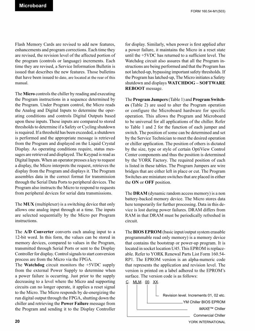
The BIOS EPROM (basic input/output system eras able programmable read only memory) is a memory device that contains the bootstrap or power-up pro gram. It is located in socket location U45. This EPROM is re place -able. Refer to YORK Renewal Parts List Form 160.54-RP1. The EPROM version is an alpha-numeric code that represents the application and revision level. The version is printed on a label adhered to the EPROM’s surface. The version code is as follows:
Microboard
C. MLM. 00. XX.
Revision level. In cre ments 01, 02 etc.
YM Chiller BIOS EPROM
MAXE™ Chiller
Commercial Chiller
FORM 160.54-M1(503)
21YORK INTERNATIONAL
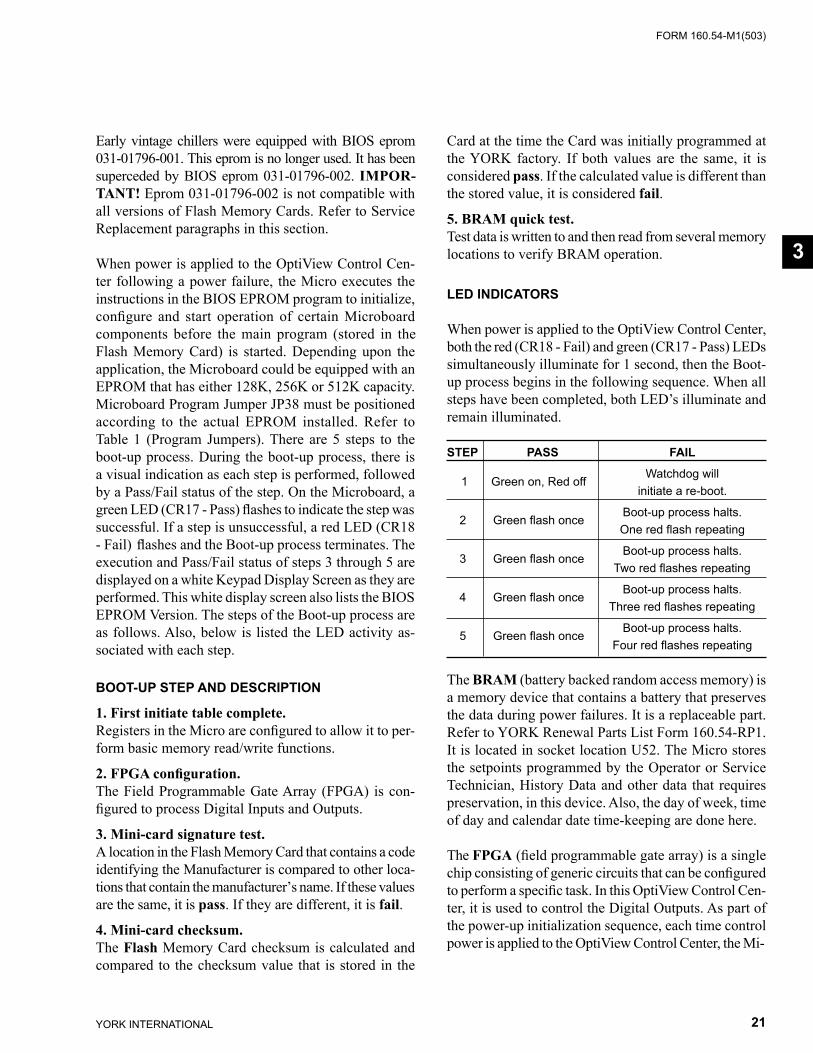
Early vintage chillers were equipped with BIOS eprom 031-01796-001. This eprom is no longer used. It has been su per ced ed by BIOS eprom 031-01796-002. IM POR -TANT! Eprom 031-01796-002 is not compatible with all versions of Flash Memory Cards. Refer to Ser vice Re place ment para graphs in this section.
When power is applied to the OptiView Control Cen-ter fol low ing a power failure, the Micro executes the in struc tions in the BIOS EPROM program to initialize, confi gure and start operation of certain Microboard com po nents be fore the main program (stored in the Flash Memory Card) is started. Depending upon the ap pli ca tion, the Microboard could be equipped with an EPROM that has either 128K, 256K or 512K ca pac i ty. Microboard Pro gram Jumper JP38 must be po si tioned according to the actual EPROM installed. Refer to Ta ble 1 (Pro gram Jump ers). There are 5 steps to the boot-up pro cess. Dur ing the boot-up process, there is a visual in di ca tion as each step is performed, followed by a Pass/Fail sta tus of the step. On the Microboard, a green LED (CR17 - Pass) fl ash es to in di cate the step was suc cess ful. If a step is un suc cess ful, a red LED (CR18 - Fail) fl ashes and the Boot-up pro cess ter mi nates. The ex e cu tion and Pass/Fail sta tus of steps 3 through 5 are displayed on a white Key pad Dis play Screen as they are performed. This white dis play screen also lists the BIOS EPROM Ver sion. The steps of the Boot-up pro cess are as fol lows. Also, be low is listed the LED ac tiv i ty as-sociated with each step.
BOOT-UP STEP AND DESCRIPTION
1. First initiate table complete.Registers in the Micro are confi gured to allow it to per- form basic mem o ry read/write func tions.
2. FPGA confi guration.The Field Pro gram ma ble Gate Array (FPGA) is con- fi g ured to process Digital Inputs and Out puts.
3. Mini-card signature test.A location in the Flash Memory Card that contains a code iden ti fy ing the Man u fac tur er is compared to oth er lo ca -tions that contain the man u fac tur er’s name. If these val ues are the same, it is pass. If they are different, it is fail.
4. Mini-card checksum.The Flash Memory Card checksum is calculated and com pared to the checksum value that is stored in the
Card at the time the Card was initially programmed at the YORK fac to ry. If both val ues are the same, it is con sid ered pass. If the cal cu lat ed value is different than the stored value, it is considered fail.
5. BRAM quick test. Test data is written to and then read from several mem o ry locations to ver i fy BRAM operation.
LED INDICATORS
When power is applied to the OptiView Control Cen ter, both the red (CR18 - Fail) and green (CR17 - Pass) LEDs si mul ta neous ly il lu mi nate for 1 sec ond, then the Boot-up pro cess begins in the fol low ing sequence. When all steps have been com plet ed, both LED’s illuminate and remain il lu mi nat ed.
STEP PASS FAIL 1 Green on, Red off Watchdog will initiate a re-boot.
2 Green fl ash once Boot-up pro cess halts. One red fl ash repeating
3 Green fl ash once Boot-up pro cess halts. Two red fl ashes repeating
4 Green fl ash once Boot-up pro cess halts. Three red fl ashes repeating
5 Green fl ash once Boot-up pro cess halts. Four red fl ashes repeating
The BRAM (battery backed random access mem o ry) is a memory device that contains a battery that pre serves the data during power failures. It is a re place able part. Refer to YORK Renewal Parts List Form 160.54-RP1. It is located in socket location U52. The Micro stores the setpoints programmed by the Op er a tor or Service Tech ni cian, History Data and other data that requires pres er va tion, in this device. Also, the day of week, time of day and calendar date time-keeping are done here.
The FPGA (fi eld programmable gate array) is a single chip consisting of generic circuits that can be con fi g ured to perform a specifi c task. In this OptiView Control Cen- ter, it is used to control the Digital Outputs. As part of the pow er-up initialization sequence, each time control pow er is ap plied to the OptiView Control Center, the Mi-
3
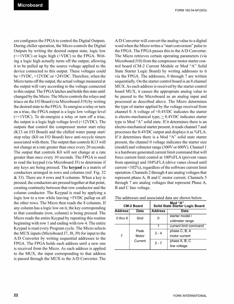
YORK INTERNATIONAL22
FORM 160.54-M1(503)
cro con fi g ures the FPGA to control the Digital Outputs. Dur ing chiller operation, the Micro controls the Digital Outputs by writ ing the de sired output state, logic low (<+1VDC) or logic high (+VDC) to the FPGA. Writ- ing a logic high ac tu al ly turns off the output, allowing it to be pulled up by the source voltage applied to the de vice connected to this out put. These voltages could be +5VDC, +12VDC or +24VDC. There fore, when the Micro turns off the out put, the ac tu al volt age measured at the out put will vary ac cord ing to the volt age con nect ed to this out put. The FPGA latches and holds this state until changed by the Micro. The Mi cro controls the relays and triacs on the I/O Board (via Microboard J19) by writing the de sired state to the FPGA. To en er gize a relay or turn on a triac, the FPGA output is a logic low voltage level (<+1VDC). To de-en er gize a relay or turn off a triac, the output is a logic high volt age level (+12VDC). The out puts that con trol the com pres sor mo tor start relay (K13 on I/O Board) and the chilled water pump start/stop relay (K0 on I/O Board) have anti-recycle timers as so ci at ed with them. The out put that con trols K13 will not change at a rate greater than once every 20 sec onds. The output that con trols K0 will not change at a rate greater than once every 10 seconds. The FPGA is used to read the keypad (via Microboard J5) to de ter mine if any keys are being pressed. The keypad is a ma trix of conductors ar ranged in rows and columns (ref. Fig. 32 & 33). There are 4 rows and 8 columns. When a key is pressed, the con duc tors are pressed together at that point, creating continuity be tween that row con duc tor and the column con duc tor. The Key pad is read by applying a log ic low to a row while leaving +5VDC pullup on all the other rows. The Micro then reads the 8 columns. If any col umn has a logic low on it, the key corresponding to that co or di nate (row, column) is being pressed. The Micro reads the en tire Keypad by re peat ing this routine be gin ning with row 1 and ending with row 4. The entire Keypad is read ev ery Program cycle. The Mi cro se lects the MUX inputs (Microboard J7, J8, J9) for in put to the A/D Converter by writing se quen tial ad dress es to the FPGA. The FPGA holds each ad dress until a new one is re ceived from the Mi cro. As each address is ap plied to the MUX, the input cor re spond ing to that ad dress is passed through the MUX to the A/D Con vert er. The
A/D Converter will con vert the an a log value to a digital word when the Micro writes a “start con ver sion” pulse to the FPGA. The FPGA pass es this to the A/D Con vert er. The Micro retrieves cer tain op er at ing pa ram e ters (via Microboard J10) from the com pres sor mo tor starter con- trol board (CM-2 Current Mod ule or Mod “A” Solid State Starter Logic Board) by writ ing ad dress es to it via the FPGA. The ad dress es, 0 through 7 are writ ten se quen tial ly. On the starter con trol board is an 8 chan nel MUX. As each address is received by the start er control board MUX, it causes the ap pro pri ate an a log value to be passed to the Microboard as an analog input and pro cessed as de scribed above. The Micro de ter mines the type of start er ap plied by the volt age re ceived from channel 0. A volt age of <0.4VDC in di cates the start er is electro-me chan i cal type; > 0.4VDC in di cates starter type is Mod “A” solid state. If it de ter mines there is an electro-me chan i cal start er present, it reads chan nel 7 and pro cess es the 0-4VDC output and dis plays it as %FLA. If it de ter mines there is a Mod “A” solid state starter present, the channel 0 volt age indicates the starter size (model) and voltmeter range (300V or 600V). Channel 1 is a hardware gen er at ed current limit command that will force current limit con trol at 100%FLA (prevent vanes from opening) and 104%FLA (drive vanes closed until current <102%), regardless of the software cur rent limit operation. Chan nels 2 through 4 are analog voltages that represent phase A, B and C motor cur rent. Channels 5 through 7 are an a log volt ag es that rep re sent Phase A, B and C line voltage.
The addresses and associated data are shown below. Mod “A”
Microboard
CM-2 Board Solid State Starter Logic BoardAddress Data Address Data
0 thru 6 Gnd 0 starter model / volt me ter range 1 cur rent limit command Peak 2 - 4 phase C, B, A 7 Motor motor current Current 5 - 7 phase A, B, C line voltage
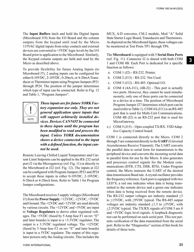
FORM 160.54-M1(503)
23YORK INTERNATIONAL
The Input Buffers latch and hold the Dig i tal In puts (Microboard J19) from the I/O Board and the col umn out puts from the keypad until read by the Mi cro. 115VAC dig i tal inputs from relay contacts and ex ter nal devices are con vert ed to +5VDC logic levels by the I/O Board prior to ap pli ca tion to the Microboard. Sim i lar ly, the Keypad column outputs are held and read by the Micro as de scribed above.
To provide flexibility for future Analog In puts (to Microboard J7), 2 analog inputs can be confi gured for either 0-10VDC, 2-10VDC, 0-20mA, or 4-20mA Trans- duc er or Ther mistor in puts using Program Jump ers JP21 through JP24. The po si tion of the jumper de ter mines which type of input can be con nect ed. Refer to Fig. 12 and Table 1, “Pro gram Jumpers”.
These inputs are for future YORK Fac- to ry ex pan sion use only. They are not gen er al ap pli ca tion spare in puts that will sup port arbitrarily in stalled de- vic es. Devices CAN NOT be con nect ed to these in puts un til the pro gram has been mod i fi ed to read and process the in put. Un less YORK doc u men ta tion shows a de vice con nect ed to the in put with a de fi ned func tion, the in put can- not be used.
Remote Leaving Chilled Liquid Tem per a ture and Cur- rent Limit Setpoints can be applied to the RS-232 se ri al port J2 via the Microgateway (ref. Fig. 11) or directly to the Microboard at J22 (ref. Fig. 12). The inputs at J22 can be con fi g ured with Program Jump ers JP23 and JP24 to ac cept these inputs in either 0-10VDC, 2-10VDC, 0-20mA or 4-20mA form. Refer to Table 1 for Pro gram Jump er con fi g u ra tions.
The Microboard receives 3 supply voltages (Microboard J1) from the Power Supply; +12VDC, -12VDC, +5VDC and Ground. The -12VDC and +12VDC are used directly by various circuits. The +12VDC and +5VDC are input to Voltage Regulators to derive oth er reg u lat ed volt- ag es. The +5VDC (fused by 5 Amp fuse F1 on rev “E” and later boards) is input to a +3.3VDC reg u la tor. The output is a 3.3VDC regulated voltage. The +12VDC (fused by 5 Amp fuse F2 on rev “E” and later boards) is in put to a 5VDC regulator. The output of this reg u -la tor pow ers only the Analog circuits. This in cludes the
MUX, A/D con vert er, CM-2 module, Mod “A” Solid State Start er Logic Board, Trans duc ers and Ther mistors. As de pict ed on the Microboard fi gure, these volt ag es can be monitored at Test Posts TP1 through TP6.
The Microboard is equipped with 5 Serial Data Ports (ref. Fig. 11). Connector J2 is shared with both COM 1 and COM 4B. Each Port is dedicated for a specifi c func tion as follows: a. COM 1 (J2) - RS-232. Printer. b. COM 2 (J13) - RS-232. Not Used. c. COM 3 (J12) - RS-485. Optional I/O. d. COM 4 (4A-J11), (4B-J2) - This port is actually
two ports. However, they cannot be used si mul ta -neous ly; only one of these ports can be con nect ed to a device at a time. The position of Microboard Program Jump er J27 determines which port can be used (refer to Table 1). COM 4A (J11) is an RS-485 port that is used for Multi-Unit Com mu ni ca tions. COM 4B (J2) is an RS-232 port that is used for MicroGateway.
e.) COM 5 (J15) – Opto-coupled TX/RX. VSD Adap- tive Capacity Control board.
COM 1 is connected directly to the Micro. COM 2 through 5 are connected directly to the UART (Uni ver sal Asynchronous Receive Transmit). The UART con verts the parallel data to serial form for trans mis sion to the peripheral device and converts the in com ing serial data to parallel form for use by the Micro. It also gen er ates and processes control signals for the Modem com- mu ni ca tions (DTR, CTS, DSR, RTS). Un der Pro gram control, the Mi cro instructs the UART of the de sired data trans mis sion Baud rate. A crystal os cil la tor pro vides the frequency reference. Each port is equipped with two LED’S; a red one indicates when data is being trans-mitted to the remote device and a green one in di cates when data is being received from the re mote de vice. The RS-232 output voltages are in dus try standard +3 to +15VDC, with +9VDC typical. The RS-485 out put voltages are industry standard +1.5 to +5VDC, with +2.5VDC typical. The TX/RX sig nals of COM 5 are 0 and +5VDC logic level sig nals. A loopback diagnostic test can be performed on each se ri al port. This test per- mits verifi cation of the data trans mit ted from the serial port. Refer to the “Diagnostics” sec tion of this book for de tails of these tests.
3
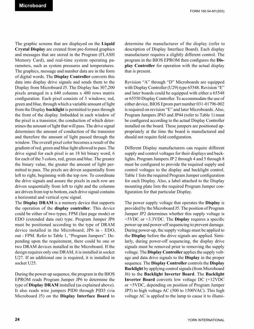
YORK INTERNATIONAL24
FORM 160.54-M1(503)
The graphic screens that are displayed on the Liquid Crystal Display are cre at ed from pre-formed graph ics and mes sag es that are stored in the Program (FLASH Mem o ry Card), and real-time system op er at ing pa- ram e ters, such as sys tem pres sures and tem per a tures. The graphics, mes sage and number data are in the form of digital words. The Dis play Controller con verts this data into display drive signals and sends them to the Display from Microboard J5. The Display has 307,200 pixels ar ranged in a 640 columns x 480 rows matrix con fi g u ra tion. Each pixel consists of 3 win dows; red, green and blue, through which a variable amount of light from the Display back light is per mit ted to pass through the front of the dis play. Im bed ded in each win dow of the pixel is a tran sis tor, the con duc tion of which de ter -mines the amount of light that will pass. The drive sig nal de ter mines the amount of conduction of the tran sis tor and therefore the amount of light passed through the win dow. The overall pixel color becomes a result of the gradient of red, green and blue light allowed to pass. The drive signal for each pixel is an 18 bit binary word; 6 for each of the 3 colors, red, green and blue. The greater the binary value, the greater the amount of light per- mit ted to pass. The pix els are driven se quen tial ly from left to right, beginning with the top row. To co or di nate the drive signals and assure the pixels in each row are driven sequentially from left to right and the columns are driven from top to bottom, each drive sig nal con tains a horizontal and vertical sync signal. The Display DRAM is a memory device that sup ports the op er a tion of the display controller. This de vice could be ei ther of two types; FPM (fast page mode) or EDO (ex tend ed data out) type. Program Jump er JP6 must be positioned according to the type of DRAM de vice in stalled in the Microboard; JP6 in - EDO, out - FPM. Refer to Table 1, “Program Jump ers”. De- pend ing upon the re quire ment, there could be one or two DRAM devices installed in the Microboard. If the de sign re quires only one DRAM, it is installed in socket U27. If an additional one is required, it is in stalled in socket U25.
During the power-up sequence, the program in the BIOS EPROM reads Program Jumper JP6 to determine the type of Display DRAM installed (as explained above). It also reads wire jumpers PID0 through PID3 (via Microboard J5) on the Display Interface Board to
de ter mine the man u fac tur er of the display (refer to de scrip tion of Dis play In ter face Board). Each display man u fac tur er re quires a slight ly different control. The pro gram in the BIOS EPROM then confi gures the Dis- play Con trol ler for operation with the actual display that is present.
Revision “A” through “D” Microboards are equipped with Display Controller (U29) type 65548. Revision “E” and later boards could be equipped with either a 65548 or 65550 Display Controller. To ac com mo date the use of either device, BIOS Eprom part number 031-01796-002 is required on re vi sion “E” and later Microboards. Also, Program Jumpers JP43 and JP44 (re fer to Table 1) must be confi gured according to the ac tu al Dis play Con trol ler installed on the board. These jump ers are po si tioned ap-propriately at the time the board is man u fac tured and should not require fi eld con fi g u ra tion.
Different Display manufacturers can require different supply and control voltages for their displays and back- lights. Program Jumpers JP 2 through 4 and 5 through 8 must be confi gured to provide the required supply and control voltages to the display and back light con trol. Table 1 lists the required Program Jumper con fi g u ra tion for each Display. Also, a label attached to the Dis play mount ing plate lists the required Program Jumper con- fi g u ra tion for that particular Display.
The power supply voltage that operates the Display is pro vid ed by the Microboard J5. The position of Pro gram Jumper JP2 determines whether this supply volt age is +5VDC or +3.3VDC. The Display requires a spe cifi c pow er-up and power-off sequencing to pre vent dam age. During power-up, the supply voltage must be ap plied to the Display before the drive signals are ap plied. Simi-larly, during power-off sequencing, the dis play drive signals must be removed prior to removing the supply voltage. The Display Controller applies the sup ply volt- age and data drive signals to the Display in the prop er sequence. The Display Controller controls the Display Backlight by ap ply ing con trol sig nals (from Microboard J6) to the Backlight Inverter Board. The Backlight Inverter Board converts low volt age DC (+12VDC or +5VDC, de pend ing on position of Pro gram Jumper JP5) to high voltage AC (500 to 1500VAC). This high voltage AC is applied to the lamp to cause it to illumi-
Microboard
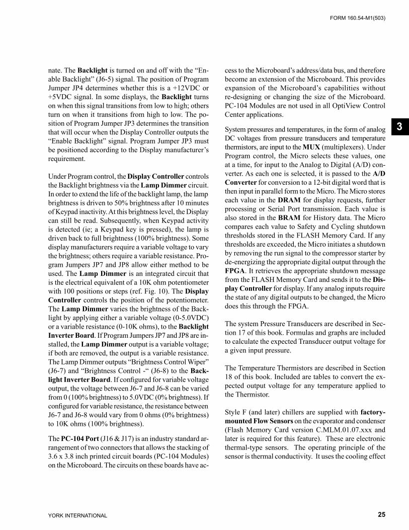
FORM 160.54-M1(503)
25YORK INTERNATIONAL
nate. The Backlight is turned on and off with the “En- able Back light” (J6-5) signal. The position of Pro gram Jump er JP4 determines whether this is a +12VDC or +5VDC sig nal. In some dis plays, the Back light turns on when this signal tran si tions from low to high; others turn on when it tran si tions from high to low. The po- si tion of Program Jumper JP3 de ter mines the tran si tion that will occur when the Display Con trol ler outputs the “Enable Backlight” sig nal. Program Jump er JP3 must be po si tioned according to the Dis play man u fac tur er’s re quire ment.
Under Program control, the Display Controller con trols the Back light brightness via the Lamp Dimmer circuit. In or der to extend the life of the back light lamp, the lamp bright ness is driven to 50% bright ness after 10 minutes of Keypad inactivity. At this bright ness lev el, the Dis play can still be read. Sub se quent ly, when Key pad ac tiv i ty is detected (ie; a Key pad key is pressed), the lamp is driv en back to full bright ness (100% bright ness). Some display man u fac tur ers require a vari able voltage to vary the bright ness; others require a vari able resistance. Pro- gram Jumpers JP7 and JP8 allow either method to be used. The Lamp Dimmer is an in te grat ed cir cuit that is the electrical equiv a lent of a 10K ohm po ten ti om e ter with 100 positions or steps (ref. Fig. 10). The Display Controller con trols the po si tion of the po ten ti om e ter. The Lamp Dimmer varies the bright ness of the Back- light by applying either a vari able volt age (0-5.0VDC) or a variable re sis tance (0-10K ohms), to the Backlight Inverter Board. If Pro gram Jump ers JP7 and JP8 are in- stalled, the Lamp Dimmer out put is a vari able volt age; if both are re moved, the output is a vari able re sis tance. The Lamp Dimmer out puts “Bright ness Control Wiper” (J6-7) and “Bright ness Con trol -“ (J6-8) to the Back-light Inverter Board. If con fi g ured for vari able volt age output, the voltage be tween J6-7 and J6-8 can be varied from 0 (100% bright ness) to 5.0VDC (0% bright ness). If con fi g ured for vari able re sis tance, the re sis tance be tween J6-7 and J6-8 would vary from 0 ohms (0% bright ness) to 10K ohms (100% bright ness).
The PC-104 Port (J16 & J17) is an industry stan dard ar- range ment of two connectors that allows the stack ing of 3.6 x 3.8 inch printed circuit boards (PC-104 Mod ules) on the Microboard. The circuits on these boards have ac-
cess to the Microboard’s address/data bus, and there fore become an extension of the Microboard. This pro vides expansion of the Microboard’s capabilities with out re-designing or changing the size of the Microboard. PC-104 Modules are not used in all OptiView Control Cen ter ap pli ca tions.
System pressures and temperatures, in the form of an a log DC voltages from pressure transducers and tem per a ture thermistors, are input to the MUX (mul ti plex ers). Under Program control, the Micro selects these values, one at a time, for input to the Analog to Digital (A/D) con-verter. As each one is selected, it is passed to the A/D Converter for conversion to a 12-bit digital word that is then input in parallel form to the Mi cro. The Mi cro stores each value in the DRAM for display re quests, fur ther processing or Serial Port trans mis sion. Each val ue is also stored in the BRAM for History data. The Micro compares each val ue to Safe ty and Cycling shut down thresholds stored in the FLASH Mem o ry Card. If any thresholds are exceeded, the Mi cro ini tiates a shut down by removing the run signal to the com pres sor starter by de-energizing the ap pro pri ate dig i tal out put through the FPGA. It retrieves the ap pro pri ate shut down message from the FLASH Mem o ry Card and sends it to the Dis- play Controller for dis play. If any an a log inputs require the state of any dig i tal out puts to be changed, the Micro does this through the FPGA.
The system Pressure Transducers are de scribed in Sec- tion 17 of this book. For mu las and graphs are included to calculate the expected Trans duc er output voltage for a given input pressure.
The Temperature Thermistors are de scribed in Section 18 of this book. Included are tables to convert the ex- pect ed output voltage for any temperature applied to the Thermistor.
Style F (and later) chillers are supplied with factory-mounted Flow Sensors on the evaporator and condenser (Flash Memory Card version C.MLM.01.07.xxx and later is required for this feature). These are electronic thermal-type sensors. The operating principle of the sensor is thermal conductivity. It uses the cooling effect
3
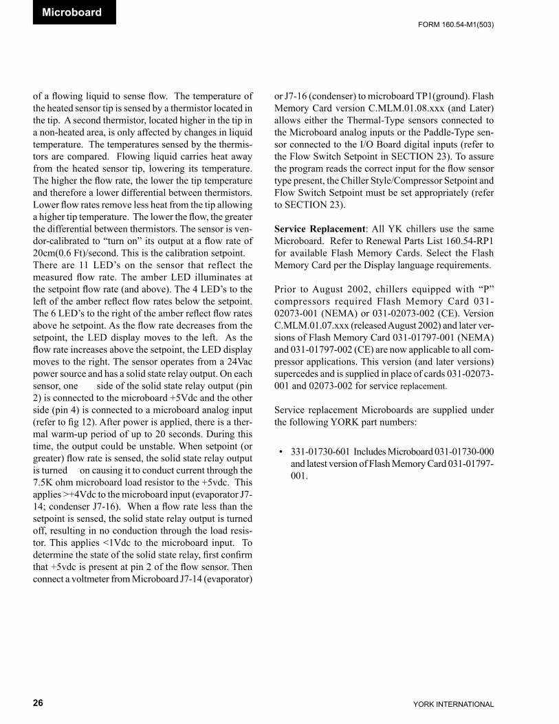
YORK INTERNATIONAL26
FORM 160.54-M1(503)
of a fl owing liquid to sense fl ow. The temperature of the heated sensor tip is sensed by a thermistor located in the tip. A second thermistor, located higher in the tip in a non-heated area, is only affected by changes in liquid temperature. The temperatures sensed by the thermis-tors are compared. Flowing liquid carries heat away from the heated sensor tip, lowering its temperature. The higher the fl ow rate, the lower the tip temperature and therefore a lower differential between thermistors. Lower fl ow rates remove less heat from the tip allowing a higher tip temperature. The lower the fl ow, the greater the differential between thermistors. The sensor is ven-dor-calibrated to “turn on” its output at a fl ow rate of 20cm(0.6 Ft)/second. This is the calibration setpoint. There are 11 LED’s on the sensor that reflect the measured fl ow rate. The amber LED illuminates at the setpoint fl ow rate (and above). The 4 LED’s to the left of the amber refl ect fl ow rates below the setpoint. The 6 LED’s to the right of the amber refl ect fl ow rates above he setpoint. As the fl ow rate decreases from the setpoint, the LED display moves to the left. As the fl ow rate increases above the setpoint, the LED display moves to the right. The sensor operates from a 24Vac power source and has a solid state relay output. On each sensor, one side of the solid state relay output (pin 2) is connected to the microboard +5Vdc and the other side (pin 4) is connected to a microboard analog input (refer to fi g 12). After power is applied, there is a ther-mal warm-up period of up to 20 seconds. During this time, the output could be unstable. When setpoint (or greater) fl ow rate is sensed, the solid state relay output is turned on causing it to conduct current through the 7.5K ohm microboard load resistor to the +5vdc. This applies >+4Vdc to the microboard input (evaporator J7-14; condenser J7-16). When a fl ow rate less than the setpoint is sensed, the solid state relay output is turned off, resulting in no conduction through the load resis-tor. This applies <1Vdc to the microboard input. To determine the state of the solid state relay, fi rst confi rm that +5vdc is present at pin 2 of the fl ow sensor. Then connect a voltmeter from Microboard J7-14 (evaporator)
Microboard
or J7-16 (condenser) to microboard TP1(ground). Flash Memory Card version C.MLM.01.08.xxx (and Later) allows either the Thermal-Type sensors connected to the Microboard analog inputs or the Paddle-Type sen-sor connected to the I/O Board digital inputs (refer to the Flow Switch Setpoint in SECTION 23). To assure the program reads the correct input for the fl ow sensor type present, the Chiller Style/Compressor Setpoint and Flow Switch Setpoint must be set appropriately (refer to SECTION 23).
Service Replacement: All YK chillers use the same Microboard. Refer to Renewal Parts List 160.54-RP1 for available Flash Memory Cards. Select the Flash Mem o ry Card per the Dis play lan guage requirements.
Prior to August 2002, chillers equipped with “P” compressors required Flash Memory Card 031-02073-001 (NEMA) or 031-02073-002 (CE). Version C.MLM.01.07.xxx (released August 2002) and later ver-sions of Flash Memory Card 031-01797-001 (NEMA) and 031-01797-002 (CE) are now applicable to all com-pressor applications. This version (and later versions) supercedes and is supplied in place of cards 031-02073-001 and 02073-002 for service replacement.
Service replacement Microboards are supplied un der the following YORK part numbers:
• 331-01730-601 In cludes Microboard 031-01730-000 and lat est version of Flash Memory Card 031-01797-001.
FORM 160.54-M1(503)
27YORK INTERNATIONAL
3
Replacement Microboards are supplied without the BRAM (U52). Remove this device from the defective board and in stall in the replacement board. If defective board is equipped with Flash Memory Card 031-01797-002 (except “P” compressors) or 031-02073-002 (“P” com pres sors), trans fer this Card to the re place ment board. If defective board is equipped with Card 031-01797-001 (except “P” com pres sors) or 031-02073-001 (“P”compressors), use Card sup plied with replacement board.
If the Microboard is replaced within the Warranty Pe- ri od, re turn the defective board along with any unused Flash Memory Cards to YORK per the Warranty Re turn Pro ce dure.
If Flash Mem o ry Card 031-01797-001 is used, it must be a ver sion C.MLM.01.04 or later (ie, .05, .06, etc) to be used with BIOS Eprom (U45) 031-01796-002. Earlier ver sions will not com plete the ini tial iza tion (boot-up) process and the chill er will not run.
IMPORTANT! Since the BRAM mem o ry device con tains all of the pro grammed setpoints and Sales Order data, using the existing BRAM in the re place ment Microboard elim i nates the need to re-pro gram this ex treme ly large amount of data. The pro cess to man u al ly pro gram the Sales Or der Data is ex treme ly time-consuming. However, if the BRAM fails and fi eld re place ment is nec es sary, follow the pro ce dure in the “Sys tems Cal i -bra tion, Ser vice Setpoints and Reset Pro ce dures” sec tion of this book.
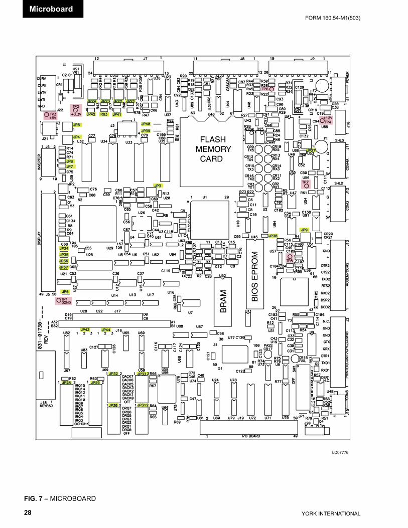
YORK INTERNATIONAL28
FORM 160.54-M1(503)Microboard
FIG. 7 – MICROBOARD
LD07776
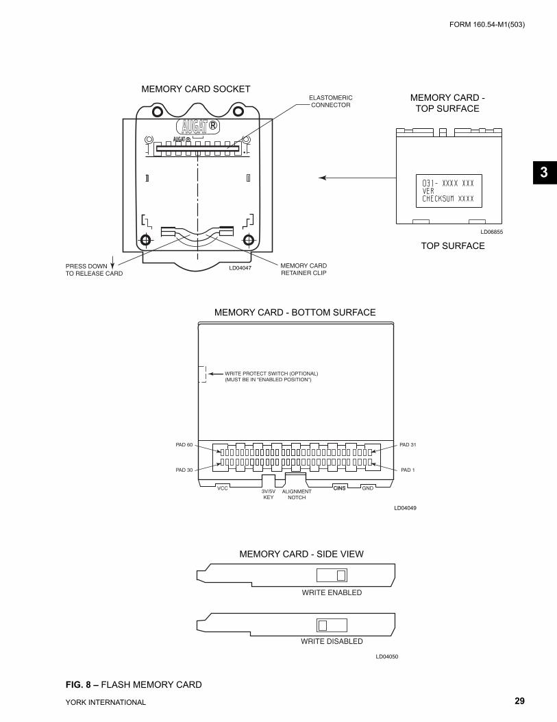
FORM 160.54-M1(503)
29YORK INTERNATIONAL
AUGAT RAUGAT R
MEMORY CARDRETAINER CLIP
PRESS DOWNTO RELEASE CARD
ELASTOMERICCONNECTOR
FIG. 8 – FLASH MEMORY CARD
LD06855
LD04049
WRITE PROTECT SWITCH (OPTIONAL)(MUST BE IN "ENABLED POSITION")
CINSCINS GNDVCC3V/5VKEY
ALIGNMENTNOTCH
PAD 60
PAD 30
PAD 31
PAD 1
LD04047
LD04050
WRITE ENABLED
WRITE DISABLED
MEMORY CARD SOCKETMEMORY CARD -
TOP SURFACE
MEMORY CARD - BOTTOM SUR FACE
MEMORY CARD - SIDE VIEW
TOP SURFACE
3
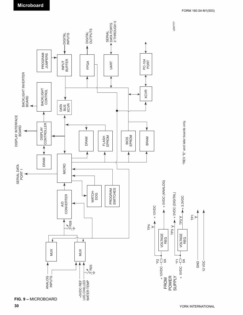
YORK INTERNATIONAL30
FORM 160.54-M1(503)
FP
GA
MU
X
MU
X
A/D
CO
NV
ER
TE
R
WAT
CH
-D
OG
PR
OG
RA
MS
WIT
CH
ES
MIC
RODR
AM
DIS
PLA
YC
ON
TR
OLL
ER
DR
AM
FLA
SH
EP
RO
M
BIO
SE
PR
OM
BR
AM
XC
VR
PC
-104
PO
RT
UA
RT
INP
UT
BU
FF
ER
PR
OG
RA
MJU
MP
ER
SB
AC
KLI
GH
TC
ON
TR
OL
DAT
AB
US
XC
VR
SE
RIA
L D
ATA
PO
RT
1
DIS
PLA
Y IN
TE
RFA
CE
BO
AR
DB
AC
KLI
GH
T IN
VE
RT
ER
BO
AR
D
DIG
ITA
LIN
PU
TS
DIG
ITA
LO
UT
PU
TS
SE
RIA
LD
ATA
PO
RT
S2
TH
RO
UG
H 5
AN
ALO
GIN
PU
TS
+5V
DC
RE
FLV
G C
HIL
LED
WAT
ER
TE
MP
R25
R28
VO
LTA
GE
RE
G
VO
LTA
GE
RE
G
+ 1
2VD
C
+ 5
VD
C GN
D
12 V
DC
YY
Y Y
TP
2 TP
1
TP
4
TP
3
+ 1
2VD
C + 5
VD
C (
AN
ALO
G)
+ 5
VD
C (
DIG
ITA
L)
+ 3
.3V
DC
FR
OM
PO
WE
RS
UP
PLY
*F2
*F1
5A 5A*R
EV
"E
" an
d la
ter
boar
ds o
nly.
FIG. 9 – MICROBOARD
LD07
777
Microboard
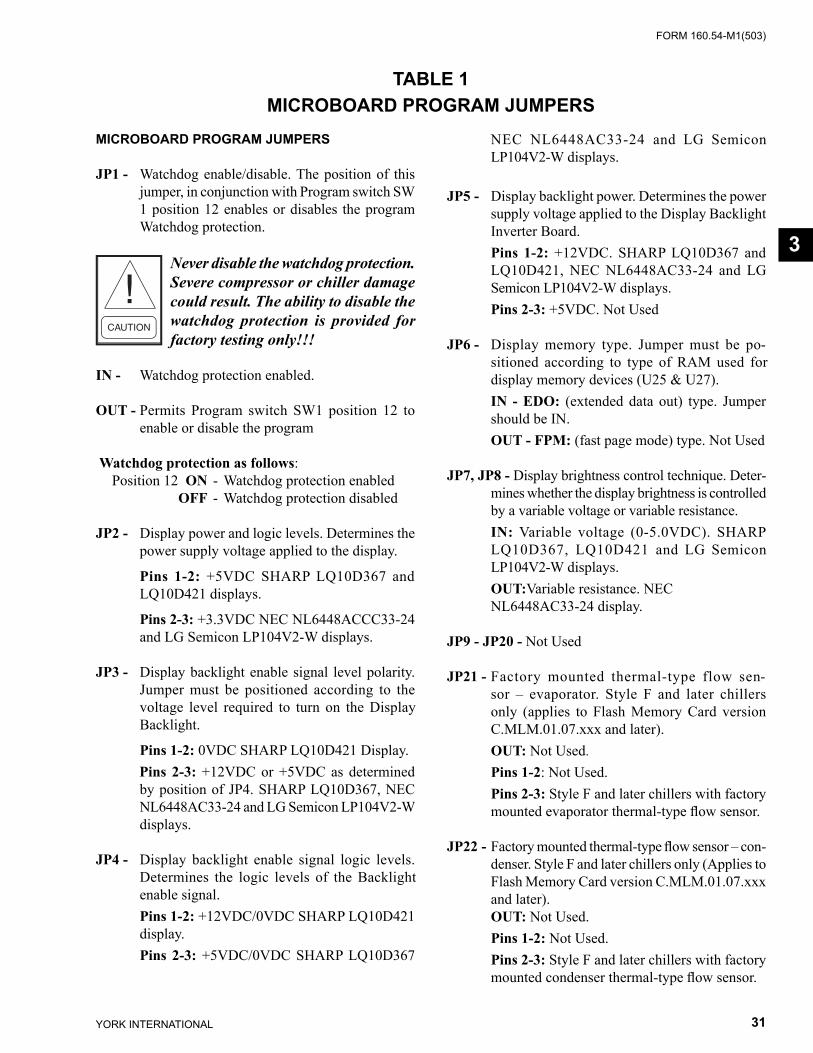
FORM 160.54-M1(503)
31YORK INTERNATIONAL
TABLE 1MICROBOARD PROGRAM JUMP ERS
MICROBOARD PROGRAM JUMPERS
JP1 - Watchdog en able/disable. The po si tion of this jump er, in con junc tion with Pro gram switch SW 1 po si tion 12 enables or dis ables the pro gram Watch dog pro tec tion.
Never disable the watchdog pro tec tion. Severe com pres sor or chiller dam age could re sult. The abil i ty to dis able the watch dog pro tec tion is pro vid ed for fac to ry test ing only!!!
IN - Watchdog protection enabled.
OUT - Permits Program switch SW1 position 12 to enable or disable the program
Watchdog protection as follows: Position 12 ON - Watchdog pro tec tion en abled OFF - Watchdog protection disabled
JP2 - Display power and logic levels. Determines the power supply voltage applied to the display.
Pins 1-2: +5VDC SHARP LQ10D367 and LQ10D421 displays.
Pins 2-3: +3.3VDC NEC NL6448ACCC33-24 and LG Semicon LP104V2-W displays.
JP3 - Display backlight enable signal level polarity. Jumper must be positioned according to the volt age lev el required to turn on the Display Back light.
Pins 1-2: 0VDC SHARP LQ10D421 Display. Pins 2-3: +12VDC or +5VDC as determined
by po si tion of JP4. SHARP LQ10D367, NEC NL6448AC33-24 and LG Semicon LP104V2-W dis plays.
JP4 - Display backlight enable signal logic levels. De ter mines the logic levels of the Backlight en able sig nal.
Pins 1-2: +12VDC/0VDC SHARP LQ10D421 dis play.
Pins 2-3: +5VDC/0VDC SHARP LQ10D367
NEC NL6448AC33-24 and LG Semicon LP104V2-W displays.
JP5 - Display backlight power. Determines the pow er supply voltage applied to the Display Backlight In vert er Board.
Pins 1-2: +12VDC. SHARP LQ10D367 and LQ10D421, NEC NL6448AC33-24 and LG Semicon LP104V2-W displays.
Pins 2-3: +5VDC. Not Used
JP6 - Display memory type. Jumper must be po- si tioned according to type of RAM used for dis play mem o ry devices (U25 & U27).
IN - EDO: (extended data out) type. Jumper should be IN.
OUT - FPM: (fast page mode) type. Not Used
JP7, JP8 - Display brightness control technique. De ter -mines whether the display brightness is con trolled by a variable voltage or variable re sis tance.
IN: Variable voltage (0-5.0VDC). SHARP LQ10D367, LQ10D421 and LG Semicon LP104V2-W displays.
OUT:Variable resistance. NEC NL6448AC33-24 dis play.
JP9 - JP20 - Not Used
JP21 - Factory mounted thermal-type flow sen-sor – evaporator. Style F and later chillers only (applies to Flash Memory Card version C.MLM.01.07.xxx and later).
OUT: Not Used. Pins 1-2: Not Used. Pins 2-3: Style F and later chillers with factory
mounted evaporator thermal-type fl ow sensor.
JP22 - Factory mounted thermal-type fl ow sensor – con-denser. Style F and later chillers only (Applies to Flash Memory Card version C.MLM.01.07.xxx and later).
OUT: Not Used. Pins 1-2: Not Used. Pins 2-3: Style F and later chillers with factory
mounted condenser thermal-type fl ow sensor.
3
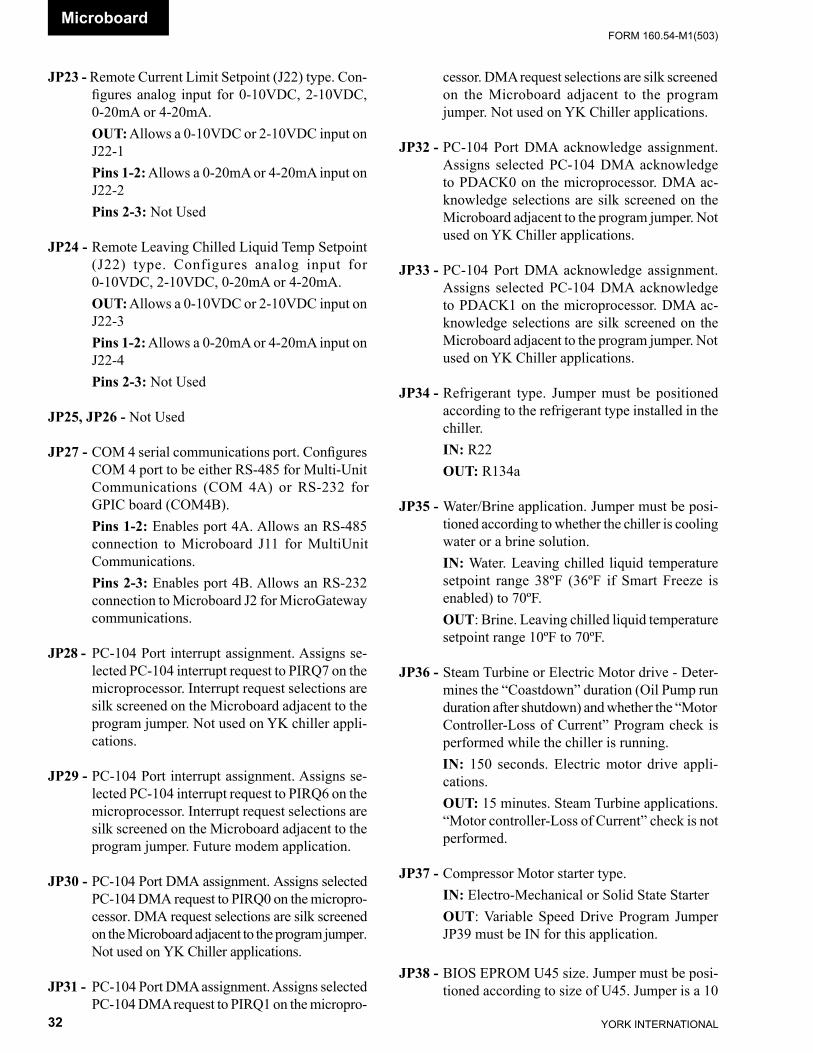
YORK INTERNATIONAL32
FORM 160.54-M1(503)Microboard
JP23 - Remote Current Limit Setpoint (J22) type. Con- fi g ures analog input for 0-10VDC, 2-10VDC, 0-20mA or 4-20mA.
OUT: Allows a 0-10VDC or 2-10VDC input on J22-1
Pins 1-2: Allows a 0-20mA or 4-20mA input on J22-2
Pins 2-3: Not Used
JP24 - Remote Leaving Chilled Liquid Temp Setpoint (J22) type. Configures analog input for 0-10VDC, 2-10VDC, 0-20mA or 4-20mA.
OUT: Allows a 0-10VDC or 2-10VDC input on J22-3
Pins 1-2: Allows a 0-20mA or 4-20mA input on J22-4
Pins 2-3: Not Used
JP25, JP26 - Not Used
JP27 - COM 4 serial communications port. Con fi g ures COM 4 port to be either RS-485 for Multi-Unit Com mu ni ca tions (COM 4A) or RS-232 for GPIC board (COM4B).
Pins 1-2: Enables port 4A. Allows an RS-485 con nec tion to Microboard J11 for Multi Unit Com mu ni ca tions.
Pins 2-3: Enables port 4B. Allows an RS-232 connection to Microboard J2 for MicroGateway com mu ni ca tions.
JP28 - PC-104 Port interrupt assignment. Assigns se- lect ed PC-104 interrupt request to PIRQ7 on the mi cro pro ces sor. Interrupt request se lec tions are silk screened on the Microboard adjacent to the pro gram jumper. Not used on YK chiller ap pli -ca tions.
JP29 - PC-104 Port interrupt assignment. Assigns se- lect ed PC-104 interrupt request to PIRQ6 on the mi cro pro ces sor. Interrupt request se lec tions are silk screened on the Microboard adjacent to the program jumper. Future modem ap pli ca tion.
JP30 - PC-104 Port DMA assignment. Assigns se lect ed PC-104 DMA request to PIRQ0 on the mi cro pro -ces sor. DMA request selections are silk screened on the Microboard adjacent to the pro gram jump er. Not used on YK Chiller ap pli ca tions.
JP31 - PC-104 Port DMA assignment. Assigns se lect ed PC-104 DMA request to PIRQ1 on the mi cro pro -
ces sor. DMA request selections are silk screened on the Microboard adjacent to the pro gram jump er. Not used on YK Chiller ap pli ca tions.
JP32 - PC-104 Port DMA acknowledge assignment. Assigns selected PC-104 DMA acknowledge to PDACK0 on the mi cro pro ces sor. DMA ac- knowl edge selections are silk screened on the Microboard adjacent to the pro gram jumper. Not used on YK Chiller ap pli ca tions.
JP33 - PC-104 Port DMA acknowledge assignment. Assigns selected PC-104 DMA acknowledge to PDACK1 on the microprocessor. DMA ac- knowl edge selections are silk screened on the Microboard ad ja cent to the program jumper. Not used on YK Chiller applications.
JP34 - Refrigerant type. Jumper must be positioned according to the refrigerant type installed in the chill er.
IN: R22 OUT: R134a
JP35 - Water/Brine application. Jumper must be po si -tioned according to whether the chiller is cool ing water or a brine solution.
IN: Water. Leaving chilled liquid temperature setpoint range 38ºF (36ºF if Smart Freeze is enabled) to 70ºF.
OUT: Brine. Leaving chilled liquid tem per a ture setpoint range 10ºF to 70ºF.
JP36 - Steam Turbine or Electric Motor drive - De ter -mines the “Coastdown” duration (Oil Pump run du ra tion after shutdown) and whether the “Mo tor Controller-Loss of Current” Program check is per formed while the chiller is running.
IN: 150 seconds. Electric motor drive ap pli -ca tions.
OUT: 15 minutes. Steam Turbine applications. “Mo tor controller-Loss of Current” check is not per formed.
JP37 - Compressor Motor starter type. IN: Electro-Mechanical or Solid State Starter OUT: Variable Speed Drive Program Jumper
JP39 must be IN for this application.
JP38 - BIOS EPROM U45 size. Jumper must be po si -tioned according to size of U45. Jumper is a 10
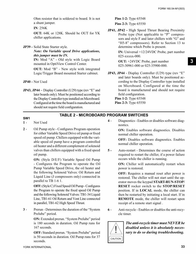
FORM 160.54-M1(503)
33YORK INTERNATIONAL
Ohm resistor that is soldered to board. It is not a shunt jump er.
IN: 256K OUT: 64K or 128K. Should be OUT for YK
chiller applications.
JP39 - Solid State Starter style. Note: On Variable speed Drive ap pli ca tions,
this jumper must be IN. IN: Mod “A” - Old style with Logic Board
mount ed in OptiView Con trol Center. OUT: Mod “B” - New style with integrated
Log ic/Trig ger Board mounted Starter cabinet.
JP40 - Not Used
JP43, JP44 – Display Controller (U29) type (rev “E” and later boards only). Must be positioned ac cord ing to the Display Con trol ler type in stalled on Microboard. Confi gured at the time the board is man u fac tured and should not require fi eld con fi g u ra tion.
SW11 - Not Used
2 - Oil Pump style - Confi gures Program op er a tion for either Variable Speed Drive oil pump or fi xed speed oil pump. Chillers equipped with the vari- able speed oil pump have a program controlled oil heater and a different complement of so le noid valves than chillers equipped with a fi xed speed oil pump.
ON: (Style D/E/F) Variable Speed Oil Pump - Con fi g ures the Program to operate the Oil Pump Vari able Speed Drive, the oil heater and the fol low ing So le noid Valves: Oil Return and Liq uid Line (J com pres sors only) connected in par al lel to TB 1-6 1.
OFF: (Style C) Fixed Speed Oil Pump - Con fi g ures the Program to operate the fi xed speed Oil Pump and the fol low ing Solenoid Valves: TB1-34 Liquid Line, TB1-61 Oil Return and Vent Line con nect ed in parallel, TB1-62 High Speed Thrust.
3 - Prerun - Determines the duration of the “Sys tem Prelube” period.
ON: Extended prerun. “System Prelube” pe ri od is 180 seconds in duration. Oil Pump runs for 167 seconds.
OFF: Standard prerun. “System Prelube” pe ri od is 50 seconds in duration. Oil Pump runs for 37 seconds.
4 - Diagnostics - Enables or disables software di ag -nos tics.
ON: Enables software diagnostics. Disables nor mal chiller operation.
OFF: Disables software diagnostics. Enables normal chiller operation.
5 - Auto-restart - Determines the course of action re quired to restart the chiller, if a power failure occurs while the chiller is running.
ON: Chiller will automatically restart when pow er is restored.
OFF: Requires a manual reset after power is restored. The chiller will not start until the op- er a tor moves the keypad START-RUN-STOP/RESET rock er switch to the STOP/RESET po si tion. If in LO CAL mode, the chiller can then be re start ed by initiating a local start. If in RE MOTE mode, the chiller will restart upon re ceipt of a remote start signal .
6 - Anti-recycle - Enables or disables the anti-recy-cle tim er.
The anti-recycle timer must NEVER be disabled unless it is ab so lute ly nec es -sary to do so during trou ble shoot ing.
Pins 1-2: Type 65548 Pins 2-3: Type 65550
JP41, JP42 - High Speed Thrust Bearing Proximity Probe type (Not applicable to “P” compres-sors and style F and later chillers with “G” and “H5-8” compressors). Refer to Sec tion 13 to de ter mine which Probe is present.
IN: Universal +12/24VDC Probe, part number 025-xxxxx-000.
OUT: +24VDC Probe, part number 025-30961-000 or 025-35900-000.
JP43, JP44 - Display Controller (U29) type (rev “E” and later boards only). Must be positioned ac- cord ing to the Display Con trol ler type in stalled on Microboard. Configured at the time the board is man u fac tured and should not require fi eld con fi g u ra tion.
Pins 1-2: Type 65548 Pins 2-3: Type 65550
TABLE 2 - MICROBOARD PROGRAM SWITCHES
3
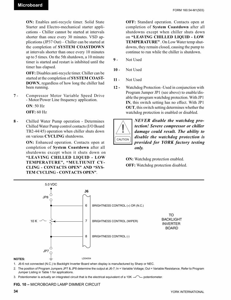
YORK INTERNATIONAL34
FORM 160.54-M1(503)Microboard
LD04054NOTES:1. J6-6 not connected (N.C.) to Backlight Inverter Board when dis play is manufactured by Sharp or NEC.2. The position of Program Jumpers JP7 & JP8 determine the out put at J6-7; In = Variable Voltage; Out = Variable Resistance. Refer to Program
Jumper Listing in Table 1 for applications.3. Potentiometer is actually an integrated circuit that is the electrical equivalent of a 10K potentiometer.
FIG. 10 – MICROBOARD LAMP DIMMER CIRCUIT
6
7
8
J6
BRIGHTNESS CONTROL (+) OR (N.C.)
BRIGHTNESS CONTROL (WIPER)
BRIGHTNESS CONTROL (-)
TO BACKLIGHTINVERTER
BOARD
JP8
JP7
5.0 VDC
10 K
OFF: Standard operation. Contacts open at com ple tion of System Coastdown after all shut downs ex cept when chiller shuts down on “LEAV ING CHILLED LIQUID - LOW TEM PER A TURE” . On Low Wa ter temp shut- downs, they re main closed, causing the pump to continue to run while the chiller is shut down.
9 - Not Used
10 - Not Used
11 - Not Used
12 - Watchdog Protection -Used in conjunction with Pro gram Jumper JP1 (see above) to enable/dis- able the pro gram watchdog protection. With JP1 IN, this switch setting has no effect. With JP1 OUT, this switch setting determines wheth er the watchdog protection is en abled or dis abled.
NEVER disable the watch dog pro- tec tion! Severe compressor or chill er dam age could result. The abil i ty to dis able the watch dog pro tec tion is pro vid ed for YORK fac to ry test ing only.
ON: Watchdog protection enabled. OFF: Watch dog protection disabled.
ON: Enables anti-recycle timer. Solid State Start er and Electro-mechanical start er ap pli -ca tions - Chill er can not be started at intervals short er than once every 30 minutes. VSD ap- pli ca tions (JP37 Out) – Chill er can be started at the completion of SYSTEM COASTDOWN at intervals short er than once every 10 minutes up to 5 times. On the 5th shutdown, a 10 minute timer is started and restart is inhibited un til the timer has elapsed.
OFF: Disables anti-recycle timer. Chiller can be start ed at the completion of SYSTEM COAST-DOWN, re gard less of how long the chill er had been running.
7 - Compressor Motor Variable Speed Drive - Mo tor/Pow er Line frequency application.
ON: 50 Hz OFF: 60 Hz
8 - Chilled Water Pump operation - Determines Chilled Water Pump control contacts (I/O Board TB2-44/45) op er a tion when chiller shuts down on various CY CLING shutdowns.
ON: Enhanced operation. Contacts open at com ple tion of System Coastdown after all shut downs ex cept when it shuts down on “LEAV ING CHILLED LIQUID - LOW TEM PER A TURE”, “MULTIUNIT CY- CLING - CON TACTS OPEN” AND “SYS- TEM CY CLING - CONTACTS OPEN”.
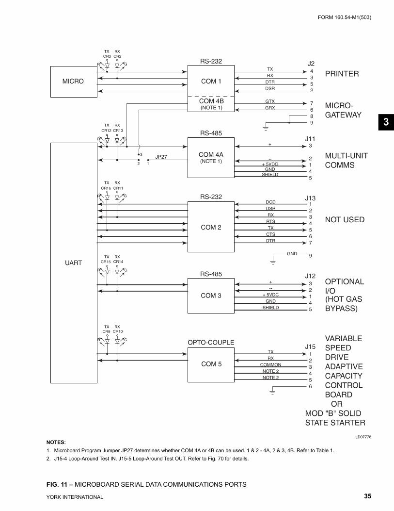
FORM 160.54-M1(503)
35YORK INTERNATIONAL
FIG. 11 – MICROBOARD SERIAL DATA COM MU NI CA TIONS PORTS
LD07778NOTES:1. Microboard Program Jumper JP27 determines whether COM 4A or 4B can be used. 1 & 2 - 4A, 2 & 3, 4B. Refer to Table 1.2. J15-4 Loop-Around Test IN. J15-5 Loop-Around Test OUT. Re fer to Fig. 70 for details.
3
MICRO
UART
COM 1
COM 4B(NOTE 1)
COM 4A(NOTE 1)
COM 2
COM 3
COM 5
OPTO-COUPLE
RS-485
RS-232
RS-485
RS-232
MICRO-GATEWAY
PRINTER
MULTI-UNITCOMMS
NOT USED
OPTIONALI/O
VARIABLE SPEEDDRIVE ADAPTIVECAPACITY CONTROLBOARD
4352
7689
3
2145
1234567
9
3 2 1 4 5
1 2 3 4 5 6
J2
J11
J13
J12
J15TXRX
COMMONNOTE 2NOTE 2
+--
+ 5VDCGND
SHIELD
DCDDSRRX
RTSTX
CTSDTR
GND
--+ 5VDC
GNDSHIELD
+
TXRX
DTRDSR
GTXGRX
12
3
CR3 CR2
JP27
(HOT GASBYPASS)
ORMOD "B" SOLIDSTATE STARTER
R G
CR12 CR13
R G
CR16 CR11
R G
CR15 CR14
R G
CR9 CR10
R G
TX RX
TX RX
TX RX
TX RX
TX RX
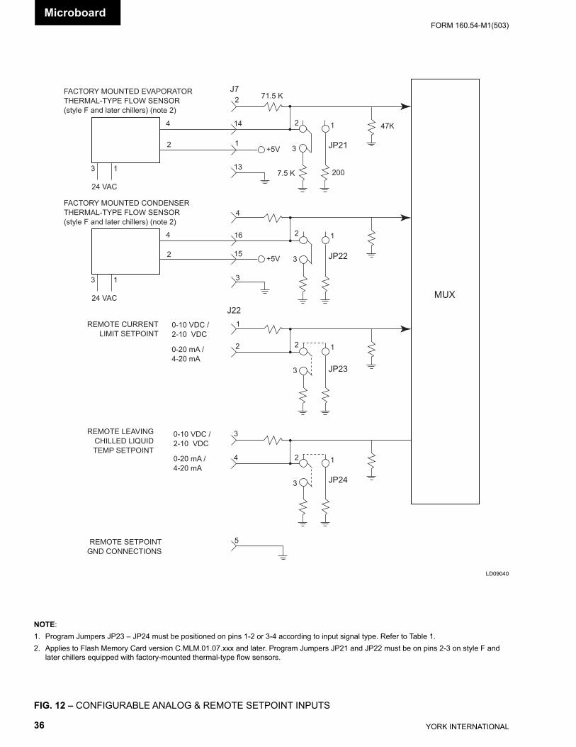
YORK INTERNATIONAL36
FORM 160.54-M1(503)
FIG. 12 – CONFIGURABLE ANALOG & REMOTE SETPOINT INPUTS
LD09040
NOTE:1. Program Jumpers JP23 – JP24 must be positioned on pins 1-2 or 3-4 according to input signal type. Refer to Table 1.2. Applies to Flash Memory Card version C.MLM.01.07.xxx and later. Program Jumpers JP21 and JP22 must be on pins 2-3 on style F and
later chillers equipped with factory-mounted thermal-type fl ow sensors.
FACTORY MOUNTED EVAPORATORTHERMAL-TYPE FLOW SENSOR (style F and later chillers) (note 2)
REMOTE CURRENTLIMIT SETPOINT
REMOTE LEAVINGCHILLED LIQUIDTEMP SETPOINT
REMOTE SETPOINTGND CONNECTIONS
24 VAC
0-10 VDC /2-10 VDC
0-20 mA /4-20 mA
5
4
3
1
2
16
4
144
2
2
13
1
13
MUX
47K
JP21
JP22
JP23
JP24
2007.5 K
12
3
12
3
12
3
12
3
71.5 K
+5V
3
15 +5V
J7
J22
0-10 VDC /2-10 VDC
0-20 mA /4-20 mA
FACTORY MOUNTED CONDENSERTHERMAL-TYPE FLOW SENSOR (style F and later chillers) (note 2)
24 VAC
4
2
13
Microboard
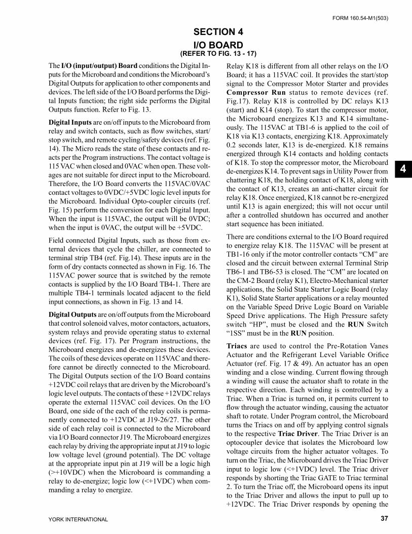
FORM 160.54-M1(503)
37YORK INTERNATIONAL
SECTION 4I/O BOARD
(REFER TO FIG. 13 - 17)
The I/O (input/output) Board conditions the Digital In- puts for the Microboard and conditions the Microboard’s Digital Outputs for application to other com po nents and devices. The left side of the I/O Board per forms the Digi-tal Inputs function; the right side per forms the Digital Outputs function. Refer to Fig. 13.
Dig i tal Inputs are on/off inputs to the Microboard from relay and switch con tacts, such as fl ow switch es, start/stop switch, and remote cycling/safe ty devices (ref. Fig. 14). The Micro reads the state of these contacts and re- acts per the Program in struc tions. The contact volt age is 115 VAC when closed and 0VAC when open. These volt-ages are not suitable for direct input to the Microboard. There fore, the I/O Board converts the 115VAC/0VAC contact voltages to 0VDC/+5VDC log ic lev el inputs for the Microboard. Individual Opto-cou pler cir cuits (ref. Fig. 15) perform the conversion for each Dig i tal In put. When the input is 115VAC, the out put will be 0VDC; when the input is 0VAC, the output will be +5VDC.
Field connected Digital Inputs, such as those from ex- ter nal devices that cycle the chiller, are connected to ter mi nal strip TB4 (ref. Fig.14). These inputs are in the form of dry contacts connected as shown in Fig. 16. The 115VAC power source that is switched by the re mote contacts is supplied by the I/O Board TB4-1. There are multiple TB4-1 terminals located adjacent to the fi eld in put connections, as shown in Fig. 13 and 14.
Digital Outputs are on/off outputs from the Microboard that control solenoid valves, motor contactors, ac tu a tors, system relays and provide operating status to ex ter nal devices (ref. Fig. 17). Per Program in struc tions, the Microboard energizes and de-energizes these de vic es. The coils of these devices operate on 115VAC and there- fore cannot be directly connected to the Microboard. The Digital Outputs section of the I/O Board contains +12VDC coil relays that are driven by the Microboard’s logic level outputs. The contacts of these +12VDC relays operate the external 115VAC coil de vic es. On the I/O Board, one side of the each of the relay coils is perma-nently connected to +12VDC at J19-26/27. The other side of each relay coil is connected to the Microboard via I/O Board con nec tor J19. The Microboard energizes each relay by driving the ap pro pri ate input at J19 to logic low volt age level (ground potential). The DC voltage at the ap pro pri ate input pin at J19 will be a logic high (>+10VDC) when the Microboard is com mand ing a relay to de-en er gize; logic low (<+1VDC) when com-manding a relay to energize.
Relay K18 is different from all other relays on the I/O Board; it has a 115VAC coil. It provides the start/stop signal to the Compressor Motor Starter and provides Compressor Run status to remote devices (ref. Fig.17). Re lay K18 is controlled by DC relays K13 (start) and K14 (stop). To start the compressor motor, the Microboard en er giz es K13 and K14 simultane-ously. The 115VAC at TB1-6 is applied to the coil of K18 via K13 con tacts, en er giz ing K18. Ap prox i mate ly 0.2 seconds later, K13 is de-en er gized. K18 remains energized through K14 con tacts and holding contacts of K18. To stop the com pres sor motor, the Microboard de-en er giz es K14. To prevent sags in Utility Power from chat ter ing K18, the holding contact of K18, along with the contact of K13, creates an anti-chatter circuit for relay K18. Once en er gized, K18 can not be re-energized un til K13 is again energized; this will not occur until after a controlled shut down has oc curred and another start se quence has been initiated.
There are conditions external to the I/O Board required to energize relay K18. The 115VAC will be present at TB1-16 only if the motor controller contacts “CM” are closed and the circuit between external Terminal Strip TB6-1 and TB6-53 is closed. The “CM” are located on the CM-2 Board (relay K1), Electro-Mechanical start er applications, the Solid State Starter Logic Board (relay K1), Solid State Starter applications or a relay mount ed on the Variable Speed Drive Logic Board on Variable Speed Drive applications. The High Pressure safety switch “HP”, must be closed and the RUN Switch “1SS” must be in the RUN position.
Triacs are used to control the Pre-Rotation Vanes Ac tu a tor and the Refrigerant Level Variable Orifi ce Ac tu a tor (ref. Fig. 17 & 49). An actuator has an open wind ing and a close winding. Current fl owing through a wind ing will cause the actuator shaft to rotate in the re spec tive di rec tion. Each winding is controlled by a Triac. When a Triac is turned on, it permits current to fl ow through the actuator winding, causing the ac tu a tor shaft to ro tate. Under Program control, the Microboard turns the Triacs on and off by applying control signals to the re spec tive Triac Driver. The Triac Driv er is an optocoupler device that isolates the Microboard low voltage cir cuits from the higher actuator voltages. To turn on the Triac, the Microboard drives the Triac Driv er input to logic low (<+1VDC) level. The Triac driv er re sponds by shorting the Triac GATE to Triac terminal 2. To turn the Triac off, the Microboard opens its input to the Triac Driver and allows the input to pull up to +12VDC. The Triac Driver responds by opening the
4
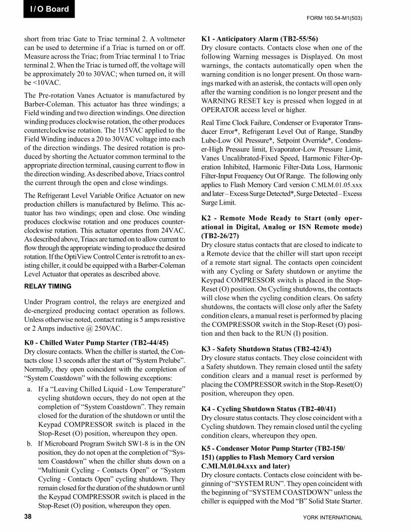
YORK INTERNATIONAL38
FORM 160.54-M1(503)I / O Board
short from triac Gate to Triac terminal 2. A volt me ter can be used to determine if a Triac is turned on or off. Measure across the Triac; from Triac terminal 1 to Triac terminal 2. When the Triac is turned off, the volt age will be ap prox i mate ly 20 to 30VAC; when turned on, it will be <10VAC.
The Pre-rotation Vanes Actuator is manufactured by Barber-Coleman. This actuator has three windings; a Field winding and two direction windings. One di rec tion wind ing produces clockwise rotation, the other pro duc es coun ter clock wise rotation. The 115VAC applied to the Field Winding induces a 20 to 30VAC voltage into each of the direction windings. The desired ro ta tion is pro- duced by shorting the Actuator common ter mi nal to the ap pro pri ate direction terminal, causing current to fl ow in the di rec tion winding. As described above, Triacs con trol the current through the open and close wind ings.
The Refrigerant Level Variable Orifi ce Actuator on new production chillers is manufactured by Belimo. This ac- tu a tor has two windings; open and close. One wind ing pro duc es clockwise rotation and one produces coun ter -clock wise rotation. This actuator operates from 24VAC. As described above, Triacs are turned on to al low cur rent to fl ow through the appropriate winding to produce the de sired rotation. If the OptiView Control Center is retrofi t to an ex-isting chiller, it could be equipped with a Barber-Coleman Level Actuator that operates as de scribed above.RELAY TIMING
Under Program control, the relays are energized and de-energized producing contact operation as follows. Unless otherwise noted, contact rating is 5 amps re sis tive or 2 Amps inductive @ 250VAC.
K0 - Chilled Water Pump Starter (TB2-44/45)Dry closure contacts. When the chiller is started, the Con- tacts close 13 seconds after the start of “System Prelube”. Normally, they open coincident with the com ple tion of “Sys tem Coastdown” with the fol low ing ex cep tions: a. If a “Leaving Chilled Liquid - Low Tem per a ture”
cy cling shutdown occurs, they do not open at the com ple tion of “System Coastdown”. They remain closed for the duration of the shutdown or until the Keypad COMPRESSOR switch is placed in the Stop-Reset (O) position, whereupon they open.
b. If Microboard Program Switch SW1-8 is in the ON position, they do not open at the completion of “Sys- tem Coastdown” when the chiller shuts down on a “Multiunit Cycling - Contacts Open” or “Sys tem Cy cling - Contacts Open” cycling shut down. They re main closed for the duration of the shut down or until the Keypad COMPRESSOR switch is placed in the Stop-Reset (O) position, where up on they open.
K1 - Anticipatory Alarm (TB2-55/56) Dry closure con tacts. Contacts close when one of the fol low ing Warn ing messages is Displayed. On most warn ings, the con tacts automatically open when the warning con di tion is no longer present. On those warn- ings marked with an as ter isk, the contacts will open only after the warn ing condition is no longer present and the WARN ING RESET key is pressed when logged in at OP ER A TOR ac cess level or higher.
Real Time Clock Failure, Condenser or Evaporator Trans- duc er Error*, Refrigerant Level Out of Range, Standby Lube-Low Oil Pressure*, Setpoint Over ride*, Condens-er-High Pressure limit, Evaporator-Low Pres sure Limit, Vanes Uncalibrated-Fixed Speed, Har mon ic Filter-Op-eration In hib it ed, Harmonic Filter-Data Loss, Har mon ic Filter-Input Fre quen cy Out Of Range. The following only applies to Flash Memory Card version C.MLM.01.05.xxx and lat er – Ex cess Surge Detected*, Surge Detected – Ex cess Surge Limit.
K2 - Remote Mode Ready to Start (only oper-ational in Digital, Analog or ISN Remote mode) (TB2-26/27)Dry closure status contacts that are closed to indicate to a Remote device that the chiller will start upon re ceipt of a remote start signal. The contacts open co in ci dent with any Cycling or Safety shutdown or anytime the Keypad COM PRES SOR switch is placed in the Stop -Reset (O) po si tion. On Cycling shutdowns, the con tacts will close when the cycling condition clears. On safety shutdowns, the con tacts will close only after the Safety condition clears, a manual reset is per formed by plac ing the COM PRES SOR switch in the Stop-Reset (O) posi-tion and then back to the RUN (I) position.
K3 - Safety Shutdown Status (TB2-42/43) Dry clo sure status contacts. They close coincident with a Safe ty shutdown. They remain closed until the safety con di tion clears and a manual reset is performed by placing the COMPRESSOR switch in the Stop-Reset(O) po si tion, whereupon they open.
K4 - Cycling Shutdown Status (TB2-40/41) Dry clo sure status contacts. They close coincident with a Cy cling shutdown. They remain closed until the cy cling condition clears, whereupon they open.
K5 - Condenser Motor Pump Starter (TB2-150/151) (applies to Flash Memory Card version C.MLM.01.04.xxx and lat er)Dry closure contacts. Contacts close coincident with be- gin ning of “SYSTEM RUN”. They open coincident with the beginning of “SYSTEM COASTDOWN” un less the chiller is equipped with the Mod “B” Solid State Starter.
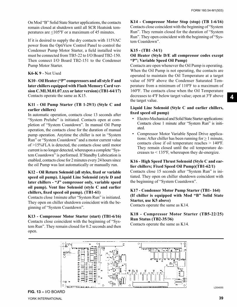
FORM 160.54-M1(503)
39YORK INTERNATIONAL
On Mod “B” Solid State Starter applications, the con tacts remain closed at shutdown until all SCR Heatsink tem-peratures are <105ºF or a maximum of 45 minutes.
If it is desired to supply the dry contacts with 115VAC pow er from the OptiView Control Panel to control the Con dens er Pump Motor Starter, a fi eld installed wire must be con nect ed from TB5-22 to I/O Board TB2-150. Then connect I/O Board TB2-151 to the Con dens er Pump Motor Starter.
K6-K 9 - Not Used
K10 - Oil Heater (“P” compressors and all style F and later chillers equipped with Flash Memory Card ver-sion C.MLM.01.07.xxx or later version) (TB1-64/17) Contacts operate the same as K15.
K11 - Oil Pump Starter (TB 1-29/1) (Style C and earlier chillers)In automatic op er a tion, contacts close 13 seconds after “System Prelube” is initiated. Contacts open at com- ple tion of “System Coastdown”. In manual Oil Pump op er a tion, the con tacts close for the duration of manual pump op er a tion. Anytime the chiller is not in “System Run” or “Sys tem Coastdown” and a motor current val ue of >15%FLA is detected, the contacts close until mo tor cur rent is no longer detected, whereupon a com plete “Sys- tem Coastdown” is performed. If Standby Lu bri ca tion is en abled, contacts close for 2 minutes ev ery 24 hours since the oil Pump was last au to mat i cal ly or man u al ly run.
K12 - Oil Return Solenoid (all styles, fi xed or vari able speed oil pump). Liquid Line Solenoid (style D and later chillers - “J” com pres sor only, vari able speed oil pump). Vent line Solenoid (style C and earlier chillers, fi xed speed oil pump). (TB1-61)Contacts close 1minute after “System Run” is ini ti at ed. They open on chill er shutdown coincident with the be- gin ning of “System Coastdown”.
K13 - Compressor Motor Starter (start) (TB1-6/16) Contacts close coincident with the beginning of “Sys- tem Run”. They remain closed for 0.2 seconds and then open.
K14 - Compressor Motor Stop (stop) (TB 1-6/16) Con tacts close coincident with the beginning of “Sys tem Run”. They remain closed for the duration of “Sys tem Run”. They open coincident with the beginning of “Sys- tem Coastdown”.
K15 - (TB1 -34/1)Oil Heater (Style D/E all compressor codes ex cept “P”; Vari able Speed Oil Pump) Contacts are open whenever the Oil Pump is op er at ing. When the Oil Pump is not op er at ing, the contacts are op er at ed to maintain the Oil Tem per a ture at a tar get val ue of 50ºF above the Condenser Saturated Tem- per a ture from a minimum of 110ºF to a maximum of 160ºF. The con tacts close when the Oil Temperature de creas es to 4ºF below target value; open at 3ºF above the target val ue.
Liquid Line Solenoid (Style C and earlier chillers, fi xed speed oil pump) • Electro-Mechanical and Solid State Starter ap pli ca tions:
Contacts close 1 minute after “System Run” is initi-ated.
• Compressor Motor Variable Speed Drive ap pli ca -tions: After chiller has been running for > 1 minute, contacts close if oil temperature reach es > 140ºF. They remain closed until the oil temperature de- creas es to < 135ºF, whereupon they de-en er gize.
K16 - High Speed Thrust Solenoid (Style C and ear-lier chillers; Fixed Speed Oil Pump)(TB1-62/1) Contacts close 15 sec onds after “System Run” is ini- ti at ed. They open on chiller shut down coincident with the beginning of “Sys tem Coastdown”.
K17 - Condenser Motor Pump Starter (TB1- 164)(If chiller is equipped with Mod “B” Solid State Starter, use K5 above)Contacts operate the same as K14.
K18 - Compressor Motor Starter (TB5-22/25) Run Status (TB2-35/36)Contacts operate the same as K14.
LD04055
FIG. 13 – I/O BOARD
4
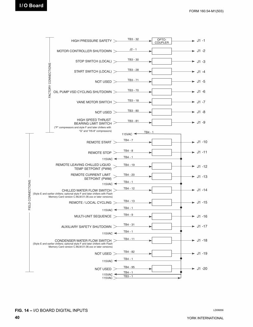
YORK INTERNATIONAL40
FORM 160.54-M1(503)I / O Board
FIG. 14 – I/O BOARD DIGITAL INPUTS
J1
J1
J1
J1
J1
J1
J1
J1
J1
-1
-2
-3
-4
-5
-6
-7
-8
-9
OPTO-COUPLERHIGH PRESSURE SAFETY
MOTOR CONTROLLER SHUTDOWN
STOP SWITCH (LOCAL)
START SWITCH (LOCAL)
NOT USED
OIL PUMP VSD CYCLING SHUTDOWN
VANE MOTOR SWITCH
NOT USED
HIGH SPEED THRUST BEARING LIMIT SWITCH
("P" compressors and style F and later chillers with "G" and "H5-8" compressors)
FAC
TOR
Y C
ON
NE
CT
ION
S
TB3 - 32
J2 - 1
TB3 - 30
TB3 - 28
TB3 - 71
TB3 - 70
TB3 - 18
TB3 - 80
TB3 - 81
J1
J1
J1
J1
J1
-10
-11
-12
-13
-14
FIE
LD C
ON
NE
CT
ION
S
115VAC
115VAC
115VAC
TB4 - 7
TB4 - 1
TB4 - 8
TB4 - 1
TB4 - 19
TB4 - 20
TB4 - 1
TB4 - 12
REMOTE START
REMOTE STOP
CHILLED WATER FLOW SWITCH
REMOTE CURRENT LIMIT SETPOINT (PWM)
REMOTE LEAVING CHILLED LIQUID TEMP SETPOINT (PWM)
(Style E and earlier chillers; optional style F and later chillers with FlashMemory Card version C.MLM.01.08.xxx or later versions)
J1
J1
J1
J1
-15
-16
-17
-18
J1 -19
J1 -20
115VAC
115VAC
115VAC
115VAC115VAC
TB4 - 13
TB4 - 1
TB4 - 9
TB4 - 31
TB4 - 1
TB4 - 11
TB4 - 82
TB4 - 1
TB4 - 95
TB4 - 1TB3 - 1
REMOTE / LOCAL CYCLING
MULTI-UNIT SEQUENCE
AUXILIARY SAFETY SHUTDOWN
CONDENSER WATER FLOW SWITCH
NOT USED
NOT USED
(Style E and earlier chillers; optional style F and later chillers with FlashMemory Card version C.MLM.01.08.xxx or later versions)
LD06856
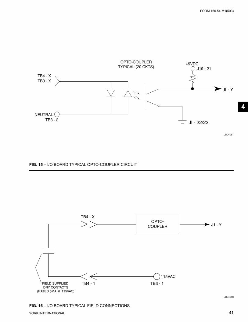
FORM 160.54-M1(503)
41YORK INTERNATIONAL
FIG. 15 – I/O BOARD TYPICAL OPTO-COUPLER CIRCUIT
FIG. 16 – I/O BOARD TYPICAL FIELD CONNECTIONS
OPTO-COUPLERTYPICAL (20 CKTS)
+5VDC J19 - 21
JI - Y
JI - 22/23
NEUTRAL TB3 - 2
TB4 - XTB3 - X
LD04057
115VAC
TB3 - 1TB4 - 1
TB4 - XOPTO-
COUPLER J1 - Y
FIELD SUPPLIED DRY CONTACTS
(RATED 5MA @ 115VAC)
LD04058
4
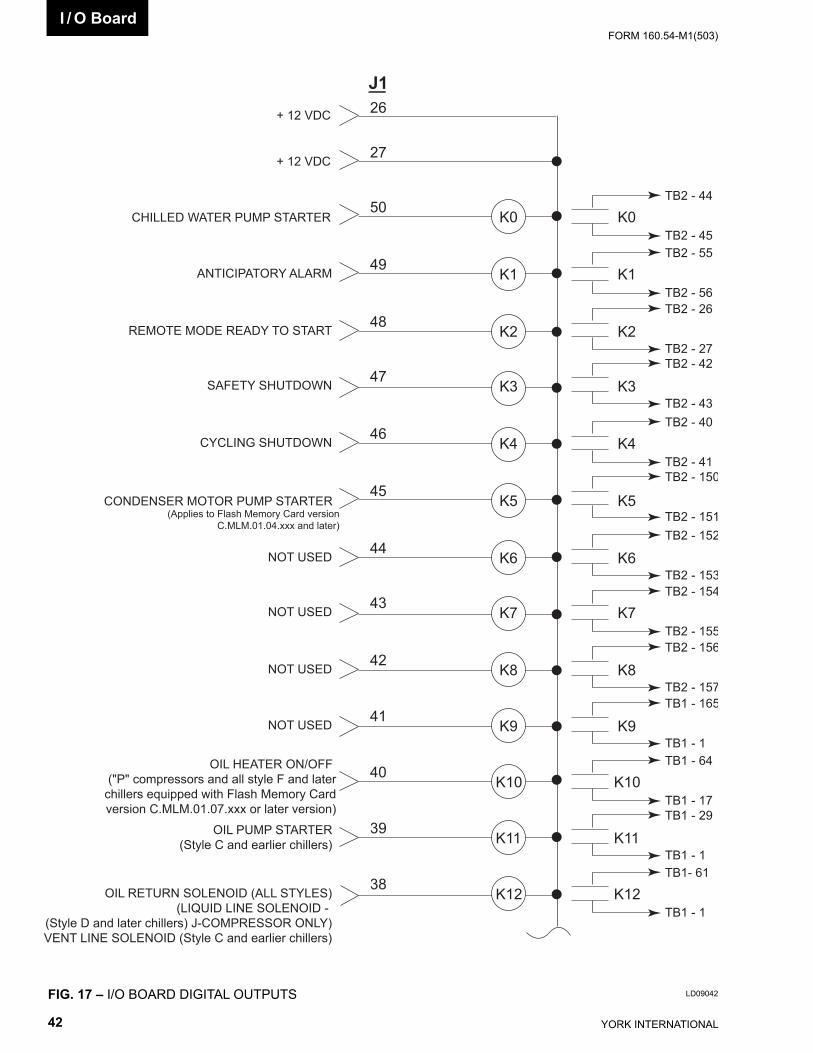
YORK INTERNATIONAL42
FORM 160.54-M1(503)I / O Board
FIG. 17 – I/O BOARD DIGITAL OUTPUTS LD09042
CHILLED WATER PUMP STARTER
+ 12 VDC
+ 12 VDC
K0
K1
K2
K3
K4
K5
K6
K7
K8
K9
K10
K11
K12
50
26
27
49
48
47
46
45
44
43
42
41
40
39
38
ANTICIPATORY ALARM
REMOTE MODE READY TO START
SAFETY SHUTDOWN
CYCLING SHUTDOWN
CONDENSER MOTOR PUMP STARTER (Applies to Flash Memory Card version
C.MLM.01.04.xxx and later)
NOT USED
NOT USED
NOT USED
NOT USED
OIL HEATER ON/OFF ("P" compressors and all style F and later
chillers equipped with Flash Memory Card version C.MLM.01.07.xxx or later version)
OIL PUMP STARTER(Style C and earlier chillers)
OIL RETURN SOLENOID (ALL STYLES)(LIQUID LINE SOLENOID -
(Style D and later chillers) J-COMPRESSOR ONLY)VENT LINE SOLENOID (Style C and earlier chillers)
K0
K1
K2
K3
K4
K5
K6
K7
K8
K9
K10
K11
K12
TB2 - 44
TB2 - 45
TB1- 61
TB1 - 1
TB1 - 29
TB1 - 1
TB1 - 64
TB1 - 17
TB1 - 165
TB1 - 1
TB2 - 156
TB2 - 157
TB2 - 154
TB2 - 155
TB2 - 152
TB2 - 153
TB2 - 150
TB2 - 151
TB2 - 40
TB2 - 41
TB2 - 42
TB2 - 43
TB2 - 26
TB2 - 27
TB2 - 55
TB2 - 56
J1
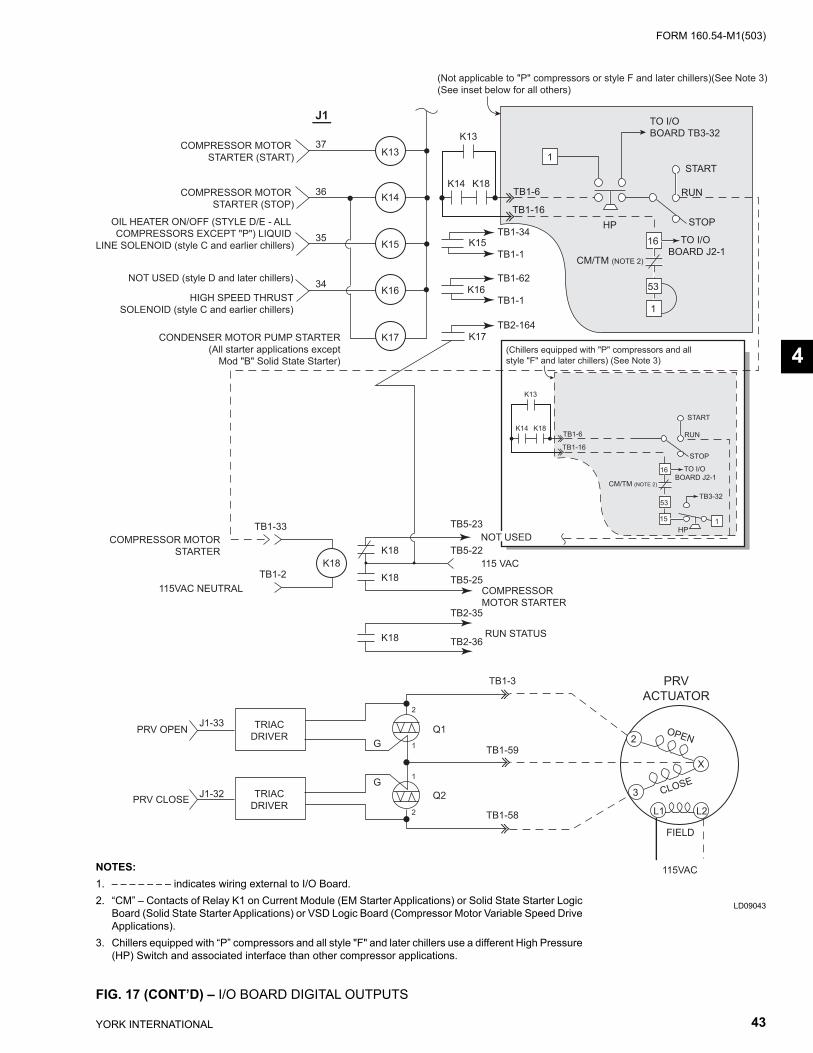
FORM 160.54-M1(503)
43YORK INTERNATIONAL
K13
K14
K15
K16
K17
K18
COMPRESSOR MOTOR STARTER (START)
NOT USED (style D and later chillers)
HIGH SPEED THRUSTSOLENOID (style C and earlier chillers)
OIL HEATER ON/OFF (STYLE D/E - ALL COMPRESSORS EXCEPT "P") LIQUID
LINE SOLENOID (style C and earlier chillers)
COMPRESSOR MOTOR STARTER (STOP)
CONDENSER MOTOR PUMP STARTER (All starter applications except
Mod "B" Solid State Starter)
37
36
35
34
J1
K15
K17
K16
TB1-34
TB2-164
TB1-1
TB1-62
TB1-1
TB1-33
TB1-2
TB5-23
TB2-36
TB2-35
TB5-22
TB5-25K18
K18
K18
RUN STATUS
PRVACTUATOR
FIELD
115VAC
OPEN
CLOSE
X
L1 L2
TB1-3
TB1-58
TB1-59
1
2
2
1G
G
TRIACDRIVER
TRIACDRIVER
J1-33
J1-32
PRV OPEN
PRV CLOSE3
2
COMPRESSOR MOTORSTARTER
115VAC NEUTRAL
Q2
Q1
K13
K18K14TB1-6
TB1-16
16
1
53
CM/TM (NOTE 2)
TO I/O BOARD J2-1
TO I/O BOARD TB3-32
START
RUN
STOP
1
HP
(Not applicable to "P" compressors or style F and later chillers)(See Note 3)(See inset below for all others)
K13
K18K14TB1-6
TB1-16
16
15 1
53
CM/TM (NOTE 2)
TO I/O BOARD J2-1
START
RUN
STOP
(Chillers equipped with "P" compressors and all style "F" and later chillers) (See Note 3)
NOT USED
COMPRESSOR MOTOR STARTER
115 VAC
HP
TB3-32
FIG. 17 (CONT’D) – I/O BOARD DIGITAL OUTPUTS
LD09043
4
NOTES:1. – – – – – – – indicates wiring external to I/O Board.2. “CM” – Contacts of Relay K1 on Current Module (EM Starter Applications) or Solid State Starter Logic
Board (Solid State Starter Applications) or VSD Logic Board (Compressor Motor Variable Speed Drive Applications).
3. Chillers equipped with “P” compressors and all style "F" and later chillers use a different High Pressure (HP) Switch and associated interface than other compressor applications.
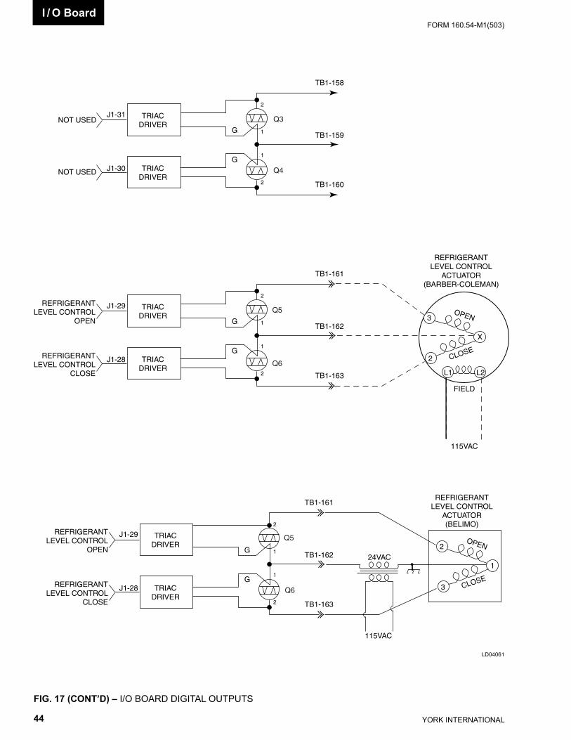
YORK INTERNATIONAL44
FORM 160.54-M1(503)
FIG. 17 (CONT’D) – I/O BOARD DIGITAL OUTPUTS
REFRIGERANTLEVEL CONTROL
ACTUATOR(BARBER-COLEMAN)
FIELD
115VAC
OPEN
CLOSE
X
L1 L2
TB1-161
TB1-163
TB1-162
1
2
2
1G
G
TRIACDRIVER
TRIACDRIVER
J1-29
J1-28
REFRIGERANTLEVEL CONTROL
OPEN
REFRIGERANTLEVEL CONTROL
CLOSE
3
2
TB1-158
TB1-160
TB1-159
1
2
2
1G
G
TRIACDRIVER
TRIACDRIVER
J1-31
J1-30
NOT USED
NOT USED
REFRIGERANTLEVEL CONTROL
ACTUATOR(BELIMO)
OPEN
CLOSE
1
TB1-161
TB1-163
TB1-162
1
2
2
1G
G
TRIACDRIVER
TRIACDRIVER
J1-29
J1-28
REFRIGERANTLEVEL CONTROL
OPEN
REFRIGERANTLEVEL CONTROL
CLOSE
2
3
115VAC
24VAC
Q3
Q6
Q5
Q4
Q6
Q5
LD04061
I / O Board
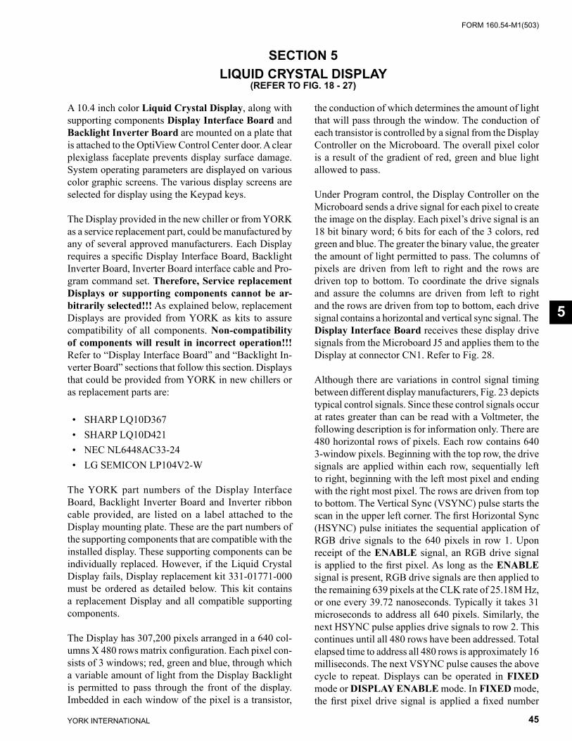
FORM 160.54-M1(503)
45YORK INTERNATIONAL
SECTION 5LIQUID CRYSTAL DISPLAY
(REFER TO FIG. 18 - 27)
A 10.4 inch color Liquid Crystal Display, along with supporting components Display Interface Board and Backlight Inverter Board are mounted on a plate that is at tached to the OptiView Control Center door. A clear plexiglass face plate prevents display surface damage. System op er at ing parameters are displayed on various color graph ic screens. The various display screens are se lect ed for display using the Keypad keys.
The Display provided in the new chiller or from YORK as a service replacement part, could be manufactured by any of several approved manufacturers. Each Dis play requires a specifi c Display Interface Board, Back light Inverter Board, Inverter Board interface cable and Pro- gram command set. There fore, Service re place ment Displays or sup port ing com po nents cannot be ar- bi trari ly selected!!! As explained below, re place ment Displays are provided from YORK as kits to as sure com pat i bil i ty of all com po nents. Non-com pat i bil i ty of com po nents will result in incorrect op er a tion!!! Refer to “Display In ter face Board” and “Back light In- vert er Board” sections that follow this section. Dis plays that could be provided from YORK in new chillers or as re place ment parts are:
• SHARP LQ10D367 • SHARP LQ10D421 • NEC NL6448AC33-24 • LG SEMICON LP104V2-W
The YORK part numbers of the Display Interface Board, Backlight Inverter Board and Inverter ribbon cable pro vid ed, are listed on a label attached to the Display mount ing plate. These are the part numbers of the sup port ing components that are compatible with the in stalled dis play. These supporting components can be individually replaced. However, if the Liquid Crystal Display fails, Display replacement kit 331-01771-000 must be or dered as detailed below. This kit contains a replacement Dis play and all compatible supporting com po nents.
The Display has 307,200 pixels arranged in a 640 col- umns X 480 rows matrix confi guration. Each pixel con- sists of 3 windows; red, green and blue, through which a variable amount of light from the Display Backlight is permitted to pass through the front of the display. Im bed ded in each window of the pixel is a transistor,
the conduction of which determines the amount of light that will pass through the window. The conduction of each transistor is controlled by a signal from the Dis play Con trol ler on the Microboard. The overall pixel color is a result of the gradient of red, green and blue light al lowed to pass.
Under Program control, the Display Controller on the Microboard sends a drive signal for each pixel to cre ate the image on the display. Each pixel’s drive signal is an 18 bit binary word; 6 bits for each of the 3 colors, red green and blue. The greater the binary value, the great er the amount of light permitted to pass. The col umns of pixels are driven from left to right and the rows are driven top to bottom. To coordinate the drive sig nals and assure the columns are driven from left to right and the rows are driven from top to bottom, each drive sig nal contains a horizontal and vertical sync signal. The Display Interface Board receives these dis play drive sig nals from the Microboard J5 and applies them to the Dis play at connector CN1. Refer to Fig. 28.
Although there are variations in control signal timing between different display manufacturers, Fig. 23 de picts typical control signals. Since these control sig nals occur at rates greater than can be read with a Volt me ter, the following description is for information only. There are 480 horizontal rows of pixels. Each row con tains 640 3-window pixels. Beginning with the top row, the drive signals are applied within each row, se quen tial ly left to right, beginning with the left most pixel and end ing with the right most pixel. The rows are driv en from top to bottom. The Vertical Sync (VSYNC) pulse starts the scan in the upper left corner. The fi rst Horizontal Sync (HSYNC) pulse initiates the se quen tial ap pli ca tion of RGB drive signals to the 640 pixels in row 1. Upon receipt of the ENABLE signal, an RGB drive signal is applied to the fi rst pixel. As long as the EN ABLE signal is present, RGB drive signals are then applied to the remaining 639 pixels at the CLK rate of 25.18M Hz, or one every 39.72 nanoseconds. Typically it takes 31 microseconds to address all 640 pixels. Sim i lar ly, the next HSYNC pulse applies drive signals to row 2. This continues until all 480 rows have been ad dressed. Total elapsed time to address all 480 rows is ap prox i mate ly 16 milliseconds. The next VSYNC pulse causes the above cycle to repeat. Displays can be op er at ed in FIXED mode or DISPLAY ENABLE mode. In FIXED mode, the fi rst pixel drive signal is applied a fi xed number
5
YORK INTERNATIONAL46
FORM 160.54-M1(503)Liquid Crystal Display
(48) of clock (CLK) cycles from the end of the HSYNC pulse and the drive signals are ter mi nat ed a fi xed num-ber (16) of CLK cycles prior to the next HSYNC pulse. In DISPLAY ENABLE mode, the pix el drive signals are applied to the pixels only while ENABLE signal is present. This signal is typically present 4-48 CLKS after the end of the HSYNC pulse and 2-16 CLKS prior to the next HSYNC pulse. All YORK applications oper-ate in the DISPLAY EN ABLE mode. The state of the ENABLE (Display In ter face Board J1-27) signal from the Microboard plac es the Display in the desired mode as follows: • SHARP LDQ10D367 & LDQ10D421 Dis plays -
When ENABLE maintained “low”, display op er ates in fi xed mode.
• NEC NL6448AC33-24 Displays - When EN ABLE maintained “high” or “open”, display op er ates in fi xed mode.
• LG SEMICON Display does not have the fi xed mode feature.
As described above, in OptiView Control Center ap pli -ca tions, the Display scan is left to right, beginning with the top row and continuing sequentially through the rows to the last row. However, in Display ap pli ca tions other than OptiView Control Centers, image reversal is sometimes required. In image reversal applications, the scan is re versed; the scan is right to left, beginning with the last row and proceeding to the top row. The SHARP or NEC Display is placed in the NORMAL or RE VERSE scan mode by the volt age levels on the Dis play In ter face Board J1-30 and J1-31 (display con- nec tor CN1-30/31). These voltage lev els are de ter mined by the con fi g u ra tion of Wire jumpers P30 and P31 on the Display In ter face Board (ref. Fig. 28). The Display reads these volt age levels and au to mat i cal ly assumes NOR MAL or RE VERSE scan op er a tion. Refer to DIS- PLAY IN TER FACE BOARD section that fol lows for jumper con fi g u ra tions.
Displays by different manufacturers can require dif fer ent timing and control signals. The Microboard must know which Display is present in order provide the cor rect signals. Therefore, when AC control power is fi rst ap-plied to the OptiView Control Center, as part of the power-up sequence, the Microboard reads the Panel ID wire jump ers P1D0 - P1D3 on the Display In ter face Board and de ter mines which Display is present. It can then pro vide the correct timing and con trol sig nals to pro duce the graph ic image, as required by the Dis play man u fac tur er. Since the Display Interface Board iden- ti fi es the Dis play for the Microboard, there is a dif fer ent
Display Interface Board required for each Dis play ap- pli ca tion and each has a unique jump er con fi g u ra tion that iden ti fi es the Dis play. A com plete ex pla na tion of this process is in clud ed in the pre ced ing “Microboard” sec tion and the “Display Interface Board” sec tion that fol lows.
The DC power source to operate the Display is pro vid ed by the Microboard J5. Some Display man u fac tur ers re-quire +5VDC; others require +3.3VDC. The po si tion of Microboard Program Jumper JP2 de ter mines which of these power sources is supplied to the Dis play. JP2 must be positioned according to the Dis play manufacturers requirements. Refer to Table 1, “Pro gram Jumpers”.
The Backlight Lamp provides the illumination for the dis play. Av er age lamp life is 25000 hours (2.9 years). Some dis plays use one lamp. Others use two lamps. Lamps are re place able, but not in ter change able be tween dif fer ent dis plays. Each Display man u fac tur er spec i fi es the re quired lamp for their display. Refer to re place ment parts list for ap pro pri ate re place ment lamp. Ser vice re place ment lamps are stocked in the YORK Ser vice Parts Dis tri bu tion Center. The lamp is il lu mi nat ed by applying a high volt age AC (500 to 1500VAC) to it. This il lu mi na tion volt age is created from a low lev el DC voltage (+12VDC or +5VDC as required by the Dis play man u fac tur er) by the Backlight Inverter Board. Lamp bright ness is con trolled by varying the high volt age AC. The great er the voltage the brighter the il lu mi na tion. The lamp is con trolled by on/off com mands and bright-ness con trol sig nals applied to the Backlight In vert er Board from the Microboard. The Microboard Pro gram de ter mines when the lamp is turned on and off and the lamp bright ness. Each Dis play man u fac tur er specifi es the Backlight Inverter Board to be used. Therefore, it will vary ac cord ing to the Display man u fac tur er. The ribbon ca ble that con nects the Microboard to the Back light Inverter Board also varies according to the Dis play man u fac tur er’s re quire ments. Refer to Fig. 29 to 31. Microboard Pro gram Jump ers JP3, 4, 5, 7 and 8 de ter mine the voltage levels of the control sig nals sent to the Backlight In vert er Board and must be con fi g ured per the Dis play man u fac tur er’s re quire ments as listed in Table 1. A detailed description of the op er a tion of this board is in the “Backlight In vert er Board” sec tion that fol lows. Also refer to the pre ced ing “Microboard” sec tion for a de tailed de scrip tion of the Lamp Dimmer circuit.
The actual Display that is installed in the OptiView Con trol Cen ter of the new chiller is determined by the Dis play man u fac tur er contractual agreement in place dur ing the time of OptiView Control Center production.

FORM 160.54-M1(503)
47YORK INTERNATIONAL
Dis plays stocked for Ser vice replacement are a result of that same agree ment. There fore, the Display received for ser vice re place ment may be by a different man u fac tur er than the one in the OptiView Con trol Center. Since each Dis play manufacturer re quires a specifi c Display In-terface Board, Backlight Inverter Board and Inverter Ribbon Cable, re place ment Displays are ordered and supplied as a Dis play Re place ment Kit (YORK Part Number 331-01771-000) to as sure com po nent com pat i -bil i ty. The items sup plied in the kit are com pat i ble with the supplied Dis play. The kit con sists of the following items mounted on a Dis play mount ing plate:
Display Replacement Kit 331-01771-000: 1. Liquid Crystal Display with Lamp 2. Appropriate Display Interface Board for item 1 3. Appropriate Backlight Inverter Board for item 1 4. Appropriate ribbon cable (Backlight In vert er Board
to Microboard) for item 1 5. Ribbon cable (Display Interface Board to
Microboard) 6. All mounting hardware 7. Installation instructions. A label at tached to the Dis-
play mounting plate lists the YORK part num bers of the Display supporting components mount ed on the Display mounting plate and the required Microboard Program Jumper (JP2 through 8) con- fi g u ra tions. Microboard Pro gram Jumpers JP2- JP8 will have to be confi gured ap pro pri ate ly for the re place ment display.
Display Handling: 1. The display is made of glass. It could break if
dropped. 2. The display front surface is easily scratched. If
soiled, wipe with a dry cotton cloth. Use no water or chemicals.
3. The display is static sensitive. Electrostatic dis- charg es may damage the display.
4. A laminated fi lm is adhered to the display front glass surface to prevent it from being scratched. Peel off very slow ly to prevent static dam age.
Always remove con trol power from the OptiView control center before con- nect ing or dis con nect ing wires to the dis play. Con nect ing or dis con nect ing wires to the dis play with pow er ap plied will dam age the dis play!!!
BACKLIGHT LAMP REPLACEMENT:
SHARP LQ10D367 Display: (Refer to Fig. 29)Removal:The Lamp slides into the Display from left to right and is secured with a lock ing tab. 1. Remove Control Power from the OptiView Con trol
Cen ter. 2. Remove protective cover from rear of Display. 3. Disconnect Lamp AC power connector from Back-
light Inverter Board. 4. Using fi ngernail or thin fl at blade screwdriver, bend
the locking tab outward slightly to clear the Lamp housing protrusion.
5. Grasp Lamp AC power connector and gently pull until Lamp housing clears locking tab.
6. Grasp Lamp housing and pull until Lamp hous ing is completely removed from the Display.
Installation: 1. Slide new Lamp into Display from left to right until
Lamp housing protrusion locks into Display lock ing tab.
2. Connect Lamp AC power connector to Back light Inverter Board.
3. Apply Control Power to OptiView Control Cen ter.
SHARP LQ10D421 Display (refer to Fig. 30)Removal:Both the top and bottom lamps slide into the Dis play from left to right and are secured with lock ing tabs. 1. Remove Control power from the OptiView Con trol
Cen ter. 2. Remove protective cover from rear of display. 3. Disconnect lamp AC power connector from de-
fec tive lamp. 4. Using a thin fl at blade screwdriver, press in on the
small black locking tab. 5. Grasp Lamp AC power connector and gently pull
until Lamp clears locking tab. 6. Grasp Lamp housing and pull until Lamp hous ing
is completely removed from the display.
Installation:
Follow instructions above for SHARP 367 Display.
NEC NL6448AC33-24 Display (refer to Fig. 31)
Removal:Not available at this time.
5
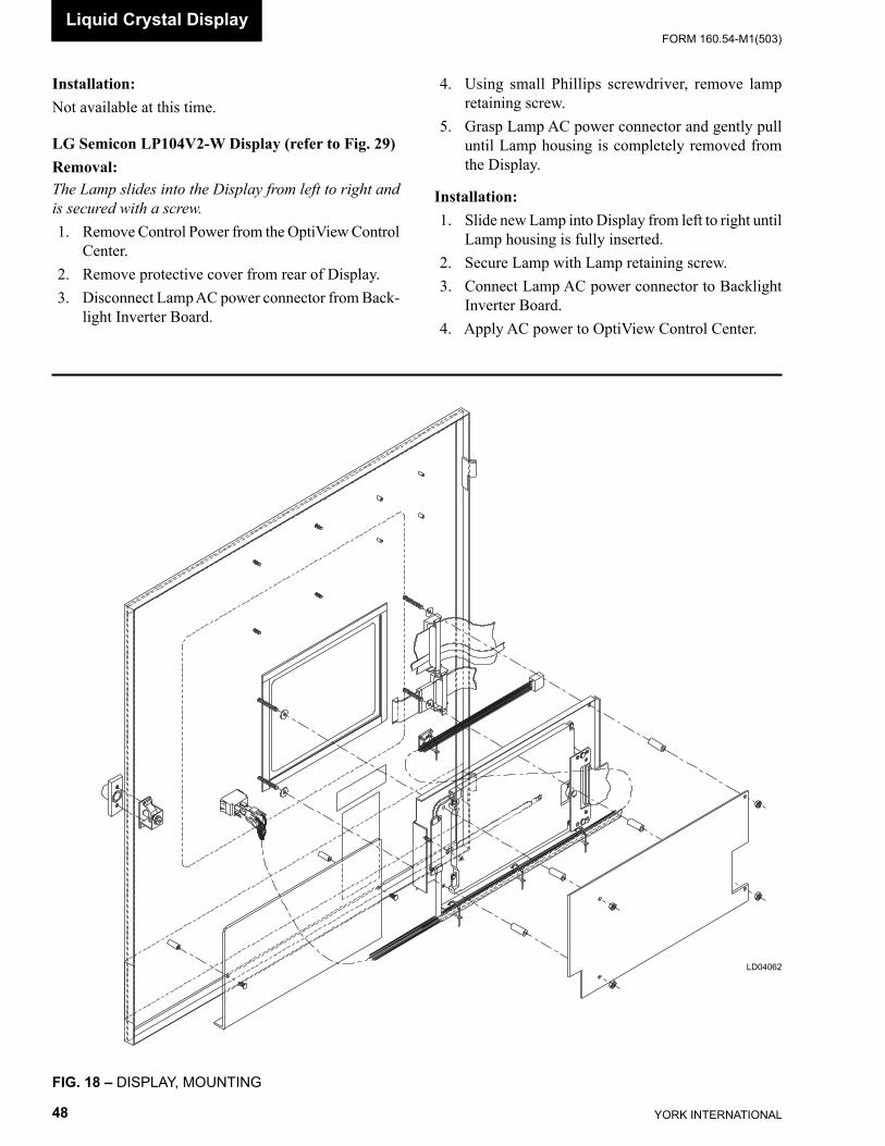
YORK INTERNATIONAL48
FORM 160.54-M1(503)Liquid Crystal Display
Installation:Not available at this time.
LG Semicon LP104V2-W Display (refer to Fig. 29)Removal:The Lamp slides into the Display from left to right and is secured with a screw. 1. Remove Control Power from the OptiView Con trol
Cen ter. 2. Remove protective cover from rear of Display. 3. Disconnect Lamp AC power connector from Back-
light Inverter Board.
FIG. 18 – DISPLAY, MOUNTING
LD04062
4. Using small Phillips screwdriver, remove lamp re tain ing screw.
5. Grasp Lamp AC power connector and gently pull until Lamp housing is completely removed from the Display.
Installation: 1. Slide new Lamp into Display from left to right until
Lamp housing is fully inserted. 2. Secure Lamp with Lamp retaining screw. 3. Connect Lamp AC power connector to Back light
Inverter Board. 4. Apply AC power to OptiView Control Center.
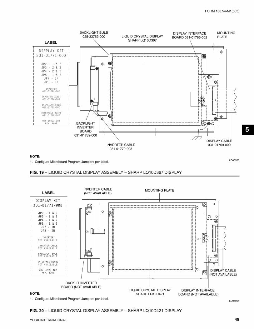
FORM 160.54-M1(503)
49YORK INTERNATIONAL
LD04064
FIG. 19 – LIQUID CRYSTAL DISPLAY ASSEMBLY – SHARP LQ10D367 DISPLAY
LD05526
FIG. 20 – LIQUID CRYSTAL DISPLAY ASSEMBLY – SHARP LQ10D421 DISPLAY
LIQUID CRYSTAL DISPLAYSHARP LQ10D421
DISPLAY CABLE(NOT AVAILABLE)
DISPLAY INTERFACE BOARD (NOT AVAILABLE)
BACKLIT INVERTERBOARD (NOT AVAILABLE)
INVERTER CABLE(NOT AVAILABLE)
MOUNTING PLATELABEL
CH1
CN2
CN1
CN3
NOTE:1. Confi gure Microboard Program Jumpers per label.
NOTE:1. Confi gure Microboard Program Jumpers per label.
LIQUID CRYSTAL DISPLAYSHARP LQ10D367
MOUNTINGPLATE
DISPLAY INTERFACEBOARD 031-01765-002
DISPLAY CABLE031-01769-000INVERTER CABLE
031-01770-003
BACKLIGHTINVERTER
BOARD031-01789-000
LABEL
BACKLIGHT BULB025-33752-000
5
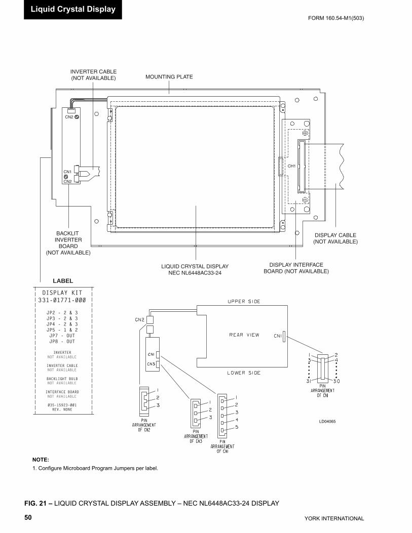
YORK INTERNATIONAL50
FORM 160.54-M1(503)
FIG. 21 – LIQUID CRYSTAL DISPLAY ASSEMBLY – NEC NL6448AC33-24 DISPLAY
NOTE: 1. Confi gure Microboard Program Jumpers per label.
LIQUID CRYSTAL DISPLAYNEC NL6448AC33-24
LABEL
MOUNTING PLATEINVERTER CABLE(NOT AVAILABLE)
BACKLIT INVERTER
BOARD(NOT AVAILABLE)
DISPLAY INTERFACEBOARD (NOT AVAILABLE)
DISPLAY CABLE(NOT AVAILABLE)
CN2
CN1
CN2
CH1
LD04065
Liquid Crystal Display
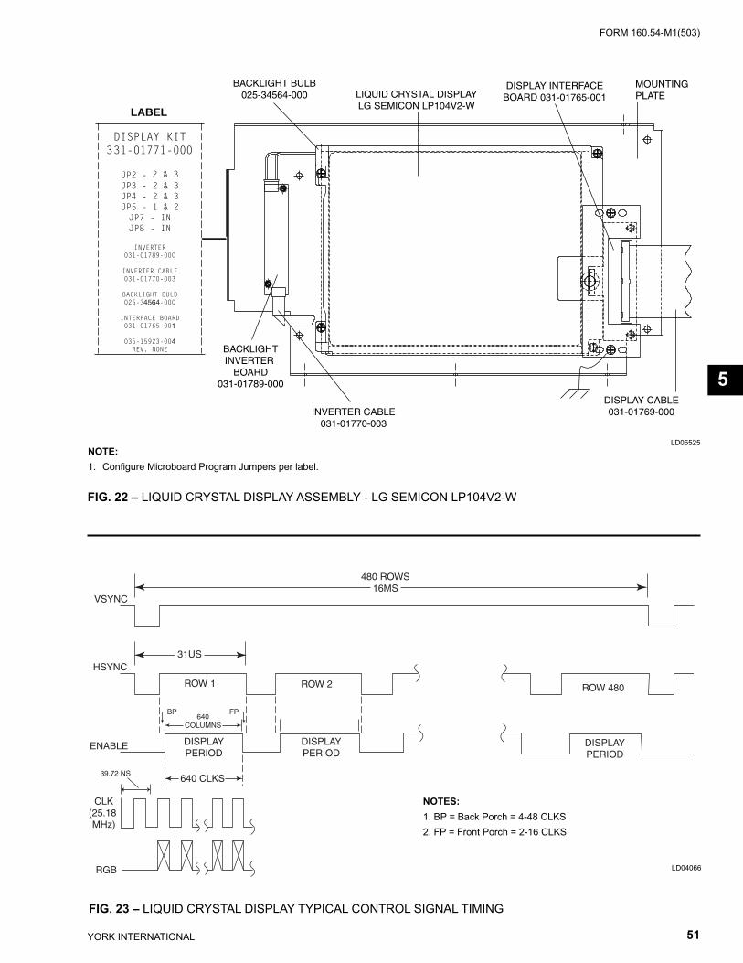
FORM 160.54-M1(503)
51YORK INTERNATIONAL
LIQUID CRYSTAL DISPLAYLG SEMICON LP104V2-W
MOUNTINGPLATE
DISPLAY INTERFACEBOARD 031-01765-001
DISPLAY CABLE031-01769-000INVERTER CABLE
031-01770-003
BACKLIGHTINVERTER
BOARD031-01789-000
LABEL
BACKLIGHT BULB025-34564-000
4564
1
4
FIG. 22 – LIQUID CRYSTAL DISPLAY ASSEMBLY - LG SEMICON LP104V2-W
LD05525NOTE:1. Confi gure Microboard Program Jumpers per label.
640 CLKS
640COLUMNS
31US
VSYNC
480 ROWS16MS
ROW 480ROW 1 ROW 2
BP FP
DISPLAYPERIOD
DISPLAYPERIOD
DISPLAYPERIOD
HSYNC
ENABLE
CLK(25.18 MHz)
RGB
39.72 NS
FIG. 23 – LIQUID CRYSTAL DISPLAY TYPICAL CONTROL SIGNAL TIMING
LD04066
NOTES: 1. BP = Back Porch = 4-48 CLKS 2. FP = Front Porch = 2-16 CLKS
5
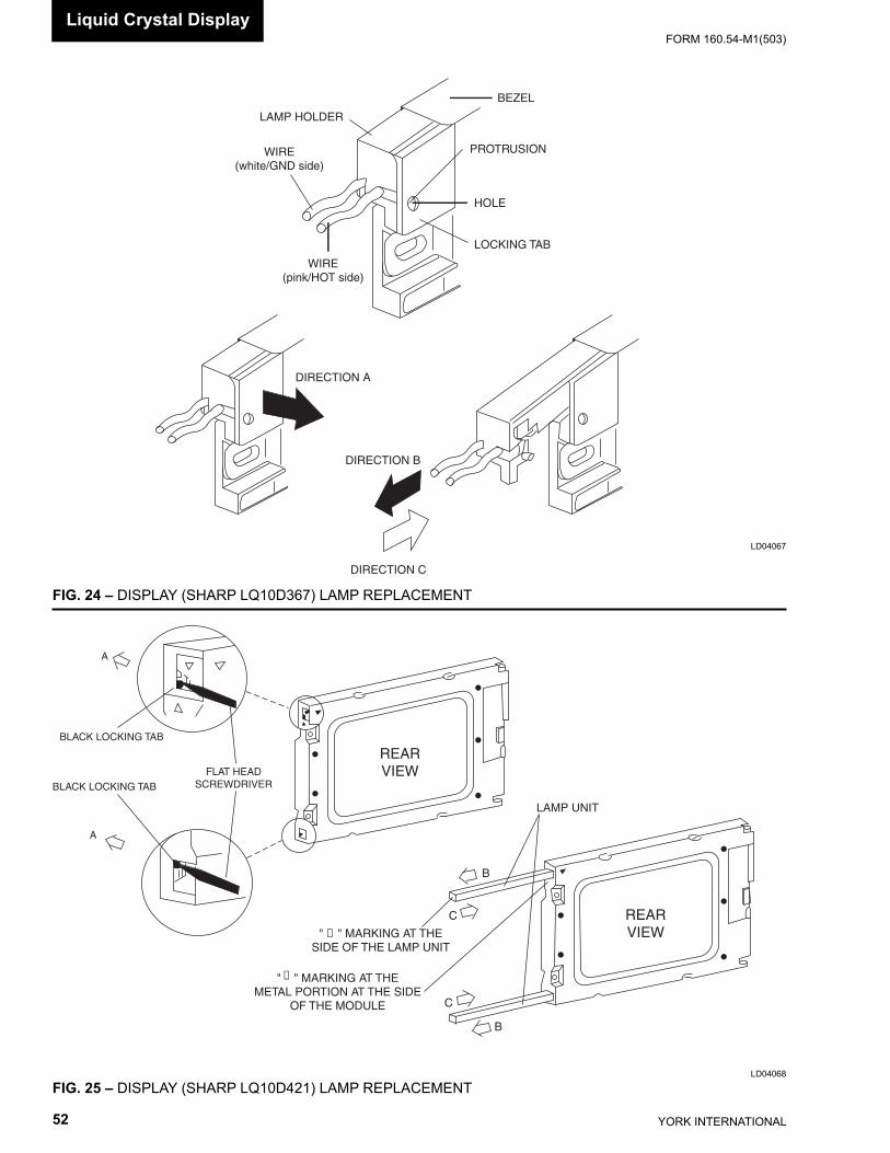
YORK INTERNATIONAL52
FORM 160.54-M1(503)
LAMP HOLDER
BEZEL
PROTRUSION
HOLE
LOCKING TAB
WIRE(white/GND side)
WIRE(pink/HOT side)
DIRECTION A
DIRECTION B
DIRECTION C
FIG. 24 – DISPLAY (SHARP LQ10D367) LAMP REPLACEMENT
LD04067
FIG. 25 – DISPLAY (SHARP LQ10D421) LAMP REPLACEMENTLD04068
BLACK LOCKING TAB
BLACK LOCKING TAB
FLAT HEADSCREWDRIVER
A
A
REARVIEW
REARVIEW
C
C
B
B
" ∇ " MARKING AT THESIDE OF THE LAMP UNIT
∇" " MARKING AT THE
METAL PORTION AT THE SIDEOF THE MODULE
LAMP UNIT
Liquid Crystal Display
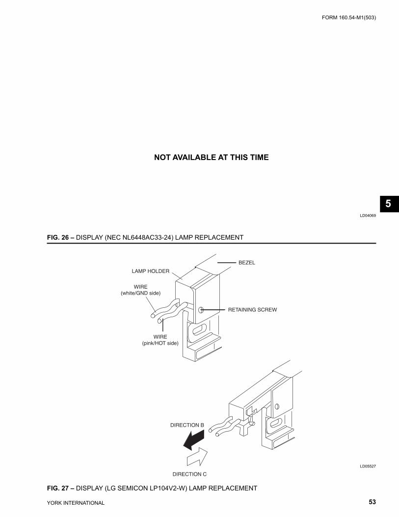
FORM 160.54-M1(503)
53YORK INTERNATIONAL
FIG. 26 – DISPLAY (NEC NL6448AC33-24) LAMP REPLACEMENT
LD04069
NOT AVAILABLE AT THIS TIME
FIG. 27 – DISPLAY (LG SEMICON LP104V2-W) LAMP REPLACEMENT
LD05527
LAMP HOLDER
BEZEL
RETAINING SCREW
WIRE(white/GND side)
WIRE(pink/HOT side)
DIRECTION B
DIRECTION C
5
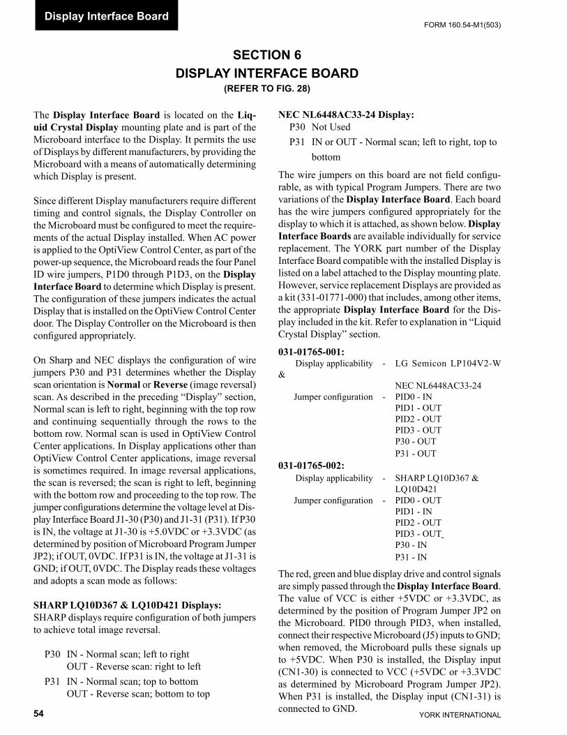
YORK INTERNATIONAL54
FORM 160.54-M1(503)Display Interface Board
SECTION 6DISPLAY INTERFACE BOARD
(REFER TO FIG. 28)
The Display Interface Board is located on the Liq- uid Crys tal Dis play mount ing plate and is part of the Microboard in ter face to the Display. It per mits the use of Displays by dif fer ent man u fac tur ers, by pro vid ing the Microboard with a means of au to mat i cal ly de ter min ing which Dis play is present.
Since different Display manufacturers require dif fer ent timing and control signals, the Display Controller on the Microboard must be confi gured to meet the re quire -ments of the actual Display installed. When AC power is applied to the OptiView Control Center, as part of the power-up sequence, the Microboard reads the four Panel ID wire jumpers, P1D0 through P1D3, on the Dis play In ter face Board to de ter mine which Display is present. The con fi g u ra tion of these jumpers in di cates the actual Dis play that is in stalled on the OptiView Control Cen ter door. The Display Con trol ler on the Microboard is then con fi g ured ap pro pri ate ly.
On Sharp and NEC displays the confi guration of wire jump ers P30 and P31 de ter mines whether the Display scan ori en ta tion is Nor mal or Reverse (im age re ver sal) scan. As de scribed in the pre ced ing “Display” sec tion, Nor mal scan is left to right, be gin ning with the top row and con tinu ing se quen tial ly through the rows to the bot tom row. Nor mal scan is used in OptiView Control Cen ter ap pli ca tions. In Dis play applications oth er than OptiView Control Cen ter ap pli ca tions, image re ver sal is some times re quired. In im age reversal ap pli ca tions, the scan is re versed; the scan is right to left, be gin ning with the bot tom row and pro ceed ing to the top row. The jump er con fi g u ra tions de ter mine the voltage level at Dis-play In ter face Board J1-30 (P30) and J1-31 (P31). If P30 is IN, the voltage at J1-30 is +5.0VDC or +3.3VDC (as de ter mined by po si tion of Microboard Pro gram Jump er JP2); if OUT, 0VDC. If P31 is IN, the volt age at J1-31 is GND; if OUT, 0VDC. The Display reads these volt ag es and adopts a scan mode as fol lows:
SHARP LQ10D367 & LQ10D421 Displays:SHARP displays require confi guration of both jump ers to achieve total image reversal. P30 IN - Normal scan; left to right OUT - Reverse scan: right to left P31 IN - Normal scan; top to bottom OUT - Re verse scan; bottom to top
NEC NL6448AC33-24 Display: P30 Not Used P31 IN or OUT - Normal scan; left to right, top to bottom
The wire jumpers on this board are not fi eld confi gu-rable, as with typical Program Jumpers. There are two vari a tions of the Display Interface Board. Each board has the wire jumpers confi gured ap pro pri ate ly for the dis play to which it is attached, as shown below. Display Interface Boards are avail able in di vid u al ly for ser vice re place ment. The YORK part num ber of the Dis play In ter face Board com pat i ble with the in stalled Dis play is listed on a label at tached to the Dis play mount ing plate. How ev er, ser vice re place ment Dis plays are pro vid ed as a kit (331-01771-000) that in cludes, among oth er items, the ap pro pri ate Display In ter face Board for the Dis- play in clud ed in the kit. Re fer to ex pla na tion in “Liq uid Crys tal Dis play” section.
031-01765-001: Display applicability - LG Semicon LP104V2-W & NEC NL6448AC33-24 Jumper confi guration - PID0 - IN PID1 - OUT PID2 - OUT PID3 - OUT P30 - OUT P31 - OUT031-01765-002: Display applicability - SHARP LQ10D367 & LQ10D421 Jumper confi guration - PID0 - OUT PID1 - IN PID2 - OUT PID3 - OUT P30 - IN P31 - IN
The red, green and blue display drive and control sig nals are simply passed through the Display Interface Board. The val ue of VCC is either +5VDC or +3.3VDC, as de ter mined by the position of Program Jump er JP2 on the Microboard. PID0 through PID3, when in stalled, con nect their re spec tive Microboard (J5) inputs to GND; when re moved, the Microboard pulls these sig nals up to +5VDC. When P30 is in stalled, the Display input (CN1-30) is con nect ed to VCC (+5VDC or +3.3VDC as de ter mined by Microboard Program Jump er JP2). When P31 is installed, the Dis play input (CN1-31) is con nect ed to GND.
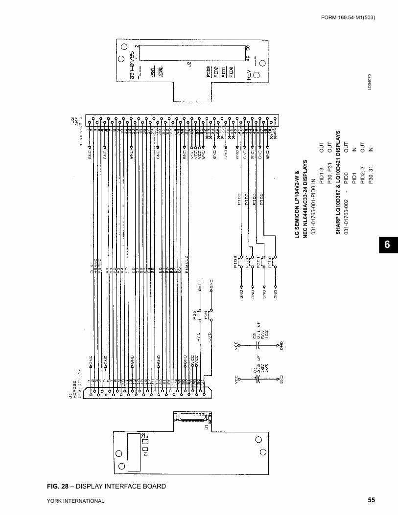
FORM 160.54-M1(503)
55YORK INTERNATIONAL
FIG. 28 – DISPLAY INTERFACE BOARD
LD04
070
LG S
EMIC
ON
LP1
04V2
-W &
NEC
NL6
448A
C33
-24
DIS
PLAY
S
031-
0176
5-00
1-PI
D0
IN
P
ID1-
3
OU
T
P
30, P
31
O
UT
SH
AR
P LQ
10D
367
& L
Q10
D42
1 D
ISPL
AYS
03
1-01
765-
002
-
PI
D0
OU
T
P
ID1
IN
P
ID2,
3
OU
T
P
30, 3
1
I
N
6
YORK INTERNATIONAL56
FORM 160.54-M1(503)Display Backlight Inverter Board
SECTION 7DISPLAY BACKLIGHT INVERTER BOARD
(REFER TO FIG. 29 - 31)
The Display Backlight Inverter Board generates a high voltage AC signal that is applied to the backlight lamp, causing it to illuminate. The magnitude of the sig nal determines the lamp bright ness. Displays by some manufacturers have two lamps; one at the top and one at the bottom of the display. Other Display man u fac tur ers have only a lamp at the top of the display.
An Inverter converts low level DC voltage (+12VDC or +5VDC, as required by the manufacturer) from the Microboard to a 500 to 1500VAC 60K Hz signal that is applied to the lamp. The higher the AC voltage, the great er the bright ness of the lamp. When this voltage is not present, the lamp is turned off.
High voltage, up to 1500VAC, is present at the out put of the back light in vert er board. Refer to Fig ures 29 to 31 and locate the out put con nec tors. Use ex treme caution when work ing in this area!!!
Different Display manufacturers require different Back- light Inverter Boards. The different board designs re quire different control voltage inputs. To ac com mo date these variations, Microboard Program Jump ers JP3 - JP5, JP7 and JP8 must be confi gured to provide the required voltage levels. A label at tached to the Display mounting plate lists the required Program Jumper con fi g u ra tion for that particular display. Refer to Table 1 for required Program Jumper confi gurations for the var i ous Display applications.
Under Program control, the Microboard generates the control signals that are applied to the Backlight In vert er Board. The Program determines when the lamp is turned on and off. It also adjusts the lamp brightness. To in- crease the average lamp life of 25000 hours, the lamp brightness is normally adjusted to 50%. This bright ness level will still allow the display to be visible. When the Program senses a Keypad key has been pressed, it ad justs the brightness to 100% (maximum).
The lamp illumination high voltage AC is generated from either +12VDC or +5VDC as required by the man u fac tur er. Microboard Program Jumper JP5 must be po si tioned to provide the required voltage. The Microboard provides the Backlight Enable sig nal. This
sig nal turns the lamp on and off. Some man u fac tur ers re- quire this sig nal to be +12VDC, others re quire +5VDC. Pro gram Jumper JP4 must be po si tioned to pro vide the re quired voltage. Further, some ap pli ca tions require this signal to be a +VDC (+12VDC or +5VDC) to turn on the lamp. Others require this signal to be 0VDC to turn on the lamp. Program Jumper JP3 must be po si tioned to pro vide the required polarity.
Depending upon the Display manufacturer, the bright- ness control input from the Microboard must be either a variable voltage or a variable resistance. Microboard Program Jumpers JP7 and JP8 are used to provide the appropriate technique (refer to Fig. 10). The lamp dim- mer circuit on the Microboard is an IC that is the elec- tri cal equivalent of a 10K ohm po ten ti om e ter with 100 po si tions or steps. The Program adjusts the position of the potentiometer. When confi gured for variable volt age (JP7 & JP8 installed), the output between Microboard J6-7 and J6-8 is a 0 to +5.0VDC signal. Not all applica-tions require the full 5.0VDC range. If con fi g ured for variable resistance (JP7 and JP8 re moved), the out put between Microboard J6-7 and J6-8 is a 0 to 10K ohm variable resistance.
The OptiView Control Center could be supplied with any of sev er al approved Displays. Each Display re- quires a spe cifi c Back light Inverter Board as speci-fi ed below and in Figures 29 to 31. These boards are individually avail able as service replacement parts (the required Back light Inverter Board part number is listed on the label at tached to the Display mounting plate). How ev er, ser vice replacement Displays are provided in a kit (YORK P/N 331-01771-000) that includes the appropriate Back light Inverter Board (refer to “Liquid Crystal Display” Section).
SHARP model LQ10D367 AND LG Semicon LP104V2-W displays re quire a TDK CXA-LO612-VJL Backlight In vert er Board (YORK P/N 031-01789-000) (ref. Fig. 29). These boards gen er ate a lamp il lu mi na tion high voltage AC from +12VDC. When the Back light Enable signal at con nec tor CN1-3 is +5VDC, the high voltage signal is applied to the lamp. When CN1-3 is 0VDC, the high voltage signal is re moved from the lamp, turning it off. The lamp bright ness is controlled by a variable volt age signal, de vel oped by the lamp dim mer circuit (ref. Fig. 10) on the Microboard and ap plied to connector
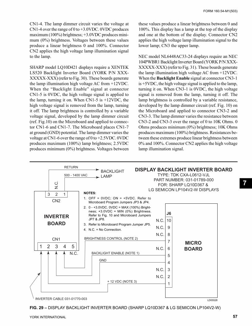
FORM 160.54-M1(503)
57YORK INTERNATIONAL
J610987654321
N.C.N.C.N.C.
N.C.
N.C.N.C.
MICROBOARD
INVERTERBOARD
1 2 3 4 5N.C.
CN1
CN2 3 2 1
N.C
.
RETURN
500 - 1400 VACBACKLIGHTLAMP
BRIGHTNESS CONTROL (NOTE 2)
BACKLIGHT ENABLE (NOTE 1)
GND
+ 12 VDC (NOTE 3)
INVERTER CABLE 031-01770-003
DISPLAY BACKLIGHT INVERTER BOARDTYPE: TDK CXA-L0612-VJL
PART NUMBER: 031-01789-000FOR: SHARP LQ10D367 &
LG SEMICON LP104V2-W DISPLAYS
CN1-4. The lamp dimmer cir cuit var ies the voltage at CN1-4 over the range of 0 to +3.0VDC. 0VDC pro duc es maximum (100%) bright ness; +3.0VDC pro duc es mini-mum (0%) bright ness. Voltages between these values produce a linear bright ness 0 and 100%. Connector CN2 applies the high volt age lamp il lu mi na tion signal to the lamp.
SHARP model LQ10D421 displays require a XENTEK LS520 Backlight Inverter Board (YORK P/N XXX-XXXXX-XXX) (refer to Fig. 30). These boards gen er ate the lamp illumination high voltage AC from +12VDC. When the “Backlight Enable” signal at con nec tor CN1-5 is 0VDC, the high voltage signal is ap plied to the lamp, turning it on. When CN1-5 is +12VDC, the high voltage signal is re moved from the lamp, turning it off. The lamp bright ness is controlled by a variable voltage sig nal, de vel oped by the lamp dim mer circuit (ref. Fig.10) on the Microboard and ap plied to connec-tor CN1-6 and CN1-7. The Microboard plac es CN1-7 at ground (GND) po ten tial. The lamp dim mer varies the voltage at CN1-6 over the range of 0 to +2.5VDC. 0VDC pro duc es max i mum (100%) lamp bright ness; 2.5VDC pro duc es min i mum (0%) bright ness. Volt ag es between
these val ues produce a linear brightness between 0 and 100%. This display has a lamp at the top of the display and one at the bottom of the display. Connector CN2 ap plies the high voltage lamp il lu mi na tion signal to the lower lamp; CN3 the upper lamp.
NEC model NL6448AC33-24 displays require an NEC 104PWBR1 Backlight Inverter Board (YORK P/N XXX-XXXXX-XXX) (refer to Fig. 31). These boards gen er ate the lamp illumination high voltage AC from +12VDC. When the Backlight Enable signal at con nec tor CN3-1 is +5VDC, the high voltage signal is ap plied to the lamp, turn ing it on. When CN3-1 is 0VDC, the high voltage signal is re moved from the lamp, turn ing it off. The lamp bright ness is controlled by a vari able re sis tance, de vel oped by the lamp dimmer circuit (ref. Fig. 10) on the Microboard and applied to con nec tor CN3-2 and CN3-3. The lamp dim mer varies the re sis tance be tween CN3-2 and CN3-3 over the range of 0 to 10K Ohms. 0 Ohms pro duc es minimum (0%) bright ness; 10K Ohms pro duc es maximum (100%) bright ness. Re sis tanc es be- tween these extremes pro duce lin ear bright ness be tween 0% and 100%. Con nec tor CN2 applies the high volt age lamp il lu mi na tion signal.
FIG. 29 – DISPLAY BACKLIGHT INVERTER BOARD (SHARP LQ10D367 & LG SEMICON LP104V2-W)
NOTES:1. OFF = 0VDC; ON = +5VDC. Refer to
Microboard Program Jumpers JP3 & JP4.2. 0 - +3.0VDC. 0VDC = MAX (100%) Bright-
ness; +3.0VDC = MIN (0%) Brightness. Refer to Fig. 10 and Microboard Jumpers JP7 & JP8.
3. Refer to Microboard Program Jumper JP5.4. N.C. = No Connection.
LD05528
7
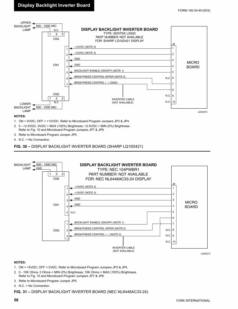
YORK INTERNATIONAL58
FORM 160.54-M1(503)
1 2 3
1 2 3
N.C.
500 - 1500 VAC
500 - 1500 VAC
CN3
CN2
CN1
N.C.
1
2
3
4
5
6
7
+12VDC (NOTE 3)
+12VDC (NOTE 3)
GND
GND
BACKLIGHT ENABLE (ON/OFF) (NOTE 1)
BRIGHTNESS CONTROL WIPER (NOTE 2)
BRIGHTNESS CONTROL ( - ) (GND)
INVERTER CABLE(NOT AVAILABLE)
1
2
3
4
5
6
7
8
9
10
N.C.
N.C.
N.C.
J6
MICROBOARD
UPPERBACKLIGHT
LAMP
LOWERBACKLIGHT
LAMP
DISPLAY BACKLIGHT INVERTER BOARDTYPE: XENTEK LS520
PART NUMBER: NOT AVAILABLEFOR: SHARP LQ10D421 DISPLAY
FIG. 31 – DISPLAY BACKLIGHT INVERTER BOARD (NEC NL6448AC33-24)
FIG. 30 – DISPLAY BACKLIGHT INVERTER BOARD (SHARP LQ10D421)
LD04072
NOTES:1. ON = 0VDC; OFF = +12VDC. Refer to Microboard Program Jumpers JP3 & JP4.2. 0 - +2.5VDC. 0VDC = MAX (100%) Brightness; +2.5VDC = MIN (0%) Brightness. Refer to Fig. 10 and Microboard Program Jumpers JP7 & JP8.3. Refer to Microboard Program Jumper JP5.4. N.C. = No Connection.
NOTES:1. ON = +5VDC; OFF = 0VDC. Refer to Microboard Program Jumpers JP3 & JP4.2. 0 - 10K Ohms. 0 Ohms = MIN (0%) Brightness; 10K Ohms = MAX (100%) Brightness. Refer to Fig. 10 and Microboard Program Jumpers JP7 & JP8.3. Refer to Microboard Program Jumper JP5.4. N.C. = No Connection.
1 2 3
500 - 1500 VAC
CN2
CN3
CN1
1
2
3
4
5
1
2
3
+12VDC (NOTE 3)
+12VDC (NOTE 3)
GND
GND
BACKLIGHT ENABLE (ON/OFF) (NOTE 1)
BRIGHTNESS CONTROL WIPER (NOTE 2)
BRIGHTNESS CONTROL ( - ) (NOTE 2)
INVERTER CABLE(NOT AVAILABLE)
1
2
3
4
5
6
7
8
9
10
N.C.
N.C.
N.C.
J6
MICROBOARD
BACKLIGHTLAMP
N.C.
GNDDISPLAY BACKLIGHT INVERTER BOARD
TYPE: NEC 104PWBR1PART NUMBER: NOT AVAILABLE
FOR: NEC NL6448AC33-24 DISPLAY
LD04073
Display Backlight Inverter Board
FORM 160.54-M1(503)
59YORK INTERNATIONAL
SECTION 8KEYPAD
(REFER TO FIGURES 32 & 33)
The Keypad contains touch-sensitive keys that allow the Operator to interface with the OptiView Control Center. The Operator presses the keys to request the desired screens of information and enter System Setpoints.
The top layer of the Keypad contains embossed areas identifying the keys. Under each embossed key area are two conductors, one on top of the other, separated by an air space. The conductors are arranged in a ma- trix of rows and columns and connected to the Key pad connector as shown in Fig. 32. The em bossed area of each key is located directly over the in ter sec tion point of the conductors. Pressing the embossed key area caus es contact and electrical continuity between the two conductors. For example, pressing the “1” key creates con ti nu ity between the Keypad connector pin 5 (col umn 3) and pin 13 (row 4). Since this connector is in ter faced to the Microboard (J18), the Microboard sens es this continuity as described below and con cludes the “1” key is pressed.
The Microboard Program continuously scans the Key- pad to determine if a key is pressed. Beginning with row 1 and proceeding through all rows, the Program places a “logic low” (<1VDC) on a row, a “logic high” (>4VDC) on the remaining rows and reads the col umns. A logic low in any column indicates a key in that col umn and row is pressed. For example, if at the time row 4
is being driven low, if column 3 is low, then the Micro con cludes the key at co or di nate of row 4 and column 3 is pressed. Since the co or di nates of all keys are stored in the Microboard’s Program, it can iden ti fy which key is at this co or di nate and responds ac cord ing ly. In this ex am ple the “1” key is pressed.
In order for the Microboard to reliably detect closed and open keys, each key must meet a closed circuit and open circuit resistance requirement. When a key is pressed, the contact resistance must be < 100 Ohms. When a key is not pressed, the contact resistance must be > 1Meg Ohm. If the Microboard is not responding to a pressed key, or if it’s detecting a closed key when none are pressed, it could be be cause the contact re sis tance requirements are not being met. The operation of each key can be checked with an Ohmmeter. To check the open and closed con-tact resistance of any key, re fer to the “Di ag nos tics and Troubleshooting” Section 23 of this book.
The Keypad is attached to the front of the OptiView Control Cen ter door with an adhesive backing. If ser vice re place ment is required, start at one corner and slowly peel the Keypad from the door. The rear side of the re- place ment Keypad is coated with an adhesive covered with a paper backing. Remove the paper back ing, align the Display and rocker switch openings and apply the Key pad to the door.
8
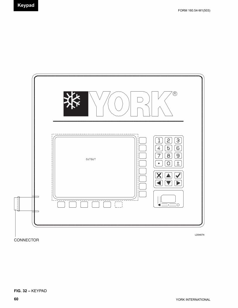
YORK INTERNATIONAL60
FORM 160.54-M1(503)Keypad
FIG. 32 – KEYPAD
CONNECTOR
LD04074
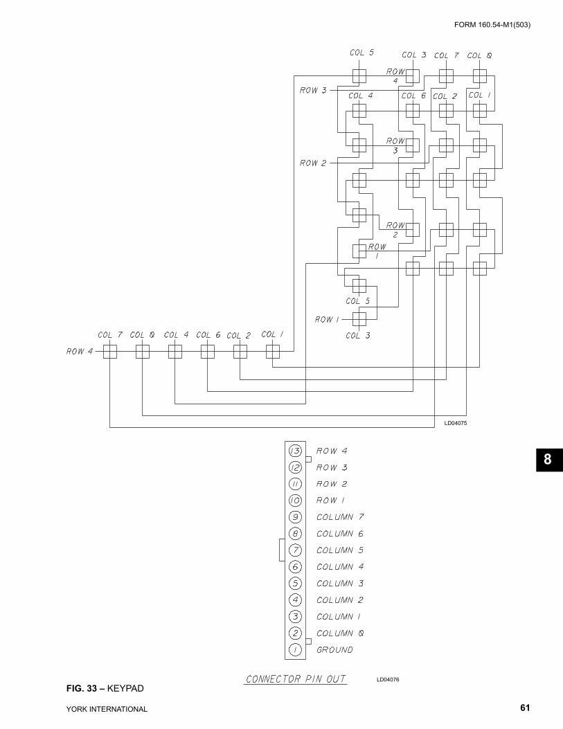
FORM 160.54-M1(503)
61YORK INTERNATIONAL
FIG. 33 – KEYPAD
LD04075
LD04076
8
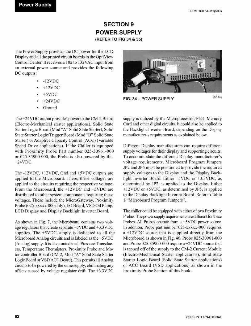
YORK INTERNATIONAL62
FORM 160.54-M1(503)
Power Sup ply
SECTION 9POWER SUPPLY(REFER TO FIG 34 & 35)
The Power Supply provides the DC power for the LCD Display and all the printed circuit boards in the OptiView Control Center. It receives a 102 to 132VAC input from an ex ter nal power source and provides the following DC out puts:
• -12VDC • +12VDC • +5VDC • +24VDC • Ground
The +24VDC output provides power to the CM-2 Board (Electro-Mechanical starter applications), Solid State Starter Logic Board (Mod “A” Solid State Starter), Sol id State Starter Logic/Trigger Board (Mod “B” Solid State Starter) or Adap tive Ca pac i ty Con trol (ACC) (Vari able Speed Drive ap pli ca tions). If the Chill er is equipped with Prox im i ty Probe Part num ber 025-30961-000 or 025-35900-000, the Probe is also powered by this +24VDC.
The -12VDC, +12VDC, Gnd and +5VDC outputs are ap plied to the Microboard. There, these voltages are ap plied to the circuits requiring the respective voltage. From the Microboard, the +12VDC and +5VDC are dis trib ut ed to other system components requiring these voltages. These include the MicroGateway, Proximity Probe (025-xxxxx-000 only), I/O Board, VSD Oil Pump, LCD Dis play and Display Backlight Inverter Board.
As shown in Fig. 7, the Microboard contains two volt- age regulators that create separate +5VDC and +3.3VDC sup plies. The +5VDC supply is dedicated to all the Microboard Analog circuits and is labeled as the +5VDC (An a log) supply. It is also routed to all Pres sure Transduc-ers, Tem per a ture Thermistors, Prox im i ty Probe and Mo-tor con trol ler Board (CM-2, Mod “A” Solid State Starter Log ic Board or VSD ACC Board). This permits all An a log cir cuits to be powered by the same supply, elim i nat ing any offsets caused by voltage reg u la tor drift. The +3.3VDC
supply is utilized by the Mi cro pro ces sor, Flash Memory Card and other digital cir cuits. It could also be applied to the Back light In vert er Board, de pend ing on the Display man u fac tur er’s re quire ments as ex plained be low.
Different Display manufacturers can require different supply voltages for their display and supporting cir cuits. To accommodate the different Display manufacturer’s voltage requirements, Microboard Program Jumpers JP2 and JP5 must be positioned to provide the required sup ply voltages to the Display and the Display Back- light Inverter Board. Either +5VDC or +3.3VDC, as de ter mined by JP2, is applied to the Display. Either +12VDC or +5VDC, as de ter mined by JP5, is applied to the Dis play Backlight Inverter Board. Refer to Table 1 “Microboard Program Jumpers”.
The chiller could be equipped with either of two Prox im i ty Probes. The power supply requirements are dif fer ent for these Probes. All Probes operate from a +5VDC power source. In addition, Probe part number 025-xxxxx-000 re quires a +12VDC source that is sup plied directly from the Microboard as shown in Fig. 46. Probe 025-30961-000 and Probe 025-35900-000 require a +24VDC source that is tapped off of the supply to the CM-2 Cur rent Mod ule (Electro-Mechanical Starter ap pli ca tions), Sol id State Start er Log ic Board (Solid State Starter ap pli ca tions) or ACC Board (VSD ap pli ca tions) as shown in the Prox im i ty Probe Sec tion of this book.
29136AFIG. 34 – POWER SUPPLY
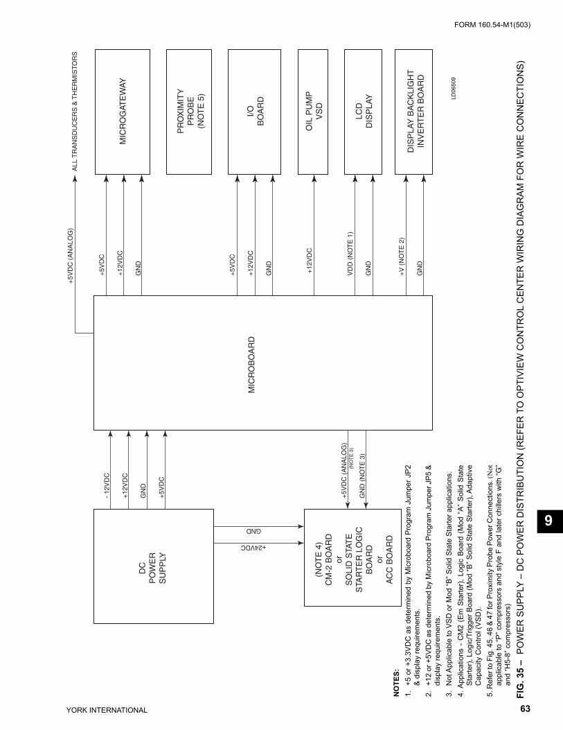
FORM 160.54-M1(503)
63YORK INTERNATIONAL
FIG
. 35
– P
OW
ER S
UPP
LY –
DC
PO
WER
DIS
TRIB
UTI
ON
(REF
ER T
O O
PTIV
IEW
CO
NTR
OL
CEN
TER
WIR
ING
DIA
GR
AM F
OR
WIR
E C
ON
NEC
TIO
NS)
NO
TES:
1. +
5 or
+3.
3VD
C a
s de
term
ined
by
Mic
robo
ard
Prog
ram
Jum
per J
P2
& di
spla
y re
quire
men
ts.
2. +
12 o
r +5V
DC
as
dete
rmin
ed b
y M
icro
boar
d Pr
ogra
m J
umpe
r JP5
&
disp
lay
requ
irem
ents
.3.
Not
App
licab
le to
VSD
or M
od “B
” Sol
id S
tate
Sta
rter a
pplic
atio
ns.
4. A
pplic
atio
ns -
CM
2 (E
m S
tarte
r), L
ogic
Boa
rd (
Mod
“A”
Sol
id S
tate
St
arte
r), L
ogic
/Trig
ger B
oard
(Mod
“B” S
olid
Sta
te S
tarte
r), A
dap t
ive
Ca p
ac i ty
Con
trol (
VSD
).5.
Ref
er to
Fig
. 45,
46
& 47
for P
roxi
mity
Pro
be P
ower
Con
nect
ions
. (N
ot
appl
icab
le to
“P” c
ompr
esso
rs a
nd s
tyle
F a
nd la
ter c
hille
rs w
ith “G
” an
d “H
5-8”
com
pres
sors
)
LD06
509
9
DC
PO
WE
RS
UP
PLY
(NO
TE
4)
CM
-2 B
OA
RD
orS
OLI
D S
TAT
ES
TAR
TE
R L
OG
ICB
OA
RD
orA
CC
BO
AR
D
MIC
RO
BO
AR
D
MIC
RO
GAT
EW
AY
PR
OX
IMIT
YP
RO
BE
(NO
TE
5)
I/OB
OA
RD
OIL
PU
MP
VS
D
LCD
DIS
PLA
Y
DIS
PLA
Y B
AC
KLI
GH
TIN
VE
RT
ER
BO
AR
D
+5V
DC
(A
NA
LOG
)A
LL T
RA
NS
DU
CE
RS
& T
HE
RM
ISTO
RS
+5V
DC
+12
VD
C
GN
D
+5V
DC
+12
VD
C
GN
D
VD
D (
NO
TE
1)
GN
D
+V
(N
OT
E 2
)
GN
D
+12
VD
C
- 12
VD
C
+12
VD
C
GN
D
+5V
DC
+5V
DC
(A
NA
LOG
)
GN
D (
NO
TE
3)
(NO
TE
3)
+24VDC
GND
YORK INTERNATIONAL64
FORM 160.54-M1(503)Current Mod ule (CM-2)
SECTION 10CURRENT MODULE (CM-2)
(REFER TO FIG 36 - 38)
On applications where the Compressor Motor is con- trolled by an Electro-Mechanical Starter, the OptiView Control Center is equipped with a Current Module. The Cur rent Mod ule pro vides com pres sor motor Over load and Power Fault protection. The Current Mod ule also pro vides an an a log voltage representing the com pres sor motor cur rent to the Microboard for dis play and Cur- rent Limit control. While the chill er is run ning, the Microboard controls the Pre-rotation Vane (PRV) po- si tion to limit the motor current to the system 100% Full Load Amp (FLA) value.
The contacts of Current Module K1 relay (identifi ed as “CM” contacts on the OptiView Control Center wiring diagram) are interfaced into the Motor Controller ini- ti at ed shut down circuit that is located between OptiView Control Center TB6-53 and I/O Board TB1-16 (ref. Fig 17 and 37). They are also connected as a digital input to I/O Board J2-1. Relay K1 is normally en er gized, main tain ing its con tacts in a closed position. When ev er the Current Module ini tiates a chiller shutdown, it de-en er giz es K1, opening its contacts. This interrupts the cir cuit to I/O Expansion Board RUN relay coil 1R (K18), de-en er giz ing it and causing the Starter to shut down. Si mul ta neous ly, the Microboard reads the open ing of these contacts via I/O Board J2-1, initiates a SYSTEM COASTDOWN and dis plays the ap pro pri ate mes sage as described below.
Three Current Transformers in the Com pres sor Mo- tor Ter mi nal Box (ref Fig. 38) provide 3 phase motor cur rent sig nals to the Diode Bridge (DB). The re quired turns ra tio of the Current Transformers is de ter mined by the sys tem 100% FLA. The Diode Bridge rectifi es and com bines the three signals into one DC signal that is applied to the parallel Variable Resistors (RES). These are Factory adjusted (fi eld adjusted on service re place ments) to provide a nominal 1.0VDC (0.15 to 1.10VDC) signal to the Current Module at J1-1 and J1-2 when the com pres sor motor current is at 100% FLA. Fig. 38 con tains a formula to calculate the re sis tance of RES re quired to achieve 1.0VDC at 100%FLA. The 100% FLA value is located on a label adhered to the inside of the OptiView Control Center door.
The motor current signal input at J1-1 & J1-2 is ap plied to potentiometer R8. This is Factory adjusted (fi eld ad- just ed on service replacements) to illuminate the 105% CURR indicator (CR6) when the com pres sor motor current reaches 105% FLA. This calibrated volt age is applied to the Power Fault detector, Overload de tec tors and Multiplexer (MUX).
The Power Fault circuit protects the compressor mo tor and driv e line from transient torque damage. It an tic i pates the transient torque condition by detecting a mo men tary in ter rup tion in motor current and de-en er giz ing the start er before damage can occur. If the chill er has been run ning for >75 seconds and the motor cur rent decreases to <10% FLA, a Power Fault shut- down is ini ti at ed. The Power Fault indicator (CR5) is il lu mi nat ed and remains illuminated until man u al ly re set with RE SET switch S2. Relay K1 is de-en er gized for 1 sec ond and then returned to the energized state. Re lay K1 con tacts (CM) open for 1 second and then re turn to the closed state. A SYSTEM COASTDOWN is ini ti at ed and POWER FAULT is displayed on the Dis play. The chiller will automatically restart upon com ple tion of SYSTEM COASTDOWN.
If the motor current remains continuously at >105% FLA for 50 seconds (Nominal), an OVERLOAD shut down is ini ti at ed. The Overload indicator (CR4) is il lu mi nat ed and re mains illuminated until manually reset with RE SET switch S2. Relay K1 is de-en er gized, open ing K1 con tacts (CM). Relay K1 remains de-ener-gized until man u al ly reset with RESET switch S2. A SYS TEM COASTDOWN is initiated and MOTOR CON TROL LER-CON TACTS OPEN is displayed. The chiller cannot be start ed until RESET switch S2 is man u al ly pressed.
If the motor current remains continuously at 245% FLA for 40 seconds, 290% FLA for 20 seconds or 360% FLA for 10 seconds, an OVERLOAD shut down is ini- ti at ed. Relay K1 and Overload indicator CR4 op er ate as de scribed immediately above. A SYSTEM COAST-DOWN is initiated and MOTOR CON TROL LER - CON TACTS OPEN is displayed. The chiller cannot
FORM 160.54-M1(503)
65YORK INTERNATIONAL
be re start ed until RESET switch is man u al ly pressed. LRA/FLA Po ten ti om e ter R16 is fac to ry adjusted (fi eld ad just ed on service replacements) to the ratio of Locked Rotor Amps to Full Load Amps. The correct setting is determined by dividing the LRA by the FLA. If Switch S1 is in the “Y-Delta/57%” po si tion, there is no 245% FLA thresh old. Switch S1 must be positioned accord-ing to the type of Electro-Me chan i cal starter present; UP for Y-delta or Autotransformer start ers, DOWN for Across-the-Line starters.
The Multiplexer (MUX) is an electronic switch with 8 inputs and 1 output. The address applied to it de ter mines the position of the switch (i.e., which input is rout ed to the output). The inputs to channel 0 through 6 are grounded (0VDC) . The input to channel 7 is a 0 to 4.0VDC analog signal, representing motor current over the range of 0 to 100% FLA. It is Factory calibrated by Po ten ti om e ter R34 to be 4.0VDC when the com pres sor motor current is at 100% FLA. Under Program con trol, the Microboard commands the MUX to route the in puts to the MUX output by ap ply ing 3-bit Binary ad dress es to the MUX address inputs at J5-1,2,3. The volt age level for a logic 1 is +12VDC and logic 0 is 0VDC. The Microboard reads the MUX outputs at J5-6. It fi rst ad- dress es chan nel 0 to de ter mine the type of starter applied. The 0VDC at channel 0 indicates to the Microboard that this is an Electro-Mechanical Starter ap pli ca tion (In all start er ap pli ca tions, the Micro reads chan nel 0 to determine the type starter applied; 0VDC = EM starter, >0VDC=Solid State Starter). It then ad dress es channel 7 (ignoring chan nels 1 through 6) to read the analog motor current volt age. The Microboard in ter prets this analog value in terms of %FLA and dis plays it upon operator keypad request. It also uses this value to invoke compressor motor Current Limit at 100% FLA and 104% FLA. When mo tor current rises to 100% FLA, the Microboard pre vents any further current rise by in hib -it ing further Pre-ro ta tion Vanes (PRV) open ing until it
de creas es to 98% FLA. If the motor current continues to rise to 104% FLA, the Microboard ap plies a close sig nal to the PRV until the motor current decreases to 102% FLA. While Current Limit is in effect, MOTOR - HIGH CURRENT LIM IT is dis played.
As detailed in the “System Calibration” section of this book, to fi eld calibrate Potentiometer R8, the PRV must be manually operated to achieve 105% FLA com pres sor motor current. Therefore, during this procedure, Cur-rent Limit is not invoked until 107% FLA and 110% FLA. The fi rst time the PRV OPEN key is pressed on the COM PRES SOR Screen after logging in at SER VICE access level, a 10 minute window is opened, al low ing the cur rent to rise to 107% FLA be fore further PRV opening is inhibited. This inhibit is re leased when the current decreases to 106% FLA. If the current con tin ues to rise to 110%, manual control is overridden and a close signal is applied to the PRV until the current de creas es to 109% FLA. After 10 min utes, the normal current limit thresholds of 100% FLA and 104% FLA are ap plied.
The MUX address inputs along with respective outputs are as follows: BINARY
DECIMAL OUT PUT J5-1 J5-2 J5-3
0 0 0 0 Ground 0 0 1 1 Ground 0 1 0 2 Ground 0 1 1 3 Ground 1 0 0 4 Ground 1 0 1 5 Ground 1 1 0 6 Ground 0-5.0VDC mo tor cur rent
1 1 1 7 an a log sig nal cal i brat ed on
CM-2 board to be +4.0VDC at
100% FLA.
10
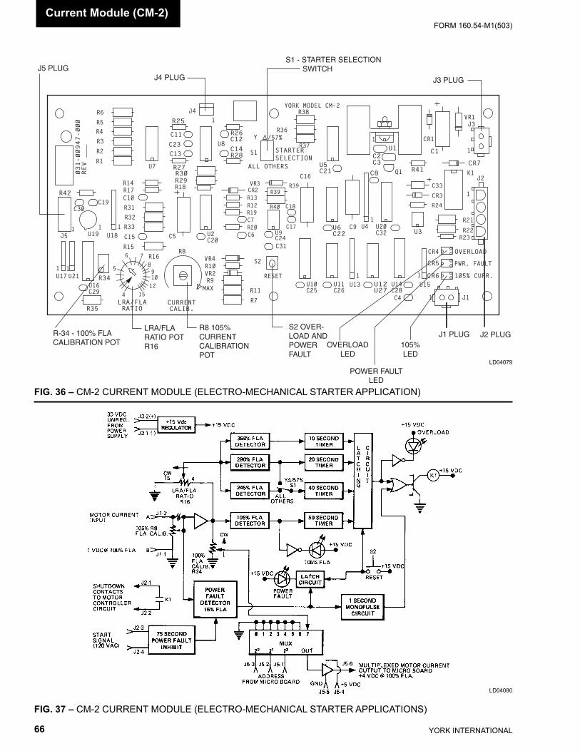
YORK INTERNATIONAL66
FORM 160.54-M1(503)Current Mod ule (CM-2)
FIG. 36 – CM-2 CURRENT MODULE (ELECTRO-MECHANICAL STARTER APPLICATION)
LD04079
FIG. 37 – CM-2 CURRENT MODULE (ELECTRO-MECHANICAL STARTER APPLICATIONS)
LD04080
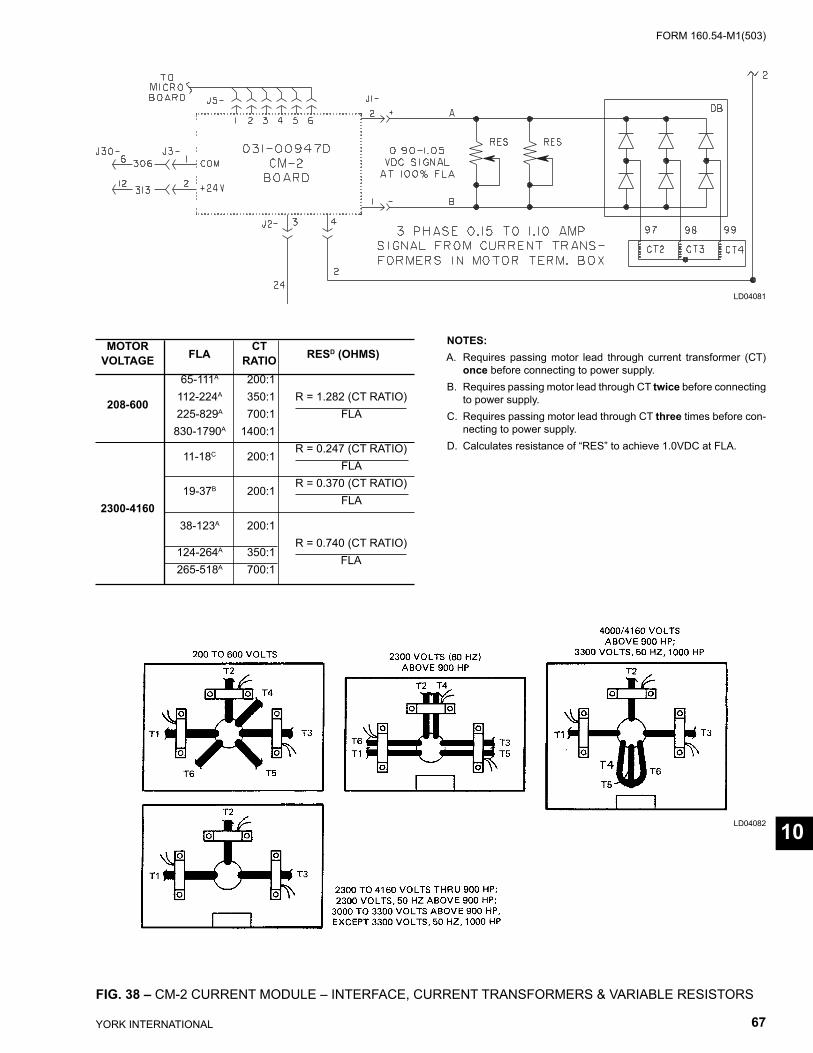
FORM 160.54-M1(503)
67YORK INTERNATIONAL
FIG. 38 – CM-2 CURRENT MODULE – INTERFACE, CURRENT TRANSFORMERS & VARIABLE RESISTORS
LD04082
LD04081
NOTES:A. Requires passing motor lead through current transformer (CT)
once before connecting to power supply.B. Requires passing motor lead through CT twice before con nect ing
to power supply.C. Requires passing motor lead through CT three times before con-
necting to power supply.D. Calculates resistance of “RES” to achieve 1.0VDC at FLA.
MOTOR CT VOLTAGE FLA RATIO RESD (OHMS)
65-111A 200:1 208-600 112-224A 350:1 R = 1.282 (CT RATIO) 225-829A 700:1 FLA 830-1790A 1400:1
11-18C 200:1 R = 0.247 (CT RATIO)
FLA
19-37B 200:1 R = 0.370 (CT RATIO)
2300-4160 FLA
38-123A 200:1
R = 0.740 (CT RATIO)
124-264A 350:1 FLA
265-518A 700:1
10

YORK INTERNATIONAL68
FORM 160.54-M1(503)Solid State Starters
SOLID STATE STARTERS
The OptiView Control Center will accommodate either of two dif fer ent YORK Liquid Cooled Solid State Start- ers (LCSSS). Later production chillers are equipped with the Mod “B” LCSSS. This style LCSSS contains the Sil i con Con trolled Rectifi er (SCR) as sem blies, an in te -grat ed Log ic/Trigger Board and in ter fac es the OptiView Con trol Cen ter via a serial data com mu ni ca tions link and hardwired re lay contacts. Ear li er vintage chillers are equipped with the pre vi ous ver sion LCSSS that in- ter fac es the OptiView Control Center via a mul ti plexed data in ter face and hardwired relay contacts. This earlier vintage LCSSS hous es the SCR as sem blies and Trig-ger Board; a sep a rate Logic Board is located inside the OptiView Con trol Cen ter. Microboard Pro gram Jumper JP39 must be po si tioned to invoke the appropriate Microboard/Pro gram op er a tion for the start er applied (refer to Table 1).
Mod “B” Serial Interface LCSSS (Refer to Fig. 39)
A complete description, theory of operation and trou- ble shoot ing instructions of this LCSSS are contained in YORK Service Manual 160.00-O2. The following de scribes the interface and interaction of the LCSSS with the OptiView Control Center.
As shown in Figure 39, the LCSSS contains a single Logic/Trigger printed circuit board. This board per forms the following functions:
• Generates the SCR trigger pulses
• Receives start/stop commands from the Microboard
• Transmits status and fault data to the Microboard
• Generates all LCSSS initiated Safety and Cycling shutdowns.
The Logic/Trigger Board is powered by +24VDC from the OptiView Control Center Power Sup ply. The OptiView Control Center Microboard (J15) com mu -ni cates with this board via a 1200 baud 0/+5VDC serial data com mu ni ca tions link. If this communications link does not operate prop er ly, cor rect Microboard J15 se ri al port op er a tion can be ver i fi ed using the Serial In puts and Out puts di ag nos tic pro ce dure in the “Di ag nos tics and
Trou ble shoot ing” section of this book. The STOP re lay con tacts on the Logic/Trig ger Board as sure a pos i tive shut down on all LCSSS ini ti at ed shut downs.
After power has been applied to the system, the Microboard will attempt to establish com mu ni ca tions with the Logic/Trigger Board. If unsuccessful within 10 at tempts, the Microboard initiates a Cycling shutdown and dis plays “LCSSS INITIALIZATION FAILED” on the System Details line of the OptiView Control Cen-ter dis play. The Microboard will continue to establish com mu ni ca tions until successful. Also, at power-up, the Log ic/Trigger Board reads wire jumpers in its connec-tor J1 to de ter mine the LCSSS model applied (refer to 160.00-O2). If an invalid jumper con fi g u ra tion is read, the Logic/trig ger Board ini tiates a Cycling shutdown and “LCSSS - IN VALID CUR RENT SCALE SE- LEC TION” is dis played on the Sys tem Details line of the OptiView Con trol Cen ter Display. The model des ig -na tion is trans mit ted to the Microboard for display on the MO TOR Screen. This des ig na tion de ter mines the al low able range for the Full Load Amps (FLA) Setpoint and Start Cur rent Setpoint. There are 4 LCSSS models: 7L, 14L, 26L and 33L. Each model has an al low able Full Load Amps (FLA) range and Start Current range as list ed below.
Communications between the Microboard and Logic/Trig ger Board are in the form of master/slave. The Microboard is the master and the Logic/Trigger Board is the slave. The Logic/Trigger Board sends two types of data to the Microboard: Status data and Fault data. Af ter suc cess ful ini tial iza tion, the Microboard sends a data re quest every 2 sec onds. Normally, the Logic/Trig ger Board re sponds to each request. However, if the Microboard does not re ceive a response to 10 con sec u tive requests, the Microboard ini tiates a Cycling shutdown and displays “LCSSS - SE- RI AL COM MU NI CA TIONS” on the System De tails line of the OptiView Con trol Center display. In ad di tion, the Log ic/Trigger Board will initiate the same Cy cling shut down if it does not re ceive a data request from the Microboard after 10 suc ces sive attempts to send data.
Anytime the Logic/Trigger Board initiates a Cycling or Safety shutdown, it opens its STOP contacts that are connected in series with the OptiView Control Cen ter’s 1R (K18) RUN relay coil. The contacts re main open as long as the condition exists. The open STOP contacts interrupt the circuit to 1R causing it to
SECTION 11SOLID STATE STARTERS
(REFER TO FIG. 39 - 41)
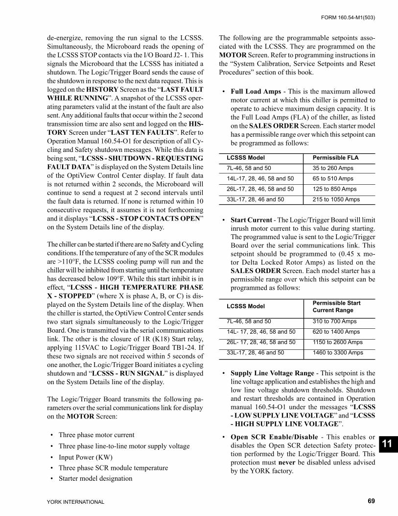
FORM 160.54-M1(503)
69YORK INTERNATIONAL
de-energize, removing the run signal to the LCSSS. Si mul ta neous ly, the Microboard reads the opening of the LCSSS STOP contacts via the I/O Board J2- 1. This signals the Microboard that the LCSSS has ini ti at ed a shutdown. The Logic/Trigger Board sends the cause of the shut down in response to the next data re quest. This is logged on the HISTORY Screen as the “LAST FAULT WHILE RUN NING”. A snapshot of the LCSSS op er -at ing pa ram e ters valid at the instant of the fault are also sent. Any ad di tion al faults that oc cur with in the 2 second trans mis sion time are also sent and logged on the HIS- TO RY Screen under “LAST TEN FAULTS”. Refer to Op er a tion Manual 160.54-O1 for de scrip tion of all Cy- cling and Safety shut down mes sag es. While this data is be ing sent, “LCSSS - SHUT DOWN - RE QUEST ING FAULT DATA” is dis played on the Sys tem De tails line of the OptiView Control Center display. If fault data is not re turned with in 2 sec onds, the Microboard will con tin ue to send a re quest at 2 second intervals until the fault data is re turned. If none is returned with in 10 con sec u tive re quests, it as sumes it is not forth com ing and it displays “LCSSS - STOP CONTACTS OPEN” on the Sys tem Details line of the display.
The chiller can be started if there are no Safety and Cy cling conditions. If the temperature of any of the SCR modules are >110°F, the LCSSS cooling pump will run and the chiller will be inhibited from starting until the tem per a ture has decreased below 109°F. While this start in hib it is in effect, “LCSSS - HIGH TEM PER A TURE PHASE X - STOPPED” (where X is phase A, B, or C) is dis-played on the System Details line of the dis play. When the chiller is started, the OptiView Control Cen ter sends two start signals simultaneously to the Logic/Trig ger Board. One is transmitted via the serial com mu ni ca tions link. The other is the closure of 1R (K18) Start re lay, ap ply ing 115VAC to Logic/Trigger Board TB1-24. If these two signals are not received within 5 seconds of one an oth er, the Logic/Trigger Board ini tiates a cy cling shut down and “LCSSS - RUN SIG NAL” is dis played on the System Details line of the display.
The Logic/Trigger Board transmits the following pa- ram e ters over the serial communications link for dis play on the MOTOR Screen:
• Three phase motor current • Three phase line-to-line motor supply voltage • Input Power (KW) • Three phase SCR module temperature • Starter model designation
The following are the programmable setpoints as so -ci at ed with the LCSSS. They are programmed on the MOTOR Screen. Refer to programming instructions in the “System Calibration, Service Setpoints and Re set Procedures” section of this book.
• Full Load Amps - This is the maximum allowed mo tor current at which this chiller is permitted to op er ate to achieve maximum design capacity. It is the Full Load Amps (FLA) of the chiller, as listed on the SALES ORDER Screen. Each starter mod el has a permissible range over which this setpoint can be programmed as follows:
LCSSS Model Permissible FLA 7L-46, 58 and 50 35 to 260 Amps
14L-17, 28, 46, 58 and 50 65 to 510 Amps
26L-17, 28, 46, 58 and 50 125 to 850 Amps
33L-17, 28, 46 and 50 215 to 1050 Amps
• Start Current - The Logic/Trigger Board will lim it in rush motor current to this value during starting. The programmed value is sent to the Logic/Trigger Board over the serial communications link. This setpoint should be programmed to (0.45 x mo-tor Delta Locked Rotor Amps) as listed on the SALES ORDER Screen. Each model starter has a per mis si ble range over which this setpoint can be pro grammed as follows:
LCSSS Model Permissible Start Current Range
7L-46, 58 and 50 310 to 700 Amps
14L- 17, 28, 46, 58 and 50 620 to 1400 Amps
26L- 17, 28, 46, 58 and 50 1150 to 2600 Amps
33L-17, 28, 46 and 50 1460 to 3300 Amps
• Supply Line Voltage Range - This setpoint is the line voltage application and establishes the high and low line voltage shutdown thresholds. Shut down and re start thresholds are contained in Operation man u al 160.54-O1 under the messages “LCSSS - LOW SUP PLY LINE VOLTAGE” and “LCSSS - HIGH SUPPLY LINE VOLTAGE”.
• Open SCR Enable/Disable - This enables or dis ables the Open SCR detection Safety protec-tion per formed by the Logic/Trigger Board. This pro tec tion must nev er be disabled unless advised by the YORK factory.
11
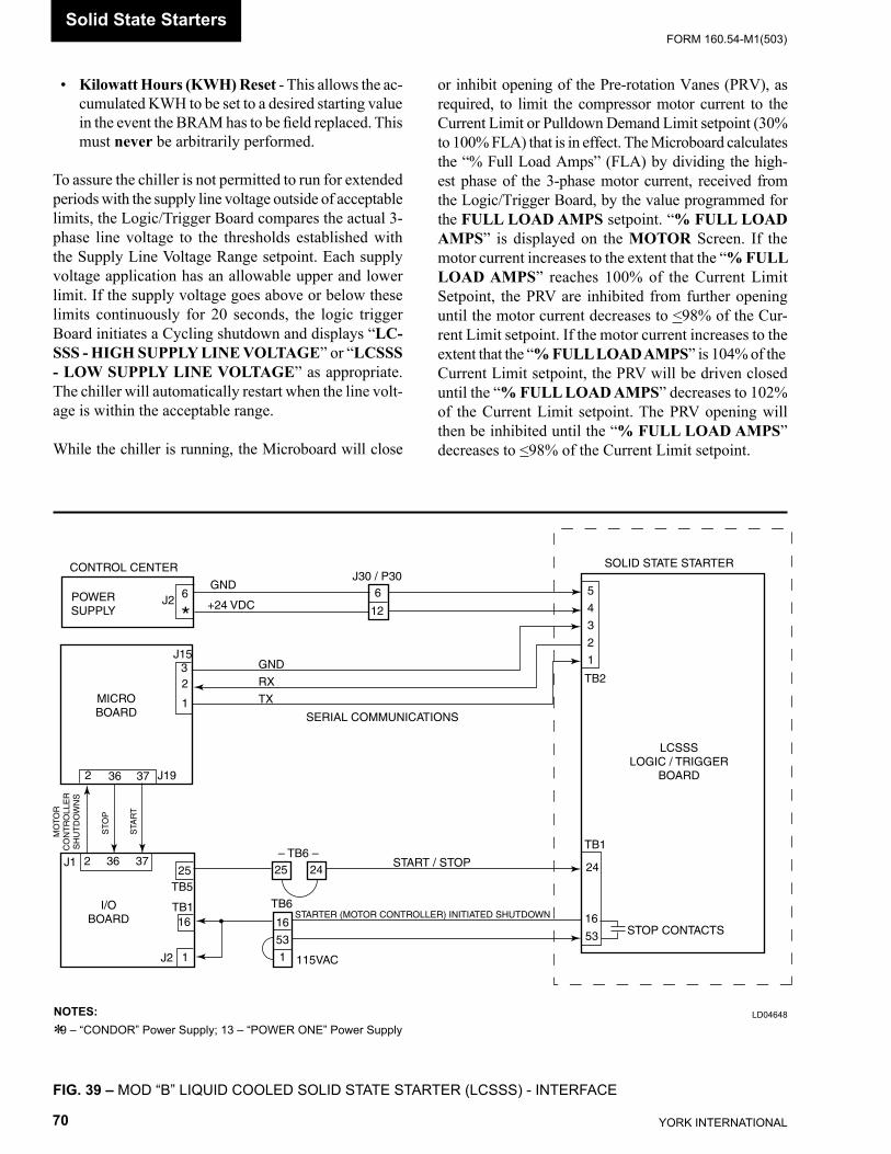
YORK INTERNATIONAL70
FORM 160.54-M1(503)
• Kilowatt Hours (KWH) Reset - This allows the ac- cu mu lat ed KWH to be set to a desired starting val ue in the event the BRAM has to be fi eld re placed. This must never be arbitrarily performed.
To assure the chiller is not permitted to run for ex tend ed periods with the supply line voltage outside of ac cept able limits, the Logic/Trigger Board compares the ac tu al 3-phase line voltage to the thresholds established with the Supply Line Voltage Range setpoint. Each sup ply voltage application has an allowable upper and low er limit. If the supply voltage goes above or below these limits continuously for 20 seconds, the logic trig ger Board initiates a Cycling shutdown and displays “LC-SSS - HIGH SUPPLY LINE VOLTAGE” or “LCSSS - LOW SUPPLY LINE VOLTAGE” as ap pro pri ate. The chiller will automatically restart when the line volt- age is within the acceptable range.
While the chiller is running, the Microboard will close
or inhibit opening of the Pre-rotation Vanes (PRV), as re quired, to limit the compressor motor current to the Cur rent Limit or Pulldown Demand Limit setpoint (30% to 100% FLA) that is in effect. The Microboard cal cu lates the “% Full Load Amps” (FLA) by dividing the high-est phase of the 3-phase motor current, re ceived from the Logic/Trig ger Board, by the value pro grammed for the FULL LOAD AMPS setpoint. “% FULL LOAD AMPS” is displayed on the MOTOR Screen. If the motor current increases to the extent that the “% FULL LOAD AMPS” reaches 100% of the Current Limit Setpoint, the PRV are inhibited from further open ing until the motor cur rent decreases to <98% of the Cur- rent Lim it setpoint. If the motor current increases to the ex tent that the “% FULL LOAD AMPS” is 104% of the Current Limit setpoint, the PRV will be driven closed until the “% FULL LOAD AMPS” de creas es to 102% of the Cur rent Limit setpoint. The PRV open ing will then be in hib it ed until the “% FULL LOAD AMPS” decreases to <98% of the Current Lim it setpoint.
LD04648NOTES: 9 – “CONDOR” Power Supply; 13 – “POWER ONE” Power Supply*
FIG. 39 – MOD “B” LIQUID COOLED SOLID STATE STARTER (LCSSS) - INTERFACE
POWERSUPPLY
MICROBOARD
I/OBOARD
LCSSSLOGIC / TRIGGER
BOARD
STOP CONTACTS
SERIAL COMMUNICATIONS
CONTROL CENTER SOLID STATE STARTER
GND
+24 VDC
J15
6
*
J30 / P306
12
J1
J19
J2
2 36 37
32
1
MO
TOR
CO
NT
RO
LLE
RS
HU
TD
OW
NS
STO
P
STA
RT
GND
RX
TX
5
4
3
2
1
TB2
TB1
24
16
53
START / STOP
STARTER (MOTOR CONTROLLER) INITIATED SHUTDOWN
115VAC
16
53
1
TB6
– TB6 –25 24
2 36 3725
16
1
TB5
TB1
J2
Solid State Starters
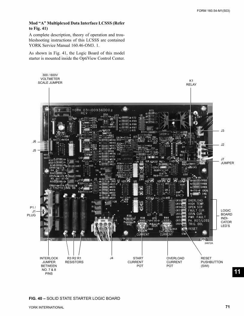
FORM 160.54-M1(503)
71YORK INTERNATIONAL
Mod “A” Multiplexed Data Interface LCSSS (Re fer to Fig. 41)A complete description, theory of operation and trou- ble shoot ing instructions of this LCSSS are contained YORK Service Manual 160.46-OM3. 1.
As shown in Fig. 41, the Logic Board of this model start er is mounted inside the OptiView Control Center.
FIG. 40 – SOLID STATE STARTER LOGIC BOARD
INTERLOCKJUMPER
BETWEENNO. 7 & 8
PINS
24672A
R3 R2 R1RESISTORS
J4 STARTCURRENT
POT
OVER LOADCURRENTPOT
RESETPUSHBUTTON(SWI)
LOGICBOARDIN DI -CA TORLED’S
J7JUMPER
J2
K1RELAY
J3
J6
J5
300 / 600VVOLTMETER
SCALE JUMPER
P1 / J1
PLUG
11
YORK INTERNATIONAL72
FORM 160.54-M1(503)
This board pro vides Overload, Power Fault, Fault Cur rent, Phase Ro ta tion/Loss, and Half Phase Pro- tec tion for the Com pres sor Motor. It also receives SCR High Temp and Trig ger Out Of Lock (OOL) shutdown sig nals from the Start er Trig ger Board. Fi nal ly, it pro- vides an a log volt ag es rep re sent ing Com pres sor Motor Cur rent, Pow er Line Volt age, Current Limit com mands and a Start er Model code to the Microboard.
The contacts of Logic Board relay K1 (identifi ed as “CM” contacts on the OptiView Con trol Center wiring diagram) are interfaced into the Motor Controller ini- ti at ed shut down circuit that is located between OptiView Con trol Center TB6-53 and I/O Board TB1-16 (ref. Fig. 16 and 37). They are also connected as a digital input to I/O Board J2-1. Relay K1 is normally en er gized, main- tain ing its con tacts in a closed position. When ev er the Logic Board initiates a chiller shut down, it de-en er giz es K1, open ing its con tacts. This interrupts the cir cuit to I/O Board RUN re lay coil 1R (K18), de-en er giz ing it and causing the Start er to de-en er gize. Si mul ta neous ly, the Microboard reads the opening of these con tacts via I/O Board J2-1, ini tiates a SYSTEM COASTDOWN and dis plays the ap pro pri ate message as described below.
When the Logic Board detects an Overload con di tion, Re lay K1 contacts open and the Over load LED il lu -mi nates. “MOTOR CON TROL LER – CONTACTS OPEN” is dis played. The contacts remain open and the LED re mains il lu mi nat ed until manually reset with the Logic Board’s S1 RESET switch. After S1 is pressed, the chiller can be restarted.
When a Power Fault, Fault Current or Half Phase condition is detected, Relay K1 con tacts open for 1 sec- ond and then close. The Power Fault LED illuminates and will re main illuminated until manually reset with the S1 RESET switch. POWER FAULT is dis played. At the com ple tion of SYSTEM COASTDOWN, the chill er will au to mat i cal ly restart.
When a Power line Phase Rotation/Loss or Trigger Board Out of Lock (OOL) con di tion is detected, Relay K1 con- tacts open and remain open for as long as the con di tion ex-ists. If the contacts remain open for more than 3 sec onds, MOTOR CONTROLLER – CON TACTS OPEN is displayed; if less than 3 seconds, POWER FAULT is dis played. The respective Ph. Rot/Loss or Trig. OOL LED illuminates and re mains il lu mi nat ed until manu-
ally reset with the S1 RE SET switch. The chiller will au to mat i cal ly restart when the contacts close.
The Starter Trigger Board monitors the Starter’s Sil- i con Controlled Rectifi er (SCR) heatsink temperature. Whenever the heatsink temperature increases to 212ºF, the Trigger Board signals the Logic Board. MO TOR CON TROL LER – CONTACTS OPEN is dis played. The Log ic Board illuminates the High Temp LED and opens Re lay K1 contacts. The LED remains il lu mi nat ed and the con tacts remain open until the tem per a ture de- creas es to less than 110ºF and manually reset with the Logic Board’s S1 RESET switch. After S1 is pressed, the chiller can be restarted. In routine op er a tion, each time the chiller is shutdown for any rea son, it is pre- vent ed from restarting until the heatsink tem per a ture de creas es to less then 110ºF. While it is waiting for the tem per a ture to decrease to this thresh old, the HIGH TEMP LED is illuminated, Relay K1 contacts are open, and MOTOR CON TROL LER – CONTACTS OPEN is dis played. When the temperature is below 110ºF, K1 contacts will open, the LED is ex tin guished, MO TOR CONTROLLER – CONTACTS OPEN mes sage is cleared and the chiller will au to mat i cal ly re start.
The Multiplexer (MUX) is an electronic switch with 8 inputs and 1 output. The address applied to it de ter mines the po si tion of the switch and therefore the out put. Under Program control, the Microboard se quen tial ly addresses MUX channels 0 through 7. The volt age output of each channel is listed in the table below. Channel 0 is an analog voltage that represents the Start er model and Power Line voltage Voltmeter scale. The Program uses this value to limit the Full Load Amps Setpoint range to the maximum allowed value for the Starter size. This value also determines the Line Volt age display range and Motor current display range. Channel 1 is a cur rent limit command that forces the Micro to perform Pre-rotation vanes inhibit and clo sure at the 100% and 104% FLA. This command is in ad di tion to the Micro’s software cur-rent limit feature that’s based on a calculation comparing the highest cur rent phase to the programmed Full Load Amp Setpoint to arrive at an FLA Percentage. Channels 2 though 4 are an a log voltages representing Phase C, B and A
Solid State Starters
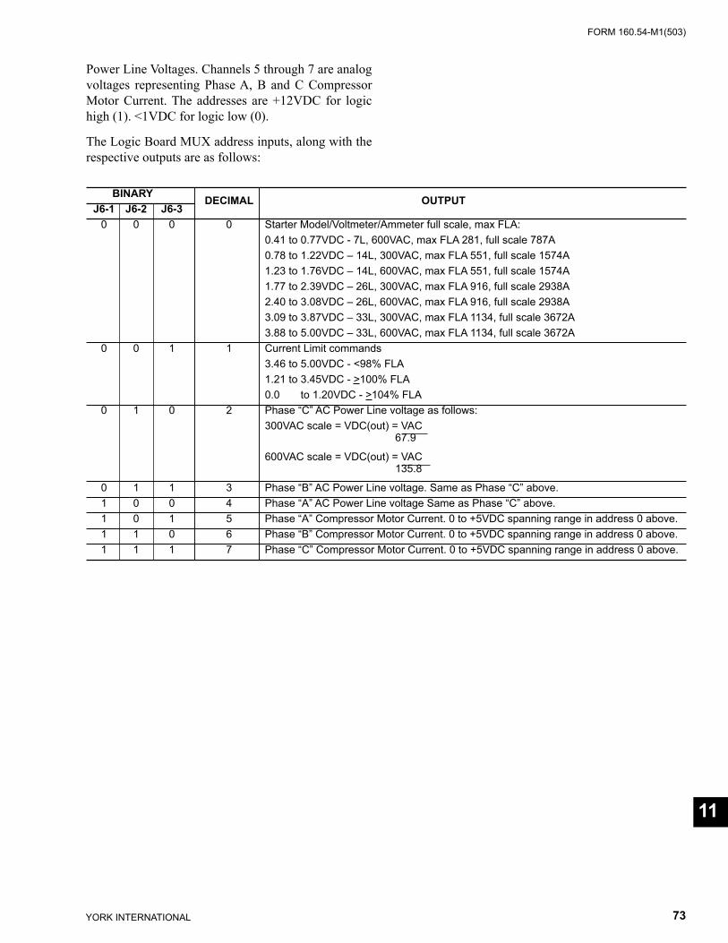
FORM 160.54-M1(503)
73YORK INTERNATIONAL
BINARY DECIMAL OUTPUT J6-1 J6-2 J6-3 0 0 0 0 Starter Model/Voltmeter/Ammeter full scale, max FLA: 0.41 to 0.77VDC - 7L, 600VAC, max FLA 281, full scale 787A 0.78 to 1.22VDC – 14L, 300VAC, max FLA 551, full scale 1574A 1.23 to 1.76VDC – 14L, 600VAC, max FLA 551, full scale 1574A 1.77 to 2.39VDC – 26L, 300VAC, max FLA 916, full scale 2938A 2.40 to 3.08VDC – 26L, 600VAC, max FLA 916, full scale 2938A 3.09 to 3.87VDC – 33L, 300VAC, max FLA 1134, full scale 3672A 3.88 to 5.00VDC – 33L, 600VAC, max FLA 1134, full scale 3672A 0 0 1 1 Current Limit commands 3.46 to 5.00VDC - <98% FLA 1.21 to 3.45VDC - >100% FLA 0.0 to 1.20VDC - >104% FLA 0 1 0 2 Phase “C” AC Power Line voltage as follows: 300VAC scale = VDC(out) = VAC 67.9
600VAC scale = VDC(out) = VAC
135.8
0 1 1 3 Phase “B” AC Power Line voltage. Same as Phase “C” above. 1 0 0 4 Phase “A” AC Power Line voltage Same as Phase “C” above. 1 0 1 5 Phase “A” Compressor Motor Current. 0 to +5VDC spanning range in address 0 above. 1 1 0 6 Phase “B” Compressor Motor Current. 0 to +5VDC spanning range in address 0 above. 1 1 1 7 Phase “C” Compressor Motor Current. 0 to +5VDC spanning range in address 0 above.
Power Line Voltages. Channels 5 through 7 are analog volt ag es representing Phase A, B and C Compressor Mo tor Current. The addresses are +12VDC for logic high (1). <1VDC for logic low (0).
The Logic Board MUX address inputs, along with the respective outputs are as follows:
11
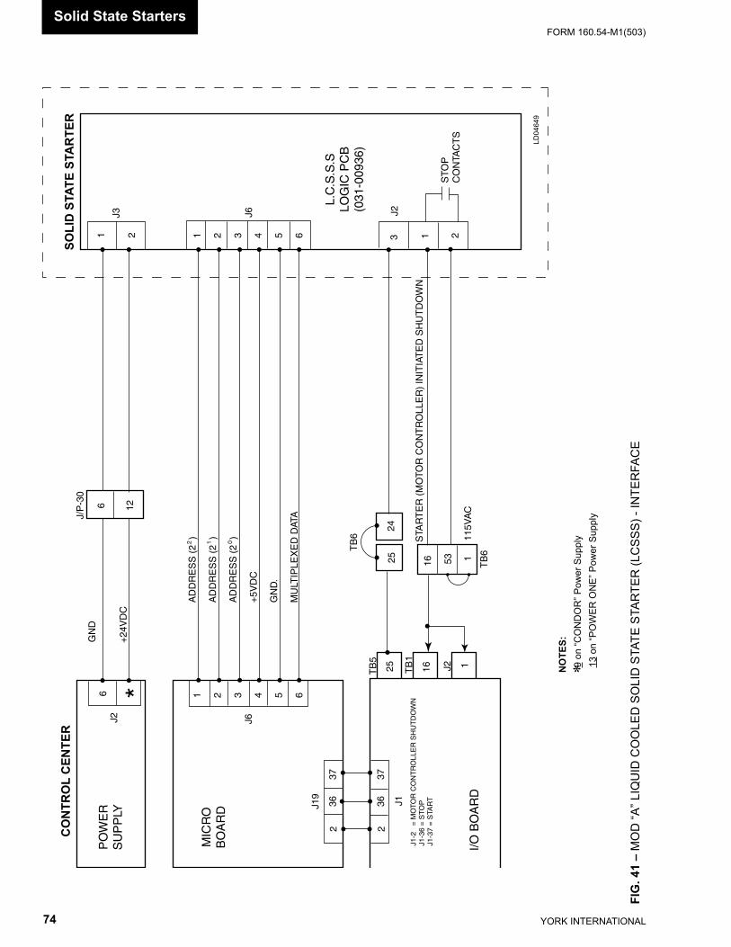
YORK INTERNATIONAL74
FORM 160.54-M1(503)
NO
TES:
9 o
n “C
ON
DO
R” P
ower
Sup
ply
13
on “P
OW
ER O
NE”
Pow
er S
uppl
y*
FIG
. 41
– M
OD
“A” L
IQU
ID C
OO
LED
SO
LID
STA
TE S
TAR
TER
(LC
SSS)
- IN
TER
FAC
E
CO
NTR
OL
CEN
TER
SOLI
D S
TATE
STA
RTE
R
PO
WE
RS
UP
PLY
MIC
RO
BO
AR
D
I/O B
OA
RD
L.C
.S.S
.SLO
GIC
PC
B(0
31-0
0936
)
236
37
236
37
J1J19
J1-2
=
MO
TOR
CO
NT
RO
LLE
R S
HU
TD
OW
NJ1
-36
= S
TOP
J1-3
7 =
STA
RT
25 16 1
TB
5
TB
1
J2
TB
6
16 53 1
TB
6
2524
3 1 2
J2
STO
PC
ON
TAC
TS
1 2 3 4 5 6
1 2 3 4 5 6
J6J3
1 2
AD
DR
ES
S (
2 )
AD
DR
ES
S (
2 )
AD
DR
ES
S (
2 )
+5V
DC
GN
D.
MU
LTIP
LEX
ED
DAT
A
GN
D
+24
VD
C
J/P
-30
6 12
6J2 J6
*
115V
AC
STA
RT
ER
(M
OTO
R C
ON
TR
OLL
ER
) IN
ITIA
TE
D S
HU
TD
OW
N
2 1 0
LD04
649
Solid State Starters
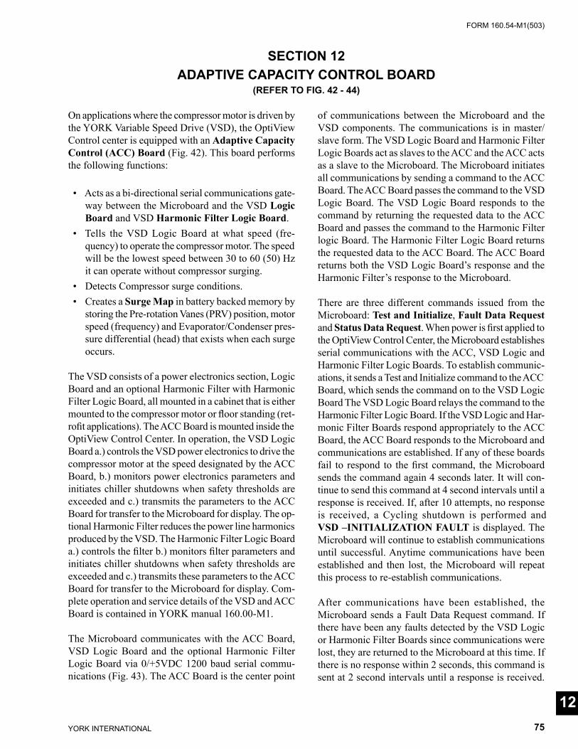
FORM 160.54-M1(503)
75YORK INTERNATIONAL
On applications where the compressor motor is driven by the YORK Variable Speed Drive (VSD), the OptiView Con trol center is equipped with an Adap tive Capacity Con trol (ACC) Board (Fig. 42). This board performs the fol low ing functions:
• Acts as a bi-directional serial com mu ni ca tions gate- way between the Microboard and the VSD Logic Board and VSD Harmonic Filter Logic Board.
• Tells the VSD Logic Board at what speed (fre- quen cy) to operate the compressor motor. The speed will be the lowest speed between 30 to 60 (50) Hz it can operate without compressor surging.
• Detects Compressor surge conditions. • Creates a Surge Map in battery backed memory by
storing the Pre-rotation Vanes (PRV) po si tion, mo tor speed (frequency) and Evap o ra tor/Con dens er pres-sure dif fer en tial (head) that exists when each surge occurs.
The VSD consists of a power electronics section, Log ic Board and an optional Harmonic Filter with Harmonic Filter Logic Board, all mounted in a cabinet that is ei ther mounted to the compressor motor or fl oor stand ing (ret- ro fi t applications). The ACC Board is mounted inside the OptiView Control Center. In operation, the VSD Logic Board a.) controls the VSD power elec tron ics to drive the com pres sor motor at the speed des ig nat ed by the ACC Board, b.) monitors power elec tron ics pa ram e ters and initiates chiller shutdowns when safety thresh olds are exceeded and c.) transmits the parameters to the ACC Board for transfer to the Microboard for display. The op-tional Harmonic Filter re duc es the power line har mon ics produced by the VSD. The Harmonic Filter Logic Board a.) controls the fi lter b.) monitors fi lter parameters and initiates chiller shut downs when safety thresholds are exceeded and c.) trans mits these pa ram e ters to the ACC Board for trans fer to the Microboard for dis play. Com-plete operation and ser vice details of the VSD and ACC Board is con tained in YORK man u al 160.00-M1.
The Microboard communicates with the ACC Board, VSD Logic Board and the optional Harmonic Filter Logic Board via 0/+5VDC 1200 baud serial com mu -ni ca tions (Fig. 43). The ACC Board is the center point
of com mu ni ca tions between the Microboard and the VSD com po nents. The communications is in master/slave form. The VSD Logic Board and Harmonic Filter Log ic Boards act as slaves to the ACC and the ACC acts as a slave to the Microboard. The Microboard initiates all communications by sending a command to the ACC Board. The ACC Board passes the command to the VSD Logic Board. The VSD Logic Board responds to the command by returning the requested data to the ACC Board and passes the command to the Harmonic Filter logic Board. The Harmonic Filter Logic Board returns the requested data to the ACC Board. The ACC Board returns both the VSD Logic Board’s response and the Harmonic Filter’s response to the Microboard.
There are three different commands issued from the Microboard: Test and Initialize, Fault Data Re quest and Status Data Request. When power is fi rst ap plied to the OptiView Control Center, the Microboard es tab lish es se ri al communications with the ACC, VSD Logic and Harmonic Filter Logic Boards. To establish com mu ni c-a tions, it sends a Test and Ini tial ize com mand to the ACC Board, which sends the command on to the VSD Logic Board The VSD Logic Board relays the com mand to the Harmonic Filter Logic Board. If the VSD Logic and Har- mon ic Filter Boards respond ap pro pri ate ly to the ACC Board, the ACC Board re sponds to the Microboard and communications are es tab lished. If any of these boards fail to re spond to the fi rst com mand, the Microboard sends the command again 4 sec onds later. It will con- tin ue to send this com mand at 4 second intervals until a response is re ceived. If, after 10 attempts, no response is re ceived, a Cycling shut down is performed and VSD –INITIALIZATION FAULT is displayed. The Microboard will con tin ue to establish com mu ni ca tions until suc cess ful. Anytime com mu ni ca tions have been es tab lished and then lost, the Microboard will repeat this process to re-establish com mu ni ca tions.
After communications have been established, the Microboard sends a Fault Data Request command. If there have been any faults detected by the VSD Logic or Harmonic Filter Boards since communications were lost, they are returned to the Microboard at this time. If there is no response within 2 seconds, this command is sent at 2 second intervals until a response is re ceived.
SECTION 12ADAPTIVE CAPACITY CONTROL BOARD
(REFER TO FIG. 42 - 44)
12
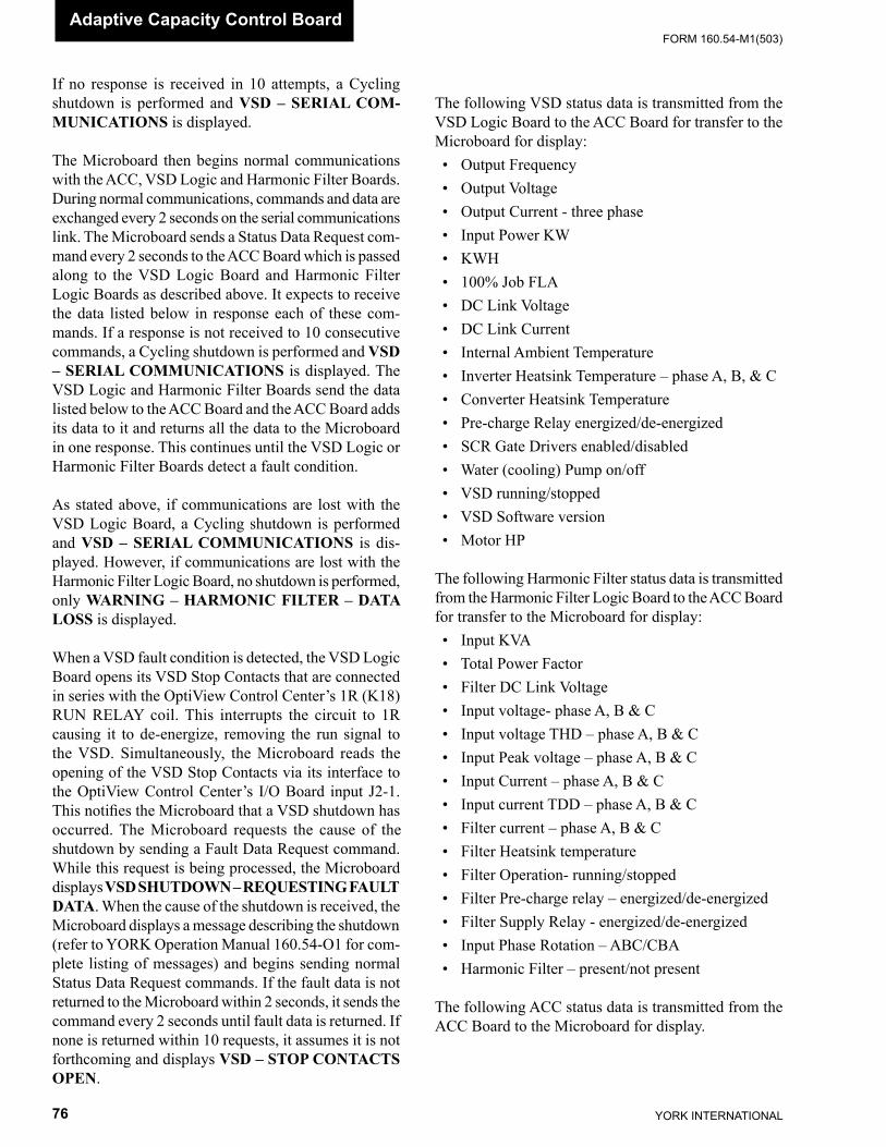
YORK INTERNATIONAL76
FORM 160.54-M1(503)Adaptive Capacity Control Board
If no response is received in 10 attempts, a Cycling shut down is performed and VSD – SERIAL COM- MU NI CA TIONS is displayed.
The Microboard then begins normal communications with the ACC, VSD Logic and Harmonic Filter Boards. During normal communications, commands and data are exchanged every 2 seconds on the serial com mu ni ca tions link. The Microboard sends a Status Data Re quest com-mand every 2 seconds to the ACC Board which is passed along to the VSD Logic Board and Harmonic Filter Logic Boards as described above. It expects to receive the data listed below in response each of these com-mands. If a response is not received to 10 consecutive commands, a Cycling shutdown is per formed and VSD – SERIAL COMMUNICATIONS is dis played. The VSD Logic and Harmonic Filter Boards send the data listed below to the ACC Board and the ACC Board adds its data to it and returns all the data to the Microboard in one response. This con tin ues until the VSD Logic or Harmonic Filter Boards detect a fault condition.
As stated above, if communications are lost with the VSD Logic Board, a Cycling shutdown is performed and VSD – SERIAL COMMUNICATIONS is dis- played. However, if communications are lost with the Harmonic Filter Logic Board, no shutdown is per formed, only WARNING – HARMONIC FILTER – DATA LOSS is displayed.
When a VSD fault condition is detected, the VSD Log ic Board opens its VSD Stop Contacts that are connected in series with the OptiView Control Cen ter’s 1R (K18) RUN RELAY coil. This interrupts the circuit to 1R caus ing it to de-energize, removing the run signal to the VSD. Si mul ta neous ly, the Microboard reads the open ing of the VSD Stop Contacts via its in ter face to the OptiView Control Cen ter’s I/O Board input J2-1. This notifi es the Microboard that a VSD shut down has oc curred. The Microboard requests the cause of the shut down by send ing a Fault Data Request com mand. While this re quest is being processed, the Microboard dis plays VSD SHUT DOWN – RE QUEST ING FAULT DATA. When the cause of the shutdown is received, the Microboard dis plays a mes sage describing the shut down (re fer to YORK Op er a tion Manual 160.54-O1 for com- plete list ing of mes sag es) and begins sending normal Status Data Request com mands. If the fault data is not returned to the Microboard within 2 seconds, it sends the com mand every 2 sec onds until fault data is re turned. If none is returned with in 10 requests, it as sumes it is not forth com ing and dis plays VSD – STOP CON TACTS OPEN.
The following VSD status data is transmitted from the VSD Logic Board to the ACC Board for transfer to the Microboard for display: • Output Frequency • Output Voltage • Output Current - three phase • Input Power KW • KWH • 100% Job FLA • DC Link Voltage • DC Link Current • Internal Ambient Temperature • Inverter Heatsink Temperature – phase A, B, & C • Converter Heatsink Temperature • Pre-charge Relay energized/de-en er gized • SCR Gate Drivers enabled/disabled • Water (cooling) Pump on/off • VSD running/stopped • VSD Software version • Motor HP
The following Harmonic Filter status data is trans mit ted from the Harmonic Filter Logic Board to the ACC Board for transfer to the Microboard for display: • Input KVA • Total Power Factor • Filter DC Link Voltage • Input voltage- phase A, B & C • Input voltage THD – phase A, B & C • Input Peak voltage – phase A, B & C • Input Current – phase A, B & C • Input current TDD – phase A, B & C • Filter current – phase A, B & C • Filter Heatsink temperature • Filter Operation- running/stopped • Filter Pre-charge relay – energized/de-en er gized • Filter Supply Relay - energized/de-en er gized • Input Phase Rotation – ABC/CBA • Harmonic Filter – present/not present The following ACC status data is transmitted from the ACC Board to the Microboard for display.
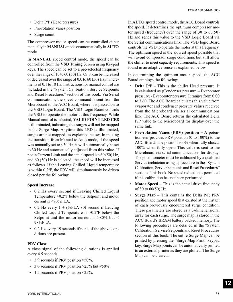
FORM 160.54-M1(503)
77YORK INTERNATIONAL
• Delta P/P (Head pressure) • Pre-rotation Vanes position • Surge count
The compressor motor speed can be controlled either man u al ly in MANUAL mode or automatically in AUTO mode.
In MANUAL speed control mode, the speed can be controlled from the VSD Tuning Screen using Key pad keys. The speed can be set to a pre-selected fre quen cy over the range of 10 to 60 (50) Hz. Or, it can be in creased or decreased over the range of 0.0 to 60 (50) Hz in in cre -ments of 0.1 to 10 Hz. Instructions for man u al con trol are included in the “System Calibration, Service Setpoints and Reset Procedures” section of this book. Via Serial communications, the speed command is sent from the Microboard to the ACC Board, where it is passed on to the VSD Logic Board. The VSD Log ic Board con trols the VSD to operate the motor at this frequency. While Manual control is selected, VALID POINT LED CR8 is illuminated, indicating that surg es will not be mapped in the Surge Map. Anytime this LED is il lu mi nat ed, surges are not mapped, as ex plained be low. In making the transition from Manual to Auto mode, if the speed was manually set to <30 Hz, it will au to mat i cal ly be set to 30 Hz and automatically ad just ed from this val ue. If not in Current Limit and the actual speed is <60 (50) Hz, and 60 (50) Hz is selected, the speed will be increased as follows. If the Leaving Chilled Liq uid tem per a ture is within 0.2ºF, the PRV will si mul ta neous ly be driven closed per the following:
Speed Increase • 0.2 Hz every second if Leaving Chilled Liquid
Tem per a ture >0.2ºF below the Setpoint and motor cur rent is <80%FLA.
• 0.2 Hz every 1 + (%FLA-80) second if Leaving Chilled Liquid Temperature is >0.2ºF below the Setpoint and the motor current is >80% but < 98%FLA.
• 0.2 Hz every 19 seconds if none of the above con- di tions are present.
PRV CloseA close signal of the following durations is ap plied every 4.5 seconds: • 3.9 seconds if PRV position >50%. • 3.0 seconds if PRV position >25% but <50%. • 1.5 seconds if PRV position <25%.
In AUTO speed control mode, the ACC Board con trols the speed. It determines the optimum compressor mo- tor speed (frequency) over the range of 30 to 60(50) Hz and sends this value to the VSD Logic Board via the Serial com mu ni ca tions link. The VSD logic Board con trols the VSD to operate the motor at this fre quen cy. The op ti mum speed is the slowest speed possible that will avoid compressor surge conditions but still allow the chiller to meet capacity re quire ments. This speed is found in an adaptive sense as explained below.
In determining the optimum motor speed, the ACC Board employs the following: • Delta P/P – This is the chiller Head pres sure. It
is calculated as (Condenser pressure – Evap o ra tor pressure) / Evaporator pressure. It ranges from 0.00 to 3.60. The ACC Board cal cu lates this value from evaporator and condenser pressure values re ceived from the Microboard via serial communications link. The ACC Board returns the calculated Delta P/P value to the Microboard for display over the same link.
• Pre-rotation Vanes (PRV) position – A po ten -ti om e ter provides PRV position (0 to 100%) to the ACC Board. The position is 0% when fully closed, 100% when fully open. This value is sent to the Microboard via serial communications for display. The potentiometer must be calibrated by a qualifi ed Ser vice technician us ing a procedure in the “Sys tem Calibration, Service setpoints and Reset Pro ce dures” section of this book. No speed reduction is per mit ted if this calibration has not been per formed.
• Motor Speed – This is the actual drive fre quen cy of 30 to 60(50) Hz.
• Surge Map – This contains the Delta P/P, PRV po si tion and motor speed that existed at the in stant of each pre vi ous ly encountered surge condition. These pa ram e ters are stored as a 3-dimenensional ar ray for each surge. The surge map is stored in the ACC Board’s BRAM battery backed memory. The fol low ing pro ce dures are detailed in the “Sys tem Cal i bra tion, Ser vice Setpoints and Reset Pro ce dures section of this book: The entire Surge Map can be printed by press ing the “Surge Map Print” keypad key. Surge Map points can be automatically print ed to an ex ter nal print er as they are plotted. The Surge Map can be cleared.
12

YORK INTERNATIONAL78
FORM 160.54-M1(503)
The Surge Map must never be cleared unless ad vised by the YORK Factory.
The following conditions must be met be fore speed re duc tion is permitted:
• The PRV calibration procedure must have been per formed.
• Auto speed control mode must be selected at the Key pad.
• Current Limit must not be in effect. When cur- rent limit is in effect, Valid Point LED CR8 is il lu mi nat ed.
• The Leaving Chilled Liquid Temperature must be with in +0.3 and –0.6ºF of the Leaving Chilled Liq- uid Setpoint.
• The Chiller must have been running for >2 min- utes.
• The Leaving Chilled Liquid temperature must be sta ble. Lowering the speed while this tem per a ture is un sta ble, would tend to increase the instability. The Microboard calculates the sta bil i ty by com- par ing the Leaving Chilled Liq uid Tem per a ture to the Leav ing Chilled Liq uid Tem per a ture Setpoint to ar rive at a rate of change value. This value is then compared to the programmed Stability Limit Setpoint. If the rate of change exceeds the Sta bil i ty Lim it Setpoint val ue, the Microboard sends a fl ag to the ACC Board. In response, the ACC Board starts a 60 sec ond tim er. VALID POINT LED CR8 will be il lu mi nat ed and speed de creas es are pro hib it ed until the timer has elapsed. Also, when making the tran si tion from Manual speed control Mode to Auto Mode, the sta bil i ty timer is started, preventing speed re duc tion for 60 seconds. The Sta bil i ty Limit setpoint is pro grammed over the range of 1000 to 7000, by a qual i fi ed Service Technician us ing the procedure in the “System Calibration, Ser vice Setpoints and Re set Procedures” sec tion of this book. This val ue is a relative value that rep re sents magnitude of sta bil i ty. Higher values cor re spond to decreasing sen si tiv i ty. Default value of 4500 will provide prop er op er a tion in most applications.
• Certain applications, such as short chilled liquid loops, multi-pass evaporators, parallel chillers and light load conditions can cause ex ces sive Pre-rota-tion Vane (PRV) movement resulting in leaving chilled liquid temperature con trol instability. This instability can be reduced by adjusting the SEN-
SITIVITY Setpoint on the Optiview Evaporator Screen. The 50% se lec tion reduces the magnitude of PRV move ment over the NORMAL selection and the 30% se lec tion reduces it even more. With Flash Mem o ry Card version C.MLM.01.06.xxx and later or “P” com pres sors with C.MLM.04.02.xxx and later, and the 50% or 30% sensitivity is selected, PRV movement is further reduced during low load conditions with variable speed drive as follows: When the PRV position is < 25% and the Leaving Chilled Liquid Temperature is within + 2.5 ºF of Setpoint, the max i mum allowed vane pulse is lim-ited to 3.5 seconds at the 25% PRV position and 0.9 seconds at 0% po si tion. PRV positions in between have linearly scaled maximums.
When the chiller is started, the speed is brought to 60 Hz. After it has been running for >2 minutes and the Leav ing Chilled Liquid Temperature is within +0.3 and –0.6ºF of the Leaving Chilled Liq uid Tem per a ture Setpoint, the ACC Board eval u ates if the speed can be reduced. If there are no conditions above that would inhibit speed re duc tion, the ACC Board compares the real-time Del ta P/P, PRV Po si tion and motor speed to the 3-di men sion al arrays stored in the Surge Map. If the real-time ar ray does not match any previous surge condition, the speed will be decreased 0.1 Hz ev ery 6 seconds until it is with in 1 Hz of previously plotted surge condition array in the Surge Map. It will then be de creased 0.1 Hz ev ery 9 seconds un til it’s to the lowest value allowed by the Surge Map. If no plotted points are encountered, the speed is low ered until a surge is encountered or a minimum of 30 Hz is reached.
The ACC Board uses two different methods of Surge Detection; Delta P method and DC Link method. Surge de tec tion is only enabled while the chiller is run ning. In de tect ing a surge using the Delta P method, the out puts of the Evaporator and Condenser pressure Trans duc ers are mon i tored to detect when the dif fer ence be tween these pres sures (Delta P) drops tran sient ly to ward Zero. This would be indicative of a surge. A surge de tect ed by the Delta P method must have all of the fol low ing con di tions occur within 5 seconds to be con sid ered a valid surge: a.) Delta P must make a neg a tive transition and exceed 3.4 PSIG for 100 Mil li sec onds. B.) Delta P must also exceed 3.5 PSIG for at least 340 mil li sec onds. C.) Delta P must make at least 2 positive tran si tions. When this criteria is met, Surge LED CR9 il lu mi nates for 2 seconds, in- di cat ing a valid surge has been de tect ed. In detecting a surge using the DC Link method, the VSD’s DC Link Current is mon i tored to detect when the cur rent drops transiently to ward zero. This, as the case with Delta P
Adaptive Capacity Control Board
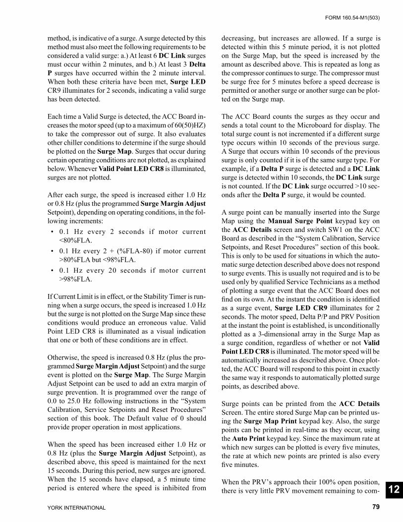
FORM 160.54-M1(503)
79YORK INTERNATIONAL
method, is indicative of a surge. A surge detected by this method must also meet the fol low ing re quire ments to be con sid ered a valid surge: a.) At least 6 DC Link surges must occur within 2 min utes, and b.) At least 3 Delta P surges have oc curred with in the 2 minute interval. When both these criteria have been met, Surge LED CR9 illuminates for 2 sec onds, indicating a valid surge has been de tect ed. Each time a Valid Surge is detected, the ACC Board in-creases the motor speed (up to a max i mum of 60(50)HZ) to take the compressor out of surge. It also evaluates other chiller conditions to determine if the surge should be plotted on the Surge Map. Surges that occur dur ing certain operating conditions are not plot ted, as ex plained below. Whenever Valid Point LED CR8 is il lu mi nat ed, surges are not plotted.
After each surge, the speed is increased either 1.0 Hz or 0.8 Hz (plus the programmed Surge Margin Ad just Setpoint), de pend ing on op er at ing conditions, in the fol- low ing in cre ments: • 0.1 Hz every 2 seconds if motor current
<80%FLA. • 0.1 Hz every 2 + (%FLA-80) if motor current
>80%FLA but <98%FLA. • 0.1 Hz every 20 seconds if motor current
>98%FLA.
If Current Limit is in effect, or the Stability Timer is run-ning when a surge occurs, the speed is increased 1.0 Hz but the surge is not plotted on the Surge Map since these conditions would produce an erroneous val ue. Valid Point LED CR8 is illuminated as a visual in di ca tion that one or both of these conditions are in effect.
Otherwise, the speed is increased 0.8 Hz (plus the pro- grammed Surge Margin Adjust Setpoint) and the surge event is plot ted on the Surge Map. The Surge Mar gin Ad just Setpoint can be used to add an extra margin of surge pre ven tion. It is pro grammed over the range of 0.0 to 25.0 Hz fol low ing instructions in the “System Cal i bra tion, Ser vice Setpoints and Reset Pro ce dures” sec tion of this book. The Default value of 0 should pro vide prop er operation in most applications.
When the speed has been increased either 1.0 Hz or 0.8 Hz (plus the Surge Margin Adjust Setpoint), as de scribed above, this speed is maintained for the next 15 seconds. During this period, new surges are ig nored. When the 15 sec onds have elapsed, a 5 minute time period is en tered where the speed is inhibited from
de creas ing, but in creas es are allowed. If a surge is de tect ed within this 5 minute period, it is not plotted on the Surge Map, but the speed is increased by the amount as described above. This is repeated as long as the com pres sor continues to surge. The compressor must be surge free for 5 min utes be fore a speed decrease is per mit ted or another surge or another surge can be plot- ted on the Surge map.
The ACC Board counts the surges as they occur and sends a total count to the Microboard for display. The total surge count is not incremented if a different surge type occurs within 10 seconds of the previous surge. A Surge that occurs within 10 seconds of the previous surge is only counted if it is of the same surge type. For example, if a Delta P surge is detected and a DC Link surge is detected within 10 seconds, the DC Link surge is not counted. If the DC Link surge occurred >10 sec- onds after the Delta P surge, it would be count ed.
A surge point can be manually inserted into the Surge Map using the Manual Surge Point keypad key on the ACC Details screen and switch SW1 on the ACC Board as de scribed in the “System Cal i bra tion, Service Setpoints, and Reset Procedures” section of this book. This is only to be used for situations in which the au to -mat ic surge detection described above does not re spond to surge events. This is usually not required and is to be used only by qualifi ed Service Tech ni cians as a meth od of plotting a surge event that the ACC Board does not fi nd on its own. At the instant the con di tion is iden ti fi ed as a surge event, Surge LED CR9 illuminates for 2 sec onds. The mo tor speed, Delta P/P and PRV Po si tion at the instant the point is es tab lished, is un con di tion al ly plot ted as a 3-dimensional ar ray in the Surge Map as a surge con di tion, regardless of whether or not Valid Point LED CR8 is il lu mi nat ed. The motor speed will be au to mat i cal ly increased as de scribed above. Once plot- ted, the ACC Board will re spond to this point in ex act ly the same way it responds to au to mat i cal ly plotted surge points, as described above.
Surge points can be printed from the ACC Details Screen. The en tire stored Surge Map can be print ed us- ing the Surge Map Print keypad key. Also, the surge points can be printed in real-time as they occur, using the Auto Print keypad key. Since the max i mum rate at which new surges can be plotted is every fi ve min utes, the rate at which new points are printed is also every fi ve min utes.
When the PRV’s approach their 100% open position, there is very little PRV movement remaining to com- 12

YORK INTERNATIONAL80
FORM 160.54-M1(503)
pen sate for an increasing load condition. Therefore, in Auto speed control mode, if there is no Current Limit in ef fect, and the PRV position reaches >98%, the speed is automatically increased at a rate based on the Delta T between the Leaving Chilled Liquid tem per a ture and the Leaving Chilled Liquid temperature Setpoint as fol lows: • 0.1 Hz every 10 seconds if Delta T is >0.2 and
<0.5ºF.• 0.1 Hz every 8 seconds if Delta T is >0.5 and
<0.9ºF.• 0.1 Hz every 6 seconds if Delta T is >0.9ºF.
If Delta P/P ever increases to >3.60, the speed will be slow ly increased to 60 Hz. If this were to occur, Delta P/P would have to decrease to <3.55 before a speed de crease would be allowed.
The microprocessor is the center point of the hardware architecture (Fig. 42). It coordinates the serial data com mu ni ca tions between the OptiView Control Center Microboard and the VSD Logic Board and Harmonic Filter Logic Board. This serial data is in 0v/+5VDC form. YM XMT (CR7) and YM RCV (CR6) LED’s illuminate during serial communications with the OptiView Control Center Microboard. Similarly, VS XMT (CR5) and VS RCV (CR4) LED’s illuminate dur ing serial com mu ni c-a tions with the VSD Logic Board. Serial communications with the Harmonic Filter logic Board take place through the mi cro pro ces sor via the Digital Signal Processor. This data is accompanied by a Framing pulse and a CLK sig nal. Although Evap o ra tor and Condenser pressures are trans- mit ted to the ACC Board via the serial com mu ni ca tions link for Delta P/P calculation, these pressures are also
ap plied directly from the Microboard to the MUX (mul- ti plex er) for Del ta P surge detection. Also ap plied to the MUX, is the out put of the PRV position Po ten ti om e ter. Under program con trol, these values are input to the mi cro pro ces sor. The EPROM contains the op er at ing Pro gram for the ACC Board. The RAM serves as the scratch pad mem o ry. The BRAM is a battery backed memory de vice where the Surge Map is stored. The Watchdog circuit main tains the mi cro pro ces sor in a re- set state dur ing low volt age conditions. This prevents the mi cro pro ces sor from reading/writing or processing data until it and sup port ing circuits have suffi cient sup- ply voltage. The Watch dog also assures that the entire Pro gram is executed and that no Pro gram latch-ups oc- cur. Surge LED CR9 illuminates for 2 seconds when a val id surge condition has been detected as ex plained above. Valid Point LED CR8 illuminates when ev er there is a con di tion in effect that prevents a Surge from being plotted on the Surge Map. These con di tions are: a.) Current Limit is in ef fect b.) Leaving Chilled Liq uid Tem per a ture Stability Timer is running, in di cat ing an un sta ble control con di tion c.) Speed con trol is in MAN- U AL mode. Switch SW1 is used to man u al ly in sert (plot) a surge point in the Surge Map.
Test points are provided as follows: • TPA: +5VDC supply voltage. • TPB: supply voltage ground. • TPC: Watchdog power failure detected. Nor mal ly
>+4.5VDC. Transitions to logic low (<3.5VDC) dur ing low voltage conditions.
• TPD: Harmonic Filter Logic Board 0/+5VDC 1200 baud serial data.
• TPE: Harmonic Filter Logic Board Frame pulse.
Adaptive Capacity Control Board
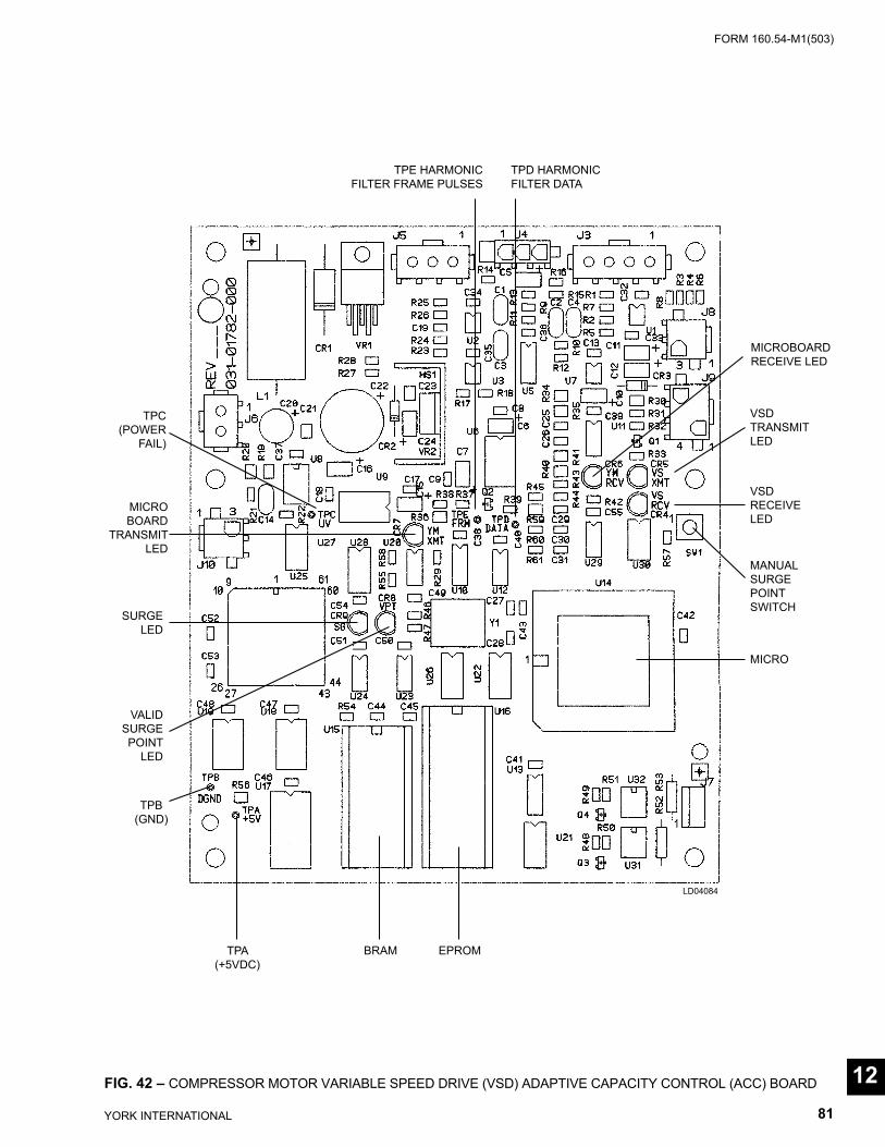
FORM 160.54-M1(503)
81YORK INTERNATIONAL
FIG. 42 – COMPRESSOR MOTOR VARIABLE SPEED DRIVE (VSD) ADAPTIVE CAPACITY CONTROL (ACC) BOARD
TPE HARMONICFILTER FRAME PULSES
TPD HARMONICFILTER DATA
MICROBOARDRECEIVE LED
VSDTRANSMITLED
VSDRECEIVELED
MANUALSURGEPOINTSWITCH
MICRO
TPC(POWER
FAIL)
MICROBOARD
TRANS MITLED
SURGELED
VALIDSURGEPOINT
LED
TPB(GND)
TPA(+5VDC)
BRAM EPROM
LD04084
12
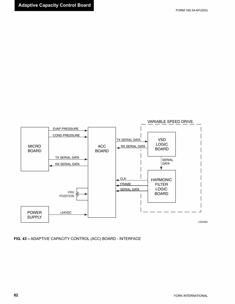
YORK INTERNATIONAL82
FORM 160.54-M1(503)
FIG. 43 – ADAPTIVE CAPACITY CONTROL (ACC) BOARD - INTERFACE
LD04085
MICROBOARD
POWERSUPPLY
ACCBOARD
VSDLOGICBOARD
HARMONICFILTERLOGICBOARD
VARIABLE SPEED DRIVE
SERIALDATA
TX SERIAL DATA
RX SERIAL DATA
CLK
FRAME
SERIAL DATA
EVAP PRESSURE
COND PRESSURE
TX SERIAL DATA
RX SERIAL DATA
+24VDC
PRVPOSITION
Adaptive Capacity Control Board
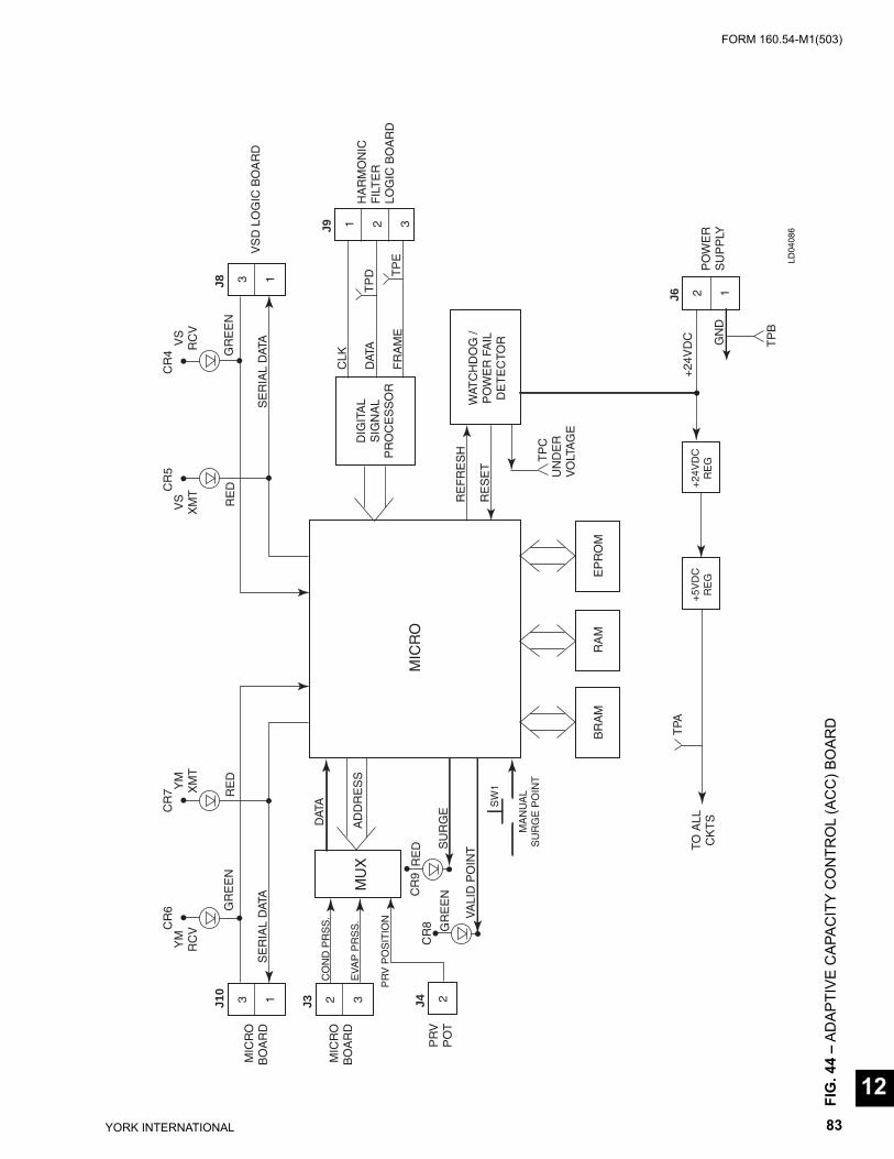
FORM 160.54-M1(503)
83YORK INTERNATIONAL
RE
FR
ES
H
RE
SE
TW
ATC
HD
OG
/P
OW
ER
FA
ILD
ET
EC
TOR
T
PC
UN
DE
RV
OLT
AG
E
DIG
ITA
LS
IGN
AL
PR
OC
ES
SO
R
CLK
DAT
A
FR
AM
E
TP
D TP
E
J9 1 2 3
BR
AM
EP
RO
MR
AM
MIC
RO
J8 3 1
RE
DG
RE
EN
SE
RIA
L D
ATA
CR
5C
R4
VS
XM
TV
SR
CV
VS
D L
OG
IC B
OA
RD
J10
J33 1
RE
DG
RE
EN
SE
RIA
L D
ATA
CR
6C
R7
YM
RC
VY
MX
MT
2 3H
AR
MO
NIC
FIL
TE
RLO
GIC
BO
AR
D
J6 2 1
PO
WE
RS
UP
PLY
TP
B
TPA
TO A
LLC
KT
S
MIC
RO
BO
AR
D
MIC
RO
BO
AR
DM
UX
DAT
A
AD
DR
ES
S
J4 2P
RV
PO
T
PR
V P
OS
ITIO
N
CO
ND
PR
SS
.
EV
AP
PR
SS
.
+5V
DC
RE
G+
24V
DC
RE
G
MA
NU
AL
SU
RG
E P
OIN
T
SW
1
VA
LID
PO
INTS
UR
GE
RE
D
GR
EE
N
CR
8C
R9
+24
VD
C GN
D
FIG
. 44
– AD
APTI
VE C
APAC
ITY
CO
NTR
OL
(AC
C) B
OAR
D
LD04
086
12
YORK INTERNATIONAL84
FORM 160.54-M1(503)Proximity Probe
SECTION 13PROXIMITY PROBE
(REFER TO FIG. 45 - 48)
The following applies to all applications except “P” compressors and style F and later chillers with “G” or “H5-8” compressors. For chillers equipped with “P” compressors, refer to Sec tion 13A: The Prox im i ty Probe senses the distance between the tip of the Proximity Probe and the surface of the High Speed Thrust collar. An ear li er vintage Probe (025-30961-000) also sensed the High Speed Drain Line oil temperature. How ev er, regardless of which Probe is installed, chill ers equipped with Flash Memory Card version C.MLM.01.03 or lat er do not sense the High Speed Drain Line oil tem- per a ture.
The output of the Proximity circuit is connected to the Microboard at J8-15 and is a 0 (0.089VDC) to +4.4VDC analog voltage corresponding to a mea sured distance of 10 to 99 mils. This is the PROX IM I TY POSITION and is displayed as “High Speed Thrust Bearing Prox im i ty Position = xx mils” on the Prox im i ty Probe Cal i bra tion Screen. The output of the 025-30961-000 Probe Temper-ature circuit is con nect ed to the Microboard at J8-1 and is a 0 to +4.5VDC analog volt age cor re spond ing to a mea- sured temperature of 0ºF (-177ºC) to 300ºF (148.9ºC). This is the OIL DRAIN LINE TEM PER A TURE and is displayed as “High Speed Thrust Bearing Oil Drain Tem per a ture = xxxºF on the Com pres sor Screen (not ap pli ca ble to Flash Memory Card version C.MLM.01.03 or later).
When the Probe is installed at the time of chiller man- u fac ture, a reference position is established. It is the dis tance between the tip of the Probe and the surface of the High Speed Thrust Collar with a minimum of 25 PSID oil pressure. Any distance between 37 and 79 mils is acceptable. It is established using a calibration pro ce dure in the “System Cal i bra tion” section of this book. This value is entered at the Keypad as the REF- ER ENCE POSITION Setpoint using the Proximity Probe Calibration Screen. Dis tanc es outside the range of 37 to 79 mils will be rejected. The value is logged on a label adhered to the inside of the OptiView Control Cen ter door. This value remains the Reference Position until the compressor is rebuilt, whereupon the calibration procedure must be re peat ed to establish a new Ref er ence Position. Since this Reference Position value is stored in the BRAM (U52) memory device on the Microboard, fi eld replacement of either of these items requires the Reference Position Setpoint to be pro grammed again.
The difference between the Reference Position and the actual Position is the PROXIMITY DIF FER EN TIAL and is displayed as “High Speed Thrust Bearing Prox- im i ty Differential = xx mils” on the Compressor Screen. For example, if the Reference Position is 50 mils and the actual Position is 45 mils, then the Dif fer en tial is -5 mils; with the same Ref er ence, if the actual Position is 55 mils, the Differential is +5 mils.
If the Differential increases to > 10 mils (+10, +11, etc.) or decreases to > 25 mils (-25, -26, etc.), a Safety shut down is performed and “THRUST BEAR ING - PROX IM I TY PROBE CLEARANCE” is displayed. The +10 thresh-old only has to be exceeded for an instant to initiate a shut down; the -25 threshold must be ex ceed ed for 2 con tin u ous seconds to initiate a shut down.
If the Reference Position is between 37 and 46 mils, the full -25 mil differential is not allowed; the max i mum al lowed distance between the tip of the Probe and the surface of the Thrust Collar is 23 mils. Therefore, when the distance decreases to < 22 mils, the Safety shut down is performed, regardless of the Differential to the Refer-ence Position.
If the distance decreases to < -17 mils, a safety shut down is performed and “THRUST BEARING - PROX IM I TY PROBE OUT OF RANGE” is dis played.
On chillers equipped with Probe 025-30961-000 and Flash Memory Card version C.MLM.01.02 and ear li er, if the Drain Line Temperature increases to >250.0ºF (121.1ºC), a Safety shutdown is per formed and “THRUST BEARING - HIGH OIL TEM PER A- TURE” is displayed. If the Temperature signal output of the Probe decreases to 0VDC, it is indicative of an open circuit or a broken wire to the Probe and a Safety shut down is initiated and “THRUST BEAR ING - OIL TEM PER A TURE SENSOR” is displayed.
When any of the above Thrust Bearing related Safety shutdowns occur, the chiller cannot be restarted until a special reset procedure is performed by a Service tech- ni cian. Some of these shutdowns also require a thrust bearing inspection. The reset procedure and bearing inspection criteria is listed in the “System Calibration, Service Setpoints and Reset Procedures” section of this book.
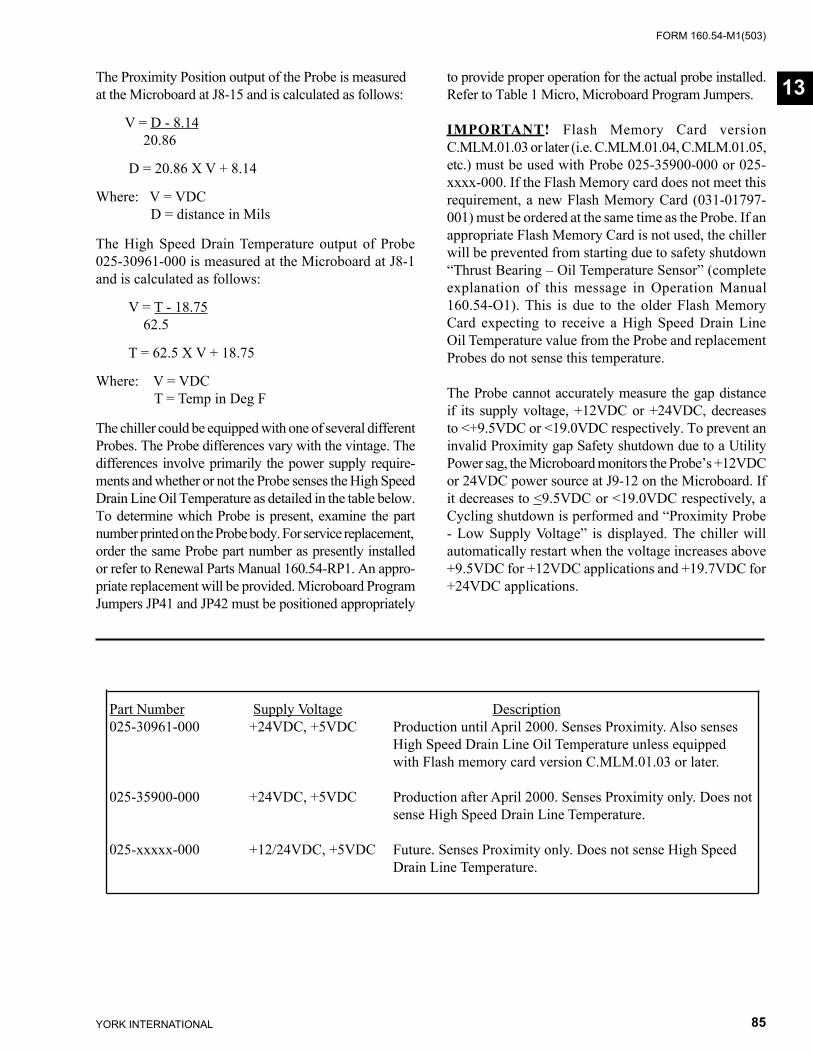
FORM 160.54-M1(503)
85YORK INTERNATIONAL
The Proximity Position output of the Probe is mea sured at the Microboard at J8-15 and is calculated as follows:
V = D - 8.14 20.86
D = 20.86 X V + 8.14
Where: V = VDC D = distance in Mils
The High Speed Drain Temperature output of Probe 025-30961-000 is measured at the Microboard at J8-1 and is calculated as follows:
V = T - 18.75 62.5
T = 62.5 X V + 18.75
Where: V = VDC T = Temp in Deg F
The chiller could be equipped with one of several dif fer ent Probes. The Probe differences vary with the vintage. The differences involve pri ma ri ly the power supply re quire -ments and whether or not the Probe senses the High Speed Drain Line Oil Temperature as detailed in the table below. To de ter mine which Probe is present, examine the part num ber printed on the Probe body. For service re place ment, order the same Probe part number as pres ent ly installed or refer to Renewal Parts Manual 160.54-RP1. An ap pro -pri ate replacement will be provided. Microboard Pro gram Jump ers JP41 and JP42 must be positioned ap pro pri ate ly
to provide proper operation for the actual probe installed. Refer to Table 1 Micro, Microboard Pro gram Jump ers.
IMPORTANT! Flash Memory Card version C.MLM.01.03 or later (i.e. C.MLM.01.04, C.MLM.01.05, etc.) must be used with Probe 025-35900-000 or 025-xxxx-000. If the Flash Memory card does not meet this requirement, a new Flash Memory Card (031-01797-001) must be ordered at the same time as the Probe. If an appropriate Flash Memory Card is not used, the chill er will be pre vent ed from starting due to safety shut down “Thrust Bearing – Oil Temperature Sensor” (com plete explanation of this message in Op er a tion Manual 160.54-O1). This is due to the older Flash Memory Card expecting to receive a High Speed Drain Line Oil Tem per a ture value from the Probe and re place ment Probes do not sense this temperature.
The Probe cannot accurately measure the gap distance if its supply voltage, +12VDC or +24VDC, decreases to <+9.5VDC or <19.0VDC respectively. To prevent an invalid Proximity gap Safety shutdown due to a Utility Power sag, the Microboard monitors the Probe’s +12VDC or 24VDC power source at J9-12 on the Microboard. If it decreases to <9.5VDC or <19.0VDC re spec tive ly, a Cycling shutdown is per formed and “Proximity Probe - Low Supply Voltage” is displayed. The chiller will au to mat i cal ly restart when the voltage increases above +9.5VDC for +12VDC ap pli ca tions and +19.7VDC for +24VDC applications.
Part Number Supply Voltage Description 025-30961-000 +24VDC, +5VDC Production until April 2000. Senses Proximity. Also senses High Speed Drain Line Oil Temperature unless equipped with Flash memory card version C.MLM.01.03 or later. 025-35900-000 +24VDC, +5VDC Production after April 2000. Senses Proximity only. Does not sense High Speed Drain Line Temperature. 025-xxxxx-000 +12/24VDC, +5VDC Future. Senses Proximity only. Does not sense High Speed Drain Line Temperature.
13
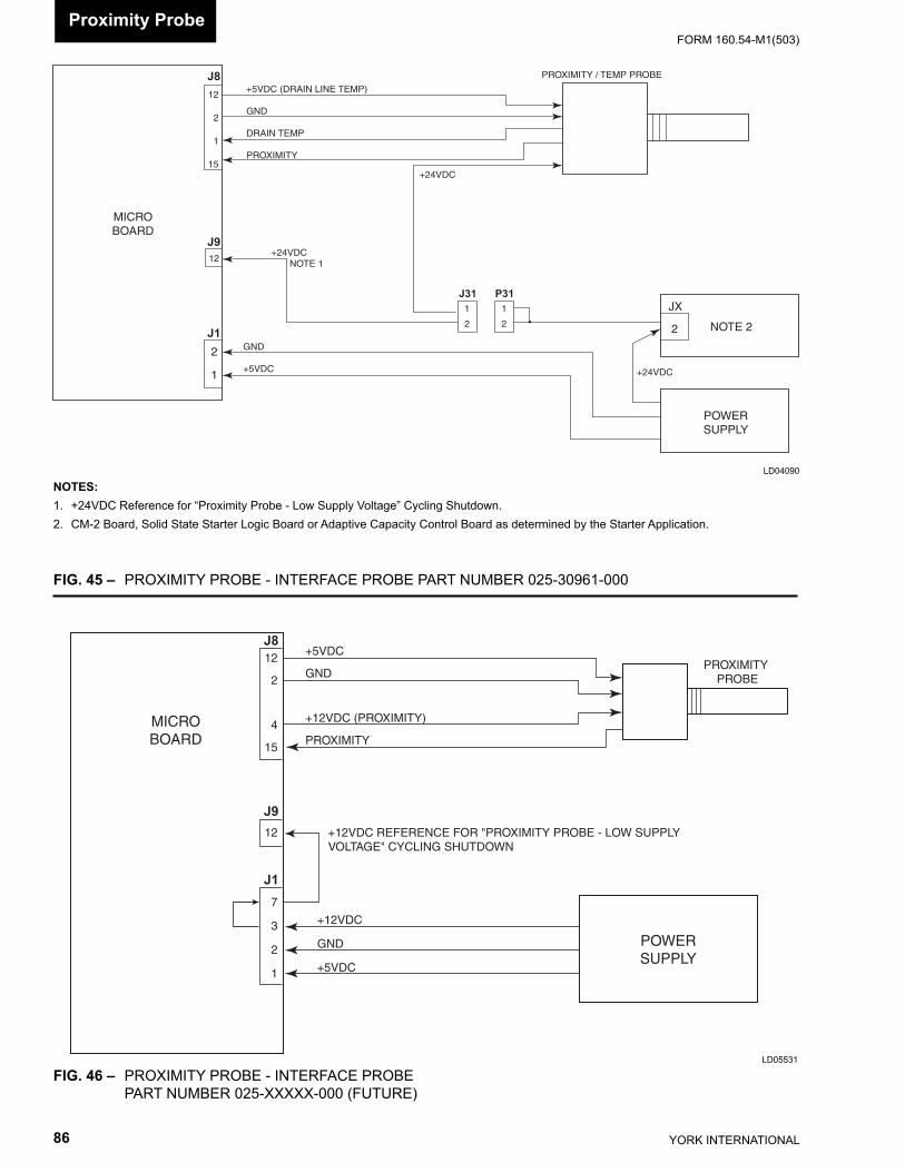
YORK INTERNATIONAL86
FORM 160.54-M1(503)
FIG. 46 – PROXIMITY PROBE - INTERFACE PROBE PART NUMBER 025-XXXXX-000 (FUTURE)
LD05531
+24VDC
POWERSUPPLY
NOTE 2
JX
2
MICROBOARD
+24VDC NOTE 1
2
1
J1
J9
J812
2
1
15
12
PROXIMITY / TEMP PROBE
+5VDC (DRAIN LINE TEMP)
GND
DRAIN TEMP
PROXIMITY
GND
+5VDC
+24VDC
J31 P311
2
1
2
NOTES:1. +24VDC Reference for “Proximity Probe - Low Supply Voltage” Cycling Shutdown.2. CM-2 Board, Solid State Starter Logic Board or Adaptive Capacity Control Board as determined by the Starter Application.
LD04090
FIG. 45 – PROXIMITY PROBE - INTERFACE PROBE PART NUM BER 025-30961-000
PROXIMITY PROBE
+5VDC
GND
+12VDC (PROXIMITY)
PROXIMITY
MICROBOARD
+12VDC
GND
+5VDC
POWERSUPPLY
7
3
2
1
12
12
2
4
15
+12VDC REFERENCE FOR "PROXIMITY PROBE - LOW SUPPLY VOLTAGE" CYCLING SHUTDOWN
J8
J9
J1
Proximity Probe
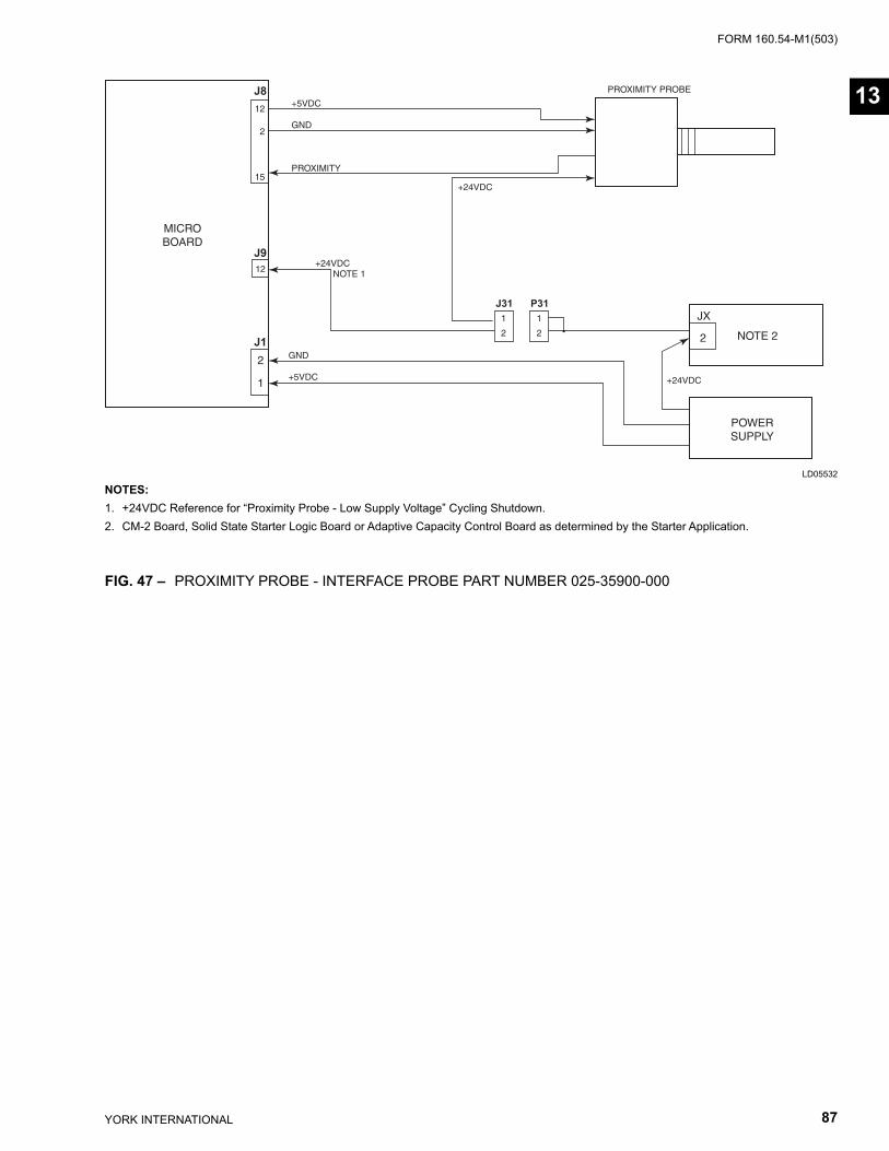
FORM 160.54-M1(503)
87YORK INTERNATIONAL
LD05532
NOTES:1. +24VDC Reference for “Proximity Probe - Low Supply Voltage” Cycling Shutdown.2. CM-2 Board, Solid State Starter Logic Board or Adaptive Capacity Control Board as determined by the Starter Application.
FIG. 47 – PROXIMITY PROBE - INTERFACE PROBE PART NUM BER 025-35900-000
+24VDC
POWERSUPPLY
NOTE 2
JX
2
MICROBOARD
+24VDC NOTE 1
2
1
J1
J9
J812
2
15
12
PROXIMITY PROBE
+5VDC
GND
PROXIMITY
GND
+5VDC
+24VDC
J31 P311
2
1
2
13
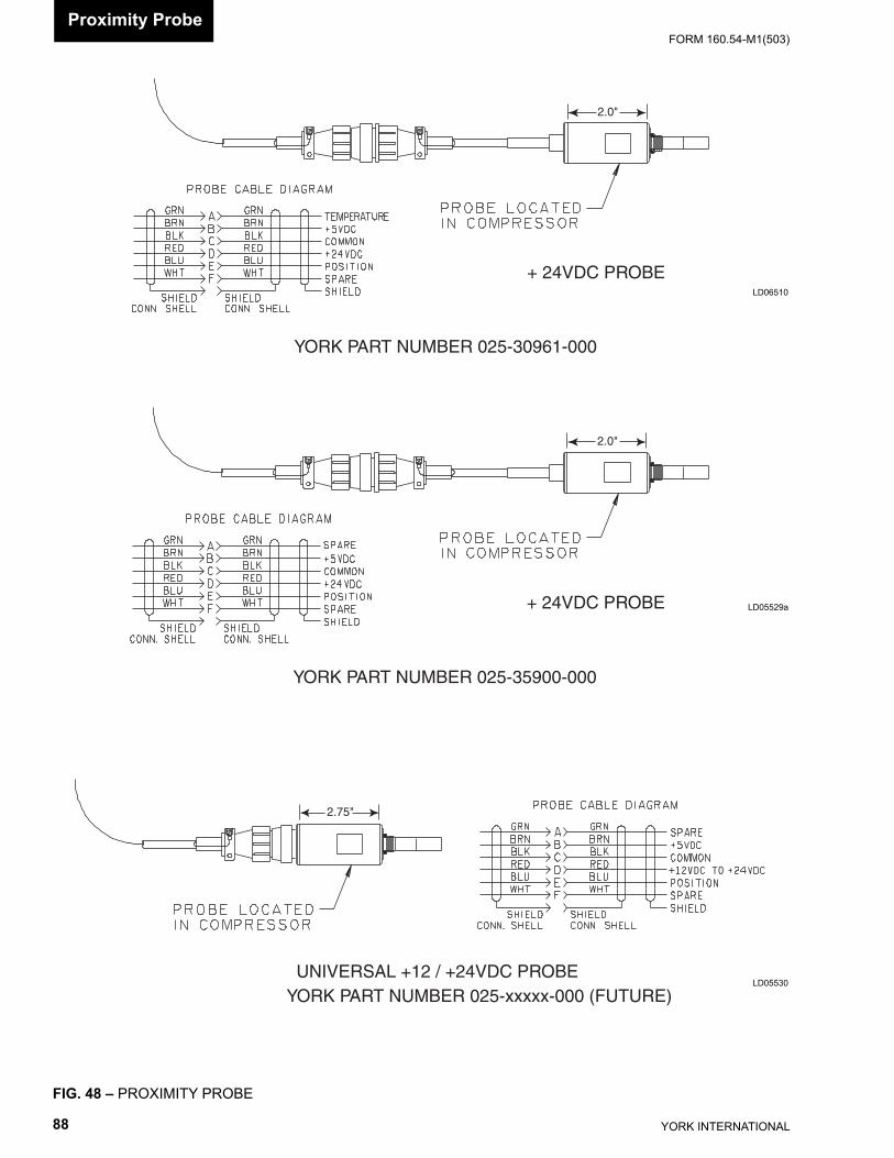
YORK INTERNATIONAL88
FORM 160.54-M1(503)
FIG. 48 – PROXIMITY PROBE
LD05530
LD06510
LD05529a+ 24VDC PROBE
2.0"
YORK PART NUMBER 025-35900-000
2.75"
UNIVERSAL +12 / +24VDC PROBEYORK PART NUMBER 025-xxxxx-000 (FUTURE)
+ 24VDC PROBE
2.0"
YORK PART NUMBER 025-30961-000
Proximity Probe
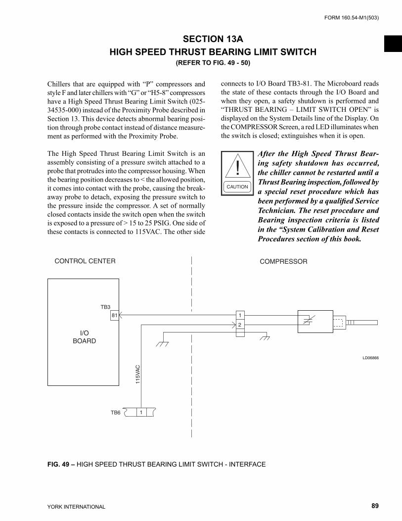
FORM 160.54-M1(503)
89YORK INTERNATIONAL
1TB6
115V
AC
I/OBOARD
CONTROL CENTER COMPRESSOR
TB3
81 1
2
SECTION 13AHIGH SPEED THRUST BEARING LIMIT SWITCH
(REFER TO FIG. 49 - 50)
Chillers that are equipped with “P” compressors and style F and later chillers with “G” or “H5-8” compressors have a High Speed Thrust Bearing Limit Switch (025-34535-000) instead of the Proximity Probe described in Sec tion 13. This device detects abnormal bearing posi-tion through probe contact instead of distance measure-ment as performed with the Proximity Probe.
The High Speed Thrust Bearing Limit Switch is an as sem bly consisting of a pressure switch attached to a probe that protrudes into the compressor housing. When the bearing position decreases to < the allowed position, it comes into contact with the probe, causing the break-away probe to detach, exposing the pressure switch to the pressure inside the compressor. A set of normally closed contacts inside the switch open when the switch is ex posed to a pres sure of > 15 to 25 PSIG. One side of these con tacts is con nect ed to 115VAC. The other side
con nects to I/O Board TB3-81. The Microboard reads the state of these con tacts through the I/O Board and when they open, a safe ty shutdown is performed and “THRUST BEAR ING – LIMIT SWITCH OPEN” is displayed on the System Details line of the Display. On the COM PRES SOR Screen, a red LED illuminates when the switch is closed; ex tin guish es when it is open.
After the High Speed Thrust Bear-ing safe ty shut down has occurred, the chill er can not be re start ed until a Thrust Bearing inspection, followed by a special reset pro ce dure which has been performed by a qual i fi ed Ser vice Tech ni cian. The re set procedure and Bear ing in spec tion cri te ria is listed in the “System Cal i bra tion and Reset Pro ce dures section of this book.
FIG. 49 – HIGH SPEED THRUST BEARING LIMIT SWITCH - INTERFACE
LD06866
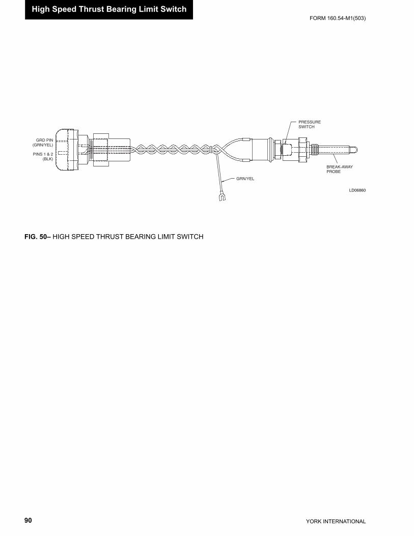
YORK INTERNATIONAL90
FORM 160.54-M1(503)
GRD PIN(GRN/YEL)
PINS 1 & 2(BLK)
GRN/YEL
PRESSURESWITCH
BREAK-AWAYPROBE
FIG. 50– HIGH SPEED THRUST BEARING LIMIT SWITCH
High Speed Thrust Bearing Limit Switch
LD06860
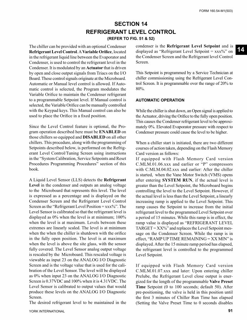
FORM 160.54-M1(503)
91YORK INTERNATIONAL
SECTION 14REFRIGERANT LEVEL CONTROL
(REFER TO FIG. 51 & 52)
The chiller can be provided with an optional Con dens er Refrigerant Level Control. A Variable Orifi ce, lo cat ed in the refrigerant liquid line between the Evap o ra tor and Condenser, is used to control the re frig er ant level in the Condenser. It is modulated by an Actuator that is driven by open and close output sig nals from Triacs on the I/O Board. These control sig nals orig i nate at the Microboard. Automatic or Manual lev el con trol is allowed. If Auto-matic control is se lect ed, the Pro gram modulates the Variable Orifi ce to maintain the Condenser refrigerant to a programmable Setpoint lev el. If Manual control is selected, the Variable Orifi ce can be manually controlled with the Keypad keys. This Manual control can also be used to place the Orifi ce in a fi xed position.
Since the Level Control feature is optional, the Pro- gram operation described here must be ENABLED on those chillers so equipped and DISABLED on all oth er chill ers. This procedure, along with the pro gram ming of Setpoints described below, is performed on the Re frig -er ant Level Control/Tuning Screen using in struc tions in the “System Calibration, Service Setpoints and Reset Procedures Programming Procedures” section of this book.
A Liquid Level Sensor (LLS) detects the Refrigerant Level in the condenser and outputs an analog voltage to the Microboard that rep re sents this level. The level is expressed as a percentage and is displayed on the Condenser Screen and the Refrigerant Level Control Screen as the “Re frig er ant Level Position = xxx%”. The Level Sensor is calibrated so that the re frig er ant level is displayed as 0% when the level is at minimum; 100% when the lev el is at maximum. Levels between these extremes are linearly scaled. The lev el is at min i mum when the when the chiller is shutdown with the orifi ce in the fully open position. The level is at max i mum when the level is above the site glass, with the sensor fully covered. The Level Sensor analog output voltage is rescaled by the Microboard. This rescaled voltage is viewable as input 23 on the ANALOG I/O Diagnostic Screen and is the voltage value that is used for the cali-bration of the Level Sensor. The level will be displayed as 0% when input 23 on the ANALOG I/O Diagnostic Screen is 0.37VDC and 100% when it is 4.31VDC. The Level Sensor is calibrated to output val ues that would produce these levels on the AN A LOG I/O Diagnostic Screen. The desired refrigerant level to be maintained in the
con dens er is the Refrigerant Level Setpoint and is dis played as “Re frig er ant Lev el Setpoint = xxx%” on the Condenser Screen and the Refrigerant level Con trol Screen. This Setpoint is pro grammed by a Service Technician at chiller com mis sion ing using the Refrigerant Level Con- trol Screen. It is pro gram ma ble over the range of 20% to 80%. AUTOMATIC OPERATION
While the chiller is shut down, an Open signal is ap plied to the Actuator, driving the Orifi ce to the fully open po si tion. This causes the Condenser refrigerant level to be ap prox i- mate ly 0%. Elevated Evaporator pres sure with respect to Condenser pressure could cause the lev el to be higher.
When a chiller start is initiated, there are two different courses of action taken, depending on the Flash Memory Card version as follows: If equipped with Flash Memory Card version C.MLM.01.06.xxx and earlier or “P” compressors with C.MLM.04.02.xxx and earlier: After the chiller is started, when the Vane Motor Switch (VMS) opens after entering SYSTEM RUN, if the ac tu al level is greater than the Level Setpoint, the Microboard begins controlling the level to the Level Setpoint. How ev er, if the actual level is less than the Level Setpoint, a linearly increasing ramp is applied to the Level Setpoint. This ramp causes the Setpoint to in crease from the ini tial refrigerant level to the pro grammed Level Setpoint over a period of 15 minutes. While this ramp is in ef fect, the ramp value is dis played as “REFRIGERANT LEVEL TAR GET = XX%” and replaces the Level Setpoint mes-sage on the Con dens er Screen. While the ramp is in effect, “RAMP UP TIME RE MAIN ING = XX MIN” is dis played. Af ter the 15 minute ramp period has elapsed, the re frig er ant level is con trolled to the pro grammed Level Setpoint.
If equipped with Flash Memory Card version C.MLM.01.07.xxx and later: Upon entering chiller Prelube, the Refrigerant Level close output is ener-gized for the length of the programmable Valve Preset Time Setpoint (0 to 100 seconds; default 50). After pre-positioning, the valve is held in this position until the fi rst 3 minutes of Chiller Run Time has elapsed (Setting the Valve Preset Time to 0 seconds disables
14

YORK INTERNATIONAL92
FORM 160.54-M1(503)Refrigerant Level Control
this pre-positioning feature). After the chiller has been running 3 minutes, if the level is greater than or equal to the Refrigerant Level Setpoint, it begins controlling to the Setpoint. However, if it is less than the Refrig-erant Level Setpoint, a linearly increasing ramp limit, called the Refrigerant Level Target, is applied to the Refrigerant Level Setpoint. This ramp limit allows the level to go from the present level to the Refrigrant Level Setpoint over a period of time programmed as the Ramp-Up Time setpoint (3 to 15 minutes; default 8). During this ramp-up period, the Refrigerant Level Target is used to control the refrigerant level in the condenser and the Refrigerant Level Setpoint message on the Condenser Screen is replaced by “REFRIGER-ANT LEVEL TARGET = XX%”. While the ramp is in effect, “RAMP UP TIME REMAINING = XX MIN” is displayed. After the ramp period has elapsed, the refrigerant level is controlled by the Refrigerant Level Setpoint for the remainder of chiller run. If the Valve Preset Time is set to 0 seconds and the Ramp-Up Time Setpoint is set to 15 minutes, the control will operate the same as previous Flash Memory Card versions, as described above.
If equipped with Flash Memory Card C.MLM.01.05C.xxx and earlier or “P” compressors with C.MLM.04.01B and ear li er, a ramp function as described above, is also executed anytime the Vane Motor Switch (VMS) transi-tions from closed to open while the chiller is running. When the VMS opens, if the re frig er ant lev el is less than the Level Setpoint, a setpoint ramp is ini ti at ed as previously described. If the re frig er ant level is great er than the Level Setpoint when the VMS opens, the level is con trolled to the Level Setpoint. Since this feature can produce unstable operation under cer tain conditions, it has been eliminated in Flash Mem o ry Card version C.MLM.01.06.xxx and later or C.MLM.04.02.xxx.
If the Liquid Level Sensor output ever increases to great er than 4.4VDC, indicating a level greater than 100%, “WARNING - REFRIGERANT LEVEL OUT OF RANGE” is displayed and the Orifi ce Actuator is driv en open until the level has decreased to a level with in range. When within range, the warning mes sage is au to mat i cal ly cleared and normal control is resumed. This feature can cause unstable operation under light load conditions. Therefore, both the warning message and the associated open signal have been eliminated in Flash Memory Card version C.MLM.01.06.xxx and later or C.MLM.04.02.xxx.
The Program applies an open or close signal, as re quired, from the Microboard to the actuator to main tain the level to the Level Setpoint. The duration of the signal de ter -mines the magnitude of change to the Or i fi ce po si tion. The duration of the signal and whether it is an open or close signal depends upon the Proportion Error and the Rate of Change of the actual level com pared to the Lev el Setpoint in a recurring period of time called a Lev el Con-trol Period. At the end of each Lev el Con trol Pe ri od, the Proportion error and Rate of Change are com pared to Programmable Setpoints Pro por tion Limit Close, Pro-portion Lim it Open and Rate Limit Close and Rate Lim it Open. The re sult of this com par i son de ter mines the signal that will be applied to the Ac tu a tor at the end of the Level Con trol Period as fol lows:
The entire chiller run time is divided into Level Con trol Periods. They occur consecutively and con tin u ous ly. The fi rst one begins upon entering SYSTEM RUN and when it ends the next one begins, etc. This repeats until the chill er is shutdown. The duration of these periods are pro grammed as the Level Control Pe ri od Setpoint This period has different ranges, depending on Flash Memory Card version as follows: 3.5 to 30.0 seconds (version C.MLM.01.06.xxx and later or C.MLM.04.02.xxx); 1.0 to 5.0 seconds (all earlier versions). The Default value varies depending upon the Flash Memory Card version and compressor application as follows: versions C.MLM.01.06.xxx and earlier (3.5 seconds); version C.MLM.01.07.xxx and later (10.0 seconds “P” com-pressors; 3.5 seconds all other compressors). At the completion of each Level Con trol Pe ri od, the ac tu al level is com pared to the Lev el Setpoint. The re sult is the Pro por tion Error (+ 3% is considered zero). The Pro por tion Error is compared to Setpoints Pro por tion Limit Open (if level is above setpoint) and Pro por tion Limit Close (if level is below setpoint). Both of these Setpoints are pro gram -ma ble over the range of 10% to 50%. If the Pro por tion Error ex ceeds the Limit Setpoint, the Pro por tion Error infl uence in the response will be large. If the Pro por tion Error is less than the Limit Setpoint, the Proportion er ror in fl u ence in the re sponse is de ter mined by how close the Proportion Error is to the Limit Setpoint; close yields larger infl uence, further yields smaller in fl u ence. To es tab lish the re sponse to the rate of change, the amount of change in the Level within the Lev el Control Period (+1% is con sid ered zero) is com pared to the Rate Limit Close (if level less than setpoint) and Rate Limit Open (if level greater than setpoint) Setpoints. Both are pro- gram ma ble over the range of 10% to 50%. (5% to 50% with Flash Memory Card version C.MLM.01.06.xxx and later or C.MLM.04.02.xxx). If the result ex ceeds the Setpoint, the rate in fl u ence in the response will be large; if
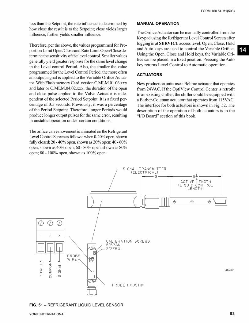
FORM 160.54-M1(503)
93YORK INTERNATIONAL
FIG. 51 – REFRIGERANT LIQUID LEVEL SENSOR
LD04091
14
less than the Setpoint, the rate infl uence is de ter mined by how close the result is to the Setpoint; close yields larg er infl uence, further yields small er in fl u ence.
Therefore, per the above, the values programmed for Pro-portion Limit Open/Close and Rate Limit Open/Close de-termine the sensitivity of the level control. Smaller val ues generally yield greater response for the same level change in the Level control Period. Also, the small er the value programmed for the Level Con trol Period, the more often an output signal is applied to the Variable Orifi ce Actua-tor. With Flash memory Card version C.MLM.01.06.xxx and later or C.MLM.04.02.xxx, the duration of the open and close pulse applied to the Valve Actuator is in de -pen dent of the selected Period Setpoint. It is a fi xed per-centage of 3.5 seconds. Previously, it was a per cent age of the Period Setpoint. Therefore, longer Pe ri ods would pro duce longer output pulses for the same error, resulting in unstable operation under certain con di tions.
The orifi ce valve movement is animated on the Re frig er ant Level Control Screen as follows: when 0-20% open, shown fully closed; 20 - 40% open, shown as 20% open; 40 - 60% open, shown as 40% open; 60 - 80% open, shown as 80% open; 80 - 100% open, shown as 100% open.
MANUAL OPERATION
The Orifi ce Actuator can be manually controlled from the Keypad using the Refrigerant Level Control Screen after logging in at SERVICE access level. Open, Close, Hold and Auto keys are used to control the Variable Or i fi ce. Using the Open, Close and Hold keys, the Vari able Ori-fi ce can be placed in a fi xed position. Pressing the Auto key returns Level Control to Automatic op er a tion.
ACTUATORS
New production units use a Belimo actuator that op er ates from 24VAC. If the OptiView Control Center is retrofi t to an existing chiller, the chiller could be equipped with a Bar ber-Coleman actuator that op er ates from 115VAC. The interface for both actuators is shown in Fig. 52. The description of the operation of both ac tu a tors is in the “I/O Board” section of this book.
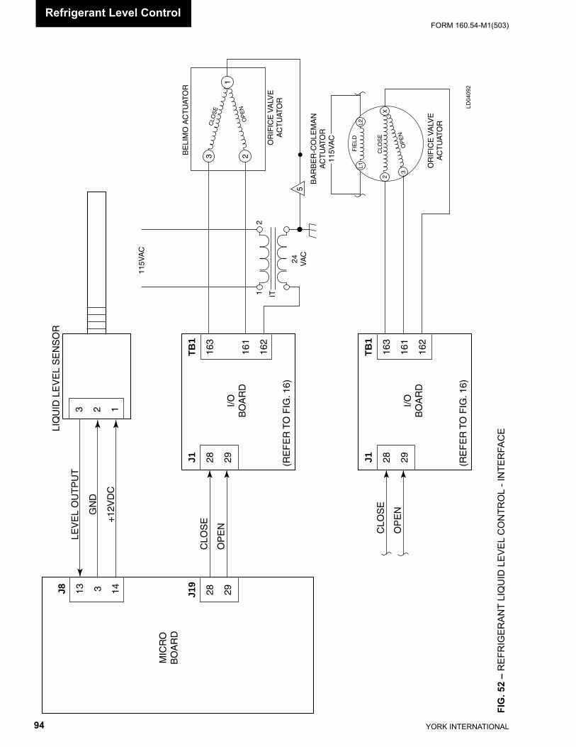
YORK INTERNATIONAL94
FORM 160.54-M1(503)
MIC
RO
BO
AR
D
I/OB
OA
RD
J19
28 29J8 13 3 14
J1 28 29
TB
1
163
161
162
(RE
FE
R T
O F
IG. 1
6)
CLO
SE
OP
EN
I/OB
OA
RD
J1 28 29
TB
1
163
161
162
(RE
FE
R T
O F
IG. 1
6)
CLO
SE
OP
EN
LEV
EL
OU
TP
UT
GN
D
+12
VD
C
3 2 1
LIQ
UID
LE
VE
L S
EN
SO
R
OR
IFIC
E V
ALV
EA
CT
UAT
OR
BA
RB
ER
-CO
LEM
AN
AC
TU
ATO
R11
5VA
C
FIE
LDL1
L2
2
3
X
5
115V
AC
IT12
24 VA
C
OR
IFIC
E V
ALV
EA
CT
UAT
OR
BE
LIM
O A
CT
UAT
OR
CLO
SE
OP
EN
OP
EN
CLO
SE
3 2
1
LD04
092
FIG
. 52
– R
EFR
IGER
ANT
LIQ
UID
LEV
EL C
ON
TRO
L - I
NTE
RFA
CE
Refrigerant Level Control
FORM 160.54-M1(503)
95YORK INTERNATIONAL
SECTION 15OIL PUMP VARIABLE SPEED DRIVE
(REFER TO FIG. 53 - 55)
On style D and later chillers, the oil pump is driven by a Variable Speed Drive (VSD) (Refer to Service Man u al 160.52-M2 for details of this device). In nor mal op er a tion, the oil pump speed is au to mat i cal ly con trolled to main tain a desired oil pres sure. The speed can be man u al ly con trolled with the Keypad keys using the Oil Sump Screen with Ser vice access level.
On those chillers equipped with the oil pump VSD, the VSD operation as described below must be EN ABLED by placing Microboard Program Switch SW1-2 in the ON position. Those chillers not equipped with the oil pump VSD must have this operation DISABLED by plac ing SW1-2 in the OFF position. Refer to Table 2, “Microboard Program Switches”.
The programming of the Setpoints referred to below is performed on the Oil Sump Screen using instructions in the “System Calibration, Service Setpoints and Re set Procedures” section of this book. These Setpoints should not be programmed by anyone other than a qual i fi ed Ser-vice Technician. Variable speed oil pump chill ers are not equipped with the Liquid Line Solenoid Valve (2SOL), or High Speed Thrust So le noid Valve (4SOL). There- fore, when Oil Pump VSD operation is ENABLED with Program Switch SW1-2, the Program is con fi g ured to operate the chiller without these so le noid valves. Op- er a tion Sequence Timing Diagrams in Fig. 4 and 5 depict chiller operation with the Oil Pump VSD enabled or disabled. Also, when equipped with the oil pump VSD, the Microboard, under Program con trol, controls the Oil Heater to maintain a specifi c oil temperature as de scribed in the “Oil Heater” sec tion below.
AUTOMATIC OPERATION
Under Program control, a speed command signal from the Microboard controls the oil pump speed by vary ing the VSD output frequency. The speed command is in the form of a Pulse Width Modulation (PWM) Sig nal as explained below. During the System Prelube period and the fi rst 15 seconds of System Run, the Pro gram operates the oil pump VSD over the range of 25 Hz to 60 Hz to maintain the oil pressure to the target value of 45 PSID. For the remainder of System Run and the Coast-down period, it operates it over the same fre quen cy range to maintain the pressure to the pro grammed Oil Pressure Setpoint.
When the chiller is started, 13 seconds after the Sys tem Prelube is initiated, the Microboard (J20-3) starts the oil pump by driving the EN (enable) input of the Oil Pump VSD to a Logic Low level (<1VDC). The Microboard (J20-1) then applies a speed command sig nal to the PWM input of the VSD that ramps the VSD output fre- quen cy from 25 Hz (45 Hz on all “P” com pres sors. 45 Hz on other compressor applications equipped with Flash Memory Card version C.MLM.01.05.xxx and later) to what ev er fre quen cy is re quired (up to a max i mum of 60 Hz) to achieve the Target Oil Pressure. (If equipped with Flash Memory card version C.MLM.01.08.xxx (and later), it is held at 45Hz for 8 seconds before re-leasing to normal control). The Tar get Oil Pres sure is fi xed at 45 PSID. The speed com mand is dis played on the Oil Sump Screen as OIL PUMP DRIVE COM-MAND FRE QUEN CY = XX HZ. The speed command to the VSD is mod u lat ed as re quired to main tain the 45 PSID Target Oil Pressure for the re main der of System Prelube and the fi rst 15 sec onds of Sys tem Run. While this target is in effect, it is dis played on the Oil Sump Screen as TARGET OIL PRES SURE = 45 PSID. The time re main ing that the Target Oil Pres sure is in effect is displayed as a count down timer in the message PULL-DOWN TIME RE MAIN ING = XX SEC. After the com pres sor has been run ning for 15 seconds, the speed of the VSD is con trolled to main tain the pro grammed Oil Pres sure Setpoint (20 to 45 PSID). This is dis played on the Oil Sump Screen as SETPOINT OIL PRES SURE = XX PSID.
During Oil Pump operation, the following minimum and maximum oil pressures are allowed: 1. During Automatic operation, if either of the fol-
lowing conditions occur, a Safety shutdown is per- formed and OIL - VARIABLE SPEED PUMP - PRESSURE SETPOINT NOT ACHIEVED is dis played. These conditions are not checked in MANUAL operation.
a. If the Oil Pressure is <35 PSID (25 PSID on “P” compressors) for 5 continuous seconds during the last 10 seconds of System Prelube or dur ing the fi rst 15 seconds of System Run.
b. If the Oil Pressure is < the programmed Oil Pressure Setpoint and the speed command is at 60 Hz for 5 continuous seconds, any time after the fi rst 30 seconds of SYSTEM RUN.
15
YORK INTERNATIONAL96
FORM 160.54-M1(503)
2. During Automatic operation, if the Oil Pres sure de creas es to < 15 PSID, a Safety shut down is per- formed and OIL - LOW DIF FER EN TIAL PRES- SURE is displayed. If it in creas es to >90 PSID, a Safe ty shut down is per formed and OIL - HIGH DIF FER EN TIAL PRESSURE is dis played.
The Microboard controls the VSD output frequency by applying a Pulse Width Modulation (PWM) speed command signal to the VSD. The signal is applied ev ery 0.7 seconds. Within the 0.7 second period, the du ra tion of time the signal is at logic low (<1VDC) and logic high (+12VDC) level determines the VSD output fre quen cy between 25 and 60 Hz. If it remains at a logic high for the entire 0.7 second period, it is com mand ing the VSD output frequency to be 25 Hz. If it is low for the entire 0.7 second period, it is commanding the VSD output frequency to be 60 Hz. Frequencies between these extremes are achieved by driving the sig nal low for a proportionate amount of time within the 0.7 sec ond period. For example, if the signal is low for 50% (0.35 seconds) of the 0.7 second period, it would be command-ing the VSD to operate at a frequency that is halfway between 25 and 60 Hz, or 42.5 Hz. The res o lu tion, or smallest increment of change is 0.01 sec onds. This al-lows the output frequency to be changed in 0.5 Hz steps. The VSD output frequency for any PWM input can be calculated as follows: Frequency in Hz = (On-Time in seconds / 0.02) + 25
The entire oil pump run time is divided into Oil Pres sure Control Periods. They run consecutively and con tin u- ous ly; when the fi rst one ends, the next one be gins, etc. This repeats until the oil pump is shutdown. The dura-tion of the periods is determined by the Control Period Setpoint. This Setpoint is pro grammed in mul ti ples of 0.3 seconds over the range of 0.3 to 2.7 sec onds. At the end of each period, the actual oil pres sure is compared to the Oil Pressure Setpoint and the speed command is changed as required to in voke VSD fre quen cy changes to increase or decrease the oil pres sure. If the error between the Oil Pressure Setpoint and the actual oil pressure is < +6 PSID, the frequency is increased or decreased 0.5 Hz to increase or decrease the oil pressure. However, if the error is > + 6 PSID, the value programmed for Control Pe ri od Setpoint determines the relative magnitude of cor rec tion ap plied to the VSD output frequency. The larg er the pro grammed value, the greater the amount of cor rec tion above 0.5 Hz is applied.
To provide an operational status to the Microboard (via I/O Board TB3-70), the VSD contains a set of nor mal ly open (N.O.) relay contacts that are driven closed as long as all the internal protection circuits are sat is fi ed. They open anytime these circuits will not permit the VSD to operate. The opening of these contacts ini tiate a chiller cycling shutdown, displaying OIL - VARI ABLE SPEED PUMP - DRIVE CONTACTS OPEN. After the problem has cleared, the contacts au to mat i cal ly close, except if the VSD experiences a short cir cuit on the output; this requires the VSD to be man u al ly reset by the removal and restoration of the VSD AC Power.
MANUAL OPERATION
The oil pump can be manually operated using the Oil Sump Screen when logged in with SERVICE AC- CESS lev el. While the chiller is running, the speed can be man u al ly adjusted over the range of 25 to 60 Hz. When the chiller is not running, manual on/off con trol, as well as manual speed control is permitted. Af ter the pump is manually turned on, it will au to mat i cal ly turn off after 10 minutes of operation, if not man u al ly ter-minated ear li er.
The RAISE and LOWER keys are used to increase and decrease the VSD output frequency in 0.5 Hz in cre ments. Each time the RAISE key is pressed, the fre quen cy is increased 0.5 Hz. Each time the LOWER key is pressed, the frequency is decreased 0.5 Hz. Re- peat ed presses of these keys are required to increase or decrease the frequency by greater amounts.
If the AUTO key is pressed, Automatic operation, as described above, is resumed.
If the SET key is pressed, the VSD is driven to a spe cifi c predetermined frequency. This permits service analysis of the oil pressure at various oil pump speeds. This fre-quency is programmed using instructions in the “System Calibration, Service Setpoints and Reset Pro ce dures” section of this book.
During Manual operation, the Oil Sump Screen can be used to monitor the actual oil pressure and the speed command.
Oil Pump Variable Speed Drive
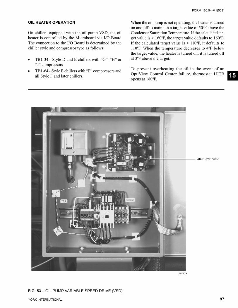
FORM 160.54-M1(503)
97YORK INTERNATIONAL
OIL HEATER OPERATION
On chillers equipped with the oil pump VSD, the oil heat er is controlled by the Microboard via I/O Board The connection to the I/O Board is determined by the chiller style and compressor type as follows:
• TB1-34 - Style D and E chillers with “G”, “H” or “J” compressors
• TB1-64 - Style E chillers with “P” compressors and all Style F and later chillers.
When the oil pump is not operating, the heater is turned on and off to maintain a target value of 50ºF above the Condenser Saturation Temperature. If the calculated tar-get value is > 160ºF, the target value de faults to 160ºF. If the calculated target value is < 110ºF, it defaults to 110ºF. When the temperature de creas es to 4ºF below the target value, the heater is turned on; it is turned off at 3ºF above the target.
To prevent overheating the oil in the event of an OptiView Control Center failure, thermostat 1HTR opens at 180ºF.
FIG. 53 – OIL PUMP VARIABLE SPEED DRIVE (VSD)
28782A
OIL PUMP VSD
15
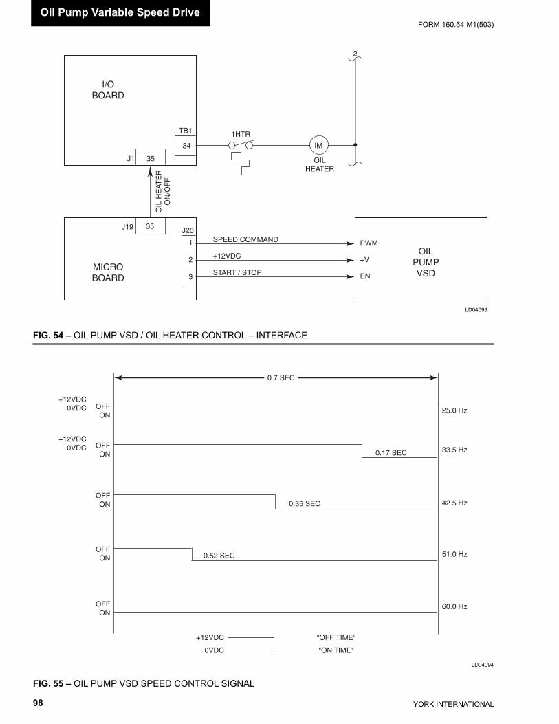
YORK INTERNATIONAL98
FORM 160.54-M1(503)
0.7 SEC
+12VDC0VDC
+12VDC0VDC
OFFON
OFFON
OFFON
OFFON
OFFON
+12VDC
0VDC
"OFF TIME"
"ON TIME"
25.0 Hz
60.0 Hz
33.5 Hz
42.5 Hz
51.0 Hz
0.17 SEC
0.35 SEC
0.52 SEC
FIG. 54 – OIL PUMP VSD / OIL HEATER CON TROL – INTERFACE
FIG. 55 – OIL PUMP VSD SPEED CON TROL SIGNAL
LD04093
LD04094
1
2
3
SPEED COMMAND
START / STOP
+12VDC
MICROBOARD
J19 J2035
PWM
+V
EN
OILPUMPVSD
I/OBOARD
TB1
J1 35
34
OIL
HE
ATE
RO
N/O
FF
IM
OILHEATER
1HTR
2
Oil Pump Variable Speed Drive
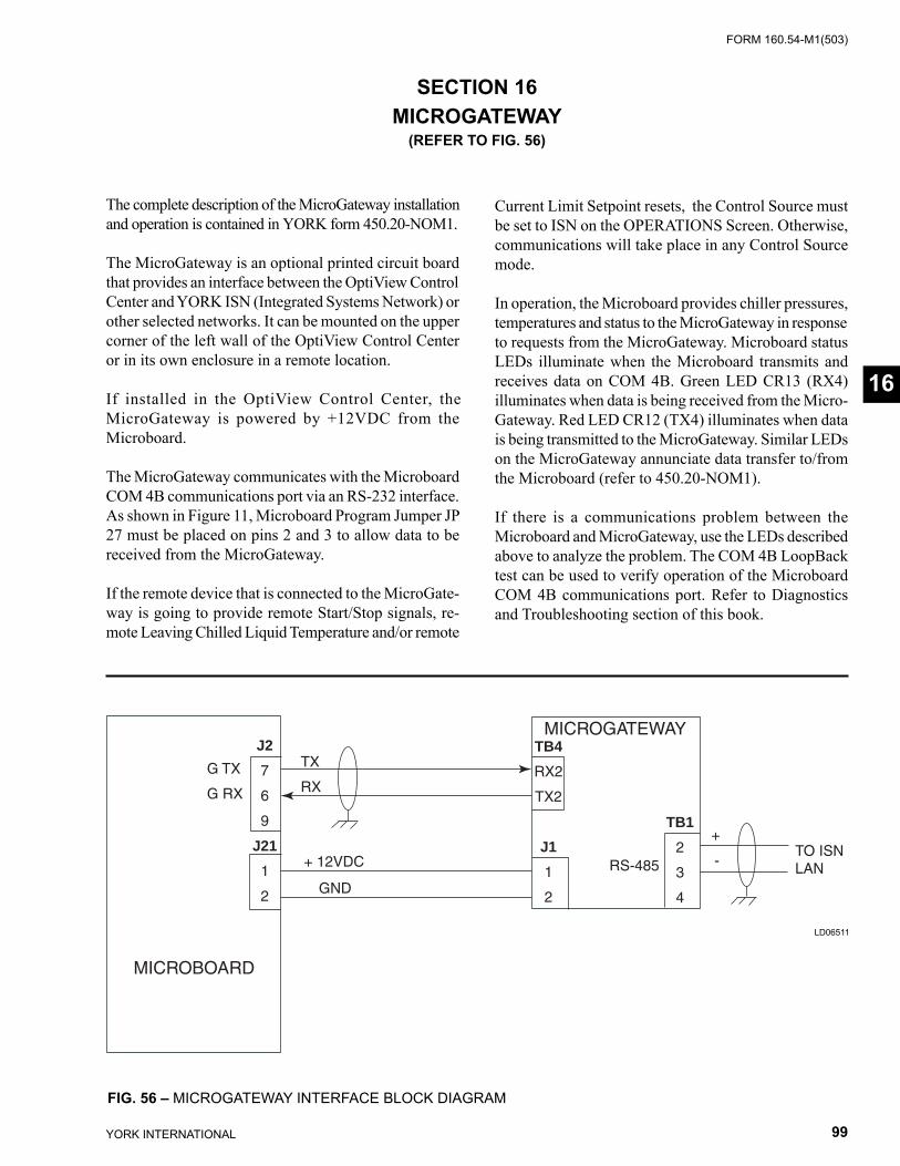
FORM 160.54-M1(503)
99YORK INTERNATIONAL
J2
7
6
9
J21
1
2
TB4
RX2
TX2
J1
1
2
TB1
2
3
4
TO ISNLAN
MICROBOARD
MICROGATEWAY
RS-485
+
-
G TX
G RX
TX
RX
+ 12VDC
GND
SECTION 16MICROGATEWAY
(REFER TO FIG. 56)
The complete description of the MicroGateway in stal la tion and operation is contained in YORK form 450.20-NOM1.
The MicroGateway is an optional printed circuit board that pro vides an interface between the OptiView Con trol Center and YORK ISN (Integrated Systems Net work) or other selected networks. It can be mounted on the upper cor ner of the left wall of the OptiView Con trol Center or in its own enclosure in a remote lo ca tion.
If installed in the OptiView Con trol Center, the MicroGateway is powered by +12VDC from the Microboard.
The MicroGateway communicates with the Microboard COM 4B com mu ni ca tions port via an RS-232 in ter face. As shown in Figure 11, Microboard Pro gram Jumper JP 27 must be placed on pins 2 and 3 to allow data to be re ceived from the MicroGateway.
If the remote device that is con nect ed to the MicroGate-way is going to provide remote Start/Stop sig nals, re-mote Leaving Chilled Liquid Temperature and/or remote
Current Limit Setpoint resets, the Control Source must be set to ISN on the OPERATIONS Screen. Otherwise, com mu ni ca tions will take place in any Con trol Source mode.
In operation, the Microboard provides chiller pres sures, tem per a tures and status to the MicroGateway in re sponse to requests from the MicroGateway. Microboard status LEDs illuminate when the Microboard trans mits and receives data on COM 4B. Green LED CR13 (RX4) illuminates when data is being received from the Micro-Gateway. Red LED CR12 (TX4) illuminates when data is being transmitted to the MicroGateway. Similar LEDs on the MicroGateway annunciate data transfer to/from the Microboard (refer to 450.20-NOM1).
If there is a communications problem between the Microboard and MicroGateway, use the LEDs de scribed above to analyze the problem. The COM 4B LoopBack test can be used to verify operation of the Microboard COM 4B communications port. Refer to Diagnostics and Troubleshooting section of this book.
16
FIG. 56 – MICROGATEWAY INTERFACE BLOCK DIAGRAM
LD06511
YORK INTERNATIONAL100
FORM 160.54-M1(503)
SECTION 17PRESSURE TRANSDUCERS
(REFER TO FIG. 57)
System pressures are sensed by Pressure Trans duc ers. The Evaporator, Condenser, Pump Oil (high side) and Sump Oil (low side) pressures are sensed. There are dif fer ent trans duc ers used to sense the various sys tem pres sures. The actual transducer used is de ter mined by the required pressure range and refrigerant ap pli ca tion. The operation of the various transducers is iden ti cal. The dif fer ence between them is simply the pres sure range over which they operate. Each of the dif fer ent trans duc ers has a different YORK part number. Fig. 55 lists the trans duc ers and the application of each one.
The transducers output a 0.5 to 4.5VDC voltage that is analogous to the pressure applied to the device. These outputs are applied to the Microboard, where this volt- age is interpreted as a pressure value in terms of PSIG (pounds per square inch gauge) in English mode or KpaG (Kilo Pascals) in Metric mode. The Program con-verts the transducer output voltage to a pressure value with the appropriate formula in Fig. 57. The pres sures are displayed and used for Chiller control and Safety shut downs.
The Evaporator and Condenser pressures are con vert ed to Saturation Temperatures per the appropriate re frig -er ant pressure/temperature conversion table contained in the Program. These Saturation Temperatures are dis played and used for Chiller control.
The outputs of the Sump and Pump oil Pressure trans duc ers are displayed individually as PSIG values. How ev er, the System Oil Pressure is displayed as a dif fer en tial value in terms of PSID (pounds per square inch dif fer en tial in gauge). This PSID value is arrived at by sub tract ing the Sump Oil Pressure transducer value from the Pump Oil Pressure transducer value. During the Sys tem Prelube period, the outputs of the oil Pres sure trans duc ers are compared in a process called Auto-Zeroing. The dif-ferential between the Sump and Pump Oil Pres sure transducer outputs during a 3 second pe ri od be gin ning 10 seconds after the start of the System Prelube period
are compared to determine the off set between them. During this period, since both of the trans duc ers are sensing the same pressure, their out puts should in di cate the same pressure. How ev er, due to accuracy tol er anc es in transducer design, dif fer enc es can exist. There fore, to compensate for differences be tween trans duc ers and assure differential pressure ac cu ra cy, this offset is fac-tored with the actual dif fer en tial pressure to pro duce the displayed PSID value. When the oil Pump is turned on following the Auto-zeroing period, the dis played dif- fer en tial value then becomes the actual differential plus or minus the offset that ex ist ed during the Auto-Zeroing period. For example, if the Pump transducer indicates 1.0 PSIG greater than the Sump transducer during the Auto-Zeroing period, then 1.0 PSIG will subtracted from the displayed PSID value while the pump is running. Sim i lar ly, if the Pump transducer in di cates 1.0 PSIG less than the sump trans duc er during this period, then 1.0 PSIG would be sub tract ed from the displayed PSID val ue while the pump is running. The Auto-zeroing will not be per formed if either trans duc er is out of range.
The transducers operate from a +5VDC power source. This supply voltage is provided from the Power supply via the Microboard. Each transducer is connected to the Microboard with three wires. Two wires provide the +5VDC supply voltage and Ground (GND) and the re main ing wire connects the transducer output to the Microboard. The voltage output of each transducer can be measured with a Voltmeter at the Microboard. Mea sure ment should be made from the transducer out- put to Ground (GND). For example, the output of the Con dens er transducer would be read from Microboard J8-21 (signal) to J8-22 (GND). To convert this output to a pressure, refer to the appropriate formula in Fig. 57. If the pressure is known, the trans duc er output can be predicted with the appropriate formula in Fig. 57.
If any of the displayed pressures do not appear to be correct, refer to the Diagnostics and Troubleshooting section of this book.
Pressure Transducers
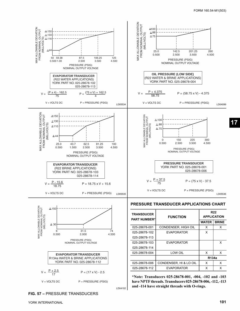
FORM 160.54-M1(503)
101YORK INTERNATIONAL
+150
+130
+110
+ 44
MA
X A
LLO
WA
BLE
DE
VIA
TIO
N
FR
OM
NO
MIN
AL
OU
TP
UT
(MIL
LIV
OLT
S)
PRESSURE (PSIG)NOMINAL OUTPUT VOLTAGE
EVAPORATOR TRANSDUCER(R22 BRINE APPLICATIONS)
YORK PART NO. 025-28678-103 025-28678-114
V = VOLTS DC P = PRESSURE (PSIG)
V = P - 15.618.75
P = 18.75 x V + 15.6
25.0 43.7 62.5 81.25 1000.500 1.500 2.500 3.500 4.500
133
+
++
+
150
116
44
50 59.38 87.5 106.25 1250.500 1.00 2.500 3.500 4.500M
AX
ALL
OW
AB
LE D
EV
IAT
ION
F
RO
M N
OM
INA
L O
UT
PU
T(M
ILLI
VO
LTS
)
PRESSURE (PSIG)NOMINAL OUTPUT VOLTAGE
EVAPORATOR TRANSDUCER(R22 WATER APPLICATIONS)
YORK PART NO. 025-28678-102 025-28678-113
V = VOLTS DC P = PRESSURE (PSIG)
V = (P x 4) - 162.575
P = (75 x V) + 162.54
FIG. 57 – PRESSURE TRANSDUCERS
LD05534 LD04099
LD05535 LD05536
LD04102
+100+ 88+ 75
MA
X A
LLO
WA
BLE
DE
VIA
TIO
N
FR
OM
NO
MIN
AL
OU
TP
UT
(MIL
LIV
OLT
S)
PRESSURE (PSIG)NOMINAL OUTPUT VOLTAGE
OIL PRESSURE (LOW SIDE)(R22 WATER & BRINE APPLICATIONS)
YORK PART NO. 025-28678-004
V = VOLTS DC P = PRESSURE (PSIG)
V = P + 4.37558.75
P = (58.75 x V) - 4.375
25.0 142.5 201.25 2600.500 2.500 3.500 4.500
EVAPORATOR TRANSDUCERR134a WATER & BRINE APPLICATIONS
YORK PART NO. 025-28678-112
+ 150
+ 30
MA
X A
LLO
WA
BLE
DE
VIA
TIO
N
FR
OM
NO
MIN
AL
OU
TP
UT
(MIL
LIV
OLT
S)
PRESSURE (PSIG)NOMINAL OUTPUT VOLTAGE
V = VOLTS DC P = PRESSURE (PSIG)
V = P + 2.517
P = (17 x V) - 2.5
6 31.5 740.500 2.000 4.500
*Note: Transducers 025-28678-001, -004, -102 and -103 have NPTF threads. Transducers 025-28678-006, -112, -113 and -114 have straight threads with O-rings.
TRANSDUCER
R22 PART NUMBER*
FUNCTION APPLICATION WATER BRINE 025-28678-001 CONDENSER, HIGH OIL X X 025-28678-102 EVAPORATOR X 025-28678-113 025-28678-103 EVAPORATOR X 025-28678-114 025-28678-004 LOW OIL X X R134a 025-28678-006 CONDENSER, HI & LO OIL X X 025-28678-112 EVAPORATOR X X
PRESSURE TRANSDUCER APPLICATIONS CHART
+ 100
+ 88+ 75
MA
X A
LLO
WA
BLE
DE
VIA
TIO
N
FR
OM
NO
MIN
AL
OU
TP
UT
(MIL
LIV
OLT
S)
PRESSURE (PSIG)NOMINAL OUTPUT VOLTAGE
V = VOLTS DC P = PRESSURE (PSIG)
V = P + 37.575
P = (75 x V) - 37.5
PRESSURE TRANSDUCERYORK PART NO. 025-28678-001 025-28678-006
0 150 225 3000.500 2.500 3.500 4.500
17
YORK INTERNATIONAL102
FORM 160.54-M1(503)
SECTION 18TEMPERATURE THERMISTORS
(REFER TO FIG. 58 - 63)
System temperatures are sensed by Thermistors. There are two different thermistor types used to sense the var- i ous system temperatures. Each type has its own YORK part number. Part numbers are listed in YORK Re new al Parts List 160.54-RP2. The Return and Leav ing Chilled Liquid, Return and Leaving Condenser Liq uid, Drop Leg Re frig er ant and Evaporator Tem per a tures are sensed by 3K Ohm thermistors. The Oil and Com pres sor Discharge tem per a tures are sensed by 50K Ohm thermistors.
The 3K Ohm thermistors are defi ned by the char ac -ter is tic of being 3000 Ohms at 77ºF (25ºC). Similarly, the 50K Ohm thermistors are 50,000 Ohms at the same tem per a ture. Both thermistor types vary their resistance as the sensed temperature varies. Both are negative tem- per a ture coeffi cient devices. That is, as the tem per a ture increases, the resistance decreases. As the tem per a ture decreases, the resistance increases.
The thermistors are connected to the Microboard. A +5VDC supply voltage is applied to one side of the ther mistor. The other side of the thermistor is connected to Ground through a series resistor on the Microboard, thus forming a voltage divider network. The tem per a ture ap plied to the thermistor determines the resistance value. The resistance value determines the amount of current that
will fl ow through the thermistor and thus the voltage drop across it. The Program reads this volt age at the input to the Microboard and converts it to a temperature value.
Each thermistor is connected to the Microboard with two wires. One wire supplies the +5VDC voltage and the oth er is the output of the thermistor. This output volt age can be measured with a Voltmeter. Mea sure ment should be made from the thermistor output to Ground (Gnd). For ex am ple, the Leaving Chilled Liq uid Tem per a ture would be read from Microboard J9-20 (output) to Microboard TP1 (Gnd). To convert this voltage to a pressure, refer to the ap pro pri ate volts/temp chart as fol lows: • Leaving Chilled Liquid Temperature – Fig. 58 • Return Chilled Liquid Temperature – Fig. 59 • Leaving and Return Condenser Liquid Tem per a ture
– Fig. 60 • Oil and Discharge Temperature – Fig. 61 • Drop Leg Refrigerant Temperature – Fig. 62 • Evaporator Refrigerant Temperature – Fig. 63
If any of the displayed pressures do not appear to be correct, refer to the “Diagnostics and Trou ble shoot ing” section of this book.
Temperature Thermistors
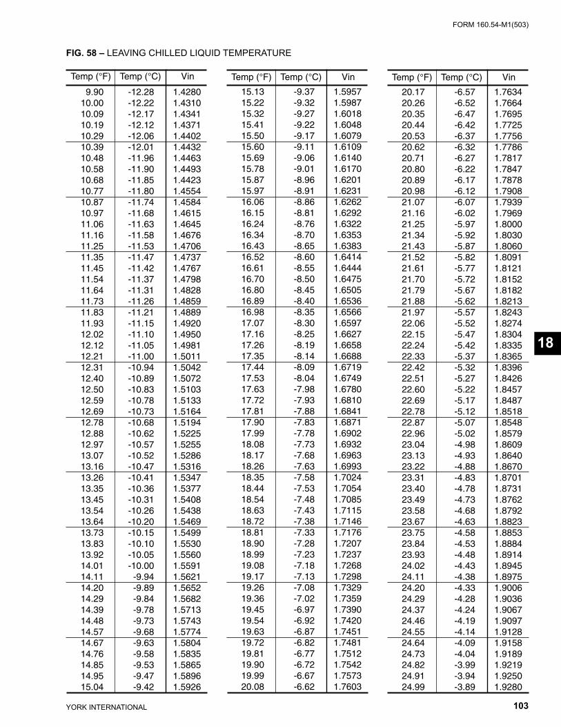
FORM 160.54-M1(503)
103YORK INTERNATIONAL
FIG. 58 – LEAVING CHILLED LIQUID TEMPERATURE
Temp (°F) Temp (°C) Vin
15.13 -9.37 1.5957 15.22 -9.32 1.5987 15.32 -9.27 1.6018 15.41 -9.22 1.6048 15.50 -9.17 1.6079 15.60 -9.11 1.6109 15.69 -9.06 1.6140 15.78 -9.01 1.6170 15.87 -8.96 1.6201 15.97 -8.91 1.6231 16.06 -8.86 1.6262 16.15 -8.81 1.6292 16.24 -8.76 1.6322 16.34 -8.70 1.6353 16.43 -8.65 1.6383 16.52 -8.60 1.6414 16.61 -8.55 1.6444 16.70 -8.50 1.6475 16.80 -8.45 1.6505 16.89 -8.40 1.6536 16.98 -8.35 1.6566 17.07 -8.30 1.6597 17.16 -8.25 1.6627 17.26 -8.19 1.6658 17.35 -8.14 1.6688 17.44 -8.09 1.6719 17.53 -8.04 1.6749 17.63 -7.98 1.6780 17.72 -7.93 1.6810 17.81 -7.88 1.6841 17.90 -7.83 1.6871 17.99 -7.78 1.6902 18.08 -7.73 1.6932 18.17 -7.68 1.6963 18.26 -7.63 1.6993 18.35 -7.58 1.7024 18.44 -7.53 1.7054 18.54 -7.48 1.7085 18.63 -7.43 1.7115 18.72 -7.38 1.7146 18.81 -7.33 1.7176 18.90 -7.28 1.7207 18.99 -7.23 1.7237 19.08 -7.18 1.7268 19.17 -7.13 1.7298 19.26 -7.08 1.7329 19.36 -7.02 1.7359 19.45 -6.97 1.7390 19.54 -6.92 1.7420 19.63 -6.87 1.7451 19.72 -6.82 1.7481 19.81 -6.77 1.7512 19.90 -6.72 1.7542 19.99 -6.67 1.7573 20.08 -6.62 1.7603
Temp (°F) Temp (°C) Vin
20.17 -6.57 1.7634 20.26 -6.52 1.7664 20.35 -6.47 1.7695 20.44 -6.42 1.7725 20.53 -6.37 1.7756 20.62 -6.32 1.7786 20.71 -6.27 1.7817 20.80 -6.22 1.7847 20.89 -6.17 1.7878 20.98 -6.12 1.7908 21.07 -6.07 1.7939 21.16 -6.02 1.7969 21.25 -5.97 1.8000 21.34 -5.92 1.8030 21.43 -5.87 1.8060 21.52 -5.82 1.8091 21.61 -5.77 1.8121 21.70 -5.72 1.8152 21.79 -5.67 1.8182 21.88 -5.62 1.8213 21.97 -5.57 1.8243 22.06 -5.52 1.8274 22.15 -5.47 1.8304 22.24 -5.42 1.8335 22.33 -5.37 1.8365 22.42 -5.32 1.8396 22.51 -5.27 1.8426 22.60 -5.22 1.8457 22.69 -5.17 1.8487 22.78 -5.12 1.8518 22.87 -5.07 1.8548 22.96 -5.02 1.8579 23.04 -4.98 1.8609 23.13 -4.93 1.8640 23.22 -4.88 1.8670 23.31 -4.83 1.8701 23.40 -4.78 1.8731 23.49 -4.73 1.8762 23.58 -4.68 1.8792 23.67 -4.63 1.8823 23.75 -4.58 1.8853 23.84 -4.53 1.8884 23.93 -4.48 1.8914 24.02 -4.43 1.8945 24.11 -4.38 1.8975 24.20 -4.33 1.9006 24.29 -4.28 1.9036 24.37 -4.24 1.9067 24.46 -4.19 1.9097 24.55 -4.14 1.9128 24.64 -4.09 1.9158 24.73 -4.04 1.9189 24.82 -3.99 1.9219 24.91 -3.94 1.9250 24.99 -3.89 1.9280
Temp (°F) Temp (°C) Vin
9.90 -12.28 1.4280 10.00 -12.22 1.4310 10.09 -12.17 1.4341 10.19 -12.12 1.4371 10.29 -12.06 1.4402 10.39 -12.01 1.4432 10.48 -11.96 1.4463 10.58 -11.90 1.4493 10.68 -11.85 1.4423 10.77 -11.80 1.4554 10.87 -11.74 1.4584 10.97 -11.68 1.4615 11.06 -11.63 1.4645 11.16 -11.58 1.4676 11.25 -11.53 1.4706 11.35 -11.47 1.4737 11.45 -11.42 1.4767 11.54 -11.37 1.4798 11.64 -11.31 1.4828 11.73 -11.26 1.4859 11.83 -11.21 1.4889 11.93 -11.15 1.4920 12.02 -11.10 1.4950 12.12 -11.05 1.4981 12.21 -11.00 1.5011 12.31 -10.94 1.5042 12.40 -10.89 1.5072 12.50 -10.83 1.5103 12.59 -10.78 1.5133 12.69 -10.73 1.5164 12.78 -10.68 1.5194 12.88 -10.62 1.5225 12.97 -10.57 1.5255 13.07 -10.52 1.5286 13.16 -10.47 1.5316 13.26 -10.41 1.5347 13.35 -10.36 1.5377 13.45 -10.31 1.5408 13.54 -10.26 1.5438 13.64 -10.20 1.5469 13.73 -10.15 1.5499 13.83 -10.10 1.5530 13.92 -10.05 1.5560 14.01 -10.00 1.5591 14.11 -9.94 1.5621 14.20 -9.89 1.5652 14.29 -9.84 1.5682 14.39 -9.78 1.5713 14.48 -9.73 1.5743 14.57 -9.68 1.5774 14.67 -9.63 1.5804 14.76 -9.58 1.5835 14.85 -9.53 1.5865 14.95 -9.47 1.5896 15.04 -9.42 1.5926
18
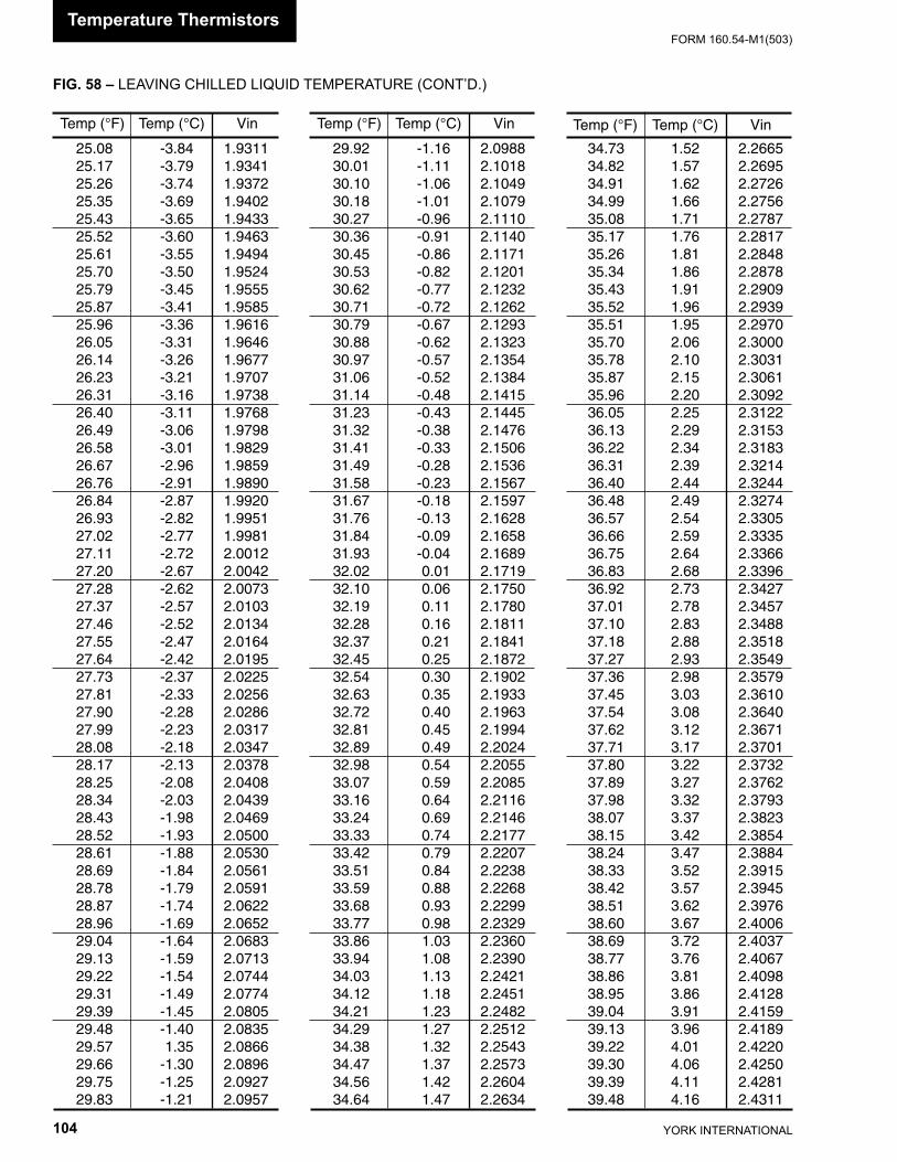
YORK INTERNATIONAL104
FORM 160.54-M1(503)
FIG. 58 – LEAVING CHILLED LIQUID TEMPERATURE (CONT’D.)
Temp (°F) Temp (°C) Vin
25.08 -3.84 1.9311 25.17 -3.79 1.9341 25.26 -3.74 1.9372 25.35 -3.69 1.9402 25.43 -3.65 1.9433 25.52 -3.60 1.9463 25.61 -3.55 1.9494 25.70 -3.50 1.9524 25.79 -3.45 1.9555 25.87 -3.41 1.9585 25.96 -3.36 1.9616 26.05 -3.31 1.9646 26.14 -3.26 1.9677 26.23 -3.21 1.9707 26.31 -3.16 1.9738 26.40 -3.11 1.9768 26.49 -3.06 1.9798 26.58 -3.01 1.9829 26.67 -2.96 1.9859 26.76 -2.91 1.9890 26.84 -2.87 1.9920 26.93 -2.82 1.9951 27.02 -2.77 1.9981 27.11 -2.72 2.0012 27.20 -2.67 2.0042 27.28 -2.62 2.0073 27.37 -2.57 2.0103 27.46 -2.52 2.0134 27.55 -2.47 2.0164 27.64 -2.42 2.0195 27.73 -2.37 2.0225 27.81 -2.33 2.0256 27.90 -2.28 2.0286 27.99 -2.23 2.0317 28.08 -2.18 2.0347 28.17 -2.13 2.0378 28.25 -2.08 2.0408 28.34 -2.03 2.0439 28.43 -1.98 2.0469 28.52 -1.93 2.0500 28.61 -1.88 2.0530 28.69 -1.84 2.0561 28.78 -1.79 2.0591 28.87 -1.74 2.0622 28.96 -1.69 2.0652 29.04 -1.64 2.0683 29.13 -1.59 2.0713 29.22 -1.54 2.0744 29.31 -1.49 2.0774 29.39 -1.45 2.0805 29.48 -1.40 2.0835 29.57 1.35 2.0866 29.66 -1.30 2.0896 29.75 -1.25 2.0927 29.83 -1.21 2.0957
Temp (°F) Temp (°C) Vin
29.92 -1.16 2.0988 30.01 -1.11 2.1018 30.10 -1.06 2.1049 30.18 -1.01 2.1079 30.27 -0.96 2.1110 30.36 -0.91 2.1140 30.45 -0.86 2.1171 30.53 -0.82 2.1201 30.62 -0.77 2.1232 30.71 -0.72 2.1262 30.79 -0.67 2.1293 30.88 -0.62 2.1323 30.97 -0.57 2.1354 31.06 -0.52 2.1384 31.14 -0.48 2.1415 31.23 -0.43 2.1445 31.32 -0.38 2.1476 31.41 -0.33 2.1506 31.49 -0.28 2.1536 31.58 -0.23 2.1567 31.67 -0.18 2.1597 31.76 -0.13 2.1628 31.84 -0.09 2.1658 31.93 -0.04 2.1689 32.02 0.01 2.1719 32.10 0.06 2.1750 32.19 0.11 2.1780 32.28 0.16 2.1811 32.37 0.21 2.1841 32.45 0.25 2.1872 32.54 0.30 2.1902 32.63 0.35 2.1933 32.72 0.40 2.1963 32.81 0.45 2.1994 32.89 0.49 2.2024 32.98 0.54 2.2055 33.07 0.59 2.2085 33.16 0.64 2.2116 33.24 0.69 2.2146 33.33 0.74 2.2177 33.42 0.79 2.2207 33.51 0.84 2.2238 33.59 0.88 2.2268 33.68 0.93 2.2299 33.77 0.98 2.2329 33.86 1.03 2.2360 33.94 1.08 2.2390 34.03 1.13 2.2421 34.12 1.18 2.2451 34.21 1.23 2.2482 34.29 1.27 2.2512 34.38 1.32 2.2543 34.47 1.37 2.2573 34.56 1.42 2.2604 34.64 1.47 2.2634
Temp (°F) Temp (°C) Vin
34.73 1.52 2.2665 34.82 1.57 2.2695 34.91 1.62 2.2726 34.99 1.66 2.2756 35.08 1.71 2.2787 35.17 1.76 2.2817 35.26 1.81 2.2848 35.34 1.86 2.2878 35.43 1.91 2.2909 35.52 1.96 2.2939 35.51 1.95 2.2970 35.70 2.06 2.3000 35.78 2.10 2.3031 35.87 2.15 2.3061 35.96 2.20 2.3092 36.05 2.25 2.3122 36.13 2.29 2.3153 36.22 2.34 2.3183 36.31 2.39 2.3214 36.40 2.44 2.3244 36.48 2.49 2.3274 36.57 2.54 2.3305 36.66 2.59 2.3335 36.75 2.64 2.3366 36.83 2.68 2.3396 36.92 2.73 2.3427 37.01 2.78 2.3457 37.10 2.83 2.3488 37.18 2.88 2.3518 37.27 2.93 2.3549 37.36 2.98 2.3579 37.45 3.03 2.3610 37.54 3.08 2.3640 37.62 3.12 2.3671 37.71 3.17 2.3701 37.80 3.22 2.3732 37.89 3.27 2.3762 37.98 3.32 2.3793 38.07 3.37 2.3823 38.15 3.42 2.3854 38.24 3.47 2.3884 38.33 3.52 2.3915 38.42 3.57 2.3945 38.51 3.62 2.3976 38.60 3.67 2.4006 38.69 3.72 2.4037 38.77 3.76 2.4067 38.86 3.81 2.4098 38.95 3.86 2.4128 39.04 3.91 2.4159 39.13 3.96 2.4189 39.22 4.01 2.4220 39.30 4.06 2.4250 39.39 4.11 2.4281 39.48 4.16 2.4311
Temperature Thermistors
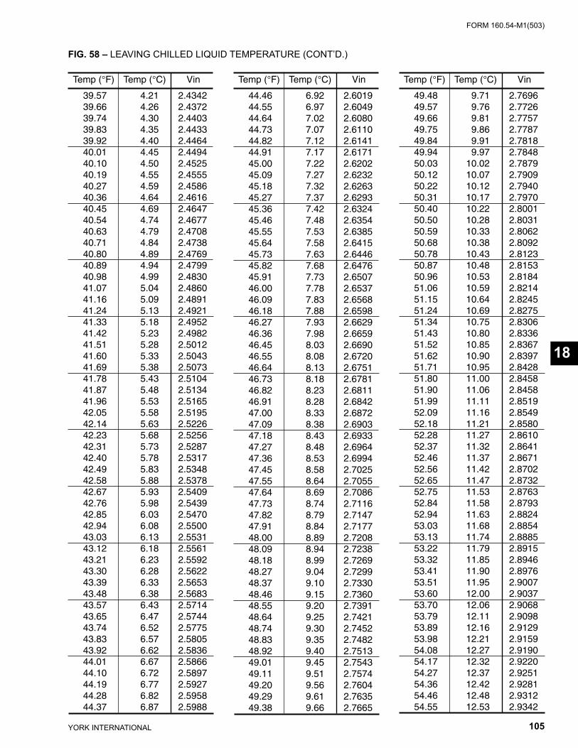
FORM 160.54-M1(503)
105YORK INTERNATIONAL
FIG. 58 – LEAVING CHILLED LIQUID TEMPERATURE (CONT’D.)
Temp (°F) Temp (°C) Vin
44.46 6.92 2.6019 44.55 6.97 2.6049 44.64 7.02 2.6080 44.73 7.07 2.6110 44.82 7.12 2.6141 44.91 7.17 2.6171 45.00 7.22 2.6202 45.09 7.27 2.6232 45.18 7.32 2.6263 45.27 7.37 2.6293 45.36 7.42 2.6324 45.46 7.48 2.6354 45.55 7.53 2.6385 45.64 7.58 2.6415 45.73 7.63 2.6446 45.82 7.68 2.6476 45.91 7.73 2.6507 46.00 7.78 2.6537 46.09 7.83 2.6568 46.18 7.88 2.6598 46.27 7.93 2.6629 46.36 7.98 2.6659 46.45 8.03 2.6690 46.55 8.08 2.6720 46.64 8.13 2.6751 46.73 8.18 2.6781 46.82 8.23 2.6811 46.91 8.28 2.6842 47.00 8.33 2.6872 47.09 8.38 2.6903 47.18 8.43 2.6933 47.27 8.48 2.6964 47.36 8.53 2.6994 47.45 8.58 2.7025 47.55 8.64 2.7055 47.64 8.69 2.7086 47.73 8.74 2.7116 47.82 8.79 2.7147 47.91 8.84 2.7177 48.00 8.89 2.7208 48.09 8.94 2.7238 48.18 8.99 2.7269 48.27 9.04 2.7299 48.37 9.10 2.7330 48.46 9.15 2.7360 48.55 9.20 2.7391 48.64 9.25 2.7421 48.74 9.30 2.7452 48.83 9.35 2.7482 48.92 9.40 2.7513 49.01 9.45 2.7543 49.11 9.51 2.7574 49.20 9.56 2.7604 49.29 9.61 2.7635 49.38 9.66 2.7665
Temp (°F) Temp (°C) Vin
39.57 4.21 2.4342 39.66 4.26 2.4372 39.74 4.30 2.4403 39.83 4.35 2.4433 39.92 4.40 2.4464 40.01 4.45 2.4494 40.10 4.50 2.4525 40.19 4.55 2.4555 40.27 4.59 2.4586 40.36 4.64 2.4616 40.45 4.69 2.4647 40.54 4.74 2.4677 40.63 4.79 2.4708 40.71 4.84 2.4738 40.80 4.89 2.4769 40.89 4.94 2.4799 40.98 4.99 2.4830 41.07 5.04 2.4860 41.16 5.09 2.4891 41.24 5.13 2.4921 41.33 5.18 2.4952 41.42 5.23 2.4982 41.51 5.28 2.5012 41.60 5.33 2.5043 41.69 5.38 2.5073 41.78 5.43 2.5104 41.87 5.48 2.5134 41.96 5.53 2.5165 42.05 5.58 2.5195 42.14 5.63 2.5226 42.23 5.68 2.5256 42.31 5.73 2.5287 42.40 5.78 2.5317 42.49 5.83 2.5348 42.58 5.88 2.5378 42.67 5.93 2.5409 42.76 5.98 2.5439 42.85 6.03 2.5470 42.94 6.08 2.5500 43.03 6.13 2.5531 43.12 6.18 2.5561 43.21 6.23 2.5592 43.30 6.28 2.5622 43.39 6.33 2.5653 43.48 6.38 2.5683 43.57 6.43 2.5714 43.65 6.47 2.5744 43.74 6.52 2.5775 43.83 6.57 2.5805 43.92 6.62 2.5836 44.01 6.67 2.5866 44.10 6.72 2.5897 44.19 6.77 2.5927 44.28 6.82 2.5958 44.37 6.87 2.5988
Temp (°F) Temp (°C) Vin
49.48 9.71 2.7696 49.57 9.76 2.7726 49.66 9.81 2.7757 49.75 9.86 2.7787 49.84 9.91 2.7818 49.94 9.97 2.7848 50.03 10.02 2.7879 50.12 10.07 2.7909 50.22 10.12 2.7940 50.31 10.17 2.7970 50.40 10.22 2.8001 50.50 10.28 2.8031 50.59 10.33 2.8062 50.68 10.38 2.8092 50.78 10.43 2.8123 50.87 10.48 2.8153 50.96 10.53 2.8184 51.06 10.59 2.8214 51.15 10.64 2.8245 51.24 10.69 2.8275 51.34 10.75 2.8306 51.43 10.80 2.8336 51.52 10.85 2.8367 51.62 10.90 2.8397 51.71 10.95 2.8428 51.80 11.00 2.8458 51.90 11.06 2.8458 51.99 11.11 2.8519 52.09 11.16 2.8549 52.18 11.21 2.8580 52.28 11.27 2.8610 52.37 11.32 2.8641 52.46 11.37 2.8671 52.56 11.42 2.8702 52.65 11.47 2.8732 52.75 11.53 2.8763 52.84 11.58 2.8793 52.94 11.63 2.8824 53.03 11.68 2.8854 53.13 11.74 2.8885 53.22 11.79 2.8915 53.32 11.85 2.8946 53.41 11.90 2.8976 53.51 11.95 2.9007 53.60 12.00 2.9037 53.70 12.06 2.9068 53.79 12.11 2.9098 53.89 12.16 2.9129 53.98 12.21 2.9159 54.08 12.27 2.9190 54.17 12.32 2.9220 54.27 12.37 2.9251 54.36 12.42 2.9281 54.46 12.48 2.9312 54.55 12.53 2.9342
18
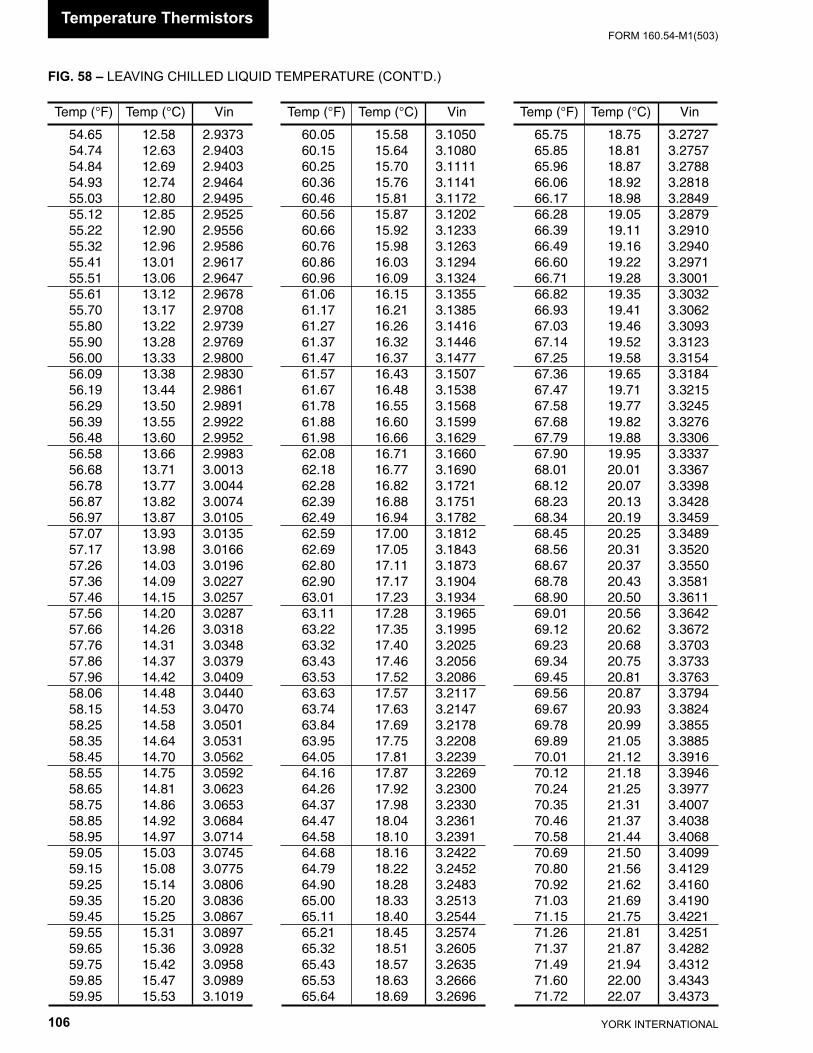
YORK INTERNATIONAL106
FORM 160.54-M1(503)
FIG. 58 – LEAVING CHILLED LIQUID TEMPERATURE (CONT’D.)
Temp (°F) Temp (°C) Vin
54.65 12.58 2.9373 54.74 12.63 2.9403 54.84 12.69 2.9403 54.93 12.74 2.9464 55.03 12.80 2.9495 55.12 12.85 2.9525 55.22 12.90 2.9556 55.32 12.96 2.9586 55.41 13.01 2.9617 55.51 13.06 2.9647 55.61 13.12 2.9678 55.70 13.17 2.9708 55.80 13.22 2.9739 55.90 13.28 2.9769 56.00 13.33 2.9800 56.09 13.38 2.9830 56.19 13.44 2.9861 56.29 13.50 2.9891 56.39 13.55 2.9922 56.48 13.60 2.9952 56.58 13.66 2.9983 56.68 13.71 3.0013 56.78 13.77 3.0044 56.87 13.82 3.0074 56.97 13.87 3.0105 57.07 13.93 3.0135 57.17 13.98 3.0166 57.26 14.03 3.0196 57.36 14.09 3.0227 57.46 14.15 3.0257 57.56 14.20 3.0287 57.66 14.26 3.0318 57.76 14.31 3.0348 57.86 14.37 3.0379 57.96 14.42 3.0409 58.06 14.48 3.0440 58.15 14.53 3.0470 58.25 14.58 3.0501 58.35 14.64 3.0531 58.45 14.70 3.0562 58.55 14.75 3.0592 58.65 14.81 3.0623 58.75 14.86 3.0653 58.85 14.92 3.0684 58.95 14.97 3.0714 59.05 15.03 3.0745 59.15 15.08 3.0775 59.25 15.14 3.0806 59.35 15.20 3.0836 59.45 15.25 3.0867 59.55 15.31 3.0897 59.65 15.36 3.0928 59.75 15.42 3.0958 59.85 15.47 3.0989 59.95 15.53 3.1019
Temp (°F) Temp (°C) Vin
60.05 15.58 3.1050 60.15 15.64 3.1080 60.25 15.70 3.1111 60.36 15.76 3.1141 60.46 15.81 3.1172 60.56 15.87 3.1202 60.66 15.92 3.1233 60.76 15.98 3.1263 60.86 16.03 3.1294 60.96 16.09 3.1324 61.06 16.15 3.1355 61.17 16.21 3.1385 61.27 16.26 3.1416 61.37 16.32 3.1446 61.47 16.37 3.1477 61.57 16.43 3.1507 61.67 16.48 3.1538 61.78 16.55 3.1568 61.88 16.60 3.1599 61.98 16.66 3.1629 62.08 16.71 3.1660 62.18 16.77 3.1690 62.28 16.82 3.1721 62.39 16.88 3.1751 62.49 16.94 3.1782 62.59 17.00 3.1812 62.69 17.05 3.1843 62.80 17.11 3.1873 62.90 17.17 3.1904 63.01 17.23 3.1934 63.11 17.28 3.1965 63.22 17.35 3.1995 63.32 17.40 3.2025 63.43 17.46 3.2056 63.53 17.52 3.2086 63.63 17.57 3.2117 63.74 17.63 3.2147 63.84 17.69 3.2178 63.95 17.75 3.2208 64.05 17.81 3.2239 64.16 17.87 3.2269 64.26 17.92 3.2300 64.37 17.98 3.2330 64.47 18.04 3.2361 64.58 18.10 3.2391 64.68 18.16 3.2422 64.79 18.22 3.2452 64.90 18.28 3.2483 65.00 18.33 3.2513 65.11 18.40 3.2544 65.21 18.45 3.2574 65.32 18.51 3.2605 65.43 18.57 3.2635 65.53 18.63 3.2666 65.64 18.69 3.2696
Temp (°F) Temp (°C) Vin
65.75 18.75 3.2727 65.85 18.81 3.2757 65.96 18.87 3.2788 66.06 18.92 3.2818 66.17 18.98 3.2849 66.28 19.05 3.2879 66.39 19.11 3.2910 66.49 19.16 3.2940 66.60 19.22 3.2971 66.71 19.28 3.3001 66.82 19.35 3.3032 66.93 19.41 3.3062 67.03 19.46 3.3093 67.14 19.52 3.3123 67.25 19.58 3.3154 67.36 19.65 3.3184 67.47 19.71 3.3215 67.58 19.77 3.3245 67.68 19.82 3.3276 67.79 19.88 3.3306 67.90 19.95 3.3337 68.01 20.01 3.3367 68.12 20.07 3.3398 68.23 20.13 3.3428 68.34 20.19 3.3459 68.45 20.25 3.3489 68.56 20.31 3.3520 68.67 20.37 3.3550 68.78 20.43 3.3581 68.90 20.50 3.3611 69.01 20.56 3.3642 69.12 20.62 3.3672 69.23 20.68 3.3703 69.34 20.75 3.3733 69.45 20.81 3.3763 69.56 20.87 3.3794 69.67 20.93 3.3824 69.78 20.99 3.3855 69.89 21.05 3.3885 70.01 21.12 3.3916 70.12 21.18 3.3946 70.24 21.25 3.3977 70.35 21.31 3.4007 70.46 21.37 3.4038 70.58 21.44 3.4068 70.69 21.50 3.4099 70.80 21.56 3.4129 70.92 21.62 3.4160 71.03 21.69 3.4190 71.15 21.75 3.4221 71.26 21.81 3.4251 71.37 21.87 3.4282 71.49 21.94 3.4312 71.60 22.00 3.4343 71.72 22.07 3.4373
Temperature Thermistors
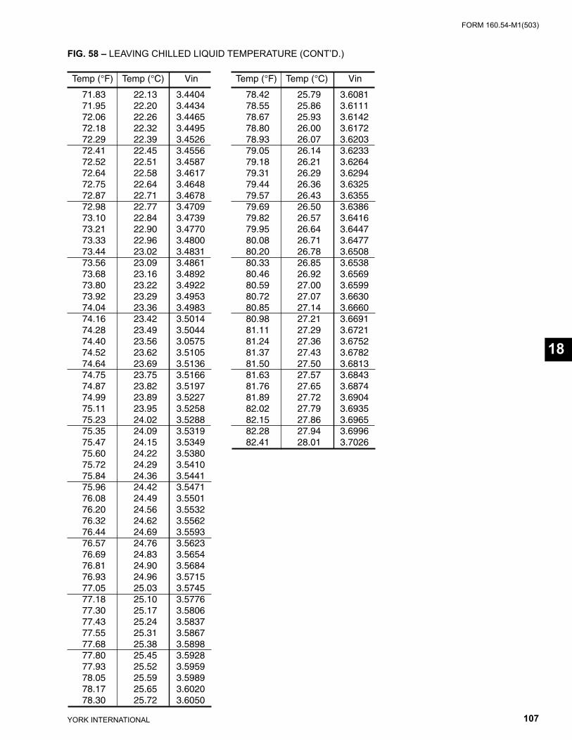
FORM 160.54-M1(503)
107YORK INTERNATIONAL
FIG. 58 – LEAVING CHILLED LIQUID TEMPERATURE (CONT’D.)
Temp (°F) Temp (°C) Vin
71.83 22.13 3.4404 71.95 22.20 3.4434 72.06 22.26 3.4465 72.18 22.32 3.4495 72.29 22.39 3.4526 72.41 22.45 3.4556 72.52 22.51 3.4587 72.64 22.58 3.4617 72.75 22.64 3.4648 72.87 22.71 3.4678 72.98 22.77 3.4709 73.10 22.84 3.4739 73.21 22.90 3.4770 73.33 22.96 3.4800 73.44 23.02 3.4831 73.56 23.09 3.4861 73.68 23.16 3.4892 73.80 23.22 3.4922 73.92 23.29 3.4953 74.04 23.36 3.4983 74.16 23.42 3.5014 74.28 23.49 3.5044 74.40 23.56 3.0575 74.52 23.62 3.5105 74.64 23.69 3.5136 74.75 23.75 3.5166 74.87 23.82 3.5197 74.99 23.89 3.5227 75.11 23.95 3.5258 75.23 24.02 3.5288 75.35 24.09 3.5319 75.47 24.15 3.5349 75.60 24.22 3.5380 75.72 24.29 3.5410 75.84 24.36 3.5441 75.96 24.42 3.5471 76.08 24.49 3.5501 76.20 24.56 3.5532 76.32 24.62 3.5562 76.44 24.69 3.5593 76.57 24.76 3.5623 76.69 24.83 3.5654 76.81 24.90 3.5684 76.93 24.96 3.5715 77.05 25.03 3.5745 77.18 25.10 3.5776 77.30 25.17 3.5806 77.43 25.24 3.5837 77.55 25.31 3.5867 77.68 25.38 3.5898 77.80 25.45 3.5928 77.93 25.52 3.5959 78.05 25.59 3.5989 78.17 25.65 3.6020 78.30 25.72 3.6050
Temp (°F) Temp (°C) Vin
78.42 25.79 3.6081 78.55 25.86 3.6111 78.67 25.93 3.6142 78.80 26.00 3.6172 78.93 26.07 3.6203 79.05 26.14 3.6233 79.18 26.21 3.6264 79.31 26.29 3.6294 79.44 26.36 3.6325 79.57 26.43 3.6355 79.69 26.50 3.6386 79.82 26.57 3.6416 79.95 26.64 3.6447 80.08 26.71 3.6477 80.20 26.78 3.6508 80.33 26.85 3.6538 80.46 26.92 3.6569 80.59 27.00 3.6599 80.72 27.07 3.6630 80.85 27.14 3.6660 80.98 27.21 3.6691 81.11 27.29 3.6721 81.24 27.36 3.6752 81.37 27.43 3.6782 81.50 27.50 3.6813 81.63 27.57 3.6843 81.76 27.65 3.6874 81.89 27.72 3.6904 82.02 27.79 3.6935 82.15 27.86 3.6965 82.28 27.94 3.6996 82.41 28.01 3.7026
18
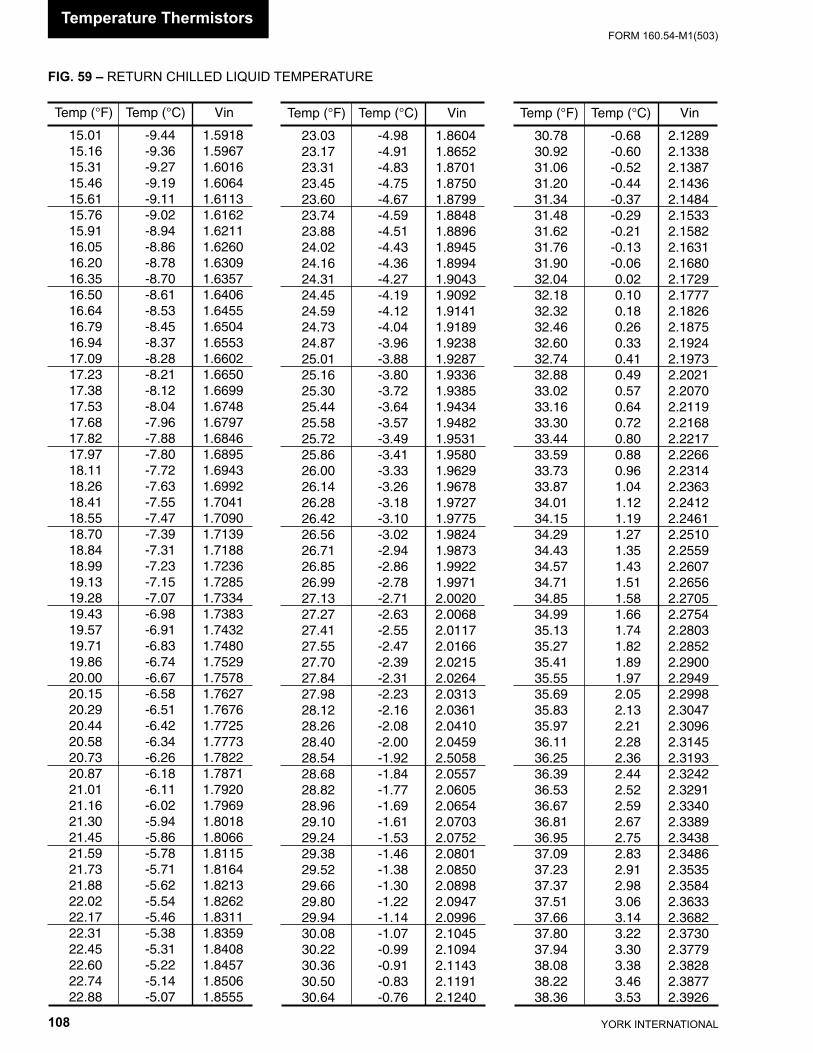
YORK INTERNATIONAL108
FORM 160.54-M1(503)
FIG. 59 – RETURN CHILLED LIQUID TEMPERATURE
Temp (°F) Temp (°C) Vin
15.01 -9.44 1.5918 15.16 -9.36 1.5967 15.31 -9.27 1.6016 15.46 -9.19 1.6064 15.61 -9.11 1.6113 15.76 -9.02 1.6162 15.91 -8.94 1.6211 16.05 -8.86 1.6260 16.20 -8.78 1.6309 16.35 -8.70 1.6357 16.50 -8.61 1.6406 16.64 -8.53 1.6455 16.79 -8.45 1.6504 16.94 -8.37 1.6553 17.09 -8.28 1.6602 17.23 -8.21 1.6650 17.38 -8.12 1.6699 17.53 -8.04 1.6748 17.68 -7.96 1.6797 17.82 -7.88 1.6846 17.97 -7.80 1.6895 18.11 -7.72 1.6943 18.26 -7.63 1.6992 18.41 -7.55 1.7041 18.55 -7.47 1.7090 18.70 -7.39 1.7139 18.84 -7.31 1.7188 18.99 -7.23 1.7236 19.13 -7.15 1.7285 19.28 -7.07 1.7334 19.43 -6.98 1.7383 19.57 -6.91 1.7432 19.71 -6.83 1.7480 19.86 -6.74 1.7529 20.00 -6.67 1.7578 20.15 -6.58 1.7627 20.29 -6.51 1.7676 20.44 -6.42 1.7725 20.58 -6.34 1.7773 20.73 -6.26 1.7822 20.87 -6.18 1.7871 21.01 -6.11 1.7920 21.16 -6.02 1.7969 21.30 -5.94 1.8018 21.45 -5.86 1.8066 21.59 -5.78 1.8115 21.73 -5.71 1.8164 21.88 -5.62 1.8213 22.02 -5.54 1.8262 22.17 -5.46 1.8311 22.31 -5.38 1.8359 22.45 -5.31 1.8408 22.60 -5.22 1.8457 22.74 -5.14 1.8506 22.88 -5.07 1.8555
Temp (°F) Temp (°C) Vin
23.03 -4.98 1.8604 23.17 -4.91 1.8652 23.31 -4.83 1.8701 23.45 -4.75 1.8750 23.60 -4.67 1.8799 23.74 -4.59 1.8848 23.88 -4.51 1.8896 24.02 -4.43 1.8945 24.16 -4.36 1.8994 24.31 -4.27 1.9043 24.45 -4.19 1.9092 24.59 -4.12 1.9141 24.73 -4.04 1.9189 24.87 -3.96 1.9238 25.01 -3.88 1.9287 25.16 -3.80 1.9336 25.30 -3.72 1.9385 25.44 -3.64 1.9434 25.58 -3.57 1.9482 25.72 -3.49 1.9531 25.86 -3.41 1.9580 26.00 -3.33 1.9629 26.14 -3.26 1.9678 26.28 -3.18 1.9727 26.42 -3.10 1.9775 26.56 -3.02 1.9824 26.71 -2.94 1.9873 26.85 -2.86 1.9922 26.99 -2.78 1.9971 27.13 -2.71 2.0020 27.27 -2.63 2.0068 27.41 -2.55 2.0117 27.55 -2.47 2.0166 27.70 -2.39 2.0215 27.84 -2.31 2.0264 27.98 -2.23 2.0313 28.12 -2.16 2.0361 28.26 -2.08 2.0410 28.40 -2.00 2.0459 28.54 -1.92 2.5058 28.68 -1.84 2.0557 28.82 -1.77 2.0605 28.96 -1.69 2.0654 29.10 -1.61 2.0703 29.24 -1.53 2.0752 29.38 -1.46 2.0801 29.52 -1.38 2.0850 29.66 -1.30 2.0898 29.80 -1.22 2.0947 29.94 -1.14 2.0996 30.08 -1.07 2.1045 30.22 -0.99 2.1094 30.36 -0.91 2.1143 30.50 -0.83 2.1191 30.64 -0.76 2.1240
Temp (°F) Temp (°C) Vin
30.78 -0.68 2.1289 30.92 -0.60 2.1338 31.06 -0.52 2.1387 31.20 -0.44 2.1436 31.34 -0.37 2.1484 31.48 -0.29 2.1533 31.62 -0.21 2.1582 31.76 -0.13 2.1631 31.90 -0.06 2.1680 32.04 0.02 2.1729 32.18 0.10 2.1777 32.32 0.18 2.1826 32.46 0.26 2.1875 32.60 0.33 2.1924 32.74 0.41 2.1973 32.88 0.49 2.2021 33.02 0.57 2.2070 33.16 0.64 2.2119 33.30 0.72 2.2168 33.44 0.80 2.2217 33.59 0.88 2.2266 33.73 0.96 2.2314 33.87 1.04 2.2363 34.01 1.12 2.2412 34.15 1.19 2.2461 34.29 1.27 2.2510 34.43 1.35 2.2559 34.57 1.43 2.2607 34.71 1.51 2.2656 34.85 1.58 2.2705 34.99 1.66 2.2754 35.13 1.74 2.2803 35.27 1.82 2.2852 35.41 1.89 2.2900 35.55 1.97 2.2949 35.69 2.05 2.2998 35.83 2.13 2.3047 35.97 2.21 2.3096 36.11 2.28 2.3145 36.25 2.36 2.3193 36.39 2.44 2.3242 36.53 2.52 2.3291 36.67 2.59 2.3340 36.81 2.67 2.3389 36.95 2.75 2.3438 37.09 2.83 2.3486 37.23 2.91 2.3535 37.37 2.98 2.3584 37.51 3.06 2.3633 37.66 3.14 2.3682 37.80 3.22 2.3730 37.94 3.30 2.3779 38.08 3.38 2.3828 38.22 3.46 2.3877 38.36 3.53 2.3926
Temperature Thermistors
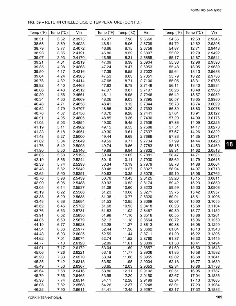
FORM 160.54-M1(503)
109YORK INTERNATIONAL
FIG. 59 – RETURN CHILLED LIQUID TEMPERATURE (CONT’D.)
Temp (°F) Temp (°C) Vin
38.51 3.62 2.3975 38.65 3.69 2.4023 38.79 3.77 2.4072 38.93 3.85 2.4121 39.07 3.93 2.4170 39.21 4.01 2.4219 39.35 4.08 2.4268 39.50 4.17 2.4316 39.64 4.24 2.4365 39.78 4.32 2.4414 39.92 4.40 2.4463 40.06 4.48 2.4512 40.20 4.56 2.4561 40.34 4.63 2.4609 40.48 4.71 2.4658 40.62 4.79 2.4707 40.76 4.87 2.4756 40.91 4.95 2.4805 41.05 5.03 2.4854 41.19 5.11 2.4902 41.33 5.18 2.4951 41.48 5.27 2.5000 41.62 5.34 2.5049 41.76 5.42 2.5098 41.90 5.50 2.5146 42.05 5.58 2.5195 42.19 5.66 2.5244 42.33 5.74 2.5293 42.48 5.82 2.5342 42.62 5.90 2.5391 42.76 5.98 2.5439 42.90 6.06 2.5488 43.05 6.14 2.5537 43.19 6.22 2.5586 43.33 6.29 2.5635 43.48 6.38 2.5684 43.62 6.46 2.5732 43.76 6.53 2.5781 43.91 6.62 2.5830 44.05 6.69 2.5879 44.19 6.77 2.5928 44.34 6.86 2.5977 44.48 6.93 2.6025 44.62 7.01 2.6074 44.77 7.10 2.6123 44.91 7.17 2.6172 45.06 7.26 2.6221 45.20 7.33 2.6270 45.35 7.42 2.6318 45.49 7.50 2.6367 45.64 7.58 2.6416 45.79 7.66 2.6465 45.93 7.74 2.6514 46.08 7.82 2.6563 46.22 7.90 2.6611
Temp (°F) Temp (°C) Vin
46.37 7.98 2.6660 46.51 8.06 2.6709 46.66 8.15 2.6758 46.80 8.22 2.6807 46.95 8.31 2.6855 47.09 8.38 2.6904 47.24 8.47 2.6953 47.39 8.55 2.7002 47.53 8.63 2.7051 47.68 8.71 2.7100 47.82 8.79 2.7148 47.97 8.87 2.7197 48.11 8.95 2.7246 48.26 9.03 2.7295 48.41 9.12 2.7344 48.56 9.20 2.7393 48.70 9.28 2.7441 48.85 9.36 2.7490 49.00 9.45 2.7539 49.15 9.53 2.7588 49.30 9.61 2.7637 49.44 9.69 2.7686 49.59 9.77 2.7734 49.74 9.86 2.7783 49.89 9.94 2.7832 50.04 10.02 2.7881 50.19 10.11 2.7930 50.34 10.19 2.7979 50.48 10.27 2.8027 50.63 10.35 2.8076 50.78 10.43 2.8125 50.93 10.52 2.8174 51.08 10.60 2.8223 51.23 10.68 2.8271 51.38 10.77 2.8320 51.53 10.85 2.8369 51.68 10.93 2.8418 51.83 11.02 2.8467 51.98 11.10 2.8516 52.13 11.18 2.8564 52.28 11.27 2.8613 52.44 11.36 2.8662 52.59 11.44 2.8711 52.74 11.52 2.8760 52.89 11.61 2.8809 53.04 11.69 2.8857 53.19 11.77 2.8906 53.34 11.86 2.8955 53.50 11.95 2.9004 53.65 12.03 2.9053 53.80 12.11 2.9102 53.95 12.20 2.0150 54.11 12.28 2.9199 54.26 12.37 2.9248 54.41 12.45 2.9297
Temp (°F) Temp (°C) Vin
54.56 12.53 2.9346 54.72 12.62 2.9395 54.87 12.71 2.9443 55.02 12.79 2.9492 55.17 12.87 2.9541 55.33 12.96 2.9590 55.48 13.05 2.9639 55.64 13.13 2.9688 55.79 13.22 2.9736 55.95 13.31 2.9785 56.11 13.40 2.9834 56.26 13.48 2.9983 56.42 13.57 2.9932 56.57 13.65 2.9980 56.73 13.74 3.0029 56.89 13.83 3.0078 57.04 13.91 3.0127 57.20 14.00 3.0176 57.36 14.09 3.0225 57.51 14.17 3.0273 57.67 14.26 3.0322 57.83 14.35 3.0371 57.99 14.44 3.0420 58.15 14.53 3.0469 58.31 14.62 3.0518 58.47 14.71 3.0566 58.62 14.79 3.0615 58.78 14.88 3.0664 58.94 14.97 3.0713 59.10 15.06 3.0762 59.26 15.15 3.0811 59.42 15.23 3.0859 59.59 15.33 3.0908 59.75 15.42 3.0957 59.91 15.51 3.1006 60.07 15.60 3.1055 60.23 15.68 3.1104 60.39 15.77 3.1152 60.55 15.86 3.1201 60.72 15.96 3.1250 60.88 16.05 3.1299 61.04 16.13 3.1348 61.20 16.22 3.1396 61.37 16.32 3.1445 61.53 16.41 3.1494 61.69 16.50 3.1543 61.85 16.58 3.1592 62.02 16.68 3.1641 62.18 16.77 3.1689 62.34 16.86 3.1738 62.51 16.95 3.1787 62.67 17.04 3.1836 62.84 17.13 3.1885 63.01 17.23 3.1934 63.17 17.32 3.1882
18
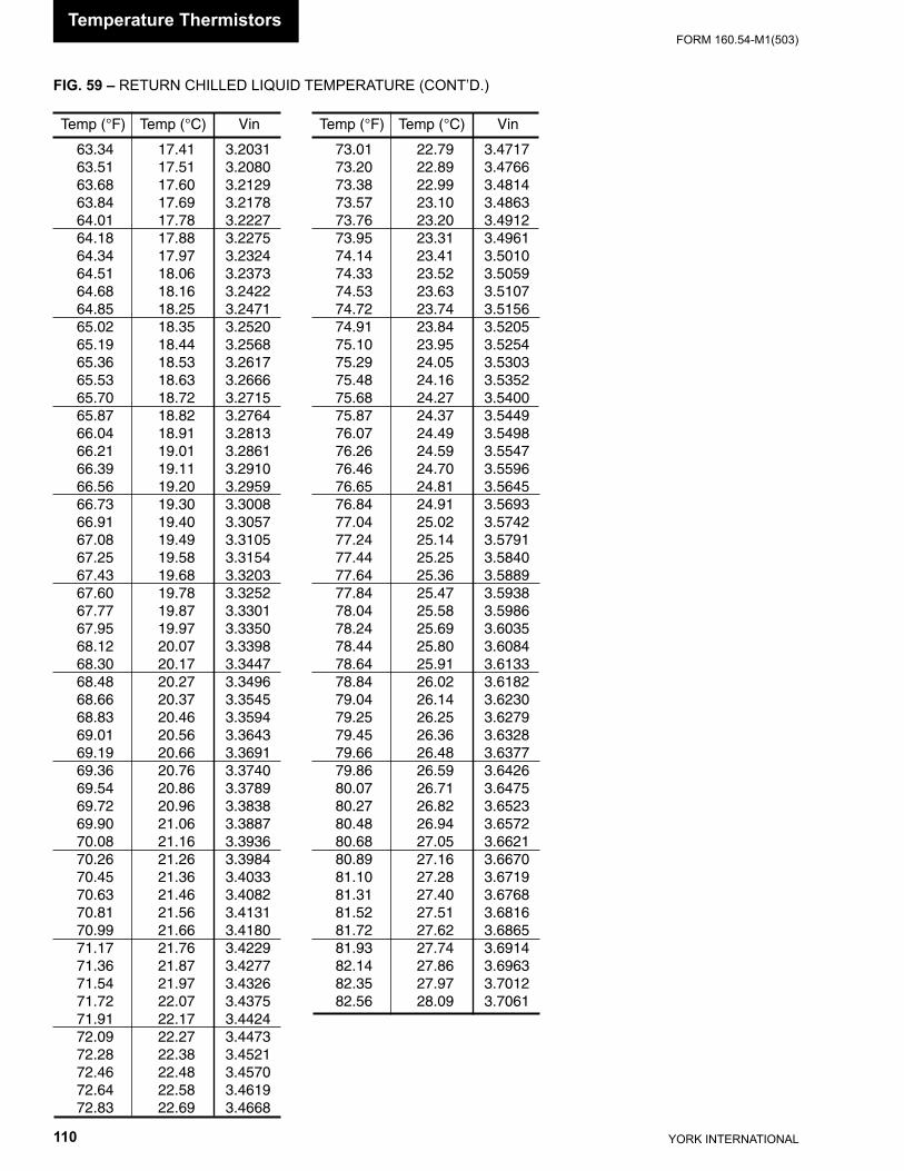
YORK INTERNATIONAL110
FORM 160.54-M1(503)
Temp (°F) Temp (°C) Vin
63.34 17.41 3.2031 63.51 17.51 3.2080 63.68 17.60 3.2129 63.84 17.69 3.2178 64.01 17.78 3.2227 64.18 17.88 3.2275 64.34 17.97 3.2324 64.51 18.06 3.2373 64.68 18.16 3.2422 64.85 18.25 3.2471 65.02 18.35 3.2520 65.19 18.44 3.2568 65.36 18.53 3.2617 65.53 18.63 3.2666 65.70 18.72 3.2715 65.87 18.82 3.2764 66.04 18.91 3.2813 66.21 19.01 3.2861 66.39 19.11 3.2910 66.56 19.20 3.2959 66.73 19.30 3.3008 66.91 19.40 3.3057 67.08 19.49 3.3105 67.25 19.58 3.3154 67.43 19.68 3.3203 67.60 19.78 3.3252 67.77 19.87 3.3301 67.95 19.97 3.3350 68.12 20.07 3.3398 68.30 20.17 3.3447 68.48 20.27 3.3496 68.66 20.37 3.3545 68.83 20.46 3.3594 69.01 20.56 3.3643 69.19 20.66 3.3691 69.36 20.76 3.3740 69.54 20.86 3.3789 69.72 20.96 3.3838 69.90 21.06 3.3887 70.08 21.16 3.3936 70.26 21.26 3.3984 70.45 21.36 3.4033 70.63 21.46 3.4082 70.81 21.56 3.4131 70.99 21.66 3.4180 71.17 21.76 3.4229 71.36 21.87 3.4277 71.54 21.97 3.4326 71.72 22.07 3.4375 71.91 22.17 3.4424 72.09 22.27 3.4473 72.28 22.38 3.4521 72.46 22.48 3.4570 72.64 22.58 3.4619 72.83 22.69 3.4668
Temp (°F) Temp (°C) Vin
73.01 22.79 3.4717 73.20 22.89 3.4766 73.38 22.99 3.4814 73.57 23.10 3.4863 73.76 23.20 3.4912 73.95 23.31 3.4961 74.14 23.41 3.5010 74.33 23.52 3.5059 74.53 23.63 3.5107 74.72 23.74 3.5156 74.91 23.84 3.5205 75.10 23.95 3.5254 75.29 24.05 3.5303 75.48 24.16 3.5352 75.68 24.27 3.5400 75.87 24.37 3.5449 76.07 24.49 3.5498 76.26 24.59 3.5547 76.46 24.70 3.5596 76.65 24.81 3.5645 76.84 24.91 3.5693 77.04 25.02 3.5742 77.24 25.14 3.5791 77.44 25.25 3.5840 77.64 25.36 3.5889 77.84 25.47 3.5938 78.04 25.58 3.5986 78.24 25.69 3.6035 78.44 25.80 3.6084 78.64 25.91 3.6133 78.84 26.02 3.6182 79.04 26.14 3.6230 79.25 26.25 3.6279 79.45 26.36 3.6328 79.66 26.48 3.6377 79.86 26.59 3.6426 80.07 26.71 3.6475 80.27 26.82 3.6523 80.48 26.94 3.6572 80.68 27.05 3.6621 80.89 27.16 3.6670 81.10 27.28 3.6719 81.31 27.40 3.6768 81.52 27.51 3.6816 81.72 27.62 3.6865 81.93 27.74 3.6914 82.14 27.86 3.6963 82.35 27.97 3.7012 82.56 28.09 3.7061
FIG. 59 – RETURN CHILLED LIQUID TEMPERATURE (CONT’D.)
Temperature Thermistors
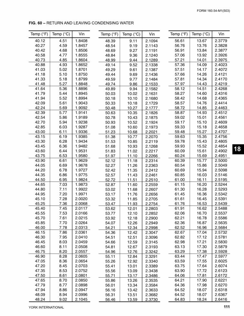
FORM 160.54-M1(503)
111YORK INTERNATIONAL
FIG. 60 – RETURN AND LEAVING CONDENSING WATER
Temp (°F) Temp (°C) Vin
40.12 4.51 1.8408 40.27 4.59 1.8457 40.42 4.68 1.8506 40.58 4.77 1.8555 40.73 4.85 1.8604 40.88 4.93 1.8652 41.03 5.02 1.8701 41.18 5.10 1.8750 41.33 5.18 1.8799 41.48 5.27 1.8848 41.64 5.36 1.8896 41.79 5.44 1.8945 41.94 5.52 1.8994 42.09 5.61 1.9043 42.24 5.69 1.9092 42.39 5.77 1.9141 42.54 5.86 1.9189 42.70 5.94 1.9238 42.85 6.03 1.9287 43.00 6.11 1.9336 43.15 6.19 1.9385 43.30 6.28 1.9434 43.45 6.36 1.9482 43.60 6.44 1.9531 43.75 6.53 1.9580 43.90 6.61 1.9629 44.05 6.69 1.9678 44.20 6.78 1.9727 44.35 6.86 1.9775 44.50 6.95 1.9824 44.65 7.03 1.9873 44.80 7.11 1.9922 44.95 7.20 1.9971 45.10 7.28 2.0020 45.25 7.36 2.0068 45.40 7.45 2.0117 45.55 7.53 2.0166 45.70 7.61 2.0215 45.85 7.70 2.0264 46.00 7.78 2.0313 46.15 7.86 2.0361 46.30 7.95 2.0410 46.45 8.03 2.0459 46.60 8.11 2.0508 46.75 8.20 2.0557 46.90 8.28 2.0605 47.05 8.36 2.0654 47.20 8.45 2.0703 47.35 8.53 2.0752 47.50 8.61 2.0801 47.65 8.70 2.0850 47.79 8.77 2.0898 47.94 8.86 2.0947 48.09 8.94 2.0996 48.24 9.02 2.1045
Temp (°F) Temp (°C) Vin
48.39 9.11 2.1094 48.54 9.19 2.1143 48.69 9.27 2.1191 48.84 9.36 2.1240 48.99 9.44 2.1289 49.14 9.52 2.1338 49.29 9.61 2.1387 49.44 9.69 2.1436 49.59 9.77 2.1484 49.74 9.86 2.1533 49.89 9.94 2.1582 50.03 10.02 2.1631 50.18 10.10 2.1680 50.33 10.18 2.1729 50.48 10.27 2.1777 50.63 10.35 2.1826 50.78 10.43 2.1875 50.93 10.52 2.1924 51.08 10.60 2.1973 51.23 10.68 2.2021 51.38 10.77 2.2070 51.53 10.85 2.2119 51.68 10.93 2.1268 51.83 11.02 2.2217 51.97 11.10 2.2266 52.12 11.18 2.2314 52.27 11.26 2.2363 52.42 11.35 2.2412 52.57 11.43 2.2461 52.72 11.51 2.2510 52.87 11.60 2.2559 53.02 11.68 2.2607 53.17 11.76 2.2656 53.32 11.85 2.2705 53.47 11.93 2.2754 53.62 12.01 2.2803 53.77 12.10 2.2852 53.92 12.18 2.2900 54.07 12.26 2.2949 54.21 12.34 2.2998 54.36 12.42 2.3047 54.51 12.51 2.3096 54.66 12.59 2.3145 54.81 12.67 2.3193 54.96 12.76 2.3242 55.11 12.84 2.3291 55.26 12.92 2.3340 55.41 13.01 2.3389 55.56 13.09 2.3438 55.71 13.17 2.3486 55.86 13.26 2.3535 56.01 13.34 2.3584 56.16 13.42 2.3633 56.31 13.51 2.3682 56.46 13.59 2.3730
Temp (°F) Temp (°C) Vin
56.61 13.67 2.3779 56.76 13.76 2.3828 56.91 13.84 2.3877 57.06 13.92 2.3926 57.21 14.01 2.3975 57.36 14.09 2.4023 57.51 14.17 2.4072 57.66 14.26 2.4121 57.81 14.34 2.4170 57.97 14.43 2.4219 58.12 14.51 2.4268 58.27 14.60 2.4316 58.42 14.68 2.4365 58.57 14.76 2.4414 58.72 14.85 2.4463 58.87 14.93 2.4512 59.02 15.01 2.4561 59.17 15.10 2.4609 59.33 15.18 2.4658 59.48 15.27 2.4707 59.63 15.35 2.4756 59.78 15.43 2.4805 59.93 15.52 2.4854 60.09 15.61 2.4902 60.24 15.69 2.4951 60.39 15.77 2.5000 60.54 15.86 2.5049 60.69 15.94 2.5098 60.85 16.03 2.5146 61.00 16.11 2.5195 61.15 16.20 2.5244 61.30 16.28 2.5293 61.45 16.36 2.5342 61.61 16.45 2.5391 61.76 16.53 2.5439 61.91 16.62 2.5488 62.06 16.70 2.5537 62.21 16.78 2.5586 62.36 16.87 2.5635 62.52 16.96 2.5684 62.67 17.04 2.5732 62.82 17.12 2.5781 62.98 17.21 2.5830 63.13 17.30 2.5879 63.29 17.38 2.5928 63.44 17.47 2.5977 63.59 17.55 2.6025 63.75 17.64 2.6074 63.90 17.72 2.6123 64.06 17.81 2.6172 64.21 17.90 2.6221 64.36 17.98 2.6270 64.52 18.07 2.6318 64.52 18.07 2.6367 64.83 18.24 2.6416
Temperature Thermistors
18
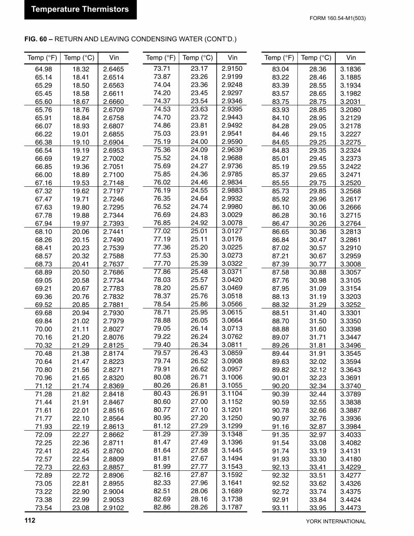
YORK INTERNATIONAL112
FORM 160.54-M1(503)
FIG. 60 – RETURN AND LEAVING CONDENSING WATER (CONT’D.)
Temp (°F) Temp (°C) Vin
64.98 18.32 2.6465 65.14 18.41 2.6514 65.29 18.50 2.6563 65.45 18.58 2.6611 65.60 18.67 2.6660 65.76 18.76 2.6709 65.91 18.84 2.6758 66.07 18.93 2.6807 66.22 19.01 2.6855 66.38 19.10 2.6904 66.54 19.19 2.6953 66.69 19.27 2.7002 66.85 19.36 2.7051 66.00 18.89 2.7100 67.16 19.53 2.7148 67.32 19.62 2.7197 67.47 19.71 2.7246 67.63 19.80 2.7295 67.78 19.88 2.7344 67.94 19.97 2.7393 68.10 20.06 2.7441 68.26 20.15 2.7490 68.41 20.23 2.7539 68.57 20.32 2.7588 68.73 20.41 2.7637 68.89 20.50 2.7686 69.05 20.58 2.7734 69.21 20.67 2.7783 69.36 20.76 2.7832 69.52 20.85 2.7881 69.68 20.94 2.7930 69.84 21.02 2.7979 70.00 21.11 2.8027 70.16 21.20 2.8076 70.32 21.29 2.8125 70.48 21.38 2.8174 70.64 21.47 2.8223 70.80 21.56 2.8271 70.96 21.65 2.8320 71.12 21.74 2.8369 71.28 21.82 2.8418 71.44 21.91 2.8467 71.61 22.01 2.8516 71.77 22.10 2.8564 71.93 22.19 2.8613 72.09 22.27 2.8662 72.25 22.36 2.8711 72.41 22.45 2.8760 72.57 22.54 2.8809 72.73 22.63 2.8857 72.89 22.72 2.8906 73.05 22.81 2.8955 73.22 22.90 2.9004 73.38 22.99 2.9053 73.54 23.08 2.9102
Temp (°F) Temp (°C) Vin
73.71 23.17 2.9150 73.87 23.26 2.9199 74.04 23.36 2.9248 74.20 23.45 2.9297 74.37 23.54 2.9346 74.53 23.63 2.9395 74.70 23.72 2.9443 74.86 23.81 2.9492 75.03 23.91 2.9541 75.19 24.00 2.9590 75.36 24.09 2.9639 75.52 24.18 2.9688 75.69 24.27 2.9736 75.85 24.36 2.9785 76.02 24.46 2.9834 76.19 24.55 2.9883 76.35 24.64 2.9932 76.52 24.74 2.9980 76.69 24.83 3.0029 76.85 24.92 3.0078 77.02 25.01 3.0127 77.19 25.11 3.0176 77.36 25.20 3.0225 77.53 25.30 3.0273 77.70 25.39 3.0322 77.86 25.48 3.0371 78.03 25.57 3.0420 78.20 25.67 3.0469 78.37 25.76 3.0518 78.54 25.86 3.0566 78.71 25.95 3.0615 78.88 26.05 3.0664 79.05 26.14 3.0713 79.22 26.24 3.0762 79.40 26.34 3.0811 79.57 26.43 3.0859 79.74 26.52 3.0908 79.91 26.62 3.0957 80.08 26.71 3.1006 80.26 26.81 3.1055 80.43 26.91 3.1104 80.60 27.00 3.1152 80.77 27.10 3.1201 80.95 27.20 3.1250 81.12 27.29 3.1299 81.29 27.39 3.1348 81.47 27.49 3.1396 81.64 27.58 3.1445 81.81 27.67 3.1494 81.99 27.77 3.1543 82.16 27.87 3.1592 82.33 27.96 3.1641 82.51 28.06 3.1689 82.69 28.16 3.1738 82.86 28.26 3.1787
Temp (°F) Temp (°C) Vin
83.04 28.36 3.1836 83.22 28.46 3.1885 83.39 28.55 3.1934 83.57 28.65 3.1982 83.75 28.75 3.2031 83.93 28.85 3.2080 84.10 28.95 3.2129 84.28 29.05 3.2178 84.46 29.15 3.2227 84.65 29.25 3.2275 84.83 29.35 3.2324 85.01 29.45 3.2373 85.19 29.55 3.2422 85.37 29.65 3.2471 85.55 29.75 3.2520 85.73 29.85 3.2568 85.92 29.96 3.2617 86.10 30.06 3.2666 86.28 30.16 3.2715 86.47 30.26 3.2764 86.65 30.36 3.2813 86.84 30.47 3.2861 87.02 30.57 3.2910 87.21 30.67 3.2959 87.39 30.77 3.3008 87.58 30.88 3.3057 87.76 30.98 3.3105 87.95 31.09 3.3154 88.13 31.19 3.3203 88.32 31.29 3.3252 88.51 31.40 3.3301 88.70 31.50 3.3350 88.88 31.60 3.3398 89.07 31.71 3.3447 89.26 31.81 3.3496 89.44 31.91 3.3545 89.63 32.02 3.3594 89.82 32.12 3.3643 90.01 32.23 3.3691 90.20 32.34 3.3740 90.39 32.44 3.3789 90.59 32.55 3.3838 90.78 32.66 3.3887 90.97 32.76 3.3936 91.16 32.87 3.3984 91.35 32.97 3.4033 91.54 33.08 3.4082 91.74 33.19 3.4131 91.93 33.30 3.4180 92.13 33.41 3.4229 92.32 33.51 3.4277 92.52 33.62 3.4326 92.72 33.74 3.4375 92.91 33.84 3.4424 93.11 33.95 3.4473
Temperature Thermistors
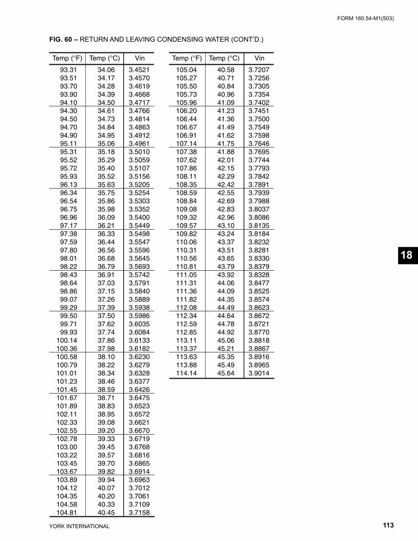
FORM 160.54-M1(503)
113YORK INTERNATIONAL
Temp (°F) Temp (°C) Vin
93.31 34.06 3.4521 93.51 34.17 3.4570 93.70 34.28 3.4619 93.90 34.39 3.4668 94.10 34.50 3.4717 94.30 34.61 3.4766 94.50 34.73 3.4814 94.70 34.84 3.4863 94.90 34.95 3.4912 95.11 35.06 3.4961 95.31 35.18 3.5010 95.52 35.29 3.5059 95.72 35.40 3.5107 95.93 35.52 3.5156 96.13 35.63 3.5205 96.34 35.75 3.5254 96.54 35.86 3.5303 96.75 35.98 3.5352 96.96 36.09 3.5400 97.17 36.21 3.5449 97.38 36.33 3.5498 97.59 36.44 3.5547 97.80 36.56 3.5596 98.01 36.68 3.5645 98.22 36.79 3.5693 98.43 36.91 3.5742 98.64 37.03 3.5791 98.86 37.15 3.5840 99.07 37.26 3.5889 99.29 37.39 3.5938 99.50 37.50 3.5986 99.71 37.62 3.6035 99.93 37.74 3.6084 100.14 37.86 3.6133 100.36 37.98 3.6182 100.58 38.10 3.6230 100.79 38.22 3.6279 101.01 38.34 3.6328 101.23 38.46 3.6377 101.45 38.59 3.6426 101.67 38.71 3.6475 101.89 38.83 3.6523 102.11 38.95 3.6572 102.33 39.08 3.6621 102.55 39.20 3.6670 102.78 39.33 3.6719 103.00 39.45 3.6768 103.22 39.57 3.6816 103.45 39.70 3.6865 103.67 39.82 3.6914 103.89 39.94 3.6963 104.12 40.07 3.7012 104.35 40.20 3.7061 104.58 40.33 3.7109 104.81 40.45 3.7158
Temp (°F) Temp (°C) Vin
105.04 40.58 3.7207 105.27 40.71 3.7256 105.50 40.84 3.7305 105.73 40.96 3.7354 105.96 41.09 3.7402 106.20 41.23 3.7451 106.44 41.36 3.7500 106.67 41.49 3.7549 106.91 41.62 3.7598 107.14 41.75 3.7646 107.38 41.88 3.7695 107.62 42.01 3.7744 107.86 42.15 3.7793 108.11 42.29 3.7842 108.35 42.42 3.7891 108.59 42.55 3.7939 108.84 42.69 3.7988 109.08 42.83 3.8037 109.32 42.96 3.8086 109.57 43.10 3.8135 109.82 43.24 3.8184 110.06 43.37 3.8232 110.31 43.51 3.8281 110.56 43.65 3.8330 110.81 43.79 3.8379 111.05 43.92 3.8328 111.31 44.06 3.8477 111.36 44.09 3.8525 111.82 44.35 3.8574 112.08 44.49 3.8623 112.34 44.64 3.8672 112.59 44.78 3.8721 112.85 44.92 3.8770 113.11 45.06 3.8818 113.37 45.21 3.8867 113.63 45.35 3.8916 113.88 45.49 3.8965 114.14 45.64 3.9014
FIG. 60 – RETURN AND LEAVING CONDENSING WATER (CONT’D.)
18
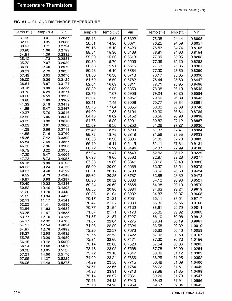
YORK INTERNATIONAL114
FORM 160.54-M1(503)
FIG. 61 – OIL AND DISCHARGE TEMPERATURE
Temp (°F) Temp (°C) Vin
31.99 -0.01 0.2637 32.63 0.35 0.2686 33.27 0.71 0.2734 33.90 1.06 0.2783 34.51 1.39 0.2832 35.12 1.73 0.2881 35.73 2.07 0.2930 36.32 2.40 0.2979 36.91 2.73 0.3027 37.49 3.05 0.3076 38.05 3.36 0.3125 38.61 3.67 0.3174 39.18 3.99 0.3223 39.72 4.29 0.3271 40.26 4.59 0.3320 40.80 4.89 0.3369 41.33 5.18 0.3418 41.85 5.47 0.3467 42.37 5.76 0.3516 42.89 6.05 0.3564 43.39 6.33 0.3613 43.89 6.61 0.3662 44.39 6.88 0.3711 44.88 7.16 0.3760 45.36 7.42 0.3809 45.84 7.69 0.3857 46.32 7.96 0.3906 46.79 8.22 0.3955 47.25 8.47 0.4004 47.72 8.73 0.4053 48.18 8.99 0.4102 48.63 9.24 0.4150 49.07 9.48 0.4199 49.52 9.73 0.4248 49.97 9.98 0.4297 50.40 10.22 0.4346 50.83 10.46 0.4395 51.26 10.70 0.4443 51.69 10.94 0.4492 52.11 11.17 0.4541 52.53 11.41 0.4590 52.94 11.63 0.4639 53.36 11.87 0.4688 53.77 12.10 0.4736 54.17 12.32 0.4785 54.57 12.54 0.4834 54.97 12.76 0.4883 55.37 12.98 0.4932 55.76 13.20 0.4980 56.15 13.42 0.5029 56.54 13.63 0.5078 56.92 13.85 0.5127 57.31 14.06 0.5176 57.68 14.27 0.5225 58.06 14.48 0.5273
Temp (°F) Temp (°C) Vin
58.43 14.68 0.5322 58.81 14.90 0.5371 59.18 15.10 0.5420 59.54 15.30 0.5469 59.90 15.50 0.5518 60.26 15.70 0.5566 60.63 15.91 0.5615 60.98 16.10 0.5664 61.33 16.30 0.5713 61.69 16.50 0.5762 62.04 16.69 0.5811 62.39 16.88 0.5859 62.73 17.07 0.5908 63.07 17.26 0.5957 63.41 17.45 0.6006 63.75 17.64 0.6055 64.09 17.83 0.6104 64.43 18.02 0.6152 64.76 18.20 0.6201 65.09 18.38 0.6250 65.42 18.57 0.6299 65.75 18.75 0.6348 66.08 18.93 0.6396 66.40 19.11 0.6445 66.72 19.29 0.6494 67.04 19.47 0.6543 67.36 19.65 0.6592 67.68 19.82 0.6641 68.00 20.00 0.6689 68.31 20.17 0.6738 68.62 20.35 0.6787 68.93 20.52 0.6836 69.24 20.69 0.6885 69.55 20.86 0.6934 69.86 21.04 0.6982 70.17 21.21 0.7031 70.47 21.37 0.7080 70.77 21.54 0.7129 71.07 21.71 0.7178 71.37 21.87 0.7227 71.67 22.04 0.7275 71.96 22.20 0.7324 72.26 22.37 0.7373 72.55 22.53 0.7422 72.84 22.69 0.7471 73.14 22.86 0.7520 73.43 23.02 0.7568 73.72 23.18 0.7617 74.00 23.34 0.7666 74.29 23.50 0.7715 74.57 23.65 0.7764 74.86 23.81 0.7813 75.14 23.97 0.7861 75.42 24.12 0.7910 75.70 24.28 0.7959
Temp (°F) Temp (°C) Vin
75.98 24.44 0.8008 76.25 24.59 0.8057 76.53 24.74 0.8105 76.81 24.90 0.8154 77.09 25.05 0.8203 77.36 25.20 0.8252 77.63 25.35 0.8301 77.90 25.50 0.8350 78.17 25.65 0.8398 78.44 25.80 0.8447 78.71 25.95 0.8496 78.98 26.10 0.8545 79.24 26.25 0.8594 79.50 26.39 0.8643 79.77 26.54 0.8691 80.03 26.69 0.8740 80.30 26.84 0.8789 80.56 26.98 0.8838 80.82 27.12 0.8887 81.08 27.27 0.8936 81.33 27.41 0.8984 81.59 27.55 0.9033 81.85 27.70 0.9082 82.11 27.84 0.9131 82.37 27.99 0.9180 82.62 28.12 0.9229 82.87 28.26 0.9277 83.12 28.40 0.9326 83.37 28.54 0.9375 83.62 28.68 0.9424 83.88 28.82 0.9473 84.13 28.96 0.9521 84.38 29.10 0.9570 84.62 29.24 0.9619 84.87 29.37 0.9668 85.11 29.51 0.9717 85.36 29.65 0.9766 85.61 29.79 0.9814 85.85 29.92 0.9863 86.10 30.06 0.9912 86.34 30.19 0.9961 86.58 30.32 1.0010 86.82 30.46 1.0059 87.06 30.59 1.0107 87.30 30.72 1.0156 87.54 30.86 1.0205 87.78 30.99 1.0254 88.02 31.12 1.0303 88.25 31.25 1.0352 88.49 31.39 1.0400 88.72 31.51 1.0449 88.96 31.65 1.0498 89.20 31.78 1.0547 89.43 31.91 1.0596 89.67 32.04 1.0645
Temperature Thermistors
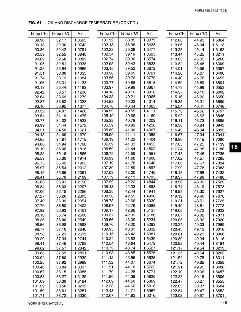
FORM 160.54-M1(503)
115YORK INTERNATIONAL
FIG. 61 – OIL AND DISCHARGE TEMPERATURE (CONT’D.)
Temp (°F) Temp (°C) Vin
89.90 32.17 1.0693 90.13 32.30 1.0742 90.36 32.42 1.0791 90.59 32.55 1.0840 90.82 32.68 1.0889 91.05 32.81 1.0938 91.28 32.94 1.0986 91.51 33.06 1.1035 91.74 33.19 1.1084 91.96 33.31 1.1133 92.19 33.44 1.1182 92.42 33.57 1.1230 92.64 33.69 1.1279 92.87 33.82 1.1328 93.10 33.95 1.1377 93.32 34.07 1.1426 93.54 34.19 1.1475 93.77 34.32 1.1523 93.99 34.44 1.1572 94.21 34.56 1.1621 94.43 34.69 1.1670 94.65 34.81 1.1719 94.88 34.94 1.1768 95.10 35.06 1.1816 95.32 35.18 1.1865 95.53 35.30 1.1914 95.75 35.42 1.1963 95.97 35.54 1.2012 96.19 35.66 1.2061 96.41 35.79 1.2109 96.63 35.91 1.2158 96.84 36.03 1.2207 97.06 36.15 1.2256 97.27 36.26 1.2305 97.49 36.39 1.2354 97.70 36.50 1.2402 97.92 36.63 1.2451 98.13 36.74 1.2500 98.35 36.86 1.2549 98.56 36.98 1.2598 98.77 37.10 1.2646 98.98 37.21 1.2695 99.20 37.34 1.2744 99.41 37.45 1.2793 99.62 37.57 1.2842 99.83 37.69 1.2891 100.04 37.80 1.2939 100.25 37.92 1.2988 100.46 38.04 1.3037 100.67 38.15 1.3086 100.88 38.27 1.3135 101.09 38.39 1.3184 101.29 38.50 1.3232 101.50 38.61 1.3281 101.71 38.73 1.3330
Temp (°F) Temp (°C) Vin
101.92 38.85 1.3379 102.13 38.96 1.3428 102.33 39.08 1.3477 102.54 39.19 1.3525 102.74 39.30 1.3574 102.95 39.42 1.3623 103.15 39.53 1.3672 103.36 39.65 1.3721 103.56 39.76 1.3770 103.77 39.88 1.3818 103.97 39.99 1.3867 104.18 40.10 1.3916 104.38 40.21 1.3965 104.58 40.33 1.4014 104.78 40.44 1.4063 104.99 40.55 1.4111 105.19 40.66 1.4160 105.39 40.78 1.4209 105.59 40.89 1.4258 105.80 41.00 1.4307 105.99 41.11 1.4355 106.19 41.22 1.4404 106.39 41.33 1.4453 106.59 41.44 1.4502 106.79 41.55 1.4551 106.99 41.66 1.4600 107.19 41.78 1.4648 107.39 41.89 1.4697 107.59 42.00 1.4746 107.79 42.11 1.4795 107.99 42.22 1.4844 108.18 42.33 1.4893 108.38 42.44 1.4941 108.58 42.55 1.4990 108.78 42.66 1.5039 108.97 42.76 1.5088 109.17 42.88 1.5137 109.37 42.99 1.5186 109.56 43.09 1.5234 109.76 43.20 1.5283 109.95 43.31 1.5332 110.15 43.42 1.5381 110.34 43.53 1.5430 110.54 43.64 1.5479 110.73 43.74 1.5527 110.93 43.85 1.5576 111.12 43.96 1.5625 111.32 44.07 1.5674 111.51 44.18 1.5723 111.70 44.28 1.5771 111.90 44.39 1.5820 112.09 44.50 1.5869 112.28 44.60 1.5918 112.48 44.71 1.5967 112.67 44.82 1.6016
Temp (°F) Temp (°C) Vin
112.86 44.93 1.6064 113.06 45.04 1.6113 113.25 45.14 1.6162 113.44 45.25 1.6211 113.63 45.35 1.6260 113.82 45.46 1.6309 114.01 45.56 1.6357 114.20 45.67 1.6406 114.40 45.78 1.6455 114.59 45.89 1.6504 114.78 45.99 1.6553 114.97 46.10 1.6602 115.16 46.20 1.6650 115.35 46.31 1.6699 115.54 46.41 1.6748 115.73 46.52 1.6797 115.92 46.63 1.6846 116.11 46.73 1.6895 116.30 46.84 1.6943 116.49 46.94 1.6992 116.67 47.04 1.7041 116.86 47.15 1.7090 117.05 47.25 1.7139 117.24 47.36 1.7188 117.43 47.46 1.7236 117.62 47.57 1.7285 117.80 47.67 1.7334 117.99 47.78 1.7383 118.18 47.88 1.7432 118.37 47.99 1.7480 118.56 48.09 1.7529 118.74 48.19 1.7578 118.93 48.30 1.7627 119.12 48.40 1.7676 119.31 48.51 1.7725 119.49 48.61 1.7773 119.68 48.72 1.7822 119.87 48.82 1.7871 120.05 48.92 1.7920 120.24 49.03 1.7969 120.43 49.13 1.8018 120.61 49.23 1.8066 120.80 49.34 1.8115 120.98 49.44 1.8164 121.17 49.54 1.8213 121.35 49.64 1.8262 121.54 49.75 1.8311 121.72 49.85 1.8359 121.91 49.95 1.8408 122.10 50.06 1.8457 122.28 50.16 1.8506 122.47 50.27 1.8555 122.65 50.37 1.8604 122.84 50.47 1.8652 123.02 50.57 1.8701
Temperature Thermistors
18
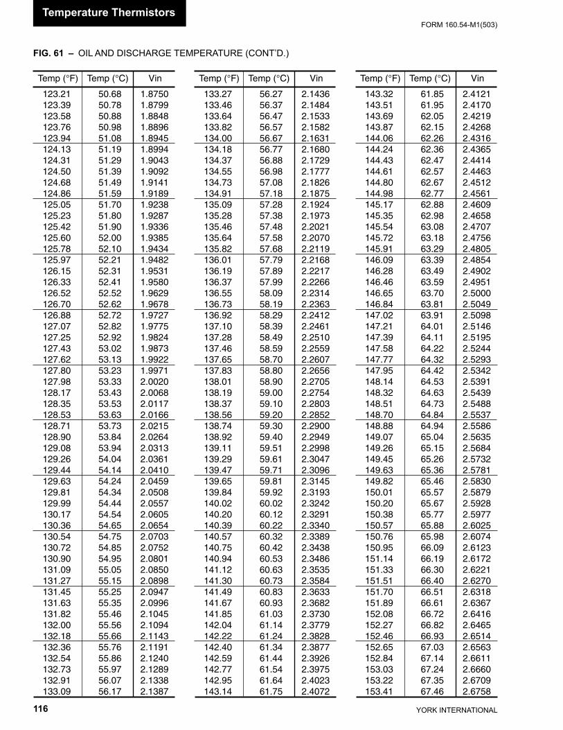
YORK INTERNATIONAL116
FORM 160.54-M1(503)
FIG. 61 – OIL AND DISCHARGE TEMPERATURE (CONT’D.)
Temp (°F) Temp (°C) Vin
123.21 50.68 1.8750 123.39 50.78 1.8799 123.58 50.88 1.8848 123.76 50.98 1.8896 123.94 51.08 1.8945 124.13 51.19 1.8994 124.31 51.29 1.9043 124.50 51.39 1.9092 124.68 51.49 1.9141 124.86 51.59 1.9189 125.05 51.70 1.9238 125.23 51.80 1.9287 125.42 51.90 1.9336 125.60 52.00 1.9385 125.78 52.10 1.9434 125.97 52.21 1.9482 126.15 52.31 1.9531 126.33 52.41 1.9580 126.52 52.52 1.9629 126.70 52.62 1.9678 126.88 52.72 1.9727 127.07 52.82 1.9775 127.25 52.92 1.9824 127.43 53.02 1.9873 127.62 53.13 1.9922 127.80 53.23 1.9971 127.98 53.33 2.0020 128.17 53.43 2.0068 128.35 53.53 2.0117 128.53 53.63 2.0166 128.71 53.73 2.0215 128.90 53.84 2.0264 129.08 53.94 2.0313 129.26 54.04 2.0361 129.44 54.14 2.0410 129.63 54.24 2.0459 129.81 54.34 2.0508 129.99 54.44 2.0557 130.17 54.54 2.0605 130.36 54.65 2.0654 130.54 54.75 2.0703 130.72 54.85 2.0752 130.90 54.95 2.0801 131.09 55.05 2.0850 131.27 55.15 2.0898 131.45 55.25 2.0947 131.63 55.35 2.0996 131.82 55.46 2.1045 132.00 55.56 2.1094 132.18 55.66 2.1143 132.36 55.76 2.1191 132.54 55.86 2.1240 132.73 55.97 2.1289 132.91 56.07 2.1338 133.09 56.17 2.1387
Temp (°F) Temp (°C) Vin
133.27 56.27 2.1436 133.46 56.37 2.1484 133.64 56.47 2.1533 133.82 56.57 2.1582 134.00 56.67 2.1631 134.18 56.77 2.1680 134.37 56.88 2.1729 134.55 56.98 2.1777 134.73 57.08 2.1826 134.91 57.18 2.1875 135.09 57.28 2.1924 135.28 57.38 2.1973 135.46 57.48 2.2021 135.64 57.58 2.2070 135.82 57.68 2.2119 136.01 57.79 2.2168 136.19 57.89 2.2217 136.37 57.99 2.2266 136.55 58.09 2.2314 136.73 58.19 2.2363 136.92 58.29 2.2412 137.10 58.39 2.2461 137.28 58.49 2.2510 137.46 58.59 2.2559 137.65 58.70 2.2607 137.83 58.80 2.2656 138.01 58.90 2.2705 138.19 59.00 2.2754 138.37 59.10 2.2803 138.56 59.20 2.2852 138.74 59.30 2.2900 138.92 59.40 2.2949 139.11 59.51 2.2998 139.29 59.61 2.3047 139.47 59.71 2.3096 139.65 59.81 2.3145 139.84 59.92 2.3193 140.02 60.02 2.3242 140.20 60.12 2.3291 140.39 60.22 2.3340 140.57 60.32 2.3389 140.75 60.42 2.3438 140.94 60.53 2.3486 141.12 60.63 2.3535 141.30 60.73 2.3584 141.49 60.83 2.3633 141.67 60.93 2.3682 141.85 61.03 2.3730 142.04 61.14 2.3779 142.22 61.24 2.3828 142.40 61.34 2.3877 142.59 61.44 2.3926 142.77 61.54 2.3975 142.95 61.64 2.4023 143.14 61.75 2.4072
Temp (°F) Temp (°C) Vin
143.32 61.85 2.4121 143.51 61.95 2.4170 143.69 62.05 2.4219 143.87 62.15 2.4268 144.06 62.26 2.4316 144.24 62.36 2.4365 144.43 62.47 2.4414 144.61 62.57 2.4463 144.80 62.67 2.4512 144.98 62.77 2.4561 145.17 62.88 2.4609 145.35 62.98 2.4658 145.54 63.08 2.4707 145.72 63.18 2.4756 145.91 63.29 2.4805 146.09 63.39 2.4854 146.28 63.49 2.4902 146.46 63.59 2.4951 146.65 63.70 2.5000 146.84 63.81 2.5049 147.02 63.91 2.5098 147.21 64.01 2.5146 147.39 64.11 2.5195 147.58 64.22 2.5244 147.77 64.32 2.5293 147.95 64.42 2.5342 148.14 64.53 2.5391 148.32 64.63 2.5439 148.51 64.73 2.5488 148.70 64.84 2.5537 148.88 64.94 2.5586 149.07 65.04 2.5635 149.26 65.15 2.5684 149.45 65.26 2.5732 149.63 65.36 2.5781 149.82 65.46 2.5830 150.01 65.57 2.5879 150.20 65.67 2.5928 150.38 65.77 2.5977 150.57 65.88 2.6025 150.76 65.98 2.6074 150.95 66.09 2.6123 151.14 66.19 2.6172 151.33 66.30 2.6221 151.51 66.40 2.6270 151.70 66.51 2.6318 151.89 66.61 2.6367 152.08 66.72 2.6416 152.27 66.82 2.6465 152.46 66.93 2.6514 152.65 67.03 2.6563 152.84 67.14 2.6611 153.03 67.24 2.6660 153.22 67.35 2.6709 153.41 67.46 2.6758
Temperature Thermistors
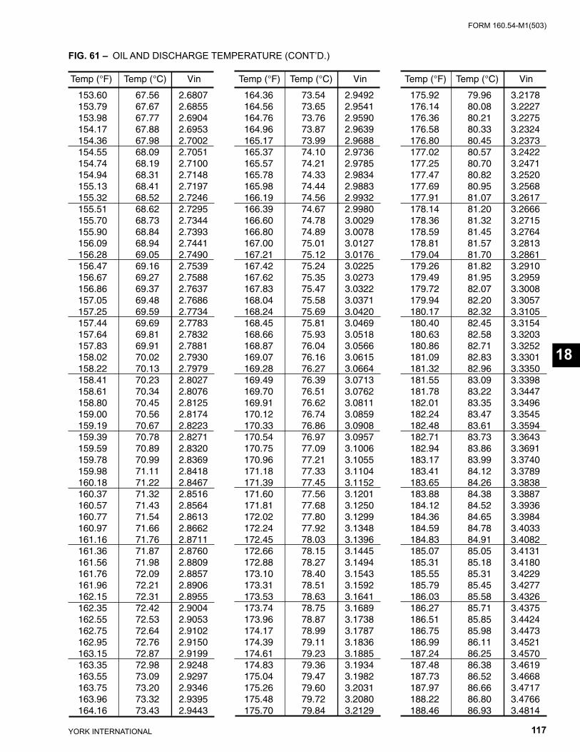
FORM 160.54-M1(503)
117YORK INTERNATIONAL
Temp (°F) Temp (°C) Vin
153.60 67.56 2.6807 153.79 67.67 2.6855 153.98 67.77 2.6904 154.17 67.88 2.6953 154.36 67.98 2.7002 154.55 68.09 2.7051 154.74 68.19 2.7100 154.94 68.31 2.7148 155.13 68.41 2.7197 155.32 68.52 2.7246 155.51 68.62 2.7295 155.70 68.73 2.7344 155.90 68.84 2.7393 156.09 68.94 2.7441 156.28 69.05 2.7490 156.47 69.16 2.7539 156.67 69.27 2.7588 156.86 69.37 2.7637 157.05 69.48 2.7686 157.25 69.59 2.7734 157.44 69.69 2.7783 157.64 69.81 2.7832 157.83 69.91 2.7881 158.02 70.02 2.7930 158.22 70.13 2.7979 158.41 70.23 2.8027 158.61 70.34 2.8076 158.80 70.45 2.8125 159.00 70.56 2.8174 159.19 70.67 2.8223 159.39 70.78 2.8271 159.59 70.89 2.8320 159.78 70.99 2.8369 159.98 71.11 2.8418 160.18 71.22 2.8467 160.37 71.32 2.8516 160.57 71.43 2.8564 160.77 71.54 2.8613 160.97 71.66 2.8662 161.16 71.76 2.8711 161.36 71.87 2.8760 161.56 71.98 2.8809 161.76 72.09 2.8857 161.96 72.21 2.8906 162.15 72.31 2.8955 162.35 72.42 2.9004 162.55 72.53 2.9053 162.75 72.64 2.9102 162.95 72.76 2.9150 163.15 72.87 2.9199 163.35 72.98 2.9248 163.55 73.09 2.9297 163.75 73.20 2.9346 163.96 73.32 2.9395 164.16 73.43 2.9443
Temp (°F) Temp (°C) Vin
164.36 73.54 2.9492 164.56 73.65 2.9541 164.76 73.76 2.9590 164.96 73.87 2.9639 165.17 73.99 2.9688 165.37 74.10 2.9736 165.57 74.21 2.9785 165.78 74.33 2.9834 165.98 74.44 2.9883 166.19 74.56 2.9932 166.39 74.67 2.9980 166.60 74.78 3.0029 166.80 74.89 3.0078 167.00 75.01 3.0127 167.21 75.12 3.0176 167.42 75.24 3.0225 167.62 75.35 3.0273 167.83 75.47 3.0322 168.04 75.58 3.0371 168.24 75.69 3.0420 168.45 75.81 3.0469 168.66 75.93 3.0518 168.87 76.04 3.0566 169.07 76.16 3.0615 169.28 76.27 3.0664 169.49 76.39 3.0713 169.70 76.51 3.0762 169.91 76.62 3.0811 170.12 76.74 3.0859 170.33 76.86 3.0908 170.54 76.97 3.0957 170.75 77.09 3.1006 170.96 77.21 3.1055 171.18 77.33 3.1104 171.39 77.45 3.1152 171.60 77.56 3.1201 171.81 77.68 3.1250 172.02 77.80 3.1299 172.24 77.92 3.1348 172.45 78.03 3.1396 172.66 78.15 3.1445 172.88 78.27 3.1494 173.10 78.40 3.1543 173.31 78.51 3.1592 173.53 78.63 3.1641 173.74 78.75 3.1689 173.96 78.87 3.1738 174.17 78.99 3.1787 174.39 79.11 3.1836 174.61 79.23 3.1885 174.83 79.36 3.1934 175.04 79.47 3.1982 175.26 79.60 3.2031 175.48 79.72 3.2080 175.70 79.84 3.2129
Temp (°F) Temp (°C) Vin
175.92 79.96 3.2178 176.14 80.08 3.2227 176.36 80.21 3.2275 176.58 80.33 3.2324 176.80 80.45 3.2373 177.02 80.57 3.2422 177.25 80.70 3.2471 177.47 80.82 3.2520 177.69 80.95 3.2568 177.91 81.07 3.2617 178.14 81.20 3.2666 178.36 81.32 3.2715 178.59 81.45 3.2764 178.81 81.57 3.2813 179.04 81.70 3.2861 179.26 81.82 3.2910 179.49 81.95 3.2959 179.72 82.07 3.3008 179.94 82.20 3.3057 180.17 82.32 3.3105 180.40 82.45 3.3154 180.63 82.58 3.3203 180.86 82.71 3.3252 181.09 82.83 3.3301 181.32 82.96 3.3350 181.55 83.09 3.3398 181.78 83.22 3.3447 182.01 83.35 3.3496 182.24 83.47 3.3545 182.48 83.61 3.3594 182.71 83.73 3.3643 182.94 83.86 3.3691 183.17 83.99 3.3740 183.41 84.12 3.3789 183.65 84.26 3.3838 183.88 84.38 3.3887 184.12 84.52 3.3936 184.36 84.65 3.3984 184.59 84.78 3.4033 184.83 84.91 3.4082 185.07 85.05 3.4131 185.31 85.18 3.4180 185.55 85.31 3.4229 185.79 85.45 3.4277 186.03 85.58 3.4326 186.27 85.71 3.4375 186.51 85.85 3.4424 186.75 85.98 3.4473 186.99 86.11 3.4521 187.24 86.25 3.4570 187.48 86.38 3.4619 187.73 86.52 3.4668 187.97 86.66 3.4717 188.22 86.80 3.4766 188.46 86.93 3.4814
FIG. 61 – OIL AND DISCHARGE TEMPERATURE (CONT’D.)
Temperature Thermistors
18
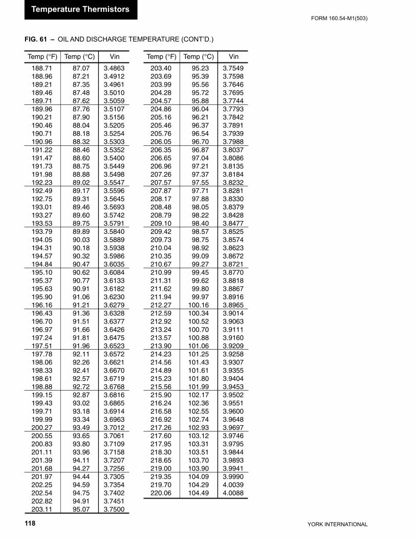
YORK INTERNATIONAL118
FORM 160.54-M1(503)
Temp (°F) Temp (°C) Vin
188.71 87.07 3.4863 188.96 87.21 3.4912 189.21 87.35 3.4961 189.46 87.48 3.5010 189.71 87.62 3.5059 189.96 87.76 3.5107 190.21 87.90 3.5156 190.46 88.04 3.5205 190.71 88.18 3.5254 190.96 88.32 3.5303 191.22 88.46 3.5352 191.47 88.60 3.5400 191.73 88.75 3.5449 191.98 88.88 3.5498 192.23 89.02 3.5547 192.49 89.17 3.5596 192.75 89.31 3.5645 193.01 89.46 3.5693 193.27 89.60 3.5742 193.53 89.75 3.5791 193.79 89.89 3.5840 194.05 90.03 3.5889 194.31 90.18 3.5938 194.57 90.32 3.5986 194.84 90.47 3.6035 195.10 90.62 3.6084 195.37 90.77 3.6133 195.63 90.91 3.6182 195.90 91.06 3.6230 196.16 91.21 3.6279 196.43 91.36 3.6328 196.70 91.51 3.6377 196.97 91.66 3.6426 197.24 91.81 3.6475 197.51 91.96 3.6523 197.78 92.11 3.6572 198.06 92.26 3.6621 198.33 92.41 3.6670 198.61 92.57 3.6719 198.88 92.72 3.6768 199.15 92.87 3.6816 199.43 93.02 3.6865 199.71 93.18 3.6914 199.99 93.34 3.6963 200.27 93.49 3.7012 200.55 93.65 3.7061 200.83 93.80 3.7109 201.11 93.96 3.7158 201.39 94.11 3.7207 201.68 94.27 3.7256 201.97 94.44 3.7305 202.25 94.59 3.7354 202.54 94.75 3.7402 202.82 94.91 3.7451 203.11 95.07 3.7500
Temp (°F) Temp (°C) Vin
203.40 95.23 3.7549 203.69 95.39 3.7598 203.99 95.56 3.7646 204.28 95.72 3.7695 204.57 95.88 3.7744 204.86 96.04 3.7793 205.16 96.21 3.7842 205.46 96.37 3.7891 205.76 96.54 3.7939 206.05 96.70 3.7988 206.35 96.87 3.8037 206.65 97.04 3.8086 206.96 97.21 3.8135 207.26 97.37 3.8184 207.57 97.55 3.8232 207.87 97.71 3.8281 208.17 97.88 3.8330 208.48 98.05 3.8379 208.79 98.22 3.8428 209.10 98.40 3.8477 209.42 98.57 3.8525 209.73 98.75 3.8574 210.04 98.92 3.8623 210.35 99.09 3.8672 210.67 99.27 3.8721 210.99 99.45 3.8770 211.31 99.62 3.8818 211.62 99.80 3.8867 211.94 99.97 3.8916 212.27 100.16 3.8965 212.59 100.34 3.9014 212.92 100.52 3.9063 213.24 100.70 3.9111 213.57 100.88 3.9160 213.90 101.06 3.9209 214.23 101.25 3.9258 214.56 101.43 3.9307 214.89 101.61 3.9355 215.23 101.80 3.9404 215.56 101.99 3.9453 215.90 102.17 3.9502 216.24 102.36 3.9551 216.58 102.55 3.9600 216.92 102.74 3.9648 217.26 102.93 3.9697 217.60 103.12 3.9746 217.95 103.31 3.9795 218.30 103.51 3.9844 218.65 103.70 3.9893 219.00 103.90 3.9941 219.35 104.09 3.9990 219.70 104.29 4.0039 220.06 104.49 4.0088
FIG. 61 – OIL AND DISCHARGE TEMPERATURE (CONT’D.)
Temperature Thermistors
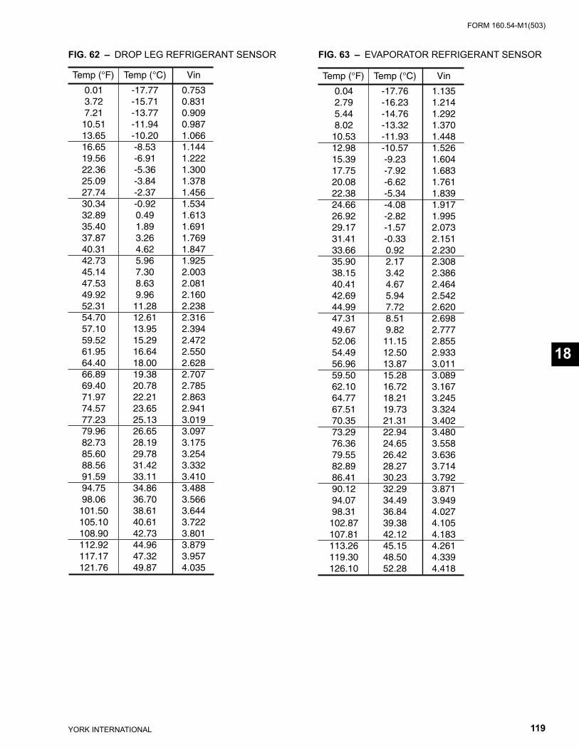
FORM 160.54-M1(503)
119YORK INTERNATIONAL
FIG. 62 – DROP LEG REFRIGERANT SENSOR FIG. 63 – EVAPORATOR REFRIGERANT SEN SOR
Temp (°F) Temp (°C) Vin
0.01 -17.77 0.753 3.72 -15.71 0.831 7.21 -13.77 0.909 10.51 -11.94 0.987 13.65 -10.20 1.066 16.65 -8.53 1.144 19.56 -6.91 1.222 22.36 -5.36 1.300 25.09 -3.84 1.378 27.74 -2.37 1.456 30.34 -0.92 1.534 32.89 0.49 1.613 35.40 1.89 1.691 37.87 3.26 1.769 40.31 4.62 1.847 42.73 5.96 1.925 45.14 7.30 2.003 47.53 8.63 2.081 49.92 9.96 2.160 52.31 11.28 2.238 54.70 12.61 2.316 57.10 13.95 2.394 59.52 15.29 2.472 61.95 16.64 2.550 64.40 18.00 2.628 66.89 19.38 2.707 69.40 20.78 2.785 71.97 22.21 2.863 74.57 23.65 2.941 77.23 25.13 3.019 79.96 26.65 3.097 82.73 28.19 3.175 85.60 29.78 3.254 88.56 31.42 3.332 91.59 33.11 3.410 94.75 34.86 3.488 98.06 36.70 3.566 101.50 38.61 3.644 105.10 40.61 3.722 108.90 42.73 3.801 112.92 44.96 3.879 117.17 47.32 3.957 121.76 49.87 4.035
Temp (°F) Temp (°C) Vin
0.04 -17.76 1.135 2.79 -16.23 1.214 5.44 -14.76 1.292 8.02 -13.32 1.370 10.53 -11.93 1.448 12.98 -10.57 1.526 15.39 -9.23 1.604 17.75 -7.92 1.683 20.08 -6.62 1.761 22.38 -5.34 1.839 24.66 -4.08 1.917 26.92 -2.82 1.995 29.17 -1.57 2.073 31.41 -0.33 2.151 33.66 0.92 2.230 35.90 2.17 2.308 38.15 3.42 2.386 40.41 4.67 2.464 42.69 5.94 2.542 44.99 7.72 2.620 47.31 8.51 2.698 49.67 9.82 2.777 52.06 11.15 2.855 54.49 12.50 2.933 56.96 13.87 3.011 59.50 15.28 3.089 62.10 16.72 3.167 64.77 18.21 3.245 67.51 19.73 3.324 70.35 21.31 3.402 73.29 22.94 3.480 76.36 24.65 3.558 79.55 26.42 3.636 82.89 28.27 3.714 86.41 30.23 3.792 90.12 32.29 3.871 94.07 34.49 3.949 98.31 36.84 4.027 102.87 39.38 4.105 107.81 42.12 4.183 113.26 45.15 4.261 119.30 48.50 4.339 126.10 52.28 4.418
Temperature Thermistors
18
YORK INTERNATIONAL120
FORM 160.54-M1(503)
SECTION 19REMOTE SETPOINTS
(See Figs. 12, 14 & 17)
There are three different Remote operating Modes that can be selected at the Keypad: Analog Remote mode, Digital Remote Mode or ISN Remote Mode.
The OptiView Control Center can receive a remote Current Limit and/or a Remote Leaving Chilled Liquid Temperature Setpoint via the following:
Analog Remote Mode • 0-10VDC Analog Input • 2-10VDC Analog Input • 0-20mA An a log Input • 4-20mA An a log Input
Digital Remote Mode • Pulse width Modulation (PWM) Input
ISN Remote Mode • RS-232 Serial Port via MicroGateway
The Analog inputs are connected to the Microboard J22 as shown in Figure 12 and described below. Microboard Program Jumpers JP23 and JP24 must be po si tioned appropriately to receive either a 0-10VDC, 2-10VDC, 0-20mA or a 4-20mA signal. Refer to Table 1 “Microboard Program Jumpers” and explanation be low for required confi gurations.
The PWM inputs are in the form of a 1 to 11 second Re- lay contact closure that applies 115VAC to the I/O Board TB4-19 (Leaving Chilled Liquid Temp) and TB4-20 (Remote Current Limit) for 1 to 11 seconds. Re fer to Fig-ure 14. The source of 115VAC is I/O Board TB4-1. The PWM input must be received at a fre quen cy of at least once every 30 minutes. If not received with in this time interval, the Program assumes the remote de vice is de-fective and defaults the Current Limit Setpoint to 100% and the Leaving Chilled Liquid Temperature Setpoint to the locally programmed Local BASE val ue.
The Microboard COM 4B RS-232 Serial Port (J2) re ceives the Setpoints in serial data form from the MicroGateway located inside the OptiView Control
Cen ter enclosure. The MicroGateway re ceives Setpoints from re mote external de vic es and transfers them to the Microboard.
CURRENT LIMIT
REMOTE CURRENT LIMIT SETPOINT with 0-10VDC, 2-10VDC, 0-20mA, 4-20mA or Pulse Width Modulation Signal – The Remote Current Lim it setpoint can be re set over the range of 100% to 30% Full Load Amps (FLA) by supplying (by others) a 0-10VDC, 2-10VDC, 0-20mA, 4-20mA or 1 to 11 sec ond Pulse Width Modulated (PWM) signal to the OptiView Con trol Center. The OptiView Control Cen ter must be con fi g ured appropriately to accept the de sired signal type as fol lows:
• The appropriate Remote Mode must be selected: ANALOG Remote Mode must be selected when using a voltage or current signal input. DIGITAL Remote Mode must be selected when using a PWM input.
• If ANALOG Remote Mode is selected, the RE- MOTE ANALOG INPUT RANGE setpoint must be set to “0-10VDC” or “2-10VDC” as de tailed be- low, re gard less of whether the signal is a voltage or cur rent input sig nal type.
• Microboard Program Jumper JP23 must be po si -tioned appropriately per the input signal type as de tailed be low. It is recommended that a qualifi ed Service Tech ni cian position this jumper.
IMPORTANT! - The signal type used for Re mote Cur rent Limit setpoint re- set and the signal type used for Re mote Leaving Chilled Liquid Tem per a ture setpoint reset must be the same. For ex am ple, if a 0-10VDC sig nal is be-ing used for Remote Leaving Chilled Liq uid Tem per a ture Reset, then a 0-10VDC sig nal must be used for Re- mote Cur rent Lim it Reset.
Remote Setpoints
FORM 160.54-M1(503)
121YORK INTERNATIONAL
0-10VDCAs shown in Fig. 12, connect input to Microboard J22-1 (signal) and J22-5 (Gnd). The setpoint varies lin ear ly from 100% to 30% FLA as the input varies from 0 to l0VDC. This input will only be accepted when AN A LOG Remote Mode is selected, the RE- MOTE AN A LOG INPUT RANGE setpoint is set for “0-10 Volts” and Microboard Pro gram Jumper JP23 has been re moved. Calculate the setpoint for various in puts as fol lows:
Setpoint (%) = 100 – (VDC x 7)
For example, if the input is 5VDC, the setpoint would be set to 65% as follows:
Setpoint (%) = 100 – (5 x 7)
= 100 – 35
= 65%
2-10VDCAs shown in Fig. 12, connect input to Microboard J22-1 (sig nal) and J22-5 (Gnd). The setpoint varies lin ear ly from 100% to 30% FLA as the input varies from 2 to 10VDC. This input will only be ac cept ed when AN A LOG Remote Mode is selected, the RE- MOTE AN A LOG INPUT RANGE setpoint is set for “2-10 Volts” and Microboard Program Jumper JP23 has been re moved. Calculate the setpoint for var i ous inputs as fol lows:
Setpoint (%) = 100 – [(VDC – 2) x 8.75]
For example, if the input is 5VDC, the setpoint would be set to 74% as follows:
Setpoint (%) = 100 – [(5 - 2) x 8.75]
= 100 – [3 x 8.75]
= 100 – 26.25
= 74%
0-20mAAs shown in Fig. 12, connect input to Microboard J22-2 (signal) and J22-5 (Gnd). The setpoint var ies lin ear ly from 100% to 30% FLA as the input var ies from 0mA to 20mA. This input will only be ac cept ed when AN A LOG remote mode is selected, the REMOTE AN A LOG INPUT RANGE setpoint is set for “0-10 Volts” and Microboard Program Jumper JP23 has been placed on pins 1 and 2. Calculate the setpoint for var i ous in puts as fol lows:
Setpoint (%) = 100 – (mA x 3.5)
For example, if the input is 8mA, the setpoint would be set to 72% as follows:
Setpoint (%) = 100 – (8 x 3.5)
= 100 – 28
= 72%
4-20mAAs shown in Fig. 12, connect input to Microboard J22-2 (signal) and J22-5 (Gnd). The setpoint var ies lin ear ly from 100% to 30% FLA as the input varies from 4mA to 20mA. This input will only be ac cept ed when AN A LOG remote mode is selected, the REMOTE AN A LOG INPUT RANGE setpoint is set for “2-10 Volts” and Microboard Program Jumper JP23 has been placed on pins 1 and 2. Calculate the setpoint for var i ous in puts as follows:
Setpoint (%)100 – [(mA – 4) x 4.3 75]
For example, if the input is 8mA, the setpoint would be set to 83% as follows:
Setpoint (%) = 100 – [(8–4) x 4.375]
= 100 – (4 x 4.375)
= 100 – 17.5
= 82.5
= 83%
PWMThe Pulse Width Modulation input is in the form of a 1 to 11 second relay contact closure that ap plies 115VAC to the I/O Board TB4-20 for 1 to 11 sec onds. As shown in Fig. 14, connect dry closure relay contacts be tween I/O Board TB4-20 (signal) and TB4-l (115Vac). The setpoint varies linearly from 100% to 30% as the relay contact closure time changes from 1 to 11 sec onds. The relay contacts should close for 1 to 11 sec onds at least once every 30 minutes to maintain the setpoint to the desired value. If a 1 to 11 second closure is not re ceived within 30 minutes of the last closure, the setpoint is de-faulted to 100%. A closure is only ac cept ed at rates not to exceed once every 70 seconds. This in put will only be accepted in DIGITAL remote mode. Cal cu late the setpoint for various pulse widths as fol lows:
Setpoint (%) = 100 – [(pulse width in seconds – 1) x 7]
For example, if the relay contacts close for 3 seconds, the setpoint would be set to 86% as follows:
19
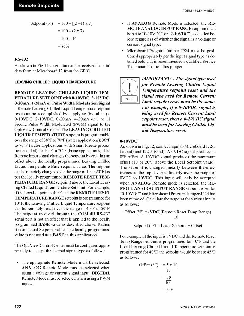
YORK INTERNATIONAL122
FORM 160.54-M1(503)
Setpoint (%) = 100 – [(3 –1) x 7]
= 100 – (2 x 7)
= 100 – 14
= 86%
RS-232As shown in Fig.11, a setpoint can be received in se ri al data form at Microboard J2 from the GPIC.
LEAVING CHILLED LIQUID TEMPERATURE
REMOTE LEAVING CHILLED LIQUID TEM- PER A TURE SETPOINT with 0- 10VDC, 2-10VDC, 0-20mA, 4-20mA or Pulse Width Mod u la tion Sig nal – Remote Leaving Chilled Liquid Temperature setpoint reset can be accomplished by supplying (by others) a 0-10VDC, 2-10VDC, 0-20mA, 4-20mA or 1 to 11 sec ond Pulse Width Modulated (PWM) signal to the OptiView Con trol Center. The LEAVING CHILLED LIQ UID TEM PER A TURE setpoint is pro gram ma ble over the range of 38°F to 70°F (water applications); 36°F to 70°F (water ap pli ca tions with Smart Freeze protec-tion en abled); or 10°F to 70°F (brine ap pli ca tions). The Re mote input signal chang es the setpoint by creating an offset above the lo cal ly programmed Leaving Chilled Liquid Tem per a ture Base setpoint value. The setpoint can be re mote ly changed over the range of 10 or 20°F (as per the lo cal ly pro grammed REMOTE RESET TEM- PER A TURE RANGE setpoint) above the Local Leav- ing Chilled Liquid Tem per a ture Setpoint. For ex am ple, if the Lo cal setpoint is 40°F and the REMOTE RE SET TEM PER A TURE RANGE setpoint is pro grammed for 10°F, the Leaving Chilled Liquid Tem per a ture setpoint can be remotely reset over the range of 40°F to 50°F. The setpoint received through the COM 4B RS-232 serial port is not an offset that is applied to the locally pro grammed BASE value as described above. Rath er, it is an actual Setpoint value. The lo cal ly programmed value is not used as a BASE in this application.
The OptiView Control Center must be confi gured ap pro -pri ate ly to accept the desired signal type as follows:
• The appropriate Remote Mode must be selected: AN A LOG Remote Mode must be selected when using a voltage or current signal input. DIGITAL Remote Mode must be selected when using a PWM input.
• If ANALOG Remote Mode is selected, the RE- MOTE ANALOG INPUT RANGE setpoint must be set to “0-10VDC” or “2-10VDC” as detailed be- low, regardless of whether the signal is a voltage or current signal type.
• Microboard Program Jumper JP24 must be po si -tioned appropriately per the input signal type as de- tailed be low. It is recommended a qualifi ed Ser vice Tech ni cian position this jumper.
IMPORTANT! - The signal type used for Remote Leaving Chilled Liquid Temperature setpoint re set and the sig nal type used for Remote Current Lim it setpoint re set must be the same. For ex am ple, if a 0-10VDC signal is being used for Re mote Current Limit setpoint reset, then a 0-10VDC sig nal must be used for Leaving Chilled Liq- uid Tem per a ture reset.
0-10VDCAs shown in Fig. 12, connect input to Microboard J22-3 (sig nal) and J22-5 (Gnd). A 0VDC sig nal pro duc es a 0°F offset. A 10VDC signal pro duc es the max i mum off set (10 or 20°F above the Local Setpoint val ue). The setpoint is changed linearly be tween these ex- tremes as the in put varies linearly over the range of 0VDC to 10VDC. This input will only be accepted when AN A LOG Remote mode is selected, the RE- MOTE AN A LOG INPUT RANGE setpoint is set for “0-10VDC” and Microboard Program Jump er JP24 has been re moved. Calculate the setpoint for var i ous inputs as fol lows:
Offset (°F) = (VDC)(Remote Reset Temp Range) 10
Setpoint (°F) = Local Setpoint + Offset
For example, if the input is 5VDC and the Remote Re set Temp Range setpoint is programmed for 10°F and the Local Leaving Chilled Liquid Temperature setpoint is programmed for 40°F, the setpoint would be set to 45°F as follows:
Offset (°F) = 5 x 10 10
= 50 10 = 5°F
Remote Setpoints
FORM 160.54-M1(503)
123YORK INTERNATIONAL
Offset (°F) = (mA)(Remote Reset Temp Range) 20
Setpoint (°F) = Local Setpoint + Offset
For example, if the input is 8mA, the Remote Reset Temp Range Setpoint is programmed for 10°F and the Lo cal Leaving Chilled Liquid Temperature setpoint is pro grammed for 40°F, the setpoint would be set to 44°F as follows:
Offset (°F) = (8)(10) 20
= 80 20
= 4°F
Setpoint (°F) = 40 + 4 = 44°F
4-20mAAs shown in Fig. 12, connect input to Microboard J22-4 (signal) and J22-5 (Gnd). A 4mA signal pro duc es a 0°F off set. A 20mA signal produces the maximum allowed offset (10 or 20°F above the Local Setpoint value). The setpoint is changed linearly between these extremes as the input varies over the range of 4-20mA. This input will only be accepted when ANALOG Re mote mode is selected, the REMOTE ANALOG IN PUT RANGE setpoint is set for “2-10VDC” and Microboard Pro gram Jumper JP24 has been placed on pins 1 and 2. Cal cu late the setpoint for various inputs as fol lows:
Offset (°F) = (mA–4)(Remote Reset Temp Range) 16
Setpoint (°F) = Local Setpoint + Offset
For example, if the input is 8mA, and the Remote Re set Temp Range setpoint is programmed for 10°F and the Local Leaving Chilled Liquid Temperature setpoint is programmed for 40°F, the setpoint would be set to 42.5°F as follows:
Offset (°F) = (8–4)(10) 16
= (4)(10) 16
Setpoint = 40 + 5 = 45°F
2-10VDCAs shown in Fig. 12, connect input to Microboard J22-3 (sig nal) and J2-5 (Gnd). A 2VDC sig nal produces a 0°F offset. A 10VDC signal produces the maximum al lowed offset (10°F or 20°F above the Local Setpoint value). The setpoint is changed linearly between these ex tremes as the input varies over the range of 2VDC to 10VDC. This input will only be ac cept ed when AN A LOG re mote mode is selected, the REMOTE AN A LOG IN PUT RANGE setpoint is set for “2-10VDC” and the Microboard Program Jumper JP24 has been re moved. Cal cu late the setpoint for var i ous inputs as fol lows:
Offset (°F) = (VDC – 2)(Remote Reset Temp Range) 8
Setpoint (°F) = Local Setpoint + Offset
For example, if the input is 5VDC and the Remote Re- set Temp Range setpoint is programmed for 10°F and the Local Leaving Chilled Liquid Temperature setpoint is programmed for 40°F, the setpoint would be set to 43.8°F.
Offset (°F) = (5 – 2)(10) 8
= (3)(10) 8
= 30 8
= 3.8°F
Setpoint (°F) = 40 + 3.8
= 43.8°F
0-20mAAs shown in Fig. 12, connect in put to Microboard J22-4 (signal) and J22-5 (Gnd). A 0mA signal pro duc es a 0°F offset. A 20mA signal pro duc es the maximum allowed offset (10 or 20°F above the Local setpoint value). The setpoint is changed lin ear ly be tween these extremes as the input varies over the range of 0-20mA. This input will only be accepted when ANALOG re mote mode is selected, the REMOTE ANALOG IN PUT RANGE setpoint is set for “0-10VDC” and Microboard Pro gram Jump er J24 has been placed on pins 1 and 2. Cal cu late the setpoint for var i ous inputs as follows:
19
YORK INTERNATIONAL124
FORM 160.54-M1(503)
Setpoint (F°) = Local Setpoint + Offset
For example, if the relay contacts close for 5 seconds and the Remote Reset Temp Range setpoint is pro grammed to 10°F and the Local Leaving Chilled Liq uid Tempera-ture setpoint is programmed for 40°F, the setpoint would be set to 44°F as follows:
Offset (°F) = (5 – 1)(10) 10
= (4)(10) 10
= 40 10
= 4°F
Setpoint (°F) = 40 + 4
= 44°F
RS-232As shown in Fig. 11, a Setpoint can be re ceived in se ri al data form at the Microboard COM 4B serial port (J2) from the MicroGateway.
= 40 16
= 2.5°F
Setpoint (°F) = 40 + 2.5 = 42.5
PWMThe Pulse Width Modulation input is in the form of a 1 to 11 second relay contact closure that ap plies 115VAC to the I/O Board TB4-19 for 1 to 11 sec onds. As shown in Fig. 14, connect dry closure relay contacts be tween I/O Board TB4-19 (input) and TB4-1 (115VAC). A con tact closure time (pulse width) of 1 second pro duc es a 0°F offset. An 11 second closure produces the max i mum al-lowed offset (10 or 20°F above the Local Setpoint value). The relay contacts should close for 1 to 11 sec onds at least once every 30 minutes to main tain the setpoint to the desired value. If a 1 to 11 secondclosure is not received within 30 minutes of the last clo sure, the setpoint is defaulted to the Local setpoint val ue. A closure is only accepted at rates not to exceed once every 70 seconds. This input will only be ac cept ed in DIGITAL Remote mode. Calculate the setpoint for various pulse widths as follows:
Offset (°F) = (pulse width in seconds – 1)(Remote Re set Temp Range)
10
Remote Setpoints
FORM 160.54-M1(503)
125YORK INTERNATIONAL
SECTION 20HOT GAS BYPASS
(REFER TO FIG. 64)
With the optional Hot Gas Bypass feature, the Con- trol Center mod u lates a valve located in the Hot Gas By pass connection between the condenser and the evap o ra tor to control the fl ow of gas to the evap o -ra tor. The valve is modulated in response to load and surging con di tions.
A Hot Gas Bypass Screen, accessed from the COM- PRES SOR Screen dis plays all the applicable pa ram e ters and allows a Service Tech ni cian to program the appli-cable setpoints and manually control the Hot Gas valve. If the chiller is equipped with the optional Hot Gas By-pass control, it must be Enabled from the OP ER A TIONS Screen using a procedure in the “System Cal i bra tion Service Setpoints and Reset Procedures” section of this book. If Disabled, the valve is driven to the fully closed position.
The Microboard controls the Hot Gas valve by send- ing a positioning com mand over the COM 3 RS-485 serial commumications link to the optional Analog I/O Board that is mounted inside the con trol Center. The Analog I/O Board converts this command into a 2-10VDC signal and applies it to the Hot Gas Valve Actuator. A 2VDC signal drives the valve fully closed (0% position); a 10VDC sig nal drives the valve fully open (100% po si tion). Positions be tween these ex tremes are linearly scaled. For ex am ple, 50% position would be achieved with a 6VDC signal. The actual valve po si tion is dis played on the HOT GAS BYPASS Screen as 0% to 100%.
A 2.5K Ohm PRV Potentiometer mounted on the Pre-rotation Vanes (PRV) assembly provides the PRV po- si tion (0 to 100%) to the Analog I/O Board. A +12VDC source is applied to the potentiometer. This position val ue is sent over the RS-485 serial com mu ni ca tions link to the Microboard, where it is displayed on the COM- PRES SOR Screen. When the PRV are fully closed, the po si tion is display as 0%; fully open displayed as 100%. Positions be tween these extremes are linearly scaled. To as sure accuracy, a PRV Calibration procedure must be performed as detailed in the “System Cal i bra tion, Service Setpoints and Reset Procedures” section of this book. The PRV position is dis played as XX on the COM- PRES SOR Screen and “Warn ing – Vanes Uncalibrated” is displayed on the Sys tem Details line of the display until the calibration is per formed.
The Evaporator and Condenser pressure trans duc ers provide these pressure values to the Microboard. The Microboard uses these values to calculate the DEL TA P/P parameter as follows: [(con dens er pressure – evap- o ra tor pressure) / evaporator pressure]. Al though this parameter is not used in the Hot Gas Control, it rep re -sents compressor “Head” and is displayed on the Hot Gas Bypass Screen for ref er ence only. These pres sures are also used to detect when a surge oc curs.
The Leaving Chilled Liquid Temperature ther mistor pro- vides the temperature to the Microboard. This value is subtracted from the Leaving Chilled Liquid Tem per a ture Setpoint to produce the TEMPERATURE DIF FER -EN TIAL parameter. This parameter is in dic a tive of chiller load.
When a surge is detected, the SURGE DE TECT ED LED illuminates for 5 seconds and the TOTAL SURGE COUNT is incremented. This count is the ac cu mu lat ed surge events that have been de tect ed over the lifetime of the chiller. This value can be reset to zero using the procedure detailed in the “System Calibration, Service Setpoints and Reset Procedures” section of this book. This should not be arbitrarily performed. The SURGE SEN SI TIV I TY setpoint can be used to make the de- tec tion more or less sensitive.
SETPOINTS
• Surge Sensitivity (0.3 to 1.3; default 0.3) – De ter -mines the surge detection sensitivity. The small er the number, the greater the sen si tiv i ty. Pro gram ma ble in 0.1 increments. This setpoint is pro grammed on the Surge Pro tec tion Screen and is common to the Surge Pro tec tion feature.
• Hold Period (30 to 120 minutes; default 30) – This is the period of time after no more surg es are de- tect ed that the Hot Gas valve closing will begin. It will be driven toward the closed po si tion in in cre -ments equal to the Close Per cent age setpoint at 10 minute intervals until fully closed. Programmable in 1 minute in cre ments.
• Close Percentage (5 to 15%; default 5%) – This is the incremental amount that the Hot Gas valve will be closed at 10 minute intervals after the HOLD PERIOD has elapsed. Refer to HOLD PERIOD above.
20
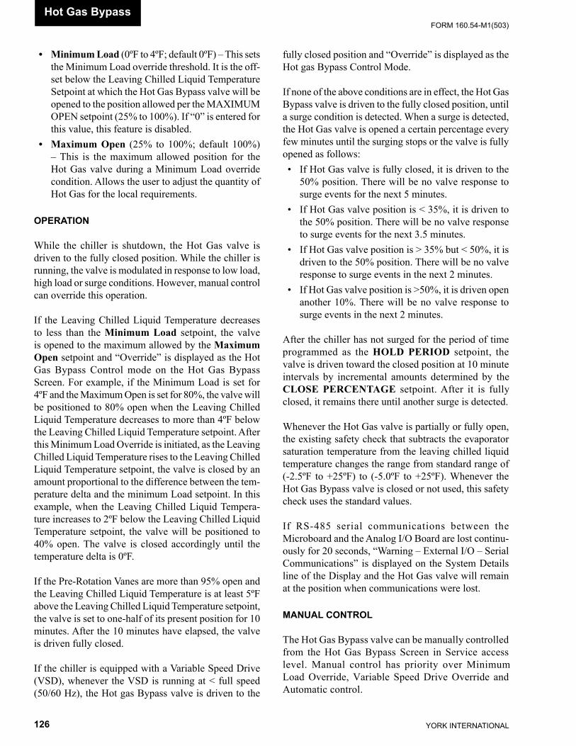
YORK INTERNATIONAL126
FORM 160.54-M1(503)Hot Gas Bypass
• Minimum Load (0ºF to 4ºF; default 0ºF) – This sets the Minimum Load override thresh old. It is the off-set below the Leaving Chilled Liq uid Tem per a ture Setpoint at which the Hot Gas By pass valve will be opened to the po si tion allowed per the MAX I MUM OPEN setpoint (25% to 100%). If “0” is entered for this val ue, this fea ture is disabled.
• Maximum Open (25% to 100%; default 100%) – This is the maximum allowed po si tion for the Hot Gas valve during a Minimum Load over ride con di tion. Allows the user to adjust the quantity of Hot Gas for the local re quire ments.
OPERATION
While the chiller is shutdown, the Hot Gas valve is driv en to the fully closed position. While the chiller is running, the valve is modulated in response to low load, high load or surge conditions. However, manual control can over ride this operation.
If the Leaving Chilled Liquid Temperature de creas es to less than the Minimum Load setpoint, the valve is opened to the maximum allowed by the Maximum Open setpoint and “Override” is dis played as the Hot Gas Bypass Control mode on the Hot Gas Bypass Screen. For example, if the Minimum Load is set for 4ºF and the Maximum Open is set for 80%, the valve will be po si tioned to 80% open when the Leaving Chilled Liq uid Temperature de creas es to more than 4ºF below the Leaving Chilled Liq uid Temperature setpoint. After this Minimum Load Override is initiated, as the Leav ing Chilled Liquid Temperature rises to the Leav ing Chilled Liquid Temperature setpoint, the valve is closed by an amount proportional to the dif fer ence be tween the tem- per a ture delta and the min i mum Load setpoint. In this example, when the Leaving Chilled Liquid Tempera-ture in creas es to 2ºF be low the Leaving Chilled Liquid Tem per a ture setpoint, the valve will be positioned to 40% open. The valve is closed accordingly until the tem per a ture delta is 0ºF.
If the Pre-Rotation Vanes are more than 95% open and the Leaving Chilled Liquid Temperature is at least 5ºF above the Leaving Chilled Liquid Temperature setpoint, the valve is set to one-half of its present position for 10 minutes. After the 10 minutes have elapsed, the valve is driven fully closed.
If the chiller is equipped with a Variable Speed Drive (VSD), whenever the VSD is running at < full speed (50/60 Hz), the Hot gas Bypass valve is driven to the
fully closed position and “Override” is displayed as the Hot gas Bypass Control Mode.
If none of the above conditions are in effect, the Hot Gas Bypass valve is driven to the fully closed position, until a surge condition is detected. When a surge is de tect ed, the Hot Gas valve is opened a certain per cent age every few minutes until the surging stops or the valve is fully opened as follows: • If Hot Gas valve is fully closed, it is driven to the
50% position. There will be no valve response to surge events for the next 5 minutes.
• If Hot Gas valve position is < 35%, it is driven to the 50% position. There will be no valve response to surge events for the next 3.5 minutes.
• If Hot Gas valve position is > 35% but < 50%, it is driven to the 50% position. There will be no valve response to surge events in the next 2 minutes.
• If Hot Gas valve position is >50%, it is driven open another 10%. There will be no valve response to surge events in the next 2 minutes.
After the chiller has not surged for the period of time programmed as the HOLD PERIOD setpoint, the valve is driven toward the closed position at 10 minute in ter vals by incremental amounts de ter mined by the CLOSE PERCENTAGE setpoint. Af ter it is fully closed, it re mains there until an oth er surge is detected.
Whenever the Hot Gas valve is partially or fully open, the existing safety check that subtracts the evaporator saturation temperature from the leaving chilled liquid temperature changes the range from standard range of (-2.5ºF to +25ºF) to (-5.0ºF to +25ºF). Whenever the Hot Gas Bypass valve is closed or not used, this safety check uses the standard values.
If RS-485 serial communications between the Microboard and the Analog I/O Board are lost con tin u- ous ly for 20 seconds, “Warning – External I/O – Serial Com mu ni ca tions” is displayed on the System Details line of the Display and the Hot Gas valve will remain at the position when communications were lost.
MANUAL CONTROL
The Hot Gas Bypass valve can be manually controlled from the Hot Gas Bypass Screen in Service access lev el. Manual control has priority over Minimum Load Over ride, Variable Speed Drive Override and Au to mat ic con trol.

FORM 160.54-M1(503)
127YORK INTERNATIONAL
20
When the OPEN or CLOSE key is pressed, the valve position will be increased or decreased by 5% to a max- i mum of 100% or minimum of 0%. Each time either key is pressed, the LED in the respective key will illuminate for 2 seconds. The Hot Gas Bypass Control Mode will display “Manual”.
ANALOG I/O BOARD
The optional Analog I/O Board mounts inside the Con- trol Center, on the upper right hand side of the Control Center. It receives the Hot gas valve positioning com- mand from the Microboard over the RS-485 serial com mu ni ca tions link and converts this digital value to a 2-10VDC analog control signal that is applied to the valve actuator. The scaling of this signal is as described above. Valve position is displayed on the HOT GAS BYPASS Screen as 0% (closed) to 100% (fully open). Positions between these extremes are linearly scaled.
The Pre-rotation Vanes (PRV) potentiometer (2.5K Ohms) is connected to P1, providing a 0 to 5VDC volt- age from a +12VDC source that represents PRV positon. Potentiometer rotation is limited to 37 degrees. PRV
position is displayed on the COMPRESSOR Screen as 0 (closed) to 100% (fully open). Positions between these extremes are linearly scaled. To assure position ac cu ra cy, a calibration procedure must be performed as de tailed in the “System Calibration, Service Setpoints and Reset Procedures” section of this book. The PRV po si tion is transmitted to the Microboard via the RS-485 serial communications link.
The Analog I/O Board must be confi gured properly for the Hot Gas control. The on-board Program Jumpers must be confi gured as follows:
JUMPER POSITION J1 Pins 2 & 3 J26 Pins 2 & 3 J39 Pins 1 & 2
There must be a 499 Ohm, 1%, ½ watt resistor con- nect ed between P10-2 and P10-5. This converts the normal 4-20mA Analog I/O Board output to a 2-10VDC valve positioning output, required by the Hot Gas valve actuator.
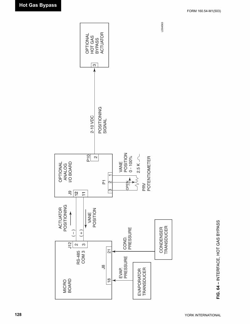
YORK INTERNATIONAL128
FORM 160.54-M1(503)
FIG
. 64
– IN
TER
FAC
E, H
OT
GAS
BYP
ASS
OP
TIO
NA
LA
NA
LOG
I/O B
OA
RD
CO
ND
EN
SE
RT
RA
NS
DU
CE
R
PR
VP
OT
EN
TIO
ME
TE
R
PO
SIT
ION
ING
SIG
NA
L
MIC
RO
BO
AR
D
EV
AP
OR
ATO
RT
RA
NS
DU
CE
R
EV
AP.
PR
ES
SU
RE
CO
ND
.P
RE
SS
UR
E
1821
12 1112 11
2 3
J8
RS
-485
CO
M 3
J12
AC
TU
ATO
RP
OS
ITIO
NIN
G
( –
)
( +
)
VA
NE
PO
SIT
ION
J9
P1
P10 2
32
1
OP
EN
VA
NE
PO
SIT
ION
0 -
100%
2.5
K
2-10
VD
CO
PT
ION
AL
HO
T G
AS
BY
PAS
SA
CT
UAT
OR
3
LD04
563
Hot Gas Bypass
FORM 160.54-M1(503)
129YORK INTERNATIONAL
SECTION 21SMART FREEZE PROTECTION
The Smart Freeze feature prevents nuisance chill er shut downs due to brief periods of chilled liquid fl ow fl uc tu a tions or other brief operating conditions that would nor mal ly cause Low Evaporator Pressure Safe ty shut downs. With this feature enabled and activated, the chiller is per mit ted to ride through these temporary con- di tions. Also, this feature allows the Leaving Chilled Liquid tem per a ture Setpoint to be set as low as 36.0ºF. Smart Freeze protection can be enabled or dis abled at the Key pad, by a Service Technician, using a pro ce dure de tailed in the “System Calibration, Service Setpoints and Reset Procedures” section of this book. It cannot be used in Brine cooling mode.
The basis of this feature is that the chilled liquid con tains an amount of heat, which cannot be eliminated im me -di ate ly. Therefore, it requires a certain amount of time for the liquid to change to a solid. During this pe ri od of time, those pa ram e ters that determine when so lid i f-i ca tion will occur, are evaluated and the ap pro pri ate Low Evaporator Temperature shutdown threshold is applied. This threshold could be lower, but not high er than the normal Safety threshold.
Smart Freeze protection uses the Evaporator Re frig -er ant Tem per a ture as one of the variables to de ter mine when freez ing is imminent. If the chiller is equipped with the Evap o ra tor Refrigerant Tem per a ture Sensor (RT7), and the sensor is enabled using the “Sys tem Calibration, Ser vice Setpoints and Reset Pro ce dures” section of this book, this value is used as the re frig er ant temperature. Oth er wise, the Evaporator Sat u ra tion Temperature (as de rived from the output of the Evap o ra tor Pressure Trans duc er. The pressure is con vert ed to a tem per a ture via the ap pro pri ate re frig er ant “pres sure/tem per a ture look up ta ble”) is used as the re frig er ant tem per a ture.
When Smart Freeze protection is Enabled, the Leav ing Chilled Liq uid Temperature Setpoint can be set as low as 36.0ºF. If set to < 38.0ºF, the LEAVING CHILLED LIQ UID – LOW TEMPERATURE cy cling shut down thresh old becomes a minimum of 34.0ºF.
Unless Smart Freeze protection is activated, the fi xed Low Evap o ra tor Pressure Safety thresholds (R22 – 54.3 PSIG, 29.6ºF) (R134a – 25.0 PSIG, 28.7ºF) are used.
SMART FREEZE protection is activated only when the feature is enabled AND the Leaving Chilled Liquid Tem per a ture Setpoint is < 38ºF. Once activated, the total num ber of seconds that the evaporator refrigerant tem per a ture is below the freeze threshold is counted. The freeze thresh old is 32.8ºF (refrigerant temp. sen- sor RT7) or 34.0º (evap o ra tor saturation temp. See Note 1 below.). The count is incremented once for every second the evap o ra tor re frig er ant tem per a ture is below the freeze thresh old and decremented once for ev ery second it is above the freeze threshold (but is never decremented below zero). Thus if the evaporator re frig er ant temperature goes be low the freeze threshold for 30 seconds, then goes above it for 10 sec onds, then goes be low the threshold for 5 seconds, the total number of sec onds the evaporator re frig -er ant tem per a ture was below the freeze threshold was 25 sec onds. If Smart Freeze is no longer activated due to the Leaving Chilled Liquid Tem per a ture Setpoint being raised to > 38.0ºF, the total num ber of seconds being tracked is set to zero.
The number of seconds it will take the chilled liquid to freeze is based on how far the evaporator refrigerant temperature is below the freeze threshold as follows:
Number of seconds to freezing = 4053.7(freeze thresh old–evaporator refrigerant tem per a ture)
Thus, if the Evaporator Saturation Temperature is be ing used as the evaporator refrigerant temperature and that temperature is 26.0ºF, it would take 8 minutes and 26 seconds for the chilled liquid to freeze.
When the total number of seconds the evaporator re frig er ant temperature is below the freeze threshold ex ceeds the “Number of seconds to freezing”, a safety shutdown is performed and “EVAPORATOR – LOW PRESSURE – SMART FREEZE” is displayed on the System details line of the display.
Even though Smart Freeze protection is enabled and ac ti vat ed, the Pre-rotation Vanes Load inhibit still oc curs at the same thresholds as with normal op er a tion; in hib it at 56.2 PSIG (R22) and 27.0 (R134a). As in nor mal op er a tion, loading will be allowed when the pres sure in creas es to 57.5 PSIG (R22) and 28.0 PSIG (R134a).
21

YORK INTERNATIONAL130
FORM 160.54-M1(503)
The following is a summary of the operation with Smart Freeze enabled and disabled:
SMART FREEZE DISABLED: • Minimum Leaving Chilled Liquid Setpoint:
38.0ºF • Low Chilled Liquid Temp cycling shutdown thresh-
old: 1º to 34.0ºF below the Leaving Chilled Liq uid temp Setpoint, as programmed, or a minimum of 36.0ºF.
• Low Evaporator Pressure safety shutdown thresh- old: R22 - 54.3 PSIG (29.6ºF); R134a – 25.0 PSIG (28.7ºF)
• PRV Load Inhibit: R22 – 56.2 PSIG; R134a – 27.0 PSIG
Load Inhibit disable: R22 – 57.5 PSIG; R134a – 28.0 PSIG
SMART FREEZE ENABLED: • Minimum Leaving Chilled Liquid Setpoint: 36.0ºF • If the Leaving Chilled Liquid Temperature Setpoint
is >38.0ºF: 1. The Low Leaving Chilled Liquid Tem per a ture
Cy cling shutdown threshold: 1 to 34.0ºF below the Leaving Chilled Liquid Tem per a ture Setpoint, as programmed, or a minimum of 36.0ºF.
2. The Low Evaporator Pressure Safety shut down threshold is the same as Smart Freeze Dis abled above.
• If the Leaving Chilled Liquid Temperature Setpoint is <38.0ºF:
1. The Low Leaving Chilled Liquid Tem per a ture Cy cling shutdown threshold: 1 to 3.0ºF below the Leaving Chilled Liquid Tem per a ture Setpoint, as programmed, or a minimum of 34.0ºF.
2. Low Evaporator Pressure shutdown threshold: Determined by how far the evaporator refrigerant temperature is below the freeze threshold of 32.8ºF (refrigerant temperature sensor RT7) or 34.0ºF (Evap o ra tor Saturation Temperature. See Note 1 below.) and the to tal number of seconds it remains there. Refer to ex pla na tion above.
• PRV Load Inhibit: same as Smart Freeze Dis abled above.
• Load Inhibit Disable: same as Smart Freeze Dis- able above.
Note 1: The freeze threshold evaporation saturation tem per a ture is 32.0ºF on Flash Mem o ry Card ver sion C.MLM.01.01 and ear li er.
Smart Freeze Protection
FORM 160.54-M1(503)
131YORK INTERNATIONAL
SECTION 22SURGE PROTECTION
This feature applies to all com pres sor codes. However, if com pres sor code other than “P”, applies to Flash Memory Card versions C.MLM.01.05.xxx and later.
The SURGE PROTECTION feature detects surge events and provides a running count of the events that occur over the lifetime of the chiller (up to a maximum of 65535). If excess surging is de tect ed, it can be con- fi g ured to shut down the chiller or initiate a special surge cor rec tion/avoid ance mode or simply display a warning mes sage.
The SURGE PROTECTION Screen, ac ces si ble from the COMPRESSOR Screen, displays all parameters relevant to this feature. All setpoints relating to this fea ture are maintained on this screen.
SURGE DETECTION
Surge events are detected by monitoring the re la tion ship between the Condenser pressure and Evap o ra tor pres-sure while the chiller is running. When the dif fer ence between these pressures decreases transiently and re-mains so for a period of time described below, and then makes a positive transition within 7 seconds, a surge event has been detected.
The surge detection sensitivity can be adjusted with the SURGE SENSITIVITY setpoint. It is adjustable over the range of 0.3 to 1.3 in 0.1 increments. Default value is 0.3. The smaller the number, the greater the sen si tiv i ty.
The Evaporator pressure transducer output is sub tract ed from the Condenser pressure output to determine the differential. If either of the following negative tran si -tions occur in the differential followed by a 0.061VDC positive differential transition within 7 seconds, a surge event is detected: • If the differential decreases > 0.6VDC for > 0.260
sec onds. • If the differential decreases > x.xVDC for > 0.390
seconds.
x.xVDC calculated as [(surge sen si -tiv i ty setpoint x 300) x 1.22] ÷ 1000
Each time a surge event is detected, the SURGE DE- TECT ED LED indicator on the SURGE PRO TEC TION Screen il lu mi nates for 5 seconds and the TOTAL SURGE COUNT in cre ments 1 count.
The TOTAL SURGE COUNT can be reset to zero us-ing the CLEAR SURGE COUNT key with the ADMIN access level.
EXCESS SURGE DETECTION
An excess surge condition is detected by comparing the number of surge events that occur in a selectable time period to a selectable threshold.
If the number of surge events (Surge Window Count) detected in the time period programmed as the COUNT WINDOW setpoint (1 to 5 minutes; default 5) exceed the threshold programmed as the COUNT LIMIT setpoint (4 to 20; default 4) an excess surge condition has been detected.
Unless the SHUTDOWN or EXTENDED RUN fea tures have been enabled, as explained below, the chiller will continue to run under the same conditions dis play ing “Warning – Excess Surge Detected”. This message will be displayed until manually reset with the Warning Reset key in Operator access level.
SURGE PROTECTION
The Control Center can be confi gured to take the fol- low ing courses of action when an excess surge con di tion has been detected. The SHUTDOWN setpoint is used to invoke a safety shutdown. The EXTENDED RUN setpoint is used to invoke a special 10 minute surge correction/avoidance mode that temporarily eliminates the conditions causing the surging, while allowing the chiller to continue to run. However, if the Hot Gas By pass control is Enabled, the Hot Gas Bypass Valve po si tion must be 100% before the Extended Run mode is implemented. If the chiller is equipped with a com pres sor motor Variable Speed Drive, the output frequency must be at full speed (50 Hz/60 Hz) before the the Ex tend ed Run mode is implemented. If the chiller is equipped with Hot Gas Bypass and compressor mo-tor Variable Speed Drive, both conditions must be met be fore Extended Run is implemented.
22
YORK INTERNATIONAL132
FORM 160.54-M1(503)
• If the SHUTDOWN setpoint is Enabled, and the EX TEND ED RUN setpoint is Disabled, a safety shut down will be performed and “Surge Protection - Excess Surge” is displayed.
• If the SHUTDOWN setpoint is Disabled and the EX TEND ED RUN setpoint is Enabled, the Pre-ro- ta tion Vanes are driven closed for 10 minutes and “Warning – Surge Protection – Excess surge Lim it” is displayed. When the 10 minutes have elapsed, if the Surge Window Count is < the Count Limit, this message and load inhibit are automatically cleared, otherwise another 10 minute period is initiated. Al- ter nat ing with this message is “Warning – Excess Surge Detected” that is displayed until manually
reset with the Warning Reset key in OPERATOR ac cess level. During the 10-minute period, a count- down timer on the Surge Pro tec tion Screen dis plays the time remaining in the period. See Hot Gas By- pass and compressor motor Variable Speed Drive exception above.
• If both the SHUTDOWN and EXTENDED RUN setpoints are Enabled, the 10 minute Extended Run period is invoked as above. However, if the SURGE WINDOW COUNT exceeds the COUNT LIMIT at the end of the 10 minute Extended Run period, a safety shutdown is performed and “Surge Pro tec tion – Excess Surge” is displayed.
Surge Protection
FORM 160.54-M1(503)
133YORK INTERNATIONAL
The chiller is supplied from the YORK Factory with all factory mounted components fully calibrated. The fol- low ing procedures are used to verify these cal i bra tions or calibrate a component after it has been fi eld re placed.
Programmable Service Setpoints are used by the Pro gram to control critical chiller operation. Also, some of these Setpoints can be used to enable or disable cer tain features. Although they have been entered at the YORK Factory, they can be changed by a fi eld Service Tech ni cian that has logged in at SERVICE access lev el. If the BRAM battery backed memory device (U52) is fi eld replaced, all of the programmed setpoints will be lost. They will have to be re-entered into the new BRAM. Each of these Setpoints is described below. Pro gram ming pro ce dures and OptiView Control Cen ter Key pad operation required in the pro ce dures be low are de tailed in YORK Operation Manual 160.54-O1. In gen er al, the fol low ing procedure is used to enter Setpoints in this sec tion: 1. Unless noted otherwise in procedures below, log
in at SERVICE access level using Access Code 1 3 8 0 .
2. Select the appropriate Display Screen. 3. Press the desired Setpoint key. A dialog box appears, giving the minimum and
max i mum allowed values, Default value and pres-ent value. The dialog box can be can celed at any time by pressing the CANCEL (X) key.
4. If the dialog box begins with the word “Enter”, use the numeric keys to enter the desired value. Lead ing zeroes are not necessary. Press the • key to place a decimal point at the appropriate place. Press ing the ▲ key displays the Default val ue. Press ing the ▼ key clears the entry. The key is a back space key and causes the entry point to move back one space. If the dialog box begins with “Select”or “En-able”, use the and keys to select the de sired val ue. The key decreases the value. The key in creas es the value.
5. Press the ENTER (✔) key. If the value is within range, it is accepted and the dialog box dis ap pears. The chiller will begin to operate based on the new value. If out of range, the value is not accepted and a message describing why it is not acceptable is displayed momentarily.
Some Safety shutdowns will not permit the chiller to start until a special reset procedure is performed. These reset
SECTION 23SYSTEM CALIBRATION, SERVICE SETPOINTS AND RESET PRO CE DURES
procedures require SERVICE access level and should not be performed by anyone other than a Ser vice Tech ni cian. Each of these procedures is described below.
ELECTRO-MECHANICAL STARTER AP PLI CA -TIONS
If the Compressor Motor is driven by an Electro-Me chan i cal Starter, the OptiView Control Center is equipped with a CM-2 Current Module along with sup port ing com po nents Diode Bridge (DB) and Cal- i bra tion Resistors (RES), as de scribed in a previous chap ter of this book. The following procedures can be used to verify the cal i bra tion and perform the calibra-tion if necessary. In ad di tion to the calibration, Switch S1 and Potentiometer R16 have to be set appropriately on the CM-2 Module. If the CM-2 and/or RES are fi eld re placed, fi eld cal i bra tion is necessary.
CM-2 Settings:
1. Place Switch S1 in the appropriate position per the Starter type:
UP: Y-Delta or Auto-transformer Start er Down: All others 2. Calculate LRA/FLA ratio by dividing the Motor
Lock Rotor Amps by the chiller Full Load Amps (LRA/FLA = ratio) and then adjust Po ten ti om e ter R16 to the ratio value.
Calibration Verifi cation:
1. At the Keypad, log in at SERVICE access lev el us ing access code 1 3 8 0 .
2. Select MOTOR Screen and set Current Lim it and Pulldown Demand Limit Setpoints to 100% FLA.
3. Run chiller. Read compressor motor current in Phase A, B, and C using a clamp-on Am me ter. Apply ammeter to highest Phase.
4. Select COMPRESSOR Screen. 5. Manually operate the Pre-rotation Vanes by press-
ing the OPEN and CLOSE Keypad keys as re quired to achieve a motor current equiv a lent to 100% FLA as indicated by the clamp-on Am me ter. The motor current value on the Display should indicate 100% FLA.
6. Manually operate the Pre-rotation Vanes by press- ing the OPEN and CLOSE keys as required to
23
YORK INTERNATIONAL134
FORM 160.54-M1(503)System Calibration
achieve a motor current equivalent to 105% FLA as indicated by the clamp-on Ammeter. The 105% LED on the CM-2 Module should il lu mi nate.
If the calibration verification does not perform as above, the following Calibration procedure will have to be per formed:
Calibration: 1. At the Keypad, log in at SERVICE access level
us ing access code 1 3 8 0 . 2. Select MOTOR Screen and set Current Lim it and
Pulldown Demand Limit Setpoints to 100% FLA. 3. Select COMPRESSOR Screen. 4. Run chiller and read compressor motor cur rent in
Phase A, B and C using a clamp-on Ammeter. Ap- ply Ammeter to highest Phase.
5. Manually operate the Pre-rotation Vanes by press ing the OPEN and CLOSE Keypad keys as re quired to achieve a motor current equivalent to 100% FLA as indicated by the clamp-on Am me ter. The voltage across Variable Re sis tors (RES) should be 0.90 to 1.05VDC. Measure this volt age by connecting a Voltmeter at CM-2 Board J1-2 (+) to J1-1(-). If necessary, adjust RES to achieve this value. Figure 38 contains for mu las to cal cu late the resistance of RES required to achieve this volt age. Adjust both re sis tors equally such that the com bined resistance equals the cal cu lat ed val ue.
6. Manually operate the Pre-rotation Vanes by press- ing the OPEN, CLOSE and HOLD Keypad keys, as required, to achieve a motor current equiv a lent to 105% FLA as indicated by the clamp-on Am me ter. Loosen locking nut on Po ten ti om e ter R8 on CM-2 and adjust until the CM-2 Module 105% LED il lu mi nates. Coun ter clock wise increases sig nal lev el; Clock wise decreases signal level. Tight en locking nut.
6. Manually operate the Pre-rotation Vanes by press ing the OPEN and CLOSE Keypad keys, as re quired, to achieve a motor current equivalent to 100% FLA as indicated by the clamp-on Am me ter. Loose locking nut on Potentiometer R34 on CM-2 and adjust until the motor current value on the Display indicates 100% FLA. Clockwise in creas es the signal level; Counterclockwise de creas es the signal level. Tight en locking nut.
SOLID STATE STARTER AP PLI CA TIONS
The chiller could be equipped with either of two dif fer ent YORK Solid State Starters. Later production chill ers are equipped with the Mod “B” se ri al data in ter face Liquid Cooled Solid State Starter (LCSSS). Earlier vin tage chill-ers are equipped with the Style “A” mul ti plexed data inter-face LCSSS. Microboard Program Jumper JP39 must be positioned to invoke the ap pro pri ate Microboard/Program operation for the start er ap plied (Re fer to Table 1). A description of these start ers is con tained in the Sol id State Starter section of this book. The pro ce dures for both start-ers are listed be low.
MOD “B” SERIAL DATA INTERFACE LIQ UID COOLED SOLID STATE STARTER
Complete details of the operation of this starter are con- tained in YORK Service Manual 160.00-O2. 1. At the Keypad, log in at SERVICE Access lev el
us ing Password 1 3 8 0 . 2. Select MOTOR Screen. 3. Enter the following setpoints using the pro ce dures
below:
Full Load Amps:This is the Full Load Amps (FLA) of the chiller as list ed on the Sales Order Screen. The Microboard uses the pro-grammed value to perform Current Limit func tions and display compressor motor current in terms of %FLA. 1. Press FULL LOAD AMPS key. 2. Use numeric keypad keys to enter correct value. 3. Press ENTER (✔) key.
Start Current: The Logic/Trigger Board will limit compressor motor current to this value during starting. The correct value is (0.45 x Delta Locked Rotor amps), as listed on the SALES ORDER Screen. 1. Press STARTING CURRENT key. 2. Use numeric keypad keys to enter correct value. 3. Press ENTER (✔) key.

FORM 160.54-M1(503)
135YORK INTERNATIONAL
Voltage Range:This is the compressor motor AC power line ap pli ca tion. Selections are 200-208, 220-240, 380, 400, 415, 440-480, 550-600 and Disabled. The Microboard uses the programmed value to determine the overvoltage and undervoltage shutdown thresholds for “LCSSS – HIGH SUPPLY LINE VOLTAGE” and “LCSSS – LOW SUP- PLY LINE VOLTAGE” cycling shut downs as de scribed in Operation Manual 160.54-O1. If DIS ABLED is se- lect ed, the shutdown thresh olds will be ig nored. This check should not be arbitrarily dis abled. 1. Press VOLTAGE RANGE key. 2. Use ◄ and ► keys to scroll to desired value. 3. Press ENTER (✔) key.
Open SCR Enable/Disable:This allows the Open SCR safety check, per formed by the Logic/Trigger Board, to be disabled. This must NEV ER be disabled unless advised by the YORK fac to ry. 1. Press OPEN SCR key. 2. Use ◄ and ► keys to select Enable or Dis able. 3. Press ENTER (✔) key.
Kilowatt Hours (KWH) Reset:This allows the KWH to be set to a desired starting value in the event the BRAM has to be fi eld replaced. This must never be arbitrarily performed. 1. Press KWH RESET key. 2. Use numeric keypad keys to enter desired value. 3. Press ENTER (✔) key.
MOD “A” MULTIPLEXED DATA INTERFACE LIQUID COOLED SOLID STATE STARTER
If the chiller is equipped with this model starter the start er Logic Board is located in the OptiView Control Center. Operation of this board and overall starter op- er a tion is contained in YORK Service Manual 160.46-OM3.1. The following procedures can be used to ver i fy the cal i bra tion and perform the calibration if necessary. If the Logic Board is fi eld replaced, fi eld cal i bra tion is necessary. Logic Board Program Jumper JP5 (300V/600V) must be placed in the appropriate position per the com pres sor motor AC power line.
Logic Board Program Jumper: Place Jumper J5 (300V/600V) in appropriate position per the Compressor Motor AC Power Line application as follows:
600V - Place over pins 1 & 2 for 380/400/415, 440/460/480 or 550/575/600 VAC applications.
300V - Place over pins 2 & 3 for 200/208 or 220/230/240 VAC applications.
Setpoints:
1. At the Keypad, log in at SERVICE access lev el us ing access code 1 3 8 0 .
2. Select MOTOR Screen. 3. Enter the following Setpoints using pro ce dures
below:
Full Load Amps :This is the Full Load Amps (FLA) of the chiller as list ed on the Sales Order Screen. The Microboard uses the pro-grammed value to perform Current Limit functions and display compressor motor current in terms of % FLA. 1. Press FULL LOAD AMPS key. 2. Use numeric keypad keys to enter cor rect val ue. 3. Press ENTER (✔) key.
Voltage Range:This is the AC Power line voltage ap plied to the Com- pres sor Motor. Selections are: 380, 400, 415, 440-480, 550-600 and Supply Voltage Range Disabled. The Microboard uses the programmed selection to de ter mine the overvoltage and undervoltage thresholds for Start er High Supply Line Voltage and Starter Low Sup ply Line Voltage. Cycling shutdowns as de scribed in Op er a tor Manual 160.54-O1. If Supply Voltage Range Disabled is selected, the thresholds will be ignored and these shutdowns will not occur. This check should not be arbitrarily disabled. 1. Press VOLTAGE RANGE key. 2. Use ◄ and ► keys to scroll to desired val ue. 3. Press ENTER (✔) key.
Current Unbalance Check Enable/Disable:While the chiller is running, if the compressor Motor current in phase A, B and C becomes un bal anced, a Safety shutdown is performed. Refer to Operator Man u al 160.54-O1 for complete de scrip tion of this check. This Setpoint allows the check to be enabled or disabled. If enabled, the check is performed; if dis abled, the check is not performed. 1. Press CURRENT UNBALANCE key. 2. Use ◄ and ► keys to select Enable or Dis-
able. 3. Press ENTER (✔) key.
23
YORK INTERNATIONAL136
FORM 160.54-M1(503)System Calibration
Calibration Verifi cation:At the Keypad, login at SERVICE access level using access code 1 3 8 0 . 1. Compressor Motor current display accuracy - a. Run chiller. b. Select COMPRESSOR Screen. c. Use the Pre-rotation Vanes HOLD keypad key
to sta bi lize the Compressor Motor current. d. Measure phase A, B and C Compressor Motor
cur rent with a clamp-on ammeter. Compare the Ammeter values with displayed mo tor current val ues. If displayed values are not within +5% of Ammeter values, refer to Solid State Starter Ser vice Manual 160.46-OM3.1 to trou ble shoot Start er.
2. Start Current - Proper starting current is (45% x Del ta locked Rotor amps).
a. Select COMPRESSOR Screen. b. Start chiller and monitor Compressor Motor
start ing current in phase A, B and C on the COMPRESSOR Screen.
Highest phase should be equiv a lent to (45% x Del ta Locked rotor amps).
3. Overload - a. Select COMPRESSOR Screen. b. Run chiller and monitor Compressor Motor cur-
rent on the COMPRESSOR Screen. c. Manually operate the Pre-rotation Vanes by
press ing the OPEN, CLOSE and HOLD keys, as required, until the high est phase in di cates a cur rent equivalent to 105% FLA.
The Display should indicate 105% and the 105% LED on the Solid State Starter Logic Board should illuminate when the 105% FLA val ue is reached.
If the calibration verifi cation does not perform as above, one or both of the following Calibration procedures will have to be performed:
Calibration: At the Keypad, log in at SERVICE access level using access code 1 3 8 0. 1. Start Current - a. Select COMPRESSOR Screen. b. Loosen locking nut on Solid State Starter Log ic
Board Potentiometer R38. c. Start chiller and monitor Compressor Motor
start ing current in Phase A, B and C on the COM PRES SOR Screen.
d. While chiller is starting, adjust START CUR- RENT potentiometer (R38) on Solid State Start er Logic Board to achieve the proper start ing cur- rent of (0.45 x Delta Locked rotor Amps) on the high est phase. Turning R38 Clock wise in creas es cur rent; Counterclockwise decreases current. Mul ti ple starts could be required to achieve the correct cal i bra tion. Tighten locking nut.
2. Overload - a. Select COMPRESSOR Screen. b. Run Chiller and monitor Compressor Motor
cur rent on the COMPRESSOR Screen. c. Manually operate the Pre-rotation Vanes by
press ing the OPEN, CLOSE and HOLD key pad keys, as required, until the highest phase indi-cates a current equivalent to 105% FLA. Adjust OVER LOAD potentiometer (R44) on Solid State Starter Logic Board until the 105% FLA LED il lu mi nates. Clockwise increases sig nal level; Coun ter clock wise decreases signal level. Tighten locking nut.
COMPRESSOR MOTOR VARIABLE SPEED DRIVEAPPLICATIONS
If the Compressor Motor is driven by the YORK Vari- able Speed Drive (VSD), the OptiView Control Cen ter is equipped with an Adaptive Capacity Control (ACC) Board. Op er a tion of this board and overall VSD op er a tion is de tailed in YORK Form 160.00-M1. There are two cal i -bra tions that have to be performed; VSD Full Load Amps and Pre-rotation Vanes position Po ten ti om e ter.
The VSD Full Load Amps value is the chiller full load amps value as listed on the Sales Order. It is used by the Program to initiate Current Limit at 100% and 104% FLA.
The PRV Calibration establishes the voltage feed back to the ACC Board at the fully closed and fully open positions. Since the feedback between these extremes is linear, the ACC Board will then know the actual PRV position at all times. PRV position is required for the speed control and surge prevention. If this procedure is not performed or not performed successfully, variable speed control is inhibited.
There are two setpoints that affect VSD operation; Surge Margin and Stability Limit. They should nev er be changed unless advised by YORK Factory Service. The Surge Margin Setpoint allows the entire surge map to be ad just ed up by a fi xed offset value. It is pro gram ma ble over the range of 0 to 25.0 Hz. The Stability Lim it Setpoint de ter -
FORM 160.54-M1(503)
137YORK INTERNATIONAL
mines wheth er a surge event is stored in the com pres sor map. When the Leaving Chilled Liquid Tem per a ture is within +0.3 and -0.8ºF of the Setpoint and the rate of change of this liq uid exceeds the pro grammed Sta bil i ty Lim it index, the sys tem is considered unstable and a surge event that oc curs un der these con di tions is not stored. The in dex is pro gram ma ble over the range of 1000 to 7000, with the Default or nominal being 4500. The pro ce dure to change these is described below.
The ACC Surge Map can be printed. By connecting a Printer and performing the procedure below, all pre vi -ous ly established surge points can be printed. Also, while leaving a Printer connected, all new surge Points can be printed as they are established. The Map can be cleared using the procedure below. However, it should never be cleared unless advised by the YORK Factory.
If required, an operating point can be established as a Surge Point by pressing the Manual surge Point key and then pressing a switch on the ACC Board. The op er at ing conditions at that instant will be captured and stored as a surge point. This is known as a Manual Surge Point. Refer to procedure below.
The Kilowatt Hour (KWH) accumulation can be cleared or set to a value using the KWH RESET key as de scribed below. This should not be performed un less ad vised by the YORK Factory.
Full Load Amps Calibration: 1. Place Compressor Start/Stop Switch in the Stop-
Re set (O) position. 2. At the keypad, log in at SERVICE access level
us ing access code 1 3 8 0. 3. Select VSD DETAILS Screen from the MO TOR
Screen. 4. In the VSD, locate the small trimpot located in the
upper-middle area of the VSD Logic Board. 5. While monitoring the VSD Full Load Amps 000.0
A message on the VSD DETAILS Screen, ad just this trimpot until the correct Full Load Amps val ue is displayed. Clockwise will increase the val ue.
Pre-rotation Vanes Position Potentiometer:When initially installed, the Potentiometer should be set so that the feedback voltage, as measured between the wiper (white wire) and common (black wire) is 0.3 to 0.7VDC.
1. Place Compressor Start/stop Switch in the Stop-Reset (O) position and wait until the “Coastdown” is complete.
2. At the Keypad, log in at SERVICE access level us ing access code 1 3 8 0.
3. Select the PRV CALIBRATE Screen from the COM PRES SOR Screen.
4. On the PRV CALIBRATE Screen, press the START CALIB key to initiate the calibration.
The CALIBRATION IN PROGRESS LED will il lu mi nate, the PRV opening LED will illuminate and an open signal is applied to the PRV. When the feed back voltage from the PRV potentiometer stops in creas ing, the ACC Board as sumes this is the full open position and logs this value as 100% open. It then applies a close sig nal to the PRV and il lu mi nates the PRV Opening LED. When the feed back volt age stops decreasing, the ACC Board as sumes this is the fully closed position and logs it as 0% open. These end point voltages are stored in the BRAM as the fully closed and fully open po si tions.
The calibration procedure can be ter- mi nat ed at any during the procedure by pressing the CAN CEL CALIB key. If the PRV were pre vi ous ly cal i brat ed suc cess ful ly, it will re vert to using the pre vi ous cal i bra tion val ues. If they were not pre vi ous ly calibrated suc- cess ful ly, Vari able Speed con trol will be in hib it ed and the VSD will op er ate at fi xed speed.
5. If the difference between the endpoint volt ag es is not greater then 0.49VDC, or if an end point is not detected with in 8 minutes, the calibration is con- sid ered “un suc cess ful”.
Setpoints:The following are the Setpoints and range of pro gram -ma ble values. The Default val ue is shown in pa ren the sis. It is the rec om mend ed val ue and should provide proper operation in most ap pli ca tions. Nev er change these val-ues unless advised by YORK Factory Ser vice. a. Surge Margin – 0.0 to 25.0 Hz. (0.0) b. Stability Limit – 1000 to 7000 (4500)
1. At the Keypad, log in at SER VICE access lev el us ing access code 1 3 8 0.
23
YORK INTERNATIONAL138
FORM 160.54-M1(503)
2. Select ACC DETAILS Screen from the MO TOR screen.
3. On the ACC DETAILS Screen, press the ap pro -pri ate Setpoints key above.
4. Use the numeric keypad keys to enter the de sired value.
Press ENTER (✔) key.
ACC Surge Map:To perform any of the following ACC Surge Map func- tions, proceed as follows: 1. At the Keypad, log in at SERVICE access lev el
using access code 1 3 8 0. 2. Select ACC DETAILS Screen from the MO TOR
Screen. 3. On the ACC DETAILS Screen, press the ap pro -
pri ate key as follows: a. Surge Map Clear – Clears all of the pre vi ous ly
es tab lished surge points that are stored in mem- o ry. When this key is pressed, a dialog box appears re quest ing the spe cial ACC Map Clear Password. En ter 0 3 6 8 and press the Enter (✔) key. A mes sage is dis played advising the clear-ing is in progress. Press switch SW1 on ACC Board, with in 15 seconds of pressing the (✔) key. Another mes sage is dis played when clear ing is com plet ed. IM POR TANT! - This should nev er be per formed un less ad vised by YORK Fac to ry Ser vice.
b. Surge Map Print – Prints the entire ar ray of stored surge points to a printer con nect ed to COM1 Serial Port. Press key again to stop print.
c. Auto Print enable/disable – Prints new surge points, as they are established, to a printer con- nect ed to COM1 Serial Port. Press key again to stop print.
d. Manual Surge Point – With in 15 sec onds of press- ing this key, press SW1 on the ACC Board for at least 1 second. The ACC Board will con fi rm rec og ni tion of this point by il lu mi nat ing red SURGE LED CR9 for 2 sec onds. The op er at ing conditions at that instant are captured and stored as a surge point.
Kilowatt Hours: 1. At the Keypad, log in at SERVICE access lev el
using access code 1 3 8 0. 2. Select MOTOR Screen. 3. Press KWH RESET key.
4. Use numeric keypad keys to enter desired value. 5. Press ENTER (✔) key.
VSD Frequency Control: The VSD Frequency can be manually controlled as fol lows: 1. At the Keypad, log in at SERVICE access lev el
using access code 1 3 8 0. 2. Select VSD TUNING Screen from the COM-
PRES SOR Screen. 3. On the VSD Tuning Screen, press the ap pro pri ate
key as follows: a. Set – Places Frequency Control in Manual Mode.
Sets the VSD speed at a specifi c fre quen cy be- tween 1.0 and 60 (50) Hz.
b. Auto – Places the VSD in automatic fre quen cy con trol. The fre quen cy is de ter mined by the ACC Board to achieve slow est speed pos si ble while avoiding surge.
c. Fixed – Sets the VSD frequency at max i mum: 60 (50) Hz.
d. Raise – Places Frequency Control in Man u al Mode. In creas es the VSD fre quen cy by 0.1 to 10.0 Hz, as programmed with the INCR AMT (in cre ment amount) key.
Each press of this key increases the fre quen cy by the programmed Amount (0.1 to 10.0 Hz)
e. Lower – Places frequency Control in Man u al Mode. De creas es the VSD fre quen cy by ?? to 10.0 Hz, as programmed with the INCR AMT (in cre ment amount) key.
Each press of this key decreases the frequency the pro grammed amount (0.1 to 10.0 Hz).
f. Incr Amt - Programmable Setpoint (0.1 to 10.0 Hz) that de ter mines the amount of increase or de crease in VSD fre quen cy that oc curs with each press of the INC or DEC key in Manual fre quen cy control mode.
PROXIMITY PROBE
The following applies to all applications except “P” com-pressors and Style F and later chillers equipped with “G” or “H5-8” compressors: When the Probe is installed at the time of manufacture or after the compressor is rebuilt in the fi eld, a Ref er ence Position is established. This remains the Ref er ence Position until the Compressor is rebuilt. It is the distance (in mils) between the tip of the Probe and the surface of the High Speed Thrust Collar with a min i mum of 25 PSID oil pressure. Any distance
System Calibration
FORM 160.54-M1(503)
139YORK INTERNATIONAL
between 37 and 79 mils is acceptable. This Reference Position is written on a label that is adhered to the inside of the OptiView Control Center door. It is also stored in the BRAM memory device (U52) on the Microboard; if the BRAM is replaced, the original Reference Po si tion value must be programmed using the procedure below. A com plete description of the Proximity Probe and the Reference Position is contained in the “Prox im i ty Probe” section of this book.
In the procedures below, the Reference Position can be established through a calibration procedure or a pre vi -ous ly established Reference Position can be entered, without performing the calibration procedure.
Anytime the chiller shuts down on a Thrust Bearing Safety shutdown, there is the potential that Com pres sor damage has occurred. Therefore, the shutdown must be evaluated by a qualifi ed Service Technician prior to restarting the chiller. Depending upon the actual shut- down message, the evaluation could require a bearing inspection. To prevent the chiller from restarting with out the proper evaluation, restart is inhibited until a spe cial reset procedure is performed. This procedure is list ed below and must not be performed by anyone oth er than a qualifi ed Service Technician.
Calibration:Perform this procedure at the time of man u fac ture or if the compressor is rebuilt in the fi eld. 1. At the Keypad, login at SERVICE access lev el us-
ing access code 1 3 8 0. 2. Place Compressor Start/Stop Switch in the Stop-
Re set (O) position. 3. Select PROXIMITY PROBE CALIBRATE Screen
from COMPRESSOR Screen. 4. On PROXIMITY PROBE CALIBRATE Screen,
press START CALIB key to initiate the cal i bra tion. The CALIBRATION IN PROGRESS LED will il- lu mi nate and the oil pump will start au to mat i cal ly. The oil pres sure is dis played on the Screen. If the CANCEL CALIB key is pressed during the proce-dure, the oil pump is turned off and the cal i bra tion is terminated.
5. When the oil pressure has reached 25 PSID, the Pro gram reads the proximity gap and the START CALIB key label changes to ACCEPT CALIB.
6. Press the ACCEPT CALIB key. The mea sured gap is entered as the Reference Position. Log this value on the Label adhered to the inside of the OptiView Control Center door. This remains the Reference Position until the Compressor is re built.
Reference Position Entry:Perform this procedure if the Reference Position had been previously established, but lost from memory due to replacement of the BRAM (U52) or other event. 1. At the Keypad, login at SERVICE access level us-
ing access code 1 3 8 0. 2. Place the Compressor Start/Stop Switch in the
Stop-Reset (O) position. 3. Select PROXIMITY PROBE CALIBRATE Screen
from COMPRESSOR Screen. 4. On PROXIMITY PROBE CALIBRATE Screen,
press the ENTER REFERENCE key. 5. Locate previously established Reference Po si tion
that has been logged on label adhered to inside of OptiView Control Center door. Using numeric key pad keys, en ter this value. Only values between 37 and 79 mils will be accepted.
6. Press ENTER (✔) key.
Safety Shutdown Reset/Inspection Proce-dure: As explained above, to prevent possible compressor dam age, the chiller should not be restarted after a Thrust Bearing safety shutdown until the shutdown has been evaluated. Therefore, to prevent the chiller from being restarted by anyone other than a qualifi ed Service Tech- ni cian, the chiller cannot be restarted un til the special re set procedure below is performed. The evaluation that has to be performed after each shut down depends on the actual message displayed and the cir cum stanc es of the shutdown (refer to HISTORY Screen) as follows: a. THRUST BEARING - PROXIMITY PROBE
CLEARANCE - If the shutdown was caused by the gap increasing to > +10 mils from the Ref- er ence Position, perform a Bearing in spec tion. If there is damage, repair compressor. Oth er wise, per form reset procedure below and re start chiller. If shutdown was caused by gap de creas ing to > -25 mils from the Reference Po si tion, perform the re set pro ce dure below and re start the chiller.
b. THRUST BEARING - PROXIMITY PROBE OUT OF RANGE - Per form reset pro ce dure be low and restart chill er.
c. THRUST BEARING - HIGH OIL TEM PER A- TURE (Not applicable to chillers equipped with Program version C.MLM.01.03 or higher) - If there have been two con sec u tive shut downs, per- form a Bear ing in spec tion. Oth er wise, perform re set pro ce dure be low and re start chiller.
d. THRUST BEARING - OIL TEM PER A TURE
23
YORK INTERNATIONAL140
FORM 160.54-M1(503)
SENSOR (Not applicable to chillers equipped with Program version C.MLM.01.03 or higher) - Per form reset procedure be low and re start chiller.
Reset Procedure:In order for the following procedure to be suc cess ful, the Proximity clearance must be between +10 and –25 mils of the Reference Po si tion and the High Speed Drain Temperature must be >50.0°F and < 179°F. 1. Place the Keypad Rocker Switch in the Stop-Re set
(O) position. 2. At the Keypad, login at SERVICE access level us-
ing access code 1 3 8 0 . 3. After Coastdown is complete, select PROX IM I TY
PROBE CALIBRATE Screen from COM PRES SOR Screen.
4. Press FAULT AC KNOWL EDGE key. EN TER PASS WORD TO CLEAR FAULT is dis played in a dialog box.
5. Enter 1 3 9 7 and press the ENTER (✔) key. This clears the fault and allows the chiller to be started.
HIGH SPEED THRUST BEARING LIMIT SWITCH
The following is only applicable to chillers equipped with “P” compressors and style F and later chillers with “G” or “H5-8” compressors: Anytime the chiller shuts down on a High Speed Thrust Bearing safety shut-down, displaying the message “THRUST BEARING - LIMIT SWITCH OPEN”, there is the potential that compressor damage has occurred. Therefore, a bear ing inspection must be performed by a qualifi ed Service Technician prior to re start ing the chill er. To prevent the chiller from re- start ing without the proper bearing eval u a tion, re start is in hib it ed until a special reset procedure is performed, as detailed below. 1. Place the COMPRESSOR Switch in the Stop-re set
position. 2. At the Keypad, login at SERVICE access lev el us-
ing access code 1 3 8 0. 3. Select COMPRESSOR Screen. 4. After Coastdown is complete, press FAULT AC-
KNOWL EDGE Key. “Enter Password to Clear Fault” is displayed in a dialog box.
5. Enter 1 3 9 7 and press the ENTER (✔) key. If the Limit Switch is closed, this clears the fault and al- lows the chiller to be started.
REFRIGERANT LEVEL CONTROL
A complete description of the Condenser refrigerant lev el control and the Setpoints that affect this control are pro vid ed in the “Refrigerant Level Control” sec- tion of this book. These setpoints are listed below. The Pro gram uses these setpoints to control the refrigerant to the desired level. If the chiller is equipped with this fea ture, the Pro gram control must be ENABLED and the Setpoints pro grammed using the procedure below.
The refrigerant level can be manually controlled through man u al control of the Variable Orifi ce using the pro- ce dure below.
The refrigerant Level Sensor, located in the Con dens er, must be properly calibrated to accurately detect the re- frig er ant level in the Condenser. The procedure below is used to perform this calibration.
Enable/Disable:If the chiller is equipped with the Re frig er ant Level Con trol, Level control op er a tion must be “En abled”. Oth er wise, it must be “Dis abled”. Use following pro- ce dure: 1. At the Keypad, log in at SERVICE access lev el,
us ing access code 1 3 8 0 . 2. Select SETPOINTS Screen. From SETPOINTS
Screen select SETUP Screen. From SETUP Screen select OPERATIONS Screen.
3. Use ◄ and ► keys to select Enable or Dis able. 4. Press ENTER (✔) key.
Setpoints:The following are the Setpoints and range of pro- gram ma ble values. The DEFAULT value is shown in pa ren the sis. The DE FAULT value is the rec om mend ed val ue and should provide proper operation in most ap- pli ca tions. However, the Setpoint can be pro grammed to oth er val ues to com pen sate for local op er at ing con- di tions. En ter Setpoints with pro ce dure below: a. Level Setpoint - 20% to 80% (50%) b. Level Control Period - 1.0 to 5.0 seconds.
3.5 to 30 seconds (Flash Memory Card version C.MLM.01.06.xxx and later and “P” compressors with C.MLM.04.02.xxx).
The Default value varies depending upon the Flash Memory Card version and compressor application: versions C.MLM.01.06.xxx and earlier (3.5 seconds); version C.MLM.01.07.xxx and later (10.0 seconds “P” compressors; 3.5 sec-onds all other compressors)
System Calibration
FORM 160.54-M1(503)
141YORK INTERNATIONAL
c. Proportion Limit Open - 10% to 50% (15%) d. Proportion Limit Close - 10% to 50% (45%)
e.Rate Limit Open - 10% to 50% (10%) 5% to 50% (10%) (Flash Memory Card ver-sion C.MLM.01.06.xxx and later or C.MLM.04.02.xxx).
f.Rate Limit Close - 10% to 50% (10%). 5% to 50% (10%) (Flash Memory Card version C.MLM.01.06.xxx and later or C.MLM.04.02.xxx)
g. Valve Preset Time – 0 to 100 seconds (50 seconds) (Flash memory Card version C.MLM.01.07.xxx and later)
h. Ramp-up Time – 3 to 15 minutes (8 minutes) (Flash Memory Card version C.MLM.01.07.xxx and later)
1. At the Keypad, log in at SER VICE access Level using access code 1 3 8 0.
2. Select REFRIGERANT LEVEL CONTROL Screen from the CONDENSER Screen.
3. On the REFRIGERANT LEVEL CONTROL Screen, select the setpoint to be programmed or press the SETPOINTS key for more setpoints
4. Using the numeric keypad keys, enter de sired val ue.
5. Press ENTER (✔) key. Manual Control:The Variable Orifi ce can be manually controlled as follows: 1. At the Keypad, log in at SERVICE access level
us ing access code 1 3 8 0. 2. Select REFRIGERANT LEVEL CONTROL
Screen from the CONDENSER Screen. 3. On the REFRIGERANT LEVEL CONTROL
Screen, press the OPEN, CLOSE or HOLD key as required to control the Variable Orifi ce to achieve the desired refrigerant level. Pressing the AUTO key invokes automatic operation.
Level Sensor Calibration:The refrigerant level in the condenser is displayed on the CONDENSER Screen and REFRIGERANT LEV EL CONTROL Screen. It should be 0% when the level is at minimum (Refrigerant Level Sensor un cov ered); 100% when the level is at maximum (Re frig er ant Level Sen-sor com plete ly cov ered). If the correct per cent age is not displayed for these levels, the Re frig er ant Level Sensor
calibration might not be correct. The cal i bra tion can be verifi ed or performed per the pro ce dure below. In this procedure, the Ser vice Technician will alternate between the REFRIGERANT LEVEL CON TROL Screen and the ANALOG I/O Di ag nos tics screen. The REFRIGERANT LEV EL CON TROL Screen is used to manually control the Orifi ce and the re frig er ant lev el is displayed there. Input 23 on the ANALOG I/O Screen represents the Re frig er ant Lev el Sensor output voltage. Although it represents this val ue, it is dif fer ent than that which is measured with a Volt me ter at the output of the Lev el Sensor because it is rescaled by Microboard components. The displayed val ue will be used for the calibration.
1. Remove the cover plate on the Refrigerant Lev el Sensor to expose the “S” (Span) and “Z” (Zero) calibration screws (Refer to Fig. 51).
2. At the Keypad, login at SERVICE access level us-ing access code 1 3 8 0.
3. Shutdown the chiller. After the Pre-rotation Vanes have fully closed and the Vane Motor Switch (VMS) has closed, the Variable Orifi ce will be driv en to the fully open position, caus ing the re frig er ant level in the condenser to be at minimum. With the level at minimum, adjust the “Z” (zero) cal i bra tion screw to achieve 0.37VDC on input 23 of the AN A LOG I/O Screen.
4. With the level at minimum, select the RE FRIG -ER ANT LEVEL CONTROL Screen and ob serve the displayed Refrigerant Level Po si tion. If not 0%, fi nely adjust the “Z” screw until 0% is displayed. Do not over-adjust! Due to sample averaging to provide display sta bil i ty dur ing chiller operation, there is ap prox i mate ly a 10 second delay between in cre men tal percentage up dates after adjustment. Wait a minimum of 20 sec onds between ad just -ments. Multiple 10-second in ter vals could be re quired to display the fi nal value.
5. Start the chiller. 6. With the chiller running, select the RE FRIG ER ANT
LEVEL CONTROL Screen and man u al ly control the orifi ce using the OPEN, CLOSE and HOLD keypad keys to place the re frig er ant level above the site glass. This plac es the refrigerant level at max i mum. With the level at maximum, adjust the “S” (span) calibration screw to achieve 4.31VDC on in put 23 of the ANALOG I/O Screen.
7. With the level at maximum, select the RE FRIG -ER ANT LEVEL CONTROL Screen and ob serve
23
YORK INTERNATIONAL142
FORM 160.54-M1(503)
the displayed Refrigerant Level Po si tion. If not 100%, fi nely adjust the “S” (span) screw until 100% is displayed. Do not over-adjust! Observe display update delay as de scribed in step 4.
8. Due to possible interaction of “Z” and “S” ad just -ments, recheck level percentage display on the RE FRIG ER ANT LEVEL CONTROL Screen at min i mum and maximum refrigerant levels.
9. Seal the Level Sensor calibration screws with a small amount of sealant.
10. Replace the Level Sensor cover plate. 11. On the REFRIGERANT LEVEL CONTROL
Screen, select AUTO Level Control op er a tion.
OIL PUMP VARIABLE SPEED DRIVE
On certain model chillers, the oil pump is driven by a small Variable Speed Drive. A complete description of the Drive op er a tion and the Setpoints that affect this con trol are provided in the “Oil Pump Vari able Speed Drive” section of this book. The Setpoints are listed be-low. The Program Vari able Speed Drive op er a tion must be EN ABLED and the Setpoints pro grammed us ing the pro ce dures below. Also, the Oil Pump Speed can be manually con trolled using the procedure below.
Enable/Disable:The Oil Pump Variable Speed Drive Pro gram op er a tion must be enabled with Microboard Pro gram Switch SW1-2 as fol lows:
SW1-2 ON - Enabled OFF - Disabled
Setpoints:
The following are the Setpoints and range of pro- gram ma ble values. The DEFAULT values (shown in pa ren the sis) are the rec om mend ed values and should pro vide prop er operation in most applications. How ev er, the Setpoints can be programmed to other values as re- quired. Enter Setpoints using procedure below: a. Oil Pressure Setpoint - 20 to 45 PSID (35) b. Control Period – 0.3 to 2.7 seconds in 0.3 sec ond
increments. (0.3) 1. At the Keypad, log in at SERVICE access Level
using access code 1 3 8 0. 2. Select OIL SUMP Screen. 3. On the OIL SUMP Screen, press the ap pro pri ate
key to select the Setpoint to be programmed. 4. If the Dialog box begins with the word “Enter”,
use the numeric keypad keys to enter the desired val ue. If it begins with “Select”, use the ◄ and ► keys to select desired value.
5. Press ENTER (✔) key.
Manual Control: The Oil Pump speed can be manually controlled be tween 25 and 60(50) Hz as follows: 1. At the Keypad, log in at SERVICE access level
us ing access code 1 3 8 0. 2. Select OIL SUMP Screen. 3. The speed can be increased and decreased in 0.5
Hz increments using the RAISE and LOW ER keys. Each time the key is pressed, the frequency is changed 0.5 Hz.
ORThe speed can be set to a specifi c frequency, as pro- grammed by the SET key as follows: 1. Press SET key. 2. Use the numeric keys to enter the desired val ue. 3. Press ENTER (✔) key. 4. If the AUTO key is pressed, automatic speed con trol
is invoked.
STANDBY LUBRICATION
To maintain oil seal integrity while the chiller is shut- down, a feature can be enabled that turns on the Oil Pump for 2 minutes every 24 hours if the chiller has not been run in the past 24 hours. While the Oil Pump is running, STAND BY LUBE IN PROCESS, along with a count down timer displaying the time remain-ing in the lube cy cle is displayed. If the chiller is style “D” equipped with an Oil Pump Variable Speed Drive, the operating oil pres sure will be the programmed Oil Pres sure Setpoint.
If at least 15 PSID of oil pressure is not achieved with in 30 seconds of turning on the Oil Pump, the cycle is ter mi -nat ed and WARNING - STANDBY LUBE - LOW OIL PRESSURE is displayed and no more stand by lu bri ca -tions will occur until a.) the FAULT AC KNOWL EDGE keypad key is pressed after login at SERVICE access level, at which point another lube cycle will be attempted or b.) the chiller is started. Standby lubrication cycles will not be performed if ei ther oil pressure transducer is reading a pressure out of its range (HOP < 6.8 PSIG; LOP < 0 PSIG). This as sures that the oil pump will not be turned on with the shells at at mo spher ic pressure, as they would be during main- te nance.
System Calibration
FORM 160.54-M1(503)
143YORK INTERNATIONAL
When logged in at SERVICE access level, the time re main ing until the next Standby lubrication cycle is dis played as NEXT OIL SEAL LUBRICATION = XX HRS on the OIL SUMP Screen.
To Enable or Disable the Standby lubrication cycles, proceed as follows: 1. At the keypad, log in at SERVICE access level
us ing access code 1 3 8 0 . 2. Select OIL SUMP Screen. 3. Use ◄ and ► keys to select Enable or Dis able. 4. Press ENTER (✔) key.
HIGH CONDENSER PRESSURE WARNING THRESHOLD
The condenser pressure at which a High Pressure warn- ing message is displayed and the Pre-rotation Vanes are inhibited from further opening, is programmable over the range of 44.9 to 162.5 PSIG (R134a), or 84.0 to 246.3 PSIG (R22). The Default value for R134a is 162.5 PSIG. The Default for R22 is 246.3 PSIG. The Warn ing message will clear and the PRV inhibit is removed when the pressure decreases to 5 PSIG below the pro grammed value. Proceed as follows to enter this value:
1. At the Keypad, log in at SERVICE access level us ing access code 1 3 8 0.
2. Select CONDENSER Screen. 3. On the Condenser Screen, press HIGH PRES SURE
WARNING THRESHOLD key. 4. Using numeric keypad keys, enter desired value. 5. Press ENTER (✔) key.
BRINE LOW EVAPORATOR PRESSURE CUT OUT
On Brine cooling applications, the Low Evaporator Pres- sure safety shutdown threshold is programmable over the range of 25.0 to 54.3 PSIG (Default 54.3 PSIG) for R22 Refrigerant and 6.0 to 25.0 PSIG (Default 25.0 PSIG) for R134a Refrigerant. The actual percentage of Brine so lu tion determines this threshold. It is cal cu lat ed at the YORK Factory and programmed at the time of man u -fac ture. If the BRAM memory device on the Microboard is re placed, the threshold will have to be pro grammed in the fi eld. The threshold is logged on an adhesive label attached to the inside of the OptiView Control Cen ter door. Pro ceed as follows to enter this value: 1. At the Keypad, log in at SERVICE access level
us ing access code 1 3 8 0.
2. Select EVAPORATOR Screen. 3. On the EVAPORATOR Screen, press the BRINE
LOW EVAPORATOR CUTOUT key. 4. Using numeric keypad keys, enter desired value. 5. Press ENTER (✔) key.
LEAVING CHILLED LIQUID TEMPERATURE CONTROL SENSITIVITY
This Setpoint adjusts the Leaving Chilled Liquid Tem- per a ture control sensitivity. It determines the mag ni tude of Pre-rotation Vanes (PRV) response to correct the er-ror between the Leaving Chilled Liquid Tem per a ture Setpoint and the actual liquid temperature leaving the chiller. There are three selections as follows: Normal - Provides standard control op er a tion. PRV
open and close pulses are stan dard du ra tions for any giv en error. Long est allowed pulse is 18 sec onds in duration. This se lec tion will pro vide prop er op er a tion in most ap- pli ca tions.
50% - Provides less sensitivity than the NOR MAL se lec tion. The longest allowed open or close pulse is limited to 50% of the max i mum al- lowed with the NORMAL selection. This pro vides less overall PRV move ment than the NOR MAL selection. This se lec tion will re duce PRV in sta bil i ty in short chilled liquid loops, multi-pass chillers , parallel chill er con fi g u ra tions and other ap pli ca tions that cause PRV in sta bil i ty.
30% - Provides less sensitivity than the 50% se- lec tion. The longest allowed open or close pulse is limited to 30% of the maximum al lowed with the NORMAL selection. This provides less overall PRV movement than the 50% se lec tion. It’s beneficial in the same applications as the 50% selection, but that re quire greater stability. This se-lection avail able with Flash Memory Card ver sion C.MLM.01.06.xxx and later or C.MLM.04.02.xxx).
Flash Memory Card version C.MLM.01.06.xxx and lat er or C.MLM.04.02.xxx have special vari able speed low load op er a tion as fol lows: If the chiller is equipped with the YORK com pres sor mo tor Variable Speed Drive and the 50% or 30% Sensitivity is selected, the Pre-rotation Vane (PRV) movement is reduced further than described above when the chiller is operating at low load. When the PRV po si tion is < 25% and the Leaving Chilled Liquid Tem per a ture is within + 2.5 ºF of Setpoint, the maximum
23
YORK INTERNATIONAL144
FORM 160.54-M1(503)
allowed vane pulse is limited to 3.5 seconds at the 25% PRV position and 0.9 seconds at 0% position. PRV posi-tions in between have linearly scaled maximums.
Proceed as follows to select this value: 1. At the Keypad, log in at SERVICE access lev el
us ing access code 1 3 8 0. 2. Select EVAPORATOR Screen. 3. Press SENSITIVITY key. 4. Use ◄ and ► keys to select desired value. 5. Press ENTER (✔) key.
DROP LEG REFRIGERANT TEMPERATURE
The chiller can be equipped with a refrigerant tem per a- ture sensor in the drop leg between the condenser and evaporator. If “Enabled” with the procedure below, this temperature is displayed on the CONDENSER Screen as the “Drop Leg Temperature”. It is subtracted from the Condenser Saturation Temperature to produce “Sub Cooling Temperature”, also displayed on the Con dens er Screen. If the chiller is equipped with the Drop Leg Re-frigerant Temperature sensor, the values are dis played on the CONDENSER Screen only if enabled with the following procedure. 1. At the Keypad, log in at SERVICE access Level
us ing access code 1 3 8 0. 2. Select CONDENSER Screen. 3. Press DROP LEG key. 4. Use ◄ and ► keys to select Enable or Disable. 5. Press ENTER (✔) key.
SMART FREEZE PROTECTION
This feature is described in the “Smart Freeze Pro- tec tion” section of this book. When turned on, it allows the Leaving Chilled Liquid Temperature Setpoint to be as low as 36ºF for water cooling applications. Along with this feature is a correspondingly lower Low Water Tem per a ture Cycling Shutdown threshold and Low Evap o ra tor Pressure Safety Shutdown threshold. The Smart Freeze Protection feature can be turned ON or OFF using the following procedure: 1. Shutdown the chiller and wait for completion of
COASTDOWN. 2. At the Keypad, log in at SERVICE access lev el
us ing access code 1 3 8 0. 3. Select EVAPORATOR Screen. 4. Press SMART FREEZE key. 5. Use ◄ and ► keys to select ON or OFF. 6. Press ENTER (✔) key.
EVAPORATOR REFRIGERANT TEM PER A TURE
If the chiller is equipped with an Evaporator Re frig er ant Temperature sensor, the feature must be Enabled with the procedure below. If not equipped with this sen sor, it must be Disabled. If enabled, this temperature is dis-played on the EVAPORATOR Screen, and is also used in the Smart Freeze Protection Low Evap o ra tor Pres sure Safe ty Shutdown threshold calculation, as ex plained in the “Smart Freeze Protection” section of this book.
Use the following procedure to Enable or Disable this feature: 1. At the keypad, log in at SERVICE access lev el
us ing access code 1 3 8 0. 2. Select EVAPORATOR Screen. 3. Press REFRIGERANT key. 4. Use ◄ and ► keys to select Enabled or Dis-
abled. 5. Press ENTER (✔) key.
HOT GAS BYPASS CONTROL
A complete description of the optional Hot Gas Bypass Control and the Setpoints that affect this control are pro vid ed in the “Hot Gas Bypass” section of this book. The Setpoints are listed below. If the chiller is equipped with this feature, it must be “Enabled” and the setpoints programmed using the procedure below. Otherwise, it must be “Disabled”. The Hot Gas valve can be man u al ly controlled using the procedure below. The total life time Surge Count can be cleared. However, this should NOT be arbitrarily performed! Since the Pre-Rotation Vanes (PRV) position is used in the Hot Gas control, the PRV position feedback potentiometer must be cal i brat ed with the procedure below.
Enable/Disable:If the chiller is equipped with the optional Hot Gas By pass control, operation must be “enabled”. Oth er wise, it must be “disabled”. Use the following pro ce dure:
1. Shutdown chiller and place COMPRESSOR Start/stop Switch in the Stop-Reset (O) position.
2. At the Keypad, log in at SERVICE access lev el, us ing password 1 3 8 0.
3. Select SETPOINTS Screen. From SETPOINTS Screen, select SETUP Screen. From SETUP Screen, select OPERATIONS Screen.
4. Use ◄ and ► keys to select Enable or Dis able.
5. Press ENTER (✔) key.
System Calibration
FORM 160.54-M1(503)
145YORK INTERNATIONAL
4. On the PRE-ROTATION VANES CAL I BRATE Screen, press the START CAL I BRA TION key to ini tiate the cal i bra tion. The CAL I BRA TION IN PROGRESS and PRV OPEN ING LED will il lu -mi nate and an open sig nal is ap plied the PRV. When the feed back volt age from the An a log I/O Board, via the RS-485 se ri al com mu ni ca tions link, stops in creas ing for 25 sec onds, the Microboard as sumes this is the ful ly open po si tion and logs this value as the 100% po si tion. It then applies a close sig nal to the PRV and il lu mi nates the PRV CLOS ING LED. When the feed back volt age stops de creas ing for 25 sec onds, the Microboard as sumes this is the fully closed po si tion and logs it as the 0% po si tion. These end point volt ag es are stored in BRAM as the fully closed and fully open po si tions.
The calibration can be terminated at any time during the procedure by press ing the CANCEL CALIB key. If the PRV were pre vi ous ly cal i brat ed suc cess ful ly, it will revert to using the pre vi ous cal i bra tion val ues. If they were not pre vi ous ly cal i brat ed suc cess -ful ly, they will re main uncalibrated.
5. If the difference between the endpoint volt ag es is not greater than 0.49VDC, “PRV CAL I BRA TION FAILED” is dis played on the Hot Gas Bypass Screen.
CHILLER STARTS AND OPERATING HOURS RESET
The Number of Starts and the Operating Hours can be reset to zero or preset to a desired num ber. However, this should nev er be ar bi trari ly per formed. Use the fol- low ing procedure: 1. At the keypad, login at ADMIN access level. This
password changes daily. Contact your local YORK Service Offi ce.
2. Select OPERATIONS screen. 3. Press NUMBER of STARTS or OP ER AT ING
HOURS key as ap pro pri ate. 4. Using numeric keypad keys, enter desired num-
ber. 5. Press ENTER key (✔) key.
Setpoints:The following are the Setpoints and range of pro gram -ma ble values. The DEFAULT value is shown in pa ren -the ses. The De fault value is the recommended val ue and should provide proper operation in most ap pli ca tions. However, the Setpoint can be programmed to oth er val-ues to com pen sate for local operating con di tions. Enter Setpoints with pro ce dure that fol lows: a. Hold Period - 30 to 120 min utes (30) b. Close Per cent age - 5% to 15% (5%) c. Min i mum Load - 0°F to 4°F (0°F) d. Maximum Open – 25% to 100% (100%) (If com-
pressor code other than “P”, applies to Flash Memory Card version C.MLM.01.05.xxx and later)
1. At the Keypad, login at SERVICE ac cess lev el us- ing pass word 1 3 8 0.
2. Select HOT GAS BY PASS Screen from the COM- PRES SOR Screen.
3. On the HOT GAS BYPASS Screen, press the ap pro pri ate key to se lect the Setpoint to be pro- grammed.
4. Using the nu mer ic Keypad keys, en ter the de sired value.
5. Press ENTER (✔) key.
Manual Control: The Hot Gas Valve can be manually controlled as follows: 1. At the Keypad, log in at SER VICE access lev el
us ing password 1 3 8 0. 2. Select HOT GAS BYPASS Screen from the COM-
PRES SOR Screen. 3. On the HOT GAS BYPASS Screen, press the
OPEN or CLOSE keys as desired. Each time the key is pressed, the valve position will be in creased or de creased 5%. Press ing the AUTO key in vokes au to mat ic op er a tion.
Pre-rotation Vanes Position Potentiometer Calibration:1. Place COMPRESSOR START/STOP switch in
the STOP-RESET po si tion (O) and wait un til the SYS TEM COASTDOWN is com plete.
2. At the Keypad, log in at SER VICE access lev el us ing password 1 3 8 0.
3. Select the PRE-ROTATION VANES CAL I BRATE Screen from the COM PRES SOR Screen.
23
YORK INTERNATIONAL146
FORM 160.54-M1(503)
SERVICE PHONE NUMBERS(Ap plies to Flash Memory Card version C.MLM.01.05.xxx and lat er) Two service phone numbers (Regional and Local), with labels, can be displayed on the OP ER A TIONS Screen. The Default value for the Regional num ber is the “North American Toll Free Number” (1-800-861-1001). How- ev er, the label and number can be changed to any de sired value. The De fault val ue for the Lo cal label and number is blank. The Service Technician en ters the Local phone num ber and label.
The entry format consists of 4 fi elds (rows), vertically from the top. Up to 40 characters/numbers can be entered for each fi eld.
Field 1 – Regional phone number label. Default val- ue is “York Intl North American Toll Free Number”
Field 2 – Regional phone number. Default value is 1-800-861-1001.
Field 3 – Local service phone number label. Defaultvalue is blank.
Field 4 – Local service phone number. Default val ue is blank.
Use the following procedure to change any of the fi elds: 1. At the Keypad, login at SERVICE access lev el us-
ing access code 1 3 8 0. 2. Select OPERATIONS Screen. 3. Press EDIT PHONE NUMBERS Key. 4. Use and keys to move green selection box
to the desired fi eld to be changed. 5. Press the ENTER (✔) key. 6. In the Dialog box that appears, a red box ap pears
over the fi rst changeable value. Use the ◄ and ► keys to position the red box over the numbercharacter to be changed or entered. Use the and keys to scroll se quen tial ly through num- bers, al pha bet char ac ters and punc tu a tion marks to se lect the desired value. When the de sired value dis played, use the ◄ and ► keys to move the red box to the next value to be changed. The numeric key pad keys can also be used to en ter numbers. Con tin ue this process until all de sired val ues have been en tered.
7. After all desired values have been entered in pre- vi ous step, press ENTER (✔) key.
SURGE PROTECTION(Applies to Flash Memory Card version C.MLM.01.05.xxx and lat er)
A complete description of the Surge Pro tec tion fea ture and setpoints that affect this control are provided in the “Surge Pro tec tion” sec tion of this book. Although most setpoints are entered with Operator ac cess level, the Surge Sensitivity setpoint and Total Surge Count clear- ing require Ser vice access level or higher.
Surge Sensitivity: 1. At the keypad, log in at SERVICE access lev el,
using 1 3 8 0. 2. Select SURGE PROTECTION Screen from COM-
PRES SOR Screen. 3. Press SURGE SENSITIVITY key. 4. Using numeric and decimal point keypad keys,
en ter desired value. Programmable over range of 0.3 to 1.3. Default value is 0.3. Use leading zeroes where necessary and place decimal point be tween fi rst and second digit (ie; 0.3, 1.2, etc.)
5. Press ENTER (✔) key.
Clear Surge Count:
This should not be arbitrarily performed.
1. At the keypad, log in at ADMIN ac cess level. Ob-tain ADMIN password from local service of fi ce. This pass word changes daily.
2. Select SURGE PRO TEC TION Screen from COM- PRES SOR Screen.
3. Press CLEAR SURGE COUNT key.
SALES ORDER DATA
All of the Sales Order Data, except the “Chill er Com mis -sion ing Date” is entered at the YORK Fac to ry at the time of chill er man u fac ture. The Service Tech ni cian must enter the Chiller Commissioning Date and modify the Job Name or Job Location if nec es sary at the com ple tion of com mis sion ing. Normally, the re main der of the Sales Or der Data should never be mod i fi ed. However, if there is a change to the chill er design, in the fi eld, this data can be mod i fi ed. If the BRAM bat tery-backed mem o ry
System Calibration
FORM 160.54-M1(503)
147YORK INTERNATIONAL
device (U52) fails and re quires fi eld re place ment, all of the data will be lost and will have to be man u al ly pro grammed.
There are three different Passwords used, depending on the circumstances, to change the Sales Order Data as fol lows: • Chiller Commissioning - Service Tech ni cian must
use password 1 3 8 0 to enter the Commissioning Date and modify Job Name and Job Location if nec es sary.
• Modifying Sales Order Data - Service Tech ni cian must use the ADMIN pass word. This pass word chang es dai ly. Contact your lo cal YORK Ser vice Of fi ce.
• BRAM Replacement - If the BRAM (U52) is fi eld re placed, the Ser vice Tech ni cian must use pass word 0 2 2 8 to enter all Sales Order Data into a new blank BRAM. When logged in at this lev el, the ACCESS LEV EL shown will be TEST OP. This pass word only works with a blank BRAM and is only appli-cable to chillers equipped with Flash Mem o ry Card Ver sion C.MLM.01.01 and later.
When using this password to enter data into a new blank BRAM, the FIN ISH PAN EL SETUP pro ce dure (list ed at the end of the entry pro ce dure be low) must be per formed af ter all data has been en tered. Fail ure to per form this pro ce dure will re sult in un re li able OptiView Con trol Cen ter op er a tion! If this pro ce dure is per formed pri or to en ter ing all data, the ability to enter more data will be ter mi nat ed.
Use the following procedure to enter data: 1. At the keypad, log in at the appropriate Access
Lev el to change the desired values. 2. From the SETPOINTS Screen, select SET UP
SCREEN. From the SETUP Screen, select SALES OR DER Screen.
3. If logged in at SERVICE Ac cess level, press SET ORDER INFO key to en ter Com mis sion ing date, Job Name or Location and proceed to step 4. If logged in at ADMIN or TEST OP level, Press SE LECT key to select the data category (OR DER, DE SIGN, NAME PLATE, SYS TEM) to be en tered.
4. Press CHANGE key. The fi rst changeable area in the selected cat e go ry will be outlined in a green se lec tion box. The procedure can be ter mi nat ed any time af ter this by pressing the CANCEL (X) key.
5. Use the and keys to move the green se lec tion box to the desired value to be changed, within the category selected.
6. Press ENTER (✔) key. 7. Enter the appropriate data. Use the numeric key pad
keys to enter numbers. Use the • key to enter a dec i mal point. Use the and keys to scroll se quen tial ly up and down through the al pha bet to en ter let ters or a comma (,), slash (/) or mi nus sign (-). Each time the key is pressed, the next high er se quen tial alphabet letter is displayed. Each time the key is pressed, the next lower alphabet let ter is dis- played. The com ma, slash and minus sign can be selected after scrolling through the en tire al pha bet. During the entry process, the ◄ key can be used to back space and the ► key can be used to for ward space.
8. Press ENTER (✔) key. 9. Use and keys to select another value to be
changed within the same category or press CAN- CEL (X) key to exit and allow selection of an oth er cat e go ry.
10. EXTREMELY IMPORTANT! If the pro ce dure above was performed using password 0 2 2 8 to enter data into a new blank BRAM, the following pro ce dure must be performed after all the desired data is entered. If the fol low ing procedure is per- formed prior to en ter ing all of the data, the ability to enter more data will be terminated. Failure to per-form this procedure after all data has been en tered will result in unreliable OptiView Control Center Op er a tion!
a. On SALES ORDER screen, press FINISH PANEL SETUP key.
b. Use ◄ and ► key to select YES.
c. Press ENTER (✔) key.
CUSTOM USER ID AND PASSWORDS
When logging in, the user is requested to enter a User ID, followed by a Password. The universal and De fault User ID is zero (0). The universal Pass word to log in at OP ER A TOR access level is 9 6 7 5. The uni ver sal Pass word to log in at SER VICE ac cess lev el is 1 3 8 0. No log in is required for VIEW ac cess level. How ev er, if de sired, the service technician can es tab lish up to four
23
YORK INTERNATIONAL148
FORM 160.54-M1(503)System Calibration
cus tom User ID’s and Passwords that can be used by Op er a tions personnel to log in at VIEW, OP ER A TOR, or SERVICE level. Up to four Custom Users can be established with User ID’s from 1 to 9999. Each user can be as signed a Pass word of 0 to 9999 and an access lev el of VIEW, OP ER A TOR or SERVICE.
Use the following procedure to establish Custom Users: 1. At the Keypad, log in at SERVICE access lev el
us ing 1 3 8 0. 2. From the SETPOINTS Screen, select SET UP
Screen. From SETUP Screen, select USER Screen.
3. Press CHANGE USER ATTRIBUTES key. The fi rst changeable area is outlined in a green se lec tion box.
4. Use the , , or keys to move the green se lec tion box to the desired value to be changed.
5. Press the ENTER (✔) key. 6. Using numeric Keypad keys, enter desired pa-
ram e ter as follows: User ID – 1 to 9999 (numbers can not be du pli cat ed
for more than one user) Password – 0 to 9999 Access Level – 0 = View, 1 = Operator, 2 = Ser vice 7. Press ENTER (✔) key. 8. After all values have been entered, press CAN CEL
key (X) to exit.
RECORD SETPOINT CHANGES(Flash memory Card version C.MLM.01.06.xxx and later or C.MLM.04.02.xxx) This feature provides a record of the last 75 Setpoint changes. The date and time the Setpoint was changed, the new Setpoint value and the Access Level and User ID used to make the change are stored. The SECURITY LOG Screen and the SECURITY LOG DETAILS Screen dis play levels of this information.
On the SECURITY LOG Screen, accessible from the HIS TO RY Screen, the Setpoint, Setpoint Category and new Setpoint value are listed and num bered in reverse order in which they were changed. The most recent is listed as number 1; the next most recent as number 2, etc. A PRINT key allows printing this entire list. Since 15 chang es can be displayed at one time, multiple pages could be necessary to display all the chang es. PAGE-UP and PAGE-DOWN keys are provided to view the entire
list. If it is de sired to view the details of a par tic u lar Setpoint change, select the Setpoint change number with the LOG ENTRY key and then press the VIEW DETAILS key. This moves to the SE CU RI TY LOG DETAILS Screen.
The SECURITY LOG DETAILS Screen displays the following Setpoint change details. The Setpoint is se-lected from the list on the SECURITY LOG Screen as explained in the previous paragraph. • Setpoint Category • Setpoint • Date and time of change • Access Level and User ID used to make the
change • Old Value • New Value
The following Setpoint changes are not logged: • Clock Mode • Custom Screen Slot Numbers • Advanced Diagnostics Communication Port Tests • Advanced Diagnostics Secondary Multiplexer
Freeze • Soft Shutdown Initiated by Operator • System Language • Display Units • Any Print Report • Cancel any Print Report • Schedule Clear • Schedule Repeat Exception Days • Schedule Start and Stop Times • Log In/Log Out • User Attributes for ID, Password and Level • Trend Start/Stop • Trend Slot Numbers, Minimums and Maximums • Trend Trigger Data • Trend Print Mode • Trend View Mode
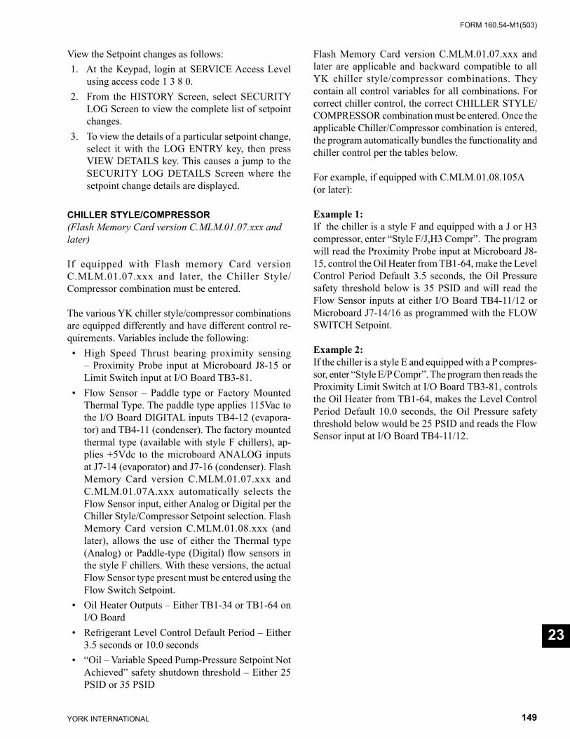
FORM 160.54-M1(503)
149YORK INTERNATIONAL
23
View the Setpoint changes as follows: 1. At the Keypad, login at SERVICE Access Level
us ing access code 1 3 8 0. 2. From the HISTORY Screen, select SECURITY
LOG Screen to view the complete list of setpoint chang es.
3. To view the details of a particular setpoint change, select it with the LOG ENTRY key, then press VIEW DETAILS key. This causes a jump to the SECURITY LOG DETAILS Screen where the setpoint change details are displayed.
CHILLER STYLE/COMPRESSOR (Flash Memory Card version C.MLM.01.07.xxx and later)
If equipped with Flash memory Card version C.MLM.01.07.xxx and later, the Chiller Style/Compressor combination must be entered.
The various YK chiller style/compressor combinations are equipped differently and have different control re-quirements. Variables include the following: • High Speed Thrust bearing proximity sensing
– Proximity Probe input at Microboard J8-15 or Limit Switch input at I/O Board TB3-81.
• Flow Sensor – Paddle type or Factory Mounted Thermal Type. The paddle type applies 115Vac to the I/O Board DIGITAL inputs TB4-12 (evapora-tor) and TB4-11 (condenser). The factory mounted thermal type (available with style F chillers), ap-plies +5Vdc to the microboard ANALOG inputs at J7-14 (evaporator) and J7-16 (condenser). Flash Memory Card version C.MLM.01.07.xxx and C.MLM.01.07A.xxx automatically selects the Flow Sensor input, either Analog or Digital per the Chiller Style/Compressor Setpoint selection. Flash Memory Card version C.MLM.01.08.xxx (and later), allows the use of either the Thermal type (Analog) or Paddle-type (Digital) fl ow sensors in the style F chillers. With these versions, the actual Flow Sensor type present must be entered using the Flow Switch Setpoint.
• Oil Heater Outputs – Either TB1-34 or TB1-64 on I/O Board
• Refrigerant Level Control Default Period – Either 3.5 seconds or 10.0 seconds
• “Oil – Variable Speed Pump-Pressure Setpoint Not Achieved” safety shutdown threshold – Either 25 PSID or 35 PSID
Flash Memory Card version C.MLM.01.07.xxx and later are applicable and backward compatible to all YK chiller style/compressor combinations. They contain all control variables for all combinations. For correct chiller control, the correct CHILLER STYLE/COMPRESSOR combination must be entered. Once the applicable Chiller/Compressor combination is entered, the program automatically bundles the functionality and chiller control per the tables below.
For example, if equipped with C.MLM.01.08.105A (or later):
Example 1:If the chiller is a style F and equipped with a J or H3 compressor, enter “Style F/J,H3 Compr”. The program will read the Proximity Probe input at Microboard J8-15, control the Oil Heater from TB1-64, make the Level Control Period Default 3.5 seconds, the Oil Pressure safety threshold below is 35 PSID and will read the Flow Sensor inputs at either I/O Board TB4-11/12 or Microboard J7-14/16 as programmed with the FLOW SWITCH Setpoint. Example 2: If the chiller is a style E and equipped with a P compres-sor, enter “Style E/P Compr”. The program then reads the Proximity Limit Switch at I/O Board TB3-81, controls the Oil Heater from TB1-64, makes the Level Control Period Default 10.0 seconds, the Oil Pressure safety threshold below would be 25 PSID and reads the Flow Sensor input at I/O Board TB4-11/12.
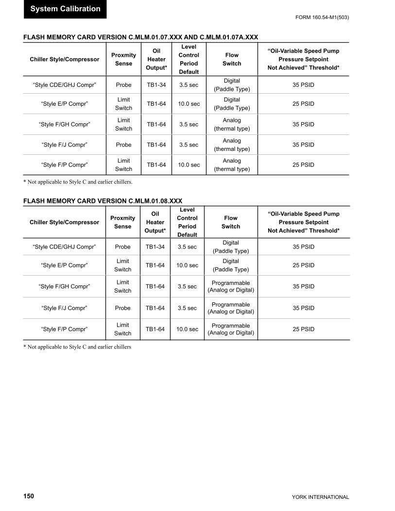
YORK INTERNATIONAL150
FORM 160.54-M1(503)System Calibration
FLASH MEMORY CARD VERSION C.MLM.01.07.XXX AND C.MLM.01.07A.XXX
Chiller Style/Compressor Proxmity
Sense
Oil Heater Output*
Level Control PeriodDefault
FlowSwitch
“Oil-Variable Speed PumpPressure Setpoint
Not Achieved” Threshold*
“Style CDE/GHJ Compr” Probe TB1-34 3.5 secDigital
(Paddle Type)35 PSID
“Style E/P Compr”Limit
SwitchTB1-64 10.0 sec
Digital(Paddle Type)
25 PSID
“Style F/GH Compr”Limit
SwitchTB1-64 3.5 sec
Analog(thermal type)
35 PSID
“Style F/J Compr” Probe TB1-64 3.5 secAnalog
(thermal type)35 PSID
“Style F/P Compr”Limit
SwitchTB1-64 10.0 sec
Analog(thermal type)
25 PSID
* Not applicable to Style C and earlier chillers.
FLASH MEMORY CARD VERSION C.MLM.01.08.XXX
Chiller Style/Compressor Proxmity
Sense
Oil Heater Output*
Level Control PeriodDefault
FlowSwitch
“Oil-Variable Speed PumpPressure Setpoint
Not Achieved” Threshold*
“Style CDE/GHJ Compr” Probe TB1-34 3.5 secDigital
(Paddle Type)35 PSID
“Style E/P Compr”Limit
SwitchTB1-64 10.0 sec
Digital(Paddle Type)
25 PSID
“Style F/GH Compr”Limit
SwitchTB1-64 3.5 sec Programmable
(Analog or Digital) 35 PSID
“Style F/J Compr” Probe TB1-64 3.5 sec Programmable(Analog or Digital) 35 PSID
“Style F/P Compr”Limit
SwitchTB1-64 10.0 sec Programmable
(Analog or Digital) 25 PSID
* Not applicable to Style C and earlier chillers
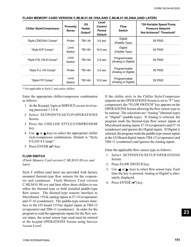
FORM 160.54-M1(503)
151YORK INTERNATIONAL
23
FLASH MEMORY CARD VERSION C.MLM.01.08.105A AND C.MLM.01.08.206A (AND LATER)
Chiller Style/Compressor Proxmity
Sense
Oil Heater Output*
Level Control PeriodDefault
FlowSwitch
“Oil-Variable Speed PumpPressure Setpoint
Not Achieved” Threshold*
“Style CDE/GHJ Compr” Probe TB1-34 3.5 secDigital
(Paddle Type)35 PSID
“Style E/P Compr”Limit
SwitchTB1-64 10.0 sec
Digital(Paddle Type)
25 PSID
“Style F/G, H5-8 Compr”Limit
SwitchTB1-64 3.5 sec Programmable
(Analog or Digital) 35 PSID
“Style F/J, H3 Compr” Probe TB1-64 3.5 sec Programmable(Analog or Digital) 35 PSID
“Style F/P Compr”Limit
SwitchTB1-64 10.0 sec Programmable
(Analog or Digital) 25 PSID
* Not applicable to Style C and earlier chillers
Enter the appropriate chiller/compressor combination as follows: 1 At the Keypad, login at SERVICE access level us-
ing password 1 3 8 0. 2 Select SETPOINTS/SETUP/OPERATIONS
Screen. 3 Press the CHILLER STYLE/COMPRESSOR
key. 4 Use or keys to select the appropriate chiller
style/compressor combination. Default is “Style F/G,H5-8 Compr”.
5 Press ENTER (✔) key.
FLOW SWITCH (Flash Memory Card version C.MLM.01.08.xxx and later)
Style F chillers (and later) are provided with factory mounted thermal-type fl ow sensors for the evapora-tor and condenser. Flash Memory Card version C.MLM.01.08.xxx and later allow these chillers to use either the thermal-type or fi eld installed paddle-type fl ow sensor. The thermal-type sensors interface to Microboard +5Vdc analog inputs at J7-14 (evaporator) and J7-16 (condenser). The paddle-type sensors inter-face to the I/O board 115Vac digital inputs at TB4-12 (evaporator) and TB4-11 (condenser). In order for the program to read the appropriate inputs for the fl ow sen-sor status, the actual sensor type used must be entered at the keypad OPERATIONS Screen using Service Access Level.
If the chiller style in the Chiller Style/Compressor setpoint on the OPERATIONS Screen is set to “F” (any compressor), the “FLOW SWITCH” key appears on the OPERATIONS Screen allowing the fl ow sensor type to be entered. The selections are “Analog” (thermal-type) or “Digital” (paddle-type). If Analog is selected, the program reads the thermal-type fl ow sensor inputs at Microboard analog inputs J7-14 (evaporator) and J7-16 (condenser) and ignores the Digital inputs. If Digital is selected, the program reads the paddle-type sensor inputs at the I/O Board digital inputs TB4-12 (evaporator) and TB4-11 (condenser) and ignores the Analog inputs.
Enter the applicable fl ow sensor type as follows: 1. Select SETPOINTS/SETUP/OPERATIONS
Screen. 2. Press FLOW SWITCH key. 3. Use or keys to select fl ow sensor type. Each
time the key is pressed, Analog or Digital is alter-nately displayed.
4. Press ENTER (✔) key.
YORK INTERNATIONAL152
FORM 160.54-M1(503)Diagnostics & Trou ble shoot ing
SECTION 24DIAGNOSTICS & TROUBLESHOOTING
The problems that could be encountered in the OptiView Control Cen ter are in the following categories: • Keypad • Display • Serial Input/Output (I/O) • Digital Input/Output (I/O) • Analog Inputs
There is a Diagnostic and associated Troubleshooting pro ce dure for each category. They are described on the fol low ing pages. Each Diagnostic is accessed from the Diagnostics Main Screen, which is entered using the procedure below. If there is an OptiView Control Cen ter problem, determine the category of the problem. Then perform the applicable Diagnostic. If the Di ag nos tic reveals a malfunction, perform the Trou ble shoot ing pro ce dure to locate the defective component.
There are several documents that must be referred to while performing the Diagnostics and Troubleshoot-ing pro ce dures. Each procedure references the Section and fi g ures of this book that describe the operation of the com po nent being test ed. Also, the applicable OptiView Con trol Cen ter wiring diagram must be used as follows:
Chillers through style E (except “P” compressors): • 160.54-PW1 (Electro-mechanical Start er) • 160.54-PW2 (Mod “A” Sol id State Starter) • 160.54-PW2.1 (Mod “B” Solid State Starter) • 160.54-PW3 (Vari able Speed Drive).
Chillers through style E (“P” compressors): • 160.54-PW8 – Chillers (Electro-me chan i cal Start-
er), • 160.54-PW9 (Mod “B” Solid State Starter) • 160.54-PW10 (Variable Speed Drive)
Style “F” chillers (all compressors): • 160.73-PW1 (Electro-mechanical Starter) • 160.73-PW2 (Mod “B” Solid State Starter) • 160.73-PW3 (Variable speed Drive)
There are two versions of the Di ag nos tics screens avail- able as follows: 1. Shown in fi gures 65 through 72. These screens are
used during the Di ag nos tics and Trou ble shoot ing pro cess. They allow output states to be changed. Access the Diagnostics Main Screen as fol lows:
1. The chiller must be stopped. 2. Place Compressor Start/Stop switch in the
Stop-Reset position (O). 3. Ensure the Compressor motor cur rent is 0%
FLA. 4. Log in at SERVICE access level using access
code 1 3 8 0. 5. Move Microboard Program Switch SW1-4 to
the ON position. A Watchdog reset will occur and the Boot-up process will commence. At the com ple tion of the Boot-up process, the Di ag nos tics Main Screen will appear. (Note: If SWI-4 is moved to the ON position before step 4 above is performed, the “LOG IN” key will be displayed and Log ging in at SERVICE ac cess level must be per formed be fore the Main Screen is displayed.
2. Not shown. Available when logged in at SER- VICE ac cess level, whether the chiller is run ning or not. Accessed from the SETUP screen via the SETPOINTS screen. There are two screens avail- able that allow the Analog Inputs volt age levels and Digital I/O states to be monitored. These screens are preceded by a general screen that pro vides the installed software versions.
SOFTWARE VERSION
Controls - FLASH Memory Card on Microboard BIOS - BIOS Eprom on Microboard Kernel - Soft ware that is part of FLASH Memory CardGUI - Soft ware that is part of FLASH Memory CardSIO - Software that is part of FLASH Memory CardGPIC - Eprom in MicroGateway
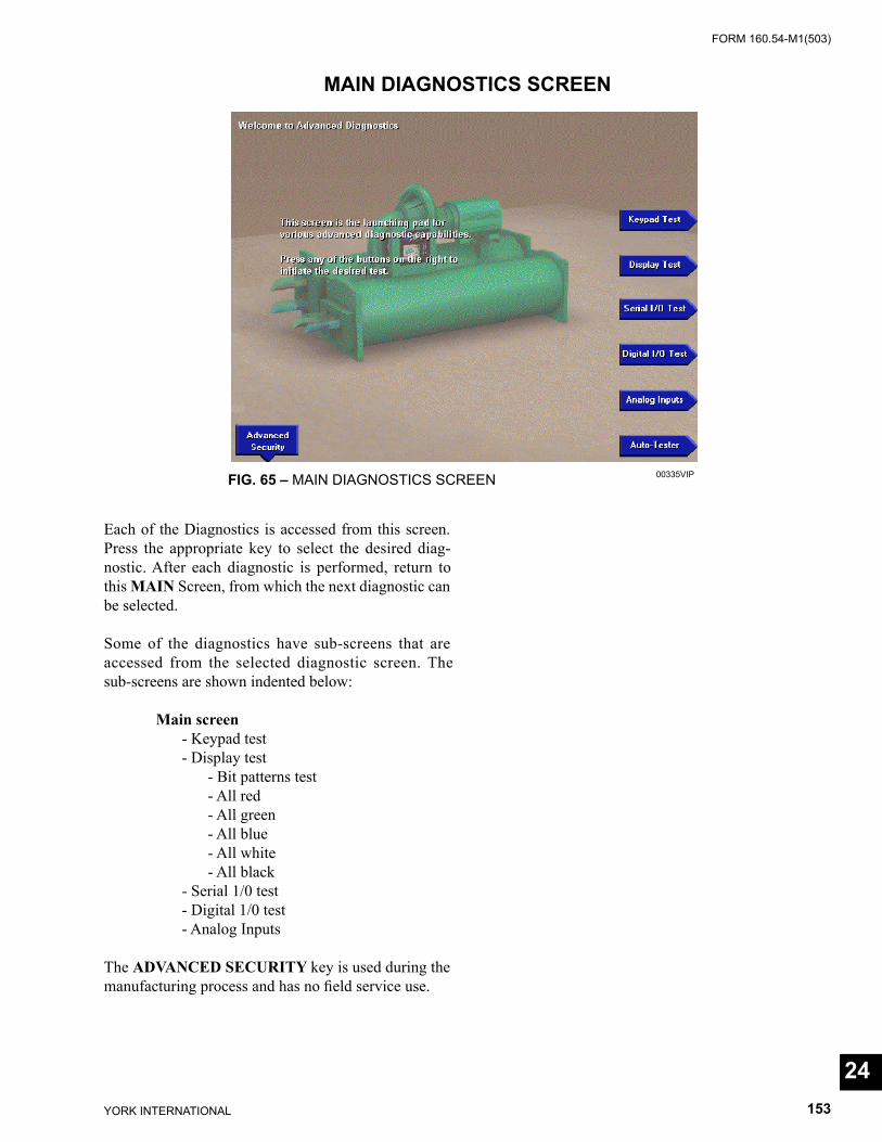
FORM 160.54-M1(503)
153YORK INTERNATIONAL
Each of the Diagnostics is accessed from this screen. Press the ap pro pri ate key to select the desired di ag -nos tic. After each diagnostic is per formed, return to this MAIN Screen, from which the next diagnostic can be se lect ed.
Some of the diagnostics have sub-screens that are ac cess ed from the se lect ed diagnostic screen. The sub-screens are shown indented below:
Main screen - Keypad test - Display test - Bit patterns test - All red - All green - All blue - All white - All black - Serial 1/0 test - Digital 1/0 test - Analog Inputs
The ADVANCED SECURITY key is used during the manufacturing pro cess and has no fi eld service use.
MAIN DIAGNOSTICS SCREEN
FIG. 65 – MAIN DIAGNOSTICS SCREEN 00335VIP
24
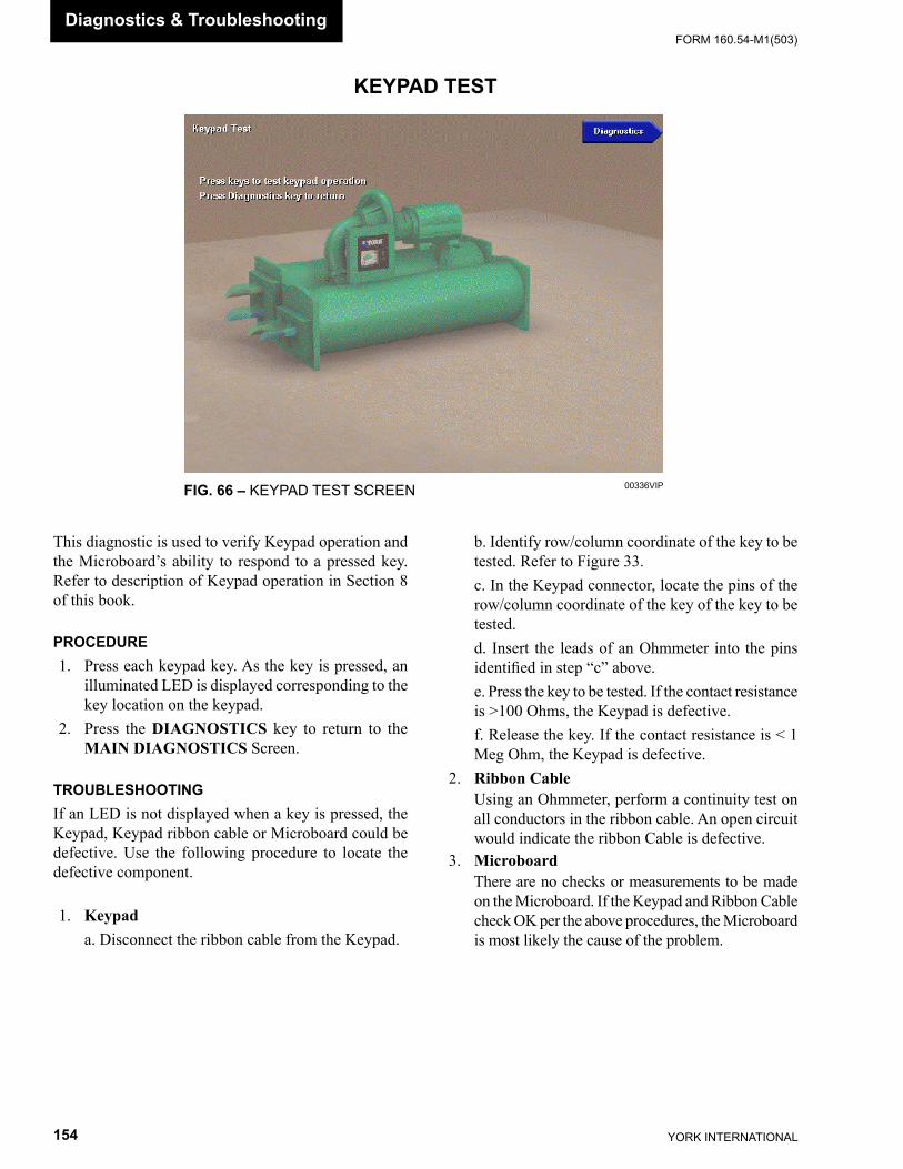
YORK INTERNATIONAL154
FORM 160.54-M1(503)
KEYPAD TEST
FIG. 66 – KEYPAD TEST SCREEN 00336VIP
This diagnostic is used to verify Keypad operation and the Microboard’s ability to respond to a pressed key. Refer to description of Keypad operation in Section 8 of this book.
PROCEDURE 1. Press each keypad key. As the key is pressed, an
il lu mi nat ed LED is displayed corresponding to the key location on the keypad.
2. Press the DIAGNOSTICS key to return to the MAIN DIAGNOSTICS Screen.
TROUBLESHOOTINGIf an LED is not displayed when a key is pressed, the Keypad, Keypad ribbon cable or Microboard could be defective. Use the following procedure to locate the defective component.
1. Keypad a. Disconnect the ribbon cable from the Key pad.
b. Identify row/column coordinate of the key to be test ed. Refer to Figure 33.
c. In the Keypad connector, locate the pins of the row/column coordinate of the key of the key to be test ed.
d. Insert the leads of an Ohmmeter into the pins iden ti fi ed in step “c” above.
e. Press the key to be tested. If the contact re sis tance is >100 Ohms, the Keypad is defective.
f. Release the key. If the contact resistance is < 1 Meg Ohm, the Keypad is defective.
2. Ribbon Cable Using an Ohmmeter, perform a continuity test on
all conductors in the ribbon cable. An open circuit would indicate the ribbon Ca ble is defective.
3. Microboard There are no checks or measurements to be made
on the Microboard. If the Keypad and Ribbon Ca ble check OK per the above pro ce dures, the Microboard is most likely the cause of the prob lem.
Diagnostics & Trou ble shoot ing
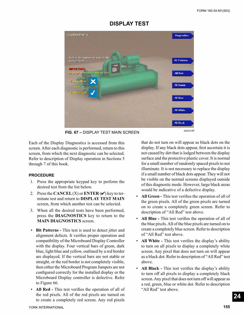
FORM 160.54-M1(503)
155YORK INTERNATIONAL
DISPLAY TEST
FIG. 67 – DISPLAY TEST MAIN SCREEN 00337VIP
Each of the Display Diagnostics is accessed from this screen. After each diagnostic is performed, return to this screen, from which the next diagnostic can be se lect ed. Refer to description of Display operation in Sec tions 5 through 7 of this book.
PROCEDURE 1. Press the appropriate keypad key to perform the
de sired test from the list below. 2. Press the CANCEL (X) or ENTER (✔) key to ter-
mi nate test and return to DISPLAY TEST MAIN screen, from which another test can be se lect ed.
3. When all the desired tests have been performed, press the DIAGNOSTICS key to return to the MAIN DIAGNOSTICS screen.
• Bit Patterns - This test is used to detect jitter and align ment defects. It verifi es proper operation and com pat i bil i ty of the Microboard Display Con trol ler with the display. Four vertical bars of green, dark blue, light blue and yellow, outlined by a red bor der are dis played. If the vertical bars are not sta ble or straight, or the red border is not com plete ly vis i ble, then either the Microboard Program Jump ers are not confi gured cor rect ly for the installed dis play or the Microboard Dis play controller is de fec tive. Re fer to Figure 66.
• All Red - This test verifi es the operation of all of the red pixels. All of the red pixels are turned on to cre ate a completely red screen. Any red pixels
that do not turn on will appear as black dots on the dis play. If any black dots appear, fi rst ascertain it is not caused by dirt that is lodged between the dis play surface and the protective plastic cover. It is normal for a small num ber of randomly spaced pix els to not illuminate. It is not necessary to replace the display if a small num ber of black dots appear. They will not be visible on the normal screens dis played outside of this di ag nos tic mode. However, large black areas would be in dic a tive of a de fec tive display.
• All Green - This test verifi es the operation of all of the green pixels. All of the green pixels are turned on to cre ate a completely green screen. Refer to de scrip tion of “All Red” test above.
• All Blue - This test verifi es the operation of all of the blue pixels. All of the blue pixels are turned on to create a completely blue screen. Refer to de scrip tion of “All Red” test above.
• All White - This test verifi es the display’s abil i ty to turn on all pixels to display a completely white screen. Any pixel that does not turn on will appear as a black dot. Refer to description of “All Red” test above.
• All Black - This test verifi es the display’s abil i ty to turn off all pixels to display a completely black screen. Any pixel that does not turn off will appear as a red, green, blue or white dot. Refer to de scrip tion “All Red” test above.
24
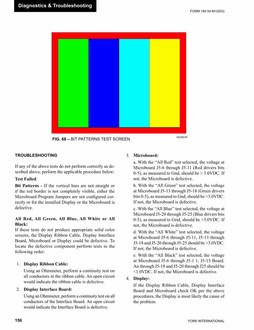
YORK INTERNATIONAL156
FORM 160.54-M1(503)Diagnostics & Trou ble shoot ing
FIG. 68 – BIT PATTERNS TEST SCREEN 00338VIP
TROUBLESHOOTING
If any of the above tests do not perform correctly as de- scribed above, perform the applicable procedure be low:Test Failed:Bit Patterns - If the vertical bars are not straight or if the red border is not completely visible, either the Microboard Program Jumpers are not con fi g ured cor- rect ly or for the installed Display or the Microboard is de fec tive.
All Red, All Green, All Blue, All White or All Black:If these tests do not produce appropriate solid color screens, the Display Ribbon Cable, Display In ter face Board, Microboard or Display could be de fec tive. To locate the defective component perform tests in the fol low ing order:
1. Display Ribbon Cable: Using an Ohmmeter, perform a continuity test on
all conductors in the ribbon cable. An open circuit would indicate the ribbon cable is defective.
2. Display Interface Board: Using an Ohmmeter, perform a continuity test on all
conductors of the Interface Board. An open cir cuit would indicate the Interface Board is de fec tive.
3. Microboard: a. With the “All Red” test selected, the voltage at
Microboard J5-6 through J5-11 (Red drivers bits 0-5), as measured to Gnd, should be > 3.0VDC. If not, the Microboard is defective.
b. With the “All Green” test selected, the voltage at Microboard J5-13 through J5-18 (Green driv ers bits 0-5), as measured to Gnd, should be >3.0VDC. If not, the Microboard is defective.
c. With the “All Blue” test selected, the voltage at Microboard J5-20 through J5-25 (Blue drivers bits 0-5), as measured to Grid, should be >3.0VDC. If not, the Microboard is defective.
d. With the “All White” test selected, the voltage at Microboard J5-6 through J5-11, J5-13 through J5-18 and J5-20 through J5-25 should be >3.0VDC. If not, the Microboard is defective.
e. With the “All Black” test selected, the voltage at Microboard J5-6 through J5-1 1, J5-13 Board. An through J5-18 and J5-20 through J25 should be <1.0VDC. If not, the Microboard is defective.
4. Display: If the Display Ribbon Cable, Display Interface
Board and Microboard check OK per the above procedures, the Display is most likely the cause of the problem.
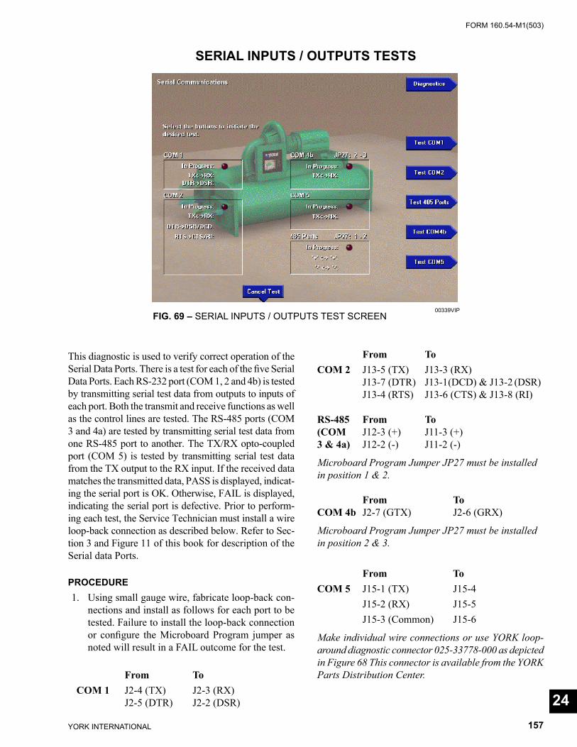
FORM 160.54-M1(503)
157YORK INTERNATIONAL
SERIAL INPUTS / OUTPUTS TESTS
FIG. 69 – SERIAL INPUTS / OUTPUTS TEST SCREEN00339VIP
This diagnostic is used to verify correct op er a tion of the Serial Data Ports. There is a test for each of the fi ve Serial Data Ports. Each RS-232 port (COM 1, 2 and 4b) is tested by transmitting serial test data from out puts to inputs of each port. Both the transmit and re ceive func tions as well as the control lines are tested. The RS-485 ports (COM 3 and 4a) are tested by trans mit ting serial test data from one RS-485 port to an oth er. The TX/RX opto-coupled port (COM 5) is tested by trans mit ting se ri al test data from the TX output to the RX input. If the received data matches the transmitted data, PASS is dis played, indicat-ing the serial port is OK. Oth er wise, FAIL is displayed, indicating the se ri al port is defective. Prior to perform-ing each test, the Service Technician must in stall a wire loop-back connection as described below. Refer to Sec-tion 3 and Fig ure 11 of this book for de scrip tion of the Serial data Ports.
PROCEDURE 1. Using small gauge wire, fabricate loop-back con-
nec tions and install as follows for each port to be tested. Failure to install the loop-back connection or confi gure the Microboard Program jumper as noted will result in a FAIL outcome for the test.
From To COM 1 J2-4 (TX) J2-3 (RX) J2-5 (DTR) J2-2 (DSR)
From ToCOM 2 J13-5 (TX) J13-3 (RX) J13-7 (DTR) J13-1(DCD) & J13-2 (DSR) J13-4 (RTS) J13-6 (CTS) & J13-8 (RI) RS-485 From To(COM J12-3 (+) J11-3 (+)3 & 4a) J12-2 (-) J11-2 (-)
Microboard Program Jumper JP27 must be in stalled in position 1 & 2.
From ToCOM 4b J2-7 (GTX) J2-6 (GRX)
Microboard Program Jumper JP27 must be in stalled in position 2 & 3.
From ToCOM 5 J15-1 (TX) J15-4 J15-2 (RX) J15-5 J15-3 (Common) J15-6
Make individual wire connections or use YORK loop-around diagnostic connector 025-33778-000 as de pict ed in Figure 68 This connector is available from the YORK Parts Distribution Center.
24
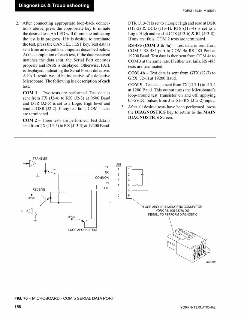
YORK INTERNATIONAL158
FORM 160.54-M1(503)Diagnostics & Trou ble shoot ing
2. After connecting appropriate loop-back con nec -tions above, press the appropriate key to initiate the de sired test. An LED will illuminate in di cat ing the test is in progress. If it is desired to ter mi nate the test, press the CANCEL TEST key. Test data is sent from an output to an input as de scribed below. At the completion of each test, if the data received matches the data sent, the Serial Port op er ates prop er ly and PASS is displayed. Oth er wise, FAIL is displayed, indicating the Serial Port is de fec tive. A FAIL result would be indicative of a defective Microboard. The following is a de scrip tion of each test.
COM 1 – Two tests are performed. Test data is sent from TX (J2-4) to RX (J2-3) at 9600 Baud and DTR (J2-5) is set to a Logic High level and read at DSR (J2-2). If any test fails, COM 1 tests are ter mi nat ed.
COM 2 – Three tests are performed. Test data is sent from TX (J13-5) to RX (J13-3) at 19200 Baud.
DTR (J13-7) is set to a Logic High and read at DSR (J13-2) & DCD (J13-1). RTS (J13-4) is set to a Logic High and read at CTS (J13-6) & R1 (J13-8). If any test fails, COM 2 tests are ter mi nat ed.
RS-485 (COM 3 & 4a) – Test data is sent from COM 3 RS-485 port to COM 4a RS-485 Port at 19200 Baud. Test data is then sent from COM 4a to COM 3 at the same rate. If either test fails, RS-485 tests are terminated.
COM 4b – Test data is sent from GTX (J2-7) to GRX (J2-6) at 19200 Baud.
COM 5 – Test data is sent from TX (J15-1) to J15-4 at 1200 Baud. This output turns the Microboard’s loop-around test Transistor on and off, applying 0/+5VDC pulses from J15-5 to RX (J15-2) input.
3. After all desired tests have been performed, press the DIAGNOSTICS key to return to the MAIN DIAGNOSTICS Screen.
FIG. 70 – MICROBOARD - COM 5 SERIAL DATA PORT
TRANSMIT
RECEIVE
+5VDC
LOOP-AROUND DIAGNOSTIC CONNECTORYORK PIN 025-33778-000
INSTALL TO PERFORM DIAGNOSTIC+5VDC
LOOP-AROUND TEST
J15
1
2
3
4
5
6
1
2
3
4
5
6
TX
RX
COMMON
IN
OUT
LD04250
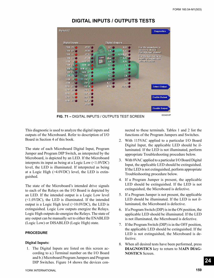
FORM 160.54-M1(503)
159YORK INTERNATIONAL
DIGITAL INPUTS / OUTPUTS TESTS
FIG. 71 – DIGITAL INPUTS / OUTPUTS TEST SCREEN 00340VIP
This diagnostic is used to analyze the digital inputs and outputs of the Microboard. Refer to description of I/O Board in Section 4 of this book.
The state of each Microboard Digital Input, Pro gram Jumper and Program DIP Switch, as in ter pret ed by the Microboard, is depicted by an LED. If the Microboard interprets its input as being at a Logic Low (<1.0VDC) level, the LED is illuminated. If in ter pret ed as being at a Logic High (>4.0VDC) level, the LED is ex tin -guished.
The state of the Microboard’s intended drive sig nals to each of the Relays on the I/O Board is de pict ed by an LED. If the intended output is a Logic Low level (<1.0VDC), the LED is illuminated. If the intended out put is a Logic High level (>10.0VDC), the LED is ex tin guished. Logic Low outputs en er gize the Relays. Logic High outputs de-energize the Relays. The state of any output can be manually set to either the EN ABLED (Logic Low) or DISABLED (Logic High) state.
PROCEDURE
Digital Inputs: 1. The Digital Inputs are listed on this screen ac-
cord ing to a.) Terminal number on the I/O Board and b.) Microboard Program Jumpers and Pro gram DIP Switch es. Figure 14 shows the de vic es con-
nect ed to these terminals. Tables 1 and 2 list the functions of the Program Jumpers and Switch es.
2. With 115VAC applied to a particular I/O Board Dig i tal Input, the applicable LED should be il- lu mi nat ed. If the LED is not illuminated, perform appropriate Troubleshooting procedure be low.
3. With 0VAC applied to a particular I/O Board Dig i tal Input, the applicable LED should be ex tin guished. If the LED is not extinguished, perform ap pro pri ate Trou ble shoot ing procedure below.
4. If a Program Jumper is present, the applicable LED should be extinguished. If the LED is not ex tin guished, the Microboard is defective.
5. If a Program Jumper is not present, the ap pli ca ble LED should be illuminated. If the LED is not il- lu mi nat ed, the Microboard is defective.
6. If a Program Switch (DIP) is in the ON position, the applicable LED should be illuminated. If the LED is not illuminated, the Microboard is de fec tive.
7. If the Program Switch (DIP) is in the OFF po si tion, the applicable LED should be extinguished. If the LED is not extinguished, the Microboard is de- fec tive.
8. When all desired tests have been performed, press DIAGNOSTICS key to return to MAIN DI AG -NOS TICS Screen.
24
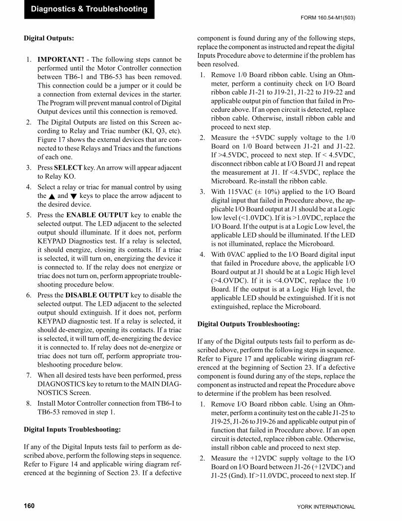
YORK INTERNATIONAL160
FORM 160.54-M1(503)Diagnostics & Trou ble shoot ing
Digital Outputs:
1. IMPORTANT! - The following steps can not be per formed until the Motor Controller connection be tween TB6-1 and TB6-53 has been re moved. This connection could be a jumper or it could be a connection from external devices in the starter. The Pro gram will pre vent manual control of Digital Output devices until this connection is removed.
2. The Digital Outputs are listed on this Screen ac- cord ing to Relay and Triac number (KI, Q3, etc). Fig ure 17 shows the external devices that are con- nect ed to these Relays and Triacs and the func tions of each one.
3. Press SELECT key. An arrow will appear ad ja cent to Relay KO.
4. Select a relay or triac for manual control by using the ▲ and ▼ keys to place the arrow ad ja cent to the desired device.
5. Press the ENABLE OUTPUT key to enable the se lect ed output. The LED adjacent to the selected output should illuminate. If it does not, perform KEYPAD Diagnostics test. If a relay is selected, it should en er gize, closing its contacts. If a triac is selected, it will turn on, energizing the device it is connected to. If the relay does not energize or triac does not turn on, per form appropriate trou ble -shoot ing procedure below.
6. Press the DISABLE OUTPUT key to disable the se lect ed output. The LED adjacent to the selected out put should extinguish. If it does not, perform KEYPAD diagnostic test. If a relay is selected, it should de-energize, opening its contacts. If a triac is selected, it will turn off, de-energizing the de vice it is connected to. If relay does not de-energize or triac does not turn off, perform ap pro pri ate trou- ble shoot ing procedure below.
7. When all desired tests have been performed, press DIAGNOSTICS key to return to the MAIN DI AG -NOS TICS Screen.
8. Install Motor Controller connection from TB6-I to TB6-53 removed in step 1.
Digital Inputs Troubleshooting:
If any of the Digital Inputs tests fail to perform as de- scribed above, perform the following steps in se quence. Refer to Figure 14 and applicable wiring di a gram ref- er enced at the beginning of Section 23. If a defective
com po nent is found during any of the following steps, re place the component as instructed and repeat the dig i tal Inputs Pro ce dure above to determine if the problem has been resolved. 1. Remove 1/0 Board ribbon cable. Using an Ohm-
me ter, perform a continuity check on I/O Board rib bon cable J1-21 to J19-21, J1-22 to J19-22 and applicable output pin of function that failed in Pro- ce dure above. If an open circuit is de tect ed, re place ribbon cable. Otherwise, install ribbon ca ble and proceed to next step.
2. Measure the +5VDC supply voltage to the 1/0 Board on 1/0 Board between J1-21 and J1-22. If >4.5VDC, proceed to next step. If < 4.5VDC, dis connect rib bon cable at I/O Board J1 and re peat the mea sure ment at J1. If <4.5VDC, replace the Microboard. Re-install the ribbon cable.
3. With 115VAC (± 10%) applied to the I/O Board dig i tal input that failed in Procedure above, the ap- pli ca ble I/O Board output at J1 should be at a Log ic low level (<1.0VDC). If it is >1.0VDC, re place the I/O Board. If the output is at a Logic Low lev el, the applicable LED should be illuminated. If the LED is not illuminated, replace the Microboard.
4. With 0VAC applied to the I/O Board digital input that failed in Procedure above, the applicable I/O Board output at J1 should be at a Logic High level (>4.OVDC). If it is <4.OVDC, replace the 1/0 Board. If the output is at a Logic High level, the ap pli ca ble LED should be extinguished. If it is not ex tin guished, replace the Microboard.
Digital Outputs Troubleshooting:
If any of the Digital outputs tests fail to perform as de- scribed above, perform the following steps in se quence. Refer to Figure 17 and applicable wiring di a gram ref- er enced at the beginning of Section 23. If a defective com po nent is found during any of the steps, replace the com po nent as instructed and repeat the Procedure above to de ter mine if the problem has been resolved. 1. Remove I/O Board ribbon cable. Using an Ohm-
me ter, perform a continuity test on the cable J1-25 to J19-25, J1-26 to J19-26 and applicable output pin of func tion that failed in Procedure above. If an open circuit is detected, replace ribbon cable. Oth er wise, install rib bon cable and proceed to next step.
2. Measure the +12VDC supply voltage to the I/O Board on I/O Board between J1-26 (+12VDC) and J1-25 (Gnd). If >11.0VDC, proceed to next step. If
FORM 160.54-M1(503)
161YORK INTERNATIONAL
<11.0VDC, dis connect ribbon cable at I/O Board J1 and repeat mea sure ment at JI. If <11.0VDC, re place the Microboard. Re-install the ribbon ca ble.
3. Using the Digital Outputs Procedure above, se- lect the output that failed the digital Output test above.
4. Press ENABLE OUTPUT key. The LED adjacent to the selected output will illuminate. The ap pro -pri ate Microboard output pin at J19 for the se lect ed output should be at a Logic Low level (<1.0VDC). If it is >1.0VDC, replace the Microboard. With the output at a Logic Low, the fol low ing should oc-cur:
a. If a Relay is selected as the output, the contacts of the relay should be closed. If they are not closed, re place the I/O Board.
b. If a Triac is selected as the output, the Triac should be turned on. If the Triac has not turned on, re place the I/O Board. See note 1 below for Triac testing.
5. Press DISABLE OUTPUT key. The LED ad ja cent to the selected output will extinguish.
a. If a Relay is selected as the output, the ap pro pri ate Microboard output pin at J19 for the se lect ed output should be at a Logic High (>10.0VDC) lev el. With the output at a Logic High level, the relay contacts
should be open. If they are not open, re place the I/O Board. If it is <10.0VDC, remove the ribbon cable from J1 of the I/O Board. On the I/O Board, measure the resistance from J1-26 to the appro-priate pin of J1 on the I/O Board for the se lect ed relay. If the resistance is >100 Ohms, re place the I/O Board. If the re sis tance is <100 Ohms, re place the Microboard.
b. If a Triac is selected as the output, the ap pro pri ate Microboard output pin at J19 for the se lect ed output should be at a Logic High (>10.0VDC) lev el. If it is <10.0VDC, replace the Microboard. With the output at a Logic High level, the Triac should be turned off. If the Triac has not turned off, re place the I/O Board. See note 1 below for Triac testing.
Notes: 1. The load (actuator) must be connected across the
Triac to determine the on/off state of the Triac. The on/off state of the Triac can be determined by mea sur ing across the device (for example, TB1-3 to TB1-59 or TB1-58 to TB1-59) with an AC Volt me ter. If the Triac is turned on, the volt- age will be <10VAC. If the Triac is turned off, the voltage will be >100VAC (Slide Valve ac tu a tor) or >20VAC (PRV, Hot Gas or Re frig er ant Level Control ac tu a tor).
24
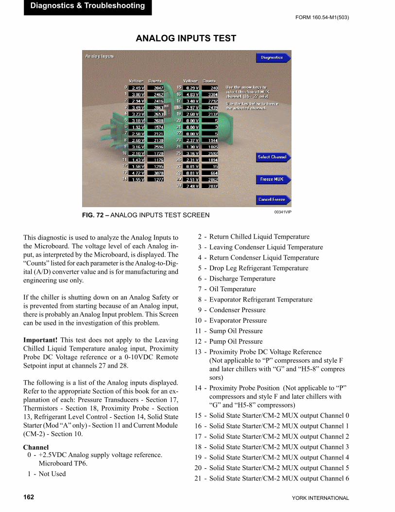
YORK INTERNATIONAL162
FORM 160.54-M1(503)
Diagnostics & Trou ble shoot ing
ANALOG INPUTS TEST
FIG. 72 – ANALOG INPUTS TEST SCREEN 00341VIP
This diagnostic is used to analyze the Analog Inputs to the Microboard. The voltage level of each Analog in- put, as in ter pret ed by the Microboard, is dis played. The “Counts” listed for each pa ram e ter is the Analog-to-Dig-ital (A/D) converter value and is for man u fac tur ing and engineering use only.
If the chiller is shutting down on an Analog Safety or is prevented from starting because of an Analog input, there is probably an Analog Input problem. This Screen can be used in the investigation of this problem.
Important! This test does not apply to the Leaving Chilled Liquid Temperature analog input, Proximity Probe DC Voltage reference or a 0-10VDC Remote Setpoint input at channels 27 and 28.
The following is a list of the Analog inputs displayed. Refer to the appropriate Section of this book for an ex- pla na tion of each: Pressure Transducers - Section 17, Thermistors - Section 18, Proximity Probe - Section 13, Refrigerant Level Control - Section 14, Solid State Start er (Mod “A” only) - Section 11 and Cur rent Mod ule (CM-2) - Sec tion 10.
0 - +2.5VDC Analog sup ply volt age reference. Microboard TP6. 1 - Not Used
2 - Return Chilled Liquid Temperature 3 - Leaving Condenser Liquid Tem per a ture 4 - Return Condenser Liquid Temperature 5 - Drop Leg Refrigerant Temperature 6 - Discharge Temperature 7 - Oil Temperature 8 - Evaporator Refrigerant Temperature 9 - Condenser Pressure10 - Evaporator Pressure11 - Sump Oil Pressure12 - Pump Oil Pressure13 - Proximity Probe DC Voltage Reference (Not applicable to “P” compressors and style F and later chillers with “G” and “H5-8” compres sors)14 - Proximity Probe Position (Not applicable to “P” compressors and style F and later chillers with “G” and “H5-8” compressors)15 - Solid State Starter/CM-2 MUX output Channel 016 - Solid State Starter/CM-2 MUX output Channel 117 - Solid State Starter/CM-2 MUX output Channel 218 - Solid State Starter/CM-2 MUX output Channel 319 - Solid State Starter/CM-2 MUX output Channel 420 - Solid State Starter/CM-2 MUX output Channel 521 - Solid State Starter/CM-2 MUX output Channel 6
Channel
FORM 160.54-M1(503)
163YORK INTERNATIONAL
22 - Solid State Starter/CM-2 MUX output Channel 723 - Refrigerant Level Position24 - Proximity Probe High Speed DrainTemperature (except “P” Compressors)(Not applicable to chillers equipped with Program ver sion C.MLM.01.03 or higher)25 - Not Used26 - Not Used27 - Remote Leaving Chilled Liquid Temperature Setpoint (0-20mA or 4-20mA)28 - Remote Current Limit Setpoint (0-20mA or 4-20mA)29 - Condenser Flow Sensor (style F and later chillers)
(Flash Memory Card version C.MLM.01.07.xxx and later).
30 - Evaporator Flow Sensor (style F and later chillers) (Flash Memory Card version C.MLM.01.07.xxx and later)
Procedure:
1. From the chart above, select the analog input that is malfunctioning. All inputs except channel 0, 15 through 22, 27 and 28 are sensors that connect di- rect ly to the Microboard via shielded cable. Chan nel 0 is a ref er ence voltage for the Analog circuits on the Microboard. Channels 15 through 22 are mul-tiplexed outputs from the Solid State Starter (Solid Sate Starter applications) or CM-2 Current Module (Electro-Mechanical Starter applications). Chan nels 27 and 28 are Remote Setpoint inputs used in Analog Remote mode.
2. Refer to Wiring Diagrams listed in front of this Sec tion to identify the device that performs this func tion and the jack and pin connection to the Microboard.
3. • Channel 0: Using a Voltmeter, measure the voltage be tween
Microboard TP6 (+2.5VDC) and TP1 (Gnd). Compare this measured value to the displayed
val ue. If the value is not within +10%, replace the Microboard.
• All channels except 0, 1, 15-22: Using a Voltmeter, measure the analog input to the
Microboard. Make the measurement between the device output and Ground connection to the de vice. For example, measure the output of the Evap o ra tor Transducer at Microboard J8-18 (sig nal) to J8-9 (Gnd).
• Channels 15-22:
Select the desired channel by pressing the SE LECT CHANNEL key and using the ▲ and ▼ keys to place the arrow head next to the de sired chan nel. Then, freeze the address of that channel to the Solid State Starter or CM-2 MUX. Then mea sure MUX output at Microboard J10-6 (signal) to J10-5 (Gnd). When com plet ed, press CANCEL FREEZE key.
• Channels 27, 28: IMPORTANT! This procedure only applies to
4-20mA in puts. It does not apply to 0-10VDC in- puts. Using a Voltmeter, measure the Remote Cur- rent Limit setpoint input at J22-2 (signal) or Re mote Leaving Chilled Liquid Temperature setpoint input at J22-4 (signal) to J22-5 (Gnd).
4. Compare the measured value in the previous step with the value displayed on the Analog Inputs Screen for that value.
5. If the measured value is not within +15% of the dis- played value, replace the Microboard. Oth er wise, proceed to the troubleshooting procedure below to fi nd the cause of the problem.
6. When all desired tests have been performed, press DIAGNOSTICS key to return the MAIN DI AG -NOS TICS Screen.
Troubleshooting :
• All Channels except 0, 1, 15-22, 27, 28: 1. Disconnect both ends of the cable of the An a log
in put that is malfunctioning. Using an Ohm me ter, per form a continuity test on all conductors in the cable. An open circuit would indicate the cable is defective.
2. Using a Voltmeter, measure the +12VDC supply volt age input at the Microboard J1-3 (+12VDC) to J1-2 (Gnd). If voltage is < 11.5VDC, check wir ing to Power Supply. If wiring is OK, the Pow er sup ply is most like ly defective.
3. Using a Voltmeter, measure the supply voltage (+5VDC, +1 2VDC or +24VDC) to the sensor. If volt age is not within +10% of specifi ed voltage, dis connect J7, J8 and J9 from the Microboard. This disconnects all analog devices from the Microboard. If the voltage increases to the cor- rect level, a Ther mistor or Trans duc er is shorted. Lo cate the short ed device and re place. If, after dis connecting the con nec tors the supply volt age is still not with in 10% of the specifi ed value, the voltage supply source (Microboard or Power Sup- ply) is most like ly de fec tive.
24
YORK INTERNATIONAL164
FORM 160.54-M1(503)
4. Verify sensor accuracy using appropriate test de- vice. Replace sensor if necessary.
• Channels 15 - 22: 1. Disconnect both ends of ribbon cable connected
to Microboard J10. Using an Ohm me ter, perform a con ti nu ity test on all conductors in the cable. An open cir cuit would indicate the cable is defective.
2. Using a Voltmeter, measure the +12VDC supply volt age input at the Microboard J1-3 (+12VDC) to J1-2 (Gnd). If voltage is <11.5VDC, check wir ing to Power Supply. If wiring is OK, the Pow er Sup ply is most like ly defective.
3. Using a Voltmeter, measure the +5VDC supply volt age to the Solid State Starter Logic Board or CM-2 Board. Make measurement at Microboard J10-4(+5VDC) to J10-5 (Gnd). If voltage is <4.5VDC, replace the Microboard.
4. Using a Voltmeter, verify the correct address is be ing sent from the Microboard to the Solid State Start er Logic Board or CM-2 Board. Freeze ad- dress as de scribed above. If the address is correct, the Sol id State Starter Logic Board or CM-2 Board or input devices to these boards is most likely the cause of the problem. If address is not correct, the Microboard is most likely the cause of the prob- lem.
5. Press CANCEL FREEZE key.
• Channels 27, 28: 1. Refer to Table 1 “Microboard Program Jumpers”
and verify Program Jumpers JP23 and JP24 are con fi g ured correctly for the type of input (0-10VDC or 4-20mA).
2. Disconnect both ends of the cable of the re mote in put that is malfunctioning. Using an Ohm me ter, per form a continuity check on all con duc tors in the cable. An open circuit would indicate the ca ble is defective.
3. If steps are OK, problem most likely is in the re mote device that supplies the remote signal.
Diagnostics & Trou ble shoot ing
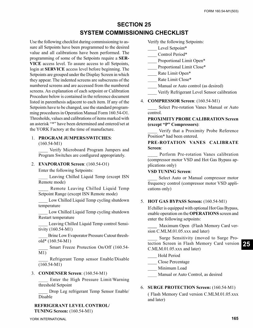
FORM 160.54-M1(503)
165YORK INTERNATIONAL
Verify the following Setpoints: ____ Level Setpoint* ____ Control Period* ____ Proportional Limit Open* ____ Proportional Limit Close* ____ Rate Limit Open* ____ Rate Limit Close* ____ Manual or Auto control (as desired) ____ Verify Refrigerant Level Sensor cal i bra tion
4. COMPRESSOR Screen: (160.54-M1) ____ Select Pre-rotation Vanes Manual or Auto
con trol. PROXIMITY PROBE CALIBRATION Screen
(except “P” Compressors): ____ Verify that a Proximity Probe Reference
Position* had been entered. PRE-ROTATION VANES CALIBRATE
Screen: ____ Perform Pre-rotation Vanes calibration
(com pres sor motor VSD and Hot Gas Bypass ap- pli ca tions only)
VSD TUNING Screen: ____ Select Auto or Manual compressor mo tor
fre quen cy control (compressor motor VSD ap pli -ca tions only)
5. HOT GAS BYPASS Screen: (160.54-M1) If chiller is equipped with optional Hot Gas By pass,
enable operation on the OPERATIONS screen and enter the following setpoints:
____ Maximum Open (Flash Memory Card ver-sion C.MLM.01.05.xxx and later)
____ Surge Sensitivity (moved to Surge Pro- tec tion Screen in Flash Memory Card versionC.MLM.01.05.xxx and later)
____ Hold Period ____ Close Percentage ____ Minimum Load ____ Manual or Auto Control, as desired
6. SURGE PROTECTION Screen: (160.54-M1) ( Flash Memory Card version C.MLM.01.05.xxx
and lat er)
SECTION 25SYSTEM COMMISSIONING CHECKLIST
Use the following checklist during commissioning to as- sure all Setpoints have been programmed to the de sired value and all calibrations have been performed. The pro gram ming of some of the Setpoints require a SER- VICE access level. To assure access to all Setpoints, login at SERVICE access level before beginning. The Setpoints are grouped under the Display Screen in which they ap pear. The indented screens are subscreens of the num bered screens and are accessed from the numbered screens. An explanation of each setpoint or Calibration Procedure below is contained in the reference doc u ment listed in parenthesis adjacent to each item. If any of the Setpoints have to be changed, use the standard pro gram -ming procedures in Operation Manual Form 160.54-O1. Thresholds, values and calibrations of items marked with an asterisk “*” have been determined and entered/set at the YORK Factory at the time of man u fac ture.
1. PROGRAM JUMPERS/SWITCHES: (160.54-M1) ____ Verify Microboard Program Jumpers and
Pro gram Switches are confi gured appropriately.
2. EVAPORATOR Screen: (160.54-O1) Enter the following Setpoints: ____ Leaving Chilled Liquid Temp (except ISN
Re mote mode) ____ Remote Leaving Chilled Liq uid Temp
Setpoint Range (except ISN Remote mode) ____ Low Chilled Liquid Temp cycling shutdown
tem per a ture ____ Low Chilled Liquid Temp cycling shutdown
Re start temperature ____ Leaving Chilled Liquid Temp control Sen si -
tiv i ty (160.54-M1) ____ Brine Low Evaporator Pressure Cutout thresh-
old* (160.54-M1) ____ Smart Freeze Protection On/Off (160.54-
M1) ____ Refrigerant Temp sensor Enable/Disable
(160.54-M1)
3. CONDENSER Screen: (160.54-M1) ____ Enter the High Pressure Limit/Warning
thresh old Setpoint ____ Drop Leg refrigerant Temp Sensor Enable/
Dis able
REFRIGERANT LEVEL CONTROL/ TUNING Screen: (160.54-M1)
25
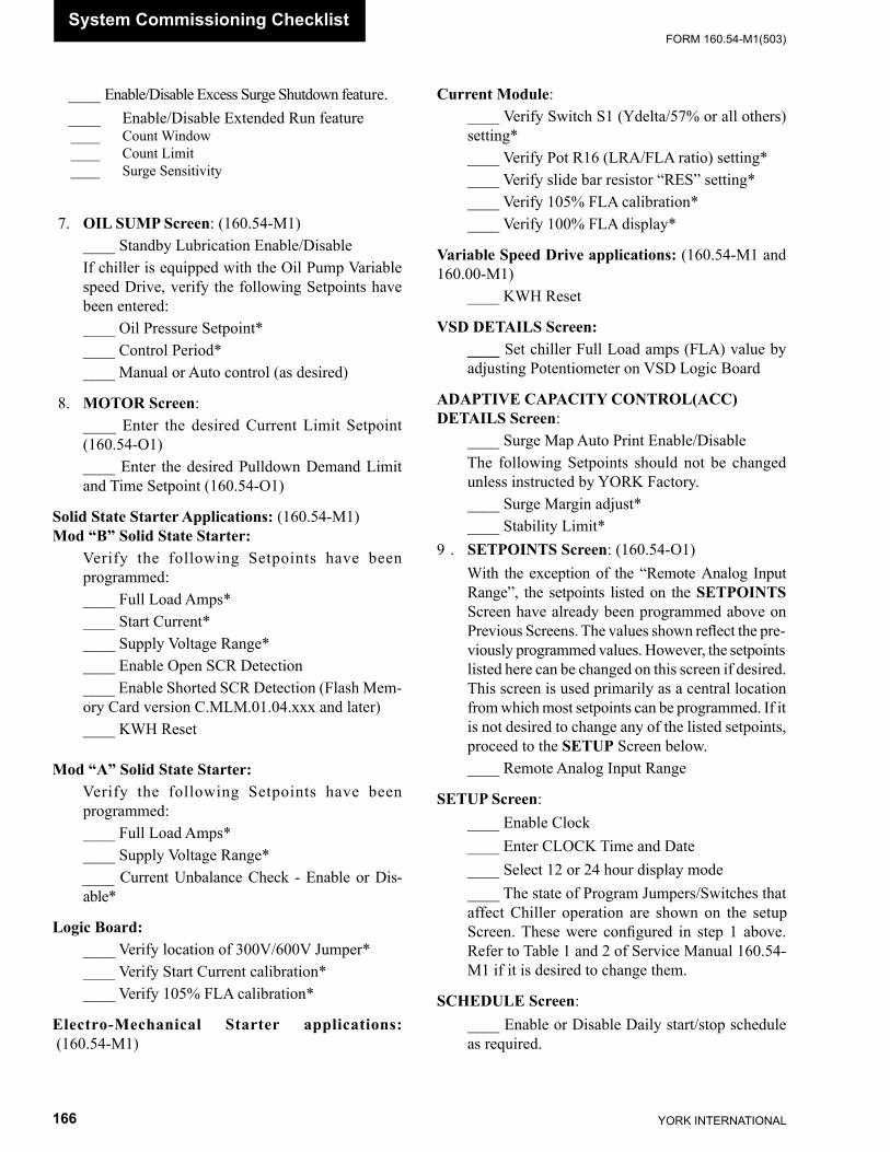
YORK INTERNATIONAL166
FORM 160.54-M1(503)System Commissioning Checklist
____ Enable/Disable Excess Surge Shutdown fea ture. ____ Enable/Disable Extended Run fea ture ____ Count Window ____ Count Limit ____ Surge Sensitivity
7. OIL SUMP Screen: (160.54-M1) ____ Standby Lubrication Enable/Disable If chill er is equipped with the Oil Pump Variable
speed Drive, verify the following Setpoints have been entered:
____ Oil Pressure Setpoint* ____ Control Period* ____ Manual or Auto control (as desired)
8. MOTOR Screen: ____ Enter the desired Current Limit Setpoint
(160.54-O1) ____ Enter the desired Pulldown Demand Limit
and Time Setpoint (160.54-O1)
Solid State Starter Applications: (160.54-M1) Mod “B” Solid State Starter: Verify the following Setpoints have been
programmed: ____ Full Load Amps* ____ Start Current* ____ Supply Voltage Range* ____ Enable Open SCR Detection ____ Enable Shorted SCR Detection (Flash Mem-
ory Card version C.MLM.01.04.xxx and later) ____ KWH Reset
Mod “A” Solid State Starter: Verify the following Setpoints have been
programmed: ____ Full Load Amps* ____ Supply Voltage Range* ____ Current Unbalance Check - Enable or Dis-
able*
Logic Board: ____ Verify location of 300V/600V Jumper* ____ Verify Start Current calibration* ____ Verify 105% FLA calibration*
Electro-Mechanical Starter applications: (160.54-M1)
Current Module: ____ Verify Switch S1 (Ydelta/57% or all others)
set ting* ____ Verify Pot R16 (LRA/FLA ratio) setting* ____ Verify slide bar resistor “RES” setting* ____ Verify 105% FLA calibration* ____ Verify 100% FLA display*
Variable Speed Drive applications: (160.54-M1 and 160.00-M1) ____ KWH Reset
VSD DETAILS Screen: ____ Set chiller Full Load amps (FLA) value by
ad just ing Potentiometer on VSD Logic Board
ADAPTIVE CAPACITY CONTROL(ACC) DETAILS Screen: ____ Surge Map Auto Print Enable/Disable The following Setpoints should not be changed
un less instructed by YORK Factory. ____ Surge Margin adjust* ____ Stability Limit* 9 . SETPOINTS Screen: (160.54-O1) With the exception of the “Remote Analog Input
Range”, the setpoints list ed on the SETPOINTS Screen have al ready been pro grammed above on Pre vi ous Screens. The val ues shown refl ect the pre- vi ous ly pro grammed values. How ev er, the setpoints listed here can be changed on this screen if de sired. This screen is used primarily as a cen tral lo ca tion from which most setpoints can be pro grammed. If it is not desired to change any of the listed setpoints, pro ceed to the SET UP Screen be low.
____ Remote Analog Input Range
SETUP Screen: ____ Enable Clock ____ Enter CLOCK Time and Date ____ Select 12 or 24 hour display mode ____ The state of Program Jumpers/Switches that
af fect Chiller operation are shown on the setup Screen. These were confi gured in step 1 above. Refer to Table 1 and 2 of Service Manual 160.54-M1 if it is desired to change them.
SCHEDULE Screen: ____ Enable or Disable Daily start/stop sched ule
as required.
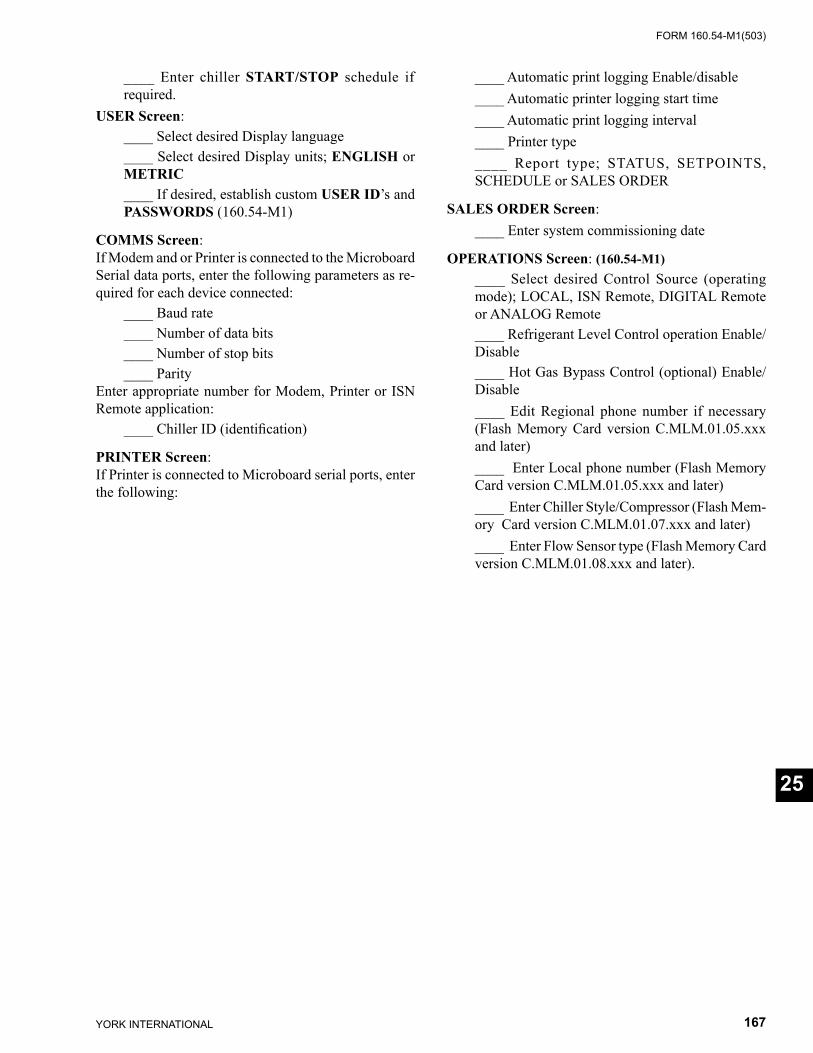
FORM 160.54-M1(503)
167YORK INTERNATIONAL
____ Enter chiller START/STOP schedule if required.
USER Screen: ____ Select desired Display language ____ Select desired Display units; EN GLISH or
MET RIC ____ If desired, establish custom USER ID’s and
PASS WORDS (160.54-M1)
COMMS Screen: If Modem and or Printer is connected to the Microboard Serial data ports, enter the following pa ram e ters as re- quired for each de vice connected: ____ Baud rate ____ Number of data bits ____ Number of stop bits ____ Parity Enter appropriate number for Modem, Print er or ISN Remote application: ____ Chiller ID (identifi cation)
PRINTER Screen: If Printer is connected to Microboard serial ports, en ter the following:
____ Automatic print logging Enable/dis able ____ Automatic printer logging start time ____ Automatic print logging interval ____ Printer type ____ Report type; STATUS, SETPOINTS,
SCHED ULE or SALES ORDER
SALES ORDER Screen: ____ Enter system commissioning date
OPERATIONS Screen: (160.54-M1) ____ Select desired Control Source (op er at ing
mode); LOCAL, ISN Remote, DIGITAL Remote or ANALOG Remote
____ Refrigerant Level Control operation En able/Dis able
____ Hot Gas Bypass Control (optional) Enable/Disable
____ Edit Regional phone number if necessary (Flash Memory Card version C.MLM.01.05.xxx and later)
____ Enter Local phone number (Flash Memory Card ver sion C.MLM.01.05.xxx and later)
____ Enter Chiller Style/Compressor (Flash Mem-ory Card version C.MLM.01.07.xxx and later)
____ Enter Flow Sensor type (Flash Memory Card version C.MLM.01.08.xxx and later).
25
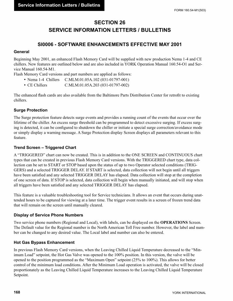
YORK INTERNATIONAL168
FORM 160.54-M1(503)Service Information Letters / Bulletins
SECTION 26SERVICE INFORMATION LETTERS / BULLETINS
GeneralBeginning May 2001, an enhanced Flash Memory Card will be supplied with new production Nema 1-4 and CE chillers. New features are outlined below and are also included in YORK Operation Manual 160.54-O1 and Ser-vice Manual 160.54-M1.Flash Mem o ry Card versions and part numbers are applied as follows:
• Nema 1-4 Chillers C.MLM.01.05A.102 (031-01797-001)• CE Chillers C.MLM.01.05A.203 (031-01797-002)
The en hanced fl ash cards are also available from the Baltimore Parts Dis tri bu tion Center for retrofi t to existing chillers.
Surge ProtectionThe Surge protection feature detects surge events and provides a running count of the events that occur over the lifetime of the chiller. An excess surge threshold can be programmed to detect excessive surging. If excess surg-ing is detected, it can be confi gured to shutdown the chiller or initiate a special surge correction/avoidance mode or simply display a warning message. A Surge Protection display Screen displays all parameters relevant to this feature.
Trend Screen – Triggered Chart A “TRIGGERED” chart can now be created. This is in addition to the ONE SCREEN and CONTINUOUS chart types that can be created in previous Flash Memory Card versions. With the TRIG GERED chart type, data col- lec tion can be set to START or STOP based upon the status of up to two Operator selected con di tions (TRIG- GERS) and a selected TRIGGER DELAY. If START is selected, data col lec tion will not begin until all triggers have been satisfi ed and any selected TRIGGER DELAY has elapsed. Data collection will stop at the completion of one screen of data. If STOP is selected, data collection will begin when manually ini ti at ed, and will stop when all triggers have been satisfi ed and any selected TRIGGER DELAY has elapsed.
This feature is a valuable troubleshooting tool for Service technicians. It allows an event that occurs during un at -tend ed hours to be captured for viewing at a later time. The trigger event results in a screen of frozen trend data that will remain on the screen until manually cleared.
Display of Service Phone NumbersTwo service phone numbers (Regional and Local), with labels, can be displayed on the OPERATIONS Screen. The Default value for the Regional number is the North American Toll Free number. However, the label and num-ber can be changed to any desired value. The Local label and number can also be entered.
Hot Gas Bypass Enhancement In previous Flash Memory Card versions, when the Leaving Chilled Liquid Temperature decreased to the “Min- i mum Load” setpoint, the Hot Gas Valve was opened to the 100% position. In this version, the valve will be opened to the position programmed as the “Maximum Open” setpoint (25% to 100%). This allows for better control of the minimum load conditions. After the Minimum Load operation is activated, the valve will be closed proportionately as the Leaving Chilled Liquid Temperature increases to the Leaving Chilled Liquid Temperature Setpoint.
SI0006 - SOFTWARE ENHANCEMENTS EFFECTIVE MAY 2001
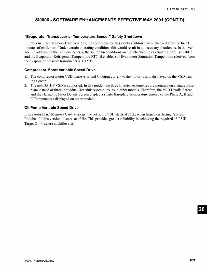
FORM 160.54-M1(503)
169YORK INTERNATIONAL
26
“Evaporator-Transducer or Temperature Sensor” Safety ShutdownIn Previous Flash Memory Card versions, the conditions for this safety shutdown were checked after the fi rst 10 minutes of chiller run. Under certain operating conditions this would result in unnecessary shutdowns. In this ver-sion, in addition to the previous criteria, the shutdown conditions are not checked unless Smart Freeze is enabled and the Evaporator Refrigerant Temperature RT7 (if enabled) or Evaporator Saturation Temperature (derived from the evaporator pressure transducer) is < 32º F.
Compressor Motor Variable Speed Drive1. The compressor motor VSD phase A, B and C output current to the motor is now displayed on the VSD Tun-
ing Screen. 2. The new 351HP VSD is supported. In this model, the three Inverter Assemblies are mounted on a single Base-
plate instead of three individual Heatsink Assemblies, as in other models. Therefore, the VSD Details Screen and the Harmonic Filter Details Screen display a single Baseplate Temperature instead of the Phase A, B and C Temperatures displayed on other models.
Oil Pump Variable Speed DriveIn previous Flash Memory Card versions, the oil pump VSD starts at 25Hz when turned on during “System Prelube”. In this version, it starts at 45Hz. This provides greater reliability in achieving the required 45 PSID Target Oil Pres sure at chiller start.
SI0006 - SOFTWARE ENHANCEMENTS EFFECTIVE MAY 2001 (CONT'D)

YORK INTERNATIONAL170
FORM 160.54-M1(503)Service Information Letters / Bulletins
GeneralBeginning March 2002, an enhanced Flash Memory Card will be supplied in new production YK Nema 1-4 and CE chillers. The new features are outlined below.
The Flash Memory Card versions and part numbers are as follows:• Nema 1-4 chillers (except “P” com pres sors) .............C.MLM.01.06.100 (031-01797-001)• CE chillers (except “P” com pres sors)........................C.MLM.01.06.200 (031-01797-002)• Nema 1-4 chillers (“P” compressors) ........................C.MLM.04.02.100 (031-02073-001)• CE chillers (“P” compressors) ...................................C.MLM.04.02.200 (031-02073-002)
These versions are also available from the Baltimore Parts Distribution Center for retrofi t to existing chillers.
Operator Soft ShutdownThis feature allows an Operator (logged in at Operator Access Level, or higher) to manually initiate a soft shut down by closing the Pre-rotation Vanes prior to shutting down the chiller. This reduces com pres sor bearing wear by elimi-nating compressor backspin at shutdown.
While the chiller is running, a SOFT SHUTDOWN key is available on the Home Screen (when Access Level is Operator or higher). Pressing this key causes the Pre-rotation Vanes to be driven fully closed. While they are clos-ing, “Vanes Closing Before Shutdown” is displayed on the System Status line. “Local Stop” is dis played on the System Details line. When the Vane Motor Switch (VMS) closes, indicating the Vanes have fully closed (or 3.5 minutes have elapsed, whichever occurs fi rst), the Start Signal is removed from the Starter and a normal Coastdown is performed.
While the Vanes are closing during the Soft Shutdown, if a standard Local Stop is initiated with the front panel Rocker Switch, or if any faults other than the following occur, the Soft Shutdown is terminated and it will im me di ate ly enter a normal Coastdown period: • “Leaving Chilled Liquid – Low Temperature” • “Remote Stop” • “Multi-unit Cycling – Contacts Open” • “System Cycling – Contacts Open” • “Control Panel – Schedule”
Following an Operator initiated Soft Shutdown, the front panel Rocker Switch must be placed in the Stop/Reset position and then to the Start position in order to start the chiller after a Soft Shutdown has been performed.
Record Setpoint ChangesThis feature provides a record of the last 75 Setpoint changes. The date and time the Setpoint was changed, the new Setpoint value and the Access Level and User ID used to make the change are stored in the BRAM. The Security Log Screen and the Security Log Details Screen display levels of this information. Both screens are available in Service Access level or higher.
On the Security Log Screen, accessible from the History Screen, the Setpoint, Setpoint Category and new Setpoint value are listed and numbered in reverse order in which they were changed. The most recent is listed as number 1; the next most recent as number 2, etc. A PRINT key allows printing this entire list. Since 15 changes can be displayed at one time, multiple pages could be necessary to display all the changes. PAGE-UP and PAGE-DOWN keys are provided to view the entire list. If it is desired to view the details of a particular Setpoint change, select the Setpoint change number with the LOG ENTRY key and then press the VIEW DETAILS key. This moves to the SECURITY LOG DETAILS Screen.
SI0019 - SOFTWARE ENHANCEMENTS EFFECTIVE MARCH 2002
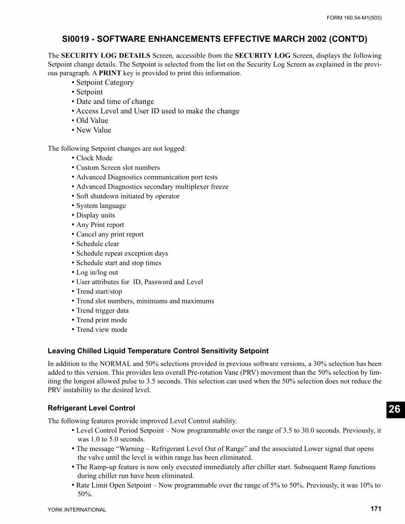
FORM 160.54-M1(503)
171YORK INTERNATIONAL
26
The SECURITY LOG DETAILS Screen, accessible from the SECURITY LOG Screen, displays the following Setpoint change details. The Setpoint is selected from the list on the Security Log Screen as explained in the previ-ous paragraph. A PRINT key is provided to print this information. • Setpoint Category • Setpoint • Date and time of change • Access Level and User ID used to make the change • Old Value • New Value
The following Setpoint changes are not logged: • Clock Mode • Custom Screen slot numbers • Advanced Diagnostics communication port tests • Advanced Diagnostics secondary multiplexer freeze • Soft shutdown initiated by operator • System language • Display units • Any Print report • Cancel any print report • Schedule clear • Schedule repeat exception days • Schedule start and stop times • Log in/log out • User attributes for ID, Password and Level • Trend start/stop • Trend slot numbers, minimums and maximums • Trend trigger data • Trend print mode • Trend view mode
Leaving Chilled Liquid Temperature Control Sensitivity SetpointIn addition to the NORMAL and 50% selections provided in previous software versions, a 30% selection has been added to this version. This provides less overall Pre-rotation Vane (PRV) movement than the 50% se lec tion by lim-iting the longest allowed pulse to 3.5 seconds. This selection can used when the 50% selection does not reduce the PRV instability to the desired level.
Refrigerant Level ControlThe following features provide improved Level Control stability.
• Level Control Period Setpoint – Now programmable over the range of 3.5 to 30.0 seconds. Previously, it was 1.0 to 5.0 seconds.
• The message “Warning – Refrigerant Level Out of Range” and the associated Lower signal that opens the valve until the level is within range has been eliminated.
• The Ramp-up feature is now only executed immediately after chiller start. Subsequent Ramp func tions during chiller run have been eliminated.
• Rate Limit Open Setpoint – Now programmable over the range of 5% to 50%. Previously, it was 10% to 50%.
SI0019 - SOFTWARE ENHANCEMENTS EFFECTIVE MARCH 2002 (CONT'D)

YORK INTERNATIONAL172
FORM 160.54-M1(503)Service Information Letters / Bulletins
• Rate Limit Close Setpoint – Now programmable over the range of 5% to 50%. Previously, it was 10% to 50%.
• The duration of the open or close pulse applied to the Valve Actuator is now independent of the selected Period Setpoint. It is now a fi xed percentage of 3.5 seconds. Previously, it was a percentage of the Pe-riod Setpoint. Therefore, longer Periods would produce longer output pulses for the same error, result-ing in unstable op er a tion under certain conditions.
Compressor Motor Variable Speed Drive
• The conditions to produce the “Harmonic Filter – Logic Board or Communications” Cycling shutdown must now be present for 10 communication cycles before a shutdown is performed.
• If either the 50% or 30% Leaving Chilled Liquid Temperature SENSITIVITY Setpoint is selected, Pre-rotation Vane movement is further reduced when the chiller is operating at low load. When the Vane position is less than 25% and Leaving Chilled Liquid Temperature is within + 2.5 ºF of Setpoint, the maximum Vane pulse is limited to 3.5 seconds at 25% position and 0.9 seconds at 0% position. Vane positions in between have linearly scaled maximums.
• In previous Flash Memory Card versions, the SET FREQUENCY Setpoint feature on the VSD TUN-ING Screen did not correctly set the desired frequency in 50Hz applications. This is corrected in this version.
• Harmonic Filter Currents are now correctly displayed at maximum values.
HistoryChiller Run Time is now included on History Details display and print.
Hot Gas BypassThe Hot Gas Valve position is now animated on the HOT GAS BYPASS Screen.
SI0019 - SOFTWARE ENHANCEMENTS EFFECTIVE MARCH 2002 (CONT'D)

FORM 160.54-M1(503)
173YORK INTERNATIONAL
26
This page intentionally left blank
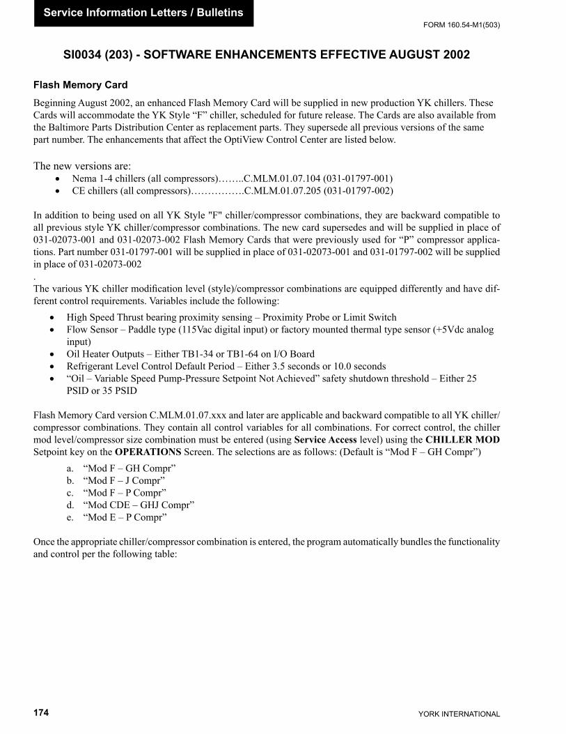
YORK INTERNATIONAL174
FORM 160.54-M1(503)Service Information Letters / Bulletins
Flash Memory CardBeginning August 2002, an enhanced Flash Memory Card will be supplied in new production YK chillers. These Cards will accommodate the YK Style “F” chiller, scheduled for future release. The Cards are also available from the Baltimore Parts Distribution Center as replacement parts. They supersede all previous versions of the same part number. The enhancements that affect the OptiView Control Center are listed below.
The new versions are: • Nema 1-4 chillers (all compressors)……..C.MLM.01.07.104 (031-01797-001)• CE chillers (all compressors)…………….C.MLM.01.07.205 (031-01797-002)
In addition to being used on all YK Style "F" chiller/compressor combinations, they are backward compatible to all previous style YK chiller/compressor combinations. The new card supersedes and will be supplied in place of 031-02073-001 and 031-02073-002 Flash Memory Cards that were previously used for “P” compressor applica-tions. Part number 031-01797-001 will be supplied in place of 031-02073-001 and 031-01797-002 will be supplied in place of 031-02073-002. The various YK chiller modifi cation level (style)/compressor combinations are equipped differently and have dif-ferent control requirements. Variables include the following:
• High Speed Thrust bearing proximity sensing – Proximity Probe or Limit Switch• Flow Sensor – Paddle type (115Vac digital input) or factory mounted thermal type sensor (+5Vdc analog
input)• Oil Heater Outputs – Either TB1-34 or TB1-64 on I/O Board• Refrigerant Level Control Default Period – Either 3.5 seconds or 10.0 seconds• “Oil – Variable Speed Pump-Pressure Setpoint Not Achieved” safety shutdown threshold – Either 25
PSID or 35 PSID
Flash Memory Card version C.MLM.01.07.xxx and later are applicable and backward compatible to all YK chiller/compressor combinations. They contain all control variables for all combinations. For correct control, the chiller mod level/compressor size combination must be entered (using Service Access level) using the CHILLER MOD Setpoint key on the OPERATIONS Screen. The selections are as follows: (Default is “Mod F – GH Compr”)
a. “Mod F – GH Compr”b. “Mod F – J Compr”c. “Mod F – P Compr”d. “Mod CDE – GHJ Compr”e. “Mod E – P Compr”
Once the appropriate chiller/compressor combination is entered, the program automatically bundles the functionality and control per the following table:
SI0034 (203) - SOFTWARE ENHANCEMENTS EFFECTIVE AUGUST 2002
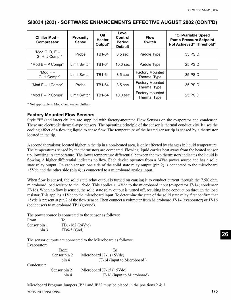
FORM 160.54-M1(503)
175YORK INTERNATIONAL
26
Chiller Mod –Compressor
ProxmitySense
Oil Heater Output*
Level Control PeriodDefault
FlowSwitch
“Oil-Variable SpeedPump Pressure Setpoint
Not Achieved” Threshold*
“Mod C, D, E – G, H, J Compr” Probe TB1-34 3.5 sec Paddle Type 35 PSID
“Mod E – P Compr” Limit Switch TB1-64 10.0 sec Paddle Type 25 PSID
“Mod F – G, H Compr” Limit Switch TB1-64 3.5 sec Factory Mounted
Thermal Type 35 PSID
“Mod F – J Compr” Probe TB1-64 3.5 sec Factory MountedThermal Type 35 PSID
“Mod F – P Compr” Limit Switch TB1-64 10.0 sec Factory mountedThermal Type 25 PSID
* Not applicable to Mod C and earlier chillers.
Factory Mounted Flow SensorsStyle "F" (and later) chillers are supplied with factory-mounted Flow Sensors on the evaporator and condenser. These are electronic thermal-type sensors. The operating principle of the sensor is thermal conductivity. It uses the cooling effect of a fl owing liquid to sense fl ow. The temperature of the heated sensor tip is sensed by a thermistor located in the tip.
A second thermistor, located higher in the tip in a non-heated area, is only affected by changes in liquid temperature. The temperatures sensed by the thermistors are compared. Flowing liquid carries heat away from the heated sensor tip, lowering its temperature. The lower temperature differential between the two thermistors indicates the liquid is fl owing. A higher differential indicates no fl ow. Each device operates from a 24Vac power source and has a solid state relay output. On each sensor, one side of the solid state relay output (pin 2) is connected to the microboard +5Vdc and the other side (pin 4) is connected to a microboard analog input.
When fl ow is sensed, the solid state relay output is turned on causing it to conduct current through the 7.5K ohm microboard load resistor to the +5vdc. This applies >+4Vdc to the microboard input (evaporator J7-14; condenser J7-16). When no fl ow is sensed, the solid state relay output is turned off, resulting in no conduction through the load resistor. This applies <1Vdc to the microboard input. To determine the state of the solid state relay, fi rst confi rm that +5vdc is present at pin 2 of the fl ow sensor. Then connect a voltmeter from Microboard J7-14 (evaporator) or J7-16 (condenser) to microboard TP1 (ground).
The power source is connected to the sensor as follows:From ToSensor pin 1 TB1-162 (24Vac) pin 3 TB6-5 (Gnd)
The sensor outputs are connected to the Microboard as follows: Evaporator: From To Sensor pin 2 Microboard J7-1 (+5Vdc) pin 4 J7-14 (input to Microboard )Condenser: Sensor pin 2 Microboard J7-15 (+5Vdc) pin 4 J7-16 (input to Microboard)
Microboard Program Jumpers JP21 and JP22 must be placed in the positions 2 & 3.
SI0034 (203) - SOFTWARE ENHANCEMENTS EFFECTIVE AUGUST 2002 (CONT'D)
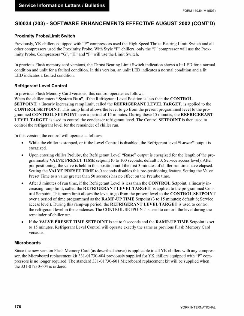
YORK INTERNATIONAL176
FORM 160.54-M1(503)Service Information Letters / Bulletins
Proximity Probe/Limit SwitchPreviously, YK chillers equipped with “P” compressors used the High Speed Thrust Bearing Limit Switch and all other compressors used the Proximity Probe. With Style “F” chillers, only the “J” compressor will use the Prox-imity Probe. Compressors “G”, “H” and “P” will use the Limit Switch.
In previous Flash memory card versions, the Thrust Bearing Limit Switch indication shows a lit LED for a normal condition and unlit for a faulted condition. In this version, an unlit LED indicates a normal condition and a lit LED indicates a faulted condition.
Refrigerant Level ControlIn previous Flash Memory Card versions, this control operates as follows: When the chiller enters “System Run”, if the Refrigerant Level Position is less than the CONTROL SETPOINT, a linearly increasing ramp limit, called the REFRIGERANT LEVEL TARGET, is applied to the CONTROL SETPOINT. This ramp limit allows the level to go from the present programmed level to the pro-grammed CONTROL SETPOINT over a period of 15 minutes. During these 15 minutes, the REFRIGERANT LEVEL TARGET is used to control the condenser refrigerant level. The Control SETPOINT is then used to control the refrigerant level for the remainder of chiller run.
In this version, the control will operate as follows: • While the chiller is stopped, or if the Level Control is disabled, the Refrigerant level “Lower” output is
energized. • Upon entering chiller Prelube, the Refrigerant Level “Raise” output is energized for the length of the pro-
grammable VALVE PRESET TIME setpoint (0 to 100 seconds; default 50; Service access level). After pre-positioning, the valve is held in this position until the fi rst 3 minutes of chiller run time have elapsed. Setting the VALVE PRESET TIME to 0 seconds disables this pre-positioning feature. Setting the Valve Preset Time to a value greater than 50 seconds has no effect on the Prelube time.
• After 3 minutes of run time, if the Refrigerant Level is less than the CONTROL Setpoint, a linearly in-creasing ramp limit, called the REFRIGERANT LEVEL TARGET, is applied to the programmed Con-trol Setpoint. This ramp limit allows the level to go from the present level to the CONTROL SETPOINT over a period of time programmed as the RAMP-UP TIME Setpoint (3 to 15 minutes; default 8; Service access level). During this ramp-up period, the REFRIGERANT LEVEL TARGET is used to control the refrigerant level in the condenser. The CONTROL SETPOINT is used to control the level during the remainder of chiller run.
• If the VALVE PRESET TIME SETPOINT is set to 0 seconds and the RAMP-UP TIME Setpoint is set to 15 minutes, Refrigerant Level Control will operate exactly the same as previous Flash Memory Card versions.
MicroboardsSince the new version Flash Memory Card (as described above) is applicable to all YK chillers with any compres-sor, the Microboard replacement kit 331-01730-604 previously supplied for YK chillers equipped with “P” com-pressors is no longer required. The standard 331-01730-601 Microboard replacement kit will be supplied when the 331-01730-604 is ordered.
SI0034 (203) - SOFTWARE ENHANCEMENTS EFFECTIVE AUGUST 2002 (CONT'D)

FORM 160.54-M1(503)
177YORK INTERNATIONAL
26
This page intentionally left blank

YORK INTERNATIONAL178
FORM 160.54-M1(503)
SI0058 - SOFTWARE ENHANCEMENTS EFFECTIVE FEBRUARY 2003
GeneralBeginning February 2003, an enhanced Flash memory Card will be supplied in all new production YK chillers. These cards are backward compatible to all previous YK chillers and are available from the Baltimore Parts Distribution Center as replacement parts. The enhancements are outlined below.
The versions and part numbers are applied as follows: • NEMA 1-4 chillers C.MLM.01.08.105 (p/n 031-01797-001)• CE chillers C.MLM.01.08.206 (p/n 031-01797-002)
Flow SensorsMod (Style) F chillers are provided with factory mounted thermal-type fl ow sensors for the evaporator and condenser. However, this Flash Memory Card version allows Style F chillers to use either the thermal-type or fi eld installed paddle-type fl ow sensor. The thermal-type sensors interface to Microboard +5Vdc analog inputs at J7-14 (evaporator) and J7-16 (condenser). The paddle-type sensors interface to the I/O board 115Vac digital inputs at TB4-12 (evapo-rator) and TB4-11 (condenser). For the program to read the appropriate inputs for the fl ow sensor status, the actual sensor type used must be entered at the keypad OPERATIONS Screen using the Service Access Level.
If the chiller Mod (style) level setpoint on the OPERATIONS Screen is set to “F” (any compressor), the “FLOW SWITCH” key appears on the OPERATIONS Screen allowing the fl ow sensor type to be entered. The selections are “Analog” (thermal-type) or “Digital” (paddle-type). If Analog is selected, the program reads the thermal-type fl ow sensor inputs at Microboard analog inputs J7-14 (evaporator) and J7-16 (condenser) and ignores the Digital inputs. If Digital is selected, the program reads the paddle-type sensor inputs at the I/O Board digital inputs TB4-12 (evaporator) and TB4-11 (condenser) and ignores the Analog inputs.
Enter the applicable fl ow sensor type as follows: 1. Select SETPOINTS/SETUP/OPERATIONS Screen. 2. Press FLOW SWITCH key. 3. Use or keys to select fl ow sensor type. Each time the key is pressed, Analog or Digital is alternately
displayed. 4. Press ENTER (✔) key.
Variable Speed Drive Oil PumpWhen the oil pump is started during System Prelube, the pump speed command is held at 45Hz for the fi rst 8 sec-onds before releasing to normal control.
Oil Pressure ThresholdThe threshold for “Oil – High Differential Pressure” safety shutdown is changed from 90 PSID to 120 PSID.
Compressor Motor Variable Speed Drive (VSD)This Flash Memory Card version supports VSD part number 371-03789-xxx (503HP; 60Hz) (419HP; 50Hz). Dis-play messages unique to this drive are displayed appropriately on the screens as follows: Phase A, B and C Base-plate Temperatures are displayed on the VSD DETAILS Screen and Filter Baseplate Temperature is displayed on the FILTER DETAILS Screen.
Service Information Letters / Bulletins

FORM 160.54-M1(503)
179YORK INTERNATIONAL
In addition to standard VSD Cycling messages, the following Cycling shutdown messages apply to this VSD:
“VSD – Low Phase A Inverter Baseplate Temperature” The chiller has shutdown because the Baseplate temperature has decreased to <37 ºF.
“VSD – Low Phase B Inverter Baseplate Temperature” Same as phase A above.
“VSD – Low Phase C Inverter Baseplate Temperature” Same as phase A above.
In addition to standard VSD Safety shutdown messages, the following Safety shutdown messages apply to this VSD:
“VSD – High Phase A Inverter Baseplate Temperature” The chiller has shutdown because the Baseplate temperature has increased to >158 ºF.
“VSD – High Phase B Inverter Baseplate Temperature” Same as phase A above.
“VSD – High Phase C Inverter Baseplate Temperature” Same as phase A above.
“Harmonic Filter – High Baseplate Temperature” The chiller has shutdown because the Baseplate temperature has increased to >194 ºF.
Microgateway In previous Flash Card versions, “Start Inhibit” and “Modifi ed Run” codes were transmitted into “Cycling” and “Safety” shutdown slots in the Microgateway. This alarmed external devices that a Cycling or Safety shutdown has occurred, when in reality, a Start Inhibit such as Anti-recycle or a Modifi ed Run event such as Current Limit is in effect. This was incorrect operation. In this version, the codes are transmitted into the proper slots in the Micro-gateway.
Security Log ScreenIn previous Flash Card versions, some setpoint changes were not logged in metric mode. All setpoint changes are now logged.
26
SI0058 - SOFTWARE ENHANCEMENTS EFFECTIVE FEBRUARY 2003 (CONT'D)
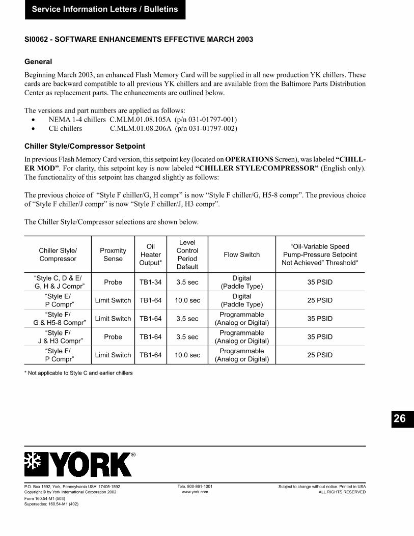
Service Information Letters / Bulletins
26
GeneralBeginning March 2003, an enhanced Flash Memory Card will be supplied in all new production YK chillers. These cards are backward compatible to all previous YK chillers and are available from the Baltimore Parts Distribution Center as replacement parts. The enhancements are outlined below.
The versions and part numbers are applied as follows: • NEMA 1-4 chillers C.MLM.01.08.105A (p/n 031-01797-001) • CE chillers C.MLM.01.08.206A (p/n 031-01797-002)
Chiller Style/Compressor SetpointIn previous Flash Memory Card version, this setpoint key (located on OPERATIONS Screen), was labeled “CHILL-ER MOD”. For clarity, this setpoint key is now labeled “CHILLER STYLE/COMPRESSOR” (English only). The functionality of this setpoint has changed slightly as follows:
The previous choice of “Style F chiller/G, H compr” is now “Style F chiller/G, H5-8 compr”. The previous choice of “Style F chiller/J compr” is now “Style F chiller/J, H3 compr”. The Chiller Style/Compressor selections are shown below.
Chiller Style/Compressor
ProxmitySense
Oil Heater Output*
Level Control PeriodDefault
Flow Switch“Oil-Variable Speed
Pump-Pressure SetpointNot Achieved” Threshold*
“Style C, D & E/ G, H & J Compr” Probe TB1-34 3.5 sec Digital
(Paddle Type) 35 PSID
“Style E/ P Compr” Limit Switch TB1-64 10.0 sec Digital
(Paddle Type) 25 PSID
“Style F/ G & H5-8 Compr” Limit Switch TB1-64 3.5 sec Programmable
(Analog or Digital) 35 PSID
“Style F/ J & H3 Compr” Probe TB1-64 3.5 sec Programmable
(Analog or Digital) 35 PSID
“Style F/ P Compr” Limit Switch TB1-64 10.0 sec Programmable
(Analog or Digital) 25 PSID
* Not applicable to Style C and earlier chillers
SI0062 - SOFTWARE ENHANCEMENTS EFFECTIVE MARCH 2003
Tele. 800-861-1001www.york.com
P.O. Box 1592, York, Pennsylvania USA 17405-1592 Subject to change without notice. Printed in USACopyright © by York International Corporation 2002 ALL RIGHTS RESERVEDForm 160.54-M1 (503) Supersedes: 160.54-M1 (402)