Embed Size (px)
Citation preview
Form Number: 160.87-EG1 (1121)
Supersedes: 160.87-EG1 (420)
Engineering Guide
Issue Date: 2021-04-11
Model YK-EP Efficiency Plus CentrifugalLiquid Chiller Style B2,500 ton to 3,500 ton (8,800 kW to 12,300 kW), UsingR-134a

2 Model YK-EP Efficiency Plus Centrifugal Liquid Chiller Style B

ContentsContentsNomenclature................................................................................................................................................... 5Introduction...................................................................................................................................................... 6Sustainability focus.......................................................................................................................................... 9Unit components............................................................................................................................................13Equipment overview...................................................................................................................................... 15System flow diagram..................................................................................................................................... 20OptiView™ control center..............................................................................................................................23Starters and drives......................................................................................................................................... 33Accessories and modifications..................................................................................................................... 42Application data..............................................................................................................................................45Electrical considerations................................................................................................................................52Dimensions..................................................................................................................................................... 64Isolators...........................................................................................................................................................81Weights............................................................................................................................................................89Guide specifications....................................................................................................................................... 90SI Metric conversion.................................................................................................................................... 103
Model YK-EP Efficiency Plus Centrifugal Liquid Chiller Style B 3

4 Model YK-EP Efficiency Plus Centrifugal Liquid Chiller Style B

Nomenclature
Approvals• ASME Boiler and Pressure Vessel Code – Section Vlll Division 1• AHRI Standard 550/590 or 551/591 (When applicable up to 3,000 tons or 10,500 kW)• UL 1995 – Heating and Cooling Equipment• ASHRAE 15 – Safety Code for Mechanical Refrigeration• ASHRAE Guideline 3 – Reducing Emission of Halogenated Refrigerants in Refrigeration and
Air-Conditioning Equipment and Systems• NEC – National Electrical Code• OSHA – Occupational Safety and Health Act
Due to the configurability of this product, images contained in this document are illustrations andmay represent the standard product with available options.
5Model YK-EP Efficiency Plus Centrifugal Liquid Chiller Style B
IntroductionThe YORK® YK-EP Chiller extends the range of the YORK single-stage centrifugal chiller productrange by providing additional capacity and greater efficiency through an economized cycle. Thisis the only product available that uses a second single-stage compressor to perform half lift inparallel. The advantage of this cycle is greater control flexibility to move the intermediate pressureto maximize efficiency or extend cooling capacity.
Matched components maximize efficiencyActual chiller efficiency cannot be determined by analyzing the theoretical efficiency of any onechiller component. It requires a specific combination of heat exchanger, compressor, and motorperformance to achieve the lowest system kW/ton. YORK YK-EP chiller technology matches chillersystem components to provide maximum chiller efficiency under actual – not just theoretical –operating conditions.Off-design is not only part load, but full load operation as well, with reduced entering condenserwater temperatures (ECWTs).
Real-world energy performanceJohnson Controls pioneered the term Real-World Energy to illustrate the energy-saving potential offocusing on chiller performance during off-design conditions. Off-design is not only part load, butfull load operation as well, with reduced entering condenser water temperatures (ECWTs). Wherechillers operate 99% of the time, operating costs add up.YORK YK-EP chillers are designed to operate on a continuous basis with cold ECWTs and fullcondenser flow at all load points, taking full advantage of Real-World conditions. This type ofoperation benefits the cooling tower as well; reducing cycling of the fan motor and ensuring goodcoverage of the cooling tower fill.YORK YK-EP chillers offer the most efficient Real-World operation of any chiller, meaning loweroperating costs and an excellent return on your chiller investment.
Open-drive designHermetic motor burnout can cause catastrophic damage to a chiller. The entire chiller must becleaned, and the refrigerant replaced. YORK YK-EP centrifugal chillers eliminate this risk by utilizingair-cooled motors. Refrigerant never comes in contact with the motor, preventing contamination ofthe rest of the chiller. Insurance companies that offer policies on large air conditioning equipmentoften consider air-cooled motors a significant advantage over hermetic refrigerant-cooled units.
High efficiency heat exchangersYK-EP chiller heat exchangers offer the latest technology in heat transfer surface design to give youmaximum efficiency and compact design. Waterside and refrigerant side design enhancementsminimize both energy consumption and tube fouling.
Single-stage compressor design and efficiency proven in themost demanding applicationsDesigned to be the most reliable chillers we’ve ever made, YORK centrifugal chillers incorporatea single-stage compressor design. With fewer moving parts and straightforward, efficientengineering, YORK single-stage compressors have proven durability records in hospitals, chemicalplants, gas processing plants, the U.S. Navy, and in other applications where minimal downtime is acrucial concern.
Model YK-EP Efficiency Plus Centrifugal Liquid Chiller Style B6

In thousands of installations worldwide, YORK single-stage compressors are working to reduceenergy costs. High strength aluminum-alloy compressor impellers feature backward curved vanesfor high efficiency. Airfoil shaped pre-rotation vanes minimize flow disruption for the most efficientpart load performance. Precisely positioned and tightly fitted, they allow the compressor to unloadsmoothly from 100% to minimum load for excellent operation in air conditioning applications.
Precision control of compressor oil pressureUtilizing our expertise in variable speed drive technology and applications, Johnson Controls hasmoved beyond the fixed head and bypass approach of oil pressure control. The old approachonly assured oil pressure at the outlet of the pump, rather than at the compressor, and allows noadjustment during chiller operation. YK-EP chillers feature two variable speed oil pumps (VSOPs),one for each compressor, to monitor and provide the correct amount of oil flow to the compressorson a continuous basis. This design also provides sophisticated electronic monitoring and protectionof the oil pump electrical supply, ensuring long life and reliable operation of the oil pump motor.Variable speed drive technology reduces oil pump power consumption, running only at the speedrequired, rather than at full head with a pressure regulating bypass valve.
Factory packaging reduces field labor costsYORK YK-EP centrifugal chillers are designed to keep installation costs low. YK-EP chillers can beshipped using Form 2, Form 3, or Form 7 shipment methods.Form 2 shipment allows the chiller to be shipped completely packaged as one assembly and saveson installation time. Form 3 shipment requires the two drive lines to ship separate from the shellsas three major assemblies. Form 7 shipment, for more complex installations, ensures the twodrivelines, evaporator, and condenser shells are split apart into four major assemblies.In all three shipping methods, refrigerant and oil charges are shipped separately, connections areclosed/flanged, wiring connections are simple plug-type to ensure simple commissioning using astarter, and heat exchanger refrigerant sides are charged with nitrogen.
Take advantage of colder cooling tower water temperaturesYORK YK-EP centrifugal chillers have been designed to take full advantage of colder cooling towerwater temperatures, which are naturally available during most operating hours. Considerableenergy savings are available by letting tower water temperature drop, rather than artificiallyholding it above 75°F (23.9°C), especially at full load and full condenser flow, as some chillersrequire. 50°F (10°C) is used as the rule of thumb in many scenarios depending on the conditions,but this Min. ECWT should be validated using the formula in Water circuits.
Off design performanceSince the vast majority of its operating hours are spent at off design conditions, a chiller should bechosen not only to meet the full load design, but also for its ability to perform efficiently at lowerloads and lower tower water temperatures. It is not uncommon for chillers with the same full loadkW/ton to have an operating cost difference of over 10% due to part load operation.Part load information can be easily and accurately generated by use of a computer. And becauseit is so important to an owner’s operating budget, this information has now been standardizedwithin the AHRI Certification Program in the form of an Integrated Part Load Value (IPLV), and NonStandard Part Load Value (NPLV).The IPLV/NPLV formulas from AHRI Standard 550/590 much more closely track actual chilleroperations. A more detailed analysis must take into account actual building load profiles, and localweather data. Part load performance data should be obtained for each job using its own designcriteria.
7Model YK-EP Efficiency Plus Centrifugal Liquid Chiller Style B

AHRI certification programYORK YK-EP chillers have been tested and certified by Air- Conditioning, Heating and RefrigerationInstitute (AHRI) in accordance with the latest edition of AHRI Standard 550/590 (I-P) and 551/591(up to 3,000 tons or 10.550 kW). Under this certification program, chillers are regularly testedin strict compliance with this standard. This provides an independent, third-party verificationof chiller performance. Refer to the AHRI site at: http://www.ahrinet.org/WCCL for completeProgram Scope, Inclusions, and Exclusions as some options listed herein fall outside the scope ofthe AHRI certification program. For verification of certification, go to the AHRI Directory at http://www.ahridirectory.org.
UL compliance – your assurance of reliabilityYORK YK-EP centrifugal chillers are approved to UL Standard 1995 for listing by a qualifiednationally recognized testing laboratory for the United States and Canada. Recognition of safetyand reliability is your assurance of trouble free performance in day-to-day building operation. Somechiller options or modifications may affect the UL compliance of the chiller. Some examples include:special motor enclosures (like TEFC, TEWAC, or TEAAC) or special panels (NEMA 4X) or special unitwiring options (anything other than NEMA 1). For further clarification, contact your local JohnsonControls Sales Office.
Computerized performance ratingsEach chiller is custom matched to meet the individual building load and energy requirements.Several standard heat exchanger tube bundle sizes and pass arrangements are available to providethe best possible match.It is not practical to provide tabulated performance for each combination, as the energyrequirements at both full and part load vary significantly with each heat exchanger and passarrangement. Computerized ratings, tailored to specific job requirements, are available througheach Johnson Controls Sales Office.
Model YK-EP Efficiency Plus Centrifugal Liquid Chiller Style B8

Sustainability focus
Ozone-depletion potential (ODP)The YORK YK-EP chiller uses one the most environmentally friendly refrigerants available today,HFC-134a (R-134a), with no Ozone Depletion Potential (ODP) and no phase-out date per theMontreal Protocol.Ozone is a very small part of the atmosphere, but its presence is nevertheless vital to humanwell-being. Most ozone resides in the upper part of the atmosphere. This region, called thestratosphere, is more than 10 kilometers (6 miles) above the Earth’s surface. There, about 90%of atmospheric ozone is contained in the ozone layer, which shields us from harmful ultravioletradiation from the sun. However, it was discovered in the mid-1970s that some human-producedchemicals could destroy ozone and deplete the ozone layer. The resulting increase in ultravioletradiation at the Earth’s surface may increase the incidences of skin cancer and eye cataracts.Following the discovery of this environmental issue, researchers focused on gaining a betterunderstanding of this threat to the ozone layer.Table 1: Phase-out and global usage of refrigerants
Refrigerant Common use ODP GWP Status 2007 Global usage(Tons)
CFC-11 Centrifugals 1.00 5000 Phased-out TraceCFC
CFC-12 Centrifugals 0.80 8500 Phased-out Trace
HCFC-22ScrollsScrewsUnitary products
0.05 1700 Phasing-out 700,000HCFC
HCFC-123 Centrifugals 0.02 120 Phasing-out 4,000
HFC-134aCentrifugalsScrews
— 1300 No phase-out 250,000
HFC-407cScrewsScrolls
— 1600 No phase-out
HFC-410AScrollsUnitary products
— 1890 No phase-out100,000
HFC-404A — 3750 No phase-out
HFC
HFC-245fa Centrifugals — 1020 No phase-out TraceHFO-1234yf Centrifugals — 4 No phase-out New
HFOHFO-513a Centrifugals — 613 No phase-out New
HC-717 (NH3)ScrewsCentrifugals
— 1 No phase-out
HC-718 (water)AbsorptionVapor Compression
— — No phase-out
HC-290 (propane) — 3 No phase-out
HC-600a (butane) — 3 No phase-out
HC (Natural Refr.)
HC-744 (CO2) — 1 No phase-out
Monitoring stations showed that ozone-depleting chemicals were steadily increasing inthe atmosphere. These trends were linked to growing production and use of chemicals likechlorofluorocarbons (CFCs) for refrigeration and air conditioning, foam blowing, and industrialcleaning. Measurements in the laboratory and the atmosphere characterized the chemicalreactions that were involved in ozone destruction. Computer models employing this informationcould predict how much ozone depletion was occurring and how much more could occur in thefuture.
9Model YK-EP Efficiency Plus Centrifugal Liquid Chiller Style B
Observations of the ozone layer showed that depletion was indeed occurring. The most severe andmost surprising ozone loss was discovered to be recurring in springtime over Antarctica. The lossin this region is commonly called the “ozone hole” because the ozone depletion is so large andlocalized. A thinning of the ozone layer also has been observed over other regions of the globe,such as the Arctic and northern middle latitudes. The work of many scientists throughout theworld has provided a basis for building a broad and solid scientific understanding of the ozonedepletion process. With this understanding, we know that ozone depletion is occurring and why.And, most importantly, we know that if ozone-depleting gases were to continue to accumulatein the atmosphere, the result would be more depletion of the ozone layer. In response to theprospect of increasing ozone depletion, the governments of the world crafted the 1987 UnitedNations Montreal Protocol as a global means to address this global issue. As a result of the broadcompliance with the Protocol and its Amendments and Adjustments and, of great significance,industry’s development of ozone friendly substitutes for the now-controlled chemicals, the totalglobal accumulation of ozone-depleting gases has slowed and begun to decrease. This has reducedthe risk of further ozone depletion.
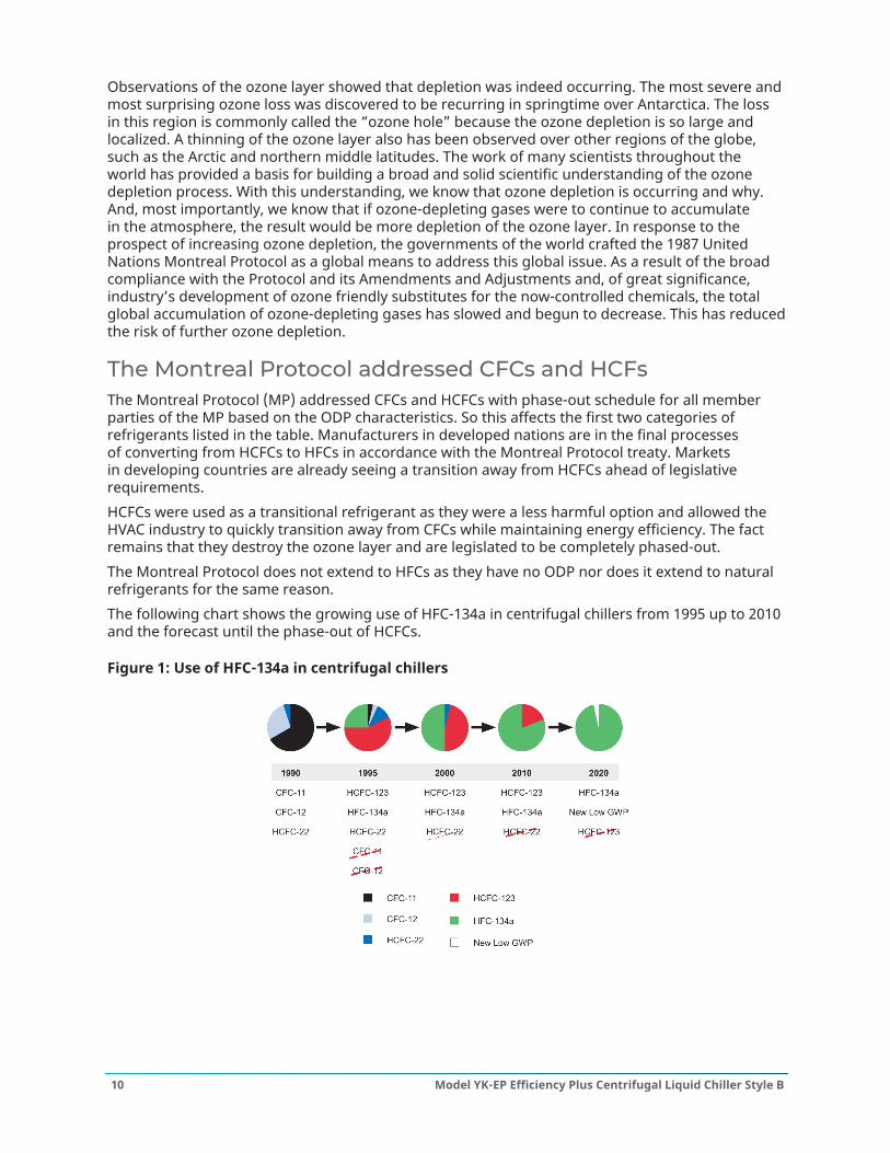
The Montreal Protocol addressed CFCs and HCFsThe Montreal Protocol (MP) addressed CFCs and HCFCs with phase-out schedule for all memberparties of the MP based on the ODP characteristics. So this affects the first two categories ofrefrigerants listed in the table. Manufacturers in developed nations are in the final processesof converting from HCFCs to HFCs in accordance with the Montreal Protocol treaty. Marketsin developing countries are already seeing a transition away from HCFCs ahead of legislativerequirements.HCFCs were used as a transitional refrigerant as they were a less harmful option and allowed theHVAC industry to quickly transition away from CFCs while maintaining energy efficiency. The factremains that they destroy the ozone layer and are legislated to be completely phased-out.The Montreal Protocol does not extend to HFCs as they have no ODP nor does it extend to naturalrefrigerants for the same reason.The following chart shows the growing use of HFC-134a in centrifugal chillers from 1995 up to 2010and the forecast until the phase-out of HCFCs.
Figure 1: Use of HFC-134a in centrifugal chillers
Model YK-EP Efficiency Plus Centrifugal Liquid Chiller Style B10

Global warming potential (GWP)Another main environmental topic is Global Warming Potential (GWP), and when we talk aboutglobal warming we’re primarily talking about smoke stacks and tail pipes. 84% of GWP is attributedto CO2 emissions, while only about 2% is related to HFCs.However, when we talk about the direct impact our YORK YK-EP Centrifugal Chiller has on theenvironment we can make strides forward, like ensuring leak tight designs are created, andmanufacturers are working to reduce refrigerant charges as much as possible.
Figure 2: Global warming potential
Direct and indirect global warming potential98% of the global warming potential of a centrifugal chiller is from the indirect effect or thegreenhouse gases produced to generate the electricity to run the chiller. The YORK YK-EPcentrifugal chiller and its superior efficiency levels dramatically reduces the indirect GWP. 2% of theGWP is from the direct effect or release of the refrigerant gases into the atmosphere.Minimizing the total climatic impact (direct and indirect GWP) requires a comprehensive approachto refrigerant choice.However, when we talk about the direct impact the YORK YK-EP Centrifugal Chiller has on theenvironment we can make strides forward, like ensuring leak tight designs are created, andmanufacturers are working to reduce refrigerant charges as much as possible.
11Model YK-EP Efficiency Plus Centrifugal Liquid Chiller Style B
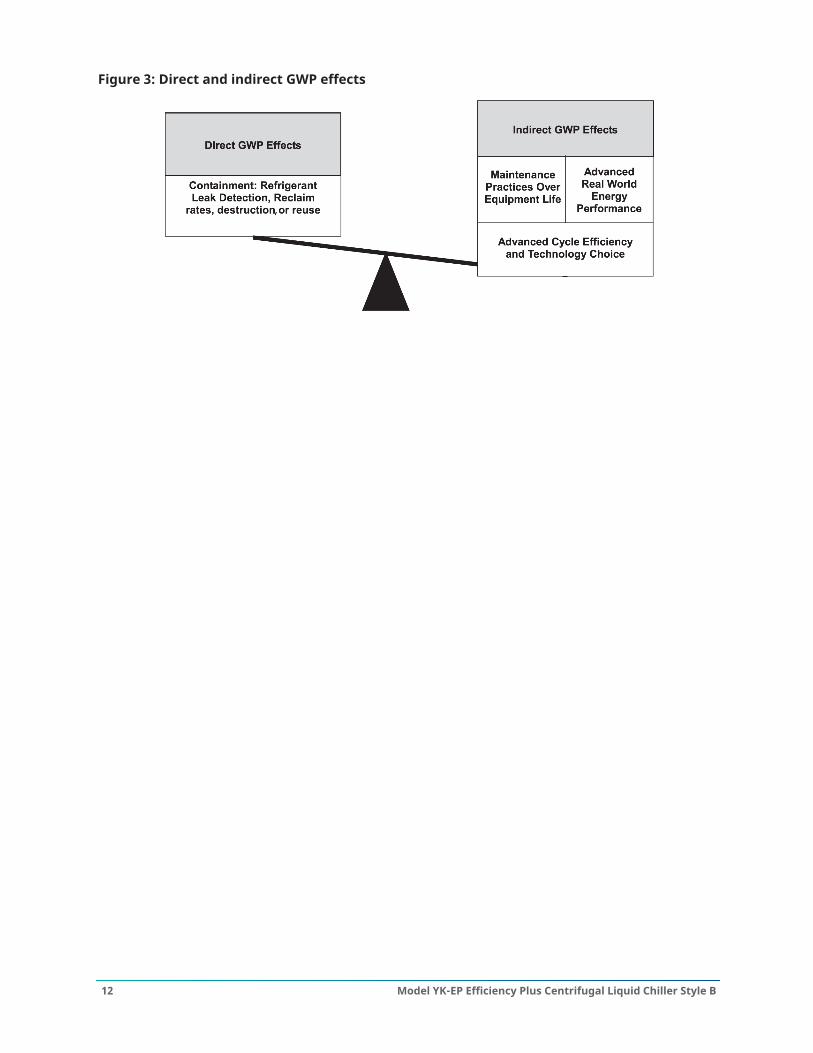
Figure 3: Direct and indirect GWP effects
Model YK-EP Efficiency Plus Centrifugal Liquid Chiller Style B12

Unit componentsFigure 4: Chiller front view
Component Description1 Primary Compressor2 Primary Open Drive Motor3 Lifting Hole4 Evaporator5 OptiView™ Control Panel6 Refrigerant Level Sight Glass7 Marine Waterboxes (Optional)8 Hot Gas Bypass (Optional)9 Economizer Open Drive Motor
10 Economizer Compressor
13Model YK-EP Efficiency Plus Centrifugal Liquid Chiller Style B
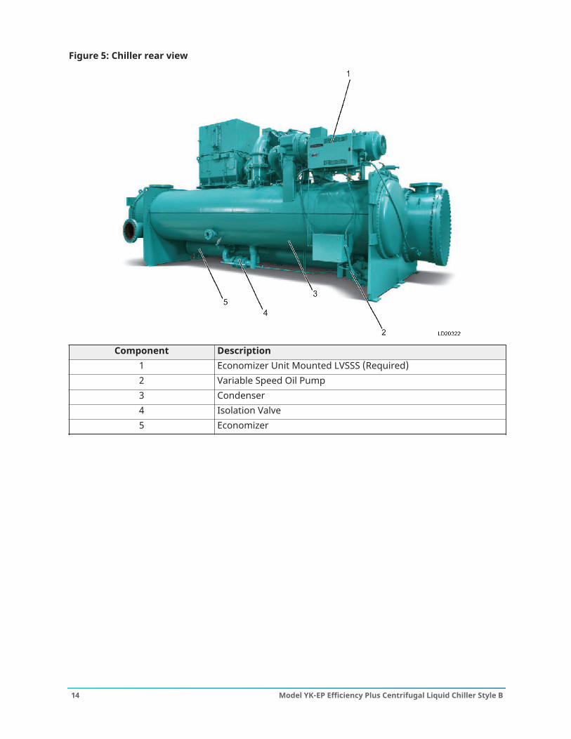
Figure 5: Chiller rear view
Component Description1 Economizer Unit Mounted LVSSS (Required)2 Variable Speed Oil Pump3 Condenser4 Isolation Valve5 Economizer
Model YK-EP Efficiency Plus Centrifugal Liquid Chiller Style B14
Equipment overview
GeneralYORK YK-EP Efficiency Plus Centrifugal Liquid Chillers can be factory-packaged including theevaporator, condenser, economizer, compressors, motors, lubrication system, control center,interconnecting unit piping, and wiring. The initial charge of refrigerant and oil is supplied for eachchiller, and is shipped separately from the unit. Actual shipping procedures depends on a numberof project-specific details.The services of a Johnson Controls factory-trained, field service representative are incurred tosupervise or perform the final leak testing, charging, the initial start-up, and concurrent operatorinstructions.Lubrication oil is force-fed to all bearings, gears and rotating surfaces by a variable speed drivepump, which operates before startup.
CompressorsTwo centrifugal compressors are provided, operating partially in parallel and discharging to acommon condenser on the chiller. Check valves are supplied on the discharge of the economizercompressor to control refrigerant flow during single compressor operation.Each of the YK-EP’s two compressors is a single-stage centrifugal type powered by an open-driveelectric motor. The casing is fully accessible with vertical circular joints and fabricated of close-graincast iron. The complete operating assembly is removable from the compressor and scroll housing.YK-EP uses the K7 compressor. As an alternative, a new compressor requiring a special quotewith the nomenclature KS is offered, yielding two major benefits. One modification improvesperformance characteristics while the other reduces pressure in high head applications.The rotor assembly consists of a heat-treated alloy steel drive shaft and impeller shaft with a highstrength, cast aluminum alloy, fully shrouded impeller. The impeller is designed for balanced thrustand is dynamically balanced and overspeed tested for smooth, vibration free operation.The insert-type journal and thrust bearings are fabricated of aluminum alloy and are precisionbored and axially grooved. The specially engineered, single helical gears with crowned teeth aredesigned so that more than one tooth is in contact at all times to provide even distribution ofcompressor load and quiet operation. Gears are integrally assembled in the compressor rotorsupport and are film lubricated. Each gear is individually mounted in its own journal and thrustbearings to isolate it from impeller and motor forces.
OptiSound™ controlThe YORK OptiSound™ Control is a patented combination of centrifugal chiller hardware andsoftware that reduces operational sound levels, expands the chiller operating range, and improveschiller performance. The OptiSound Control feature continuously monitors the characteristics ofthe compressor discharge gas and optimizes the diffuser spacing to minimize gas-flow disruptionsfrom the impeller. This innovative technology improves operating sound levels of the chiller anaverage of 7 dBA, and up to 13 dBA on the largest models, far superior to competitors' soundlevels. It can also reduce part-load sound levels below the full-load level.In addition, the OptiSound Control provides the benefit of an expanded operating range. Itimproves performance and reliability by minimizing diffuser gas stall at off design operation,particularly conditions of very low load combined with little or no condenser water relief. Theelimination of the gas stall condition can also result in improved chiller efficiency at off designconditions.
15Model YK-EP Efficiency Plus Centrifugal Liquid Chiller Style B
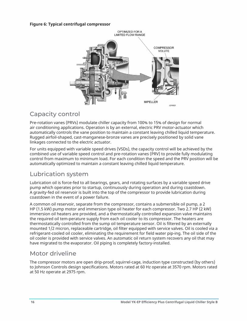
Figure 6: Typical centrifugal compressor
Capacity controlPre-rotation vanes (PRVs) modulate chiller capacity from 100% to 15% of design for normalair conditioning applications. Operation is by an external, electric PRV motor-actuator whichautomatically controls the vane position to maintain a constant leaving chilled liquid temperature.Rugged airfoil-shaped, cast-manganese-bronze vanes are precisely positioned by solid vanelinkages connected to the electric actuator.For units equipped with variable speed drives (VSDs), the capacity control will be achieved by thecombined use of variable speed control and pre-rotation vanes (PRV) to provide fully modulatingcontrol from maximum to minimum load. For each condition the speed and the PRV position will beautomatically optimized to maintain a constant leaving chilled liquid temperature.
Lubrication systemLubrication oil is force-fed to all bearings, gears, and rotating surfaces by a variable speed drivepump which operates prior to startup, continuously during operation and during coastdown.A gravity-fed oil reservoir is built into the top of the compressor to provide lubrication duringcoastdown in the event of a power failure.A common oil reservoir, separate from the compressor, contains a submersible oil pump, a 2HP (1.5 kW) pump motor and immersion type oil heater for each compressor. Two 2.7 HP (2 kW)immersion oil heaters are provided, and a thermostatically controlled expansion valve maintainsthe required oil temperature supply from each oil cooler to its compressor. The heaters arethermostatically controlled from the sump oil temperature sensor. Oil is filtered by an externallymounted 1/2 micron, replaceable cartridge, oil filter equipped with service valves. Oil is cooled via arefrigerant-cooled oil cooler, eliminating the requirement for field water piping. The oil side of theoil cooler is provided with service valves. An automatic oil return system recovers any oil that mayhave migrated to the evaporator. Oil piping is completely factory-installed.
Motor drivelineThe compressor motors are open drip-proof, squirrel-cage, induction type constructed (by others)to Johnson Controls design specifications. Motors rated at 60 Hz operate at 3570 rpm. Motors ratedat 50 Hz operate at 2975 rpm.
Model YK-EP Efficiency Plus Centrifugal Liquid Chiller Style B16

The open motors are provided with a D-flange, and are factory-mounted to a cast iron adaptermounted on the compressor. This unique design allows the motor to be rigidly coupled to thecompressor to provide factory alignment of motor and compressor shafts.The motor drive shaft is directly connected to the compressor shaft with a flexible disc coupling.The coupling is of all metal construction with no wearing parts to assure long life, and nolubrication requirements to provide low maintenance.A large, steel terminal box with a gasketed front access cover is provided on each motor for field-connected conduit. There are six terminals (three for medium voltage) brought through the motorcasing into the terminal box. Jumpers are furnished for three-lead types of starting. Motor terminallugs are not furnished. Overload/over current transformers are furnished with remote mountedelectromechanical starters only. For chillers supplied with solid state starters or variable speeddrives, the current transformers are supplied inside the starter/drive panels.
Flash economizer (intercooler)The flash economizer (intercooler) is a single-stage type, consisting of a horizontal pressure vesselwith internally mounted baffles and liquid spray pipe, an externally mounted level transmitterlocated with a liquid level pipe assembly and an external control valve mounted in the liquid outletto the evaporator. Refrigerant from the condenser, after expanding through the condenser levelcontrol valve, enters through the internal spray pipe, where flash gas is removed and channeledthrough baffles, out the top and on to the economizer compressor section. The remaining liquidfeeds out of the economizer through a liquid level control valve to the evaporator.
Heat exchangersShells - Evaporator and condenser shells are fabricated from rolled carbon steel plates with fusionwelded seams. Carbon steel tube sheets, drilled and reamed to accommodate the tubes, arewelded to the end of each shell. Intermediate tube supports are fabricated from carbon steelplates, drilled and reamed to eliminate sharp edges, and spaced no more than 4 ft (1.2 m) apart.The refrigerant side of each shell is designed, tested, and stamped in accordance with ASME Boilerand Pressure Vessel Code, Section VIII – Division I, or other pressure vessel code as appropriate.Tubes - Heat exchanger tubes are state-of-the-art, high-efficiency, internally and externallyenhanced type to provide optimum performance. Tubes in both the evaporator and condenserare 3/4 in. (19 mm) O.D. standard or 1 in. (25.4 mm) O.D. copper alloy and utilize the “skip-fin”design, providing a smooth internal and external surface at each intermediate tube support. Thisprovides extra wall thickness (nearly twice as thick) and non work-hardened copper at the supportlocation, extending the life of the heat exchangers. Each tube is roller expanded into the tubesheets providing a leak-proof seal, and is individually replaceable.Evaporator - The evaporator is a shell-and-tube, flooded-type heat exchanger. A distributortrough provides uniform distribution of refrigerant over the entire shell length to yield optimumheat transfer. Aluminum mesh eliminators are located above the tube bundle to prevent liquidrefrigerant carry over into the compressor. A 2 1/4 in. (57 mm) diameter liquid level sight glass isconveniently located on the side of the shell to aid in determining proper refrigerant charge. Theevaporator shell contains a dual refrigerant relief valve arrangement set at 180 psig (1.34 MPa). A 1in. (25.4 mm) refrigerant charging valve is provided.Condenser - The condenser is a shell-and-tube type, with a discharge gas baffle to prevent directhigh velocity impingement on the tubes. The diffusers provide dynamic pressure recovery andenhanced chiller efficiency. An integral subcooler is located at the bottom of the condensershell providing highly effective liquid refrigerant subcooling for the highest cycle efficiency. Thecondenser contains dual refrigerant relief valves set at 235 psig (1.72 MPa). A 4 in. (102 mm)liquid level sight glass is conveniently located on the side of the shell to aid in determining properrefrigerant charge.
17Model YK-EP Efficiency Plus Centrifugal Liquid Chiller Style B

Waterboxes - Standard waterboxes are compact type and fabricated of steel. The design workingpressure is 150 psig (1.14 MPa) and are tested at 225 psig (1.65 MPa). Integral steel water bafflesare located and welded within the waterbox to provide the required pass arrangements. Stub-outwater nozzle connections with ANSI/AWWA C-606 couplings grooves are welded to the waterboxes.These nozzle connections are suitable for ANSI/AWWA C-606 couplings, welding or flanges, andare capped for shipment. Plugged 3/4 in. (19mm) drain and vent connections are provided in eachwaterbox, except for marine waterboxes with vertical nozzles where there are drain connectionsonly. Although compact waterboxes are installed on standard units, marine waterboxes areavailable. See the Accessories and modifications section for details.
Refrigerant conversion to a low GWP - HFOCustomers can purchase YK-EP Style B chillers using HFC-134a now. In the future, this refrigerantcan be replaced by a low GWP, non-flammable, and A1 Toxicity classification one (HFO-513A orR-513A), if necessary during the chiller’s life cycle. No hardware modification is necessary; just anew OptiView software version updated for this refrigerant is required.
Refrigerant flow controlRefrigerant flow to the evaporator is controlled by the economizer level control. Liquid refrigerantlevel is continuously monitored to provide optimum subcooler, condenser, and evaporatorperformance. The economizer level control electronically adjusts to all real-world operatingconditions, providing the most efficient and reliable operation of refrigerant flow control.
Refrigerant isolation valvesFactory-installed isolation valves in the compressor discharge line and refrigerant liquid line areavailable for the chiller. This allows isolation and storage of the refrigerant charge in the chillercondenser during servicing, eliminating time-consuming transfers to remote storage vessels. Bothvalves are positive shut-off, assuring integrity of the storage system.
Isolation mountingThe unit is provided with eight vibration isolation mounts of nominal 1 in. (25 mm) operatingheight. The pads have a neoprene pad to contact the foundation, bonded to a steel plate. Thevibration isolation pads assemblies mount under steel plates affixed to the chiller tube sheets.
Refrigerant containmentThe standard unit is designed as a complete and compact factory-packaged chiller. It has minimumjoints from which refrigerant can leak. The entire assembly is thoroughly leak tested at the factorybefore shipment. The YORK YK-EP chiller includes accessible service valves that facilitate transfer ofrefrigerant to a remote refrigerant storage/recycling system.
PaintExterior surfaces are protected with one coat of Caribbean blue, durable alkyd modified, vinylenamel, and machinery paint.
ShipmentYORK YK-EP centrifugal chillers are designed to keep installation costs low. YK-EP chillers can beshipped using Form 2, Form 3, or Form 7 shipment methods.
• Form 2 shipment allows the chiller to be shipped completely packaged as one assembly andsaves on installation time.
Model YK-EP Efficiency Plus Centrifugal Liquid Chiller Style B18
• Form 3 shipment requires the two drive lines to ship separate from the shells as three majorassemblies.
• Form 7 shipment, for more complex installations, ensures the two drivelines, evaporator, andcondenser shells are split apart into four major assemblies.
In all three shipping methods, refrigerant and oil charges are shipped separately, connections areclosed/flanged, wiring connections are simple plug-type to ensure simple commissioning using astarter, and heat exchanger refrigerant sides are charged with nitrogen.
Water flow switchesThermal-type water flow switches are factory mounted in the evaporator and condenser waternozzles, and are factory wired to the control panel. These solid state flow sensors have a smallinternal heating element. They use the cooling effect of the flowing fluid to detect when anadequate flow rate is established. The sealed sensor probe is 316 stainless steel, which is suited tohigh working pressures.
19Model YK-EP Efficiency Plus Centrifugal Liquid Chiller Style B
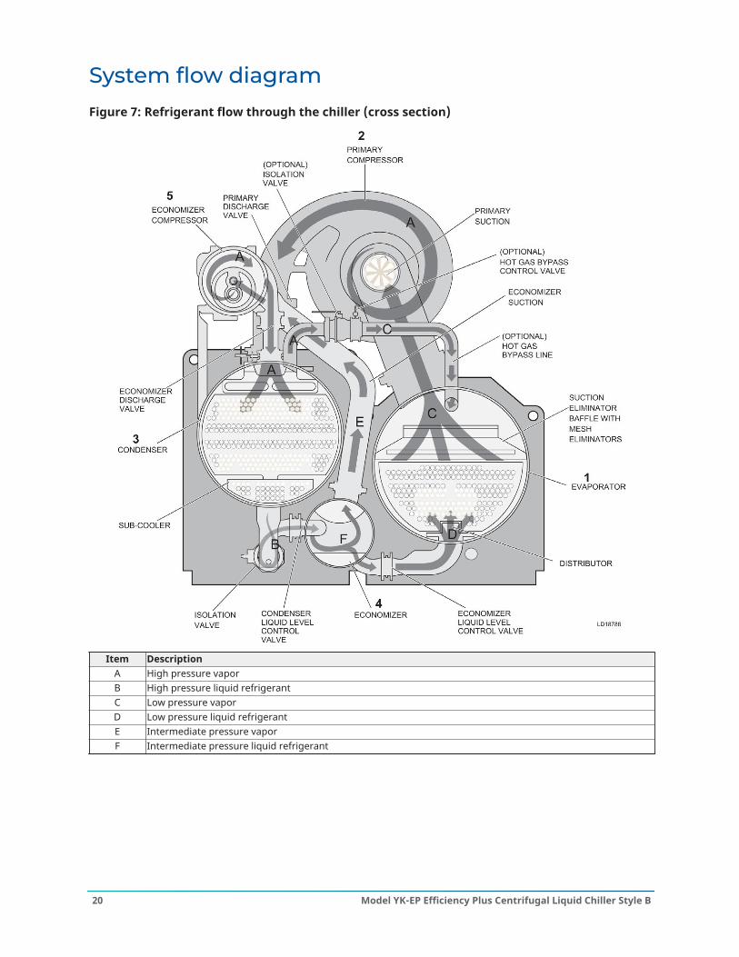
System flow diagramFigure 7: Refrigerant flow through the chiller (cross section)
Item DescriptionA High pressure vaporB High pressure liquid refrigerantC Low pressure vaporD Low pressure liquid refrigerantE Intermediate pressure vaporF Intermediate pressure liquid refrigerant
Model YK-EP Efficiency Plus Centrifugal Liquid Chiller Style B20
How it worksThe YORK YK-EP chiller operates much the same as the YORK YK Single Stage chiller. The onlyexception is a small economizer loop to compress partially expanded gas to extend capacity andimprove efficiency.Step 1. EvaporatorLiquid refrigerant (R-134a) flows into the evaporator and is distributed to contact a bundle of tubesthat carry the chilled liquid for the system. The low pressure liquid refrigerant absorbs heat fromthe chilled liquid causing the refrigerant to boil. The boiled refrigerant rises to the top of the tubebundle as vapor and passes through a mesh pad that prevents liquid refrigerant droplets frombeing drawn into the compressor.
Step 2. Primary CompressorThe refrigerant vapor that has passed through the mesh pad is drawn up to the compressor.Centrifugal compression is used to pressurize the refrigerant and develop flow. The high pressurerefrigerant vapor is then discharged from the compressor to the condenser.
Step 3. CondenserThe high pressure refrigerant vapor is distributed across a bundle of tubes carrying cooling liquidin the condenser. The high temperature and high pressure refrigerant vapor rejects heat to thecooling liquid that is passing through the tubes. The cooling liquid will generally later reject itsheat to the environment in a cooling tower. When the refrigerant vapor gives up its heat to thecooling liquid, it condenses on the outside of the tubes and drips down to the sub-cooler. The liquidrefrigerant passes through the sub-cooler where it rejects some more heat to the cooling liquid asthe refrigerant temperature is reduced.
Step 4. Expansion And EconomizerThe refrigerant liquid from the condenser is partially expanded to a pressure intermediate tothe evaporator and condenser. The partially expanded two phase refrigerant is separated toliquid and vapor streams in the economizer. The liquid stream is expanded a second time torepeat the cycle in the evaporator. The vapor stream is drawn out of the economizer by theeconomizer compressor. Note that the quality of refrigerant delivered to the evaporator, as a resultof economizing, extends the refrigerating effect of the flow through the evaporator and primarycompressor.
Step 5. Economizer CompressorThe economizer compressor draws the refrigerant vapor from the economizer. The efficiencybenefit of the cycle is a result of not having to compress this gas over the full head of the chillersystem. As in the primary compressor, centrifugal compression is used to pressurize the refrigerantand develop flow. The high pressure vapor refrigerant is then discharged from the economizercompressor to the condenser.
21Model YK-EP Efficiency Plus Centrifugal Liquid Chiller Style B

Figure 8: Refrigerant instrumentation diagram
Model YK-EP Efficiency Plus Centrifugal Liquid Chiller Style B22
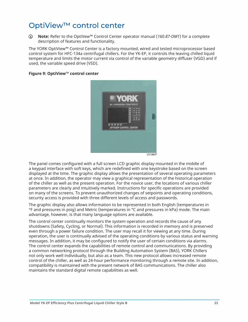
OptiView™ control centerNote: Refer to the OptiVew™ Control Center operator manual (160.87-OM1) for a completedescription of features and functionality.
The YORK OptiView™ Control Center is a factory mounted, wired and tested microprocessor basedcontrol system for HFC-134a centrifugal chillers. For the YK-EP, it controls the leaving chilled liquidtemperature and limits the motor current via control of the variable geometry diffuser (VGD) and ifused, the variable speed drive (VSD).
Figure 9: OptiView™ control center
The panel comes configured with a full screen LCD graphic display mounted in the middle ofa keypad interface with soft keys, which are redefined with one keystroke based on the screendisplayed at the time. The graphic display allows the presentation of several operating parametersat once. In addition, the operator may view a graphical representation of the historical operationof the chiller as well as the present operation. For the novice user, the locations of various chillerparameters are clearly and intuitively marked. Instructions for specific operations are providedon many of the screens. To prevent unauthorized changes of setpoints and operating conditions,security access is provided with three different levels of access and passwords.The graphic display also allows information to be represented in both English (temperatures in°F and pressures in psig) and Metric (temperatures in °C and pressures in kPa) mode. The mainadvantage, however, is that many language options are available.The control center continually monitors the system operation and records the cause of anyshutdowns (Safety, Cycling, or Normal). This information is recorded in memory and is preservedeven through a power failure condition. The user may recall it for viewing at any time. Duringoperation, the user is continually advised of the operating conditions by various status and warningmessages. In addition, it may be configured to notify the user of certain conditions via alarms.The control center expands the capabilities of remote control and communications. By providinga common networking protocol through the Building Automation System (BAS), YORK Chillersnot only work well individually, but also as a team. This new protocol allows increased remotecontrol of the chiller, as well as 24-hour performance monitoring through a remote site. In addition,compatibility is maintained with the present network of BAS communications. The chiller alsomaintains the standard digital remote capabilities as well.
23Model YK-EP Efficiency Plus Centrifugal Liquid Chiller Style B
Both of these remote control capabilities allow for the standard Energy Management System (EMS)interface:
1. Remote Run/Stop2. Remote Leaving Chilled Liquid Temperature Setpoint adjustment (0 VDC to 10 VDC, 2 VDC to
10 VDC, 0 mA to 20 mA, or 4 mA to 20 mA) or Pulse Width Modulation3. Remote Current Limit Setpoint adjustment (0 VDC to 10 VDC, 2 VDC to 10 VDC, 0 mA to 20 mA,
or 4 mA to 20 mA) or Pulse Width Modulation4. Remote READY TO START Contacts5. Safety Shutdown Contacts6. Cycling Shutdown Contacts
The following are few examples of the information displayed on some of the more importantscreens:
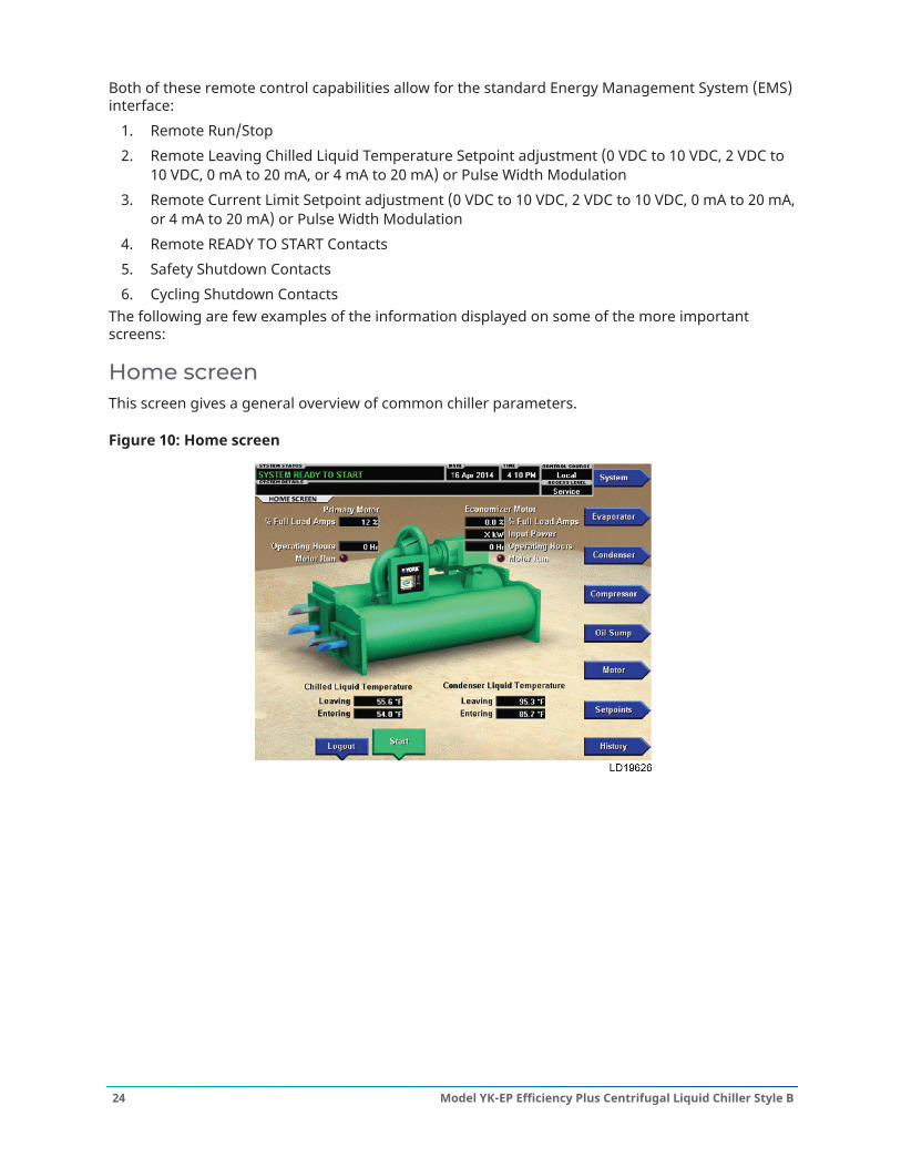
Home screenThis screen gives a general overview of common chiller parameters.
Figure 10: Home screen
Model YK-EP Efficiency Plus Centrifugal Liquid Chiller Style B24
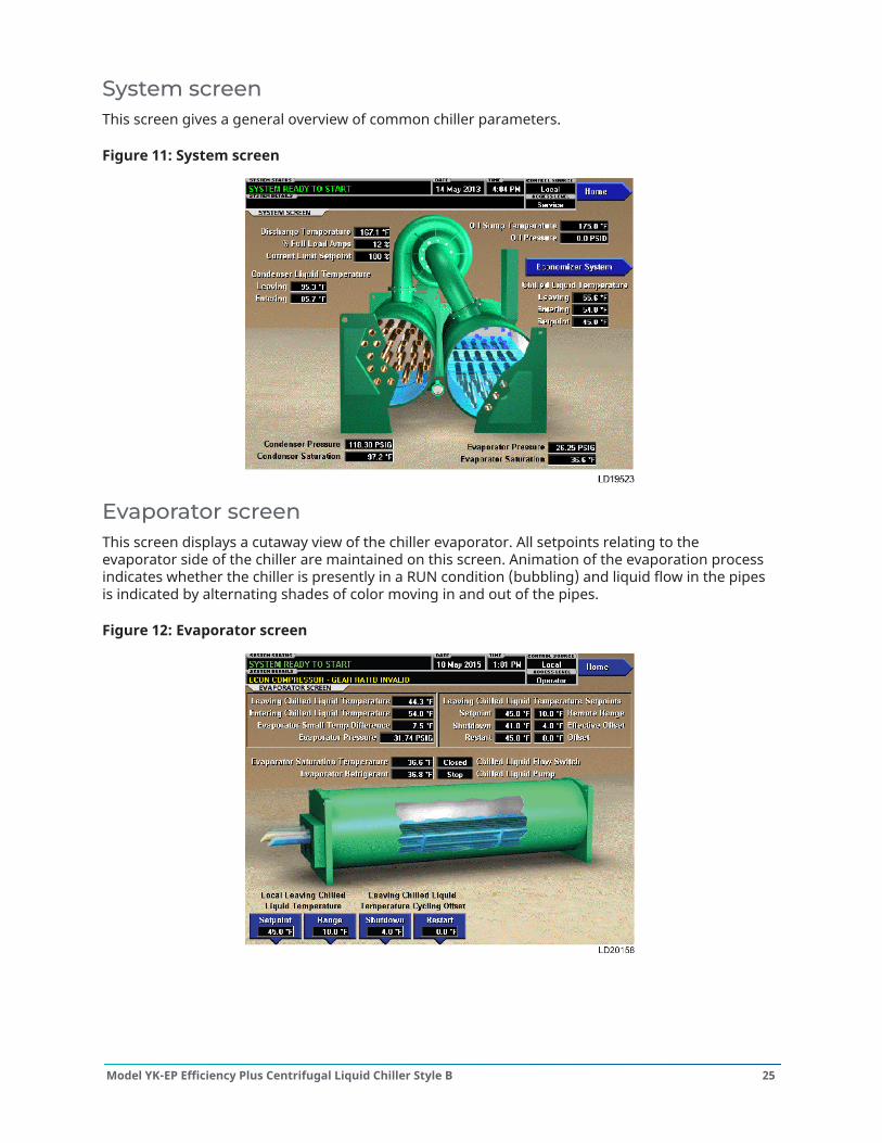
System screenThis screen gives a general overview of common chiller parameters.
Figure 11: System screen
Evaporator screenThis screen displays a cutaway view of the chiller evaporator. All setpoints relating to theevaporator side of the chiller are maintained on this screen. Animation of the evaporation processindicates whether the chiller is presently in a RUN condition (bubbling) and liquid flow in the pipesis indicated by alternating shades of color moving in and out of the pipes.
Figure 12: Evaporator screen
25Model YK-EP Efficiency Plus Centrifugal Liquid Chiller Style B

Condenser screenThis screen displays a cutaway view of the chiller condenser. All setpoints relating to the condenserside of the chiller are maintained on this screen. Animation indicates condenser liquid flow.
Figure 13: Condenser screen
Economizer system screenThis screen displays a cutaway of the chiller economizer.
Figure 14: Economizer system screen
Model YK-EP Efficiency Plus Centrifugal Liquid Chiller Style B26
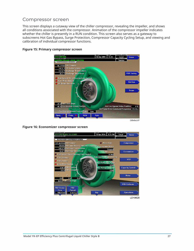
Compressor screenThis screen displays a cutaway view of the chiller compressor, revealing the impeller, and showsall conditions associated with the compressor. Animation of the compressor impeller indicateswhether the chiller is presently in a RUN condition. This screen also serves as a gateway tosubscreens Hot Gas Bypass, Surge Protection, Compressor Capacity Cycling Setup, and viewing andcalibration of individual compressor functions.
Figure 15: Primary compressor screen
Figure 16: Economizer compressor screen
27Model YK-EP Efficiency Plus Centrifugal Liquid Chiller Style B
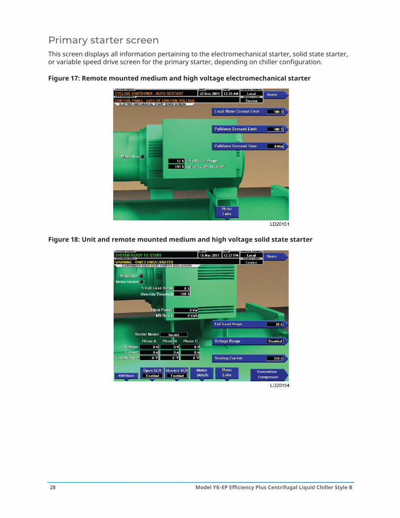
Primary starter screenThis screen displays all information pertaining to the electromechanical starter, solid state starter,or variable speed drive screen for the primary starter, depending on chiller configuration.
Figure 17: Remote mounted medium and high voltage electromechanical starter
Figure 18: Unit and remote mounted medium and high voltage solid state starter
Model YK-EP Efficiency Plus Centrifugal Liquid Chiller Style B28
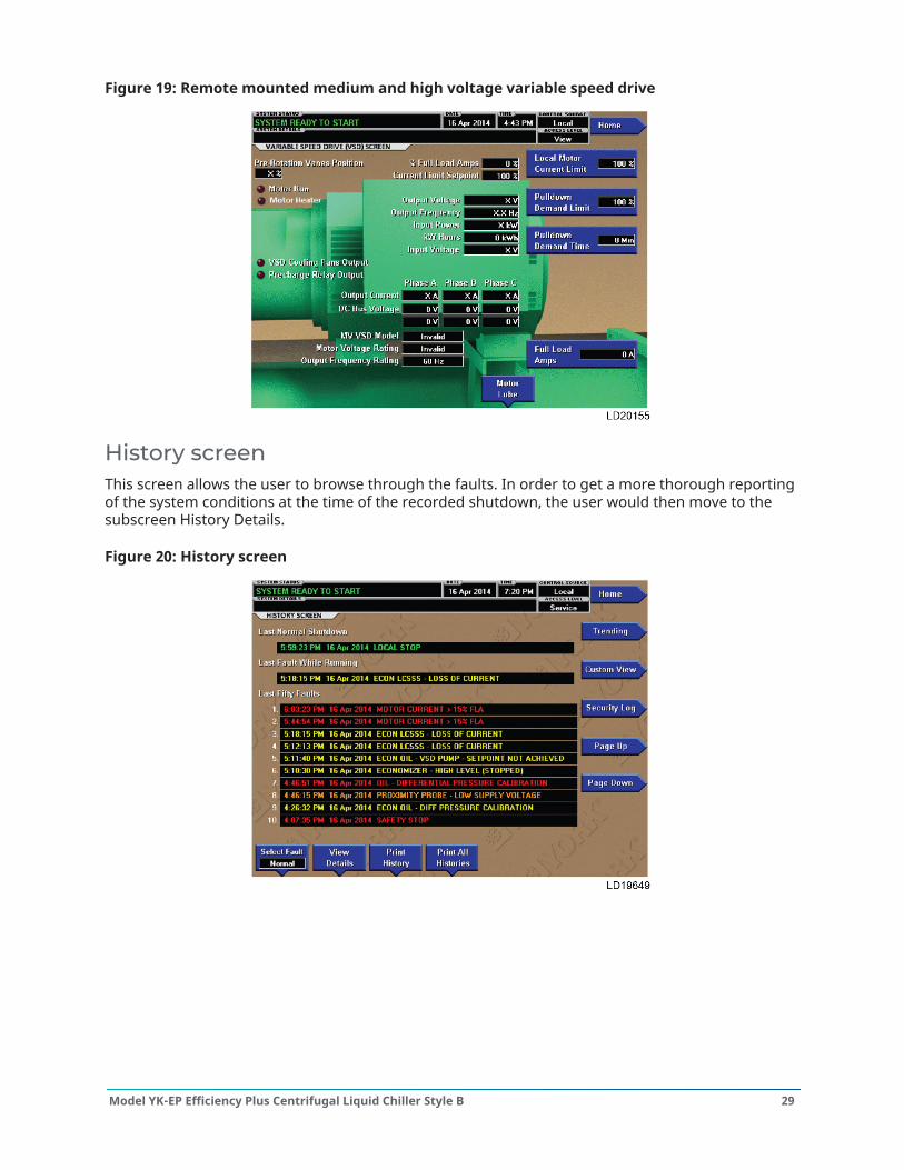
Figure 19: Remote mounted medium and high voltage variable speed drive
History screenThis screen allows the user to browse through the faults. In order to get a more thorough reportingof the system conditions at the time of the recorded shutdown, the user would then move to thesubscreen History Details.
Figure 20: History screen
29Model YK-EP Efficiency Plus Centrifugal Liquid Chiller Style B
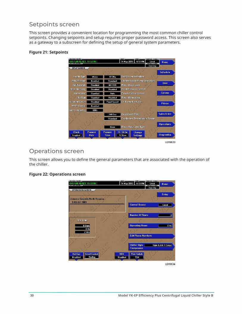
Setpoints screenThis screen provides a convenient location for programming the most common chiller controlsetpoints. Changing setpoints and setup requires proper password access. This screen also servesas a gateway to a subscreen for defining the setup of general system parameters.
Figure 21: Setpoints
Operations screenThis screen allows you to define the general parameters that are associated with the operation ofthe chiller.
Figure 22: Operations screen
Model YK-EP Efficiency Plus Centrifugal Liquid Chiller Style B30
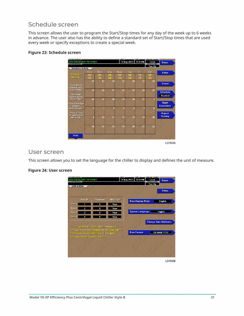
Schedule screenThis screen allows the user to program the Start/Stop times for any day of the week up to 6 weeksin advance. The user also has the ability to define a standard set of Start/Stop times that are usedevery week or specify exceptions to create a special week.
Figure 23: Schedule screen
User screenThis screen allows you to set the language for the chiller to display and defines the unit of measure.
Figure 24: User screen
31Model YK-EP Efficiency Plus Centrifugal Liquid Chiller Style B

Sales order screenThis screen displays the order parameters. This information is loaded at the factory or by theinstallation/service technician.
Figure 25: Sales order screen
Trending screenOn this screen, up to six user-selected parameters selected from a list of over 140, can be plottedin a time line graph format. The graph can be customized to record points once every second up toonce every hour. There are two types of charts that can be created: a single or continuous screen.The single screen collects data for one screen width (450 data points across the X-axis) then stops.The continuous screen keeps collecting the data but the oldest data drops off the graph from left toright at the next data collection interval. For ease of identification, each plotted parameter, title, andassociated Y-axis labeling is color coordinated.
Figure 26: Trending screen
Model YK-EP Efficiency Plus Centrifugal Liquid Chiller Style B32
Starters and drives
Compressor motor starter and drivesThe YORK YK-EP is available with a variety of starter options for the primary compressor motor.The economizer compressor motor is always equipped with a unit mounted low voltage solid statestarter (LVSSS).Table 2: YORK YK-EP compressor motor starter options (primary)Starteroptions
Variable speeddrive (VSD) Solid state starter (SSS) Across-the-line
(EMS)Auto transformer(EMS)
Primary reactor(EMS)
Assembly Remote mounted Unitmounted Remote mounted Remote mounted Remote mounted Remote mounted
Voltage Medium/high Medium Medium/high Medium/high Medium/high Medium/high60 Hz 2300 to 13800 2300 or 4160 2300 to 13200 2300 to 13200 2300 to 13200 2300 to 1320050 Hz 3300 to 11000 3300 2300 to 11000 2300 to 11000 2300 to 11000 2300 to 11000
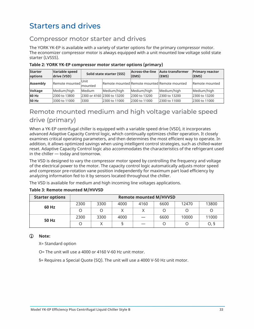
Remote mounted medium and high voltage variable speeddrive (primary)When a YK-EP centrifugal chiller is equipped with a variable speed drive (VSD), it incorporatesadvanced Adaptive Capacity Control logic, which continually optimizes chiller operation. It closelyexamines critical operating parameters, and then determines the most efficient way to operate. Inaddition, it allows optimized savings when using intelligent control strategies, such as chilled-waterreset. Adaptive Capacity Control logic also accommodates the characteristics of the refrigerant usedin the chiller — today and tomorrow.The VSD is designed to vary the compressor motor speed by controlling the frequency and voltageof the electrical power to the motor. The capacity control logic automatically adjusts motor speedand compressor pre-rotation vane position independently for maximum part load efficiency byanalyzing information fed to it by sensors located throughout the chiller.The VSD is available for medium and high incoming line voltages applications.Table 3: Remote mounted M/HVVSD
Starter options Remote mounted M/HVVSD2300 3300 4000 4160 6600 12470 13800
60 HzO O X X O O O
2300 3300 4000 — 6600 10000 1100050 Hz
O X § — O O O, §
Note:
X= Standard option
O= The unit will use a 4000 or 4160 V-60 Hz unit motor.
§= Requires a Special Quote (SQ). The unit will use a 4000 V-50 Hz unit motor.
33Model YK-EP Efficiency Plus Centrifugal Liquid Chiller Style B
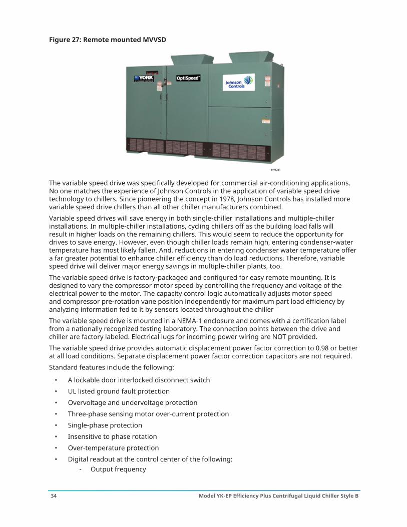
Figure 27: Remote mounted MVVSD
The variable speed drive was specifically developed for commercial air-conditioning applications.No one matches the experience of Johnson Controls in the application of variable speed drivetechnology to chillers. Since pioneering the concept in 1978, Johnson Controls has installed morevariable speed drive chillers than all other chiller manufacturers combined.Variable speed drives will save energy in both single-chiller installations and multiple-chillerinstallations. In multiple-chiller installations, cycling chillers off as the building load falls willresult in higher loads on the remaining chillers. This would seem to reduce the opportunity fordrives to save energy. However, even though chiller loads remain high, entering condenser-watertemperature has most likely fallen. And, reductions in entering condenser water temperature offera far greater potential to enhance chiller efficiency than do load reductions. Therefore, variablespeed drive will deliver major energy savings in multiple-chiller plants, too.The variable speed drive is factory-packaged and configured for easy remote mounting. It isdesigned to vary the compressor motor speed by controlling the frequency and voltage of theelectrical power to the motor. The capacity control logic automatically adjusts motor speedand compressor pre-rotation vane position independently for maximum part load efficiency byanalyzing information fed to it by sensors located throughout the chillerThe variable speed drive is mounted in a NEMA-1 enclosure and comes with a certification labelfrom a nationally recognized testing laboratory. The connection points between the drive andchiller are factory labeled. Electrical lugs for incoming power wiring are NOT provided.The variable speed drive provides automatic displacement power factor correction to 0.98 or betterat all load conditions. Separate displacement power factor correction capacitors are not required.Standard features include the following:
• A lockable door interlocked disconnect switch• UL listed ground fault protection• Overvoltage and undervoltage protection• Three-phase sensing motor over-current protection• Single-phase protection• Insensitive to phase rotation• Over-temperature protection• Digital readout at the control center of the following:
- Output frequency
Model YK-EP Efficiency Plus Centrifugal Liquid Chiller Style B34

- Three-phase output voltage- Three-phase output current- Input power (kW)- Self diagnostic service parameters- Kilowatt-hours (kWH)- Input kVa- Total power-factor- Three-phase input voltage- Three-phase input current- Self diagnostic service parameters
The remote mounted M/HVVSD delivers reliable operation and improves the off-designperformance. In case of 50 Hz countries, you can save more, reducing the initial cost, because theMVVSD will convert the frequency from 50 Hz to 60 Hz. As a result, the remote mounted M/HVVSDcan handle more amps with the same hardware. In addition, a potential lower cost is realized in4160 V (60 Hz) units versus 3300 V (50 Hz) units.The 24-pulse phase shifting isolation transformer provides protection for the drive. It also acts asa buffer between power line surges and acts as a filter to stop these disturbances from reachingsensitive electronic devices.The Johnson Controls transformer also protects the building’s electrical system from unlikely drivefailures which may cause a surge or disturbance on the line that is feeding the system.Johnson Controls’ front-end transformer also provides the ability to match incoming line voltage tothe motor voltage in use without further penalizing efficiency. Johnson Controls offers the widestinput voltage range for remote mounted M/HVVSD chillers in the industry, such as 11000 V, 12470V, or 13800 V.
Figure 28: Typical OptiSpeed medium-voltage drive from 3.3 kV and 4.16 kV input
35Model YK-EP Efficiency Plus Centrifugal Liquid Chiller Style B

Figure 29: Typical OptiSpeed high-voltage drive from 6.6 kV to 13.8 kV input
Table 4: Remote mounted HVVSDStarter type Advantages
Remote mountedHVVSD
• Lowest chiller life cycle through part load energy savings.
• Application-specific designs enable efficient, precise load control andseamless integration with equipment control panel and BAS.
• Soft start with input current less than full load current.
• Smooth acceleration reduces stresses on motor and driveline.
• Reduces compressor sound levels at most operating conditions.
• Rugged and reliable with no moving parts.
• Helps buildings comply with IEEE Std. 519. No optional filter needed.
• Multi-level PWM output closely simulates a true sine wave, allowingthe use of standard motors and bearings.
Model YK-EP Efficiency Plus Centrifugal Liquid Chiller Style B36
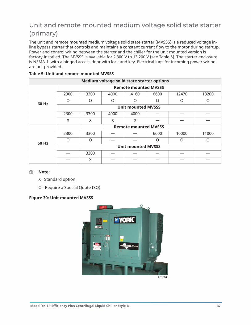
Unit and remote mounted medium voltage solid state starter(primary)The unit and remote mounted medium voltage solid state starter (MVSSS) is a reduced voltage in-line bypass starter that controls and maintains a constant current flow to the motor during startup.Power and control wiring between the starter and the chiller for the unit mounted version isfactory-installed. The MVSSS is available for 2,300 V to 13,200 V (see Table 5). The starter enclosureis NEMA-1, with a hinged access door with lock and key. Electrical lugs for incoming power wiringare not provided.Table 5: Unit and remote mounted MVSSS
Medium voltage solid state starter optionsRemote mounted MVSSS
2300 3300 4000 4160 6600 12470 13200O O O O O O O
Unit mounted MVSSS2300 3300 4000 4000 — — —
60 Hz
X X X X — — —Remote mounted MVSSS
2300 3300 — — 6600 10000 11000O O — — O O O
Unit mounted MVSSS— 3300 — — — — —
50 Hz
— X — — — — —
Note:
X= Standard option
O= Require a Special Quote (SQ)
Figure 30: Unit mounted MVSSS
37Model YK-EP Efficiency Plus Centrifugal Liquid Chiller Style B
Standard features include digital readout at the control center of the following:
• Display only- Three-phase input voltage- Three-phase current- Input Power (kW)- Killowatt-Hours (kWh)- Starter Model- Motor Run (LED)- Motor Current % Full Load Amps- Current Limit Setpoints- Pulldown Demand Time Left
• Programmable- Local Motor Current Limit- Pulldown Demand Limit- Pulldown Demand Time
Other features include the following:
• Low line voltage• 115 V control transformer• Three-leg motor current sensing overloads• Phase rotation and single-phase failure protection• High temperature safety protection• Motor current imbalance and under-voltage safeties• Open and shorted SCR protection• Momentary power interruption protection
The unit mounted MVSSS is air cooled generating about the same heat as an auto-transformer E-Mstarter. Ground fault protection and surge protection are also standard features. The 50,000 A shortcircuit withstand rating is in accordance with UL Standard 508.Table 6: Unit mounted MVSSSStarter type Advantages
Unit mounted MVSSS
• Smooth, controlled start profile.
• Unit mounted, factory wired and tested.
• Rugged and reliable with no moving parts.
• Application-specific designs enable seamless integration withequipment control panel and BAS.
Remote mounted medium and high voltageelectromechanical starter (primary)A remote mounted medium and high voltage electromechanical starter (M/HVEMS) for the primarycompressor motor is available, selected for proper size and type for job requirements and inaccordance with YORK Engineering Standard (R-1206) for Starters. The starter assembly hascontactor and accessories for controlling the primary compressor motor.
Model YK-EP Efficiency Plus Centrifugal Liquid Chiller Style B38
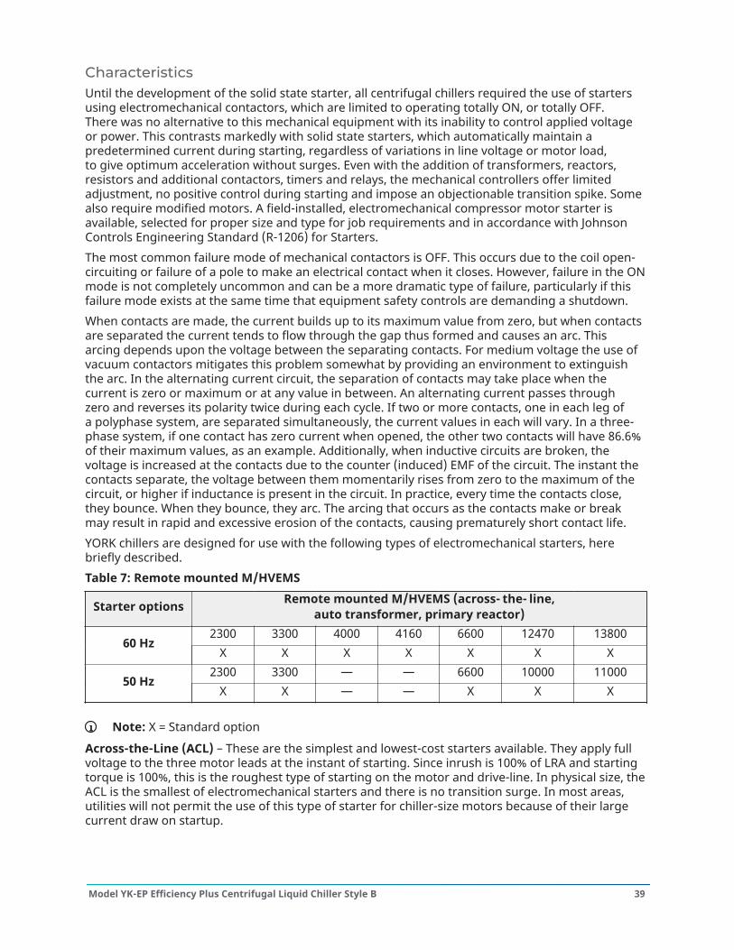
CharacteristicsUntil the development of the solid state starter, all centrifugal chillers required the use of startersusing electromechanical contactors, which are limited to operating totally ON, or totally OFF.There was no alternative to this mechanical equipment with its inability to control applied voltageor power. This contrasts markedly with solid state starters, which automatically maintain apredetermined current during starting, regardless of variations in line voltage or motor load,to give optimum acceleration without surges. Even with the addition of transformers, reactors,resistors and additional contactors, timers and relays, the mechanical controllers offer limitedadjustment, no positive control during starting and impose an objectionable transition spike. Somealso require modified motors. A field-installed, electromechanical compressor motor starter isavailable, selected for proper size and type for job requirements and in accordance with JohnsonControls Engineering Standard (R-1206) for Starters.The most common failure mode of mechanical contactors is OFF. This occurs due to the coil open-circuiting or failure of a pole to make an electrical contact when it closes. However, failure in the ONmode is not completely uncommon and can be a more dramatic type of failure, particularly if thisfailure mode exists at the same time that equipment safety controls are demanding a shutdown.When contacts are made, the current builds up to its maximum value from zero, but when contactsare separated the current tends to flow through the gap thus formed and causes an arc. Thisarcing depends upon the voltage between the separating contacts. For medium voltage the use ofvacuum contactors mitigates this problem somewhat by providing an environment to extinguishthe arc. In the alternating current circuit, the separation of contacts may take place when thecurrent is zero or maximum or at any value in between. An alternating current passes throughzero and reverses its polarity twice during each cycle. If two or more contacts, one in each leg ofa polyphase system, are separated simultaneously, the current values in each will vary. In a three-phase system, if one contact has zero current when opened, the other two contacts will have 86.6%of their maximum values, as an example. Additionally, when inductive circuits are broken, thevoltage is increased at the contacts due to the counter (induced) EMF of the circuit. The instant thecontacts separate, the voltage between them momentarily rises from zero to the maximum of thecircuit, or higher if inductance is present in the circuit. In practice, every time the contacts close,they bounce. When they bounce, they arc. The arcing that occurs as the contacts make or breakmay result in rapid and excessive erosion of the contacts, causing prematurely short contact life.YORK chillers are designed for use with the following types of electromechanical starters, herebriefly described.Table 7: Remote mounted M/HVEMS
Starter options Remote mounted M/HVEMS (across- the- line,auto transformer, primary reactor)
2300 3300 4000 4160 6600 12470 1380060 Hz
X X X X X X X2300 3300 — — 6600 10000 11000
50 HzX X — — X X X
Note: X = Standard option
Across-the-Line (ACL) – These are the simplest and lowest-cost starters available. They apply fullvoltage to the three motor leads at the instant of starting. Since inrush is 100% of LRA and startingtorque is 100%, this is the roughest type of starting on the motor and drive-line. In physical size, theACL is the smallest of electromechanical starters and there is no transition surge. In most areas,utilities will not permit the use of this type of starter for chiller-size motors because of their largecurrent draw on startup.
39Model YK-EP Efficiency Plus Centrifugal Liquid Chiller Style B
Auto-Transformer (AT) – These starters are reduced-voltage starters. Transformers are usedto step down the voltage to the motor during startup. The result is reduced inrush current andstarting torque at the level of 42% or 64% depending upon whether 65% or 80% voltage taps areused. They provide closed transition (with three-lead motors) with reduced line disturbance.Primary Reactor – These starters are reduced-voltage starters. Transformers are used to stepdown the voltage to the motor during startup. The result is reduced starting torque at the level of42% or 64%, but with reduced inrush current of 65% or 80% depending upon whether 65% or 80%voltage taps are used. They provide closed transition (with three-lead motors) with reduced linedisturbance.
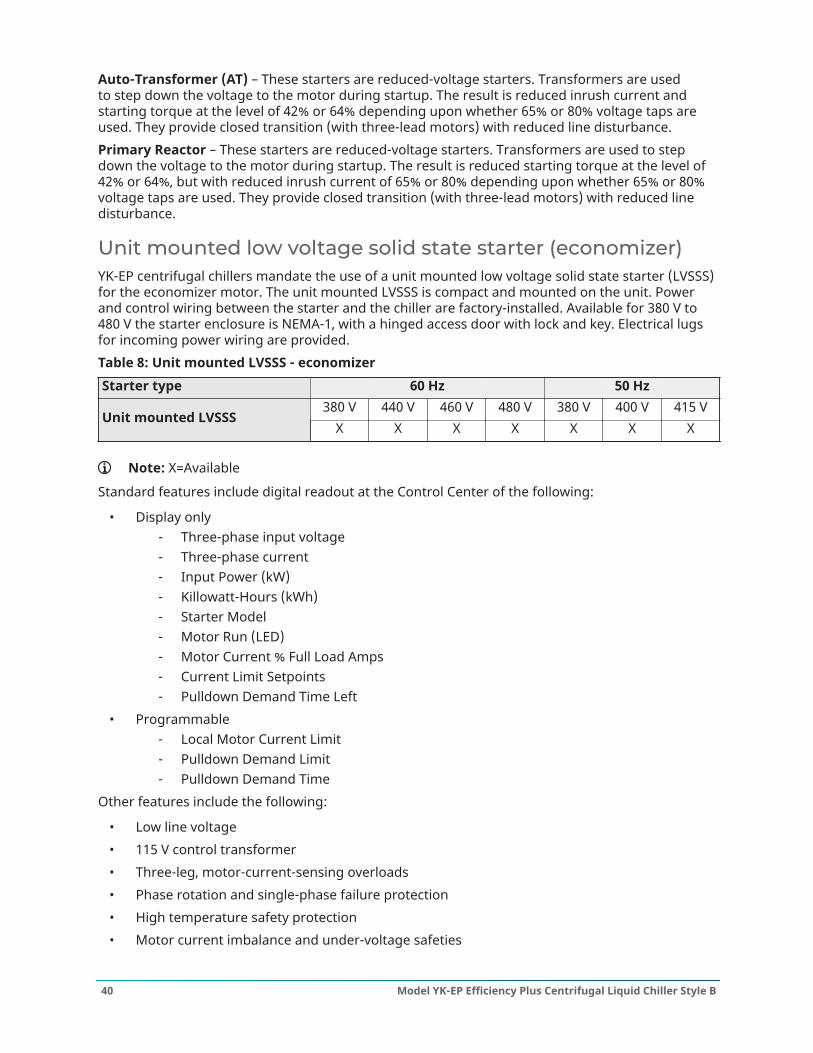
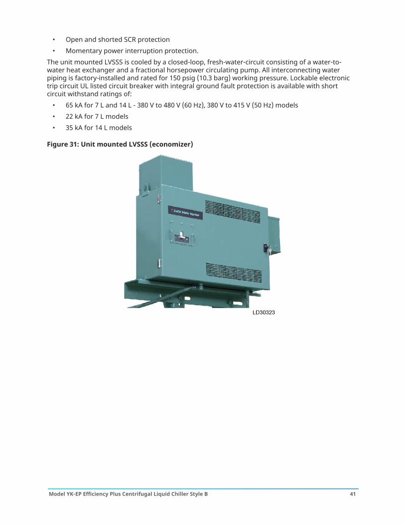
Unit mounted low voltage solid state starter (economizer)YK-EP centrifugal chillers mandate the use of a unit mounted low voltage solid state starter (LVSSS)for the economizer motor. The unit mounted LVSSS is compact and mounted on the unit. Powerand control wiring between the starter and the chiller are factory-installed. Available for 380 V to480 V the starter enclosure is NEMA-1, with a hinged access door with lock and key. Electrical lugsfor incoming power wiring are provided.Table 8: Unit mounted LVSSS - economizerStarter type 60 Hz 50 Hz
380 V 440 V 460 V 480 V 380 V 400 V 415 VUnit mounted LVSSS
X X X X X X X
Note: X=Available
Standard features include digital readout at the Control Center of the following:
• Display only- Three-phase input voltage- Three-phase current- Input Power (kW)- Killowatt-Hours (kWh)- Starter Model- Motor Run (LED)- Motor Current % Full Load Amps- Current Limit Setpoints- Pulldown Demand Time Left
• Programmable- Local Motor Current Limit- Pulldown Demand Limit- Pulldown Demand Time
Other features include the following:
• Low line voltage• 115 V control transformer• Three-leg, motor-current-sensing overloads• Phase rotation and single-phase failure protection• High temperature safety protection• Motor current imbalance and under-voltage safeties
Model YK-EP Efficiency Plus Centrifugal Liquid Chiller Style B40
• Open and shorted SCR protection• Momentary power interruption protection.
The unit mounted LVSSS is cooled by a closed-loop, fresh-water-circuit consisting of a water-to-water heat exchanger and a fractional horsepower circulating pump. All interconnecting waterpiping is factory-installed and rated for 150 psig (10.3 barg) working pressure. Lockable electronictrip circuit UL listed circuit breaker with integral ground fault protection is available with shortcircuit withstand ratings of:
• 65 kA for 7 L and 14 L - 380 V to 480 V (60 Hz), 380 V to 415 V (50 Hz) models• 22 kA for 7 L models• 35 kA for 14 L models
Figure 31: Unit mounted LVSSS (economizer)
41Model YK-EP Efficiency Plus Centrifugal Liquid Chiller Style B

Accessories and modifications
BAS remote controlA communication interface permitting an exchange of chiller data with a BACnet MS/TP, ModbusRTU, LONworks or N2 Metasys network is available with an optional E-Link
® Gateway. The Johnson
Controls E-Link Gateway mounts conveniently inside the Optiview™ panel and allows remote BASnetworks to monitor values and issue commands to the chiller to control operation.
Dual oil filterDual oil filters with a multi-port changeover valve and manual shutoff valves are optional to allowchanging of one filter while the chiller is operating.
Factory insulation of evaporatorFactory applied thermal insulation of the flexible, closed cell plastic type, 3/4 in. (19 mm) thick isattached with vapor proof cement to the evaporator shell, tube sheets, suction connection, and(as necessary) to the auxiliary tubing. Not included is the insulation of waterboxes and nozzles.This insulation will normally prevent condensation in environments with relative humidities up to75% and dry bulb temperatures ranging from 50°F to 90°F (10°C to 32.2°C). 1 1/2 in. (38 mm) thickinsulation is also available for relative humidities up to 90% and dry bulb temperatures rangingfrom 50°F to 90°F (10°C to 32.2°C).
Knock-down shipmentThe YORK YK-EP chiller can be shipped diassembled into major subassemblies (evaporator,condenser, driveline, etc.) as required to rig into tight spaces. This is particularly convenient forexisting buildings where equipment room access does not allow rigging a factory packaged chiller.
High ambient temperatureChiller modifications are available to allow for installation in areas where the ambients exceed122°F (50°C). Special drive motors are required above 104°F (40°C). Evaporator design pressuresmust be increased for ambient temperatures above 112.8°F (45°C). The control panel is suited for122°F (50°C) ambient. Unit mounted medium voltage solid state starters must be derated and/ormodified above 110°F (43.3°C). The remote mounted M/HVVSD and M/HVSSS options must be de-rated above its standard 104°F (40°C) limit.
High voltage motorsHigh voltage motors from 6000 V to 13800 V (60 Hz) and 6000 V to 11000 V (50 Hz) are available.
Hinges and davit armsHinges and/or davit arms are available to ease servicing the chiller. Hinges on the nozzle end of acompact waterbox still require that facility water piping be disconnected.
Marine waterboxesMarine waterboxes allow service access for cleaning of the heat exchanger tubes without the needto break the water piping. Bolted on covers are arranged for convenient access. ANSI/AWWA C-606couplings nozzle connections are standard; flanges are optional. Marine waterboxes are availablefor condenser and/or evaporator.
Model YK-EP Efficiency Plus Centrifugal Liquid Chiller Style B42
Refrigerant storage/recycling systemA refrigerant storage/recycling system is a self contained package consisting of a refrigerantcompressor with oil separator, storage receiver, water cooled condenser, filter drier, and thenecessary valves and hoses to remove, replace, and distill refrigerant. All necessary controls andsafety devices are a permanent part of the system.
Special motors enclosuresThere are job applications, primarily in manufacturing plants, and process applications, where moremotor protection is required. Listed below are several alternatives.
Note: Chiller certification to UL by a third party could be affected. Contact a Johnson Controlssales office for a specific selection.
Weather-protected type I motors (WP-I)A Weather-Protected Type I motor is an open machine with its ventilating passages constructed toprevent the passage of a cylindrical rod 3/4 in. in diameter. This affords protection against intrusionof rodents and some types of debris. These are regularly used in the pulp industry and where grimeis present.
Weather-protected type II motors (WP-II)A Weather-Protected Type II motor has, in addition to the enclosure defined for Weather-ProtectedType I motor, ventilating passages at both intake and exhaust sections. These passages arearranged so that high-velocity air and airborne particles, blown into the motor, can be dischargedwithout entering the internal ventilating passages that lead directly to the electric parts of themotor itself. Space heaters are required with WP-II.
Totally enclosed fan-cooled motors (TEFC)TEFC motors are used where the location is extremely dirty, dusty, or wet, both indoors andoutdoors. A totally enclosed fan-cooled unit is enclosed to prevent the free exchange of air betweenthe inside and outside of the case but not sufficiently enclosed as to be termed air-tight. It is air-cooled by means of a fully guarded fan blowing cooling air over the outside of the motor. The fan isexternally mounted on the motor shaft.
Totally enclosed air-to-air cooled (TEAAC)TEAAC motors are used when the environment is dirty or corrosive. A TEAAC motor is a totallyenclosed motor, cooled by circulating the internal air through an air-to-air heat exchanger.
Totally enclosed water-to-air cooled (TEWAC)TEWAC motors are used when the environment is dirty or corrosive, in hazardous areas, or whereminimum noise levels are required. A TEWAC motor is a totally enclosed machine which is cooledby circulating internal air which, in turn, is cooled by circulating water. It is provided with aninternal water-cooled heat exchanger for cooling the internal air. Fans, integral with the rotor shaft,circulate the internal air.
Spring isolation mountingSpring isolation mounting is available instead of standard isolation mounting pads when required.Four level adjusting, spring type vibration isolator assemblies with non skid pads are provided forfield installation. Isolators are designed for 1 in. (25 mm) deflection.
43Model YK-EP Efficiency Plus Centrifugal Liquid Chiller Style B
Tube and/or tube sheet materials and/or waterbox coatingCopper-nickel or titanium tubes can be provided in lieu of standard copper for condenser and/orevaporator for protection against aggressive water conditions. Tube sheets may be of the clad type.Epoxy or ceramic coating may be applied to waterboxes or to tubesheet and waterboxes.
Water flangesFour 150 psig (1.14 MPa) ANSI raised-face flanges for condenser and evaporator water connectionsare factory-welded to water nozzles. Companion flanges, bolts, nuts, and gaskets are not included.
Model YK-EP Efficiency Plus Centrifugal Liquid Chiller Style B44

Application dataThe following discussion is a user’s guide in the application and installation of YK-EP chillers toensure the reliable, trouble free life for which this equipment was designed. While this guide isdirected towards normal, water chilling applications, the Johnson Controls sales representative canprovide complete recommendations on other types of applications.
Brine applicationsVarious types of brine can be used in both the evaporator and condenser in lieu of water.The OptiView™ panel is programmed in the factory to allow extending the evaporator leavingbrine temperature setpoint below 36°F (2.2°C). The low evaporator pressure cutout is factoryprogrammed to the appropriate value depending on the percentage concentration and type ofbrine solution.When the chiller is not running, brine should not be flowing through the evaporator. However,if there is brine flowing through the evaporator, there must be flow through the condenser toprevent tubes from freezing. In brine applications, the condenser pump control will close whenthe condenser saturation temperature reaches 35°F (1.7°C) and the pump will shut off when thetemperature increases to 40°F (4.4°C). This is applicable if tied to the condenser pump control.
LocationYORK YK-EP chillers are virtually vibration free and may generally be located at any level in abuilding where the construction will support the total system operating weight.The unit site must be a floor, mounting pad, or foundation that is level within 1/4 in. (6.4 mm) andcan support the operating weight of the unit.Sufficient clearance to permit normal service and maintenance work must be provided all aroundand above the unit. Additional space should be provided at one end of the unit to permit cleaningof evaporator and condenser tubes as required. A doorway or other properly located opening maybe used.Install the chiller in an indoor location where temperatures range from 40°F to 104°F (4.4°C to40°C). The dew point temperature in the equipment room must be below the entering condenserwater temperature to prevent condensing water vapor inside of the unit mounted low and mediumvoltage solid state starter (L/MVSSS) cabinet (if applicable). Applications using cooling sourcesother than evaporative or closed loop air exchange methods need to request a factory-suppliedtemperature control valve to prevent condensation inside the unit mounted L/MVSSS cabinet (ifapplicable). Other areas susceptible to water vapor condensate are outside of the condenser shelland condenser waterboxes. Example applications include when the condenser water comes fromchilled water, wells, river, or other low temperature fluids.
Multiple unitsSelection - Many applications require multiple units to meet the total capacity requirements aswell as to provide flexibility and some degree of protection against equipment shutdown. Thereare several common unit arrangements for this type of application. The YK-EP chiller has beendesigned to be readily adapted to the requirements of these various arrangements.Parallel Arrangement - Chillers may be applied in multiples with chilled and condenser watercircuits connected in parallel between the units. Figure 32 represents a parallel arrangement withtwo chillers. Parallel chiller arrangements may consist of equally or unequally sized units. Whenmultiple units are in operation, they will load and unload at equal percentages of design full loadfor the chiller.
45Model YK-EP Efficiency Plus Centrifugal Liquid Chiller Style B

Figure 32: Parallel evaporators - Parallel condensers
S – Temperature sensor for chiller capacity controlT – Thermostat for chiller capacity control
Depending on the number of units and operating characteristics of the units, loading andunloading schemes should be designed to optimize the overall efficiency of the chiller plant. It isrecommended to use an evaporator bypass piping arrangement to bypass fluid around evaporatorof any unit which has cycled off at reduced load conditions. It is also recommended to alternate thechiller cycling order to equalize chiller starts and run hours.Series Arrangement - Chillers may be applied in pairs with chilled water circuits connected inseries and condenser water circuits connected in parallel. All of the chilled water flows throughboth evaporators with each unit handling approximately one half of the total load. When the loaddecreases to a customer selected load value, one of the units will be shut down by a sequencecontrol. Because all water is flowing through the operating unit, that unit will cool the water to therequired temperature. See Figure 33.
Figure 33: Series evaporators - Parallel condensers
Series Counter Flow Arrangement - Chillers may be applied in pairs with chilled water circuitsconnected in series and with the condenser water in series counter flow. All of the chilled waterflows through both evaporators. All of the condenser water flows through both condensers. Thewater ranges are split, which allows a lower temperature difference or “head” on each chiller,than multiple units in parallel. For equal chillers, the machine at higher temperature level willtypically provide slightly more than half the capacity. The compressor motors and gear codes onthe two chillers are often matched, such that the high temperature machine can operate at the lowtemperature conditions when one unit is cycled off at part loads (as compared to series-parallelchillers which are typically not identical). See Figure 34.
Model YK-EP Efficiency Plus Centrifugal Liquid Chiller Style B46
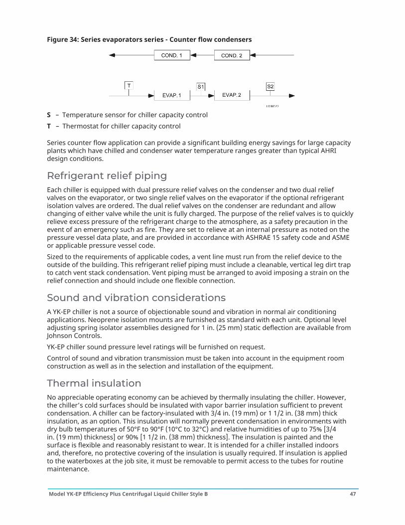
Figure 34: Series evaporators series - Counter flow condensers
S – Temperature sensor for chiller capacity controlT – Thermostat for chiller capacity control
Series counter flow application can provide a significant building energy savings for large capacityplants which have chilled and condenser water temperature ranges greater than typical AHRIdesign conditions.
Refrigerant relief pipingEach chiller is equipped with dual pressure relief valves on the condenser and two dual reliefvalves on the evaporator, or two single relief valves on the evaporator if the optional refrigerantisolation valves are ordered. The dual relief valves on the condenser are redundant and allowchanging of either valve while the unit is fully charged. The purpose of the relief valves is to quicklyrelieve excess pressure of the refrigerant charge to the atmosphere, as a safety precaution in theevent of an emergency such as fire. They are set to relieve at an internal pressure as noted on thepressure vessel data plate, and are provided in accordance with ASHRAE 15 safety code and ASMEor applicable pressure vessel code.Sized to the requirements of applicable codes, a vent line must run from the relief device to theoutside of the building. This refrigerant relief piping must include a cleanable, vertical leg dirt trapto catch vent stack condensation. Vent piping must be arranged to avoid imposing a strain on therelief connection and should include one flexible connection.
Sound and vibration considerationsA YK-EP chiller is not a source of objectionable sound and vibration in normal air conditioningapplications. Neoprene isolation mounts are furnished as standard with each unit. Optional leveladjusting spring isolator assemblies designed for 1 in. (25 mm) static deflection are available fromJohnson Controls.YK-EP chiller sound pressure level ratings will be furnished on request.Control of sound and vibration transmission must be taken into account in the equipment roomconstruction as well as in the selection and installation of the equipment.
Thermal insulationNo appreciable operating economy can be achieved by thermally insulating the chiller. However,the chiller’s cold surfaces should be insulated with vapor barrier insulation sufficient to preventcondensation. A chiller can be factory-insulated with 3/4 in. (19 mm) or 1 1/2 in. (38 mm) thickinsulation, as an option. This insulation will normally prevent condensation in environments withdry bulb temperatures of 50°F to 90°F (10°C to 32°C) and relative humidities of up to 75% [3/4in. (19 mm) thickness] or 90% [1 1/2 in. (38 mm) thickness]. The insulation is painted and thesurface is flexible and reasonably resistant to wear. It is intended for a chiller installed indoorsand, therefore, no protective covering of the insulation is usually required. If insulation is appliedto the waterboxes at the job site, it must be removable to permit access to the tubes for routinemaintenance.
47Model YK-EP Efficiency Plus Centrifugal Liquid Chiller Style B

VentilationThe ASHRAE Standard 15 Safety Code for Mechanical Refrigeration requires that all machineryrooms be vented to the outdoors utilizing mechanical ventilation by one or more power driven fans.This standard, plus National Fire Protection Association Standard 90A, state, local and any otherrelated codes should be reviewed for specific requirements. Since the YK-EP chiller motors are aircooled, ventilation should allow for the removal of heat from the motor.In addition, the ASHRAE Standard 15 requires a refrigerant vapor detector to be employed forall refrigerants. It must be located in an area where refrigerant from a leak would be likely toconcentrate. An alarm is to be activated and the mechanical ventilation started at a value nogreater than the TLV (Threshold Limit Value) of the refrigerant.
Water circuitsFlow rate - For normal water chilling duty, evaporator and condenser flow rates are permittedat water velocity levels in the heat exchangers tubes of between 3 ft/sec and 12 ft/sec (0.91 m/s and 3.66 m/s) for constant flow applications. Variable flow applications are possible, and initialchiller selections should be made accordingly to allow proper range of flow while maintainingthe minimum velocity indicated at the certified rating for the unit. Variable flow in the condenseris not recommended, as it generally raises the energy consumption of the system by keepingthe condenser pressure high in the chiller. Additionally, the rate of fouling in the condenser willincrease at lower water velocities associated with variable flow, raising system maintenance costs.Cooling towers typically have narrow ranges of operation with respect to flow rates, and will bemore effective with full design flow. See Table 9 for flow limits.Temperature ranges - For normal water chilling duty, leaving chilled water temperatures may beselected between 38°F (3.3°C) and 36°F (2.2°C) with Smart Freeze enabled] and 70°F (21.1°C) toobtain temperature deltas between entering chilled and leaving chilled water temperature of 3°F(1.7°C) up to 30°F (16.7°C).Water quality - The practical and economical application of liquid chillers requires that thequality of the water supply for the condenser and evaporator be analyzed by a water treatmentspecialist. Water quality may affect the performance of any chiller through corrosion, depositionof heat-resistant scale, sedimentation or organic growth. These will degrade chiller performanceand increase operating and maintenance costs. Normally, performance may be maintained bycorrective water treatment and periodic cleaning of tubes. If water conditions exist which cannot becorrected by proper water treatment, it may be necessary to provide a larger allowance for fouling,and/or to specify special materials of construction. Refer to the Application Guide 160.00-AD5 formore details.General piping - All chilled water and condenser water piping should be designed and installedin accordance with accepted piping practice. Chilled water and condenser water pumps shouldbe located to discharge through the chiller to assure positive pressure and flow through the unit.Piping should include offsets to provide flexibility and should be arranged to prevent drainageof water from the evaporator and condenser when the pumps are shut off. Piping should beadequately supported and braced independently of the chiller to avoid the imposition of strain onchiller components. Hangers must allow for alignment of the pipe. Isolators in the piping and in thehangers are highly desirable in achieving sound and vibration control.Convenience considerations - To facilitate the performance of routine maintenance work, someor all of the following steps may be taken by the purchaser. Evaporator and condenser waterboxesare equipped with plugged vent and drain connections, except for marine waterboxes with verticalnozzles where there are drain connections only. If required, vent and drain valves may be installedwith or without piping to an open drain. Pressure gauges with stopcocks and stop valves may beinstalled in the inlets and outlets of the condenser and chilled water line as close as possible to thechiller. An overhead monorail or beam may be used to facilitate servicing.
Model YK-EP Efficiency Plus Centrifugal Liquid Chiller Style B48
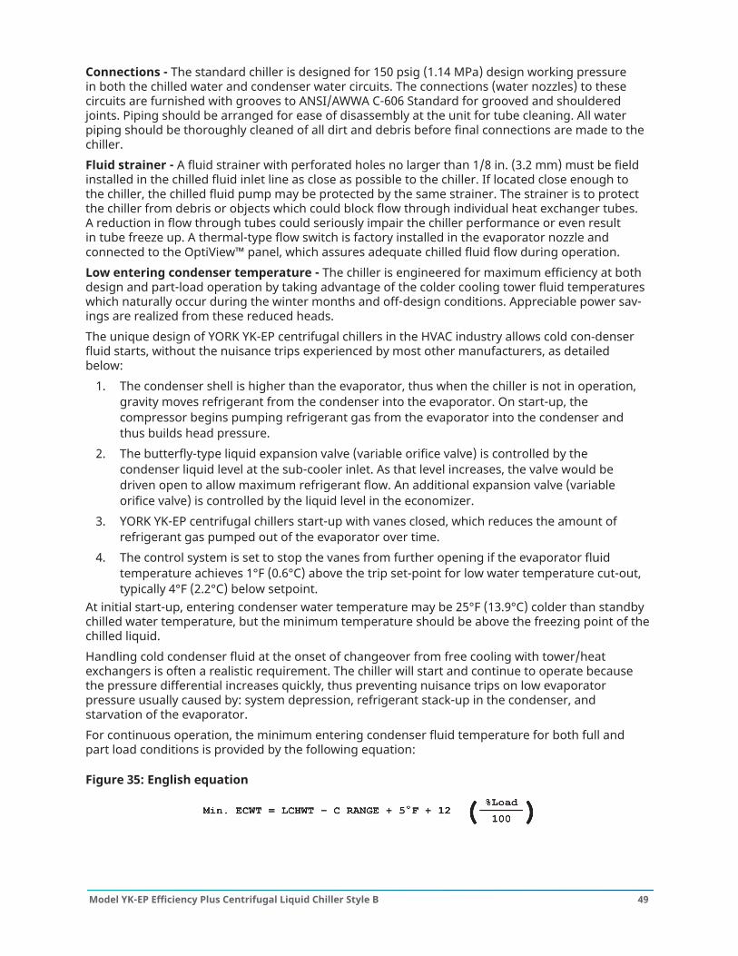
Connections - The standard chiller is designed for 150 psig (1.14 MPa) design working pressurein both the chilled water and condenser water circuits. The connections (water nozzles) to thesecircuits are furnished with grooves to ANSI/AWWA C-606 Standard for grooved and shoulderedjoints. Piping should be arranged for ease of disassembly at the unit for tube cleaning. All waterpiping should be thoroughly cleaned of all dirt and debris before final connections are made to thechiller.Fluid strainer - A fluid strainer with perforated holes no larger than 1/8 in. (3.2 mm) must be fieldinstalled in the chilled fluid inlet line as close as possible to the chiller. If located close enough tothe chiller, the chilled fluid pump may be protected by the same strainer. The strainer is to protectthe chiller from debris or objects which could block flow through individual heat exchanger tubes.A reduction in flow through tubes could seriously impair the chiller performance or even resultin tube freeze up. A thermal-type flow switch is factory installed in the evaporator nozzle andconnected to the OptiView™ panel, which assures adequate chilled fluid flow during operation.Low entering condenser temperature - The chiller is engineered for maximum efficiency at bothdesign and part-load operation by taking advantage of the colder cooling tower fluid temperatureswhich naturally occur during the winter months and off-design conditions. Appreciable power sav-ings are realized from these reduced heads.The unique design of YORK YK-EP centrifugal chillers in the HVAC industry allows cold condenserfluid starts, without the nuisance trips experienced by most other manufacturers, as detailedbelow:
1. The condenser shell is higher than the evaporator, thus when the chiller is not in operation,gravity moves refrigerant from the condenser into the evaporator. On start-up, thecompressor begins pumping refrigerant gas from the evaporator into the condenser andthus builds head pressure.
2. The butterfly-type liquid expansion valve (variable orifice valve) is controlled by thecondenser liquid level at the sub-cooler inlet. As that level increases, the valve would bedriven open to allow maximum refrigerant flow. An additional expansion valve (variableorifice valve) is controlled by the liquid level in the economizer.
3. YORK YK-EP centrifugal chillers start-up with vanes closed, which reduces the amount ofrefrigerant gas pumped out of the evaporator over time.
4. The control system is set to stop the vanes from further opening if the evaporator fluidtemperature achieves 1°F (0.6°C) above the trip set-point for low water temperature cut-out,typically 4°F (2.2°C) below setpoint.
At initial start-up, entering condenser water temperature may be 25°F (13.9°C) colder than standbychilled water temperature, but the minimum temperature should be above the freezing point of thechilled liquid.Handling cold condenser fluid at the onset of changeover from free cooling with tower/heatexchangers is often a realistic requirement. The chiller will start and continue to operate becausethe pressure differential increases quickly, thus preventing nuisance trips on low evaporatorpressure usually caused by: system depression, refrigerant stack-up in the condenser, andstarvation of the evaporator.For continuous operation, the minimum entering condenser fluid temperature for both full andpart load conditions is provided by the following equation:
Figure 35: English equation
49Model YK-EP Efficiency Plus Centrifugal Liquid Chiller Style B
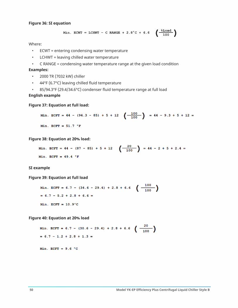
Figure 36: SI equation
Where:• ECWT = entering condensing water temperature• LCHWT = leaving chilled water temperature• C RANGE = condensing water temperature range at the given load condition
Examples:• 2000 TR (7032 kW) chiller• 44°F (6.7°C) leaving chilled fluid temperature• 85/94.3°F (29.4/34.6°C) condenser fluid temperature range at full load
English example
Figure 37: Equation at full load:
Figure 38: Equation at 20% load:
SI example
Figure 39: Equation at full load
Figure 40: Equation at 20% load
Model YK-EP Efficiency Plus Centrifugal Liquid Chiller Style B50
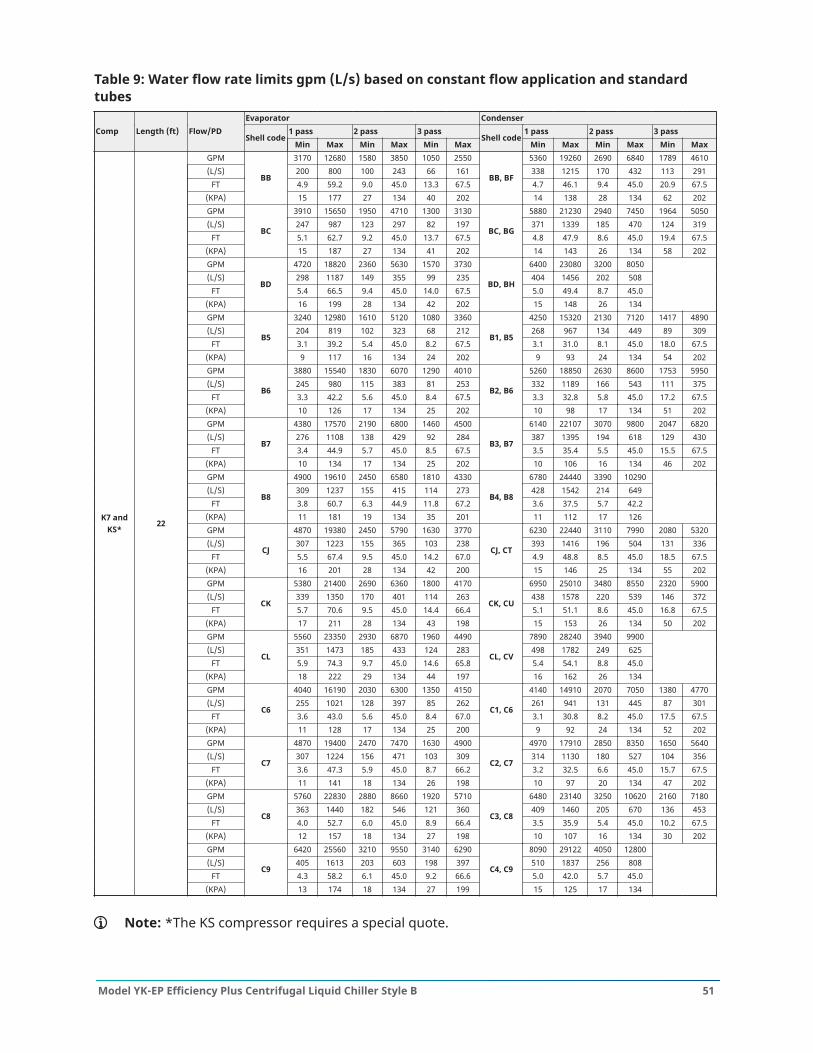
Table 9: Water flow rate limits gpm (L/s) based on constant flow application and standardtubes
Evaporator Condenser1 pass 2 pass 3 pass 1 pass 2 pass 3 passComp Length (ft) Flow/PD
Shell codeMin Max Min Max Min Max
Shell codeMin Max Min Max Min Max
GPM 3170 12680 1580 3850 1050 2550 5360 19260 2690 6840 1789 4610(L/S) 200 800 100 243 66 161 338 1215 170 432 113 291
FT 4.9 59.2 9.0 45.0 13.3 67.5 4.7 46.1 9.4 45.0 20.9 67.5(KPA)
BB
15 177 27 134 40 202
BB, BF
14 138 28 134 62 202GPM 3910 15650 1950 4710 1300 3130 5880 21230 2940 7450 1964 5050(L/S) 247 987 123 297 82 197 371 1339 185 470 124 319
FT 5.1 62.7 9.2 45.0 13.7 67.5 4.8 47.9 8.6 45.0 19.4 67.5(KPA)
BC
15 187 27 134 41 202
BC, BG
14 143 26 134 58 202GPM 4720 18820 2360 5630 1570 3730 6400 23080 3200 8050(L/S) 298 1187 149 355 99 235 404 1456 202 508
FT 5.4 66.5 9.4 45.0 14.0 67.5 5.0 49.4 8.7 45.0(KPA)
BD
16 199 28 134 42 202
BD, BH
15 148 26 134GPM 3240 12980 1610 5120 1080 3360 4250 15320 2130 7120 1417 4890(L/S) 204 819 102 323 68 212 268 967 134 449 89 309
FT 3.1 39.2 5.4 45.0 8.2 67.5 3.1 31.0 8.1 45.0 18.0 67.5(KPA)
B5
9 117 16 134 24 202
B1, B5
9 93 24 134 54 202GPM 3880 15540 1830 6070 1290 4010 5260 18850 2630 8600 1753 5950(L/S) 245 980 115 383 81 253 332 1189 166 543 111 375
FT 3.3 42.2 5.6 45.0 8.4 67.5 3.3 32.8 5.8 45.0 17.2 67.5(KPA)
B6
10 126 17 134 25 202
B2, B6
10 98 17 134 51 202GPM 4380 17570 2190 6800 1460 4500 6140 22107 3070 9800 2047 6820(L/S) 276 1108 138 429 92 284 387 1395 194 618 129 430
FT 3.4 44.9 5.7 45.0 8.5 67.5 3.5 35.4 5.5 45.0 15.5 67.5(KPA)
B7
10 134 17 134 25 202
B3, B7
10 106 16 134 46 202GPM 4900 19610 2450 6580 1810 4330 6780 24440 3390 10290(L/S) 309 1237 155 415 114 273 428 1542 214 649
FT 3.8 60.7 6.3 44.9 11.8 67.2 3.6 37.5 5.7 42.2(KPA)
B8
11 181 19 134 35 201
B4, B8
11 112 17 126GPM 4870 19380 2450 5790 1630 3770 6230 22440 3110 7990 2080 5320(L/S) 307 1223 155 365 103 238 393 1416 196 504 131 336
FT 5.5 67.4 9.5 45.0 14.2 67.0 4.9 48.8 8.5 45.0 18.5 67.5(KPA)
CJ
16 201 28 134 42 200
CJ, CT
15 146 25 134 55 202GPM 5380 21400 2690 6360 1800 4170 6950 25010 3480 8550 2320 5900(L/S) 339 1350 170 401 114 263 438 1578 220 539 146 372
FT 5.7 70.6 9.5 45.0 14.4 66.4 5.1 51.1 8.6 45.0 16.8 67.5(KPA)
CK
17 211 28 134 43 198
CK, CU
15 153 26 134 50 202GPM 5560 23350 2930 6870 1960 4490 7890 28240 3940 9900(L/S) 351 1473 185 433 124 283 498 1782 249 625
FT 5.9 74.3 9.7 45.0 14.6 65.8 5.4 54.1 8.8 45.0(KPA)
CL
18 222 29 134 44 197
CL, CV
16 162 26 134GPM 4040 16190 2030 6300 1350 4150 4140 14910 2070 7050 1380 4770(L/S) 255 1021 128 397 85 262 261 941 131 445 87 301
FT 3.6 43.0 5.6 45.0 8.4 67.0 3.1 30.8 8.2 45.0 17.5 67.5(KPA)
C6
11 128 17 134 25 200
C1, C6
9 92 24 134 52 202GPM 4870 19400 2470 7470 1630 4900 4970 17910 2850 8350 1650 5640(L/S) 307 1224 156 471 103 309 314 1130 180 527 104 356
FT 3.6 47.3 5.9 45.0 8.7 66.2 3.2 32.5 6.6 45.0 15.7 67.5(KPA)
C7
11 141 18 134 26 198
C2, C7
10 97 20 134 47 202GPM 5760 22830 2880 8660 1920 5710 6480 23140 3250 10620 2160 7180(L/S) 363 1440 182 546 121 360 409 1460 205 670 136 453
FT 4.0 52.7 6.0 45.0 8.9 66.4 3.5 35.9 5.4 45.0 10.2 67.5(KPA)
C8
12 157 18 134 27 198
C3, C8
10 107 16 134 30 202GPM 6420 25560 3210 9550 3140 6290 8090 29122 4050 12800(L/S) 405 1613 203 603 198 397 510 1837 256 808
FT 4.3 58.2 6.1 45.0 9.2 66.6 5.0 42.0 5.7 45.0
K7 andKS*
22
(KPA)
C9
13 174 18 134 27 199
C4, C9
15 125 17 134
Note: *The KS compressor requires a special quote.
51Model YK-EP Efficiency Plus Centrifugal Liquid Chiller Style B
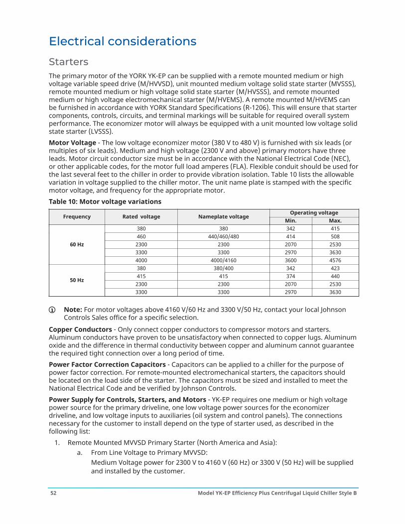
Electrical considerations
StartersThe primary motor of the YORK YK-EP can be supplied with a remote mounted medium or highvoltage variable speed drive (M/HVVSD), unit mounted medium voltage solid state starter (MVSSS),remote mounted medium or high voltage solid state starter (M/HVSSS), and remote mountedmedium or high voltage electromechanical starter (M/HVEMS). A remote mounted M/HVEMS canbe furnished in accordance with YORK Standard Specifications (R-1206). This will ensure that startercomponents, controls, circuits, and terminal markings will be suitable for required overall systemperformance. The economizer motor will always be equipped with a unit mounted low voltage solidstate starter (LVSSS).Motor Voltage - The low voltage economizer motor (380 V to 480 V) is furnished with six leads (ormultiples of six leads). Medium and high voltage (2300 V and above) primary motors have threeleads. Motor circuit conductor size must be in accordance with the National Electrical Code (NEC),or other applicable codes, for the motor full load amperes (FLA). Flexible conduit should be used forthe last several feet to the chiller in order to provide vibration isolation. Table 10 lists the allowablevariation in voltage supplied to the chiller motor. The unit name plate is stamped with the specificmotor voltage, and frequency for the appropriate motor.Table 10: Motor voltage variations
Operating voltageFrequency Rated voltage Nameplate voltage
Min. Max.380 380 342 415460 440/460/480 414 508
2300 2300 2070 25303300 3300 2970 3630
60 Hz
4000 4000/4160 3600 4576380 380/400 342 423415 415 374 440
2300 2300 2070 253050 Hz
3300 3300 2970 3630
Note: For motor voltages above 4160 V/60 Hz and 3300 V/50 Hz, contact your local JohnsonControls Sales office for a specific selection.
Copper Conductors - Only connect copper conductors to compressor motors and starters.Aluminum conductors have proven to be unsatisfactory when connected to copper lugs. Aluminumoxide and the difference in thermal conductivity between copper and aluminum cannot guaranteethe required tight connection over a long period of time.Power Factor Correction Capacitors - Capacitors can be applied to a chiller for the purpose ofpower factor correction. For remote-mounted electromechanical starters, the capacitors shouldbe located on the load side of the starter. The capacitors must be sized and installed to meet theNational Electrical Code and be verified by Johnson Controls.Power Supply for Controls, Starters, and Motors - YK-EP requires one medium or high voltagepower source for the primary driveline, one low voltage power sources for the economizerdriveline, and low voltage inputs to auxiliaries (oil system and control panels). The connectionsnecessary for the customer to install depend on the type of starter used, as described in thefollowing list:
1. Remote Mounted MVVSD Primary Starter (North America and Asia):a. From Line Voltage to Primary MVVSD:
Medium Voltage power for 2300 V to 4160 V (60 Hz) or 3300 V (50 Hz) will be suppliedand installed by the customer.
Model YK-EP Efficiency Plus Centrifugal Liquid Chiller Style B52
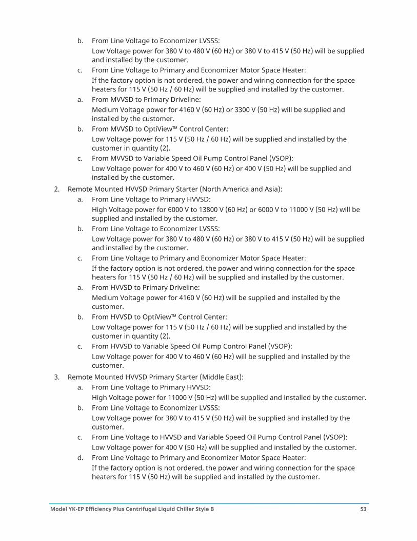
b. From Line Voltage to Economizer LVSSS:Low Voltage power for 380 V to 480 V (60 Hz) or 380 V to 415 V (50 Hz) will be suppliedand installed by the customer.
c. From Line Voltage to Primary and Economizer Motor Space Heater:If the factory option is not ordered, the power and wiring connection for the spaceheaters for 115 V (50 Hz / 60 Hz) will be supplied and installed by the customer.
a. From MVVSD to Primary Driveline:Medium Voltage power for 4160 V (60 Hz) or 3300 V (50 Hz) will be supplied andinstalled by the customer.
b. From MVVSD to OptiView™ Control Center:Low Voltage power for 115 V (50 Hz / 60 Hz) will be supplied and installed by thecustomer in quantity (2).
c. From MVVSD to Variable Speed Oil Pump Control Panel (VSOP):Low Voltage power for 400 V to 460 V (60 Hz) or 400 V (50 Hz) will be supplied andinstalled by the customer.
2. Remote Mounted HVVSD Primary Starter (North America and Asia):a. From Line Voltage to Primary HVVSD:
High Voltage power for 6000 V to 13800 V (60 Hz) or 6000 V to 11000 V (50 Hz) will besupplied and installed by the customer.
b. From Line Voltage to Economizer LVSSS:Low Voltage power for 380 V to 480 V (60 Hz) or 380 V to 415 V (50 Hz) will be suppliedand installed by the customer.
c. From Line Voltage to Primary and Economizer Motor Space Heater:If the factory option is not ordered, the power and wiring connection for the spaceheaters for 115 V (50 Hz / 60 Hz) will be supplied and installed by the customer.
a. From HVVSD to Primary Driveline:Medium Voltage power for 4160 V (60 Hz) will be supplied and installed by thecustomer.
b. From HVVSD to OptiView™ Control Center:Low Voltage power for 115 V (50 Hz / 60 Hz) will be supplied and installed by thecustomer in quantity (2).
c. From HVVSD to Variable Speed Oil Pump Control Panel (VSOP):Low Voltage power for 400 V to 460 V (60 Hz) will be supplied and installed by thecustomer.
3. Remote Mounted HVVSD Primary Starter (Middle East):a. From Line Voltage to Primary HVVSD:
High Voltage power for 11000 V (50 Hz) will be supplied and installed by the customer.b. From Line Voltage to Economizer LVSSS:
Low Voltage power for 380 V to 415 V (50 Hz) will be supplied and installed by thecustomer.
c. From Line Voltage to HVVSD and Variable Speed Oil Pump Control Panel (VSOP):Low Voltage power for 400 V (50 Hz) will be supplied and installed by the customer.
d. From Line Voltage to Primary and Economizer Motor Space Heater:If the factory option is not ordered, the power and wiring connection for the spaceheaters for 115 V (50 Hz) will be supplied and installed by the customer.
53Model YK-EP Efficiency Plus Centrifugal Liquid Chiller Style B
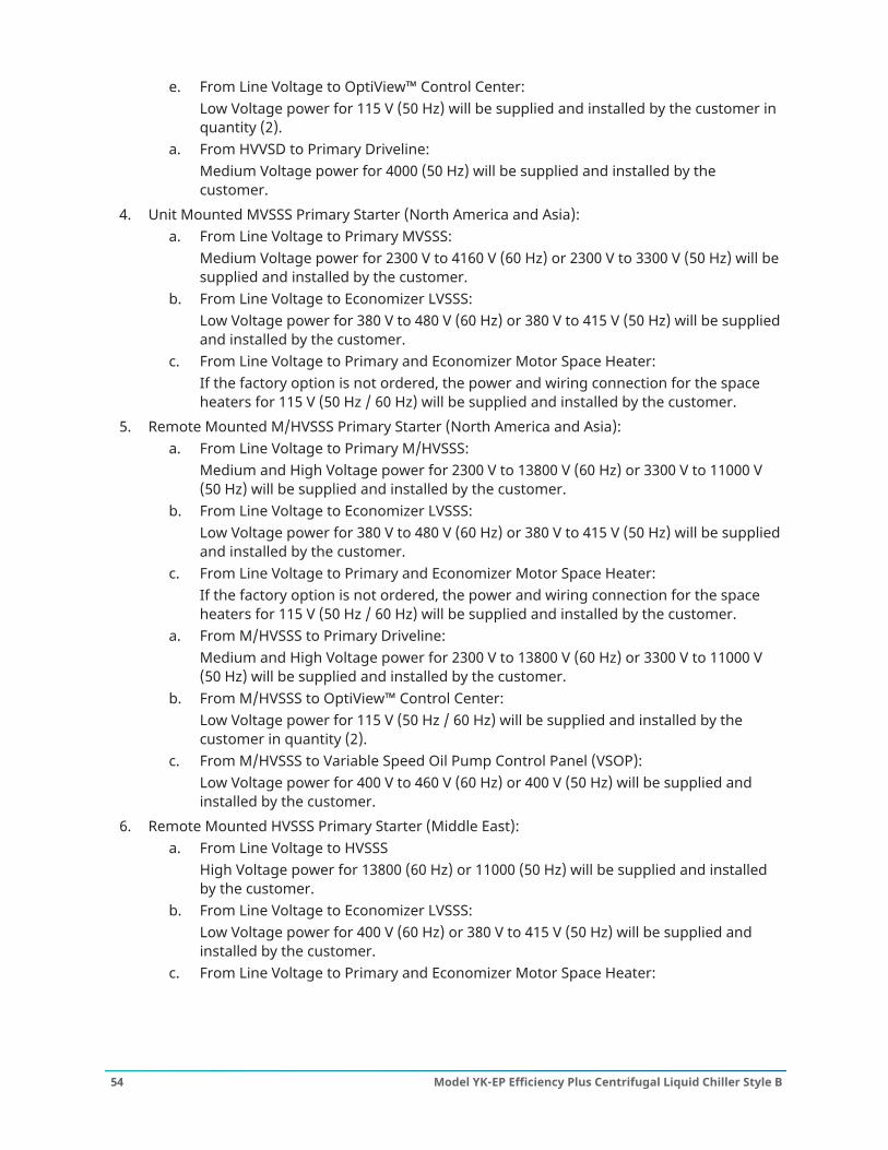
e. From Line Voltage to OptiView™ Control Center:Low Voltage power for 115 V (50 Hz) will be supplied and installed by the customer inquantity (2).
a. From HVVSD to Primary Driveline:Medium Voltage power for 4000 (50 Hz) will be supplied and installed by thecustomer.
4. Unit Mounted MVSSS Primary Starter (North America and Asia):a. From Line Voltage to Primary MVSSS:
Medium Voltage power for 2300 V to 4160 V (60 Hz) or 2300 V to 3300 V (50 Hz) will besupplied and installed by the customer.
b. From Line Voltage to Economizer LVSSS:Low Voltage power for 380 V to 480 V (60 Hz) or 380 V to 415 V (50 Hz) will be suppliedand installed by the customer.
c. From Line Voltage to Primary and Economizer Motor Space Heater:If the factory option is not ordered, the power and wiring connection for the spaceheaters for 115 V (50 Hz / 60 Hz) will be supplied and installed by the customer.
5. Remote Mounted M/HVSSS Primary Starter (North America and Asia):a. From Line Voltage to Primary M/HVSSS:
Medium and High Voltage power for 2300 V to 13800 V (60 Hz) or 3300 V to 11000 V(50 Hz) will be supplied and installed by the customer.
b. From Line Voltage to Economizer LVSSS:Low Voltage power for 380 V to 480 V (60 Hz) or 380 V to 415 V (50 Hz) will be suppliedand installed by the customer.
c. From Line Voltage to Primary and Economizer Motor Space Heater:If the factory option is not ordered, the power and wiring connection for the spaceheaters for 115 V (50 Hz / 60 Hz) will be supplied and installed by the customer.
a. From M/HVSSS to Primary Driveline:Medium and High Voltage power for 2300 V to 13800 V (60 Hz) or 3300 V to 11000 V(50 Hz) will be supplied and installed by the customer.
b. From M/HVSSS to OptiView™ Control Center:Low Voltage power for 115 V (50 Hz / 60 Hz) will be supplied and installed by thecustomer in quantity (2).
c. From M/HVSSS to Variable Speed Oil Pump Control Panel (VSOP):Low Voltage power for 400 V to 460 V (60 Hz) or 400 V (50 Hz) will be supplied andinstalled by the customer.
6. Remote Mounted HVSSS Primary Starter (Middle East):a. From Line Voltage to HVSSS
High Voltage power for 13800 (60 Hz) or 11000 (50 Hz) will be supplied and installedby the customer.
b. From Line Voltage to Economizer LVSSS:Low Voltage power for 400 V (60 Hz) or 380 V to 415 V (50 Hz) will be supplied andinstalled by the customer.
c. From Line Voltage to Primary and Economizer Motor Space Heater:
Model YK-EP Efficiency Plus Centrifugal Liquid Chiller Style B54
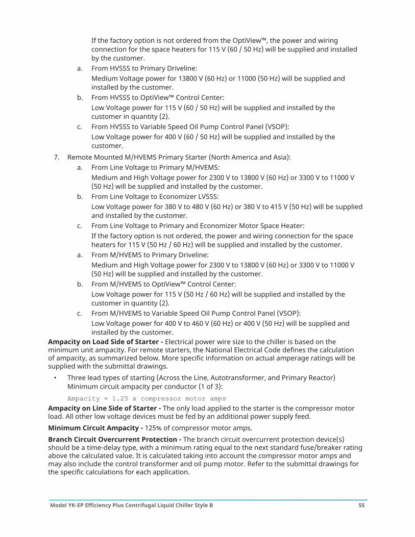
If the factory option is not ordered from the OptiView™, the power and wiringconnection for the space heaters for 115 V (60 / 50 Hz) will be supplied and installedby the customer.
a. From HVSSS to Primary Driveline:Medium Voltage power for 13800 V (60 Hz) or 11000 (50 Hz) will be supplied andinstalled by the customer.
b. From HVSSS to OptiView™ Control Center:Low Voltage power for 115 V (60 / 50 Hz) will be supplied and installed by thecustomer in quantity (2).
c. From HVSSS to Variable Speed Oil Pump Control Panel (VSOP):Low Voltage power for 400 V (60 / 50 Hz) will be supplied and installed by thecustomer.
7. Remote Mounted M/HVEMS Primary Starter (North America and Asia):a. From Line Voltage to Primary M/HVEMS:
Medium and High Voltage power for 2300 V to 13800 V (60 Hz) or 3300 V to 11000 V(50 Hz) will be supplied and installed by the customer.
b. From Line Voltage to Economizer LVSSS:Low Voltage power for 380 V to 480 V (60 Hz) or 380 V to 415 V (50 Hz) will be suppliedand installed by the customer.
c. From Line Voltage to Primary and Economizer Motor Space Heater:If the factory option is not ordered, the power and wiring connection for the spaceheaters for 115 V (50 Hz / 60 Hz) will be supplied and installed by the customer.
a. From M/HVEMS to Primary Driveline:Medium and High Voltage power for 2300 V to 13800 V (60 Hz) or 3300 V to 11000 V(50 Hz) will be supplied and installed by the customer.
b. From M/HVEMS to OptiView™ Control Center:Low Voltage power for 115 V (50 Hz / 60 Hz) will be supplied and installed by thecustomer in quantity (2).
c. From M/HVEMS to Variable Speed Oil Pump Control Panel (VSOP):Low Voltage power for 400 V to 460 V (60 Hz) or 400 V (50 Hz) will be supplied andinstalled by the customer.
Ampacity on Load Side of Starter - Electrical power wire size to the chiller is based on theminimum unit ampacity. For remote starters, the National Electrical Code defines the calculationof ampacity, as summarized below. More specific information on actual amperage ratings will besupplied with the submittal drawings.
• Three lead types of starting (Across the Line, Autotransformer, and Primary Reactor)Minimum circuit ampacity per conductor (1 of 3):Ampacity = 1.25 x compressor motor amps
Ampacity on Line Side of Starter - The only load applied to the starter is the compressor motorload. All other low voltage devices must be fed by an additional power supply feed.Minimum Circuit Ampacity - 125% of compressor motor amps.Branch Circuit Overcurrent Protection - The branch circuit overcurrent protection device(s)should be a time-delay type, with a minimum rating equal to the next standard fuse/breaker ratingabove the calculated value. It is calculated taking into account the compressor motor amps andmay also include the control transformer and oil pump motor. Refer to the submittal drawings forthe specific calculations for each application.
55Model YK-EP Efficiency Plus Centrifugal Liquid Chiller Style B
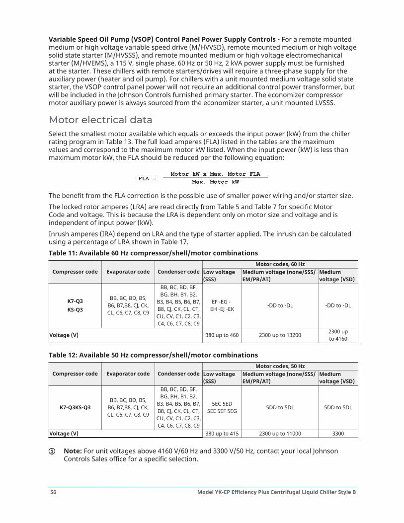
Variable Speed Oil Pump (VSOP) Control Panel Power Supply Controls - For a remote mountedmedium or high voltage variable speed drive (M/HVVSD), remote mounted medium or high voltagesolid state starter (M/HVSSS), and remote mounted medium or high voltage electromechanicalstarter (M/HVEMS), a 115 V, single phase, 60 Hz or 50 Hz, 2 kVA power supply must be furnishedat the starter. These chillers with remote starters/drives will require a three-phase supply for theauxiliary power (heater and oil pump). For chillers with a unit mounted medium voltage solid statestarter, the VSOP control panel power will not require an additional control power transformer, butwill be included in the Johnson Controls furnished primary starter. The economizer compressormotor auxiliary power is always sourced from the economizer starter, a unit mounted LVSSS.
Motor electrical dataSelect the smallest motor available which equals or exceeds the input power (kW) from the chillerrating program in Table 13. The full load amperes (FLA) listed in the tables are the maximumvalues and correspond to the maximum motor kW listed. When the input power (kW) is less thanmaximum motor kW, the FLA should be reduced per the following equation:
The benefit from the FLA correction is the possible use of smaller power wiring and/or starter size.The locked rotor amperes (LRA) are read directly from Table 5 and Table 7 for specific MotorCode and voltage. This is because the LRA is dependent only on motor size and voltage and isindependent of input power (kW).Inrush amperes (IRA) depend on LRA and the type of starter applied. The inrush can be calculatedusing a percentage of LRA shown in Table 17.Table 11: Available 60 Hz compressor/shell/motor combinations
Motor codes, 60 HzCompressor code Evaporator code Condenser code Low voltage
(SSS)Medium voltage (none/SSS/EM/PR/AT)
Mediumvoltage (VSD)
K7-Q3KS-Q3
BB, BC, BD, B5,B6, B7,B8, CJ, CK,CL, C6, C7, C8, C9
BB, BC, BD, BF,BG, BH, B1, B2,
B3, B4, B5, B6, B7,B8, CJ, CK, CL, CT,CU, CV, C1, C2, C3,C4, C6, C7, C8, C9
EF -EG -EH -EJ -EK -DD to -DL -DD to -DL
Voltage (V) 380 up to 460 2300 up to 13200 2300 upto 4160
Table 12: Available 50 Hz compressor/shell/motor combinationsMotor codes, 50 Hz
Compressor code Evaporator code Condenser code Low voltage(SSS)
Medium voltage (none/SSS/EM/PR/AT)
Mediumvoltage (VSD)
K7-Q3KS-Q3BB, BC, BD, B5,
B6, B7,B8, CJ, CK,CL, C6, C7, C8, C9
BB, BC, BD, BF,BG, BH, B1, B2,
B3, B4, B5, B6, B7,B8, CJ, CK, CL, CT,CU, CV, C1, C2, C3,C4, C6, C7, C8, C9
5EC 5ED5EE 5EF 5EG 5DD to 5DL 5DD to 5DL
Voltage (V) 380 up to 415 2300 up to 11000 3300
Note: For unit voltages above 4160 V/60 Hz and 3300 V/50 Hz, contact your local JohnsonControls Sales office for a specific selection.
Model YK-EP Efficiency Plus Centrifugal Liquid Chiller Style B56
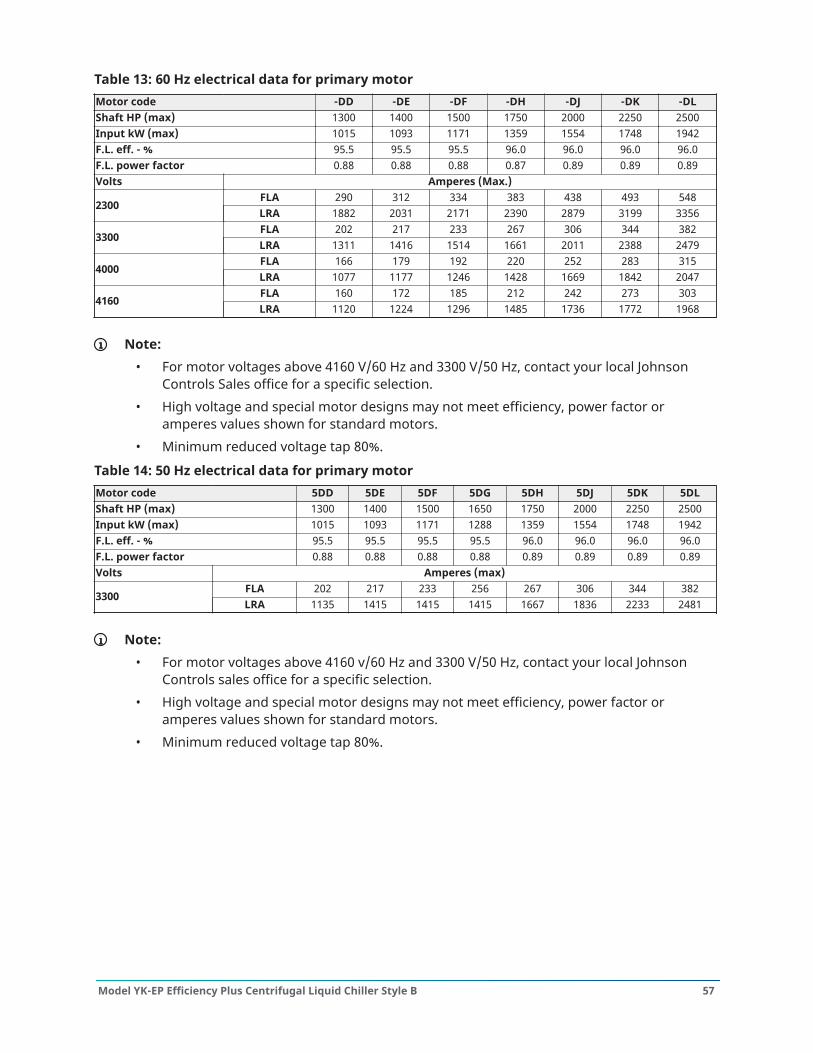
Table 13: 60 Hz electrical data for primary motorMotor code -DD -DE -DF -DH -DJ -DK -DLShaft HP (max) 1300 1400 1500 1750 2000 2250 2500Input kW (max) 1015 1093 1171 1359 1554 1748 1942F.L. eff. - % 95.5 95.5 95.5 96.0 96.0 96.0 96.0F.L. power factor 0.88 0.88 0.88 0.87 0.89 0.89 0.89Volts Amperes (Max.)
FLA 290 312 334 383 438 493 5482300
LRA 1882 2031 2171 2390 2879 3199 3356FLA 202 217 233 267 306 344 382
3300LRA 1311 1416 1514 1661 2011 2388 2479FLA 166 179 192 220 252 283 315
4000LRA 1077 1177 1246 1428 1669 1842 2047FLA 160 172 185 212 242 273 303
4160LRA 1120 1224 1296 1485 1736 1772 1968
Note:• For motor voltages above 4160 V/60 Hz and 3300 V/50 Hz, contact your local Johnson
Controls Sales office for a specific selection.• High voltage and special motor designs may not meet efficiency, power factor or
amperes values shown for standard motors.• Minimum reduced voltage tap 80%.
Table 14: 50 Hz electrical data for primary motorMotor code 5DD 5DE 5DF 5DG 5DH 5DJ 5DK 5DLShaft HP (max) 1300 1400 1500 1650 1750 2000 2250 2500Input kW (max) 1015 1093 1171 1288 1359 1554 1748 1942F.L. eff. - % 95.5 95.5 95.5 95.5 96.0 96.0 96.0 96.0F.L. power factor 0.88 0.88 0.88 0.88 0.89 0.89 0.89 0.89Volts Amperes (max)
FLA 202 217 233 256 267 306 344 3823300
LRA 1135 1415 1415 1415 1667 1836 2233 2481
Note:• For motor voltages above 4160 v/60 Hz and 3300 V/50 Hz, contact your local Johnson
Controls sales office for a specific selection.• High voltage and special motor designs may not meet efficiency, power factor or
amperes values shown for standard motors.• Minimum reduced voltage tap 80%.
57Model YK-EP Efficiency Plus Centrifugal Liquid Chiller Style B
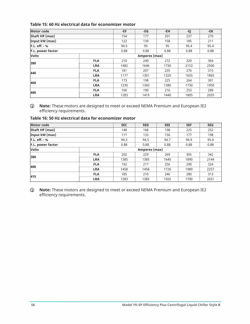
Table 15: 60 Hz electrical data for economizer motorMotor code -EF -EG -EH -EJ -EKShaft HP (max) 154 177 201 237 270Input kW (max) 122 139 158 185 211F.L. eff. - % 94.5 95 95 95.4 95.4F.L. power factor 0.88 0.88 0.88 0.88 0.88Volts Amperes (max)
FLA 210 240 272 320 364380
LRA 1482 1646 1730 2153 2500FLA 181 207 235 276 315
440LRA 1177 1301 1320 1655 1865FLA 173 198 225 264 301
460LRA 1230 1360 1380 1730 1950FLA 166 190 216 253 288
480LRA 1283 1419 1440 1805 2035
Note: These motors are designed to meet or exceed NEMA Premium and European IE2efficiency requirements.
Table 16: 50 Hz electrical data for economizer motorMotor code 5EC 5ED 5EE 5EF 5EGShaft HP (max) 148 168 198 225 252Input kW (max) 117 133 156 177 198F.L. eff. - % 94.3 94.5 94.7 94.9 95.0F.L. power factor 0.88 0.88 0.88 0.88 0.88Volts Amperes (max)
FLA 202 229 269 305 342380
LRA 1385 1385 1640 1890 2144FLA 192 217 256 290 324
400LRA 1458 1458 1726 1989 2257FLA 185 210 246 280 313
415LRA 1283 1385 1502 1700 2031
Note: These motors are designed to meet or exceed NEMA Premium and European IE2efficiency requirements.
Model YK-EP Efficiency Plus Centrifugal Liquid Chiller Style B58
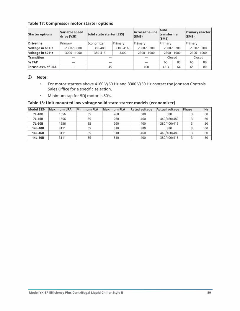
Table 17: Compressor motor starter options
Starter options Variable speeddrive (VSD) Solid state starter (SSS) Across-the-line
(EMS)
Autotransformer(EMS)
Primary reactor(EMS)
Driveline Primary Economizer Primary Primary Primary PrimaryVoltage in 60 Hz 2300-13800 380-480 2300-4160 2300-13200 2300-13200 2300-13200Voltage in 50 Hz 3000-11000 380-415 3300 2300-11000 2300-11000 2300-11000Transition — — — Closed Closed% TAP — — — 65 80 65 80Inrush as% of LRA — 45 100 42.3 64 65 80
Note:• For motor starters above 4160 V/60 Hz and 3300 V/50 Hz contact the Johnson Controls
Sales Office for a specific selection.• Minimum tap for 5DJ motor is 80%.
Table 18: Unit mounted low voltage solid state starter models (economizer)Model SSS- Maximum LRA Minimum FLA Maximum FLA Rated voltage Actual voltage Phase Hz
7L-40B 1556 35 260 380 380 3 607L-46B 1556 35 260 460 440/460/480 3 607L-50B 1556 35 260 400 380/400/415 3 50
14L-40B 3111 65 510 380 380 3 6014L-46B 3111 65 510 460 440/460/480 3 6014L-50B 3111 65 510 400 380/400/415 3 50
59Model YK-EP Efficiency Plus Centrifugal Liquid Chiller Style B
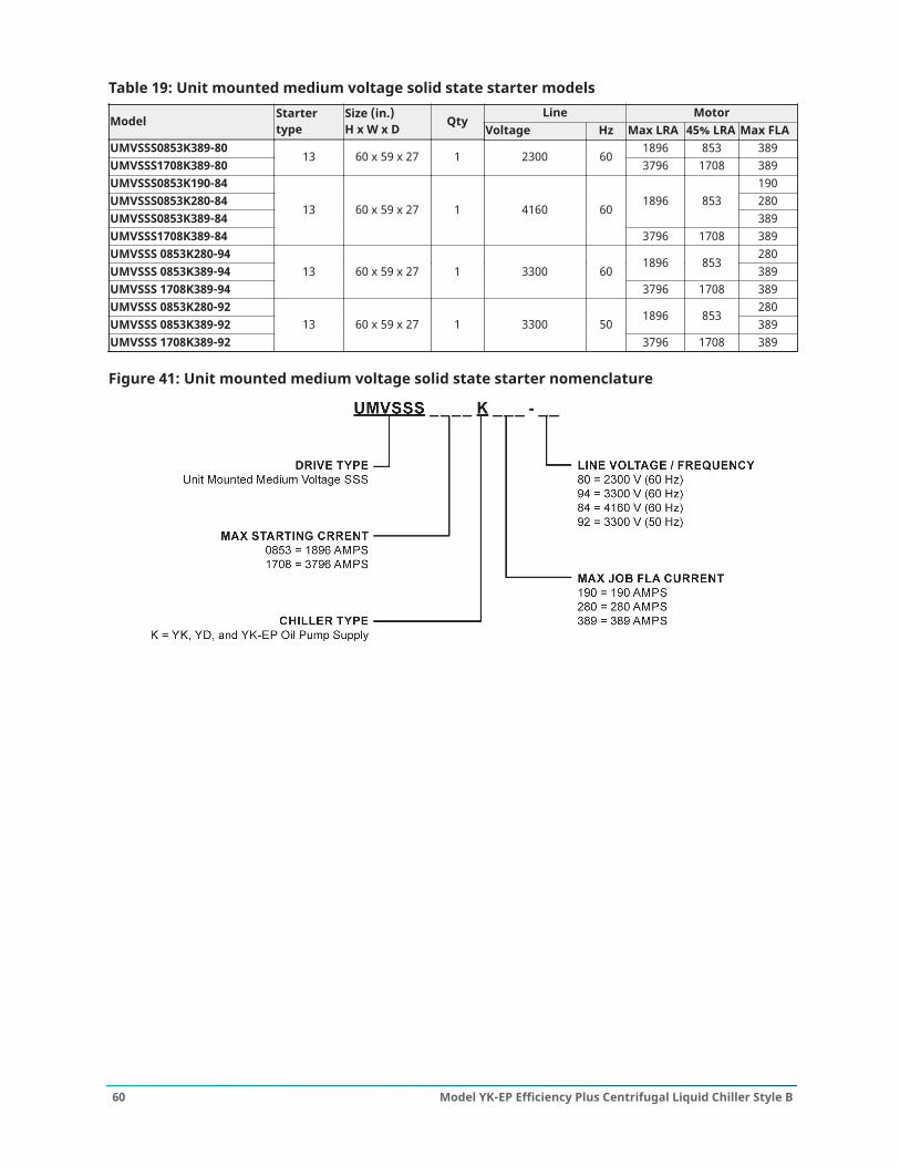
Table 19: Unit mounted medium voltage solid state starter modelsLine Motor
Model Startertype
Size (in.)H x W x D Qty
Voltage Hz Max LRA 45% LRA Max FLAUMVSSS0853K389-80 1896 853 389UMVSSS1708K389-80
13 60 x 59 x 27 1 2300 603796 1708 389
UMVSSS0853K190-84 190UMVSSS0853K280-84 280UMVSSS0853K389-84
1896 853389
UMVSSS1708K389-84
13 60 x 59 x 27 1 4160 60
3796 1708 389UMVSSS 0853K280-94 280UMVSSS 0853K389-94
1896 853389
UMVSSS 1708K389-9413 60 x 59 x 27 1 3300 60
3796 1708 389UMVSSS 0853K280-92 280UMVSSS 0853K389-92
1896 853389
UMVSSS 1708K389-9213 60 x 59 x 27 1 3300 50
3796 1708 389
Figure 41: Unit mounted medium voltage solid state starter nomenclature
Model YK-EP Efficiency Plus Centrifugal Liquid Chiller Style B60
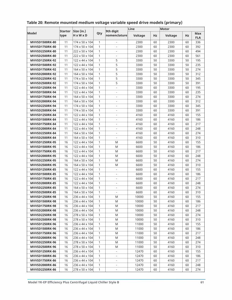
Table 20: Remote mounted medium voltage variable speed drive models (primary)Line Motor
Model Startertype
Size (in.)H x W x D Qty 9th digit
nomenclature Voltage Hz Voltage Hz MaxFLA
MVVSD1500RK-80 11 174 x 50 x 104 1 - 2300 60 2300 60 336MVVSD1750RK-80 11 174 x 50 x 104 1 - 2300 60 2300 60 392MVVSD2250RK-80 11 222 x 50 x 104 1 - 2300 60 2300 60 494MVVSD2500RK-80 11 222 x 50 x 104 1 - 2300 60 2300 60 561MVVSD1250RK-92 11 122 x 44 x 104 1 5 3300 50 3300 50 195MVVSD1500RK-92 11 122 x 44 x 104 1 5 3300 50 3300 50 235MVVSD1750RK-92 11 164 x 50 x 104 1 5 3300 50 3300 50 274MVVSD2000RK-92 11 164 x 50 x 104 1 5 3300 50 3300 50 312MVVSD2250RK-92 11 174 x 50 x 104 1 5 3300 50 3300 50 345MVVSD2500RK-92 11 174 x 50 x 104 1 5 3300 50 3300 50 391MVVSD1250RK-94 11 122 x 44 x 104 1 - 3300 60 3300 60 195MVVSD1500RK-94 11 122 x 44 x 104 1 - 3300 60 3300 60 235MVVSD1750RK-94 11 164 x 50 x 104 1 - 3300 60 3300 60 274MVVSD2000RK-94 11 164 x 50 x 104 1 - 3300 60 3300 60 312MVVSD2250RK-94 11 174 x 50 x 104 1 - 3300 60 3300 60 345MVVSD2500RK-94 11 174 x 50 x 104 1 - 3300 60 3300 60 391MVVSD1250RK-84 11 122 x 44 x 104 1 - 4160 60 4160 60 155MVVSD1500RK-84 11 122 x 44 x 104 1 - 4160 60 4160 60 186MVVSD1750RK-84 11 122 x 44 x 104 1 - 4160 60 4160 60 217MVVSD2000RK-84 11 122 x 44 x 104 1 - 4160 60 4160 60 248MVVSD2250RK-84 11 164 x 50 x 104 1 - 4160 60 4160 60 274MVVSD2500RK-84 11 164 x 50 x 104 1 - 4160 60 4160 60 310MVVSD1250RK-95 16 122 x 44 x 104 1 M 6600 50 4160 60 155MVVSD1500RK-95 16 122 x 44 x 104 1 M 6600 50 4160 60 186MVVSD1750RK-95 16 122 x 44 x 104 1 M 6600 50 4160 60 217MVVSD2000RK-95 16 122 x 44 x 104 1 M 6600 50 4160 60 248MVVSD2250RK-95 16 164 x 50 x 104 1 M 6600 50 4160 60 274MVVSD2500RK-95 16 164 x 50 x 104 1 M 6600 50 4160 60 310MVVSD1250RK-85 16 122 x 44 x 104 1 - 6600 60 4160 60 155MVVSD1500RK-85 16 122 x 44 x 104 1 - 6600 60 4160 60 186MVVSD1750RK-85 16 122 x 44 x 104 1 - 6600 60 4160 60 217MVVSD2000RK-85 16 122 x 44 x 104 1 - 6600 60 4160 60 248MVVSD2250RK-85 16 164 x 50 x 104 1 - 6600 60 4160 60 274MVVSD2500RK-85 16 164 x 50 x 104 1 - 6600 60 4160 60 310MVVSD1250RK-98 16 236 x 44 x 104 1 M 10000 50 4160 60 155MVVSD1500RK-98 16 236 x 44 x 104 1 M 10000 50 4160 60 186MVVSD1750RK-98 16 236 x 44 x 104 1 M 10000 50 4160 60 217MVVSD2000RK-98 16 236 x 44 x 104 1 M 10000 50 4160 60 248MVVSD2250RK-98 16 278 x 50 x 104 1 M 10000 50 4160 60 274MVVSD2500RK-98 16 278 x 50 x 104 1 M 10000 50 4160 60 310MVVSD1250RK-96 16 236 x 44 x 104 1 M 11000 50 4160 60 155MVVSD1500RK-96 16 236 x 44 x 104 1 M 11000 50 4160 60 186MVVSD1750RK-96 16 236 x 44 x 104 1 M 11000 50 4160 60 217MVVSD2000RK-96 16 236 x 44 x 104 1 M 11000 50 4160 60 248MVVSD2250RK-96 16 278 x 50 x 104 1 M 11000 50 4160 60 274MVVSD2500RK-96 16 278 x 50 x 104 1 M 11000 50 4160 60 310MVVSD1250RK-86 16 236 x 44 x 104 1 - 12470 60 4160 60 155MVVSD1500RK-86 16 236 x 44 x 104 1 - 12470 60 4160 60 186MVVSD1750RK-86 16 236 x 44 x 104 1 - 12470 60 4160 60 217MVVSD2000RK-86 16 236 x 44 x 104 1 - 12470 60 4160 60 248MVVSD2250RK-86 16 278 x 50 x 104 1 - 12470 60 4160 60 274
61Model YK-EP Efficiency Plus Centrifugal Liquid Chiller Style B
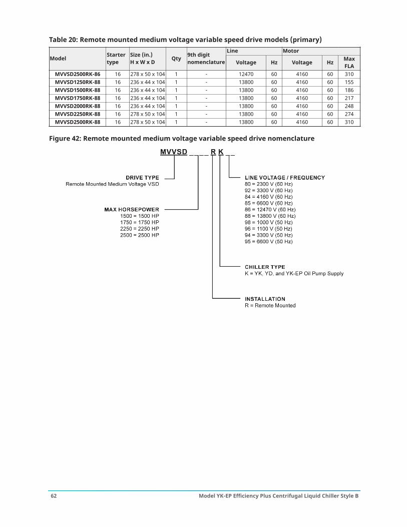
Table 20: Remote mounted medium voltage variable speed drive models (primary)Line Motor
Model Startertype
Size (in.)H x W x D Qty 9th digit
nomenclature Voltage Hz Voltage Hz MaxFLA
MVVSD2500RK-86 16 278 x 50 x 104 1 - 12470 60 4160 60 310MVVSD1250RK-88 16 236 x 44 x 104 1 - 13800 60 4160 60 155MVVSD1500RK-88 16 236 x 44 x 104 1 - 13800 60 4160 60 186MVVSD1750RK-88 16 236 x 44 x 104 1 - 13800 60 4160 60 217MVVSD2000RK-88 16 236 x 44 x 104 1 - 13800 60 4160 60 248MVVSD2250RK-88 16 278 x 50 x 104 1 - 13800 60 4160 60 274MVVSD2500RK-88 16 278 x 50 x 104 1 - 13800 60 4160 60 310
Figure 42: Remote mounted medium voltage variable speed drive nomenclature
Model YK-EP Efficiency Plus Centrifugal Liquid Chiller Style B62

Table 21: Remote mounted medium voltage solid state starter modelsLine Motor
Model Startertype
Size (in.)H x W x D Qty
Voltage Hz Max LRA 45% LRA Max FLAMVSSS0853RK310-80 310MVSSS0853RK360-80
1896 853360
MVSSS1708RK360-8092 x 36 x 36
360MVSSS1708RK550-80
12
92 x 72 x 36
1 2300 603796 1708
550MVSSS0853RK190-84 190MVSSS0853RK280-84 280MVSSS0853RK310-84 310MVSSS0853RK360-84
1896 853
360MVSSS1708RK360-84
92 x 36 x 36
360MVSSS1708RK550-84
12
92 x 72 x 36
1 4160 60
3796 1708550
MVSSS0853RK280-94 280MVSSS0853RK310-94 310MVSSS0853RK360-94
1896 853360
MVSSS1708RK360-94
92 x 36 x 36
360MVSSS1708RK550-94
12
92 x 72 x 36
1 3300 60
3796 1708550
MVSSS0853RK280-92 280MVSSS0853RK310-92 310MVSSS0853RK360-92
1896 853360
MVSSS1708RK360-92
92 x 36 x 36
360MVSSS1708RK550-92
12
92 x 72 x 36
1 3300 50
3796 1708550
Figure 43: Remote mounted medium voltage solid state starter nomenclature
63Model YK-EP Efficiency Plus Centrifugal Liquid Chiller Style B
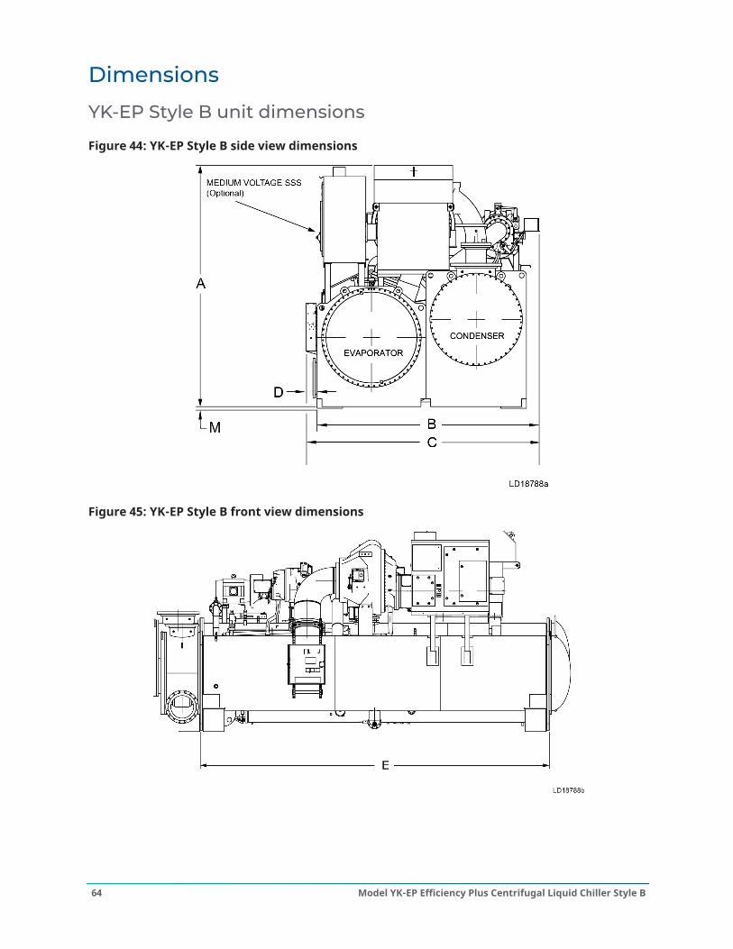
Dimensions
YK-EP Style B unit dimensions
Figure 44: YK-EP Style B side view dimensions
Figure 45: YK-EP Style B front view dimensions
Model YK-EP Efficiency Plus Centrifugal Liquid Chiller Style B64

Table 22: YK-EP unit dimensionsEvaporator-condenser shell codes dimensions, ft in. (mm)
Dimension typeB-B B-C C-B C-C
A12 ft 9 in.
(3,886)13 ft 0 in.
(3,962)13 ft 3 in.
(4,039)14 ft 5 in.
(4,394)
B12 ft 0 in.
(3,658)11 ft 10 in.
(3,606)12 ft 6 in.
(3,810)13 ft 3 in.
(4,039)
C12 ft 8 in.
(3,861)12 ft 6 in.
(3,810)13 ft 2 in.
(4,013)13 ft 11 in.
(4,242)
D8 in.(203)
8 in.(203)
8 in.(203)
8 in.(203)
E22 ft 0 in.
(6,706)22 ft 0 in.
(6,706)22 ft 0 in.
(6,706)22 ft 0 in.
(6,706)
Table 23: Additional operating height clearanceType of chiller mounting MNeoprene pad isolators 1 in. (25 mm)Spring isolators 1 in. deflection 1 in. (25 mm)Direct mount 3/4 in. (19 mm)
Note:1. All dimensions are approximate. Certified dimensions are available on request.2. Water nozzles can be located on either end of unit. Add 1/2 in. (13 mm) to nozzle length
for flanges connections.3. To determine overall height, add dimension M for the appropriate isolator type.4. Use of motors with motor hoods may increase overall unit dimensions.5. Tubesheets are provided with jacking point notches.6. Control panel in the shipment position will reduce overall width by 8 in. (203 mm).
65Model YK-EP Efficiency Plus Centrifugal Liquid Chiller Style B
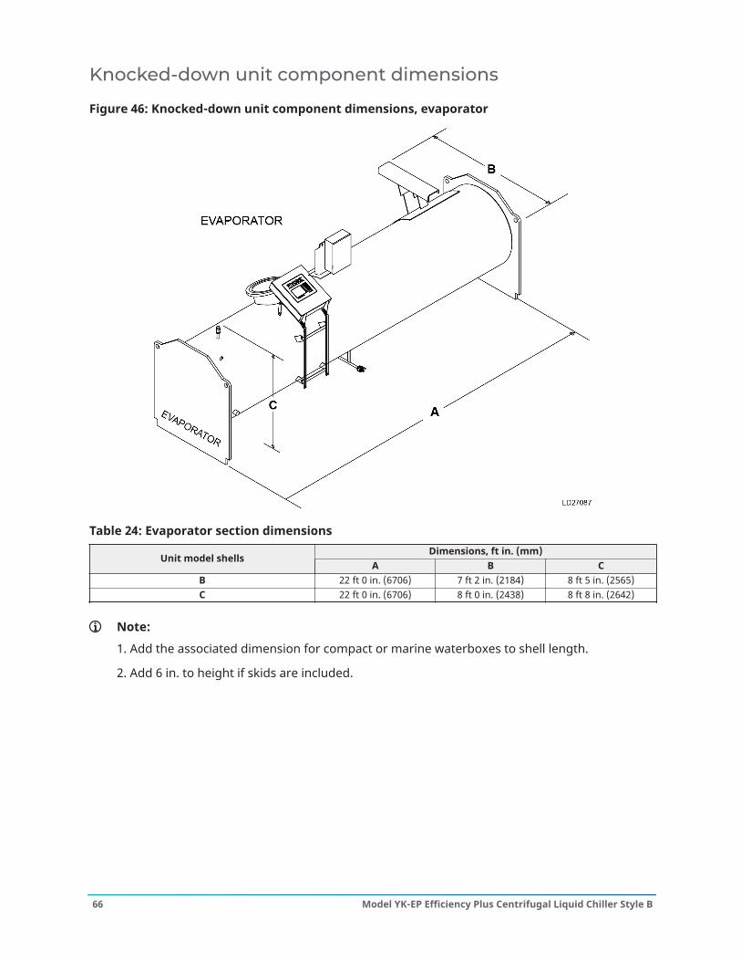
Knocked-down unit component dimensions
Figure 46: Knocked-down unit component dimensions, evaporator
Table 24: Evaporator section dimensionsDimensions, ft in. (mm)
Unit model shellsA B C
B 22 ft 0 in. (6706) 7 ft 2 in. (2184) 8 ft 5 in. (2565)C 22 ft 0 in. (6706) 8 ft 0 in. (2438) 8 ft 8 in. (2642)
Note:
1. Add the associated dimension for compact or marine waterboxes to shell length.
2. Add 6 in. to height if skids are included.
Model YK-EP Efficiency Plus Centrifugal Liquid Chiller Style B66
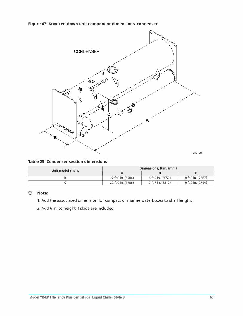
Figure 47: Knocked-down unit component dimensions, condenser
Table 25: Condenser section dimensionsDimensions, ft in. (mm)
Unit model shellsA B C
B 22 ft 0 in. (6706) 6 ft 9 in. (2057) 8 ft 9 in. (2667)C 22 ft 0 in. (6706) 7 ft 7 in. (2312) 9 ft 2 in. (2794)
Note:
1. Add the associated dimension for compact or marine waterboxes to shell length.
2. Add 6 in. to height if skids are included.
67Model YK-EP Efficiency Plus Centrifugal Liquid Chiller Style B
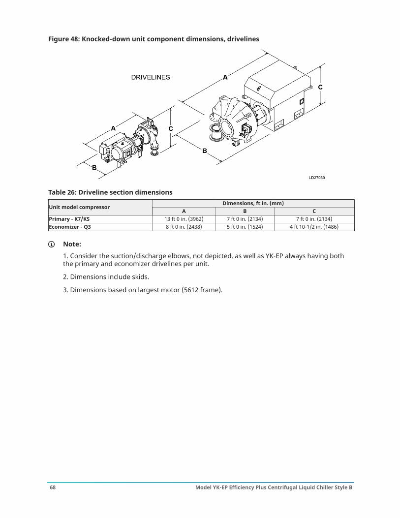
Figure 48: Knocked-down unit component dimensions, drivelines
Table 26: Driveline section dimensionsDimensions, ft in. (mm)
Unit model compressorA B C
Primary - K7/KS 13 ft 0 in. (3962) 7 ft 0 in. (2134) 7 ft 0 in. (2134)Economizer - Q3 8 ft 0 in. (2438) 5 ft 0 in. (1524) 4 ft 10-1/2 in. (1486)
Note:
1. Consider the suction/discharge elbows, not depicted, as well as YK-EP always having boththe primary and economizer drivelines per unit.
2. Dimensions include skids.
3. Dimensions based on largest motor (5612 frame).
Model YK-EP Efficiency Plus Centrifugal Liquid Chiller Style B68
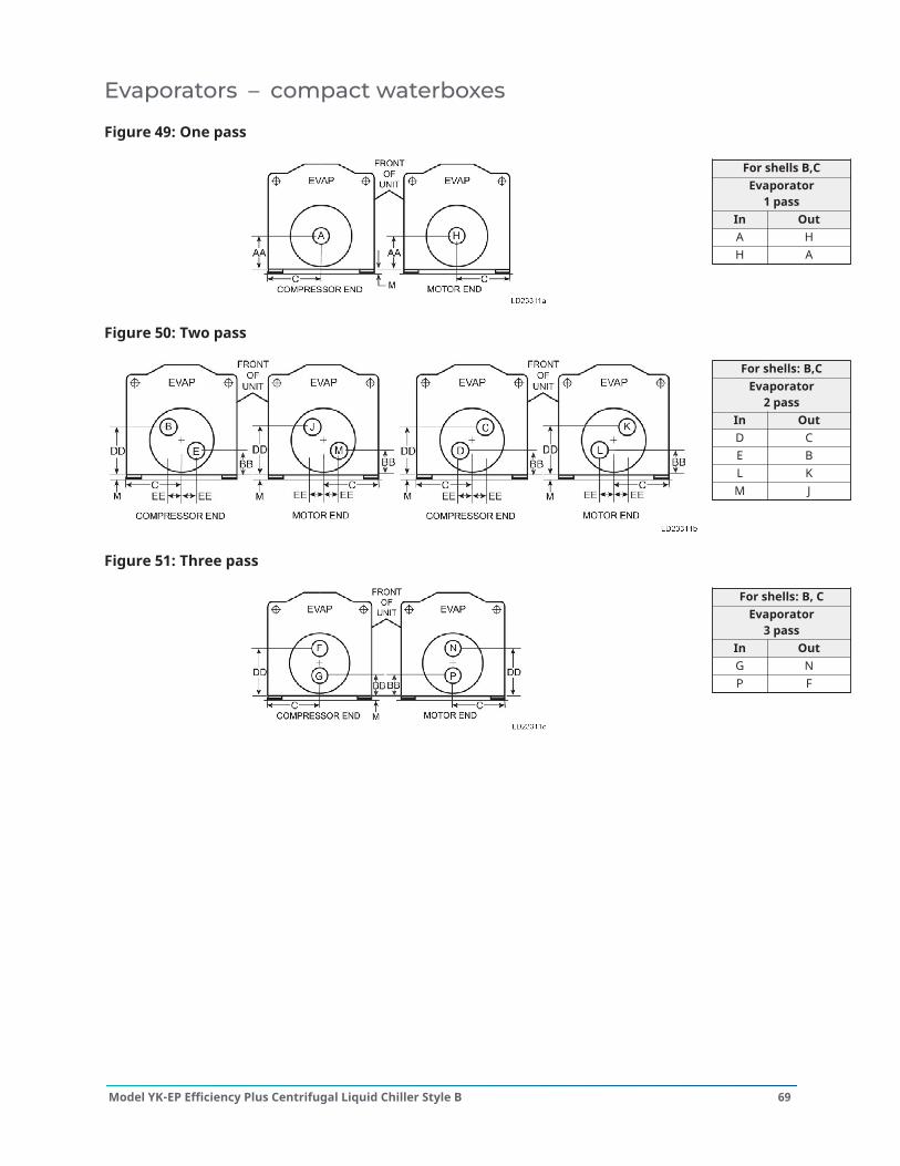
Evaporators – compact waterboxes
Figure 49: One pass
For shells B,CEvaporator
1 passIn OutA HH A
Figure 50: Two pass
For shells: B,CEvaporator
2 passIn OutD CE BL KM J
Figure 51: Three pass
For shells: B, CEvaporator
3 passIn OutG NP F
69Model YK-EP Efficiency Plus Centrifugal Liquid Chiller Style B
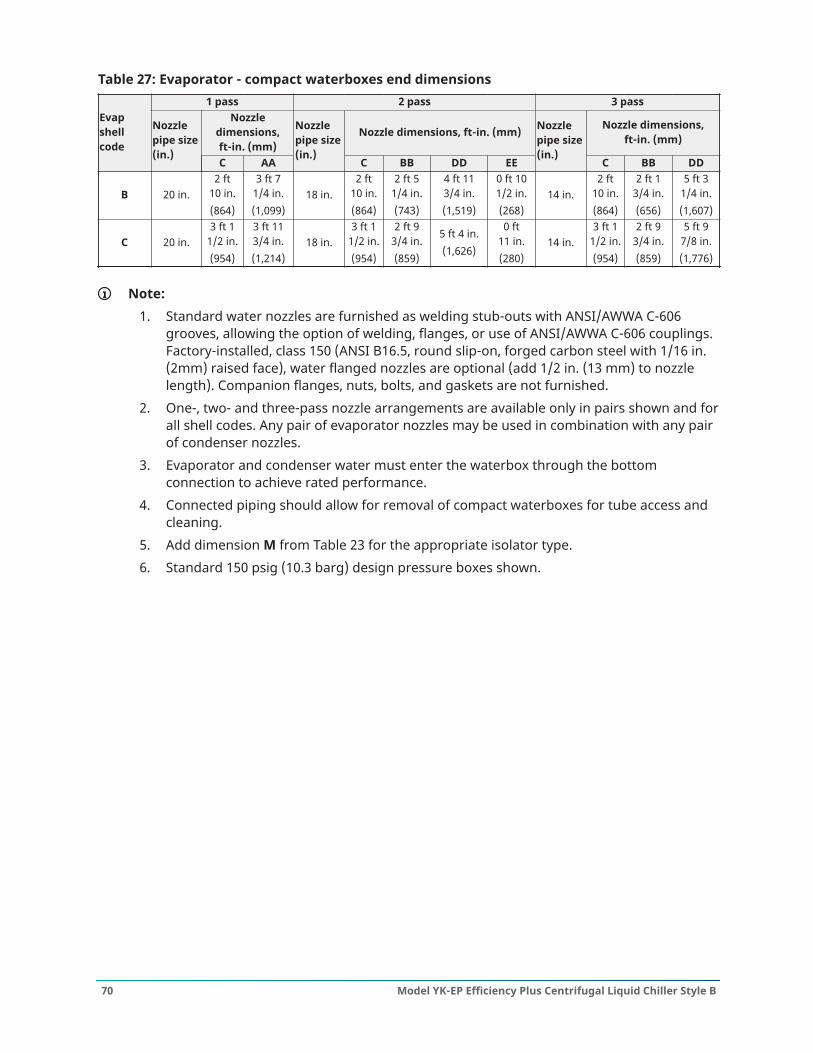
Table 27: Evaporator - compact waterboxes end dimensions1 pass 2 pass 3 pass
Nozzledimensions,ft-in. (mm)
Nozzle dimensions, ft-in. (mm) Nozzle dimensions,ft-in. (mm)
Evapshellcode
Nozzlepipe size(in.)
C AA
Nozzlepipe size(in.)
C BB DD EE
Nozzlepipe size(in.)
C BB DD
B 20 in.2 ft
10 in.(864)
3 ft 71/4 in.(1,099)
18 in.2 ft
10 in.(864)
2 ft 51/4 in.(743)
4 ft 113/4 in.(1,519)
0 ft 101/2 in.(268)
14 in.2 ft
10 in.(864)
2 ft 13/4 in.(656)
5 ft 31/4 in.(1,607)
C 20 in.3 ft 1
1/2 in.(954)
3 ft 113/4 in.(1,214)
18 in.3 ft 1
1/2 in.(954)
2 ft 93/4 in.(859)
5 ft 4 in.(1,626)
0 ft11 in.(280)
14 in.3 ft 1
1/2 in.(954)
2 ft 93/4 in.(859)
5 ft 97/8 in.(1,776)
Note:1. Standard water nozzles are furnished as welding stub-outs with ANSI/AWWA C-606
grooves, allowing the option of welding, flanges, or use of ANSI/AWWA C-606 couplings.Factory-installed, class 150 (ANSI B16.5, round slip-on, forged carbon steel with 1/16 in.(2mm) raised face), water flanged nozzles are optional (add 1/2 in. (13 mm) to nozzlelength). Companion flanges, nuts, bolts, and gaskets are not furnished.
2. One-, two- and three-pass nozzle arrangements are available only in pairs shown and forall shell codes. Any pair of evaporator nozzles may be used in combination with any pairof condenser nozzles.
3. Evaporator and condenser water must enter the waterbox through the bottomconnection to achieve rated performance.
4. Connected piping should allow for removal of compact waterboxes for tube access andcleaning.
5. Add dimension M from Table 23 for the appropriate isolator type.6. Standard 150 psig (10.3 barg) design pressure boxes shown.
Model YK-EP Efficiency Plus Centrifugal Liquid Chiller Style B70
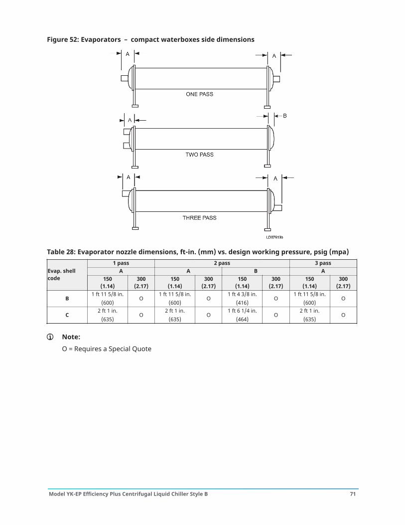
Figure 52: Evaporators – compact waterboxes side dimensions
Table 28: Evaporator nozzle dimensions, ft-in. (mm) vs. design working pressure, psig (mpa)1 pass 2 pass 3 pass
A A B AEvap. shellcode 150
(1.14)300
(2.17)150
(1.14)300
(2.17)150
(1.14)300
(2.17)150
(1.14)300
(2.17)
B1 ft 11 5/8 in.
(600)O
1 ft 11 5/8 in.(600)
O1 ft 4 3/8 in.
(416)O
1 ft 11 5/8 in.(600)
O
C2 ft 1 in.
(635)O
2 ft 1 in.(635)
O1 ft 6 1/4 in.
(464)O
2 ft 1 in.(635)
O
Note:
O = Requires a Special Quote
71Model YK-EP Efficiency Plus Centrifugal Liquid Chiller Style B
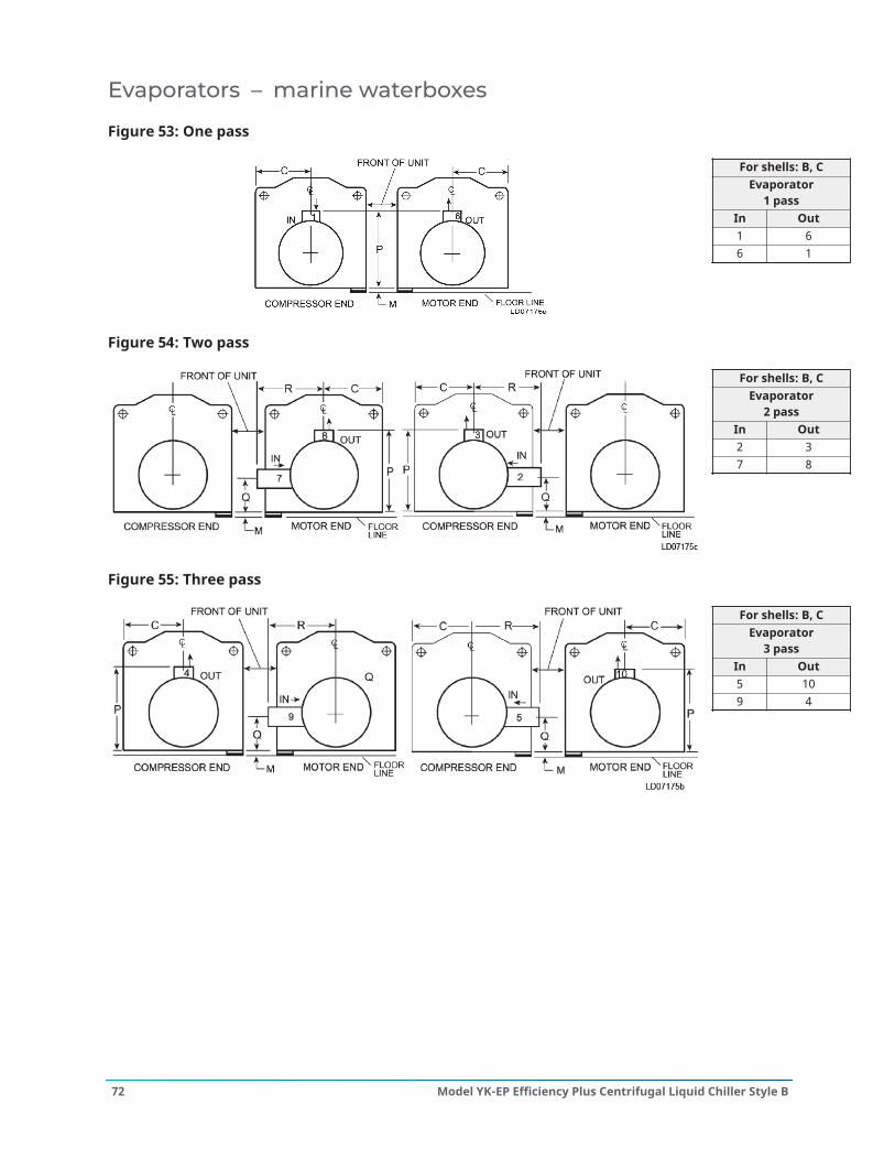
Evaporators – marine waterboxes
Figure 53: One pass
For shells: B, CEvaporator
1 passIn Out1 66 1
Figure 54: Two pass
For shells: B, CEvaporator
2 passIn Out2 37 8
Figure 55: Three pass
For shells: B, CEvaporator
3 passIn Out5 109 4
Model YK-EP Efficiency Plus Centrifugal Liquid Chiller Style B72

Table 29: Evaporator - marine waterboxes end dimensions1 pass 2 pass 3 pass
Nozzledimensions,ft-in. (mm)
Nozzle dimensions, ft-in. (mm) Nozzle dimensions, ft-in. (mm)Evapshellcode
Nozzlepipesize(in.) C P
Nozzlepipesize(in.) C P Q R
Nozzlepipesize(in.) C P Q R
B 20 in.2 ft
10 in.(864)
6 ft 95/8 in.(2,075)
18 in.2 ft
10 in.(864)
6 ft 95/8 in.(2,075)
1 ft 71/2 in.(497)
3 ft 01/8 in.(918)
14 in.2 ft
10 in.(864)
6 ft 95/8 in.(2,075)
1 ft 71/2 in.(497)
3 ft 01/8 in.(918)
C 20 in.3 ft 1
1/2 in.(954)
7 ft 51/8 in.(2,264)
18 in.3 ft 1
1/2 in.(954)
7 ft 51/8 in.(2,264)
2 ft 1 in.(635)
3 ft 03/4 in.(935)
14 in.3 ft 1
1/2 in.(954)
7 ft 51/8 in.(2,264)
2 ft 1 in.(635)
3 ft 03/4 in.(935)
Note:
1. All dimensions are approximate. Certified dimensions are available upon request.
2. Standard water nozzles are Schedule 40 pipe size, furnished as welding stub-outs with ANSI/AWWA C-606 grooves, allowing the option of welding, flanges, or use of ANSI/AWWA C-606couplings. Factory-installed, class 150 (ANSI B16.5, round slip-on, forged carbon steel with1/16 in. (2 mm) raised face), water flanged nozzles are optional (add 1/2 in. (13 mm) to nozzlelength). Companion flanges, nuts, bolts, and gaskets are not furnished.
3. One-, two-, and three-pass nozzle arrangements are available only in pairs shown and forall shell codes. Any pair of evaporator nozzles may be used in combination with any pair ofcondenser nozzles. Compact waterboxes on one heat exchanger may be used with MarineWaterboxes on the other heat exchanger.
4. Add dimension M from Table 23 for the appropriate isolator type.
73Model YK-EP Efficiency Plus Centrifugal Liquid Chiller Style B
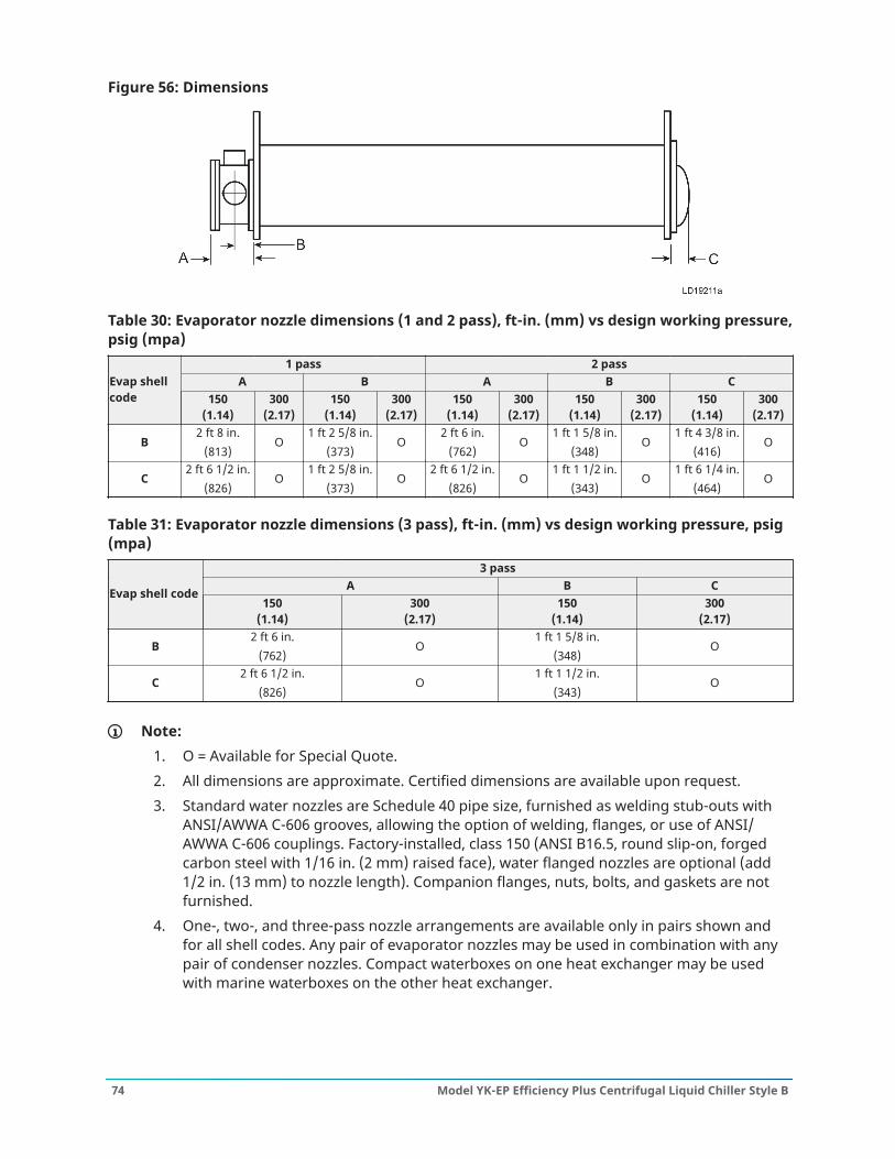
Figure 56: Dimensions
Table 30: Evaporator nozzle dimensions (1 and 2 pass), ft-in. (mm) vs design working pressure,psig (mpa)
1 pass 2 passA B A B CEvap shell
code 150(1.14)
300(2.17)
150(1.14)
300(2.17)
150(1.14)
300(2.17)
150(1.14)
300(2.17)
150(1.14)
300(2.17)
B2 ft 8 in.
(813)O
1 ft 2 5/8 in.(373)
O2 ft 6 in.
(762)O
1 ft 1 5/8 in.(348)
O1 ft 4 3/8 in.
(416)O
C2 ft 6 1/2 in.
(826)O
1 ft 2 5/8 in.(373)
O2 ft 6 1/2 in.
(826)O
1 ft 1 1/2 in.(343)
O1 ft 6 1/4 in.
(464)O
Table 31: Evaporator nozzle dimensions (3 pass), ft-in. (mm) vs design working pressure, psig(mpa)
3 passA B CEvap shell code
150(1.14)
300(2.17)
150(1.14)
300(2.17)
B2 ft 6 in.
(762)O
1 ft 1 5/8 in.(348)
O
C2 ft 6 1/2 in.
(826)O
1 ft 1 1/2 in.(343)
O
Note:1. O = Available for Special Quote.2. All dimensions are approximate. Certified dimensions are available upon request.3. Standard water nozzles are Schedule 40 pipe size, furnished as welding stub-outs with
ANSI/AWWA C-606 grooves, allowing the option of welding, flanges, or use of ANSI/AWWA C-606 couplings. Factory-installed, class 150 (ANSI B16.5, round slip-on, forgedcarbon steel with 1/16 in. (2 mm) raised face), water flanged nozzles are optional (add1/2 in. (13 mm) to nozzle length). Companion flanges, nuts, bolts, and gaskets are notfurnished.
4. One-, two-, and three-pass nozzle arrangements are available only in pairs shown andfor all shell codes. Any pair of evaporator nozzles may be used in combination with anypair of condenser nozzles. Compact waterboxes on one heat exchanger may be usedwith marine waterboxes on the other heat exchanger.
Model YK-EP Efficiency Plus Centrifugal Liquid Chiller Style B74
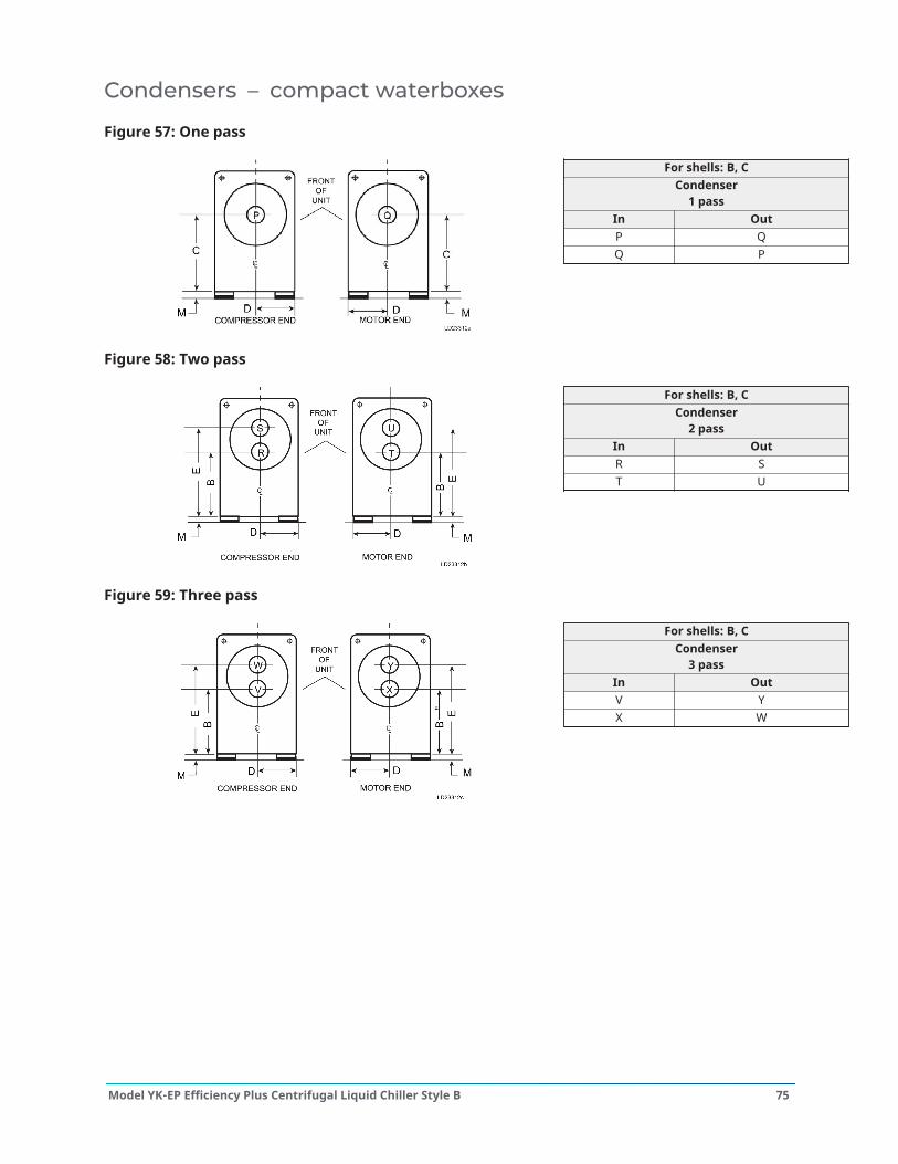
Condensers – compact waterboxes
Figure 57: One pass
For shells: B, CCondenser
1 passIn OutP QQ P
Figure 58: Two pass
For shells: B, CCondenser
2 passIn OutR ST U
Figure 59: Three pass
For shells: B, CCondenser
3 passIn OutV YX W
75Model YK-EP Efficiency Plus Centrifugal Liquid Chiller Style B
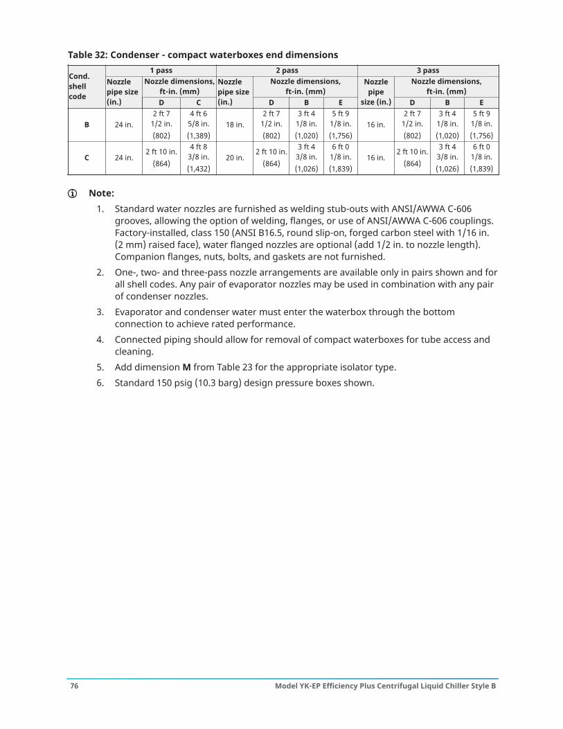
Table 32: Condenser - compact waterboxes end dimensions1 pass 2 pass 3 pass
Nozzle dimensions,ft-in. (mm)
Nozzle dimensions,ft-in. (mm)
Nozzle dimensions,ft-in. (mm)
Cond.shellcode
Nozzlepipe size(in.) D C
Nozzlepipe size(in.) D B E
Nozzlepipe
size (in.) D B E
B 24 in.2 ft 7
1/2 in.(802)
4 ft 65/8 in.(1,389)
18 in.2 ft 7
1/2 in.(802)
3 ft 41/8 in.(1,020)
5 ft 91/8 in.(1,756)
16 in.2 ft 7
1/2 in.(802)
3 ft 41/8 in.(1,020)
5 ft 91/8 in.(1,756)
C 24 in.2 ft 10 in.
(864)
4 ft 83/8 in.(1,432)
20 in.2 ft 10 in.
(864)
3 ft 43/8 in.(1,026)
6 ft 01/8 in.(1,839)
16 in.2 ft 10 in.
(864)
3 ft 43/8 in.(1,026)
6 ft 01/8 in.(1,839)
Note:1. Standard water nozzles are furnished as welding stub-outs with ANSI/AWWA C-606
grooves, allowing the option of welding, flanges, or use of ANSI/AWWA C-606 couplings.Factory-installed, class 150 (ANSI B16.5, round slip-on, forged carbon steel with 1/16 in.(2 mm) raised face), water flanged nozzles are optional (add 1/2 in. to nozzle length).Companion flanges, nuts, bolts, and gaskets are not furnished.
2. One-, two- and three-pass nozzle arrangements are available only in pairs shown and forall shell codes. Any pair of evaporator nozzles may be used in combination with any pairof condenser nozzles.
3. Evaporator and condenser water must enter the waterbox through the bottomconnection to achieve rated performance.
4. Connected piping should allow for removal of compact waterboxes for tube access andcleaning.
5. Add dimension M from Table 23 for the appropriate isolator type.6. Standard 150 psig (10.3 barg) design pressure boxes shown.
Model YK-EP Efficiency Plus Centrifugal Liquid Chiller Style B76
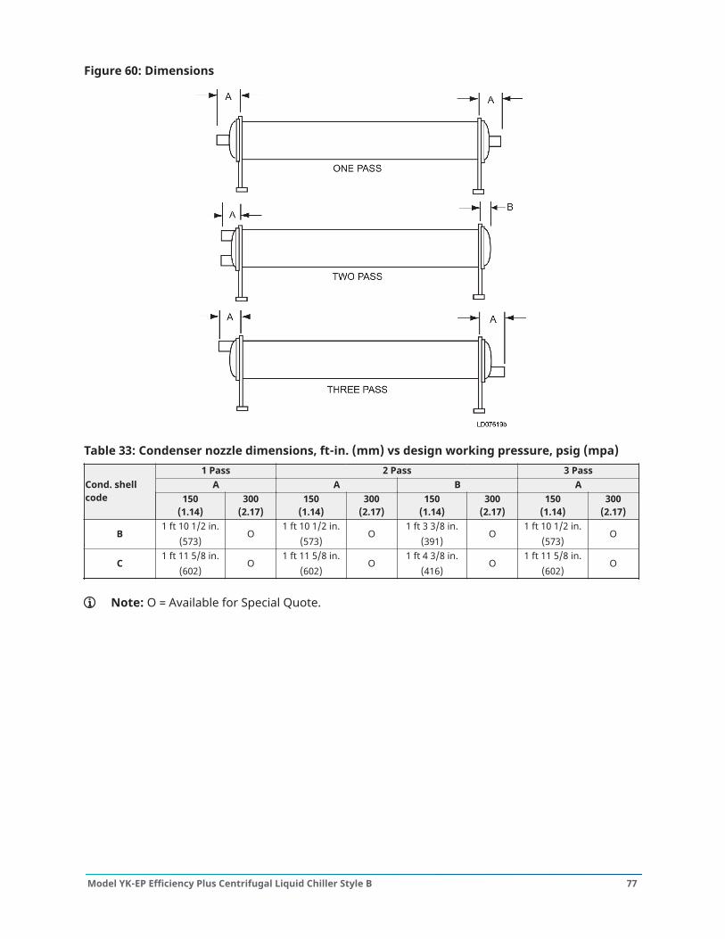
Figure 60: Dimensions
Table 33: Condenser nozzle dimensions, ft-in. (mm) vs design working pressure, psig (mpa)1 Pass 2 Pass 3 Pass
A A B ACond. shellcode 150
(1.14)300
(2.17)150
(1.14)300
(2.17)150
(1.14)300
(2.17)150
(1.14)300
(2.17)
B1 ft 10 1/2 in.
(573)O
1 ft 10 1/2 in.(573)
O1 ft 3 3/8 in.
(391)O
1 ft 10 1/2 in.(573)
O
C1 ft 11 5/8 in.
(602)O
1 ft 11 5/8 in.(602)
O1 ft 4 3/8 in.
(416)O
1 ft 11 5/8 in.(602)
O
Note: O = Available for Special Quote.
77Model YK-EP Efficiency Plus Centrifugal Liquid Chiller Style B

Condensers – marine waterboxes
Figure 61: One pass
For shells: B, CCondenser
1 passIn Out11 1616 11
Figure 62: Two pass
For shells: B, CCondenser
2 passIn Out17 1812 13
Figure 63: Three pass
For shells: B, CCondenser
3 passIn Out15 2019 14
Model YK-EP Efficiency Plus Centrifugal Liquid Chiller Style B78

Table 34: Condenser - marine waterboxes end dimensions1 pass 2 pass 3 pass
Nozzledimensions,ft-in. (mm)
Nozzle dimensions, ft-in. (mm) Nozzle dimensions, ft-in. (mm)Condshell code
Nozzlepipesize(in.) D S
Nozzlepipesize(in) D S T U
Nozzlepipesize(in) D S T U
B 24 in.2 ft 7
1/2 in.(802)
7 ft 53/8 in.(2,271)
18 in.2 ft 7
1/2 in.(802)
7 ft 53/8 in.(2,271)
3 ft 11/8 in.(943)
2 ft10 in.(864)
16 in.2 ft 7
1/2 in.(802)
7 ft 53/8 in.(2,271)
3 ft 11/8 in.(943)
2 ft10 in.(864)
C 24 in.2 ft
10 in.(864)
7 ft 91/4 in.(2,369)
20 in.2 ft
10 in.(864)
7 ft 91/4 in.(2,369)
3 ft3 in.(991)
2 ft 111/2 in.(903)
16 in.2 ft
10 in.(864)
7 ft 91/4 in.(2,369)
3 ft3 in.(991)
2 ft 111/2 in.(903)
Note:1. All dimensions are approximate. Certified dimensions are available upon request.2. Standard water nozzles are Schedule 40 pipe size, furnished as welding stub-outs with
ANSI/AWWA C-606 grooves, allowing the option of welding, flanges, or use of ANSI/AWWA C-606 couplings. Factory-installed, class 150 (ANSI B16.5, round slip-on, forgedcarbon steel with 1/16 in. (2 mm) raised face), water flanged nozzles are optional (add1/2 in. (13 mm) to nozzle length). Companion flanges, nuts, bolts, and gaskets are notfurnished.
3. One-, two-, and three-pass nozzle arrangements are available only in pairs shown andfor all shell codes. Any pair of evaporator nozzles may be used in combination with anypair of condenser nozzles. Compact waterboxes on one heat exchanger may be usedwith Marine Waterboxes on the other heat exchanger.
4. Condenser water must enter the waterbox through the bottom connection for properoperation of the sub-cooler to achieve rated performance.
5. Add dimension M from Table 23 for the appropriate isolator type.
79Model YK-EP Efficiency Plus Centrifugal Liquid Chiller Style B
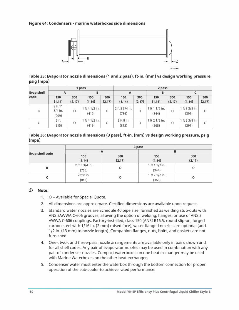
Figure 64: Condensers - marine waterboxes side dimensions
Table 35: Evaporator nozzle dimensions (1 and 2 pass), ft-in. (mm) vs design working pressure,psig (mpa)
1 pass 2 passA B A B CEvap shell
code 150(1.14)
300(2.17)
150(1.14)
300(2.17)
150(1.14)
300(2.17)
150(1.14)
300(2.17)
150(1.14)
300(2.17)
B2 ft 113/4 in.(909)
O1 ft 4 1/2 in.
(419)O
2 ft 5 3/4 in.(756)
O1 ft 1 1/2 in.
(344)O
1 ft 3 3/8 in.(391)
O
C3 ft
(915)O
1 ft 4 1/2 in.(419)
O2 ft 8 in.
(813)O
1 ft 2 1/2 in.(368)
O1 ft 3 3/8 in.
(391)O
Table 36: Evaporator nozzle dimensions (3 pass), ft-in. (mm) vs design working pressure, psig(mpa)
3 passA BEvap shell code
150(1.14)
300(2.17)
150(1.14)
300(2.17)
B2 ft 5 3/4 in.
(756)O
1 ft 1 1/2 in.(344)
O
C2 ft 8 in.
(813)O
1 ft 2 1/2 in.(368)
O
Note:1. O = Available for Special Quote.2. All dimensions are approximate. Certified dimensions are available upon request.3. Standard water nozzles are Schedule 40 pipe size, furnished as welding stub-outs with
ANSI/AWWA C-606 grooves, allowing the option of welding, flanges, or use of ANSI/AWWA C-606 couplings. Factory-installed, class 150 (ANSI B16.5, round slip-on, forgedcarbon steel with 1/16 in. (2 mm) raised face), water flanged nozzles are optional (add1/2 in. (13 mm) to nozzle length). Companion flanges, nuts, bolts, and gaskets are notfurnished.
4. One-, two-, and three-pass nozzle arrangements are available only in pairs shown andfor all shell codes. Any pair of evaporator nozzles may be used in combination with anypair of condenser nozzles. Compact waterboxes on one heat exchanger may be usedwith Marine Waterboxes on the other heat exchanger.
5. Condenser water must enter the waterbox through the bottom connection for properoperation of the sub-cooler to achieve rated performance.
Model YK-EP Efficiency Plus Centrifugal Liquid Chiller Style B80
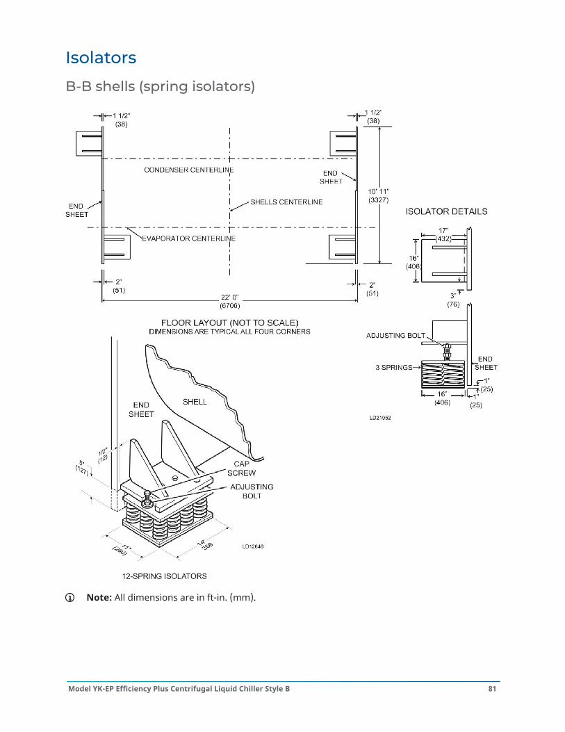
Isolators
B-B shells (spring isolators)
Note: All dimensions are in ft-in. (mm).
81Model YK-EP Efficiency Plus Centrifugal Liquid Chiller Style B
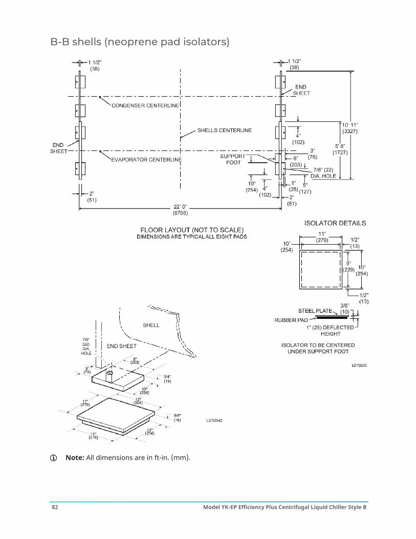
B-B shells (neoprene pad isolators)
Note: All dimensions are in ft-in. (mm).
Model YK-EP Efficiency Plus Centrifugal Liquid Chiller Style B82

B-C shells (spring isolators)
Note: All dimensions are in ft-in. (mm).
83Model YK-EP Efficiency Plus Centrifugal Liquid Chiller Style B
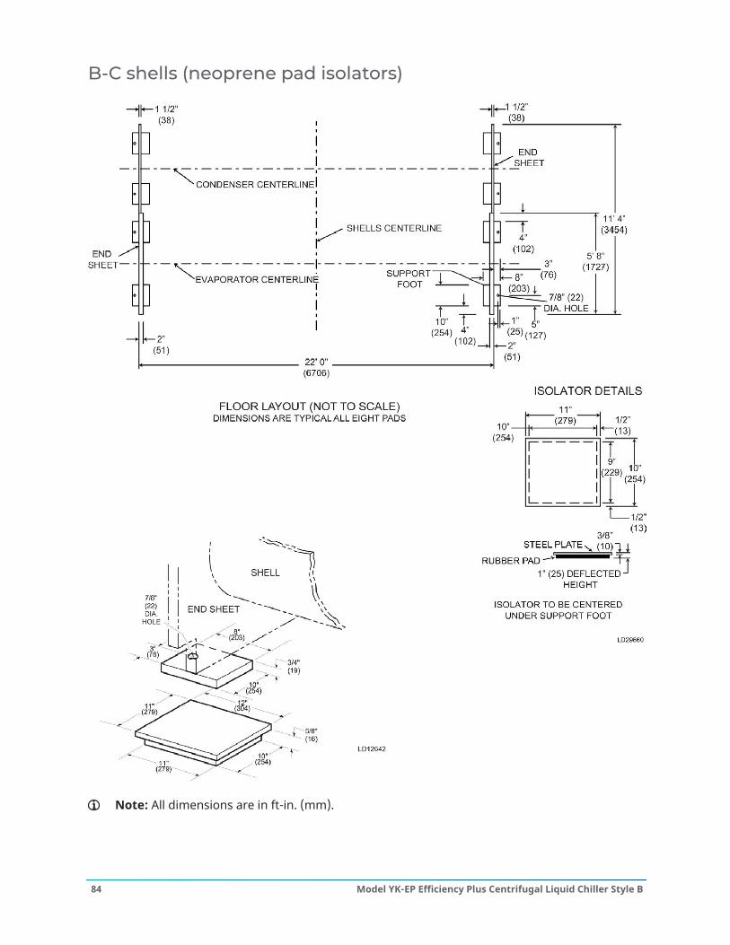
B-C shells (neoprene pad isolators)
Note: All dimensions are in ft-in. (mm).
Model YK-EP Efficiency Plus Centrifugal Liquid Chiller Style B84
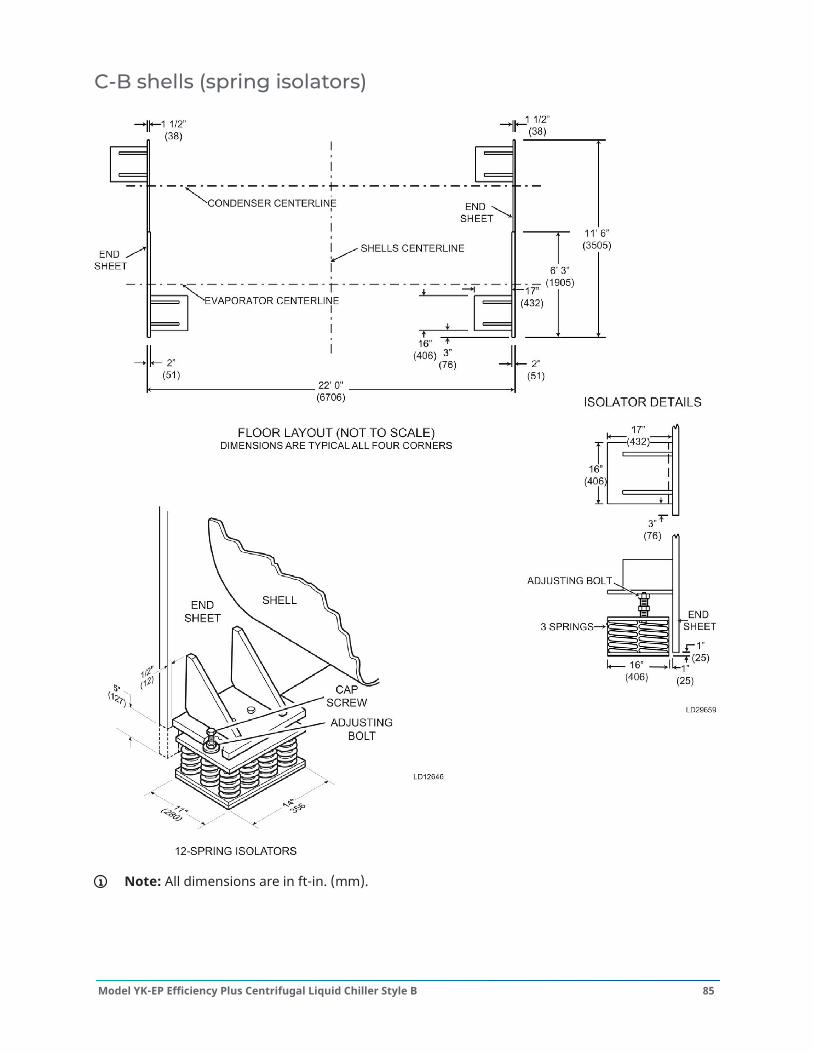
C-B shells (spring isolators)
Note: All dimensions are in ft-in. (mm).
85Model YK-EP Efficiency Plus Centrifugal Liquid Chiller Style B
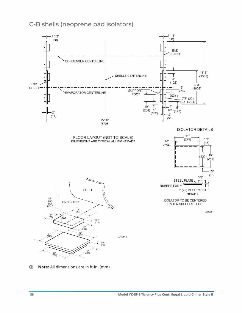
C-B shells (neoprene pad isolators)
Note: All dimensions are in ft-in. (mm).
Model YK-EP Efficiency Plus Centrifugal Liquid Chiller Style B86
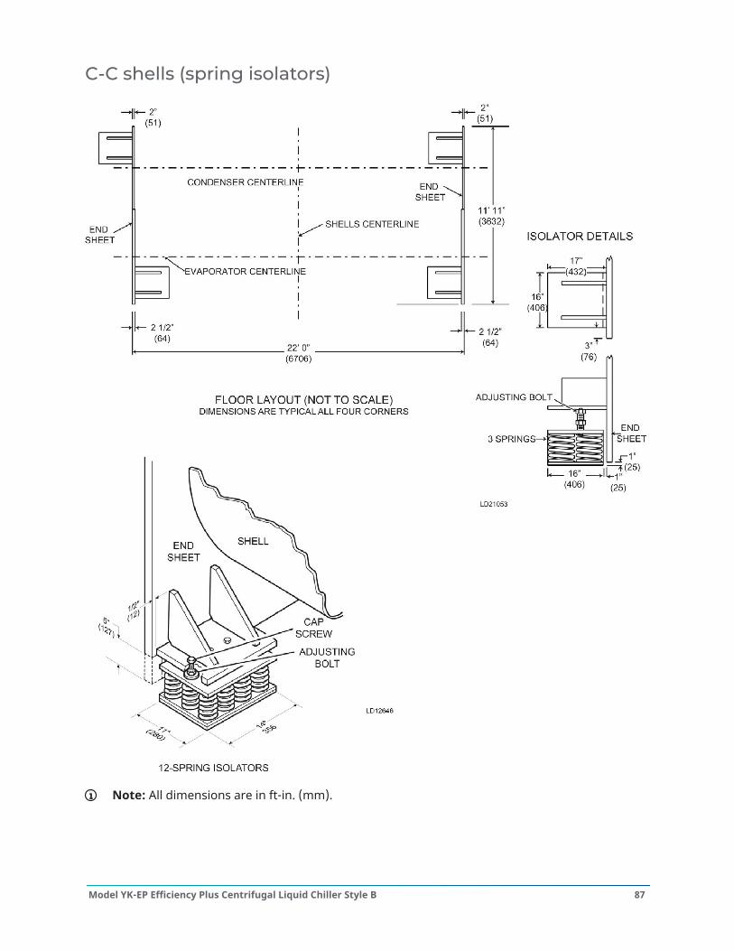
C-C shells (spring isolators)
Note: All dimensions are in ft-in. (mm).
87Model YK-EP Efficiency Plus Centrifugal Liquid Chiller Style B
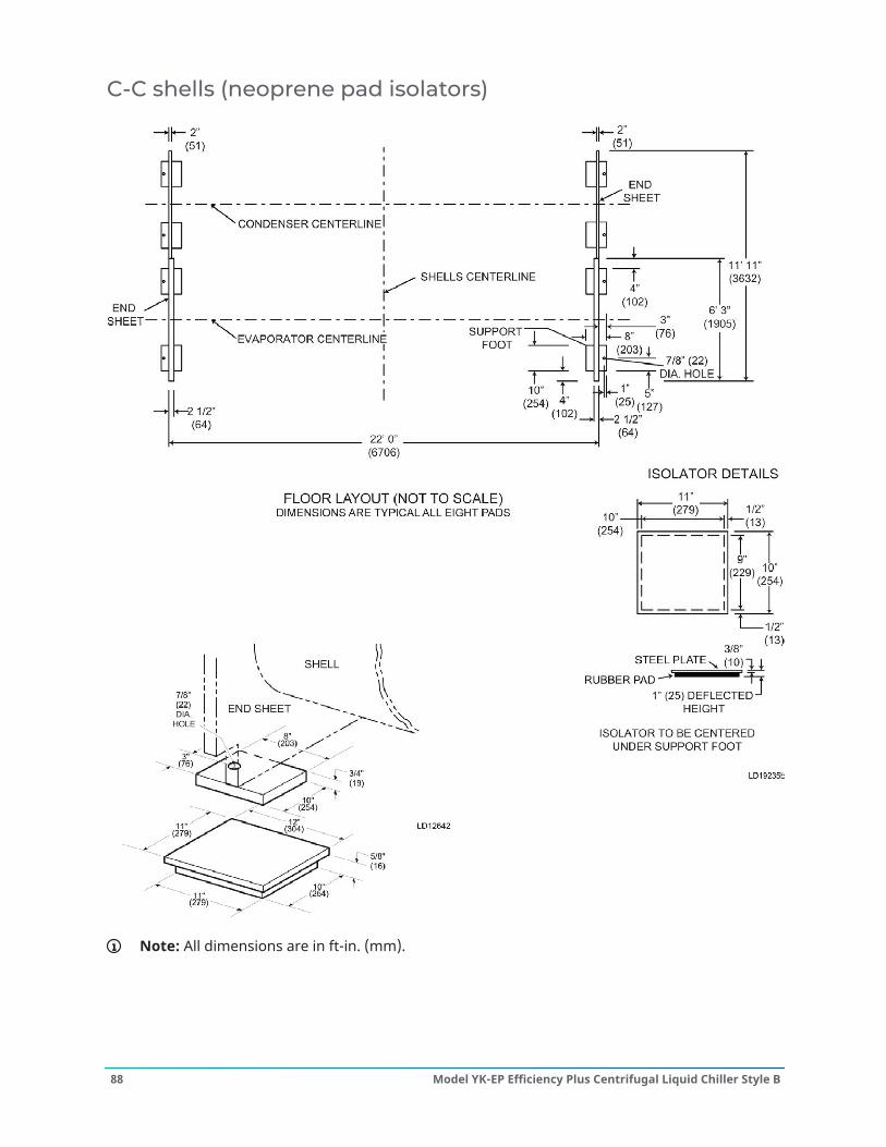
C-C shells (neoprene pad isolators)
Note: All dimensions are in ft-in. (mm).
Model YK-EP Efficiency Plus Centrifugal Liquid Chiller Style B88
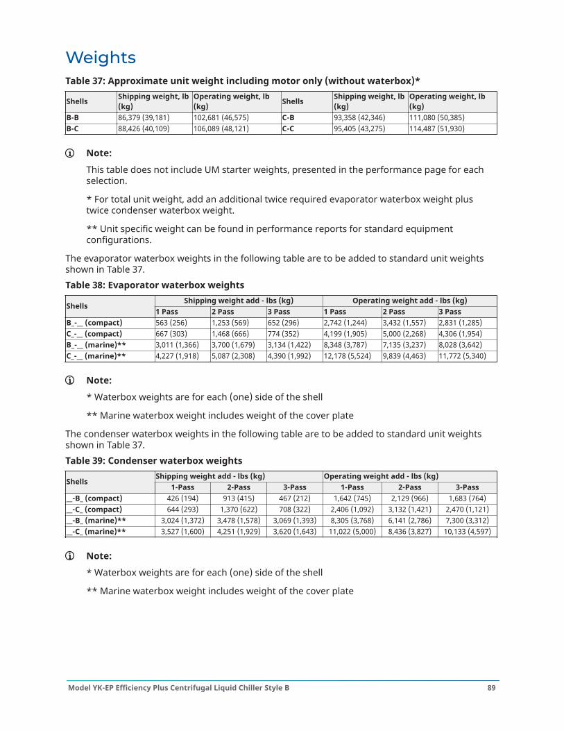
WeightsTable 37: Approximate unit weight including motor only (without waterbox)*
Shells Shipping weight, lb(kg)
Operating weight, lb(kg) Shells Shipping weight, lb
(kg)Operating weight, lb(kg)
B-B 86,379 (39,181) 102,681 (46,575) C-B 93,358 (42,346) 111,080 (50,385)B-C 88,426 (40,109) 106,089 (48,121) C-C 95,405 (43,275) 114,487 (51,930)
Note:
This table does not include UM starter weights, presented in the performance page for eachselection.
* For total unit weight, add an additional twice required evaporator waterbox weight plustwice condenser waterbox weight.
** Unit specific weight can be found in performance reports for standard equipmentconfigurations.
The evaporator waterbox weights in the following table are to be added to standard unit weightsshown in Table 37.Table 38: Evaporator waterbox weights
Shipping weight add - lbs (kg) Operating weight add - lbs (kg)Shells
1 Pass 2 Pass 3 Pass 1 Pass 2 Pass 3 PassB_-__ (compact) 563 (256) 1,253 (569) 652 (296) 2,742 (1,244) 3,432 (1,557) 2,831 (1,285)C_-__ (compact) 667 (303) 1,468 (666) 774 (352) 4,199 (1,905) 5,000 (2,268) 4,306 (1,954)B_-__ (marine)** 3,011 (1,366) 3,700 (1,679) 3,134 (1,422) 8,348 (3,787) 7,135 (3,237) 8,028 (3,642)C_-__ (marine)** 4,227 (1,918) 5,087 (2,308) 4,390 (1,992) 12,178 (5,524) 9,839 (4,463) 11,772 (5,340)
Note:
* Waterbox weights are for each (one) side of the shell
** Marine waterbox weight includes weight of the cover plate
The condenser waterbox weights in the following table are to be added to standard unit weightsshown in Table 37.Table 39: Condenser waterbox weights
Shipping weight add - lbs (kg) Operating weight add - lbs (kg)Shells
1-Pass 2-Pass 3-Pass 1-Pass 2-Pass 3-Pass__-B_ (compact) 426 (194) 913 (415) 467 (212) 1,642 (745) 2,129 (966) 1,683 (764)__-C_ (compact) 644 (293) 1,370 (622) 708 (322) 2,406 (1,092) 3,132 (1,421) 2,470 (1,121)__-B_ (marine)** 3,024 (1,372) 3,478 (1,578) 3,069 (1,393) 8,305 (3,768) 6,141 (2,786) 7,300 (3,312)__-C_ (marine)** 3,527 (1,600) 4,251 (1,929) 3,620 (1,643) 11,022 (5,000) 8,436 (3,827) 10,133 (4,597)
Note:
* Waterbox weights are for each (one) side of the shell
** Marine waterbox weight includes weight of the cover plate
89Model YK-EP Efficiency Plus Centrifugal Liquid Chiller Style B
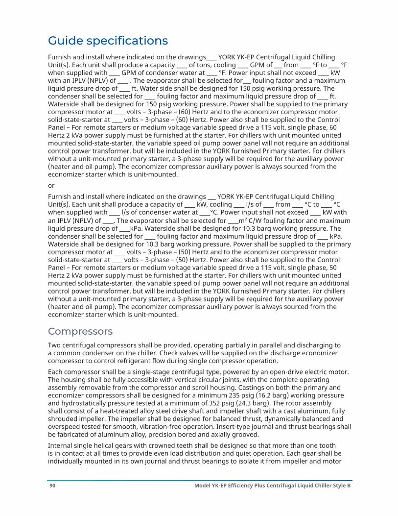
Guide specificationsFurnish and install where indicated on the drawings____ YORK YK-EP Centrifugal Liquid ChillingUnit(s). Each unit shall produce a capacity ____ of tons, cooling ____ GPM of ___ from ____ °F to ____ °Fwhen supplied with ____ GPM of condenser water at ____ °F. Power input shall not exceed ____ kWwith an IPLV (NPLV) of ____ . The evaporator shall be selected for___ fouling factor and a maximumliquid pressure drop of ____ ft. Water side shall be designed for 150 psig working pressure. Thecondenser shall be selected for ____ fouling factor and maximum liquid pressure drop of ____ ft.Waterside shall be designed for 150 psig working pressure. Power shall be supplied to the primarycompressor motor at ____ volts – 3-phase – (60) Hertz and to the economizer compressor motorsolid-state-starter at ____ volts – 3-phase – (60) Hertz. Power also shall be supplied to the ControlPanel – For remote starters or medium voltage variable speed drive a 115 volt, single phase, 60Hertz 2 kVa power supply must be furnished at the starter. For chillers with unit mounted unitedmounted solid-state-starter, the variable speed oil pump power panel will not require an additionalcontrol power transformer, but will be included in the YORK furnished Primary starter. For chillerswithout a unit-mounted primary starter, a 3-phase supply will be required for the auxiliary power(heater and oil pump). The economizer compressor auxiliary power is always sourced from theeconomizer starter which is unit-mounted.orFurnish and install where indicated on the drawings ___ YORK YK-EP Centrifugal Liquid ChillingUnit(s). Each unit shall produce a capacity of ____ kW, cooling ____ l/s of ____ from ____ °C to ____ °Cwhen supplied with ____ l/s of condenser water at ____°C. Power input shall not exceed ____ kW withan IPLV (NPLV) of ____. The evaporator shall be selected for ____m2 C/W fouling factor and maximumliquid pressure drop of ____kPa. Waterside shall be designed for 10.3 barg working pressure. Thecondenser shall be selected for ____ fouling factor and maximum liquid pressure drop of ____ kPa.Waterside shall be designed for 10.3 barg working pressure. Power shall be supplied to the primarycompressor motor at ____ volts – 3-phase – (50) Hertz and to the economizer compressor motorsolid-state-starter at ____ volts – 3-phase – (50) Hertz. Power also shall be supplied to the ControlPanel – For remote starters or medium voltage variable speed drive a 115 volt, single phase, 50Hertz 2 kVa power supply must be furnished at the starter. For chillers with unit mounted unitedmounted solid-state-starter, the variable speed oil pump power panel will not require an additionalcontrol power transformer, but will be included in the YORK furnished Primary starter. For chillerswithout a unit-mounted primary starter, a 3-phase supply will be required for the auxiliary power(heater and oil pump). The economizer compressor auxiliary power is always sourced from theeconomizer starter which is unit-mounted.
CompressorsTwo centrifugal compressors shall be provided, operating partially in parallel and discharging toa common condenser on the chiller. Check valves will be supplied on the discharge economizercompressor to control refrigerant flow during single compressor operation.Each compressor shall be a single-stage centrifugal type, powered by an open-drive electric motor.The housing shall be fully accessible with vertical circular joints, with the complete operatingassembly removable from the compressor and scroll housing. Castings on both the primary andeconomizer compressors shall be designed for a minimum 235 psig (16.2 barg) working pressureand hydrostatically pressure tested at a minimum of 352 psig (24.3 barg). The rotor assemblyshall consist of a heat-treated alloy steel drive shaft and impeller shaft with a cast aluminum, fullyshrouded impeller. The impeller shall be designed for balanced thrust, dynamically balanced andoverspeed tested for smooth, vibration-free operation. Insert-type journal and thrust bearings shallbe fabricated of aluminum alloy, precision bored and axially grooved.Internal single helical gears with crowned teeth shall be designed so that more than one toothis in contact at all times to provide even load distribution and quiet operation. Each gear shall beindividually mounted in its own journal and thrust bearings to isolate it from impeller and motor
Model YK-EP Efficiency Plus Centrifugal Liquid Chiller Style B90

forces. Shaft seals shall be provided and are of the double bellows, double-seal, cartridge type. Agravity-fed oil reservoir shall be built into the top of the compressor to provide lubrication duringcoast-down in the event of a power failure.Fixed Speed Drive - Capacity control shall be achieved by use of pre-rotation vanes to provide fullymodulating control from full load to minimum load.Variable Speed Drive - Capacity control shall be accomplished by the Adaptive Capacity Control(ACC), providing an optimal relationship between compressor speed and inlet pre-rotation vaneposition for maximum energy efficiency. Control shall automatically compensate for adverseoperating conditions, such as fouled tubes, and adjust to prior operation after correction of theseconditions.The unit shall be capable of continuous, reliable operation with low ECWT at all load conditions asoutlined on the equipment schedule. An external electric actuator shall automatically control pre-rotation vane position.
Lubrication systemLubrication oil shall be force-fed to all compressor bearings, gears, and rotating surfaces byexternal variable speed oil pumps. The oil pumps shall vary oil flow to the compressor based onoperating and stand-by conditions, ensuring adequate lubrication at all times. The oil pumps shalloperate prior to start-up, during compressor operation and during coastdown. Compressors shalleach have an auxiliary reservoir to provide lubrication during coastdown in the event of a powerfailure.An oil reservoir, separate from the compressor, shall contain the two submersible 2 HP oil pumpsand a oil heaters, thermostatically controlled to remove refrigerant from the oil. The oil reservoirshall be listed as part of the chiller by a nationally recognized testing laboratory and shall be factoryair strength tested at 1.1 times design working pressure.Oil shall be filtered by an externally mounted 1/2 micron replaceable cartridge oil filter equippedwith service valves. Oil cooling shall be done via a refrigerant cooled oil cooler, with all pipingfactory-installed. Oil side of the oil cooler shall be provided with service valves.An automatic oil return system to recover any oil that may have migrated to the evaporator shall beprovided. Oil piping shall be completely factory-installed and tested.
Motor drivelineEach compressor motor shall be an open drip-proof, squirrel cage, induction type operating at 3570rpm for 60 Hz operation and 2975 rpm for 50 Hz operation.Each open motor shall be provided with a D-flange, bolted to a cast iron adaptor mounted onthe compressor to allow the motor to be rigidly coupled to the compressor. This ensures factoryalignment of motor and compressor shafts.Each motor drive shaft shall be directly connected to its compressor shaft with a flexible disccoupling. The coupling shall have all metal construction with no wearing parts to assure longlife, and no lubrication requirements to provide low maintenance. A large steel terminal box withgasketed front access cover shall be provided for field-connected conduit.
EvaporatorEvaporator shall be of the shell-and-tube, flooded type designed for a minimum of 180 psig (12.4barg) working pressure on the refrigerant side. Shell shall be fabricated from rolled carbon steelplates with fusion welded seams, carbon steel tube sheets, drilled and reamed to accommodate thetubes, and intermediate tube supports spaced no more than four feet apart. The refrigerant sideof each shell is designed, tested and stamped in accordance with ASME Boiler and Pressure VesselCode, Section VIII – Division I, or other pressure vessel code as appropriate.
91Model YK-EP Efficiency Plus Centrifugal Liquid Chiller Style B
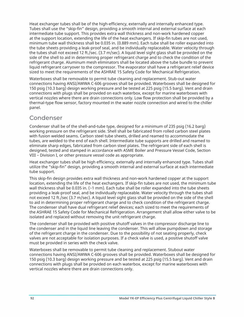
Heat exchanger tubes shall be of the high-efficiency, externally and internally enhanced type.Tubes shall use the “skip-fin” design, providing a smooth internal and external surface at eachintermediate tube support. This provides extra wall thickness and non-work hardened copperat the support location, extending the life of the heat exchangers. If skip-fin tubes are not used,minimum tube wall thickness shall be 0.035 in. (0.889 mm). Each tube shall be roller expanded intothe tube sheets providing a leak-proof seal, and be individually replaceable. Water velocity throughthe tubes shall not exceed 12 ft./sec. (3.7 m/sec). A liquid level sight glass shall be provided on theside of the shell to aid in determining proper refrigerant charge and to check the condition of therefrigerant charge. Aluminum mesh eliminators shall be located above the tube bundle to preventliquid refrigerant carryover to the compressor. The evaporator shall have a refrigerant relief devicesized to meet the requirements of the ASHRAE 15 Safety Code for Mechanical Refrigeration.Waterboxes shall be removable to permit tube cleaning and replacement. Stub-out waterconnections having ANSI/AWWA C-606 grooves shall be provided. Waterboxes shall be designed for150 psig (10.3 barg) design working pressure and be tested at 225 psig (15.5 barg). Vent and drainconnections with plugs shall be provided on each waterbox, except for marine waterboxes withvertical nozzles where there are drain connections only. Low flow protection shall be provided by athermal-type flow sensor, factory mounted in the water nozzle connection and wired to the chillerpanel.
CondenserCondenser shall be of the shell-and-tube type, designed for a minimum of 235 psig (16.2 barg)working pressure on the refrigerant side. Shell shall be fabricated from rolled carbon steel plateswith fusion welded seams. Carbon steel tube sheets, drilled and reamed to accommodate thetubes, are welded to the end of each shell. Intermediate tube supports are drilled and reamed toeliminate sharp edges, fabricated from carbon steel plates. The refrigerant side of each shell isdesigned, tested and stamped in accordance with ASME Boiler and Pressure Vessel Code, SectionVIII – Division I, or other pressure vessel code as appropriate.Heat exchanger tubes shall be high efficiency, externally and internally enhanced type. Tubes shallutilize the “skip-fin” design, providing a smooth internal and external surface at each intermediatetube support.This skip-fin design provides extra wall thickness and non-work hardened copper at the supportlocation, extending the life of the heat exchangers. If skip-fin tubes are not used, the minimum tubewall thickness shall be 0.035 in. (~1 mm). Each tube shall be roller expanded into the tube sheetsproviding a leak-proof seal, and be individually replaceable. Water velocity through the tubes shallnot exceed 12 ft./sec (3.7 m/sec). A liquid level sight glass shall be provided on the side of the shellto aid in determining proper refrigerant charge and to check condition of the refrigerant charge.The condenser shall have dual refrigerant relief devices; each sized to meet the requirements ofthe ASHRAE 15 Safety Code for Mechanical Refrigeration. Arrangement shall allow either valve to beisolated and replaced without removing the unit refrigerant charge.The condenser shall be provided with positive shutoff valves in the compressor discharge line tothe condenser and in the liquid line leaving the condenser. This will allow pumpdown and storageof the refrigerant charge in the condenser. Due to the possibility of not seating properly, checkvalves are not acceptable for isolation purposes. If a check valve is used, a positive shutoff valvemust be provided in series with the check valve.Waterboxes shall be removable to permit tube cleaning and replacement. Stubout waterconnections having ANSI/AWWA C-606 grooves shall be provided. Waterboxes shall be designed for150 psig (10.3 barg) design working pressure and be tested at 225 psig (15.5 barg). Vent and drainconnections with plugs shall be provided on each waterbox, except for marine waterboxes withvertical nozzles where there are drain connections only.
Model YK-EP Efficiency Plus Centrifugal Liquid Chiller Style B92

Refrigerant flow controlRefrigerant flow shall be controlled by a variable orifice. The variable orifice controls shallautomatically adjust to maintain proper refrigerant level in the condenser, economizer, andevaporator. This shall be controlled by monitoring refrigerant level in the condenser andeconomizer, assuring optimal subcooler and economizer performance.
Flash economizer (intercooler)A single stage, horizontal type, flash economizer (intercooler) shall be provided with internallymounted baffles, liquid spray pipe, an externally mounted level transmitter and an external controlvalve.
Control centerGeneral – The chiller shall be controlled by a single microprocessor based control center. Thechiller control panel shall provide control of chiller operation and monitoring of chiller sensors,actuators, relays and switches. The chiller panel shall provide capacity control operation of thecompressors, and shall provide cycling of primary compressor in response to load requirements.Control Panel – The control panel shall include a 10.4 in. diagonal color liquid crystal display (LCD)surrounded by "soft" keys which are redefined based on the screen displayed at that time. Thisshall be mounted in the middle of a keypad interface and installed in a locked enclosure. Thescreen shall detail all operations and parameters, using a graphical representation of the chillerand its major components. Panel verbiage shall be available in other languages as an option, withEnglish always available. Data shall be displayed in either English or Metric units. Smart FreezePoint Protection shall run the chiller at 36°F (2.2°C) leaving chilled water temperature, and not havenuisance trips on low water temperature. The sophisticated program and sensor shall monitor thechiller water temperature to prevent freeze up. The panel shall display countdown timer messagesso the operator knows when functions are starting and stopping. Every programmable point shallhave a pop up screen with the allowable ranges, so that the chiller cannot be programmed tooperate outside of its design limits.The chiller control panel shall also provide:
1. System operating information including:- Entering and leaving chilled water temperature- Entering and leaving condenser water temperature- Evaporator and condenser saturation temperature- Differential oil pressure (both compressors)- Percent motor current (both motors)- Compressor discharge temperature (both compressors)- Oil reservoir temperature- Compressor thrust bearing positioning (primary compressors)- Chiller operating hours, and operating hours- Number of unit starts, and number of starts each compressor
2. Local programming of setpoints through the universal keypad including:- Leaving chilled water temperature- Percent current limit- Pull down demand limiting- Six week schedule for starting and stopping the chiller, pumps and tower- Remote reset temperature range
93Model YK-EP Efficiency Plus Centrifugal Liquid Chiller Style B
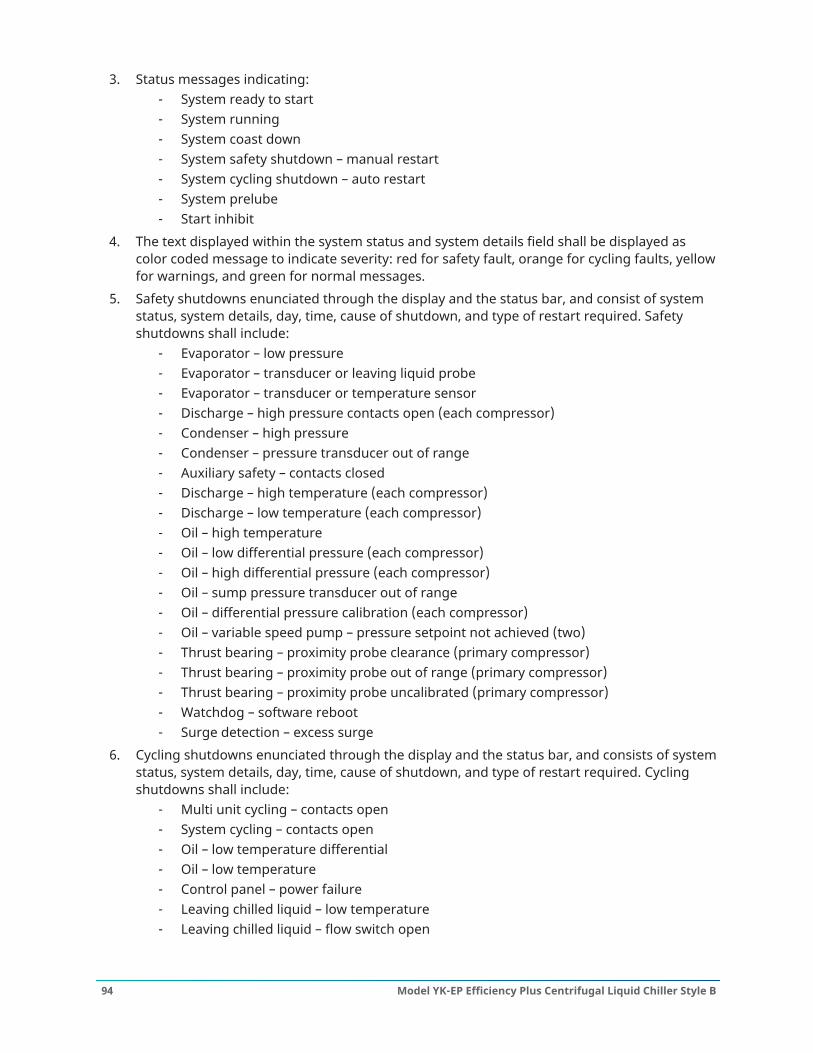
3. Status messages indicating:- System ready to start- System running- System coast down- System safety shutdown – manual restart- System cycling shutdown – auto restart- System prelube- Start inhibit
4. The text displayed within the system status and system details field shall be displayed ascolor coded message to indicate severity: red for safety fault, orange for cycling faults, yellowfor warnings, and green for normal messages.
5. Safety shutdowns enunciated through the display and the status bar, and consist of systemstatus, system details, day, time, cause of shutdown, and type of restart required. Safetyshutdowns shall include:
- Evaporator – low pressure- Evaporator – transducer or leaving liquid probe- Evaporator – transducer or temperature sensor- Discharge – high pressure contacts open (each compressor)- Condenser – high pressure- Condenser – pressure transducer out of range- Auxiliary safety – contacts closed- Discharge – high temperature (each compressor)- Discharge – low temperature (each compressor)- Oil – high temperature- Oil – low differential pressure (each compressor)- Oil – high differential pressure (each compressor)- Oil – sump pressure transducer out of range- Oil – differential pressure calibration (each compressor)- Oil – variable speed pump – pressure setpoint not achieved (two)- Thrust bearing – proximity probe clearance (primary compressor)- Thrust bearing – proximity probe out of range (primary compressor)- Thrust bearing – proximity probe uncalibrated (primary compressor)- Watchdog – software reboot- Surge detection – excess surge
6. Cycling shutdowns enunciated through the display and the status bar, and consists of systemstatus, system details, day, time, cause of shutdown, and type of restart required. Cyclingshutdowns shall include:
- Multi unit cycling – contacts open- System cycling – contacts open- Oil – low temperature differential- Oil – low temperature- Control panel – power failure- Leaving chilled liquid – low temperature- Leaving chilled liquid – flow switch open
Model YK-EP Efficiency Plus Centrifugal Liquid Chiller Style B94

- Motor controller – contacts open (each motor)- Motor controller – loss of current (each motor)- Power fault for each motor- Control panel – schedule- Proximity probe – low supply voltage (Primary compressor)- Oil – variable speed pump – drive contacts open (each pump)
7. Security access to prevent unauthorized change of setpoints, to allow local or remote controlof the chiller, and to allow manual operation of the pre rotation vanes and oil pump. Accessshall be through ID and password recognition, which is defined by three different levels ofuser competence: view, operator, and service.
8. Trending data with the ability to customize points of once every second to once every hour.The panel shall trend up to 6 different parameters from a list of over 140, without the need ofan external monitoring system.
9. The operating program is stored in non volatile memory (Flash) to eliminate reprogrammingthe chiller due to AC power failure. Programmed setpoints shall be retained in lithium batterybacked RTC memory for a minimum of 11 years with power removed from the system.
10. A fused connection through a transformer mounted on the variable speed oil pump panelshall provide individual overcurrent protected power for all controls.
11. A numbered terminal strip for all required field interlock wiring.12. An RS-232 port to output current Status Report, History Reports, and Data Logging and a
record of the last 10 cycling or safety shutdowns to a field supplied printer. Data logs to aprinter or a computer at a set programmable interval. This data can be preprogrammed toprint from 1 minute to 1 day.
13. The capability to interface with a building automation system to provide:- Remote chiller start and stop- Remote leaving chiller liquid temperature adjust- Remote current limit setpoint adjust- Remote ready to start contacts- Safety shutdown contacts- Cycling shutdown contacts- Run contacts
High and medium voltage VSD starter (option for primarycompressor)The Variable Speed Drive will be remote floor mounted. It will vary the compressor motor speedby controlling the frequency and voltage of the electrical power to the motor. The capacitycontrol logic shall automatically adjust motor speed and compressor pre-rotation vane positionindependently for maximum part-load efficiency by analyzing information fed to it by sensorslocated throughout the chiller.
DefinitionsFor the purpose of this Specification, the following definitions apply:
• VSD - Variable speed drive is a device that is used to vary the speed of a previously fixedspeed motor.
95Model YK-EP Efficiency Plus Centrifugal Liquid Chiller Style B

• NPC - Neutral Point Clamp is a VSD topology that has the advantage of reducing the high lineto neutral voltage that can occur in other traditional drive designs that can reach 2.7 to 3.3times normal levels.
• PWM - Pulse Width Modulation is a method of controlling power devices to convert voltagelevels. PWM is a popular method of control for converting DC voltage to AC voltage.
• IGBT- Insulated Gate Bipolar Transistor is a high speed electrical switching power device. It isvery efficient requiring very low power for control circuits
• HCT - Hall Effect Current Transformer are used for detection of currents over a fre-quencyrange of DC to high frequency without direct contact or shunts.
• CPT- Control Power Transformer is typically used to power control circuits and relays for theVSD.
• FLA - Full Load Amps.
ComponentsThe VSD shall consist of the following components:
• Incoming Disconnect• A 24 pulse input Isolation Transformer from high voltages to 4160 V with Rectifier that limits
electrical power supply distortion.• Frequency Converter/Inverter• VSD Protective System/Devices• Output filter or reactor (when required to limit reflected voltage)• Output Disconnect(s) or bypass (when specified on Data Sheet)• Diagnostics and Control Circuits• Two control power transformers, for the Control Center and for chiller oil pump operation
FeaturesThe following features will be provided:
• PWM type utilizing IGBTs with a power factor of 0.95 or better at all loads and speeds• Door interlocked circuit breaker capable of being padlocked• UL listed ground fault protection• Over voltage and under voltage protection• 3-phase sensing motor over current protection• Single phase protection• Insensitive to phase rotation• Over temperature protection• Digital readout at the chiller unit control panel of output frequency, output voltage, 3-phase
output current, input Kilowatts and Kilowatt-hours, self-diagnostic service parameters,Elapsed Time Meter
• Separate meters for this information will not be acceptable
General design and fabricationThe VSD inverter/chopper shall be of the pulse width modulated (PWM) Neutral Point Clamp(NPC) type. The output devices shall be Insulated Gate Bipolar Transistors (IGBTs) with a minimum
Model YK-EP Efficiency Plus Centrifugal Liquid Chiller Style B96

voltage rating of 3300 V. Use of lower rated devices is unacceptable due to the quantity of devicesrequired in the design.
• All components and material shall be new and of the latest field proven design and in currentproduction. Obsolete components or components scheduled for immediate discontinuationshall not be used.
• The equipment shall be completely factory built, assembled, wired, and tested. When itis necessary to disassemble the units for ease of transportation, adequate materials andinstructions shall be provided for easy field reassembling.
• For VSD applications where the line voltage is higher than 6600 V, and the drive uses an inputvoltage of 6600 V or less, then any transformer used to reduce the line voltage from greaterthan 6600 V to less than 6600 V must have the transformer inefficiencies included in thechiller energy analysis.
• The VSD shall be capable of continuous operation up to altitudes of 5,000 ft (1,500 m), if notthe VSD should be oversized to comply with the design conditions.
Enclosures and coolingThe VSD enclosure shall be suitable for installation in an indoor, unclassified area.All enclosure openings exceeding 0.25 in. (6 mm) in width shall be provided with screens to preventthe entrance of snakes, rodents, etc. The maximum screen mesh opening width shall be 0.25 in. (6mm).A “loss of cooling” fault shutdown shall be furnished with this forced cooled equipment. In theevent of clogged filters or fan failure, the drive will shut down safely without electronic componentfailure.Air filters shall be of a reusable type that can be easily cleaned. All doors or front panels will be fullygasketed. Air exhaust from cooling fans will be at the top of the enclosure away from personnel infront of the equipment.Fan motors shall be protected by an input circuit breaker. Metal squirrel cage ball bearing 460 Vthree phase fan motors are to be used in the drive design. Plastic muffin fans are not acceptable. Asspecified on the data sheet, fan power will be obtained from a remote 460 V three-phase power orfrom the primary 2300 / 3300 / 4160 V power through a tap on the input transformer.The maximum noise level of the unit shall not exceed 80 dBA at a distance of 3.3 ft (1 m) from theunit and at a height of 4.9 ft (1.5 m) above the floor.
PaintingUse Manufacturer’s standard finish.
Operational controlsAll operator controls and adjustments are through the Chiller control center.The VSD shall include necessary components to protect the VSD and motor against motor overload,internal faults in either the motor or VSD and disturbances in the incoming AC line.The following conditions shall cause the VSD to be shut down with the output voltage reduced tozero. The failure shall be annunciated on the Chiller control center.
• Cooling fan loss• Input transformer over temperature• Heatsink over temperature• Motor current overload• Output current imbalance
97Model YK-EP Efficiency Plus Centrifugal Liquid Chiller Style B
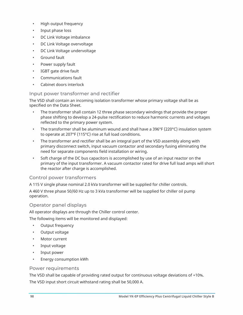
• High output frequency• Input phase loss• DC Link Voltage imbalance• DC Link Voltage overvoltage• DC Link Voltage undervoltage• Ground fault• Power supply fault• IGBT gate drive fault• Communications fault• Cabinet doors interlock
Input power transformer and rectifierThe VSD shall contain an incoming isolation transformer whose primary voltage shall be asspecified on the Data Sheet.
• The transformer shall contain 12 three phase secondary windings that provide the properphase shifting to develop a 24-pulse rectification to reduce harmonic currents and voltagesreflected to the primary power system.
• The transformer shall be aluminum wound and shall have a 396°F (220°C) insulation systemto operate at 207°F (115°C) rise at full load conditions.
• The transformer and rectifier shall be an integral part of the VSD assembly along withprimary disconnect switch, input vacuum contactor and secondary fusing eliminating theneed for separate components field installation or wiring.
• Soft charge of the DC bus capacitors is accomplished by use of an input reactor on theprimary of the input transformer. A vacuum contactor rated for drive full load amps will shortthe reactor after charge is accomplished.
Control power transformersA 115 V single phase nominal 2.0 kVa transformer will be supplied for chiller controls.A 460 V three phase 50/60 Hz up to 3 kVa transformer will be supplied for chiller oil pumpoperation.
Operator panel displaysAll operator displays are through the Chiller control center.The following items will be monitored and displayed:
• Output frequency• Output voltage• Motor current• Input voltage• Input power• Energy consumption kWh
Power requirementsThe VSD shall be capable of providing rated output for continuous voltage deviations of +10%.The VSD input short circuit withstand rating shall be 50,000 A.
Model YK-EP Efficiency Plus Centrifugal Liquid Chiller Style B98

The VSD shall be able to ride through voltage dips down to 10% of minimum, such as thoseexperienced during motor starting.The VSD 40 second overload current rating shall be set at 105% of rated compressor current.The VSD shall help buildings comply with the requirements of IEEE Std. 519.Voltage distortion shall not exceed 3% and current distortion shall not exceed 5% at the inputlugs of the VSD over an operating power range of 30% to 100% of rated power with phase voltageimbalance per the 3% specification.The VSD converter section shall be configured as a 24 pulse or greater to eliminate the need forharmonic filters.
Power busAll power bus bars, when part of the standard design and other current carrying parts shall be tin-plated copper for corrosion resistance. Power bus bar joints shall be tin plated.Bus bars shall be braced to withstand short circuit currents shown on the Data Sheet with aminimum of 50 kAIC.Input and output connections shall be either top or bottom access in the standard design.
Inverter section designThe VSD inverter section shall consist of three cells where each cell has two series DC powersupplies per phase. Each DC supply is derived from a phase shifted secondary of the inputtransformer that cancels reflected harmonics back to the power line. The DC power supply isfiltered by long lasting oil filled capacitors. Electrolytic capacitors are not permitted.Each cell has eight 3300 V Insulated Gate Bipolar Transistors (IGBTs) in a single phase bridgeconnection such that when in combination with the other bridges, a 5 level output voltage isconstructed to the motor. A bridge neutral point is jumpered to each of the three cells. Thisconfiguration called Neutral Point Clamp (NPC) provides a normal phase to ground level voltagesthat are superior to other direct PWM or multi-level twelve cell VSD designs that can cause 1.8 to 3.3times normal line to ground voltage.Each power device communicates to the microprocessor with fiber optic communications. No otherisolation method is allowed.A high resistance ground detection circuit at the neutral point is used for system shutdowns in theevent the load has a ground fault.Two Hall Effect Current Transformers (HCT) are used for current feedback on the VSD output.PWM firing pulses will result in an output voltage and current waveform that will result in less than2% torque ripple over a 20 to 1 speed range on the motor.
DisconnectsThe VSD shall include a main disconnect device with an interlocked and padlockable handlemechanism. The disconnecting device shall be a medium voltage vacuum contactor with a boltedpressure disconnect switch whose blades are externally visible from outside the enclosure. Thedisconnect device shall have a momentary withstand rating greater than the available fault currentindicated on the Data Sheet.When multiple doors are supplied, all doors shall be electrically interlocked with the disconnectdevice. The interlocks shall include provisions to manually override for test and repair.
Wiring and terminationsBus bar with standard four-hole pattern to be supplied for input and output shall be provided forconnection of external wiring and shall be conveniently located, clearly numbered, and identified.
99Model YK-EP Efficiency Plus Centrifugal Liquid Chiller Style B
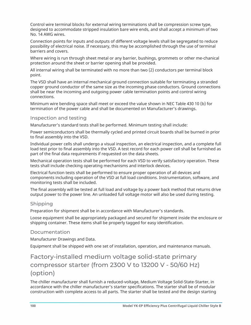
Control wire terminal blocks for external wiring terminations shall be compression screw type,designed to accommodate stripped insulation bare wire ends, and shall accept a minimum of twoNo. 14 AWG wires.Connection points for inputs and outputs of different voltage levels shall be segregated to reducepossibility of electrical noise. If necessary, this may be accomplished through the use of terminalbarriers and covers.Where wiring is run through sheet metal or any barrier, bushings, grommets or other me-chanicalprotection around the sheet or barrier opening shall be provided.All internal wiring shall be terminated with no more than two (2) conductors per terminal blockpoint.The VSD shall have an internal mechanical ground connection suitable for terminating a strandedcopper ground conductor of the same size as the incoming phase conductors. Ground connectionsshall be near the incoming and outgoing power cable termination points and control wiringconnections.Minimum wire bending space shall meet or exceed the value shown in NEC Table 430 10 (b) fortermination of the power cable and shall be documented on Manufacturer’s drawings.
Inspection and testingManufacturer’s standard tests shall be performed. Minimum testing shall include:Power semiconductors shall be thermally cycled and printed circuit boards shall be burned in priorto final assembly into the VSD.Individual power cells shall undergo a visual inspection, an electrical inspection, and a complete fullload test prior to final assembly into the VSD. A test record for each power cell shall be furnished aspart of the final data requirements if requested on the data sheets.Mechanical operation tests shall be performed for each VSD to verify satisfactory operation. Thesetests shall include checking operating mechanisms and interlock devices.Electrical function tests shall be performed to ensure proper operation of all devices andcomponents including operation of the VSD at full load conditions. Instrumentation, software, andmonitoring tests shall be included.The final assembly will be tested at full load and voltage by a power back method that returns driveoutput power to the power line. An unloaded full voltage motor will also be used during testing.
ShippingPreparation for shipment shall be in accordance with Manufacturer’s standards.Loose equipment shall be appropriately packaged and secured for shipment inside the enclosure orshipping container. These items shall be properly tagged for easy identification.
DocumentationManufacturer Drawings and Data.Equipment shall be shipped with one set of installation, operation, and maintenance manuals.
Factory-installed medium voltage solid-state primarycompressor starter (from 2300 V to 13200 V - 50/60 Hz)(option)The chiller manufacturer shall furnish a reduced-voltage, Medium Voltage Solid-State-Starter, inaccordance with the chiller manufacturer’s starter specifications. The starter shall be of modularconstruction with complete access to all parts. The starter shall be tested and the design starting
Model YK-EP Efficiency Plus Centrifugal Liquid Chiller Style B100
current and overload settings adjusted at the factory. The starter shall provide, through the use ofsix in-line (not inside the Delta) silicon controlled rectifiers (2 per phase), a smooth acceleration ofthe motor without current transitions or transients.The following protective devices and convenience items shall be factory mounted and wired to thestarter:
1. Three leg sensing electronic overloads – shuts unit down if current exceeds 105% of FLA toprotect the motor windings.
2. Phase rotation protection circuit – denies start-up when detecting incorrect power wiringphase sequence to the starter which could cause reverse motor rotation and damage theequipment.
3. Single-phase failure protection circuit – ensures against motor burnout by shutting the unitdown if power loss occurs in any of the incoming lines during start-up.
4. High temperature safety protection system – temperature activated switches on heat sinkswill shut the unit down if the SCR temperature exceeds acceptable limits.
5. Three phase digital ammeter and digital voltmeter readout via control center – easily cross-check design current and voltage limitations against supply characteristics.
6. Starter mounted load break rated input disconnect switch with interlocked padlockablehandle. Positive disconnecting means shall be visible from outside the enclosure, in operatorarea. All doors shall be interlocked with the disconnecting means.
7. Open/Shorted SCR Protection – Failed semiconductor devices are automatically detected andreported via the Control Center.
8. Power Fault Protection – momentary power interruption protection detects powerinterruptions within 3 line cycles and interrupts power to the compressor motor within 1additional line cycle.
9. Electrical connections – these tin-plated or copper bus bars provide easy connection toincoming copper power lines.
10. Wattmeter – An instantaneous wattmeter tells the customer how much power the chiller isconsuming. A kilowatt-hour energy meter is also provided to measure power consumptionover a period of time.
11. Shutdown History – The Medium Voltage Solid-State-Starter shall provide the system controlpanel with ten histories of previous unit shutdowns initiated by the starter.
In addition, the Starter shall include as standard, the following convenience items already mountedand wired to the starter at the factory:
• Auxiliary control supply transformer – eliminates the need for running separate 115 V - 1 ph -50/60 Hz power source wiring to the chiller Control Center.
Remote electromechanical compressor motor starter(option)A remote mounted electromechanical starter shall be furnished for each compressor motor. Thestarter shall be furnished in accordance with the chiller manufacturer’s starter specifications, andas specified elsewhere in these specifications.
Portable refrigerant storage / recycling system (option)A portable, self contained refrigerant storage/recycling system shall be provided consisting of arefrigerant compressor with oil separator, storage receiver, water cooled condenser, filter drier and
101Model YK-EP Efficiency Plus Centrifugal Liquid Chiller Style B

necessary valves and hoses to remove, replace and distill refrigerant. All necessary controls andsafety devices shall be a permanent part of the system.
Model YK-EP Efficiency Plus Centrifugal Liquid Chiller Style B102
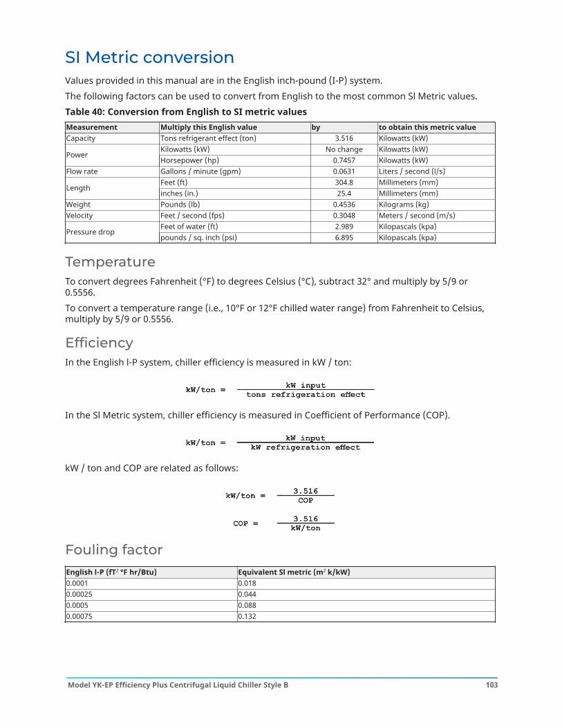
SI Metric conversionValues provided in this manual are in the English inch-pound (I-P) system.The following factors can be used to convert from English to the most common Sl Metric values.Table 40: Conversion from English to SI metric valuesMeasurement Multiply this English value by to obtain this metric valueCapacity Tons refrigerant effect (ton) 3.516 Kilowatts (kW)
Kilowatts (kW) No change Kilowatts (kW)Power
Horsepower (hp) 0.7457 Kilowatts (kW)Flow rate Gallons / minute (gpm) 0.0631 Liters / second (l/s)
Feet (ft) 304.8 Millimeters (mm)Length
inches (in.) 25.4 Millimeters (mm)Weight Pounds (lb) 0.4536 Kilograms (kg)Velocity Feet / second (fps) 0.3048 Meters / second (m/s)
Feet of water (ft) 2.989 Kilopascals (kpa)Pressure drop
pounds / sq. inch (psi) 6.895 Kilopascals (kpa)
TemperatureTo convert degrees Fahrenheit (°F) to degrees Celsius (°C), subtract 32° and multiply by 5/9 or0.5556.To convert a temperature range (i.e., 10°F or 12°F chilled water range) from Fahrenheit to Celsius,multiply by 5/9 or 0.5556.
EfficiencyIn the English l-P system, chiller efficiency is measured in kW / ton:
In the Sl Metric system, chiller efficiency is measured in Coefficient of Performance (COP).
kW / ton and COP are related as follows:
Fouling factorEnglish l-P (fT2 °F hr/Btu) Equivalent Sl metric (m2 k/kW)0.0001 0.0180.00025 0.0440.0005 0.0880.00075 0.132
103Model YK-EP Efficiency Plus Centrifugal Liquid Chiller Style B

© 2021 Johnson Controls. P.O. Box 423, Milwaukee, WI 53201, USA. Subject to change without notice. All rights reserved.