Embed Size (px)
Citation preview

Acta Biomaterialia xxx (2014) xxx–xxx
Contents lists available at ScienceDirect
Acta Biomaterialia
journal homepage: www.elsevier .com/locate /actabiomat
Mechanics of microwear traces in tooth enamel
http://dx.doi.org/10.1016/j.actbio.2014.11.0471742-7061/Published by Elsevier Ltd. on behalf of Acta Materialia Inc.
⇑ Corresponding author at: Materials Measurement Laboratory, National Instituteof Standards and Technology, Gaithersburg, MD 20899, USA. Tel.: +1 301 975 5775.
E-mail address: [email protected] (B.R. Lawn).
Please cite this article in press as: Borrero-Lopez O et al. Mechanics of microwear traces in tooth enamel. Acta Biomater (2014), http://dx.doi.org/1j.actbio.2014.11.047
Oscar Borrero-Lopez a, Antonia Pajares a, Paul J. Constantino b, Brian R. Lawn b,c,⇑a Departamento de Ingeniería Mecánica, Energética y de los Materiales, Universidad de Extremadura, 06006 Badajoz, Spainb Department of Biology, Saint Michaels College, Colchester, VT 05439, USAc Materials Measurement Laboratory, National Institute of Standards and Technology, Gaithersburg, MD 20899, USA
a r t i c l e i n f o a b s t r a c t
Article history:Received 4 July 2014Received in revised form 6 November 2014Accepted 25 November 2014Available online xxxx
Keywords:Enamel microwearContact mechanicsMicroplasticityMicrofractureDiet
It is hypothesized that microwear traces in natural tooth enamel can be simulated and quantified usingmicroindentation mechanics. Microcontacts associated with particulates in the oral wear medium aremodeled as sharp indenters with fixed semi-apical angle. Distinction is made between markings fromstatic contacts (pits) and translational contacts (scratches). Relations for the forces required to producecontacts of given dimensions are derived, with particle angularity and compliance specifically taken intoaccount so as to distinguish between different abrasives in food sources. Images of patterns made onhuman enamel with sharp indenters in axial and sliding loading are correlated with theoreticalpredictions. Special attention is given to threshold conditions for transition from a microplasticity to amicrocracking mode, corresponding to mild and severe wear domains. It is demonstrated that the typicalmicrowear trace is generated at loads on the order of 1 N – i.e. much less than the forces exerted innormal biting – attesting to the susceptibility of teeth to wear in everyday mastication, especially in dietswith sharp, hard and large inclusive intrinsic or extraneous particulates.
Published by Elsevier Ltd. on behalf of Acta Materialia Inc.
1. Introduction
The wear of teeth by small particulates is of great interest toevolutionary biologists because of its utility as an indicator of diet.This interest is manifest in the extensive field of dental microwear[1–14]. Conventional wisdom has it that hard foods are fractured incompression (normal, axial loading), leaving residual pits on theenamel surface, whereas soft foods are ground down in shear (slid-ing, translational loading), leaving scratches. Individual microcon-tact signals typically occur on a width scale of 1–20 lm [5,7]. Theratio of pits to scratches is taken as a measure of diet: some teethshow either scratches or pits, suggesting specialist diets; othersshow both scratches and pits, suggesting more omnivorous diets.Most advances in interpretation are based on quantifying this ratio,using ever more sophisticated methodologies in imaging and digi-tizing techniques [14]. Microwear patterns tend to be transient, sothat they are indicators of recent food intake rather than a full die-tary history.
What is missing from dental microwear is a first-principlesaccount of the basic contact micromechanics of pit and scratchformation. This deficiency provides the rationale for the currentstudy, i.e. a strong physically based analytical footing for
describing individual microwear events in a hitherto empiricalfield. Wear can be life-limiting in some species of animals, espe-cially grazers and browsers, where the work rate is high and con-tinual. In humans, wear can be sufficiently severe (bruxing) tonecessitate treatment by a dentist. A recent paper by Lucas et al.[15] set a precedent for an understanding by examining the natureof individual wear tracks produced by translating individual parti-cles glued to a nanoindenter tip. The principal consideration in thatstudy was the competitive roles of silicate-based phytoliths in veg-etable matter [16], quartz dust in the atmosphere [10] and evenenamel particles, typically 1–100 lm in diameter. It was suggestedthat incursive particulates should be at least as hard as enamel andshould have a sufficiently high attack angle in order to cause signif-icant tooth wear. However, the Lucas et al. study focused almostexclusively on the ultra-low load (mN) region, whereas the typeof material removal process that leads to accelerated tooth wearinvolves much more deleterious microfracture [17,18]. Such differ-entiations in removal processes are well understood by tribologistsand ceramic machinists as a transition between polishing andabrasion [19], and are a manifestation of an intrinsic ductile–brittletransition with increasing contact load and dimension [20,21]. Thistransition, along with the roles of particle compliance and sharp-ness, remains to be quantified in the context of dental microwear.
Accordingly, in this paper, microwear in tooth enamel is exam-ined using the well-established methods of indentation mechanics[21–24] as the basis for modeling the action of angulate, compliant
0.1016/
2 O. Borrero-Lopez et al. / Acta Biomaterialia xxx (2014) xxx–xxx
particles in food diet. First, controlled indentation experiments inaxial and translational loading are employed to simulate individualpits and scratches. Distinction is made between polishing andabrasion damage modes by identifying the loading conditionsunder which the microcontact undergoes a plastic to brittle transi-tion. For modeling, the particles are considered to be ‘‘sharp’’, i.e.with fixed-angle profiles, as opposed to ‘‘blunt’’, with fixed-radiusprofiles. (Some consideration has been given to blunt contacts inan earlier analysis of the role of food size in tooth fracture[25,26], but sharp contacts are more deleterious and thereby serveas a worst case.) This type of indentation-based analysis has beenpre-empted in a preceding model of macrowear, in which toothocclusal wear rates were determined by integration of individualmicrowear events over a macroscopic contact area over time[18]. However, that earlier model was generic, without attentionto individual contact micromechanics. The roles of particle angu-larity, compliance, size and number are now elucidated. The pros-pect of using trace dimensions, specifically track width and depth,to infer corresponding microcontact conditions in naturally occur-ring microwear tracks is examined. It is demonstrated that the con-tact loads lie in the region of 1 N, i.e. two to three orders ofmagnitude below the nominal bite forces for humans and otherhominid species. The implications of the analysis concerning die-tary characteristics are explored.
2. Morphology of pits and scratches
Extracted molars from healthy adults were obtained from localdentists, and were disinfected using an ethanol solution (70%) andstored in distilled water under refrigeration. Those with any sur-face damage were discarded, and four others were embeddedupright in a resin mold, as depicted in Fig. 1. The top surfaces werelightly ground to produce island facets 2–3 mm in diameter onthe cusps, and then finished in an automatic polishing machine(Phoenix 4000, Buehler, Lake Bluff, IL) using diamond particlesuspensions down to 1 lm. The maximum depth removed belowthe original occlusal surface was 100 lm, i.e. small compared withthe thickness�1.5 mm of the enamel. Preliminary Vickers indenta-tions (HSV-30, Shimadzu, Kyoto, Japan) at a load of 10 N on the pol-ished surfaces yielded hardness values H = 4.0 ± 0.2 GPa (mean andstandard deviation, 10 indents).
A conical Rockwell diamond indenter with included anglew = 60� and tip radius 25 lm (Nanotest, Micro Materials Ltd.,
Resin
Embeddedmolar
Fig. 1. Schematic diagram showing the embedment of a molar tooth into a resin moldtesting.
Please cite this article in press as: Borrero-Lopez O et al. Mechanics of microwej.actbio.2014.11.047
Wrexham, UK) was selected in an attempt to simulate wear eventsin a particle-rich diet. The indenter had some surface imperfectionson a scale of �3 lm in the near-tip region, but, in the context of theirregular geometries of natural particulates, this was considered toadd a touch of realism. Tests were run in both normal axial and lat-eral sliding contact over a load range of 0.1–3 N on the polishedsurfaces, which were kept moist during the testing. In the axialtests, the loads were ramped up monotonically to maximum loadand held for 5 s before unloading. In the sliding tests, the speci-mens were translated at 2 lm s�1, with load applied linearly at5 mN s�1 to its prescribed maximum and then held steady over afurther translation distance of 200 lm. The indentation sites wereexamined and photographed by optical microscopy (Epiphot 300,Nikon, Tokyo, Japan). Some specimens were sputter-coated witha gold layer and then examined by scanning electron microscopy(SEM; QUANTA 3D FEG, FEI Company, Hillsboro, OR) using second-ary electrons at low voltage (5 kV). All tests produced residualimpressions, indicating that the Rockwell indenter can be consid-ered effectively sharp.
Optical microscope images of the indentations in axial contactare shown in Fig. 2 at normal loads of 0.25, 0.5, 1 and 2 N. Theimpressions have somewhat irregular edges, attributable to theaforementioned imperfections in the shape of the indenter tip,but are otherwise near-circular. Radially extending cracks areclearly evident at the higher loads in Fig. 2, but not at the lowerloads, consistent with the existence of a plastic-to-brittle thresholdcontact dimension [20]. Also faintly visible is some peripheralmicrocracking at the highest load.
Analogous optical images of indentations in translationalmotion are shown in Fig. 3 at loads of 0.25, 0.5, 1 and 2 N. Theseimages are reminiscent of scratches in a broad range of brittle sol-ids [27]. Once beyond the initial load ramp, the linear traces inFig. 3 assume a constant steady-state width. Again, outwardextending cracks, similar to those observed in Fig. 2, but with a ten-dency to propagate more in the direction of translation, are evidentat the higher loads. Peripheral microcracking is more pronouncedthan in static loading, coalescing in places into lateral cracks[28]. The incidence of cracking of any type becomes more evidentat the higher loads, again indicative of threshold behavior. Note theapparent absence of any cracking within the tracks, consistent witha surface smearing action of the moving contact.
Higher magnification SEM images of the contact sites at theupper end of the load range are pictured in Fig. 4. It is apparent that
Wear facets
Occlusalview
. Grinding and polishing of the top surface produces smooth planar test facets for
ar traces in tooth enamel. Acta Biomater (2014), http://dx.doi.org/10.1016/

Fig. 2. Optical microscope images of static indentations or pits in polished tooth enamel using a Rockwell cone indenter with tip radius 25 lm: loads (a) 0.25 N, (b) 0.5 N, (c)1 N and (d) 2 N. The same scale is used for all images.
Fig. 3. Optical microscope images of scratches in polished tooth enamel using the same indenter as in Fig. 2, but in sliding mode: loads (a) 0.25 N, (b) 0.5 N, (c) 1 N and (d) 2 N.Note different scales on each image.
O. Borrero-Lopez et al. / Acta Biomaterialia xxx (2014) xxx–xxx 3
Please cite this article in press as: Borrero-Lopez O et al. Mechanics of microwear traces in tooth enamel. Acta Biomater (2014), http://dx.doi.org/10.1016/j.actbio.2014.11.047

(a)
(b)
10 µm
10 µm
Fig. 4. SEM images of portions of tracks from microcontacts with a diamond coneindenter at load P = 2 N in (a) axial loading and (b) translational loading (slidingdirection left to right). Note the copious amount of debris from microcracking, withsmearing at the sliding interface.
0
90
60
30
030 60 90
True indenter angle, ψ
Effe
ctiv
e in
dent
er a
ngle
, ψ′
E I/E = 10
1
0.1
0.01
(b)
PlasticElastic
P
E I
E
a
h
(a)
Ψ ′
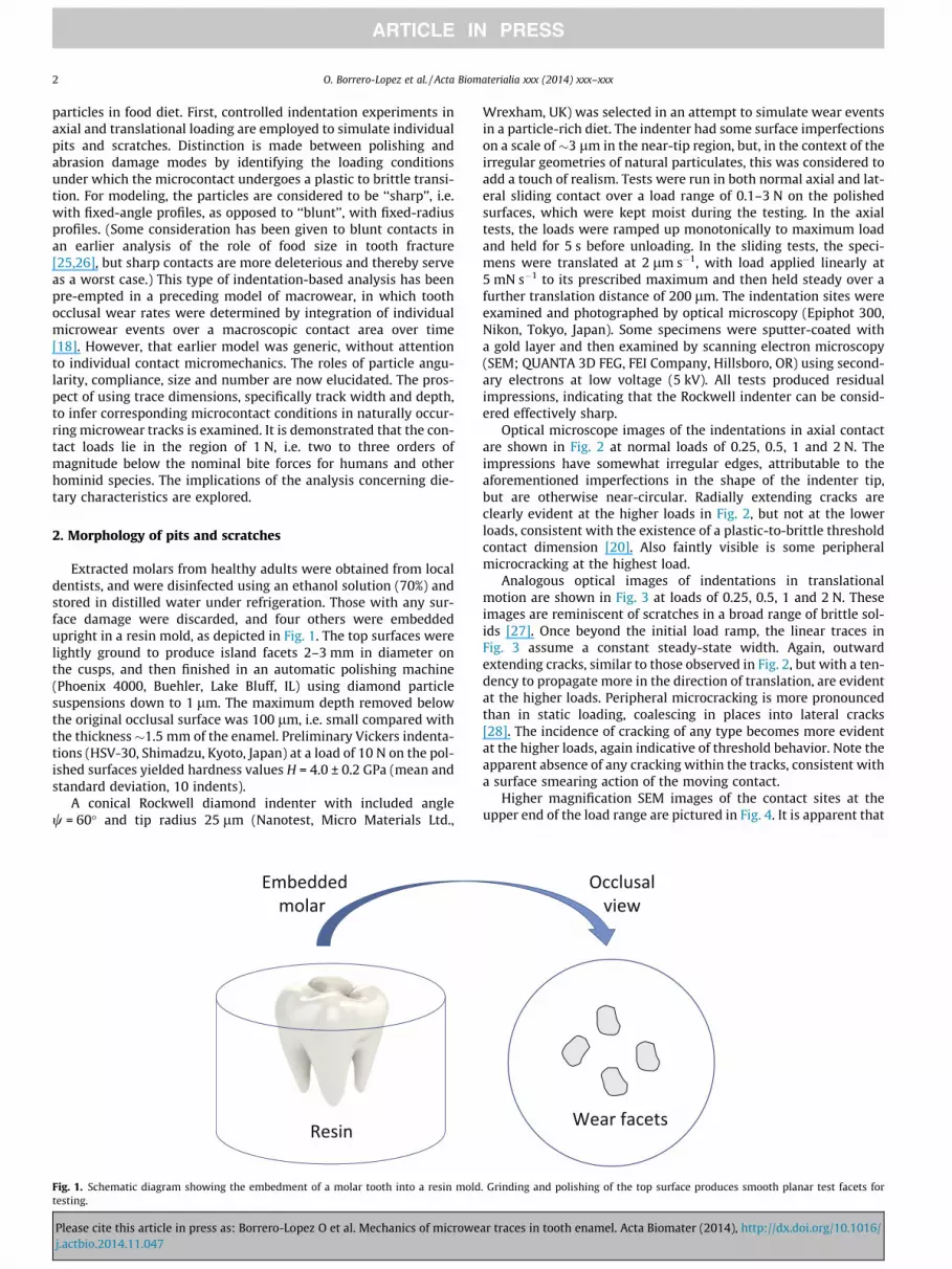
Fig. 5. (a) Idealized geometry of asperity contact. A conical indenter under load Pproduces a depression of half-width a on the test surface. The non-rigid compliantindenting particle blunts the contact, increasing the true semi-apical angle w to theeffective angle w0 . Sliding contact translates the configuration out of the page ofdiagram. Upon unloading, elastic recovery leaves residual impression of depth h. (b)Plot of w0 vs. w for selected modulus ratios EI/E (Reproduced from Ref. [18].).
4 O. Borrero-Lopez et al. / Acta Biomaterialia xxx (2014) xxx–xxx
the contacts at these loads have significantly disrupted the enamelmicrostructure. The static indentation (Fig. 4a) has left a pit withinwhich material has been crushed and partially ejected. Some of thedebris is visible on the surface outside the actual contact area.Radial cracks are visible. The sliding indentation (Fig. 4b) showsa smooth, smeared out trace, but with evidence of the same typeof crushing and debris at the sides, coalescing into lateral cracksin places. (The surfaces in these images were not subjected to apost-indentation rinse and clean preparation prior to insertion intothe SEM, thus preserving the debris field.) It is not difficult toenvisage that any such debris itself could contribute significantlyto the particulate components responsible for accelerated wear.
One advantage of the smearing within the scratches is that itallows for relatively straightforward measurements of thesmoothed cross-section profiles. Since a sharper particle will leavea deeper contact, it is apparent that the profile must contain usefulinformation on the effective angle of the indenting particle, evenallowing for the shallowing effects of elastic recovery. Accordingly,measurements of the width 2a and residual depth h were madeacross scratches over the load range 0.25–3 N, using a surface pro-filometer (Surftest SJ-400, Mitutoyo, Kanagawa, Japan). Such mea-surements over five scratches yielded h/a = 0.30 ± 0.12, i.e.relatively shallow traces in these tests.
In the next section, micromechanical models are developed topredict loads and particle sharpness from contact dimensions.
Please cite this article in press as: Borrero-Lopez O et al. Mechanics of microwej.actbio.2014.11.047
3. Contact micromechanics
3.1. Microplasticity modes
Fig. 5a shows a schematic of a tooth surface contact with asharp, fixed-profile indenter of included half-angle w, at normalload P and contact half-width a. The contact may be static (axialloading) or sliding (translational loading). A major simplificationensuing from the fixed-profile geometry is that of geometrical sim-ilarity [22], in which the contact can be defined by
P=a2 ¼ ap ð1Þ
where the indentation pressure p is independent of load, but depen-dent on indenter angle w, i.e. p = p(w), with a an indenter shape fac-tor. It is assumed for the moment that a is the same in static andsliding contact. In the case of ideally elastic contacts, a compliantindenter will increase (blunt) the effective half-angle w0 (i.e.w0 > w) according to the Sneddon relation [29]
tan w0 ¼ ð1þ E=EIÞtan w ð2Þ
where E and EI are specimen and indenter modulus, respectively.Fig. 5b shows plots of effective half-angle w0 as a function of truehalf-angle w for selected ratios EI/E, demonstrating how compliantparticles blunt the contact. If the contacting particle were to deformplastically, w0 would increase further, so Eq. (2) affords a lowerbound to the blunting. The angle dependence of indentation pres-sure can be approximated by the Johnson equation for ideal elas-tic/plastic contacts [24], with due allowance for indentercompliance by replacing w with w0, i.e.
ar traces in tooth enamel. Acta Biomater (2014), http://dx.doi.org/10.1016/

Contact half-width, a (µm)
0
2
4
6
8
10
2016128
16 20 12
Con
tact
load
, P (N
)
ψ = 15o
30o
45o
75o60o
(a) Indenter modulus EI/E =1
0
2
4
6
8
10
Con
tact
load
, P (N
)
(b) Indenter angle ψ = 45o
EI/E = 10
1
0.1
0 4 8
0 4
Fig. 7. Plots of load P vs. contact half-width a for conical particles (a = p) on toothenamel from Eq. (4), (a) for different indenter angles w at fixed modulus ratio EI/E = 1, and (b) for different modulus ratio at mid-range indenter angle 45�.
0
30
60
90
Effe
ctiv
e se
mi-a
ngle
, ψ’
10-2 10-1 100 101 102
O. Borrero-Lopez et al. / Acta Biomaterialia xxx (2014) xxx–xxx 5
p ¼ ð2Y=3Þ½1þ lnðE cot w0=3YÞ� ð3Þ
where Y is the yield stress of the specimen material.To evaluate Y for tooth enamel, it is convenient to resort to data
from Vickers indentation hardness tests, in combination with nom-inal values of enamel material properties [18,30]. Vickers diamondpyramid indenters may be considered to be effectively rigid(EI = 1000 GPa) relative to enamel (E = 90 GPa), so w0 � w = 74� inEq. (2). Fig. 6 plots p/E vs. Y/E from Eq. (3) in this rigid-indenterlimit. Identifying the contact pressure p with Vickers hardnessH = 4.0 GPa gives H/E = 4.0 GPa/90 GPa = 0.045, corresponding toY/E = 0.027 on the Johnson curve. This gives Y = 2.4 GPa = 0.60Hfor tooth enamel. Inserting this value into Eq. (3) yields an expres-sion for applied load P in terms of contact half-width a for anyindenting particle of shape parameter a and effective includedangle w0
P ¼ 0:40aHa2f1þ ln½0:56ðE=HÞ cot w0�g ð4Þ
Plots of P vs. a are shown for conical particles (a = p) in Fig. 7afor different indenter angles w and fixed modulus ratio EI/E = 1, andin Fig. 7b for different modulus ratios at mid-range indenter angle45�. The contact loads generated over a given contact size a dimin-ish systematically at higher w and lower EI. The loads are on theorder of 0.1–10 N over the half-width data range a = 1–20 lm.
Allusion was made in Section 2 to information about the inden-ter characteristics contained by the profile of an unloaded impres-sion. The residual impression depth h is somewhat less than that atmaximum load, owing to elastic recovery. There are several treat-ments of elastic recovery beneath sharp indenters, but here resortis made to a semi-empirical relation for the relative residual depthfrom an earlier study [31]:
h=a ¼ fðc cot w0Þ2 � ½2ð1� m2Þc2 cot w0�H=Eg1=2
ð5Þ
where c = 0.91 is a geometrical constant to account for the depres-sion of the indented surface outside the loaded impression. Insert-ing Poisson’s ratio m = 0.25 and H/E = 4.0 GPa/90 GPa for enamelinto Eq. (5) yields the plot of w0 vs. h/a in Fig. 8. The measured valueh/a = 0.30 for the scratches in Section 2 corresponds to an effectiveangle w0 = 69.5�. This is somewhat larger than the nominal angle of60� for the Rockwell cone indenter, attesting to the blunting effectof the rounded tip.
3.2. Microcracking thresholds
It is well documented in the literature [20], as well as by theobservations in Section 2, that in semi-brittle materials there existsa threshold for cracking in contact events. At higher loads, fixed-
0.10
0.08
0.06
0.04
0.02
00 0.100.050.025 0.075
Y/E
p/E
Johnson
H/E (Vickers)
Y/E
Fig. 6. Plot of Johnson Eq. (3) showing contact pressure p vs. yield stress Y, bothaxes normalized to specimen modulus E. Dashed lines indicate values for Vickersindenter on tooth enamel.
Residual depth/indent half-width, h/a
Fig. 8. Effective indenter semi-apical angle w0 vs. relative depth h/a of residualimpression.
Please cite this article in press as: Borrero-Lopez O et al. Mechanics of microwej.actbio.2014.11.047
profile indenters produce cracks extending radially from the plasticimpression. In axial loading, these radial cracks have a basic penny-like geometry [32] and satisfy the fracture mechanics relationbetween load P and radial crack half-width c [21,33]
P=c3=2 ¼ ð1=nÞðH=EÞ1=2T ð6Þ
with T the toughness and an angle-dependent coefficient
n ¼ n0ðcot w0Þ2=3 ð7Þ
Eq. (6) is the fracture counterpart of Eq. (1) for plastic deformation.To quantify the threshold condition, it is again convenient to
use data from Vickers diamond pyramid tests, employing commer-cial hardness testing machines over load ranges 0.1–10 N (HSV-30,
ar traces in tooth enamel. Acta Biomater (2014), http://dx.doi.org/10.1016/

10102
10101
10100
1010-1-1
10103
Indenter load, Indenter load, P(N)(N)
Inde
ntat
ion
dim
ensi
on (µ
m)
Inde
ntat
ion
dim
ensi
on (µ
m)
a(P)
P*
c(P)
Pthth
c
a
1010-2 1010-1 10101 101031010-3 10100 10102
Fig. 9. Vickers contact dimensions a and c as a function of load P for tests onpolished tooth enamel. Data are mean values (five indents per point) fromexperiment, lines from theory. Standard deviations are 5% in a and 10% in c(smaller than data points). Note how the curves cross each other at load P⁄,indicating a brittle–plastic transition. Load Pth indicates threshold below whichradial cracks do not initiate.
100
102
10-4
10-2
0 30 60 90Effective indenter angle, Ψ ’
Mic
roco
ntac
t for
ce, P
(N)
Threshold
a = 10 µm
a = 1 µm
Fig. 10. Plot of microcontact load P as a function of effective indenter half-angle w0
from Eq. (4) for two contact half-widths a (solid curves). Also plotted is thresholdload Pth from Eqs. (8) and (9). Calculations for conical indenter (a = p).
6 O. Borrero-Lopez et al. / Acta Biomaterialia xxx (2014) xxx–xxx
Shimadzu, Kyoto, Japan) and 50–100 N (MV-1, Matsuzawa, Tokyo,Japan), with a fixed hold time of 5 s at maximum penetration.Accordingly, Vickers indentations were made on polished trans-verse enamel sections of extracted human molar teeth, taking careto keep the specimens moist at all times [34]. The results are plot-ted in Fig. 9. The filled symbols are plastic impression size a andradial crack size c for Vickers indentations, measured along indentdiagonals, as a function of axial load P (average 5 indents or 10 lin-ear measurements per point). The line through the a(P) data is aplot of Eq. (1), with p = H = 4.0 GPa for enamel and a = 2 for pyrami-dal indenters. The line through the c(P) data in Fig. 9 is a fit toEq. (6) with H/E = 4.0 GPa/90 GPa and T = 1.0 MPa m1/2, yielding acoefficient n = 0.020. (Allowing for scatter in the data, this coeffi-cient compares with an earlier value of 0.016 from Vickers testson a range of ceramic materials [33].) Inserting w0 � w = 74� forVickers indenters into Eq. (7) then yields the angle-independentquantity no = 0.046.
The plot in Fig. 9 demonstrates the threshold condition. The a(P)and c(P) curves cross each other at P = P⁄, below which load anyradial cracks would be subsumed into the plastic impression. Inactuality, the radial cracks disappear at some higher load Pth = kP⁄
(k > 1), because these cracks first have to be initiated [35].Combining Eqs. (4, 6 and 7) then yields the following thresholdload relation, slightly modified from earlier derivations [21] toaccommodate indenter shape
Pth ¼ ðk=a3n40ÞðT
4=E2HÞFðw0Þ ð8Þ
with effective angle term
Fðw0Þ ¼ 15:6ðtan w0Þ8=3=f1þ ln½0:56ðE=HÞcotw0�g3 ð9Þ
In Fig. 9, the load Pth = 250 mN, below which radial cracks nolonger appear relative to the crossover at P⁄ = 25 mN, defines thequantity k = Pth/P⁄ = 10. It is apparent from inspection of Eq. (9)that the critical load in Eq. (8) is highly sensitive to indenter angle(and compliance), evidenced by a reported reduction in Pth by morethan an order of magnitude in going from Vickers to corner-cube(w = 74–54.7�, axis to edge angle) indenters [36].
4. Discussion
An analysis of wear track formation in tooth enamel hasbeen developed, based on long-established micromechanics of
Please cite this article in press as: Borrero-Lopez O et al. Mechanics of microwej.actbio.2014.11.047
deformation and fracture beneath sharp, fixed-profile indenter tips(Fig. 5a). The assumption of a fixed profile leads to simplificationsin modeling, specifically in relation to the relative scales ofplasticity and fracture processes in the ensuing wear process. Thissimplification leads naturally to the concept of a threshold load,below which plasticity modes dominate (mild wear) and abovewhich fracture modes dominate (severe wear). Images of contactsites in axial and translational loading (Figs. 2–4) confirm theessential features of individual microcontact pits and scratches,with plastic impressions and (at higher loads) accompanyingcracks and debris. For contact radii in the range a = 1–20 lm,typical of natural microwear signals, corresponding contact loadsare in the order of P � 0.1–10 N (Fig. 7).
A principal outcome of the micromechanics analysis is theexplicit inclusion of particle angle and modulus in the contactequations. Recall that the effective indenter angle w0 increases withboth increasing particle angle w and decreasing particle modulus EI
(Fig. 5b). Of particular concern is how the microcontact force P inEq. (4) varies with w0 for specified indent half-widths a. This forceis plotted in Fig. 10 as the solid curves for fixed a = 1 lm and10 lm, with a = p for conical indenters. Interestingly, while P issensitive to the value of a (quadratic dependence in Eq. (4)), it ismuch less so to w0 (logarithmic dependence in Eq. (4)). Includedas the dashed curve in Fig. 10 is the threshold force Pth fromEq. (8), again for a = p. This quantity reflects an especially highsensitivity of the F function in Eq. (9) to w0. Note that the solidand dashed curves cross each other: the domain Pth < P at low w0
is that of microcrack-dominated severe wear from sharp, hardparticles; the domain P < Pth at high w0 is that of plasticity-dominated mild-wear from blunt, compliant particles. As anillustrative example, consider a mid-range particle angle w = 45�:the crossovers at w0 � 43� for a = 1 lm and w0 � 77� for a = 10 lmin Fig. 10 correspond to minimum particle moduli EI � 27 GPaand EI �1 in Eq. (2) needed to exceed the respective microcrack-ing thresholds. In this context, note that silica particles found innatural diets of many mammals (especially herbivores) have anintermediate modulus EI � 75 GPa.
One factor not included explicitly in the formulation is that ofparticle size. Yet it is well established in tribology studies thatcoarser particles can effect the transition from mild (polishing) tosevere (abrasion) removal processes in brittle materials. For anygiven mass of particulates in a wear medium, larger particles willmake fewer microcontacts over any given wear facet, meaning thatthose particles will shoulder higher individual loads. To take the
ar traces in tooth enamel. Acta Biomater (2014), http://dx.doi.org/10.1016/

O. Borrero-Lopez et al. / Acta Biomaterialia xxx (2014) xxx–xxx 7
argument further, consider the bounding case of a close-packedarray of particles with characteristic dimension l. Then the areaoccupied by one particle is �l2, so the number of particles in unitarea is �1/l2. Therefore, the number of microcontacts diminishesrapidly as particle size increases, so again each particle experiencesa higher force. For a wear medium with a distribution of particlesizes, e.g. a soft food bolus, the largest will make first contactand thereby assume an inordinate proportion of the net load overa wear facet. Accordingly, diets with coarser incursive grits may beexpected to greatly accelerate the enamel abrasion rate by effect-ing a transition from mild to severe wear.
The current analysis pertains to individual microwear events.Integration over all such events within an occlusal facet over timecan be used to obtain a macroscopic volume removal rate equation.A model of this type in a previous study [18] provided such anequation, analogous to the well-documented Archard’s law [19],with the efficacy of the removal process quantified by an angle-dependent wear coefficient K � cot w0. However, that earlier modelcircumvented any consideration of the detailed micromechanics ofthe individual events, other than indicating that K will be muchgreater for a microcracking than for a microplasticity mode. Thecurrent analysis augments that earlier study by outlining themicromechanics of individual events, with specific attention tothe loads required to produce pits and scratches of given scaleand to the threshold conditions for transition from mild to severewear. The images in Figs. 2–4 suggest microcracking on the scaleof the enamel microstructure, i.e. �5 lm, consistent with the sug-gestion that the protein sheaths between hydroxyapatite rods canact as favorable weak interface sites for crack paths [37–43].
It is to be acknowledged that the analysis is based on simplify-ing assumptions that are open to discussion. The first of theserelates to the representation of impinging particulates as sharp,fixed-angle indenters. This simplification enables the explicitintroduction of indenter angle and modulus via Sneddon’s equa-tion for elastic contacts (Eq. (2)). In reality, microcontacting parti-cles have less well-defined angles, often with rounded tips, andmay themselves undergo plastic deformation. However, thefixed-profile geometry with elastic contacts represents a worstcase, and thus provides a conservative estimate of the damage pro-cess. It is also assumed in Johnson’s Eq. (3) that the indented mate-rial is ideally elastic–plastic, i.e. linearly elastic up to a well-definedyield stress Y = 2.4 GPa, whereas tooth enamel is more nonlinear inits initial stress–strain response, with preliminary irreversibledeformation reported at stresses as low as 0.33 GPa [40,41]. Inactuality, the yield stress Y appears in the present analysis as littlemore than a fitting parameter, and its physical interpretation is notcentral to the derivations. Another simplification implicit in theanalysis is the focus on a single static or sliding contact event,whereas wear facets are made up of many such interacting eventsover time. Damage can accumulate from multiple passes, furtherexacerbating a transition from deformation-controlled to frac-ture-controlled removal processes [44], so again the present modelis conservative in its capacity to account for wear rates. It has fur-ther been assumed that the indenter shape factor a in Eq. (1) is thesame in static and sliding contact, whereas the contact stresses arelikely to redistribute toward the leading edge of a translating par-ticle, thereby enhancing the contact pressure at any given load.Finally, the model ignores the effects of microstructural anisotropyand property gradients within the enamel: nanoindentation testson cross sections of human molars have shown that the hardnessof enamel can diminish by a factor of 2 to 3 with increasing depthbelow the occlusal surface as the configuration of hydroxyapatiteprisms changes [45], while abrasion tests on bovine enamel aftererosion in acidic solutions have demonstrated a strong correlationbetween wear rate and Vickers hardness [46]. However, incorpora-tion of these factors into a more complex model is unlikely to shift
Please cite this article in press as: Borrero-Lopez O et al. Mechanics of microwej.actbio.2014.11.047
the curves significantly along the (logarithmic) load axis in Fig. 10,so the main conclusions drawn from the analysis remain valid.
The chief impact of this study may lie more in biology thanmaterials science, specifically in the insight it can provide intothe fundamental mechanisms of microwear [1–6,8–14]. As men-tioned in the Introduction, this is a highly active, and sometimescontentious, area of evolutionary science [14,47]. The images inFigs. 2–4 indicate that axial and translational tests with standardindenters can simulate naturally occurring microwear signals fromthe diets of humans and other mammals [15]. The contact analysiscan be used to extract quantitative information on the loads andparticle characteristics responsible for such signals. For instance,Eq. (4) can be used to infer loads P � 1 N for real-life microcontactsof micrometer-scale half-width. Recall that the tests were made onlightly polished surfaces, less than one-tenth of the enamel thick-ness, so the estimated load may be slightly higher on pristineocclusal surfaces. However, this value could be lower by a factorof 2 or 3 in severely worn teeth, owing to the diminished hardnessin the enamel subsurface [45]. Regardless of such variations, loadsof this order are relatively small in comparison with nominal biteforces for humans and other mammals, affirming that some formof enamel wear is not an unexpected occurrence in consumptionof foods with a distribution of included sharp particulates. Noteagain that the effective angle w0 appears as a logarithmic term inEq. (4), so that estimates of P from this equation are relativelyinsensitive to true particle angle and modulus. This same insensi-tivity means that it is difficult to infer anything about the geometryor size of particulates from the widths of the microcontact mark-ings alone. However, depth measurements can provide an estimateof the effective particle angle. Also, as demonstrated in Fig. 10, theappearance of well-developed cracks outside the periphery of amicrowear pit or scratch would be clear evidence of contact withsharp, hard particles, although it is also acknowledged that anytraces of such cracking could be smeared out on a well-worn sur-face. Finally, given the appearance of copious enamel debris atthe higher load indentations in Fig. 4, it is not difficult to contem-plate the extreme wear rates experienced under extreme mastica-tion or bruxing conditions.
5. Conclusions
(i) Microwear traces (pits and scratches) from particle contactsin natural tooth enamel can be simulated and quantified bystatic and sliding microindentation experiments.
(ii) Microcontact relations enable forces associated with theproduction of individual microwear traces to be evaluated.These forces are orders of magnitude lower than thoseincurred during normal biting activity.
(iii) The roles of particle angle and modulus in microwear pro-duction are elucidated.
(iv) Dietary conditions under which wear undergoes a transitionfrom mild to severe are interpreted in terms of a shift frommicroplasticity to microfracture damage modes.
(v) The impact of the study on evolutionary biology is discussed.
Disclosures
There are no conflicts of interest. Information of product namesand suppliers in this paper is not to imply endorsement by NIST.
Acknowledgements
We wish to thank David and Oscar Maestre for kindly providingdental samples from their clinic (Maxilodental Maestre, Badajoz,Spain), Maria Carbajo (Facility of Analysis and Characterization of
ar traces in tooth enamel. Acta Biomater (2014), http://dx.doi.org/10.1016/

8 O. Borrero-Lopez et al. / Acta Biomaterialia xxx (2014) xxx–xxx
Solids and Surfaces, UEx, Badajoz, Spain) for the SEM images inFig. 4, and Centro Tecnologico Industrial de Extremadura (CETIEX,Badajoz, Spain) for use of their profilometer. Robert Cook (NIST)provided useful comments on the paper. This study was supportedin part by the US National Science Foundation (Grant # 1118385)and from NIST funding (administered via Dakota Consulting Inc.).
Appendix A. Figures with essential color discrimination
Certain figures in this article, particularly Figs. 1–3 and 9, maybe difficult to interpret in black and white. The full color imagescan be found in the on-line version, at http://dx.doi.org/10.1016/j.actbio.2014.11.047.
References
[1] Walker A, Hoeck HN, Perez L. Microwear of mammalian teeth as an indicator ofdiet. Science 1978;201:908–10.
[2] Grine FE. Trophic differences between ‘gracile’ and ‘robust’ Australopithecines:a scanning electron microscope analysis of occlusal events. S Afr J Sci1981;7:203–30.
[3] Fortelius M. Ungulate cheek teeth: developmental, functional and evolutionaryinterrelations. Acta Zool Fennica 1985;180:1–76.
[4] Janis CM, Fortelius M. On the means whereby mammals achieve increasedfunctional durability of their dentitions, with special reference to limitingfactors. Biol Rev 1988;63:197–230.
[5] Teaford MF. A review of dental microwear and diet in modern mammals.Microscopy 1988;2:1149–66.
[6] Ungar PS. Dental allometry, morphology, and wear as evidence for diet in fossilprimates. Evol Anthrop 1998;6:205–17.
[7] Grine FE, Kay RF. Early hominid diets from quantitative image analysis ofdental microwear. Nature 1988;333:765–8.
[8] Scott RS, Ungar PS, Bergstrom TS, Brown CA, Childs BE, Teaford MF, et al. Dentalmicrowear texture analysis: technical considerations. J Human Evol2006;51:339–49.
[9] Sanson G. The biomechanics of browsing and grazing. Amer J Bot2006;93:1531–45.
[10] Damuth J, Janis CM. On the relationship between hypsodonty and feedingecology in ungulate mammals, and its utility in palaeoecology. Biol Rev2011;86:733–58.
[11] Teaford MF, Ungar PS. Diet and the evolution of the earliest human ancestors.Proc Natl Acad Sci USA 2000;97:13506–11.
[12] Lucas PW. Dental functional morphology: how teeth work. Cambridge:Cambridge University Press; 2004.
[13] Ungar PS. Mammal teeth. Baltimore, MD: Johns Hopkins University Press; 2010.[14] Ungar P, Sponheimer M. The diets of early hominins. Science 2011;334:190–3.[15] Lucas PW, Omar R, Al-Fadhalah K, Almusallam AS, Henry AG, Michael S, et al.
Mechanisms and causes of wear in tooth enamel: implications for hominindiets. J R Soc Interface 2013;10:20120923.
[16] Piperno DR. Phytoliths: a comprehensive guide for archaeologists andpaleoecologists. Lanham, MD: AltaMira Press; 2006.
[17] Arsecularatne JA, Hoffman M. On the wear mechanisms of human dentalenamel. J Mech Behav Biomed Mater 2010;3:347–56.
[18] Borrero-Lopez O, Pajares A, Constantino P, Lawn BR. A model for predictingwear rates in tooth enamel. J Mech Behav Biomed Mater 2014;37:226–34.
Please cite this article in press as: Borrero-Lopez O et al. Mechanics of microwej.actbio.2014.11.047
[19] Hutchings IM. Tribology: friction and wear of engineering materials. BocaRaton: CRC Press; 1992.
[20] Lawn BR, Marshall DB. Hardness, toughness, and brittleness: an indentationanalysis. J Am Ceram Soc 1979;62:347–50.
[21] Lawn BR, Cook RF. Probing material properties with sharp indenters: aretrospective. J Mater Sci 2012;47:1–22.
[22] Tabor D. Hardness of metals. Oxford: Clarendon Press; 1951.[23] Lawn BR, Wilshaw TR. Indentation fracture: principles and applications. J
Mater Sci 1975;10:1049–81.[24] Johnson KL. Contact mechanics. London: Cambridge University Press; 1985.[25] Lucas PW, Constantino PJ, Wood BA, Lawn BR. Dental enamel as a dietary
indicator in mammals. BioEssays 2008;30:374–85.[26] Lawn BR, Lee JJ-W, Constantino PJ, Lucas PW. Predicting failure in mammalian
enamel. J Mech Behav Biomed Mater 2009;2:33–42.[27] Swain MV. Microfracture about scratches in brittle solids. Proc R Soc London
Ser A 1979;366:575–97.[28] Marshall DB, Lawn BR, Evans AG. Elastic/plastic indentation damage in
ceramics: the lateral crack system. J Am Ceram Soc 1982;65:561–6.[29] Sneddon IN. Boussinesq’s problem for a rigid cone. Math Proc Cambridge
Philos Soc 1948;44:492–507.[30] Lee JJ-W, Constantino PJ, Lucas PW, Lawn BR. Fracture in teeth – a diagnostic
for inferring bite force and tooth function. Biol Rev 2011;86:959–74.[31] Lawn BR, Howes VR. Elastic recovery at hardness indentations. J Mater Sci
1981;16:2745–52.[32] Lawn BR, Fuller ER. Equilibrium penny-like cracks in indentation fracture. J
Mater Sci 1975;10:2016–24.[33] Anstis GR, Chantikul P, Marshall DB, Lawn BR. A critical evaluation of
indentation techniques for measuring fracture toughness: I. Direct crackmeasurements. J Am Ceram Soc 1981;64:533–8.
[34] Chai H, Lee JJ-W, Constantino PJ, Lucas PW, Lawn BR. Remarkable resilience ofteeth. Proc Natl Acad Sci USA 2009;106:7289–93.
[35] Lawn BR, Evans AG. A model for crack initiation in elastic/plastic indentationfields. J Mater Sci 1977;12:2195–9.
[36] Pharr GM. Measurement of mechanical properties by ultra-low loadindentation. Mater Sci Eng A 1998;253:151–9.
[37] Osborn JW. Dental tissues. In: Osborn JW, editor. Dental anatomy andembryology, vol. 1. Oxford: Blackwell; 1981.
[38] Boyde A, Martin L. Enamel microstructure determination in hominoid andcercopithecoid primates. Anat Embryol 1982;165:193–212.
[39] He LH, Fujisawa N, Swain MV. Elastic modulus and stress–strain response ofhuman enamel by nano-indentation. Biomaterials 2006;27:4388–98.
[40] He LH, Swain MV. Contact induced deformation of enamel. Appl Phys Lett2007;90(171916):171911–3.
[41] He LH, Swain MV. A ‘metallic-like’ deformable biocomposite. J Dent2007;35:431–7.
[42] He LH, Swain MV. Influence of environment on the mechanical behavior ofmature human enamel. Biomaterials 2007;28:4512–20.
[43] Myoung S, Lee JJ-W, Constantino PJ, Lucas PW, Chai H, Lawn BR. Morphologyand fracture of enamel. J Biomech 2009;42:1947–51.
[44] Cho S-J, Hockey BJ, Lawn BR, Bennison SJ. Grain-size and R-curve effects in theabrasive wear of alumina. J Am Ceram Soc 1989;72:1249–52.
[45] Cuy JL, Mann AB, Livi KJ, Teaford MF, Weihs TP. Nanoindentation mapping ofthe mechanical properties of human molar tooth enamel. Arch Oral Biol2002;7:281–91.
[46] Attin T, Koidal U, Buchalla W, Schaller HG, Keilbassa AM, Hellwig E. Correlationof microhardness and wear in differently eroded bovine dental enamel. ArchOral Biol 1997;42:243–50.
[47] Rabenold D, Pearson OM. Scratching the surface: a critique of Lucas et al.(2013)’s conclusion that phytioliths do not abrade enamel. J Human Evol 2014.
ar traces in tooth enamel. Acta Biomater (2014), http://dx.doi.org/10.1016/