Embed Size (px)
Citation preview
Journal of Communications ISSN 1796-2021 Volume 6, Number 6, September 2011 Special Issue: Recent Advance on Wireless Networks
Guest Editors: Lei Shu, Hsiao-Hwa Chen, Takahiro Hara, Der-Jiunn Deng, and Lei Wang
Contents Guest Editorial Lei Shu, Hsiao-Hwa Chen, Takahiro Hara, Der-Jiunn Deng, and Lei Wang
421
SPECIAL ISSUE PAPERS The Web of Things: A Survey (Invited Paper) Deze Zeng, Song Guo, and Zixue Cheng Power Saving and Energy Optimization Techniques for Wireless Sensor Neworks (Invited Paper) Sandra Sendra, Jaime Lloret, Miguel García, and José F. Toledo Secure Localization in Wireless Sensor Networks: A Survey (Invited Paper) Jinfang Jiang, Guangjie Han, Chuan Zhu, Yuhui Dong, and Na Zhang A Real-time Two-way Authentication Method Based on Instantaneous Channel State Information for Wireless Communication Systems Xiangyu Lu, Yuyan Zhang, Yuexing Peng, Hui Zhao, and Wenbo Wang Delay Tolerant Network on Android Phones: Implementation Issues and Performance Measurements Rerngvit Yanggratoke, Abdullah Azfar, María José Peroza Marval, and Sharjeel Ahmed A New Evaluation Model for Security Protocols Chao Yang, Jianfeng Ma, and Xuewen Dong On-Demand QoS Multicast Routing for Triple-Layered LEO/HEO/GEO Satellite IP Networks Zhizhong Yin, Long Zhang, and Xianwei Zhou
424
439
460
471
477
485
495

Special Issue on Recent Advance on Wireless Networks
Guest Editorial Wireless networks technologies had already facilitated people’s daily life for more than 50 years. But, still, many
new emerging applications, e.g., games, multimedia content disseminations, are motivating the further development in various areas of wireless networks. It is our great pleasure to bring you this special issue of Journal of Communications on “Recent Advance on Wireless Networks”, which aims at presenting innovative and significant research on the design, implementation, usage, and evaluation of wireless networks, applications, and novel techniques.
We are deeply grateful of receiving many excellent submissions to this special issue. The reviewing and revision process for all papers was rigorous and thorough. The accepted papers fall into various areas of wireless networks design. In the following, we briefly summarize the papers included in this special issue.
The increasing number of embedded devices in the vision of the Internet of Things enables the existing Web with smart things. Conventional web services are enriched to a new way to narrow the gap between the virtual world and the physical world. In the first paper, “The Web of Things: A Survey” by Deze Zeng, Guo Song, Zixue Cheng, the architecture and a number of key enabling technologies of Web of Things are elaborated. The authors further provide illustration for a number of pioneer open platforms and prototypes, and summarize the most recent research achievements. Some systematic comparisons are also provided to highlight the insight in the evolution and future of Web of Things. A number of open challenging issues are also discussed that shall be faced and tackled by research community.
Limited energy supply in wireless sensor networks causes the biggest constraint for sensor networks applications. In the second paper, “Power Saving and Energy Optimization Techniques for Wireless Sensor Neworks” by Sandra Sendra, Jaime Lloret, Miguel García, José F. Toledo, the authors present a survey of power saving and energy consumption optimization techniques for wireless sensor networks. This survey focuses on introducing the most well known available methods to readers, and mainly analyzes these methods based on four points of view: Device hardware, transmission, MAC protocols and routing protocols.
In the third paper, “Secure Localization in Wireless Sensor Networks: A Survey” by Jinfang Jiang, Guangjie Han, Chuan Zhu, Yuhui Dong, Na Zhang, sensor nodes localization in wireless sensor networks is studied from the viewpoint of security. The paper shows how the localization process can be attacked in a number of ways, and what kinds of methods can be used to solve the security problem. The known attacks in secure localization are classified into two categories: 1) attacks on nodes and 2) attacks on information. Based on these two kinds of attacks, the secure localization schemes are discussed and reclassified into two categories: 1) secure node authentication (SNA) and secure information verification (SIV). Finally, the paper presents the open research problems of secure localization in WSNs.
The fourth paper, “A Real-time Two-way Authentication Method Based on Instantaneous Channel State Information for Wireless Communication Systems” by Xiangyu Lu, Yuyan Zhang, Yuexing Peng, Hui Zhao, Wenbo Wang, presents a simple but effective method to authenticate the legitimate transmitter in physical layer by use of channel state information (CSI). The proposed method is based on three features of the channels: 1) privacy can differentiate transmitter; 2) randomness can enhance the security by changing the authentication code on time with the change of the CSI; and 3) continuous changes on time- and frequency-domain can be used to predict the CSI reliably within channel's coherent time and bandwidth. With the widely applied pilot-aided channel estimation method and the simple channel prediction algorithm, the proposed method determines whether the current message is sent by the same transmitter by comparing the estimated CSI of the current message with the predicted CSI of the previous message, and the hypothesis testing and mutual information measure are used for authentication determination. By implementing the proposed method at both ends of the communication pair, the two-way real-time per-message authentication is achieved for wireless communication systems.
It is the truth that many regions of the world do not have access to the Internet due to lack of proper communication infrastructure, especially in the developing countries. In the fifth paper, “Delay Tolerant Network on Android Phones: Implementation Issues and Performance Measurements” by Rerngvit Yanggratoke, Abdullah Azfar, María José Peroza Marval, Sharjeel Ahmed, the authors consider the Delay Tolerant Network (DTN) as a promising solution to solve the problem of lack of connectivity for communications. The authors make the android phones to be DTN capable and carry messages with a DTN boundless. The implementation of DTN on Android phone is described in this paper, and performance measurements including DTN bandwidth and battery consumption are also given.
The study of security protocols, especially their performance, in WLAN is considered as an important research problem. The sixth paper, “A New Evaluation Model for Security Protocols” by Chao Yang, Jianfeng Ma, mainly proposes a novel security protocol simulation architecture and a simulation extending method for simulating security protocols of WLAN. The authors then set up a simulation platform for modeling security protocols based on OPNET. By having simulation on the platform, the authors demonstrate the feasibility and correctness of this new evaluation model.
The seventh paper, “On-Demand QoS Multicast Routing for Triple-Layered LEO/HEO/GEO Satellite IP Networks”
JOURNAL OF COMMUNICATIONS, VOL. 6, NO. 6, SEPTEMBER 2011 421
© 2011 ACADEMY PUBLISHERdoi:10.4304/jcm.6.6.421-423

by Zhizhong Yin, Long Zhang, Xianwei Zhou, introduces a novel triple-layered satellite network architecture including 1) the Geostationary Earth Orbit (GEO), 2) the Highly Elliptical Orbit (HEO), and 3) the Low Earth Orbit (LEO) satellite layers, which provides the near-global coverage with 24 hour uninterrupted over the areas varying from 75° S to 90° N. Based on this network architecture, the authors propose an on-demand QoS multicast routing protocol for satellite IP networks. Simulation results demonstrate the enhancement of the proposed new protocol compared with conventional non-QoS shortest path tree strategy.
We would like to express our sincere gratitude to the reviewers who provided highly constructive feedbacks. We also thank the staff at the JCM Academy Publisher for their efficient job in handling the manuscripts. Last but not the least, we would extend our sincere appreciation to the Editor-in-Chief of the Journal of Communications, Dr. Haohong Wang, for providing this opportunity and facilitating preparation of an excellent journal special issue.
Guest Editors: Lei Shu, Osaka University Email: [email protected] Hsiao-Hwa Chen, National Cheng Kung University Email: [email protected] Takahiro Hara, Osaka University Email: [email protected] Der-Jiunn Deng, National Changhua University of Education Email: [email protected] Lei Wang, Dalian University of Technology Email: [email protected]
Lei Shu is a currently Specially Assigned Researcher in Department of Multimedia Engineering, Graduate School of Information Science and Technology, Osaka University, Japan. He received the B.Sc. degree in Computer Science from South Central University for Nationalities, China, 2002, and the M.Sc. degree in Computer Engineering from Kyung Hee University, Korea, 2005, and the PhD degree in Digital Enterprise Research Institute, NUIG, in 2010. He has published over 90 papers in related conferences, journals, and books. He had been awarded the Globecom 2010 Best Paper Award. He has served as editors of Wiley, European Transactions on Telecommunications, IET Communications, Wiley Wireless Communication and Mobile Computing, KSII Transactions on Internet and Information Systems (TIIS), Journal of Communications, etc. He has served as various Co-Chair for international conferences, e.g., ICC, ISCC, and IWCMC; TPC members of more conferences, e.g., MASS, ICCCN, ICC, Globecom, and WCNC. His research interests include wireless sensor network, security, and multimedia communications. He is a member of IEEE and IEEE ComSoc. Email: [email protected].
Hsiao-Hwa Chen ([email protected]) currently is a Distinguished Professor in Department of Engineering Science, National Cheng Kung University, Taiwan, and he was the founding Director of the Institute of Communications Engineering of the National Sun Yat-Sen University, Taiwan. He received BSc and MSc degrees from Zhejiang University, China, and PhD degree from University of Oulu, Finland, in 1982, 1985 and 1990, respectively, all in Electrical Engineering. He has authored or co-authored over 400 technical papers in major international journals and conferences, six books and more than ten book chapters in the areas of communications, including the books titled "Next Generation Wireless Systems and Networks" (512 pages) and "The Next Generation CDMA Technologies" (468 pages), both published by John Wiley and Sons in 2005 and 2007, respectively. He has been an active volunteer for IEEE various technical activities for over 22 years. Currently, he is serving as the Chair for IEEE ComSoc Communications and Information Security Technical Committee. He served as the Chair for IEEE ComSoc Radio Communications Committee from
2007 to 2008. He served or is serving as conferences/symposia/workshops chair/co-chair of many major IEEE conferences, including VTC, ICC, Globecom and WCNC, etc. He served or is serving as Associate Editor or/and Guest Editor of numerous important technical journals. He is serving as the Editor (Asia and Pacific) for Wiley's Wireless Communications and Mobile Computing (WCMC) Journal and Wiley's International Journal of Communication Systems. He is the founding Editor-in-Chief of Wiley' Security and Communication Networks journal (www.interscience.wiley.com/journal/security). He is also an adjunct Professor of Zhejiang University, China, and Shanghai Jiao Tong University, China. Professor Chen is a recipient of the Best Paper Award in IEEE WCNC 2008, and a recipient of IEEE Radio Communications Committee Outstanding Service Award in 2008. He is a Fellow of IEEE, a Fellow of IET and a Fellow of BCS.
422 JOURNAL OF COMMUNICATIONS, VOL. 6, NO. 6, SEPTEMBER 2011
© 2011 ACADEMY PUBLISHER
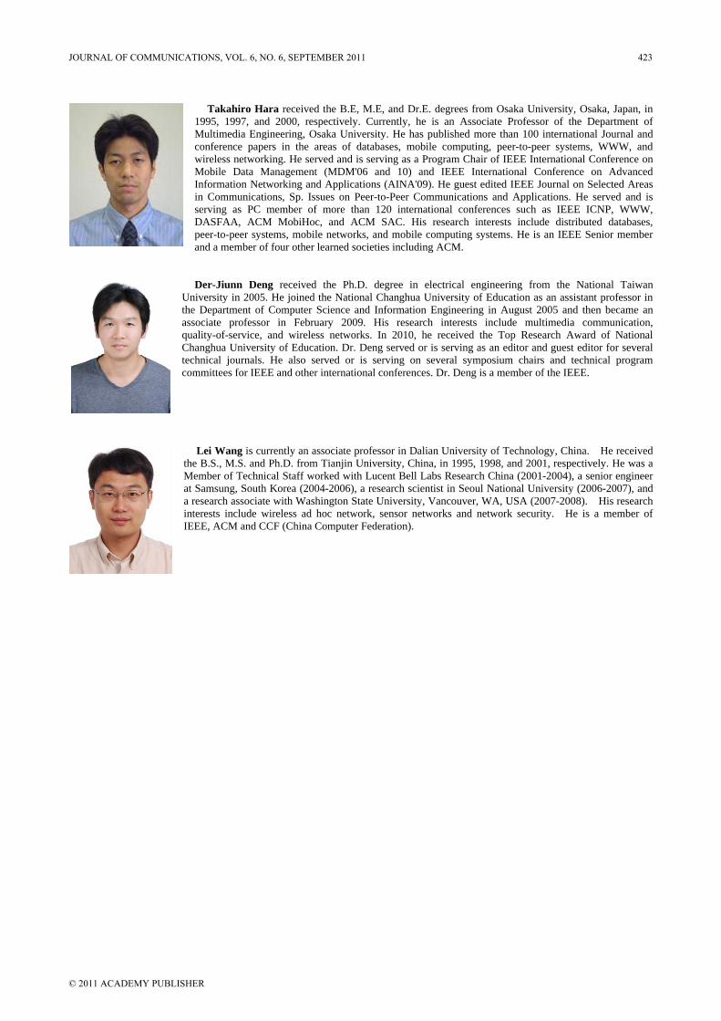
Takahiro Hara received the B.E, M.E, and Dr.E. degrees from Osaka University, Osaka, Japan, in 1995, 1997, and 2000, respectively. Currently, he is an Associate Professor of the Department of Multimedia Engineering, Osaka University. He has published more than 100 international Journal and conference papers in the areas of databases, mobile computing, peer-to-peer systems, WWW, and wireless networking. He served and is serving as a Program Chair of IEEE International Conference on Mobile Data Management (MDM'06 and 10) and IEEE International Conference on Advanced Information Networking and Applications (AINA'09). He guest edited IEEE Journal on Selected Areas in Communications, Sp. Issues on Peer-to-Peer Communications and Applications. He served and is serving as PC member of more than 120 international conferences such as IEEE ICNP, WWW, DASFAA, ACM MobiHoc, and ACM SAC. His research interests include distributed databases, peer-to-peer systems, mobile networks, and mobile computing systems. He is an IEEE Senior member and a member of four other learned societies including ACM.
Der-Jiunn Deng received the Ph.D. degree in electrical engineering from the National Taiwan University in 2005. He joined the National Changhua University of Education as an assistant professor in the Department of Computer Science and Information Engineering in August 2005 and then became an associate professor in February 2009. His research interests include multimedia communication, quality-of-service, and wireless networks. In 2010, he received the Top Research Award of National Changhua University of Education. Dr. Deng served or is serving as an editor and guest editor for several technical journals. He also served or is serving on several symposium chairs and technical program committees for IEEE and other international conferences. Dr. Deng is a member of the IEEE.
Lei Wang is currently an associate professor in Dalian University of Technology, China. He received the B.S., M.S. and Ph.D. from Tianjin University, China, in 1995, 1998, and 2001, respectively. He was a Member of Technical Staff worked with Lucent Bell Labs Research China (2001-2004), a senior engineer at Samsung, South Korea (2004-2006), a research scientist in Seoul National University (2006-2007), and a research associate with Washington State University, Vancouver, WA, USA (2007-2008). His research interests include wireless ad hoc network, sensor networks and network security. He is a member of IEEE, ACM and CCF (China Computer Federation).
JOURNAL OF COMMUNICATIONS, VOL. 6, NO. 6, SEPTEMBER 2011 423
© 2011 ACADEMY PUBLISHER
The Web of Things: A Survey
Deze Zeng, Song Guo, and Zixue ChengSchool of Computer Science and Engineering, The University of Aizu, Japan
Email: d8112106, sguo, [email protected]
Abstract— In the vision of the Internet of Things (IoT), anincreasing number of embedded devices of all sorts (e.g.,sensors, mobile phones, cameras, smart meters, smart cars,traffic lights, smart home appliances, etc.) are now capableof communicating and sharing data over the Internet.Although the concept of using embedded systems to controldevices, tools and appliances has been proposed for almostdecades now, with every new generation, the ever-increasingcapabilities of computation and communication pose newopportunities, but also new challenges. As IoT becomes anactive research area, different methods from various pointsof view have been explored to promote the developmentand popularity of IoT. One trend is viewing IoT as Web ofThings (WoT) where the open Web standards are supportedfor information sharing and device interoperation. By pene-trating smart things into existing Web, the conventional webservices are enriched with physical world services. This WoTvision enables a new way of narrowing the barrier betweenvirtual and physical worlds. In this paper, we elaboratethe architecture and some key enabling technologies ofWoT. Some pioneer open platforms and prototypes are alsoillustrated. The most recent research results are carefullysummarized. Furthermore, many systematic comparisonsare made to provide the insight in the evolution and futureof WoT. Finally, we point out some open challenging issuesthat shall be faced and tackled by research community.
Index Terms— Internet of Things, Web of Things, Survey
I. INTRODUCTION
Ubiquitous computing (a.k.a., pervasive computing),which has been extensively studied for many years, is ex-periencing radical changes recently as the physical worlddevices, e.g., home appliances and industrial machines,are becoming smart thanks to the progress in computingtechnology development. In parallel, the communicationtechniques also make much progress recently. Internetaccess will very likely become commonly accessible bythose “smart things”, motivating the concept of Internetof Things (IoT).
IoT is regarded as the next big possibility and challengeto the Internet. The Internet will be no longer just anetwork of computers, but will potentially involve trillionsof smart things with embedded systems. IoT will greatlyincrease the size and scope of current Internet, providingnew design opportunities and challenges. Internet withsmart things is generally viewed as a constrained IPnetwork with limited packet size, high degree of packetloss, and even intermittent connectivity and characterizedby severe limits on throughput, available power, and par-ticularly the complexity that can be supported. A variety
Manuscript received February 15, 2011; revised May 15, 2011;accepted June 15, 2011.
of recent research activities have been launched to addressthose challenging issues, from the technological to thesocial aspects. In particular, a central issue focuses on howto make a full interoperability of interconnected devicespossible, to provide them with an always higher degree ofsmartness by enabling their adaptation and autonomousbehavior while guaranteeing trust, privacy, and security[1].
Currently, the web has already become the major medi-um of communication in today’s Internet. On the otherhand, tiny web server technology has been researchedfor decades and now various embedded tiny web serversare available. More specifically, web services have beenproven to be indispensable in creating interoperable ap-plications on today’s Internet. Smart things with embed-ded web servers can be abstracted as web services andseamlessly integrated into the existing web. It is naturalto reuse existing web technologies and standards to unifythe cyber-world and the physical-world. As a result, oneresearch trend treats IoT as Web of Things (WoT). Asexisting web technologies can be reused and adapted tobuild new applications and services with participation ofsmart things. This yields higher flexibility, customizationand productivity. In brief, different from traditional viewof IoT which gives everyday device an IP address andmakes them interconnected on the Internet, WoT enablesthem to speak the same language, so as to communicateand interoperate freely on the Web.
The WoT vision depicts a view where a collection ofweb services that could be discovered, composed andexecuted. Thus enriches the scope of traditional webservices by promoting the web from only cyber-worldservices to both cyber-world and physical-world services.Furthermore, WoT actually is an ecosystem of servicesnot only about adding more services in but more about or-chestrating various kinds of services in a graceful manner,making the services more human-centric and intelligent.
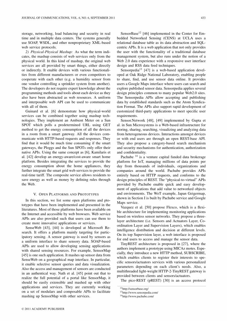
Let us use an example to illustrate the concept ofWoT. After the nuclear leakage accident happened atFukushima Dai-ichi Nuclear Power Plant on 11 March,2011 after the devastative tsunami, people have concernedthe radiation level at each places. A Japan Geigermaphas then been developed by integrating Google Map webservice and geiger counter readings. It provides a newweb service which visualizes the crowd-sourced radiationgeiger counter readings across Japan on a Google map.A snapshot is taken as shown in Fig. 11.
1http://japan.failedrobot.com/
(Invited Paper)
424 JOURNAL OF COMMUNICATIONS, VOL. 6, NO. 6, SEPTEMBER 2011
© 2011 ACADEMY PUBLISHERdoi:10.4304/jcm.6.6.424-438
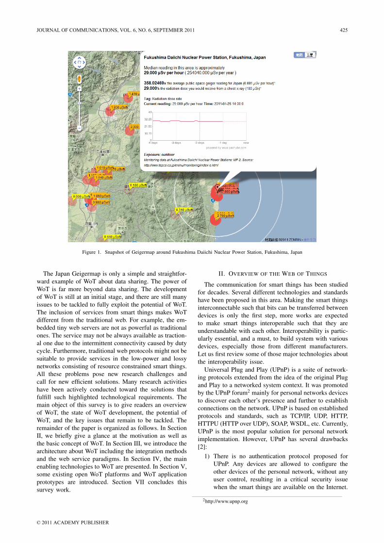
Figure 1. Snapshot of Geigermap around Fukushima Daiichi Nuclear Power Station, Fukushima, Japan
The Japan Geigermap is only a simple and straightfor-ward example of WoT about data sharing. The power ofWoT is far more beyond data sharing. The developmentof WoT is still at an initial stage, and there are still manyissues to be tackled to fully exploit the potential of WoT.The inclusion of services from smart things makes WoTdifferent from the traditional web. For example, the em-bedded tiny web servers are not as powerful as traditionalones. The service may not be always available as traction-al one due to the intermittent connectivity caused by dutycycle. Furthermore, traditional web protocols might not besuitable to provide services in the low-power and lossynetworks consisting of resource constrained smart things.All these problems pose new research challenges andcall for new efficient solutions. Many research activitieshave been actively conducted toward the solutions thatfulfill such highlighted technological requirements. Themain object of this survey is to give readers an overviewof WoT, the state of WoT development, the potential ofWoT, and the key issues that remain to be tackled. Theremainder of the paper is organized as follows. In SectionII, we briefly give a glance at the motivation as well asthe basic concept of WoT. In Section III, we introduce thearchitecture about WoT including the integration methodsand the web service paradigms. In Section IV, the mainenabling technologies to WoT are presented. In Section V,some existing open WoT platforms and WoT applicationprototypes are introduced. Section VII concludes thissurvey work.
II. OVERVIEW OF THE WEB OF THINGS
The communication for smart things has been studiedfor decades. Several different technologies and standardshave been proposed in this area. Making the smart thingsinterconnectable such that bits can be transferred betweendevices is only the first step, more works are expectedto make smart things interoperable such that they areunderstandable with each other. Interoperability is partic-ularly essential, and a must, to build system with variousdevices, especially those from different manufacturers.Let us first review some of those major technologies aboutthe interoperability issue.
Universal Plug and Play (UPnP) is a suite of network-ing protocols extended from the idea of the original Plugand Play to a networked system context. It was promotedby the UPnP forum2 mainly for personal networks devicesto discover each other’s presence and further to establishconnections on the network. UPnP is based on establishedprotocols and standards, such as TCP/IP, UDP, HTTP,HTTPU (HTTP over UDP), SOAP, WSDL, etc. Currently,UPnP is the most popular solution for personal networkimplementation. However, UPnP has several drawbacks[2]:
1) There is no authentication protocol proposed forUPnP. Any devices are allowed to configure theother devices of the personal network, without anyuser control, resulting in a critical security issuewhen the smart things are available on the Internet.
2http://www.upnp.org
JOURNAL OF COMMUNICATIONS, VOL. 6, NO. 6, SEPTEMBER 2011 425
© 2011 ACADEMY PUBLISHER
2) UPnP is not strictly standardized as some UPnPdevices are based unstandardized protocols suchas HTTPU, restricting its universal interconnectionsomehow.
3) UPnP is inapplicable to some resource-constraineddevices because it normally uses a lot of heavy pro-tocols (e.g., SOAP, WSDL, etc.) involving complexprocessing.
Alternatively, the JXTA technology3 is proposed asa solution for peer-to-peer applications design, enablinginterconnections of heterogeneous devices into a samenetwork. Later on, a C language based version, JXTA-C was proposed in order to embed JXTA into resource-constrained devices [3]. Unfortunately, JXTA protocolshave not been standardized and have not been widelyaccepted for embedded devices in industry either.
One trend is integrating the devices into the Web.It has been found that the web severs can be built ina size of only a few KBs [2], [4], [5]. It is possibleto integrate the web servers into many devices directly.Those devices then proactively serve their functionalityover the Web. Using the free, open, flexible, and scalableWeb as the universal platform to integrate smart devicesoutperforms all other solutions mentioned earlier in termsof easiness, flexibility, customization and security. Thisidea has attracted much attention from both academiaand industry, especially after the IoT concept emergesrecently.
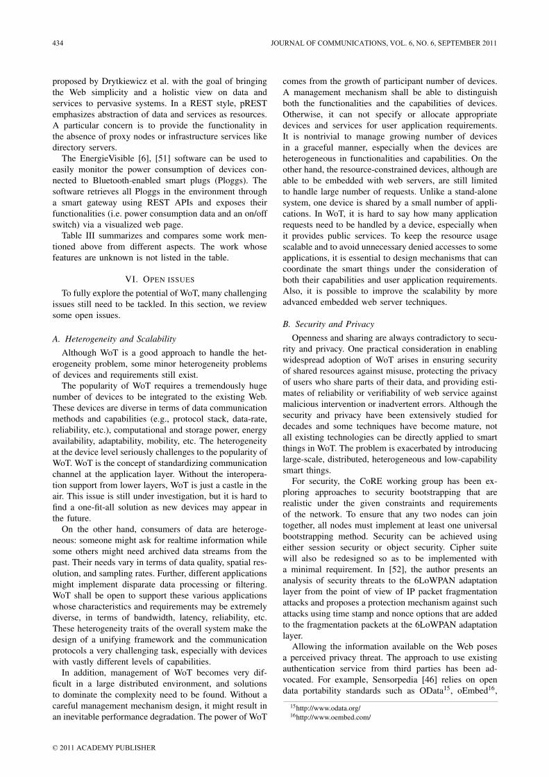
The web browsers have been available on almost anyplatform, from computers to PDAs, smart phones, andtablets, and become the de facto standard user interfaceto a variety of applications. The Web-enabled applicationscan be accessed from any location provided there is anInternet connection. Applied to embedded systems, webtechnologies can offer platform-independent interfacessuch that the end-users do not need to install specific soft-wares and drivers for different devices. Also, developersdo not have to tediously develop different softwares anddrivers targeting different platforms for one thing. TheWeb provides a one-for-all solution. An overview of ofWoT vision is shown in Fig. 2.
Furthermore, although devices become programmable,providing great opportunities to create more innovativeand powerful applications, development, especially com-position, of applications that run on top of those physicaldevices is still a cumbersome process as it requires exten-sive expert knowledge (e.g. specific APIs in a specific pro-gramming language) about all different physical devices.This more or less constrains development of smart thingsbased services. Fortunately, existing web technologies(e.g. mashup), which previously targeted for cyber-worldweb services can be reused for application developmentwith the participation of physical smart things providedthat they can be abstracted as web services. By reusingexisting web technologies, the expenses for additionalinfrastructure and overall implementation time can be
3http://java.sun.com/othertech/jxta/
minimized. These technologies can promote the progressof IoT significantly.
III. WEB-ORIENTED ARCHITECTURE
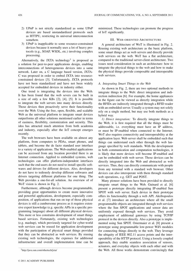
A general architecture of WoT is illustrated in Fig. 2.Reusing existing web architecture as the basic platform,some smart things act as web servers and directly provideweb services on the web. WoT has a flat architecture,compared to the traditional server-client architecture. Twoissues need consideration in such an architecture: how tointegrate the physical things to the web and how to makethe physical things provide composable and interoperableweb services.
A. Integrating Smart Things to the Web
As shown in Fig. 2, there are two optional methods tointegrate things to the Web: direct integration and indi-rection indirection [6]. For example, the home appliancesin the figure can be viewed as directly integration whilethe RFIDs are indirectly integrated through a RFID readerwith an embedded server. Usually a system may not solelyrely on a single method, but may use both methods as ahybrid way.
1) Direct integration: To directly integrate things tothe Web, it is first required that all the things must beaddressable, i.e. everything must have an IP address,or must be IP-enabled when connected to the Internet.WoT also requires connectivity and interoperability at theapplication layer. Web server shall be embedded such thatthings can understand each other through the web lan-guage specified by web standards. With the developmentin both communication and computation technologies, itis likely that more devices will become IP-enabled andcan be embedded with web server. Those devices can bedirectly integrated into the Web and abstracted as webservices. Thus, they can directly communicate with peoplefrom any terminal with a standard web browser. Otherdevices can also interoperate with them through standardweb operations, e.g. GET and POST.
Many pioneer solutions have been provided to directlyintegrate smart things to the Web. Guinard et al. [6]present a prototype directly integrating IP-enabled SunSPOT with web server. Each device in their prototypeoffers its functionality through a web API. Akribopouloset al. [7] introduce an architecture where all the smallprogrammable objects are integrated through web serviceswhere the Sun SPOT applications and sensor data areuniformly exposed through web services. They avoidemployment of additional gateways by using TCP/IPprotocol in the devices directly. Also a prototype is imple-mented using Sun SPOT. Ostermaier et al. [8] present aprototype using programmable low-power WiFi modulesfor connecting things directly to the web. They leveragethe ubiquity of IEEE 802.11 access points and the inter-operability of the HTTP protocol. Using a loosely coupledapproach, they enable seamless association of sensors,actuators, and everyday objects with each other and withthe Web. All those works demonstrate convincingly that
426 JOURNAL OF COMMUNICATIONS, VOL. 6, NO. 6, SEPTEMBER 2011
© 2011 ACADEMY PUBLISHER
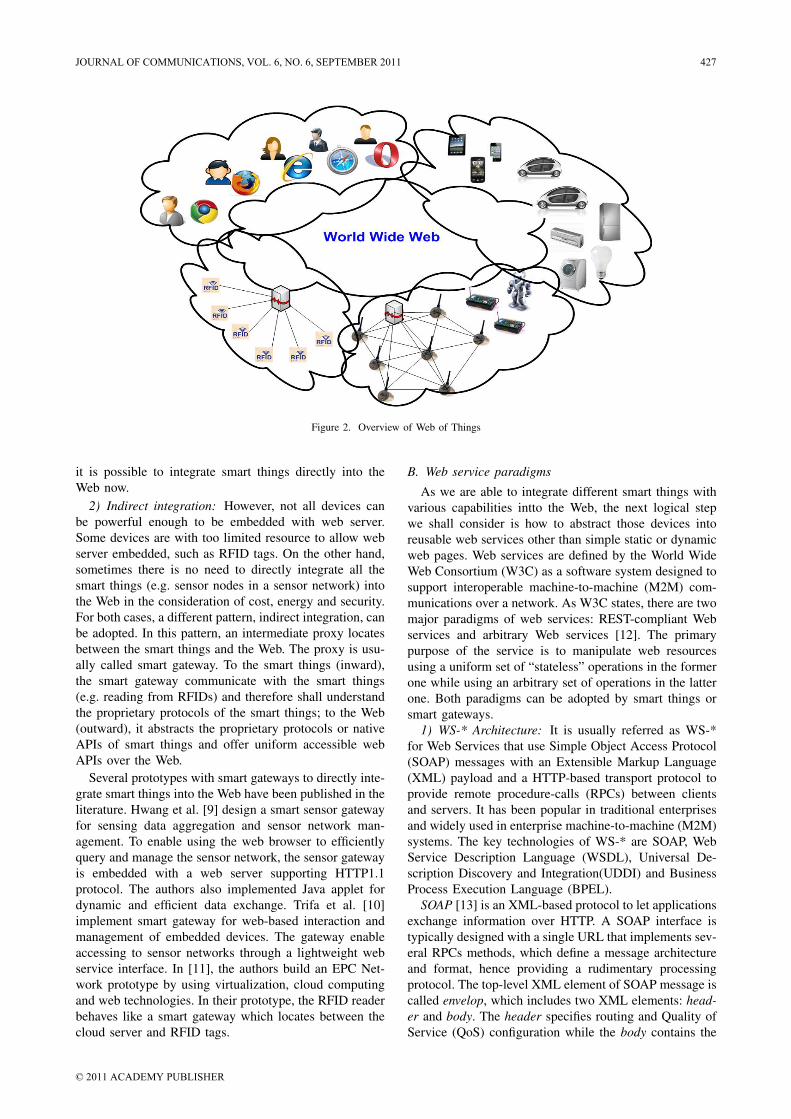
Figure 2. Overview of Web of Things
it is possible to integrate smart things directly into theWeb now.
2) Indirect integration: However, not all devices canbe powerful enough to be embedded with web server.Some devices are with too limited resource to allow webserver embedded, such as RFID tags. On the other hand,sometimes there is no need to directly integrate all thesmart things (e.g. sensor nodes in a sensor network) intothe Web in the consideration of cost, energy and security.For both cases, a different pattern, indirect integration, canbe adopted. In this pattern, an intermediate proxy locatesbetween the smart things and the Web. The proxy is usu-ally called smart gateway. To the smart things (inward),the smart gateway communicate with the smart things(e.g. reading from RFIDs) and therefore shall understandthe proprietary protocols of the smart things; to the Web(outward), it abstracts the proprietary protocols or nativeAPIs of smart things and offer uniform accessible webAPIs over the Web.
Several prototypes with smart gateways to directly inte-grate smart things into the Web have been published in theliterature. Hwang et al. [9] design a smart sensor gatewayfor sensing data aggregation and sensor network man-agement. To enable using the web browser to efficientlyquery and manage the sensor network, the sensor gatewayis embedded with a web server supporting HTTP1.1protocol. The authors also implemented Java applet fordynamic and efficient data exchange. Trifa et al. [10]implement smart gateway for web-based interaction andmanagement of embedded devices. The gateway enableaccessing to sensor networks through a lightweight webservice interface. In [11], the authors build an EPC Net-work prototype by using virtualization, cloud computingand web technologies. In their prototype, the RFID readerbehaves like a smart gateway which locates between thecloud server and RFID tags.
B. Web service paradigms
As we are able to integrate different smart things withvarious capabilities intto the Web, the next logical stepwe shall consider is how to abstract those devices intoreusable web services other than simple static or dynamicweb pages. Web services are defined by the World WideWeb Consortium (W3C) as a software system designed tosupport interoperable machine-to-machine (M2M) com-munications over a network. As W3C states, there are twomajor paradigms of web services: REST-compliant Webservices and arbitrary Web services [12]. The primarypurpose of the service is to manipulate web resourcesusing a uniform set of “stateless” operations in the formerone while using an arbitrary set of operations in the latterone. Both paradigms can be adopted by smart things orsmart gateways.
1) WS-* Architecture: It is usually referred as WS-*for Web Services that use Simple Object Access Protocol(SOAP) messages with an Extensible Markup Language(XML) payload and a HTTP-based transport protocol toprovide remote procedure-calls (RPCs) between clientsand servers. It has been popular in traditional enterprisesand widely used in enterprise machine-to-machine (M2M)systems. The key technologies of WS-* are SOAP, WebService Description Language (WSDL), Universal De-scription Discovery and Integration(UDDI) and BusinessProcess Execution Language (BPEL).
SOAP [13] is an XML-based protocol to let applicationsexchange information over HTTP. A SOAP interface istypically designed with a single URL that implements sev-eral RPCs methods, which define a message architectureand format, hence providing a rudimentary processingprotocol. The top-level XML element of SOAP message iscalled envelop, which includes two XML elements: head-er and body. The header specifies routing and Quality ofService (QoS) configuration while the body contains the
JOURNAL OF COMMUNICATIONS, VOL. 6, NO. 6, SEPTEMBER 2011 427
© 2011 ACADEMY PUBLISHER
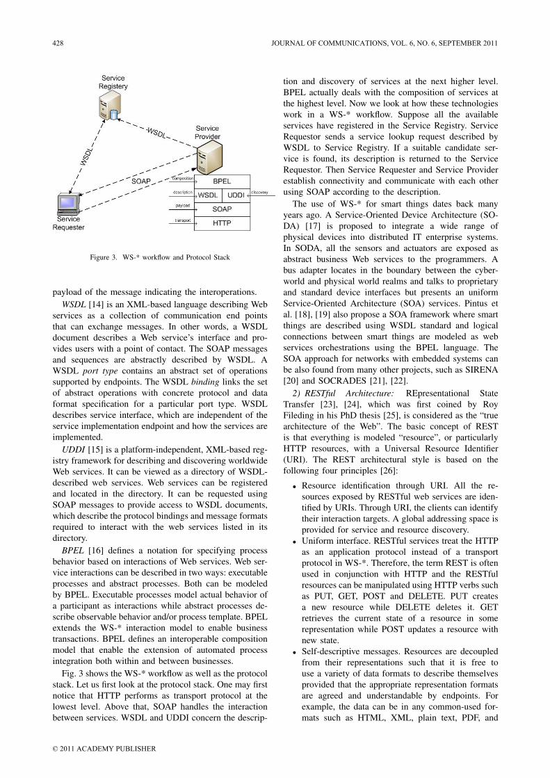
Figure 3. WS-* workflow and Protocol Stack
payload of the message indicating the interoperations.WSDL [14] is an XML-based language describing Web
services as a collection of communication end pointsthat can exchange messages. In other words, a WSDLdocument describes a Web service’s interface and pro-vides users with a point of contact. The SOAP messagesand sequences are abstractly described by WSDL. AWSDL port type contains an abstract set of operationssupported by endpoints. The WSDL binding links the setof abstract operations with concrete protocol and dataformat specification for a particular port type. WSDLdescribes service interface, which are independent of theservice implementation endpoint and how the services areimplemented.
UDDI [15] is a platform-independent, XML-based reg-istry framework for describing and discovering worldwideWeb services. It can be viewed as a directory of WSDL-described web services. Web services can be registeredand located in the directory. It can be requested usingSOAP messages to provide access to WSDL documents,which describe the protocol bindings and message formatsrequired to interact with the web services listed in itsdirectory.
BPEL [16] defines a notation for specifying processbehavior based on interactions of Web services. Web ser-vice interactions can be described in two ways: executableprocesses and abstract processes. Both can be modeledby BPEL. Executable processes model actual behavior ofa participant as interactions while abstract processes de-scribe observable behavior and/or process template. BPELextends the WS-* interaction model to enable businesstransactions. BPEL defines an interoperable compositionmodel that enable the extension of automated processintegration both within and between businesses.
Fig. 3 shows the WS-* workflow as well as the protocolstack. Let us first look at the protocol stack. One may firstnotice that HTTP performs as transport protocol at thelowest level. Above that, SOAP handles the interactionbetween services. WSDL and UDDI concern the descrip-
tion and discovery of services at the next higher level.BPEL actually deals with the composition of services atthe highest level. Now we look at how these technologieswork in a WS-* workflow. Suppose all the availableservices have registered in the Service Registry. ServiceRequestor sends a service lookup request described byWSDL to Service Registry. If a suitable candidate ser-vice is found, its description is returned to the ServiceRequestor. Then Service Requester and Service Providerestablish connectivity and communicate with each otherusing SOAP according to the description.
The use of WS-* for smart things dates back manyyears ago. A Service-Oriented Device Architecture (SO-DA) [17] is proposed to integrate a wide range ofphysical devices into distributed IT enterprise systems.In SODA, all the sensors and actuators are exposed asabstract business Web services to the programmers. Abus adapter locates in the boundary between the cyber-world and physical world realms and talks to proprietaryand standard device interfaces but presents an uniformService-Oriented Architecture (SOA) services. Pintus etal. [18], [19] also propose a SOA framework where smartthings are described using WSDL standard and logicalconnections between smart things are modeled as webservices orchestrations using the BPEL language. TheSOA approach for networks with embedded systems canbe also found from many other projects, such as SIRENA[20] and SOCRADES [21], [22].
2) RESTful Architecture: REpresentational StateTransfer [23], [24], which was first coined by RoyFileding in his PhD thesis [25], is considered as the “truearchitecture of the Web”. The basic concept of RESTis that everything is modeled “resource”, or particularlyHTTP resources, with a Universal Resource Identifier(URI). The REST architectural style is based on thefollowing four principles [26]:
• Resource identification through URI. All the re-sources exposed by RESTful web services are iden-tified by URIs. Through URI, the clients can identifytheir interaction targets. A global addressing space isprovided for service and resource discovery.
• Uniform interface. RESTful services treat the HTTPas an application protocol instead of a transportprotocol in WS-*. Therefore, the term REST is oftenused in conjunction with HTTP and the RESTfulresources can be manipulated using HTTP verbs suchas PUT, GET, POST and DELETE. PUT createsa new resource while DELETE deletes it. GETretrieves the current state of a resource in somerepresentation while POST updates a resource withnew state.
• Self-descriptive messages. Resources are decoupledfrom their representations such that it is free touse a variety of data formats to describe themselvesprovided that the appropriate representation formatsare agreed and understandable by endpoints. Forexample, the data can be in any common-used for-mats such as HTML, XML, plain text, PDF, and
428 JOURNAL OF COMMUNICATIONS, VOL. 6, NO. 6, SEPTEMBER 2011
© 2011 ACADEMY PUBLISHER
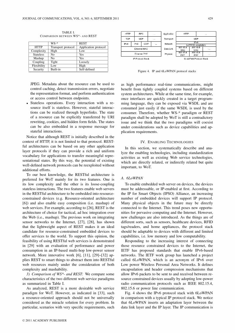
TABLE I.COMPARISON BETWEEN WS*- AND REST
WS-* RESTHTTP Transport protocol Application protocol
Complexity High LowStateless No YesMashup No Yes
Coupling Tight LooselyFlexibility Low HighSecurity Built-in Self-defined
JPEG. Metadata about the resource can be used tocontrol caching, detect transmission errors, negotiatethe representation format, and perform authenticationor access control between endpoints.
• Stateless operations. Every interaction with a re-source itself is stateless. However, stateful interac-tions can be realized through hyperlinks. The stateof a resource can be explicitly transferred by URIrewriting, cookies, and hidden form fields. The statescan be also embedded in a response message forstateful interactions.
Notice that although REST is initially described in thecontext of HTTP, it is not limited to that protocol. REST-ful architectures can be based on any other applicationlayer protocols if they can provide a rich and uniformvocabulary for applications to transfer meaningful repre-sentational states. By this way, the potential of existingwell-defined network protocols can be reexploited withoutadditional efforts.
To our best knowledge, the RESTful architecture ispreferred for WoT mainly for its two features. One isits low complexity and the other is its loose-couplingstateless interactions. The two features enable web serversin the RESTful architecture to be embedded into resource-constrained devices (e.g. Resource-oriented architecture[6]) and also enable easy composition (i.e. mashup) ofweb services. For example, according to [26], REST is thearchitecture of choice for tactical, ad hoc integration overthe Web (i.e., mashup). The previous work on integratingsensor networks to the Internet, [27], [28], has shownthat the lightweight aspect of REST makes it an idealcandidate for resource-constrained embedded devices tooffer services to the world. To support this opinion, thefeasibility of using RESTful web services is demonstratedin [29] with an evaluation of performance and powerconsumption in an IP-based multi-hop low-power sensornetwork. More innovative work [6], [11], [29]–[32] ap-plies REST to smart things to abstract them into RESTfulweb resources mainly under the consideration of bothcomplexity and mashability.
3) Comparison of WS*- and REST: We compare somecharacteristics of the two different web service paradigmsas summarized in Table I.
As analyzed, REST is a more desirable web serviceparadigm for WoT. However, as indicated in [33], sucha resource-oriented approach should not be universallyconsidered as the miracle solution for every problem. Inparticular, scenarios with very specific requirements, such
Figure 4. IP and 6LoWPAN protocol stacks
as high performance real-time communications, mightbenefit from tightly coupled systems based on differentsystem architectures. While at the same time, for example,once interfaces are quickly created in a target program-ming language, they can be exposed via WSDL and areconsumed just easily if the same WSDL is used by theconsumer. Therefore, whether WS-* paradigm or RESTparadigm shall be adopted by WoT is still a contradictoryissue and we think that the two paradigms will coexistunder considerations such as device capabilities and ap-plication requirements.
IV. ENABLING TECHNOLOGIES
In this section, we systematically describe and ana-lyze the enabling technologies, including standardizationactivities as well as existing Web service technologies,which are directly related, or indirectly related but quiteimportant, to WoT.
A. 6LoWPAN
To enable embedded web server on devices, the devicesmust be addressable, or IP-enabled at first. According tothe IP for Smart Objects (IPSO) Alliance, an increasingnumber of embedded devices will support IP protocol.Many physical objects in the future may be directlyconnected to the Internet. This trend poses new opportu-nities for pervasive computing and the Internet. However,new challenges are also introduced. As the things are ofdifferent sorts, such as sensors, healthcare devices, RFIDtags/readers, and home appliances, the protocol stackshould be adaptable to devices with different and limitedcapabilities, i.e. low memory and low computability.
Responding to the increasing interest of connectingthose resource constrained devices to the Internet, theIETF has proposed standards that enable IPv6-basednetworks. The IETF work group has launched a projectcalled 6LoWPAN, which is an acronym of IPv6 overLow power Wireless Personal Area Networks. It definesencapsulation and header compression mechanisms thatallow IPv6 packets to be sent to and received between re-source constrained devices usually by adopting low-powerradio communication protocols such as IEEE 802.15.4,802.15.6 or power line communication.
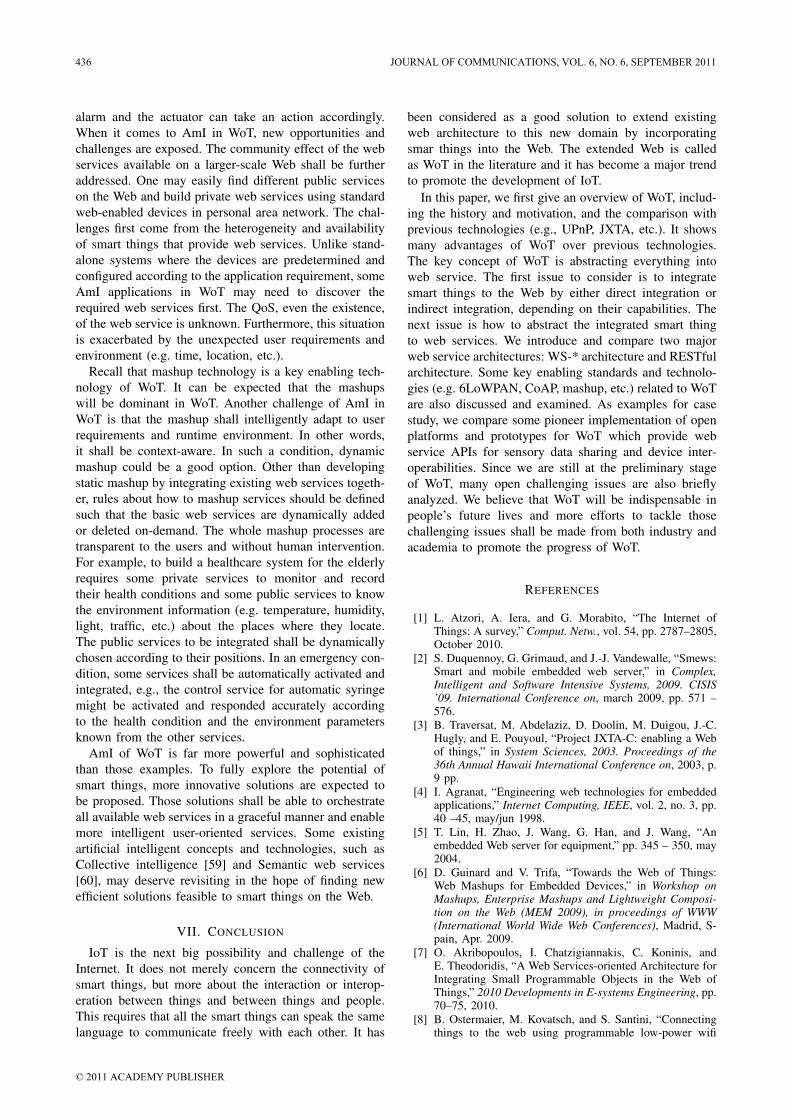
Fig. 4 shows the IPv6 protocol stack with 6LoWPANin comparison with a typical IP protocol stack. We noticethat 6LoWPAN inserts an adaptation layer between thedata link layer and the IP layer. The IP communication is
JOURNAL OF COMMUNICATIONS, VOL. 6, NO. 6, SEPTEMBER 2011 429
© 2011 ACADEMY PUBLISHER
provided above the adaptation layer. The necessity of theadaptation layer is mainly because one IP packet may notfit within one layer 2 frame , e.g. 802.15.4 MAC frame.
The adaptation layer is the main component of 6Low-PAN as it enable IPv6 packets to fit into IEEE 802.15.4frame payload. It has the following functions.
• Header compression. TCP/IP headers are too largeto the data link layer protocol, e.g. IEEE 802.15.4,for most devices. For example, IPv6 header has 40bytes. Without header compression, it is impossibleto transmit any payload effectively by a data linklayer protocol such as IEEE 802.15.4, which has amaximum packet size of only 128 bytes. By headercompression, the header overhead is much reduced.In the best case, the compressed 6LowPAN/UDPheader for local unicast communication can be com-pressed to only 6 bytes while traditional IPv6/UPDheader requires 48 bytes.
• Packet fragmentation and reassembling. The datalink layer supports packets in small size. For exam-ple, IEEE 802.15.4 supports Maximum TransmissionUnit (MTU) in size of only 128 bytes while IPv6packet can be as large as 1280 bytes. This mismatchhas to be handled by fragmentation and reassemblingin the adaptation layer.
• Edge routing. To connect personal area networksto the Internet, edge routers, which locate on theedge between personal area networks (PANs) andthe Internet, play an essential role as they route IPpackets into the PAN devices from outside and viceversa. While at the same time, the edge routers alsohave management features such as distribution ofIPv6 prefix and neighbor discovery.
Compared to traditional IP stack, the network layer islimited to IPv6 because IPv4 has reached its exhaustionrecently. When a large number of, maybe in trillions,devices need IP addresses, IPv6 is able to make all devicesaddressable at the IP layer. Although both TCP and UDPare supported, the most common transport protocol usedby 6LoWPAN is UDP. The Web can be viewed as themost popular application protocol. Web applications todaymainly depend on payloads of HTML, XML, or SOAPcarried over HTTP and TCP. The payload can be in sizefrom hundreds of bytes to several KBs, which is toolarge for use on some 6LoWPAN nodes. Furthermore,the Web applications over 6LoWPAN shall make use ofUDP for performance, efficiency and complexity reasons.Therefore, the Web applications over 6LoWPAN shall befault tolerant due to the unreliability of UDP.
B. CoAP
In 2010, the IETF established a new working groupfocusing on Constrained RESTful Environment (CoRE).CoRE is characterized by its additional constraints com-pared to traditional IP networks. To handle those differ-ences and tackle various challenging issues, the CoREworking group is working on a framework for applications
Figure 5. HTTP and CoAP protocol stacks
intended to run on the constrained networks. The frame-work is designed for applications such as smart energy,home appliance, industry automation, as well as otherM2M applications that deal with manipulation of vari-ous resources on constrained networks, e.g. monitoring,control and management of resources. As a main part ofthe framework, Constrained Application Protocol(CoAP)is defined by the CoRE working group.
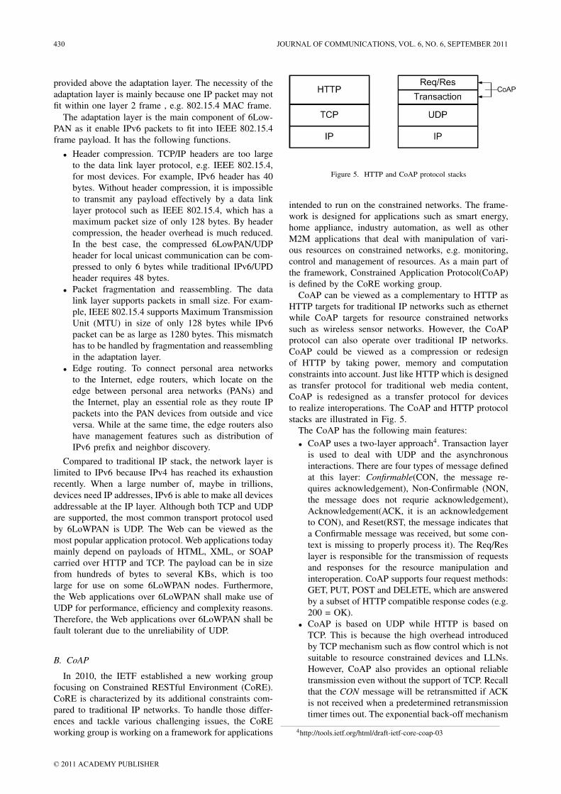
CoAP can be viewed as a complementary to HTTP asHTTP targets for traditional IP networks such as ethernetwhile CoAP targets for resource constrained networkssuch as wireless sensor networks. However, the CoAPprotocol can also operate over traditional IP networks.CoAP could be viewed as a compression or redesignof HTTP by taking power, memory and computationconstraints into account. Just like HTTP which is designedas transfer protocol for traditional web media content,CoAP is redesigned as a transfer protocol for devicesto realize interoperations. The CoAP and HTTP protocolstacks are illustrated in Fig. 5.
The CoAP has the following main features:• CoAP uses a two-layer approach4. Transaction layer
is used to deal with UDP and the asynchronousinteractions. There are four types of message definedat this layer: Confirmable(CON, the message re-quires acknowledgement), Non-Confirmable (NON,the message does not requrie acknowledgement),Acknowledgement(ACK, it is an acknowledgementto CON), and Reset(RST, the message indicates thata Confirmable message was received, but some con-text is missing to properly process it). The Req/Reslayer is responsible for the transmission of requestsand responses for the resource manipulation andinteroperation. CoAP supports four request methods:GET, PUT, POST and DELETE, which are answeredby a subset of HTTP compatible response codes (e.g.200 = OK).
• CoAP is based on UDP while HTTP is based onTCP. This is because the high overhead introducedby TCP mechanism such as flow control which is notsuitable to resource constrained devices and LLNs.However, CoAP also provides an optional reliabletransmission even without the support of TCP. Recallthat the CON message will be retransmitted if ACKis not received when a predetermined retransmissiontimer times out. The exponential back-off mechanism
4http://tools.ietf.org/html/draft-ietf-core-coap-03
430 JOURNAL OF COMMUNICATIONS, VOL. 6, NO. 6, SEPTEMBER 2011
© 2011 ACADEMY PUBLISHER
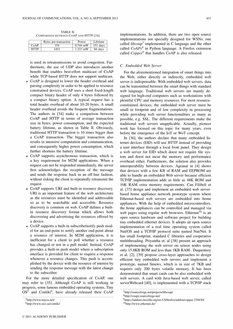
TABLE II.COMPARISON BETWEEN COAP AND HTTP [34]
Bytes per-transaction Power LifetimeCoAP 154 0.744 mW 151 daysHTTP 1451 1.333 mW 84 days
is used in retransmissions to avoid congestion. Fur-thermore, the use of UDP also introduces anotherbenefit that enables best-effort multicast of CoAPwhile TCP-based HTTP does not support multicast.
• CoAP is designed to lower the header overhead andparsing complexity in order to be applied to resourceconstrained devices. CoAP uses a short fixed-lengthcompact binary header of only 4 bytes followed bya compact binary option. A typical request has atotal header overhead of about 10-20 bytes. A smallheader overhead avoids the frequent fragmentations.The authors in [34] make a comparison betweenCoAP and HTTP in terms of average transactionsize in bytes, power consumption, and the expectedbattery lifetime, as shown in Table II. Obviously,traditional HTTP transaction is 10 times bigger thana CoAP transaction. The bigger transaction alsoresults in intensive computation and communication,and consequently higher power consumption, whichfurther shortens the battery lifetime.
• CoAP supports asynchronous transaction, which isa key requirement for M2M applications. When arequest can not be responded immediately, the serverfirst acknowledges the reception of the messageand sends the response back in an off-line fashion,without risking the client to repeatedly retransmit therequest.
• CoAP supports URI and built-in resource discovery.URI is an important feature of the web architectureas the resources must be identified and addressableso as to be searchable and accessible. Resourcediscovery is common on web. CoAP defines a built-in resource discovery format which allows bothdiscovering and advertising the resources offered bya device.
• CoAP supports a built-in subscribe/notify push mod-el for an end-point to notify another end-point abouta resource of interest. In M2M application, it isinefficient for a client to poll whether a resourcehas changed or not in a pull model. Instead, CoAPprovides a built-in push model where a subscriptioninterface is provided for client to request a responsewhenever a resource changes. This push is accom-plished by the device with the resource of interest bysending the response message with the latest changeto the subscriber.
For the more detailed specification of CoAP, onemay refer to [35]. Although CoAP is still working inprogress, some famous embedded operating systems, TinyOS5 and Contiki6, have already released their CoAP
5http://www.tinyos.net/6http://www.sics.se/contiki/
implementations. In addition, there are two open sourceimplementations not specially designed for WSNs: onecalled libcoap7 implemented in C language and the othercalled CoAPy8 in Python language. A Firefox extensioncalled Copper9 that handles CoAP is also released.
C. Embedded Web Server
For the aforementioned integration of smart things intothe Web, either directly or indirectly, embedded webserver is indispensable. With embedded web servers, datacan be transmitted between the smart things with standardweb language. Traditional web servers are mainly de-signed for high-end computers such as workstations withplentiful CPU and memory resources. For most resource-constrained devices, the embedded web server must besmall in footprint and of low complexity in processingwhile providing web server functionalities as many aspossible, e.g. SSL. The different requirements make thetraditional web servers unapplicable. Actually, pioneerwork has focused on this topic for many years, evenbefore the emergence of the IoT or WoT concept.
In [36], the authors declare that many embedded In-ternet devices (EID) will use HTTP instead of providinga user interface through a local front panel. They designa web server for EID which doest not require file sys-tem and doest not incur the memory and performanceoverhead either. Furthermore, the solution also providesinteroperability between devices. Agranat in [4] showsthat devices with a few KB of RAM and EEPROM areable to handle an embedded Web server because efficientTCP/IP implementation adds as little as 48K ROM and16K RAM extra memory requirements. Can Filibeli etal. [37] design and implement an embedded web server-based home appliance network prototype system whereEthernut-based web servers are embedded into homeappliances. With the help of embedded microcontrollers,the home appliances can be controlled and managed viaweb pages using regular web browsers. Ethernut10 is anopen source hardware and software project for buildingtiny embedded ethernet devices. It adopts an open sourceimplementation of a real time operating system calledNut/OS and a TCP/IP protocol suite named Nut/Net. Ithas small footprint, standard C libraries and cooperativemultithreading. Priyantha et. al [38] present an approachof implementing the web server on sensor nodes usingonly 15.8KB ROM and less than 1KB RAM . Duquennoyet al. [2], [39] propose cross-layer approaches to designefficient tiny embedded web servers and implement aprototype, named Smews, which is in size of 7KB andrequires only 200 bytes volatile memory. It has beendemonstrated that smart cards can be also embedded withweb servers. A card with Java-based web server, calledserverWebcard [40], is implemented with a TCP/IP stack
7http://sourceforge.net/projects/libcoap/8http://coapy.sourceforge.net/9https://addons.mozilla.org/en-US/firefox/addon/copper-270430/10http://www.ethernut.de/
JOURNAL OF COMMUNICATIONS, VOL. 6, NO. 6, SEPTEMBER 2011 431
© 2011 ACADEMY PUBLISHER
and a minimal set of HTTP1.0 functions. OMA(Open Mo-bile Alliance) specifies Smart Card Web Server (SCWS)standard to allow web servers to be used within smartcards such that network operators’ services can be provid-ed through web browser [41]. More importantly, SCWSis portable across any handsets with browsers.
There are much more work than those mentionedabove, which implement lightweight embedded webservers with different features in different programminglanguages. Further efforts are on more powerful embed-ded web servers but with little resource requirement.It can be expected that the embedded servers will becommon in future embedded devices.
D. Service Composition Development
With the emergence of IoT, huge numbers of embed-ded devices with various functions will be connected tothe Internet. Although the connectivity allows devicesto provide some specified services on the Internet, itis not the ultimate goal. To fully explore the potentialof those devices, they shall be able to cooperate witheach other. However, there is a tight coupling among thedevices, the services provided as well as the developmentmethods. It is not easy to integrate devices from differentmanufacturers. While, up to date, new applications in thisfield are mainly produced by designers and engineers,we claim that even users could invent new applicationsunforeseen by technical experts with simple and effectivecomposition rules and easy-to-use building blocks.
Fortunately, as we have known, web servers are pos-sible to be embedded into devices such that they canprovide web services on the Internet. Even for thosewhich can not directly provide, a smart gateway can act asa proxy to provide web service. Imagine we have severaldifferent devices such as temperature sensor, humiditysensor, GPS device as well as some healthcare devices(e.g. EKG sensor). We want to build a healthcare systemwhich can monitor and record the health condition ofpatients as well as environment information (e.g. temper-ature, humidity, position) of the patient. Traditionally, thedeveloper shall understand all the native APIs provided byeach device and write programs to integrate informationprovided by those devices. This requires extensive timeand technical expertise. In WoT, all the things are abstract-ed as web resources, which are addressable, searchableand accessible on the Web. The developer can use uniformweb standard to integrate all the abstracted web resourcesneeded as well as existing virtual web service (e.g. GoogleMap) together to create a mashup. Mashups are new webapplication/service created by composing various originalweb services from disparate, or even competing providers.Mashup can be viewed as a key feature of Web 2.0 or oneof the main differences to Web1.0. In Web2.0, There areplentiful web service available such as Twitter, Facebook,Flickr, Linkedin, eBay, Yahoo Maps, and so on. Mostprovide APIs to allow developers to create more newservices based on their basic services. This has become amajor web application development trend. For example, a
web service, called Wikipediavision11, is created by usingGoogle Map APIs and Wikipedia APIs to timely show theplaces where anonymous edits to Wikipedia are happen-ing on Google Map. However, different from traditionalWeb2.0 mashup, mashups in WoT include not only virtualweb services but also physical web services provided bythings. Some researchers call this Web3.0 mashup andargue that we are going to enter a Web3.0 era. As moreweb-enabled things will be abstracted as web services andpublished on the Web, together with the popularity andprogress of virtual world web services, more fruitful andpowerful composite Web3.0 services can be envisionedin the future. We believe that Web3.0 mashup will be themain technical engine to make progress for both WoT andIoT.
In [6], Guinard et al. apply REST principles to em-bedded devices and present two representative Web3.0mashup styles, physical-virtual mashups and physical-physical mashups.
1) Physical-Virtual Mashup: As indicated by its name,this mashup consists of web services from both the phys-ical world and the virtual world. Although the embeddeddevices can provide some web services to answer HTTPqueries from users such as checking the state of thedevices or changing the state of the devices, it mightnot always be sufficient to satisfy the user’s requirement.For example, suppose some sensor nodes are distributedover the city to monitor the temperature of differentspots. It is desirable that the values can be displayedin a visual way (e.g. on a map) such that people caneasily get the information about any specified spot. Undersuch requirement, the developer can mashup virtual mapservice and physical sensor web service to create atemperature monitoring web application which displaystemperatures of different places on the map. Any services,either physical or virtual, are able to be mashuped if theyfollow the same standard (e.g. REST) and provide anuniform interface to communicate with.
Many mashup products or prototypes have been de-veloped including both virtual and physical services.The WoT example shown in Section I can be viewedas a classical physical-virtual mashup. Guinard et al.[6] implement an application, called EnergyVisualizer,which offers a GUI on the Web to monitor the powerconsumption and to control different home appliances.EnergyVisualizer is built by using the self-defined REST-ful Plogg API and Google Web Toolkit APIs. The mashupcalls the Ploggs Smart Gateway at a constant interval byissuing a GET HTTP request to the Ploggs and feedsthe response in an interoperable data in JSON formatto the corresponding graphs. Furthermore, they also putswitch buttons on the web page, where by clickinga button the corresponding appliance can be turn onor off. In the cloud computing industry, the providers,e.g. Amazon Web Services, Google’s Google Apps, andSalesforce.com’s Force.com., use web interface or APIto allow users to provision and scale physical servers,
11http://www.lkozma.net/wpv/index.html
432 JOURNAL OF COMMUNICATIONS, VOL. 6, NO. 6, SEPTEMBER 2011
© 2011 ACADEMY PUBLISHER
storage, networking, load balancing and security in realtime and in multiple data centers. The systems generallyuse SOAP, WSDL, and other nonproprietary XML-basedweb service protocols.
2) Physical-Physical Mashup: As what the term indi-cates, the mashup consists of web services only from thephysical world. In this kind of mashup, the original webservices are all provided by smart things, either directlyor indirectly. It enable devices with various functionali-ties from different manufacturers or even competitors tocooperate with each other (e.g. a humidity sensor fromone vendor controlling a sprinkler system from another).The developers do not require expert knowledge about theprogramming methods and tools about each device as theyalso have been abstracted as web resources. A uniformand interposable web API can be used to communicatewith all of them.
Guinard et al. [6] demonstrate how physical-worldservices can be combined together using mashup tech-nologies. They implement an Ambient Meter on a SunSPOT which polls a predetermined URL using GETmethod to get the energy consumption of all the devicesin a room from a smart gateway. All the devices com-municate with HTTP-based requests and responses. Theyfind that it would be much time consuming if the smartgateways, the Ploggs and the Sun SPOTs only offer theirnative APIs. Using the same concept as [6], Kamilaris etal. [42] develop an energy-aware/cost-aware smart homeplatform. Besides integrating the services to provide theenergy consumption about the home appliances, theyfurther integrate the smart grid web services to provide thereal-time tariff. The composite service allows residents tosave energy as well as money by defining rules throughthe Web.
V. OPEN PLATFORMS AND PROTOTYPES
In this section, we list some open platforms and pto-totypes that have been implemented and presented in theliteratures. Most of those platforms have been available onthe Internet and accessible by web browsers. Web serviceAPIs are also provided such that users can use them tocreate more innovative applications or services.
SenseWeb [43], [44] is developed at Microsoft Re-search. It offers a platform mainly targeting for partic-ipatory sensing. A sensor gateway is used by sensors asa uniform interface to share sensory data. SOAP-basedAPIs are used to allow developing sensing applicationswith shared sensing resources. For example, SensorMap[45] is one such application. It mashes up sensor data fromSenseWeb on a geographical map interface. In particular,it enable selective sensor queries and data visualization.Also the access and management of sensors are conductedin an authentical way. Nath et al. [45] point out that torealize the full potential of a portal like SensorMap, itshould be easily extensible and mashed up with otherapplications and services. They are currently workingon a set of modulars and composable APIs to facilitatemashing up SensorMap with other services.
SensorBase12 [46] implemented in the Center for Em-bedded Networked Sensing (CENS) at UCLA uses arelational database table as its data abstraction and SQL-centric APIs. It is a web application that not only providesthe user with the functionality of a traditional databasemanagement system, but also runs under the notion of aWeb 2.0 data experience with a responsive user interfacedesign and RSS data feed techniques.
Sensorpedia13 [47] is a web-based application devel-oped at Oak Ridge National Laboratory, enabling peopleto share, find, and use sensor data online. It providesusers a Google Maps interface where users can search andexplore published sensor data. Sensorpedia applies severaldesign principles common to many popular Web2.0 sites.The Sensorpedia APIs allow accepting and publishingdata by established standards such as the Atom Syndica-tion Format. The APIs also support rapid development ofcustomized third-party applications to meet specific userrequirements.
Sensor.Network [48], [49] implemented by Gupta etal. in Sun Microsystems is a Web-based infrastructure forstoring, sharing, searching, visualizing and analyzing datafrom heterogeneous devices. Interactions amongst devicesor with end users are through an open REST-base API.They also propose a category-based search mechanismand security mechanisms for authentication, authorizationand confidentiality.
Pachube 14 is a venture capital funded data brokerageplatform for IoT, managing millions of data points perday from thousands of individuals, organizations andcompanies around the world. Pachube provides APIsentirely based on HTTP requests, and conforms to thedesign principles of REST. The “physical-to-virtual” APIsprovided by Pachube enable quick and easy develop-ment of applications that add value to networked objectsand environments. The WoT example, Japan Geigermap,shown in Section I is built by Pachube service and GoogleMaps service.
Vazquez et al. [50] propose Flexco, which is a flexi-ble architecture for implementing monitoring applicationsbased on wireless sensor networks. They propose a three-layer architecture (i.e. Sensors and Actuators Layer, Co-ordination Layer and Supervision Layers), which enablesintelligence distribution and decision at different levels.On its top Supervision layer, a web interface is proposedfor end users to access and manage the sensor data.
TinyREST architecture is proposed in [27], where theauthors implement a prototype using MICAz motes. Espe-cially, they introduce a new HTTP method, SUBSCRIBE,which enables clients to register their interests to spe-cific sensors/actuators services with various personalizedparameters depending on each client’s needs. Also, amultithreaded light-weight HTTP-2-TinyREST gateway isprovided between clients and sensors/actuators.
The pico-REST (pREST) [30] is an access protocol
12http://sensorbase.org/13http://www.sensorpedia.com/14http://www.pachube.com/
JOURNAL OF COMMUNICATIONS, VOL. 6, NO. 6, SEPTEMBER 2011 433
© 2011 ACADEMY PUBLISHER
proposed by Drytkiewicz et al. with the goal of bringingthe Web simplicity and a holistic view on data andservices to pervasive systems. In a REST style, pRESTemphasizes abstraction of data and services as resources.A particular concern is to provide the functionality inthe absence of proxy nodes or infrastructure services likedirectory servers.
The EnergieVisible [6], [51] software can be used toeasily monitor the power consumption of devices con-nected to Bluetooth-enabled smart plugs (Ploggs). Thesoftware retrieves all Ploggs in the environment througha smart gateway using REST APIs and exposes theirfunctionalities (i.e. power consumption data and an on/offswitch) via a visualized web page.
Table III summarizes and compares some work men-tioned above from different aspects. The work whosefeatures are unknown is not listed in the table.
VI. OPEN ISSUES
To fully explore the potential of WoT, many challengingissues still need to be tackled. In this section, we reviewsome open issues.
A. Heterogeneity and Scalability
Although WoT is a good approach to handle the het-erogeneity problem, some minor heterogeneity problemsof devices and requirements still exist.
The popularity of WoT requires a tremendously hugenumber of devices to be integrated to the existing Web.These devices are diverse in terms of data communicationmethods and capabilities (e.g., protocol stack, data-rate,reliability, etc.), computational and storage power, energyavailability, adaptability, mobility, etc. The heterogeneityat the device level seriously challenges to the popularity ofWoT. WoT is the concept of standardizing communicationchannel at the application layer. Without the interopera-tion support from lower layers, WoT is just a castle in theair. This issue is still under investigation, but it is hard tofind a one-fit-all solution as new devices may appear inthe future.
On the other hand, consumers of data are heteroge-neous: someone might ask for realtime information whilesome others might need archived data streams from thepast. Their needs vary in terms of data quality, spatial res-olution, and sampling rates. Further, different applicationsmight implement disparate data processing or filtering.WoT shall be open to support these various applicationswhose characteristics and requirements may be extremelydiverse, in terms of bandwidth, latency, reliability, etc.These heterogeneity traits of the overall system make thedesign of a unifying framework and the communicationprotocols a very challenging task, especially with deviceswith vastly different levels of capabilities.
In addition, management of WoT becomes very dif-ficult in a large distributed environment, and solutionsto dominate the complexity need to be found. Without acareful management mechanism design, it might result inan inevitable performance degradation. The power of WoT
comes from the growth of participant number of devices.A management mechanism shall be able to distinguishboth the functionalities and the capabilities of devices.Otherwise, it can not specify or allocate appropriatedevices and services for user application requirements.It is nontrivial to manage growing number of devicesin a graceful manner, especially when the devices areheterogeneous in functionalities and capabilities. On theother hand, the resource-constrained devices, although areable to be embedded with web servers, are still limitedto handle large number of requests. Unlike a stand-alonesystem, one device is shared by a small number of appli-cations. In WoT, it is hard to say how many applicationrequests need to be handled by a device, especially whenit provides public services. To keep the resource usagescalable and to avoid unnecessary denied accesses to someapplications, it is essential to design mechanisms that cancoordinate the smart things under the consideration ofboth their capabilities and user application requirements.Also, it is possible to improve the scalability by moreadvanced embedded web server techniques.
B. Security and PrivacyOpenness and sharing are always contradictory to secu-
rity and privacy. One practical consideration in enablingwidespread adoption of WoT arises in ensuring securityof shared resources against misuse, protecting the privacyof users who share parts of their data, and providing esti-mates of reliability or verifiability of web service againstmalicious intervention or inadvertent errors. Although thesecurity and privacy have been extensively studied fordecades and some techniques have become mature, notall existing technologies can be directly applied to smartthings in WoT. The problem is exacerbated by introducinglarge-scale, distributed, heterogeneous and low-capabilitysmart things.
For security, the CoRE working group has been ex-ploring approaches to security bootstrapping that arerealistic under the given constraints and requirementsof the network. To ensure that any two nodes can jointogether, all nodes must implement at least one universalbootstrapping method. Security can be achieved usingeither session security or object security. Cipher suitewill also be redesigned so as to be implemented witha minimal requirement. In [52], the author presents ananalysis of security threats to the 6LoWPAN adaptationlayer from the point of view of IP packet fragmentationattacks and proposes a protection mechanism against suchattacks using time stamp and nonce options that are addedto the fragmentation packets at the 6LoWPAN adaptationlayer.
Allowing the information available on the Web posesa perceived privacy threat. The approach to use existingauthentication service from third parties has been ad-vocated. For example, Sensorpedia [46] relies on opendata portability standards such as OData15, oEmbed16,
15http://www.odata.org/16http://www.oembed.com/
434 JOURNAL OF COMMUNICATIONS, VOL. 6, NO. 6, SEPTEMBER 2011
© 2011 ACADEMY PUBLISHER
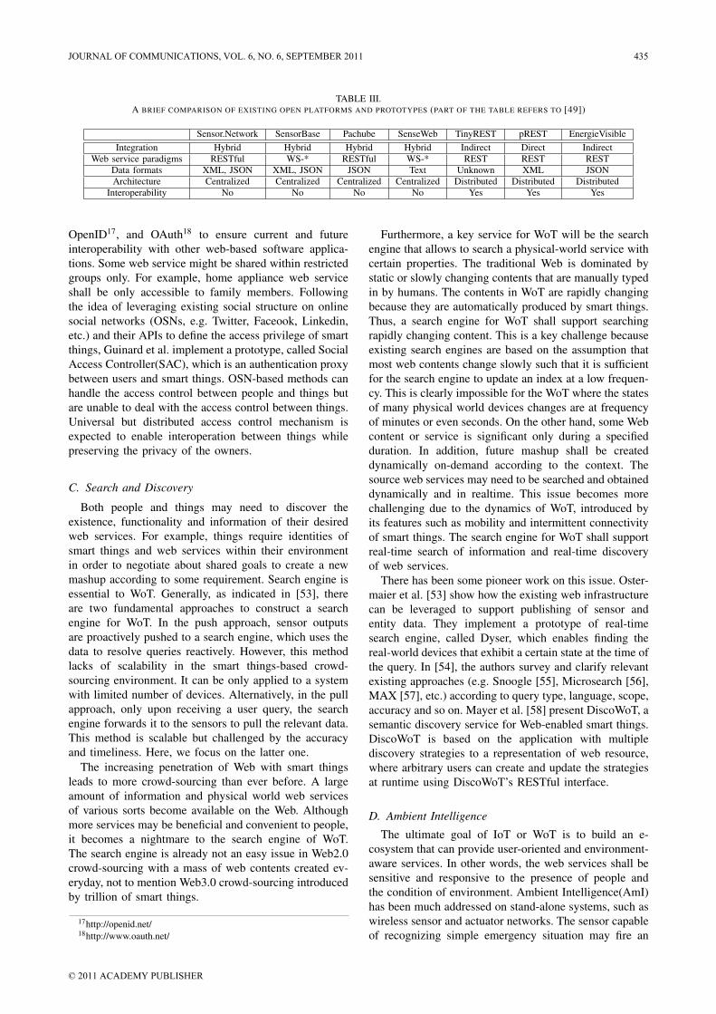
TABLE III.A BRIEF COMPARISON OF EXISTING OPEN PLATFORMS AND PROTOTYPES (PART OF THE TABLE REFERS TO [49])
Sensor.Network SensorBase Pachube SenseWeb TinyREST pREST EnergieVisibleIntegration Hybrid Hybrid Hybrid Hybrid Indirect Direct Indirect
Web service paradigms RESTful WS-* RESTful WS-* REST REST RESTData formats XML, JSON XML, JSON JSON Text Unknown XML JSONArchitecture Centralized Centralized Centralized Centralized Distributed Distributed Distributed
Interoperability No No No No Yes Yes Yes
OpenID17, and OAuth18 to ensure current and futureinteroperability with other web-based software applica-tions. Some web service might be shared within restrictedgroups only. For example, home appliance web serviceshall be only accessible to family members. Followingthe idea of leveraging existing social structure on onlinesocial networks (OSNs, e.g. Twitter, Faceook, Linkedin,etc.) and their APIs to define the access privilege of smartthings, Guinard et al. implement a prototype, called SocialAccess Controller(SAC), which is an authentication proxybetween users and smart things. OSN-based methods canhandle the access control between people and things butare unable to deal with the access control between things.Universal but distributed access control mechanism isexpected to enable interoperation between things whilepreserving the privacy of the owners.
C. Search and Discovery
Both people and things may need to discover theexistence, functionality and information of their desiredweb services. For example, things require identities ofsmart things and web services within their environmentin order to negotiate about shared goals to create a newmashup according to some requirement. Search engine isessential to WoT. Generally, as indicated in [53], thereare two fundamental approaches to construct a searchengine for WoT. In the push approach, sensor outputsare proactively pushed to a search engine, which uses thedata to resolve queries reactively. However, this methodlacks of scalability in the smart things-based crowd-sourcing environment. It can be only applied to a systemwith limited number of devices. Alternatively, in the pullapproach, only upon receiving a user query, the searchengine forwards it to the sensors to pull the relevant data.This method is scalable but challenged by the accuracyand timeliness. Here, we focus on the latter one.
The increasing penetration of Web with smart thingsleads to more crowd-sourcing than ever before. A largeamount of information and physical world web servicesof various sorts become available on the Web. Althoughmore services may be beneficial and convenient to people,it becomes a nightmare to the search engine of WoT.The search engine is already not an easy issue in Web2.0crowd-sourcing with a mass of web contents created ev-eryday, not to mention Web3.0 crowd-sourcing introducedby trillion of smart things.
17http://openid.net/18http://www.oauth.net/
Furthermore, a key service for WoT will be the searchengine that allows to search a physical-world service withcertain properties. The traditional Web is dominated bystatic or slowly changing contents that are manually typedin by humans. The contents in WoT are rapidly changingbecause they are automatically produced by smart things.Thus, a search engine for WoT shall support searchingrapidly changing content. This is a key challenge becauseexisting search engines are based on the assumption thatmost web contents change slowly such that it is sufficientfor the search engine to update an index at a low frequen-cy. This is clearly impossible for the WoT where the statesof many physical world devices changes are at frequencyof minutes or even seconds. On the other hand, some Webcontent or service is significant only during a specifiedduration. In addition, future mashup shall be createddynamically on-demand according to the context. Thesource web services may need to be searched and obtaineddynamically and in realtime. This issue becomes morechallenging due to the dynamics of WoT, introduced byits features such as mobility and intermittent connectivityof smart things. The search engine for WoT shall supportreal-time search of information and real-time discoveryof web services.
There has been some pioneer work on this issue. Oster-maier et al. [53] show how the existing web infrastructurecan be leveraged to support publishing of sensor andentity data. They implement a prototype of real-timesearch engine, called Dyser, which enables finding thereal-world devices that exhibit a certain state at the time ofthe query. In [54], the authors survey and clarify relevantexisting approaches (e.g. Snoogle [55], Microsearch [56],MAX [57], etc.) according to query type, language, scope,accuracy and so on. Mayer et al. [58] present DiscoWoT, asemantic discovery service for Web-enabled smart things.DiscoWoT is based on the application with multiplediscovery strategies to a representation of web resource,where arbitrary users can create and update the strategiesat runtime using DiscoWoT’s RESTful interface.
D. Ambient Intelligence
The ultimate goal of IoT or WoT is to build an e-cosystem that can provide user-oriented and environment-aware services. In other words, the web services shall besensitive and responsive to the presence of people andthe condition of environment. Ambient Intelligence(AmI)has been much addressed on stand-alone systems, such aswireless sensor and actuator networks. The sensor capableof recognizing simple emergency situation may fire an
JOURNAL OF COMMUNICATIONS, VOL. 6, NO. 6, SEPTEMBER 2011 435
© 2011 ACADEMY PUBLISHER
alarm and the actuator can take an action accordingly.When it comes to AmI in WoT, new opportunities andchallenges are exposed. The community effect of the webservices available on a larger-scale Web shall be furtheraddressed. One may easily find different public serviceson the Web and build private web services using standardweb-enabled devices in personal area network. The chal-lenges first come from the heterogeneity and availabilityof smart things that provide web services. Unlike stand-alone systems where the devices are predetermined andconfigured according to the application requirement, someAmI applications in WoT may need to discover therequired web services first. The QoS, even the existence,of the web service is unknown. Furthermore, this situationis exacerbated by the unexpected user requirements andenvironment (e.g. time, location, etc.).
Recall that mashup technology is a key enabling tech-nology of WoT. It can be expected that the mashupswill be dominant in WoT. Another challenge of AmI inWoT is that the mashup shall intelligently adapt to userrequirements and runtime environment. In other words,it shall be context-aware. In such a condition, dynamicmashup could be a good option. Other than developingstatic mashup by integrating existing web services togeth-er, rules about how to mashup services should be definedsuch that the basic web services are dynamically addedor deleted on-demand. The whole mashup processes aretransparent to the users and without human intervention.For example, to build a healthcare system for the elderlyrequires some private services to monitor and recordtheir health conditions and some public services to knowthe environment information (e.g. temperature, humidity,light, traffic, etc.) about the places where they locate.The public services to be integrated shall be dynamicallychosen according to their positions. In an emergency con-dition, some services shall be automatically activated andintegrated, e.g., the control service for automatic syringemight be activated and responded accurately accordingto the health condition and the environment parametersknown from the other services.
AmI of WoT is far more powerful and sophisticatedthan those examples. To fully explore the potential ofsmart things, more innovative solutions are expected tobe proposed. Those solutions shall be able to orchestrateall available web services in a graceful manner and enablemore intelligent user-oriented services. Some existingartificial intelligent concepts and technologies, such asCollective intelligence [59] and Semantic web services[60], may deserve revisiting in the hope of finding newefficient solutions feasible to smart things on the Web.
VII. CONCLUSION
IoT is the next big possibility and challenge of theInternet. It does not merely concern the connectivity ofsmart things, but more about the interaction or interop-eration between things and between things and people.This requires that all the smart things can speak the samelanguage to communicate freely with each other. It has
been considered as a good solution to extend existingweb architecture to this new domain by incorporatingsmar things into the Web. The extended Web is calledas WoT in the literature and it has become a major trendto promote the development of IoT.
In this paper, we first give an overview of WoT, includ-ing the history and motivation, and the comparison withprevious technologies (e.g., UPnP, JXTA, etc.). It showsmany advantages of WoT over previous technologies.The key concept of WoT is abstracting everything intoweb service. The first issue to consider is to integratesmart things to the Web by either direct integration orindirect integration, depending on their capabilities. Thenext issue is how to abstract the integrated smart thingto web services. We introduce and compare two majorweb service architectures: WS-* architecture and RESTfularchitecture. Some key enabling standards and technolo-gies (e.g. 6LoWPAN, CoAP, mashup, etc.) related to WoTare also discussed and examined. As examples for casestudy, we compare some pioneer implementation of openplatforms and prototypes for WoT which provide webservice APIs for sensory data sharing and device inter-operabilities. Since we are still at the preliminary stageof WoT, many open challenging issues are also brieflyanalyzed. We believe that WoT will be indispensable inpeople’s future lives and more efforts to tackle thosechallenging issues shall be made from both industry andacademia to promote the progress of WoT.
REFERENCES
[1] L. Atzori, A. Iera, and G. Morabito, “The Internet ofThings: A survey,” Comput. Netw., vol. 54, pp. 2787–2805,October 2010.
[2] S. Duquennoy, G. Grimaud, and J.-J. Vandewalle, “Smews:Smart and mobile embedded web server,” in Complex,Intelligent and Software Intensive Systems, 2009. CISIS’09. International Conference on, march 2009, pp. 571 –576.
[3] B. Traversat, M. Abdelaziz, D. Doolin, M. Duigou, J.-C.Hugly, and E. Pouyoul, “Project JXTA-C: enabling a Webof things,” in System Sciences, 2003. Proceedings of the36th Annual Hawaii International Conference on, 2003, p.9 pp.
[4] I. Agranat, “Engineering web technologies for embeddedapplications,” Internet Computing, IEEE, vol. 2, no. 3, pp.40 –45, may/jun 1998.
[5] T. Lin, H. Zhao, J. Wang, G. Han, and J. Wang, “Anembedded Web server for equipment,” pp. 345 – 350, may2004.
[6] D. Guinard and V. Trifa, “Towards the Web of Things:Web Mashups for Embedded Devices,” in Workshop onMashups, Enterprise Mashups and Lightweight Composi-tion on the Web (MEM 2009), in proceedings of WWW(International World Wide Web Conferences), Madrid, S-pain, Apr. 2009.
[7] O. Akribopoulos, I. Chatzigiannakis, C. Koninis, andE. Theodoridis, “A Web Services-oriented Architecture forIntegrating Small Programmable Objects in the Web ofThings,” 2010 Developments in E-systems Engineering, pp.70–75, 2010.
[8] B. Ostermaier, M. Kovatsch, and S. Santini, “Connectingthings to the web using programmable low-power wifi
436 JOURNAL OF COMMUNICATIONS, VOL. 6, NO. 6, SEPTEMBER 2011
© 2011 ACADEMY PUBLISHER
modules,” in Proceedings of the 2nd International Work-shop on the Web of Things (WoT 2011), San Francisco,CA, USA, June 2011, accepted for publication.
[9] K. il Hwang, J. In, N. Park, and D. seop Eom, “Adesign and implementation of wireless sensor gateway forefficient querying and managing through world wide web,”Consumer Electronics, IEEE Transactions on, vol. 49,no. 4, pp. 1090 – 1097, nov. 2003.
[10] V. Trifa, S. Wiel, D. Guinard, and T. Bohnert, “Designand implementation of a gateway for web-based interactionand management of embedded devices,” in Proceedingsof the 2nd International Workshop on Sensor NetworkEngineering (IWSNE), 2009.
[11] D. Guinard, C. Floerkemeier, and S. Sarma, “Cloud com-puting, rest and mashups to simplify rfid application de-velopment and deployment,” in Proceedings of the 2ndInternational Workshop on the Web of Things (WoT 2011).San Fransisco, USA: ACM, June 2011.
[12] W3C Working Group, “Web Services Architecture,”http://www.w3.org/TR/ws-arch/.
[13] D. Box, D. Ehnebuske, G. Kakivaya, A. Layman,N. Mendelsohn, H. Nielsen, S. Thatte, and D. Winer,“Simple object access protocol (SOAP) 1.1,” 2000.
[14] E. Christensen, F. Curbera, G. Meredith, and S. Weer-awarana, “Web services description language (WSDL)1.1,” http://www.w3.org/TR/wsdl, 2001.
[15] T. Bellwood, L. Clement, D. Ehnebuske, A. Hately,M. Hondo, Y. Husband, K. Januszewski, S. Lee, B. M-cKee, J. Munter, et al., “UDDI Version 3.0,” Publishedspecification, Oasis, vol. 5, pp. 16–18, 2002.
[16] D. Jordan, J. Evdemon, A. Alves, A. Arkin, S. Askary,C. Barreto, B. Bloch, F. Curbera, M. Ford, Y. Goland,et al., “Web services business process execution languageversion 2.0,” OASIS Standard, vol. 11, 2007.
[17] S. de Deugd, R. Carroll, K. Kelly, B. Millett, and J. Ricker,“Soda: Service oriented device architecture,” PervasiveComputing, IEEE, vol. 5, no. 3, pp. 94 –96, july-sept. 2006.
[18] A. Pintus, D. Carboni, A. Piras, and A. Giordano, “Con-necting smart things through web services orchestrations,”in Proceedings of the 10th international conference onCurrent trends in web engineering, ser. ICWE’10. Berlin,Heidelberg: Springer-Verlag, 2010, pp. 431–441.
[19] ——, “Connecting smart things through web servicesorchestrations,” in Proceedings of the 10th internationalconference on Current trends in web engineering, ser.ICWE’10. Berlin, Heidelberg: Springer-Verlag, 2010, pp.431–441.
[20] F. Jammes and H. Smit, “Service-oriented paradigms inindustrial automation,” Industrial Informatics, IEEE Trans-actions on, vol. 1, no. 1, pp. 62 – 70, feb. 2005.
[21] L. de Souza, P. Spiess, D. Guinard, M. Khler,S. Karnouskos, and D. Savio, “Socrades: A web servicebased shop floor integration infrastructure,” in The Inter-net of Things, ser. Lecture Notes in Computer Science,C. Floerkemeier, M. Langheinrich, E. Fleisch, F. Mattern,and S. Sarma, Eds. Springer Berlin / Heidelberg, 2008,vol. 4952, pp. 50–67.
[22] P. Spiess, S. Karnouskos, D. Guinard, D. Savio, O. Baeck-er, L. M. S. d. Souza, and V. Trifa, “Soa-based integrationof the internet of things in enterprise services,” in Proceed-ings of the 2009 IEEE International Conference on WebServices, ser. ICWS ’09. Washington, DC, USA: IEEEComputer Society, 2009, pp. 968–975.
[23] R. T. Fielding and R. N. Taylor, “Principled design of themodern web architecture,” pp. 407–416, 2000.
[24] ——, “Principled design of the modern web architecture,”ACM Trans. Internet Technol., vol. 2, pp. 115–150, May2002.
[25] R. T. Fielding, “Architectural styles and the design of
network-based software architectures,” Ph.D. dissertation,2000, aAI9980887.
[26] C. Pautasso, O. Zimmermann, and F. Leymann, “Restfulweb services vs. ”big”’ web services: making the rightarchitectural decision,” in Proceeding of the 17th interna-tional conference on World Wide Web, ser. WWW ’08.New York, NY, USA: ACM, 2008, pp. 805–814.
[27] T. Luckenbach, P. Gober, S. Arbanowski, A. Kotsopoulos,and K. Kim, “TinyREST: A protocol for integrating sensornetworks into the internet,” in Proc. of REALWSN, 2005.
[28] S. Makelainen and T. Alakoski, “Fixed-mobile hybridmashups: Applying the rest principles to mobile-specificresources,” in Proceedings of the 2008 international work-shops on Web Information Systems Engineering, ser. WISE’08. Berlin, Heidelberg: Springer-Verlag, 2008, pp. 172–182.
[29] D. Yazar and A. Dunkels, “Efficient application integrationin IP-based sensor networks,” in Proceedings of the FirstACM Workshop on Embedded Sensing Systems for Energy-Efficiency in Buildings, ser. BuildSys ’09. New York, NY,USA: ACM, 2009, pp. 43–48.
[30] W. Drytkiewicz, I. Radusch, S. Arbanowski, andR. Popescu-Zeletin, “pREST: a REST-based protocol forpervasive systems,” in Mobile Ad-hoc and Sensor Systems,2004 IEEE International Conference on. IEEE, 2004, pp.340–348.
[31] E. Wilde, “Putting things to rest,” School of Information,UC Berkeley. Report 2007-015., Tech. Rep., 2007. [On-line]. Available: http://escholarship.org/uc/item/1786t1dm
[32] V. Stirbu, “Towards a RESTful Plug and Play Experiencein the Web of Things,” in Proceedings of the 2008 IEEEInternational Conference on Semantic Computing. Wash-ington, DC, USA: IEEE Computer Society, 2008, pp. 512–517.
[33] D. Guinard, V. Trifa, F. Mattern, and E. Wilde, From theInternet of Things to the Web of Things: Resource OrientedArchitecture and Best Practices. Springer, Dec. 2010,ch. 5.
[34] W. Colitti, K. Steenhaut, and N. De Caro, “IntegratingWireless Sensor Networks with the Web,” in Extendingthe Internet to Low power and Lossy Networks (IP+SN2011), 2011.
[35] C. B. Z. Shelby, K. Hartke and B. Frank, “Constrained ap-plication protocol (coap),” http://tools.ietf.org/html/draft-ietf-core-coap-05, March 2011.
[36] A. Wilson, “The challenge of embedded internet design,”Real-Time Magazine, pp. 78–80, 1998.
[37] M. Can Filibeli, O. Ozkasap, and M. Reha Civanlar,“Embedded web server-based home appliance networks,”J. Netw. Comput. Appl., vol. 30, pp. 499–514, April 2007.
[38] N. B. Priyantha, A. Kansal, M. Goraczko, and F. Zhao,“Tiny web services: design and implementation of inter-operable and evolvable sensor networks,” in Proceedingsof the 6th ACM conference on Embedded network sensorsystems, ser. SenSys ’08. New York, NY, USA: ACM,2008, pp. 253–266.
[39] S. Duquennoy, G. Grimaud, and J.-J. Vandewalle, “TheWeb of Things: Interconnecting Devices with High Usabil-ity and Performance,” in Embedded Software and Systems,2009. ICESS ’09. International Conference on, May 2009,pp. 323 –330.
[40] J. Rees and P. Honeyman, “Webcard: a java card webserver,” in Proceedings of the fourth working conference onsmart card research and advanced applications on Smartcard research and advanced applications. Norwell, MA,USA: Kluwer Academic Publishers, 2001, pp. 197–207.
[41] O. M. A. Ltd., “Smartcard-web-server,” April 2008.[42] A. Kamilaris and A. Pitsillides, “Exploiting Demand Re-
sponse in Web-based Energy-aware Smart Homes,” in The
JOURNAL OF COMMUNICATIONS, VOL. 6, NO. 6, SEPTEMBER 2011 437
© 2011 ACADEMY PUBLISHER

First International Conference on Smart Grids, GreenCommunications and IT Energy-aware Technologies, 2011.
[43] A. Santanche, S. Nath, J. Liu, B. Priyantha, and F. Zhao,“Senseweb: Browsing the physical world in real time,”Demo Abstract, ACM/IEEE IPSN06, Nashville, TN, 2006.
[44] W. Grosky, A. Kansal, S. Nath, J. Liu, and F. Zhao,“Senseweb: An infrastructure for shared sensing,” Multi-media, IEEE, vol. 14, no. 4, pp. 8 –13, oct.-dec. 2007.
[45] S. Nath, J. Liu, and F. Zhao, “Sensormap for wide-areasensor webs,” Computer, vol. 40, no. 7, pp. 90 –93, july2007.
[46] M. H. Gong Chen, Nathan Yau and D. Estrin, “Sharingsensor network data,” in CENS Technical Report 71, Tech.Rep., March 2007.
[47] B. L. Gorman, D. R. Resseguie, and C. Tomkins-Tinch,“Sensorpedia: Information sharing across incompatiblesensor systems,” in Proceedings of the 2009 InternationalSymposium on Collaborative Technologies and Systems.Washington, DC, USA: IEEE Computer Society, 2009, pp.448–454.
[48] V. Gupta, A. Poursohi, and P. Udupi, “Sensor.Network: Anopen data exchange for the web of things,” in PervasiveComputing and Communications Workshops (PERCOMWorkshops), 2010 8th IEEE International Conference on,292010-april2 2010, pp. 753 –755.
[49] V. Gupta, P. Udupi, and A. Poursohi, “Early lessons frombuilding Sensor.Network: an open data exchange for theweb of things,” in Pervasive Computing and Communica-tions Workshops (PERCOM Workshops), 2010 8th IEEEInternational Conference on, 29 2010-april 2 2010, pp.738 –744.
[50] J. Vazquez, A. Almeida, I. Doamo, X. Laiseca, and P. Or-duna, “Flexeo: an architecture for integrating WirelessSensor Networks into the Internet of Things,” pp. 219–228, 2009.
[51] D. Guinard, M. Weiss, and V. Trifa, “Are you energy-efficient? sense it on the web!” in Adjunct Proceedingsof Pervasive 2009 (International Conference on PervasiveComputing), Nara, Japan, May 2009.
[52] H. Kim, “Protection against packet fragmentation attacksat 6lowpan adaptation layer,” in Proceedings of the 2008International Conference on Convergence and Hybrid In-formation Technology. Washington, DC, USA: IEEEComputer Society, 2008, pp. 796–801.
[53] B. Ostermaier, K. Romer, F. Mattern, M. Fahrmair, andW. Kellerer, “A Real-Time Search Engine for the Webof Things,” in Proceedings of Internet of Things 2010International Conference (IoT 2010), Tokyo, Japan, Nov.2010.
[54] K. Romer, B. Ostermaier, F. Mattern, M. Fahrmair, andW. Kellerer, “Real-time search for real-world entities: Asurvey,” Nov. 2010.
[55] H. Wang, C. Tan, and Q. Li, “Snoogle: A search engine forpervasive environments,” Parallel and Distributed Systems,IEEE Transactions on, vol. 21, no. 8, pp. 1188 –1202, aug.2010.
[56] C. C. Tan, B. Sheng, H. Wang, and Q. Li, “Microsearch:When search engines meet small devices,” in Proceedingsof the 6th International Conference on Pervasive Com-puting, ser. Pervasive ’08. Berlin, Heidelberg: Springer-Verlag, 2008, pp. 93–110.
[57] K.-K. Yap, V. Srinivasan, and M. Motani, “Max: human-centric search of the physical world,” in Proceedings ofthe 3rd international conference on Embedded networkedsensor systems, ser. SenSys ’05. New York, NY, USA:ACM, 2005, pp. 166–179.
[58] S. Mayer and D. Guinard, “An extensible discovery servicefor smart things,” in Proceedings of the 2nd InternationalWorkshop on the Web of Things (WoT 2011). SanFransisco, USA: ACM, June 2011.
[59] P. Levy, Collective intelligence: Mankind’s emerging worldin cyberspace. Perseus Publishing, 1999.
[60] S. Narayanan and S. A. McIlraith, “Simulation, verificationand automated composition of web services,” in Proceed-ings of the 11th international conference on World WideWeb, ser. WWW ’02. New York, NY, USA: ACM, 2002,pp. 77–88.
Deze Zeng is currently a Ph.D. candidate at University of Aizu,Aizu-Wakamatsu, Japan. He received his BS degree from Schoolof Computer Science and Technology, Huazhong University ofScience and Technology, China in 2007 and MS degrees fromUniversity of Aizu, Aizu-Wakamatsu, Japan in 2009.
His current research interests are mainly in the areas ofprotocol design and performance analysis of wireless networks,with a special emphasis on MAC protocol design and DelayTolerant Networks. His research interests also include WirelessSensor Networks, Pervasive Computing and Internet of Things.
Song Guo received the Ph.D. degree in computer sciencefrom the University of Ottawa, Ottawa, Canada, in 2005. Sincethen, he held a position with the Department of Electrical andComputer Engineering, The University of British Columbia,Vancouver, BC, Canada, on a Natural Sciences and EngineeringResearch Council of Canada (NSERC) Postdoctoral Fellowship.He is currently an Associate Professor with the School ofComputer Science and Engineering, University of Aizu, Aizu-Wakamatsu, Japan. His research interests are mainly in the areasof protocol design and performance analysis for computer andtelecommunication networks, presently focusing on modeling,analysis, cross-layer optimization, and performance evaluationof wireless ad hoc and sensor networks for reliable, energy effi-cient, and cost-effective communications. He is senior memberof IEEE.
Zixue Cheng received the B.Eng. degree from Northeast HeavyMachinery Institute, Qinhaungdao, China, in 1982, and theM.S. and Ph.D. degrees in engineering from Tohoku University,Sendai, Japan, in 1990 and 1993, respectively.
He was an Assistant Professor from 1993 to 1999, an Asso-ciate Professor from 1999 to 2002, and has been a Full Professorsince 2002 with the University of Aizu, Aizu-Wakamatsu, Japan.His current interests include distributed algorithms, distanceeducation, ubiquitous learning, context-aware service plat-forms,and functional safety for embedded systems.
438 JOURNAL OF COMMUNICATIONS, VOL. 6, NO. 6, SEPTEMBER 2011
© 2011 ACADEMY PUBLISHER
Power saving and energy optimization techniques for Wireless Sensor Networks
Sandra Sendra, Jaime Lloret, Miguel García and José F. Toledo Universidad Politécnica de Valencia
Camino Vera s/n, 46022, Valencia, Spain [email protected], [email protected], [email protected], [email protected]
Abstract— Wireless sensor networks have become increasingly popular due to their wide range of applications. Energy consumption is one of the biggest constraints of the wireless sensor node and this limitation combined with a typical deployment of large number of nodes have added many challenges to the design and management of wireless sensor networks. They are typically used for remote environment monitoring in areas where providing electrical power is difficult. Therefore, the devices need to be powered by batteries and alternative energy sources. Because battery energy is limited, the use of different techniques for energy saving is one of the hottest topics in WSNs. In this work, we present a survey of power saving and energy optimization techniques for wireless sensor networks, which enhances the ones in existence and introduces the reader to the most well known available methods that can be used to save energy. They are analyzed from several points of view: Device hardware, transmission, MAC and routing protocols. Index Terms— Power-saving strategies, energy consumption, energy management, network communication protocols, wireless sensor networks.
I. INTRODUCTION
A Wireless Sensor Network (WSN) can be defined as a network of small embedded devices, called sensors, which communicate wirelessly following an ad hoc configuration. They are located strategically inside a physical medium and are able to interact with it in order to measure physical parameters from the environment and provide the sensed information [1]. The nodes mainly use a broadcast communication and the network topology can change constantly due, for example, to the fact that nodes are prone to fail. Because of this, we should keep in mind that nodes should be autonomous and, frequently, they will be disregarded. This kind of device has limited power, low computational capabilities and limited memory. One of the main issues that should be studied in WSNs is their scalability feature [2], their connection strategy for communication [3] and the limited energy to supply the device.
The desire to advance in research and development of WSN was initially motivated by military applications such as surveillance of threats on the battlefield, mainly because WSN can replace single high-cost sensor assets with large arrays of distributed sensors. There are other
interesting fields like home control, building automation and medical applications. A number of hospitals and medical centers are exploring the use of WSN technology in a wide range of applications, including pre-hospital and in-hospital patient monitoring and rehabilitation and disaster response. WSNs can also be found in environmental monitoring applications such as marine fish farms [4] and fire detection in forest and rural areas [5].
As we already mentioned, sensor nodes in WSNs are usually battery powered but nodes are typically unattended because of their deployment in hazardous, hostile or remote environments. A number of power-saving techniques must be used both in the design of electronic transceiver circuits and in network protocols. The first step towards reduced power consumption is a sound electronic design [6], selecting the right components and applying appropriate design techniques to each case.
One of the major causes of energy loss in the WSN node is the idle mode consumption, when the node is not transmitting/receiving any information but listening and waiting for information from other nodes. There is also an energy loss due to packet collision, as all packets involved in the collision are discarded and must be retransmitted. A third cause of energy loss is the reception of packets not addressed to the node. The fourth major source of wasted energy is the transmission –and possible retransmission- of control packets, as these can be seen as protocol overhead.
There are several studies that present different aspects related to power saving techniques, but all of them are focused in a single way to improve the energy consumption and save power in WSNs. The main objective of this paper is to present a survey of the different power saving and energy optimization techniques for WSNs and ad-hoc connections, so we will tackle this issue from several perspectives in order to provide a whole view in this matter.
The paper is organized as follows. Section 2 shows some previously published surveys related to power saving techniques in WSN. The description of the typical hardware architecture that can be seen in any sensor node and the considerations that should be taken in into account for energy-aware sensor deployment are show in section 3. Section 4 describes the main energy parameters that should be considered in the transmission system.
Manuscript received May 11, 2011; revised July 6, 2011; acceptedJuly 2, 2011.
(Invited Paper)
JOURNAL OF COMMUNICATIONS, VOL. 6, NO. 6, SEPTEMBER 2011 439
© 2011 ACADEMY PUBLISHERdoi:10.4304/jcm.6.6.439-459
Some important energy-aware MAC protocols are explained in Section 5. In Section 6, we discuss different routing protocols that are focused on saving energy methods. Finally, the conclusion is drawn in Section 7.
II. EXISTING SURVEYS
The power management schemes of wireless sensor networks have attracted high attention in recent years. Much published research has addressed all kinds of issues related to them.
We can find several works related to energy conservation techniques. They tend to focus on comparative routing protocols or MAC-protocols. Some of them show techniques related to the operation mode of the nodes and its radio system. In this section we will see some of these works, and we will provide some of the key conclusions presented in these papers.
In [7], G.P. Halkes et al. compared S-MAC and T-MAC, which try to save energy by introducing a duty-cycle to mitigate idle listening time, with CSMA/CA. This choice was taken because it is the most important cause of energy consumption in typical sensor network scenarios where the communications between nodes is not continuous. They show the effects of low-power listening, a physical layer optimization, in combination with these MAC protocols. The results show that using a low-power listening is very effective at mitigating idle listening. The absolute lowest energy consumption is reached in combination with T-MAC, while the results about S-MAC show that this protocol suffers from over-provisioning. Since its duty cycle is fixed for all nodes, often a rather large value must be selected to avoid dropping messages under peak loads, which causes S-MAC’s idle-listening to deteriorate for increasing traffic loads. Although S-MAC achieves acceptable results, they are not as good as those of T-MAC with low-power listening. T-MAC presents an aggressive time-out policy that allows it to adapt seamlessly to variations in traffic induced by typical sensor network applications at the expense of a reduction in peak throughput. T-MAC performs slightly better for variations over time (events) than for variations in location.
V. Raghunathan et al. [8] review several techniques to address the energy consumption challenge. This work also describes recent advances in energy-aware platforms for information processing and communication protocols for sensor collaboration. The article looks at emerging and hitherto largely unexplored techniques such as the use of environmental energy harvesting and the optimization of the energy consumed during sensing. The paper presents some promising research directions for alleviating the energy problem in WSNs, including hierarchical architectures, ultra-low-power MAC protocols, environmental energy harvesting, and energy aware sensing. The authors explain and present an architecture of sensor node in order to be considered energy efficient. At the same time, they present a wireless sensor module, a heliomote, which is used in different tests in order to show that it is possible to provide energy to the nodes from alternative sources instead of from a
battery, which has a limited life time. They also compare three MAC protocols. These are B-MAC, STEM-T, and WiseMAC, which are characterized by low power consumption in the media access process.
Another significant work is presented by N. A. Pantazis et al. in [9]. The authors focus their explanations on the fundamental concepts of energy management, including the need of power management in the wireless sensor network, and discuss the side effects of power management in terms of cost. They say that the cost of power management must always be borne in mind when speaking about a power control system. The cost of power management is important for evaluating the performance of a power control system, no matter what the specific objectives may be. Throughout the document, they describe different types of power management systems and different approaches and goals they may have. The authors divide the power conservation mechanisms into two main categories based on their primary objectives. On the one hand, Passive PCMs are divided into three sub-categories: Physical Layer, Fine-Grain, and Coarse-Grain PCMs. In the implementation of the Coarse-Grain PCMs, two basic approaches were distinguished: Distributed and Backbone-based. On the other hand, the classification of the Active PCMs is based on the layer (MAC, Network, and Transport). Various algorithms were studied for each classification. Each power management scheme is discussed in terms of objective, mechanism, performance, and application scenario. The similarities and differences between schemes of the same clustering category are also presented. The authors conclude the paper by stating that although the performance of the presented power management schemes is promising, further research would be necessary to address other issues, such as quality of service (QoS). Energy-aware QoS in wireless sensor networks will certainly ensure guaranteed bandwidth, or delay, through the duration of a connection as well as provide the most energy-efficient path.
S. Saxena et al. review the main approaches for energy conservation in wireless sensor networks in [10]. They presented a systematic and comprehensive classification of the solutions related to save energy. This involves characterizing the interactions between different protocols and exploiting cross-layer interactions. They also made a protocol classification and explain each part. The authors comment that most of the solutions presented by other authors are based on the assumption that the radio energy consumption is much higher than data sampling or processing consumption, while many real applications have greater power consumption in data sampling/processing than in radio transmission. Furthermore, they observed that the data acquisition research field of has not been fully explored in terms of energy conservation. Finally, the authors come to the conclusion that there is an increasing interest towards MAC protocols used for time synchronization and energy conservation in the recent years. They also made a reference to the node’s mobility, which is yet another challenging task in energy optimization.
440 JOURNAL OF COMMUNICATIONS, VOL. 6, NO. 6, SEPTEMBER 2011
© 2011 ACADEMY PUBLISHER
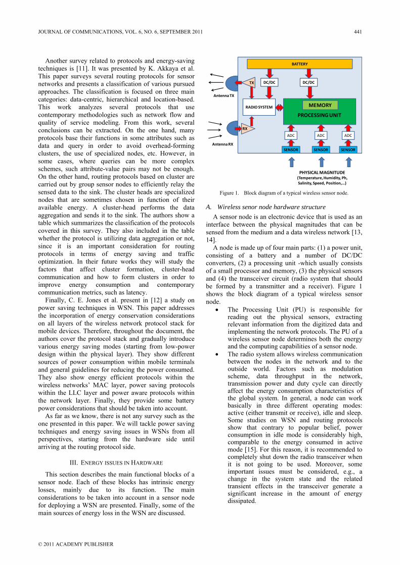
Another survey related to protocols and energy-saving techniques is [11]. It was presented by K. Akkaya et al. This paper surveys several routing protocols for sensor networks and presents a classification of various pursued approaches. The classification is focused on three main categories: data-centric, hierarchical and location-based. This work analyzes several protocols that use contemporary methodologies such as network flow and quality of service modeling. From this work, several conclusions can be extracted. On the one hand, many protocols base their functions in some attributes such as data and query in order to avoid overhead-forming clusters, the use of specialized nodes, etc. However, in some cases, where queries can be more complex schemes, such attribute-value pairs may not be enough. On the other hand, routing protocols based on cluster are carried out by group sensor nodes to efficiently relay the sensed data to the sink. The cluster heads are specialized nodes that are sometimes chosen in function of their available energy. A cluster-head performs the data aggregation and sends it to the sink. The authors show a table which summarizes the classification of the protocols covered in this survey. They also included in the table whether the protocol is utilizing data aggregation or not, since it is an important consideration for routing protocols in terms of energy saving and traffic optimization. In their future works they will study the factors that affect cluster formation, cluster-head communication and how to form clusters in order to improve energy consumption and contemporary communication metrics, such as latency.
Finally, C. E. Jones et al. present in [12] a study on power saving techniques in WSN. This paper addresses the incorporation of energy conservation considerations on all layers of the wireless network protocol stack for mobile devices. Therefore, throughout the document, the authors cover the protocol stack and gradually introduce various energy saving modes (starting from low-power design within the physical layer). They show different sources of power consumption within mobile terminals and general guidelines for reducing the power consumed. They also show energy efficient protocols within the wireless networks’ MAC layer, power saving protocols within the LLC layer and power aware protocols within the network layer. Finally, they provide some battery power considerations that should be taken into account.
As far as we know, there is not any survey such as the one presented in this paper. We will tackle power saving techniques and energy saving issues in WSNs from all perspectives, starting from the hardware side until arriving at the routing protocol side.
III. ENERGY ISSUES IN HARDWARE
This section describes the main functional blocks of a sensor node. Each of these blocks has intrinsic energy losses, mainly due to its function. The main considerations to be taken into account in a sensor node for deploying a WSN are presented. Finally, some of the main sources of energy loss in the WSN are discussed.
Figure 1. Block diagram of a typical wireless sensor node.
A. Wireless senor node hardware structure A sensor node is an electronic device that is used as an
interface between the physical magnitudes that can be sensed from the medium and a data wireless network [13, 14].
A node is made up of four main parts: (1) a power unit, consisting of a battery and a number of DC/DC converters, (2) a processing unit -which usually consists of a small processor and memory, (3) the physical sensors and (4) the transceiver circuit (radio system that should be formed by a transmitter and a receiver). Figure 1 shows the block diagram of a typical wireless sensor node.
• The Processing Unit (PU) is responsible for reading out the physical sensors, extracting relevant information from the digitized data and implementing the network protocols. The PU of a wireless sensor node determines both the energy and the computing capabilities of a sensor node.
• The radio system allows wireless communication between the nodes in the network and to the outside world. Factors such as modulation scheme, data throughput in the network, transmission power and duty cycle can directly affect the energy consumption characteristics of the global system. In general, a node can work basically in three different operating modes: active (either transmit or receive), idle and sleep. Some studies on WSN and routing protocols show that contrary to popular belief, power consumption in idle mode is considerably high, comparable to the energy consumed in active mode [15]. For this reason, it is recommended to completely shut down the radio transceiver when it is not going to be used. Moreover, some important issues must be considered, e.g., a change in the system state and the related transient effects in the transceiver generate a significant increase in the amount of energy dissipated.
SENSOR
PROCESSING UNIT
BATTERY
DC/DCDC/DC
MEMORYRADIO SYSTEM
PHYSICAL MAGNITUDE(Temperature, Humidity, Ph, Salinity, Speed, Position,…)
ADC
SENSOR SENSOR
ADC ADC
TX
RX
AntennaTX
AntennaRX
JOURNAL OF COMMUNICATIONS, VOL. 6, NO. 6, SEPTEMBER 2011 441
© 2011 ACADEMY PUBLISHER
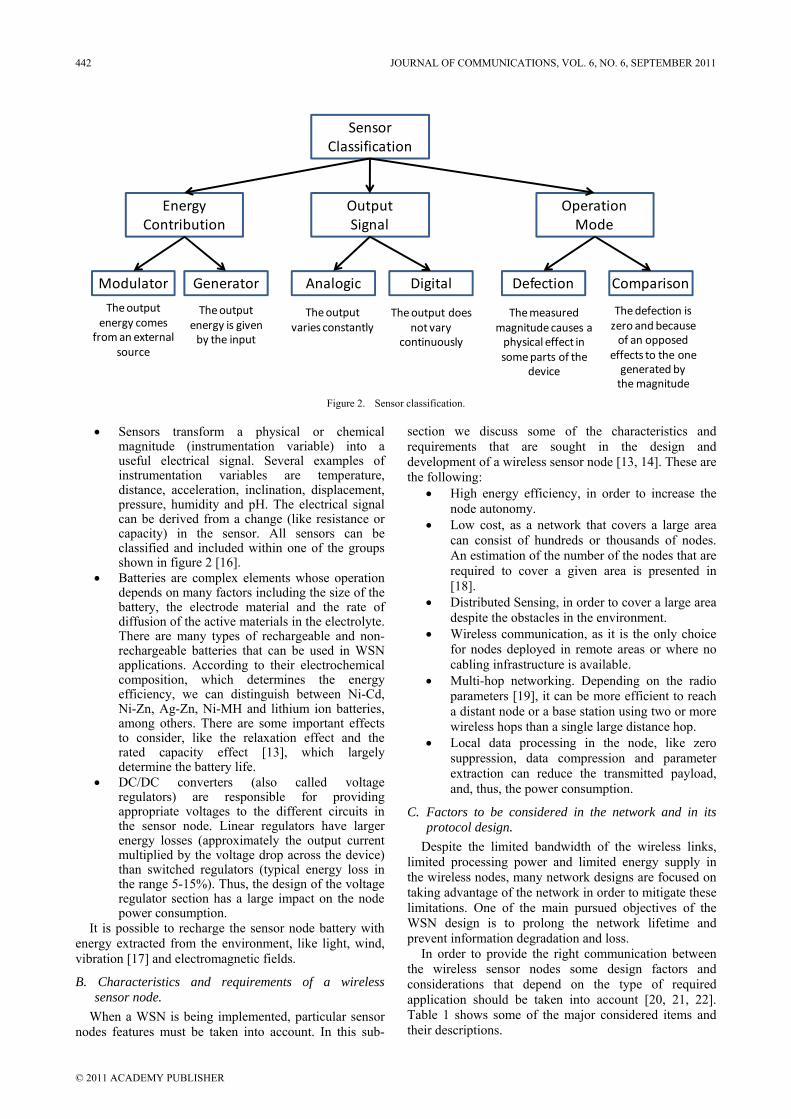
Figure 2. Sensor classification.
• Sensors transform a physical or chemical magnitude (instrumentation variable) into a useful electrical signal. Several examples of instrumentation variables are temperature, distance, acceleration, inclination, displacement, pressure, humidity and pH. The electrical signal can be derived from a change (like resistance or capacity) in the sensor. All sensors can be classified and included within one of the groups shown in figure 2 [16].
• Batteries are complex elements whose operation depends on many factors including the size of the battery, the electrode material and the rate of diffusion of the active materials in the electrolyte. There are many types of rechargeable and non-rechargeable batteries that can be used in WSN applications. According to their electrochemical composition, which determines the energy efficiency, we can distinguish between Ni-Cd, Ni-Zn, Ag-Zn, Ni-MH and lithium ion batteries, among others. There are some important effects to consider, like the relaxation effect and the rated capacity effect [13], which largely determine the battery life.
• DC/DC converters (also called voltage regulators) are responsible for providing appropriate voltages to the different circuits in the sensor node. Linear regulators have larger energy losses (approximately the output current multiplied by the voltage drop across the device) than switched regulators (typical energy loss in the range 5-15%). Thus, the design of the voltage regulator section has a large impact on the node power consumption.
It is possible to recharge the sensor node battery with energy extracted from the environment, like light, wind, vibration [17] and electromagnetic fields.
B. Characteristics and requirements of a wireless sensor node.
When a WSN is being implemented, particular sensor nodes features must be taken into account. In this sub-
section we discuss some of the characteristics and requirements that are sought in the design and development of a wireless sensor node [13, 14]. These are the following:
• High energy efficiency, in order to increase the node autonomy.
• Low cost, as a network that covers a large area can consist of hundreds or thousands of nodes. An estimation of the number of the nodes that are required to cover a given area is presented in [18].
• Distributed Sensing, in order to cover a large area despite the obstacles in the environment.
• Wireless communication, as it is the only choice for nodes deployed in remote areas or where no cabling infrastructure is available.
• Multi-hop networking. Depending on the radio parameters [19], it can be more efficient to reach a distant node or a base station using two or more wireless hops than a single large distance hop.
• Local data processing in the node, like zero suppression, data compression and parameter extraction can reduce the transmitted payload, and, thus, the power consumption.
C. Factors to be considered in the network and in its protocol design.
Despite the limited bandwidth of the wireless links, limited processing power and limited energy supply in the wireless nodes, many network designs are focused on taking advantage of the network in order to mitigate these limitations. One of the main pursued objectives of the WSN design is to prolong the network lifetime and prevent information degradation and loss.
In order to provide the right communication between the wireless sensor nodes some design factors and considerations that depend on the type of required application should be taken into account [20, 21, 22]. Table 1 shows some of the major considered items and their descriptions.
Sensor Classification
EnergyContribution
Output Signal
OperationMode
Modulator Generator Analogic Digital Defection Comparison
The output energy comes
from an external source
The output energy is given by the input
The output varies constantly
The output does not vary
continuously
The measured magnitude causes a physical effect in some parts of the
device
The defection is zero and because of an opposed
effects to the one generated bythemagnitude
442 JOURNAL OF COMMUNICATIONS, VOL. 6, NO. 6, SEPTEMBER 2011
© 2011 ACADEMY PUBLISHER
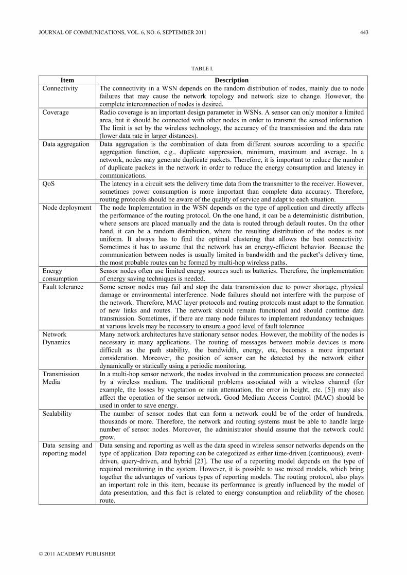
TABLE I.
Item DescriptionConnectivity The connectivity in a WSN depends on the random distribution of nodes, mainly due to node
failures that may cause the network topology and network size to change. However, the complete interconnection of nodes is desired.
Coverage Radio coverage is an important design parameter in WSNs. A sensor can only monitor a limited area, but it should be connected with other nodes in order to transmit the sensed information. The limit is set by the wireless technology, the accuracy of the transmission and the data rate (lower data rate in larger distances).
Data aggregation Data aggregation is the combination of data from different sources according to a specific aggregation function, e.g., duplicate suppression, minimum, maximum and average. In a network, nodes may generate duplicate packets. Therefore, it is important to reduce the number of duplicate packets in the network in order to reduce the energy consumption and latency in communications.
QoS The latency in a circuit sets the delivery time data from the transmitter to the receiver. However, sometimes power consumption is more important than complete data accuracy. Therefore, routing protocols should be aware of the quality of service and adapt to each situation.
Node deployment The node Implementation in the WSN depends on the type of application and directly affects the performance of the routing protocol. On the one hand, it can be a deterministic distribution, where sensors are placed manually and the data is routed through default routes. On the other hand, it can be a random distribution, where the resulting distribution of the nodes is not uniform. It always has to find the optimal clustering that allows the best connectivity. Sometimes it has to assume that the network has an energy-efficient behavior. Because the communication between nodes is usually limited in bandwidth and the packet’s delivery time, the most probable routes can be formed by multi-hop wireless paths.
Energy consumption
Sensor nodes often use limited energy sources such as batteries. Therefore, the implementation of energy saving techniques is needed.
Fault tolerance Some sensor nodes may fail and stop the data transmission due to power shortage, physical damage or environmental interference. Node failures should not interfere with the purpose of the network. Therefore, MAC layer protocols and routing protocols must adapt to the formation of new links and routes. The network should remain functional and should continue data transmission. Sometimes, if there are many node failures to implement redundancy techniques at various levels may be necessary to ensure a good level of fault tolerance
Network Dynamics
Many network architectures have stationary sensor nodes. However, the mobility of the nodes is necessary in many applications. The routing of messages between mobile devices is more difficult as the path stability, the bandwidth, energy, etc, becomes a more important consideration. Moreover, the position of sensor can be detected by the network either dynamically or statically using a periodic monitoring.
Transmission Media
In a multi-hop sensor network, the nodes involved in the communication process are connected by a wireless medium. The traditional problems associated with a wireless channel (for example, the losses by vegetation or rain attenuation, the error in height, etc. [5]) may also affect the operation of the sensor network. Good Medium Access Control (MAC) should be used in order to save energy.
Scalability The number of sensor nodes that can form a network could be of the order of hundreds, thousands or more. Therefore, the network and routing systems must be able to handle large number of sensor nodes. Moreover, the administrator should assume that the network could grow.
Data sensing and reporting model
Data sensing and reporting as well as the data speed in wireless sensor networks depends on the type of application. Data reporting can be categorized as either time-driven (continuous), event-driven, query-driven, and hybrid [23]. The use of a reporting model depends on the type of required monitoring in the system. However, it is possible to use mixed models, which bring together the advantages of various types of reporting models. The routing protocol, also plays an important role in this item, because its performance is greatly influenced by the model of data presentation, and this fact is related to energy consumption and reliability of the chosen route.
JOURNAL OF COMMUNICATIONS, VOL. 6, NO. 6, SEPTEMBER 2011 443
© 2011 ACADEMY PUBLISHER
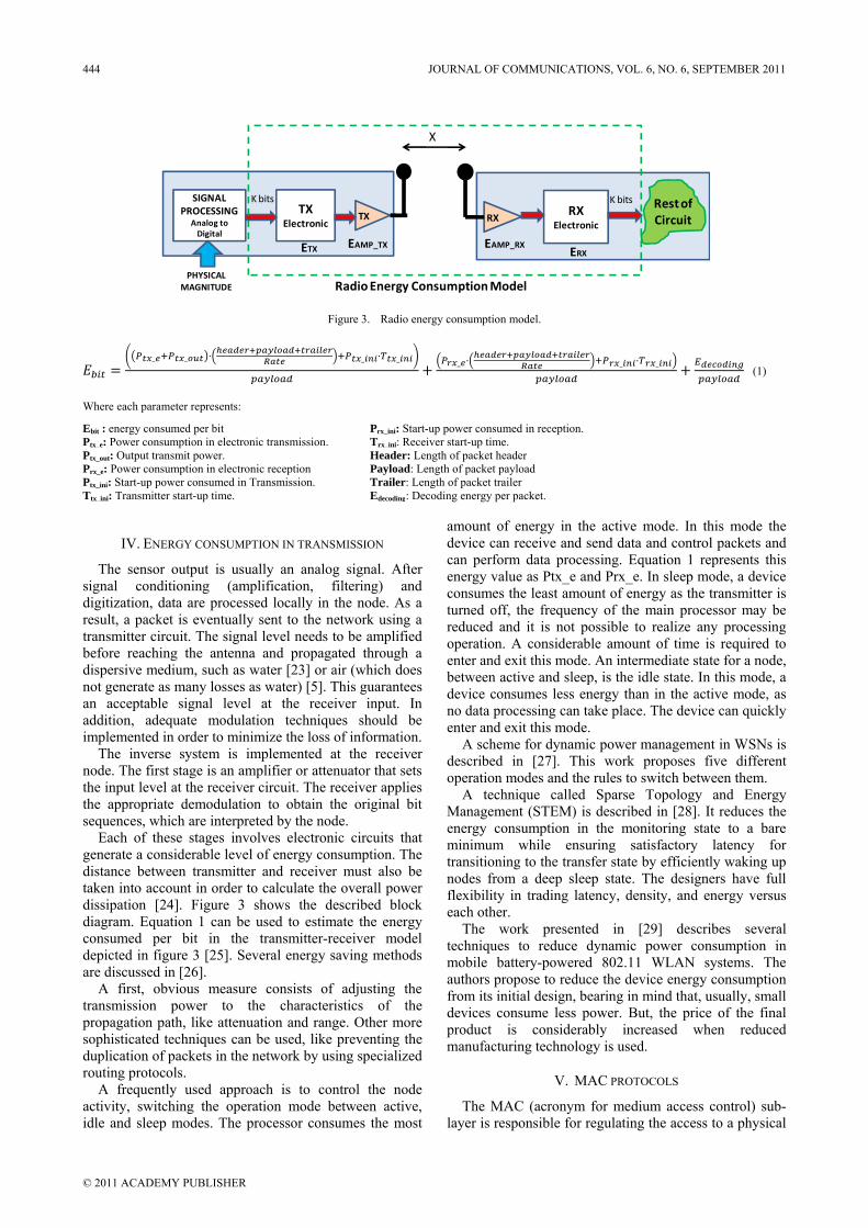
Figure 3. Radio energy consumption model.
_ _ _ _ _ _ _ (1)
Where each parameter represents:
Ebit : energy consumed per bit Prx_ini: Start-up power consumed in reception. Ptx_e: Power consumption in electronic transmission. Trx_ini: Receiver start-up time. Ptx_out: Output transmit power. Header: Length of packet header Prx_e: Power consumption in electronic reception Payload: Length of packet payload Ptx_ini: Start-up power consumed in Transmission. Trailer: Length of packet trailer Ttx_ini: Transmitter start-up time. Edecoding: Decoding energy per packet.
IV. ENERGY CONSUMPTION IN TRANSMISSION
The sensor output is usually an analog signal. After signal conditioning (amplification, filtering) and digitization, data are processed locally in the node. As a result, a packet is eventually sent to the network using a transmitter circuit. The signal level needs to be amplified before reaching the antenna and propagated through a dispersive medium, such as water [23] or air (which does not generate as many losses as water) [5]. This guarantees an acceptable signal level at the receiver input. In addition, adequate modulation techniques should be implemented in order to minimize the loss of information.
The inverse system is implemented at the receiver node. The first stage is an amplifier or attenuator that sets the input level at the receiver circuit. The receiver applies the appropriate demodulation to obtain the original bit sequences, which are interpreted by the node.
Each of these stages involves electronic circuits that generate a considerable level of energy consumption. The distance between transmitter and receiver must also be taken into account in order to calculate the overall power dissipation [24]. Figure 3 shows the described block diagram. Equation 1 can be used to estimate the energy consumed per bit in the transmitter-receiver model depicted in figure 3 [25]. Several energy saving methods are discussed in [26].
A first, obvious measure consists of adjusting the transmission power to the characteristics of the propagation path, like attenuation and range. Other more sophisticated techniques can be used, like preventing the duplication of packets in the network by using specialized routing protocols.
A frequently used approach is to control the node activity, switching the operation mode between active, idle and sleep modes. The processor consumes the most
amount of energy in the active mode. In this mode the device can receive and send data and control packets and can perform data processing. Equation 1 represents this energy value as Ptx_e and Prx_e. In sleep mode, a device consumes the least amount of energy as the transmitter is turned off, the frequency of the main processor may be reduced and it is not possible to realize any processing operation. A considerable amount of time is required to enter and exit this mode. An intermediate state for a node, between active and sleep, is the idle state. In this mode, a device consumes less energy than in the active mode, as no data processing can take place. The device can quickly enter and exit this mode.
A scheme for dynamic power management in WSNs is described in [27]. This work proposes five different operation modes and the rules to switch between them.
A technique called Sparse Topology and Energy Management (STEM) is described in [28]. It reduces the energy consumption in the monitoring state to a bare minimum while ensuring satisfactory latency for transitioning to the transfer state by efficiently waking up nodes from a deep sleep state. The designers have full flexibility in trading latency, density, and energy versus each other.
The work presented in [29] describes several techniques to reduce dynamic power consumption in mobile battery-powered 802.11 WLAN systems. The authors propose to reduce the device energy consumption from its initial design, bearing in mind that, usually, small devices consume less power. But, the price of the final product is considerably increased when reduced manufacturing technology is used.
V. MAC PROTOCOLS
The MAC (acronym for medium access control) sub-layer is responsible for regulating the access to a physical
TXTX
Electronic
PHYSICAL MAGNITUDE
SIGNAL PROCESSING
Analog toDigital
K bits
RXRX
Electronic
K bits Restof Circuit
X
ERXEAMP_RXEAMP_TXETX
Radio Energy ConsumptionModel
444 JOURNAL OF COMMUNICATIONS, VOL. 6, NO. 6, SEPTEMBER 2011
© 2011 ACADEMY PUBLISHER
medium shared by several devices. MAC protocols must avoid collisions due to simultaneous transmissions and must perform other important functions like addressing, error checking and delivery notification. An efficient MAC protocol should possess many characteristics. The most important are:
• Predictability of delay • Adaptability • Energy efficiency • Reliability • Scalability
In this section, a number of works that propose MAC protocols concerned with energy efficiency are briefly described.
A. Energy and Rate based MAC Protocol - ER-MAC The first work that can be cited is the one presented by
R. Kannan et al. [30]. This work presents the Energy and Rate based MAC Protocol (ER-MAC). It is based on TDMA and aims at avoiding energy waste. Packet loss due to collisions is absent because two nodes do not transmit in the same time slot. Although packet loss may occur due to other reasons like interference and loss of signal strength, there is no need to use a contention mechanism because the slots are pre-assigned to each node. ER-MAC uses the concept of periodic listen and sleep. Each node is assigned two TDMA slots for transmission and nodes know the transmission slots of its neighbors. Nodes periodically share information about their power levels and determine whether to use one or two slots for transmission. The proposed protocol is simulated in a scenario of 100 nodes. The results show that ER-MAC achieves a significant increase in energy savings compared to other existing MAC layer protocols.
B. Dominating-awake-interval protocol, Periodically-fully-awake-interval protocol and Quorum-based protocol.
In [31], the authors propose three asynchronous protocols that are directly applicable to MANET technology based on IEEE 802.11. These protocols are named as dominating-awake-interval protocol, periodically-fully-awake-interval protocol and quorum-based protocol. The authors state that devices really send more beacon packets than original IEEE 802.11 standard and they study the best manners to wake-up the devices. Designed protocols use the following rules: (1) send the highest number of beacons in order to prevent the problem of false neighbors and (2) mobile hosts in power saving mode must put more emphasis on sending beacons. Their protocol does not use a clock synchronization system. Moreover, the patterns to wake-up two devices overlap as a function of the difference of time between them. Finally, in order to predict the exact timing to wake-up, when a host hears a beacon from another host, it must wake-up based on another time pattern. The simulations of their protocol show that it is efficient, saves energy and establishes the most likely route.
C. Distributed Wireless Ordering Protocol - DWOP V. Kanodia et al. present the design and the analysis of
the Distributed Wireless Ordering Protocol (DWOP) [32]. It is a distributed scheduling algorithm and media access protocol for wireless ad-hoc networks. It exploits overheard information from other nodes to estimate channel contention. The design of DWOP is based on a graph-theoretic problem formulation. It allows well-characterized deviations from the reference order in more complex topologies and achieves the exact reference ordering in fully connected graphs. DWOP enables QoS differentiation as well as fairness when combined with TCP. A theoretical model indicates that the scheme provides rapid convergence for newly arriving nodes, and extensive simulations indicate that nearly exact reference ordering can be achieved, even in complex asymmetric and perceived-collision topologies. The authors use the piggybacking head-of-line packet priorities in IEEE 802.11 control messages. This allows the nodes to assess the relative priority of their own queued packets. Moreover, the authors propose a distributed stale entry detection method that enables a quick recovery to the steady state.
D. Battery Aware Medium Access Control - BAMAC Usually, MAC protocols for ad-hoc wireless networks
are designed without taking into account the state of the node battery. In [33], S. Jayashree presents a MAC protocol in which each node contains a table that contains information about the battery charge level for each of its neighbors (close nodes that can be accessed). RTS, CTS, Data and ACK packets carry information regarding the battery level of the node that originated the packet. Any listening node fills its table with the information of the load levels of each neighboring nodes. This protocol uses a back-off mechanism, in order to determine which node should receive the packet. The goal of the back-off mechanism is to provide a near round-robin scheduling of the nodes which is based on some temporal parameters like the longest possible time required to transmit a packet successfully, including the RTS-CTS-Data-ACK handshake and the Short and DCF inter-frame spacing durations used in IEEE 802.11. Factors such as the minimum size of the contention window and rank are also considered. The nodes are scheduled based on their remaining battery capacities, that is, the higher the remaining battery capacity, the lower the back-off period. The algorithm allows a node to send the packet to a neighboring node with a higher level of battery. In this way, a uniform rate of battery discharge is guaranteed across all the nodes and consequently, the network lifetime will be longer, because the fall of nodes will be later. The proposed protocol is implemented using GloMoSim simulator and it is compared with the DWOP protocol. The simulations show that the battery life lasts around 70% and reduces battery consumption to nominal packet transmission by 21% compared with IEEE 802.11 and MAC DWOP protocol.
JOURNAL OF COMMUNICATIONS, VOL. 6, NO. 6, SEPTEMBER 2011 445
© 2011 ACADEMY PUBLISHER
E. Wireless Indoor Flexible High Bit rate Modem Architecture - WIND-FLEX
G. Razzano [34] describes a control architecture that is widely used in local area networks on the structure of WIND-FLEX (Wireless Indoor Flexible High Bit rate Modem Architecture). The author studies the energy consumption in a wireless modem and presents a control method based on fuzzy logic, which has already been applied for determining the transmission power in CDMA (Code-Division Multiple-Access). Power consumption depends on the data rate and thus a reduction in the energy consumption is possible selecting the bit data rate as a function of the traffic situation.
F. Distributed Coordination Function - DCF In [35], E.-S. Jung and N. H. Vaidya present a
mechanism for optimizing the energy saving mechanism in the Distributed Coordination Function (DCF) of IEEE 802.11 networks. In DCF, the time is divided into beacon intervals. At the beginning of each beacon interval, each node in power saving mode periodically wakes up in a period of time called ATIM window. During this period, nodes exchange packets to determine whether the node needs to stay in active mode during the remaining time of the beacon. The energy saving and performance achieved by the nodes is directly proportional to the size of the ATIM window. The authors propose a dynamic adaptation mechanism where a suitable size of ATIM window can be chosen according to network conditions. The protocol has been called Dynamic Power Saving Mechanism (DPSM). A node is able to turn off the wireless network interface every time it finishes the packet transmission process. Initially, each node starts with a minimum ATIM window size, which is increased if they meet some rules. The authors show that the proposed system improves energy consumption without degrading the network performance.
G. Multiple Access with Collision Avoidance Multiple Access Collision Avoidance MACA [36]
protocol makes use of RTS, CTS, DATA and ACK sequences to operate. MACA proceeds as follows:
1) Before sending a message, the transmitter sends a RTS control message (“ready to send”), containing the length of the upcoming data message. The time taken to transmit a control message (~30 bytes) is called a slot.
2) If the receiver hears the RTS and is not currently “deferring,” it replies with a CTS control message (“clear to send”), which includes a copy of the length field from the RTS.
3) Any station that hears a CTS defers any transmissions for long enough to allow someone to send a data message of the specified length. This avoids colliding with the CTS sender (the receiver of the upcoming data message).
4) Any station that hears an RTS defers any transmissions for a single slot (long enough for the reply CTS to be received, but not long enough for the actual data message to be sent, because contention is receiver-local).
5) Backoff: if no CTS response is received for an RTS, the sender must retransmit the RTS. It waits for an integer number of slots before retransmitting. The integer is chosen randomly between 1 and BO (backoff counter). BO is doubled for every retransmit, and reduced to 1 for every successful RTS-CTS pair.
H. Multiple Access with Collision Avoidance for Wireless - MACAW
MACAW (MACA for Wireless) [37] presents a series of improvements to the basic MACA algorithm. First, the authors suggest a less aggressive backoff algorithm because the exponential increase/reset to 1 policy of MACA leads to large oscillations in the retransmission interval. They propose to increase the backoff by 1.5 after a timeout, and decrease it by 1 after a successful RTS-CTS pair. Moreover, they arrange values for the backoff counter between clients in order to let the clients with lower backoff counter access the media. They also changed the backoff counter to be per-destination, rather than a single counter. The second proposal is that receivers should send an ACK to the sender after successfully receiving a data message. This is suggested because the minimum TCP retransmission timeout is relatively long (0.5 seconds), so it takes a long time to recover from lost or corrupted messages. A link layer timeout can be more aggressive, because it can take advantage of the knowledge of the individual link latency (rather than the end-to-end timeout in TCP). Thirdly, they propose two related techniques for allowing transmitters to more effectively avoid contention:
• A DS (Data Sending) packet should be sent after a successful RTS-CTS exchange, just before the data message itself. The idea here is to explicitly announce that the RTS-CTS succeeded, so that if a pad can hear an RTS but not the CTS response, it does not attempt to transmit a message during the subsequent data transfer period. The reasoning here is subtle: as noted before, contention is only at the receiver, so one wouldn’t think that a node that can hear the RTS but not the CTS should avoid transmitting. However, sending a message requires that the sender hear the CTS response (as well as the eventual ACK); therefore, if another node within range is sending, it would be pointless to also try to transmit.
• Suppose that two devices, A and B, in different cells/cluster are competing for the channel, if one of them “wins”, it will effectively monopolize the channel. The authors propose to fix it by the following manner: when a receiver hears an RTS while it is deferring a transmission, at the end of the deferral period it replies with an RRTS (“ready for RTS”) packet, prompting the sender to resend the RTS.
Note that the best-case performance of MACAW is actually lower than that of MACA, because the additional ACK and DS messages sent by MACAW incur overhead. However, MACAW is much more resistant to interference, and ensures much fairer allocation of the medium among different transmitters.
446 JOURNAL OF COMMUNICATIONS, VOL. 6, NO. 6, SEPTEMBER 2011
© 2011 ACADEMY PUBLISHER
I. Power Aware Multi-Access protocol with Signalling- PAMAS
In [38], the authors develop a multi-access protocol for ad hoc radio networks. The protocol is based on the original MACA protocol [36], with the addition of a separate signaling channel. The protocol conserves the battery power of the nodes by intelligently powering off the nodes that are not actively transmitting or receiving packets. This protocol uses 6 operational modes for the node. It is based on RTS-CTS Schemes and achieves these power savings without affecting the delay or throughput behavior of the basic protocol. The RTS-CTS message exchange takes place over a signaling channel that is separate from the channel used for packet transmissions. This separate signaling channel enables the nodes to determine when and how long they can be powered off. In order to characterize the energy conserving behavior of PAMAS protocol, the authors provide several simulations where they compared the energy used by PAMAS without power conservation and PAMAS with power conservation. The results show that this improvement over the MACA protocol, produce energy savings of approximately 10%.
J. Sensor MAC – S-MAC S-MAC [39] is an improvement of PAMAS. It reduces
further wastage from idle listening by making idle nodes shut off their radios. S-MAC reduces the waste of energy and self-configures. It adopts a contention-based scheme in order to have collision avoidance and good scalability. Overhearing makes contention-based protocols less efficient, so each node chooses a schedule, stores the schedule table, and exchanges it with its neighbors before starting its periodic listen and sleep modes. Their schedules are broadcasted to all their immediate neighbors, thus the time interval for listening and sleeping can be selected according to different application scenarios. In order to demonstrate the effectiveness and measure the performance of S-MAC, the authors implemented it on a wireless sensor network test bed. Motes were developed by some researchers of the University of California, Berkeley. These devices were based on an 8-bit Atmel AT90LS8535 microcontroller running at 4 MHz. However, S-MAC does not avoid collisions between two RTS or CTS messages (like PAMAS), which is a significant wastage of energy. Moreover, the sleep time interval is the same for each node, which is unfair for the nodes with less energy. To make weaker nodes sleep more can increase efficiency. Furthermore, S-MAC assigns sleep schedules without taking into account the criticality of a node.
K. Floor Acquisition Multiple Access - FAMA FAMA is another MACA-based scheme that requires
every transmitting station to acquire the control of the floor (i.e., the wireless channel) before it actually sends any data packet [40]. Unlike MACA or MACAW, FAMA requires that collision avoidance should be performed both at the transmitter as well as at the receiver.
In order to “acquire the floor”, the transmitter node sends a RTS using either non-persistent packet sensing (NPS) or non-persistent carrier sensing (NCS), and the receiver replies with a CTS packet, which contains the address of the source node. Any station that hears the CTS packet will know which station has acquired the floor. CTS packets are repeated long enough for the benefit of any hidden sender. Authors recommend NCS variant for ad hoc networks since it addresses the hidden terminal problem effectively.
L. Interleaved Carrier Sense Multiple Access - ICSMA The presence of exposed terminals is a significant
problem in ad hoc wireless networks. S. Jagadeesan et al. propose a new MAC protocol called Interleaved Carrier Sense Multiple Access (ICSMA) Protocol for Ad hoc wireless networks to solve this problem in [41]. ICSMA reduces the number of exposed terminals and tries to maximize the number of simultaneous sessions in ad hoc networks. ICSMA access mechanism is based on the RTS-CTS-DATA-ACK access mechanism of the IEEE 802.11 DCF. It bases its operation in the use of two identical channels, where its handshaking process is interleaved between them. A node can originate the transmission in either channel 1 or channel 2 depending on the channel availability. In the ICSMA access mechanism, node A sends a RTS packet over channel 1 to Node B after waiting for a time period of DCF Inter Frame Spacing (IFS). Node B verifies the E-NAV in order to find out the availability of free time slots. If there are free available slots, then it responds a CTS packet over the channel 2 within Short Inter Frame Space (SIFS) time. If the CTS packet is not received by Node A successfully, it assumes a collision of the RTS packet or unavailability of Node B and it tries to send the RTS again after a back-off time (it uses a back-off mechanism similar to that used in IEEE 802.11 DCF). When Node A receives the CTS packet over channel 2, it transmits a DATA packet over channel 1, within SIFS time and expects the ACK through channel 2. If the ACK does not arrive within SIFS time, then Node A assumes a collision and attempts a re-transmission after back-off time. The simulations show that this protocol performed better than IEEE 802.11 when they are compared in terms of throughput, channel access delay, throughput fairness, and delay fairness.
M. Multiple Access with Collision Avoidance by Invitation - MACA-BI
Another MAC protocol based on MACA is MACA-BI. It was presented by F. Talucci et al. in [42]. MACA-BI eliminates the need of RTS packets, thus reducing the overhead given by each packet transmission and simplifying the implementation, while preserving the data collision free property of MACA. MACA-BI is less vulnerable to control packet corruption than MACA. In addition, the “receiver driven” mechanism of MACA-BI automatically provides traffic regulation, flow control and congestion control. This protocol is more robust to failures such as hidden terminal collision, direct collision or noise corruption and it also is less sensitive to the TX-
JOURNAL OF COMMUNICATIONS, VOL. 6, NO. 6, SEPTEMBER 2011 447
© 2011 ACADEMY PUBLISHER
RX turn-around time. In order to test the performance of this protocol the authors developed an analytical model in a single-hop configuration and a simulation model to evaluate it in multihop environments (all of them operating at 1 Mbps). The results show the efficiency of MACA-BI in wireless networks where improving the steady (predictable) traffic at higher channel speeds plays a key role. Collisions between control packets, and between control and data packets, may exist because of carrier sense failure due to non-zero propagation delays or due to the hidden terminal transmission. The authors conclude by letting us know that the probability of collisions among data packets is not possible in MACA-BI. The best manner to recover from this kind of data loss is only by using explicit ACKs.
N. Multiple Access with Reduced Handshake - MARCH Multiple Access with Reduced Handshake (MARCH)
protocol, presented by C.-K.Toh et al. in [43], improves communication throughput in wireless multihop ad hoc networks by reducing the amount of control overhead. It combines the advantages of both sender and receiver-initiated protocols. Unlike other receiver-initiated protocols, MARCH operates without resorting to any traffic prediction. This protocol reduces the number of handshakes required to transmit a data packet, so it outperforms other sender-initiated protocols. The novelty of this approach is that a mobile host (MH) has knowledge of the data packet arrival of its neighboring MH from the overheard CTS packets. The simulation results show that MARCH outperforms MACA in several issues. MARCH protocol has a lower probability of control packet collision. Therefore its control overhead is much lower than MACA at all traffic loads. Furthermore, because it exploits the fact that control messages are overheard by the neighbors, this protocol is more deterministic and does not resort to network prediction, unlike most receiver-initiated protocols.
O. Hop-Reservation Multiple Access - HRMA In [44], Z. Yang et al. describe a multichannel MAC
protocol for ad-hoc networks operating with simple FHSS radios on ISM bands. HRMA is based on a common hopping sequence for the entire network and requires half-duplex slow frequency-hopping radios with no carrier sensing to operate. In HRMA the time is slotted. The protocol can be viewed as a time-slot reservation protocol in which a time slot is also assigned a separate frequency channel. Each slot consists of one synchronizing period, one HR period, one RTS period and one CTS period, each of which is used to exclusively send or receive the synchronizing packet, the HR packet, the RTS packet, and the CTS packet, respectively. For synchronization purposes, a special slot, called synchronizing slot, is defined. It has the same size as the regular slot. Each slot is assigned to a frequency hop. All the nodes that are not transmitting or receiving data packets are called idle nodes. They must hop to the synchronizing frequency and exchange synchronizing messages during the synchronizing period of each slot. During the HR, RTS and CTS periods of each slot, all
idle nodes must dwell on the common frequency hop assigned to each slot. HRMA dynamically allocates frequency bands to nodes using a common frequency-hopping pattern. In this way, the data and acknowledgements are transmitted without hidden-terminal interference, which allows merging systems and permits nodes to join existing systems. The simulation results show that HRMA’s throughput performance is significantly better than the slotted ALOHA. HRMA can achieve a maximum throughput that is comparable to the theoretical maximum value, especially when data packets are large compared to the slot size used for frequency hopping. This high throughput is obtained through a very simple reservation mechanism without the need of complex code assignment.
P. Receiver-Based AutoRate (RBAR) protocol - RBAR Receiver-Based AutoRate (RBAR) protocol is a rate
adaptive MAC protocol [45]. G. Holland et al. base their design on different assumptions. The first one is that the rate selection can be improved by providing timelier and more complete channel quality information. The second one is that the channel quality information is best acquired at the receiver and, finally, the third one is that the transmitting channel quality information to the sender can be costly, both in terms of the resources consumed in transmitting the quantity of information needed as well as the potential loss in timeliness of the information due to transmission delays. The novelty of RBAR is that it allows the channel quality estimation mechanism to directly access all of the information made available to it by the receiving hardware, for more accurate rate selection. The rate selection is performed on a per-packet basis during the RTS/CTS exchange, just prior to data packet transmission. Simulations show that this protocol results in a more efficient channel quality estimation which is then respected in a higher overall throughput. RBAR can be implemented inside IEEE 802.11 without significant changes.
There are some other works proposing other MAC protocols. Some of them are new proposals and others are schemes based on existing protocols. However, we have presented in this paper the most important ones. Table 2 shows the classification of the explained protocols. It summarizes the main characteristics of each one. A dash (-) means that the information is not provided by the authors or it cannot be correctly ascertained from their paper.
VI. ROUTING PROTOCOLS
Routing protocols provide different mechanisms to develop and maintain the routing tables of the nodes of the network and find a path between all nodes of the network. Routing protocols must be adaptable to any type of topology to allow reaching any remote host in any network. Initially, a metric used for measurement must be defined in the routing protocol in order to find the best route. A routing protocol must be designed looking for very specific main objectives. Among the functions that it should have, here we highlight the following:
448 JOURNAL OF COMMUNICATIONS, VOL. 6, NO. 6, SEPTEMBER 2011
© 2011 ACADEMY PUBLISHER

TABLE II.
Classification MAC Protocol Collision Avoidance Reliability
The Energy is taken into
account Adaptability Delay
Predictability
Contention-Based Protocols
Sender-initiated Protocols
Single-Channel Protocols
MACAW Yes
Reliability in the channel which is shared between
participating nodes.
More efficient
than MACA
- -
FAMA Yes - - - -
MACA Yes When the delivery is unidirectional
Few efficient - -
Multi-Channel Protocols
S-MAC No - Yes Yes -
ICSMA Yes - - - -
PAMAS - - Yes - -
Receiver-initiated Protocols
MACA-BI Yes - - - Yes
MARCH Yes - - - No
Protocols with Reservations mechanisms
Synchronous Protocols
DPSM - - Yes - -
HRMA Yes - - - -
DCF - - Yes - -
Asynchronous Protocols
Periodically-Fully-Awake Yes - Yes - -
Quorum-Based Yes - Yes - -
Dominated-
Awake Yes - Yes - -
Protocols with scheduling
mechanisms
DWOP - - Yes - -
ER-MAC - - Yes - -
Other MAC protocols
BAMAC - - Yes - -
RBAR No - - Yes -
• Maintain a reasonably small routing table. • Choose the best route to a given destination. This
would imply be the fastest, most reliable, highest capacity or the least cost route.
• Maintain a regular basis to update the routing table when nodes change their position appear in the network.
• Have a small number of messages in order to waste low bandwidth and save energy.
• Require little time to converge in order to provide the most updated network.
In this section, we will review the most well known routing protocols for WSNs that are related to energy saving techniques.
A. Energy Aware Routing protocol - EAR Energy aware routing protocol [46] is a reactive
protocol that aims to increase the lifetime of the network. This protocol seeks to maintain a set of paths instead of maintaining or enforcing one optimal path at higher rates, although the behavior of this protocol is similar to directed diffusion protocols. These routes are selected and maintained by a probability factor. The value of this probability depends on the lowest level of energy achieved in each path. Because the system has several ways to establish a route, the energy of a path cannot be determined easily. Network survivability is the main
metric of this protocol. The protocol assumes that each node is addressable through a class-based addressing scheme which includes the location and the type of nodes. When the protocol starts, there is a process of flooding, which is used to discover all the routes between various source/destination pairs and their costs. This will allow creating routing tables, where high-cost paths are discarded. By using these tables, data is sent to its destination with a probability that is inversely proportional to the cost of the node. The destination node performs a localized flooding in order to maintain the paths that are still operative. Compared to other protocols, the energy aware routing protocol provides an overall improvement of 21.5% in energy savings and increases the network life by about 44%. However, having to collect location information, and the establishment of the steering mechanism for nodes, complicates the path settings.
B. Low Energy Adaptive Clustering Hierarchy - LEACH Heinzelman et al. presented in [47] a hierarchical
clustering algorithm for sensor networks called Low Energy Adaptive Clustering Hierarchy (LEACH). It is a clustering based protocol that includes the formation of distributed groups. It randomly selects a few nodes as cluster heads (CHs) and rotates this role to evenly
JOURNAL OF COMMUNICATIONS, VOL. 6, NO. 6, SEPTEMBER 2011 449
© 2011 ACADEMY PUBLISHER
distribute the energy load among the nodes of the network. In LEACH, CH nodes compress the data arriving from the nodes in their respective groups, and send summary packets to the base station. This reduces the amount of information transmitted to the base station. Data collection is centralized and is carried out periodically. Therefore, this protocol is appropriate when constant monitoring of the WSN is needed. The operation of LEACH is separated into two phases, the setup phase and the steady-state phase. In the setup phase the groups are organized and certain fraction of nodes are elected as CHs. In the steady-state phase, data transfer to the base station occurs. All elected CHs announce to the other nodes of the network, through a broadcast message, that they are the new CHs. All non-CH nodes, after receiving this notice, choose the group they want to belong to. This decision is based on the intensity of the warning signal. Non-CH nodes inform the appropriate CHs that it is a member of their group. After receiving all messages from the nodes that wish to be included in the cluster, the CH node creates a TDMA program and assigns to each node a time slot to transmit data. This program is broadcasted to all nodes in the cluster. During the steady state, the sensor nodes can sense and transmit data to the CHs. The CH node, after receiving all data, adds its information and sends it to the base station. After some time, which is determined a priori, the network returns to the setup phase again and starts another round of new CHs election. Each group communicates using different CDMA codes in order to reduce interference with nodes that belong to other groups. Although LEACH is able to increase the network lifetime, there are still a number of questions about the assumptions used in this protocol. LEACH assumes that all nodes have enough transmission power to reach the base station and each node has the computational power to support different MAC protocols. Therefore, it is not applicable to networks deployed in large regions. It also assumes that nodes always have data to send, and nodes that are located close to each other have correlated data. It is unclear how the CHs are uniformly distributed over the network. Therefore, it may happen that the elected CHs are concentrated in one part of the network, so some nodes may not have a CH in their surroundings. Moreover, the idea of dynamic clustering can result in an extra overhead that can increase the energy consumption. Finally, the protocol assumes that all nodes start with the same amount of energy in each round of election, and assumes that a CH consumes approximately the same amount of energy.
C. Hybrid Energy-Efficient Distributed clustering- HEED
The paper in [48] proposes a method of saving energy for clusters of nodes in WSNs. HEED (Hybrid Energy-Efficient Distributed clustering) periodically selects the main nodes in the cluster according to a set of parameters such as residual energy and a secondary endpoint. It also seeks to extend the network lifetime by distributing energy consumption. It also tries to reduce high control on the network. The authors explain the grouping process and the determination of the responsible node. The
system does not take care of the type of technology used. This work compares HEED protocol with others. HEED optimizes the use of resources according to the network density and the application requirements.
D. Hierarchical Power-Aware Routing (HPAR) Another example of hierarchical protocol is presented
by Q. Li et al. in [49]. The Hierarchical Power-Aware Routing (HPAR) protocol bases its operation on the division of the network into groups of sensors. Each group is formed by geographically close sensors covering a zone. Each zone is treated as an entity. In order to perform the routing between nodes, each zone is allowed to decide how a message is routed through the other areas, so maximizing the battery life of the nodes. Messages are routed along the path that has the maximum value on all the remaining minimum power values. This route is called max-min path. In order to send a message through an area, the route through the area and the sensors involved in estimating the power level of the area should be found. Each message is routed through the areas with the information about the estimation. The role of area management for message routing is assigned to a node. This protocol is based on the idea that the use of high residual energy nodes can be more expensive than the path with minimum energy consumption. The protocol seeks a balance between minimizing the total power consumption (using Dijkstra algorithm to find the path with least power consumption) and maximizing the minimal residual power of the network.
E. Power-Efficient Gathering in Sensor Information Systems - PEGASIS
In [50], an enhancement over LEACH protocol was proposed. The protocol, called Power-Efficient Gathering in Sensor Information Systems (PEGASIS), is a near optimal chain-based protocol. The basic foundation of this protocol is that nodes need only to communicate with their nearest neighbors, taking turns to communicate with the base station. When all nodes have established a connection with the base station, a new round will start and so on. This type of communication between nodes reduces the power required to transmit data through a path and ensures power distribution in all nodes. Therefore, PEGASIS has two main objectives. On the one hand, PEGASIS increases the lifetime of each node using collaboration techniques and, as a result, the network lifetime is extended. Moreover, the protocol allows only local coordination among close nodes, so the bandwidth consumed in communication is reduced. In addition, PEGASIS assumes that all nodes maintain a comprehensive database of the location of other nodes. To set the distance that each node has to its neighbor, the protocol uses the received signal strength to subsequently adjust the intensity of the signal in order to hear just one node. By contrast, PEGASIS requires adjustments to dynamic topologies in order to know where to find the destination node and in order to know where to route their data. Simulation results show that PEGASIS is able to double the network lifetime in comparison to using LEACH protocol.
450 JOURNAL OF COMMUNICATIONS, VOL. 6, NO. 6, SEPTEMBER 2011
© 2011 ACADEMY PUBLISHER
F. Hierarchical-PEGASIS An extension and improvement of PEGASIS (called
hierarchical-PEGASIS) was introduced in [51]. Its aim is to reduce the delay of the packets transmitted to the base station. This protocol bases its operation in the assumption that only those spatially separated nodes may transmit simultaneously. It is a chain-based protocol with CDMA capable nodes, which constructs a chain of nodes forming a hierarchical structure and each selected node in a particular level transmits data to the node in the upper level of the hierarchy. In the performance test, the authors simulate simultaneous data transmissions to show how it avoids collisions through approaches that incorporate signal coding and spatial transmissions. The simulation shows that the new method ensures data transmitting in parallel and reduces the delay significantly. It has also shown that the proposal improves the previous version (PEGASIS) by a factor of about 60.
G. Minimum Energy Communication Network - MECN In [52], the authors propose a protocol, called
Minimum Energy Communication Network (MECN), which calculates the energy efficiency of the subnets. It uses low-power GPS system. MECN identifies a region for every node. The region consists of nodes in a surrounding area where the transmission through those nodes is more energy efficient than direct transmission. The enclosure of a node is created by joining all regions that the region of the node can achieve. The main idea of MECN is to find a subnet that has fewer nodes and requires less transmission power between two particular nodes. In this way, global minimum power paths are not taken into account for all the network nodes. This is done using a localized search for each node considering its region. MECN is self-reconfigurable and thus can dynamically adapt to node failures or to the deployment of new sensors.
H. Small Minimum Energy Communication Network - SMECN
Small Minimum Energy Communication Network (SMECN) [53] is an improvement of MECN. In their algorithm, the authors considered for MECN the possible obstacles between any pair of nodes. Simulations show that SMECN is more energy-efficient than MECN and the links cost maintenance is lower. In addition, the number of hops for transmissions is decreased. On the other hand, finding a sub-network with a smaller number of edges introduces more overhead in the algorithm.
I. Threshold sensitive Energy Efficient sensor Network - TEEN
Threshold sensitive Energy Efficient sensor Network protocol (TEEN) [54] was developed for reactive networks. Sensor nodes continuously detect the environment but data transmission is only carried out when a parameter reaches a threshold value. The sensed value is stored in an internal variable in the node, called the sensed value (SV). There are two thresholds, hard threshold and soft threshold. When a parameter reaches its hard threshold value, the node switches on its
transmitter and sends the sensed data to the cluster head. The soft threshold is a small change in the value of the attribute that causes the node to change to transmit mode and to start the transmission process. It gives a more accurate picture of the network, even if it means higher energy consumption. Thus, the user can decide on the tradeoff between energy efficiency and data accuracy. When CHs are changed, the new values of the above parameters are broadcasted. The main drawback of this system is that if the thresholds are not received, the sensed reported is not transmitted, and the user does not get any data from the network. In the TEEN protocol, the process of data detection consumes less power than the transmission of messages, so that energy consumption in this system is less than proactive networks. In addition, if necessary, the user can modify the soft threshold and broadcast the new parameters to the other sensors.
J. Adaptive Threshold sensitive Energy Efficient sensor Network - APTEEN
On the other hand, Adaptive Threshold sensitive Energy Efficient sensor Network protocol (APTEEN) [55] is a hybrid protocol that changes the frequency and threshold values used in the TEEN protocol according to the user needs and the type of application. The main feature of the APTEEN scheme is that it includes a combination of proactive and reactive policies. It has the possibility of adjusting the interval timer and the threshold values so as to redress power consumption according to the type of implemented application. In APTEEN, the node continuously monitors the environment, and only the nodes that detect an attribute value above the hard threshold will transmit data. The nodes will also transmit when the attribute value changes are equal to or greater than the soft threshold. If a node does not send data over a period of time equal to the timer, it will have to retransmit lost data. APTEEN uses a modified TDMA scheme to implement the hybrid network. The operation is based on the performance of TDMA, where a transmission time slot is assigned to each node in the cluster. The biggest weakness is the additional complexity to implement the features of the threshold and timer. APTEEN performance is between LEACH and TEEN in terms of energy dissipation and lifetime of the network. TEEN offers better performance by decreasing the number of transmissions.
K. ACtive QUery forwarding In sensoR nEtworks- ACQUIRE
In [56], Sadagopan et al. proposed a technique for querying sensor networks, which was called ACtive QUery forwarding In sensoR nEtworks (ACQUIRE).This protocol is a novel mechanism for data extraction in energy-constrained sensor networks. The key features of ACQUIRE are the injection of active queries into the network with triggered local updates. ACQUIRE performs its function in an energy efficient manner compared to other approaches. The network is a distributed database where complex queries can be further divided into several sub queries. The sink node sends a query, which is then forwarded by each node.
JOURNAL OF COMMUNICATIONS, VOL. 6, NO. 6, SEPTEMBER 2011 451
© 2011 ACADEMY PUBLISHER
Nodes with relevant data will respond. It is not a continuously persistent query, so the flooding does not dominate the costs associated with querying. Moreover, when data aggregation is employed, duplicate responses can generate in suboptimal data collection in terms of energy costs, so, once the query is being resolved completely, it is sent back through either the reverse or shortest-path to the base station. Moreover, ACQUIRE can provide efficient query by adjusting the value of the look-ahead number of hops. When the number of hops is equal to the network diameter, ACQUIRE mechanism behaves similar to flooding mechanism. ACQUIRE protocol shows good results with optimal parameter settings that outperform all the other schemes on complex, one-shot, non-aggregate queries for replicated data. It can reduce the energy consumption of other approached by more than 60% in some cases.
L. Information-Driven Sensor Querying and Constrained Anisotropic Diffusion Routing – IDSQ and CADR
Two routing techniques called information-driven sensor querying (IDSQ) and constrained anisotropic diffusion routing (CADR) are presented by M. Chu et al. in [57]. The main idea of both protocols is to maximize the information gain, by choosing the best query sensors and route data, while latency and bandwidth are minimized. This is achieved by activating only the sensors that are close to a particular event, thus data routes are dynamically adjusted. There are some differences between these protocols. While CADR aims to be a general form of directed diffusion, IDSQ is based on a protocol in which the querying node could determine which node can provide the most useful information while balancing the energy cost. Moreover, in CADR, the local information/cost gradient and end-user requirements are used in order specify an information/cost objective, and routes data, for each node. In addition, CADR can diffuse its queries only to the sensor nodes that can get the data (by only activating the right ones). IDSQ can be seen as a complementary optimization procedure because it does not specifically define how the query and the information are routed between sensors and the base station. However, simulation results shows that directed diffusion techniques, where queries are diffused in an isotropic fashion and reaching nearest neighbors first, are less energy-efficient than these approaches. A disadvantage of both protocols is that both need too much processing in their nodes.
M. COUGAR Another data-centric protocol, presented by Y. Yao et
al., is COUGAR [24]. This protocol views the network as a huge distributed database system. The main idea is to use declarative queries to summarize query processing such as the election of relevant sensors, etc. COUGAR utilizes in-network data aggregation to obtain more energy savings. In order to reduce resource usage and thus extend the lifetime of a sensor network, COUGAR uses a user query technique, where a query optimizer generates an efficient query plan for in-network query
processing. Through an additional query layer that lies between the network and application layers, this protocol supports the summary. COUGAR adds an architecture for the sensor database system, where sensor nodes elect a leader node in order to perform data aggregation and transmit the data to the sink. This fact provides in-network computation ability that can provide energy efficiency in situations where the number of sensors generating and sending data to the leader is very large. In contrast, COUGAR has some drawbacks. On the one hand, the addition of a query layer on each sensor node may add an extra overhead in terms of energy consumption and memory storage. On the other hand, in order to obtain successful in-network data computation, synchronization among nodes is required before sending the data to the leader node. Finally, the leader nodes should be dynamically maintained to prevent them from being hot-spots.
N. Geographic Adaptive Fidelity - GAF Geographic Adaptive Fidelity (GAF) was presented by
Y. Xu et al. in [15]. It is an energy-aware location-based routing algorithm designed primarily for mobile ad hoc networks, although it may also be applicable to sensor networks. This protocol divides the network area into fixed zones where nodes collaborate with each other to play different roles and form a virtual grid. The main goal of GAF is the energy conservation by turning off unnecessary nodes in the network without affecting the level of routing fidelity. There is a virtual grid formed to cover an area. Each node uses a GPS-indicated location to associate itself with a point in the virtual grid. Inside these virtual grids, the nodes associated with the same point on the grid, receive the same value in terms of the cost of packet routing. GAF defines three states. These states are: discovery, for determining the neighbors in the grid, active reflecting participation in routing, and sleep, when the radio is turned off. GAF can increase the network lifetime even increasing the number of nodes, because, some nodes located in a particular grid area can remain in sleep mode in order to reduce the global energy consumption of the network. When a node is in sleep mode, it can change its state from sleep mode to active mode in order to balance the network load. Furthermore, the parameters related to the time for the sleep mode are specified during the routing process. In addition, to handle mobility, each node in the grid estimates its transmission time in the grid and sends its data to its neighbors. The sleeping neighbors adjust their sleeping time accordingly in order to keep the routing fidelity. Simulation results show that GAF performs as well as a regular ad hoc routing protocol in terms of latency and packet loss and increases the lifetime of the network by saving energy. However, GAF can be considered as a hierarchical protocol without aggregation, and consequently it can have the same weaknesses as a hierarchical protocol.
O. Geographic and Energy Aware Routing - GEAR Geographic and Energy Aware Routing (GEAR) is a
location based routing protocol too. It was presented by
452 JOURNAL OF COMMUNICATIONS, VOL. 6, NO. 6, SEPTEMBER 2011
© 2011 ACADEMY PUBLISHER
Y. Yu et al. in [58]. The main idea of this protocol is to restrict the number of queries in directed diffusion considering a certain region rather than sending the queries to the whole network. In GEAR, each node keeps an estimated cost and a learning cost to reach the destination through its neighbors. In order to estimate the cost as a combination of the residual energy and the distance to a destination, it uses energy aware and geographically-informed neighbor selection heuristics to route a packet towards the destination region. The learned cost is obtained as a refinement of the estimated routing cost around the holes of the network. A hole is generated when a node does not have any closer neighbor to the target region than itself. If there are no holes, the estimated cost is equal to the learned cost and it is spread one hop back every time a packet reaches the destination. We can distinguish two phases in the algorithm flow. In the first one, when a node receives a packet, it checks its neighbors to see if there is a neighbor closer to the target region. The nearest neighbor node is selected as the next hop. When the network registers a hole, one of the neighbors is picked to forward the packet based on the learning cost function. In the second phase, when a packet has reached the region, it can be diffused in that region by either recursive geographic forwarding or by restricted flooding. Restricted flooding is usually used when the sensors are not densely deployed while recursive geographic flooding is more energy efficient in high-density networks. GEAR reduces energy consumption in the route setup and it performs better than GPSR in terms of packet delivery. The simulations show that for an uneven traffic distribution, this protocol delivers from 70% to 80% more packets than GPSR. For uniform traffic pairs GEAR, it delivers from 25% to 35% more packets than GPSR.
P. Sequential Assignment Routing - SAR Sequential assignment routing (SAR) [59] was the first
protocol for sensor networks that includes the notion of QoS in its routing decisions. The SAR algorithm generates multiple trees where the root of each tree is a one hop neighbor from the sink. Each tree grows outward from the sink by taking into consideration the QoS metric, the energy of each path and the priority level of each packet. This algorithm selects the path based on them. When the sensor node has exclusive use of a path, the energy resources are estimated by the number of packets. As a result, each sensor node selects its path to route the data back to the sink. Simulation results show that it offers less power consumption than other network algorithms, which only focus the energy consumption of each packet without considering its priority. In contrast, SAR maintains multiple paths from nodes to the sink which generates an overhead because of the tables and states maintenance of each sensor node, especially when the number of nodes is too big.
Q. SPEED A real-time communication protocol for sensor
networks, called SPEED, is proposed by T. Hea et al. in [60]. SPEED is specifically tailored to be a stateless-
localized algorithm with minimal control overhead. This protocol provides three types of real-time communication services, called, real-time unicast, real-time area-multicast and real-time area-anycast, for ad hoc sensor networks. SPEED is an efficient and scalable protocol for sensor networks where the resources of each node are scarce. It can also provide congestion avoidance when the network is congested. In this protocol, each node maintains information about its neighbors and uses geographic forwarding to find the paths. Furthermore, SPEED tries to ensure a certain speed for each packet so each application can estimate the end-to-end delay for the packets by dividing the distance to the sink by the speed of the packet before making the admission decision. The beacon exchange mechanism collects information about the nodes and their location. Then, the delay estimation at each node is calculated by the elapsed time when an ACK is received from a neighbor as a response to a transmitted data packet. After that, the node, which meets the speed requirement, is selected. If it is not possible, the relay ratio of the node will be checked. The Neighborhood Feedback Loop module calculates the relay ratio by looking at the packet failure ratios of the neighbors of a node. The algorithm eliminates congestion by sending messages back to the source nodes, thus they will pursue new routes. SPEED maintains a desired delivery speed across the network through a novel combination of feedback control and non-deterministic QoS-aware geographic forwarding. The design takes into account that the end-to-end delay depends on not only single hop delay, but also on the distance a packet travels. SPEED algorithm tries to support a real-time communication service with a desired delivery speed across the wireless sensor network, so the end-to-end delay is proportional to the distance between the source and the destination. Delivery speed is always smaller than the actual speed of the packet in the network, unless the packet is routed exactly along a straight line.
R. Directed Diffusion Directed diffusion is data-centric protocol where all
nodes in the directed diffusion-based network are application aware. This protocol was presented by C. Intanagonwiwat et al. in [61]. Directed diffusion protocol is suitable for query applications, which does not need global network topology maintenance. In addition, it enables diffusion to achieve energy savings by selecting good paths empirically and by caching and processing the data. This protocol has several features that can be highlighted. On the one hand, directed diffusion has the potential for significant energy efficiency. It outperforms an idealized traditional data dissemination scheme like omniscient multicast, even with an un-optimized path selection. On the other hand, diffusion mechanisms are stable under certain ranges of network dynamics. By contrast, this protocol is not the most suitable for continuous monitoring of a medium, because the computational requirements needed are high, which will imply more energy consumption.
JOURNAL OF COMMUNICATIONS, VOL. 6, NO. 6, SEPTEMBER 2011 453
© 2011 ACADEMY PUBLISHER
S. Rumor Routing Rumor Routing [62], presented by D. Braginsky et al.
is a variation of the Directed Diffusion protocol. It represents a compromise between flooding queries and flooding event notifications. This protocol was designed for contexts in which geographic routing criteria are not applicable because a coordinate system is not available or the phenomenon of interest is not geographically correlated. The protocol is based on the following assumption: when the number of events is low, compared to the number of queries, event flooding can be efficient. Rumor routing algorithm uses long-lived packets called agents, to flood events through the network. When a node detects an event, it adds such event to its local table and generates an agent. Agents travel through the network in order to propagate information about local events to distant nodes. When a node generates a query for an event, the nodes that know the route, can respond to the query by referring its event table, thus the cost of flooding the whole network is avoided. Simulations show that Rumor Routing algorithm is a good method for delivering queries to events in large networks under a wide range of conditions, while maintaining energy requirements lower than other alternatives. Its design is able to be adjusted to different application requirements, to support different queries to event ratios, successful delivery rates, and route repair. In addition, it is capable to handling node failures and degrade its delivery rate linearly with the number of failed nodes.
T. Self Organizing Protocol - SOP In [63], Subramanian et al. proposed a genetic
architecture and a self-organizing protocol that allows large number of sensors to coordinate among themselves. The main goals of the algorithm are to minimize power utilization, localize operations and tolerate node and link failures. This routing protocol is based on a hierarchical architecture where groups of nodes are formed and merge when needed. It uses the Local Markov Loops algorithm in order to support fault tolerance. SOP can consider mobile or stationary sensors. Collected data are forwarded through the nodes to the most powerful base station.
U. Two-Phase geographic Greedy Forwarding - TPGF We can also find papers which present protocols for
very specific applications. In [64], presented by L. Shu et al., authors propose an efficient Two-Phase geographic Greedy Forwarding (TPGF) routing algorithm for Wireless multimedia Sensor Networks (WMSNs). TPGF is different from other geographic routing algorithms, because TPGF is a pure geographic routing algorithm that does not include the face routing concept and also does not require the computation and preservation of the planar graph in WSNs. This fact allows more links to be available for TPGF to explore more node disjoint routing paths. However, TPGF does not have the well-known Local Minimum Problem. The operation of this algorithm is divided mainly in two phases. In the first of them, the algorithm should explore the possible routing path, guarantying the correct delivery through routing path
while bypassing holes in WMSNs. The second phase is responsible for optimizing the found routing path with the least number of hops. TPGF can be considered an iterative algorithm due to it can be executed repeatedly to find multiple node-disjoint routing paths. The algorithm structure contemplates as inputs, the location of the current forwarding node, the location of the base station and the locations of 1-hop neighbor nodes; meanwhile, its outputs are the location of the next-hop node or successful acknowledgement or unsuccessful acknowledgement. The goals of the simulation try to demonstrate that TPGF can find more routing paths and prove that it can have shorter average path length than other algorithms like GPSR. To evaluate the TPGF routing algorithm, the authors use a sensor network simulator NetTopo. The network size in simulation is fixed as 600 × 400. For each fixed number of sensor nodes and transmission radius, the average number of paths and the average path length are computed from 100 simulation results using 100 random seeds for network deployment. The simulations results show that, on the one hand, TPGF can find much more number of paths than that of GPSR on both GG and RNG planar graphs. In addition, the after optimization the average path length of TPGF is much shorter than GPSR and finally, it is proved that TPGF can have shorter average path length than that of GPSR.
V. Energy Consumed uniformly-Connected K-Neighborhood - EC-CKN
Related with Network lifetime, Z. Yuan et al. present a paper [65] where propose a new sleep scheduling algorithm, named EC-CKN (Energy Consumed uniformly-Connected K-Neighborhood) algorithm, to prolong the network lifetime. In this work, the authors propose a new sleep scheduling algorithm, named EC-CKN, which is proposed to balance the energy consumption and prolongs the network lifetime. This algorithm takes the nodes’ residual energy information as the parameter to decide whether a node to be active or sleep and not only can achieve the k_connected neighborhoods problem, it also can assure the k awake neighbor nodes have more residual energy than other neighbor nodes at the current epoch. To do the simulations, the authors suppose a model of transmitter and receiver, considering the power consumption of each part of the circuit, depending on the number of bits transmitted. To these nodes, the sleep scheduling algorithm is applied. The algorithm takes an input parameter K, the required minimum number of awake neighbors per node. In EC-CKN, a node broadcasts its current residual energy information and computes a subset of neighbors. Before the node can go to sleep it makes sure that all nodes in subset are connected by nodes with major amount of energy and each of its neighbors has at least k neighbors from subset. With this process, the system guarantees, that if a node has less than k neighbors, none of its neighbors goes to sleep and if it has more than k neighbors, at least k neighbors of them decide to remain awake.
454 JOURNAL OF COMMUNICATIONS, VOL. 6, NO. 6, SEPTEMBER 2011
© 2011 ACADEMY PUBLISHER

TABLE III.
Network Structure Main Functions Energy Routing Protocol Flat Hierarchical
Location Based
QoS based Scalability
Data Aggregation Mobility
Query Based Multipath
Negotiation Based
Power Consumption
ACQUIRE Yes - - - Limited Yes Limited Yes No No -
APTEEN - Yes - - Good Yes Fixed
BS No No No Maximum
CADR Yes - - - Limited Yes No No No No -
COUGAR Yes - - - Limited Yes No Yes No No Limited Directed Diffusion Yes - - - Limited Yes Limited Yes Yes Yes Limited
EC-CKN - - - YES Good No No Yes - - - Energy Aware
Routing Yes - - - Limited No Limited Yes No No -
GAF - - Yes - Good No Limited No No No Limited
GEAR - - Yes - Limited No Limited No No No Limited
HEED - Yes - - Good Yes Yes No No No - Hierarchical-
PEGASIS - Yes - - Low No Fixed
BS No No No Maximum
HPAR - Yes - - Good No No No No No -
IDSQ Yes - - - Limited Yes No No No No -
LEACH - Yes - - Good Yes Fixed
BS No No No Maximum
MECN - Yes - - Low No No No No No Maximum
PEGASIS - Yes - - Low No Fixed
BS No No No Maximum Rumor Routing Yes - - - Good Yes Limited Yes No No -
SAR - - - Yes Limited Yes No Yes No Yes -
SMECN - Yes - - Low No No No No No Maximum
SOP - Yes - - Low No No No No No -
SPEED - - - Yes Limited No No Yes No No -
TEEN - Yes - - Good Yes Fixed
BS No No No Maximum
TPGF - - Yes - Good Yes No No - - -
The information needed to maintain this situation is
extracted by computing locally with 2-hop neighborhood information and from the information about the residual energy exchanged. To prove its energy consumption, authors show a comparison between the energy consumption and network lifetime comparison among CKN and EC-CKN algorithm. Finally they conclude that the energy consumption in EC-CKN based WSN is well balanced.
There are more works published proposing other routing protocols for WSNs. Some of them are new, while others are based on existing protocols. Table 3 classifies the energy-aware routing protocols described in this section. It shows their main characteristics. A dash (-) means that the information is not provided by the authors or it cannot be correctly ascertained from their paper. Fixed BS means fixed base station.
VII. CONCLUSION
In this paper, we have presented the main causes of energy loss in wireless sensor nodes.
The main characteristics required to make a wireless sensor node and the factors to be considered when implementing a WSN or ad-hoc network have been discussed.
We discussed the energy wastage given by the electronic circuit. Therefore, counting on a sound electronic design that includes the right components for the sensor device is absolutely essential.
Finally, we show and compare several MAC and routing protocols that have been designed to optimize the power consumption without compromising the data delivery in WSNs.
REFERENCES
[1] J. Yick, B. Mukherjee, D. Ghosal, “Wireless sensor network survey”. Computer Networks, Vol 52, Issue 12, Pp. 2292-2330, August 2008
[2] J. Lloret, M. Garcia, J. Tomás, F. Boronat, GBP-WAHSN: a group-based protocol for large wireless ad hoc and sensor networks. J. Comput. Sci. Technol. 2008, 23, 461-480.
[3] M. Garcia, D. Bri, F. Boronat, J. Lloret, A new neighbor selection strategy for group-based wireless sensor
JOURNAL OF COMMUNICATIONS, VOL. 6, NO. 6, SEPTEMBER 2011 455
© 2011 ACADEMY PUBLISHER
networks, 4th Int. Conference on Networking and Services (ICNS 2008), Gosier, Guadalupe, March 16-21, 2008.
[4] M. Garcia, S. Sendra, G. Lloret and J. Lloret, “Monitoring and Control Sensor System for Fish Feeding in Marine Fish Farms”, IET Communications, The Institution of Engineering and Technology, 2011. IN PRESS
[5] J. Lloret, M. Garcia, D. Bri and S. Sendra. A Wireless Sensor Network Deployment for Rural and Forest Fire Detection and Verification. Sensors. Vol. 9 Issue: 11. Pp. 8722-8747 October 2009.
[6] M. Hempstead, M. J. Lyons, D. Brooks, and G-Y Wei, “Survey of Hardware Systems for Wireless Sensor Networks”, Journal of Low Power Electronics, Vol.4, pp.1–10, 2008
[7] G. Halkes, T. V. Dam, and K. Langendoen. Comparing energy-saving MAC protocols for wireless sensor networks. ACM Mobile Networks and Applications, Vol. 10, Issue: 5, Pp.783–791, 2005.
[8] V. Raghunathan, S.Ganeriwal and M.Srivastava, "Emerging techniques for long lived wireless sensor networks," IEEE Communications Magazine, vol.44, no.4, pp. 108- 114, April 2006
[9] N. A. Pantazis and D. D. Vergados, “A survey on power control issues in wireless sensor networks”, Journal IEEE Communications Surveys and Tutorials, Vol. 9, Pp. 86-107, 2007
[10] S. Saxena, S. Mishra, A. Kumar and D. S. Chauhan, “Efficient Power Utilization Techniques for Wireless Sensor Networks–A Survey”, International Journal on Computer Science and Engineering, vol.:3, Issue:2, Pp. 905-925, February 2011
[11] K. Akkaya and M. Younis,” A survey on routing protocols for wireless sensor networks”, Ad Hoc Networks, Vol. 3, Issue 3, Pp. 325-349, May 2005
[12] C. E. Jones, K. M. Sivalingam, P. Agrawal and J. C. Chen, “A Survey of Energy Efficient Network Protocols for Wireless Networks” Journal Wireless Networks archive Vol. 7, Issue 4, pp 343-358. (2001)
[13] V. Raghunathan, C.Schurgers, S. Park and M.B. Srivastava, "Energy-aware wireless microsensor networks," Journal of IEEE Signal Processing Magazine, , vol.19, no.2, pp.40-50, Mar 2002
[14] M.A.M. Vieira, C.N. Coelho, D.C. da Silva, J.M. da Mata, "Survey on wireless sensor network devices,", Emerging Technologies and Factory Automation (ETFA '03).Vol.1, no., pp. 537- 544, 16-19 Sept. 2003
[15] Y. Xu, J. Heidemann, and D. Estrin, “Geography-informed energy conservation for ad hoc routing”. 7th annual international conference on Mobile computing and networking, July 16-21, 2001, Rome, Italy. pp. 70-84
[16] J. Tomas, J. Lloret, D. Bri and S. Sendra, “Sensors and their Application for Disabled and Elderly People”, Handbook of Research on Personal Autonomy Technologies and Disability Informatics, IGI Global. Pp. 311-330. 2011.
[17] R. Amirtharajah, S. Meringer, J. O. Mur-Miranda, A. Chandrakasan and J. Lang, “A Micropower Programmable DSP Powered using a MEMSbased Vibration-to-Electric Energy Converter,” 5th IEEE Symposium on Computers and Communications (ISCC 2000). Vol. 43, pp. 362-363, February, 2000.
[18] J. Lloret, S. Sendra, H. Coll and M. Garcia, “Saving Energy in Wireless Local Area Sensor Networks”, The Computer Journal, Oxford University Press, Vol. 53 Issue10, Pp. 1658-1673, October 2009
[19] M. Bhardwaj, T. Garnett, A. P. Chandrakasan. "Upper bounds on the lifetime of sensor networks". IEEE
International Conference on ICC 2001., vol.3, no., pp.785-790 vol.3, Helsinki, Finland, June 11-15, 2001
[20] J.N. Al-Karaki, A.E. Kamal, "Routing techniques in wireless sensor networks: a survey", IEEE Wireless Communications, vol.11, no.6, pp. 6- 28, Dec. 2004.
[21] J. Lach, D. Evans, J. McCune, and J. Brandon. “Power efficient adaptable wireless sensor networks”. In International Conference on Military and Aerospace Programmable Logic Devices (MAPLD), Washington, D.C. (USA), September 9-11, 2003
[22] I. F. Akyildiz, W. Su, Y. Sankarasubramaniam and E. Cayirci, “Wireless sensor networks: a survey”, Computer Networks, Vol. 38, Issue 4, Pages 393-422, March 2002.
[23] M. Garcia, S. Sendra, M. Atenas and J. Lloret, “Underwater Wireless Ad-hoc Networks: A Survey”, Mobile Ad hoc Networks: Current Status and Future Trends, CRC Press, Taylor and Francis, 2011. In press
[24] Y. Yao and J. Gehrke, “The cougar approach to in-network query processing in sensor networks", Special Interest Group on Management Of Data (SIGMOD) 2002, Vol 31, No 3, September 2002
[25] Y. Sankarasubramaniam, I. F. Akyildiz and S. W. McLaughlin, “Energy efficiency based packet size optimization in wireless sensor networks”, First IEEE Workshop on Sensor Network Protocols and Applications (SNPA 2003). Anchorage, Alaska, USA, May 2003
[26] M. Cardei, M. T. Thai, Yingshu Li and Weili Wu, "Energy-efficient target coverage in wireless sensor networks,". 24th Annual Joint Conference of the IEEE Computer and Communications Societies (INFOCOM 2005), Pp. 1976- 1984, vol. 3, 13-17 March 2005.
[27] A. Sinha, A. Chandrakasan, "Dynamic power management in wireless sensor networks," IEEE Design & Test of Computers, vol.18, no.2, pp.62-74, Mar/Apr 2001
[28] C. Schurgers, V. Tsiatsis, S. Ganeriwal and M. Srivastava, “Optimizing Sensor Networks in the Energy-Latency-Density Design Space”, IEEE Transactions on Mobile Computing, Vol. 1, No. 1, pp. 70-80.
[29] S. S. Meiyappan, G. Frederiks and S. Hahn. Dynamic Power Save Techniques for Next Generation WLAN Systems. Proceedings of the 38th Southeastern Symposium on System Theory (SSST), Cookeville, Tennessee, USA, 5-7 March 2006, pp. 508-512.
[30] R. Kannan, R. Kalidindi, S. S. Iyengar, Vijay Kumar. “Energy and rate based MAC protocol for wireless sensor networks. Special section on sensor network technology and sensor data management”, Vol. 32 , Issue 4, Pp. 60-65, December 2003.
[31] Y-C. Tseng, C-S. Hsu y T-Y Hsieh,. Power-saving protocols for IEEE 802.11-based multi-hop ad hoc networks, 21st Annual Joint Conference of the IEEE Computer and Communications Societies (IEEE INFOCOM 2002), New York, NY, USA, June 23-27, Pp. 200–209.
[32] V. Kanodia, A. Sabharwal, B. Sadeghi and E. Knightly , “Ordered packet scheduling in wireless ad hoc networks: mechanisms and performance analysis”, In proceedings of The Third ACM International Symposium on Mobile Ad Hoc Networking and Computing, 9-11 June 2002, Lausanne, Switzerland.
[33] S. Jayashree, B. S. Manoj y C.S. R. Murthy. A battery aware medium access control (BAMAC) protocol for Ad-hoc wireless network. 15th IEEE International Symposium on Personal, Indoor and Mobile Radio Communications (PIMRC 2004), Barcelona (Spain), 5-8 September, Vol. 2, Pp. 995-999.
456 JOURNAL OF COMMUNICATIONS, VOL. 6, NO. 6, SEPTEMBER 2011
© 2011 ACADEMY PUBLISHER
[34] G. Razzano y A. Pietrabissa. An Efficient Power Saving Mechanism for Wireless LAN, Proceedings of the Eighth IEEE International Symposium on Computers and Communication (ISCC’03), Kemer , Antalya, Turkey. June 30 – july 3, Pp. 705- 709.
[35] E-S. Jung and N. H. Vaidya. An Energy Efficient MAC Protocol for Wireless LANs, Proceedings of the 21st Annual Joint Conference of the IEEE Computer and Communications Societies (IEEE INFOCOM 2002), New York, NY, USA, June 23-27, 2002, Vol.3, pp.1756- 1764.
[36] P. Karn, “MACA - a new channel access method for packet radio”. Proceedings of the 9th Computer Networking Conference ARRL/CRRL Amateur Radio. Pp. 134- 140. September 22, 1990. London, Ontario Canada.
[37] V. Bhargavan, A. Demers, S. Shenker, L. Zhang, “MACAW: a media access protocol for wireless LAN's”. ACM SIGCOMM Computer Communication Review. Volume 24, Issue 4, pp. 212-225. October, 1994.
[38] S. Singh and C.S. Raghavendra, PAMAS: Power aware multi-access protocol with signalling for ad hoc networks, ACM SIGCOMM Computer Communication Review, Volume 28 Issue 3, July 1998.
[39] Wei Ye; J. Heidemann, D. Estrin, "An energy-efficient MAC protocol for wireless sensor networks," 21st Annual Joint Conference of the IEEE Computer and Communications Societies. INFOCOM 2002. vol.3, pp. 1567- 1576, 2002
[40] C. L. Fullmer and J. J. Garcia-Luna-Aceves, “Floor Acquisition Multiple Access (FAMA) for packet-radio networks”, ACM SIGCOMM, Cambridge MA, August 28–September 1, 1995.
[41] S. Jagadeesan, B. S. Manoj and C.S.R. Murthy, "Interleaved carrier sense multiple access: an efficient MAC protocol for ad hoc wireless networks," IEEE International Conference on Communications, 2003. Anchorage, Alaska, 11-15 May 2003, Pp. 1124- 1128.
[42] F. Talucci, M. Gerla and L. Fratta, "MACA-BI (MACA By Invitation)-a receiver oriented access protocol for wireless multihop networks," 8th IEEE International Symposium on Personal, Indoor and Mobile Radio Communications (PIMRC '97). 1-4 Sep 1997, Helsinki, Finland. vol.2, pp.435-439
[43] C.-K. Toh, V. Vassiliou, G. Guichal and C.-H. Shih, "MARCH: a medium access control protocol for multihop wireless ad hoc networks". 21st Century Military Communications Conference (MILCOM 2000), 22 - 25 October 2000, Los Angeles, CA , USA, no., pp.512-516.
[44] Z. Yang and J.J Garcia-Luna-Aceves, "Hop-reservation multiple access (HRMA) for ad-hoc networks". 8th Annual Joint Conference of the IEEE Computer and Communications Societies. March 21-25, 1999, New York, NY , USA, pp.194-201.
[45] G. Holland, N. Vaidya and P. Bahl, “A rate-adaptive MAC protocol for multi-Hop wireless networks”, 7th annual int. conference on Mobile computing and networking, July 16-21, 2001, Rome, Italy.
[46] R. C. Shah and J. Rabaey, “Energy Aware Routing for Low Energy Ad Hoc Sensor Networks", IEEE Wireless Communications and Networking Conference (WCNC), March 17-21, 2002, Orlando, FL.
[47] W. Heinzelman, A. Chandrakasan and H. Balakrishnan, "Energy-Efficient Communication Protocol for Wireless Microsensor Networks," 33rd Hawaii International Conference on System Sciences (HICSS '00), 4-7 January, 2000, Maui, Hawaii.
[48] O. Younis and S. Fahmy. Distributed Clustering in Ad-hoc Sensor Networks: A Hybrid, Energy-Efficient Approach,
23rd Annual Joint Conference of the IEEE Computer and Communications Societies (IEEE INFOCOM 2004). Hong Kong, China, 7-11 de Marzo, Vol.1, pp: 640-652. IEEE Computer Society Press. Washington, USA.
[49] Q. Li, J. Aslam and D. Rus. “Hierarchical power-aware routing in sensor networks” DIMACS Workshop on Pervasive Networking. 21 May 2001, Piscataway (USA).
[50] S. Lindsey, C. Raghavendra, “PEGASIS: Power-Efficient Gathering in Sensor Information Systems", IEEE Aerospace Conference 2002, Vol. 3, Big Sky, Montana, 9-16 March 2002. Pp. 1125-1130.
[51] A. Savvides, C-C Han, aind M. Srivastava,”Dynamic fine-grained localization in Ad-Hoc networks of sensors," Proceedings of the Seventh ACM Annual International Conference on Mobile Computing and Networking (MobiCom), July 16-21, 2001, Rome, Italy. pp. 166-179.
[52] V. Rodoplu and T. H. Meng, “Minimum Energy Mobile Wireless Networks", IEEE Journal Selected Areas in Communications, Vol. 17, n. 8, August 1999, Pp. 1333-1344.
[53] L. Li and J. Y Halpern, “Minimum energy mobile wireless networks revisited,” IEEE International Conference on Communications (ICC’01), Helsinki, Finland, 11-15 June. 2001.
[54] A. Manjeshwar and D. P. Agarwal, "TEEN: a routing protocol for enhanced efficiency in wireless sensor networks," In 1st International Workshop on Parallel and Distributed Computing Issues in Wireless Networks and Mobile Computing, April 23-27 2001, San Francisco, California, USA
[55] A. Manjeshwar and D. P. Agarwal, "APTEEN: A hybrid protocol for efficient routing and comprehensive information retrieval in wireless sensor networks", 16th International Parallel and Distributed Processing Symposium (IPDPS 2002), 15-19 April 2002, Fort Lauderdale, FL, USA, pp. 195-202.
[56] N. Sadagopan, B. Krishnamachari, A. Helmy, "The ACQUIRE mechanism for efficient querying in sensor networks". 1st IEEE International Workshop on Sensor Network Protocols and Applications, 2003, Pp. 149- 155, 11 May 2003
[57] M. Chu, H. Haussecker, and F. Zhao, “Scalable Information-Driven Sensor Querying and Routing for ad hoc Heterogeneous Sensor Networks," The International Journal of High Performance Computing Applications, Vol. 16, No. 3, Pp. 293-313, August 2002.
[58] Y. Yu, D. Estrin, and R. Govindan, “Geographical and Energy-Aware Routing: A Recursive Data Dissemination Protocol for Wireless Sensor Networks,” UCLA Computer Science Department Technical Report, UCLA-CSD TR-01-0023, May 2001.
[59] K. Sohrabi, J. Gao, V. Ailawadhi, and G. J. Pottie, "Protocols for self-organization of a wireless sensor network,” IEEE Personal Communications, Vol. 7, No. 5, pp. 16-27, October 2000.
[60] T. Hea, J. A. Stankovica, C. Lub and T. Abdelzahera, “SPEED: A stateless protocol for real-time communication in sensor networks", in the Proceedings of International Conference on Distributed Computing Systems, 19-22 May 2003, Providence, RI, USA.
[61] C. Intanagonwiwat, R. Govindan and D. Estrin, "Directed diffusion: A scalable and robust communication paradigm for sensor networks", 6th Annual ACM/IEEE international conference on Mobile computing and networking, 6-11 August, Boston, MA, USA, 2000.
[62] D. Braginsky and D. Estrin, “Rumor Routing Algorithm for Sensor Networks," 1st ACM international workshop on
JOURNAL OF COMMUNICATIONS, VOL. 6, NO. 6, SEPTEMBER 2011 457
© 2011 ACADEMY PUBLISHER
Wireless sensor networks and applications, 28 September, 2002. Atlanta, GA, USA.
[63] L. Subramanian and R. H. Katz, "An Architecture for Building Self Configurable Systems," IEEE/ACM Workshop on Mobile Ad Hoc Networking and Computing, Boston, MA, August 2000.
[64] Lei Shu, Y. Zhang, L. Yang, Y. Wang, M. Hauswirth, N. Xiong, TPGF: Geographic Routing in Wireless Multimedia
Sensor Networks. In Springer Journal of Telecommunication Systems (JTS), Vol. 44(1-2), 2010
[65] Z. Yuan, L. Wang, Lei Shu, T. Hara, Z. Qin. A Balanced Energy Consumption Sleep Scheduling Algorithm in Wireless Sensor Networks. In the 7th International Wireless Communications & Mobile Computing Conference (IWCMC 2011), Istanbul, Turkey, July 5-8, 2011.
458 JOURNAL OF COMMUNICATIONS, VOL. 6, NO. 6, SEPTEMBER 2011
© 2011 ACADEMY PUBLISHER
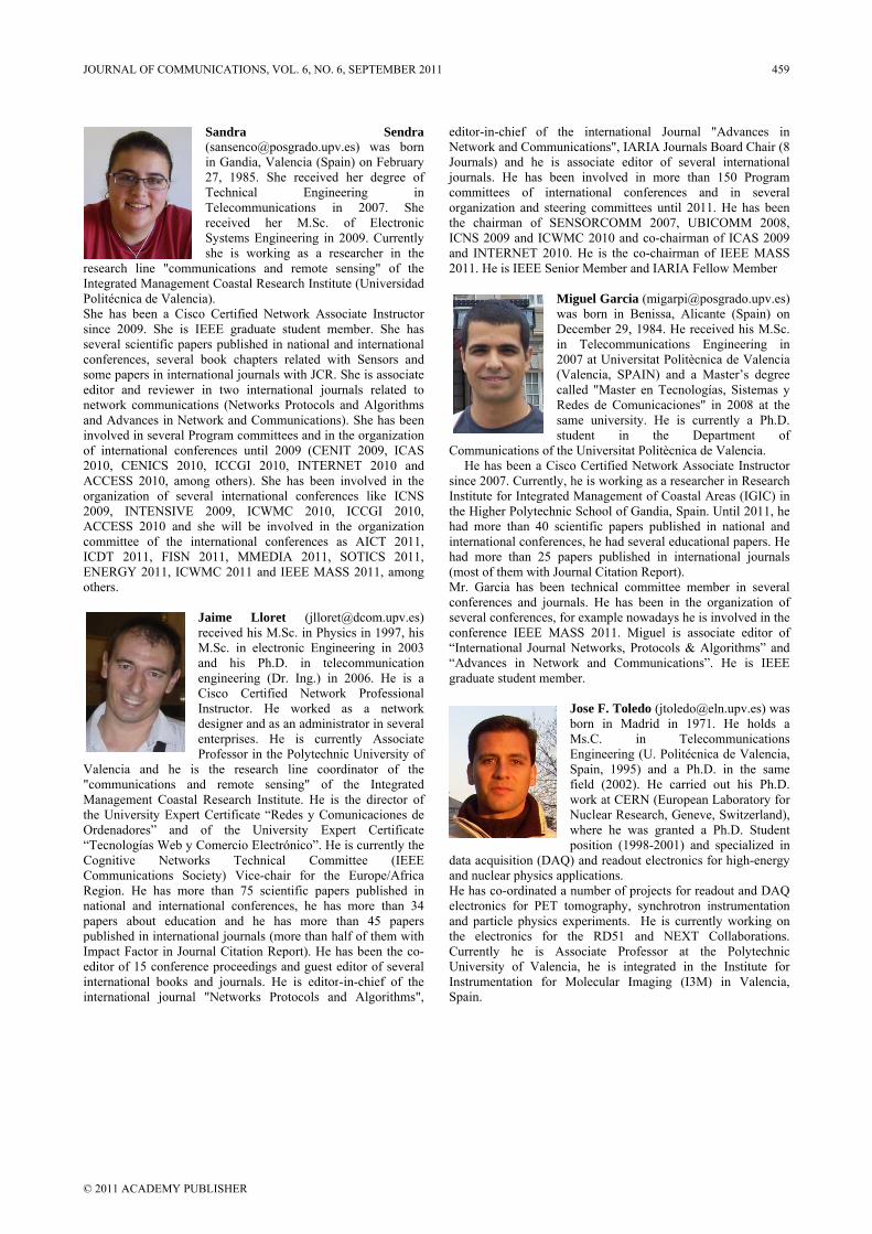
research line Integrated MaPolitécnica de She has been since 2009. Sseveral scienticonferences, ssome papers ineditor and renetwork command Advancesinvolved in seof internation2010, CENICACCESS 201organization o2009, INTENACCESS 201committee ofICDT 2011, ENERGY 201others.
Valencia and"communicatiManagement the UniversityOrdenadores” “Tecnologías WCognitive CommunicatioRegion. He hnational and papers about published in inImpact Factoreditor of 15 cointernational binternational j
Sandr(sansein Gan27, 19TechnTelecoreceivSystemshe is
"communicatianagement Coas Valencia). a Cisco Certi
She is IEEE gific papers pubseveral book cn international j
eviewer in twomunications (Ns in Network aneveral Program nal conferencesCS 2010, ICC0, among otheof several inteNSIVE 2009, 0 and she wil
f the internatioFISN 2011,
11, ICWMC 20
Jaime receiveM.Sc. iand hengineeCisco InstructdesigneenterpriProfess
d he is the rons and remCoastal Resear
y Expert Certifiand of the
Web y ComercNetworks T
ons Society) Vhas more than international ceducation an
nternational jour in Journal Citonference procbooks and jourjournal "Netw
ra enco@posgradondia, Valencia 985. She rece
nical Enommunications
ved her M.Sms Engineerings working as ions and remostal Research In
ified Network graduate studenlished in nationchapters relatedjournals with J
o international Networks Protocnd Communicacommittees and
s until 2009 (CGI 2010, INT
ers). She has bernational conf
ICWMC 20ll be involved onal conferencMMEDIA 20
011 and IEEE M
Lloret (jld his M.Sc. in in electronic Eis Ph.D. in ering (Dr. Ing.
Certified Netor. He worker and as an admises. He is cor in the Polyteresearch line
mote sensing" rch Institute. H
ficate “Redes y e University cio Electrónico”Technical CVice-chair for 75 scientific p
conferences, hend he has mournals (more thtation Report). eedings and gurnals. He is ed
works Protocols
Seo.upv.es) was (Spain) on Feb
eived her degrngineering s in 2007. Sc. of Electg in 2009. Curra researcher i
ote sensing" onstitute (Univer
Associate Instrnt member. Shnal and internad with SensorsJCR. She is asso
journals relatcols and Algor
ations). She hasd in the organizCENIT 2009, TERNET 2010been involved iferences like 010, ICCGI
in the organizces as AICT 11, SOTICS MASS 2011, a
[email protected] in 199
Engineering in telecommunic
) in 2006. Hetwork Profess
ked as a netministrator in securrently Assoechnic Universcoordinator oof the Integ
He is the directComunicacionExpert Certi
”. He is currentCommittee (
the Europe/Apapers publish
e has more thaore than 45 pan half of themHe has been th
uest editor of seditor-in-chief os and Algorith
endra born
bruary ee of
in She
tronic rently n the
of the rsidad
ructor e has
ational s and ociate ed to
rithms s been zation ICAS
0 and in the ICNS 2010, zation 2011, 2011, mong
pv.es) 7, his 2003
cation e is a sional twork everal ociate sity of f the grated tor of
nes de ificate tly the (IEEE Africa hed in an 34 papers m with he co-everal of the hms",
editoNetwJournjourncommorganthe ICNSand 2011
ComH
sinceInstitthe Hhad interhad (mosMr. confseverconf“Inte“Advgradu
data and nHe helectand the CurrUnivInstrSpain
or-in-chief of work and Commnals) and he inals. He has bmittees of innization and stchairman of SS 2009 and ICWINTERNET 20
1. He is IEEE S
mmunications ofHe has been a Ce 2007. Currenttute for Integra
Higher Polytechmore than 40
rnational confermore than 25
st of them with Garcia has be
ferences and joral conferences
ference IEEE Mernational Journvances in Netuate student me
acquisition (DAnuclear physicshas co-ordinatedtronics for PETparticle physicelectronics fo
rently he isversity of Valerumentation fon.
the internatiomunications", IAis associate edbeen involved nternational coteering commitSENSORCOMMWMC 2010 an010. He is the enior Member
Miguel Garciwas born in BDecember 29,in Telecomm2007 at Unive(Valencia, SPcalled "MasteRedes de Comsame universistudent in
f the UniversitaCisco Certified tly, he is workinated Managemehnic School of scientific pape
rences, he had spapers publis
Journal Citatioeen technical cournals. He hass, for example nMASS 2011. Mnal Networks, Ptwork and Comember.
Jose F. Tolborn in MMs.C. EngineeringSpain, 1995field (2002work at CENuclear Rewhere he wposition (19
AQ) and reados applications. d a number of pT tomography,s experiments.
or the RD51 Associate Pro
encia, he is inr Molecular I
onal Journal ARIA Journals ditor of severa
in more thanonferences anttees until 2011M 2007, UBI
nd co-chairman co-chairman oand IARIA Fel
ia (migarpi@poBenissa, Alica, 1984. He recemunications Eersitat PolitècniPAIN) and a Mer en Tecnologímunicaciones" ity. He is curr
the Depat Politècnica de
Network Assong as a research
ent of Coastal AGandia, Spain. ers published iseveral educatioshed in internaon Report). ommittee mems been in the onowadays he is Miguel is assoProtocols & Ammunications”
ledo (jtoledo@eMadrid in 1971
in Telecog (U. Politécnic5) and a Ph.D
2). He carried ERN (European
search, Genevewas granted a 998-2001) and ut electronics f
projects for rea, synchrotron i
He is currentand NEXT C
ofessor at thntegrated in thImaging (I3M)
"Advances inBoard Chair (8
al internationaln 150 Programnd in several1. He has beenICOMM 2008,
of ICAS 2009of IEEE MASSlow Member
osgrado.upv.es)nte (Spain) on
eived his M.Sc.Engineering inica de Valencia
Master’s degreeías, Sistemas yin 2008 at therently a Ph.D.partment ofe Valencia. ciate Instructorher in ResearchAreas (IGIC) in
Until 2011, hein national andonal papers. Heational journals
mber in severalorganization ofinvolved in the
ociate editor oflgorithms” and
”. He is IEEE
eln.upv.es) was1. He holds aommunicationsca de Valencia,
D. in the sameout his Ph.D.Laboratory for
e, Switzerland),Ph.D. Studentspecialized in
for high-energy
adout and DAQinstrumentationtly working onCollaborations.
he Polytechniche Institute for) in Valencia,
n 8 l
m l n ,
9 S
) n . n a e y e . f
r h n e d e s
l f e f d E
s a s , e . r , t n y
Q n n . c r ,
JOURNAL OF COMMUNICATIONS, VOL. 6, NO. 6, SEPTEMBER 2011 459
© 2011 ACADEMY PUBLISHER
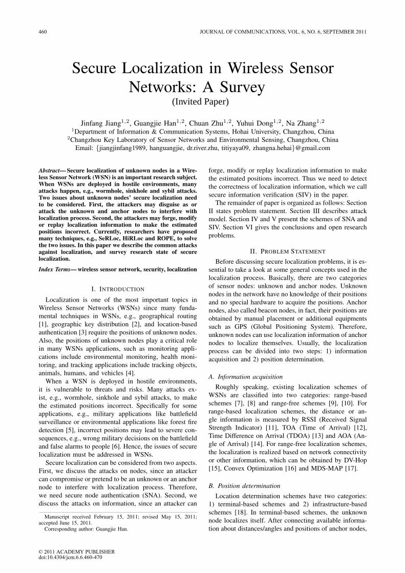
Secure Localization in Wireless SensorNetworks: A Survey
Jinfang Jiang1,2, Guangjie Han1,2, Chuan Zhu1,2, Yuhui Dong1,2, Na Zhang1,21Department of Information & Communication Systems, Hohai University, Changzhou, China
2Changzhou Key Laboratory of Sensor Networks and Environmental Sensing, Changzhou, ChinaEmail: jiangjinfang1989, hanguangjie, dr.river.zhu, titiyaya09, [email protected]
Abstract— Secure localization of unknown nodes in a Wire-less Sensor Network (WSN) is an important research subject.When WSNs are deployed in hostile environments, manyattacks happen, e.g., wormhole, sinkhole and sybil attacks.Two issues about unknown nodes’ secure localization needto be considered. First, the attackers may disguise as orattack the unknown and anchor nodes to interfere withlocalization process. Second, the attackers may forge, modifyor replay localization information to make the estimatedpositions incorrect. Currently, researchers have proposedmany techniques, e.g., SeRLoc, HiRLoc and ROPE, to solvethe two issues. In this paper we describe the common attacksagainst localization, and survey research state of securelocalization.
Index Terms— wireless sensor network, security, localization
I. INTRODUCTION
Localization is one of the most important topics inWireless Sensor Networks (WSNs) since many funda-mental techniques in WSNs, e.g., geographical routing[1], geographic key distribution [2], and location-basedauthentication [3] require the positions of unknown nodes.Also, the positions of unknown nodes play a critical rolein many WSNs applications, such as monitoring appli-cations include environmental monitoring, health moni-toring, and tracking applications include tracking objects,animals, humans, and vehicles [4].
When a WSN is deployed in hostile environments,it is vulnerable to threats and risks. Many attacks ex-ist, e.g., wormhole, sinkhole and sybil attacks, to makethe estimated positions incorrect. Specifically for someapplications, e.g., military applications like battlefieldsurveillance or environmental applications like forest firedetection [5], incorrect positions may lead to severe con-sequences, e.g., wrong military decisions on the battlefieldand false alarms to people [6]. Hence, the issues of securelocalization must be addressed in WSNs.
Secure localization can be considered from two aspects.First, we discuss the attacks on nodes, since an attackercan compromise or pretend to be an unknown or an anchornode to interfere with localization process. Therefore,we need secure node authentication (SNA). Second, wediscuss the attacks on information, since an attacker can
Manuscript received February 15, 2011; revised May 15, 2011;accepted June 15, 2011.
Corresponding author: Guangjie Han.
forge, modify or replay localization information to makethe estimated positions incorrect. Thus we need to detectthe correctness of localization information, which we callsecure information verification (SIV) in the paper.
The remainder of paper is organized as follows: SectionII states problem statement. Section III describes attackmodel. Section IV and V present the schemes of SNA andSIV. Section VI gives the conclusions and open researchproblems.
II. PROBLEM STATEMENT
Before discussing secure localization problems, it is es-sential to take a look at some general concepts used in thelocalization process. Basically, there are two categoriesof sensor nodes: unknown and anchor nodes. Unknownnodes in the network have no knowledge of their positionsand no special hardware to acquire the positions. Anchornodes, also called beacon nodes, in fact, their positions areobtained by manual placement or additional equipmentssuch as GPS (Global Positioning System). Therefore,unknown nodes can use localization information of anchornodes to localize themselves. Usually, the localizationprocess can be divided into two steps: 1) informationacquisition and 2) position determination.
A. Information acquisition
Roughly speaking, existing localization schemes ofWSNs are classified into two categories: range-basedschemes [7], [8] and range-free schemes [9], [10]. Forrange-based localization schemes, the distance or an-gle information is measured by RSSI (Received SignalStrength Indicator) [11], TOA (Time of Arrival) [12],Time Difference on Arrival (TDOA) [13] and AOA (An-gle of Arrival) [14]. For range-free localization schemes,the localization is realized based on network connectivityor other information, which can be obtained by DV-Hop[15], Convex Optimization [16] and MDS-MAP [17].
B. Position determination
Location determination schemes have two categories:1) terminal-based schemes and 2) infrastructure-basedschemes [18]. In terminal-based schemes, the unknownnode localizes itself. After connecting available informa-tion about distances/angles and positions of anchor nodes,
(Invited Paper)
460 JOURNAL OF COMMUNICATIONS, VOL. 6, NO. 6, SEPTEMBER 2011
© 2011 ACADEMY PUBLISHERdoi:10.4304/jcm.6.6.460-470
the position of an unknown node can simply be computedby trilateration [15], multilateration [19], and triangulation[14]. In infrastructure-based schemes, reference nodesincluding trusted neighbor nodes, mainly anchor nodesto localize the unknown node.
Adversaries can attack localization in both two steps.The goal of the adversary is to make the unknown nodesobtain false positions, by compromising normal nodesto send false localization information, or pretend to bea legitimate node to forge, modify or replay signals.Thus, security measures are needed to make the estimatedpositions still correct under attacks.
III. ATTACK MODEL
Localization process can be attacked in a numberof different ways. Researchers have addressed a set ofknown attacks [18]. The known attacks can be dividedinto two categories: external and internal attacks. Theadversary is external if it is outside the WSN and im-plements malicious behaviors without right cryptographickey. Otherwise, the adversary is internal, in which casethe adversary controls one or more fraudulent nodes. Inthis paper, the attacks are classified into two categories:1) attacks on nodes and 2) attacks on information.
A. Attacks on Nodes
In this paper, malicious nodes contain attackers andcompromised nodes. An attacker is an external nodewhich intrudes into the WSN. A compromised node isan normal node ( an unknown or an anchor node) in theWSN compromised by the attacker. Attacks on nodes arelisted as follows:
Compromise: Node compromise is the most fundamentalattack in WSN that leads to other kinds of attacks. Itoccurs when an attacker gains control of a node in theWSN. Normally, compromised nodes can be obtained bythe following methods: 1) attackers capture normal nodesand reprogram them; 2) attackers deploy nodes with largercomputing resources such as laptops to attack normalnodes [20]. With compromised node, an attacker canalter the node to listen information in the WSN, revokelegitimate nodes, input malicious data, and cause internalattacks, e.g., DoS attack.
Replication: If an adversary manages to capture a nodeand extract the authentication/encryption keys, it canproduce a large number of replicas having the sameidentity (ID) from the captured node and integrate theminto the WSN at chosen locations, which is called thenode replication attack. Since the credentials of replicasare all the clones from the captured nodes, the replicascan be considered as legitimate members of the network[21]. It is always assumed that the adversary cannotcreate new IDs for replicated nodes, since otherwise theattackers will have to create the corresponding securityinformation (keys, codes, etc.), which is very difficult andeven infeasible in most cases [22]. Once the adversaryreplicates one or more sensor nodes, it can execute the
malicious operations. For instance, the replicas may injectfalse localization information into the WSN.
Figure 1. Node impersonation attack: (a) the Invisible Node attack. Themalicious node M simply stands between two nodes A and B that are notin direct range. The invisible node M silently repeats the communicationbetween nodes A and B, which misleadingly assume that nodes A andB communicate directly. In this way, the malicious node succeeds inimpersonating node A to node B and vice versa. (b) the Stolen Identityattack. The malicious node M succeeds in stealing all the authenticationcredentials from a legitimate node A, such as the certified signature keys.If the malicious node outraces the legitimate node in updating the stolencredentials, then the credentials of the legitimate node will not be validanymore. Thus, only the malicious node will be able to communicatewith node B. This kind of attack is not just a matter of stealing a nodesidentity, but also a matter of abusing the trust relationships that otherparties may have had established with the legitimate node.
Impersonation: One form of node impersonation attackis the Invisible Node attack, and the other one is the StolenIdentity attack [23], as shown in Figure 1.
Sybil attack: Sybil attack is launched by a malicious nodewhich has virtually multiple identities (IDs). We refer toa malicious node’s additional identities as Sybil nodes.A Sybil node can get an identity in one of two ways.It can fabricate a new identity, or steal an identity froma legitimate node [24]. A sybil node can send messageswith different IDs. For example, in localization process,one malicious node may masquerade as several anchornodes to send false information at the same time.
Wormhole attack: In a wormhole attack, an attackerrecords a packet or individual bits of a packet at onelocation in the network. Then, it tunnels the packet(possibly selectively) to another location and replays it.The tunnel can be established in many different ways,for example, through an out-of-band channel, packet en-capsulation, high-powered transmission, packet relay andprotocol deviations [25]. In localization process, the attackmay tunnel totally different and erroneous localizationinformation.
B. Attacks on Information
In the localization systems, unknown nodes always usethe localization information of anchor nodes to localizethemselves. The target of malicious nodes is usuallyto make localization information incorrect. Attacks oninformation are listed as follows:
Forgery: Forgery attack is the malicious node sendsmisleading information in the localization systems. Forexample, in the active system [26], the malicious nodepretends to be an anchor node to voluntarily send localiza-tion information. In the passive system [26], the maliciousnode pretends to be an unknown node to be localized.
JOURNAL OF COMMUNICATIONS, VOL. 6, NO. 6, SEPTEMBER 2011 461
© 2011 ACADEMY PUBLISHER
Alteration: Alteration attack is the most direct attack.This attack targets the information exchanged between anunknown and an anchor node. Adversaries may directlyalter the coordinates, time or the number of hops andincrease the localization error of unknown nodes. For ex-ample, in Collaborative Collusion [27], all malicious nodecan collaborate with each other to alter the informationthey receives or replays.
Interference: Interference attack is the malicious nodeinterferes with the signal measurements. For example, inrange-based localization systems, malicious nodes mayplace obstacles between signal sender and receiver toprolong transmission time, change angle of arrival orweaken received signal strength [28].
Replay: Replay attack is the most common or simpleattack, especially when the capability and resources of theadversary are limited. In this attack, the malicious nodecongests the information transmission between sender andreceiver, then replays the outdated information. Usingthe outdated information, the unknown nodes calculateinaccurate positions. Unlike other attacks, replay attackcan destroy the whole network with one node.
Flooding: Similar to data flooding attack on routing pro-tocol [29], flooding attack on localization is the maliciousnode broadcasts large quantities of useless data packetsto all nodes in its communication range. The commoncharacteristic of flooding attack is to exhaust the availablenetwork communication bandwidth so that the other nodescan not communicate with each other. Moreover, thesender and receiver are busy to send or receive theexcessive packets from the attacker and consume a lotof network resources.
Selective forwarding: In selective forwarding attack [30],the malicious node behaves like black hole and refusesto forward sensitive messages and simply drops them,ensuring that they are not propagated any further. Theselective forwarding attack is difficult to detect. First, toavoid raising suspicions, an adversary selectively dropspackets instead of dropping every packet. In addition,there are many reasons result in packet dropout, e.g.,unreliable wireless communications. And in some cases,sensor nodes go into sleep state to save power. Theycannot send and receive data in this period. Therefore,it is essential to identify the packet dropout is caused byselective forwarding or any other reasons.
IV. SECURE NODE AUTHENTICATION
Many secure localization schemes have been proposed[27]. They can be classified into two categories: SNAand SIV. For SNA, in most cases, unknown nodes arelocalized based on the reference nodes, e.g., trusted an-chor nodes. A number of schemes have been proposed tosecure the positions of unknown nodes, which are calledsecure localization for unknown nodes [31], [32]. How-ever, none of these schemes can work properly when theanchor nodes are compromised. Thus, secure localizationfor anchor nodes is needed.
A. Secure Localization for Unknown Nodes
In general, the main localization algorithms are clas-sified into two categories: range-based and range-free.In this paper, we also classify secure localization forunknown nodes into this two categories.
1) Range-based Secure Localization: Based on thedistance-bounding protocols [33], Capkun et al. proposethe verifiable multilateration (VM) technique [31], [34].With a central authority and several anchor nodes whichare also named verifiers, VM enables a secure compu-tation and verification of the unknown nodes’ positionsin the presence of attackers. In VM, verifiers (v1, ..., vn)which are in the communication range of the unknownnode u perform distance bounding to the node u and ob-tain distance bounds db1, ..., dbn. These distance bounds,as well as the positions of the verifiers are then reported tothe central authority. The authority computes an estimateposition (xu, yu) of the unknown node using distancebounds. Then, the authority runs two tests: 1) σ- test: forall vi, does the distance between (xu, yu) and vi differfrom the measured distance bound dbi by less than theexpected distance measurement error σ? 2) point in thetriangle test: does (xu, yu) fall within at least one physicaltriangle formed by a triplet of verifiers? If both the σ andthe point in the triangle tests are positive, the authorityaccepts (xu, yu) as correct; else, the position is rejected.
Based on VM, the authors propose a secure cooperativepositioning mechanism called SPINE [31], [34]. SPINE isexecuted in three phases: 1) the unknown nodes measuredistance bounds to their neighbors; 2) the distance boundsare verified through VM; and 3) the positions of theunknown nodes are computed by a distributed algorithm,or by the central authority using a centralized positioningalgorithm. Therefore, nodes in SPINE cannot produceerroneous distance measurements. However, SPINE hassome drawbacks, e.g., in order to perform verifiablemultilateration, a high number of verifiers are required.
Capkun et al. use the Covert Base Station (CBS)and Mobile Base Station (MBS) to verify the positionsof unknown nodes [32], [35]. In the CBS case, forinfrastructure-centric localization, the public base station(PBS) sends a nonce firstly. When a node replies tothe nonce, all the CBSs compute its position togetherbased on TDOA and check if this position is consistentwith the time differences. If not, an attack is detectedand the estimated position is rejected. For node-centriclocalization, the unknown node broadcasts a radio signaland an ultrasound signal at the same time, then eachCBS obtains the estimated distance based on the arrivaltime differences of two signals. Also, the CBS obtainscalculated distance using nodes reported location andCBS’ location. Finally, the CBS compares estimated andcalculated distances and rejects inconsistent ones. In theMBS case, it first requires unknown nodes to broadcast aradio signal. After a given period of time, it moves to adifferent location to broadcast a ultrasound signal. Thenthe MBS implements the same operations as a CBS does.
In [36], Anjum et al. present a secure localization algo-
462 JOURNAL OF COMMUNICATIONS, VOL. 6, NO. 6, SEPTEMBER 2011
© 2011 ACADEMY PUBLISHER
rithm called SLA. It is considered that each anchor nodehas a capability to vary power level. Each power levelis assumed to correspond to a different communicationrange. When an unknown node is localized, the sink noderequests anchor nodes to send localization nonce to thenode at different power levels. As a result, each unknownnode receives a set of unique nonce and retransmits themback to the sink. The sink then determines the positionof the unknown node. Compared with VM, SLA do notneed fine-grained time synchronization. But the model ofpower level and transmission range is just suitable for out-door environment not in-door ones [37]. In addition, SLAhas a few drawbacks: 1) anchor and sink nodes are allassumed to be trusted; 2) only considering a single sensornode being compromised and ruling out collaborativeattacks between sensor nodes; 3) SLA is a centralizedapproach which creates bottle-neck at the base station.
Zhang et al. [38] propose SLS for ultra-wideband(UWB) sensor networks. To localize a node, anchor nodesfirst measure their respective distance to the node witha modified two-way ToA approach, called K-distance.The anchor leader then collects all the distance estimateswhereby to derive a MMSE location estimate. Subse-quently, SLS employs a location validity test by checkingwhether the location is inside the polygon formed by allthe anchor nodes to detect possible attacks. Comparedwith VM, SLS is more robust and gernal, e.g., usingmobile anchor nodes to replace static ones and makingeach anchor node take turns to act as the leader to balancetheir resource usage. However, the process of SLS is morecomplex than that of VM and consumes higher energy.
In [39], based on an attack-driven model specified withthe Petri net, an enhanced secure localization scheme(ESLS) is proposed, which extends the idea in [38] anddefends against not only distance reduction attacks butalso distance enlargement attacks. The major contributionis the first time to use the Petri net to validate a securityscheme for WSNs.
In [40], Arisar et al. present a two-way “Greet, Meetand Locate” (GML) mechanism for secure location esti-mation based on geographical sectorization. GML com-prises of three phases: Greet, Meet and Locate. 1) Greet: alight-weight authentication scheme, the HB+ Protocol, isused to perform two-way authentication, individually byunknown and anchor nodes. 2) Meet: the Diffie Hellmankey exchange algorithm is used that allows exchange ofsecret shared keys between two users in an adversarialenvironment over an insecure communication medium.3) Locate: the location is estimated via ToA based tech-nique. Moreover, a double-averaging mechanism is alsopresented to minimize the localization error.
In [41], Alfaro et al. provide three algorithms thatenable the unknown nodes to determine their positionsin presence of neighbor sensors that may lie about theirlocations. The first algorithm is called the Majority-ThreeNeighbor Signals. When an unknown node is localized,all the neighbor anchor nodes send their locations to it.For every three anchor nodes, the unknown node uses
trilateration to calculate a position. Then, a majoritydecision rule is used to correct the final position of theunknown node. The second algorithm is the Majority-Two Neighbor Signals. The unknown node uses only twoneighbor anchor nodes, therefore the correct location isone of the two points of intersection of the two circlescentered at two neighbors. The third algorithm is calledthe Tabulated-Two Neighbor Signals. It is assumed theunknown node may trust one of the neighbor anchornodes. Then, the unknown node implements the secondalgorithm for every neighbor anchor nodes except thetrusted one. Finally, the unknown node calculates theoccurrence frequency of each position and accepts themost frequently occurring one as the correct position. Thethree algorithms have been extended to localize unknownnodes in [42].
Comparison of the above mentioned schemes is shownin table I.
TABLE I.COMPARISON OF RANGE-BASED SECURE LOCALIZATION
Algorithm Technique Observation
VM Distance-bounding Nanosecond clockSPINE Distance-bounding Nanosecond clock
High number of anchor nodesCapkun et al. CBS and MBS Centralized approach[32], [35] Rely on locations of CBSSLA Distance-bounding Centralized approach
Vary power level Resist only one compromisedsensor node
SLS K-distance Complexapproach, MMSE, Higher energy consumptionvalidity test
ESLS Petri net Higher energy consumptionGML HB+ Protocol Complex
Diffie HellmanToA
Alfaro et al. Trilateration Dense network[41] Majority decision
2) Range-free Secure Localization: In [43], the authorspropose a distributed range-free localization algorithmcalled SeRLoc, which does not require any communi-cation among unknown nodes. The SeRLoc uses trustedlocators equipped with a set of higher-power sectoredantennas to replace anchor nodes. The locators havelonger transmission range than unknown nodes. They sendanchor beacons to unknown nodes, in which containstheir positions and the sectors of the antenna. Whena node hears multiple locators, it computes the centerof gravity of the sectors corresponding to locators asits position. The SeRLoc is robust against severe WSNattacks, such as the wormhole attack, the sybil attack andcompromised sensor nodes. However, SeRLoc is based onthe assumption that no jamming of the wireless mediumis feasible. And it does not protect against attacks on loca-tor’s information, which are avoided by checking networkproperties such as sector uniqueness and communicationrange. Moreover, in order to minimize the region of sectorintersection to improve localization, we need to increasethe number of locators and sectored antennas.
In order to reduce the influence on localization ac-
JOURNAL OF COMMUNICATIONS, VOL. 6, NO. 6, SEPTEMBER 2011 463
© 2011 ACADEMY PUBLISHER
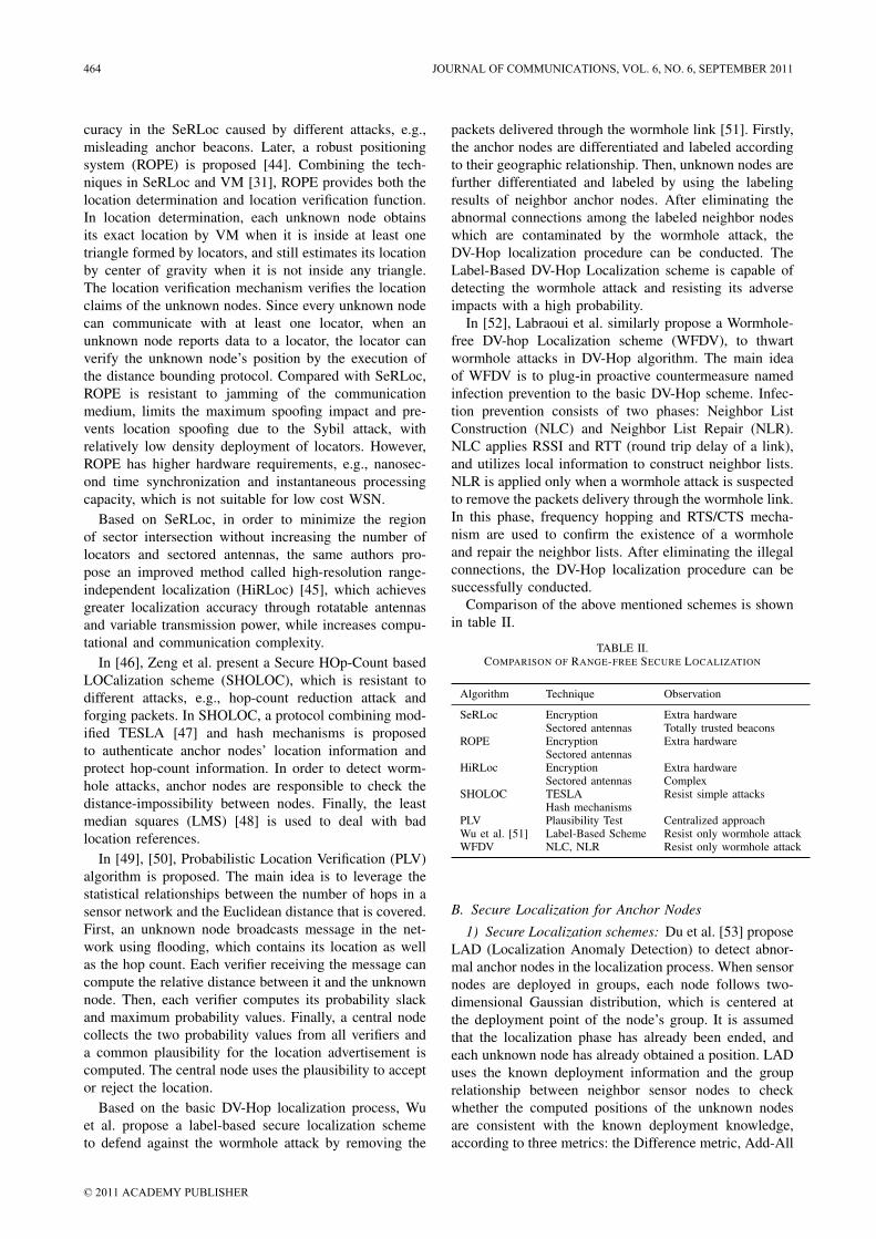
curacy in the SeRLoc caused by different attacks, e.g.,misleading anchor beacons. Later, a robust positioningsystem (ROPE) is proposed [44]. Combining the tech-niques in SeRLoc and VM [31], ROPE provides both thelocation determination and location verification function.In location determination, each unknown node obtainsits exact location by VM when it is inside at least onetriangle formed by locators, and still estimates its locationby center of gravity when it is not inside any triangle.The location verification mechanism verifies the locationclaims of the unknown nodes. Since every unknown nodecan communicate with at least one locator, when anunknown node reports data to a locator, the locator canverify the unknown node’s position by the execution ofthe distance bounding protocol. Compared with SeRLoc,ROPE is resistant to jamming of the communicationmedium, limits the maximum spoofing impact and pre-vents location spoofing due to the Sybil attack, withrelatively low density deployment of locators. However,ROPE has higher hardware requirements, e.g., nanosec-ond time synchronization and instantaneous processingcapacity, which is not suitable for low cost WSN.
Based on SeRLoc, in order to minimize the regionof sector intersection without increasing the number oflocators and sectored antennas, the same authors pro-pose an improved method called high-resolution range-independent localization (HiRLoc) [45], which achievesgreater localization accuracy through rotatable antennasand variable transmission power, while increases compu-tational and communication complexity.
In [46], Zeng et al. present a Secure HOp-Count basedLOCalization scheme (SHOLOC), which is resistant todifferent attacks, e.g., hop-count reduction attack andforging packets. In SHOLOC, a protocol combining mod-ified TESLA [47] and hash mechanisms is proposedto authenticate anchor nodes’ location information andprotect hop-count information. In order to detect worm-hole attacks, anchor nodes are responsible to check thedistance-impossibility between nodes. Finally, the leastmedian squares (LMS) [48] is used to deal with badlocation references.
In [49], [50], Probabilistic Location Verification (PLV)algorithm is proposed. The main idea is to leverage thestatistical relationships between the number of hops in asensor network and the Euclidean distance that is covered.First, an unknown node broadcasts message in the net-work using flooding, which contains its location as wellas the hop count. Each verifier receiving the message cancompute the relative distance between it and the unknownnode. Then, each verifier computes its probability slackand maximum probability values. Finally, a central nodecollects the two probability values from all verifiers anda common plausibility for the location advertisement iscomputed. The central node uses the plausibility to acceptor reject the location.
Based on the basic DV-Hop localization process, Wuet al. propose a label-based secure localization schemeto defend against the wormhole attack by removing the
packets delivered through the wormhole link [51]. Firstly,the anchor nodes are differentiated and labeled accordingto their geographic relationship. Then, unknown nodes arefurther differentiated and labeled by using the labelingresults of neighbor anchor nodes. After eliminating theabnormal connections among the labeled neighbor nodeswhich are contaminated by the wormhole attack, theDV-Hop localization procedure can be conducted. TheLabel-Based DV-Hop Localization scheme is capable ofdetecting the wormhole attack and resisting its adverseimpacts with a high probability.
In [52], Labraoui et al. similarly propose a Wormhole-free DV-hop Localization scheme (WFDV), to thwartwormhole attacks in DV-Hop algorithm. The main ideaof WFDV is to plug-in proactive countermeasure namedinfection prevention to the basic DV-Hop scheme. Infec-tion prevention consists of two phases: Neighbor ListConstruction (NLC) and Neighbor List Repair (NLR).NLC applies RSSI and RTT (round trip delay of a link),and utilizes local information to construct neighbor lists.NLR is applied only when a wormhole attack is suspectedto remove the packets delivery through the wormhole link.In this phase, frequency hopping and RTS/CTS mecha-nism are used to confirm the existence of a wormholeand repair the neighbor lists. After eliminating the illegalconnections, the DV-Hop localization procedure can besuccessfully conducted.
Comparison of the above mentioned schemes is shownin table II.
TABLE II.COMPARISON OF RANGE-FREE SECURE LOCALIZATION
Algorithm Technique Observation
SeRLoc Encryption Extra hardwareSectored antennas Totally trusted beacons
ROPE Encryption Extra hardwareSectored antennas
HiRLoc Encryption Extra hardwareSectored antennas Complex
SHOLOC TESLA Resist simple attacksHash mechanisms
PLV Plausibility Test Centralized approachWu et al. [51] Label-Based Scheme Resist only wormhole attackWFDV NLC, NLR Resist only wormhole attack
B. Secure Localization for Anchor Nodes
1) Secure Localization schemes: Du et al. [53] proposeLAD (Localization Anomaly Detection) to detect abnor-mal anchor nodes in the localization process. When sensornodes are deployed in groups, each node follows two-dimensional Gaussian distribution, which is centered atthe deployment point of the node’s group. It is assumedthat the localization phase has already been ended, andeach unknown node has already obtained a position. LADuses the known deployment information and the grouprelationship between neighbor sensor nodes to checkwhether the computed positions of the unknown nodesare consistent with the known deployment knowledge,according to three metrics: the Difference metric, Add-All
464 JOURNAL OF COMMUNICATIONS, VOL. 6, NO. 6, SEPTEMBER 2011
© 2011 ACADEMY PUBLISHER
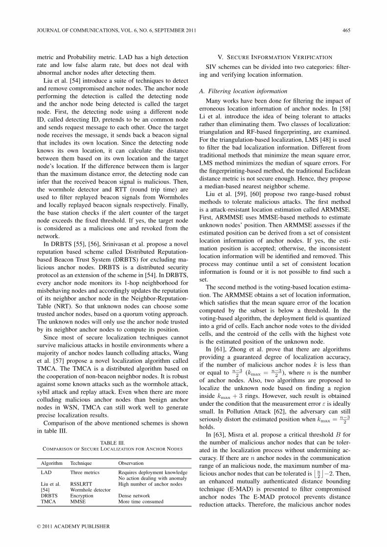
metric and Probability metric. LAD has a high detectionrate and low false alarm rate, but does not deal withabnormal anchor nodes after detecting them.
Liu et al. [54] introduce a suite of techniques to detectand remove compromised anchor nodes. The anchor nodeperforming the detection is called the detecting nodeand the anchor node being detected is called the targetnode. First, the detecting node using a different nodeID, called detecting ID, pretends to be an common nodeand sends request message to each other. Once the targetnode receives the message, it sends back a beacon signalthat includes its own location. Since the detecting nodeknows its own location, it can calculate the distancebetween them based on its own location and the targetnode’s location. If the difference between them is largerthan the maximum distance error, the detecting node caninfer that the received beacon signal is malicious. Then,the wormhole detector and RTT (round trip time) areused to filter replayed beacon signals from Wormholesand locally replayed beacon signals respectively. Finally,the base station checks if the alert counter of the targetnode exceeds the fixed threshold. If yes, the target nodeis considered as a malicious one and revoked from thenetwork.
In DRBTS [55], [56], Srinivasan et al. propose a novelreputation based scheme called Distributed Reputation-based Beacon Trust System (DRBTS) for excluding ma-licious anchor nodes. DRBTS is a distributed securityprotocol as an extension of the scheme in [54]. In DRBTS,every anchor node monitors its 1-hop neighborhood formisbehaving nodes and accordingly updates the reputationof its neighbor anchor node in the Neighbor-Reputation-Table (NRT). So that unknown nodes can choose sometrusted anchor nodes, based on a quorum voting approach.The unknown nodes will only use the anchor node trustedby its neighbor anchor nodes to compute its position.
Since most of secure localization techniques cannotsurvive malicious attacks in hostile environments where amajority of anchor nodes launch colluding attacks, Wanget al. [57] propose a novel localization algorithm calledTMCA. The TMCA is a distributed algorithm based onthe cooperation of non-beacon neighbor nodes. It is robustagainst some known attacks such as the wormhole attack,sybil attack and replay attack. Even when there are morecolluding malicious anchor nodes than benign anchornodes in WSN, TMCA can still work well to generateprecise localization results.
Comparison of the above mentioned schemes is shownin table III.
TABLE III.COMPARISON OF SECURE LOCALIZATION FOR ANCHOR NODES
Algorithm Technique Observation
LAD Three metrics Requires deployment knowledgeNo action dealing with anomaly
Liu et al. RSSI,RTT High number of anchor nodes[54] Wormhole detectorDRBTS Encryption Dense networkTMCA MMSE More time consumed
V. SECURE INFORMATION VERIFICATION
SIV schemes can be divided into two categories: filter-ing and verifying location information.
A. Filtering location information
Many works have been done for filtering the impact oferroneous location information of anchor nodes. In [58]Li et al. introduce the idea of being tolerant to attacksrather than eliminating them. Two classes of localization:triangulation and RF-based fingerprinting, are examined.For the triangulation-based localization, LMS [48] is usedto filter the bad localization information. Different fromtraditional methods that minimize the mean square error,LMS method minimizes the median of square errors. Forthe fingerprinting-based method, the traditional Euclideandistance metric is not secure enough. Hence, they proposea median-based nearest neighbor scheme.
Liu et al. [59], [60] propose two range-based robustmethods to tolerate malicious attacks. The first methodis a attack-resistant location estimation called ARMMSE.First, ARMMSE uses MMSE-based methods to estimateunknown nodes’ position. Then ARMMSE assesses if theestimated position can be derived from a set of consistentlocation information of anchor nodes. If yes, the esti-mation position is accepted; otherwise, the inconsistentlocation information will be identified and removed. Thisprocess may continue until a set of consistent locationinformation is found or it is not possible to find such aset.
The second method is the voting-based location estima-tion. The ARMMSE obtains a set of location information,which satisfies that the mean square error of the locationcomputed by the subset is below a threshold. In thevoting-based algorithm, the deployment field is quantizedinto a grid of cells. Each anchor node votes to the dividedcells, and the centroid of the cells with the highest voteis the estimated position of the unknown node.
In [61], Zhong et al. prove that there are algorithmsproviding a guaranteed degree of localization accuracy,if the number of malicious anchor nodes k is less thanor equal to n−3
2 (kmax = n−32 ), where n is the number
of anchor nodes. Also, two algorithms are proposed tolocalize the unknown node based on finding a regioninside kmax + 3 rings. However, such result is obtainedunder the condition that the measurement error ε is ideallysmall. In Pollution Attack [62], the adversary can stillseriously distort the estimated position when kmax = n−3
2holds.
In [63], Misra et al. propose a critical threshold B forthe number of malicious anchor nodes that can be toler-ated in the localization process without undermining ac-curacy. If there are n anchor nodes in the communicationrange of an malicious node, the maximum number of ma-licious anchor nodes that can be tolerated is
⌊n2
⌋−2. Then,
an enhanced mutually authenticated distance boundingtechnique (E-MAD) is presented to filter compromisedanchor nodes The E-MAD protocol prevents distancereduction attacks. Therefore, the malicious anchor nodes
JOURNAL OF COMMUNICATIONS, VOL. 6, NO. 6, SEPTEMBER 2011 465
© 2011 ACADEMY PUBLISHER
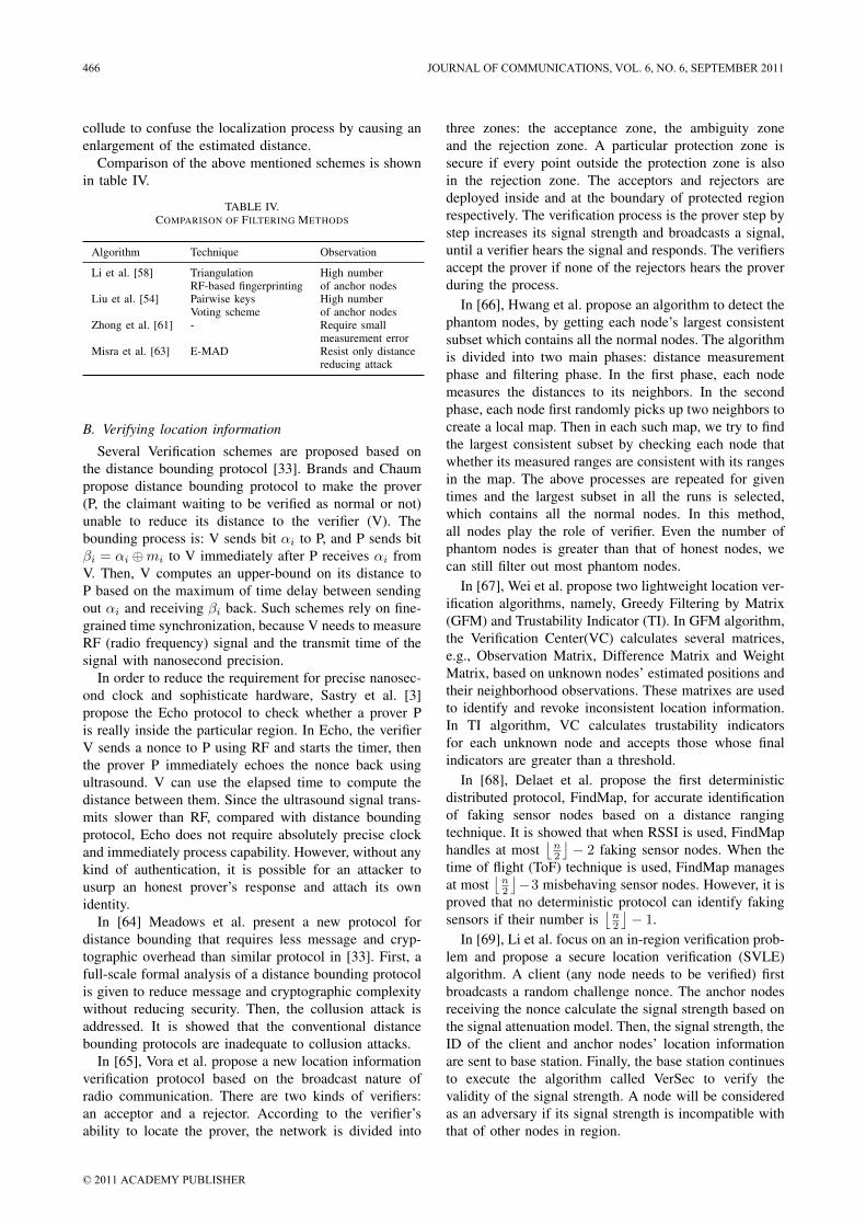
collude to confuse the localization process by causing anenlargement of the estimated distance.
Comparison of the above mentioned schemes is shownin table IV.
TABLE IV.COMPARISON OF FILTERING METHODS
Algorithm Technique Observation
Li et al. [58] Triangulation High numberRF-based fingerprinting of anchor nodes
Liu et al. [54] Pairwise keys High numberVoting scheme of anchor nodes
Zhong et al. [61] - Require smallmeasurement error
Misra et al. [63] E-MAD Resist only distancereducing attack
B. Verifying location information
Several Verification schemes are proposed based onthe distance bounding protocol [33]. Brands and Chaumpropose distance bounding protocol to make the prover(P, the claimant waiting to be verified as normal or not)unable to reduce its distance to the verifier (V). Thebounding process is: V sends bit αi to P, and P sends bitβi = αi ⊕mi to V immediately after P receives αi fromV. Then, V computes an upper-bound on its distance toP based on the maximum of time delay between sendingout αi and receiving βi back. Such schemes rely on fine-grained time synchronization, because V needs to measureRF (radio frequency) signal and the transmit time of thesignal with nanosecond precision.
In order to reduce the requirement for precise nanosec-ond clock and sophisticate hardware, Sastry et al. [3]propose the Echo protocol to check whether a prover Pis really inside the particular region. In Echo, the verifierV sends a nonce to P using RF and starts the timer, thenthe prover P immediately echoes the nonce back usingultrasound. V can use the elapsed time to compute thedistance between them. Since the ultrasound signal trans-mits slower than RF, compared with distance boundingprotocol, Echo does not require absolutely precise clockand immediately process capability. However, without anykind of authentication, it is possible for an attacker tousurp an honest prover’s response and attach its ownidentity.
In [64] Meadows et al. present a new protocol fordistance bounding that requires less message and cryp-tographic overhead than similar protocol in [33]. First, afull-scale formal analysis of a distance bounding protocolis given to reduce message and cryptographic complexitywithout reducing security. Then, the collusion attack isaddressed. It is showed that the conventional distancebounding protocols are inadequate to collusion attacks.
In [65], Vora et al. propose a new location informationverification protocol based on the broadcast nature ofradio communication. There are two kinds of verifiers:an acceptor and a rejector. According to the verifier’sability to locate the prover, the network is divided into
three zones: the acceptance zone, the ambiguity zoneand the rejection zone. A particular protection zone issecure if every point outside the protection zone is alsoin the rejection zone. The acceptors and rejectors aredeployed inside and at the boundary of protected regionrespectively. The verification process is the prover step bystep increases its signal strength and broadcasts a signal,until a verifier hears the signal and responds. The verifiersaccept the prover if none of the rejectors hears the proverduring the process.
In [66], Hwang et al. propose an algorithm to detect thephantom nodes, by getting each node’s largest consistentsubset which contains all the normal nodes. The algorithmis divided into two main phases: distance measurementphase and filtering phase. In the first phase, each nodemeasures the distances to its neighbors. In the secondphase, each node first randomly picks up two neighbors tocreate a local map. Then in each such map, we try to findthe largest consistent subset by checking each node thatwhether its measured ranges are consistent with its rangesin the map. The above processes are repeated for giventimes and the largest subset in all the runs is selected,which contains all the normal nodes. In this method,all nodes play the role of verifier. Even the number ofphantom nodes is greater than that of honest nodes, wecan still filter out most phantom nodes.
In [67], Wei et al. propose two lightweight location ver-ification algorithms, namely, Greedy Filtering by Matrix(GFM) and Trustability Indicator (TI). In GFM algorithm,the Verification Center(VC) calculates several matrices,e.g., Observation Matrix, Difference Matrix and WeightMatrix, based on unknown nodes’ estimated positions andtheir neighborhood observations. These matrixes are usedto identify and revoke inconsistent location information.In TI algorithm, VC calculates trustability indicatorsfor each unknown node and accepts those whose finalindicators are greater than a threshold.
In [68], Delaet et al. propose the first deterministicdistributed protocol, FindMap, for accurate identificationof faking sensor nodes based on a distance rangingtechnique. It is showed that when RSSI is used, FindMaphandles at most
⌊n2
⌋− 2 faking sensor nodes. When the
time of flight (ToF) technique is used, FindMap managesat most
⌊n2
⌋−3 misbehaving sensor nodes. However, it is
proved that no deterministic protocol can identify fakingsensors if their number is
⌊n2
⌋− 1.
In [69], Li et al. focus on an in-region verification prob-lem and propose a secure location verification (SVLE)algorithm. A client (any node needs to be verified) firstbroadcasts a random challenge nonce. The anchor nodesreceiving the nonce calculate the signal strength based onthe signal attenuation model. Then, the signal strength, theID of the client and anchor nodes’ location informationare sent to base station. Finally, the base station continuesto execute the algorithm called VerSec to verify thevalidity of the signal strength. A node will be consideredas an adversary if its signal strength is incompatible withthat of other nodes in region.
466 JOURNAL OF COMMUNICATIONS, VOL. 6, NO. 6, SEPTEMBER 2011
© 2011 ACADEMY PUBLISHER
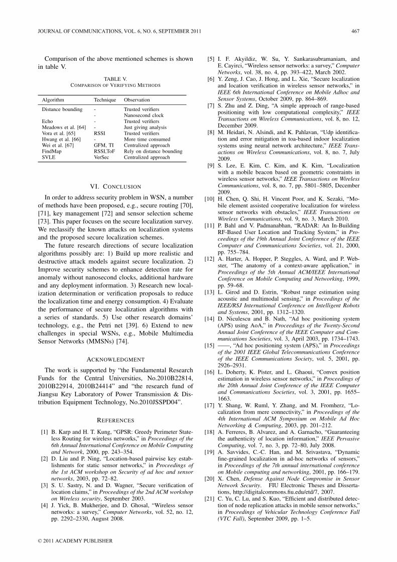
Comparison of the above mentioned schemes is shownin table V.
TABLE V.COMPARISON OF VERIFYING METHODS
Algorithm Technique Observation
Distance bounding - Trusted verifiers- Nanosecond clock
Echo - Trusted verifiersMeadows et al. [64] - Just giving analysisVora et al. [65] RSSI Trusted verifiersHwang et al. [66] - More time consumedWei et al. [67] GFM, TI Centralized approachFindMap RSSI,ToF Rely on distance boundingSVLE VerSec Centralized approach
VI. CONCLUSION
In order to address security problem in WSN, a numberof methods have been proposed, e.g., secure routing [70],[71], key management [72] and sensor selection scheme[73]. This paper focuses on the secure localization survey.We reclassify the known attacks on localization systemsand the proposed secure localization schemes.
The future research directions of secure localizationalgorithms possibly are: 1) Build up more realistic anddestructive attack models against secure localization. 2)Improve security schemes to enhance detection rate foranomaly without nanosecond clocks, additional hardwareand any deployment information. 3) Research new local-ization determination or verification proposals to reducethe localization time and energy consumption. 4) Evaluatethe performance of secure localization algorithms witha series of standards. 5) Use other research domains’technology, e.g., the Petri net [39]. 6) Extend to newchallenges in special WSNs, e.g., Mobile MultimediaSensor Networks (MMSNs) [74].
ACKNOWLEDGMENT
The work is supported by “the Fundamental ResearchFunds for the Central Universities, No.2010B22814,2010B22914, 2010B24414” and “the research fund ofJiangsu Key Laboratory of Power Transmission & Dis-tribution Equipment Technology, No.2010JSSPD04”.
REFERENCES
[1] B. Karp and H. T. Kung, “GPSR: Greedy Perimeter State-less Routing for wireless networks,” in Proceedings of the6th Annual International Conference on Mobile Computingand Network, 2000, pp. 243–354.
[2] D. Liu and P. Ning, “Location-based pairwise key estab-lishments for static sensor networks,” in Proceedings ofthe 1st ACM workshop on Security of ad hoc and sensornetworks, 2003, pp. 72–82.
[3] S. U. Sastry, N. and D. Wagner, “Secure verification oflocation claims,” in Proceedings of the 2nd ACM workshopon Wireless security, September 2003.
[4] J. Yick, B. Mukherjee, and D. Ghosal, “Wireless sensornetworks: a survey,” Computer Networks, vol. 52, no. 12,pp. 2292–2330, August 2008.
[5] I. F. Akyildiz, W. Su, Y. Sankarasubramaniam, andE. Cayirci, “Wireless sensor networks: a survey,” ComputerNetworks, vol. 38, no. 4, pp. 393–422, March 2002.
[6] Y. Zeng, J. Cao, J. Hong, and L. Xie, “Secure localizationand location verification in wireless sensor networks,” inIEEE 6th International Conference on Mobile Adhoc andSensor Systems, October 2009, pp. 864–869.
[7] S. Zhu and Z. Ding, “A simple approach of range-basedpositioning with low computational complexity,” IEEETransactions on Wireless Communications, vol. 8, no. 12,December 2009.
[8] M. Heidari, N. Alsindi, and K. Pahlavan, “Udp identifica-tion and error mitigation in toa-based indoor localizationsystems using neural network architecture,” IEEE Trans-actions on Wireless Communications, vol. 8, no. 7, July2009.
[9] S. Lee, E. Kim, C. Kim, and K. Kim, “Localizationwith a mobile beacon based on geometric constraints inwireless sensor networks,” IEEE Transactions on WirelessCommunications, vol. 8, no. 7, pp. 5801–5805, December2009.
[10] H. Chen, Q. Shi, H. Vincent Poor, and K. Sezaki, “Mo-bile element assisted cooperative localization for wirelesssensor networks with obstacles,” IEEE Transactions onWireless Communications, vol. 9, no. 3, March 2010.
[11] P. Bahl and V. Padmanabhan, “RADAR: An In-BuildingRF-Based User Location and Tracking System,” in Pro-ceedings of the 19th Annual Joint Conference of the IEEEComputer and Communications Societies, vol. 21, 2000,pp. 755–784.
[12] A. Harter, A. Hopper, P. Steggles, A. Ward, and P. Web-ster, “The anatomy of a context-aware application,” inProceedings of the 5th Annual ACM/IEEE InternationalConference on Mobile Computing and Networking, 1999,pp. 59–68.
[13] L. Girod and D. Estrin, “Robust range estimation usingacoustic and multimodal sensing,” in Proceedings of theIEEE/RSJ International Conference on Intelligent Robotsand Systems, 2001, pp. 1312–1320.
[14] D. Niculescu and B. Nath, “Ad hoc positioning system(APS) using AoA,” in Proceedings of the Twenty-SecondAnnual Joint Conference of the IEEE Computer and Com-munications Societies, vol. 3, April 2003, pp. 1734–1743.
[15] ——, “Ad hoc positioning system (APS),” in Proceedingsof the 2001 IEEE Global Telecommunications Conferenceof the IEEE Communications Society, vol. 5, 2001, pp.2926–2931.
[16] L. Doherty, K. Pister, and L. Ghaoui, “Convex positionestimation in wireless sensor networks,” in Proceedings ofthe 20th Annual Joint Conference of the IEEE Computerand Communications Societies, vol. 3, 2001, pp. 1655–1663.
[17] Y. Shang, W. Ruml, Y. Zhang, and M. Fromherz, “Lo-calization from mere connectivity,” in Proceedings of the4th International ACM Symposium on Mobile Ad HocNetworking & Computing, 2003, pp. 201–212.
[18] A. Ferreres, B. Alvarez, and A. Garnacho, “Guaranteeingthe authenticity of location information,” IEEE PervasiveComputing, vol. 7, no. 3, pp. 72–80, July 2008.
[19] A. Savvides, C.-C. Han, and M. Srivastava, “Dynamicfine-grained localization in ad-hoc networks of sensors,”in Proceedings of the 7th annual international conferenceon Mobile computing and networking, 2001, pp. 166–179.
[20] X. Chen, Defense Against Node Compromise in SensorNetwork Security. FIU Electronic Theses and Disserta-tions, http://digitalcommons.fiu.edu/etd/7, 2007.
[21] C. Yu, C. Lu, and S. Kuo, “Efficient and distributed detec-tion of node replication attacks in mobile sensor networks,”in Proceedings of Vehicular Technology Conference Fall(VTC Fall), September 2009, pp. 1–5.
JOURNAL OF COMMUNICATIONS, VOL. 6, NO. 6, SEPTEMBER 2011 467
© 2011 ACADEMY PUBLISHER
[22] K. Xing, F. Liu, C. Cheng, and D. Du, “Real-time detectionof clone attacks in wireless sensor networks,” in Proceed-ings of the 28th International Conference on DistributedComputing Systems, June 2008, pp. 3–10.
[23] K. Glynos, P. Kotzanikolaou, and C. Douligeris, “Pre-venting impersonation attacks in manet with multi-factorauthentication,” in Proceedings of the Third InternationalSymposium on Modeling and Optimization in Mobile, AdHoc, and Wireless Networks, April 2005, pp. 59–64.
[24] J. Newsome, E. Shi, D. Song, and A. Perrig, “Thesybil attack in sensor networks: Analysis & defenses,”in Proceedings of the Third International Symposium onInformation Processing in Sensor Networks, April 2004,pp. 259–268.
[25] M. Jain and H. Kandwal, “A survey on complex wormholeattack in wireless ad hoc networks,” in Proceedings of the2009 International Conference on Advances in Computing,Control, and Telecommunication Technologies, December2009, pp. 555–558.
[26] A. Quazi, “An overview on the time delay estimate inactive and passive systems for target localization,” IEEETransactions on Acoustics Speech and Signal Processing,vol. 29, no. 3, pp. 527–533, June 1981.
[27] J. Jiang, G. Han, S. L., H. Chao, and S. Nishio, “A novelsecure localization scheme against collaborative collusionin wireless sensor networks,” in the 7th International Wire-less Communications & Mobile Computing Conference,July 2011.
[28] X. Cao, B. Yu, G. Chen, and F. Ren, “Security analysison node localization systems of wireless sensor networks,”China Journal Of Software, vol. 19, no. 4, pp. 879–887,April 2008.
[29] P. Yi, Z. Dai, Z. Y., and S. Zhang, “Resisting floodingattacks in ad hoc networks,” in Proceedings of the Inter-national Conference on Information Technology: Codingand Computing, no. 2, April 2005, pp. 657–662.
[30] L. Bysani and A. Turuk, “A survey on selective forwardingattack in wireless sensor networks,” in Proceedings of theInternational Conference on Devices and Communications(ICDeCom), February 2011, pp. 1–5.
[31] S. Capkun and J. Hubaux, “Secure positioning of wirelessdevices with application to sensor networks,” in Proceed-ings of the 24th Annual Joint Conference of the IEEEComputer and Communications Societies, no. 3, 2005, pp.1917–1928.
[32] S. Capkun, K. Rasmussen, M. Cagalj, and M. Srivastava,“Secure location verification with hidden and mobile basestations,” in IEEE Transactions on Mobile Computing,vol. 7, no. 4, 2008, pp. 470–483.
[33] S. Brands and D. Chaum, “Distance-bounding protocols,”in Proceedings of the the EUROCRYPT 93 Workshop onthe Theory and Application of Cryptographic Techniqueson Advances in Cryptology, 1994, pp. 344–359.
[34] S. Capkun and J. Hubaux, “Secure positioning in wirelessnetwork,” in IEEE Journal on Selected Areas in Commu-nications, vol. 24, no. 2, 2006, pp. 221–232.
[35] S. Capkun, M. Cagalj, and M. Srivastava, “Secure localiza-tion with hidden and mobile base stations,” in Proceedingsof the 25th IEEE International Conference on ComputerCommunications, 2006, pp. 1–10.
[36] F. Anjum, S. Pandey, and P. Agrawal, “Secure localizationin sensor networks using transmission range variation,” inProceedings of the 2nd IEEE International Conference onMobile Adhoc and Sensor Systems Conference, November2005, pp. 203–211.
[37] S. Ganu, A. Krishnakumar, and P. Krishnan,“Infrastructure-based location estimation in wlannetworks,” in IEEE Wireless Communications andNetworking Conference, March 2004, pp. 465–470.
[38] Y. Zhang, W. Liu, Y. Fang, and D. Wu, “Secure localizationand authentication in ultra-wideband sensor networks,”in IEEE Journal on Selected Areas in Communication,vol. 24, no. 4, 2006, pp. 829–835.
[39] D. He, L. Cui, and H. Huang, “Design and verificationof enhanced secure localization scheme in wireless sensornetworks,” in IEEE transactions on Parallel and Dis-tributed Systems, vol. 20, no. 7, July 2009.
[40] S. Arisar and A. Kemp, “Secure location estimation inlarge scale wireless sensor networks,” in Proceedings of the3rd International Conference on Next Generation MobileApplications, Services and Technologies, 2009, pp. 472–476.
[41] J. Alfaro, M. Barbeau, and E. Kranakis, “Secure local-ization of nodes in wireless sensor networks with limitednumber of truth tellers,” in Proceedings of the 7th AnnualCommunications Networks and Services Research Confer-ence, 2009, pp. 86–93.
[42] ——, “Secure geolocalization of wireless sensor nodes inthe presence of misbehaving anchor nodes,” in Annals ofTelecommunications, November 2010, pp. 1–18.
[43] L. Lazos and R. Poovendran, “SeRLoc: Secure range-independent localization for wireless sensor networks,”in Proceedings of the 3rd ACM Workshop on WirelessSecurity, 2004, pp. 21–30.
[44] ——, “ROPE: robust position estimation in wireless sensornetworks,” in Proceedings of the 4th International Sympo-sium on Information Processing in Sensor Networks, April2005, pp. 324–331.
[45] ——, “HiRLoc: High-resolution robust localization forwireless sensor networks,” in IEEE Journal on SelectedAreas in Communications, vol. 24, no. 2, 2006, pp. 233–246.
[46] Y. Zeng, S. Zhang, S. Guo, and L. Xie, “Secure hop-countbased localization in wireless sensor networks,” in 2007International Conference on Computational Intelligenceand Security, December 2007, pp. 907–911.
[47] A. Perrig, R. Canetti, D. Tygar, and D. Song, “Efficientauthentication and signature of multicast streams overlossy channels,” in Proceedings of Oakland, May 2000,pp. 56–73.
[48] P. Rousseeuw and A. Leroy, “Robust regression and outlierdetection,” in WileyInterscience, 2003.
[49] E. Ekici, J. Mcnair, and D. Al-Abri, “A probabilisticapproach to location verification in wireless sensor net-works,” in IEEE International Conference on Communi-cations, vol. 8, June 2006, pp. 3485–3490.
[50] E. Ekici, S. Vural, J. Mcnair, and D. Al-Abri, “Secureprobabilistic location verification in randomly deployedwireless sensor networks,” in Ad Hoc Networks, vol. 6,no. 2, 2008, pp. 195–209.
[51] J. Wu, H. Chen, W. Lou, Z. Wang, and Z. Wang, “Label-based dv-hop localization againstwormhole attacks in wire-less sensor networks,” in Proceedings of the 5th IEEEInternational Conference on Networking, Architecture, andStorage, September 2010, pp. 79–88.
[52] N. Labraoui and M. Gueroui, “Secure range-free localiza-tion scheme in wireless sensor networks,” in Proceedingsof the 10th International Symposium on Programming andSystems (ISPS), April 2011, pp. 1–8.
[53] W. Du, L. Fang, and P. Ning, “LAD: Localization anomalydetection forwireless sensor networks,” in The Journal ofParallel and Distributed Computing, vol. 66, no. 7, 2006,pp. 874–886.
[54] D. Liu, P. Ning, and W. Du, “Detecting malicious beaconnodes for secure location discovery in wireless sensornetworks,” in Proceedings of the 25th IEEE InternationalConference on Distributed Computing Systems, 2005, pp.609–691.
468 JOURNAL OF COMMUNICATIONS, VOL. 6, NO. 6, SEPTEMBER 2011
© 2011 ACADEMY PUBLISHER
[55] A. Srinivasan, J. Teitelbaum, and J. Wu, “DRBTS: Dis-tributed reputation-based beacon trust system,” in Pro-ceedings of the 2nd IEEE International Symposium onDependable, Autonomic and Secure Computing, 2006, pp.277–283.
[56] A. Srinivasan, J. Wu, and J. Teitelbaum, “Distributedreputation-based secure localization in sensor networks,”in Journal of Autonomic and Trusted Computing, 2007.
[57] X. Wang, L. Qian, and H. Jiang, “Tolerant majority-colluding attacks for secure localization in wireless sensornetworks,” in Proceedings of 5th International Confer-ence on Wireless Communications, Networking and MobileComputing, 2009, pp. 1–5.
[58] Z. Li, W. Trappe, and B. Nath, “Robust statistical methodsfor securing wireless localization in sensor networks,”in Proceedings of the 4th International Symposium onInformation Processing in Sensor Networks (IPSN), 2005,pp. 91–98.
[59] D. Liu, P. Ning, and W. Du, “Attack-resistant locationestimation in sensor networks,” in Proceedings of the 4thInternational Symposium on Information Processing inSensor Networks (IPSN), April 2005, pp. 99–106.
[60] D. Liu, P. Ning, A. Liu, W. Wang, and W. Du, “Attack-resistant location estimation in sensor networks,” in ACMTransactions on Information and System Security (TIS-SEC), vol. 11, no. 4, 2005, pp. 1–39.
[61] S. Zhong, M. Jadliwala, S. Upadhyaya, and C. Qiao,“Towards a theory of robust localization against maliciousbeacon nodes,” in Proceedings of the 27th IEEE Interna-tional Conference on Computer Communication, 2008, pp.1391–1399.
[62] Y. Zeng, J. Cao, Z. S., S. Guo, and L. Xie, “Pollutionattack: A new attack against localization in wireless sensornetworks,” in Proceedings of Wireless Communicationsand Networking Conference, April 2009, pp. 2038–2043.
[63] S. Misra, G. Xue, and S. Bhardwaj, “Secure and robustlocalization in a wireless ad hoc environment,” in IEEETransactions on Vehicular Technology, vol. 58, no. 3, 2009,pp. 1480–1489.
[64] C. Meadows, R. Poovendran, D. Pavlovic, L. Chang, andP. Syverson, “Distance bounding protocols: Authenticationlogic analysis and collusion attacks,” in Secure Localiza-tion and Time Synchronization in Wireless Ad Hoc andSensor Networks, 2007, pp. 279–298.
[65] A. Vora and M. Nesterenko, “Secure location verificationusing radio broadcast,” in IEEE Transactions on Depend-able and Secure Computing, vol. 3, no. 4, December 2006,pp. 377–385.
[66] J. Hwang, T. He, and Y. Kim, “Detecting phantom nodes inwireless sensor networks,” in Proceedings of the 26th IEEEInternational Conference on Computer Communications,May 2007, pp. 2391 – 2395.
[67] Y. Wei, Z. Yu, and Y. Guan, “Location verification algo-rithms for wireless sensor networks,” in Proceedings of the27th International Conference on Distributed ComputingSystems, June 2007, p. 70.
[68] S. Delaet, P. Mandal, M. Rokicki, and T. S., “Deterministicsecure positioning in wireless sensor networks,” in IEEEInternational Conference on Distributed Computing inSensor Networks (DCOSS), June 2008, pp. 469–477.
[69] C. Li, F. Chen, Y. Zhan, and L. Wang, “Security verifica-tion of location estimate in wireless sensor networks,” inProceedings of the 2010 6th International Conference onWireless Communications Networking and Mobile Com-puting (WiCOM), 2010, pp. 1–4.
[70] T. Mulugeta, L. Shu, M. Hauswirth, C. M., T. Hara,and S. Nishio, “Secure two phase geographic forwardingrouting protocol in wireless multimedia sensor networks,”in the IEEE Global Communication Conference, December2010, pp. 1–6.
[71] T. Mulugeta, L. Shu, M. Hauswirth, Z. Zhou, andS. Nishio, “Secured geographic forwarding in wirelessmultimedia sensor networks,” in Journal of InformationProcessing, 2010 (to appear).
[72] L. He, Y. Zhang, L. Shu, A. Vasilakos, and M. Park, “En-ergy efficient location-dependent key management schemefor wireless sensor networks,” in the IEEE Global Com-munication Conference, 2010, pp. 1–5.
[73] G. Han, L. Shu, J. Ma, J. Park, and J. Ni, “Power-awareand reliable sensor selection based on trust for wirelesssensor networks,” in Journal of Communications, vol. 5,no. 1, January 2010, pp. 23–30.
[74] L. Shu, Y. Chen, T. Hara, M. Hauswirth, and S. Nishio,“The new challenge: Mobile multimedia sensor networks,”in In Indersicence, International Journal of MultimediaIntelligence and Security, vol. 2, no. 2, 2011, pp. 107–119.
Jinfang Jiang is currently pursu-ing Master degree from Departmentof Information & CommunicationEngineering at Hohai University,China. She received her B.S. degreein Information & CommunicationEngineering from Hohai University,China, in 2009. Her current re-
search interests are security and localization for WirelessSensor Networks.
Guangjie Han is currently anAssociate Professor of Departmentof Information & CommunicationSystem at Hohai University, China.He is also a visiting researchscholar of Osaka University fromOct. 2010 to Oct. 2011. He fin-ished the work as a Post doctor of
Department of Computer Science at Chonnam NationalUniversity, Korea, in February 2008. He received hisPh.D. degree in Department of Computer Science fromNortheastern University, Shenyang, China, in 2004. Hehas published over 90 papers in related internationalconferences and journals. He has served as an editorof ANC and IJIDCS. He has served as a Co-chair formore than 10 international conferences/workshops; a TPCmember of more than 30 conferences. He has served asa reviewer of more than 20 journals. His current researchinterests are security and trust management, localizationand tracking, cooperative computing for Wireless SensorNetworks. He is a member of IEEE.
Chuan Zhu was born in Liaon-ing, China. He received his Ph.D.degree in Department of ComputerScience from Northeastern Univer-sity, Shenyang, China, in 2009. Heis currently a lecturer of Depart-ment of Computer at the HohaiUniversity, China. His current re-
search interests are coverage and connectivity for wirelesssensor networks, smart home, Internet of things.
JOURNAL OF COMMUNICATIONS, VOL. 6, NO. 6, SEPTEMBER 2011 469
© 2011 ACADEMY PUBLISHER
Yuhui Dong is currently persu-ing her Masters degree from De-partment of Information & Com-munication Engineering at the Ho-hai University, China. She receivedher B.S. degree in Information &Communication Engineering fromHohai University, China, in 2009.
Her current research interests is routing security forWireless Sensor Networks.
Na Zhang is currently persuingher Masters degree from Depart-ment of Communication & Infor-mation Engineering at Hohai Uni-versity, China. She received herB.S. degree in Electronics & In-formation Engineering from HohaiUniversity, China, in 2009. Her cur-
rent research interests is sensor localization algorithms inunderwater wireless sensor networks .
470 JOURNAL OF COMMUNICATIONS, VOL. 6, NO. 6, SEPTEMBER 2011
© 2011 ACADEMY PUBLISHER
A Real-time Two-way Authentication MethodBased on Instantaneous Channel State Information
for Wireless Communication SystemsXiangyu Lu, Yuyan Zhang, Yuexing Peng, Hui Zhao, Wenbo Wang
Wireless Signal Processing & Network LabKey Lab of Universal Wireless Communications, Ministry of Education
Beijing University of Posts & Telecommunications, Beijing, ChinaEmail:[email protected], [email protected], yxpeng,hzhao,[email protected]
Abstract—Traditional solutions handle security at the applica-tion layer, which causes huge signaling overhead and long delayif authentication is implemented for every signal to enhance thesecurity of wireless communication systems. In this paper, a real-time and two-way authentication method is proposed, which isbased on the characteristics of radio channel including random-ness and privacy. For the proposed method, the unique instantchannel state information (CSI) can be used to authenticate thetransmitter. In frequency- and time-selective fading channels, thecurrent estimated CSI is compared with the predicted CSI, whichis implemented at the previous frame, in order to authenticate thevalidation of the received signal. Both the hypothesis testing andmutual information measure methods are used for authenticationdetermination, and the Mont Carlo simulation results verify theefficiency of the proposed method.
Index Terms—Physical-layer security; authentication; channelstate information (CSI); channel estimation; channel prediction;hypothesis testing; mutual information measure.
I. INTRODUCTION
Authentication is the process where claims of identity areverified. Most mechanisms of authentication of mainstreamwireless communication systems, such as cellular mobile com-munication systems [1], wireless broadband access systems[2] and wireless sensor networks (WSN) [3][4], are basedon traditional cryptography encryption and functioned at highlayer. The authentication is set up by invoking the higher layerprotocol stack at call establishing, location updating, and othervalue-added service.
In wireless communication system, especially the acentricnetworks like WSN and wireless ad hoc networks, the broad-cast nature of the channels makes it easy for wiretappingand other attacks via air interface, and the existing securitymechanism for wireless communication does not contain theappropriate design of real-time identity authentication [5][6].Moreover, two-way authentication, which means the commu-nication pair should authenticate each other, is required toavoid fake user (source) attacks and fake base station (sink)attacks [7][8]. Under this circumstance, a reliable two-wayreal-time authentication mechanism is urgently needed. How-ever, if every message is authenticated in order to strengthenthe real-time security, the current authentication process will
Manuscript received July 18, 2011; accepted August 3, 2011.
call the upper layer authentication protocol, which will bringabout huge signaling overhead and result in very long delay.Obviously the wireless communication system cannot enduresuch huge signaling overhead, and the authentication causedprotocol processing delay makes the quality of service (QoS)unacceptable. Therefor more effective and real-time two-wayauthentication mechanism is urgently needed.
Recently channel-like fingerprint has been used to enhancethe security in physical layer (PHY) [9]-[15]. Besides thebroadcast feature, the radio channels feature randomness andprivacy as well due to the multipath propagation effect ofradio waveform [16]. That is to say, (1) randomness means thechannel state information (CSI) varies rapidly and randomly.With the characteristics of randomness, the authentication ismore reliable because the random and variable CSI makesthe authentication code (namely, the CSI) change fast. (2)privacy means the CSI of the link between communicationpair is unique due to the CSI decorrelates rapidly in spaceand time if the paths are separated by the order of an RFwavelength or more in scatter rich environments. Based onthe randomness and privacy features of channel, Faria et.alfirstly proposed a scheme in [9] to detect identity-basedattacks by using the signal strength information, namely, theinstantaneous signal-to-noise ratio (SNR). Xiao et al. proposedthe authentication methods using the CSI information in [10]-[12], and then extended the PHY authentication methods tomultiple-input multiple-output (MIMO) systems [13][14] andorthogonal frequency-division multiplexing (OFDM) systems[15].
In this paper, we propose a real-time two-way authenticationmethod in physical layer based on instantaneous CSI. Ourmethod differs with the existed methods on that we estimateand predict the CSI, and then compares the predicted CSIwith the newly estimated CSI. When the predicted CSI andthe estimated CSI is highly correlated, the identity of theauthenticated user is said to be verified. Our method can bereliably used as PHY authentication is due to the observationthat the CSI changes continuously in time- and frequency-domain, and results in the predicted CSI will be highly cor-related with the previous estimated CSI of the same channel.Since the pilot-aided channel estimation and simple predictionmethods are widely applied to obtain the CSI in all kinds
JOURNAL OF COMMUNICATIONS, VOL. 6, NO. 6, SEPTEMBER 2011 471
© 2011 ACADEMY PUBLISHERdoi:10.4304/jcm.6.6.471-476
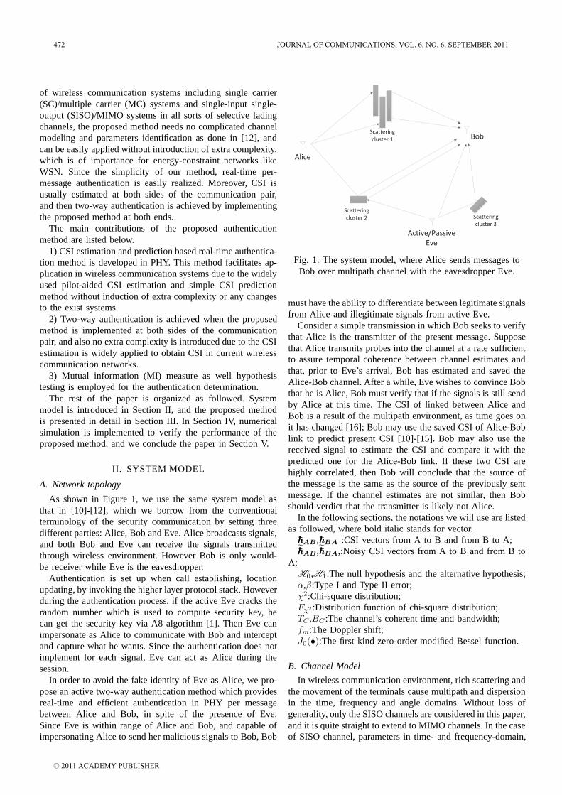
of wireless communication systems including single carrier(SC)/multiple carrier (MC) systems and single-input single-output (SISO)/MIMO systems in all sorts of selective fadingchannels, the proposed method needs no complicated channelmodeling and parameters identification as done in [12], andcan be easily applied without introduction of extra complexity,which is of importance for energy-constraint networks likeWSN. Since the simplicity of our method, real-time per-message authentication is easily realized. Moreover, CSI isusually estimated at both sides of the communication pair,and then two-way authentication is achieved by implementingthe proposed method at both ends.
The main contributions of the proposed authenticationmethod are listed below.
1) CSI estimation and prediction based real-time authentica-tion method is developed in PHY. This method facilitates ap-plication in wireless communication systems due to the widelyused pilot-aided CSI estimation and simple CSI predictionmethod without induction of extra complexity or any changesto the exist systems.
2) Two-way authentication is achieved when the proposedmethod is implemented at both sides of the communicationpair, and also no extra complexity is introduced due to the CSIestimation is widely applied to obtain CSI in current wirelesscommunication networks.
3) Mutual information (MI) measure as well hypothesistesting is employed for the authentication determination.
The rest of the paper is organized as followed. Systemmodel is introduced in Section II, and the proposed methodis presented in detail in Section III. In Section IV, numericalsimulation is implemented to verify the performance of theproposed method, and we conclude the paper in Section V.
II. SYSTEM MODEL
A. Network topology
As shown in Figure 1, we use the same system model asthat in [10]-[12], which we borrow from the conventionalterminology of the security communication by setting threedifferent parties: Alice, Bob and Eve. Alice broadcasts signals,and both Bob and Eve can receive the signals transmittedthrough wireless environment. However Bob is only would-be receiver while Eve is the eavesdropper.
Authentication is set up when call establishing, locationupdating, by invoking the higher layer protocol stack. Howeverduring the authentication process, if the active Eve cracks therandom number which is used to compute security key, hecan get the security key via A8 algorithm [1]. Then Eve canimpersonate as Alice to communicate with Bob and interceptand capture what he wants. Since the authentication does notimplement for each signal, Eve can act as Alice during thesession.
In order to avoid the fake identity of Eve as Alice, we pro-pose an active two-way authentication method which providesreal-time and efficient authentication in PHY per messagebetween Alice and Bob, in spite of the presence of Eve.Since Eve is within range of Alice and Bob, and capable ofimpersonating Alice to send her malicious signals to Bob, Bob
Alice
Bob
Active/Passive
Eve
Scattering
cluster 1
Scattering
cluster 2 Scattering
cluster 3
Fig. 1: The system model, where Alice sends messages toBob over multipath channel with the eavesdropper Eve.
must have the ability to differentiate between legitimate signalsfrom Alice and illegitimate signals from active Eve.
Consider a simple transmission in which Bob seeks to verifythat Alice is the transmitter of the present message. Supposethat Alice transmits probes into the channel at a rate sufficientto assure temporal coherence between channel estimates andthat, prior to Eve’s arrival, Bob has estimated and saved theAlice-Bob channel. After a while, Eve wishes to convince Bobthat he is Alice, Bob must verify that if the signals is still sendby Alice at this time. The CSI of linked between Alice andBob is a result of the multipath environment, as time goes onit has changed [16]; Bob may use the saved CSI of Alice-Boblink to predict present CSI [10]-[15]. Bob may also use thereceived signal to estimate the CSI and compare it with thepredicted one for the Alice-Bob link. If these two CSI arehighly correlated, then Bob will conclude that the source ofthe message is the same as the source of the previously sentmessage. If the channel estimates are not similar, then Bobshould verdict that the transmitter is likely not Alice.
In the following sections, the notations we will use are listedas followed, where bold italic stands for vector.AB ,BA :CSI vectors from A to B and from B to A;AB ,BA,:Noisy CSI vectors from A to B and from B to
A;H0,H1:The null hypothesis and the alternative hypothesis;α,β:Type I and Type II error;χ2:Chi-square distribution;Fχ2 :Distribution function of chi-square distribution;TC ,BC :The channel’s coherent time and bandwidth;fm:The Doppler shift;J0(•):The first kind zero-order modified Bessel function.
B. Channel Model
In wireless communication environment, rich scattering andthe movement of the terminals cause multipath and dispersionin the time, frequency and angle domains. Without loss ofgenerality, only the SISO channels are considered in this paper,and it is quite straight to extend to MIMO channels. In the caseof SISO channel, parameters in time- and frequency-domain,
472 JOURNAL OF COMMUNICATIONS, VOL. 6, NO. 6, SEPTEMBER 2011
© 2011 ACADEMY PUBLISHER
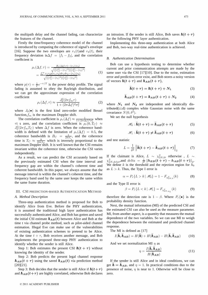
the multipath delay and the channel fading, can characterizethe features of the channel.
Firstly the time/frequency coherence model of the channelis introduced by computing the coherence of signal’s envelope[16]. Suppose the two envelopes are r1(t)and r2(t), theirfrequency deviation is∆f = |f1 − f2|, and the correlationcoefficient is
ρr(∆f, τ) = Rr(∆f,τ)−〈r1〉〈r2〉√[〈r21〉−〈r1〉
2][〈r22〉−〈r2〉2]
=∫
∞
0r1r2p(r1,r2)dr1dr2−〈r1〉〈r2〉√[〈r21〉−〈r1〉
2][〈r22〉−〈r2〉2]
(1)
where p(τ) = 1T e
−τ/T is the power delay profile. The signalfading is assumed to obey the Rayleigh distribution, andwe can get the approximate expression of the correlationcoefficient
ρr(∆f, τ) ≈J20 (2πfmτ)
1 + (2π∆f)2σ2τ
(2)
where J0(•) is the first kind zero-order modified Besselfunction,fm is the maximum Doppler shift.
The correlation coefficient is ρr(∆f) ≈ 11+(2π∆f)2σ2
τwhen
τ i s zero, and the correlation coefficient is ρr(0, TC) ≈J20 (2πfmTC) when ∆f is zero. When the coherence band-
width is defined with the limitation of ρr(∆f) = 0.5, thecoherence bandwidth is BC = 1
2πστ, and the coherence
time is TC ≈ 916πfm
which is inversely proportional to themaximum Doppler shift. It is well known that the CSI remainsinvariant within the coherence time, otherwise the CSI variesindependently.
As a result, we can predict the CSI accurately based onthe previously estimated CSI when the time interval andfrequency gap are within the channel’s coherent time andcoherent bandwidth. In this paper, we always assume that themessage interval is within the channel’s coherent time, and thefrequency band used by the same user keeps the same withinthe same frame duration.
III. CSI PREDICTION-BASED AUTHENTICATION METHOD
A. Method Description
Three-step authentication method is proposed for Bob toidentify Alice from Eve. Before the PHY authentication,it is assumed the traditional high layer authentication hassuccessfully authenticated Alice, and Bob has gotten and savedthe initial CSI estimate AB(t) between Alice and Bob at thetime t via channel probe method, such as pilot-aided channelestimation. Illegal Eve can make use of the vulnerabilitiesof existing authentication schemes to pretend to be Alice.At the time t + τ , Bob receives another message, and Bobimplements the proposed three-step PHY authentication toidentify whether the sender is still Alice.
Step 1: Bob estimates the present CSI (t + τ) withoutknowing the identity of the sender.
Step 2: Bob predicts the present legal channel responseAB(t+ τ) using the saved AB(t) via prediction method[20][21].
Step 3: Bob decides that the sender is still Alice if (t+τ)and AB(t+τ) are highly correlated, otherwise Bob declares
an intrusion. If the sender is still Alice, Bob saves (t+ τ)for the following PHY layer authentication.
Implementing this three-step authentication at both Aliceand Bob, two-way real-time authentication is achieved.
B. Authentication Determination
Bob can use a hypothesis testing to determine whethercurrent and prior communication attempts are made by thesame user via the CSI [17][10]. Due to the noise, estimationerror and prediction error exist, and Bob stores a noisy versionof vectors (t+ τ) and AB(t+ τ),
(t+ τ) = (t+ τ) +N1 (3)
AB(t+ τ) = AB(t+ τ) +N2 (4)
where N1 and N2 are independent and identically dis-tributed(i.i.d) complex white Gaussian noise with the samecovariance N(0, δ2).
We set the null hypothesis
H0 : (t+ τ) = AB(t+ τ) (5)
H1 : (t+ τ) = AB(t+ τ) (6)
and test statistic
L =1
δ2
∥∥∥(t+ τ)− AB(t+ τ)∥∥∥2
(7)
If the claimant is Alice, L ∼ χ22N,0, otherwise , L ∼
χ22N,delat,and delta = 1
δ2 ‖hEB(t+ τ)− hAB(t+ τ)‖2.We define k is the threshold and the rejection region for 0
as L > k. Thus, the Type I error is
α = PrL > k | H0 = 1− Fχ2
2N,0(k) (8)
and the Type II error is
β = PrL < k | H1 = Fχ2
2N,µL
(k) (9)
therefore the detection rate is 1 − β. Where Pr• is theprobability density function.
Next, the mutual information (MI) of the predicted CSI andthe estimated CSI can also be used as the measure parameter.MI, from another aspect, is a quantity that measures the mutualdependence of the two variables. So we can use MI to weighthe dependence between the estimated and predicted channelresponse.
The MI is defined as [17]
I(, AB) = H() +H(AB)−H(, AB) (10)
And we set normalization MI η as
η =I(, AB)
H(AB)(11)
If the sender is still Alice and in ideal conditions, we canget = AB , and η = 1. In practical conditions duo to thepresence of noise, η is near to 1. Otherwise will be close tozero.
JOURNAL OF COMMUNICATIONS, VOL. 6, NO. 6, SEPTEMBER 2011 473
© 2011 ACADEMY PUBLISHER
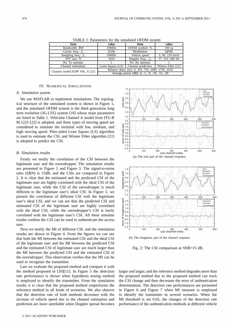
TABLE I: Parameters for the simulated OFDM systemItem value Item value
Bandwidth: BW 10MHz OFDM symbol: Ts 100 usCarrier freq.: fc 2GHz Modulation QPSK
Sampling freq.: fs 10MHz Vehicle speed 3, 60, 120 km/hFFT size: N 1024 Doppler freq.: fd 17, 333, 666 Hz
No. Tx antenna: 1 No. Rx antenna: 1Channel estimation: Least Square (LS) Channel prediction: Winner Filter [21]
Channel model:3GPP Veh. A [22] Relative delay (ns): 0, 310, 710, 1090, 1730, 2510Average power (dB): 0, -1, -9, -10, -15, -20
IV. NUMERICAL SIMULATIONS
A. Simulation system
We use MATLAB to implement simulations. The topolog-ical structure of the simulated system is shown in Figure 1,and the simulated OFDM system is the third generation longterm evolution (3G-LTE) system [18] whose main parametersare listed in Table 1. Vehicular Channel A model from ITU-RM.1225 [22] is adopted, and three types of moving speed areconsidered to simulate the terminal with low, medium, andhigh moving speed. Pilot-aided Least Square (LS) algorithmis used to estimate the CSI, and Winner Filter algorithm [21]is adopted to predict the CSI.
B. Simulation results
Firstly we testify the correlation of the CSI between thelegitimate user and the eavesdropper. The simulation resultsare presented in Figure 2 and Figure 3. The signal-to-noiseratio (SRN) is 15dB, and the CSIs are compared in Figure2. It is clear that the estimated and the predicted CSI of thelegitimate user are highly correlated with the ideal CSI of thelegitimate user, while the CSI of the eavesdropper is muchdifferent to the legitimate user’s ideal CSI. In Figure 3, wepresent the correlation of different CSI with the legitimateuser’s ideal CSI, and we can see that the predicted CSI andestimated CSI of the legitimate user are highly correlatedwith the ideal CSI, while the eavesdropper’s CSI is lowlycorrelated with the legitimate user’s CSI. All these simulateresults confirm the CSI can be used to authenticate the accessuser.
Next we testify the MI of different CSI, and the simulationresults are shown in Figure 4. From the figures we can seethat both the MI between the estimated CSI and the ideal CSIof the legitimate user and the MI between the predicted CSIand the estimated CSI of legitimate user are much larger thanthe MI between the predicted CSI and the estimated CSI ofthe eavesdropper. This observation verifies that the MI can beused to recognize the transmitter.
Last we evaluate the proposed method and compare it withthe method proposed in [10][11]. In Figure 5 the detectionrate performance is shown when hypothesis testing methodis employed to identify the transmitter. From the simulationresults it is clear that the proposed method outperforms thereference method in all kinds of scenarios. We also observethat the detection rate of both methods decreases with theincrease of vehicle speed due to the channel estimation andprediction are more unreliable when Doppler spread becomes
0 100 200 300 400 500 600-2.0
-1.5
-1.0
-0.5
0.0
0.5
1.0
1.5
2.0
2.50 100 200 300 400 500 600
-1.5
-1.0
-0.5
0.0
0.5
1.0
1.5
Estimation
Prediction
Eavesdropper
err
or
of re
al p
art
sub channel index
Ideal
Estimation
Prediction
Eavesdropper
rea
l p
art
(a) The real part of the channel response.
0 100 200 300 400 500 600-1.5
-1.0
-0.5
0.0
0.5
1.0
1.5
2.0
0 100 200 300 400 500 600-1.5
-1.0
-0.5
0.0
0.5
1.0
1.5
Estimation
Prediction
Eavesdropper
err
or
of im
ag
ina
ry p
art
sub channel index
ima
gin
ary
pa
rt
Ideal
Estimation
Rrediction
Eavesdropper
(b) The imaginary part of the channel response.
Fig. 2: The CSI comparison at SNR=15 dB.
larger and larger, and the reference method degrades more thanthe proposed method due to the proposed method can trackthe CSI change and then decreases the error of authenticationdetermination. The detection rate performances are presentedin Figure 6 and Figure 7 when MI measure is employedto identify the transmitter in several scenarios. When theMI threshold is set 0.65, the changes of the detection rateperformance of the authentication methods at different vehicle
474 JOURNAL OF COMMUNICATIONS, VOL. 6, NO. 6, SEPTEMBER 2011
© 2011 ACADEMY PUBLISHER
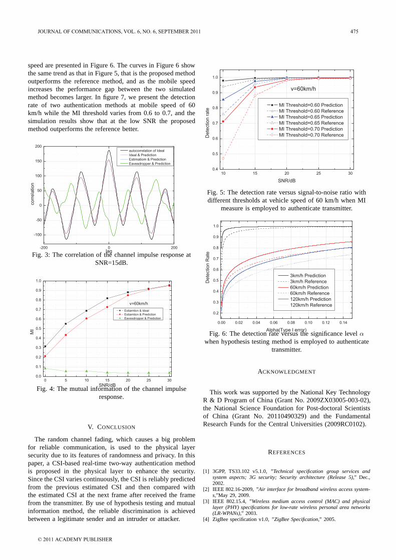
speed are presented in Figure 6. The curves in Figure 6 showthe same trend as that in Figure 5, that is the proposed methodoutperforms the reference method, and as the mobile speedincreases the performance gap between the two simulatedmethod becomes larger. In figure 7, we present the detectionrate of two authentication methods at mobile speed of 60km/h while the MI threshold varies from 0.6 to 0.7, and thesimulation results show that at the low SNR the proposedmethod outperforms the reference better.
-200 0 200
-100
-50
0
50
100
150
200
corr
ela
tion
lag
autocorrelation of Ideal
Ideal & Prediction
Estimatiom & Prediction
Eavesdropper & Prediction
Fig. 3: The correlation of the channel impulse response atSNR=15dB.
0 5 10 15 20 25 300.0
0.1
0.2
0.3
0.4
0.5
0.6
0.7
0.8
0.9
1.0
MI
SNR/dB
Estiamtion & Ideal
Estiamtion & Prediction
Eavesdropper & Prediction
v=60km/h
Fig. 4: The mutual information of the channel impulseresponse.
V. CONCLUSION
The random channel fading, which causes a big problemfor reliable communication, is used to the physical layersecurity due to its features of randomness and privacy. In thispaper, a CSI-based real-time two-way authentication methodis proposed in the physical layer to enhance the security.Since the CSI varies continuously, the CSI is reliably predictedfrom the previous estimated CSI and then compared withthe estimated CSI at the next frame after received the framefrom the transmitter. By use of hypothesis testing and mutualinformation method, the reliable discrimination is achievedbetween a legitimate sender and an intruder or attacker.
10 15 20 25 300.4
0.5
0.6
0.7
0.8
0.9
1.0
v=60km/h
Dete
ction r
ate
SNR/dB
MI Threshold=0.60 Prediction
MI Threshold=0.60 Reference
MI Threshold=0.65 Prediction
MI Threshold=0.65 Reference
MI Threshold=0.70 Prediction
MI Threshold=0.70 Reference
Fig. 5: The detection rate versus signal-to-noise ratio withdifferent thresholds at vehicle speed of 60 km/h when MI
measure is employed to authenticate transmitter.
0.00 0.02 0.04 0.06 0.08 0.10 0.12 0.14
0.2
0.3
0.4
0.5
0.6
0.7
0.8
0.9
1.0
De
tectio
n R
ate
Alpha(Type I error)
3km/h Prediction
3km/h Reference
60km/h Prediction
60km/h Reference
120km/h Prediction
120km/h Reference
Fig. 6: The detection rate versus the significance level αwhen hypothesis testing method is employed to authenticate
transmitter.
ACKNOWLEDGMENT
This work was supported by the National Key TechnologyR & D Program of China (Grant No. 2009ZX03005-003-02),the National Science Foundation for Post-doctoral Scientistsof China (Grant No. 20110490329) and the FundamentalResearch Funds for the Central Universities (2009RC0102).
REFERENCES
[1] 3GPP, TS33.102 v5.1.0, ”Technical specification group services andsystem aspects; 3G security; Security architecture (Release 5),” Dec.,2002.
[2] IEEE 802.16-2009, ”Air interface for broadband wireless access system-s,”May 29, 2009.
[3] IEEE 802.15.4, ”Wireless medium access control (MAC) and physicallayer (PHY) specifications for low-rate wireless personal area networks(LR-WPANs),” 2003.
[4] ZigBee specification v1.0, ”ZigBee Specification,” 2005.
JOURNAL OF COMMUNICATIONS, VOL. 6, NO. 6, SEPTEMBER 2011 475
© 2011 ACADEMY PUBLISHER
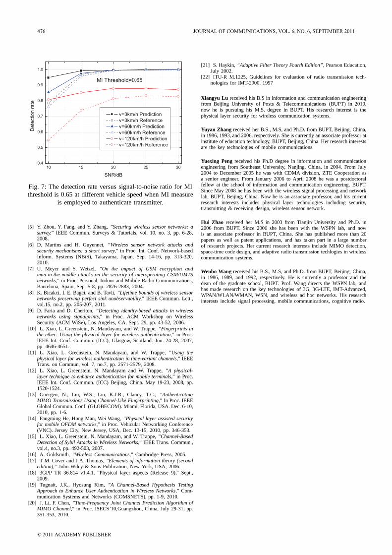
10 15 20 25 300.4
0.5
0.6
0.7
0.8
0.9
1.0
MI Threshold=0.65
De
tectio
n r
ate
SNR/dB
v=3km/h Prediction
v=3km/h Reference
v=60km/h Prediction
v=60km/h Reference
v=120km/h Prediction
v=120km/h Reference
Fig. 7: The detection rate versus signal-to-noise ratio for MIthreshold is 0.65 at different vehicle speed when MI measure
is employed to authenticate transmitter.
[5] Y. Zhou, Y. Fang, and Y. Zhang, ”Securing wireless sensor networks: asurvey,” IEEE Commun. Surveys & Tutorials, vol. 10, no. 3, pp. 6-28,2008.
[6] D. Martins and H. Guyennet, ”Wireless sensor network attacks andsecurity mechanisms: a short survey,” in Proc. Int. Conf. Network-basedInform. Systems (NBiS), Takayama, Japan, Sep. 14-16, pp. 313-320,2010.
[7] U. Meyer and S. Wetzel, ”On the impact of GSM encryption andman-in-the-middle attacks on the security of interoperating GSM/UMTSnetworks,” in Proc. Personal, Indoor and Mobile Radio Communications,Barcelona, Spain, Sep. 5-8, pp. 2876-2883, 2004.
[8] K. Bicakci, I. E. Bagci, and B. Tavli, ”Lifetime bounds of wireless sensornetworks preserving perfect sink unobservability,” IEEE Commun. Lett.,vol.15, no.2, pp. 205-207, 2011.
[9] D. Faria and D. Cheriton, ”Detecting identity-based attacks in wirelessnetworks using signalprints,” in Proc. ACM Workshop on WirelessSecurity (ACM WiSe), Los Angeles, CA, Sept. 29, pp. 43-52, 2006.
[10] L. Xiao, L. Greenstein, N. Mandayam, and W. Trappe, ”Fingerprints inthe ether: Using the physical layer for wireless authentication,” in Proc.IEEE Int. Conf. Commun. (ICC), Glasgow, Scotland. Jun. 24-28, 2007,pp. 4646-4651.
[11] L. Xiao, L. Greenstein, N. Mandayam, and W. Trappe, ”Using thephysical layer for wireless authentication in time-variant channels,” IEEETrans. on Commun, vol. 7, no.7, pp. 2571-2579, 2008.
[12] L. Xiao, L. Greenstein, N. Mandayam and W. Trappe, ”A physical-layer technique to enhance authentication for mobile terminals,” in Proc.IEEE Int. Conf. Commun. (ICC) Beijing, China. May 19-23, 2008, pp.1520-1524.
[13] Goergen, N., Lin, W.S., Liu, K.J.R., Clancy, T.C., ”AuthenticatingMIMO Transmissions Using Channel-Like Fingerprinting,” In Proc. IEEEGlobal Commun. Conf. (GLOBECOM). Miami, Florida, USA. Dec. 6-10,2010, pp. 1-6.
[14] Fangming He, Hong Man, Wei Wang, ”Physical layer assisted securityfor mobile OFDM networks,” in Proc. Vehicular Networking Conference(VNC). Jersey City, New Jersey, USA, Dec. 13-15, 2010, pp. 346-353.
[15] L. Xiao, L. Greenstein, N. Mandayam, and W. Trappe, ”Channel-BasedDetection of Sybil Attacks in Wireless Networks,” IEEE Trans. Commun.,vol.4, no.3, pp. 492-503, 2007.
[16] A. Goldsmith, ”Wireless Communications,” Cambridge Press, 2005.[17] T M. Cover and J A. Thomas, ”Elements of information theory (second
edition),” John Wiley & Sons Publication, New York, USA, 2006.[18] 3GPP TR 36.814 v1.4.1, ”Physical layer aspects (Release 9),” Sept.,
2009.[19] Tugnait, J.K., Hyosung Kim, ”A Channel-Based Hypothesis Testing
Approach to Enhance User Authentication in Wireless Networks,” Com-munication Systems and Networks (COMSNETS), pp. 1-9, 2010.
[20] J. Li, F. Chen, ”Time-Frequency Joint Channel Prediction Algorithm ofMIMO Channel,” in Proc. ISECS’10,Guangzhou, China, July 29-31, pp.351-353, 2010.
[21] S. Haykin, ”Adaptive Filter Theory Fourth Edition”, Pearson Education,July 2002.
[22] ITU-R M.1225, Guidelines for evaluation of radio transmission tech-nologies for IMT-2000, 1997
Xiangyu Lu received his B.S in information and communication engineeringfrom Beijing University of Posts & Telecommunications (BUPT) in 2010,now he is pursuing his M.S. degree in BUPT. His research interest is thephysical layer security for wireless communication systems.
Yuyan Zhang received her B.S., M.S, and Ph.D. from BUPT, Beijing, China,in 1986, 1993, and 2006, respectively. She is currently an associate professor atinstitute of education technology, BUPT, Beijing, China. Her research interestsare the key technologies of mobile communications.
Yuexing Peng received his Ph.D degree in information and communicationengineering from Southeast University, Nanjing, China, in 2004. From July2004 to December 2005 he was with CDMA division, ZTE Cooperation asa senior engineer. From January 2006 to April 2008 he was a postdoctoralfellow at the school of information and communication engineering, BUPT.Since May 2008 he has been with the wireless signal processing and networklab, BUPT, Beijing, China. Now he is an associate professor, and his currentresearch interests includes physical layer technologies including security,transmitting & receiving design, wireless sensor network.
Hui Zhao received her M.S in 2003 from Tianjin University and Ph.D. in2006 from BUPT. Since 2006 she has been with the WSPN lab, and nowis an associate professor in BUPT, China. She has published more than 20papers as well as patent applications, and has taken part in a large numberof research projects. Her current research interests include MIMO detection,space-time code design, and adaptive radio transmission techlogies in wirelesscommunication systems.
Wenbo Wang received his B.S., M.S, and Ph.D. from BUPT, Beijing, China,in 1986, 1989, and 1992, respectively. He is currently a professor and thedean of the graduate school, BUPT. Prof. Wang directs the WSPN lab, andhas made research on the key technologies of 3G, 3G-LTE, IMT-Advanced,WPAN/WLAN/WMAN, WSN, and wireless ad hoc networks. His researchinterests include signal processing, mobile communications, cognitive radio.
476 JOURNAL OF COMMUNICATIONS, VOL. 6, NO. 6, SEPTEMBER 2011
© 2011 ACADEMY PUBLISHER
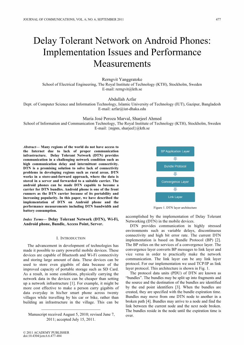
Delay Tolerant Network on Android Phones: Implementation Issues and Performance
Measurements
Rerngvit Yanggratoke School of Electrical Engineering, The Royal Institute of Technology (KTH), Stockholm, Sweden
E-mail: [email protected]
Abdullah Azfar Dept. of Computer Science and Information Technology, Islamic University of Technology (IUT), Gazipur, Bangladesh
E-mail: [email protected]
María José Peroza Marval, Sharjeel Ahmed School of Information and Communication Technology, The Royal Institute of Technology (KTH), Stockholm, Sweden
E-mail: mjpm, [email protected]
Abstract— Many regions of the world do not have access to the Internet due to lack of proper communication infrastructure. Delay Tolerant Network (DTN) provides communication in a challenging network condition such as high communication delay and intermittent connectivity. DTN is a promising solution to solve lack of connectivity problems in developing regions such as rural areas. DTN works in a store-and-forward approach, where the data is stored in a server and forwarded to a suitable carrier. The android phones can be made DTN capable to become a carrier for DTN bundles. Android phone is one of the front runners as the DTN carrier because of its portability and increasing popularity. In this paper, we have described the implementation of DTN on Android phone and the performance measurements including DTN bandwidth and battery consumption. Index Terms— Delay Tolerant Network (DTN), Wi-Fi, Android phone, Bundle, Access Point, Server.
I. INTRODUCTION
The advancement in development of technologies has made it possible to carry powerful mobile devices. These devices are capable of Bluetooth and Wi-Fi connectivity and storing large amount of data. These devices can be used to store even gigabits of data because of the improved capacity of portable storage such as SD Card. As a result, in some conditions, physically carrying the network data in the devices can be cheaper than setting up a network infrastructure [1]. For example, it might be more cost effective to make a person carry gigabits of data everyday in his/her smart phone across twenty villages while travelling by his car or bike, rather than building an infrastructure in the village. This can be
Manuscript received August 5, 2010; revised June 7,
2011; accepted July 15, 2011.
accomplished by the implementation of Delay Tolerant Networking (DTN) in the mobile devices.
DTN provides communication in highly stressed environments such as variable delays, discontinuous connectivity and high bit error rate. The current DTN implementation is based on Bundle Protocol (BP) [2]. The BP relies on the services of a convergence layer. The convergence layer converts BP messages to link layer and vice versa in order to practically make the network communication. The link layer can be any link layer protocol. For our implementation we used TCP/IP as link layer protocol. This architecture is shown in Fig. 1.
The protocol data units (PDU) of DTN are known as “bundles”. The bundles may be split up into fragments and the source and the destination of the bundles are identified by the end point identifiers [3]. When the bundles are created, they are specified with the bundle expiration time. Bundles may move from one DTN node to another in a broken path [4]. Bundles may arrive to a node and find the link between the current node and the next node broken. The bundles reside in the node until the expiration time is over.
Figure 1. DTN layer architecture
JOURNAL OF COMMUNICATIONS, VOL. 6, NO. 6, SEPTEMBER 2011 477
© 2011 ACADEMY PUBLISHERdoi:10.4304/jcm.6.6.477-484
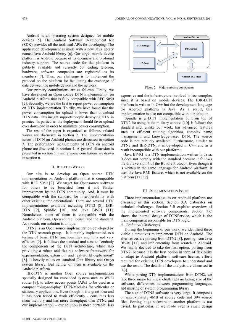
Android is an operating system designed for mobile devices [5]. The Android Software Development Kit (SDK) provides all the tools and APIs for developing. The application development is made with a new Java library named Java Android library [6]. Our target mobile device platform is Android because of its openness and profound industry support. The source code for the platform is publicly available and currently 50 leading telecom, hardware, software companies are registered as its members [7]. Thus, our challenge is to implement the protocol on the platform for facilitating the exchange of data between the mobile device and the network.
Our primary contributions are as follows. Firstly, we have developed an Open source DTN implementation on Android platform that is fully compatible with RFC 5050 [2]. Secondly, we are the first to report power consumption on DTN implementation. Thirdly, we have found that the power consumption for upload is lower than download DTN data. This insight supports people deploying DTN in practice. In particular, the deployment should favor upload over download in order to minimize power consumption.
The rest of the paper is organized as follows: related works are discussed in section 2. The implementation issues of DTN on Android phones are discussed in section 3. The performance measurements of DTN on android phone are discussed in section 4. A general discussion is presented in section 5. Finally, some conclusions are drawn in section 6.
II. RELATED WORKS
Our aim is to develop an Open source DTN implementation on Android platform that is compatible with RFC 5050 [2]. We target for Opensource software for others to be benefited from it and further improvement by the DTN community. And, it must be compatible with the standard for interoperability with other existing implementations. There are several DTN implementations available including DTN2 [8], IBR-DTN [9], Spindle [10], and Java BP-RI [11]. Nonetheless, none of them is compatible with the Android platform, Open source license, and the standard. As a result, our solution is unique.
DTN2 is an Open source implementation developed by the DTN research group. It is mainly implemented as a testing of basic DTN functionalities and it is not very efficient [9]. It follows the standard and aims to “embody the components of the DTN architecture, while also providing a robust and flexible software framework for experimentation, extension, and real-world deployment” [8]. It heavily relies on standard C++ library and Oasys system library. But neither of them is available on the Android platform.
IBR-DTN is another Open source implementation specially designed for embedded system such as Wi-Fi router [9], to allow access points (APs) to be used as a compact “plug-and-play” DTN-Modules for vehicular or stationary applications. Even though it is a great idea and it has been tested to work efficiently - consumes less main memory and has more throughput than DTN2 and our implementation – our solution is more portable, less
expensive and the infrastructure involved is less complex since it is based on mobile devices. The IBR-DTN platform is written in C++ but the development language for Android platform is Java. As a result, this implementation is also not compatible with our solution.
Spindle is a DTN implementation built on top of DTN2 for using in the military context [10]. It follows the standard and, unlike our work, has advanced features such as efficient routing algorithm, complex name management, and knowledge-based DTN. The source code is not publicly available. Furthermore, similar to DTN2 and IBR-DTN, it is developed in C++ and as a result incompatible with our platform.
Java BP-RI is a DTN implementation written in Java. It does not comply with the standard because it follows the draft version 4 of the Bundle Protocol. Even though it is written in the same language for Android platform, it uses the Java-RMI feature, which is not available on the platform [11][12].
III. IMPLEMENTATION ISSUES
Three implementation issues on Android platform are discussed in this section. Section 3.A elaborates on technical challenges. Section 3.B explains overview of the implemented software components. Section 3.C shows the internal design of DTNService, which is the main component responsible for DTN logic. A. Technical Challenges
During the beginning of our work, we identified three viable alternatives to implement DTN on Android. The alternatives are porting from DTN2 [8], porting from Java BP-RI [11], and implementing from scratch in Android. We finally decided to take the first option, porting from DTN2, because it is the best option in term of flexibility to adapt to Android platform, software license, efforts required for existing DTN developers to understand and use the result. The details of the analysis are discussed in [13].
While porting DTN implementations from DTN2, we face three major technical challenges including size of the software, differences between programming languages, and missing of system programming library.
The size of DTN2 software is very large. It composes of approximately 4MB of source code and 394 source files. Porting huge software to another platform is not trivial. In particular, if we made even a small design
Figure 2. Major software components
478 JOURNAL OF COMMUNICATIONS, VOL. 6, NO. 6, SEPTEMBER 2011
© 2011 ACADEMY PUBLISHER
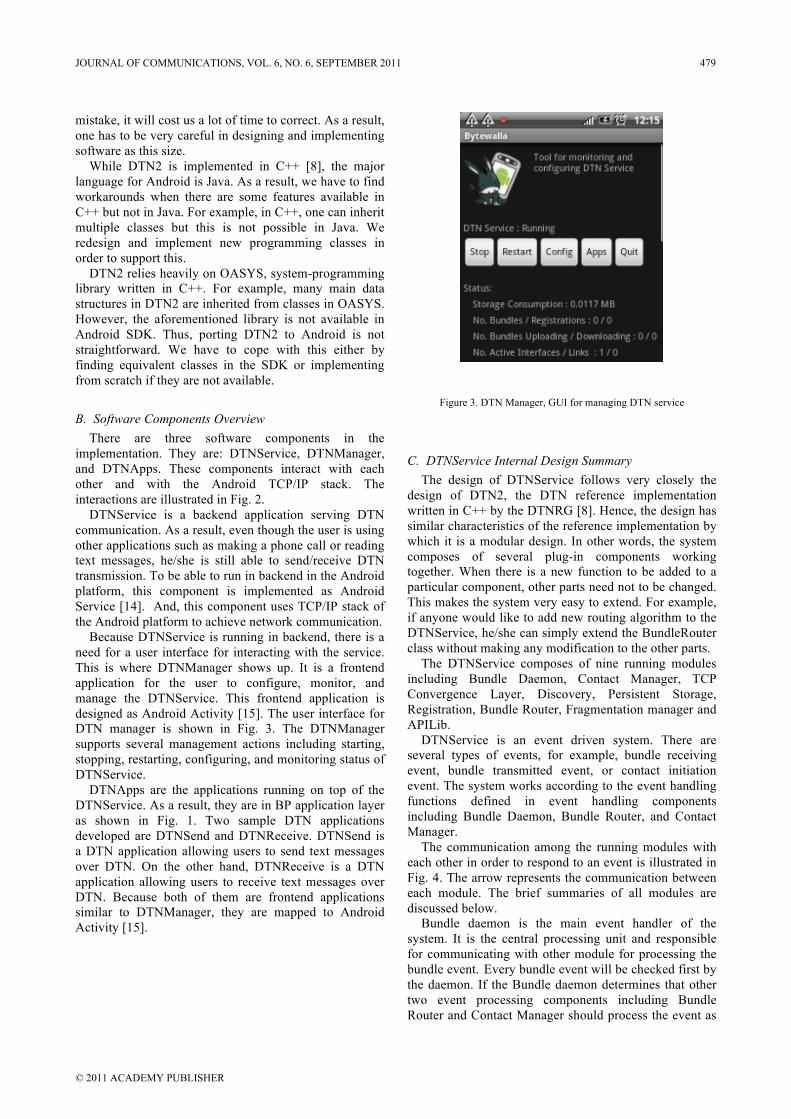
mistake, it will cost us a lot of time to correct. As a result, one has to be very careful in designing and implementing software as this size.
While DTN2 is implemented in C++ [8], the major language for Android is Java. As a result, we have to find workarounds when there are some features available in C++ but not in Java. For example, in C++, one can inherit multiple classes but this is not possible in Java. We redesign and implement new programming classes in order to support this.
DTN2 relies heavily on OASYS, system-programming library written in C++. For example, many main data structures in DTN2 are inherited from classes in OASYS. However, the aforementioned library is not available in Android SDK. Thus, porting DTN2 to Android is not straightforward. We have to cope with this either by finding equivalent classes in the SDK or implementing from scratch if they are not available.
B. Software Components Overview There are three software components in the
implementation. They are: DTNService, DTNManager, and DTNApps. These components interact with each other and with the Android TCP/IP stack. The interactions are illustrated in Fig. 2.
DTNService is a backend application serving DTN communication. As a result, even though the user is using other applications such as making a phone call or reading text messages, he/she is still able to send/receive DTN transmission. To be able to run in backend in the Android platform, this component is implemented as Android Service [14]. And, this component uses TCP/IP stack of the Android platform to achieve network communication.
Because DTNService is running in backend, there is a need for a user interface for interacting with the service. This is where DTNManager shows up. It is a frontend application for the user to configure, monitor, and manage the DTNService. This frontend application is designed as Android Activity [15]. The user interface for DTN manager is shown in Fig. 3. The DTNManager supports several management actions including starting, stopping, restarting, configuring, and monitoring status of DTNService.
DTNApps are the applications running on top of the DTNService. As a result, they are in BP application layer as shown in Fig. 1. Two sample DTN applications developed are DTNSend and DTNReceive. DTNSend is a DTN application allowing users to send text messages over DTN. On the other hand, DTNReceive is a DTN application allowing users to receive text messages over DTN. Because both of them are frontend applications similar to DTNManager, they are mapped to Android Activity [15].
Figure 3. DTN Manager, GUI for managing DTN service
C. DTNService Internal Design Summary The design of DTNService follows very closely the
design of DTN2, the DTN reference implementation written in C++ by the DTNRG [8]. Hence, the design has similar characteristics of the reference implementation by which it is a modular design. In other words, the system composes of several plug-in components working together. When there is a new function to be added to a particular component, other parts need not to be changed. This makes the system very easy to extend. For example, if anyone would like to add new routing algorithm to the DTNService, he/she can simply extend the BundleRouter class without making any modification to the other parts.
The DTNService composes of nine running modules including Bundle Daemon, Contact Manager, TCP Convergence Layer, Discovery, Persistent Storage, Registration, Bundle Router, Fragmentation manager and APILib.
DTNService is an event driven system. There are several types of events, for example, bundle receiving event, bundle transmitted event, or contact initiation event. The system works according to the event handling functions defined in event handling components including Bundle Daemon, Bundle Router, and Contact Manager.
The communication among the running modules with each other in order to respond to an event is illustrated in Fig. 4. The arrow represents the communication between each module. The brief summaries of all modules are discussed below.
Bundle daemon is the main event handler of the system. It is the central processing unit and responsible for communicating with other module for processing the bundle event. Every bundle event will be checked first by the daemon. If the Bundle daemon determines that other two event processing components including Bundle Router and Contact Manager should process the event as
JOURNAL OF COMMUNICATIONS, VOL. 6, NO. 6, SEPTEMBER 2011 479
© 2011 ACADEMY PUBLISHER
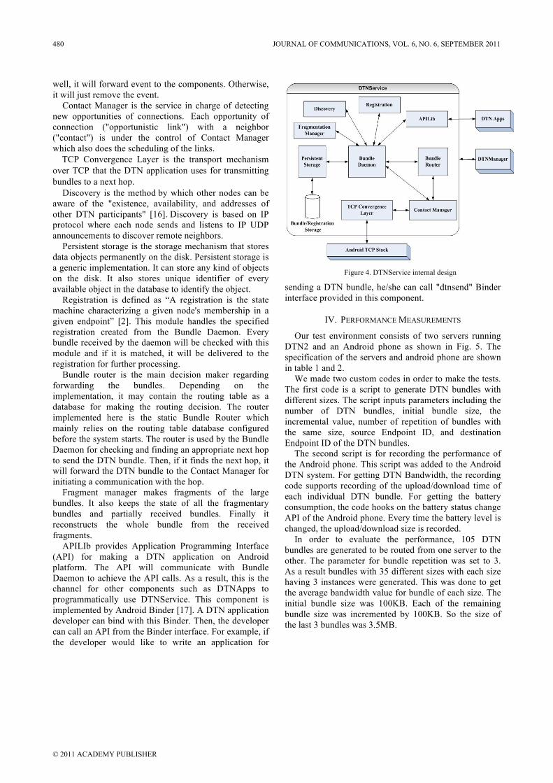
well, it will forward event to the components. Otherwise, it will just remove the event.
Contact Manager is the service in charge of detecting new opportunities of connections. Each opportunity of connection ("opportunistic link") with a neighbor ("contact") is under the control of Contact Manager which also does the scheduling of the links.
TCP Convergence Layer is the transport mechanism over TCP that the DTN application uses for transmitting bundles to a next hop.
Discovery is the method by which other nodes can be aware of the "existence, availability, and addresses of other DTN participants" [16]. Discovery is based on IP protocol where each node sends and listens to IP UDP announcements to discover remote neighbors.
Persistent storage is the storage mechanism that stores data objects permanently on the disk. Persistent storage is a generic implementation. It can store any kind of objects on the disk. It also stores unique identifier of every available object in the database to identify the object.
Registration is defined as “A registration is the state machine characterizing a given node's membership in a given endpoint” [2]. This module handles the specified registration created from the Bundle Daemon. Every bundle received by the daemon will be checked with this module and if it is matched, it will be delivered to the registration for further processing.
Bundle router is the main decision maker regarding forwarding the bundles. Depending on the implementation, it may contain the routing table as a database for making the routing decision. The router implemented here is the static Bundle Router which mainly relies on the routing table database configured before the system starts. The router is used by the Bundle Daemon for checking and finding an appropriate next hop to send the DTN bundle. Then, if it finds the next hop, it will forward the DTN bundle to the Contact Manager for initiating a communication with the hop.
Fragment manager makes fragments of the large bundles. It also keeps the state of all the fragmentary bundles and partially received bundles. Finally it reconstructs the whole bundle from the received fragments.
APILIb provides Application Programming Interface (API) for making a DTN application on Android platform. The API will communicate with Bundle Daemon to achieve the API calls. As a result, this is the channel for other components such as DTNApps to programmatically use DTNService. This component is implemented by Android Binder [17]. A DTN application developer can bind with this Binder. Then, the developer can call an API from the Binder interface. For example, if the developer would like to write an application for
sending a DTN bundle, he/she can call "dtnsend" Binder interface provided in this component.
IV. PERFORMANCE MEASUREMENTS
Our test environment consists of two servers running DTN2 and an Android phone as shown in Fig. 5. The specification of the servers and android phone are shown in table 1 and 2.
We made two custom codes in order to make the tests. The first code is a script to generate DTN bundles with different sizes. The script inputs parameters including the number of DTN bundles, initial bundle size, the incremental value, number of repetition of bundles with the same size, source Endpoint ID, and destination Endpoint ID of the DTN bundles.
The second script is for recording the performance of the Android phone. This script was added to the Android DTN system. For getting DTN Bandwidth, the recording code supports recording of the upload/download time of each individual DTN bundle. For getting the battery consumption, the code hooks on the battery status change API of the Android phone. Every time the battery level is changed, the upload/download size is recorded.
In order to evaluate the performance, 105 DTN bundles are generated to be routed from one server to the other. The parameter for bundle repetition was set to 3. As a result bundles with 35 different sizes with each size having 3 instances were generated. This was done to get the average bandwidth value for bundle of each size. The initial bundle size was 100KB. Each of the remaining bundle size was incremented by 100KB. So the size of the last 3 bundles was 3.5MB.
Figure 4. DTNService internal design
Figure 2. Major software components
480 JOURNAL OF COMMUNICATIONS, VOL. 6, NO. 6, SEPTEMBER 2011
© 2011 ACADEMY PUBLISHER
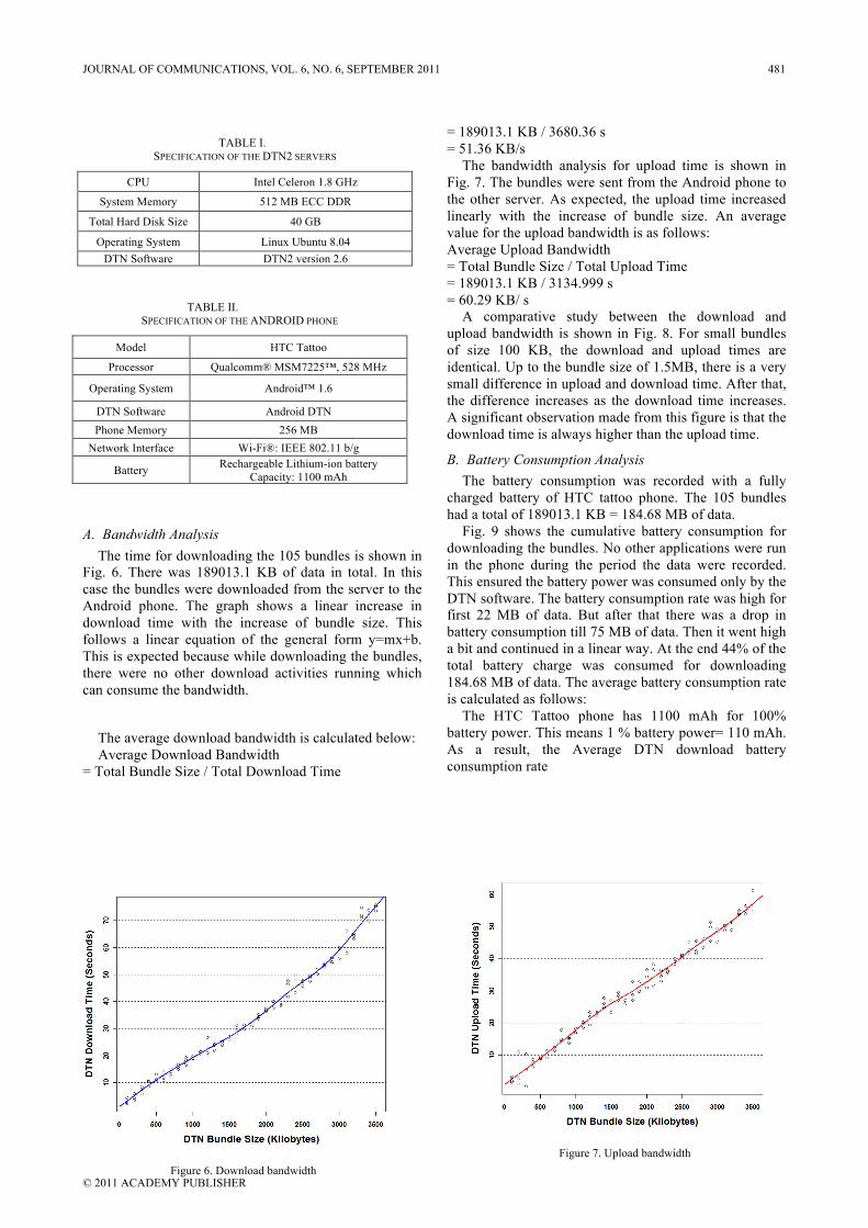
A. Bandwidth Analysis The time for downloading the 105 bundles is shown in
Fig. 6. There was 189013.1 KB of data in total. In this case the bundles were downloaded from the server to the Android phone. The graph shows a linear increase in download time with the increase of bundle size. This follows a linear equation of the general form y=mx+b. This is expected because while downloading the bundles, there were no other download activities running which can consume the bandwidth.
The average download bandwidth is calculated below: Average Download Bandwidth
= Total Bundle Size / Total Download Time
= 189013.1 KB / 3680.36 s = 51.36 KB/s
The bandwidth analysis for upload time is shown in Fig. 7. The bundles were sent from the Android phone to the other server. As expected, the upload time increased linearly with the increase of bundle size. An average value for the upload bandwidth is as follows: Average Upload Bandwidth = Total Bundle Size / Total Upload Time = 189013.1 KB / 3134.999 s = 60.29 KB/ s
A comparative study between the download and upload bandwidth is shown in Fig. 8. For small bundles of size 100 KB, the download and upload times are identical. Up to the bundle size of 1.5MB, there is a very small difference in upload and download time. After that, the difference increases as the download time increases. A significant observation made from this figure is that the download time is always higher than the upload time.
B. Battery Consumption Analysis The battery consumption was recorded with a fully
charged battery of HTC tattoo phone. The 105 bundles had a total of 189013.1 KB = 184.68 MB of data.
Fig. 9 shows the cumulative battery consumption for downloading the bundles. No other applications were run in the phone during the period the data were recorded. This ensured the battery power was consumed only by the DTN software. The battery consumption rate was high for first 22 MB of data. But after that there was a drop in battery consumption till 75 MB of data. Then it went high a bit and continued in a linear way. At the end 44% of the total battery charge was consumed for downloading 184.68 MB of data. The average battery consumption rate is calculated as follows:
The HTC Tattoo phone has 1100 mAh for 100% battery power. This means 1 % battery power= 110 mAh. As a result, the Average DTN download battery consumption rate
Figure 7. Upload bandwidth
Figure 2. Major software components
Figure 6. Download bandwidth
Figure 2. Major software components
TABLE I. SPECIFICATION OF THE DTN2 SERVERS
CPU Intel Celeron 1.8 GHz
System Memory 512 MB ECC DDR
Total Hard Disk Size 40 GB
Operating System Linux Ubuntu 8.04 DTN Software DTN2 version 2.6
TABLE II. SPECIFICATION OF THE ANDROID PHONE
Model HTC Tattoo
Processor Qualcomm® MSM7225™, 528 MHz
Operating System Android™ 1.6
DTN Software Android DTN Phone Memory 256 MB
Network Interface Wi-Fi®: IEEE 802.11 b/g
Battery Rechargeable Lithium-ion battery Capacity: 1100 mAh
JOURNAL OF COMMUNICATIONS, VOL. 6, NO. 6, SEPTEMBER 2011 481
© 2011 ACADEMY PUBLISHER
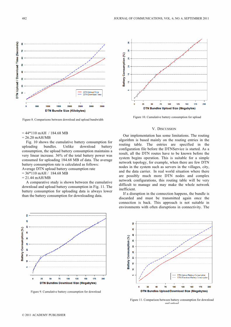
= 44*110 mAH / 184.68 MB = 26.20 mAH/MB
Fig. 10 shows the cumulative battery consumption for uploading bundles. Unlike download battery consumption, the upload battery consumption maintains a very linear increase. 36% of the total battery power was consumed for uploading 184.68 MB of data. The average battery consumption rate is calculated as follows: Average DTN upload battery consumption rate = 36*110 mAH / 184.68 MB = 21.44 mAH/MB
A comparative study is shown between the cumulative download and upload battery consumption in Fig. 11. The battery consumption for uploading data is always lower than the battery consumption for downloading data.
V. DISCUSSION
Our implementation has some limitations. The routing algorithm is based mainly on the routing entries in the routing table. The entries are specified in the configuration file before the DTNService is started. As a result, all the DTN routes have to be known before the system begins operation. This is suitable for a simple network topology, for example, when there are few DTN nodes in the system such as servers in the villages, city, and the data carrier. In real world situation where there are possibly much more DTN nodes and complex network configurations, this routing table will be very difficult to manage and may make the whole network inefficient.
If a disruption in the connection happens, the bundle is discarded and must be transmitted again once the connection is back. This approach is not suitable in environments with often disruptions in connectivity. The
Figure 8. Comparisons between download and upload bandwidth
Figure 8. Comparisons between download and upload bandwidth
Figure 11. Comparison between battery consumption for download
and upload
Figure 5. Download bandwidth
Figure 10. Cumulative battery consumption for upload
Figure 2. Major software components
Figure 5. Download bandwidth
Figure 2. Major software components
Figure 9. Cumulative battery consumption for download
Figure 2. Major software components
Figure 5. Download bandwidth
482 JOURNAL OF COMMUNICATIONS, VOL. 6, NO. 6, SEPTEMBER 2011
© 2011 ACADEMY PUBLISHER
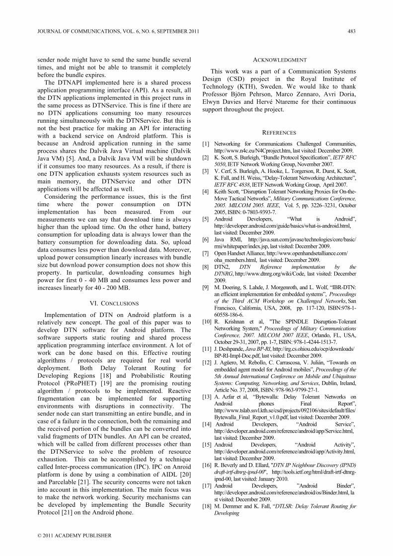
sender node might have to send the same bundle several times, and might not be able to transmit it completely before the bundle expires.
The DTNAPI implemented here is a shared process application programming interface (API). As a result, all the DTN applications implemented in this project runs in the same process as DTNService. This is fine if there are no DTN applications consuming too many resources running simultaneously with the DTNService. But this is not the best practice for making an API for interacting with a backend service on Android platform. This is because an Android application running in the same process shares the Dalvik Java Virtual machine (Dalvik Java VM) [5]. And, a Dalvik Java VM will be shutdown if it consumes too many resources. As a result, if there is one DTN application exhausts system resources such as main memory, the DTNService and other DTN applications will be affected as well.
Considering the performance issues, this is the first time where the power consumption on DTN implementation has been measured. From our measurements we can say that download time is always higher than the upload time. On the other hand, battery consumption for uploading data is always lower than the battery consumption for downloading data. So, upload data consumes less power than download data. Moreover, upload power consumption linearly increases with bundle size but download power consumption does not show this property. In particular, downloading consumes high power for first 0 - 40 MB and consumes less power and increases linearly for 40 - 200 MB.
VI. CONCLUSIONS
Implementation of DTN on Android platform is a relatively new concept. The goal of this paper was to develop DTN software for Android platform. The software supports static routing and shared process application programming interface environment. A lot of work can be done based on this. Effective routing algorithms / protocols are required for real world deployment. Both Delay Tolerant Routing for Developing Regions [18] and Probabilistic Routing Protocol (PRoPHET) [19] are the promising routing algorithm / protocols to be implemented. Reactive fragmentation can be implemented for supporting environments with disruptions in connectivity. The sender node can start transmitting an entire bundle, and in case of a failure in the connection, both the remaining and the received portion of the bundles can be converted into valid fragments of DTN bundles. An API can be created, which will be called from different processes other than the DTNService to solve the problem of resource exhaustion. This can be accomplished by a technique called Inter-process communication (IPC). IPC on Anroid platform is done by using a combination of AIDL [20] and Parcelable [21]. The security concerns were not taken into account in this implementation. The main focus was to make the network working. Security mechanisms can be developed by implementing the Bundle Security Protocol [21] on the Android phone.
ACKNOWLEDGMENT
This work was a part of a Communication Systems Design (CSD) project in the Royal Institute of Technology (KTH), Sweden. We would like to thank Professor Björn Pehrson, Marco Zennaro, Avri Doria, Elwyn Davies and Hervé Ntareme for their continuous support throughout the project.
REFERENCES
[1] Networking for Communications Challenged Communities, http://www.n4c.eu/N4Cproject.htm, last visited: December 2009.
[2] K. Scott, S. Burleigh, “Bundle Protocol Specification”, IETF RFC 5050, IETF Network Working Group, November 2007.
[3] V. Cerf, S. Burleigh, A. Hooke, L. Torgerson, R. Durst, K. Scott, K. Fall, and H. Weiss, “Delay-Tolerant Networking Architecture”, IETF RFC 4838, IETF Network Working Group, April 2007.
[4] Keith Scott, “Disruption Tolerant Networking Proxies for On-the-Move Tactical Networks”, Military Communications Conference, 2005. MILCOM 2005. IEEE, Vol. 5, pp. 3226–3231, October 2005, ISBN: 0-7803-9393-7.
[5] Android Developers, “What is Android”, http://developer.android.com/guide/basics/what-is-android.html, last visited: December 2009.
[6] Java RMI, http://java.sun.com/javase/technologies/core/basic/ rmi/whitepaper/index.jsp, last visited: December 2009.
[7] Open Handset Alliance, http://www.openhandsetalliance.com/ oha_members.html, last visited: December 2009.
[8] DTN2, DTN Reference implementation by the DTNRG, http://www.dtnrg.org/wiki/Code, last visited: December 2009.
[9] M. Doering, S. Lahde, J. Morgenroth, and L. Wolf, “IBR-DTN: an efficient implementation for embedded systems”, Proceedings of the Third ACM Workshop on Challenged Networks, San Francisco, California, USA, 2008, pp. 117-120, ISBN:978-1-60558-186-6.
[10] R. Krishnan et al, "The SPINDLE Disruption-Tolerant Networking System," Proceedings of Military Communications Conference, 2007. MILCOM 2007 IEEE, Orlando, FL, USA, October 29-31, 2007, pp. 1-7, ISBN: 978-1-4244-1513-7.
[11] J. Deshpande, Java BP-RI, http://irg.cs.ohiou.edu/ocp/downloads/ BP-RI-Impl-Doc.pdf, last visited: December 2009.
[12] J. Agüero, M. Rebollo, C. Carrascosa, V. Julián, “Towards on embedded agent model for Android mobiles”, Proceedings of the 5th Annual International Conference on Mobile and Ubiquitous Systems: Computing, Networking, and Services, Dublin, Ireland, Article No. 37, 2008, ISBN: 978-963-9799-27-1.
[13] A. Azfar et al, “Bytewalla: Delay Tolerant Networks on Android phones Final Report”, http://www.tslab.ssvl.kth.se/csd/projects/092106/sites/default/files/Bytewalla_Final_Report_v1.0.pdf, last visited: December 2009.
[14] Android Developers, “Android Service”, http://developer.android.com/reference/android/app/Service.html, last visited: December 2009.
[15] Android Developers, “Android Activity”, http://developer.android.com/reference/android/app/Activity.html, last visited: December 2009.
[16] R. Beverly and D. Ellard, "DTN IP Neighbour Discovery (IPND) draft-irtf-dtnrg-ipnd-00", http://tools.ietf.org/html/draft-irtf-dtnrg-ipnd-00, last visited: January 2010.
[17] Android Developers, ”Android Binder”, http://developer.android.com/reference/android/os/Binder.html, last visited: December 2009.
[18] M. Demmer and K. Fall, “DTLSR: Delay Tolerant Routing for Developing
JOURNAL OF COMMUNICATIONS, VOL. 6, NO. 6, SEPTEMBER 2011 483
© 2011 ACADEMY PUBLISHER
Regions”, http://www.cs.berkeley.edu/~kfall/papers/dtlsr-nsdr07.pdf , last visited: December 2009.
[19] A. Lindgren and A. Doria, “Prophet routing protocol”, http://www.dtnrg.org/docs/specs/draft-lindgren-dtnrg-prophet-02.txt, last visited: December 2009.
[20] Android Developers, “Designing a Remote Interface Using AIDL”, http://developer.android.com/guide/developing/tools/aidl.html, last visited: December 2009.
[21] Android Developers, “Android Parcelable”, http://developer.android.com/reference/android/os/Parcelable.html, last visited: December 2009.
Rerngvit Yanggratoke is doing his PhD with topic “Autonomous Resource Allocation in Cloud Computing” in School of Electrical Engineering with The Royal Institute of Technology (KTH) in Stockholm, Sweden. He got his MS in Erasmus Mundus NordSecMob program specialized in Security and Mobile Computing from Aalto University School of Science and Technology (TKK), Finland and Royal Institute of Technology (KTH), Sweden. He received his BSc degree in Computer Engineering from Chulalongkorn University, Bangkok, Thailand in 2006. He worked as a software engineer in the company named Openface Internet during the period April 2006 – April 2008. He also served as a system administrator in Dhammasociety Fund, Thailand during the period April 2008 – August 2008. He was provided full scholarship for two years studying in his MS from the European Union. His major research interests are delay tolerant networking, information system security, and high performance distributed system. Abdullah Azfar is working as an Assistant Professor in the Computer Science and Information Technology department of Islamic University of Technology (IUT), Gazipur, Bangladesh. He got his MS in Erasmus Mundus NordSecMob program specialized in Security and Mobile Computing from Norwegian
University of Science and Technology (NTNU), Norway and The Royal Institute of Technology (KTH), Sweden in 2010. He received his BSc degree in Computer Science and Information Technology from Islamic University of Technology (IUT), Gazipur, Bangladesh in 2005. He served as a lecturer in Islamic University of Technology during the period March 2006 – July 2008 and July 2010 – December 2010. He also served as a lecturer in Prime University, Dhaka, Bangladesh during the period October 2005 – February 2006. He received the Erasmus Mundus scholarship from the European Union for his MS studies. His research interests are mainly focused on Information Security, VoIP Communication, Cryptography and Mobile Computing. María José Peroza Marval got her MS in Internetworking program specialized in Networking and Radio Communication Systems in Royal Institute of Technology (KTH), Sweden. She received her BSc degree in Electronic Engineering from Simon Bolivar University, Caracas, Venezuela in 2005 (graduated with an Honourable Mention for her bachelor thesis). She worked as a Network Engineer in the company named MOVILNET, Venezuela, during the period May 2006 – October 2007. She also worked as an Operations Analyst in Dayco Telecom, Venezuela, during the period September 2005 – May 2006. Her research interest is mainly focused on conventional Networking and Optical Networking. Sharjeel Ahmed is doing his MS in Information and Communication Technology Entrepreneurship in Royal Institute of Technology (KTH), Sweden. He received his BSc degree in Computer Science from COMSATS Institute of Information Technology, Lahore, Pakistan in 2007. He worked as a software engineer during the period March 2007 – August 2008. He has innovated in a number of fields of information technology and software development. With his research-based ideas and a vision apart, he has evolved from being a software engineer to an internet entrepreneur and now working on his ideas to start new startups.
484 JOURNAL OF COMMUNICATIONS, VOL. 6, NO. 6, SEPTEMBER 2011
© 2011 ACADEMY PUBLISHER
A New Evaluation Model for Security Protocols
Chao YANG, Jianfeng MA, Xuewen DONGKey Laboratory of Computer Networks and Information Security, Ministry of Education, Xidian University, Xi’an 710071,
China;
School of Computer Science and Technology, Xidian University, Xi’an 710071, China
Abstract-Till today, the study of performance of security
protocols of WLAN has been one of research focuses. Whereas,
owing to enormous complexity and low efficiency of modeling
security protocols, there has been by now no uniform method
or technology that can be used generally to simulate and
evaluate security protocols, and no simulation system
available that can well support research on performance of
security protocols. So in view of the status quo, we, in this
paper, mainly propose a novel security protocol simulation
architecture and a simulation extending method for simulating
security protocols of WLAN, and then set up a simulation
platform for modeling such protocols based on OPNET, a
famous simulation software. Finally, with an instance of
extending and simulating a security protocol of WLAN, the
validity and the universality of the simulation architecture and
the extending method as well as the feasibility and correctness
of the simulation platform are demonstrated.
I. INTRODUCTION
Security in wireless network, such as WLAN[1] ,is a
critical concern[2]. More and more scholars focus on the
study of WLAN security protocols[3]. However, how to
evaluate security protocols in terms of security and
performance is an important and tough task[4]. There are
three common approaches which can be exploited to carry
on evaluation of security protocols—testing, mathematical
analysis and simulation[5]. Due to lower costs and
maneuverability, the simulation approach has been widely
used.However, the simulation approach has some
disadvantages in terms of efficiency and extensibility. To
the best of our knowledge, there exists no unified
simulation approach on how to evaluate WLAN security
protocols, because of the complexity and inefficiency of
security protocols modeling. Moreover, popular simulation
tools, such as OPNET[6] and NS2[7] , do not have built-in
security protocol models or universal interfaces to support the evaluation of WLAN security protocols, which leads to
lots of repetitive works and low comparability of different
performance researches[8].
To address the problem mentioned above, we propose, in
this paper, a universal and extensible security protocol
simulation platform for WLAN. First of all, the architecture
design of the platform is presented. One of the key features
of it is the ability to provide a universal interface to
incorporate various security protocols into the simulation platform conveniently and exactly. Furthermore, a general
method for security protocols extension is demonstrated. It
specifies how to modify the protocol module and embed it
into the simulation platform, which standardize the
extension process. Finally, according to the proposed
architecture and method, we implement the simulation
platform in OPNET and validate its feasibility, correctness
and universality through extending and simulating WEP[15] and EAP-TLS[16] security protocols. The results show that
our simulation platform has characteristics of universality
and extensibility.
The rest of this paper is organized as follows. Section II
discuses the related work of security protocol simulation.
Section III designs the architecture of the simulation
platform for WLAN security protocols. Section IV provides
a detailed description of the simulation interface and the core components of the architecture. Section V describes
the method for security protocols extension. In section VI,
we present a simulation experiment for the validation of the
proposed platform. Finally, Section VII concludes this
paper.
II. RELATED WORK
There are two lines of researches focusing on security
protocol simulation in the research community.The first one focus on how to utilize various kinds of
methods and tools to simulate and evaluate WLAN security
protocols, and improve them through the analysis of the
simulation results. This kind of research is extremely
popular, such as [9] [10] [11] and so on.
The second one concentrates on how to develop a
simulation platform or framework to standardize the
simulation and evaluation of security protocols, which is very useful in improving the efficiency and extensibility of
security protocol simulation. However, only a few research
works, described below, have been reported on this topic.
Zhao et al. established a simulation framework to model
BGP security protocols and PKI system[12]. With this
framework, they evaluated certification path building
Manuscript received January 1, 2011; revised June 1, 2011; accepted
July 1, 2011.
Supported by Fundamental Research Funds for the CentralUniversities( JY10000903006)
JOURNAL OF COMMUNICATIONS, VOL. 6, NO. 6, SEPTEMBER 2011 485
© 2011 ACADEMY PUBLISHERdoi:10.4304/jcm.6.6.485-494
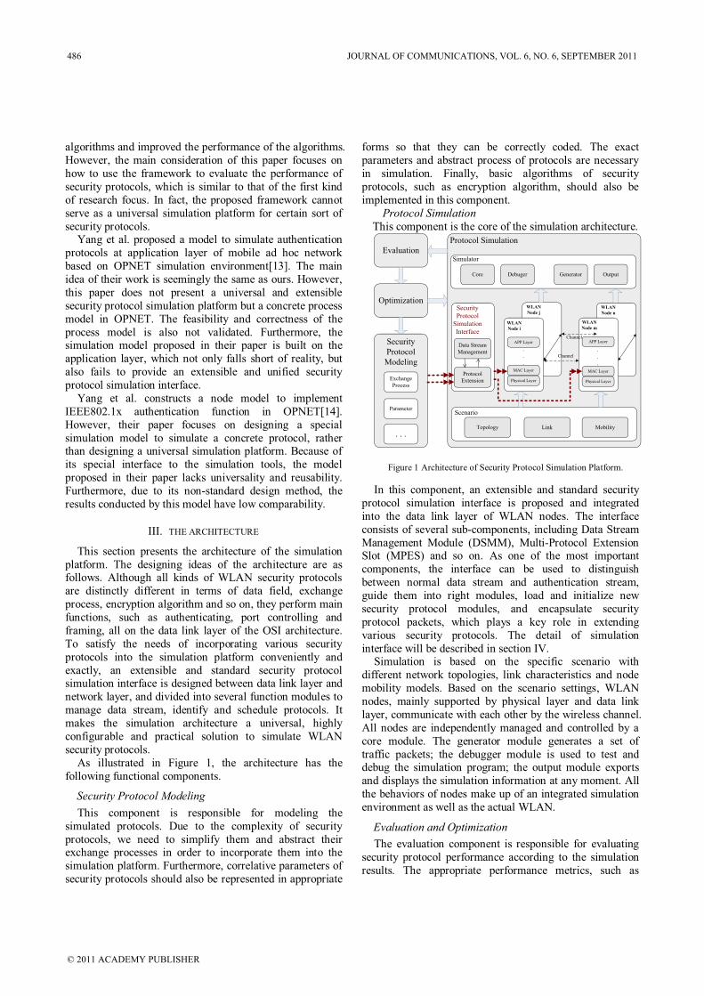
algorithms and improved the performance of the algorithms.
However, the main consideration of this paper focuses on
how to use the framework to evaluate the performance of
security protocols, which is similar to that of the first kind
of research focus. In fact, the proposed framework cannot
serve as a universal simulation platform for certain sort of
security protocols.Yang et al. proposed a model to simulate authentication
protocols at application layer of mobile ad hoc network
based on OPNET simulation environment[13]. The main
idea of their work is seemingly the same as ours. However,
this paper does not present a universal and extensible
security protocol simulation platform but a concrete process
model in OPNET. The feasibility and correctness of the
process model is also not validated. Furthermore, thesimulation model proposed in their paper is built on the
application layer, which not only falls short of reality, but
also fails to provide an extensible and unified security
protocol simulation interface.
Yang et al. constructs a node model to implement
IEEE802.1x authentication function in OPNET[14].
However, their paper focuses on designing a special
simulation model to simulate a concrete protocol, rather than designing a universal simulation platform. Because of
its special interface to the simulation tools, the model
proposed in their paper lacks universality and reusability.
Furthermore, due to its non-standard design method, the
results conducted by this model have low comparability.
III. THE ARCHITECTURE
This section presents the architecture of the simulation
platform. The designing ideas of the architecture are as follows. Although all kinds of WLAN security protocols
are distinctly different in terms of data field, exchange
process, encryption algorithm and so on, they perform main
functions, such as authenticating, port controlling and
framing, all on the data link layer of the OSI architecture.
To satisfy the needs of incorporating various security
protocols into the simulation platform conveniently and
exactly, an extensible and standard security protocol simulation interface is designed between data link layer and
network layer, and divided into several function modules to
manage data stream, identify and schedule protocols. It
makes the simulation architecture a universal, highly
configurable and practical solution to simulate WLAN
security protocols.
As illustrated in Figure 1, the architecture has the
following functional components.
Security Protocol Modeling
This component is responsible for modeling the
simulated protocols. Due to the complexity of security
protocols, we need to simplify them and abstract their exchange processes in order to incorporate them into the
simulation platform. Furthermore, correlative parameters of
security protocols should also be represented in appropriate
forms so that they can be correctly coded. The exact
parameters and abstract process of protocols are necessary
in simulation. Finally, basic algorithms of security
protocols, such as encryption algorithm, should also be
implemented in this component.
Protocol SimulationThis component is the core of the simulation architecture.
Evaluation
Optimization
Security
Protocol
Modeling
Exchange
Process
Parameter
Security
Protocol
Simulation
Interface
Data Stream
Management
Protocol
Extension
Scenario
Topology
MAC Layer
Physical Layer
WLAN
Node i
APP Layer
.
.
.
WLAN
Node j
WLAN
Node n
MAC Layer
Physical Layer
APP Layer
.
.
.
WLAN
Node m
Core Generator Output
Simulator
Debuger
Protocol Simulation
Channel
Channel
Link Mobility
. . .
Figure 1 Architecture of Security Protocol Simulation Platform.
In this component, an extensible and standard security
protocol simulation interface is proposed and integrated
into the data link layer of WLAN nodes. The interface
consists of several sub-components, including Data Stream
Management Module (DSMM), Multi-Protocol Extension Slot (MPES) and so on. As one of the most important
components, the interface can be used to distinguish
between normal data stream and authentication stream,
guide them into right modules, load and initialize new
security protocol modules, and encapsulate security
protocol packets, which plays a key role in extending
various security protocols. The detail of simulation
interface will be described in section IV.Simulation is based on the specific scenario with
different network topologies, link characteristics and node
mobility models. Based on the scenario settings, WLAN
nodes, mainly supported by physical layer and data link
layer, communicate with each other by the wireless channel.
All nodes are independently managed and controlled by a
core module. The generator module generates a set of
traffic packets; the debugger module is used to test and debug the simulation program; the output module exports
and displays the simulation information at any moment. All
the behaviors of nodes make up of an integrated simulation
environment as well as the actual WLAN.
Evaluation and Optimization
The evaluation component is responsible for evaluating
security protocol performance according to the simulation
results. The appropriate performance metrics, such as
486 JOURNAL OF COMMUNICATIONS, VOL. 6, NO. 6, SEPTEMBER 2011
© 2011 ACADEMY PUBLISHER
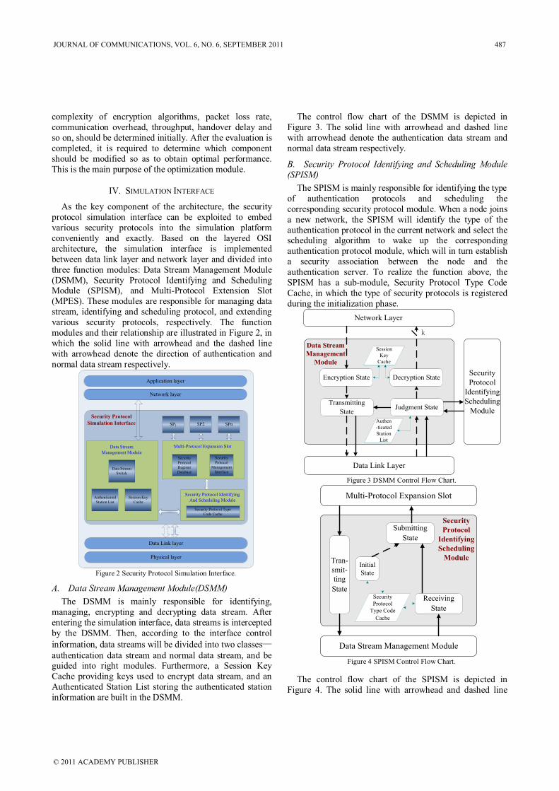
complexity of encryption algorithms, packet loss rate,
communication overhead, throughput, handover delay and
so on, should be determined initially. After the evaluation is
completed, it is required to determine which component
should be modified so as to obtain optimal performance.
This is the main purpose of the optimization module.
IV. SIMULATION INTERFACE
As the key component of the architecture, the security
protocol simulation interface can be exploited to embed
various security protocols into the simulation platform
conveniently and exactly. Based on the layered OSI
architecture, the simulation interface is implemented
between data link layer and network layer and divided into
three function modules: Data Stream Management Module
(DSMM), Security Protocol Identifying and Scheduling Module (SPISM), and Multi-Protocol Extension Slot
(MPES). These modules are responsible for managing data
stream, identifying and scheduling protocol, and extending
various security protocols, respectively. The function
modules and their relationship are illustrated in Figure 2, in
which the solid line with arrowhead and the dashed line
with arrowhead denote the direction of authentication and
normal data stream respectively.
Data Link layer
Physical layer
Security Protocol
Simulation Interface
Security
Protocol
Register
Database
Security
Protocol
Management
Interface
SP1 SP2 SPn
Multi-Protocol Expansion Slot
Network layer
Application layer
Data Stream
Switch
Data Stream
Management Module
Security Protocol Identifying
And Scheduling ModuleAuthenticated
Station List
Session Key
Cache
Security Protocol Type
Code Cache
Figure 2 Security Protocol Simulation Interface.
A. Data Stream Management Module(DSMM)
The DSMM is mainly responsible for identifying,
managing, encrypting and decrypting data stream. After
entering the simulation interface, data streams is intercepted
by the DSMM. Then, according to the interface control
information, data streams will be divided into two classes—
authentication data stream and normal data stream, and be guided into right modules. Furthermore, a Session Key
Cache providing keys used to encrypt data stream, and an
Authenticated Station List storing the authenticated station
information are built in the DSMM.
The control flow chart of the DSMM is depicted in
Figure 3. The solid line with arrowhead and dashed line
with arrowhead denote the authentication data stream and
normal data stream respectively.
B. Security Protocol Identifying and Scheduling Module(SPISM)
The SPISM is mainly responsible for identifying the type
of authentication protocols and scheduling the
corresponding security protocol module. When a node joins
a new network, the SPISM will identify the type of the
authentication protocol in the current network and select the scheduling algorithm to wake up the corresponding
authentication protocol module, which will in turn establish
a security association between the node and the
authentication server. To realize the function above, the
SPISM has a sub-module, Security Protocol Type Code
Cache, in which the type of security protocols is registered
during the initialization phase.
Network Layer
Data Link Layer
Security
Protocol
Identifying
Scheduling
Module
Data Stream
Management
Module
k
Session
Key
Cache
Authen
-ticated
Station
List
Encryption State
Transmitting
State
Decryption State
Judgment State
Figure 3 DSMM Control Flow Chart.
Multi-Protocol Expansion Slot
Data Stream Management Module
Initial
State
Submitting
State
Tran-
smit-
ting
StateSecurity
Protocol
Type Code
Cache
Receiving
State
Security
Protocol
Identifying
Scheduling
Module
Figure 4 SPISM Control Flow Chart.
The control flow chart of the SPISM is depicted in
Figure 4. The solid line with arrowhead and dashed line
JOURNAL OF COMMUNICATIONS, VOL. 6, NO. 6, SEPTEMBER 2011 487
© 2011 ACADEMY PUBLISHER
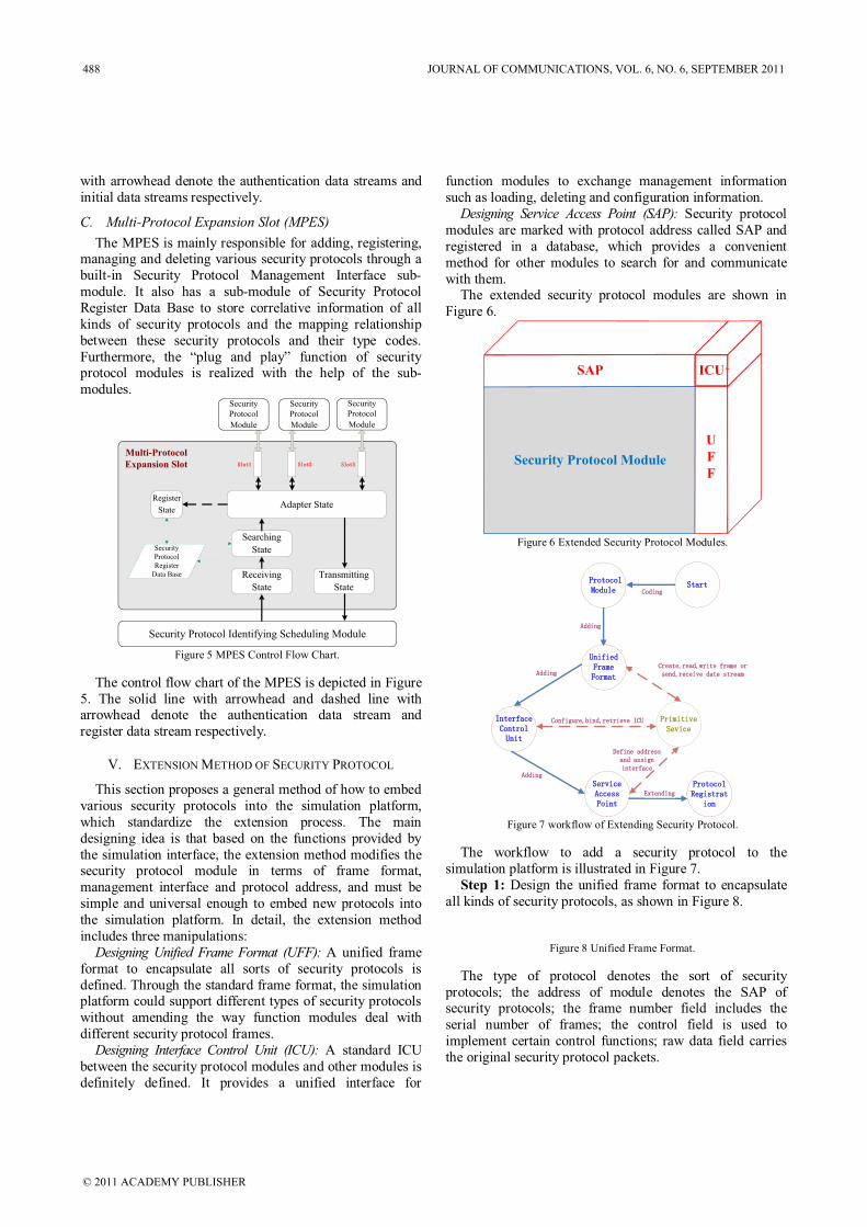
with arrowhead denote the authentication data streams and
initial data streams respectively.
C. Multi-Protocol Expansion Slot (MPES)
The MPES is mainly responsible for adding, registering, managing and deleting various security protocols through a
built-in Security Protocol Management Interface sub-
module. It also has a sub-module of Security Protocol
Register Data Base to store correlative information of all
kinds of security protocols and the mapping relationship
between these security protocols and their type codes.
Furthermore, the “plug and play” function of security protocol modules is realized with the help of the sub-
modules.
Security
Protocol
Register
Data Base
Adapter State
Security Protocol Identifying Scheduling Module
Security
Protocol
Module
Security
Protocol
Module
Security
Protocol
Module
Receiving
State
Transmitting
State
Register
State
SSlloott11 SSlloott22 SSlloott33
Searching
State
Multi-Protocol
Expansion Slot
Figure 5 MPES Control Flow Chart.
The control flow chart of the MPES is depicted in Figure
5. The solid line with arrowhead and dashed line with arrowhead denote the authentication data stream and
register data stream respectively.
V. EXTENSION METHOD OF SECURITY PROTOCOL
This section proposes a general method of how to embed
various security protocols into the simulation platform,
which standardize the extension process. The main
designing idea is that based on the functions provided by
the simulation interface, the extension method modifies the security protocol module in terms of frame format,
management interface and protocol address, and must be
simple and universal enough to embed new protocols into
the simulation platform. In detail, the extension method
includes three manipulations:
Designing Unified Frame Format (UFF): A unified frame
format to encapsulate all sorts of security protocols is
defined. Through the standard frame format, the simulation platform could support different types of security protocols
without amending the way function modules deal with
different security protocol frames.
Designing Interface Control Unit (ICU): A standard ICU
between the security protocol modules and other modules is
definitely defined. It provides a unified interface for
function modules to exchange management information
such as loading, deleting and configuration information.
Designing Service Access Point (SAP): Security protocol
modules are marked with protocol address called SAP and
registered in a database, which provides a convenient
method for other modules to search for and communicate
with them.The extended security protocol modules are shown in
Figure 6.
Security Protocol ModuleSecurity Protocol Module
SAP
U
F
F
ICU
Figure 6 Extended Security Protocol Modules.
DDeeffiinnee aaddddrreessss
aanndd aassssiiggnn
iinntteerrffaaccee
UUnniiffiieedd
FFrraammee
FFoorrmmaatt
IInntteerrffaaccee
CCoonnttrrooll
UUnniitt
SSeerrvviiccee
AAcccceessss
PPooiinntt
PPrriimmiittiivvee
SSeevviiccee
CCrreeaattee,,rreeaadd,,wwrriittee ffrraammee oorr
sseenndd,,rreecceeiivvee ddaattee ssttrreeaamm
CCoonnffiigguurree,,bbiinndd,,rreettrriieevvee IICCUU
PPrroottooccooll
MMoodduullee
PPrroottooccooll
RReeggiissttrraatt
iioonn
SSttaarrttCCooddiinngg
AAddddiinngg
AAddddiinngg
AAddddiinngg
EExxtteennddiinngg
Figure 7 workflow of Extending Security Protocol.
The workflow to add a security protocol to the
simulation platform is illustrated in Figure 7.
Step 1: Design the unified frame format to encapsulate
all kinds of security protocols, as shown in Figure 8.
Figure 8 Unified Frame Format.
The type of protocol denotes the sort of security
protocols; the address of module denotes the SAP of security protocols; the frame number field includes the
serial number of frames; the control field is used to
implement certain control functions; raw data field carries
the original security protocol packets.
488 JOURNAL OF COMMUNICATIONS, VOL. 6, NO. 6, SEPTEMBER 2011
© 2011 ACADEMY PUBLISHER
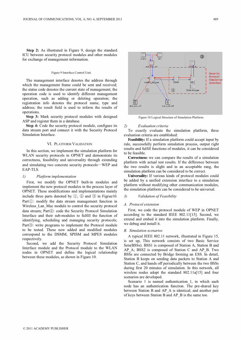
Step 2: As illustrated in Figure 9, design the standard
ICU between security protocol modules and other modules
for exchange of management information.
Figure 9 Interface Control Unit.
The management interface denotes the address through
which the management frame could be sent and received;
the status code denotes the current state of management; the operation code is used to identify different management
operation, such as adding or deleting operation; the
registration info denotes the protocol name, type and
address; the result field is used to inform the results of
operations.
Step 3: Mark security protocol modules with designed
ASP and register them in a database.
Step 4: Code the security protocol module, configure itsdata stream port and connect it with the Security Protocol
Simulation Interface.
VI. PLATFORM VALIDATION
In this section, we implement the simulation platform for
WLAN security protocols in OPNET and demonstrate its
correctness, feasibility and universality through extending
and simulating two concrete security protocols—WEP and
EAP-TLS.
1) Platform implementation
First, we modify the OPNET built-in modules and
implement the new protocol modules in the process layer of
OPNET. These modifications and implementations mainly
include three parts denoted by , and in Figrue10.
Part : modify the data stream management function in
Wireless_Lan_Mac module to control the security protocol
data stream; Part : code the Security Protocol Simulation
Interface and their sub-modules to fulfill the function of
identifying, scheduling and managing security protocols;
Part : write programs to implement the Protocol module
to be tested. These new added and modified modules
correspond to the DSMM, SPISM and MPES modules
respectively.
Second, we add the Security Protocol Simulation
Interface module and the Protocol module to the WLAN nodes in OPNET and define the logical relationship
between these modules, as shown in Figure 10.
SSeeccuurriittyy
PPrroottooccooll
SSiimmuullaattiioonn
IInntteerrffaaccee
Figure 10 Logical Structure of Simulation Platform.
2) Evaluation criteriaTo exactly evaluate the simulation platform, three
evaluation criteria are established:
Feasibility: If a simulation platform could accept input by
rule, successfully perform simulation process, output right
results and fulfill functions of modules, it can be considered to be feasible.
Correctness: we can compare the results of a simulation
platform with actual test results. If the difference between
the two results is slight and in an acceptable rang, the
simulation platform can be considered to be correct.
Universality: If various kinds of protocol modules could
be added by a unified extension interface to a simulation
platform without modifying other communication modules, the simulation platform can be considered to be universal.
3) Validation of Feasibility
A. Protocol extension
First, we code the protocol module of WEP in OPNET
according to the standard IEEE 802.11[15]. Second, we
extend and embed it into the simulation platform. Finally,
we debug and install it.
B. Simulation scenarios
A typical IEEE 802.11 network, illustrated in Figure 15,
is set up, This network consists of two Basic Service
Sets(BSSs). BSS1 is composed of Station A, Station B and
AP_A; BSS2 is composed of Station C and AP_B. Two BSSs are connected by Bridge forming an ESS. In detail,
Station B keeps on sending data packets to Station A and
Station C, and hands off periodically between the two BSSs
during first 20 minutes of simulation. In this network, all
wireless nodes adopt the standard 802.11a[15] and four
scenarios are developed.
Scenario 1 is named authentication_1, in which each
node has an authentication function. The pre-shared keybetween Station B and AP_A is identical; and another pair
of keys between Station B and AP_B is the same too.
JOURNAL OF COMMUNICATIONS, VOL. 6, NO. 6, SEPTEMBER 2011 489
© 2011 ACADEMY PUBLISHER
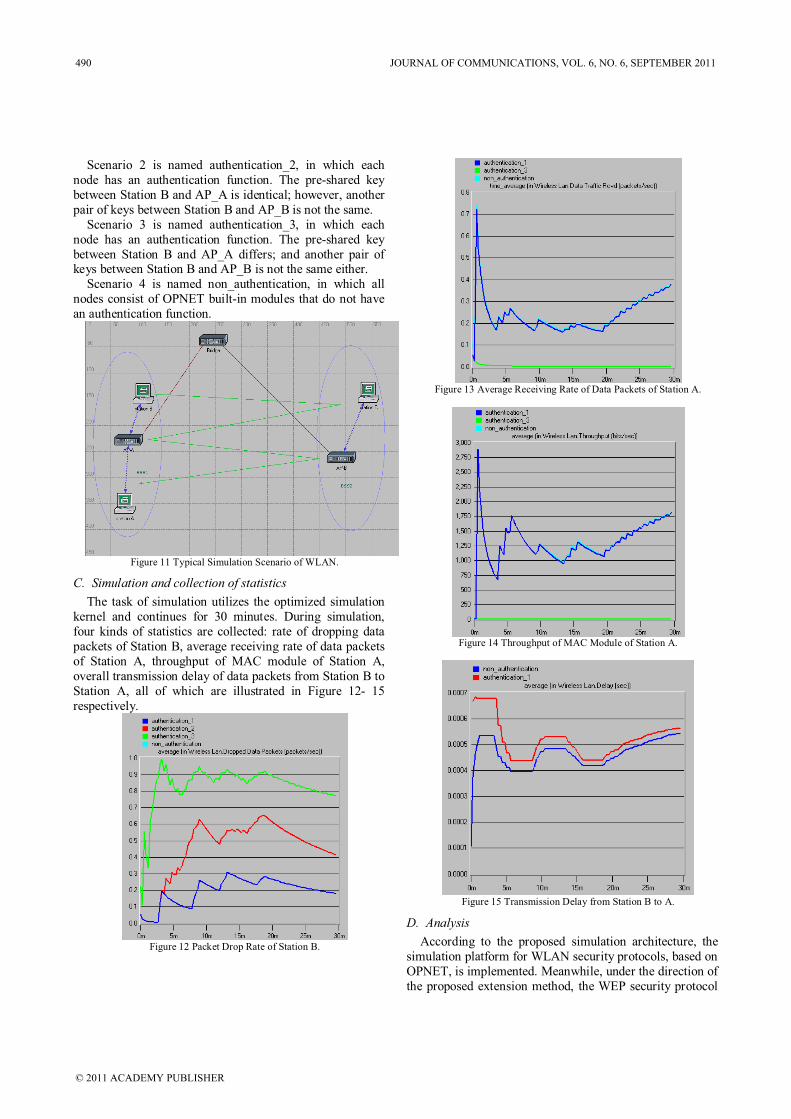
Scenario 2 is named authentication_2, in which each
node has an authentication function. The pre-shared key
between Station B and AP_A is identical; however, another
pair of keys between Station B and AP_B is not the same.
Scenario 3 is named authentication_3, in which each
node has an authentication function. The pre-shared key
between Station B and AP_A differs; and another pair of keys between Station B and AP_B is not the same either.
Scenario 4 is named non_authentication, in which all
nodes consist of OPNET built-in modules that do not have
an authentication function.
Figure 11 Typical Simulation Scenario of WLAN.
C. Simulation and collection of statistics
The task of simulation utilizes the optimized simulation
kernel and continues for 30 minutes. During simulation,
four kinds of statistics are collected: rate of dropping data
packets of Station B, average receiving rate of data packets
of Station A, throughput of MAC module of Station A,
overall transmission delay of data packets from Station B to
Station A, all of which are illustrated in Figure 12- 15
respectively.
Figure 12 Packet Drop Rate of Station B.
Figure 13 Average Receiving Rate of Data Packets of Station A.
Figure 14 Throughput of MAC Module of Station A.
Figure 15 Transmission Delay from Station B to A.
D. Analysis
According to the proposed simulation architecture, the
simulation platform for WLAN security protocols, based on
OPNET, is implemented. Meanwhile, under the direction of
the proposed extension method, the WEP security protocol
490 JOURNAL OF COMMUNICATIONS, VOL. 6, NO. 6, SEPTEMBER 2011
© 2011 ACADEMY PUBLISHER
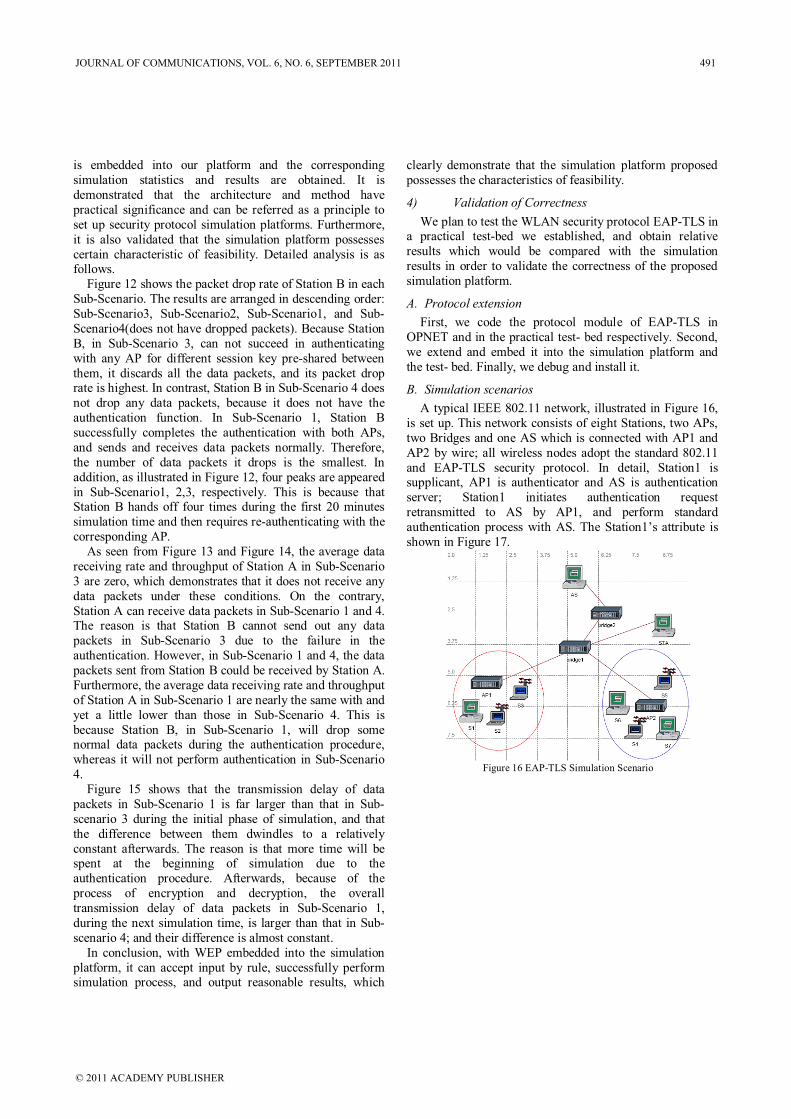
is embedded into our platform and the corresponding
simulation statistics and results are obtained. It is
demonstrated that the architecture and method have
practical significance and can be referred as a principle to
set up security protocol simulation platforms. Furthermore,
it is also validated that the simulation platform possesses
certain characteristic of feasibility. Detailed analysis is as follows.
Figure 12 shows the packet drop rate of Station B in each
Sub-Scenario. The results are arranged in descending order:
Sub-Scenario3, Sub-Scenario2, Sub-Scenario1, and Sub-
Scenario4(does not have dropped packets). Because Station
B, in Sub-Scenario 3, can not succeed in authenticating
with any AP for different session key pre-shared between
them, it discards all the data packets, and its packet drop rate is highest. In contrast, Station B in Sub-Scenario 4 does
not drop any data packets, because it does not have the
authentication function. In Sub-Scenario 1, Station B
successfully completes the authentication with both APs,
and sends and receives data packets normally. Therefore,
the number of data packets it drops is the smallest. In
addition, as illustrated in Figure 12, four peaks are appeared
in Sub-Scenario1, 2,3, respectively. This is because that Station B hands off four times during the first 20 minutes
simulation time and then requires re-authenticating with the
corresponding AP.
As seen from Figure 13 and Figure 14, the average data
receiving rate and throughput of Station A in Sub-Scenario
3 are zero, which demonstrates that it does not receive any
data packets under these conditions. On the contrary,
Station A can receive data packets in Sub-Scenario 1 and 4. The reason is that Station B cannot send out any data
packets in Sub-Scenario 3 due to the failure in the
authentication. However, in Sub-Scenario 1 and 4, the data
packets sent from Station B could be received by Station A.
Furthermore, the average data receiving rate and throughput
of Station A in Sub-Scenario 1 are nearly the same with and
yet a little lower than those in Sub-Scenario 4. This is
because Station B, in Sub-Scenario 1, will drop some normal data packets during the authentication procedure,
whereas it will not perform authentication in Sub-Scenario
4.
Figure 15 shows that the transmission delay of data
packets in Sub-Scenario 1 is far larger than that in Sub-
scenario 3 during the initial phase of simulation, and that
the difference between them dwindles to a relatively
constant afterwards. The reason is that more time will be spent at the beginning of simulation due to the
authentication procedure. Afterwards, because of the
process of encryption and decryption, the overall
transmission delay of data packets in Sub-Scenario 1,
during the next simulation time, is larger than that in Sub-
scenario 4; and their difference is almost constant.
In conclusion, with WEP embedded into the simulation
platform, it can accept input by rule, successfully perform simulation process, and output reasonable results, which
clearly demonstrate that the simulation platform proposed
possesses the characteristics of feasibility.
4) Validation of Correctness
We plan to test the WLAN security protocol EAP-TLS in a practical test-bed we established, and obtain relative
results which would be compared with the simulation
results in order to validate the correctness of the proposed
simulation platform.
A. Protocol extension
First, we code the protocol module of EAP-TLS in
OPNET and in the practical test- bed respectively. Second,
we extend and embed it into the simulation platform and
the test- bed. Finally, we debug and install it.
B. Simulation scenarios
A typical IEEE 802.11 network, illustrated in Figure 16,
is set up. This network consists of eight Stations, two APs,
two Bridges and one AS which is connected with AP1 and
AP2 by wire; all wireless nodes adopt the standard 802.11
and EAP-TLS security protocol. In detail, Station1 is supplicant, AP1 is authenticator and AS is authentication
server; Station1 initiates authentication request
retransmitted to AS by AP1, and perform standard
authentication process with AS. The Station1’s attribute is
shown in Figure 17.
Figure 16 EAP-TLS Simulation Scenario
JOURNAL OF COMMUNICATIONS, VOL. 6, NO. 6, SEPTEMBER 2011 491
© 2011 ACADEMY PUBLISHER
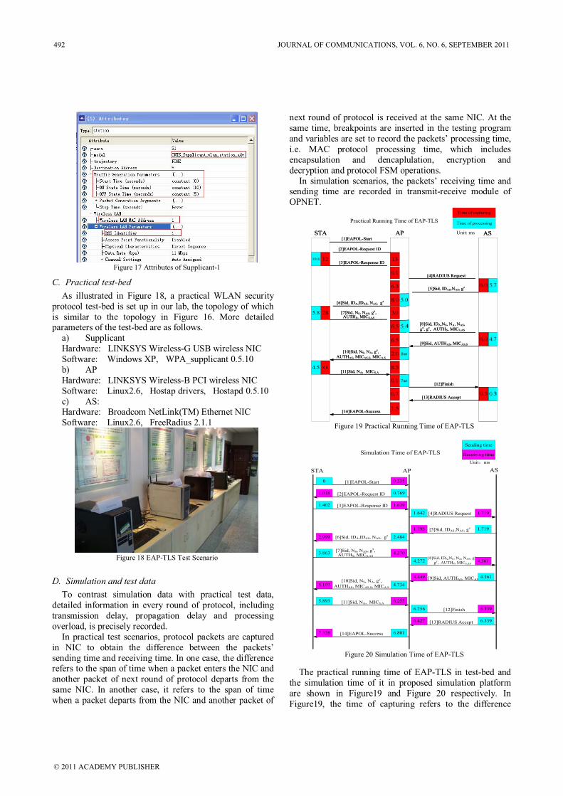
Figure 17 Attributes of Supplicant-1
C. Practical test-bed
As illustrated in Figure 18, a practical WLAN security
protocol test-bed is set up in our lab, the topology of which
is similar to the topology in Figure 16. More detailedparameters of the test-bed are as follows.
a) Supplicant
Hardware: LINKSYS Wireless-G USB wireless NIC
Software: Windows XP, WPA_supplicant 0.5.10
b) AP
Hardware: LINKSYS Wireless-B PCI wireless NIC
Software: Linux2.6, Hostap drivers, Hostapd 0.5.10
c) AS: Hardware: Broadcom NetLink(TM) Ethernet NIC
Software: Linux2.6, FreeRadius 2.1.1
Figure 18 EAP-TLS Test Scenario
D. Simulation and test data
To contrast simulation data with practical test data,
detailed information in every round of protocol, including
transmission delay, propagation delay and processing
overload, is precisely recorded.
In practical test scenarios, protocol packets are captured
in NIC to obtain the difference between the packets’
sending time and receiving time. In one case, the difference refers to the span of time when a packet enters the NIC and
another packet of next round of protocol departs from the
same NIC. In another case, it refers to the span of time
when a packet departs from the NIC and another packet of
next round of protocol is received at the same NIC. At the
same time, breakpoints are inserted in the testing program
and variables are set to record the packets’ processing time,
i.e. MAC protocol processing time, which includes
encapsulation and dencaplulation, encryption and
decryption and protocol FSM operations.
In simulation scenarios, the packets’ receiving time and sending time are recorded in transmit-receive module of
OPNET.
STA AP AS[1]EAPOL-Start
[2]EAPOL-Request ID
[3]EAPOL-Response ID
[5]Sid, IDAS,NAS, gz
[7]Sid, NS, NAS, gx,AUTHS, MICS,AS
[8]Sid, IDA,NS, NA, NAS,
gx, gy, AUTHS, MICS,AS
[4]RADIUS Request
[6]Sid, IDA,IDAS, NAS, gz 0
285.8
[13]RADIUS Accept
[14]EAPOL-Success
[9]Sid, AUTHAS, MICAS,S
[10]Sid, NS, NA, gy,
AUTHAS, MICAS,S, MICA,S
[11]Sid, NA, MICS,A
[12]Finish
us
8.04.5
us
1210.8
000000000000000
ssssss
ssssss
STASTA APAP ASAS[1]EAPOL-Start
[2]EAPOL-Request ID
[3]EAPOL-Response ID
[5]Sid, IDAS,NAS, gz
[7]Sid, NS, NAS, gx,AUTHS, MICS,AS
[8]Sid, IDA,NS, NA, NAS,
gx, gy, AUTHS, MICS,AS
[4]RADIUS Request
[6]Sid, IDA,IDAS, NAS, gz
13
0.1
6.3
6.0 4.7
8.0 5.0
285.8 30
6.5 5.4
[13]RADIUS Accept
[14]EAPOL-Success
[9]Sid, AUTHAS, MICAS,S
[10]Sid, NS, NA, gy,
AUTHAS, MICAS,S, MICA,S
[11]Sid, NA, MICS,A
[12]Finish
6.5
2.0 8us
8.04.5 8.5
0.5 0.30.7
1.5
0.1 7us
6.0 5.7
Time of capturing
Time of processing
Unit: ms
TPractical Running Time of EAP-TLS
1210.8
Figure 19 Practical Running Time of EAP-TLS
[1]EAPOL-Start
[2]EAPOL-Request ID
[3]EAPOL-Response ID
[13]RADIUS Accept
[14]EAPOL-Success
STA AP AS
[5]Sid, IDAS,NAS, gz
[7]Sid, NS, NAS, gx,AUTHS, MICS,AS
[8]Sid, IDA,NS, NA, NAS, gx,
gy, AUTHS, MICS,AS
[9]Sid, AUTHAS, MICAS,S[10]Sid, NS, NA, gy,
AUTHAS, MICAS,S, MICA,S
[11]Sid, NA, MICS,A
[12]Finish
[4]RADIUS Request
[6]Sid, IDA,IDAS, NAS, gz
Sending time
Receiving time
Unit ms
Simulation Time of EAP-TLS
0.2350
0.7691.018
1.402 1.639
1.642 1.719
1.7191.795
2.4842.999
3.863 4.270
4.272 4.361
4.3614.449
4.7345.107
5.893 6.253
6.256 6.339
6.3396.427
6.8017.328
Figure 20 Simulation Time of EAP-TLS
The practical running time of EAP-TLS in test-bed and
the simulation time of it in proposed simulation platform
are shown in Figure19 and Figure 20 respectively. In
Figure19, the time of capturing refers to the difference
492 JOURNAL OF COMMUNICATIONS, VOL. 6, NO. 6, SEPTEMBER 2011
© 2011 ACADEMY PUBLISHER
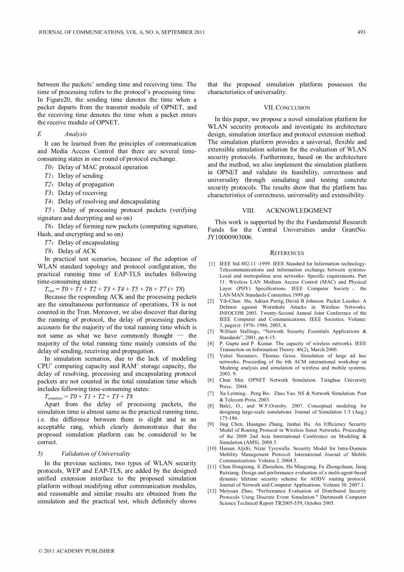
between the packets’ sending time and receiving time. The
time of processing refers to the protocol’s processing time.
In Figure20, the sending time denotes the time when a
packet departs from the transmit module of OPNET, and
the receiving time denotes the time when a packet enters
the receive module of OPNET.
E Analysis
It can be learned from the principles of communication
and Media Access Control that there are several time-
consuming states in one round of protocol exchange.
T0 Delay of MAC protocol operation
T1 Delay of sending
T2 Delay of propagation
T3 Delay of receiving
T4 Delay of resolving and dencapsulating
T5 Delay of processing protocol packets (verifying
signature and decrypting and so on)
T6 Delay of forming new packets (computing signature,
Hash, and encrypting and so on)
T7 Delay of encapsulating
T8 Delay of ACK
In practical test scenarios, because of the adoption of
WLAN standard topology and protocol configuration, the
practical running time of EAP-TLS includes following time-consuming states:
Trun = T0 + T1 + T2 + T3 + T4 + T5 + T6 + T7 (+ T8)
Because the responding ACK and the processing packets
are the simultaneous performance of operations, T8 is not
counted in the Trun. Moreover, we also discover that during
the running of protocol, the delay of processing packets
accounts for the majority of the total running time which is
not same as what we have commonly thought — the
majority of the total running time mainly consists of the
delay of sending, receiving and propagation.
In simulation scenarios, due to the lack of modeling CPU’ computing capacity and RAM’ storage capacity, the
delay of resolving, processing and encapsulating protocol
packets are not counted in the total simulation time which
includes following time-consuming states:
Tsimulate = T0 + T1 + T2 + T3 + T8Apart from the delay of processing packets, the
simulation time is almost same as the practical running time,
i.e. the difference between them is slight and in an acceptable rang, which clearly demonstrates that the
proposed simulation platform can be considered to be
correct.
5) Validation of Universality
In the previous sections, two types of WLAN security
protocols, WEP and EAP-TLS, are added by the designed
unified extension interface to the proposed simulation
platform without modifying other communication modules,
and reasonable and similar results are obtained from the
simulation and the practical test, which definitely shows
that the proposed simulation platform possesses the
characteristics of universality.
VII. CONCLUSION
In this paper, we propose a novel simulation platform for
WLAN security protocols and investigate its architecture
design, simulation interface and protocol extension method.
The simulation platform provides a universal, flexible and extensible simulation solution for the evaluation of WLAN
security protocols. Furthermore, based on the architecture
and the method, we also implement the simulation platform
in OPNET and validate its feasibility, correctness and
universality through simulating and testing concrete
security protocols. The results show that the platform has
characteristics of correctness, universality and extensibility.
VIII. ACKNOWLEDGMENT
This work is supported by the the Fundamental Research
Funds for the Central Universities under GrantNo.
JY10000903006.
REFERENCES
[1] IEEE Std 802.11 -1999. IEEE Standard for Information technology-
Telecommunications and information exchange between systems-
Local and metropolitan area networks- Specific requirements. Part
11: Wireless LAN Medium Access Control (MAC) and Physical
Layer (PHY) Specifications. IEEE Computer Society the
LAN/MAN Standards Committee.1999.pp.
[2] Yih-Chun Hu, Adrian Perrig, David B Johnson. Packet Leashes: A
Defense against Wormhole Attacks in Wireless Networks.
INFOCOM 2003. Twenty-Second Annual Joint Conference of the
IEEE Computer and Communications. IEEE Societies. Volume:
3, page(s): 1976- 1986. 2003, 4.
[3] William Stallings, “Network Security Essentials Applications &
Standards”, 2001, pp 4-15.
[4] P. Gupta and P. Kumar. The capacity of wireless networks. IEEE
Transaction on Information Theory. 46(2), March 2000.
[5] Valeri Naoumov, Thomas Gross. Simulation of large ad hoc
networks. Proceeding of the 6th ACM international workshop on
Modeing analysis and simulation of wireless and mobile systems.
2003. 9.
[6] Chen Min. OPNET Network Simulation. Tsinghua University
Press 2004.
[7] Xu Leiming Peng Bo Zhao Yao. NS & Network Simulation. Post
& Telecom Press. 2003.
[8] Balci, O., and W.F.Ormsby. 2007. Conceptual modeling for
designing large-scale simulations. Journal of Simulation 1:3 (Aug.)
175-186.
[9] Jing Chen, Huanguo Zhang, Junhui Hu. An Efficiency Security
Model of Routing Protocol in Wireless Senor Networks. Proceeding
of the 2008 2nd Asia International Conference on Modeling &
Simulation (AMS). 2008.5.
[10] Hassan Aljifri, Nizar Tyrewalla. Security Model for Intra-Domain
Mobility Management Protocol. International Journal of Mobile
Communications. Volume 2. 2004.5.
[11] Chen Hongsong, Ji Zhenzhou, Hu Mingzeng, Fu Zhongchuan, Jiang
Ruixiang. Design and performance evaluation of a multi-agent-based
dynamic lifetime security scheme for AODV routing protocol.
Journal of Network and Computer Applications. Volume 30. 2007.1.
[12] Meiyuan Zhao, "Performance Evaluation of Distributed Security
Protocols Using Discrete Event Simulation." Dartmouth Computer
Science Technical Report TR2005-559, October 2005.
JOURNAL OF COMMUNICATIONS, VOL. 6, NO. 6, SEPTEMBER 2011 493
© 2011 ACADEMY PUBLISHER
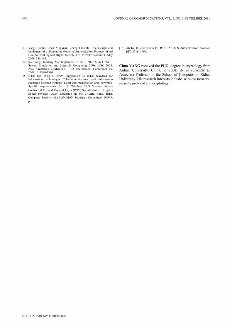
[13] Yang Dianjie, Chen Xingyuan, Zhang Chuanfu. The Design and
Implement of a Simulation Model of Authentication Protocol of Ad
Hoc. Networking and Digital Society ICNDS 2009. Volume 1, May
2009. 186-189.
[14] Kai Yang, Jianfeng Ma, Implement of IEEE 802.1X in OPNET.
Syetem Simulation and Scientific Computing. 2008. ICSC 2008.
Asia Simulation Conference – 7th International Conference on.
2008.10. 1390-1394.
[15] IEEE Std 802.11a -1999. Supplement to IEEE Standard for
Information technology- Telecommunications and information
exchange between systems- Local and metropolitan area networks-
Specific requirements. Part 11: Wireless LAN Medium Access
Control (MAC) and Physical Layer (PHY) Specifications Higher-
Speed Physical Layer Extension in the 2.4GHz Band. IEEE
Computer Society the LAN/MAN Standards Committee. 1999.9.
pp.
[16] Aboba, B. and Simon D., PPP EAP TLS Authentication Protocol.
RFC 2716, 1999.
Chao YANG received the PHD. degree in cryptology from
Xidian University, China, in 2008; He is currently an
Associate Professor in the School of Computer of Xidian
University. His research interests include: wireless network, security protocol and cryptology.
494 JOURNAL OF COMMUNICATIONS, VOL. 6, NO. 6, SEPTEMBER 2011
© 2011 ACADEMY PUBLISHER
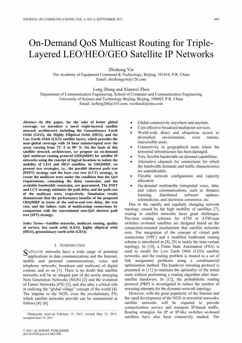
On-Demand QoS Multicast Routing for Triple-Layered LEO/HEO/GEO Satellite IP Networks
Zhizhong Yin
The Academy of Equipment Command & Technology, Beijing, 101416, P.R. China Email: [email protected]
Long Zhang and Xianwei Zhou
Department of Communication Engineering, School of Computer and Communication Engineering University of Science and Technology Beijing, Beijing, 100083, P.R. China
Email: [email protected], [email protected]
Abstract—In this paper, for the sake of better global coverage, we introduce a novel triple-layered satellite network architecture including the Geostationary Earth Orbit (GEO), the Highly Elliptical Orbit (HEO), and the Low Earth Orbit (LEO) satellite layers, which provides the near-global coverage with 24 hour uninterrupted over the areas varying from 75° S to 90° N. On the basis of this satellite network architecture, we propose an on-demand QoS multicast routing protocol (ODQMRP) for satellite IP networks using the concept of logical locations to isolate the mobility of LEO and HEO satellites. In ODQMRP, we present two strategies, i.e., the parallel shortest path tree (PSPT) strategy and the least cost tree (LCT) strategy, to create the multicast trees under the condition that the QoS requirements, containing the delay constraint, and the available bandwidth constraint, are guaranteed. The PSPT and LCT strategy minimize the path delay and the path cost of the multicast trees, respectively. Simulation results demonstrate that the performance benefits of the proposed ODQMRP in terms of the end-to-end tree delay, the tree cost, and the failure ratio of multicasting connections by comparison with the conventional non-QoS shortest path tree (SPT) strategy. Index Terms—Satellite networks, multicast routing, quality of service, low earth orbit (LEO), highly elliptical orbit (HEO), geostationary earth orbit (GEO).
I. INTRODUCTION ATELLITE networks have a wide range of potential applications in data communications and the Internet,
mobile and personal communications, voice and telephony networks, broadcast and multicast of digital content, and so on [1]. There is no doubt that satellite networks will be an integral part of the newly emerging Next Generation Networks (NGN) [2] and the evolution of Future Networks (FN) [3], and also play a critical role in realizing the “global village” concept of the world [4]. The impetus to the NGN, even the revolutionary FN, which satellite networks provide can be summarized as follows [4]–[6].
• Global connectivity anywhere and anytime. • Cost-effective broadcast/multipoint services. • World-wide direct and ubiquitous access to
diversified environments, even remote, inaccessible areas.
• Connectivity in geographical areas where the terrestrial infrastructure has been damaged.
• Very flexible bandwidth-on-demand capabilities. • Alternative channels for connections for which
the bandwidth demands and traffic characteristics are unpredictable.
• Flexible network configuration and capacity allocation
• On-demand multimedia (integrated voice, data, and video) communications, such as distance learning, distributed software updates, telemedicine, and electronic commerce, etc.
Due to the rapidly and regularly changing network topology caused by the high mobility of satellites [7], routing in satellite networks faces great challenges. Previous routing schemes for ATM or ATM-type switches on-board satellites are designed based on the connection-oriented mechanisms that satellite networks own. The integration of the concept of virtual path connections (VPC) and a modified traditional routing scheme is introduced in [8], [9] to tackle the time-variant topology. In [10], a Finite State Automation (FSA) is used to model the Low Earth Orbit (LEO) satellite networks, and the routing problem is treated as a set of link assignment problems using a combinatorial optimization method. The handover rerouting protocol is presented in [11] to maintain the optimality of the initial route without performing a routing algorithm after inter-satellite handovers. In [12], the probabilistic routing protocol (PRP) is investigated to reduce the number of rerouting attempts for the dynamic network topology.
However, with the great popularity of the Internet and the rapid development of the NGN in terrestrial networks, satellite networks will be required to provide connectionless service and transport IP-based traffic. Routing strategies for IP or IP-like switches on-board satellites have also been extensively studied. The
S
Manuscript received February 15, 2011; revised May 15, 2011;accepted June 15, 2011
JOURNAL OF COMMUNICATIONS, VOL. 6, NO. 6, SEPTEMBER 2011 495
© 2011 ACADEMY PUBLISHERdoi:10.4304/jcm.6.6.495-508
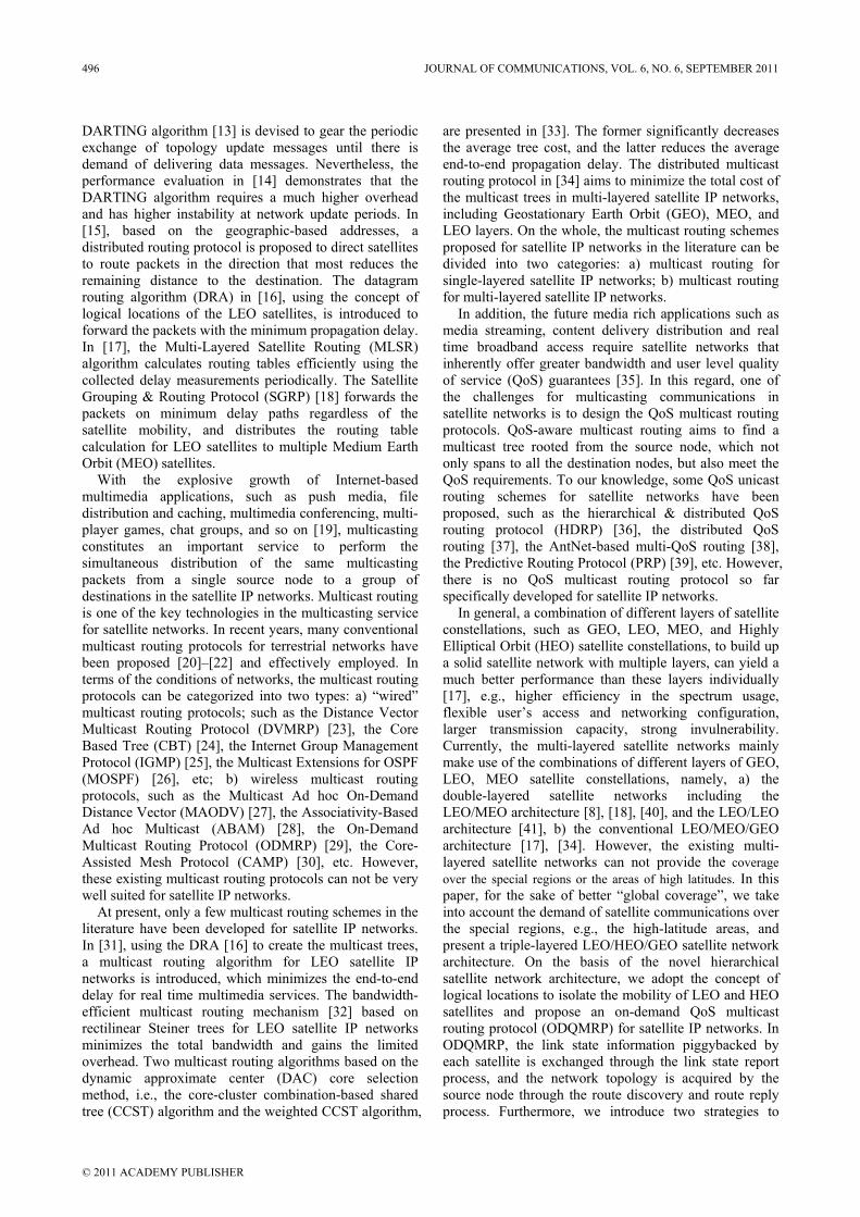
DARTING algorithm [13] is devised to gear the periodic exchange of topology update messages until there is demand of delivering data messages. Nevertheless, the performance evaluation in [14] demonstrates that the DARTING algorithm requires a much higher overhead and has higher instability at network update periods. In [15], based on the geographic-based addresses, a distributed routing protocol is proposed to direct satellites to route packets in the direction that most reduces the remaining distance to the destination. The datagram routing algorithm (DRA) in [16], using the concept of logical locations of the LEO satellites, is introduced to forward the packets with the minimum propagation delay. In [17], the Multi-Layered Satellite Routing (MLSR) algorithm calculates routing tables efficiently using the collected delay measurements periodically. The Satellite Grouping & Routing Protocol (SGRP) [18] forwards the packets on minimum delay paths regardless of the satellite mobility, and distributes the routing table calculation for LEO satellites to multiple Medium Earth Orbit (MEO) satellites.
With the explosive growth of Internet-based multimedia applications, such as push media, file distribution and caching, multimedia conferencing, multi-player games, chat groups, and so on [19], multicasting constitutes an important service to perform the simultaneous distribution of the same multicasting packets from a single source node to a group of destinations in the satellite IP networks. Multicast routing is one of the key technologies in the multicasting service for satellite networks. In recent years, many conventional multicast routing protocols for terrestrial networks have been proposed [20]–[22] and effectively employed. In terms of the conditions of networks, the multicast routing protocols can be categorized into two types: a) “wired” multicast routing protocols; such as the Distance Vector Multicast Routing Protocol (DVMRP) [23], the Core Based Tree (CBT) [24], the Internet Group Management Protocol (IGMP) [25], the Multicast Extensions for OSPF (MOSPF) [26], etc; b) wireless multicast routing protocols, such as the Multicast Ad hoc On-Demand Distance Vector (MAODV) [27], the Associativity-Based Ad hoc Multicast (ABAM) [28], the On-Demand Multicast Routing Protocol (ODMRP) [29], the Core-Assisted Mesh Protocol (CAMP) [30], etc. However, these existing multicast routing protocols can not be very well suited for satellite IP networks.
At present, only a few multicast routing schemes in the literature have been developed for satellite IP networks. In [31], using the DRA [16] to create the multicast trees, a multicast routing algorithm for LEO satellite IP networks is introduced, which minimizes the end-to-end delay for real time multimedia services. The bandwidth-efficient multicast routing mechanism [32] based on rectilinear Steiner trees for LEO satellite IP networks minimizes the total bandwidth and gains the limited overhead. Two multicast routing algorithms based on the dynamic approximate center (DAC) core selection method, i.e., the core-cluster combination-based shared tree (CCST) algorithm and the weighted CCST algorithm,
are presented in [33]. The former significantly decreases the average tree cost, and the latter reduces the average end-to-end propagation delay. The distributed multicast routing protocol in [34] aims to minimize the total cost of the multicast trees in multi-layered satellite IP networks, including Geostationary Earth Orbit (GEO), MEO, and LEO layers. On the whole, the multicast routing schemes proposed for satellite IP networks in the literature can be divided into two categories: a) multicast routing for single-layered satellite IP networks; b) multicast routing for multi-layered satellite IP networks.
In addition, the future media rich applications such as media streaming, content delivery distribution and real time broadband access require satellite networks that inherently offer greater bandwidth and user level quality of service (QoS) guarantees [35]. In this regard, one of the challenges for multicasting communications in satellite networks is to design the QoS multicast routing protocols. QoS-aware multicast routing aims to find a multicast tree rooted from the source node, which not only spans to all the destination nodes, but also meet the QoS requirements. To our knowledge, some QoS unicast routing schemes for satellite networks have been proposed, such as the hierarchical & distributed QoS routing protocol (HDRP) [36], the distributed QoS routing [37], the AntNet-based multi-QoS routing [38], the Predictive Routing Protocol (PRP) [39], etc. However, there is no QoS multicast routing protocol so far specifically developed for satellite IP networks.
In general, a combination of different layers of satellite constellations, such as GEO, LEO, MEO, and Highly Elliptical Orbit (HEO) satellite constellations, to build up a solid satellite network with multiple layers, can yield a much better performance than these layers individually [17], e.g., higher efficiency in the spectrum usage, flexible user’s access and networking configuration, larger transmission capacity, strong invulnerability. Currently, the multi-layered satellite networks mainly make use of the combinations of different layers of GEO, LEO, MEO satellite constellations, namely, a) the double-layered satellite networks including the LEO/MEO architecture [8], [18], [40], and the LEO/LEO architecture [41], b) the conventional LEO/MEO/GEO architecture [17], [34]. However, the existing multi-layered satellite networks can not provide the coverage over the special regions or the areas of high latitudes. In this paper, for the sake of better “global coverage”, we take into account the demand of satellite communications over the special regions, e.g., the high-latitude areas, and present a triple-layered LEO/HEO/GEO satellite network architecture. On the basis of the novel hierarchical satellite network architecture, we adopt the concept of logical locations to isolate the mobility of LEO and HEO satellites and propose an on-demand QoS multicast routing protocol (ODQMRP) for satellite IP networks. In ODQMRP, the link state information piggybacked by each satellite is exchanged through the link state report process, and the network topology is acquired by the source node through the route discovery and route reply process. Furthermore, we introduce two strategies to
496 JOURNAL OF COMMUNICATIONS, VOL. 6, NO. 6, SEPTEMBER 2011
© 2011 ACADEMY PUBLISHER
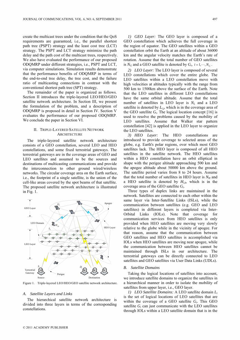
create the multicast trees under the condition that the QoS requirements are guaranteed, i.e., the parallel shortest path tree (PSPT) strategy and the least cost tree (LCT) strategy. The PSPT and LCT strategy minimize the path delay and the path cost of the multicast trees, respectively. We also have evaluated the performance of our proposed ODQMRP under different strategies, i.e., PSPT and LCT, via computer simulations. Simulation results demonstrate that the performance benefits of ODQMRP in terms of the end-to-end tree delay, the tree cost, and the failure ratio of multicasting connections in contrast with the conventional shortest path tree (SPT) strategy.
The remainder of the paper is organized as follows. Section II introduces the triple-layered LEO/HEO/GEO satellite network architecture. In Section III, we present the formulation of the problem, and a description of ODQMRP is proposed in detail in Section IV. Section V evaluates the performance of our proposed ODQMRP. We conclude the paper in Section VI.
II. TRIPLE-LAYERED SATELLITE NETWORK ARCHITECTURE
The triple-layered satellite network architecture consists of a GEO constellation, several LEO and HEO constellations, and some fixed terrestrial gateways. The terrestrial gateways are in the coverage areas of GEO and LEO satellites and assumed to be the sources and destinations of multicasting communications and provide the interconnection to other ground wired/wireless networks. The circular coverage area on the Earth surface, i.e., the footprint of a single satellite, is the union of the cell-like areas covered by the spot beams of that satellite. The proposed satellite network architecture is illustrated in Fig. 1.
GEO Layer
LEO Layer
HEO Layer
Terrestrial Gateway
Source Destination
iG
,i jL
iL,i kH
Apogee
Perigee
SiD
LEO Domain
Figure 1. Triple-layered LEO/HEO/GEO satellite network architecture.
A. Satellite Layers and Links The hierarchical satellite network architecture is
divided into three layers in terms of the corresponding constellations.
1) GEO Layer: The GEO layer is composed of a GEO constellation which achieves the full coverage in the region of equator. The GEO satellites within a GEO constellation orbit the Earth at an altitude of about 36000 km and the angular velocity matches the Earth’s rate of rotation. Assume that the total number of GEO satellites is NG and a GEO satellite is denoted by Gi, 1, , Gi N= .
2) LEO Layer: The LEO layer is composed of several LEO constellations which cover the entire globe. The LEO satellites within a LEO constellation move with high velocities at altitudes typically with the range from 500 km to 1500km above the surface of the Earth. Note that the LEO satellites in different LEO constellations have the same orbital altitude. Assume that the total number of satellites in LEO layer is NL and a LEO satellite is denoted by Li,j, which is in the coverage area of the GEO satellite Gi. The logical location concept [16] is used to resolve the problems caused by the mobility of LEO satellites. Assume that Walker star pattern constellation [42] is applied in the LEO layer to organize the LEO satellites.
3) HEO Layer: The HEO constellations are introduced to provide coverage to selected areas of the globe, e.g. Earth's polar regions, over which most GEO satellites lack. The HEO layer is composed of all HEO satellites in the satellite network. The HEO satellites within a HEO constellation have an orbit elliptical in shape with the perigee altitude approaching 500 km and the apogee altitude about 50000 km above the ground. The satellite period varies from 8 to 24 hours. Assume that the total number of satellites in HEO layer is NH and a HEO satellite is denoted by Hi,k, which is in the coverage area of the GEO satellite Gi.
Three types of duplex links are maintained in the network. Satellites are connected to each other within the same layer via Inter-Satellite Links (ISLs), while the communication between satellites (e.g. GEO and LEO satellites) in different layers is completed via Inter-Orbital Links (IOLs). Note that coverage for communication services from HEO satellites is only provided when HEO satellites are moving very slowly relative to the globe while in the vicinity of apogee. For that reason, assume that the communication between GEO satellites and HEO satellites is accomplished via IOLs when HEO satellites are moving near apogee, while the communication between HEO satellites cannot be maintained through ISLs in our architecture. The terrestrial gateways can be directly connected to LEO satellites and GEO satellites via User Data Links (UDLs).
B. Satellite Domains Taking the logical locations of satellites into account,
we introduce satellite domains to organize the satellites in a hierarchical manner in order to isolate the mobility of satellites from upper layer, i.e., GEO layer.
1) LEO Satellite Domains: A LEO satellite domain Li is the set of logical locations of LEO satellites that are within the coverage of a GEO satellite Gi. This GEO satellite Gi can just communicate with the LEO satellites through IOLs within a LEO satellite domain that is in the
JOURNAL OF COMMUNICATIONS, VOL. 6, NO. 6, SEPTEMBER 2011 497
© 2011 ACADEMY PUBLISHER
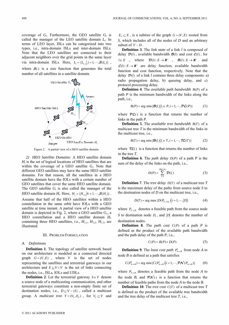
coverage of Gi. Furthermore, the GEO satellite Gi is called the manager of the LEO satellite domain Li. In terms of LEO layer, ISLs can be categorized into two types, i.e., intra-domain ISLs and inter-domain ISLs. Note that the LEO satellites are connected to their adjacent neighbors over the grid points in the same layer via intra-domain ISLs. Here, , 1, , ( )i i j iL L j L= = S , where ( )⋅S is a size function that generates the total number of all satellites in a satellite domain.
1G
1H
1,1H3,1H
2,1H
Figure 2. A partial view of a HEO satellite domain.
2) HEO Satellite Domains: A HEO satellite domain Hi is the set of logical locations of HEO satellites that are within the coverage of a GEO satellite Gi. Note that different GEO satellites may have the same HEO satellite domains. For that reason, all the satellites in a HEO satellite domain have the IOLs with a certain number of GEO satellites that cover the same HEO satellite domain. The GEO satellite Gi is also called the manager of the HEO satellite domain Hi. Here, , 1, , ( )i i k iH H k H= = S . Assume that half of the HEO satellites within a HEO constellation in the same orbit have IOLs with a GEO satellite at time instant. A partial view of a HEO satellite domain is depicted in Fig. 2, where a GEO satellite G1, a HEO constellation and a HEO satellite domain H1 containing three HEO satellites, i.e., H1,1, H1,2, H1,3, are illustrated.
III. PROBLEM FORMULATION
A. Definitions Definition 1. The topology of satellite network based
on our architecture is modeled as a connected directed graph ( , )G V E= , where V is the set of nodes representing the satellites and terrestrial gateways in our architecture and E V V⊆ × is the set of links connecting the nodes, i.e., ISLs, IOLs and UDLs.
Definition 2. Let the terrestrial gateway S V∈ denote a source node of a multicasting communication, and other terrestrial gateways constitute a non-empty finite set of destination nodes, i.e., D V S⊆ − , called a multicast group. A multicast tree ( , )T TT V E= , for TV V⊆ and
TE E⊆ , is a subtree of the graph ( , )G V E= rooted from S, which includes all of the nodes of D and an arbitrary subset of V D− .
Definition 3. The link state of a link l is composed of delay ( )lD , available bandwidth ( )lB and cost ( )lC , for l E∈ , where ( ) :l E +→D R , ( ) :l E +→B R and
( ) :l E +→C R are delay function, available bandwidth function and cost function, respectively. Note that the delay ( )lD of a link l contains three delay components: a) radio propagation delay, b) queuing delay, and c) protocol processing delay.
Definition 4. The available path bandwidth ( )B P of a path P is the minimum bandwidth of the links along the path, i.e.,
( ) arg min ( ) , 1, , ( )i iB P l l P i P= ∈ =B PL (1)
where ( )⋅PL is a function that returns the number of links in the path P.
Definition 5. The available tree bandwidth ( )B T of a multicast tree T is the minimum bandwidth of the links in the multicast tree, i.e.,
( ) arg min ( ) , 1, , ( )i iB T l l T i T= ∈ =B TL (2)
where ( )⋅TL is a function that returns the number of links in the tree T.
Definition 6. The path delay ( )D P of a path P is the sum of the delay of the links on the path, i.e.,
( )
1( ) ( )
P
ii
D P l=
= ∑PL
D (3)
Definition 7. The tree delay ( )D T of a multicast tree T is the maximum delay of the paths from source node S to the destination nodes of D on the multicast tree, i.e.,
( ) arg max ( ) 1, , iS DD T D P i D→= = (4)
where iS DP → denotes a feasible path from the source node
S to destination node iD , and D denotes the number of destination nodes.
Definition 8. The path cost ( )C P of a path P is defined as the product of the available path bandwidth and the path delay of the path P, i.e.,
( ) ( ) ( )C P B P D P= × (5)
Definition 9. The least cost path A BP∗→ from node A to
node B is defined as a path that satisfies
( ) arg min ( ) 1, , ( )iA B A B A BC P C P i P∗→ → →= = PN (6)
where A BP → denotes a feasible path from the node A to the node B, and ( )⋅PN is a function that returns the number of feasible paths from the node A to the node B.
Definition 10. The tree cost ( )C T of a multicast tree T is defined as the product of the available tree bandwidth and the tree delay of the multicast tree T, i.e.,
498 JOURNAL OF COMMUNICATIONS, VOL. 6, NO. 6, SEPTEMBER 2011
© 2011 ACADEMY PUBLISHER
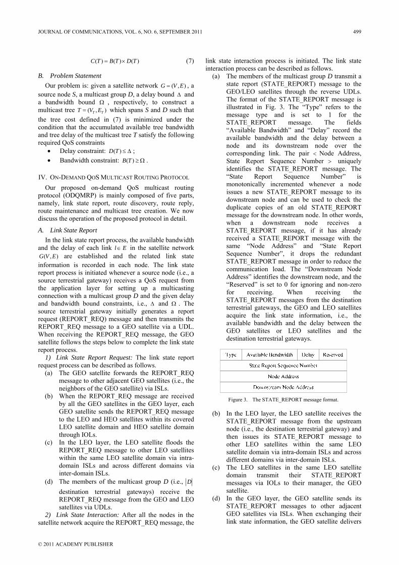
( ) ( ) ( )C T B T D T= × (7)
B. Problem Statement Our problem is: given a satellite network ( , )G V E= , a
source node S, a multicast group D, a delay bound Δ and a bandwidth bound Ω , respectively, to construct a multicast tree ( , )T TT V E= which spans S and D such that the tree cost defined in (7) is minimized under the condition that the accumulated available tree bandwidth and tree delay of the multicast tree T satisfy the following required QoS constraints
• Delay constraint: ( )D T ≤ Δ ; • Bandwidth constraint: ( )B T ≥ Ω .
IV. ON-DEMAND QOS MULTICAST ROUTING PROTOCOL Our proposed on-demand QoS multicast routing
protocol (ODQMRP) is mainly composed of five parts, namely, link state report, route discovery, route reply, route maintenance and multicast tree creation. We now discuss the operation of the proposed protocol in detail.
A. Link State Report In the link state report process, the available bandwidth
and the delay of each link l E∈ in the satellite network ( , )G V E are established and the related link state
information is recorded in each node. The link state report process is initiated whenever a source node (i.e., a source terrestrial gateway) receives a QoS request from the application layer for setting up a multicasting connection with a multicast group D and the given delay and bandwidth bound constraints, i.e., Δ and Ω . The source terrestrial gateway initially generates a report request (REPORT_REQ) message and then transmits the REPORT_REQ message to a GEO satellite via a UDL. When receiving the REPORT_REQ message, the GEO satellite follows the steps below to complete the link state report process.
1) Link State Report Request: The link state report request process can be described as follows.
(a) The GEO satellite forwards the REPORT_REQ message to other adjacent GEO satellites (i.e., the neighbors of the GEO satellite) via ISLs.
(b) When the REPORT_REQ message are received by all the GEO satellites in the GEO layer, each GEO satellite sends the REPORT_REQ message to the LEO and HEO satellites within its covered LEO satellite domain and HEO satellite domain through IOLs.
(c) In the LEO layer, the LEO satellite floods the REPORT_REQ message to other LEO satellites within the same LEO satellite domain via intra-domain ISLs and across different domains via inter-domain ISLs.
(d) The members of the multicast group D (i.e., D destination terrestrial gateways) receive the REPORT_REQ message from the GEO and LEO satellites via UDLs.
2) Link State Interaction: After all the nodes in the satellite network acquire the REPORT_REQ message, the
link state interaction process is initiated. The link state interaction process can be described as follows.
(a) The members of the multicast group D transmit a state report (STATE_REPORT) message to the GEO/LEO satellites through the reverse UDLs. The format of the STATE_REPORT message is illustrated in Fig. 3. The “Type” refers to the message type and is set to 1 for the STATE_REPORT message. The fields “Available Bandwidth” and “Delay” record the available bandwidth and the delay between a node and its downstream node over the corresponding link. The pair < Node Address, State Report Sequence Number > uniquely identifies the STATE_REPORT message. The “State Report Sequence Number” is monotonically incremented whenever a node issues a new STATE_REPORT message to its downstream node and can be used to check the duplicate copies of an old STATE_REPORT message for the downstream node. In other words, when a downstream node receives a STATE_REPORT message, if it has already received a STATE_REPORT message with the same “Node Address” and “State Report Sequence Number”, it drops the redundant STATE_REPORT message in order to reduce the communication load. The “Downstream Node Address” identifies the downstream node, and the “Reserved” is set to 0 for ignoring and non-zero for receiving. When receiving the STATE_REPORT messages from the destination terrestrial gateways, the GEO and LEO satellites acquire the link state information, i.e., the available bandwidth and the delay between the GEO satellites or LEO satellites and the destination terrestrial gateways.
Figure 3. The STATE_REPORT message format.
(b) In the LEO layer, the LEO satellite receives the STATE_REPORT message from the upstream node (i.e., the destination terrestrial gateway) and then issues its STATE_REPORT message to other LEO satellites within the same LEO satellite domain via intra-domain ISLs and across different domains via inter-domain ISLs.
(c) The LEO satellites in the same LEO satellite domain transmit their STATE_REPORT messages via IOLs to their manager, the GEO satellite.
(d) In the GEO layer, the GEO satellite sends its STATE_REPORT messages to other adjacent GEO satellites via ISLs. When exchanging their link state information, the GEO satellite delivers
JOURNAL OF COMMUNICATIONS, VOL. 6, NO. 6, SEPTEMBER 2011 499
© 2011 ACADEMY PUBLISHER
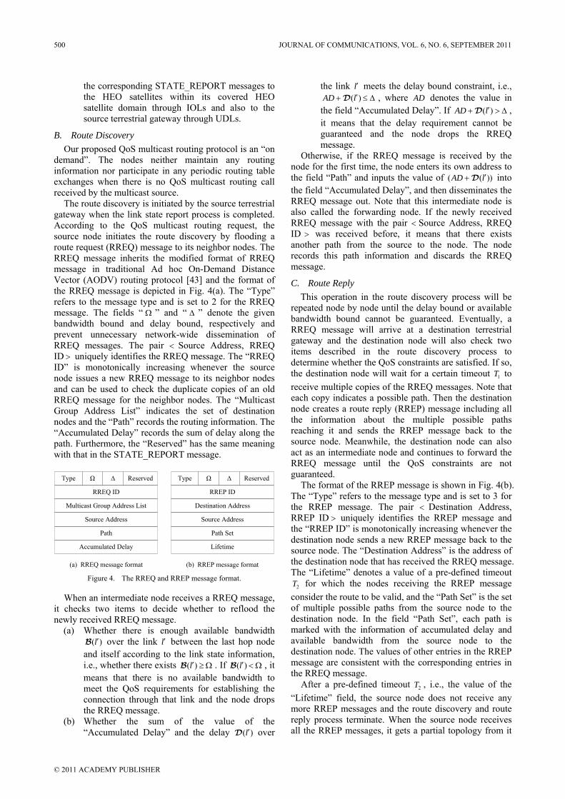
the corresponding STATE_REPORT messages to the HEO satellites within its covered HEO satellite domain through IOLs and also to the source terrestrial gateway through UDLs.
B. Route Discovery Our proposed QoS multicast routing protocol is an “on
demand”. The nodes neither maintain any routing information nor participate in any periodic routing table exchanges when there is no QoS multicast routing call received by the multicast source.
The route discovery is initiated by the source terrestrial gateway when the link state report process is completed. According to the QoS multicast routing request, the source node initiates the route discovery by flooding a route request (RREQ) message to its neighbor nodes. The RREQ message inherits the modified format of RREQ message in traditional Ad hoc On-Demand Distance Vector (AODV) routing protocol [43] and the format of the RREQ message is depicted in Fig. 4(a). The “Type” refers to the message type and is set to 2 for the RREQ message. The fields “ Ω ” and “ Δ ” denote the given bandwidth bound and delay bound, respectively and prevent unnecessary network-wide dissemination of RREQ messages. The pair < Source Address, RREQ ID > uniquely identifies the RREQ message. The “RREQ ID” is monotonically increasing whenever the source node issues a new RREQ message to its neighbor nodes and can be used to check the duplicate copies of an old RREQ message for the neighbor nodes. The “Multicast Group Address List” indicates the set of destination nodes and the “Path” records the routing information. The “Accumulated Delay” records the sum of delay along the path. Furthermore, the “Reserved” has the same meaning with that in the STATE_REPORT message.
Type Ω Δ Reserved
RREQ ID
Multicast Group Address List
Source Address
Path
Type Ω Δ Reserved
RREP ID
Destination Address
Source Address
Path Set
Lifetime
(a) RREQ message format (b) RREP message format
Accumulated Delay
Figure 4. The RREQ and RREP message format.
When an intermediate node receives a RREQ message, it checks two items to decide whether to reflood the newly received RREQ message.
(a) Whether there is enough available bandwidth ( )l′B over the link l′ between the last hop node
and itself according to the link state information, i.e., whether there exists ( )l′ ≥ ΩB . If ( )l′ < ΩB , it means that there is no available bandwidth to meet the QoS requirements for establishing the connection through that link and the node drops the RREQ message.
(b) Whether the sum of the value of the “Accumulated Delay” and the delay ( )l′D over
the link l′ meets the delay bound constraint, i.e., ( )AD l′+ ≤ ΔD , where AD denotes the value in
the field “Accumulated Delay”. If ( )AD l′+ > ΔD , it means that the delay requirement cannot be guaranteed and the node drops the RREQ message.
Otherwise, if the RREQ message is received by the node for the first time, the node enters its own address to the field “Path” and inputs the value of ( ( ))AD l′+D into the field “Accumulated Delay”, and then disseminates the RREQ message out. Note that this intermediate node is also called the forwarding node. If the newly received RREQ message with the pair < Source Address, RREQ ID > was received before, it means that there exists another path from the source to the node. The node records this path information and discards the RREQ message.
C. Route Reply This operation in the route discovery process will be
repeated node by node until the delay bound or available bandwidth bound cannot be guaranteed. Eventually, a RREQ message will arrive at a destination terrestrial gateway and the destination node will also check two items described in the route discovery process to determine whether the QoS constraints are satisfied. If so, the destination node will wait for a certain timeout 1T to receive multiple copies of the RREQ messages. Note that each copy indicates a possible path. Then the destination node creates a route reply (RREP) message including all the information about the multiple possible paths reaching it and sends the RREP message back to the source node. Meanwhile, the destination node can also act as an intermediate node and continues to forward the RREQ message until the QoS constraints are not guaranteed.
The format of the RREP message is shown in Fig. 4(b). The “Type” refers to the message type and is set to 3 for the RREP message. The pair < Destination Address, RREP ID > uniquely identifies the RREP message and the “RREP ID” is monotonically increasing whenever the destination node sends a new RREP message back to the source node. The “Destination Address” is the address of the destination node that has received the RREQ message. The “Lifetime” denotes a value of a pre-defined timeout
2T for which the nodes receiving the RREP message consider the route to be valid, and the “Path Set” is the set of multiple possible paths from the source node to the destination node. In the field “Path Set”, each path is marked with the information of accumulated delay and available bandwidth from the source node to the destination node. The values of other entries in the RREP message are consistent with the corresponding entries in the RREQ message.
After a pre-defined timeout 2T , i.e., the value of the “Lifetime” field, the source node does not receive any more RREP messages and the route discovery and route reply process terminate. When the source node receives all the RREP messages, it gets a partial topology from it
500 JOURNAL OF COMMUNICATIONS, VOL. 6, NO. 6, SEPTEMBER 2011
© 2011 ACADEMY PUBLISHER
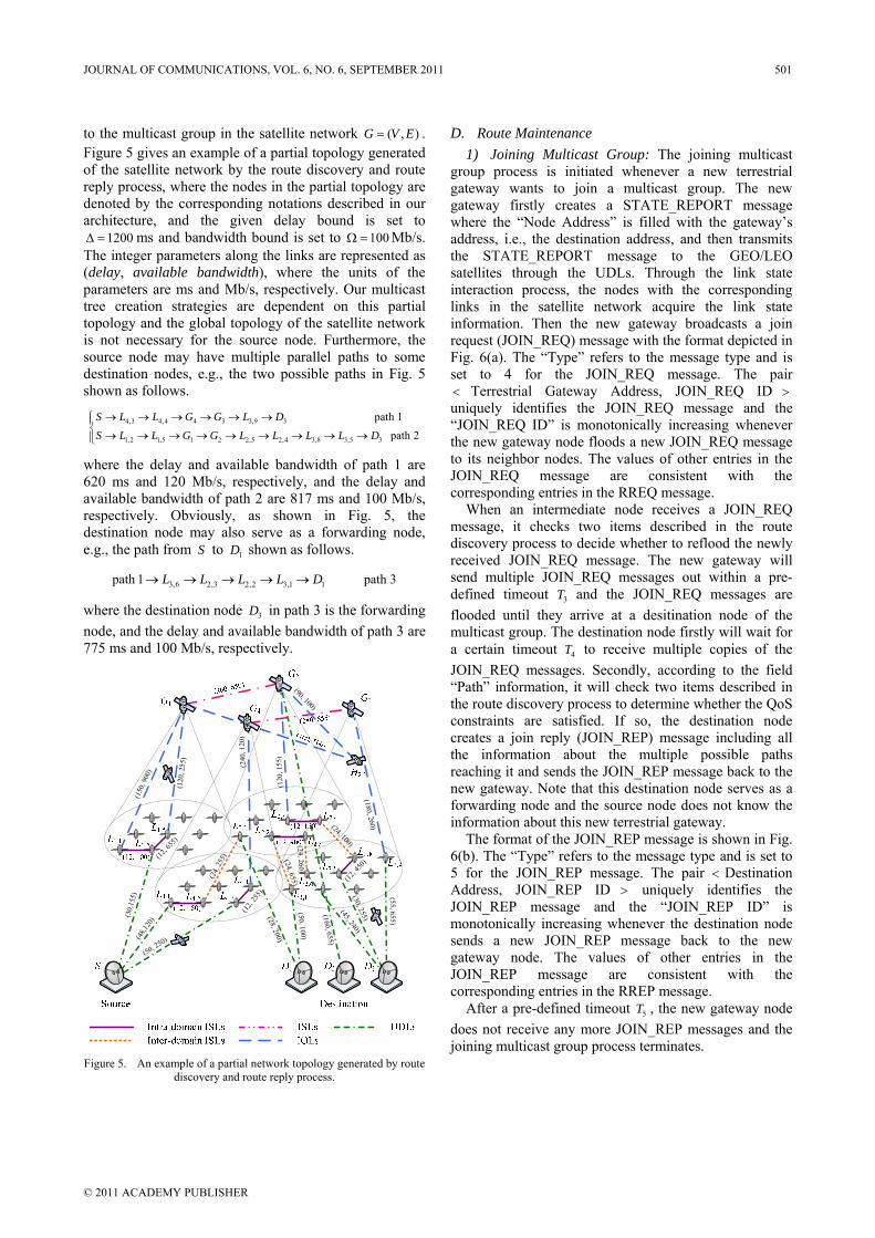
to the multicast group in the satellite network ( , )G V E= . Figure 5 gives an example of a partial topology generated of the satellite network by the route discovery and route reply process, where the nodes in the partial topology are denoted by the corresponding notations described in our architecture, and the given delay bound is set to
1200Δ = ms and bandwidth bound is set to 100Ω = Mb/s. The integer parameters along the links are represented as (delay, available bandwidth), where the units of the parameters are ms and Mb/s, respectively. Our multicast tree creation strategies are dependent on this partial topology and the global topology of the satellite network is not necessary for the source node. Furthermore, the source node may have multiple parallel paths to some destination nodes, e.g., the two possible paths in Fig. 5 shown as follows.
4,3 4,4 4 3 3,9 3
1,2 1,5 1 2 2,5 2,4 3,8 3,5 3
path 1path 2
S L L G G L DS L L G G L L L L D→ → → → → →⎧⎪
⎨ → → → → → → → → →⎪⎩
where the delay and available bandwidth of path 1 are 620 ms and 120 Mb/s, respectively, and the delay and available bandwidth of path 2 are 817 ms and 100 Mb/s, respectively. Obviously, as shown in Fig. 5, the destination node may also serve as a forwarding node, e.g., the path from S to 1D shown as follows.
3,6 2,3 2,2 3,1 1path 1 path 3L L L L D→ → → → →
where the destination node 3D in path 3 is the forwarding node, and the delay and available bandwidth of path 3 are 775 ms and 100 Mb/s, respectively.
(30,
155)
(48,1
20)
(50, 250)
(12, 2
55)
(12, 6
55)
(12, 4
50)
(24,
255) (24, 655)
(24, 2 60)
(24, 100)
(150
, 900
)
(120
, 255
)
(240
, 120
)
(180, 260)
(120
, 155
)
(90, 100)
(28, 200)
(50, 100)
(160, 655)(45, 240)
(30, 255)
(55, 655)
Figure 5. An example of a partial network topology generated by route
discovery and route reply process.
D. Route Maintenance 1) Joining Multicast Group: The joining multicast
group process is initiated whenever a new terrestrial gateway wants to join a multicast group. The new gateway firstly creates a STATE_REPORT message where the “Node Address” is filled with the gateway’s address, i.e., the destination address, and then transmits the STATE_REPORT message to the GEO/LEO satellites through the UDLs. Through the link state interaction process, the nodes with the corresponding links in the satellite network acquire the link state information. Then the new gateway broadcasts a join request (JOIN_REQ) message with the format depicted in Fig. 6(a). The “Type” refers to the message type and is set to 4 for the JOIN_REQ message. The pair < Terrestrial Gateway Address, JOIN_REQ ID > uniquely identifies the JOIN_REQ message and the “JOIN_REQ ID” is monotonically increasing whenever the new gateway node floods a new JOIN_REQ message to its neighbor nodes. The values of other entries in the JOIN_REQ message are consistent with the corresponding entries in the RREQ message.
When an intermediate node receives a JOIN_REQ message, it checks two items described in the route discovery process to decide whether to reflood the newly received JOIN_REQ message. The new gateway will send multiple JOIN_REQ messages out within a pre-defined timeout 3T and the JOIN_REQ messages are flooded until they arrive at a desitination node of the multicast group. The destination node firstly will wait for a certain timeout 4T to receive multiple copies of the JOIN_REQ messages. Secondly, according to the field “Path” information, it will check two items described in the route discovery process to determine whether the QoS constraints are satisfied. If so, the destination node creates a join reply (JOIN_REP) message including all the information about the multiple possible paths reaching it and sends the JOIN_REP message back to the new gateway. Note that this destination node serves as a forwarding node and the source node does not know the information about this new terrestrial gateway.
The format of the JOIN_REP message is shown in Fig. 6(b). The “Type” refers to the message type and is set to 5 for the JOIN_REP message. The pair < Destination Address, JOIN_REP ID > uniquely identifies the JOIN_REP message and the “JOIN_REP ID” is monotonically increasing whenever the destination node sends a new JOIN_REP message back to the new gateway node. The values of other entries in the JOIN_REP message are consistent with the corresponding entries in the RREP message.
After a pre-defined timeout 5T , the new gateway node does not receive any more JOIN_REP messages and the joining multicast group process terminates.
JOURNAL OF COMMUNICATIONS, VOL. 6, NO. 6, SEPTEMBER 2011 501
© 2011 ACADEMY PUBLISHER
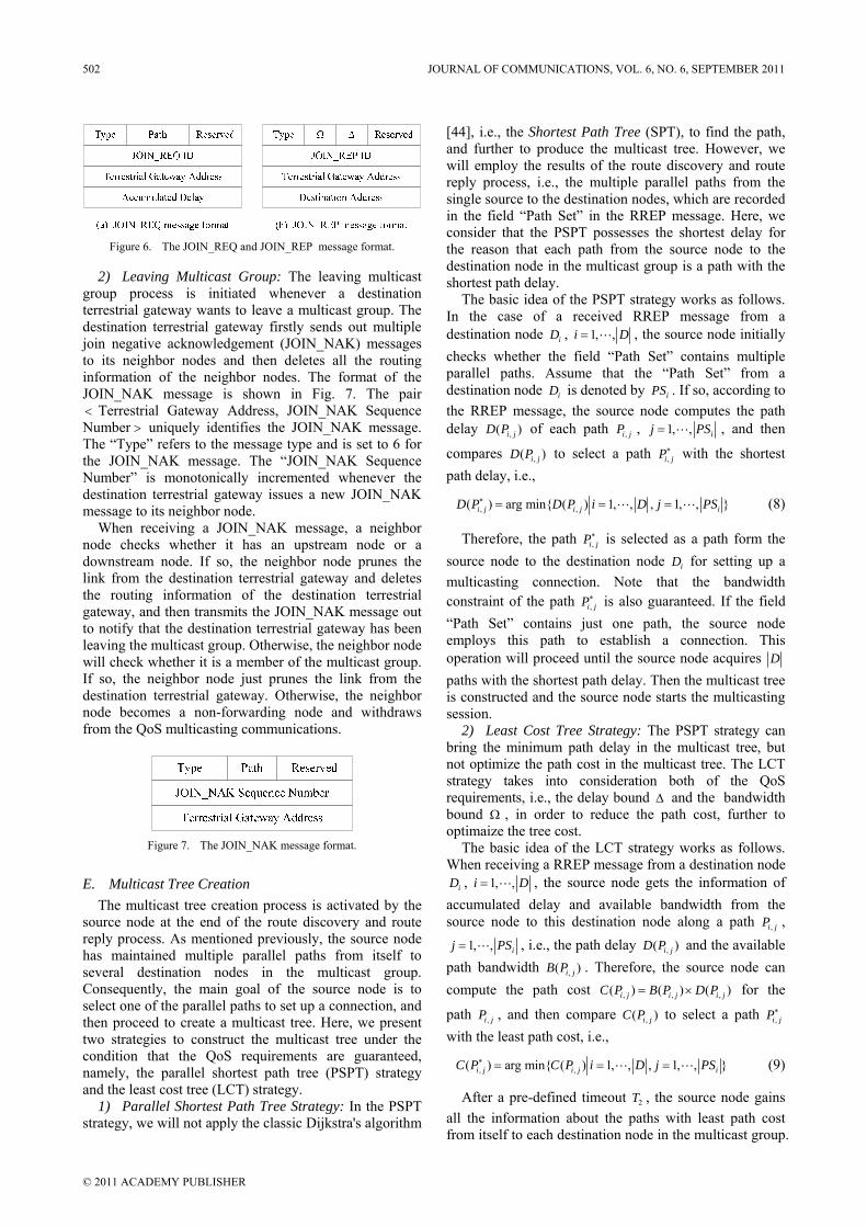
Figure 6. The JOIN_REQ and JOIN_REP message format.
2) Leaving Multicast Group: The leaving multicast group process is initiated whenever a destination terrestrial gateway wants to leave a multicast group. The destination terrestrial gateway firstly sends out multiple join negative acknowledgement (JOIN_NAK) messages to its neighbor nodes and then deletes all the routing information of the neighbor nodes. The format of the JOIN_NAK message is shown in Fig. 7. The pair < Terrestrial Gateway Address, JOIN_NAK Sequence Number > uniquely identifies the JOIN_NAK message. The “Type” refers to the message type and is set to 6 for the JOIN_NAK message. The “JOIN_NAK Sequence Number” is monotonically incremented whenever the destination terrestrial gateway issues a new JOIN_NAK message to its neighbor node.
When receiving a JOIN_NAK message, a neighbor node checks whether it has an upstream node or a downstream node. If so, the neighbor node prunes the link from the destination terrestrial gateway and deletes the routing information of the destination terrestrial gateway, and then transmits the JOIN_NAK message out to notify that the destination terrestrial gateway has been leaving the multicast group. Otherwise, the neighbor node will check whether it is a member of the multicast group. If so, the neighbor node just prunes the link from the destination terrestrial gateway. Otherwise, the neighbor node becomes a non-forwarding node and withdraws from the QoS multicasting communications.
Figure 7. The JOIN_NAK message format.
E. Multicast Tree Creation The multicast tree creation process is activated by the
source node at the end of the route discovery and route reply process. As mentioned previously, the source node has maintained multiple parallel paths from itself to several destination nodes in the multicast group. Consequently, the main goal of the source node is to select one of the parallel paths to set up a connection, and then proceed to create a multicast tree. Here, we present two strategies to construct the multicast tree under the condition that the QoS requirements are guaranteed, namely, the parallel shortest path tree (PSPT) strategy and the least cost tree (LCT) strategy.
1) Parallel Shortest Path Tree Strategy: In the PSPT strategy, we will not apply the classic Dijkstra's algorithm
[44], i.e., the Shortest Path Tree (SPT), to find the path, and further to produce the multicast tree. However, we will employ the results of the route discovery and route reply process, i.e., the multiple parallel paths from the single source to the destination nodes, which are recorded in the field “Path Set” in the RREP message. Here, we consider that the PSPT possesses the shortest delay for the reason that each path from the source node to the destination node in the multicast group is a path with the shortest path delay.
The basic idea of the PSPT strategy works as follows. In the case of a received RREP message from a destination node iD , 1, ,i D= , the source node initially checks whether the field “Path Set” contains multiple parallel paths. Assume that the “Path Set” from a destination node iD is denoted by iPS . If so, according to the RREP message, the source node computes the path delay ,( )i jD P of each path ,i jP , 1, , ij PS= , and then
compares ,( )i jD P to select a path ,i jP∗ with the shortest path delay, i.e.,
, ,( ) arg min ( ) 1, , , 1, , i j i j iD P D P i D j PS∗ = = = (8)
Therefore, the path ,i jP∗ is selected as a path form the source node to the destination node iD for setting up a multicasting connection. Note that the bandwidth constraint of the path ,i jP∗ is also guaranteed. If the field “Path Set” contains just one path, the source node employs this path to establish a connection. This operation will proceed until the source node acquires D paths with the shortest path delay. Then the multicast tree is constructed and the source node starts the multicasting session.
2) Least Cost Tree Strategy: The PSPT strategy can bring the minimum path delay in the multicast tree, but not optimize the path cost in the multicast tree. The LCT strategy takes into consideration both of the QoS requirements, i.e., the delay bound Δ and the bandwidth bound Ω , in order to reduce the path cost, further to optimaize the tree cost.
The basic idea of the LCT strategy works as follows. When receiving a RREP message from a destination node
iD , 1, ,i D= , the source node gets the information of accumulated delay and available bandwidth from the source node to this destination node along a path ,i jP ,
1, , ij PS= , i.e., the path delay ,( )i jD P and the available path bandwidth ,( )i jB P . Therefore, the source node can compute the path cost , , ,( ) ( ) ( )i j i j i jC P B P D P= × for the
path ,i jP , and then compare ,( )i jC P to select a path ,i jP∗ with the least path cost, i.e.,
, ,( ) arg min ( ) 1, , , 1, , i j i j iC P C P i D j PS∗ = = = (9)
After a pre-defined timeout 2T , the source node gains all the information about the paths with least path cost from itself to each destination node in the multicast group.
502 JOURNAL OF COMMUNICATIONS, VOL. 6, NO. 6, SEPTEMBER 2011
© 2011 ACADEMY PUBLISHER
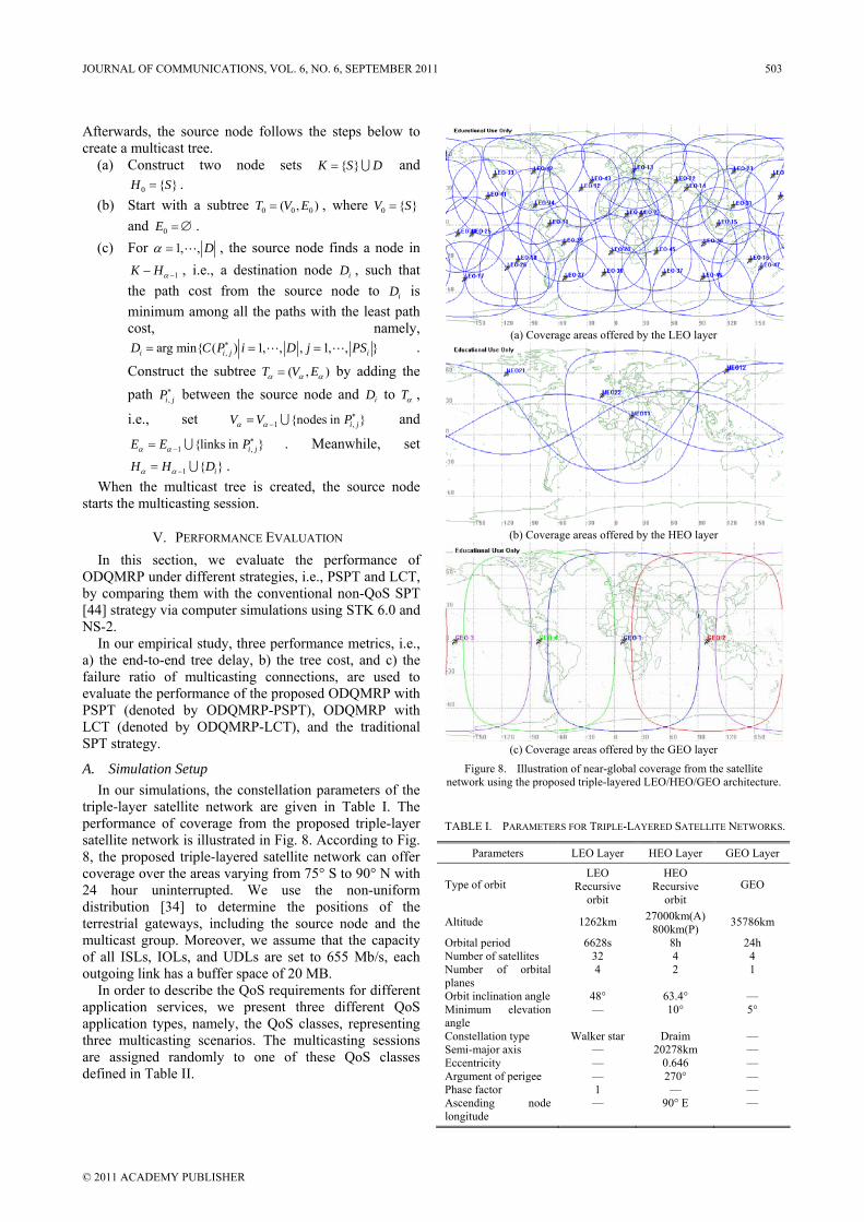
Afterwards, the source node follows the steps below to create a multicast tree.
(a) Construct two node sets K S D= ∪ and 0 H S= .
(b) Start with a subtree 0 0 0( , )T V E= , where 0 V S= and 0E = ∅ .
(c) For 1, , Dα = , the source node finds a node in
1K Hα −− , i.e., a destination node iD , such that the path cost from the source node to iD is minimum among all the paths with the least path cost, namely,
,arg min ( ) 1, , , 1, , i i j iD C P i D j PS∗= = = . Construct the subtree ( , )T V Eα α α= by adding the path ,i jP∗ between the source node and iD to Tα ,
i.e., set 1 ,nodes in i jV V Pα α∗
−= ∪ and
1 ,links in i jE E Pα α∗
−= ∪ . Meanwhile, set
1 iH H Dα α −= ∪ . When the multicast tree is created, the source node
starts the multicasting session.
V. PERFORMANCE EVALUATION In this section, we evaluate the performance of
ODQMRP under different strategies, i.e., PSPT and LCT, by comparing them with the conventional non-QoS SPT [44] strategy via computer simulations using STK 6.0 and NS-2.
In our empirical study, three performance metrics, i.e., a) the end-to-end tree delay, b) the tree cost, and c) the failure ratio of multicasting connections, are used to evaluate the performance of the proposed ODQMRP with PSPT (denoted by ODQMRP-PSPT), ODQMRP with LCT (denoted by ODQMRP-LCT), and the traditional SPT strategy.
A. Simulation Setup In our simulations, the constellation parameters of the
triple-layer satellite network are given in Table I. The performance of coverage from the proposed triple-layer satellite network is illustrated in Fig. 8. According to Fig. 8, the proposed triple-layered satellite network can offer coverage over the areas varying from 75° S to 90° N with 24 hour uninterrupted. We use the non-uniform distribution [34] to determine the positions of the terrestrial gateways, including the source node and the multicast group. Moreover, we assume that the capacity of all ISLs, IOLs, and UDLs are set to 655 Mb/s, each outgoing link has a buffer space of 20 MB.
In order to describe the QoS requirements for different application services, we present three different QoS application types, namely, the QoS classes, representing three multicasting scenarios. The multicasting sessions are assigned randomly to one of these QoS classes defined in Table II.
(a) Coverage areas offered by the LEO layer
(b) Coverage areas offered by the HEO layer
(c) Coverage areas offered by the GEO layer
Figure 8. Illustration of near-global coverage from the satellite network using the proposed triple-layered LEO/HEO/GEO architecture.
TABLE I. PARAMETERS FOR TRIPLE-LAYERED SATELLITE NETWORKS.
Parameters LEO Layer HEO Layer GEO Layer
Type of orbit LEO
Recursive orbit
HEO Recursive
orbit GEO
Altitude 1262km 27000km(A) 800km(P) 35786km
Orbital period 6628s 8h 24h Number of satellites 32 4 4 Number of orbital planes
4 2 1
Orbit inclination angle 48° 63.4° — Minimum elevation angle
— 10° 5°
Constellation type Walker star Draim — Semi-major axis — 20278km — Eccentricity — 0.646 — Argument of perigee — 270° — Phase factor 1 — — Ascending node longitude
— 90° E —
JOURNAL OF COMMUNICATIONS, VOL. 6, NO. 6, SEPTEMBER 2011 503
© 2011 ACADEMY PUBLISHER
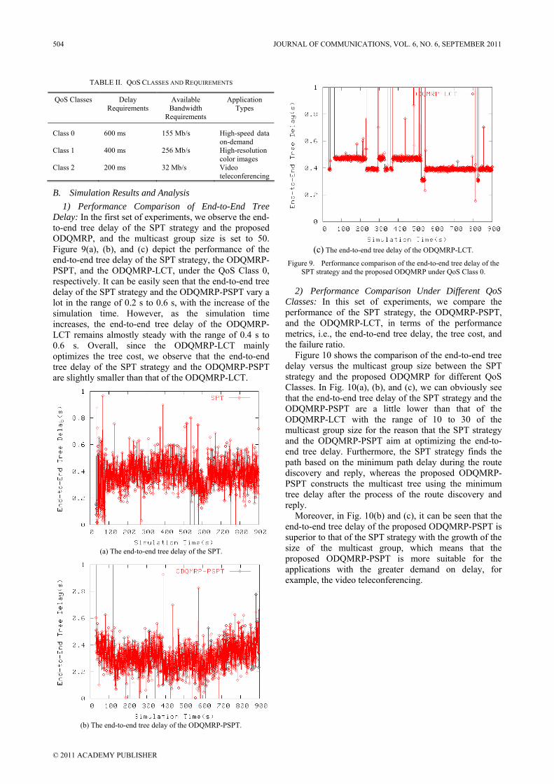
TABLE II. QOS CLASSES AND REQUIREMENTS
QoS Classes Delay Requirements
Available Bandwidth
Requirements
Application Types
Class 0 600 ms 155 Mb/s High-speed data on-demand
Class 1 400 ms 256 Mb/s High-resolution color images
Class 2 200 ms 32 Mb/s Video teleconferencing
B. Simulation Results and Analysis 1) Performance Comparison of End-to-End Tree
Delay: In the first set of experiments, we observe the end-to-end tree delay of the SPT strategy and the proposed ODQMRP, and the multicast group size is set to 50. Figure 9(a), (b), and (c) depict the performance of the end-to-end tree delay of the SPT strategy, the ODQMRP-PSPT, and the ODQMRP-LCT, under the QoS Class 0, respectively. It can be easily seen that the end-to-end tree delay of the SPT strategy and the ODQMRP-PSPT vary a lot in the range of 0.2 s to 0.6 s, with the increase of the simulation time. However, as the simulation time increases, the end-to-end tree delay of the ODQMRP-LCT remains almostly steady with the range of 0.4 s to 0.6 s. Overall, since the ODQMRP-LCT mainly optimizes the tree cost, we observe that the end-to-end tree delay of the SPT strategy and the ODQMRP-PSPT are slightly smaller than that of the ODQMRP-LCT.
(a) The end-to-end tree delay of the SPT.
(b) The end-to-end tree delay of the ODQMRP-PSPT.
(c) The end-to-end tree delay of the ODQMRP-LCT.
Figure 9. Performance comparison of the end-to-end tree delay of the SPT strategy and the proposed ODQMRP under QoS Class 0.
2) Performance Comparison Under Different QoS Classes: In this set of experiments, we compare the performance of the SPT strategy, the ODQMRP-PSPT, and the ODQMRP-LCT, in terms of the performance metrics, i.e., the end-to-end tree delay, the tree cost, and the failure ratio.
Figure 10 shows the comparison of the end-to-end tree delay versus the multicast group size between the SPT strategy and the proposed ODQMRP for different QoS Classes. In Fig. 10(a), (b), and (c), we can obviously see that the end-to-end tree delay of the SPT strategy and the ODQMRP-PSPT are a little lower than that of the ODQMRP-LCT with the range of 10 to 30 of the multicast group size for the reason that the SPT strategy and the ODQMRP-PSPT aim at optimizing the end-to-end tree delay. Furthermore, the SPT strategy finds the path based on the minimum path delay during the route discovery and reply, whereas the proposed ODQMRP-PSPT constructs the multicast tree using the minimum tree delay after the process of the route discovery and reply.
Moreover, in Fig. 10(b) and (c), it can be seen that the end-to-end tree delay of the proposed ODQMRP-PSPT is superior to that of the SPT strategy with the growth of the size of the multicast group, which means that the proposed ODQMRP-PSPT is more suitable for the applications with the greater demand on delay, for example, the video teleconferencing.
504 JOURNAL OF COMMUNICATIONS, VOL. 6, NO. 6, SEPTEMBER 2011
© 2011 ACADEMY PUBLISHER
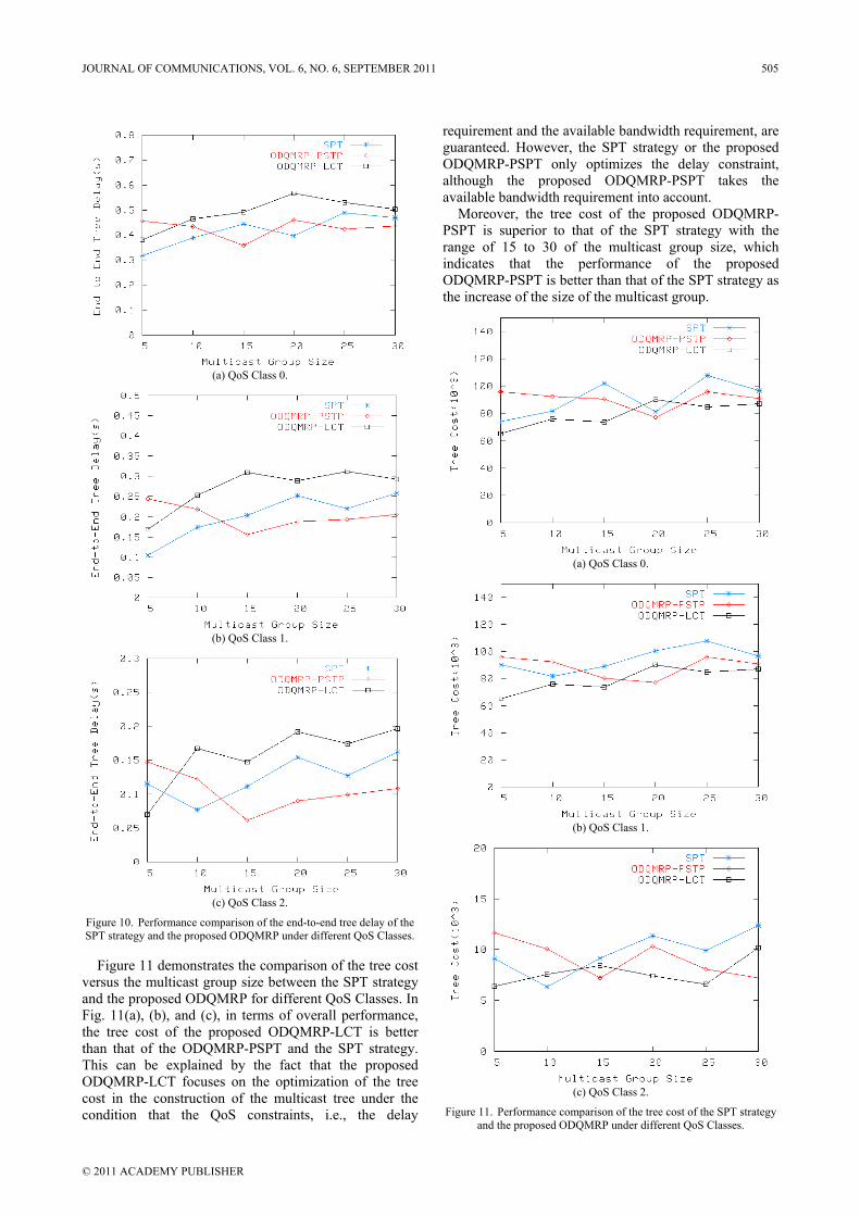
(a) QoS Class 0.
(b) QoS Class 1.
(c) QoS Class 2.
Figure 10. Performance comparison of the end-to-end tree delay of the SPT strategy and the proposed ODQMRP under different QoS Classes.
Figure 11 demonstrates the comparison of the tree cost versus the multicast group size between the SPT strategy and the proposed ODQMRP for different QoS Classes. In Fig. 11(a), (b), and (c), in terms of overall performance, the tree cost of the proposed ODQMRP-LCT is better than that of the ODQMRP-PSPT and the SPT strategy. This can be explained by the fact that the proposed ODQMRP-LCT focuses on the optimization of the tree cost in the construction of the multicast tree under the condition that the QoS constraints, i.e., the delay
requirement and the available bandwidth requirement, are guaranteed. However, the SPT strategy or the proposed ODQMRP-PSPT only optimizes the delay constraint, although the proposed ODQMRP-PSPT takes the available bandwidth requirement into account.
Moreover, the tree cost of the proposed ODQMRP-PSPT is superior to that of the SPT strategy with the range of 15 to 30 of the multicast group size, which indicates that the performance of the proposed ODQMRP-PSPT is better than that of the SPT strategy as the increase of the size of the multicast group.
(a) QoS Class 0.
(b) QoS Class 1.
(c) QoS Class 2.
Figure 11. Performance comparison of the tree cost of the SPT strategy and the proposed ODQMRP under different QoS Classes.
JOURNAL OF COMMUNICATIONS, VOL. 6, NO. 6, SEPTEMBER 2011 505
© 2011 ACADEMY PUBLISHER
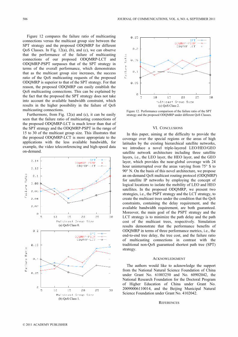
Figure 12 compares the failure ratio of multicasting connections versus the multicast group size between the SPT strategy and the proposed ODQMRP for different QoS Classes. In Fig. 12(a), (b), and (c), we can observe that the performance of the failure of multicasting connections of our proposed ODQMRP-LCT and ODQMRP-PSPT surpasses that of the SPT strategy in terms of the overall performance, which demonstrates that as the multicast group size increases, the success ratio of the QoS multicasting requests of the proposed ODQMRP is superior to that of the SPT strategy. For that reason, the proposed ODQMRP can easily establish the QoS multicasting connections. This can be explained by the fact that the proposed the SPT strategy does not take into account the available bandwidth constraint, which results in the higher possibility in the failure of QoS multicasting connections.
Furthermore, from Fig. 12(a) and (c), it can be easily seen that the failure ratio of multicasting connections of the proposed ODQMRP-LCT is much lower than that of the SPT strategy and the ODQMRP-PSPT in the range of 15 to 30 of the multicast group size. This illustrates that the proposed ODQMRP-LCT is more appropriate to the applications with the less available bandwidth, for example, the video teleconferencing and high-speed data on-demand.
(a) QoS Class 0.
(b) QoS Class 1.
(c) QoS Class 2.
Figure 12. Performance comparison of the failure ratio of the SPT strategy and the proposed ODQMRP under different QoS Classes.
VI. CONCLUSIONS In this paper, aiming at the difficulty to provide the
coverage over the special regions or the areas of high latitudes by the existing hierarchical satellite networks, we introduce a novel triple-layered LEO/HEO/GEO satellite network architecture including three satellite layers, i.e., the LEO layer, the HEO layer, and the GEO layer, which provides the near-global coverage with 24 hour uninterrupted over the areas varying from 75° S to 90° N. On the basis of this novel architecture, we propose an on-demand QoS multicast routing protocol (ODQMRP) for satellite IP networks by employing the concept of logical locations to isolate the mobility of LEO and HEO satellites. In the proposed ODQMRP, we present two strategies, i.e., the PSPT strategy and the LCT strategy, to create the multicast trees under the condition that the QoS constraints, containing the delay requirement, and the available bandwidth requirement, are both guaranteed. Moreover, the main goal of the PSPT strategy and the LCT strategy is to minimize the path delay and the path cost of the multicast trees, respectively. Simulation results demonstrate that the performance benefits of ODQMRP in terms of three performance metrics, i.e., the end-to-end tree delay, the tree cost, and the failure ratio of multicasting connections in contrast with the traditional non-QoS guaranteed shortest path tree (SPT) strategy.
ACKNOWLEDGMENT
The authors would like to acknowledge the support from the National Natural Science Foundation of China under Grant No. 61003250 and No. 60902042, the National Research Foundation for the Doctoral Program of Higher Education of China under Grant No. 20090006110014, and the Beijing Municipal Natural Science Foundation under Grant No. 4102042.
REFERENCES
506 JOURNAL OF COMMUNICATIONS, VOL. 6, NO. 6, SEPTEMBER 2011
© 2011 ACADEMY PUBLISHER
[1] B. R. Elbert, The Satellite Communication Applications Handbook, 2nd ed., Norwood, MA: Artech House, 2004, pp. 14–26.
[2] T. H. Nguyen and M. N. O. Sadiku, “Next generation networks”, IEEE Potentials, vol. 21, no. 2, pp. 6–8, Apr. /May. 2002.
[3] International Telecommunication Union, “Terms of reference of ITU-T focus group on future networks”, [Online]. Available: http://www.itu.int/oth/T3A02000001/en
[4] P. Chitre and F. Yegenoglu, “Next-generation satellite networks: architectures and implementations”, IEEE Communications Magazine, vol. 37, no. 3, pp. 30–36, Mar. 1999.
[5] I. F. Akyildiz and S. Jeong, “Satellite ATM networks: a survey”, IEEE Communications Magazine, vol. 35, no. 7, pp. 30–43, Jul. 1997.
[6] G. Akkor, “Multicast communication support over satellite networks”, Ph.D. dissertation, Department of Electrical and Computer Engineering, University of Maryland, College Park, MD, 2005.
[7] L. Wood, A. Clerget, I. Andrikopoulos, G. Pavlou, and W. Dabbous, “IP routing issues in satellite constellation networks”, International Journal of Satellite Communications, vol. 19, no. 1, pp. 69–92, Jan. /Feb. 2001.
[8] M. Werner, C. Delucchi, H. Vogel, G. Maral, and J. De Ridder, “ATM-based routing in LEO/MEO satellite networks with intersatellite links”, IEEE Journal on Selected Areas in Communications, vol. 15, no. 1, pp. 69–82, Jan. 1997.
[9] M. Werner, G. Berndl, B. Edmaier, “Performance of optimized routing in LEO intersatellite link networks”, in Proc. IEEE VTC’97, vol. 1, May. 1997, 246–250.
[10] H. S. Chang, B. W. Kim, C. G. Lee, S. L. Min, Y. Choi, H. S. Yang, D. N. Kim, and C. S. Kim, “FSA-based link assignment and routing in low-Earth orbit satellite networks”, IEEE Transactions on Vehicular Technology, vol. 47, no. 3, pp. 1037–1048, Aug. 1998.
[11] H. Uzunalioglu, I. F. Akyildiz, Y. Yesha, and W. Yen, “Footprint handover rerouting protocol for low Earth orbit satellite networks”, Wireless Networks, vol. 5, no. 5, pp. 327–337, Sept. 1999.
[12] H. Uzunalioglu, “Probabilistic routing protocol for low Earth orbit satellite networks”, in Proc. IEEE ICC’98, Jun. 1998, pp. 89–93.
[13] K. Tsai and R. P. Ma, “DARTING: a cost-effective routing alternative for large space-based dynamic-topology networks”, in Proc. IEEE MILCOM’95, vol. 2, Nov. 1995, pp. 682–686.
[14] R. A. Raines, R. F. Janoso, D. M. Gallagher, and D. L. Coulliette, “Simulation of two routing protocols operating in a low Earth orbit satellite network environment”, in Proc. IEEE MILCOM’97, vol. 1, Nov. 1997, pp. 429–433.
[15] T. R. Henderson and R. H. Katz, “On distributed, geographic-based packet routing for LEO satellite networks”, in Proc. IEEE GLOBECOM’00, vol. 2, Nov. /Dec. 2000, pp. 1119–1123.
[16] E. Ekici, I. F. Akyildiz, and M. D. Bender, “A distributed routing algorithm for datagram traffic in LEO satellite networks”, IEEE/ACM Transactions on Networking, vol. 9, no. 2, pp. 137–147, Apr. 2001.
[17] I. F. Akyildiz, E. Ekici, and M. D. Bender, “MLSR: a novel routing algorithm for multilayered satellite IP networks”, IEEE/ACM Transactions on Networking, vol. 10, no. 3, pp. 411–424, Jun. 2002.
[18] C. Chen and E. Ekici, “A routing protocol for hierarchical LEO/MEO satellite IP networks”, Wireless Networks, vol. 11, no. 4, pp. 507–521, Jul. 2005.
[19] B. Quinn and K. Almeroth, “IP multicast applications: challenges and solutions”, Internet RFC 3170, Sept. 2001.
[20] L. H. Sahasrabuddhe and B. Mukherjee, “Multicast routing algorithms and protocols: a tutorial”, IEEE Network, vol. 14, no. 1, pp. 90–102, Jan. /Feb. 2000.
[21] P. Paul and S. V. Raghavan, “Survey of multicast routing algorithms and protocols”, in Proc. 15th International Conference on Computer Communication, vol. 1, Aug. 2002, pp. 902–926.
[22] U. Varshney, “Multicast over wireless networks”, Communications of the ACM, vol. 45, no. 12, pp. 31–37, Dec. 2002.
[23] D. Waitzman, C. Partridge, and S. E. Deering, “Distance vector multicast routing protocol”, Internet RFC 1075, Nov. 1988.
[24] A. Ballardie, “Core based trees (CBT version 2) multicast routing”, Internet RFC 2189, Sept. 1997.
[25] S. Deering, “Host extensions for IP multicasting”, Internet RFC 1112, Aug. 1989.
[26] J. Moy, “Multicast routing extensions for OSPF”, Communications of the ACM, vol. 37, no. 8, pp. 61–66, Aug. 1994.
[27] E. M. Royer and C. E. Perkins. “Multicast operation of the ad hoc on-demand distance vector routing protocol”, in Proc. ACM MOBICOM,’99 Aug. 1999, pp. 207–218.
[28] C. K. Toh, G. Guichal, and S. Bunchua, “ABAM: on-demand associativity-based multicast routing for ad hoc mobile networks”, in Proc. IEEE VTC’00, vol. 3, Sept. 2000, pp. 987–993.
[29] S. Lee, W. Su, and M. Gerla, “On-demand multicast routing protocol (ODMRP) for ad hoc networks”, Internet Draft, Jul. 2000.
[30] J. J. Garcia-Luna-Aceves and E. L. Madruga, “The core-assisted mesh protocol”, IEEE Journal on Selected Areas in Communications, vol. 17, no. 8, pp. 1380–1394, Aug. 1999.
[31] E. Ekici, I. F. Akyildiz, and M. D. Bender, “A multicast routing algorithm for LEO satellite IP networks”, IEEE/ACM Transactions on Networking, vol. 10, no. 2, pp. 183–192, Apr. 2002.
[32] D. Yang and W. Liao, “On multicast routing using rectilinear Steiner trees for LEO satellite networks”, IEEE Transactions on Vehicular Technology, vol. 57, no. 4, pp. 2560–2569, Jul. 2008.
[33] L. Chen, J. Zhang, and K. Liu, “Core-based shared tree multicast routing algorithms for LEO satellite IP networks”, Chinese Journal of Aeronautics, vol. 20, no. 4, pp. 353–361, Aug. 2007.
[34] I. F. Akyildiz, E. Ekici, and G. Yue, “A distributed multicast routing scheme for multi-layered satellite IP networks”, Wireless Networks, vol. 9, no. 5, pp. 535–544, Sept. 2003.
[35] S. Kota and M. Marchese, “Quality of service for satellite IP networks: a survey”, International Journal of Satellite Communications and Networking, vol. 21, no. 4–5, pp. 303–349, Jul. 2003.
[36] Y. Zhou, F. Sun, and B. Zhang, “A novel QoS routing protocol for LEO and MEO satellite networks”, International Journal of Satellite Communications and Networking, vol. 25, no. 6, pp. 603–617, Sept. 2007.
[37] H, Xu, F. Huang, and S. Wu, “A distributed QoS routing based on ant algorithm for LEO satellite network”, Journal of Electronics, vol. 24, no. 6, pp. 765–771, Nov. 2007.
JOURNAL OF COMMUNICATIONS, VOL. 6, NO. 6, SEPTEMBER 2011 507
© 2011 ACADEMY PUBLISHER
[38] P. Wang, X. Gu, and G. Liu, “Multi-QoS routing for LEO satellite networks”, in Proc. 9th International Conference on Advanced Communication Technology, vol. 1, Feb. 2007, pp. 728–731.
[39] O. Ercetin, S. Krishnamurthy, S. Dao, and L. Tassiulas, “A predictive QoS routing scheme for broadband low Earth orbit satellite networks”, in Proc. 11th IEEE International Symposium on Personal, Indoor and Mobile Radio Communications, vol. 2, Sept. 2000, pp. 1064–1074.
[40] K. Kimura, K. Inagaki, and Y. Karasawa, “Double-layered inclined orbit constellation for advanced satellite communications network”, IEICE Transactions on Communications, vol. E80-B, no. 1, pp. 93–102, Jan. 1997.
[41] L. Chin, J. Chang, and C. Huang, “Performance of a two-layer LEO satellite communication network”, IEEE Transactions on Aerospace and Electronic Systems, vol. 33, no. 1, pp. 225–231, Jan. 1997.
[42] L. Wood, “Internetworking with satellite constellations”, Ph.D. dissertation, School of Electronics, Computing and Mathematics, University of Surrey, Guildford, United Kingdom, 2001.
[43] C. Perkins, E. Belding-Royer, and S. Das, “Ad hoc on-demand distance vector (AODV) routing”, Internet RFC 3561, Jul. 2003.
[44] J. A. Bondy and U. S. R. Murty, Graph Theory with Applications, Great Britain: The Macmillan Press, 1976, pp. 15–20.
Zhizhong Yin received his B.S. degree from the Academy of Equipment Command & Technology, Beijing, China in 1988, and his M.S. degree in digital multimedia engineering from the School of Information Engineering, University of Science and Technology Beijing, Beijing, China in 2002. He is currently working toward the Ph.D degree in communication and
information systems at the Department of Communication Engineering, School of Information Engineering, University of Science and Technology Beijing, Beijing, China. He has also been a senior engineer at the Academy of Equipment Command & Technology, Beijing, China. His current research interests include satellite networks, broadband wireless communications,
cognitive radio networks, mobile computing, and next generation networks.
Long Zhang received his B.S. degree in communication engineering from the Faculty of Information Engineering, China University of Geosciences, Wuhan, China in June 2006. He is currently working toward the Ph.D degree in communication and information systems at the Department of Communication Engineering,
School of Information Engineering, University of Science and Technology Beijing, Beijing, China. His current research interests include deep space information networks, delay and disruption tolerant networks, cognitive radio, satellite and space communications, mobile ad hoc networks, and future information networks.
Xianwei Zhou received his B.S. degree in Department of Mathematics from the Southwest China Normal University, Chongqing, China in 1986, and his M.S. degree in Department of System Science and Mathematics from Zhengzhou University, Zhengzhou, China in 1992, and in 1999, he obtained the Ph.D. degree in Department of Transportation
Engineering from the Southwest Jiaotong University, Chengdu, China. He was engaged in postdoctor study in information and communication engineering at the School of Electronic and Information Engineering, Beijing Jiaotong University, Beijing China, from 1999 to 2000. In 2001, he joined the Department of Communication Engineering, School of Information Engineering, University of Science and Technology Beijing, Beijing, China, where he is currently a professor and Ph.D. supervisor. So far he has published over 100 research papers in the domestic and international scientific journals and conferences. His current research interests include security of communication networks, next generation networks, cognitive radio, mobile IPv6, scheduling theory, and game theory.
508 JOURNAL OF COMMUNICATIONS, VOL. 6, NO. 6, SEPTEMBER 2011
© 2011 ACADEMY PUBLISHER

Call for Papers and Special Issues
Aims and Scope. Journal of Communications (JCM) is a scholarly peer-reviewed international scientific journal published monthly, focusing on theories, systems,
methods, algorithms and applications in communications. It provide a high profile, leading edge forum for academic researchers, industrial professionals, engineers, consultants, managers, educators and policy makers working in the field to contribute and disseminate innovative new work on communications.
JCM invites original, previously unpublished, research, survey and tutorial papers, plus case studies and short research notes, on both applied and theoretical aspects of communications. These areas include, but are not limited to, the following topics: • Signal Processing for Communications • Multimedia Processing and Communications • Communication QoS and Performance Modeling • Cross-layer Design and Optimization • Communication and Information Theory • Communication Software and Services • Protocol and Algorithms for Communications • Wireless Communications and Networking • Wireless Ad-hoc and Sensor Networking • Broadband Wireless Access • Cooperative Communications and Networking
• Optical Communications and Networking • Broadband Networking and Protocols • Internet Services, Systems and Applications • P2P Communications and Networking • Pervasive Computing and Grid Networking • Communication Network Security • Cognitive Radio Communications and Networking • Hardware Architecture for Communications and Networking • Parallel and Distributed Computing • Satellite and Space Communications • Emerging Communication Technology and Standards
Special Issue Guidelines
Special issues feature specifically aimed and targeted topics of interest contributed by authors responding to a particular Call for Papers or by
invitation, edited by guest editor(s). We encourage you to submit proposals for creating special issues in areas that are of interest to the Journal. Preference will be given to proposals that cover some unique aspect of the technology and ones that include subjects that are timely and useful to the readers of the Journal. A Special Issue is typically made of 8 to 12 papers, with each paper 8 to 12 pages of length, and the papers include:
• A Guest Editorial; • 2-3 Invited Survey papers from world well-known scientists in the specific area; • 6-10 Research papers reflecting the latest advances in the specific area. The following information should be included as part of the proposal: • Proposed title for the Special Issue • An initial version of Call for Papers with specific topics covered in the Special Issue • Name, contact, position, affiliation, and biography of the Guest Editor(s) • Tentative time-table for the call for papers and reviews • Potential authors and topics for the Invited Survey papers • List of potential reviewers • Plans for advertising the Call for Paper and attracting high-quality paper submissions If a proposal is accepted, the guest editor will be responsible for: • Submitting a final “Call for Papers” to be included on the Journal’s Web site. • Distribution of the Call for Papers broadly to various mailing lists and sites. • Leading a fair and strict review process for the paper submissions, collecting 2-3 reviews for each paper before the final decision making.
Authors should be informed the Author Instructions. • Providing JCM the completed and approved final versions of the papers formatted in the Journal’s style, together with all authors’ contact
information. • Writing a one- or two-page introductory editorial to be published in the Special Issue. In the Guest Editor Team building process, it is highly recommended that a world well-known scientist (e.g., IEEE or ACM Fellow) in the area is
involved in this effort to promote the visibility of the Special Issue in the society. On the other hand, it is suggested to consider the geographic coverage of the team. Due to conflict-of-interest, the Guest Editors are not encouraged to submit their own papers to the Special Issue. Recommended Papers from an International Conference
JCM accept recommendations from well-known International conferences. The conference organizer can recommend the best papers (top 5% of
the accepted papers) to be considered in either JCM regular issue or a JCM special issue. A fast-track review process would be conducted by a JCM Editor for these recommended papers and the final decisions are made based on the review feedback.
The following information should be included as part of the proposal: • The name of the conference/workshop, and the URL of the event • A brief description of the event, including: number of submitted and accepted papers, and number of attendees. If these numbers are not yet
available, please refer to previous events. First time conference would NOT be considered. • Tentative time-table for the paper submission. If a proposal is accepted, the conference organizer needs to submit the following items at a later stage: • The list of the best papers (top 5% of the accepted papers) for recommendation • The submitted conference paper draft and review feedbacks If a conference contributes more than 5 papers that are finally accepted by JCM, the organizer would be invited to serve as a Guest Co-Editor of a
JCM annual Special Issue, “SI on the Latest Advances in Communications and Networking”, and these accepted papers would be included in the same Special Issue. Otherwise, the accepted papers would be published in JCM regular issues.
More information is available on the web site at http://www.academypublisher.com/jcm/.