Embed Size (px)
Citation preview
IP LDK-20 Installation Manual
IIPPLLDDKK 2200 INSTALLATION MANUAL
IP LDK-20 Installation Manual
RREEVVIISSIIOONN HHIISSTTOORRYY
ISSUE DATE CONTENTS OF CHANGES REMARK
ISSUE 1.0 ISSUE 1.1
2005.3 2005.5
Initial Release Add Expansion Modules and VMIBE/AAFBE
IP LDK-20 Installation Manual
i
TTAABBLLEE OOFF CCOONNTTEENNTTSS
■ IMPORTANT SAFETY INSTRUCTIONS ....................................................... 1
Safety requirements .................................................................................................................... 1
■ PRECAUTION................................................................................................. 2
■ THE STRUCTURE OF MANUAL ................................................................... 3
SECTION 1. INTRODUCTION................................................................................ 4 1.1 The IP LDK-20 System highlights......................................................................................... 4 1.2 System Connection Diagram............................................................................................... 4 1.3 System Components............................................................................................................ 5 1.4 Specifications ....................................................................................................................... 6
1.4.1 General specifications.............................................................................................................. 6 1.4.2 System Capacity ...................................................................................................................... 7
SECTION 2. KSU INSTALLATION ......................................................................... 8 2.1 Pre-Installation...................................................................................................................... 8
2.1.1 Safety installation instructions ................................................................................................. 8 2.1.2 Installation precautions ............................................................................................................ 8 2.1.3 Wiring precautions ................................................................................................................... 8
2.2 KSU Installation.................................................................................................................... 9 2.2.1 Unpacking ................................................................................................................................ 9 2.2.2 KSU exterior and dimension................................................................................................... 10 2.2.3 KSU with expansion module exterior and dimension............................................................. 11 2.2.4 Opening and closing the front cover...................................................................................... 12 2.2.5 Frame ground connection...................................................................................................... 14 2.2.6 Power Supply Unit (PSU) installation .................................................................................... 15 2.2.7 External backup batteries installation .................................................................................... 16 2.2.8 KSU mounting........................................................................................................................ 17
SECTION 3. BOARD INSTALLATION.................................................................. 20 3.1 Installation of the Boards.................................................................................................... 20 3.2 MBUB (Main Board Unit) ................................................................................................... 21
3.2.1 Modular Jack(MJ1~MJ3) Pin Assignment............................................................................. 23 3.3 Installation of the CO Line Board....................................................................................... 29
3.3.1 LCOB (CID Loop Start CO line Interface Board)................................................................... 29 3.3.2 STIB (Basic Rate Interface Board: Selectable S/T interface) ............................................... 32 3.3.3 CBIB (CID Loop Start CO line + Basic Rate Interface Board) .............................................. 36
3.4 Installation of the Extension Board .................................................................................... 39 3.4.1 DTIB4 (Digital Terminal Interface Board) .............................................................................. 39 3.4.2 DTIB8 (Digital Terminal Interface Board) .............................................................................. 40 3.4.3 SLIB4 (Single Line Interface Board) ...................................................................................... 41 3.4.4 SLIB8 (Single Line Interface Board) ...................................................................................... 42
3.5 Other Board Installations.................................................................................................... 43 3.5.1 VMIBE (Voice Mail Interface Board Enhanced) .................................................................... 43 3.5.2 AAFBE(Auto Attendant Function Board Enhanced) ............................................................. 44 3.5.3 LANU (LAN interface Unit)..................................................................................................... 45 3.5.4 MODU (MODEM function Unit) ............................................................................................. 46
SECTION 4. EXPANSION MODULE INSTALLATION.......................................... 47
IP LDK-20 Installation Manual
ii
4.1 Unpacking............................................................................................................................ 47 4.2 Opening and closing the front cover................................................................................... 48
4.2.1 Opening the front cover .......................................................................................................... 48 4.2.2 Closing the front cover ............................................................................................................ 49
4.3 Opening and closing the front cover................................................................................... 50 4.3.1 Connecting Expansion Module to KSU .................................................................................. 50 4.3.2 Wall mounting ......................................................................................................................... 51 4.3.3 Rack Mounting ........................................................................................................................ 52
4.4 External backup batteries connection................................................................................. 54 4.5 VOIM (Voice over Internet Protocol Interface Module) installation.................................... 55
Various switches and connectors functions .................................................................................... 56 4.5.1 Pin assignment........................................................................................................................ 57 4.5.2 VOIU(Voice over Internet Protocol Interface Unit) ................................................................. 58
4.6 SLIM(SLT Interface Module) Installation ............................................................................ 59 4.6.1 Pin assignment........................................................................................................................ 59
4.7 DTIM(DKT Interface Module).............................................................................................. 60 4.7.1 Pin assignment........................................................................................................................ 60
SECTION 5. TERMINAL CONNECTION.............................................................. 61 5.1 Terminal Models................................................................................................................. 61 5.2 Terminal Cabling Distance................................................................................................. 62 5.3 Keyset Connection ............................................................................................................. 63
5.3.1 Digital Keyset ......................................................................................................................... 63 5.3.2 SLT......................................................................................................................................... 63
5.4 Connecting Additional Terminals....................................................................................... 64 5.4.1 External Music Source wiring ................................................................................................ 64 5.4.2 Relay Contacts....................................................................................................................... 64 5.4.3 External Paging wiring ........................................................................................................... 64 5.4.4 Alarm Detection wiring........................................................................................................... 64
SECTION 6. STARTING THE IPLDK-20 SYSTEM .............................................. 65 6.1 Before Starting the IP LDK-20 System.............................................................................. 65 6.2 Basic Preprogramming....................................................................................................... 65
6.2.1 DKTU (Station 10) programming........................................................................................... 65 6.2.2 Entering programming mode ................................................................................................. 67 6.2.3 Pre-programming ................................................................................................................... 68
SECTION 7. TROUBLESHOOTING ...................................................................... 76
IP LDK-20 Installation Manual Introduction
1
■ Important Safety Instructions Safety requirements When using your telephone equipment, basic safety precautions should always be followed to reduce the risk of fire, electric shock and other personal injury, including the following: • Please read and understand all instructions. • Follow all warnings and instructions marked on the product. • Unplug this product from the wall outlet before cleaning. Just a damp cloth should be used for cleaning; do not
use liquid or aerosol cleaners. • Do not use this product near water, such as in a bathtub, wash bowl, kitchen sink, or laundry tub, in a wet
basement, or near a swimming pool. • Do not place this product on an unstable cart, stand, or table. The product may fall, causing serious damage to
the product or personal injury. • Slots and openings in the KSU and the back or bottom are provided for ventilation, to protect it from overheating,
these openings must not be blocked or covered. The openings should never be blocked by placing the product on a bed, sofa, rug, or other similar surface. This product should never be placed near or over a radiator or other heat source. This product should not be placed in a built-in installation without proper ventilation.
• This product should be operated only from the type of power source indicated on the product label. If you are not sure of the type of power supply to your home, consult your dealer or local power company.
• Do not allow anything to rest on the power cord. Do not locate this product where the cord could be abused by people walking on it.
• Do not overload wall outlets and extension cords as this can result in the risk of fire or electric shock. • Never push objects of any kind into this product through KSU slots or connectors as they may touch dangerous
voltage points or short out parts that could result in a risk of fire or electric shock. Never spill liquid of any kind on the product.
• To reduce the risk of electric shock, do not disassemble this product. Instead, take it to a qualified person when service or repair work is required. Opening or removing covers may expose you to dangerous voltages or other risk. Incorrect reassemble can cause electric shock when the appliance is subsequently used.
• Unplug this product from the wall outlet and refer servicing to qualified service personnel under the following conditions: - When the power supply cord or plug is damaged or frayed. - If liquid has been spilled into the product. - If the product has been exposed to rain or water. - If the product does not operate normally by following the operating instructions. Adjust only those controls that
are covered by the operating instructions because improper adjustment of other controls may result in damage and will often require extensive work by a qualified technician to restore the product to normal operation.
- If the product has been dropped or the KSU has been damaged. - If the product exhibits a distinct change in performance.
• Avoid using a telephone during an electrical storm. There may be a remote risk of electric shock from lightning. • In the event of a gas leak, do not use the telephone near the leak.
IP LDK-20 Installation Manual Introduction
2
■ Precaution • Keep the system away from heating appliances and electrical noise generating devices such as fluorescent
lamps, motors and televisions. These noise sources can interfere with the performance of the IP LDK-20 System.
• This system should be kept free of dust, moisture, high temperature (more than 40 degrees) and vibration, and should not be exposed to direct sunlight.
• Never attempt to insert wires, pins, etc. into the system. If the system does not operate properly, the trouble has been repaired by an authorized LG service center.
• Do not use benzene, paint thinner, or any abrasive powder to clean the KSU. Wipe it with a soft cloth.
CAUTION
• This system should only be installed and serviced by qualified service personnel. • When a failure occurs which exposes any internal parts, disconnect the power supply cord immediately and
return this system to your dealer. • To prevent the risk of fire, electric shock or energy hazard, do not expose this product to rain or any type of
moisture. • To protect PCB from static electricity, discharge body static before touching connectors and/or components
by touching ground or wearing a ground strap.
WARNING Danger of explosion if battery is incorrectly replaced. Replace only with the same or equivalent type recommended by the manufacturer. Dispose of used batteries according to the manufacturer’s instructions.
IP LDK-20 Installation Manual Introduction
3
■ The Structure of Manual This installation manual is designed to provide as general information for the IP LDK-20 System. It provides instructions for installing the hardware, and programming the IP LDK-20 System using keyset. This manual contains the following sections: Section 1. Introduction Provides general information on the IP LDK-20 System, including the system specifications and capacity. Section 2. KSU Installation Describes detailed instructions for planning the installation site and procedures to install the IP LDK-20 System. Section 3. Board Installation Describes general information and detailed instructions for installing boards and add-on boards. Section 4. Expansion Module Installation Describes the kinds of terminals, maximum distance, and the other device connections for the terminal. Section 5. Terminal Connection Describes the kinds of terminals, maximum distance, and the other device connections for the terminal. Section 6. Starting the IP LDK-20 System Provides general information for starting the system and basic preprogramming. Section 7. Troubleshooting Provides information on the IP LDK-20 System and troubleshooting.
IP LDK-20 Installation Manual Introduction
4
SECTION 1. INTRODUCTION 1.1 The IP LDK-20 System highlights Features of the IP LDK-20 System include: • Flexible architecture • Optional LAN Interface • Stable & enhanced voice features • Simple installation & efficient system management
- Remote admin through BRI connection - Remote admin through PSTN modem - Remote admin through LAN connection
• Value-added features - Distinctive voice mail - CID (CO & SLT) - VOIP Service
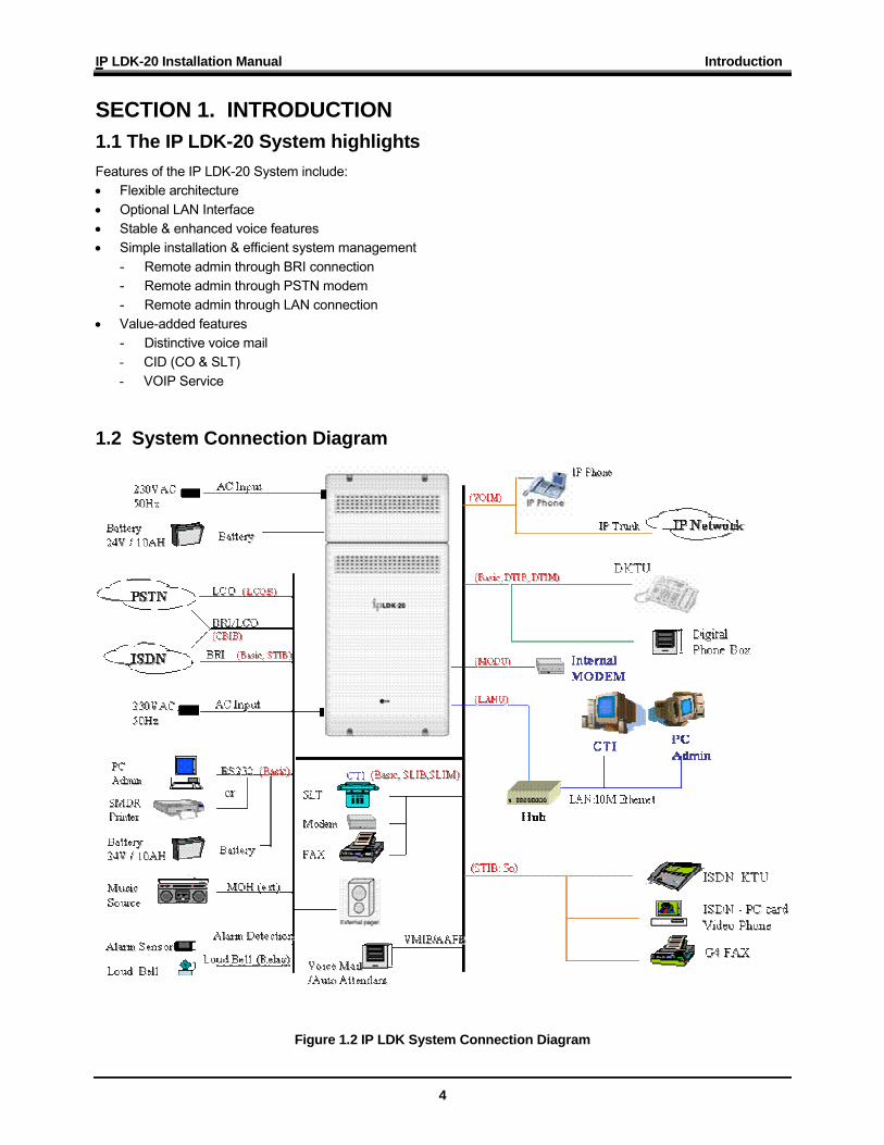
1.2 System Connection Diagram
Figure 1.2 IP LDK System Connection Diagram
IP LDK-20 Installation Manual Introduction
5
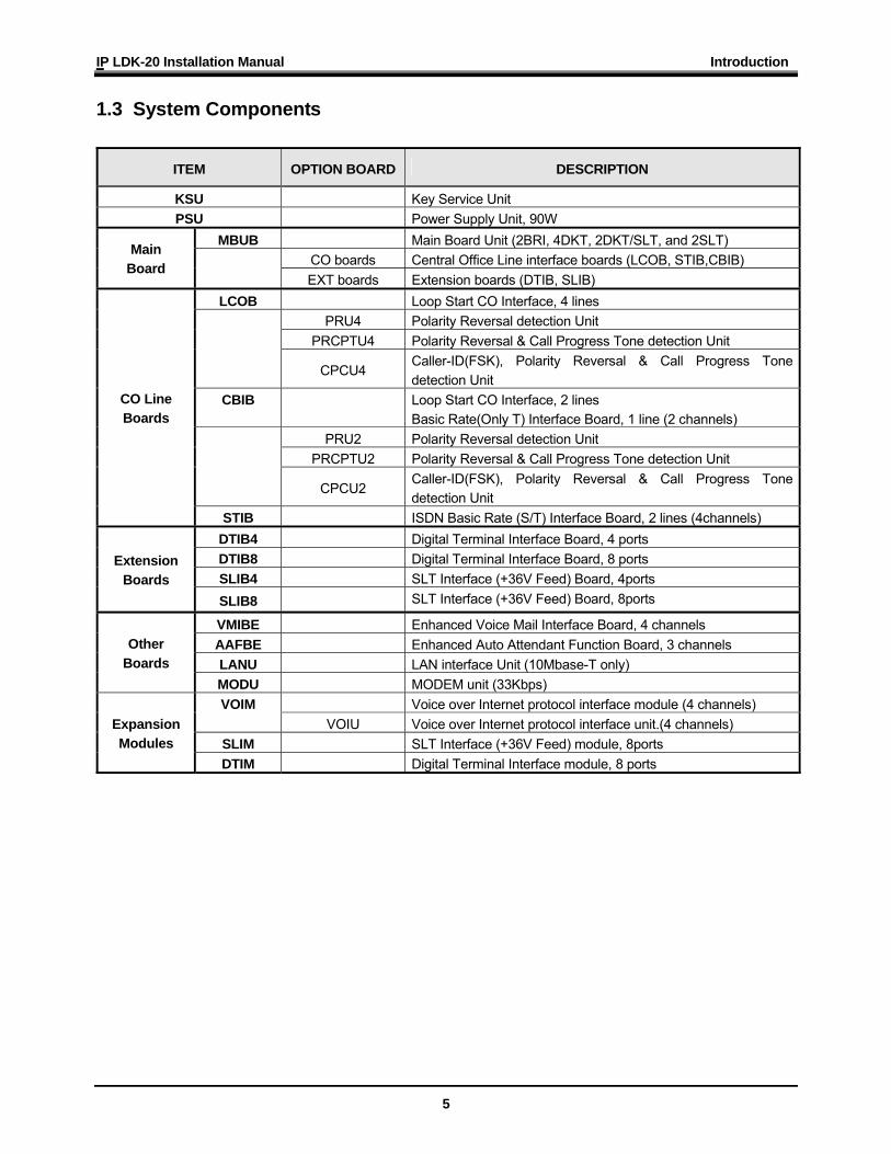
1.3 System Components
ITEM OPTION BOARD DESCRIPTION
KSU Key Service Unit PSU Power Supply Unit, 90W
MBUB Main Board Unit (2BRI, 4DKT, 2DKT/SLT, and 2SLT) CO boards Central Office Line interface boards (LCOB, STIB,CBIB)
Main Board
EXT boards Extension boards (DTIB, SLIB) LCOB Loop Start CO Interface, 4 lines
PRU4 Polarity Reversal detection Unit PRCPTU4 Polarity Reversal & Call Progress Tone detection Unit
CPCU4 Caller-ID(FSK), Polarity Reversal & Call Progress Tone detection Unit
CBIB
Loop Start CO Interface, 2 lines Basic Rate(Only T) Interface Board, 1 line (2 channels)
PRU2 Polarity Reversal detection Unit PRCPTU2 Polarity Reversal & Call Progress Tone detection Unit
CPCU2 Caller-ID(FSK), Polarity Reversal & Call Progress Tone detection Unit
CO Line Boards
STIB ISDN Basic Rate (S/T) Interface Board, 2 lines (4channels) DTIB4 Digital Terminal Interface Board, 4 ports DTIB8 Digital Terminal Interface Board, 8 ports SLIB4 SLT Interface (+36V Feed) Board, 4ports
Extension Boards
SLIB8 SLT Interface (+36V Feed) Board, 8ports
VMIBE Enhanced Voice Mail Interface Board, 4 channels AAFBE Enhanced Auto Attendant Function Board, 3 channels LANU LAN interface Unit (10Mbase-T only)
Other Boards
MODU MODEM unit (33Kbps) Voice over Internet protocol interface module (4 channels) VOIM
VOIU Voice over Internet protocol interface unit.(4 channels) SLIM SLT Interface (+36V Feed) module, 8ports
Expansion Modules
DTIM Digital Terminal Interface module, 8 ports
IP LDK-20 Installation Manual Introduction
6
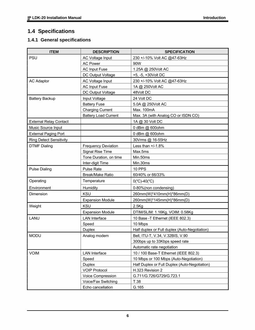
1.4 Specifications 1.4.1 General specifications
ITEM DESCRIPTION SPECIFICATION
AC Voltage Input 230 +/-10% Volt AC @47-63Hz AC Power 90W AC Input Fuse 1.25A @ 250Volt AC
PSU
DC Output Voltage +5, -5, +30Volt DC AC Voltage Input 230 +/-10% Volt AC @47-63Hz AC Input Fuse 1A @ 250Volt AC
AC Adaptor
DC Output Voltage 48Volt DC Input Voltage 24 Volt DC Battery Fuse 5.0A @ 250Volt AC Charging Current Max. 100mA
Battery Backup
Battery Load Current Max. 3A (with Analog CO or ISDN CO) External Relay Contact 1A @ 30 Volt DC Music Source Input 0 dBm @ 600ohm External Paging Port 0 dBm @ 600ohm Ring Detect Sensitivity 30Vrms @ 16-55Hz
Frequency Deviation Less than +/-1.8% Signal Rise Time Max.5ms Tone Duration, on time Min.50ms
DTMF Dialing
Inter-digit Time Min.30ms Pulse Rate 10 PPS Pulse Dialing Break/Make Ratio 60/40% or 66/33%
Operating Temperature 0(℃)-40(℃)
Environment Humidity 0-80%(non condensing) KSU 260mm(W)*410mm(H)*86mm(D) Dimension Expansion Module 260mm(W)*145mm(H)*86mm(D) KSU 2.5Kg Weight Expansion Module DTIM/SLIM: 1.16Kg, VOIM: 0.58Kg LAN Interface 10 Base -T Ethernet (IEEE 802.3) Speed 10 Mbps
LANU
Duplex Half duplex or Full duplex (Auto-Negotiation) Bell, ITU-T, V.34, V.32BIS, V.90 300bps up to 33Kbps speed rate
MODU Analog modem
Automatic rate negotiation LAN Interface 10 / 100 Base-T Ethernet (IEEE 802.3) Speed 10 Mbps or 100 Mbps (Auto-Negotiation) Duplex Half Duplex or Full Duplex (Auto-Negotiation) VOIP Protocol H.323 Revision 2 Voice Compression G.711/G.726/G729/G.723.1 Voice/Fax Switching T.38
VOIM
Echo cancellation G.165
IP LDK-20 Installation Manual Introduction
7
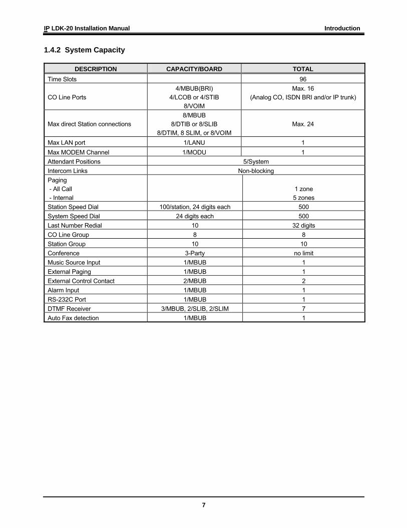
1.4.2 System Capacity
DESCRIPTION CAPACITY/BOARD TOTAL Time Slots 96
CO Line Ports 4/MBUB(BRI)
4/LCOB or 4/STIB 8/VOIM
Max. 16 (Analog CO, ISDN BRI and/or IP trunk)
Max direct Station connections 8/MBUB
8/DTIB or 8/SLIB 8/DTIM, 8 SLIM, or 8/VOIM
Max. 24
Max LAN port 1/LANU 1 Max MODEM Channel 1/MODU 1 Attendant Positions 5/System Intercom Links Non-blocking Paging - All Call - Internal
1 zone 5 zones
Station Speed Dial 100/station, 24 digits each 500 System Speed Dial 24 digits each 500 Last Number Redial 10 32 digits CO Line Group 8 8 Station Group 10 10 Conference 3-Party no limit Music Source Input 1/MBUB 1 External Paging 1/MBUB 1 External Control Contact 2/MBUB 2 Alarm Input 1/MBUB 1 RS-232C Port 1/MBUB 1 DTMF Receiver 3/MBUB, 2/SLIB, 2/SLIM 7 Auto Fax detection 1/MBUB 1
IP LDK-20 Installation Manual KSU Installation
8
SECTION 2. KSU INSTALLATION 2.1 Pre-Installation Please read the following guidelines concerning installation and connection before installing the IP LDK-20 System. Be sure also to comply with applicable local regulations. 2.1.1 Safety installation instructions When installing the telephone wiring, basic safety precautions should always be followed to reduce the risk of fire, electric shock and personal injury, including the following: • Never install the telephone wiring during a lightning storm. • Never install the telephone jack in wet locations unless the jack is specifically designed for wet locations. • Never touch uninsulated telephone wires or terminals unless the telephone line has been disconnected at the
network interface. • Use caution when installing or modifying telephone lines. • Anti-static precautions should be taken during installation. 2.1.2 Installation precautions The IP LDK-20 System is designed for wall mounting or a free-standing rack. Avoid installing in the following places. • In direct sunlight and hot, cold, or humid places. Temperature range : 0 to 40℃ • Places where shocks or vibrations are frequent or strong. • Dusty places, or places where water or oil may come into contact with the system. • Near high-frequency generating devices such as sewing machines or electric welders. • On or near computers, fax machines, or other office equipment, as well as microwave ovens or air conditioners. • Do not obstruct the area around the IP LDK-20 System (for reasons of maintenance and inspection) • Do not block the openings on the top of the IP LDK-20 System. • Do not stack up the optional service boards. 2.1.3 Wiring precautions Be sure to follow these precautions when wiring. • Do not wire the telephone cable in parallel with an AC power source, such as a computer, fax machine, etc. If the
cables are run near those wires, shield the cables with metal tubing or use shielded cables and ground the shields. • If the cables are run on the floor, use protectors to prevent the wires from being stepped on. Avoid wiring under
carpets. • Avoid using the same power supply outlet for computers, fax machines, and other office equipment to avoid
induction noise interruption when using the IP LDK-20 near other machines. • The power and battery switches of the IP LDK-20 System must be OFF during wiring. After the wiring is
completed, the power switch may be turned ON. • Incorrect wiring may cause the IP LDK-20 System to operate improperly. • If an extension does not operate properly, disconnect the telephone from the extension line and then re-connect,
or turn the power of the IP LDK-20 System OFF and ON again. • Use twisted pair cable for CO line connection.
IP LDK-20 Installation Manual KSU Installation
9
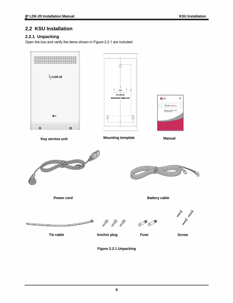
2.2 KSU Installation 2.2.1 Unpacking Open the box and verify the items shown in Figure 2.2.1 are included:
Figure 2.2.1 Unpacking
Key service unit
Tie cable Anchor plug Screw Fuse
Power cord
Mounting template
Battery cable
Manual
IP LDK-20 Installation Manual KSU Installation
10
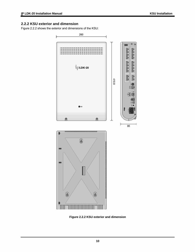
2.2.2 KSU exterior and dimension Figure 2.2.2 shows the exterior and dimensions of the KSU:
Figure 2.2.2 KSU exterior and dimension
IP LDK-20 Installation Manual KSU Installation
11
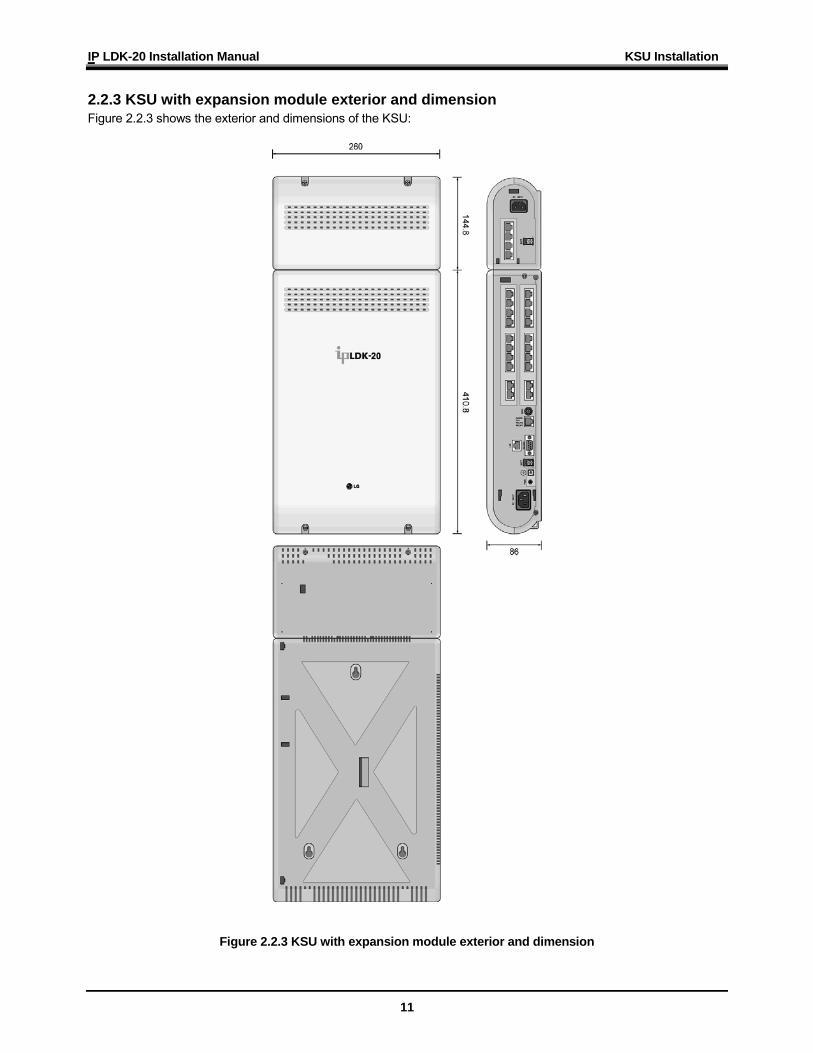
2.2.3 KSU with expansion module exterior and dimension Figure 2.2.3 shows the exterior and dimensions of the KSU:
Figure 2.2.3 KSU with expansion module exterior and dimension
IP LDK-20 Installation Manual KSU Installation
12
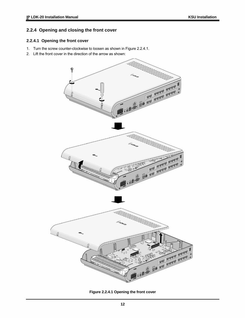
2.2.4 Opening and closing the front cover 2.2.4.1 Opening the front cover
1. Turn the screw counter-clockwise to loosen as shown in Figure 2.2.4.1. 2. Lift the front cover in the direction of the arrow as shown:
Figure 2.2.4.1 Opening the front cover
IP LDK-20 Installation Manual KSU Installation
13
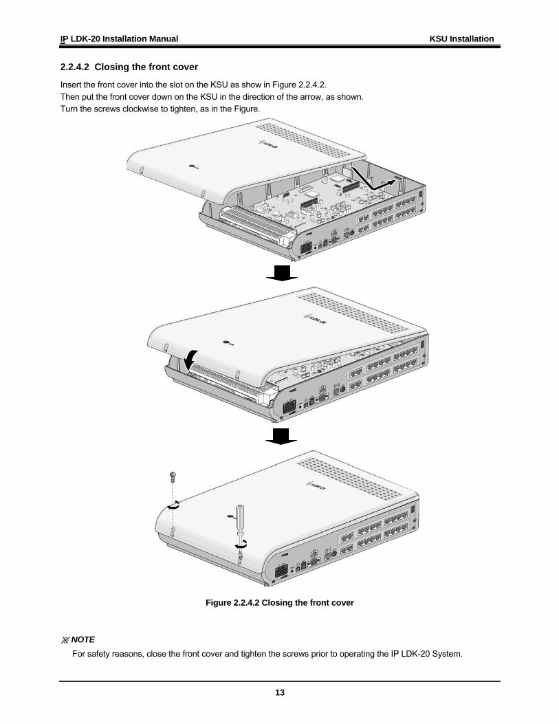
2.2.4.2 Closing the front cover
Insert the front cover into the slot on the KSU as show in Figure 2.2.4.2. Then put the front cover down on the KSU in the direction of the arrow, as shown. Turn the screws clockwise to tighten, as in the Figure.
Figure 2.2.4.2 Closing the front cover ※ NOTE
For safety reasons, close the front cover and tighten the screws prior to operating the IP LDK-20 System.
IP LDK-20 Installation Manual KSU Installation
14
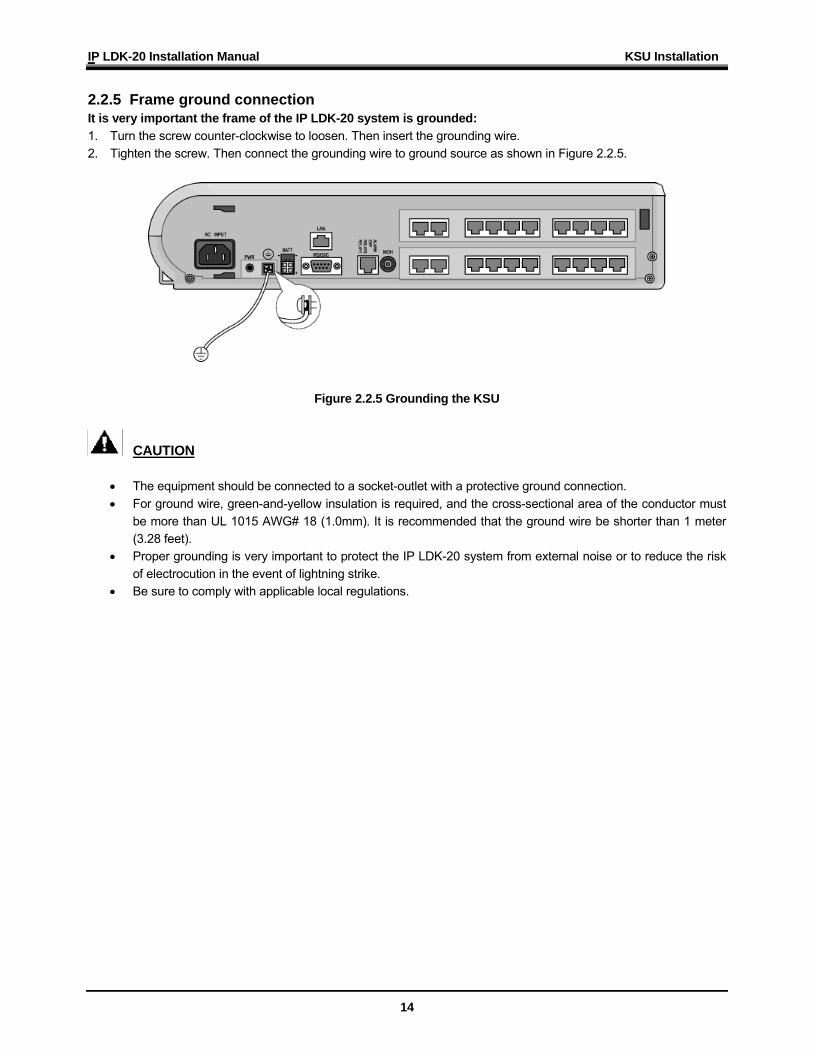
2.2.5 Frame ground connection It is very important the frame of the IP LDK-20 system is grounded: 1. Turn the screw counter-clockwise to loosen. Then insert the grounding wire. 2. Tighten the screw. Then connect the grounding wire to ground source as shown in Figure 2.2.5.
Figure 2.2.5 Grounding the KSU
CAUTION
• The equipment should be connected to a socket-outlet with a protective ground connection. • For ground wire, green-and-yellow insulation is required, and the cross-sectional area of the conductor must
be more than UL 1015 AWG# 18 (1.0mm). It is recommended that the ground wire be shorter than 1 meter (3.28 feet).
• Proper grounding is very important to protect the IP LDK-20 system from external noise or to reduce the risk of electrocution in the event of lightning strike.
• Be sure to comply with applicable local regulations.
IP LDK-20 Installation Manual KSU Installation
15
2.2.6 Power Supply Unit (PSU) installation Before installation, make sure that the KSU not plugged into an outlet. The PSU is located at the left-most area of the KSU, and is capable of providing three kinds of power sources to MBUB through the 7PIN connector, CN19 (refer to the following table). The AC Input Voltage and Fuse Rating
RANGE OF INPUT VOLTAGE CONNECT TO FUSE RATINGS 207V AC - 253V AC CN19 on the MBUB 1.25A @250V
PSU Capacity
PSU TYPE +5V DC -5V DC +30V DC PSU (SMPS) 3.0A 100mA 1.9A
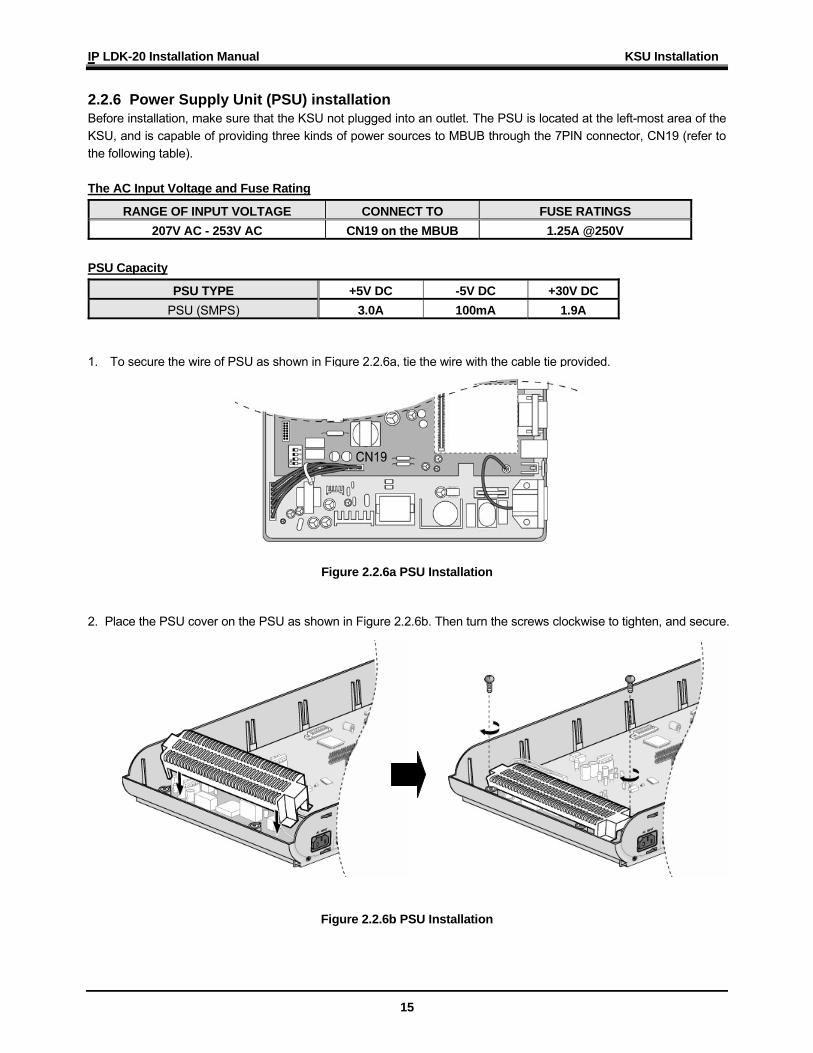
1. To secure the wire of PSU as shown in Figure 2.2.6a, tie the wire with the cable tie provided.
Figure 2.2.6a PSU Installation
2. Place the PSU cover on the PSU as shown in Figure 2.2.6b. Then turn the screws clockwise to tighten, and secure.
Figure 2.2.6b PSU Installation
IP LDK-20 Installation Manual KSU Installation
16
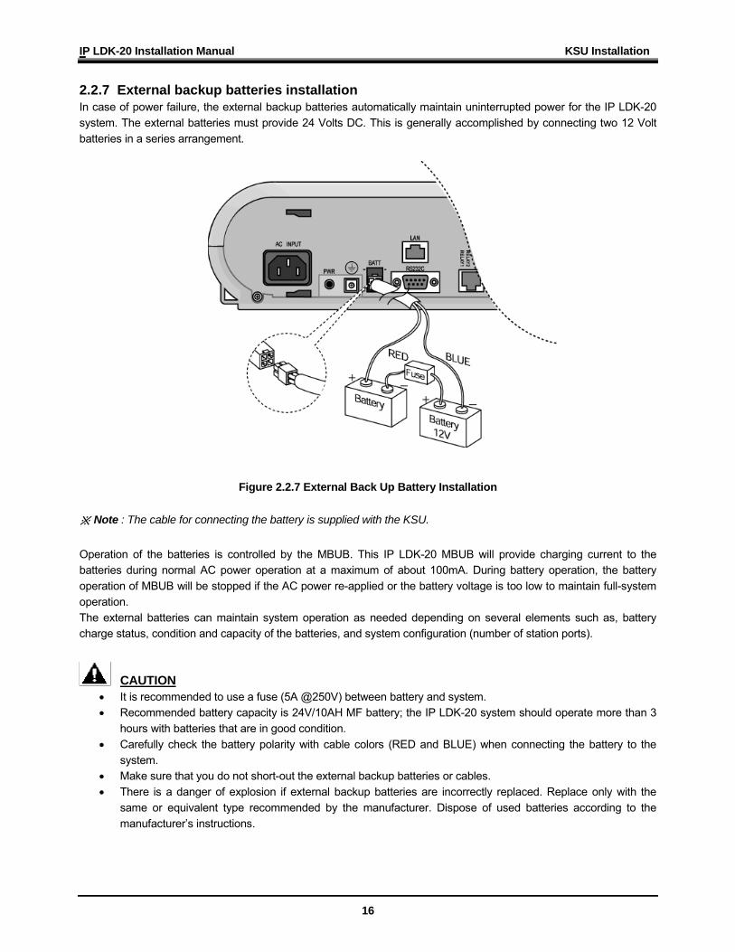
2.2.7 External backup batteries installation In case of power failure, the external backup batteries automatically maintain uninterrupted power for the IP LDK-20 system. The external batteries must provide 24 Volts DC. This is generally accomplished by connecting two 12 Volt batteries in a series arrangement.
Figure 2.2.7 External Back Up Battery Installation ※ Note : The cable for connecting the battery is supplied with the KSU. Operation of the batteries is controlled by the MBUB. This IP LDK-20 MBUB will provide charging current to the batteries during normal AC power operation at a maximum of about 100mA. During battery operation, the battery operation of MBUB will be stopped if the AC power re-applied or the battery voltage is too low to maintain full-system operation. The external batteries can maintain system operation as needed depending on several elements such as, battery charge status, condition and capacity of the batteries, and system configuration (number of station ports).
CAUTION • It is recommended to use a fuse (5A @250V) between battery and system. • Recommended battery capacity is 24V/10AH MF battery; the IP LDK-20 system should operate more than 3
hours with batteries that are in good condition. • Carefully check the battery polarity with cable colors (RED and BLUE) when connecting the battery to the
system. • Make sure that you do not short-out the external backup batteries or cables. • There is a danger of explosion if external backup batteries are incorrectly replaced. Replace only with the
same or equivalent type recommended by the manufacturer. Dispose of used batteries according to the manufacturer’s instructions.
IP LDK-20 Installation Manual KSU Installation
17
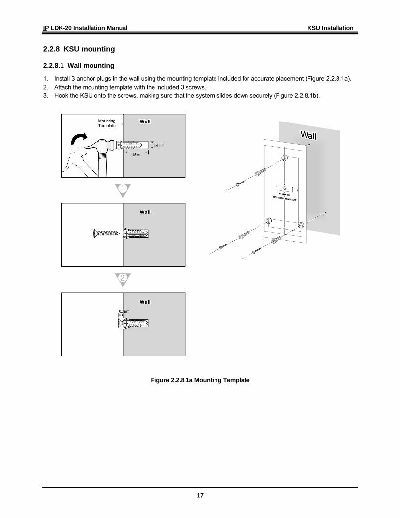
2.2.8 KSU mounting 2.2.8.1 Wall mounting
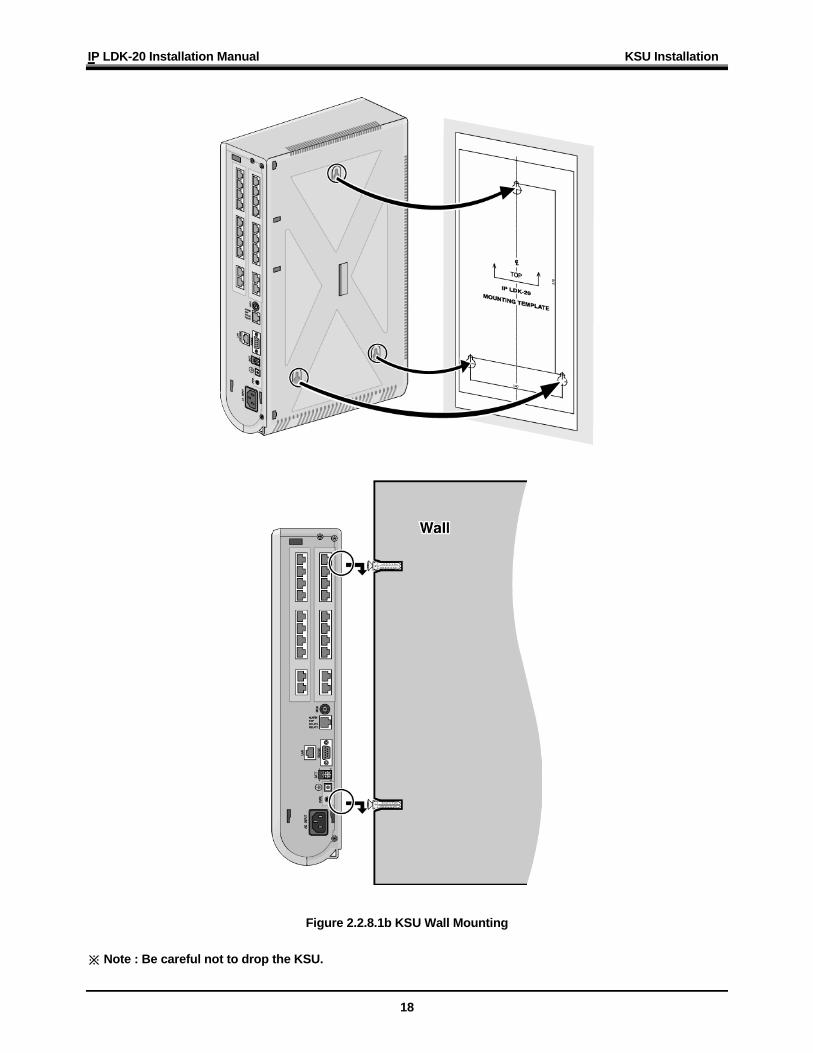
1. Install 3 anchor plugs in the wall using the mounting template included for accurate placement (Figure 2.2.8.1a). 2. Attach the mounting template with the included 3 screws. 3. Hook the KSU onto the screws, making sure that the system slides down securely (Figure 2.2.8.1b).
Figure 2.2.8.1a Mounting Template
IP LDK-20 Installation Manual KSU Installation
18
Figure 2.2.8.1b KSU Wall Mounting ※ Note : Be careful not to drop the KSU.
IP LDK-20 Installation Manual KSU Installation
19
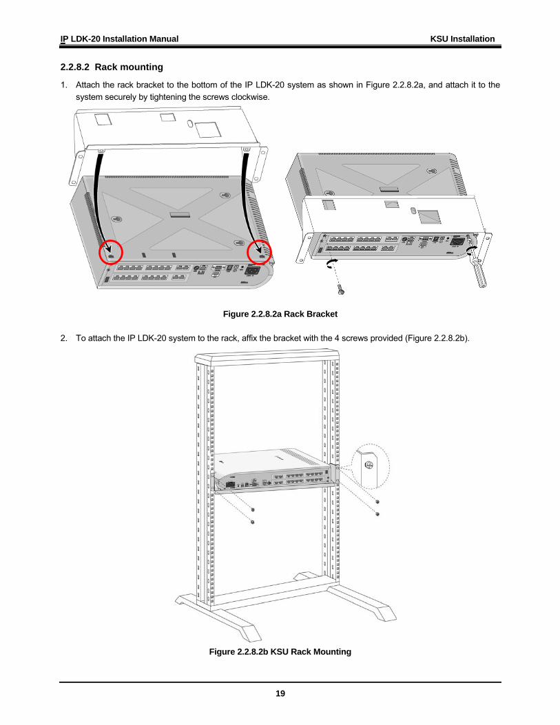
2.2.8.2 Rack mounting
1. Attach the rack bracket to the bottom of the IP LDK-20 system as shown in Figure 2.2.8.2a, and attach it to the system securely by tightening the screws clockwise.
Figure 2.2.8.2a Rack Bracket 2. To attach the IP LDK-20 system to the rack, affix the bracket with the 4 screws provided (Figure 2.2.8.2b).
Figure 2.2.8.2b KSU Rack Mounting
IP LDK-20 Installation Manual Board Installation
20
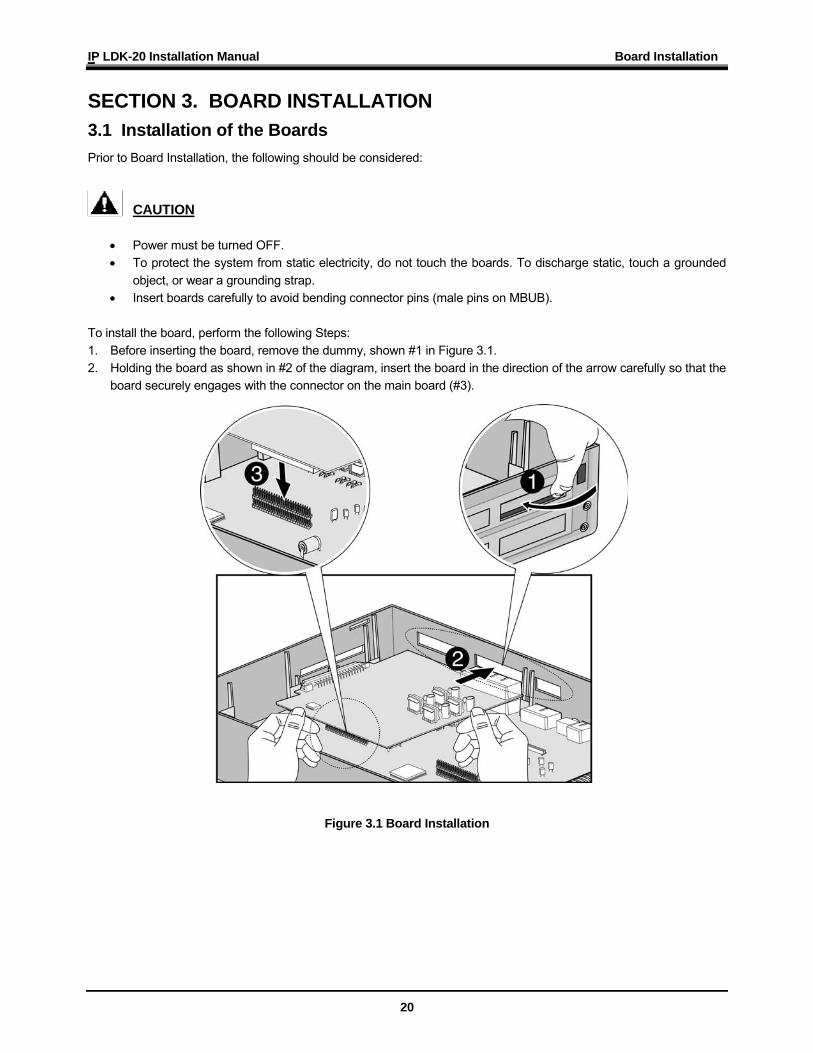
SECTION 3. BOARD INSTALLATION 3.1 Installation of the Boards Prior to Board Installation, the following should be considered:
CAUTION
• Power must be turned OFF. • To protect the system from static electricity, do not touch the boards. To discharge static, touch a grounded
object, or wear a grounding strap. • Insert boards carefully to avoid bending connector pins (male pins on MBUB).
To install the board, perform the following Steps: 1. Before inserting the board, remove the dummy, shown #1 in Figure 3.1. 2. Holding the board as shown in #2 of the diagram, insert the board in the direction of the arrow carefully so that the
board securely engages with the connector on the main board (#3).
Figure 3.1 Board Installation
IP LDK-20 Installation Manual Board Installation
21
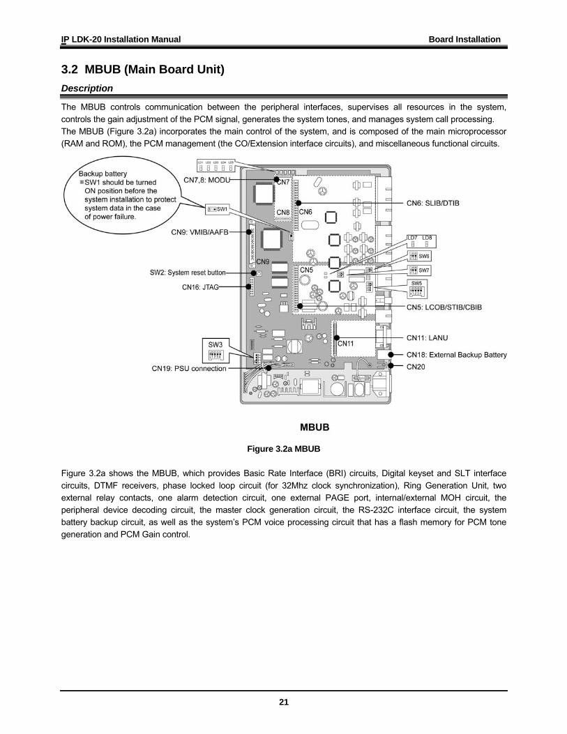
3.2 MBUB (Main Board Unit) Description
The MBUB controls communication between the peripheral interfaces, supervises all resources in the system, controls the gain adjustment of the PCM signal, generates the system tones, and manages system call processing. The MBUB (Figure 3.2a) incorporates the main control of the system, and is composed of the main microprocessor (RAM and ROM), the PCM management (the CO/Extension interface circuits), and miscellaneous functional circuits.
Figure 3.2a MBUB
Figure 3.2a shows the MBUB, which provides Basic Rate Interface (BRI) circuits, Digital keyset and SLT interface circuits, DTMF receivers, phase locked loop circuit (for 32Mhz clock synchronization), Ring Generation Unit, two external relay contacts, one alarm detection circuit, one external PAGE port, internal/external MOH circuit, the peripheral device decoding circuit, the master clock generation circuit, the RS-232C interface circuit, the system battery backup circuit, as well as the system’s PCM voice processing circuit that has a flash memory for PCM tone generation and PCM Gain control.
IP LDK-20 Installation Manual Board Installation
22
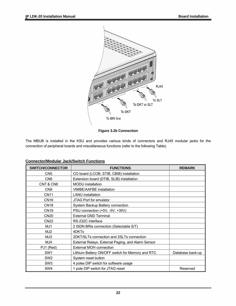
Figure 3.2b Connection The MBUB is installed in the KSU and provides various kinds of connectors and RJ45 modular jacks for the connection of peripheral boards and miscellaneous functions (refer to the following Table). Connector/Modular Jack/Switch Functions
SWITCH/CONNECTOR FUNCTIONS REMARK CN5 CO board (LCOB, STIB, CBIB) installation CN6 Extension board (DTIB, SLIB) installation
CN7 & CN8 MODU installation CN9 VMIBE/AAFBE installation CN11 LANU installation CN16 JTAG Port for emulator CN18 System Backup Battery connection CN19 PSU connection (+5V, -5V, +30V) CN20 External GND Terminal CN22 RS-232C interface MJ1 2 ISDN BRIs connection (Selectable S/T) MJ2 4DKTs MJ3 2DKT/SLTs connection and 2SLTs connection MJ4 External Relays, External Paging, and Alarm Sensor
PJ1 (Red) External MOH connection SW1 Lithium Battery ON/OFF switch for Memory and RTC Database back-up SW2 System reset button SW3 4 poles DIP switch for software usage SW4 1 pole DIP switch for JTAG reset Reserved
IP LDK-20 Installation Manual Board Installation
23
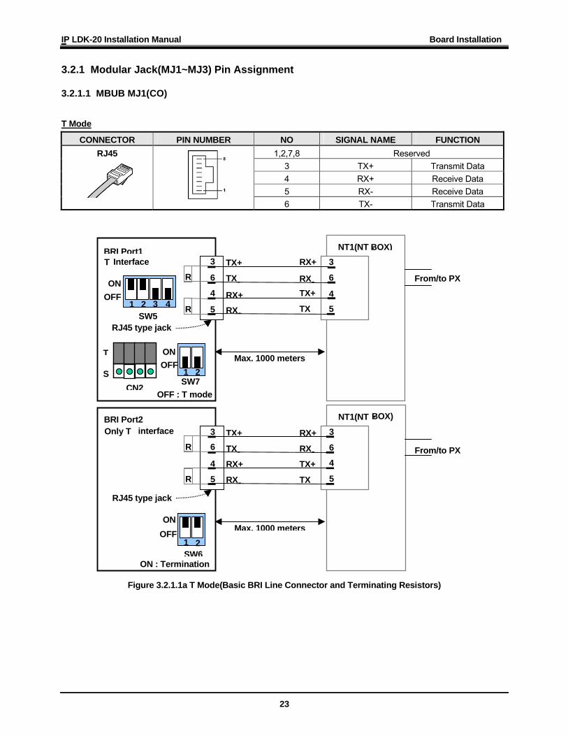
3.2.1 Modular Jack(MJ1~MJ3) Pin Assignment 3.2.1.1 MBUB MJ1(CO)
T Mode
CONNECTOR PIN NUMBER NO SIGNAL NAME FUNCTION 1,2,7,8 Reserved
3 TX+ Transmit Data 4 RX+ Receive Data 5 RX- Receive Data
RJ45
6 TX- Transmit Data
Figure 3.2.1.1a T Mode(Basic BRI Line Connector and Terminating Resistors)
NT1(NT -BOX)3
6
45
RX+
RX-TX+
TX
BRI Port1TX+
TX-RX+
RX-
3 6 4
T Interface R
R
SW7 1 2
ON
OFF : T mode
SW5 1 2 3 4
ON
T
S CN2
5 RJ45 type jack
Max. 1000 meters
OFF From/to PX
NT1(NT -BOX)
3
6
4
5
RX+
RX-TX+
TX
BRI Port2 TX+
TX-RX+
RX-
3 6 4
Only T interface R
R
SW61 2
ON
ON : Termination
5 RJ45 type jack
Max. 1000 meters
From/to PX
OFF
OFF
IP LDK-20 Installation Manual Board Installation
24
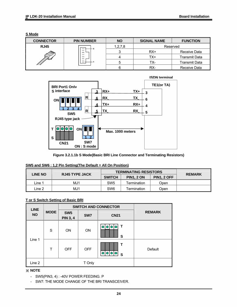
S Mode
CONNECTOR PIN NUMBER NO SIGNAL NAME FUNCTION 1,2,7,8 Reserved
3 RX+ Receive Data 4 TX+ Transmit Data 5 TX- Transmit Data
RJ45
6 RX- Receive Data
Figure 3.2.1.1b S Mode(Basic BRI Line Connector and Terminating Resistors) SW5 and SW6 : 1,2 Pin Setting(The Default = All On Position)
TERMINATING RESISTORS LINE NO RJ45 TYPE JACK SWITCH PIN1, 2 ON PIN1, 2 OFF
REMARK
Line 1 MJ1 SW5 Termination Open Line 2 MJ1 SW6 Termination Open
T or S Switch Setting of Basic BRI
SWITCH AND CONNECTOR LINE NO
MODE SW5 PIN 3, 4
SW7 CN21 REMARK
S ON ON
Line 1
T OFF OFF
Default
Line 2 T Only
※ NOTE - SW5(PIN3, 4) : -40V POWER FEEDING. P - SW7: THE MODE CHANGE OF THE BRI TRANSCEIVER.
TE1(or TA) 3
6
4
5
TX+
TX-RX+
RX-
BRI Port1 Only RX+
RX-TX+
TX-
3
6
4
S interface R
R
ISDN terminal
SW7 1 2
ON
ON : S mode
SW5 1 2 3 4
ON
T S
CN21
5
RJ45 type jack
Max. 1000 meters
T S
T S
IP LDK-20 Installation Manual Board Installation
25
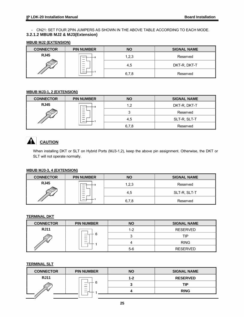
- CN21: SET FOUR 2PIN JUMPERS AS SHOWN IN THE ABOVE TABLE ACCORDING TO EACH MODE. 3.2.1.2 MBUB MJ2 & MJ3(Extension)
MBUB MJ2 (EXTENSION)
CONNECTOR PIN NUMBER NO SIGNAL NAME
1,2,3 Reserved
4,5 DKT-R, DKT-T
RJ45
6,7,8 Reserved
MBUB MJ3-1, 2 (EXTENSION)
CONNECTOR PIN NUMBER NO SIGNAL NAME
1,2 DKT-R, DKT-T
3 Reserved
4,5 SLT-R, SLT-T
RJ45
6,7,8 Reserved
CAUTION
When installing DKT or SLT on Hybrid Ports (MJ3-1,2), keep the above pin assignment. Otherwise, the DKT or SLT will not operate normally.
MBUB MJ3-3, 4 (EXTENSION)
CONNECTOR PIN NUMBER NO SIGNAL NAME
1,2,3 Reserved
4,5 SLT-R, SLT-T
RJ45
6,7,8 Reserved TERMINAL DKT
CONNECTOR PIN NUMBER NO SIGNAL NAME 1-2 RESERVED
3 TIP
4 RING
RJ11
5-6 RESERVED TERMINAL SLT
CONNECTOR PIN NUMBER NO SIGNAL NAME
1-2 RESERVED 3 TIP
RJ11
4 RING
IP LDK-20 Installation Manual Board Installation
26
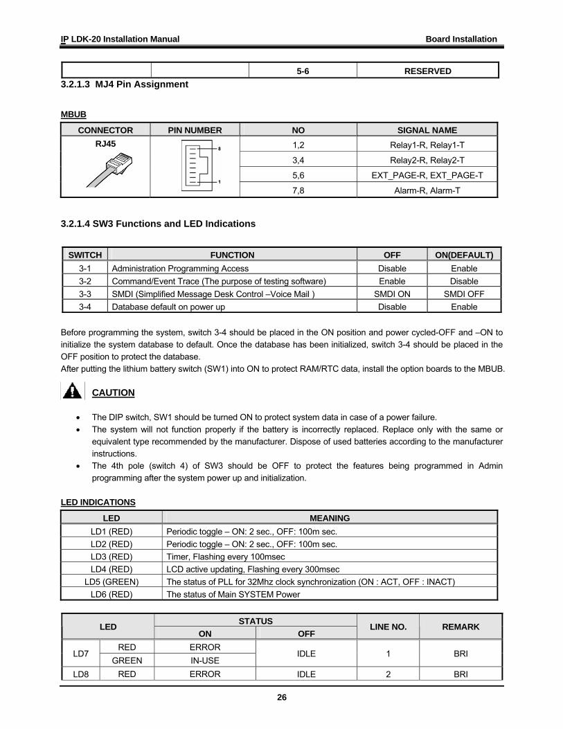
5-6 RESERVED 3.2.1.3 MJ4 Pin Assignment
MBUB
CONNECTOR PIN NUMBER NO SIGNAL NAME 1,2 Relay1-R, Relay1-T
3,4 Relay2-R, Relay2-T
5,6 EXT_PAGE-R, EXT_PAGE-T
RJ45
7,8 Alarm-R, Alarm-T 3.2.1.4 SW3 Functions and LED Indications
SWITCH FUNCTION OFF ON(DEFAULT)
3-1 Administration Programming Access Disable Enable 3-2 Command/Event Trace (The purpose of testing software) Enable Disable 3-3 SMDI (Simplified Message Desk Control –Voice Mail ) SMDI ON SMDI OFF 3-4 Database default on power up Disable Enable
Before programming the system, switch 3-4 should be placed in the ON position and power cycled-OFF and –ON to initialize the system database to default. Once the database has been initialized, switch 3-4 should be placed in the OFF position to protect the database. After putting the lithium battery switch (SW1) into ON to protect RAM/RTC data, install the option boards to the MBUB.
CAUTION
• The DIP switch, SW1 should be turned ON to protect system data in case of a power failure. • The system will not function properly if the battery is incorrectly replaced. Replace only with the same or
equivalent type recommended by the manufacturer. Dispose of used batteries according to the manufacturer instructions.
• The 4th pole (switch 4) of SW3 should be OFF to protect the features being programmed in Admin programming after the system power up and initialization.
LED INDICATIONS
LED MEANING LD1 (RED) Periodic toggle – ON: 2 sec., OFF: 100m sec. LD2 (RED) Periodic toggle – ON: 2 sec., OFF: 100m sec. LD3 (RED) Timer, Flashing every 100msec LD4 (RED) LCD active updating, Flashing every 300msec
LD5 (GREEN) The status of PLL for 32Mhz clock synchronization (ON : ACT, OFF : INACT) LD6 (RED) The status of Main SYSTEM Power
STATUS LED
ON OFF LINE NO. REMARK
RED ERROR LD7
GREEN IN-USE IDLE 1 BRI
LD8 RED ERROR IDLE 2 BRI
IP LDK-20 Installation Manual Board Installation
27
GREEN IN-USE
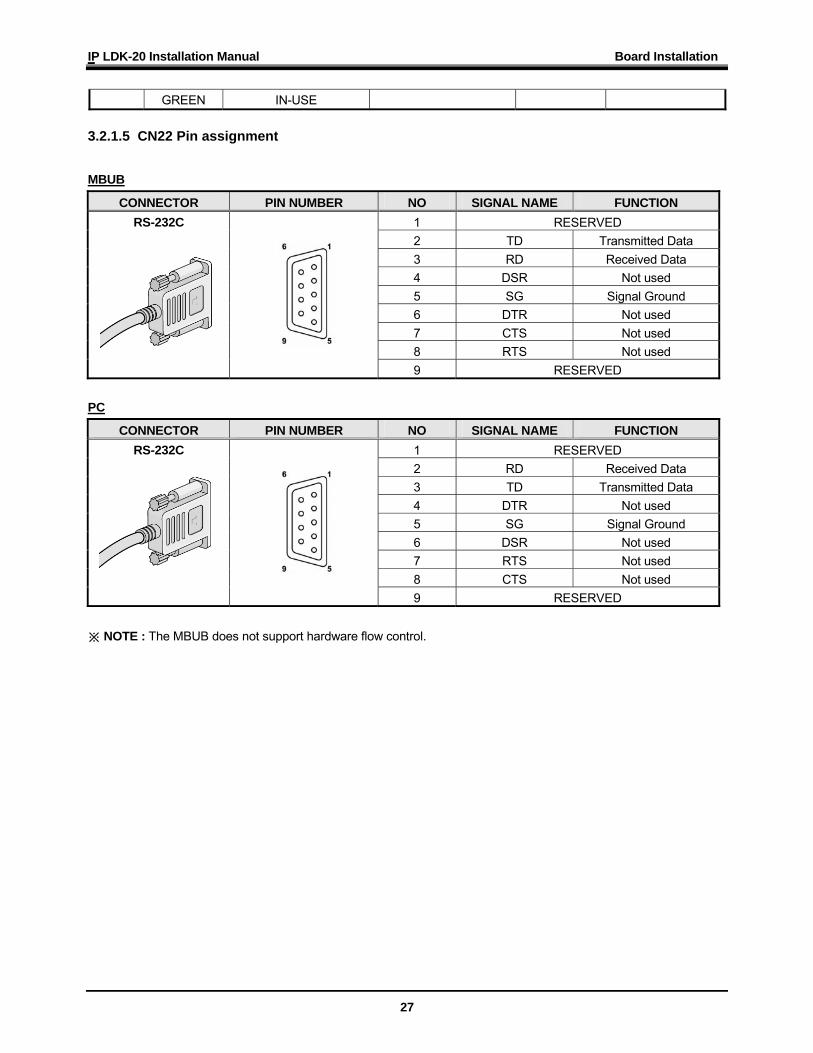
3.2.1.5 CN22 Pin assignment
MBUB
CONNECTOR PIN NUMBER NO SIGNAL NAME FUNCTION 1 RESERVED 2 TD Transmitted Data 3 RD Received Data 4 DSR Not used 5 SG Signal Ground 6 DTR Not used 7 CTS Not used 8 RTS Not used
RS-232C
9 RESERVED PC
CONNECTOR PIN NUMBER NO SIGNAL NAME FUNCTION 1 RESERVED 2 RD Received Data 3 TD Transmitted Data 4 DTR Not used 5 SG Signal Ground 6 DSR Not used 7 RTS Not used 8 CTS Not used
RS-232C
9 RESERVED ※ NOTE : The MBUB does not support hardware flow control.

IP LDK-20 Installation Manual Board Installation
28
IP LDK-20 Installation Manual Board Installation
29
3.3 Installation of the CO Line Board
BOARD PORT CONNECTOR
TYPE DESCRIPTION CABLE REMARK
LCOB 2 ports (4 LCO)
RJ45 Loop Start CO Line Interface 2 wire
STIB 2 ports (2 BRI)
RJ45 ISDN Basic Rate Interface (2B+D) 4 wire Switched
T or S
CBIB 2 ports
( 1 BRI+2 LCO) RJ45
ISDN Basic Rate Interface (2B+D) + Loop Start CO Line Interface
4 wire (Port 1) 2 wire (Port 2)
T mode only.
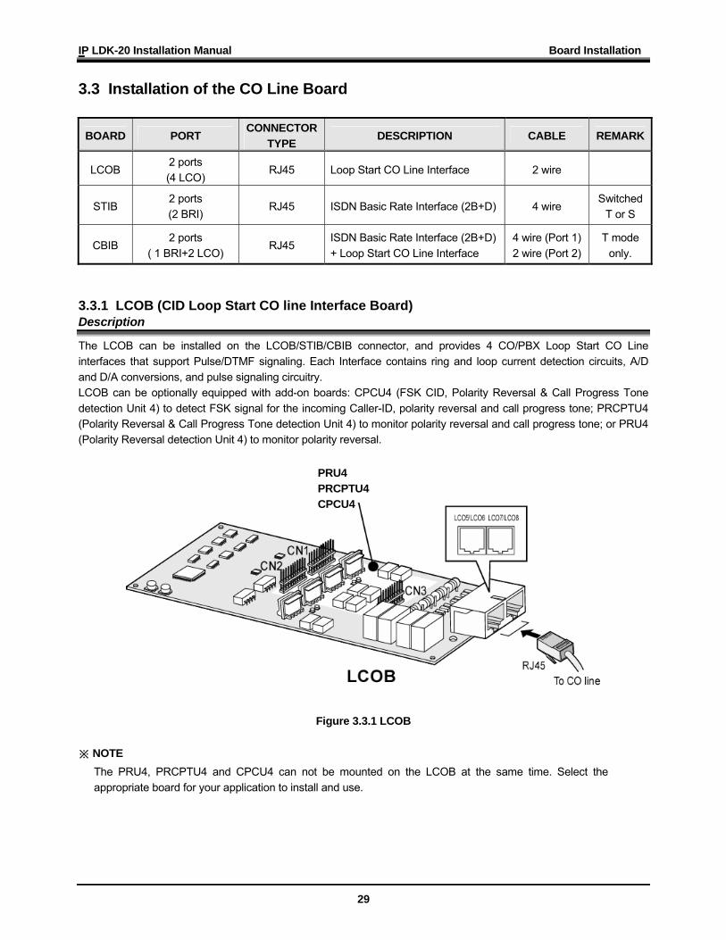
3.3.1 LCOB (CID Loop Start CO line Interface Board) Description
The LCOB can be installed on the LCOB/STIB/CBIB connector, and provides 4 CO/PBX Loop Start CO Line interfaces that support Pulse/DTMF signaling. Each Interface contains ring and loop current detection circuits, A/D and D/A conversions, and pulse signaling circuitry. LCOB can be optionally equipped with add-on boards: CPCU4 (FSK CID, Polarity Reversal & Call Progress Tone detection Unit 4) to detect FSK signal for the incoming Caller-ID, polarity reversal and call progress tone; PRCPTU4 (Polarity Reversal & Call Progress Tone detection Unit 4) to monitor polarity reversal and call progress tone; or PRU4 (Polarity Reversal detection Unit 4) to monitor polarity reversal.
Figure 3.3.1 LCOB
※ NOTE The PRU4, PRCPTU4 and CPCU4 can not be mounted on the LCOB at the same time. Select the appropriate board for your application to install and use.
PRU4 PRCPTU4 CPCU4
IP LDK-20 Installation Manual Board Installation
30
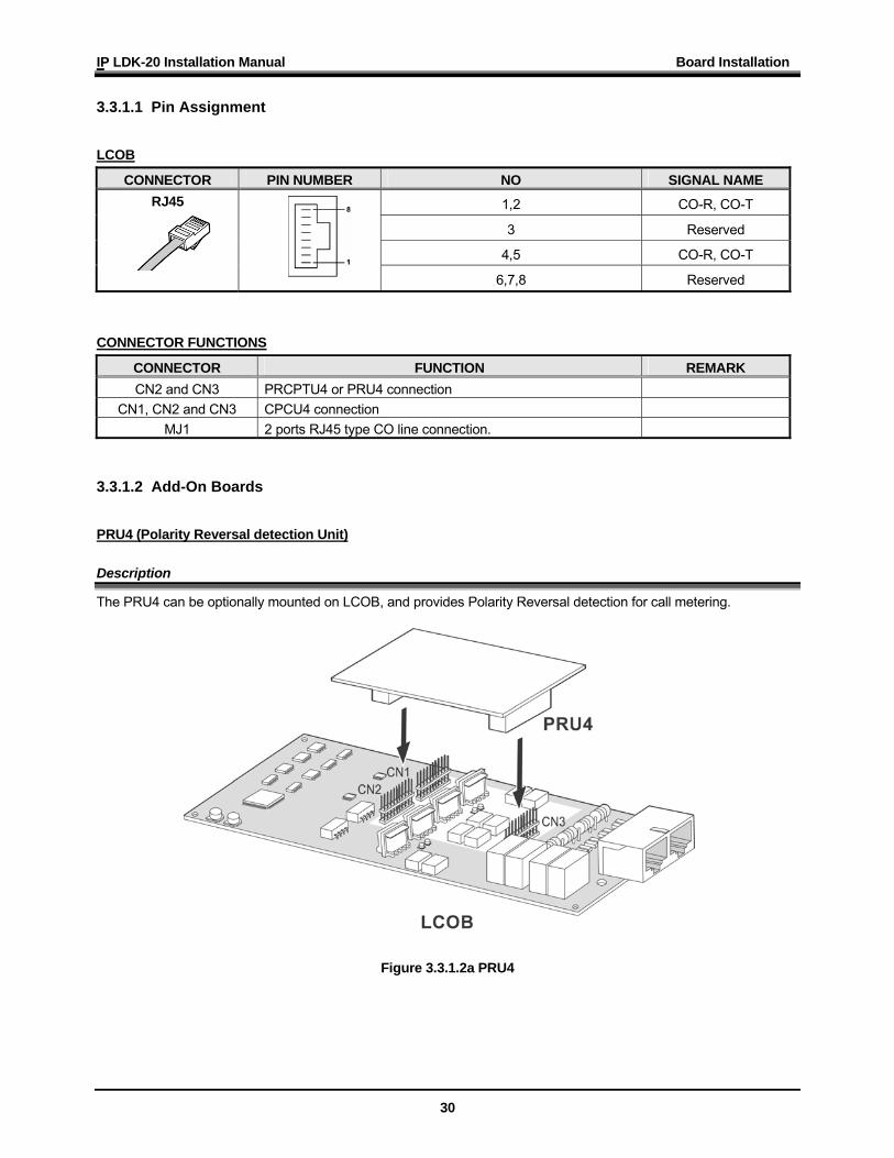
3.3.1.1 Pin Assignment
LCOB
CONNECTOR PIN NUMBER NO SIGNAL NAME
1,2 CO-R, CO-T
3 Reserved
4,5 CO-R, CO-T
RJ45
6,7,8 Reserved
CONNECTOR FUNCTIONS
CONNECTOR FUNCTION REMARK CN2 and CN3 PRCPTU4 or PRU4 connection
CN1, CN2 and CN3 CPCU4 connection MJ1 2 ports RJ45 type CO line connection.
3.3.1.2 Add-On Boards
PRU4 (Polarity Reversal detection Unit) Description
The PRU4 can be optionally mounted on LCOB, and provides Polarity Reversal detection for call metering.
Figure 3.3.1.2a PRU4
IP LDK-20 Installation Manual Board Installation
31
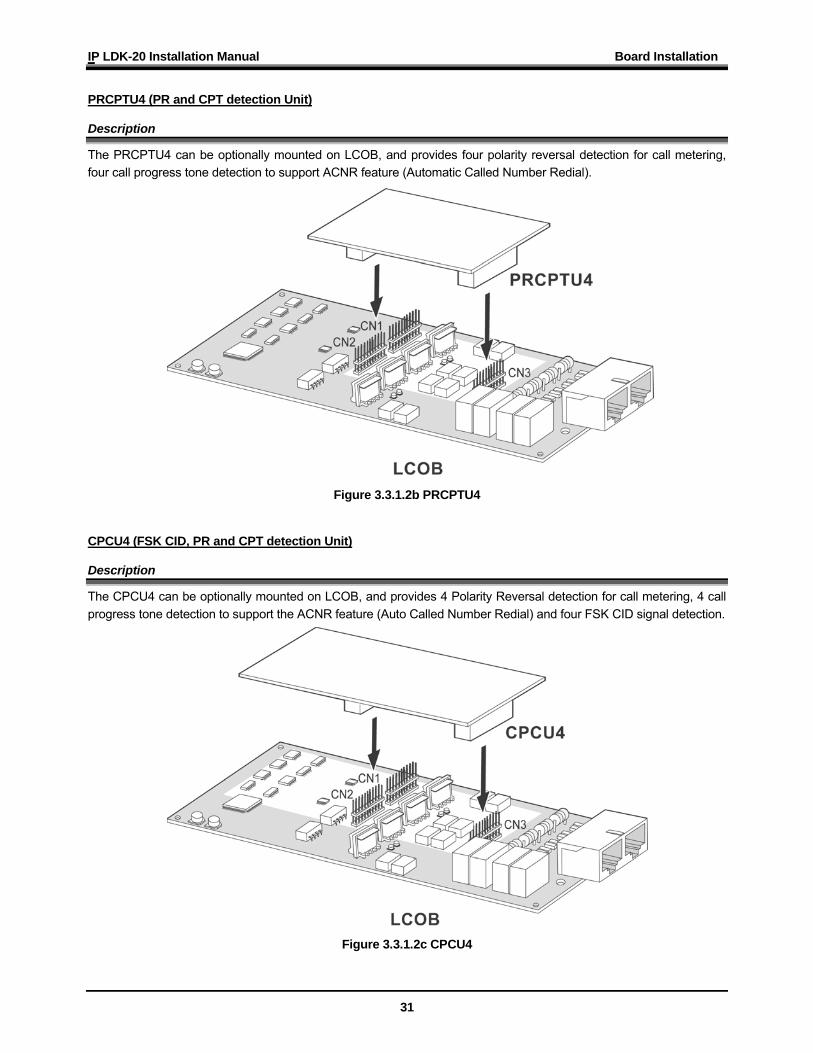
PRCPTU4 (PR and CPT detection Unit)
Description
The PRCPTU4 can be optionally mounted on LCOB, and provides four polarity reversal detection for call metering, four call progress tone detection to support ACNR feature (Automatic Called Number Redial).
Figure 3.3.1.2b PRCPTU4 CPCU4 (FSK CID, PR and CPT detection Unit)
Description
The CPCU4 can be optionally mounted on LCOB, and provides 4 Polarity Reversal detection for call metering, 4 call progress tone detection to support the ACNR feature (Auto Called Number Redial) and four FSK CID signal detection.
Figure 3.3.1.2c CPCU4
IP LDK-20 Installation Manual Board Installation
32
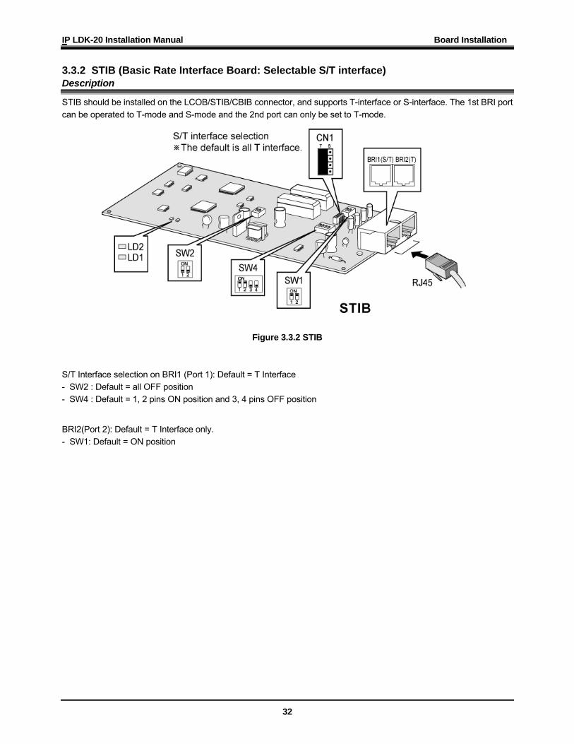
3.3.2 STIB (Basic Rate Interface Board: Selectable S/T interface) Description
STIB should be installed on the LCOB/STIB/CBIB connector, and supports T-interface or S-interface. The 1st BRI port can be operated to T-mode and S-mode and the 2nd port can only be set to T-mode.
Figure 3.3.2 STIB S/T Interface selection on BRI1 (Port 1): Default = T Interface - SW2 : Default = all OFF position - SW4 : Default = 1, 2 pins ON position and 3, 4 pins OFF position
BRI2(Port 2): Default = T Interface only. - SW1: Default = ON position
IP LDK-20 Installation Manual Board Installation
33
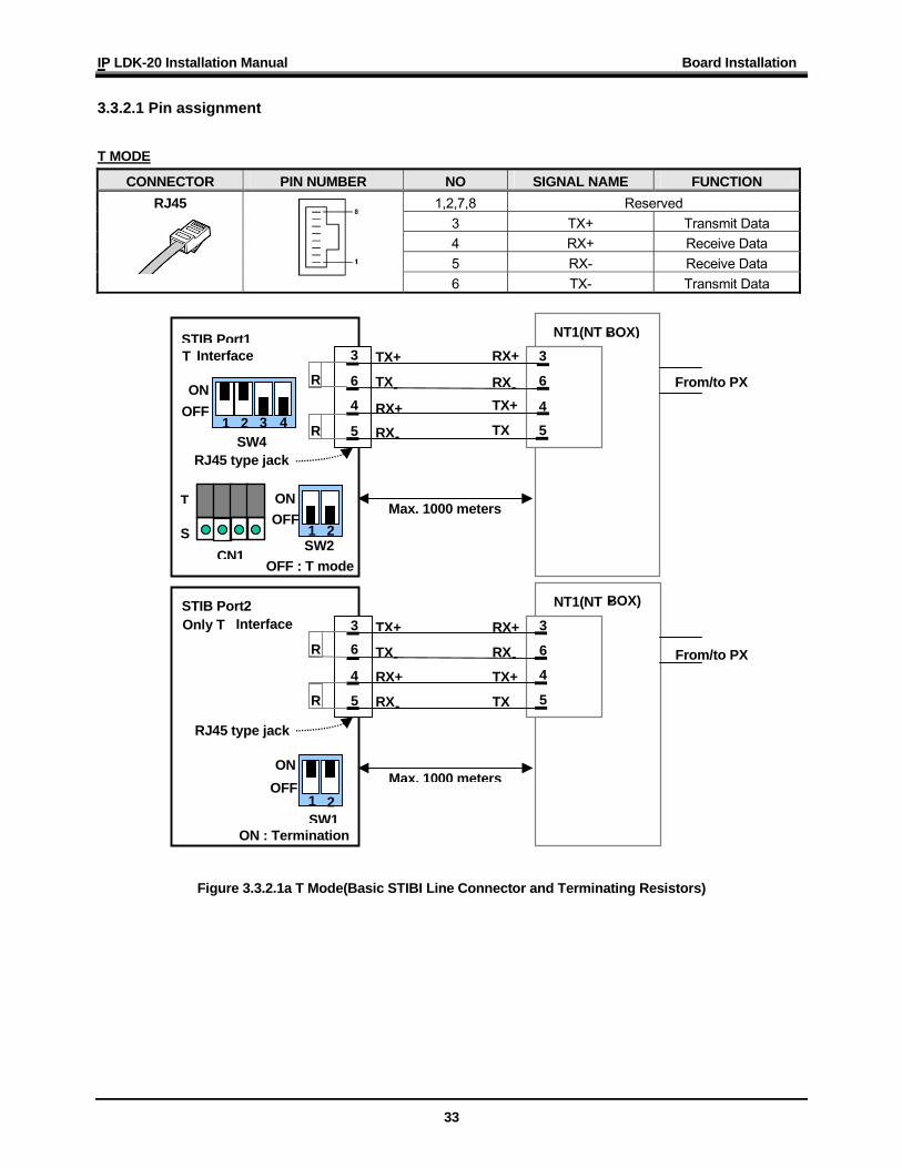
3.3.2.1 Pin assignment
T MODE
CONNECTOR PIN NUMBER NO SIGNAL NAME FUNCTION 1,2,7,8 Reserved
3 TX+ Transmit Data 4 RX+ Receive Data 5 RX- Receive Data
RJ45
6 TX- Transmit Data
Figure 3.3.2.1a T Mode(Basic STIBI Line Connector and Terminating Resistors)
NT1(NT -BOX) 3
6
45
RX+
RX-TX+
TX
STIB Port1TX+
TX-RX+
RX-
3 6 4
T Interface R
R
SW2 1 2
ON
OFF : T mode
SW4 1 2 3 4
ON
T
S CN1
5 RJ45 type jack
Max. 1000 meters
OFF From/to PX
NT1(NT -BOX) 3
6
4
5
RX+
RX-TX+
TX
STIB Port2 TX+
TX-RX+
RX-
3 6 4
Only T Interface R
R
SW11 2
ON
ON : Termination
5 RJ45 type jack
Max. 1000 meters
From/to PX
OFF
OFF
IP LDK-20 Installation Manual Board Installation
34
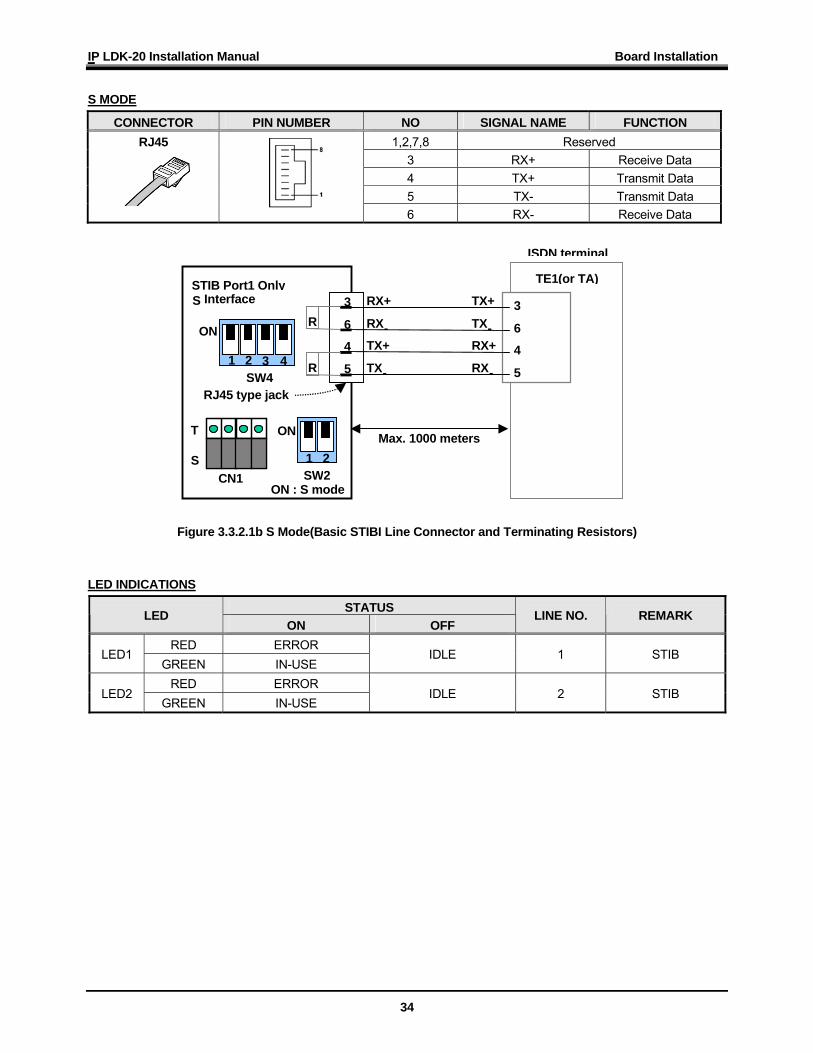
S MODE
CONNECTOR PIN NUMBER NO SIGNAL NAME FUNCTION 1,2,7,8 Reserved
3 RX+ Receive Data 4 TX+ Transmit Data 5 TX- Transmit Data
RJ45
6 RX- Receive Data
Figure 3.3.2.1b S Mode(Basic STIBI Line Connector and Terminating Resistors) LED INDICATIONS
STATUS LED ON OFF
LINE NO. REMARK
RED ERROR LED1
GREEN IN-USE IDLE 1 STIB
RED ERROR LED2
GREEN IN-USE IDLE 2 STIB
TE1(or TA) 3
6
4
5
TX+
TX-RX+
RX-
STIB Port1 Only RX+
RX-TX+
TX-
3
6
4
S Interface R
R
ISDN terminal
SW21 2
ON
ON : S mode
SW4 1 2 3 4
ON
T S
CN1
5
RJ45 type jack
Max. 1000 meters
IP LDK-20 Installation Manual Board Installation
35
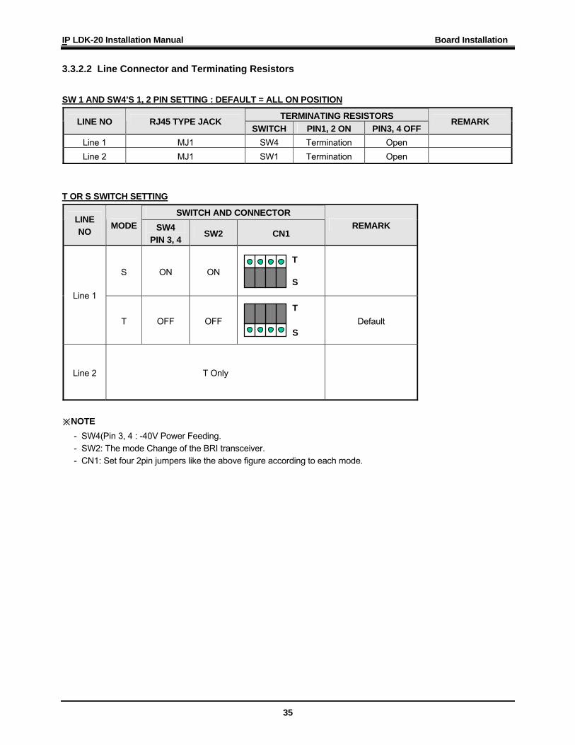
3.3.2.2 Line Connector and Terminating Resistors
SW 1 AND SW4’S 1, 2 PIN SETTING : DEFAULT = ALL ON POSITION
TERMINATING RESISTORS LINE NO RJ45 TYPE JACK SWITCH PIN1, 2 ON PIN3, 4 OFF
REMARK
Line 1 MJ1 SW4 Termination Open Line 2 MJ1 SW1 Termination Open
T OR S SWITCH SETTING
SWITCH AND CONNECTOR LINE NO
MODE SW4 PIN 3, 4
SW2 CN1 REMARK
S ON ON
Line 1
T OFF OFF
Default
Line 2 T Only
※NOTE
- SW4(Pin 3, 4 : -40V Power Feeding. - SW2: The mode Change of the BRI transceiver. - CN1: Set four 2pin jumpers like the above figure according to each mode.
T S
T S
IP LDK-20 Installation Manual Board Installation
36
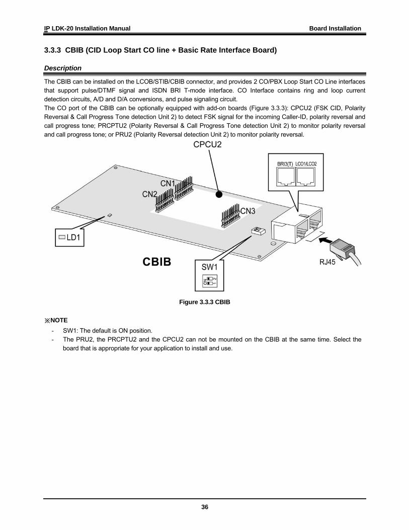
3.3.3 CBIB (CID Loop Start CO line + Basic Rate Interface Board) Description
The CBIB can be installed on the LCOB/STIB/CBIB connector, and provides 2 CO/PBX Loop Start CO Line interfaces that support pulse/DTMF signal and ISDN BRI T-mode interface. CO Interface contains ring and loop current detection circuits, A/D and D/A conversions, and pulse signaling circuit. The CO port of the CBIB can be optionally equipped with add-on boards (Figure 3.3.3): CPCU2 (FSK CID, Polarity Reversal & Call Progress Tone detection Unit 2) to detect FSK signal for the incoming Caller-ID, polarity reversal and call progress tone; PRCPTU2 (Polarity Reversal & Call Progress Tone detection Unit 2) to monitor polarity reversal and call progress tone; or PRU2 (Polarity Reversal detection Unit 2) to monitor polarity reversal.
Figure 3.3.3 CBIB ※NOTE
- SW1: The default is ON position. - The PRU2, the PRCPTU2 and the CPCU2 can not be mounted on the CBIB at the same time. Select the
board that is appropriate for your application to install and use.
IP LDK-20 Installation Manual Board Installation
37
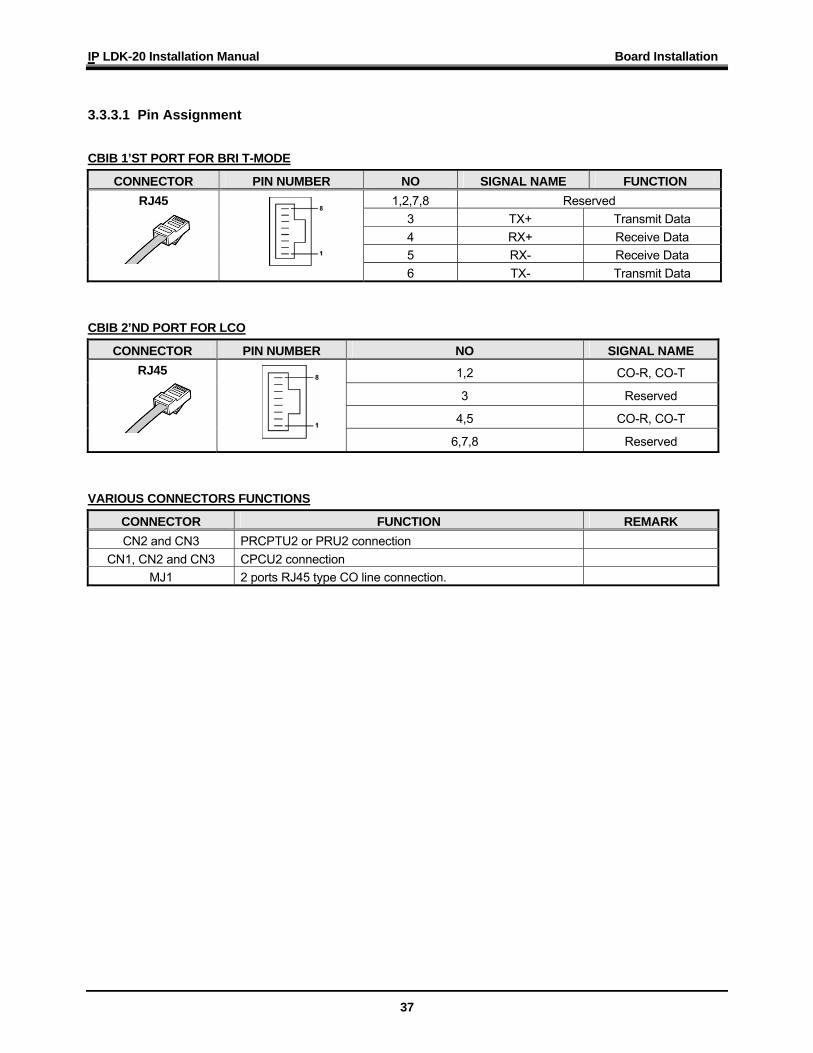
3.3.3.1 Pin Assignment
CBIB 1’ST PORT FOR BRI T-MODE
CONNECTOR PIN NUMBER NO SIGNAL NAME FUNCTION 1,2,7,8 Reserved
3 TX+ Transmit Data 4 RX+ Receive Data 5 RX- Receive Data
RJ45
6 TX- Transmit Data CBIB 2’ND PORT FOR LCO
CONNECTOR PIN NUMBER NO SIGNAL NAME
1,2 CO-R, CO-T
3 Reserved
4,5 CO-R, CO-T
RJ45
6,7,8 Reserved
VARIOUS CONNECTORS FUNCTIONS
CONNECTOR FUNCTION REMARK CN2 and CN3 PRCPTU2 or PRU2 connection
CN1, CN2 and CN3 CPCU2 connection MJ1 2 ports RJ45 type CO line connection.
IP LDK-20 Installation Manual Board Installation
38
3.3.3.2 Add-On Boards
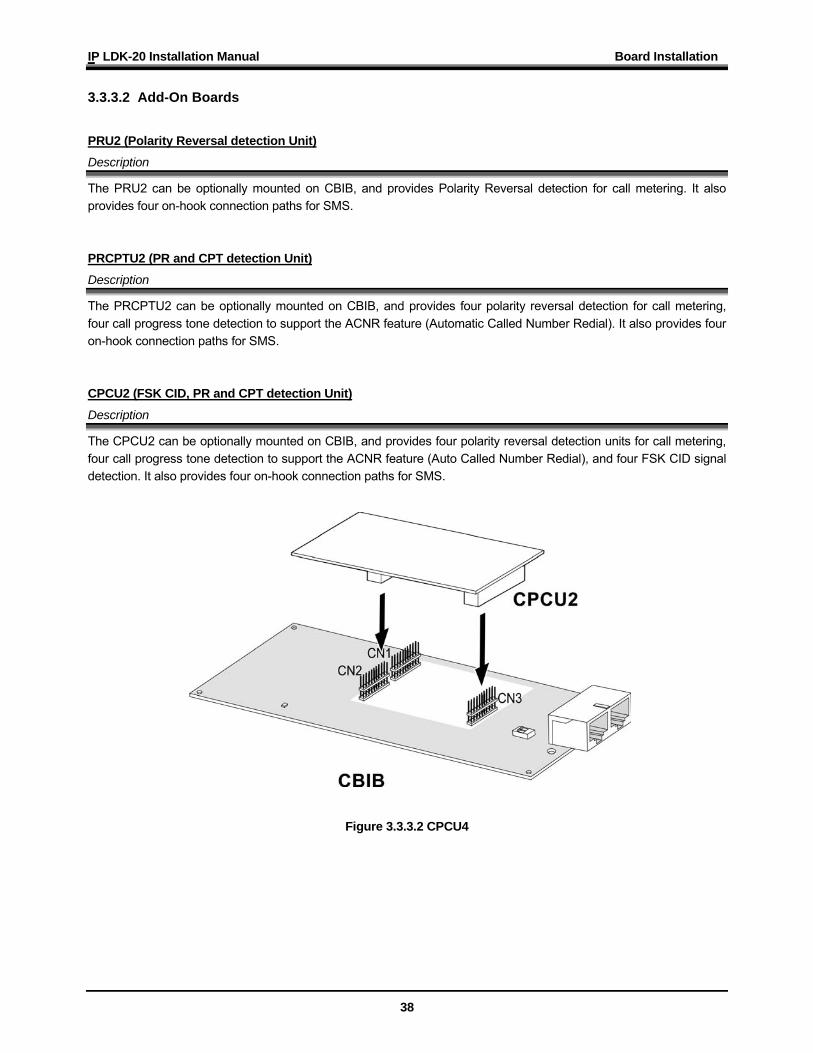
PRU2 (Polarity Reversal detection Unit) Description
The PRU2 can be optionally mounted on CBIB, and provides Polarity Reversal detection for call metering. It also provides four on-hook connection paths for SMS. PRCPTU2 (PR and CPT detection Unit) Description
The PRCPTU2 can be optionally mounted on CBIB, and provides four polarity reversal detection for call metering, four call progress tone detection to support the ACNR feature (Automatic Called Number Redial). It also provides four on-hook connection paths for SMS. CPCU2 (FSK CID, PR and CPT detection Unit) Description
The CPCU2 can be optionally mounted on CBIB, and provides four polarity reversal detection units for call metering, four call progress tone detection to support the ACNR feature (Auto Called Number Redial), and four FSK CID signal detection. It also provides four on-hook connection paths for SMS.
Figure 3.3.3.2 CPCU4
IP LDK-20 Installation Manual Board Installation
39
3.4 Installation of the Extension Board
BOARD PORT CONNECTOR TYPE REMARK DTIB4 4 DKT ports RJ45 Digital Terminal Interface : 4 ports DTIB8 8 DKT ports RJ45 Digital Terminal Interface : 8 ports SLIB4 4 SLT ports RJ45 Single line telephone Interface : 4 ports SLIB8 8 SLT ports RJ45 Single line telephone Interface : 8 ports
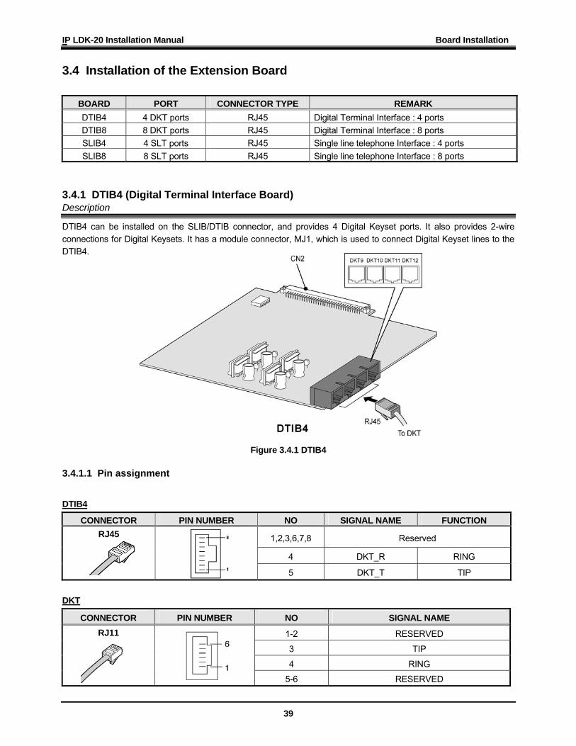
3.4.1 DTIB4 (Digital Terminal Interface Board) Description
DTIB4 can be installed on the SLIB/DTIB connector, and provides 4 Digital Keyset ports. It also provides 2-wire connections for Digital Keysets. It has a module connector, MJ1, which is used to connect Digital Keyset lines to the DTIB4.
Figure 3.4.1 DTIB4 3.4.1.1 Pin assignment
DTIB4
CONNECTOR PIN NUMBER NO SIGNAL NAME FUNCTION
1,2,3,6,7,8 Reserved
4 DKT_R RING
RJ45
5 DKT_T TIP
DKT
CONNECTOR PIN NUMBER NO SIGNAL NAME
1-2 RESERVED
3 TIP
4 RING
RJ11
5-6 RESERVED
IP LDK-20 Installation Manual Board Installation
40
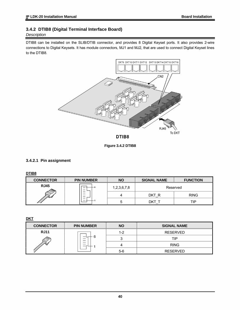
3.4.2 DTIB8 (Digital Terminal Interface Board) Description
DTIB8 can be installed on the SLIB/DTIB connector, and provides 8 Digital Keyset ports. It also provides 2-wire connections to Digital Keysets. It has module connectors, MJ1 and MJ2, that are used to connect Digital Keyset lines to the DTIB8.
Figure 3.4.2 DTIB8 3.4.2.1 Pin assignment
DTIB8
CONNECTOR PIN NUMBER NO SIGNAL NAME FUNCTION
1,2,3,6,7,8 Reserved
4 DKT_R RING
RJ45
5 DKT_T TIP
DKT
CONNECTOR PIN NUMBER NO SIGNAL NAME
1-2 RESERVED
3 TIP
4 RING
RJ11
5-6 RESERVED
IP LDK-20 Installation Manual Board Installation
41
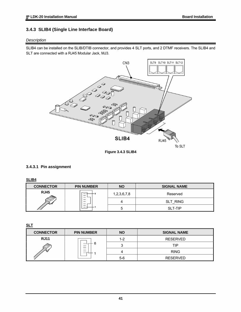
3.4.3 SLIB4 (Single Line Interface Board) Description
SLIB4 can be installed on the SLIB/DTIB connector, and provides 4 SLT ports, and 2 DTMF receivers. The SLIB4 and SLT are connected with a RJ45 Modular Jack, MJ3.
Figure 3.4.3 SLIB4
3.4.3.1 Pin assignment
SLIB4
CONNECTOR PIN NUMBER NO SIGNAL NAME
1,2,3,6,7,8 Reserved
4 SLT_RING
RJ45
5 SLT-TIP
SLT
CONNECTOR PIN NUMBER NO SIGNAL NAME
1-2 RESERVED
3 TIP
4 RING
RJ11
5-6 RESERVED
IP LDK-20 Installation Manual Board Installation
42
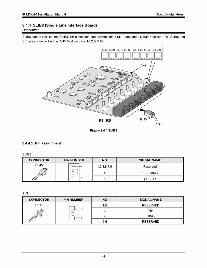
3.4.4 SLIB8 (Single Line Interface Board) Description
SLIB8 can be installed the SLIB/DTIB connector, and provides the 8 SLT ports and 2 DTMF receivers. The SLIB8 and SLT are connected with a RJ45 Modular Jack, MJ2 & MJ3.
Figure 3.4.4 SLIB8 3.4.4.1 Pin assignment
SLIB8
CONNECTOR PIN NUMBER NO SIGNAL NAME
1,2,3,6,7,8 Reserved
4 SLT_RING
RJ45
5 SLT-TIP
SLT
CONNECTOR PIN NUMBER NO SIGNAL NAME
1-2 RESERVED
3 TIP
4 RING
RJ11
5-6 RESERVED
IP LDK-20 Installation Manual Board Installation
43
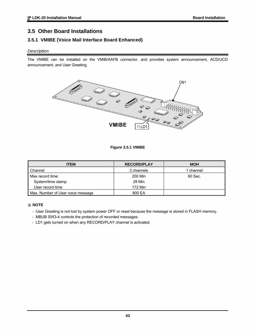
3.5 Other Board Installations 3.5.1 VMIBE (Voice Mail Interface Board Enhanced) Description
The VMIBE can be installed on the VMIB/AAFB connector, and provides system announcement, ACD/UCD announcement, and User Greeting.
Figure 3.5.1 VMIBE
ITEM RECORD/PLAY MOH Channel 3 channels 1 channel Max record time:
System/time stamp User record time
200 Min 28 Min 172 Min
60 Sec.
Max. Number of User voice message 800 EA ※ NOTE
- User Greeting is not lost by system power OFF or reset because the message is stored in FLASH memory. - MBUB SW3-4 controls the protection of recorded messages. - LD1 gets turned on when any RECORD/PLAY channel is activated.
IP LDK-20 Installation Manual Board Installation
44
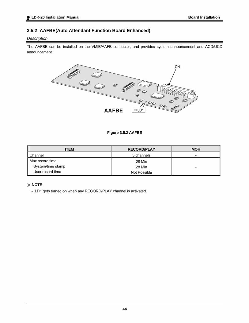
3.5.2 AAFBE(Auto Attendant Function Board Enhanced) Description
The AAFBE can be installed on the VMIB/AAFB connector, and provides system announcement and ACD/UCD announcement.
Figure 3.5.2 AAFBE
ITEM RECORD/PLAY MOH Channel 3 channels - Max record time:
System/time stamp User record time
28 Min 28 Min
Not Possible -
※ NOTE
- LD1 gets turned on when any RECORD/PLAY channel is activated.
IP LDK-20 Installation Manual Board Installation
45
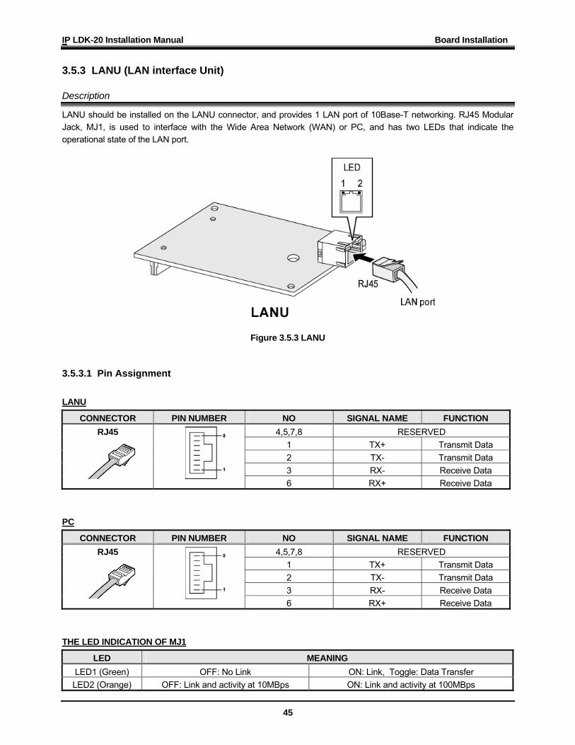
3.5.3 LANU (LAN interface Unit) Description
LANU should be installed on the LANU connector, and provides 1 LAN port of 10Base-T networking. RJ45 Modular Jack, MJ1, is used to interface with the Wide Area Network (WAN) or PC, and has two LEDs that indicate the operational state of the LAN port.
Figure 3.5.3 LANU 3.5.3.1 Pin Assignment LANU
CONNECTOR PIN NUMBER NO SIGNAL NAME FUNCTION 4,5,7,8 RESERVED
1 TX+ Transmit Data 2 TX- Transmit Data 3 RX- Receive Data
RJ45
6 RX+ Receive Data PC
CONNECTOR PIN NUMBER NO SIGNAL NAME FUNCTION 4,5,7,8 RESERVED
1 TX+ Transmit Data 2 TX- Transmit Data 3 RX- Receive Data
RJ45
6 RX+ Receive Data THE LED INDICATION OF MJ1
LED MEANING LED1 (Green) OFF: No Link ON: Link, Toggle: Data Transfer
LED2 (Orange) OFF: Link and activity at 10MBps ON: Link and activity at 100MBps
IP LDK-20 Installation Manual Board Installation
46
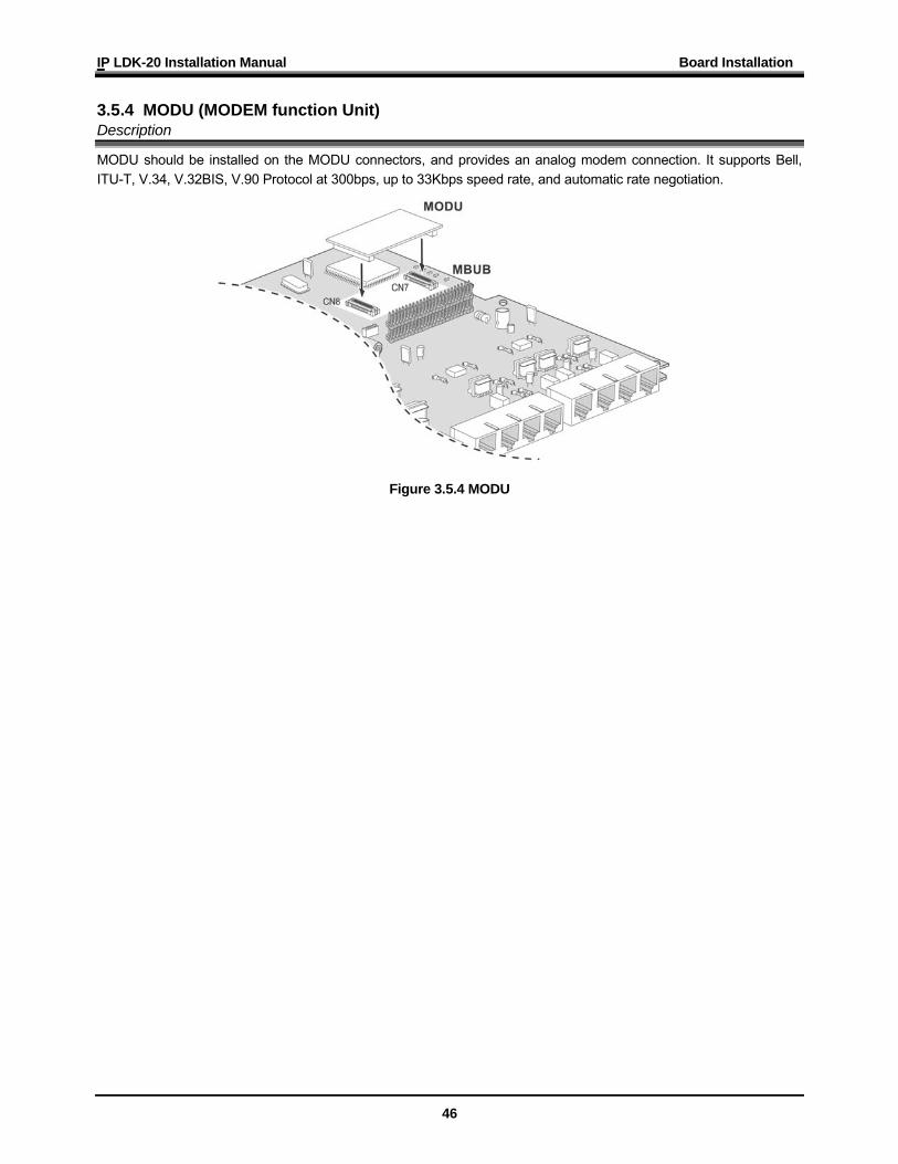
3.5.4 MODU (MODEM function Unit) Description
MODU should be installed on the MODU connectors, and provides an analog modem connection. It supports Bell, ITU-T, V.34, V.32BIS, V.90 Protocol at 300bps, up to 33Kbps speed rate, and automatic rate negotiation.
Figure 3.5.4 MODU
IP LDK-20 Installation Manual Board Installation
47
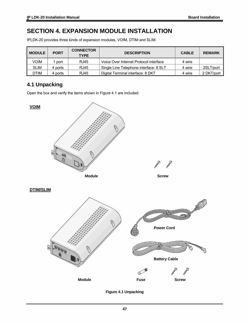
SECTION 4. EXPANSION MODULE INSTALLATION IPLDK-20 provides three kinds of expansion modules, VOIM, DTIM and SLIM.
MODULE PORT CONNECTOR
TYPE DESCRIPTION CABLE REMARK
VOIM 1 port RJ45 Voice Over Internet Protocol interface 4 wire SLIM 4 ports RJ45 Single Line Telephone interface: 8 SLT 4 wire 2SLT/port DTIM 4 ports RJ45 Digital Terminal interface: 8 DKT 4 wire 2 DKT/port
4.1 Unpacking Open the box and verify the items shown in Figure 4.1 are included:
Figure 4.1 Unpacking
Module Screw
VOIM
DTIM/SLIM
Module Screw Fuse
Power Cord
Battery Cable
IP LDK-20 Installation Manual Board Installation
48
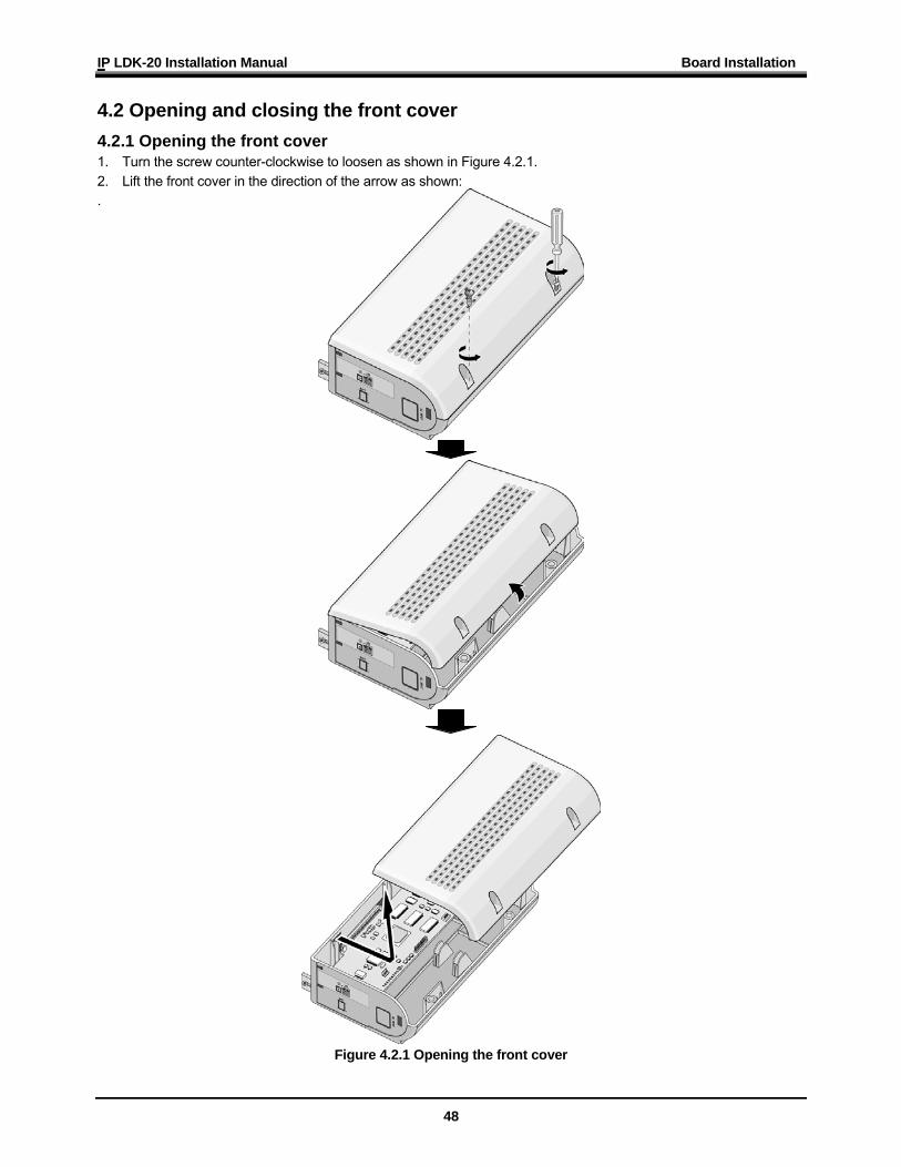
4.2 Opening and closing the front cover 4.2.1 Opening the front cover 1. Turn the screw counter-clockwise to loosen as shown in Figure 4.2.1. 2. Lift the front cover in the direction of the arrow as shown: .
Figure 4.2.1 Opening the front cover
IP LDK-20 Installation Manual Board Installation
49
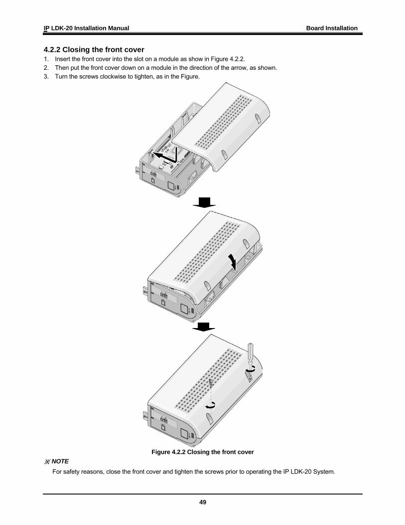
4.2.2 Closing the front cover 1. Insert the front cover into the slot on a module as show in Figure 4.2.2. 2. Then put the front cover down on a module in the direction of the arrow, as shown. 3. Turn the screws clockwise to tighten, as in the Figure.
Figure 4.2.2 Closing the front cover ※ NOTE
For safety reasons, close the front cover and tighten the screws prior to operating the IP LDK-20 System.
IP LDK-20 Installation Manual Board Installation
50
4.3 Opening and closing the front cover
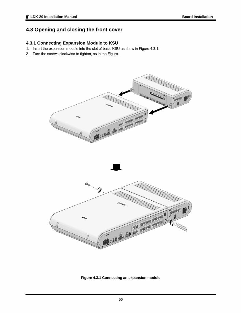
4.3.1 Connecting Expansion Module to KSU 1. Insert the expansion module into the slot of basic KSU as show in Figure 4.3.1. 2. Turn the screws clockwise to tighten, as in the Figure.
Figure 4.3.1 Connecting an expansion module
IP LDK-20 Installation Manual Board Installation
51
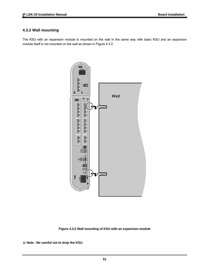
4.3.2 Wall mounting The KSU with an expansion module is mounted on the wall in the same way with basic KSU and an expansion module itself is not mounted on the wall as shown in Figure 4.3.2.
Figure 4.3.2 Wall mounting of KSU with an expansion module ※ Note : Be careful not to drop the KSU.
IP LDK-20 Installation Manual Board Installation
52
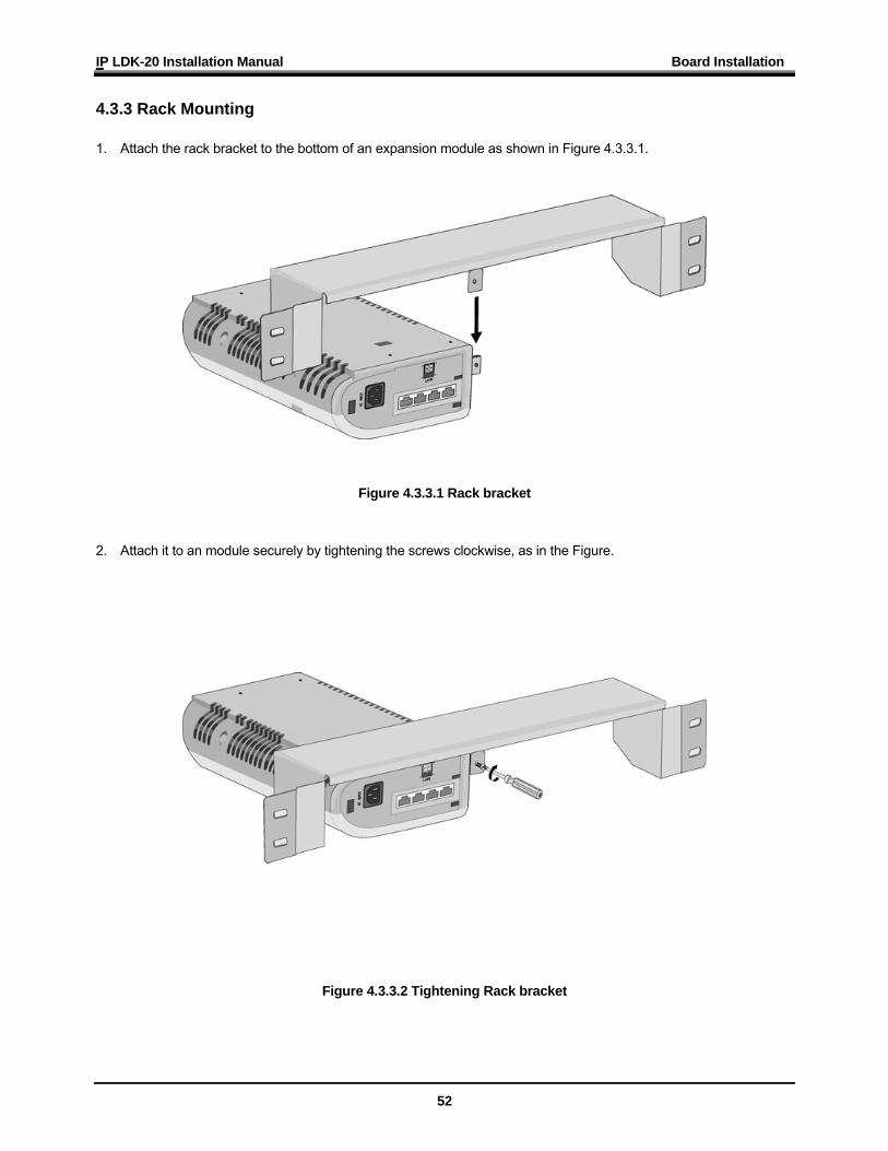
4.3.3 Rack Mounting 1. Attach the rack bracket to the bottom of an expansion module as shown in Figure 4.3.3.1.
Figure 4.3.3.1 Rack bracket 2. Attach it to an module securely by tightening the screws clockwise, as in the Figure.
Figure 4.3.3.2 Tightening Rack bracket
IP LDK-20 Installation Manual Board Installation
53
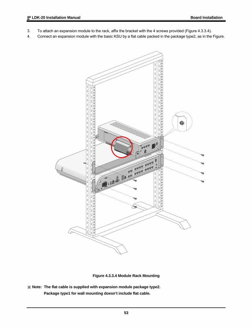
3. To attach an expansion module to the rack, affix the bracket with the 4 screws provided (Figure 4.3.3.4). 4. Connect an expansion module with the basic KSU by a flat cable packed in the package type2, as in the Figure.
Figure 4.3.3.4 Module Rack Mounting ※ Note: The flat cable is supplied with expansion module package type2. Package type1 for wall mounting doesn’t include flat cable.
IP LDK-20 Installation Manual Board Installation
54
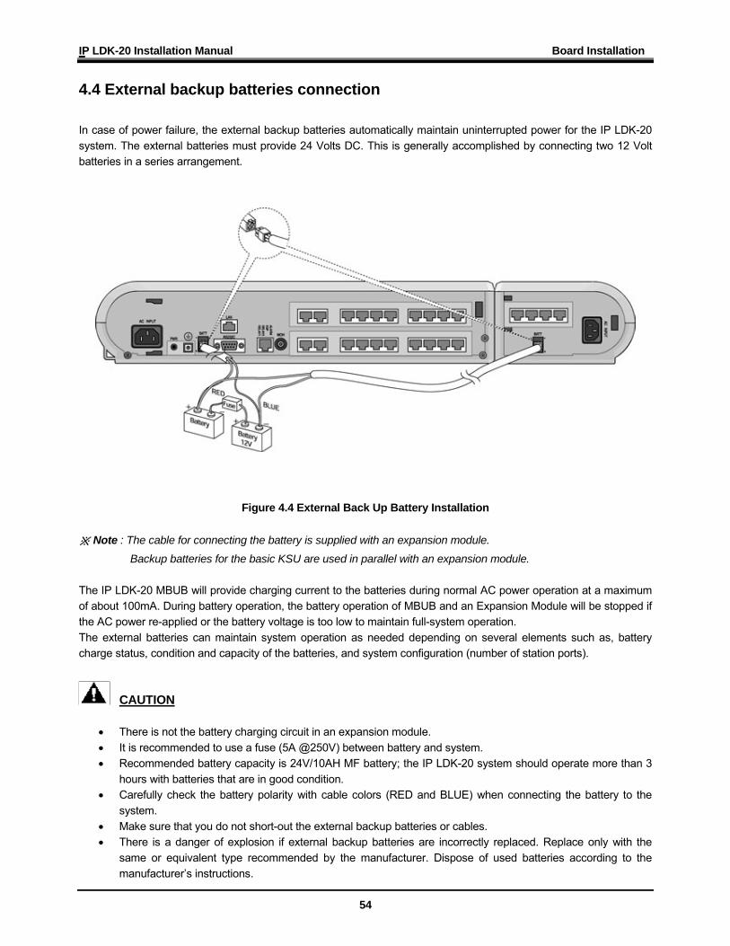
4.4 External backup batteries connection In case of power failure, the external backup batteries automatically maintain uninterrupted power for the IP LDK-20 system. The external batteries must provide 24 Volts DC. This is generally accomplished by connecting two 12 Volt batteries in a series arrangement.
Figure 4.4 External Back Up Battery Installation ※ Note : The cable for connecting the battery is supplied with an expansion module.
Backup batteries for the basic KSU are used in parallel with an expansion module. The IP LDK-20 MBUB will provide charging current to the batteries during normal AC power operation at a maximum of about 100mA. During battery operation, the battery operation of MBUB and an Expansion Module will be stopped if the AC power re-applied or the battery voltage is too low to maintain full-system operation. The external batteries can maintain system operation as needed depending on several elements such as, battery charge status, condition and capacity of the batteries, and system configuration (number of station ports).
CAUTION • There is not the battery charging circuit in an expansion module. • It is recommended to use a fuse (5A @250V) between battery and system. • Recommended battery capacity is 24V/10AH MF battery; the IP LDK-20 system should operate more than 3
hours with batteries that are in good condition. • Carefully check the battery polarity with cable colors (RED and BLUE) when connecting the battery to the
system. • Make sure that you do not short-out the external backup batteries or cables. • There is a danger of explosion if external backup batteries are incorrectly replaced. Replace only with the
same or equivalent type recommended by the manufacturer. Dispose of used batteries according to the manufacturer’s instructions.
IP LDK-20 Installation Manual Board Installation
55
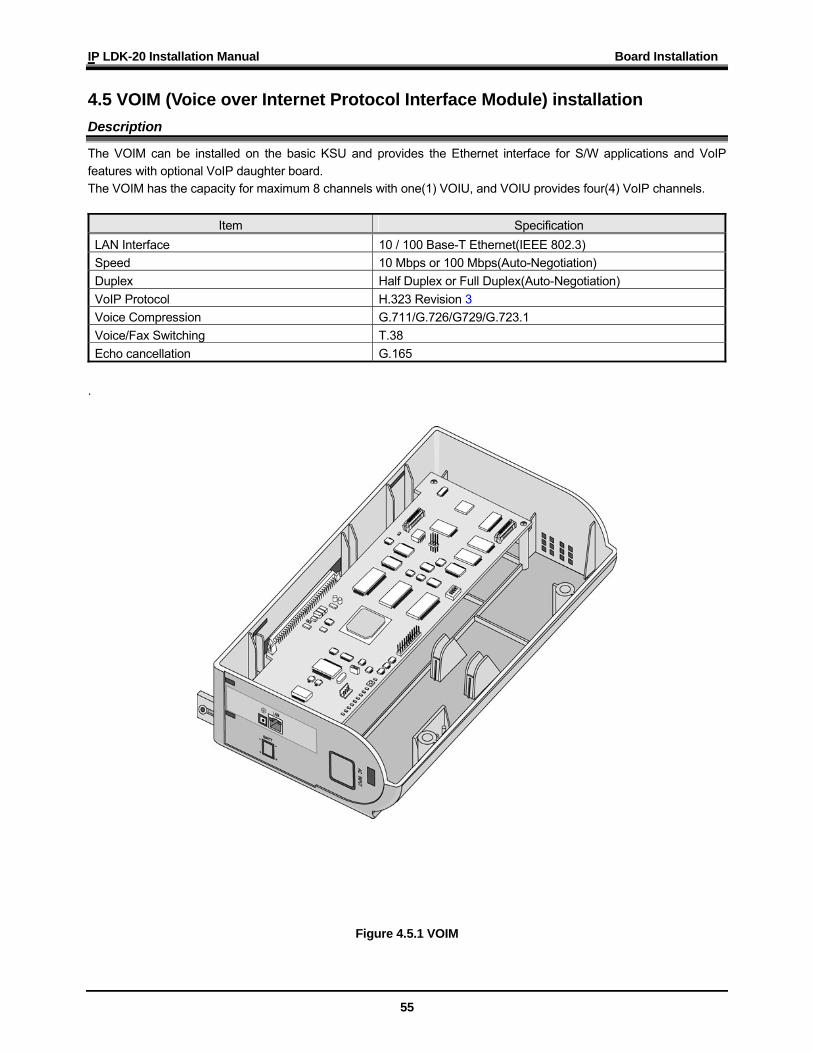
4.5 VOIM (Voice over Internet Protocol Interface Module) installation Description
The VOIM can be installed on the basic KSU and provides the Ethernet interface for S/W applications and VoIP features with optional VoIP daughter board. The VOIM has the capacity for maximum 8 channels with one(1) VOIU, and VOIU provides four(4) VoIP channels.
Item Specification LAN Interface 10 / 100 Base-T Ethernet(IEEE 802.3) Speed 10 Mbps or 100 Mbps(Auto-Negotiation) Duplex Half Duplex or Full Duplex(Auto-Negotiation) VoIP Protocol H.323 Revision 3 Voice Compression G.711/G.726/G729/G.723.1 Voice/Fax Switching T.38 Echo cancellation G.165
.
Figure 4.5.1 VOIM
IP LDK-20 Installation Manual Board Installation
56
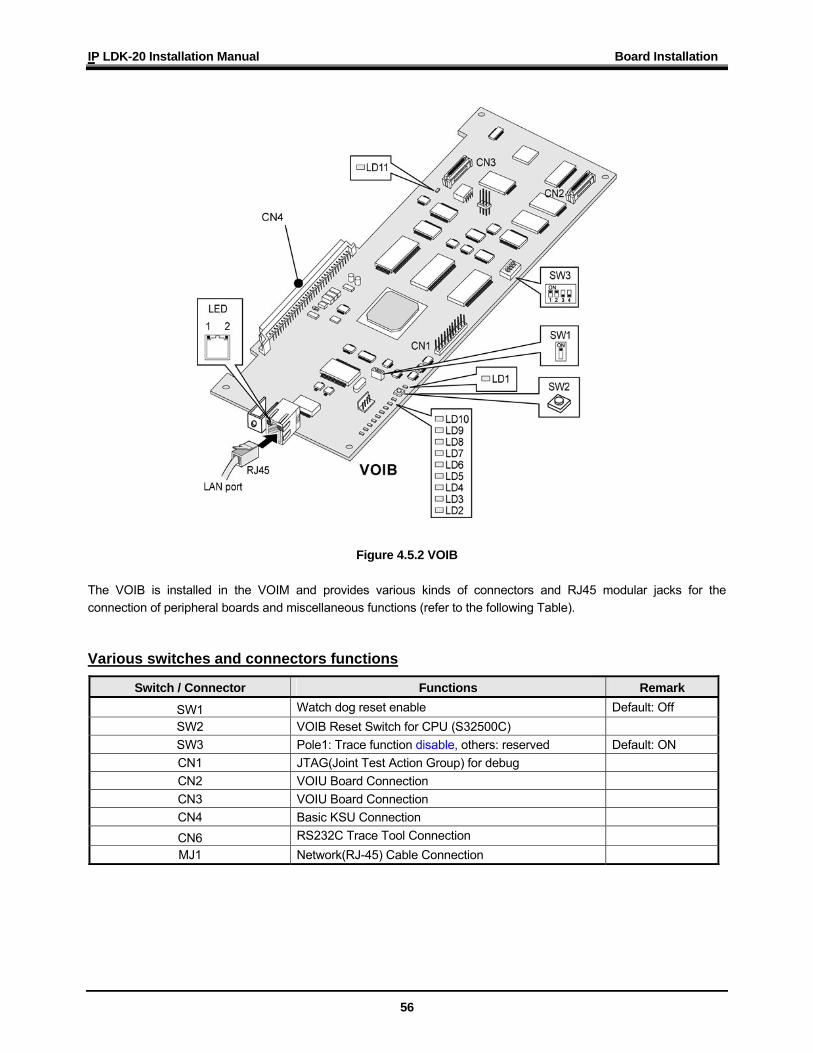
Figure 4.5.2 VOIB The VOIB is installed in the VOIM and provides various kinds of connectors and RJ45 modular jacks for the connection of peripheral boards and miscellaneous functions (refer to the following Table). Various switches and connectors functions
Switch / Connector Functions Remark
SW1 Watch dog reset enable Default: Off SW2 VOIB Reset Switch for CPU (S32500C) SW3 Pole1: Trace function disable, others: reserved Default: ON CN1 JTAG(Joint Test Action Group) for debug CN2 VOIU Board Connection CN3 VOIU Board Connection CN4 Basic KSU Connection CN6 RS232C Trace Tool Connection MJ1 Network(RJ-45) Cable Connection
IP LDK-20 Installation Manual Board Installation
57
LED indications
LED Functions Remark
LD1 DSP HINT interrupt LED (ON: Active, OFF: Idle)
LD2 Periodic toggle – ON: 1 sec., OFF: 1 sec. LD3 Channel8 Seize indication LED (ON: Busy, OFF: Idle) LD4 Channel7 Seize indication LED (ON: Busy, OFF: Idle) LD5 Channel6 Seize indication LED (ON: Busy, OFF: Idle) LD6 Channel5 Seize indication LED (ON: Busy, OFF: Idle) LD7 Channel4 Seize indication LED (ON: Busy, OFF: Idle) LD8 Channel3 Seize indication LED (ON: Busy, OFF: Idle) LD9 Channel2 Seize indication LED (ON: Busy, OFF: Idle) LD10 Channel1 Seize indication LED (ON: Busy, OFF: Idle) LD11 VOIB DSP operation status LED (ON: Normal, OFF: Fail) LD12 VOIU DSP operation status LED (ON: Normal, OFF: Fail)
MJ1-LD1 Link Status LED (ON: Link, Toggle: Data transfer) MJ1-LD2 Speed Status LED (ON: 100Mbps operation, OFF: 10Mbps)
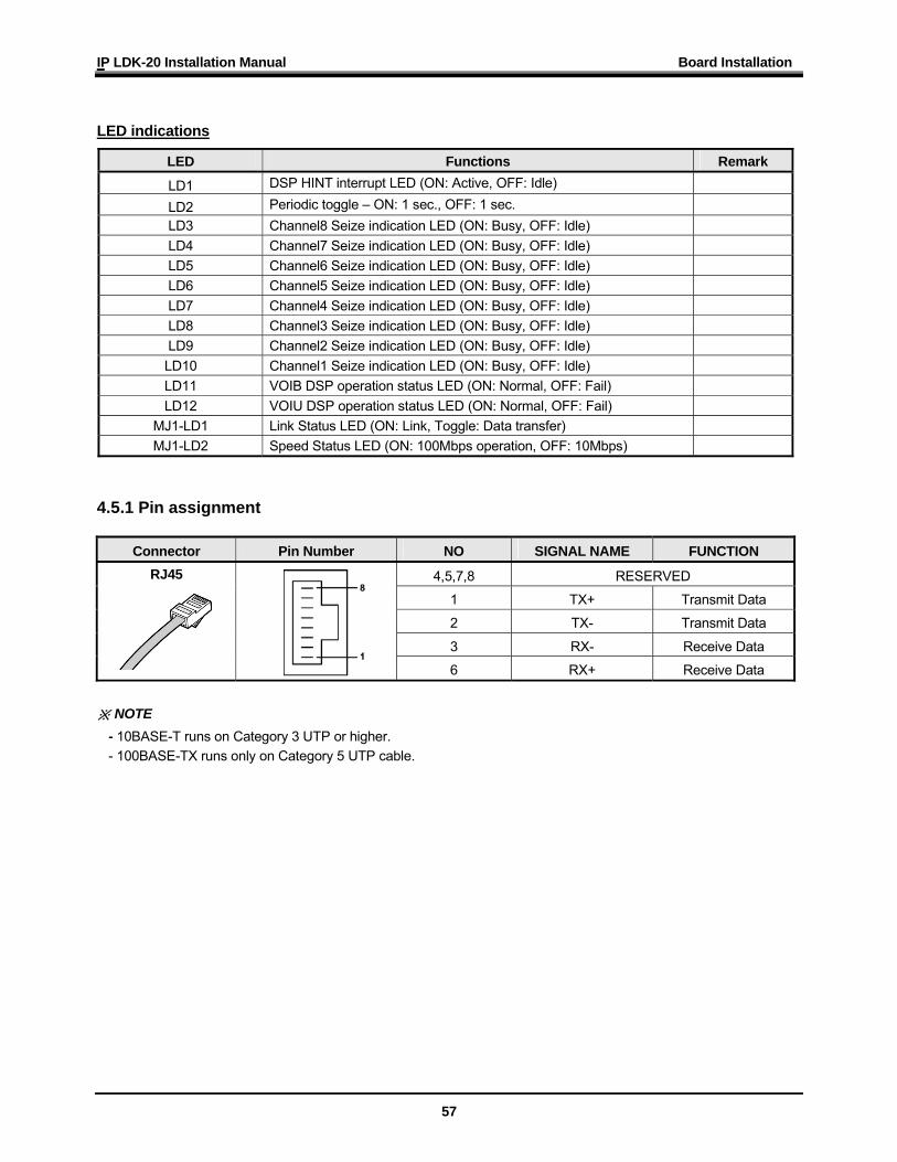
4.5.1 Pin assignment
Connector Pin Number NO SIGNAL NAME FUNCTION
4,5,7,8 RESERVED
1 TX+ Transmit Data
2 TX- Transmit Data
3 RX- Receive Data
RJ45
6 RX+ Receive Data ※ NOTE
- 10BASE-T runs on Category 3 UTP or higher. - 100BASE-TX runs only on Category 5 UTP cable.
IP LDK-20 Installation Manual Board Installation
58
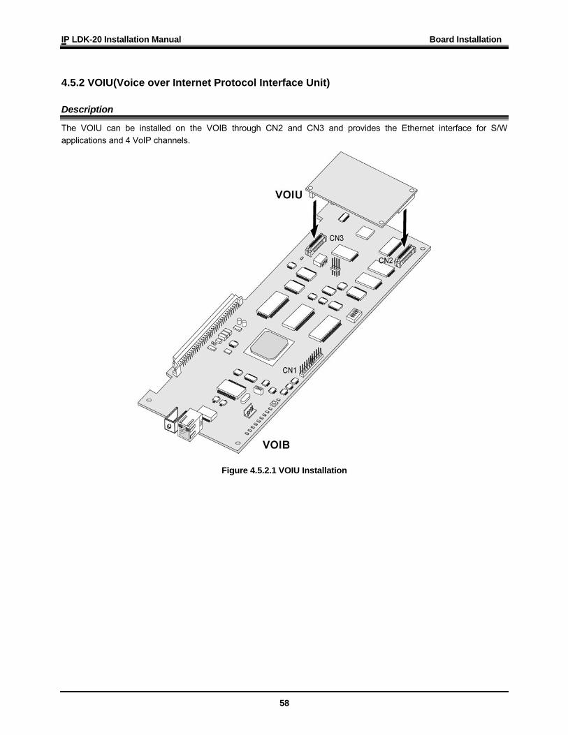
4.5.2 VOIU(Voice over Internet Protocol Interface Unit) Description
The VOIU can be installed on the VOIB through CN2 and CN3 and provides the Ethernet interface for S/W applications and 4 VoIP channels.
Figure 4.5.2.1 VOIU Installation
IP LDK-20 Installation Manual Board Installation
59
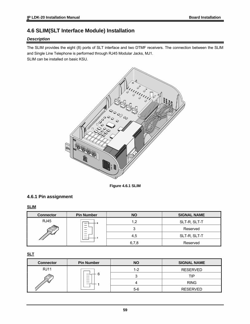
4.6 SLIM(SLT Interface Module) Installation Description
The SLIM provides the eight (8) ports of SLT interface and two DTMF receivers. The connection between the SLIM and Single Line Telephone is performed through RJ45 Modular Jacks, MJ1. SLIM can be installed on basic KSU.
Figure 4.6.1 SLIM 4.6.1 Pin assignment SLIM
Connector Pin Number NO SIGNAL NAME
1,2 SLT-R, SLT-T
3 Reserved
4,5 SLT-R, SLT-T
RJ45
6,7,8 Reserved
SLT
Connector Pin Number NO SIGNAL NAME
1-2 RESERVED 3 TIP
4 RING
RJ11
5-6 RESERVED
IP LDK-20 Installation Manual Board Installation
60
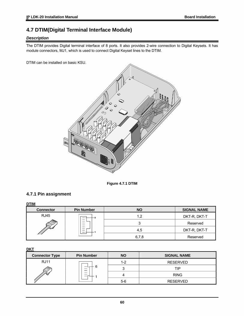
4.7 DTIM(Digital Terminal Interface Module) Description
The DTIM provides Digital terminal interface of 8 ports. It also provides 2-wire connection to Digital Keysets. It has module connectors, MJ1, which is used to connect Digital Keyset lines to the DTIM.
DTIM can be installed on basic KSU.
Figure 4.7.1 DTIM 4.7.1 Pin assignment DTIM
Connector Pin Number NO SIGNAL NAME
1,2 DKT-R, DKT-T
3 Reserved
4,5 DKT-R, DKT-T
RJ45
6,7,8 Reserved
DKT
Connector Type Pin Number NO SIGNAL NAME
1-2 RESERVED 3 TIP
4 RING
RJ11
5-6 RESERVED
IPLDK-20 Installation Manual Terminal Connection
61
SECTION 5. TERMINAL CONNECTION
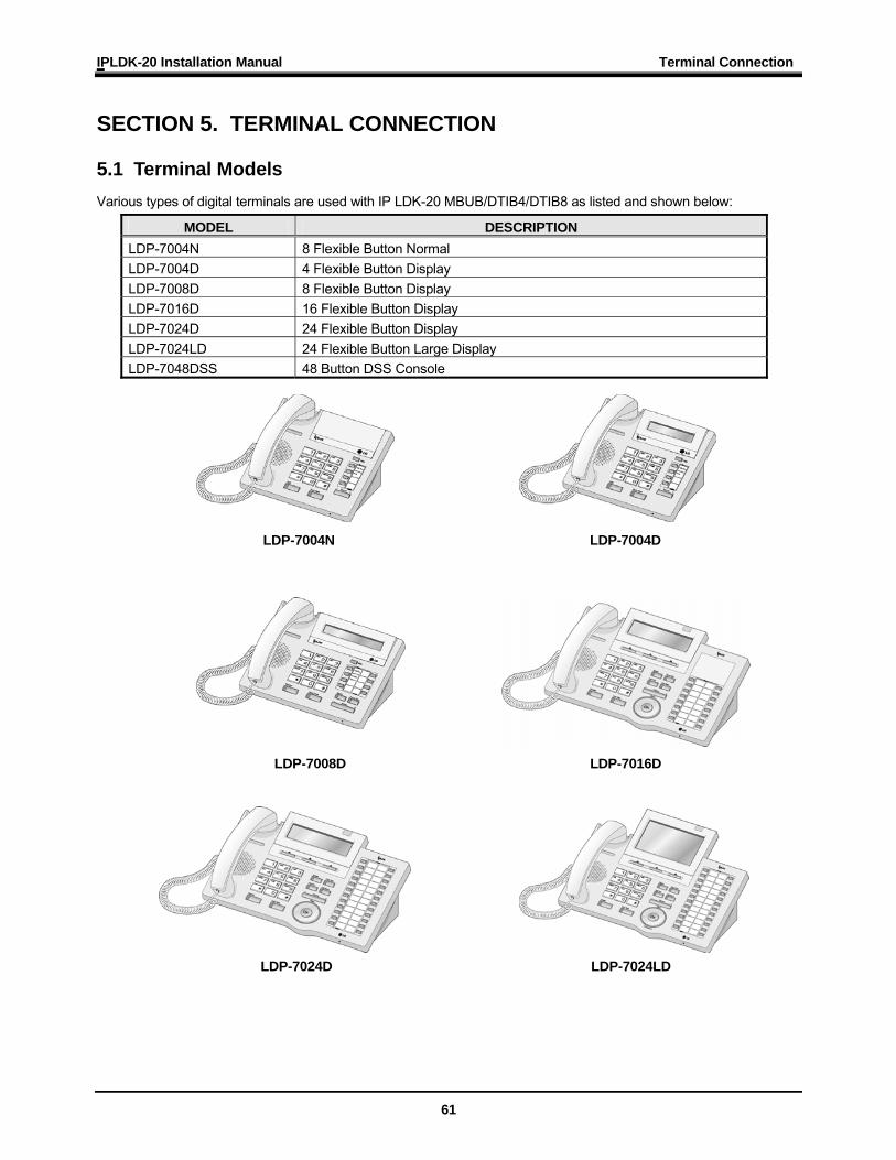
5.1 Terminal Models Various types of digital terminals are used with IP LDK-20 MBUB/DTIB4/DTIB8 as listed and shown below:
MODEL DESCRIPTION LDP-7004N 8 Flexible Button Normal LDP-7004D 4 Flexible Button Display LDP-7008D 8 Flexible Button Display LDP-7016D 16 Flexible Button Display LDP-7024D 24 Flexible Button Display LDP-7024LD 24 Flexible Button Large Display LDP-7048DSS 48 Button DSS Console
LDP-7004N LDP-7004D
LDP-7008D LDP-7016D
LDP-7024D LDP-7024LD
IPLDK-20 Installation Manual Terminal Connection
62
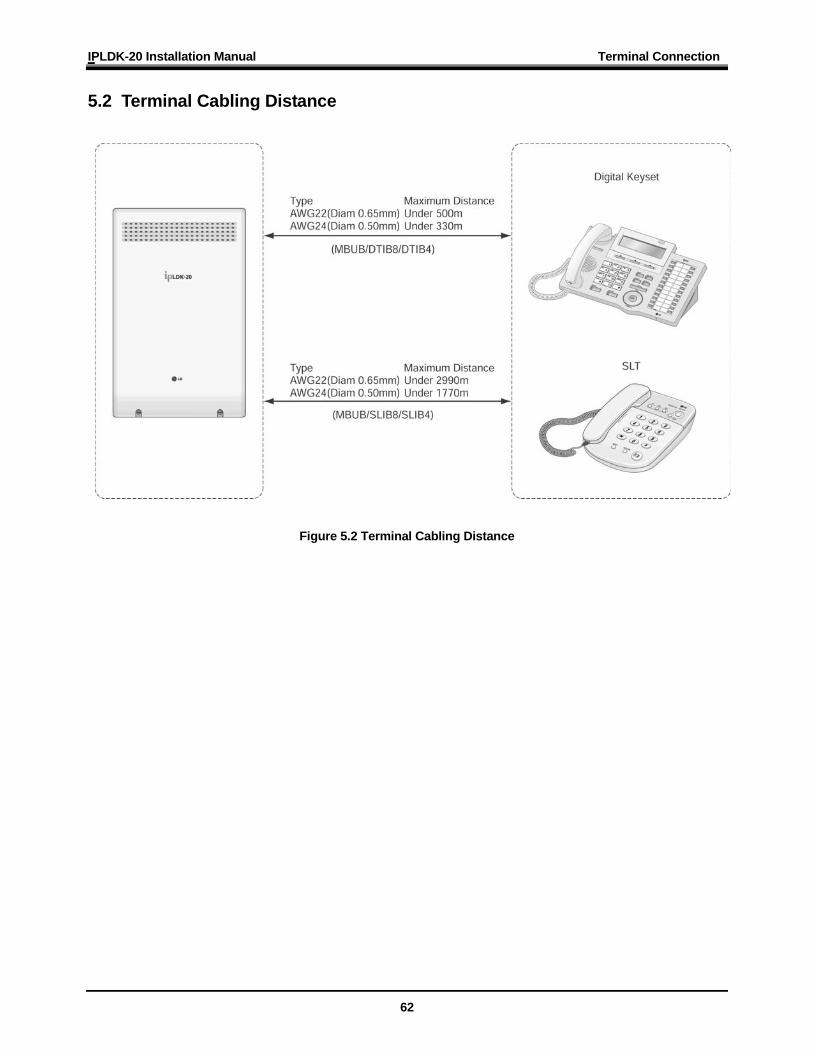
5.2 Terminal Cabling Distance
Figure 5.2 Terminal Cabling Distance
IPLDK-20 Installation Manual Terminal Connection
63
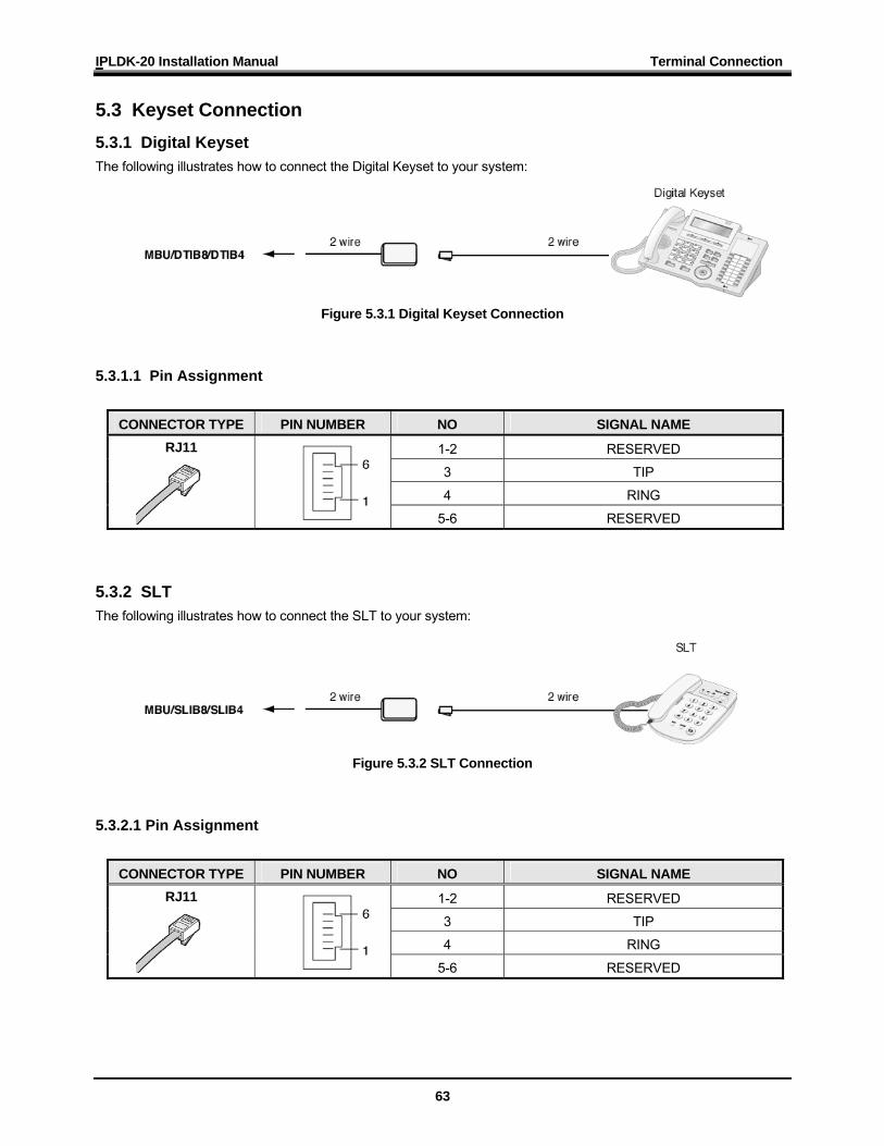
5.3 Keyset Connection 5.3.1 Digital Keyset The following illustrates how to connect the Digital Keyset to your system:
Figure 5.3.1 Digital Keyset Connection
5.3.1.1 Pin Assignment
CONNECTOR TYPE PIN NUMBER NO SIGNAL NAME
1-2 RESERVED
3 TIP
4 RING
RJ11
5-6 RESERVED
5.3.2 SLT The following illustrates how to connect the SLT to your system:
Figure 5.3.2 SLT Connection
5.3.2.1 Pin Assignment
CONNECTOR TYPE PIN NUMBER NO SIGNAL NAME
1-2 RESERVED
3 TIP
4 RING
RJ11
5-6 RESERVED
IPLDK-20 Installation Manual Terminal Connection
64
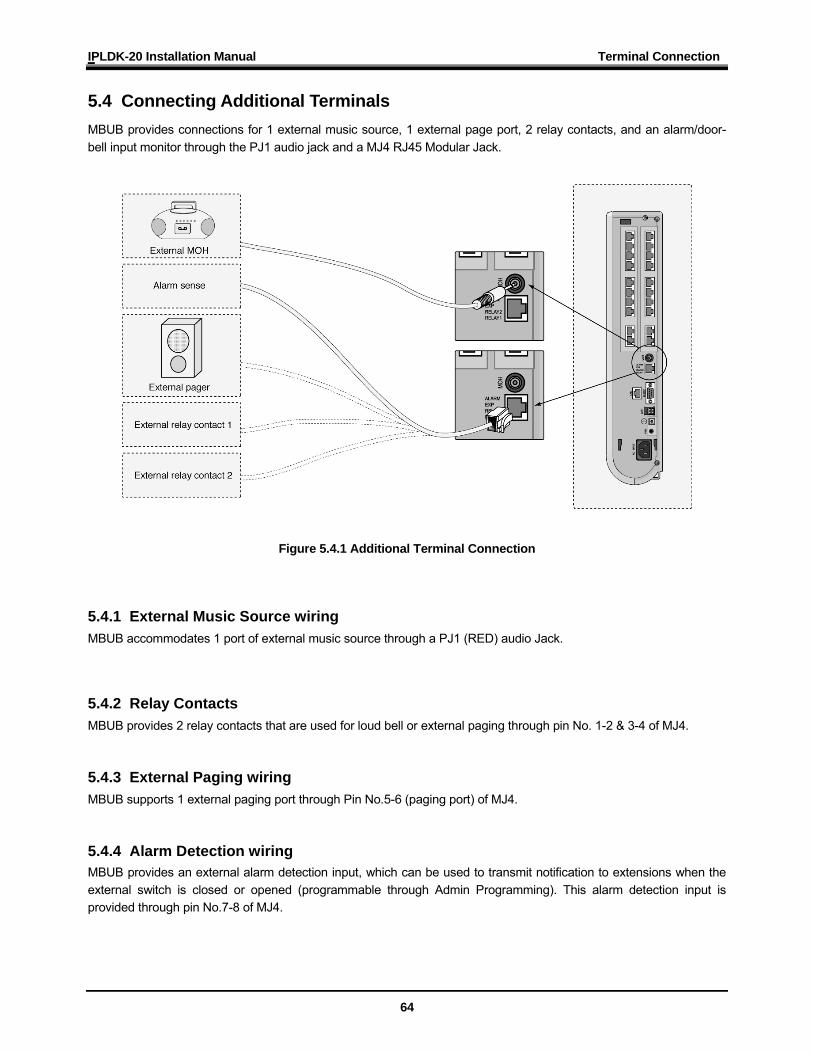
5.4 Connecting Additional Terminals MBUB provides connections for 1 external music source, 1 external page port, 2 relay contacts, and an alarm/door-bell input monitor through the PJ1 audio jack and a MJ4 RJ45 Modular Jack.
Figure 5.4.1 Additional Terminal Connection
5.4.1 External Music Source wiring MBUB accommodates 1 port of external music source through a PJ1 (RED) audio Jack.
5.4.2 Relay Contacts MBUB provides 2 relay contacts that are used for loud bell or external paging through pin No. 1-2 & 3-4 of MJ4. 5.4.3 External Paging wiring MBUB supports 1 external paging port through Pin No.5-6 (paging port) of MJ4. 5.4.4 Alarm Detection wiring MBUB provides an external alarm detection input, which can be used to transmit notification to extensions when the external switch is closed or opened (programmable through Admin Programming). This alarm detection input is provided through pin No.7-8 of MJ4.
IPLDK-20 Installation Manual Starting the IP LDK-20 System
65
SECTION 6. STARTING THE IPLDK-20 SYSTEM
6.1 Before Starting the IP LDK-20 System The DIP switch (SW1) of Memory Backup Battery should be turned ON before installing the MBUB, to protect system data in the case of a power failure. To prepare for preprogramming, perform the following Steps: 1. Set the DIP switch (SW3) on the MBUB to ON. To initialize all the data in Admin Programming, the 4th pole of SW3 should be set to ON. Plug the AC power cord into the IP LDK-20 System and AC outlet. Program the Country Code as applicable. Reset the IP LDK-20 System. Set the 4th pole of SW3 on the MBUB to OFF when the system operates normally. The 4th pole of SW3 is set to OFF,
to protect the various features addressed by Admin Programming after system power-up and initialization.
6.2 Basic Preprogramming The IP LDK-20 System can be programmed to meet an individual customer's need. There are two ways to perform ADMIN Programming: - PC ADMIN : Refer to the PC ADMIN Programming Manual. - DKTU : In this manual we explain DKTU (Station 10) in ADMIN Programming.
6.2.1 DKTU (Station 10) programming All programming is done at Station 10 (Station port # 00) using the LDP-7024D digital key telephone. Additional programming stations may be assigned (PGM 113 – FLEX 1), but only 1 DKTU can be active in the programming mode at any one time. When in programming mode, Station 10 does not operate as a normal telephone, but instead works as a programming instrument with all of the buttons redefined. The keys of the dial pad are used to enter the various data fields and to enter numerical information: - Flexible Buttons
The 24 buttons located at the top of the phone are used to indicate a specific data field and to enter information. - SPEED Button and * Key
Are sometimes used to delete data or to indicate the end of data input. - REDIAL Button
Could be used to delete one digit or character from the end of entered digits or characters.
IPLDK-20 Installation Manual Starting the IP LDK-20 System
66
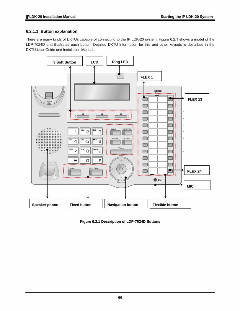
6.2.1.1 Button explanation
There are many kinds of DKTUs capable of connecting to the IP LDK-20 system. Figure 6.2.1 shows a model of the LDP-7024D and illustrates each button. Detailed DKTU information for this and other keysets is described in the DKTU User Guide and Installation Manual.
Figure 6.2.1 Description of LDP-7024D Buttons
Fixed button Flexible button
Ring LED
FLEX 13
.
.
.
.
.
.
.
FLEX 24
Speaker phone
MIC
LCD
FLEX 1
Navigation button
3 Soft Button
IPLDK-20 Installation Manual Starting the IP LDK-20 System
67
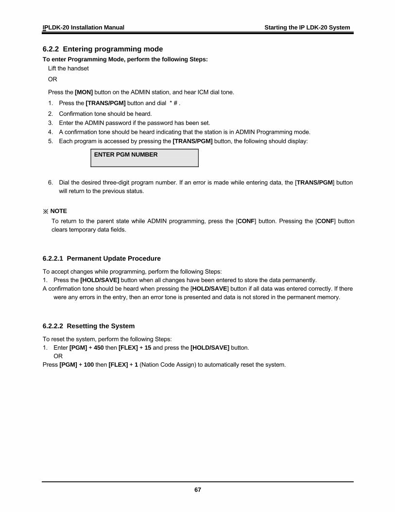
6.2.2 Entering programming mode To enter Programming Mode, perform the following Steps:
Lift the handset
OR
Press the [MON] button on the ADMIN station, and hear ICM dial tone.
1. Press the [TRANS/PGM] button and dial *# .
2. Confirmation tone should be heard. 3. Enter the ADMIN password if the password has been set. 4. A confirmation tone should be heard indicating that the station is in ADMIN Programming mode. 5. Each program is accessed by pressing the [TRANS/PGM] button, the following should display:
6. Dial the desired three-digit program number. If an error is made while entering data, the [TRANS/PGM] button
will return to the previous status.
※ NOTE To return to the parent state while ADMIN programming, press the [CONF] button. Pressing the [CONF] button clears temporary data fields.
6.2.2.1 Permanent Update Procedure
To accept changes while programming, perform the following Steps: 1. Press the [HOLD/SAVE] button when all changes have been entered to store the data permanently. A confirmation tone should be heard when pressing the [HOLD/SAVE] button if all data was entered correctly. If there
were any errors in the entry, then an error tone is presented and data is not stored in the permanent memory.
6.2.2.2 Resetting the System
To reset the system, perform the following Steps: 1. Enter [PGM] + 450 then [FLEX] + 15 and press the [HOLD/SAVE] button.
OR Press [PGM] + 100 then [FLEX] + 1 (Nation Code Assign) to automatically reset the system.
ENTER PGM NUMBER
IPLDK-20 Installation Manual Starting the IP LDK-20 System
68
6.2.3 Pre-programming Location PGM-Nation Code & Site Name (PGM100)
※ NOTE : The 4th pole of the DIP switch (SW 3) on the MPB must be turned ON.
Procedure
Nation Code
To program the Nation code, perform the following Steps: 1. Press [Trans/PGM] + PGM Number(100), then [Flex1] + 7. Press [HOLD/SAVE] to accept change. ※ NOTE : Press the reset button after setting the nation code to restart the system
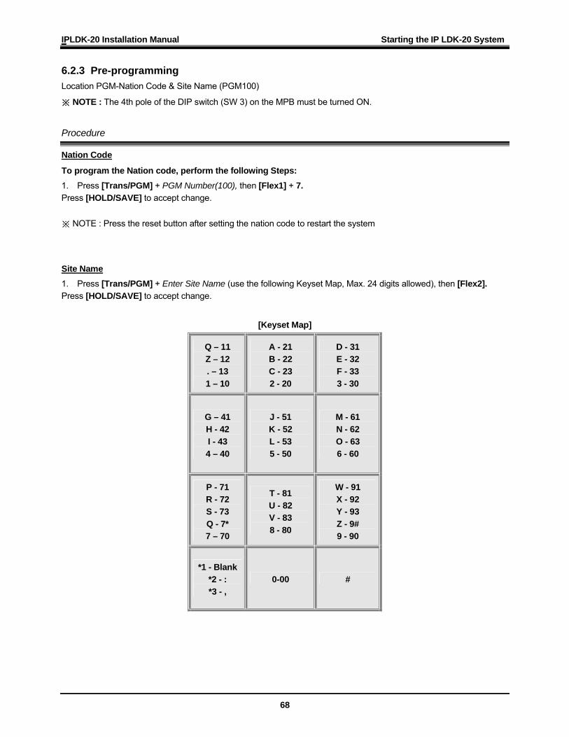
Site Name 1. Press [Trans/PGM] + Enter Site Name (use the following Keyset Map, Max. 24 digits allowed), then [Flex2]. Press [HOLD/SAVE] to accept change.
[Keyset Map]
Q – 11 Z – 12 . – 13 1 – 10
A - 21 B - 22 C - 23 2 - 20
D - 31 E - 32 F - 33 3 - 30
G – 41 H - 42 I - 43 4 – 40
J - 51 K - 52 L - 53 5 - 50
M - 61 N - 62 O - 63 6 - 60
P - 71 R - 72 S - 73 Q - 7* 7 – 70
T - 81 U - 82 V - 83 8 - 80
W - 91 X - 92 Y - 93 Z - 9# 9 - 90
*1 - Blank *2 - : *3 - ,
0-00 #

IPLDK-20 Installation Manual Starting the IP LDK-20 System
69
International Calling Codes
NATION CODE NATION CODE NATION CODE America 1 Argentina 54 Australia 61 Bahrain 973 Bangladesh 880 Belgium 32 Bolivia 591 Brazil 55 Brunei 673 Burma 95 Cameroon 237 Chile 56
China (Taiwan) 886 CIS 7 Colombia 57 Costa Rica 506 Cyprus 357 Czech 42 Denmark 45 Ecuador 593 Egypt 20
El Salvador 503 Ethiopia 251 Fiji 679 Finland 358 France 33 Gabon 241
Germany 49 Ghana 233 Greece 30 Guam 671 Guatemala 502 Guyana 592 Haiti 509 Honduras 504 Hong Kong 852 India 91 Indonesia 62 Iran 98 Iraq 964 Ireland 353 Israel 972 Italy 39 Japan 81 Jordan 962
Kenya 254 Korea 82 Kuwait 965 Liberia 231 Libya 218 Luxembourg 352
Malaysia 60 Malta 356 Mexico 52 Monaco 377 Morocco 212 Netherlands 31
New Zealand 64 Nigeria 234 Norway 47 Oman 968 Pakistan 92 Panama 507 P.N.G 675 Paraguay 595 Peru 51
Philippines 63 Portugal 351 Qatar 974 Saudi Arabia 966 Senegal 221 Singapore 65 South Africa 27 Spain 34 Sri Lanka 94 Swaziland 268 Sweden 46 Switzerland 41 TELKOM *27 Thailand 66 Tunisia 216 Turkey 90 U.A.E. 971 United Kingdom 44
Uruguay 598 Venezuela 58 Y.A.R. 967 TELSTRA *61
IPLDK-20 Installation Manual Starting the IP LDK-20 System
70
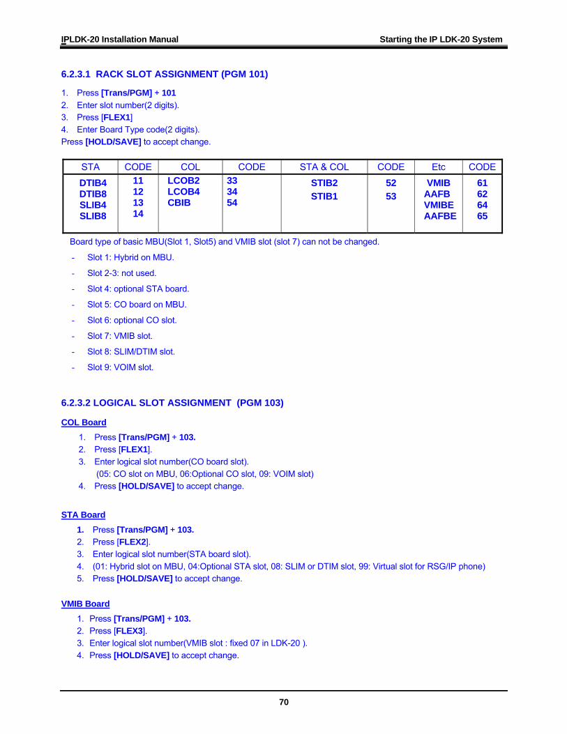
6.2.3.1 RACK SLOT ASSIGNMENT (PGM 101)
1. Press [Trans/PGM] + 101 2. Enter slot number(2 digits). 3. Press [FLEX1] 4. Enter Board Type code(2 digits). Press [HOLD/SAVE] to accept change.
STA CODE COL CODE STA & COL CODE Etc CODE DTIB4 DTIB8 SLIB4 SLIB8
11 12 13 14
LCOB2 LCOB4 CBIB
33 34 54
STIB2 STIB1
52 53
VMIB AAFB VMIBE AAFBE
61 62 64 65
Board type of basic MBU(Slot 1, Slot5) and VMIB slot (slot 7) can not be changed.
- Slot 1: Hybrid on MBU.
- Slot 2-3: not used.
- Slot 4: optional STA board.
- Slot 5: CO board on MBU.
- Slot 6: optional CO slot.
- Slot 7: VMIB slot.
- Slot 8: SLIM/DTIM slot.
- Slot 9: VOIM slot.
6.2.3.2 LOGICAL SLOT ASSIGNMENT (PGM 103)
COL Board 1. Press [Trans/PGM] + 103. 2. Press [FLEX1]. 3. Enter logical slot number(CO board slot).
(05: CO slot on MBU, 06:Optional CO slot, 09: VOIM slot) 4. Press [HOLD/SAVE] to accept change.
STA Board
1. Press [Trans/PGM] + 103. 2. Press [FLEX2]. 3. Enter logical slot number(STA board slot). 4. (01: Hybrid slot on MBU, 04:Optional STA slot, 08: SLIM or DTIM slot, 99: Virtual slot for RSG/IP phone) 5. Press [HOLD/SAVE] to accept change.
VMIB Board 1. Press [Trans/PGM] + 103. 2. Press [FLEX3]. 3. Enter logical slot number(VMIB slot : fixed 07 in LDK-20 ). 4. Press [HOLD/SAVE] to accept change.
IPLDK-20 Installation Manual Starting the IP LDK-20 System
71
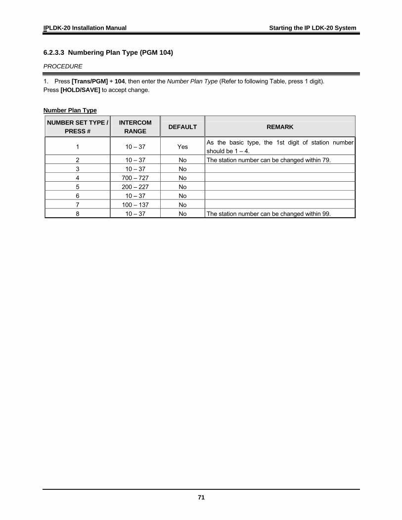
6.2.3.3 Numbering Plan Type (PGM 104)
PROCEDURE
1. Press [Trans/PGM] + 104, then enter the Number Plan Type (Refer to following Table, press 1 digit). Press [HOLD/SAVE] to accept change.
Number Plan Type
NUMBER SET TYPE / PRESS #
INTERCOM RANGE
DEFAULT REMARK
1 10 – 37 Yes As the basic type, the 1st digit of station number should be 1 – 4.
2 10 – 37 No The station number can be changed within 79. 3 10 – 37 No 4 700 – 727 No 5 200 – 227 No 6 10 – 37 No 7 100 – 137 No 8 10 – 37 No The station number can be changed within 99.
IPLDK-20 Installation Manual Starting the IP LDK-20 System
72
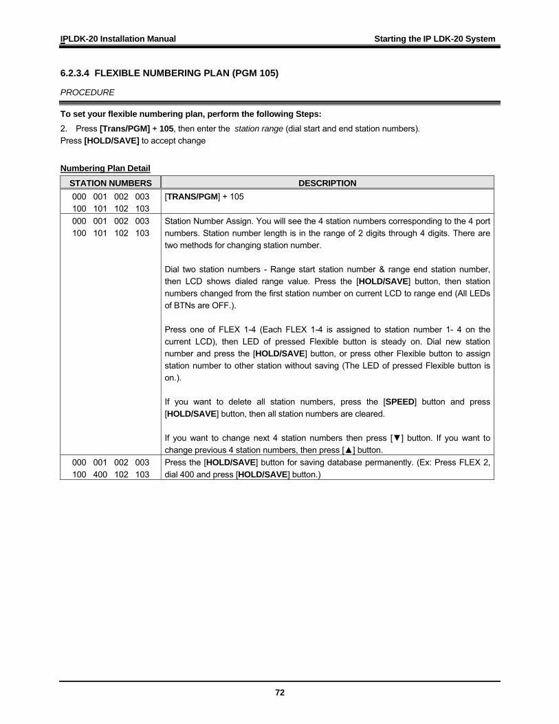
6.2.3.4 FLEXIBLE NUMBERING PLAN (PGM 105)
PROCEDURE
To set your flexible numbering plan, perform the following Steps: 2. Press [Trans/PGM] + 105, then enter the station range (dial start and end station numbers). Press [HOLD/SAVE] to accept change Numbering Plan Detail
STATION NUMBERS DESCRIPTION 000 001 002 003 100 101 102 103
[TRANS/PGM] + 105
000 001 002 003 100 101 102 103
Station Number Assign. You will see the 4 station numbers corresponding to the 4 port numbers. Station number length is in the range of 2 digits through 4 digits. There are two methods for changing station number. Dial two station numbers - Range start station number & range end station number, then LCD shows dialed range value. Press the [HOLD/SAVE] button, then station numbers changed from the first station number on current LCD to range end (All LEDs of BTNs are OFF.). Press one of FLEX 1-4 (Each FLEX 1-4 is assigned to station number 1- 4 on the current LCD), then LED of pressed Flexible button is steady on. Dial new station number and press the [HOLD/SAVE] button, or press other Flexible button to assign station number to other station without saving (The LED of pressed Flexible button is on.). If you want to delete all station numbers, press the [SPEED] button and press [HOLD/SAVE] button, then all station numbers are cleared. If you want to change next 4 station numbers then press [▼] button. If you want to change previous 4 station numbers, then press [▲] button.
000 001 002 003 100 400 102 103
Press the [HOLD/SAVE] button for saving database permanently. (Ex: Press FLEX 2, dial 400 and press [HOLD/SAVE] button.)
IPLDK-20 Installation Manual Starting the IP LDK-20 System
73
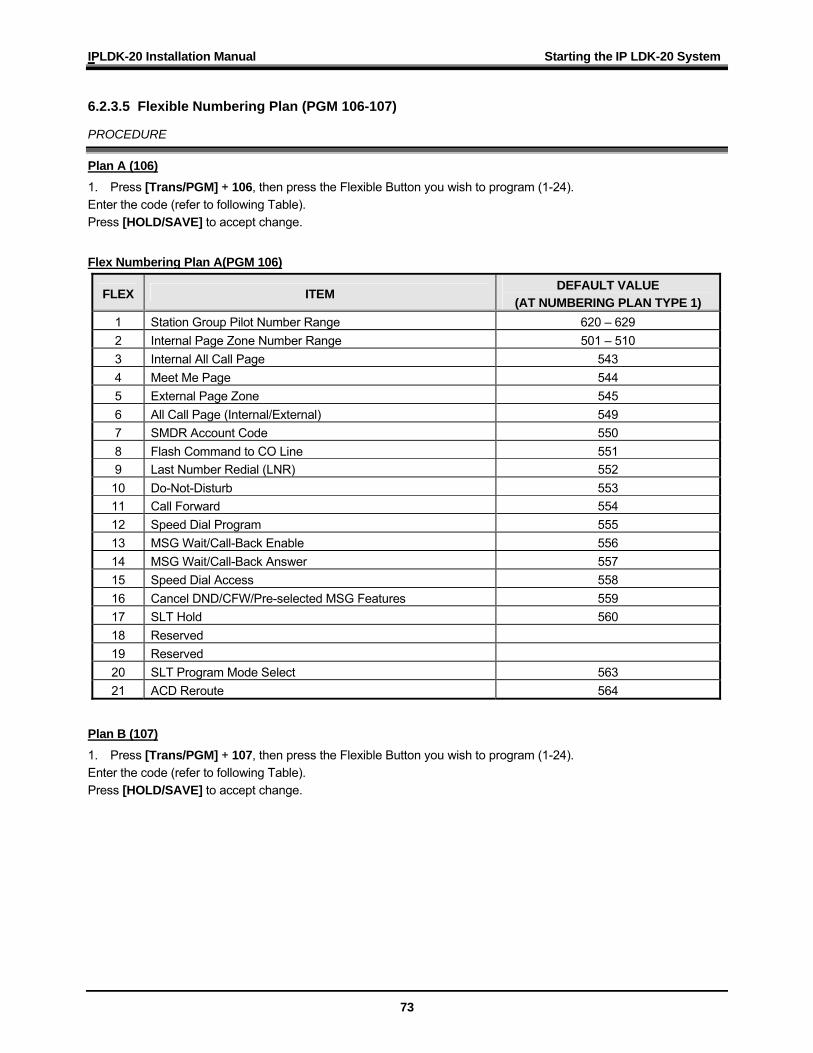
6.2.3.5 Flexible Numbering Plan (PGM 106-107)
PROCEDURE
Plan A (106) 1. Press [Trans/PGM] + 106, then press the Flexible Button you wish to program (1-24). Enter the code (refer to following Table). Press [HOLD/SAVE] to accept change. Flex Numbering Plan A(PGM 106)
FLEX ITEM DEFAULT VALUE
(AT NUMBERING PLAN TYPE 1) 1 Station Group Pilot Number Range 620 – 629 2 Internal Page Zone Number Range 501 – 510 3 Internal All Call Page 543 4 Meet Me Page 544 5 External Page Zone 545 6 All Call Page (Internal/External) 549 7 SMDR Account Code 550 8 Flash Command to CO Line 551 9 Last Number Redial (LNR) 552 10 Do-Not-Disturb 553 11 Call Forward 554 12 Speed Dial Program 555 13 MSG Wait/Call-Back Enable 556 14 MSG Wait/Call-Back Answer 557 15 Speed Dial Access 558 16 Cancel DND/CFW/Pre-selected MSG Features 559 17 SLT Hold 560 18 Reserved 19 Reserved 20 SLT Program Mode Select 563 21 ACD Reroute 564
Plan B (107) 1. Press [Trans/PGM] + 107, then press the Flexible Button you wish to program (1-24). Enter the code (refer to following Table). Press [HOLD/SAVE] to accept change.
IPLDK-20 Installation Manual Starting the IP LDK-20 System
74
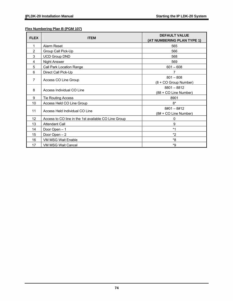
Flex Numbering Plan B (PGM 107)
FLEX ITEM DEFAULT VALUE
(AT NUMBERING PLAN TYPE 1) 1 Alarm Reset 565 2 Group Call Pick-Up 566 3 UCD Group DND 568 4 Night Answer 569 5 Call Park Location Range 601 – 608 6 Direct Call Pick-Up 7
7 Access CO Line Group 801 – 808
(8 + CO Group Number)
8 Access Individual CO Line 8801 – 8812
(88 + CO Line Number) 9 Tie Routing Access 8901 10 Access Held CO Line Group 8*
11 Access Held Individual CO Line 8#01 – 8#12
(8# + CO Line Number) 12 Access to CO line in the 1st available CO Line Group 0 13 Attendant Call 9 14 Door Open – 1 *1 15 Door Open – 2 *2 16 VM MSG Wait Enable *8 17 VM MSG Wait Cancel *9
IPLDK-20 Installation Manual Starting the IP LDK-20 System
75
6.2.3.6 IP setting for System (PGM 108)
PROCEDURE
IP Name (Use the # to skip) 1. Press [Trans/PGM] + 108, then press [FLEX1]. Enter the code (max. 16 characters). Press [HOLD/SAVE] to accept change.
Server IP Address 1. Press [Trans/PGM] + 108, then press the [FLEX2] button. Enter the Server IP Address (12 digits). Press [HOLD/SAVE] to accept change.
CLI IP Address 1. Press [Trans/PGM] + 108, then press the [FLEX3] button. Enter the CLI IP Address (12 digits). Press [HOLD/SAVE] to accept change.
Gateway Address (Use the # to skip) 1. Press [Trans/PGM] + 108, then press the [FLEX4] button. Enter the Gateway Address (12 digits). Press [HOLD/SAVE] to accept change.
Subnet Mask Address (Use the # to skip) 1. Press [Trans/PGM] + 108, then press the [FLEX5] button. Enter the Subnet Mask (12 digits). Press [HOLD/SAVE] to accept change.
IP LDK-20 Installation Manual Troubleshooting
76
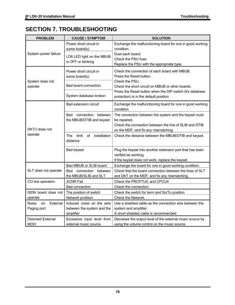
SECTION 7. TROUBLESHOOTING PROBLEM CAUSE / SYMPTOM SOLUTION
Power short circuit in some board(s)
System power failure LD6 LED light on the MBUB is OFF or blinking
Exchange the malfunctioning board for one in good working condition. Dust each board. Check the PSU fuse. Replace the PSU with the appropriate type.
Power short circuit in some board(s)
Bad board connection System does not operate
System database broken
Check the connection of each board with MBUB. Press the Reset button. Check the PSU. Check the short circuit on MBUB or other boards. Press the Reset button when the DIP switch (for database protection) is in the default position.
Bad extension circuit Exchange the malfunctioning board for one in good working condition.
Bad connection between the MBUB/DTIB and keyset
The connection between the system and the keyset must be repaired. Check the connection between the line of SLIB and DTIB on the MDF, and fix any mismatching.
The limit of installation distance
Check the distance between the MBUB/DTIB and keyset.
DKTU does not operate
Bad keyset Plug the keyset into another extension port that has been verified as working. If the keyset does not work, replace the keyset.
Bad MBUB or SLIB board Exchange the board for one in good working condition. SLT does not operate Bad connection between
the MBUB/SLIB and SLT Check that the board connection between the lines of SLT and DKT on the MDF, and fix any mismatching.
ACNR Fail Check the PRCPTU4, and CPCU4 CO line operation Bad connection Check the connection. The position of switch Check the switch for term and So/To position ISDN board does not
operate Network problem Check the Network. Noise on External Paging port
Induced noise on the wire between the system and the amplifier
Use a shielded cable as the connection wire between the system and amplifier. A short shielded cable is recommended.
Distorted External MOH
Excessive input level from external music source
Decrease the output level of the external music source by using the volume control on the music source.