Embed Size (px)
Citation preview
Interpreting Variability Through Multiple Methodologies: The Interplay of Form and Function in Epipalaeolithic
Microliths
by
Danielle Aviva Macdonald
A thesis submitted in conformity with the requirements for the degree of Doctor of Philosophy
Department of Anthropology University of Toronto
© Copyright by Danielle Aviva Macdonald 2013
ii
Interpreting Variability Through Multiple Methodologies: The
Interplay of Form and Function in Epipalaeolithic Microliths
Danielle Aviva Macdonald
Doctor of Philosophy
Department of Anthropology
University of Toronto
2013
Abstract
The reason and significance of variation in material culture is one of the most fundamental
debates in archaeological studies. These debates factor strongly into Levantine Epipalaeolithic
research, where the morphological variability of microlithic tools has been interpreted to
represent distinct cultural or ethnic communities. This dissertation addresses microlith variability
during the Middle Epipalaeolithic (≈17,500 – 14,600 cal BP) through the analysis of lithic
assemblages from Wadi Mataha, ‘Uyun al-Hammâm, and Kharaneh IV (Jordan). Although
regionally disparate, the lithic assemblages are characterized by the same geometric microlith
type: the trapeze-rectangle. The integration of typological, technological, morphometric, and use-
wear analyses allows for the subtleties in material culture to be explored among these sites. In
addition to these analyses, new methods for use-wear quantification are presented.
This dissertation sets out to test several hypotheses in regards to the microlith assemblages: 1)
microliths will have overlapping functions, indicating that function does not drive form; and 2)
microliths will show differences in technological style. These hypotheses relate back to current
debates in Epipalaeolithic research about the nature of microlith variability. Is variation in
microlith morphology the product of different technological sequences of production or microlith
function? Or is variability the result of different cultural practices? This material culture
variability is explored through the lens of the chaîne opératoire, where I advocate for the
inclusion of functional analysis into our study of lithic assemblages. Through the integration of
multiple methods, I suggest there is not a direct correlation between microlith form and function.

iii
Instead, the variability we witness in microliths during the Middle Epipalaeolithic is the result of
local expressions within different communities.
iv
Acknowledgments
First, I would like to greatly thank my supervisor, Michael Chazan, for his support, advice, and
encouragement. His guidance was invaluable throughout this process. I would also like to thank
Ted Banning, who first took me to Jordan in 2004 and has encouraged me throughout my
research. Thank you to Carl Knappett for insightful comments and discussions about materiality
and the chaîne opératoire. I would also like to thank Ed Swenson and Gary Coupland for their
thoughtful observations and support. Thank you to Prof. Ofer Bar-Yosef for his comments and
insights as my external examiner.
A very special thank you to Lisa Maher, whose continued support and friendship over the past
decade led me to study the Epipalaeolithic. The field work and research opportunities she offered
me at ‘Uyun al-Hammâm and Kharaneh IV have been invaluable. I look forward to many more
years of collaboration.
Thank you to the field crews from ‘Uyun al-Hammâm and Kharaneh IV, who made excavations
a fun and amazing adventure! Importantly, thank you to Toby Richter and Jay Stock, for late
night discussions on the Epipalaeolithic, music, and everything in between. Thank you to Joel
Janetski for access to the Wadi Mataha material and for the detailed excavation of such an
amazing site.
I would like to express my gratitude to Jayne Wilkins and Matt Walls. Our discussions over
shared lunches will always be treasured. To all of the University of Toronto graduate students,
including Jenn Campbell, Adam Allentuck, Lauren Norman, Lesley Howse, Matt Mosher, Phil
Hitchings, Emma Humphrey, Greg Braun, Emily Hubbard, and many more, whose friendship
and support I cherish. To David Bilton, for letting me harvest his family’s wheat and for
enthusiastically participating in the experiment. Thank you to Peter Bikoulis, who took the time
to make beautiful maps.
Many people graciously shared their expertise with me over the course of this research. To Ben
Schoville, who patiently coached me through the tps programs over e-mail. Dan Rahimi, who
made three beautiful hafts with his expert wood-working skills and inspired me to explore the
experiential element of hafted tools. To Dodi Ben Ami, who knapped a set of amazing geometric

v
microliths. Thank you to Patricia Anderson, who invited me to France to participate in the
harvest and showed me such amazing hospitality while I was there. To Sylvie Beyries, who
trained me in the art of use-wear analysis.
The research on quantitative use-wear could not have been possible without the help and support
of many people. Conversations with Adrian Evans, James Stemp, and Harry Lerner ignited an
interest in use-wear quantification and I look forward to continued work together. Thank you to
Jim York from Moog Inc., for spending his weekends at the office while I used the Alicona and
for showing me amazing hospitality while I was visiting. Support and software was generously
provided by Manfred Prantl and Stefan Scherer from Alicona. Mountains Map software was
provided by Anne Berger and Francois Blateyron from Digital Surf.
Most importantly, I would like to thank my husband Jim McCarthy. His support, love, and
encouragement got me through these years. Without him this would not have been possible.
vi
Table of Contents
Acknowledgments .......................................................................................................................... iv
Table of Contents ........................................................................................................................... vi
List of Tables ............................................................................................................................... xiii
List of Figures ............................................................................................................................. xvii
Chapter 1 Introduction .................................................................................................................... 1
1.1 Introduction ......................................................................................................................... 1
1.2 Material Culture Variability ................................................................................................ 2
1.2.1 Communicative Style .............................................................................................. 3
1.2.2 Technological Style ................................................................................................ 4
1.2.3 Chaîne Opératoire .................................................................................................. 7
1.2.4 Behavioural Archaeology ....................................................................................... 8
1.3 Summary ........................................................................................................................... 10
1.4 Outline of Thesis ............................................................................................................... 12
Chapter 2 The Epipalaeolithic of the Southern Levant ................................................................. 14
Introduction .............................................................................................................................. 14 2
2.1 The Epipalaeolithic ........................................................................................................... 14
2.2 History of Epipalaeolithic Research in the Southern Levant ............................................ 18
2.3 Culture and the Environment ............................................................................................ 22
2.4 The Early Epipalaeolithic (23,000-17,500 cal BP) ........................................................... 27
2.4.1 Masraqan ............................................................................................................... 27
2.4.2 Nebekian ............................................................................................................... 28
2.4.3 Kebaran ................................................................................................................. 28
vii
2.4.4 Nizzanan ............................................................................................................... 29
2.5 The Middle Epipalaeolithic (17,500 – 14,600 cal BP) ..................................................... 30
2.5.1 Geometric Kebaran ............................................................................................... 30
2.5.2 Mushabian ............................................................................................................. 31
2.5.3 Ramonian .............................................................................................................. 32
2.6 The Late Epipalaeolithic (14,600-11,600 cal BP) ............................................................ 32
2.6.1 Early Natufian ....................................................................................................... 32
2.6.2 Late Natufian ........................................................................................................ 34
2.6.3 Harifian ................................................................................................................. 34
2.7 Recent Debates in Epipalaeolithic Research ..................................................................... 35
Chapter 3 The Sites: Wadi Mataha, ‘Uyun al-Hammâm, and Kharaneh IV ................................ 39
Introduction .............................................................................................................................. 39 3
3.1 Wadi Mataha ..................................................................................................................... 39
3.1.1 Wadi Mataha Stratigraphy and Dates ................................................................... 40
3.1.2 Geometric Kebaran Occupation ............................................................................ 42
3.1.3 Natufian Occupations ............................................................................................ 43
3.1.4 Wadi Mataha Summary ........................................................................................ 43
3.2 ‘Uyun al-Hammâm ........................................................................................................... 44
3.2.1 ‘Uyun al-Hammâm Stratigraphy and Dates .......................................................... 45
3.2.2 Geometric Kebaran Occupation ............................................................................ 47
3.3 Kharaneh IV ...................................................................................................................... 49
3.3.1 Kharaneh IV Stratigraphy and Dates .................................................................... 51
3.3.2 Early Epipalaeolithic Occupations ........................................................................ 53
3.3.3 Middle Epipalaeolithic Occupations ..................................................................... 55
3.4 Summary ........................................................................................................................... 57
viii
Chapter 4 Typology and Technology of Microliths ..................................................................... 58
Introduction .............................................................................................................................. 58 4
4.1 Methods ............................................................................................................................. 58
4.1.1 Raw Material Analysis .......................................................................................... 59
4.1.2 Analysis of Reduction Strategy ............................................................................ 59
4.1.3 Retouched Tool Analysis ...................................................................................... 60
4.1.4 Microlith Analysis ................................................................................................ 61
4.2 Wadi Mataha ..................................................................................................................... 64
4.2.1 Reduction Strategy ................................................................................................ 64
4.2.2 Retouched Tools ................................................................................................... 66
4.2.3 Microlith Assemblage ........................................................................................... 67
4.2.4 Wadi Mataha Summary ........................................................................................ 73
4.3 ‘Uyun al-Hammâm ........................................................................................................... 73
4.3.1 Reduction Strategy ................................................................................................ 73
4.3.2 Retouched Tools ................................................................................................... 75
4.3.3 Microlith Assemblage ........................................................................................... 75
4.3.4 ‘Uyun al-Hammâm Summary ............................................................................... 81
4.4 Kharaneh IV ...................................................................................................................... 82
4.4.1 Reduction Strategy ................................................................................................ 82
4.4.2 Retouched Tools ................................................................................................... 84
4.4.3 Microlith Assemblage ........................................................................................... 85
4.4.4 Kharaneh IV Summary ......................................................................................... 94
4.5 Discussion ......................................................................................................................... 94
4.5.1 Raw Materials and Reduction Strategy ................................................................. 94
4.5.2 Retouched Tools and Microlith Assemblages ...................................................... 95
ix
4.5.3 Summary ............................................................................................................. 102
Chapter 5 Geometric Morphometric Analysis ............................................................................ 104
Introduction ............................................................................................................................ 104 5
5.1 Background to Morphometrics ....................................................................................... 104
5.2 Geometric Morphometrics and Lithics ........................................................................... 107
5.3 Methods ........................................................................................................................... 109
5.4 Results ............................................................................................................................. 111
5.5 Discussion ....................................................................................................................... 115
Chapter 6 Use-wear Experiments ............................................................................................... 117
Introduction ............................................................................................................................ 117 6
6.1 Experimental Design ....................................................................................................... 117
6.2 Replicated Tools ............................................................................................................. 118
6.3 Laboratory Experiments .................................................................................................. 120
6.4 Harvesting Experiments .................................................................................................. 123
6.4.1 Harvesting in Ontario .......................................................................................... 123
6.4.2 Harvesting in France ........................................................................................... 125
6.5 Summary ......................................................................................................................... 128
Chapter 7 Use-Wear Analysis of the Microlith Assemblages .................................................... 130
Introduction ............................................................................................................................ 130 7
7.1 Microlith Function .......................................................................................................... 132
7.2 Identifying Motion .......................................................................................................... 138
7.2.1 Longitudinal Motion ........................................................................................... 138
7.2.2 Transverse Motion .............................................................................................. 139
7.2.3 Drilling/Boring Motion ....................................................................................... 139
7.2.4 Impact ................................................................................................................. 139
x
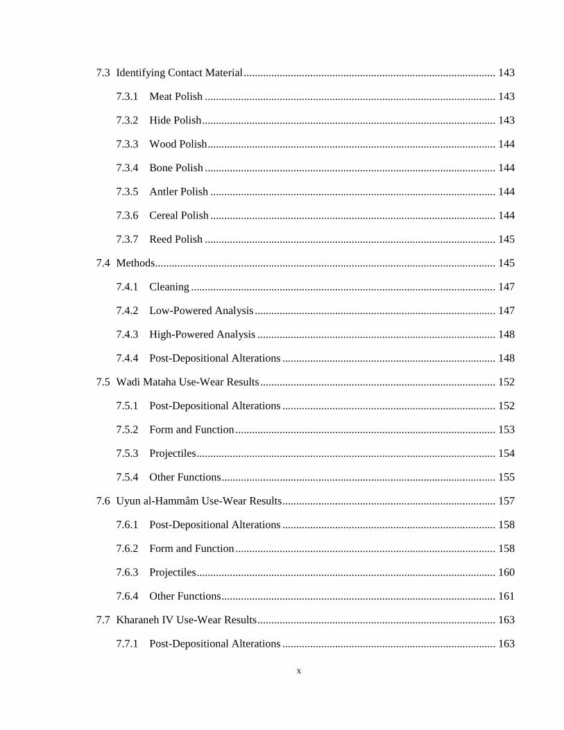
7.3 Identifying Contact Material ........................................................................................... 143
7.3.1 Meat Polish ......................................................................................................... 143
7.3.2 Hide Polish .......................................................................................................... 143
7.3.3 Wood Polish ........................................................................................................ 144
7.3.4 Bone Polish ......................................................................................................... 144
7.3.5 Antler Polish ....................................................................................................... 144
7.3.6 Cereal Polish ....................................................................................................... 144
7.3.7 Reed Polish ......................................................................................................... 145
7.4 Methods ........................................................................................................................... 145
7.4.1 Cleaning .............................................................................................................. 147
7.4.2 Low-Powered Analysis ....................................................................................... 147
7.4.3 High-Powered Analysis ...................................................................................... 148
7.4.4 Post-Depositional Alterations ............................................................................. 148
7.5 Wadi Mataha Use-Wear Results ..................................................................................... 152
7.5.1 Post-Depositional Alterations ............................................................................. 152
7.5.2 Form and Function .............................................................................................. 153
7.5.3 Projectiles ............................................................................................................ 154
7.5.4 Other Functions ................................................................................................... 155
7.6 Uyun al-Hammâm Use-Wear Results ............................................................................. 157
7.6.1 Post-Depositional Alterations ............................................................................. 158
7.6.2 Form and Function .............................................................................................. 158
7.6.3 Projectiles ............................................................................................................ 160
7.6.4 Other Functions ................................................................................................... 161
7.7 Kharaneh IV Use-Wear Results ...................................................................................... 163
7.7.1 Post-Depositional Alterations ............................................................................. 163
xi
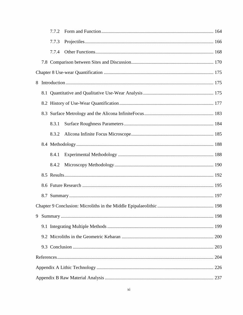
7.7.2 Form and Function .............................................................................................. 164
7.7.3 Projectiles ............................................................................................................ 166
7.7.4 Other Functions ................................................................................................... 168
7.8 Comparison between Sites and Discussion ..................................................................... 170
Chapter 8 Use-wear Quantification ............................................................................................ 175
Introduction ............................................................................................................................ 175 8
8.1 Quantitative and Qualitative Use-Wear Analysis ........................................................... 175
8.2 History of Use-Wear Quantification ............................................................................... 177
8.3 Surface Metrology and the Alicona InfiniteFocus .......................................................... 183
8.3.1 Surface Roughness Parameters ........................................................................... 184
8.3.2 Alicona Infinite Focus Microscope ..................................................................... 185
8.4 Methodology ................................................................................................................... 188
8.4.1 Experimental Methodology ................................................................................ 188
8.4.2 Microscopy Methodology ................................................................................... 190
8.5 Results ............................................................................................................................. 192
8.6 Future Research .............................................................................................................. 195
8.7 Summary ......................................................................................................................... 197
Chapter 9 Conclusion: Microliths in the Middle Epipalaeolithic ............................................... 198
Summary ................................................................................................................................ 198 9
9.1 Integrating Multiple Methods ......................................................................................... 199
9.2 Microliths in the Geometric Kebaran ............................................................................. 200
9.3 Conclusion ...................................................................................................................... 203
References ................................................................................................................................... 204
Appendix A Lithic Technology .................................................................................................. 226
Appendix B Raw Material Analysis ........................................................................................... 237
xii
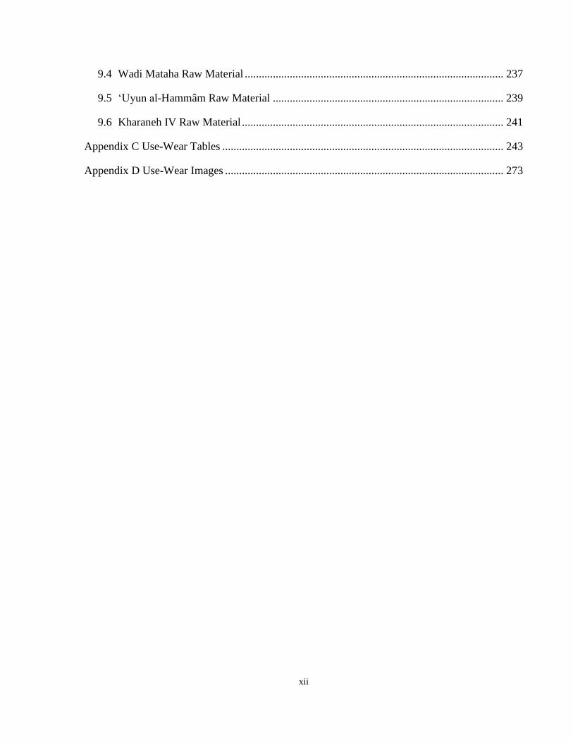
9.4 Wadi Mataha Raw Material ............................................................................................ 237
9.5 ‘Uyun al-Hammâm Raw Material .................................................................................. 239
9.6 Kharaneh IV Raw Material ............................................................................................. 241
Appendix C Use-Wear Tables .................................................................................................... 243
Appendix D Use-Wear Images ................................................................................................... 273
xiii
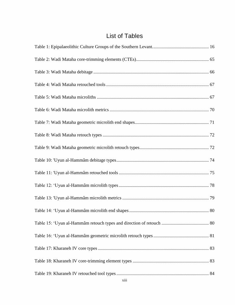
List of Tables
Table 1: Epipalaeolithic Culture Groups of the Southern Levant. ................................................ 16
Table 2: Wadi Mataha core-trimming elements (CTEs) ............................................................... 65
Table 3: Wadi Mataha debitage .................................................................................................... 66
Table 4: Wadi Mataha retouched tools ......................................................................................... 67
Table 5: Wadi Mataha microliths ................................................................................................. 67
Table 6: Wadi Mataha microlith metrics ...................................................................................... 70
Table 7: Wadi Mataha geometric microlith end shapes ................................................................ 71
Table 8: Wadi Mataha retouch types ............................................................................................ 72
Table 9: Wadi Mataha geometric microlith retouch types ............................................................ 72
Table 10: 'Uyun al-Hammâm debitage types ................................................................................ 74
Table 11: 'Uyun al-Hammâm retouched tools .............................................................................. 75
Table 12: ‘Uyun al-Hammâm microlith types .............................................................................. 78
Table 13: 'Uyun al-Hammâm microlith metrics ........................................................................... 79
Table 14: ‘Uyun al-Hammâm microlith end shapes ..................................................................... 80
Table 15: ‘Uyun al-Hammâm retouch types and direction of retouch ......................................... 80
Table 16: ‘Uyun al-Hammâm geometric microlith retouch types ................................................ 81
Table 17: Kharaneh IV core types ................................................................................................ 83
Table 18: Kharaneh IV core-trimming element types .................................................................. 83
Table 19: Kharaneh IV retouched tool types ................................................................................ 84
xiv
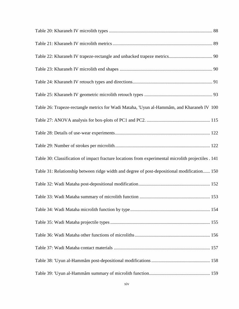
Table 20: Kharaneh IV microlith types ........................................................................................ 88
Table 21: Kharaneh IV microlith metrics ..................................................................................... 89
Table 22: Kharaneh IV trapeze-rectangle and unbacked trapeze metrics ..................................... 90
Table 23: Kharaneh IV microlith end shapes ............................................................................... 90
Table 24: Kharaneh IV retouch types and directions .................................................................... 91
Table 25: Kharaneh IV geometric microlith retouch types .......................................................... 93
Table 26: Trapeze-rectangle metrics for Wadi Mataha, 'Uyun al-Hammâm, and Kharaneh IV 100
Table 27: ANOVA analysis for box-plots of PC1 and PC2. ...................................................... 115
Table 28: Details of use-wear experiments ................................................................................. 122
Table 29: Number of strokes per microlith. ................................................................................ 122
Table 30: Classification of impact fracture locations from experimental microlith projectiles . 141
Table 31: Relationship between ridge width and degree of post-depositional modification ...... 150
Table 32: Wadi Mataha post-depositional modification ............................................................. 152
Table 33: Wadi Mataha summary of microlith function ............................................................ 153
Table 34: Wadi Mataha microlith function by type .................................................................... 154
Table 35: Wadi Mataha projectile types ..................................................................................... 155
Table 36: Wadi Mataha other functions of microliths ................................................................ 156
Table 37: Wadi Mataha contact materials .................................................................................. 157
Table 38: 'Uyun al-Hammâm post-depositional modifications .................................................. 158
Table 39: 'Uyun al-Hammâm summary of microlith function.................................................... 159
xv
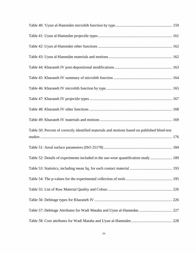
Table 40: 'Uyun al-Hammâm microlith function by type ........................................................... 159
Table 41: Uyun al-Hammâm projectile types ............................................................................. 161
Table 42: Uyun al-Hammâm other functions ............................................................................. 162
Table 43: Uyun al-Hammâm materials and motions .................................................................. 162
Table 44: Kharaneh IV post-depositional modifications ............................................................ 163
Table 45: Kharaneh IV summary of microlith function ............................................................. 164
Table 46: Kharaneh IV microlith function by type ..................................................................... 165
Table 47: Kharaneh IV projectile types ...................................................................................... 167
Table 48: Kharaneh IV other functions ...................................................................................... 168
Table 49: Kharaneh IV materials and motions ........................................................................... 169
Table 50: Percent of correctly identified materials and motions based on published blind-test
studies ......................................................................................................................................... 176
Table 51: Areal surface parameters (ISO 25178) ....................................................................... 184
Table 52: Details of experiments included in the use-wear quantification study ....................... 189
Table 53: Statistics, including mean Sq, for each contact material ............................................ 193
Table 54: The p-values for the experimental collection of tools ................................................ 195
Table 55: List of Raw Material Quality and Colour ................................................................... 226
Table 56: Debitage types for Kharaneh IV ................................................................................. 226
Table 57: Debitage Attributes for Wadi Mataha and Uyun al-Hammâm. .................................. 227
Table 58: Core attributes for Wadi Mataha and Uyun al-Hammâm ........................................... 228
xvi
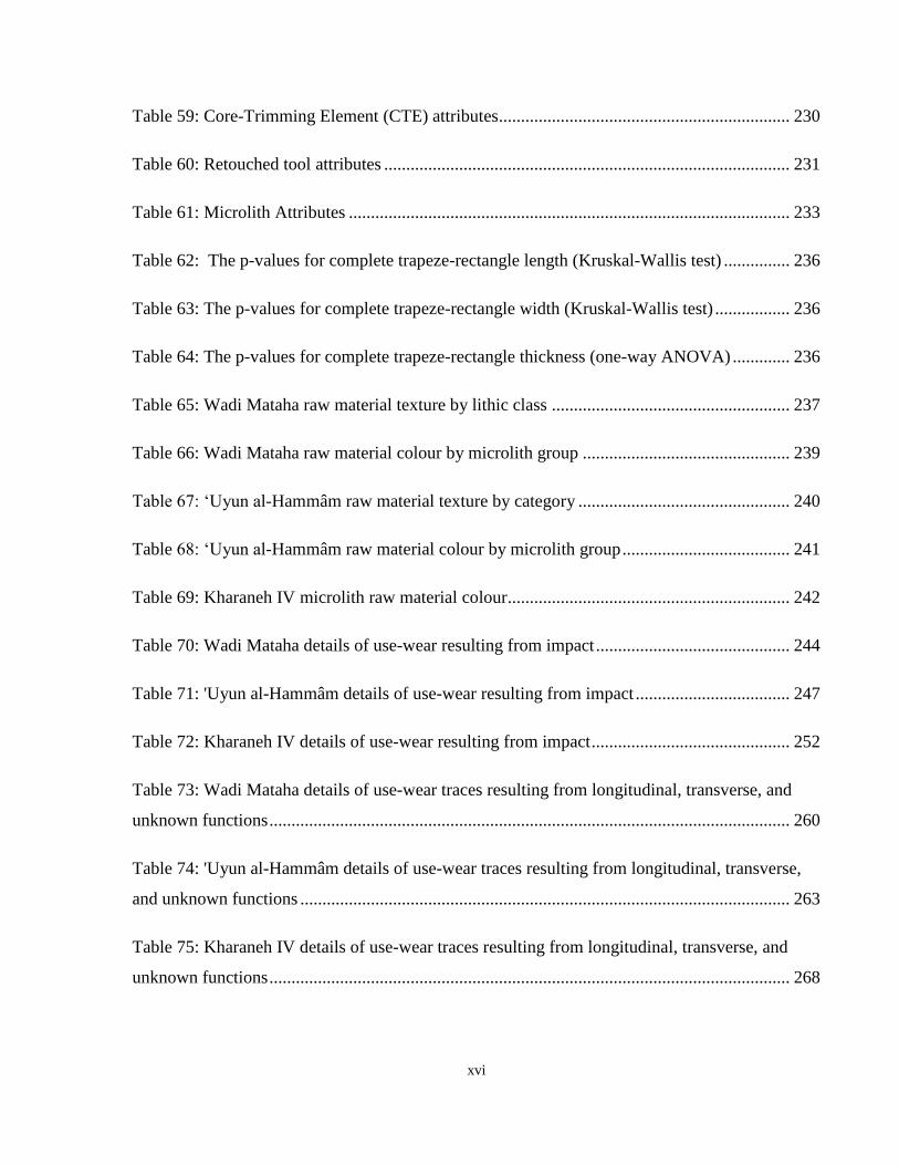
Table 59: Core-Trimming Element (CTE) attributes .................................................................. 230
Table 60: Retouched tool attributes ............................................................................................ 231
Table 61: Microlith Attributes .................................................................................................... 233
Table 62: The p-values for complete trapeze-rectangle length (Kruskal-Wallis test) ............... 236
Table 63: The p-values for complete trapeze-rectangle width (Kruskal-Wallis test) ................. 236
Table 64: The p-values for complete trapeze-rectangle thickness (one-way ANOVA) ............. 236
Table 65: Wadi Mataha raw material texture by lithic class ...................................................... 237
Table 66: Wadi Mataha raw material colour by microlith group ............................................... 239
Table 67: ‘Uyun al-Hammâm raw material texture by category ................................................ 240
Table 68: ‘Uyun al-Hammâm raw material colour by microlith group ...................................... 241
Table 69: Kharaneh IV microlith raw material colour ................................................................ 242
Table 70: Wadi Mataha details of use-wear resulting from impact ............................................ 244
Table 71: 'Uyun al-Hammâm details of use-wear resulting from impact ................................... 247
Table 72: Kharaneh IV details of use-wear resulting from impact ............................................. 252
Table 73: Wadi Mataha details of use-wear traces resulting from longitudinal, transverse, and
unknown functions ...................................................................................................................... 260
Table 74: 'Uyun al-Hammâm details of use-wear traces resulting from longitudinal, transverse,
and unknown functions ............................................................................................................... 263
Table 75: Kharaneh IV details of use-wear traces resulting from longitudinal, transverse, and
unknown functions ...................................................................................................................... 268
xvii
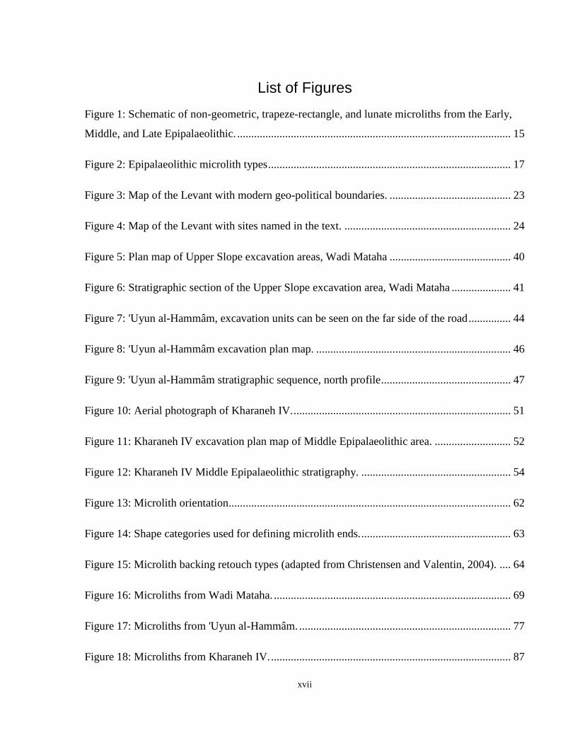
List of Figures
Figure 1: Schematic of non-geometric, trapeze-rectangle, and lunate microliths from the Early,
Middle, and Late Epipalaeolithic. ................................................................................................. 15
Figure 2: Epipalaeolithic microlith types ...................................................................................... 17
Figure 3: Map of the Levant with modern geo-political boundaries. ........................................... 23
Figure 4: Map of the Levant with sites named in the text. ........................................................... 24
Figure 5: Plan map of Upper Slope excavation areas, Wadi Mataha ........................................... 40
Figure 6: Stratigraphic section of the Upper Slope excavation area, Wadi Mataha ..................... 41
Figure 7: 'Uyun al-Hammâm, excavation units can be seen on the far side of the road ............... 44
Figure 8: 'Uyun al-Hammâm excavation plan map. ..................................................................... 46
Figure 9: 'Uyun al-Hammâm stratigraphic sequence, north profile .............................................. 47
Figure 10: Aerial photograph of Kharaneh IV. ............................................................................. 51
Figure 11: Kharaneh IV excavation plan map of Middle Epipalaeolithic area. ........................... 52
Figure 12: Kharaneh IV Middle Epipalaeolithic stratigraphy. ..................................................... 54
Figure 13: Microlith orientation .................................................................................................... 62
Figure 14: Shape categories used for defining microlith ends. ..................................................... 63
Figure 15: Microlith backing retouch types (adapted from Christensen and Valentin, 2004). .... 64
Figure 16: Microliths from Wadi Mataha. .................................................................................... 69
Figure 17: Microliths from 'Uyun al-Hammâm. ........................................................................... 77
Figure 18: Microliths from Kharaneh IV. ..................................................................................... 87
xviii
Figure 19: Percent Frequency of microlith classes at Wadi Mataha, ‘Uyun al-Hammâm, and
Kharaneh IV. ................................................................................................................................. 97
Figure 20: Percent frequencies of geometric microlith types ....................................................... 98
Figure 21: Cumulative frequency graph of trapeze-rectangle microlith retouch type .................. 99
Figure 22: Mean length and widths of trapeze-rectangles .......................................................... 101
Figure 23: Orthogonal sliding of semilandmarks for 'Uyun al-Hammâm microliths ................. 106
Figure 24: Location of landmarks on a trapeze-rectangle .......................................................... 110
Figure 25: Consensus shape of trapeze-rectangles from Wadi Mataha, ‘Uyun al-Hammâm, and
Kharaneh IV ................................................................................................................................ 111
Figure 26: Principal component analysis of Wadi Mataha (top), ‘Uyun al-Hammâm (middle),
and Kharaneh IV (bottom) .......................................................................................................... 112
Figure 27: Principal component analysis comparing trapeze-rectangles from Wadi Mataha, 'Uyun
al-Hammâm, and Kharaneh IV ................................................................................................... 114
Figure 28: Box plots comparing PC1 and PC2 between Wadi Mataha, 'Uyun al-Hammâm, and
Kharaneh IV ................................................................................................................................ 115
Figure 29: Range of replicated microliths used for experiments ................................................ 119
Figure 30: Experimental hafts. .................................................................................................... 119
Figure 31: Schematic of Wadi Hammeh 27 sickle (adapted from Edwards 2007) .................... 120
Figure 32: Meat cutting experiment in the laboratory (University of Toronto) ......................... 121
Figure 33: Field planted with Triticum monococcum (St. Vallier de Thiey, France 2011). ....... 126
Figure 34: Use-wear recording form ........................................................................................... 146
Figure 35: Measurement of ridge width to assess post-depositional .......................................... 151
xix
Figure 36: Frequency of functions for trapeze-rectangles and unbacked ................................... 165
Figure 37: Frequency of functional actions at Wadi Mataha, 'Uyun al-Hammâm, and Kharaneh
IV ................................................................................................................................................ 172
Figure 38: Frequency of diagnostic impact fracture location on geometric and non-geometric
microliths from Wadi Mataha, 'Uyun al-Hammâm, and Kharaneh IV ....................................... 172
Figure 39: Schematic of Ra (mean roughness) calculation across a surface profile path (surface
length). ........................................................................................................................................ 185
Figure 40: The Alicona InfiniteFocus microscope with lithic sample on the stage .................... 186
Figure 41: Examples of the images produced by the Alicona microscope for each contact
material. ...................................................................................................................................... 191
Figure 42: Example of sampling method of 10 µm x10 µm squares from the lithic surface (antler
working tool). .............................................................................................................................. 192
Figure 43: Box-plot showing the Sq values for each contact material ....................................... 194
Figure 44: Cumulative frequency graph of Wadi Mataha raw material quality ......................... 238
Figure 45: Cumulative frequency graph of 'Uyun al-Hammâm raw material quality ................ 240
Figure 46: WM-2493. Projectile bard, step terminating bending fracture (ventral surface) ...... 274
Figure 47: WM-2493. Projectile bard, step terminating bending fracture (dorsal surface) ........ 274
Figure 48: WM-2510. Projectile tip, impact burination ............................................................. 274
Figure 49: WM-2570. Projectile tip, impact burination ............................................................. 274
Figure 50: WZ148.G13.29.217. Projectile bard, step terminating bending fracture .................. 275
Figure 51: WZ148.H11.11.201. Projectile bard or transverse, step terminating bending fracture
..................................................................................................................................................... 275
xx
Figure 52: WZ148.H15.110.210. Projectile bard, step terminating bending fracture ................ 275
Figure 53: WZ148.H15.110.219. Projectile tip, step terminating bending fracture. .................. 275
Figure 54: KHIV.AQ40.13.4. Projectile bard or transverse, step terminating bending fracture 276
Figure 55: KHIV.AR38.11.1. Projectile bard or transverse, step terminating bending fracture 276
Figure 56: KHIV.AS42.10.2. Projectile bard or transverse, step terminating bending fracture . 276
Figure 57: WM-2376 Cutting meat, weak generic polish and rounding .................................... 277
Figure 58: WM-2466 Projectile, angled striations and weak generic polish .............................. 277
Figure 59: WM-2382 Cutting meat, weak generic polish and rounding .................................... 277
Figure 60: WM-2532 Cutting meat, weak .................................................................................. 277
Figure 61: WZ148.G13.29.216 Transverse motion on soft material, weak generic polish ........ 278
Figure 62: WZ148.G13.39.234 Cutting meat/ hide, weak generic polish. ................................. 278
Figure 63:WZ148.G13.30.269 Cutting meat/hide, weak generic polish .................................... 278
Figure 64: WZ148.H11.20.201 Cutting hard contact material ................................................... 278
Figure 65: WZ148.H11.20.205 Cutting meat/weak generic polish ............................................ 279
Figure 66: WZ148.H16.105.206 Projectile with weak generic polish ....................................... 279
Figure 67: WZ148.H16.105.202 Cutting meat/weak generic polish .......................................... 279
Figure 68: WZ148.H16.115.200 Cutting medium/hard material ............................................... 279
Figure 69: KHIV.AQ36.36.1 Projectile, angled linear polish .................................................... 280
Figure 70: KHIV.AQ40.13.8 Projectile with bright polish (bone contact) ................................ 280
Figure 71: KHIV.AQ40.13.5 Projectile; angled linear polish .................................................... 280
xxi
Figure 72: KHIV.AQ40.13.10 Projectile with bright polish (bone contact) .............................. 280
Figure 73: KHIV.AQ40.13.69 Bright localized polish, hard contact material .......................... 281
Figure 74: KHIV.AR38.11.4 Heavy butchering Very bright polish at the edge of the piece,
moving into generic weak polish ................................................................................................ 281
Figure 75: KHIV.AR38.11.2 Unknown function, bright polish at the tip .................................. 281
Figure 76: KHIV.AS36.7.5 Cutting meat/hide. Weak generic polish ........................................ 281
Figure 77: KHIV.AS42.10.2 Projectile with weak generic polish ............................................. 282
Figure 78: KHIV.AS42.10.6 Projectile with weak generic polish ............................................. 282
Figure 79: KHIV.AS42.10.3 Unknown function, hafting using a hard material ........................ 282
Figure 80: KHIV.AS42.10.21 Cutting meat/hide, weak generic polish ..................................... 282
Figure 81: KHIV.AS42.10.36 Transverse motion, bright polish, hard contact material ............ 283
Figure 82: KHIV.AT41.9.3 Projectile with linear polish ........................................................... 283
Figure 83: KHIV.AS42.10.36 Transverse motion, bright polish, hard contact material ............ 283
Figure 84: KHIV.AT41.9.6 Projectile with bright polish (bone contact?) ................................. 283
1
Chapter 1 Introduction
1.1 Introduction
The driving force behind variability in lithic form has long been a topic of debate among
archaeologists (e.g., Binford and Binford, 1969, Bisson, 2000, Bordes, 1961, Dibble and
Rolland, 1992, Dibble, 1984). Scholars have hypothesized that tool form is the result of ethnic
identity (Bordes, 1961, Bordes and de Sonneville-Bordes, 1970), functional requirements
(Binford and Binford, 1969), or technological sequences of production (Dibble and Rolland,
1992). These debates factor strongly into Levantine Epipalaeolithic (23 000-11 600 cal BP)
research, where the chronological and regional morphological variability of microlithic tools
have been interpreted to represent distinct cultural or ethnic communities (e.g., Bar-Yosef, 1970,
Goring-Morris, 1987, Henry, 1995). This interpretation has been critiqued by other researchers
who hypothesize that microlith variability is the result of technological sequences of production
(Neeley and Barton, 1994). This critique has sparked controversy, causing strong reactions in the
archaeological community as people defended the cultural hypothesis for Epipalaeolithic lithic
variability (see Chapter 2, section 2.7). Although technological evidence was brought into this
discussion by Neeley and Barton (1994), functional evidence has rarely informed this debate (but
see Richter, 2007). Exploring the functional and technological aspects of microlith variability
will greatly contribute to our understanding of how microlithic tools acted as both utilitarian
artifacts and carriers of cultural information during the Epipalaeolithic.
This dissertation addresses the underlying meaning of microlith variability during the
Epipalaeolithic through the use of multiple techniques to analyze variation in lithic tools at the
Middle Epipalaeolithic (Geometric Kebaran) sites of Wadi Mataha, ‘Uyun al-Hammâm, and
Kharaneh IV. Addressing variability in morphology, technological production, and function, the
primary hypotheses driving this research are:
1. Different forms of geometric microliths will have overlapping functions, as function is
not the driving force behind variation in form.
2
2. Microliths from each site will show differences in ‘technological style’ at each stage of
the tool’s life history, suggesting that these tools were manufactured and used in distinct
communities.
3. The microliths functioned as sickle inserts, indicating a deep time depth for the use of the
microliths as cereal-harvesting tools.
The question of why Epipalaeolithic microlith form changes across time and space links into
larger discussions of how people interact with material culture. The people of the Epipalaeolithic
were modern humans practicing a hunting-gathering subsistence pattern. Because this period
precedes the Neolithic, many studies examine features of the Epipalaeolithic looking for initial
signs of Neolithic behaviours (Bar-Yosef and Belfer-Cohen, 1989, Grosman and Belfer-Cohen,
1999, Hillman, 2000, Verhoeven, 2004). Thus, the Epipalaeolithic is often viewed as a step
towards agriculture. However, this teleological framework suggests that the Epipalaeolithic
people were actively pushing themselves towards domestication. In contrast to viewing it as a
‘transitional’ period, the Epipalaeolithic needs to be viewed on its own merit (e.g., Boyd, 2006)
with increasing diversity a dominant feature of the Epipalaeolithic. Understanding this diversity
and change in material culture, not as an evolutionary step towards agriculture, but as a feature of
modern human behaviour, is an important step towards understanding interactions between
people and objects.
1.2 Material Culture Variability
Archaeologists have approached material culture variability in numerous ways. This variability
often relates to the material properties of the artifact that are highly visible and easily compared
between objects. As archaeologists, we often equate this variability to ‘style’. The concept of
style has been used by archaeologist to organize material culture both temporally and regionally,
and has been attributed to processes at the individual, group, and ‘cultural’ levels (Conkey and
Hastorf, 1990:1). As noted above, groupings and interpretations of Epipalaeolithic cultures are
based on the morphological style of microliths. This constructs an archaeological narrative
hinged on our interpretations of material culture variability. This section will review
archaeological literature on style, dichotomized between ‘communicative’ style and
‘technological’ style in an effort to problematize our current understanding of Epipalaeolithic
3
material culture and highlight ways of interpreting variability witnessed in the archaeological
record.
1.2.1 Communicative Style
Wobst defined style as an active form of communication in his seminal paper (1977). He
highlighted that style had previously been defined as elements of material culture that are ‘non-
functional’. This created a dichotomy between function and style that permeated archaeological
thought for decades. In contrast, he defines style as “the part of formal variability in material
culture that can be related to the participation of artifacts in processes of information exchange”
(1977: 321). Thus, he ascribed a communicative function to style, subtly breaking down the
distinction between style and function. However, this did not extend to the ‘everyday’
functioning of the artifact; style is functional only in that it has a purpose to communicate. For
style to be an effective communicator, it needs to have a specific target audience that can decode
the message. Archaeologically, this ‘communicative’ style is often interpreted as a message of
group solidarity, both within the group and to create social boundaries between groups. Artifacts
that carry messages of group affiliation need to have public visibility, signaling to members
within and outside the community.
Wiessner (1983) further elaborated on Wobst’s definition of style, stating that style is “formal
variation in material culture that transmits information about personal and social identity”
(Wiessner, 1983: 256). Her definition highlights the integration of identity with the concept of
style, suggesting that style broadcasts group or individual identities to other communities.
Through her work with Kalahari San populations, Wiessner defined two types of style. The first
is ‘emblemic style’, which communicates conscious identity (or affiliation) to a specific
audience. This style is predicated on the presence of social boundaries between groups; there
needs to be an ‘other’ to which the style is communicating. The second type is ‘assertive style’,
which communicates information about individual identity; the personalization of style by
individuals (Wiessner, 1983). This style is more mutable than emblemic style, as it does not have
a specific referent at which the communication is aimed.
Her conceptualization of style is best illustrated through her ethnographic research. Analysis of
Kalahari San metal arrowheads showed clear variability among individual hunter’s arrows, but
there were no clear differences in variability at the band level in terms of size, tip shape, and base
4
shape (Wiessner, 1983). The variability at the individual level can be considered assertive style.
Despite there being no difference at the band level, there were striking differences seen between
different language groups, suggesting that material culture boundaries are not as permeable
between language groups as they are between different bands. This suggests that, for this
ethnographic case study, patterns of regional variation in metal arrowheads marked boundaries
between different linguistic groups. San informants approached the other groups point’s with
trepidation, acknowledging the differences in style and the unknown qualities of points not from
their language group. Furthermore, there appeared to be little fusing of style between these
groups, despite contact during seasonal rounds (Wiessner, 1983). Through this, Wiessner
suggests that San arrowheads represent emblemic style, actively distinguishing between different
linguistic groups.
1.2.2 Technological Style
In contrast to communicative style, technological interpretations of style are the expression of
variability in material culture without a communicative function. Elements of technological style
can be incorporated into the action of tool production, tool use, or tool form. Technological style
can include an agent’s embodied experience within their community, creating technical acts
within a framework of cultural acts (Dobres, 2000). Thereby, the action of creating also becomes
an active communication within a group, but without the conscious desire to communicate.
Early work by Mauss (1935) studied movements of the body, highlighting that techniques and
ways of acting are culturally situated. These ideas were further expanded by other
anthropologists studying technology, looking at material culture variability as an expression of
different techniques or technological ‘choice’. To understand this technological choice,
Lemonnier has suggested that anthropological inquiry into technical systems should “investigate
whether some technological choices are arbitrary from a technological point of view” (1992:18).
Thus, technological style results from choices that are not constrained by the utilitarian function
of the object. Through this perspective, style can be considered as entering all aspects of the
technological process, including the choice of raw material, how a tool is manufactured, and how
it is used. Does the ‘style’ we witness in material culture – from raw material, to manufacture, to
use – fall outside the constraints of function? This perspective does not divorce style from
function, but highlights how style is an integral part of all elements of technology.
5
Writing at the same time as Wobst, Sackett (1977) suggested that artifacts are objects of action
being made and used in daily life, as part of a cultural system. How the object interacts in
economic and social realms is the artifact’s function. Sackett also argues that artifacts can be
viewed as having ‘style’; the properties that place them in a cultural-historic framework. Linking
into concepts from the anthropology of technology, style in this context is the choice that groups
make for the aspects of material culture for which there could be multiple avenues to the same
(utilitarian) function (Sackett, 1977). Thus, because choice is socially transmitted, style is
historically unique to a specific time and place. Artifact variability relates to these two modes,
style and function, which are both elements of material culture. This perspective brought the
concept of style to everyday objects in archaeology, placing them into the social realm without
removing their utilitarian purposes.
Sackett further elaborates on this concept of style, creating a dichotomized system, iconological
and isochrestic style, that have passive and active elements (Sackett, 1982). His ‘iconological’
style is similar to Wiessner’s emblemic style or Wobst’s definition of style. Here, style is a
purposeful signaling of social information regarding the boundaries between human groups.
However, his major contribution to archaeological discussions of style lies in his definition of
‘isochrestic variation’. This highlights the different choices made in tool production that result in
the same end product, particularly the same functional end (Sackett, 1982). For Sackett, this is a
passive process of enculturation, where the available choice is unconsciously made based on
cultural context (Sackett, 1990). In lithic technology, these choices can lie in the raw materials
chosen for manufacture, the knapping technique used, and the sequence of flake removals,
among other technological actions. Choices are learned through interaction with a community,
through the historical context of the group. Therefore, through understanding isochrestic
variation in material culture, insights can be gained into the differences and boundaries between
communities. This theory suggests that function and style result in all formal variation in
material culture, giving equal weight to the function of objects in how they are designed.
Through the lens of isochrestic variation, style is the unconscious choice made by a group or
individual that results from traditions or norms within culture. Thus, it is assumed that
similarities in material production are the result of interaction and shared learning among people
while they are creating that material culture.
6
Using the framework of isochrestic style, Sackett commented on Wiessner’s seminal paper
defining emblemic and assertive style (Wiessner, 1983), suggesting that variability in material
culture might not be an active process of ethnic signaling (Sackett, 1985). He does not hesitate to
agree with the observation that different language groups are manufacturing different ‘styles’ of
arrows, but challenges the interpretation that this style is a conscious process of ethnic
differentiation. Instead, he suggests that the style witnessed in the Kalahari San arrowheads is
better described as isochrestic style, where variability is part of a passive process and the result
of enculturation in social groups. Wiessner (1985) contests this by stating that style should only
be considered as an active process, not something that is acquired through routine. She highlights
the communicative nature of style, where the craftsperson intentionally imbues an artifact with
style to convey a specific message. Revisiting the material, there appear to be elements of both
active and technological style found in the material culture of the San people. This debate
suggests that artifacts can be situated between active and technological style, and that this
dichotomy is not divided by a fixed boundary.
Some archaeologists have attempted to bridge active, or communicative, and passive elements of
style. Dietler and Herbich (1998) argue that material culture is often separated into three
categories: 'style', 'technology', and 'function', the former of which is often thought to be the key
to understanding the social realm in the archaeological record. These authors equate the
differences in active and passive style to the differences in structure and agency; passive style is
controlled by cultural organization and overarching structure, while active style is a choice of
communication and symbols that can be manipulated to articulate different meanings. Dietler
and Herbich use Bourdieu’s theory of practice and habitus to bridge these two different
conceptions of style. In their framework, habitus generates patterned actions, and techniques are
formed within these patterns. These are called 'tendencies' by the authors, which limit the range
of possible choice within the cultural framework. Material culture is thus situated in social life,
where style is not 'added' to materials, but grows in tandem with the formation of social identity
through the enactment of techniques. Based on ethnographic examples from the Luo, the authors
show how situated learning can result in 'micro-styles' of pottery production which permeate all
aspects of the material culture during the manufacturing stages (Dietler and Herbich, 1998). This
micro-style is developed within a group of potters as they learn within that particular community.
In this context, style is the result of different choices made by the artisans while performing
7
similar stages of the technological process (Dietler and Herbich, 1989). This allows for the
artisans to make individual modifications (active style) within a range of cultural choices
(passive style).
1.2.3 Chaîne Opératoire
The discussion of technological style brings us to the concept of the chaîne opératoire. A term
originally coined by André Leroi-Gourhan (1964), the concept of the chaîne opératoire was first
introduced into archaeological interpretation to situate technology in social contexts. In this
scheme, the ‘connaissance’ (knowledge) of the task is enacted through the ‘savoir-faire’ (skill)
of the craftsperson. Thus, the chaîne opératoire is the combination of both the sequence of
technical actions and conception behind these actions, creating a pattern (Chazan, 2009:471).
This pattern has linear and non-linear elements, where the sequence of actions is performed in
order (…bladelet removed from core, bladelet ends snapped, bladelets retouched…), while the
concepts behind this sequence are non-linear (configuration of bladelet hafting, concept of tool
shape etc.). In the context of lithic analysis, the chaîne opératoire includes all processes that a
lithic undergoes, including raw material collection, manufacture, use, and discard (Inizan, et al.,
1992:12). However, the chaîne opératoire has primarily been used to reconstruct methods of
manufacture (e.g., Bar-Yosef and Van Peer, 2009, Davidzon and Goring-Morris, 2003, Sellet,
1993).
Through the lens of the chaîne opératoire, lithics are incorporated into the general context of
human societies where every tool is a product of a technological system, rooted in a societal or
cultural context. Each stone tool is part of a lithic sub-system that interacts with other material
sub-systems such as bone and wood to create technologies used in everyday actions (Soressi and
Geneste, 2011). Thus, no artifact is isolated but is part of a larger technological system. These
conceptual schemes are physically realized through operational sequences. In lithic analysis, this
concept is accessed through several different methods including refitting, experimental
flintknapping, and technological attribute analysis (e.g., Bar-Yosef and Van Peer, 2009).
Although much of archaeological literature has focused on a linear progression from one stage to
another, these sequences are often iterative, repeating stages of manufacture, hafting, use, and re-
tooling prior to discarding the artifact.
8
Two different foci have been identified for discussing the chaîne opératoire (Conneller,
2011:17). The first of these is the sequence of material transformations, prioritizing the process
of materials through different actions. This includes the transformation of a core, through
reductive flintknapping, into one or more finished tools. The second is the physical enactment of
the sequence, highlighting the people involved with the material culture. This focuses on the
gestures and behaviours of past peoples imprinted onto objects. Technological analysis of
debitage and finished tools allows us to reconstruct transformative processes while lithic use-
wear analysis allows us to focus on the second description of the chaîne opératoire,
reconstructing human behaviours through traces and remnants left on stone tool surfaces.
Recently Knappett (2011) argued that the chaîne opératoire provides a lens through which we
can evaluate material culture in both a local and regional context. Often the chaîne opératoire is
used as a prescriptive method of analysis, to create generalized models or schematics by
amalgamating techniques into an idealized ‘norm’. However, it can also be used as a descriptive
method, documenting fluctuations and variations in material culture. Thus, the chaîne opératoire
allows us to move between different scales of analysis, between the variation witnessed between
single artifacts and variations between assemblages at the regional level (Knappett, 2011).
The chaîne opératoire has often been contrasted with the North American approach of reduction
analysis. It has been suggested that the former focuses on cognition rather than purely reductive
sequencing, as advocated by proponents of the latter technique (Bleed, 2001, Shott, 2003,
Tostevin, 2011). The strength of the chaîne opératoire is that it illuminates past processes
through objects, making it an ideal method for evaluating past human-material interactions. This
interaction is guided by knowledge and the skill of the artisan (Chazan, 2009). Thus, the focus of
the chaîne opératoire is on gestures and techniques, integrating the human element into our
understanding of material culture. However, as mentioned previously, the chaîne opératoire is
rarely used to understand the processes beyond manufacturing. This is where we turn to
behavioral archaeology to integrate function into the life-history of material culture.
1.2.4 Behavioural Archaeology
When initially conceptualized, behavioural archaeology set out to develop a method to study the
relationships between human behaviour and material culture (Reid, et al., 1975). This early
definition has been subsequently refined, acknowledging that human behaviour is artifact based
9
and therefore cannot be easily separated from materials (Schiffer, 2010). It looks to understand
human-technology interactions at every scale from within a 'life-history' perspective (Hollenback
and Schiffer, 2010). In this context, life history is defined as a sequence of interactions and
activities that an artifact goes through during its lifetime (LaMotta and Schiffer, 2001:21). Life-
history analyses not only incorporate tool manufacturing, but also explore the conception, use,
recycling, and discard of objects (Hollenback and Schiffer, 2010).
Behavioral archaeology maps the movements of material culture from a behavioral or systemic
state to an archaeological state (S-A process). Materials can also undergo 'successive system
states' where they pass through a series of processes prior to deposition in the archaeological
record. Artifacts can move back to a systemic state through modern behaviours such as
excavation, looting, and collection (A-S process). Finally, the transformation of materials
without human interaction, such as post-depositional processes, is termed the A-A process
(Schiffer, 1976). Thus, behavioral analysis continues past manufacturing, where the chaîne
opératoire approach often terminates.
Behavioral archaeology is based on four strategies which form the basis for questions this
analysis asks about the relationship between people and material culture. These four strategies
are (as outlined in Schiffer, 1976):
1. Using past (archaeological) material culture to answer questions about past behaviours.
Inferences made through this strategy are based on the application of laws to
archaeological interpretation.
2. Evaluating present material culture to make inferences about past behaviour. These
results tend to be general questions because they are not temporally or geographically
restricted.
3. The study of past materials to derive behavioural laws, applicable to both past and
present behaviors. This constructs general rules about human behaviour that is not linked
to time or space constraints.
4. Using present material culture to explain present behaviours.
10
In constructing a behavioral analysis, a 'behavioral chain' is built which maps out the sequence of
actions that took place during the life history of an object (Hollenback and Schiffer, 2010). A
behavioural chain is the sequence of all activities in which an element participates during its
systemic context (Schiffer, 1976:49). The proponents of this technique admit that it is often
difficult to construct a complete chain, therefore usually only segments are created. These chains
are depicted as tables which organize the activities of an object against contextual information
such as time, location, and interacting elements. The systemic portion of the life-history can also
be modeled as a flow chart moving through the stages of procurement, manufacture, use,
recycling, and discard (Schiffer, 1976).
The four strategies outlined above illuminate the deeply embedded processual goals of
behavioral archaeology, including the application of general laws to the archaeological record.
This method of analysis separates the object from the techniques and gestures of people
interacting with material culture, essentializing the technology to a generalized schematic such as
behavioural chains and flow charts. Thus, behavioural archaeology does not have the same
ability as the chaîne opératoire to integrate individuals and gestures into analysis because it is
focused on making generalized laws and theories applicable only at ‘zoomed-out’ scales.
1.3 Summary
Much of the current archaeological literature has focused on sequences of manufacture in the
chaîne opératoire (e.g., Bar-Yosef and Van Peer, 2009), thus deprioritizing tool function in
favour of understanding the manufacturing process. In contrast, behavioral archaeology
incorporates the full life-history of the tool. However, in doing so it removes the human element
of gestures and techniques and loses the ability to approach materials from a multi-scalar
perspective. I would like to advocate the reintegration of function into our understanding of the
chaîne opératoire and integrate a life-history approach (Kopytoff, 1986, Schiffer, 1976, 2010)
into these methods. This recognizes that objects undergo complex processes after manufacture
and before discard that are integral to our understanding of the interaction between people and
objects (Gosden and Marshall, 1999). Function and use are essential elements in understanding
an object’s life history and use-wear analysis is uniquely suited to address tool use and
behaviours in the past. Furthermore, by moving the chaîne opératoire into the microscopic scale
11
of analysis, we can evaluate material properties in new ways, illuminating traces of past
processes and behaviours otherwise invisible in the archaeological record.
Research by Olivier Gosselain (Gosselain, 1992, Gosselain, 1999, 2000) marries the concept of
technological style with the chaîne opératoire, looking for how social boundaries and identity
are expressed at different stages of the chaîne opératoire. He articulates the importance of
understanding subtle aspects of material culture for identifying social boundaries. Using
ethnographic examples from West and Sub-Saharan Africa, he shows that different facets of
identity are woven into each stage of the chaîne opératoire. This is because different stages of
the chaîne opératoire involve different types of social interactions, which can result in different
levels of technical fluidity. Technologically malleable and highly visible stages are more
susceptible to variability and change as they are taught and learned among individuals
(Gosselain, 2000). In the context of lithic analysis, I suggest that the form of tools and their use
falls within these categories; form is a highly visible aspect of lithic technology and is easily
malleable through retouching to change the shape. However, the use of a tool is the most visible
element of technology. Although not always a performance, tool use often takes place within
communities where multiple individuals are present. Furthermore, the gestures used in the
performance of tasks such as hunting, butchering, and harvesting, are usually expressive and
include social interaction. Manufacturing details that are not visible in the final product, such as
core preparation and retouching technique, are influenced only by a small handful of people: the
teachers and other knappers. Thus, form and use are both highly flexible and easily shared (or
identified) across social boundaries, while technological production is more restricted and locally
based.
Highly visible elements of material culture can communicate social boundaries, as in Wiessner’s
emblemic style (1983), or they can be easily transmitted between groups. Technological
diffusion happens with material culture that is easily borrowed or imitated without the need for
migration (Gosselain, 2000). Thus, these ‘diffuse technologies’ can be transmitted through
limited interactions, resulting in shared technologies with little self-identification of a common
social group. I suggest that the trapeze-rectangle microliths, characteristic of the Middle
Epipalaeolithic, are a technologically malleable and highly visible technology that is widespread
as a result of technological diffusion and not limited to functional characteristics. Through the
chaîne opératoire, I will explore the less visible elements of technological production and the
12
more visible elements of tool shape and use. Variability seen between the sites of Wadi Mataha,
‘Uyun al-Hammâm, and Kharaneh IV suggests that the Geometric Kebaran is not a homogenized
‘culture’ with a cohesive identity, but represents a composition of communities through which
technological ideas were shared and adapted to specific community needs.
1.4 Outline of Thesis
This dissertation presents a detailed analysis of three Middle Epipalaeolithic microlith
assemblages from the sites of Wadi Mataha, ‘Uyun al-Hammâm, and Kharaneh IV to understand
variability in lithic technology. Using an approach combining elements of the chaîne opératoire
and life-history, this variability is explored through typological classification, technological
analysis, morphometric analysis, and use-wear analysis.
Chapter 2 begins with a history of Epipalaeolithic research in the southern Levant. Following is a
discussion of the Epipalaeolithic, highlighting the differences between commonly used culture
distinctions in the Early, Middle, and Late Epipalaeolithic. This chapter focuses on how
archaeologists currently differentiate between groups and how they define these differences on
the basis of the lithic assemblages. Recent debates surrounding the interpretation of
Epipalaeolithic culture groups are also presented to situate the study in current issues.
The following chapter, Chapter 3, introduces the three sites chosen for analysis, Wadi Mataha,
‘Uyun al-Hammâm, and Kharaneh IV. These three sites date to the Middle Epipalaeolithic
period. They each contain very different cultural features and are situated in three different
regions of Jordan. Comparison of site features and stratigraphy is presented in order to set the
stage for the detailed analysis of the microlith assemblages.
The next chapter, Chapter 4, presents the results of the typological and technological analysis of
the three lithic assemblages. Basic reduction strategies are discussed, typological classifications
of tool assemblages, and raw material choice. Emphasis is placed on the microlith assemblages,
both the non-geometric and geometric microliths, as these tools are used as cultural indicators for
the Geometric Kebaran.
13
The morphology of the geometric microliths is more fully explored in Chapter 5. This chapter
uses geometric morphometrics to evaluate the differences in trapeze-rectangle form among the
three sites. This work highlights both intra- and inter-site variability in the geometric microliths.
Several experiments were conducted to generate a reference collection for lithic use-wear
analysis. Descriptions of these experiments are in Chapter 6. In addition, this chapter presents
my experiences using hafted microlithic tools on a variety of materials. This takes an experiential
approach to understanding microlith function, further informing our conception of how these
tools may have been used.
Both low- and high-powered use-wear analyses were undertaken to look for traces of use on the
microliths. Chapter 7 presents the methods and the results of this use-wear analysis. For this
analysis a sample of non-geometric and geometric microliths were analyzed. The results of each
site are presented separately and then compared to understand patterns in function between
different forms of microliths.
Chapter 8 presents a new quantitative method of use-wear analysis. Although this analysis was
not used on an archaeological sample for this dissertation, it has the potential to contribute to our
understanding of tool function through the refinement of the identification of contact material.
This is evidenced through the analysis of the experimental collection presented in Chapter 6.
Finally, a synthesis of the results from the typology, morphological, and functional analyses is
presented in Chapter 9. This chapter highlights the similarities and differences among the three
sites, identifying patterns within the microlith variability. How does the variability of microliths
help us understand the meaning of variability in material culture during the Epipalaeolithic and
our definition of the Geometric Kebaran?
14
Chapter 2 The Epipalaeolithic of the Southern Levant
Introduction 2
This chapter outlines the background to the Epipalaeolithic in the Southern Levant, setting the
stage for the analysis of three Middle Epipalaeolithic lithic assemblages. The chapter begins with
a history of Epipalaeolithic research in the Levant, followed by a summary overview of the
general chronological sequence of the Epipalaeolithic, beginning with the Early, then the Middle,
and the Late Epipalaeolithic periods. Within each of these periods, the general culture history is
focused on how archaeologists have divided and defined cultures from the archaeological
material culture record. Finally, I will present recent and topical debates in Epipalaeolithic
research oriented around how we interpret material culture variability.
The Epipalaeolithic is often discussed as a prelude to the origins of agriculture. Epipalaeolithic
culture groups have been placed in contrast to the Neolithic, identifying traces and developments
from hunting and gathering towards agricultural development. Thus, archaeologists have focused
on the final stages of the Epipalaeolithic, the Natufian, to find the origins of agriculture.
However, the earlier Epipalaeolithic periods exhibit behavioural variability and innovations
linked to economic, technological, and social changes also witnessed in the Natufian and
Neolithic (Maher, et al., 2012a), suggesting a long-term trajectory. Current Epipalaeolithic
literature does not focus enough attention on these earlier phases, thereby ignoring complex
human relationships with material culture and the environment.
2.1 The Epipalaeolithic
The Epipalaeolithic period took place during the transition from the Late Pleistocene to the Early
Holocene in Southwest Asia and North Africa. It is divided into three main periods, the Early (23
000-17 500 cal BP), the Middle (17 500-14 600 cal BP) and the Late (14 600-11 600 cal BP).
Each of these periods are defined from their lithic assemblages, with the Early Epipalaeolithic
characterized by non-geometric microliths, the Middle Epipalaeolithic characterized by trapeze-
rectangle geometric microliths, and the Late Epipalaeolithic characterized by lunates (Figure 1).
Early and Middle Epipalaeolithic sites are traditionally understood as ephemeral hunter-gatherers
sites, although recent evidence for built habitations, deep cultural deposits, and cemeteries is
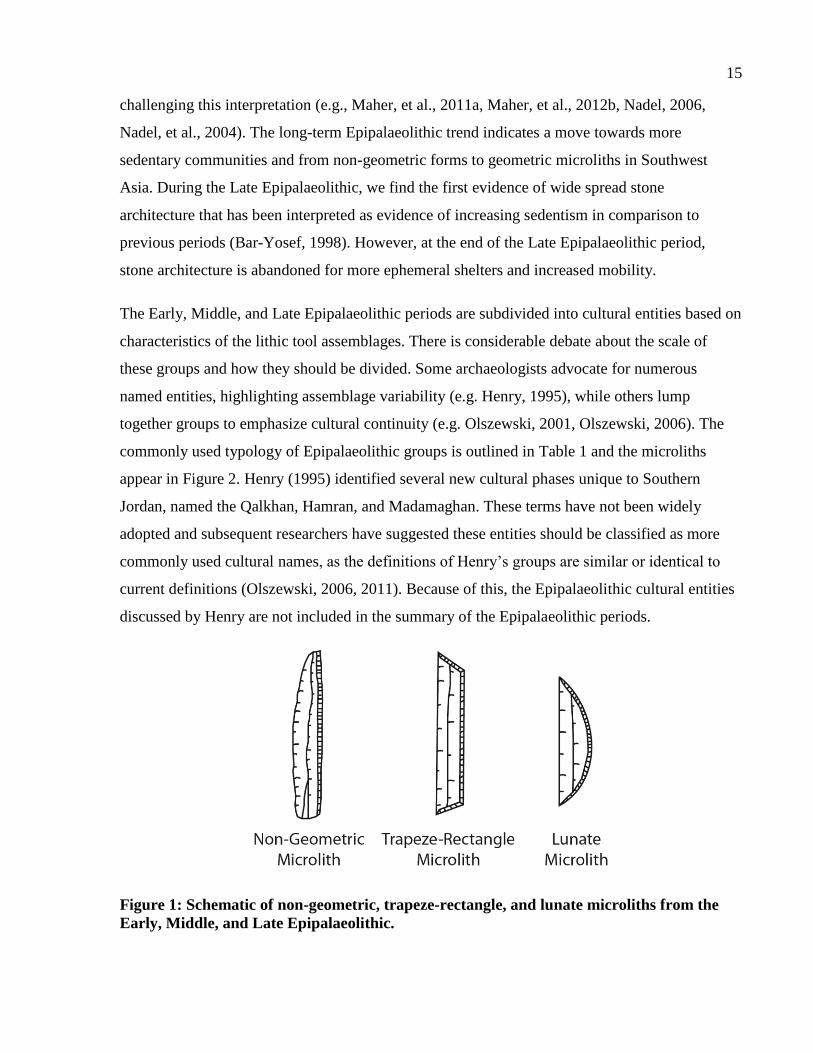
15
challenging this interpretation (e.g., Maher, et al., 2011a, Maher, et al., 2012b, Nadel, 2006,
Nadel, et al., 2004). The long-term Epipalaeolithic trend indicates a move towards more
sedentary communities and from non-geometric forms to geometric microliths in Southwest
Asia. During the Late Epipalaeolithic, we find the first evidence of wide spread stone
architecture that has been interpreted as evidence of increasing sedentism in comparison to
previous periods (Bar-Yosef, 1998). However, at the end of the Late Epipalaeolithic period,
stone architecture is abandoned for more ephemeral shelters and increased mobility.
The Early, Middle, and Late Epipalaeolithic periods are subdivided into cultural entities based on
characteristics of the lithic tool assemblages. There is considerable debate about the scale of
these groups and how they should be divided. Some archaeologists advocate for numerous
named entities, highlighting assemblage variability (e.g. Henry, 1995), while others lump
together groups to emphasize cultural continuity (e.g. Olszewski, 2001, Olszewski, 2006). The
commonly used typology of Epipalaeolithic groups is outlined in Table 1 and the microliths
appear in Figure 2. Henry (1995) identified several new cultural phases unique to Southern
Jordan, named the Qalkhan, Hamran, and Madamaghan. These terms have not been widely
adopted and subsequent researchers have suggested these entities should be classified as more
commonly used cultural names, as the definitions of Henry’s groups are similar or identical to
current definitions (Olszewski, 2006, 2011). Because of this, the Epipalaeolithic cultural entities
discussed by Henry are not included in the summary of the Epipalaeolithic periods.
Figure 1: Schematic of non-geometric, trapeze-rectangle, and lunate microliths from the
Early, Middle, and Late Epipalaeolithic.
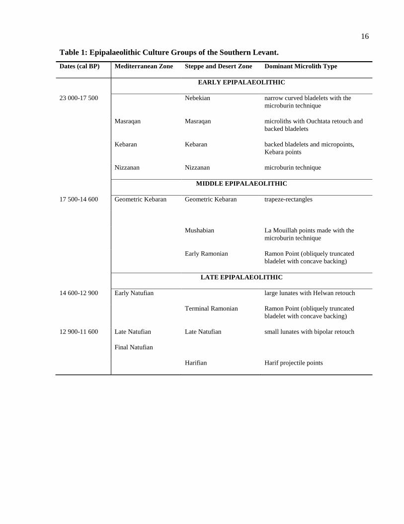
16
Table 1: Epipalaeolithic Culture Groups of the Southern Levant.
Dates (cal BP) Mediterranean Zone Steppe and Desert Zone Dominant Microlith Type
EARLY EPIPALAEOLITHIC
23 000-17 500 Nebekian narrow curved bladelets with the
microburin technique
Masraqan Masraqan microliths with Ouchtata retouch and
backed bladelets
Kebaran Kebaran backed bladelets and micropoints,
Kebara points
Nizzanan Nizzanan microburin technique
MIDDLE EPIPALAEOLITHIC
17 500-14 600 Geometric Kebaran Geometric Kebaran trapeze-rectangles
Mushabian La Mouillah points made with the
microburin technique
Early Ramonian Ramon Point (obliquely truncated
bladelet with concave backing)
LATE EPIPALAEOLITHIC
14 600-12 900 Early Natufian large lunates with Helwan retouch
Terminal Ramonian Ramon Point (obliquely truncated
bladelet with concave backing)
12 900-11 600 Late Natufian Late Natufian small lunates with bipolar retouch
Final Natufian
Harifian Harif projectile points
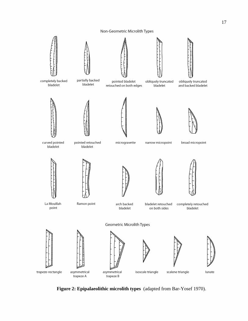
17
Figure 2: Epipalaeolithic microlith types (adapted from Bar-Yosef 1970).
18
2.2 History of Epipalaeolithic Research in the Southern Levant
The Epipalaeolithic was first identified in the Southern Levant by Dorothy Garrod, who
uncovered Late Epipalaeolithic deposits from several sites, including Shukba and el-Wad caves
in Israel (Garrod, 1932). Garrod describes the most abundant microliths at Shukba as being
“small lunate with blunted back’ (1932: 258). She describes the microliths from el-Wad as
similar to these lunates, with backing that had been “trimmed from both surfaces, the result being
to make it sharp instead of blunt” (1932: 261), suggesting they were backed with Helwan
retouch. Both sites contain several burials from the microlith bearing deposits and have an
abundance of worked bone tools. Garrod labeled these sites as Mesolithic based on European
comparisons and not as Epipalaeolithic, but coined the term ‘Natufian’ to describe the local
cultural complex (Garrod, 1932). Other early research in the region included the excavations of
Kebara Cave (then termed Mugharet el-Kebarah). These excavations uncovered remarkable
worked bone material including carved sickle handles and fish hooks (Turville-Petre, 1932).
Following these initial excavations, Perrot and colleagues began excavations in 1955 at the
Natufian site ‘Ain Mallaha, located in northern Israel (Perrot, 1966). These excavations resulted
in the discovery of several round stone structures, bone, and lithic artifacts. The most remarkable
find from this site was the discovery of a human burial containing the skeleton of a 3-5 month
old puppy (Davis and Valla, 1978). The individual’s hand rested on the body of the puppy, who
was buried close to the individual’s head, leading the investigators to speculate that the
domesticated dog emerged during the Natufian.
Meanwhile, on the other side of the Jordan Valley, Diana Kirkbride was surveying southern
Jordan. With the help of local populations she located two Epipalaeolithic sites, the Early
Epipalaeolithic site Wadi Madamagh (Kirkbride, 1958) and the Late Epipalaeolithic/Neolithic
site of Beidha (Kirkbride, 1966). The rockshelter Wadi Madamagh contained several hearths and
rich cultural material, making it an important Early Epipalaeolithic site east of the Jordan Valley.
Beidha became a significant excavation for Kirkbride and she continued to excavate at the site
until 1983.
The first large systematic exploration of the Levantine Epipalaeolithic was undertaken in the
1960’s during Ofer Bar-Yosef’s dissertation research (1970). In this work, Bar-Yosef created the
first Epipalaeolithic type list specific to the Levant (derived from North African typologies
19
developed by Tixier (1963)). Although other researchers have expanded on this typology (e.g.,
Byrd, 1989, Goring-Morris, 1987, Henry, 1989, 1995, Hours, 1974), Bar-Yosef’s typology is
still widely used today. His dissertation presented the lithic assemblages from eight excavated
Epipalaeolithic sites and 23 surface scatters, classifying them into cultural groups based on the
proportion of microlith types present in the assemblage. This work focused on Epipalaeolithic
assemblages to the west of the Rift Valley, in Israel and Palestine. Sites discussed by Bar-Yosef
in this work include the Early Epipalaeolithic site of Ein Gev I, which had evidence for a hut
structure and a human burial, both rarely discovered at Early Epipalaeolithic sites.
During the period the excavations at Hayonim Cave began, directed by Bar-Yosef, Arensburg,
and Tchernov (Bar-Yosef, 1991). They began work in 1965 and their initial goal was to establish
the cultural sequence and classify the lithic assemblage using Bordes’ methods. The excavations
revealed stratified Late Epipalaeolithic, Early Epipalaeolithic, Upper, and Middle Palaeolithic
deposits. In early seasons the directors identified cultural remains on the terrace outside the cave,
and excavations were conducted there during the 1970’s by Henry revealing further
Epipalaeolithic material.
Moving south, the Negev and the Sinai also became a focus of research in the late 1970’s and
early 1980’s. Early work in this region was conducted by A.E. Marks and colleagues in the
central Negev highlands (Marks, 1975, 1976). Other early research in this region was conducted
by Bar-Yosef and Phillips (1977) near Gebel Maghara in the Sinai. The largest archaeological
survey to be conducted in this region was the Emergency Survey of the Negev, commencing in
1979, the results of which were published by the director of excavations, Nigel Goring-Morris
(1987), as part of his dissertation research. This survey began as the Israeli Defense Forces were
redeployed into the Negev, allowing easier access into the region. By the mid-1980’s, over 280
Epipalaeolithic sites had been identified in the Negev and Sinai regions of the Southern Levant
(Goring-Morris, 1987).
During the ‘70s and ‘80s, research was also expanding in Jordan, with the beginning of several
regional survey projects. Although these surveys were not exclusively focused towards the
identification of Epipalaeolithic sites, they did discover and map numerous Late Pleistocene
occupations across Jordan. These survey projects have covered the areas of southern Jordan,
Wadi Hasa, the Azraq Basin, Wadi Hammeh, Wadi Hisban, and Wadi Ziqlab.
20
Directed by Donald Henry, the Southern Jordan survey project covered four study areas,
including the Judayid Basin, Jebel Qalkha, Jebel Mueisi/Mishraq/Muheimi, and Jebel Hamra
(Henry, 1995). This project began active field research in 1979 and concluded in 1988. The
project identified eighteen Epipalaeolithic sites ranging from the beginning to the end of the
Epipalaeolithic sequence. Henry defined several new archaeological entities from these
Epipalaeolithic assemblages, diverging from the generally used typology originally constructed
by Bar-Yosef (1970). These include the Early Epipalaeolithic industries of the Qalkhan and the
Early Hamran, the Middle Epipalaeolithic Hamran industry, and the Late Epipalaeolithic
Madamaghan industry (Henry, 1995). These designations were not widely adopted by the
archaeological community, with most researchers favouring the more commonly used
typological groupings mentioned above.
The Wadi Hasa Survey Project also began in 1979 under the direction of Burton MacDonald
(MacDonald, et al., 1998). This wadi is located southeast of the Dead Sea, in West-Central
Jordan. Although it was originally focused on identifying sites dating to the earlier historic
periods, the project mapped all archaeological occupations found within the wadi. The
identification of over 200 prehistoric sites during this survey led to the creation of the Wadi Hasa
Paleolithic Project, which focused on the Palaeolithic occupations in the wadi. This resulted in
the discovery of over 10 Epipalaeolithic sites throughout the wadi ranging from the Early to the
Late Epipalaeolithic (Clark, et al., 1998). Test excavations began on these Epipalaeolithic site
during 1984 and continued over several seasons (Olszewski, 2011).
Survey and excavation in the Azraq Basin area, eastern Jordan, was conducted by Andrew
Garrard and colleagues from the mid-1970’s to early-1990’s as part of the Azraq Basin Early
Prehistory Project (Garrard, et al., 1994, Garrard and Byrd, 1992, Garrard, et al., 1985, Garrard
and Stanley Price, 1977). This survey project covered the 12 000 km2 area of the Azraq Basin,
identifying prehistoric sites in an area previously considered environmentally ‘marginal’.
Fourteen Epipalaeolithic sites ranging from the Early Epipalaeolithic to the Late Epipalaeolithic
were discovered in the region around and to the west of the oasis (Garrard, et al., 1994). These
sites include the only Epipalaeolithic ‘mega-sites’: Jilat 6, Uwaynid 18, Uwaynid 14, and
Kharaneh IV. These sites are notable for their density of deposits and large size (Kharaneh IV,
the largest of these sites, is 21 000 m2). Jilat 6 and Kharaneh IV both contain stratified Early and
Middle Epipalaeolithic deposits, while the Uwaynid sites are primarily composed of Early
21
Epipalaeolithic material (Garrard, et al., 1994). Additional work was conducted to the east of
Azraq in the basalt desert (Betts, 1986). This work has identified several Late Epipalaeolithic
occupations and renewed work is just beginning in this area to continue excavations of Natufian
deposits at Shubekha.
Moving to the north of Jordan, systematic survey was conducted throughout Wadi Hammeh
(Edwards, 2001, Edwards, et al., 1996). This survey identified early, middle and late
Epipalaeolithic occupations, totaling six sites (Edwards, et al., 1996). The site Wadi Hammeh 27
is notable for the discovery of a preserved ‘sickle’ with two rows of microlith inserts (Edwards,
2007). Philip Edwards also directed the Wadi Hisban survey, located just to the north of the
Dead Sea in the Jordan Valley. This survey located an additional five Epipalaeolithic sites
ranging from the Middle to the Late Epipalaeolithic (Edwards, et al., 1999).
Wadi Ziqlab, located in northern Jordan, has been subject to intensive survey by E.B. Banning
since 1981. Extensive survey of the wadi in 2000 and 2001 located six sites containing material
from the Early and Middle Epipalaeolithic (Maher, 2005a, Maher, et al., 2001, Maher and
Banning, 2001). The site of ‘Uyun al-Hammâm was found during this survey and was
subsequently excavated (Maher, 2005b, 2007a, Maher and Banning, 2003, Maher, 2011). Other
Epipalaeolithic sites found during this survey were ephemeral occupations or disturbed contexts
within later occupations. Under the same project, the neighbouring Wadi Taiyiba was surveyed
and two additional Early Epipalaeolithic sites were located (Maher and Banning, 2001, Maher, et
al., n.d.).
Epipalaeolithic research has been ongoing in the Levant for over 80 years. During these decades,
hundreds of sites have been identified or excavated, resulting in a rich archaeological record
(Figure 4). The above-mentioned projects represent some of the larger initiatives aimed towards
the survey and excavation of multiple Epipalaeolithic sites. However, there has also been
ongoing work across the Levant of single excavations, targeting large sites such as el-Wad,
Ohalo II, Kebara Cave, Neve David, Hayonim, ‘Ain Mallaha, and Nahel Oren. The importance
of these excavations and others like them cannot be underestimated in their contribution to our
understanding of the Epipalaeolithic.
22
2.3 Culture and the Environment
Interpretations of the Epipalaeolithic have been intrinsically intertwined with the changing
environment and climate (e.g. Bar-Yosef and Belfer-Cohen, 1989, Belfer-Cohen and Bar-Yosef,
2000, Goring-Morris and Belfer-Cohen, 1998, Goring-Morris, et al., 2009). Epipalaeolithic
cultures are divided into Mediterranean or steppe/desert groups, creating a dichotomy between
those that lived in the core and those that lived on the margins (see Table 1). Furthermore,
interpretations of Epipalaeolithic mobility are linked to these environmental zones. It is thought
that Early Epipalaeolithic groups concentrated in the Mediterranean zones and sparsely
populated the steppe (Bar-Yosef and Belfer-Cohen, 1989). Later, Geometric Kebaran groups
spread further into the steppe and into the desert as the vegetation zones fluctuated. During the
Early Natufian, larger villages began in the Mediterranean zone and dispersed outwards,
spreading Natufian cultural traits across the region (e.g. Goring-Morris, et al., 2009). This ‘core-
periphery’ model has recently been challenged, highlighting the problems associated with using
climate data to explain culture change (Richter, 2009). A brief description of the geography,
environmental regions, and climate is presented to situate the Epipalaeolithic typology in
context.
The Levant is situated between the southern Taurus Mountains to the north, and the Sinai
Peninsula to the south. Its eastern extent stretches to the Middle Euphrates valley and the western
edge borders the Mediterranean Sea (Bar-Yosef and Belfer-Cohen, 1989) (Figure 3, Figure 4).
The topography of the southern Levant is divided into several north-south strips (from west to
east), the coastal plain, the mountainous region, the Jordan-Araba rift valley, the eastern plateau,
and the eastern lowlands (Horowitz, 1979). The coastal plain, which borders the Mediterranean
Sea, and the mountainous region are both located in modern Israel/Palestine. The mountainous
zone is composed of carbonate rocks, limestone, dolomites, and chalk (Horowitz, 1979), and are
filled with caves as a result of karstic or marine processes (Fellner, 1995b). Adjacent to this
region is the Jordan-Araba Rift Valley which divides Israel/Palestine and Jordan. The Dead Sea
is situated in this valley, providing the lowest land elevations at 423 m below sea level. Finally,
the eastern extent of the southern Levant is characterized by the Jordanian Plateau, a landscape
gently inclined to the east. The plateau is punctuated by large depressions such as the Azraq
Basin, which covers 12,000 km2 of the plateau (Garrard, et al., 1994).
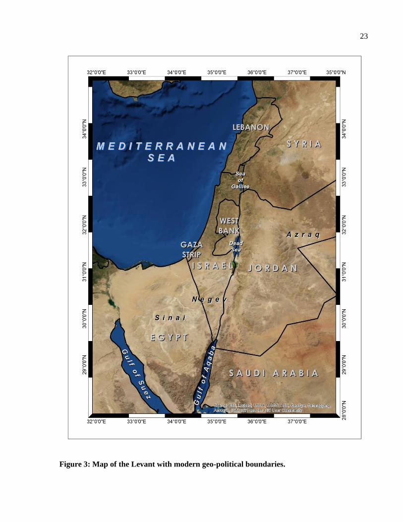
23
Figure 3: Map of the Levant with modern geo-political boundaries.
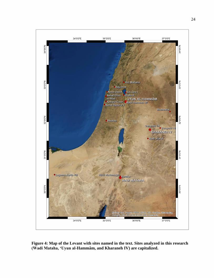
24
Figure 4: Map of the Levant with sites named in the text. Sites analyzed in this research
(Wadi Mataha, ‘Uyun al-Hammâm, and Kharaneh IV) are capitalized.
25
Modern climate zones are often used as a basis for understanding the distribution of
Epipalaeolithic cultures across Levantine geography. The current environment is characterized
by three vegetation zones; the Mediterranean zone, the Irano-Turanian steppe, and the Saharo-
Arabian desert (Bar-Yosef and Belfer-Cohen, 1989). The Mediterranean zone is characterized by
a high average rainfall with over 350mm of precipitation per year. Over 800 plant species can be
found in this region including deciduous forest plants and evergreen varieties (Zohary, 1962).
Prior to agriculture, these forests would have covered much of the Mediterranean area. In
contrast, the Irano-Turanian steppe is drier, with only 200-350mm of average rainfall. There is a
decrease in the range of flora species present in the steppe with approximately 300 different
species including small shrubs, brushwood, and pistachio trees (Zohary, 1962). Finally, the
Saharo-Arabian desert has a mean precipitation of less than 200mm per year, with as little as
50mm of average rain in some regions. This zone is populated by approximately 300 different
species of desert plants. Palynological evidence from the Huleh Basin, Israel, indicates that the
extent of these vegetation zones has fluctuated over time (van Zeist and Bottema, 1982). During
the Epipalaeolithic, the boundaries of these zones would have been in flux, shifting based on the
relative precipitation at the time (Bottema and van Zeist, 1981, van Zeist and Bottema, 1982, van
Zeist and Bottema, 1991).
The fluctuations in vegetation zones are linked to several notable global climate events that took
place during the Epipalaeolithic. Multiple lines of evidence build an image of the palaeoclimatic
conditions for the Levant during the Terminal Pleistocene, including lacustrine sediments,
palaeosols, fluvial sediments, terrestrial palaeobotanical records, speleothems, mollusks,
calcretes, deep-sea cores and coral records (Robinson, et al., 2006).
The beginning of the Epipalaeolithic took place during the Last Glacial Maximum (25 000-18
000 cal BP), which was generally cooler and drier than current conditions. During this time Lake
Lisan, the Late Pleistocene lake present in the current location of the Dead Sea basin, would have
been high, having reached its maximum height of >164 m below sea level at approximately
25,000 cal BP (Bartov, et al., 2002). Towards the end of the Last Glacial Maximum in the Levant
the climate began to ameliorate, with rainfall increasing in the region. This would have resulted
in more vegetation during the Middle Epipalaeolithic. The levels of Lake Lisan also dropped
significantly, reaching levels of 300 m below sea level at approximately 15,000 cal BP.
26
Following the Last Glacial Maximum was the Heinrich 1 event, a rapid but short cooling event.
The presence of this event in the Levant is evident through cooling phases witnessed in the
speleothem records from Soreq Cave, Israel (Bar-Matthews, et al., 1999). This event occurred at
16 800-16 500 cal BP, just prior to the warmer climate of the Bølling-Allerød interstadial
(Maher, et al., 2011b). Current evidence suggests that the Middle Epipalaeolithic began 795-
1145 years prior to the beginning of the Heinrich 1 event and was therefore not a motivator for
the cultural change seen between the Early and Middle Epipalaeolithic (Maher, et al., 2011b).
However, the people living during the Middle Epipalaeolithic would have experienced the
environmental effects of the Heinrich I event and would have adapted within their own cultural
framework to the change in climate.
The Bølling-Allerød interstadial is characterized by an increase in precipitation and rapid
warming (Robinson, et al., 2006). This is viewed as a phase of climate amelioration in the region
and was accompanied by increased soil development in the Levant (Maher, et al., 2011b). The
Bølling-Allerød likely began 60-410 years after the beginning of the Early Natufian (Maher, et
al., 2011b). This suggests that the Early Natufian people enjoyed this warmer weather but that
climate change did not herald the beginning of the Natufian.
The final major Pleistocene climate event was the Younger Dryas, marked by arid and cold
conditions in comparison to the preceding period (Robinson, et al., 2006). The aridity during this
period happened very rapidly and was very pronounced. Lake Lisan levels also continued to fall,
reaching levels lower than the current levels of the Dead Sea. This event likely happened during
the Late Natufian, some 230-680 years after the transition from the Early Natufian (Maher, et al.,
2011b).
Traditional models of cultural groups in the Epipalaeolithic cite these climatic events as the
prime motivator for cultural change. For example, Bar-Yosef and Belfer-Cohen (1989) suggest
that the Geometric Kebaran developed during the climatic amelioration that arose after the Last
Glacial Maximum. They go on to state that resource stress brought about by the abrupt climatic
change caused Geometric Kebaran populations living in arid regions to move back into the
Mediterranean zone (Bar-Yosef and Belfer-Cohen, 1989: 486). These shrinking territories
resulted in pressure on available resources and a shift in social organization towards the features
seen in the Early Natufian. Other prevailing models associate the onset of the Early Natufian
27
with the Bølling-Allerød and link the climatic stress associated with the Younger Dryas to
increased mobility witnessed in the Late Natufian (e.g. Grosman and Belfer-Cohen, 1999).
The model of climate change as a prime mover of cultural change has recently been challenged
(Maher, et al., 2011b, Richter, 2009). These researchers suggest that the relationship between
humans and climate change is more complex than the current models, and that nuanced, regional
views of human environment interactions need to be adopted (Maher, et al., 2011b).
2.4 The Early Epipalaeolithic (23,000-17,500 cal BP)
The Early Epipalaeolithic period in the Southern Levant exhibits continuity with the preceding
Upper Palaeolithic through the continued use of microlith technologies (Goring-Morris and
Belfer-Cohen, 1998). These Early Epipalaeolithic microliths tend to be continuously backed with
abrupt retouch and very little modification from the blank to the finished tool (Belfer-Cohen and
Goring-Morris, 2002). This minimal retouch probably reflects the nature of the haft.
Unfortunately, no hafts have been recovered from this period, therefore there is little known
about the composition or form of hafted Early Epipalaeolithic tools.
2.4.1 Masraqan
The earliest Epipalaeolithic entity is the Masraqan. These sites are found along the western
shores of Lake Lisan and the lowlands of the central Negev and north Sinai (Goring-Morris and
Belfer-Cohen, 1998). Masraqan lithic assemblages are dominated by bladelets with Ouchtata
(very fine) and steep retouch. The microburin technique was not used for the production of
bladelets during this period. Settlement patterns suggest that there was periodic aggregation and
dispersal of small groups (Goring-Morris and Belfer-Cohen, 1998). This entity is characterized
by small hunting and gatherer communities moving across the eastern and southern portion of
the Southern Levant.
The best studied Masraqan assemblage is the site of Ohalo II, located on the southern coast of the
Sea of Galilee, Israel. This site was submerged until the waters retreated in the late-1980’s,
exposing several well preserved hut structures (Nadel, 2002, Nadel and Werker, 1999).
Stratigraphic levels from the hut floors indicates that they were re-occupied several times, with
evidence for maintenance and rebuilding of the structures (Nadel and Werker, 1999). Botanical
remains shows that the inhabitants of Ohalo II were using local grasses as bedding around the
28
interior of the hut (Nadel, et al., 2004) and a variety of plants, including willow, tamarisk, and
oak, to construct the hut superstructures (Nadel and Werker, 1999). Recent evidence suggests
that the inhabitants of the site were grinding starchy cereals such as wheat, barley, and oats, on a
large stone in one of the hut features (Nadel, et al., 2012). Other archaeological evidence from
the site includes a human burial and an abundance of lithics. A single adult male burial was
found to the west of the huts; skeletal evidence suggests he suffered from physical disabilities in
his later years (Nadel and Werker, 1999). Detailed recording of artifact distributions located
discrete interior and exterior flintknapping areas (Nadel, 2001), where the inhabitants of the site
were manufacturing microliths with Ouchtata or abrupt retouch (and at times the both retouch
styles along the same piece) (Nadel, 2003). This unique preservation of Ohalo II allows a
glimpse into the use of perishable materials at the very beginning of the Epipalaeolithic,
highlighting the complexity of material culture used by hunter-gatherers during this period that is
often forgotten in less well-preserved contexts.
2.4.2 Nebekian
The Nebekian is contemporaneous with the Masraqan and is found in arid regions on the eastern
margins of the Transjordanian plateau. This industry was first defined in the 1950s by Rust at
Rockshelter 3, Jabrub, based on the presence of very narrow backed bladelets with truncations
(Olszewski, 2006). The microburin technique was habitually used during the Nebekain to
produce narrow, arched-backed and curved pointed bladelets (Belfer-Cohen and Goring-Morris,
2002). Tentatively, the Azraq ‘mega-sites’ of Wadi Jilat 6 (lower phase), Uwaynid 14, and
Uwaynid 18 have been labeled as Nebekian occupations, but these assignments have not been
solidified (see Byrd, 1988, Olszewski, 2006).
2.4.3 Kebaran
The most widespread cultural entity identified in the Early Epipalaeolithic period is the Kebaran,
and these sites are primarily found in the Mediterranean zone (Bar-Yosef and Belfer-Cohen,
1989). This culture was originally named by Dorothy Garrod after the assemblage collected from
layer ‘C’ at Kebara Cave. The lithic assemblages of the Kebaran are dominated by microliths
(>50%), the majority of which are non-geometric microliths (>90%) including obliquely
truncated bladelets and micropoints. These are manufactured on single-platform bladelet cores
29
(Bar-Yosef, 1975). The microburin technique was not used for microlith production. The non-
microlithic assemblage includes tools such as burins and scrapers (Bar-Yosef, 1970).
Several regional and chronological variants of the Kebaran have been identified, sub-divided on
the basis of frequency of different non-geometric microlith types (Bar-Yosef, 1981, Fellner,
1995b:21-22). These include ‘Cluster A’ (narrow, curved micropoints), ‘Cluster B’ (curved,
pointed backed bladelets, sometimes with a basal truncation), ‘Cluster C’ (narrow micropoints
and obliquely truncated backed bladelets), and ‘Cluster D’ (obliquely truncated backed bladelets,
also called Kebara points). ‘Clusters A’ and ‘B’ are viewed as early, regionally distinct groups,
while ‘Cluster Cs’ and ‘D’ are viewed as later chronological (Bar-Yosef, 1981). In addition, the
presence of Kebara points is usually considered to be characteristic of the late Kebaran (Bar-
Yosef and Belfer-Cohen, 1989). More recent publications have opted to remove the distinction
between these clusters, favouring a more fluid interpretation of material culture variability. There
is some evidence of groundstone technologies during this period, with the presence of basalt
bowls, mortars, and pestles recovered from Kebaran sites.
Kebaran sites tend to be relatively small, ranging between 25 and 400 m2
(Bar-Yosef, 1970, Bar-
Yosef and Belfer-Cohen, 1989), although it has also been suggested that the larger sites, >50 m2,
are the result of periphery scatters of material and realistically sites should be considered as 25-
50 m2 in area (Bar-Yosef, 1981). Kebaran occupations are usually interpreted as ephemeral
seasonal camps. Site distribution patterns and gazelle cementum analysis suggest that there was a
pattern of circulating seasonal mobility, with highlands occupied during the spring/summer and
lowlands occupied during the autumn/winter (Bar-Yosef and Belfer-Cohen, 1989, Lieberman,
1993). Stratified assemblages such as Ein Gev I and Nahal Hadera V indicate that groups were
repeatedly occupying the same location on the landscape, resulting in thick cultural deposits
(Bar-Yosef and Belfer-Cohen, 1989).
2.4.4 Nizzanan
The Nizzanan is a late Early Epipalaeolithic variant with sites primarily to the east and the south
of Lake Lisan (Goring-Morris and Belfer-Cohen, 1998). The lithic technology is similar to the
Nebekian with the habitual use of the microburin technique. The dominant microliths are scalene
and isosceles triangles, with the latter often bring very small at 0.4 mm (Garrard and Byrd,
1992). Non-geometric microliths include microgravettes, curved, pointed, and arched backed
30
pieces (Garrard and Byrd, 1992). Ephemeral Nizzanan sites are found in the Negev and there is
evidence for larger occupations in the eastern desert of Jordan (Goring-Morris and Belfer-Cohen,
1998), including the upper deposits of Wadi Jilat 6 (Phase A) (Garrard and Byrd, 1992).
2.5 The Middle Epipalaeolithic (17,500 – 14,600 cal BP)
During the Middle Epipalaeolithic sites spread further into the arid regions of the Southern
Levant (Bar-Yosef and Vogel, 1987). Like the Early Epipalaeolithic, the Middle Epipalaeolithic
is divided into cultural units based on the variability in lithic assemblages across the region.
Primary changes in the lithic technology include a shift from non-geometric microliths to the
systematic use of geometric microliths such as trapeze-rectangles.
2.5.1 Geometric Kebaran
The Geometric Kebaran is the most prominent and widespread culture group during the Middle
Epipalaeolithic (Bar-Yosef and Vogel, 1987). It is suggested that the Geometric Kebaran was
derived from the Kebaran industry, spreading beyond the Mediterranean zone into the Negev,
Sinai, and the Sahara-Arabian desert of eastern Jordan (Bar-Yosef and Belfer-Cohen, 1989).
Geometric Kebaran lithic assemblages are characterized by a high proportion of trapeze-
rectangle geometric microliths in the tool assemblages (>50%) (Bar-Yosef, 1970). The
microburin technique was rarely used in the production of these microliths.
Initially, Bar-Yosef (1981) split the Geometric Kebaran into two distinct groups, those with thick
geometrics and those with thin geometrics. The Geometric Kebaran A had trapeze-rectangles
manufactured on narrow bladelets, approximately 4.5-6.5 mm wide. These sites are concentrated
in the Mediterranean zone and Bar-Yosef suggested that they represent a continuum from the
preceding Kebaran period. In contrast, the Geometric Kebaran B group is identified on the basis
of thick microliths, 7-8mm wide, and sites of this group are found in arid regions such as the
Negev and Sinai. Recently, these distinctions have been abandoned as it becomes clearer that
microlith width is a continuum and does not cluster into two distinct groups.
Trapeze-rectangle microliths are standardized across a large portion of the Southern Levant
(Maher, 2005a), suggesting that there may have been some cultural contact or exchange across
the region. It has been suggested that the introduction of geometric microliths in the Levant was
the result of a heavy reliance on composite tools (Belfer-Cohen and Goring-Morris, 2002).
31
Although there are no recovered hafts from the Geometric Kebaran, there is indirect evidence for
hafting found at the site of Lagama North VIII. At this location, a concentration of trapeze-
rectangles was found with preserved calcareous adhesive along the backed edge, indicating that
these were placed longitudinally in a haft (Bar-Yosef and Goring-Morris, 1977). Groundstone
tools are found at many Geometric Kebaran sites, including pestles and bowls used for grinding
(Bar-Yosef and Belfer-Cohen, 1989).
Geometric Kebaran sites range from very small occupations (15-25 m2) to larger sites at 300-400
m2 (Bar-Yosef, 1981, Bar-Yosef and Belfer-Cohen, 1989). Recent excavations have identified
very large Geometric Kebaran occupations at the site of ‘Uyun al-Hammâm, approximately
1,500 m2 (Maher, 2007b). In addition, the mega-site of Kharaneh IV in the Eastern Desert
contains trapeze-rectangle microliths and could tentatively be assigned to the Geometric
Kebaran. These two sites indicate there is a large range in the size of Geometric Kebaran
occupations during the Middle Epipalaeolithic, with some exceptionally large sites occupied
during this time.
2.5.2 Mushabian
The Mushabian was first identified near Gebel Maghara in Wadi Mushabi, northern Sinai (Bar-
Yosef and Phillips, 1977, Phillips and Mintz, 1977). This industry is contemporaneous with the
Geometric Kebaran and is located in arid regions of the Negev and Sinai. The Mushabian is
characterized by the intensive use of the microburin technique to produce La Mouillah points
(backed bladelets with a microburin scar creating an oblique truncation), arched backed
bladelets, and scalene triangles (Bar-Yosef and Phillips, 1977, Goring-Morris, 1987, Phillips and
Mintz, 1977). Larger tools such as scrapers, perforators, and burins are rare in these assemblages.
This industry may have been contemporaneous with the Geometric Kebaran, or it may have
begun at the end of Geometric Kebaran occupations of the Negev and Sinai (Fellner, 1995b).
The sites are generally small and range from 25 to 150 m2. There is some evidence of
stratification suggesting the reuse of a single locale (Bar-Yosef, 1981). It has been noted that the
Mushabian bears a resemblance to Epipalaeolithic assemblages in North Africa, particularly in
the presence of La Mouillah points, which are found in the Iberomaurusian of the Maghreb
(Phillips and Mintz, 1977). However, a clear link between these and African assemblages has not
been established.
32
2.5.3 Ramonian
Sites of the Ramonian industry are also located in the Negev and the Sinai (Goring-Morris,
1987). This entity is characterized by the Ramon point, a bladelet with an oblique truncation over
a microburin scar, with concave backing. The Ramon point has been described as a variant of a
La Mouillah point because of the use of the microburin technique to truncate the bladelet. This
industry has been divided into two phases, early and terminal, with the former lacking geometric
microliths and the latter having lunates. Based on the presence of lunates, the Terminal
Ramonian is associated with the Late Epipalaeolithic. Although there is evidence of stratified
Ramonian deposits overlying Mushabian assemblages (Fellner, 1995b), some authors have
argued that there are numerous similarities between the Mushabian and the Ramonian,
suggesting that they should not be classified as separate cultural entities but lumped together as
one group (Henry, 1998, Maher, 2005a).
2.6 The Late Epipalaeolithic (14,600-11,600 cal BP)
As with the other Epipalaeolithic periods, the Late Epipalaeolithic is divided into distinct cultural
entities based on variability within the lithic assemblages. The most prominently studied cultural
entity is the Natufian, which immediately precedes the advent of farming villages. Some
researches divide the Natufian into three different stages, the Early, Late, and Final Natufian.
Others create a simple dichotomy between the Early and the Late Natufian; it is this distinction
that will be discussed below. The majority of Epipalaeolithic research has focused on the
Natufian to better comprehend the shift from hunter-gatherer to agricultural practices.
2.6.1 Early Natufian
The Early Natufian is characterized by stone architecture, large groundstone tools, worked bone,
on-site burials, and personal ornamentation. Many of these archaeological features are also found
during the preceding Middle Epipalaeolithic and even into the Early Epipalaeolithic, but the
systematic adoption of this suite of traits is not witnessed until the Natufian. Early Natufian sites
range in size from small occupations to larger ‘base camps’ with stone architecture. These large
sites, such as Hayonim, ‘Ain Mallaha, and el-Wad, are concentrated in the Mediterranean Zone,
which has been labeled the Natufian ‘homeland’ (Bar-Yosef, 1998).
33
Stone structures from the Early Natufian are generally semi-subterranean and circular with stone-
lined walls (Bar-Yosef, 1998). It has been argued that the Early Natufian occupation pattern has
more evidence for semi-sedentary to sedentary behaviours then the Middle Epipalaeolithic, with
evidence of permanent stone architecture and on-site burials (Perlès and Phillips, 1991). This
interpretation is supported by the high density of fast-moving animals in Early Natufian faunal
assemblages, suggesting that the inhabitants of these communities were able to focus on the
small game that surrounded their base camps (Munro, 2003). Faunal evidence of year-round
hunting at Natufian sites has been linked to the change from circulating mobility to radiating
mobility, where foraging groups would continually return to the same base camp (Lieberman,
1993).
The interpretation that the Early Natufian people were sedentary has recently been challenged.
Using discard distribution patterns from Wadi Hammeh 27, Hardy-Smith and Edwards (2004)
suggest that Natufian structures were filled with refuse. The lack of disposal strategies suggests
that Natufian populations were not yet adapted to sedentary living, and the authors advocate
more nuanced definitions of mobility and sedentism. Boyd (2006) furthers this debate by
suggesting that Early Natufian structures may reflect a shift towards new conceptions of ‘place’
on the landscape rather than sedentism. This links the architecture to the landscape without
presupposing settlement patterns. Regardless of the interpretation, the systematic use of stone
architecture is a feature of the Natufian not seen in previous periods.
The lithic assemblage from the Natufian period is characterized by the production of lunates,
often using the microburin technique. These miniature half-moon-shaped lithics were hafted
together to create larger composite tools. Bone hafts with longitudinal grooves for insets have
been recovered in Natufian archaeological assemblages, such as those found at Wadi Hammeh
27 and Kebara Cave (Edwards, 2007, Noy, 1991). Lunates occur in sites all across the Southern
Levant, suggesting that there was some cultural contact or interaction between groups throughout
the region. In the Early Natufian, lunates were primarily backed using Helwan retouch, a method
of bifacial backing that creates a pointed edge (Bar-Yosef, 1998, Valla and Bar-Yosef, 1979).
This method of backing was abandoned in the Late Natufian. As well, Early Natufian microlith
assemblages tend to have larger lunates than the Late Natufian, with an average length of 21mm
or longer (Valla and Bar-Yosef, 1979). Other authors have suggested that these size divisions are
also geographically sensitive (Olszewski, 1986).
34
The Natufian also saw a florescence of groundstone and art objects. Although both of these
artifact types occurred in the preceding Geometric Kebaran, there was a dramatic increase in
their prevalence during the Natufian. Numerous art objects have been recovered from Natufian
sites, including decorated functional objects such as shaft straighteners and non-functional
objects like animal figurines (Noy, 1991). As well, beads and pendants that would have served as
personal ornaments are found in Natufian contexts (Belfer-Cohen, 1991). Several Early Natufian
sites, including Hayonim Cave, el-Wad, and ‘Ain Mallaha, have burials that exhibit evidence for
personal ornamentation (Belfer-Cohen, 1988, 1995). Although it has been implied that this
represents social stratification, this hypothesis has been challenged, suggesting there is not
sufficient evidence for hierarchy in the Early Natufian (Belfer-Cohen, 1995)
2.6.2 Late Natufian
During the Late Natufian, populations became increasing mobile, moving away from the larger
villages with stone architecture. Communities spread beyond the Natufian ‘homeland’
centralized in the Mediterranean Zone and moved outwards into new territories. However, in
some areas these populations continued to return to the old sites such as Hayonim, ‘Ain Mallaha,
and Nahal Oren to bury their dead in secondary contexts (Bar-Yosef, 1998, Valla, et al., 1991).
Although the microlith assemblages of the Late Natufian are also dominated by lunates, they are
notably different from the lunates found in the Early Natufian. Late Natufian lunates are usually
backed using unifacial retouch, creating a blunted back. They are also smaller than the Early
Natufian lunates, with an average length of approximately 13mm (Olszewski, 1986).
2.6.3 Harifian
The Harifian is a Late Epipalaeolithic variant, restricted to the arid regions of the Levant in the
Negev and Sinai (Goring-Morris, 1991). Site size ranges from 200 to 750 m2. Several sites
display evidence of architecture in the form of round stone structures. Larger structures are semi-
subterranean and circular, lined with stone slabs (Goring-Morris, 1991). Settlement patterns
suggest that Harifian groups aggregated in large camps at high elevation from spring to autumn.
As colder winter conditions set in these aggregated groups would disperse into smaller camps at
lower elevations (Goring-Morris, 1991).
35
The material culture exhibits many of the same traits as the preceding Natufian, including
bladelets produced from single-platform cores, and the use of the microburin technique for
bladelet truncation (Henry, 1989: 220). What makes the Harifian unique is the presence of the
Shunera and Harif points, the first projectile points to be used in this region. Shunera points are
associated with the earliest Harifian, and are small, triangular points with rounded bases often
made with Helwan retouch (Goring-Morris, 1991). Harif points are found in later Harifian sites
and are small unifacially retouched points with a sharp point at the distal end and a
triangular/stemmed shaped base (Marks, 1973). These minimally retouched projectile points
replaced geometric microliths as the primary hunting technology in these arid regions (Henry,
1989: 221). The continued use of projectile points and the abandonment of microliths
characterize subsequent Pre-Pottery Neolithic A lithic assemblages. Exotic materials are also
present in Harifian assemblages including turquoise pendants and shell beads from the Red and
Mediterranean Seas (Goring-Morris, 1991). Ground-stone artifacts are common with both non-
portable bedrock cup-marks and portable ground-stone tools such as grinding tools and shaft
straighteners.
2.7 Recent Debates in Epipalaeolithic Research
Active debates among scholars have tried to identify the reason for the variability seen in
Epipalaeolithic microlith assemblages (e.g. Barton and Neeley, 1996, Clark, 1996, Goring-
Morris, 1996, Goring-Morris, et al., 1996, Henry, 1996, Neeley and Barton, 1994, Phillips,
1996). Early interpretations suggest that boundaries between microlith types represent
boundaries between people, and that different forms of tools are markers of different ethnic or
cultural groups (Bar-Yosef, 1970, Fellner, 1995b, Goring-Morris and Belfer-Cohen, 1998,
Henry, 1995). These theories suggest that our typological classifications of microlith types
represent meaningful distinctions between different groups on the Epipalaeolithic landscape. The
interpretation that variability in stone tool form is indicative of ethnic group identity has been
questioned by some recent scholars who highlight the inherent bias in typological analysis
(Neeley and Barton, 1994, Olszewski, 2001, 2006, Pirie, 2004). In addition, a few studies have
attempted to move beyond solely typological analysis of Epipalaeolithic lithics by addressing
stone tool function (Richter, 2007, Tomenchuk, 1983, 1985).
36
A major critique of the ‘ethnic’ interpretation of typological diversity in microliths is that of
Neeley and Barton (1994). These authors compare non-geometric backed bladelets with
geometric microliths to assess whether the typological classification scheme currently used for
Epipalaeolithic lithic assemblages is useful for distinguishing different groups. From this
analysis, they suggest that the types currently identified in the archaeological record are not the
result of different groups but represent different stages in a ‘reduction sequence’. In their
constructed sequence, straight-backed bladelets are the initial stage, which are then retouched
into scalene or arched-backed bladelets. They propose a similar scheme for geometric microliths,
with various geometric shapes retouched into other geometrics based on the configuration of the
haft. For example, they exhibit how a rectangle, triangle, or lunate could be retouched into a
trapeze microlith. Through this retouching sequence, they suggest that sites with assemblages
composed primarily of microliths in the ‘earlier stages’ of reduction are initial flint-knapping and
tooling sites. Using traditional typologies, these sites would be separated on a chronological or
regional basis and interpreted to represent different groups.
These authors also suggest that the differences in the abundance of the microburin technique was
part of a ‘technological continuum’ (Neeley and Barton, 1994: 277) and not the result of
different ethnic groups. They propose that low microburin frequencies seen in the Geometric
Kebaran were not because this technique was not used for bladelet truncation (as usually
inferred). Instead, they hypothesize that the geometric microliths were manufactured on the
microburin waste product, thereby removing evidence of this technological technique from the
archaeological record of the period. Using metrics, they show that bladelets from Geometric
Kebaran assemblages are almost twice as long as the geometrics from the same time period.
They link this evidence to raw material availability, suggesting that the Geometric Kebaran may
represent a different expression of the contemporary Mushabian (where the microburin technique
is prevalent). Thus, they postulate that the lack of microburin technique seen during the
Geometric Kebaran is the result of raw material conservation, where every part of the bladelet
was retouched into a tool.
These technological interpretations of Epipalaeolithic microlith variability caused a wave of
negative reaction in the archaeological community. Several rounds of comments were
subsequently published, with a response from the original authors. Many of these comments
focus on perceived methodological flaws or misinterpretation of the archaeological material. In
37
the initial critiques, Fellner (1995a) points out that the metrics provided by Neeley and Barton
for the Geometric Kebaran fail to account for the double truncation needed to produce the typical
trapeze-rectangle microliths, which would result in needing longer blanks to produce two
microliths from a single bladelet. He further argues that microlith types are often geographically
and chronologically restricted; if different types were the results of resharpening, logically
multiple geometric types would be found at each site (Fellner, 1995a). Other critiques highlight
the same issue, stating that Neeley and Barton (1994) are inaccurate in their assertion that
trapeze-rectangles, triangles, and lunates occur throughout the Levantine Epipalaeolithic
(Goring-Morris, 1996).
Kaufman’s critique (1995) emphasizes the fact that there are multiple documented ways to
segment a bladelet, many of which do not require the use of the microburin technique. This is
supported by Henry (1996), who states that trapeze-rectangles were manufactured through
snapping and the flexion scars are witnessed on the debitage in these assemblages. Furthermore,
the vast amount of debitage present on Epipalaeolithic sites suggests that raw material
conservation was not a concern for most Epipalaeolithic knappers. Thus, there would be no need
to conserve raw materials by retouching all of the microburins into geometric microliths
(Goring-Morris, 1996, Henry, 1996, Kaufman, 1995). As well, there is evidence for Mushabian
and Geometric Kebaran populations occupying similar territories, therefore each group would
have had access to the same food and raw material resources. This shows that there are
differences between the Mushabian and the Geometric Kebaran sites relate to more than
economics and raw material conservation.
Finally, many microlith assemblages truncated with the microburin technique have residual
evidence of the microburin scar on the retouched microlith. Thus, it would be highly unlikely
that the microburin scar would have been retouched away on all trapeze-rectangles (Goring-
Morris, 1996). Phillips (1996) argues that a technological approach alone is not enough to
understand the variability witnessed in the Levantine Epipalaeolithic; using the chaîne
opératoire, researchers can gain a deeper understanding for lithic variability. All five
commentaries adhere to the hypothesis that microlith variability is the result of cultural groups
and social factors, and not technological differences (Fellner, 1995a, Goring-Morris, 1996,
Henry, 1996, Kaufman, 1995, Phillips, 1996).
38
A single voice supported the technological hypothesis proposed by Neeley and Barton,
suggesting that the researchers critiquing the technological hypothesis are bound to French
typological systems that links patterns in the archaeological record to culture (Clark, 1996). In
response to the critiques, Barton and Neeley (1996) adhered to their original position, stressing
the economic reasons behind material culture variability. This debate accentuated the divide
between archaeologists favouring a cultural hypothesis and those favouring a behavioural
hypothesis for lithic variability. No resolution was found between Neeley and Barton and their
detractors, however the published debate did highlight a need for further inquest into the nature
and meaning of lithic variability in the Epipalaeolithic.
As time has progressed, other researchers have questioned the paradigm that lithic variability is
representative of cultural groups. Despite this, most researchers would contend that the
technological hypothesis proposed by Neeley and Barton (1994) does not properly reflect the
archaeological lithic assemblages from the Epipalaeolithic. If the variability witnessed in the
archaeological microlith assemblages of the Epipalaeolithic is not the result of reduction
sequences, as posited by Neeley and Barton (1994), then what is the driving force? Is it the result
of cultural differences between contemporary groups or functional differences? Furthermore, is
there variability within Epipalaeolithic assemblages attributable to the same cultural group? A
detailed analysis of the microlith assemblages from Wadi Mataha, ‘Uyun al-Hammâm, and
Kharaneh IV will contribute to this debate by integrating typological, technological, and
functional analyses to understand material cultural variability in the Epipalaeolithic.
39
Chapter 3 The Sites: Wadi Mataha, ‘Uyun al-Hammâm, and Kharaneh IV
Introduction 3
This chapter will introduce the three sites chosen for analysis: Wadi Mataha, ‘Uyun al-Hammâm,
and Kharaneh IV. These three sites are situated in southern Jordan, northern Jordan, and eastern
Jordan respectively, offering a range of different ecological resources to the sites’ inhabitants.
For each site, the location, stratigraphy, and major archaeological features are presented to
provide context for the analysis of the microlith assemblages.
3.1 Wadi Mataha
Wadi Mataha is a multicomponent Epipalaeolithic site, located near the ancient city of Petra in
southern Jordan. Geometric Kebaran, Early Natufian, and Late Natufian occupations are present
at Wadi Mataha. The site is located in the Mediterranean zone and is close to the desert lowlands
and the Irano-Turanian steppe (Baadsgaard, et al., 2010). The Epipalaeolithic occupations are
situated on a steep talus slope at the edge of Mughar al-Mataha, a large sandstone monolith. The
site is approximately 950 m above sea level and is adjacent to Wadi Mataha, a river valley
flowing towards Petra to the south. Chert nodules are readily available in this main drainage
(Janetski and Chazan, 2001a), providing the site’s inhabitants with lithic raw materials. The site
excavation divided into three areas, the lower, middle, and upper slopes (Figure 5). The lower
and middle slope areas contain exclusively Early Natufian deposits. The Geometric Kebaran
deposits are located on the upper slope of the site, where Late Natufian deposits overlie them
(Janetski and Chazan, 2001b).
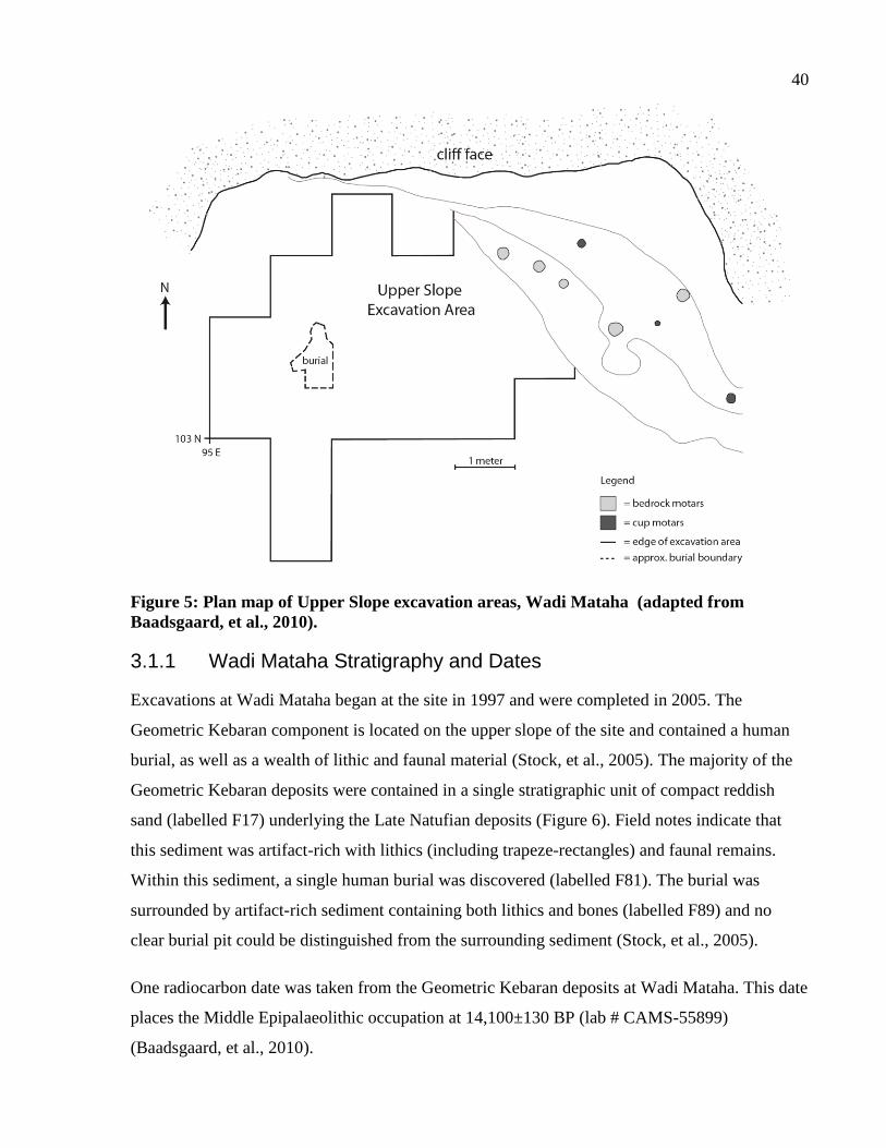
40
Figure 5: Plan map of Upper Slope excavation areas, Wadi Mataha (adapted from
Baadsgaard, et al., 2010).
3.1.1 Wadi Mataha Stratigraphy and Dates
Excavations at Wadi Mataha began at the site in 1997 and were completed in 2005. The
Geometric Kebaran component is located on the upper slope of the site and contained a human
burial, as well as a wealth of lithic and faunal material (Stock, et al., 2005). The majority of the
Geometric Kebaran deposits were contained in a single stratigraphic unit of compact reddish
sand (labelled F17) underlying the Late Natufian deposits (Figure 6). Field notes indicate that
this sediment was artifact-rich with lithics (including trapeze-rectangles) and faunal remains.
Within this sediment, a single human burial was discovered (labelled F81). The burial was
surrounded by artifact-rich sediment containing both lithics and bones (labelled F89) and no
clear burial pit could be distinguished from the surrounding sediment (Stock, et al., 2005).
One radiocarbon date was taken from the Geometric Kebaran deposits at Wadi Mataha. This date
places the Middle Epipalaeolithic occupation at 14,100±130 BP (lab # CAMS-55899)
(Baadsgaard, et al., 2010).
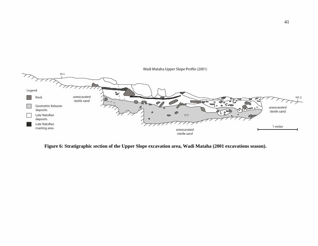
41
Figure 6: Stratigraphic section of the Upper Slope excavation area, Wadi Mataha (2001 excavations season).
42
3.1.2 Geometric Kebaran Occupation
The Geometric Kebaran deposits at Wadi Mataha are located in the upper slope area of the site,
beneath the Late Natufian occupation. The Geometric Kebaran deposits contain lithics and well
preserved faunal material. The faunal remains recovered from the Geometric Kebaran deposits
indicate that the inhabitants of the site hunted a wide range of fauna, including medium and
small mammals, reptiles, and birds (Baadsgaard, et al., 2002). The assemblage is particularly rich
in gazelles and caprines, both of which would have been locally available. The small animal
assemblage is dominated by tortoises, followed by birds in lower numbers (Baadsgaard, et al.,
2002). Botanical remains show evidence for Cerealia sp. pollen, suggesting that cereal crops
were present in the local environment (Baadsgaard, et al., 2010). It is unknown if these cereals
were exploited for food during the Geometric Kebaran occupation of the site.
The most remarkable find from the Geometric Kebaran deposits is a complete human burial. The
adult male skeleton (F81) was found in association with a fragmentary juvenile skeleton. The
adult was lying face-down in the burial pit, with the hands and feet positioned behind the back,
presumably bound together (Stock, et al., 2005). This unusual placement of the body suggests
that there may have been a negative association with this individual during his lifetime. The
skeleton itself has bilateral asymmetry in the upper limbs, which were also very strong and
robust. There is no evidence of pathology, leading the authors to suggest that the asymmetry is
the result of hunting-gathering behaviours. The lower limb robusticity corresponds with high
terrestrial mobility, indicating the individual spent time walking the landscape (Stock, et al.,
2005). This burial is associated with several grave offerings including a breached ground stone
bowl and a large flint blade.
A single chert nodule recovered from the Geometric Kebaran deposits displayed a unique
anthropogenic shape (Gregg, et al., 2011). This nodule was analyzed using scanning electron
microscopy to identify microscopic manufacturing traces. Microscopic analysis revealed
incisions and evidence of intentional smoothing of the surface. These manufacturing traces were
in areas where the object was thinned or shaped, suggesting that the nodule was worked to
accentuate the 'human' form of a natural formation. In addition, striations along the back of the
'head' were interpreted to represent hair (Gregg, et al., 2011). These types of objects are rare
from the Geometric Kebaran, although not completely absent from the archaeological record.
43
3.1.3 Natufian Occupations
In addition to the Geometric Kebaran deposits, there are extensive Early and Late Natufian
occupations at Wadi Mataha. The Early Natufian occupations are located on the lower and
middle slope and contain two structures, interpreted to be terrace walls with artifact-dense fill.
There is evidence that the wall underwent several phases of maintenance and repair (Janetski and
Chazan, 2004). A carved stone bowl and a decorated basalt shaft-straightener were found in the
floor deposits adjacent to the walls. Several modified pebbles and an incised chert nodule were
recovered from the Natufian deposits at the site. Several of these pieces have incised line patterns
and designs across the object, while one is interpreted to be a schematic representation of a
figure with up-stretched arms. One of these structures also has evidence for an activity area in
front of the wall containing roasting pits.
The Late Natufian occupations contain a roasting area and a rich, dark midden. Additional
features include five bedrock mortars and three cup mortars at the northeastern edge of the site,
adjacent to the Late Natufian occupation area. Due to the difficultly in dating these features, it is
not known when they were manufactured or whether they were used during any single
occupation phase at the site. However, grooves on the deepest mortars match grooved pestles
recovered from the Late Natufian deposits, making it likely that they were used during this
period (Janetski and Chazan, 2004). Botanical data and starch grain analysis recovered starches
from several Late Natufian pestles suggesting that inhabitants of the site were exploiting cereals
at during the Late Natufian (Baadsgaard, et al., 2010).
3.1.4 Wadi Mataha Summary
In summary, of the Epipalaeolithic occupations at Wadi Mataha, the Geometric Kebaran one was
not extensive and likely represents a small habitation site. Despite the small occupation, these
deposits contain several features that are rare for Geometric Kebaran occupations, including a
bound human burial and an incised chert nodule. The Early Natufian deposits have evidence for
terrace walls and stone structures, while the Late Natufian occupations have evidence for
middens, roasting areas, and cereal exploitation.
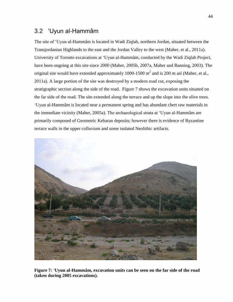
44
3.2 ‘Uyun al-Hammâm
The site of ‘Uyun al-Hammâm is located in Wadi Ziqlab, northern Jordan, situated between the
Transjordanian Highlands to the east and the Jordan Valley to the west (Maher, et al., 2011a).
University of Toronto excavations at ‘Uyun al-Hammâm, conducted by the Wadi Ziqlab Project,
have been ongoing at this site since 2000 (Maher, 2005b, 2007a, Maher and Banning, 2003). The
original site would have extended approximately 1000-1500 m2 and is 200 m asl (Maher, et al.,
2011a). A large portion of the site was destroyed by a modern road cut, exposing the
stratigraphic section along the side of the road. Figure 7 shows the excavation units situated on
the far side of the road. The site extended along the terrace and up the slope into the olive trees.
‘Uyun al-Hammâm is located near a permanent spring and has abundant chert raw materials in
the immediate vicinity (Maher, 2005a). The archaeological strata at ‘Uyun al-Hammâm are
primarily composed of Geometric Kebaran deposits; however there is evidence of Byzantine
terrace walls in the upper colluvium and some isolated Neolithic artifacts.
Figure 7: 'Uyun al-Hammâm, excavation units can be seen on the far side of the road
(taken during 2005 excavations).
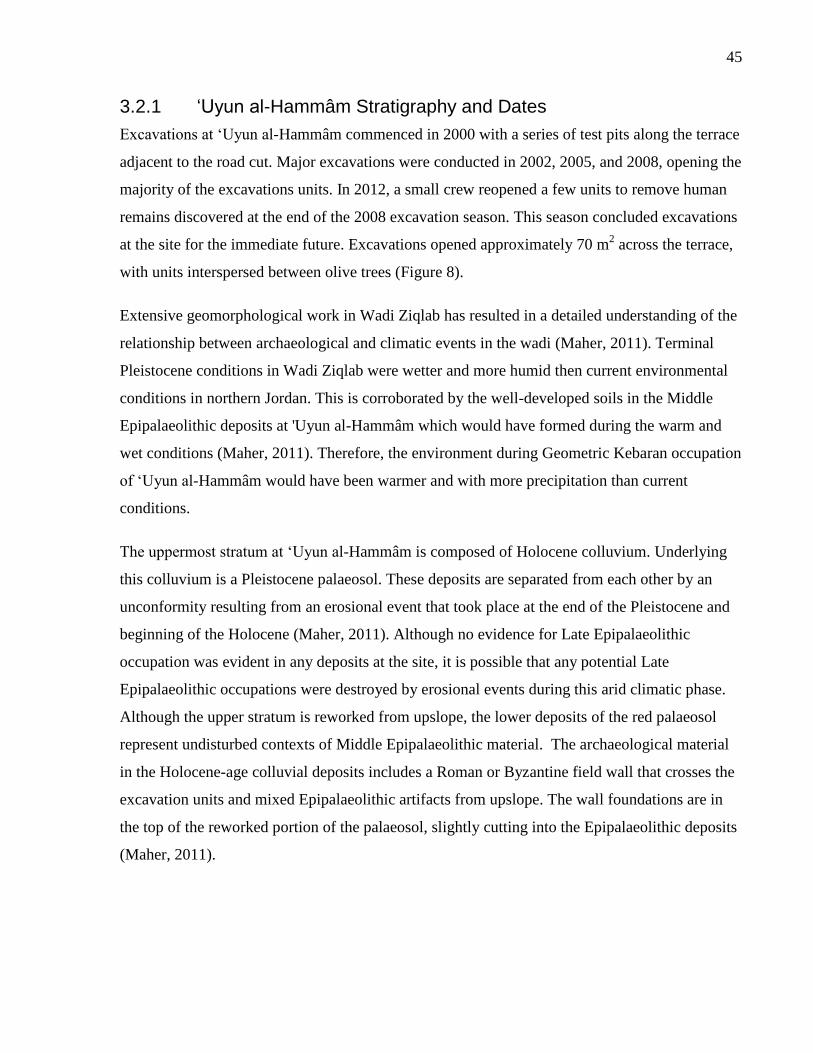
45
3.2.1 ‘Uyun al-Hammâm Stratigraphy and Dates
Excavations at ‘Uyun al-Hammâm commenced in 2000 with a series of test pits along the terrace
adjacent to the road cut. Major excavations were conducted in 2002, 2005, and 2008, opening the
majority of the excavations units. In 2012, a small crew reopened a few units to remove human
remains discovered at the end of the 2008 excavation season. This season concluded excavations
at the site for the immediate future. Excavations opened approximately 70 m2 across the terrace,
with units interspersed between olive trees (Figure 8).
Extensive geomorphological work in Wadi Ziqlab has resulted in a detailed understanding of the
relationship between archaeological and climatic events in the wadi (Maher, 2011). Terminal
Pleistocene conditions in Wadi Ziqlab were wetter and more humid then current environmental
conditions in northern Jordan. This is corroborated by the well-developed soils in the Middle
Epipalaeolithic deposits at 'Uyun al-Hammâm which would have formed during the warm and
wet conditions (Maher, 2011). Therefore, the environment during Geometric Kebaran occupation
of ‘Uyun al-Hammâm would have been warmer and with more precipitation than current
conditions.
The uppermost stratum at ‘Uyun al-Hammâm is composed of Holocene colluvium. Underlying
this colluvium is a Pleistocene palaeosol. These deposits are separated from each other by an
unconformity resulting from an erosional event that took place at the end of the Pleistocene and
beginning of the Holocene (Maher, 2011). Although no evidence for Late Epipalaeolithic
occupation was evident in any deposits at the site, it is possible that any potential Late
Epipalaeolithic occupations were destroyed by erosional events during this arid climatic phase.
Although the upper stratum is reworked from upslope, the lower deposits of the red palaeosol
represent undisturbed contexts of Middle Epipalaeolithic material. The archaeological material
in the Holocene-age colluvial deposits includes a Roman or Byzantine field wall that crosses the
excavation units and mixed Epipalaeolithic artifacts from upslope. The wall foundations are in
the top of the reworked portion of the palaeosol, slightly cutting into the Epipalaeolithic deposits
(Maher, 2011).
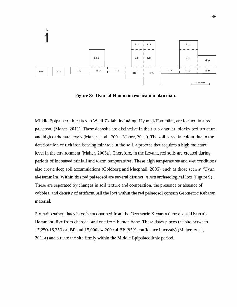
46
Figure 8: 'Uyun al-Hammâm excavation plan map.
Middle Epipalaeolithic sites in Wadi Ziqlab, including ‘Uyun al-Hammâm, are located in a red
palaeosol (Maher, 2011). These deposits are distinctive in their sub-angular, blocky ped structure
and high carbonate levels (Maher, et al., 2001, Maher, 2011). The soil is red in colour due to the
deterioration of rich iron-bearing minerals in the soil, a process that requires a high moisture
level in the environment (Maher, 2005a). Therefore, in the Levant, red soils are created during
periods of increased rainfall and warm temperatures. These high temperatures and wet conditions
also create deep soil accumulations (Goldberg and Macphail, 2006), such as those seen at ‘Uyun
al-Hammâm. Within this red palaeosol are several distinct in situ archaeological loci (Figure 9).
These are separated by changes in soil texture and compaction, the presence or absence of
cobbles, and density of artifacts. All the loci within the red palaeosol contain Geometric Kebaran
material.
Six radiocarbon dates have been obtained from the Geometric Kebaran deposits at ‘Uyun al-
Hammâm, five from charcoal and one from human bone. These dates places the site between
17,250-16,350 cal BP and 15,000-14,200 cal BP (95% confidence intervals) (Maher, et al.,
2011a) and situate the site firmly within the Middle Epipalaeolithic period.
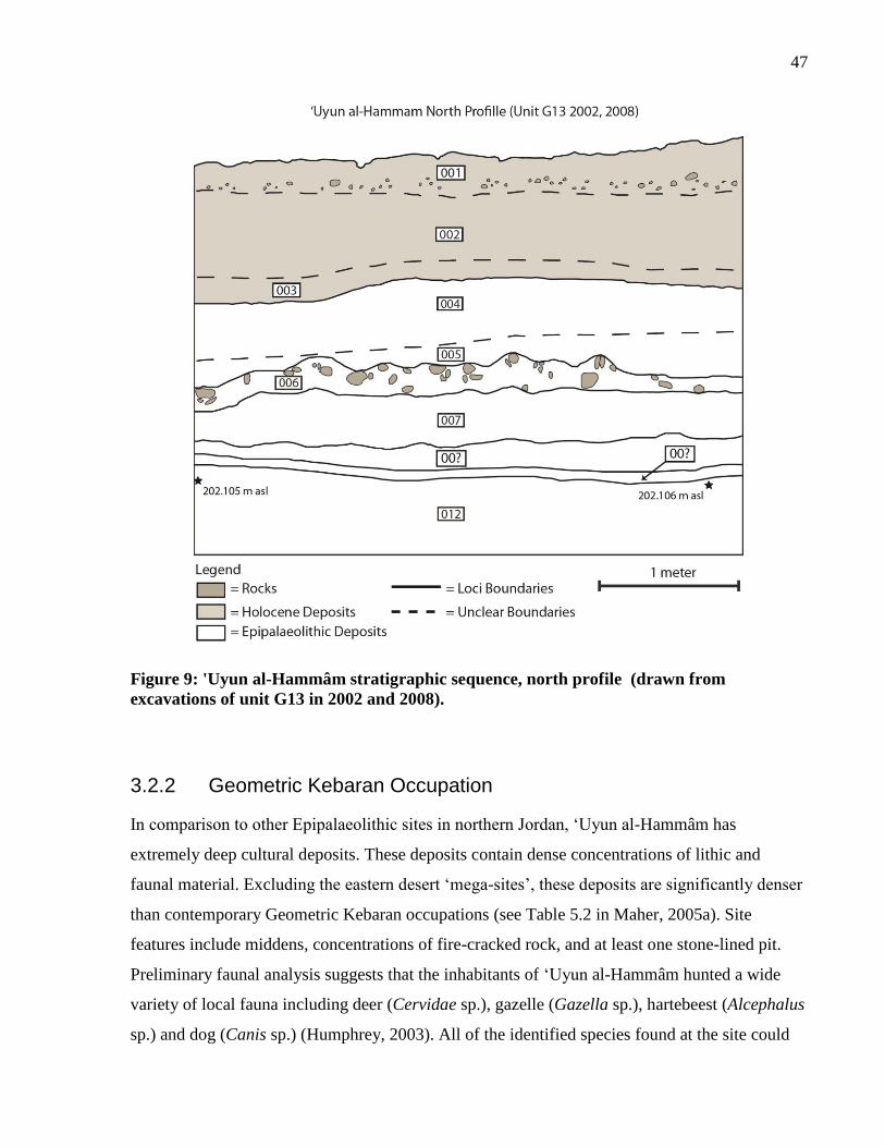
47
Figure 9: 'Uyun al-Hammâm stratigraphic sequence, north profile (drawn from
excavations of unit G13 in 2002 and 2008).
3.2.2 Geometric Kebaran Occupation
In comparison to other Epipalaeolithic sites in northern Jordan, ‘Uyun al-Hammâm has
extremely deep cultural deposits. These deposits contain dense concentrations of lithic and
faunal material. Excluding the eastern desert ‘mega-sites’, these deposits are significantly denser
than contemporary Geometric Kebaran occupations (see Table 5.2 in Maher, 2005a). Site
features include middens, concentrations of fire-cracked rock, and at least one stone-lined pit.
Preliminary faunal analysis suggests that the inhabitants of ‘Uyun al-Hammâm hunted a wide
variety of local fauna including deer (Cervidae sp.), gazelle (Gazella sp.), hartebeest (Alcephalus
sp.) and dog (Canis sp.) (Humphrey, 2003). All of the identified species found at the site could
48
have been hunted in the surrounding forest-steppe (Maher and Banning, 2003). The faunal
remains include items of both high and low utility, suggesting that complete carcasses were
brought to the site for butchering (Humphrey, 2003). Detailed faunal analysis currently being
conducted for the recent excavation material will provide further insight into the subsistence
practices of the people from ‘Uyun al-Hammâm.
The retouched lithic assemblage is composed of classic Middle Epipalaeolithic tools, including
trapeze-rectangle microliths and endscrapers on blades (Maher, 2005a). The complete lithic
assemblage has been analyzed and the results are summarized in Chapter 3. Attribute analysis of
the debitage suggests that the entire flintknapping sequence was undertaken at the site, with
evidence for core preparation, maintenance, and discard (Macdonald, 2007).
The site has been interpreted as a cemetery because of the large number of human interments.
During the course of excavations, eleven individuals were uncovered (Maher, et al., 2011a).
These were buried in a variety of positions, including extended, flexed, multiple burials, and
secondary contexts. This number of Middle Epipalaeolithic burials has not been found on any
other sites from this period, making the burials at ‘Uyun al-Hammâm unique for the Geometric
Kebaran (Maher, 2006). Osteological analysis indicates that none of the human remains show
evidence of interpersonal violence (Maher, et al., 2011a), suggesting it is unlikely that the
associated burials are the result of a catastrophic violent event, but rather that the site was re-
used several times for human burial.
Burial pits are not obvious in the compact sediment, so it is difficult to associate artifacts with
individuals. As a result, only items in direct association were considered as grave goods,
potentially underestimating the objects offered with the burials (Maher, et al., 2011a). Despite
this, there is a wealth of artifacts and faunal remains interred with the individuals at ‘Uyun al-
Hammâm. Artifacts include worked bone, chipped and ground stone, unmodified cobbles, and
ochre. Animal remains include articulated tortoises, aurochsen, gazelle, deer, and fox elements.
The most remarkable find was an articulated post-cranial fox skeleton buried with one individual
and a fox skull with a right humerus buried with another, adjacent individual (Maher, et al.,
2011a). The proximity of these two fox burials and similar metrics make it likely that these fox
elements belong to the same fox individual. This unique treatment of the fox in association with
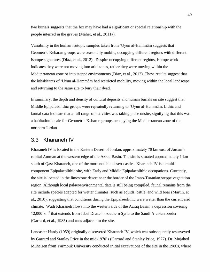
49
two burials suggests that the fox may have had a significant or special relationship with the
people interred in the graves (Maher, et al., 2011a).
Variability in the human isotopic samples taken from ‘Uyun al-Hammâm suggests that
Geometric Kebaran groups were seasonally mobile, occupying different regions with different
isotope signatures (Diaz, et al., 2012). Despite occupying different regions, isotope work
indicates they were not moving into arid zones, rather they were moving within the
Mediterranean zone or into steppe environments (Diaz, et al., 2012). These results suggest that
the inhabitants of ‘Uyun al-Hammâm had restricted mobility, moving within the local landscape
and returning to the same site to bury their dead.
In summary, the depth and density of cultural deposits and human burials on site suggest that
Middle Epipalaeolithic groups were repeatedly returning to ‘Uyun al-Hammâm. Lithic and
faunal data indicate that a full range of activities was taking place onsite, signifying that this was
a habitation locale for Geometric Kebaran groups occupying the Mediterranean zone of the
northern Jordan.
3.3 Kharaneh IV
Kharaneh IV is located in the Eastern Desert of Jordan, approximately 70 km east of Jordan’s
capital Amman at the western edge of the Azraq Basin. The site is situated approximately 1 km
south of Qasr Kharaneh, one of the more notable desert castles. Kharaneh IV is a multi-
component Epipalaeolithic site, with Early and Middle Epipalaeolithic occupations. Currently,
the site is located in the limestone desert near the border of the Irano-Turanian steppe vegetation
region. Although local palaeoenvironmental data is still being compiled, faunal remains from the
site include species adapted for wetter climates, such as equids, cattle, and wild boar (Martin, et
al., 2010), suggesting that conditions during the Epipalaeolithic were wetter than the current arid
climate. Wadi Kharaneh flows into the western side of the Azraq Basin, a depression covering
12,000 km2 that extends from Jebel Druze in southern Syria to the Saudi Arabian border
(Garrard, et al., 1985) and runs adjacent to the site.
Lancaster Hardy (1959) originally discovered Kharaneh IV, which was subsequently resurveyed
by Garrard and Stanley Price in the mid-1970’s (Garrard and Stanley Price, 1977). Dr. Mujahed
Muheisen from Yarmouk University conducted initial excavations of the site in the 1980s, where
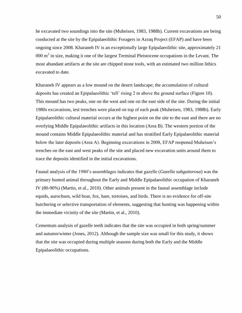
50
he excavated two soundings into the site (Muheisen, 1983, 1988b). Current excavations are being
conducted at the site by the Epipalaeolithic Foragers in Azraq Project (EFAP) and have been
ongoing since 2008. Kharaneh IV is an exceptionally large Epipalaeolithic site, approximately 21
000 m2 in size, making it one of the largest Terminal Pleistocene occupations in the Levant. The
most abundant artifacts at the site are chipped stone tools, with an estimated two million lithics
excavated to date.
Kharaneh IV appears as a low mound on the desert landscape; the accumulation of cultural
deposits has created an Epipalaeolithic ‘tell’ rising 2 m above the ground surface (Figure 10).
This mound has two peaks, one on the west and one on the east side of the site. During the initial
1980s excavations, test trenches were placed on top of each peak (Muheisen, 1983, 1988b). Early
Epipalaeolithic cultural material occurs at the highest point on the site to the east and there are no
overlying Middle Epipalaeolithic artifacts in this location (Area B). The western portion of the
mound contains Middle Epipalaeolithic material and has stratified Early Epipalaeolithic material
below the later deposits (Area A). Beginning excavations in 2008, EFAP reopened Muheisen’s
trenches on the east and west peaks of the site and placed new excavation units around them to
trace the deposits identified in the initial excavations.
Faunal analysis of the 1980’s assemblages indicates that gazelle (Gazella subguttorosa) was the
primary hunted animal throughout the Early and Middle Epipalaeolithic occupation of Kharaneh
IV (80-90%) (Martin, et al., 2010). Other animals present in the faunal assemblage include
equids, aurochsen, wild boar, fox, hare, tortoises, and birds. There is no evidence for off-site
butchering or selective transportation of elements, suggesting that hunting was happening within
the immediate vicinity of the site (Martin, et al., 2010).
Cementum analysis of gazelle teeth indicates that the site was occupied in both spring/summer
and autumn/winter (Jones, 2012). Although the sample size was small for this study, it shows
that the site was occupied during multiple seasons during both the Early and the Middle
Epipalaeolithic occupations.
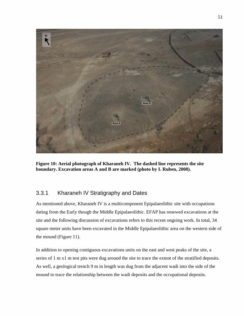
51
Figure 10: Aerial photograph of Kharaneh IV. The dashed line represents the site
boundary. Excavation areas A and B are marked (photo by I. Ruben, 2008).
3.3.1 Kharaneh IV Stratigraphy and Dates
As mentioned above, Kharaneh IV is a multicomponent Epipalaeolithic site with occupations
dating from the Early though the Middle Epipalaeolithic. EFAP has renewed excavations at the
site and the following discussion of excavations refers to this recent ongoing work. In total, 34
square meter units have been excavated in the Middle Epipalaeolithic area on the western side of
the mound (Figure 11).
In addition to opening contiguous excavations units on the east and west peaks of the site, a
series of 1 m x1 m test pits were dug around the site to trace the extent of the stratified deposits.
As well, a geological trench 9 m in length was dug from the adjacent wadi into the side of the
mound to trace the relationship between the wadi deposits and the occupational deposits.
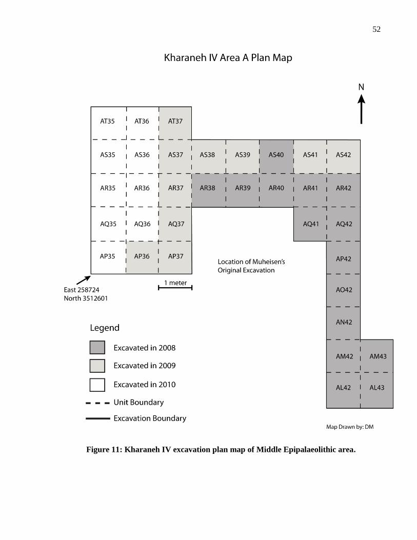
52
Figure 11: Kharaneh IV excavation plan map of Middle Epipalaeolithic area.
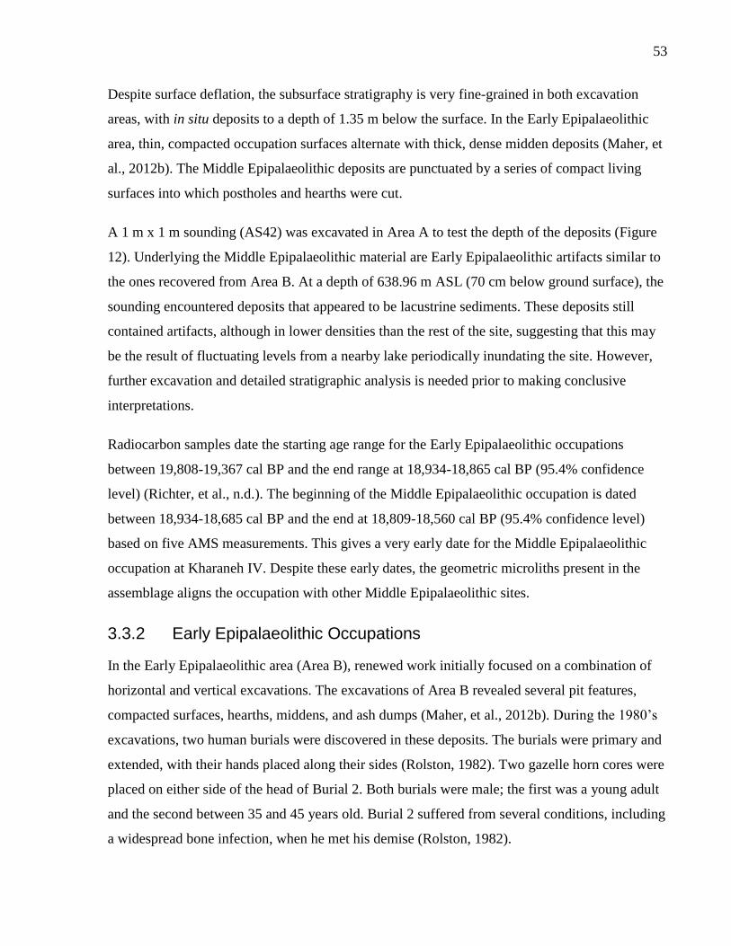
53
Despite surface deflation, the subsurface stratigraphy is very fine-grained in both excavation
areas, with in situ deposits to a depth of 1.35 m below the surface. In the Early Epipalaeolithic
area, thin, compacted occupation surfaces alternate with thick, dense midden deposits (Maher, et
al., 2012b). The Middle Epipalaeolithic deposits are punctuated by a series of compact living
surfaces into which postholes and hearths were cut.
A 1 m x 1 m sounding (AS42) was excavated in Area A to test the depth of the deposits (Figure
12). Underlying the Middle Epipalaeolithic material are Early Epipalaeolithic artifacts similar to
the ones recovered from Area B. At a depth of 638.96 m ASL (70 cm below ground surface), the
sounding encountered deposits that appeared to be lacustrine sediments. These deposits still
contained artifacts, although in lower densities than the rest of the site, suggesting that this may
be the result of fluctuating levels from a nearby lake periodically inundating the site. However,
further excavation and detailed stratigraphic analysis is needed prior to making conclusive
interpretations.
Radiocarbon samples date the starting age range for the Early Epipalaeolithic occupations
between 19,808-19,367 cal BP and the end range at 18,934-18,865 cal BP (95.4% confidence
level) (Richter, et al., n.d.). The beginning of the Middle Epipalaeolithic occupation is dated
between 18,934-18,685 cal BP and the end at 18,809-18,560 cal BP (95.4% confidence level)
based on five AMS measurements. This gives a very early date for the Middle Epipalaeolithic
occupation at Kharaneh IV. Despite these early dates, the geometric microliths present in the
assemblage aligns the occupation with other Middle Epipalaeolithic sites.
3.3.2 Early Epipalaeolithic Occupations
In the Early Epipalaeolithic area (Area B), renewed work initially focused on a combination of
horizontal and vertical excavations. The excavations of Area B revealed several pit features,
compacted surfaces, hearths, middens, and ash dumps (Maher, et al., 2012b). During the 1980’s
excavations, two human burials were discovered in these deposits. The burials were primary and
extended, with their hands placed along their sides (Rolston, 1982). Two gazelle horn cores were
placed on either side of the head of Burial 2. Both burials were male; the first was a young adult
and the second between 35 and 45 years old. Burial 2 suffered from several conditions, including
a widespread bone infection, when he met his demise (Rolston, 1982).
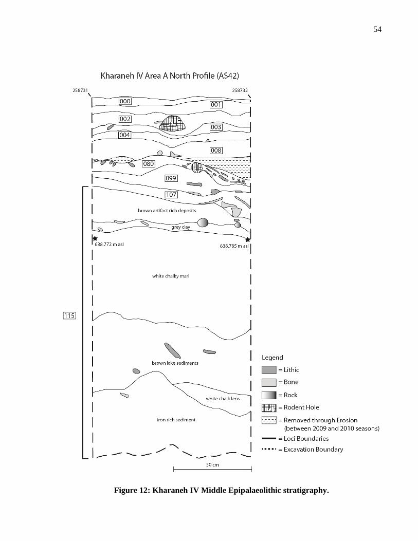
54
Figure 12: Kharaneh IV Middle Epipalaeolithic stratigraphy.
55
Preliminary lithic analysis from these deposits shows that 84% of the overall retouched
assemblage is composed of microliths, and >50% can be confidently identified as non-geometric
microliths (Maher and Macdonald, n.d.). These microliths are primarily gracile oblique-truncated
and backed bladelets, and micropoints. The lithic reduction strategy seems to be focused on
using narrow chert nodules for the production of gracile blanks to be retouched into microliths.
Energy was loaded towards the beginning of the sequence with a lot of investment in core
shaping instead of core maintenance. Faunal analysis is still ongoing but field observations
suggest that gazelle was the primary prey during the Early Epipalaeolithic.
During the 2010 excavations, evidence for one, possibly two, hut structures was uncovered
(Maher, et al., 2012b). Radiocarbon dates from above and below the floor of hut 1 place the date
between 19,400 and 18,800 cal BP. The structure is just over 2 m x 3 m in size and is covered by
an organic-rich, black layer containing abundant charcoal fragments. This suggests that the huts
were burned after abandonment. Situated beneath the burned layer, but on top of the hut floor,
are groundstone fragments, red ochre, and articulated aurochs vertebrae. Near the center of the
structure are three distinct concentrations of pierced marine shells accompanied by large chunks
of red ochre. These concentrations contain over 1,000 shells from both the Mediterranean and
Red Seas, imported from up to 270 km away (Maher, et al., 2012b).
3.3.3 Middle Epipalaeolithic Occupations
Muheisen’s original excavations in the Middle Epipalaeolithic component of the site unearthed a
variety of archaeological features including what he identified as occupation surfaces, hearths,
and post-holes (Muheisen, 1983, 1988a). He identified five hearths on a compact living floor
surrounded by a series of small post-holes 10-28 cm in diameter. Muheisen interpreted these as
representing a possible hut feature enclosing the hearths. In 2008, a series of excavation units
were placed around Muheisen’s previous excavation unit to trace the extent of these features.
Muheisen originally labeled this area as ‘Phase D’, but has since been relabeled ‘Area A’ for the
new excavations. Initial analysis of the lithic assemblage indicated that, although there are
classic trapeze-rectangles, the assemblage also contains asymmetrical trapezoids, lunates,
triangles, and a variety of other geometric forms (Muheisen and Wada, 1995). These microlith
types will be further explored in Chapter 3.
56
The three new excavation seasons at Kharaneh IV (2008, 2009, and 2010) identified a number of
features similar to those recorded by Muheisen. These features included the three compact
surfaces, three hearth deposits, and a series of dark brown sediment deposits interpreted as post-
holes. Artifacts chosen for analysis for this dissertation are from the in situ compact surfaces.
During the 2009 field season, two overlapping hearth deposits were excavated, surrounded by a
number of dark brown sediment stains. These deposits were interpreted as post-holes on the basis
of their shape and composition. The goal of the 2010 season was to expand the excavation areas
to the west and the north of the previous excavations to understand the relationship between the
hearths and compact surfaces, to the expose the remainder of the hearth deposits, and to find the
compact surfaces’ boundaries.
During the 2010 season, an additional 12 m2 to the north and west of the previous excavations
were exposed. The stratigraphy of these areas was similar to that of the previous seasons, with a
series of overlying compact surfaces, some covered with loose fill deposits. The remainders of
the overlapping hearths left in situ from 2009 were exposed and new postholes were identified
around the northeast side of the hearths.
The results of the 2010 excavation season further corroborated the results from previous seasons.
The Middle Epipalaeolithic deposits contain a series of compact occupation surfaces on which
people had discarded lithics and remains of hunted animals. Cut into these surfaces are several
hearths. The two overlapping hearths show evidence of an ephemeral structure placed over the
fireplace, perhaps as a cooking structure or as a drying or smoking rack. Future excavations at
the site will continue to expose the horizontal extent of the Middle Epipalaeolithic deposits at
Kharaneh IV to identify potential structural features like the ones found in the Early
Epipalaeolithic deposits.
Artifacts recovered during the 2008-2010 excavation seasons include a wealth of lithic and
faunal material. In addition, worked bone is abundant, with notched mandibles and long bones,
bone points, and awls. A wide range of shell ornaments has been recovered from both the Early
and Middle Epipalaeolithic deposits, with increasing frequency during the Middle
Epipalaeolithic (Richter, et al., 2011). In total, 15 different species occur in the assemblage. Most
common are dentalium shell beads, native to the Mediterranean and Red Seas. Other common
species include Nerita sanguinolenta from the Red Sea and Mitrella scripta from the
57
Mediterranean Sea. Euplica turturina from the Indo-Pacific is present in low frequencies. The
presence of shells from the Mediterranean Sea, Red Sea, and possibly as far as the Indian Ocean,
suggests that the people of Kharaneh IV had extensive trade networks that stretched at least 290
km (Richter, et al., 2011).
3.4 Summary
The Epipalaeolithic was a diverse period and archaeologists have identified a range of different
cultural groups identified by their material culture. The Middle Epipalaeolithic sites of Wadi
Mataha, ‘Uyun al-Hammâm, and Kharaneh IV represent three diverse Middle Epipalaeolithic
occupations. Wadi Mataha (ca. 14,100 ±130 BP) is a small Geometric Kebaran occupation, but
the presence of a bound human burial suggests that some non-subsistence activities took place at
the site. ‘Uyun al-Hammâm (17,250-16,350 cal BP and 15,000-14,200 cal BP) has the largest
number of human burials for any Geometric Kebaran occupation. The depth and density of
cultural deposits suggests that the inhabitants of the site were continuously returning to the same
locale, often to bury their dead. Finally, Kharaneh IV (18,800 to 18,600 cal. BP) is the largest
recorded Epipalaeolithic site at 21 000 m2. Excellent preservation at the site allows the recovery
of hearths and post-holes from the Middle Epipalaeolithic deposits, features not found at the
other two sites. The current marginal location of Kharaneh IV, the reason behind the large size,
and the early dates leaves many questions open to pursue in the future.
Although the other site features are diverse, the lithic assemblages from these three Middle
Epipalaeolithic sites contain trapeze-rectangle microliths, the hallmark of the Geometric Kebaran
period. Comparison of these three assemblages will illuminate how people during the
Epipalaeolithic conceptualized, manufactured, and used their tools.
58
Chapter 4 Typology and Technology of Microliths
Introduction 4
Epipalaeolithic chipped-stone assemblages are characterized by high frequencies of microliths,
with different microlith types acting as fossile directeurs for each Epipalaeolithic phase (Bar-
Yosef, 1970, Goring-Morris, 1987, Henry, 1998, Tixier, 1963). As mentioned in previous
chapters, variability in microlith morphology has been used to identify regionally and
chronologically distinct groups across the Levant. Chronologically, microliths move from non-
geometric forms in the earlier Epipalaeolithic towards geometric forms in the middle and later
periods. For this analysis, I employed typologies developed by Bar-Yosef (1970) and Goring-
Morris (1987) that are applicable to sites across the Mediterranean and arid zones of the
Southern Levant.
This chapter will describe the Middle Epipalaeolithic lithic assemblages from Wadi Mataha,
‘Uyun al-Hammâm, and Kharaneh IV, focusing on the microlith components of the assemblages.
To place the microliths in context, the lithic assemblage for each site will be discussed, including
the cores, debitage, and retouched (macrolithic) tools. Following this, the microliths will be
presented, emphasizing typological and technological features, including overall morphology,
retouch type, and retouch direction. Finally, I will compare the microliths and overall lithic
assemblages of the three sites, highlighting differences and similarities among the assemblages.
4.1 Methods
The lithic assemblages were divided into categories of microliths, debitage1, retouched pieces
(macrolithic), cores, and core-trimming elements (CTEs) for each site. In addition to the analysis
of each artifact category, raw material was assessed where possible. Each category was analyzed
separately according to criteria developed for those artifacts types, outlined below.
1 Defined here as the unretouched products of flintknapping including flakes, blades, chips, and shatter
59
4.1.1 Raw Material Analysis
Raw material analysis was undertaken, where possible, focusing on the microlith category rather
than the entire lithic assemblage. For Wadi Mataha and ‘Uyun al-Hammâm, the raw material was
also analyzed for the debitage and tool assemblages. Unfortunately, raw material analysis has not
been completed for the Kharaneh IV macrolithic tools or debitage. Therefore, only the raw
material characteristics for the Kharaneh IV microliths will be presented.
For the raw material analysis, quality and colour were recorded for each artifact. Raw material
quality was assessed visually, with ordinal categories of very fine, fine, coarse, very coarse, and
indeterminate quality. Colour was similarly evaluated with descriptive classes indicating the
overall colour of the artifact. These colour categories were developed for each site
independently, therefore, a ‘light-brown’ material from one site is not the same material as a
‘light brown’ material from another site. The colour classifications are used for only intra-site
analysis; however, interesting observations about the range of material types can be made
through comparing raw material choice among sites. Artifacts that were completely patinated,
burned, or otherwise modified, obscuring the raw material, were categorized as ‘indeterminate’.
Although general interpretation from the raw material analysis will be discussed, the results are
presented in Appendix B since this analysis was not undertaken as a primary focus of this
research. A complete list of the raw material quality and colours can be found in Appendix A,
Table 55.
4.1.2 Analysis of Reduction Strategy
Detailed debitage attribute analysis was conducted for the Wadi Mataha and ‘Uyun al-Hammâm
lithic assemblages. However, due to the large size of the assemblage (> 2 million excavated
lithics) only preliminary debitage typological analysis has been completed for Kharaneh IV. The
debitage analysis for Kharaneh IV focused on identifying debitage types, modified from the type
list developed for the analysis of blade reduction of Levantine Neolithic naviform cores (Wilke
and Quintero, 1994) (Appendix A, Table 56). Kharaneh IV cores and core-trimming elements
were also classified into typological groups. Future attribute analysis on the Kharaneh IV
assemblage is pending.
60
For Wadi Mataha and ‘Uyun al-Hammâm, debitage was divided into groups of flakes, blades,
shatter, and chips (pieces <1cm). For the purposes of this analysis, blades are defined as detached
pieces, twice as long as they are wide, with parallel margins. As well, there is no distinction
between blades and bladelets in the debitage assemblage, emphasising the continuity in size
between smaller and larger blades. The flake and blade categories were further subdivided into
complete, proximal, and medial/distal fragments. For each piece, termination type and platform
attributes were recorded where possible. Raw material, post-depositional processes, and evidence
of burning were also documented for each piece. For the complete list of attributes recorded for
each site see Appendix A, Table 57.
Cores were classified on the basis of their morphology and the targeted removals (e.g., blade,
bladelet, and flake). Metrics taken on each core included the maximum length and width, the
core platform dimensions, maximum facet dimensions, and probable reason for core
abandonment. A complete list of core types and attributes is provided in Appendix A, Table 58.
Core-trimming elements (CTEs) were divided into two separate categories: core-preparation and
core-maintenance elements. Core-preparation elements are removed during the initial shaping to
prepare the core for subsequent removals. These lithics include crested blades and initial
platform spalls. In contrast, core-maintenance elements are removed during reduction to
maintain the core shape. These elements manipulate the platform or correct issues on the core
face so that removals can continue. Platform-maintenance elements include angle-correction
elements and core tablets. Elements specifically targeting issues on the core face include core
face rejuvenation elements and partially crested blades. In addition to typological classification,
metrics were recorded for each CTE, including the maximum length, width, and thickness of
each piece (Appendix A, Table 59).
4.1.3 Retouched Tool Analysis
Non-microlithic retouched tools (macrolithic) were classified according to Epipalaeolithic
typologies developed by Bar-Yosef (1970) and Goring-Morris (1987) for the Southern Levant
that are widely used typologies for this period. The former typology focusses more generally on
Epipalaeolithic assemblages from Israel/Palestine, while the latter was developed specifically for
sites in the Negev and Sinai. For the retouched tools, metrics were taking on each piece,
including the maximum length, width and thickness. Raw material quality and colour was
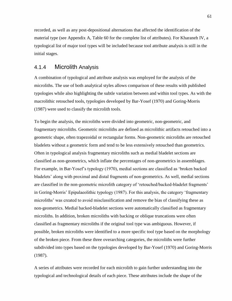
61
recorded, as well as any post-depositional alternations that affected the identification of the
material type (see Appendix A, Table 60 for the complete list of attributes). For Kharaneh IV, a
typological list of major tool types will be included because tool attribute analysis is still in the
initial stages.
4.1.4 Microlith Analysis
A combination of typological and attribute analysis was employed for the analysis of the
microliths. The use of both analytical styles allows comparison of these results with published
typologies while also highlighting the subtle variation between and within tool types. As with the
macrolithic retouched tools, typologies developed by Bar-Yosef (1970) and Goring-Morris
(1987) were used to classify the microlith tools.
To begin the analysis, the microliths were divided into geometric, non-geometric, and
fragmentary microliths. Geometric microliths are defined as microlithic artifacts retouched into a
geometric shape, often trapezoidal or rectangular forms. Non-geometric microliths are retouched
bladelets without a geometric form and tend to be less extensively retouched than geometrics.
Often in typological analysis fragmentary microliths such as medial bladelet sections are
classified as non-geometrics, which inflate the percentages of non-geometrics in assemblages.
For example, in Bar-Yosef’s typology (1970), medial sections are classified as ‘broken backed
bladelets’ along with proximal and distal fragments of non-geometrics. As well, medial sections
are classified in the non-geometric microlith category of ‘retouched/backed-bladelet fragments’
in Goring-Morris’ Epipalaeolithic typology (1987). For this analysis, the category ‘fragmentary
microliths’ was created to avoid misclassification and remove the bias of classifying these as
non-geometrics. Medial backed-bladelet sections were automatically classified as fragmentary
microliths. In addition, broken microliths with backing or oblique truncations were often
classified as fragmentary microliths if the original tool type was ambiguous. However, if
possible, broken microliths were identified to a more specific tool type based on the morphology
of the broken piece. From these three overarching categories, the microliths were further
subdivided into types based on the typologies developed by Bar-Yosef (1970) and Goring-Morris
(1987).
A series of attributes were recorded for each microlith to gain further understanding into the
typological and technological details of each piece. These attributes include the shape of the
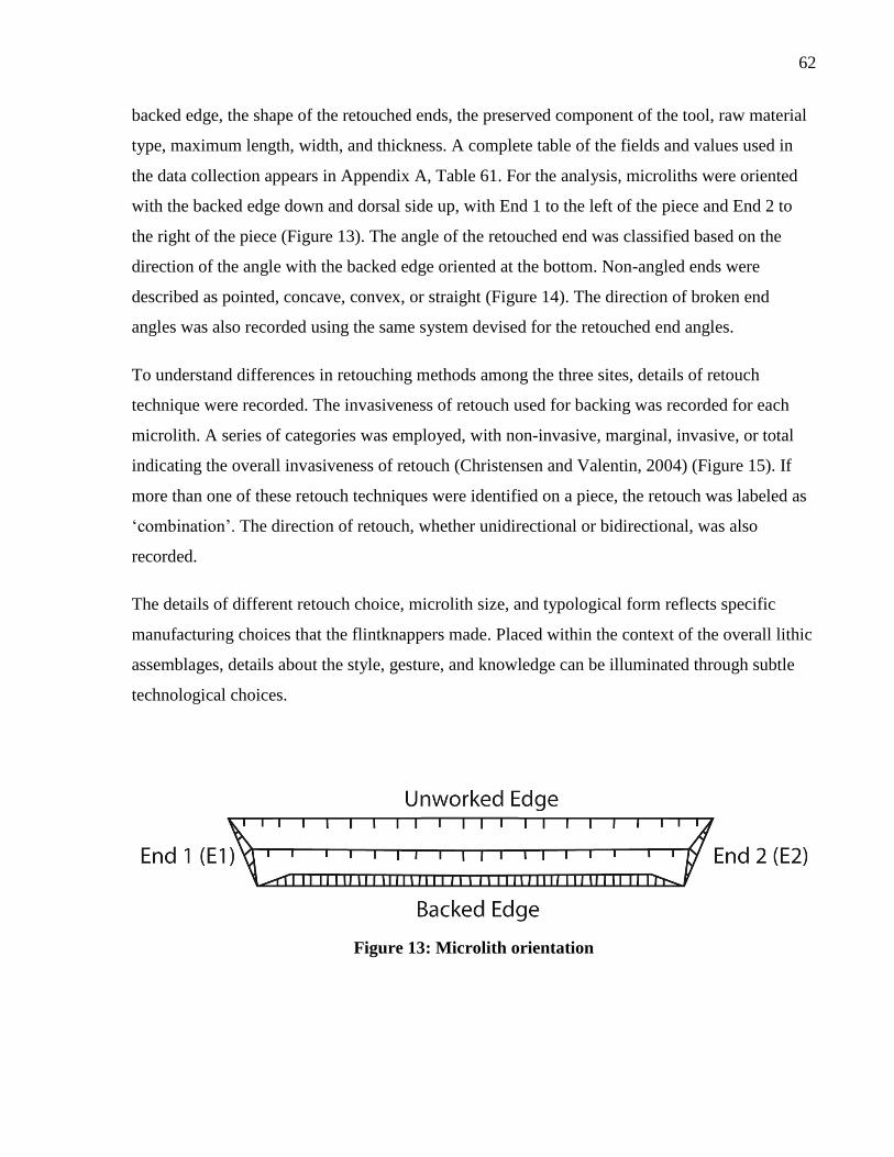
62
backed edge, the shape of the retouched ends, the preserved component of the tool, raw material
type, maximum length, width, and thickness. A complete table of the fields and values used in
the data collection appears in Appendix A, Table 61. For the analysis, microliths were oriented
with the backed edge down and dorsal side up, with End 1 to the left of the piece and End 2 to
the right of the piece (Figure 13). The angle of the retouched end was classified based on the
direction of the angle with the backed edge oriented at the bottom. Non-angled ends were
described as pointed, concave, convex, or straight (Figure 14). The direction of broken end
angles was also recorded using the same system devised for the retouched end angles.
To understand differences in retouching methods among the three sites, details of retouch
technique were recorded. The invasiveness of retouch used for backing was recorded for each
microlith. A series of categories was employed, with non-invasive, marginal, invasive, or total
indicating the overall invasiveness of retouch (Christensen and Valentin, 2004) (Figure 15). If
more than one of these retouch techniques were identified on a piece, the retouch was labeled as
‘combination’. The direction of retouch, whether unidirectional or bidirectional, was also
recorded.
The details of different retouch choice, microlith size, and typological form reflects specific
manufacturing choices that the flintknappers made. Placed within the context of the overall lithic
assemblages, details about the style, gesture, and knowledge can be illuminated through subtle
technological choices.
Figure 13: Microlith orientation
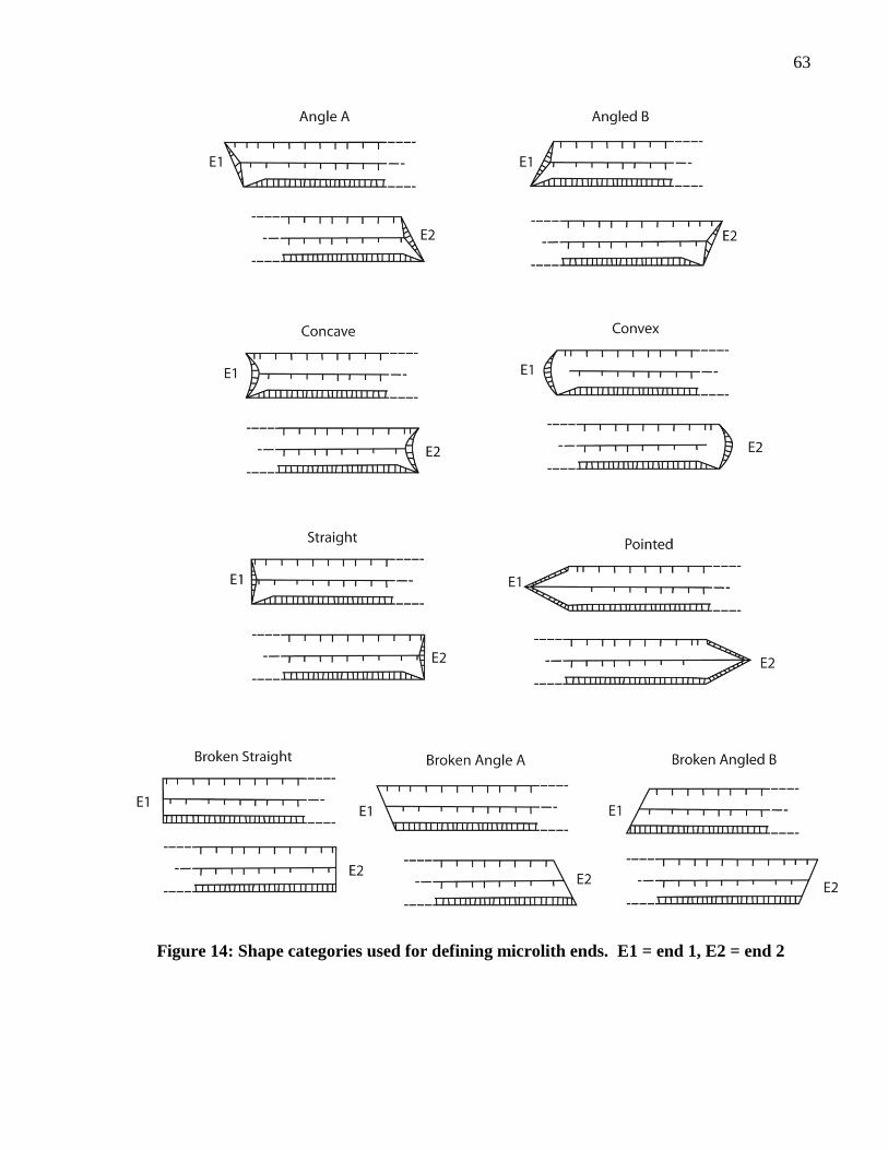
63
Figure 14: Shape categories used for defining microlith ends. E1 = end 1, E2 = end 2
64
4.2 Wadi Mataha
The total excavated lithic assemblage from the Geometric
Kebaran levels at Wadi Mataha consists of 2,862 lithics:
412 retouched artifacts, 2,367 pieces of debitage, 12 cores,
26 core-trimming elements, and 45 microburins. Because
of the small size of the Geometric Kebaran assemblage at
Wadi Mataha, no sampling was necessary and the entire
assemblage was analyzed.
4.2.1 Reduction Strategy
In total, 12 cores have been recovered from the Middle
Epipalaeolithic deposits at Wadi Mataha. The cores are
primarily broad-faced cores (75.0%, n=9) typical of the
Middle Epipalaeolithic. Of the broad-faced cores, five have
unidirectional removals, two have opposed removals, and
one is a change-of-orientation core. In addition to the
broad-faced cores, there is one sub-pyramidal bladelet core,
one irregularly shaped core, and one broken core. The
majority of the cores were discarded because of hinged
terminations on the core face (n=4, 33.3%) or because the
core was exhausted for further removals (n=4, 33.3%).
Another 16.7% were abandoned because the core face was
no longer at an optimal angle for removals. One core was
broken (8.3%) and one core was discarded for unknown
reasons. Disregarding the broken core, 72.7% (n=8) of the
cores were still being used to remove bladelets at the point of discard. The other 27.3% (n=3) of
the cores had final removals with a length to width ratio of less than two, indicating that the final
removals were flakes. Two of these flake cores are wide-faced cores similar in shape to the other
wide-faced cores used for microlith production. Therefore these may have also functioned as
microlith cores earlier in their life cycle.
Figure 15: Microlith backing
retouch types (adapted from
Christensen and Valentin,
2004).
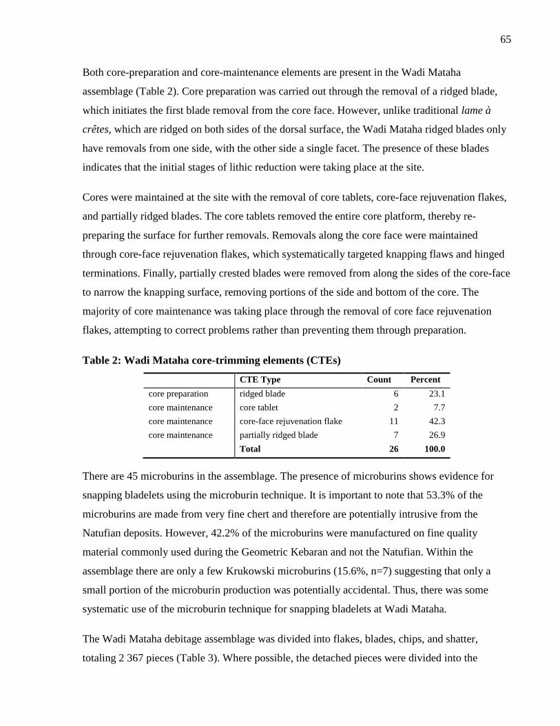
65
Both core-preparation and core-maintenance elements are present in the Wadi Mataha
assemblage (Table 2). Core preparation was carried out through the removal of a ridged blade,
which initiates the first blade removal from the core face. However, unlike traditional lame à
crêtes, which are ridged on both sides of the dorsal surface, the Wadi Mataha ridged blades only
have removals from one side, with the other side a single facet. The presence of these blades
indicates that the initial stages of lithic reduction were taking place at the site.
Cores were maintained at the site with the removal of core tablets, core-face rejuvenation flakes,
and partially ridged blades. The core tablets removed the entire core platform, thereby re-
preparing the surface for further removals. Removals along the core face were maintained
through core-face rejuvenation flakes, which systematically targeted knapping flaws and hinged
terminations. Finally, partially crested blades were removed from along the sides of the core-face
to narrow the knapping surface, removing portions of the side and bottom of the core. The
majority of core maintenance was taking place through the removal of core face rejuvenation
flakes, attempting to correct problems rather than preventing them through preparation.
Table 2: Wadi Mataha core-trimming elements (CTEs)
CTE Type Count Percent
core preparation ridged blade 6 23.1
core maintenance core tablet 2 7.7
core maintenance core-face rejuvenation flake 11 42.3
core maintenance partially ridged blade 7 26.9
Total 26 100.0
There are 45 microburins in the assemblage. The presence of microburins shows evidence for
snapping bladelets using the microburin technique. It is important to note that 53.3% of the
microburins are made from very fine chert and therefore are potentially intrusive from the
Natufian deposits. However, 42.2% of the microburins were manufactured on fine quality
material commonly used during the Geometric Kebaran and not the Natufian. Within the
assemblage there are only a few Krukowski microburins (15.6%, n=7) suggesting that only a
small portion of the microburin production was potentially accidental. Thus, there was some
systematic use of the microburin technique for snapping bladelets at Wadi Mataha.
The Wadi Mataha debitage assemblage was divided into flakes, blades, chips, and shatter,
totaling 2 367 pieces (Table 3). Where possible, the detached pieces were divided into the
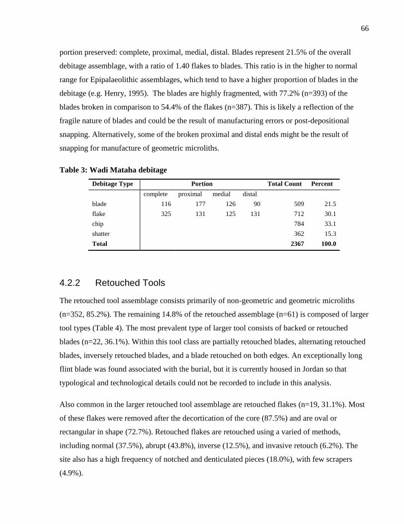
66
portion preserved: complete, proximal, medial, distal. Blades represent 21.5% of the overall
debitage assemblage, with a ratio of 1.40 flakes to blades. This ratio is in the higher to normal
range for Epipalaeolithic assemblages, which tend to have a higher proportion of blades in the
debitage (e.g. Henry, 1995). The blades are highly fragmented, with 77.2% (n=393) of the
blades broken in comparison to 54.4% of the flakes (n=387). This is likely a reflection of the
fragile nature of blades and could be the result of manufacturing errors or post-depositional
snapping. Alternatively, some of the broken proximal and distal ends might be the result of
snapping for manufacture of geometric microliths.
Table 3: Wadi Mataha debitage
Debitage Type Portion Total Count Percent
complete proximal medial distal
blade 116 177 126 90 509 21.5
flake 325 131 125 131 712 30.1
chip 784 33.1
shatter 362 15.3
Total 2367 100.0
4.2.2 Retouched Tools
The retouched tool assemblage consists primarily of non-geometric and geometric microliths
(n=352, 85.2%). The remaining 14.8% of the retouched assemblage (n=61) is composed of larger
tool types (Table 4). The most prevalent type of larger tool consists of backed or retouched
blades (n=22, 36.1%). Within this tool class are partially retouched blades, alternating retouched
blades, inversely retouched blades, and a blade retouched on both edges. An exceptionally long
flint blade was found associated with the burial, but it is currently housed in Jordan so that
typological and technological details could not be recorded to include in this analysis.
Also common in the larger retouched tool assemblage are retouched flakes (n=19, 31.1%). Most
of these flakes were removed after the decortication of the core (87.5%) and are oval or
rectangular in shape (72.7%). Retouched flakes are retouched using a varied of methods,
including normal (37.5%), abrupt (43.8%), inverse (12.5%), and invasive retouch (6.2%). The
site also has a high frequency of notched and denticulated pieces (18.0%), with few scrapers
(4.9%).
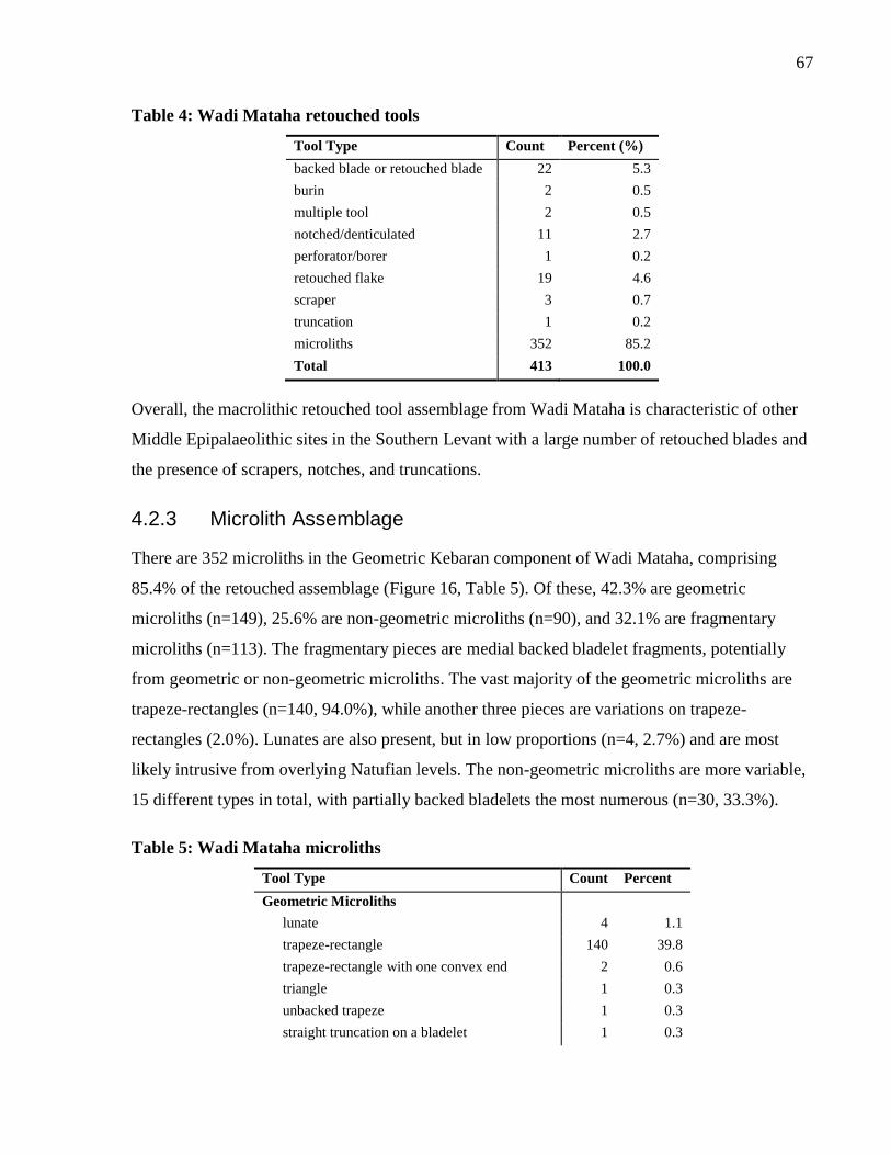
67
Table 4: Wadi Mataha retouched tools
Tool Type Count Percent (%)
backed blade or retouched blade 22 5.3
burin 2 0.5
multiple tool 2 0.5
notched/denticulated 11 2.7
perforator/borer 1 0.2
retouched flake 19 4.6
scraper 3 0.7
truncation 1 0.2
microliths 352 85.2
Total 413 100.0
Overall, the macrolithic retouched tool assemblage from Wadi Mataha is characteristic of other
Middle Epipalaeolithic sites in the Southern Levant with a large number of retouched blades and
the presence of scrapers, notches, and truncations.
4.2.3 Microlith Assemblage
There are 352 microliths in the Geometric Kebaran component of Wadi Mataha, comprising
85.4% of the retouched assemblage (Figure 16, Table 5). Of these, 42.3% are geometric
microliths (n=149), 25.6% are non-geometric microliths (n=90), and 32.1% are fragmentary
microliths (n=113). The fragmentary pieces are medial backed bladelet fragments, potentially
from geometric or non-geometric microliths. The vast majority of the geometric microliths are
trapeze-rectangles (n=140, 94.0%), while another three pieces are variations on trapeze-
rectangles (2.0%). Lunates are also present, but in low proportions (n=4, 2.7%) and are most
likely intrusive from overlying Natufian levels. The non-geometric microliths are more variable,
15 different types in total, with partially backed bladelets the most numerous (n=30, 33.3%).
Table 5: Wadi Mataha microliths
Tool Type Count Percent
Geometric Microliths
lunate 4 1.1
trapeze-rectangle 140 39.8
trapeze-rectangle with one convex end 2 0.6
triangle 1 0.3
unbacked trapeze 1 0.3
straight truncation on a bladelet 1 0.3
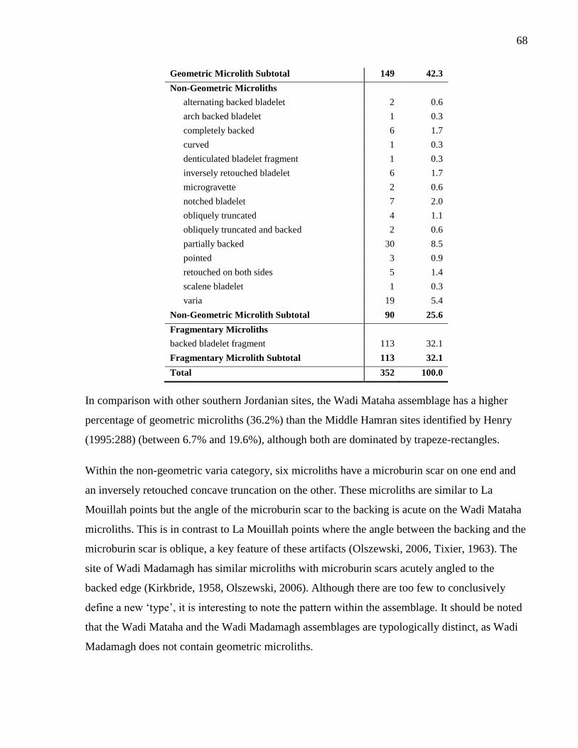
68
Geometric Microlith Subtotal 149 42.3
Non-Geometric Microliths
alternating backed bladelet 2 0.6
arch backed bladelet 1 0.3
completely backed 6 1.7
curved 1 0.3
denticulated bladelet fragment 1 0.3
inversely retouched bladelet 6 1.7
microgravette 2 0.6
notched bladelet 7 2.0
obliquely truncated 4 1.1
obliquely truncated and backed 2 0.6
partially backed 30 8.5
pointed 3 0.9
retouched on both sides 5 1.4
scalene bladelet 1 0.3
varia 19 5.4
Non-Geometric Microlith Subtotal 90 25.6
Fragmentary Microliths
backed bladelet fragment 113 32.1
Fragmentary Microlith Subtotal 113 32.1
Total 352 100.0
In comparison with other southern Jordanian sites, the Wadi Mataha assemblage has a higher
percentage of geometric microliths (36.2%) than the Middle Hamran sites identified by Henry
(1995:288) (between 6.7% and 19.6%), although both are dominated by trapeze-rectangles.
Within the non-geometric varia category, six microliths have a microburin scar on one end and
an inversely retouched concave truncation on the other. These microliths are similar to La
Mouillah points but the angle of the microburin scar to the backing is acute on the Wadi Mataha
microliths. This is in contrast to La Mouillah points where the angle between the backing and the
microburin scar is oblique, a key feature of these artifacts (Olszewski, 2006, Tixier, 1963). The
site of Wadi Madamagh has similar microliths with microburin scars acutely angled to the
backed edge (Kirkbride, 1958, Olszewski, 2006). Although there are too few to conclusively
define a new ‘type’, it is interesting to note the pattern within the assemblage. It should be noted
that the Wadi Mataha and the Wadi Madamagh assemblages are typologically distinct, as Wadi
Madamagh does not contain geometric microliths.
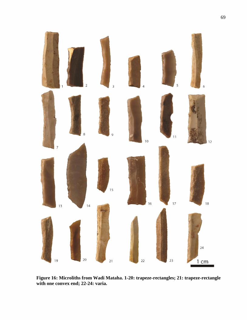
69
Figure 16: Microliths from Wadi Mataha. 1-20: trapeze-rectangles; 21: trapeze-rectangle
with one convex end; 22-24: varia.
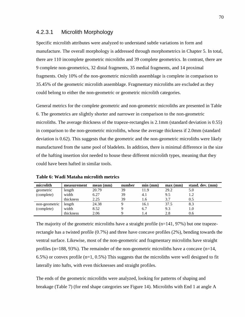
70
4.2.3.1 Microlith Morphology
Specific microlith attributes were analyzed to understand subtle variations in form and
manufacture. The overall morphology is addressed through morphometrics in Chapter 5. In total,
there are 110 incomplete geometric microliths and 39 complete geometrics. In contrast, there are
9 complete non-geometrics, 32 distal fragments, 35 medial fragments, and 14 proximal
fragments. Only 10% of the non-geometric microlith assemblage is complete in comparison to
35.45% of the geometric microlith assemblage. Fragmentary microliths are excluded as they
could belong to either the non-geometric or geometric microlith categories.
General metrics for the complete geometric and non-geometric microliths are presented in Table
6. The geometrics are slightly shorter and narrower in comparison to the non-geometric
microliths. The average thickness of the trapeze-rectangles is 2.1mm (standard deviation is 0.55)
in comparison to the non-geometric microliths, whose the average thickness if 2.0mm (standard
deviation is 0.62). This suggests that the geometric and the non-geometric microliths were likely
manufactured from the same pool of bladelets. In addition, there is minimal difference in the size
of the hafting insertion slot needed to house these different microlith types, meaning that they
could have been hafted in similar tools.
Table 6: Wadi Mataha microlith metrics
microlith measurement mean (mm) number min (mm) max (mm) stand. dev. (mm)
geometric length 20.79 39 11.9 29.2 5.0
(complete) width 6.27 39 4.1 9.5 1.2
thickness 2.25 39 1.6 3.7 0.5
non-geometric length 24.38 9 16.1 37.5 8.3
(complete) width 8.52 9 6.7 9.3 1.0
thickness 2.06 9 1.4 2.8 0.6
The majority of the geometric microliths have a straight profile (n=141, 97%) but one trapeze-
rectangle has a twisted profile (0.7%) and three have concave profiles (2%), bending towards the
ventral surface. Likewise, most of the non-geometric and fragmentary microliths have straight
profiles (n=188, 93%). The remainder of the non-geometric microliths have a concave (n=14,
6.5%) or convex profile (n=1, 0.5%) This suggests that the microliths were well designed to fit
laterally into hafts, with even thicknesses and straight profiles.
The ends of the geometric microliths were analyzed, looking for patterns of shaping and
breakage (Table 7) (for end shape categories see Figure 14). Microliths with End 1 at angle A
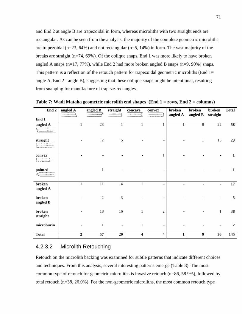
71
and End 2 at angle B are trapezoidal in form, whereas microliths with two straight ends are
rectangular. As can be seen from the analysis, the majority of the complete geometric microliths
are trapezoidal (n=23, 64%) and not rectangular (n=5, 14%) in form. The vast majority of the
breaks are straight (n=74, 69%). Of the oblique snaps, End 1 was more likely to have broken
angled A snaps (n=17, 77%), while End 2 had more broken angled B snaps (n=9, 90%) snaps.
This pattern is a reflection of the retouch pattern for trapezoidal geometric microliths (End 1=
angle A, End 2= angle B), suggesting that these oblique snaps might be intentional, resulting
from snapping for manufacture of trapeze-rectangles.
Table 7: Wadi Mataha geometric microlith end shapes (End 1 = rows, End 2 = columns)
End 2
End 1
angled A
angled B
straight
concave
convex
broken
angled A
broken
angled B
broken
straight
Total
angled A
1 23 1 1 1 1 8 22 58
straight
- 2 5 - - - 1 15 23
convex
- - - - 1 - - - 1
pointed
- 1 - - - - - - 1
broken
angled A
1 11 4 1 - - - - 17
broken
angled B
- 2 3 - - - - - 5
broken
straight
- 18 16 1 2 - - 1 38
microburin
- 1 - 1 - - - - 2
Total 2 57 29 4 4 1 9 36 145
4.2.3.2 Microlith Retouching
Retouch on the microlith backing was examined for subtle patterns that indicate different choices
and techniques. From this analysis, several interesting patterns emerge (Table 8). The most
common type of retouch for geometric microliths is invasive retouch (n=86, 58.9%), followed by
total retouch (n=38, 26.0%). For the non-geometric microliths, the most common retouch type
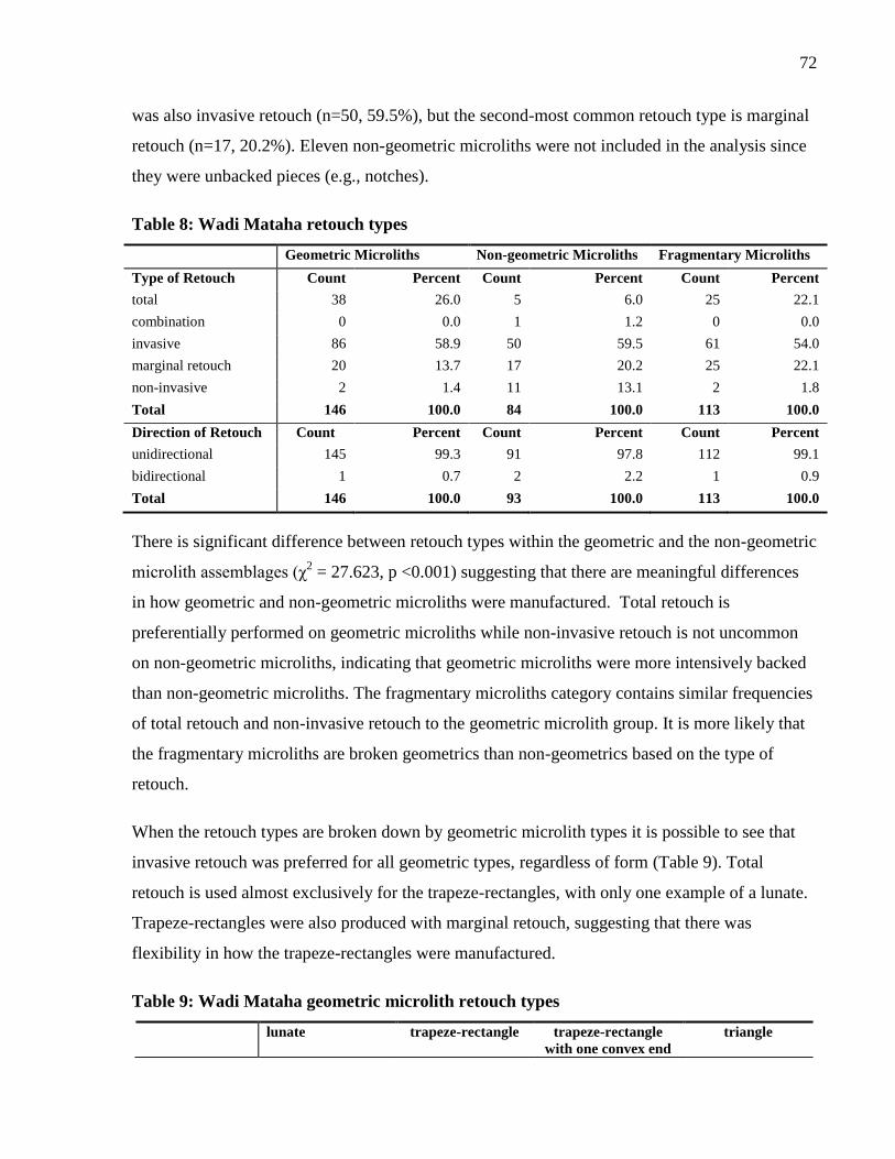
72
was also invasive retouch (n=50, 59.5%), but the second-most common retouch type is marginal
retouch (n=17, 20.2%). Eleven non-geometric microliths were not included in the analysis since
they were unbacked pieces (e.g., notches).
Table 8: Wadi Mataha retouch types
Geometric Microliths Non-geometric Microliths Fragmentary Microliths
Type of Retouch Count Percent Count Percent Count Percent
total 38 26.0 5 6.0 25 22.1
combination 0 0.0 1 1.2 0 0.0
invasive 86 58.9 50 59.5 61 54.0
marginal retouch 20 13.7 17 20.2 25 22.1
non-invasive 2 1.4 11 13.1 2 1.8
Total 146 100.0 84 100.0 113 100.0
Direction of Retouch Count Percent Count Percent Count Percent
unidirectional 145 99.3 91 97.8 112 99.1
bidirectional 1 0.7 2 2.2 1 0.9
Total 146 100.0 93 100.0 113 100.0
There is significant difference between retouch types within the geometric and the non-geometric
microlith assemblages (χ2 = 27.623, p <0.001) suggesting that there are meaningful differences
in how geometric and non-geometric microliths were manufactured. Total retouch is
preferentially performed on geometric microliths while non-invasive retouch is not uncommon
on non-geometric microliths, indicating that geometric microliths were more intensively backed
than non-geometric microliths. The fragmentary microliths category contains similar frequencies
of total retouch and non-invasive retouch to the geometric microlith group. It is more likely that
the fragmentary microliths are broken geometrics than non-geometrics based on the type of
retouch.
When the retouch types are broken down by geometric microlith types it is possible to see that
invasive retouch was preferred for all geometric types, regardless of form (Table 9). Total
retouch is used almost exclusively for the trapeze-rectangles, with only one example of a lunate.
Trapeze-rectangles were also produced with marginal retouch, suggesting that there was
flexibility in how the trapeze-rectangles were manufactured.
Table 9: Wadi Mataha geometric microlith retouch types
lunate trapeze-rectangle trapeze-rectangle
with one convex end
triangle
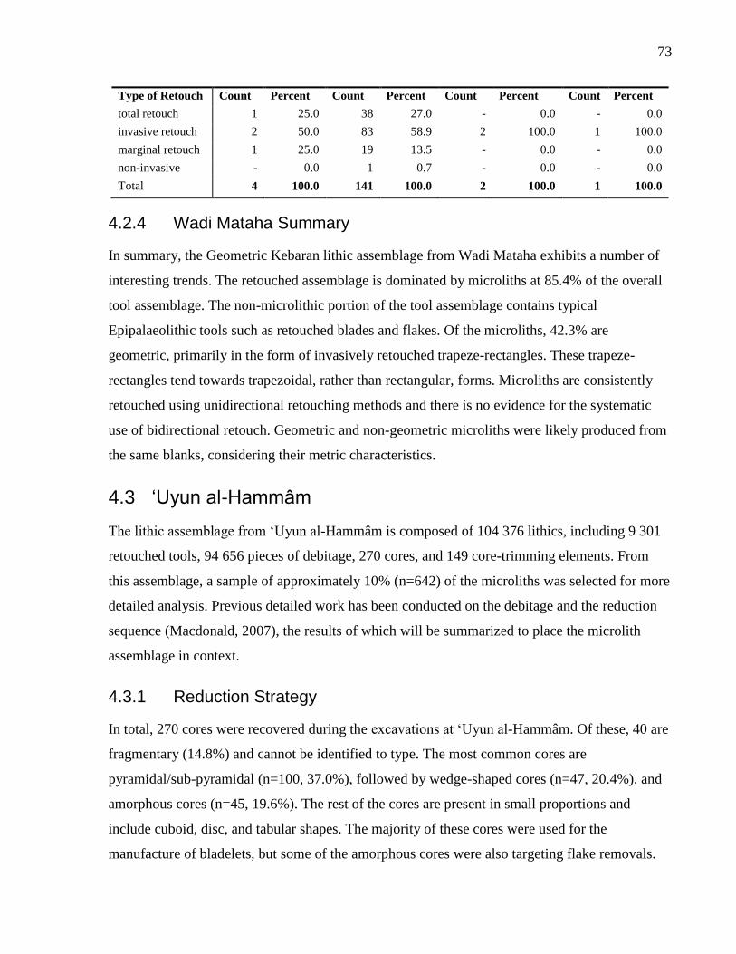
73
Type of Retouch Count Percent Count Percent Count Percent Count Percent
total retouch 1 25.0 38 27.0 - 0.0 - 0.0
invasive retouch 2 50.0 83 58.9 2 100.0 1 100.0
marginal retouch 1 25.0 19 13.5 - 0.0 - 0.0
non-invasive - 0.0 1 0.7 - 0.0 - 0.0
Total 4 100.0 141 100.0 2 100.0 1 100.0
4.2.4 Wadi Mataha Summary
In summary, the Geometric Kebaran lithic assemblage from Wadi Mataha exhibits a number of
interesting trends. The retouched assemblage is dominated by microliths at 85.4% of the overall
tool assemblage. The non-microlithic portion of the tool assemblage contains typical
Epipalaeolithic tools such as retouched blades and flakes. Of the microliths, 42.3% are
geometric, primarily in the form of invasively retouched trapeze-rectangles. These trapeze-
rectangles tend towards trapezoidal, rather than rectangular, forms. Microliths are consistently
retouched using unidirectional retouching methods and there is no evidence for the systematic
use of bidirectional retouch. Geometric and non-geometric microliths were likely produced from
the same blanks, considering their metric characteristics.
4.3 ‘Uyun al-Hammâm
The lithic assemblage from ‘Uyun al-Hammâm is composed of 104 376 lithics, including 9 301
retouched tools, 94 656 pieces of debitage, 270 cores, and 149 core-trimming elements. From
this assemblage, a sample of approximately 10% (n=642) of the microliths was selected for more
detailed analysis. Previous detailed work has been conducted on the debitage and the reduction
sequence (Macdonald, 2007), the results of which will be summarized to place the microlith
assemblage in context.
4.3.1 Reduction Strategy
In total, 270 cores were recovered during the excavations at ‘Uyun al-Hammâm. Of these, 40 are
fragmentary (14.8%) and cannot be identified to type. The most common cores are
pyramidal/sub-pyramidal (n=100, 37.0%), followed by wedge-shaped cores (n=47, 20.4%), and
amorphous cores (n=45, 19.6%). The rest of the cores are present in small proportions and
include cuboid, disc, and tabular shapes. The majority of these cores were used for the
manufacture of bladelets, but some of the amorphous cores were also targeting flake removals.
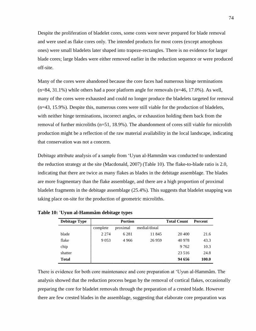
74
Despite the proliferation of bladelet cores, some cores were never prepared for blade removal
and were used as flake cores only. The intended products for most cores (except amorphous
ones) were small bladelets later shaped into trapeze-rectangles. There is no evidence for larger
blade cores; large blades were either removed earlier in the reduction sequence or were produced
off-site.
Many of the cores were abandoned because the core faces had numerous hinge terminations
(n=84, 31.1%) while others had a poor platform angle for removals (n=46, 17.0%). As well,
many of the cores were exhausted and could no longer produce the bladelets targeted for removal
(n=43, 15.9%). Despite this, numerous cores were still viable for the production of bladelets,
with neither hinge terminations, incorrect angles, or exhaustion holding them back from the
removal of further microliths (n=51, 18.9%). The abandonment of cores still viable for microlith
production might be a reflection of the raw material availability in the local landscape, indicating
that conservation was not a concern.
Debitage attribute analysis of a sample from ‘Uyun al-Hammâm was conducted to understand
the reduction strategy at the site (Macdonald, 2007) (Table 10). The flake-to-blade ratio is 2.0,
indicating that there are twice as many flakes as blades in the debitage assemblage. The blades
are more fragmentary than the flake assemblage, and there are a high proportion of proximal
bladelet fragments in the debitage assemblage (25.4%). This suggests that bladelet snapping was
taking place on-site for the production of geometric microliths.
Table 10: 'Uyun al-Hammâm debitage types
Debitage Type Portion Total Count Percent
complete proximal medial/distal
blade 2 274 6 281 11 845 20 400 21.6
flake 9 053 4 966 26 959 40 978 43.3
chip 9 762 10.3
shatter 23 516 24.8
Total 94 656 100.0
There is evidence for both core maintenance and core preparation at ‘Uyun al-Hammâm. The
analysis showed that the reduction process began by the removal of cortical flakes, occasionally
preparing the core for bladelet removals through the preparation of a crested blade. However
there are few crested blades in the assemblage, suggesting that elaborate core preparation was
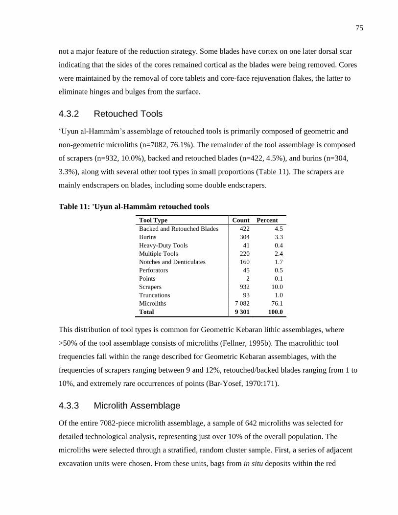
75
not a major feature of the reduction strategy. Some blades have cortex on one later dorsal scar
indicating that the sides of the cores remained cortical as the blades were being removed. Cores
were maintained by the removal of core tablets and core-face rejuvenation flakes, the latter to
eliminate hinges and bulges from the surface.
4.3.2 Retouched Tools
‘Uyun al-Hammâm’s assemblage of retouched tools is primarily composed of geometric and
non-geometric microliths (n=7082, 76.1%). The remainder of the tool assemblage is composed
of scrapers (n=932, 10.0%), backed and retouched blades (n=422, 4.5%), and burins (n=304,
3.3%), along with several other tool types in small proportions (Table 11). The scrapers are
mainly endscrapers on blades, including some double endscrapers.
Table 11: 'Uyun al-Hammâm retouched tools
Tool Type Count Percent
Backed and Retouched Blades 422 4.5
Burins 304 3.3
Heavy-Duty Tools 41 0.4
Multiple Tools 220 2.4
Notches and Denticulates 160 1.7
Perforators 45 0.5
Points 2 0.1
Scrapers 932 10.0
Truncations 93 1.0
Microliths 7 082 76.1
Total 9 301 100.0
This distribution of tool types is common for Geometric Kebaran lithic assemblages, where
>50% of the tool assemblage consists of microliths (Fellner, 1995b). The macrolithic tool
frequencies fall within the range described for Geometric Kebaran assemblages, with the
frequencies of scrapers ranging between 9 and 12%, retouched/backed blades ranging from 1 to
10%, and extremely rare occurrences of points (Bar-Yosef, 1970:171).
4.3.3 Microlith Assemblage
Of the entire 7082-piece microlith assemblage, a sample of 642 microliths was selected for
detailed technological analysis, representing just over 10% of the overall population. The
microliths were selected through a stratified, random cluster sample. First, a series of adjacent
excavation units were chosen. From these units, bags from in situ deposits within the red
76
Pleistocene sediments were separated from the disturbed loci. From these in situ contexts, a 20%
random sample was chosen for analysis.
The majority of the microliths are geometrics (n=428, 66.7%), with trapeze-rectangles being the
most frequent type (n=403, 94.2%) (Figure 17, Table 12). The remainder of the geometrics are
asymmetrical trapeze B (n=12, 2.8%) or other variations on trapeze-rectangles (n=10, 2.3%). As
well, a single lunate was recovered from the deposits.
There is more variability in the non-geometric microlith category, but they represent a small
proportion of the overall microlith assemblage (n=83, 12.9%). In total, there are 16 different non-
geometric microlith types, with the most prevalent being partially backed bladelets (n=11,
13.3%). Completely backed bladelets, inversely retouched bladelets, notched bladelets, obliquely
truncated and backed bladelets, and pointed backed bladelets each represent 10.8% of the non-
geometric microlith assemblage. The remaining 10 types are represented in frequencies less than
10% of the non-geometric microliths.
The fragmentary microliths are composed entirely of medial backed-bladelet fragments (n=131,
20.4%). These fragments were not identifiable to type, but many could have been medial
sections of broken trapeze-rectangles.
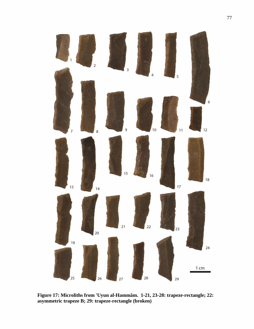
77
Figure 17: Microliths from 'Uyun al-Hammâm. 1-21, 23-28: trapeze-rectangle; 22:
asymmetric trapeze B; 29: trapeze-rectangle (broken)
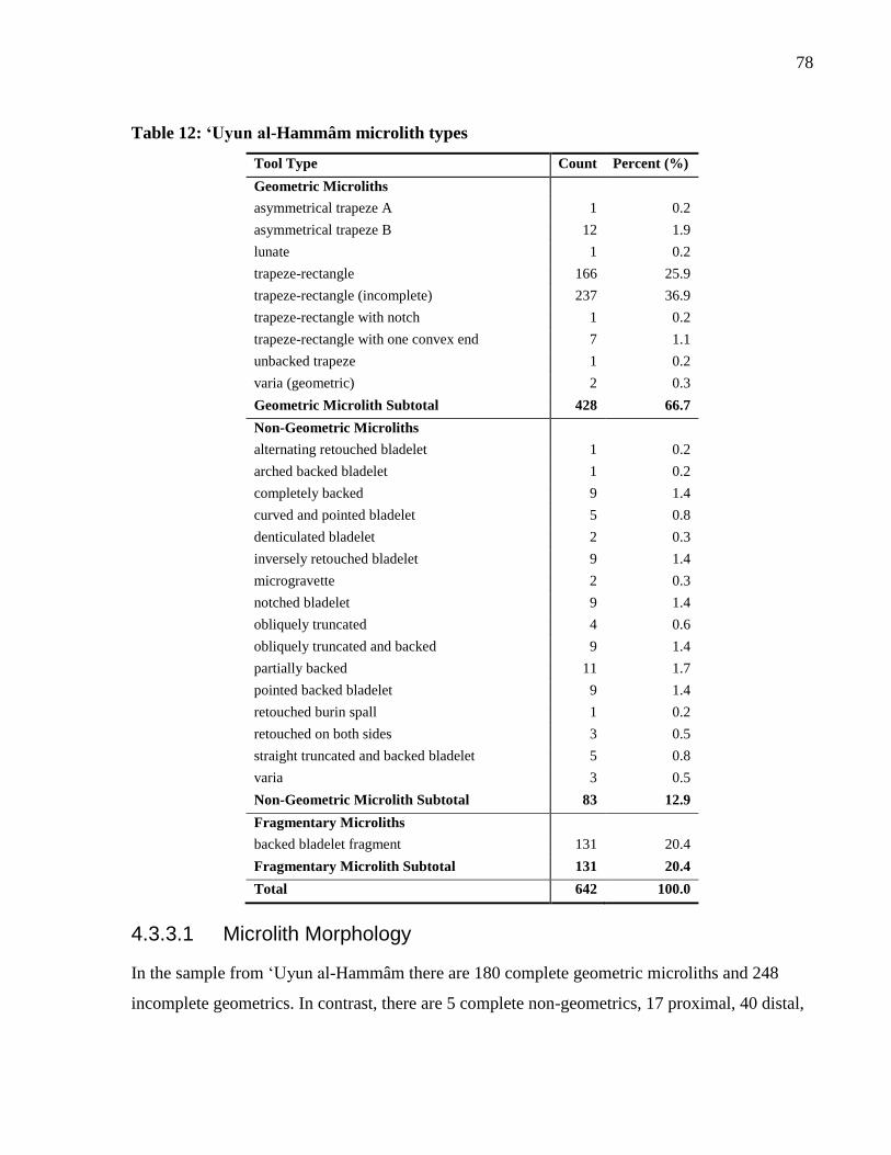
78
Table 12: ‘Uyun al-Hammâm microlith types
Tool Type Count Percent (%)
Geometric Microliths
asymmetrical trapeze A 1 0.2
asymmetrical trapeze B 12 1.9
lunate 1 0.2
trapeze-rectangle 166 25.9
trapeze-rectangle (incomplete) 237 36.9
trapeze-rectangle with notch 1 0.2
trapeze-rectangle with one convex end 7 1.1
unbacked trapeze 1 0.2
varia (geometric) 2 0.3
Geometric Microlith Subtotal 428 66.7
Non-Geometric Microliths
alternating retouched bladelet 1 0.2
arched backed bladelet 1 0.2
completely backed 9 1.4
curved and pointed bladelet 5 0.8
denticulated bladelet 2 0.3
inversely retouched bladelet 9 1.4
microgravette 2 0.3
notched bladelet 9 1.4
obliquely truncated 4 0.6
obliquely truncated and backed 9 1.4
partially backed 11 1.7
pointed backed bladelet 9 1.4
retouched burin spall 1 0.2
retouched on both sides 3 0.5
straight truncated and backed bladelet 5 0.8
varia 3 0.5
Non-Geometric Microlith Subtotal 83 12.9
Fragmentary Microliths
backed bladelet fragment 131 20.4
Fragmentary Microlith Subtotal 131 20.4
Total 642 100.0
4.3.3.1 Microlith Morphology
In the sample from ‘Uyun al-Hammâm there are 180 complete geometric microliths and 248
incomplete geometrics. In contrast, there are 5 complete non-geometrics, 17 proximal, 40 distal,
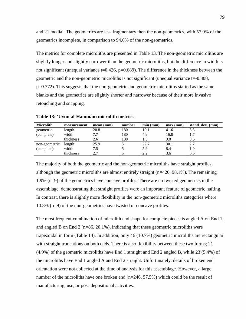
79
and 21 medial. The geometrics are less fragmentary then the non-geometrics, with 57.9% of the
geometrics incomplete, in comparison to 94.0% of the non-geometrics.
The metrics for complete microliths are presented in Table 13. The non-geometric microliths are
slightly longer and slightly narrower than the geometric microliths, but the difference in width is
not significant (unequal variance t=0.426, p=0.689). The difference in the thickness between the
geometric and the non-geometric microliths is not significant (unequal variance t=-0.308,
p=0.772). This suggests that the non-geometric and geometric microliths started as the same
blanks and the geometrics are slightly shorter and narrower because of their more invasive
retouching and snapping.
Table 13: 'Uyun al-Hammâm microlith metrics
Microlith measurement mean (mm) number min (mm) max (mm) stand. dev. (mm)
geometric length 20.8 180 10.1 41.6 5.5
(complete) width 7.7 180 4.9 16.8 1.7
thickness 2.6 180 1.3 3.8 0.6
non-geometric length 25.9 5 22.7 30.1 2.7
(complete) width 7.5 5 5.9 8.4 1.0
thickness 2.7 5 2.2 3.6 0.6
The majority of both the geometric and the non-geometric microliths have straight profiles,
although the geometric microliths are almost entirely straight (n=420, 98.1%). The remaining
1.9% (n=9) of the geometrics have concave profiles. There are no twisted geometrics in the
assemblage, demonstrating that straight profiles were an important feature of geometric hafting.
In contrast, there is slightly more flexibility in the non-geometric microliths categories where
10.8% (n=9) of the non-geometrics have twisted or concave profiles.
The most frequent combination of microlith end shape for complete pieces is angled A on End 1,
and angled B on End 2 (n=86, 20.1%), indicating that these geometric microliths were
trapezoidal in form (Table 14). In addition, only 46 (10.7%) geometric microliths are rectangular
with straight truncations on both ends. There is also flexibility between these two forms; 21
(4.9%) of the geometric microliths have End 1 straight and End 2 angled B, while 23 (5.4%) of
the microliths have End 1 angled A and End 2 straight. Unfortunately, details of broken end
orientation were not collected at the time of analysis for this assemblage. However, a large
number of the microliths have one broken end (n=246, 57.5%) which could be the result of
manufacturing, use, or post-depositional activities.
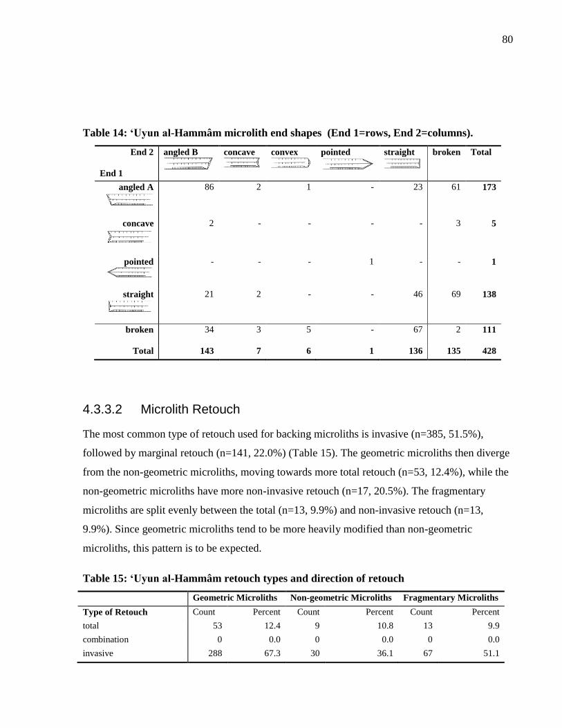
80
Table 14: ‘Uyun al-Hammâm microlith end shapes (End 1=rows, End 2=columns).
End 2
End 1
angled B
concave
convex
pointed
straight
broken Total
angled A
86 2 1 - 23 61 173
concave
2 - - - - 3 5
pointed
- - - 1 - - 1
straight
21 2 - - 46 69 138
broken
34 3 5 - 67 2 111
Total 143 7 6 1 136 135 428
4.3.3.2 Microlith Retouch
The most common type of retouch used for backing microliths is invasive (n=385, 51.5%),
followed by marginal retouch (n=141, 22.0%) (Table 15). The geometric microliths then diverge
from the non-geometric microliths, moving towards more total retouch (n=53, 12.4%), while the
non-geometric microliths have more non-invasive retouch (n=17, 20.5%). The fragmentary
microliths are split evenly between the total (n=13, 9.9%) and non-invasive retouch (n=13,
9.9%). Since geometric microliths tend to be more heavily modified than non-geometric
microliths, this pattern is to be expected.
Table 15: ‘Uyun al-Hammâm retouch types and direction of retouch
Geometric Microliths Non-geometric Microliths Fragmentary Microliths
Type of Retouch Count Percent Count Percent Count Percent
total 53 12.4 9 10.8 13 9.9
combination 0 0.0 0 0.0 0 0.0
invasive 288 67.3 30 36.1 67 51.1
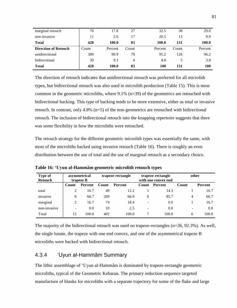
81
marginal retouch 76 17.8 27 32.5 38 29.0
non-invasive 11 2.6 17 20.5 13 9.9
Total 428 100.0 83 100.0 131 100.0
Direction of Retouch Count Percent Count Percent Count Percent
unidirectional 389 90.9 79 95.2 126 96.2
bidirectional 39 9.1 4 4.8 5 3.8
Total 428 100.0 83 100 131 100
The direction of retouch indicates that unidirectional retouch was preferred for all microlith
types, but bidirectional retouch was also used in microlith production (Table 15). This is most
common in the geometric microliths, where 9.1% (n=39) of the geometrics are retouched with
bidirectional backing. This type of backing tends to be more extensive, either as total or invasive
retouch. In contrast, only 4.8% (n=5) of the non-geometrics are retouched with bidirectional
retouch. The inclusion of bidirectional retouch into the knapping repertoire suggests that there
was some flexibility in how the microliths were retouched.
The retouch strategy for the different geometric microlith types was essentially the same, with
most of the microliths backed using invasive retouch (Table 16). There is roughly an even
distribution between the use of total and the use of marginal retouch as a secondary choice.
Table 16: ‘Uyun al-Hammâm geometric microlith retouch types
Type of
Retouch
asymmetrical
trapeze B
trapeze-rectangle trapeze-rectangle
with one convex end
other
Count Percent Count Percent Count Percent Count Percent
total 2 16.7 49 12.2 1 14.3 1 16.7
invasive 8 66.7 269 66.9 6 85.7 4 66.7
marginal 2 16.7 74 18.4 - 0.0 1 16.7
non-invasive - 0.0 10 2.5 - 0.0 - 0.0
Total 12 100.0 402 100.0 7 100.0 6 100.0
The majority of the bidirectional retouch was used on trapeze-rectangles (n=36, 92.3%). As well,
the single lunate, the trapeze with one end convex, and one of the asymmetrical trapeze B
microliths were backed with bidirectional retouch.
4.3.4 ‘Uyun al-Hammâm Summary
The lithic assemblage of ‘Uyun al-Hammâm is dominated by trapeze-rectangle geometric
microliths, typical of the Geometric Kebaran. The primary reduction sequence targeted
manufacture of blanks for microliths with a separate trajectory for some of the flake and large
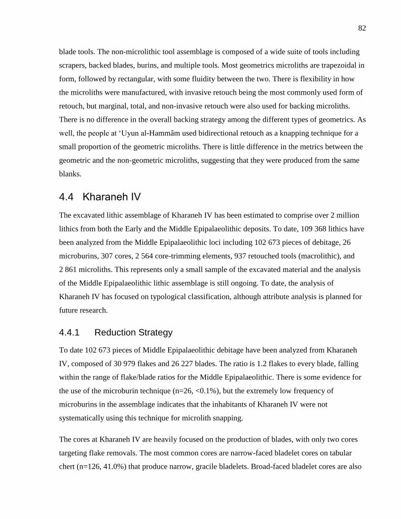
82
blade tools. The non-microlithic tool assemblage is composed of a wide suite of tools including
scrapers, backed blades, burins, and multiple tools. Most geometrics microliths are trapezoidal in
form, followed by rectangular, with some fluidity between the two. There is flexibility in how
the microliths were manufactured, with invasive retouch being the most commonly used form of
retouch, but marginal, total, and non-invasive retouch were also used for backing microliths.
There is no difference in the overall backing strategy among the different types of geometrics. As
well, the people at ‘Uyun al-Hammâm used bidirectional retouch as a knapping technique for a
small proportion of the geometric microliths. There is little difference in the metrics between the
geometric and the non-geometric microliths, suggesting that they were produced from the same
blanks.
4.4 Kharaneh IV
The excavated lithic assemblage of Kharaneh IV has been estimated to comprise over 2 million
lithics from both the Early and the Middle Epipalaeolithic deposits. To date, 109 368 lithics have
been analyzed from the Middle Epipalaeolithic loci including 102 673 pieces of debitage, 26
microburins, 307 cores, 2 564 core-trimming elements, 937 retouched tools (macrolithic), and
2 861 microliths. This represents only a small sample of the excavated material and the analysis
of the Middle Epipalaeolithic lithic assemblage is still ongoing. To date, the analysis of
Kharaneh IV has focused on typological classification, although attribute analysis is planned for
future research.
4.4.1 Reduction Strategy
To date 102 673 pieces of Middle Epipalaeolithic debitage have been analyzed from Kharaneh
IV, composed of 30 979 flakes and 26 227 blades. The ratio is 1.2 flakes to every blade, falling
within the range of flake/blade ratios for the Middle Epipalaeolithic. There is some evidence for
the use of the microburin technique (n=26, <0.1%), but the extremely low frequency of
microburins in the assemblage indicates that the inhabitants of Kharaneh IV were not
systematically using this technique for microlith snapping.
The cores at Kharaneh IV are heavily focused on the production of blades, with only two cores
targeting flake removals. The most common cores are narrow-faced bladelet cores on tabular
chert (n=126, 41.0%) that produce narrow, gracile bladelets. Broad-faced bladelet cores are also
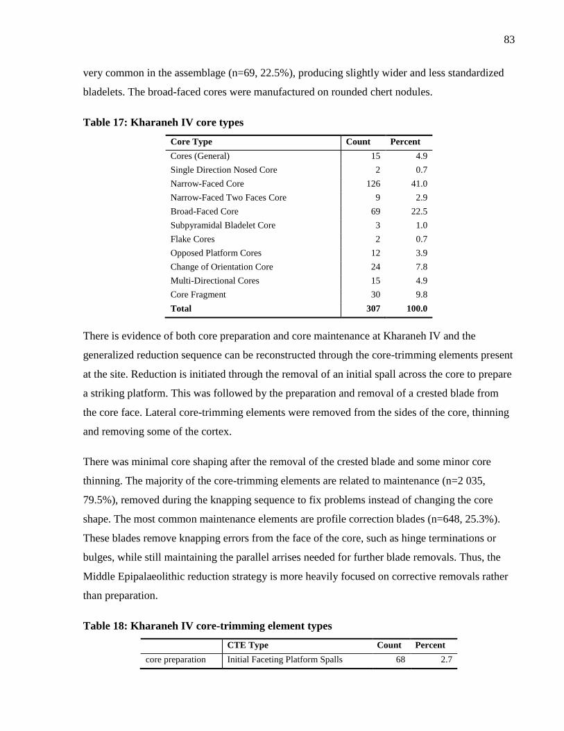
83
very common in the assemblage (n=69, 22.5%), producing slightly wider and less standardized
bladelets. The broad-faced cores were manufactured on rounded chert nodules.
Table 17: Kharaneh IV core types
Core Type Count Percent
Cores (General) 15 4.9
Single Direction Nosed Core 2 0.7
Narrow-Faced Core 126 41.0
Narrow-Faced Two Faces Core 9 2.9
Broad-Faced Core 69 22.5
Subpyramidal Bladelet Core 3 1.0
Flake Cores 2 0.7
Opposed Platform Cores 12 3.9
Change of Orientation Core 24 7.8
Multi-Directional Cores 15 4.9
Core Fragment 30 9.8
Total 307 100.0
There is evidence of both core preparation and core maintenance at Kharaneh IV and the
generalized reduction sequence can be reconstructed through the core-trimming elements present
at the site. Reduction is initiated through the removal of an initial spall across the core to prepare
a striking platform. This was followed by the preparation and removal of a crested blade from
the core face. Lateral core-trimming elements were removed from the sides of the core, thinning
and removing some of the cortex.
There was minimal core shaping after the removal of the crested blade and some minor core
thinning. The majority of the core-trimming elements are related to maintenance (n=2 035,
79.5%), removed during the knapping sequence to fix problems instead of changing the core
shape. The most common maintenance elements are profile correction blades (n=648, 25.3%).
These blades remove knapping errors from the face of the core, such as hinge terminations or
bulges, while still maintaining the parallel arrises needed for further blade removals. Thus, the
Middle Epipalaeolithic reduction strategy is more heavily focused on corrective removals rather
than preparation.
Table 18: Kharaneh IV core-trimming element types
CTE Type Count Percent
core preparation Initial Faceting Platform Spalls 68 2.7
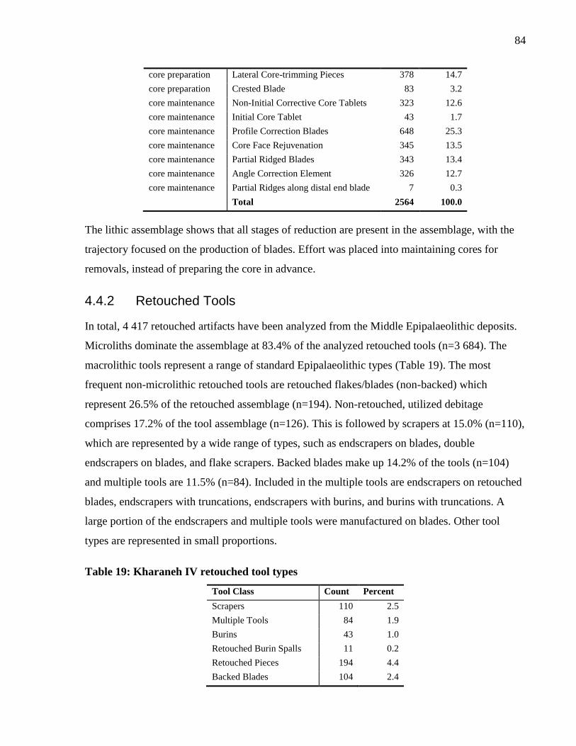
84
core preparation Lateral Core-trimming Pieces 378 14.7
core preparation Crested Blade 83 3.2
core maintenance Non-Initial Corrective Core Tablets 323 12.6
core maintenance Initial Core Tablet 43 1.7
core maintenance Profile Correction Blades 648 25.3
core maintenance Core Face Rejuvenation 345 13.5
core maintenance Partial Ridged Blades 343 13.4
core maintenance Angle Correction Element 326 12.7
core maintenance Partial Ridges along distal end blade 7 0.3
Total 2564 100.0
The lithic assemblage shows that all stages of reduction are present in the assemblage, with the
trajectory focused on the production of blades. Effort was placed into maintaining cores for
removals, instead of preparing the core in advance.
4.4.2 Retouched Tools
In total, 4 417 retouched artifacts have been analyzed from the Middle Epipalaeolithic deposits.
Microliths dominate the assemblage at 83.4% of the analyzed retouched tools (n=3 684). The
macrolithic tools represent a range of standard Epipalaeolithic types (Table 19). The most
frequent non-microlithic retouched tools are retouched flakes/blades (non-backed) which
represent 26.5% of the retouched assemblage (n=194). Non-retouched, utilized debitage
comprises 17.2% of the tool assemblage (n=126). This is followed by scrapers at 15.0% (n=110),
which are represented by a wide range of types, such as endscrapers on blades, double
endscrapers on blades, and flake scrapers. Backed blades make up 14.2% of the tools (n=104)
and multiple tools are 11.5% (n=84). Included in the multiple tools are endscrapers on retouched
blades, endscrapers with truncations, endscrapers with burins, and burins with truncations. A
large portion of the endscrapers and multiple tools were manufactured on blades. Other tool
types are represented in small proportions.
Table 19: Kharaneh IV retouched tool types
Tool Class Count Percent
Scrapers 110 2.5
Multiple Tools 84 1.9
Burins 43 1.0
Retouched Burin Spalls 11 0.2
Retouched Pieces 194 4.4
Backed Blades 104 2.4
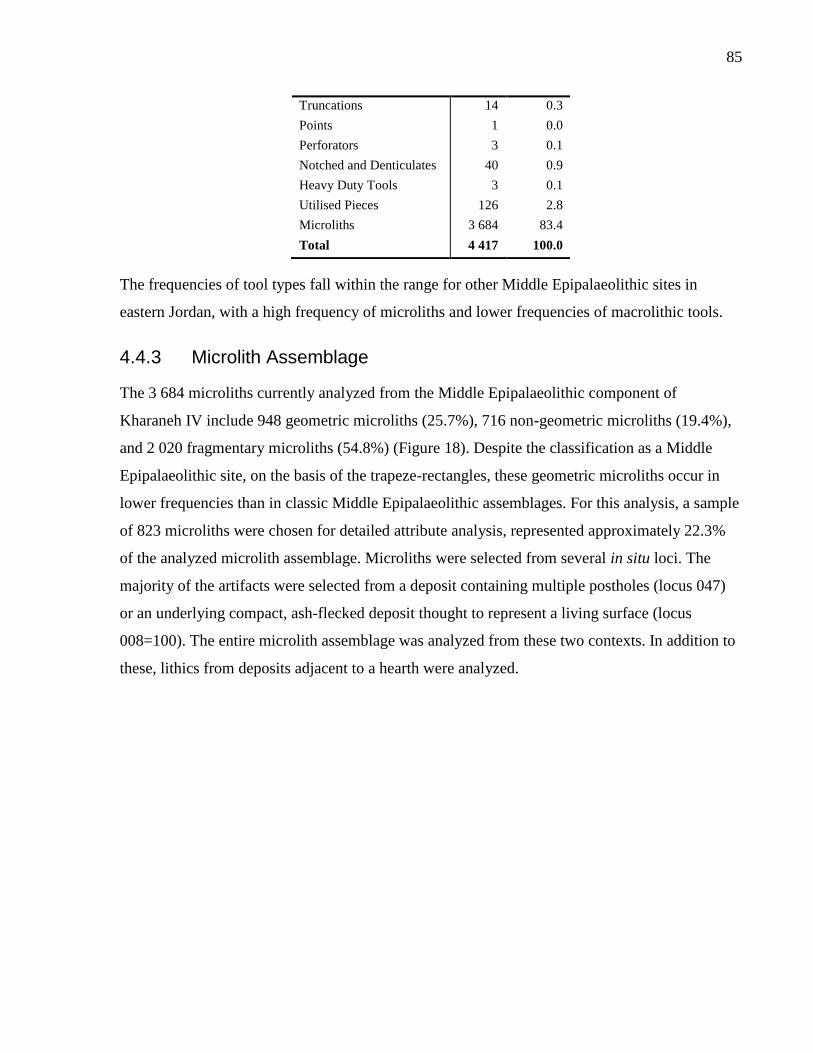
85
Truncations 14 0.3
Points 1 0.0
Perforators 3 0.1
Notched and Denticulates 40 0.9
Heavy Duty Tools 3 0.1
Utilised Pieces 126 2.8
Microliths 3 684 83.4
Total 4 417 100.0
The frequencies of tool types fall within the range for other Middle Epipalaeolithic sites in
eastern Jordan, with a high frequency of microliths and lower frequencies of macrolithic tools.
4.4.3 Microlith Assemblage
The 3 684 microliths currently analyzed from the Middle Epipalaeolithic component of
Kharaneh IV include 948 geometric microliths (25.7%), 716 non-geometric microliths (19.4%),
and 2 020 fragmentary microliths (54.8%) (Figure 18). Despite the classification as a Middle
Epipalaeolithic site, on the basis of the trapeze-rectangles, these geometric microliths occur in
lower frequencies than in classic Middle Epipalaeolithic assemblages. For this analysis, a sample
of 823 microliths were chosen for detailed attribute analysis, represented approximately 22.3%
of the analyzed microlith assemblage. Microliths were selected from several in situ loci. The
majority of the artifacts were selected from a deposit containing multiple postholes (locus 047)
or an underlying compact, ash-flecked deposit thought to represent a living surface (locus
008=100). The entire microlith assemblage was analyzed from these two contexts. In addition to
these, lithics from deposits adjacent to a hearth were analyzed.
86
The geometric forms tend towards trapeze-rectangles, both backed and unbacked (n=158, 19.2%)
(
Table 20). Although the geometrics are primarily variants of trapeze-rectangles, there many
geometric types present in the assemblage. These include lunates, parallelograms, and triangles.
The plethora of geometric types is unusual for Middle Epipalaeolithic assemblages, which tend
to be dominated by trapeze-rectangles. In addition, there is considerable variability within the
trapeze-rectangles themselves. Some are very wide, with rounded corners, while others are
narrower with more angular edges. There are also several trapeze-rectangles with large notches
(n=12) or denticulations (n=8) on the cutting edge.
As a result of this variability, Muheisen and Wada (1995) identified 14 distinct types of
geometric microliths during the initial analysis of the Middle Epipalaeolithic Kharaneh IV
assemblage. However, many of these types (quasi-trapezes) are likely broken microliths.
Consequently, these types are not adopted for this analysis.
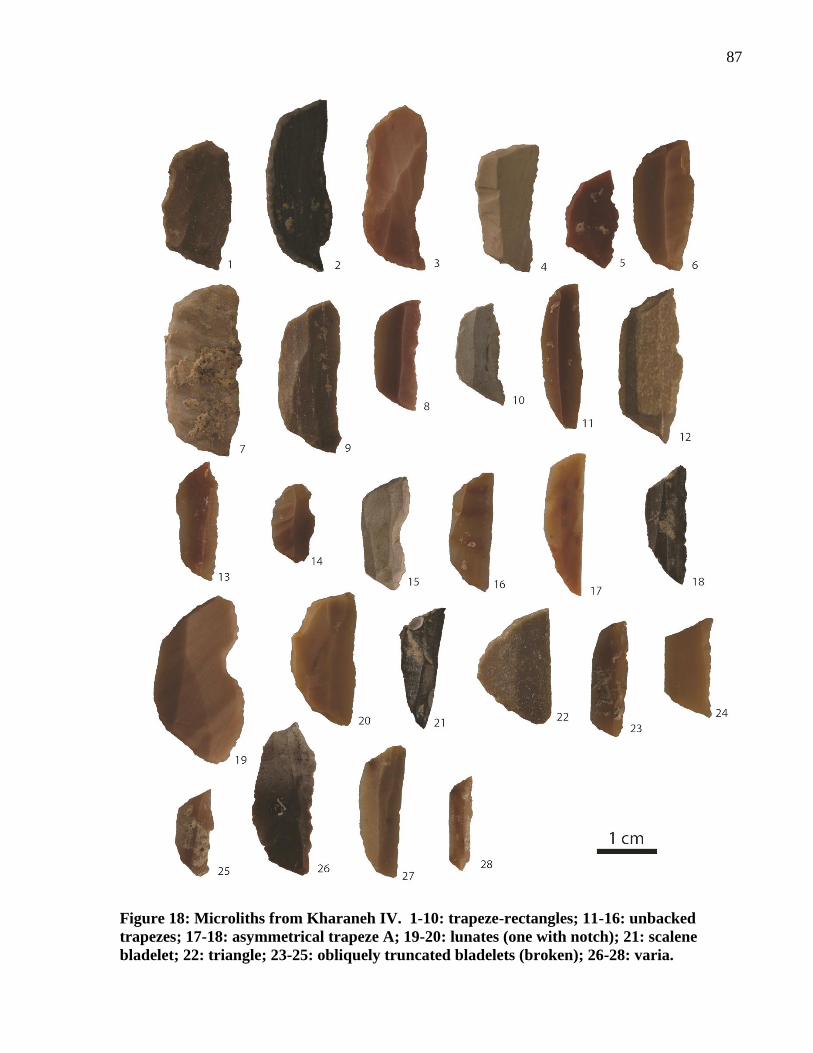
87
Figure 18: Microliths from Kharaneh IV. 1-10: trapeze-rectangles; 11-16: unbacked
trapezes; 17-18: asymmetrical trapeze A; 19-20: lunates (one with notch); 21: scalene
bladelet; 22: triangle; 23-25: obliquely truncated bladelets (broken); 26-28: varia.
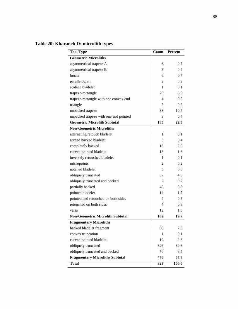
88
Table 20: Kharaneh IV microlith types
Tool Type Count Percent
Geometric Microliths
asymmetrical trapeze A 6 0.7
asymmetrical trapeze B 3 0.4
lunate 6 0.7
parallelogram 2 0.2
scalene bladelet 1 0.1
trapeze-rectangle 70 8.5
trapeze-rectangle with one convex end 4 0.5
triangle 2 0.2
unbacked trapeze 88 10.7
unbacked trapeze with one end pointed 3 0.4
Geometric Microlith Subtotal 185 22.5
Non-Geometric Microliths
alternating retouch bladelet 1 0.1
arched backed bladelet 3 0.4
completely backed 16 2.0
curved pointed bladelet 13 1.6
inversely retouched bladelet 1 0.1
micropoints 2 0.2
notched bladelet 5 0.6
obliquely truncated 37 4.5
obliquely truncated and backed 2 0.2
partially backed 48 5.8
pointed bladelet 14 1.7
pointed and retouched on both sides 4 0.5
retouched on both sides 4 0.5
varia 12 1.5
Non-Geometric Microlith Subtotal 162 19.7
Fragmentary Microliths
backed bladelet fragment 60 7.3
convex truncation 1 0.1
curved pointed bladelet 19 2.3
obliquely truncated 326 39.6
obliquely truncated and backed 70 8.5
Fragmentary Microliths Subtotal 476 57.8
Total 823 100.0
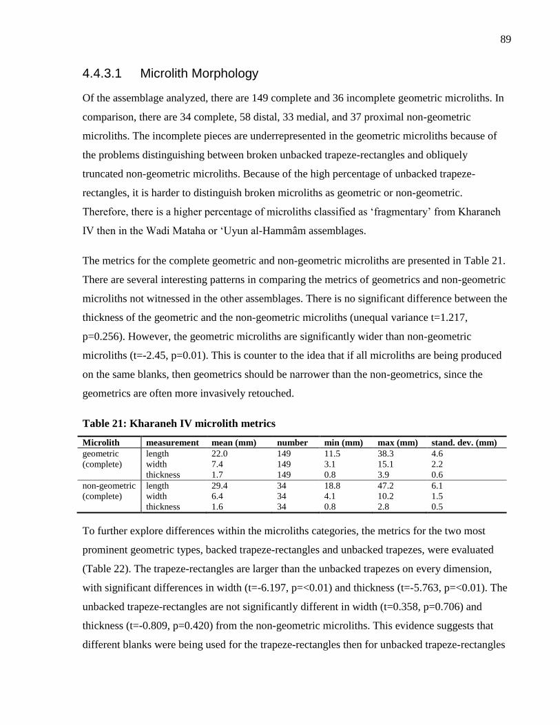
89
4.4.3.1 Microlith Morphology
Of the assemblage analyzed, there are 149 complete and 36 incomplete geometric microliths. In
comparison, there are 34 complete, 58 distal, 33 medial, and 37 proximal non-geometric
microliths. The incomplete pieces are underrepresented in the geometric microliths because of
the problems distinguishing between broken unbacked trapeze-rectangles and obliquely
truncated non-geometric microliths. Because of the high percentage of unbacked trapeze-
rectangles, it is harder to distinguish broken microliths as geometric or non-geometric.
Therefore, there is a higher percentage of microliths classified as ‘fragmentary’ from Kharaneh
IV then in the Wadi Mataha or ‘Uyun al-Hammâm assemblages.
The metrics for the complete geometric and non-geometric microliths are presented in Table 21.
There are several interesting patterns in comparing the metrics of geometrics and non-geometric
microliths not witnessed in the other assemblages. There is no significant difference between the
thickness of the geometric and the non-geometric microliths (unequal variance t=1.217,
p=0.256). However, the geometric microliths are significantly wider than non-geometric
microliths (t=-2.45, p=0.01). This is counter to the idea that if all microliths are being produced
on the same blanks, then geometrics should be narrower than the non-geometrics, since the
geometrics are often more invasively retouched.
Table 21: Kharaneh IV microlith metrics
Microlith measurement mean (mm) number min (mm) max (mm) stand. dev. (mm)
geometric length 22.0 149 11.5 38.3 4.6
(complete) width 7.4 149 3.1 15.1 2.2
thickness 1.7 149 0.8 3.9 0.6
non-geometric length 29.4 34 18.8 47.2 6.1
(complete) width 6.4 34 4.1 10.2 1.5
thickness 1.6 34 0.8 2.8 0.5
To further explore differences within the microliths categories, the metrics for the two most
prominent geometric types, backed trapeze-rectangles and unbacked trapezes, were evaluated
(Table 22). The trapeze-rectangles are larger than the unbacked trapezes on every dimension,
with significant differences in width (t=-6.197, p=<0.01) and thickness (t=-5.763, p=<0.01). The
unbacked trapeze-rectangles are not significantly different in width (t=0.358, p=0.706) and
thickness (t=-0.809, p=0.420) from the non-geometric microliths. This evidence suggests that
different blanks were being used for the trapeze-rectangles then for unbacked trapeze-rectangles
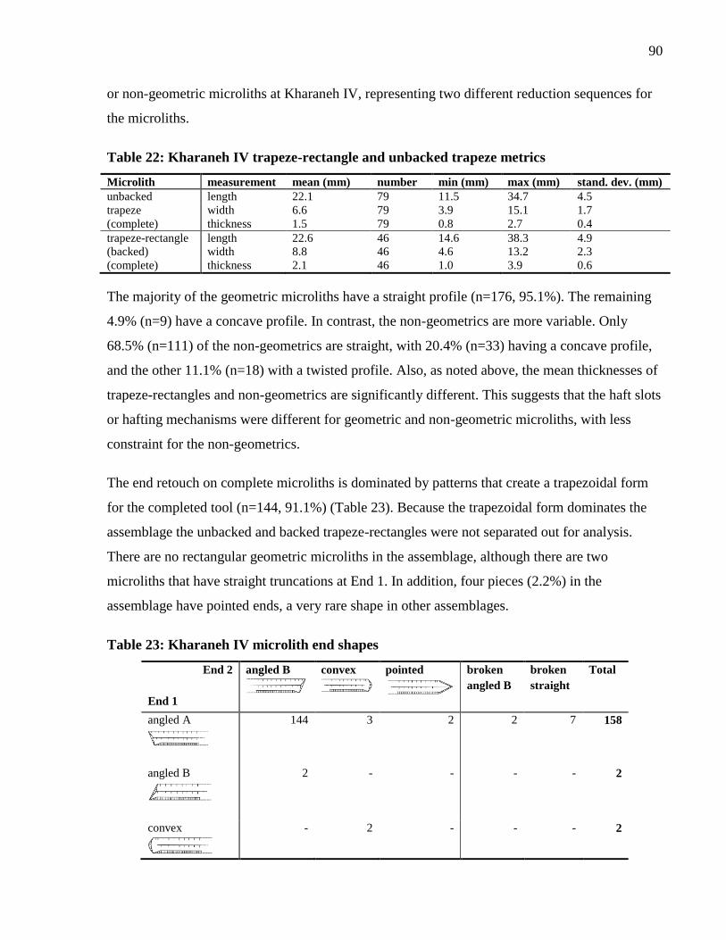
90
or non-geometric microliths at Kharaneh IV, representing two different reduction sequences for
the microliths.
Table 22: Kharaneh IV trapeze-rectangle and unbacked trapeze metrics
Microlith measurement mean (mm) number min (mm) max (mm) stand. dev. (mm)
unbacked length 22.1 79 11.5 34.7 4.5
trapeze width 6.6 79 3.9 15.1 1.7
(complete) thickness 1.5 79 0.8 2.7 0.4
trapeze-rectangle length 22.6 46 14.6 38.3 4.9
(backed) width 8.8 46 4.6 13.2 2.3
(complete) thickness 2.1 46 1.0 3.9 0.6
The majority of the geometric microliths have a straight profile (n=176, 95.1%). The remaining
4.9% (n=9) have a concave profile. In contrast, the non-geometrics are more variable. Only
68.5% (n=111) of the non-geometrics are straight, with 20.4% (n=33) having a concave profile,
and the other 11.1% (n=18) with a twisted profile. Also, as noted above, the mean thicknesses of
trapeze-rectangles and non-geometrics are significantly different. This suggests that the haft slots
or hafting mechanisms were different for geometric and non-geometric microliths, with less
constraint for the non-geometrics.
The end retouch on complete microliths is dominated by patterns that create a trapezoidal form
for the completed tool (n=144, 91.1%) (Table 23). Because the trapezoidal form dominates the
assemblage the unbacked and backed trapeze-rectangles were not separated out for analysis.
There are no rectangular geometric microliths in the assemblage, although there are two
microliths that have straight truncations at End 1. In addition, four pieces (2.2%) in the
assemblage have pointed ends, a very rare shape in other assemblages.
Table 23: Kharaneh IV microlith end shapes
End 2
End 1
angled B
convex
pointed
broken
angled B
broken
straight
Total
angled A
144 3 2 2 7 158
angled B
2 - - - - 2
convex
- 2 - - - 2
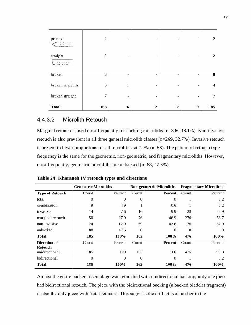
91
pointed
2 - - - - 2
straight
2 - - - - 2
broken
8 - - - - 8
broken angled A
3 1 - - - 4
broken straight
7 - - - - 7
Total 168 6 2 2 7 185
4.4.3.2 Microlith Retouch
Marginal retouch is used most frequently for backing microliths (n=396, 48.1%). Non-invasive
retouch is also prevalent in all three general microlith classes (n=269, 32.7%). Invasive retouch
is present in lower proportions for all microliths, at 7.0% (n=58). The pattern of retouch type
frequency is the same for the geometric, non-geometric, and fragmentary microliths. However,
most frequently, geometric microliths are unbacked (n=88, 47.6%).
Table 24: Kharaneh IV retouch types and directions
Geometric Microliths Non-geometric Microliths Fragmentary Microliths
Type of Retouch Count Percent Count Percent Count Percent
total 0 0 0 0 1 0.2
combination 9 4.9 1 0.6 1 0.2
invasive 14 7.6 16 9.9 28 5.9
marginal retouch 50 27.0 76 46.9 270 56.7
non-invasive 24 12.9 69 42.6 176 37.0
unbacked 88 47.6 0 0 0 0
Total 185 100% 162 100% 476 100%
Direction of
Retouch
Count Percent Count Percent Count Percent
unidirectional 185 100 162 100 475 99.8
bidirectional 0 0 0 0 1 0.2
Total 185 100% 162 100% 476 100%
Almost the entire backed assemblage was retouched with unidirectional backing; only one piece
had bidirectional retouch. The piece with the bidirectional backing (a backed bladelet fragment)
is also the only piece with ‘total retouch’. This suggests the artifact is an outlier in the
92
assemblage. When analyzing the direction of retouch, the retouch ends were included if the piece
was unbacked, since the technique of retouching is the same whether on the ends or along the
length of the microlith.
The geometrics types are mostly produced with marginal or non-invasive retouch. The rare
occurrences of invasive retouch were used to knap a variety of types including trapeze-
rectangles, lunates, parallelograms, and triangles. There doesn’t appear to be a pattern associated
with retouch types and geometric microlith group, except that marginal and non-invasive retouch
are popular for geometrics.
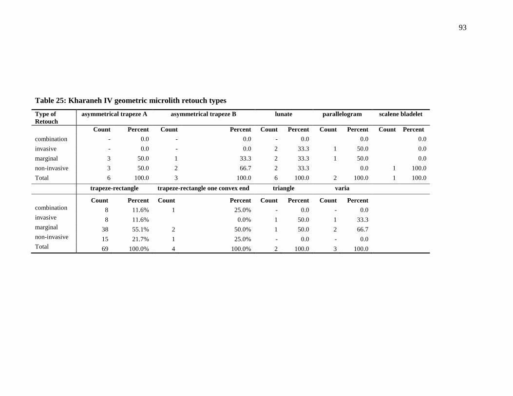
93
Table 25: Kharaneh IV geometric microlith retouch types
Type of
Retouch
asymmetrical trapeze A asymmetrical trapeze B lunate parallelogram scalene bladelet
Count Percent Count Percent Count Percent Count Percent Count Percent
combination - 0.0 - 0.0 - 0.0 0.0 0.0
invasive - 0.0 - 0.0 2 33.3 1 50.0 0.0
marginal 3 50.0 1 33.3 2 33.3 1 50.0 0.0
non-invasive 3 50.0 2 66.7 2 33.3 0.0 1 100.0
Total 6 100.0 3 100.0 6 100.0 2 100.0 1 100.0
trapeze-rectangle trapeze-rectangle one convex end triangle varia
Count Percent Count Percent Count Percent Count Percent
combination 8 11.6% 1 25.0% - 0.0 - 0.0
invasive 8 11.6% 0.0% 1 50.0 1 33.3
marginal 38 55.1% 2 50.0% 1 50.0 2 66.7
non-invasive 15 21.7% 1 25.0% - 0.0 - 0.0
Total 69 100.0% 4 100.0% 2 100.0 3 100.0
94
4.4.4 Kharaneh IV Summary
The site of Kharaneh IV has an extensive lithic assemblage showing evidence of all reduction
stages including core preparation, maintenance, tool manufacture, and discard. The retouched
lithic assemblage is predominantly composed of microliths (83.4%), with similar representation
of geometric (22.5%) and non-geometric microliths (19.7%). The geometric microliths are
highly variable, but trapeze-rectangles still predominate in the form of backed (8.5%) and
unbacked trapezes (10.7%). Although there is flexibility in microlith types, there is less
variability in the retouch style. All microlith classes are marginally, non-invasively, or invasively
retouched with unidirectional backing. Despite the similarities in the raw materials and the
retouch patterns between the geometric and the non-geometric microliths, the metrics suggest
that trapeze-rectangles were being produced from different blanks then the unbacked trapezes
and the non-geometrics.
4.5 Discussion
When evaluated together, the lithic assemblages from Wadi Mataha, ‘Uyun al-Hammâm and
Kharaneh IV exhibit some interesting patterns. All these sites have common elements, but they
subtly diverge when one considers reduction strategies used and variability in microlith
attributes. These differences will be discussed below.
4.5.1 Raw Materials and Reduction Strategy
At Wadi Mataha, the majority of the cores for the production of bladelets are broad-faced. Many
of the cores were still able to produce microliths prior to their discard, suggesting that raw
material was not scarce on the local landscape or that cores were not transported with the site’s
inhabitants. Both core preparation and maintenance were conducted at the site, with an emphasis
on maintaining the core face for removals. The microburin technique was used at the site for
snapping bladelets, although some of the microburins may be intrusive from later Natufian
deposits. Microliths are manufactured on fine or high-quality cherts, with no difference between
the raw material selection for geometric and non-geometric microliths.
In contrast, the most common core types at ‘Uyun al-Hammâm are subpyramidal bladelet cores
and wedge-shaped cores. As at Wadi Mataha, these cores were targeting the removal of
95
bladelets. Although many cores were abandoned because of hinged terminations, almost 20%
had no discernible reason for abandonment. There is a separate reduction sequence for many of
the flakes, indicated through the presence of amorphous flake cores and different raw material
choices between the flake and blade categories. There is evidence for core preparation and
maintenance at the site, although there was very little preparation of the cores. The microburin
technique was not used at the site for the production of microliths and bladelets were likely
truncated through snapping. Preliminary observation suggests that there is no difference between
the cherts chosen for the geometric and the non-geometric microliths (Appendix B).
The cores recovered from Kharaneh IV represent a wide range of types, almost all of which were
directed towards the removal of blades and bladelets. These include both narrow-faced and
broad-faced cores, among other types. Core-trimming elements are present in the assemblage,
representing both core preparation and core maintenance. Most of the effort is focused on
maintenance, but there is still more evidence at Kharaneh IV for core preparation than at the
other sites. Only 26 microburins have been found in the analyzed lithic assemblage of over
100,000 lithics, indicating un-systematic use of the technique. As with the other sites, there is no
difference between the cherts chosen for the geometric and the non-geometric microliths.
Ongoing raw material survey at Kharaneh IV will help trace the sources of different cherts used
for tool production at the site.
The reduction strategies for the three sites are primarily focused on the production of bladelets to
be retouched into various microlith forms. The entire reduction sequence was enacted at each
site, with a focus on core maintenance rather than core preparation.
4.5.2 Retouched Tools and Microlith Assemblages
At Wadi Mataha, the retouched assemblage is composed of 85.4% microliths. The rest of the
assemblage is primarily comprised of backed blades, retouched flakes, and notches. 42.3% of the
microliths are geometric, mostly in the form of invasively retouched trapeze-rectangles. These
trapeze-rectangles tend towards trapezoidal, rather than rectangular, forms. Microliths are
consistently retouched using unidirectional retouching methods and there is no evidence for the
systematic use of bidirectional retouch. Both geometric and non-geometric microliths were
probably manufactured from the same blanks, considering their similar metrics and raw material
selection.
96
The microliths at ‘Uyun al-Hammâm comprises 76.1% of the retouched assemblage. The
remainder of the assemblage contains scrapers, backed blades, and other types in small
proportions. The microliths are primarily geometrics, at 66.7% of the assemblage. Trapeze-
rectangles dominate the assemblage at 62.8% of the microliths. There is some flexibility in the
form of the trapeze-rectangles; 20.1% of the geometrics are trapezoidal, 10.7% are rectangular,
and 4.9% are somewhere in-between. Unidirectional retouch was preferred, but bidirectional
retouch was also used for microlith backing. There is little difference in the raw material
selection and the metrics between the geometric and the non-geometric microliths, suggesting
they were manufactured from the same blanks.
The retouched lithics from Kharaneh IV are also primarily microliths, at 83.4% of the
assemblage. Retouched pieces make up the next most frequent tool type, followed by scrapers
and backed blades. In contrast to Wadi Mataha and ‘Uyun al-Hammâm, the frequencies of
geometric (22.5%) and non-geometric microliths (19.7%) are similar. The geometrics are highly
variable, with 10 different types represented in the assemblage. Unbacked trapeze-rectangles
(8.5%) and backed trapeze-rectangles are the most prevalent geometric microliths (10.7%). The
trapeze-rectangles are highly variable, including narrow angular pieces and wide rounded forms.
Despite this variability in trapezoidal form, there are no rectangles in the assemblage. Retouch
was most commonly marginal or non-invasive, with a small percentage of invasive retouch.
Neither total nor bidirectional retouch were used in the assemblage for the production of
microliths. The geometrics are significantly wider and thicker than the non-geometric
microliths. In addition, the non-geometric microliths are more variable in their profile shape,
including twisted and concave forms. This suggests that these microlith classes are from different
reduction trajectories, despite the similarities in raw material choice, and that different hafting
configurations were possible. Alternately, these microliths could have been from the same
reduction sequence but were actively selected for their width and profile from the pool of
available blanks. This is particularly apparent in the differences between the unbacked and the
backed trapeze-rectangles. The unbacked trapezes seem to be manufactured on the same blanks
as the non-geometric microliths, while the backed trapeze-rectangles are manufactured on very
different blanks.
For all three sites, the tools are representative of types typically found in Middle Epipalaeolithic
assemblages. They are dominated by microliths, with an emphasis on geometrics. This pattern
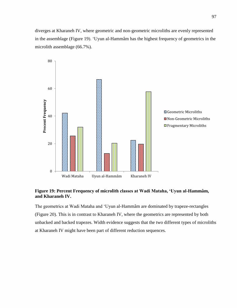
97
diverges at Kharaneh IV, where geometric and non-geometric microliths are evenly represented
in the assemblage (Figure 19). ‘Uyun al-Hammâm has the highest frequency of geometrics in the
microlith assemblage (66.7%).
Figure 19: Percent Frequency of microlith classes at Wadi Mataha, ‘Uyun al-Hammâm,
and Kharaneh IV.
The geometrics at Wadi Mataha and ‘Uyun al-Hammâm are dominated by trapeze-rectangles
(Figure 20). This is in contrast to Kharaneh IV, where the geometrics are represented by both
unbacked and backed trapezes. Width evidence suggests that the two different types of microliths
at Kharaneh IV might have been part of different reduction sequences.
0
20
40
60
80
Wadi Mataha Uyun al-Hammâm Kharaneh IV
Pre
cen
t F
req
ue
ncy
Geometric Microliths
Non-Geometric Microliths
Fragmentary Microliths
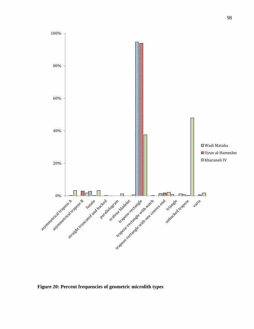
98
Figure 20: Percent frequencies of geometric microlith types
0%
20%
40%
60%
80%
100%
Wadi Mataha
Uyun al-Hammâm
Kharaneh IV
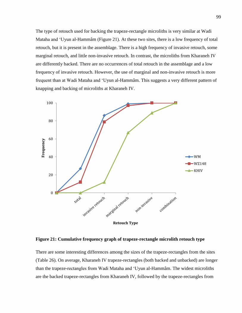
99
The type of retouch used for backing the trapeze-rectangle microliths is very similar at Wadi
Mataha and ‘Uyun al-Hammâm (Figure 21). At these two sites, there is a low frequency of total
retouch, but it is present in the assemblage. There is a high frequency of invasive retouch, some
marginal retouch, and little non-invasive retouch. In contrast, the microliths from Kharaneh IV
are differently backed. There are no occurrences of total retouch in the assemblage and a low
frequency of invasive retouch. However, the use of marginal and non-invasive retouch is more
frequent than at Wadi Mataha and ‘Uyun al-Hammâm. This suggests a very different pattern of
knapping and backing of microliths at Kharaneh IV.
Figure 21: Cumulative frequency graph of trapeze-rectangle microlith retouch type
There are some interesting differences among the sizes of the trapeze-rectangles from the sites
(Table 26). On average, Kharaneh IV trapeze-rectangles (both backed and unbacked) are longer
than the trapeze-rectangles from Wadi Mataha and ‘Uyun al-Hammâm. The widest microliths
are the backed trapeze-rectangles from Kharaneh IV, followed by the trapeze-rectangles from
0
20
40
60
80
100
Fre
qu
en
cy
Retouch Type
WM
WZ148
KHIV
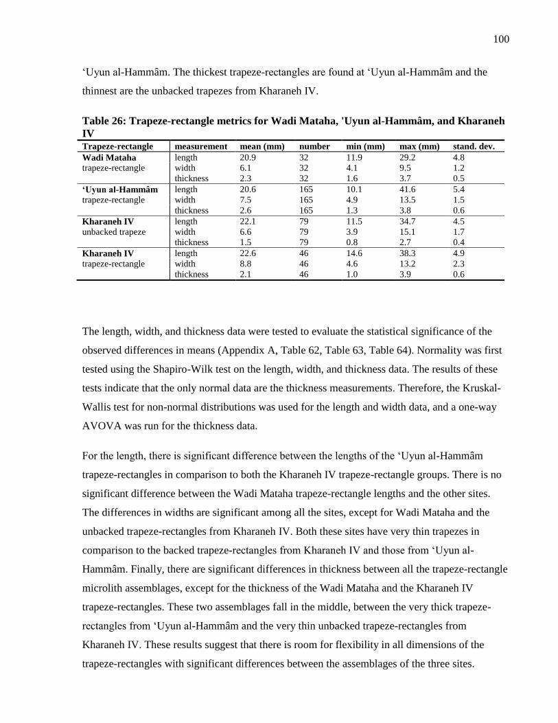
100
‘Uyun al-Hammâm. The thickest trapeze-rectangles are found at ‘Uyun al-Hammâm and the
thinnest are the unbacked trapezes from Kharaneh IV.
Table 26: Trapeze-rectangle metrics for Wadi Mataha, 'Uyun al-Hammâm, and Kharaneh
IV
Trapeze-rectangle measurement mean (mm) number min (mm) max (mm) stand. dev.
Wadi Mataha length 20.9 32 11.9 29.2 4.8
trapeze-rectangle width 6.1 32 4.1 9.5 1.2
thickness 2.3 32 1.6 3.7 0.5
‘Uyun al-Hammâm length 20.6 165 10.1 41.6 5.4
trapeze-rectangle width 7.5 165 4.9 13.5 1.5
thickness 2.6 165 1.3 3.8 0.6
Kharaneh IV length 22.1 79 11.5 34.7 4.5
unbacked trapeze width 6.6 79 3.9 15.1 1.7
thickness 1.5 79 0.8 2.7 0.4
Kharaneh IV length 22.6 46 14.6 38.3 4.9
trapeze-rectangle width 8.8 46 4.6 13.2 2.3
thickness 2.1 46 1.0 3.9 0.6
The length, width, and thickness data were tested to evaluate the statistical significance of the
observed differences in means (Appendix A, Table 62, Table 63, Table 64). Normality was first
tested using the Shapiro-Wilk test on the length, width, and thickness data. The results of these
tests indicate that the only normal data are the thickness measurements. Therefore, the Kruskal-
Wallis test for non-normal distributions was used for the length and width data, and a one-way
AVOVA was run for the thickness data.
For the length, there is significant difference between the lengths of the ‘Uyun al-Hammâm
trapeze-rectangles in comparison to both the Kharaneh IV trapeze-rectangle groups. There is no
significant difference between the Wadi Mataha trapeze-rectangle lengths and the other sites.
The differences in widths are significant among all the sites, except for Wadi Mataha and the
unbacked trapeze-rectangles from Kharaneh IV. Both these sites have very thin trapezes in
comparison to the backed trapeze-rectangles from Kharaneh IV and those from ‘Uyun al-
Hammâm. Finally, there are significant differences in thickness between all the trapeze-rectangle
microlith assemblages, except for the thickness of the Wadi Mataha and the Kharaneh IV
trapeze-rectangles. These two assemblages fall in the middle, between the very thick trapeze-
rectangles from ‘Uyun al-Hammâm and the very thin unbacked trapeze-rectangles from
Kharaneh IV. These results suggest that there is room for flexibility in all dimensions of the
trapeze-rectangles with significant differences between the assemblages of the three sites.
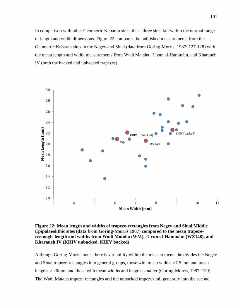
101
In comparison with other Geometric Kebaran sites, these three sites fall within the normal range
of length and width dimensions. Figure 22 compares the published measurements from the
Geometric Kebaran sites in the Negev and Sinai (data from Goring-Morris, 1987: 127-128) with
the mean length and width measurements from Wadi Mataha, ‘Uyun al-Hammâm, and Kharaneh
IV (both the backed and unbacked trapezes).
Figure 22: Mean length and widths of trapeze-rectangles from Negev and Sinai Middle
Epipalaeolithic sites (data from Goring-Morris 1987) compared to the mean trapeze-
rectangle length and widths from Wadi Mataha (WM), ‘Uyun al-Hammâm (WZ148), and
Kharaneh IV (KHIV unbacked, KHIV backed)
Although Goring-Morris notes there is variability within the measurements, he divides the Negev
and Sinai trapeze-rectangles into general groups, those with mean widths >7.5 mm and mean
lengths > 20mm, and those with mean widths and lengths smaller (Goring-Morris, 1987: 130).
The Wadi Mataha trapeze-rectangles and the unbacked trapezes fall generally into the second
10
12
14
16
18
20
22
24
26
28
30
3 4 5 6 7 8 9 10 11
Me
an
Le
ng
th (
mm
)
Mean Width (mm)
KHIV (backed) KHIV (unbacked)
WM WZ148
102
group, with mean widths of less than 7.5 mm. However, both sites have mean lengths greater
than 20 mm. ‘Uyun al-Hammâm is located at the cusp between the groups defined by Goring-
Morris, with a mean width of 7.5 mm and a mean length of 20.6 mm. The backed trapeze-
rectangle microliths from Kharaneh IV are aligned with the larger trapeze-rectangle microlith
group, although they are not as wide as some of the trapeze-rectangles from Shunera I, Shunera
XII, Shunera XIIB, Shunera XXV, Azariq XVIII, and Nahal Lavan 105. The addition of the
three study sites to the distribution further strengthens the assessment that there is considerable
variability in the range of sizes of trapeze-rectangles. Bar-Yosef (1970) initially hypothesized
that sites containing large or small trapeze-rectangles represented two distinct populations. I
would suggest that trapeze-rectangle measurements represent a continuum of form and not clear
separation between different groups.
4.5.3 Summary
Several interesting patterns are revealed from the results of the technological and typological
analysis of Wadi Mataha, ‘Uyun al-Hammâm, and Kharaneh IV. All three sites are located in
regions with abundant resources, including high-quality raw materials for flint knapping. The
debitage assemblages indicate that the complete reduction sequence is taking place at all three
sites, suggesting that flintknapping was an important activity performed at these locations.
Both Wadi Mataha and ‘Uyun al-Hammâm fit conformably within the designation of the
Geometric Kebaran. In contrast, Kharaneh IV is a very different assemblage. Although Kharaneh
IV has a lot of trapeze-rectangles, it also exhibits a high percentage of non-geometric microliths.
There is also a very high frequency of fragmentary microliths at Kharaneh IV. The nature of the
microlith assemblage with backed and unbacked trapeze rectangles makes the identification of
the fragmentary microliths very difficult. Thus, it is hard to know if many of these pieces were
geometric microliths prior to breakage. This site also has the most variable geometric microlith
assemblage, suggesting that there are complexities within the notion how microliths could be
designed and formed.
The technological and typological analysis of microliths from Wadi Mataha, ‘Uyun al-Hammâm,
and Kharaneh IV indicates that there were subtle differences in how geometric microliths were
being manufactured during the Middle Epipalaeolithic. This variability suggests that there is
flexibility within the technology that is expressed differently at different sites. This flexibility
103
may reflect ‘micro-styles’ (Dietler and Herbich, 1998) of trapeze rectangle production at each
site, or the technological style that come from producing material culture within a local group.
Subtle differences in the backing style between the three sites hint at different techniques for
producing microliths that may be taught and shared within each knapping community. The next
chapter will further explore the variability in geometric microliths from these sites through a
more detailed analysis of microlith shape.
104
Chapter 5 Geometric Morphometric Analysis
Introduction 5
In the previous chapter, the technological and typological variability of the Wadi Mataha, ‘Uyun
al-Hammâm, and Kharaneh IV lithic assemblages was analyzed. However, microlith form and
shape can only be described in a limited fashion through typology. Using typological
classifications for Epipalaeolithic microliths allows comparability between assemblages, but it
homogenizes the variability within these typological classes. Thus, new ways of presenting
morphological variability need to be explored if we are to understand fully the subtle variations
within microlith classes.
The field of geometric morphometrics studies shape variation in biological specimens (Adams, et
al., 2004, Bookstein, 1991), where shape is defined as the “geometric properties of an object
invariant to position, orientation, and size differences" (Slice, 2007:262). In this chapter, the
results of geometric morphometric analysis of trapeze-rectangle shape will be presented. This
analysis was conducted on a sample of complete trapeze rectangles from Wadi Mataha, ‘Uyun
al-Hammâm, and Kharaneh IV to evaluate variability in microlith form among the sites. Subtle
variation in form illuminates the choices made by flintknappers during the Middle
Epipalaeolithic and how different communities manipulated technology around a generalized
ideal. Geometric morphometric analysis of Epipalaeolithic microliths will contribute to our
understanding of how shape changes between different communities, indicating how stylistic
behaviour is displayed in everyday technology.
5.1 Background to Morphometrics
Traditional morphometric methods use multivariate statistics to describe shape through the
analysis of variables such as length, width, and distances between landmarks (Rohlf and Marcus,
1993). Over time, these traditional methods were replaced with geometric morphometric
approaches that allow an object’s shape to be preserved throughout the analysis. Geometric
morphometrics allows the non-shape data, including size and orientation, to be removed so that
only shape remains for the analysis (Adams, et al., 2004). The inception of geometric
morphometric techniques was the result of developing new statistical methods that could be
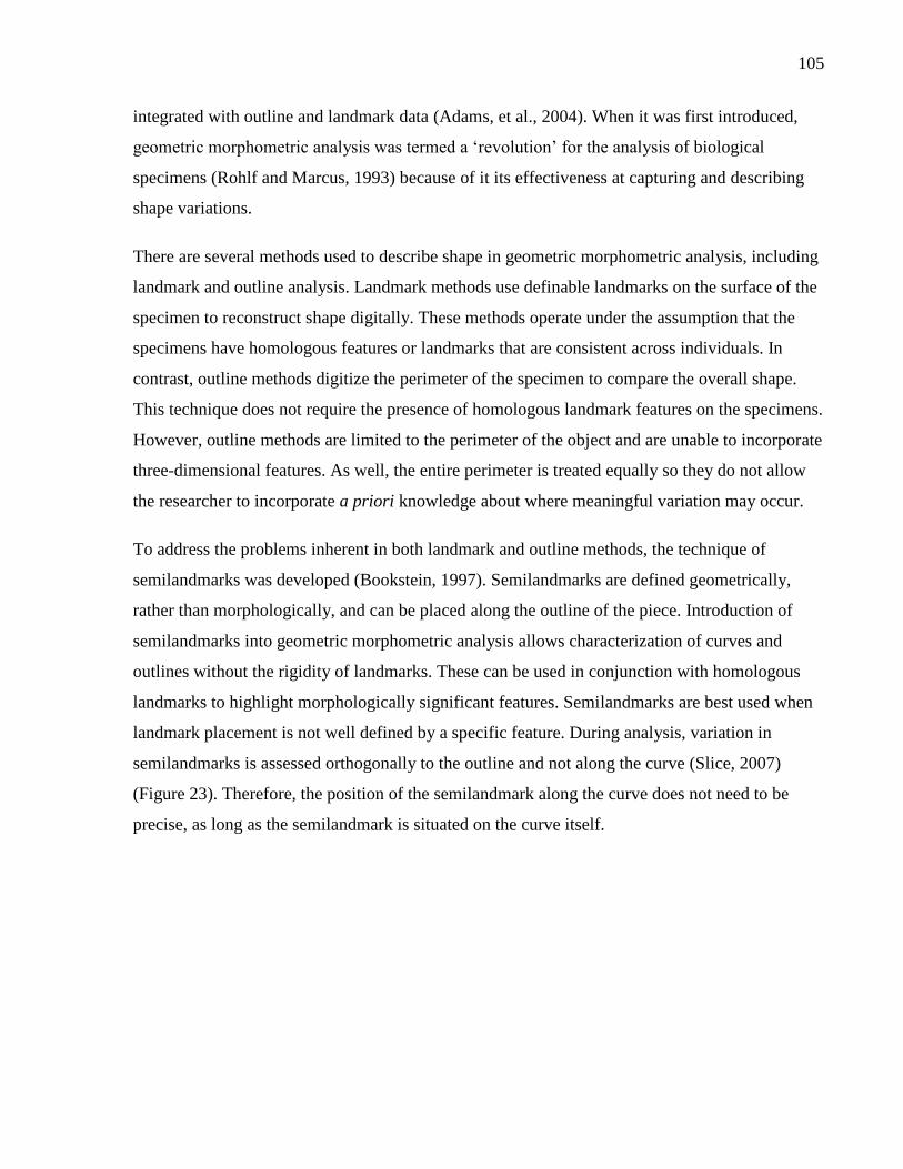
105
integrated with outline and landmark data (Adams, et al., 2004). When it was first introduced,
geometric morphometric analysis was termed a ‘revolution’ for the analysis of biological
specimens (Rohlf and Marcus, 1993) because of it its effectiveness at capturing and describing
shape variations.
There are several methods used to describe shape in geometric morphometric analysis, including
landmark and outline analysis. Landmark methods use definable landmarks on the surface of the
specimen to reconstruct shape digitally. These methods operate under the assumption that the
specimens have homologous features or landmarks that are consistent across individuals. In
contrast, outline methods digitize the perimeter of the specimen to compare the overall shape.
This technique does not require the presence of homologous landmark features on the specimens.
However, outline methods are limited to the perimeter of the object and are unable to incorporate
three-dimensional features. As well, the entire perimeter is treated equally so they do not allow
the researcher to incorporate a priori knowledge about where meaningful variation may occur.
To address the problems inherent in both landmark and outline methods, the technique of
semilandmarks was developed (Bookstein, 1997). Semilandmarks are defined geometrically,
rather than morphologically, and can be placed along the outline of the piece. Introduction of
semilandmarks into geometric morphometric analysis allows characterization of curves and
outlines without the rigidity of landmarks. These can be used in conjunction with homologous
landmarks to highlight morphologically significant features. Semilandmarks are best used when
landmark placement is not well defined by a specific feature. During analysis, variation in
semilandmarks is assessed orthogonally to the outline and not along the curve (Slice, 2007)
(Figure 23). Therefore, the position of the semilandmark along the curve does not need to be
precise, as long as the semilandmark is situated on the curve itself.
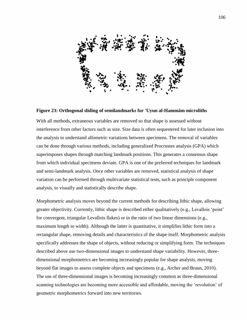
106
Figure 23: Orthogonal sliding of semilandmarks for 'Uyun al-Hammâm microliths
With all methods, extraneous variables are removed so that shape is assessed without
interference from other factors such as size. Size data is often sequestered for later inclusion into
the analysis to understand allometric variations between specimens. The removal of variables
can be done through various methods, including generalized Procrustes analysis (GPA) which
superimposes shapes through matching landmark positions. This generates a consensus shape
from which individual specimens deviate. GPA is one of the preferred techniques for landmark
and semi-landmark analysis. Once other variables are removed, statistical analysis of shape
variation can be performed through multivariate statistical tests, such as principle component
analysis, to visually and statistically describe shape.
Morphometric analysis moves beyond the current methods for describing lithic shape, allowing
greater objectivity. Currently, lithic shape is described either qualitatively (e.g., Levallois ‘point’
for convergent, triangular Levallois flakes) or in the ratio of two linear dimensions (e.g.,
maximum length to width). Although the latter is quantitative, it simplifies lithic form into a
rectangular shape, removing details and characteristics of the shape itself. Morphometric analysis
specifically addresses the shape of objects, without reducing or simplifying form. The techniques
described above use two-dimensional images to understand shape variability. However, three-
dimensional morphometrics are becoming increasingly popular for shape analysis, moving
beyond flat images to assess complete objects and specimens (e.g., Archer and Braun, 2010).
The use of three-dimensional images is becoming increasingly common as three-dimensional
scanning technologies are becoming more accessible and affordable, moving the ‘revolution’ of
geometric morphometrics forward into new territories.
107
5.2 Geometric Morphometrics and Lithics
Several recent studies have applied the biological technique of geometric morphometrics to lithic
assemblages to understand shape variability among artifacts (e.g., Buchanan, 2006, Eren and
Lycett, 2012, Iovita, 2011, Lycett, et al., 2010, Thulman, 2012). Geometric morphometric
analysis is more powerful for evaluating shape characteristics than metrics currently used by
many lithic analysts because it graphically and statistically represents shape without conflating
variables such as size into the analysis. Furthermore, it fully defines artifact shape while
exploring nuances of form not adequately captured by linear measurements. The tps suite of
programs (e.g., Rohlf, 2010a, 2010b, 2011) is popular among researchers since it uses
semilandmarks and is available for free online (http://life.bio.sunysb.edu/morph/). These
programs are designed by F. James Rohlf and are continuously being adapted and improved.
Some of the earliest research using geometric morphometric analysis to describe lithic variability
was conducted using landmark methods. In one early paper, Lycett et al. (2006) collected
landmark coordinates using a crossbeam co-ordinate caliper to conduct landmark geometric
morphometric analysis on a selection of cores. The primary purpose of this paper was to test the
new method of data collection with the crossbeam calipers and its ability to aid in the
qualification of lithic shape. Later landmark geometric morphometric analysis by the authors
incorporated generalized Procrustes analysis (GPA) using Morphologika software to test whether
Victoria West cores are actually large Levallois cores (Lycett, et al., 2010). The results of their
analysis suggest that the Victoria West cores are more similar to Lower Palaeolithic artifacts
such as handaxes and are a continuation of Acheulian traditions.
In other early research using landmark analysis, Buchanan (2006) used geometric morphometrics
to quantify resharpening and to evaluate resharpening models of Folsom points. For this
research, he used a landmark and semi-landmark approach using the tpsDig software to place the
landmarks. Three landmarks were defined (one at the tip and two at the base) and 33
semilandmarks were placed around the outline of the points. The shape of the point was
determined through 12 inter-landmark distances, which showed a high degree of asymmetry in
the assemblages for blade length. The author suggested that this showed evidence of
resharpening Folsom points (Buchanan, 2006). Later work by the same author used
108
morphometrics to distinguish among Clovis, Folsom, and Plainview points through landmark
and semi-landmark analysis using the tps suite of programs (Buchanan and Collard, 2010).
In recent work, Costa (2010) used the tps suite of programs to evaluate the shape of both bone
and stone handaxes. The tps programs use a Procrustes superimposition to remove size and thin-
plate spline deformation to facilitate visualization of shape changes from the mean. The results
of the geometric morphometric analysis show that there is no difference between the shapes of
the bone and the stone handaxes (Costa, 2010).
Another recent paper used landmark and semi-landmark analysis to look at standardization in
Middle and Upper Palaeolithic assemblages (Monnier and McNulty, 2010). For this research,
symmetry of the artifacts along the tool axis was used to position the landmarks. Twenty-four
semilandmarks were evenly spaced along the tool, with the endpoints of the axis marked as
homologous landmarks using tpsDig. The results show that there was more standardization in the
Upper than the Middle Palaeolithic, but that the Neolithic (used as a control) was the least
standardized (Monnier and McNulty, 2010).
Outline methods such as elliptical Fourier analysis (EFA) have also been used to assess lithic
shape. In outline methods no landmarks are assumed and the artifacts are analyzed based on their
perimeter outlines. Several studies have used EFA to understand variability in lithic morphology
(Iovita, 2009, 2010, 2011, Iovita and McPherron, 2011). These papers have evaluated the
interplay between lithic 'development' and shape (Iovita, 2009) and resharpening (Iovita, 2010).
In a recent paper Iovita (2011) used elliptical Fourier analysis to evaluate how retooling affects
shape variation and the functional implications of resharpening. The results showed that Aterian
tools were resharpened in the haft, becoming increasingly more rounded, and that they were
resharpened more heavily on one edge than the other. The geometric morphometric analysis on
Aterian tools indicates that they are not consistent with projectile points (Iovita, 2011), showing
how geometric morphometrics can contribute to our understanding of tool diversity during the
Middle Stone Age.
Both landmark and outline methods of analysis have been applied to lithic assemblages, but
landmark analysis is most commonly used in the published literature. Robust geometric
morphometric analysis for lithic artifacts uses a combination of landmarks and semilandmarks to
incorporate data from homologous points with outline data. This is corroborated by recent
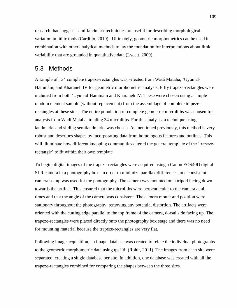
109
research that suggests semi-landmark techniques are useful for describing morphological
variation in lithic tools (Cardillo, 2010). Ultimately, geometric morphometrics can be used in
combination with other analytical methods to lay the foundation for interpretations about lithic
variability that are grounded in quantitative data (Lycett, 2009).
5.3 Methods
A sample of 134 complete trapeze-rectangles was selected from Wadi Mataha, ‘Uyun al-
Hammâm, and Kharaneh IV for geometric morphometric analysis. Fifty trapeze-rectangles were
included from both ‘Uyun al-Hammâm and Kharaneh IV. These were chosen using a simple
random element sample (without replacement) from the assemblage of complete trapeze-
rectangles at these sites. The entire population of complete geometric microliths was chosen for
analysis from Wadi Mataha, totaling 34 microliths. For this analysis, a technique using
landmarks and sliding semilandmarks was chosen. As mentioned previously, this method is very
robust and describes shapes by incorporating data from homologous features and outlines. This
will illuminate how different knapping communities altered the general template of the ‘trapeze-
rectangle’ to fit within their own template.
To begin, digital images of the trapeze-rectangles were acquired using a Canon EOS40D digital
SLR camera in a photography box. In order to minimize parallax differences, one consistent
camera set up was used for the photography. The camera was mounted on a tripod facing down
towards the artifact. This ensured that the microliths were perpendicular to the camera at all
times and that the angle of the camera was consistent. The camera mount and position were
stationary throughout the photography, removing any potential distortion. The artifacts were
oriented with the cutting edge parallel to the top frame of the camera, dorsal side facing up. The
trapeze-rectangles were placed directly onto the photography box stage and there was no need
for mounting material because the trapeze-rectangles are very flat.
Following image acquisition, an image database was created to relate the individual photographs
to the geometric morphometric data using tpsUtil (Rohlf, 2011). The images from each site were
separated, creating a single database per site. In addition, one database was created with all the
trapeze-rectangles combined for comparing the shapes between the three sites.
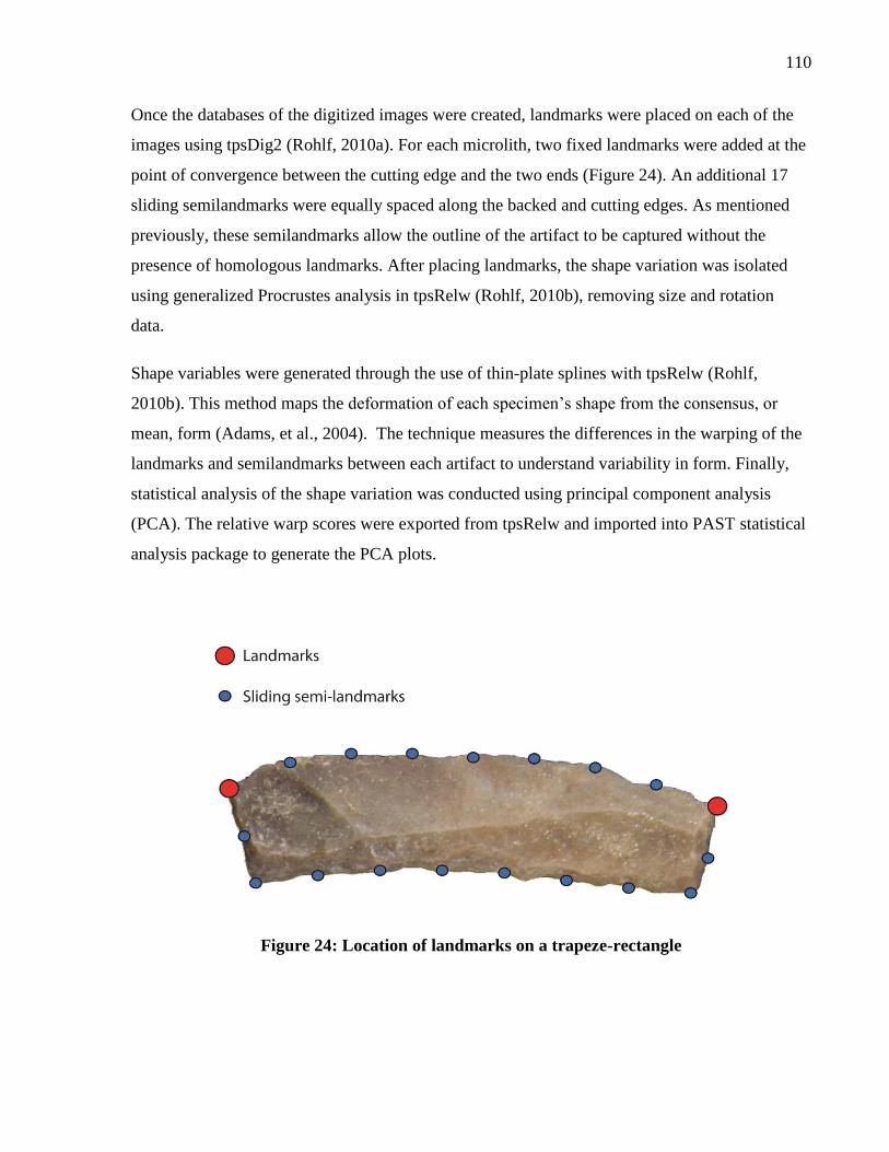
110
Once the databases of the digitized images were created, landmarks were placed on each of the
images using tpsDig2 (Rohlf, 2010a). For each microlith, two fixed landmarks were added at the
point of convergence between the cutting edge and the two ends (Figure 24). An additional 17
sliding semilandmarks were equally spaced along the backed and cutting edges. As mentioned
previously, these semilandmarks allow the outline of the artifact to be captured without the
presence of homologous landmarks. After placing landmarks, the shape variation was isolated
using generalized Procrustes analysis in tpsRelw (Rohlf, 2010b), removing size and rotation
data.
Shape variables were generated through the use of thin-plate splines with tpsRelw (Rohlf,
2010b). This method maps the deformation of each specimen’s shape from the consensus, or
mean, form (Adams, et al., 2004). The technique measures the differences in the warping of the
landmarks and semilandmarks between each artifact to understand variability in form. Finally,
statistical analysis of the shape variation was conducted using principal component analysis
(PCA). The relative warp scores were exported from tpsRelw and imported into PAST statistical
analysis package to generate the PCA plots.
Figure 24: Location of landmarks on a trapeze-rectangle
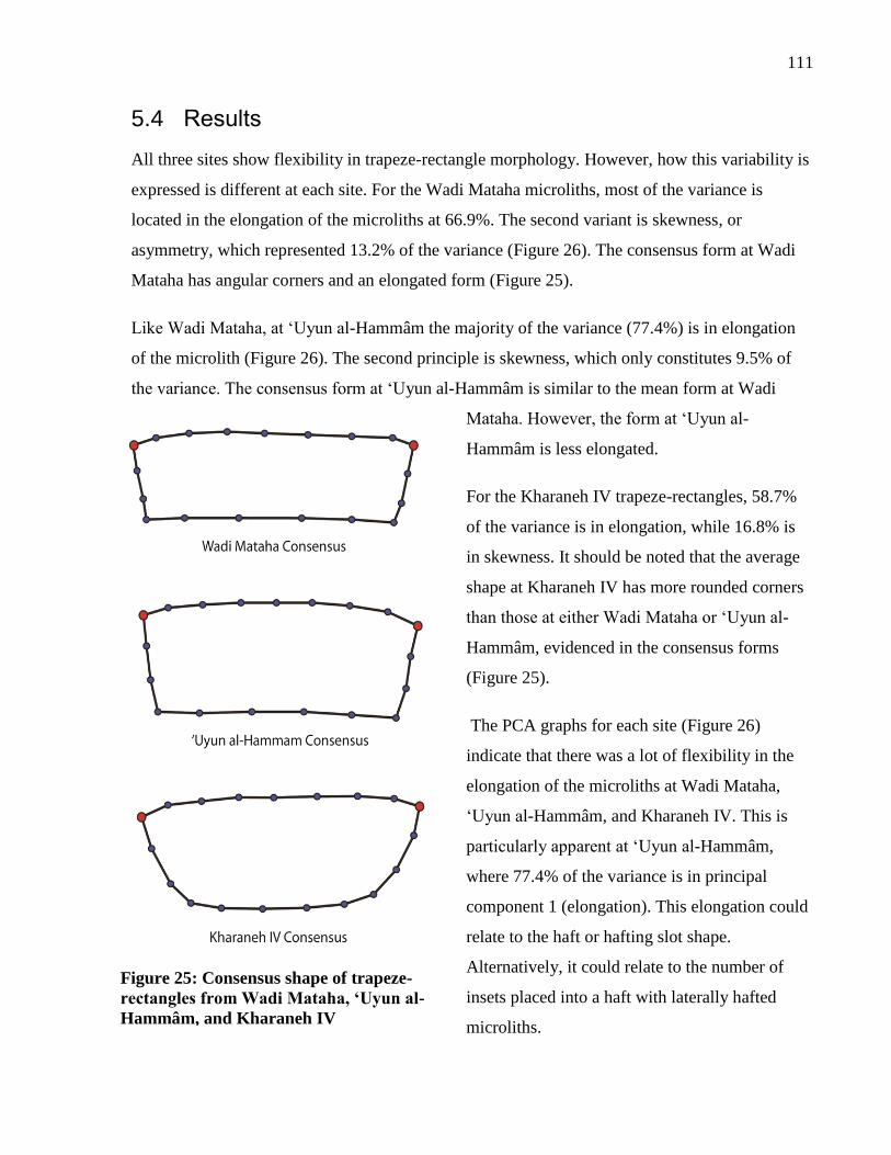
111
5.4 Results
All three sites show flexibility in trapeze-rectangle morphology. However, how this variability is
expressed is different at each site. For the Wadi Mataha microliths, most of the variance is
located in the elongation of the microliths at 66.9%. The second variant is skewness, or
asymmetry, which represented 13.2% of the variance (Figure 26). The consensus form at Wadi
Mataha has angular corners and an elongated form (Figure 25).
Like Wadi Mataha, at ‘Uyun al-Hammâm the majority of the variance (77.4%) is in elongation
of the microlith (Figure 26). The second principle is skewness, which only constitutes 9.5% of
the variance. The consensus form at ‘Uyun al-Hammâm is similar to the mean form at Wadi
Mataha. However, the form at ‘Uyun al-
Hammâm is less elongated.
For the Kharaneh IV trapeze-rectangles, 58.7%
of the variance is in elongation, while 16.8% is
in skewness. It should be noted that the average
shape at Kharaneh IV has more rounded corners
than those at either Wadi Mataha or ‘Uyun al-
Hammâm, evidenced in the consensus forms
(Figure 25).
The PCA graphs for each site (Figure 26)
indicate that there was a lot of flexibility in the
elongation of the microliths at Wadi Mataha,
‘Uyun al-Hammâm, and Kharaneh IV. This is
particularly apparent at ‘Uyun al-Hammâm,
where 77.4% of the variance is in principal
component 1 (elongation). This elongation could
relate to the haft or hafting slot shape.
Alternatively, it could relate to the number of
insets placed into a haft with laterally hafted
microliths.
Figure 25: Consensus shape of trapeze-
rectangles from Wadi Mataha, ‘Uyun al-
Hammâm, and Kharaneh IV
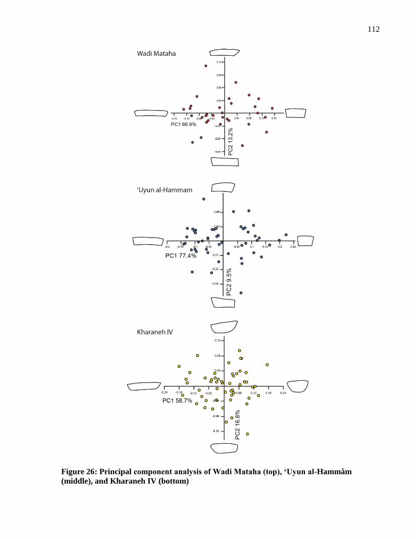
112
Figure 26: Principal component analysis of Wadi Mataha (top), ‘Uyun al-Hammâm
(middle), and Kharaneh IV (bottom)
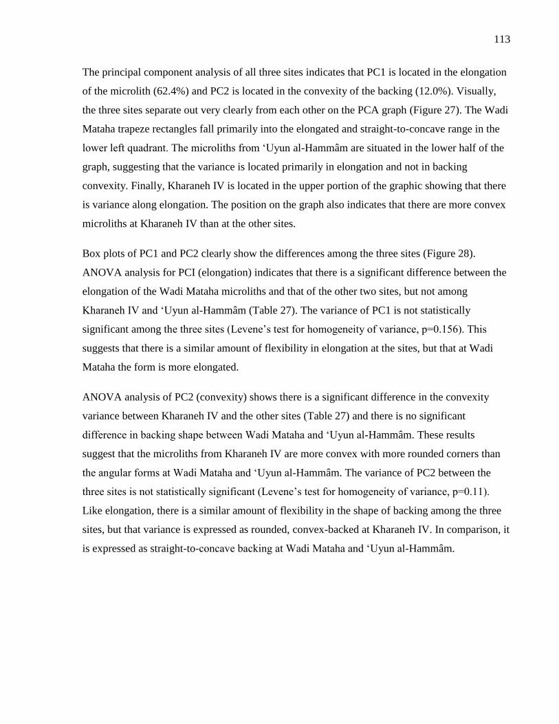
113
The principal component analysis of all three sites indicates that PC1 is located in the elongation
of the microlith (62.4%) and PC2 is located in the convexity of the backing (12.0%). Visually,
the three sites separate out very clearly from each other on the PCA graph (Figure 27). The Wadi
Mataha trapeze rectangles fall primarily into the elongated and straight-to-concave range in the
lower left quadrant. The microliths from ‘Uyun al-Hammâm are situated in the lower half of the
graph, suggesting that the variance is located primarily in elongation and not in backing
convexity. Finally, Kharaneh IV is located in the upper portion of the graphic showing that there
is variance along elongation. The position on the graph also indicates that there are more convex
microliths at Kharaneh IV than at the other sites.
Box plots of PC1 and PC2 clearly show the differences among the three sites (Figure 28).
ANOVA analysis for PCI (elongation) indicates that there is a significant difference between the
elongation of the Wadi Mataha microliths and that of the other two sites, but not among
Kharaneh IV and ‘Uyun al-Hammâm (Table 27). The variance of PC1 is not statistically
significant among the three sites (Levene’s test for homogeneity of variance, p=0.156). This
suggests that there is a similar amount of flexibility in elongation at the sites, but that at Wadi
Mataha the form is more elongated.
ANOVA analysis of PC2 (convexity) shows there is a significant difference in the convexity
variance between Kharaneh IV and the other sites (Table 27) and there is no significant
difference in backing shape between Wadi Mataha and ‘Uyun al-Hammâm. These results
suggest that the microliths from Kharaneh IV are more convex with more rounded corners than
the angular forms at Wadi Mataha and ‘Uyun al-Hammâm. The variance of PC2 between the
three sites is not statistically significant (Levene’s test for homogeneity of variance, p=0.11).
Like elongation, there is a similar amount of flexibility in the shape of backing among the three
sites, but that variance is expressed as rounded, convex-backed at Kharaneh IV. In comparison, it
is expressed as straight-to-concave backing at Wadi Mataha and ‘Uyun al-Hammâm.
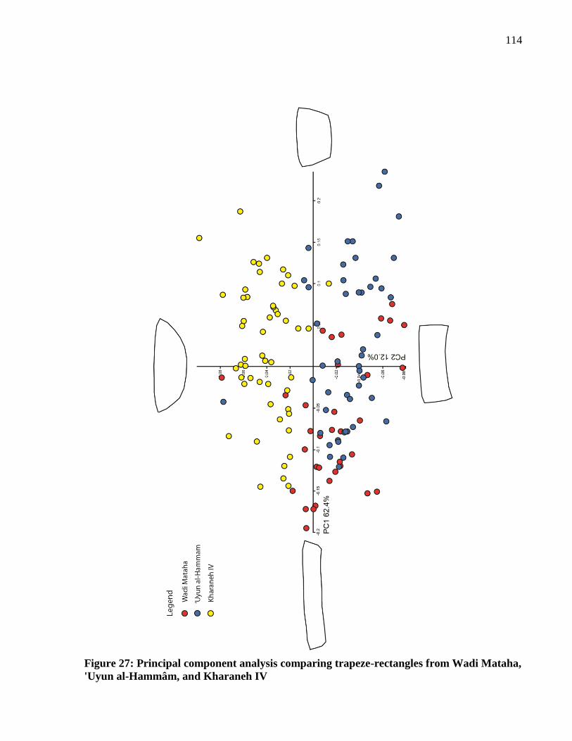
114
Figure 27: Principal component analysis comparing trapeze-rectangles from Wadi Mataha,
'Uyun al-Hammâm, and Kharaneh IV
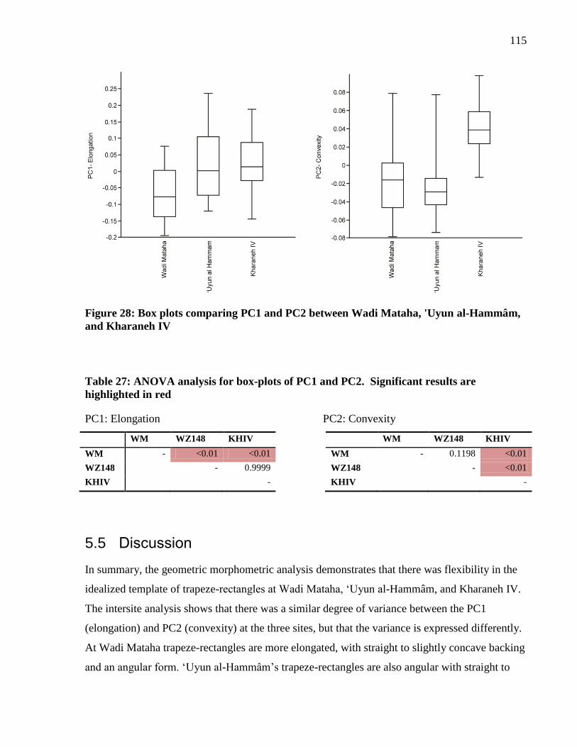
115
Figure 28: Box plots comparing PC1 and PC2 between Wadi Mataha, 'Uyun al-Hammâm,
and Kharaneh IV
Table 27: ANOVA analysis for box-plots of PC1 and PC2. Significant results are
highlighted in red
PC1: Elongation PC2: Convexity
WM WZ148 KHIV WM WZ148 KHIV
WM - <0.01 <0.01 WM - 0.1198 <0.01
WZ148 - 0.9999 WZ148 - <0.01
KHIV - KHIV -
5.5 Discussion
In summary, the geometric morphometric analysis demonstrates that there was flexibility in the
idealized template of trapeze-rectangles at Wadi Mataha, ‘Uyun al-Hammâm, and Kharaneh IV.
The intersite analysis shows that there was a similar degree of variance between the PC1
(elongation) and PC2 (convexity) at the three sites, but that the variance is expressed differently.
At Wadi Mataha trapeze-rectangles are more elongated, with straight to slightly concave backing
and an angular form. ‘Uyun al-Hammâm’s trapeze-rectangles are also angular with straight to
116
slightly concave backing, but have the greatest variance in elongation. Kharaneh IV trapeze-
rectangles have significantly different backing shape from the other sites, with rounded corners.
These results suggest that the flintknappers at the three sites were working around a similar
framework of trapeze-rectangle form, but manipulated their technology in slightly different ways
to create a unique expression of trapeze-rectangle form at each site. These differences could be
the result of different shapes of tool hafting slots, requiring different shaped trapeze-rectangles.
Alternately, or in addition, it could be that the overall form of trapeze-rectangles easily
permeates regional social boundaries, but that different communities have slightly different ways
manufacturing the final form based on local traditions and learning.
The use of morphometrics to describe shape moves beyond traditional typological descriptions,
accessing details of form not inherent in typological analysis. This suggests there are elements of
technological style inherent in the manufacturing process of trapeze-rectangle microliths,
changing the shape of these tools without deviating from the trapeze-rectangle template. Thus,
regional interaction may have mitigated the exchange of general technological knowledge; with
the trapeze-rectangle acting as a ‘diffuse technology’, one which is easily shared or borrowed
(Gosselain, 2000). The adaptation of this microlith form by different communities suggests that
it was a technologically malleable form that was easily adopted. This idea will be tested through
the analysis of microlith function from Wadi Mataha, ‘Uyun al-Hammâm and Kharaneh IV.
How do these differences in technological production and morphology relate to the function of
these artifacts? Are the differences witnessed in trapeze-rectangles the result of different
communities adopting and using this technology for different tasks? The contribution of
functional information into the discussion of the Geometric Kebaran will illuminate how
everyday actions were intertwined with material culture variability. The following three chapters
tackle the issue of microlith function through experimentation, use-wear analysis, and finally the
development of new quantitative use-wear methods.
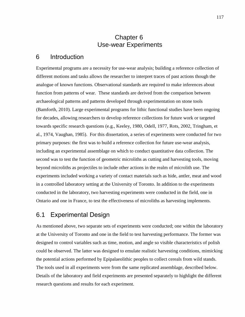
117
Chapter 6 Use-wear Experiments
Introduction 6
Experimental programs are a necessity for use-wear analysis; building a reference collection of
different motions and tasks allows the researcher to interpret traces of past actions though the
analogue of known functions. Observational standards are required to make inferences about
function from patterns of wear. These standards are derived from the comparison between
archaeological patterns and patterns developed through experimentation on stone tools
(Bamforth, 2010). Large experimental programs for lithic functional studies have been ongoing
for decades, allowing researchers to develop reference collections for future work or targeted
towards specific research questions (e.g., Keeley, 1980, Odell, 1977, Rots, 2002, Tringham, et
al., 1974, Vaughan, 1985). For this dissertation, a series of experiments were conducted for two
primary purposes: the first was to build a reference collection for future use-wear analysis,
including an experimental assemblage on which to conduct quantitative data collection. The
second was to test the function of geometric microliths as cutting and harvesting tools, moving
beyond microliths as projectiles to include other actions in the realm of microlith use. The
experiments included working a variety of contact materials such as hide, antler, meat and wood
in a controlled laboratory setting at the University of Toronto. In addition to the experiments
conducted in the laboratory, two harvesting experiments were conducted in the field, one in
Ontario and one in France, to test the effectiveness of microliths as harvesting implements.
6.1 Experimental Design
As mentioned above, two separate sets of experiments were conducted; one within the laboratory
at the University of Toronto and one in the field to test harvesting performance. The former was
designed to control variables such as time, motion, and angle so visible characteristics of polish
could be observed. The latter was designed to emulate realistic harvesting conditions, mimicking
the potential actions performed by Epipalaeolithic peoples to collect cereals from wild stands.
The tools used in all experiments were from the same replicated assemblage, described below.
Details of the laboratory and field experiments are presented separately to highlight the different
research questions and results for each experiment.
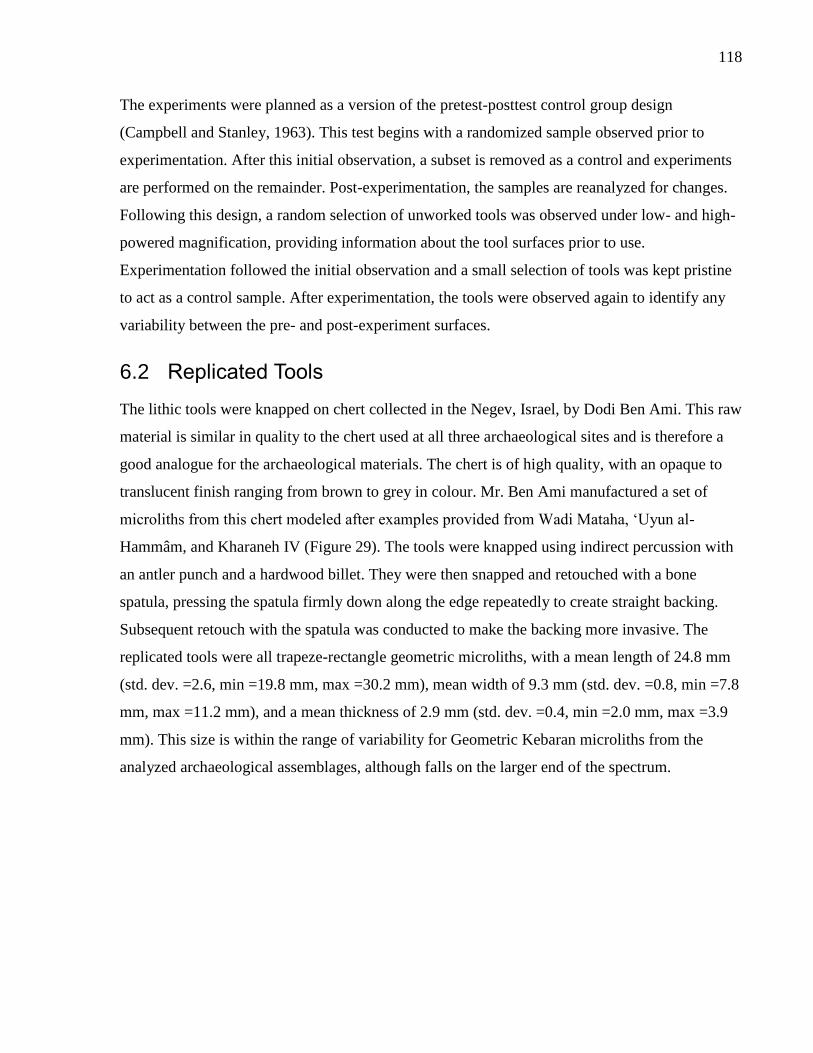
118
The experiments were planned as a version of the pretest-posttest control group design
(Campbell and Stanley, 1963). This test begins with a randomized sample observed prior to
experimentation. After this initial observation, a subset is removed as a control and experiments
are performed on the remainder. Post-experimentation, the samples are reanalyzed for changes.
Following this design, a random selection of unworked tools was observed under low- and high-
powered magnification, providing information about the tool surfaces prior to use.
Experimentation followed the initial observation and a small selection of tools was kept pristine
to act as a control sample. After experimentation, the tools were observed again to identify any
variability between the pre- and post-experiment surfaces.
6.2 Replicated Tools
The lithic tools were knapped on chert collected in the Negev, Israel, by Dodi Ben Ami. This raw
material is similar in quality to the chert used at all three archaeological sites and is therefore a
good analogue for the archaeological materials. The chert is of high quality, with an opaque to
translucent finish ranging from brown to grey in colour. Mr. Ben Ami manufactured a set of
microliths from this chert modeled after examples provided from Wadi Mataha, ‘Uyun al-
Hammâm, and Kharaneh IV (Figure 29). The tools were knapped using indirect percussion with
an antler punch and a hardwood billet. They were then snapped and retouched with a bone
spatula, pressing the spatula firmly down along the edge repeatedly to create straight backing.
Subsequent retouch with the spatula was conducted to make the backing more invasive. The
replicated tools were all trapeze-rectangle geometric microliths, with a mean length of 24.8 mm
(std. dev. =2.6, min =19.8 mm, max =30.2 mm), mean width of 9.3 mm (std. dev. =0.8, min =7.8
mm, max =11.2 mm), and a mean thickness of 2.9 mm (std. dev. =0.4, min =2.0 mm, max =3.9
mm). This size is within the range of variability for Geometric Kebaran microliths from the
analyzed archaeological assemblages, although falls on the larger end of the spectrum.
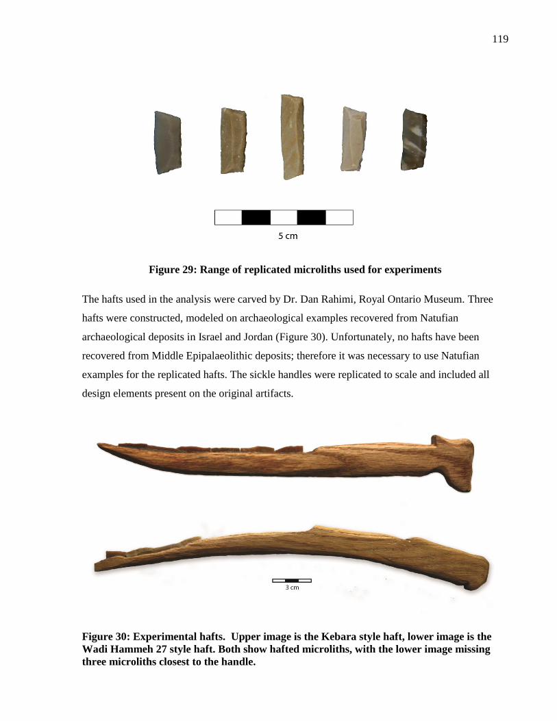
119
Figure 29: Range of replicated microliths used for experiments
The hafts used in the analysis were carved by Dr. Dan Rahimi, Royal Ontario Museum. Three
hafts were constructed, modeled on archaeological examples recovered from Natufian
archaeological deposits in Israel and Jordan (Figure 30). Unfortunately, no hafts have been
recovered from Middle Epipalaeolithic deposits; therefore it was necessary to use Natufian
examples for the replicated hafts. The sickle handles were replicated to scale and included all
design elements present on the original artifacts.
Figure 30: Experimental hafts. Upper image is the Kebara style haft, lower image is the
Wadi Hammeh 27 style haft. Both show hafted microliths, with the lower image missing
three microliths closest to the handle.
120
The first two hafts were modeled after a bone artifact
recovered from the Natufian deposits at Kebara Cave, Israel
(Noy, 1991).This haft has been interpreted as a sickle, with
the lithics inset lengthwise along the handle. In addition, it
has a zoomorphic head at the end of the handle representing
an ungulate. The piece has a slightly arched profile, curved
forwards towards the front of the sickle. Dr. Rahimi carved
two examples based on the Kebara sickle and these became
the primary hafts used in the harvesting experiments.
The third experimental haft was modeled from a wooden
handle recovered from the site of Wadi Hammeh 27, Jordan
(Edwards, 2007). This implement is also interpreted as a
sickle but unlike the Kebara example, this piece has two
parallel grooves for hafting microliths (Figure 31). This haft
design also has a curved profile but the curve is in the
opposite direction from the Kebara sickle, curving
backwards towards the body. This makes the implement
difficult to use for cutting grains, as will be described in the
harvesting section.
6.3 Laboratory Experiments
A series of different contact materials were chosen for the
laboratory-based experiments. The contact materials chosen
were meat, dry hide, hardwood, and antler, representing
different possible materials used in prehistory. Also, they
range in hardness, thereby producing a large range of
different polishes for the reference collection. All of the
laboratory-based experiments were performed in a controlled
setting by the author in the Department of Anthropology, the
University of Toronto. Figure 31: Schematic of Wadi
Hammeh 27 sickle (adapted from
Edwards 2007)
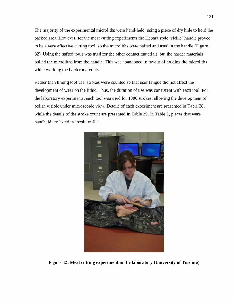
121
The majority of the experimental microliths were hand-held, using a piece of dry hide to hold the
backed area. However, for the meat cutting experiments the Kebara style ‘sickle’ handle proved
to be a very effective cutting tool, so the microliths were hafted and used in the handle (Figure
32). Using the hafted tools was tried for the other contact materials, but the harder materials
pulled the microliths from the handle. This was abandoned in favour of holding the microliths
while working the harder materials.
Rather than timing tool use, strokes were counted so that user fatigue did not affect the
development of wear on the lithic. Thus, the duration of use was consistent with each tool. For
the laboratory experiments, each tool was used for 1000 strokes, allowing the development of
polish visible under microscopic view. Details of each experiment are presented in Table 28,
while the details of the stroke count are presented in Table 29. In Table 2, pieces that were
handheld are listed in ‘position #1’.
Figure 32: Meat cutting experiment in the laboratory (University of Toronto)
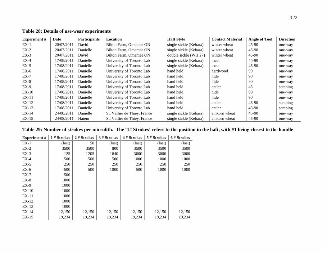
122
Table 28: Details of use-wear experiments
Experiment # Date Participants Location Haft Style Contact Material Angle of Tool Direction
EX-1 20/07/2011 David Bilton Farm, Omemee ON single sickle (Kebara) winter wheat 45-90 one-way
EX-2 20/07/2011 Danielle Bilton Farm, Omemee ON single sickle (Kebara) winter wheat 45-90 one-way
EX-3 20/07/2011 David Bilton Farm, Omemee ON double sickle (WH 27) winter wheat 45-90 one-way
EX-4 17/08/2011 Danielle University of Toronto Lab single sickle (Kebara) meat 45-90 one-way
EX-5 17/08/2011 Danielle University of Toronto Lab single sickle (Kebara) meat 45-90 one-way
EX-6 17/08/2011 Danielle University of Toronto Lab hand held hardwood 90 one-way
EX-7 17/08/2011 Danielle University of Toronto Lab hand held hide 90 one-way
EX-8 17/08/2011 Danielle University of Toronto Lab hand held hide 90 one-way
EX-9 17/08/2011 Danielle University of Toronto Lab hand held antler 45 scraping
EX-10 17/08/2011 Danielle University of Toronto Lab hand held hide 90 one-way
EX-11 17/08/2011 Danielle University of Toronto Lab hand held hide 90 one-way
EX-12 17/08/2011 Danielle University of Toronto Lab hand held antler 45-90 scraping
EX-13 17/08/2011 Danielle University of Toronto Lab hand held antler 45-90 scraping
EX-14 24/08/2011 Danielle St. Vallier de Thiey, France single sickle (Kebara) einkorn wheat 45-90 one-way
EX-15 24/08/2011 Hatem St. Vallier de Thiey, France single sickle (Kebara) einkorn wheat 45-90 one-way
Table 29: Number of strokes per microlith. The ‘1# Strokes’ refers to the position in the haft, with #1 being closest to the handle
Experiment # 1 # Strokes 2 # Strokes 3 # Strokes 4 # Strokes 5 # Strokes 6 # Strokes
EX-1 (lost) 50 (lost) (lost) (lost) (lost)
EX-2 3500 3500 800 3500 3500 3500
EX-3 125 1205 1640 3000 3000 3000
EX-4 500 500 500 1000 1000 1000
EX-5 250 250 250 250 250 250
EX-6 500 500 1000 500 1000 1000
EX-7 500
EX-8 1000
EX-9 1000
EX-10 1000
EX-11 1000
EX-12 1000
EX-13 1000
EX-14 12,150 12,150 12,150 12,150 12,150 12,150
EX-15 19,234 19,234 19,234 19,234 19,234 19,234
123
As mentioned previously, I initially attempted to work all contact materials with hafted
microliths. However, this quickly proved impossible for the harder contact materials; the
microliths caught in the hard surfaces and were pulled from the haft. As a result, microliths were
used handheld for working antler, wood, and hide (hide was worked last and it was decided not
to haft the microliths, although the soft nature of hide would have been workable with the hafted
microliths). Although several of the microliths were used as handheld tools, these tools would
not have been used without a haft during the Epipalaeolithic. The small size of the tools makes
them challenging to hold for extended periods of time and a user with larger hands would find
the task almost impossible.
The only laboratory experiment used with hafted microliths was the meat-cutting experiment. In
this experiment, small chunks of meat were severed from the main shoulder. The hafted
microliths functioned very well to slice through the meat with minimal physical contact. Using
this technique, the meat could be cleanly cut with ease. This suggests that a potential function of
the microliths could be longitudinal motions through soft material, such as meat.
6.4 Harvesting Experiments
Harvesting wheat comprised the second stage of the experiments. The goal of these experiments
was to test the usability of microliths and Epipalaeolithic hafts for harvesting cereals. Two
separate harvesting experiments were conducted, one located in southern Ontario and the other in
southern France. The Ontario experiments functioned as a pilot study for the later harvesting
experiments in France, where einkorn wheat was harvested as part of a larger experiment. Both
experiments are described below, highlighting the experiences of the harvesters using the hafted
microliths and the replicated sickles.
6.4.1 Harvesting in Ontario
The initial harvesting experiment took place on a farm owned by the Bilton family outside of
Omemee, Ontario on July 20th
, 2011. This farm grew winter wheat (Triticum hybernum) for sale
in local agricultural markets and the farmer had cornered off an area for the experimental
harvesting prior to mechanically harvesting the wheat. There were two participants in the study,
myself and David Bilton, the son of the farm owner and a fellow archaeologist. The wheat was
dry, with a small amount of moisture remaining in the stems. The area harvested was 17.88 m2
124
(456 cm x 392 cm) with an average of 690 stalks of wheat per square meter. The mean stem
diameter was 3.2 mm, average plant height was 111 cm from the ground (including the ear), and
the mean length of the ear was 74.0 mm. The experiment numbers for the sickles used during the
harvesting are experiments 1, 2, and 3 (EX-1, EX-2, EX-3). Details about stroke counts, tool
angle, and direction of motion can be found in Table 28-2.
We started harvesting by using the two Kebara-style sickles (EX-1, EX-2). Microliths were
hafted into the sickle handles using clear silicone. Within the first few minutes the sickle that
David was using (EX-1) lost four microliths, possibly due to poor hafting, enthusiastic
harvesting, or a combination of both. This sickle was only used for 50 strokes before the
microliths were lost. Next, David started using the double sickle (modeled after Wadi Hammeh
27) (EX-3) and used that for the rest of the day. Over the course of harvesting, David lost six
microliths from the double sickle, beginning with the two closest to the holding position and then
moving up successively. I lost the center microlith about half-way through the day but continued
to harvest with the Kebara-style sickle (EX-2) for the remainder of the day, favoring the two
microliths closest to the handle to prevent further loss.
Our primary observation at the end of the pilot harvesting study was that the sickles worked
extremely well, despite losing some of the microliths. Small spaces between the microliths
caught the stalks, which contributed to the microliths being pulled out of the hafts. This problem
was remedied for the later experiments conducted in France. Both of the haft designs were very
comfortable to hold and did not cause hand fatigue after a full day of harvesting. The
zoomorphic head at the base of the Kebara sickle handle kept my hand from slipping off the end
of the handle and comfortably fit my grip. Upon reflection, it seems that this zoomorphic head
was purposeful as both a decorative and functional design element. Although the Wadi Hammeh
27 sickle does not have a similar animal design, it does have a small ridge at the handle. This
ridge also kept David’s hand from slipping and was comfortable to hold, functioning the same as
the Kebara sickle’s handle.
Overall, the Kebara sickle functioned more effectively as a harvesting implement. The sickle’s
curve towards the front helped to gather multiple stalks towards the microlith’s cutting edges. In
contact, the Wadi Hammeh 27 sickle curved backwards, making it more challenging to cut
multiple stalks. As well, the parallel cutting edges were redundant for harvesting cereals. Based
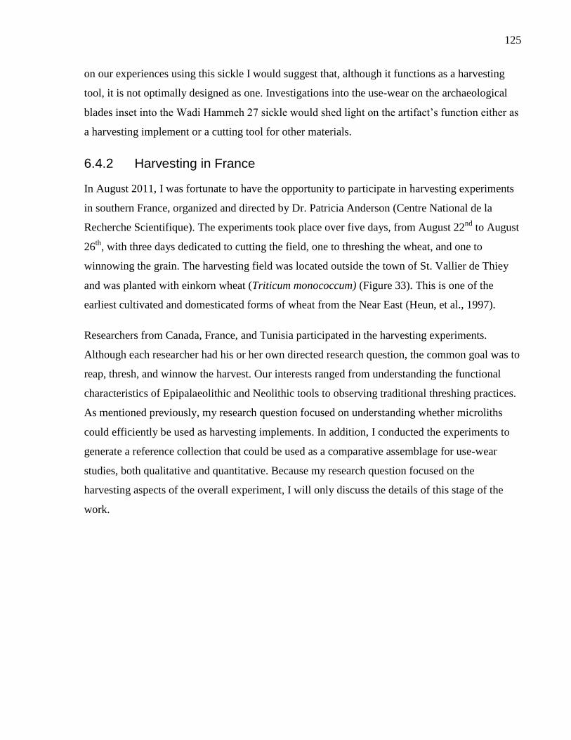
125
on our experiences using this sickle I would suggest that, although it functions as a harvesting
tool, it is not optimally designed as one. Investigations into the use-wear on the archaeological
blades inset into the Wadi Hammeh 27 sickle would shed light on the artifact’s function either as
a harvesting implement or a cutting tool for other materials.
6.4.2 Harvesting in France
In August 2011, I was fortunate to have the opportunity to participate in harvesting experiments
in southern France, organized and directed by Dr. Patricia Anderson (Centre National de la
Recherche Scientifique). The experiments took place over five days, from August 22nd
to August
26th
, with three days dedicated to cutting the field, one to threshing the wheat, and one to
winnowing the grain. The harvesting field was located outside the town of St. Vallier de Thiey
and was planted with einkorn wheat (Triticum monococcum) (Figure 33). This is one of the
earliest cultivated and domesticated forms of wheat from the Near East (Heun, et al., 1997).
Researchers from Canada, France, and Tunisia participated in the harvesting experiments.
Although each researcher had his or her own directed research question, the common goal was to
reap, thresh, and winnow the harvest. Our interests ranged from understanding the functional
characteristics of Epipalaeolithic and Neolithic tools to observing traditional threshing practices.
As mentioned previously, my research question focused on understanding whether microliths
could efficiently be used as harvesting implements. In addition, I conducted the experiments to
generate a reference collection that could be used as a comparative assemblage for use-wear
studies, both qualitative and quantitative. Because my research question focused on the
harvesting aspects of the overall experiment, I will only discuss the details of this stage of the
work.
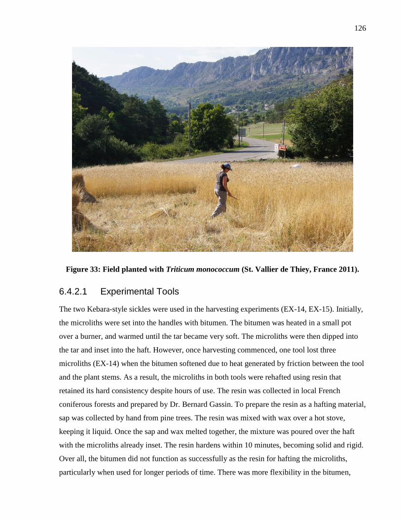
126
Figure 33: Field planted with Triticum monococcum (St. Vallier de Thiey, France 2011).
6.4.2.1 Experimental Tools
The two Kebara-style sickles were used in the harvesting experiments (EX-14, EX-15). Initially,
the microliths were set into the handles with bitumen. The bitumen was heated in a small pot
over a burner, and warmed until the tar became very soft. The microliths were then dipped into
the tar and inset into the haft. However, once harvesting commenced, one tool lost three
microliths (EX-14) when the bitumen softened due to heat generated by friction between the tool
and the plant stems. As a result, the microliths in both tools were rehafted using resin that
retained its hard consistency despite hours of use. The resin was collected in local French
coniferous forests and prepared by Dr. Bernard Gassin. To prepare the resin as a hafting material,
sap was collected by hand from pine trees. The resin was mixed with wax over a hot stove,
keeping it liquid. Once the sap and wax melted together, the mixture was poured over the haft
with the microliths already inset. The resin hardens within 10 minutes, becoming solid and rigid.
Over all, the bitumen did not function as successfully as the resin for hafting the microliths,
particularly when used for longer periods of time. There was more flexibility in the bitumen,
127
increasing as the bitumen heated in the sun and with the friction of contact with the cereal. This
heating caused the microliths to fall out after continued use. In contrast, the resin was much
harder and did not lose strength or soften with continued use.
The only negative aspect of resin hafting was removing the microliths at the end of the
experiment. The pieces hafted in bitumen were easy to remove; each microlith was rocked gently
back and forth to loosen the hafting material and was then pulled from the haft. The pieces hafted
in resin would not wiggle as there was no flexibility in the material. Therefore the resin had to be
carefully chipped away from the microlith, removing the surrounding resin until the resin was
thin enough to break under lateral pressure, allowing the microliths to be removed. This was
done very carefully to protect the surface of the microlith for use-wear traces.
6.4.2.2 Field Characteristics
The field was planted with einkorn wheat (Triticum monococcum) in a random pattern
mimicking the growth pattern of wild cereals. The overall size of the field was approximately
630 m2 but it was parceled into smaller sections for each harvester. Einkorn wheat is an early
Near Eastern domesticated crop and has a similar breakage pattern to its wild progenitor. The
field was planted very densely with wheat, with 792 stems per square meter. This is on the high
end of wild cereal strands that usually have 600-800 stalks per square meter (Anderson personal
communication). There was an average of 19 spikelets per seed head. The overall grain yield was
15 kg in total at the end of the harvest after threshing and winnowing.
6.4.2.3 Details of the Experiment
The two Kebara-style sickles were used in the experiments; one was used by me (EX-14) and the
other by Hatem El Gtari (EX-15), an archaeologist from Tunisia. Stroke counts were
approximated by recording the average number of strokes cut per minute, averaged over 10 times
at the beginning of each day. The average number of strokes for my harvesting was 30 strokes
per minute, while the average for Hatem, who was a more vigorous harvester, was 59 strokes per
minute.
Experiment 14 was conducted using a Kebara-style haft with seven hafted microliths. Microliths
1-3 (with 1 being closest to the handle) became dislodged as a result of the bitumen hafting and
were re-hafted with resin. To cut the wheat stalks, a handful of approximately 7-10 stems were
128
collected in my left hand. The stems were then twisted half a turn, bundling the stems together
into a group. Two to three fast strokes with the sickle were required to cut through the bundle,
pulling the sickle towards myself in a smooth motion. Cutting was done close to the ground,
approximately 20-30 cm from the soil surface. In total, the sickle was used for approximately
12,150 strokes (405 minutes of cutting) over three days. The total field size harvested during this
time was 78 m2. This use duration exceeds the 10,000 strokes needed to observe macroscopic
luster as identified by Unger-Hamilton (1991), but is less than Yamada’s 11 hours of harvesting
(2000).
Experiment 15 was also conducted using a Kebara-style sickle, but this experiment was
performed by Hatem. The microliths in this sickle were originally hafted with bitumen but were
reset using resin at the same time as the other sickle was rehafted. In total, this sickle was used
for approximately 19,234 strokes, equaling 326 minutes of harvesting time. The total field size
harvested with this sickle was 84.25 m2.
The results of the experiment indicated that the hafted microliths were very efficient harvesting
tools. The regular size and shape of the flint implements allowed them to function without
breaking, catching stems, or falling out of the handle while harvesting. The Kebara-style hafts
were ergonomic, fitting comfortably into the hand without causing fatigue. The gazelle head
functioned to keep one’s hand from slipping off the end of the tool while vigorously cutting
wheat, suggesting that the zoomorphic design had a functional purpose in addition its decorative
characteristics. After three days and more than 12,000 strokes, the tools still functioned at cutting
grain stems (although the harvester was feeling fatigued).
6.5 Summary
The experimental program was designed for two purposes, 1) to test the functionality of
geometric microliths and Epipalaeolithic replicated hafts as harvesting implements and 2) to
build a reference collection for use-wear analysis. In addition, a selection of these experimental
tools was used to test new methods of use-wear quantification, described in Chapter 7. Wear was
visible on many of the experimental tools and polish was most prominent on the wheat-
harvesting tools and the harder contact materials, such as antler. These are typical results for
polish; both sickle polish and antler polish are described as ‘bright’, or in the case of cereals,
‘extremely bright’ (Vaughan, 1985:32,35), and tend to be easy to see. Future experiments will
129
build upon this reference collection to include additional contact materials, motions, and
durations of use.
Overall, the microliths function very well as harvesting tools, performing over three days of
intensive harvesting without losing cutting ability. Likewise, they also worked as cutting tools
for softer contact materials, such as meat, although harvesting felt more natural with the hafted
microliths. The straight, thin cutting edge on the microlith performed longitudinal cutting
motions effectively and the thin nature of the microliths allowed them to slice quickly through
various materials. Through experimentation it became clear that hafting material was an integral
element that greatly affected the effectiveness of the tool. Finding a balance between durability
and ease of retooling would have been an important consideration in choosing appropriate mastic
during the Epipalaeolithic. Both hafts were very comfortable to use, although the Kebara style
haft worked better as a harvesting implement than did the Wadi Hammeh 27 style haft. This
suggests that the Wadi Hammeh 27 tool may have had an alternative function, or that the design
integrated elements beyond functional requirements. The laboratory and harvesting experiments
resulted in a better understanding of how microliths functioned as cutting tools and the design
features of Epipalaeolithic hafts.
130
Chapter 7 Use-Wear Analysis of the Microlith Assemblages
Introduction 7
Use-wear analysis reconstructs past actions of tool use through the observation of striations,
polish, and microfractures on tool surfaces. The details of action, the duration of use, and the
type of materials worked will all impact the development of wear features on the lithic surface.
By carefully recording traces and imprints left on the tool we can interpret past behaviours
through archaeological materials.
The analytical technique of use-wear analysis has traditionally relied on qualitative observations
to identify wear patterns microscopically, either at high or low magnifications. Low-powered
microscopy highlights microfractures and damage on a tool’s edge (Odell, 1977, Odell and
Odell-Vereecken, 1980, Tringham, et al., 1974). This type of analysis is usually conducted with a
stereomicroscope at magnifications less than 100x and can be done relatively quickly, allowing
for the analysis of large sample sizes. Stereomicroscopy has a good depth of field and allows
large image areas to be captured, but it does not image the specimen’s surface at high enough
resolution to allow the observation of subtle polishes and striations. Overall, the
stereomicroscope excels at assessing the pattern of microfractures produced on a flake’s edge
(Tringham, et al., 1974) and its ease of use makes it excellent for initial analysis of large
assemblages.
In contrast, high-powered microscopy at magnifications between 100 and 1 000x allows the
observation of polishes and striations (Keeley, 1980, Vaughan, 1985). This analysis is
traditionally performed with an incident light microscope. In comparison to stereomicroscopy,
incident light microscopy (with bright field illumination) directs light downwards towards the
specimen, striking the surface at 90 degrees to the focal plane (Keeley, 1980). This lighting
coupled with high numerical apertures allows observation of surface features at high
magnifications. Limitations of incident light microscopy are poor depth of field and short
working distances. High-powered microscopy is also very time-consuming, meaning only small
sample sizes can be analyzed for most studies. The strength of high-powered incident-light
131
microscopy is that it allows identification of microstriations and polish that are not easily
detected at lower magnifications.
Due to the strengths and weaknesses of both techniques, the combination of low-powered and
high-powered microscopy is integral to interpreting microwear patterns on a tool’s surface (e.g.,
Grace, 1989, Grace, 1996, van Gijn, 2010). Ultimately, high-powered magnification is better at
evaluating the types of materials worked through the identification of polish types and the
direction of use through striations, while low-powered approaches excel at assessing the
direction of use through the analysis of fractures and allows larger samples to be analyzed. Thus,
the combination of these approaches provides a more robust analysis of wear features than the
use of any single technique.
Although there were a few early ventures into use-wear analysis (e.g., Curwen, 1930, 1935,
Evans, 1872, Spurrell, 1892), microscopic approaches to use-wear was first widely applied to
lithic assemblages by Russian archaeologist S.A. Semenov (1964). Semenov’s early work
highlighted the applications of microscopic functional analysis for a variety of archaeological
materials and, once translated into English, brought use-wear analysis to a Western audience.
Semenov’s work combined tool morphology, interpretations of hafting, manufacture, and use-
wear (including low- and high-powered magnifications) to inform his interpretation of tool
function.
Despite this early integrative approach, during the subsequent decade the study of lithic tribology
became dichotomized into two camps, those who advocated low-powered use-wear analysis
(<100x magnification) (Odell, 1977, Odell, 1975, Tringham, et al., 1974) and those who
advocated high-powered magnifications (>100x magnification) (Keeley, 1974, 1980, Vaughan,
1985) (a debate humorously described in Odell 1990). It should be noted that even the
proponents of high-powered analysis used stereomicroscopes at low magnifications to assess
edge fractures and locate potential worn surfaces (e.g., Keeley, 1980). Critics of the high-
powered approach point out that descriptive terminology for polish such as “melted snow” (see
Keeley, 1980:56) and “greasy luster” (see Keeley, 1980:53) are highly subjective and difficult to
replicate (Grace, 1996). Other arguments against high-powered analysis cite the extreme time
investment in analysis, suggesting that only small samples sizes can be analyzed under high
magnifications (Odell and Odell-Vereecken, 1980). In contrast, critics of the low-powered
132
method suggested that post-depositional fractures are difficult to distinguish from use fractures
and that multiple variables need to be considered when interpreting fractures (Keeley and
Newcomer, 1977).
Over time, this dichotomous relationship between low- and high-powered analyses has
disintegrated. Grace states that during the 1989 Uppsala conference “a consensus emerged so
that different approaches (high and low power) were not seen as competing techniques, but as
alternative strategies dependent on the specific archaeological problem” (1993:385). Recent
studies are integrating these two use-wear techniques, providing a more holistic approach to use-
wear studies (e.g., Dinnis, et al., 2009, Lemorini, et al., 2006, Lombard, 2005, Richter, 2007,
Rots, et al., 2011, Rots and Williamson, 2004). Considering the strengths and weaknesses of both
methods, the combination of low-powered and high-powered microscopy is integral to
interpreting patterns of polishes, microstrations, and microfractures produced on a tool during
use. Therefore, both techniques are used for lithic use-wear analysis in this research.
7.1 Microlith Function
Several lithic use-wear researchers have examined Levantine Epipalaeolithic assemblages.
However, most of this work has focused on Natufian sites, attempting to identify tool functions
prior to the origins of agriculture (e.g., Anderson, 1991, Büller, 1983, Richter, 2007, Unger-
Hamilton, 1991). The cumulative work on Natufian geometric microliths suggests that lunates
had multiple functions, including as projectiles, cutting tools, and harvesting elements hafted into
composite sickles.
Although most of the use-wear studies have been conducted on Natufian assemblages, there have
been a few studies on Geometric Kebaran assemblages. The presence of use-wear fractures has
been identified at the Geometric Kebaran site ‘Ain Miri, located in northern Israel. During
technological analysis on the lithic assemblage the authors noted several impact fractures on the
microliths, reporting 76 fractures from an assemblage of 1734 microliths (Shimelmitz, et al.,
2004). As well, tools from the Geometric Kebaran sites of Hefziba and Neve David, both on the
Israeli Coastal Plain, were analyzed for projectile fractures (Yaroshevich, 2006). At both sites
diagnostic impact fractures were found on the ends and unretouched edges of the geometric
microliths, suggesting that trapeze-rectangles could have been used for barbs and projectile tips
(Yaroshevich, 2006). Further details about the diagnostic impact fractures from Neve David
133
indicate that most of the fractures are either parallel fractures initiating on the tip (removing the
edge) or fractures along the unretouched edge (Yaroshevich, et al., 2010). Where present,
striations are oriented parallel to the longitudinal axis. The authors conclude that the trapeze-
rectangles at Neve David were hafted as lateral elements or as projectile barbs (Yaroshevich, et
al., 2010). It is important to note that the above studies only assessed the assemblages for traces
of projectile impact and alternative functions for geometric microliths were not explored. Thus,
further exploration is needed into other potential functions for microliths during the Geometric
Kebaran.
The multicomponent site of Hayonim Cave and Hayonim Terrace is perhaps the best-studied
Epipalaeolithic site for use-wear analysis (Tomenchuk, 1985, Valla, et al., 1991). Hayonim Cave
is a large Epipalaeolithic site located in Western Galilee (Bar-Yosef, 1991). This site has both
Kebaran and Natufian components and use-wear analysis has been conducted on samples from
both occupations. The Natufian component extends onto a terrace in front of the cave where
excavations have uncovered several structures and a wealth of material culture (Henry and Leroi-
Gourhan, 1976). Several use-wear studies have been conducted on the Natufian lithics from
Hayonim Cave and Hayonim Terrace, while only one study has been conducted on the Kebaran
assemblage from the cave deposits.
Using a quantitative use-wear method based on fracture mechanics, Tomenchuk (1983, 1985)
assessed the microlith assemblages from the Kebaran and Natufian components at Hayonim
Cave. He analyzed 78 Kebaran samples from Hayonim Cave, level Ca. Through his analysis he
suggested that obliquely-truncated backed bladelets and proto-triangles were used as tips in
projectile armatures. Proto-triangles may have been hafted in pairs, creating a point, while the
obliquely-truncated backed bladelets were hafted singly. There is also evidence that backed
bladelets were used in a longitudinal motion as dagger or spear insets. The analysis indicated that
two bladelets occupied the same position in the haft; therefore, Tomenchuk suggests that it was a
double-edged tool. Although Tomenchuk suggests that these bladelets were hafted in a bilateral
configuration (with bladelets along each side of a dagger) they could have also been hafted in
parallel rows like the Natufian ‘sickle’ discovered at Wadi Hammeh 27 (see Edwards, 2007).
Tomenchuk’s analysis of the Natufian levels from Hayonim Cave looked at 52 tools from locus
4. His analysis suggested that, of the seven lunates studied, five lunates functioned as projectile
134
barbs while two functioned as tips. Although Tomenchuk found no evidence of microliths being
used as harvesting tools, there was evidence of cereal harvesting in the non-microlithic
assemblage (1983, 1985).
Preliminary use-wear analysis of the Natufian deposits of Hayonim Terrace suggested that the
geometric microliths were primarily projectile elements (Valla, et al., 1991). In addition to their
use as hunting implements, three backed blades and two segments were used as cutting tools;
two for cutting meat and three for cutting plant material. The three with plant polish were further
explored by Anderson (1991) who suggested that the traces correspond to harvesting of green to
semi-green wild cereals. One tool was used for a relatively short time, while the others were used
for at least four hours. The cereal was probably harvested low to the ground, as indicated by the
presence of striations. Although there is evidence of multiple uses of microliths at Hayonim
Terrace, the authors still suggest that microliths primarily functioned as projectile inserts (Valla,
et al., 1991).
During subsequent analysis, the entire tool assemblage from Hayonim Terrace was sorted to find
pieces with macroscopic evidence of polish and rounding, totaling 344 artifacts (Anderson and
Valla, 1996). Of these, 48 tools had clear evidence of cereal polish. These sickle elements were
manufactured on both formal and unretouched tools, including geometric and non-geometric
microliths. In addition, three tools had evidence for reed cutting, nine tools had traces of hide
cutting, and nine tools showed evidence of working mineral materials, such as soft stone.
A recent use-wear study revisited the Hayonim Cave assemblage, as well as the Natufian sites of
‘Ain Rahub (Northern Jordan) and Salibiya I (Jordan Valley). The results of this analysis
indicates that microliths were used for a variety of purposes at these sites (Richter, 2007).
Microscopic traces suggest that at ‘Ain Rahub, microliths were used on soft material (meat, hide,
plants) and semi-soft materials (soaked wood, certain types of hides). Similarly, the Salibiya I
microliths had evidence for longitudinal motions on soft and medium materials. Microliths from
Hayonim Cave also had some evidence for transverse motions and impact fractures. Looking at
the differences between the Early and Late Natufian lunates at Hayonim suggests that the use of
lunates as transverse points was common in the earlier period, decreasing in frequency as
Helwan retouch decreased (Richter, 2007). The results of the study suggest that lunates were
135
used for a variety of tasks and that there was no correlation between microlith form and function
at these three sites during the Natufian (Richter, 2007).
Contrary to the results presented by Richter, use-wear analysis on Natufian assemblages from the
sites of el-Wad and ‘Ain Mallaha in Israel suggest that lunates and backed bladelets functioned
as parts of composite projectiles and not as multipurpose tools (Büller, 1983). The material at el-
Wad had both evidence of meat polish and some spots of bone polish, interpreted as resulting
from bone contact during impact. However, the presence of impact fractures is not fully
discussed and alternative hypothesis for the presence of meat and bone polishes are not presented
in Büllers’ argument. Without impact fractures as corroborating evidence, these polishes could
be the result of butchering practices. The ‘Ain Mallaha assemblage also had evidence of hafting
material, interpreted as resin, not present on the el-Wad collection (Büller, 1983).
Recent analysis of ‘Ain Mallaha identified several lunates with impact damage from the Early
and Late Natufian occupations at the site (Marder, et al., 2006). A potential hafting configuration
was reconstructed based on the location pattern of the diagnostic impact fractures, suggesting
that the lunates were hafted as transverse or slightly canted tips, or as oblique barbs. The
similarity in fracture types between the Early and Late Natufian assemblages at the site suggests
that there was little change in hafting configurations over time at the site. This is contrary to the
decline seen in transverse arrowhead frequency from the Early to the Late Natufian at Hayonim
(Richter, 2007).
Although there is excellent evidence to indicate that Natufian microliths functioned in part as
insets for harvesting implements, how these harvesting tools were used and the nature of
cultivation has been subject to much debate. Unger-Hamilton (1989, 1991) analyzed a series of
Early and Late Natufian sites, including Kebara, el-Wad, Hayonim, Nahal Oren, and Jericho to
assess the use of lithics as harvesting tools. Because her research question focused on plant
processing, other functions were not addressed during the analysis and only pieces with visible
gloss were chosen for microscopic study. This created a bias towards well developed polish,
excluding traces of meat and hide working. The results of her study suggested that, of the 360
Natufian lithics analyzed, 138 had definitive cereal polish and 182 had probable cereal polish.
The majority of the polishes were created through contact with barley or emmer wheat, but other
plants were also harvested, including reeds and bulrushes. Unger-Hamilton also suggested that
136
the presence of striations in the cereal polish on the Natufian tools is indicative of soil tilling,
indicating that Natufian people were cultivating cereals. This interpretation is highly debated and
Anderson (1991) suggests that heavy striations are the result of harvesting close to the ground
and not soil tillage.
More recently, Yamada (2000) researched the development of agricultural practices in the
Southern Levant from the Late Natufian through the Pottery Neolithic, examining changes in
harvesting practices on the basis of use-wear traces. He analyzed assemblages from three
Natufian sites: Saflulim in the Negev and Halizon Tachtit and Iraq ed-Dubb in the Mediterranean
zone of the Levant. The results of his analysis suggested that the backed bladelets at Saflumin
were used for plant harvesting. In addition, one microlith was found to be used for cutting dry
hide. At Hilazon Tachtit, a small sample of eighteen pieces was analyzed. Although he indicates
that one sickle element was identified, the lithic type is not given. At Iraq ed-Dubb, four pieces
were identified to have sickle sheen. Forty-three lunates were also examined from the site, but
they were affected by post-depositional polish, obscuring any use-related polished.
Use-wear studies on the Syrian Natufian assemblages from Mureybet and Abu Hureyra show
that geometric microliths functioned primarily as projectile insets (Anderson, 1983). At
Mureybet, the large lunates and triangles had evidence for fresh hide and meat polish, as well as
abrasion traces oriented perpendicularly and obliquely from the top. From these traces, and based
on comparisons with Danish assemblages, the large lunates and triangles were interpreted to be
hafted as slightly canted transverse arrowheads (Anderson, 1983). In contrast, the smaller lunates
and microliths from Mureybet exhibit different traces with light meat or fresh hide polish, faint
striations, and linear abrasion traces. These were interpreted to be hafted as barbs and projectile
tips. Finally, at Abu Hureyra there was evidence that one large narrow lunate was hafted as a
transverse arrowhead.
In addition to the evidence for projectile function, there was also some evidence from Abu
Hureyra that microliths functioned as inserts for sickles (Anderson, 1991). A sample of eight
tools from the site had visible gloss, including five microliths. This gloss was similar to the
polish produced from einkorn harvesting experiments leading the author to suggest that the gloss
on the archaeological tools was from wheat harvesting. The results of the analysis suggested that
137
cereals were harvested in a green-semi green state and were cut close to the ground, similar to
the plant harvesting tools found at Hayonim.
Outside of the Levant, only a few use-wear studies have been conducted on Epipalaeolithic
North African assemblages and the majority of these studies have been done on Egyptian
microliths. These studies suggest that microliths were used for multiple activities and these
activities do not correlate with typological classes (Close, 2002). An early study of
Epipalaeolithic Qadan material from Egypt evaluated five lunates with macroscopic gloss (Juel
Jensen, 1991). The authors were seeking to check the validity of the early claims that these were
used for cereal harvesting. This was done using high-powered microscopy. Analysis showed that
the orientation of the striations suggests that the tools were used in a perpendicular motion rather
than a longitudinal one. The authors were unable to ascertain the contact material, but they
suggested that contact could have been with dry hide and not cereals.
Another study of the tools from an Epipalaeolithic Qadan site in Southern Egypt showed that
both arch-backed bladelets and lunates have traces of use. The analysis showed that function
does not correlate with form at the site, as both arch-backed bladelets and lunates were used for
scraping hard materials (bone/wood) and cutting soft materials (meat/hide) (Becker and
Wendorf, 1993). In contrast, research on Upper and Epipalaeolithic sites in the Sinai resulted in
the recovery of only a few projectile fractures on microliths and no other wear traces (Becker,
1999).
The overall pattern of use-wear traces from previously analyzed Epipalaeolithic assemblages
suggests that microliths were used as multifunctional tools. This is not to suggest that a single
microlith would be used for a variety of tasks, but that microlith type does not indicate the
function of the tool. The analysis of the Kebaran component of Hayonim Cave suggests that non-
geometric microliths were used as bilateral cutting implements or spear tips. Current research
into Geometric Kebaran assemblages indicates that trapeze-rectangles were used as projectiles,
hafted as lateral elements or barbs. However, these studies have been biased towards the
identification of projectile fractures, and multiple functions have not been explored. Finally,
Natufian lunates were used for a wide variety of functions, including as projectiles, cutting
implements, and inserts for sickles. The overall pattern suggests that there is no direct correlation
between microlith type and function during the Early and Late Epipalaeolithic. The Middle
138
Epipalaeolithic needs to be further explored for alternative microlith functions to understand the
relationship between form and function during the Geometric Kebaran. The study of Geometric
Kebaran assemblages presented in this research is the first to explore alternative microlith
functions beyond their use as projectile inserts.
7.2 Identifying Motion
The presence, type, and location of fractures are excellent for the identification of tool motion.
The microfracture terminology used in this chapter is defined in the Ho Ho committee report
(1979), where fracture initiations and terminations were first defined for archaeological tools.
Fractures can either be observed with the aid of a hand lens or low-powered magnification. The
nature and types of fractures produced on a tool’s edge through use is directly related to how the
tool was moved in relation to the contact material. Decades of rigorous experimentation has
resulted in a large corpus of features that can be used to understand the motion of working.
7.2.1 Longitudinal Motion
Longitudinal motions are actions in which the movement is parallel with the tool’s edge. These
motions include cutting (unidirectional) and sawing (bidirectional). As defined by Tringham et
al. (1974), cutting is a unidirectional motion with the angle of use approximately vertical or
slightly oblique, while sawing is a bidirectional motion with the tool held at the 90 degree angle
to the contact material. It has also been suggested that cutting is enacted on soft materials, while
sawing is done on harder materials (Tringham, et al., 1974), however not all researchers use this
definition.
Longitudinal motions produce fractures that alternate between the dorsal and ventral faces (Odell
and Odell-Vereecken, 1980). Although fractures will occur on both sides of the edge, working
angle may result in more fractures accumulating on one face as pressure is not equally
distributed to both sides (Tringham, et al., 1974). Several types of flake removals can be
produced through longitudinal motions (Tringham, et al., 1974). Snap fractures can be indicative
of longitudinal motion as they often occur when cutting or sawing with an unretouched edge due
to the bending stress on the tool’s edge (Grace, 1989). Experiments have shown that sawing
harder materials such as wood produce snap fractures on thinner edges (Keeley, 1980) and can
result in a highly fractured margin (Vaughan, 1985:31). In contrast, the presence of feather
139
terminating bending initiations along the edge can suggest cutting of a softer material (Lawrence,
1979).
7.2.2 Transverse Motion
Transverse motions are actions that run perpendicular to the tool’s edge such as scraping,
shaving, or whittling. These tend to have lower angles of contact between the contact material
and the tool than longitudinal motions. Transverse motions are identifiable by the presence of
unifacial conchoidal flake fractures that often cover a wide area along the tool’s edge (Odell and
Odell-Vereecken, 1980). Other authors have suggested that the fractures are continuous and
localized when contact is concentrated along a small part of the edge (Tringham, et al., 1974). If
striations are present they are oriented perpendicularly to the edge of the tool (Odell and Odell-
Vereecken, 1980).
7.2.3 Drilling/Boring Motion
Drilling and boring are a combination of downwards pressure and rotational motions to create a
hole or depression in the contact material. The wear is localized on a protrusion of the tool,
rather than along an edge. Fractures are located on all sides of the used area, usually in a circular
arrangement indicating the direction of motion. The downward pressure often results in crushing
and fractures initiating from the tool’s tip (Odell and Odell-Vereecken, 1980).
7.2.4 Impact
Although impact fractures are often associated with weapons and hunting implements, there are
several different motions that can cause diagnostic impact fractures. In addition to projectile and
hunting impact, these fractures can also be caused by any percussive motion such as adzing,
chopping, or wedging (Grace, 1989, Keeley, 1980). Several studies have conducted large
experimental programs identifying and defining diagnostic impact fractures on microlithic tools
(e.g. Chesnaux, 2009, Crombé, et al., 2001, Fischer, et al., 1984, Lombard and Pargeter, 2008,
Philibert, 2002, Yaroshevich, et al., 2010). Initially identified by Fischer (1984), diagnostic
impact fractures include step terminating bending fractures and spin-off fractures. The former
fracture type lacks a negative bulb of percussion and terminates in the step facture (for details
about fracture definitions, see the Ho-Ho committee report 1979). Spin-off fractures are
secondary cone removals that initiate from bending fractures. Based on experimentation, Fischer
140
(1984) suggested that spin-offs should be at least 1mm long if present on only one side of the
bending fracture. Spin-offs on both sides of the fracture are diagnostic of impact. At times, spin-
off fractures can resemble burin blows, removing the edge of a piece. For the purposes of this
analysis these are referred to as impact burinations.
The location of diagnostic impact fractures can lead to an understanding of how the microlith
was hafted. Experimentation has shown that diagnostic fractures initiating on the un-hafted edge
of microliths occur on transversally hafted, obliquely hafted tips, barbs, and laterally hafted
microliths (Crombé, et al., 2001, Fischer, et al., 1984, Lombard and Pargeter, 2008, Nuzhnyj,
1989, 1990, Yaroshevich, et al., 2010). In addition, transverse fractures tend to be perpendicular
to the long axis of the microlith, while laterally hafted pieces often have obliquely angled
fractures. In contrast, microliths hafted as tips have diagnostic impact fractures or burin-like
breaks oriented parallel to the longitudinal axis (Barton and Bergman, 1982, Bergman and
Newcomer, 1983, Crombé, et al., 2001, Nuzhnyj, 1990). It is important to note that barbs and
laterally hafted pieces have lower frequencies of impact damage (5%) than tips, which have
higher frequencies (32%) (Crombé, et al., 2001).
Recent research has been conducted on a series of experimentally produced Epipalaeolithic
microliths, including trapeze-rectangles, to reconstruct potential hafting configurations
(Yaroshevich, et al., 2010). This work resulted in a detailed classification scheme for fracture
locations identified on Epipalaeolithic microliths used as projectiles. In this classification scheme
fractures are broken into two general groups, a) fractures oriented parallel to the longitudinal axis
of the microlith and b) fractures oriented obliquely or perpendicularly to the longitudinal axis of
the microlith. These groups each have three subgroups, 1) fractures initiating on the unretouched
edge, 2) fractures initiating on the retouched edge that remove only the tip, and 3) fractures
initiating on the retouched edge that split the microlith across the body. These are combined into
a series of fracture locations and directions that represent the types identified on the experimental
set (Table 30). It should be noted that the fractures are diagnostic impact fractures as defined by
Fischer et al. (1984); they are step-terminating bending fractures, spin-off fractures, or impact
burinations.
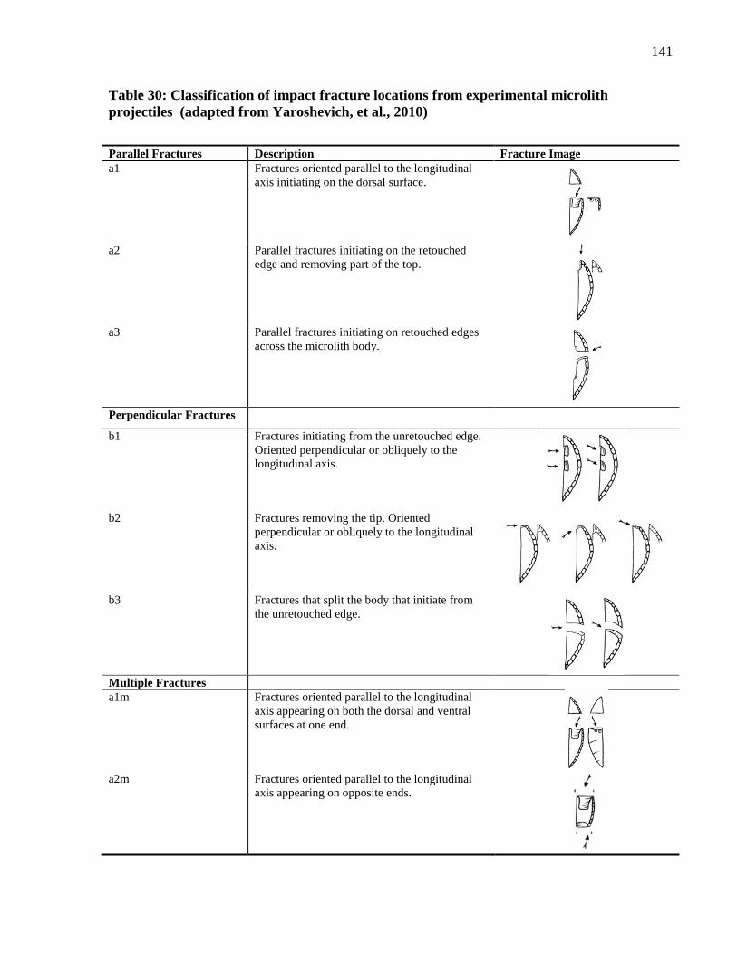
141
Table 30: Classification of impact fracture locations from experimental microlith
projectiles (adapted from Yaroshevich, et al., 2010)
Parallel Fractures Description Fracture Image
a1 Fractures oriented parallel to the longitudinal
axis initiating on the dorsal surface.
a2 Parallel fractures initiating on the retouched
edge and removing part of the top.
a3 Parallel fractures initiating on retouched edges
across the microlith body.
Perpendicular Fractures
b1 Fractures initiating from the unretouched edge.
Oriented perpendicular or obliquely to the
longitudinal axis.
b2 Fractures removing the tip. Oriented
perpendicular or obliquely to the longitudinal
axis.
b3 Fractures that split the body that initiate from
the unretouched edge.
Multiple Fractures
a1m Fractures oriented parallel to the longitudinal
axis appearing on both the dorsal and ventral
surfaces at one end.
a2m Fractures oriented parallel to the longitudinal
axis appearing on opposite ends.
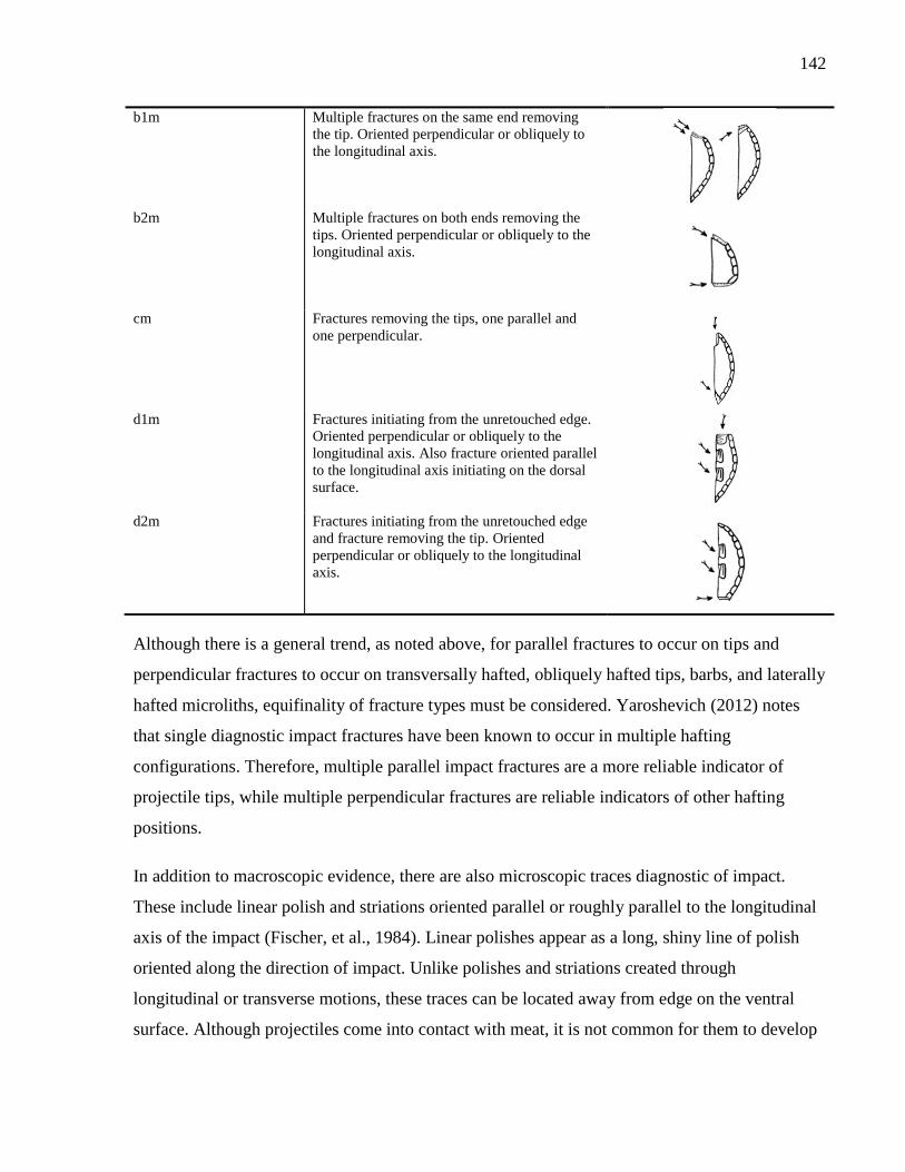
142
b1m Multiple fractures on the same end removing
the tip. Oriented perpendicular or obliquely to
the longitudinal axis.
b2m Multiple fractures on both ends removing the
tips. Oriented perpendicular or obliquely to the
longitudinal axis.
cm Fractures removing the tips, one parallel and
one perpendicular.
d1m
Fractures initiating from the unretouched edge.
Oriented perpendicular or obliquely to the
longitudinal axis. Also fracture oriented parallel
to the longitudinal axis initiating on the dorsal
surface.
d2m Fractures initiating from the unretouched edge
and fracture removing the tip. Oriented
perpendicular or obliquely to the longitudinal
axis.
Although there is a general trend, as noted above, for parallel fractures to occur on tips and
perpendicular fractures to occur on transversally hafted, obliquely hafted tips, barbs, and laterally
hafted microliths, equifinality of fracture types must be considered. Yaroshevich (2012) notes
that single diagnostic impact fractures have been known to occur in multiple hafting
configurations. Therefore, multiple parallel impact fractures are a more reliable indicator of
projectile tips, while multiple perpendicular fractures are reliable indicators of other hafting
positions.
In addition to macroscopic evidence, there are also microscopic traces diagnostic of impact.
These include linear polish and striations oriented parallel or roughly parallel to the longitudinal
axis of the impact (Fischer, et al., 1984). Linear polishes appear as a long, shiny line of polish
oriented along the direction of impact. Unlike polishes and striations created through
longitudinal or transverse motions, these traces can be located away from edge on the ventral
surface. Although projectiles come into contact with meat, it is not common for them to develop
143
continuous meat/hide polish along the edge. This is likely because they are not in the same
continuous contact with the animals as cutting tools (Fischer, et al., 1984).
7.3 Identifying Contact Material
Although it has been argued that contact material can be identified through the use of low-
powered magnification, more success has been found in the use of high-powered magnifications
for the identification of contact materials based on polish characteristics. Several general polish
descriptions are used in the descriptions of specific contact material polish. The first is generic
weak polish, which is distinguishable from the surrounding surface based on a slightly brighter
finish (Vaughan, 1985). This weak polish often forms at the beginning of contact, prior to the
development of identifiable polishes, but it is also very similar to polishes produced from meat
contact. Smooth-pitted polish is characterized by small polish components formed on higher
points of microtopography of generic weak polish (Vaughan, 1985:30). These terms are used to
describe polish types for various contact materials. A selection of contact materials commonly
used in prehistory is described below. This list is not exhaustive and several materials such as
fish, ochre, and soft stone use-wear traces are not presented here.
7.3.1 Meat Polish
Meat polish has a dull sheen and low contrast with the surrounding unmodified surface (Keeley,
1980:53, Vaughan, 1985:38). Some researchers have noted a ‘greasy luster’ in association with
this polish (Keeley, 1980:53). It tends to be distributed in uneven patches close to the edge of the
tool (Vaughan, 1985:38). Meat polish is often classified as a generic weak polish, distinguishable
as slightly brighter than the natural reflective properties of the raw material (Vaughan, 1985:30).
This polish tends to be associated with hide polishes from butchering practices without bone
contact.
7.3.2 Hide Polish
Dry hide polish initially starts as a generic weak polish. It then becomes extremely dull and
highly pitted, spreading across the edge of the tool (Vaughan, 1985:37). Dampened hides result
in a brighter, smooth-pitted polish along the edge of the tool. In contrast, fresh hide working
results in a bright, greasy polish (Keeley, 1980). The greasy polish from fresh hide is highly
bumpy and textured, but lacks the micropitting seen in polish from bone contact. Dry-hide or
144
leather is occasionally associated with the presence of circular pits. Striations are rarely
associated with hide working (Keeley 1980).
7.3.3 Wood Polish
Wood polish is very bright and appears smooth under high-powered magnifications. It initially
forms on microtopographic peaks and gradually spreads, connecting these polished areas.
Striations are not common on woodworking tools but, when they do occur, they appear as broad
and shallow and are oriented in the direction of movement (Keeley, 1980). Softwoods leave
more polish on the tool surface than hardwoods after the same use duration (Keeley, 1980,
Vaughan, 1985).
7.3.4 Bone Polish
Bone working produces a bright polish with a pitted appearance. Due to the hard nature of bone,
the polish tends to be discontinuous and begins to form on the higher points of the
microtopography. ‘Comet tail’ striations in the polish are aligned with the direction of action,
indicating motion (Vaughan, 1985). Striations tend to be deep and narrow (Keeley, 1980). Bone
polish is also distinguishable by the presence of numerous small pits on the surface (Keeley,
1980).
7.3.5 Antler Polish
Noted differences are seen in antler polish resulting from sawing motions versus antler polish
resulting from scraping motions. ‘Smooth’ antler polish is produced by transverse motions across
the contact material, resulting in very bright smooth polish. When not well developed, this polish
is often difficult to distinguish from wood polish (Keeley, 1980). When the polish is well
developed it displays small defuse depressions with vague troughs indicating the direction of
motion. In contrast, ‘rough’ antler polish is produced from sawing actions and is characterized by
bright smooth pitted polish (Keeley, 1980).
7.3.6 Cereal Polish
Cutting plants results in bright to extremely bright polish, completely linked over the surface
with a raised appearance (Vaughan, 1985:36). The polish is ‘pock-marked’ with filled-in
striations and ‘comet-shaped pits’ indicating the direction of movement. It has been argued that
145
the frequency of striations is related to the distance of the cut from the ground surface,
suggesting that increased striations are the result of sediment particles abrading the polish
(Anderson, 1991).
7.3.7 Reed Polish
Cutting reeds results in a very bright, smooth-pitted polish, highly reflective with a ‘domed’
appearance (Vaughan, 1985:35). Reed polish has also been described as having a ‘wet’
appearance, with no striations, distinguishing it from cereal polish (van Gijn, 1999).
7.4 Methods
A combination of low- and high-powered analysis was chosen for the functional study of the
microlith assemblages. As mentioned previously, this combination allows the most holistic
approach to the analysis of wear features through the assessment of features observable at
multiple scales including fractures, polish, and striations. Interpretation of microlith function was
made through the use of several analogues. The first was the experimental set of tools described
in Chapter 6. In addition, there has been a long history of rigorous experimentation in the field of
use-wear analysis. Thus, published literature and photomicrographs were used to identify wear
traces and link them to potential functions (examples include Anderson, 1991, Keeley, 1980,
Tringham, et al., 1974, Vaughan, 1985). A recording sheet was devised so that the results from
both the low-powered and high-powered analysis could be mapped onto the same sheet (Figure
34).
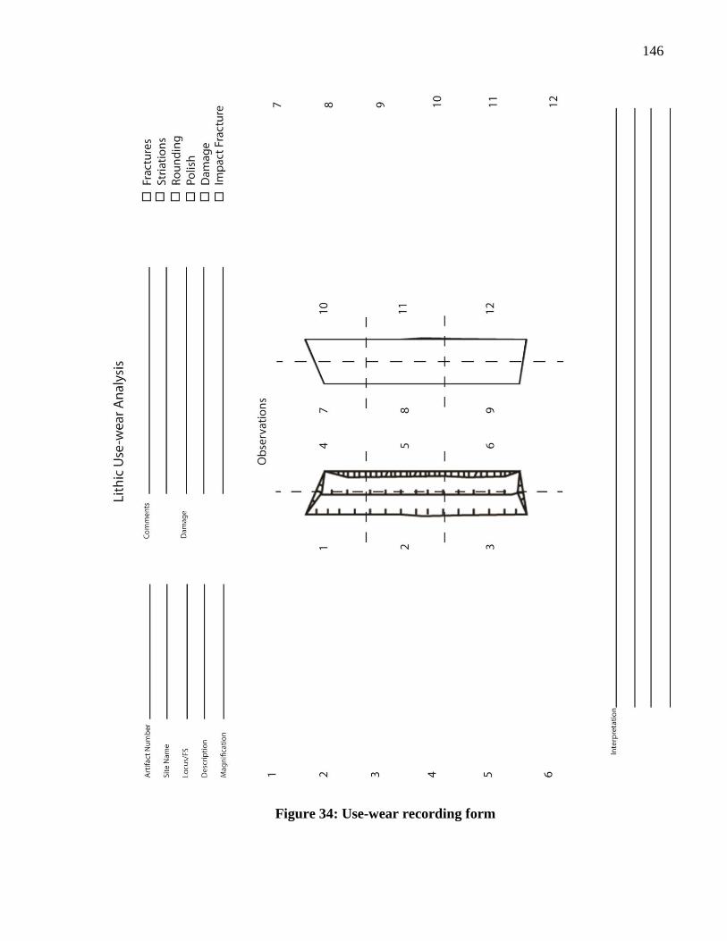
146
Figure 34: Use-wear recording form
147
7.4.1 Cleaning
Initially, each tool was cleaned in the field using a soft brush and clean water to remove any
adhering soil particles. This cleaning method was sufficient for the low-powered analysis. When
necessary the pieces were re-cleaned with technical wipes dipped in pure alcohol to remove
finger grease and material that had collected on the pieces prior to microscopic analysis.
The tools chosen for high-powered analysis were further cleaned using chemical methods
adapted from Keeley (1980). To begin, each piece was immersed in water and placed in an
ultrasonic bath for 10 minutes. The water was changed after each artifact was cleaned. Each
artifact was soaked in a bath of 10% sodium hydroxide (NaOH) for 10 minutes and then 10%
hydrochloric acid (HCl) for an additional 10 minutes. Finally, the tools were bathed in an
ultrasonic water bath for 10 minutes to remove any remaining chemical traces. This method
ensures that any adhering mineral or organic traces are removed prior to analysis so they do not
interfere with identification of use-wear traces. Additional spot cleaning using alcohol was done
as necessary at the time of analysis to remove finger grease, dust, and other materials that
adhered to the artifact after chemical cleaning.
7.4.2 Low-Powered Analysis
Low-powered functional analysis was conducted on a sample of 200 microliths from each site.
Several contexts were randomly selected from the materials analyzed for the typological analysis
to obtain the sample.
Low-powered analysis was conducted prior to high-powered analysis, focusing on identifying
macroscopic fractures and visible polishes. An Olympus SZX9 stereomicroscope was used for
low-powered analysis of the collections. Magnification ranged from 5 to100x, with the majority
of the samples analyzed between 20 and 50x. Samples were illuminated with an adjustable light
source, allowing the samples to be illuminated from multiple angles to highlight use features.
The number, type, location, and frequency of fractures were recorded using low-powered
magnification. The number of fractures was recorded as greater than or less than five fractures
per 10 mm. This division has previously been used by Grace who suggests that isolated and
small clusters of fractures may be the result of post-depositional processes and should not
recorded as use-features (Grace, 1989). Fracture type was recorded as snap, bending, or
148
conchoidal and the terminating type was noted (feathered, step, hinged). These fracture types
were identified on the basis of the typology outlined in the Ho Ho committee report (1979).
Diagnostic impact fractures were identified according to the criteria of Fischer et al. (1984). The
location of diagnostic impact fractures were classified using Yaroshevich’s (2010) system. This
classification system provided a reference for the position of impact fractures on the microliths
and a guild for interpreting possible hafting configurations (Table 30).
7.4.3 High-Powered Analysis
After the analysis of each piece using a stereomicroscope, 50 pieces identified with evidence of
use were selected for high-powered analysis. Any pieces with labeling, patination, burning, or
other modifications obscuring the edge were not subjected to further analysis.
Preliminary analysis was conducted with a Nikon Eclipse 50i microscope using the incident-light
illumination, with magnifications ranging from 100 to 1000x. Subsequent images were taken
using the white light illumination setting on an Olympus LEXT laser-scanning confocal
microscope, available at the time of analysis. This microscope was chosen to present the images
because it is able to stitch together images at different focal planes, thereby creating an image in
focus at all depths of field. Identification of polish and striations was based on comparisons
between artifacts and the experimental collections and published photomicrographs of
experimentally produced polish (Anderson, 1991, Keeley, 1980, Vaughan, 1985). The criteria
used for identification are described above in Section 1.2.
7.4.4 Post-Depositional Alterations
Post-depositional alterations can greatly affect the identification of use-wear features on an
artifact’s surface. Therefore, it is important to identify the degree of post-depositional
modification to an artifact’s surface prior to interpreting use-wear analysis. There are several
common alterations that happen to lithic surfaces in a depositional environment including
fractures, striations, plastic deformation, roundness of edges and ridges, polished surfaces, pits,
and patination (Burroni, et al., 2002). The presence of these features can confuse or mask use-
wear patterns leading to problems in interpretation.
A number of researchers have used trampling experiments to identify the difference between use
and post-depositional fractures (e.g., McBrearty, et al., 1998, Pargeter, 2011, Shea and Klenck,
149
1993, Tringham, et al., 1974). When resulting from trampling, fractures tend to be unevenly
distributed along the tool’s edge and can occur in clusters or as isolated fractures. These fractures
often occur on both faces of the tool and tend to be broad, oriented perpendicularly to the edge
(McBrearty, et al., 1998). Trampling damage can obscure and mimic use-traces causing
confusion when interpreting function (Shea and Klenck, 1993). Furthermore, diagnostic impact
fractures can be produced from trampling, although these occur in very low frequencies
(Pargeter, 2011). This can result in incorrect interpretations of hunting if not corroborated with
other evidence such as the presence of other diagnostic impact fractures or linear polish traces.
In addition to the trampling experiments, Grace (1989) has identified several criteria that analysts
need to consider when distinguishing wear-related fractures from post-depositional ones. He
notes that unpatterned and randomly oriented fractures are easily produced through damage.
Damage fractures tend to be isolated or appear in low frequencies, and he uses frequencies of
less than five fractures per 10mm as a cut-off value. Also, damage can occur on any edge,
therefore the random distribution of fractures along an edge suggests post-depositional
fracturing. In contrast, the placement of fractures along a potentially used edge, but not along all
edges, suggests that the fractures are the result of use. He also suggests that corroborative
evidence of use is needed, and the presence of polish, striations, or rounding should be
investigated. Finally, it is notoriously difficult to identify fractures on retouched edges and these
should not be considered during low-powered analysis.
The fracture pattern for each microlith was individually assessed during analysis. Using the cut-
off that Grace (1989) proposes, fractures occurring with less than five fractures per 10mm were
considered to have resulted from trampling or other post-depositional processes and were not
included in the functional interpretation. However, diagnostic impact fractures were recorded
individually as these can often occur as isolated fractures.
Measurements of lithic edge and ridge roundness are common methods to understand the impact
of post-depositional processes on a sample. Roundness can easily be observed through
microscopy and can be measured using a variety of image analysis programs from
photomicrographs. Rigorous experimentation undertaken by Shackley (1974) showed that lithics
travel through several stages of natural wear that impact the rounding of dorsal scar ridges.
Initially, a chert flake can sustain a certain amount of movement in sediment without showing
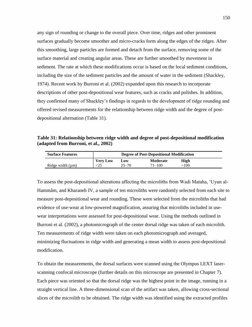
150
any sign of rounding or change to the overall piece. Over time, ridges and other prominent
surfaces gradually become smoother and micro-cracks form along the edges of the ridges. After
this smoothing, large particles are formed and detach from the surface, removing some of the
surface material and creating angular areas. These are further smoothed by movement in
sediment. The rate at which these modifications occur is based on the local sediment conditions,
including the size of the sediment particles and the amount of water in the sediment (Shackley,
1974). Recent work by Burroni et al. (2002) expanded upon this research to incorporate
descriptions of other post-depositional wear features, such as cracks and polishes. In addition,
they confirmed many of Shackley’s findings in regards to the development of ridge rounding and
offered revised measurements for the relationship between ridge width and the degree of post-
depositional alternation (Table 31).
Table 31: Relationship between ridge width and degree of post-depositional modification
(adapted from Burroni, et al., 2002)
Surface Features Degree of Post-Depositional Modification
Very Low Low Moderate High
Ridge width (µm) <25 25–70 71–100 >100
To assess the post-depositional alterations affecting the microliths from Wadi Mataha, ‘Uyun al-
Hammâm, and Kharaneh IV, a sample of ten microliths were randomly selected from each site to
measure post-depositional wear and rounding. These were selected from the microliths that had
evidence of use-wear at low-powered magnification, assuring that microliths included in use-
wear interpretations were assessed for post-depositional wear. Using the methods outlined in
Burroni et al. (2002), a photomicrograph of the center dorsal ridge was taken of each microlith.
Ten measurements of ridge width were taken on each photomicrograph and averaged,
minimizing fluctuations in ridge width and generating a mean width to assess post-depositional
modification.
To obtain the measurements, the dorsal surfaces were scanned using the Olympus LEXT laser-
scanning confocal microscope (further details on this microscope are presented in Chapter 7).
Each piece was oriented so that the dorsal ridge was the highest point in the image, running in a
straight vertical line. A three-dimensional scan of the artifact was taken, allowing cross-sectional
slices of the microlith to be obtained. The ridge width was identified using the extracted profiles
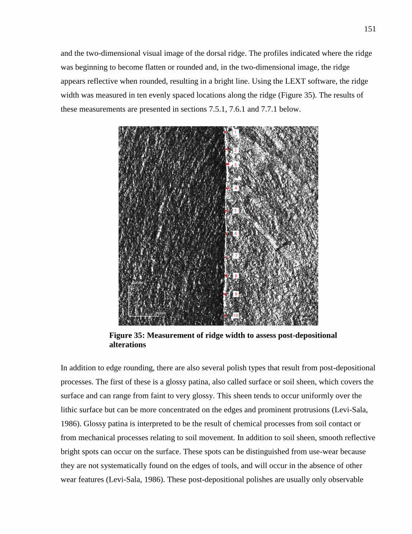
151
and the two-dimensional visual image of the dorsal ridge. The profiles indicated where the ridge
was beginning to become flatten or rounded and, in the two-dimensional image, the ridge
appears reflective when rounded, resulting in a bright line. Using the LEXT software, the ridge
width was measured in ten evenly spaced locations along the ridge (Figure 35). The results of
these measurements are presented in sections 7.5.1, 7.6.1 and 7.7.1 below.
Figure 35: Measurement of ridge width to assess post-depositional
alterations
In addition to edge rounding, there are also several polish types that result from post-depositional
processes. The first of these is a glossy patina, also called surface or soil sheen, which covers the
surface and can range from faint to very glossy. This sheen tends to occur uniformly over the
lithic surface but can be more concentrated on the edges and prominent protrusions (Levi-Sala,
1986). Glossy patina is interpreted to be the result of chemical processes from soil contact or
from mechanical processes relating to soil movement. In addition to soil sheen, smooth reflective
bright spots can occur on the surface. These spots can be distinguished from use-wear because
they are not systematically found on the edges of tools, and will occur in the absence of other
wear features (Levi-Sala, 1986). These post-depositional polishes are usually only observable
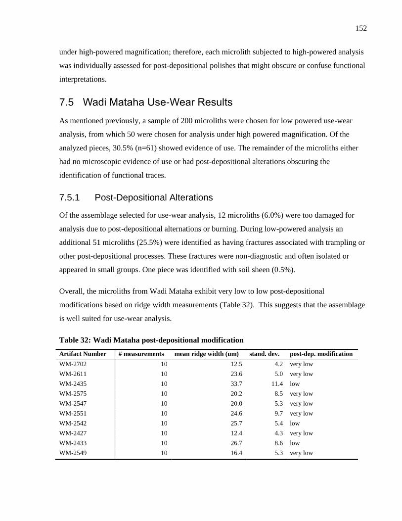
152
under high-powered magnification; therefore, each microlith subjected to high-powered analysis
was individually assessed for post-depositional polishes that might obscure or confuse functional
interpretations.
7.5 Wadi Mataha Use-Wear Results
As mentioned previously, a sample of 200 microliths were chosen for low powered use-wear
analysis, from which 50 were chosen for analysis under high powered magnification. Of the
analyzed pieces, 30.5% (n=61) showed evidence of use. The remainder of the microliths either
had no microscopic evidence of use or had post-depositional alterations obscuring the
identification of functional traces.
7.5.1 Post-Depositional Alterations
Of the assemblage selected for use-wear analysis, 12 microliths (6.0%) were too damaged for
analysis due to post-depositional alternations or burning. During low-powered analysis an
additional 51 microliths (25.5%) were identified as having fractures associated with trampling or
other post-depositional processes. These fractures were non-diagnostic and often isolated or
appeared in small groups. One piece was identified with soil sheen (0.5%).
Overall, the microliths from Wadi Mataha exhibit very low to low post-depositional
modifications based on ridge width measurements (Table 32). This suggests that the assemblage
is well suited for use-wear analysis.
Table 32: Wadi Mataha post-depositional modification
Artifact Number # measurements mean ridge width (um) stand. dev. post-dep. modification
WM-2702 10 12.5 4.2 very low
WM-2611 10 23.6 5.0 very low
WM-2435 10 33.7 11.4 low
WM-2575 10 20.2 8.5 very low
WM-2547 10 20.0 5.3 very low
WM-2551 10 24.6 9.7 very low
WM-2542 10 25.7 5.4 low
WM-2427 10 12.4 4.3 very low
WM-2433 10 26.7 8.6 low
WM-2549 10 16.4 5.3 very low
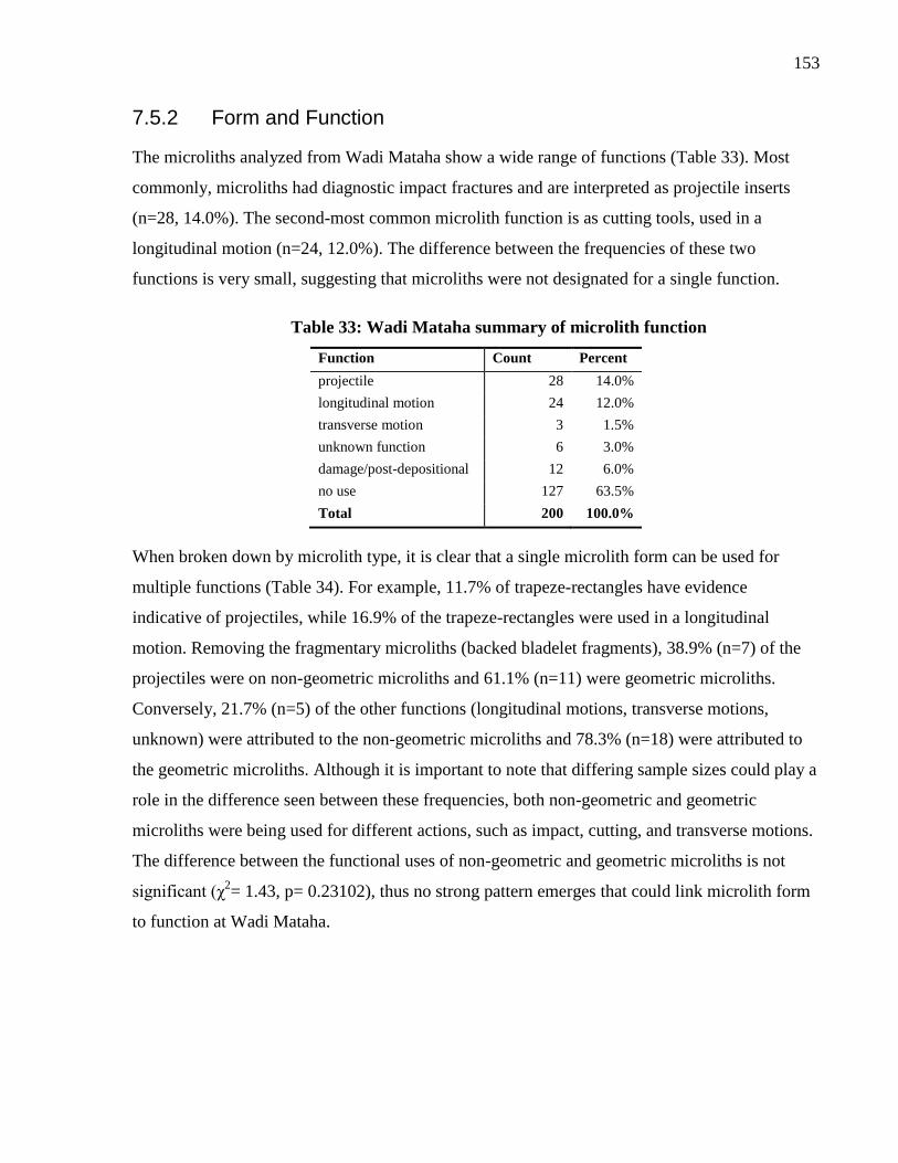
153
7.5.2 Form and Function
The microliths analyzed from Wadi Mataha show a wide range of functions (Table 33). Most
commonly, microliths had diagnostic impact fractures and are interpreted as projectile inserts
(n=28, 14.0%). The second-most common microlith function is as cutting tools, used in a
longitudinal motion (n=24, 12.0%). The difference between the frequencies of these two
functions is very small, suggesting that microliths were not designated for a single function.
Table 33: Wadi Mataha summary of microlith function
Function Count Percent
projectile 28 14.0%
longitudinal motion 24 12.0%
transverse motion 3 1.5%
unknown function 6 3.0%
damage/post-depositional 12 6.0%
no use 127 63.5%
Total 200 100.0%
When broken down by microlith type, it is clear that a single microlith form can be used for
multiple functions (Table 34). For example, 11.7% of trapeze-rectangles have evidence
indicative of projectiles, while 16.9% of the trapeze-rectangles were used in a longitudinal
motion. Removing the fragmentary microliths (backed bladelet fragments), 38.9% (n=7) of the
projectiles were on non-geometric microliths and 61.1% (n=11) were geometric microliths.
Conversely, 21.7% (n=5) of the other functions (longitudinal motions, transverse motions,
unknown) were attributed to the non-geometric microliths and 78.3% (n=18) were attributed to
the geometric microliths. Although it is important to note that differing sample sizes could play a
role in the difference seen between these frequencies, both non-geometric and geometric
microliths were being used for different actions, such as impact, cutting, and transverse motions.
The difference between the functional uses of non-geometric and geometric microliths is not
significant (χ2= 1.43, p= 0.23102), thus no strong pattern emerges that could link microlith form
to function at Wadi Mataha.
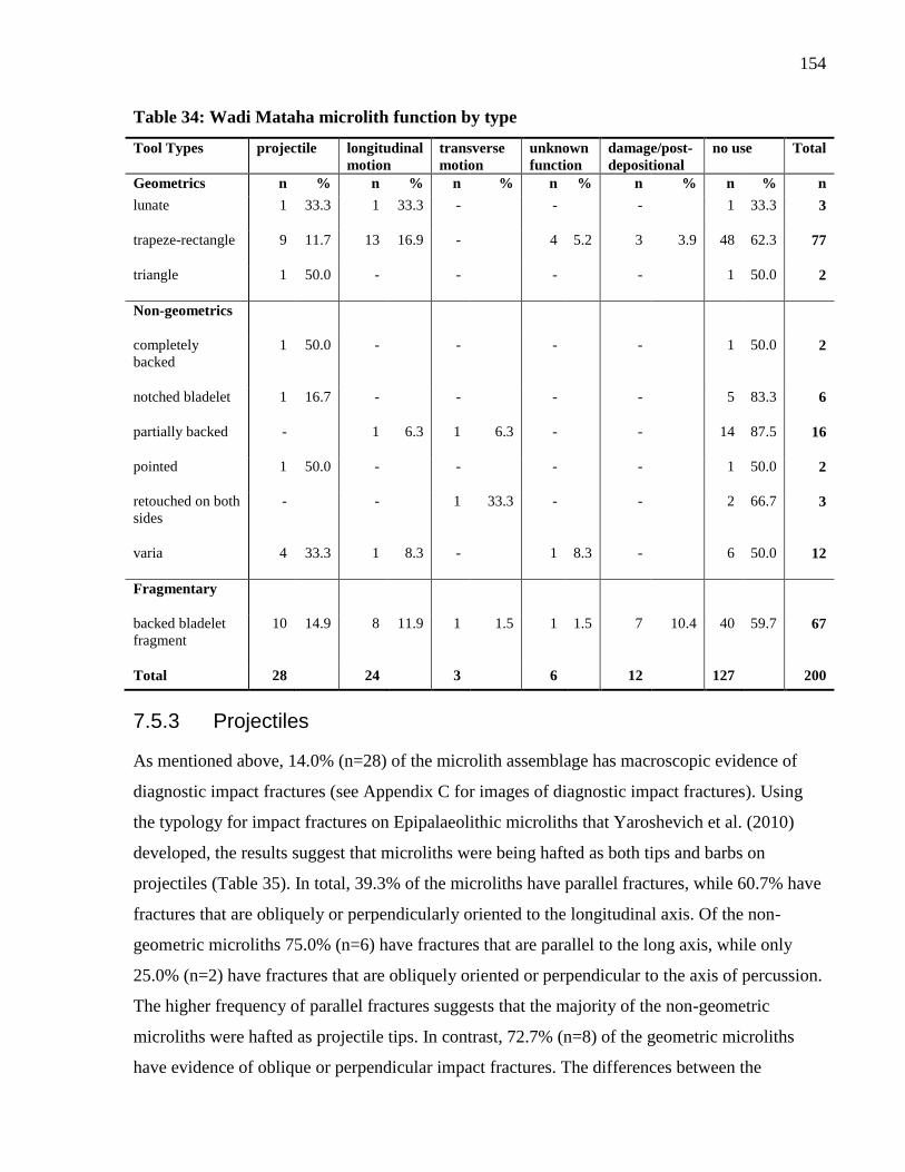
154
Table 34: Wadi Mataha microlith function by type
Tool Types projectile longitudinal
motion
transverse
motion
unknown
function
damage/post-
depositional
no use Total
Geometrics n % n % n % n % n % n % n
lunate 1 33.3 1 33.3 - - - 1 33.3 3
trapeze-rectangle 9 11.7 13 16.9 - 4 5.2 3 3.9 48 62.3 77
triangle 1 50.0 - - - - 1 50.0 2
Non-geometrics
completely
backed
1 50.0 - - - - 1 50.0 2
notched bladelet 1 16.7 - - - - 5 83.3 6
partially backed - 1 6.3 1 6.3 - - 14 87.5 16
pointed 1 50.0 - - - - 1 50.0 2
retouched on both
sides
- - 1 33.3 - - 2 66.7 3
varia 4 33.3 1 8.3 - 1 8.3 - 6 50.0 12
Fragmentary
backed bladelet
fragment
10 14.9 8 11.9 1 1.5 1 1.5 7 10.4 40 59.7 67
Total 28 24 3 6 12 127 200
7.5.3 Projectiles
As mentioned above, 14.0% (n=28) of the microlith assemblage has macroscopic evidence of
diagnostic impact fractures (see Appendix C for images of diagnostic impact fractures). Using
the typology for impact fractures on Epipalaeolithic microliths that Yaroshevich et al. (2010)
developed, the results suggest that microliths were being hafted as both tips and barbs on
projectiles (Table 35). In total, 39.3% of the microliths have parallel fractures, while 60.7% have
fractures that are obliquely or perpendicularly oriented to the longitudinal axis. Of the non-
geometric microliths 75.0% (n=6) have fractures that are parallel to the long axis, while only
25.0% (n=2) have fractures that are obliquely oriented or perpendicular to the axis of percussion.
The higher frequency of parallel fractures suggests that the majority of the non-geometric
microliths were hafted as projectile tips. In contrast, 72.7% (n=8) of the geometric microliths
have evidence of oblique or perpendicular impact fractures. The differences between the

155
orientation of diagnostic impact fractures on non-geometric and geometric microliths is
statistically significant (χ2= 5.445, p= 0.0196). From this data, a pattern emerges where the non-
geometric microliths are likely functioning as straight projectile tips and the geometric microliths
acted as barbs, laterally hafted inserts, obliquely hafted, or transverse tips.
Table 35: Wadi Mataha projectile types
Tool Types Parallel Oblique/Perpendicular Multiple Total %
a1 a1m a2 a2m a3 b1 b2 b3 d1m dm2
Geometrics
lunate - - 1 - - - - - - - 1 3.6
trapeze-rectangle - - 1 - 1 3 1 1 2 - 9 32.1
triangle - - - - - - - 1 - - 1 3.6
Non-geometrics
completely
backed
- - - 1 - - - - - - 1 3.6
notched bladelet - 1 - - - - - - - - 1 3.6
pointed 1 - - - - - - - - - 1 3.6
varia - 2 - 1 - - - - - 1 4 14.3
Fragmentary
backed bladelet
fragment
- 1 1 - - 3 2 1 2 - 10 35.7
Total 1 4 3 2 1 6 3 3 4 1 28 100.0
Percent 3.6 14.3 10.7 7.1 3.6 21.4 10.7 10.7 14.3 3.6 100.0
High-powered use-wear analysis revealed evidence of striations and linear polish resulting from
impact. One backed bladelet fragment had one large shallow angled striation running across the
ventral face. Two other backed bladelets had evidence of angled linear polish. In addition, five
microliths had localized areas of weak generic polish, possibly resulting from contact with
animal flesh and hide during the hunting process.
7.5.4 Other Functions
In addition to functioning as projectile inserts, functional traces indicate that microliths also
acted in longitudinal and transverse motions (Table 36). At Wadi Mataha 12% (n=24) of the
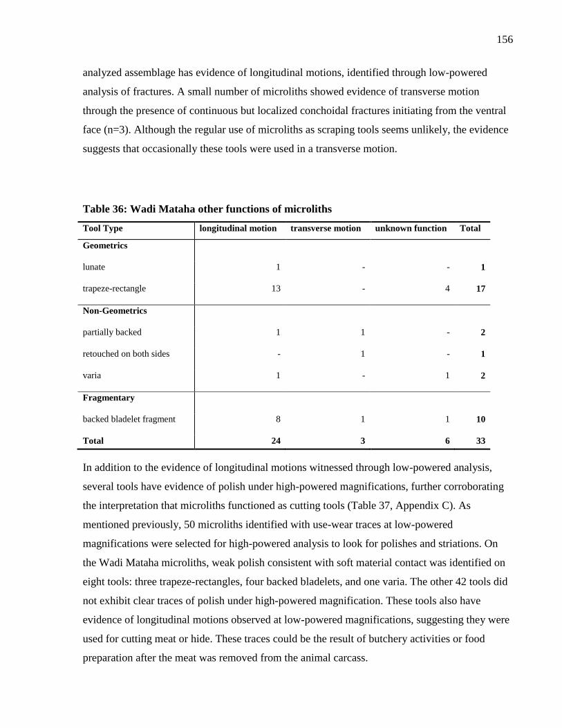
156
analyzed assemblage has evidence of longitudinal motions, identified through low-powered
analysis of fractures. A small number of microliths showed evidence of transverse motion
through the presence of continuous but localized conchoidal fractures initiating from the ventral
face (n=3). Although the regular use of microliths as scraping tools seems unlikely, the evidence
suggests that occasionally these tools were used in a transverse motion.
Table 36: Wadi Mataha other functions of microliths
Tool Type longitudinal motion transverse motion unknown function Total
Geometrics
lunate 1 - - 1
trapeze-rectangle 13 - 4 17
Non-Geometrics
partially backed 1 1 - 2
retouched on both sides - 1 - 1
varia 1 - 1 2
Fragmentary
backed bladelet fragment 8 1 1 10
Total 24 3 6 33
In addition to the evidence of longitudinal motions witnessed through low-powered analysis,
several tools have evidence of polish under high-powered magnifications, further corroborating
the interpretation that microliths functioned as cutting tools (Table 37, Appendix C). As
mentioned previously, 50 microliths identified with use-wear traces at low-powered
magnifications were selected for high-powered analysis to look for polishes and striations. On
the Wadi Mataha microliths, weak polish consistent with soft material contact was identified on
eight tools: three trapeze-rectangles, four backed bladelets, and one varia. The other 42 tools did
not exhibit clear traces of polish under high-powered magnification. These tools also have
evidence of longitudinal motions observed at low-powered magnifications, suggesting they were
used for cutting meat or hide. These traces could be the result of butchery activities or food
preparation after the meat was removed from the animal carcass.
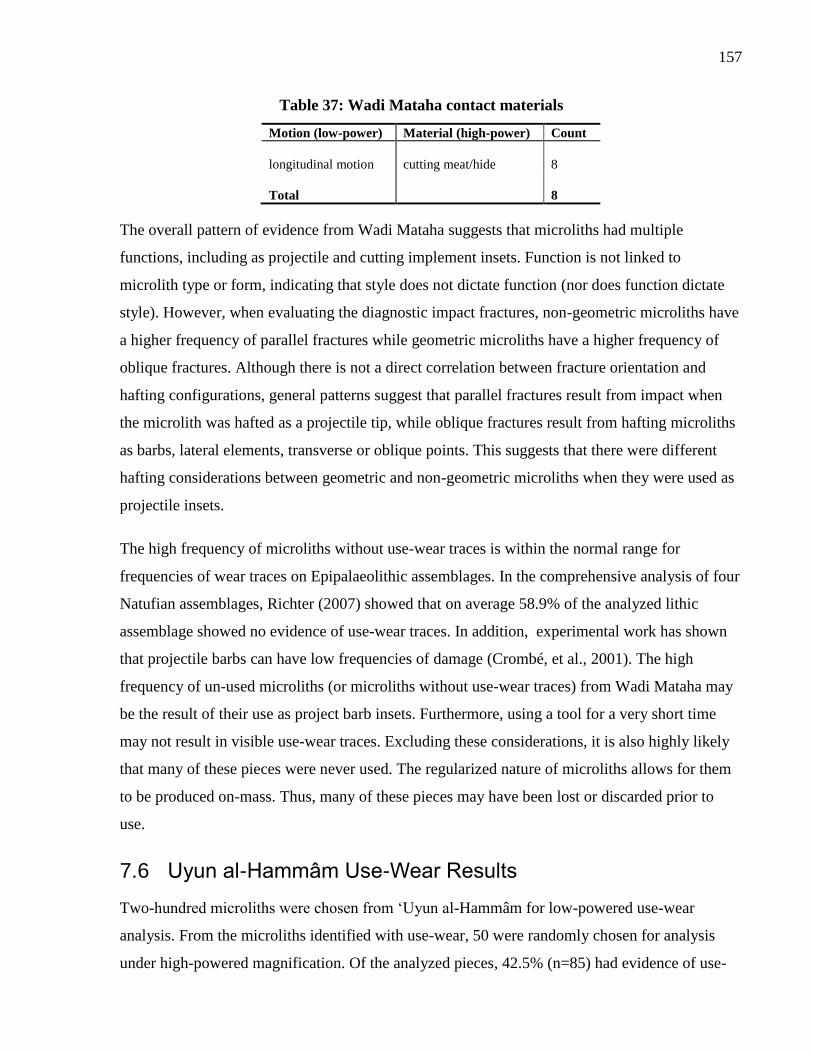
157
Table 37: Wadi Mataha contact materials
Motion (low-power) Material (high-power) Count
longitudinal motion
cutting meat/hide
8
Total
8
The overall pattern of evidence from Wadi Mataha suggests that microliths had multiple
functions, including as projectile and cutting implement insets. Function is not linked to
microlith type or form, indicating that style does not dictate function (nor does function dictate
style). However, when evaluating the diagnostic impact fractures, non-geometric microliths have
a higher frequency of parallel fractures while geometric microliths have a higher frequency of
oblique fractures. Although there is not a direct correlation between fracture orientation and
hafting configurations, general patterns suggest that parallel fractures result from impact when
the microlith was hafted as a projectile tip, while oblique fractures result from hafting microliths
as barbs, lateral elements, transverse or oblique points. This suggests that there were different
hafting considerations between geometric and non-geometric microliths when they were used as
projectile insets.
The high frequency of microliths without use-wear traces is within the normal range for
frequencies of wear traces on Epipalaeolithic assemblages. In the comprehensive analysis of four
Natufian assemblages, Richter (2007) showed that on average 58.9% of the analyzed lithic
assemblage showed no evidence of use-wear traces. In addition, experimental work has shown
that projectile barbs can have low frequencies of damage (Crombé, et al., 2001). The high
frequency of un-used microliths (or microliths without use-wear traces) from Wadi Mataha may
be the result of their use as project barb insets. Furthermore, using a tool for a very short time
may not result in visible use-wear traces. Excluding these considerations, it is also highly likely
that many of these pieces were never used. The regularized nature of microliths allows for them
to be produced on-mass. Thus, many of these pieces may have been lost or discarded prior to
use.
7.6 Uyun al-Hammâm Use-Wear Results
Two-hundred microliths were chosen from ‘Uyun al-Hammâm for low-powered use-wear
analysis. From the microliths identified with use-wear, 50 were randomly chosen for analysis
under high-powered magnification. Of the analyzed pieces, 42.5% (n=85) had evidence of use-
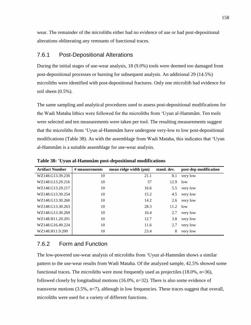
158
wear. The remainder of the microliths either had no evidence of use or had post-depositional
alterations obliterating any remnants of functional traces.
7.6.1 Post-Depositional Alterations
During the initial stages of use-wear analysis, 18 (9.0%) tools were deemed too damaged from
post-depositional processes or burning for subsequent analysis. An additional 29 (14.5%)
microliths were identified with post-depositional fractures. Only one microlith had evidence for
soil sheen (0.5%).
The same sampling and analytical procedures used to assess post-depositional modifications for
the Wadi Mataha lithics were followed for the microliths from ‘Uyun al-Hammâm. Ten tools
were selected and ten measurements were taken per tool. The resulting measurements suggest
that the microliths from ‘Uyun al-Hammâm have undergone very-low to low post-depositional
modifications (Table 38). As with the assemblage from Wadi Mataha, this indicates that ‘Uyun
al-Hammâm is a suitable assemblage for use-wear analysis.
Table 38: 'Uyun al-Hammâm post-depositional modifications
Artifact Number # measurements mean ridge width (µm) stand. dev. post-dep modification
WZ148.G13.39.236 10 21.1 8.1 very low
WZ148.G13.29.216 10 57 12.9 low
WZ148.G13.29.217 10 16.6 5.5 very low
WZ148.G13.30.254 10 15.2 4.5 very low
WZ148.G13.30.260 10 14.2 2.6 very low
WZ148.G13.30.263 10 28.3 11.2 low
WZ148.G13.30.269 10 16.4 2.7 very low
WZ148.H11.20.201 10 12.7 3.8 very low
WZ148.G16.49.224 10 11.6 2.7 very low
WZ148.H11.9.200 10 23.4 8 very low
7.6.2 Form and Function
The low-powered use-wear analysis of microliths from ‘Uyun al-Hammâm shows a similar
pattern to the use-wear results from Wadi Mataha. Of the analyzed sample, 42.5% showed some
functional traces. The microliths were most frequently used as projectiles (18.0%, n=36),
followed closely by longitudinal motions (16.0%, n=32). There is also some evidence of
transverse motions (3.5%, n=7), although in low frequencies. These traces suggest that overall,
microliths were used for a variety of different functions.
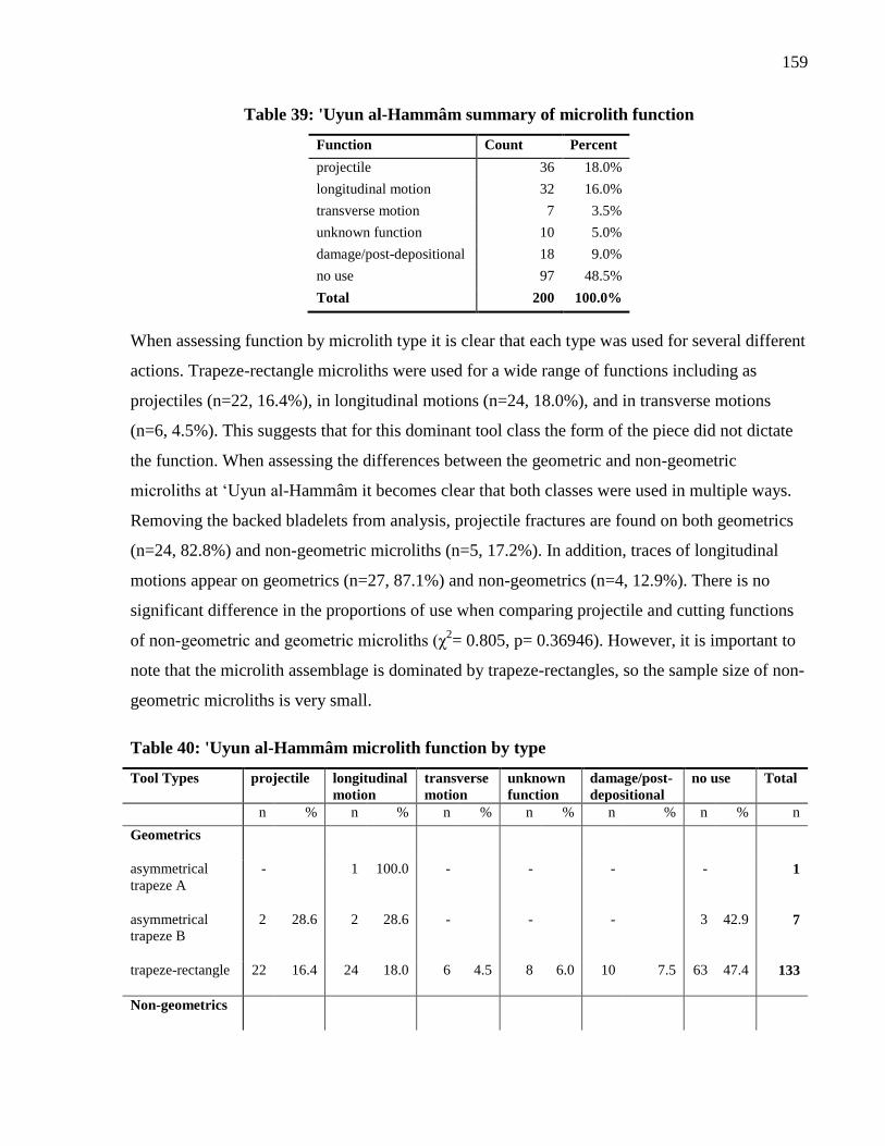
159
Table 39: 'Uyun al-Hammâm summary of microlith function
Function Count Percent
projectile 36 18.0%
longitudinal motion 32 16.0%
transverse motion 7 3.5%
unknown function 10 5.0%
damage/post-depositional 18 9.0%
no use 97 48.5%
Total 200 100.0%
When assessing function by microlith type it is clear that each type was used for several different
actions. Trapeze-rectangle microliths were used for a wide range of functions including as
projectiles (n=22, 16.4%), in longitudinal motions (n=24, 18.0%), and in transverse motions
(n=6, 4.5%). This suggests that for this dominant tool class the form of the piece did not dictate
the function. When assessing the differences between the geometric and non-geometric
microliths at ‘Uyun al-Hammâm it becomes clear that both classes were used in multiple ways.
Removing the backed bladelets from analysis, projectile fractures are found on both geometrics
(n=24, 82.8%) and non-geometric microliths (n=5, 17.2%). In addition, traces of longitudinal
motions appear on geometrics (n=27, 87.1%) and non-geometrics (n=4, 12.9%). There is no
significant difference in the proportions of use when comparing projectile and cutting functions
of non-geometric and geometric microliths (χ2= 0.805, p= 0.36946). However, it is important to
note that the microlith assemblage is dominated by trapeze-rectangles, so the sample size of non-
geometric microliths is very small.
Table 40: 'Uyun al-Hammâm microlith function by type
Tool Types projectile longitudinal
motion
transverse
motion
unknown
function
damage/post-
depositional
no use Total
n % n % n % n % n % n % n
Geometrics
asymmetrical
trapeze A
- 1 100.0 - - - - 1
asymmetrical
trapeze B
2 28.6 2 28.6 - - - 3 42.9 7
trapeze-rectangle 22 16.4 24 18.0 6 4.5 8 6.0 10 7.5 63 47.4 133
Non-geometrics
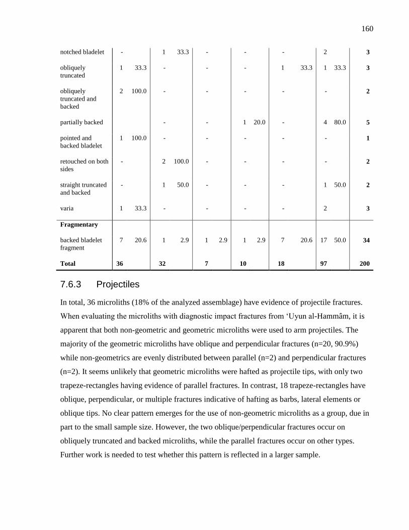
160
notched bladelet - 1 33.3 - - - 2 3
obliquely
truncated
1 33.3 - - - 1 33.3 1 33.3 3
obliquely
truncated and
backed
2 100.0 - - - - - 2
partially backed - - 1 20.0 - 4 80.0 5
pointed and
backed bladelet
1 100.0 - - - - - 1
retouched on both
sides
- 2 100.0 - - - - 2
straight truncated
and backed
- 1 50.0 - - - 1 50.0 2
varia 1 33.3 - - - - 2 3
Fragmentary
backed bladelet
fragment
7 20.6 1 2.9 1 2.9 1 2.9 7 20.6 17 50.0 34
Total 36 32 7 10 18 97 200
7.6.3 Projectiles
In total, 36 microliths (18% of the analyzed assemblage) have evidence of projectile fractures.
When evaluating the microliths with diagnostic impact fractures from ‘Uyun al-Hammâm, it is
apparent that both non-geometric and geometric microliths were used to arm projectiles. The
majority of the geometric microliths have oblique and perpendicular fractures (n=20, 90.9%)
while non-geometrics are evenly distributed between parallel (n=2) and perpendicular fractures
(n=2). It seems unlikely that geometric microliths were hafted as projectile tips, with only two
trapeze-rectangles having evidence of parallel fractures. In contrast, 18 trapeze-rectangles have
oblique, perpendicular, or multiple fractures indicative of hafting as barbs, lateral elements or
oblique tips. No clear pattern emerges for the use of non-geometric microliths as a group, due in
part to the small sample size. However, the two oblique/perpendicular fractures occur on
obliquely truncated and backed microliths, while the parallel fractures occur on other types.
Further work is needed to test whether this pattern is reflected in a larger sample.
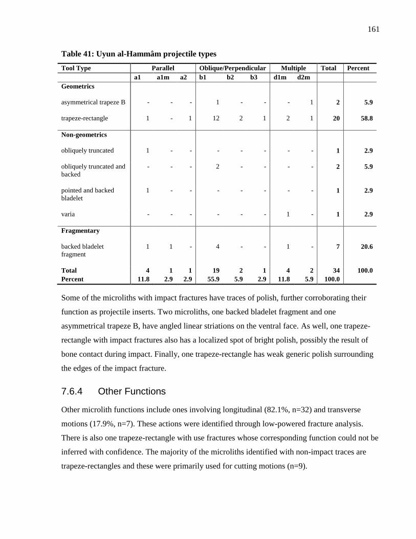
161
Table 41: Uyun al-Hammâm projectile types
Tool Type Parallel Oblique/Perpendicular Multiple Total Percent
a1 a1m a2 b1 b2 b3 d1m d2m
Geometrics
asymmetrical trapeze B - - - 1 - - - 1 2 5.9
trapeze-rectangle 1 - 1 12 2 1 2 1 20 58.8
Non-geometrics
obliquely truncated 1 - - - - - - - 1 2.9
obliquely truncated and
backed
- - - 2 - - - - 2 5.9
pointed and backed
bladelet
1 - - - - - - - 1 2.9
varia - - - - - - 1 - 1 2.9
Fragmentary
backed bladelet
fragment
1 1 - 4 - - 1 - 7 20.6
Total 4 1 1 19 2 1 4 2 34 100.0
Percent 11.8 2.9 2.9 55.9 5.9 2.9 11.8 5.9 100.0
Some of the microliths with impact fractures have traces of polish, further corroborating their
function as projectile inserts. Two microliths, one backed bladelet fragment and one
asymmetrical trapeze B, have angled linear striations on the ventral face. As well, one trapeze-
rectangle with impact fractures also has a localized spot of bright polish, possibly the result of
bone contact during impact. Finally, one trapeze-rectangle has weak generic polish surrounding
the edges of the impact fracture.
7.6.4 Other Functions
Other microlith functions include ones involving longitudinal (82.1%, n=32) and transverse
motions (17.9%, n=7). These actions were identified through low-powered fracture analysis.
There is also one trapeze-rectangle with use fractures whose corresponding function could not be
inferred with confidence. The majority of the microliths identified with non-impact traces are
trapeze-rectangles and these were primarily used for cutting motions (n=9).
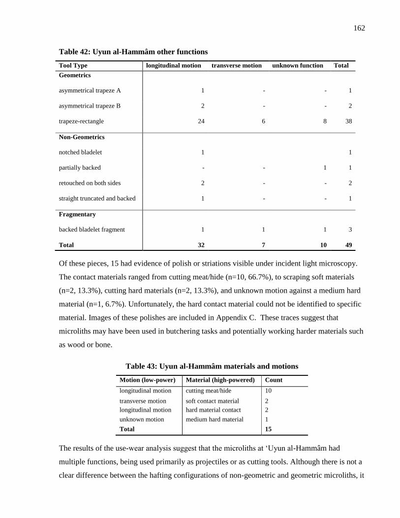
162
Table 42: Uyun al-Hammâm other functions
Tool Type longitudinal motion transverse motion unknown function Total
Geometrics
asymmetrical trapeze A 1 - - 1
asymmetrical trapeze B 2 - - 2
trapeze-rectangle 24 6 8 38
Non-Geometrics
notched bladelet 1 1
partially backed - - 1 1
retouched on both sides 2 - - 2
straight truncated and backed 1 - - 1
Fragmentary
backed bladelet fragment 1 1 1 3
Total 32 7 10 49
Of these pieces, 15 had evidence of polish or striations visible under incident light microscopy.
The contact materials ranged from cutting meat/hide (n=10, 66.7%), to scraping soft materials
(n=2, 13.3%), cutting hard materials (n=2, 13.3%), and unknown motion against a medium hard
material (n=1, 6.7%). Unfortunately, the hard contact material could not be identified to specific
material. Images of these polishes are included in Appendix C. These traces suggest that
microliths may have been used in butchering tasks and potentially working harder materials such
as wood or bone.
Table 43: Uyun al-Hammâm materials and motions
Motion (low-power) Material (high-powered) Count
longitudinal motion cutting meat/hide 10
transverse motion soft contact material 2
longitudinal motion hard material contact 2
unknown motion medium hard material 1
Total 15
The results of the use-wear analysis suggest that the microliths at ‘Uyun al-Hammâm had
multiple functions, being used primarily as projectiles or as cutting tools. Although there is not a
clear difference between the hafting configurations of non-geometric and geometric microliths, it
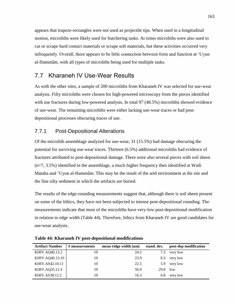
163
appears that trapeze-rectangles were not used as projectile tips. When used in a longitudinal
motion, microliths were likely used for butchering tasks. At times microliths were also used to
cut or scrape hard contact materials or scrape soft materials, but these activities occurred very
infrequently. Overall, there appears to be little connection between form and function at ‘Uyun
al-Hammâm, with all types of microliths being used for multiple tasks.
7.7 Kharaneh IV Use-Wear Results
As with the other sites, a sample of 200 microliths from Kharaneh IV was selected for use-wear
analysis. Fifty microliths were chosen for high-powered microscopy from the pieces identified
with use fractures during low-powered analysis. In total 97 (48.5%) microliths showed evidence
of use-wear. The remaining microliths were either lacking use-wear traces or had post-
depositional processes obscuring traces of use.
7.7.1 Post-Depositional Alterations
Of the microlith assemblage analyzed for use-wear, 31 (15.5%) had damage obscuring the
potential for surviving use-wear traces. Thirteen (6.5%) additional microliths had evidence of
fractures attributed to post-depositional damage. There were also several pieces with soil sheen
(n=7, 3.5%) identified in the assemblage, a much higher frequency then identified at Wadi
Mataha and ‘Uyun al-Hammâm. This may be the result of the arid environment at the site and
the fine silty sediment in which the artifacts are buried.
The results of the edge-rounding measurements suggest that, although there is soil sheen present
on some of the lithics, they have not been subjected to intense post-depositional rounding. The
measurements indicate that most of the microliths have very-low post-depositional modification
in relation to edge width (Table 44). Therefore, lithics from Kharaneh IV are good candidates for
use-wear analysis.
Table 44: Kharaneh IV post-depositional modifications
Artifact Number # measurements mean ridge width (um) stand. dev. post-dep modification
KHIV.AQ40.13.2 10 24.2 7.3 very low
KHIV.AQ40.13.10 10 23.9 8.3 very low
KHIV.AS42.10.11 10 22.5 5.9 very low
KHIV.AQ35.12.4 10 56.9 29.8 low
KHIV.AS38.12.2 10 16.3 6.8 very low
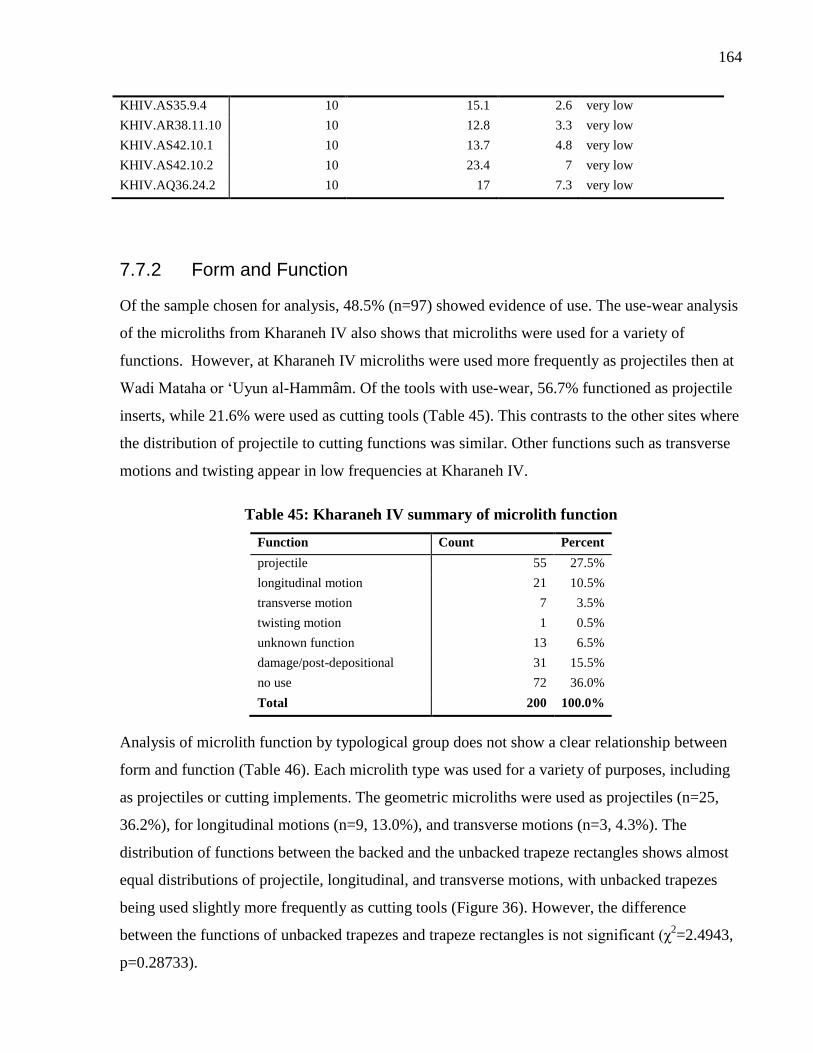
164
KHIV.AS35.9.4 10 15.1 2.6 very low
KHIV.AR38.11.10 10 12.8 3.3 very low
KHIV.AS42.10.1 10 13.7 4.8 very low
KHIV.AS42.10.2 10 23.4 7 very low
KHIV.AQ36.24.2 10 17 7.3 very low
7.7.2 Form and Function
Of the sample chosen for analysis, 48.5% (n=97) showed evidence of use. The use-wear analysis
of the microliths from Kharaneh IV also shows that microliths were used for a variety of
functions. However, at Kharaneh IV microliths were used more frequently as projectiles then at
Wadi Mataha or ‘Uyun al-Hammâm. Of the tools with use-wear, 56.7% functioned as projectile
inserts, while 21.6% were used as cutting tools (Table 45). This contrasts to the other sites where
the distribution of projectile to cutting functions was similar. Other functions such as transverse
motions and twisting appear in low frequencies at Kharaneh IV.
Table 45: Kharaneh IV summary of microlith function
Function Count Percent
projectile 55 27.5%
longitudinal motion 21 10.5%
transverse motion 7 3.5%
twisting motion 1 0.5%
unknown function 13 6.5%
damage/post-depositional 31 15.5%
no use 72 36.0%
Total 200 100.0%
Analysis of microlith function by typological group does not show a clear relationship between
form and function (Table 46). Each microlith type was used for a variety of purposes, including
as projectiles or cutting implements. The geometric microliths were used as projectiles (n=25,
36.2%), for longitudinal motions (n=9, 13.0%), and transverse motions (n=3, 4.3%). The
distribution of functions between the backed and the unbacked trapeze rectangles shows almost
equal distributions of projectile, longitudinal, and transverse motions, with unbacked trapezes
being used slightly more frequently as cutting tools (Figure 36). However, the difference
between the functions of unbacked trapezes and trapeze rectangles is not significant (χ2=2.4943,
p=0.28733).
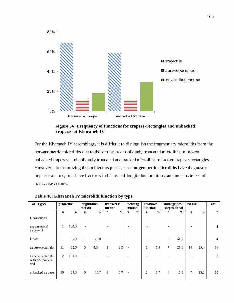
165
Figure 36: Frequency of functions for trapeze-rectangles and unbacked
trapezes at Kharaneh IV
For the Kharaneh IV assemblage, it is difficult to distinguish the fragmentary microliths from the
non-geometric microliths due to the similarity of obliquely truncated microliths to broken,
unbacked trapezes, and obliquely truncated and backed microliths to broken trapeze-rectangles.
However, after removing the ambiguous pieces, six non-geometric microliths have diagnostic
impact fractures, four have fractures indicative of longitudinal motions, and one has traces of
transverse actions.
Table 46: Kharaneh IV microlith function by type
Tool Types projectile longitudinal
motion
transverse
motion
twisting
motion
unknown
function
damage/post
-depositional
no use Total
n % n % n % n % n % n % n % n
Geometrics
asymmetrical
trapeze B
1 100.0 - - - - - - 1
lunate 1 25.0 1 25.0 - - - 2 50.0 - 4
trapeze-rectangle 11 32.6 3 8.8 1 2.9 - 2 5.9 7 20.6 10 29.4 34
trapeze-rectangle
with one convex
end
2 100.0 - - - - - - 2
unbacked trapeze 10 33.3 5 16.7 2 6.7 - 2 6.7 4 13.3 7 23.3 30
0%
20%
40%
60%
80%
trapeze-rectangle unbacked trapeze
projectile
transverse motion
longitudinal motion
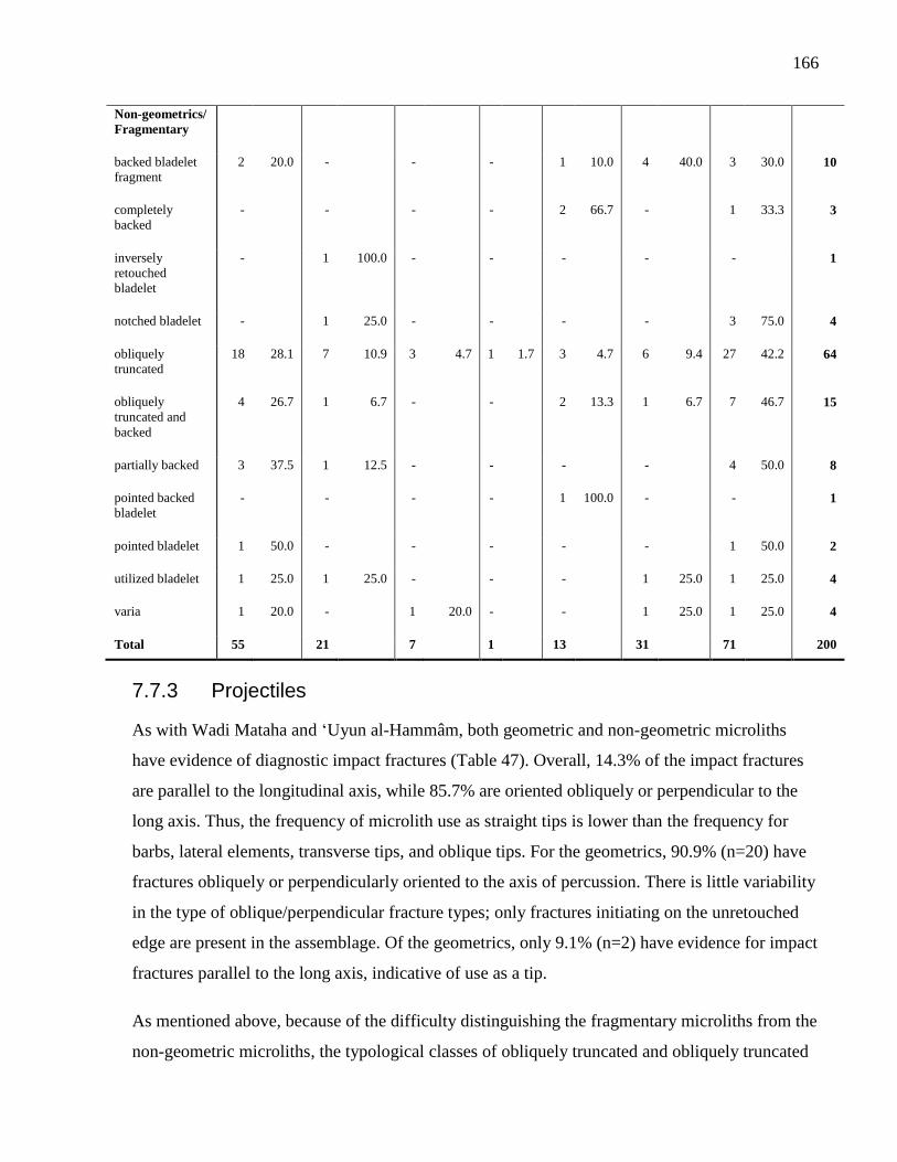
166
Non-geometrics/
Fragmentary
backed bladelet
fragment
2 20.0 - - - 1 10.0 4 40.0 3 30.0 10
completely
backed
- - - - 2 66.7 - 1 33.3 3
inversely
retouched
bladelet
- 1 100.0 - - - - - 1
notched bladelet - 1 25.0 - - - - 3 75.0 4
obliquely
truncated
18 28.1 7 10.9 3 4.7 1 1.7 3 4.7 6 9.4 27 42.2 64
obliquely
truncated and
backed
4 26.7 1 6.7 - - 2 13.3 1 6.7 7 46.7 15
partially backed 3 37.5 1 12.5 - - - - 4 50.0 8
pointed backed
bladelet
- - - - 1 100.0 - - 1
pointed bladelet 1 50.0 - - - - - 1 50.0 2
utilized bladelet 1 25.0 1 25.0 - - - 1 25.0 1 25.0 4
varia 1 20.0 - 1 20.0 - - 1 25.0 1 25.0 4
Total 55 21 7 1 13 31 71 200
7.7.3 Projectiles
As with Wadi Mataha and ‘Uyun al-Hammâm, both geometric and non-geometric microliths
have evidence of diagnostic impact fractures (Table 47). Overall, 14.3% of the impact fractures
are parallel to the longitudinal axis, while 85.7% are oriented obliquely or perpendicular to the
long axis. Thus, the frequency of microlith use as straight tips is lower than the frequency for
barbs, lateral elements, transverse tips, and oblique tips. For the geometrics, 90.9% (n=20) have
fractures obliquely or perpendicularly oriented to the axis of percussion. There is little variability
in the type of oblique/perpendicular fracture types; only fractures initiating on the unretouched
edge are present in the assemblage. Of the geometrics, only 9.1% (n=2) have evidence for impact
fractures parallel to the long axis, indicative of use as a tip.
As mentioned above, because of the difficulty distinguishing the fragmentary microliths from the
non-geometric microliths, the typological classes of obliquely truncated and obliquely truncated
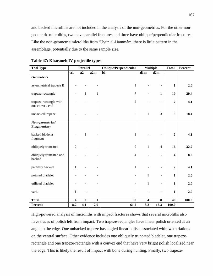
167
and backed microliths are not included in the analysis of the non-geometrics. For the other non-
geometric microliths, two have parallel fractures and three have oblique/perpendicular fractures.
Like the non-geometric microliths from ‘Uyun al-Hammâm, there is little pattern in the
assemblage, potentially due to the same sample size.
Table 47: Kharaneh IV projectile types
Tool Type Parallel Oblique/Perpendicular Multiple Total Percent
a1 a2 a2m b1 d1m d2m
Geometrics
asymmetrical trapeze B - - - 1 - - 1 2.0
trapeze-rectangle - 1 1 7 - 1 10 20.4
trapeze-rectangle with
one convex end
- - - 2 - - 2 4.1
unbacked trapeze - - - 5 1 3 9 18.4
Non-geometrics/
Fragmentary
backed bladelet
fragment
- 1 - 1 - - 2 4.1
obliquely truncated 2 - - 9 1 4 16 32.7
obliquely truncated and
backed
- - - 4 - - 4 8.2
partially backed 1 - - 1 - - 2 4.1
pointed bladelet - - - - 1 - 1 2.0
utilized bladelet - - - - 1 - 1 2.0
varia 1 - - - - - 1 2.0
Total 4 2 1 30 4 8 49 100.0
Percent 8.2 4.1 2.0 61.2 8.2 16.3 100.0
High-powered analysis of microliths with impact fractures shows that several microliths also
have traces of polish left from impact. Two trapeze-rectangles have linear polish oriented at an
angle to the edge. One unbacked trapeze has angled linear polish associated with two striations
on the ventral surface. Other evidence includes one obliquely truncated bladelet, one trapeze-
rectangle and one trapeze-rectangle with a convex end that have very bright polish localized near
the edge. This is likely the result of impact with bone during hunting. Finally, two trapeze-
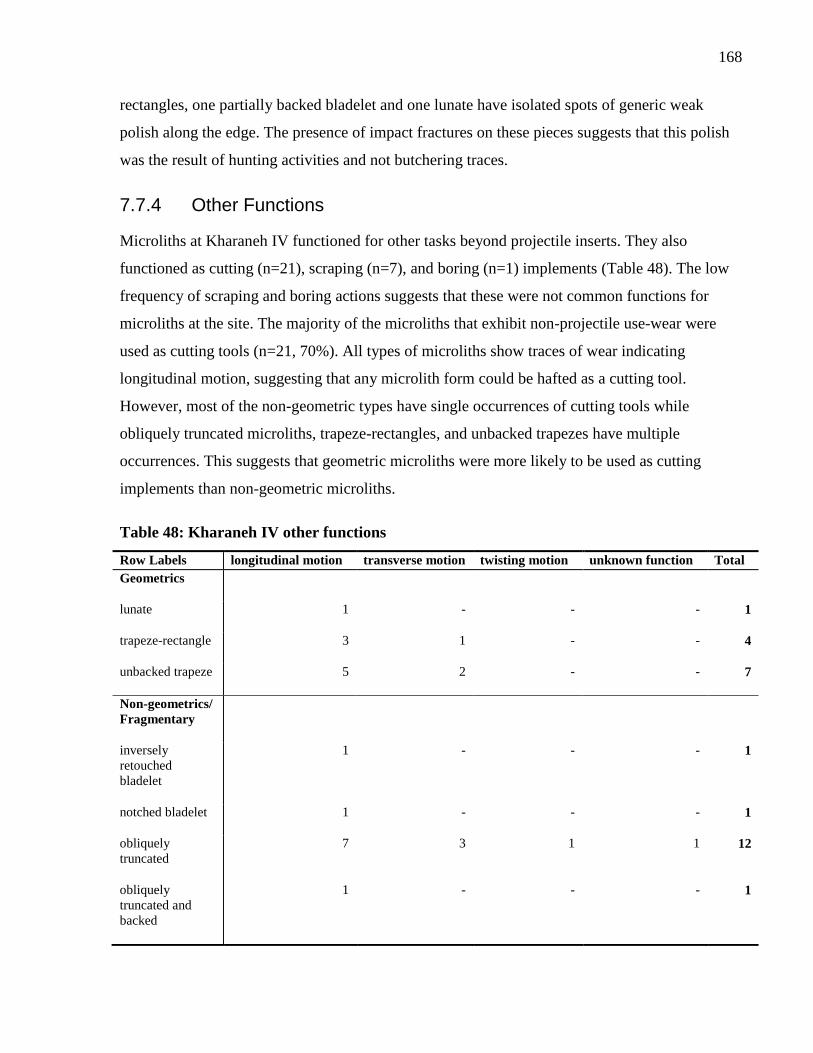
168
rectangles, one partially backed bladelet and one lunate have isolated spots of generic weak
polish along the edge. The presence of impact fractures on these pieces suggests that this polish
was the result of hunting activities and not butchering traces.
7.7.4 Other Functions
Microliths at Kharaneh IV functioned for other tasks beyond projectile inserts. They also
functioned as cutting (n=21), scraping (n=7), and boring (n=1) implements (Table 48). The low
frequency of scraping and boring actions suggests that these were not common functions for
microliths at the site. The majority of the microliths that exhibit non-projectile use-wear were
used as cutting tools (n=21, 70%). All types of microliths show traces of wear indicating
longitudinal motion, suggesting that any microlith form could be hafted as a cutting tool.
However, most of the non-geometric types have single occurrences of cutting tools while
obliquely truncated microliths, trapeze-rectangles, and unbacked trapezes have multiple
occurrences. This suggests that geometric microliths were more likely to be used as cutting
implements than non-geometric microliths.
Table 48: Kharaneh IV other functions
Row Labels longitudinal motion transverse motion twisting motion unknown function Total
Geometrics
lunate 1 - - - 1
trapeze-rectangle 3 1 - - 4
unbacked trapeze 5 2 - - 7
Non-geometrics/
Fragmentary
inversely
retouched
bladelet
1 - - - 1
notched bladelet 1 - - - 1
obliquely
truncated
7 3 1 1 12
obliquely
truncated and
backed
1 - - - 1
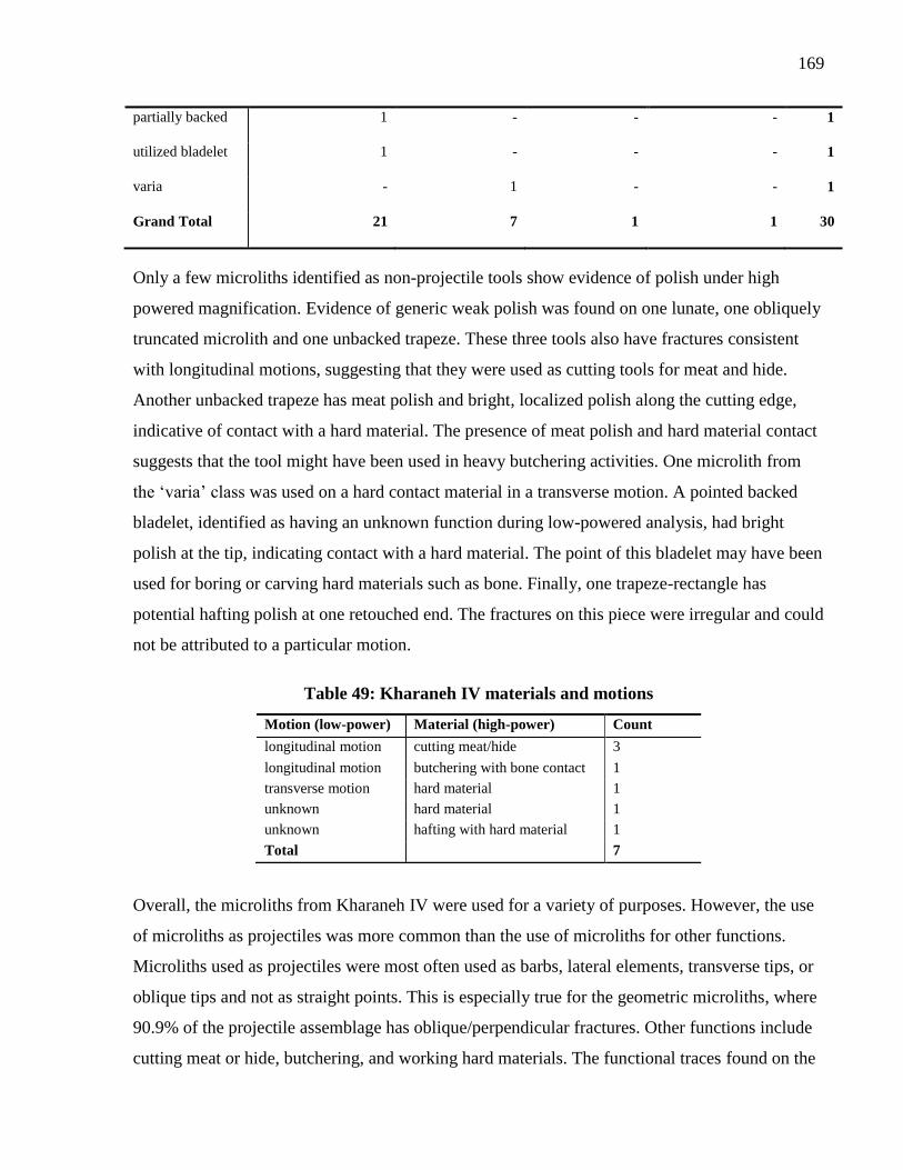
169
partially backed 1 - - - 1
utilized bladelet 1 - - - 1
varia - 1 - - 1
Grand Total 21 7 1 1 30
Only a few microliths identified as non-projectile tools show evidence of polish under high
powered magnification. Evidence of generic weak polish was found on one lunate, one obliquely
truncated microlith and one unbacked trapeze. These three tools also have fractures consistent
with longitudinal motions, suggesting that they were used as cutting tools for meat and hide.
Another unbacked trapeze has meat polish and bright, localized polish along the cutting edge,
indicative of contact with a hard material. The presence of meat polish and hard material contact
suggests that the tool might have been used in heavy butchering activities. One microlith from
the ‘varia’ class was used on a hard contact material in a transverse motion. A pointed backed
bladelet, identified as having an unknown function during low-powered analysis, had bright
polish at the tip, indicating contact with a hard material. The point of this bladelet may have been
used for boring or carving hard materials such as bone. Finally, one trapeze-rectangle has
potential hafting polish at one retouched end. The fractures on this piece were irregular and could
not be attributed to a particular motion.
Table 49: Kharaneh IV materials and motions
Overall, the microliths from Kharaneh IV were used for a variety of purposes. However, the use
of microliths as projectiles was more common than the use of microliths for other functions.
Microliths used as projectiles were most often used as barbs, lateral elements, transverse tips, or
oblique tips and not as straight points. This is especially true for the geometric microliths, where
90.9% of the projectile assemblage has oblique/perpendicular fractures. Other functions include
cutting meat or hide, butchering, and working hard materials. The functional traces found on the
Motion (low-power) Material (high-power) Count
longitudinal motion cutting meat/hide 3
longitudinal motion butchering with bone contact 1
transverse motion hard material 1
unknown hard material 1
unknown hafting with hard material 1
Total 7
170
microlith assemblage at Kharaneh IV suggest that microlith morphology did not constrain the
function of the tool.
7.8 Comparison between Sites and Discussion
The overall pattern at Wadi Mataha, ‘Uyun al-Hammâm, and Kharaneh IV suggests that there is
not a direct correlation between microlith form and how the microlith functioned. Use-wear
traces indicate that microliths were used for a wide range of functions, from projectile
components to cutting implements to scraping tools.
In summary, 30.5% of the Wadi Mataha assemblage had evidence of use-wear. Similar
frequencies of microliths used as projectile inserts (14.0%) and microliths used as cutting tools
(12.0%). The most dominant geometric microlith type, trapeze-rectangles, had 11.7% used as
projectiles and 16.9% used as cutting tools. High-powered analysis suggests that the cutting tools
were used to cut meat or hide, perhaps for butchering activities. A pattern emerges from the
projectile data where non-geometric microliths functioned as projectile tips, while geometric
microliths were hafted as barbs, laterally hafted inserts, obliquely hafted, or transverse tips.
Unfortunately, it is not possible to tease out the specifics of the geometric microlith hafting
configurations with the current data as currently published experiments do not exhibit strong
patterns in fracture types among these modes of hafting. Hopefully future experiments with
larger sample sizes will be able to illuminate differences. Overall, no clear pattern emerges
between microlith type and function, with non-geometric and geometric microliths being used
for all functions.
‘Uyun al-Hammâm had a higher frequency of use-wear than Wadi Mataha; 42.5% of the
assemblage has evidence of use. The analysis indicates that microliths were primarily used as
projectiles (18.0%) or as cutting tools (16.0%). Like the assemblage from Wadi Mataha, these
actions occurred with similar frequency. Trapeze-rectangles were used for a variety of tasks, but
projectiles and cutting were the most prevalent activities. There is no clear pattern between the
hafting configurations of geometric and non-geometric microliths, yet geometrics were rarely
used as projectile tips. High-powered analysis suggests that microliths were used on a wider
variety of materials than the microliths from Wadi Mataha. There is evidence that microliths
were used to cut meat and hide, scrape soft material, and cut hard materials.
171
Kharaneh IV had the highest frequency of used microliths at 48.5%. The majority of these were
projectiles (27.5%), followed by cutting tools (10.5%). This is distinctly different from the Wadi
Mataha and ‘Uyun al-Hammâm assemblages where the microliths were almost evenly
distributed in function between projectiles and cutting. There is no correlation between microlith
form and function at Kharaneh IV, with microlith types being used for several different
functions. Trapeze-rectangles and unbacked trapezes were not used for different tasks and
functioned as projectile inserts, cutting tools, and scraping tools. Diagnostic impact fractures
occur as parallel fractures (14.3%) and oblique/perpendicular fractures (85.7%). The majority of
the geometric microliths have the latter type of fractures, indicating that they were not used as
tips for arming projectiles. Non-projectile functions include cutting meat and hide, butchering
activities with bone contact, and working hard materials.
Comparing the functions between the three sites, it is clear that Kharaneh IV had the highest
frequency of projectile use (Figure 37). Although the archaeological deposits at Kharaneh IV
have clear evidence of activities outside of hunting, the microlith functional analysis suggests
that these tools were a large part of the hunting tool kit. If Kharaneh IV is an aggregation site,
this suggests that groups coming to the site had less flexibility in their use of microliths than did
the occupants of ‘Uyun al-Hammâm or Wadi Mataha. In addition, the high frequency of
projectile use at Kharaneh IV could be a reflection of increasing focus on gazelle hunting at the
site, at witnessed in high frequency of gazelle remains in the faunal assemblage (Martin, et al.,
2010).
The distribution of diagnostic impact fracture location on the projectile inserts for each site
shows some interesting patterns (Figure 38). At Wadi Mataha, there is a clear divide between the
use of non-geometrics as projectile tips and geometrics in other hafting configurations. This
functional segregation of non-geometric and geometric microliths has also been recorded for
microliths from the Belgian Mesolithic site of Verrebroek, where non-geometric microliths were
used as tips and geometric microliths were used as barbs (Crombé, et al., 2001). The same
pattern is not present at ‘Uyun al-Hammâm or Kharaneh IV. In contrast, the geometric microliths
from ‘Uyun al-Hammâm and Kharaneh IV are almost exclusively used as barbs, lateral elements,
oblique tips, or transverse tips, where non-geometrics are used in all hafting arrangements. This
suggests that non-geometric microliths had a different role in the projectile technology at Wadi
Mataha than it did at the other sites.
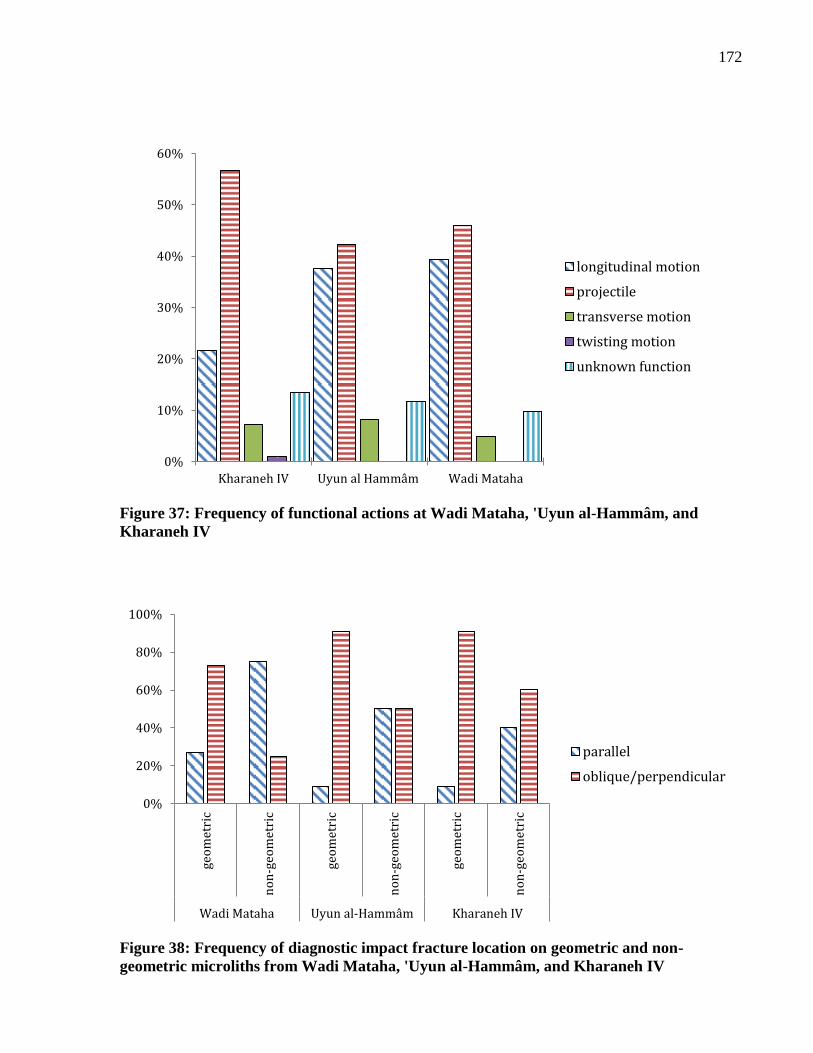
172
Figure 37: Frequency of functional actions at Wadi Mataha, 'Uyun al-Hammâm, and
Kharaneh IV
Figure 38: Frequency of diagnostic impact fracture location on geometric and non-
geometric microliths from Wadi Mataha, 'Uyun al-Hammâm, and Kharaneh IV
0%
10%
20%
30%
40%
50%
60%
Kharaneh IV Uyun al Hammâm Wadi Mataha
longitudinal motion
projectile
transverse motion
twisting motion
unknown function
0%
20%
40%
60%
80%
100%
geo
met
ric
no
n-g
eom
etri
c
geo
met
ric
no
n-g
eom
etri
c
geo
met
ric
no
n-g
eom
etri
c
Wadi Mataha Uyun al-Hammâm Kharaneh IV
parallel
oblique/perpendicular

173
The use-wear analysis of Wadi Mataha, ‘Uyun al-Hammâm, and Kharaneh IV fits with patterns
seen in previous research. The frequency of microlith use for Wadi Mataha and ‘Uyun al-
Hammâm fall generally within the pattern seen in Natufian assemblages (Richter, 2007).
However, the frequency of use for Kharaneh IV is higher. This suggests that microliths were
being more heavily used at this site in comparison to the other locations. This does not relate to
raw material availability, as high quality raw material is available in the immediate vicinity of
Kharaneh IV. Therefore, this suggests different patterns of behaviour between Wadi Mataha,
‘Uyun al-Hammâm, and Kharaneh IV, with the inhabitants of the latter site using their tools
more intensively.
Studies of Natufian microliths have presented diverse interpretations about the functional uses of
microliths; research has shown that use has ranged from projectiles, to cutting tools, to segments
for harvesting equipment (e.g., Anderson and Valla, 1996, Richter, 2007). Currently published
research of Geometric Kebaran microlith assemblages has focused on the use of microliths as
projectiles, to the detriment of other functions (e.g., Shimelmitz, et al., 2004, Yaroshevich, et al.,
2010). The analysis from Wadi Mataha, ‘Uyun al-Hammâm, and Kharaneh IV suggests that the
microliths from these Geometric Kebaran assemblages were used for multiple functions.
Although extensive experimental work was conducted to create a reference sample for harvesting
traces, none were found in the microlith assemblage. This suggests that if the Geometric Kebaran
groups were collecting, they were not using microliths for the task. Furthermore, there is no
correlation between the function of a microlith and its typological class. This fits within the
general pattern seen in later Natufian assemblages, where microliths were functioning in multiple
ways and were used to perform multiple tasks. Previous use-wear analysis shows evidence of
microliths being used both in harvesting implements and in projectiles during the Natufian. This
suggests that they adapted a known technology, microliths, to perform new tasks such as
harvesting.
The results of low- and high-powered use-wear analysis reveal interesting patterns of how
microliths functioned during the Middle Epipalaeolithic. However, several of the polish types,
particularly the hard material polishes, were not identifiable to a specific contact material.
Further information into the specifics of these contact materials is important for our
understanding of potential ‘craft’ activities undertaken by Geometric Kebaran groups, such as
manufacture of bone tools and ornaments, shell beads, and wooden objects. The following

174
chapter explores a new method of use-wear analysis which has the potential to tease out
differences in polish types through the quantification of surface roughness. Although this method
is still in development, preliminary results conducted on the experimental assemblage (presented
in Chapter 5) are very promising.
175
Chapter 8 Use-wear Quantification
Introduction 8
As the field of use-wear analysis has developed, so has the number of techniques that address
tool function. Several new methods have been published in recent years, incorporating both
qualitative and quantitative approaches. In this chapter, I will present a recent development in
quantitative microscopy, specifically the Alicona InfiniteFocus microscope, and its applications
to lithic micro-wear analysis. The Alicona InfiniteFocus microscope characterizes surface texture
and has the ability to generate measurements of surface roughness, particularly useful for lithic
use-wear studies. The application of this microscope to the quantification of use-wear is explored
through the analysis of an experimental collection of lithic tools used on known materials. The
results suggest that the microscope is a promising new technology that can contribute to the
further development of lithic use-wear quantification.
To begin, this chapter introduces key issues within the current practice of archaeological use-
wear analysis and how quantification can contribute to the field. Next, the history of quantitative
use-wear analysis is presented, followed by a description of the Alicona InfiniteFocus
microscope. A description of the methods used for this work is detailed and the surface
parameters chosen for analysis are outlined. The results from study of the experimental tools are
discussed in context of the applications of the microscope. Finally, future directions of research
with use-wear quantification are discussed, highlighting areas where the Alicona InfiniteFocus
microscope can contribute to the growing discipline of use-wear analysis.
8.1 Quantitative and Qualitative Use-Wear Analysis
As seen in previous chapters, the technique of use-wear has traditionally relied on the qualitative
observations of specialists who identify wear patterns microscopically. The ability to recognize
visual differences between types of wear is a highly specialized field, requiring the use of
experimental reference collections to interpret archaeological assemblages. Within the current
literature, most authors suggest that the combination of low- and high-powered approaches
provides a more holistic picture of tool function than the use of a single method alone (e.g.,
Lemorini, et al., 2006, Richter, 2007, Rots, 2008, van Gijn, 2010).
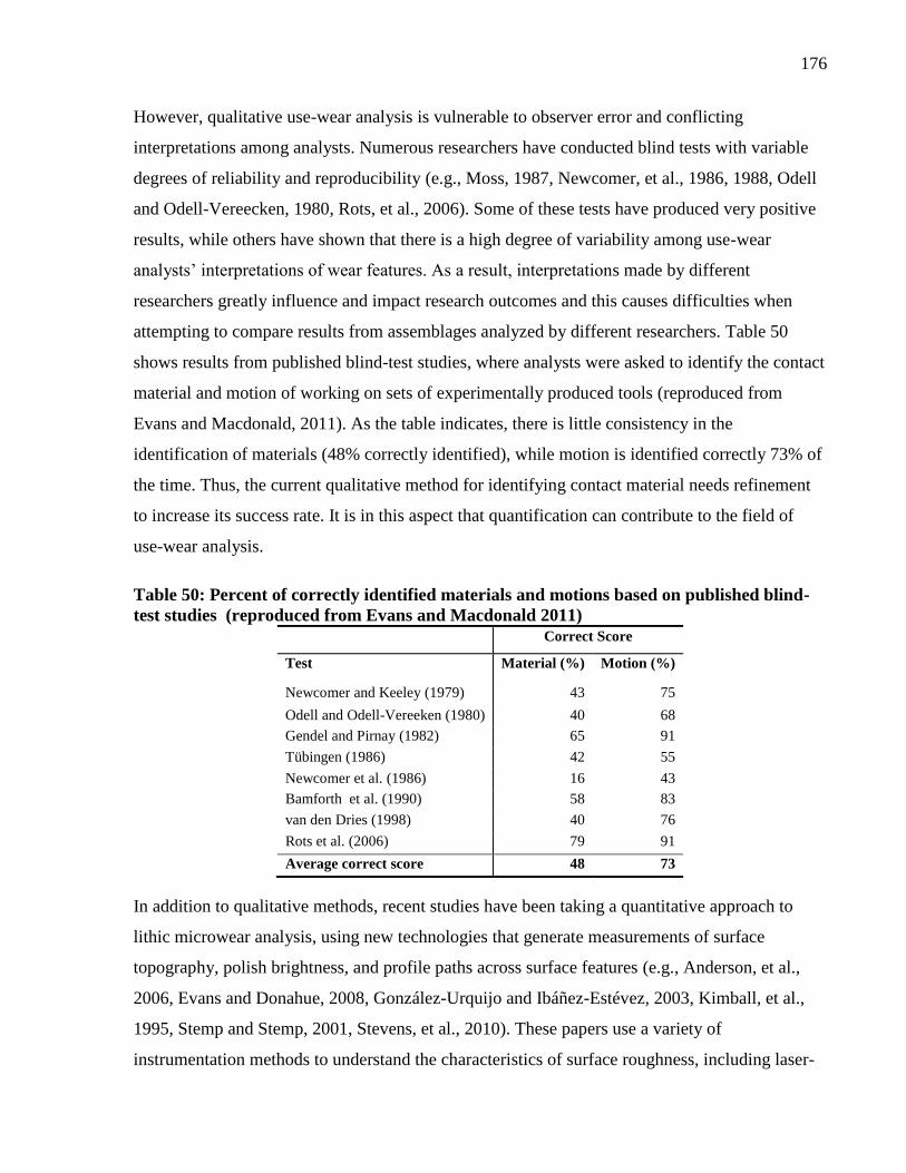
176
However, qualitative use-wear analysis is vulnerable to observer error and conflicting
interpretations among analysts. Numerous researchers have conducted blind tests with variable
degrees of reliability and reproducibility (e.g., Moss, 1987, Newcomer, et al., 1986, 1988, Odell
and Odell-Vereecken, 1980, Rots, et al., 2006). Some of these tests have produced very positive
results, while others have shown that there is a high degree of variability among use-wear
analysts’ interpretations of wear features. As a result, interpretations made by different
researchers greatly influence and impact research outcomes and this causes difficulties when
attempting to compare results from assemblages analyzed by different researchers. Table 50
shows results from published blind-test studies, where analysts were asked to identify the contact
material and motion of working on sets of experimentally produced tools (reproduced from
Evans and Macdonald, 2011). As the table indicates, there is little consistency in the
identification of materials (48% correctly identified), while motion is identified correctly 73% of
the time. Thus, the current qualitative method for identifying contact material needs refinement
to increase its success rate. It is in this aspect that quantification can contribute to the field of
use-wear analysis.
Table 50: Percent of correctly identified materials and motions based on published blind-
test studies (reproduced from Evans and Macdonald 2011) Correct Score
Test Material (%) Motion (%)
Newcomer and Keeley (1979) 43 75
Odell and Odell-Vereeken (1980) 40 68
Gendel and Pirnay (1982) 65 91
Tübingen (1986) 42 55
Newcomer et al. (1986) 16 43
Bamforth et al. (1990) 58 83
van den Dries (1998) 40 76
Rots et al. (2006) 79 91
Average correct score 48 73
In addition to qualitative methods, recent studies have been taking a quantitative approach to
lithic microwear analysis, using new technologies that generate measurements of surface
topography, polish brightness, and profile paths across surface features (e.g., Anderson, et al.,
2006, Evans and Donahue, 2008, González-Urquijo and Ibáñez-Estévez, 2003, Kimball, et al.,
1995, Stemp and Stemp, 2001, Stevens, et al., 2010). These papers use a variety of
instrumentation methods to understand the characteristics of surface roughness, including laser-
177
scanning confocal microscopy (Evans and Donahue, 2008, Stemp and Chung, 2011), laser
profilometry (Stemp and Stemp, 2001, 2003), optical interferometry (Anderson, et al., 2006), and
atomic force microscopy (Faulks, et al., 2011, Kimball, et al., 1995). In these studies, the authors
focus specifically on the analysis of polished surfaces, operating under the principle that different
contact materials (e.g., hide, wood, and antler) have surface characteristics that are
distinguishable from each other on a microscopic scale. When these contact materials interact
with lithics they react with and cause modification to the surface of the lithic. Surface wear will
have different textures based on the contact material, because each material has a different
surface texture and material hardness. For example, harder contact materials will produce a
smoother surface on the used portion of the lithic, as they influence the lithic surface to a greater
degree than would a softer material.
The future development of quantitative analysis has the potential to allow greater comparability
among tools, assemblages, and the results of different researchers. In combination with
qualitative research, quantitative analysis can provide a robust understanding of lithic tool
function.
8.2 History of Use-Wear Quantification
Some of the earliest attempts at quantifying use-wear on lithics used grayscale analysis on
images of surface polish (Grace, et al., 1985). In Grace’s early studies, images of experimental
lithics were captured by photography and histograms were generated to represent wear
statistically on the basis of brightness of polish (as grey scales). To characterize each polish type,
Grace compared each pixel to the neighboring pixels, developing grey levels for the images. He
aimed to quantify the texture of the used surface, with rougher surfaces having greater
differences in the neighboring grey levels and smoother surfaces having less difference. The
results of the study showed that the grey-scale images of the different polish types had
significant overlap and Grace et al. concluded that, although the technique seems promising,
further work was needed.
Later studies by Knutsson (Knutsson, 1988, Knutsson, et al., 1988) built on the work by Grace
and colleagues by trying to correlate the manual identification of polish with digitized pictures of
wear. As with Grace’s method, images were converted to grey scales and each pixel’s grey levels
were compared to the neighbouring pixel to analyze the texture of the image. The results show a
178
separation between groups of unused, vegetable, wood, hide and antler working tools. However,
although there was separation, there was also overlap between the wood, antler, and plant tools,
and the unused and the hide tools. The final results show that there are three different texture
groups: bone, wood/antler/plant, and unused/hide.
Vila and Gallart (1993) also used image analysis by examining the bright areas (polished
surfaces) on photomicrographs, excluding darker areas thought to be unworn. They analyzed
tools used on five different contact materials (wood, bone, antler, hide, and grasses) and
unworked tools, and were able to show differences between pairs of contact materials using t-
tests.
More recent work by Gonzalez-Urquijo and Ibanez-Estevez (2003) used an approach similar to
that of Vila and Gallart (1993). In their study, the authors evaluated the grey scale of pixels on
digitized images, looking at the texture, pattern of distribution, and the degree of development of
the polished areas. Specifically they were interested in the degree of polish linkage (how
connected the polished areas are), the size, and the morphology of the polished areas. Through
this research, they were able to show that polish pattern was a good indicator of contact material.
Image analysis has been used in other ways, including investigating the fractal properties of
microwear polishes. For example, Rees et al. (1991) conducted experiments to determine
whether flint microwear polishes have fractal properties and to ascertain whether there are
quantifiable differences in calculated fractal dimensions for microwear polishes produced by
different worked materials. The authors used grey-scale image analysis based upon previous
image analysis publications. Their results suggested that both polished and unpolished flint
surfaces have fractal properties and that most polished flint surfaces have a lower fractal
dimension than unpolished flints. However, different contact materials did not produce
differences in the fractal dimension. Therefore, this method was successful at determining the
differences among polished and unpolished surfaces, but not for determining differences among
polishes.
Recent image analysis includes the measurement of surface features on scanning electron
microscope (SEM) images. Although these measurements are not attempting to describe surface
texture, surface features can still be quantified in two dimensions. For example, research by
Goodale et al. (2010) measured the thickness of blade edges to determine the intensity of use and
179
the curation of harvesting tools, showing that thick edges result from sickle elements being used
for more than 16 hours.
Image analysis has also been used to characterize surface textures of different raw material types
(Lerner, 2009, Lerner, et al., 2007). For this research, Lerner uses SEM images imported into
ClemexVision Professional Edition image analysis software to quantify the texture of different
non-flint raw material surfaces after use. In the software, images are converted into binary format
and features of the tool’s surface, such as the degree of rounding and the invasiveness of polish,
are measured. Perhaps the most influential aspect of this work is its contribution to
understanding how raw material affects the development of polish and the degree of wear visible
on different tools. Lerner’s work highlights the importance of assessing and reporting raw
material type when conducting use-wear studies.
Other recent research into image analysis includes the use of rotated image with maximum
average power spectrum (RIMPS). This system characterizes surfaces by using digitized images
to detect the directions of surface topography patterns that can then be quantified using statistical
packages (Alvarez, et al., 2011). Using the RIMPS method, Alvarez et al. (2011) show
differences between contact materials as they conclude that wear produced by harder materials is
concentrated at topographic peaks while that from softer materials also affects valley bottoms.
Finally, red laser He-Ne has been used to collect data from gloss on sickle elements that can then
be analyzed using methods similar to image analysis (Vardi, et al., 2010). In this study, the
authors analyzed the reflection of polish from archaeological tools interpreted as harvesting
tools. These reflections were then transformed into grey-scale images and flattened into two-
dimensional histograms. The results show that very glossy blades reflect a narrower scatter beam
and have taller curves in comparison to less glossy blades.
In addition to image analysis, several early studies attempted to quantify use-wear by directly
measuring the surface of the tool. One of the earliest studies incorporating the direct
measurement of surface characteristics was the work by Beyries et al. (1988). Here the authors
used a roughometer to characterize use-wear observations and to understand the differences
among wear types. Their study showed that different types of polish produce different average
roughness measurements and that the differentiation among polish types is possible with
quantitative methods.
180
Other early research into direct surface characterization by Anderson et al. (1998) used an optical
rugosimeter to measure worn areas in three-dimensions. In this study, measurements of lithic
surfaces were made on four randomly selected areas, two from unused areas and two from used
areas on the tool’s surface. The computational software Toposurf was used to calculate several
surface characteristics, including average peak, average valley, developed surface, and bearing
area. Their results showed that the nature of the raw material has an influence in optical
microscopy and in quantified texture analysis on the microtopography. Furthermore, the bearing
area parameter is always greater on the used portions of the tool in comparison to the unused
portions, suggesting that this would be a useful parameter for distinguishing worn surfaces.
Profilometry techniques characterize surface texture along a two-dimensional profile, or cross-
sectional path, along the used surface of the tool. These methods have been used by a several
researchers to quantify surface characteristics, but especially by James Stemp (2009, 2001,
2003). Stemp uses laser profilometry, a non-contact form of profilmetry that calculates profile
paths across a surface based on a laser path rather than a contact stylus, to quantify polished
areas on tool surfaces. His experimental work has addressed several archaeological questions,
including how wear accrues over increasing stroke counts using pottery and wood as contact
materials (Stemp and Stemp, 2003) and whether different contact materials can be distinguished
by their fractal properties (Stemp, et al., 2009). Using scale-sensitive fractal analysis and length-
scale plots, Stemp was also able to show that roughness from use happens frequently below 0.1
mm (and always below 1 mm). This indicates that roughness needs to be measured at very small
scales to differentiate among materials (Stemp, et al., 2009).
Astruc et al. (2011) conducted recent work using profile measurements to understand the
manufacturing techniques employed to create a rare obsidian bracelet found at the Aceramic
Neolithic site of Aşikli Höyük. In this study, the authors extracted profiles of the bracelet at 1mm
intervals to reconstruct its overall symmetry. They also evaluated the mean roughness for various
areas on the bracelet to see if they corresponded to different manufacturing stages. The results
indicate that three different techniques were used to shape and finish the bracelet, suggesting that
the crafts-person who produced the bracelet was highly skilled. Furthermore, they suggest that
the skill level required training and, although this find is unique so far, likely there would have
been more of these artifacts in prehistory. This work moves beyond the identification of contact
181
material, integrating elements of technique and skill to employ quantitative data for
interpretation of social processes.
In another case of research on surface profiles, Anderson et al. (2006) used a vertical-scanning
interferometer to access the development of wear produced by wheat on flint blades from a
tribulum. First, they scanned a blade with the interferometer and extracted a profile. Then they
used the blade in controlled cereal-cutting experiments and rescanned it across the same profile
to identify the processes by which wear develops on the tool. The results showed that the profile
had been smoothed after use and that the valleys in the surface had been filled, indicating that
part of the contract material was deposited on the tool’s surface.
Dumont published earlier work using an optical interferometer (1982) to measure striations on
the surface of lithics. This goal of this work was to differentiate between polish types based on
the assumption that different polishes have distinguishable microtopographies. In this study,
Dumont surmised that hard contact materials exhibit more ‘point pressures’ because they do not
deform over the surface of the flint. Other studies using more updated interferometry techniques
include the use of white-light interferometry. This has recently been used with great success to
evaluate techniques of stone vase manufacture in Bronze Age Crete (Vargiolu, et al., 2007).
Research into use-wear quantification has shifted to the exploration of surface texture in three
dimensions, evaluating areal characteristics rather than profile paths. Early work by Kimball
(Kimball, et al., 1998, Kimball, et al., 1995) focused on the use of atomic force microscopy
(AFM) to characterize surface texture. They looked at experimental tools used for one hour each
on meat, dry hide, wood, and antler contact materials. Ten 1x1 µm areas were selected for
roughness analysis, five from peaks and five from valleys within a 255 µm2 area. The results of
the analysis show that hard contact materials smooth the tool surface more than softer materials,
providing a small average roughness value.
More recent work by Faulks et al. (2011) further explores the utility of AFM for lithic use-wear
analysis. These researchers address the question of whether AFM can determine polish
formation. However, they operate under the assumption that visual qualitative methods are
adequate for determining contact material. Combining high-powered microscopy methods with
AFM, the authors analyzed six different polishes produced from different contact materials
(bone, dry hide, fresh hide, wood, meat and hafting polish) on Mousterian tools from the site of
182
Weasel Cave, Russia. The AFM images were 50 µm x 50 µm (512x512 pixels) in size and the
researchers use the microscope’s proprietary software to calculate the average roughness of the
peaks, valleys, and slopes using approximately ten different 2 µm x 2 µm areas. The results of
the study show that all of the polishes, except for those resulting from dry hide, have lower
average roughness values than the unused flint polish. Meat and dry hide were the least
developed polishes while bone and wood were better developed.
Several studies have shown the potential of the laser-scanning confocal microscope for use-wear
quantification (Evans and Donahue, 2008, Evans and Macdonald, 2011, Stemp and Chung, 2011,
Stemp, et al., 2012). These studies have highlighted the utility of this technique for determining
the roughness characteristics of polishes caused by different contact materials. Research by
Evans (2008) using the Olympus LEXT 3100 laser-scanning confocal microscope showed that
different contact materials produce clearly different average roughness values. Unworked
artifacts had the most variable, roughest surfaces. Greasy hide and dry hide produced the next
roughest signatures, and could not be distinguished statistically at the smaller scale, but could at
the larger scale. Fresh hide was next and could be distinguished at the smaller scale, but not at
the larger scale. Antler and wood produced the smoothest surfaces and separate very well from
the hide.
Stemp and Chung (2011) build upon Stemp’s (2009) previous fractal work by evaluating the
fractal properties of areal surfaces, rather than profile paths. Using the Olympus LEXT OLS4000
laser-scanning confocal microscope (LSCM) the authors showed that the LSCM was useful for
documenting surface textures of obsidian tools at lower magnifications of 20x. Furthermore,
fractal analysis was able to discriminate between the contact materials of hide and wood, but
shell posed some difficulties.
Another study using a LSCM, in this case a NEAT ORU Spectral Imaging FluoView FV1000,
worked under the assumption that different contact materials produce distinct quantitative
signatures (Stevens, et al., 2010). In this work, the authors present use-wear data in the form of
probability statements that report on the use of the tool and the certainty of the attribution. Their
aim was to combine quantitative data on use-wear polishes with qualitative data on edge damage
to arrive at a multivariate approach to classification. Results showed good probability of
183
correctly identifying contact materials, but they are not comparable with other quantitative
studies as Stevens et al. do not measure the same surface parameters.
White-light scanning confocal microscopy has been used to identify wear on teeth with great
success, but has not been used on lithic samples. For example, Scott el al. (2006, 2005) used the
surface parameters of complexity, anisotropy, heterogeneity, and textural volume fill to
differentiate surface textures of teeth among different primate species. These measurements on
modern species were then used as an analogy to conclude that Australopithecus africanus
microwear is more anisotropic, meaning that they ate more tough foods than Paranthropus
robustus, whose teeth exhibited a more complex microwear pattern produced by a diet of hard
and brittle foods.
Although there are currently no published studies using the Alicona InfiniteFocus microscope for
lithic analysis, there have been a few studies using the microscope for the analysis of faunal
remains and human teeth. Research into the morphology of cut marks on faunal remains has
shown very promising results (Bello, et al., 2009, Bello and Soligo, 2008). This work has
focused on evaluating various parameters associated with cut marks, including the slope angle,
the opening angle, bisector angle, shoulder angle, and floor radius of a cut to determine
characteristics of the cutting tool and hand position. Results have shown that force and tool edge
angles differed between the researchers’ experimental work and the cut marks produced by H.
erectus at the Boxgrove site, England. In addition, the Alicona InfiniteFocus microscope has also
been used to measure profile paths of perikymata ridges to quantify the growth and development
of human teeth (Bocaege, et al., 2010). My research explores the application of this microscope
for lithic use-wear studies, building upon previous research conducted in the quantification of
lithic use-wear analysis.
8.3 Surface Metrology and the Alicona InfiniteFocus
Many of the new microscopy technologies employed by archaeologists for use-wear
quantification, including the Alicona InfiniteFocus microscope, were designed for surface
metrology applications in the field of engineering. Surface metrology is the measurement of
deviations on a surface (Whitehouse, 2011) characterizing surface texture. Traditionally, surface
metrology has been used to study machined and engineered surfaces, evaluating deviations
produced through manufacturing processes and wear. However, it has recently been applied to
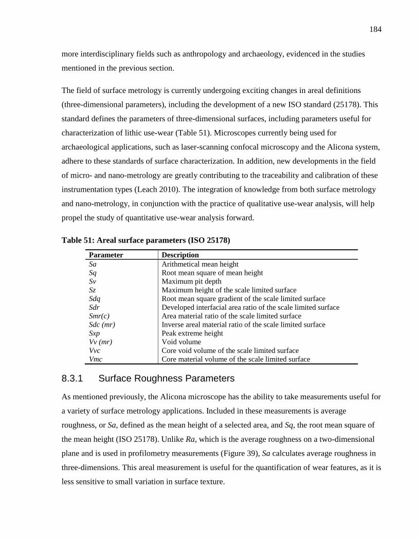
184
more interdisciplinary fields such as anthropology and archaeology, evidenced in the studies
mentioned in the previous section.
The field of surface metrology is currently undergoing exciting changes in areal definitions
(three-dimensional parameters), including the development of a new ISO standard (25178). This
standard defines the parameters of three-dimensional surfaces, including parameters useful for
characterization of lithic use-wear (Table 51). Microscopes currently being used for
archaeological applications, such as laser-scanning confocal microscopy and the Alicona system,
adhere to these standards of surface characterization. In addition, new developments in the field
of micro- and nano-metrology are greatly contributing to the traceability and calibration of these
instrumentation types (Leach 2010). The integration of knowledge from both surface metrology
and nano-metrology, in conjunction with the practice of qualitative use-wear analysis, will help
propel the study of quantitative use-wear analysis forward.
Table 51: Areal surface parameters (ISO 25178)
Parameter Description
Sa Arithmetical mean height
Sq Root mean square of mean height
Sv Maximum pit depth
Sz Maximum height of the scale limited surface
Sdq Root mean square gradient of the scale limited surface
Sdr Developed interfacial area ratio of the scale limited surface
Smr(c) Area material ratio of the scale limited surface
Sdc (mr) Inverse areal material ratio of the scale limited surface
Sxp Peak extreme height
Vv (mr) Void volume
Vvc Core void volume of the scale limited surface
Vmc Core material volume of the scale limited surface
8.3.1 Surface Roughness Parameters
As mentioned previously, the Alicona microscope has the ability to take measurements useful for
a variety of surface metrology applications. Included in these measurements is average
roughness, or Sa, defined as the mean height of a selected area, and Sq, the root mean square of
the mean height (ISO 25178). Unlike Ra, which is the average roughness on a two-dimensional
plane and is used in profilometry measurements (Figure 39), Sa calculates average roughness in
three-dimensions. This areal measurement is useful for the quantification of wear features, as it is
less sensitive to small variation in surface texture.
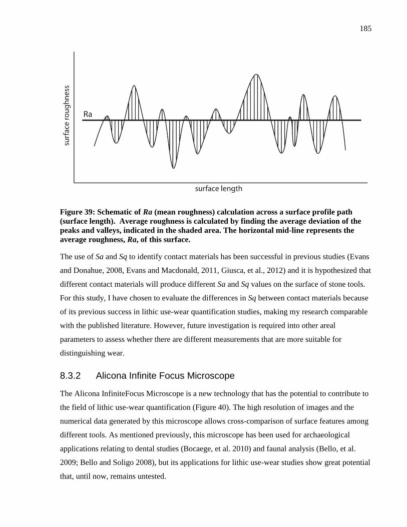
185
Figure 39: Schematic of Ra (mean roughness) calculation across a surface profile path
(surface length). Average roughness is calculated by finding the average deviation of the
peaks and valleys, indicated in the shaded area. The horizontal mid-line represents the
average roughness, Ra, of this surface.
The use of Sa and Sq to identify contact materials has been successful in previous studies (Evans
and Donahue, 2008, Evans and Macdonald, 2011, Giusca, et al., 2012) and it is hypothesized that
different contact materials will produce different Sa and Sq values on the surface of stone tools.
For this study, I have chosen to evaluate the differences in Sq between contact materials because
of its previous success in lithic use-wear quantification studies, making my research comparable
with the published literature. However, future investigation is required into other areal
parameters to assess whether there are different measurements that are more suitable for
distinguishing wear.
8.3.2 Alicona Infinite Focus Microscope
The Alicona InfiniteFocus Microscope is a new technology that has the potential to contribute to
the field of lithic use-wear quantification (Figure 40). The high resolution of images and the
numerical data generated by this microscope allows cross-comparison of surface features among
different tools. As mentioned previously, this microscope has been used for archaeological
applications relating to dental studies (Bocaege, et al. 2010) and faunal analysis (Bello, et al.
2009; Bello and Soligo 2008), but its applications for lithic use-wear studies show great potential
that, until now, remains untested.
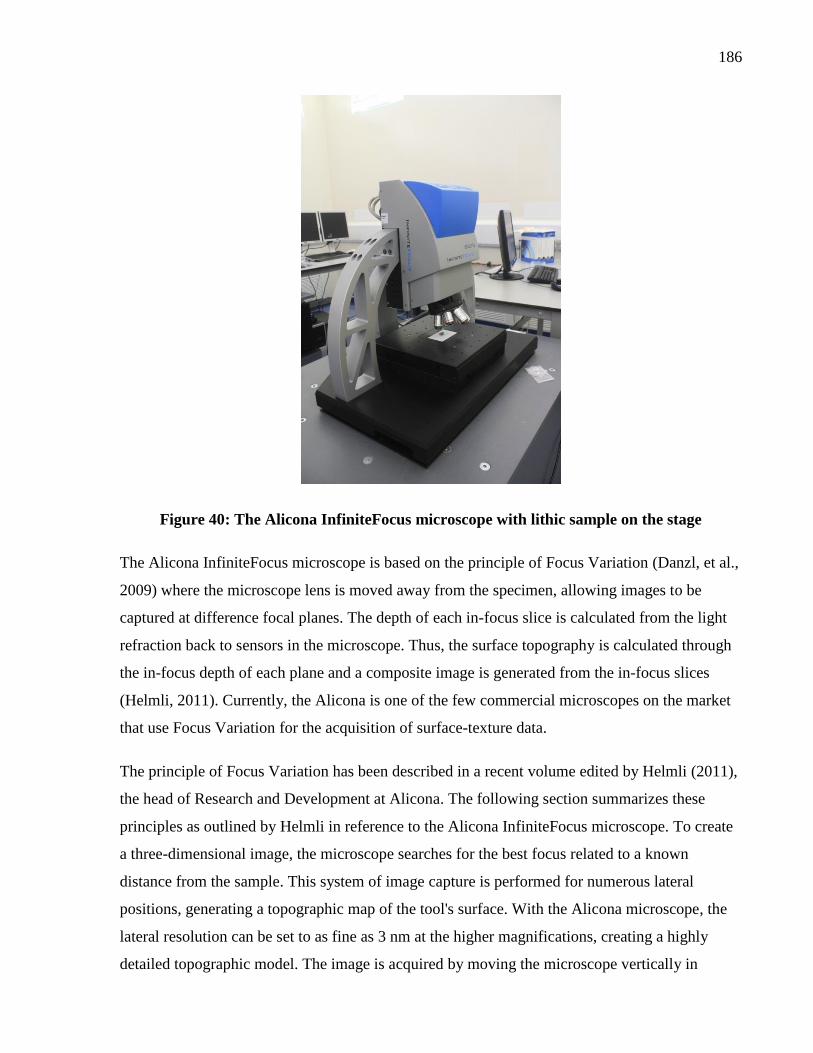
186
Figure 40: The Alicona InfiniteFocus microscope with lithic sample on the stage
The Alicona InfiniteFocus microscope is based on the principle of Focus Variation (Danzl, et al.,
2009) where the microscope lens is moved away from the specimen, allowing images to be
captured at difference focal planes. The depth of each in-focus slice is calculated from the light
refraction back to sensors in the microscope. Thus, the surface topography is calculated through
the in-focus depth of each plane and a composite image is generated from the in-focus slices
(Helmli, 2011). Currently, the Alicona is one of the few commercial microscopes on the market
that use Focus Variation for the acquisition of surface-texture data.
The principle of Focus Variation has been described in a recent volume edited by Helmli (2011),
the head of Research and Development at Alicona. The following section summarizes these
principles as outlined by Helmli in reference to the Alicona InfiniteFocus microscope. To create
a three-dimensional image, the microscope searches for the best focus related to a known
distance from the sample. This system of image capture is performed for numerous lateral
positions, generating a topographic map of the tool's surface. With the Alicona microscope, the
lateral resolution can be set to as fine as 3 nm at the higher magnifications, creating a highly
detailed topographic model. The image is acquired by moving the microscope vertically in
187
relation to the object, bringing the object in and out of focus. The sensor within the microscope
identifies and measures where the object was best in focus. This is then repeated at sequential
lateral positions to build an image. The sensor then evaluates the region around each pixel to
calculate the standard deviation of the grey levels of the local region, thereby measuring the
focus. If the focus is very low or very high, the grey values are almost identical with a low
standard deviation. Focus variation for different types of light sources can be used to collect
information, not just coaxial illumination used by techniques such as image confocal
microscopy. Light types available for this system include ring light, dark field illumination,
diffuse illumination, point light source, and coaxial illumination. This allows different sample
types to be imaged.
The Alicona microscope has a motorized stage that moves in the xy directions, while the
microscope objectives move in the z direction. The microscope has a vertical range of 100 mm,
making it excellent for highly variable surfaces. The available objectives range from 2.5x-100x
magnification and have a vertical resolution of up to 10 nm, but increasing the vertical resolution
also increases the scan time. The Alicona microscope generates three-dimensional images of
surface topography, useful for optical surface metrology applications such as surface roughness
measurements, profile path measurements, and visual details of topographic features. In addition
to its applications for surface metrology, the microscope produces high-resolution images with a
good depth of field. This eliminates the challenges of many other microscopy techniques where
the depth of field limits the ability to assess topographic features. The microscope is non-contact
and any surface can be analyzed with no sample preparation. This is particularity useful for
archaeological materials, as the technique is non-destructive.
Although the Alicona InfiniteFocus microscope has a lot of strengths, the technology also has
limitations in comparison to other techniques. Translucent materials cause significant problems
when acquiring a focus variation measurement. Although replicas or coatings can be used to
counteract this problem, it is not always possible to replicate or modify the object. Also, because
the microscope measures a range of focuses, there needs to be sufficient contrast on the sample’s
surface to obtain a measurement. Thus, the microscope has difficulties obtaining measurements
from highly polished or smooth surfaces. The surface must have a level of roughness and a
surface texture >15 nm is required to obtain a measurement (Helmli, 2011).
188
8.4 Methodology
8.4.1 Experimental Methodology
For quantitative analysis, experimental tools used on five different contact materials were
analyzed. These tools were chosen from the experimental assemblage described in Chapter 6.
The chosen contact materials were antler, wood, hide, meat, and wheat. Unworked surfaces were
also included in the analysis to create a control sample. Two different experimental tools for
antler, hide, and meat were included in the analysis. Unfortunately, due to limitations in
accessing the microscope, only one experimental tool was included for both wood and wheat.
Details about the experimental tools included in this analysis are summarized in Table 52.
Prior to analysis with the Alicona, each tool was thoroughly cleaned using methods adapted from
Keeley (1980). First, each piece was cleaned with warm water and a mild detergent while being
lightly brushed with a soft-bristled tooth brush. Next each piece was soaked in a bath of 10%
sodium hydroxide (NaOH) for 10 minutes to remove organic deposits. Following this cleaning,
the artifacts were soaked in 10% hydrochloric acid (HCl) for 10 minutes to remove any mineral
deposits. The NaOH and the HCl were changed after the cleaning of each piece. Finally, the
experimental tools were bathed in water for 10 minutes to remove any remaining chemical
traces. Although chemical cleaning is not accepted by all use-wear analysts, it was chosen for
this study to remove the possibility that the roughness measurements of the tools’ surfaces were
measuring adhering materials and not measuring actual surface texture. I am currently involved
in a study with Dr. Adrian Evans to investigate the impact of widely used cleaning methods on
surface roughness measurements, including the described chemical cleaning, cleaning with only
soap and water, and cleaning with soap, water and alcohol. This study will shed light on the
impact of cleaning methods for use-wear quantification and help standardize sample preparation.
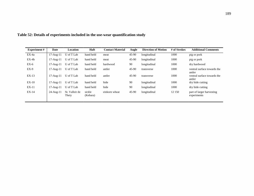
189
Table 52: Details of experiments included in the use-wear quantification study
Experiment # Date Location Haft Contact Material Angle Direction of Motion # of Strokes Additional Comments
EX-4a 17-Aug-11 U of T Lab hand held meat 45-90 longitudinal 1000 pig or pork
EX-4b 17-Aug-11 U of T Lab hand held meat 45-90 longitudinal 1000 pig or pork
EX-6 17-Aug-11 U of T Lab hand held hardwood 90 longitudinal 1000 dry hardwood
EX-9 17-Aug-11 U of T Lab hand held antler 45-90 transverse 1000 ventral surface towards the
antler
EX-13 17-Aug-11 U of T Lab hand held antler 45-90 transverse 1000 ventral surface towards the
antler
EX-10 17-Aug-11 U of T Lab hand held hide 90 longitudinal 1000 dry hide cutting
EX-11 17-Aug-11 U of T Lab hand held hide 90 longitudinal 1000 dry hide cutting
EX-14 24-Aug-11 St. Valleir de
Theiy
sickle
(Kebara)
einkorn wheat 45-90 longitudinal 12 150 part of larger harvesting
experiments
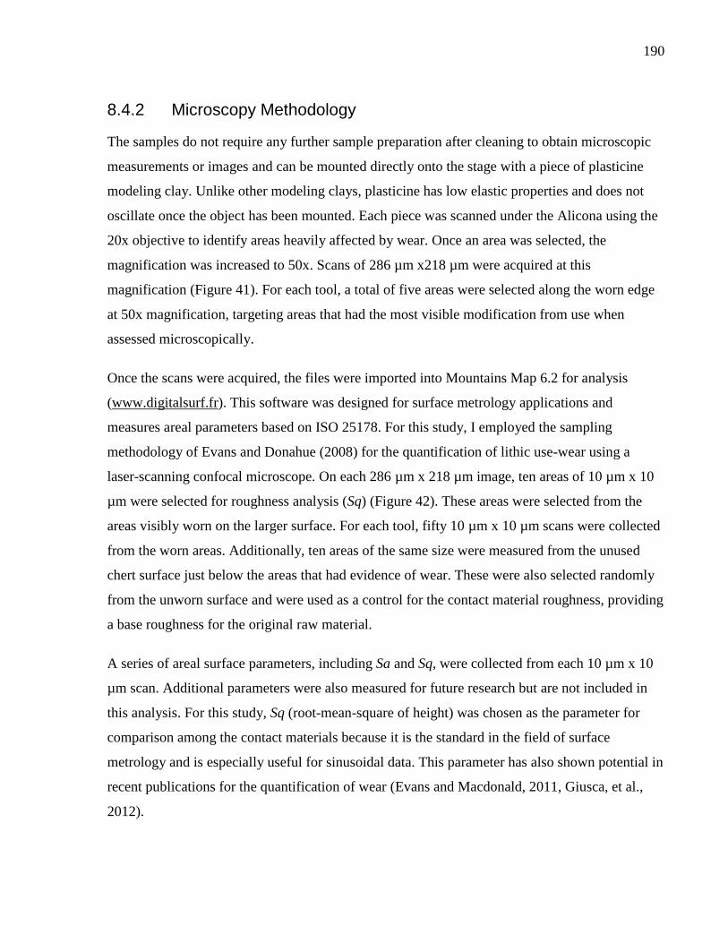
190
8.4.2 Microscopy Methodology
The samples do not require any further sample preparation after cleaning to obtain microscopic
measurements or images and can be mounted directly onto the stage with a piece of plasticine
modeling clay. Unlike other modeling clays, plasticine has low elastic properties and does not
oscillate once the object has been mounted. Each piece was scanned under the Alicona using the
20x objective to identify areas heavily affected by wear. Once an area was selected, the
magnification was increased to 50x. Scans of 286 µm x218 µm were acquired at this
magnification (Figure 41). For each tool, a total of five areas were selected along the worn edge
at 50x magnification, targeting areas that had the most visible modification from use when
assessed microscopically.
Once the scans were acquired, the files were imported into Mountains Map 6.2 for analysis
(www.digitalsurf.fr). This software was designed for surface metrology applications and
measures areal parameters based on ISO 25178. For this study, I employed the sampling
methodology of Evans and Donahue (2008) for the quantification of lithic use-wear using a
laser-scanning confocal microscope. On each 286 µm x 218 µm image, ten areas of 10 µm x 10
µm were selected for roughness analysis (Sq) (Figure 42). These areas were selected from the
areas visibly worn on the larger surface. For each tool, fifty 10 µm x 10 µm scans were collected
from the worn areas. Additionally, ten areas of the same size were measured from the unused
chert surface just below the areas that had evidence of wear. These were also selected randomly
from the unworn surface and were used as a control for the contact material roughness, providing
a base roughness for the original raw material.
A series of areal surface parameters, including Sa and Sq, were collected from each 10 µm x 10
µm scan. Additional parameters were also measured for future research but are not included in
this analysis. For this study, Sq (root-mean-square of height) was chosen as the parameter for
comparison among the contact materials because it is the standard in the field of surface
metrology and is especially useful for sinusoidal data. This parameter has also shown potential in
recent publications for the quantification of wear (Evans and Macdonald, 2011, Giusca, et al.,
2012).
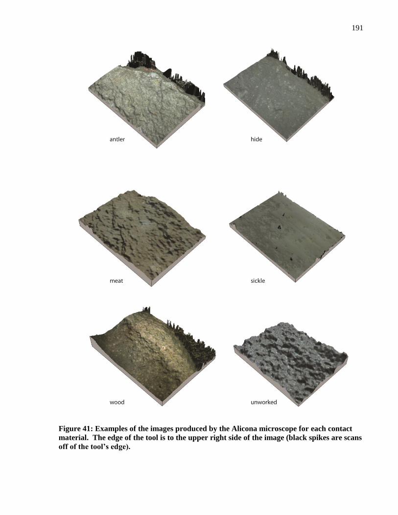
191
Figure 41: Examples of the images produced by the Alicona microscope for each contact
material. The edge of the tool is to the upper right side of the image (black spikes are scans
off of the tool’s edge).
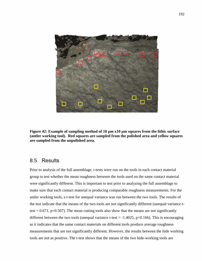
192
Figure 42: Example of sampling method of 10 µm x10 µm squares from the lithic surface
(antler working tool). Red squares are sampled from the polished area and yellow squares
are sampled from the unpolished area.
8.5 Results
Prior to analysis of the full assemblage, t-tests were run on the tools in each contact material
group to test whether the mean roughness between the tools used on the same contact material
were significantly different. This is important to test prior to analyzing the full assemblage to
make sure that each contact material is producing comparable roughness measurements. For the
antler working tools, a t-test for unequal variance was run between the two tools. The results of
the test indicate that the means of the two tools are not significantly different (unequal variance t-
test = 0.671, p=0.507). The mean cutting tools also show that the means are not significantly
different between the two tools (unequal variance t-test = -1.4025, p=0.166). This is encouraging
as it indicates that the same contact materials on different tools produce average roughness
measurements that are not significantly different. However, the results between the hide working
tools are not as positive. The t-test shows that the means of the two hide-working tools are
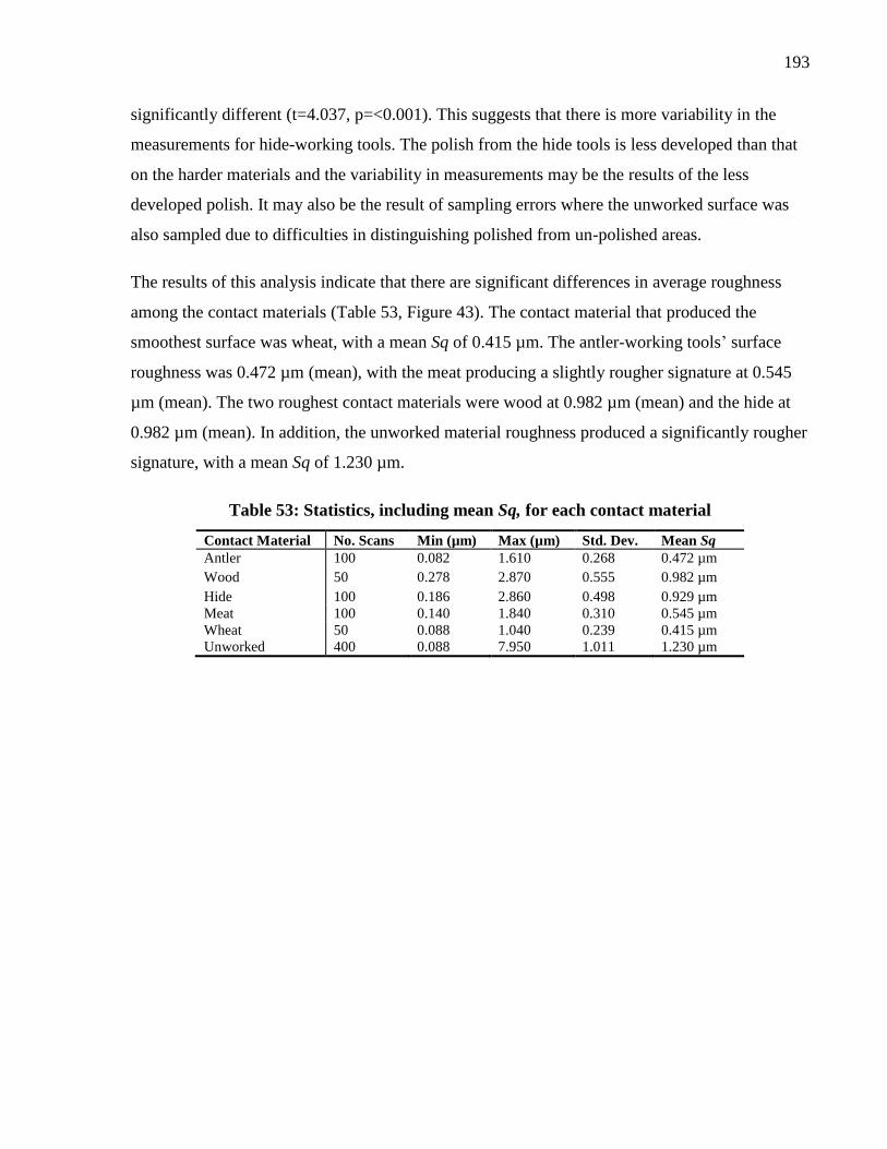
193
significantly different (t=4.037, p=<0.001). This suggests that there is more variability in the
measurements for hide-working tools. The polish from the hide tools is less developed than that
on the harder materials and the variability in measurements may be the results of the less
developed polish. It may also be the result of sampling errors where the unworked surface was
also sampled due to difficulties in distinguishing polished from un-polished areas.
The results of this analysis indicate that there are significant differences in average roughness
among the contact materials (Table 53, Figure 43). The contact material that produced the
smoothest surface was wheat, with a mean Sq of 0.415 µm. The antler-working tools’ surface
roughness was 0.472 µm (mean), with the meat producing a slightly rougher signature at 0.545
µm (mean). The two roughest contact materials were wood at 0.982 µm (mean) and the hide at
0.982 µm (mean). In addition, the unworked material roughness produced a significantly rougher
signature, with a mean Sq of 1.230 µm.
Table 53: Statistics, including mean Sq, for each contact material
Contact Material No. Scans Min (µm) Max (µm) Std. Dev. Mean Sq
Antler 100 0.082 1.610 0.268 0.472 µm
Wood 50 0.278 2.870 0.555 0.982 µm
Hide 100 0.186 2.860 0.498 0.929 µm
Meat 100 0.140 1.840 0.310 0.545 µm
Wheat 50 0.088 1.040 0.239 0.415 µm
Unworked 400 0.088 7.950 1.011 1.230 µm
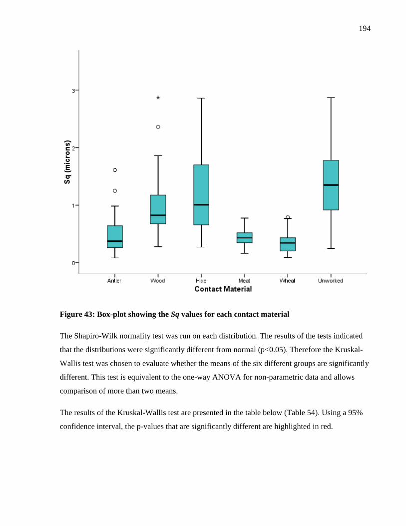
194
Figure 43: Box-plot showing the Sq values for each contact material
The Shapiro-Wilk normality test was run on each distribution. The results of the tests indicated
that the distributions were significantly different from normal (p<0.05). Therefore the Kruskal-
Wallis test was chosen to evaluate whether the means of the six different groups are significantly
different. This test is equivalent to the one-way ANOVA for non-parametric data and allows
comparison of more than two means.
The results of the Kruskal-Wallis test are presented in the table below (Table 54). Using a 95%
confidence interval, the p-values that are significantly different are highlighted in red.
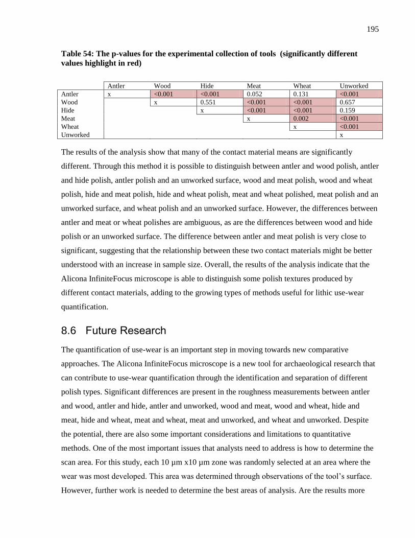
195
Table 54: The p-values for the experimental collection of tools (significantly different
values highlight in red)
Antler Wood Hide Meat Wheat Unworked
Antler x <0.001 <0.001 0.052 0.131 <0.001
Wood x 0.551 <0.001 <0.001 0.657
Hide x <0.001 <0.001 0.159
Meat x 0.002 <0.001
Wheat x <0.001
Unworked x
The results of the analysis show that many of the contact material means are significantly
different. Through this method it is possible to distinguish between antler and wood polish, antler
and hide polish, antler polish and an unworked surface, wood and meat polish, wood and wheat
polish, hide and meat polish, hide and wheat polish, meat and wheat polished, meat polish and an
unworked surface, and wheat polish and an unworked surface. However, the differences between
antler and meat or wheat polishes are ambiguous, as are the differences between wood and hide
polish or an unworked surface. The difference between antler and meat polish is very close to
significant, suggesting that the relationship between these two contact materials might be better
understood with an increase in sample size. Overall, the results of the analysis indicate that the
Alicona InfiniteFocus microscope is able to distinguish some polish textures produced by
different contact materials, adding to the growing types of methods useful for lithic use-wear
quantification.
8.6 Future Research
The quantification of use-wear is an important step in moving towards new comparative
approaches. The Alicona InfiniteFocus microscope is a new tool for archaeological research that
can contribute to use-wear quantification through the identification and separation of different
polish types. Significant differences are present in the roughness measurements between antler
and wood, antler and hide, antler and unworked, wood and meat, wood and wheat, hide and
meat, hide and wheat, meat and wheat, meat and unworked, and wheat and unworked. Despite
the potential, there are also some important considerations and limitations to quantitative
methods. One of the most important issues that analysts need to address is how to determine the
scan area. For this study, each 10 µm x10 µm zone was randomly selected at an area where the
wear was most developed. This area was determined through observations of the tool’s surface.
However, further work is needed to determine the best areas of analysis. Are the results more
196
meaningful on the areas completely modified by wear? Or are they more meaningful on areas
where the original tool’s surface can be contrasted with the texture produced through use?
The assessment that the surface roughness of the worn areas is a useful parameter for
determining contact material is based on previous studies, but this does not mean that it is the
only useful surface parameter. The ISO standard includes measurements of volume analysis,
maximum peaks, maximum valleys, along with numerous other measurements. A recent study
conducted with the National Physical Laboratories, UK, evaluated the evolution of wear as lithic
tools were used over increasing periods of time (Giusca, et al., 2012). Included in this study was
a secondary aim of finding suitable areal surface texture parameters (ISO/FDIS 25178-2: 2010)
that can differentiate between use duration. The results of this experiment showed that in
addition to Sa and Sq, the parameters Sz, Smr, Smc, Sdq, Sdr and Vvc also were useful in
accessing use duration (Table 51). More research is required to understand the nature of these
parameters in relation to the identification of contact material.
As shown in the review of previous studies, there are multiple microscopes on the market that
have the ability to generate surface roughness values. However, it is not known if the values
from these microscopes are comparable with one another. A recently published study to test the
comparability of the Alicona and the LEXT laser-scanning confocal microscope (Evans and
Macdonald, 2011) showed that average roughness was comparable between the two microscopes
when measuring an antler working tool, but there were some unexplained differences in the Sq
value. This study is currently being expanded to include an experimental collection of hide-
scraping tools to increase the sample size. These tools will be evaluated under a LEXT laser-
scanning confocal microscope, an atomic force microscope, and the Alicona InfiniteFocus
microscope to understand the results of areal analysis among these three systems. Understanding
how the results from different types of instrumentation relate to each other is imperative to
moving quantitative use-wear analysis forward.
As part of this project, a blind test study is currently being conducted on the LEXT laser-
scanning confocal microscope. This study targets the identification of two hard contact materials,
wood and antler, which are notoriously difficult to distinguish by use-wear analysis. The results
from the LEXT measurements will be compared to the results from an experienced use-wear
197
analyst to determine the potential of surface metrology microscopes for the classification of
ambiguous contact material traces.
Finally, further expansion into the field of tribology is needed to understand the characteristics of
wear. Understanding the type of wear, whether adhesive, abrasive or other, will help develop the
methods needed to understand how and why lithic surfaces are changed during use. This will
further our understanding of the parameters needed to test these changes.
8.7 Summary
In conclusion, quantitative methods have the potential to contribute to the growing field of lithic
use-wear analysis. While this appears to be a very useful endeavor, it is important to move
towards developing best-practice methods for quantitative analysis, including how to choose the
area of analysis and the best parameters for characterizing surface features. Finally, the use of
qualitative methods of use-wear analysis cannot be divorced from quantitative methods. Choice
of the location for analysis and the interpretations made from the results are built upon the
traditional use-wear methods. Quantitative methods are not replacements for low- and high-
powered microscopy; they are new methodologies to be used in tandem with qualitative research
to gain a robust view of lithic tool function. The continued development of this methodology will
allow researchers to interpret difficult use-wear traces, thereby gaining further insight into
Palaeolithic stone tool use.
198
Chapter 9 Conclusion: Microliths in the Middle Epipalaeolithic
Summary 9
Interpretations of microlith variability have shaped our conceptions of the Epipalaeolithic.
Regional and chronological variability in microlith form has been interpreted to represent distinct
culture groups (e.g. Bar-Yosef, 1970, Goring-Morris, 1987, Henry, 1995). This interpretation
was challenged by Neeley and Barton (1994) who suggested that microlith form was the result of
different reduction stages. Their highly controversial interpretation sparked a storm of debate as
people defended the cultural hypothesis (Fellner, 1995a, Goring-Morris, 1996, Henry, 1996,
Kaufman, 1995, Phillips, 1996). Despite this debate, functional interpretations of microlith form
were not explored as an explanation for variability. This dissertation set out to evaluate microlith
variability in the Middle Epipalaeolithic by integrating functional analysis into the debate.
The three sites of Wadi Mataha, ‘Uyun al-Hammâm, and Kharaneh IV contain a range of
features and vary in size, suggesting that there were differences in the way these communities
inhabited the landscape at the end of the Pleistocene. These differences could relate, in part, to
site function, with Kharaneh IV acting as an aggregation locale for several different groups.
Despite these differences, all three communities were using the same microlith technology, the
trapeze-rectangle, which was widespread in the southern Levant during the Middle
Epipalaeolithic. Using multiple methods including typology, technological analysis,
morphometrics, and use-wear, differences in visible and non-visible aspects of technology were
explored to assess the variability witnessed in material culture at the three study sites.
Initially, I set out to test several hypotheses in regards to the microliths found at Wadi Mataha,
‘Uyun al-Hammâm, and Kharaneh IV. I hypothesized that microliths would have overlapping
functions, indicating that function does not drive form. Second, I hypothesized that microliths
would show differences in technological style as witnessed through subtle variations in
manufacture. Finally, I hypothesized that microliths functioned as sickle elements, suggesting a
deep time depth for harvesting behaviours that are found later in the Natufian. These
hypothesizes relate back to current debates in Epipalaeolithic research about the nature of
microlith variability. Is variation in microlith morphology the product of different technological
199
sequences of production? Or the result of varying function? Or is it the result of different cultural
group’s stylistic preferences?
Through the exploration of microlith form, function, and technology, I suggest that the subtle
variability witnessed among the Middle Epipalaeolithic microliths results from different learning
communities. Using Gosselain’s (2000) interpretations of social identity and the chaîne
opératoire, I propose that the concept of trapeze-rectangles was easily transmitted between
groups because of its high visibility, but the details of manufacture vary among communities as
these were enacted within a localized and inter-personal context. Thus, the trapeze-rectangle was
a wide-spread technology without the need for identical sequences of production or exact
duplication in form. People were performing culturally and community-situated gestures that
transformed materials into trapeze-rectangles specific to their group.
The third hypothesis, whether microliths were used as harvesting tools, was addressed through
use-wear analysis. The analysis shows that microliths were employed for several different tasks
at the three sites, suggesting that they could be easily adapted to fit a variety of applications.
However, from the sample selected, harvesting was not one of these functions. Further sampling
of other tool types, such as retouched blades, is needed to determine if harvesting behaviours
were enacted using different tools. The absence of cereal traces on the microliths does, however,
indicate that the function of microliths changed over time, with the adoption of a previously used
form (geometric microliths) for new uses such as harvesting during the Natufian. This highlights
the flexibility of microlith technology as it can be adapted to new applications.
9.1 Integrating Multiple Methods
The methods employed for this research varied from traditional typological analysis to the
development of new quantitative microscopy techniques. The integration of quantitative
techniques, such as morphometrics and Focus Variation microscopy, allow an increased level of
comparability among the assemblages. Furthermore, these methods allow us to access aspects of
material culture that were previously unobtainable. For example, morphometric analysis
complements traditional metrics to describe shape more precisely. It allows subtle details in
form, such as the curvature of the backed edge, and the angles between the retouched ends and
use-edge, to be described and compared. Although still in early stages of development,
quantitative microscopy can be useful to tease out differences in contact materials that are
200
difficult to identity visually. Details of surface texture at the nanoscale moves beyond what
traditional microscopy is able to assess and gives new information on the nature of use-wear
polishes. These techniques are useful in combination with traditional qualitative analyses and the
integration of multiple methods presents a robust understanding of microlith variation. Using
methods that explore technology, typology and function allows us to extend the chaîne
opératoire beyond manufacture and into later stages of the tool’s ‘life-history’, incorporating the
use of the tool.
Lithic use-wear analysis contributes to our understanding of human behaviour in the past through
addressing tool function within the chaîne opératoire. Classic analyses of the chaîne opératoire
used refitting and technological studies to understand the manufacturing processes of lithic tools.
These studies reconstruct the chaîne opératoire by using macroscale data, using the artifact’s
qualities and properties to understand process within the larger lithic sub-system. However,
microwear analysis builds from the microscopic scale outwards to understand tools in their social
context. Use-wear analysis brings us further into the non-visible realm, operating on scales of
nanometers and microns. This leaves us with the question of how microscale traces can
contribute to our understanding of macro-scale phenomena. Can non-visible traces be related to
social processes? I suggest that use-wear provides an integral element of the chaîne opératoire
and that microscopic information can illuminate details of gestures not captured in typological
and technological analysis. Traces of use remaining on a tool’s surface, such as fractures,
polishes, and striations, hint at dynamic movement in the past. Without this information, the later
stages of a tool’s life-history are lost. It can be argued that when a tool is used it is most visible
and active in its social realm, therefore understanding its function brings us closest to the social
realm. Lithic microwear analysis has an important place in our conceptualization of the chaîne
opératoire and, by moving into realms of non-visible data, we can reveal subtle features of
human behaviour not captured at the macroscopic scale.
9.2 Microliths in the Geometric Kebaran
Through the analysis of Wadi Mataha, ‘Uyun al-Hammâm, and Kharaneh IV microlith
assemblages, we can reconstruct a general chaîne opératoire of these tools. From a prescriptive
perspective (Knappett, 2011), the chaîne opératoire of Geometric Kebaran trapeze-rectangle
microliths can be viewed as follows:
201
Acquire raw materials
Knap blanks for microlith production
Retouch blanks into trapeze-rectangles
Haft trapeze-rectangles longitudinally or as barbs or as transverse tips
Use hafted tools as cutting tools or projectiles
Discard
This creates a generalized scheme for how microliths functioned across the region. However, we
can also take a descriptive perspective (Knappett, 2011), focusing on the variability within and
among the sites. Through this descriptive lens, details of the fluctuations and changes in material
culture are highlighted.
To begin, the reduction strategies for the three sites were primarily focused on the production of
bladelets to be retouched into various microlith forms. All three sites used raw materials that
were available within the surrounding region, although some material from Wadi Mataha and
small amounts of material from Kharaneh IV may have traveled from greater distances. Raw
material is plentiful at all three sites, suggesting that there was no need for conservation. The
entire reduction sequence was enacted at the sites, evidenced through the presence of cores, core-
trimming elements, and debitage, as well as finished tools. The knapping sequence focused on
core maintenance rather than core preparation, indicating that the size and shape of the microlith
blank did not need to be standardized.
For all three sites, the tools are representative of types typically found in Middle Epipalaeolithic
assemblages, including scrapers, burins, and notches. Tool assemblages are dominated by
microliths, with an emphasis on geometrics. This pattern diverges at Kharaneh IV, where
geometric and non-geometric microliths are evenly represented in the assemblage. However, this
may be the result of fragmentation patterns as Kharaneh IV has the highest proportion of
fragmentary microliths. ‘Uyun al-Hammâm has the highest frequency of geometrics in the
microlith assemblage, primarily composed of trapeze-rectangles. The geometrics at Wadi Mataha
are also dominated by trapeze-rectangle microliths. This is in contrast to Kharaneh IV, where the
geometrics are represented by both unbacked and backed trapezes. Width evidence suggests that
the two different types of microliths at Kharaneh IV might have been part of different reduction
sequences. The microliths from Wadi Mataha and ‘Uyun al-Hammâm were backed using
202
invasive retouch. In contrast, the microliths from Kharaneh IV were backed with non-invasive
retouch, indicating a very different pattern in retouching traditions in comparison to the other
two sites.
Morphometric analysis reveals variability in trapeze-rectangle shape among the three sites. The
geometric microliths from Wadi Mataha are elongated with straight to concave backing, the ones
from ‘Uyun al-Hammâm are angular with straight to concave backing and have a high degree of
variance in elongation, and the trapeze-rectangles from Kharaneh IV have rounded corners, a
feature not seen at the other two sites. The variability witnessed in one typological group from
three sites suggests that different communities adapted and envisioned these geometric
microliths in their own ways. I would suggest that this is because trapeze-rectangles can be
considered as a diffuse technology that is easily transmitted between groups with minimal
interaction.
Previous experimental and functional studies of Geometric Kebaran sites focused on the
application of microliths as projectile insets (e.g., Yaroshevich, et al., 2010). For this
dissertation, I focused experimental work on alternative uses of geometric microliths, including
their potential function as harvesting or cutting implements. Experimentation using replicated
Epipalaeolithic hafts showed that, when hafted longitudinally, trapeze-rectangle microliths
functioned very well as cutting tools for cereals and soft materials such as meat.
Use-wear analysis of the three assemblages displays no direct correlation between microlith
function and form. At all three sites, microliths preformed numerous tasks, including as
projectile insets and as cutting implements. The trapeze-rectangles from Wadi Mataha and ‘Uyun
al-Hammâm had almost equal incidences of use as cutting and projectile tools, while Kharaneh
IV had a much higher frequency of projectile use. Microliths used as cutting tools were likely
hafted longitudinally in the haft, although there is no evidence as to whether there would have
been a single blade (similar to the haft from Kebara) or parallel blades (similar to the Wadi
Hammeh 27 haft). The pattern of poly-functionality for a single form fits with previous use-wear
analyses of Natufian assemblages that suggest lunates were used for multiple purposes.
However, unlike Natufian assemblages, there is no evidence for the use of trapeze-rectangles for
harvesting in the Geometric Kebaran.
203
The clearest pattern of projectile use is found at the site of Wadi Mataha, where geometric
microliths were primarily hafted as oblique barbs or transverse tips while non-geometrics were
hafted as straight tips. This suggests that at Wadi Mataha there was as clear notion of how
geometric and non-geometric microliths were hafted when used as projectiles. In contrast, at
both ‘Uyun al-Hammâm and Kharaneh IV, geometric microliths were used also exclusively as
barbs or transverse tips, while non-geometric microliths were more variable in their hafting
configuration as projectiles. Thus, projectiles at Wadi Mataha may have had trapeze-rectangles
hafted as oblique barbs, with a non-geometric microlith at the tip. Both ‘Uyun-al Hammâm and
Kharaneh IV would have had geometrics hafted as barbs or transverse tips, and non-geometrics
either hafted at the tip or also hafted in a similar manner to the geometrics. This suggests a range
of different hafting configurations for microliths as projectile insets.
Overall, there is a lot of flexibility in how microliths were used and manufactured during the
Middle Epipalaeolithic. Although the form of the trapeze-rectangle was widespread, it was
expressed differently within different communities.
9.3 Conclusion
In conclusion, the results from the analysis suggest that there is not a direct causal relationship
between form and function in Epipalaeolithic microliths. Although the two are intrinsically
intertwined, different communities had flexibility within the constraints of their technology.
Skilled people made decisions within the norm of their community about how a microlith was
made and used. Future work will explore the remainder of the lithic assemblages, situating the
chaîne opératoire of microliths into the wider sphere of technology.
In a recent paper, Ingold (2010) discusses the interrelations between people and objects. The
paper seeks to break down the common model that agents impose form onto materials. Instead,
Ingold advocates the view that we should follow the materials. Instead of imposing form, people
bring together diverse materials, combining and redirecting their flow, thus changing the course
of materials. This paper alludes to some of the biggest problems in the chaîne opératoire: what is
the beginning and end of a material? Where do you begin and end the chaîne opératoire?
Although this question is not easily answered, I advocate the integration of function into our
conceptions of the chaîne opératoire, incorporating additional aspects of the tool’s life-history
that can illuminate gestures in prehistory.
204
References
Adams, D.C., Rohlf, F.J., Slice, D.E., 2004. Geometric Morphometrics: Ten Years of Progress
following the 'Revolution', Italian Journal of Zoology 71, 5-16.
Alvarez, M., Fuetes, N., Favret, E., Dolce, M.V., Forlano, A., 2011. Quantifying Use-Wear
Traces through RIMAPS and Variogram Analyses., Archaeological and Anthropological
Sciences, 1-11.
Anderson, P., 1983. A Consideration of the Uses of Certain Backed and "Lustered" Stone Tools
from Late Mesolithic and Natufian Levels of Abu Hureyra and Mureybet (Syria), in: Cauvin, J.
(Ed.), Traces d'Utilisation sur les Outils Neolithiques du Proche Orient, Maison de l'Orient,
Paris.
Anderson, P., 1991. Harvesting of Wild Cereals During the Natufian as Seen from the
Experimental Cultivation and Harvest of Wild Einkorn Wheat and Microwear Analysis of Stone
Tools, in: Bar-Yosef, O., Valla, F. (Eds.), The Natufian Culture in the Levant, International
Monographs in Prehistory, Michigan, pp. 521-556.
Anderson, P., Astruc, L., Vargiolu, R., Zahouani, H., 1998. Contribution of quantitative analysis
of surface states to a multi-method approach for characterising plant-processing traces on flint
tools with gloss, Functional Analysis of Lithic Artefacts: Current State of the Research, XIII
International Congress of Prehistoric and Protohistoric Sciences, Workshops, Tome II, ABACO
Edizioni, Forli, pp. 1151–1160.
Anderson, P., Georges, J.-M., Vargiolu, R., Zahouani, H., 2006. Insights from a tribological
analysis of the tribulum, Journal Of Archaeological Science 33, 1559-1568.
Anderson, P., Valla, F., 1996. 'Glossed Tolls' from Hayonim Terrace: Blank Choice and
Functional Tendencies, in: Kozlowski, S.K., Gebel, H. (Eds.), Neolithic Chipped Stone
Industries of the Fertile Crescent and their Contemporaries in Adjacent Regions ex Oriente,
Berlin, pp. 341-362.
Archer, W., Braun, D., 2010. Variability in bifacial technology at Elandsfontein, Western cape,
South Africa: A geometric morphometric approach, Journal Of Archaeological Science 37, 201-
209.
Astruc, L., Vargiolu, R., Ben Tkaya, M., Balkan-Atli, N., Ozbasaran, M., Zahouani, H., 2011.
Multi-Scale Tribological Analysis of the Technique of Manufacture of an Obsidian Bracelet
from Asikli Hoyuk (Aceramic Neolithic, Central Anatolia), Journal Of Archaeological Science
38, 3415-3424.
Baadsgaard, A., Chazan, M., Cummings, L.S., Janetski, J., 2010. Natufian Strategy Shifts:
Evidences from Wadi Mataha 2, Petra, Jordan, Eurasian Prehistory 7, 1-27.
Baadsgaard, A., Janetski, J., Chazan, M., 2002. Preliminary Results of the Wadi Mataha (Petra
Basin, Jordan) Faunal Analysis, in: Buitenhuis, H., Choyke, A.M., Mashkour, M., Al-Shiyab,
205
A.H. (Eds.), Archaeozoology of the Near East, ARC-Publicaties, Yarmouk University, pp. 98-
111.
Bamforth, D., 2010. Conducting Experimental Research as a Basis for Microwear Analysis, in:
Ferguson, J. (Ed.), Designing Experimental Research in Archaeology: Examining Technology
Through Production and Use, University of Colorado Press, Boulder, pp. 93-109.
Bamforth, D., Burns, G.R., Woodman, C., 1990. Ambiguous Use Traces and Blind Test Results
and New Data, Journal Of Archaeological Science 17, 413-430.
Bar-Matthews, M., Ayalon, A., Kaufman, A., Wasserburg, G., 1999. The Eastern Mediterranean
Paleoclimate as a Reflection of Regional Events: Soreq Cave, Israel, Earth and Planetary
Science Letters 116, 85-95.
Bar-Yosef, O., 1970. Epipalaeolithic Cultures of Palestine, Archaeology, Hebrew University of
Jerusalem, Jerusalem.
Bar-Yosef, O., 1975. The Epi-Paleolithic in Palestine and Sinai, in: Wendorf, F., Marks, A.E.
(Eds.), Problems in Prehistory: North Africa and the Levant, SMU Press, Dallas, pp. 363-378.
Bar-Yosef, O., 1981. The Epi-palaeolithic Complexes in the Southern Levant, in: Cauvin, J.,
Sanlaville, P. (Eds.), Préhistoire du Levant, Centre National des Recherches Scientifique, Paris,
pp. 389-408.
Bar-Yosef, O., 1991. The Archaeology of the Natufian Layer at Hayonim Cave in: Bar-Yosef,
O., Valla, F. (Eds.), The Natufian Culture in the Levant, International Monographs in Prehistory,
Ann Arbor.
Bar-Yosef, O., 1998. The Natufian Culture in the Levant, Threshold to the Origins of
Agriculture, Evolutionary Anthropology, 159-177.
Bar-Yosef, O., Belfer-Cohen, A., 1989. The Origins of Sedentism and Farming Communities in
the Levant, Journal of World Prehistory 3, 447-498.
Bar-Yosef, O., Goring-Morris, A.N., 1977. Geometric Kebaran A Occurrences, in: Bar-Yosef,
O., Phillips, J. (Eds.), Prehistoric Investigations in Gebel Maghara, Northern Sinai, Hebrew
University, Jerusalem, pp. 115-148.
Bar-Yosef, O., Phillips, J., 1977. Prehistoric Investigations in Gebel Maghara, Northern Sinai,
The Hebrew University of Jerusalem, Jerusalem.
Bar-Yosef, O., Van Peer, P., 2009. The Chaîne Opératoire Approach in Middle Paleolithic
Archaeology, Current Anthropology 50, 103-131.
Bar-Yosef, O., Vogel, J., 1987. Relative and Absolute Chronology of the Epi-Palaeolithic in the
Southern Levant, in: Aurenche, O., Evin, J., Hours, F. (Eds.), Chronologies in the Near East,
British Archaeological Reports, Oxford.
206
Barton, C.M., Neeley, M., 1996. Phantom Cultures of the Levantine Epipalaeolithic, Antiquity
70, 139-147.
Barton, R.N.E., Bergman, C.A., 1982. Hunters at Hengistbury: Some Evidence from
Experimental Archaeology, World Archaeology 14, 237-248.
Bartov, Y., Stein, M., Enzel, Y., Agnon, A., Reches, Z., 2002. Lake Levels and Sequence
Stratigraphy of Lake Lisan, the Late Pleistocene Precursor of the Dead Sea, Quaternary
Research 57, 9-21.
Becker, M., 1999. Reconstructing Prehistoric Hunter-Gatherer Mobility Patterns and the
Implications for the Shift to Sedentism: A Perspective from the Near East, PhD Dissertation,
Department of Anthropology, University of Colorado.
Becker, M., Wendorf, F., 1993. A Microwear Study of a Late Pleistocene Qadan Assemblage
from Southern Egypt, Journal Of Field Archaeology 20, 389-398.
Belfer-Cohen, A., 1988. The Natufian Graveyard in Hayonim Cave Paléorient 14, 297-308.
Belfer-Cohen, A., 1991. Art Items from Layer B, Hayomin Cave: A Case Study of Art in a
Natufian Context, in: Bar-Yosef, O., Valla, F. (Eds.), The Natufian Culture in the Levant,
International Monographs in Prehistory, Michigan, pp. 569-588.
Belfer-Cohen, A., 1995. Rethinking Social Stratification in the Natufian Culture: The Evidence
from Burials, in: Campbell, S., Green, A. (Eds.), The Archaeology of Death in the Ancient Near
East, Oxbow Books, Oxford, pp. 9-16.
Belfer-Cohen, A., Bar-Yosef, O., 2000. Early Sedentism in the Near East: A Bumpy Ride to
Village Life, in: Kuijt, I. (Ed.), Life in Neolithic Farming Communities: Social Organization,
Identity, and Differentiation, Kluwer Academic/ Plenum Publishing, New York, pp. 19-37.
Belfer-Cohen, A., Goring-Morris, N., 2002. Why Microliths? Microlithization in the Levant in:
Elston, R., Kuhn, S. (Eds.), Thinking Small: Global Perspectives on Microlithic Technologies,
American Anthropological Association, Arlington pp. 57-68.
Bello, S., Parfitt, S., Stringer, C., 2009. Quantitative micromorphological analyses of cut marks
produced by ancient and modern handaxes, Journal Of Archaeological Science 36, 1869-1880.
Bello, S., Soligo, C., 2008. A new method for the quantitative analysis of cutmark
micromorphology, Journal Of Archaeological Science 35, 1542-1552.
Bergman, C.A., Newcomer, M.H., 1983. Flint Arrowhead Breakage: Examples from Ksar Akil,
Lebanon, Journal Of Field Archaeology 10, 238-243.
Betts, A., 1986. The Prehistory of the Basalt Desert, Transjordan: An Analysis, Institute of
Archaeology, London University, London, p. 331.
207
Beyries, S., Delamare, F., Quantin, J.-C., 1988. Traceologie et Rugosimetrie Tridimensionnelle,
in: Beyries, S. (Ed.), Traceology et Technologie: Aspects Methodologiques, BAR International
Oxford, pp. 115-132.
Binford, S., Binford, L., 1969. Stone Tools and Human Behaviour, Scientific American 4, 70-84.
Bisson, M., 2000. Nineteenth Century Tools for Twenty-First Century Archaeology? Why the
Middle Paleolithic Typology of Francois Bordes must be Replaced, Journal of Archaeological
Method and Theory 7, 1-48.
Bleed, P., 2001. Trees or Chains, Links or Branches: Conceptual Alternatives for Consideration
of Stone Tool Production and Other Sequential Activities, Journal of Archaeological Method
and Theory 8, 101-127.
Bocaege, E., Humphrey, L., Hillson, S., 2010. Technical Note: A New Three-Dimensional
Technique for High Resolution Quantitative Recording of Perikymata, American Journal of
Physical Anthropology 141, 498-503.
Bookstein, F.L., 1991. Morphometric Tools for Landmark Data: Geometry and Biology,
Cambridge University Press, New York.
Bookstein, F.L., 1997. Landmark Methods for Forms without Landmarks: Morphometrics of
Group Differences in Outline Shape, Medical Image Analysis 1, 225-243.
Bordes, F., 1961. The Mousterian Cultures of France, Science 134 803-810.
Bordes, F., de Sonneville-Bordes, D., 1970. The Significance of Variability in Palaeolithic
Assemblages, World Archaeology 2, 61-73.
Bottema, S., van Zeist, W., 1981. Palynological Evidence for the Climatic History of the Near
East, 50,000-6,000 BP, in: Cauvin, J., Sanlaville, P. (Eds.), Préhistoire du Levant, Centre
National des Recherches Scientifique, Paris, pp. 111-132.
Boyd, B., 2006. On 'Sedentism' in Later Epipalaeolithic (Natufian) Levant, World Archaeology
38, 164-178.
Buchanan, B., 2006. An Analysis of Folsom Projectile Point Resharpening using Quantitative
Comparisons of Form and Allometry, Journal Of Archaeological Science 33, 185-199.
Buchanan, B., Collard, M., 2010. An Assessment of the Impact of Resharpening on Paleoindian
Projectile Point Blade Shape using Geometric Morphometric Techniques, in: Lycett, S.,
Chauhan, P.R. (Eds.), New Perspectives on Old Stones: Analytical Approaches to Paleolithic
Technologies, Springer, New York, pp. 255-274.
Büller, H., 1983. Methodological Problems in the Microwear Analysis of Tools Selected from
the Natufian Sites of El Wad and Ain Mallaha, in: Cauvin, J. (Ed.), Traces d'Utilisation sur les
Outils Neolithiques du Proche Orient, Maison de l'Orient, Paris.
208
Burroni, D., Donahue, R.E., Pollard, A.M., Mussi, M., 2002. The Surface Alteration Features of
Flint Artefacts as a Record of Environmental Processes, Journal Of Archaeological Science 29,
1277-1287.
Byrd, B., 1988. Late Pleistocene Settlement Diversity in the Azraq Basin, Paléorient 14, 257-
264.
Byrd, B., 1989. The Natufian Encampment at Beidha: Late Pleistocene Adaptations in the
Southern Levant, Aarhus University Press, Arhus.
Campbell, D.T., Stanley, J.C., 1963. Experimental and Quasi-Experimental Designs for
Research, Rand McNally and Company, Chicago.
Cardillo, M., 2010. Some Applications of Geometric Morphometrics to Archaeology, in: Elewa,
A.M.T. (Ed.), Morphometrics to Nonmorphometricians, Springer, pp. 325-341.
Chazan, M., 2009. Pattern and Technology: Why the Chaîne Opératoire Matters, in: Shea, J.,
Lieberman, D. (Eds.), Transitions in Prehistory: Essays in Honor of Ofer Bar-Yosef, Oxbow
Books, Oxford, pp. 467-476.
Chesnaux, L., 2009. Sauveterrian Microliths: Evidence of the Hunting Weapons of the Last
Hunter-Gatherers of the Northern Alps, in: Pétillion, J.-M., Dias-Meirnho, M.-H., Cattelain, P.,
Honegger, M., Normand, C., Valdeyron, N. (Eds.), International Union for Prehistoric and
Protohistoric Sciences XVth world congress, Palethnologie Lisbon.
Christensen, M., Valentin, B., 2004. Armatures de Projectiles et Outils: De la Production à
l'Abandon, in: Pigeot, N. (Ed.), Les Derniers Magdaléniens d'Étoilles: Perspectives Culturelles et
Paléohistoriques, CNRS Editions Paris.
Clark, G., 1996. Plus Francais que les Francais, Antiquity 70, 138-139.
Clark, G., Neeley, M., MacDonald, B., Schuldenrein, J., 'Amr, K., 1998. Wadi Hasa Paleolithic
Project - 1992: Preliminary Report, in: Coinman, N. (Ed.), The Archaeology of the Wadi al-
Hasa, West-Central Jordan, Volume I: Surveys, Settlement Patterns, and Paleoenvironments,
Arizona State University, Tempe, pp. 157-164.
Close, A., 2002. Backed Bladelets Are a Foreign Country, in: Elston, R., Kuhn, S. (Eds.),
Thinking Small: Global Perspectives on Microlithic Technologies, American Anthropological
Association, Arlington pp. 31-44.
Conkey, M., Hastorf, C.A., 1990. Introduction, in: Conkey, M., Hastorf, C.A. (Eds.), The use of
style in archaeology, Cambridge University Press, Cambridge, pp. 1-4.
Conneller, C., 2011. An Archaeology of Materials: Substantial Transformations in Early
Prehistoric Europe, Routledge, New York.
Costa, A., 2010. A Geometric Morphometric Assessment of Plan Shape in Bone and Stone
Acheulean Bifaces from the Middle Pleistocene Site of Castel di Guido, Latium, Italy, in: Lycett,
209
S., Chauhan, P.R. (Eds.), New Perspectives on Old Stones: Analytical Approaches to Paleolithic
Technologies, Springer, New York, pp. 23-42.
Crombé, P., Perdaen, Y., Sergant, J., Casper, J.-P., 2001. Wear Analysis on Early Microliths
from the Verrebroek Site, East Flanders, Belgium, Journal Of Field Archaeology 28, 253-269.
Curwen, E.C., 1930. Prehistoric Flint Sickles, Antiquity 4.
Curwen, E.C., 1935. Agriculture and Flint Sickle in Palestine, Antiquity 9, 62-66.
Danzl, R., Helmli, F., Scherer, S., 2009. Focus variation - a new technology for high resolution
optical 3D surface metrology, The 10th International Conference of the Slovenian Society for
Non-Destructive Testing: Application of Contemporary Non-Destructive Testing in Engineering,
Ljubljana, Slovenia.
Davidzon, A., Goring-Morris, A.N., 2003. Sealed in Stone: The Upper Palaeolithic Early
Ahmarian Knapping Method in the Light of Refitting Studies at Nahal Nizzana XIII, Western
Negev, Israel, Journal of The Israel Prehistoric Society 33, 75-205.
Davis, S., Valla, F., 1978. Evidence for Domestication of the Dog 12,000 years ago in the
Natufian of Israel, Nature 276, 608-610.
Diaz, A.L., O'Connell, T.C., Maher, L.A., Stock, J.T., 2012. Subsistence and mobility strategies
in the Epipalaeolithic: a stable isotope analysis of human and faunal remains at 'Uyun al-
Hammam, northern Jordan, Journal Of Archaeological Science 39, 1984-1992.
Dibble, H., Rolland, N., 1992. On Assemblage Variability in the Middle Palaeolithic of Western
Europe: History, Perspectives and a New Synthesis, in: Dibble, H., Mellars, P. (Eds.), The
Middle Paleolithic: Adaptation, Behaviour, and Variability, University of Pennsylvania,
University Museum Monograph 72, Philadelphia, pp. 1-28.
Dibble, H.L., 1984. Interpreting Typological Variation of Middle Paleolithic Scrapers: Function,
Style, or Sequence of Reduction?, Journal Of Field Archaeology 11, 431-436.
Dietler, M., Herbich, I., 1989. Tich Matek: The Technology of Luo Pottery Production and the
Definition of Ceramic Style, World Archaeology 21, 148-164.
Dietler, M., Herbich, I., 1998. Habitus, Techniques, Style: An Integrated Approach to the Social
Understanding of Material Culture and Boundaries, in: Stark, M.T. (Ed.), The Archaeology of
Social Boundaries, Smithsonian Institution Press, Washington, pp. 232-263.
Dinnis, R., Pawlik, A., Gaillard, C., 2009. Bladelet cores as weapon tips? Hafting residue
identification and micro-wear analysis of three carinated burins from the late Aurignacian of Les
Vachons, France, Journal Of Archaeological Science 36, 1922-1934.
Dobres, M.-A., 2000. Technology and Social Agency, Blackwell Publishers, Oxford.
Dumont, J., 1982. The Quantification of Microwear Traces: A New Use for Interferometry,
World Archaeology 14, 206-217.
210
Edwards, P., 2001. Nine Millennia by Lake Lisan: The Epipalaeolithic in the East Jordan Valley
Between 20,000 and 11,000 Years Ago, in: Bisheh, G. (Ed.), Studies in the History and
Archaeology of Jordan VII, Department of Antiquity of Jordan, Amman, pp. 85-93.
Edwards, P., 2007. A 14 000 Year-Old Hunter-Gatherer's Toolkit, Antiquity 81, 865-876.
Edwards, P., Head, M.J., Macumber, P., 1999. An Epipalaeolithic Sequence from Wadi Hisban
in the East Jordan Valley, Annual of the Department of Antiquities of Jordan XLIII, 27-48.
Edwards, P., Macumber, P., John Head, M., 1996. The Early Epipalaeolithic of Wadi al-
Hammeh, Levant 28, 115-130.
Eren, M.I., Lycett, S.J., 2012. Why Levallois? A Morphometric Comparison of Experimental
‘Preferential’ Levallois Flakes versus Debitage Flakes, PloS One 7.
Evans, A.A., Donahue, R.E., 2008. Laser scanning confocal microscopy: a potential technique
for the study of lithic microwear, Journal Of Archaeological Science 35, 2223-2230.
Evans, A.A., Macdonald, D., 2011. Using metrology in early prehistoric stone tool research:
further work and a brief instrument comparison, Scanning 33, 294-303.
Evans, J., 1872. The Ancient Stone Implements, Weapons, and Ornaments of Great Britain,
Longmans Green & Co, London.
Faulks, N., Kimball, L.R., Hidjrati, N., Coffey, T., 2011. Atomic Force Microscopy of
Microwear Traces on Mousterian Tools from Myshtylagty Lagat (Weasel Cave), Russia,
Scanning 33, 304-315.
Fellner, R., 1995a. Technology or Typology?: A Response to Neeley and Barton, Antiquity 69,
381-383.
Fellner, R.O., 1995b. Cultural Change and the Epipalaeolithic of Palestine, British
Archaeological Reports, Oxford.
Fischer, A., Vemming Hansen, P., Rasmussen, P., 1984. Macro and Micro Wear Traces on Lithic
Projectile Points, Journal of Danish Archaeology 3, 19-46.
Garrard, A., Baird, D., Byrd, B., 1994. The Chronological Basis and Significance of the Late
Palaeolithic and Neolithic Sequence in the Azraq Basin, Jordan, in: Bar-Yosef, O., Valla, F.
(Eds.), Radiocarbon, pp. 177-199.
Garrard, A., Byrd, B., 1992. New Dimensions to the Epipalaeolithic of the Wadi El-Jilat in
Central Jordan, Paléorient 18, 47-62.
Garrard, A., Harvey, P., Hivernel, F., Byrd, B., 1985. The Environmental History of the Azraq
Basin, in: Hadidi, A. (Ed.), Studies in the History and Archaeology of Jordan II, Department of
Antiquities, Amman, pp. 109-115.
211
Garrard, A., Stanley Price, N., 1977. A Survey of Prehistoric Sites in the Azraq Basin, Eastern
Jordan, Paléorient 3, 109-126.
Garrod, D., 1932. A New Mesolithic Industry: The Natufian of Palestine, The Journal of the
Royal Anthropological Institute of Great Britain and Ireland 62, 257-269.
Gendel, P.A., Pirnay, L., 1982. Microwear Analysis of Experimental Stone Tools: Further Test
Results, Stud Praehistorica Belg 2, 251-265.
Giusca, C., Evans, A.A., Macdonald, D.A., Leach, R.K., 2012. The Effect of Use Duration on
Surface Roughness Measurements of Stone Tools NPL Report ENG, National Physical
Laboratories, Teddington, UK.
Goldberg, P., Macphail, R., 2006. Practical and Theoretical Geoarchaeology, Blackwell
Publishing, Oxford.
González-Urquijo, J.E., Ibáñez-Estévez, J.J., 2003. The Quantification of Use-Wear Polish Using
Image Analysis. First Results, Journal Of Archaeological Science 30, 481-489.
Goodale, N., Otis, H., Andrefsky, W., Kuijt, I., Finlayson, B., Bart, K., 2010. Sickle Blade Life-
History and the Transition to Agriculture: An Early Neolithic Case Study from Southwest Asia,
Journal Of Archaeological Science 37, 1192-1201.
Goring-Morris, A.N., 1987. At the Edge: Terminal Pleistocene Hunter-Gatherers in the Negev
and Sinai, B.A.R. International Series 361, Oxford.
Goring-Morris, A.N., 1991. The Harifian of the Southern Levant, in: Bar-Yosef, O., Valla, F.
(Eds.), The Natufian Culture in the Levant, International Monographs in Prehistory, Ann Arbor,
pp. 173-216.
Goring-Morris, A.N., 1996. Square Pegs into Round Holes: A Critique of Neeley and Barton,
Antiquity 70, 130-135.
Goring-Morris, A.N., Belfer-Cohen, A., 1998. The Articulation of Cultural Processes and Late
Quaternary Environmental Changes in Cisjordan, Paléorient 23, 71-93.
Goring-Morris, A.N., Henry, D.O., Phillips, J., Clark, G., Barton, C.M., Neeley, M., 1996.
Pattern in the Epipalaeolithic of the Levant: Debate after Neeley and Barton, Antiquity 70, 130-
147.
Goring-Morris, N., Hovers, E., Belfer-Cohen, A., 2009. The Dynamics of Pleistocene and Early
Holocene Settlement Patterns and Human Adaptations in the Levant: An Overview, in: Shea, J.,
Lieberman, D. (Eds.), Transitions in Prehistory: Essays in Honor of Ofer Bar-Yosef, Oxbow
Books, Oxford, pp. 185-252.
Gosden, C., Marshall, Y., 1999. The Cultural Biography of Objects, World Archaeology 31, 169-
178.
212
Gosselain, O.P., 1992. Technology and Style: Potters and Pottery Among Bafia of Cameroon,
Man 27, 559-586.
Gosselain, O.P., 1999. In Pots We Trust: The Processing of Clay and Symbols in Sub-Saharan
Africa, Journal of Material Culture 4, 205-230.
Gosselain, O.P., 2000. Materializing Identities: An African Perspective, Journal of
Archaeological Method and Theory 7, 187-217.
Grace, R., 1989. Interpreting the Function of Stone Tools: The Quantification and
Computerization of Microwear Analysis, BAR, Oxford.
Grace, R., 1993. New Methods in Use-Wear Analysis, in: Anderson, P., Beyries, S., Otte, M.,
Plisson, H. (Eds.), Traces et Fonction: Les Gestes Retrouvés Études et Recherches
Archéologiques de l'Université de Liège Liège
Grace, R., 1996. Use-wear Analysis: The State of the Art, Archaeometry 38, 209-229.
Grace, R., Graham, D.G., Newcomer, M.H., 1985. The Quantification of Microwear Polishes,
World Archaeology 17, 112-120.
Gregg, M.W., Chazan, M., Janetski, J., 2011. Variability in Symbolic Behaviour in the Southern
Levant at the End of the Pleistocene, Before Farming 1, 1-12.
Grosman, L., Belfer-Cohen, A., 1999. Zooming onto the 'Younger Dryas', in: Cappers, R.T.j.,
Bottema, S. (Eds.), The Dawn of Farming in the Near East, Ex Orient, Berlin, pp. 49-54.
Hardy-Smith, T., Edwards, P., 2004. The Garbage Crisis in Prehistory: Artefact Discard Patterns
at the Early Natufian Site of Wadi Hammeh 27 and the Origins of Household Refuse Disposal
Strategies, Journal Of Anthropological Archaeology 23, 253-289.
Helmli, F., 2011. Focus Variation Instruments, in: Leach, R. (Ed.), Optical Measurement of
Surface Topography, Springer, Berlin, pp. 131-166.
Henry, D.O., 1989. From Foraging to Agriculture: The Levant at the End of the Ice Age,
University of Pennsylvania Press, Philadelphia.
Henry, D.O., 1995. Prehistoric Cultural Ecology and Evolution: Insights from Southern Jordan,
Plenum Press, New York.
Henry, D.O., 1996. Functional Minimalism versus Ethnicity in Explaining the Patterns in the
Levantine Epipalaeolithic, Antiquity 70, 135-136.
Henry, D.O., 1998. Prehistoric Human Ecology in the Southern Levant East of the Rift from
20,000-6,000 BP, Paléorient 23, 107-119.
Henry, D.O., Leroi-Gourhan, A., 1976. The Excavation of Hayonim Terrace. An Interim Report,
Journal Of Field Archaeology 3, 391-406.
213
Heun, M., Scafer-Pregl, R., Klawan, D., Castagna, R., Accerbi, M., Borghi, B., Salamini, F.,
1997. Site of Einkorn Wheat Domestication Identified by DNA Fingerprinting, Science 278,
1312-1314.
Hillman, G.C., 2000. Abu Hureyra 1: The Epipalaeolithic, in: Moore, A.M.T., Hillman, G.C.,
Legge, A.J. (Eds.), Village on the Euphrates: From Foraging to Farming at Abu Hureyra, Oxford
University Press, Oxford.
Hollenback, K.L., Schiffer, M.B., 2010. Technology and Material Life, in: Hicks, D., Beaudry,
M. (Eds.), The Oxford Handbook of Material Culture, Oxford University Press, Oxford, pp. 313-
332.
Horowitz, A., 1979. The Quaternary of Israel, Academic Press, New York.
Hours, F., 1974. Remarques sur l'Utilisation de listes-types pour l'étude du Paléolithique
Supérieur et de l'Epipalaeolithique du Levant, Paléorient 2, 3-18.
Humphrey, E., 2003. To Aggregate or to Disperse: A Preliminary Taphonomic Analysis of a
Middle Epipalaeolithic Site in Wadi Ziqlab, Northern Jordan, Anthropology, Department of
Anthropology, University of Toronto, Toronto, p. 37.
Ingold, T., 2010. The Textility of Making, Cambridge Journal of Economics 34, 91-102.
Inizan, M.-L., Tixier, J., Rocher, H., 1992. The Technology of Knapped Stone, Centre National
de la Recherche Scientifique, Meudon.
Iovita, R., 2009. Ontogenetic scaling and lithic systematics: method and application, Journal Of
Archaeological Science 36, 1447-1457.
Iovita, R., 2010. Comparing Stone Tool ResharpeningTrajectories with the Aid of Elliptical
Fourier Analysis, in: Lycett, S.J., Chauhan, P.R. (Eds.), New Perspectives on Old Stones:
Analytical Approaches to Paleolithic Technologies, Springer pp. 235-253.
Iovita, R., 2011. Shape Variation in Aterian Tanged Tools and the Origins of Projectile
Technology: A Morphometric Perspective on Stone Tool Function, PloS One 6, e29029.
Iovita, R., McPherron, S.P., 2011. The Handaxe Reloaded: A Morphometric Reassessment of
Acheulian and Middle Paleolithic Handaxes, Journal of Human Evolution 61, 61-74.
Janetski, J., Chazan, M., 2001a. Excavations at Wadi Mataha: A Multi-Component
Epipalaeolithic Site in Southern Jordan, 2nd International Congress on the Archaeology of the
Ancient Near East, Copenhagen, Denmark.
Janetski, J., Chazan, M., 2001b. Excavations at Wadi Mataha: A Multi-component
Epipalaeolithic Site in Southern Jordan, University of Toronto, pp. 1-7.
Janetski, J., Chazan, M., 2004. Shifts in Natufian Strategies and the Younger Dryas: Evidence
from Wadi Mataha, Southern Jordan, in: Delage, C. (Ed.), The Last Hunter-Gatherers in the Near
East, BAR International Series, Oxford, pp. 161-168.

214
Jones, J., 2012. Using Gazelle Dental Cementum Studies to Explore Seasonality and Mobility
Patterns of the Early-Middle Epipalaeolithic Azraq Basin, Jordan, Quaternary International 252,
195-201.
Juel Jensen, H., 1991. Understanding the Late Palaeolithic Tools with Lustrous Edges from the
Lower Nile Valley, Antiquity 65, 122-128.
Kaufman, D., 1995. Microburins and Microliths of the Levantine Epipalaeolithic: A Comment
on the Paper by Neeley and Barton, Antiquity 69, 375-381.
Keeley, L., 1974. Technique and Methodology in Microwear Studies: A Critical Review, World
Archaeology 5, 323-336.
Keeley, L., 1980. Experimental Determination of Stone Tool Uses: A Microwear Analysis, The
University of Chicago Press, Chicago.
Keeley, L., Newcomer, M.H., 1977. Microwear Analysis of Experimental Flint Tools: a Test
Case, Journal Of Archaeological Science 4, 29-62.
Kimball, L.R., Allen, P.E., Kimball, J.F., Schlichting, B., Pham, K., 1998. The Analysis of
Microwear Polishes with the Atomic Force Microscope XIII Congress of the International Union
of Prehistoric and Protohistoric Sciences, ABACO, Forli, Italy, pp. 1121-1132.
Kimball, L.R., Kimball, J.F., Allen, P.E., 1995. Microwear polishes as viewed through the
atomic force microscope: New frontiers, Lithic Technology 20, 6-28.
Kirkbride, D.V.W., 1958. A Kebaran Rock Shelter in Wadi Madamagh, Near Petra, Jordan, Man
58, 55-58.
Kirkbride, D.V.W., 1966. Five Seasons at the Pre-Pottery Neolithic Village of Beidha in Jordan,
Palestine Exploration Quarterly 98, 8-72.
Knappett, C., 2011. Networks of objects, meshworks of things, in: Ingold, T. (Ed.), Redrawing
Anthropology: Materials, Movements, Lines, Ashgate Publishing, Surrey, pp. 45-63.
Knutsson, K., 1988. Making and Using Stone Tools: The Analysis of the Lithic Assemblages
from Middle Neolithic Sites with Flint in Vasterbotten, Northern Sweden, Societas
Archaeologica Upsaliensis, Uppsala.
Knutsson, K., Dahlquist, B., Knutsson, H., 1988. Patterns of Tools Use: The microwear analysis
of the quartz and flint assemblage from the Bjurselet site, Vasterbotten, Northern Sweden, in:
Beyries, S. (Ed.), Industries Lithiques: Traceology et Technologie. Volume 1: Aspects
Archaeologique, Oxford, pp. 253-294.
Kopytoff, I., 1986. The Cultural Biography of Things: Commoditization as Process, in:
Appadurai, A. (Ed.), The Social Life of Things: Commodities in Cultural Perspective,
Cambridge University Press, Cambridge, pp. 64-91.
215
LaMotta, V.M., Schiffer, M.B., 2001. Behavioral Archaeology: Towards a New Synthesis, in:
Hodder, I. (Ed.), Archaeological Theory Today, Polity Press, Cambridge, pp. 14-64.
Lawrence, R.A., 1979. Experimental Evidence for the Significance of Attributes used in Edge-
Damage Analysis, in: Hayden, B. (Ed.), Lithic Use-Wear Analysis, Academic Press, New York,
pp. 113-121.
Lemonnier, P., 1992. Elements for an Anthropology of Technology, Museum of Anthropology,
University of Michigan, Ann Arbor.
Lemorini, C., Stiner, M., Gopher, A., Shimelmitz, R., Barkai, R., 2006. Use-wear Analysis of an
Amudian Laminar Assemblage from the Acheuleo-Yabrudian of Qesem Cave, Israel, Journal Of
Archaeological Science 33, 921-934.
Lerner, H., 2009. Non-Flint Raw Material Use in Prehistory, in: Sternke, F., Eigeland, L., Costa,
L.-J. (Eds.).
Lerner, H., Du, X., Costopoulos, A., Ostoja-Starzewski, M., 2007. Lithic raw material physical
properties and use-wear accrual, Journal Of Archaeological Science 34, 711-722.
Leroi-Gourhan, A., 1964. Le geste et la parole, MIT Press, Cambridge.
Levi-Sala, I., 1986. Use wear and post-depositional surface modification: A word of caution
Journal Of Archaeological Science 13, 229-244.
Lieberman, D., 1993. The Rise and Fall of Seasonal Mobility Among Hunter-Gatherers: The
Case Study of the Southern Levant, Current Anthropology 34, 599-631.
Lombard, M., 2005. Evidence of hunting and hafting during the Middle Stone Age at Sibidu
Cave, KwaZulu-Natal, South Africa: A Multianalytical Approach, Journal of Human Evolution
48, 279-300.
Lombard, M., Pargeter, J., 2008. Hunting with Howiesons Poort segments: pilot experimental
study and the functional interpretation of archaeological tools, Journal Of Archaeological
Science 35, 2523-2531.
Lycett, S., von Cramon-Taubadel, N., Foley, R., 2006. A Crossbeam Co-ordinate Caliper for the
Morphometric Analysis of Lithic Nuclei: A Description, Test and Empirical Examples of
Application, Journal Of Archaeological Science 33, 847-861.
Lycett, S.J., 2009. Quantifying Transitions: Morphometric Approaches to Palaeolithic Variability
and Technological Change, in: Camps, M., Chauhan, P.R. (Eds.), Sourcebook for Paleolithic
Transitions, Springer, pp. 79-92.
Lycett, S.J., von Cramon-Taubadel, N., Gowlett, J.A.J., 2010. A comparative 3D geometric
morphometric analysis of Victoria West cores: implications for the origins of Levallois
technology, Journal Of Archaeological Science 37, 1110-1117.
216
MacDonald, B., Banning, E.B., Pavlish, L.A., 1998. The Wadi al-Hasa Survey 1979: A
Preliminary Report, in: Coinman, N. (Ed.), The Archaeology of the Wadi al-Hasa, West-Central
Jordan, Volume I: Surveys, Settlement Patterns, and Paleoenvironments, Arizona State
University, Tempe, pp. 13-28.
Macdonald, D., 2007. Debitage Analysis of 'Uyun al-Hammam: The Reconstruction of
Epipalaeolithic Reduction Sequences, Department of Anthropology, Department of
Anthropology, University of Victoria, Victoria.
Maher, L., 2005a. The Epipalaeolithic in Context: Palaeolandscapes and Prehistoric Occupation
of Wadi Ziqlab, Northern Jordan, Department of Anthropology, Department of Anthropology,
University of Toronto Toronto.
Maher, L., 2005b. Recent Excavations at the Middle Epipalaeolithic Encampment of 'Uyun al-
Hammam, Northern Jordan, Annual of the Department of Antiquities of Jordan. 49, 101-114.
Maher, L., 2006. Looking Through the Telescope? Reassessing the Emergence of Natufian
Complexity in Light of New Burial Evidence from Northern Jordan, Relatively Speaking: An
Archaeology of Relationships in the Prehistoric Near East Workshop, forthcoming proceedings
University of Lampeter, Wales.
Maher, L., 2007a. 2005 Excavations at the Geometric Kebaran Site of 'Uyun a-Hammam, al-
Kura District, Jordan, Annual of the Department of Antiquities of Jordan. 51, 263-271.
Maher, L., Banning, E.B., 2003. Excavations at a Geometric Kebaran site in Wadi Ziqlab,
Northern Jordan, Antiquity 77.
Maher, L., Lohr, M., Betts, M., Parslow, C., Banning, E.B., 2001. Middle Epipalaeolithic Sites in
Wadi Ziqlab, Northern Jordan, Paléorient 27, 5-19.
Maher, L., Macdonald, D.A., n.d. Assessing Typo-Technological Variability in Epipalaeolithic
Assemblages: Preliminary Results from Two Case Studies from the Southern Levant, in: Borrell,
F., Molist, M., Ibanez-Estevez, J.J. (Eds.), The State of Stone: Terminologies, Continuities and
Contexts in Near Eastern Lithics. Studies in Early Near Eastern Production, Subsistence &
Environment 13, Ex orient, Berlin.
Maher, L., Richter, T., Stock, J.T., 2012a. The Pre-Natufian Epipalaeolithic: Long Term
Behavioural Trends in the Levant, Evolutionary Anthropology 21, 69-81.
Maher, L., Stock, J.T., Finney, S., Heywood, J.J.N., Miracle, P.T., Banning, E.B., 2011a. A
Unique Human-Fox Burial from a Pre-Natufian Cemetery in the Levant (Jordan), PloS One 6,
e15815.
Maher, L.A., 2007b. Microliths and Mortuary Practices: New Perspectives on the Epipalaeolithic
in Northern and Eastern Jordan, in: Levy, T.E., Daviau, P.M.M., Younker, R., Shaer, M. (Eds.),
Crossing Jordan: North American Contributions to the Archaeology of Jordan, Equinox
Publishing Limited, Sheffield, pp. 195-202.
217
Maher, L.A., 2011. Reconstructing Paleolandscapes and Prehistoric Occupation of Wadi Ziqlab,
Northern Jordan, Geoarchaeology 26, 649-692.
Maher, L.A., Banning, E.B., 2001. Geoarchaeological Survey in Wadi Ziqlab, Jordan, Annual of
the Department of Antiquities of Jordan 45, 61-70.
Maher, L.A., Banning, E.B., Chazan, M., 2011b. Oasis or Mirage? Assessing the Role of Abrupt
Climate Change in the Prehistory of the Southern Levant, Cambridge Archaeological Journal
21, 1-29.
Maher, L.A., Macdonald, D.A., Alaica, A., Stock, J.T., Banning, E.B., n.d. Two Early
Epipalaeolithic Sites in Wadi Taiyiba, Northern Jordan, submitted to Paleorient, 50 pages.
Maher, L.A., Richter, T., Macdonald, D., Jones, M.D., Martin, L., Stock, J.T., 2012b. Twenty
Thousand-Year-Old Huts at a Hunter-Gatherer Settlement in Eastern Jordan, PloS One 7,
e31447.
Marder, O., Pelegrin, J., Valentin, B., Valla, F., 2006. Reconstructing Microlith Shaping:
Archaeological and Experimental Observations of Early and Final Natufian Lunates at Eynan
(Ain Mallaha), Israel, Eurasian Prehistory 4, 99-158.
Marks, A.E., 1973. The Harif Point: A New Tool Type from the Terminal Epipalaeolithic of the
Central Negev, Israel, Paléorient 1, 97-99.
Marks, A.E., 1975. An Outline of Prehistoric Occurrences and Chronology in the Central Negev,
Israel, in: Wendorf, F., Marks, A.E. (Eds.), Problems in Prehistory: North Africa and the Levant,
Southern Methodist University Press, Dallas, pp. 351-362.
Marks, A.E., 1976. Prehistory and Paleoenvironments in the Central Negev, Isreal, Southern
Methodist University, Dallas.
Martin, L., Edwards, Y., Garrard, A., 2010. Hunting Practices at an Eastern Jordanian
Epipalaeolithic Aggregation Site: The Case of Kharaneh IV, Levant 42, 107-135.
Mauss, M., 1935. Les techniques du corps, Journal de Psychologie 32, 271-293.
McBrearty, S., Bishop, L., Plummer, T., Dewar, R., Conard, N., 1998. Tools Underfoot: Human
Trampling as an Agent of Lithic Artifact Edge Modification, American Antiquity 63, 108-129.
Monnier, G., McNulty, K., 2010. Questioning the Link Between Stone Tool Standardization and
Behavioural Modernity, in: Lycett, S., Chauhan, P.R. (Eds.), New Perspectives on Old Stones:
Analytical Approaches to Paleolithic Technologies, Springer, New York, pp. 61-82.
Moss, E., 1987. A review of “Investigating microwear polishes with blind tests”, Journal Of
Archaeological Science 14.
Muheisen, M., 1983. La Prehistoire en Jordanie. Recherches sur L'Epipaeolithique, L'Universite
de Bordeaux I.
218
Muheisen, M., 1988a. Le Gisement de Kharaneh IV. Note sommaire sur la phase D, Paléorient
14, 265-269.
Muheisen, M., 1988b. Le Paleolithique et l'Epipaleolithic en Jordanie, L'Universite de Bordeaux
I.
Muheisen, M., Wada, H., 1995. An Analysis of the Microliths at Kharaneh IV, Phase D, Square
A20/37, Paléorient 21, 75-95.
Munro, N., 2003. Small Game, The Younger Dryas, and the Transition to Agriculture in the
Southern Levant, Mitteilungen der Gesellschaft fur Urgeschichte 12, 47-71.
n/a, 1979. The Ho Ho Classification and Nomenclature Committee Report, in: Hayden, B. (Ed.),
Lithic Use-Wear Analysis, Academic Press, New York, pp. 133-135.
Nadel, D., 2001. Indoor/Outdoor Flint Knapping and Minute Debitage Remains: The Evidence
from the Ohalo II Submerged Camp (19.5KY, Jordan Valley), Lithic Technology 26, 118-137.
Nadel, D., 2002. Ohalo II: A 23,000 year Old Fisher-Hunter-Gatherers' Camp on the Shore of the
Sea of Galilee, Reuben and Edith Hecth Museum, University of Haifa, Haifa.
Nadel, D., 2003. The Ohalo II Flint Assemblage and the Beginning of the Epipalaeolithic in the
Jordan Valley, in: Goring-Morris, A.N., Belfer-Cohen, A. (Eds.), More Than Meets the Eye:
Studies on Upper Palaeolithic Diversity in the Near East, Oxbow Oxford, pp. 216-229.
Nadel, D., 2006. Residence Ownership and Continuity From the Early Epipalaeolithic to the
Neolithic, in: Banning, E.B., Chazan, M. (Eds.), Domesticating Space: Construction,
Community, and Cosmology in the Late Prehistoric Near East, ex Orient, Berlin, pp. 25-34.
Nadel, D., Piperno, D.R., Holst, I., Snir, A., Weiss, E., 2012. New Evidence for the Processing of
Wild Cereal Grains at Ohalo II, a 23 000-year-old Campsite on the Shore of the Sea of Galilee,
Israel, Antiquity 86, 990-1003.
Nadel, D., Weiss, E., Simchoni, O., Tsatskin, A., Danin, A., Kislev, M., 2004. Stone Age Hut in
Israel Yields World's Oldest Evidence of Bedding, Proceedings of the National Academy of
Science 101, 6821-6826.
Nadel, D., Werker, E., 1999. The Oldest Ever Brush Hut Plant Remains from Ohalo II, Jordan
Valley, Israel (19 K BP), Antiquity 73, 755-764.
Neeley, M., Barton, C.M., 1994. A New Approach to Interpreting Late Pleistocene Microlith
Industries in Southeast Asia, Antiquity 68, 275-288.
Newcomer, M., Grace, R., Unger-Hamilton, R., 1986. Investigating microwear polishes with
blind tests, Journal Of Archaeological Science 13, 203-217.
Newcomer, M., Grace, R., Unger-Hamilton, R., 1988. Microwear methodology: a reply to Moss,
Hurcombe and Bamforth, Journal Of Archaeological Science 15, 25-33.
219
Newcomer, M.H., Keeley, L., 1979. Testing a Method of Microwear Analysis with Experimental
Flint Tools, in: Hayden, B. (Ed.), Lithic Use-Wear Analysis, Academic Press New York, pp.
195-206.
Noy, T., 1991. Art and Decoration of the Natufian at Nahal Oren, in: Bar-Yosef, O., Valla, F.
(Eds.), The Natufian Culture in the Levant, International Monographs in Prehistory, Michigan.
Nuzhnyj, D., 1989. L'utilisation des microlithes géométriques et non géometrics comme
armatures de projectiles, Bullentin de la Société Prehistoriqye Française 86, 88-96.
Nuzhnyj, D., 1990. Projectile damage on Upper Paleolithic microliths and the use of bow and
arrow among Pleistocene hunters in the Ukraine. , in: Graslund, B., Knutsson, H., Knutsson, K.,
Taffinder, J. (Eds.), The Interpretative Possibilities of Microwear Studies: Proceedings of the
International Conference of Lithic Use-Wear Analysis, Societas Archaeologica Upsaliensis,
Uppsala, pp. 113-124.
Odell, G., 1977. The Application of Micro-Wear Analysis to the Lithic Component of an Entire
Prehistoric Settlement: Methods, Problems, and Functional Reconstructions, Department of
Anthropology, Harvard University.
Odell, G., 1990. Brer Rabbit Seeks True Knowledge, in: Graslund, B., Knutsson, H., Knutsson,
K., Taffinder, J. (Eds.), The Interpretative Possibilities of Microwear Studies, Societas
Archaeologica Upsaliensis, Uppsala, pp. 125-134.
Odell, G., Odell-Vereecken, F., 1980. Verifying the Reliability of Lithic Use-Wear Assessments
by 'Blind Tests': The Low-Power Approach, Journal Of Field Archaeology 70, 87-120.
Odell, G.H., 1975. Micro-Wear in Perspective: A Sympathetic Response to Lawrence H. Keeley,
World Archaeology 7, 226-240.
Olszewski, D., 1986. A Reassessment of Average Lunate Length as a Chronological Marker,
Paléorient 21, 39-44.
Olszewski, D., 2001. My "Back and Truncated Bladelet", Your "Point": Terminology and
Interpretation in Levantine Epipalaeolithic Assemblages, in: Canerva, I., Lemorini, C., Zampetti,
D., Biagi, P. (Eds.), Beyond Tools: Redefining the PPN Lithic Assemblages of the Levant.
Proceedings of the Third Workshop on PPN Chipped Lithic Industries, Ex Oriente, Berlin.
Olszewski, D., 2006. Issues in the Levantine Epipalaeolithic: The Madamaghan, Nebekian and
Qalkhan (Levant Epipalaeolithic), Paléorient 32, 19-26.
Olszewski, D., 2011. Lithic “Culture” Issues: Insights from the Wadi al-Hasa Epipalaeolithic, in:
Healey, E., Campbell, S., Maeda, O. (Eds.), The State of the Stone: Terminologies, Continuities
and Contexts in Near Eastern Lithics, ex Oriente, Berlin, pp. 51-66.
Pargeter, J., 2011. Assessing the Macrofracture Method for Identifying Stone Age Hunting
Weaponry, Journal Of Archaeological Science 38, 2882-2888.
220
Perlès, C., Phillips, J., 1991. The Natufian Conference - Discussion, in: Bar-Yosef, O., Valla, F.
(Eds.), The Natufian Culture in the Levant, International Monographs in Prehistory, Michigan,
pp. 637-644.
Perrot, J., 1966. Le gisement Natoufien de Mallaha (Eynan), Israel, L'Anthropologie 70, 437-
484.
Philibert, S., 2002. Les Derniers <Sauvages>. Territoires Économiques et Systèmes Techno-
Fonctionnels Mésolithiques, Archaeopree, Oxford.
Phillips, J., 1996. The Real Nature of Variability of Levantine Epipalaeolithic Assemblages,
Antiquity 70, 137-138.
Phillips, J., Mintz, E., 1977. The Mushabian, in: Bar-Yosef, O., Phillips, J. (Eds.), Prehistoric
Investigations in Gebel Maghara, Northern Sinai, The Hebrew University, Jerusalem.
Pirie, A., 2004. Constructing Prehistory: Lithic Analysis in the Levantine Epipalaeolithic,
Journal of the Royal Anthropological Institute 10, 675-703.
Rees, D., Wilkinson, G.G., Grace, R., Orton, C.R., 1991. An Investigation of the Fractal
Properties of Flint Microwear Images, Journal Of Archaeological Science 18, 629-640.
Reid, J.J., Schiffer, M.B., Rathje, W., 1975. Behavioral Archaeology: Four Strategies, American
Anthropologist 77, 864-869.
Richter, T., 2007. A Comparative Use-Wear Analysis of Late Epipalaeolithic (Natufian) Chipped
Stone Artefacts from the Southern Levant, Levant 39, 97-122.
Richter, T., 2009. Marginal Landscapes? The Azraq Oasis and the Cultural Landscape of the
Final Pleistocene Southern Levant, Institute of Archaeology University College London,
London.
Richter, T., Garrard, A., Allcock, S., Maher, L., 2011. Interaction before Agriculture:
Exchanging Material and Sharing Knowledge in the Final Pleistocene Levant, Cambridge
Archaeological Journal 21, 95-114.
Richter, T., Maher, L.A., Garrad, A., Edinborough, K., Jones, M., Stock, J.T., n.d.
Epipalaeolithic Settlement Dynamics in Southwest Asia: New Radiocarbon Evidence from the
Azraq Basin, Journal of Quaternary Science.
Robinson, S., Black, S., Sellwood, B., Valdes, P., 2006. A Review of Palaeoclimates and
Palaeoenvironments in the Levant and Eastern Mediterranean from 25,000 to 5000 Year BP:
Setting the Environmental Background for the Evolution of Human Civilisation, Quaternary
Science Review 25, 1517-1541.
Rohlf, F.J., 2010a. tpsDig2, Department of Ecology and Evolution. State University of New
York, Stony Brook.
221
Rohlf, F.J., 2010b. tspRelw, Department of Ecology and Evolution. State University of New
York, Stony Brook.
Rohlf, F.J., 2011. tpsUtil, Department of Ecology and Evolution. State University of New York,
Stony Brook.
Rohlf, F.J., Marcus, L.F., 1993. A Revolution in Morphometrics, Trends in Ecology & Evolution
8, 129-132.
Rolston, S.L., 1982. Two Prehistoric Burials from Qasr Kharaneh, Annual of the Department of
Antiquities of Jordan 26, 221-229.
Rots, V., 2002. Hafting Traces on Flint Tools: Possibilities and Limitations of Macro- and
Microscopic Approaches Archaeology, Katholieke Universiteit Leuven, Leuven.
Rots, V., 2008. Hafting Traces on Flint Tools, in: Longo, L., Skakun, N. (Eds.), 'Prehistoric
Technology' 40 Years Later: Functional Studies and the Russian Legacy Archaeopress, Oxford,
pp. 75-84.
Rots, V., Pirnay, L., Pirson, P., Baudoux, O., 2006. Blind tests shed light on possibilities and
limitations for identifying stone tool prehension and hafting, Journal Of Archaeological Science
33, 935-952.
Rots, V., Van Peer, P., Vermeersch, P.M., 2011. Aspects of tool production, use, and hafting in
Palaeolithic assemblages from Northeast Africa, Journal of Human Evolution 60, 637-664.
Rots, V., Williamson, B.S., 2004. Microwear and Residue Analysis in Perspective: The
Contribution of Ethnoarchaeological Evidence, Journal Of Archaeological Science 31, 1287-
1299.
Sackett, J., 1977. The Meaning of Style in Archaeology: A General Model, American Antiquity
42, 369-380.
Sackett, J., 1982. Approaches to Style in Lithic Archaeology, Journal Of Anthropological
Research 1, 59-112.
Sackett, J., 1990. Style and Ethnicity in Archaeology: The Case for Isochrestism, in: Conkey, M.,
Hastorf, C.A. (Eds.), The Uses of Style in Archaeology, Cambridge University Press,
Cambridge, pp. 32-43.
Sackett, J.R., 1985. Style and Ethnicity in the Kalahari: A Reply to Wiessner, American
Antiquity 50, 154-159.
Schiffer, M.B., 1976. Behavioral Archaeology, Academic Press, New York.
Schiffer, M.B., 2010. Behavioural Archaeology: Principles and Practice, Equinox Publishing,
London.
222
Scott, R.S., Unger, P.S., Bergstrom, T.S., Brown, C.A., Childs, B.E., Teaford, M.F., Walker, A.,
2006. Dental Microwear Texture Analysis: Technical Considerations, Journal of Human
Evolution 51, 339-349.
Scott, R.S., Unger, P.S., Bergstrom, T.S., Brown, C.A., Grine, F.E., Teaford, M.F., Walker, A.,
2005. Dental Microwear Texture Analysis Shows Within-Species Diet Variability in Fossil
Hominins, Nature 436, 693-695.
Sellet, F., 1993. Chaîne Opératoire: The Concept and its Applications, Lithic Technology 18,
106-112.
Semenov, S.A., 1964. Prehistoric Technology: An Experimental Study of the Oldest Tools and
Artifacts from Traces of Manufacture and Wear, Barnes and Noble, New Jersey.
Shackley, M., 1974. Stream Abrasion of Flint Implements, Nature 248, 501-502.
Shea, J., Klenck, J., 1993. An Experimental Investigation of the Effects of Trampling on the
Results of Lithic Microwear Analysis, Journal Of Archaeological Science 20, 175-194.
Shimelmitz, R., Barkai, R., Gopher, A., 2004. The Geometric Kebaran Microlithic Assemblage
of Ain Miri, Northern Israel, Paléorient 30, 127-140.
Shott, M., 2003. Chaîne Opératoire and Reduction Sequence, Lithic Technology 28, 95-105.
Slice, D.E., 2007. Geometric Morphometrics, Annual Review Of Anthropology 36, 261-281.
Soressi, M., Geneste, J.-M., 2011. The History and Efficacy of the Chaîne Opératoire Approach
to Lithic Analysis: Studying Techniques to Reveal Past Societies in an Evolutionary Perspective,
PaleoAnthropology, 334-350.
Soriano, S., Villa, P., Wadley, L., 2007. Blade Technology and Tool Forms in the Middle Stone
Age of South Africa: The Howiesons Poort and Post-Howiesons Poort at Rose Cottage Cave,
Journal Of Archaeological Science 34, 681-703.
Spurrell, F.C.J., 1892. Notes on Early Sickles, Archaeological Journal 49, 53-69.
Stemp, W.J., Childs, B.E., Vionnet, S., Brown, C.A., 2009. Quantification and Discrimination of
Lithic Use-Wear: Surface Profile Measurements and Length-Scale Fractal Analysis,
Archaeometry 3.
Stemp, W.J., Chung, S., 2011. Discrimination of surface wear on obsidian tools using LSCM and
RelA: pilot study results (area-scale analysis of obsidian tool surfaces), Scanning 33, 279-293.
Stemp, W.J., Lerner, H.J., Kristant, E.H., 2012. Quantifying Microwear on Experimental
Mistassini Quartzite Scrapers: Preliminary Results of Exploratory Research Using LSCM and
Scale-Sensitive Fractal Analysis, Scanning 00, 1-12.
223
Stemp, W.J., Stemp, M., 2001. UBM Laser Profilometry and Lithic Use-Wear Analysis: A
Variable Length Scale Investigation of Surface Topography, Journal Of Archaeological Science
28, 81-88.
Stemp, W.J., Stemp, M., 2003. Documenting Stages of Polish Development on Experimental
Stone Tools: Surface Characterization by Fractal Geometry Using UBM Laser Profilometry,
Journal Of Archaeological Science 30, 287-296.
Stevens, N.E., Harro, D., Hicklin, A., 2010. Practical quantitative lithic use-wear analysis using
multiple classifiers, Journal Of Archaeological Science 37, 2671-2678.
Stock, J.T., Pfeiffer, S.K., Chazan, M., Janetski, J., 2005. F-18 Skeleton from Wadi Mataha,
Jordan, and its Bearing on Human Variability in the Epipalaeolithic of the Levant American
Journal of Physical Anthropology 128, 453-465.
Thulman, D., 2012. Discriminating Paleoindian Point Types from Florida using Landmark
Geometric Morphometrics, Journal Of Archaeological Science 39, 1599-1607.
Tixier, J., 1963. Typologie de L'Épipaléolithique du Maghreb, Art et Métiers Graphiques, Paris.
Tomenchuk, J., 1983. Predicting the Past: Examples from the Use-Wear Study of Selected
Chipped Stone Tools, from two Epipalaeolithic Occupations in Israel, in: Cauvin, J. (Ed.), Traces
d'Utilisation sur les Outils Neolithiques du Proche Orient, Maison de l'Orient, Paris.
Tomenchuk, J., 1985. The Development of a Wholly Parametric Use-Wear Methodology and its
Applications to Two Selected Samples of Epipaleolithic Chipped Stone Tools from Hayonim
Cave, Israel, Department of Anthropology, University of Toronto, Toronto.
Tostevin, G.B., 2011. Levels of Theory and Social Practice in the Reduction Sequence and
Chaîne Opératoire Methods of Lithic Analysis, PaleoAnthropology, 351-375.
Tringham, R., Cooper, G., Odell, G., Voytek, B., Whitman, A., 1974. Experimentation in the
Formation of Edge Damage: A New Approach to Lithic Analysis, Journal Of Field Archaeology
1, 171-196.
Turville-Petre, F., 1932. Excavations in the Mugharet El-Kebarah, Journal of the Royal
Anthropological Institute of Great Britain and Ireland 62, 271-276.
Unger-Hamilton, R., 1989. The Epi-Palaeolithic Southern Levant and the Origins of Cultivation,
Current Anthropology 30, 88-103.
Unger-Hamilton, R., 1991. Natufian Plant Husbandry in the Southern Levant and Comparison
with that of the Neolithic Periods: The Lithic Perspective, in: Bar-Yosef, O., Valla, F. (Eds.),
The Natufian Culture in the Levant, International Monographs in Prehistory, Michigan, pp. 483-
520.
Valla, F., Bar-Yosef, O., 1979. L'Evolution du Natoufien. Nouvelles Suggestions, Paléorient 5,
145-152.
224
Valla, F., Le Mort, F., Plisson, H., 1991. Les Fouilles en Cours sur la Terrasse d'Hayonim in:
Bar-Yosef, O., Valla, F. (Eds.), The Natufian Culture in the Levant, International Monographs in
Prehistory, Oxford, pp. 93-110.
van den Dries, M.H., 1998. Archaeology and the Application of Artificial Intelligence, Leiden
University, Leiden.
van Gijn, A., 1999. The Interpretation of "Sickles". A Cautionary Tale, in: Anderson, P. (Ed.),
The Prehistory of Agriculture, Los Angeles pp. 363-372.
van Gijn, A., 2010. Flint in Focus: Lithic Biographies in the Neolithic and Bronze Age,
Sidestone Press, Leiden.
van Zeist, W., Bottema, S., 1982. Vegetation History of the Eastern Mediterranean and the Near
East During the Last 20,000 Years, in: Bintliff, J.L., van Zeist, W. (Eds.), Palaeoclimates,
Palaeoenvironments and the Human Communities in the Eastern Mediterranean Region in Later
Prehistory, BAR International Series, Oxford, pp. 277-321.
van Zeist, W., Bottema, S., 1991. Late Quaternary Vegetation of the Near East, Dr. Ludwig
Reichert Verlag, Wiesbaden.
Vardi, J., Golan, A., Levy, D., Gilead, I., 2010. Tracing sickle blade levels of wear and discard
patterns: a new sickle gloss quantification method, Journal Of Archaeological Science 37, 1716-
1724.
Vargiolu, R., Morero, E., Boleti, A., Procopiou, H., Pailler-Mattei, C., Zahouani, H., 2007. Effect
of Abrasion During Stone Tool Vase Drilling in Bronze Age Crete, Wear 263, 48-56.
Vaughan, P., 1985. Use-wear Analysis of Flaked Stone Tools, The University of Arizona Press,
Tucson.
Verhoeven, M., 2004. Beyond Boundaries: Nature, Culture and a Holistic Approach to
Domestication in the Levant, Journal of World Prehistory 18, 179-282.
Vila, A., Gallart, F., 1993. Caracterizacion de los Micropulidos de Uso: Ejemplo de Aplicacion
del Analisis de Imagenes Digitalizadas, in: Anderson, P., Beyries, S., Otte, M., Plisson, H.
(Eds.), Traces et Fonction: Les Gestes Retrouvés, University de Liege, Liege.
Whitehouse, D.J., 2011. Handbook of Surface and Nanometrology, Second ed., CrC Press, Boca
Raton.
Wiessner, P., 1983. Style and Social Information in Kalahari San Projectile Points, American
Antiquity 49, 253-276.
Wiessner, P., 1985. Style or Isochrestic Variation? A Reply to Sackett, American Antiquity 50,
160-166.
225
Wilke, P.J., Quintero, L.A., 1994. Naviform Core-and-Blade Technology: Assemblage Character
as Determined by Replicative Experiments, in: Gebel, H., Kozlowski, S.K. (Eds.), Neolithic
Chipped Stone Industries of the Fertile Crescent, ex Orient, Berlin, pp. 33-60.
Wobst, M., 1977. Stylistic Behavior and Information Exchange, in: Cleland, C. (Ed.), For the
Director: Research Essays in Honor of James B. Griffin, Museum of Michigan Ann Arbor, pp.
317-342.
Yamada, S., 2000. Development of the Neolithic: Lithic Use-wear Analysis of Major Tool Types
in Southern Levant, Department of Anthropology, Harvard University, Cambridge.
Yaroshevich, A., 2006. Techno-Morphological Aspects of Microlithic Projectile Implements:
Examples from the Levantine Geometric Kebaran and the East European Epigravettian
Archaeology, Ethnology & Anthropology of Eurasia 4.
Yaroshevich, A., 2012. Experimentally obtained examples of projectile damage: cases of similar
fracture types on microlithic tips and side elements, Bulgarian e-Journal of Archaeology 1, 1-13.
Yaroshevich, A., Kaufman, D., Nuzhnyy, D., Bar Yosef, O., Weinstein-Evron, M., 2010. Design
and Performance of Microlith Implemented Projectiles During the Middle and Late
Epipalaeolithic of the Levant: Experimental and Archaeological Evidence, Journal Of
Archaeological Science 37, 638-388.
Zohary, M., 1962. Plant Life of Palestine: Israel and Jordan, Ronald Press, New York.
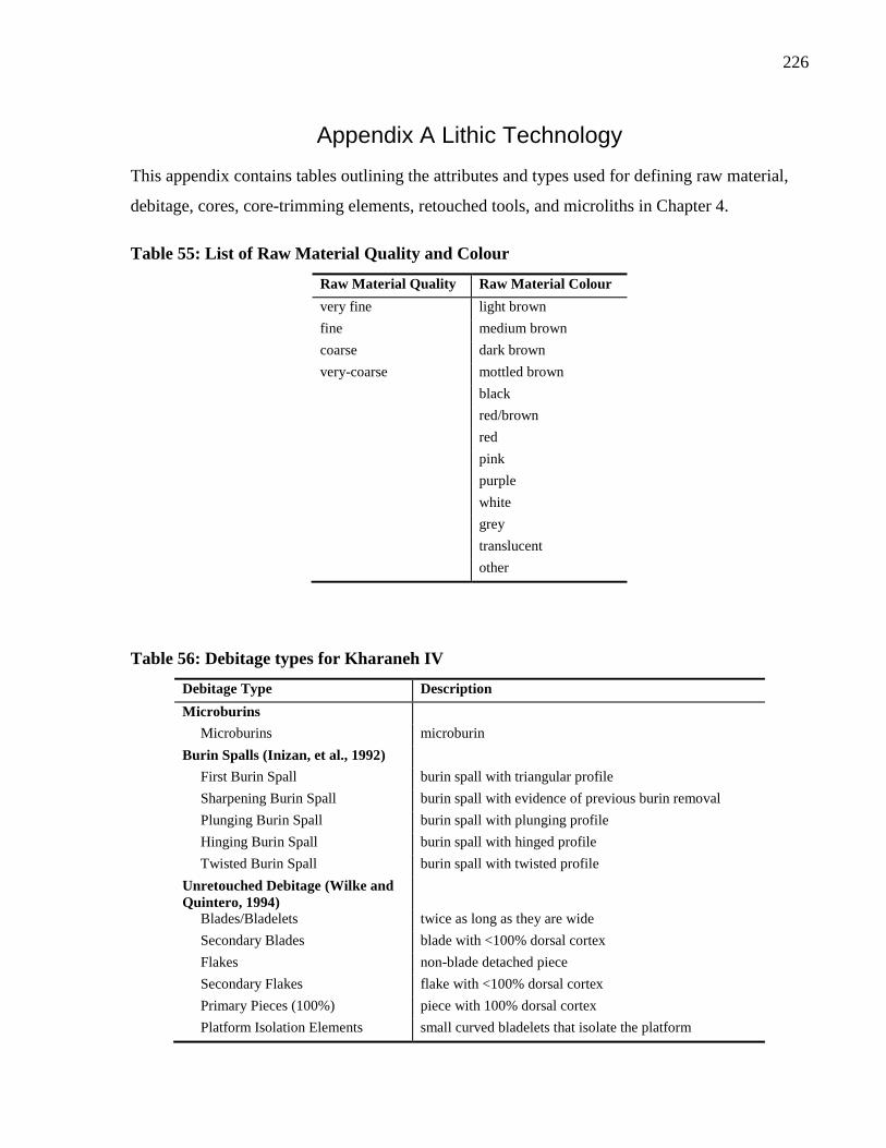
226
Appendix A Lithic Technology
This appendix contains tables outlining the attributes and types used for defining raw material,
debitage, cores, core-trimming elements, retouched tools, and microliths in Chapter 4.
Table 55: List of Raw Material Quality and Colour
Raw Material Quality Raw Material Colour
very fine light brown
fine medium brown
coarse dark brown
very-coarse mottled brown
black
red/brown
red
pink
purple
white
grey
translucent
other
Table 56: Debitage types for Kharaneh IV
Debitage Type Description
Microburins
Microburins microburin
Burin Spalls (Inizan, et al., 1992)
First Burin Spall burin spall with triangular profile
Sharpening Burin Spall burin spall with evidence of previous burin removal
Plunging Burin Spall burin spall with plunging profile
Hinging Burin Spall burin spall with hinged profile
Twisted Burin Spall burin spall with twisted profile
Unretouched Debitage (Wilke and
Quintero, 1994)
Blades/Bladelets twice as long as they are wide
Secondary Blades blade with <100% dorsal cortex
Flakes non-blade detached piece
Secondary Flakes flake with <100% dorsal cortex
Primary Pieces (100%) piece with 100% dorsal cortex
Platform Isolation Elements small curved bladelets that isolate the platform
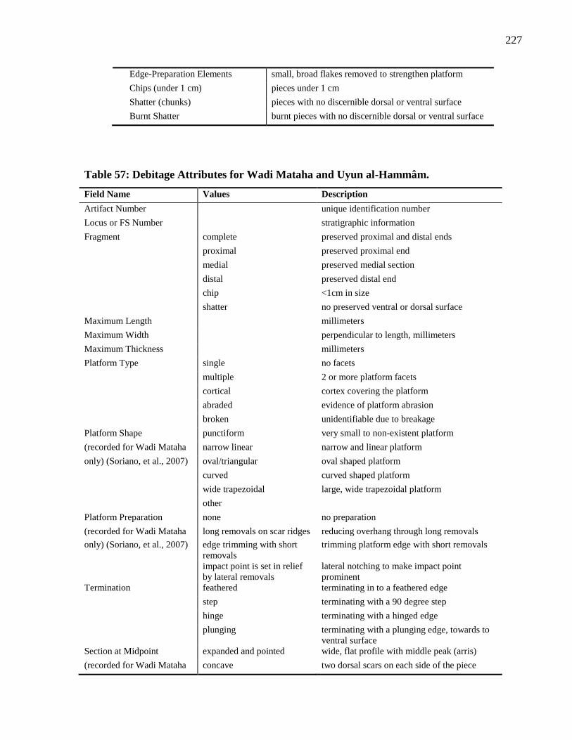
227
Edge-Preparation Elements small, broad flakes removed to strengthen platform
Chips (under 1 cm) pieces under 1 cm
Shatter (chunks) pieces with no discernible dorsal or ventral surface
Burnt Shatter burnt pieces with no discernible dorsal or ventral surface
Table 57: Debitage Attributes for Wadi Mataha and Uyun al-Hammâm.
Field Name Values Description
Artifact Number unique identification number
Locus or FS Number stratigraphic information
Fragment complete preserved proximal and distal ends
proximal preserved proximal end
medial preserved medial section
distal preserved distal end
chip <1cm in size
shatter no preserved ventral or dorsal surface
Maximum Length millimeters
Maximum Width perpendicular to length, millimeters
Maximum Thickness millimeters
Platform Type single no facets
multiple 2 or more platform facets
cortical cortex covering the platform
abraded evidence of platform abrasion
broken unidentifiable due to breakage
Platform Shape punctiform very small to non-existent platform
(recorded for Wadi Mataha narrow linear narrow and linear platform
only) (Soriano, et al., 2007) oval/triangular oval shaped platform
curved curved shaped platform
wide trapezoidal large, wide trapezoidal platform
other
Platform Preparation none no preparation
(recorded for Wadi Mataha long removals on scar ridges reducing overhang through long removals
only) (Soriano, et al., 2007) edge trimming with short
removals
trimming platform edge with short removals
impact point is set in relief
by lateral removals
lateral notching to make impact point
prominent
Termination feathered terminating in to a feathered edge
step terminating with a 90 degree step
hinge terminating with a hinged edge
plunging terminating with a plunging edge, towards to
ventral surface
Section at Midpoint expanded and pointed wide, flat profile with middle peak (arris)
(recorded for Wadi Mataha concave two dorsal scars on each side of the piece
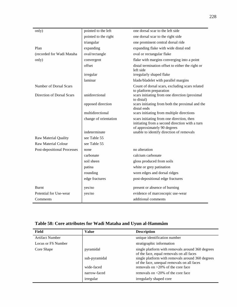
228
only) pointed to the left one dorsal scar to the left side
pointed to the right one dorsal scar to the right side
triangular one prominent central dorsal ride
Plan expanding expanding flake with wide distal end
(recorded for Wadi Mataha oval/rectangle oval or rectangular flake
only) convergent flake with margins converging into a point
offset distal termination offset to either the right or
left side
irregular irregularly shaped flake
laminar blade/bladelet with parallel margins
Number of Dorsal Scars Count of dorsal scars, excluding scars related
to platform preparation
Direction of Dorsal Scars unidirectional scars initiating from one direction (proximal
to distal)
opposed direction scars initiating from both the proximal and the
distal ends
multidirectional scars initiating from multiple directions
change of orientation scars initiating from one direction, then
initiating from a second direction with a turn
of approximately 90 degrees
indeterminate unable to identify direction of removals
Raw Material Quality see Table 55
Raw Material Colour see Table 55
Post-depositional Processes none no alteration
carbonate calcium carbonate
soil sheen gloss produced from soils
patina white or grey patination
rounding worn edges and dorsal ridges
edge fractures post-depositional edge fractures
Burnt yes/no present or absence of burning
Potential for Use-wear yes/no evidence of marcoscopic use-wear
Comments additional comments
Table 58: Core attributes for Wadi Mataha and Uyun al-Hammâm
Field Value Description
Artifact Number unique identification number
Locus or FS Number stratigraphic information
Core Shape pyramidal single platform with removals around 360 degrees
of the face, equal removals on all faces
sub-pyramidal single platform with removals around 360 degrees
of the face, unequal removals on all faces
wide-faced removals on >20% of the core face
narrow-faced removals on <20% of the core face
irregular irregularly shaped core
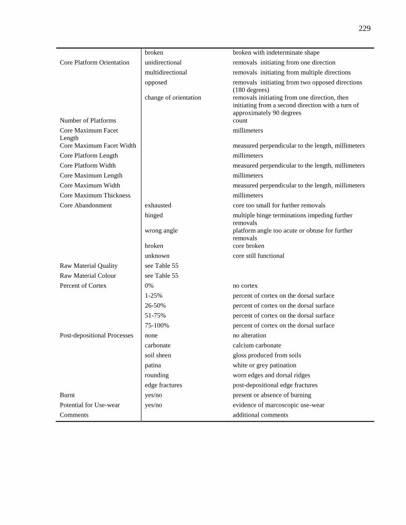
229
broken broken with indeterminate shape
Core Platform Orientation unidirectional removals initiating from one direction
multidirectional removals initiating from multiple directions
opposed removals initiating from two opposed directions
(180 degrees)
change of orientation removals initiating from one direction, then
initiating from a second direction with a turn of
approximately 90 degrees
Number of Platforms count
Core Maximum Facet
Length
millimeters
Core Maximum Facet Width measured perpendicular to the length, millimeters
Core Platform Length millimeters
Core Platform Width measured perpendicular to the length, millimeters
Core Maximum Length millimeters
Core Maximum Width measured perpendicular to the length, millimeters
Core Maximum Thickness millimeters
Core Abandonment exhausted core too small for further removals
hinged multiple hinge terminations impeding further
removals
wrong angle platform angle too acute or obtuse for further
removals
broken core broken
unknown core still functional
Raw Material Quality see Table 55
Raw Material Colour see Table 55
Percent of Cortex 0% no cortex
1-25% percent of cortex on the dorsal surface
26-50% percent of cortex on the dorsal surface
51-75% percent of cortex on the dorsal surface
75-100% percent of cortex on the dorsal surface
Post-depositional Processes none no alteration
carbonate calcium carbonate
soil sheen gloss produced from soils
patina white or grey patination
rounding worn edges and dorsal ridges
edge fractures post-depositional edge fractures
Burnt yes/no present or absence of burning
Potential for Use-wear yes/no evidence of marcoscopic use-wear
Comments additional comments
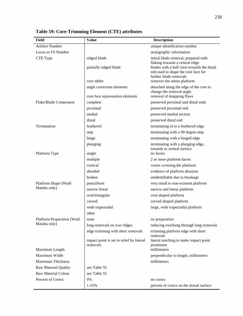
230
Table 59: Core-Trimming Element (CTE) attributes
Field Value Description
Artifact Number unique identification number
Locus or FS Number stratigraphic information
CTE Type ridged blade initial blade removal, prepared with
flaking towards a central ridge
partially ridged blade blades with a half crest towards the distal
end used to shape the core face for
further blade removals
core tablet removes the entire platform
angle correction elements detached along the edge of the core to
change the removal angle
core face rejuvenation elements removal of knapping flaws
Flake/Blade Component complete preserved proximal and distal ends
proximal preserved proximal end
medial preserved medial section
distal preserved distal end
Termination feathered terminating in to a feathered edge
step terminating with a 90 degree step
hinge terminating with a hinged edge
plunging terminating with a plunging edge,
towards to ventral surface
Platform Type single no facets
multiple 2 or more platform facets
cortical cortex covering the platform
abraded evidence of platform abrasion
broken unidentifiable due to breakage
Platform Shape (Wadi
Mataha only)
punctiform very small to non-existent platform
narrow linear narrow and linear platform
oval/triangular oval shaped platform
curved curved shaped platform
wide trapezoidal large, wide trapezoidal platform
other
Platform Preparation (Wadi
Mataha only)
none no preparation
long removals on scar ridges reducing overhang through long removals
edge trimming with short removals trimming platform edge with short
removals
impact point is set in relief by lateral
removals
lateral notching to make impact point
prominent
Maximum Length millimeters
Maximum Width perpendicular to length, millimeters
Maximum Thickness millimeters
Raw Material Quality see Table 55
Raw Material Colour see Table 55
Percent of Cortex 0% no cortex
1-25% percent of cortex on the dorsal surface
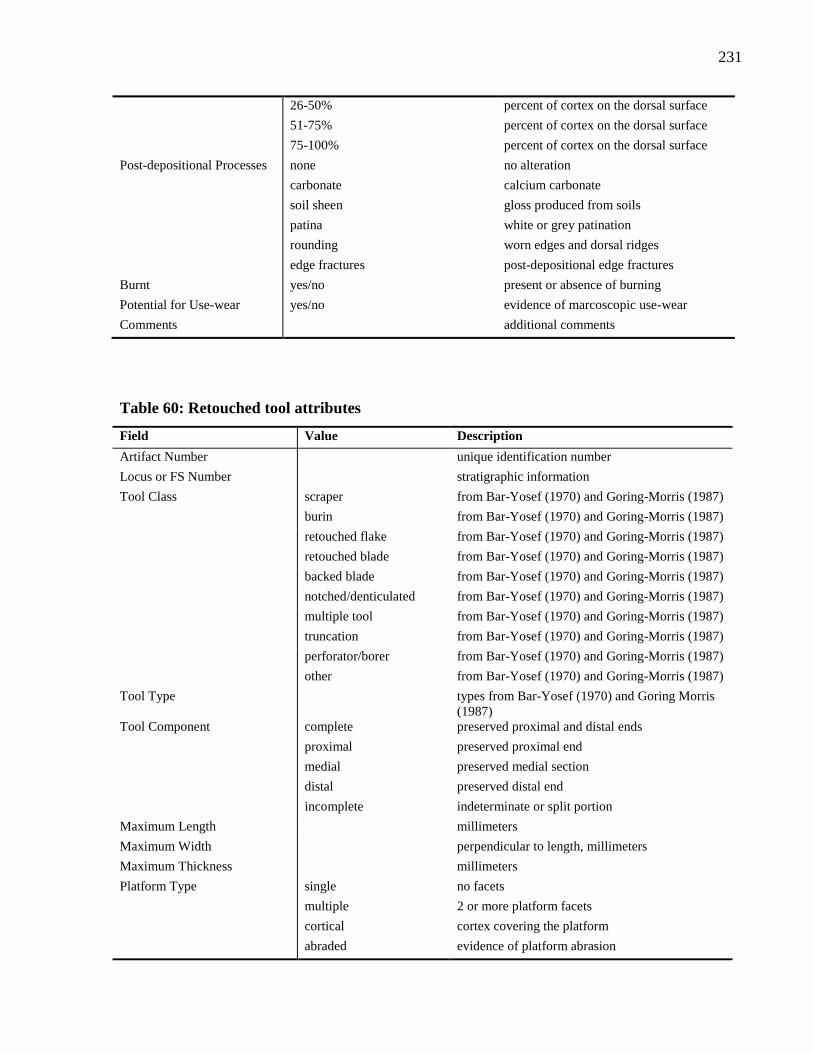
231
26-50% percent of cortex on the dorsal surface
51-75% percent of cortex on the dorsal surface
75-100% percent of cortex on the dorsal surface
Post-depositional Processes none no alteration
carbonate calcium carbonate
soil sheen gloss produced from soils
patina white or grey patination
rounding worn edges and dorsal ridges
edge fractures post-depositional edge fractures
Burnt yes/no present or absence of burning
Potential for Use-wear yes/no evidence of marcoscopic use-wear
Comments additional comments
Table 60: Retouched tool attributes
Field Value Description
Artifact Number unique identification number
Locus or FS Number stratigraphic information
Tool Class scraper from Bar-Yosef (1970) and Goring-Morris (1987)
burin from Bar-Yosef (1970) and Goring-Morris (1987)
retouched flake from Bar-Yosef (1970) and Goring-Morris (1987)
retouched blade from Bar-Yosef (1970) and Goring-Morris (1987)
backed blade from Bar-Yosef (1970) and Goring-Morris (1987)
notched/denticulated from Bar-Yosef (1970) and Goring-Morris (1987)
multiple tool from Bar-Yosef (1970) and Goring-Morris (1987)
truncation from Bar-Yosef (1970) and Goring-Morris (1987)
perforator/borer from Bar-Yosef (1970) and Goring-Morris (1987)
other from Bar-Yosef (1970) and Goring-Morris (1987)
Tool Type types from Bar-Yosef (1970) and Goring Morris
(1987)
Tool Component complete preserved proximal and distal ends
proximal preserved proximal end
medial preserved medial section
distal preserved distal end
incomplete indeterminate or split portion
Maximum Length millimeters
Maximum Width perpendicular to length, millimeters
Maximum Thickness millimeters
Platform Type single no facets
multiple 2 or more platform facets
cortical cortex covering the platform
abraded evidence of platform abrasion
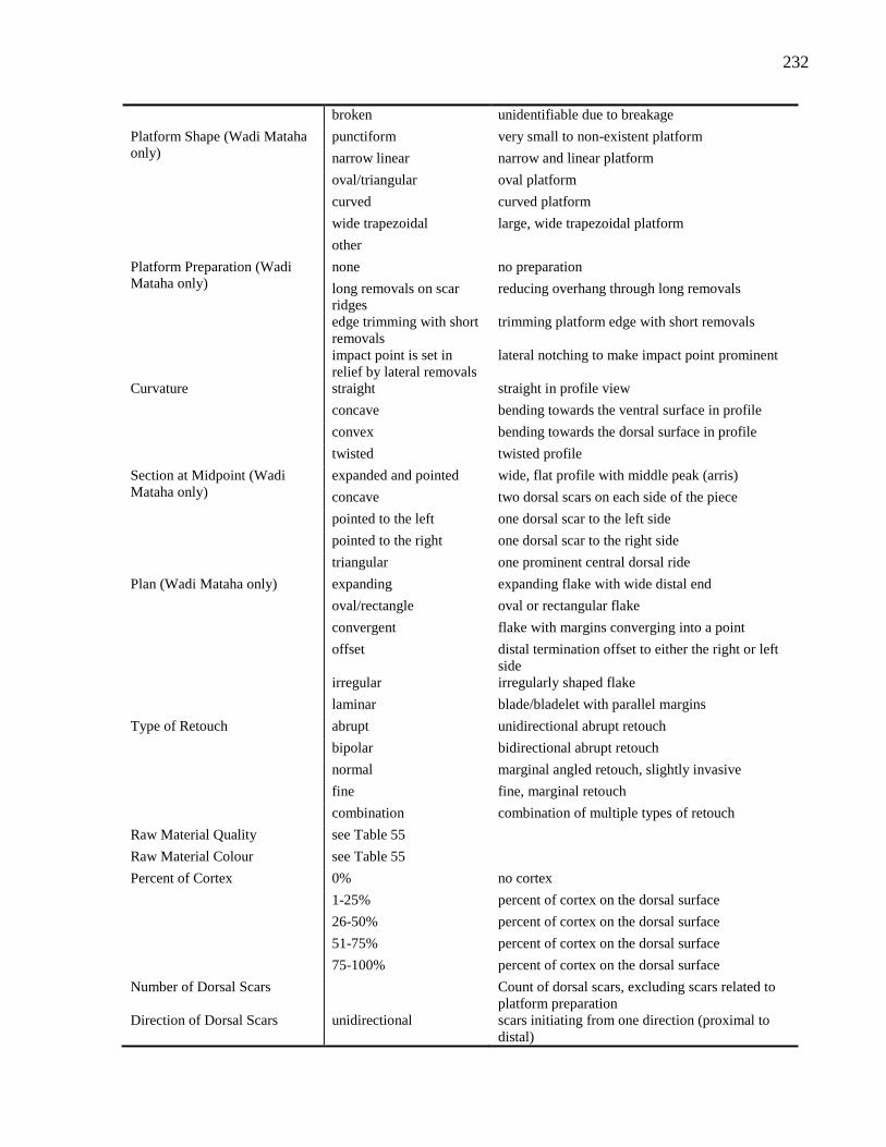
232
broken unidentifiable due to breakage
Platform Shape (Wadi Mataha
only)
punctiform very small to non-existent platform
narrow linear narrow and linear platform
oval/triangular oval platform
curved curved platform
wide trapezoidal large, wide trapezoidal platform
other
Platform Preparation (Wadi
Mataha only)
none no preparation
long removals on scar
ridges
reducing overhang through long removals
edge trimming with short
removals
trimming platform edge with short removals
impact point is set in
relief by lateral removals
lateral notching to make impact point prominent
Curvature straight straight in profile view
concave bending towards the ventral surface in profile
convex bending towards the dorsal surface in profile
twisted twisted profile
Section at Midpoint (Wadi
Mataha only)
expanded and pointed wide, flat profile with middle peak (arris)
concave two dorsal scars on each side of the piece
pointed to the left one dorsal scar to the left side
pointed to the right one dorsal scar to the right side
triangular one prominent central dorsal ride
Plan (Wadi Mataha only) expanding expanding flake with wide distal end
oval/rectangle oval or rectangular flake
convergent flake with margins converging into a point
offset distal termination offset to either the right or left
side
irregular irregularly shaped flake
laminar blade/bladelet with parallel margins
Type of Retouch abrupt unidirectional abrupt retouch
bipolar bidirectional abrupt retouch
normal marginal angled retouch, slightly invasive
fine fine, marginal retouch
combination combination of multiple types of retouch
Raw Material Quality see Table 55
Raw Material Colour see Table 55
Percent of Cortex 0% no cortex
1-25% percent of cortex on the dorsal surface
26-50% percent of cortex on the dorsal surface
51-75% percent of cortex on the dorsal surface
75-100% percent of cortex on the dorsal surface
Number of Dorsal Scars Count of dorsal scars, excluding scars related to
platform preparation
Direction of Dorsal Scars unidirectional scars initiating from one direction (proximal to
distal)
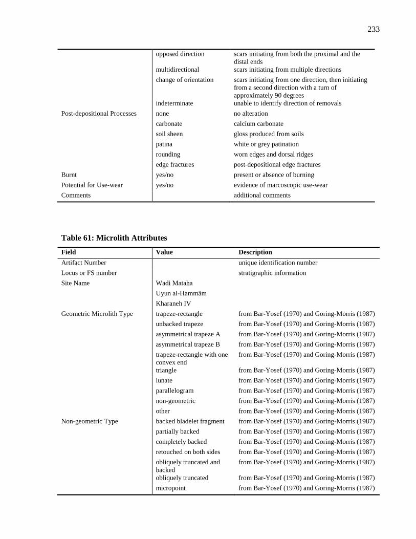
233
opposed direction scars initiating from both the proximal and the
distal ends
multidirectional scars initiating from multiple directions
change of orientation scars initiating from one direction, then initiating
from a second direction with a turn of
approximately 90 degrees
indeterminate unable to identify direction of removals
Post-depositional Processes none no alteration
carbonate calcium carbonate
soil sheen gloss produced from soils
patina white or grey patination
rounding worn edges and dorsal ridges
edge fractures post-depositional edge fractures
Burnt yes/no present or absence of burning
Potential for Use-wear yes/no evidence of marcoscopic use-wear
Comments additional comments
Table 61: Microlith Attributes
Field Value Description
Artifact Number unique identification number
Locus or FS number stratigraphic information
Site Name Wadi Mataha
Uyun al-Hammâm
Kharaneh IV
Geometric Microlith Type trapeze-rectangle from Bar-Yosef (1970) and Goring-Morris (1987)
unbacked trapeze from Bar-Yosef (1970) and Goring-Morris (1987)
asymmetrical trapeze A from Bar-Yosef (1970) and Goring-Morris (1987)
asymmetrical trapeze B from Bar-Yosef (1970) and Goring-Morris (1987)
trapeze-rectangle with one
convex end
from Bar-Yosef (1970) and Goring-Morris (1987)
triangle from Bar-Yosef (1970) and Goring-Morris (1987)
lunate from Bar-Yosef (1970) and Goring-Morris (1987)
parallelogram from Bar-Yosef (1970) and Goring-Morris (1987)
non-geometric from Bar-Yosef (1970) and Goring-Morris (1987)
other from Bar-Yosef (1970) and Goring-Morris (1987)
Non-geometric Type backed bladelet fragment from Bar-Yosef (1970) and Goring-Morris (1987)
partially backed from Bar-Yosef (1970) and Goring-Morris (1987)
completely backed from Bar-Yosef (1970) and Goring-Morris (1987)
retouched on both sides from Bar-Yosef (1970) and Goring-Morris (1987)
obliquely truncated and
backed
from Bar-Yosef (1970) and Goring-Morris (1987)
obliquely truncated from Bar-Yosef (1970) and Goring-Morris (1987)
micropoint from Bar-Yosef (1970) and Goring-Morris (1987)
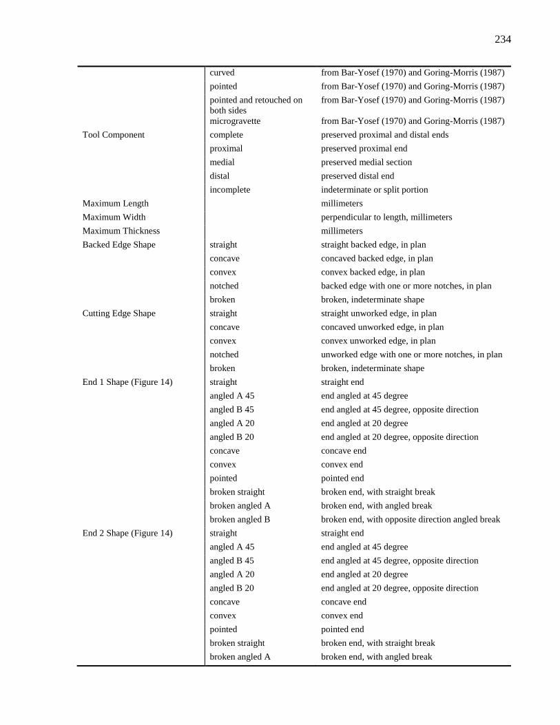
234
curved from Bar-Yosef (1970) and Goring-Morris (1987)
pointed from Bar-Yosef (1970) and Goring-Morris (1987)
pointed and retouched on
both sides
from Bar-Yosef (1970) and Goring-Morris (1987)
microgravette from Bar-Yosef (1970) and Goring-Morris (1987)
Tool Component complete preserved proximal and distal ends
proximal preserved proximal end
medial preserved medial section
distal preserved distal end
incomplete indeterminate or split portion
Maximum Length millimeters
Maximum Width perpendicular to length, millimeters
Maximum Thickness millimeters
Backed Edge Shape straight straight backed edge, in plan
concave concaved backed edge, in plan
convex convex backed edge, in plan
notched backed edge with one or more notches, in plan
broken broken, indeterminate shape
Cutting Edge Shape straight straight unworked edge, in plan
concave concaved unworked edge, in plan
convex convex unworked edge, in plan
notched unworked edge with one or more notches, in plan
broken broken, indeterminate shape
End 1 Shape (Figure 14) straight straight end
angled A 45 end angled at 45 degree
angled B 45 end angled at 45 degree, opposite direction
angled A 20 end angled at 20 degree
angled B 20 end angled at 20 degree, opposite direction
concave concave end
convex convex end
pointed pointed end
broken straight broken end, with straight break
broken angled A broken end, with angled break
broken angled B broken end, with opposite direction angled break
End 2 Shape (Figure 14) straight straight end
angled A 45 end angled at 45 degree
angled B 45 end angled at 45 degree, opposite direction
angled A 20 end angled at 20 degree
angled B 20 end angled at 20 degree, opposite direction
concave concave end
convex convex end
pointed pointed end
broken straight broken end, with straight break
broken angled A broken end, with angled break
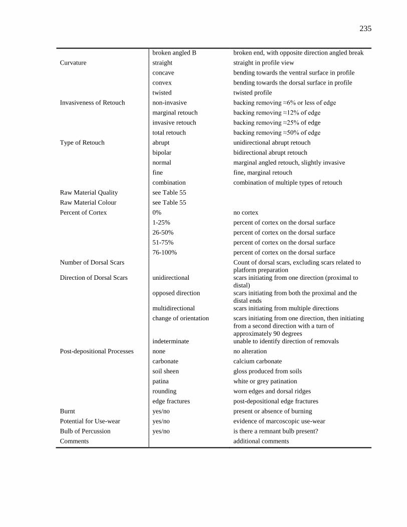
235
broken angled B broken end, with opposite direction angled break
Curvature straight straight in profile view
concave bending towards the ventral surface in profile
convex bending towards the dorsal surface in profile
twisted twisted profile
Invasiveness of Retouch non-invasive backing removing ≈6% or less of edge
marginal retouch backing removing ≈12% of edge
invasive retouch backing removing ≈25% of edge
total retouch backing removing ≈50% of edge
Type of Retouch abrupt unidirectional abrupt retouch
bipolar bidirectional abrupt retouch
normal marginal angled retouch, slightly invasive
fine fine, marginal retouch
combination combination of multiple types of retouch
Raw Material Quality see Table 55
Raw Material Colour see Table 55
Percent of Cortex 0% no cortex
1-25% percent of cortex on the dorsal surface
26-50% percent of cortex on the dorsal surface
51-75% percent of cortex on the dorsal surface
76-100% percent of cortex on the dorsal surface
Number of Dorsal Scars Count of dorsal scars, excluding scars related to
platform preparation
Direction of Dorsal Scars unidirectional scars initiating from one direction (proximal to
distal)
opposed direction scars initiating from both the proximal and the
distal ends
multidirectional scars initiating from multiple directions
change of orientation scars initiating from one direction, then initiating
from a second direction with a turn of
approximately 90 degrees
indeterminate unable to identify direction of removals
Post-depositional Processes none no alteration
carbonate calcium carbonate
soil sheen gloss produced from soils
patina white or grey patination
rounding worn edges and dorsal ridges
edge fractures post-depositional edge fractures
Burnt yes/no present or absence of burning
Potential for Use-wear yes/no evidence of marcoscopic use-wear
Bulb of Percussion yes/no is there a remnant bulb present?
Comments additional comments
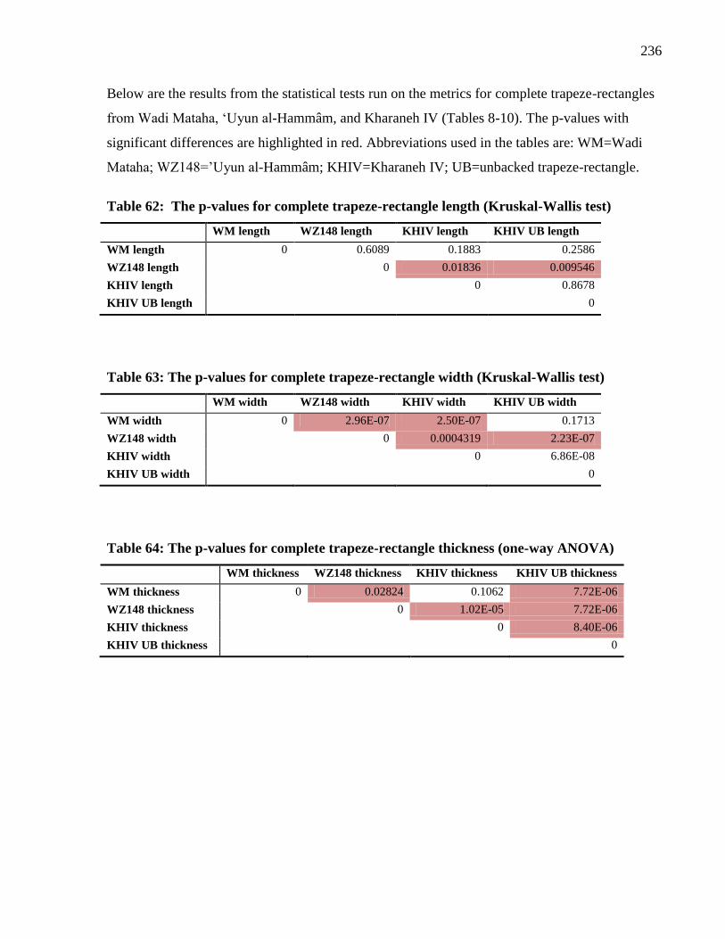
236
Below are the results from the statistical tests run on the metrics for complete trapeze-rectangles
from Wadi Mataha, ‘Uyun al-Hammâm, and Kharaneh IV (Tables 8-10). The p-values with
significant differences are highlighted in red. Abbreviations used in the tables are: WM=Wadi
Mataha; WZ148=’Uyun al-Hammâm; KHIV=Kharaneh IV; UB=unbacked trapeze-rectangle.
Table 62: The p-values for complete trapeze-rectangle length (Kruskal-Wallis test)
WM length WZ148 length KHIV length KHIV UB length
WM length 0 0.6089 0.1883 0.2586
WZ148 length 0 0.01836 0.009546
KHIV length 0 0.8678
KHIV UB length 0
Table 63: The p-values for complete trapeze-rectangle width (Kruskal-Wallis test)
WM width WZ148 width KHIV width KHIV UB width
WM width 0 2.96E-07 2.50E-07 0.1713
WZ148 width 0 0.0004319 2.23E-07
KHIV width 0 6.86E-08
KHIV UB width 0
Table 64: The p-values for complete trapeze-rectangle thickness (one-way ANOVA)
WM thickness WZ148 thickness KHIV thickness KHIV UB thickness
WM thickness 0 0.02824 0.1062 7.72E-06
WZ148 thickness 0 1.02E-05 7.72E-06
KHIV thickness 0 8.40E-06
KHIV UB thickness 0
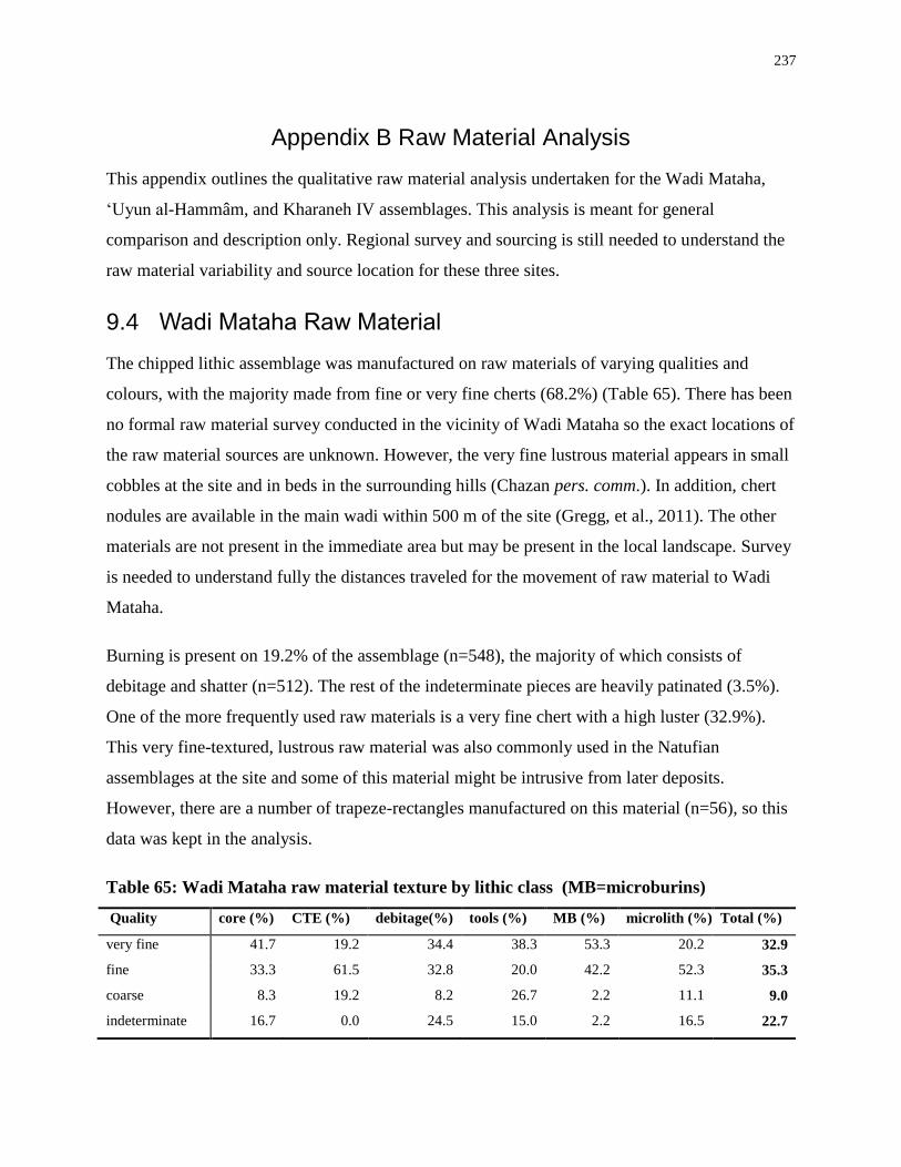
237
Appendix B Raw Material Analysis
This appendix outlines the qualitative raw material analysis undertaken for the Wadi Mataha,
‘Uyun al-Hammâm, and Kharaneh IV assemblages. This analysis is meant for general
comparison and description only. Regional survey and sourcing is still needed to understand the
raw material variability and source location for these three sites.
9.4 Wadi Mataha Raw Material
The chipped lithic assemblage was manufactured on raw materials of varying qualities and
colours, with the majority made from fine or very fine cherts (68.2%) (Table 65). There has been
no formal raw material survey conducted in the vicinity of Wadi Mataha so the exact locations of
the raw material sources are unknown. However, the very fine lustrous material appears in small
cobbles at the site and in beds in the surrounding hills (Chazan pers. comm.). In addition, chert
nodules are available in the main wadi within 500 m of the site (Gregg, et al., 2011). The other
materials are not present in the immediate area but may be present in the local landscape. Survey
is needed to understand fully the distances traveled for the movement of raw material to Wadi
Mataha.
Burning is present on 19.2% of the assemblage (n=548), the majority of which consists of
debitage and shatter (n=512). The rest of the indeterminate pieces are heavily patinated (3.5%).
One of the more frequently used raw materials is a very fine chert with a high luster (32.9%).
This very fine-textured, lustrous raw material was also commonly used in the Natufian
assemblages at the site and some of this material might be intrusive from later deposits.
However, there are a number of trapeze-rectangles manufactured on this material (n=56), so this
data was kept in the analysis.
Table 65: Wadi Mataha raw material texture by lithic class (MB=microburins)
Quality core (%) CTE (%) debitage(%) tools (%) MB (%) microlith (%) Total (%)
very fine 41.7 19.2 34.4 38.3 53.3 20.2 32.9
fine 33.3 61.5 32.8 20.0 42.2 52.3 35.3
coarse 8.3 19.2 8.2 26.7 2.2 11.1 9.0
indeterminate 16.7 0.0 24.5 15.0 2.2 16.5 22.7
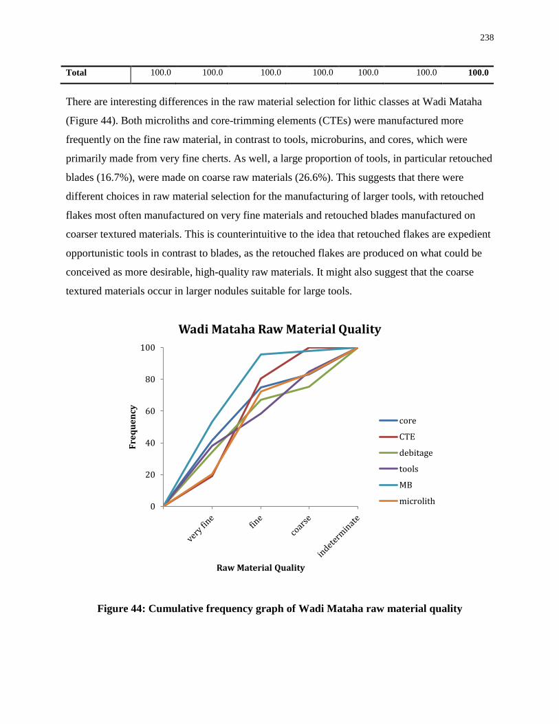
238
Total 100.0 100.0 100.0 100.0 100.0 100.0 100.0
There are interesting differences in the raw material selection for lithic classes at Wadi Mataha
(Figure 44). Both microliths and core-trimming elements (CTEs) were manufactured more
frequently on the fine raw material, in contrast to tools, microburins, and cores, which were
primarily made from very fine cherts. As well, a large proportion of tools, in particular retouched
blades (16.7%), were made on coarse raw materials (26.6%). This suggests that there were
different choices in raw material selection for the manufacturing of larger tools, with retouched
flakes most often manufactured on very fine materials and retouched blades manufactured on
coarser textured materials. This is counterintuitive to the idea that retouched flakes are expedient
opportunistic tools in contrast to blades, as the retouched flakes are produced on what could be
conceived as more desirable, high-quality raw materials. It might also suggest that the coarse
textured materials occur in larger nodules suitable for large tools.
Figure 44: Cumulative frequency graph of Wadi Mataha raw material quality
0
20
40
60
80
100
Fre
qu
en
cy
Raw Material Quality
Wadi Mataha Raw Material Quality
core
CTE
debitage
tools
MB
microlith
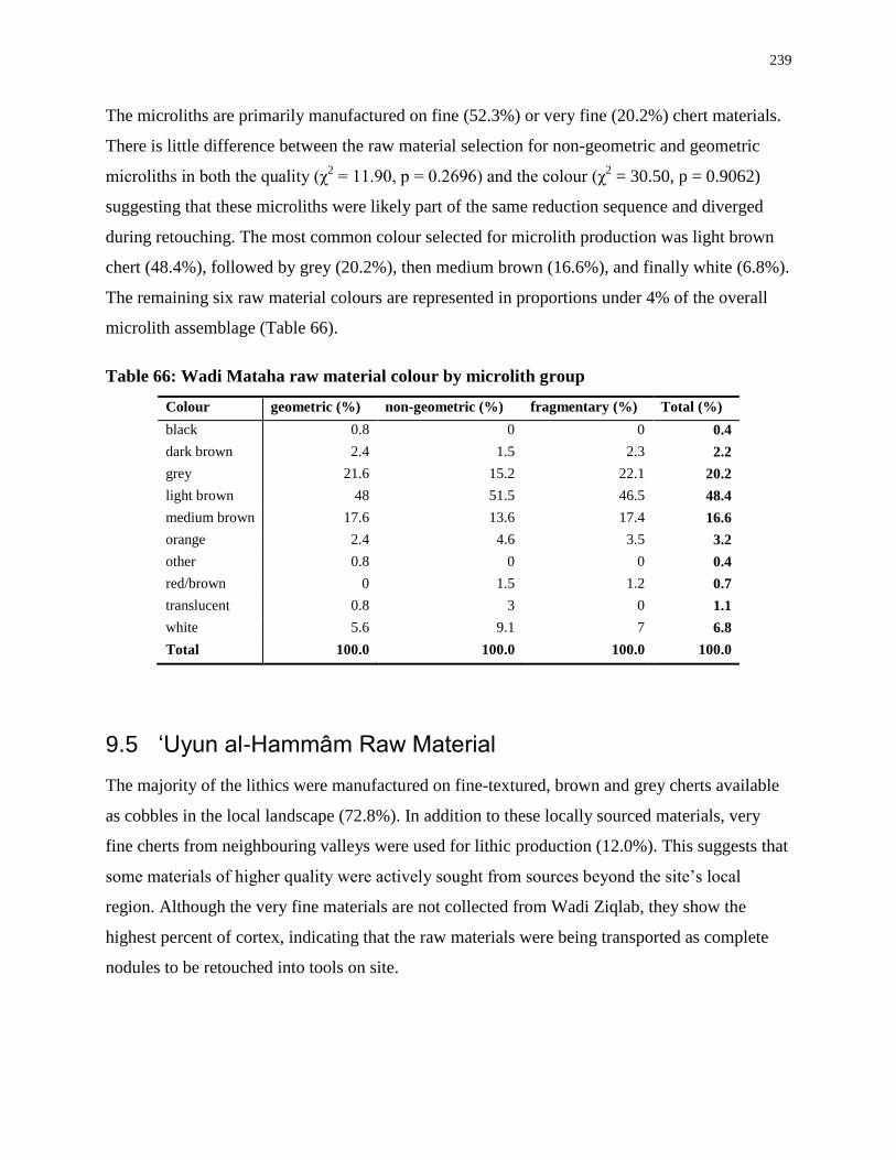
239
The microliths are primarily manufactured on fine (52.3%) or very fine (20.2%) chert materials.
There is little difference between the raw material selection for non-geometric and geometric
microliths in both the quality (χ2 = 11.90, p = 0.2696) and the colour (χ
2 = 30.50, p = 0.9062)
suggesting that these microliths were likely part of the same reduction sequence and diverged
during retouching. The most common colour selected for microlith production was light brown
chert (48.4%), followed by grey (20.2%), then medium brown (16.6%), and finally white (6.8%).
The remaining six raw material colours are represented in proportions under 4% of the overall
microlith assemblage (Table 66).
Table 66: Wadi Mataha raw material colour by microlith group
Colour geometric (%) non-geometric (%) fragmentary (%) Total (%)
black 0.8 0 0 0.4
dark brown 2.4 1.5 2.3 2.2
grey 21.6 15.2 22.1 20.2
light brown 48 51.5 46.5 48.4
medium brown 17.6 13.6 17.4 16.6
orange 2.4 4.6 3.5 3.2
other 0.8 0 0 0.4
red/brown 0 1.5 1.2 0.7
translucent 0.8 3 0 1.1
white 5.6 9.1 7 6.8
Total 100.0 100.0 100.0 100.0
9.5 ‘Uyun al-Hammâm Raw Material
The majority of the lithics were manufactured on fine-textured, brown and grey cherts available
as cobbles in the local landscape (72.8%). In addition to these locally sourced materials, very
fine cherts from neighbouring valleys were used for lithic production (12.0%). This suggests that
some materials of higher quality were actively sought from sources beyond the site’s local
region. Although the very fine materials are not collected from Wadi Ziqlab, they show the
highest percent of cortex, indicating that the raw materials were being transported as complete
nodules to be retouched into tools on site.
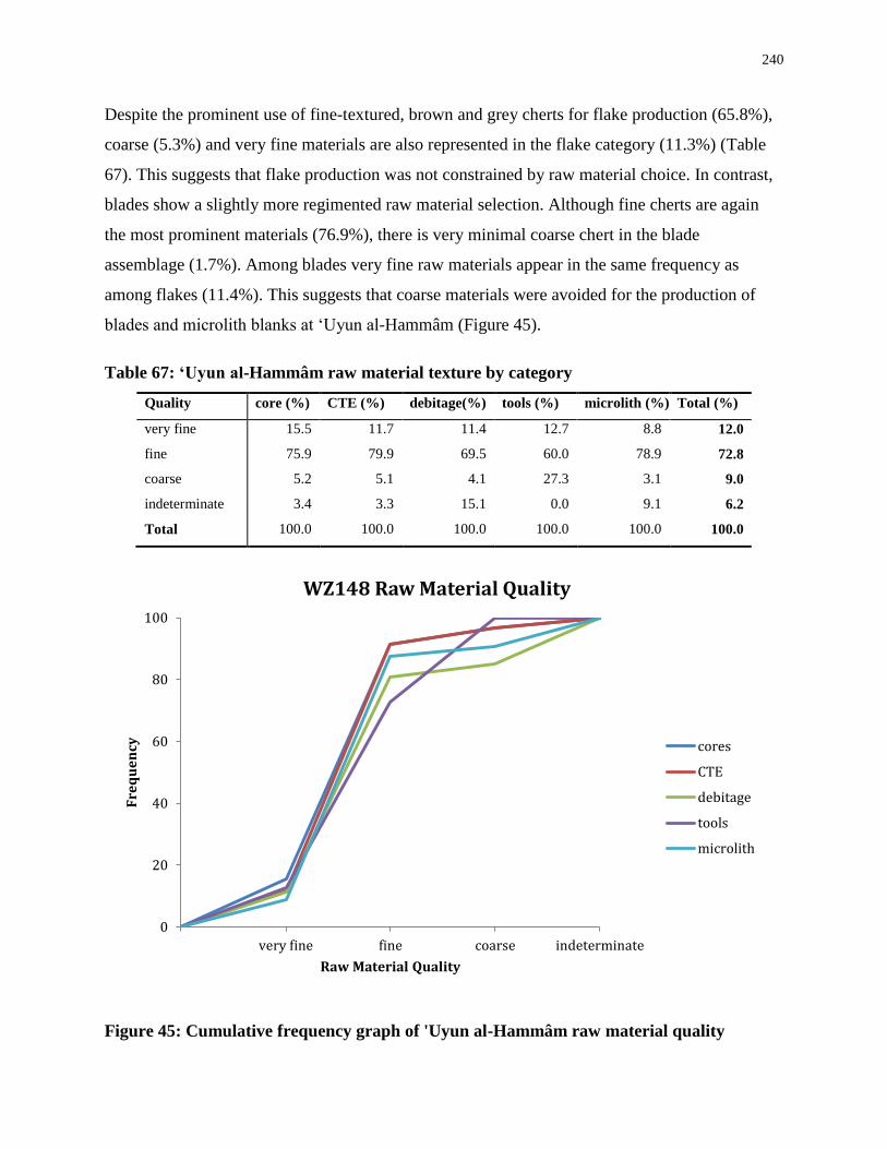
240
Despite the prominent use of fine-textured, brown and grey cherts for flake production (65.8%),
coarse (5.3%) and very fine materials are also represented in the flake category (11.3%) (Table
67). This suggests that flake production was not constrained by raw material choice. In contrast,
blades show a slightly more regimented raw material selection. Although fine cherts are again
the most prominent materials (76.9%), there is very minimal coarse chert in the blade
assemblage (1.7%). Among blades very fine raw materials appear in the same frequency as
among flakes (11.4%). This suggests that coarse materials were avoided for the production of
blades and microlith blanks at ‘Uyun al-Hammâm (Figure 45).
Table 67: ‘Uyun al-Hammâm raw material texture by category
Quality core (%) CTE (%) debitage(%) tools (%) microlith (%) Total (%)
very fine 15.5 11.7 11.4 12.7 8.8 12.0
fine 75.9 79.9 69.5 60.0 78.9 72.8
coarse 5.2 5.1 4.1 27.3 3.1 9.0
indeterminate 3.4 3.3 15.1 0.0 9.1 6.2
Total 100.0 100.0 100.0 100.0 100.0 100.0
Figure 45: Cumulative frequency graph of 'Uyun al-Hammâm raw material quality
0
20
40
60
80
100
very fine fine coarse indeterminate
Fre
qu
en
cy
Raw Material Quality
WZ148 Raw Material Quality
cores
CTE
debitage
tools
microlith
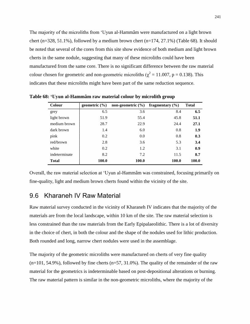
241
The majority of the microliths from ‘Uyun al-Hammâm were manufactured on a light brown
chert (n=328, 51.1%), followed by a medium brown chert (n=174, 27.1%) (Table 68). It should
be noted that several of the cores from this site show evidence of both medium and light brown
cherts in the same nodule, suggesting that many of these microliths could have been
manufactured from the same core. There is no significant difference between the raw material
colour chosen for geometric and non-geometric microliths (χ2 = 11.007, p = 0.138). This
indicates that these microliths might have been part of the same reduction sequence.
Table 68: ‘Uyun al-Hammâm raw material colour by microlith group
Colour geometric (%) non-geometric (%) fragmentary (%) Total
grey 6.5 3.6 8.4 6.5
light brown 51.9 55.4 45.8 51.1
medium brown 28.7 22.9 24.4 27.1
dark brown 1.4 6.0 0.8 1.9
pink 0.2 0.0 0.8 0.3
red/brown 2.8 3.6 5.3 3.4
white 0.2 1.2 3.1 0.9
indeterminate 8.2 7.2 11.5 8.7
Total 100.0 100.0 100.0 100.0
Overall, the raw material selection at ‘Uyun al-Hammâm was constrained, focusing primarily on
fine-quality, light and medium brown cherts found within the vicinity of the site.
9.6 Kharaneh IV Raw Material
Raw material survey conducted in the vicinity of Kharaneh IV indicates that the majority of the
materials are from the local landscape, within 10 km of the site. The raw material selection is
less constrained than the raw materials from the Early Epipalaeolithic. There is a lot of diversity
in the choice of chert, in both the colour and the shape of the nodules used for lithic production.
Both rounded and long, narrow chert nodules were used in the assemblage.
The majority of the geometric microliths were manufactured on cherts of very fine quality
(n=101, 54.9%), followed by fine cherts (n=57, 31.0%). The quality of the remainder of the raw
material for the geometrics is indeterminable based on post-depositional alterations or burning.
The raw material pattern is similar in the non-geometric microliths, where the majority of the
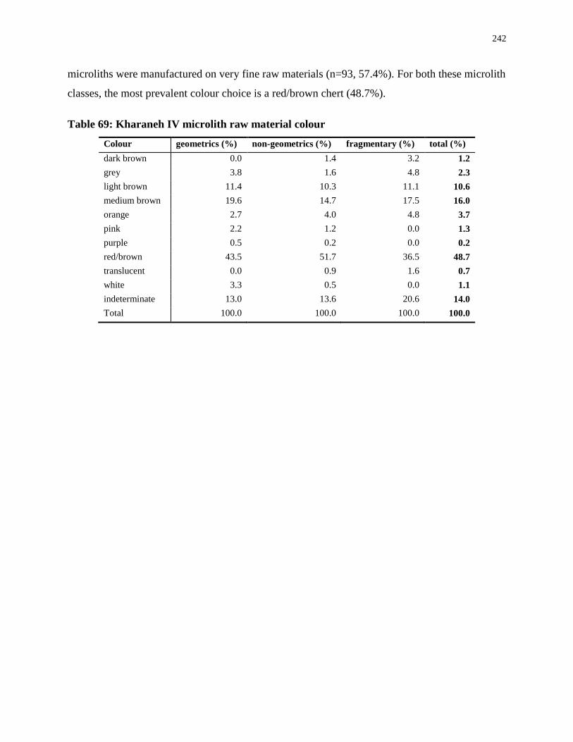
242
microliths were manufactured on very fine raw materials (n=93, 57.4%). For both these microlith
classes, the most prevalent colour choice is a red/brown chert (48.7%).
Table 69: Kharaneh IV microlith raw material colour
Colour geometrics (%) non-geometrics (%) fragmentary (%) total (%)
dark brown 0.0 1.4 3.2 1.2
grey 3.8 1.6 4.8 2.3
light brown 11.4 10.3 11.1 10.6
medium brown 19.6 14.7 17.5 16.0
orange 2.7 4.0 4.8 3.7
pink 2.2 1.2 0.0 1.3
purple 0.5 0.2 0.0 0.2
red/brown 43.5 51.7 36.5 48.7
translucent 0.0 0.9 1.6 0.7
white 3.3 0.5 0.0 1.1
indeterminate 13.0 13.6 20.6 14.0
Total 100.0 100.0 100.0 100.0

243
Appendix C Use-Wear Tables
This appendix contains the details of the use-wear traces identified through both low-powered
and high-powered microscopic analysis. Impact data is presented first, followed by data on other
functions such as longitudinal cutting, transverse, and unknown functions.
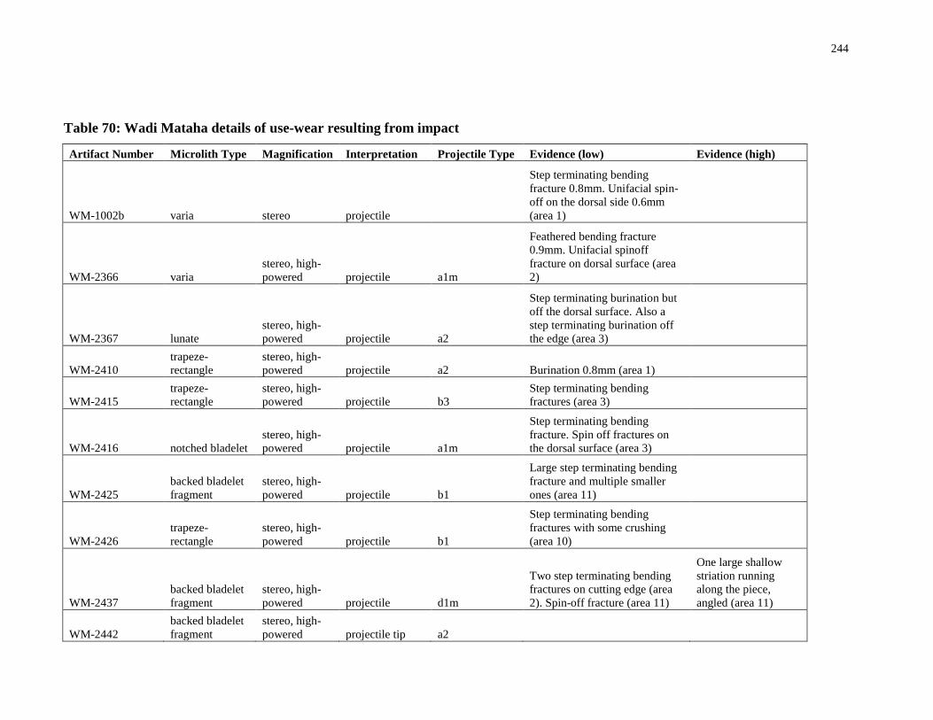
244
Table 70: Wadi Mataha details of use-wear resulting from impact
Artifact Number Microlith Type Magnification Interpretation Projectile Type Evidence (low) Evidence (high)
WM-1002b varia stereo projectile
Step terminating bending
fracture 0.8mm. Unifacial spin-
off on the dorsal side 0.6mm
(area 1)
WM-2366 varia
stereo, high-
powered projectile a1m
Feathered bending fracture
0.9mm. Unifacial spinoff
fracture on dorsal surface (area
2)
WM-2367 lunate
stereo, high-
powered projectile a2
Step terminating burination but
off the dorsal surface. Also a
step terminating burination off
the edge (area 3)
WM-2410
trapeze-
rectangle
stereo, high-
powered projectile a2 Burination 0.8mm (area 1)
WM-2415
trapeze-
rectangle
stereo, high-
powered projectile b3
Step terminating bending
fractures (area 3)
WM-2416 notched bladelet
stereo, high-
powered projectile a1m
Step terminating bending
fracture. Spin off fractures on
the dorsal surface (area 3)
WM-2425
backed bladelet
fragment
stereo, high-
powered projectile b1
Large step terminating bending
fracture and multiple smaller
ones (area 11)
WM-2426
trapeze-
rectangle
stereo, high-
powered projectile b1
Step terminating bending
fractures with some crushing
(area 10)
WM-2437
backed bladelet
fragment
stereo, high-
powered projectile d1m
Two step terminating bending
fractures on cutting edge (area
2). Spin-off fracture (area 11)
One large shallow
striation running
along the piece,
angled (area 11)
WM-2442
backed bladelet
fragment
stereo, high-
powered projectile tip a2
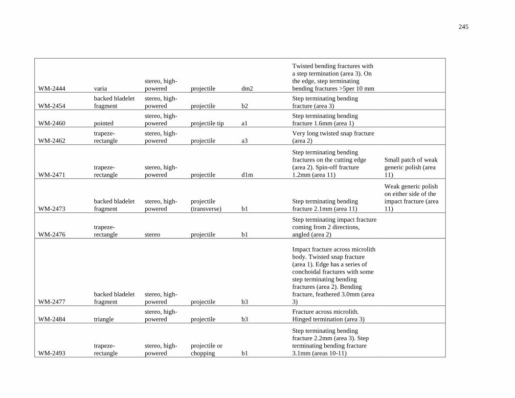
245
WM-2444 varia
stereo, high-
powered projectile dm2
Twisted bending fractures with
a step termination (area 3). On
the edge, step terminating
bending fractures >5per 10 mm
WM-2454
backed bladelet
fragment
stereo, high-
powered projectile b2
Step terminating bending
fracture (area 3)
WM-2460 pointed
stereo, high-
powered projectile tip a1
Step terminating bending
fracture 1.6mm (area 1)
WM-2462
trapeze-
rectangle
stereo, high-
powered projectile a3
Very long twisted snap fracture
(area 2)
WM-2471
trapeze-
rectangle
stereo, high-
powered projectile d1m
Step terminating bending
fractures on the cutting edge
(area 2). Spin-off fracture
1.2mm (area 11)
Small patch of weak
generic polish (area
11)
WM-2473
backed bladelet
fragment
stereo, high-
powered
projectile
(transverse) b1
Step terminating bending
fracture 2.1mm (area 11)
Weak generic polish
on either side of the
impact fracture (area
11)
WM-2476
trapeze-
rectangle stereo projectile b1
Step terminating impact fracture
coming from 2 directions,
angled (area 2)
WM-2477
backed bladelet
fragment
stereo, high-
powered projectile b3
Impact fracture across microlith
body. Twisted snap fracture
(area 1). Edge has a series of
conchoidal fractures with some
step terminating bending
fractures (area 2). Bending
fracture, feathered 3.0mm (area
3)
WM-2484 triangle
stereo, high-
powered projectile b3
Fracture across microlith.
Hinged termination (area 3)
WM-2493
trapeze-
rectangle
stereo, high-
powered
projectile or
chopping b1
Step terminating bending
fracture 2.2mm (area 3). Step
terminating bending fracture
3.1mm (areas 10-11)
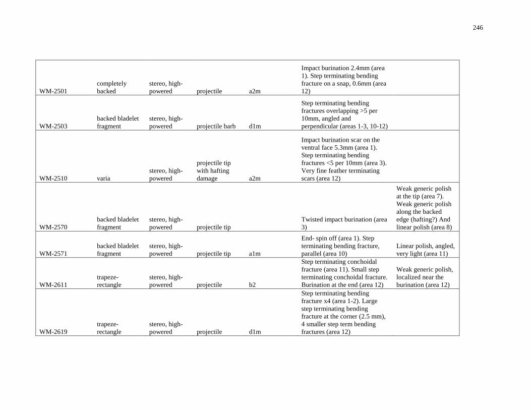
246
WM-2501
completely
backed
stereo, high-
powered projectile a2m
Impact burination 2.4mm (area
1). Step terminating bending
fracture on a snap, 0.6mm (area
12)
WM-2503
backed bladelet
fragment
stereo, high-
powered projectile barb d1m
Step terminating bending
fractures overlapping >5 per
10mm, angled and
perpendicular (areas 1-3, 10-12)
WM-2510 varia
stereo, high-
powered
projectile tip
with hafting
damage a2m
Impact burination scar on the
ventral face 5.3mm (area 1).
Step terminating bending
fractures <5 per 10mm (area 3).
Very fine feather terminating
scars (area 12)
WM-2570
backed bladelet
fragment
stereo, high-
powered projectile tip
Twisted impact burination (area
3)
Weak generic polish
at the tip (area 7).
Weak generic polish
along the backed
edge (hafting?) And
linear polish (area 8)
WM-2571
backed bladelet
fragment
stereo, high-
powered projectile tip a1m
End- spin off (area 1). Step
terminating bending fracture,
parallel (area 10)
Linear polish, angled,
very light (area 11)
WM-2611
trapeze-
rectangle
stereo, high-
powered projectile b2
Step terminating conchoidal
fracture (area 11). Small step
terminating conchoidal fracture.
Burination at the end (area 12)
Weak generic polish,
localized near the
burination (area 12)
WM-2619
trapeze-
rectangle
stereo, high-
powered projectile d1m
Step terminating bending
fracture x4 (area 1-2). Large
step terminating bending
fracture at the corner (2.5 mm),
4 smaller step term bending
fractures (area 12)
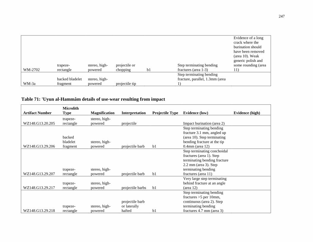
247
WM-2702
trapeze-
rectangle
stereo, high-
powered
projectile or
chopping b1
Step terminating bending
fractures (area 1-3)
Evidence of a long
crack where the
burination should
have been removed
(area 10). Weak
generic polish and
some rounding (area
11)
WM-3a
backed bladelet
fragment
stereo, high-
powered projectile tip
Step terminating bending
fracture, parallel, 1.3mm (area
1)
Table 71: 'Uyun al-Hammâm details of use-wear resulting from impact
Artifact Number
Microlith
Type Magnification Interpretation Projectile Type Evidence (low) Evidence (high)
WZ148.G13.20.205
trapeze-
rectangle
stereo, high-
powered projectile
Impact burination (area 2)
WZ148.G13.29.206
backed
bladelet
fragment
stereo, high-
powered projectile barb b1
Step terminating bending
fracture 3.1 mm, angled up
(area 10). Step terminating
bending fracture at the tip
0.4mm (area 12)
WZ148.G13.29.207
trapeze-
rectangle
stereo, high-
powered projectile barb b1
Step terminating conchoidal
fractures (area 1). Step
terminating bending fracture
2.2 mm (area 3). Step
terminating bending
fractures (area 11)
WZ148.G13.29.217
trapeze-
rectangle
stereo, high-
powered projectile barbs b1
Very large step terminating
behind fracture at an angle
(area 12)
WZ148.G13.29.218
trapeze-
rectangle
stereo, high-
powered
projectile barb
or laterally
hafted b1
Step terminating bending
fractures >5 per 10mm,
continuous (area 2). Step
terminating bending
fractures 4.7 mm (area 3)
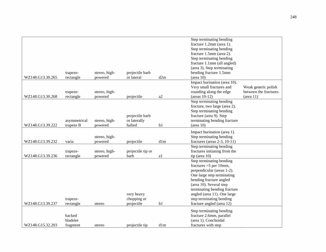
248
WZ148.G13.30.265
trapeze-
rectangle
stereo, high-
powered
projectile barb
or lateral d2m
Step terminating bending
fracture 1.2mm (area 1).
Step terminating bending
fracture 1.5mm (area 2).
Step terminating bending
fracture 1.1mm (all angled)
(area 3). Step terminating
bending fracture 1.5mm
(area 10)
WZ148.G13.30.268
trapeze-
rectangle
stereo, high-
powered projectile a2
Impact burination (area 10).
Very small fractures and
rounding along the edge
(areas 10-12)
Weak generic polish
between the fractures
(area 11)
WZ148.G13.39.222
asymmetrical
trapeze B
stereo, high-
powered
projectile barb
or laterally
hafted b1
Step terminating bending
fracture, two large (area 2).
Step terminating bending
fracture (area 9). Step
terminating bending fracture
(area 10)
WZ148.G13.39.232 varia
stereo, high-
powered projectile d1m
Impact burination (area 1).
Step terminating bending
fractures (areas 2-3, 10-11)
WZ148.G13.39.236
trapeze-
rectangle
stereo, high-
powered
projectile tip or
barb a1
Step terminating bending
fractures initiating from the
tip (area 10)
WZ148.G13.39.237
trapeze-
rectangle stereo
very heavy
chopping or
projectile b1
Step terminating bending
fractures >5 per 10mm,
perpendicular (areas 1-2).
One large step terminating
bending fracture angled
(area 10). Several step
terminating bending fracture
angled (area 11). One large
step terminating bending
fracture angled (area 12)
WZ148.G15.32.203
backed
bladelet
fragment stereo projectile tip d1m
Step terminating bending
fracture 2.6mm, parallel
(area 1). Conchoidal
fractures with step
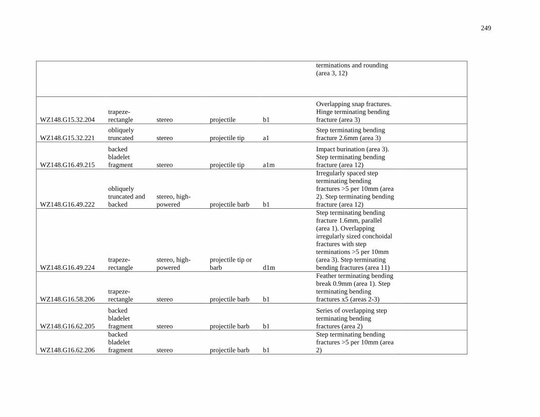
249
terminations and rounding
(area 3, 12)
WZ148.G15.32.204
trapeze-
rectangle stereo projectile b1
Overlapping snap fractures.
Hinge terminating bending
fracture (area 3)
WZ148.G15.32.221
obliquely
truncated stereo projectile tip a1
Step terminating bending
fracture 2.6mm (area 3)
WZ148.G16.49.215
backed
bladelet
fragment stereo projectile tip a1m
Impact burination (area 3).
Step terminating bending
fracture (area 12)
WZ148.G16.49.222
obliquely
truncated and
backed
stereo, high-
powered projectile barb b1
Irregularly spaced step
terminating bending
fractures >5 per 10mm (area
2). Step terminating bending
fracture (area 12)
WZ148.G16.49.224
trapeze-
rectangle
stereo, high-
powered
projectile tip or
barb d1m
Step terminating bending
fracture 1.6mm, parallel
(area 1). Overlapping
irregularly sized conchoidal
fractures with step
terminations >5 per 10mm
(area 3). Step terminating
bending fractures (area 11)
WZ148.G16.58.206
trapeze-
rectangle stereo projectile barb b1
Feather terminating bending
break 0.9mm (area 1). Step
terminating bending
fractures x5 (areas 2-3)
WZ148.G16.62.205
backed
bladelet
fragment stereo projectile barb b1
Series of overlapping step
terminating bending
fractures (area 2)
WZ148.G16.62.206
backed
bladelet
fragment stereo projectile barb b1
Step terminating bending
fractures >5 per 10mm (area
2)
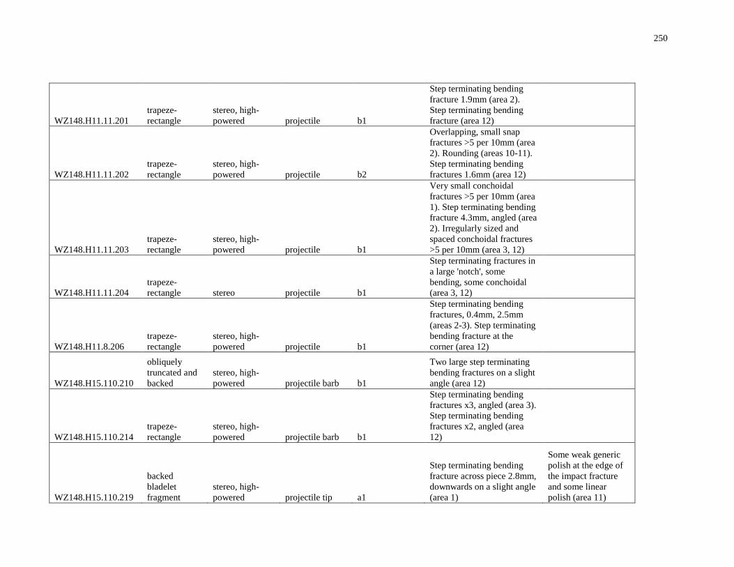
250
WZ148.H11.11.201
trapeze-
rectangle
stereo, high-
powered projectile b1
Step terminating bending
fracture 1.9mm (area 2).
Step terminating bending
fracture (area 12)
WZ148.H11.11.202
trapeze-
rectangle
stereo, high-
powered projectile b2
Overlapping, small snap
fractures >5 per 10mm (area
2). Rounding (areas 10-11).
Step terminating bending
fractures 1.6mm (area 12)
WZ148.H11.11.203
trapeze-
rectangle
stereo, high-
powered projectile b1
Very small conchoidal
fractures >5 per 10mm (area
1). Step terminating bending
fracture 4.3mm, angled (area
2). Irregularly sized and
spaced conchoidal fractures
>5 per 10mm (area 3, 12)
WZ148.H11.11.204
trapeze-
rectangle stereo projectile b1
Step terminating fractures in
a large 'notch', some
bending, some conchoidal
(area 3, 12)
WZ148.H11.8.206
trapeze-
rectangle
stereo, high-
powered projectile b1
Step terminating bending
fractures, 0.4mm, 2.5mm
(areas 2-3). Step terminating
bending fracture at the
corner (area 12)
WZ148.H15.110.210
obliquely
truncated and
backed
stereo, high-
powered projectile barb b1
Two large step terminating
bending fractures on a slight
angle (area 12)
WZ148.H15.110.214
trapeze-
rectangle
stereo, high-
powered projectile barb b1
Step terminating bending
fractures x3, angled (area 3).
Step terminating bending
fractures x2, angled (area
12)
WZ148.H15.110.219
backed
bladelet
fragment
stereo, high-
powered projectile tip a1
Step terminating bending
fracture across piece 2.8mm,
downwards on a slight angle
(area 1)
Some weak generic
polish at the edge of
the impact fracture
and some linear
polish (area 11)
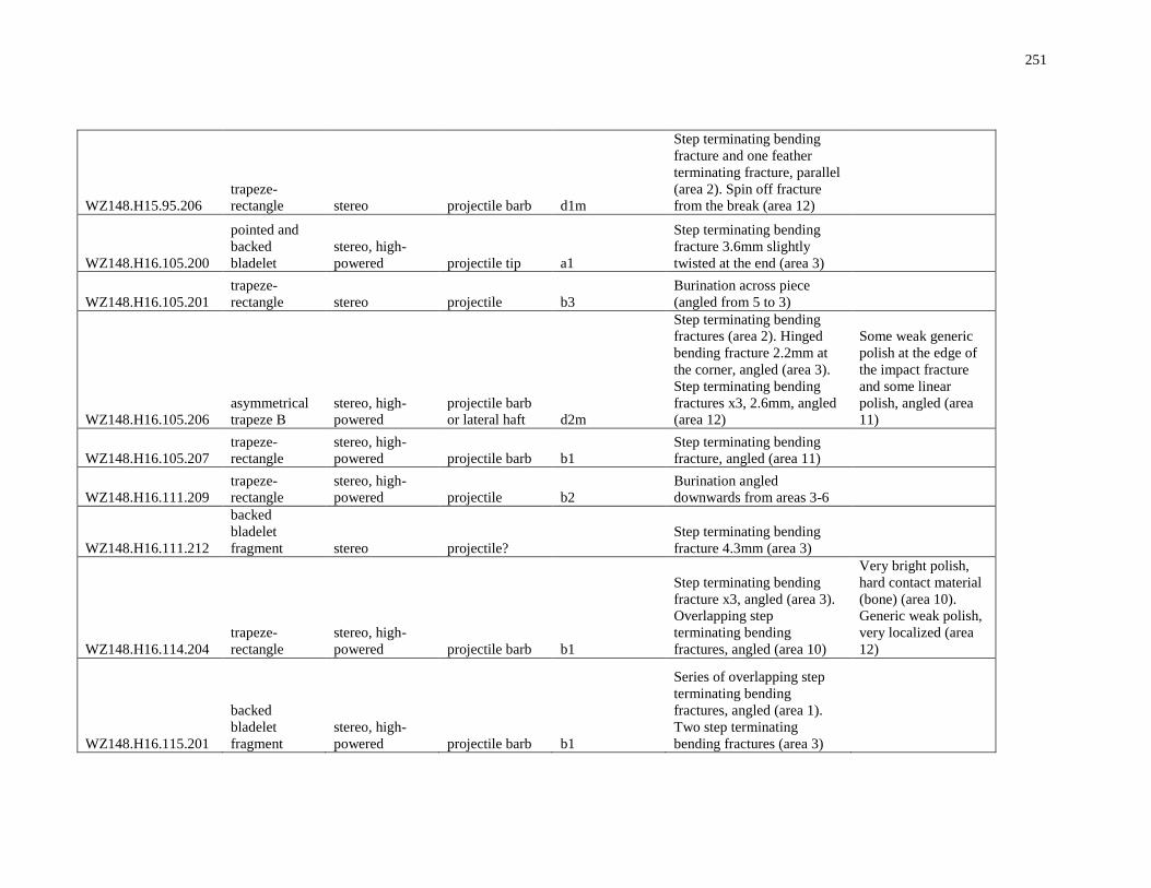
251
WZ148.H15.95.206
trapeze-
rectangle stereo projectile barb d1m
Step terminating bending
fracture and one feather
terminating fracture, parallel
(area 2). Spin off fracture
from the break (area 12)
WZ148.H16.105.200
pointed and
backed
bladelet
stereo, high-
powered projectile tip a1
Step terminating bending
fracture 3.6mm slightly
twisted at the end (area 3)
WZ148.H16.105.201
trapeze-
rectangle stereo projectile b3
Burination across piece
(angled from 5 to 3)
WZ148.H16.105.206
asymmetrical
trapeze B
stereo, high-
powered
projectile barb
or lateral haft d2m
Step terminating bending
fractures (area 2). Hinged
bending fracture 2.2mm at
the corner, angled (area 3).
Step terminating bending
fractures x3, 2.6mm, angled
(area 12)
Some weak generic
polish at the edge of
the impact fracture
and some linear
polish, angled (area
11)
WZ148.H16.105.207
trapeze-
rectangle
stereo, high-
powered projectile barb b1
Step terminating bending
fracture, angled (area 11)
WZ148.H16.111.209
trapeze-
rectangle
stereo, high-
powered projectile b2
Burination angled
downwards from areas 3-6
WZ148.H16.111.212
backed
bladelet
fragment stereo projectile?
Step terminating bending
fracture 4.3mm (area 3)
WZ148.H16.114.204
trapeze-
rectangle
stereo, high-
powered projectile barb b1
Step terminating bending
fracture x3, angled (area 3).
Overlapping step
terminating bending
fractures, angled (area 10)
Very bright polish,
hard contact material
(bone) (area 10).
Generic weak polish,
very localized (area
12)
WZ148.H16.115.201
backed
bladelet
fragment
stereo, high-
powered projectile barb b1
Series of overlapping step
terminating bending
fractures, angled (area 1).
Two step terminating
bending fractures (area 3)
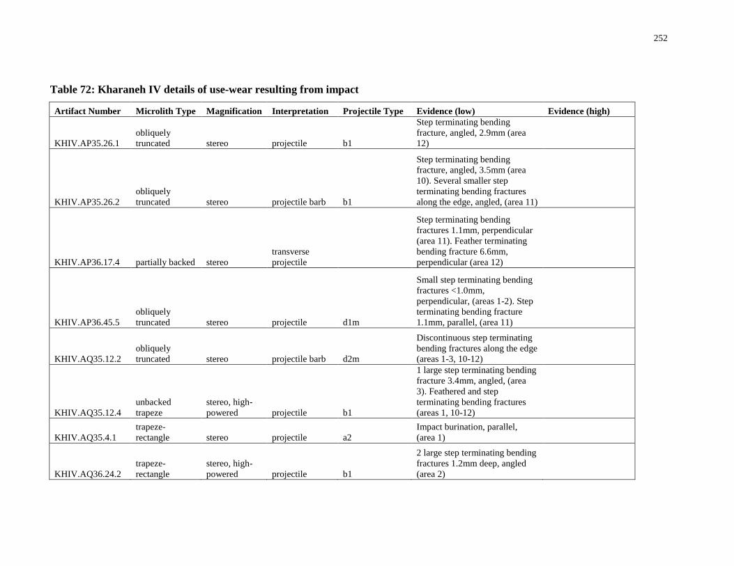
252
Table 72: Kharaneh IV details of use-wear resulting from impact
Artifact Number Microlith Type Magnification Interpretation Projectile Type Evidence (low) Evidence (high)
KHIV.AP35.26.1
obliquely
truncated stereo projectile b1
Step terminating bending
fracture, angled, 2.9mm (area
12)
KHIV.AP35.26.2
obliquely
truncated stereo projectile barb b1
Step terminating bending
fracture, angled, 3.5mm (area
10). Several smaller step
terminating bending fractures
along the edge, angled, (area 11)
KHIV.AP36.17.4 partially backed stereo
transverse
projectile
Step terminating bending
fractures 1.1mm, perpendicular
(area 11). Feather terminating
bending fracture 6.6mm,
perpendicular (area 12)
KHIV.AP36.45.5
obliquely
truncated stereo projectile d1m
Small step terminating bending
fractures <1.0mm,
perpendicular, (areas 1-2). Step
terminating bending fracture
1.1mm, parallel, (area 11)
KHIV.AQ35.12.2
obliquely
truncated stereo projectile barb d2m
Discontinuous step terminating
bending fractures along the edge
(areas 1-3, 10-12)
KHIV.AQ35.12.4
unbacked
trapeze
stereo, high-
powered projectile b1
1 large step terminating bending
fracture 3.4mm, angled, (area
3). Feathered and step
terminating bending fractures
(areas 1, 10-12)
KHIV.AQ35.4.1
trapeze-
rectangle stereo projectile a2
Impact burination, parallel,
(area 1)
KHIV.AQ36.24.2
trapeze-
rectangle
stereo, high-
powered projectile b1
2 large step terminating bending
fractures 1.2mm deep, angled
(area 2)
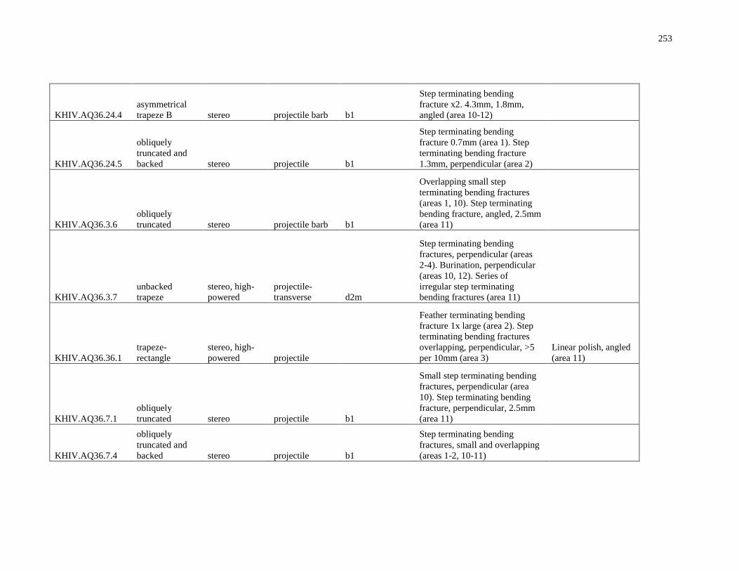
253
KHIV.AQ36.24.4
asymmetrical
trapeze B stereo projectile barb b1
Step terminating bending
fracture x2. 4.3mm, 1.8mm,
angled (area 10-12)
KHIV.AQ36.24.5
obliquely
truncated and
backed stereo projectile b1
Step terminating bending
fracture 0.7mm (area 1). Step
terminating bending fracture
1.3mm, perpendicular (area 2)
KHIV.AQ36.3.6
obliquely
truncated stereo projectile barb b1
Overlapping small step
terminating bending fractures
(areas 1, 10). Step terminating
bending fracture, angled, 2.5mm
(area 11)
KHIV.AQ36.3.7
unbacked
trapeze
stereo, high-
powered
projectile-
transverse d2m
Step terminating bending
fractures, perpendicular (areas
2-4). Burination, perpendicular
(areas 10, 12). Series of
irregular step terminating
bending fractures (area 11)
KHIV.AQ36.36.1
trapeze-
rectangle
stereo, high-
powered projectile
Feather terminating bending
fracture 1x large (area 2). Step
terminating bending fractures
overlapping, perpendicular, >5
per 10mm (area 3)
Linear polish, angled
(area 11)
KHIV.AQ36.7.1
obliquely
truncated stereo projectile b1
Small step terminating bending
fractures, perpendicular (area
10). Step terminating bending
fracture, perpendicular, 2.5mm
(area 11)
KHIV.AQ36.7.4
obliquely
truncated and
backed stereo projectile b1
Step terminating bending
fractures, small and overlapping
(areas 1-2, 10-11)
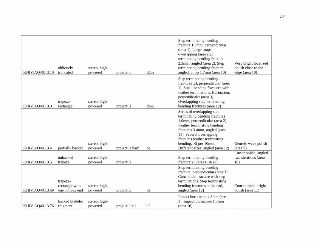
254
KHIV.AQ40.13.10
obliquely
truncated
stereo, high-
powered projectile d2m
Step terminating bending
fracture 1.0mm, perpendicular
(area 1). Large snaps
overlapping large step
terminating bending fracture
2.3mm, angled (area 2). Step
terminating bending fracture,
angled, at tip 1.7mm (area 10)
Very bright localized
polish close to the
edge (area 10)
KHIV.AQ40.13.3
trapeze-
rectangle
stereo, high-
powered projectile dm2
Step terminating bending
fractures x3, perpendicular (area
1). Small bending fractures with
feather terminations. Burination,
perpendicular (area 3).
Overlapping step terminating
bending fractures (area 12)
KHIV.AQ40.13.4 partially backed
stereo, high-
powered projectile barb b1
Series of overlapping step
terminating bending fractures
1.0mm, perpendicular (area 2).
Feather terminating bending
fractures 3.4mm, angled (area
11). Several overlapping
fractures feather terminating
bending. >5 per 10mm.
Different sizes, angled (area 12)
Generic weak polish
(area 9)
KHIV.AQ40.13.5
unbacked
trapeze
stereo, high-
powered projectile
Step terminating bending
fracture x3 (areas 10-12)
Linear polish, angled
two striations (area
10)
KHIV.AQ40.13.69
trapeze-
rectangle with
one convex end
stereo, high-
powered projectile b1
Step terminating bending
fracture, perpendicular (area 3).
Conchoidal fracture with step
terminations. Step terminating
bending fractures at the end,
angled (area 12)
Concentrated bright
polish (area 11)
KHIV.AQ40.13.76
backed bladelet
fragment
stereo, high-
powered projectile tip a2
Impact burination 4.8mm (area
1). Impact burination 1.7mm
(area 10)
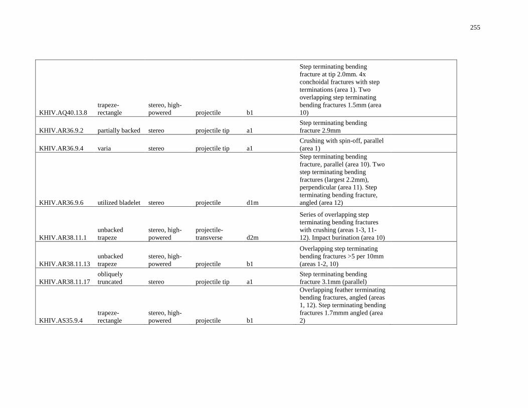
255
KHIV.AQ40.13.8
trapeze-
rectangle
stereo, high-
powered projectile b1
Step terminating bending
fracture at tip 2.0mm. 4x
conchoidal fractures with step
terminations (area 1). Two
overlapping step terminating
bending fractures 1.5mm (area
10)
KHIV.AR36.9.2 partially backed stereo projectile tip a1
Step terminating bending
fracture 2.9mm
KHIV.AR36.9.4 varia stereo projectile tip a1
Crushing with spin-off, parallel
(area 1)
KHIV.AR36.9.6 utilized bladelet stereo projectile d1m
Step terminating bending
fracture, parallel (area 10). Two
step terminating bending
fractures (largest 2.2mm),
perpendicular (area 11). Step
terminating bending fracture,
angled (area 12)
KHIV.AR38.11.1
unbacked
trapeze
stereo, high-
powered
projectile-
transverse d2m
Series of overlapping step
terminating bending fractures
with crushing (areas 1-3, 11-
12). Impact burination (area 10)
KHIV.AR38.11.13
unbacked
trapeze
stereo, high-
powered projectile b1
Overlapping step terminating
bending fractures >5 per 10mm
(areas 1-2, 10)
KHIV.AR38.11.17
obliquely
truncated stereo projectile tip a1
Step terminating bending
fracture 3.1mm (parallel)
KHIV.AS35.9.4
trapeze-
rectangle
stereo, high-
powered projectile b1
Overlapping feather terminating
bending fractures, angled (areas
1, 12). Step terminating bending
fractures 1.7mmm angled (area
2)
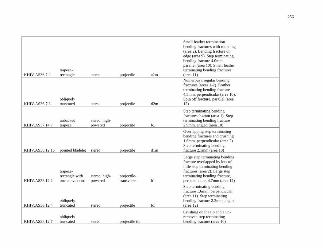
256
KHIV.AS36.7.2
trapeze-
rectangle stereo projectile a2m
Small feather termination
bending fractures with rounding
(area 2). Bending fracture on
edge (area 9). Step terminating
bending fracture 4.0mm,
parallel (area 10). Small feather
terminating bending fractures
(area 11)
KHIV.AS36.7.3
obliquely
truncated stereo projectile d2m
Numerous irregular bending
fractures (areas 1-2). Feather
terminating bending fracture
4.5mm, perpendicular (area 10).
Spin off fracture, parallel (area
12)
KHIV.AS37.14.7
unbacked
trapeze
stereo, high-
powered projectile b1
Step terminating bending
fractures 0.4mm (area 1). Step
terminating bending fracture
2.9mm, angled (area 10)
KHIV.AS38.12.15 pointed bladelet stereo projectile d1m
Overlapping step terminating
bending fractures and crushing
1.6mm, perpendicular (area 2).
Step terminating bending
fracture 2.1mm (area 10)
KHIV.AS38.12.2
trapeze-
rectangle with
one convex end
stereo, high-
powered
projectile-
transverse b1
Large step terminating bending
fracture overlapped by lots of
little step terminating bending
fractures (area 2). Large step
terminating bending fracture,
perpendicular, 4.7mm (area 12)
KHIV.AS38.12.4
obliquely
truncated stereo projectile b1
Step terminating bending
fracture 1.6mm, perpendicular
(area 11). Step terminating
bending fracture 2.3mm, angled
(area 12)
KHIV.AS38.12.7
obliquely
truncated stereo projectile tip
Crushing on the tip and a un-
removed step terminating
bending fracture (area 10)
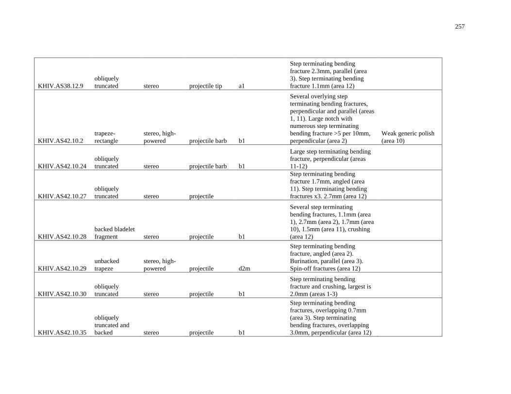
257
KHIV.AS38.12.9
obliquely
truncated stereo projectile tip a1
Step terminating bending
fracture 2.3mm, parallel (area
3). Step terminating bending
fracture 1.1mm (area 12)
KHIV.AS42.10.2
trapeze-
rectangle
stereo, high-
powered projectile barb b1
Several overlying step
terminating bending fractures,
perpendicular and parallel (areas
1, 11). Large notch with
numerous step terminating
bending fracture >5 per 10mm,
perpendicular (area 2)
Weak generic polish
(area 10)
KHIV.AS42.10.24
obliquely
truncated stereo projectile barb b1
Large step terminating bending
fracture, perpendicular (areas
11-12)
KHIV.AS42.10.27
obliquely
truncated stereo projectile
Step terminating bending
fracture 1.7mm, angled (area
11). Step terminating bending
fractures x3. 2.7mm (area 12)
KHIV.AS42.10.28
backed bladelet
fragment stereo projectile b1
Several step terminating
bending fractures, 1.1mm (area
1), 2.7mm (area 2), 1.7mm (area
10), 1.5mm (area 11), crushing
(area 12)
KHIV.AS42.10.29
unbacked
trapeze
stereo, high-
powered projectile d2m
Step terminating bending
fracture, angled (area 2).
Burination, parallel (area 3).
Spin-off fractures (area 12)
KHIV.AS42.10.30
obliquely
truncated stereo projectile b1
Step terminating bending
fracture and crushing, largest is
2.0mm (areas 1-3)
KHIV.AS42.10.35
obliquely
truncated and
backed stereo projectile b1
Step terminating bending
fractures, overlapping 0.7mm
(area 3). Step terminating
bending fractures, overlapping
3.0mm, perpendicular (area 12)
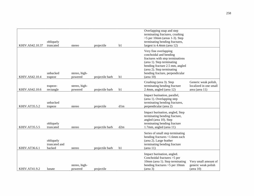
258
KHIV.AS42.10.37
obliquely
truncated stereo projectile b1
Overlapping snap and step
terminating fractures, crushing
>5 per 10mm (areas 1-3). Step
terminating bending fractures,
largest is 4.4mm (area 12)
KHIV.AS42.10.4
unbacked
trapeze
stereo, high-
powered projectile barb b1
Very fine overlapping
conchoidal and bending
fractures with step terminations
(area 1). Step terminating
bending fracture 2.5 mm, angled
(area 2). Step terminating
bending fracture, perpendicular
(area 10)
KHIV.AS42.10.6
trapeze-
rectangle
stereo, high-
powered projectile barb b1
Crushing (area 3). Step
terminating bending fracture
2.4mm, angled (area 12)
Generic weak polish,
localized in one small
area (area 11)
KHIV.AT35.5.2
unbacked
trapeze stereo projectile d1m
Impact burination, parallel,
(area 1). Overlapping step
terminating bending fractures,
perpendicular (area 2)
KHIV.AT35.5.5
obliquely
truncated stereo projectile barb d2m
Impact burination, angled, Step
terminating bending fracture,
angled (area 10). Step
terminating bending fracture
1.7mm, angled (area 11)
KHIV.AT36.6.1
obliquely
truncated and
backed stereo projectile barb b1
Series of small step terminating
bending fractures <1.6mm each
(area 2). Large feather
terminating bending fracture
(area 11)
KHIV.AT41.9.2 lunate
stereo, high-
powered projectile
Impact burination, angled.
Conchoidal fractures >5 per
10mm (area 1). Step terminating
bending fractures >5 per 10mm
(area 3)
Very small amount of
generic weak polish
(area 10)
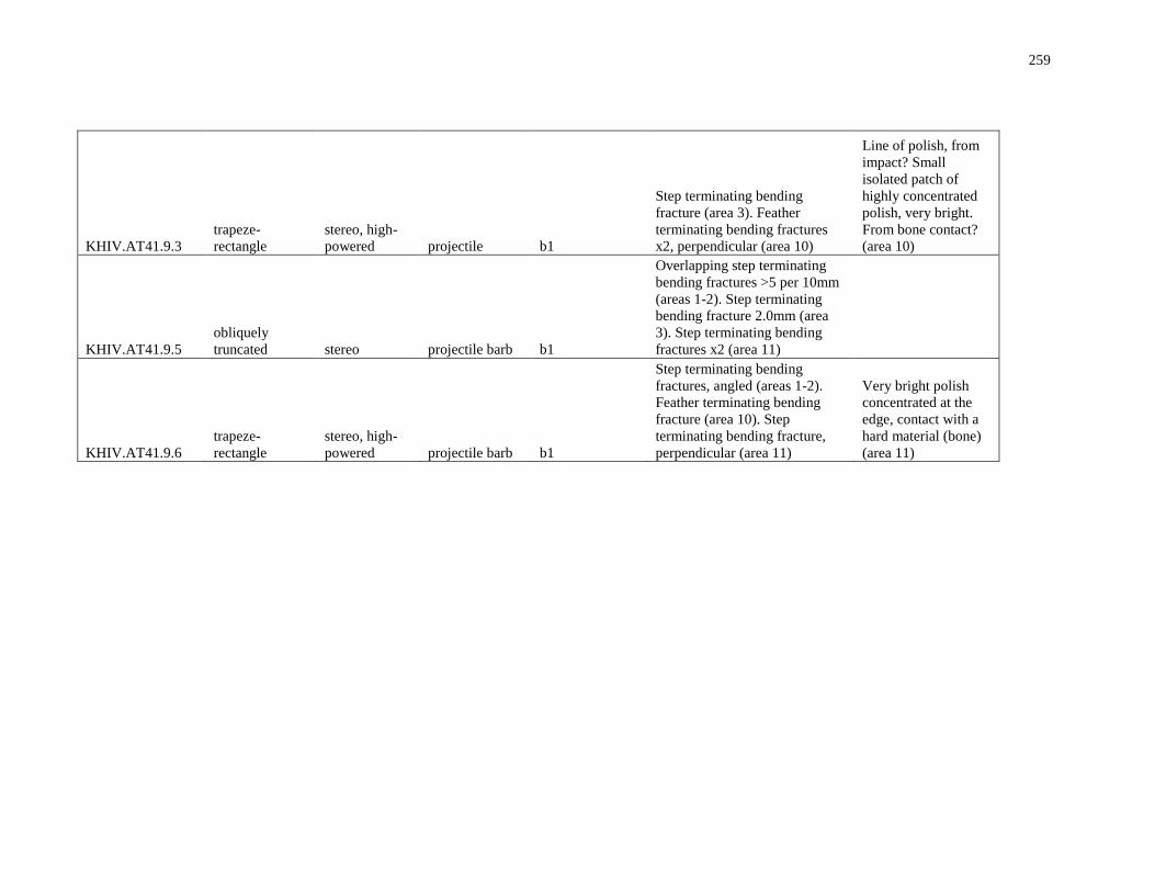
259
KHIV.AT41.9.3
trapeze-
rectangle
stereo, high-
powered projectile b1
Step terminating bending
fracture (area 3). Feather
terminating bending fractures
x2, perpendicular (area 10)
Line of polish, from
impact? Small
isolated patch of
highly concentrated
polish, very bright.
From bone contact?
(area 10)
KHIV.AT41.9.5
obliquely
truncated stereo projectile barb b1
Overlapping step terminating
bending fractures >5 per 10mm
(areas 1-2). Step terminating
bending fracture 2.0mm (area
3). Step terminating bending
fractures x2 (area 11)
KHIV.AT41.9.6
trapeze-
rectangle
stereo, high-
powered projectile barb b1
Step terminating bending
fractures, angled (areas 1-2).
Feather terminating bending
fracture (area 10). Step
terminating bending fracture,
perpendicular (area 11)
Very bright polish
concentrated at the
edge, contact with a
hard material (bone)
(area 11)
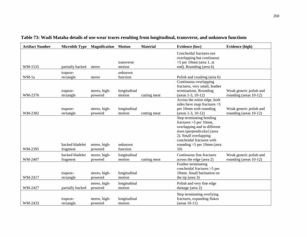
260
Table 73: Wadi Mataha details of use-wear traces resulting from longitudinal, transverse, and unknown functions
Artifact Number Microlith Type Magnification Motion Material Evidence (low) Evidence (high)
WM-1535 partially backed stereo
transverse
motion
Conchoidal fractures not
overlapping but continuous
>5 per 10mm (area 1, at
end). Rounding (area 6)
WM-1a
trapeze-
rectangle stereo
unknown
function
Polish and crushing (area 6)
WM-2376
trapeze-
rectangle
stereo, high-
powered
longitudinal
motion cutting meat
Continuous overlapping
fractures, very small, feather
terminations. Rounding
(areas 1-3, 10-12)
Weak generic polish and
rounding (areas 10-12)
WM-2382
trapeze-
rectangle
stereo, high-
powered
longitudinal
motion cutting meat
Across the entire edge, both
sides have snap fractures >5
per 10mm with rounding
(areas 1-3, 10-12)
Weak generic polish and
rounding (areas 10-12)
WM-2395
backed bladelet
fragment
stereo, high-
powered
unknown
function
Step terminating bending
fractures >5 per 10mm,
overlapping and in different
sizes (perpendicular) (area
2). Small overlapping
conchoidal fractures with
rounding >5 per 10mm (area
10)
WM-2407
backed bladelet
fragment
stereo, high-
powered
longitudinal
motion cutting meat
Continuous fine fractures
across the edge (area 2)
Weak generic polish and
rounding (areas 10-12)
WM-2417
trapeze-
rectangle
stereo, high-
powered
longitudinal
motion
Feather terminating
conchoidal fractures >5 per
10mm. Small burination on
the tip (area 3)
WM-2427 partially backed
stereo, high-
powered
longitudinal
motion
Polish and very fine edge
damage (area 2)
WM-2433
trapeze-
rectangle
stereo, high-
powered
longitudinal
motion
Step terminating overlying
fractures, expanding flakes
(areas 10-11)
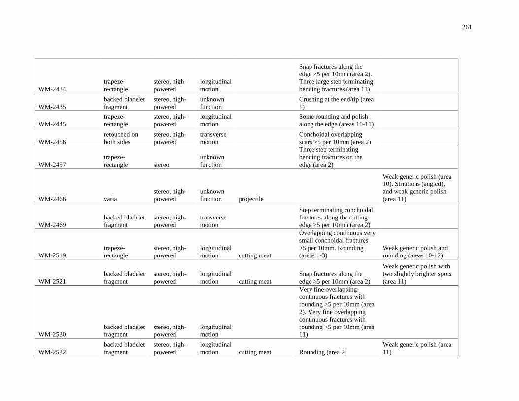
261
WM-2434
trapeze-
rectangle
stereo, high-
powered
longitudinal
motion
Snap fractures along the
edge >5 per 10mm (area 2).
Three large step terminating
bending fractures (area 11)
WM-2435
backed bladelet
fragment
stereo, high-
powered
unknown
function
Crushing at the end/tip (area
1)
WM-2445
trapeze-
rectangle
stereo, high-
powered
longitudinal
motion
Some rounding and polish
along the edge (areas 10-11)
WM-2456
retouched on
both sides
stereo, high-
powered
transverse
motion
Conchoidal overlapping
scars >5 per 10mm (area 2)
WM-2457
trapeze-
rectangle stereo
unknown
function
Three step terminating
bending fractures on the
edge (area 2)
WM-2466 varia
stereo, high-
powered
unknown
function projectile
Weak generic polish (area
10). Striations (angled),
and weak generic polish
(area 11)
WM-2469
backed bladelet
fragment
stereo, high-
powered
transverse
motion
Step terminating conchoidal
fractures along the cutting
edge >5 per 10mm (area 2)
WM-2519
trapeze-
rectangle
stereo, high-
powered
longitudinal
motion cutting meat
Overlapping continuous very
small conchoidal fractures
>5 per 10mm. Rounding
(areas 1-3)
Weak generic polish and
rounding (areas 10-12)
WM-2521
backed bladelet
fragment
stereo, high-
powered
longitudinal
motion cutting meat
Snap fractures along the
edge >5 per 10mm (area 2)
Weak generic polish with
two slightly brighter spots
(area 11)
WM-2530
backed bladelet
fragment
stereo, high-
powered
longitudinal
motion
Very fine overlapping
continuous fractures with
rounding >5 per 10mm (area
2). Very fine overlapping
continuous fractures with
rounding >5 per 10mm (area
11)
WM-2532
backed bladelet
fragment
stereo, high-
powered
longitudinal
motion cutting meat Rounding (area 2)
Weak generic polish (area
11)
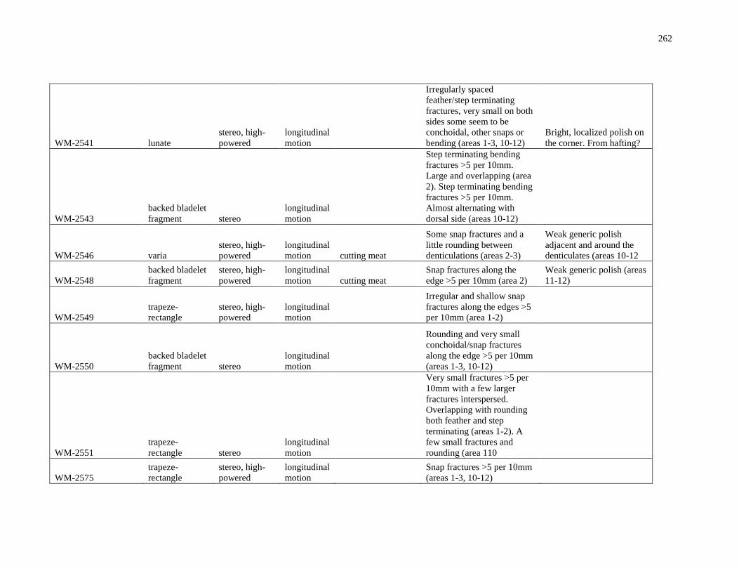
262
WM-2541 lunate
stereo, high-
powered
longitudinal
motion
Irregularly spaced
feather/step terminating
fractures, very small on both
sides some seem to be
conchoidal, other snaps or
bending (areas 1-3, 10-12)
Bright, localized polish on
the corner. From hafting?
WM-2543
backed bladelet
fragment stereo
longitudinal
motion
Step terminating bending
fractures >5 per 10mm.
Large and overlapping (area
2). Step terminating bending
fractures >5 per 10mm.
Almost alternating with
dorsal side (areas 10-12)
WM-2546 varia
stereo, high-
powered
longitudinal
motion cutting meat
Some snap fractures and a
little rounding between
denticulations (areas 2-3)
Weak generic polish
adjacent and around the
denticulates (areas 10-12
WM-2548
backed bladelet
fragment
stereo, high-
powered
longitudinal
motion cutting meat
Snap fractures along the
edge >5 per 10mm (area 2)
Weak generic polish (areas
11-12)
WM-2549
trapeze-
rectangle
stereo, high-
powered
longitudinal
motion
Irregular and shallow snap
fractures along the edges >5
per 10mm (area 1-2)
WM-2550
backed bladelet
fragment stereo
longitudinal
motion
Rounding and very small
conchoidal/snap fractures
along the edge >5 per 10mm
(areas 1-3, 10-12)
WM-2551
trapeze-
rectangle stereo
longitudinal
motion
Very small fractures >5 per
10mm with a few larger
fractures interspersed.
Overlapping with rounding
both feather and step
terminating (areas 1-2). A
few small fractures and
rounding (area 110
WM-2575
trapeze-
rectangle
stereo, high-
powered
longitudinal
motion
Snap fractures >5 per 10mm
(areas 1-3, 10-12)
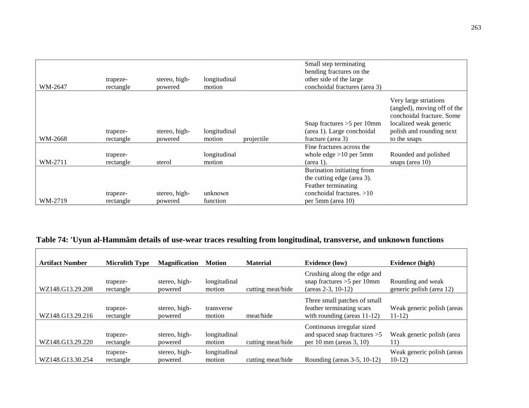
263
WM-2647
trapeze-
rectangle
stereo, high-
powered
longitudinal
motion
Small step terminating
bending fractures on the
other side of the large
conchoidal fractures (area 3)
WM-2668
trapeze-
rectangle
stereo, high-
powered
longitudinal
motion projectile
Snap fractures >5 per 10mm
(area 1). Large conchoidal
fracture (area 3)
Very large striations
(angled), moving off of the
conchoidal fracture. Some
localized weak generic
polish and rounding next
to the snaps
WM-2711
trapeze-
rectangle sterol
longitudinal
motion
Fine fractures across the
whole edge >10 per 5mm
(area 1).
Rounded and polished
snaps (area 10)
WM-2719
trapeze-
rectangle
stereo, high-
powered
unknown
function
Burination initiating from
the cutting edge (area 3).
Feather terminating
conchoidal fractures. >10
per 5mm (area 10)
Table 74: 'Uyun al-Hammâm details of use-wear traces resulting from longitudinal, transverse, and unknown functions
Artifact Number Microlith Type Magnification Motion Material Evidence (low) Evidence (high)
WZ148.G13.29.208
trapeze-
rectangle
stereo, high-
powered
longitudinal
motion cutting meat/hide
Crushing along the edge and
snap fractures >5 per 10mm
(areas 2-3, 10-12)
Rounding and weak
generic polish (area 12)
WZ148.G13.29.216
trapeze-
rectangle
stereo, high-
powered
transverse
motion meat/hide
Three small patches of small
feather terminating scars
with rounding (areas 11-12)
Weak generic polish (areas
11-12)
WZ148.G13.29.220
trapeze-
rectangle
stereo, high-
powered
longitudinal
motion cutting meat/hide
Continuous irregular sized
and spaced snap fractures >5
per 10 mm (areas 3, 10)
Weak generic polish (area
11)
WZ148.G13.30.254
trapeze-
rectangle
stereo, high-
powered
longitudinal
motion cutting meat/hide Rounding (areas 3-5, 10-12)
Weak generic polish (areas
10-12)
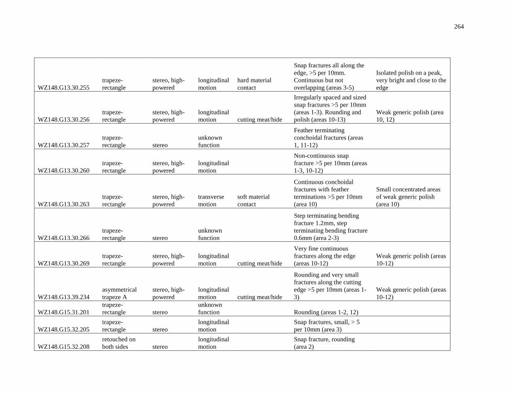
264
WZ148.G13.30.255
trapeze-
rectangle
stereo, high-
powered
longitudinal
motion
hard material
contact
Snap fractures all along the
edge, >5 per 10mm.
Continuous but not
overlapping (areas 3-5)
Isolated polish on a peak,
very bright and close to the
edge
WZ148.G13.30.256
trapeze-
rectangle
stereo, high-
powered
longitudinal
motion cutting meat/hide
Irregularly spaced and sized
snap fractures >5 per 10mm
(areas 1-3). Rounding and
polish (areas 10-13)
Weak generic polish (area
10, 12)
WZ148.G13.30.257
trapeze-
rectangle stereo
unknown
function
Feather terminating
conchoidal fractures (areas
1, 11-12)
WZ148.G13.30.260
trapeze-
rectangle
stereo, high-
powered
longitudinal
motion
Non-continuous snap
fracture >5 per 10mm (areas
1-3, 10-12)
WZ148.G13.30.263
trapeze-
rectangle
stereo, high-
powered
transverse
motion
soft material
contact
Continuous conchoidal
fractures with feather
terminations >5 per 10mm
(area 10)
Small concentrated areas
of weak generic polish
(area 10)
WZ148.G13.30.266
trapeze-
rectangle stereo
unknown
function
Step terminating bending
fracture 1.2mm, step
terminating bending fracture
0.6mm (area 2-3)
WZ148.G13.30.269
trapeze-
rectangle
stereo, high-
powered
longitudinal
motion cutting meat/hide
Very fine continuous
fractures along the edge
(areas 10-12)
Weak generic polish (areas
10-12)
WZ148.G13.39.234
asymmetrical
trapeze A
stereo, high-
powered
longitudinal
motion cutting meat/hide
Rounding and very small
fractures along the cutting
edge >5 per 10mm (areas 1-
3)
Weak generic polish (areas
10-12)
WZ148.G15.31.201
trapeze-
rectangle stereo
unknown
function
Rounding (areas 1-2, 12)
WZ148.G15.32.205
trapeze-
rectangle stereo
longitudinal
motion
Snap fractures, small, > 5
per 10mm (area 3)
WZ148.G15.32.208
retouched on
both sides stereo
longitudinal
motion
Snap fracture, rounding
(area 2)
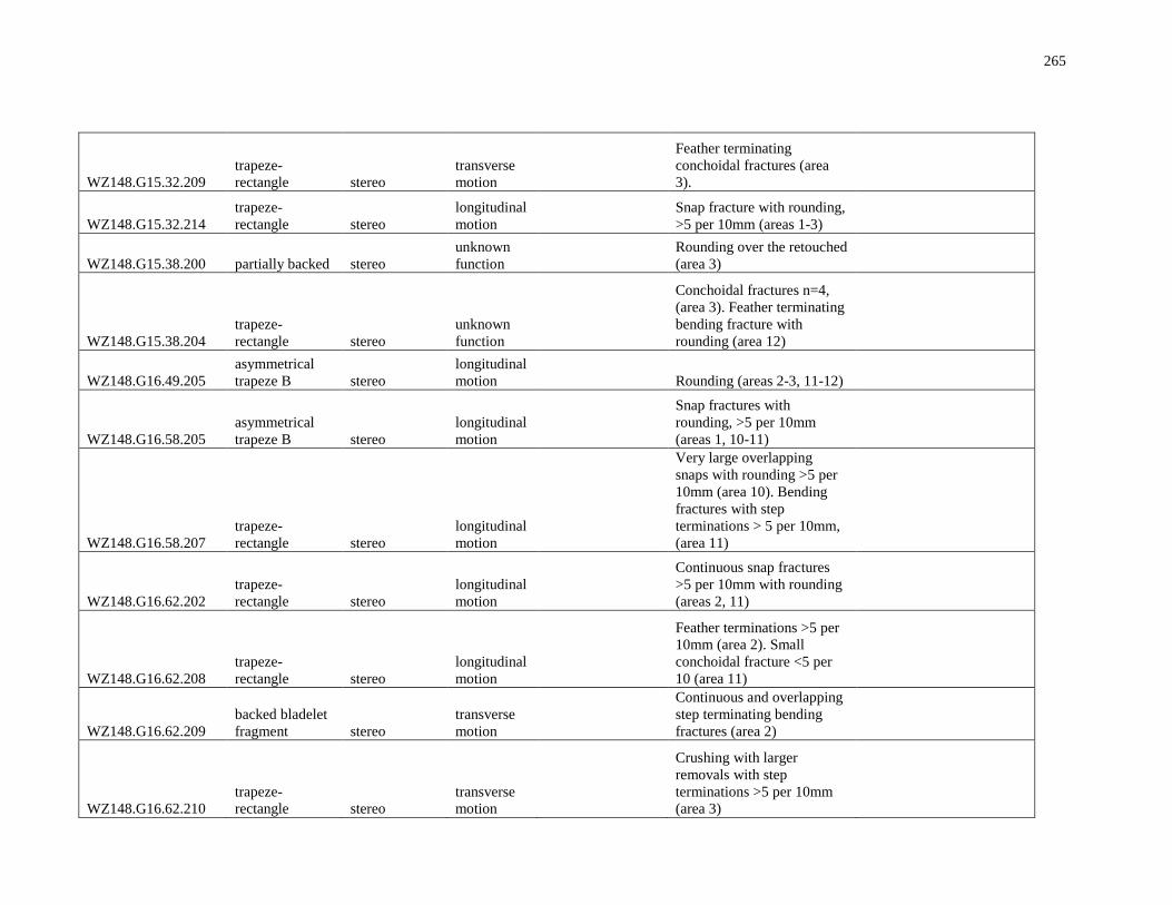
265
WZ148.G15.32.209
trapeze-
rectangle stereo
transverse
motion
Feather terminating
conchoidal fractures (area
3).
WZ148.G15.32.214
trapeze-
rectangle stereo
longitudinal
motion
Snap fracture with rounding,
>5 per 10mm (areas 1-3)
WZ148.G15.38.200 partially backed stereo
unknown
function
Rounding over the retouched
(area 3)
WZ148.G15.38.204
trapeze-
rectangle stereo
unknown
function
Conchoidal fractures n=4,
(area 3). Feather terminating
bending fracture with
rounding (area 12)
WZ148.G16.49.205
asymmetrical
trapeze B stereo
longitudinal
motion
Rounding (areas 2-3, 11-12)
WZ148.G16.58.205
asymmetrical
trapeze B stereo
longitudinal
motion
Snap fractures with
rounding, >5 per 10mm
(areas 1, 10-11)
WZ148.G16.58.207
trapeze-
rectangle stereo
longitudinal
motion
Very large overlapping
snaps with rounding >5 per
10mm (area 10). Bending
fractures with step
terminations > 5 per 10mm,
(area 11)
WZ148.G16.62.202
trapeze-
rectangle stereo
longitudinal
motion
Continuous snap fractures
>5 per 10mm with rounding
(areas 2, 11)
WZ148.G16.62.208
trapeze-
rectangle stereo
longitudinal
motion
Feather terminations >5 per
10mm (area 2). Small
conchoidal fracture <5 per
10 (area 11)
WZ148.G16.62.209
backed bladelet
fragment stereo
transverse
motion
Continuous and overlapping
step terminating bending
fractures (area 2)
WZ148.G16.62.210
trapeze-
rectangle stereo
transverse
motion
Crushing with larger
removals with step
terminations >5 per 10mm
(area 3)
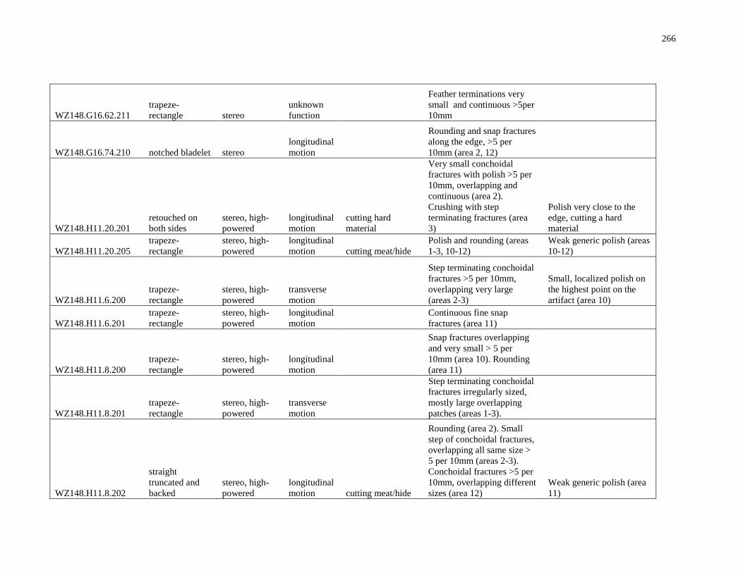
266
WZ148.G16.62.211
trapeze-
rectangle stereo
unknown
function
Feather terminations very
small and continuous >5per
10mm
WZ148.G16.74.210 notched bladelet stereo
longitudinal
motion
Rounding and snap fractures
along the edge, >5 per
10mm (area 2, 12)
WZ148.H11.20.201
retouched on
both sides
stereo, high-
powered
longitudinal
motion
cutting hard
material
Very small conchoidal
fractures with polish >5 per
10mm, overlapping and
continuous (area 2).
Crushing with step
terminating fractures (area
3)
Polish very close to the
edge, cutting a hard
material
WZ148.H11.20.205
trapeze-
rectangle
stereo, high-
powered
longitudinal
motion cutting meat/hide
Polish and rounding (areas
1-3, 10-12)
Weak generic polish (areas
10-12)
WZ148.H11.6.200
trapeze-
rectangle
stereo, high-
powered
transverse
motion
Step terminating conchoidal
fractures >5 per 10mm,
overlapping very large
(areas 2-3)
Small, localized polish on
the highest point on the
artifact (area 10)
WZ148.H11.6.201
trapeze-
rectangle
stereo, high-
powered
longitudinal
motion
Continuous fine snap
fractures (area 11)
WZ148.H11.8.200
trapeze-
rectangle
stereo, high-
powered
longitudinal
motion
Snap fractures overlapping
and very small > 5 per
10mm (area 10). Rounding
(area 11)
WZ148.H11.8.201
trapeze-
rectangle
stereo, high-
powered
transverse
motion
Step terminating conchoidal
fractures irregularly sized,
mostly large overlapping
patches (areas 1-3).
WZ148.H11.8.202
straight
truncated and
backed
stereo, high-
powered
longitudinal
motion cutting meat/hide
Rounding (area 2). Small
step of conchoidal fractures,
overlapping all same size >
5 per 10mm (areas 2-3).
Conchoidal fractures >5 per
10mm, overlapping different
sizes (area 12)
Weak generic polish (area
11)
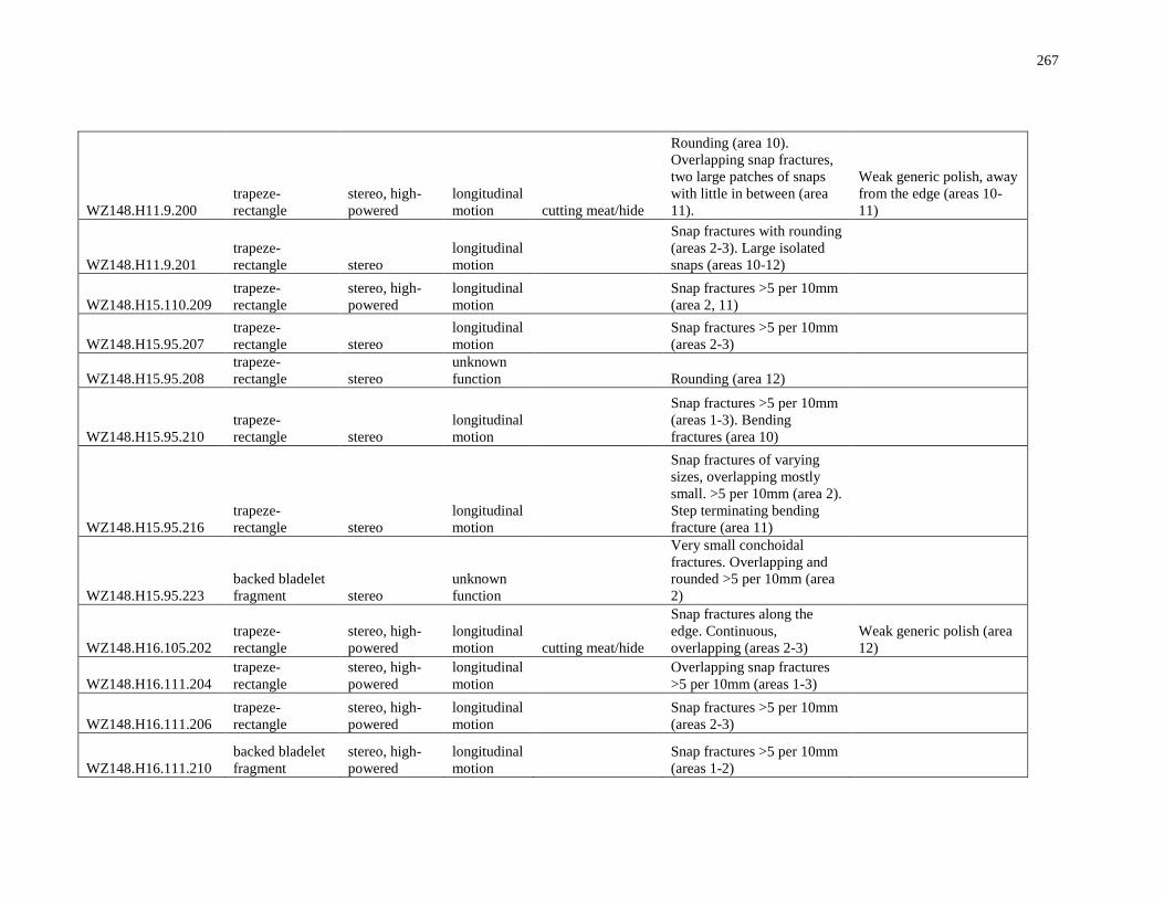
267
WZ148.H11.9.200
trapeze-
rectangle
stereo, high-
powered
longitudinal
motion cutting meat/hide
Rounding (area 10).
Overlapping snap fractures,
two large patches of snaps
with little in between (area
11).
Weak generic polish, away
from the edge (areas 10-
11)
WZ148.H11.9.201
trapeze-
rectangle stereo
longitudinal
motion
Snap fractures with rounding
(areas 2-3). Large isolated
snaps (areas 10-12)
WZ148.H15.110.209
trapeze-
rectangle
stereo, high-
powered
longitudinal
motion
Snap fractures >5 per 10mm
(area 2, 11)
WZ148.H15.95.207
trapeze-
rectangle stereo
longitudinal
motion
Snap fractures >5 per 10mm
(areas 2-3)
WZ148.H15.95.208
trapeze-
rectangle stereo
unknown
function
Rounding (area 12)
WZ148.H15.95.210
trapeze-
rectangle stereo
longitudinal
motion
Snap fractures >5 per 10mm
(areas 1-3). Bending
fractures (area 10)
WZ148.H15.95.216
trapeze-
rectangle stereo
longitudinal
motion
Snap fractures of varying
sizes, overlapping mostly
small. >5 per 10mm (area 2).
Step terminating bending
fracture (area 11)
WZ148.H15.95.223
backed bladelet
fragment stereo
unknown
function
Very small conchoidal
fractures. Overlapping and
rounded >5 per 10mm (area
2)
WZ148.H16.105.202
trapeze-
rectangle
stereo, high-
powered
longitudinal
motion cutting meat/hide
Snap fractures along the
edge. Continuous,
overlapping (areas 2-3)
Weak generic polish (area
12)
WZ148.H16.111.204
trapeze-
rectangle
stereo, high-
powered
longitudinal
motion
Overlapping snap fractures
>5 per 10mm (areas 1-3)
WZ148.H16.111.206
trapeze-
rectangle
stereo, high-
powered
longitudinal
motion
Snap fractures >5 per 10mm
(areas 2-3)
WZ148.H16.111.210
backed bladelet
fragment
stereo, high-
powered
longitudinal
motion
Snap fractures >5 per 10mm
(areas 1-2)
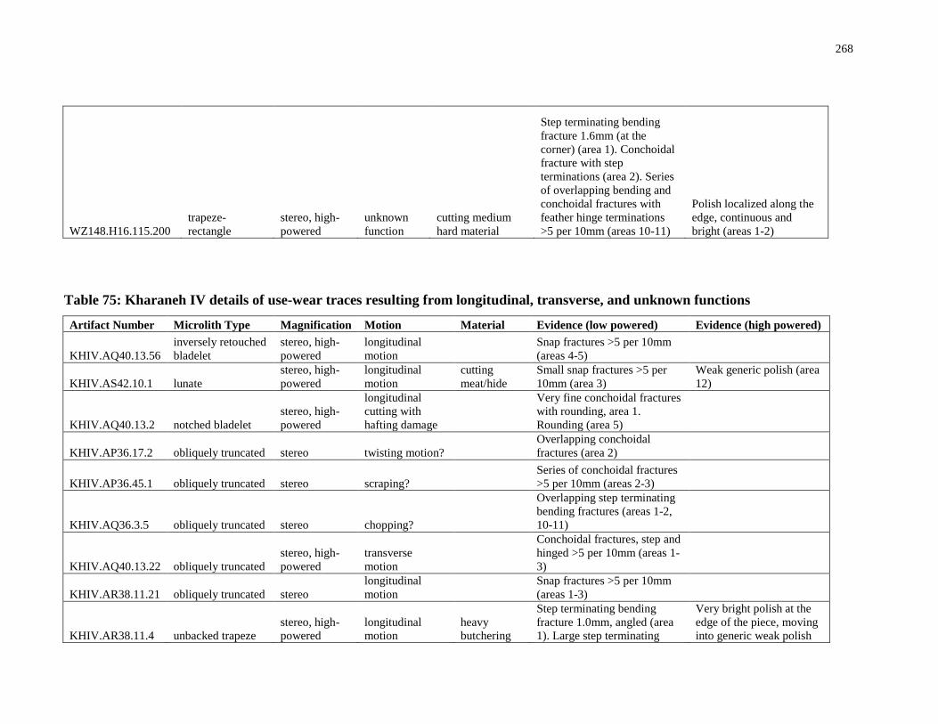
268
WZ148.H16.115.200
trapeze-
rectangle
stereo, high-
powered
unknown
function
cutting medium
hard material
Step terminating bending
fracture 1.6mm (at the
corner) (area 1). Conchoidal
fracture with step
terminations (area 2). Series
of overlapping bending and
conchoidal fractures with
feather hinge terminations
>5 per 10mm (areas 10-11)
Polish localized along the
edge, continuous and
bright (areas 1-2)
Table 75: Kharaneh IV details of use-wear traces resulting from longitudinal, transverse, and unknown functions
Artifact Number Microlith Type Magnification Motion Material Evidence (low powered) Evidence (high powered)
KHIV.AQ40.13.56
inversely retouched
bladelet
stereo, high-
powered
longitudinal
motion
Snap fractures >5 per 10mm
(areas 4-5)
KHIV.AS42.10.1 lunate
stereo, high-
powered
longitudinal
motion
cutting
meat/hide
Small snap fractures >5 per
10mm (area 3)
Weak generic polish (area
12)
KHIV.AQ40.13.2 notched bladelet
stereo, high-
powered
longitudinal
cutting with
hafting damage
Very fine conchoidal fractures
with rounding, area 1.
Rounding (area 5)
KHIV.AP36.17.2 obliquely truncated stereo twisting motion?
Overlapping conchoidal
fractures (area 2)
KHIV.AP36.45.1 obliquely truncated stereo scraping?
Series of conchoidal fractures
>5 per 10mm (areas 2-3)
KHIV.AQ36.3.5 obliquely truncated stereo chopping?
Overlapping step terminating
bending fractures (areas 1-2,
10-11)
KHIV.AQ40.13.22 obliquely truncated
stereo, high-
powered
transverse
motion
Conchoidal fractures, step and
hinged >5 per 10mm (areas 1-
3)
KHIV.AR38.11.21 obliquely truncated stereo
longitudinal
motion
Snap fractures >5 per 10mm
(areas 1-3)
KHIV.AR38.11.4 unbacked trapeze
stereo, high-
powered
longitudinal
motion
heavy
butchering
Step terminating bending
fracture 1.0mm, angled (area
1). Large step terminating
Very bright polish at the
edge of the piece, moving
into generic weak polish
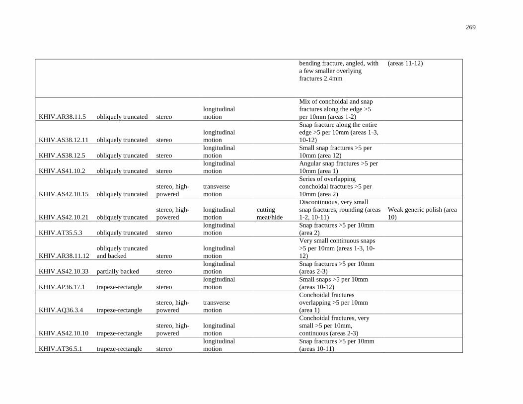
269
bending fracture, angled, with
a few smaller overlying
fractures 2.4mm
(areas 11-12)
KHIV.AR38.11.5 obliquely truncated stereo
longitudinal
motion
Mix of conchoidal and snap
fractures along the edge >5
per 10mm (areas 1-2)
KHIV.AS38.12.11 obliquely truncated stereo
longitudinal
motion
Snap fracture along the entire
edge >5 per 10mm (areas 1-3,
10-12)
KHIV.AS38.12.5 obliquely truncated stereo
longitudinal
motion
Small snap fractures >5 per
10mm (area 12)
KHIV.AS41.10.2 obliquely truncated stereo
longitudinal
motion
Angular snap fractures >5 per
10mm (area 1)
KHIV.AS42.10.15 obliquely truncated
stereo, high-
powered
transverse
motion
Series of overlapping
conchoidal fractures >5 per
10mm (area 2)
KHIV.AS42.10.21 obliquely truncated
stereo, high-
powered
longitudinal
motion
cutting
meat/hide
Discontinuous, very small
snap fractures, rounding (areas
1-2, 10-11)
Weak generic polish (area
10)
KHIV.AT35.5.3 obliquely truncated stereo
longitudinal
motion
Snap fractures >5 per 10mm
(area 2)
KHIV.AR38.11.12
obliquely truncated
and backed stereo
longitudinal
motion
Very small continuous snaps
>5 per 10mm (areas 1-3, 10-
12)
KHIV.AS42.10.33 partially backed stereo
longitudinal
motion
Snap fractures >5 per 10mm
(areas 2-3)
KHIV.AP36.17.1 trapeze-rectangle stereo
longitudinal
motion
Small snaps >5 per 10mm
(areas 10-12)
KHIV.AQ36.3.4 trapeze-rectangle
stereo, high-
powered
transverse
motion
Conchoidal fractures
overlapping >5 per 10mm
(area 1)
KHIV.AS42.10.10 trapeze-rectangle
stereo, high-
powered
longitudinal
motion
Conchoidal fractures, very
small >5 per 10mm,
continuous (areas 2-3)
KHIV.AT36.5.1 trapeze-rectangle stereo
longitudinal
motion
Snap fractures >5 per 10mm
(areas 10-11)
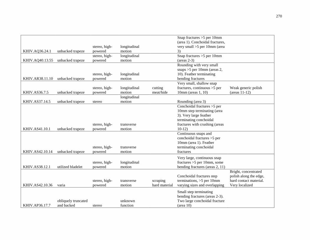
270
KHIV.AQ36.24.1 unbacked trapeze
stereo, high-
powered
longitudinal
motion
Snap fractures >5 per 10mm
(area 1). Conchoidal fractures,
very small >5 per 10mm (area
3)
KHIV.AQ40.13.55 unbacked trapeze
stereo, high-
powered
longitudinal
motion
Snap fractures >5 per 10mm
(areas 2-3)
KHIV.AR38.11.10 unbacked trapeze
stereo, high-
powered
longitudinal
motion
Rounding with very small
snaps >5 per 10mm (areas 2,
10). Feather terminating
bending fractures
KHIV.AS36.7.5 unbacked trapeze
stereo, high-
powered
longitudinal
motion
cutting
meat/hide
Very small, shallow snap
fractures, continuous >5 per
10mm (areas 1, 10)
Weak generic polish
(areas 11-12)
KHIV.AS37.14.5 unbacked trapeze stereo
longitudinal
motion
Rounding (area 3)
KHIV.AS41.10.1 unbacked trapeze
stereo, high-
powered
transverse
motion
Conchoidal fractures >5 per
10mm step terminating (area
3). Very large feather
terminating conchoidal
fractures with crushing (areas
10-12)
KHIV.AS42.10.14 unbacked trapeze
stereo, high-
powered
transverse
motion
Continuous snaps and
conchoidal fractures >5 per
10mm (area 1). Feather
terminating conchoidal
fractures
KHIV.AS38.12.1 utilized bladelet
stereo, high-
powered
longitudinal
motion
Very large, continuous snap
fractures >5 per 10mm, some
bending fractures (areas 2, 11)
KHIV.AS42.10.36 varia
stereo, high-
powered
transverse
motion
scraping
hard material
Conchoidal fractures step
terminations, >5 per 10mm
varying sizes and overlapping
Bright, concentrated
polish along the edge,
hard contact material.
Very localized
KHIV.AP36.17.7
obliquely truncated
and backed stereo
unknown
function
Small step terminating
bending fractures (areas 2-3).
Two large conchoidal fracture
(area 10)

271
KHIV.AP36.17.8 completely backed stereo
unknown
function
Step terminating bending
fracture 2.0mm, perpendicular
(area 2). Snap fractures >5 per
10mm (area 3)
KHIV.AQ40.13.49
obliquely truncated
and backed
stereo, high-
powered
unknown
function
Conchoidal fractures and step
terminating bending fractures
>5 per 10mm. Snap fractures
across piece (area 2-3)
KHIV.AQ40.13.9 unbacked trapeze
stereo, high-
powered
unknown
function
Step terminating bending
fractures overlapping retouch,
continuous >5 per 10mm
(areas 1-3)
KHIV.AR38.11.2
pointed backed
bladelet stereo
unknown
function hard material
Combination of feather
terminating and step
terminating bending fractures.
Also conchoidal fractures >5
per 10mm, overlapping and
different sizes (areas 1-3, 8)
polish at the tip, bright and
concentrated (area 10)
KHIV.AS42.10.11 completely backed
stereo, high-
powered
unknown
function
Feather terminating bending
fractures x 2 (area 2). Massive
feather terminating conchoidal
fractures x2 6.7mm (area 10)
KHIV.AS42.10.19
backed bladelet
fragment
stereo, high-
powered
unknown
function
Step and feather terminating
conchoidal fractures (areas 2-
3). Small conchoidal fractures
(area 12)
KHIV.AS42.10.23 obliquely truncated stereo
unknown
function
Step terminating bending
fractures >5 per 10mm (area
3). Cluster of step terminating
bending fractures 1.2mm, >5
per 10mm (area 11)
KHIV.AS42.10.3 trapeze-rectangle
stereo, high-
powered
unknown
function
Feather and step terminating
bending fractures >5 per
10mm. Irregularly sizes and
overlapping, but continuous
(areas 1-2). step terminating
bending fractures x4,
perpendicular (area 3)
polish along the end,
bright and localized,
probably from hafting
using a hard material (area
10)
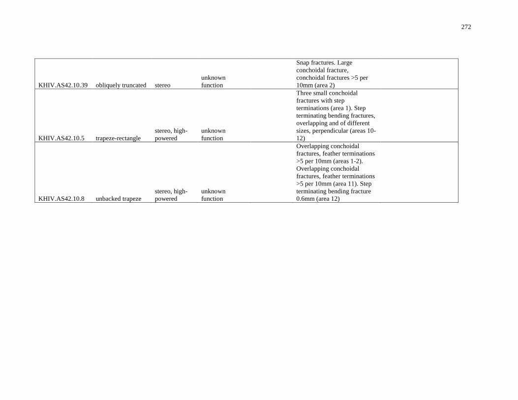
272
KHIV.AS42.10.39 obliquely truncated stereo
unknown
function
Snap fractures. Large
conchoidal fracture,
conchoidal fractures >5 per
10mm (area 2)
KHIV.AS42.10.5 trapeze-rectangle
stereo, high-
powered
unknown
function
Three small conchoidal
fractures with step
terminations (area 1). Step
terminating bending fractures,
overlapping and of different
sizes, perpendicular (areas 10-
12)
KHIV.AS42.10.8 unbacked trapeze
stereo, high-
powered
unknown
function
Overlapping conchoidal
fractures, feather terminations
>5 per 10mm (areas 1-2).
Overlapping conchoidal
fractures, feather terminations
>5 per 10mm (area 11). Step
terminating bending fracture
0.6mm (area 12)

273
Wadi Mataha Low-Powered Photomicrographs
Appendix D Use-Wear Images
This appendix contains a sample of photomicrographs of wear traces taken using from low-
powered and high-powered magnification.
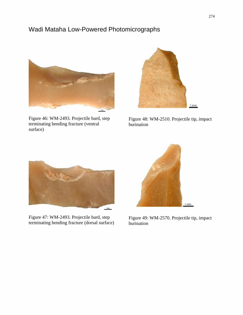
274
Wadi Mataha Low-Powered Photomicrographs
Figure 46: WM-2493. Projectile bard, step
terminating bending fracture (ventral
surface)
Figure 47: WM-2493. Projectile bard, step
terminating bending fracture (dorsal surface)
Figure 48: WM-2510. Projectile tip, impact
burination
Figure 49: WM-2570. Projectile tip, impact
burination
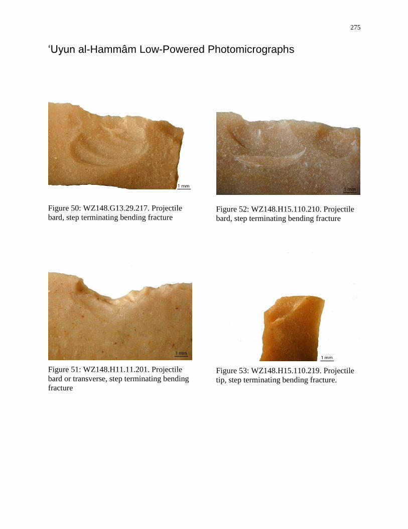
275
‘Uyun al-Hammâm Low-Powered Photomicrographs
Figure 50: WZ148.G13.29.217. Projectile
bard, step terminating bending fracture
Figure 51: WZ148.H11.11.201. Projectile
bard or transverse, step terminating bending
fracture
Figure 52: WZ148.H15.110.210. Projectile
bard, step terminating bending fracture
Figure 53: WZ148.H15.110.219. Projectile
tip, step terminating bending fracture.
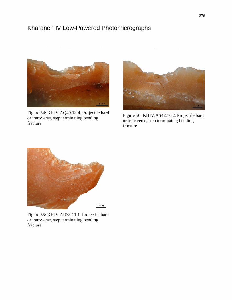
276
Kharaneh IV Low-Powered Photomicrographs
Figure 54: KHIV.AQ40.13.4. Projectile bard
or transverse, step terminating bending
fracture
Figure 55: KHIV.AR38.11.1. Projectile bard
or transverse, step terminating bending
fracture
Figure 56: KHIV.AS42.10.2. Projectile bard
or transverse, step terminating bending
fracture
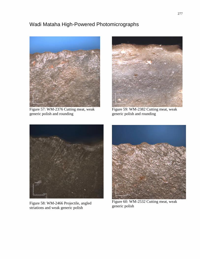
277
Wadi Mataha High-Powered Photomicrographs
Figure 57: WM-2376 Cutting meat, weak
generic polish and rounding
Figure 58: WM-2466 Projectile, angled
striations and weak generic polish
Figure 59: WM-2382 Cutting meat, weak
generic polish and rounding
Figure 60: WM-2532 Cutting meat, weak
generic polish
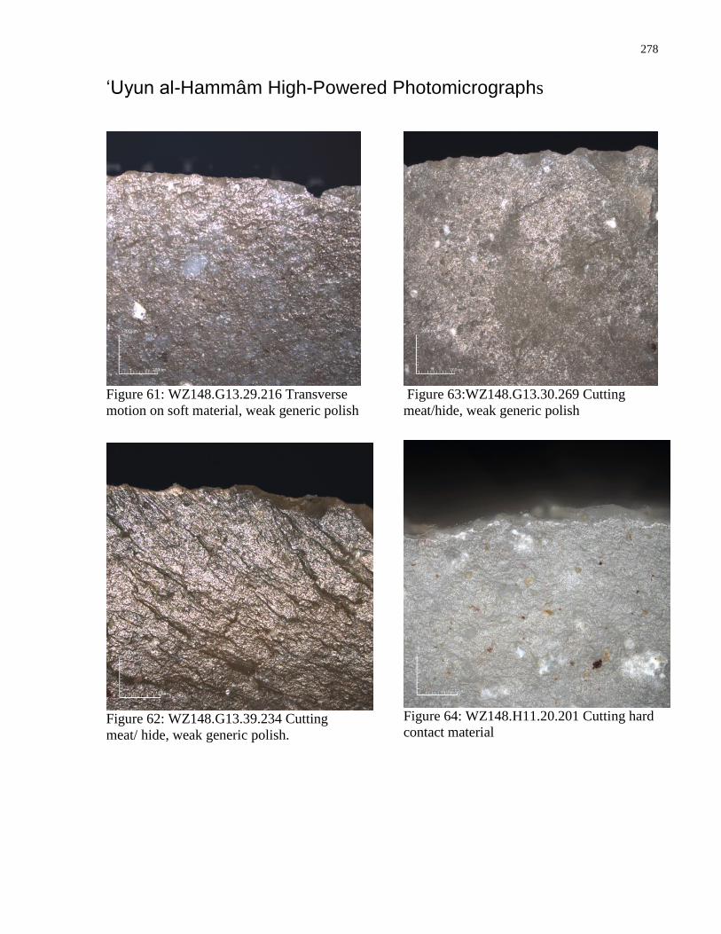
278
‘Uyun al-Hammâm High-Powered Photomicrographs
Figure 61: WZ148.G13.29.216 Transverse
motion on soft material, weak generic polish
Figure 62: WZ148.G13.39.234 Cutting
meat/ hide, weak generic polish.
Figure 63:WZ148.G13.30.269 Cutting
meat/hide, weak generic polish
Figure 64: WZ148.H11.20.201 Cutting hard
contact material
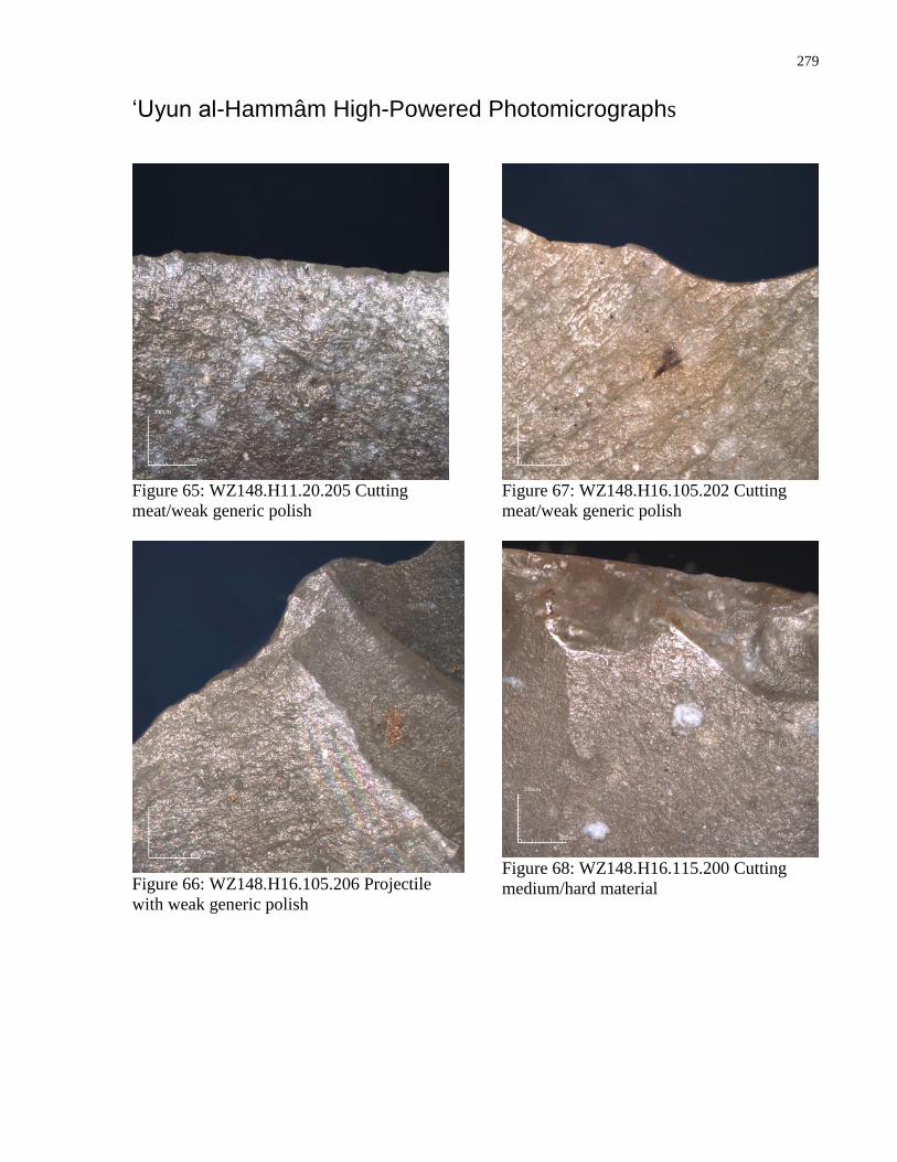
279
‘Uyun al-Hammâm High-Powered Photomicrographs
Figure 65: WZ148.H11.20.205 Cutting
meat/weak generic polish
Figure 66: WZ148.H16.105.206 Projectile
with weak generic polish
Figure 67: WZ148.H16.105.202 Cutting
meat/weak generic polish
Figure 68: WZ148.H16.115.200 Cutting
medium/hard material
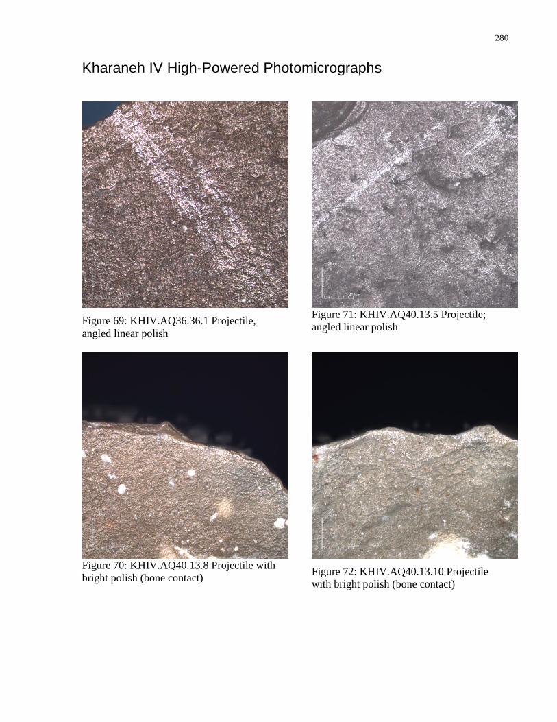
280
Kharaneh IV High-Powered Photomicrographs
Figure 69: KHIV.AQ36.36.1 Projectile,
angled linear polish
Figure 70: KHIV.AQ40.13.8 Projectile with
bright polish (bone contact)
Figure 71: KHIV.AQ40.13.5 Projectile;
angled linear polish
Figure 72: KHIV.AQ40.13.10 Projectile
with bright polish (bone contact)
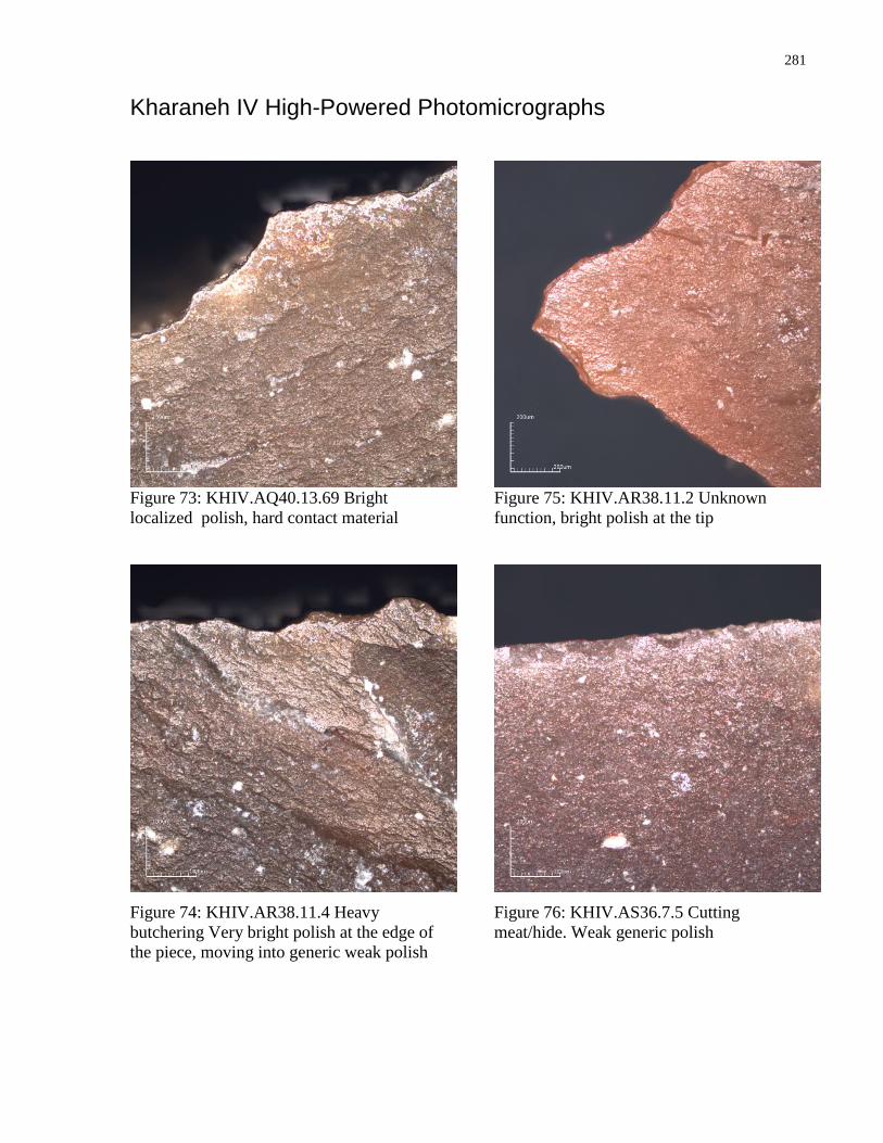
281
Kharaneh IV High-Powered Photomicrographs
Figure 73: KHIV.AQ40.13.69 Bright
localized polish, hard contact material
Figure 74: KHIV.AR38.11.4 Heavy
butchering Very bright polish at the edge of
the piece, moving into generic weak polish
Figure 75: KHIV.AR38.11.2 Unknown
function, bright polish at the tip
Figure 76: KHIV.AS36.7.5 Cutting
meat/hide. Weak generic polish
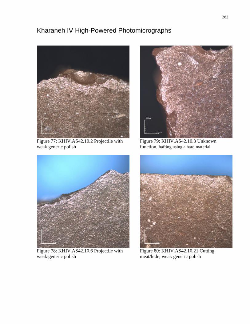
282
Kharaneh IV High-Powered Photomicrographs
Figure 77: KHIV.AS42.10.2 Projectile with
weak generic polish
Figure 78: KHIV.AS42.10.6 Projectile with
weak generic polish
Figure 79: KHIV.AS42.10.3 Unknown
function, hafting using a hard material
Figure 80: KHIV.AS42.10.21 Cutting
meat/hide, weak generic polish
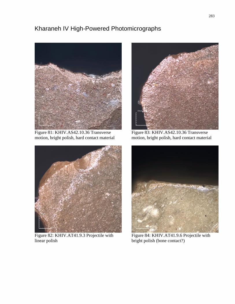
283
Kharaneh IV High-Powered Photomicrographs
Figure 81: KHIV.AS42.10.36 Transverse
motion, bright polish, hard contact material
Figure 82: KHIV.AT41.9.3 Projectile with
linear polish
Figure 83: KHIV.AS42.10.36 Transverse
motion, bright polish, hard contact material
Figure 84: KHIV.AT41.9.6 Projectile with
bright polish (bone contact?)