Embed Size (px)
Citation preview

Formalising high-performance systems methodologies
G.R. Ribeiro Justo, Paul Howells, Mark d'Inverno *
Cavendish School of Computer Science, University of Westminster, 115, New Cavendish Street, London WIM 8JS, UK
Abstract
This paper presents a Z formal framework to describe software design methodologies (SDM) for high-performance
systems (HPS). The framework consists of two main parts: the characterisation of the main activities in the develop-
ment of HPS, and the components of the SDM (concepts, artifacts, representation and actions) which are essential for
any methodology. The framework relates these two parts by identifying generic components of each activity that can be
used to classify and formalise SDM for HPS. This is illustrated in the paper by presenting part of the speci®cation of a
well-known method. Ó 1999 Elsevier Science B.V. All rights reserved.
Keywords: Z formal framework; Software design methodologies; High-performance systems
1. Introduction
With the large number of software design methodologies (SDMs) currently available, designers andmanagers are faced with the di�cult task of deciding which methodology best suits their projects. In orderto solve these problems, there is an urgent need for models or frameworks which allow us to characterise,classify and integrate SDMs and many authors have proposed such solutions [5,29,3,2]. However, most ofthem concentrate only on particular properties of the life-cycle model or software process model on whichSDMs are based, and whilst still important in enabling users to evaluate properties of particular SDMs [5],do not go further in considering the structure of the SDMs and their components. When solutions doconsider their structure and components [28] it becomes possible not only to give a more detailed com-parison and evaluation of systems, but to allow for the integration of di�erent components of SDMs.
Journal of Systems Architecture 45 (1999) 441±464
* Corresponding author. E-mail: [email protected]
1383-7621/99/$ ± see front matter Ó 1999 Elsevier Science B.V. All rights reserved.
PII: S 1 3 8 3 - 7 6 2 1 ( 9 8 ) 0 0 0 1 7 - 4

Unfortunately, most of these models and frameworks are based on traditional (sequential) SDMs. Littlehas been done to systematically classify and evaluate SDMs and tools for high-performance systems (HPS)the ®eld where parallel computing is applied. Attempts have been made in presenting surveys of methodsand tools applied to the development of HPS [18] but there are not frameworks or models similar to thoseapplied to traditional software. There are many reasons for this, the main one being the lack of life-cycle orsoftware process models that describe the development of HPS. The principal consequence is that HPSdevelopers cannot systematically compare the few SDMs available. In addition, tool developers have littleinsight into how their tools can be applied and integrated to SDMs.
The main objective of this paper is to present a formal framework to describe SDMs for HPS. Althoughthe framework aims at the systematic classi®cation of methods, it can also be applied to the classi®cation oftools by identifying which components or activities they can support.
In the following Section 2, a characterisation of the main activities in the development of HPS is in-troduced. This characterisation is the basis for the framework which is presented in Section 3. First, wedescribe existing frameworks and then informally introduce our own. The formal speci®cation in Z of theframework components and the design process is presented in Sections 4 and 5. Section 6 presents a casestudy that illustrates how the framework has been used to specify an existing SDM for HPS. Finally, wepresent conclusions.
2. Characterisation of the development of HPS
Independently of the approach taken (life cycle models [25,23] or software process models [2]), tradi-tional software development has been fully characterised by its activities and their relationships. Unfor-tunately, little work has been done to characterise the HPS software design process, one of the reasonsbeing the young state of the ®eld. Another important reason is the historical development of HPS them-selves; much of the initial work on the development of HPS consisted of the transformation of legacy(sequential) code into parallel code. This activity was supposed to be performed automatically by paral-lelising compilers [26]. However, the resulting parallelism was considered harmful and had to be hiddenfrom the user, and consequently HPS development was viewed merely as a small variation of the traditionalsoftware process. The limitations of this approach have now been recognised [1] and it is clear that theprogrammer/designer must share the responsibility of exposing parallelism. In fact, the advantages of ex-plicit parallelism have been recognised by certain authors for some time [14], and there is now an urgentneed for more SDMs (and tools) that support the development of explicitly parallel programs [18].
2.1. The role of performance-related activities
One of the main di�erences between traditional software development and HPS development is that inthe former, performance usually plays a minor role and is only considered in the ®nal stages of the de-velopment. For HPS, however, performance is a dominant issue and some authors claim that it should beconsidered in all stages of the development [11,19]. This means that there is some tension between theperformance activities (performance engineering activities) and the ``traditional'' development activities(software engineering activities). As these activities are usually related in di�erent ways by tools and
442 G.R. Ribeiro Justo et al. / Journal of Systems Architecture 45 (1999) 441±464
methods, we have decided to consider a concurrent view of them. This means, for example, that perfor-mance prototypes can be developed both in the early stages of the development [11,19] and after the im-plementation [4].
2.2. Software engineering activities
In most methodologies the development starts with the problem speci®cation, and the eventual de-scription of a solution design (software). Traditionally, an implementation (code) is derived later from thisdescription, possibly assuming a certain environment (target machine). In terms of HPS, however, infor-mation about the target machine (hardware) will not only in¯uence the implementation but it may in¯uencethe solution itself [11]. So, in general the hardware description could be constructed and analysed simul-taneously with the software. This enables us to model SDMs where the hardware-dependent designs arederived from abstract (virtual) designs [17], and also those where the hardware characteristics are taken intoaccount during the design, especially to reduce ``performance design errors'' [4].
Certainly, an implementation is only derived after a software/hardware description has been produced.However, many approaches assume the transformation of existing programs known as parallelisation. It ispossible that the software engineering activities could start from the code generation state. Finally, thecorrectness of the implementation can be tested, and possible errors can be traced by using debugging tools.
2.3. Performance engineering activities
Performance engineering activities consist of measuring the performance and then analysing the results.For simpli®cation, the description of our model presented in this paper shows the performance engineeringactivities as a single activity. The performance measurements (statistics) can be obtained before the pro-gram has been implemented (using performance prediction methods) or after (using prediction or moni-toring methods). The statistics about program performance produced via prediction or monitoring are thenanalysed, typically with the support of visualisation tools.
The results can then be used to modify the program or the design to improve performance. It is im-portant to understand that the performance measurements do not simply include time or resource usage butalso scalability and portability, which measure the relationship between the software and hardware.
3. The formal framework for HPS methodologies
3.1. Some existing frameworks
Davis and Comer [5] present a framework to compare life cycle models. This is based on ®ve metricswhich measure properties of the life cycle and how it responds to the evolution of the users' needs. Thisframework can help developers in evaluating how their methodologies may react to the users' needs but asit concentrates on major properties, it does not help in the integration of components of life cycle models orin the evaluation of supporting tools.
G.R. Ribeiro Justo et al. / Journal of Systems Architecture 45 (1999) 441±464 443

The framework proposed by Conradi et al. [3] concentrates on the evolutionary properties of thesoftware development process: it is particularly important for the systematic evaluation of the capabilitiesof SDMs to support evolution.
The framework proposed by Blum [2] focuses not on life cycle models but on the software process. Theauthor de®nes the software process as a series of activities ± with respect to a software product ± fromconception to implementation. He also identi®es two major domains in the software process: the problemdomain where the problem is solved, and the implementation domain where a solution to the problem isexecuted. So, problem-oriented SDMs concentrate on producing a better understanding of the problem andits solution and product-oriented SDMs concentrate on the generation of an implementation from aspeci®cation. Another dimension of the framework is the separation of SDMs based on conceptual modelsfrom those based on formal models. Conceptual models describe (subjective) guidelines for design decisionsand validation, whilst formal models prescribe (objective) criteria for correct behaviour of the softwareproduct.
The above frameworks focus on general properties of SDMs, but not on their structure and components.They do not provide the support for integration of SDMs, for example. By contrast, the framework pre-sented by Song and Osterweil [29] describes the components of SDMs based on the empirical observation ofa group of existing and relevant SDMs. The components are organised in a hierarchical way where the toplevel assumes that the objective of SDMs is to provide a systematic way (actions) for the production ofartifacts using di�erent representations, following some principles and guidelines (concepts). These ele-ments are then further decomposed. Thus the framework allows a detailed description of SDMs andtherefore can also be used to de®ne the possible integration of components of di�erent methods.
3.2. Informal description of the framework
Our framework follows the same principles of that presented in [29] where the basic components ofSDMs are identi®ed, and then categorised. These components are also: Concepts, Artifacts, Representationand Actions. However, our view of what these elements are di�ers from that as suggested by Song andOsterweil [29]. One of the main reasons is that we want to present a framework which is formally speci®ed,and as such, some abstract notions considered by Song and Osterweil are not relevant. Another importantpoint is the nature of these components, which depends very much on the SDMs to which the frameworkwill be applied. Song and Osterweil are interested in problem-oriented methods whilst we are interested insolution-oriented methods; the kind of methods usually available for HPS.
In summary, SDMs, for us, consist of Concepts which are basic elements that are related to form Ar-tifacts which are produced and manipulated by Actions. These artifacts can be realised using di�erentconcrete Representations. An informal description of each component is presented below. In Section 4 theywill be speci®ed formally.
Concepts denote the basic (usually atomic) elements that are used in a method; they are the buildingblocks from which Artifacts are constructed. They can be, for example, a task in [24] or a template in [20].The framework presents Concepts which are general enough to characterise many SDMs.
Artifacts are structured elements de®ned from Concepts or other Artifacts. They usually de®ne rela-tionships amongst Concepts and Artifacts. For example, a con®guration of tasks in [24] or a network oftemplates in [20] de®ne a relationship amongst the tasks or templates respectively.
444 G.R. Ribeiro Justo et al. / Journal of Systems Architecture 45 (1999) 441±464

Representation is a concrete realisation of Artifacts. The type of Representation of the Artifacts de®nesthe nature of the method in terms of its formality and visual basis. The framework de®nes four categories ofRepresentation: Textual, Textual Formal, Structural and Formal_Visual. The ®rst category, Textual, de-notes pieces of text in an informal language which has no formal semantics. The second category is alsotextual but is de®ned in a formal language, for example, Communicating Sequential Processes (CSP) [14].The last two categories comprise graphical representations but the Structural ones do not have a formalsemantics and are simply manipulated as pictures whilst the Formal_Visual have a formal semantics andcan be formally manipulated [13]. For example, a con®guration diagram in [24] is classi®ed as Structuralbut a Petri Net in [11] is Formal_Visual.
Actions denote the operations provided by SDMs for the production and manipulation of the Artifacts.The framework provides a collection of operations which we believe are su�cient to characterise mostSDMs for HPS.
Having identi®ed the basic components of the SDM, the next part of the framework consists of acollection of basic components for the software development characterisation, which was presented inSection 2. This means that for each activity its basic components (Concepts, Artifacts, Representation andActions) are identi®ed. The complete structure of the framework is presented in Table 1. Below we describethe components of each activity:
Software Description: the main issue of this activity is to decompose the system into a collection ofparallel units and to describe the relationship between them [24]. In this case, the framework provides theconcept of Parallel Units which are structured into the Design_Structure that relates the Parallel Units.Another important aspect of the software description is the way the Parallel Units behave or interactamong themselves. In the framework, this is de®ned by the Behaviour_Description. The Design_Structure isusually represented in a Structural way. Most SDMs for HPS include some form of graphical represen-tation [18]. However, these representations do not present a well-de®ned semantics and are only used toillustrate the Design_Structure. The Behaviour_Description is usually represented in a Textual form like apiece of code or more formally (Formal_Textual) using a speci®cation language [15]. There are, however,cases where Formal_visual representations are used [18].
These artifacts are built using actions for Decompose and Identify Parallel Units or Selecting pre-de®nedartifacts. The Behaviour_Description can also be speci®ed (Specify) or built from pre-de®ned descriptions[20]. The Mapping_Description relates artifacts from the Software and Hardware Description.
Hardware Description: this activity is based on the concepts of hardware components which are essentialfor a (parallel) machine model [31]. This description is usually presented in a simple declarative way [16].Textual representations indicating the hardware parameters are the most common but graphical repre-sentations are also used [32].
Code Generation & Optimisation: this activity is concerned with Program_Structures which are puttogether to form the Program_Code. These structures can denote loops [1] or other elementary pro-gram components [20]. The process of code generation and optimisation basically consist of Derive_Codefrom the Software Description artifacts and Transform_Code to make it more suitable for the speci®chardware.
Testing & Debugging: the concepts of Test and Error are the basic elements of this Activity. Theseelements are usually structured as lists which are mostly represented textually but sometimes graphically[18].
G.R. Ribeiro Justo et al. / Journal of Systems Architecture 45 (1999) 441±464 445

Table 1
Classi®cation of the components of the framework with respect to our characterisation
Activities Framework components
Concepts Artifacts Representation Actions
Software description Parallel Unit Design_Structure(DS) Structural Decompose_PU
Mode of Parallelism Message_Structure(MS) Textual Specify_MS
Synchronisation mode Behaviour_Description Formal_Textual Speci®c_Interactions
Mapping_Description Formal_Visual Speci®c_Mapping
Speci®c_PU_Behaviour
Verify_Interactions
Derive_DS
Re®ne_DS
Select_Behaviour_Template
Select_Mapping_Template
Select_Message_Template
Modify_Struct/Desar
Hardware description Processor Type Processor_Description Sturctural Speci®c_Processor
Memory Type Memory_Description Formal_Textual Specify_Memory
Network Type Network_Description Textual Speci®c_Network
Virtual_Description select_Network_Template
Speci®c_Virtual_Network
Verify_SH_Suitability
Modify_Description
Code generation and
optimisation
Program_ Structure
Optimisation
Program_code (Sequential
and Parallel)
Formal_Textual Derive_Code
Program_Skeleton Structural Transform_Code
Formal_visual Select_Transformation
Apply_Transformation
Testing and debugging Correctness Test Error
Program
List_of_Tests Formal_Textual Identify_Error
List_of_Errors Structural Specify_Test
Program_Code Formal_Visual Apply_Test
Program_Skeleton Check_Property
Performance engineering Performance evaluation Performance_Model Formal_Textual Select_Statistics
Portability Performance_ Statistics Structural Select_Events
Suitability List_ of_ Events Formal_Visual Identify_Bottlenecks
Check_Property
Specify_Model
Derive_Model
Derive_Statistics
Derive_Events
446 G.R. Ribeiro Justo et al. / Journal of Systems Architecture 45 (1999) 441±464

Performance Engineering: this activity consists of the derivation of Performance_Statistics about theProgram_Code or Design_Structure [11]. Again, these artifacts are represented textually but there is somemechanism to represent them graphically [19].
One of the important aspects of the framework, as we will see in Section 4, is to enable the SDM de-velopers, and also their users, to classify the components of a SDM in a systematic way. Table 1 corre-sponds to an archetypal methodology and the intention is to identify which of those components aparticular methodology contains. Even though the components presented in Table 1 enable us to describethe components of SDMs in detail and categorise them into general (process) activities, there is still an issuethat must be considered, the speci®c design process of SDMs [27]. The design process of a method mainlyestablishes the ordering that the actions should be applied (or the ordering that the artifacts are created). Asthis aspect is very important in classifying SDMs, we decide that it should be included in our framework.We assume, therefore, that SDMs are composed of (partially) ordered steps and that the steps can befurther decomposed into (partially) ordered sets of actions. Section 4 presents a formal description of theframework in terms of Z.
4. Formalisation of the framework
The Z language [30] is based on set theory and ®rst order logic. It extends the use of these languages byallowing an additional mathematical type known as the schema type. Syntactically a schema is a box di-vided into two parts by a horizontal line. There are two types of schema: state and operation. In a stateschema, the upper half is known as the declarative part, and is used to declare variables and their types. Thesecond part of the state schema is known as the predicate part, and in this part we show how the variablesare related and constrained. Each schema has a distinct name. Semantically, a schema can be considered ashaving the same type as the Cartesian product of the types of its variables, without ordering, and with thestate space constrained by the schema predicates. State schemas describe the possible states of a system.Modularity is facilitated in Z by allowing schemas to be included within other schemas.
Operations e�ect state, and are characterised by their e�ect on the state. An operation schema relates thestate variables before and after the operation. The general operation schema has a before state (unprimedstate variables), an after state (primed state variables), inputs (question-marked variables), outputs (ex-clamation-marked variables), and a set of pre-conditions for the application of the operation. The use of Zin providing frameworks for the presentation, evaluation and comparison of classes of systems has beenshown elsewhere [6±10,21,22] and will not be considered further here.
The structure of the speci®cation mirrors the structure of the software description activity of theframework. Section 4.1 de®nes the basic concepts, and Sections 4.2 and 4.3 detail artifacts and actions,respectively.
4.1. Concepts
The concepts are represented below as free types. The de®nitions are not complete but can be easilyextended to cover all methods. For example, we de®ne a parallel unit to be either a process, a task or atemplate. Other categories can be added similarly.
G.R. Ribeiro Justo et al. / Journal of Systems Architecture 45 (1999) 441±464 447

[PROCESS; TASK; TEMPLATE]
PARALLEL UNIT::� process áá PROCESS ññ| task áá TASK ññ| template áá TEMPLATE ññ
A Parallelism mode is either shared-memory or distributed.
[SHARED MEMORY, DISTRIBUTED]
PARALLELISM ::� shared áá SHARED MEMORY ññ| dist áá DISTRIBUTED ññ
The Synchronisation mode is either synchronous, asynchronous or a remote procedure call (rpc).[SYNCHRONOUS, ASYNCHRONOUS, RPC]
SYNCHRONISATION::� syn áá SYNCHRONOUS ññ| asy áá ASYNCHRONOUS ññ| rpc áá RPC ññ
We also introduce a textual description type.
[ DESCRIPTION ]
4.2. Artifacts
4.2.1. Design structureThe Design_Structure is a collection of relationships between the Concepts. Before we can de®ne the
artifacts we must de®ne the set of concepts used in the design structure. These concepts are de®ned in thefollowing state schemas.
448 G.R. Ribeiro Justo et al. / Journal of Systems Architecture 45 (1999) 441±464

All the Concepts are combined in the schema below.
We now construct the general relationships between the Concepts. First, we add the feature of Paral-lel_Unit_Groups by means of additional structure over Parallel_Units that indicates that one parallel unit isthe direct sub-unit of another. The schema asserts that each parallel unit can have at most one parent unit,only known parallel units can occur in the parent_unit mapping and parallel units cannot be their ownparent. The variable, PU_groups, identi®es the parallel units which have sub-units.
In the Related_Parallel_Units schema, the related_PUs variable is a relation between Parallel Units. Forexample, (p, q) 2 related_PUs means that p can communicate with q. Additional constraints can be placedon the relation as required. Note that only known Parallel Units can occur in the relation.
G.R. Ribeiro Justo et al. / Journal of Systems Architecture 45 (1999) 441±464 449

We now assign a synchronisation mode to each parallel unit link. First, we de®ne a type to representthese links.
The schema below speci®es that only related Parallel Units can be assigned a known synchronisationmode.
In addition, we assign a parallelism mode to each link between parallel units.
The general state for the design structured is comprised of the substates above.
Initially, all variables in this state are equal to the empty set. This is easily speci®ed and omitted forreasons of space.
LINK � � PARALLEL_UNIT � PARALLEL_UNIT
450 G.R. Ribeiro Justo et al. / Journal of Systems Architecture 45 (1999) 441±464

4.2.2. Message structureThe message Structure speci®es how the parallel unit link structure is to be achieved by providing in-
formation about the message delivery system. For example, it details aspects such as message routing.
The following state schema represents the routing that is used in the message structure artifact. Itspeci®es that routes can only be associated with existing parallel unit links, and only known parallel unitscan occur in the root. Necessarily, the ®rst and last units of the route representation must correspond tothose as speci®ed in the link representation.
At this level of abstraction the message structure consists solely of message routing.
4.2.3. Behaviour descriptionThe behaviour of a parallel unit gives information about aspects of each parallel unit. For example, the
behaviour of a parallel unit might be described as a CSP process.
At this level, the Behaviour_Description simply provides information of how the behaviour is to berepresented. The representation is one of four categories as de®ned below.
A ROUTE is a non-repeating (acyclic) sequence of Parallel Units.ROUTE � � iseq PARALLEL_UNIT
Message_StructureMessage_Routing
[BEHAVIOUR]
REPRESENTATION ::� Structural j Textual j Formal_Textual j Formal_Visual
G.R. Ribeiro Justo et al. / Journal of Systems Architecture 45 (1999) 441±464 451

4.2.4. Mapping descriptionThe last artifact of the software description activity is the Mapping_Description, which speci®es how the
logical structure is mapped onto the hardware. We only specify the representation of the mapping de-scription.
4.2.5. The artifacts general stateIn general, the Software Description Activity comprises the four artifacts described above.
4.3. Operations on design structure
All operations are de®ned on the SD_Artifacts state. The speci®cation makes extensive use of framingschemas which help to control the modi®cation of information in the state schemas and improve thereadability of operation schemas. For example, to specify that only the related parallel units artifact ismodi®ed we use the schemas below.
[MAPPING]
452 G.R. Ribeiro Justo et al. / Journal of Systems Architecture 45 (1999) 441±464
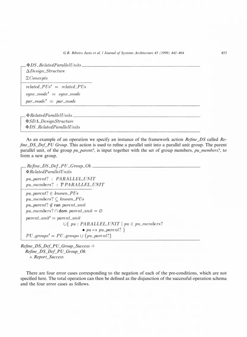
As an example of an operation we specify an instance of the framework action Re®ne_DS called Re-®ne_DS_Def_PU Group. This action is used to re®ne a parallel unit into a parallel unit group. The parentparallel unit, of the group pu_parent?, is input together with the set of group members, pu_members?, toform a new group.
There are four error cases corresponding to the negation of each of the pre-conditions, which are notspeci®ed here. The total operation can then be de®ned as the disjunction of the successful operation schemaand the four error cases as follows.
Re®ne_DS_Def_PU_Group_Success �̂Re®ne_DS_Def_PU_Group_Ok
Ù Report_Success
G.R. Ribeiro Justo et al. / Journal of Systems Architecture 45 (1999) 441±464 453
Re®ne_DS_Def_PU_Group �̂Re®ne_DS_Def_PU_Group_Success
Ú Re®ne_DS_Def_PU_Group_Error1Ú Re®ne_DS_Def_PU_Group_Error2Ú Re®ne_DS_Def_PU_Group_Error3Ú Re®ne_DS_Def_PU_Group_Error4
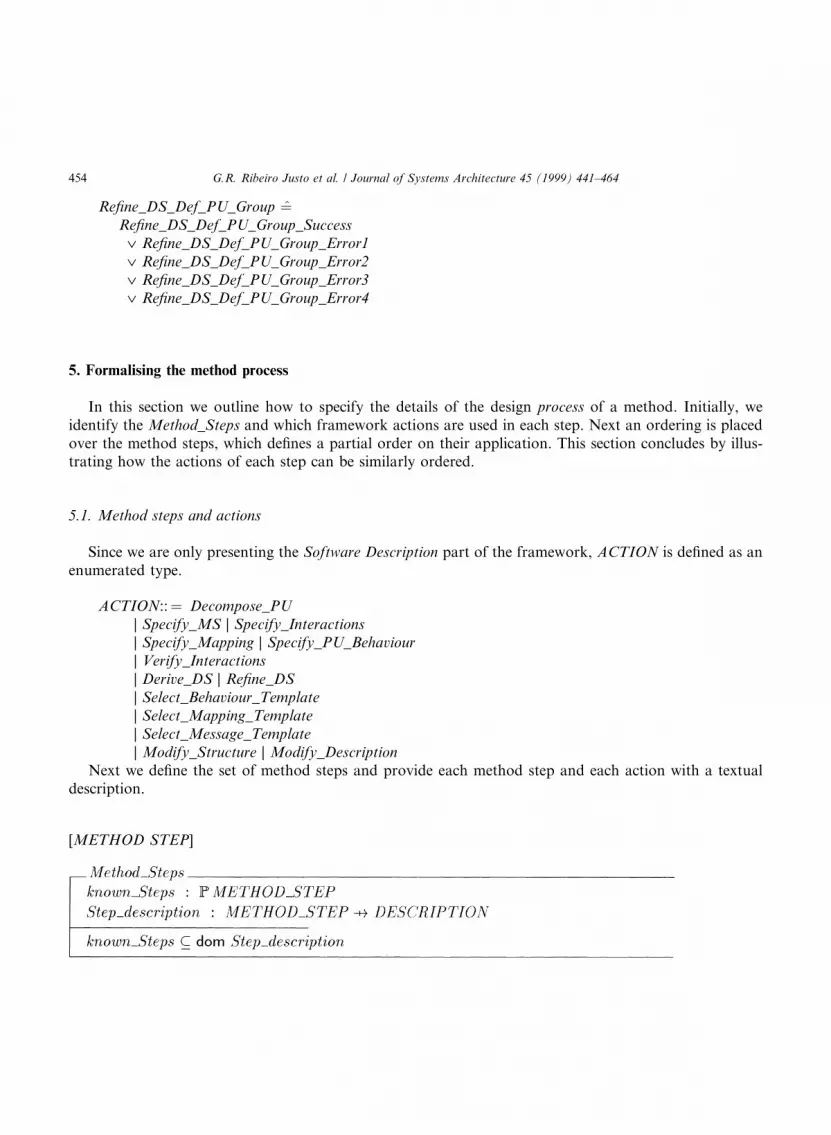
5. Formalising the method process
In this section we outline how to specify the details of the design process of a method. Initially, weidentify the Method_Steps and which framework actions are used in each step. Next an ordering is placedover the method steps, which de®nes a partial order on their application. This section concludes by illus-trating how the actions of each step can be similarly ordered.
5.1. Method steps and actions
Since we are only presenting the Software Description part of the framework, ACTION is de®ned as anenumerated type.
ACTION::� Decompose_PU| Specify_MS | Specify_Interactions| Specify_Mapping | Specify_PU_Behaviour| Verify_Interactions| Derive_DS | Re®ne_DS| Select_Behaviour_Template| Select_Mapping_Template| Select_Message_Template| Modify_Structure | Modify_Description
Next we de®ne the set of method steps and provide each method step and each action with a textualdescription.
[METHOD STEP]
454 G.R. Ribeiro Justo et al. / Journal of Systems Architecture 45 (1999) 441±464

Lastly, we can identify which actions are used by each step. Note, that step_actions is a relation, so thatany action may be used in several method steps.
5.1.1. Ordering of method steps and actionsWe illustrate how the ordering of method steps and actions can be de®ned by using two ordering re-
lations. The ®rst is used to place a strict sequential order over steps and actions and the second to indicatethat steps and actions can be performed in parallel.
The SEQ_ORDER[X] ordering as speci®ed below is non-re¯exive, non-symmetric and transitive. Itmay be desirable to alter these constraints depending on a particular method, the example constraints aremerely illustrative.
SEQ ORDER�X � ��fseq order: X $ X j �seq order \ �id X � � [�^�8x; y: X � x seq order y ) :y seg order x�^�8x; y; z: X � x seq order y ^ y seq order z ) x seq order y�g
As another example, the PAR_ORDER[X] ordering as speci®ed below is re¯exive, symmetric andtransitive.
PAR ORDER�X � ��fpar order: X $ X j�8x; y: X � x par order y�^�8x; y: X � x par order y ) y par order x�^�8x; y; z: X � x par order y ^ y par order z) x par order z�g
G.R. Ribeiro Justo et al. / Journal of Systems Architecture 45 (1999) 441±464 455

The constraints on step ordering are that only known steps can be ordered. The interpretation of befores
s2 is that if s1 beforeS s2 then step s1 must be performed before step s2. The interpretation of overlapS is thatif s1 overlapS s2 then step s1 can be performed in parallel with step s2.
If a particular method requires consistency constraints between the two orderings beforeS and overlapS
then these can be added as below. For example, if two steps must be performed in sequence then theycannot be performed in parallel. Conversely, if two steps can be performed in parallel then they should notbe forced to be performed in sequence.
The actions of each step are ordered independently of other steps. This is achieved by using the sameordering as for steps. The interpretation of the ordering of actions within each step is similar to that of themethod steps. However, the action ordering is indexed by the method step. For example, a1 beforeA (s) a2means that, within step s, action a1 must be performed before action a2.
456 G.R. Ribeiro Justo et al. / Journal of Systems Architecture 45 (1999) 441±464

The schema Step_Action_Ordering is de®ned in an analogous way to Step_Ordering and is not presentedhere.
5.2. Associating concepts, artifacts and actions with steps
To allow the analysis and comparison of di�erent method processes it is necessary to associate withevery step the set of actions it uses. In addition, we need to record those concepts and artifacts which areused by each action. Once this is achieved we can make detailed comparisons between di�erent methodprocesses. Since we are only presenting the software description part of the framework, the de®nitions ofCONCEPT and ARTIFACT are restricted accordingly.
This schema de®nes which artifacts are used, which concepts are used by each of these artifacts, and therepresentation of each artifact.
PARALLEL UNITS::� Process | TaskPARALLELISM MODES::� Shared_Memory | DistributedSYNCHRONISATION MODES::� Synchronous | Asynchronous
| Client_Server | Remote_Procedure_CallCONCEPT::� puáá PARALLEL_UNITS ññ
| paráá PARALLELISM_MODES ññ| syncáá SYNCHRONISATION_MODES ññ
ARTIFACT::� parallel_unit_groups| related_parallel_units| link_synchronisation_modes| pu_synchronisation_modes
G.R. Ribeiro Justo et al. / Journal of Systems Architecture 45 (1999) 441±464 457

This schema de®nes the artifact and set of concepts used by each action. The last predicate ensures thatthe action is well-de®ned. Speci®cally, it asserts that the concepts used by the action are a subset of thoseassociated with the artifact.
Finally, in the Step Descriptions_schema, the concepts and artifacts associated with each step are in-ferred.
The Method Process general state is comprised of the state schemas given above.
458 G.R. Ribeiro Justo et al. / Journal of Systems Architecture 45 (1999) 441±464

This outlines how the process of a design method can be speci®ed. We can now proceed to a discussionof how the framework and its formal speci®cation has been applied to an existing method known asPartitioning, Communication, Agglomeration and Mapping (PCAM).
6. PCAM case study
6.1. Informal description of PCAM
Partitioning, Communication, Agglomeration and Mapping (PCAM) is a methodology proposed byFoster [12] for the design of MIMD algorithms. The main approach is to guide the designer by focusing onimportant ``qualities'' of the design at di�erent stages. In the ®rst two stages (Partitioning and Commu-nication), the designer should focus on concurrency and scalability of the design. In the last two stages(Agglomeration and Mapping), the emphasis is on locality and performance-oriented issues. The meth-odology is essentially sequential, although it allows some backtracking, as described below:
1. Partitioning. In this stage, data and computation are partitioned into small tasks. All characteristics ofthe target hardware are ignored, and the criteria used for decomposition are based entirely on softwarecharacteristics. The neglect of hardware properties means that little attention is paid to performance at thisstage and that the decomposition is likely to be ®ner grained than desired for the ®nal design. The majorissue is to obtain as many disjoint tasks as possible (using domain or functional decomposition). The mainartifact of this stage is therefore a collection of disjoint tasks.
2. Communication. In this stage, the collection of disjoint tasks is re®ned into a directed graph and a setof quanti®ed message lengths. The issue here is to maximise the extent by which communication can occurconcurrently with each other and with computation, and minimise communication overheads. Fostersuggests that it is important that communication costs are balanced between tasks and that the connectivityof each task is kept low. The resulting artifact of this stage is a directed graph of tasks.
3. Agglomeration. Decisions made in the previous stages are revised with respect to performance re-quirements at this stage. More speci®cally, the granularity is adjusted to a chosen class of hardware. Thedescription of this stage comes from the manner of changing the granularity by ``agglomerating'' (com-bining or serialising) tasks into larger agglomerated tasks within which all parallelism is removed. Theprimary consideration is to match the granularity and associated computation/communication ratio to thehardware, whilst retaining su�cient parallel slackness. For the purpose of load balancing, Foster suggeststhat (agglomerated) tasks should all have similar computation and communication costs, and that the
G.R. Ribeiro Justo et al. / Journal of Systems Architecture 45 (1999) 441±464 459

coarser the granularity the more this is important. At the end of this stage, a directed graph of (agglom-erated) tasks is constructed.
4. Mapping. In this stage, the processors on which each (agglomerated) task should executed is speci®ed.One of the main decisions is whether to build an automatic loading balancing routine. Foster suggests thatautomatic load balancing is not usually necessary unless tasks are dynamically created, are of dissimilarsizes or communication patterns are irregular. In simple cases, mapping is done manually by placing tasksthat are able to execute concurrently on di�erent processors, whilst placing those that communicate withfrequency on the same processor. The main artifact of this stage is basically a ``partitioned'' directed graphof (agglomerated) tasks, with respect to the (topology of) processors.
Notice that PCAM does not include explicitly performance engineering activities. In order to make de-cisions about alternatives, however, an understanding of the costs is required. Foster suggests that thisunderstanding can be formalised in mathematical performance models. These models are used to comparethe e�ciency of di�erent algorithms, to evaluate scalability and to identify bottlenecks or other ine�ciencies.
6.2. Classi®cation of PCAM
To derive the formal speci®cation of a methodology using our framework, the methodology developermust classify the methodology according to Table 1. A classi®cation for PCAM is presented in Table 2. Foreach stage of PCAM, we identify the main concepts, artifacts, representations and actions.
During the partitioning, the data and computation are decomposed into Tasks. Tasks correspond to theunits of parallelism and are used to de®ne the collection of tasks which is speci®ed by the artifact De-
Table 2
Stages Components
Concepts Artifacts Representation Action
Software Description
1. Partitioning Task Design_Structure Structural Decompose_PU
2. Communication Communication Structure Message_Structure Structural Specify_Interations
Re®ne_DS
3. Agglomeration Agglomerated Task Design_Structure Structural Re®ne_DS
Modify_Stru/Descr
4. Mapping Topology of Processors Mapping_Description Structural Fromal_Textual Specify_Mapping
Hardware Description Processor_Type Processor_Description Textual Specify-Processor
Network_ Description Structural Specify_Network
Performance Engineering Performance Portability Performance_Models Formal_Textual Specify_Model
Derive_Model
Identify_Bottlenecks
460 G.R. Ribeiro Justo et al. / Journal of Systems Architecture 45 (1999) 441±464

sign_Structure. A Design_Structure usually de®nes a graph (a structural representation as there is no se-mantics associated to the graph) but in this stage the graph has no edges. The Design_Structure is built byapplying the action Decompose_PU.
In the next stage, the Message_Structure is speci®ed by applying the Specify_Interactions action. Thisaction basically adds information to the Design_Structure. The collection of tasks is transformed into adirected graph by applying action Re®ne_DS to the Design_Structure.
The Agglomeration stage focuses basically upon re®ning the Design_Structure by combining tasks. TheDesign_Structure is also updated with information about the tasks granularity (Modify Struc/Descr).
The mapping can be represented in two ways: the topology of processors (network) (Structural) or withmapping formula (Formal_Textual). In either case, the action is Specify_Mapping. Extra information aboutthe hardware description is also registered in a textual representation (Processor_Description) or structuralrepresentation (Network_Description).
As discussed previously, performance engineering in PCAM is based on analytical modelling andconsists of the de®nition of Performance_Models. These models are represented as functions or equations(Formal_Textual). Two actions are usually applied: Specify_Model to create a new model or Derive_Modelto create a model from another one. The models are used not only to understand the design but moreimportantly to identify ine�ciencies and bottlenecks (Identify_Bottlenecks).
6.3. Formal speci®cation of PCAM
The method developer must re®ne the framework concept types. For example, the PCAM conceptswould be de®ned as follows. The only parallel units allowed are tasks, the only parallelism mode is dis-tributed and the synchronisation mode can be only synchronous or asynchronous.
" p: PARALLEL_UNIT � p 2 ran task" p: PARALLELISM � p 2 ran distributed" s: SYNCHRONISATION � p 62 ran rpc
Some of the framework artifacts can be used directly without modi®cation to describe an artifact of aparticular method. In PCAM, for example, the Design Structure de®ned during the Agglomeration stageuses directly the Parallel_Unit_Groups artifact schema.
In other cases the framework artifact schemas need to be re®ned, in order to de®ne method speci®cartifacts. This is achieved by de®ning a new artifact schema which includes schemas from the frameworkand then placing additional constraints as necessary. For example, in PCAM we do not consider paral-lelism and synchronisation modes, and in addition, there are no relations between the parallel units (tasks)during this ®rst stage (Partitioning). This is speci®ed as follows.
G.R. Ribeiro Justo et al. / Journal of Systems Architecture 45 (1999) 441±464 461

A representation in PCAM is either Structural or Formal Textual.
Actions are de®ned either by framework operations with possible extra constraints. The action of ag-glomeration of tasks in PCAM simply reuses the framework operation schema.
Operational constraints can be made in an analogous way to state constraints as shown above inPCAM_Design_Structure.
After classifying the main components of the the method, the method developer should group the ac-tions according to the method design process. In the case of PCAM, the steps (stages) are clearly identi®edand follow a sequential order. They are formally speci®ed using our framework as follows.
Next we must de®ne which actions are used in each step. For example, for the communication step weidentify two actions.
In this method the steps are sequential.
PCAM_Re®ne_DS_Def_PU_Group�Re®ne_DS_Def_PU_Group
462 G.R. Ribeiro Justo et al. / Journal of Systems Architecture 45 (1999) 441±464
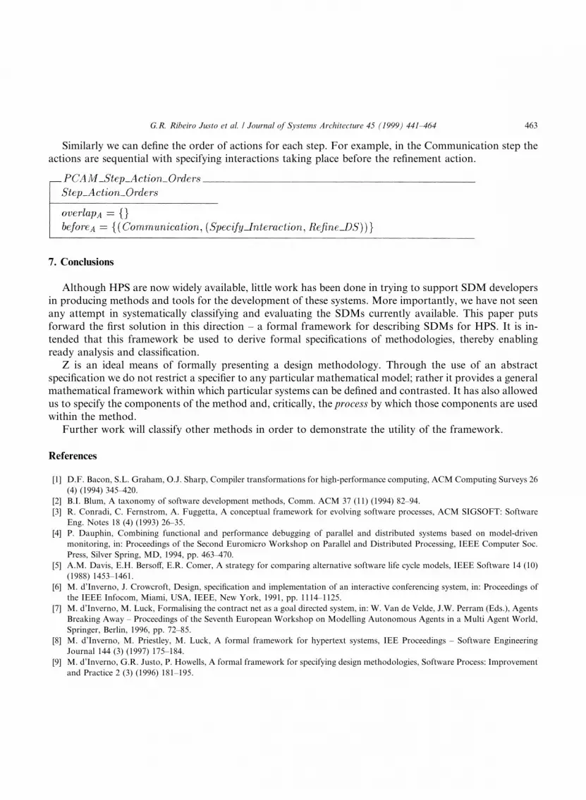
Similarly we can de®ne the order of actions for each step. For example, in the Communication step theactions are sequential with specifying interactions taking place before the re®nement action.
7. Conclusions
Although HPS are now widely available, little work has been done in trying to support SDM developersin producing methods and tools for the development of these systems. More importantly, we have not seenany attempt in systematically classifying and evaluating the SDMs currently available. This paper putsforward the ®rst solution in this direction ± a formal framework for describing SDMs for HPS. It is in-tended that this framework be used to derive formal speci®cations of methodologies, thereby enablingready analysis and classi®cation.
Z is an ideal means of formally presenting a design methodology. Through the use of an abstractspeci®cation we do not restrict a speci®er to any particular mathematical model; rather it provides a generalmathematical framework within which particular systems can be de®ned and contrasted. It has also allowedus to specify the components of the method and, critically, the process by which those components are usedwithin the method.
Further work will classify other methods in order to demonstrate the utility of the framework.
References
[1] D.F. Bacon, S.L. Graham, O.J. Sharp, Compiler transformations for high-performance computing, ACM Computing Surveys 26
(4) (1994) 345±420.
[2] B.I. Blum, A taxonomy of software development methods, Comm. ACM 37 (11) (1994) 82±94.
[3] R. Conradi, C. Fernstrom, A. Fuggetta, A conceptual framework for evolving software processes, ACM SIGSOFT: Software
Eng. Notes 18 (4) (1993) 26±35.
[4] P. Dauphin, Combining functional and performance debugging of parallel and distributed systems based on model-driven
monitoring, in: Proceedings of the Second Euromicro Workshop on Parallel and Distributed Processing, IEEE Computer Soc.
Press, Silver Spring, MD, 1994, pp. 463±470.
[5] A.M. Davis, E.H. Berso�, E.R. Comer, A strategy for comparing alternative software life cycle models, IEEE Software 14 (10)
(1988) 1453±1461.
[6] M. d'Inverno, J. Crowcroft, Design, speci®cation and implementation of an interactive conferencing system, in: Proceedings of
the IEEE Infocom, Miami, USA, IEEE, New York, 1991, pp. 1114±1125.
[7] M. d'Inverno, M. Luck, Formalising the contract net as a goal directed system, in: W. Van de Velde, J.W. Perram (Eds.), Agents
Breaking Away ± Proceedings of the Seventh European Workshop on Modelling Autonomous Agents in a Multi Agent World,
Springer, Berlin, 1996, pp. 72±85.
[8] M. d'Inverno, M. Priestley, M. Luck, A formal framework for hypertext systems, IEE Proceedings ± Software Engineering
Journal 144 (3) (1997) 175±184.
[9] M. d'Inverno, G.R. Justo, P. Howells, A formal framework for specifying design methodologies, Software Process: Improvement
and Practice 2 (3) (1996) 181±195.
G.R. Ribeiro Justo et al. / Journal of Systems Architecture 45 (1999) 441±464 463

[10] M. d'Inverno, M. Luck, Development and application of an agent based framework, in: Proceedings of the IEEE ICFEM'97, the
First IEEE International Conference on Formal Engineering Methods, IEEE, to appear.
[11] A. Ferscha, J. Johnson, N-MAP: A virtual processor discrete event simulation tool for performance prediction in the CAPSE
environment, in: Proceedings of the 28th Annual Hawaii International Conference on Systems Sciences, IEEE Computer Soc.
Press, Silver Spring, MD, 1995, pp. 276±285.
[12] I. Foster, Designing and Building Parallel Programs, Addison-Wesley, Reading, MA, 1995.
[13] D. Harel, On visual formalisms, Comm. ACM 31 (5) (1988) 514±530.
[14] C.A.R. Hoare, Communicating Sequential Processes, Prentice-Hall, Englewood Cli�s, NJ, 1985.
[15] P. Howells, S. Goldsack, B. Quirk, Designing from Modal Action Logic (MAL), Technical report, FOREST Project, Imperial
College of Science & Technology, 1988.
[16] Inmos, Occam2: Toolset User Manual, Part 1, User Guide and Tools, 1991.
[17] L.H. Jamieson, Characterizing parallel algorithms, in: L.H. Jamieson, D. Gannon, R.J. Douglas (Eds.), The Characteristics of
Parallel Algorithms, MIT Press, Cambridge, MA, 1987, pp. 65±100.
[18] I. Jelly, I. Gorton, Software engineering for parallel systems, Information and Software Technology 36 (7) (1994) 379±380.
[19] G.R.R. Justo, A graphical approach to performance-oriented development of parallel programs, in: Proceedings of the Second
International Conference on High Performance Computing, Tata McGraw-Hill, New Delhi, 1995.
[20] G.R.R. Justo, A rigorous method for the constructive design of parallel vand distributed programs, in: Proceedings of the 28th
Annual Hawaii International Conference on Systems Sciences, IEEE Computer Soc. Press, Silver Spring, MD, 1995, pp. 319±328.
[21] M. Luck, M. d'Inverno, A formal framework for agency and autonomy, in: Proceedings of the First International Conference on
Multi-Agent Systems, AAAI Press/MIT Press, San Fransisco, CA, 1995, pp. 254±260.
[22] M. Luck, M. d'Inverno, Structuring a Z speci®cation to provide a formal framework for autonomous agent systems, in: J.P.
Bowen, M.G. Hinchey (Eds.), Proceedings of the Ninth International Conference of Z Users, ZUM'95, Lecture Notes in
Computer Science, Springer, Berlin, 1995, pp. 47±62.
[23] Luqui, Software evolution through rapid prototyping, IEEE Computer 22 (5) (1989) 13±25.
[24] J. Magee, N. Dulay, J. Kramer, A constructive development environment for parallel distributed programs, in: Second
International Workshop on Con®gurable Distributed Systems, IEEE Computer Soc. Press, Silver Spring, MD, 1994.
[25] D. McCraken, M. Jackson, Life cycle concept considered harmful, ACM SIGSOFT: Software Eng. Notes 7 (2) (1982) 29±32.
[26] D.A. Padua, M.J. Wolfe, Advanced compiler optimisations for supercomputers, Comm. ACM 29 (12) (1986) 1184±1201.
[27] I. Sommerville, Software Engineering, Addison-Wesley, Reading, MA, 1989.
[28] X. Song, Systematic integration of design methods, IEEE Software 14 (2) (1995) 107±117.
[29] X. Song, L.J. Osterweil, Towards objective, systematic design-methods comparisons, IEEE Software 9 (1992) 43±53.
[30] J.M. Spivey, The Z Notation: A Reference Manual, 2nd ed., Prentice-Hall, Englewood Cli�s, NJ, 1992.
[31] R. van Rein, An Object Oriented Framework for Mapping Concurrent Applications to Parallel and Distributed Architectures,
M.Sc. Thesis, Dept. of Computer Science, University of Twente, The netherlands, 1994.
[32] G. Wirtz, Modularization, Re-use and testing for parallel message-passing programs, in: Proceedings of the 28th Annual Hawaii
International Conference on Systems Sciences, IEEE Computer Soc. Press, Silver Spring, MD, 1995, pp. 299±308.
464 G.R. Ribeiro Justo et al. / Journal of Systems Architecture 45 (1999) 441±464


