Embed Size (px)
Citation preview
Influence of Deteriorated Suspension Components on ABS Braking
Ondřej Vaculína*, Jiří Svobodab, Michael Valášeka, Pavel Steinbauera
aDepartment of Mechanics, Biomechanics and Mechatronics Faculty of Mechanical Engineering Czech Technical University in Prague Karlovo nám. 13 12135 Prague 2 Czech Republic Tel.:+420 224 357 219 Fax:+420 224 916 709 E-mail:{Ondrej.Vaculin; Michael.Valasek; Pavel.Steinbauer}@fs.cvut.cz bDepartment of Automobiles, Internal Combustion Engines and Railway Vehicles Faculty of Mechanical Engineering Czech Technical University in Prague Technická 4 166 07 Prague 6 Czech Republic Tel.:+420 224 352 498 Fax:+420 224 916 709 E-mail:[email protected]
* Corresponding author.
O. Vaculín et al.
Vehicle ride control depends not only on vehicle design, but also on the condition of the vehicle components and suspension components in particular. Moreover the current vehicles are equipped with many kinds of electronic devices assisting driver in his daily and emergency situations. The devices focused on the active safety should increase the vehicle handling capabilities, e.g. by a targeted intervention of the brakes on the individual wheels. These systems require the correctly functioning wheel suspension. However, the used vehicles do not guarantee the correctly functioning wheel suspension. The worn dampers have less damping capabilities and the worn bushings results in an improper wheel alignment. This paper presents a simulation study of the influence of worn suspension components such as dampers and shocks on the braking capabilities of the vehicle. Stopping distance of vehicles as well as lateral shift is compared for different levels of worn and defective suspension components. Keywords: damper, bushing, suspension aging, stopping distance
Introduction The condition of suspension components is besides the vehicle design very important for the ride control and therefore it is a critical issue for the active safety. Moreover, current vehicles are equipped with many kinds of control devices whose target is increasing the active safety such as ABS and other systems building on the ABS functionality. Particularly for such systems the proper function of suspension is of high importance, [1]. These systems require exact wheel positioning and the best possible contact between tyre and road. The shock absorbers are together with the springs the main force components in the suspension system. The shocks are designed to slow down the suspension movement by dissipating energy. It is well known that most shock absorbers used in the motor vehicle industry are neither linear nor symmetrical, [2, 3]. Rubber bushings can also be found in almost all vehicle suspension systems. The suspension components are connected to each other, to the subframe, and to the body structure via the rubber bushings. They serve to isolate minor vibration, reduce transmitted road shock, operate noise free, and should be very durable. The condition of the shock absorbers in suspension does affect the vehicle handling and driving safety significantly. Since the damping characteristics of the shocks deteriorate gradually over time, the decline in ride control may even pass unnoticed. German TÜV Rheinland Group [4] estimated in 2002 that every eighth personal vehicle in Germany has defective shock absorbers. Their experiments indicate that the defective shock absorbers can cause not only pure handling, but also an increase of the stopping distance from 80 km/h by two to three meters. TÜV SÜD [5] adds that the deteriorated shocks could occur even on two-year-old vehicles. The study performed in Germany on 12 thousand vehicles in 2004 [6] mentions the increase of the stopping distance from 80 km/h by up to 6,1 m and the ratio of the vehicles with unsatisfactory dampers to 14,4 % and among vehicles with more than one hundred thousand kilometers to even 21,4 % (!). The contribution of the already mentioned electronic devices can be due to the worn or even defective shocks reduced. But not only properly working dampers are important for the correct functionality of the active safety devices. Further component of interest from the aging point of view are the rubber bushings in vehicle suspension. The worn bushings have reduced
Vehicle System Dynamics
functionality. Furthermore the clearance in the whole suspension is increased due to the worn damper bushings as well as all bushings in vehicle suspension. It results not only in a reduced vehicle damping, but also in an inaccurate wheel guidance, e.g. in a modified toe angle. There was even observed a shimmy phenomenon of the wheels caused by the clearance in the past. Studies on identification and modelling of rubber bushings are presented e.g. in [7] and [8]. The authors propose both static and dynamic models of the bushings. This paper addresses measurements of the data necessary to identify the elastokinematics for a multibody model. The simulation experiments are focused on the negative influence of the suspension component aging on the vehicle ride control. The models of deteriorated components are varied on a reference 3D vehicle model and a handling benchmark such as emergency braking with antilock brakes is evaluated in order to indicate the influence. The study is based on a lower middle class vehicle, which is designed with front MacPherson strut and torsion beam suspension in the rear. The elastokinematics was measured on the front suspension.
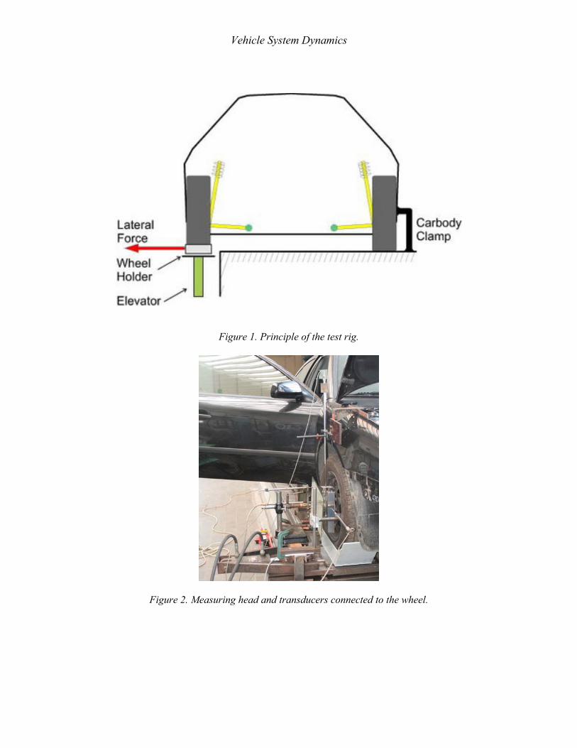
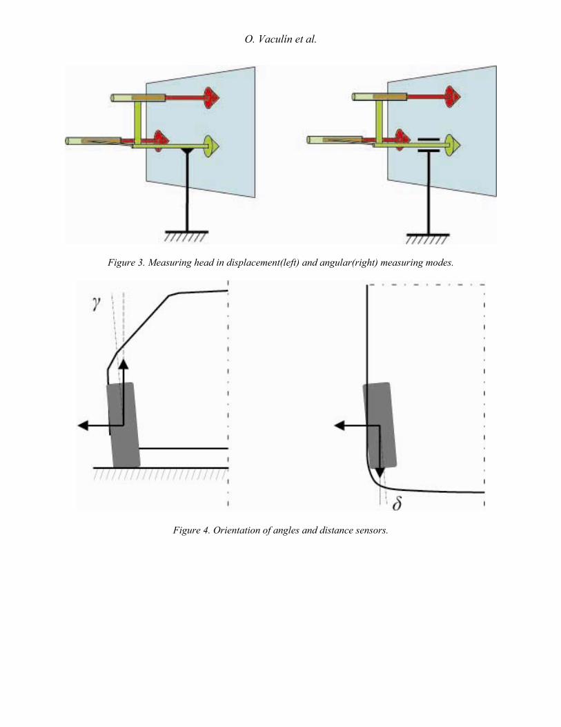
Experimental Test Rig In order to measure the elastokinematic properties of a vehicle suspension, an already existing test rig [9] has been modified. The tests rig allows performing quasistatic measurements of the compliance influence on the wheel motion. The vehicle body is fixed to the frame of the test rig as indicated in Figure 1. The wheel can be vertically positioned e.g. in order to measure the elastokinematics for different suspension deflections. It is placed in a wheel holder and loaded by a hydraulic cylinder with a lateral force. The force between the loading hydraulic cylinder and the wheel holder is measured with an HBM force transducer. Orientation of the positive force is from the wheel outside as indicated in Figure 1. The measuring head (see Figure 2) on a wheel is equipped with two inductive displacement transducers from HBM in lateral direction and measures in two modes; the first mode provides displacement measurements and the second angular measurements as indicated in Figure 3. The transducers are mounted 0,12 m above and behind the wheel center. Further, the third displacement transducer can measure the wheel displacement in vertical direction and the fourth in longitudinal direction. The measured signals are amplified with a measuring amplifier HBM and the analogue signals are then captured with a 16bit A/D converter NI DAQC 6036E in a computer. The hydraulic force generation is performed by a separated control system. During one measurement at least one cycle is performed with both positive and negative forces acting on the wheel. The orientation of camber and toe angles and measured displacement is presented in Figure 4.
Experimental Results
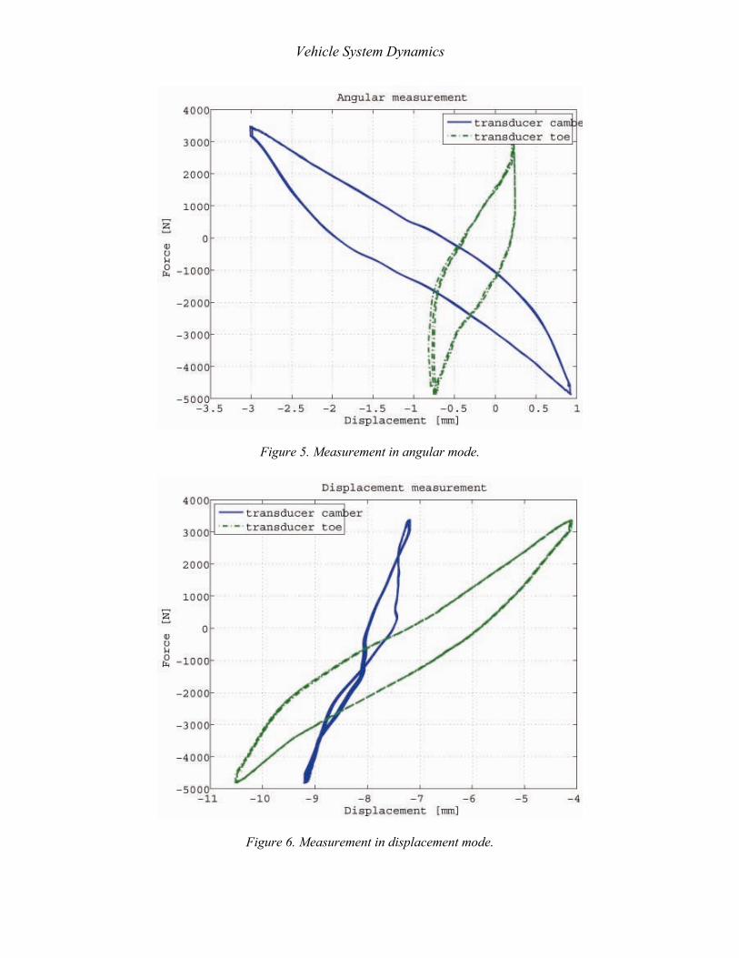
The experimental results are presented in Figures 5 and 6. Figure 5 present the measurements performed in the angular mode of the measuring head. The measured curves represent the relative displacement between the wheel center and the sensor positions, which are 0.12 m above for the
O. Vaculín et al.
wheel center for the camber displacement transducer and 0.12 m behind the wheel center for the toe displacement transducer. The real wheel alignment i.e. the toe and camber angles can be calculated from these displacements. Figure 6 presents the measurements performed in the displacement mode. The measured curves represent the absolute displacement between the test rig frame (inertial system) and the sensor positions, which are the same as in the previous case. The real displacement of the wheel center in lateral direction can be calculated from the displacement and angular measurements together. One can observe significant hysteresis in all presented measurements. The hysteresis is caused e.g. by friction in the system or by the friction between tyre and the tyre holder. In order to eliminate the hysteresis, the measured data are averaged and further the offsets are subtracted, in order to get zero displacements for zero forces. The wheel alignment is calculated from the angular measurements as follows:
,arctan
,arctan
⎟⎠⎞
⎜⎝⎛=
⎟⎟⎠
⎞⎜⎜⎝
⎛=
ls
ls
δ
γ
δ
γ (1)
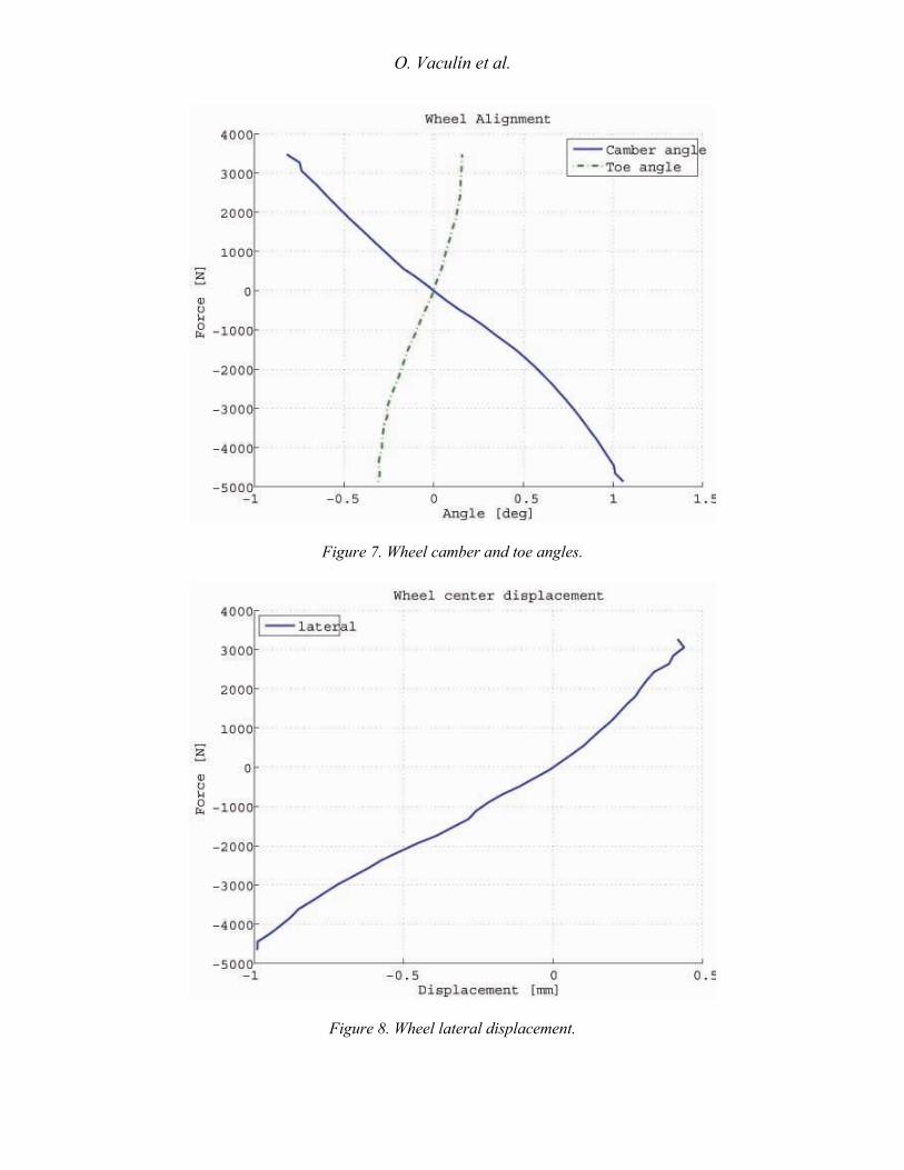
where γ is the camber angle, sγ is the measured displacement from the camber displacement transducer in angular mode, l is the distance of the transducer from the wheel center, i.e. 0.12 m, δ is the toe angle, and sδ is the measured displacement from the toe displacement transducer in the angular mode. The wheel lateral displacement can be calculated from both angular and deflection measurements, e.g.:
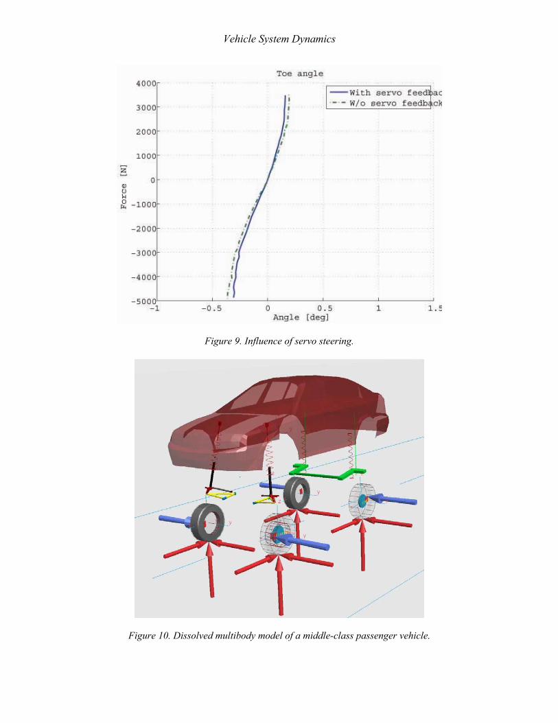
,δδ ssy y −= (2) where y is the lateral displacement syδ is the measured displacement from the toe displacement transducer in the displacement mode and, sδ is the measured displacement from the toe displacement transducer in the angular mode. The lateral displacement can be also calculated from the camber angle in a similar way. The recalculated values of the wheel alignment according to (1) are presented in Figure 7, the wheel lateral displacement calculated from (2) is shown Figure 8. The most important measurements are the wheel alignment (camber and toe angle) and the lateral displacement of the wheel center. These quantities will be further used to describe the model of compliances in the vehicle suspension. Despite the steering wheel was blocked during the measurements some motion of the steering mechanism was observed. It is caused by the hydraulic servo steering feedback control. The feedback is active just when the engine drives the hydraulic pump for the servo steering. It results in the necessity to measure not only with a blocked steering wheel, but also with the running
Vehicle System Dynamics
engine. The difference of the resulting toe angle with the running engine, ie with the servo feedback and with the dead engine is presented in Figure 9.
Simulation Model The simulation study is based on a further development of the vehicle model presented in [1], which describes the same lower middle-class passenger car, which has been also measured on the test rig. The vehicle is designed with front MacPherson strut and torsion beam suspension in the rear. In order to simulate an emergency braking manoeuvre, the brake substructure is included in the model as indicated in Figure 10. The contact between the vehicle and the road is modelled with the tyre substructure consisting of four Pacejka similarity tyres. The front suspension system has been modified, in order to include the bushing and steering compliances. The parameters have been identified with parameter optimisation. The marginal shocks have less than 50 percent damping ability than new shocks. In order to see the trends the characteristics of the shocks are reduced to 50 percent for the worn shocks and even shocks without any functionality are simulated. They represent the worst case - the defective shocks. The worn rubber bushings are represented with stiffness reduced to about one third of the new and a clearance is added to the bushing position. In order to simulate the stopping distance at the emergency braking the vehicle brakes must be equipped with the anti-lock system. The structure of the model of the anti-lock system has four wheel sensors and four modulators (4S4M). Despite a complex implementation of the anti-lock brake algorithm is available [1], these first simulation experiments should indicate the trends, the detailed modelling of the anti-lock brakes is not necessary. Thus a simplified generic model can be used, which takes the information on wheel slip directly from the tyre model. It accelerates the simulation process significantly. The vehicle is modelled as a multibody system including the anti-lock brakes in the SIMPACK simulation package.
Simulation Results In order to study the influence of the deterioration of vehicle components on the vehicle active safety the emergency braking manoeuvre is chosen. The vehicle should stop from the initial velocity 100 km/h and the stopping distance is compared. Two simulation experiments are performed. The first should serve for the evaluation of the deteriorated damper influence, the second of the worn bushings influence. Couple of simulation scenarios has been tested. They includes different road excitations both deterministic (bumps, holes) and stochastic road. This paper presents a deterministic scenario: The first braking manoeuvre begins at the simulation time 1 s with the full braking after passing a 10 meters long and 0.1 meters high bump, which excites the vehicle. The vehicle response on the bump introduces vehicle vibrations and fluctuation of the vertical tyre force. The second manoeuvre simulates a model with deteriorated bushings just on the left hand side. The total simulation time is 5 s in both cases; however the vehicle stops usually earlier. After stopping of the vehicle the simulation is aborted.
O. Vaculín et al.
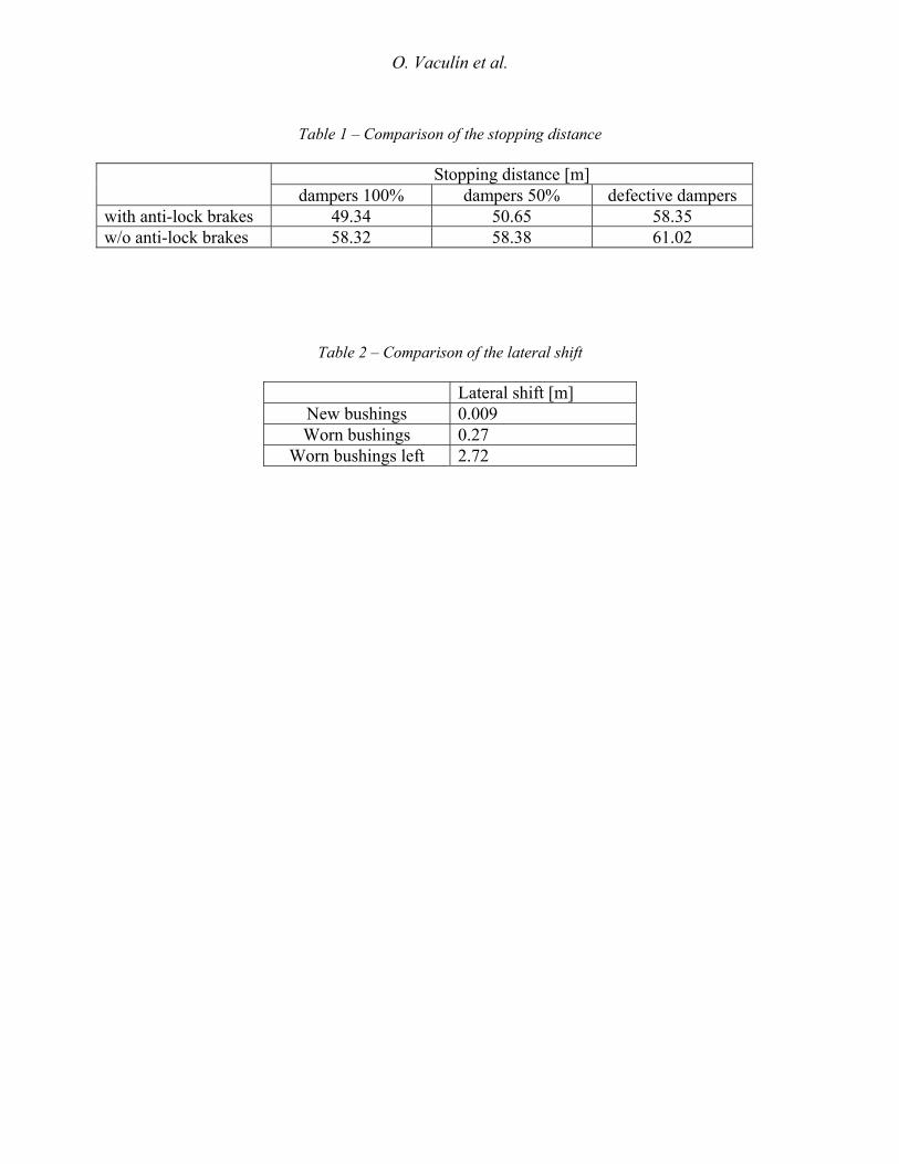
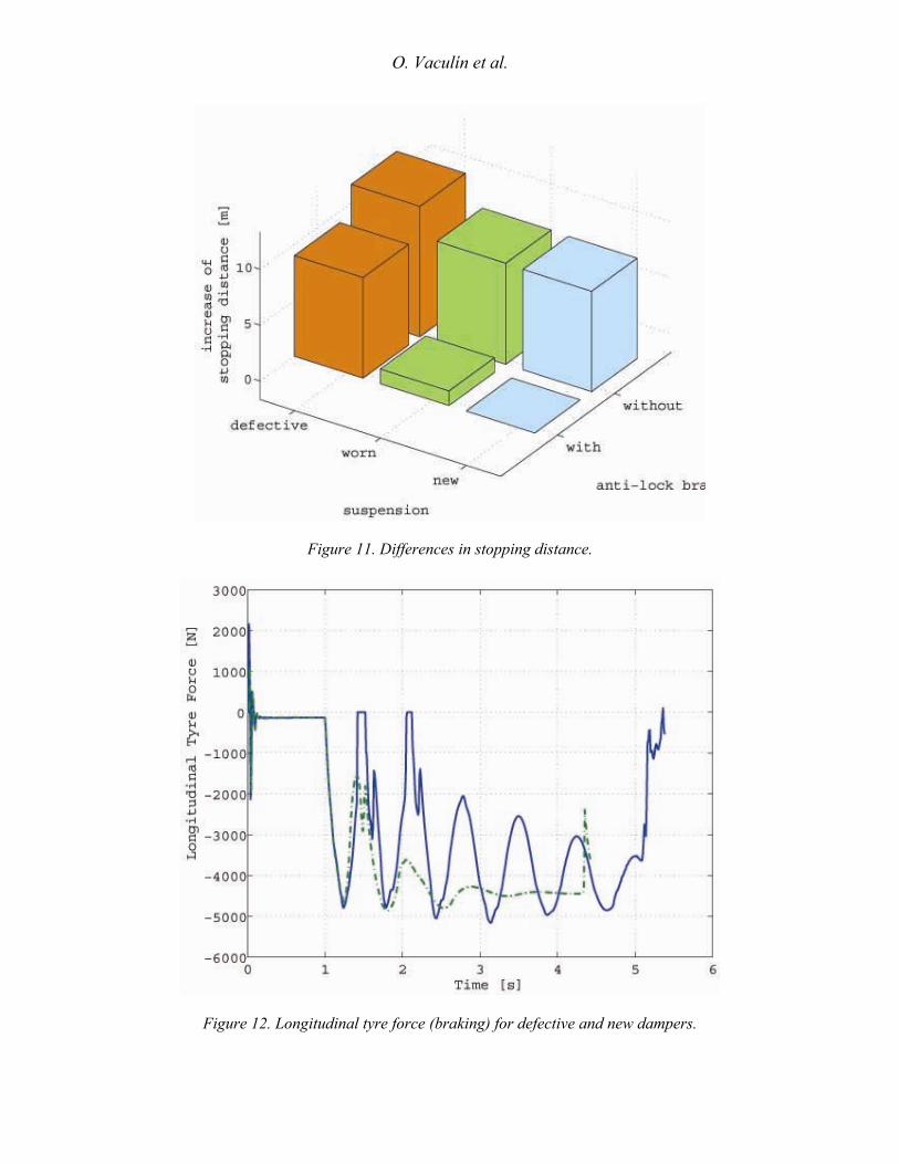
The absolute stopping distance depends on many factors and vehicle parameters, particularly on the friction between the road and the tyre. The friction depends not only on the material and conditions of the road surface, but also on the tyre properties and their conditions. Because of that the simulation results are considered to be relative and should serve to compare the trends and cannot be compared to the other results measuring the stopping distance. Several simulation experiments have been performed in order to study the influence of the worn or defective shocks. The first series is focused on the conditions of the front axle; the rear axle has the original characteristics. The simulation results are summarised in Table 1 and Figure 11. The data presented in Table 1 indicate that the anti-lock brakes are more sensitive on the damper condition. Nevertheless, the vehicle stopping distance without the anti-lock brakes is every time longer, while the wheels are blocked and thus smaller longitudinal forces can be transferred. Figure 12 shows an example of the simulation results. The braking force on a tyre of vehicles with anti-lock brakes with defective and new dampers is presented. From the Figure 12 it is visible that the wheel with defective dampers even looses twice its contact with the road (the longitudinal force is zero). In order to study the influence of the wheel alignment on the ride control, the lateral position of the vehicle after stopping is evaluated. The vehicle with new dampers and bushings is compared with the vehicle with new dampers and worn bushings. Furthermore a vehicle with worn bushings just on the left hand side is added to the comparison. The results are presented in Table 2. As expected, the directional stability of the vehicle is significantly influenced by the worn bushings. Particularly the situation, in which the vehicle has worn bushings just on one side (e.g. after some incorrect reparation) is very dangerous, since the driver has to compensate the significant lateral motion with the steering.
Conclusions This paper presented measurements of compliances in the front suspension performed on the test rig. The suspension compliance was implemented to the vehicle multibody model. A model of a lower middle class passenger vehicle with elastokinematics on the front axle was introduced. In order to study the influence of the worn or even defective shock absorbers and bushings the new parameter sets was defined. This effort resulted in a set of models with the same structure and with different parameters. The simulation experiments indicate that the worn bushings have a significant influence on the results with defective shocks. However, the vehicle lateral stability is influenced by worn bushings even for new dampers. The results indicate that the influence of the worn components on the performance of the vehicle with anti-lock brakes is more significant than without anti-lock brakes, the stopping distance with defective shocks is by meters longer for the presented simulation scenario.
Vehicle System Dynamics
Acknowledgments
The authors acknowledge the kind financial support of the Ministry of Education, Youth and Sports of the Czech Republic by the grant 1M0568.
References [1] Valášek, M., Vaculín, O., Kejval, J. Global Chassis Control: Integration Synergy of Brake and Suspension Control for Active Safety, in: Proceedings of the International Symposium on Advanced Vehicle Control 2004 (AVEC 04), Arnhem, 2004, pp. 495-500. [2] Gillespie, T.D. (1992), Fundamentals of Vehicle Dynamics, SAE International, ISBN 1-56091-199-9.
[3] Milliken, W.F., Milliken, D.L. (1995), Race Car Vehicle Dynamics, SAE International, ISBN 1-56091-526-9.
[4] TÜV Rheinland Group (2002), Fünf Millionen defekte Fahrzeuge in Deutschland unterwegs, http://www.tuv.com/de/news_sicherheitsrisiko_stossdaempfer.html.
[5] TÜV SÜD (2004), Am Boden bleiben: Stoßdämpfer auch bei "Neuen" prüfen, Infodienst auto aktuell 3/2004, http://www.tuev-sued.de/konzern2/presse2/service-_und_magazinthemen2/2001119.
[6] Bielefelder Verlag (2004), TÜV: schlechte Dämpfer - langer Bremsweg, Auto Räder Reifen, http://zeuss.bva-bielefeld.de/gb/2004/branchenthemen/index.php?seite=item&id=76.
[7] Blundell, M.V., (1997), The influence of rubber bush compliance on vehicle suspension movement, Materials and Design 19(1998):29-37.
[8] Roscher, T., Venhovens, P., Lieblig, S. (2002), Identification of Rubber Bushings, In: International Conference on Noise and Vibration Engineering ISMA 2002, Leuven, pp. 1903-1911.
[9] Svoboda J. (jun), Svoboda J. (sen) (1999), Elastokinematika vozu Tatra Beta CL 1,3, technical report, CTU in Prague.
O. Vaculín et al.
Table 1 – Comparison of the stopping distance
Stopping distance [m]
dampers 100% dampers 50% defective dampers with anti-lock brakes 49.34 50.65 58.35 w/o anti-lock brakes 58.32 58.38 61.02
Table 2 – Comparison of the lateral shift
Lateral shift [m] New bushings 0.009 Worn bushings 0.27
Worn bushings left 2.72
Vehicle System Dynamics
Figure 1. Principle of the test rig.
Figure 2. Measuring head and transducers connected to the wheel.
O. Vaculín et al.
Figure 3. Measuring head in displacement(left) and angular(right) measuring modes.
Figure 4. Orientation of angles and distance sensors.
Vehicle System Dynamics
Figure 5. Measurement in angular mode.
Figure 6. Measurement in displacement mode.
O. Vaculín et al.
Figure 7. Wheel camber and toe angles.
Figure 8. Wheel lateral displacement.
Vehicle System Dynamics
Figure 9. Influence of servo steering.
Figure 10. Dissolved multibody model of a middle-class passenger vehicle.
O. Vaculín et al.
Figure 11. Differences in stopping distance.
Figure 12. Longitudinal tyre force (braking) for defective and new dampers.


