Embed Size (px)
Citation preview
International Journal of Research in Engineering and Science (IJRES)
ISSN (Online): 2320-9364, ISSN (Print): 2320-9356
www.ijres.org Volume 09 Issue 12 ǁ 2021 ǁ PP. 41-51
www.ijres.org 41 | Page
“Automatic Braking ActionofVehicles”
DeeptangshuHomray
Dr. D.Y.PatilCollege of Engineering.
Underthe guidance of Mr. Sunil Patil
Abstract
The Automatic Braking System (ABS)* system is an effective intelligentvehicle safety mechanism for avoiding
any possible collision. This studydevelops a national-level road safety evaluation model which is the
intelligentvehicle function. This includes the potential maximum impact and realisticimpact. Road fatalities and
severe injuries trends, the proportion of differentcollisiontypes, the effectiveness ofcollisionavoidance.
----------------------------------------------------------------------------------------------------------------------------- ----------
Date of Submission: 02-12-2021 Date of acceptance: 16-12-2021
----------------------------------------------------------------------------------------------------------------------------- ----------
I. Introduction: The vehicle technology has increased rapidly over the years, especially
inrelationwithaneffectivebrakingsystemtoavoidcollisions.Theintroductionofthe Anti-Lock Braking System
(ABS), Traction Control (TC), Brake Assist andElectronic Stability Control (ESC) functions, Electronic Brake-
ForceDistribution (EBD) system are some of the major developments which theAutomotive Industry has seen
over the years. These systems are used to provideproper control over the vehicle and to minimize the accidents
due touncontrollability ofthevehicles.
In parallel to these developments, various technologies like the SensorBased Braking System has been
developed which are capable of detecting anypossible physical obstacles for example- other vehicles and
pedestrians. Thiscollision avoidance system is capable of sensing any obstruction on its way andassists the
driver to slow down the vehicle automatically and if necessary, thento a halt. The modern sensors are highly
advanced having a quick response timein slowing downthevehiclecompared toa
humanreactiontimewhichresultsin minimizing the road fatalities. But, these systems are very costly
andsophisticated and hence are mostly used by premium luxury manufacturers liketheMercedes-Benz
andVolvo.
II. Objective:
This paper investigates the development and implication of a simple andeconomical Self Braking
System that can be installed in any economical familycar as the majority percentage of the population in India
belongs to the middle-class group and affording such premium cars is not feasible. Safety in economical
vehicles are limited only to the use of Airbags and ESP which mayseem beneficial for the people inside but not
for any pedestrian or a personoutside the vehicle. Hence developing a low cost, easy install system is a needas
35% of accidental deaths in India are caused due to road fatalities andaccidents and out of which about 78% of
the road accidents is due to thecarelessnessandnegligenceofthedriver.
Thisnewsystemisdesignedtoprovideasolutionthisproblem.Sometimesthe drivers are not be able to brake
manually exactly at the required time in asituation of sudden braking action, but the vehicle can still stop
automaticallyusingitssensorstodetecttheobstaclesto avoidanaccident.
“Automatic Braking ActionofVehicles”
www.ijres.org 42 | Page
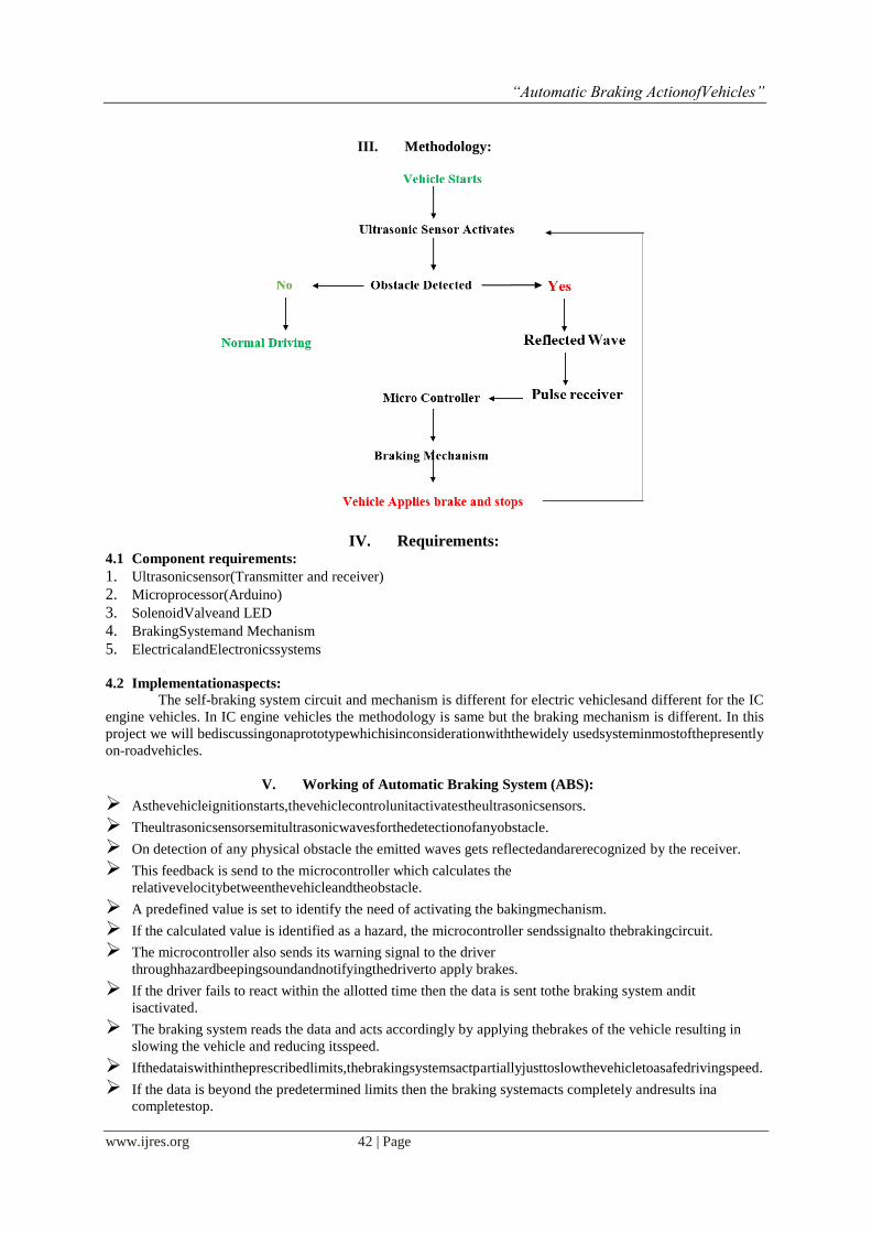
III. Methodology:
IV. Requirements: 4.1 Component requirements:
1. Ultrasonicsensor(Transmitter and receiver)
2. Microprocessor(Arduino)
3. SolenoidValveand LED
4. BrakingSystemand Mechanism
5. ElectricalandElectronicssystems
4.2 Implementationaspects:
The self-braking system circuit and mechanism is different for electric vehiclesand different for the IC
engine vehicles. In IC engine vehicles the methodology is same but the braking mechanism is different. In this
project we will bediscussingonaprototypewhichisinconsiderationwiththewidely usedsysteminmostofthepresently
on-roadvehicles.
V. Working of Automatic Braking System (ABS):
Asthevehicleignitionstarts,thevehiclecontrolunitactivatestheultrasonicsensors.
Theultrasonicsensorsemitultrasonicwavesforthedetectionofanyobstacle.
On detection of any physical obstacle the emitted waves gets reflectedandarerecognized by the receiver.
This feedback is send to the microcontroller which calculates the
relativevelocitybetweenthevehicleandtheobstacle.
A predefined value is set to identify the need of activating the bakingmechanism.
If the calculated value is identified as a hazard, the microcontroller sendssignalto thebrakingcircuit.
The microcontroller also sends its warning signal to the driver
throughhazardbeepingsoundandnotifyingthedriverto apply brakes.
If the driver fails to react within the allotted time then the data is sent tothe braking system andit
isactivated.
The braking system reads the data and acts accordingly by applying thebrakes of the vehicle resulting in
slowing the vehicle and reducing itsspeed.
Ifthedataiswithintheprescribedlimits,thebrakingsystemsactpartiallyjusttoslowthevehicletoasafedrivingspeed.
If the data is beyond the predetermined limits then the braking systemacts completely andresults ina
completestop.
“Automatic Braking ActionofVehicles”
www.ijres.org 43 | Page
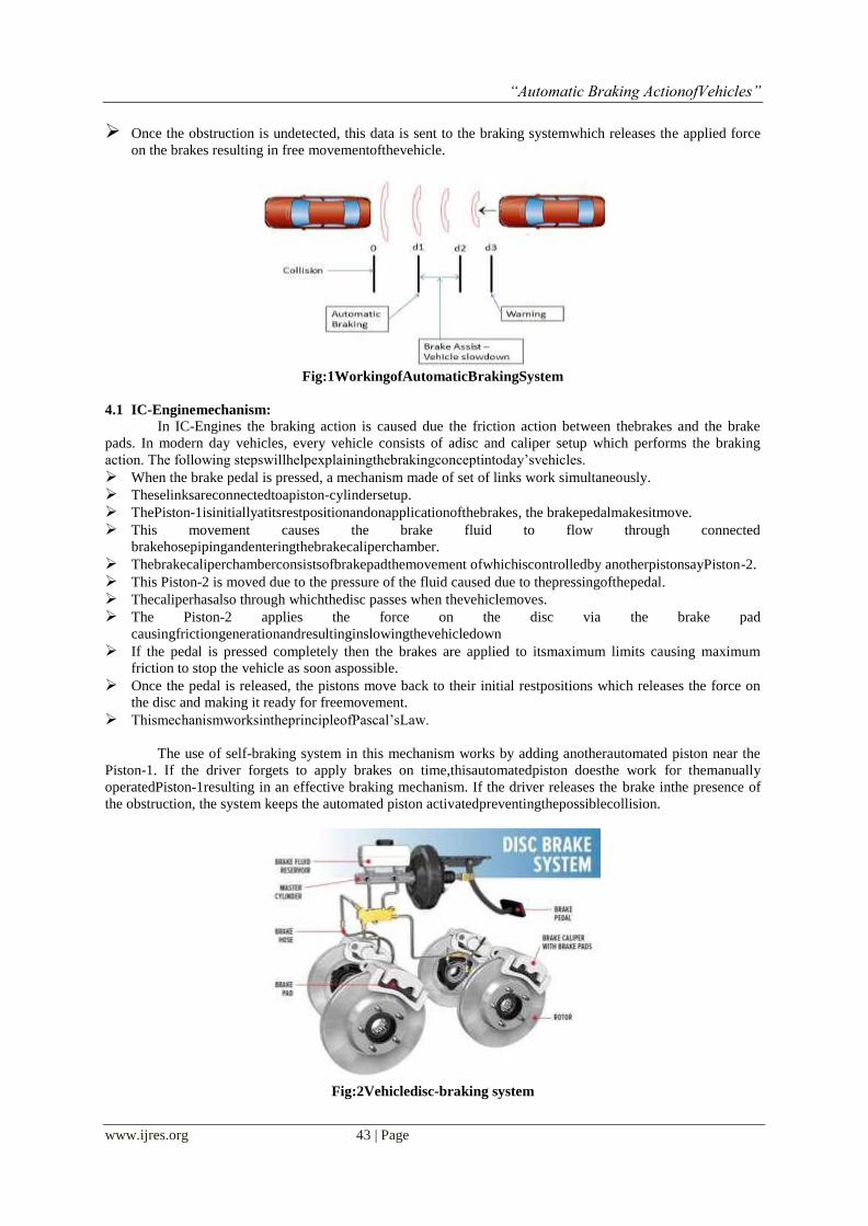
Once the obstruction is undetected, this data is sent to the braking systemwhich releases the applied force
on the brakes resulting in free movementofthevehicle.
Fig:1WorkingofAutomaticBrakingSystem
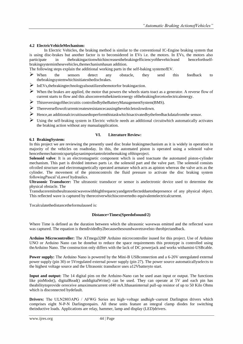
4.1 IC-Enginemechanism:
In IC-Engines the braking action is caused due the friction action between thebrakes and the brake
pads. In modern day vehicles, every vehicle consists of adisc and caliper setup which performs the braking
action. The following stepswillhelpexplainingthebrakingconceptintoday‟svehicles.
When the brake pedal is pressed, a mechanism made of set of links work simultaneously.
Theselinksareconnectedtoapiston-cylindersetup.
ThePiston-1isinitiallyatitsrestpositionandonapplicationofthebrakes, the brakepedalmakesitmove.
This movement causes the brake fluid to flow through connected
brakehosepipingandenteringthebrakecaliperchamber.
Thebrakecaliperchamberconsistsofbrakepadthemovement ofwhichiscontrolledby anotherpistonsayPiston-2.
This Piston-2 is moved due to the pressure of the fluid caused due to thepressingofthepedal.
Thecaliperhasalso through whichthedisc passes when thevehiclemoves.
The Piston-2 applies the force on the disc via the brake pad
causingfrictiongenerationandresultinginslowingthevehicledown
If the pedal is pressed completely then the brakes are applied to itsmaximum limits causing maximum
friction to stop the vehicle as soon aspossible.
Once the pedal is released, the pistons move back to their initial restpositions which releases the force on
the disc and making it ready for freemovement.
ThismechanismworksintheprincipleofPascal‟sLaw.
The use of self-braking system in this mechanism works by adding anotherautomated piston near the
Piston-1. If the driver forgets to apply brakes on time,thisautomatedpiston doesthe work for themanually
operatedPiston-1resulting in an effective braking mechanism. If the driver releases the brake inthe presence of
the obstruction, the system keeps the automated piston activatedpreventingthepossiblecollision.
Fig:2Vehicledisc-braking system
“Automatic Braking ActionofVehicles”
www.ijres.org 44 | Page
4.2 ElectricVehicleMechanism:
In Electric Vehicles, the braking method is similar to the conventional IC-Engine braking system that
is using disc-brakes but another factor is to beconsidered in EVs i.e. the motors. In EVs, the motors also
participate in thebrakingactionwhichincreasesthebrakingefficiencyofthevehicleand henceforthself-
brakingsysteminthesevehicles,themechanismhasan addition.
The following steps explain the additional working parts in the self-baking systemofEV.
When the sensors detect any obstacle, they send this feedback to
thebrakingsystemwhichinitiatesthediscbrakes.
InEVs,thebrakingtechnologyalsoutilizesthemotorfor brakingaction.
When the brakes are applied, the motor that powers the wheels starts toact as a generator. A reverse flow of
current starts to flow and this alsoconvertsthekineticenergy ofthebrakingforcetoelectricalenergy.
Thisreversingofthecircuitis controlledbytheBatteryManagementSystem(BMS).
Thereverseflowofcurrentcreatesresistancecausingthevehicletoslowdown.
Hence,an additionalcircuitisusedtoperformthistaskwhichisactivatedbythefeedbackdatafromthe sensor.
Using the self-braking system in Electric vehicle needs an additional circuitwhich automatically activates
the braking action without any manualapplication.
VI. Literature Review:
6.1 BrakingSystem:
In this project we are reviewing the presently used disc brake brakingmechanism as it is widely in operation in
majority of the vehicles on roadtoday. In this, the automated piston is operated using a solenoid valve
hencethemechatronicspartplaysanimportantroleinthemaking ofthisproject.
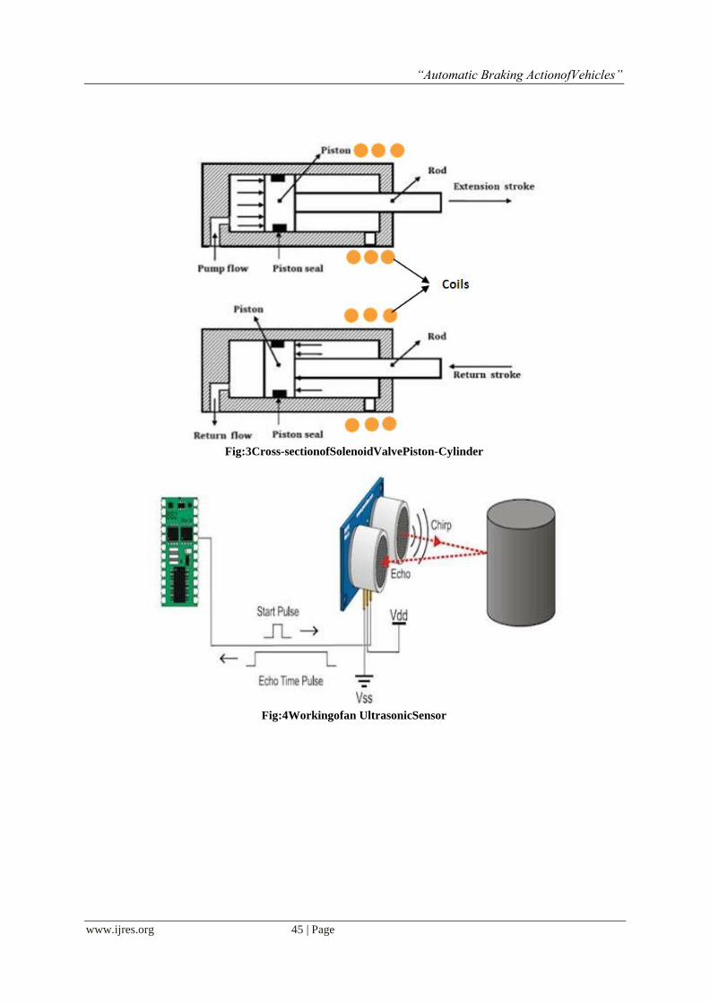
Solenoid valve: It is an electromagnetic component which is used toactuate the automated piston-cylinder
mechanism. This part is divided intotwo parts i.e. the solenoid part and the valve part. The solenoid consists
ofcoiled structure and electromagnetically operated armature which acts as apiston whereas the valve acts as the
cylinder. The movement of the pistoncontrols the fluid pressure to activate the disc braking system
followingPascal‟sLawof hydraulics.
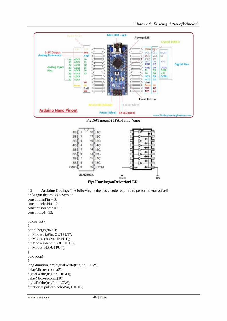
Ultrasonic Transducer: The ultrasonic transducer or sensor is anelectronic device used to determine the
physical obstacle. The
Transduceremitstheultrasonicwaveswithhighfrequencyandgetreflectedduetothepresence of any physical object.
This reflected wave is captured by thereceiverwhichisconvertedto equivalentelectricalcurrent.
Tocalculatethedistancetheformulaused is:
Distance=Timex(Speedofsound/2)
Where Time is defined as the duration between which the ultrasonic wavewas emitted and the reflected wave
was captured. The equation is thendividedby2becausethesoundwavetravelsto theobjectandback.
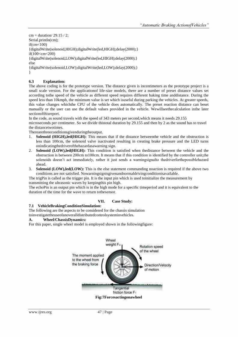
Arduino Microcontroller: The ATmega328P Arduino microcontroller isused for this project. Use of Arduino
UNO or Arduino Nano can be donebut to reduce the space requirements this prototype is controlled using
theArduino Nano. The construction only differs with the lack of DC powerjack and works withamini-USBcable.
Power supply: The Arduino Nano is powered by the Mini-B USBconnection and a 6-20V unregulated external
power supply (pin 30) or 5Vregulated external power supply (pin 27). The power source automaticallyselects to
the highest voltage source and the Ultrasonic transducer uses a12Vbatteryto start.
Input and output: The 14 digital pins on the Arduino-Nano can be used asan input or output. The functions
like pinMode(), digitalRead() anddigitalWrite() can be used. They can operate at 5V and each pin has
theabilitytoprovide orreceive amaximumcurrent of40 mA.Ithasaninternal pull-up resistor of up to 50 Kilo Ohms
which is disconnected bydefault.
Drivers: The ULN2803APG / AFWG Series are high−voltage andhigh−current Darlington drivers which
comprises eight N-P-N Darlingtonpairs. All these units feature an integral clamp diodes for switching
theinductive loads. Applications are relay, hammer, lamp and display (LED)drivers.
“Automatic Braking ActionofVehicles”
www.ijres.org 45 | Page
Fig:3Cross-sectionofSolenoidValvePiston-Cylinder
Fig:4Workingofan UltrasonicSensor
“Automatic Braking ActionofVehicles”
www.ijres.org 46 | Page
Fig:5ATmega328PArduino Nano
Fig:6DarlingtonDriverforLED.
6.2 Arduino Coding: The following is the basic code required to performthetaskofself
brakingin theprototypeversion.
constinttrigPin = 3;
constintechoPin = 2;
constint solenoid = 9;
constint led= 13;
voidsetup()
{
Serial.begin(9600);
pinMode(trigPin, OUTPUT);
pinMode(echoPin, INPUT);
pinMode(solenoid, OUTPUT);
pinMode(led,OUTPUT);
}
void loop()
{
long duration, cm;digitalWrite(trigPin, LOW);
delayMicroseconds(5);
digitalWrite(trigPin, HIGH);
delayMicroseconds(10);
digitalWrite(trigPin, LOW);
duration = pulseIn(echoPin, HIGH);
“Automatic Braking ActionofVehicles”
www.ijres.org 47 | Page
cm = duration/ 29.15 / 2;
Serial.println(cm);
if(cm<100)
{digitalWrite(solenoid,HIGH);digitalWrite(led,HIGH);delay(2000);}
if(100<cm<200)
{digitalWrite(solenoid,LOW);digitalWrite(led,HIGH);delay(2000);}
else
{digitalWrite(solenoid,LOW);digitalWrite(led,LOW);delay(2000);}
}
6.3 Explanation:
The above coding is for the prototype version. The distance given is incentimeters as the prototype project is a
small scale version. For the applicationof life-size models, there are a number of preset distance values set
according tothe speed of the vehicle as different speed requires different baking time anddistance. During the
speed less than 10kmph, the minimum value is set which isuseful during parking the vehicles. At greater speeds,
this value changes whichthe CPU of the vehicle does automatically. The preset reaction distance can beset
manually or the user can use the default values provided in the vehicle. Wewillseethecalculation inthe later
sectionofthisreport.
In the code, as sound travels with the speed of 343 meters per second,which means it needs 29.155
microseconds per centimeter. So we divide thistotal duration by 29.155 and then by 2 as the sound has to travel
the distancetwotimes.
Therearethreeconditionsgivenduringtheoutput.
1. Solenoid (HIGH),led(HIGH): This means that if the distance betweenthe vehicle and the obstruction is
less than 100cm, the solenoid valve isactivated resulting in creating brake pressure and the LED turns
onindicatingthedriverofthehazardasawarning sign.
2. Solenoid (LOW),led(HIGH): This condition is satisfied when thedistance between the vehicle and the
obstruction is between 200cm to100cm. It means that if this condition is identified by the controller unit,the
solenoids doesn‟t act immediately, rather it just sends a warningsignalto thedriverforthepossiblehazard
ahead.
3. Solenoid (LOW),led(LOW): This is the else statement commanding noaction is required if the above two
conditions are not satisfied. Nowarningsignisgivenandnormaldrivingconditionisavailable.
The trigPin is called as the trigger pin. It is the input pin which is used toinitialize the measurement by
transmitting the ultrasonic waves by keepingthis pin high.
The echoPin is an output pin which is in the high mode for a specific timeperiod and it is equivalent to the
duration of the time for the wave to return tothesensor.
VII. Case Study:
7.1 VehicleBrakingConditionSimulation:
The following are the aspects to be considered for the chassis simulation
toinvestigatetheuseofanoveralldistributedcontrolsysteminvehicles.
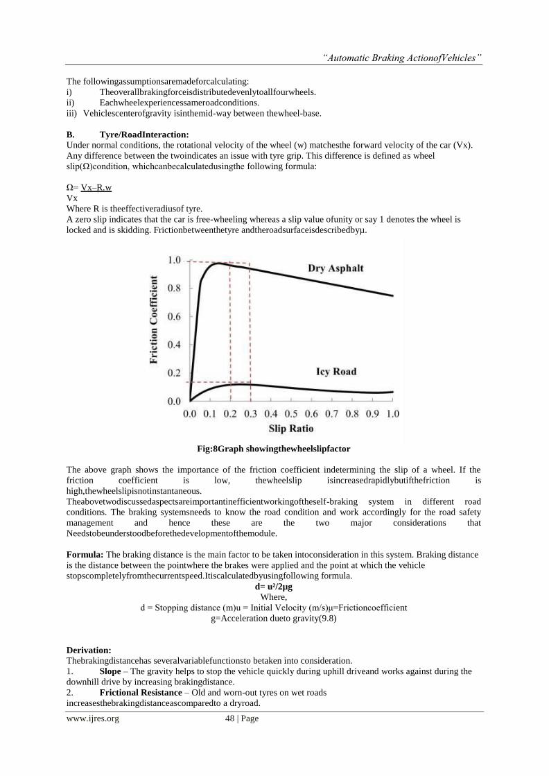
A. Wheel/ChassisDynamics:
For this paper, single wheel model is employed shown in the followingfigure:
Fig:7Forcesactingonawheel
“Automatic Braking ActionofVehicles”
www.ijres.org 48 | Page
The followingassumptionsaremadeforcalculating:
i) Theoverallbrakingforceisdistributedevenlytoallfourwheels.
ii) Eachwheelexperiencessameroadconditions.
iii) Vehiclescenterofgravity isinthemid-way between thewheel-base.
B. Tyre/RoadInteraction:
Under normal conditions, the rotational velocity of the wheel (w) matchesthe forward velocity of the car (Vx).
Any difference between the twoindicates an issue with tyre grip. This difference is defined as wheel
slip(Ω)condition, whichcanbecalculatedusingthe following formula:
Ω= Vx–R.w
Vx
Where R is theeffectiveradiusof tyre.
A zero slip indicates that the car is free-wheeling whereas a slip value ofunity or say 1 denotes the wheel is
locked and is skidding. Frictionbetweenthetyre andtheroadsurfaceisdescribedbyµ.
Fig:8Graph showingthewheelslipfactor
The above graph shows the importance of the friction coefficient indetermining the slip of a wheel. If the
friction coefficient is low, thewheelslip isincreasedrapidlybutifthefriction is
high,thewheelslipisnotinstantaneous.
Theabovetwodiscussedaspectsareimportantinefficientworkingoftheself-braking system in different road
conditions. The braking systemsneeds to know the road condition and work accordingly for the road safety
management and hence these are the two major considerations that
Needstobeunderstoodbeforethedevelopmentofthemodule.
Formula: The braking distance is the main factor to be taken intoconsideration in this system. Braking distance
is the distance between the pointwhere the brakes were applied and the point at which the vehicle
stopscompletelyfromthecurrentspeed.Itiscalculatedbyusingfollowing formula.
d= u²/2µg
Where,
d = Stopping distance (m)u = Initial Velocity (m/s)μ=Frictioncoefficient
g=Acceleration dueto gravity(9.8)
Derivation:
Thebrakingdistancehas severalvariablefunctionsto betaken into consideration.
1. Slope – The gravity helps to stop the vehicle quickly during uphill driveand works against during the
downhill drive by increasing brakingdistance.
2. Frictional Resistance – Old and worn-out tyres on wet roads
increasesthebrakingdistanceascomparedto a dryroad.
“Automatic Braking ActionofVehicles”
www.ijres.org 49 | Page
3. Initial velocity- More the initial velocity, more will be the time requiredtostopthevehicle.
Using basic equation of motion from physics: v² = u² + 2ad, where „v’ is finalvelocity, „u’ is initial velocity, „a’
is acceleration rate and„d‟is distancetraveled.
Asthefinalvelocityafterbrakingis0,theequationcanbewrittenas0=u²+2adfromthe aboveequation,d=-u²/2a.
The deceleration of a vehicle depends on the coefficient of friction and the slopeof the path it is travelling on.
The acceleration due to gravity is multiplied by thegrade of the road which gives us an approximated estimation
of the accelerationcauseddue to the slope ofthe road.
Acceleration rate (a) = Acceleration due to gravity (g) x (friction coefficient (µ) + grade(G))
Thereforethefinalformulabecomes:d =u²/2g(µ+G)
For this project demonstration, grade factor is neglected and hence equationaboveisconsidered.
Calculations: For calculations, the following python coding was adaptedforaccurateand
exactresults.Thiswasonlyforexperimentalpurpose.
>>>print (“Calculatethestoppingdistance”)
>>>speed=int(input(“Entertheinitialspeedinkm/hr:”))
>>>v=speed/ 0.2777778
>>>g=9.8
>>>coef= int(input(“Enterthefriction coefficient:”))
>>>dist= (v*v) /(2*g*coef)
>>>print (“Thedistancetravelledbeforestoppingis”,dist,“metres”)
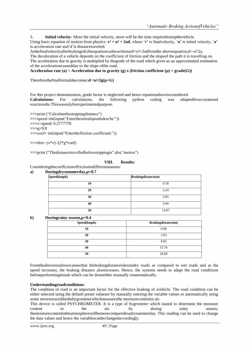
VIII. Results:
Consideringthecoefficientoffrictionindifferentseasons:
a) Duringdrysummerday,µ=0.7
Speed(kmph) Brakingdistance(m)
10 0.58
20 2.24
30 5.05
40 9.00
50 14.07
b) Duringrainy season,µ=0.4
Speed(kmph) Brakingdistance(m)
10 0.98
20 3.93
30 8.85
40 15.74
50 24.60
Fromtheaboveresultswecanseethat thebrakingdistanceislessindry roads as compared to wet roads and as the
speed increases, the braking distance alsoincreases. Hence, the systems needs to adapt the road conditions
beforeperformingitstask which can be doneeither manually orautomatically.
Understandingroadconditions:
The condition of road is an important factor for the effective braking of avehicle. The road condition can be
either selected using the default preset valuesor by manually entering the variable values or automatically using
some moresensorslikethehygrometerwhichmeasuresthe moisturecontentin air.
This device is called PSYCHROMETER. It is a type of hygrometer which isused to determine the moisture
content in the air. As during rainy season,
themoisturecontentintheatmospherewillbemorecomparedtoadrysummerday. This reading can be used to change
the data values and hence the variablescanbechangedaccordingly.
“Automatic Braking ActionofVehicles”
www.ijres.org 50 | Page
Advantages andApplications:
IncreasedRoadSafety
Parkingassist
Automatedguidedvehiclesinindustries
Applicableinself-drivingvehicletechnology
SpeedControl
TrafficDiscipline
Minimizedbackward/reversecollisions
Safetymeasureincheapervehicles
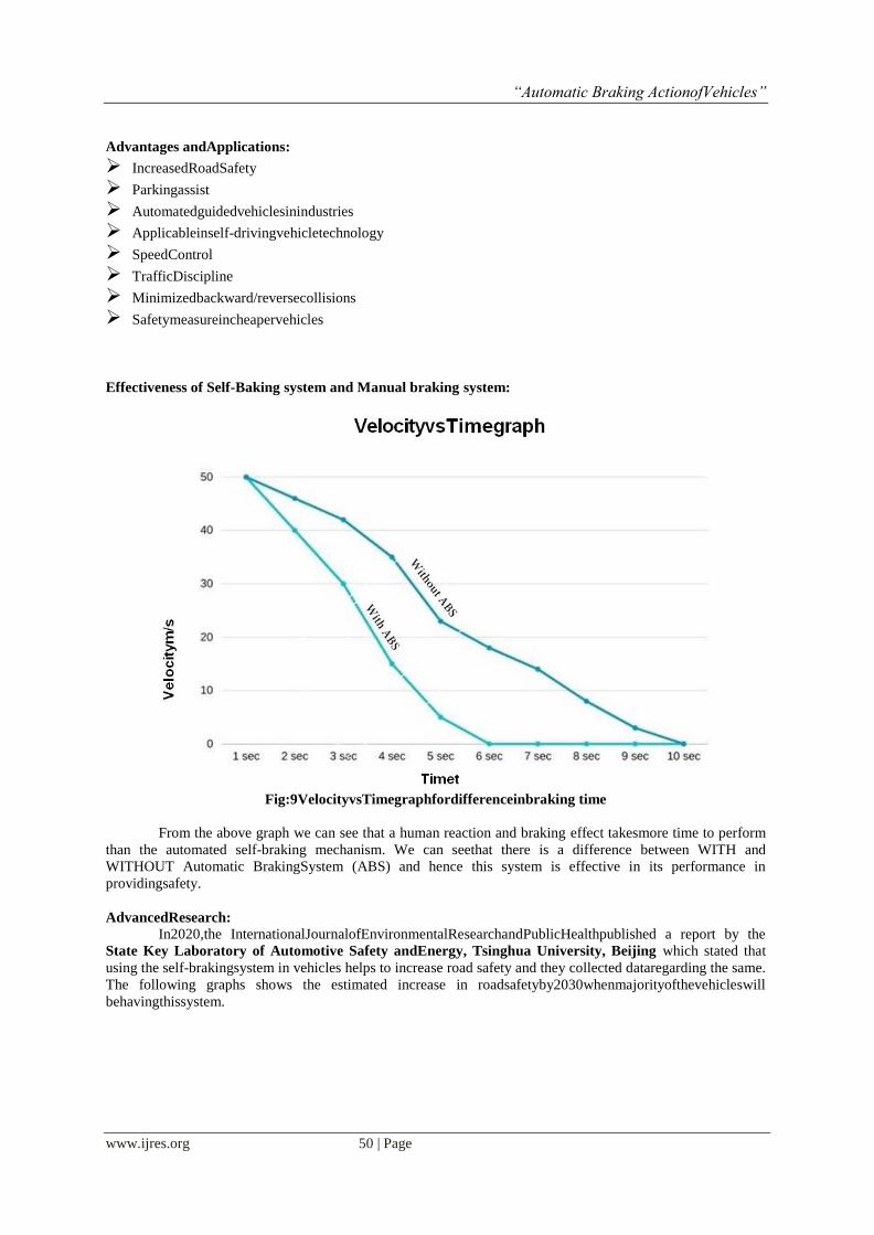
Effectiveness of Self-Baking system and Manual braking system:
Fig:9VelocityvsTimegraphfordifferenceinbraking time
From the above graph we can see that a human reaction and braking effect takesmore time to perform
than the automated self-braking mechanism. We can seethat there is a difference between WITH and
WITHOUT Automatic BrakingSystem (ABS) and hence this system is effective in its performance in
providingsafety.
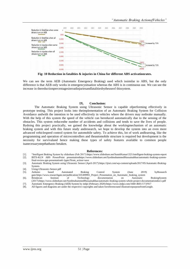
AdvancedResearch:
In2020,the InternationalJournalofEnvironmentalResearchandPublicHealthpublished a report by the
State Key Laboratory of Automotive Safety andEnergy, Tsinghua University, Beijing which stated that
using the self-brakingsystem in vehicles helps to increase road safety and they collected dataregarding the same.
The following graphs shows the estimated increase in roadsafetyby2030whenmajorityofthevehicleswill
behavingthissystem.
“Automatic Braking ActionofVehicles”
www.ijres.org 51 | Page
Fig: 10 Reduction in fatalities & injuries in China for different ABS activationrates.
We can see the term AEB (Automatic Emergency Braking) used which issimilar to ABS, but the only
difference is that AEB only works in emergencysituation whereas the ABS is in continuous use. We can see the
increase in thereductionpercentagesinroadinjuriesandfatalitiesbytheuseof thissystem.
IX. Conclusion:
The Automatic Braking System using Ultrasonic Sensor is capable ofperforming effectively in
prototype testing. This project looks into theimplementation of an Automatic Braking System for Collision
Avoidance andwith the intention to be used effectively in vehicles where the drivers may notbrake manually.
With the help of this system the speed of the vehicle can bereduced automatically due to the sensing of the
obstacles. This system reducesthe number of accidents and collisions and tends to save the lives of people.
Bydoing this project practically, we gained the knowledge about the workingmechanism of an automatic
braking system and with this future study andresearch, we hope to develop the system into an even more
advanced vehiclespeed control system for automobile safety. To achieve this, lot of work andlearning, like the
programming and operation of microcontrollers and theautomobile structure is required but development is the
necessity for survivaland hence making these types of safety features available to common people
isanecessarystepthathasto betaken.
References: [1]. “Intelligent Braking System by slideshare (Feb 2017):https://www.slideshare.net/SumitKumar1321/intelligent-braking-system-report
[2]. BITS-KLN ABS PowerPoint presentationhttps://www.slideshare.net/SyedmuhammedHussainabbas/automatic-braking-system-final-review-ppt-presentation6-1pptx?from_action=save
[3]. Automatic Braking System using Ultrasonic Sensor (April-2017):https://ijisrt.com/wp-content/uploads/2017/05/Automatic-Braking-
System- [4]. Using-Ultrasonic-Sensor.pdf
[5]. Arduino based Automated Braking Control System (June 2019) byResearch
gate:https://www.researchgate.net/publication/335309991_Project_Presentation_on_Automatic_braking_system [6]. Brindavan Institute of Technology documentation on Automatic BrakingSystem
(2017):https://www.slideshare.net/SyedmuhammedHussainabbas/automatic-braking-system-whole-project-documentationdocx-pdf
[7]. Automatic Emergency Braking (AEB) System by mdpi (February 2020):https://www.mdpi.com/1660-4601/17/3/917 [8]. All figures and diagrams are under the respective copyrights and taken forreferenceand illustrativepurposefromGoogle.


