Embed Size (px)
Citation preview

Increasing the transformer ratio at the Argonne wakefield accelerator
C. Jing,1,2 J. G. Power,2 M. Conde,2 W. Liu,2 Z. Yusof,2 A. Kanareykin,1 and W. Gai2
1Euclid Techlabs, LLC, 5900 Harper Road, Solon, Ohio 44139, USA2High Energy Physics Division, Argonne National Laboratory, Argonne, Illinois 60439, USA
(Received 22 November 2010; published 16 February 2011)
The transformer ratio is defined as the ratio of the maximum energy gain of the witness bunch to the
maximum energy loss experienced by the drive bunch (or a bunch within a multidrive bunch train). This
plays an important role in the collinear wakefield acceleration scheme. A high transformer ratio is
desirable since it leads to a higher overall efficiency under similar conditions (e.g. the same beam loading,
the same structure, etc.). One technique to enhance the transformer ratio beyond the ordinary limit of 2 is
to use a ramped bunch train. The first experimental demonstration observed a transformer ratio only
marginally above 2 due to the mismatch between the drive microbunch length and the frequency of the
accelerating structure [C. Jing, A. Kanareykin, J. Power, M. Conde, Z. Yusof, P. Schoessow, and W. Gai,
Phys. Rev. Lett. 98, 144801 (2007)]. Recently, we revisited this experiment with an optimized microbunch
length using a UV laser stacking technique at the Argonne Wakefield Accelerator facility and measured a
transformer ratio of 3.4. Measurements and data analysis from these experiments are presented in detail.
DOI: 10.1103/PhysRevSTAB.14.021302 PACS numbers: 29.20.Ej
I. INTRODUCTION
The transformer ratio (R) in a collinear wakefield accel-erator is defined as the ratio of the maximum energy gainedby the witness bunch to the maximum energy lost by thedrive bunch, or, in the case of a bunch train, the maximumenergy lost by a bunch in the drive train. It is a figure ofmerit that helps to characterize the energy transfer effi-ciency from the drive beam(s) to the trailing witness beam.While R< 2 for longitudinally symmetric drive beams [1],there are several techniques that can achieve R> 2 bybreaking the symmetry of the drive beam. Examples in-clude an asymmetric longitudinal bunch profile [1], or abunch train with asymmetrical time structure (equivalent tofrequency modulation), or a bunch train with asymmetricalcharge structure (equivalent to amplitude modulation) [2].In this paper, the ramped bunch train (RBT) method waschosen because it is the most mature technology due to therelative ease with which it can be implemented in a photo-cathode rf gun.
The principle of the RBT technique is shown in Fig. 1.All bunches in the RBT experience the same maximumdecelerating field (W�
1 ) while the maximum acceleratingfield (Wþ
n ) behind each bunch increases, thus increasingthe transformer ratio ðRn ¼ Wþ
n =W�1 Þ with each succes-
sive bunch. (This is only strictly true for the center of thebunch but we only wish to illustrate the general concepthere.) This is achieved by spacing the bunches at half-integer multiples of the fundamental wavelength andramping up their charge according to the ratio 1:3:5:7.The half-integer spacing places the trailing bunch in theaccelerating phase of the preceding bunch so that thetrailing bunch has its self-wakefield reduced by the accel-erating field of the preceding bunch. The charge of trailing
bunch is increased until the net decelerating field inside thebunch is equal to the preceding bunch.During the first joint Euclid-Argonne experiment [3] a
RBT of two bunches was sent through a 13.625 GHzdielectric-loaded accelerating structure. The enhancementover the single bunch transformer ratio (R1 ¼ Wþ
1 =W�1 ¼
1:75) was measured to be 1.31 implying R2 ¼ Wþ2 =W
�1 ¼
2:3. The reason R is only slightly greater than 2 is because
FIG. 1. The ramped bunch train (RBT) method used to gen-erate the transformer ratio, R > 2. (a) The single bunch wake-field (red) due to a Gaussian drive beam (blue) yieldsR1 ¼ Wþ
1 =W�1 ¼ 2. (b) For this structure, a train of four
Gaussian drive bunches (blue) with an overall triangular pattern(dotted line) is moving to the left. Bunches are separated bydistance d ¼ 2:5� (in general, multiples of 0:5�), where � is thewavelength of the wakefield. The ratio of the charge is 1:3:5:7;the transformer ratio increases as Rn ¼ Wþ
n =W�1 ¼ 2n. This is
only exactly true at the bunch center.
PHYSICAL REVIEW SPECIAL TOPICS - ACCELERATORS AND BEAMS 14, 021302 (2011)
1098-4402=11=14(2)=021302(6) 021302-1 � 2011 American Physical Society

there was a mismatch between the wavelength of thefundamental mode of the wakefield (� ¼ 22 mm) andthe bunch length (�z ¼ 2 mm) produced by the ArgonneWakefield Accelerator (AWA) drive gun [4]. To understandthe reason for the mismatch we briefly revisit the theory ofthe RBT.
The theoretical derivation of the single bunch trans-former ratio (R1) and the transformer ratio along theRBT (Rn) are provided in Ref. [3] and we only recap themain results here. (Note, the analysis we present is for adielectric wakefield accelerator but the conclusion can begeneralized to metallic structures and linear plasma wake-field accelerators.) Numerical simulations [5] reveal thedependence of the peak acceleration gradient (Wþ
1 ) and R1
on the bunch length�z (Fig. 2, taken from Ref. [5]). As onewould expect, the peak accelerating gradient increases as
the bunch length decreases, but the behavior of R1 as afunction of�z=� (where � represents the wavelength of thefundamental accelerating mode) is more complicated thanthe monotonically decreasing behavior ofWþ. R is peakednear �z ¼ �=4, while dropping off towards 1 for bunchlengths on either side of �=4. To understand how�z effectsthe transformer ratio enhancement (Rn:Rn�1) numericalsimulations were performed for the previous experiment[3] [13.625 GHz dielectric-loaded accelerating (DLA)structure, � ¼ 2 mm]. Figure 3(a) shows that there is nosignificant increase for the transformer ratio after thesecond drive bunch.When planning the experiment of this paper we had two
options by which we could improve the �z=� ratio over theprevious experiment where �z=�� 1=11. We could eitherincrease the AWA drive bunch length to match the fre-quency of the existing 13.625 GHz DLA structure orfabricate a new DLA structure with its frequency tuned�� 4�z. We chose to increase the drive bunch length anduse the previously developed and tested 13.625 GHz struc-ture. The AWA drive bunch length was increased with thenewly implemented method based on a UV laser pulsestacking technique [6]. Two crystals are used to stretchthe AWA laser pulse from 8 to �24 ps satisfying the13.65 GHz structure requirements, which extends thebunch length to 2.7 mm rms, slightly less than the idealquarter wavelength value due to rf compression effects inthe photoinjector. The exact bunch length chosen was atrade off between the strength of the wakefield and thesingle bunch transformer ratio. A shorter bunch will excitea larger wakefield, thus making it easier to measure theacceleration of the witness bunch in the experiment, butdecrease the transformer ratio.In Sec. II we discuss the UV laser stacking technique
and laser measurement results. Then we present the detailsof the latest experiment of transformer ratio enhancement
FIG. 3. Transformer ratio for an RBT. R as a function of bunch length and number of bunches for the dielectric wakefield acceleratorused in the experiment. (a) R is enhanced in a 13.625 GHz dielectric-loaded accelerator when driven by a longer bunch length (�z ¼4:5 mm, representative of the old AWA drive gun) compared to a shorter bunch (�z ¼ 2 mm, the current AWA drive gun). (b) For thecurrent AWA facility, �z ¼ 2 mm and R can be increased by choosing the correct structure operating frequency. (Note thatcalculations are based on the single mode wakefield excitation. Shorter bunch lengths may lead to higher order mode excitationinside the structure which will result in slightly different values.)
FIG. 2. Transformer ratio for a single bunch. R and peakaccelerating field, Eþ
z , as a function of the normalized bunchlength (�z=�). The plot is from Ref. [5]. (Single mode operationwas assumed in the calculation.)
C. JING et al. Phys. Rev. ST Accel. Beams 14, 021302 (2011)
021302-2

in Sec. III, including the experimental results and simula-tions. Finally, in Sec. IV we summarize the pros and consof the RBT technique based on experiences gained fromthe two experiments.
II. ELECTRON BUNCH LENGTHENINGTECHNIQUE: UV LASER STACKING
The characteristics of the electron bunch emitted froman rf photocathode gun are directly linked to the distribu-tion of the laser pulse striking the photocathode. Therefore,the ability to control the transverse and temporal (longitu-dinal) laser distribution allows one to create a variety ofuseful electron bunch profiles. Two methods of longitudi-nal pulse shaping have been used for rf photocathode guns.The first, spectral masking, is a frequency domain tech-nique that manipulates light in the Fourier transform planeto produce the flattop pulse shape [7]. If this technique isapplied in the IR, the pulse shape tends not to be preservedafter amplification and harmonic generation. On the otherhand, if the spectral masking is applied in the UV theinsertion losses can be very large. The second, temporalpulse stacking, directly stacks longitudinally Gaussianpulses into an approximate flattop and was previouslyaccomplished using a combination of half-wave platesand beam-splitting cube polarizers [8]. However, this sys-tem is difficult to adjust and align in practice.
In this section, we show how to create the desiredlongitudinally flattop (or elongated Gaussian) laser pulseshape with birefringent crystals [9,10]. The basic idea is touse a series of birefringent crystals to divide the input pulseinto a stack of Gaussian pulses and then recombine them.We begin by describing in detail the specific case of fourstacked Gaussians. A sketch of how to use two birefringentcrystals to create four stacked Gaussian pulses, approxi-mating the flattop, is shown in Fig. 4. The input Gaussianpulse is linearly polarized in the vertical direction while theoptical axis of the first crystal (the 14 mm long crystal inFig. 4) is tilted at a 45� angle relative to the vertical. For�-BBO (BaB2O4, a negative uniaxial crystal), the e ray (orthe component of the input pulse that is parallel to theoptical axis), will move ahead of the o ray (the componentof the input pulse that is perpendicular to the optic axis) bythe amount, �t1, for a crystal length L1. In this case (ne <no, where no and ne are the index of refraction of the o rayand the e ray), the extraordinary axis is the fast axis. The45� orientation creates an equal intensity e ray and o ray.
(Notice that the relative intensity between the two rays canbe controlled by a simple rotation of the optical axis whichleaves open the possibility of triangular shaped pulse gen-eration.) The two (intermediate) pulses emerging from thefirst crystal are now themselves oriented at 45� to thevertical. The next crystal, a 7-mm long crystal, has itsoptical axis oriented in the same direction as the inputpulse; i.e., in the vertical. When the two intermediatepulses pass through the second crystal, they are eachfurther divided into two more pulses separated by �t2with crystal length L2, thus producing the four outputpulses. Streak camera measurement of the temporal laserprofile after the crystals is shown in Fig. 5. It indicates thatthe pulse shape is closer to a ‘‘fat’’ Gaussian than to aflattop pulse due to the imperfections in the technique,including rotation angles and insertion loss variation ofthe crystals. The electron bunch length resulted from thelengthened laser pulse was simulated in PARMELA.Simulation results show the bunch length was increasedfrom 1.5 to 2.7 mm (rms), and this value can be maintainedover a large charge range of bunch charges, 1 to 15 nC.In the example just considered, an input pulse of inten-
sity Io, incident on a pulse stacker of two crystals, willproduce four output pulses of intensity Io=4, less insertionlosses. In general, it is easy to see that N crystals willgenerate 2N output pulses of intensity Io=2N, less insertionlosses. Therefore, the number of pulses in the stack islimited by the transparency of the crystals and the amountof laser energy needed for the application.
III. EXPERIMENT TO ENHANCETRANSFORM RATIO
A single UV laser pulse from the AWA laser system isused to generate both the drive RBT and the witness bunchwhich is used as the main probe to measure the wakefield
FIG. 4. Laser pulse stacking principle used during the experiment.
FIG. 5. Laser pulse stacking characterization. (a) The crystalsetup used during the experiment and (b) streak camera mea-surement of the temporal laser profile after the crystals.
INCREASING THE TRANSFORMER RATIO AT THE . . . Phys. Rev. ST Accel. Beams 14, 021302 (2011)
021302-3

created by the drive RBT. The UV laser pulse is firstdivided by a 90%_10% laser beam splitter with the lowerenergy portion being used to generate the witness beamand the higher portion for the drive RBT. The witness laserpulse is sent directly to the photocathode, thus remainingshort and allowing for more accurate measurement of thedrive wakefield. An optical delay line on a remotely con-trolled translation stage was used the control the witnessbunch delay relative to the drive bunch train. For the driveRBT, an intensity ramped laser pulse train is formed withlaser splitters, mirrors, and neutral density filters (similar tothat in the previous experiment [3]) and transported to thephotocathode of the AWA 1.3 GHz rf photoinjector toproduce the drive RBT with the required charge distribu-tion and intrabunch spacing. The final step is to send thedrive laser pulse train through the laser stacking crystalsbefore the injection to the gun to increase the microbunchlength of each drive bunch.
The experiment of this paper is similar to the previousone (e.g. conducted in the same 15 MeVAWA beam line)but was improved by increasing the drive bunch lengthwhile keeping thewitness bunch short (asmentioned above)and by improving the data-taking methods. In the newsetup, an independently controlled shutter for each bunchof the RBT’s was available. The shutters were remotelycontrolled and incorporated into the frame grabber controls,which allowed us to quickly acquire the energy spectrome-ter data in various combinations of drive bunches and wit-ness bunch. For example, we acquired the witness bunchalone, the witness behind one drive bunch, or the witnessbehind two drive bunches, etc. The charge ratio and bunchspacing are two critical parameters that must be controlledfor the transformer ratio to be enhanced. In the previousexperiment, the charge information was obtained with twointegrating current transformers (ICTs) located before andafter the 13.625 GHz dielectric-loaded accelerator.However, the ICT does not have a fast enough responsetime to distinguish individual bunches in the train (thebunch spacing is �769 ps or �23 cm for the AWA beamline). Thus, while the total charge can be accurately mea-sured using an ICT, the measurement of the charge ratioalong the bunch train is difficult. To overcome this difficultya field probe (a pin probe at the end of coax cable) wasplaced near a ceramic break in the beam line to monitor thefield from the passing electron bunches, allowing us tomeasure the charge ratio along the train. The ceramic DCbreak has a very low Q which allowed the signal from theleading bunch to decay significantly before the signal fromthe following bunch arrives. Using a 16 GHz scopewewereable to measure the charge ratio along the ramped bunchtrain in a single shot (i.e. a single pulse of the accelerator)with reasonable accuracy. Last, a recent upgrade was madeto the AWA low level rf system which reduced the shortterm rf phase jitter down to 1�, which significantly im-proved the stability of the measurements.
A two-drive-bunch RBT was used in the first phase ofthe experiment and a four-bunch RBT in the second phase.The measured charge ratio Q2=Q1 ¼ 2:7 was based onseveral different approaches we will call: (i) ICT average,(ii) pin probe single shot, and (iii) ICT with laser intensitycorrection (ICT signal was normalized with the laser in-tensity which was monitored simultaneously through alaser diode). Ideally, the charge ratio of 3 would achievethe highest transformer ratio but this requires using theideal bunch length (�z=� ¼ 1=4). However, due to theslightly shorter bunch length used (2.7 mm), two longitu-dinal modes were excited in the DLA structure, the TM01
mode at 13.625 GHz and the TM02 mode at 39.4 GHz. Wenote that the amplitude of the second mode is much smallerso it is not a major limitation. This is because the shorterbunch length leads to a higher wakefield, which in turnmakes the energy change of the witness bunch easier todetect. Taking into account the E-field attenuation of thetwo modes (2:5 dB=m for the TM01 and 1:2 dB=m for theTM02 mode) and a charge ratio of 2.7 we chose a spacing of23.07 cm between the two drive bunches to maximize thewakefield transformer ratio; a value of 3.6 was obtained inthe simulation (Fig. 6). The witness bunch location isapproximately 70 cm behind the first drive bunch (Fig. 6)because the fourth drive bunch was 69 cm (3� 23 cm)behind the lead bunch in the four-bunch RBT case.Although the optical delay line of the witness bunch isindependent of the drive RBT, the range over which theremotely controllable fine-tuning range is limited. Thecoarse position of the witness bunch, which is set bymoving a translation stage by hand, remained untouchedduring the entire experiment for convenience.Figure 7 compares the measured wakefield created by
the first drive bunch alone (blue markers) and the seconddrive bunch alone (red markers), to the simulations. Themeasurements were made through monitoring energy
FIG. 6. Simulation of the longitudinal wake potential of thetwo-bunch RBT. Drive bunches are shown in red and the wake isin blue. In the plot, Wþ
d1 and Wþd1þd2 represent maximum accel-
erating fields behind the first and the second drive bunch,respectively, in the two-bunch RBT case. W�
d1 ¼ W�d1þd2 repre-
sent maximum decelerating fields inside the first and the seconddrive bunch, respectively.
C. JING et al. Phys. Rev. ST Accel. Beams 14, 021302 (2011)
021302-4
change of the trailing witness bunch. Note that the singlebunch wake generated by adjacent drive bunches is 180�out of phase due to the half-integer spacing of the RBTmethod. The simulation results plotted in Fig. 7 showreasonably good agreement with the experimental data.
Measurements of the single bunch transformer ratio, R1,were performed first. The maximum decelerating field(Fig. 1, W�
1 ) of a single drive bunch was measured by
comparing its energy at high charge (Q1) to its energy atlow charge (� tens of pC) where the self-wake becamenegligible. There is a linac tank before the 13.625 GHzDLA structure. But the uncertainty of energy change due tothe wakefield of the linac tank is very small compared tothe DLA structure because the linac has a very largeaperture (verified by simulation with ABCI—a wakefieldsimulation code). The measured peak decelerating wake ofthe drive bunch after passing through the 0.4 m longdielectric accelerator was 41 keV=nC (mean) with a stan-dard deviation (�) of 2:5 keV=nC (20 samples). The maxi-mum accelerating field (Fig. 1,W1þ) behind a single drivebunch was measured (with the witness bunch) to be79:7 keV=nC (mean) with � ¼ 8:7 keV=nC. Therefore,the transformer ratio of a single drive bunch, R1, is 1.94.
The first measurements of the transformer ratio enhance-ment (Rn:Rn�1) used a two-bunch RBT. Before measuringthe maximum wakefield in the accelerating phase fromeither the first drive bunch alone (Wþ
d1) or two drive
bunches together (Wþd1þd2), we carefully tuned the bunch
spacing (23.07 cm between two drive bunches) and chargeratio (2.7) to ensure the second drive bunch was losingthe same amount of energy as the lead drive bunch alone(i.e.,W�
d1 ¼ W�d1þd2 in Fig. 6). The maximum wakefield in
the accelerating phase from the first drive bunch wasWþ
d1 ¼ 82:4 keV (� ¼ 15:1 keV), and that from both
drive bunches together was Wd1þd2þ ¼ 144:6 keV
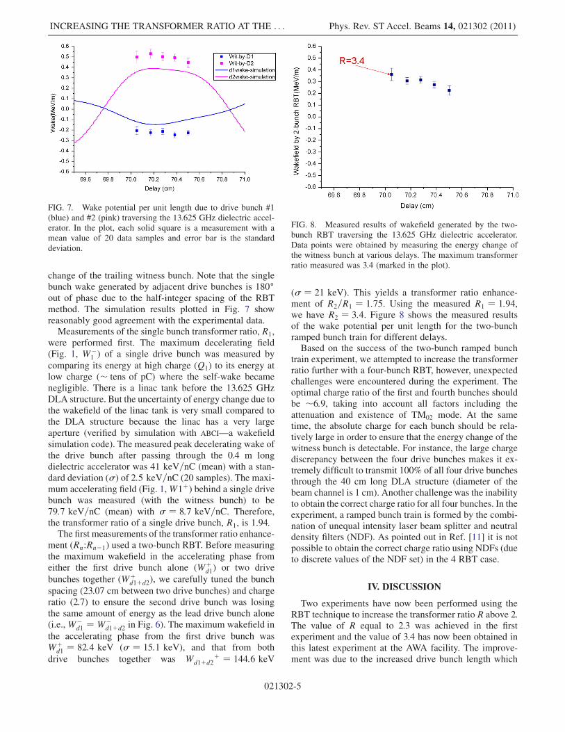
(� ¼ 21 keV). This yields a transformer ratio enhance-ment of R2=R1 ¼ 1:75. Using the measured R1 ¼ 1:94,we have R2 ¼ 3:4. Figure 8 shows the measured resultsof the wake potential per unit length for the two-bunchramped bunch train for different delays.Based on the success of the two-bunch ramped bunch
train experiment, we attempted to increase the transformerratio further with a four-bunch RBT, however, unexpectedchallenges were encountered during the experiment. Theoptimal charge ratio of the first and fourth bunches shouldbe �6:9, taking into account all factors including theattenuation and existence of TM02 mode. At the sametime, the absolute charge for each bunch should be rela-tively large in order to ensure that the energy change of thewitness bunch is detectable. For instance, the large chargediscrepancy between the four drive bunches makes it ex-tremely difficult to transmit 100% of all four drive bunchesthrough the 40 cm long DLA structure (diameter of thebeam channel is 1 cm). Another challenge was the inabilityto obtain the correct charge ratio for all four bunches. In theexperiment, a ramped bunch train is formed by the combi-nation of unequal intensity laser beam splitter and neutraldensity filters (NDF). As pointed out in Ref. [11] it is notpossible to obtain the correct charge ratio using NDFs (dueto discrete values of the NDF set) in the 4 RBT case.
IV. DISCUSSION
Two experiments have now been performed using theRBT technique to increase the transformer ratio R above 2.The value of R equal to 2.3 was achieved in the firstexperiment and the value of 3.4 has now been obtained inthis latest experiment at the AWA facility. The improve-ment was due to the increased drive bunch length which
FIG. 8. Measured results of wakefield generated by the two-bunch RBT traversing the 13.625 GHz dielectric accelerator.Data points were obtained by measuring the energy change ofthe witness bunch at various delays. The maximum transformerratio measured was 3.4 (marked in the plot).
FIG. 7. Wake potential per unit length due to drive bunch #1(blue) and #2 (pink) traversing the 13.625 GHz dielectric accel-erator. In the plot, each solid square is a measurement with amean value of 20 data samples and error bar is the standarddeviation.
INCREASING THE TRANSFORMER RATIO AT THE . . . Phys. Rev. ST Accel. Beams 14, 021302 (2011)
021302-5

improved the match to the rf wavelength of the DLA. Theattempt to extend the experiment to a four-bunch drivetrain was unsuccessful due the practical considerations.The major challenge was the need to precisely controlthe charge ratio. A possible advantage of the RBT schemecompared to other schemes to increase the transformerratio (e.g. a triangular bunch shape) is that laser beammanipulation is easier than electron bunch manipulation.Electron bunch transportation was challenging due to thedramatic difference in charge along the bunch train. Forexample, in the case of four-bunch RBT, the fourth bunchis 7 times higher in charge than the first one. Since allbunches in the train have the same radius but differentcharge, the defocusing due to space charge for each bunchin the train is very different which makes it difficult totransport the bunches through the same wakefield device.A method to compensate for this limitation is to scale theradius of all beams so that all beams have the same chargedensity; this is under development. Another difficulty isthat the deflecting force (dipole modes excited by the off-axial beam) increases along the RBT. A higher energydrive beam would mitigate this to some extent, but theoverall bunch number in the RBT scheme is limited bythese considerations. However, this is not a major draw-back since the transformer ratio is enhanced by factor of2N (where N is the bunch number in the drive train) and avery high R value even with a limited bunch number.
Finally, let us briefly compare the two major techniquesused for transformer ratio enhancement: bunch train vsbunch shaping. The comparison is theoretical since thelater technique has yet to be experimentally demonstrated.For the comparison, we used the same total bunch length L,and only considered single mode operation �0 for simplic-ity. The bunch train distribution has N Gaussian micro-bunches separated by �0=2, which is the minimum spacingrequired by the RBT technique [2], so that L ¼ N�0=2.From Ref. [1], for a triangular bunch with the same length,
L, yields R ¼ �N=2. While from Ref. [3], R for a rampedbunch train increases as R ¼ 2N. In other words, the RBTtechnique increases the transformer ratio slightly fasterthan the bunch shaping method by a factor of 4=�. Ofcourse, in an actual wakefield accelerator design, factorsother than R also matter. But parameter optimization is avery complicated topic and beyond the scope of ourdiscussion.
ACKNOWLEDGMENTS
This work was supported by the Department of Energy,Office of High Energy Physics, under Contract No. W-31-109-ENG-38.
[1] K. L. Bane, P. Chen, and P. B. Wilson, IEEE Trans. Nucl.Sci. 32, 3524 (1985).
[2] V.M. Tsakanov, Nucl. Instrum. Methods Phys. Res., Sect.A 432, 202 (1999).
[3] C. Jing, A. Kanareykin, J. Power, M. Conde, Z. Yusof, P.Schoessow, and W. Gai, Phys. Rev. Lett. 98, 144801(2007).
[4] http://www.hep.anl.gov/awa.[5] J. G. Power and W. Gai, WF-Note-187, http://www
.hep.anl.gov/awa/wfnotes/wf187.pdf.[6] J. G. Power and C. Jing, in Proceedings of the Advanced
Accelerator Concept (AIP 1086), Santa Cruz, CA, 2008(AIP, New York, 2009), pp. 689–695.
[7] A.M. Weiner, Rev. Sci. Instrum. 71, 1929 (2000).[8] S. Zhou, F.W. Wise, and D.G. Ouzounov, Opt. Lett. 32,
871 (2007).[9] J. Li, R. Tikhoplava, and A. C. Melissinosa, Nucl. Instrum.
Methods Phys. Res., Sect. A 564, 57 (2006).[10] B. Dromey, M. Zepf, M. Landreman, K. O’Keeffe, T.
Robinson, and S.M. Hooker, Appl. Opt. 46, 5142 (2007).[11] J. G. Power, WF-Note-215, http://www.hep.anl.gov/awa/
wfnotes/wf215.pdf.
C. JING et al. Phys. Rev. ST Accel. Beams 14, 021302 (2011)
021302-6