Embed Size (px)
Citation preview

Operator’s Manual
Dual Maverick ® 450 (AU)
Register your machine: www.lincolnelectric.com/register
Authorized Service and Distributor Locator: www.lincolnelectric.com/locator
IM10537 | Issue D ate May-21 © Lincoln Global, Inc. All Rights Reserved.
For use with machines having Code Numbers:
12881
Need Help? Call 1.888.935.3877 to talk to a Service Representative
Hours of Operation: 8:00 AM to 6:00 PM (ET) Mon. thru Fri.
After hours? Use “Ask the Experts” at lincolnelectric.comA Lincoln Service Representative will contact you no later than the following business day.
For Service outside the USA: Email: [email protected]
Save for future reference
Date Purchased
Code: (ex: 10859)
Serial: (ex: U1060512345)

THANK YOU FOR SELECTING A QUALITY PRODUCT BY LINCOLN ELEC TRIC.
PLEASE EXAMINE CARTON AND EQUIPMENT FORDAMAGE IMMEDIATELY
When this equipment is shipped, title passes to the purchaserupon receipt by the carrier. Consequently, claims for materialdamaged in shipment must be made by the purchaser against thetransportation company at the time the shipment is received.
SAFETY DEPENDS ON YOU
Lincoln arc welding and cutting equipment is designed and builtwith safety in mind. However, your overall safety can be increasedby proper installation ... and thoughtful operation on your part. DO NOT INSTALL, OPERATE OR REPAIR THIS EQUIPMENT WITHOUT READING THIS MANUAL AND THE SAFETYPRECAUTIONS CONTAINED THROUGHOUT. And, most importantly,think before you act and be careful.
This statement appears where the information must be followedexactly to avoid serious personal injury or loss of life.
This statement appears where the information must be followedto avoid minor personal injury or damage to this equipment.
KEEP YOUR HEAD OUT OF THE FUMES.
DON’T get too close to the arc.Use corrective lenses if necessaryto stay a reasonable distanceaway from the arc.
READ and obey the Safety DataSheet (SDS) and the warning labelthat appears on all containers ofwelding materials.
USE ENOUGH VENTILATION orexhaust at the arc, or both, tokeep the fumes and gases from your breathing zone and the general area.
IN A LARGE ROOM OR OUTDOORS, natural ventilation may beadequate if you keep your head out of the fumes (See below).
USE NATURAL DRAFTS or fans to keep the fumes away from your face.
If you de velop unusual symptoms, see your supervisor. Perhaps the welding atmosphere and ventilation system should be checked.
WEAR CORRECT EYE, EAR & BODY PROTECTION
PROTECT your eyes and face with welding helmetproperly fitted and with proper grade of filter plate(See ANSI Z49.1).
PROTECT your body from welding spatter and arcflash with protective clothing including woolenclothing, flame-proof apron and gloves, leatherleggings, and high boots.
PROTECT others from splatter, flash, and glarewith protective screens or barriers.
IN SOME AREAS, protection from noise may be appropriate.
BE SURE protective equipment is in good condition.
Also, wear safety glasses in work areaAT ALL TIMES.
SPECIAL SITUATIONS
DO NOT WELD OR CUT containers or materials which previouslyhad been in contact with hazardous substances unless they areproperly cleaned. This is extremely dangerous.
DO NOT WELD OR CUT painted or plated parts unless specialprecautions with ventilation have been taken. They can releasehighly toxic fumes or gases.
Additional precautionary measures
PROTECT compressed gas cylinders from excessive heat,mechanical shocks, and arcs; fasten cylinders so they cannot fall.
BE SURE cylinders are never grounded or part of an electrical circuit.
REMOVE all potential fire hazards from welding area.
ALWAYS HAVE FIRE FIGHTING EQUIPMENT READY FORIMMEDIATE USE AND KNOW HOW TO USE IT.
WARNING
CAUTION
Safety 01 of 04 - 5/16/2018

SECTION A:WARNINGS
CALIFORNIA PROPOSITION 65 WARNINGS
WARNING: Breathing diesel engine exhaustexposes you to chemicals known to the Stateof California to cause cancer and birth defects,
or other reproductive harm.• Always start and operate the engine in a
well-ventilated area.• If in an exposed area, vent the exhaust to the outside.• Do not modify or tamper with the exhaust system. • Do not idle the engine except as necessary.For more information go to www.P65 warnings.ca.gov/diesel
WARNING: This product, when used for welding or
cutting, produces fumes or gases which contain
chemicals known to the State of California to cause
birth defects and, in some cases, cancer. (California
Health & Safety Code § 25249.5 et seq.)
WARNING: Cancer and Reproductive Harm
www.P65warnings.ca.gov
ARC WELDING CAN BE HAZARDOUS. PROTECTYOURSELF AND OTHERS FROM POSSIBLE SERIOUSINJURY OR DEATH. KEEP CHILDREN AWAY. PACEMAKER WEARERS SHOULD CONSULT WITHTHEIR DOCTOR BEFORE OPERATING.
Read and understand the following safety highlights. Foradditional safety information, it is strongly recommended that you purchase a copy of “Safety in Welding & Cutting - ANSI Standard Z49.1” from the American Welding Society, P.O. Box 351040, Miami, Florida 33135 or CSA Standard W117.2-1974. A Free copy of “Arc Welding Safety” booklet E205 is available from the Lincoln Electric Company, 22801 St. Clair Avenue, Cleveland, Ohio 44117-1199.
BE SURE THAT ALL INSTALLATION, OPERATION,MAINTENANCE AND REPAIR PROCEDURES AREPERFORMED ONLY BY QUALIFIED INDIVIDUALS.
FOR ENGINE POWEREDEQUIPMENT.
1.a. Turn the engine off before troubleshootingand maintenance work unless themaintenance work requires it to be running.
1.b. Operate engines in open, well-ventilated areas or vent the engineexhaust fumes outdoors.
1.c. Do not add the fuel near an open flame weldingarc or when the engine is running. Stop theengine and allow it to cool before refueling toprevent spilled fuel from vaporizing on contact
with hot engine parts and igniting. Do not spill fuel when fillingtank. If fuel is spilled, wipe it up and do not start engine untilfumes have been eliminated.
1.d. Keep all equipment safety guards, covers and devices in position and in good repair.Keep hands, hair, clothing and tools away from V-belts, gears, fans and all other moving parts when starting, operating orrepairing equipment.
1.e. In some cases it may be necessary to remove safety guards toperform required maintenance. Remove guards only whennecessary and replace them when the maintenance requiringtheir removal is complete. Always use the greatest care whenworking near moving parts.
1.f. Do not put your hands near the engine fan. Do not attempt tooverride the governor or idler by pushing on the throttle controlrods while the engine is running.
1.g. To prevent accidentally starting gasoline engines while turningthe engine or welding generator during maintenance work,disconnect the spark plug wires, distributor cap or magneto wireas appropriate.
1.h. To avoid scalding, do not remove the radiatorpressure cap when the engine is hot.
ELECTRIC ANDMAGNETIC FIELDS MAYBE DANGEROUS
2.a. Electric current flowing through any conductorcauses localized Electric and Magnetic Fields (EMF). Welding current creates EMF fields around welding cables and welding machines
2.b. EMF fields may interfere with some pacemakers, and welders having a pacemaker should consult their physicianbefore welding.
2.c. Exposure to EMF fields in welding may have other health effectswhich are now not known.
2.d. All welders should use the following procedures in order tominimize exposure to EMF fields from the welding circuit:
2.d.1. Route the electrode and work cables together - Securethem with tape when possible.
2.d.2. Never coil the electrode lead around your body.
2.d.3. Do not place your body between the electrode and workcables. If the electrode cable is on your right side, thework cable should also be on your right side.
2.d.4. Connect the work cable to the workpiece as close as pos-sible to the area being welded.
2.d.5. Do not work next to welding power source.
SAFETY
Safety 02 of 04 - 5/16/2018

ELECTRIC SHOCK CAN KILL.
3.a. The electrode and work (or ground) circuits areelectrically “hot” when the welder is on. Donot touch these “hot” parts with your bare skin or wet clothing.Wear dry, hole-free gloves to insulate hands.
3.b. Insulate yourself from work and ground using dry insulation.Make certain the insulation is large enough to cover your full areaof physical contact with work and ground.
In addition to the normal safety precautions, if
welding must be performed under electrically
hazardous conditions (in damp locations or while
wearing wet clothing; on metal structures such as
floors, gratings or scaffolds; when in cramped
positions such as sitting, kneeling or lying, if there
is a high risk of unavoidable or accidental contact
with the workpiece or ground) use the following
equipment:
• Semiautomatic DC Constant Voltage (Wire) Welder.
• DC Manual (Stick) Welder.
• AC Welder with Reduced Voltage Control.
3.c. In semiautomatic or automatic wire welding, the electrode,electrode reel, welding head, nozzle or semiautomatic weldinggun are also electrically “hot”.
3.d. Always be sure the work cable makes a good electricalconnection with the metal being welded. The connection shouldbe as close as possible to the area being welded.
3.e. Ground the work or metal to be welded to a good electrical (earth)ground.
3.f. Maintain the electrode holder, work clamp, welding cable andwelding machine in good, safe operating condition. Replacedamaged insulation.
3.g. Never dip the electrode in water for cooling.
3.h. Never simultaneously touch electrically “hot” parts of electrodeholders connected to two welders because voltage between thetwo can be the total of the open circuit voltage of bothwelders.
3.i. When working above floor level, use a safety belt to protectyourself from a fall should you get a shock.
3.j. Also see It ems 6.c. and 8.
ARC RAYS CAN BURN.
4.a. Use a shield with the proper filter and cover plates to protect youreyes from sparks and the rays of the arc when welding orobserving open arc welding. Headshield and filter lens shouldconform to ANSI Z87. I standards.
4.b. Use suitable clothing made from durable flame-resistant materialto protect your skin and that of your helpers from the arc rays.
4.c. Protect other nearby personnel with suitable, non-flammablescreening and/or warn them not to watch the arc nor exposethemselves to the arc rays or to hot spatter or metal.
FUMES AND GASESCAN BE DANGEROUS.
5.a. Welding may produce fumes and gaseshazardous to health. Avoid breathing thesefumes and gases. When welding, keep your head out of the fume.Use enough ventilation and/or exhaust at the arc to keep fumesand gases away from the breathing zone. When welding
hardfacing (see instructions on container or SDS)
or on lead or cadmium plated steel and other
metals or coatings which produce highly toxic
fumes, keep exposure as low as possible and
within applicable OSHA PEL and ACGIH TLV limits
using local exhaust or mechanical ventilation
unless exposure assessments indicate otherwise.
In confined spaces or in some circumstances,
outdoors, a respirator may also be required.
Additional precautions are also required when
welding
on galvanized steel.
5. b. The operation of welding fume control equipment is affected byvarious factors including proper use and positioning of theequipment, maintenance of the equipment and the specificwelding procedure and application involved. Worker exposurelevel should be checked upon installation and periodicallythereafter to be certain it is within applicable OSHA PEL andACGIH TLV limits.
5.c. Do not weld in locations near chlorinated hydrocarbon vaporscoming from degreasing, cleaning or spraying operations. Theheat and rays of the arc can react with solvent vapors to formphosgene, a highly toxic gas, and other irritating products.
5.d. Shielding gases used for arc welding can displace air and causeinjury or death. Always use enough ventilation, especially inconfined areas, to insure breathing air is safe.
5.e. Read and understand the manufacturer’s instructions for thisequipment and the consumables to be used, including theSafety Data Sheet (SDS) and follow your employer’s safetypractices. SDS forms are available from your weldingdistributor or from the manufacturer.
5.f. Also see item 1.b.
SAFETY
Safety 03 of 04 - 5/16/2018

WELDING AND CUTTINGSPARKS CAN CAUSEFIRE OR EXPLOSION.
6.a. Remove fire hazards from the welding area. Ifthis is not possible, cover them to prevent the welding sparksfrom starting a fire. Remember that welding sparks and hotmaterials from welding can easily go through small cracks andopenings to adjacent areas. Avoid welding near hydraulic lines.Have a fire extinguisher readily available.
6.b. Where compressed gases are to be used at the job site, specialprecautions should be used to prevent hazardous situations.Refer to “Safety in Welding and Cutting” (ANSI Standard Z49.1)and the operating information for the equipment being used.
6.c. When not welding, make certain no part of the electrode circuit istouching the work or ground. Accidental contact can causeoverheating and create a fire hazard.
6.d. Do not heat, cut or weld tanks, drums or containers until theproper steps have been taken to insure that such procedures will not cause flammable or toxic vapors from substances inside.They can cause an explosion even though they have been“cleaned”. For information, purchase “Recommended SafePractices for the Preparation for Welding and Cutting ofContainers and Piping That Have Held Hazardous Substances”,AWS F4.1 from the American Welding Society (see address above).
6.e. Vent hollow castings or containers before heating, cutting orwelding. They may explode.
6.f. Sparks and spatter are thrown from the welding arc. Wear oil freeprotective garments such as leather gloves, heavy shirt, cufflesstrousers, high shoes and a cap over your hair. Wear ear plugswhen welding out of position or in confined places. Always wearsafety glasses with side shields when in a welding area.
6.g. Connect the work cable to the work as close to the welding areaas practical. Work cables connected to the building framework orother locations away from the welding area increase thepossibility of the welding current passing through lifting chains,crane cables or other alternate circuits. This can create firehazards or overheat lifting chains or cables until they fail.
6.h. Also see item 1.c.
6.I. Read and follow NFPA 51B “Standard for Fire Prevention DuringWelding, Cutting and Other Hot Work”, available from NFPA, 1Batterymarch Park, PO box 9101, Quincy, MA 022690-9101.
6.j. Do not use a welding power source for pipe thawing.
CYLINDER MAY EXPLODE IFDAMAGED.
7.a. Use only compressed gas cylinders containingthe correct shielding gas for the process usedand properly operating regulators designed forthe gas and pressure used. All hoses, fittings,etc. should be suitable for the application andmaintained in good condition.
7.b. Always keep cylinders in an upright position securely chained toan undercarriage or fixed support.
7.c. Cylinders should be located:
• Away from areas where they may be struck or subjectedto physical damage.
• A safe distance from arc welding or cutting operationsand any other source of heat, sparks, or flame.
7.d. Never allow the electrode, electrode holder or any otherelectrically “hot” parts to touch a cylinder.
7.e. Keep your head and face away from the cylinder valve outletwhen opening the cylinder valve.
7.f. Valve protection caps should always be in place and hand tightexcept when the cylinder is in use or connected for use.
7.g. Read and follow the instructions on compressed gas cylinders,associated equipment, and CGA publication P-l, “Precautions forSafe Handling of Compressed Gases in Cylinders,” available fromthe Compressed Gas Association, 14501 George Carter WayChantilly, VA 20151.
FOR ELECTRICALLYPOWERED EQUIPMENT.
8.a. Turn off input power using the disconnectswitch at the fuse box before working on the equipment.
8.b. Install equipment in accordance with the U.S. National ElectricalCode, all local codes and the manufacturer’s recommendations.
8.c. Ground the equipment in accordance with the U.S. NationalElectrical Code and the manufacturer’s recommendations.
Refer to
http://www.lincolnelectric.com/safety
for additional safety information.
SAFETY
Safety 04 of 04 - 5/16/2018

2
SAFETY
Electromagnetic Compatibility (EMC)
ConformanceProducts displaying the CE mark are in conformity with European Community Council Directive of 15 Dec2004 on the approximation of the laws of the Member States relating to electromagnetic compatibility,2004/108/EC. It was manufactured in conformity with a national standard that implements a harmonizedstandard: EN 60974-10 Electromagnetic Compatibility (EMC) Product Standard for Arc Welding Equipment.It is for use with other Lincoln Electric equipment. It is designed for industrial and professional use.
IntroductionAll electrical equipment generates small amounts of electromagnetic emission. Electrical emission may betransmitted through power lines or radiated through space, similar to a radio transmitter. When emissionsare received by other equipment, electrical interference may result. Electrical emissions may affect manykinds of electrical equipment; other nearby welding equipment, radio and TV reception, numerical controlledmachines, telephone systems, computers, etc. Be aware that interference may result and extra precautionsmay be required when a welding power source is used in a domestic establishment.
Installation and UseThe user is responsible for installing and using the welding equipment according to the manufacturer’sinstructions. If electromagnetic disturbances are detected then it shall be the responsibility of the user of thewelding equipment to resolve the situation with the technical assistance of the manufacturer. In some casesthis remedial action may be as simple as earthing (grounding) the welding circuit, see Note. In other cases itcould involve construction of an electromagnetic screen enclosing the power source and the work completewith associated input filters. In all cases electromagnetic disturbances must be reduced to the point wherethey are no longer troublesome.
Note: The welding circuit may or may not be earthed for safety reasons according to nationalcodes. Changing the earthing arrangements should only be authorized by a person who iscompetent to access whether the changes will increase the risk of injury, e.g., by allowingparallel welding current return paths which may damage the earth circuits of other equipment.
Assessment of AreaBefore installing welding equipment the user shall make an assessment of potential electromagnetic prob-lems in the surrounding area. The following shall be taken into account:
a) other supply cables, control cables, signaling and telephone cables; above, below and adjacent to thewelding equipment;
b) radio and television transmitters and receivers;
c) computer and other control equipment;
d) safety critical equipment, e.g., guarding of industrial equipment;
e) the health of the people around, e.g., the use of pacemakers and hearing aids;
f) equipment used for calibration or measurement
g) the immunity of other equipment in the environment. The user shall ensure that other equipment beingused in the environment is compatible. This may require additional protection measures;
h) the time of day that welding or other activities are to be carried out.

3
SAFETY
Electromagnetic Compatibility (EMC)
The size of the surrounding area to be considered will depend on the structure of the building and otheractivities that are taking place. The surrounding area may extend beyond the boundaries of the premises.
Methods of Reducing Emissions
Mains SupplyWelding equipment should be connected to the mains supply according to the manufacturer’s recommenda-tions. If interference occurs, it may be necessary to take additional precautions such as filtering of the mainssupply. Consideration should be given to shielding the supply cable of permanently installed welding equip-ment, in metallic conduit or equivalent. Shielding should be electrically continuous throughout its length. Theshielding should be connected to the welding power source so that good electrical contact is maintainedbetween the conduit and the welding power source enclosure.
Maintenance of the Welding EquipmentThe welding equipment should be routinely maintained according to the manufacturer’s recommendations.All access and service doors and covers should be closed and properly fastened when the welding equip-ment is in operation. The welding equipment should not be modified in any way except for those changesand adjustments covered in the manufacturers instructions. In particular, the spark gaps of arc striking andstabilizing devices should be adjusted and maintained according to the manufacturer’s recommendations.
Welding CablesThe welding cables should be kept as short as possible and should be positioned close together, running ator close to floor level.
Equipotential BondingBonding of all metallic components in the welding installation and adjacent to it should be considered.However, metallic components bonded to the work piece will increase the risk that the operator couldreceive a shock by touching these metallic components and the electrode at the same time. The operatorshould be insulated from all such bonded metallic components.
Earthing of the WorkpieceWhere the workpiece is not bonded to earth for electrical safety, not connected to earth because of its sizeand position, e.g., ships hull or building steelwork, a connection bonding the workpiece to earth may reduceemissions in some, but not all instances. Care should be taken to prevent the earthing of the workpieceincreasing the risk of injury to users, or damage to other electrical equipment. Where necessary, the connec-tion of the workpiece to earth should be made by a direct connection to the workpiece, but in some countrieswhere direct connection is not permitted, the bonding should be achieved by suitable capacitance, selectedaccording to national regulations.
Screening and ShieldingSelective screening and shielding of other cables and equipment in the surrounding area may alleviate prob-lems of interference. Screening of the entire welding installation may be considered for special applications1.
_________________________
1 Portions of the preceding text are contained in EN 60974-10: “Electromagnetic Compatibility (EMC) prod-uct standard for arc welding equipment.”

INSTALLATION ...........................................................................................................................SECTION ATECHNICAL SPECIFICATIONS...................................................................................................................A-1VRD (VOLTAGE REDUCTION DEVICE) .......................................................................................................A-2LOCATION AND VENTILATION ..................................................................................................................A-3STORING ............................................................................................................................................A-3STACKING ............................................................................................................................................A-3ANGLE OF OPERATION ............................................................................................................................A-3LIFTING ............................................................................................................................................A-3HIGH ALTITUDE OPERATION ....................................................................................................................A-4HIGH TEMPERATURE OPERATION ............................................................................................................A-4TOWING ............................................................................................................................................A-4VEHICLE MOUNTING ................................................................................................................................A-4PRE-OPERATION ENGINE SERVICE...........................................................................................................A-4OIL ............................................................................................................................................A-4FUEL - USE DIESEL FUEL ONLY ...............................................................................................................A-5ENGINE COOLANT ...................................................................................................................................A-5BATTERY CONNECTION ...........................................................................................................................A-5MUFFLER OUTLET PIPE ...........................................................................................................................A-5SPARK ARRESTOR...................................................................................................................................A-5CASE FRONT CONTROLS .........................................................................................................................A-6WELDING TERMINALS .............................................................................................................................A-8WELDING OUTPUT CABLES......................................................................................................................A-8MACHINE GROUNDING.............................................................................................................................A-8REMOTE CONTROL .................................................................................................................................A-9AUXILIARY POWER RECEPTACLES ..........................................................................................................A-9STANDBY POWER CONNECTIONS ............................................................................................................A-9CABLE INDUCTANCE AND ITS EFFECTS ON WELDING ..............................................................................A-9CONNECTION OF WIRE FEEDERS WITH CONTROL CABLE (14 PIN)..........................................................A-10CONNECTION OF ACROSS THE ARC WIRE FEEDERS TO THE DUAL MAVERICK® 450 (AU) ......................A-11ELECTRICAL CAUTIONS .........................................................................................................................A-12
OPERATION ................................................................................................................................SECTION BGENERAL DESCRIPTION ..........................................................................................................................B-1FOR AUXILIARY POWER: ..........................................................................................................................B-1ENGINE OPERATION ................................................................................................................................B-1ADD FUEL ............................................................................................................................................B-2HAND PRIMER BUTTON ...........................................................................................................................B-2RECOMMENDED APPLICATIONS ..............................................................................................................B-2GENERATOR............................................................................................................................................B-2AUTO-START INSTRUCTION ....................................................................................................................B-2BREAK-IN PERIOD ..................................................................................................................................B-2ENGINE OPERATION ................................................................................................................................B-3TYPICAL FUEL CONSUMPTION.................................................................................................................B-3WELDER OPERATION...............................................................................................................................B-4PARALLELING..........................................................................................................................................B-6AUXILIARY POWER OPERATION................................................................................................................B-7DISPLAY OPERATION...............................................................................................................................B-8
ACCESSORIES ............................................................................................................................SECTION C
MAINTENANCE...........................................................................................................................SECTION DROUTINE AND PERIODIC MAINTENANCE..................................................................................................D-1ENGINE MAINTENANCE ...........................................................................................................................D-1AIR FILTER ............................................................................................................................................D-1FUEL FILTERS .........................................................................................................................................D-3COOLING SYSTEM...................................................................................................................................D-3NAMEPLATES / WARNING DECALS MAINTENANCE ..................................................................................D-3WELDER / GENERATOR MAINTENANCE ..................................................................................................D-3FAN BELT CHANGE..................................................................................................................................D-3OIL CHANGE............................................................................................................................................D-3BATTERY HANDLING ...............................................................................................................................D-4PREVENTING ELECTRICAL DAMAGE.........................................................................................................D-4
4
TABLE OF CONTENTS

PREVENTING BATTERY DISCHARGE.........................................................................................................D-4PREVENTING BATTERY BUCKLING ...........................................................................................................D-4CHARGING THE BATTERY ........................................................................................................................D-4BATTERY LOCKOUT SWITCH....................................................................................................................D-4
TROUBLESHOOTING ...................................................................................................................SECTION E
DIAGRAMS .................................................................................................................................SECTION F
PARTS LIST...............................................................................................PARTS.LINCOLNELECTRIC.COMCONTENT/DETAILS MAY BE CHANGED OR UPDATED WITHOUT NOTICE. FOR MOST CURRENT INSTRUCTIONMANUALS, GO TO PARTS.LINCOLNELECTRIC.COM.

A-1
INSTALLATIONDUAL MAVERICK® 450 (AU)
INSTALLATIONTECHNICAL SPECIFICATIONS - DUAL MAVERICK® 450 (AU) (K4393-1) CODE 12881
Make/Model Description Speed (RPM) Displacement Starting Dry Capacities cu. in. (ltrs.) System
3 cylinder High Idle 3000 69 (1.1) 12VDC Battery & Fuel: 20 gal.Perkins® 26.4 HP (19.7kw) starter (75.6 L)403D-11 3000 RPM Full Load 3000 Bore x Stroke inch (mm) Oil: 1.16 gal. (4.4L)
Diesel Engine Low Idle 2100 3.03 X 3.19 Radiator Coolant: (71 x 81mm) 5.0gal. (18.9L)
INPUT - DIESEL ENGINE
RATED OUTPUT @ 104°F(40°C) - WELDERSINGLE MODE DUAL MODE
Duty Cycle Welding Volts at Rated Duty Cycle Welding Volts at Rated Output Amps Output Amps 100% 350 A 34 Volts 100% 225 A 26 Volts 100% 450 A 26 volts 100% 210 A 28.4 Volts
OUTPUT @ 104°F (40°C) – WELDER AND GENERATOR
SINGLE MODE DUAL MODE
Welding Range Welding Range 50-450 Amps CC 30 – 225 Amps CC 30-370 Amps CV 30 – 230 Amps CV
20 - 255 Amps TIG 20 - 255 Amps TIG Open Circuit Voltage Open Circuit Voltage 60 MAX OCV @ 3000 RPM (4) 60 MAX OCV @ 3000 RPM (4)
Auxiliary Power Auxiliary Power 230 VAC (2) x 6600 Watts, 50 Hz, Single Phase 230 VAC (2) x 6600 Watts, 50 Hz, Single Phase 400 VAC x 13000 Watts, 50 Hz, Three Phase 400 VAC x 13000 Watts, 50 Hz, Three Phase
PHYSICAL DIMENSIONS
Height (2) Width (3) Depth Weight
36.1 in 27.0 in. 65.0 in. 1155 lbs. (917 mm) (686 mm) (1651 mm) (524 kg) (Approx.)
Lift Bail weight rating 2130 lbs. (966 kg.) Maximum.
(1) Output rating in watts is equivalent to volt-amperes at unity power factor.Output voltage is within +/- 10% at all loads up to rated capacity. When welding, available auxiliary power will be reduced.
(2) Top of Enclosure, add 8.3” (211mm) for exhaust pipe, also add 3.65”(93mm) for metal skid.(3) Without metal skid.(4) Reduced to less than 13V when VRD (VOLTAGE REDUCTION DEVICE IS ON)

A-2
INSTALLATIONDUAL MAVERICK® 450 (AU)
SAFETY PRECAUTIONSOnly qualified personnel should install, use, or service this equipment.
Do not attempt to use this equipment until you havethoroughly read the engine manufacturer’s manual suppliedwith your welder. It includes important safety precautions,detailed engine starting, operating and maintenanceinstructions, and parts lists.
ELECTRIC SHOCK can kill.• Do not touch electrically live parts or
electrode with skin or wet clothing.
• Insulate yourself from work and ground
• Always wear dry insulating gloves.
ENGINE EXHAUST can kill.• Use in open, well ventilated areas or vent
exhaust outside.
MOVING PARTS can injure.• Do not operate with doors open or
guards off.
• Stop engine before servicing.
• Keep away from moving parts.
See additional warning information at front of thisoperator’s manual.
VRD (VOLTAGE REDUCTION DEVICE)
The VRD feature provides additional safety in the Stick, Wire, Pipe,TIG, and Gouge modes especially in an environment with a higherrisk of electric shock such as wet areas and hot humid sweatyconditions.
The VRD reduces the OCV (Open Circuit Voltage) at the weldingoutput terminals while not welding to less than 13V DC when theresistance of the output circuit is above 200Ω (ohms).
The VRD requires that the welding cable connections be kept ingood electrical condition because poor connections will contributeto poor starting. Having good electrical connections also limits thepossibility of other safety issues such as heat-generated damage,burns and fires.
The machine is shipped with the VRD switch in the “OFF” position.To turn it "ON" or "OFF":
1. Switch the High Idle/Run - Stop switch to the Stop position.
2. Remove the 8 screws on the upper panel (Fig A.1). Pull outthe panel to have access to the PC control boards (Fig A.1).
FIGURE A.1
3. Locate VRD switches (as marked in Fig A.2) on both PCcontrol boards. Left position on each switch indicates "OFF"state; right position on each switch indicates "ON" state. PCControl Board on the left is for settings for the left user. PCControl board on the right is for settings for the right user.
FIGURE A.2
4. Set VRD switches as desired. Toggle left for “OFF”. Toggleright for “ON”
5. Reinstall the upper panel with screws from Step 2. Turn onthe High Idle/Run switch. Confirm VRD status on the LCDscreen display related to that PC board.
When the VRD switch is in the "ON" position, the display will showa green tab with "VOLTS<30". If the VRD switch is in the "ON"position and stud voltage is above 30 volts or while welding, thedisplay will show a red tab with "VOLTS>30".
WARNING

A-3
INSTALLATIONDUAL MAVERICK® 450 (AU)
LOCATION AND VENTILATION
The welder should be located to provide an unrestricted flow ofclean, cool air to the cooling air inlets and to avoid restricting thecooling air outlets. Locate the welder so that the engine exhaustfumes are properly vented to an outside area.
DO NOT MOUNT OVER COMBUSTIBLE SUR-FACESWhere there is a combustible surface directly understationary or fixed electrical equipment, that surface shouldbe covered with a steel plate at least .06”(1.6mm) thick,which should extend not less than 5.90”(150mm) beyond theequipment on all sides.
STORING
1. Store the machine in a cool, dry place when it is not in use.Protect it from dust and dirt. Keep it where it can’t beaccidentally damaged from construction activities, movingvehicles, and other hazards.
2. Drain the engine oil and refill with fresh 10W30 oil. Run theengine for about five minutes to circulate oil to all the parts.See the MAINTENANCE section of this manual for details onchanging oil.
3. Remove the battery, recharge it, and adjust the electrolytelevel. Store the battery in a dry, dark place.
STACKING
Dual Maverick® 450 (AU) machines cannot be stacked.
ANGLE OF OPERATION
To achieve optimum engine performance the Dual Maverick® 450 (AU) should be run in a level position.
The maximum angle of operation for the machine is 35 degreescontinuous in all directions.
When operating the welder at an angle, provisions must be madefor checking and maintaining the oil level at the normal (FULL) oilcapacity. The effective fuel capacity will be slightly less than thespecified 20 gal.(75.7 ltrs.).
LIFTING
The weighs approximately 1294 lbs.(587 kg) with a full tank offuel, 1155 lbs.(524kg) without fuel. A lift bail and fork pockets areinstalled on the machine. Lift welder ONLY using the lift bail orfork pockets.
FALLING EQUIPMENT can causeinjury.• Lift only with equipment of adequate
lifting capacity.
• Be sure machine is stable when lifting.
• Do not lift this machine using lift bail if it is equippedwith a heavy accessory such as trailer or gas cylinder.
• Do not lift machine if lift bail is damaged.
• Do not operate machine while suspended from lift bail.
• DO NOT EXCEED MAXIMUM LIFT BAIL WEIGHTRATING.
( SEE TECHNICAL SPECIFICATIONS PAGE)
CAUTION
WARNING
A-4
INSTALLATIONDUAL MAVERICK® 450 (AU)
HIGH ALTITUDE OPERATION
The naturally aspirated engine will run correctly up to an attitudeof 600 m (2000 ft.) If the engine is to operate at an attitude abovethis, an increase in smoke may be seen. This is normal for anaturally aspirated engine.
HIGH TEMPERATURE OPERATION
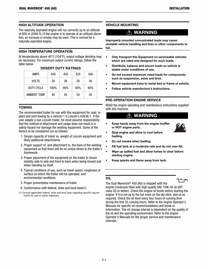
At temperatures above 40°C (104°F), output voltage derating maybe necessary. For maximum output current ratings, follow thetable below.
DESERT DUTY RATINGS
TOWING
The recommended trailer for use with this equipment for road, in-plant and yard towing by a vehicle (1) is Lincoln’s K2636-1. If theuser adapts a non-Lincoln trailer, he must assume responsibilitythat the method of attachment and usage does not result in asafety hazard nor damage the welding equipment. Some of thefactors to be considered are as follows:
1. Design capacity of trailer vs. weight of Lincoln equipment andlikely additional attachments.
2. Proper support of, and attachment to, the base of the weldingequipment so that there will be no undue stress to the trailer’sframework.
3. Proper placement of the equipment on the trailer to insurestability side to side and front to back when being moved andwhen standing by itself.
4. Typical conditions of use, such as travel speed, roughness ofsurface on which the trailer will be operated, andenvironmental conditions.
5. Proper preventative maintenance of trailer.
6. Conformance with federal, state and local laws(1).(1) Consult applicable federal, state and local laws regarding specific require-
ments for use on public highways.
VEHICLE MOUNTING
Improperly mounted concentrated loads may causeunstable vehicle handling and tires or other components tofail.
• Only transport this Equipment on serviceable vehicleswhich are rated and designed for such loads.
• Distribute, balance and secure loads so vehicle isstable under conditions of use.
• Do not exceed maximum rated loads for componentssuch as suspension, axles and tires.
• Mount equipment base to metal bed or frame of vehicle.
• Follow vehicle manufacture’s instructions.
PRE-OPERATION ENGINE SERVICE
READ the engine operating and maintenance instructions suppliedwith this machine.
• Keep hands away from the engine muffleror HOT engine parts.
• Stop engine and allow to cool beforefuelling.
• Do not smoke when fuelling.
• Fill fuel tank at a moderate rate and do not over-fill.
• Wipe up spilled fuel and allow fumes to clear beforestarting engine.
• Keep sparks and flame away from tank.
OIL
The Dual Maverick® 450 (AU) is shipped with theengine crankcase filled with high quality SAE 10W-30 oil (APIclass CD or better). Check the engine oil levels before starting theengine. If it is not up to the full mark on the dip stick, add oil asrequired. Check the oil level every four hours of running timeduring the first 35 running hours. Refer to the engine Operator’sManuals for specific oil recommendations and break-ininformation. The oil change interval is dependent on the quality ofthe oil and the operating environment. Refer to the engineOperator’s Manuals for the proper service and maintenanceintervals.
WARNING
AMPS 450 450 425 400
VOLTS 26 26 26 26
DUTY CYCLE 100% 90% 60% 60%
AMBIENT TEMP 40 45 50 55
WARNING

A-5
INSTALLATIONDUAL MAVERICK® 450 (AU)
FUEL - USE DIESEL FUEL ONLY
Fill the fuel tank with clean, fresh diesel fuel. Thecapacity of the fuel tank is approximately 20 gallons (75.7 liters). See engine Operator’s Manual for specificfuel recommendations. Running out of fuel may require bleedingthe fuel injection pump.
NOTE: Before starting the engine, open the fuel shutoff valve onthe fuel filter located on the liftbale.
ENGINE COOLANT
HOT COOLANT can burn skin.Do not remove cap if radiator is hot.
The welder is shipped with the engine and radiatorfilled with a 50% mixture of ethylene glycol andwater. See the MAINTENANCE section and theengine Operator’s Manual for more information oncoolant.
BATTERY CONNECTION
GASES FROM BATTERY can explode.Keep sparks, flame and cigarettes away frombattery.
To prevent EXPLOSION when:
• INSTALLING A NEW BATTERY — disconnect negativecable from old battery first and connect to new batterylast.
• CONNECTING A BATTERY CHARGER — removebattery from welder by disconnecting negative cablefirst, then positive cable and battery clamp. Whenreinstalling, connect negative cable last. Keep wellventilated.
• USING A BOOSTER — connect positive lead to batteryfirst then connect negative lead to negative battery leadat engine foot.
BATTERY ACID can burn eyes andskin.• Wear gloves and eye protection and be
careful when working near battery.
• Follow instructions printed on battery.
IMPORTANT: To prevent ELECTRICAL DAMAGE WHEN:
a) Installing new battery.
b) Using a booster.
Use correct polarity — NEGATIVE GROUND.
The Dual Maverick® 450 (AU) is shipped with the negative batterycable disconnected. Before you operate the machine, make surethe High Idle / Run - Stop switch is in the STOP position andattach the disconnected cable securely to the negative (-) batteryterminal.
Remove the insulating cap from the negative battery terminal.Replace and tighten negative battery cable terminal. NOTE: Thismachine is furnished with a wet charged battery; if unused forseveral months, the battery may require a booster charge. Be sureto use the correct polarity when charging the battery.
MUFFLER OUTLET PIPE
Remove the plastic plug covering the muffler outlet tube. Usingthe clamp provided secure the outlet pipe to the outlet tube withthe pipe positioned such that it will direct the exhaust in thedesired position.
SPARK ARRESTOR
Some federal, state or local laws may require that petrol or dieselengines be equipped with exhaust spark arrestors when they areoperated in certain locations where unarrested sparks maypresent a fire hazard. When required by local regulations, asuitable spark arrestor, must be installed and properly maintained.
An incorrect arrestor may lead to damage to the engine oradversely affect performance.
WARNING
WARNING
CAUTION

A-6
INSTALLATIONDUAL MAVERICK® 450 (AU)
CASE FRONT CONTROLS
1. LCD SCREEN, IP67 RATED OPERATOR A - The LCD screendisplays information about welding mode, output voltage orcurrent, engine status and machine settings. It allowsoperator to select welding mode and read the output voltageor current when presetting using the output control knob.During welding, the screen displays the actual output voltage(VOLTS) and current (AMPS). A memory feature holds thescreens on for 5 seconds after welding is stopped. Thisallows the operator to read the actual current and voltage justprior to when welding was ceased. In engine status section,information about engine hours, filter condition, engine oiland other service items are displayed..
2. OUTPUT CONTROL OPERATOR A - The OUTPUT KNOB is usedto preset the output voltage or current as displayed on theLCD screen for the six welding modes. When in the ARCGOUGING or CV-WIRE modes and when a remote control isconnected to the 6-Pin or 14-Pin Connector, the auto-sensingcircuit automatically switches the OUTPUT CONTROL fromcontrol at the welder to the remote control. When in
DOWNHILL PIPE and CC-STICK modes if a remote control isconnected to the 6-Pin or 14 Pin Connectors, the output iscontrolled by the remote and the output control on themachine is used to set the maximum current range for theremote.
3. SINGLE/DUAL OPERATOR MODE SWITCH - The switch allowsthe user to choose between Single Operator and DualOperator weld modes. Single Operator mode is when theswitch is in the “Left” position. Dual Operator mode is whenthe switch is in the “Right” position.
4. 14-PIN WIRE FEEDER CONNECTION OPERATOR A - Forattaching wire feeder control cables. Includes contactorclosure circuit, auto-sensing remote control circuit, and 42Vpower. The remote control circuit operates the same as the 6 Pin Amphenol. NOTE: That 115V is not available.
5. WIRE FEEDER POLARITY SWITCH - Matches the polarity of thewire feeder voltmeter to the polarity of the electrode.
6. 6-PIN REMOTE CONTROL CONNECTOR OPERATOR A - Forattaching optional remote control equipment. Includes auto-sensing remote control circuit.
1
2
5
6
8 10
17
18
19
20
21
7
23
22
16
1214
15
13
9
11 24
3
4

A-7
INSTALLATIONDUAL MAVERICK® 450 (AU)
7. 15 AMP CIRCUIT BREAKER (2) - Auxiliary output breakerprotects the 230V, single phase receptacle.
8. 25 AMP CIRCUIT BREAKER - Auxiliary output breakerprotects the 400V, three phase receptacle.
9. 230VAC SINGLE PHASE RECEPTACLE (QTY 2) - protected by15 Amp circuit breaker and is IP66 rated
10. 400V THREE PHASE AUXILIARY PLUG - protected by a 25 Acircuit breaker and is IP66 rated
11. POSITIVE AND NEGATIVE WELD TERMINAL OPERATOR A -Provides a connection point for the electrode and workcables.
12. GLOW PLUG PUSH BUTTON - When pushed activates theglow plugs. Glow plug should not be activated for more than20 seconds continuously.
13. RUN / STOP SWITCH - RUN position energizes the engineprior to starting. STOP position stops the engine. The oilpressure interlock switch prevents battery drain if the switchis left in the RUN position and the engine is not operating.
14. START PUSH BUTTON- Energizes the starter motor to crankthe engine.
15. EMERGENCY STOP – Push to stop the engine immediately.The stop button needs to be manually reset after use in orderto turn on the engine again.
16. BATTERY BREAKER - For protection of Battery ChargingCircuit.
17. LCD SCREEN, IP67 RATED OPERATOR B
18. OUTPUT CONTROL OPERATOR B
19. 6-PIN REMOTE CONTROL CONNECTION OPERATOR B
20. WIRE FEEDER POLARITY SWITCH OPERATOR B
21. 14-PIN WIRE FEEDER CONNECTION OPERATOR B
22. RESIDUAL CURRENT DEVICE – 30mA- Instantly breaks theauxiliary circuit to prevent serious harm from an ongoingelectric shock.
23. WIRE FEEDER CIRCUIT BREAKER- 42V WIRE FEEDERBREAKERS
24. POSITIVE AND NEGATIVE WELD TERMINAL OPERATOR B

A-8
INSTALLATIONDUAL MAVERICK® 450 (AU)
WELDING TERMINALS
From the main screen select MIG / FCAW / TIG welding. Pressknob to select screen that shows Weld Output Override. (FigureA.3)
Press knob to select either OFF - output controlled by welding gunswitch or ON - output always ON (electrode always hot).
FIGURE A.3
WELDING OUTPUT CABLES
With the engine off, connect the electrode and work cables to theterminals provided. These connections should be checkedperiodically and tightened if necessary.
Listed in Table A.1 are copper cable sizes recommended for therated current and duty cycle. Lengths stipulated are the distancefrom the welder to work and back to the welder again. Cable sizesare increased for greater lengths primarily for the purpose ofminimizing cable voltage drop.
TABLE A.1 TOTAL COMBINED LENGTH OFELECTRODE AND WORK CABLES
MACHINE GROUNDING
Because this portable engine driven welder creates its own power,it is not necessary to connect its frame to an earth ground, unlessthe machine is connected to premises wiring (home, shop, etc.).
To prevent dangerous electric shock, other equipment towhich this engine driven welder supplies power must:
• Be grounded to the frame of the welder using agrounded type plug or be double insulated.
• Do not ground the machine to a pipe that carriesexplosive or combustible material.
When this welder is mounted on a truck or trailer, its frame mustbe securely connected to the metal frame of the vehicle. Whenthis engine driven welder is connected to premises wiring such asthat in a home or shop, its frame must be connected to the systemearth ground. See further connection instructions in the sectionentitled “Standby Power Connections” as well as the article on grounding in the latest National Electrical Code andthe local codes.
In general, if the machine is to be grounded, it should beconnected with a #8 or larger copper wire to a solid earth groundsuch as a metal ground stake going into the ground for at least 10Feet or to the metal framework of a building which has beeneffectively grounded.
The National Electric Code lists a number of alternate means ofgrounding electrical equipment. A machine grounding studmarked with the symbol is provided on the front of the welder.
WARNING
?
Remote
Weld Output Override
OFF(OUTPUT CONTROLLED
BY TORCH/FOOT PEDAL SWITCH)
ON(OUTPUT ALWAYS ON)
Press knob to select
Output ON Cable Length
Cable Size for 400 Amps 60% Duty
Cycle
Cable Size for300 AMPS60% Duty
CycleLengths up to 100 ft. (30m) 2/0 AWG 1/0 AWG
100 ft. (30m) to 150 ft. (61m) 2/0 AWG 1/0 AWG
150 ft. (46m) to 200 ft. (61m) 3/0 AWG 2/0

REMOTE CONTROL
The Dual Maverick® 450 (AU) is equipped with a 6-pin and a 14-pin connector. The 6-pin connector is for connecting the K857 orK857-1 Remote Control or for TIG welding, the K870 foot Amptrolor the K963-3 hand Amptrol. When in the CC-STICK, ARCGOUGING, TIG or CV-WIRE modes and when a remote control isconnected to the 6-pin Connector, the auto-sensing circuitautomatically switches the OUTPUT control from control at thewelder to remote control.
The 14-pin connector is used to directly connect a wire feedercontrol cable. In the CV-WIRE mode, when the control cable isconnected to the 14-pin connector, the auto-sensing circuitautomatically makes the Output Control inactive and the wirefeeder voltage control active.
In each case, once connected control maybe optionally changedback to the control panel using the display remote button. Themaximum and minimum current range can be setup / modified indisplay.
NOTE: When a wire feeder with a built in welding voltagecontrol is connected to the 14-pin connector, do notconnect anything to the 6-pin connector.
AUXILIARY POWER RECEPTACLES
For heavy loads switch the "HIGH IDLE/RUN-STOP" control switchto the "High Idle" mode and set weld output at max.
The auxiliary power of the Dual Maverick® 450 (AU) consists oftwo 230 VAC receptacles protected by two 15 Amp circuitbreakers.
One 400 VAC 18.8 Amps receptacle that is protected by a 25 Amp3 Pole circuit breaker.
The auxiliary power capacity is 6,600 Watts Continuous of 50 Hz,single phase power and 13,000 Watts continuous of 50 Hz, threephase power.
STANDBY POWER CONNECTIONS
The Dual Maverick® 450 (AU) is suitable for temporary, standbyor emergency power using the engine manufacturer’srecommended maintenance schedule.
The Dual Maverick® 450 (AU) can be permanently installed as astandby power unit for 400 VAC, three phase, 18.8Amps service.
Connections must be made by a licensed electrician who candetermine how the power can be adapted to the particularinstallation and comply with all applicable electrical codes.
Take necessary steps to assure load is limited to the capacity ofthe Dual Maverick® 450 (AU).
CABLE INDUCTANCE AND ITS EFFECTS ON WELDING
Excessive cable inductance will cause the welding performance todegrade. There are several factors that contribute to the overallinductance of the cabling system including cable size, length, andnumber of loops. To reduce cable inductance do not loop weldingcables see figure A.4, especially consistently in one direction. Ifthere are loops separate them as much as possible and make theloop as large as possible. A straight or zig-zag pattern betweenthe machine and work is recommended see figure A.4.
If a spooling mechanism is used to store the welding cables,unspool the cables. Avoid leaving more than 30 feet of cable oneach storage spool. For best performance completely unspool thewelding cables.
For optimal performance when welding with two operatorsmaintain some distance between the left and right sets of weldingcables and use individual work piece cables.
FIGURE A.4
WARNING
Work Lead
Electrode
Work Lead
Electrode
A-9
INSTALLATIONDUAL MAVERICK® 450 (AU)

A-10
INSTALLATIONDUAL MAVERICK® 450 (AU)
CONNECTION OF WIRE FEEDERS WITH CONTROLCABLE (14 PIN)
Shut off welder before making any electrical connections.
CONNECTION OF LF-72, LF-74, FLEX FEED 74 HT,FLEX FEED 84, LN-25 PRO DUAL POWER TO THEDUAL MAVERICK® 450 (AU)
Note: The Dual Maverick 450 (AU) can operate two different wirefeeders at the same time.
• Shut the welder off.
• Set the “WIRE FEEDER VOLTMETER” switch to either “+” or“-” as required by the electrode being used.
• For electrode Positive, connect the electrode cable to the "+"terminal of the welder and work cable to the "-" terminal ofthe welder. For electrode Negative, connect the electrodecable "-" terminal of the welder and work cable to the "+"terminal of the welder.
• Using the display Set "MODE" to MIG/FCAW.
• Adjust the “PINCH” setting to desired Crispness. SOFT for MIGand CRISP for Innershield.
• Set the "Weld Output Override" to the desired settings usingthe display.
• Connect the 14 pin control cable from the wire feeder to theengine drive (See Figure A.5).
• This procedure can be done for both “Single” and “Dual” operator modes.
WARNING
ENGINE WELDER
K1797-xx CABLE
K1797-xx CABLE
WIRE FEEDER AOperator A Operator B
WIRE FEEDER B
FIGURE A.5

A-11
INSTALLATIONDUAL MAVERICK® 450 (AU)
CONNECTION OF ACROSS THE ARC WIRE FEEDERSTO THE DUAL MAVERICK® 450 (AU)
These connections instructions apply to both the LN-25 Pro andActiv8 models. The feeders have an internal contactor and theelectrode is not energized until the gun trigger is closed. When thegun trigger is closed the wire will begin to feed and the weldingprocess is started.
• Shut the welder off.
• For electrode Positive, connect the electrode cable to the "+"terminal of the welder and work cable to the "-" terminal ofthe welder. For electrode Negative, connect the electrodecable "-" terminal of the welder and work cable to the "+"terminal of the welder.
• Attach the single lead from the front of the feeder to workusing the spring clip at the end of the lead. This is a controllead to supply current to the wire feeder motor; it does notcarry welding current (See Figure A.6).
• Using the display Set "MODE" to MIG/FCAW
• Set the "Weld Output Override" to "ON" setting using thedisplay.
• Set the "PINCH" setting to "0" initially and adjust to suit.
NOTE: The LN-25 (K431) Remote Control Module and(K432) Remote Control Module are not recommended foruse with the Dual Maverick® 450 (AU).
ENGINE WELDEROperator A Operator B
FIGURE A.6

Certain electrical devices cannot be powered by this product. See Table A.2
TABLE A.2ELECTRICAL DEVICE USE WITH THIS PRODUCT
Type
Resistive
Capacitive
Inductive
Capacitive / Inductive
Common Electrical Devices
Heaters, toasters, incandescentlight bulbs, electric range, hotpan, skillet, coffee maker.
TV sets, radios, microwaves,appliances with electrical control.
Single-phase induction motors,drills, well pumps, grinders, smallrefrigerators, weed and hedgetrimmers.
Computers, high resolution TV sets,complicated electrical equipment.
Possible Concerns
NONE
Voltage spikes or high voltage regulation can cause the capac-itative elements to fail. Surgeprotection, transient protection, andadditional loading is recom-mended for 100% fail-safe opera-tion. DO NOT RUNTHESE DEVICES WITHOUTADDITIONAL RESISTIVE TYPELOADS.
These devices require large current inrush for starting.Some synchronous motors maybe frequency sensitive to attainmaximum output torque, butthey SHOULD BE SAFE fromany frequency induced failures.
An inductive type line condition-er along with transient andsurge protection is required,and liabilities still exist. DO NOT USE THESE DEVICESWITH THIS PRODUCT.
The Lincoln Electric Company is not responsible for any damage to electrical components improperly connected to this product.
A-12
INSTALLATIONDUAL MAVERICK® 450 (AU)
CAUTION

OPERATIONSAFETY PRECAUTIONSRead and understand this entire section beforeoperating your Dual Maverick® 450 (AU).
• Do not attempt to use this equipment until you havethoroughly read the engine manufacturer’s manualsupplied with your welder. It includes important safetyprecautions, detailed engine starting, operating andmaintenance instructions, and parts lists.
ELECTRIC SHOCK can kill.• Do not touch electrically live parts or
electrode with skin or wet clothing.
• Insulate yourself from work and ground
• Always wear dry insulating gloves.
ENGINE EXHAUST can kill.• Use in open, well ventilated areas or vent
exhaust outside
• Do not stack anything near the engine.
MOVING PARTS can injure.• Do not operate with doors open or guards
off.
• Stop engine before servicing.
• Keep away from moving parts
• Only qualified personnel should operate this equipment.
• Always operate the welder with the door closed and theside panels in place as these provide maximumprotection from moving parts and insure proper coolingair flow.
GENERAL DESCRIPTION
The Dual Maverick® 450 (AU) is a dual-operator multi-purposediesel engine-driven welding power source. The machine uses abrushless alternator / generator for DC multipurpose welding, for230 VAC single phase, 400VAC three phase. The DC weldingcontrol system uses state of the art Chopper Technology forsuperior welding performance.
The Dual Maverick® 450 (AU) is fitted with a selectable VRD(Voltage Reduction Device). The VRD operate in Stick, Wire, TIG,PIPE, and GOUGE modes reducing the OCV to <13 volts,increasing operator safety when welding is performed inenvironments with increased hazard of electric shock such as wetareas and hot, humid sweaty conditions.
FOR AUXILIARY POWER:
Start the engine and set the IDLER control switch to the desiredoperating mode. Full power is available regardless of the weldingcontrol settings providing no welding current is being drawn.
ENGINE OPERATION
Before Starting the Engine:
• Be sure the machine is on a level surface.
• Open side engine door and remove the engine oil dipstick andwipe it with a clean cloth. Reinsert the dipstick and check thelevel on the dipstick.
• Add oil (if necessary) to bring thelevel up to the full mark. Do notoverfill. Close engine door.
• Check radiator for proper coolant level. (Fill if necessary).
• See Engine Owner’s Manual for specific oil and coolantrecommendations.
ADD FUEL
DIESEL FUEL can cause fire.• Stop engine while fueling.
• Do not smoke when fueling.
• Keep sparks and flame away from tank.
• Do not leave unattended while fueling.
• Wipe up spilled fuel and allow fumes to clear beforestarting engine.
• Do not overfill tank, fuel expansion may cause overflow.
DIESEL FUEL ONLY-Low sulfur fuel or ultra low sulphur fuelin U.S.A. and Canada.• Remove the fuel tank cap.
• Fill the tank. DO NOT FILL THE TANK TO THE POINT OFOVERFLOW.
• Replace the fuel cap and tighten securely.
• See Engine Owner’s Manual for specific fuel recom-mendations.
HAND PRIMER BUTTON
Air in the fuel system will cause the following engine problems:
• Hard to start
• Run rough
• Misfire
• Fuel knock
For faster air purge, a small amount of air can be vented from thesystem by pumping the hand primer button on the fuel filter head.(See Figure B.1, Engine Service Side View)
WARNING
WARNING
B-1
OPERATIONDUAL MAVERICK® 450 (AU)

FIGURE B.1 Engine Service Side View
RECOMMENDED APPLICATIONS
The Dual Maverick® 450 (AU) provides excellent constant currentDC welding output for stick (SMAW) and TIG welding. The DualMaverick® 450 (AU) also provides excellent constant voltage DCwelding output for MIG (GMAW), Innershield (FCAW), Outershield(FCAW-G) and Metal Core welding. In addition the Dual Maverick® 450 (AU) can be used for Arc Gouging withcarbons up to 3/8”(10mm) in diameter.
The Dual Maverick® 450 (AU) is not recommended for pipethawing.
GENERATOR
The Dual Maverick® 450 (AU) provides smooth 230 VAC singlephase and 400 VAC three phase, 50Hz output for auxiliary powerand emergency standby power.
AUTO-START INSTRUCTION
1. To make Auto Start active, press home button for the mainmenu. Rotate knob to select "Setup" icon and press knob.
2. Auto-Start On/Off: Determines On/Off states for Auto-startfeature.
a. Rotate knob to select “Auto-Start On/Off” and pressknob to confirm.
b. Rotate knob to select “On” or ”Off” and press knob toconfirm.
3. Auto-Start No Load Period: Determines when no load is on,how long the welder will be on before auto shutdown. Thisperiod will be reset to the setting value when load appears.
a. Rotate knob to select “Auto-Start No Load Period” andpress knob to confirm.
b. Rotate knob to change the period from 15 min to 120min and press knob to confirm.
4. Tap-Start Active Period: Determines how long tap start willbe active.
a. Rotate knob to select “Tap-Start Active Period” andpress knob to confirm.
b. Rotate knob to change the period from 15 min to 120min and press knob to confirm.
5. Press home button to go to the main menu. Select weldingmode. Confirm Auto Start settings on the display.
6. When Auto-Start feature is turned "ON" and a remote isplugged in the engine can be remotely turned off bycompleting the following pattern on the remote knob:
1) Remote Knob to Min.
2) Remote knob to Max.
3) Remote Knob to Middle.
4) Remote knob to Max.
5) Remote knob to Min.
Each step should be completed within 3 seconds.
7) Auto start does not work when small loads such as across thearc wire feeders are connected. In this case turn Auto Startoff.
8) To restart engine, firmly tap and hold electrode to work for 0.1to 1 sec. Ensure there is direct contact between metal part ofthe electrode and work.
9) Pull electrode away from work and wait a few seconds forengine to come up to speed.
NOTE: Small loads across the output terminals such as an acrossthe arc wire feeder may cause the auto start count to restartwithout shutting down the engine. Remove any such smallloads. Or turn Auto start off.
BREAK-IN PERIOD
Lincoln Electric selects high quality, heavy-duty industrial enginesfor the portable welding machines we offer. While it is normal tosee a small amount of crankcase oil consumption during initialoperation, excessive oil use, wetstacking (oil or tar like substanceat the exhaust port), or excessive smoke is not normal.
Larger machines with a capacity of 350 amperes and higher,which are operated at low or no-load conditions for extendedperiods of time are especially susceptible to the conditionsdescribed above. To accomplish successful engine break-in, mostdiesel-powered equipment needs only to be run at a reasonablyheavy load within the rating of the welder for some period of timeduring the engine’s early life. However, if the welder is subjectedto extensive light loading, occasional moderate to heavy loading ofthe engine may sometimes be necessary. Caution must beobserved in correctly loading a diesel/generator unit.
1. Connect the welder output studs to a suitable resistive load bank.Note that any attempt to short the output studs by connecting thewelding leads together, direct shorting of the output studs, orconnecting the output leads to a length of steel will result incatastrophic damage to the generator and voids the warranty.
2. Set the welder controls for an output current and voltage withinthe welder rating and duty cycle. Note that any attempt toexceed the welder rating or duty cycle for any period of time willresult in catastrophic damage to the generator and voids thewarranty.
3. Periodically shut off the engine and check the crankcase oil level.
During break-in, subject the Welder to moderate loads.Avoid long periods running at idle. Before stopping theengine, remove all loads and allow the engine to coolseveral minutes.
CAUTION
B-2
OPERATIONDUAL MAVERICK® 450 (AU)

ENGINE OPERATION
STARTING THE ENGINE
1. Open the engine service compartment door and check thatthe fuel shutoff valve on the fuel filter separator located onthe liftbale is in the open position.
2. Ensure the battery lockout switch is in OFF position.
3. Check for proper oil level and coolant level. Close engineservice compartment door.
4. Remove heavy auxiliary loads from the AC power receptacles.
5. Firmly set the Operator Selector Switch to Single or Dual. TheOperator Selector Switch can be set to Single or Dual modeand must be securely in one of the two positions.
6. Set the RUN/IDLE/STOP switch to “AUTO IDLE”.
7. For cold weather starting, press Glow Plug Button and hold 15to 20 seconds.
8. Press START button until the engine starts or for up to 10seconds.
9. Release the engine START button when the engine starts.
10. Allow the engine to warm up at low idle speed for severalminutes before applying a load and/or switching to high idle.Allow a longer warm up time in cold weather.
COLD WEATHER STARTING
With a fully charged battery and the proper weight oil, the engineshould start satisfactorily even down to about -4°F(-20°C) belowthis it may be desirable to use the included block heater.
NOTE: Extreme cold weather starting may require longer glow plugoperations.
STOPPING THE ENGINE
Switch the RUN/IDLE/STOP switch to “STOP”. This turns off thevoltage supplied to the shutdown solenoid. A backup shutdowncan be accomplished by shutting off the fuel valve located on thefuel pre-filter located on the liftbale.
EMERGENCY STOPPING
Emergency shutoff controls are for EMERGENCY USE ONLY. DONOT use emergency shutoff devices or controls for normalstopping procedure.
TYPICAL FUEL CONSUMPTION
Refer to Table B.2 for typical fuel consumption of the Dual Maverick® 450 (AU) Engine for various operating settings.
TABLE B.2
NOTE: This data is for reference only. Fuel consumption is approximate andcan be influenced by many factors, including engine maintenance, environ-mental conditions and fuel quality.
TYPICAL DUAL MAVERICK 450 (AU) FUEL CONSUMPTION
LoadPERKINS
403D-11 T4igal./hr (liters/hr)
Operating Time for 20 gallons (75.7 L)
(Hours)
Low Idle No Load0.226(0.856) 88.50
2120 RPM
STICK WELD OUTPUT0.453(1.716) 44.15
50A @ 22V
STICK WELD OUTPUT0.536(2.027) 37.31
100A @ 24V
STICK WELD OUTPUT0.646(2.447) 30.96
150A @ 26V
STICK WELD OUTPUT0.77(2.917) 25.97
200A @ 28V
STICK WELD OUTPUT1.012(3.831) 19.76
300A @ 32V
STICK WELD OUTPUT
1.41(5.337) 14.18350A @ 34V
(OR 450A @ 26V
Aux. 5000W 0.78(2.954) 25.64
Aux. 8000W 0.973(3.684) 20.55
Aux. 13000W 1.457(5.514) 13.73
AUTO START IDLE WaitState 0 N/A
B-3
OPERATIONDUAL MAVERICK® 450 (AU)

WELDER OPERATION
DUTY CYCLE
Duty Cycle is the percentage of time the load is being applied in a10 minute period. For example a 60% duty cycle, represents 6minutes of load and 4 minutes of no load in a 10 minute period.
ELECTRODE INFORMATION
For any electrode the procedures should be kept within the ratingof the machine. For information on electrodes and their properapplication see (www.lincolnelectric.com) or the appropriateLincoln publication.
The Dual Maverick® 450 (AU) can be used with a broad range ofDC stick electrodes. The MODE switch provides two stick weldingsettings as follows:
Constant Current (CC-STICK) Welding
Stick "Mode" is designed for horizontal and vertical-up weldingwith all types of electrodes, especially low hydrogen.
The ARC Force setting on the mode screen controls the shortcircuit current (arc-force) during stick welding to adjust for a softor crisp arc. Increasing the number from -10(soft) to +10(crisp)increases the short circuit current and prevents sticking of theelectrode to the plate while welding. This can also increasespatter. It is recommended that the ARC CONTROL be set to theminimum number without electrode sticking. Start with the dialset at 0 (OFF).
Note: Due to the low OCV with the VRD on, a very slight delayduring striking of the electrodes may occur. Due to therequirement of the resistance in the circuit to be low for a VRD tooperate, a good metal-to-metal contact must be made betweenthe metal core of the electrode and the job. A poor connectionanywhere in the welding output circuit may limit the operation ofthe VRD. This includes a good connection of the work clamp tothe job. The work clamp should be connected as close aspractical to where the welding will be performed.
For Re-Striking Electrodes
Some electrodes form a cone at the end of the electrode after thewelding arc has been broken, particularly iron powder and lowhydrogen electrodes. This cone will need to be broken off in orderto have the metal core of the electrode make contact.
E6010 - To begin welding with VRD active.
E7018, E7024 - Tap, slide and lift in one motion.
Once the arc is started, normal welding technique for theapplication is then used.
For other electrodes the above techniques should be tried first andvaried as needed to suit operator preference. The goal forsuccessful starting is good metal to metal contact.
DOWNHILL PIPE Welding
This slope controlled mode is intended for "out-of-position" and"down hill" pipe welding where the operator would like to controlthe current level by changing the arc length.
The ARC FORCE setting sets the short circuit current (arc-force)during stick welding to adjust for a soft or more forceful diggingarc (crisp). Increasing the number from -10(soft) to +10(crisp)increases the short circuit current which results in a more forcefuldigging arc.
Typically a forceful digging arc is preferred for root and hotpasses. A softer arc is preferred for fill and cap passes whereweld puddle control and deposition (“stacking” of iron) are key tofast travel speeds. This can also increase spatter.
It is recommended that the ARC FORCE be set to the minimumnumber without electrode sticking. Start with the setting at 0.
NOTE: With the VRD set to the “ON” position (See figure A.2 forlocation) there is no output in the downhill pipe mode.
B-4
OPERATIONDUAL MAVERICK® 450 (AU)
+ _+ _
Work Lead
Work Lead
Electrode
Electrode

TIG Welding
The TOUCH START TIG is for DC TIG (Tungsten Inert Gas) welding.To initiate a weld, the selector knob is used to set to the desiredcurrent and the tungsten is touched to the work. During the timethe tungsten is touching the work there is very little voltage orcurrent and, in general, no tungsten contamination. Then, thetungsten is gently lifted off the work in a rocking motion, whichestablishes the arc.
When in the touch start TIG mode and when a Amptrol isconnected to the 6-Pin connector the selector knob is used to setthe maximum current range of the current control of the Amptrol.
The ARC FORCE is not active in the TIG mode. To STOP a weld,simply pull the TIG torch away from the work.
When the arc voltage reaches approximately 30 Volts the arc willgo out and the machine will reset the current to the Touch Startlevel.
To reinitiate the arc, retouch the tungsten to the work and lift.Alternatively, the weld can be stopped by releasing the Amptrol orarc start switch.
The Dual Maverick® 450 (AU) can be used in a wide variety of DCTIG welding applications. In general the ‘Touch Start’ featureallows contamination free starting without the use of a Hi-frequency unit.
If desired, the K930-2 TIG Module can be used with the DualMaverick® 450 (AU). The settings are for reference.
Dual Maverick® 450 (AU) settings when using the K930-2 TIGModule with an Amptrol or Arc Start Switch:
• Set the MODE to the TOUCH START TIG setting.
• Set the "IDLER" Switch to the "AUTO/IDLE/RUN" position.
• Set the "Weld Output Override" to the "REMOTELYCONTROLLED" position.
This will keep the "Solid State" contactor open and provide a"cold" electrode until the Amptrol or Arc Start Switch is pressed.
When using the TIG Module, the selector knob on the DualMaverick® 450 (AU) is used to set the maximum range of theCURRENT CONTROL on the TIG Module or an Amptrol if connectedto the TIG Module.
NOTE: The TIG process is to receive a low voltage weldingprocess. There is no difference in operation with the VRD“ON” or “OFF” for this mode.
B-5
OPERATIONDUAL MAVERICK® 450 (AU)
+ _
PTA-17, 2 Cable, K1782-2 12.5’PTA-17, 2 Cable, K1782-4 25’
Foot PedalK870
Foot PedalK870
Work Lead
+ _
PTA-17, 2 Cable, K1782-2 12.5’PTA-17, 2 Cable, K1782-4 25’
Work Lead

WIRE WELDING-CV
Connect a wire feeder to the Dual Maverick® 450 (AU) accordingto the instructions in INSTALLATION INSTRUCTIONS Section.
The Dual Maverick® 450 (AU) in the CV-WIRE mode, permits it tobe used with a broad range of flux cored wire (Innershield andOutershield) electrodes and solid wires for MIG welding (gas metalarc welding). Welding can be finely tuned using the PINCH from –10 (soft) to +10 (crisp) changes the arc from soft and washed-into crisp and narrow. It acts as an inductance/pinch control. Theproper setting depends on the procedure and operator preference.Start with the setting at 0 (OFF).
If the engine bogs while wire welding check that the powerrequired for the process does not exceed the rated power of themachine. For unusually high wire feed speeds and low voltagecombinations it may be necessary to disable the variable speedfeature(see “SET-UP” section) and set the ignition switch to highidle.
Note: Due to the low OCV with the VRD on, a very slight delayduring striking of the electrodes may occur. Due to therequirement of the resistance in the circuit to be low for a VRD tooperate, a good metal-to-metal contact must be made betweenthe metal core of the electrode and the job. A poor connectionanywhere in the welding output circuit may limit the operation ofthe VRD. This includes a good connection of the work clamp to thejob. The work clamp should be connected as close as practical towhere the welding will be performed.
ARC GOUGING
Dual Maverick® 450 (AU) can be used for Arc Gouging withcarbons up to 3/8”(10mm) in diameter.
Use the selector knob to adjust output current to the desired levelfor the gouging electrode being used.
The ARC FORCE is not active in the ARC GOUGING Mode. The ARCFORCE is automatically set to maximum when the ARC GOUGINGmode is selected which provides the best ARC GOUGINGperformance.
PARALLELING
When paralleling machines in order to combine their outputs, allunits must be operated in the CC-STICK mode only at the sameoutput settings. Use the selector knob to choose stick mode fromthe home screen. Operation in other modes may produce erraticoutputs, and large output imbalances between the units.
B-6
OPERATIONDUAL MAVERICK® 450 (AU)
B-6
TYPICAL CURRENT RANGES (1) FOR TUNGSTEN ELECTRODES(2)
Tungsten Electrode DCEN (-) DCEP (+) Approximate Argon Gas Flow TIG TORCH
Diameter in. (mm) Flow Rate C.F.H. ( l /min.) Nozzle Size (4), (5)
1%, 2% Thoriated 1%, 2% Thoriated Aluminum Stainless SteelTungsten Tungsten
.010 (.25) 2-15 (3) 3-8 (2-4) 3-8 (2-4) #4, #5, #60.020 (.50) 5-20 (3) 5-10 (3-5) 5-10 (3-5)0.040 (1.0) 15-80 (3) 5-10 (3-5) 5-10 (3-5)
1/16 (1.6) 70-150 10-20 5-10 (3-5) 9-13 (4-6) #5, #6
3/32 (2.4) 150-250 15-30 13-17 (6-8) 11-15 (5-7) #6, #7, #81/8 (3.2) 250-400 25-40 15-23 (7-11) 11-15 (5-7)
5/32 (4.0) 400-500 40-55 21-25 (10-12) 13-17 (6-8) #8, #10
(1) When used with argon gas. The current ranges shown must be reduced when using argon/helium or pure helium shielding gases.(2) Tungsten electrodes are classified as follows by the American Welding Society (AWS):
Pure EWP1% Thoriated EWTh-1
2% Thoriated EWTh-2Though not yet recognized by the AWS, Ceriated Tungsten is now widely accepted as a substitute for 2% Thoriated Tungsten in AC and DC applications.
(3) DCEP is not commonly used in these sizes.(4) TIG torch nozzle "sizes" are in multiples of 1/16ths of an inch:
# 4 = 1/4 in. (6 mm)# 5 = 5/16 in. (8 mm)# 6 = 3/8 in. (10 mm)# 7 = 7/16 in. (11 mm)# 8 = 1/2 in. (12.5 mm)#10 = 5/8 in. (16 mm)
(5) TIG torch nozzles are typically made from alumina ceramic. Special applications may require lava nozzles, which are less prone to breakage, but cannot withstand high temperaturesand high duty cycles.
TABLE B.3

AUXILIARY POWER OPERATION
Start the engine and set the IDLER control switch to the desiredoperating mode. Full power is available regardless of the weldingcontrol settings, if no welding current is being drawn.
For heavy loads set to HIGH IDLE and maximum weld output formaximum starting power.
SIMULTANEOUS WELDING AND AUXILIARYPOWER LOADS
It must be noted that the specified auxiliary power ratings are withno welding load.
Simultaneous welding and power loads are specified in table B.5.
TABLE B.5 DUAL MAVERICK® 450 (AU) SIMULTANEOUS WELDING AND POWER LOADS
B-7
OPERATIONDUAL MAVERICK® 450 (AU)
Simultaneous Each SideDual Current
Single Current Aux Power 3 Phase Amps Single Phase Amps
0 0 13000 18.8 15.0
50 100 11000 16.1 15.0
100 200 7300 10.7 15.0
150 300 2600 3.8 11.8
175 350 0 0.0 0.0
225 450 0 0.0 0.0

B-8
OPERATIONDUAL MAVERICK® 450 (AU)
DISPLAY OPERATION:SEE FIG B.2
1. HOME - Brings up the home screen (main menu)
2. REMOTE CONTROL - Toggles the remote controlON / OFF
3. HELP - Displays additional information describingthe function
4. BACK - Goes back to the previous screen
5. SELECTOR KNOB - rotate adjusts values, pushconfirms the selected value or choice
Note: When Dual Maverick 450 (AU) is first started, it will return tothe screen that was shown when the machine was turned off.
HOME SCREEN
Pressing the Home button displays the home menu. Rotate theknob to select the desired weld mode, or choose engine options orset-up menu. Push the selector knob to make the selection.
S
?
Press knob to select
StickWelding
?
MAVERICK
www.lincolnelectric.com
1 4
2 3
5
FIGURE B.2

B-9
OPERATIONDUAL MAVERICK® 450 (AU)
STICK WELDING
Manual entry operates like a traditional welding machine. Simplyset the desired preset amperage or voltage and begin to weld.The “Preset” screen appears when welding is not active. It showsthe amount of fuel on the left hand side; the weld mode in thelower left hand corner; the preset value in the middle; and theweld output status in the upper right corner.
?
Press knob for options
100 AF
E
½
OutputOFF
Arc Force
-10
?
Press knob for optionsRemote
ON
100 AF
E
½
Arc Force
-10
OutputOFF
Stick Welding Basic OCV
?
225 A
15.1 V
OutputON
Arc Force
-10
Stick Welding Basic Arc is struck
?
225 A
15.1 V
OutputON
Arc Force
-10
Stick Welding Basic 5 seconds after arc goes out
Stick Welding Basic OCV w Remote
?
Press knob for options
100 AF
E
½
3600 SEC UNTIL AUTOSHUTDOWN
OutputOFF
Arc Force
-10
?
Press knob to select
StickWelding
Stick Welding Basic OCV w Auto-start
Showspresentcurrent
ShowsAutostartstatus
Showspresentcurrent
Actual arcamps
Actual arcvolts
Flashes
Showspresentcurrent

B-10
OPERATIONDUAL MAVERICK® 450 (AU)
?
ArcForce
-4Press knob
to select ?
Stick Welding ARC FORCE
?
Press knob to select
RemoteControlRange50-450A
ArcForce
+10
Stick Options
?
Press knob to select
Set MAXIMUM forRemote Control
50A 210A
OutputOFF
?
Arc Force
-10
?
Adjusting the maximum and minimumvalues of the remote control can improvethe remte control sensitivity. For example,setting the maximum range to 110 andthe minimum range to 90 makes it easyto adjust the output by increments of 1with the remote.
Press knob to continue
?
Arc Force prevents the electrode fromsticking during welding. It is a temporaryincrease in current when the arc is too short.It can make out of position welding easier.For a smooth arc with less spatter, use lessArc Force. For a crisp arc with morepenetration, use more Arc Force.
Press knob to continue
?
Press knob to select
Set MINIMUM forRemote Control
50A 210A
OutputOFF
?
Arc Force
-10
Stick Welding Remote Control
All weld modes support using a remote control like K857-1. Plug theremote into the 6 pin connector on the front of the machine.
Press the remote button on the display to toggle between control at theremote and control at the knob on the machine. The remote buttondoes not function when welding is occurring.
When the remote is enabled, a bar will appear underneath the presetvalue showing the remote range. The standard range allows the remoteto adjust from the minimum to the maximum value of the machine.
Max currentvalueflashes
Bar adjustsas numberchanges
Min currentvalueflashes
Bar adjustsas numberchanges

B-11
OPERATIONDUAL MAVERICK® 450 (AU)
MIG/FCAW WELDING
Manual entry operates like a traditional welding machine. Simplyset the desired preset amperage or voltage and begin to weld.The “Preset” screen appears when welding is not active. It showsthe amount of fuel on the left hand side; the weld mode in thelower left hand corner; the preset value in the middle; and theweld output status in the upper right corner.
?
Press knob for select
RemoteControlRange13.0 - 40.0 V
PinchMode
OFF
Weld OutputOverride
ON
MIG Options
?
Remote
Weld Output Override
OFF(OUTPUT CONTROLLED
BY TORCH/FOOT PEDAL SWITCH)
ON(OUTPUT ALWAYS ON)
Press knob to select
Output ON
MIG Settings
?
PinchMode
-4
Press knob to select
?
Pinch Mode
?
Press knob to select
MIG/FCAW-GSWelding
?
Press knob for options
33.7V
F
E
½Pinch Mode
OFF
OutputOFF
?200
1/16”
?
Press knob for optionsRemote
ON
33.7V
F
E
½
OutputOFF
Pinch Mode
OFF
?200
1/16”
MIG Welding Basic OCVMIG Welding Basic OCV
w Remote
?
Pinch, also called inductance, changes therate of current rise when the electrodeshort circuits to the work. More pinch mayreduce spatter, while less pinch makes thepuddle more fluid, resulting in a flatter,smoother weld bead.
Press knob to continue
Pinch Mode Info
Showspresentvoltage
Showspresentvoltage

B-12
OPERATIONDUAL MAVERICK® 450 (AU)
ENGINE STATUS SCREEN
The Engine Status screen provides information about the engineservicing and operation.
Five parts of the engine are monitored for service: Oil, Coolant, Air Filter, Fan Belt and Fuel Filter. To view detailed informationabout an item, rotate the knob until the item is highlighted in red.The top of the screen displays the number of hours remaining untilservice is required for the selected item.
The red/yellow/green bars for each item indicate how much timeis left.
Green = Normal operation
Yellow = Service is required soon
Red = Service is overdue
After service has been performed on an item, press and hold theknob for 5 second to reset the service interval timer.
?
Press knob to select
Engine
?
120 Hours Remaining
Oil
Press and hold knob to reset:
Air Filter Fan Belt
FuelFilter
210.5Hrs
12.1 V0
WaterSeparator
Wire FeedSpeed
WireDiameter
?
?
WireDiameter
Press knob for weld page
200Select Maximum WFS
Expected
IPM
?
Wire Diameter
Press knob to select
0.025” / 0.6mm
0.030” / 0.8mm
0.035” / 0.9mm
0.040” / 1.0mm
0.045” / 1.2mm
0.052” / 1.4mm
Note: Select the maximum wire feed speed (WFS) that willbe used during the welding session to ensure poweroutput to the wire feeder is sufficient.

B-13
OPERATIONDUAL MAVERICK® 450 (AU)
SET-UP
The set-up allows for customization of the Maverick. Optionsavailable in the Set-up menu are:
• AUTO-START: NO LOAD PERIOD
• TAP START ACTIVE PERIOD
• AUTO-START: ON/OFF
• PIN
• DISPLAY BRIGHTNESS
• DIAGNOSTIC INFORMATION - Diagnostic information pagecan be used to get useful information about the welder. ECGFAULT CODE is the number of pulse detected from ECG faultlamp. The fault codes can be found in troubleshooting section(E-4).
• NEW PCB CALIBRATION - When new PCB(s) is installed onthe machine, calibration is needed for both Single and Dualmodes. On Single mode, only follow the instructions on theleft display. On Dual mode, only follow the instructions on theright display. To ensure proper calibration ensure mode wasin Stick at 150 amps set point before entering setup menu.Failure to do so will not allow welder to enter calibrationmode.
• VARIABLE SPEED ON/OFF - Turn the variable speed functionoff when desired weld output is not reached. For example, inhigh altitude areas that have lower oxygen levels, theoperator can turn off the variable speed function to increaseweld output.
• RESTORE FACTORY SETTINGS
• MACHINE SELECT - When a new PCB(s) is installed on themachine, the PCB has to go through a "Machine Select"process. This setup option should only be used if the initial"Machine Select" process was not completed successfully.To enter this setup option use the following pass code: 3210.Ensure the correct K # and Code number is used for themachine. Failure to do so can permanently damage thewelder.
?
Press knob to select
Set-up
?
Press knob to select
Auto-Start: No Load Period
Tap Start Active Period
Auto-Start: On/Off
PIN
Display Brightness
Diagnostic information
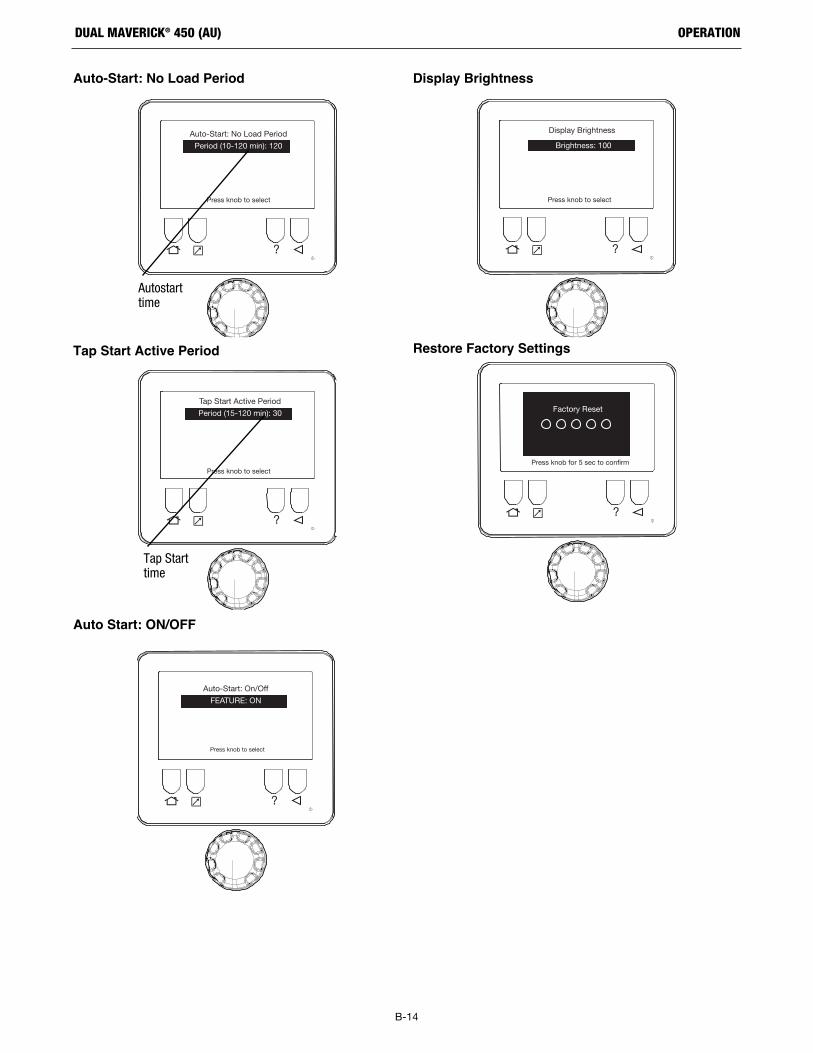
B-14
OPERATIONDUAL MAVERICK® 450 (AU)
Auto-Start: No Load Period
Tap Start Active Period
Auto Start: ON/OFF
Display Brightness
Restore Factory Settings
?
Press knob to select
Auto-Start: No Load Period
Period (10-120 min): 120
Autostarttime
?
Press knob to select
Brightness: 100
Display Brightness
?
Press knob for 5 sec to confirm
Factory Reset
?
Press knob to select
Tap Start Active Period
Period (15-120 min): 30
Auto-Start: On/Off
FEATURE: ON
Press knob to select
?
Tap Starttime

B-15
OPERATIONDUAL MAVERICK® 450 (AU)
PIN
DO NOT FORGET THE PIN! The PIN may only be reset by aLincoln Authorized Service Shop.
Rotate the knob to adjust the value of thePIN. Press the knob to advance to the nextnumber. Press the BACK button to go thethe previous number.
Entry of the Supervisor PIN is similar to theOperator PIN.
?
Operator
PIN
Supervisor
PIN
Press knob to select
8 1 2 38 1 2 3
ON
OFF
Rotate the knob to turn the PIN on or off.Press the knob to select.
Press knob to select
?
Operator
PIN
Supervisor
PIN
8 1 2 38 1 2 3OFF
ON
To turn on Operator security, rotate the knobuntil Operator PIN is highlighted and pressthe knob.
?
Operator
PIN
Supervisor
PIN
Press knob to select
8 1 2 38 1 2 3
OFF
OFF

B-16
OPERATIONDUAL MAVERICK® 450 (AU)
Variable Speed Setup Diagnostic Info
New PCB Calibration - Right Side Display (DualMode)
New PCB Calibration - Left Side Display (SingleMode)
Press knob to select
Feature: ON
Variable Speed On/Off
?
Diagnostic Information
Press knob to continue
ECG Fault Code: 0
Engine Part #: Perkins 403D-11Tap
Weld PCB HW: G9022-1
Weld PCB SW: A-17
Machine K#: K4833-1
Code #: 12723
Display #: CR9060
?
Mode: StickWelding
Ensure in Stick Mode andOutput Volts > 50
Stud Volts: 0VWeld Amps: 1A
?
Press knob to continue
Ensure in Single Modeand Stick Modeat 150A Setpoint
Mode: StickWelding
Stud Volts: 0VWeld Amps: 2A
?
Press knob to continue
Mode: StickWelding
Apply Load at150 (+-20) Amps
for 30 sec.
Stud Volts: 0VWeld Amps: 2A
?

B-17
OPERATIONDUAL MAVERICK® 450 (AU)
MACHINE SELECT
Enter the correct K# and Code # for the welder the PCB is beinginstalled on. K# and Code # can be found above the top nameplate(“Machine Information Above”). Failure to enter the correctK# and Code # may result in permanent damage to the welder.
If correct K # and Code # entered. The Welder will be accepted.
Press knob to select
?
Display Brightness
Diagnostic Information
New PCB Calibration
Variable Speed On/Off
Restore Factory SettingsMachine
Machine Select
Press knob to select
Machine Select
K#:CODE#:
K 0 0 0 0 - 00 0 0 0 0
?
Press knob to continue
Machine Select
Welder Accepted!
?

C-1
ACCESSORIESDUAL MAVERICK® 450 (AU)
ACCESSORIESOPTIONAL FIELD INSTALLED ACCESSORIES
K2636-1 Medium Trailer
K2639-1 Fender Kit
K2640-1 Cable Rack
K2641-2 Four Wheel Trailer
K857 Remote Control
K857-1 Remote Control
K2613-5A1 Ln-25 PRO with K126 PRO Gun
K126-12 K126 PRO Gun
KP1696-068 Drive Roll Kit
K12038-2 Invertec PC610 Plasma
K12048-1 Tomahawk 1025 Plasma

D-1
MAINTENANCEDUAL MAVERICK® 450 (AU)
MAINTENANCESAFETY PRECAUTIONS
• Have qualified personnel do all maintenance andtroubleshooting work.
• Turn the engine off before working inside the machineor servicing the engine.
• Remove guards only when necessary to performmaintenance and replace them when the maintenancerequiring their removal is complete. If guards aremissing from the machine, obtain replacements from aLincoln Distributor. (See Operating Manual Parts List.)
Read the Safety Precautions in the front of this manual andin the Engine Owner’s Manual before working on thismachine.
Keep all equipment safety guards, covers, and devices inposition and in good repair. Keep hands, hair, clothing, andtools away from the gears, fans, and all other moving partswhen starting, operating, or repairing the equipment.
ROUTINE AND PERIODIC MAINTENANCE
DAILY
• Check the Engine oil levels.
• Refill the fuel tank to minimize moisture condensation in thetank.
• Open the water drain valve located on the bottom of the waterseparator element 1 or 2 turns and allow to drain into acontainer suitable for diesel fuel for 2 to 3 seconds. Repeat theabove drainage procedure until diesel fuel is detected in thecontainer.
• Check coolant level in the coolant recovery bottle.
WEEKLY
Blow out the machine with low pressure air periodically. Inparticularly dirty locations, and the radiator, this may be requiredonce a week.
ENGINE MAINTENANCE
Refer to the “Periodic Checks” section of the Engine Operator’sManual for the recommended maintenance schedule of thefollowing:
a) Engine Oil and Filter
b) Air Cleaner
c) Fuel Filter - and Delivery System
d) Alternator Belt
e) Battery
f ) Cooling System
Refer to Table D.1 at the end of this section for various enginemaintenance components.
TABLE D.1
AIR FILTER
Excessive air filter restriction will result in reduced enginelife.
Never use gasoline or low flash point solvents for cleaningthe air cleaner element. A fire or explosion could result.
Never run the engine without the air cleaner. Rapid enginewear will result from contaminants, such as dust and dirtbeing drawn into the engine.
The diesel engine is equipped with a dry type air filter. Neverapply oil to it. Service the air cleaner as follows:
Replace the element as indicated by the service indicator. (SeeService Instructions and Installation Tips for Engine Air Filter.)
WARNING
CAUTION
WARNING
CAUTION

D-2
MAINTENANCEDUAL MAVERICK® 450 (AU)
Unfasten or unlatch theservice cover. Becausethe filter fits tightly over theoutlet tube to create the critical seal, there willbe some initial resistance, similar to breakingthe seal on a jar. Gently move the end of the filterback and forth to break the seal then rotate whilepulling straight out. Avoid knocking the filteragainst the housing.
Remove the FilterRemove the Filter
Rotate thefilter whilepullingstraight out.
If your air cleaner has a safety filter, replace it every third primaryfilter change. Remove the safety filter as you would the primaryfilter. Make sure you cover the air cleaner outlet tube to avoid anyunfiltered contaminant dropping into the engine.
If your air cleaner is equipped with a Vacuator ValveVisually check and physically squeeze to make sure thevalve is flexible and not inverted, damaged or plugged.
Inspect the new filter carefully, paying attention tothe inside of the open end, which is thesealing area. NEVER install a damagedfilter. A new Donaldson radial sealfilter may have a dry lubricant on theseal to aid installation.
If you're servicing the safety filter, this should be seated intoposition before installing the primary filter.
Insert the new filter carefully. Seat the filter by hand, making certain it iscompletely into the air cleaner housingbefore securing the cover in place.
If the service cover hits the filter before it is fully in place, removethe cover and push the filter (by hand) further into the air cleanerand try again. The cover should go on with no extra force.
Once the filter is in place, secure the service cover.
Make sure that all mounting bands, clamps, bolts, and connectionsin the entire air cleaner system are tight. Check for holes in pipingand repair if needed. Any leaks in your intake piping will send dustdirectly to the engine!
The critical sealing area will stretchslightly, adjust itself and distribute the sealing pressure evenly. Tocomplete a tight seal, apply pressure by hand at the outer rim ofthe filter, not the flexible center. (Avoid pushing on the center of theurethane end cap.) No cover pressure is required to hold the seal.NEVER use the service cover to push the filter into place! Using thecover to push the filter in could cause damage to the housing, coverfasteners and will void the warranty.
Visually inspect the old filter for any signsof leaks. A streak of dust on the clean sideof the filter is a telltale sign. Remove anycause of leaks before installing new filter.
Clean Both Surfaces of the Outlet TubeClean Both Surfaces of the Outlet Tubeand Check the Vacuator™ Valveand Check the Vacuator™ Valve
Inspect the OldInspect the OldFilter for Leak CluesFilter for Leak Clues
Inspect the New Filter for DamageInspect the New Filter for Damage
Insert the New Radial Seal Filter ProperlyInsert the New Radial Seal Filter Properly
Check Connectors for Tight FitCheck Connectors for Tight Fit
NEVER use the service cover toNEVER use the service cover topush the filter into place! Usingpush the filter into place! Usingthe cover to push the filter in couldthe cover to push the filter in couldcause damage to the housing, covercause damage to the housing, coverfasteners and will void the warranty.fasteners and will void the warranty.
CautionCaution
Use a clean cloth to wipe the filter sealing surface and the inside ofthe outlet tube. Contaminant on the sealing surface could hinder aneffective seal and cause leakage. Make sure that all contaminant isremoved before the new filter is inserted. Dirt accidently transferredto the inside of the outlet tube will reach the engine and cause wear. Engine manufacturers say that it takes only a few grams ofdirt to "dust" an engine! Be careful not to damage the sealing areaon the tube.
Wipe both sidesof the outlettube clean.
Outer edge of theoutlet tube
Inner edge of theoutlet tube
Service InstructionsService InstructionsSingle- and Two-Stage Engine Air CleanersSingle- and Two-Stage Engine Air Cleaners

FUEL FILTERS
When working on the fuel system:
• Keep naked lights away, do not smoke!
• Do not spill fuel!
The Dual Maverick® 450 (AU) is equipped with a Fuel Filterlocated to left of air cleaner.The procedure for changing the filteris as follows.
1. Close the fuel shutoff valve.
2. Clean the area around the fuel filter head. Remove the filter.Clean the gasket surface of the filter head and replace the o-ring.
3. Fill the clean filter with clean fuel, and lubricate the o-ring sealwith clean lubricating oil.
4. Install the filter as specified by the filter manufacturer.
Mechanical overtightening will distort the threads, filterelement seal or filter can.
COOLING SYSTEM
The Dual Maverick® 450 (AU) is equipped with a pressureradiator. Keep the radiator cap tight to prevent loss of coolant.Clean and flush the coolant system periodically to preventclogging the passage and over-heating the engine. Whenantifreeze is needed, always use the permanent type.
• Every 500 hours check radiator to ensure there is no finblockage or leaks. Clean as necessary with an environmentallyfriendly degreaser and low pressure water.
• When draining the entire contents of the system, removeradiator cap. Pull drain hose through the battery access door inthe base and open shut off valve until system is empty.
• When refilling, close shut off valve on drain hose.
NAMEPLATES / WARNING DECALS MAINTENANCE
Whenever routine maintenance is performed on this machine - orat least yearly - inspect all nameplates and labels for legibility.Replace those which are no longer clear. Refer to the parts list forthe replacement item number.
WELDER / GENERATOR MAINTENANCE
STORAGE
Store the Dual Maverick® 450 (AU) in clean, dry, protected areas.
CLEANING
Blow out the generator and controls periodically with low pressureair. Do this at least once a week in particularly dirty areas.
FAN BELT CHANGE
Ensure when changing the fan belt a Lincoln recommended fanbelt is used or equivalent EPDM material, 762 mm datum lengthand XPZ profile(Width 10, Height 8 mm, Cogged) belt is used.Tension new belts to 120lbs, used belts to 80lbs, using aBurroughs guage. Refer to engine operator's manual for properinstallation and tension.
OIL CHANGE
Remove battery cover (see below) and route oil drain hose throughopening to change engine oil.
WARNING
WARNING
D-3
MAINTENANCEDUAL MAVERICK® 450 (AU)
Remove batterycover for oilchange.

BATTERY HANDLING
GASES FROM BATTERY can explode.Keep sparks, flame and cigarettes away frombattery.
To prevent EXPLOSION when:• INSTALLING A NEW BATTERY - disconnect
negative cable from old battery first andconnect to new battery last.
• CONNECTING A BATTERY CHARGER -Remove battery from welder by discon-necting negative cable first, then positivecable and battery clamp. When reinstalling, connectnegative cable last. Keep well ventilated.
• USING A BOOSTER - connect positive lead to batteryfirst then connect negative lead to engine foot.
BATTERY ACID CAN BURN EYES AND SKIN.• Wear gloves and eye protection and be
careful when working near battery. Followinstructions printed on battery.
PREVENTING ELECTRICAL DAMAGE
1. When replacing, jumping, or otherwise connecting the batteryto the battery cables, the proper polarity must be observed.Failure to observe the proper polarity could result in damageto the charging circuit. The positive (+) battery cable has ared terminal cover.
2. If the battery requires charging from an external charger,disconnect the negative battery cable first and then thepositive battery cable before attaching the charger leads.Failure to do so can result in damage to the internal chargercomponents. When reconnecting the cables, connect thepositive cable first and the negative cable last.
PREVENTING BATTERY DISCHARGE
Turn the RUN/STOP switch to stop when engine is not running.
PREVENTING BATTERY BUCKLING
Tighten nuts on battery clamp until snug.
CHARGING THE BATTERY
When you charge, jump, replace, or otherwise connect batterycables to the battery, be sure the polarity is correct. Improperpolarity can damage the charging circuit. The Dual Maverick® 450(AU) positive (+) battery terminal has a red terminal cover.
If you need to charge the battery with an external charger,disconnect the negative cable first, then the positive cable beforeyou attach the charger leads.
After the battery is charged, reconnect the positive battery cablefirst and the negative cable last. Failure to do so can result indamage to the internal charger components.
Follow the instructions of the battery charger manufacturer forproper charger settings and charging time.
BATTERY LOCKOUT SWITCH
The Battery Lockout Switch is provided to disable the battery whileperforming maintenance on the machine.
WARNING
D-4
MAINTENANCEDUAL MAVERICK® 450 (AU)

If for any reason you do not understand the test procedures or are unable to perform the tests/repairs safely, contact your Lincoln Authorized Service Facility for technical troubleshooting assistance before you proceed.
WWW.LINCOLNELECTRIC.COM/LOCATOR
E-1
TROUBLESHOOTINGDUAL MAVERICK® 450 (AU)
TROUBLESHOOTINGHow to Use Troubleshooting Guide
Service and Repair should only be performedby Lincoln Electric Factory TrainedPersonnel. Unauthorized repairs performedon this equipment may result in danger tothe technician and machine operator and willinvalidate your factory warranty. For your safety and toavoid Electrical Shock, please observe all safety notes andprecautions detailed throughout this manual.
This Troubleshooting Guide is provided to help you locate andrepair possible machine malfunctions. Simply follow the three-step procedure listed below.
Step 1. LOCATE PROBLEM (SYMPTOM).
Look under the column labeled “PROBLEM (SYMPTOMS).” Thiscolumn describes possible symptoms that the machine mayexhibit. Find the listing that best describes the symptom that themachine is exhibiting.
Step 2. POSSIBLE CAUSE.The second column labeled “POSSIBLE CAUSE” lists the obviousexternal possibilities that may contribute to the machine symptom. Step 3. RECOMMENDED COURSE OF ACTIONThis column provides a course of action for the Possible Cause,generally it states to contact your local Lincoln Authorized FieldService Facility.
If you do not understand or are unable to perform theRecommended Course of Action safely, contact your local Lincoln Authorized Field Service Facility.
E
ELECTRIC SHOCK can kill.• Turn off machine at the disconnect switch
on the rear of the machine and removemain power supply connections beforedoing any troubleshooting.
WARNING
WARNING

If for any reason you do not understand the test procedures or are unable to perform the tests/repairs safely, contact your Lincoln Authorized Service Facility for technical troubleshooting assistance before you proceed.
WWW.LINCOLNELECTRIC.COM/LOCATOR
Observe all Safety Guidelines detailed throughout this manual
PROBLEMS(SYMPTOMS)
POSSIBLECAUSE
RECOMMENDEDCOURSE OF ACTION
E-2
TROUBLESHOOTINGDUAL MAVERICK® 450 (AU)
AUXILIARY OUTPUT
No auxiliary power 1. Check that the circuit breakers did not trip.
If all recommended possible areas ofmisadjustment have been checked and theproblem persists, Contact your local LincolnAuthorized Field Service Facility.
2. Check that the RCD has not reset.
3. Inspect AVR 5 AMP fuse did not blow.
4. Faulty Field Relay(CR3) located under theright control PC board.
ENGINE
Engine will not crank 1. Low or weak battery. Battery lockout switchis in OFF position.
If all recommended possible areas ofmisadjustment have been checked and theproblem persists, Contact your local LincolnAuthorized Field Service Facility.
2. Inspect for loose or corroded batteryterminals.
3. “Battery circuit” circuit breaker (CB4) hastripped. Located on upper control panelbeside E-stop button.
4. Faulty starter motor
5. Check starter relay(CR2). Located on lefthand side of fuel tank shield below ECU.
6. E-stop is engaged
Engine will crank but not start 1. Out of fuel.
2. Enter correct security PIN if the PIN functionis enabled.
3. Fuel pump not working
4. Water separator valve closed.
Engine shuts down shortly after starting 1. Low fuel level.
2. Low oil level.
3. Clogged fuel filter. Clean.
4. Faulty oil pressure switch.
Engine has low output or 1. Low fuel
2. Clogged fuel filter
3. Clogged air filter
4. Poor quality fuel – fuel has sat for a longtime.
Engine will not go to low idle 1. Idler switch is in the High Idle position.
2. Aux load might be on
3. Faulty PC board.
Engine does not go to full power whenusing auxiliary power.
1. The auxiliary power load is less than 100Watts. Set the STOP/AUTO/HIGH IDLEswitch to HIGH IDLE.
2. Disconnect / turn off auxiliary power loadsbefore starting the engine.
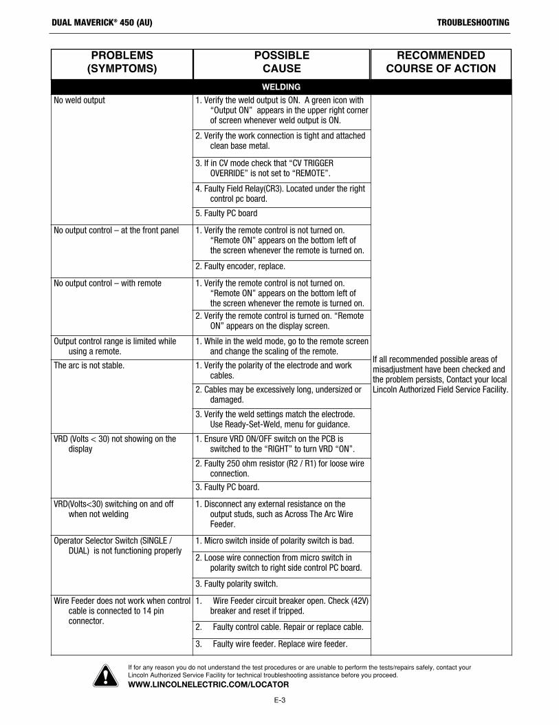
If for any reason you do not understand the test procedures or are unable to perform the tests/repairs safely, contact your Lincoln Authorized Service Facility for technical troubleshooting assistance before you proceed.
WWW.LINCOLNELECTRIC.COM/LOCATOR
E-3
TROUBLESHOOTINGDUAL MAVERICK® 450 (AU)
PROBLEMS(SYMPTOMS)
POSSIBLECAUSE
RECOMMENDEDCOURSE OF ACTION
WELDING
No weld output 1. Verify the weld output is ON. A green icon with“Output ON” appears in the upper right cornerof screen whenever weld output is ON.
If all recommended possible areas ofmisadjustment have been checked andthe problem persists, Contact your localLincoln Authorized Field Service Facility.
2. Verify the work connection is tight and attachedclean base metal.
3. If in CV mode check that “CV TRIGGEROVERRIDE” is not set to “REMOTE”.
4. Faulty Field Relay(CR3). Located under the rightcontrol pc board.
5. Faulty PC board
No output control – at the front panel 1. Verify the remote control is not turned on.“Remote ON” appears on the bottom left ofthe screen whenever the remote is turned on.
2. Faulty encoder, replace.
No output control – with remote 1. Verify the remote control is not turned on.“Remote ON” appears on the bottom left ofthe screen whenever the remote is turned on.
2. Verify the remote control is turned on. “RemoteON” appears on the display screen.
Output control range is limited whileusing a remote.
1. While in the weld mode, go to the remote screenand change the scaling of the remote.
The arc is not stable. 1. Verify the polarity of the electrode and workcables.
2. Cables may be excessively long, undersized ordamaged.
3. Verify the weld settings match the electrode.Use Ready-Set-Weld, menu for guidance.
VRD (Volts < 30) not showing on thedisplay
1. Ensure VRD ON/OFF switch on the PCB isswitched to the “RIGHT” to turn VRD “ON”.
2. Faulty 250 ohm resistor (R2 / R1) for loose wireconnection.
3. Faulty PC board.
VRD(Volts<30) switching on and offwhen not welding
1. Disconnect any external resistance on theoutput studs, such as Across The Arc WireFeeder.
Operator Selector Switch (SINGLE /DUAL) is not functioning properly
1. Micro switch inside of polarity switch is bad.
2. Loose wire connection from micro switch inpolarity switch to right side control PC board.
3. Faulty polarity switch.
Wire Feeder does not work when controlcable is connected to 14 pinconnector.
1. Wire Feeder circuit breaker open. Check (42V)breaker and reset if tripped.
2. Faulty control cable. Repair or replace cable.
3. Faulty wire feeder. Replace wire feeder.

If for any reason you do not understand the test procedures or are unable to perform the tests/repairs safely, contact your Lincoln Authorized Service Facility for technical troubleshooting assistance before you proceed.
WWW.LINCOLNELECTRIC.COM/LOCATOR
E-4
TROUBLESHOOTINGDUAL MAVERICK® 450 (AU)
FLASH CODENUMBER FAULT
WILL ENGINESHUTDOWN? CORRECTIVE ACTION
1 Unit not calibrated Yes ECM requires calibration
2 Excessive engine speed Yes Check over-speed parameter settingCheck electrical interferenceCheck wiring and connectors
Check ECM ground connectionsCheck actuator connections and fitment
3 Engine speed unusually low
Yes Check parameter settingsCheck actuator connections and fitment
Check machine loading upon engine
4 Engine protection inputtriggered
Yes Check parameter settingsCheck Engine protection inputs
Check engine protection run time setting
5 Factory calibration lost Yes Reload calibration fileContact distributor
6 Analogue sensor inputout of range
No Check throttle wiringRecalibrate/Reset throttle settings.
7 Throttle position / IVSsignal mis-match
No - mayrestrict
acceleration
Verify wiring on throttle and IVSCheck throttle and IVS parameters
Check throttle configuration
8 ECM failure Yes Check wiring, shielding and ECMconnections. Cycle ignition key. Check
electrical interference.Consult distributor.
9 Excessive actuatorcurrent limiting
No Check actuator wiringCheck actuator fitment
Check parameter settings
10 No engine speed signal Yes - nonstart
Check speed pick up fitmentCheck speed pick up wiring
Check electrical interference on pick upsensor and wiring.
Check contamination on sensor
11 Autocrank detects enginenon start
No Check wiring and settings.Check engine mechanicals
12 Excessive current drawon Auxiliary output
No Check wiring to outputCheck current draw of lamp, relay etc.
13 Excessive current drawon Auxiliary2 output
No Check wiring to outputCheck current draw of lamp, relay etc.
14 Actuator disconnected oropen circuit
Yes Check actuator wiring and fitmentCheck electrical interference
Check actuator resistance(less than 10 ohms)
ENGINE FAULT FLASH CODES ON ECG

F-1
WIRING DIAGRAMDUAL MAVERICK® 450 (AU)
NO
TE
: T
his
dia
gra
m is
fo
r re
fere
nce
on
ly.
It m
ay n
ot
be
accu
rate
fo
r al
l mac
hin
es c
ove
red
by
this
man
ual
. T
he
spec
ific
dia
gra
m f
or
a p
arti
cula
r co
de
is in
clu
ded
wit
h t
he
mac
hin
e. I
f th
e d
iag
ram
is il
leg
ible
, wri
te t
o t
he
Ser
vice
Dep
artm
ent
for
a re
pla
cem
ent.
Giv
e th
e eq
uip
men
t co
de
nu
mb
er.
BU
4 BK
GY
WH
1
GY
1 4
2W
H
STA
RT
BU
TTO
N
4B77B21 2B75B
GN
D-A
76B
CO
NTA
CT
OR
WO
RK
42V
AC
GR
OU
NDA
MP
HE
NO
L 1
J A D CH BK E F GI
R
DU
AL
MA
VE
RIC
K 4
50 (A
U) W
IRIN
G D
IAG
RA
ME
LEC
TRIC
AL
SY
MB
OLS
PE
R E
1537
AL
L C
AS
EFR
ON
T C
OM
PO
NE
NTS
SH
OW
N V
IEW
ED
FR
OM
RE
AR
B2-
PO
S
B4-
NE
G
B5-
PO
S
B1-
NE
G
CH
OP
PE
RP
CB
3
B6
B5
B4
B1
B2
B3
B7
B8
L1 C
HO
KE
RE
MO
TE
CO
NTR
OL
FUE
L LV
L.S
EN
SO
R
WK
235
5J229
228
241
G
SW
ITC
H
SW
ITC
H
OIL
PR
ES
SU
RE
SE
NS
OR
& S
WIT
CH
CO
OLA
NT
TEM
PE
RA
TUR
ES
EN
SO
R &
SW
ITC
H
SH
OW
N IN
"RU
N"/
"HIG
H"
PO
SIT
ION
EN
GIN
ES
UP
PO
RT
ON
BA
SE
EN
GIN
E B
LO
CK
12V
BA
TTE
RY
-+S
TA
RTI
NG
MO
TO
R
STA
RTE
RS
OLE
NO
ID
ALT
ER
NA
TOR
GLO
W P
LUG
BU
TTO
N
+-
13A
R1
222D
PO
S-S
TUD
PO
S-S
TUD
SE
NS
OR
SE
NS
OR
208A
SW
ITC
H C
ON
TAC
TSS
HO
WN
IN "
+" P
OS
ITIO
N
WIR
E F
EE
DE
RV
OLT
ME
TER
SW
ITC
H
A.0
9G
9673
PR
INT
BO
LT B
ES
IDE
ST
ATO
R F
OO
T
EM
ER
GE
NC
YS
TOP
CB
2C
B3
7
L1
L2
12
L3
15A
15A
NA E
NA E
NL1
L3L2
2C2B
2A
RC
D40
A
5A
230
V1
PH
AS
E
E 400
V3
PH
AS
E
206A
208A
221D
WE
LDIN
G O
UT
PU
TT
ER
MIN
AL
WE
LDIN
G O
UT
PU
TT
ER
MIN
AL
I+
221E
GR
OU
ND
ST
UD
ON
AU
XIL
IAR
Y P
OW
ER
RE
CE
PTA
CL
E P
AN
EL
T2
T3
T1
TE
RM
INA
L B
LOC
K O
NL
OW
ER
CO
NTR
OL
PA
NE
LT
OP
LE
FT
CO
NT
RO
LP
CB
1
X1
X2
X3
D1
RE
CTI
FIE
R B
RID
GE
ST
ATO
RW
ELD
1W
IND
ING
S
222E
B3
CH
OK
E
206A
4BR
77B
R
2BR
75B
R
GN
D-A
R
41R
42A
R
76B
R
CO
NTA
CT
OR
WO
RK
42V
AC
GR
OU
ND
AM
PH
EN
OL
1
J A D CH BK E F GI
2BR
GN
D-B
R
A B C D E F
76B
R75
BR
AM
PH
EN
OL
277
BR
B4-
NE
G
B5-
PO
S
B1-
NE
G
B2-
PO
S
CH
OP
PE
RP
CB
4
B3
B2
B1
B4 B5 B
6
B7
B8
L2 C
HO
KE
RE
MO
TE
CO
NTR
OL
RE
MO
TE
CO
NTR
OL
CO
NTA
CT
OR
GR
OU
ND
+
- PO
S-S
TUD
PO
S-S
TUD
B3
CH
OK
E
SW
ITC
H C
ON
TAC
TSS
HO
WN
IN "
+" P
OS
ITIO
N
WIR
E F
EE
DE
RV
OLT
ME
TER
SW
ITC
H
I+
CO
NT
RO
LP
CB
2
Y1
Y2
Y3
D2
RE
CTI
FIE
R B
RID
GE
ST
ATO
RW
ELD
2W
IND
ING
S
206A
R
1423
25
23R 25
R
WE
LDIN
G O
UT
PU
TT
ER
MIN
AL
11
230
V1
PH
AS
E
15 15
14R
SW
1
WH
ITE
TO
RO
IDB
LA
CK
RO
TO
RE
XC
ITE
R F
IELD
BLACK
W UV
A BC
SP
EE
D
SE
NS
OR
+ - AC
TU
AT
OR
+ -
2335G
5757
N
5858
N
66
GND-A
GN
D-K
B+
234
86
54
32
11211
109
87 6
1212 11
1034 9
856 7
EN
GIN
EC
ON
TR
OL
LE
R
EC
G
J1 (
GR
EY
)J2
(B
LA
CK
)
LIG23
3A
NO
NC
GR
OU
ND
ST
UD
RIG
HT
UP
PE
R C
ON
TR
OL
PA
NE
L
GND-B
ON
/ ID
LER
CO
NTR
OL
/S
TOP
SW
ITC
H1
523 6
8 7+ -
239
844
5J
AC
CB410A
+
238C
232Z
231
231
378
232L
GND-T
GND-Z
206D
R
232T
21R
41 42A
5H
GN
D-P
GN
D-A
R
GN
D-B
R
5HG
ND
-X
2B
GN
D-B
A B C D F
76B
75B
AM
PH
EN
OL
277
A77
BR
EM
OT
EC
ON
TRO
L
CO
NTA
CT
OR
GR
OU
ND
4BE
AV
R B
L4-U
+EX
AUXNAUXL
0
-EX
230115
EXT POT
GGLLOO
WWPP
LLUUGG
SS
LC
DD
ISP
LAY
LE
FT
WH
GY
CO
NTR
OL
BO
AR
D L
EFT
CO
NTR
OL
BO
AR
D R
IGH
T
41R
42A
R
5D
U4
W4
V4
V2
V1
EM
CF
ILT
ER
AU
X-L
400V
3P
H
CB
1 2
0A
ST
UD
BE
SID
ES
TA
TOR
FO
OT
2 3
5
BU
BK
BY
PA
SS
FILT
ER
AS
SE
MB
LY
2 4
76A
75A
77A
R
2R 4R75A
R76
AR
821
GND-X+ -S
ING
LE/
DU
AL
SW
1
221E
G9022-1
1415 208C
275A
77A
BK
BU
B1
W1
R1
GY
U1
Y1
WH
G1
76A 4
J2
AMP776230
113
24
23
12
35
J1
832
86 52A
6622
9
GN
D-Z
232
92TR
92TL
23 25 25FT
23FT
844
615
232K
285
WH
ITE
BLA
CK
AMP776200
18
915
1623
G9022-1
J1
228
241
92TL
92TR
23FT
25FT
378 61
5
23R
25R
232L
GN
D-T
AMP776200
1
8
915
1623
14R
206D
R75
AR
77A
R
2R
4R
76A
R
J2
AMP776230
113
24
23
12
35
BK
BU
B2
W2
R2
GY
U2
Y2
WH
G2
208
CR
J3
J3
206D
LC
DD
ISP
LAY
RIG
HT
3
5
BU
BK
BU
GY
WH
JP1
208A
R
21
238A
5G42V
AC
WIN
DIN
GS
41C
400
VR
DO
FF
ON
VR
DO
FF
ON
236A
236
238D
236A
+
85
30
87A
86 C
R2
87
377
377
285
52A
238A
237
821
L3
L2
L1
7E
232
13B
238
232K
238B
4BR
B6
CH
OK
E
Con
nect
ion
Poi
nton
Cho
pper
Pan
elC
onne
ctio
n P
oint
on C
hopp
er P
anel
Con
nect
ion
Poi
nton
Cho
pper
Pan
el
Con
nect
ion
Poi
nt o
n C
hopp
er P
anel
233
233A
233B
RED
234
221D
222E
WE
LDIN
G O
UT
PU
TT
ER
MIN
AL
BY
PA
SS
FILT
ER
AS
SE
MB
LY
2A5A
ENCODER
6 5 4 3 2 1
V
BLA
CK
BLU
EG
RE
EN
YE
LLO
WW
HIT
E
RE
D
ENCODER
6 5 4 3 2 1
V
BLA
CK
BLU
EG
RE
EN
YE
LLO
WW
HIT
E
RE
D
GN
D IN
HIG
H
VO
LTA
GE
BO
X
CB
510
A
42A
R42
A
4141
R
21R
BK
208C
GN
D-C
5GN
D-E
GN
D-E
GN
D-D
GN
D-D
206A
R R2
13B
R
13A
R
42C
85
30
87A
86
CR
1
87
16
J1P1
R1
W1
Y1
G1
U1
B1
16
J2P2
R2
W2
Y2
G2
U2
B2
232Z
W2
W3
U2 U3
V3
U1
W1
AU
XIL
IAR
YW
IND
ING
B
207
207R
207
B6
CH
OK
E
207R
C A
208C
R
LOC
KO
UT
SW
ITC
H
AC
R3
R4
203
204A
201
202A
204A
222D
ISO
LA
TE
DN
EU
TR
AL
ST
UD
BE
SID
ES
TA
TOR
FO
OT
5X
CO
M
NC
CO
M
NC
CO
M
NO
204
202
200
200A
203
201
5
200
202A
EM
C-N
232T
832
232T
A23
2TB
832A
832B
CR
3
CR
4
CR
5
208A
R
400
B5A
2C
5C
5E
2B
5D5C
5E
5C2C
2B2A
RC
D40
A
FO
R M
AC
HIN
ES
BU
ILT
BE
FO
RE
MA
RC
H 2
021
5AC
BA
5D5E

31.0
478
8.5
22.4
457
0
65.0
016
51
43.0
710
93.9
59.5
015
11.3
33.4
084
8.312
.75
323.
8
31.0
078
7.4
Cen
ter
of G
ravi
ty39
.09
992.
936
.08
916.
4
5.75
1469.
9025
1.5
30.0
476
3
27.0
468
6.8
28.8
673
3
F-2
DIMENSION PRINTDUAL MAVERICK® 450 (AU)

WARNING
AVISO DEPRECAuCION
ATTENTION
WARNuNG
ATENÇÃO
Spanish
French
German
Portuguese
Japanese
Chinese
Korean
Arabic
READ AND UNDERSTAND THE MANUFACTURER’S INSTRUCTION FOR THIS EQUIPMENT AND THE CONSUMABLES TO BEUSED AND FOLLOW YOUR EMPLOYER’S SAFETY PRACTICES.
SE RECOMIENDA LEER Y ENTENDER LAS INSTRUCCIONES DEL FABRICANTE PARA EL USO DE ESTE EQUIPO Y LOSCONSUMIBLES QUE VA A UTILIZAR, SIGA LAS MEDIDAS DE SEGURIDAD DE SU SUPERVISOR.
LISEZ ET COMPRENEZ LES INSTRUCTIONS DU FABRICANT EN CE QUI REGARDE CET EQUIPMENT ET LES PRODUITS AETRE EMPLOYES ET SUIVEZ LES PROCEDURES DE SECURITE DE VOTRE EMPLOYEUR.
LESEN SIE UND BEFOLGEN SIE DIE BETRIEBSANLEITUNG DER ANLAGE UND DEN ELEKTRODENEINSATZ DES HER-STELLERS. DIE UNFALLVERHÜTUNGSVORSCHRIFTEN DES ARBEITGEBERS SIND EBENFALLS ZU BEACHTEN.
l Do not touch electrically live parts orelectrode with skin or wet clothing.
l Insulate yourself from work andground.
l No toque las partes o los electrodosbajo carga con la piel o ropa moja-da.
l Aislese del trabajo y de la tierra.
l Ne laissez ni la peau ni des vête-ments mouillés entrer en contactavec des pièces sous tension.
l Isolez-vous du travail et de la terre.
l Berühren Sie keine stromführendenTeile oder Elektroden mit IhremKörper oder feuchter Kleidung!
l Isolieren Sie sich von denElektroden und dem Erdboden!
l Não toque partes elétricas e elec-trodos com a pele ou roupa molha-da.
l Isole-se da peça e terra.
l Keep flammable materials away.
l Mantenga el material combustiblefuera del área de trabajo.
l Gardez à l’écart de tout matérielinflammable.
l Entfernen Sie brennbarres Material!
l Mantenha inflamáveis bem guarda-dos.
l Wear eye, ear and body protection.
l Protéjase los ojos, los oídos y elcuerpo.
l Protégez vos yeux, vos oreilles etvotre corps.
l Tragen Sie Augen-, Ohren- und Kör-perschutz!
l Use proteção para a vista, ouvido ecorpo.

WARNING
AVISO DEPRECAuCION
ATTENTION
WARNuNG
ATENÇÃO
Spanish
French
German
Portuguese
Japanese
Chinese
Korean
Arabic
LEIA E COMPREENDA AS INSTRUÇÕES DO FABRICANTE PARA ESTE EQUIPAMENTO E AS PARTES DE USO, E SIGA ASPRÁTICAS DE SEGURANÇA DO EMPREGADOR.
l Keep your head out of fumes.l Use ventilation or exhaust to
remove fumes from breathing zone.
l Los humos fuera de la zona de res-piración.
l Mantenga la cabeza fuera de loshumos. Utilice ventilación oaspiración para gases.
l Gardez la tête à l’écart des fumées.l Utilisez un ventilateur ou un aspira-
teur pour ôter les fumées des zonesde travail.
l Vermeiden Sie das Einatmen vonSchweibrauch!
l Sorgen Sie für gute Be- undEntlüftung des Arbeitsplatzes!
l Mantenha seu rosto da fumaça.l Use ventilação e exhaustão para
remover fumo da zona respiratória.
l Turn power off before servicing.
l Desconectar el cable de ali-mentación de poder de la máquinaantes de iniciar cualquier servicio.
l Débranchez le courant avant l’entre-tien.
l Strom vor Wartungsarbeitenabschalten! (Netzstrom völlig öff-nen; Maschine anhalten!)
l Não opere com as tampas removidas.l Desligue a corrente antes de fazer
serviço.l Não toque as partes elétricas nuas.
l Do not operate with panel open orguards off.
l No operar con panel abierto oguardas quitadas.
l N’opérez pas avec les panneauxouverts ou avec les dispositifs deprotection enlevés.
l Anlage nie ohne Schutzgehäuseoder Innenschutzverkleidung inBetrieb setzen!
l Mantenha-se afastado das partesmoventes.
l Não opere com os paineis abertosou guardas removidas.

CUSTOMER ASSISTANCE POLICY
The business of The Lincoln Electric Company is manufacturingand selling high quality welding equipment, consumables, andcutting equipment. Our challenge is to meet the needs of ourcustomers and to exceed their expectations. On occasion,purchasers may ask Lincoln Electric for advice or informationabout their use of our products. We respond to our customersbased on the best information in our possession at that time.Lincoln Electric is not in a position to warrant or guarantee suchadvice, and assumes no liability, with respect to such informationor advice. We expressly disclaim any warranty of any kind,including any warranty of fitness for any customer’s particularpurpose, with respect to such information or advice. As a matterof practical consideration, we also cannot assume any respon-sibility for updating or correcting any such information or adviceonce it has been given, nor does the provision of information oradvice create, expand or alter any warranty with respect to thesale of our products.
Lincoln Electric is a responsive manufacturer, but the selectionand use of specific products sold by Lincoln Electric is solelywithin the control of, and remains the sole responsibility of thecustomer. Many variables beyond the control of Lincoln Electricaffect the results obtained in applying these types of fabricationmethods and service requirements.
Subject to Change – This information is accurate to the best of ourknowledge at the time of printing. Please refer to www.lincolnelectric.com for any updated information.


