Embed Size (px)
Citation preview

0707 © 2006 Titan Tool Inc. All rights reserved. Form No. 313-2692BPrinted in the U. S. A.
Do not use this equipment before reading this manual!
RentSpray 450Airless Sprayer
Owner’s ManualFor professional use only
NOTE: This manual contains important warningsand instructions. Please read and retain forreference.
NOTE: This manual contains important warningsand instructions. Please read and retain forreference.
Model Number 766-4070

2 © Titan Tool Inc. All rights reserved.
This symbol indicates a hazardous situation,which, if not not avoided could result in death orserious injury.
To reduce the risks of fire or explosion, electricalshock and the injury to persons, read and under-stand all instructions included in this manual. Befamiliar with the controls and proper usage of theequipment.
HAZARD: INJECTION INJURY
A high pressure paint stream produced by thisequipment can pierce the skin and underlyingtissues, leading to serious injury and possibleamputation. See a physician immediately.DO NOT TREAT AN INJECTION INJURY AS A SIMPLE CUT!Injection can lead to amputation. See a physicianimmediately.The maximum operating range of the sprayer is 3000 PSI / 20.6MPa fluid pressure.
PREVENTION:• NEVER aim the gun at any part of the body. • Do not aim the gun at, or spray any person or animal.• NEVER allow any part of the body to touch the fluid stream.
DO NOT allow body to touch a leak in the fluid hose.• NEVER put your hand in front of the gun. Gloves will not
provide protection against an injection injury.• ALWAYS lock the gun trigger, shut the pump off, and
release all pressure before servicing, cleaning the tip orguard, changing tip, or leaving unattended. Pressure willnot be released by turning off the motor. ThePRIME/SPRAY valve or pressure bleed valve must beturned to their appropriate positions to relieve systempressure. Refer to the PRESSURE RELIEFPROCEDURE described in this manual.
• ALWAYS keep the tip guard in place while spraying. Thetip guard provides some protection but is mainly a warningdevice.
• ALWAYS remove the spray tip before flushing or cleaningthe system.
• Paint hose can develop leaks from wear, kinking andabuse. A leak can inject material into the skin. Inspectthe hose before each use. Do not use hose to lift or pullequipment.
• NEVER use a spray gun without a working trigger lockand trigger guard in place.
• All accessories must be rated at or above 3000 PSI / 20.6MPa. This includes spray tips, guns, extensions, and hose.
• Do not leave the unit energized or under pressure whileunattended. When the unit is not in use, turn off the unitand relieve the pressure in accordance with thePRESSURE RELIEF PROCEDURE described in thismanual.
• Verify that all connections are secure before operating theunit. Unsecured parts may eject at great force or leak ahigh pressure fluid stream causing severe injury.
• Always engage the trigger lock when not spraying. Verifythe trigger lock is functioning properly.
NOTE TO PHYSICIAN:Injection into the skin is a traumatic injury. It isimportant to treat the injury as soon as possible. DONOT delay treatment to research toxicity. Toxicity is aconcern with some coatings injected directly into theblood stream. Consultation with a plastic surgeon orreconstructive hand surgeon may be advisable.
HAZARD: HAZARDOUS VAPORSPaints, solvents, insecticides, and other materials canbe harmful if inhaled or come in contact with the body.Vapors can cause severe nausea, fainting, orpoisoning.
PREVENTION:• Use a respirator or mask if vapors can be
inhaled. Read all instructions supplied with themask to be sure it will provide the necessaryprotection.
• Wear protective eyewear.• Wear protective clothing as required by coating
manufacturer.
HAZARD: EXPLOSION OR FIRE Solvent and paint fumes can explode or ignite.Property damage and/or severe injury can occur.
PREVENTION:• Provide extensive exhaust and fresh air introduction to
keep the air within the spray area free from accumulationof flammable vapors. Solvent and paint fumes canexplode or ignite.
• Do not spray in a confined area.• Avoid all ignition sources such as static electric
sparks, open flames, pilot lights, electricalappliances, and hot objects. Connecting or disconnectingpower cords or working light switches can make sparks.Paint or solvent flowing through the equipment is able toresult in static electricity.
• Do not smoke in spray area.• Fire extinguisher must be present and in good working
order.• Place pump at least 25 feet (7.62 meters) from the spray
object in a well ventilated area (add more hose ifnecessary). Flammable vapors are often heavier than air.Floor area must be extremely well ventilated. The pumpcontains arcing parts that emit sparks and can ignitevapors.
• The equipment and objects in and around the spray areamust be properly grounded to prevent static sparks.
• Keep area clean and free of paint or solvent containers,rags and other flammable materials.
• Use only conductive or grounded high pressure fluid hose.Gun must be grounded through hose connections.
• For electric units — power cord must be connected to agrounded circuit.
• Always flush unit into a separate metal container, at lowpump pressure, with spray tip removed. Hold gun firmlyagainst side of container to ground container and preventstatic sparks.
• Follow the material and solvent manufacturer's warningsand instructions. Know the contents of the paints andsolvents being sprayed. Read all Material Safety DataSheets (MSDS) and container labels provided with thepaints and solvents. Follow the paint and solventmanufacturer’s safety instructions.
• Use extreme caution when using materials with aflashpoint below 70ºF (21ºC). Flashpoint is thetemperature that a fluid can produce enough vapors toignite.
• Plastic can cause static sparks. Never hang plastic toenclose a spray area. Do not use plastic drop clothswhen spraying flammable materials.
• Use lowest possible pressure to flush equipment.• Do not spray onto pump assembly.
Important Safety Information • Read all safety information before
operating the equipment. Save these instructions.
© Titan Tool Inc. All rights reserved. 3
HAZARD: EXPLOSION HAZARD DUE TOINCOMPATIBLE MATERIALS
Will cause property damage or severe injury.
PREVENTION:• Do not use materials containing bleach or chlorine.• Do not use halogenated hydrocarbon solvents such as
bleach, mildewcide, methylene chloride and 1,1,1 -trichloroethane. They are not compatible with aluminum.
• Contact your coating supplier about the compatibility ofmaterial with aluminum.
HAZARD: GENERALCan cause severe injury or property damage.
• Read all instructions and safety precautions beforeoperating equipment.
• Follow all appropriate local, state, and national codesgoverning ventilation, fire prevention, and operation.
• The United States Government Safety Standards havebeen adopted under the Occupational Safety and HealthAct (OSHA). These standards, particularly part 1910 ofthe General Standards and part 1926 of the ConstructionStandards should be consulted.
• Use only manufacturer authorized parts. User assumesall risks and liabilities when using parts that do not meetthe minimum specifications and safety requirements of thepump manufacturer.
• All hoses, fittings, and filter parts must be secured beforeoperating spray pump. Unsecured parts can eject at greatforce or leak a high pressure fluid stream causing severeinjury.
• Before each use, check all hoses for cuts, leaks, abrasionor bulging of cover. Check for damage or movement ofcouplings. Immediately replace the hose if any of theseconditions exist. Never repair a paint hose. Replace itwith another grounded high-pressure hose.
• Do not kink or over-bend the hose. Airless hose candevelop leaks from wear, kinking and abuse. A leak caninject material into the skin.
• Do not expose the hose to temperatures or pressures inexcess of those specified by manufacturer.
• Do not spray outdoors on windy days.• Wear clothing to keep paint off skin and hair.• Do not operate or spray near children. Keep children
away from the equipment at all times.• Do not overreach or stand on an unstable support. Keep
effective footing and balance at all times.• Use lowest possible pressure to flush equipment.• Stay alert and watch what you are doing.• Do not operate the unit when fatigued or under the
influence of drugs or alcohol.• For electric units — Always unplug cord from outlet before
working on equipment.• Do not use the hose as a strength member to pull or lift
the equipment.• Do not lift by cart handle when loading or unloading.
Grounding InstructionsThis product must be grounded. In the event of an electricalshort circuit, grounding reduces the risk of electric shock byproviding an escape wire for the electric current. This productis equipped with a cord having a grounding wire with anappropriate grounding plug. The plug must be plugged into anoutlet that is properly installed and grounded in accordancewith all local codes and ordinances.
Improper installation of the grounding plugcan result in a risk of electric shock.
If repair or replacement of the cord or plug is necessary, do notconnect the green grounding wire to either flat blade terminal.The wire with insulation having a green outer surface with orwithout yellow stripes is the grounding wire and must beconnected to the grounding pin.Check with a qualified electrician or serviceman if thegrounding instructions are not completely understood, or if youare in doubt as to whether the product is properly grounded.Do not modify the plug provided. If the plug will not fit theoutlet, have the proper outlet installed by a qualifiedelectrician.
IMPORTANT: Use only a 3-wire extension cord that has a3-blade grounding plug and a 3-slot receptacle that willaccept the plug on the product. Make sure your extensioncord is in good condition. When using an extension cord,be sure to use one heavy enough to carry the current yourproduct will draw. An undersized cord will cause a dropin line voltage resulting in loss of power and overheating.A 12 gauge cord is recommended. If an extension cord isto be used outdoors, it must be marked with the suffix W-A after the cord type designation. For example, adesignation of SJTW-A would indicate that the cord wouldbe appropriate for outdoor use.
IMPORTANT: When the sprayer is used with a generatoror uncontrolled line voltage, the use of Titan’s “Line SurgeProtector” (P/N 800-935) is recommended.
SpecificationsGallons per minute (GPM) ...............0.40 (1.5 LPM)Maximum tip sizes ...........................0.019”Maximum pressure ..........................3000 PSI (20.6 MPa)Power...............................................3/4 HP DC motorWeight ..............................................34 lbs. (15.4 kg)Maximum hose length......................300’ (91.4 m )
Grounded Outlet
Grounding Pin
Cover for grounded outlet box
Important Safety Information • Read all safety information before
operating the equipment. Save these instructions.

Table of ContentsSafety Precautions .................................................................2General Description ...............................................................4Operation ................................................................................4
Setup ....................................................................................4Preparing to Paint .................................................................5Painting.................................................................................5Pressure Relief Procedure ...................................................5
Spraying ..................................................................................6Spraying Technique ..............................................................6Practice.................................................................................7
Cleanup ...................................................................................7Cleaning the Spray Tip .........................................................7
Maintenance............................................................................8General Repair and Service Notes.......................................8Replacing the Motor .............................................................8Replacing the Motor Brushes ...............................................8Replacing the Gears.............................................................8Replacing the Transducer.....................................................9Replacing the PRIME/SPRAY Valve.....................................9Servicing the Fluid Section .................................................10Replacing the Filters ...........................................................11
Troubleshooting ...................................................................12Parts Listings........................................................................18
Main Assembly....................................................................18Motor Assembly ..................................................................19Electrical Schematic ...........................................................19Gear Box Assembly ............................................................20Siphon assembly ................................................................21Stand Assembly ..................................................................21Fluid Section Assembly ......................................................22Accessories ........................................................................23Labels .................................................................................23
Warranty ................................................................................24
General DescriptionThis airless sprayer is a precision power tool used for sprayingmany types of materials. Read and follow this instructionmanual carefully for proper operating instructions,maintenance, and safety information.
OperationThis equipment produces a fluid stream atextremely high pressure. Read and understandthe warnings in the Safety Precautions section atthe front of this manual before operating thisequipment.
Liquid Holder
and Drip Cup
Return Hose
Motor
SiphonTube Pressure
Control Knob
Oil Cup
ON/OFF Switch
PRIME/ SPRAY Valve
Fluid Section
Outlet Fitting
4 © Titan Tool Inc. All rights reserved.
SetupPerform the following procedure before plugging in the powercord of an electric sprayer.
1. Ensure that the siphon tube and the return hose areattached and secure.
2. Using a wrench, attach a minimum of 50’ x 1/4” nylonairless spray hose to the outlet fitting on the sprayer.Tighten securely.
3. Attach an airless spray gun to the spray hose. Using twowrenches (one on the gun and one on the hose), tightensecurely.
Make sure all airless hoses and spray guns areelectrically grounded and rated at or above themaximum operating pressure range of the airlesssprayer.
4. Make sure the pressure control knob is turned fullycounterclockwise to its minimum setting.
5. Make sure the ON/OFF switch is in its OFF position.6. Fill the oil cup with one tablespoon of piston seal lubricant
(Piston Lube).
IMPORTANT: Never operate unit for more than tenseconds without fluid. Operating this unit without fluidwill cause unnecessary wear to the packings.
7. Make sure the electrical service is correct for the sprayer.8. Plug the power cord into a properly grounded outlet at
least 25’ from the spray area.
IMPORTANT: Always use a minimum 12 gauge, three-wireextension cord with a grounded plug. Never remove thethird prong or use an adapter.
Preparing a New SprayerIf this sprayer is new, it is shipped with test fluid in the fluidsection to prevent corrosion during shipment and storage.This fluid must be thoroughly cleaned out of the system withmineral spirits before you begin spraying.IMPORTANT: Always keep the trigger lock on the spraygun in the locked position while preparing the system.
1. Place the siphon tube into a container of mineral spiritsthat has a flash point of 140ºF (60ºC) or above.
2. Place the return hose into a metal waste container.3. Set the pressure to minimum by turning the pressure
control knob fully counterclockwise.
4. Move the PRIME/SPRAY valve down tothe PRIME position.
5. Turn on the sprayer by moving theON/OFF switch to the ON position.
6. Allow the sprayer to run for 15–30 secondsto flush the test fluid out through the return hose and intothe waste container.
7. Turn off the sprayer by moving the ON/OFF switch to theOFF position.
NOTE: Do not attach the tip to the spray gun yet.Remove the tip if it is already attached.

Preparing to PaintBefore painting, it is important to make sure that the fluid in thesystem is compatible with the paint that is going to be used.
IMPORTANT: Always keep the trigger lock on the spraygun in the locked position while preparing the system.
1. Place the siphon tube into a container of the appropriatesolvent for the material being sprayed (refer torecommendations of the material manufacturer). Anexample of the appropriate solvent is water for latex paint.
2. Place the return hose into a metal waste container.3. Set the pressure to minimum by turning the pressure
control knob fully counterclockwise.
4. Move the PRIME/SPRAY valve down to thePRIME position.
5. Turn on the sprayer by moving the ON/OFF switch to theON position.
6. Allow the sprayer to run for 15–30 seconds to flush the oldsolvent out through the return hose and into the metalwaste container.
7. Turn off the sprayer by moving the ON/OFF switch to theOFF position.
8. Move the PRIME/SPRAY valve up to theSPRAY position.
9. Turn on the sprayer. Make sure thepressure is still set to minimum with thepressure control knob turned fully counterclockwise.
10. Unlock the gun by turning the gun trigger lock to theunlocked position.
Ground the gun by holding itagainst the edge of the metalcontainer while flushing. Failureto do so may lead to a staticelectric discharge, which maycause a fire.
11. Trigger the gun into the metal waste container until the oldsolvent is gone and fresh solvent is coming out of the gun.
12. Lock the gun by turning the gun triggerlock to the locked position.
13. Set down the gun and increase thepressure by turning the pressure controlknob slowly clockwise.
14. Check the entire system for leaks. Ifleaks occur, follow the “Pressure ReliefProcedure” in this manual before tightening any fittings orhoses.
15. Follow the “Pressure Relief Procedure” in this manualbefore changing from solvent to paint.
Be sure to follow the pressure relief procedurewhen shutting down the sprayer for any purpose,including servicing or adjusting any part of thespray system, changing or cleaning spray tips, orpreparing for cleanup.
Trigger lock in locked position.
NOTE: Make sure that the spray gun does not have atip or tip guard installed.
NOTE: Hold the return hose in the wastecontainer when moving thePRIME/SPRAY valve to PRIME incase the sprayer is pressurized.
NOTE: Incompatible fluids and paint may cause thevalves to become stuck closed, which wouldrequire disassembly and cleaning of thesprayer’s fluid section.
Painting1. Place the siphon tube into a container of paint.2. Place the return hose into a metal waste container.3. Set the pressure to minimum by turning the pressure
control knob fully counterclockwise.4. Move the PRIME/SPRAY valve down to the
PRIME position.5. Turn on the sprayer by moving the ON/OFF
switch to the ON position.6. Allow the sprayer to run until paint is
coming through the return hose into the metal wastecontainer.
7. Turn off the sprayer by moving the ON/OFF switch to theOFF position.
8. Remove the return hose from the waste container andplace it in its operating position above the container ofpaint.
9. Move the PRIME/SPRAY valve up to theSPRAY position.
10. Turn on the sprayer.11. Unlock the gun by turning the gun trigger
lock to the unlocked position.
Ground the gun by holding itagainst the edge of the metalcontainer while flushing. Failureto do so may lead to a staticelectric discharge, which maycause a fire.
12. Trigger the gun into the metal waste container until all airand solvent is flushed from the spray hose and paint isflowing freely. from the gun.
13. Lock the gun by turning the gun triggerlock to the locked position.
14. Turn off the sprayer.15. Attach tip guard and tip to the gun as
instructed by the tip guard or tip manuals.
POSSIBLE INJECTION HAZARD.Do not spray without the tip guardin place. Never trigger the gun unless the tip is ineither the spray or the unclog position. Alwaysengage the gun trigger lock before removing,replacing or cleaning tip.
16. Turn on the sprayer.17. Increase the pressure by turning the pressure control
knob slowly clockwise and test the spray pattern on apiece of cardboard. Adjust the pressure control knob untilthe spray from the gun is completely atomized. Try tokeep the pressure control knob at the lowest setting thatmaintains good atomization.
NOTE: Turning the pressure up higher then needed toatomize the paint will cause premature tip wearand additional overspray.
Trigger lock in locked position.
© Titan Tool Inc. All rights reserved. 5

Pressure Relief ProcedureBe sure to follow the pressure relief procedurewhen shutting the unit down for any purpose,including servicing or adjusting any part of thespray system, changing or cleaning spray tips, orpreparing for cleanup.
1. Lock the gun by turning the gun triggerlock to the locked position.
2. Turn off the sprayer by moving theON/OFF switch to the OFF position.
3. Set the pressure to minimum by turningthe pressure control knob fullycounterclockwise.
4. Unlock the gun by turning the gun triggerlock to the unlocked position.
5. Hold the metal part of the gun firmly tothe side of a metal container to groundthe gun and avoid a build up of staticelectricity.
6. Trigger the gun to remove anypressure that may still be in the hose.
7. Lock the gun by turning the gun trigger lock to the lockedposition.
8. Move the PRIME/SPRAY valve down to thePRIME position.
SprayingPOSSIBLE INJECTION HAZARD. Do not spraywithout the tip guard in place. Never trigger thegun unless the tip is in either the spray or theunclog position. Always engage the gun triggerlock before removing, replacing, or cleaning tip.
Spraying TechniqueThe following techniques, if followed, will assure professionalpainting results.Hold the gun perpendicular to the surface and always at equaldistance from the surface. Depending on the type of material,surface, or desired spray pattern, the gun should be held at adistance of 12 to 14 inches (30 to 35 cm).Move the gun either across or up and down the surface at asteady rate. Moving the gun at a consistent speed conservesmaterial and provides even coverage. The correct sprayingspeed allows a full, wet coat of paint to be applied without runsor sags.Holding the gun closer to the surface deposits more paint onthe surface and produces a narrower spray pattern. Holdingthe gun farther from the surface produces a thinner coat andwider spray pattern. If runs, sags, or excessive paint occur,change to a spray tip with a smaller orifice. If there is aninsufficient amount of paint on the surface or you desire tospray faster, a larger orifice tip should be selected.Maintain uniform spray stroke action. Spray alternately fromleft to right and right to left. Begin movement of the gun beforethe trigger is pulled.
start stroke
release trigger
pull trigger
end stroke
Trigger lock in locked position.
6 © Titan Tool Inc. All rights reserved.
Avoid arcing or holding the gun at an angle. This will result inan uneven finish.
Proper lapping (overlap of spray pattern) is essential to aneven finish. Lap each stroke. If you are spraying horizontally,aim at the bottom edge of the preceding stroke, so as to lapthe previous pattern by 50%.
For corners and edges, split thecenter of the spray pattern on thecorner or edge and sprayvertically so that both adjoiningsections receive approximatelyeven amounts of paint.When spraying with a shield, hold it firmly against the surface.Angle the spray gun slightly away from the shield and towardthe surface. This will prevent paint from being forcedunderneath.Shrubs next to houses should be tied back and covered with acanvas cloth. The cloth should be removed as soon as possible.gun extensions are extremely helpful in these situations.Nearby objects such as automobiles, outdoor furniture, etc.should be moved or covered whenever in the vicinity of aspray job. Be careful of any other surrounding objects thatcould be damaged by overspray.
Overlap edges
1stpass
2ndpass
3rdpass
4thpass
5thpass
Too Thick
Offspray
Arcing Gun at angle

Practice1. Be sure that the paint hose is free of kinks and clear of
objects with sharp cutting edges.2. Turn the pressure control knob counterclockwise to its to
its lowest setting.3. Turn the PRIME/SPRAY valve up to its SPRAY position.4. Turn the pressure control knob clockwise to its highest
setting. The paint hose should stiffen as paint begins toflow through it.
5. Unlock the gun trigger lock.6. Trigger the spray gun to bleed air out of the hose.7. When paint reaches the spray tip, spray a test area to
check the spray pattern.8. Use the lowest pressure setting
necessary to get a good spraypattern. If the pressure is set toohigh, the spray pattern will be toolight. If the pressure is set toolow, tailing will appear or thepaint will spatter out in gobsrather than in a fine spray.
CleanupSpecial cleanup instructions for use withflammable solvents:
• Always flush spray gun preferably outside and at least onehose length from spray pump.
• If collecting flushed solvents in a one gallon metalcontainer, place it into an empty five gallon container, thenflush solvents.
• Area must be free of flammable vapors.• Follow all cleanup instructions.
IMPORTANT: The sprayer, hose, and gun should becleaned thoroughly after daily use. Failure to do sopermits material to build up, seriously affecting theperformance of the unit.
Always spray at minimum pressure with the gunnozzle tip removed when using mineral spirits orany other solvent to clean the sprayer, hose, orgun. Static electricity buildup may result in a fireor explosion in the presence of flammable vapors.
1. Follow the “Pressure Relief Procedure” found in theOperation section of this manual.
2. Remove the gun tip and tip guard and clean with a brushusing the appropriate solvent.
3. Place the siphon tube into a container of the appropriatesolvent (refer to recommendations of the materialmanufacturer). An example of the appropriate solvent iswater for latex paint.
4. Place the return hose into a metal waste container.
5. Move the PRIME/SPRAY valve down to itsPRIME position.
6. Set the pressure to minimum by turning the pressurecontrol knob fully counterclockwise.
7. Turn on the sprayer by moving the ON/OFF switch to theON position.
8. Allow the solvent to circulate through the sprayer andflush the paint out of the return hose into the metal wastecontainer.
NOTE: Hold the return hose in the wastecontainer when moving thePRIME/SPRAY valve to PRIME incase the sprayer is pressurized.
Good spray pattern
Paint tailing pattern
9. Turn off the sprayer by moving the ON/OFFswitch to the OFF position.
10. Move the PRIME/SPRAY valve up to itsSPRAY position.
11. Turn on the sprayer.
Ground the gun by holding it againstthe edge of the metal container whileflushing. Failure to do so may leadto a static electric discharge, whichmay cause a fire.
12. Trigger the gun into the metal wastecontainer until the paint is flushed out of the hose andsolvent is coming out of the gun.
13. Continue to trigger the spray gun into the waste containeruntil the solvent coming out of the gun is clean.
14. Follow the “Pressure Relief Procedure” found in theOperation section of this manual.
15. Unplug the sprayer and store in a clean, dry area.
IMPORTANT: Do not store the unit under pressure.
Cleaning the Spray Tip1. Flush the gun with solvent immediately after the work is
completed. 2. Oil the retractor pins to prevent them from seizing up.
Should the spray tip become clogged, reversethe spray tip with the lever and pull the trigger.Once the obstruction comes out of the spraytip, release the trigger, reverse the spray tipback to the spray pattern setting, and resumespraying.
Do not attempt to clean the tip with your finger. Do not use a needle or other sharp pointedinstrument to clean the tip. The hard tungstencarbide is brittle and can be chipped.
NOTE: For long-term or cold weather storage, pumpmineral spirits through the entire system.For short-term storage when using latex paint,pump water mixed with Titan Liquid Shield Plusthrough the entire system (see the Accessoriessection of this manual for part number).
© Titan Tool Inc. All rights reserved. 7

MaintenanceBefore proceeding, follow the Pressure ReliefProcedure outlined previously in this manual.Additionally, follow all other warnings to reducethe risk of an injection injury, injury from movingparts or electric shock. Always unplug thesprayer before servicing!
General Repair and Service NotesThe following tools are needed when repairing this sprayer:
Phillips Screwdriver 3/8" Hex WrenchNeedle Nose Pliers 5/16" Hex WrenchAdjustable Wrench 1/4" Hex WrenchRubber Mallet 3/16" Hex WrenchFlat-blade Screwdriver 5/32” Hex Wrench
1. Before repairing any part of the sprayer, read theinstructions carefully, including all warnings.
IMPORTANT: Never pull on a wire to disconnect it. Pullingon a wire could loosen the connector from the wire.
2. Test your repair before regular operation of the sprayer to besure that the problem is corrected. If the sprayer does notoperate properly, review the repair procedure to determine ifeverything was done correctly. Refer to the TroubleshootingCharts to help identify other possible problems.
3. Make certain that the service area is well ventilated incase solvents are used during cleaning. Always wearprotective eyewear while servicing. Additional protectiveequipment may be required depending on the type ofcleaning solvent. Always contact the supplier of solventsfor recommendations.
4. If you have any further questions concerning your TITANAirless Sprayer, call TITAN:
Customer Service (U.S.) .......................1-800-526-5362Fax ................................................1-800-528-4826
Customer Service (Canada)..................1-800-565-8665Fax ................................................ 1-905-856-8496
Customer Service (International)...........1-201-337-1240Fax ................................................1-201-405-7449
Replacing the Motor1. Unplug the sprayer.2. Loosen and remove the four motor cover screws.
Remove the motor cover.3. Disconnect the black and red wires coming from the pump
housing. Disconnect the black and red wires from thecapacitors. Disconnect the black and red wires from themotor.
4. Remove the capacitors from their mounting clip.5. Loosen and remove the four motor mounting screws.6. Pull the motor out of the pump housing.
7. With the motor removed, inspect the gears in the pumphousing for damage or excessive wear. Replace thegears, if necessary.
8. Install the new motor into the pump housing.
9. Secure the motor with the four motor mounting screws.10. Using the double-sided tape and the tie wrap that came
with the new motor, attach the capacitors to the motor.
NOTE: Rotate the motor fan manually until thearmature gear engages with the mating gear inthe pump housing.
NOTE: If the motor will not dislodge from the pumphousing:• Remove the front cover plate.• Using a rubber mallet, carefully tap on the
front of the motor crankshaft that extends through the connecting rod.
8 © Titan Tool Inc. All rights reserved.
a. Place the double-side tape on the capacitors, and stick thecapacitors onto the motor. The capacitors should bepositioned in the same spot as they were on the old motor.
b. Wrap the tie wrap around the capacitors and the motor.11. Reconnect the wires (refer to the electrical schematic in
the Parts List section of this manual).12. Slide the motor cover over the motor. Secure the motor
cover with the four motor cover screws.
Replacing the Motor BrushesPerform this procedure using Motor Brush Kit P/N 704-276.
1. Loosen and remove the four motor cover screws.Remove the motor cover.
2. Loosen and remove the two shroud screws. Remove theshroud.
3. Using a small screwdriver, pry off the two plastic brushcovers.
4. Disconnect the black and red wires from the motorbrushes. Remove the motor brushes.
5. Install the new motor brushes and snap on the plasticbrush covers.
6. Reconnect the black and red wires from the motorbrushes (refer to the electrical schematic in the Parts Listsection of this manual).
7. Position the shroud over the motor fan. Secure theshroud with the two shroud screws.
8. Slide the motor cover over the motor. Secure the motorcover with the four motor cover screws.
Replacing the Gears1. Loosen and remove the four motor cover screws.
Remove the motor cover.2. Disconnect the black and red wires coming from the pump
housing.3. Loosen and remove the four motor mounting screws.4. Pull the motor out of the pump housing.
5. Inspect the armature gear on the end of the motor fordamage or excessive wear. If this gear is completelyworn out, replace the entire motor.
6. Remove and inspect the 2nd stage gear for damage orexcessive wear. Replace if necessary.
7. Remove and inspect the gear and crank assembly fordamage or excessive wear. Replace if necessary.
8. Reassemble the pump by reversing the above steps.During reassembly, make sure the thrust washers is inplace.
NOTE: If the motor will not dislodge from the pumphousing:• Remove the front cover plate.• Using a rubber mallet, carefully tap on the
front of the motor crankshaft that extends through the connecting rod.
BLACK
BLACKBLA
CK
RE
D
RED
RED
Motor Cover
Brush Cover
Motor
Pump Housing
Capacitors
Motor MountingScrew
ShroudShroud Screw Motor Cover
Screw
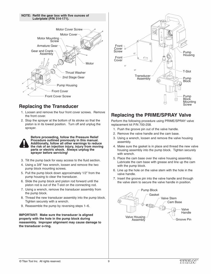
Replacing the Transducer1. Loosen and remove the four front cover screws. Remove
the front cover.2. Stop the sprayer at the bottom of its stroke so that the
piston is in its lowest position. Turn off and unplug thesprayer.
Before proceeding, follow the Pressure ReliefProcedure outlined previously in this manual.Additionally, follow all other warnings to reducethe risk of an injection injury, injury from movingparts or electric shock. Always unplug thesprayer before servicing!
3. Tilt the pump back for easy access to the fluid section.4. Using a 3/8” hex wrench, loosen and remove the two
pump block mounting screws.5. Pull the pump block down approximately 1/2” from the
pump housing to clear the transducer.6. Slide the pump block and piston rod forward until the
piston rod is out of the T-slot on the connecting rod.7. Using a wrench, remove the transducer assembly from
the pump block.8. Thread the new transducer assembly into the pump block.
Tighten securely with a wrench.9. Reassemble the pump by reversing steps 1–6.
IMPORTANT: Make sure the transducer is alignedproperly with the hole in the pump block duringreassembly. Improper alignment may cause damage tothe transducer o-ring.
Front Cover
Pump Housing
Front Cover Screw
2nd Stage Gear
Thrust Washer
Motor
Gear and CrankAssembly
Armature Gear
Motor Mounting Screw
Motor Cover
Motor Cover Screw
NOTE: Refill the gear box with five ounces ofLubriplate (P/N 314-171).
© Titan Tool Inc. All rights reserved. 9
Replacing the PRIME/SPRAY ValvePerform the following procedure using PRIME/SPRAY valvereplacement kit P/N 700-258.
1. Push the groove pin out of the valve handle.2. Remove the valve handle and the cam base.3. Using a wrench, loosen and remove the valve housing
assembly.4. Make sure the gasket is in place and thread the new valve
housing assembly into the pump block. Tighten securelywith wrench.
5. Place the cam base over the valve housing assembly.Lubricate the cam base with grease and line up the camwith the pump block.
6. Line up the hole on the valve stem with the hole in thevalve handle.
7. Insert the groove pin into the valve handle and throughthe valve stem to secure the valve handle in position.
Gasket
Cam BaseValve Stem
Pump Block
Valve Housing Assembly
Valve Handle
Groove Pin
T-Slot
Pump Housing
Pump Block
Pump Block Mounting Screw
Front Cover
Front Cover Screw
Transducer Assembly

Servicing the Fluid SectionUse the following procedures to service the valves and repackthe fluid section. Perform the following steps beforeperforming any maintenance on the fluid section.
1. Loosen and remove the four front cover screws. Removethe front cover.
2. Stop the sprayer at the bottom of its stroke so that thepiston is in its lowest position. Turn off and unplug thesprayer.
3. Perform the Pressure Relief Procedure and unplug thesprayer.
Before proceeding, follow the Pressure ReliefProcedure outlined previously in this manual.Additionally, follow all other warnings to reducethe risk of an injection injury, injury from movingparts or electric shock. Always unplug thesprayer before servicing!
4. Unscrew the return hose assembly from the pump block.5. Remove the retaining clip that holds the suction set in the
foot valve. Pull the suction set out of the foot valve.6. Tilt the pump back for easy access to the fluid section.
Servicing the ValvesThe design of Titan's fluid sectionallows access to the foot valve andseat as well as the outlet valve andseat without completelydisassembling the fluid section. Itis possible that the valves may notseat properly because of debrisstuck in the foot valve seat or outletvalve seat. Use the followinginstructions to clean the valves andreverse or replace the seats.
1. Using a wrench, loosen andremove the foot valve housingfrom the pump block.
2. Clean out any debris in the foot valve housing andexamine the valve housing and seat. If the seat isdamaged, reverse or replace the seat.
3. Using a 3/4" socket wrench, loosen and remove the outletvalve retainer from the piston rod.
4. Clean out any debris andexamine the outlet valve retainerand seat. If the seat is damaged,reverse or replace the seat.
5. Remove, clean, and inspect the outlet cage, crushwasher, and outlet valve ball. Replace if they are worn ordamaged.
6. Reassemble the valves by reversing the steps above.
NOTE: During reassembly of the outlet valve, applyone drop of Loctite (included in the repackingkit) to the threads of the outlet valve retainerbefore threading it into the piston rod. Then,torque the retainer to 144 in./lbs. (12 ft./lbs.).
NOTE: Always service theoutlet valve with thepiston rod attached tothe pump. This willprevent the piston rodfrom rotating duringdisassembly of theoutlet valve.
Outlet Valve Retainer
Outlet Valve Seat
Outlet Valve Ball
Outlet Cage
Crush Washer
Piston Rod
Foot Valve Housing
Foot Valve Seat
Foot Valve Ball
Bushing
O-Ring
Lower Cage
Lower Seal
10 © Titan Tool Inc. All rights reserved.
Repacking the Fluid Section1. Remove the foot valve and outlet valve assemblies using
the steps in the “Servicing the Valves” procedure above.
2. Using 3/8” a hexwrench, loosen andremove the twopump blockmounting screws.
3. Pull the pump blockdown approximately1/2” from the pumphousing.
4. Slide the pump blockand piston rodforward until thepiston rod is out ofthe T-slot on theconnecting rod.
5. Slide the piston rodout through thebottom of the pumpblock.
6. Loosen and removethe retainer nut andpiston guide from thepump block.
7. Remove the upperand lower packings from the pump block.
8. Clean the pump block and install the new upper and lowerpackings. Refer to the illustration below for properpacking orientation.
9. Inspect the piston rod for wear and replace if necessary.10. Reassemble the outlet valve assembly into the piston rod.
Tighten the outlet valve retainer with a wrench until secure.
IMPORTANT: Never use a wrench on the piston itself.This could cause damage to the piston and cause leakage.11. Insert the piston guide into the retainer nut. Thread the
retainer nut into the pump block until it is hand tight.12. Slide the piston guide tool (included in the repacking kit)
over the top of the piston rod and insert the piston rodthrough the bottom of the pump block. Using a rubbermallet, tap the bottom of the piston rod lightly until thepiston rod is in position in the pump block.
13. Using a wrench, tighten the retainer nut securely.14. Slide the top of the piston rod into the T-slot on the
connecting rod.
NOTE: Coat the piston guide tool and the piston rodwith grease before inserting them into thepump block.
NOTE: Use the T-slot on the connecting rod to holdthe piston rod in position while securing theoutlet valve retainer.
Install lower packings with raised lip and O-ring
facing up.
Install upper packing with raised lip and O-ring
facing down.
O-Ring
O-RingRaised Lip
Raised Lip
Connecting Rod
Retainer NutPiston GuideUpper Packing
Pump Block
Lower Packings
Pump Block Mounting Screw
Piston Rod
T-Slot
NOTE: The outlet valve does not need to bedisassembled from the piston rod for thisprocedure.
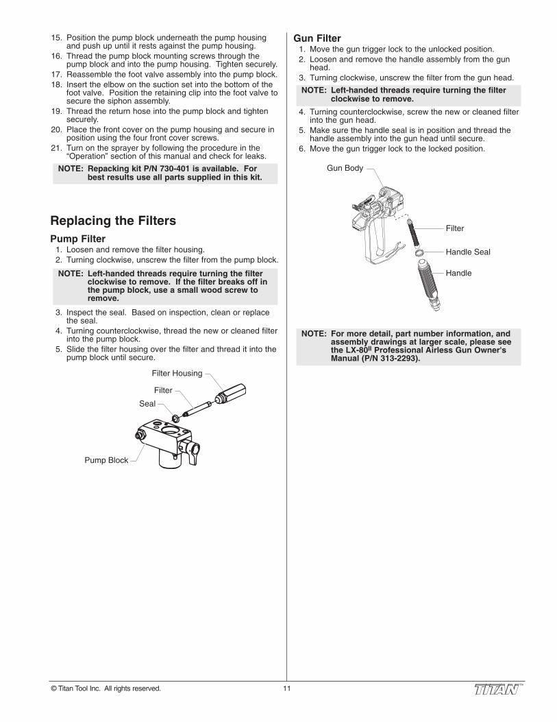
15. Position the pump block underneath the pump housingand push up until it rests against the pump housing.
16. Thread the pump block mounting screws through thepump block and into the pump housing. Tighten securely.
17. Reassemble the foot valve assembly into the pump block.18. Insert the elbow on the suction set into the bottom of the
foot valve. Position the retaining clip into the foot valve tosecure the siphon assembly.
19. Thread the return hose into the pump block and tightensecurely.
20. Place the front cover on the pump housing and secure inposition using the four front cover screws.
21. Turn on the sprayer by following the procedure in the“Operation” section of this manual and check for leaks.
Replacing the Filters Pump Filter
1. Loosen and remove the filter housing.2. Turning clockwise, unscrew the filter from the pump block.
3. Inspect the seal. Based on inspection, clean or replacethe seal.
4. Turning counterclockwise, thread the new or cleaned filterinto the pump block.
5. Slide the filter housing over the filter and thread it into thepump block until secure.
Pump Block
Seal
Filter
Filter Housing
NOTE: Left-handed threads require turning the filterclockwise to remove. If the filter breaks off inthe pump block, use a small wood screw toremove.
NOTE: Repacking kit P/N 730-401 is available. Forbest results use all parts supplied in this kit.
Gun Filter1. Move the gun trigger lock to the unlocked position.2. Loosen and remove the handle assembly from the gun
head.3. Turning clockwise, unscrew the filter from the gun head.
4. Turning counterclockwise, screw the new or cleaned filterinto the gun head.
5. Make sure the handle seal is in position and thread thehandle assembly into the gun head until secure.
6. Move the gun trigger lock to the locked position.
NOTE: For more detail, part number information, andassembly drawings at larger scale, please seethe LX-80II Professional Airless Gun Owner'sManual (P/N 313-2293).
Gun Body
Handle Seal
Filter
Handle
NOTE: Left-handed threads require turning the filterclockwise to remove.
© Titan Tool Inc. All rights reserved. 11
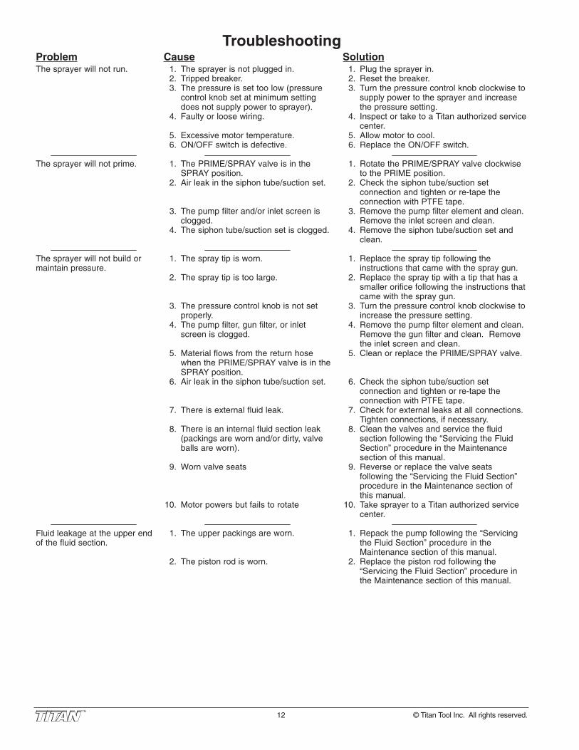
Solution1. Plug the sprayer in.2. Reset the breaker.3. Turn the pressure control knob clockwise to
supply power to the sprayer and increasethe pressure setting.
4. Inspect or take to a Titan authorized servicecenter.
5. Allow motor to cool.6. Replace the ON/OFF switch.
1. Rotate the PRIME/SPRAY valve clockwiseto the PRIME position.
2. Check the siphon tube/suction setconnection and tighten or re-tape theconnection with PTFE tape.
3. Remove the pump filter element and clean.Remove the inlet screen and clean.
4. Remove the siphon tube/suction set andclean.
1. Replace the spray tip following theinstructions that came with the spray gun.
2. Replace the spray tip with a tip that has asmaller orifice following the instructions thatcame with the spray gun.
3. Turn the pressure control knob clockwise toincrease the pressure setting.
4. Remove the pump filter element and clean.Remove the gun filter and clean. Removethe inlet screen and clean.
5. Clean or replace the PRIME/SPRAY valve.
6. Check the siphon tube/suction setconnection and tighten or re-tape theconnection with PTFE tape.
7. Check for external leaks at all connections.Tighten connections, if necessary.
8. Clean the valves and service the fluidsection following the “Servicing the FluidSection” procedure in the Maintenancesection of this manual.
9. Reverse or replace the valve seatsfollowing the “Servicing the Fluid Section”procedure in the Maintenance section ofthis manual.
10. Take sprayer to a Titan authorized servicecenter.
1. Repack the pump following the “Servicingthe Fluid Section” procedure in theMaintenance section of this manual.
2. Replace the piston rod following the“Servicing the Fluid Section” procedure inthe Maintenance section of this manual.
Cause1. The sprayer is not plugged in.2. Tripped breaker.3. The pressure is set too low (pressure
control knob set at minimum settingdoes not supply power to sprayer).
4. Faulty or loose wiring.
5. Excessive motor temperature.6. ON/OFF switch is defective.
1. The PRIME/SPRAY valve is in theSPRAY position.
2. Air leak in the siphon tube/suction set.
3. The pump filter and/or inlet screen isclogged.
4. The siphon tube/suction set is clogged.
1. The spray tip is worn.
2. The spray tip is too large.
3. The pressure control knob is not setproperly.
4. The pump filter, gun filter, or inletscreen is clogged.
5. Material flows from the return hosewhen the PRIME/SPRAY valve is in theSPRAY position.
6. Air leak in the siphon tube/suction set.
7. There is external fluid leak.
8. There is an internal fluid section leak(packings are worn and/or dirty, valveballs are worn).
9. Worn valve seats
10. Motor powers but fails to rotate
1. The upper packings are worn.
2. The piston rod is worn.
TroubleshootingProblemThe sprayer will not run.
The sprayer will not prime.
The sprayer will not build ormaintain pressure.
Fluid leakage at the upper endof the fluid section.
12 © Titan Tool Inc. All rights reserved.

© Titan Tool Inc. All rights reserved. 13
TroubleshootingProblemExcessive surge at the spraygun.
Poor spray pattern.
The sprayer lacks power.
Cause1. Wrong type of airless spray hose.
2. The spray tip worn or too large.
3. Excessive pressure.
1. The spray tip is too large for thematerial being used.
2. Incorrect pressure setting.
3. Insufficient fluid delivery.4. The material being sprayed is too
viscous.
1. The pressure adjustment is too low.
2. Improper voltage supply.
Solution1. Replace hose with a minimum of 50’ x 1/4”
grounded textile braid airless paint sprayhose.
2. Replace the spray tip following theinstructions that came with the spray gun.
3. Rotate the pressure control knobcounterclockwise to decrease spraypressure.
1. Replace the spray tip with a new or smallerspray tip following the instructions thatcame with the spray gun.
2. Rotate the pressure control knob to adjustthe pressure for a proper spray pattern.
3. Clean all screens and filters.4. Add solvent to the material according to the
manufacturer's recommendations.
1. Rotate the pressure control knob clockwiseto increase the pressure setting.
2. Connect the input voltage to the propervoltage for the sprayer.

14 © Titan Tool Inc. Tous droits réservés.Français
Importantes consignes de sécurité • Lire toutes ces consignes
avant d’utiliser l’appareil. Garder ces consignes.
Indique une situation à risque, laquelle, si elle n'est pasévitée, peut entraîner des blessures graves, voire lamort.
Pour réduire les risques d’incendie ou d’explosion, dechoc électrique et de blessure, vous devez lire etcomprendre les directives figurant dans ce manuel.Familiarisez-vous avec les commandes et l’utilisationadéquate de l’équipement.
DANGER : INJECTION CUTANÉELe jet de haute pression produit par cet appareil peuttranspercer la peau et les tissus sous-jacents, causant desblessures graves pouvant entraîner l'amputation.NE PAS TRAITER CE TYPE DE BLESSURE COMME UNE SIMPLECOUPURE! Une amputation peut en résulter. ON DOITCONSULTER UN MÉDICIN SUR-LE-CHAMP. La pression maximale de ce pulvérisateur est d’environ 3 000 PSI /20,6 MPa.
MESURES PRÉVENTIVES :• Ne pas pointer le pistolet vers une partie du corps. • Ne pas pointer le pistolet vers une personne ou un animal; ne
pas pulvériser non plus de produit dessus.• NE JAMAIS mettre une partie du corps devant le jet de produit.
NE JAMAIS toucher les fuites du flexible de pulvérisation.• NE JAMAIS mettre la main, même gantée, devant le pistolet (les
gants n’offrent aucune protection contre les blessures parinjection).
• TOUJOURS verrouiller la détente, arrêter la pompe et relâcher toutela pression avant d’effectuer la maintenance de l’appareil ou de lelaisser sans surveillance, d’en nettoyer le protège-embout oul’embout, ou de remplacer ce dernier. La pression ne sera pasrelâchée par le simple arrêt du moteur; pour ce faire, on doit se servirdu bouton PRIME/SPRAY (se reporter à la section COMMENTLIBÉRER LA PRESSION, du présent manuel).
• TOUJOURS s'assurer que le protège-embout est en place avant depulvériser. Il est cependant à noter que, s’il assure une certaineprotection, ce dispositif joue surtout un rôle préventif.
• TOUJOURS retirer l’embout avant de vidanger ou de nettoyerl’appareil.
• TOUJOURS inspecter le flexible avant de commencer; celui-cipeut présenter des fuites attribuables à l’usure, à une flexionexcessibe ou à un traitement abusif, lesquelles fuites présententdes risques d’injection cutanée. Ne pas utiliser le flexible poursoulever ou tirer l’équipement.
• NE JAMAIS utiliser de pistolet sans verrou de détente et protège-doigts.
• Tous les accessoires (pistolets, embouts, rallonges, flexibles etc.)doivent pouvoir subir une pression nominale de 3 000 PSI / 20,6MPa ou plus.
• Ne laissez pas l’appareil sous tension ou sous pression quand vousvous en éloignez. Quand vous n’utilisez pas l’appareil, éteignez-leet libérez la pression conformément aux instructions COMMENTLIBÉRER LA PRESSION, du présent manuel.
• Vérifiez que toutes les connexions sont bien serrées avantd’utiliser l’appareil. Toute pièce qui n’est pas fixée solidementrisque d’être projetée violemment ou d’entraîner la fuite d’un jetde liquide à une pression extrêmement élevée, ce qui pourraitcauser des blessures graves.
• Verrouillez toujours la détente quand vous ne pulvérisez pas.Vérifiez que le verrou de la détente fonctionne correctement.
REMARQUE À L’INTENTION DES MÉDECINS : Les injections cutanées sont des lésions traumatiques; ilimporte donc de les traiter sans délai. On NE DOIT PAS retarderce traitement sous prétexte de vérifier la toxicité du produit encause, celle-ci n’étant conséquente que dans le cas d’injectiondirecte de certains produits dans le système sanguin. Il pourraits’avérer nécessaire de consulter un plasticien ou un spécialisteen chirurgie reconstructive de la main.
DANGER : ÉMANATIONS DANGEREUSESCertains produits (peintures, solvants, insecticides ou autres)peuvent être nocifs s’ils sont inhalés ou entrent en contactavec l’organisme. Les émanations de ces produits peuventprovoquer de graves nausées, évanouissements ouempoisonnements.MESURES PRÉVENTIVES :
• Se servir d’un masque ou d’un respirateur s’il y arisque d’inhalation (lire toutes les directives concernantces dispositifs afin de s’assurer qu’ils offrent laprotection requise).
• Porter des lunettes de protection.• Porter les vêtements de protection prescrits par le fabricant du
produit utilisé.
DANGER : EXPLOSION OU INCENDIELes émanations de certains produits peuvent exploser ous’enflammer, et risquent d’entraîner des dommages matérielsou de graves blessures.MESURES PRÉVENTIVES :
• S’assurer que l’aire de travail est dotée de moyens d’évacuationd’air vicié et d’introduction d’air frais pour éviter l’accumulation devapeurs inflammables. Les vapeurs dégagées par la peinture oules solvants peuvent provoquer une explosion ou s’enflammer.
• Ne pas pulvériser de produit dans un endroit clos.• Ne pas travailler près de sources d’ignition (décharges
électrostatiques ou étincelles provoquées par lebranchement/ débranchement d’appareils ou lacommutation d’interrupteurs, d'appareils électriques, flammesnues, veilleuses, objets chauds, etc.). La peinture ou le solvants’écoulant dans l’équipement peut générer de l’électricité statique.
• Ne pas fumer dans l’aire de travail.• L’aire de travail doit être munie d’un extincteur en bon état de
marche.• Prévoir un espace d’au moins 7.62 mètres entre la pompe et
l’objet à pulvériser s’ils sont dans la même pièce bien ventilée(rallonger le flexible au besoin). Les vapeurs inflammables étantsouvent plus lourdes que l’air, l’espace au-dessus du plancherdoit être particulièrement bien aéré. La pompe contient despièces qui produisent des arcs et émettent des étincelles pouvantenflammer les vapeurs.
• Les appareils et objets à l’intérieur ou à proximité de l’aire detravail doivent être adéquatement mis à la terre pour éviter lesdécharges électrostatiques.
• Veillez à ce que la zone soit propre et exempte de contenants depeinture ou de solvant, chiffons ou autres matériauxinflammables.
• Les flexibles dont on se sert doivent être conçus pour subir lespressions élevées et faits de matériaux conducteurs ou mis à laterre adéquatement; le pistolet sera mis à la terre par le biais deses raccords aux flexibles.
• Pour les appareils électriques — Le cordon d’alimentation doitêtre branché à un circuit trifilaire.
• L’appareil doit toujours être vidangé à basse pression, emboutretiré, dans un contenant métallique distinct. Tenir le pistoletcontre la paroi du contenant de manière à mettre ce dernier à laterre et à prévenir les décharges électrostatiques.
• Toujours respecter les mises en garde et les directives dufabricant des produits et solvants utilisés. On doit connaître lesproduits contenus dans les peintures et solvants qu'on pulvérise.Lire les fiches techniques santé-sécurité (FTSS) et les étiquettesdes contenants fournies avec les peintures et solvants. Suivresles consignes de sécurité du fabricant de peinture et de solvant.
• S’entourer de toutes les précautions possibles lorsqu’on utilisedes produits ayant un point d’éclair inférieur à 21°C (70°F). Lepoint d'éclair est la température à laquelle le liquide peut créersuffisamment de vapeurs et s'enflammer.
• Le plastique est générateur de décharges électrostatiques; nejamais en suspendre pour fermer une aire de travail ou en utiliseren guise de toile de protection lorsqu’on pulvérise un produitinflammable.
• Se servir de la pression la plus basse possible pour vidangerl’appareil.
• Ne pas pulvériser de produit sur la pompe.
© Titan Tool Inc. Tous droits réservés. 15 Français
Importantes consignes de sécurité • Lire toutes ces consignes
avant d’utiliser l’appareil. Garder ces consignes.
DANGER : EXPLOSION CAUSÉE PAR DES PRODUITSINCOMPATIBLES
Ce type d’explosion peut entraîner des dommages matérielsou des blessures graves.
MESURES PRÉVENTIVES :
• Ne pas utiliser de produits contenant du chlore ou du javellisant.
• Ne pas utiliser de solvants à base de halons comme l’eau dejavel, les agents antimoisissure, le chlorure de méthylène et letrichloroéthane-1-1-1, lesquels ne sont pas compatibles avecl’aluminium.
• Communiquer avec le fournisseur du produit concerné pour enconnaître la compatibilité avec l’aluminium.
DANGER : GÉNÉRALITÉSD’autres dangers peuvent entraîner des dommages matériels ou desblessures graves.
• Lire toutes les directives et consignes de sécurité avant d’utiliserl’appareil.
• Observer tous les codes locaux, provinciaux, d’état et nationauxrégissant la ventilation, la prévention des incendies et lefonctionnement de l’appareil.
• Aux États-Unis, le gouvernement a adopté des normes desécurité en vertu de l’Occupational Safety and Health Act (OSHA).Le cas échéant, on doit les consulter, notamment les parties 1910des normes générales et 1926 des normes de construction.
• N’utiliser que les pièces autorisées par le fabricant; les utilisateursqui choisiront d’utiliser des composants dont les caractéristiquestechniques et les exigences en matière de sécurité sontinférieures devront en assumer tous les risques et responsabilités.
• Tous les raccords, les tuyaux et les bouchons de remplissagedoivent être fixés solidement en place avant d’utiliser la pompede pulvérisation. Toute pièce qui n’est pas fixée solidementrisque d’être projetée violemment ou d’entraîner la fuite d’un jetde liquide à une pression extrêmement élevée, ce qui pourraitcauser des blessures graves.
• Avant chaque utilisation, examiner tous les flexibles afin deconfirmer l’absence de coupures, de fuites, d’abrasions ou derenflements. Vérifier également l’intégrité des raccords. Remplacersans délai les pièces qui semblent présenter des défectuosités. Nejamais tenter de réparer un flexible; remplacer ceux qui font défautpar des modèles haute pression, avec mise à la terre.
•. Ne faites pas de nouer avec le tuyau et ne le tordez pas trop. Letuyau à vide peut présenter des fuites suite à l’usure, les nouerou les mauvais traitements. Une fuite risque d’injecter du produitdans la peau.
•. N’exposez pas le tuyau à des températures ou des pressionssupérieures à celles spécifiées par le fabricant.
• Ne pas pulvériser à l’extérieur par grands vents.• Porter des vêtements aptes à protéger la peau et les cheveux du
produit utilisé.• Ne pas utiliser le pistolet ou ne pas pulvériser de produits en
présence d’enfants à proximité. Éloigner les enfants del’équipement en tout temps.
• Ne pas s'étirer ni ne travailler sur un support instable. Toujoursgarder les deux pieds au sol pour rester en équilibre.
• Se servir de la pression la plus basse possible pour vidangerl’appareil.
• Rester vigilant et faire attention à ce que l'on fait.• Ne pas se servir de l'équipement en cas de fatigue ou si vos
aptitudes sont affaiblies par la consommation de drogues ou deboissons alcoolisées.
• Pour les appareils électriques — Débranchez toujours le cordonélectrique de la prise avant de travailler sur l’équipement.
• N’utilisez pas le tuyau pour tirer ou soulever l’équipement.• Ne pas soulever par la poignée de chariot en chargeant ou en
déchargeant.
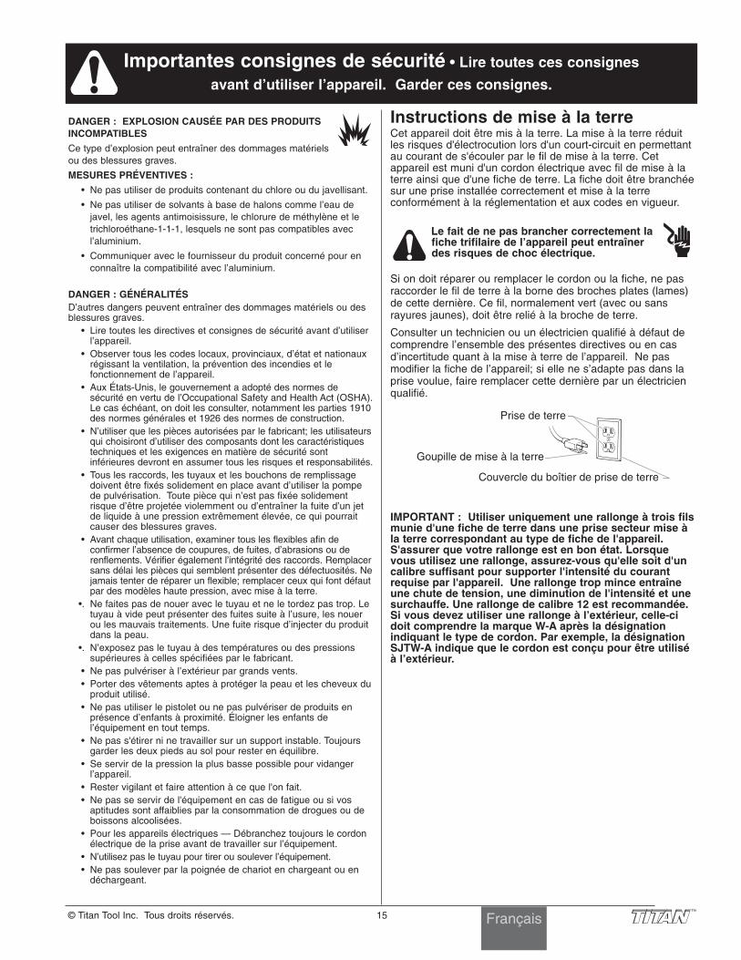
Instructions de mise à la terreCet appareil doit être mis à la terre. La mise à la terre réduitles risques d'électrocution lors d'un court-circuit en permettantau courant de s'écouler par le fil de mise à la terre. Cetappareil est muni d'un cordon électrique avec fil de mise à laterre ainsi que d'une fiche de terre. La fiche doit être branchéesur une prise installée correctement et mise à la terreconformément à la réglementation et aux codes en vigueur.
Le fait de ne pas brancher correctement lafiche trifilaire de l’appareil peut entraînerdes risques de choc électrique.
Si on doit réparer ou remplacer le cordon ou la fiche, ne pasraccorder le fil de terre à la borne des broches plates (lames)de cette dernière. Ce fil, normalement vert (avec ou sansrayures jaunes), doit être relié à la broche de terre.
Consulter un technicien ou un électricien qualifié à défaut decomprendre l’ensemble des présentes directives ou en casd’incertitude quant à la mise à terre de l’appareil. Ne pasmodifier la fiche de l’appareil; si elle ne s’adapte pas dans laprise voulue, faire remplacer cette dernière par un électricienqualifié.
IMPORTANT : Utiliser uniquement une rallonge à trois filsmunie d'une fiche de terre dans une prise secteur mise àla terre correspondant au type de fiche de l'appareil.S'assurer que votre rallonge est en bon état. Lorsquevous utilisez une rallonge, assurez-vous qu'elle soit d'uncalibre suffisant pour supporter l'intensité du courantrequise par l'appareil. Une rallonge trop mince entraîneune chute de tension, une diminution de l'intensité et unesurchauffe. Une rallonge de calibre 12 est recommandée.Si vous devez utiliser une rallonge à l’extérieur, celle-cidoit comprendre la marque W-A après la désignationindiquant le type de cordon. Par exemple, la désignationSJTW-A indique que le cordon est conçu pour être utiliséà l’extérieur.
Prise de terre
Goupille de mise à la terre
Couvercle du boîtier de prise de terre

16 © Titan Tool Inc. Todos los derechos reservados.Español
Información de seguridad importante • Lea toda la información de
seguridad antes de operar el equipo. Guarde estas instrucciones.
Indica una situación peligrosa que, de no evitarse,puede causar la muerte o lesiones graves.
Para reducir los riesgos de incendios, explosiones,descargas eléctricas o lesiones a las personas, lea yentienda todas las instrucciones incluidas en este manu-al. Familiarícese con los controles y el uso adecuado delequipo.
PELIGRO: LESIÓN POR INYECCIÓNEl flujo de pintura a alta presión que produce este equipopuede perforar la piel y los tejidos subyacentes,ocasionando lesiones graves y posible amputación.CONSULTE A UN MÉDICO INMEDIATAMENTE.
¡NO TRATE LA LESIÓN POR INYECCIÓN COMO UNACORTADURA SIMPLE! La inyección puede ocasionar amputación.Consulte a un médico inmediatamente.La gama operativa máxima de la pistola es de 3000 PSI / 20.6 MPade presión del líquido.PREVENCIÓN:
• NUNCA apunte la pistola a ninguna parte del cuerpo.• No apunte con la pistola ni rocíe a cualquier persona o animal.• NUNCA deje que ninguna parte del cuerpo toque el flujo de
líquido. NO deje que el cuerpo toque una fuga de la manguera delíquido.
• NUNCA ponga la mano frente a la pistola. Los guantes noprotegen contra una lesión por inyección.
• SIEMPRE ponga el seguro del gatillo, apague la bomba y liberetoda la presión antes de dar servicio, limpiar la boquilla oprotección, cambiar la boquilla o dejar la pistola sin supervisión. Nose libera la presión al apagar el motor. Debe girarse la perillaPRIME/ SPRAY (CEBAR/ROCIAR) a PRIME (CEBAR) para aliviarla presión. Consulte el PROCEDIMIENTO PARA ALIVIAR LAPRESIÓN descrito en este manual.
• SIEMPRE mantenga la protección de la boquilla en su sitio alrociar. La protección de la boquilla sirve principalmente dedispositivo de advertencia.
• SIEMPRE retire la boquilla rociadora antes de enjuagar o limpiarel sistema.
• La manguera de pintura puede presentar fugas por desgaste,dobleces y maltrato. La fuga puede inyectar material traspasandola piel. Inspeccione la manguera antes de cada uso. No usemangueras para levantar o tirar del equipo.
• NUNCA use una pistola rociadora sin contar con el seguro y laprotección del gatillo.
• Todos los accesorios deben tener capacidades nominales de3000 PSI / 20.6 MPa como mínimo. Esto incluye las boquillasrociadoras, pistolas, extensiones y manguera.
• No deje el aparato con corriente ni con presión cuando nadie estépendiente de ella. Cuando no utilice el aparato, apáguelo y liberela presión siguiendo las instrucciones del PROCEDIMIENTOPARA ALIVIAR LA PRESIÓN descrito en este manual.
• Antes de utilizar el aparato, verifique que todas las conexionesson seguras. Las partes no aseguradas pueden ser expulsadascon gran fuerza o filtrar fluido a alta presión y provocar lesionesseveras.
• Ponga siempre el seguro del gatillo cuando no esté pulverizando.Verifique que el seguro del gatillo funciona correctamente.
NOTA PARA EL MÉDICO: La inyección a través de la piel es unalesión traumática. Es importante tratar la lesión tan pronto seaposible. NO retrase el tratamiento para investigar la toxicidad. Latoxicidad es un factor a considerar con ciertos revestimientosinyectados directamente en la corriente sanguínea. Puede seraconsejable consultar con un cirujano plástico o un cirujanoespecialista en reconstrucción de las manos.
PELIGRO: VAPORES PELIGROSOS
Las pinturas, solventes, insecticidas y demás materialespueden ser nocivos si se inhalan o toman contacto con elcuerpo. Los vapores pueden causar náuseas graves,desmayos o envenamiento.
PREVENCIÓN:• Use un respirador o mascarilla si pueden inhalarse los
vapores. Lea todas las instrucciones suministradascon la mascarilla para revisar que brinde la protecciónnecesaria.
• Use lentes protectores.• Use ropa protectora según lo indique el fabricante del
revestimiento.
PELIGRO: EXPLOSIÓN O INCENDIO
Los vapores de solventes y pinturas pueden explotar oinflamarse. Pueden producirse daños materiales, lesionesgraves o ambos.PREVENCIÓN:
• Cuente con escape y entrada de aire fresco para mantener elaire dentro de la zona de aplicación sin acumulaciones devapores inflamables. Los gases producidos por solventes opinturas pueden causar explosiones o incendios.
• No rocíe en lugares cerrados.• Evite todas las fuentes de ignición como las chispas de
electricidad estática, las llamas expuestas, applianceselectricidad, las luces piloto y los objetos calientes. La conexión odesconexión de cables eléctricos o interruptores de luzoperativos puede producir chispas. Si la pintura o el solventefluyen por el equipo se puede generar electricidad estática.
• No fume en el área de aplicación.• Debe haber un extintor de incendios en buen estado.• Coloque la bomba de pintura a un mínimo de 7.62 meters (25
pies) del objeto a pintar dentro de un área bien ventilada (añadamás manguera si es necesario). Los vapores inflamables songeneralmente más pesados que el aire. El área debe estarsumamente bien ventilada.
• El equipo y los objetos dentro y alrededor del área a pintar debenestar debidamente conectados a tierra para evitar las chispas deestática.
• Mantenga el área limpia y libre de contenedores de pintura osolvente, trapos y otros materiales inflamables.
• Use solamente una manguera conductora o conectada a tierrapara líquidos a alta presión. La pistola debe conectarse a tierra através de las conexiones de la manguera.
• Para las aparatos eléctricas — Debe conectarse el cableeléctrico a un circuito a tierra.
• Siempre enjuague la unidad dentro de un recipiente metálicoseparado, con la bomba a baja presión y habiendo sacado laboquilla rociadora. Sostenga la pistola firmemente contra elcostado del recipiente para conectar a tierra el mismo y evitarchispas de estática.
• Siga las advertencias e instrucciones del fabricante del material ydel solvente. Conozca los contenidos de las pinturas y lossolventes con los que rocía. Lea todas las Hojas de Datos sobreSeguridad de Materiales (MSDS) y las etiquetas del contenedorprovistas con las pinturas y los solventes. Siga las instruccionesde seguridad del fabricante de pinturas o solventes.
• Tenga muchísmo cuidado al usar materiales cuyo punto deignición sea inferior a 70°F (21°C). El punto de inflamación es latemperatura a la que un fluido puede producir vapores suficientespara encenderse.
• El plástico puede causar chispas de estática. Nunca cuelgueplásticos para cerrar una zona a pintar. No use mantas plásticasal aplicar materiales inflamables.
• Use la presión más baja posible para enjuagar el equipo.• No rocíe el ensamblaje de la bomba.

© Titan Tool Inc. Todos los derechos reservados. 17 Español
Información de seguridad importante • Lea toda la información de
seguridad antes de operar el equipo. Guarde estas instrucciones.
PELIGRO: POSIBLE EXPLOSIÓN DEBIDO AMATERIALES INCOMPATIBLES
Causará daños materiales o lesiones graves.
PREVENCIÓN:
• No use materiales que contengan blanqueador o cloro.
• No use solventes de hidrocarburos halogenados comoblanqueador, mohocida, cloruro de metileno y 1,1,1 tricloroetano.No son compatibles con el aluminio.
• Diríjase al proveedor de revestimientos para obtener los datos decompatibilidad del material con el aluminio.
PELIGRO: GENERAL
Puede causar daños materiales o lesiones graves.
PREVENCIÓN:
• Lea todas las instrucciones y las precauciones de seguridadantes de operar el equipo.
• Siga todos los códigos locales, estatales y nacionalescorrespondientes que rijan la ventilación, prevención deincendios y operación.
• Se han adoptado las normas de seguridad del Gobierno de losEstados Unidos según la Ley de seguridad ocupacional y salud(Occupational Safety and Health Act, OSHA). Deben consultarseestas normas, particularmente el apartado 1910 de las Normasgenerales y el apartado 1926 de las Normas de construcción.
• Utilice solamente componentes autorizados por el fabricante. Elusuario asume todo riesgo y responsabilidad al utilizarcomponentes que no cumplan con las especificaciones mínimasy requisitos de seguridad del fabricante de la bomba.
• Todos los acopladores, las mangueras y las tapas de los filtrosdeben estar asegurados antes de operar la bomba de rocío. Laspartes no aseguradas pueden ser expulsadas con gran fuerza ofiltrar fluido a alta presión y provocar lesiones severas.
• Antes de cada uso, revise todas las mangueras en busca decortes, fugas, abrasión o hinchazón de la cubierta. Revise si haydaños o movimiento de los acoplamiento. Cambieinmediatamente la manguera si existe alguna de estascondiciones. Nunca repare una manguera de pintura. Cámbielapor otra manguera conectada a tierra apta para alta presión.
• No retuerza ni doble la manguera en exceso. En la mangueraairless pueden aparecer fugas a causa del desgaste, deretorcimientos o de un mal uso. Una fuga puede inyectar materialen la piel.
• No exponga la manguera a temperaturas o presiones quesuperen las especificadas por el fabricante.
• No pinte en exteriores en días con viento.
• Use ropa que mantenga la pintura alejada de la piel y el cabello.
• No lo opere ni rocíe cerca de los niños. Mantenga a los niñosalejados del equipo en todo momento.
• No se asome ni se pare sobre soportes inestables. Mantengasiempre la posición firme y el equilibrio efectivos.
• Use la presión más baja posible para enjuagar el equipo.
• Manténgase alerta y mire lo que hace.
• No utilice la unidad cuando se encuentre cansado o bajo lainfluencia de las drogas o el alcohol.
• Para las aparatos eléctricas — Desenchufe siempre el cableantes de trabajar en el equipo.
• No utilice la manguera como elemento de fuerza para tirar delequipo o levantarlo.
• No levantar por la manija del carro al cargar o descargando.
Instrucciones para conectar a tierraEste producto se debe conectar a tierra. En caso de queocurra un corto circuito, la conexión a tierra reduce el riesgode choque eléctrico al proporcionar un alambre de escapepara la corriente eléctrica. Este producto está equipado conun cable que tiene un alambre de conexión a tierra con unenchufe de conexión a tierra apropiado. El enchufe se debeenchufar en una toma de corriente que se haya instalado yconectado a tierra debidamente, de acuerdo con todos loscódigos y estatutos locales.
La instalación incorrecta del enchufe atierra puede ocasionar un riesgo dechoque eléctrico.
Si es necesario reparar o cambiar el cable o el enchufe, noconecte el cable verde a tierra a ninguno de las terminales deespiga plana. El cable con aislamiento de color verde porfuera con o sin rayas amarillas es el alambre a tierra y debeconectarse a la espiga a tierra.
Consulte a un electricista o técnico de servicio capacitado silas instrucciones para la conexión a tierra no se entiendenclaramente o si tiene dudas en cuanto a que el producto estédebidamente conectado a tierra. No modifique el enchufe quese incluye. Si el enchufe no encaja en el receptáculo, pida aun electricistas capacitado que instale un receptáculoadecuado.
IMPORTANTE: Use solamente extensiones trifilares quetengan un enchufe de conexión a tierra de 3 hojas y unreceptáculo de triple ranura que acepte el enchufe delproducto. Asegúrese de que su extensión esté en buenascondiciones. Cuando use una extensión, asegúrese deusar una que sea lo suficientemente resistente como parasoportar la corriente que descargue su producto. Un cablede un tamaño menor causará una caída de voltage en lalínea que dará como resultado una pérdida de energía y unsobrecalenta|ôento. Se recomienda usar un cable decalibre 12. Si se utiliza un cable de extensión en el exterior,tiene que estar marcado con el sufijo W-A después de ladesignación del tipo de cable. Por ejemplo, SJTW-A paraindicar que el cable es apropiado para uso en exteriores.
Tomacorriente aterrado
Terminal de tierra
Tapa de la caja del tomacorriente aterrado

18 © Titan Tool Inc. All rights reserved.
Parts List Main Assembly
1
2
3
5
6
7
4
8
9
10
11
5
Item Part # Description Quantity1 704-181 Screw..........................................................42 766-232 Motor cover.................................................13 ---------- Motor assembly ..........................................14 704-179 Left leg assembly........................................15 761-178 Screw..........................................................46 766-115 Fluid section assembly ...............................1
Item Part # Description Quantity7 704-117 Screw..........................................................28 ---------- Gear box assembly.....................................19 704-178 Right leg assembly .....................................110 700-258 PRIME/SPRAY valve assembly..................111 704-300 Siphon assembly ........................................1

© Titan Tool Inc. All rights reserved. 19
1
2
3
4
5
6
7
8
9
10
11
4
Motor Assembly
Item Part # Description Quantity1 704-363 Capacitor/rectifier kit, 120V
(includes item 21 on page 21) ....................12 700-681 Screw..........................................................43 704-269 Y adapter (negative, black).........................14 704-276 Brush kit
(includes retainer caps) ..............................15 704-285 Shroud ........................................................26 704-322 Shroud screw..............................................2
Item Part # Description Quantity7 704-277 Motor, 120V, complete
(includes items 1, 5, 6, 10, and 11) ............18 704-258 Y adapter (positive, red) .............................19 704-331 Gasket ........................................................1
10 704-250 Motor fan.....................................................111 854-915 Screw..........................................................112 770-099 Tie wrap (not shown) ..................................113 314-991 Tape (not shown) ........................................1
NOTE: All electrical work should be performed bya Titan authorized service center.
Electrical Schematic
AC
AC+
+ +
Sw
itch
Whi
te
Circ
uit
Bre
aker
Black
Cap
acito
rsRectifier
Plu
g
Motor
Motor Starter
Micro Switch (Pressure Control)

20 © Titan Tool Inc. All rights reserved.
Gear Box Assembly
2
1
10
11
8
9
13
12
14
15
17
16
18
19
20
21
3
24
1
26
27
1
28
25
22
23
4
5
6
7

© Titan Tool Inc. All rights reserved. 21
Item Part # Description Quantity1 700-139 Screw........................................................102 704-019 Front cover..................................................13 704-173 Crankshaft/gear assembly ..........................14 704-174 Thrust washer .............................................15 704-176 2nd stage gear............................................16 766-101 Pump housing.............................................17 700-2060 Connecting rod ...........................................18 704-102 Pressure control knob.................................19 704-124 Retainer ring ...............................................110 704-123 Spring .........................................................111 704-158 Plunger .......................................................112 704-128 Microswitch .................................................113 765-063 Strain relief, 230V .......................................114 800-741 Power cord (includes item 13)....................1
Item Part # Description Quantity15 704-229 Ground screw .............................................116 704-122 Screw..........................................................217 766-452 Transducer assembly .................................118 800-038 Motor starter ...............................................119 704-126 Lock washer................................................220 730-260 Screw..........................................................221 704-323 Screw..........................................................122 704-169 MIcroswitch mounting plate ........................123 704-125 Washer........................................................224 700-785 Lock washer................................................225 704-380 ON/OFF switch ...........................................126 704-211 Circuit breaker ............................................127 704-363 Capacitor/rectifier kit (includes item 21) .....128 766-441 Electrical box cover ....................................1
Siphon Assembly (P/N 704-300)
Item Part # Description Quantity1 700-1023 Siphon tube assembly
(includes items 2–4, and 7) ........................12 704-263 Return hose ................................................13 700-805 Inlet screen .................................................14 704-121 O-ring..........................................................2
704-109 O-ring (for hot solvents, optional)5 700-1024 Elbow ..........................................................16 704-127 Retaining clip ..............................................1
1
2
3
4
5
6
Stand Assembly
Item Part # Description Quantity1 700-761 Cord wrap ...................................................12 710-199 Plug.............................................................43 704-164 Leg, left .......................................................14 700-642 Screw..........................................................25 700-1043 Drip cup ......................................................16 704-188 Screw..........................................................17 704-156 Leg, right.....................................................1
704-179 Leg, left, complete (includes items 1, and 2–4)
704-178 Leg, right, complete(includes items 2 and 5–7)
1
3
2
4
5
6
7
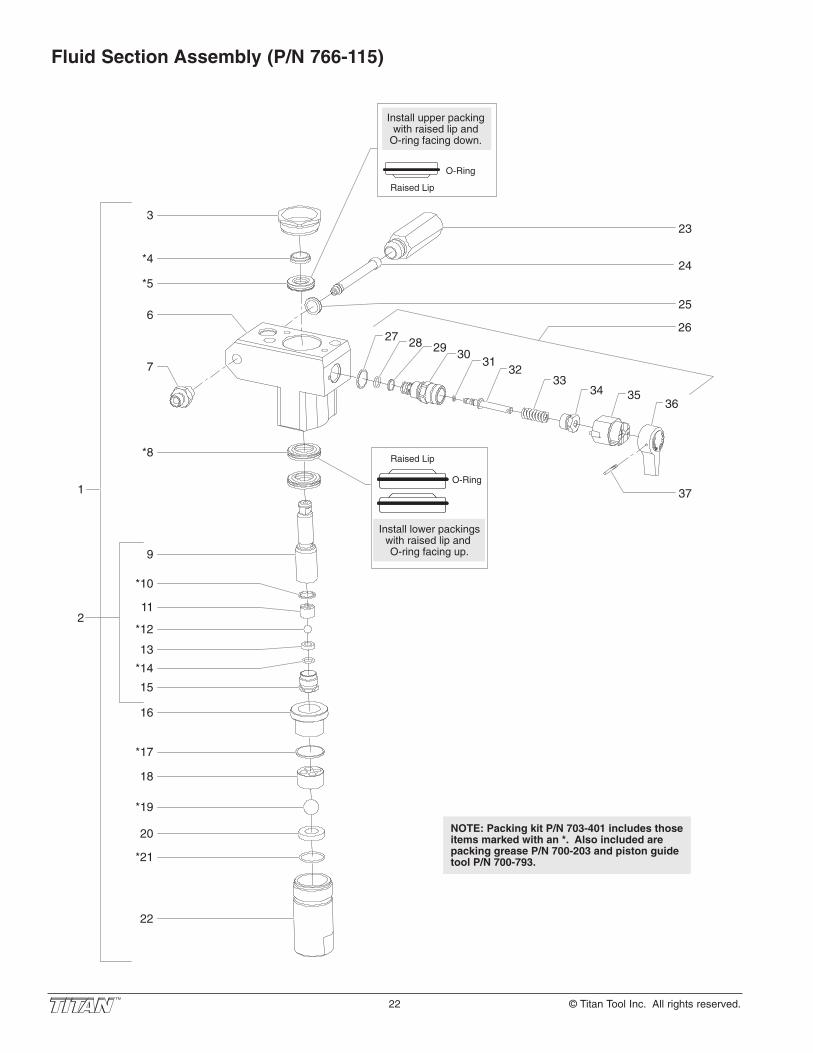
22 © Titan Tool Inc. All rights reserved.
Fluid Section Assembly (P/N 766-115)
1
2
26
3
*4
*5
6
7
*8
*10
11
13
*14
15
16
*17
18
*19
20
*21
22
*12
9
25
37
24
23
27 28 29 3031
3233
34 3536
Install lower packings with raised lip and O-ring facing up.
Install upper packing with raised lip and
O-ring facing down.
O-Ring
O-Ring
Raised Lip
Raised Lip
NOTE: Packing kit P/N 703-401 includes those items marked with an *. Also included are packing grease P/N 700-203 and piston guide tool P/N 700-793.

© Titan Tool Inc. All rights reserved. 23
Item Part # Description Quantity1 766-274 Fluid section, bare (excludes items 22–36) .12 704-552 Piston assembly (includes items 9–14) ......13 730-508 Retainer ......................................................14 700-587 Piston guide................................................15 700-072 Upper packing w/tool ..................................16 704-633 Pump block .................................................17 227-006 Outlet fitting.................................................18 700-601 Lower packing ...........................................29 704-551 Piston rod....................................................110 704-610 Outlet cage .................................................111 704-612 Crush washer..............................................112 762-144 Outlet valve ball ..........................................113 704-558 Outlet valve seat.........................................114 704-587 Outlet vavle retainer ...................................115 704-289 Bushing.......................................................116 700-821 Lower seal ..................................................117 730-510 Lower cage .................................................118 762-145 Foot valve ball ............................................119 762-137 Foot valve seat ...........................................120 762-058 O-ring..........................................................121 704-054 Foot valve housing .....................................1
Item Part # Description Quantity22 700-421 Filter housing ..............................................123 500-200-03 Filter............................................................124 560-038 Seal.............................................................125 700-258 PRIME/SPRAY valve assembly
(includes items 26—36)..............................126 700-537 Gasket ........................................................127 221-012 O-Ring, Viton ..............................................128 222-012 O-Ring, PTFE.............................................129 800-924 Valve housing .............................................130 700-721 O-Ring, Viton ..............................................1
700-897 O-Ring, PTFE (optional).............................131 700-250 Valve stem ..................................................132 800-926 Spring .........................................................133 700-248 Valve retainer..............................................134 700-252 Cam base ...................................................135 700-697 Valve handle ...............................................136 700-759 Groove pin ..................................................137 762-202 Packing tool (not shown) ............................1
NOTE: When using “HOT” solvents, replace Viton o-ring (item 30) with optional PTFE o-ring (700-897). Install with o-ring tool (700-890).
AccessoriesAirless Tip SelectionTips are selected by the orifice size and fan width. The properselection is determined by the fan width required for a specificjob and by the orifice size that will supply the desired amountof fluid and accomplish proper atomization.For light viscosity fluids, smaller orifice tips generally aredesired. For heavier viscosity materials, larger orifice tips arepreferred. Please refer to the chart below.
The following chart indicates the most common sizes and theappropriate materials to be sprayed.
Fan widths measuring 8" to 12" (20 to 30 cm) are preferredbecause they offer more control while spraying and are lesslikely to plug.
Liquid Shield PlusCleans and protects spray systemsagainst rust, corrosion and prematurewear. Now with -25º anti-freezeprotection.
Part # Description314-483...........4 ounce bottle314-482...........1 quart bottle
Tip Size Spray Material Filter Type
.011 – .013 Lacquers and stains 100 mesh filter
.015 – .019 Oil and latex 60 mesh filter
.021 – .026 Heavy bodied latex and blockfillers 30 mesh filter
NOTE: Do not exceed the sprayer's recommended tipsize.
Piston LubeSpecially formulated to prevent materialsfrom adhering to the piston rod, whichbecomes abrasive to the upper seals.Piston Lube will break down any materialthat may accumulate in the oil cup andkeep it from drying.
Part # Description314-481...........4 ounce bottle314-480...........8 ounce bottle
MiscellaneousPart No. Description490-012...........Hose Coupling, 1/4" x 1/4"730-397...........High Pressure Fl. Gauge314-171...........Lubriplate, 14 ounce individual314-172...........Lubriplate, 6 lb. can
700-1037..........Electrostatic discharge (ESD) wrist strap
LabelsPart # Description
313-1851 Front cover label313-2687 Motor cover label, RentSpray 450313-1673 Warning label
(injection/explosion)313-1847 Shock hazard label

24 © Titan Tool Inc. All rights reserved.
United States Sales & Service1-800-526-5362
Fax 1-800-528-4826
107 Bauer DriveOakland, NJ 07436
www.titantool.com
Canadian Branch1-800-565-8665
Fax 1-905-856-8496
200 Trowers Road, Unit 7BWoodbridge, Ontario L4L 5Z8
International1-201-337-1240
Fax 1-201-405-7449
107 Bauer DriveOakland, NJ 07436 USA
Material Safety Data Sheets (MSDS) are available on Titan’s website or by calling Customer Service.
PatentsThis product is covered by one or more of the following U.S. patents:
6,031,352 5,848,566 5,769,321 5,725,364 5,671,656 5,435,697 5,228,8425,346,037 5,252,210 5,217,238 5,192,425 4,908,538 4,768,929 4,744,571D384,676 6,179,222 5,934,883 4,723,892
Titan Tool, Inc., (“Titan”) warrants that at the time of delivery to the original purchaser for use (“End User”), the equipmentcovered by this warranty is free from defects in material and workmanship. With the exception of any special, limited, orextended warranty published by Titan, Titan’s obligation under this warranty is limited to replacing or repairing without chargethose parts which, to Titan’s reasonable satisfaction, are shown to be defective within twelve (12) months after sale to the EndUser. This warranty applies only when the unit is installed and operated in accordance with the recommendations andinstructions of Titan.
This warranty does not apply in the case of damage or wear caused by abrasion, corrosion or misuse, negligence, accident,faulty installation, substitution of non-Titan component parts, or tampering with the unit in a manner to impair normal operation.
Defective parts are to be returned to an authorized Titan sales/service outlet. All transportation charges, including return to thefactory, if necessary, are to be borne and prepaid by the End User. Repaired or replaced equipment will be returned to the EndUser transportation prepaid.
THERE IS NO OTHER EXPRESS WARRANTY. TITAN HEREBY DISCLAIMS ANY AND ALL IMPLIED WARRANTIESINCLUDING, BUT NOT LIMITED TO, THOSE OF MERCHANTABILITY AND FITNESS FOR A PARTICULAR PURPOSE, TOTHE EXTENT PERMITTED BY LAW. THE DURATION OF ANY IMPLIED WARRANTIES WHICH CANNOT BE DISCLAIMED ISLIMITED TO THE TIME PERIOD SPECIFIED IN THE EXPRESS WARRANTY. IN NO CASE SHALL TITAN LIABILITY EXCEEDTHE AMOUNT OF THE PURCHASE PRICE. LIABILITY FOR CONSEQUENTIAL, INCIDENTAL OR SPECIAL DAMAGESUNDER ANY AND ALL WARRANTIES IS EXCLUDED TO THE EXTENT PERMITTED BY LAW.
TITAN MAKES NO WARRANTY AND DISCLAIMS ALL IMPLIED WARRANTIES OF MERCHANTABILITY AND FITNESS FOR APARTICULAR PURPOSE WITH RESPECT TO ACCESSORIES, EQUIPMENT, MATERIALS OR COMPONENTS SOLD BUT NOTMANUFACTURED BY TITAN. THOSE ITEMS SOLD, BUT NOT MANUFACTURED BY TITAN (SUCH AS GAS ENGINES,SWITCHES, HOSES, ETC.) ARE SUBJECT TO THE WARRANTY, IF ANY, OF THEIR MANUFACTURER. TITAN WILL PROVIDETHE PURCHASER WITH REASONABLE ASSISTANCE IN MAKING ANY CLAIM FOR BREACH OF THESE WARRANTIES.
Warranty