Embed Size (px)
Citation preview
This information is subject to the controls of the Export Administration Regulations [EAR]. This information shall not be provided to non-U.S. persons or transferred by any means to any location outside the United States contrary to the requirements of the EAR.
Technical Manual
SPIRIT II 400
Register your equipment: www.lincolnelectric.com/register
Save for future reference
Date Purchased:
Model Number:
Serial Number:
THE LINCOLN ELECTRIC COMPANY BK8053-000095 Rev C | Issue Date: 23-May-2018 4130 Carolina Commerce Pkwy Ladson, SC 29456 U.S.A. © Lincoln Global, Inc. All Rights Reserved Phone: +1.843.695.4000 www.lincolnelectric.com
Manual Plasma Cutting System with FineLine High Definition Technology
®
™
Prologue Spirit II User’s Manual
This information is subject to the controls of the Export Administration Regulations [EAR]. This information shall not be provided to non-U.S. persons or transferred by any means to any location outside the United States contrary to the requirements of the EAR.
ii
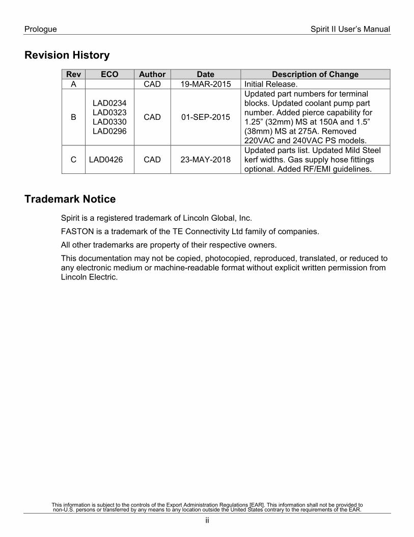
Revision History Rev ECO Author Date Description of Change
A CAD 19-MAR-2015 Initial Release.
B
LAD0234 LAD0323 LAD0330 LAD0296
CAD 01-SEP-2015
Updated part numbers for terminal blocks. Updated coolant pump part number. Added pierce capability for 1.25” (32mm) MS at 150A and 1.5” (38mm) MS at 275A. Removed 220VAC and 240VAC PS models.
C LAD0426 CAD 23-MAY-2018 Updated parts list. Updated Mild Steel kerf widths. Gas supply hose fittings optional. Added RF/EMI guidelines.
Trademark Notice
Spirit is a registered trademark of Lincoln Global, Inc. FASTON is a trademark of the TE Connectivity Ltd family of companies. All other trademarks are property of their respective owners. This documentation may not be copied, photocopied, reproduced, translated, or reduced to any electronic medium or machine-readable format without explicit written permission from Lincoln Electric.
Spirit II User’s Manual Prologue
This information is subject to the controls of the Export Administration Regulations [EAR]. This information shall not be provided to non-U.S. persons or transferred by any means to any location outside the United States contrary to the requirements of the EAR.
iii
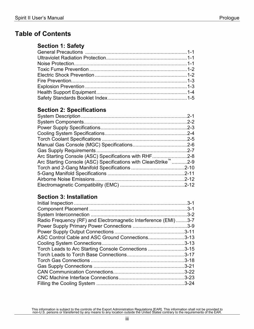
Table of Contents
Section 1: Safety General Precautions ......................................................................... 1-1 Ultraviolet Radiation Protection .......................................................... 1-1 Noise Protection................................................................................. 1-1 Toxic Fume Prevention ...................................................................... 1-2 Electric Shock Prevention .................................................................. 1-2 Fire Prevention................................................................................... 1-3 Explosion Prevention ......................................................................... 1-3 Health Support Equipment ................................................................. 1-4 Safety Standards Booklet Index ......................................................... 1-5 Section 2: Specifications System Description ............................................................................ 2-1 System Components .......................................................................... 2-2 Power Supply Specifications .............................................................. 2-3 Cooling System Specifications ........................................................... 2-4 Torch Coolant Specifications ............................................................. 2-5 Manual Gas Console (MGC) Specifications ....................................... 2-6 Gas Supply Requirements ................................................................. 2-7 Arc Starting Console (ASC) Specifications with RHF ......................... 2-8 Arc Starting Console (ASC) Specifications with CleanStrike™ ........... 2-9 Torch and 2-Gang Manifold Specifications ...................................... 2-10 5-Gang Manifold Specifications ....................................................... 2-11 Airborne Noise Emissions ................................................................ 2-12 Electromagnetic Compatibility (EMC) .............................................. 2-12 Section 3: Installation Initial Inspection ................................................................................. 3-1 Component Placement ...................................................................... 3-1 System Interconnection ..................................................................... 3-2 Radio Frequency (RF) and Electromagnetic Interference (EMI) ........ 3-7 Power Supply Primary Power Connections ....................................... 3-9 Power Supply Output Connections .................................................. 3-11 ASC Control Cable and ASC Ground Connections.......................... 3-13 Cooling System Connections ........................................................... 3-13 Torch Leads to Arc Starting Console Connections .......................... 3-15 Torch Leads to Torch Base Connections ......................................... 3-17 Torch Gas Connections ................................................................... 3-18 Gas Supply Connections ................................................................. 3-21 CAN Communication Connections................................................... 3-22 CNC Machine Interface Connections ............................................... 3-23 Filling the Cooling System ............................................................... 3-24
Prologue Spirit II User’s Manual
This information is subject to the controls of the Export Administration Regulations [EAR]. This information shall not be provided to non-U.S. persons or transferred by any means to any location outside the United States contrary to the requirements of the EAR.
iv
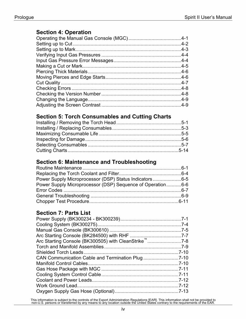
Section 4: Operation Operating the Manual Gas Console (MGC) ....................................... 4-1 Setting up to Cut ................................................................................ 4-2 Setting up to Mark .............................................................................. 4-3 Verifying Input Gas Pressures ........................................................... 4-4 Input Gas Pressure Error Messages .................................................. 4-4 Making a Cut or Mark ......................................................................... 4-5 Piercing Thick Materials ..................................................................... 4-6 Moving Pierces and Edge Starts ........................................................ 4-6 Cut Quality ......................................................................................... 4-7 Checking Errors ................................................................................. 4-8 Checking the Version Number ........................................................... 4-8 Changing the Language ..................................................................... 4-9 Adjusting the Screen Contrast ........................................................... 4-9 Section 5: Torch Consumables and Cutting Charts Installing / Removing the Torch Head ................................................ 5-1 Installing / Replacing Consumables ................................................... 5-3 Maximizing Consumable Life ............................................................. 5-5 Inspecting for Damage ....................................................................... 5-6 Selecting Consumables ..................................................................... 5-7 Cutting Charts .................................................................................. 5-14 Section 6: Maintenance and Troubleshooting Routine Maintenance ......................................................................... 6-1 Replacing the Torch Coolant and Filter .............................................. 6-4 Power Supply Microprocessor (DSP) Status Indicators ..................... 6-5 Power Supply Microprocessor (DSP) Sequence of Operation ........... 6-6 Error Codes ....................................................................................... 6-7 General Troubleshooting ................................................................... 6-9 Chopper Test Procedure .................................................................. 6-11 Section 7: Parts List Power Supply (BK300234 - BK300239) ............................................. 7-1 Cooling System (BK300275) .............................................................. 7-4 Manual Gas Console (BK300610) ..................................................... 7-5 Arc Starting Console (BK284500) with RHF ...................................... 7-7 Arc Starting Console (BK300505) with CleanStrike™ ......................... 7-8 Torch and Manifold Assemblies ......................................................... 7-9 Shielded Torch Leads ...................................................................... 7-10 CAN Communication Cable and Termination Plug .......................... 7-10 Manifold Control Cables ................................................................... 7-10 Gas Hose Package with MGC ......................................................... 7-11 Cooling System Control Cable ......................................................... 7-11 Coolant and Power Leads ................................................................ 7-12 Work Ground Lead ........................................................................... 7-12 Oxygen Supply Gas Hose (Optional) ............................................... 7-13
Spirit II User’s Manual Prologue
This information is subject to the controls of the Export Administration Regulations [EAR]. This information shall not be provided to non-U.S. persons or transferred by any means to any location outside the United States contrary to the requirements of the EAR.
v
Nitrogen Supply Gas Hose (Optional) .............................................. 7-13 Air Supply Gas Hose (Optional) ....................................................... 7-13 H17 Supply Gas Hose (Optional) ..................................................... 7-13 Supply Gas Hose Fittings Kit, BK300624 (Optional) ........................ 7-14 "CII" Cable (for Optional External Inova) .......................................... 7-15 "FII" Cable (for Optional Internal Inova) ........................................... 7-16 "JII" Cable (for Optional Internal Inova) ............................................ 7-17 PCB Assemblies – Component Reference Locations ...................... 7-18 Section 8: Internal Inova Console Option Overview ............................................................................................ 8-1 Plug Identification ............................................................................... 8-1 Unique Interconnect Cables ............................................................... 8-1 Grounding .......................................................................................... 8-2 Parts List ............................................................................................ 8-3 Appendix A: Electromagnetic Compatibility (EMC) Background ....................................................................................... A-1 Installation and Use .......................................................................... A-1 Assessment of Area .......................................................................... A-2 Methods of Reducing Emissions ....................................................... A-2
DÉCLARATION DE RESPONSABILITÉ LIMITÉELincoln Electric Company (Lincoln) garantit à l’usager final (acheteur) detous les appareils de soudage et de coupage neufs, d’électrode et de flux(collectivement appelés « Biens ») qu’ils ne présenteront aucun défaut defabrication et de matériel.Cette garantie est annulée si l’appareil a été sujet à une mauvaiseinstallation, à des soins inappropriés ou à des opérations anormales.PÉRIODE DE GARANTIE (1) (2) (3) (4) (5) (6) (7) (8) (9)
Lincoln assurera les dépenses relatives aux pièces et à la main d’œuvrepour la correction des défauts durant la période de garantie. Toutepériode de garantie commence à la date de l’achat, chez un DistributeurLincoln Agréé ou dans un Atelier de Service Agréé par Lincoln, parl’usager final d’origine, ou bien à partir de la date de fabrication siaucune preuve d’achat n’est disponible, le tout dans les conditionssuivantes :
7 Ans• Redresseurs d’alimentation principale sur les soudeuses Idealarc® de type
non-onduleur
3 Ans• Toutes les soudeuses, dévidoirs et machines pour couper le plasma de Lin-
coln.• Casques auto-obscurcissants Viking™ désignés par les numéros de
référence de produits se terminant en "-2" (ex. KXXXX-2). Les exceptionsfigurent dans la liste pour 2 Ans.
2 Ans• Casques auto-obscurissants, tous les autres casques Viking™ y compris
les casques de la série 1740 et les casques passifs 4x5.
1 An• Handy MIG®, Handy Core®, Weld Pak™ HD• Tous les refroidisseurs à eau (modèles internes ou externes)• Tous les régulateurs de gaz • Toutes les baguettes d’électrode, fils à souder et flux (Contacter le
Représentant de Ventes Lincoln le plus proche)• Robots de soudage à l’arc et de coupage et contrôleurs robotiques• Tous les appareils de Contrôle des Vapeurs de Soudage, y compris les ap-
pareils portables, les unités centrales, les extincteurs et les accessoires(Ne comprend pas les articles de matériel consommable figurant sur laliste d’articles ayant 30 jours de garantie)
• Tout les accessoires de soudage et de coupage, y compris les modules dedévidoirs, les chariots, les options à installer sur le terrain qui sont venduesséparément, les options non fixées, les fournitures de soudage, les jeuxd’accessoires standards et les produits Magnum® (Ne comprend pas lespièces consommables et les pistolets / torches figurant sur la liste d’arti-cles ayant une garantie de 90 et 30 jours)
• Toutes les torches TIG Pro-Torch™ • Toutes les torches de coupage au plasma• Toutes les pièces de rechange non consommables achetées• Les Pistolets à Bobine Magnum® 250LX• Les Pistolets à système pousser• Mobiles VRTEX® 360 et VRTEX®
• Viking™ PAPR Blower Unit• Poussoirs magnétiques main
90 Jours• Tous les ensembles de pistolet et câble et les pistolets à bobine Magnum®
SG
30 Jours• Tous les articles consommables pouvant être utilisés avec les Systèmes de
Contrôle des Vapeurs de Soudage décrits plus haut. Ceci comprend lestuyaux, les filtres, les courroies et les adaptateurs de tuyaux
• Tous les logiciels• Pièces non consommables - Lincoln n’est responsable du changement
d’aucune pièce non consommable nécessaire du fait d’une usure normale.
Période de Temps Non Spécifiée • Les produits d’habillement Red Line™ sont garantis contre les défauts de
fabrication. Du fait que les applications varient, il relève de la responsabil-ité de l’usager de sélectionner le bon produit pour chaque application. Lesproduits d’habillement Red Line™ ne sont pas sujets à la garantie aprèsusage.
• Les produits de la gamme de lunettes de sécurité Red Line™ sont garantiscontre les défauts de fabrication
CONDITIONS DE GARANTIE À OBTENIR COUVERTURE DE LA GARANTIE :L’acheteur doit contacter un Atelier de Service Agréé par Lincoln (LASF).Pour une assistance à la recherche d’un LASF, aller sur www.lincolnelectric.com/locator
La détermination finale de la garantie sur les produits de soudage et decoupage sera faite par Lincoln ou par l’Atelier de Service Agréé parLincoln.RÉPARATIONS COUVERTES PAR LA GARANTIE : Si Lincoln ou l’Atelier de Service Agréé par Lincoln confirme l’existenced’un défaut couvert par cette garantie, celui-ci sera corrigé parréparation ou par changement, au choix de Lincoln.
À la demande de Lincoln, l’acheteur doit rendre, à Lincoln ou à son Atelierde Service Agréé, tout « Bien » réclamé comme défectueux couvert par lagarantie de Lincoln.FRAIS DE PORT : L’acheteur est responsable de l’expédition vers et depuis l’Atelier deService Agréé par Lincoln.LIMITES DE LA GARANTIE:LINCOLN N’ACCEPTERA AUCUNE RESPONSABILITÉ DANS LE CAS DE RÉPARATIONSEFFECTUÉES HORS D’UN ATELIER DE SERVICE AGRÉÉ PAR LINCOLN.
LA RESPONSABILITÉ DE LINCOLN SELON CETTE GARANTIE NE DÉPASSERA PAS LECOÛT DE LA CORRECTION DU DÉFAUT DU PRODUIT DE LINCOLN.
LINCOLN NE SERA PAS RESPONSABLE DES DOMMAGES ACCIDENTELS OUCONSÉQUENTS (TELS QUE LA PERTE D’AFFAIRES COMMERCIALES, ETC.) CAUSÉSPAR LE DÉFAUT OU PAR LE TEMPS NÉCESSAIRE À LA CORRECTION DU DÉFAUT.
CETTE GARANTIE ÉCRITE EST LA SEULE GARANTIE EXPRESSE FOURNIE PARLINCOLN CONCERNANT SES PRODUITS. LES GARANTIES IMPLIQUÉES PAR LA LOI,TELLES QUE LA GARANTIE DE QUALITÉ MARCHANDE, SE LIMITENT À LA DURÉE DECETTE GARANTIE LIMITÉE POUR L’APPAREIL EN QUESTION.
CETTE GARANTIE DONNE À L’ACHETEUR DES DROITS LÉGAUX SPÉCIFIQUES.L’ACHETEUR PEUT ÉGALEMENT AVOIR D’AUTRES DROITS QUI PEUVENT VARIERD’UN ÉTAT À L’AUTRE.
(1) Les appareils fabriqués pour The Lincoln Electric Company sont sujets àla période de garantie du fabricant original.
(2) Tous les moteurs et accessoires pour moteurs sont garantis par le fabri-cant du moteur ou des accessoires pour moteurs et ils ne sont pas cou-verts par cette garantie.
(3) Les compresseurs AIR VANTAGE® 500 sont garantis par le fabricant ducompresseur et ne sont pas couverts par cette garantie.
(4) Tous les Produits MK sont garantis par MK Products et ne sont pas cou-verts par cette garantie. Contacter le 1-800-787-9707.
(5) Lincoln Electric n’est pas responsable de l’usure des câbles ni des dom-mages résultant de l’usure des câbles suite à des courbures et à l’abra-sion. L’usager final est responsable de l’inspection de routine des câblespour vérifier qu’ils ne présentent pas d’usure éventuelle et pour y remédieravant la panne du câble.
(6) Tous les Produits Burny Kaliburn sont garantis par Burny Kaliburn et nesont pas couverts par cette garantie. Email: [email protected].
(7) Tous les Produits Vernon Tools sont garantis par Vernon Tool et ne sontpas couverts par cette garantie. www.vernontool.com/sales/product-warranty
(8) Tous les Produits Arc Products sont garantis par Arc Products et ne sontpas couverts par cette garantie. Email: [email protected]
(8) Tous les Produits ELCo Enterprises, Inc sont garantis par ELCo Enter-prises, Inc et ne sont pas couverts par cette garantie. Contacter le (517) 782-8040
RESPONSABILITÉ LIMITÉEGarantie actuelle disponible à www.lincolnelectric.com/warranty
Mar 14
THE LINCOLN ELECTRIC COMPANY22801 St. Clair Avenue • Cleveland, OH • 44117-1199 • U.S.A.
Phone: +1.888.935.3877 • www.lincolnelectric.com
The Lincoln Electric Company4130 Carolina Commerce Parkway, Ladson, SC 29456Phone: +1.843.695.4000 | www.lincolnelectric.comMC15-50 03/15 ©Lincoln Global, Inc. All Rights Reserved.
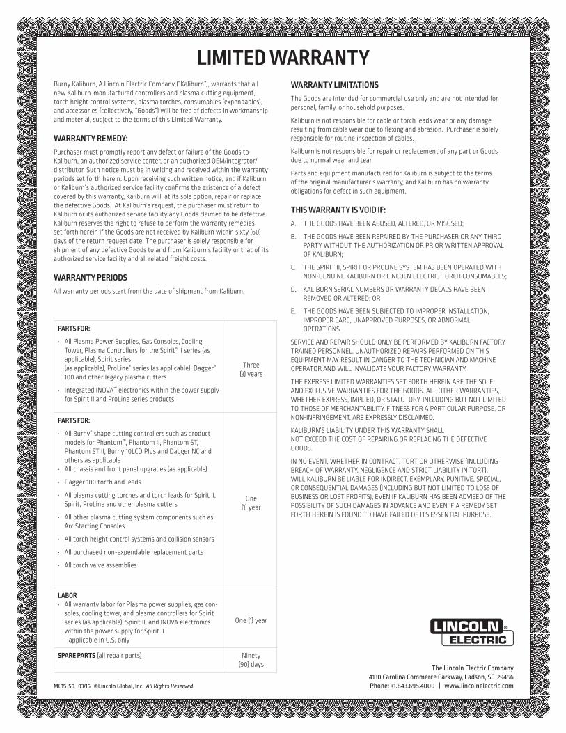
Burny Kaliburn, A Lincoln Electric Company (“Kaliburn”), warrants that all new Kaliburn-manufactured controllers and plasma cutting equipment, torch height control systems, plasma torches, consumables (expendables), and accessories (collectively, “Goods”) will be free of defects in workmanship and material, subject to the terms of this Limited Warranty.
WARRANTY REMEDY:Purchaser must promptly report any defect or failure of the Goods to Kaliburn, an authorized service center, or an authorized OEM/integrator/distributor. Such notice must be in writing and received within the warranty periods set forth herein. Upon receiving such written notice, and if Kaliburn or Kaliburn’s authorized service facility confirms the existence of a defect covered by this warranty, Kaliburn will, at its sole option, repair or replace the defective Goods. At Kaliburn’s request, the purchaser must return to Kaliburn or its authorized service facility any Goods claimed to be defective. Kaliburn reserves the right to refuse to perform the warranty remedies set forth herein if the Goods are not received by Kaliburn within sixty (60) days of the return request date. The purchaser is solely responsible for shipment of any defective Goods to and from Kaliburn’s facility or that of its authorized service facility and all related freight costs.
WARRANTY PERIODSAll warranty periods start from the date of shipment from Kaliburn.
PARTS FOR:
• All Plasma Power Supplies, Gas Consoles, Cooling Tower, Plasma Controllers for the Spirit® II series (as applicable), Spirit series (as applicable), ProLine® series (as applicable), Dagger® 100 and other legacy plasma cutters
• Integrated INOVA™ electronics within the power supply for Spirit II and ProLine series products
Three (3) years
PARTS FOR:
• All Burny® shape cutting controllers such as product models for Phantom™, Phantom II, Phantom ST, Phantom ST II, Burny 10LCD Plus and Dagger NC and others as applicable
• All chassis and front panel upgrades (as applicable)
• Dagger 100 torch and leads
• All plasma cutting torches and torch leads for Spirit II, Spirit, ProLine and other plasma cutters
• All other plasma cutting system components such as Arc Starting Consoles
• All torch height control systems and collision sensors
• All purchased non-expendable replacement parts
• All torch valve assemblies
One (1) year
LABOR• All warranty labor for Plasma power supplies, gas con-
soles, cooling tower, and plasma controllers for Spirit series (as applicable), Spirit II, and INOVA electronics within the power supply for Spirit II - applicable in U.S. only
One (1) year
SPARE PARTS (all repair parts) Ninety (90) days
WARRANTY LIMITATIONSThe Goods are intended for commercial use only and are not intended for personal, family, or household purposes.
Kaliburn is not responsible for cable or torch leads wear or any damage resulting from cable wear due to flexing and abrasion. Purchaser is solely responsible for routine inspection of cables.
Kaliburn is not responsible for repair or replacement of any part or Goods due to normal wear and tear.
Parts and equipment manufactured for Kaliburn is subject to the terms of the original manufacturer’s warranty, and Kaliburn has no warranty obligations for defect in such equipment.
THIS WARRANTY IS VOID IF:A. THE GOODS HAVE BEEN ABUSED, ALTERED, OR MISUSED;
B. THE GOODS HAVE BEEN REPAIRED BY THE PURCHASER OR ANY THIRD PARTY WITHOUT THE AUTHORIZATION OR PRIOR WRITTEN APPROVAL OF KALIBURN;
C. THE SPIRIT II, SPIRIT OR PROLINE SYSTEM HAS BEEN OPERATED WITH NON-GENUINE KALIBURN OR LINCOLN ELECTRIC TORCH CONSUMABLES;
D. KALIBURN SERIAL NUMBERS OR WARRANTY DECALS HAVE BEEN REMOVED OR ALTERED; OR
E. THE GOODS HAVE BEEN SUBJECTED TO IMPROPER INSTALLATION, IMPROPER CARE, UNAPPROVED PURPOSES, OR ABNORMAL OPERATIONS.
SERVICE AND REPAIR SHOULD ONLY BE PERFORMED BY KALIBURN FACTORY TRAINED PERSONNEL. UNAUTHORIZED REPAIRS PERFORMED ON THIS EQUIPMENT MAY RESULT IN DANGER TO THE TECHNICIAN AND MACHINE OPERATOR AND WILL INVALIDATE YOUR FACTORY WARRANTY.
THE EXPRESS LIMITED WARRANTIES SET FORTH HEREIN ARE THE SOLE AND EXCLUSIVE WARRANTIES FOR THE GOODS. ALL OTHER WARRANTIES, WHETHER EXPRESS, IMPLIED, OR STATUTORY, INCLUDING BUT NOT LIMITED TO THOSE OF MERCHANTABILITY, FITNESS FOR A PARTICULAR PURPOSE, OR NON-INFRINGEMENT, ARE EXPRESSLY DISCLAIMED.
KALIBURN’S LIABILITY UNDER THIS WARRANTY SHALL NOT EXCEED THE COST OF REPAIRING OR REPLACING THE DEFECTIVE GOODS.
IN NO EVENT, WHETHER IN CONTRACT, TORT OR OTHERWISE (INCLUDING BREACH OF WARRANTY, NEGLIGENCE AND STRICT LIABILITY IN TORT), WILL KALIBURN BE LIABLE FOR INDIRECT, EXEMPLARY, PUNITIVE, SPECIAL, OR CONSEQUENTIAL DAMAGES (INCLUDING BUT NOT LIMITED TO LOSS OF BUSINESS OR LOST PROFITS), EVEN IF KALIBURN HAS BEEN ADVISED OF THE POSSIBILITY OF SUCH DAMAGES IN ADVANCE AND EVEN IF A REMEDY SET FORTH HEREIN IS FOUND TO HAVE FAILED OF ITS ESSENTIAL PURPOSE.
LIMITED WARRANTY
DÉCLARATION DE RESPONSABILITÉ LIMITÉELincoln Electric Company (Lincoln) garantit à l’usager final (acheteur) detous les appareils de soudage et de coupage neufs, d’électrode et de flux(collectivement appelés « Biens ») qu’ils ne présenteront aucun défaut defabrication et de matériel.Cette garantie est annulée si l’appareil a été sujet à une mauvaiseinstallation, à des soins inappropriés ou à des opérations anormales.PÉRIODE DE GARANTIE (1) (2) (3) (4) (5) (6) (7) (8) (9)
Lincoln assurera les dépenses relatives aux pièces et à la main d’œuvrepour la correction des défauts durant la période de garantie. Toutepériode de garantie commence à la date de l’achat, chez un DistributeurLincoln Agréé ou dans un Atelier de Service Agréé par Lincoln, parl’usager final d’origine, ou bien à partir de la date de fabrication siaucune preuve d’achat n’est disponible, le tout dans les conditionssuivantes :
7 Ans• Redresseurs d’alimentation principale sur les soudeuses Idealarc® de type
non-onduleur
3 Ans• Toutes les soudeuses, dévidoirs et machines pour couper le plasma de Lin-
coln.• Casques auto-obscurcissants Viking™ désignés par les numéros de
référence de produits se terminant en "-2" (ex. KXXXX-2). Les exceptionsfigurent dans la liste pour 2 Ans.
2 Ans• Casques auto-obscurissants, tous les autres casques Viking™ y compris
les casques de la série 1740 et les casques passifs 4x5.
1 An• Handy MIG®, Handy Core®, Weld Pak™ HD• Tous les refroidisseurs à eau (modèles internes ou externes)• Tous les régulateurs de gaz • Toutes les baguettes d’électrode, fils à souder et flux (Contacter le
Représentant de Ventes Lincoln le plus proche)• Robots de soudage à l’arc et de coupage et contrôleurs robotiques• Tous les appareils de Contrôle des Vapeurs de Soudage, y compris les ap-
pareils portables, les unités centrales, les extincteurs et les accessoires(Ne comprend pas les articles de matériel consommable figurant sur laliste d’articles ayant 30 jours de garantie)
• Tout les accessoires de soudage et de coupage, y compris les modules dedévidoirs, les chariots, les options à installer sur le terrain qui sont venduesséparément, les options non fixées, les fournitures de soudage, les jeuxd’accessoires standards et les produits Magnum® (Ne comprend pas lespièces consommables et les pistolets / torches figurant sur la liste d’arti-cles ayant une garantie de 90 et 30 jours)
• Toutes les torches TIG Pro-Torch™ • Toutes les torches de coupage au plasma• Toutes les pièces de rechange non consommables achetées• Les Pistolets à Bobine Magnum® 250LX• Les Pistolets à système pousser• Mobiles VRTEX® 360 et VRTEX®
• Viking™ PAPR Blower Unit• Poussoirs magnétiques main
90 Jours• Tous les ensembles de pistolet et câble et les pistolets à bobine Magnum®
SG
30 Jours• Tous les articles consommables pouvant être utilisés avec les Systèmes de
Contrôle des Vapeurs de Soudage décrits plus haut. Ceci comprend lestuyaux, les filtres, les courroies et les adaptateurs de tuyaux
• Tous les logiciels• Pièces non consommables - Lincoln n’est responsable du changement
d’aucune pièce non consommable nécessaire du fait d’une usure normale.
Période de Temps Non Spécifiée • Les produits d’habillement Red Line™ sont garantis contre les défauts de
fabrication. Du fait que les applications varient, il relève de la responsabil-ité de l’usager de sélectionner le bon produit pour chaque application. Lesproduits d’habillement Red Line™ ne sont pas sujets à la garantie aprèsusage.
• Les produits de la gamme de lunettes de sécurité Red Line™ sont garantiscontre les défauts de fabrication
CONDITIONS DE GARANTIE À OBTENIR COUVERTURE DE LA GARANTIE :L’acheteur doit contacter un Atelier de Service Agréé par Lincoln (LASF).Pour une assistance à la recherche d’un LASF, aller sur www.lincolnelectric.com/locator
La détermination finale de la garantie sur les produits de soudage et decoupage sera faite par Lincoln ou par l’Atelier de Service Agréé parLincoln.RÉPARATIONS COUVERTES PAR LA GARANTIE : Si Lincoln ou l’Atelier de Service Agréé par Lincoln confirme l’existenced’un défaut couvert par cette garantie, celui-ci sera corrigé parréparation ou par changement, au choix de Lincoln.
À la demande de Lincoln, l’acheteur doit rendre, à Lincoln ou à son Atelierde Service Agréé, tout « Bien » réclamé comme défectueux couvert par lagarantie de Lincoln.FRAIS DE PORT : L’acheteur est responsable de l’expédition vers et depuis l’Atelier deService Agréé par Lincoln.LIMITES DE LA GARANTIE:LINCOLN N’ACCEPTERA AUCUNE RESPONSABILITÉ DANS LE CAS DE RÉPARATIONSEFFECTUÉES HORS D’UN ATELIER DE SERVICE AGRÉÉ PAR LINCOLN.
LA RESPONSABILITÉ DE LINCOLN SELON CETTE GARANTIE NE DÉPASSERA PAS LECOÛT DE LA CORRECTION DU DÉFAUT DU PRODUIT DE LINCOLN.
LINCOLN NE SERA PAS RESPONSABLE DES DOMMAGES ACCIDENTELS OUCONSÉQUENTS (TELS QUE LA PERTE D’AFFAIRES COMMERCIALES, ETC.) CAUSÉSPAR LE DÉFAUT OU PAR LE TEMPS NÉCESSAIRE À LA CORRECTION DU DÉFAUT.
CETTE GARANTIE ÉCRITE EST LA SEULE GARANTIE EXPRESSE FOURNIE PARLINCOLN CONCERNANT SES PRODUITS. LES GARANTIES IMPLIQUÉES PAR LA LOI,TELLES QUE LA GARANTIE DE QUALITÉ MARCHANDE, SE LIMITENT À LA DURÉE DECETTE GARANTIE LIMITÉE POUR L’APPAREIL EN QUESTION.
CETTE GARANTIE DONNE À L’ACHETEUR DES DROITS LÉGAUX SPÉCIFIQUES.L’ACHETEUR PEUT ÉGALEMENT AVOIR D’AUTRES DROITS QUI PEUVENT VARIERD’UN ÉTAT À L’AUTRE.
(1) Les appareils fabriqués pour The Lincoln Electric Company sont sujets àla période de garantie du fabricant original.
(2) Tous les moteurs et accessoires pour moteurs sont garantis par le fabri-cant du moteur ou des accessoires pour moteurs et ils ne sont pas cou-verts par cette garantie.
(3) Les compresseurs AIR VANTAGE® 500 sont garantis par le fabricant ducompresseur et ne sont pas couverts par cette garantie.
(4) Tous les Produits MK sont garantis par MK Products et ne sont pas cou-verts par cette garantie. Contacter le 1-800-787-9707.
(5) Lincoln Electric n’est pas responsable de l’usure des câbles ni des dom-mages résultant de l’usure des câbles suite à des courbures et à l’abra-sion. L’usager final est responsable de l’inspection de routine des câblespour vérifier qu’ils ne présentent pas d’usure éventuelle et pour y remédieravant la panne du câble.
(6) Tous les Produits Burny Kaliburn sont garantis par Burny Kaliburn et nesont pas couverts par cette garantie. Email: [email protected].
(7) Tous les Produits Vernon Tools sont garantis par Vernon Tool et ne sontpas couverts par cette garantie. www.vernontool.com/sales/product-warranty
(8) Tous les Produits Arc Products sont garantis par Arc Products et ne sontpas couverts par cette garantie. Email: [email protected]
(8) Tous les Produits ELCo Enterprises, Inc sont garantis par ELCo Enter-prises, Inc et ne sont pas couverts par cette garantie. Contacter le (517) 782-8040
RESPONSABILITÉ LIMITÉEGarantie actuelle disponible à www.lincolnelectric.com/warranty
Mar 14
THE LINCOLN ELECTRIC COMPANY22801 St. Clair Avenue • Cleveland, OH • 44117-1199 • U.S.A.
Phone: +1.888.935.3877 • www.lincolnelectric.com
The Lincoln Electric Company4130 Carolina Commerce Parkway, Ladson, SC 29456
Teléfono: +1.843.695.4000 | www.lincolnelectric.com
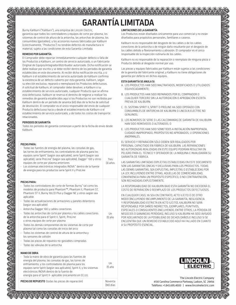
Burny Kaliburn (“Kaliburn”), una empresa de Lincoln Electric, garantiza que todos los controladores y equipos de corte por plasma, los sistemas de control de altura de la antorcha, las antorchas de plasma, los consumibles (gastables), y los accesorios nuevos fabricados por Kaliburn (colectivamente, “Productos”) no tendrán defectos de manufactura ni material, sujeto a las condiciones de esta Garantía Limitada.
REMEDIO POR GARANTÍA:El Comprador debe reportar inmediatamente cualquier defecto o falla de los Productos a Kaliburn, un centro de servicio autorizado, o un Fabricante Original de Equipos/integrador/distribuidor autorizado. Dicha notificación se debe realizar por escrito y se debe recibir dentro de los períodos de garantía establecidos en este documento. Al recibir dicha notificación escrita, y si Kaliburn o el establecimiento de servicio autorizado de Kaliburn confirma la existencia de un defecto cubierto por esta garantía, Kaliburn, según su elección exclusiva, reparará o reemplazará los Productos defectuosos. A solicitud de Kaliburn, el comprador debe devolver, a Kaliburn o su establecimiento de servicio autorizado, cualquier Producto que se afirma está defectuoso. Kaliburn se reserva el derecho de negarse a realizar los remedios de garantía establecidos aquí si los Productos no son recibidos por Kaliburn dentro de un período de sesenta (60) días de la fecha de solicitud de devolución. El comprador es el único responsable del envío de cualquier Producto defectuoso hacia y desde el establecimiento de Kaliburn o el establecimiento de servicio autorizado, y de todos los costos de transporte relacionados.
PERIODOS DE GARANTÍATodos los periodos de garantía comienzan a partir de la fecha de envío desde Kaliburn.
PIEZAS PARA:• Todas las fuentes de energía del plasma, las consolas de gas,
las torres de enfriamiento, los controladores de plasma para los equipos serie Spirit® (según sea aplicable), serie Spirit (según sea aplicable), serie ProLine® (según sea aplicable), Dagger® 100 y otros equipos de corte por plasma anteriores
• Los sistemas electrónicos integrados INOVA™ dentro de la fuente de energía para los productos serie Spirit II y ProLine
Tres (3) años
PIEZAS PARA:• Todos los controladores de corte de formas Burny® tal como los
modelos de producto para Phantom™, Phantom II, Phantom ST, Phantom ST II, Burny 10LCD Plus y Dagger NC y otros según sea aplicable
• Todas las actualizaciones de armazones y paneles delanteros (según sea aplicable)
• Antorcha Dagger 100 y cables conectores• Todas las antorchas de corte por plasma y los cables conectores
de la antorcha para el Spirit II, Spirit, ProLine y otros equipos de corte por plasma
• Todos los demás componentes de los sistemas de corte por plasma tal como las consolas de inicio del arco
• Todos los sistemas de control de altura de la antorcha y los sensores de colisión
• Todas las piezas de repuesto no-gastables compradas• Todas las válvulas de la antorcha
Un (1) año
MANO DE OBRA• Toda la mano de obra de garantía para las fuentes de
energía del plasma, las consolas de gas, las torres de enfriamiento, y los controladores de plasma para los equipos serie Spirit (según sea aplicable), Spirit II, y los sistemas electrónicos INOVA dentro de la fuente de energía para el Spirit II- aplicable únicamente en EE.UU.
Un (1) año
PIEZAS DE REPUESTO (todas las piezas de reparación) Noventa (90) días
LIMITACIONES DE LA GARANTÍALos Productos están diseñados únicamente para uso comercial y no están diseñados para propósitos personales, familiares o caseros.
Kaliburn no es responsable del desgaste de los cables o de los cables conectores de la antorcha o de ningún daño resultante por el desgaste de los cables debido a flexionamiento y abrasión. El comprador es el único responsable de la inspección rutinaria de los cables.
Kaliburn no es responsable de la reparación o reemplazo de ninguna pieza o Producto debido al desgaste normal por uso.
Las piezas y equipos fabricados por Kaliburn están sujetos a las condiciones de la garantía del fabricante original, y Kaliburn no tiene obligaciones de garantía por defecto en dichos equipos.
ESTA GARANTÍA SE ANULA SI:A. LOS PRODUCTOS HAN SIDO MALTRATADOS, MODIFICADOS O UTILIZADOS
EQUIVOCADAMENTE;
B. LOS PRODUCTOS HAN SIDO REPARADOS POR EL COMPRADOR O CUALQUIER TERCERO SIN LA AUTORIZACIÓN O APROBACIÓN ESCRITA PREVIA DE KALIBURN;
C. EL SISTEMA SPIRIT II, SPIRIT O PROLINE HA SIDO OPERADO CON CONSUMIBLES DE ANTORCHA DE KALIBURN O LINCOLN ELECTRIC NO GENUINOS;
D. LOS NÚMEROS DE SERIE O LAS CALCOMANÍAS DE GARANTÍA DE KALIBURN HAN SIDO REMOVIDOS O ALTERADOS; O
E. LOS PRODUCTOS HAN SIDO SOMETIDOS A INSTALACIÓN INAPROPIADA, CUIDADO INAPROPIADO, PROPÓSITOS NO APROBADOS, U OPERACIONES ANORMALES.
EL SERVICIO Y REPARACIÓN SÓLO DEBEN SER REALIZADOS POR PERSONAL CAPACITADO EN FÁBRICA DE KALIBURN. LAS REPARACIONES NO AUTORIZADAS REALIZADAS EN ESTE EQUIPO PODRÍAN RESULTAR EN PELIGRO PARA EL TÉCNICO Y OPERADOR DE LA MÁQUINA E INVALIDARÁN SU GARANTÍA DE FÁBRICA.
LAS GARANTÍAS LIMITADAS EXPLÍCITAS ESTABLECIDAS EN ESTE DOCUMENTO SON LAS GARANTÍAS ÚNICAS Y EXCLUSIVAS PARA LOS PRODUCTOS. TODAS LAS DEMÁS GARANTÍAS, SEA EXPLÍCITAS, IMPLÍCITAS O ESTABLECIDAS POR LA LEY, INCLUYENDO ENTRE OTRAS, AQUELLAS DE COMERCIABILIDAD, CONVENIENCIA PARA UN PROPÓSITO ESPECÍFICO, O NO CONTRAVENCIÓN, SON RECHAZADAS EXPLÍCITAMENTE.
LA RESPONSABILIDAD DE KALIBURN BAJO ESTA GARANTÍA NO EXCEDERÁ EL COSTO DE REPARACIÓN O REEMPLAZO DE LOS PRODUCTOS DEFECTUOSOS.
EN CUALQUIER CASO, YA SEA EN CONTRATO, ACTO ILÍCITO O DE OTRO MODO (INCLUYENDO INCUMPLIMIENTO DE LA GARANTÍA, NEGLIGENCIA Y RESPONSABILIDAD ESTRICTA EN ACTO ILÍCITO), KALIBURN NO SERÁ RESPONSABLE POR DAÑOS INDIRECTOS, EJEMPLARES, PUNITIVOS, ESPECIALES O CONSIGUIENTES (INCLUYENDO, ENTRE OTROS, LA PÉRDIDA DE NEGOCIOS O GANANCIAS PERDIDAS), INCLUSO SI KALIBURN HA SIDO AVISADO POR ADELANTADO DE LA POSIBILIDAD DE DICHOS DAÑOS E INCLUSO SI SE ENCUENTRA QUE UN REMEDIO ESTABLECIDO AQUÍ HA FALLADO EN CUANTO A SU PROPÓSITO ESENCIAL.
GARANTÍA LIMITADA
DÉCLARATION DE RESPONSABILITÉ LIMITÉELincoln Electric Company (Lincoln) garantit à l’usager final (acheteur) detous les appareils de soudage et de coupage neufs, d’électrode et de flux(collectivement appelés « Biens ») qu’ils ne présenteront aucun défaut defabrication et de matériel.Cette garantie est annulée si l’appareil a été sujet à une mauvaiseinstallation, à des soins inappropriés ou à des opérations anormales.PÉRIODE DE GARANTIE (1) (2) (3) (4) (5) (6) (7) (8) (9)
Lincoln assurera les dépenses relatives aux pièces et à la main d’œuvrepour la correction des défauts durant la période de garantie. Toutepériode de garantie commence à la date de l’achat, chez un DistributeurLincoln Agréé ou dans un Atelier de Service Agréé par Lincoln, parl’usager final d’origine, ou bien à partir de la date de fabrication siaucune preuve d’achat n’est disponible, le tout dans les conditionssuivantes :
7 Ans• Redresseurs d’alimentation principale sur les soudeuses Idealarc® de type
non-onduleur
3 Ans• Toutes les soudeuses, dévidoirs et machines pour couper le plasma de Lin-
coln.• Casques auto-obscurcissants Viking™ désignés par les numéros de
référence de produits se terminant en "-2" (ex. KXXXX-2). Les exceptionsfigurent dans la liste pour 2 Ans.
2 Ans• Casques auto-obscurissants, tous les autres casques Viking™ y compris
les casques de la série 1740 et les casques passifs 4x5.
1 An• Handy MIG®, Handy Core®, Weld Pak™ HD• Tous les refroidisseurs à eau (modèles internes ou externes)• Tous les régulateurs de gaz • Toutes les baguettes d’électrode, fils à souder et flux (Contacter le
Représentant de Ventes Lincoln le plus proche)• Robots de soudage à l’arc et de coupage et contrôleurs robotiques• Tous les appareils de Contrôle des Vapeurs de Soudage, y compris les ap-
pareils portables, les unités centrales, les extincteurs et les accessoires(Ne comprend pas les articles de matériel consommable figurant sur laliste d’articles ayant 30 jours de garantie)
• Tout les accessoires de soudage et de coupage, y compris les modules dedévidoirs, les chariots, les options à installer sur le terrain qui sont venduesséparément, les options non fixées, les fournitures de soudage, les jeuxd’accessoires standards et les produits Magnum® (Ne comprend pas lespièces consommables et les pistolets / torches figurant sur la liste d’arti-cles ayant une garantie de 90 et 30 jours)
• Toutes les torches TIG Pro-Torch™ • Toutes les torches de coupage au plasma• Toutes les pièces de rechange non consommables achetées• Les Pistolets à Bobine Magnum® 250LX• Les Pistolets à système pousser• Mobiles VRTEX® 360 et VRTEX®
• Viking™ PAPR Blower Unit• Poussoirs magnétiques main
90 Jours• Tous les ensembles de pistolet et câble et les pistolets à bobine Magnum®
SG
30 Jours• Tous les articles consommables pouvant être utilisés avec les Systèmes de
Contrôle des Vapeurs de Soudage décrits plus haut. Ceci comprend lestuyaux, les filtres, les courroies et les adaptateurs de tuyaux
• Tous les logiciels• Pièces non consommables - Lincoln n’est responsable du changement
d’aucune pièce non consommable nécessaire du fait d’une usure normale.
Période de Temps Non Spécifiée • Les produits d’habillement Red Line™ sont garantis contre les défauts de
fabrication. Du fait que les applications varient, il relève de la responsabil-ité de l’usager de sélectionner le bon produit pour chaque application. Lesproduits d’habillement Red Line™ ne sont pas sujets à la garantie aprèsusage.
• Les produits de la gamme de lunettes de sécurité Red Line™ sont garantiscontre les défauts de fabrication
CONDITIONS DE GARANTIE À OBTENIR COUVERTURE DE LA GARANTIE :L’acheteur doit contacter un Atelier de Service Agréé par Lincoln (LASF).Pour une assistance à la recherche d’un LASF, aller sur www.lincolnelectric.com/locator
La détermination finale de la garantie sur les produits de soudage et decoupage sera faite par Lincoln ou par l’Atelier de Service Agréé parLincoln.RÉPARATIONS COUVERTES PAR LA GARANTIE : Si Lincoln ou l’Atelier de Service Agréé par Lincoln confirme l’existenced’un défaut couvert par cette garantie, celui-ci sera corrigé parréparation ou par changement, au choix de Lincoln.
À la demande de Lincoln, l’acheteur doit rendre, à Lincoln ou à son Atelierde Service Agréé, tout « Bien » réclamé comme défectueux couvert par lagarantie de Lincoln.FRAIS DE PORT : L’acheteur est responsable de l’expédition vers et depuis l’Atelier deService Agréé par Lincoln.LIMITES DE LA GARANTIE:LINCOLN N’ACCEPTERA AUCUNE RESPONSABILITÉ DANS LE CAS DE RÉPARATIONSEFFECTUÉES HORS D’UN ATELIER DE SERVICE AGRÉÉ PAR LINCOLN.
LA RESPONSABILITÉ DE LINCOLN SELON CETTE GARANTIE NE DÉPASSERA PAS LECOÛT DE LA CORRECTION DU DÉFAUT DU PRODUIT DE LINCOLN.
LINCOLN NE SERA PAS RESPONSABLE DES DOMMAGES ACCIDENTELS OUCONSÉQUENTS (TELS QUE LA PERTE D’AFFAIRES COMMERCIALES, ETC.) CAUSÉSPAR LE DÉFAUT OU PAR LE TEMPS NÉCESSAIRE À LA CORRECTION DU DÉFAUT.
CETTE GARANTIE ÉCRITE EST LA SEULE GARANTIE EXPRESSE FOURNIE PARLINCOLN CONCERNANT SES PRODUITS. LES GARANTIES IMPLIQUÉES PAR LA LOI,TELLES QUE LA GARANTIE DE QUALITÉ MARCHANDE, SE LIMITENT À LA DURÉE DECETTE GARANTIE LIMITÉE POUR L’APPAREIL EN QUESTION.
CETTE GARANTIE DONNE À L’ACHETEUR DES DROITS LÉGAUX SPÉCIFIQUES.L’ACHETEUR PEUT ÉGALEMENT AVOIR D’AUTRES DROITS QUI PEUVENT VARIERD’UN ÉTAT À L’AUTRE.
(1) Les appareils fabriqués pour The Lincoln Electric Company sont sujets àla période de garantie du fabricant original.
(2) Tous les moteurs et accessoires pour moteurs sont garantis par le fabri-cant du moteur ou des accessoires pour moteurs et ils ne sont pas cou-verts par cette garantie.
(3) Les compresseurs AIR VANTAGE® 500 sont garantis par le fabricant ducompresseur et ne sont pas couverts par cette garantie.
(4) Tous les Produits MK sont garantis par MK Products et ne sont pas cou-verts par cette garantie. Contacter le 1-800-787-9707.
(5) Lincoln Electric n’est pas responsable de l’usure des câbles ni des dom-mages résultant de l’usure des câbles suite à des courbures et à l’abra-sion. L’usager final est responsable de l’inspection de routine des câblespour vérifier qu’ils ne présentent pas d’usure éventuelle et pour y remédieravant la panne du câble.
(6) Tous les Produits Burny Kaliburn sont garantis par Burny Kaliburn et nesont pas couverts par cette garantie. Email: [email protected].
(7) Tous les Produits Vernon Tools sont garantis par Vernon Tool et ne sontpas couverts par cette garantie. www.vernontool.com/sales/product-warranty
(8) Tous les Produits Arc Products sont garantis par Arc Products et ne sontpas couverts par cette garantie. Email: [email protected]
(8) Tous les Produits ELCo Enterprises, Inc sont garantis par ELCo Enter-prises, Inc et ne sont pas couverts par cette garantie. Contacter le (517) 782-8040
RESPONSABILITÉ LIMITÉEGarantie actuelle disponible à www.lincolnelectric.com/warranty
Mar 14
THE LINCOLN ELECTRIC COMPANY22801 St. Clair Avenue • Cleveland, OH • 44117-1199 • U.S.A.
Phone: +1.888.935.3877 • www.lincolnelectric.com
The Lincoln Electric Company4130 Carolina Commerce Parkway, Ladson, SC 29456
Tel: +1.843.695.4000 | www.lincolnelectric.com
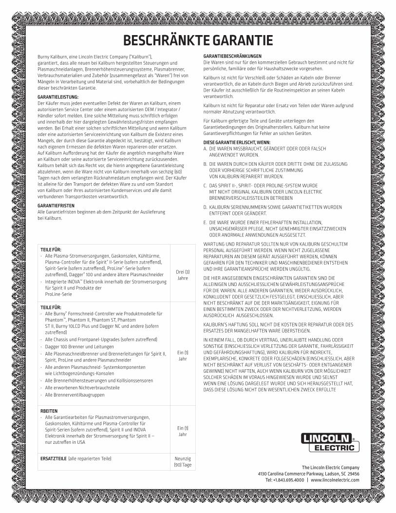
Burny Kaliburn, eine Lincoln Electric Company (“Kaliburn”), garantiert, dass alle neuen bei Kaliburn hergestellten Steuerungen und Plasmaschneidanlagen, Brennerhöhensteuerungssysteme, Plasmabrenner, Verbrauchsmaterialien und Zubehör (zusammengefasst als “Waren”) frei von Mängeln in Verarbeitung und Material sind, vorbehaltlich der Bedingungen dieser beschränkten Garantie.
GARANTIELEISTUNG:Der Käufer muss jeden eventuellen Defekt der Waren an Kaliburn, einem autorisierten Service Center oder einem autorisierten OEM / Integrator / Händler sofort melden. Eine solche Mitteilung muss schriftlich erfolgen und innerhalb der hier dargelegten Gewährleistungsfristen empfangen werden. Bei Erhalt einer solchen schriftlichen Mitteilung und wenn Kaliburn oder eine autorisierten Serviceeinrichtung von Kaliburn die Existenz eines Mangels, der durch diese Garantie abgedeckt ist, bestätigt, wird Kaliburn nach eigenem Ermessen die defekten Waren reparieren oder ersetzen. Auf Kaliburn Aufforderung hat der Käufer die angeblich mangelhafte Ware an Kaliburn oder seine autorisierte Serviceeinrichtung zurückzusenden. Kaliburn behält sich das Recht vor, die hierin angegebene Garantieleistung abzulehnen, wenn die Ware nicht von Kaliburn innerhalb von sechzig (60) Tagen nach dem verlangten Rücknahmedatum empfangen wird. Der Käufer ist alleine für den Transport der defekten Ware zu und vom Standort von Kaliburn oder ihres autorisierten Kundenservices und alle damit verbundenen Transportkosten verantwortlich.
GARANTIEFRISTENAlle Garantiefristen beginnen ab dem Zeitpunkt der Auslieferung bei Kaliburn.
GARANTIEBESCHRÄNKUNGENDie Waren sind nur für den kommerziellen Gebrauch bestimmt und nicht für persönliche, familiäre oder für Haushaltszwecke vorgesehen.
Kaliburn ist nicht für Verschleiß oder Schäden an Kabeln oder Brenner verantwortlich, die an Kabeln durch Biegen und Abrieb zurückzuführen sind. Der Käufer ist ausschließlich für die Routineinspektion an seinen Kabeln verantwortlich.
Kaliburn ist nicht für Reparatur oder Ersatz von Teilen oder Waren aufgrund normaler Abnutzung verantwortlich.
Für Kaliburn gefertigte Teile und Geräte unterliegen den Garantiebedingungen des Originalherstellers. Kaliburn hat keine Garantieverpflichtungen für Fehler an solchen Geräten.
DIESE GARANTIE ERLISCHT, WENN:A. DIE WAREN MISSBRAUCHT, GEÄNDERT ODER ODER FALSCH
ANGEWENDET WURDEN.
B. DIE WAREN DURCH DEN KÄUFER ODER DRITTE OHNE DIE ZULASSUNG ODER VORHERIGE SCHRIFTLICHE ZUSTIMMUNG VON KALIBURN REPARIERT WURDEN.
C. DAS SPIRIT II-, SPIRIT- ODER PROLINE-SYSTEM WURDE MIT NICHT ORIGINAL KALIBURN ODER LINCOLN ELECTRIC BRENNERVERSCHLEISSTEILEN BETRIEBEN
D. KALIBURN SERIENNUMMERN SOWIE GARANTIETIKETTEN WURDEN ENTFERNT ODER GEÄNDERT.
E. DIE WARE WURDE EINER FEHLERHAFTEN INSTALLATION, UNSACHGEMÄSSER PFLEGE, NICHT GENEHMIGTER EINSATZZWECKEN ODER ANORMALE ANWENDUNGEN AUSGESETZT.
WARTUNG UND REPARATUR SOLLTEN NUR VON KALIBURN GESCHULTEM PERSONAL AUSGEFÜHRT WERDEN. WENN NICHT ZUGELASSENE REPARATUREN AN DIESEM GERÄT AUSGEFÜHRT WERDEN, KÖNNEN GEFAHREN FÜR DEN TECHNIKER UND MASCHINENBEDIENER ENTSTEHEN UND IHRE GARANTIEANSPRÜCHE WERDEN UNGÜLTIG.
DIE HIER ANGEGEBENEN EINGESCHRÄNKTEN GARANTIEN SIND DIE ALLEINIGEN UND AUSSCHLIESSLICHEN GEWÄHRLEISTUNGSANSPRÜCHE FÜR DIE WAREN. ALLE ANDEREN GARANTIEN, WEDER AUSDRÜCKLICH, KONKLUDENT ODER GESETZLICH FESTGELEGT, EINSCHLIESSLICH, ABER NICHT BESCHRÄNKT AUF DIE DER MARKTGÄNGIGKEIT, EIGNUNG FÜR EINEN BESTIMMTEN ZWECK ODER DER NICHTVERLETZUNG, WERDEN AUSDRÜCKLICH AUSGESCHLOSSEN.
KALIBURN’S HAFTUNG SOLL NICHT DIE KOSTEN DER REPARATUR ODER DES ERSATZES DER MANGELHAFTEN WARE ÜBERSTEIGEN.
IN KEINEM FALL, OB DURCH VERTRAG, UNERLAUBTE HANDLUNG ODER SONSTIGE (EINSCHLIESSLICH VERLETZUNG DER GARANTIE, FAHRLÄSSIGKEIT UND GEFÄHRDUNGSHAFTUNG), WIRD KALIBURN FÜR INDIREKTE, EXEMPLARISCHE, KONKRETE ODER FOLGESCHÄDEN (EINSCHLIESSLICH, ABER NICHT BESCHRÄNKT AUF VERLUST VON GESCHÄFTS- ODER ENTGANGENER GEWINNE) NICHT HAFTEN, AUCH WENN KALIBURN VON DER MÖGLICHKEIT SOLCHER SCHÄDEN IM VORAUS HINGEWIESEN WURDE UND SELNST WENN EINE LÖSUNG DARGELEGT WURDE UND SICH HERAUSGESTELLT HAT, DASS DIESE LÖSUNG NICHT DEN WESENTLICHEN ZWECK ERFÜLLTE
BESCHRÄNKTE GARANTIE
TEILE FÜR:• Alle Plasma-Stromversorgungen, Gaskonsolen, Kühltürme,
Plasma-Controller für die Spirit® II-Serie (sofern zutreffend), Spirit-Serie (sofern zutreffend), ProLine®-Serie (sofern zutreffend), Dagger® 100 und andere ältere Plasmaschneider
• Integrierte INOVA™ Elektronik innerhalb der Stromversorgung für Spirit II und Produkte der ProLine-Serie
Drei (3) Jahre
TEILE FÜR:• Alle Burny® Formschneid-Controller wie Produktmodelle für
Phantom™, Phantom II, Phantom ST, Phantom ST II, Burny 10LCD Plus und Dagger NC und andere (sofern zutreffend)
• Alle Chassis und Frontpanel-Upgrades (sofern zutreffend)• Dagger 100 Brenner und Leitungen• Alle Plasmaschneidbrenner und Brennerleitungen für Spirit II,
Spirit, ProLine und andere Plasmaschneider• Alle anderen Plasmaschneid- Systemkomponenten
wie Lichtbogenzündungs-Konsolen• Alle Brennerhöhensteuerungen und Kollisionssensoren• Alle erworbenen Nichtverbrauchsteile• Alle Brennerventilbaugruppen
Ein (1) Jahr
RBEITEN• Alle Garantiearbeiten für Plasmastromversorgungen,
Gaskonsolen, Kühltürme und Plasma-Controller für Spirit-Serien (sofern zutreffend), Spirit II und INOVA Elektronik innerhalb der Stromversorgung für Spirit II – nur zutreffen in USA
Ein (1) Jahr
ERSATZTEILE (alle reparierten Teile) Neunzig (90) Tage
DÉCLARATION DE RESPONSABILITÉ LIMITÉELincoln Electric Company (Lincoln) garantit à l’usager final (acheteur) detous les appareils de soudage et de coupage neufs, d’électrode et de flux(collectivement appelés « Biens ») qu’ils ne présenteront aucun défaut defabrication et de matériel.Cette garantie est annulée si l’appareil a été sujet à une mauvaiseinstallation, à des soins inappropriés ou à des opérations anormales.PÉRIODE DE GARANTIE (1) (2) (3) (4) (5) (6) (7) (8) (9)
Lincoln assurera les dépenses relatives aux pièces et à la main d’œuvrepour la correction des défauts durant la période de garantie. Toutepériode de garantie commence à la date de l’achat, chez un DistributeurLincoln Agréé ou dans un Atelier de Service Agréé par Lincoln, parl’usager final d’origine, ou bien à partir de la date de fabrication siaucune preuve d’achat n’est disponible, le tout dans les conditionssuivantes :
7 Ans• Redresseurs d’alimentation principale sur les soudeuses Idealarc® de type
non-onduleur
3 Ans• Toutes les soudeuses, dévidoirs et machines pour couper le plasma de Lin-
coln.• Casques auto-obscurcissants Viking™ désignés par les numéros de
référence de produits se terminant en "-2" (ex. KXXXX-2). Les exceptionsfigurent dans la liste pour 2 Ans.
2 Ans• Casques auto-obscurissants, tous les autres casques Viking™ y compris
les casques de la série 1740 et les casques passifs 4x5.
1 An• Handy MIG®, Handy Core®, Weld Pak™ HD• Tous les refroidisseurs à eau (modèles internes ou externes)• Tous les régulateurs de gaz • Toutes les baguettes d’électrode, fils à souder et flux (Contacter le
Représentant de Ventes Lincoln le plus proche)• Robots de soudage à l’arc et de coupage et contrôleurs robotiques• Tous les appareils de Contrôle des Vapeurs de Soudage, y compris les ap-
pareils portables, les unités centrales, les extincteurs et les accessoires(Ne comprend pas les articles de matériel consommable figurant sur laliste d’articles ayant 30 jours de garantie)
• Tout les accessoires de soudage et de coupage, y compris les modules dedévidoirs, les chariots, les options à installer sur le terrain qui sont venduesséparément, les options non fixées, les fournitures de soudage, les jeuxd’accessoires standards et les produits Magnum® (Ne comprend pas lespièces consommables et les pistolets / torches figurant sur la liste d’arti-cles ayant une garantie de 90 et 30 jours)
• Toutes les torches TIG Pro-Torch™ • Toutes les torches de coupage au plasma• Toutes les pièces de rechange non consommables achetées• Les Pistolets à Bobine Magnum® 250LX• Les Pistolets à système pousser• Mobiles VRTEX® 360 et VRTEX®
• Viking™ PAPR Blower Unit• Poussoirs magnétiques main
90 Jours• Tous les ensembles de pistolet et câble et les pistolets à bobine Magnum®
SG
30 Jours• Tous les articles consommables pouvant être utilisés avec les Systèmes de
Contrôle des Vapeurs de Soudage décrits plus haut. Ceci comprend lestuyaux, les filtres, les courroies et les adaptateurs de tuyaux
• Tous les logiciels• Pièces non consommables - Lincoln n’est responsable du changement
d’aucune pièce non consommable nécessaire du fait d’une usure normale.
Période de Temps Non Spécifiée • Les produits d’habillement Red Line™ sont garantis contre les défauts de
fabrication. Du fait que les applications varient, il relève de la responsabil-ité de l’usager de sélectionner le bon produit pour chaque application. Lesproduits d’habillement Red Line™ ne sont pas sujets à la garantie aprèsusage.
• Les produits de la gamme de lunettes de sécurité Red Line™ sont garantiscontre les défauts de fabrication
CONDITIONS DE GARANTIE À OBTENIR COUVERTURE DE LA GARANTIE :L’acheteur doit contacter un Atelier de Service Agréé par Lincoln (LASF).Pour une assistance à la recherche d’un LASF, aller sur www.lincolnelectric.com/locator
La détermination finale de la garantie sur les produits de soudage et decoupage sera faite par Lincoln ou par l’Atelier de Service Agréé parLincoln.RÉPARATIONS COUVERTES PAR LA GARANTIE : Si Lincoln ou l’Atelier de Service Agréé par Lincoln confirme l’existenced’un défaut couvert par cette garantie, celui-ci sera corrigé parréparation ou par changement, au choix de Lincoln.
À la demande de Lincoln, l’acheteur doit rendre, à Lincoln ou à son Atelierde Service Agréé, tout « Bien » réclamé comme défectueux couvert par lagarantie de Lincoln.FRAIS DE PORT : L’acheteur est responsable de l’expédition vers et depuis l’Atelier deService Agréé par Lincoln.LIMITES DE LA GARANTIE:LINCOLN N’ACCEPTERA AUCUNE RESPONSABILITÉ DANS LE CAS DE RÉPARATIONSEFFECTUÉES HORS D’UN ATELIER DE SERVICE AGRÉÉ PAR LINCOLN.
LA RESPONSABILITÉ DE LINCOLN SELON CETTE GARANTIE NE DÉPASSERA PAS LECOÛT DE LA CORRECTION DU DÉFAUT DU PRODUIT DE LINCOLN.
LINCOLN NE SERA PAS RESPONSABLE DES DOMMAGES ACCIDENTELS OUCONSÉQUENTS (TELS QUE LA PERTE D’AFFAIRES COMMERCIALES, ETC.) CAUSÉSPAR LE DÉFAUT OU PAR LE TEMPS NÉCESSAIRE À LA CORRECTION DU DÉFAUT.
CETTE GARANTIE ÉCRITE EST LA SEULE GARANTIE EXPRESSE FOURNIE PARLINCOLN CONCERNANT SES PRODUITS. LES GARANTIES IMPLIQUÉES PAR LA LOI,TELLES QUE LA GARANTIE DE QUALITÉ MARCHANDE, SE LIMITENT À LA DURÉE DECETTE GARANTIE LIMITÉE POUR L’APPAREIL EN QUESTION.
CETTE GARANTIE DONNE À L’ACHETEUR DES DROITS LÉGAUX SPÉCIFIQUES.L’ACHETEUR PEUT ÉGALEMENT AVOIR D’AUTRES DROITS QUI PEUVENT VARIERD’UN ÉTAT À L’AUTRE.
(1) Les appareils fabriqués pour The Lincoln Electric Company sont sujets àla période de garantie du fabricant original.
(2) Tous les moteurs et accessoires pour moteurs sont garantis par le fabri-cant du moteur ou des accessoires pour moteurs et ils ne sont pas cou-verts par cette garantie.
(3) Les compresseurs AIR VANTAGE® 500 sont garantis par le fabricant ducompresseur et ne sont pas couverts par cette garantie.
(4) Tous les Produits MK sont garantis par MK Products et ne sont pas cou-verts par cette garantie. Contacter le 1-800-787-9707.
(5) Lincoln Electric n’est pas responsable de l’usure des câbles ni des dom-mages résultant de l’usure des câbles suite à des courbures et à l’abra-sion. L’usager final est responsable de l’inspection de routine des câblespour vérifier qu’ils ne présentent pas d’usure éventuelle et pour y remédieravant la panne du câble.
(6) Tous les Produits Burny Kaliburn sont garantis par Burny Kaliburn et nesont pas couverts par cette garantie. Email: [email protected].
(7) Tous les Produits Vernon Tools sont garantis par Vernon Tool et ne sontpas couverts par cette garantie. www.vernontool.com/sales/product-warranty
(8) Tous les Produits Arc Products sont garantis par Arc Products et ne sontpas couverts par cette garantie. Email: [email protected]
(8) Tous les Produits ELCo Enterprises, Inc sont garantis par ELCo Enter-prises, Inc et ne sont pas couverts par cette garantie. Contacter le (517) 782-8040
RESPONSABILITÉ LIMITÉEGarantie actuelle disponible à www.lincolnelectric.com/warranty
Mar 14
THE LINCOLN ELECTRIC COMPANY22801 St. Clair Avenue • Cleveland, OH • 44117-1199 • U.S.A.
Phone: +1.888.935.3877 • www.lincolnelectric.com
The Lincoln Electric Company4130 Carolina Commerce Parkway, Ladson, SC 29456
Téléphone : +1.843.695.4000 | www.lincolnelectric.com
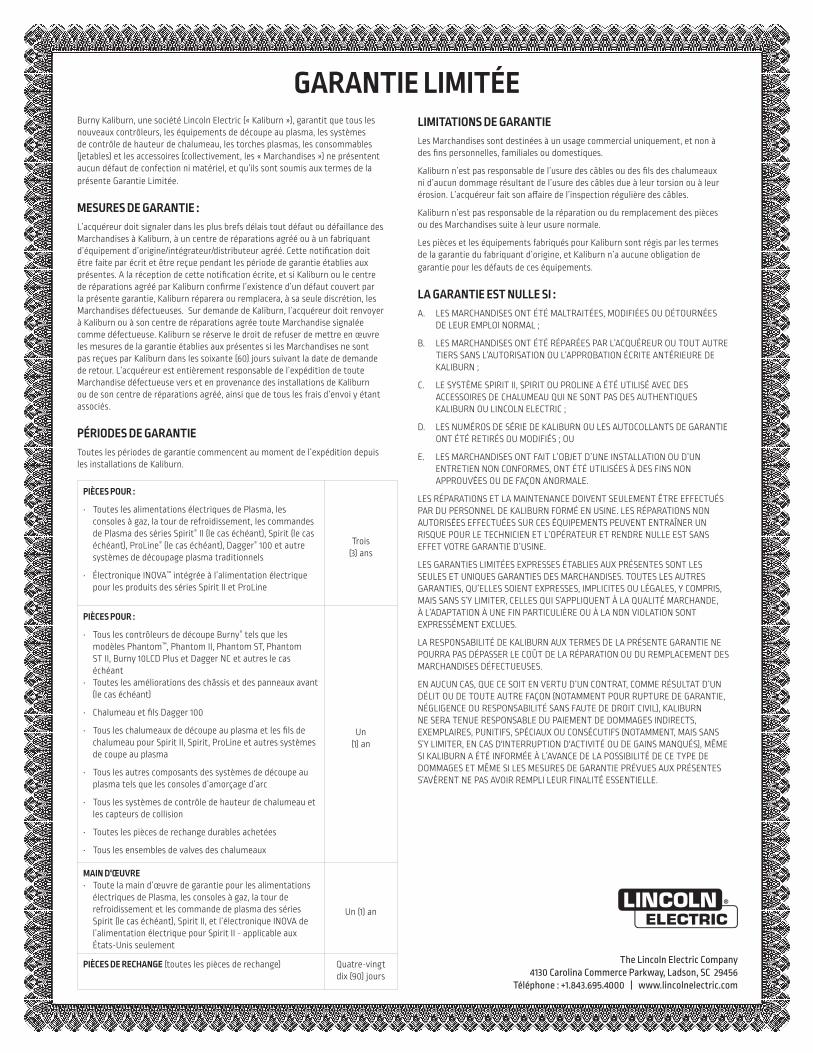
Burny Kaliburn, une société Lincoln Electric (« Kaliburn »), garantit que tous les nouveaux contrôleurs, les équipements de découpe au plasma, les systèmes de contrôle de hauteur de chalumeau, les torches plasmas, les consommables (jetables) et les accessoires (collectivement, les « Marchandises ») ne présentent aucun défaut de confection ni matériel, et qu’ils sont soumis aux termes de la présente Garantie Limitée.
MESURES DE GARANTIE :L’acquéreur doit signaler dans les plus brefs délais tout défaut ou défaillance des Marchandises à Kaliburn, à un centre de réparations agréé ou à un fabriquant d’équipement d’origine/intégrateur/distributeur agréé. Cette notification doit être faite par écrit et être reçue pendant les période de garantie établies aux présentes. A la réception de cette notification écrite, et si Kaliburn ou le centre de réparations agréé par Kaliburn confirme l’existence d’un défaut couvert par la présente garantie, Kaliburn réparera ou remplacera, à sa seule discrétion, les Marchandises défectueuses. Sur demande de Kaliburn, l’acquéreur doit renvoyer à Kaliburn ou à son centre de réparations agrée toute Marchandise signalée comme défectueuse. Kaliburn se réserve le droit de refuser de mettre en œuvre les mesures de la garantie établies aux présentes si les Marchandises ne sont pas reçues par Kaliburn dans les soixante (60) jours suivant la date de demande de retour. L’acquéreur est entièrement responsable de l’expédition de toute Marchandise défectueuse vers et en provenance des installations de Kaliburn ou de son centre de réparations agréé, ainsi que de tous les frais d’envoi y étant associés.
PÉRIODES DE GARANTIEToutes les périodes de garantie commencent au moment de l’expédition depuis les installations de Kaliburn.
PIÈCES POUR :
• Toutes les alimentations électriques de Plasma, les consoles à gaz, la tour de refroidissement, les commandes de Plasma des séries Spirit® II (le cas échéant), Spirit (le cas échéant), ProLine® (le cas échéant), Dagger® 100 et autre systèmes de découpage plasma traditionnels
• Électronique INOVA™ intégrée à l’alimentation électrique pour les produits des séries Spirit II et ProLine
Trois (3) ans
PIÈCES POUR :
• Tous les contrôleurs de découpe Burny® tels que les modèles Phantom™, Phantom II, Phantom ST, Phantom ST II, Burny 10LCD Plus et Dagger NC et autres le cas échéant
• Toutes les améliorations des châssis et des panneaux avant (le cas échéant)
• Chalumeau et fils Dagger 100
• Tous les chalumeaux de découpe au plasma et les fils de chalumeau pour Spirit II, Spirit, ProLine et autres systèmes de coupe au plasma
• Tous les autres composants des systèmes de découpe au plasma tels que les consoles d’amorçage d’arc
• Tous les systèmes de contrôle de hauteur de chalumeau et les capteurs de collision
• Toutes les pièces de rechange durables achetées
• Tous les ensembles de valves des chalumeaux
Un (1) an
MAIN D'ŒUVRE• Toute la main d’œuvre de garantie pour les alimentations
électriques de Plasma, les consoles à gaz, la tour de refroidissement et les commande de plasma des séries Spirit (le cas échéant), Spirit II, et l’électronique INOVA de l’alimentation électrique pour Spirit II - applicable aux États-Unis seulement
Un (1) an
PIÈCES DE RECHANGE (toutes les pièces de rechange) Quatre-vingt dix (90) jours
LIMITATIONS DE GARANTIELes Marchandises sont destinées à un usage commercial uniquement, et non à des fins personnelles, familiales ou domestiques.
Kaliburn n’est pas responsable de l’usure des câbles ou des fils des chalumeaux ni d’aucun dommage résultant de l’usure des câbles due à leur torsion ou à leur érosion. L’acquéreur fait son affaire de l’inspection régulière des câbles.
Kaliburn n’est pas responsable de la réparation ou du remplacement des pièces ou des Marchandises suite à leur usure normale.
Les pièces et les équipements fabriqués pour Kaliburn sont régis par les termes de la garantie du fabriquant d’origine, et Kaliburn n’a aucune obligation de garantie pour les défauts de ces équipements.
LA GARANTIE EST NULLE SI :A. LES MARCHANDISES ONT ÉTÉ MALTRAITÉES, MODIFIÉES OU DÉTOURNÉES
DE LEUR EMPLOI NORMAL ;
B. LES MARCHANDISES ONT ÉTÉ RÉPARÉES PAR L’ACQUÉREUR OU TOUT AUTRE TIERS SANS L’AUTORISATION OU L’APPROBATION ÉCRITE ANTÉRIEURE DE KALIBURN ;
C. LE SYSTÈME SPIRIT II, SPIRIT OU PROLINE A ÉTÉ UTILISÉ AVEC DES ACCESSOIRES DE CHALUMEAU QUI NE SONT PAS DES AUTHENTIQUES KALIBURN OU LINCOLN ELECTRIC ;
D. LES NUMÉROS DE SÉRIE DE KALIBURN OU LES AUTOCOLLANTS DE GARANTIE ONT ÉTÉ RETIRÉS OU MODIFIÉS ; OU
E. LES MARCHANDISES ONT FAIT L’OBJET D’UNE INSTALLATION OU D’UN ENTRETIEN NON CONFORMES, ONT ÉTÉ UTILISÉES À DES FINS NON APPROUVÉES OU DE FAÇON ANORMALE.
LES RÉPARATIONS ET LA MAINTENANCE DOIVENT SEULEMENT ÊTRE EFFECTUÉS PAR DU PERSONNEL DE KALIBURN FORMÉ EN USINE. LES RÉPARATIONS NON AUTORISÉES EFFECTUÉES SUR CES ÉQUIPEMENTS PEUVENT ENTRAÎNER UN RISQUE POUR LE TECHNICIEN ET L’OPÉRATEUR ET RENDRE NULLE EST SANS EFFET VOTRE GARANTIE D’USINE.
LES GARANTIES LIMITÉES EXPRESSES ÉTABLIES AUX PRÉSENTES SONT LES SEULES ET UNIQUES GARANTIES DES MARCHANDISES. TOUTES LES AUTRES GARANTIES, QU’ELLES SOIENT EXPRESSES, IMPLICITES OU LÉGALES, Y COMPRIS, MAIS SANS S’Y LIMITER, CELLES QUI S’APPLIQUENT À LA QUALITÉ MARCHANDE, À L’ADAPTATION À UNE FIN PARTICULIÈRE OU À LA NON VIOLATION SONT EXPRESSÉMENT EXCLUES.
LA RESPONSABILITÉ DE KALIBURN AUX TERMES DE LA PRÉSENTE GARANTIE NE POURRA PAS DÉPASSER LE COÛT DE LA RÉPARATION OU DU REMPLACEMENT DES MARCHANDISES DÉFECTUEUSES.
EN AUCUN CAS, QUE CE SOIT EN VERTU D’UN CONTRAT, COMME RÉSULTAT D’UN DÉLIT OU DE TOUTE AUTRE FAÇON (NOTAMMENT POUR RUPTURE DE GARANTIE, NÉGLIGENCE OU RESPONSABILITÉ SANS FAUTE DE DROIT CIVIL), KALIBURN NE SERA TENUE RESPONSABLE DU PAIEMENT DE DOMMAGES INDIRECTS, EXEMPLAIRES, PUNITIFS, SPÉCIAUX OU CONSÉCUTIFS (NOTAMMENT, MAIS SANS S’Y LIMITER, EN CAS D'INTERRUPTION D'ACTIVITÉ OU DE GAINS MANQUÉS), MÊME SI KALIBURN A ÉTÉ INFORMÉE À L’AVANCE DE LA POSSIBILITÉ DE CE TYPE DE DOMMAGES ET MÊME SI LES MESURES DE GARANTIE PRÉVUES AUX PRÉSENTES S’AVÈRENT NE PAS AVOIR REMPLI LEUR FINALITÉ ESSENTIELLE.
GARANTIE LIMITÉE
DÉCLARATION DE RESPONSABILITÉ LIMITÉELincoln Electric Company (Lincoln) garantit à l’usager final (acheteur) detous les appareils de soudage et de coupage neufs, d’électrode et de flux(collectivement appelés « Biens ») qu’ils ne présenteront aucun défaut defabrication et de matériel.Cette garantie est annulée si l’appareil a été sujet à une mauvaiseinstallation, à des soins inappropriés ou à des opérations anormales.PÉRIODE DE GARANTIE (1) (2) (3) (4) (5) (6) (7) (8) (9)
Lincoln assurera les dépenses relatives aux pièces et à la main d’œuvrepour la correction des défauts durant la période de garantie. Toutepériode de garantie commence à la date de l’achat, chez un DistributeurLincoln Agréé ou dans un Atelier de Service Agréé par Lincoln, parl’usager final d’origine, ou bien à partir de la date de fabrication siaucune preuve d’achat n’est disponible, le tout dans les conditionssuivantes :
7 Ans• Redresseurs d’alimentation principale sur les soudeuses Idealarc® de type
non-onduleur
3 Ans• Toutes les soudeuses, dévidoirs et machines pour couper le plasma de Lin-
coln.• Casques auto-obscurcissants Viking™ désignés par les numéros de
référence de produits se terminant en "-2" (ex. KXXXX-2). Les exceptionsfigurent dans la liste pour 2 Ans.
2 Ans• Casques auto-obscurissants, tous les autres casques Viking™ y compris
les casques de la série 1740 et les casques passifs 4x5.
1 An• Handy MIG®, Handy Core®, Weld Pak™ HD• Tous les refroidisseurs à eau (modèles internes ou externes)• Tous les régulateurs de gaz • Toutes les baguettes d’électrode, fils à souder et flux (Contacter le
Représentant de Ventes Lincoln le plus proche)• Robots de soudage à l’arc et de coupage et contrôleurs robotiques• Tous les appareils de Contrôle des Vapeurs de Soudage, y compris les ap-
pareils portables, les unités centrales, les extincteurs et les accessoires(Ne comprend pas les articles de matériel consommable figurant sur laliste d’articles ayant 30 jours de garantie)
• Tout les accessoires de soudage et de coupage, y compris les modules dedévidoirs, les chariots, les options à installer sur le terrain qui sont venduesséparément, les options non fixées, les fournitures de soudage, les jeuxd’accessoires standards et les produits Magnum® (Ne comprend pas lespièces consommables et les pistolets / torches figurant sur la liste d’arti-cles ayant une garantie de 90 et 30 jours)
• Toutes les torches TIG Pro-Torch™ • Toutes les torches de coupage au plasma• Toutes les pièces de rechange non consommables achetées• Les Pistolets à Bobine Magnum® 250LX• Les Pistolets à système pousser• Mobiles VRTEX® 360 et VRTEX®
• Viking™ PAPR Blower Unit• Poussoirs magnétiques main
90 Jours• Tous les ensembles de pistolet et câble et les pistolets à bobine Magnum®
SG
30 Jours• Tous les articles consommables pouvant être utilisés avec les Systèmes de
Contrôle des Vapeurs de Soudage décrits plus haut. Ceci comprend lestuyaux, les filtres, les courroies et les adaptateurs de tuyaux
• Tous les logiciels• Pièces non consommables - Lincoln n’est responsable du changement
d’aucune pièce non consommable nécessaire du fait d’une usure normale.
Période de Temps Non Spécifiée • Les produits d’habillement Red Line™ sont garantis contre les défauts de
fabrication. Du fait que les applications varient, il relève de la responsabil-ité de l’usager de sélectionner le bon produit pour chaque application. Lesproduits d’habillement Red Line™ ne sont pas sujets à la garantie aprèsusage.
• Les produits de la gamme de lunettes de sécurité Red Line™ sont garantiscontre les défauts de fabrication
CONDITIONS DE GARANTIE À OBTENIR COUVERTURE DE LA GARANTIE :L’acheteur doit contacter un Atelier de Service Agréé par Lincoln (LASF).Pour une assistance à la recherche d’un LASF, aller sur www.lincolnelectric.com/locator
La détermination finale de la garantie sur les produits de soudage et decoupage sera faite par Lincoln ou par l’Atelier de Service Agréé parLincoln.RÉPARATIONS COUVERTES PAR LA GARANTIE : Si Lincoln ou l’Atelier de Service Agréé par Lincoln confirme l’existenced’un défaut couvert par cette garantie, celui-ci sera corrigé parréparation ou par changement, au choix de Lincoln.
À la demande de Lincoln, l’acheteur doit rendre, à Lincoln ou à son Atelierde Service Agréé, tout « Bien » réclamé comme défectueux couvert par lagarantie de Lincoln.FRAIS DE PORT : L’acheteur est responsable de l’expédition vers et depuis l’Atelier deService Agréé par Lincoln.LIMITES DE LA GARANTIE:LINCOLN N’ACCEPTERA AUCUNE RESPONSABILITÉ DANS LE CAS DE RÉPARATIONSEFFECTUÉES HORS D’UN ATELIER DE SERVICE AGRÉÉ PAR LINCOLN.
LA RESPONSABILITÉ DE LINCOLN SELON CETTE GARANTIE NE DÉPASSERA PAS LECOÛT DE LA CORRECTION DU DÉFAUT DU PRODUIT DE LINCOLN.
LINCOLN NE SERA PAS RESPONSABLE DES DOMMAGES ACCIDENTELS OUCONSÉQUENTS (TELS QUE LA PERTE D’AFFAIRES COMMERCIALES, ETC.) CAUSÉSPAR LE DÉFAUT OU PAR LE TEMPS NÉCESSAIRE À LA CORRECTION DU DÉFAUT.
CETTE GARANTIE ÉCRITE EST LA SEULE GARANTIE EXPRESSE FOURNIE PARLINCOLN CONCERNANT SES PRODUITS. LES GARANTIES IMPLIQUÉES PAR LA LOI,TELLES QUE LA GARANTIE DE QUALITÉ MARCHANDE, SE LIMITENT À LA DURÉE DECETTE GARANTIE LIMITÉE POUR L’APPAREIL EN QUESTION.
CETTE GARANTIE DONNE À L’ACHETEUR DES DROITS LÉGAUX SPÉCIFIQUES.L’ACHETEUR PEUT ÉGALEMENT AVOIR D’AUTRES DROITS QUI PEUVENT VARIERD’UN ÉTAT À L’AUTRE.
(1) Les appareils fabriqués pour The Lincoln Electric Company sont sujets àla période de garantie du fabricant original.
(2) Tous les moteurs et accessoires pour moteurs sont garantis par le fabri-cant du moteur ou des accessoires pour moteurs et ils ne sont pas cou-verts par cette garantie.
(3) Les compresseurs AIR VANTAGE® 500 sont garantis par le fabricant ducompresseur et ne sont pas couverts par cette garantie.
(4) Tous les Produits MK sont garantis par MK Products et ne sont pas cou-verts par cette garantie. Contacter le 1-800-787-9707.
(5) Lincoln Electric n’est pas responsable de l’usure des câbles ni des dom-mages résultant de l’usure des câbles suite à des courbures et à l’abra-sion. L’usager final est responsable de l’inspection de routine des câblespour vérifier qu’ils ne présentent pas d’usure éventuelle et pour y remédieravant la panne du câble.
(6) Tous les Produits Burny Kaliburn sont garantis par Burny Kaliburn et nesont pas couverts par cette garantie. Email: [email protected].
(7) Tous les Produits Vernon Tools sont garantis par Vernon Tool et ne sontpas couverts par cette garantie. www.vernontool.com/sales/product-warranty
(8) Tous les Produits Arc Products sont garantis par Arc Products et ne sontpas couverts par cette garantie. Email: [email protected]
(8) Tous les Produits ELCo Enterprises, Inc sont garantis par ELCo Enter-prises, Inc et ne sont pas couverts par cette garantie. Contacter le (517) 782-8040
RESPONSABILITÉ LIMITÉEGarantie actuelle disponible à www.lincolnelectric.com/warranty
Mar 14
THE LINCOLN ELECTRIC COMPANY22801 St. Clair Avenue • Cleveland, OH • 44117-1199 • U.S.A.
Phone: +1.888.935.3877 • www.lincolnelectric.com
林肯电气公司地址:4130 Carolina Commerce Parkway, Ladson, SC 29456
手机:+1.843.695.4000 | www.lincolnelectric.comMC15-50 03/15 ©Lincoln Global, Inc.保留所有权利。
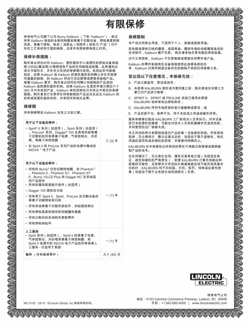
林肯电气公司旗下公司 Burny Kaliburn (下称 “Kaliburn”),保证所有 Kaliburn 制造的全新控制器和等离子切割设备、焊枪高度控制系统、等离子焊枪、耗材(消耗品)和附件(统称为“产品”)均不存在工艺和材料方面的缺陷,且受本有限保修条款之约束。
保修补救措施:
购买者必须及时向 Kaliburn、授权服务中心或授权的原始设备制造商 (OEM)/集成商/分销商报告产品的任何缺陷或故障。此类通知必须以书面形式,并在本文所述的保修期内收到。收到此类书面通知后,如果 Kaliburn 或 Kaliburn 的授权服务机构确认存在本保修所涵盖的缺陷,则 Kaliburn 将自行决定修理或更换有缺陷产品。 根据 Kaliburn 要求,购买者必须将任何确认有缺陷的产品退回 Kaliburn 或其授权服务机构。如果 Kaliburn 在退货申请日期后六十(60) 天内未收到产品,Kaliburn 有权拒绝执行本协议中规定的保修措施。购买者自行负责将任何有缺陷的产品运往及运出 Kaliburn 的机构或其授权服务机构,并承担所有相关运费。
保修期
所有保修期自 Kaliburn 发货之日起计算。
用于以下设备的零件:
• Spirit® II 系列(如适用)、Spirit 系列(如适用)、ProLine® 系列、Dagger® 100 及其他传统等离子切割机的所有等离子电源,气体控制台、冷却塔、等离子体控制器
• 在 Spirit II 和 ProLine 系列产品的电源中集成的 INOVA ™ 电子产品
三 (3) 年
用于以下设备的零件:
• 所有的 Burny® 仿形切割控制器,如 Phantom™
、Phantom II、Phantom ST、Phantom ST II,Burny 10LCD Plus 和 Dagger NC 及其他适用产品型号
• 所有机箱和前面板升级件(如适用)
• Dagger 100 焊枪及引线
• 所有用于 Spirit II、Spirit、ProLine 及切割设备的等离子切割焊枪和引线
• 所有其他等离子切割系统组件,如起弧控制台
• 所有焊枪高度控制系统和碰撞传感器
• 所有已购买的非消耗性更换零件
• 所有焊枪阀组件
一 (1) 年
人工服务• Spirit 系列(如适用)、Spirit II 的等离子电源、
气体控制台、冷却塔和等离子体控制器,和 Spirit II 电源中的 INOVA 电子产品的所有保修人工服务 - 仅适用于美国
一 (1) 年
备件 (所有维修零件) 九十 (90) 天
保修限制
本产品仅供商业用途,不适用于个人,家庭或居家用途。
因电缆或焊枪引线的磨损,或因弯曲、磨损导致的电缆磨损造成的任何损坏,Kaliburn 概不负责。 购买者单独负责电缆的常规检查。
对于正常损耗,Kaliburn 不负责维修或更换任何零件或产品。
Kaliburn 的零件制造商及设备制造商受此保修条款的约束,Kaliburn 对其所制造设备存在的缺陷不承担任何保修义务。
若出现以下任意情况,本保修无效:
A. 产品已被滥用,更改或误用;
B. 未获得 KALIBURN 授权或书面同意之前,购买者或任何第三方便已对产品进行维修;
C. SPIRIT II、SPIRIT 或 PROLINE 系统已使用非原装 KALIBURN 或林肯电动焊枪耗材;
D. KALIBURN 序列号或质保标签已被删除或更改;或
E. 产品安装不当、保养不当、用于未批准之用途或操作异常。
服务和维修仅能由 KALIBURN 工厂经培训人员来执行。对本设备进行未经授权的维修,可能会对技术人员和机器操作员造成危险,并将使您的出厂保修失效。
本文所述的明示有限担保是对产品的唯一且独家的担保。所有其他担保,无论是明示,默示还是法定的,包括但不限于适销性,特定用途的适用性或非侵权的担保,本保修均明确否认。
KALIBURN 在本保修协议所承担的责任不得超过其修理或更换缺陷产品的成本。
在任何情况下,无论是在合同、侵权还是其他方面(包括违反保证,疏忽和侵权的严格责任),即使 KALIBURN 已事先知晓这种损害的可能性,且即使本文所述的补救措施被发现不能实现其基本目的时,KALIBURN 均不对间接、示范、惩罚、特殊或后果性损害(包括但不限于业务损失或利润损失)负责。
有限保修
Spirit II User’s Manual Section 1: Safety
This information is subject to the controls of the Export Administration Regulations [EAR]. This information shall not be provided to non-U.S. persons or transferred by any means to any location outside the United States contrary to the requirements of the EAR.
1-1
Section 1: Safety General Precautions
Whereas plasma cutting has been used safely for years, it does require certain precautions to ensure the safety of the operator and other people around the equipment. The following safety information must be provided to each person who will operate, observe, perform maintenance, or work in close proximity to this piece of equipment. Always wear appropriate personal protective equipment (PPE).
Installation, operation, and repairs made to the Spirit system should only be performed by qualified personnel. The system makes use of both A.C. and D.C. circuitry for operation. Fatal shock hazard does exist. Exercise extreme caution while working on the system.
Ultraviolet Radiation Protection
Plasma cutting produces ultraviolet radiation similar to a welding arc. This ultraviolet radiation can cause skin and eye burns. For this reason, it is essential that proper protection be worn. The eyes are best protected by using safety glasses or a welding helmet with an AWS No. 12 shade or ISO 4850 No. 13 shade, which provides protection up to 400 amperes. All exposed skin areas should be covered with flame-retardant clothing. The cutting area should also be prepared in such a way that ultraviolet light does not reflect. Walls and other surfaces should be painted with dark colors to reduce reflected light. Protective screens or curtains should be installed to protect additional workers in the area from ultraviolet radiation.
Noise Protection
The system generates high noise levels while cutting. Depending on the size of the cutting area, distance from the cutting torch, and arc current cutting level, acceptable noise levels may be exceeded. Proper ear protection should be used as defined by local or national codes. See Section 2 for noise emission levels.
Section 1: Safety Spirit II User’s Manual
This information is subject to the controls of the Export Administration Regulations [EAR]. This information shall not be provided to non-U.S. persons or transferred by any means to any location outside the United States contrary to the requirements of the EAR.
1-2
Toxic Fume Prevention
Care should be taken to ensure adequate ventilation in the cutting area. Some materials give off toxic fumes that can be harmful or fatal to people in the vicinity of the cutting area. Also, some solvents decompose and form harmful gases when exposed to ultraviolet radiation. These solvents should be removed from the area prior to cutting. Galvanized metal can produce harmful gases during the cutting process. Ensure proper ventilation and use breathing equipment when cutting these materials. Certain metals coated with or containing lead, cadmium, zinc, beryllium, and mercury produce harmful toxins. Do not cut these metals unless all people subjected to the fumes wear proper air breathing equipment.
Electric Shock Prevention
The Spirit system uses high open circuit voltages that can be fatal. Extreme care should be used when operating or performing maintenance on the system. Only qualified personnel should service the system. Observe the following guidelines to protect against electric shock: • A wall-mounted disconnect switch should be installed and fused according to local
and national electrical codes. The disconnect switch should be located as close as possible to the power supply so it can be turned off in case of an emergency.
• The primary power cord should have a 600 volt minimum rating in order to protect the operator. In addition, it should be sized according to local and national electrical codes. Inspect the primary power cord frequently. Never operate the system if the power cord is damaged in any way.
• Make sure the primary power ground wire is connected to the input power ground stud on the power supply. Make sure the connection is securely tightened.
• Make sure the positive output (work ground) of the power supply is connected to a bare metal area on the cutting table. A driven ground rod should be placed no further than five feet from this connection. Make sure this ground point on the cutting table is used as the star ground point for all other ground connections.
• Inspect the torch leads frequently. Never use the system if the leads are damaged in any way.
• Do not stand in wet, damp areas when operating or performing maintenance on the system.
• Wear insulated gloves and shoes while operating or performing maintenance on the system.
• Make sure the system is switched off at the wall disconnect before servicing the power supply or torch.
Spirit II User’s Manual Section 1: Safety
This information is subject to the controls of the Export Administration Regulations [EAR]. This information shall not be provided to non-U.S. persons or transferred by any means to any location outside the United States contrary to the requirements of the EAR.
1-3
• Never change torch consumable parts unless the system is switched off at the wall disconnect.
• Do not attempt to remove any parts from beneath the torch when cutting. Remember that the workpiece forms the current path back to the power supply.
• Never bypass the safety interlock devices. • Before removing any of the covers, switch the system off at the wall disconnect.
Wait at least five (5) minutes before removing any cover. This will give the capacitors inside the unit time to discharge. See Section 6 for additional safety precautions.
• Never operate the system without all of the covers in place. See Section 6 for additional safety precautions.
• Preventive maintenance should be performed daily to avoid possible safety hazards.
Fire Prevention
When using the Spirit system, it is necessary to exercise good judgment. While cutting, the arc produces sparks that could cause a fire if they fall on flammable materials. Make sure that all flammable materials are a suitable distance away from the cutting area. All flammable liquids should be at least 40 feet away from the cutting area, preferably stored in a metal cabinet. Plasma cutting should never be attempted on containers that contain flammable materials. Make sure that fire extinguishers are readily accessible in the cutting area. Make sure that the cutting area is properly ventilated when using oxygen as a cutting gas.
Explosion Prevention
The Spirit system uses compressed gases. Use proper techniques when handling compressed gas cylinders and other compressed gas equipment. Observe the following guidelines to protect against explosion: • The combination of Preflow/Postflow, Plasma and Shield input gases should always
adhere to the types specified in the cut charts for a given material type. • When changing to a different type of gas (oxidizing or oxygen containing to
combustible or vice versa), a purge of the gas lines (30 second minimum) must be completed to reduce the risk of fire or explosion.
• Do not connect H17 (combustible gas) to the gas inputs (Pre/Postflow, Plasma, or Shield) at the same time as Oxygen or Air.
Section 1: Safety Spirit II User’s Manual
This information is subject to the controls of the Export Administration Regulations [EAR]. This information shall not be provided to non-U.S. persons or transferred by any means to any location outside the United States contrary to the requirements of the EAR.
1-4
• Never operate the system in the presence of explosive gases or other explosive materials.
• Never cut pressurized cylinders or any closed container. • When using a water table and cutting aluminum under water or with water touching
the underside of the aluminum plate, hydrogen gas is produced. This hydrogen gas may collect under the plate and explode during the cutting process. Make sure the water table is properly aerated to help prevent the accumulation of hydrogen gas.
• Handle all gas cylinders in accordance with safety standards published by the U.S. Compressed Gas Association (CGA), American Welding Society (AWS), Canadian Standards Association (CSA), or other local or national codes.
• Compressed gas cylinders should be maintained properly. Never attempt to use a cylinder that is leaking, cracked, or has other signs of physical damage.
• All gas cylinders should be secured to a wall or rack to prevent accidental knock over.
• If a compressed gas cylinder is not being used, replace the protective valve cover. • Never attempt to repair compressed gas cylinders. • Keep compressed gas cylinders away from intense heat, sparks, or flames. • Clear the compressed gas cylinder connection point by opening the valve
momentarily prior to installing a regulator. • Never lubricate compressed gas cylinder valves or pressure regulators with any type
of oil or grease. • Never use a compressed gas cylinder or pressure regulator for any purpose other
than which it is intended. • Never use a pressure regulator for any gas other than which it is intended. • Never use a pressure regulator that is leaking or has other signs of physical
damage. • Never use oxygen hoses and pressure regulators for any gas other than oxygen. • Never use any gas hose that is leaking or has other signs of physical damage.
Health Support Equipment
The Spirit system creates electric and magnetic fields that may interfere with certain types of health support equipment, such as pacemakers. Any person who uses a pacemaker or similar item should consult a doctor before operating, observing, maintaining, or servicing the system. Observe the following guidelines to minimize exposure to these electric and magnetic fields: • Stay as far away from the power supply, torch, torch leads, and arc starting console
as possible. • Route the torch leads as close as possible to the work ground cable. • Never place your body between the torch leads and work ground cable. Keep the
work ground cable and the torch leads on the same side of your body. • Never stand in the center of a coiled up set of torch leads or work ground cable.
Spirit II User’s Manual Section 1: Safety
This information is subject to the controls of the Export Administration Regulations [EAR]. This information shall not be provided to non-U.S. persons or transferred by any means to any location outside the United States contrary to the requirements of the EAR.
1-5
Safety Standards Booklet Index For further information concerning safety practices to be exercised with plasma arc cutting equipment, please refer to the following publications: 1. AWS Standard AWN, Arc Welding and Cutting Noise, obtainable from the American
Welding Society, 550 NW LeJeune Road, Miami, FL 33126. 2. AWS Standard C5.2, Recommended Practices for Plasma Arc Cutting, obtainable
from the American Welding Society, 550 NW LeJeune Road, Miami, FL 33126. 3. AWS Standard FSW, Fire Safety in Welding and Cutting, obtainable from the
American Welding Society, 550 NW LeJeune Road, Miami, FL 33126. 4. AWS Standard F4.1, Recommended Safe Practices for Preparation for Welding and
Cutting of Containers and Piping, obtainable from the American Welding Society, 550 NW LeJeune Road, Miami, FL 33126.
5. AWS Standard ULR, Ultraviolet Reflectance of Paint, obtainable from the American
Welding Society, 550 NW LeJeune Road, Miami, FL 33126. 6. AWS / ANSI Standard Z49.1, Safety in Welding, Cutting, and Allied Processes,
obtainable from the American Welding Society, 550 NW LeJeune Road, Miami, FL 33126.
7. ANSI Standard Z41.1, Standard For Men’s Safety-Toe Footwear, obtainable from
the American National Standards Institute, 11 West 42nd Street, New York, NY 10036.
8. ANSI Standard Z49.2, Fire Prevention in the Use of Cutting and Welding
Processes, obtainable from the American National Standards Institute, 11 West 42nd Street, New York, NY 10036.
9. ANSI Standard Z87.1, Safe Practices For Occupation and Educational Eye and
Face Protection, obtainable from the American National Standards Institute, 11 West 42nd Street, New York, NY 10036.
10. ANSI Standard Z88.2, Respiratory Protection, obtainable from the American
National Standards Institute, 11 West 42nd Street, New York, NY 10036. 11. OSHA Standard 29CFR 1910.252, Safety and Health Standards, obtainable from
the U.S. Government Printing Office, Washington, D.C. 20402.
Section 1: Safety Spirit II User’s Manual
This information is subject to the controls of the Export Administration Regulations [EAR]. This information shall not be provided to non-U.S. persons or transferred by any means to any location outside the United States contrary to the requirements of the EAR.
1-6
12. NFPA Standard 51, Oxygen - Fuel Gas Systems for Welding, Cutting, and Allied Processes, obtainable from the National Fire Protection Association, 1 Batterymarch Park, Quincy, MA 02269.
13. NFPA Standard 51B, Cutting and Welding Processes, obtainable from the National
Fire Protection Association, 1 Batterymarch Park, Quincy, MA 02269. 14. NFPA Standard 70, National Electrical Code, obtainable from the National Fire
Protection Association, 1 Batterymarch Park, Quincy, MA 02269. 15. CGA booklet P-1, Safe Handling of Compressed Gases in Containers, obtainable
from the Compressed Gas Association, 1725 Jefferson Davis Highway, Suite 1004, Arlington, VA 22202.
16. CGA booklet P-14, Accident Prevention in Oxygen-Rich and Oxygen-Deficient
Atmospheres, obtainable from the Compressed Gas Association, 1725 Jefferson Davis Highway, Suite 1004, Arlington, VA 22202.
17. CGA booklet TB-3, Hose Line Flashback Arrestors, obtainable from the
Compressed Gas Association, 1725 Jefferson Davis Highway, Suite 1004, Arlington, VA 22202.
18. CSA Standard W117.2, Safety in Welding, Cutting, and Allied Processes,
obtainable from Canadian Standards Association, 178 Rexdale Boulevard, Toronto, Ontario M9W lR3, Canada.
19. Canadian Electrical Code Part 1, Safety Standard for Electrical Installations,
obtainable from the Canadian Standards Association, 178 Rexdale Boulevard, Toronto, Ontario M9W 1R3, Canada.
Spirit II User’s Manual Section 2: Specifications
This information is subject to the controls of the Export Administration Regulations [EAR]. This information shall not be provided to non-U.S. persons or transferred by any means to any location outside the United States contrary to the requirements of the EAR.
2-1
Section 2: Specifications System Description
The Spirit II 400 is a 400 amp microprocessor controlled, 100% duty cycle high current density plasma cutting and marking system. It utilizes a precision, dual gas torch that is capable of cutting mild steel up to 3" thick and stainless steel up to 1-1/2” thick. The system contains a manually controlled gas console, which also provides the primary interface to the entire Spirit system. The Spirit II system is available with an Arc Starting Console (ASC) that utilizes CleanStrike™ technology, which results in reduced EMI and thereby minimizes interference with sensitive electronic equipment. For cutting mild steel, the system uses oxygen for the plasma gas and either oxygen or air for the shielding gas. When cutting stainless steel or other non-ferrous materials, air or H17 (17.5% hydrogen, 32.5% argon, 50% nitrogen) is used for the plasma gas and either air or nitrogen is used for the shielding gas. Oxygen and nitrogen are used for the preflow and postflow gases. The torch is water-cooled and consumables are machined to exacting dimensions and checked with the latest computerized measuring systems. Nine nozzle sizes (30, 50, 70, 100, 150, 200, 260, 275, and 400 amps) are available to produce excellent cut quality throughout the cutting range. The same consumable are used for cutting and marking, which is determined by selecting the desired process in the Manual Gas Console. Prior to marking, the plasma gas and shield gas supply connections the back of the Manual Gas Console need to be connected to nitrogen. Each enclosure in the system is rated for IP21S sealing, which is intended for indoor use only. The system is not suitable for use in rain or snow. Systems containing an ASC with CleanStrike™ Technology are only recommended for use with downdraft cutting tables.
Section 2: Specifications Spirit II User’s Manual
This information is subject to the controls of the Export Administration Regulations [EAR]. This information shall not be provided to non-U.S. persons or transferred by any means to any location outside the United States contrary to the requirements of the EAR.
2-2
System Components The Spirit II 400 System consists of the following components: Standard Components • Power Supply • Cooling System (includes torch coolant) • Cooling System Control Cable • Manual Gas Console • CAN Cable • Arc Starting Console (ASC) with Remote High Frequency (RHF)
- or - Arc Starting Console (ASC) with CleanStrike™ Technology
• ASC Control Cable • ASC Ground Cable • Torch and Handle Assembly • Torch Lead Set • 5-gang Manifold Assembly • 5-gang Manifold Control Cable • 2-gang Manifold Assembly • 2-gang Manifold Control Cable • 17 Inch Plasma Hose • Coolant and Power Leads • Gas Hose Package • Work Ground Lead • Spirit II User’s Manual
Optional Components • Supply Gas Hoses • Supply Gas Hose Fittings • Internal Inova Console
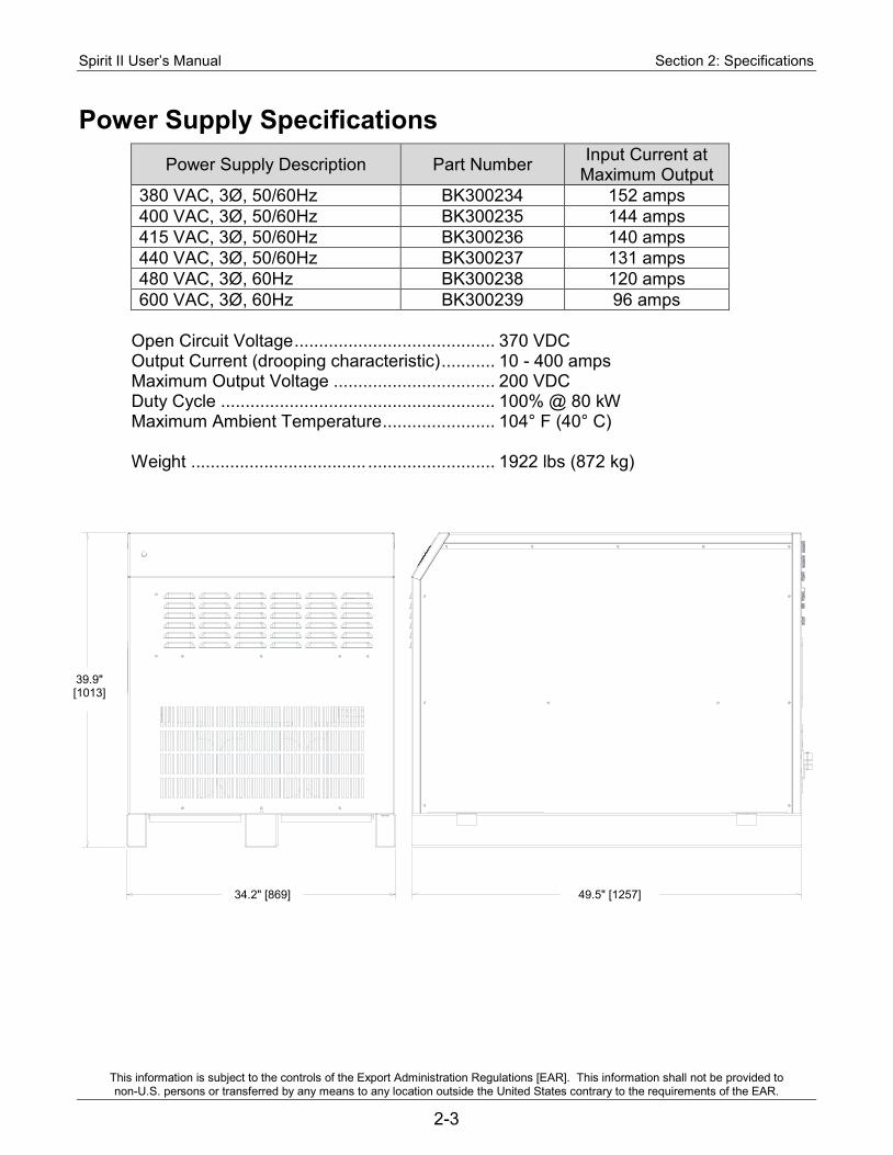
Spirit II User’s Manual Section 2: Specifications
This information is subject to the controls of the Export Administration Regulations [EAR]. This information shall not be provided to non-U.S. persons or transferred by any means to any location outside the United States contrary to the requirements of the EAR.
2-3
Power Supply Specifications Power Supply Description Part Number Input Current at
Maximum Output 380 VAC, 3Ø, 50/60Hz BK300234 152 amps 400 VAC, 3Ø, 50/60Hz BK300235 144 amps 415 VAC, 3Ø, 50/60Hz BK300236 140 amps 440 VAC, 3Ø, 50/60Hz BK300237 131 amps 480 VAC, 3Ø, 60Hz BK300238 120 amps 600 VAC, 3Ø, 60Hz BK300239 96 amps
Open Circuit Voltage ......................................... 370 VDC Output Current (drooping characteristic) ........... 10 - 400 amps Maximum Output Voltage ................................. 200 VDC Duty Cycle ........................................................ 100% @ 80 kW Maximum Ambient Temperature ....................... 104° F (40° C) Weight .................................... .......................... 1922 lbs (872 kg)
39.9" [1013]
34.2" [869] 49.5" [1257]
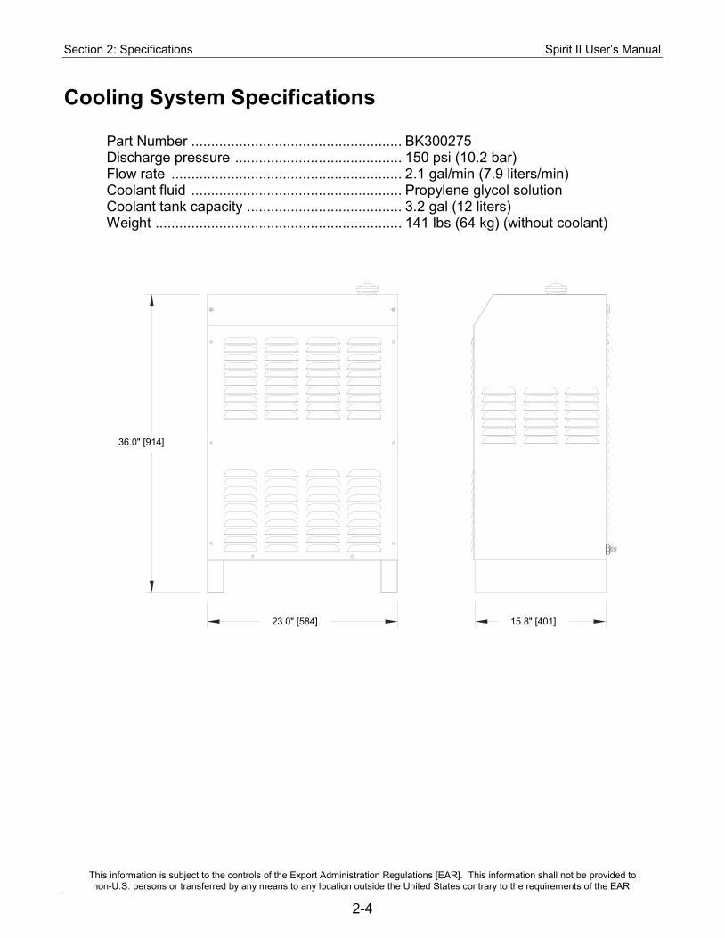
Section 2: Specifications Spirit II User’s Manual
This information is subject to the controls of the Export Administration Regulations [EAR]. This information shall not be provided to non-U.S. persons or transferred by any means to any location outside the United States contrary to the requirements of the EAR.
2-4
Cooling System Specifications Part Number ..................................................... BK300275 Discharge pressure .......................................... 150 psi (10.2 bar) Flow rate .......................................................... 2.1 gal/min (7.9 liters/min) Coolant fluid ..................................................... Propylene glycol solution Coolant tank capacity ....................................... 3.2 gal (12 liters) Weight .............................................................. 141 lbs (64 kg) (without coolant)
36.0" [914]
23.0" [584] 15.8" [401]
Spirit II User’s Manual Section 2: Specifications
This information is subject to the controls of the Export Administration Regulations [EAR]. This information shall not be provided to non-U.S. persons or transferred by any means to any location outside the United States contrary to the requirements of the EAR.
2-5
Torch Coolant Specifications
Note: Refer to the supplier’s most current Material Safety Data Sheet for information regarding safety, handling, and storage of torch coolant.
The Spirit system is shipped without torch coolant in the reservoir. Coolant must be added before applying power to the system. Only use approved torch coolant solution for optimal system performance as commercially available antifreeze contains corrosion inhibitors that will damage the cooling system. The standard coolant solution consists of 25% industrial grade propylene glycol and provides freezing protection down to -13º C (9º F). The standard solution can be ordered in one-gallon containers, PN BK500695. For operating temperatures below -13º C, a 50% solution of industrial grade propylene glycol can be ordered in one-gallon containers, PN BK500895, providing protection down to -36º C (-33º F). Failure to use the proper propylene glycol solution may result in cooling system and/or torch damage. The torch coolant should be flushed out of the Spirit system every six months and replaced with new coolant. The coolant filter / deionization cartridge should also be changed at the same time. See Section 6 for details.
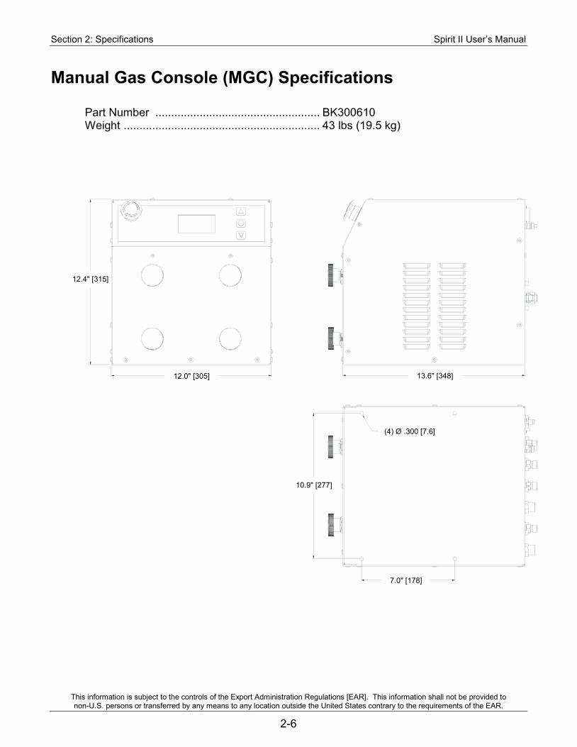
Section 2: Specifications Spirit II User’s Manual
This information is subject to the controls of the Export Administration Regulations [EAR]. This information shall not be provided to non-U.S. persons or transferred by any means to any location outside the United States contrary to the requirements of the EAR.
2-6
Manual Gas Console (MGC) Specifications Part Number .................................................... BK300610 Weight .............................................................. 43 lbs (19.5 kg)
(4) .300 [7.6]
13.7 [348]
2.4 [315]
12.0 [305]
10.9 [277]
7.0 [178]
12.4" [315]
12.0" [305] 13.6" [348]
10.9" [277]
7.0" [178]
(4) Ø .300 [7.6]
Spirit II User’s Manual Section 2: Specifications
This information is subject to the controls of the Export Administration Regulations [EAR]. This information shall not be provided to non-U.S. persons or transferred by any means to any location outside the United States contrary to the requirements of the EAR.
2-7
Gas Supply Requirements Plasma gas types: Mild Steel ..................................................... Oxygen Stainless Steel ............................................ Air, Nitrogen, or H17 Aluminum .................................................... Air or Nitrogen Shield gas types: Mild Steel ..................................................... Oxygen or Air Stainless Steel ............................................. Air or Nitrogen Aluminum .................................................... Air or Nitrogen Preflow gas type ............................................... Air or Nitrogen Marking gas type............................................... Nitrogen or Argon/Air Plasma gas flow rate (maximum): Oxygen ........................................................ 78 scfh (2209 liters/hour) Air ................................................................ 67 scfh (1897 liters/hour) H17 or Nitrogen ........................................... 106 scfh (3002 liters/hour) Shield gas flow rate (maximum): Oxygen ........................................................ 19 scfh (538 liters/hour) Air ................................................................ 258 scfh (7306 liters/hour) Nitrogen ...................................................... 326 scfh (9231 liters/hour) Preflow gas flow rate (maximum) ...................... 60 scfh (1699 liters/hour) Marking gas flow rate (maximum) ..................... 89 scfh (2520 liters/hour) Rated Inlet gas pressure ................................... 115 psi (7.9 bar) Minimum Inlet gas pressure .............................. 105 psi (7.2 bar) Maximum Inlet gas pressure ............................. 145 psi (10.0 bar) Oxygen and nitrogen should be supplied with a purity of at least 99.5%. H17 should be supplied with a purity of at least 99.995%. A potential fire hazard exists when cutting with oxygen. It is recommended that an exhaust ventilation system be used when cutting with oxygen. Flashback arrestors must be supplied (unless they are not available for the chosen gases and pressures) to prevent a possible fire from propagating back to the gas supplies. Ensure that oxygen lines remain free from contaminants such as oil and grease. The mixture of such contaminants with oxygen presents an additional fire hazard. Compressed air must be clean, dry, and oil-free and may be supplied from compressed cylinders or from an air compressor. Be aware that shop air systems are prone to oil and moisture contamination. If shop air is used, it must be cleaned to ISO 8573.1: Class 1.4.1. Specify dry air when using compressed cylinders. Breathing quality air contains moisture and must not be used. 3/8” (inside diameter) hoses are required for all inlet gas connections. Mating connectors are available as an option. Quick-connect fittings must not be used.
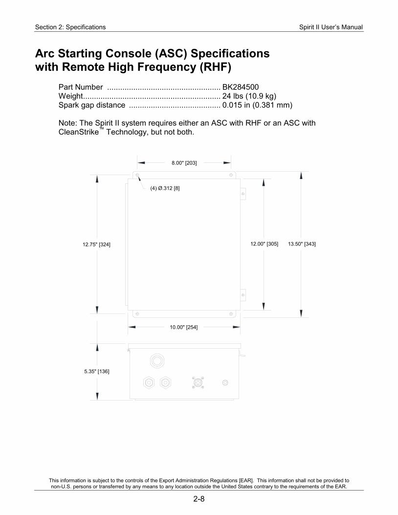
Section 2: Specifications Spirit II User’s Manual
This information is subject to the controls of the Export Administration Regulations [EAR]. This information shall not be provided to non-U.S. persons or transferred by any means to any location outside the United States contrary to the requirements of the EAR.
2-8
Arc Starting Console (ASC) Specifications with Remote High Frequency (RHF)
Part Number .................................................... BK284500 Weight ............................................................... 24 lbs (10.9 kg) Spark gap distance .......................................... 0.015 in (0.381 mm) Note: The Spirit II system requires either an ASC with RHF or an ASC with CleanStrike™ Technology, but not both.
12.75" [324]
8.00" [203]
12.00" [305] 13.50" [343]
10.00" [254]
5.35" [136]
(4) Ø.312 [8]
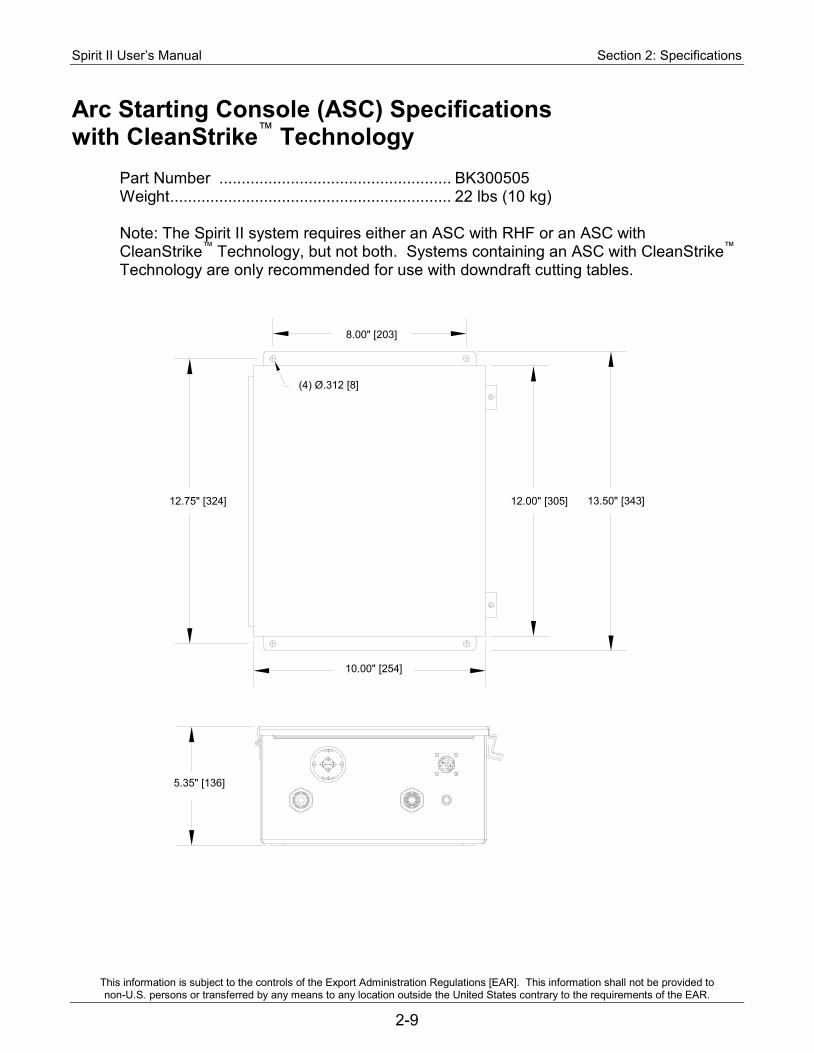
Spirit II User’s Manual Section 2: Specifications
This information is subject to the controls of the Export Administration Regulations [EAR]. This information shall not be provided to non-U.S. persons or transferred by any means to any location outside the United States contrary to the requirements of the EAR.
2-9
Arc Starting Console (ASC) Specifications with CleanStrike™ Technology
Part Number .................................................... BK300505 Weight ............................................................... 22 lbs (10 kg) Note: The Spirit II system requires either an ASC with RHF or an ASC with CleanStrike™ Technology, but not both. Systems containing an ASC with CleanStrike™ Technology are only recommended for use with downdraft cutting tables.
12.75" [324]
8.00" [203]
12.00" [305] 13.50" [343]
10.00" [254]
5.35" [136]
(4) Ø.312 [8]
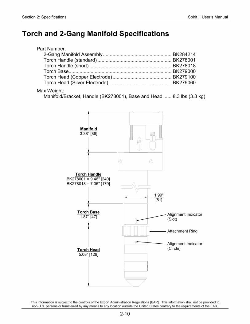
Section 2: Specifications Spirit II User’s Manual
This information is subject to the controls of the Export Administration Regulations [EAR]. This information shall not be provided to non-U.S. persons or transferred by any means to any location outside the United States contrary to the requirements of the EAR.
2-10
Torch and 2-Gang Manifold Specifications Part Number: 2-Gang Manifold Assembly .................................................. BK284214 Torch Handle (standard) ...................................................... BK278001 Torch Handle (short) ............................................................ BK278018 Torch Base........................................................................... BK279000 Torch Head (Copper Electrode) ........................................... BK279100 Torch Head (Silver Electrode) .............................................. BK279060 Max Weight: Manifold/Bracket, Handle (BK278001), Base and Head ...... 8.3 lbs (3.8 kg)
Torch Head 5.08" [129]
Torch Base 1.87" [47]
Torch Handle BK278001 = 9.46" [240] BK278018 = 7.06" [179]
1.99" [51]
Alignment Indicator (Slot)
Alignment Indicator (Circle)
Attachment Ring
Manifold 3.38" [86]
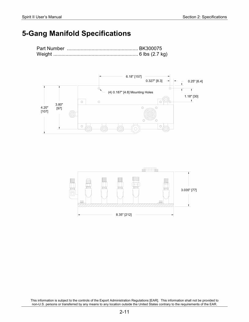
Spirit II User’s Manual Section 2: Specifications
This information is subject to the controls of the Export Administration Regulations [EAR]. This information shall not be provided to non-U.S. persons or transferred by any means to any location outside the United States contrary to the requirements of the EAR.
2-11
5-Gang Manifold Specifications Part Number .................................................... BK300075 Weight .............................................................. 6 lbs (2.7 kg)
4.20" [107]
3.80" [97]
6.18" [157] 0.327" [8.3] 0.25" [6.4]
1.18" [30]
8.35" [212]
3.035" [77]
(4) 0.187" [4.8] Mounting Holes
Section 2: Specifications Spirit II User’s Manual
This information is subject to the controls of the Export Administration Regulations [EAR]. This information shall not be provided to non-U.S. persons or transferred by any means to any location outside the United States contrary to the requirements of the EAR.
2-12
Airborne Noise Emissions The system generates high noise levels while cutting. Depending on the size of the cutting area, distance from the cutting torch, and arc current cutting level, acceptable noise levels may be exceeded. Proper ear protection should be used as defined by local or national codes. The following chart gives the noise levels generated by the system when operating at 400 amps, 205 arc volts. The measurements were made with a sound level meter.
Distance From Torch A-Weighted Sound Pressure Level
C-Weighted Sound Pressure Level
1 meter horizontal / 1.6 meters above the
workpiece 120 dB 115 dB
The maximum noise level is 131 dB at a distance of 3 inches (76.2 mm) from the torch while cutting at 400 amps, 205 arc volts.
Electromagnetic Compatibility (EMC) The 380V 50/60Hz and 415V 50/60Hz CE marked Spirit II plasma cutting systems are manufactured to comply with the European standard EN 60974-10 (Electromagnetic compatibility (EMC) – Product standard for arc welding equipment). Information about the EMC standard EN 60974-10 can be found in Appendix A.
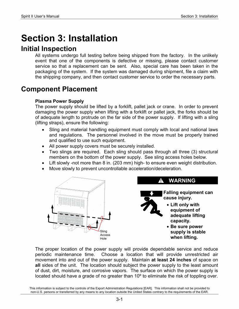
Spirit II User’s Manual Section 3: Installation
This information is subject to the controls of the Export Administration Regulations [EAR]. This information shall not be provided to non-U.S. persons or transferred by any means to any location outside the United States contrary to the requirements of the EAR.
3-1
Section 3: Installation Initial Inspection
All systems undergo full testing before being shipped from the factory. In the unlikely event that one of the components is defective or missing, please contact customer service so that a replacement can be sent. Also, special care has been taken in the packaging of the system. If the system was damaged during shipment, file a claim with the shipping company, and then contact customer service to order the necessary parts.
Component Placement Plasma Power Supply The power supply should be lifted by a forklift, pallet jack or crane. In order to prevent damaging the power supply when lifting with a forklift or pallet jack, the forks should be of adequate length to protrude on the far side of the power supply. If lifting with a sling (lifting straps), ensure the following:
• Sling and material handling equipment must comply with local and national laws and regulations. The personnel involved in the move must be properly trained and qualified to use such equipment.
• All power supply covers must be securely installed. • Two slings are required. Each sling should pass through all three (3) structural
members on the bottom of the power supply. See sling access holes below. • Lift slowly -not more than 8 in. (203 mm) high- to ensure even weight distribution. • Move slowly to prevent uncontrollable acceleration/deceleration.
WARNING
Falling equipment can cause injury. • Lift only with
equipment of adequate lifting capacity.
• Be sure power supply is stable when lifting.
The proper location of the power supply will provide dependable service and reduce periodic maintenance time. Choose a location that will provide unrestricted air movement into and out of the power supply. Maintain at least 24 inches of space on all sides of the unit. The location should subject the power supply to the least amount of dust, dirt, moisture, and corrosive vapors. The surface on which the power supply is located should have a grade of no greater than 10º to eliminate the risk of toppling over.
Sling Access Hole
Section 3: Installation Spirit II User’s Manual
This information is subject to the controls of the Export Administration Regulations [EAR]. This information shall not be provided to non-U.S. persons or transferred by any means to any location outside the United States contrary to the requirements of the EAR.
3-2
The power supply must be cleaned as often as necessary to prevent the accumulation of metallic dust inside the unit. See Section 2 for unit dimensions. Manual Gas Console (MGC) The MGC should be mounted near the CNC controller so that it is easy accessible by the operator. See Section 2 for mounting dimensions. Arc Starting Console (ASC) The ASC should be mounted in a convenient location that is away from other electronic control devices. The ASC with CleanStrike™ Technology offers significantly reduced emissions compared to ASC with RHF, however, the high voltage pulse generated inside the unit may interfere with the operation of sensitive control electronics. The ASC is usually mounted on the gantry of the cutting machine or on the cutting table. See Section 2 for mounting dimensions. 5-Gang Manifold The 5-gang manifold assembly must be mounted within 6 feet (1.8 m) of the torch. See Section 2 for mounting dimensions. 2-Gang Manifold The 2-gang manifold assembly must be mounted to the torch. See Section 2 for mounting dimensions. Torch The torch must be installed on the positioner of an arc voltage control (height control) capable of maintaining the cutting arc voltage within 1 arc volt. The arc voltage must be adjustable in 1 arc volt increments. The positioner must be rigid to ensure cut quality and a torch collision sensor is highly recommended. See Section 2 for mounting dimensions. Cooling System The cooling system must be located within 8 feet (2.4 meters) of the plasma power supply. The surface on which the cooling system is located should have a grade of no greater than 10º to eliminate the risk of toppling over. See Section 2 for unit dimensions.
System Interconnection The Spirit II system interconnection diagrams on the following pages will assist in the planning and installation of the system as well as identifying cables and hoses upon receipt. The optional Inova torch height control is also shown to assist with its connections, whether as an external console or internal to the plasma power supply.
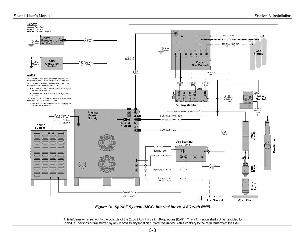
Spirit II User’s Manual Section 3: Installation
This information is subject to the controls of the Export Administration Regulations [EAR]. This information shall not be provided to non-U.S. persons or transferred by any means to any location outside the United States contrary to the requirements of the EAR.
3-3
Figure 1a: Spirit II System (MGC, Internal Inova, ASC with RHF)

Section 3: Installation Spirit II User’s Manual
This information is subject to the controls of the Export Administration Regulations [EAR]. This information shall not be provided to non-U.S. persons or transferred by any means to any location outside the United States contrary to the requirements of the EAR.
3-4
Figure 1b: Spirit II System (MGC, External Inova, ASC with RHF)

Spirit II User’s Manual Section 3: Installation
This information is subject to the controls of the Export Administration Regulations [EAR]. This information shall not be provided to non-U.S. persons or transferred by any means to any location outside the United States contrary to the requirements of the EAR.
3-5
Figure 1c: Spirit II System (MGC, Internal Inova, ASC with CleanStrike™ Technology)
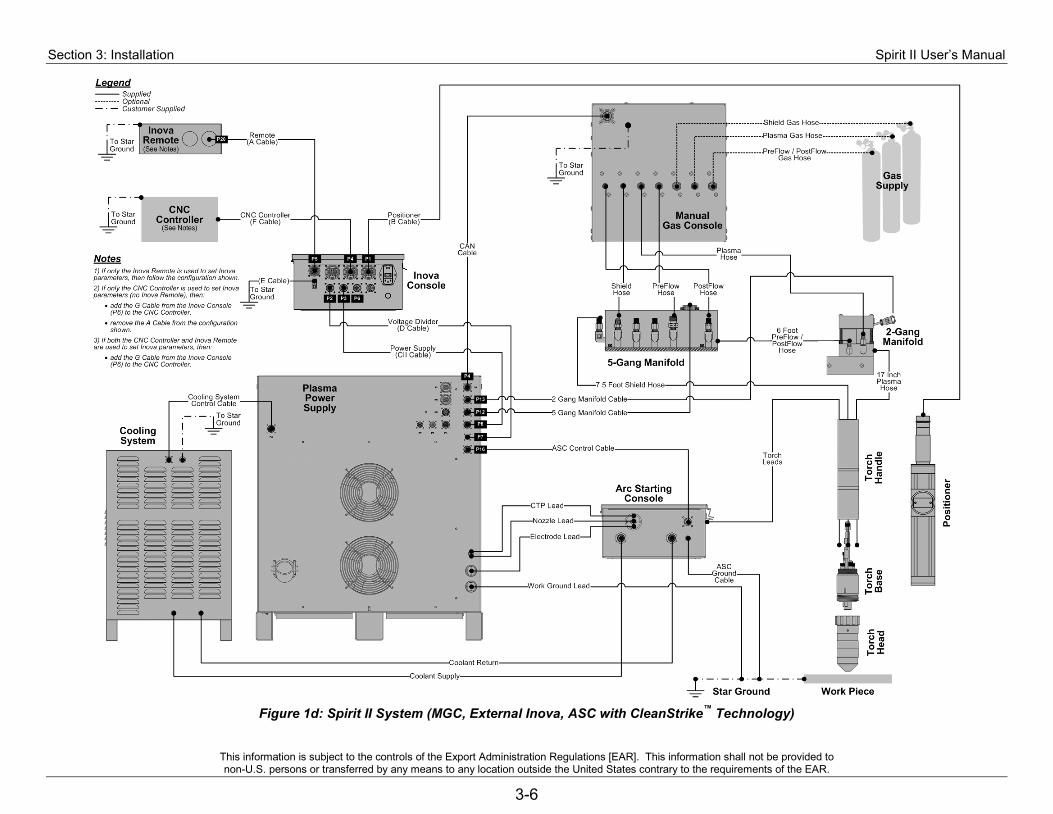
Section 3: Installation Spirit II User’s Manual
This information is subject to the controls of the Export Administration Regulations [EAR]. This information shall not be provided to non-U.S. persons or transferred by any means to any location outside the United States contrary to the requirements of the EAR.
3-6
Figure 1d: Spirit II System (MGC, External Inova, ASC with CleanStrike™ Technology)
Spirit II User’s Manual Section 3: Installation
This information is subject to the controls of the Export Administration Regulations [EAR]. This information shall not be provided to non-U.S. persons or transferred by any means to any location outside the United States contrary to the requirements of the EAR.
3-7
Radio Frequency (RF) and Electromagnetic Interference (EMI)
Overview This section describes the proper grounding of the Spirit II Plasma System components to minimize Radio Frequency (RF) and Electromagnetic Interference (EMI). The Arc Starting Console (ASC), by nature of its function in the system, is a source of RF/EMI along with other system components such as drive amplifiers. If proper grounding techniques are not employed during system installation, RF/EMI can couple into other components causing system malfunction and/or component failure. While this section outlines best practices for grounding, this does not guarantee system immunity. These guidelines should be the basis for initial installation and modifications made as necessary to achieve complete immunity. Types of Grounds There are three different types of grounds in a plasma system. 1. Service or Protective Earth (PE) ground. This is the ground associated with the
mains power supplied to the system. The purpose is to prevent a shock hazard with respect to the plasma equipment and work table. It represents the service ground connected to the plasma power supply and all other system components such as drive amplifiers and CNC. The PE or Service ground must be connected to each piece of equipment per local and national codes.
2. DC power ground. This is the work lead of the power supply and is connected to the cutting table to complete the electrical path for the cutting current.
3. RF/EMI ground. This is the ground for limiting RF/EMI noise in the system. This is the ground that this section addresses.
RF/EMI Grounding Rules 1. The cutting table is used as the common star grounding point. All RF/EMI grounds
should terminate at this point. The star ground connection to the table should have welded studs to the table with a copper bus bar mounted to them. All hardware used for ground connections should be copper or brass with exception of the studs welded to the table.
2. A ground rod that meets all applicable local and national electrical codes must be installed within 20 ft. of the star ground point. This is the PE ground and should be connected to the star ground with a minimum of a 6 AWG green/yellow cable.
3. The work, electrode and pilot arc leads from the power supply should be bundled together for as long a distance as possible and segregated from control leads. Ideally the power and control leads should run in separate cable tracks – if not, a minimum separation of 6 in. is recommended.
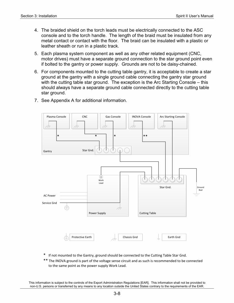
Section 3: Installation Spirit II User’s Manual
This information is subject to the controls of the Export Administration Regulations [EAR]. This information shall not be provided to non-U.S. persons or transferred by any means to any location outside the United States contrary to the requirements of the EAR.
3-8
4. The braided shield on the torch leads must be electrically connected to the ASC console and to the torch handle. The length of the braid must be insulated from any metal contact or contact with the floor. The braid can be insulated with a plastic or leather sheath or run in a plastic track.
5. Each plasma system component as well as any other related equipment (CNC, motor drives) must have a separate ground connection to the star ground point even if bolted to the gantry or power supply. Grounds are not to be daisy-chained.
6. For components mounted to the cutting table gantry, it is acceptable to create a star ground at the gantry with a single ground cable connecting the gantry star ground with the cutting table star ground. The exception is the Arc Starting Console – this should always have a separate ground cable connected directly to the cutting table star ground.
7. See Appendix A for additional information.
Cutting Table
Gantry
CNC INOVA Console Arc Starting Console
Power Supply
GroundRod
+WorkLead
AC Power
Service Gnd
Star Gnd.
Star Gnd.
Protective Earth Chassis Gnd Earth Gnd
Gas ConsolePlasma Console
* ***
* If not mounted to the Gantry, ground should be connected to the Cutting Table Star Gnd.** The INOVA ground is part of the voltage sense circuit and as such is recommended to be connected to the same point as the power supply Work Lead.
*
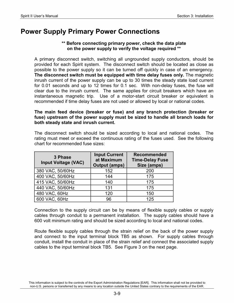
Spirit II User’s Manual Section 3: Installation
This information is subject to the controls of the Export Administration Regulations [EAR]. This information shall not be provided to non-U.S. persons or transferred by any means to any location outside the United States contrary to the requirements of the EAR.
3-9
Power Supply Primary Power Connections
** Before connecting primary power, check the data plate on the power supply to verify the voltage required **
A primary disconnect switch, switching all ungrounded supply conductors, should be provided for each Spirit system. The disconnect switch should be located as close as possible to the power supply so it can be turned off quickly in case of an emergency. The disconnect switch must be equipped with time delay fuses only. The magnetic inrush current of the power supply can be up to 30 times the steady state load current for 0.01 seconds and up to 12 times for 0.1 sec. With non-delay fuses, the fuse will clear due to the inrush current. The same applies for circuit breakers which have an instantaneous magnetic trip. Use of a motor-start circuit breaker or equivalent is recommended if time delay fuses are not used or allowed by local or national codes. The main feed device (breaker or fuse) and any branch protection (breaker or fuse) upstream of the power supply must be sized to handle all branch loads for both steady state and inrush current. The disconnect switch should be sized according to local and national codes. The rating must meet or exceed the continuous rating of the fuses used. See the following chart for recommended fuse sizes:
3 Phase Input Voltage (VAC)
Input Current at Maximum
Output (amps)
Recommended Time-Delay Fuse
Size (amps) 380 VAC, 50/60Hz 152 200 400 VAC, 50/60Hz 144 175 415 VAC, 50/60Hz 140 175 440 VAC, 50/60Hz 131 175 480 VAC, 60Hz 120 150 600 VAC, 60Hz 96 125
Connection to the supply circuit can be by means of flexible supply cables or supply cables through conduit to a permanent installation. The supply cables should have a 600 volt minimum rating and should be sized according to local and national codes. Route flexible supply cables through the strain relief on the back of the power supply and connect to the input terminal block TB5 as shown. For supply cables through conduit, install the conduit in place of the strain relief and connect the associated supply cables to the input terminal block TB5. See Figure 3 on the next page.
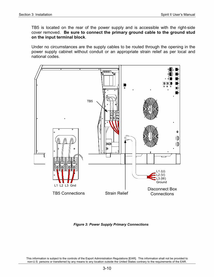
Section 3: Installation Spirit II User’s Manual
This information is subject to the controls of the Export Administration Regulations [EAR]. This information shall not be provided to non-U.S. persons or transferred by any means to any location outside the United States contrary to the requirements of the EAR.
3-10
TB5 is located on the rear of the power supply and is accessible with the right-side cover removed. Be sure to connect the primary ground cable to the ground stud on the input terminal block. Under no circumstances are the supply cables to be routed through the opening in the power supply cabinet without conduit or an appropriate strain relief as per local and national codes.
Strain Relief Disconnect Box
Connections TB5 Connections
L1 (U) L2 (V) L3 (W) Ground
L1 L2 L3 Gnd
Figure 3: Power Supply Primary Connections
TB5
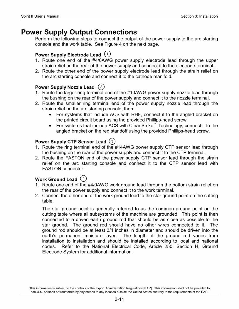
Spirit II User’s Manual Section 3: Installation
This information is subject to the controls of the Export Administration Regulations [EAR]. This information shall not be provided to non-U.S. persons or transferred by any means to any location outside the United States contrary to the requirements of the EAR.
3-11
Power Supply Output Connections Perform the following steps to connect the output of the power supply to the arc starting console and the work table. See Figure 4 on the next page. Power Supply Electrode Lead 1. Route one end of the #4/0AWG power supply electrode lead through the upper
strain relief on the rear of the power supply and connect it to the electrode terminal. 2. Route the other end of the power supply electrode lead through the strain relief on
the arc starting console and connect it to the cathode manifold. Power Supply Nozzle Lead 1. Route the larger ring terminal end of the #10AWG power supply nozzle lead through
the bushing on the rear of the power supply and connect it to the nozzle terminal. 2. Route the smaller ring terminal end of the power supply nozzle lead through the
strain relief on the arc starting console, then: • For systems that include ACS with RHF, connect it to the angled bracket on
the printed circuit board using the provided Phillips-head screw. • For systems that include ACS with CleanStrike™ Technology, connect it to the
angled bracket on the red standoff using the provided Phillips-head screw. Power Supply CTP Sensor Lead 1. Route the ring terminal end of the #14AWG power supply CTP sensor lead through
the bushing on the rear of the power supply and connect it to the CTP terminal. 2. Route the FASTON end of the power supply CTP sensor lead through the strain
relief on the arc starting console and connect it to the CTP sensor lead with FASTON connector.
Work Ground Lead 1. Route one end of the #4/0AWG work ground lead through the bottom strain relief on
the rear of the power supply and connect it to the work terminal. 2. Connect the other end of the work ground lead to the star ground point on the cutting
table. The star ground point is generally referred to as the common ground point on the cutting table where all subsystems of the machine are grounded. This point is then connected to a driven earth ground rod that should be as close as possible to the star ground. The ground rod should have no other wires connected to it. The ground rod should be at least 3/4 inches in diameter and should be driven into the earth’s permanent moisture layer. The length of the ground rod varies from installation to installation and should be installed according to local and national codes. Refer to the National Electrical Code, Article 250, Section H, Ground Electrode System for additional information.
1
2
3
4
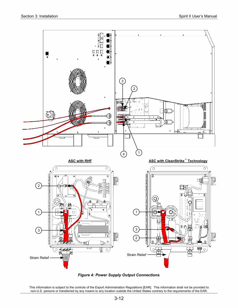
Section 3: Installation Spirit II User’s Manual
This information is subject to the controls of the Export Administration Regulations [EAR]. This information shall not be provided to non-U.S. persons or transferred by any means to any location outside the United States contrary to the requirements of the EAR.
3-12
ASC with RHF ASC with CleanStrike™ Technology
4 1
3
2
Strain Relief
1
3
2
Figure 4: Power Supply Output Connections
Strain Relief
1
3
2
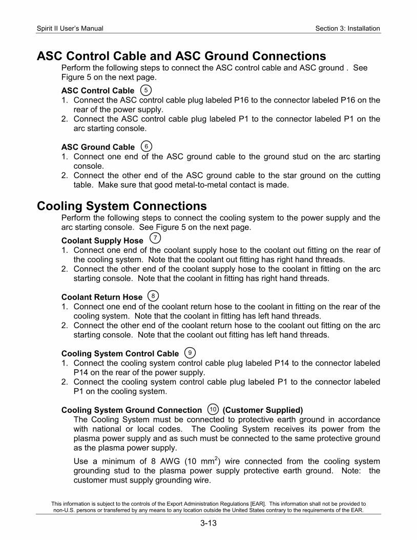
Spirit II User’s Manual Section 3: Installation
This information is subject to the controls of the Export Administration Regulations [EAR]. This information shall not be provided to non-U.S. persons or transferred by any means to any location outside the United States contrary to the requirements of the EAR.
3-13
ASC Control Cable and ASC Ground Connections Perform the following steps to connect the ASC control cable and ASC ground . See Figure 5 on the next page. ASC Control Cable 1. Connect the ASC control cable plug labeled P16 to the connector labeled P16 on the
rear of the power supply. 2. Connect the ASC control cable plug labeled P1 to the connector labeled P1 on the
arc starting console. ASC Ground Cable 1. Connect one end of the ASC ground cable to the ground stud on the arc starting
console. 2. Connect the other end of the ASC ground cable to the star ground on the cutting
table. Make sure that good metal-to-metal contact is made.
Cooling System Connections Perform the following steps to connect the cooling system to the power supply and the arc starting console. See Figure 5 on the next page. Coolant Supply Hose 1. Connect one end of the coolant supply hose to the coolant out fitting on the rear of
the cooling system. Note that the coolant out fitting has right hand threads. 2. Connect the other end of the coolant supply hose to the coolant in fitting on the arc
starting console. Note that the coolant in fitting has right hand threads. Coolant Return Hose 1. Connect one end of the coolant return hose to the coolant in fitting on the rear of the
cooling system. Note that the coolant in fitting has left hand threads. 2. Connect the other end of the coolant return hose to the coolant out fitting on the arc
starting console. Note that the coolant out fitting has left hand threads. Cooling System Control Cable 1. Connect the cooling system control cable plug labeled P14 to the connector labeled
P14 on the rear of the power supply. 2. Connect the cooling system control cable plug labeled P1 to the connector labeled
P1 on the cooling system. Cooling System Ground Connection (Customer Supplied) The Cooling System must be connected to protective earth ground in accordance
with national or local codes. The Cooling System receives its power from the plasma power supply and as such must be connected to the same protective ground as the plasma power supply.
Use a minimum of 8 AWG (10 mm2) wire connected from the cooling system grounding stud to the plasma power supply protective earth ground. Note: the customer must supply grounding wire.
10
5
6
7
8
9
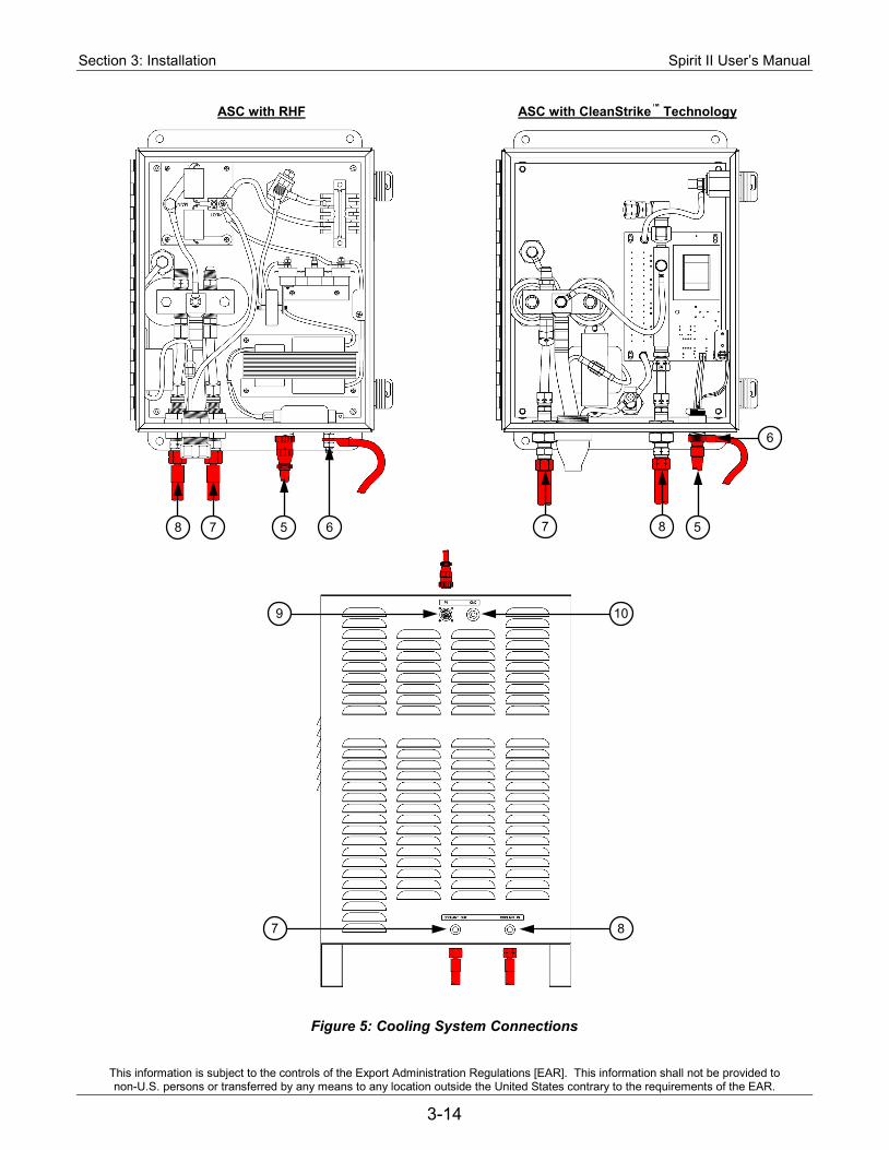
Section 3: Installation Spirit II User’s Manual
This information is subject to the controls of the Export Administration Regulations [EAR]. This information shall not be provided to non-U.S. persons or transferred by any means to any location outside the United States contrary to the requirements of the EAR.
3-14
ASC with RHF ASC with CleanStrike™ Technology
Figure 5: Cooling System Connections
7 8
10 9
8 7 5 6
6
5 7 8
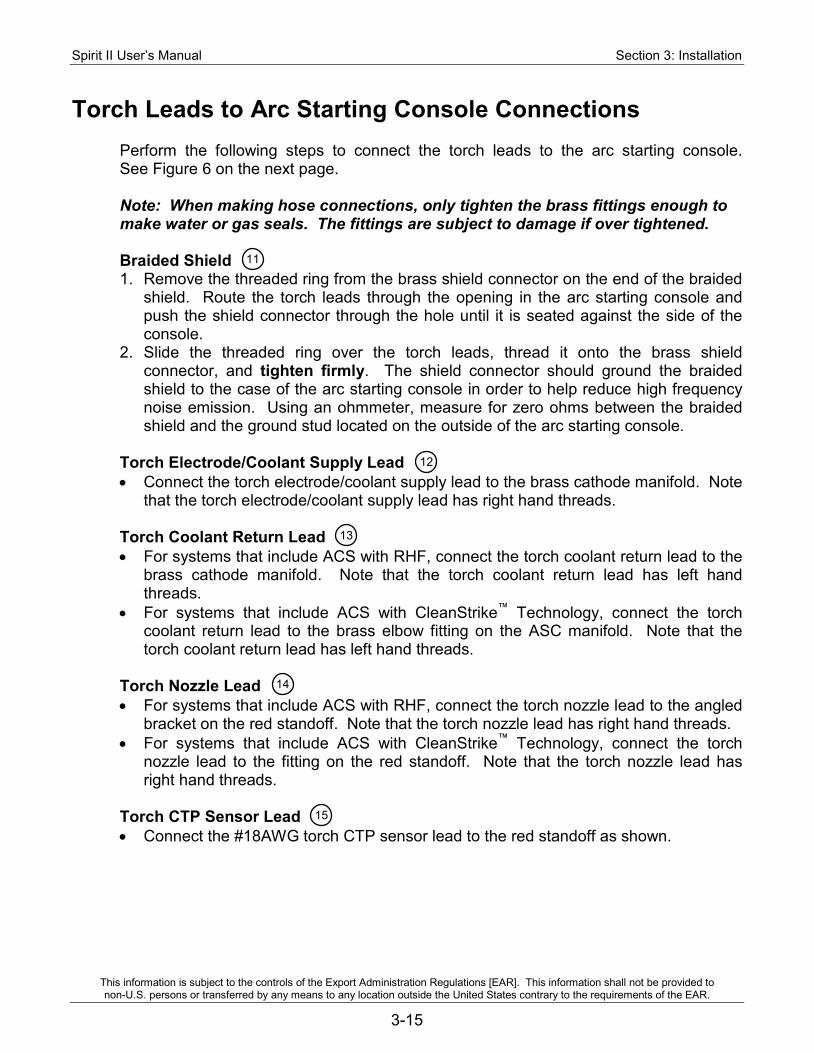
Spirit II User’s Manual Section 3: Installation
This information is subject to the controls of the Export Administration Regulations [EAR]. This information shall not be provided to non-U.S. persons or transferred by any means to any location outside the United States contrary to the requirements of the EAR.
3-15
Torch Leads to Arc Starting Console Connections Perform the following steps to connect the torch leads to the arc starting console. See Figure 6 on the next page. Note: When making hose connections, only tighten the brass fittings enough to make water or gas seals. The fittings are subject to damage if over tightened. Braided Shield 1. Remove the threaded ring from the brass shield connector on the end of the braided
shield. Route the torch leads through the opening in the arc starting console and push the shield connector through the hole until it is seated against the side of the console.
2. Slide the threaded ring over the torch leads, thread it onto the brass shield connector, and tighten firmly. The shield connector should ground the braided shield to the case of the arc starting console in order to help reduce high frequency noise emission. Using an ohmmeter, measure for zero ohms between the braided shield and the ground stud located on the outside of the arc starting console.
Torch Electrode/Coolant Supply Lead • Connect the torch electrode/coolant supply lead to the brass cathode manifold. Note
that the torch electrode/coolant supply lead has right hand threads. Torch Coolant Return Lead • For systems that include ACS with RHF, connect the torch coolant return lead to the
brass cathode manifold. Note that the torch coolant return lead has left hand threads.
• For systems that include ACS with CleanStrike™ Technology, connect the torch coolant return lead to the brass elbow fitting on the ASC manifold. Note that the torch coolant return lead has left hand threads.
Torch Nozzle Lead • For systems that include ACS with RHF, connect the torch nozzle lead to the angled
bracket on the red standoff. Note that the torch nozzle lead has right hand threads. • For systems that include ACS with CleanStrike™ Technology, connect the torch
nozzle lead to the fitting on the red standoff. Note that the torch nozzle lead has right hand threads.
Torch CTP Sensor Lead • Connect the #18AWG torch CTP sensor lead to the red standoff as shown.
11
12
13
14
15
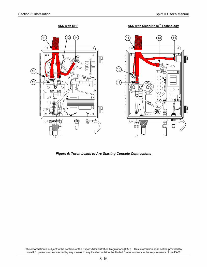
Section 3: Installation Spirit II User’s Manual
This information is subject to the controls of the Export Administration Regulations [EAR]. This information shall not be provided to non-U.S. persons or transferred by any means to any location outside the United States contrary to the requirements of the EAR.
3-16
ASC with RHF ASC with CleanStrike™ Technology
*
15
12
14 13 11
15
13
12 14 11
Figure 6: Torch Leads to Arc Starting Console Connections
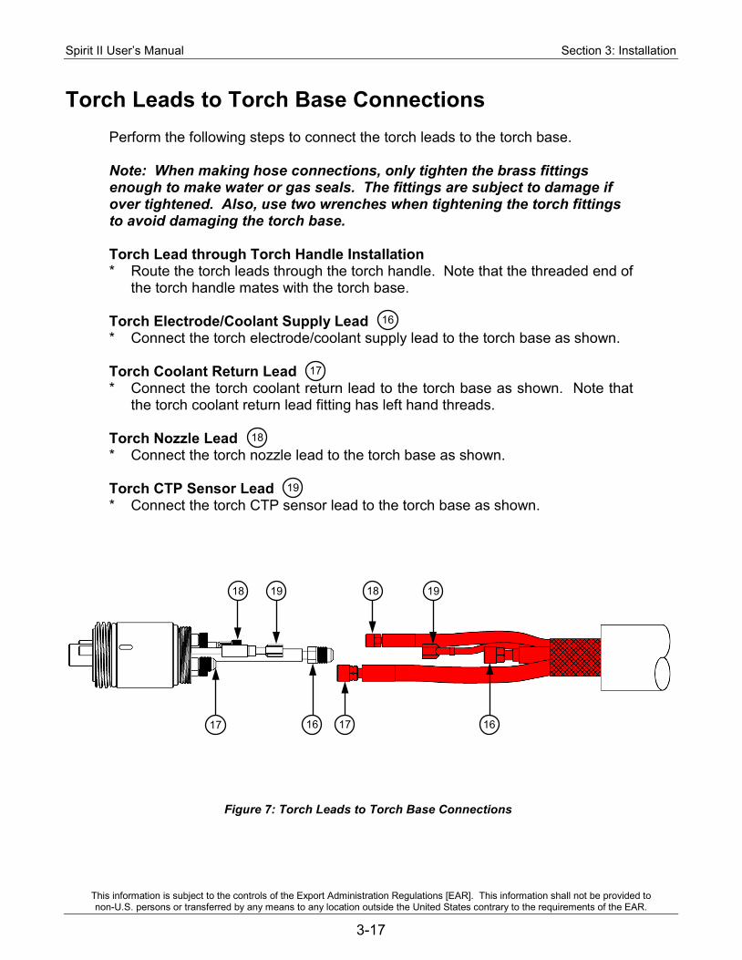
Spirit II User’s Manual Section 3: Installation
This information is subject to the controls of the Export Administration Regulations [EAR]. This information shall not be provided to non-U.S. persons or transferred by any means to any location outside the United States contrary to the requirements of the EAR.
3-17
Torch Leads to Torch Base Connections
Perform the following steps to connect the torch leads to the torch base.
Note: When making hose connections, only tighten the brass fittings enough to make water or gas seals. The fittings are subject to damage if over tightened. Also, use two wrenches when tightening the torch fittings to avoid damaging the torch base. Torch Lead through Torch Handle Installation * Route the torch leads through the torch handle. Note that the threaded end of
the torch handle mates with the torch base. Torch Electrode/Coolant Supply Lead * Connect the torch electrode/coolant supply lead to the torch base as shown. Torch Coolant Return Lead * Connect the torch coolant return lead to the torch base as shown. Note that
the torch coolant return lead fitting has left hand threads. Torch Nozzle Lead * Connect the torch nozzle lead to the torch base as shown. Torch CTP Sensor Lead * Connect the torch CTP sensor lead to the torch base as shown.
18 19 18 19
17 16 17 16
Figure 7: Torch Leads to Torch Base Connections
16
17
18
19
Section 3: Installation Spirit II User’s Manual
This information is subject to the controls of the Export Administration Regulations [EAR]. This information shall not be provided to non-U.S. persons or transferred by any means to any location outside the United States contrary to the requirements of the EAR.
3-18
Torch Gas Connections Perform the following steps to connect the torch gas hoses to the manual gas console, torch base, and manifold assemblies. See Figure 8. Note: When making hose connections, only tighten the brass fittings enough to make gas seals. The fittings are subject to damage if over tightened. 7.5 Foot Shield Gas Hose 1. Route one end of the 7.5 foot (2.3 m) shield gas hose through the torch
handle and connect to the shield gas fitting on the torch base. 2. Connect the other end of the 7.5 foot (2.3 m) shield gas hose to the shield
gas outlet on the 5-gang manifold. 17 Inch Plasma Gas Hose 1. Route one end of the 17 inch (432 mm) plasma gas hose through the torch
handle and connect to the plasma gas fitting on the torch base. 2. Thread the torch handle onto the torch base, being careful not to twist the
torch leads and gas hoses when tightening the torch handle. 3. Tighten the base to the handle using a pin style adjustable spanner wrench
(fits 2" diameter with ¼" diameter pin). 4. Attach the 2-gang manifold assembly to the torch handle. The top of the
manifold bracket should be flush with the top of the torch handle. 5. Connect the other end of the 17 inch (432 mm) plasma gas hose to the
plasma gas outlet on the 2-gang manifold. 6. Mount the torch handle/base/manifold to the positioner. Note the alignment
indicators on the torch base (slot) and torch head (circle). These aid in aligning the quick-disconnect torch base and head and should be oriented so they are clearly visible when the operator is changing heads.
6 Foot Preflow/Postflow Gas Hose 1. Connect one end of the 6 foot (1.8 m) preflow/postflow gas hose to the
preflow/postflow outlet on the 5-gang manifold. 2. Connect the other end of the 6 foot (1.8 m) preflow/postflow gas hose to the
preflow/postflow inlet on the 2-gang manifold.
20
21
22
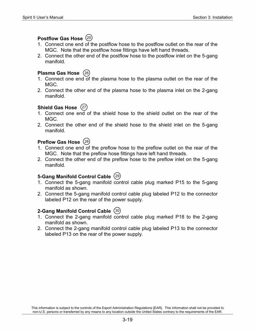
Spirit II User’s Manual Section 3: Installation
This information is subject to the controls of the Export Administration Regulations [EAR]. This information shall not be provided to non-U.S. persons or transferred by any means to any location outside the United States contrary to the requirements of the EAR.
3-19
Postflow Gas Hose 1. Connect one end of the postflow hose to the postflow outlet on the rear of the
MGC. Note that the postflow hose fittings have left hand threads. 2. Connect the other end of the postflow hose to the postflow inlet on the 5-gang
manifold.
Plasma Gas Hose 1. Connect one end of the plasma hose to the plasma outlet on the rear of the
MGC. 2. Connect the other end of the plasma hose to the plasma inlet on the 2-gang
manifold. Shield Gas Hose 1. Connect one end of the shield hose to the shield outlet on the rear of the
MGC. 2. Connect the other end of the shield hose to the shield inlet on the 5-gang
manifold.
Preflow Gas Hose 1. Connect one end of the preflow hose to the preflow outlet on the rear of the
MGC. Note that the preflow hose fittings have left hand threads. 2. Connect the other end of the preflow hose to the preflow inlet on the 5-gang
manifold. 5-Gang Manifold Control Cable 1. Connect the 5-gang manifold control cable plug marked P15 to the 5-gang
manifold as shown. 2. Connect the 5-gang manifold control cable plug labeled P12 to the connector
labeled P12 on the rear of the power supply. 2-Gang Manifold Control Cable 1. Connect the 2-gang manifold control cable plug marked P18 to the 2-gang
manifold as shown. 2. Connect the 2-gang manifold control cable plug labeled P13 to the connector
labeled P13 on the rear of the power supply.
25
26
27
28
29
30
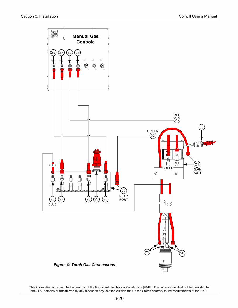
Section 3: Installation Spirit II User’s Manual
This information is subject to the controls of the Export Administration Regulations [EAR]. This information shall not be provided to non-U.S. persons or transferred by any means to any location outside the United States contrary to the requirements of the EAR.
3-20
Figure 8: Torch Gas Connections
Manual Gas Console
25
22
26
22
21
30
RED
GREEN
REAR PORT
REAR PORT
BLUE 27
21 20
20 28 29
BLUE GREEN
RED
27 25 28 26
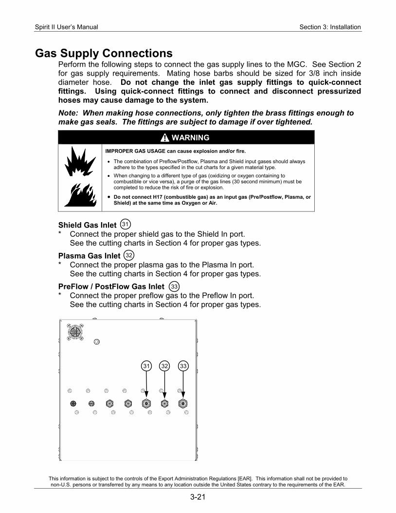
Spirit II User’s Manual Section 3: Installation
This information is subject to the controls of the Export Administration Regulations [EAR]. This information shall not be provided to non-U.S. persons or transferred by any means to any location outside the United States contrary to the requirements of the EAR.
3-21
Gas Supply Connections Perform the following steps to connect the gas supply lines to the MGC. See Section 2 for gas supply requirements. Mating hose barbs should be sized for 3/8 inch inside diameter hose. Do not change the inlet gas supply fittings to quick-connect fittings. Using quick-connect fittings to connect and disconnect pressurized hoses may cause damage to the system. Note: When making hose connections, only tighten the brass fittings enough to make gas seals. The fittings are subject to damage if over tightened.
WARNING
IMPROPER GAS USAGE can cause explosion and/or fire.
• The combination of Preflow/Postflow, Plasma and Shield input gases should always adhere to the types specified in the cut charts for a given material type.
• When changing to a different type of gas (oxidizing or oxygen containing to combustible or vice versa), a purge of the gas lines (30 second minimum) must be completed to reduce the risk of fire or explosion.
• Do not connect H17 (combustible gas) as an input gas (Pre/Postflow, Plasma, or Shield) at the same time as Oxygen or Air.
Shield Gas Inlet * Connect the proper shield gas to the Shield In port.
See the cutting charts in Section 4 for proper gas types. Plasma Gas Inlet * Connect the proper plasma gas to the Plasma In port.
See the cutting charts in Section 4 for proper gas types. PreFlow / PostFlow Gas Inlet * Connect the proper preflow gas to the Preflow In port.
See the cutting charts in Section 4 for proper gas types.
31
32
33
31 33 32

Section 3: Installation Spirit II User’s Manual
This information is subject to the controls of the Export Administration Regulations [EAR]. This information shall not be provided to non-U.S. persons or transferred by any means to any location outside the United States contrary to the requirements of the EAR.
3-22
CAN Communication Connections Perform the following steps to connect the plasma power supply to the MGC. CAN Cable * Connect the male end of the CAN cable to the connector labeled P4 on the rear of
the plasma power supply. * Connect the female end of the CAN cable to the top connector on the rear of the
MGC.
35
35
35
Spirit II User’s Manual Section 3: Installation
This information is subject to the controls of the Export Administration Regulations [EAR]. This information shall not be provided to non-U.S. persons or transferred by any means to any location outside the United States contrary to the requirements of the EAR.
3-23
CNC Machine Interface Connections Perform the following steps to properly interface the Spirit system with a CNC cutting machine. See the system schematic for additional information. Plasma Start Input The power supply requires a contact closure between P8 pins 3 and 4 to commence the cutting or marking sequence. The sequence is terminated when the contacts are opened. The contacts should be rated for 24VDC - 7.3mA. Arc Hold Input The power supply requires a contact closure between P8 pins 10 and 11 to inhibit arc starting even though a plasma start signal has been applied to the unit. When the contacts are opened, the arc is initiated. This feature is used to decrease cycle time by allowing pre-cut gas and contact sequencing to occur simultaneously with initial torch height positioning. The contacts should be rated for 24VDC - 7.3mA. Motion Output The power supply provides a maintained contact closure output between P8 pins 12 and 14 as long as an arc is maintained between the torch and the workpiece. The motion contacts are rated for 24VDC – 10mA. Remote On/Off Input The power supply requires a maintained contact closure between P8 pins 5 and 6 to energize the system from a remote location, provided that the OFF Button on the manual gas console is released. The contacts should be rated for 24VAC – 10mA. Opening the contacts deenergizes the system. If the remote on/off feature is to be used, remove the jumper between positions 1 and 2 on the J17 connector on the microprocessor DSP board. Power Supply Ready Output The power supply provides a maintained contact closure output between P8 pins 7 and 8 when the system is ready to cut or mark. The contacts are open during gas purge or when an error occurs. The contacts are rated for 24VDC – 10mA.

Section 3: Installation Spirit II User’s Manual
This information is subject to the controls of the Export Administration Regulations [EAR]. This information shall not be provided to non-U.S. persons or transferred by any means to any location outside the United States contrary to the requirements of the EAR.
3-24
Filling the Cooling System
WARNING: Do not touch the fans inside the cooling system. Important: Never turn on the system when the coolant reservoir is empty. Important: When handling coolant, wear nitrile gloves and safety glasses. Important: Only use approved coolant. Commercially available antifreeze
contains corrosion inhibitors that will damage the cooling system. See Section 2 for more information.
1. Remove primary power from the Spirit system. 2. Ensure the torch base and torch head (with consumables) are properly installed. 3. Ensure the coolant supply (in and out) hoses are properly installed. 4. Remove the coolant reservoir cap/level gauge and then remove the cover from the
cooling system. 5. Ensure the coolant filter housing is tightened securely. 6. Ensure the drain petcock on the bottom of the reservoir is tightened securely. 7. Fill the reservoir with approximately 2 ½ gallons of approved coolant. 8. Apply primary power to the Spirit system and enable it by releasing (turn right) the
OFF Button on the MGC.
9. On the MGC main menu, move the pointer to On. Press the select button to start the coolant pump circulating coolant through the system. Note: The coolant pump will turn off automatically if the coolant level drops below the minimum level inside the reservoir. If this happens, add more coolant.
10. With the coolant pump running, locate the small red push-button on top of the coolant filter housing. Press and hold the red button until no air or bubbles are seen inside the filter housing. Dry any coolant that leaks out.
11. Check for coolant leaks at all hose connections, the arc starting console, and at the torch.
12. Push the OFF Button on the MGC to stop the coolant pump. 13. Remove primary power from the Spirit system. 14. Fill the reservoir with coolant until the coolant gauge indicates full. 15. Replace the cooling system cover and replace the coolant reservoir cap/level gauge. 16. End of procedure.
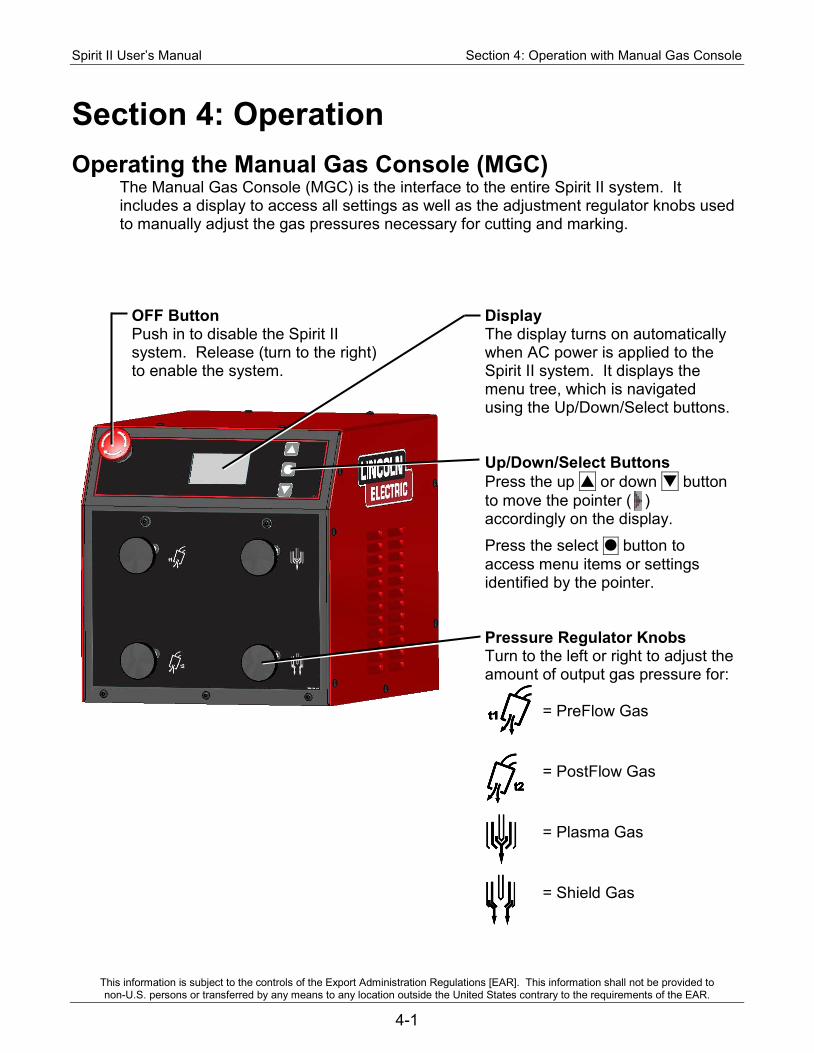
Spirit II User’s Manual Section 4: Operation with Manual Gas Console
This information is subject to the controls of the Export Administration Regulations [EAR]. This information shall not be provided to non-U.S. persons or transferred by any means to any location outside the United States contrary to the requirements of the EAR.
4-1
Section 4: Operation Operating the Manual Gas Console (MGC)
The Manual Gas Console (MGC) is the interface to the entire Spirit II system. It includes a display to access all settings as well as the adjustment regulator knobs used to manually adjust the gas pressures necessary for cutting and marking.
OFF Button Push in to disable the Spirit II system. Release (turn to the right) to enable the system.
Display The display turns on automatically when AC power is applied to the Spirit II system. It displays the menu tree, which is navigated using the Up/Down/Select buttons. Up/Down/Select Buttons Press the up or down button to move the pointer ( ) accordingly on the display.
Press the select button to access menu items or settings identified by the pointer. Pressure Regulator Knobs Turn to the left or right to adjust the amount of output gas pressure for: = PreFlow Gas
= PostFlow Gas
= Plasma Gas
= Shield Gas
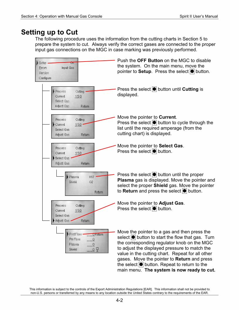
Section 4: Operation with Manual Gas Console Spirit II User’s Manual
This information is subject to the controls of the Export Administration Regulations [EAR]. This information shall not be provided to non-U.S. persons or transferred by any means to any location outside the United States contrary to the requirements of the EAR.
4-2
Setting up to Cut The following procedure uses the information from the cutting charts in Section 5 to prepare the system to cut. Always verify the correct gases are connected to the proper input gas connections on the MGC in case marking was previously performed.
Push the OFF Button on the MGC to disable the system. On the main menu, move the pointer to Setup. Press the select button.
Press the select button until Cutting is displayed.
Move the pointer to Current. Press the select button to cycle through the list until the required amperage (from the cutting chart) is displayed.
Move the pointer to Select Gas. Press the select button.
Press the select button until the proper Plasma gas is displayed. Move the pointer and select the proper Shield gas. Move the pointer to Return and press the select button.
Move the pointer to Adjust Gas. Press the select button.
Move the pointer to a gas and then press the select button to start the flow that gas. Turn the corresponding regulator knob on the MGC to adjust the displayed pressure to match the value in the cutting chart. Repeat for all other gases. Move the pointer to Return and press the select button. Repeat to return to the main menu. The system is now ready to cut.
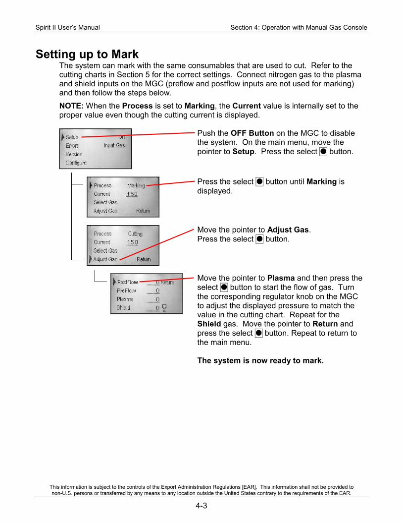
Spirit II User’s Manual Section 4: Operation with Manual Gas Console
This information is subject to the controls of the Export Administration Regulations [EAR]. This information shall not be provided to non-U.S. persons or transferred by any means to any location outside the United States contrary to the requirements of the EAR.
4-3
Setting up to Mark The system can mark with the same consumables that are used to cut. Refer to the cutting charts in Section 5 for the correct settings. Connect nitrogen gas to the plasma and shield inputs on the MGC (preflow and postflow inputs are not used for marking) and then follow the steps below. NOTE: When the Process is set to Marking, the Current value is internally set to the proper value even though the cutting current is displayed.
Push the OFF Button on the MGC to disable the system. On the main menu, move the pointer to Setup. Press the select button.
Press the select button until Marking is displayed.
Move the pointer to Adjust Gas. Press the select button.
Move the pointer to Plasma and then press the select button to start the flow of gas. Turn the corresponding regulator knob on the MGC to adjust the displayed pressure to match the value in the cutting chart. Repeat for the Shield gas. Move the pointer to Return and press the select button. Repeat to return to the main menu. The system is now ready to mark.
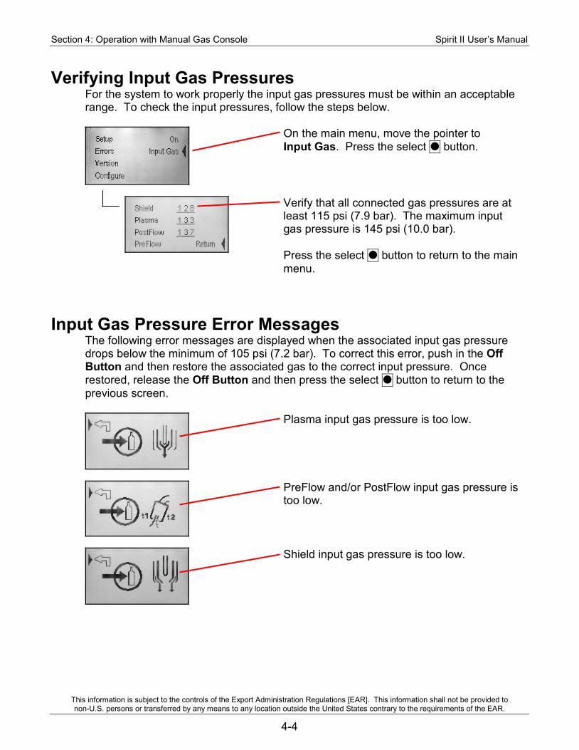
Section 4: Operation with Manual Gas Console Spirit II User’s Manual
This information is subject to the controls of the Export Administration Regulations [EAR]. This information shall not be provided to non-U.S. persons or transferred by any means to any location outside the United States contrary to the requirements of the EAR.
4-4
Verifying Input Gas Pressures For the system to work properly the input gas pressures must be within an acceptable range. To check the input pressures, follow the steps below.
On the main menu, move the pointer to Input Gas. Press the select button.
Verify that all connected gas pressures are at least 115 psi (7.9 bar). The maximum input gas pressure is 145 psi (10.0 bar). Press the select button to return to the main menu.
Input Gas Pressure Error Messages The following error messages are displayed when the associated input gas pressure drops below the minimum of 105 psi (7.2 bar). To correct this error, push in the Off Button and then restore the associated gas to the correct input pressure. Once restored, release the Off Button and then press the select button to return to the previous screen.
Plasma input gas pressure is too low.
PreFlow and/or PostFlow input gas pressure is too low.
Shield input gas pressure is too low.
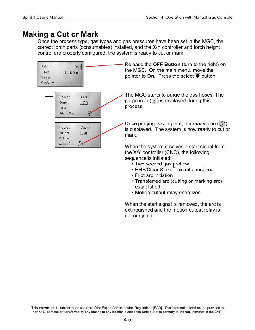
Spirit II User’s Manual Section 4: Operation with Manual Gas Console
This information is subject to the controls of the Export Administration Regulations [EAR]. This information shall not be provided to non-U.S. persons or transferred by any means to any location outside the United States contrary to the requirements of the EAR.
4-5
Making a Cut or Mark Once the process type, gas types and gas pressures have been set in the MGC, the correct torch parts (consumables) installed, and the X/Y controller and torch height control are properly configured, the system is ready to cut or mark.
Release the OFF Button (turn to the right) on the MGC. On the main menu, move the pointer to On. Press the select button.
The MGC starts to purge the gas hoses. The purge icon ( ) is displayed during this process. Once purging is complete, the ready icon ( ) is displayed. The system is now ready to cut or mark. When the system receives a start signal from the X/Y controller (CNC), the following sequence is initiated:
• Two second gas preflow • RHF/CleanStrike™ circuit energized • Pilot arc initiation • Transferred arc (cutting or marking arc)
established • Motion output relay energized
When the start signal is removed, the arc is extinguished and the motion output relay is deenergized.

Section 4: Operation with Manual Gas Console Spirit II User’s Manual
This information is subject to the controls of the Export Administration Regulations [EAR]. This information shall not be provided to non-U.S. persons or transferred by any means to any location outside the United States contrary to the requirements of the EAR.
4-6
Piercing Thick Materials Care must be taken when piercing thick materials in order to prevent damage to the shield cap and nozzle. As with all thicknesses, the pierce height must be set high enough so the metal ejected while piercing does not come into contact with the shield cap. Also, some of the material ejected during the pierce may adhere to the top side of the plate and form a ring of solidified material around the pierce point. Action must be taken so the torch does not move from the pierce height down to the cutting height and come into contact with this solidified metal. The torch should not move from the pierce height down to the cutting height until the X/Y controller has moved the torch away from the pierce point. One way to accomplish this may be to program the pierce time on the torch height control system to a value that is longer than the X/Y controller motion delay time.
Moving Pierces and Edge Starts On very thick materials, an edge start or moving pierce may be required to prevent damage to the torch consumables. With a moving pierce, the X/Y machine should begin moving at approximately 5–10 inches/minute (125–250 mm/min) as soon as the arc transfers to the plate. After the arc completely penetrates the plate, the torch should be positioned at the proper cutting height and the X/Y machine speed should be increased to the correct level. With an edge start the torch should be positioned at the edge of the material prior to starting the arc.
Spirit II User’s Manual Section 4: Operation with Manual Gas Console
This information is subject to the controls of the Export Administration Regulations [EAR]. This information shall not be provided to non-U.S. persons or transferred by any means to any location outside the United States contrary to the requirements of the EAR.
4-7
Cut Quality Before the optimum cutting condition can be achieved on a particular material type and thickness, the machine operator must have a thorough understanding of the cutting characteristics of the Spirit II system. When the cut quality is not satisfactory, the cutting speed, torch height, or gas pressures may need to be adjusted in small increments until the proper cutting condition is obtained. The following guidelines should be useful in determining which cutting parameter to adjust. Note: Before making any parameter changes, verify that the torch is square to the workpiece. Also, it is essential to have the correct torch parts in place and to ensure that they are in good condition. Check the electrode for excessive wear and the nozzle and shield cap orifices for roundness. Also, check the parts for any dents or distortions. Irregularities in the torch parts can cause cut quality problems. 1. A positive cut angle (top dimension of piece smaller than the bottom dimension)
usually occurs when the torch standoff distance is too high, when cutting too fast, or when excessive power is used to cut a given plate thickness.
2. A negative cut angle (top dimension of piece larger than the bottom dimension) usually occurs when the torch standoff distance is too low or when the cutting speed is too slow.
3. Top dross usually occurs when the torch standoff distance is too high.
4. Bottom dross usually occurs when the cutting speed is either too slow (slow-speed dross) or too fast (high-speed dross). Low-speed dross is easily removed, while high-speed dross usually requires grinding or chipping off. When using oxygen as the shielding gas, bottom dross can sometimes be removed by increasing the shield gas pressure. However, increasing the shield pressure too much can cause cut face irregularities (see below). Bottom dross also occurs more frequently as the metal heats up. As more pieces are cut out of a particular plate, the more likely they are to form dross.
5. When using oxygen as a shielding gas, cut face irregularities usually indicate that the shield gas pressure is too high or the torch standoff distance is too low.
6. A concave cut face usually indicates that the torch standoff distance is too low or the shield gas pressure is too high. A convex cut face usually indicates that the torch standoff distance is too high or the shield gas pressure is too low.
7. Note that different material compositions have an effect on dross formation.
8. If the material is not being completely severed, the likely causes are that the cutting current is too low, the travel speed is too high, the gas pressures are incorrect, the incorrect gas types are selected, the incorrect consumables are installed in the torch, or the consumables are worn.
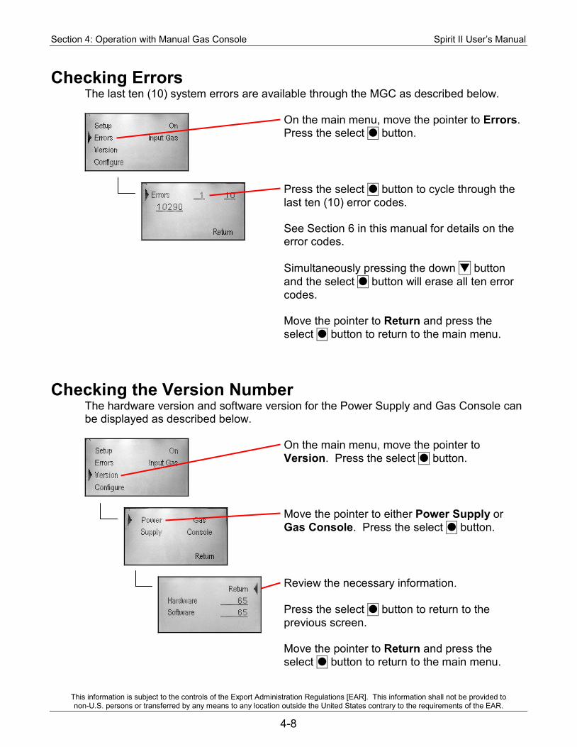
Section 4: Operation with Manual Gas Console Spirit II User’s Manual
This information is subject to the controls of the Export Administration Regulations [EAR]. This information shall not be provided to non-U.S. persons or transferred by any means to any location outside the United States contrary to the requirements of the EAR.
4-8
Checking Errors The last ten (10) system errors are available through the MGC as described below.
On the main menu, move the pointer to Errors. Press the select button.
Press the select button to cycle through the last ten (10) error codes. See Section 6 in this manual for details on the error codes. Simultaneously pressing the down button and the select button will erase all ten error codes. Move the pointer to Return and press the select button to return to the main menu.
Checking the Version Number The hardware version and software version for the Power Supply and Gas Console can be displayed as described below.
On the main menu, move the pointer to Version. Press the select button.
Move the pointer to either Power Supply or Gas Console. Press the select button.
Review the necessary information. Press the select button to return to the previous screen. Move the pointer to Return and press the select button to return to the main menu.
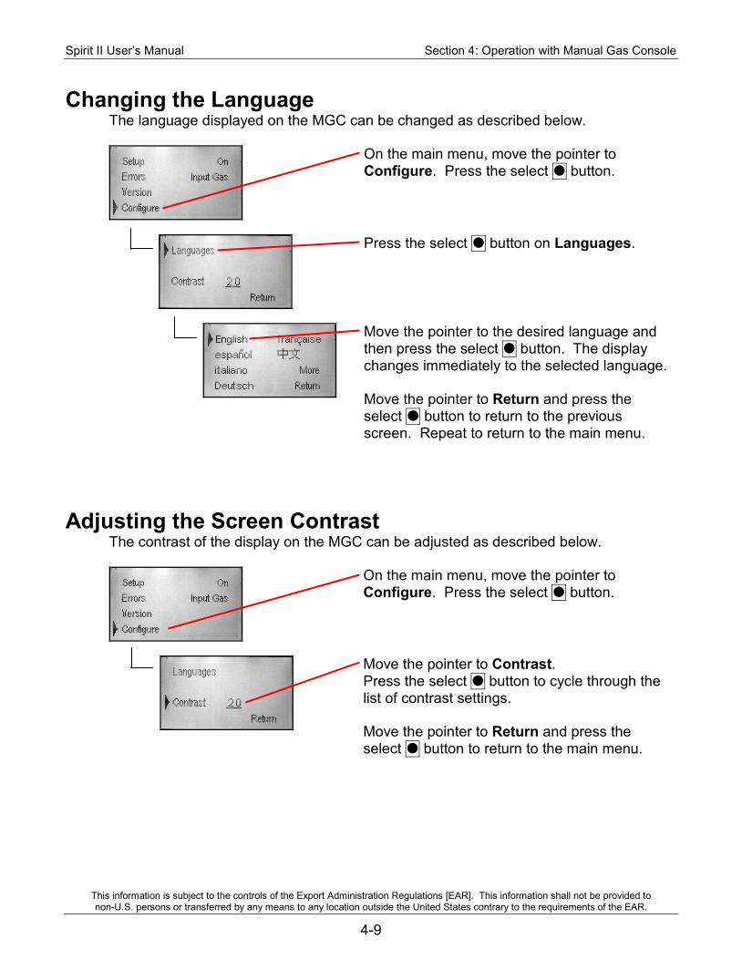
Spirit II User’s Manual Section 4: Operation with Manual Gas Console
This information is subject to the controls of the Export Administration Regulations [EAR]. This information shall not be provided to non-U.S. persons or transferred by any means to any location outside the United States contrary to the requirements of the EAR.
4-9
Changing the Language The language displayed on the MGC can be changed as described below.
On the main menu, move the pointer to Configure. Press the select button.
Press the select button on Languages.
Move the pointer to the desired language and then press the select button. The display changes immediately to the selected language. Move the pointer to Return and press the select button to return to the previous screen. Repeat to return to the main menu.
Adjusting the Screen Contrast The contrast of the display on the MGC can be adjusted as described below.
On the main menu, move the pointer to Configure. Press the select button.
Move the pointer to Contrast. Press the select button to cycle through the list of contrast settings. Move the pointer to Return and press the select button to return to the main menu.

Section 4: Operation with Manual Gas Console Spirit II User’s Manual
This information is subject to the controls of the Export Administration Regulations [EAR]. This information shall not be provided to non-U.S. persons or transferred by any means to any location outside the United States contrary to the requirements of the EAR.
4-10
BLANK
Spirit II User’s Manual Section 5: Torch Consumables and Cutting Charts
This information is subject to the controls of the Export Administration Regulations [EAR]. This information shall not be provided to non-U.S. persons or transferred by any means to any location outside the United States contrary to the requirements of the EAR.
5-1
Section 5: Torch Consumables and Cutting Charts Installing / Removing the Torch Head
DANGER!
Electric Shock Can Kill. • Remove primary power from the Spirit system before installing or
removing the torch head.
WARNING!
Hot Parts Can Burn Skin. • Do not touch hot parts bare handed. • Always use gloves when handling the torch as it can be hot after
cutting, especially with high amperages and long cut times. • Allow cooling period before working on the torch.
Each time the torch head is connected to the torch base, use a cotton swab to apply a small amount of o-ring lubricant on each of the seven o-rings on the top of the torch head. Reminder: do not use an excessive amount of o-ring lubricant. 1. Align the indicator on the torch head (circle) with the one on the torch base (slot). 2. Apply enough upward force to engage the threads while tightening the attachment
ring. Turn the attachment ring to the RIGHT to tighten. 3. Keep tightening the attachment ring until it stops. There should be no gap between
the attachment ring and the o-ring on the torch base. During this process, a small amount of coolant will collect in the torch head. It is normal for this coolant to discharge between the o-ring on the torch base and the attachment ring while the system is being pressurized. If coolant continues to discharge after the system is pressurized, turn off the plasma power supply, remove the torch head and inspect the o-rings for damage.
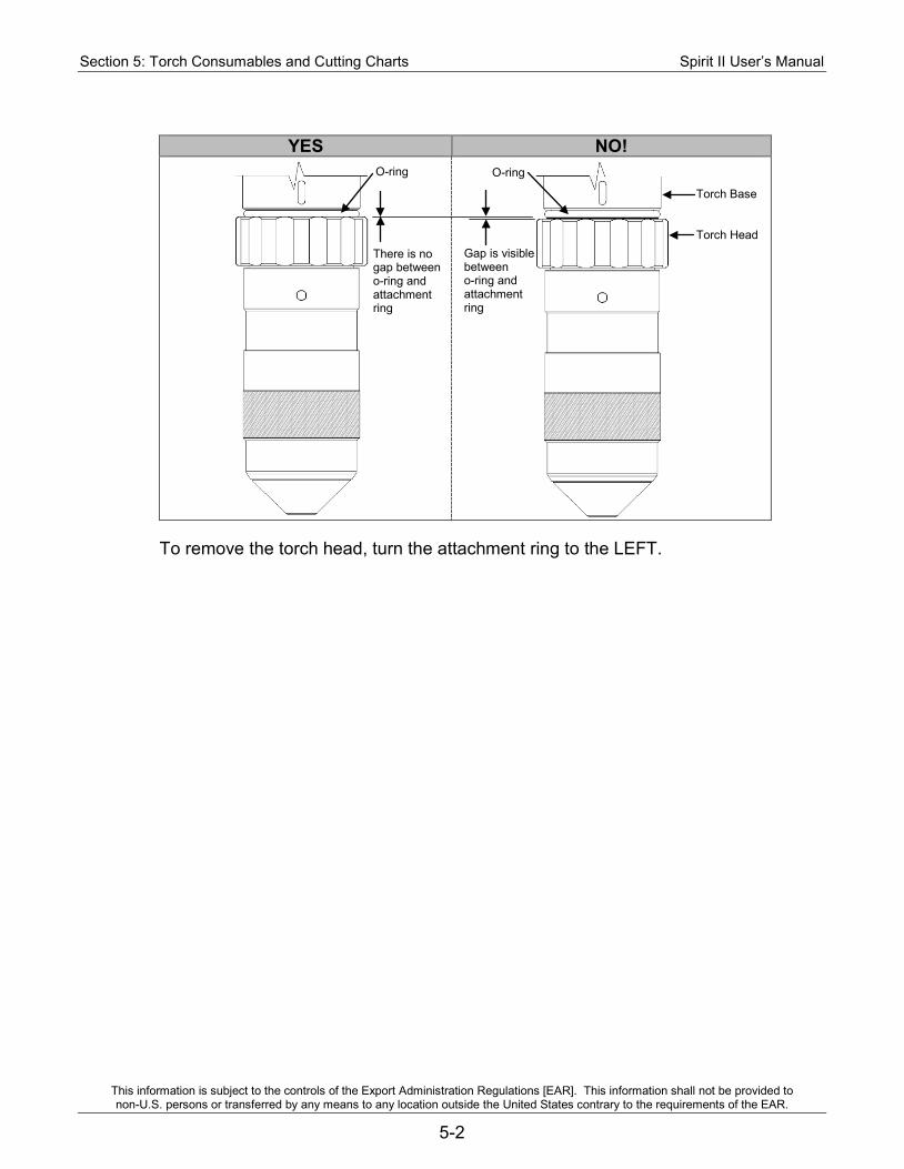
Section 5: Torch Consumables and Cutting Charts Spirit II User’s Manual
This information is subject to the controls of the Export Administration Regulations [EAR]. This information shall not be provided to non-U.S. persons or transferred by any means to any location outside the United States contrary to the requirements of the EAR.
5-2
YES NO!
To remove the torch head, turn the attachment ring to the LEFT.
There is no gap between o-ring and attachment ring
Gap is visible between o-ring and attachment ring
O-ring O-ring
Torch Base Torch Head
Spirit II User’s Manual Section 5: Torch Consumables and Cutting Charts
This information is subject to the controls of the Export Administration Regulations [EAR]. This information shall not be provided to non-U.S. persons or transferred by any means to any location outside the United States contrary to the requirements of the EAR.
5-3
Installing / Replacing Consumables DANGER!
Electric Shock Can Kill. • Remove primary power from the Spirit system before installing or
removing the torch head.
WARNING!
Hot Parts Can Burn Skin. • Do not touch hot parts bare handed. • Always use gloves when handling the torch as it can be hot after
cutting, especially with high amperages and long cut times. • Allow cooling period before working on the torch.
Note: When installing the consumables, do not use an excessive amount of o-ring lubricant. Also ensure that the lubricant is placed only on the o-rings. Excess lubricant can interfere with gas flow, which can cause starting problems, poor cut quality, and short consumable life. 1. Unthread the torch head from the torch base by turning the attachment ring to
the LEFT. Verify the torch base doesn't unthread from the torch handle. 2. Remove the outer retaining cap from the torch head. 3. Remove the inner retaining cap from the torch head. 4. Separate the shield cap from either the inner retaining cap or the outer
retaining cap. 5. Use the nozzle removal tool (P/N BK277056) to remove the nozzle from the
torch head. To do this, insert the tool into the groove on the nozzle and hold the tool/nozzle in the palm of your hand. Pull both hands apart using a linear motion as shown in the left image below. Do not use a prying or bending motion as shown in the right image below.
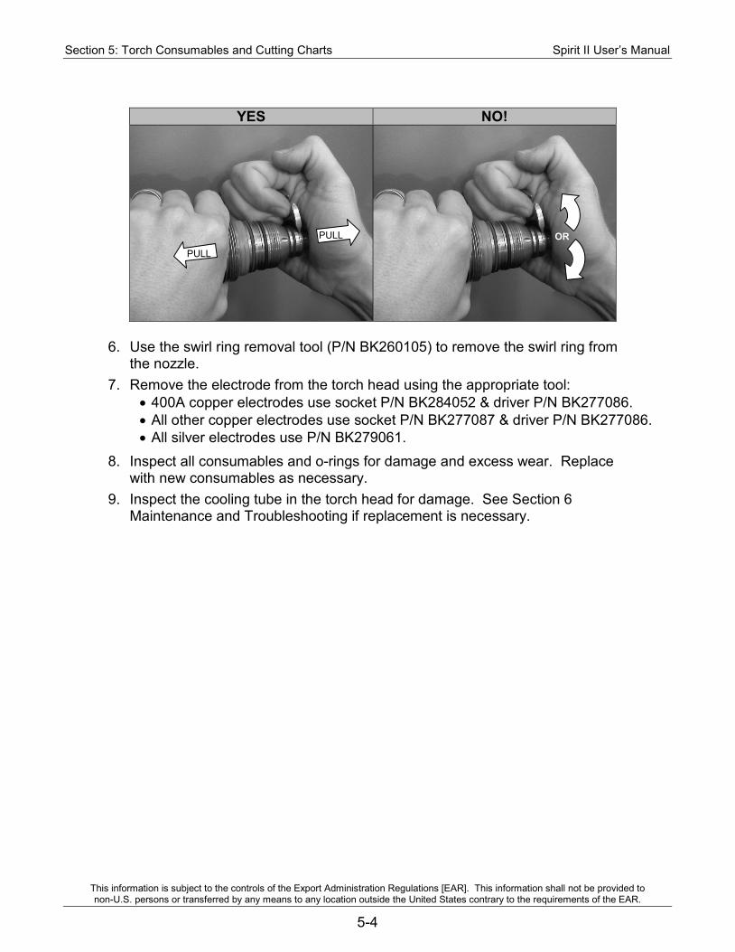
Section 5: Torch Consumables and Cutting Charts Spirit II User’s Manual
This information is subject to the controls of the Export Administration Regulations [EAR]. This information shall not be provided to non-U.S. persons or transferred by any means to any location outside the United States contrary to the requirements of the EAR.
5-4
YES NO!
6. Use the swirl ring removal tool (P/N BK260105) to remove the swirl ring from the nozzle.
7. Remove the electrode from the torch head using the appropriate tool: • 400A copper electrodes use socket P/N BK284052 & driver P/N BK277086. • All other copper electrodes use socket P/N BK277087 & driver P/N BK277086. • All silver electrodes use P/N BK279061.
8. Inspect all consumables and o-rings for damage and excess wear. Replace with new consumables as necessary.
9. Inspect the cooling tube in the torch head for damage. See Section 6 Maintenance and Troubleshooting if replacement is necessary.
PULL
PULL OR
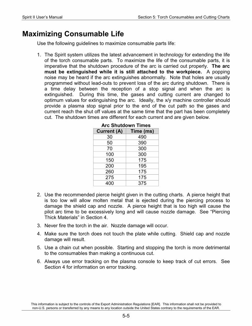
Spirit II User’s Manual Section 5: Torch Consumables and Cutting Charts
This information is subject to the controls of the Export Administration Regulations [EAR]. This information shall not be provided to non-U.S. persons or transferred by any means to any location outside the United States contrary to the requirements of the EAR.
5-5
Maximizing Consumable Life Use the following guidelines to maximize consumable parts life: 1. The Spirit system utilizes the latest advancement in technology for extending the life
of the torch consumable parts. To maximize the life of the consumable parts, it is imperative that the shutdown procedure of the arc is carried out properly. The arc must be extinguished while it is still attached to the workpiece. A popping noise may be heard if the arc extinguishes abnormally. Note that holes are usually programmed without lead-outs to prevent loss of the arc during shutdown. There is a time delay between the reception of a stop signal and when the arc is extinguished. During this time, the gases and cutting current are changed to optimum values for extinguishing the arc. Ideally, the x/y machine controller should provide a plasma stop signal prior to the end of the cut path so the gases and current reach the shut off values at the same time that the part has been completely cut. The shutdown times are different for each current and are given below.
Arc Shutdown Times Current (A) Time (ms)
30 490 50 390 70 300
100 300 150 175 200 195 260 175 275 175 400 375
2. Use the recommended pierce height given in the cutting charts. A pierce height that
is too low will allow molten metal that is ejected during the piercing process to damage the shield cap and nozzle. A pierce height that is too high will cause the pilot arc time to be excessively long and will cause nozzle damage. See “Piercing Thick Materials” in Section 4.
3. Never fire the torch in the air. Nozzle damage will occur. 4. Make sure the torch does not touch the plate while cutting. Shield cap and nozzle
damage will result. 5. Use a chain cut when possible. Starting and stopping the torch is more detrimental
to the consumables than making a continuous cut. 6. Always use error tracking on the plasma console to keep track of cut errors. See
Section 4 for information on error tracking.
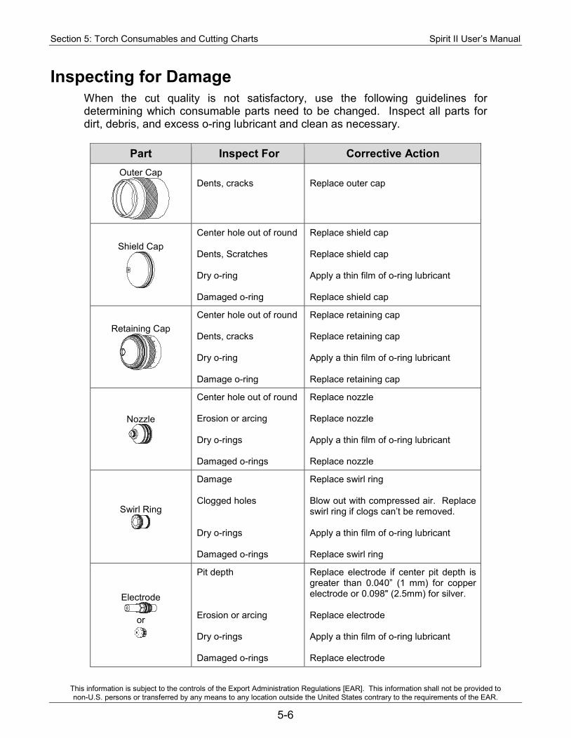
Section 5: Torch Consumables and Cutting Charts Spirit II User’s Manual
This information is subject to the controls of the Export Administration Regulations [EAR]. This information shall not be provided to non-U.S. persons or transferred by any means to any location outside the United States contrary to the requirements of the EAR.
5-6
Inspecting for Damage When the cut quality is not satisfactory, use the following guidelines for determining which consumable parts need to be changed. Inspect all parts for dirt, debris, and excess o-ring lubricant and clean as necessary.
Part Inspect For Corrective Action Outer Cap
Dents, cracks
Replace outer cap
Shield Cap
Center hole out of round Dents, Scratches Dry o-ring Damaged o-ring
Replace shield cap Replace shield cap Apply a thin film of o-ring lubricant Replace shield cap
Retaining Cap
Center hole out of round Dents, cracks Dry o-ring Damage o-ring
Replace retaining cap Replace retaining cap Apply a thin film of o-ring lubricant Replace retaining cap
Nozzle
Center hole out of round Erosion or arcing Dry o-rings Damaged o-rings
Replace nozzle Replace nozzle Apply a thin film of o-ring lubricant Replace nozzle
Swirl Ring
Damage Clogged holes Dry o-rings Damaged o-rings
Replace swirl ring Blow out with compressed air. Replace swirl ring if clogs can’t be removed. Apply a thin film of o-ring lubricant Replace swirl ring
Electrode
or
Pit depth Erosion or arcing Dry o-rings Damaged o-rings
Replace electrode if center pit depth is greater than 0.040” (1 mm) for copper electrode or 0.098" (2.5mm) for silver. Replace electrode Apply a thin film of o-ring lubricant Replace electrode
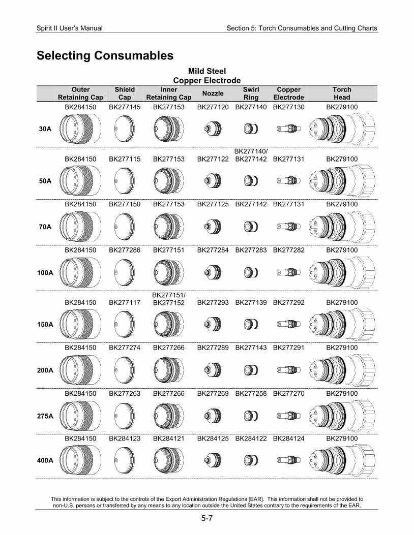
Spirit II User’s Manual Section 5: Torch Consumables and Cutting Charts
This information is subject to the controls of the Export Administration Regulations [EAR]. This information shall not be provided to non-U.S. persons or transferred by any means to any location outside the United States contrary to the requirements of the EAR.
5-7
Selecting Consumables Mild Steel
Copper Electrode Outer
Retaining Cap Shield Cap
Inner Retaining Cap Nozzle Swirl
Ring Copper
Electrode Torch Head
BK284150 BK277145 BK277153 BK277120 BK277140 BK277130 BK279100
30A
BK284150 BK277115 BK277153 BK277122 BK277140/ BK277142 BK277131 BK279100
50A
BK284150 BK277150 BK277153 BK277125 BK277142 BK277131 BK279100
70A
BK284150 BK277286 BK277151 BK277284 BK277283 BK277282 BK279100
100A
BK284150 BK277117 BK277151/ BK277152 BK277293 BK277139 BK277292 BK279100
150A
BK284150 BK277274 BK277266 BK277289 BK277143 BK277291 BK279100
200A
BK284150 BK277263 BK277266 BK277269 BK277258 BK277270 BK279100
275A
BK284150 BK284123 BK284121 BK284125 BK284122 BK284124 BK279100
400A
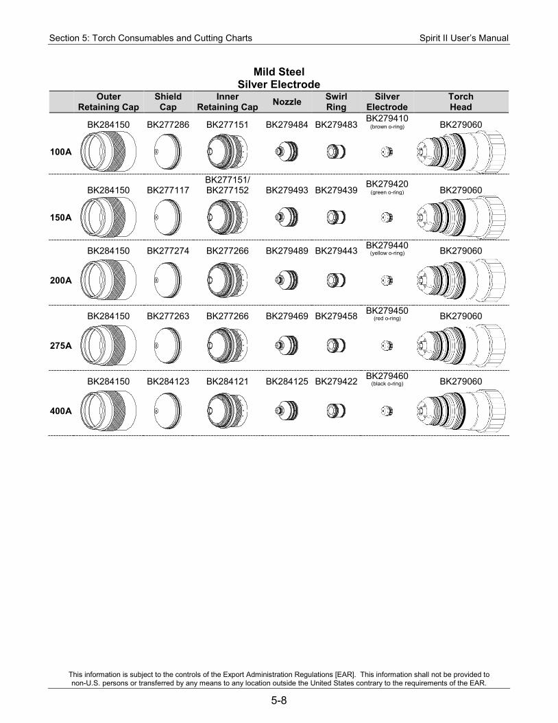
Section 5: Torch Consumables and Cutting Charts Spirit II User’s Manual
This information is subject to the controls of the Export Administration Regulations [EAR]. This information shall not be provided to non-U.S. persons or transferred by any means to any location outside the United States contrary to the requirements of the EAR.
5-8
Mild Steel Silver Electrode
Outer Retaining Cap
Shield Cap
Inner Retaining Cap Nozzle Swirl
Ring Silver
Electrode Torch Head
BK284150 BK277286 BK277151 BK279484 BK279483 BK279410
(brown o-ring) BK279060
100A
BK284150 BK277117
BK277151/ BK277152 BK279493 BK279439
BK279420 (green o-ring) BK279060
150A
BK284150 BK277274 BK277266 BK279489 BK279443 BK279440
(yellow o-ring) BK279060
200A
BK284150 BK277263 BK277266 BK279469 BK279458 BK279450
(red o-ring) BK279060
275A
BK284150 BK284123 BK284121 BK284125 BK279422 BK279460
(black o-ring) BK279060
400A
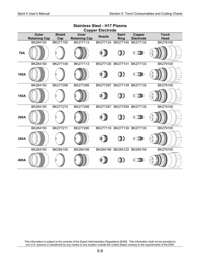
Spirit II User’s Manual Section 5: Torch Consumables and Cutting Charts
This information is subject to the controls of the Export Administration Regulations [EAR]. This information shall not be provided to non-U.S. persons or transferred by any means to any location outside the United States contrary to the requirements of the EAR.
5-9
Stainless Steel - H17 Plasma Copper Electrode
Outer Retaining Cap
Shield Cap
Inner Retaining Cap Nozzle Swirl
Ring Copper
Electrode Torch Head
BK284150 BK277150 BK277113 BK277124 BK277140 BK277132 BK279100
70A
BK284150 BK277146 BK277113 BK277126 BK277141 BK277133 BK279100
100A
BK284150 BK277298 BK277266 BK277297 BK277139 BK277135 BK279100
150A
BK284150 BK277274 BK277266 BK277287 BK277259 BK277135 BK279100
200A
BK284150 BK277211 BK277280 BK277118 BK277139 BK277135 BK279100
260A
BK284150 BK284155 BK284156 BK284158 BK284122 BK284159 BK279100
400A

Section 5: Torch Consumables and Cutting Charts Spirit II User’s Manual
This information is subject to the controls of the Export Administration Regulations [EAR]. This information shall not be provided to non-U.S. persons or transferred by any means to any location outside the United States contrary to the requirements of the EAR.
5-10
Stainless Steel - Air or Nitrogen Plasma Copper Electrode
Outer Retaining Cap
Shield Cap
Inner Retaining Cap Nozzle Swirl
Ring Copper
Electrode Torch Head
BK284150 BK277144 BK277110 BK277121 BK277138 BK277137 BK279100
30A
BK284150 BK277149 BK277110 BK277123 BK277142 BK277137 BK279100
50A
BK284150 BK277150 BK277153 BK277125 BK277142 BK277131 BK279100
70A
BK284150 BK277286 BK277151 BK277284 BK277283 BK277282 BK279100
100A
BK284150 BK277117 BK277152 BK277293 BK277139 BK277292 BK279100
150A
BK284150 BK277274 BK277266 BK277289 BK277143 BK277291 BK279100
200A
BK284150 BK277263 BK277266 BK277276 BK277258 BK277270 BK279100
275A
BK284150 BK284155 BK284156 BK284157 BK284122 BK284159 BK279100
400A
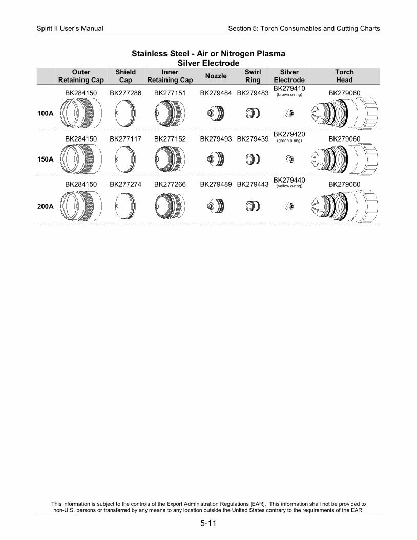
Spirit II User’s Manual Section 5: Torch Consumables and Cutting Charts
This information is subject to the controls of the Export Administration Regulations [EAR]. This information shall not be provided to non-U.S. persons or transferred by any means to any location outside the United States contrary to the requirements of the EAR.
5-11
Stainless Steel - Air or Nitrogen Plasma Silver Electrode
Outer Retaining Cap
Shield Cap
Inner Retaining Cap Nozzle Swirl
Ring Silver
Electrode Torch Head
BK284150 BK277286 BK277151 BK279484 BK279483 BK279410
(brown o-ring) BK279060
100A
BK284150 BK277117 BK277152 BK279493 BK279439
BK279420 (green o-ring) BK279060
150A
BK284150 BK277274 BK277266 BK279489 BK279443 BK279440
(yellow o-ring) BK279060
200A
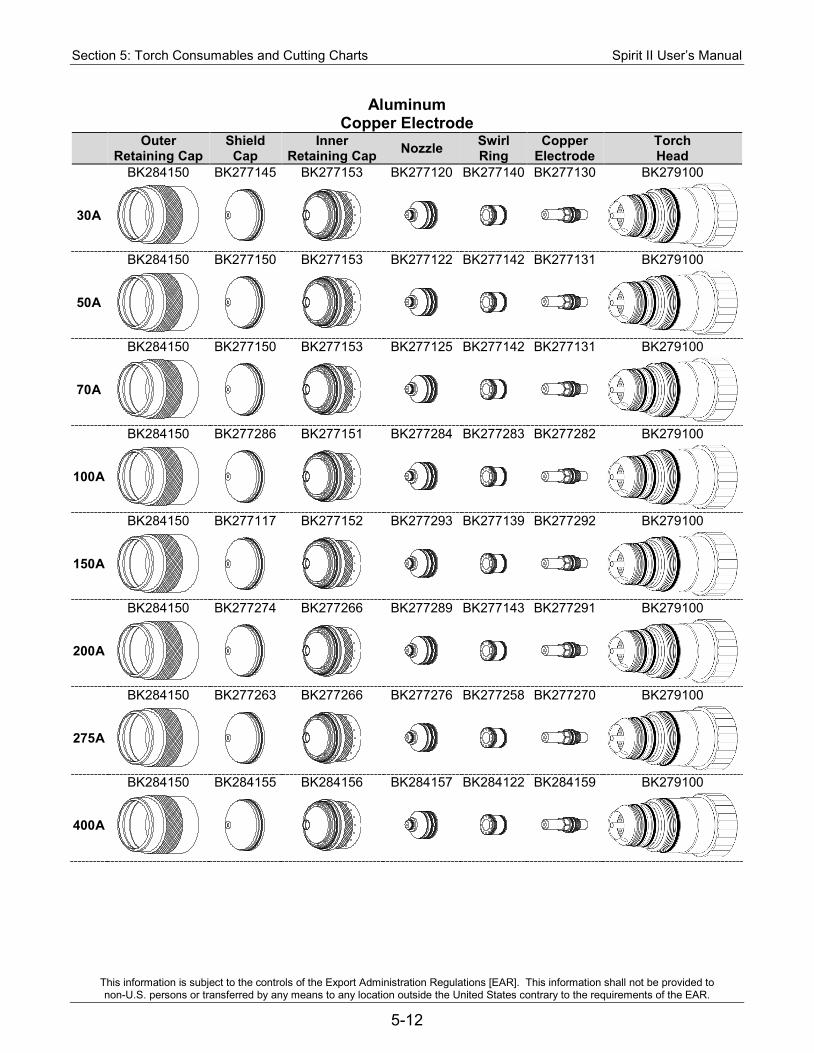
Section 5: Torch Consumables and Cutting Charts Spirit II User’s Manual
This information is subject to the controls of the Export Administration Regulations [EAR]. This information shall not be provided to non-U.S. persons or transferred by any means to any location outside the United States contrary to the requirements of the EAR.
5-12
Aluminum Copper Electrode
Outer Retaining Cap
Shield Cap
Inner Retaining Cap Nozzle Swirl
Ring Copper
Electrode Torch Head
BK284150 BK277145 BK277153 BK277120 BK277140 BK277130 BK279100
30A
BK284150 BK277150 BK277153 BK277122 BK277142 BK277131 BK279100
50A
BK284150 BK277150 BK277153 BK277125 BK277142 BK277131 BK279100
70A
BK284150 BK277286 BK277151 BK277284 BK277283 BK277282 BK279100
100A
BK284150 BK277117 BK277152 BK277293 BK277139 BK277292 BK279100
150A
BK284150 BK277274 BK277266 BK277289 BK277143 BK277291 BK279100
200A
BK284150 BK277263 BK277266 BK277276 BK277258 BK277270 BK279100
275A
BK284150 BK284155 BK284156 BK284157 BK284122 BK284159 BK279100
400A
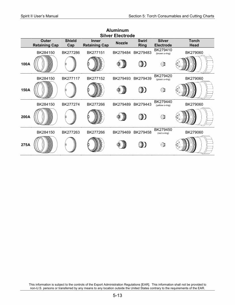
Spirit II User’s Manual Section 5: Torch Consumables and Cutting Charts
This information is subject to the controls of the Export Administration Regulations [EAR]. This information shall not be provided to non-U.S. persons or transferred by any means to any location outside the United States contrary to the requirements of the EAR.
5-13
Aluminum Silver Electrode
Outer Retaining Cap
Shield Cap
Inner Retaining Cap Nozzle Swirl
Ring Silver
Electrode Torch Head
BK284150 BK277286 BK277151 BK279484 BK279483 BK279410
(brown o-ring) BK279060
100A
BK284150 BK277117 BK277152 BK279493 BK279439
BK279420 (green o-ring) BK279060
150A
BK284150 BK277274 BK277266 BK279489 BK279443 BK279440
(yellow o-ring) BK279060
200A
BK284150 BK277263 BK277266 BK279469 BK279458 BK279450
(red o-ring) BK279060
275A

Section 5: Torch Consumables and Cutting Charts Spirit II User’s Manual
This information is subject to the controls of the Export Administration Regulations [EAR]. This information shall not be provided to non-U.S. persons or transferred by any means to any location outside the United States contrary to the requirements of the EAR.
5-14
Cutting Charts The cutting charts shown on the following pages are intended to give the operator the best starting point to use when making a cut on a particular material type and thickness. Small adjustments may have to be made to achieve the best cut. Also, remember that the arc voltage must be increased as the electrode wears in order to maintain the correct cutting height.
Material Current Preflow & Postflow Gas
Plasma Gas
Shield Gas
Copper Electrode
Silver Electrode
Mild Steel 30 Amps Air Oxygen Oxygen Page 5-15 Mild Steel 50 Amps Air Oxygen Oxygen or Air Page 5-16 Mild Steel 70 Amps Air Oxygen Air Page 5-17 Mild Steel 100 Amps Air Oxygen Air Page 5-18 Page 5-45 Mild Steel 150 Amps Air Oxygen Air Page 5-19 Page 5-46 Mild Steel 200 Amps Air Oxygen Air Page 5-20 Page 5-47 Mild Steel 275 Amps Air Oxygen Air Page 5-21 Page 5-48 Mild Steel 400 Amps Air Oxygen Air Page 5-22 Page 5-49
Stainless Steel 30 Amps Air Air Air Page 5-23 Stainless Steel 50 Amps Air Air Nitrogen Page 5-24 Stainless Steel 70 Amps Nitrogen H17 Nitrogen Page 5-25 Stainless Steel 70 Amps Air Air Nitrogen Page 5-26 Stainless Steel 100 Amps Nitrogen H17 Nitrogen Page 5-27 Stainless Steel 100 Amps Air Air Nitrogen Page 5-28 Page 5-50 Stainless Steel 150 Amps Nitrogen H17 Nitrogen Page 5-29 Stainless Steel 150 Amps Air Air Nitrogen Page 5-30 Page 5-51 Stainless Steel 200 Amps Nitrogen H17 Nitrogen Page 5-31 Stainless Steel 200 Amps Air Air Nitrogen Page 5-32 Page 5-52 Stainless Steel 260 Amps Nitrogen H17 Nitrogen Page 5-33 Stainless Steel 275 Amps Air Air Nitrogen Page 5-34 Stainless Steel 400 Amps Nitrogen H17 Nitrogen Page 5-35 Stainless Steel 400 Amps Nitrogen Nitrogen Air Page 5-36
Aluminum 30 Amps Air Air Nitrogen Page 5-37 Aluminum 50 Amps Air Air Nitrogen Page 5-38 Aluminum 70 Amps Air Air Nitrogen Page 5-39 Aluminum 100 Amps Air Air Nitrogen Page 5-40 Page 5-53 Aluminum 150 Amps Air Air Nitrogen Page 5-41 Page 5-54 Aluminum 200 Amps Air Air Nitrogen Page 5-42 Page 5-55 Aluminum 275 Amps Air Air Nitrogen Page 5-43 Page 5-56 Aluminum 400 Amps Nitrogen Nitrogen Air Page 5-44
WARNING
IMPROPER GAS USAGE can cause explosion and/or fire.
• The combination of Preflow/Postflow, Plasma and Shield input gases should always adhere to the types specified in the cut charts for a given material type.
• When changing to a different type of gas (oxidizing or oxygen containing to combustible or vice versa), a purge of the gas lines (30 second minimum) must be completed to reduce the risk of fire or explosion.
• Do not connect H17 (combustible gas) to the gas inputs (Pre/Postflow, Plasma, or Shield) at the same time as Oxygen or Air.
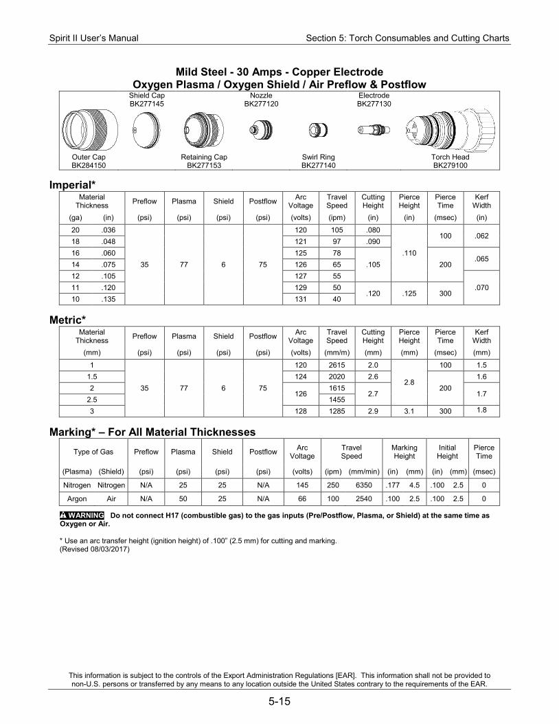
Spirit II User’s Manual Section 5: Torch Consumables and Cutting Charts
This information is subject to the controls of the Export Administration Regulations [EAR]. This information shall not be provided to non-U.S. persons or transferred by any means to any location outside the United States contrary to the requirements of the EAR.
5-15
Mild Steel - 30 Amps - Copper Electrode Oxygen Plasma / Oxygen Shield / Air Preflow & Postflow
Shield Cap Nozzle Electrode BK277145 BK277120 BK277130
Outer Cap Retaining Cap Swirl Ring Torch Head BK284150 BK277153 BK277140 BK279100
Imperial*
Material Thickness Preflow Plasma Shield Postflow Arc
Voltage Travel Speed
Cutting Height
Pierce Height
Pierce Time
Kerf Width
(ga) (in) (psi) (psi) (psi) (psi) (volts) (ipm) (in) (in) (msec) (in)
20 .036
35 77 6 75
120 105 .080
.110
100 .062 18 .048 121 97 .090 16 .060 125 78
.105 200 .065
14 .075 126 65 12 .105 127 55
.070 11 .120 129 50 .120 .125 300
10 .135 131 40 Metric*
Material Thickness Preflow Plasma Shield Postflow Arc
Voltage Travel Speed
Cutting Height
Pierce Height
Pierce Time
Kerf Width
(mm) (psi) (psi) (psi) (psi) (volts) (mm/m) (mm) (mm) (msec) (mm)
1
35 77 6 75
120 2615 2.0
2.8
100 1.5 1.5 124 2020 2.6
200 1.6
2 126
1615 2.7 1.7
2.5 1455 3 128 1285 2.9 3.1 300 1.8
Marking* – For All Material Thicknesses
Type of Gas Preflow Plasma Shield Postflow Arc Voltage
Travel Speed
Marking Height
Initial Height
Pierce Time
(Plasma) (Shield) (psi) (psi) (psi) (psi) (volts) (ipm) (mm/min) (in) (mm) (in) (mm) (msec)
Nitrogen Nitrogen N/A 25 25 N/A 145 250 6350 .177 4.5 .100 2.5 0
Argon Air N/A 50 25 N/A 66 100 2540 .100 2.5 .100 2.5 0
WARNING Do not connect H17 (combustible gas) to the gas inputs (Pre/Postflow, Plasma, or Shield) at the same time as Oxygen or Air.
* Use an arc transfer height (ignition height) of .100” (2.5 mm) for cutting and marking. (Revised 08/03/2017)
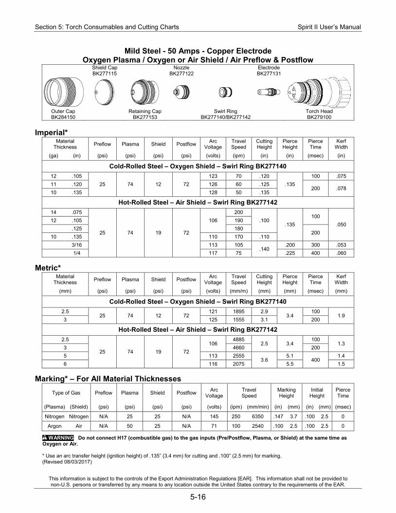
Section 5: Torch Consumables and Cutting Charts Spirit II User’s Manual
This information is subject to the controls of the Export Administration Regulations [EAR]. This information shall not be provided to non-U.S. persons or transferred by any means to any location outside the United States contrary to the requirements of the EAR.
5-16
Mild Steel - 50 Amps - Copper Electrode Oxygen Plasma / Oxygen or Air Shield / Air Preflow & Postflow
Shield Cap Nozzle Electrode BK277115 BK277122 BK277131
Outer Cap Retaining Cap Swirl Ring Torch Head BK284150 BK277153 BK277140/BK277142 BK279100
Imperial*
Material Thickness Preflow Plasma Shield Postflow Arc
Voltage Travel Speed
Cutting Height
Pierce Height
Pierce Time
Kerf Width
(ga) (in) (psi) (psi) (psi) (psi) (volts) (ipm) (in) (in) (msec) (in)
Cold-Rolled Steel – Oxygen Shield – Swirl Ring BK277140 12 .105
25 74 12 72 123 70 .120
.135 100 .075
11 .120 126 60 .125 200 .078
10 .135 128 50 .135
Hot-Rolled Steel – Air Shield – Swirl Ring BK277142 14 .075
25 74 19 72
106 200
.100 .135
100 .050
12 .105 190 .125 180
200 10 .135 110 170 .110 3/16 113 105
.140 .200 300 .053
1/4 117 75 .225 400 .060 Metric*
Material Thickness Preflow Plasma Shield Postflow Arc
Voltage Travel Speed
Cutting Height
Pierce Height
Pierce Time
Kerf Width
(mm) (psi) (psi) (psi) (psi) (volts) (mm/m) (mm) (mm) (msec) (mm)
Cold-Rolled Steel – Oxygen Shield – Swirl Ring BK277140 2.5
25 74 12 72 121 1895 2.9
3.4 100
1.9 3 125 1555 3.1 200
Hot-Rolled Steel – Air Shield – Swirl Ring BK277142 2.5
25 74 19 72 106
4885 2.5 3.4
100 1.3
3 4660 200 5 113 2555
3.6 5.1
400 1.4
6 116 2075 5.5 1.5 Marking* – For All Material Thicknesses
Type of Gas Preflow Plasma Shield Postflow Arc Voltage
Travel Speed
Marking Height
Initial Height
Pierce Time
(Plasma) (Shield) (psi) (psi) (psi) (psi) (volts) (ipm) (mm/min) (in) (mm) (in) (mm) (msec)
Nitrogen Nitrogen N/A 25 25 N/A 145 250 6350 .147 3.7 .100 2.5 0
Argon Air N/A 50 25 N/A 71 100 2540 .100 2.5 .100 2.5 0
WARNING Do not connect H17 (combustible gas) to the gas inputs (Pre/Postflow, Plasma, or Shield) at the same time as Oxygen or Air.
* Use an arc transfer height (ignition height) of .135” (3.4 mm) for cutting and .100” (2.5 mm) for marking. (Revised 08/03/2017)
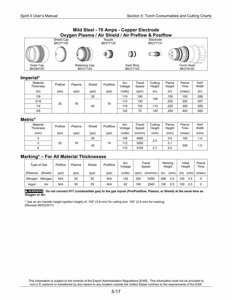
Spirit II User’s Manual Section 5: Torch Consumables and Cutting Charts
This information is subject to the controls of the Export Administration Regulations [EAR]. This information shall not be provided to non-U.S. persons or transferred by any means to any location outside the United States contrary to the requirements of the EAR.
5-17
Mild Steel - 70 Amps - Copper Electrode Oxygen Plasma / Air Shield / Air Preflow & Postflow
Shield Cap Nozzle Electrode BK277150 BK277125 BK277131
Outer Cap Retaining Cap Swirl Ring Torch Head BK284150 BK277153 BK277142 BK279100
Imperial*
Material Thickness Preflow Plasma Shield Postflow Arc
Voltage Travel Speed
Cutting Height
Pierce Height
Pierce Time
Kerf Width
(in) (psi) (psi) (psi) (psi) (volts) (ipm) (in) (in) (msec) (in)
1/8
25 76
35
74
110 190 .100
.150 100 .056 3/16
40 113 130 .200 200 .057
1/4 116 120 .110 .225 300 .059 3/8 122 75 .140 .250 400 .065
Metric*
Material Thickness Preflow Plasma Shield Postflow Arc
Voltage Travel Speed
Cutting Height
Pierce Height
Pierce Time
Kerf Width
(mm) (psi) (psi) (psi) (psi) (volts) (mm/m) (mm) (mm) (msec) (mm)
3 25 76
35 74
109 4995 2.5
3.6 100 1.4 5
40 113 3265 5.1
300 1.5 6 115 3105 2.7 5.5
Marking* – For All Material Thicknesses
Type of Gas Preflow Plasma Shield Postflow Arc Voltage
Travel Speed
Marking Height
Initial Height
Pierce Time
(Plasma) (Shield) (psi) (psi) (psi) (psi) (volts) (ipm) (mm/min) (in) (mm) (in) (mm) (msec)
Nitrogen Nitrogen N/A 25 25 N/A 135 250 6350 .096 2.4 .100 2.5 0
Argon Air N/A 50 25 N/A 62 100 2540 .100 2.5 .100 2.5 0
WARNING Do not connect H17 (combustible gas) to the gas inputs (Pre/Postflow, Plasma, or Shield) at the same time as Oxygen or Air.
* Use an arc transfer height (ignition height) of .150” (3.8 mm) for cutting and .100” (2.5 mm) for marking. (Revised 08/03/2017)
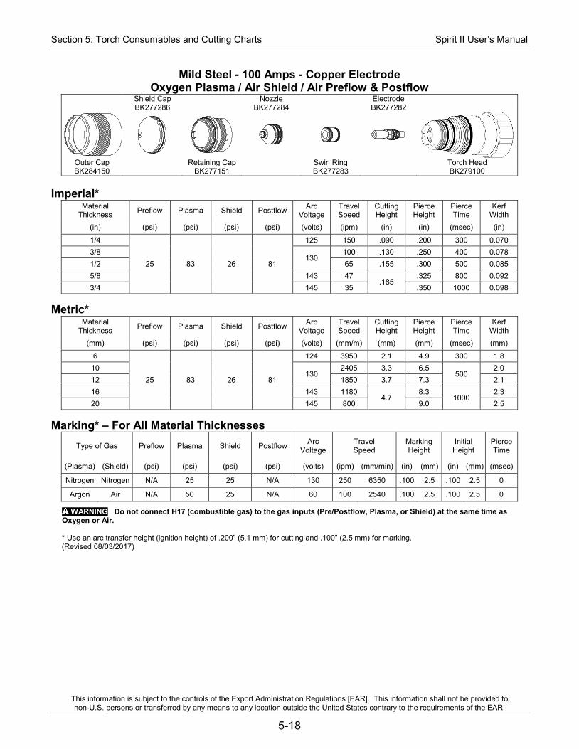
Section 5: Torch Consumables and Cutting Charts Spirit II User’s Manual
This information is subject to the controls of the Export Administration Regulations [EAR]. This information shall not be provided to non-U.S. persons or transferred by any means to any location outside the United States contrary to the requirements of the EAR.
5-18
Mild Steel - 100 Amps - Copper Electrode Oxygen Plasma / Air Shield / Air Preflow & Postflow
Shield Cap Nozzle Electrode BK277286 BK277284 BK277282
Outer Cap Retaining Cap Swirl Ring Torch Head BK284150 BK277151 BK277283 BK279100
Imperial*
Material Thickness Preflow Plasma Shield Postflow Arc
Voltage Travel Speed
Cutting Height
Pierce Height
Pierce Time
Kerf Width
(in) (psi) (psi) (psi) (psi) (volts) (ipm) (in) (in) (msec) (in)
1/4
25 83 26 81
125 150 .090 .200 300 0.070 3/8
130 100 .130 .250 400 0.078
1/2 65 .155 .300 500 0.085 5/8 143 47
.185 .325 800 0.092
3/4 145 35 .350 1000 0.098 Metric*
Material Thickness Preflow Plasma Shield Postflow Arc
Voltage Travel Speed
Cutting Height
Pierce Height
Pierce Time
Kerf Width
(mm) (psi) (psi) (psi) (psi) (volts) (mm/m) (mm) (mm) (msec) (mm)
6
25 83 26 81
124 3950 2.1 4.9 300 1.8 10
130 2405 3.3 6.5
500 2.0
12 1850 3.7 7.3 2.1 16 143 1180
4.7 8.3
1000 2.3
20 145 800 9.0 2.5 Marking* – For All Material Thicknesses
Type of Gas Preflow Plasma Shield Postflow Arc Voltage
Travel Speed
Marking Height
Initial Height
Pierce Time
(Plasma) (Shield) (psi) (psi) (psi) (psi) (volts) (ipm) (mm/min) (in) (mm) (in) (mm) (msec)
Nitrogen Nitrogen N/A 25 25 N/A 130 250 6350 .100 2.5 .100 2.5 0
Argon Air N/A 50 25 N/A 60 100 2540 .100 2.5 .100 2.5 0
WARNING Do not connect H17 (combustible gas) to the gas inputs (Pre/Postflow, Plasma, or Shield) at the same time as Oxygen or Air.
* Use an arc transfer height (ignition height) of .200” (5.1 mm) for cutting and .100” (2.5 mm) for marking. (Revised 08/03/2017)
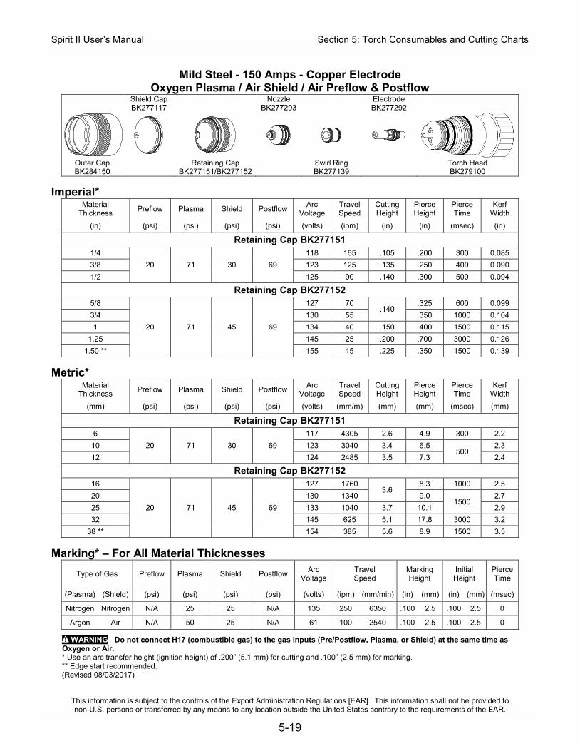
Spirit II User’s Manual Section 5: Torch Consumables and Cutting Charts
This information is subject to the controls of the Export Administration Regulations [EAR]. This information shall not be provided to non-U.S. persons or transferred by any means to any location outside the United States contrary to the requirements of the EAR.
5-19
Mild Steel - 150 Amps - Copper Electrode Oxygen Plasma / Air Shield / Air Preflow & Postflow
Shield Cap Nozzle Electrode BK277117 BK277293 BK277292
Outer Cap Retaining Cap Swirl Ring Torch Head BK284150 BK277151/BK277152 BK277139 BK279100
Imperial*
Material Thickness Preflow Plasma Shield Postflow Arc
Voltage Travel Speed
Cutting Height
Pierce Height
Pierce Time
Kerf Width
(in) (psi) (psi) (psi) (psi) (volts) (ipm) (in) (in) (msec) (in)
Retaining Cap BK277151 1/4
20 71 30 69 118 165 .105 .200 300 0.085
3/8 123 125 .135 .250 400 0.090 1/2 125 90 .140 .300 500 0.094
Retaining Cap BK277152 5/8
20 71 45 69
127 70 .140
.325 600 0.099 3/4 130 55 .350 1000 0.104 1 134 40 .150 .400 1500 0.115
1.25 145 25 .200 .700 3000 0.126 1.50 ** 155 15 .225 .350 1500 0.139
Metric*
Material Thickness Preflow Plasma Shield Postflow Arc
Voltage Travel Speed
Cutting Height
Pierce Height
Pierce Time
Kerf Width
(mm) (psi) (psi) (psi) (psi) (volts) (mm/m) (mm) (mm) (msec) (mm)
Retaining Cap BK277151 6
20 71 30 69 117 4305 2.6 4.9 300 2.2
10 123 3040 3.4 6.5 500
2.3 12 124 2485 3.5 7.3 2.4
Retaining Cap BK277152 16
20 71 45 69
127 1760 3.6
8.3 1000 2.5 20 130 1340 9.0
1500 2.7
25 133 1040 3.7 10.1 2.9 32 145 625 5.1 17.8 3000 3.2
38 ** 154 385 5.6 8.9 1500 3.5 Marking* – For All Material Thicknesses
Type of Gas Preflow Plasma Shield Postflow Arc Voltage
Travel Speed
Marking Height
Initial Height
Pierce Time
(Plasma) (Shield) (psi) (psi) (psi) (psi) (volts) (ipm) (mm/min) (in) (mm) (in) (mm) (msec)
Nitrogen Nitrogen N/A 25 25 N/A 135 250 6350 .100 2.5 .100 2.5 0
Argon Air N/A 50 25 N/A 61 100 2540 .100 2.5 .100 2.5 0
WARNING Do not connect H17 (combustible gas) to the gas inputs (Pre/Postflow, Plasma, or Shield) at the same time as Oxygen or Air. * Use an arc transfer height (ignition height) of .200” (5.1 mm) for cutting and .100” (2.5 mm) for marking. ** Edge start recommended. (Revised 08/03/2017)
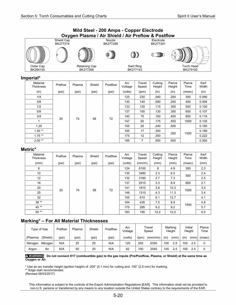
Section 5: Torch Consumables and Cutting Charts Spirit II User’s Manual
This information is subject to the controls of the Export Administration Regulations [EAR]. This information shall not be provided to non-U.S. persons or transferred by any means to any location outside the United States contrary to the requirements of the EAR.
5-20
Mild Steel - 200 Amps - Copper Electrode Oxygen Plasma / Air Shield / Air Preflow & Postflow
Shield Cap Nozzle Electrode BK277274 BK277289 BK277291
Outer Cap Retaining Cap Swirl Ring Torch Head BK284150 BK277266 BK277143 BK279100
Imperial*
Material Thickness Preflow Plasma Shield Postflow Arc
Voltage Travel Speed
Cutting Height
Pierce Height
Pierce Time
Kerf Width
(in) (psi) (psi) (psi) (psi) (volts) (ipm) (in) (in) (msec) (in)
1/4
20 74 58 72
125 230 .040 .200 300 0.090 3/8 130 140 .090 .250 400 0.094 1/2 133 120 .115 .300 500 0.100 5/8 137 100 .130 .350 600 0.107 3/4 140 75 .150 .400 800 0.116 1 147 50 .175 .450 1000 0.135
1.25 155 25 .240 .500
1500
0.160 1.50 ** 165 17 .300
.350 0.189
1.75 ** 175 12 .350 0.222 2.00 ** 185 7 .500 .500 0.260
Metric*
Material Thickness Preflow Plasma Shield Postflow Arc
Voltage Travel Speed
Cutting Height
Pierce Height
Pierce Time
Kerf Width
(mm) (psi) (psi) (psi) (psi) (volts) (mm/m) (mm) (mm) (msec) (mm)
6
20 74 58 72
124 6100 .8 4.9 300 2.3 10 130 3480 2.3 6.5
500 2.4
12 132 3160 2.7 7.3 2.5 16 137 2515 3.3 8.9 800 2.7 20 141 1810 3.8 10.3
1000 3.0
25 146 1310 4.3 11.3 3.4 32 155 610 6.1 12.7
1500
4.1 38 ** 164 435 7.5 8.9 4.8 45 ** 175 295 9.2 9.2 5.7 50 ** 183 195 12.2 12.2 6.5
Marking* – For All Material Thicknesses
Type of Gas Preflow Plasma Shield Postflow Arc Voltage
Travel Speed
Marking Height
Initial Height
Pierce Time
(Plasma) (Shield) (psi) (psi) (psi) (psi) (volts) (ipm) (mm/min) (in) (mm) (in) (mm) (msec)
Nitrogen Nitrogen N/A 25 25 N/A 120 250 6350 .100 2.5 .100 2.5 0
Argon Air N/A 50 25 N/A 62 100 2540 .100 2.5 .100 2.5 0
WARNING Do not connect H17 (combustible gas) to the gas inputs (Pre/Postflow, Plasma, or Shield) at the same time as Oxygen or Air.
* Use an arc transfer height (ignition height) of .200” (5.1 mm) for cutting and .100” (2.5 mm) for marking. ** Edge start recommended. (Revised 08/03/2017)
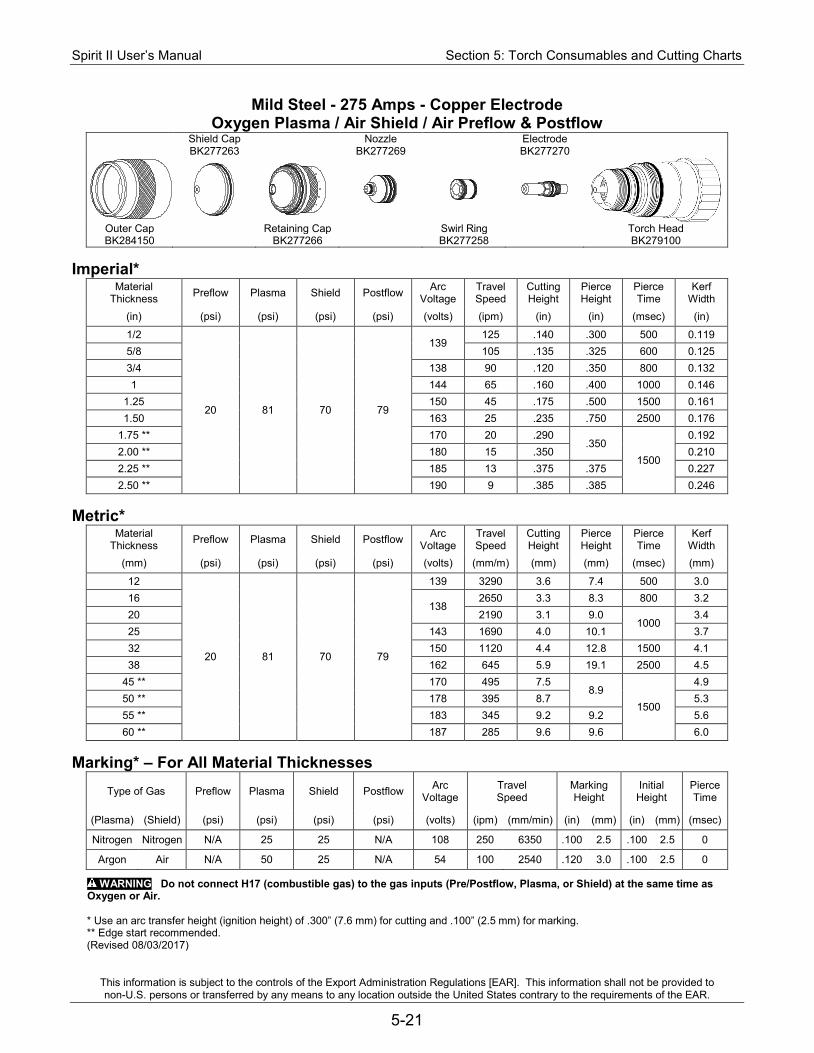
Spirit II User’s Manual Section 5: Torch Consumables and Cutting Charts
This information is subject to the controls of the Export Administration Regulations [EAR]. This information shall not be provided to non-U.S. persons or transferred by any means to any location outside the United States contrary to the requirements of the EAR.
5-21
Mild Steel - 275 Amps - Copper Electrode Oxygen Plasma / Air Shield / Air Preflow & Postflow
Shield Cap Nozzle Electrode BK277263 BK277269 BK277270
Outer Cap Retaining Cap Swirl Ring Torch Head BK284150 BK277266 BK277258 BK279100
Imperial*
Material Thickness Preflow Plasma Shield Postflow Arc
Voltage Travel Speed
Cutting Height
Pierce Height
Pierce Time
Kerf Width
(in) (psi) (psi) (psi) (psi) (volts) (ipm) (in) (in) (msec) (in)
1/2
20 81 70 79
139 125 .140 .300 500 0.119
5/8 105 .135 .325 600 0.125 3/4 138 90 .120 .350 800 0.132 1 144 65 .160 .400 1000 0.146
1.25 150 45 .175 .500 1500 0.161 1.50 163 25 .235 .750 2500 0.176
1.75 ** 170 20 .290 .350
1500
0.192 2.00 ** 180 15 .350 0.210 2.25 ** 185 13 .375 .375 0.227 2.50 ** 190 9 .385 .385 0.246
Metric*
Material Thickness Preflow Plasma Shield Postflow Arc
Voltage Travel Speed
Cutting Height
Pierce Height
Pierce Time
Kerf Width
(mm) (psi) (psi) (psi) (psi) (volts) (mm/m) (mm) (mm) (msec) (mm)
12
20 81 70 79
139 3290 3.6 7.4 500 3.0 16
138 2650 3.3 8.3 800 3.2
20 2190 3.1 9.0 1000
3.4 25 143 1690 4.0 10.1 3.7 32 150 1120 4.4 12.8 1500 4.1 38 162 645 5.9 19.1 2500 4.5
45 ** 170 495 7.5 8.9
1500
4.9 50 ** 178 395 8.7 5.3 55 ** 183 345 9.2 9.2 5.6 60 ** 187 285 9.6 9.6 6.0
Marking* – For All Material Thicknesses
Type of Gas Preflow Plasma Shield Postflow Arc Voltage
Travel Speed
Marking Height
Initial Height
Pierce Time
(Plasma) (Shield) (psi) (psi) (psi) (psi) (volts) (ipm) (mm/min) (in) (mm) (in) (mm) (msec)
Nitrogen Nitrogen N/A 25 25 N/A 108 250 6350 .100 2.5 .100 2.5 0
Argon Air N/A 50 25 N/A 54 100 2540 .120 3.0 .100 2.5 0
WARNING Do not connect H17 (combustible gas) to the gas inputs (Pre/Postflow, Plasma, or Shield) at the same time as Oxygen or Air.
* Use an arc transfer height (ignition height) of .300” (7.6 mm) for cutting and .100” (2.5 mm) for marking. ** Edge start recommended. (Revised 08/03/2017)
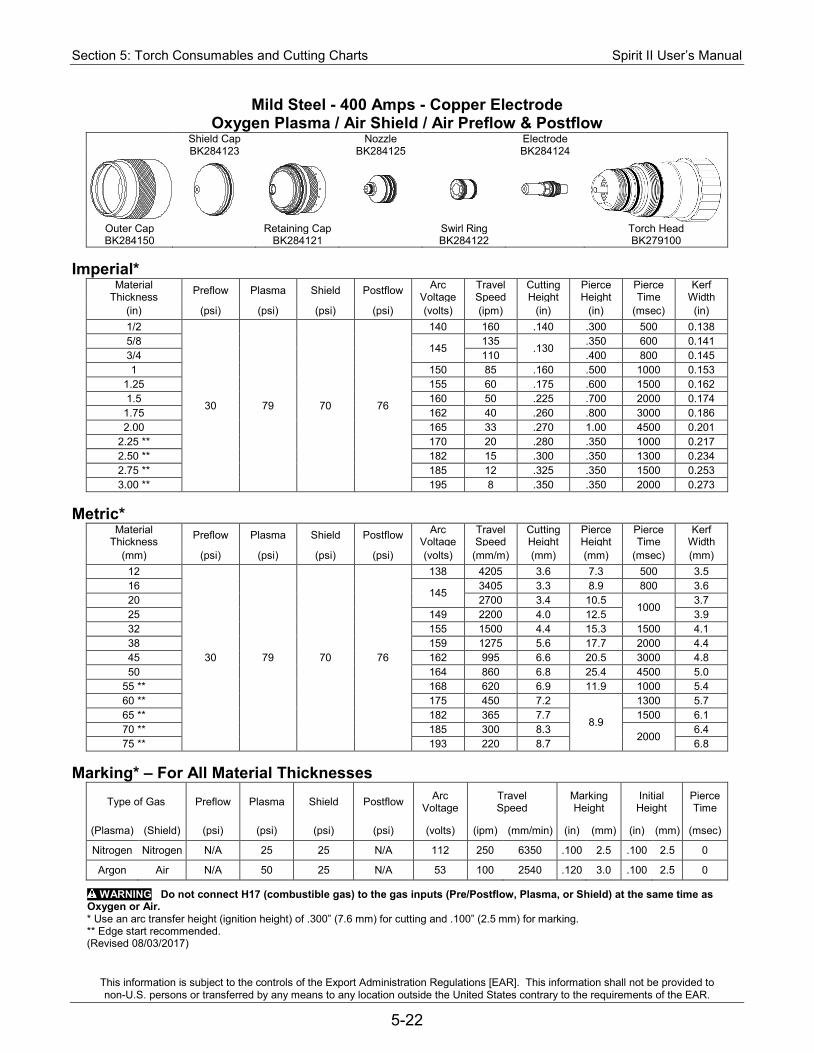
Section 5: Torch Consumables and Cutting Charts Spirit II User’s Manual
This information is subject to the controls of the Export Administration Regulations [EAR]. This information shall not be provided to non-U.S. persons or transferred by any means to any location outside the United States contrary to the requirements of the EAR.
5-22
Mild Steel - 400 Amps - Copper Electrode Oxygen Plasma / Air Shield / Air Preflow & Postflow
Shield Cap Nozzle Electrode BK284123 BK284125 BK284124
Outer Cap Retaining Cap Swirl Ring Torch Head BK284150 BK284121 BK284122 BK279100
Imperial*
Material Thickness Preflow Plasma Shield Postflow Arc
Voltage Travel Speed
Cutting Height
Pierce Height
Pierce Time
Kerf Width
(in) (psi) (psi) (psi) (psi) (volts) (ipm) (in) (in) (msec) (in) 1/2
30 79 70 76
140 160 .140 .300 500 0.138 5/8
145 135
.130 .350 600 0.141
3/4 110 .400 800 0.145 1 150 85 .160 .500 1000 0.153
1.25 155 60 .175 .600 1500 0.162 1.5 160 50 .225 .700 2000 0.174
1.75 162 40 .260 .800 3000 0.186 2.00 165 33 .270 1.00 4500 0.201
2.25 ** 170 20 .280 .350 1000 0.217 2.50 ** 182 15 .300 .350 1300 0.234 2.75 ** 185 12 .325 .350 1500 0.253 3.00 ** 195 8 .350 .350 2000 0.273
Metric*
Material Thickness Preflow Plasma Shield Postflow Arc
Voltage Travel Speed
Cutting Height
Pierce Height
Pierce Time
Kerf Width
(mm) (psi) (psi) (psi) (psi) (volts) (mm/m) (mm) (mm) (msec) (mm) 12
30 79 70 76
138 4205 3.6 7.3 500 3.5 16
145 3405 3.3 8.9 800 3.6
20 2700 3.4 10.5 1000
3.7 25 149 2200 4.0 12.5 3.9 32 155 1500 4.4 15.3 1500 4.1 38 159 1275 5.6 17.7 2000 4.4 45 162 995 6.6 20.5 3000 4.8 50 164 860 6.8 25.4 4500 5.0
55 ** 168 620 6.9 11.9 1000 5.4 60 ** 175 450 7.2
8.9
1300 5.7 65 ** 182 365 7.7 1500 6.1 70 ** 185 300 8.3
2000 6.4
75 ** 193 220 8.7 6.8 Marking* – For All Material Thicknesses
Type of Gas Preflow Plasma Shield Postflow Arc Voltage
Travel Speed
Marking Height
Initial Height
Pierce Time
(Plasma) (Shield) (psi) (psi) (psi) (psi) (volts) (ipm) (mm/min) (in) (mm) (in) (mm) (msec)
Nitrogen Nitrogen N/A 25 25 N/A 112 250 6350 .100 2.5 .100 2.5 0
Argon Air N/A 50 25 N/A 53 100 2540 .120 3.0 .100 2.5 0
WARNING Do not connect H17 (combustible gas) to the gas inputs (Pre/Postflow, Plasma, or Shield) at the same time as Oxygen or Air. * Use an arc transfer height (ignition height) of .300” (7.6 mm) for cutting and .100” (2.5 mm) for marking. ** Edge start recommended. (Revised 08/03/2017)
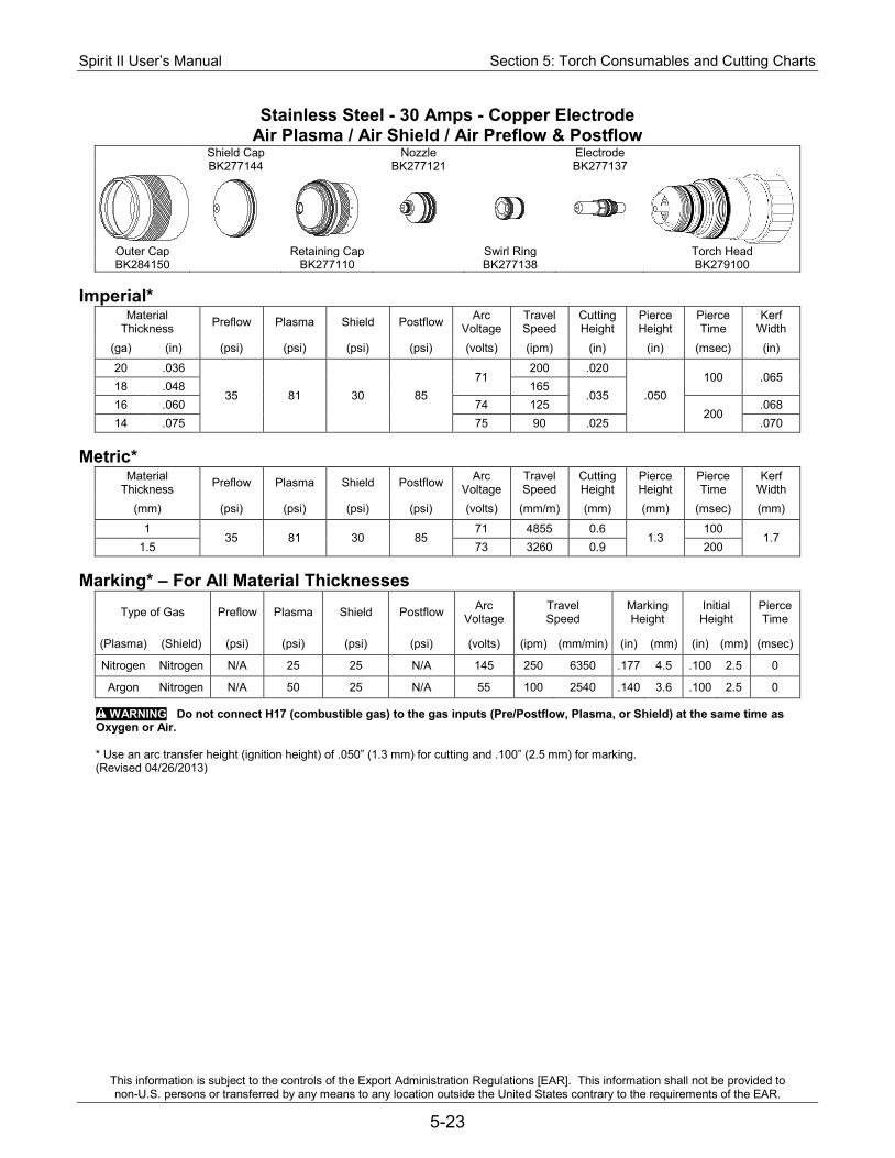
Spirit II User’s Manual Section 5: Torch Consumables and Cutting Charts
This information is subject to the controls of the Export Administration Regulations [EAR]. This information shall not be provided to non-U.S. persons or transferred by any means to any location outside the United States contrary to the requirements of the EAR.
5-23
Stainless Steel - 30 Amps - Copper Electrode Air Plasma / Air Shield / Air Preflow & Postflow
Shield Cap Nozzle Electrode BK277144 BK277121 BK277137
Outer Cap Retaining Cap Swirl Ring Torch Head BK284150 BK277110 BK277138 BK279100
Imperial*
Material Thickness Preflow Plasma Shield Postflow Arc
Voltage Travel Speed
Cutting Height
Pierce Height
Pierce Time
Kerf Width
(ga) (in) (psi) (psi) (psi) (psi) (volts) (ipm) (in) (in) (msec) (in)
20 .036
35 81 30 85 71
200 .020
.050 100 .065
18 .048 165 .035
16 .060 74 125 200
.068 14 .075 75 90 .025 .070
Metric*
Material Thickness Preflow Plasma Shield Postflow Arc
Voltage Travel Speed
Cutting Height
Pierce Height
Pierce Time
Kerf Width
(mm) (psi) (psi) (psi) (psi) (volts) (mm/m) (mm) (mm) (msec) (mm)
1 35 81 30 85
71 4855 0.6 1.3
100 1.7
1.5 73 3260 0.9 200 Marking* – For All Material Thicknesses
Type of Gas Preflow Plasma Shield Postflow Arc Voltage
Travel Speed
Marking Height
Initial Height
Pierce Time
(Plasma) (Shield) (psi) (psi) (psi) (psi) (volts) (ipm) (mm/min) (in) (mm) (in) (mm) (msec)
Nitrogen Nitrogen N/A 25 25 N/A 145 250 6350 .177 4.5 .100 2.5 0
Argon Nitrogen N/A 50 25 N/A 55 100 2540 .140 3.6 .100 2.5 0
WARNING Do not connect H17 (combustible gas) to the gas inputs (Pre/Postflow, Plasma, or Shield) at the same time as Oxygen or Air.
* Use an arc transfer height (ignition height) of .050” (1.3 mm) for cutting and .100” (2.5 mm) for marking. (Revised 04/26/2013)
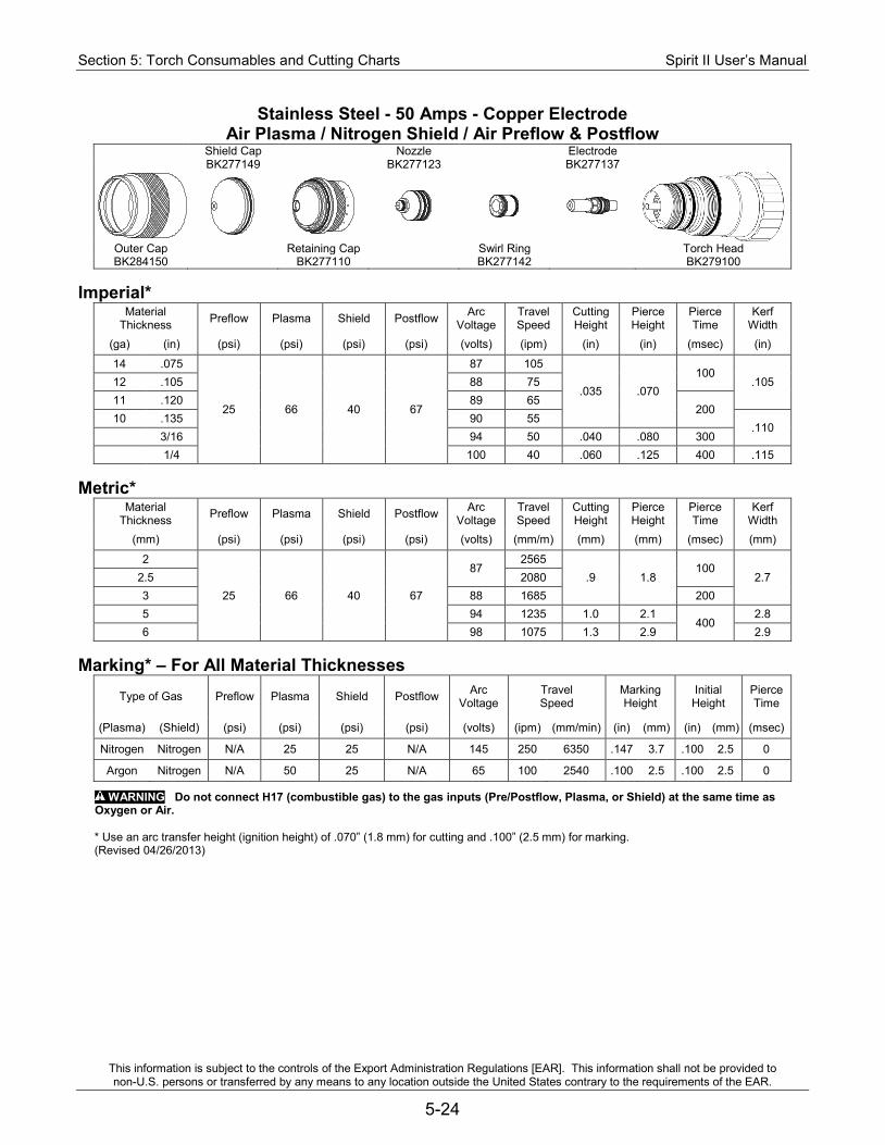
Section 5: Torch Consumables and Cutting Charts Spirit II User’s Manual
This information is subject to the controls of the Export Administration Regulations [EAR]. This information shall not be provided to non-U.S. persons or transferred by any means to any location outside the United States contrary to the requirements of the EAR.
5-24
Stainless Steel - 50 Amps - Copper Electrode Air Plasma / Nitrogen Shield / Air Preflow & Postflow
Shield Cap Nozzle Electrode BK277149 BK277123 BK277137
Outer Cap Retaining Cap Swirl Ring Torch Head BK284150 BK277110 BK277142 BK279100
Imperial*
Material Thickness Preflow Plasma Shield Postflow Arc
Voltage Travel Speed
Cutting Height
Pierce Height
Pierce Time
Kerf Width
(ga) (in) (psi) (psi) (psi) (psi) (volts) (ipm) (in) (in) (msec) (in)
14 .075
25 66 40 67
87 105
.035 .070 100
.105 12 .105 88 75 11 .120 89 65
200 10 .135 90 55
.110 3/16 94 50 .040 .080 300 1/4 100 40 .060 .125 400 .115
Metric*
Material Thickness Preflow Plasma Shield Postflow Arc
Voltage Travel Speed
Cutting Height
Pierce Height
Pierce Time
Kerf Width
(mm) (psi) (psi) (psi) (psi) (volts) (mm/m) (mm) (mm) (msec) (mm)
2
25 66 40 67
87 2565
.9 1.8 100
2.7 2.5 2080 3 88 1685 200 5 94 1235 1.0 2.1
400 2.8
6 98 1075 1.3 2.9 2.9 Marking* – For All Material Thicknesses
Type of Gas Preflow Plasma Shield Postflow Arc Voltage
Travel Speed
Marking Height
Initial Height
Pierce Time
(Plasma) (Shield) (psi) (psi) (psi) (psi) (volts) (ipm) (mm/min) (in) (mm) (in) (mm) (msec)
Nitrogen Nitrogen N/A 25 25 N/A 145 250 6350 .147 3.7 .100 2.5 0
Argon Nitrogen N/A 50 25 N/A 65 100 2540 .100 2.5 .100 2.5 0
WARNING Do not connect H17 (combustible gas) to the gas inputs (Pre/Postflow, Plasma, or Shield) at the same time as Oxygen or Air.
* Use an arc transfer height (ignition height) of .070” (1.8 mm) for cutting and .100” (2.5 mm) for marking. (Revised 04/26/2013)
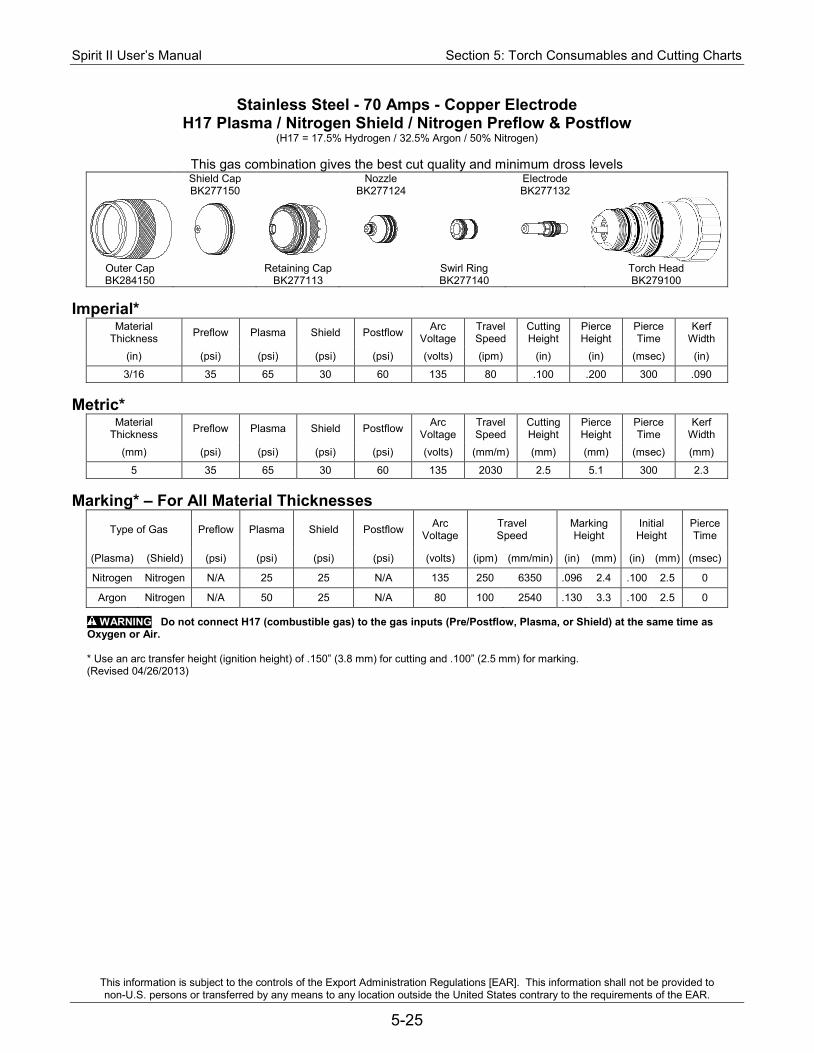
Spirit II User’s Manual Section 5: Torch Consumables and Cutting Charts
This information is subject to the controls of the Export Administration Regulations [EAR]. This information shall not be provided to non-U.S. persons or transferred by any means to any location outside the United States contrary to the requirements of the EAR.
5-25
Stainless Steel - 70 Amps - Copper Electrode H17 Plasma / Nitrogen Shield / Nitrogen Preflow & Postflow
(H17 = 17.5% Hydrogen / 32.5% Argon / 50% Nitrogen)
This gas combination gives the best cut quality and minimum dross levels Shield Cap Nozzle Electrode BK277150 BK277124 BK277132
Outer Cap Retaining Cap Swirl Ring Torch Head BK284150 BK277113 BK277140 BK279100
Imperial*
Material Thickness Preflow Plasma Shield Postflow Arc
Voltage Travel Speed
Cutting Height
Pierce Height
Pierce Time
Kerf Width
(in) (psi) (psi) (psi) (psi) (volts) (ipm) (in) (in) (msec) (in)
3/16 35 65 30 60 135 80 .100 .200 300 .090 Metric*
Material Thickness Preflow Plasma Shield Postflow Arc
Voltage Travel Speed
Cutting Height
Pierce Height
Pierce Time
Kerf Width
(mm) (psi) (psi) (psi) (psi) (volts) (mm/m) (mm) (mm) (msec) (mm)
5 35 65 30 60 135 2030 2.5 5.1 300 2.3 Marking* – For All Material Thicknesses
Type of Gas Preflow Plasma Shield Postflow Arc Voltage
Travel Speed
Marking Height
Initial Height
Pierce Time
(Plasma) (Shield) (psi) (psi) (psi) (psi) (volts) (ipm) (mm/min) (in) (mm) (in) (mm) (msec)
Nitrogen Nitrogen N/A 25 25 N/A 135 250 6350 .096 2.4 .100 2.5 0
Argon Nitrogen N/A 50 25 N/A 80 100 2540 .130 3.3 .100 2.5 0
WARNING Do not connect H17 (combustible gas) to the gas inputs (Pre/Postflow, Plasma, or Shield) at the same time as Oxygen or Air.
* Use an arc transfer height (ignition height) of .150” (3.8 mm) for cutting and .100” (2.5 mm) for marking. (Revised 04/26/2013)
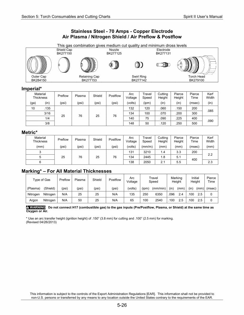
Section 5: Torch Consumables and Cutting Charts Spirit II User’s Manual
This information is subject to the controls of the Export Administration Regulations [EAR]. This information shall not be provided to non-U.S. persons or transferred by any means to any location outside the United States contrary to the requirements of the EAR.
5-26
Stainless Steel - 70 Amps - Copper Electrode Air Plasma / Nitrogen Shield / Air Preflow & Postflow
This gas combination gives medium cut quality and minimum dross levels
Shield Cap Nozzle Electrode BK277150 BK277125 BK277131
Outer Cap Retaining Cap Swirl Ring Torch Head BK284150 BK277153 BK277142 BK279100
Imperial*
Material Thickness Preflow Plasma Shield Postflow Arc
Voltage Travel Speed
Cutting Height
Pierce Height
Pierce Time
Kerf Width
(ga) (in) (psi) (psi) (psi) (psi) (volts) (ipm) (in) (in) (msec) (in)
10 .135
25 76 25 76
132 120 .060 .150 200 .085
3/16 134 100 .070 .200 300 1/4 140 75 .090 .225 400
.090 3/8 148 50 .120 .250 500
Metric*
Material Thickness Preflow Plasma Shield Postflow Arc
Voltage Travel Speed
Cutting Height
Pierce Height
Pierce Time
Kerf Width
(mm) (psi) (psi) (psi) (psi) (volts) (mm/m) (mm) (mm) (msec) (mm)
3 25 76 25 76
131 3210 1.4 3.3 200 2.2
5 134 2445 1.8 5.1 400
6 138 2050 2.1 5.5 2.3 Marking* – For All Material Thicknesses
Type of Gas Preflow Plasma Shield Postflow Arc Voltage
Travel Speed
Marking Height
Initial Height
Pierce Time
(Plasma) (Shield) (psi) (psi) (psi) (psi) (volts) (ipm) (mm/min) (in) (mm) (in) (mm) (msec)
Nitrogen Nitrogen N/A 25 25 N/A 135 250 6350 .096 2.4 .100 2.5 0
Argon Nitrogen N/A 50 25 N/A 65 100 2540 .100 2.5 .100 2.5 0
WARNING Do not connect H17 (combustible gas) to the gas inputs (Pre/Postflow, Plasma, or Shield) at the same time as Oxygen or Air.
* Use an arc transfer height (ignition height) of .150” (3.8 mm) for cutting and .100” (2.5 mm) for marking. (Revised 04/26/2013)
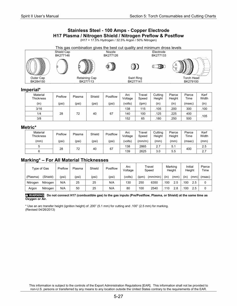
Spirit II User’s Manual Section 5: Torch Consumables and Cutting Charts
This information is subject to the controls of the Export Administration Regulations [EAR]. This information shall not be provided to non-U.S. persons or transferred by any means to any location outside the United States contrary to the requirements of the EAR.
5-27
Stainless Steel - 100 Amps - Copper Electrode H17 Plasma / Nitrogen Shield / Nitrogen Preflow & Postflow
(H17 = 17.5% Hydrogen / 32.5% Argon / 50% Nitrogen)
This gas combination gives the best cut quality and minimum dross levels Shield Cap Nozzle Electrode BK277146 BK277126 BK277133
Outer Cap Retaining Cap Swirl Ring Torch Head BK284150 BK277113 BK277141 BK279100
Imperial*
Material Thickness Preflow Plasma Shield Postflow Arc
Voltage Travel Speed
Cutting Height
Pierce Height
Pierce Time
Kerf Width
(in) (psi) (psi) (psi) (psi) (volts) (ipm) (in) (in) (msec) (in)
3/16 28 72 40 67
138 115 .105 .200 300 .100 1/4 140 100 .125 .225 400
.105 3/8 152 65 .180 .250 500
Metric*
Material Thickness Preflow Plasma Shield Postflow Arc
Voltage Travel Speed
Cutting Height
Pierce Height
Pierce Time
Kerf Width
(mm) (psi) (psi) (psi) (psi) (volts) (mm/m) (mm) (mm) (msec) (mm)
5 28 72 40 67
138 2865 2.7 5.1 400
2.5 6 139 2625 3.0 5.5 2.7
Marking* – For All Material Thicknesses
Type of Gas Preflow Plasma Shield Postflow Arc Voltage
Travel Speed
Marking Height
Initial Height
Pierce Time
(Plasma) (Shield) (psi) (psi) (psi) (psi) (volts) (ipm) (mm/min) (in) (mm) (in) (mm) (msec)
Nitrogen Nitrogen N/A 25 25 N/A 130 250 6350 .100 2.5 .100 2.5 0
Argon Nitrogen N/A 50 25 N/A 80 100 2540 .110 2.8 .100 2.5 0
WARNING Do not connect H17 (combustible gas) to the gas inputs (Pre/Postflow, Plasma, or Shield) at the same time as Oxygen or Air.
* Use an arc transfer height (ignition height) of .200” (5.1 mm) for cutting and .100” (2.5 mm) for marking. (Revised 04/26/2013)
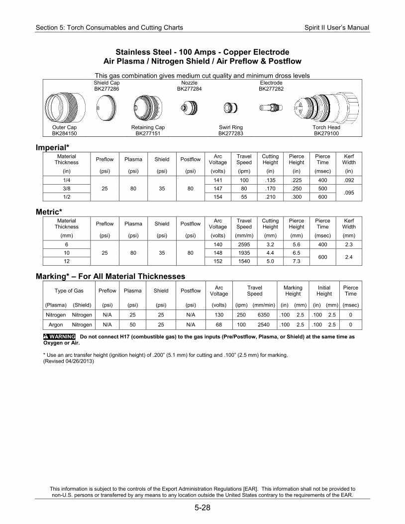
Section 5: Torch Consumables and Cutting Charts Spirit II User’s Manual
This information is subject to the controls of the Export Administration Regulations [EAR]. This information shall not be provided to non-U.S. persons or transferred by any means to any location outside the United States contrary to the requirements of the EAR.
5-28
Stainless Steel - 100 Amps - Copper Electrode Air Plasma / Nitrogen Shield / Air Preflow & Postflow
This gas combination gives medium cut quality and minimum dross levels
Shield Cap Nozzle Electrode BK277286 BK277284 BK277282
Outer Cap Retaining Cap Swirl Ring Torch Head BK284150 BK277151 BK277283 BK279100
Imperial*
Material Thickness Preflow Plasma Shield Postflow Arc
Voltage Travel Speed
Cutting Height
Pierce Height
Pierce Time
Kerf Width
(in) (psi) (psi) (psi) (psi) (volts) (ipm) (in) (in) (msec) (in)
1/4 25 80 35 80
141 100 .135 .225 400 .092 3/8 147 80 .170 .250 500
.095 1/2 154 55 .210 .300 600
Metric*
Material Thickness Preflow Plasma Shield Postflow Arc
Voltage Travel Speed
Cutting Height
Pierce Height
Pierce Time
Kerf Width
(mm) (psi) (psi) (psi) (psi) (volts) (mm/m) (mm) (mm) (msec) (mm)
6 25 80 35 80
140 2595 3.2 5.6 400 2.3 10 148 1935 4.4 6.5
600 2.4 12 152 1540 5.0 7.3
Marking* – For All Material Thicknesses
Type of Gas Preflow Plasma Shield Postflow Arc Voltage
Travel Speed
Marking Height
Initial Height
Pierce Time
(Plasma) (Shield) (psi) (psi) (psi) (psi) (volts) (ipm) (mm/min) (in) (mm) (in) (mm) (msec)
Nitrogen Nitrogen N/A 25 25 N/A 130 250 6350 .100 2.5 .100 2.5 0
Argon Nitrogen N/A 50 25 N/A 68 100 2540 .100 2.5 .100 2.5 0
WARNING Do not connect H17 (combustible gas) to the gas inputs (Pre/Postflow, Plasma, or Shield) at the same time as Oxygen or Air.
* Use an arc transfer height (ignition height) of .200” (5.1 mm) for cutting and .100” (2.5 mm) for marking. (Revised 04/26/2013)
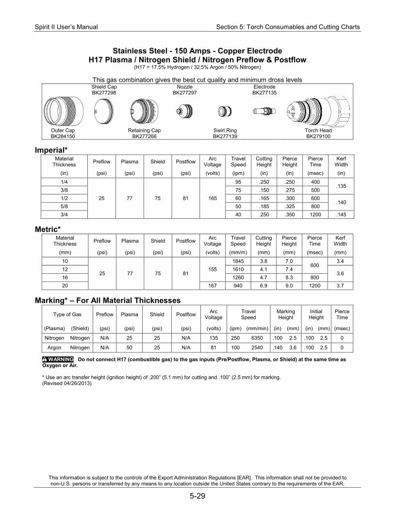
Spirit II User’s Manual Section 5: Torch Consumables and Cutting Charts
This information is subject to the controls of the Export Administration Regulations [EAR]. This information shall not be provided to non-U.S. persons or transferred by any means to any location outside the United States contrary to the requirements of the EAR.
5-29
Stainless Steel - 150 Amps - Copper Electrode H17 Plasma / Nitrogen Shield / Nitrogen Preflow & Postflow
(H17 = 17.5% Hydrogen / 32.5% Argon / 50% Nitrogen)
This gas combination gives the best cut quality and minimum dross levels Shield Cap Nozzle Electrode BK277298 BK277297 BK277135
Outer Cap Retaining Cap Swirl Ring Torch Head BK284150 BK277266 BK277139 BK279100
Imperial*
Material Thickness Preflow Plasma Shield Postflow Arc
Voltage Travel Speed
Cutting Height
Pierce Height
Pierce Time
Kerf Width
(in) (psi) (psi) (psi) (psi) (volts) (ipm) (in) (in) (msec) (in)
1/4
25 77 75 81 165
95 .250 .250 400 .135
3/8 75 .150 .275 500 1/2 60 .165 .300 600
.140 5/8 50 .185 .325 800 3/4 40 .250 .350 1200 .145
Metric*
Material Thickness Preflow Plasma Shield Postflow Arc
Voltage Travel Speed
Cutting Height
Pierce Height
Pierce Time
Kerf Width
(mm) (psi) (psi) (psi) (psi) (volts) (mm/m) (mm) (mm) (msec) (mm)
10
25 77 75 81 155
1845 3.8 7.0 600
3.4 12 1610 4.1 7.4
3.6 16 1260 4.7 8.3 800 20 167 940 6.9 9.0 1200 3.7
Marking* – For All Material Thicknesses
Type of Gas Preflow Plasma Shield Postflow Arc Voltage
Travel Speed
Marking Height
Initial Height
Pierce Time
(Plasma) (Shield) (psi) (psi) (psi) (psi) (volts) (ipm) (mm/min) (in) (mm) (in) (mm) (msec)
Nitrogen Nitrogen N/A 25 25 N/A 135 250 6350 .100 2.5 .100 2.5 0
Argon Nitrogen N/A 50 25 N/A 81 100 2540 .140 3.6 .100 2.5 0
WARNING Do not connect H17 (combustible gas) to the gas inputs (Pre/Postflow, Plasma, or Shield) at the same time as Oxygen or Air.
* Use an arc transfer height (ignition height) of .200” (5.1 mm) for cutting and .100” (2.5 mm) for marking. (Revised 04/26/2013)
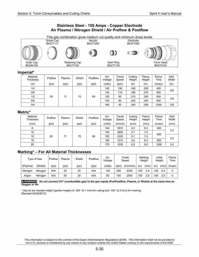
Section 5: Torch Consumables and Cutting Charts Spirit II User’s Manual
This information is subject to the controls of the Export Administration Regulations [EAR]. This information shall not be provided to non-U.S. persons or transferred by any means to any location outside the United States contrary to the requirements of the EAR.
5-30
Stainless Steel - 150 Amps - Copper Electrode Air Plasma / Nitrogen Shield / Air Preflow & Postflow
This gas combination gives medium cut quality and minimum dross levels
Shield Cap Nozzle Electrode BK277117 BK277293 BK277292
Outer Cap Retaining Cap Swirl Ring Torch Head BK284150 BK277152 BK277139 BK279100
Imperial*
Material Thickness Preflow Plasma Shield Postflow Arc
Voltage Travel Speed
Cutting Height
Pierce Height
Pierce Time
Kerf Width
(in) (psi) (psi) (psi) (psi) (volts) (ipm) (in) (in) (msec) (in)
1/4
20 71 70 69
145 150 .160 .250 400 .125
3/8 150 115 .180 .275 500 1/2 155 85 .210 .300 600
.130 5/8 160 60 .220 .325 800 3/4 168 45 .240 .350 1200 .135
Metric*
Material Thickness Preflow Plasma Shield Postflow Arc
Voltage Travel Speed
Cutting Height
Pierce Height
Pierce Time
Kerf Width
(mm) (psi) (psi) (psi) (psi) (volts) (mm/m) (mm) (mm) (msec) (mm)
6
20 71 70 69
144 3910 4.0 6.3 400 3.2
10 150 2805 4.7 7.0 600
12 153 2330 5.1 7.4 3.3
16 160 1510 5.6 8.3 800 20 170 1030 6.2 9.0 1200 3.4
Marking* – For All Material Thicknesses
Type of Gas Preflow Plasma Shield Postflow Arc Voltage
Travel Speed
Marking Height
Initial Height
Pierce Time
(Plasma) (Shield) (psi) (psi) (psi) (psi) (volts) (ipm) (mm/min) (in) (mm) (in) (mm) (msec)
Nitrogen Nitrogen N/A 25 25 N/A 135 250 6350 .100 2.5 .100 2.5 0
Argon Nitrogen N/A 50 25 N/A 65 100 2540 .100 2.5 .100 2.5 0
WARNING Do not connect H17 (combustible gas) to the gas inputs (Pre/Postflow, Plasma, or Shield) at the same time as Oxygen or Air.
* Use an arc transfer height (ignition height) of .200” (5.1 mm) for cutting and .100” (2.5 mm) for marking. (Revised 04/26/2013)

Spirit II User’s Manual Section 5: Torch Consumables and Cutting Charts
This information is subject to the controls of the Export Administration Regulations [EAR]. This information shall not be provided to non-U.S. persons or transferred by any means to any location outside the United States contrary to the requirements of the EAR.
5-31
Stainless Steel - 200 Amps - Copper Electrode H17 Plasma / Nitrogen Shield / Nitrogen Preflow & Postflow
(H17 = 17.5% Hydrogen / 32.5% Argon / 50% Nitrogen)
This gas combination gives the good cut quality and minimum dross levels Shield Cap Nozzle Electrode BK277274 BK277287 BK277135
Outer Cap Retaining Cap Swirl Ring Torch Head BK284150 BK277266 BK277259 BK279100
Imperial*
Material Thickness Preflow Plasma Shield Postflow Arc
Voltage Travel Speed
Cutting Height
Pierce Height
Pierce Time
Kerf Width
(in) (psi) (psi) (psi) (psi) (volts) (ipm) (in) (in) (msec) (in)
3/8
37 72 79 68
156 80 .195 .250 500 .150
1/2 148 75 .130 .300 600 5/8 155 60 .190 .350 800
.155 3/4 160 50 .200 .400 1200 1.0 170 35 .240 .450 1500 .160
Metric*
Material Thickness Preflow Plasma Shield Postflow Arc
Voltage Travel Speed
Cutting Height
Pierce Height
Pierce Time
Kerf Width
(mm) (psi) (psi) (psi) (psi) (volts) (mm/m) (mm) (mm) (msec) (mm)
10
37 72 79 68
154 2010 4.7 6.5 600 3.8
12 149 1935 3.6 7.3 16 155 1515 4.8 8.9 800
3.9 20 161 1215 5.2 10.3
1500 25 169 915 6.0 11.3 4.1
Marking* – For All Material Thicknesses
Type of Gas Preflow Plasma Shield Postflow Arc Voltage
Travel Speed
Marking Height
Initial Height
Pierce Time
(Plasma) (Shield) (psi) (psi) (psi) (psi) (volts) (ipm) (mm/min) (in) (mm) (in) (mm) (msec)
Nitrogen Nitrogen N/A 25 25 N/A 120 250 6350 .100 2.5 .100 2.5 0
Argon Nitrogen N/A 50 25 N/A 72 100 2540 .120 3.0 .100 2.5 0
WARNING Do not connect H17 (combustible gas) to the gas inputs (Pre/Postflow, Plasma, or Shield) at the same time as Oxygen or Air.
* Use an arc transfer height (ignition height) of .200” (5.1 mm) for cutting and .100” (2.5 mm) for marking. (Revised 04/26/2013)
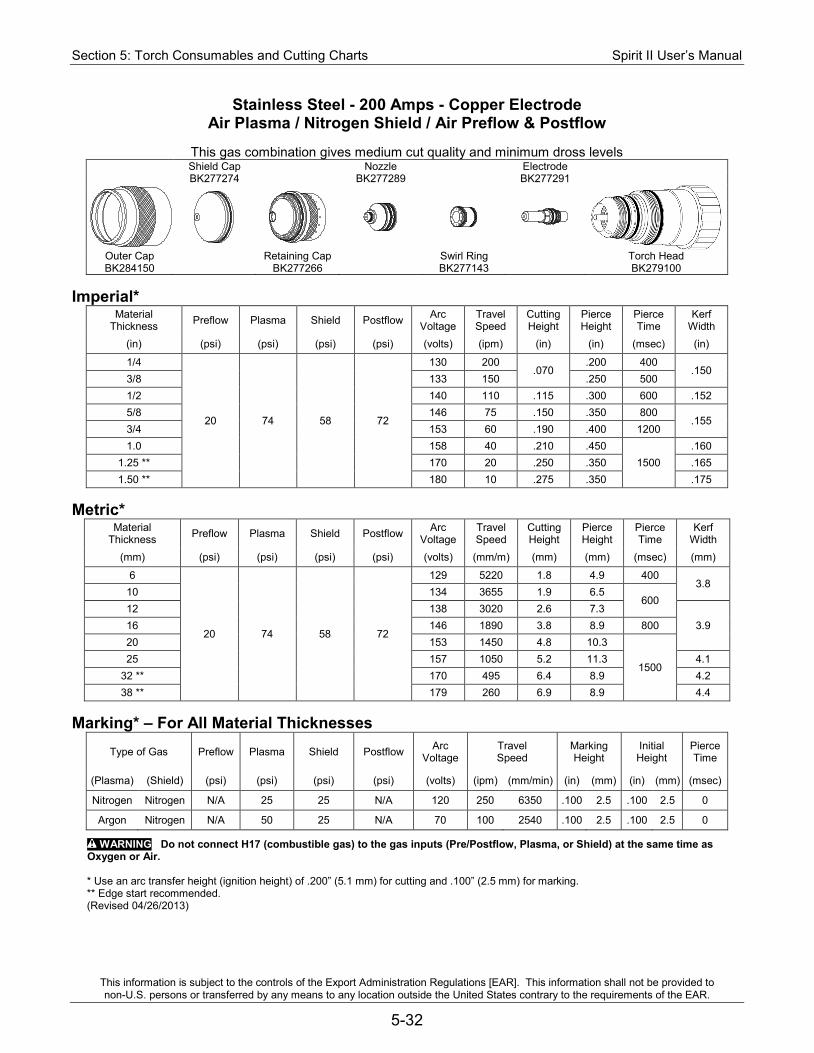
Section 5: Torch Consumables and Cutting Charts Spirit II User’s Manual
This information is subject to the controls of the Export Administration Regulations [EAR]. This information shall not be provided to non-U.S. persons or transferred by any means to any location outside the United States contrary to the requirements of the EAR.
5-32
Stainless Steel - 200 Amps - Copper Electrode Air Plasma / Nitrogen Shield / Air Preflow & Postflow
This gas combination gives medium cut quality and minimum dross levels
Shield Cap Nozzle Electrode BK277274 BK277289 BK277291
Outer Cap Retaining Cap Swirl Ring Torch Head BK284150 BK277266 BK277143 BK279100
Imperial*
Material Thickness Preflow Plasma Shield Postflow Arc
Voltage Travel Speed
Cutting Height
Pierce Height
Pierce Time
Kerf Width
(in) (psi) (psi) (psi) (psi) (volts) (ipm) (in) (in) (msec) (in)
1/4
20 74 58 72
130 200 .070
.200 400 .150
3/8 133 150 .250 500 1/2 140 110 .115 .300 600 .152 5/8 146 75 .150 .350 800
.155 3/4 153 60 .190 .400 1200 1.0 158 40 .210 .450
1500 .160
1.25 ** 170 20 .250 .350 .165 1.50 ** 180 10 .275 .350 .175
Metric*
Material Thickness Preflow Plasma Shield Postflow Arc
Voltage Travel Speed
Cutting Height
Pierce Height
Pierce Time
Kerf Width
(mm) (psi) (psi) (psi) (psi) (volts) (mm/m) (mm) (mm) (msec) (mm)
6
20 74 58 72
129 5220 1.8 4.9 400 3.8
10 134 3655 1.9 6.5 600
12 138 3020 2.6 7.3 3.9 16 146 1890 3.8 8.9 800
20 153 1450 4.8 10.3
1500 25 157 1050 5.2 11.3 4.1
32 ** 170 495 6.4 8.9 4.2 38 ** 179 260 6.9 8.9 4.4
Marking* – For All Material Thicknesses
Type of Gas Preflow Plasma Shield Postflow Arc Voltage
Travel Speed
Marking Height
Initial Height
Pierce Time
(Plasma) (Shield) (psi) (psi) (psi) (psi) (volts) (ipm) (mm/min) (in) (mm) (in) (mm) (msec)
Nitrogen Nitrogen N/A 25 25 N/A 120 250 6350 .100 2.5 .100 2.5 0
Argon Nitrogen N/A 50 25 N/A 70 100 2540 .100 2.5 .100 2.5 0
WARNING Do not connect H17 (combustible gas) to the gas inputs (Pre/Postflow, Plasma, or Shield) at the same time as Oxygen or Air.
* Use an arc transfer height (ignition height) of .200” (5.1 mm) for cutting and .100” (2.5 mm) for marking. ** Edge start recommended. (Revised 04/26/2013)
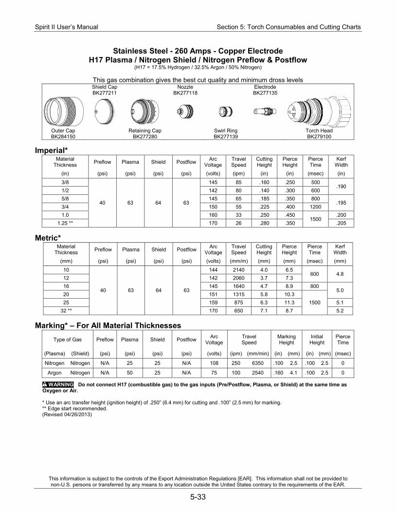
Spirit II User’s Manual Section 5: Torch Consumables and Cutting Charts
This information is subject to the controls of the Export Administration Regulations [EAR]. This information shall not be provided to non-U.S. persons or transferred by any means to any location outside the United States contrary to the requirements of the EAR.
5-33
Stainless Steel - 260 Amps - Copper Electrode H17 Plasma / Nitrogen Shield / Nitrogen Preflow & Postflow
(H17 = 17.5% Hydrogen / 32.5% Argon / 50% Nitrogen)
This gas combination gives the best cut quality and minimum dross levels Shield Cap Nozzle Electrode BK277211 BK277118 BK277135
Outer Cap Retaining Cap Swirl Ring Torch Head BK284150 BK277280 BK277139 BK279100
Imperial*
Material Thickness Preflow Plasma Shield Postflow Arc
Voltage Travel Speed
Cutting Height
Pierce Height
Pierce Time
Kerf Width
(in) (psi) (psi) (psi) (psi) (volts) (ipm) (in) (in) (msec) (in)
3/8
40 63 64 63
145 85 .160 .250 500 .190
1/2 142 80 .140 .300 600 5/8 145 65 .185 .350 800
.195 3/4 150 55 .225 .400 1200 1.0 160 33 .250 .450
1500 .200
1.25 ** 170 26 .280 .350 .205 Metric*
Material Thickness Preflow Plasma Shield Postflow Arc
Voltage Travel Speed
Cutting Height
Pierce Height
Pierce Time
Kerf Width
(mm) (psi) (psi) (psi) (psi) (volts) (mm/m) (mm) (mm) (msec) (mm)
10
40 63 64 63
144 2140 4.0 6.5 600 4.8
12 142 2060 3.7 7.3 16 145 1640 4.7 8.9 800
5.0 20 151 1315 5.8 10.3
1500 25 159 875 6.3 11.3 5.1 32 ** 170 650 7.1 8.7 5.2
Marking* – For All Material Thicknesses
Type of Gas Preflow Plasma Shield Postflow Arc Voltage
Travel Speed
Marking Height
Initial Height
Pierce Time
(Plasma) (Shield) (psi) (psi) (psi) (psi) (volts) (ipm) (mm/min) (in) (mm) (in) (mm) (msec)
Nitrogen Nitrogen N/A 25 25 N/A 108 250 6350 .100 2.5 .100 2.5 0
Argon Nitrogen N/A 50 25 N/A 75 100 2540 .160 4.1 .100 2.5 0
WARNING Do not connect H17 (combustible gas) to the gas inputs (Pre/Postflow, Plasma, or Shield) at the same time as Oxygen or Air.
* Use an arc transfer height (ignition height) of .250” (6.4 mm) for cutting and .100” (2.5 mm) for marking. ** Edge start recommended. (Revised 04/26/2013)
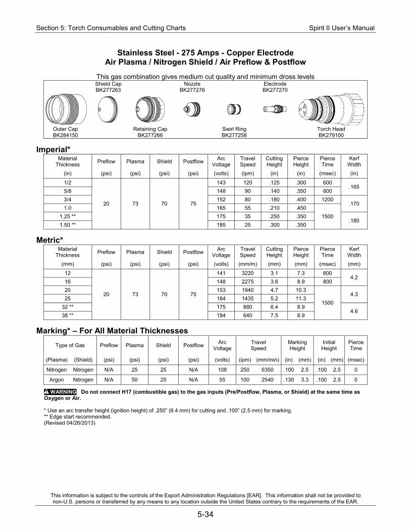
Section 5: Torch Consumables and Cutting Charts Spirit II User’s Manual
This information is subject to the controls of the Export Administration Regulations [EAR]. This information shall not be provided to non-U.S. persons or transferred by any means to any location outside the United States contrary to the requirements of the EAR.
5-34
Stainless Steel - 275 Amps - Copper Electrode Air Plasma / Nitrogen Shield / Air Preflow & Postflow
This gas combination gives medium cut quality and minimum dross levels
Shield Cap Nozzle Electrode BK277263 BK277276 BK277270
Outer Cap Retaining Cap Swirl Ring Torch Head BK284150 BK277266 BK277258 BK279100
Imperial*
Material Thickness Preflow Plasma Shield Postflow Arc
Voltage Travel Speed
Cutting Height
Pierce Height
Pierce Time
Kerf Width
(in) (psi) (psi) (psi) (psi) (volts) (ipm) (in) (in) (msec) (in)
1/2
20 73 70 75
143 120 .125 .300 600 .165
5/8 148 90 .140 .350 800 3/4 152 80 .180 .400 1200
.170 1.0 165 55 .210 .450
1500 1.25 ** 175 35 .250 .350 .180
1.50 ** 185 25 .300 .350 Metric*
Material Thickness Preflow Plasma Shield Postflow Arc
Voltage Travel Speed
Cutting Height
Pierce Height
Pierce Time
Kerf Width
(mm) (psi) (psi) (psi) (psi) (volts) (mm/m) (mm) (mm) (msec) (mm)
12
20 73 70 75
141 3220 3.1 7.3 600 4.2
16 148 2275 3.6 8.9 800 20 153 1940 4.7 10.3
1500 4.3
25 164 1435 5.2 11.3 32 ** 175 880 6.4 8.9
4.6 38 ** 184 640 7.5 8.9
Marking* – For All Material Thicknesses
Type of Gas Preflow Plasma Shield Postflow Arc Voltage
Travel Speed
Marking Height
Initial Height
Pierce Time
(Plasma) (Shield) (psi) (psi) (psi) (psi) (volts) (ipm) (mm/min) (in) (mm) (in) (mm) (msec)
Nitrogen Nitrogen N/A 25 25 N/A 108 250 6350 .100 2.5 .100 2.5 0
Argon Nitrogen N/A 50 25 N/A 55 100 2540 .130 3.3 .100 2.5 0
WARNING Do not connect H17 (combustible gas) to the gas inputs (Pre/Postflow, Plasma, or Shield) at the same time as Oxygen or Air.
* Use an arc transfer height (ignition height) of .250” (6.4 mm) for cutting and .100” (2.5 mm) for marking. ** Edge start recommended. (Revised 04/26/2013)
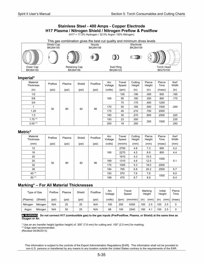
Spirit II User’s Manual Section 5: Torch Consumables and Cutting Charts
This information is subject to the controls of the Export Administration Regulations [EAR]. This information shall not be provided to non-U.S. persons or transferred by any means to any location outside the United States contrary to the requirements of the EAR.
5-35
Stainless Steel - 400 Amps - Copper Electrode H17 Plasma / Nitrogen Shield / Nitrogen Preflow & Postflow
(H17 = 17.5% Hydrogen / 32.5% Argon / 50% Nitrogen)
This gas combination gives the best cut quality and minimum dross levels Shield Cap Nozzle Electrode BK284155 BK284158 BK284159
Outer Cap Retaining Cap Swirl Ring Torch Head BK284150 BK284156 BK284122 BK279100
Imperial*
Material Thickness Preflow Plasma Shield Postflow Arc
Voltage Travel Speed
Cutting Height
Pierce Height
Pierce Time
Kerf Width
(in) (psi) (psi) (psi) (psi) (volts) (ipm) (in) (in) (msec) (in)
1/2
30 80 82 96
165 105 .190 .300 600 .165
5/8 90 .180 .350 800 .175 3/4 75 .170 .400 1200
.200 1 170 50 .185 .500 1500 1.25 175 40 .210 .700 2000 1.5 185 30 .270 .800 2500 .225
1.75 ** 193 23 .300 .350 1500
.235 2.00 ** 200 18 .350 .250
Metric*
Material Thickness Preflow Plasma Shield Postflow Arc
Voltage Travel Speed
Cutting Height
Pierce Height
Pierce Time
Kerf Width
(mm) (psi) (psi) (psi) (psi) (volts) (mm/m) (mm) (mm) (msec) (mm)
12
30 80 82 96
165 2750 4.8 7.3 600 4.2
16 2270 4.5 8.9 800 4.4 20 1810 4.3 10.5
1500 5.1 25 169 1310 4.6 12.5
32 175 1005 5.3 18.0 2000 38 184 765 6.8 20.2 2500 5.7
45 ** 193 570 7.6 7.8 1500
6.0 50 ** 199 470 8.7 8.9 6.4
Marking* – For All Material Thicknesses
Type of Gas Preflow Plasma Shield Postflow Arc Voltage
Travel Speed
Marking Height
Initial Height
Pierce Time
(Plasma) (Shield) (psi) (psi) (psi) (psi) (volts) (ipm) (mm/min) (in) (mm) (in) (mm) (msec)
Nitrogen Nitrogen N/A 25 25 N/A 100 250 6350 .100 2.5 .100 2.5 0
Argon Nitrogen N/A 50 25 N/A 68 100 2540 .160 4.1 .100 2.5 0
WARNING Do not connect H17 (combustible gas) to the gas inputs (Pre/Postflow, Plasma, or Shield) at the same time as Oxygen or Air.
* Use an arc transfer height (ignition height) of .300” (7.6 mm) for cutting and .100” (2.5 mm) for marking. ** Edge start recommended. (Revised 04/26/2013)
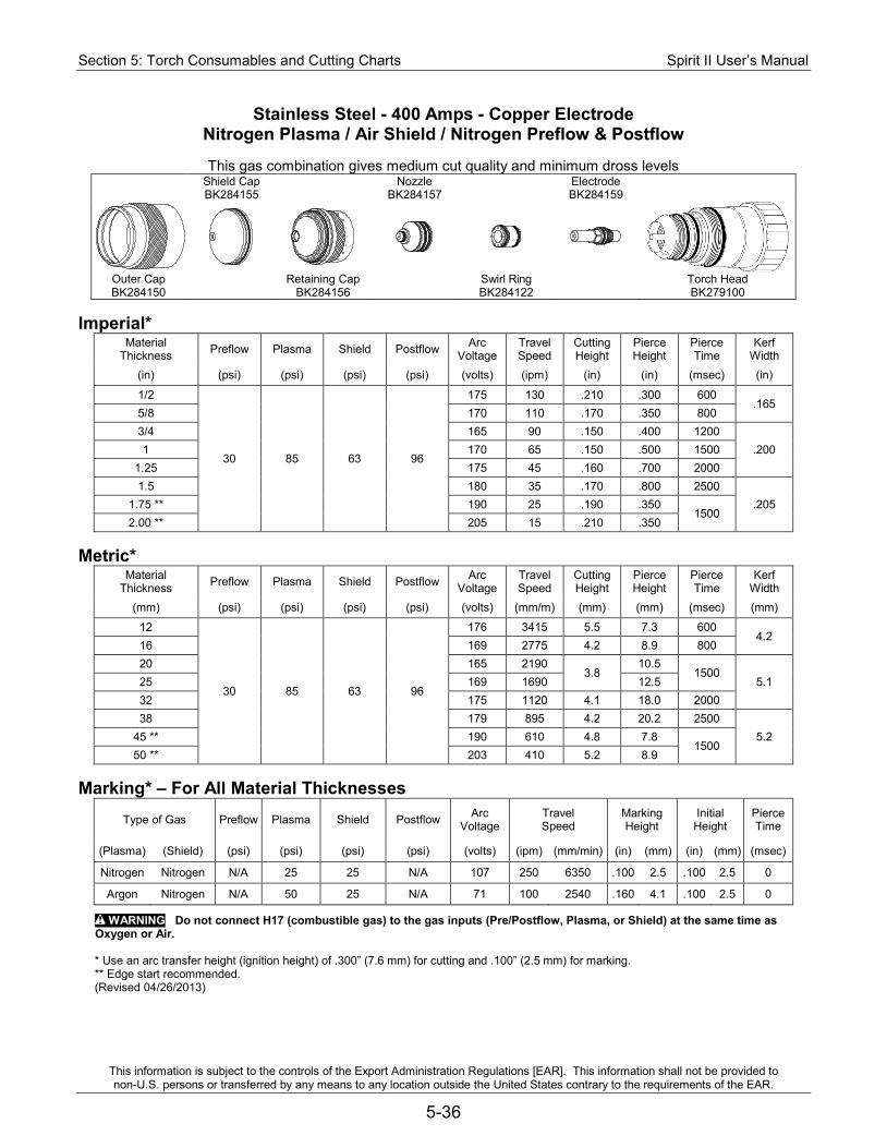
Section 5: Torch Consumables and Cutting Charts Spirit II User’s Manual
This information is subject to the controls of the Export Administration Regulations [EAR]. This information shall not be provided to non-U.S. persons or transferred by any means to any location outside the United States contrary to the requirements of the EAR.
5-36
Stainless Steel - 400 Amps - Copper Electrode Nitrogen Plasma / Air Shield / Nitrogen Preflow & Postflow
This gas combination gives medium cut quality and minimum dross levels
Shield Cap Nozzle Electrode BK284155 BK284157 BK284159
Outer Cap Retaining Cap Swirl Ring Torch Head BK284150 BK284156 BK284122 BK279100
Imperial*
Material Thickness Preflow Plasma Shield Postflow Arc
Voltage Travel Speed
Cutting Height
Pierce Height
Pierce Time
Kerf Width
(in) (psi) (psi) (psi) (psi) (volts) (ipm) (in) (in) (msec) (in)
1/2
30 85 63 96
175 130 .210 .300 600 .165
5/8 170 110 .170 .350 800 3/4 165 90 .150 .400 1200
.200 1 170 65 .150 .500 1500 1.25 175 45 .160 .700 2000 1.5 180 35 .170 .800 2500
.205 1.75 ** 190 25 .190 .350 1500
2.00 ** 205 15 .210 .350 Metric*
Material Thickness Preflow Plasma Shield Postflow Arc
Voltage Travel Speed
Cutting Height
Pierce Height
Pierce Time
Kerf Width
(mm) (psi) (psi) (psi) (psi) (volts) (mm/m) (mm) (mm) (msec) (mm)
12
30 85 63 96
176 3415 5.5 7.3 600 4.2
16 169 2775 4.2 8.9 800 20 165 2190
3.8 10.5
1500 5.1 25 169 1690 12.5
32 175 1120 4.1 18.0 2000 38 179 895 4.2 20.2 2500
5.2 45 ** 190 610 4.8 7.8 1500
50 ** 203 410 5.2 8.9 Marking* – For All Material Thicknesses
Type of Gas Preflow Plasma Shield Postflow Arc Voltage
Travel Speed
Marking Height
Initial Height
Pierce Time
(Plasma) (Shield) (psi) (psi) (psi) (psi) (volts) (ipm) (mm/min) (in) (mm) (in) (mm) (msec)
Nitrogen Nitrogen N/A 25 25 N/A 107 250 6350 .100 2.5 .100 2.5 0
Argon Nitrogen N/A 50 25 N/A 71 100 2540 .160 4.1 .100 2.5 0
WARNING Do not connect H17 (combustible gas) to the gas inputs (Pre/Postflow, Plasma, or Shield) at the same time as Oxygen or Air.
* Use an arc transfer height (ignition height) of .300” (7.6 mm) for cutting and .100” (2.5 mm) for marking. ** Edge start recommended. (Revised 04/26/2013)
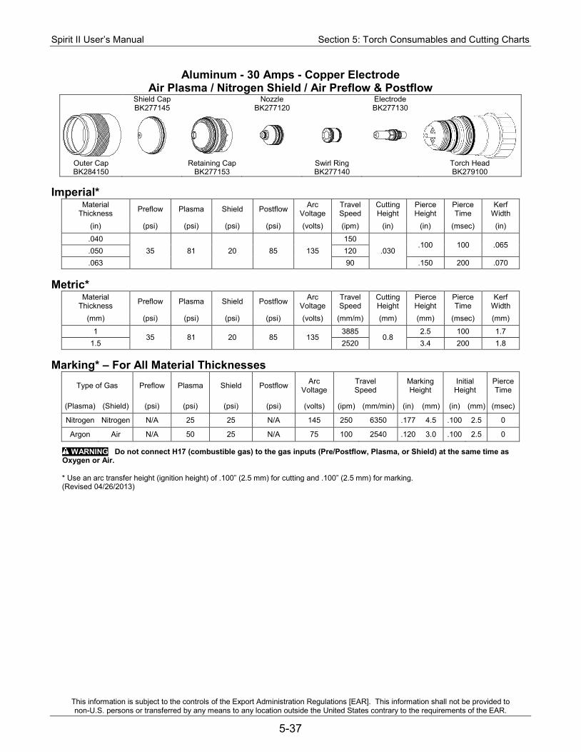
Spirit II User’s Manual Section 5: Torch Consumables and Cutting Charts
This information is subject to the controls of the Export Administration Regulations [EAR]. This information shall not be provided to non-U.S. persons or transferred by any means to any location outside the United States contrary to the requirements of the EAR.
5-37
Aluminum - 30 Amps - Copper Electrode Air Plasma / Nitrogen Shield / Air Preflow & Postflow
Shield Cap Nozzle Electrode BK277145 BK277120 BK277130
Outer Cap Retaining Cap Swirl Ring Torch Head BK284150 BK277153 BK277140 BK279100
Imperial*
Material Thickness Preflow Plasma Shield Postflow Arc
Voltage Travel Speed
Cutting Height
Pierce Height
Pierce Time
Kerf Width
(in) (psi) (psi) (psi) (psi) (volts) (ipm) (in) (in) (msec) (in)
.040 35 81 20 85 135
150 .030
.100 100 .065 .050 120 .063 90 .150 200 .070
Metric*
Material Thickness Preflow Plasma Shield Postflow Arc
Voltage Travel Speed
Cutting Height
Pierce Height
Pierce Time
Kerf Width
(mm) (psi) (psi) (psi) (psi) (volts) (mm/m) (mm) (mm) (msec) (mm)
1 35 81 20 85 135
3885 0.8
2.5 100 1.7 1.5 2520 3.4 200 1.8
Marking* – For All Material Thicknesses
Type of Gas Preflow Plasma Shield Postflow Arc Voltage
Travel Speed
Marking Height
Initial Height
Pierce Time
(Plasma) (Shield) (psi) (psi) (psi) (psi) (volts) (ipm) (mm/min) (in) (mm) (in) (mm) (msec)
Nitrogen Nitrogen N/A 25 25 N/A 145 250 6350 .177 4.5 .100 2.5 0
Argon Air N/A 50 25 N/A 75 100 2540 .120 3.0 .100 2.5 0
WARNING Do not connect H17 (combustible gas) to the gas inputs (Pre/Postflow, Plasma, or Shield) at the same time as Oxygen or Air.
* Use an arc transfer height (ignition height) of .100” (2.5 mm) for cutting and .100” (2.5 mm) for marking. (Revised 04/26/2013)
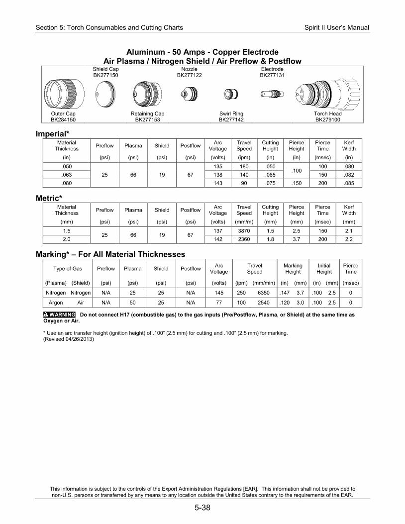
Section 5: Torch Consumables and Cutting Charts Spirit II User’s Manual
This information is subject to the controls of the Export Administration Regulations [EAR]. This information shall not be provided to non-U.S. persons or transferred by any means to any location outside the United States contrary to the requirements of the EAR.
5-38
Aluminum - 50 Amps - Copper Electrode Air Plasma / Nitrogen Shield / Air Preflow & Postflow
Shield Cap Nozzle Electrode BK277150 BK277122 BK277131
Outer Cap Retaining Cap Swirl Ring Torch Head BK284150 BK277153 BK277142 BK279100
Imperial*
Material Thickness Preflow Plasma Shield Postflow Arc
Voltage Travel Speed
Cutting Height
Pierce Height
Pierce Time
Kerf Width
(in) (psi) (psi) (psi) (psi) (volts) (ipm) (in) (in) (msec) (in)
.050 25 66 19 67
135 180 .050 .100
100 .080 .063 138 140 .065 150 .082 .080 143 90 .075 .150 200 .085
Metric*
Material Thickness Preflow Plasma Shield Postflow Arc
Voltage Travel Speed
Cutting Height
Pierce Height
Pierce Time
Kerf Width
(mm) (psi) (psi) (psi) (psi) (volts) (mm/m) (mm) (mm) (msec) (mm)
1.5 25 66 19 67
137 3870 1.5 2.5 150 2.1 2.0 142 2360 1.8 3.7 200 2.2
Marking* – For All Material Thicknesses
Type of Gas Preflow Plasma Shield Postflow Arc Voltage
Travel Speed
Marking Height
Initial Height
Pierce Time
(Plasma) (Shield) (psi) (psi) (psi) (psi) (volts) (ipm) (mm/min) (in) (mm) (in) (mm) (msec)
Nitrogen Nitrogen N/A 25 25 N/A 145 250 6350 .147 3.7 .100 2.5 0
Argon Air N/A 50 25 N/A 77 100 2540 .120 3.0 .100 2.5 0
WARNING Do not connect H17 (combustible gas) to the gas inputs (Pre/Postflow, Plasma, or Shield) at the same time as Oxygen or Air.
* Use an arc transfer height (ignition height) of .100” (2.5 mm) for cutting and .100” (2.5 mm) for marking. (Revised 04/26/2013)
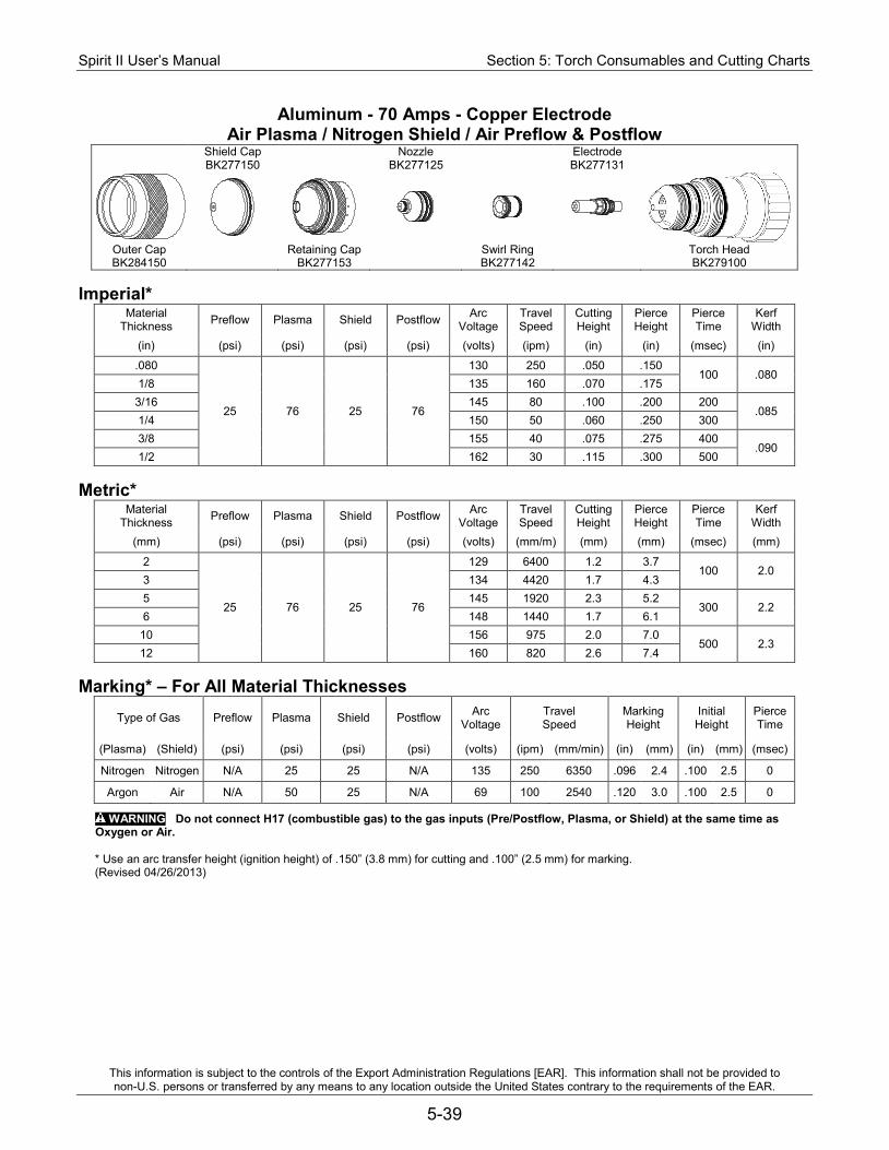
Spirit II User’s Manual Section 5: Torch Consumables and Cutting Charts
This information is subject to the controls of the Export Administration Regulations [EAR]. This information shall not be provided to non-U.S. persons or transferred by any means to any location outside the United States contrary to the requirements of the EAR.
5-39
Aluminum - 70 Amps - Copper Electrode Air Plasma / Nitrogen Shield / Air Preflow & Postflow
Shield Cap Nozzle Electrode BK277150 BK277125 BK277131
Outer Cap Retaining Cap Swirl Ring Torch Head BK284150 BK277153 BK277142 BK279100
Imperial*
Material Thickness Preflow Plasma Shield Postflow Arc
Voltage Travel Speed
Cutting Height
Pierce Height
Pierce Time
Kerf Width
(in) (psi) (psi) (psi) (psi) (volts) (ipm) (in) (in) (msec) (in)
.080
25 76 25 76
130 250 .050 .150 100 .080
1/8 135 160 .070 .175 3/16 145 80 .100 .200 200
.085 1/4 150 50 .060 .250 300 3/8 155 40 .075 .275 400
.090 1/2 162 30 .115 .300 500
Metric*
Material Thickness Preflow Plasma Shield Postflow Arc
Voltage Travel Speed
Cutting Height
Pierce Height
Pierce Time
Kerf Width
(mm) (psi) (psi) (psi) (psi) (volts) (mm/m) (mm) (mm) (msec) (mm)
2
25 76 25 76
129 6400 1.2 3.7 100 2.0
3 134 4420 1.7 4.3 5 145 1920 2.3 5.2
300 2.2 6 148 1440 1.7 6.1
10 156 975 2.0 7.0 500 2.3
12 160 820 2.6 7.4 Marking* – For All Material Thicknesses
Type of Gas Preflow Plasma Shield Postflow Arc Voltage
Travel Speed
Marking Height
Initial Height
Pierce Time
(Plasma) (Shield) (psi) (psi) (psi) (psi) (volts) (ipm) (mm/min) (in) (mm) (in) (mm) (msec)
Nitrogen Nitrogen N/A 25 25 N/A 135 250 6350 .096 2.4 .100 2.5 0
Argon Air N/A 50 25 N/A 69 100 2540 .120 3.0 .100 2.5 0
WARNING Do not connect H17 (combustible gas) to the gas inputs (Pre/Postflow, Plasma, or Shield) at the same time as Oxygen or Air.
* Use an arc transfer height (ignition height) of .150” (3.8 mm) for cutting and .100” (2.5 mm) for marking. (Revised 04/26/2013)

Section 5: Torch Consumables and Cutting Charts Spirit II User’s Manual
This information is subject to the controls of the Export Administration Regulations [EAR]. This information shall not be provided to non-U.S. persons or transferred by any means to any location outside the United States contrary to the requirements of the EAR.
5-40
Aluminum - 100 Amps - Copper Electrode Air Plasma / Nitrogen Shield / Air Preflow & Postflow
Shield Cap Nozzle Electrode BK277286 BK277284 BK277282
Outer Cap Retaining Cap Swirl Ring Torch Head BK284150 BK277151 BK277283 BK279100
Imperial*
Material Thickness Preflow Plasma Shield Postflow Arc
Voltage Travel Speed
Cutting Height
Pierce Height
Pierce Time
Kerf Width
(in) (psi) (psi) (psi) (psi) (volts) (ipm) (in) (in) (msec) (in)
1/4 25 80 26 80
158 105 .155 .250 300 .095 3/8 162 90 .180 .275 400 .098 1/2 165 70 .195 .300 500 .100
Metric*
Material Thickness Preflow Plasma Shield Postflow Arc
Voltage Travel Speed
Cutting Height
Pierce Height
Pierce Time
Kerf Width
(mm) (psi) (psi) (psi) (psi) (volts) (mm/m) (mm) (mm) (msec) (mm)
6 25 80 26 80
158 2710 3.8 6.3 300 2.4 10 162 2210 4.6 7.0
500 2.5 12 165 1890 4.9 7.4
Marking* – For All Material Thicknesses
Type of Gas Preflow Plasma Shield Postflow Arc Voltage
Travel Speed
Marking Height
Initial Height
Pierce Time
(Plasma) (Shield) (psi) (psi) (psi) (psi) (volts) (ipm) (mm/min) (in) (mm) (in) (mm) (msec)
Nitrogen Nitrogen N/A 25 25 N/A 130 250 6350 .100 2.5 .100 2.5 0
Argon Air N/A 50 25 N/A 71 100 2540 .120 3.0 .100 2.5 0
WARNING Do not connect H17 (combustible gas) to the gas inputs (Pre/Postflow, Plasma, or Shield) at the same time as Oxygen or Air.
* Use an arc transfer height (ignition height) of .250” (6.4 mm) for cutting and .100” (2.5 mm) for marking. (Revised 04/26/2013)
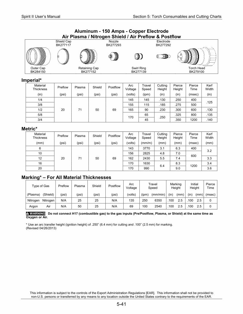
Spirit II User’s Manual Section 5: Torch Consumables and Cutting Charts
This information is subject to the controls of the Export Administration Regulations [EAR]. This information shall not be provided to non-U.S. persons or transferred by any means to any location outside the United States contrary to the requirements of the EAR.
5-41
Aluminum - 150 Amps - Copper Electrode Air Plasma / Nitrogen Shield / Air Preflow & Postflow
Shield Cap Nozzle Electrode BK277117 BK277293 BK277292
Outer Cap Retaining Cap Swirl Ring Torch Head BK284150 BK277152 BK277139 BK279100
Imperial*
Material Thickness Preflow Plasma Shield Postflow Arc
Voltage Travel Speed
Cutting Height
Pierce Height
Pierce Time
Kerf Width
(in) (psi) (psi) (psi) (psi) (volts) (ipm) (in) (in) (msec) (in)
1/4
20 71 50 69
145 145 .130 .250 400 .125
3/8 155 115 .185 .275 500 1/2 165 90 .230 .300 600 .130 5/8
170 65
.250 .325 800 .135
3/4 45 .350 1200 .140 Metric*
Material Thickness Preflow Plasma Shield Postflow Arc
Voltage Travel Speed
Cutting Height
Pierce Height
Pierce Time
Kerf Width
(mm) (psi) (psi) (psi) (psi) (volts) (mm/m) (mm) (mm) (msec) (mm)
6
20 71 50 69
143 3770 3.1 6.3 400 3.2
10 156 2825 4.8 7.0 600
12 162 2430 5.5 7.4 3.3 16 170 1630
6.4 8.3
1200 3.4
20 170 990 9.0 3.6 Marking* – For All Material Thicknesses
Type of Gas Preflow Plasma Shield Postflow Arc Voltage
Travel Speed
Marking Height
Initial Height
Pierce Time
(Plasma) (Shield) (psi) (psi) (psi) (psi) (volts) (ipm) (mm/min) (in) (mm) (in) (mm) (msec)
Nitrogen Nitrogen N/A 25 25 N/A 135 250 6350 .100 2.5 .100 2.5 0
Argon Air N/A 50 25 N/A 69 100 2540 .100 2.5 .100 2.5 0
WARNING Do not connect H17 (combustible gas) to the gas inputs (Pre/Postflow, Plasma, or Shield) at the same time as Oxygen or Air.
* Use an arc transfer height (ignition height) of .250” (6.4 mm) for cutting and .100” (2.5 mm) for marking. (Revised 04/26/2013)
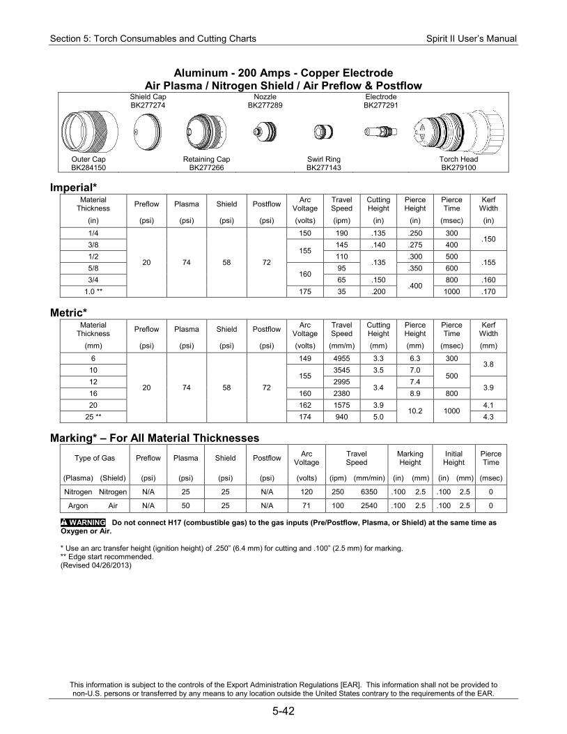
Section 5: Torch Consumables and Cutting Charts Spirit II User’s Manual
This information is subject to the controls of the Export Administration Regulations [EAR]. This information shall not be provided to non-U.S. persons or transferred by any means to any location outside the United States contrary to the requirements of the EAR.
5-42
Aluminum - 200 Amps - Copper Electrode Air Plasma / Nitrogen Shield / Air Preflow & Postflow
Shield Cap Nozzle Electrode BK277274 BK277289 BK277291
Outer Cap Retaining Cap Swirl Ring Torch Head BK284150 BK277266 BK277143 BK279100
Imperial*
Material Thickness Preflow Plasma Shield Postflow Arc
Voltage Travel Speed
Cutting Height
Pierce Height
Pierce Time
Kerf Width
(in) (psi) (psi) (psi) (psi) (volts) (ipm) (in) (in) (msec) (in)
1/4
20 74 58 72
150 190 .135 .250 300 .150
3/8 155
145 .140 .275 400 1/2 110
.135 .300 500
.155 5/8
160 95 .350 600
3/4 65 .150 .400
800 .160 1.0 ** 175 35 .200 1000 .170
Metric*
Material Thickness Preflow Plasma Shield Postflow Arc
Voltage Travel Speed
Cutting Height
Pierce Height
Pierce Time
Kerf Width
(mm) (psi) (psi) (psi) (psi) (volts) (mm/m) (mm) (mm) (msec) (mm)
6
20 74 58 72
149 4955 3.3 6.3 300 3.8
10 155
3545 3.5 7.0 500
12 2995 3.4
7.4 3.9
16 160 2380 8.9 800 20 162 1575 3.9
10.2 1000 4.1
25 ** 174 940 5.0 4.3 Marking* – For All Material Thicknesses
Type of Gas Preflow Plasma Shield Postflow Arc Voltage
Travel Speed
Marking Height
Initial Height
Pierce Time
(Plasma) (Shield) (psi) (psi) (psi) (psi) (volts) (ipm) (mm/min) (in) (mm) (in) (mm) (msec)
Nitrogen Nitrogen N/A 25 25 N/A 120 250 6350 .100 2.5 .100 2.5 0
Argon Air N/A 50 25 N/A 71 100 2540 .100 2.5 .100 2.5 0
WARNING Do not connect H17 (combustible gas) to the gas inputs (Pre/Postflow, Plasma, or Shield) at the same time as Oxygen or Air.
* Use an arc transfer height (ignition height) of .250” (6.4 mm) for cutting and .100” (2.5 mm) for marking. ** Edge start recommended. (Revised 04/26/2013)
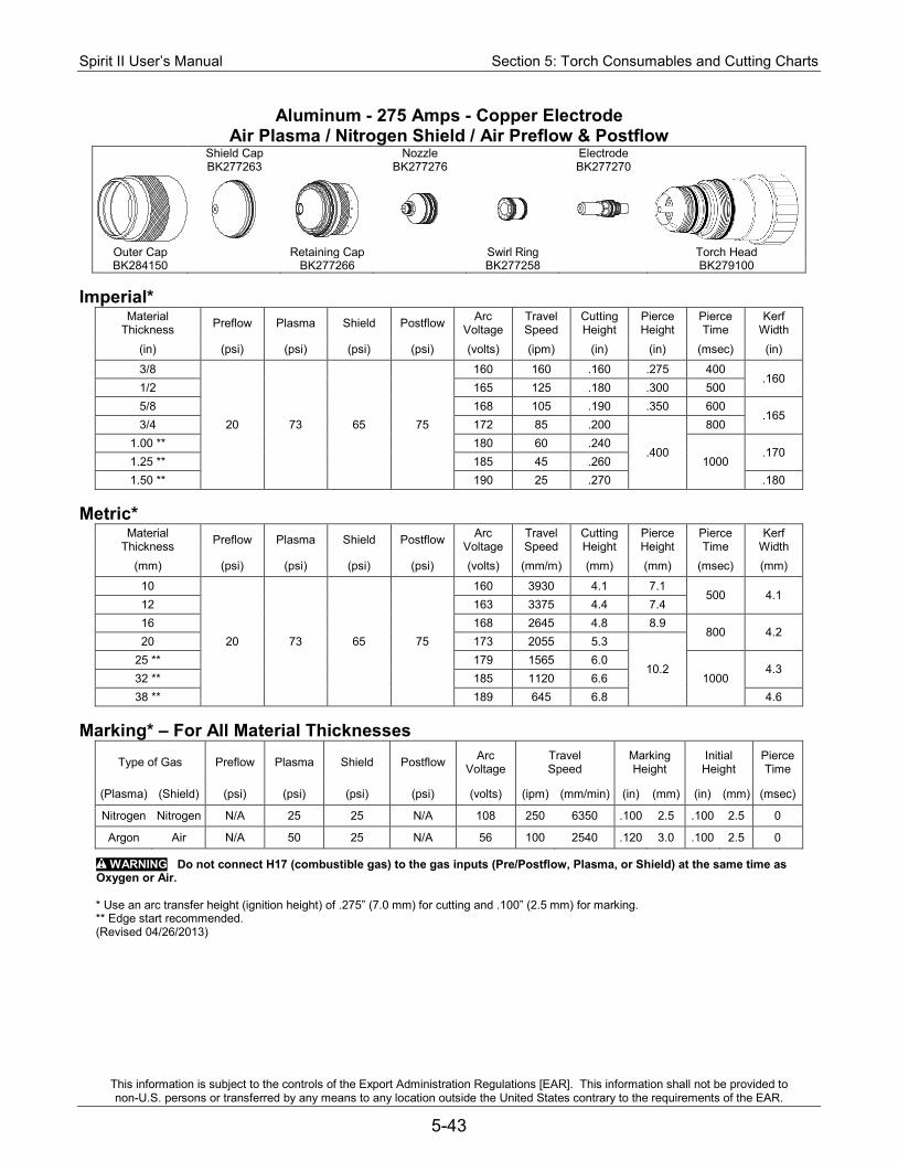
Spirit II User’s Manual Section 5: Torch Consumables and Cutting Charts
This information is subject to the controls of the Export Administration Regulations [EAR]. This information shall not be provided to non-U.S. persons or transferred by any means to any location outside the United States contrary to the requirements of the EAR.
5-43
Aluminum - 275 Amps - Copper Electrode Air Plasma / Nitrogen Shield / Air Preflow & Postflow
Shield Cap Nozzle Electrode BK277263 BK277276 BK277270
Outer Cap Retaining Cap Swirl Ring Torch Head BK284150 BK277266 BK277258 BK279100
Imperial*
Material Thickness Preflow Plasma Shield Postflow Arc
Voltage Travel Speed
Cutting Height
Pierce Height
Pierce Time
Kerf Width
(in) (psi) (psi) (psi) (psi) (volts) (ipm) (in) (in) (msec) (in)
3/8
20 73 65 75
160 160 .160 .275 400 .160
1/2 165 125 .180 .300 500 5/8 168 105 .190 .350 600
.165 3/4 172 85 .200
.400
800 1.00 ** 180 60 .240
1000 .170
1.25 ** 185 45 .260 1.50 ** 190 25 .270 .180
Metric*
Material Thickness Preflow Plasma Shield Postflow Arc
Voltage Travel Speed
Cutting Height
Pierce Height
Pierce Time
Kerf Width
(mm) (psi) (psi) (psi) (psi) (volts) (mm/m) (mm) (mm) (msec) (mm)
10
20 73 65 75
160 3930 4.1 7.1 500 4.1
12 163 3375 4.4 7.4 16 168 2645 4.8 8.9
800 4.2 20 173 2055 5.3
10.2 25 ** 179 1565 6.0
1000 4.3
32 ** 185 1120 6.6 38 ** 189 645 6.8 4.6
Marking* – For All Material Thicknesses
Type of Gas Preflow Plasma Shield Postflow Arc Voltage
Travel Speed
Marking Height
Initial Height
Pierce Time
(Plasma) (Shield) (psi) (psi) (psi) (psi) (volts) (ipm) (mm/min) (in) (mm) (in) (mm) (msec)
Nitrogen Nitrogen N/A 25 25 N/A 108 250 6350 .100 2.5 .100 2.5 0
Argon Air N/A 50 25 N/A 56 100 2540 .120 3.0 .100 2.5 0
WARNING Do not connect H17 (combustible gas) to the gas inputs (Pre/Postflow, Plasma, or Shield) at the same time as Oxygen or Air.
* Use an arc transfer height (ignition height) of .275” (7.0 mm) for cutting and .100” (2.5 mm) for marking. ** Edge start recommended. (Revised 04/26/2013)
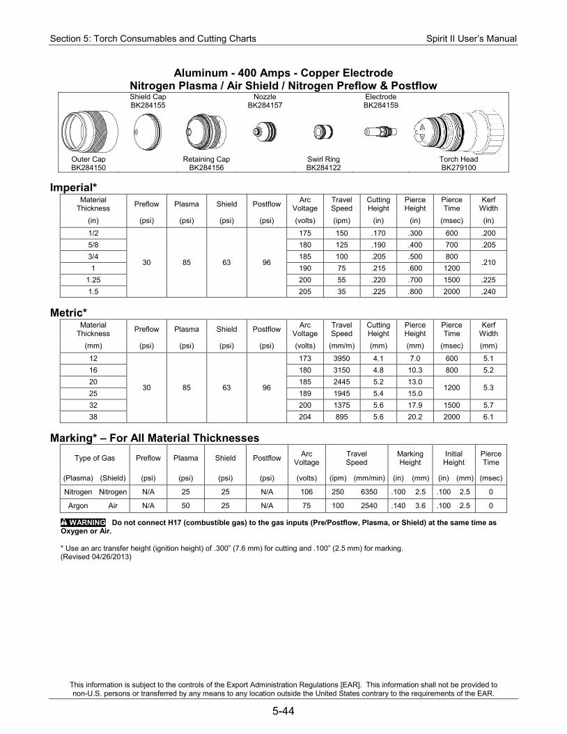
Section 5: Torch Consumables and Cutting Charts Spirit II User’s Manual
This information is subject to the controls of the Export Administration Regulations [EAR]. This information shall not be provided to non-U.S. persons or transferred by any means to any location outside the United States contrary to the requirements of the EAR.
5-44
Aluminum - 400 Amps - Copper Electrode Nitrogen Plasma / Air Shield / Nitrogen Preflow & Postflow
Shield Cap Nozzle Electrode BK284155 BK284157 BK284159
Outer Cap Retaining Cap Swirl Ring Torch Head BK284150 BK284156 BK284122 BK279100
Imperial*
Material Thickness Preflow Plasma Shield Postflow Arc
Voltage Travel Speed
Cutting Height
Pierce Height
Pierce Time
Kerf Width
(in) (psi) (psi) (psi) (psi) (volts) (ipm) (in) (in) (msec) (in)
1/2
30 85 63 96
175 150 .170 .300 600 .200 5/8 180 125 .190 .400 700 .205 3/4 185 100 .205 .500 800
.210 1 190 75 .215 .600 1200
1.25 200 55 .220 .700 1500 .225 1.5 205 35 .225 .800 2000 .240
Metric*
Material Thickness Preflow Plasma Shield Postflow Arc
Voltage Travel Speed
Cutting Height
Pierce Height
Pierce Time
Kerf Width
(mm) (psi) (psi) (psi) (psi) (volts) (mm/m) (mm) (mm) (msec) (mm)
12
30 85 63 96
173 3950 4.1 7.0 600 5.1 16 180 3150 4.8 10.3 800 5.2 20 185 2445 5.2 13.0
1200 5.3 25 189 1945 5.4 15.0 32 200 1375 5.6 17.9 1500 5.7 38 204 895 5.6 20.2 2000 6.1
Marking* – For All Material Thicknesses
Type of Gas Preflow Plasma Shield Postflow Arc Voltage
Travel Speed
Marking Height
Initial Height
Pierce Time
(Plasma) (Shield) (psi) (psi) (psi) (psi) (volts) (ipm) (mm/min) (in) (mm) (in) (mm) (msec)
Nitrogen Nitrogen N/A 25 25 N/A 106 250 6350 .100 2.5 .100 2.5 0
Argon Air N/A 50 25 N/A 75 100 2540 .140 3.6 .100 2.5 0
WARNING Do not connect H17 (combustible gas) to the gas inputs (Pre/Postflow, Plasma, or Shield) at the same time as Oxygen or Air.
* Use an arc transfer height (ignition height) of .300” (7.6 mm) for cutting and .100” (2.5 mm) for marking. (Revised 04/26/2013)
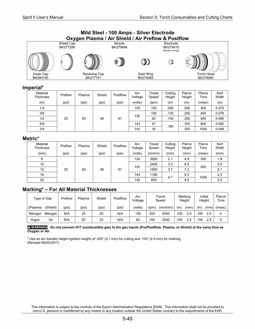
Spirit II User’s Manual Section 5: Torch Consumables and Cutting Charts
This information is subject to the controls of the Export Administration Regulations [EAR]. This information shall not be provided to non-U.S. persons or transferred by any means to any location outside the United States contrary to the requirements of the EAR.
5-45
Mild Steel - 100 Amps - Silver Electrode Oxygen Plasma / Air Shield / Air Preflow & Postflow
Shield Cap Nozzle Electrode BK277286 BK279484 BK279410
(brown o-ring)
Outer Cap Retaining Cap Swirl Ring Torch Head BK284150 BK277151 BK279483 BK279060
Imperial*
Material Thickness Preflow Plasma Shield Postflow Arc
Voltage Travel Speed
Cutting Height
Pierce Height
Pierce Time
Kerf Width
(in) (psi) (psi) (psi) (psi) (volts) (ipm) (in) (in) (msec) (in)
1/4
25 83 26 81
125 150 .090 .200 300 0.070 3/8
130 100 .130 .250 400 0.078
1/2 65 .155 .300 500 0.085 5/8 143 47
.185 .325 800 0.092
3/4 145 35 .350 1000 0.098 Metric*
Material Thickness Preflow Plasma Shield Postflow Arc
Voltage Travel Speed
Cutting Height
Pierce Height
Pierce Time
Kerf Width
(mm) (psi) (psi) (psi) (psi) (volts) (mm/m) (mm) (mm) (msec) (mm)
6
25 83 26 81
124 3950 2.1 4.9 300 1.8 10
130 2405 3.3 6.5
500 2.0
12 1850 3.7 7.3 2.1 16 143 1180
4.7 8.3
1000 2.3
20 145 800 9.0 2.5 Marking* – For All Material Thicknesses
Type of Gas Preflow Plasma Shield Postflow Arc Voltage
Travel Speed
Marking Height
Initial Height
Pierce Time
(Plasma) (Shield) (psi) (psi) (psi) (psi) (volts) (ipm) (mm/min) (in) (mm) (in) (mm) (msec)
Nitrogen Nitrogen N/A 25 25 N/A 130 250 6350 .100 2.5 .100 2.5 0
Argon Air N/A 50 25 N/A 60 100 2540 .100 2.5 .100 2.5 0
WARNING Do not connect H17 (combustible gas) to the gas inputs (Pre/Postflow, Plasma, or Shield) at the same time as Oxygen or Air.
* Use an arc transfer height (ignition height) of .200” (5.1 mm) for cutting and .100” (2.5 mm) for marking. (Revised 08/03/2017)
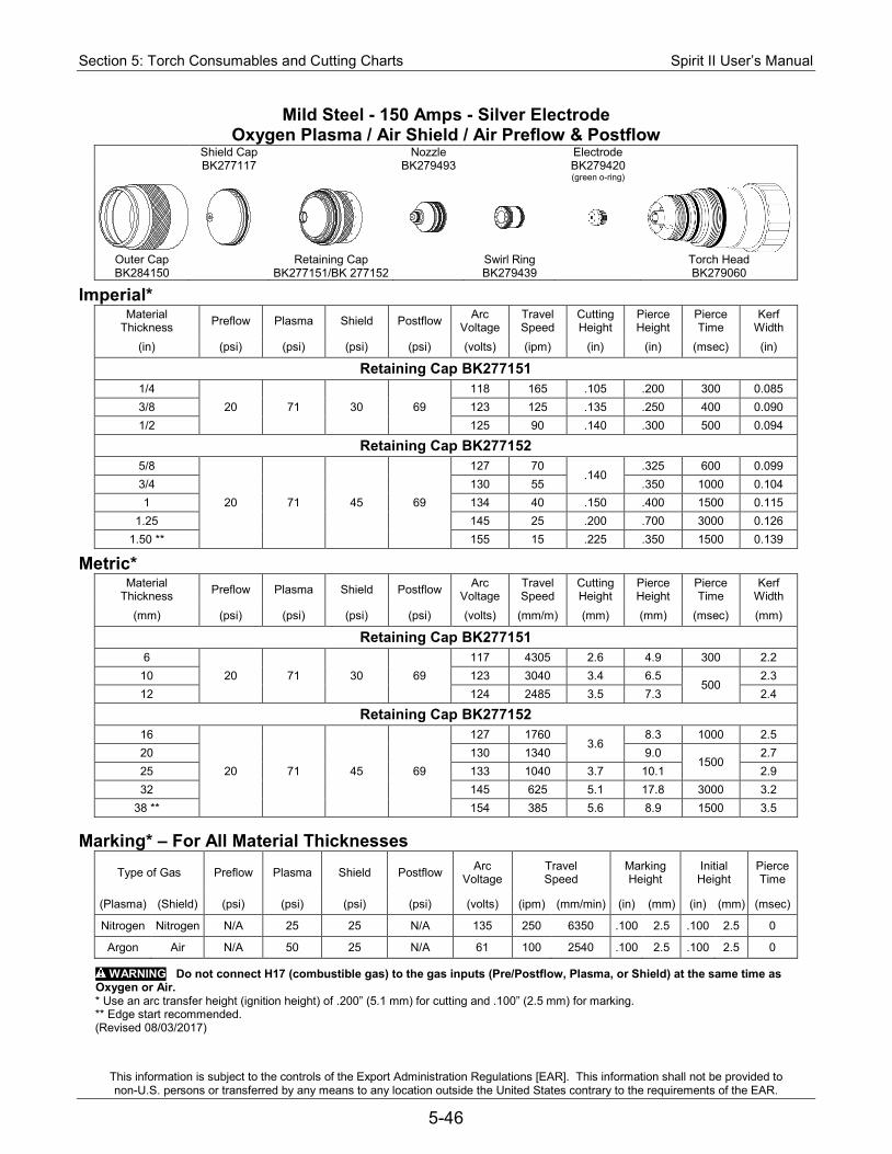
Section 5: Torch Consumables and Cutting Charts Spirit II User’s Manual
This information is subject to the controls of the Export Administration Regulations [EAR]. This information shall not be provided to non-U.S. persons or transferred by any means to any location outside the United States contrary to the requirements of the EAR.
5-46
Mild Steel - 150 Amps - Silver Electrode Oxygen Plasma / Air Shield / Air Preflow & Postflow
Shield Cap Nozzle Electrode BK277117 BK279493 BK279420
(green o-ring)
Outer Cap Retaining Cap Swirl Ring Torch Head BK284150 BK277151/BK 277152 BK279439 BK279060
Imperial* Material
Thickness Preflow Plasma Shield Postflow Arc Voltage
Travel Speed
Cutting Height
Pierce Height
Pierce Time
Kerf Width
(in) (psi) (psi) (psi) (psi) (volts) (ipm) (in) (in) (msec) (in)
Retaining Cap BK277151 1/4
20 71 30 69 118 165 .105 .200 300 0.085
3/8 123 125 .135 .250 400 0.090 1/2 125 90 .140 .300 500 0.094
Retaining Cap BK277152 5/8
20 71 45 69
127 70 .140
.325 600 0.099 3/4 130 55 .350 1000 0.104 1 134 40 .150 .400 1500 0.115
1.25 145 25 .200 .700 3000 0.126 1.50 ** 155 15 .225 .350 1500 0.139
Metric* Material
Thickness Preflow Plasma Shield Postflow Arc Voltage
Travel Speed
Cutting Height
Pierce Height
Pierce Time
Kerf Width
(mm) (psi) (psi) (psi) (psi) (volts) (mm/m) (mm) (mm) (msec) (mm)
Retaining Cap BK277151 6
20 71 30 69 117 4305 2.6 4.9 300 2.2
10 123 3040 3.4 6.5 500
2.3 12 124 2485 3.5 7.3 2.4
Retaining Cap BK277152 16
20 71 45 69
127 1760 3.6
8.3 1000 2.5 20 130 1340 9.0
1500 2.7
25 133 1040 3.7 10.1 2.9 32 145 625 5.1 17.8 3000 3.2
38 ** 154 385 5.6 8.9 1500 3.5
Marking* – For All Material Thicknesses Type of Gas Preflow Plasma Shield Postflow Arc
Voltage Travel Speed
Marking Height
Initial Height
Pierce Time
(Plasma) (Shield) (psi) (psi) (psi) (psi) (volts) (ipm) (mm/min) (in) (mm) (in) (mm) (msec)
Nitrogen Nitrogen N/A 25 25 N/A 135 250 6350 .100 2.5 .100 2.5 0
Argon Air N/A 50 25 N/A 61 100 2540 .100 2.5 .100 2.5 0
WARNING Do not connect H17 (combustible gas) to the gas inputs (Pre/Postflow, Plasma, or Shield) at the same time as Oxygen or Air. * Use an arc transfer height (ignition height) of .200” (5.1 mm) for cutting and .100” (2.5 mm) for marking. ** Edge start recommended. (Revised 08/03/2017)
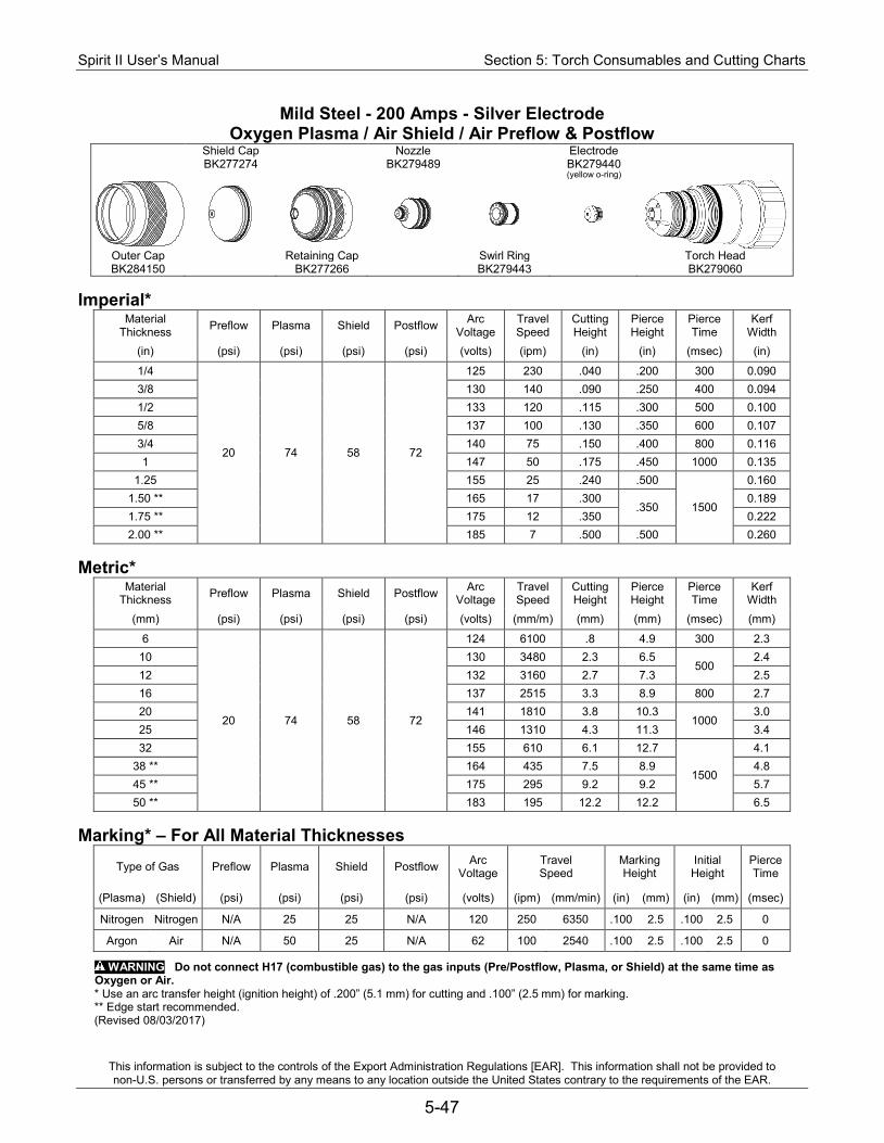
Spirit II User’s Manual Section 5: Torch Consumables and Cutting Charts
This information is subject to the controls of the Export Administration Regulations [EAR]. This information shall not be provided to non-U.S. persons or transferred by any means to any location outside the United States contrary to the requirements of the EAR.
5-47
Mild Steel - 200 Amps - Silver Electrode Oxygen Plasma / Air Shield / Air Preflow & Postflow
Shield Cap Nozzle Electrode BK277274 BK279489 BK279440
(yellow o-ring)
Outer Cap Retaining Cap Swirl Ring Torch Head BK284150 BK277266 BK279443 BK279060
Imperial*
Material Thickness Preflow Plasma Shield Postflow Arc
Voltage Travel Speed
Cutting Height
Pierce Height
Pierce Time
Kerf Width
(in) (psi) (psi) (psi) (psi) (volts) (ipm) (in) (in) (msec) (in)
1/4
20 74 58 72
125 230 .040 .200 300 0.090 3/8 130 140 .090 .250 400 0.094 1/2 133 120 .115 .300 500 0.100 5/8 137 100 .130 .350 600 0.107 3/4 140 75 .150 .400 800 0.116 1 147 50 .175 .450 1000 0.135
1.25 155 25 .240 .500
1500
0.160 1.50 ** 165 17 .300
.350 0.189
1.75 ** 175 12 .350 0.222 2.00 ** 185 7 .500 .500 0.260
Metric*
Material Thickness Preflow Plasma Shield Postflow Arc
Voltage Travel Speed
Cutting Height
Pierce Height
Pierce Time
Kerf Width
(mm) (psi) (psi) (psi) (psi) (volts) (mm/m) (mm) (mm) (msec) (mm)
6
20 74 58 72
124 6100 .8 4.9 300 2.3 10 130 3480 2.3 6.5
500 2.4
12 132 3160 2.7 7.3 2.5 16 137 2515 3.3 8.9 800 2.7 20 141 1810 3.8 10.3
1000 3.0
25 146 1310 4.3 11.3 3.4 32 155 610 6.1 12.7
1500
4.1 38 ** 164 435 7.5 8.9 4.8 45 ** 175 295 9.2 9.2 5.7 50 ** 183 195 12.2 12.2 6.5
Marking* – For All Material Thicknesses
Type of Gas Preflow Plasma Shield Postflow Arc Voltage
Travel Speed
Marking Height
Initial Height
Pierce Time
(Plasma) (Shield) (psi) (psi) (psi) (psi) (volts) (ipm) (mm/min) (in) (mm) (in) (mm) (msec)
Nitrogen Nitrogen N/A 25 25 N/A 120 250 6350 .100 2.5 .100 2.5 0
Argon Air N/A 50 25 N/A 62 100 2540 .100 2.5 .100 2.5 0
WARNING Do not connect H17 (combustible gas) to the gas inputs (Pre/Postflow, Plasma, or Shield) at the same time as Oxygen or Air. * Use an arc transfer height (ignition height) of .200” (5.1 mm) for cutting and .100” (2.5 mm) for marking. ** Edge start recommended. (Revised 08/03/2017)
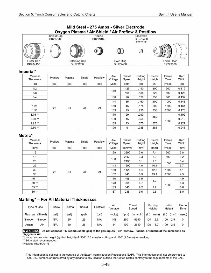
Section 5: Torch Consumables and Cutting Charts Spirit II User’s Manual
This information is subject to the controls of the Export Administration Regulations [EAR]. This information shall not be provided to non-U.S. persons or transferred by any means to any location outside the United States contrary to the requirements of the EAR.
5-48
Mild Steel - 275 Amps - Silver Electrode Oxygen Plasma / Air Shield / Air Preflow & Postflow
Shield Cap Nozzle Electrode BK277263 BK279469 BK279450
(red o-ring)
Outer Cap Retaining Cap Swirl Ring Torch Head BK284150 BK277266 BK279458 BK279060
Imperial*
Material Thickness Preflow Plasma Shield Postflow Arc
Voltage Travel Speed
Cutting Height
Pierce Height
Pierce Time
Kerf Width
(in) (psi) (psi) (psi) (psi) (volts) (ipm) (in) (in) (msec) (in)
1/2
20 81 70 79
139 125 .140 .300 500 0.119
5/8 105 .135 .325 600 0.125 3/4 138 90 .120 .350 800 0.132 1 144 65 .160 .400 1000 0.146
1.25 150 45 .175 .500 1500 0.161 1.50 163 25 .235 .750 2500 0.176
1.75 ** 170 20 .290 .350
1500
0.192 2.00 ** 180 15 .350 0.210 2.25 ** 185 13 .375 .375 0.227 2.50 ** 190 9 .385 .385 0.246
Metric*
Material Thickness Preflow Plasma Shield Postflow Arc
Voltage Travel Speed
Cutting Height
Pierce Height
Pierce Time
Kerf Width
(mm) (psi) (psi) (psi) (psi) (volts) (mm/m) (mm) (mm) (msec) (mm)
12
20 81 70 79
139 3290 3.6 7.4 500 3.0 16
138 2650 3.3 8.3 800 3.2
20 2190 3.1 9.0 1000
3.4 25 143 1690 4.0 10.1 3.7 32 150 1120 4.4 12.8 1500 4.1 38 162 645 5.9 19.1 2500 4.5
45 ** 170 495 7.5 8.9
1500
4.9 50 ** 178 395 8.7 5.3 55 ** 183 345 9.2 9.2 5.6 60 ** 187 285 9.6 9.6 6.0
Marking* – For All Material Thicknesses
Type of Gas Preflow Plasma Shield Postflow Arc Voltage
Travel Speed
Marking Height
Initial Height
Pierce Time
(Plasma) (Shield) (psi) (psi) (psi) (psi) (volts) (ipm) (mm/min) (in) (mm) (in) (mm) (msec)
Nitrogen Nitrogen N/A 25 25 N/A 108 250 6350 .100 2.5 .100 2.5 0
Argon Air N/A 50 25 N/A 54 100 2540 .120 3.0 .100 2.5 0
WARNING Do not connect H17 (combustible gas) to the gas inputs (Pre/Postflow, Plasma, or Shield) at the same time as Oxygen or Air. * Use an arc transfer height (ignition height) of .300” (7.6 mm) for cutting and .100” (2.5 mm) for marking. ** Edge start recommended. (Revised 08/03/2017)
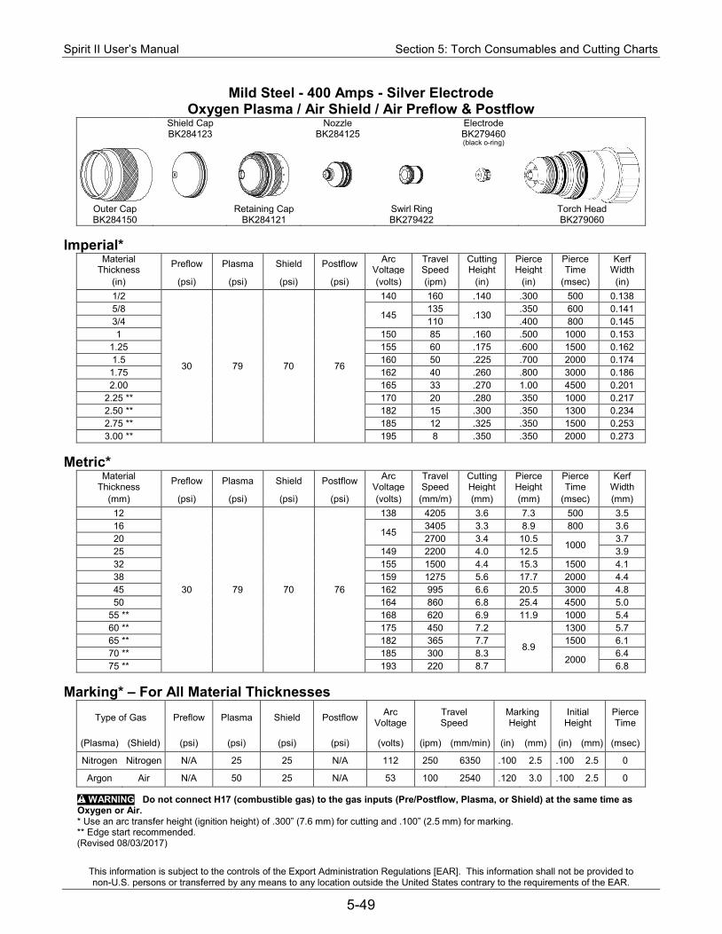
Spirit II User’s Manual Section 5: Torch Consumables and Cutting Charts
This information is subject to the controls of the Export Administration Regulations [EAR]. This information shall not be provided to non-U.S. persons or transferred by any means to any location outside the United States contrary to the requirements of the EAR.
5-49
Mild Steel - 400 Amps - Silver Electrode Oxygen Plasma / Air Shield / Air Preflow & Postflow
Shield Cap Nozzle Electrode BK284123 BK284125 BK279460
(black o-ring)
Outer Cap Retaining Cap Swirl Ring Torch Head BK284150 BK284121 BK279422 BK279060
Imperial*
Material Thickness Preflow Plasma Shield Postflow Arc
Voltage Travel Speed
Cutting Height
Pierce Height
Pierce Time
Kerf Width
(in) (psi) (psi) (psi) (psi) (volts) (ipm) (in) (in) (msec) (in) 1/2
30 79 70 76
140 160 .140 .300 500 0.138 5/8
145 135
.130 .350 600 0.141
3/4 110 .400 800 0.145 1 150 85 .160 .500 1000 0.153
1.25 155 60 .175 .600 1500 0.162 1.5 160 50 .225 .700 2000 0.174
1.75 162 40 .260 .800 3000 0.186 2.00 165 33 .270 1.00 4500 0.201
2.25 ** 170 20 .280 .350 1000 0.217 2.50 ** 182 15 .300 .350 1300 0.234 2.75 ** 185 12 .325 .350 1500 0.253 3.00 ** 195 8 .350 .350 2000 0.273
Metric*
Material Thickness Preflow Plasma Shield Postflow Arc
Voltage Travel Speed
Cutting Height
Pierce Height
Pierce Time
Kerf Width
(mm) (psi) (psi) (psi) (psi) (volts) (mm/m) (mm) (mm) (msec) (mm) 12
30 79 70 76
138 4205 3.6 7.3 500 3.5 16
145 3405 3.3 8.9 800 3.6
20 2700 3.4 10.5 1000
3.7 25 149 2200 4.0 12.5 3.9 32 155 1500 4.4 15.3 1500 4.1 38 159 1275 5.6 17.7 2000 4.4 45 162 995 6.6 20.5 3000 4.8 50 164 860 6.8 25.4 4500 5.0
55 ** 168 620 6.9 11.9 1000 5.4 60 ** 175 450 7.2
8.9
1300 5.7 65 ** 182 365 7.7 1500 6.1 70 ** 185 300 8.3
2000 6.4
75 ** 193 220 8.7 6.8 Marking* – For All Material Thicknesses
Type of Gas Preflow Plasma Shield Postflow Arc Voltage
Travel Speed
Marking Height
Initial Height
Pierce Time
(Plasma) (Shield) (psi) (psi) (psi) (psi) (volts) (ipm) (mm/min) (in) (mm) (in) (mm) (msec)
Nitrogen Nitrogen N/A 25 25 N/A 112 250 6350 .100 2.5 .100 2.5 0
Argon Air N/A 50 25 N/A 53 100 2540 .120 3.0 .100 2.5 0
WARNING Do not connect H17 (combustible gas) to the gas inputs (Pre/Postflow, Plasma, or Shield) at the same time as Oxygen or Air. * Use an arc transfer height (ignition height) of .300” (7.6 mm) for cutting and .100” (2.5 mm) for marking. ** Edge start recommended. (Revised 08/03/2017)

Section 5: Torch Consumables and Cutting Charts Spirit II User’s Manual
This information is subject to the controls of the Export Administration Regulations [EAR]. This information shall not be provided to non-U.S. persons or transferred by any means to any location outside the United States contrary to the requirements of the EAR.
5-50
Stainless Steel - 100 Amps - Silver Electrode Air Plasma / Nitrogen Shield / Air Preflow & Postflow
Shield Cap Nozzle Electrode BK277286 BK279484 BK279410
(brown o-ring)
Outer Cap Retaining Cap Swirl Ring Torch Head BK284150 BK277151 BK279483 BK279060
Imperial*
Material Thickness Preflow Plasma Shield Postflow Arc
Voltage Travel Speed
Cutting Height
Pierce Height
Pierce Time
Kerf Width
(in) (psi) (psi) (psi) (psi) (volts) (ipm) (in) (in) (msec) (in)
1/4 25 80 35 80
141 100 .135 .225 400 .092 3/8 147 80 .170 .250 500
.095 1/2 154 55 .210 .300 600
Metric*
Material Thickness Preflow Plasma Shield Postflow Arc
Voltage Travel Speed
Cutting Height
Pierce Height
Pierce Time
Kerf Width
(mm) (psi) (psi) (psi) (psi) (volts) (mm/m) (mm) (mm) (msec) (mm)
6 25 80 35 80
140 2595 3.2 5.6 400 2.3 10 148 1935 4.4 6.5
600 2.4 12 152 1540 5.0 7.3
Marking* – For All Material Thicknesses
Type of Gas Preflow Plasma Shield Postflow Arc Voltage
Travel Speed
Marking Height
Initial Height
Pierce Time
(Plasma) (Shield) (psi) (psi) (psi) (psi) (volts) (ipm) (mm/min) (in) (mm) (in) (mm) (msec)
Nitrogen Nitrogen N/A 25 25 N/A 130 250 6350 .100 2.5 .100 2.5 0
Argon Nitrogen N/A 50 25 N/A 68 100 2540 .100 2.5 .100 2.5 0
WARNING Do not connect H17 (combustible gas) to the gas inputs (Pre/Postflow, Plasma, or Shield) at the same time as Oxygen or Air.
* Use an arc transfer height (ignition height) of .200” (5.1 mm) for cutting and .100” (2.5 mm) for marking. (Revised 04/26/2013)
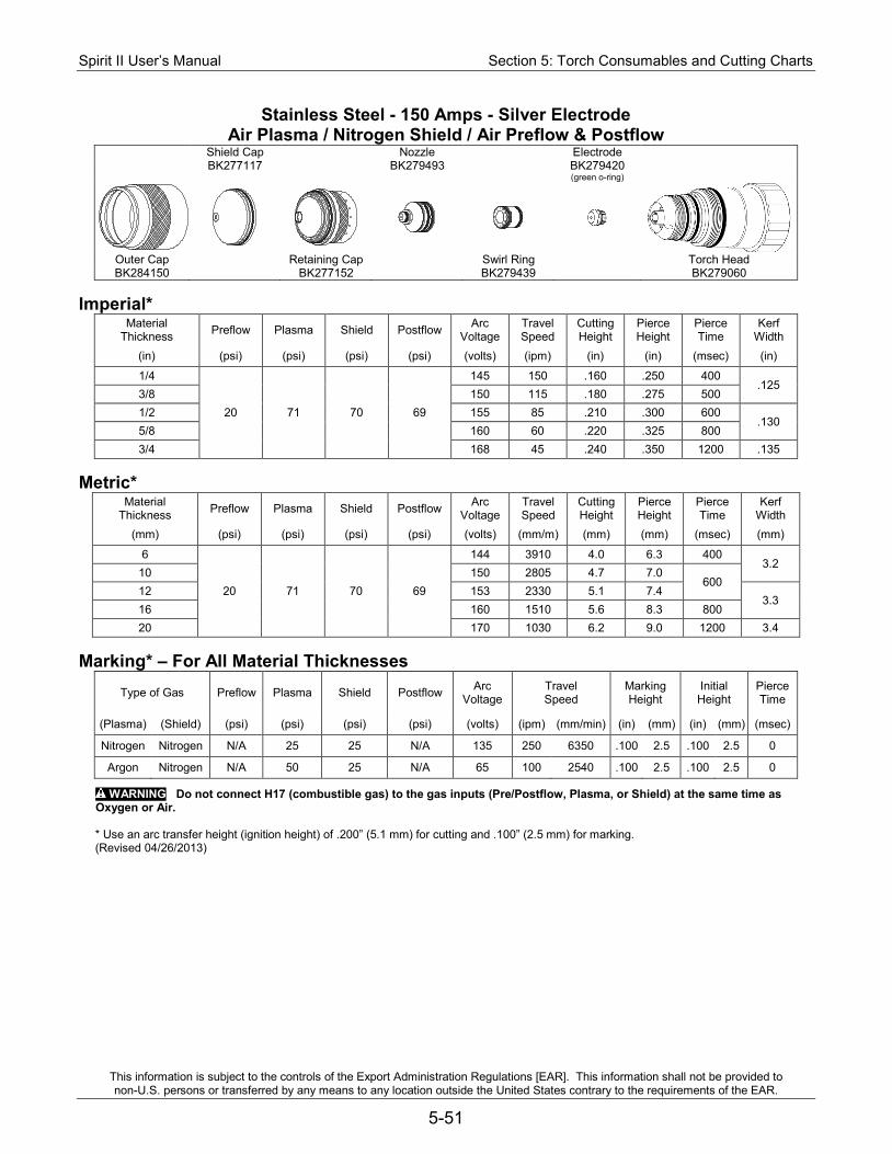
Spirit II User’s Manual Section 5: Torch Consumables and Cutting Charts
This information is subject to the controls of the Export Administration Regulations [EAR]. This information shall not be provided to non-U.S. persons or transferred by any means to any location outside the United States contrary to the requirements of the EAR.
5-51
Stainless Steel - 150 Amps - Silver Electrode Air Plasma / Nitrogen Shield / Air Preflow & Postflow
Shield Cap Nozzle Electrode BK277117 BK279493 BK279420
(green o-ring)
Outer Cap Retaining Cap Swirl Ring Torch Head BK284150 BK277152 BK279439 BK279060
Imperial*
Material Thickness Preflow Plasma Shield Postflow Arc
Voltage Travel Speed
Cutting Height
Pierce Height
Pierce Time
Kerf Width
(in) (psi) (psi) (psi) (psi) (volts) (ipm) (in) (in) (msec) (in)
1/4
20 71 70 69
145 150 .160 .250 400 .125
3/8 150 115 .180 .275 500 1/2 155 85 .210 .300 600
.130 5/8 160 60 .220 .325 800 3/4 168 45 .240 .350 1200 .135
Metric*
Material Thickness Preflow Plasma Shield Postflow Arc
Voltage Travel Speed
Cutting Height
Pierce Height
Pierce Time
Kerf Width
(mm) (psi) (psi) (psi) (psi) (volts) (mm/m) (mm) (mm) (msec) (mm)
6
20 71 70 69
144 3910 4.0 6.3 400 3.2
10 150 2805 4.7 7.0 600
12 153 2330 5.1 7.4 3.3
16 160 1510 5.6 8.3 800 20 170 1030 6.2 9.0 1200 3.4
Marking* – For All Material Thicknesses
Type of Gas Preflow Plasma Shield Postflow Arc Voltage
Travel Speed
Marking Height
Initial Height
Pierce Time
(Plasma) (Shield) (psi) (psi) (psi) (psi) (volts) (ipm) (mm/min) (in) (mm) (in) (mm) (msec)
Nitrogen Nitrogen N/A 25 25 N/A 135 250 6350 .100 2.5 .100 2.5 0
Argon Nitrogen N/A 50 25 N/A 65 100 2540 .100 2.5 .100 2.5 0
WARNING Do not connect H17 (combustible gas) to the gas inputs (Pre/Postflow, Plasma, or Shield) at the same time as Oxygen or Air.
* Use an arc transfer height (ignition height) of .200” (5.1 mm) for cutting and .100” (2.5 mm) for marking. (Revised 04/26/2013)
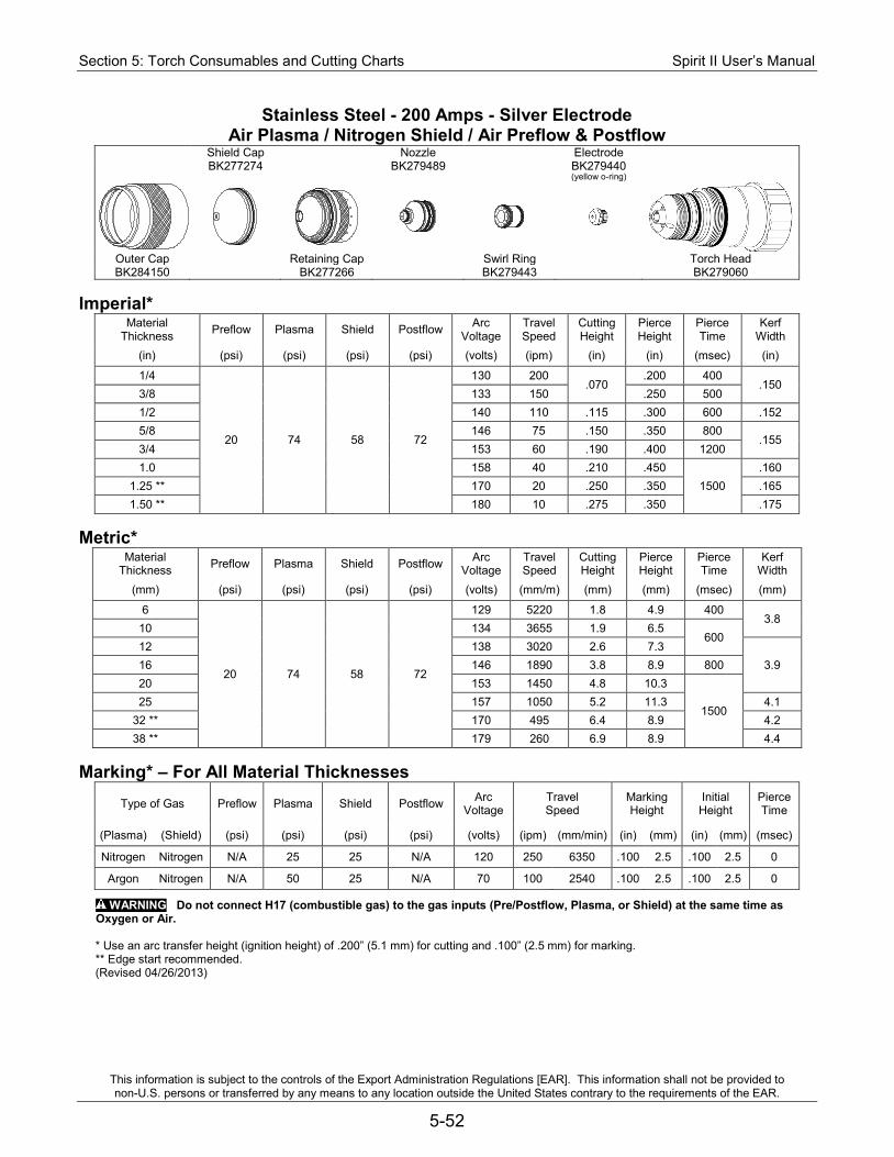
Section 5: Torch Consumables and Cutting Charts Spirit II User’s Manual
This information is subject to the controls of the Export Administration Regulations [EAR]. This information shall not be provided to non-U.S. persons or transferred by any means to any location outside the United States contrary to the requirements of the EAR.
5-52
Stainless Steel - 200 Amps - Silver Electrode Air Plasma / Nitrogen Shield / Air Preflow & Postflow
Shield Cap Nozzle Electrode BK277274 BK279489 BK279440
(yellow o-ring)
Outer Cap Retaining Cap Swirl Ring Torch Head BK284150 BK277266 BK279443 BK279060
Imperial*
Material Thickness Preflow Plasma Shield Postflow Arc
Voltage Travel Speed
Cutting Height
Pierce Height
Pierce Time
Kerf Width
(in) (psi) (psi) (psi) (psi) (volts) (ipm) (in) (in) (msec) (in)
1/4
20 74 58 72
130 200 .070
.200 400 .150
3/8 133 150 .250 500 1/2 140 110 .115 .300 600 .152 5/8 146 75 .150 .350 800
.155 3/4 153 60 .190 .400 1200 1.0 158 40 .210 .450
1500 .160
1.25 ** 170 20 .250 .350 .165 1.50 ** 180 10 .275 .350 .175
Metric*
Material Thickness Preflow Plasma Shield Postflow Arc
Voltage Travel Speed
Cutting Height
Pierce Height
Pierce Time
Kerf Width
(mm) (psi) (psi) (psi) (psi) (volts) (mm/m) (mm) (mm) (msec) (mm)
6
20 74 58 72
129 5220 1.8 4.9 400 3.8
10 134 3655 1.9 6.5 600
12 138 3020 2.6 7.3 3.9 16 146 1890 3.8 8.9 800
20 153 1450 4.8 10.3
1500 25 157 1050 5.2 11.3 4.1
32 ** 170 495 6.4 8.9 4.2 38 ** 179 260 6.9 8.9 4.4
Marking* – For All Material Thicknesses
Type of Gas Preflow Plasma Shield Postflow Arc Voltage
Travel Speed
Marking Height
Initial Height
Pierce Time
(Plasma) (Shield) (psi) (psi) (psi) (psi) (volts) (ipm) (mm/min) (in) (mm) (in) (mm) (msec)
Nitrogen Nitrogen N/A 25 25 N/A 120 250 6350 .100 2.5 .100 2.5 0
Argon Nitrogen N/A 50 25 N/A 70 100 2540 .100 2.5 .100 2.5 0
WARNING Do not connect H17 (combustible gas) to the gas inputs (Pre/Postflow, Plasma, or Shield) at the same time as Oxygen or Air.
* Use an arc transfer height (ignition height) of .200” (5.1 mm) for cutting and .100” (2.5 mm) for marking. ** Edge start recommended. (Revised 04/26/2013)
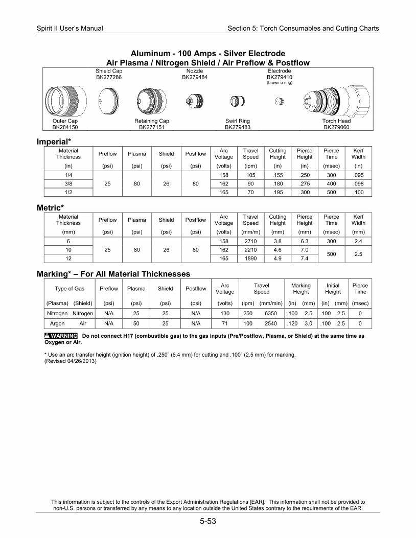
Spirit II User’s Manual Section 5: Torch Consumables and Cutting Charts
This information is subject to the controls of the Export Administration Regulations [EAR]. This information shall not be provided to non-U.S. persons or transferred by any means to any location outside the United States contrary to the requirements of the EAR.
5-53
Aluminum - 100 Amps - Silver Electrode Air Plasma / Nitrogen Shield / Air Preflow & Postflow
Shield Cap Nozzle Electrode BK277286 BK279484 BK279410
(brown o-ring)
Outer Cap Retaining Cap Swirl Ring Torch Head BK284150 BK277151 BK279483 BK279060
Imperial*
Material Thickness Preflow Plasma Shield Postflow Arc
Voltage Travel Speed
Cutting Height
Pierce Height
Pierce Time
Kerf Width
(in) (psi) (psi) (psi) (psi) (volts) (ipm) (in) (in) (msec) (in)
1/4 25 80 26 80
158 105 .155 .250 300 .095 3/8 162 90 .180 .275 400 .098 1/2 165 70 .195 .300 500 .100
Metric*
Material Thickness Preflow Plasma Shield Postflow Arc
Voltage Travel Speed
Cutting Height
Pierce Height
Pierce Time
Kerf Width
(mm) (psi) (psi) (psi) (psi) (volts) (mm/m) (mm) (mm) (msec) (mm)
6 25 80 26 80
158 2710 3.8 6.3 300 2.4 10 162 2210 4.6 7.0
500 2.5 12 165 1890 4.9 7.4
Marking* – For All Material Thicknesses
Type of Gas Preflow Plasma Shield Postflow Arc Voltage
Travel Speed
Marking Height
Initial Height
Pierce Time
(Plasma) (Shield) (psi) (psi) (psi) (psi) (volts) (ipm) (mm/min) (in) (mm) (in) (mm) (msec)
Nitrogen Nitrogen N/A 25 25 N/A 130 250 6350 .100 2.5 .100 2.5 0
Argon Air N/A 50 25 N/A 71 100 2540 .120 3.0 .100 2.5 0
WARNING Do not connect H17 (combustible gas) to the gas inputs (Pre/Postflow, Plasma, or Shield) at the same time as Oxygen or Air.
* Use an arc transfer height (ignition height) of .250” (6.4 mm) for cutting and .100” (2.5 mm) for marking. (Revised 04/26/2013)
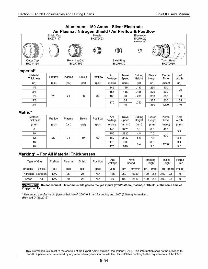
Section 5: Torch Consumables and Cutting Charts Spirit II User’s Manual
This information is subject to the controls of the Export Administration Regulations [EAR]. This information shall not be provided to non-U.S. persons or transferred by any means to any location outside the United States contrary to the requirements of the EAR.
5-54
Aluminum - 150 Amps - Silver Electrode Air Plasma / Nitrogen Shield / Air Preflow & Postflow
Shield Cap Nozzle Electrode BK277117 BK279493 BK279420
(green o-ring)
Outer Cap Retaining Cap Swirl Ring Torch Head BK284150 BK277152 BK279439 BK279060
Imperial*
Material Thickness Preflow Plasma Shield Postflow Arc
Voltage Travel Speed
Cutting Height
Pierce Height
Pierce Time
Kerf Width
(in) (psi) (psi) (psi) (psi) (volts) (ipm) (in) (in) (msec) (in)
1/4
20 71 50 69
145 145 .130 .250 400 .125
3/8 155 115 .185 .275 500 1/2 165 90 .230 .300 600 .130 5/8
170 65
.250 .325 800 .135
3/4 45 .350 1200 .140 Metric*
Material Thickness Preflow Plasma Shield Postflow Arc
Voltage Travel Speed
Cutting Height
Pierce Height
Pierce Time
Kerf Width
(mm) (psi) (psi) (psi) (psi) (volts) (mm/m) (mm) (mm) (msec) (mm)
6
20 71 50 69
143 3770 3.1 6.3 400 3.2
10 156 2825 4.8 7.0 600
12 162 2430 5.5 7.4 3.3 16 170 1630
6.4 8.3
1200 3.4
20 170 990 9.0 3.6 Marking* – For All Material Thicknesses
Type of Gas Preflow Plasma Shield Postflow Arc Voltage
Travel Speed
Marking Height
Initial Height
Pierce Time
(Plasma) (Shield) (psi) (psi) (psi) (psi) (volts) (ipm) (mm/min) (in) (mm) (in) (mm) (msec)
Nitrogen Nitrogen N/A 25 25 N/A 135 250 6350 .100 2.5 .100 2.5 0
Argon Air N/A 50 25 N/A 69 100 2540 .100 2.5 .100 2.5 0
WARNING Do not connect H17 (combustible gas) to the gas inputs (Pre/Postflow, Plasma, or Shield) at the same time as Oxygen or Air.
* Use an arc transfer height (ignition height) of .250” (6.4 mm) for cutting and .100” (2.5 mm) for marking. (Revised 04/26/2013)
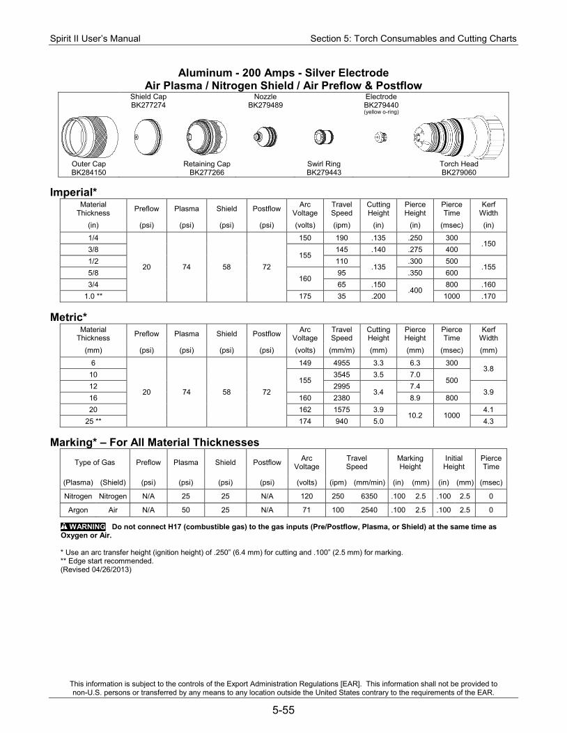
Spirit II User’s Manual Section 5: Torch Consumables and Cutting Charts
This information is subject to the controls of the Export Administration Regulations [EAR]. This information shall not be provided to non-U.S. persons or transferred by any means to any location outside the United States contrary to the requirements of the EAR.
5-55
Aluminum - 200 Amps - Silver Electrode Air Plasma / Nitrogen Shield / Air Preflow & Postflow
Shield Cap Nozzle Electrode BK277274 BK279489 BK279440
(yellow o-ring)
Outer Cap Retaining Cap Swirl Ring Torch Head BK284150 BK277266 BK279443 BK279060
Imperial*
Material Thickness Preflow Plasma Shield Postflow Arc
Voltage Travel Speed
Cutting Height
Pierce Height
Pierce Time
Kerf Width
(in) (psi) (psi) (psi) (psi) (volts) (ipm) (in) (in) (msec) (in)
1/4
20 74 58 72
150 190 .135 .250 300 .150
3/8 155
145 .140 .275 400 1/2 110
.135 .300 500
.155 5/8
160 95 .350 600
3/4 65 .150 .400
800 .160 1.0 ** 175 35 .200 1000 .170
Metric*
Material Thickness Preflow Plasma Shield Postflow Arc
Voltage Travel Speed
Cutting Height
Pierce Height
Pierce Time
Kerf Width
(mm) (psi) (psi) (psi) (psi) (volts) (mm/m) (mm) (mm) (msec) (mm)
6
20 74 58 72
149 4955 3.3 6.3 300 3.8
10 155
3545 3.5 7.0 500
12 2995 3.4
7.4 3.9
16 160 2380 8.9 800 20 162 1575 3.9
10.2 1000 4.1
25 ** 174 940 5.0 4.3 Marking* – For All Material Thicknesses
Type of Gas Preflow Plasma Shield Postflow Arc Voltage
Travel Speed
Marking Height
Initial Height
Pierce Time
(Plasma) (Shield) (psi) (psi) (psi) (psi) (volts) (ipm) (mm/min) (in) (mm) (in) (mm) (msec)
Nitrogen Nitrogen N/A 25 25 N/A 120 250 6350 .100 2.5 .100 2.5 0
Argon Air N/A 50 25 N/A 71 100 2540 .100 2.5 .100 2.5 0
WARNING Do not connect H17 (combustible gas) to the gas inputs (Pre/Postflow, Plasma, or Shield) at the same time as Oxygen or Air.
* Use an arc transfer height (ignition height) of .250” (6.4 mm) for cutting and .100” (2.5 mm) for marking. ** Edge start recommended. (Revised 04/26/2013)
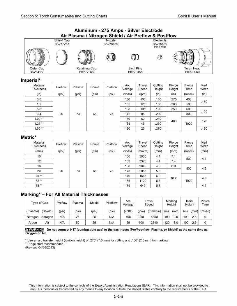
Section 5: Torch Consumables and Cutting Charts Spirit II User’s Manual
This information is subject to the controls of the Export Administration Regulations [EAR]. This information shall not be provided to non-U.S. persons or transferred by any means to any location outside the United States contrary to the requirements of the EAR.
5-56
Aluminum - 275 Amps - Silver Electrode Air Plasma / Nitrogen Shield / Air Preflow & Postflow
Shield Cap Nozzle Electrode BK277263 BK279469 BK279450
(red o-ring)
Outer Cap Retaining Cap Swirl Ring Torch Head BK284150 BK277266 BK279458 BK279060
Imperial*
Material Thickness Preflow Plasma Shield Postflow Arc
Voltage Travel Speed
Cutting Height
Pierce Height
Pierce Time
Kerf Width
(in) (psi) (psi) (psi) (psi) (volts) (ipm) (in) (in) (msec) (in)
3/8
20 73 65 75
160 160 .160 .275 400 .160
1/2 165 125 .180 .300 500 5/8 168 105 .190 .350 600
.165 3/4 172 85 .200
.400
800 1.00 ** 180 60 .240
1000 .170
1.25 ** 185 45 .260 1.50 ** 190 25 .270 .180
Metric*
Material Thickness Preflow Plasma Shield Postflow Arc
Voltage Travel Speed
Cutting Height
Pierce Height
Pierce Time
Kerf Width
(mm) (psi) (psi) (psi) (psi) (volts) (mm/m) (mm) (mm) (msec) (mm)
10
20 73 65 75
160 3930 4.1 7.1 500 4.1
12 163 3375 4.4 7.4 16 168 2645 4.8 8.9
800 4.2 20 173 2055 5.3
10.2 25 ** 179 1565 6.0
1000 4.3
32 ** 185 1120 6.6 38 ** 189 645 6.8 4.6
Marking* – For All Material Thicknesses
Type of Gas Preflow Plasma Shield Postflow Arc Voltage
Travel Speed
Marking Height
Initial Height
Pierce Time
(Plasma) (Shield) (psi) (psi) (psi) (psi) (volts) (ipm) (mm/min) (in) (mm) (in) (mm) (msec)
Nitrogen Nitrogen N/A 25 25 N/A 108 250 6350 .100 2.5 .100 2.5 0
Argon Air N/A 50 25 N/A 56 100 2540 .120 3.0 .100 2.5 0
WARNING Do not connect H17 (combustible gas) to the gas inputs (Pre/Postflow, Plasma, or Shield) at the same time as Oxygen or Air.
* Use an arc transfer height (ignition height) of .275” (7.0 mm) for cutting and .100” (2.5 mm) for marking. ** Edge start recommended. (Revised 04/26/2013)

Spirit II User’s Manual Section 6: Maintenance &Troubleshooting
This information is subject to the controls of the Export Administration Regulations [EAR]. This information shall not be provided to non-U.S. persons or transferred by any means to any location outside the United States contrary to the requirements of the EAR.
6-1
Section 6: Maintenance & Troubleshooting WARNING: Only qualified maintenance personnel should perform maintenance on the Spirit system. The system utilizes potentially fatal A.C. and D.C. voltages. All maintenance should be performed with safety in mind. Use extreme caution when working near the power conversion module (i.e., chopper). The large electrolytic capacitors store large amounts of energy even after power has been removed from the system. Wait at least five minutes after turning off power, and then use a voltmeter to verify that the capacitors are fully discharged before touching the power conversion module. Capacitor failure can injure and/or cause property damage. If troubleshooting requires the system to be powered with the enclosure panels removed, remain clear of the capacitors. Failure of a capacitor can result in a sudden release of stored energy causing rupture of the capacitor case.
Routine Maintenance Note: At minimum, these checks should be performed on a monthly basis. In excessively dirty environments or in heavy usage situations, the checks should be performed more frequently.
Power Supply 1. Remove the left, right, and top covers on the power supply. 2. Using clean, dry, compressed air (30 psi maximum), blow out all accumulated dust,
including dust on PC boards and fans. In an excessively dirty environment, blow out the unit on a weekly basis.
3. Verify the ground and primary three phase A.C. voltage connections are tight. 4. Verify all PC board connectors are installed securely. 5. Verify all rear cable connectors are installed securely. 6. Verify the electrode lead and work ground lead are secure and free from corrosion.
Cooling System 1. Remove the cover on the cooling system. Check the torch coolant filter /
deionization cartridge and replace if dirty. 2. Flush the cooling system every six months and replace the coolant and coolant filter
/ deionization cartridge.
Section 6: Maintenance &Troubleshooting Spirit II User’s Manual
This information is subject to the controls of the Export Administration Regulations [EAR]. This information shall not be provided to non-U.S. persons or transferred by any means to any location outside the United States contrary to the requirements of the EAR.
6-2
Manual Gas Console (MGC) 1. Remove the cover of the manual gas console. Using clean, dry, compressed air (30
psi maximum), blow out all accumulated dust inside the unit. In an excessively dirty environment, blow out the unit on a weekly basis.
2. Verify that all PC board connectors are installed securely. 3. Verify that all gas hose connectors are tight and that there are no leaks. Only
tighten the gas fittings enough to make a gas seal. The fittings are subject to damage if over tightened.
4. Inspect all gas hoses to ensure no damage exists. Immediately replace any damaged gas hoses.
Torch, Torch Leads, and Gas Hoses 1. Verify that all torch lead and gas hose connections are tight and that there are no
gas or coolant leaks. Only tighten the fittings enough to make a coolant or gas seal. The fittings are subject to damage if over tightened.
2. Verify that the braided shield of the torch leads is fastened securely to the brass shield adapter that connects to the arc starting console. Also, make sure the shield adapter is secured tightly to the arc starting console enclosure.
3. Inspect the braided shield for nicks or cuts and replace if necessary. 4. Remove the torch handle and verify that the connections at the torch base are
tightened securely. Only tighten the fittings enough to make a coolant or gas seal. The fittings are subject to damage if over tightened. Coolant leaking from the drain hole in the torch handle indicates damaged or loose torch leads.
5. Make sure the torch lead insulating sleeves are positioned to properly cover the brass torch fittings at the torch base.
6. Inspect the outer sleeve on the torch base's electrode/coolant supply lead. If nicks, cuts or holes are found, replace the torch base.
7. Remove the torch consumables from the torch head and inspect all o-rings. Replace any o-rings with cuts, nicks, abrasions, or any other signs of wear. Faulty o-rings may cause gas or coolant leaks, which will affect cut quality.
8. With the electrode removed, inspect the cooling tube in the torch head for damage. If using the copper electrode, the torch head uses cooling tube P/N BK277007. If replacement is required, use tool P/N BK200109. If using the silver electrode, the torch head uses cooling tube holder assembly P/N BK279216. Remove this using the tool (socket P/N BK277087 & driver P/N BK277086) and inspect the o-rings for damage. Apply a small amount of o-ring lubricant before re-installing in the torch head.
9. Wipe any excess o-ring lubricant off of the torch base and head.

Spirit II User’s Manual Section 6: Maintenance &Troubleshooting
This information is subject to the controls of the Export Administration Regulations [EAR]. This information shall not be provided to non-U.S. persons or transferred by any means to any location outside the United States contrary to the requirements of the EAR.
6-3
Arc Starting Console (ASC) 1. Open the cover (door) of the arc starting console and verify that all leads and hoses
are tightened securely. Only tighten the fittings enough to make a coolant or gas seal. The fittings are subject to damage if over tightened.
2. For systems that include ASC with RHF, check the spark gap electrodes for signs of wear. Replace electrodes that have rounded faces. Use a clean feeler gauge and set the spark gap to .015” (.38 mm).
Work Ground 1. Verify that the work ground lead is securely fastened to the star ground on the
cutting table, and that the connection point is free from corrosion. Use a wire brush to clean the connection point if necessary.

Section 6: Maintenance &Troubleshooting Spirit II User’s Manual
This information is subject to the controls of the Export Administration Regulations [EAR]. This information shall not be provided to non-U.S. persons or transferred by any means to any location outside the United States contrary to the requirements of the EAR.
6-4
Replacing the Torch Coolant and Filter
WARNING: Do not touch the fans inside the cooling system. Important: Never turn on the system when the coolant reservoir is empty. Important: When handling coolant, wear nitrile gloves and safety glasses. Important: Only use approved coolant. Commercially available antifreeze
contains corrosion inhibitors that will damage the cooling system. See Section 2 for more information.
The torch coolant should be flushed out of the system every six months and replaced with new coolant. Replace the coolant filter / deionization cartridge at the same time. 1. Remove primary power from the Spirit system. 2. Ensure the torch base and torch head (with consumables) are properly installed. 3. Ensure the coolant supply (in and out) hoses are properly installed. 4. Remove the coolant reservoir cap/level gauge. 5. Remove the cover from the cooling system. 6. Connect a 3/8" ID hose and bucket to the drain petcock on the bottom of the
reservoir. Unscrew the petcock to drain the reservoir. Leave the hose and bucket in place after the coolant drains out.
7. Remove the coolant supply hose (coolant out) from the rear of the cooling system. Note that the coolant supply hose has right hand threads. Be prepared for some coolant to escape from the fitting on the cooling system and from the supply hose.
8. Blow compressed air (100 psi maximum) into the coolant supply hose. This will force the remaining coolant from the torch, torch leads, and supply hose into the reservoir and out of the drain petcock. Continue until coolant stops flowing into the bucket.
9. Tighten the drain petcock and remove the hose and bucket. 10. Unscrew the coolant filter housing and remove the coolant filter / deionization
cartridge. Install a new coolant filter / deionization cartridge and replace the coolant filter housing. Dry any leaked coolant.
11. Reconnect the coolant supply hose on the rear of the cooling system. 12. Follow all of the steps in "Filling the Cooling System" in Section 3 of this manual to
complete this procedure.
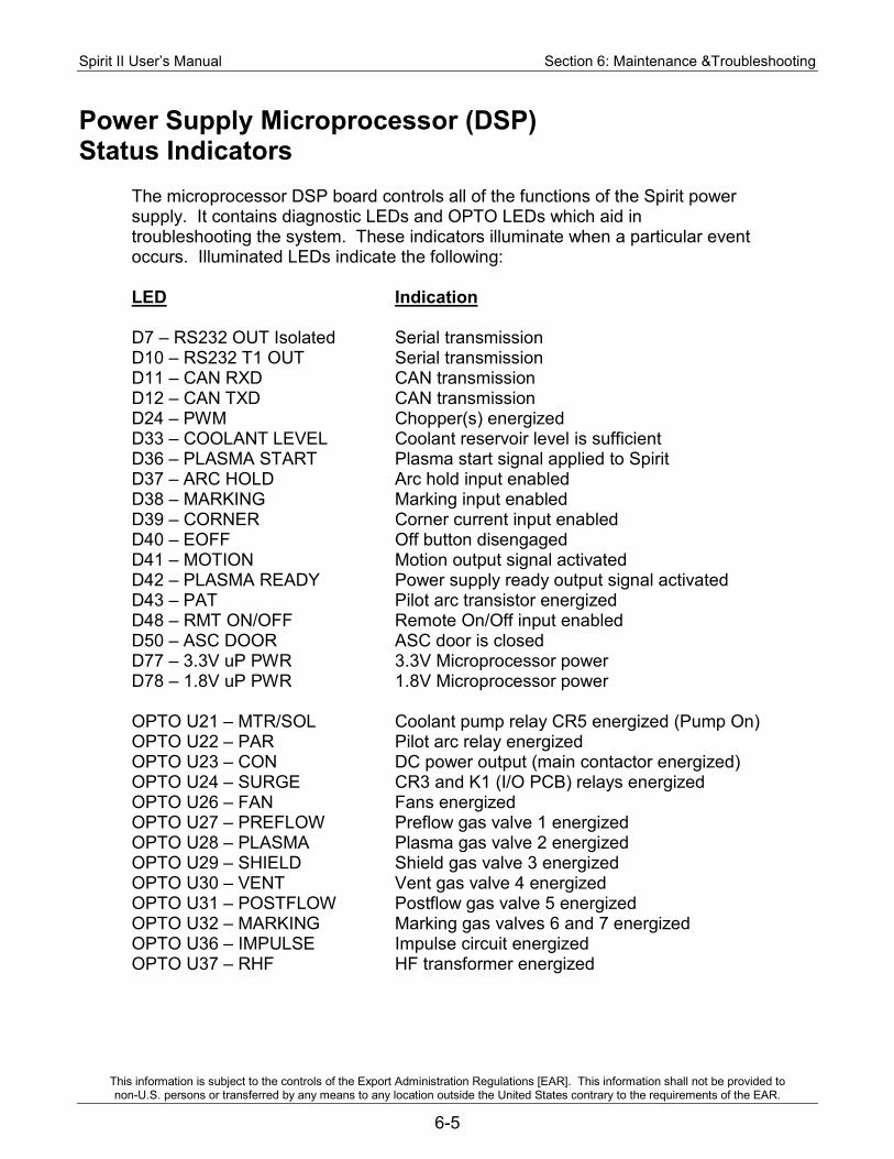
Spirit II User’s Manual Section 6: Maintenance &Troubleshooting
This information is subject to the controls of the Export Administration Regulations [EAR]. This information shall not be provided to non-U.S. persons or transferred by any means to any location outside the United States contrary to the requirements of the EAR.
6-5
Power Supply Microprocessor (DSP) Status Indicators
The microprocessor DSP board controls all of the functions of the Spirit power supply. It contains diagnostic LEDs and OPTO LEDs which aid in troubleshooting the system. These indicators illuminate when a particular event occurs. Illuminated LEDs indicate the following: LED Indication D7 – RS232 OUT Isolated Serial transmission D10 – RS232 T1 OUT Serial transmission D11 – CAN RXD CAN transmission D12 – CAN TXD CAN transmission D24 – PWM Chopper(s) energized D33 – COOLANT LEVEL Coolant reservoir level is sufficient D36 – PLASMA START Plasma start signal applied to Spirit D37 – ARC HOLD Arc hold input enabled D38 – MARKING Marking input enabled D39 – CORNER Corner current input enabled D40 – EOFF Off button disengaged D41 – MOTION Motion output signal activated D42 – PLASMA READY Power supply ready output signal activated D43 – PAT Pilot arc transistor energized D48 – RMT ON/OFF Remote On/Off input enabled D50 – ASC DOOR ASC door is closed D77 – 3.3V uP PWR 3.3V Microprocessor power D78 – 1.8V uP PWR 1.8V Microprocessor power OPTO U21 – MTR/SOL Coolant pump relay CR5 energized (Pump On) OPTO U22 – PAR Pilot arc relay energized OPTO U23 – CON DC power output (main contactor energized) OPTO U24 – SURGE CR3 and K1 (I/O PCB) relays energized OPTO U26 – FAN Fans energized OPTO U27 – PREFLOW Preflow gas valve 1 energized OPTO U28 – PLASMA Plasma gas valve 2 energized OPTO U29 – SHIELD Shield gas valve 3 energized OPTO U30 – VENT Vent gas valve 4 energized OPTO U31 – POSTFLOW Postflow gas valve 5 energized OPTO U32 – MARKING Marking gas valves 6 and 7 energized OPTO U36 – IMPULSE Impulse circuit energized OPTO U37 – RHF HF transformer energized
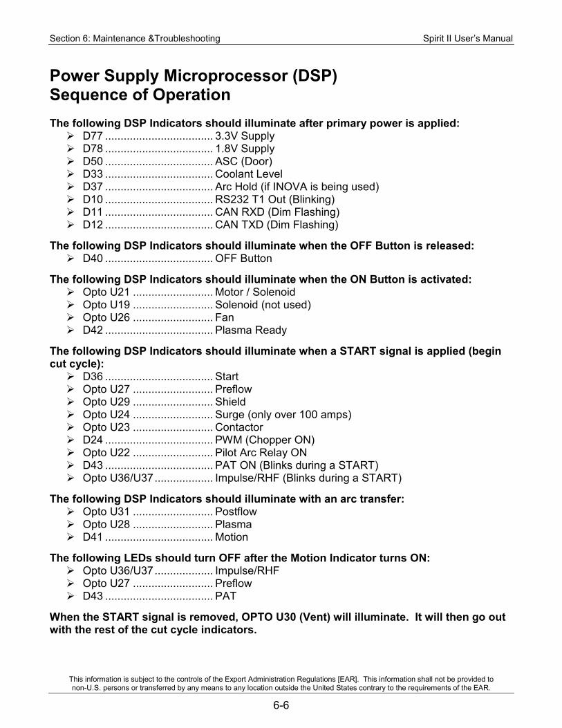
Section 6: Maintenance &Troubleshooting Spirit II User’s Manual
This information is subject to the controls of the Export Administration Regulations [EAR]. This information shall not be provided to non-U.S. persons or transferred by any means to any location outside the United States contrary to the requirements of the EAR.
6-6
Power Supply Microprocessor (DSP) Sequence of Operation The following DSP Indicators should illuminate after primary power is applied: D77 ................................... 3.3V Supply D78 ................................... 1.8V Supply D50 ................................... ASC (Door) D33 ................................... Coolant Level D37 ................................... Arc Hold (if INOVA is being used) D10 ................................... RS232 T1 Out (Blinking) D11 ................................... CAN RXD (Dim Flashing) D12 ................................... CAN TXD (Dim Flashing)
The following DSP Indicators should illuminate when the OFF Button is released: D40 ................................... OFF Button
The following DSP Indicators should illuminate when the ON Button is activated: Opto U21 .......................... Motor / Solenoid Opto U19 .......................... Solenoid (not used) Opto U26 .......................... Fan D42 ................................... Plasma Ready
The following DSP Indicators should illuminate when a START signal is applied (begin cut cycle): D36 ................................... Start Opto U27 .......................... Preflow Opto U29 .......................... Shield Opto U24 .......................... Surge (only over 100 amps) Opto U23 .......................... Contactor D24 ................................... PWM (Chopper ON) Opto U22 .......................... Pilot Arc Relay ON D43 ................................... PAT ON (Blinks during a START) Opto U36/U37 ................... Impulse/RHF (Blinks during a START)
The following DSP Indicators should illuminate with an arc transfer: Opto U31 .......................... Postflow Opto U28 .......................... Plasma D41 ................................... Motion
The following LEDs should turn OFF after the Motion Indicator turns ON: Opto U36/U37 ................... Impulse/RHF Opto U27 .......................... Preflow D43 ................................... PAT
When the START signal is removed, OPTO U30 (Vent) will illuminate. It will then go out with the rest of the cut cycle indicators.
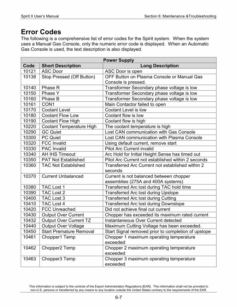
Spirit II User’s Manual Section 6: Maintenance &Troubleshooting
This information is subject to the controls of the Export Administration Regulations [EAR]. This information shall not be provided to non-U.S. persons or transferred by any means to any location outside the United States contrary to the requirements of the EAR.
6-7
Error Codes The following is a comprehensive list of error codes for the Spirit system. When the system uses a Manual Gas Console, only the numeric error code is displayed. When an Automatic Gas Console is used, the text description is also displayed.
Power Supply Code Short Description Long Description 10121 ASC Door ASC Door is open 10138 Stop Pressed (Off Button) OFF Button on Plasma Console or Manual Gas
Console is pressed. 10140 Phase R Transformer Secondary phase voltage is low 10150 Phase Y Transformer Secondary phase voltage is low 10160 Phase B Transformer Secondary phase voltage is low 10161 CON1 Main Contactor failed to open 10170 Coolant Level Coolant Level is low 10180 Coolant Flow Low Coolant flow is low 10190 Coolant Flow High Coolant flow is high 10220 Coolant Temperature High The coolant temperature is high 10290 GC Quiet Lost CAN communication with Gas Console 10300 PC Quiet Lost CAN communication with Plasma Console 10320 FCC Invalid Using default current, remove start 10330 PAC Invalid Pilot Arc Current invalid 10340 AH IHS Timeout Arc Hold for Initial Height Sense has timed out 10350 PAT Not Established Pilot Arc Current not established within 2 seconds 10360 TAC Not Established Transferred Arc Current not established within 2
seconds 10370 Current Unbalanced Current is not balanced between chopper
assemblies (275A and 400A systems) 10380 TAC Lost 1 Transferred Arc lost during TAC hold time 10390 TAC Lost 2 Transferred Arc lost during Upslope 10400 TAC Lost 3 Transferred Arc lost during Cutting 10410 TAC Lost 4 Transferred Arc lost during Downslope 10420 FCC Unreached Did not achieve final cut current 10430 Output Over Current Chopper has exceeded its maximum rated current 10432 Output Over Current TZ Instantaneous Over Current detected 10440 Output Over Voltage Maximum Cutting Voltage has been exceeded. 10450 Start Premature Removal Start Signal removed prior to completion of upslope 10461 Chopper1 Temp Chopper 1 maximum operating temperature
exceeded 10462 Chopper2 Temp Chopper 2 maximum operating temperature
exceeded 10463 Chopper3 Temp Chopper 3 maximum operating temperature
exceeded

Section 6: Maintenance &Troubleshooting Spirit II User’s Manual
This information is subject to the controls of the Export Administration Regulations [EAR]. This information shall not be provided to non-U.S. persons or transferred by any means to any location outside the United States contrary to the requirements of the EAR.
6-8
Gas Console
Code Short Description Long Description 20200 Low Plasma Input Pressure is low 20210 Shield Low Input Pressure is low 20230 Low Pre/Post Input Pressure is low
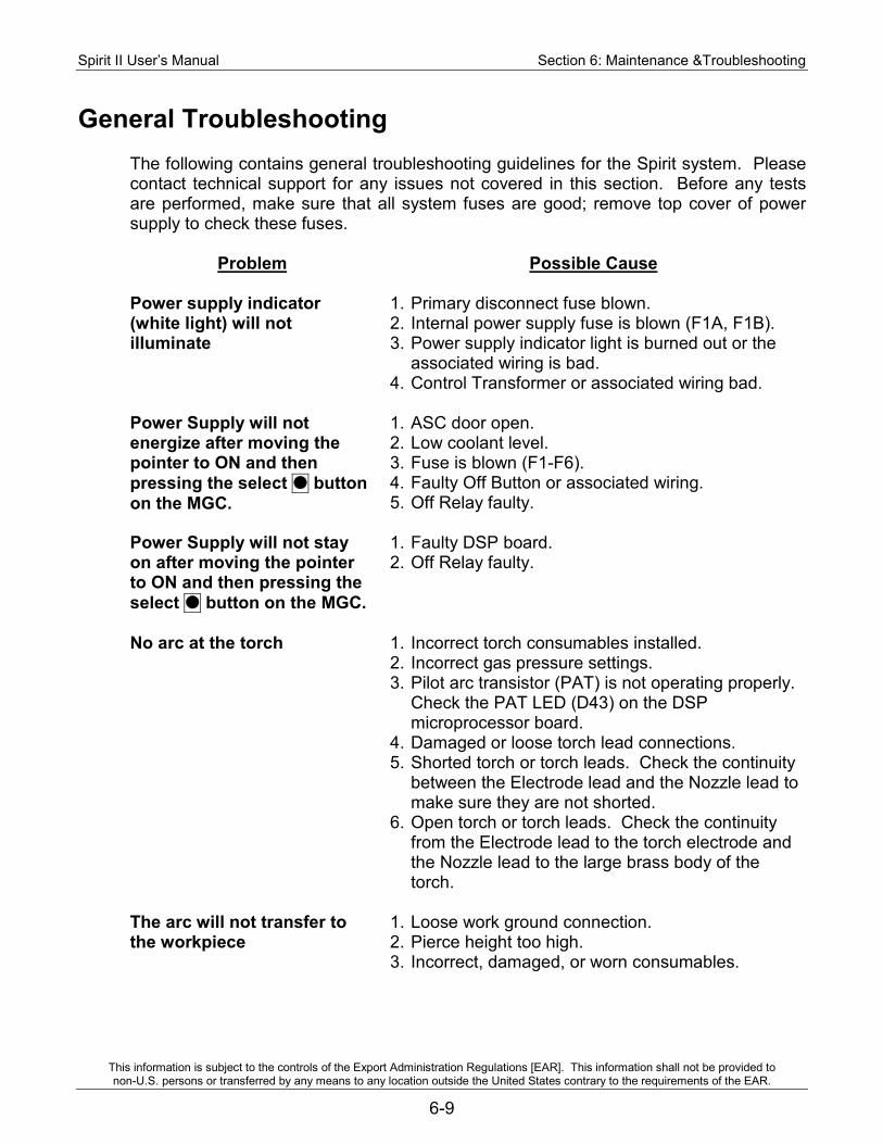
Spirit II User’s Manual Section 6: Maintenance &Troubleshooting
This information is subject to the controls of the Export Administration Regulations [EAR]. This information shall not be provided to non-U.S. persons or transferred by any means to any location outside the United States contrary to the requirements of the EAR.
6-9
General Troubleshooting
The following contains general troubleshooting guidelines for the Spirit system. Please contact technical support for any issues not covered in this section. Before any tests are performed, make sure that all system fuses are good; remove top cover of power supply to check these fuses.
Problem Possible Cause
Power supply indicator (white light) will not illuminate
1. Primary disconnect fuse blown. 2. Internal power supply fuse is blown (F1A, F1B). 3. Power supply indicator light is burned out or the
associated wiring is bad. 4. Control Transformer or associated wiring bad.
Power Supply will not energize after moving the pointer to ON and then pressing the select button on the MGC.
1. ASC door open. 2. Low coolant level. 3. Fuse is blown (F1-F6). 4. Faulty Off Button or associated wiring. 5. Off Relay faulty.
Power Supply will not stay on after moving the pointer to ON and then pressing the select button on the MGC.
1. Faulty DSP board. 2. Off Relay faulty.
No arc at the torch 1. Incorrect torch consumables installed. 2. Incorrect gas pressure settings. 3. Pilot arc transistor (PAT) is not operating properly.
Check the PAT LED (D43) on the DSP microprocessor board.
4. Damaged or loose torch lead connections. 5. Shorted torch or torch leads. Check the continuity
between the Electrode lead and the Nozzle lead to make sure they are not shorted.
6. Open torch or torch leads. Check the continuity from the Electrode lead to the torch electrode and the Nozzle lead to the large brass body of the torch.
The arc will not transfer to the workpiece
1. Loose work ground connection. 2. Pierce height too high. 3. Incorrect, damaged, or worn consumables.
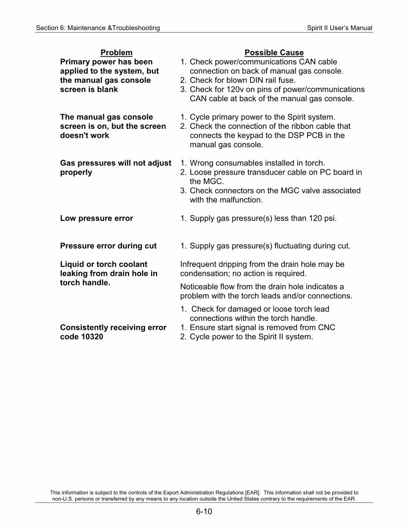
Section 6: Maintenance &Troubleshooting Spirit II User’s Manual
This information is subject to the controls of the Export Administration Regulations [EAR]. This information shall not be provided to non-U.S. persons or transferred by any means to any location outside the United States contrary to the requirements of the EAR.
6-10
Problem Possible Cause Primary power has been applied to the system, but the manual gas console screen is blank
1. Check power/communications CAN cable connection on back of manual gas console.
2. Check for blown DIN rail fuse. 3. Check for 120v on pins of power/communications
CAN cable at back of the manual gas console.
The manual gas console screen is on, but the screen doesn't work
1. Cycle primary power to the Spirit system. 2. Check the connection of the ribbon cable that
connects the keypad to the DSP PCB in the manual gas console.
Gas pressures will not adjust properly
1. Wrong consumables installed in torch. 2. Loose pressure transducer cable on PC board in
the MGC. 3. Check connectors on the MGC valve associated
with the malfunction.
Low pressure error 1. Supply gas pressure(s) less than 120 psi.
Pressure error during cut 1. Supply gas pressure(s) fluctuating during cut.
Liquid or torch coolant leaking from drain hole in torch handle.
Infrequent dripping from the drain hole may be condensation; no action is required. Noticeable flow from the drain hole indicates a problem with the torch leads and/or connections. 1. Check for damaged or loose torch lead
connections within the torch handle. Consistently receiving error code 10320
1. Ensure start signal is removed from CNC 2. Cycle power to the Spirit II system.

Spirit II User’s Manual Section 6: Maintenance &Troubleshooting
This information is subject to the controls of the Export Administration Regulations [EAR]. This information shall not be provided to non-U.S. persons or transferred by any means to any location outside the United States contrary to the requirements of the EAR.
6-11
Chopper Test Procedure WARNING: Only qualified maintenance personnel should perform the chopper test procedure. The system utilizes potentially fatal A.C. and D.C. voltages. All maintenance should be performed with safety in mind. Use extreme caution when working near the power conversion module (i.e., chopper). The large electrolytic capacitors store large amounts of energy even after power has been removed from the system. Wait at least five minutes after turning off power, and then use a voltmeter to verify that the capacitors are fully discharged before touching the power conversion module. Capacitor failure can injure and/or cause property damage. If troubleshooting requires the system to be powered with the enclosure panels removed, remain clear of the capacitors. Failure of a capacitor can result in a sudden release of stored energy causing rupture of the capacitor case. IMPORTANT: Depending upon the system, there are one, two or three chopper assemblies in the power supply. The following steps must be performed on each chopper with the other chopper(s) disabled. To disable a chopper, remove the plug from J1 on the chopper PCB (see drawing on next page). 1. Remove primary power from the Spirit system.
2. Remove the top, left, right and front covers from the power supply to expose the DSP PCB, input and output terminal blocks and chopper(s).
3. Remove the HF/ISC wire connected to TB2 side 2 (right side) from position 2 or 3. Make sure to isolate the connector so that it doesn’t come in contact with anything metal during this test. Return the jumper wire to the original position at the end of this test.
TB2, Side 2, Position 2 TB2, Side 2, Position 3 HF/ISC Wire
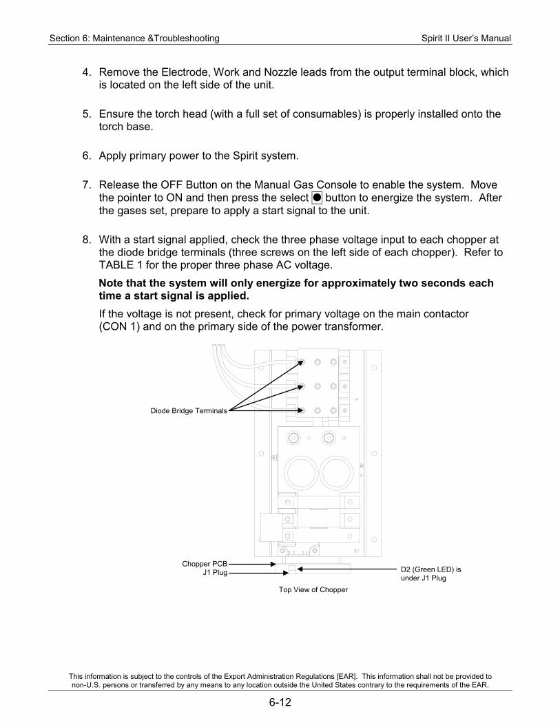
Section 6: Maintenance &Troubleshooting Spirit II User’s Manual
This information is subject to the controls of the Export Administration Regulations [EAR]. This information shall not be provided to non-U.S. persons or transferred by any means to any location outside the United States contrary to the requirements of the EAR.
6-12
4. Remove the Electrode, Work and Nozzle leads from the output terminal block, which is located on the left side of the unit.
5. Ensure the torch head (with a full set of consumables) is properly installed onto the torch base.
6. Apply primary power to the Spirit system.
7. Release the OFF Button on the Manual Gas Console to enable the system. Move the pointer to ON and then press the select button to energize the system. After the gases set, prepare to apply a start signal to the unit.
8. With a start signal applied, check the three phase voltage input to each chopper at the diode bridge terminals (three screws on the left side of each chopper). Refer to TABLE 1 for the proper three phase AC voltage. Note that the system will only energize for approximately two seconds each time a start signal is applied. If the voltage is not present, check for primary voltage on the main contactor (CON 1) and on the primary side of the power transformer.
Top View of Chopper
Diode Bridge Terminals
Chopper PCB J1 Plug D2 (Green LED) is
under J1 Plug
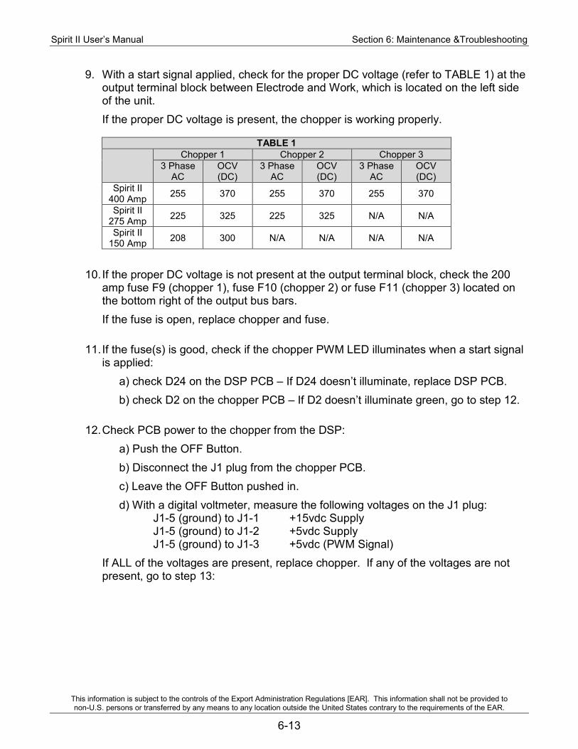
Spirit II User’s Manual Section 6: Maintenance &Troubleshooting
This information is subject to the controls of the Export Administration Regulations [EAR]. This information shall not be provided to non-U.S. persons or transferred by any means to any location outside the United States contrary to the requirements of the EAR.
6-13
9. With a start signal applied, check for the proper DC voltage (refer to TABLE 1) at the output terminal block between Electrode and Work, which is located on the left side of the unit. If the proper DC voltage is present, the chopper is working properly.
TABLE 1
Chopper 1 Chopper 2 Chopper 3
3 Phase AC
OCV (DC)
3 Phase AC
OCV (DC)
3 Phase AC
OCV (DC)
Spirit II 400 Amp 255 370 255 370 255 370
Spirit II 275 Amp 225 325 225 325 N/A N/A
Spirit II 150 Amp 208 300 N/A N/A N/A N/A
10. If the proper DC voltage is not present at the output terminal block, check the 200
amp fuse F9 (chopper 1), fuse F10 (chopper 2) or fuse F11 (chopper 3) located on the bottom right of the output bus bars. If the fuse is open, replace chopper and fuse.
11. If the fuse(s) is good, check if the chopper PWM LED illuminates when a start signal is applied:
a) check D24 on the DSP PCB – If D24 doesn’t illuminate, replace DSP PCB. b) check D2 on the chopper PCB – If D2 doesn’t illuminate green, go to step 12.
12. Check PCB power to the chopper from the DSP: a) Push the OFF Button. b) Disconnect the J1 plug from the chopper PCB. c) Leave the OFF Button pushed in. d) With a digital voltmeter, measure the following voltages on the J1 plug:
J1-5 (ground) to J1-1 +15vdc Supply J1-5 (ground) to J1-2 +5vdc Supply J1-5 (ground) to J1-3 +5vdc (PWM Signal)
If ALL of the voltages are present, replace chopper. If any of the voltages are not present, go to step 13:
Section 6: Maintenance &Troubleshooting Spirit II User’s Manual
This information is subject to the controls of the Export Administration Regulations [EAR]. This information shall not be provided to non-U.S. persons or transferred by any means to any location outside the United States contrary to the requirements of the EAR.
6-14
13. Remove primary power from the Spirit system. Check cable continuity between the chopper PCB and DSP PCB. Use a digital voltmeter set up to read resistance (ohms) and make the following measurements:
Chopper (1) J1-1 to DSP J7-1 Chopper (1) J1-2 to DSP J7-2 Chopper (1) J1-3 to DSP J7-3 Chopper (1) J1-5 to DSP J7-4 Chopper (2) J1-1 to DSP J8-1 Chopper (2) J1-2 to DSP J8-2 Chopper (2) J1-3 to DSP J8-3 Chopper (2) J1-5 to DSP J8-4 Chopper (3) J1-1 to DSP J9-1 Chopper (3) J1-2 to DSP J9-2 Chopper (3) J1-3 to DSP J9-3 Chopper (3) J1-5 to DSP J9-4
If ALL of the continuity readings are good, replace DSP PCB.
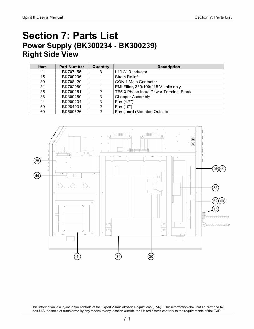
Spirit II User’s Manual Section 7: Parts List
This information is subject to the controls of the Export Administration Regulations [EAR]. This information shall not be provided to non-U.S. persons or transferred by any means to any location outside the United States contrary to the requirements of the EAR.
7-1
Section 7: Parts List Power Supply (BK300234 - BK300239) Right Side View
Item Part Number Quantity Description 4 BK707155 3 L1/L2/L3 Inductor
15 BK709296 1 Strain Relief 30 BK708120 1 CON 1 Main Contactor 31 BK702080 1 EMI Filter, 380/400/415 V units only 35 BK709251 2 TB5 3 Phase Input Power Terminal Block 38 BK300250 3 Chopper Assembly 44 BK200204 3 Fan (4.7") 59 BK284031 2 Fan (10") 60 BK500526 2 Fan guard (Mounted Outside)
38
44
59
35
4 31 30
60
59
15
60
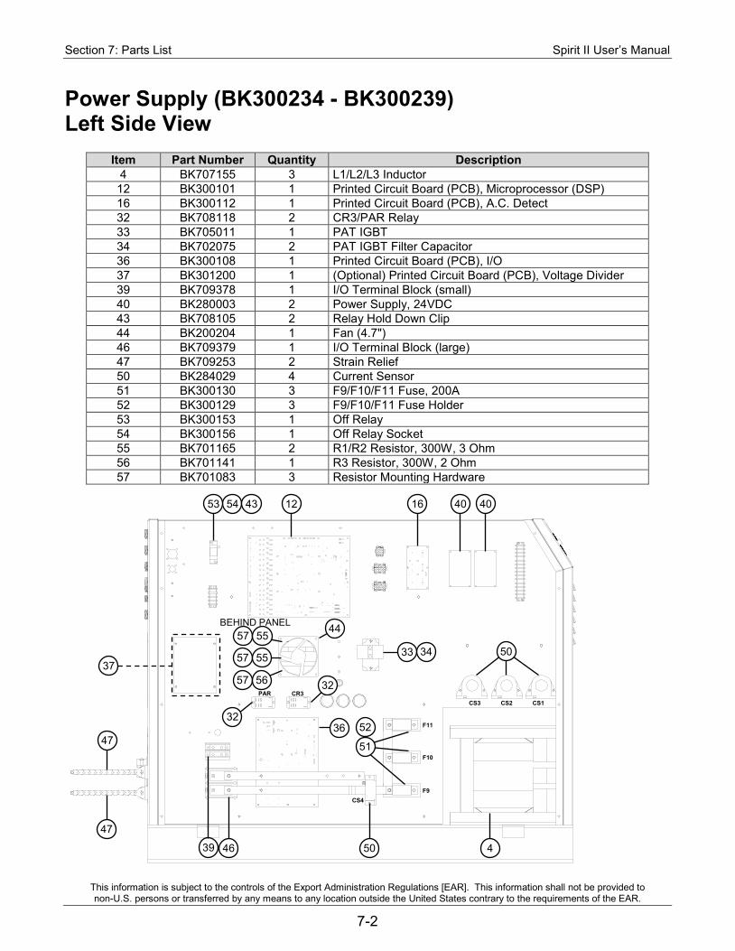
Section 7: Parts List Spirit II User’s Manual
This information is subject to the controls of the Export Administration Regulations [EAR]. This information shall not be provided to non-U.S. persons or transferred by any means to any location outside the United States contrary to the requirements of the EAR.
7-2
Power Supply (BK300234 - BK300239) Left Side View
Item Part Number Quantity Description 4 BK707155 3 L1/L2/L3 Inductor 12 BK300101 1 Printed Circuit Board (PCB), Microprocessor (DSP) 16 BK300112 1 Printed Circuit Board (PCB), A.C. Detect 32 BK708118 2 CR3/PAR Relay 33 BK705011 1 PAT IGBT 34 BK702075 2 PAT IGBT Filter Capacitor 36 BK300108 1 Printed Circuit Board (PCB), I/O 37 BK301200 1 (Optional) Printed Circuit Board (PCB), Voltage Divider 39 BK709378 1 I/O Terminal Block (small) 40 BK280003 2 Power Supply, 24VDC 43 BK708105 2 Relay Hold Down Clip 44 BK200204 1 Fan (4.7") 46 BK709379 1 I/O Terminal Block (large) 47 BK709253 2 Strain Relief 50 BK284029 4 Current Sensor 51 BK300130 3 F9/F10/F11 Fuse, 200A 52 BK300129 3 F9/F10/F11 Fuse Holder 53 BK300153 1 Off Relay 54 BK300156 1 Off Relay Socket 55 BK701165 2 R1/R2 Resistor, 300W, 3 Ohm 56 BK701141 1 R3 Resistor, 300W, 2 Ohm 57 BK701083 3 Resistor Mounting Hardware
54
52
53 16 40 40
46 50
47
47
4
33 34 37
12
44
50
51
32
39
BEHIND PANEL
36
57
57
57
55
55
56
32
43
PAR CR3
F9
CS3 CS2 CS1
F10
F11
CS4
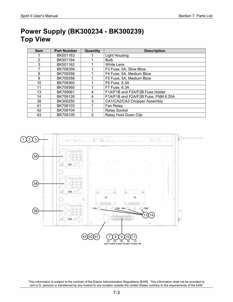
Spirit II User’s Manual Section 7: Parts List
This information is subject to the controls of the Export Administration Regulations [EAR]. This information shall not be provided to non-U.S. persons or transferred by any means to any location outside the United States contrary to the requirements of the EAR.
7-3
Power Supply (BK300234 - BK300239) Top View
Item Part Number Quantity Description 1 BK501163 1 Light Housing 2 BK501164 1 Bulb 3 BK501162 1 White Lens 7 BK709359 1 F3 Fuse, 5A, Slow Blow 8 BK709358 1 F4 Fuse, 5A, Medium Blow 9 BK709358 1 F5 Fuse, 5A, Medium Blow
10 BK709360 1 F6 Fuse, 6.3A 11 BK709360 1 F7 Fuse, 6.3A 13 BK709061 4 F1A/F1B and F2A/F2B Fuse Holder 14 BK709128 4 F1A/F1B and F2A/F2B Fuse, FNM 6.25A 38 BK300250 3 CA1/CA2/CA3 Chopper Assembly 41 BK708103 1 Fan Relay 42 BK708104 1 Relay Socket 43 BK708105 2 Relay Hold Down Clip
F1A F1B F2A F2B
T2 T3
CA1
CA2
CA3
F3 F4 F5 F6 F7 (pos 1) (pos 4) (pos 12) (pos 17) (pos 19)
42 43
1 2 3
38
14
38
38
41
13
7 8 9 10 11
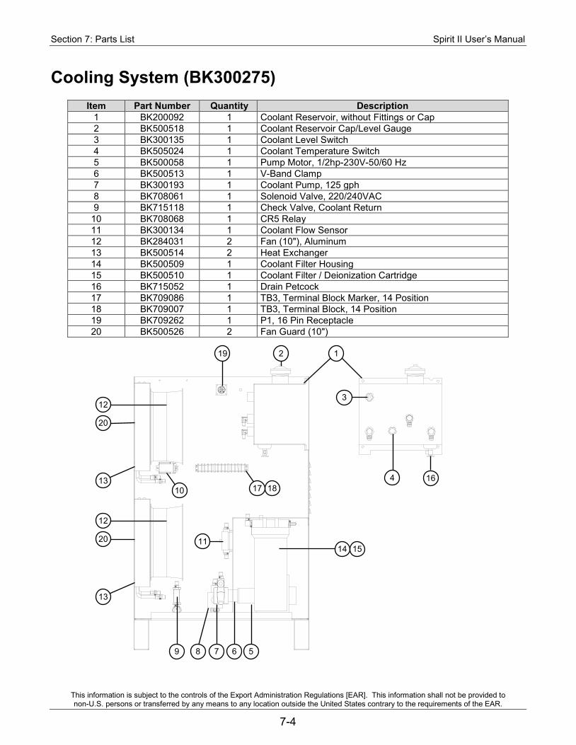
Section 7: Parts List Spirit II User’s Manual
This information is subject to the controls of the Export Administration Regulations [EAR]. This information shall not be provided to non-U.S. persons or transferred by any means to any location outside the United States contrary to the requirements of the EAR.
7-4
Cooling System (BK300275)
Item Part Number Quantity Description 1 BK200092 1 Coolant Reservoir, without Fittings or Cap 2 BK500518 1 Coolant Reservoir Cap/Level Gauge 3 BK300135 1 Coolant Level Switch 4 BK505024 1 Coolant Temperature Switch 5 BK500058 1 Pump Motor, 1/2hp-230V-50/60 Hz 6 BK500513 1 V-Band Clamp 7 BK300193 1 Coolant Pump, 125 gph 8 BK708061 1 Solenoid Valve, 220/240VAC 9 BK715118 1 Check Valve, Coolant Return
10 BK708068 1 CR5 Relay 11 BK300134 1 Coolant Flow Sensor 12 BK284031 2 Fan (10"), Aluminum 13 BK500514 2 Heat Exchanger 14 BK500509 1 Coolant Filter Housing 15 BK500510 1 Coolant Filter / Deionization Cartridge 16 BK715052 1 Drain Petcock 17 BK709086 1 TB3, Terminal Block Marker, 14 Position 18 BK709007 1 TB3, Terminal Block, 14 Position 19 BK709262 1 P1, 16 Pin Receptacle 20 BK500526 2 Fan Guard (10")
10
2
3
4 16
20
14
9 5
15
1 19
12
18 13
20
12
13
17
8 7 6
11
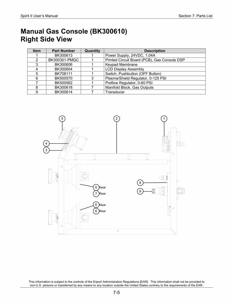
Spirit II User’s Manual Section 7: Parts List
This information is subject to the controls of the Export Administration Regulations [EAR]. This information shall not be provided to non-U.S. persons or transferred by any means to any location outside the United States contrary to the requirements of the EAR.
7-5
Manual Gas Console (BK300610) Right Side View
Item Part Number Quantity Description 1 BK300613 1 Power Supply, 24VDC, 1.04A 2 BK300301-PMGC 1 Printed Circuit Board (PCB), Gas Console DSP 3 BK300606 1 Keypad Membrane 4 BK300604 1 LCD Display Assembly 5 BK708111 1 Switch, Pushbutton (OFF Button) 6 BK500570 3 Plasma/Shield Regulator, 0-125 PSI 7 BK500562 1 Preflow Regulator, 0-60 PSI 8 BK300618 7 Manifold Block, Gas Outputs 9 BK300614 7 Transducer
1 5 2
4
9
3
8
7
6
Near
Rear
Near
Rear
6
6
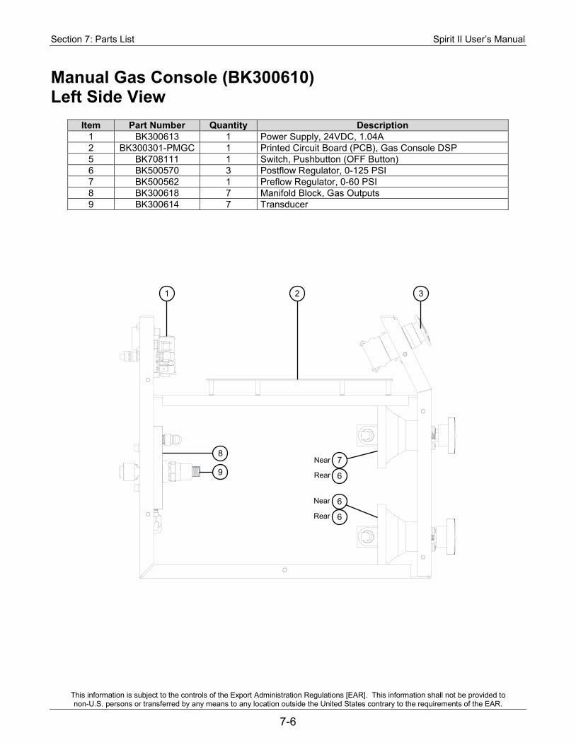
Section 7: Parts List Spirit II User’s Manual
This information is subject to the controls of the Export Administration Regulations [EAR]. This information shall not be provided to non-U.S. persons or transferred by any means to any location outside the United States contrary to the requirements of the EAR.
7-6
Manual Gas Console (BK300610) Left Side View
Item Part Number Quantity Description 1 BK300613 1 Power Supply, 24VDC, 1.04A 2 BK300301-PMGC 1 Printed Circuit Board (PCB), Gas Console DSP 5 BK708111 1 Switch, Pushbutton (OFF Button) 6 BK500570 3 Postflow Regulator, 0-125 PSI 7 BK500562 1 Preflow Regulator, 0-60 PSI 8 BK300618 7 Manifold Block, Gas Outputs 9 BK300614 7 Transducer
1 3 2
8
9 7
6
6
6
Near
Rear
Near
Rear
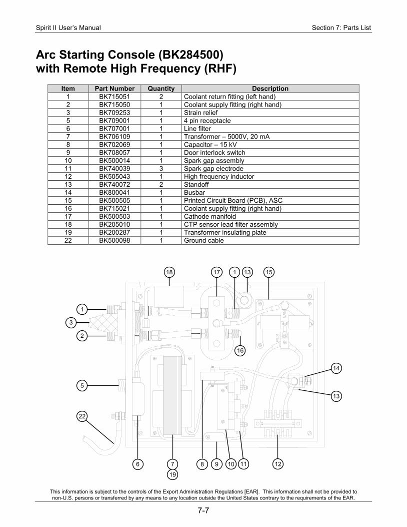
Spirit II User’s Manual Section 7: Parts List
This information is subject to the controls of the Export Administration Regulations [EAR]. This information shall not be provided to non-U.S. persons or transferred by any means to any location outside the United States contrary to the requirements of the EAR.
7-7
Arc Starting Console (BK284500) with Remote High Frequency (RHF)
Item Part Number Quantity Description 1 BK715051 2 Coolant return fitting (left hand) 2 BK715050 1 Coolant supply fitting (right hand) 3 BK709253 1 Strain relief 5 BK709001 1 4 pin receptacle 6 BK707001 1 Line filter 7 BK706109 1 Transformer – 5000V, 20 mA 8 BK702069 1 Capacitor – 15 kV 9 BK708057 1 Door interlock switch
10 BK500014 1 Spark gap assembly 11 BK740039 3 Spark gap electrode 12 BK505043 1 High frequency inductor 13 BK740072 2 Standoff 14 BK800041 1 Busbar 15 BK500505 1 Printed Circuit Board (PCB), ASC 16 BK715021 1 Coolant supply fitting (right hand) 17 BK500503 1 Cathode manifold 18 BK205010 1 CTP sensor lead filter assembly 19 BK200287 1 Transformer insulating plate 22 BK500098 1 Ground cable
14
18
1
17 1 15
13
2
5
22
6 7 8 9 10 11 12
16
13
3
19
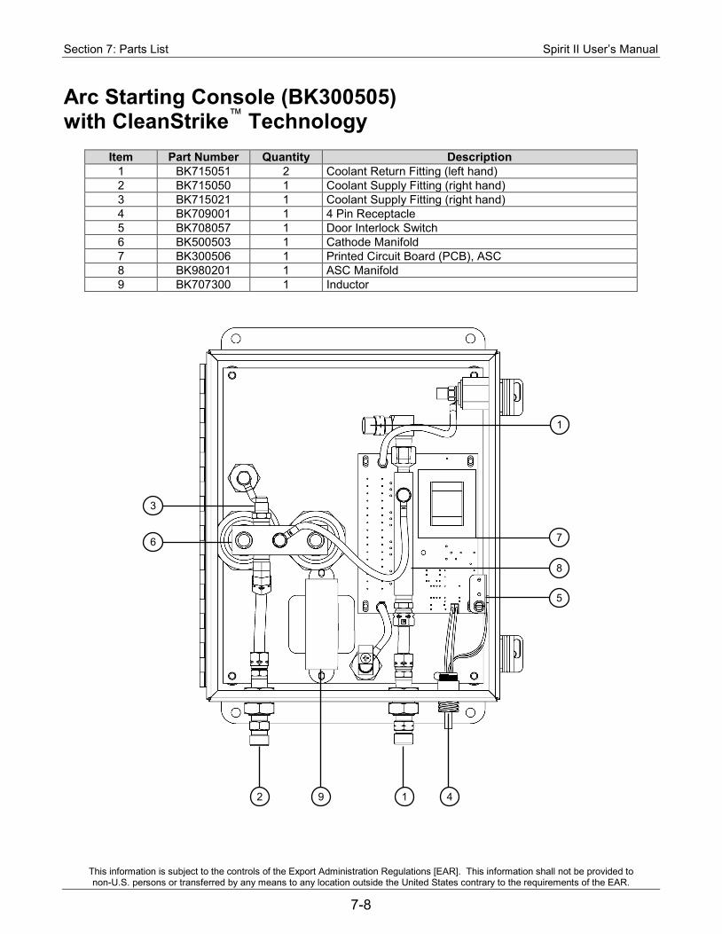
Section 7: Parts List Spirit II User’s Manual
This information is subject to the controls of the Export Administration Regulations [EAR]. This information shall not be provided to non-U.S. persons or transferred by any means to any location outside the United States contrary to the requirements of the EAR.
7-8
Arc Starting Console (BK300505) with CleanStrike™ Technology
Item Part Number Quantity Description 1 BK715051 2 Coolant Return Fitting (left hand) 2 BK715050 1 Coolant Supply Fitting (right hand) 3 BK715021 1 Coolant Supply Fitting (right hand) 4 BK709001 1 4 Pin Receptacle 5 BK708057 1 Door Interlock Switch 6 BK500503 1 Cathode Manifold 7 BK300506 1 Printed Circuit Board (PCB), ASC 8 BK980201 1 ASC Manifold 9 BK707300 1 Inductor
3
6
2 9 4 1
1
7
8
5
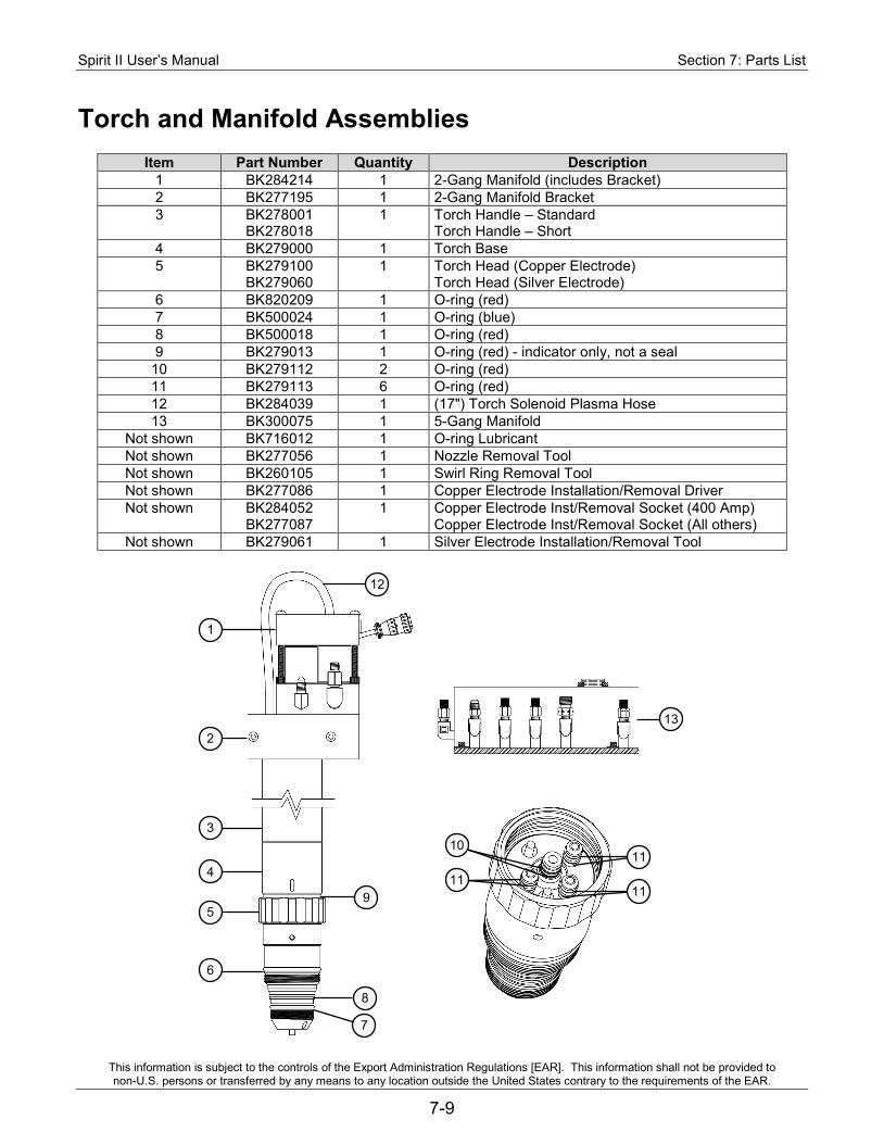
Spirit II User’s Manual Section 7: Parts List
This information is subject to the controls of the Export Administration Regulations [EAR]. This information shall not be provided to non-U.S. persons or transferred by any means to any location outside the United States contrary to the requirements of the EAR.
7-9
Torch and Manifold Assemblies
Item Part Number Quantity Description 1 BK284214 1 2-Gang Manifold (includes Bracket) 2 BK277195 1 2-Gang Manifold Bracket 3 BK278001
BK278018 1 Torch Handle – Standard
Torch Handle – Short 4 BK279000 1 Torch Base 5 BK279100
BK279060 1 Torch Head (Copper Electrode)
Torch Head (Silver Electrode) 6 BK820209 1 O-ring (red) 7 BK500024 1 O-ring (blue) 8 BK500018 1 O-ring (red) 9 BK279013 1 O-ring (red) - indicator only, not a seal
10 BK279112 2 O-ring (red) 11 BK279113 6 O-ring (red) 12 BK284039 1 (17") Torch Solenoid Plasma Hose 13 BK300075 1 5-Gang Manifold
Not shown BK716012 1 O-ring Lubricant Not shown BK277056 1 Nozzle Removal Tool Not shown BK260105 1 Swirl Ring Removal Tool Not shown BK277086 1 Copper Electrode Installation/Removal Driver Not shown BK284052
BK277087 1 Copper Electrode Inst/Removal Socket (400 Amp)
Copper Electrode Inst/Removal Socket (All others) Not shown BK279061 1 Silver Electrode Installation/Removal Tool
13
1
12
2
3
4
5 9
6
8
7
11
11
10
11
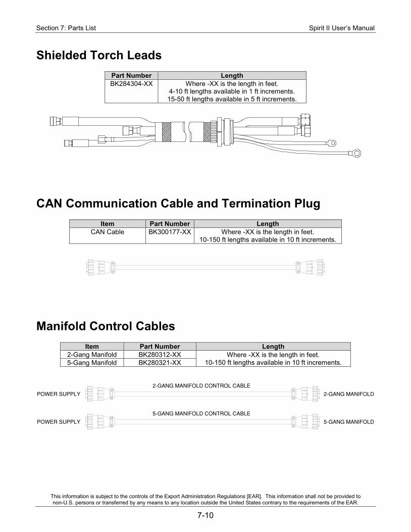
Section 7: Parts List Spirit II User’s Manual
This information is subject to the controls of the Export Administration Regulations [EAR]. This information shall not be provided to non-U.S. persons or transferred by any means to any location outside the United States contrary to the requirements of the EAR.
7-10
Shielded Torch Leads
Part Number Length BK284304-XX Where -XX is the length in feet.
4-10 ft lengths available in 1 ft increments. 15-50 ft lengths available in 5 ft increments.
CAN Communication Cable and Termination Plug
Item Part Number Length CAN Cable BK300177-XX Where -XX is the length in feet.
10-150 ft lengths available in 10 ft increments.
Manifold Control Cables
Item Part Number Length 2-Gang Manifold BK280312-XX Where -XX is the length in feet.
10-150 ft lengths available in 10 ft increments. 5-Gang Manifold BK280321-XX
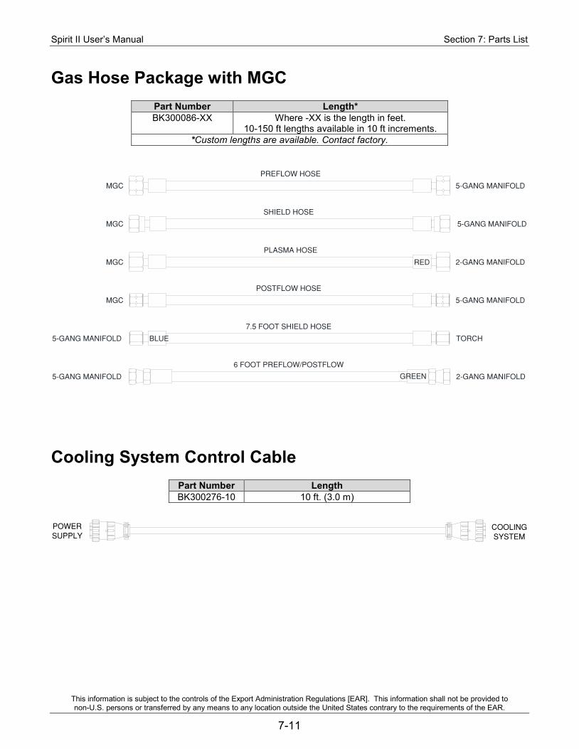
Spirit II User’s Manual Section 7: Parts List
This information is subject to the controls of the Export Administration Regulations [EAR]. This information shall not be provided to non-U.S. persons or transferred by any means to any location outside the United States contrary to the requirements of the EAR.
7-11
Gas Hose Package with MGC
Part Number Length* BK300086-XX Where -XX is the length in feet.
10-150 ft lengths available in 10 ft increments. *Custom lengths are available. Contact factory.
Cooling System Control Cable
Part Number Length BK300276-10 10 ft. (3.0 m)
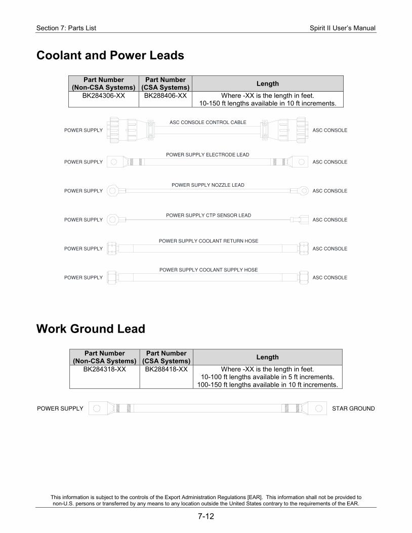
Section 7: Parts List Spirit II User’s Manual
This information is subject to the controls of the Export Administration Regulations [EAR]. This information shall not be provided to non-U.S. persons or transferred by any means to any location outside the United States contrary to the requirements of the EAR.
7-12
Coolant and Power Leads
Part Number (Non-CSA Systems)
Part Number (CSA Systems) Length
BK284306-XX BK288406-XX Where -XX is the length in feet. 10-150 ft lengths available in 10 ft increments.
Work Ground Lead
Part Number (Non-CSA Systems)
Part Number (CSA Systems) Length
BK284318-XX BK288418-XX Where -XX is the length in feet. 10-100 ft lengths available in 5 ft increments.
100-150 ft lengths available in 10 ft increments.
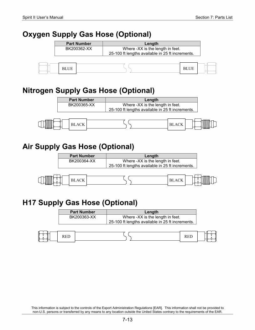
Spirit II User’s Manual Section 7: Parts List
This information is subject to the controls of the Export Administration Regulations [EAR]. This information shall not be provided to non-U.S. persons or transferred by any means to any location outside the United States contrary to the requirements of the EAR.
7-13
Oxygen Supply Gas Hose (Optional) Part Number Length BK200362-XX Where -XX is the length in feet.
25-100 ft lengths available in 25 ft increments.
Nitrogen Supply Gas Hose (Optional) Part Number Length BK200365-XX Where -XX is the length in feet.
25-100 ft lengths available in 25 ft increments.
Air Supply Gas Hose (Optional) Part Number Length BK200364-XX Where -XX is the length in feet.
25-100 ft lengths available in 25 ft increments.
H17 Supply Gas Hose (Optional) Part Number Length BK200363-XX Where -XX is the length in feet.
25-100 ft lengths available in 25 ft increments.
BLUE BLUE
BLACK
BLACK BLACK
RED RED
BLACK
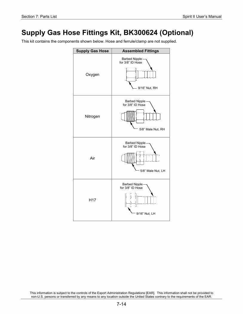
Section 7: Parts List Spirit II User’s Manual
This information is subject to the controls of the Export Administration Regulations [EAR]. This information shall not be provided to non-U.S. persons or transferred by any means to any location outside the United States contrary to the requirements of the EAR.
7-14
Supply Gas Hose Fittings Kit, BK300624 (Optional) This kit contains the components shown below. Hose and ferrule/clamp are not supplied.
Supply Gas Hose Assembled Fittings
Oxygen
Nitrogen
Air
H17
Barbed Nipple for 3/8” ID Hose
9/16” Nut, RH
5/8” Male Nut, RH
5/8” Male Nut, LH
9/16” Nut, LH
Barbed Nipple for 3/8” ID Hose
Barbed Nipple for 3/8” ID Hose
Barbed Nipple for 3/8” ID Hose
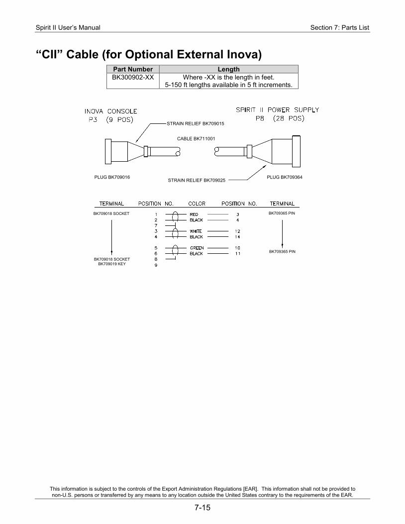
Spirit II User’s Manual Section 7: Parts List
This information is subject to the controls of the Export Administration Regulations [EAR]. This information shall not be provided to non-U.S. persons or transferred by any means to any location outside the United States contrary to the requirements of the EAR.
7-15
“CII” Cable (for Optional External Inova) Part Number Length BK300902-XX Where -XX is the length in feet.
5-150 ft lengths available in 5 ft increments.
STRAIN RELIEF BK709015
CABLE BK711001
STRAIN RELIEF BK709025 PLUG BK709364 PLUG BK709016
BK709018 SOCKET
BK709018 SOCKET BK709019 KEY
BK709365 PIN
BK709365 PIN
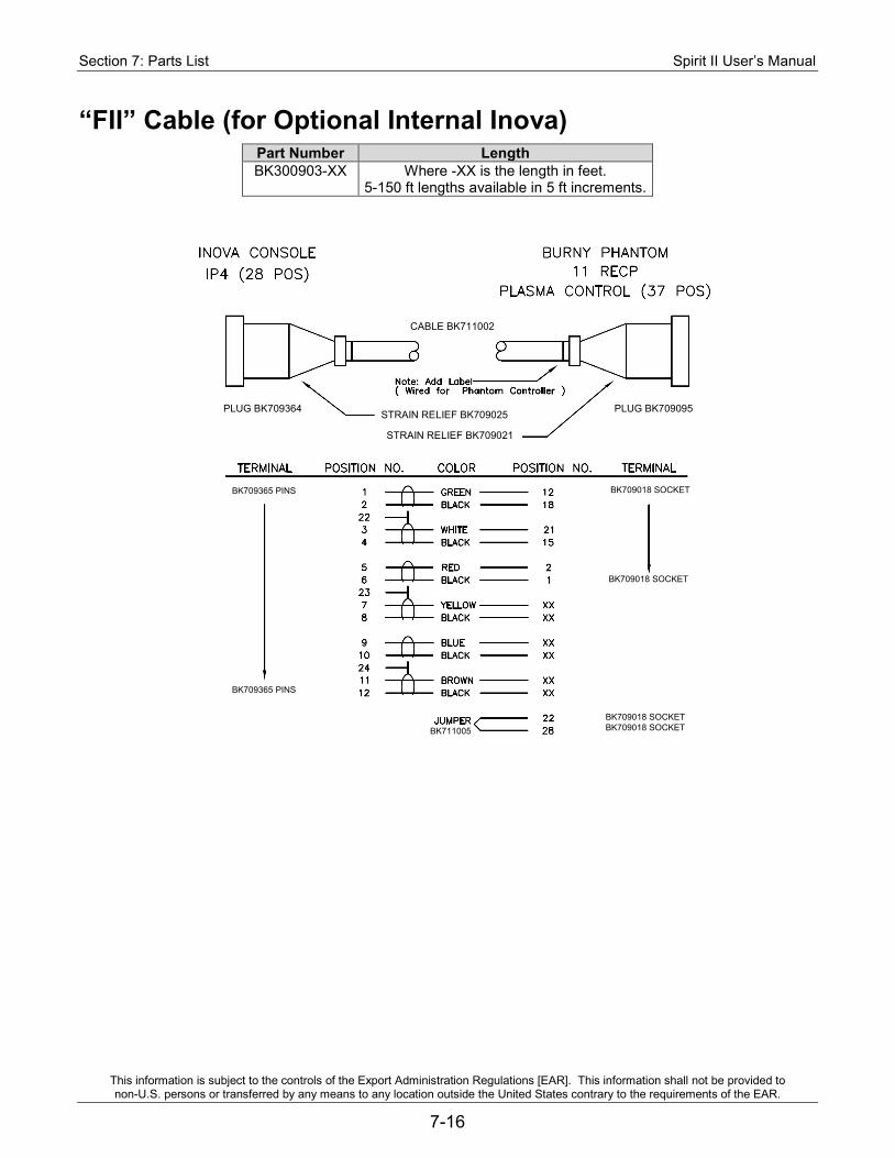
Section 7: Parts List Spirit II User’s Manual
This information is subject to the controls of the Export Administration Regulations [EAR]. This information shall not be provided to non-U.S. persons or transferred by any means to any location outside the United States contrary to the requirements of the EAR.
7-16
“FII” Cable (for Optional Internal Inova) Part Number Length BK300903-XX Where -XX is the length in feet.
5-150 ft lengths available in 5 ft increments.
STRAIN RELIEF BK709021
CABLE BK711002
STRAIN RELIEF BK709025 PLUG BK709095 PLUG BK709364
BK709365 PINS
BK709365 PINS
BK709018 SOCKET
BK709018 SOCKET
BK709018 SOCKET BK709018 SOCKET BK711005
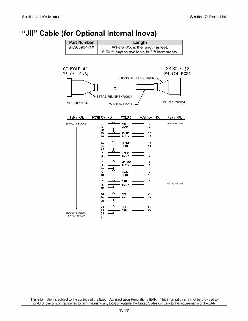
Spirit II User’s Manual Section 7: Parts List
This information is subject to the controls of the Export Administration Regulations [EAR]. This information shall not be provided to non-U.S. persons or transferred by any means to any location outside the United States contrary to the requirements of the EAR.
7-17
“JII” Cable (for Optional Internal Inova) Part Number Length BK300904-XX Where -XX is the length in feet.
5-50 ft lengths available in 5 ft increments.
STRAIN RELIEF BK709021
STRAIN RELIEF BK709025
CABLE BK711049 PLUG BK709364 PLUG BK709020
BK709018 SOCKET
BK709018 SOCKET BK709019 KEY
BK709365 PIN
BK709365 PIN
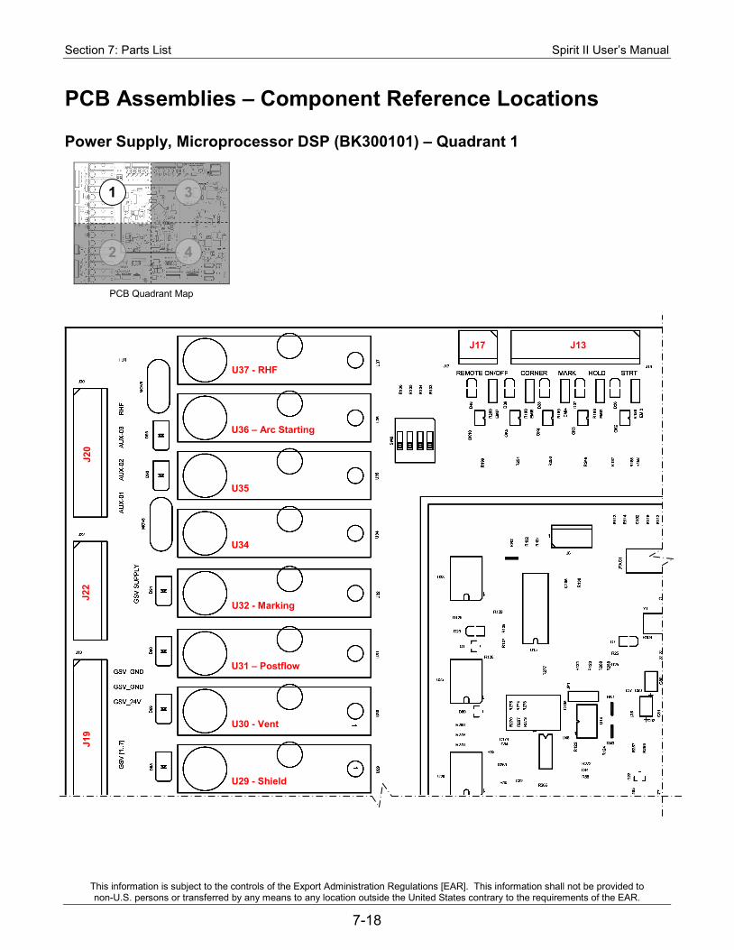
Section 7: Parts List Spirit II User’s Manual
This information is subject to the controls of the Export Administration Regulations [EAR]. This information shall not be provided to non-U.S. persons or transferred by any means to any location outside the United States contrary to the requirements of the EAR.
7-18
PCB Assemblies – Component Reference Locations
Power Supply, Microprocessor DSP (BK300101) – Quadrant 1
J17 J13
U37 - RHF
U36 – Arc Starting
U35
U34
U32 - Marking
U31 – Postflow
U30 - Vent
U29 - Shield
J20
J22
J19
PCB Quadrant Map
1 3
4 2
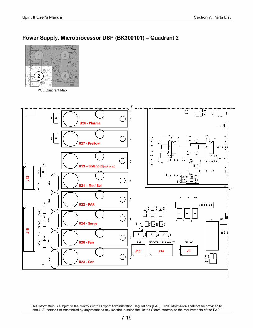
Spirit II User’s Manual Section 7: Parts List
This information is subject to the controls of the Export Administration Regulations [EAR]. This information shall not be provided to non-U.S. persons or transferred by any means to any location outside the United States contrary to the requirements of the EAR.
7-19
Power Supply, Microprocessor DSP (BK300101) – Quadrant 2
J15
U28 - Plasma
U27 - Preflow
U19 – Solenoid (not used)
U21 – Mtr / Sol
U22 - PAR
U24 - Surge
U26 - Fan
U23 - Con
J16
J12
J14 J1
PCB Quadrant Map
1 3
4 2
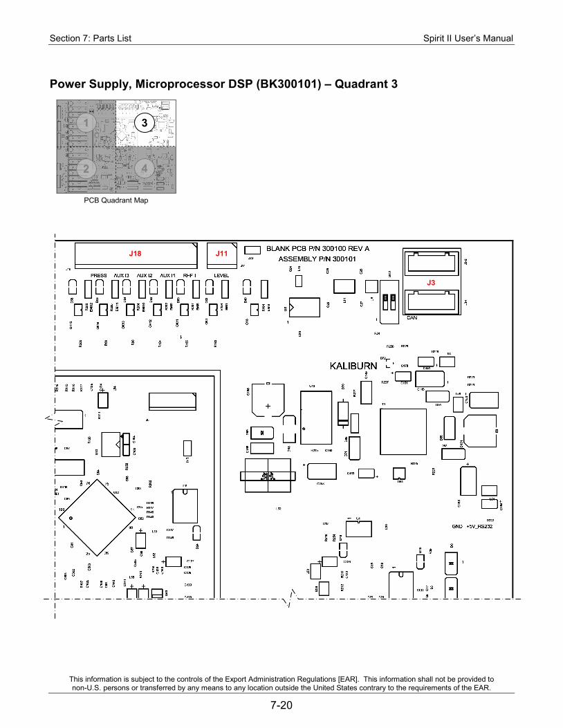
Section 7: Parts List Spirit II User’s Manual
This information is subject to the controls of the Export Administration Regulations [EAR]. This information shall not be provided to non-U.S. persons or transferred by any means to any location outside the United States contrary to the requirements of the EAR.
7-20
Power Supply, Microprocessor DSP (BK300101) – Quadrant 3
J18 J11
J3
PCB Quadrant Map
1 3
4 2
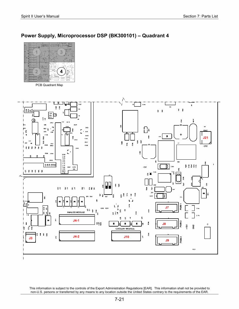
Spirit II User’s Manual Section 7: Parts List
This information is subject to the controls of the Export Administration Regulations [EAR]. This information shall not be provided to non-U.S. persons or transferred by any means to any location outside the United States contrary to the requirements of the EAR.
7-21
PCB Quadrant Map
Power Supply, Microprocessor DSP (BK300101) – Quadrant 4
J3 J4-2
J4-1
J10
J7
J8
J9
J21
1 3
4 2
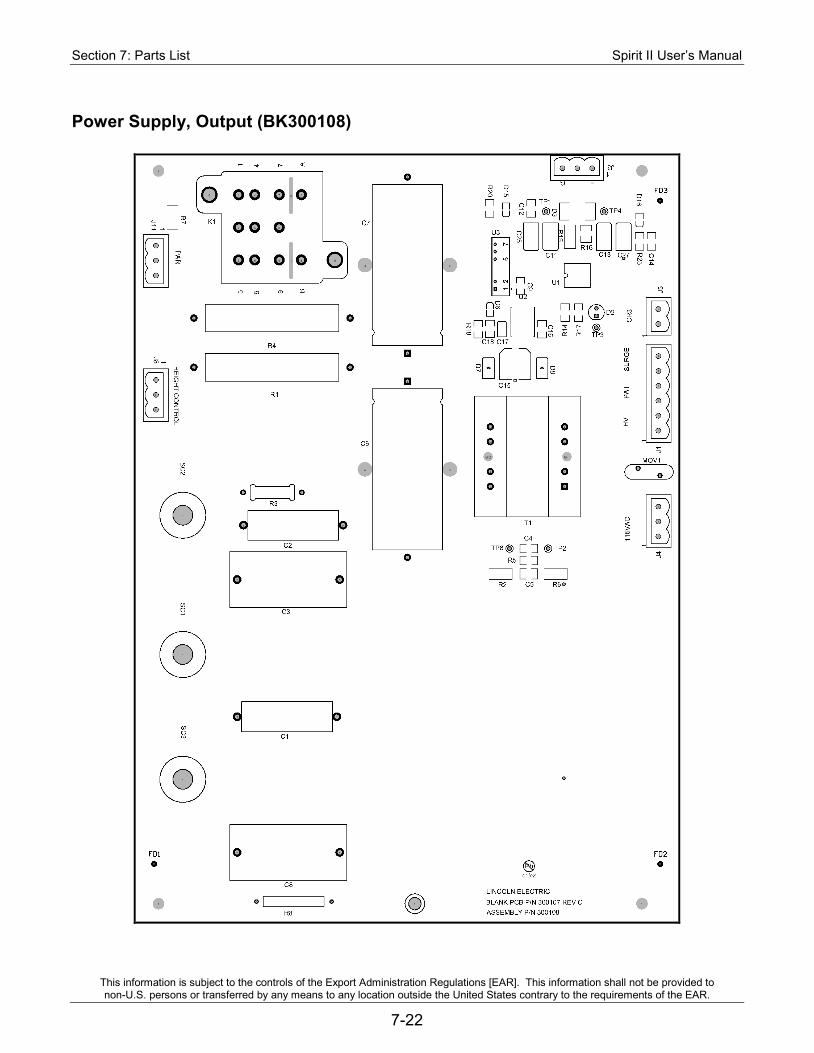
Section 7: Parts List Spirit II User’s Manual
This information is subject to the controls of the Export Administration Regulations [EAR]. This information shall not be provided to non-U.S. persons or transferred by any means to any location outside the United States contrary to the requirements of the EAR.
7-22
Power Supply, Output (BK300108)
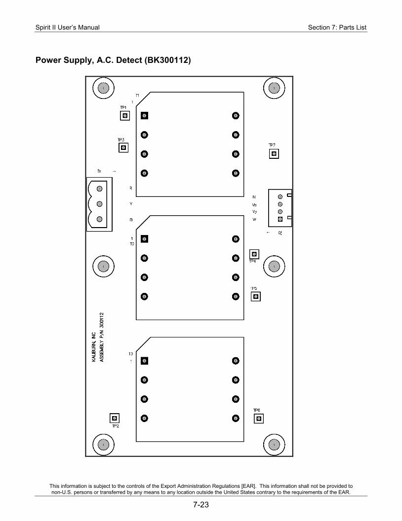
Spirit II User’s Manual Section 7: Parts List
This information is subject to the controls of the Export Administration Regulations [EAR]. This information shall not be provided to non-U.S. persons or transferred by any means to any location outside the United States contrary to the requirements of the EAR.
7-23
Power Supply, A.C. Detect (BK300112)
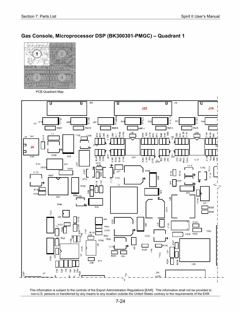
Section 7: Parts List Spirit II User’s Manual
This information is subject to the controls of the Export Administration Regulations [EAR]. This information shall not be provided to non-U.S. persons or transferred by any means to any location outside the United States contrary to the requirements of the EAR.
7-24
Gas Console, Microprocessor DSP (BK300301-PMGC) – Quadrant 1
PCB Quadrant Map
1 3
4 2
J25 J19
J4
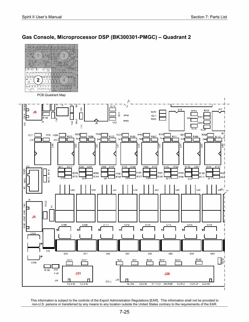
Spirit II User’s Manual Section 7: Parts List
This information is subject to the controls of the Export Administration Regulations [EAR]. This information shall not be provided to non-U.S. persons or transferred by any means to any location outside the United States contrary to the requirements of the EAR.
7-25
Gas Console, Microprocessor DSP (BK300301-PMGC) – Quadrant 2
J6
PCB Quadrant Map
1 3
4 2
J5
J31 J28
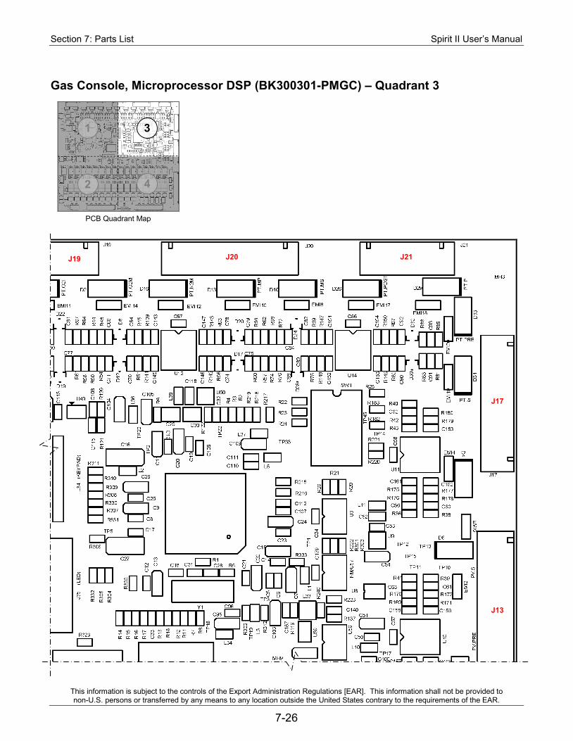
Section 7: Parts List Spirit II User’s Manual
This information is subject to the controls of the Export Administration Regulations [EAR]. This information shall not be provided to non-U.S. persons or transferred by any means to any location outside the United States contrary to the requirements of the EAR.
7-26
Gas Console, Microprocessor DSP (BK300301-PMGC) – Quadrant 3
J19
PCB Quadrant Map
1 3
4 2
J20 J21
J17
J13
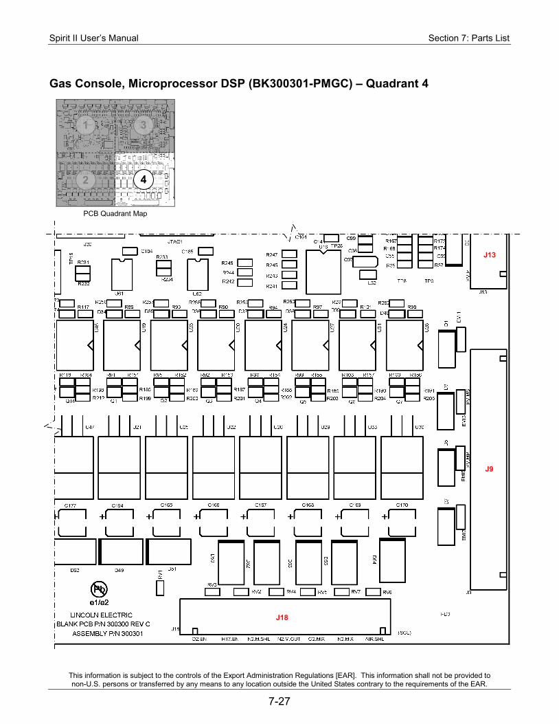
Spirit II User’s Manual Section 7: Parts List
This information is subject to the controls of the Export Administration Regulations [EAR]. This information shall not be provided to non-U.S. persons or transferred by any means to any location outside the United States contrary to the requirements of the EAR.
7-27
PCB Quadrant Map
Gas Console, Microprocessor DSP (BK300301-PMGC) – Quadrant 4
J13
1 3
4 2
J9
J18
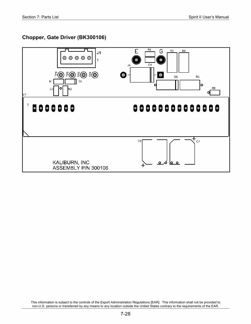
Section 7: Parts List Spirit II User’s Manual
This information is subject to the controls of the Export Administration Regulations [EAR]. This information shall not be provided to non-U.S. persons or transferred by any means to any location outside the United States contrary to the requirements of the EAR.
7-28
Chopper, Gate Driver (BK300106)

Spirit II User’s Manual Section 8: Internal Inova Console Option
This information is subject to the controls of the Export Administration Regulations [EAR]. This information shall not be provided to non-U.S. persons or transferred by any means to any location outside the United States contrary to the requirements of the EAR.
8-1
Section 8: Internal Inova Console Option Overview
This optional Inova system is designed to provide arc voltage control to any plasma cutting system, however, combining it with the Spirit II provides the added convenience of having Inova console built directly into the plasma power supply. This section only covers topics unique to the Spirit II system with the internally installed Inova console. See the standard Inova manual for all other Inova information.
Plug Identification Connections for the internal Inova console option are distinguished from other connections on the back of the power supply by the addition of the letter "I" before the plug number. The function of each plug (e.g., IP1) is the same as the corresponding plug found on the external Inova console (e.g., P1).
Spirit II 150/275 Spirit II 400
Unique Interconnect Cables Two unique interconnect cables are required for this option with the Spirit II system. The FII cable is used to connect the Spirit II internal Inova console (IP4) to the X/Y Machine (CNC controller). The JII cable is used to connect multiple Spirit II internal Inova consoles (IP8). See the parts list in Section 7 for more details on these cables.
POSITIONER
CONSOLE #2
REMOTE
X/Y MACHINE
RS-422 IN
RS-422 OUT
POSITIONER
CONSOLE #2
REMOTE
X/Y MACHINE
RS-422 IN
RS-422 OUT
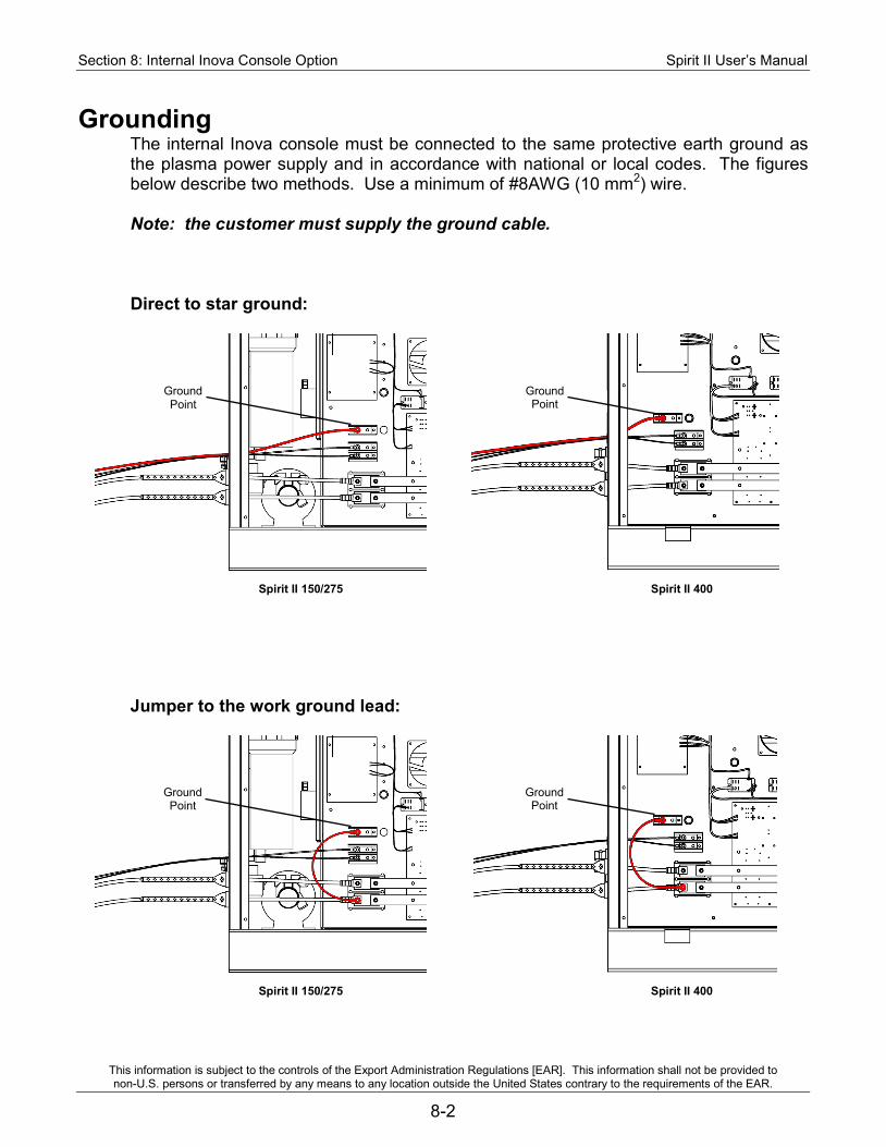
Section 8: Internal Inova Console Option Spirit II User’s Manual
This information is subject to the controls of the Export Administration Regulations [EAR]. This information shall not be provided to non-U.S. persons or transferred by any means to any location outside the United States contrary to the requirements of the EAR.
8-2
Grounding The internal Inova console must be connected to the same protective earth ground as the plasma power supply and in accordance with national or local codes. The figures below describe two methods. Use a minimum of #8AWG (10 mm2) wire. Note: the customer must supply the ground cable. Direct to star ground:
Spirit II 150/275 Spirit II 400
Jumper to the work ground lead:
Spirit II 150/275 Spirit II 400
Ground Point
Ground Point
Ground Point
Ground Point
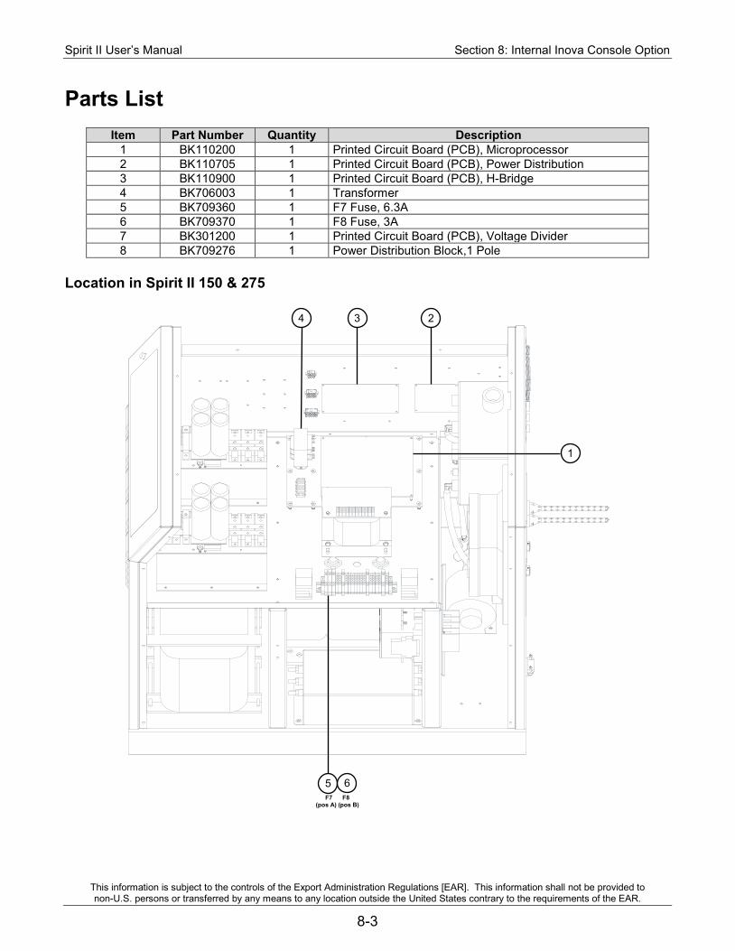
Spirit II User’s Manual Section 8: Internal Inova Console Option
This information is subject to the controls of the Export Administration Regulations [EAR]. This information shall not be provided to non-U.S. persons or transferred by any means to any location outside the United States contrary to the requirements of the EAR.
8-3
Parts List
Item Part Number Quantity Description 1 BK110200 1 Printed Circuit Board (PCB), Microprocessor 2 BK110705 1 Printed Circuit Board (PCB), Power Distribution 3 BK110900 1 Printed Circuit Board (PCB), H-Bridge 4 BK706003 1 Transformer 5 BK709360 1 F7 Fuse, 6.3A 6 BK709370 1 F8 Fuse, 3A 7 BK301200 1 Printed Circuit Board (PCB), Voltage Divider 8 BK709276 1 Power Distribution Block,1 Pole
Location in Spirit II 150 & 275
1
3 2 4
5 6 F7 F8
(pos A) (pos B)
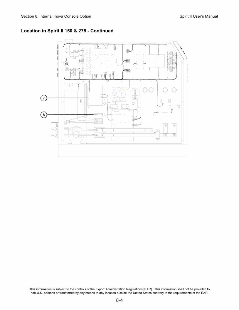
Section 8: Internal Inova Console Option Spirit II User’s Manual
This information is subject to the controls of the Export Administration Regulations [EAR]. This information shall not be provided to non-U.S. persons or transferred by any means to any location outside the United States contrary to the requirements of the EAR.
8-4
Location in Spirit II 150 & 275 - Continued
8
7
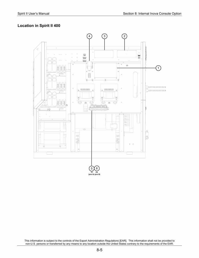
Spirit II User’s Manual Section 8: Internal Inova Console Option
This information is subject to the controls of the Export Administration Regulations [EAR]. This information shall not be provided to non-U.S. persons or transferred by any means to any location outside the United States contrary to the requirements of the EAR.
8-5
Location in Spirit II 400
1
5 6
3 4 2
F7 F8 (pos A) (pos B)
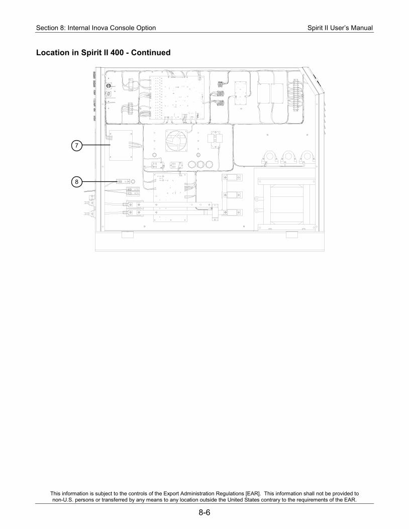
Section 8: Internal Inova Console Option Spirit II User’s Manual
This information is subject to the controls of the Export Administration Regulations [EAR]. This information shall not be provided to non-U.S. persons or transferred by any means to any location outside the United States contrary to the requirements of the EAR.
8-6
Location in Spirit II 400 - Continued
7
8
Spirit II User’s Manual Appendix A: Electromagnetic Compatibility (EMC)
This information is subject to the controls of the Export Administration Regulations [EAR]. This information shall not be provided to non-U.S. persons or transferred by any means to any location outside the United States contrary to the requirements of the EAR.
A-1
Appendix A: Electromagnetic Compatibility (EMC) Background
The 380V 50/60Hz and 415V 50/60Hz CE marked Spirit plasma cutting systems are manufactured to comply with the European standard EN 60974-10 (Electromagnetic compatibility (EMC) – Product standard for arc welding equipment). The system has been tested in accordance with CISPR 11, EMC classification – Group 2 ISM (Class A). The limits used in this standard are based on practical experience. However, the ability of plasma cutting equipment to work in a compatible manner with other radio and electronic systems is greatly influenced by the manner in which it is installed and used. For this reason, it is important that the plasma cutting equipment be installed and used in accordance with the information below if electromagnetic compatibility is to be achieved. Plasma cutting equipment is primarily intended for use in an industrial environment. There may be potential difficulties in ensuring electromagnetic compatibility in other environments.
Installation and Use
The user is responsible for installing and using the plasma cutting equipment according to the manufacturer’s instructions. If electromagnetic disturbances are detected then it shall be the responsibility of the user of the plasma cutting equipment to resolve the situation with the technical assistance of the manufacturer. In some cases this remedial action may be as simple as earthing the plasma cutting circuit, see Note. In other cases it could involve constructing an electromagnetic screen enclosing the plasma power source and the work, complete with associated input filters. In all cases, electromagnetic disturbances shall be reduced to the point where they are no longer troublesome. Note: The plasma cutting circuit may or may not be earthed for safety reasons. Changing the earthing arrangements should only be authorized by a person who is competent to assess whether the changes will increase the risk of injury, e.g. by allowing parallel plasma cutting current return paths which may damage the earth circuits of other equipment. Further guidance is given in IEC 974-13 Arc welding equipment – Installation and use.
Appendix A: Electromagnetic Compatibility (EMC) Spirit II User’s Manual
This information is subject to the controls of the Export Administration Regulations [EAR]. This information shall not be provided to non-U.S. persons or transferred by any means to any location outside the United States contrary to the requirements of the EAR.
A-2
Assessment of Area Before installing plasma cutting equipment, the user shall make an assessment of potential electromagnetic problems in the surrounding area. The following shall be taken into account: a) other supply cables, control cables, signaling and telephone cables; above, below
and adjacent to the plasma cutting equipment; b) radio and television transmitters and receivers; c) computer and other control equipment; d) safety critical equipment, e.g. guarding of industrial equipment; e) the health of the people around, e.g. the use of pacemakers and hearing aids; f) equipment used for calibration or measurement; g) the immunity of other equipment in the environment; the user shall ensure that other
equipment being used in the environment is compatible; this may require additional protection measures;
h) the time of day that plasma cutting or other activities are to be carried out.
The size of the surrounding area to be considered will depend on the structure of the building and other activities that are taking place. The surrounding area may extend beyond the boundaries of the premises.
Methods of Reducing Emissions Mains Supply Plasma cutting equipment should be connected to the mains supply according to the manufacturer’s recommendations. If interference occurs, it may be necessary to take additional precautions such as filtering of the mains supply. Consideration should be given to shielding the supply cable of permanently installed plasma cutting equipment in metallic conduit or equivalent. Shielding should be electrically continuous throughout its length. The shielding should be connected to the plasma power source so that good electrical contact is maintained between the conduit and the plasma power source enclosure. Maintenance of the Plasma Cutting Equipment The plasma cutting equipment should be routinely maintained according to the manufacturer’s recommendations. All access and service doors and covers should be closed and properly fastened when the plasma cutting equipment is in operation. The plasma cutting equipment should not be modified in any way except for those changes and adjustments covered in the manufacturer’s instructions. In particular, the spark gaps (if the system includes ACS with RHF) and stabilizing devices should be adjusted and maintained according to the manufacturer’s recommendations. Plasma Cutting Cables The plasma cutting cables should be kept as short as possible and should be positioned close together, running at or close to the floor level.

Spirit II User’s Manual Appendix A: Electromagnetic Compatibility (EMC)
This information is subject to the controls of the Export Administration Regulations [EAR]. This information shall not be provided to non-U.S. persons or transferred by any means to any location outside the United States contrary to the requirements of the EAR.
A-3
Equipotential Bonding Bonding of all metallic components in the plasma cutting installation and adjacent to it should be considered. However, metallic components bonded to the workpiece will increase the risk that the operator could receive a shock by touching these metallic components and the electrode at the same time. The operator should be insulated from all such bonded metallic components. Earthing of the Workpiece Where the workpiece is not bonded to earth for electrical safety, nor connected to earth because of its size and position, e.g. ship’s hull or building steelwork, a connection bonding the workpiece to earth may reduce emissions in some, but not all instances. Care should be taken to prevent the earthing of the workpiece increasing the risk of injury to users, or damage to other electrical equipment. Where necessary, the connection of the workpiece to earth should be made by a direct connection to the workpiece, but in some countries where direct connection is not permitted, the bonding should be achieved by suitable capacitance, selected according to national regulations. Screening and Shielding Selective screening and shielding of other cables and equipment in the surrounding area may alleviate problems of interference. Screening of the entire welding installation may be considered for special applications.

Appendix A: Electromagnetic Compatibility (EMC) Spirit II User’s Manual
This information is subject to the controls of the Export Administration Regulations [EAR]. This information shall not be provided to non-U.S. persons or transferred by any means to any location outside the United States contrary to the requirements of the EAR.
A-4
BLANK


