Embed Size (px)
Citation preview
How to Configure the NFX150
Published
2022-03-14

Juniper Networks, Inc.1133 Innovation WaySunnyvale, California 94089USA408-745-2000www.juniper.net
Juniper Networks, the Juniper Networks logo, Juniper, and Junos are registered trademarks of Juniper Networks, Inc.in the United States and other countries. All other trademarks, service marks, registered marks, or registered servicemarks are the property of their respective owners.
Juniper Networks assumes no responsibility for any inaccuracies in this document. Juniper Networks reserves the rightto change, modify, transfer, or otherwise revise this publication without notice.
How to Configure the NFX150Copyright © 2022 Juniper Networks, Inc. All rights reserved.
The information in this document is current as of the date on the title page.
YEAR 2000 NOTICE
Juniper Networks hardware and software products are Year 2000 compliant. Junos OS has no known time-relatedlimitations through the year 2038. However, the NTP application is known to have some difficulty in the year 2036.
END USER LICENSE AGREEMENT
The Juniper Networks product that is the subject of this technical documentation consists of (or is intended for usewith) Juniper Networks software. Use of such software is subject to the terms and conditions of the End User LicenseAgreement ("EULA") posted at https://support.juniper.net/support/eula/. By downloading, installing or using suchsoftware, you agree to the terms and conditions of that EULA.
ii
Table of Contents
About This Guide | xi
1 Overview
NFX150 System Overview | 2
Overview | 2
NFX150 Models | 3
Benefits and Uses of NFX150 | 6
NFX150 Feature Overview | 7
Software Architecture | 8
Interfaces | 9
Supported Features | 15
Performance Modes | 16
Licensing | 21
Junos OS Releases Supported on NFX Series Hardware | 23
NFX Product Compatibility | 25
2 Initial Configuration
Initial Configuration on NFX150 Devices | 29
Factory-Default Settings | 29
Enabling Basic Connectivity | 31
Establishing the Connection | 33
Zero Touch Provisioning on NFX Series Devices | 34
Understanding Zero Touch Provisioning | 34
Pre-staging an NFX Series Device | 35
Provisioning an NFX Series Device | 38
Provisioning an NFX Series Device Using Sky Enterprise | 39
iii
3 Generating YANG Files
YANG files on NFX150 Devices | 41
Understanding YANG on NFX150 Devices | 41
Generating YANG Files | 42
4 Configuring Interfaces
Mapping Interfaces on NFX150 Devices | 45
Mapping Physical Interfaces to Virtual Interfaces on NFX150 Devices | 45
Mapping Physical Ports to VNF Interfaces Through SR-IOV | 46
Mapping Layer 3 Dataplane Interfaces to OVS | 46
Configuring the In-Band Management Interface | 47
ADSL2 and ADSL2+ Interfaces on NFX150 Devices | 48
ADSL Interface Overview | 48
Configuring ADSL SFP Interface Using VLANs on NFX150 Network Services Platform | 50
Configuring ADSL SFP Interface Without Using VLANs on NFX150 Network Services Platform | 52
VDSL2 Interfaces on NFX150 Devices | 54
VDSL Interface Overview | 54
VDSL2 Network Deployment Topology | 55
VDSL2 Interface Support on NFX Series Devices | 57
Configuring VDSL SFP Interface Using VLANs on NFX150 Network Services Platform | 59
Configuring VDSL SFP Interface Without Using VLANs on NFX150 Network Services Platform | 61
Configuring the LTE Module on NFX Devices | 63
Configuring the LTE Module for Primary Mode | 64
Configuring the LTE Module for Dial-on-Demand Mode | 66
Configuring the LTE Module for Backup Mode | 68
Configuring the LTE Interface Module in an NFX Chassis Cluster | 70
Upgrading the Modem Firmware on NFX Devices Through Over-the-Air (OTA) | 75
iv
5 Configuring USB Pass-Through on NFX Series Devices
Supporting File Transfer from USB on NFX Series Devices | 80
6 Configuring Security
IP Security on NFX Devices | 84
Overview | 84
Configuring Security | 86
Configuring Interfaces | 86
Configuring Routing Options | 87
Configuring Security IKE | 88
Configuring Security IPsec | 91
Configuring Security Policies | 93
Configuring Security Zones | 94
UTM on NFX Devices | 94
Application Security on NFX Devices | 95
Intrusion Detection and Prevention on NFX Devices | 96
Integrated User Firewall Support on NFX Devices | 97
7 Configuring VNFs
Prerequisites to Onboard Virtual Network Functions on NFX150 Devices | 100
Prerequisites for VNFs | 100
Configuring VNFs on NFX150 Devices | 101
Load the VNF Image | 101
Prepare the Bootstrap Configuration | 102
Allocate CPUs for a VNF | 103
Allocate Memory for a VNF | 105
(Optional) Attach a Config Drive to the VNF | 106
Configure Interfaces and VLANs for a VNF | 108
Configuring VNF Storage Devices | 112
v

Instantiating a VNF | 113
Verify that the VNF Instantiated Successfully | 114
Managing VNFs on NFX Series Devices | 115
Managing VNF States | 115
Managing VNF MAC Addresses | 116
Managing the MTU of a VNF Interface | 117
Accessing a VNF from the JCP | 118
Viewing the List of VNFs | 118
Displaying the Details of a VNF | 119
Deleting a VNF | 119
Configuring Analyzer VNF and Port-mirroring | 120
8 Configuring Mapping of Address and Port with Encapsulation (MAP-E)
Mapping of Address and Port with Encapsulation on NFX Series Devices | 122
Overview | 122
Benefits of MAP-E | 122
MAP-E Terminology | 123
MAP-E Functionality | 124
Configuring MAP-E on NFX Series Devices | 125
Overview | 125
Requirements | 125
Topology Overview | 125
Configure an NFX Series Device as a MAP-E CE Device | 126
Configure an MX Series Device as a BR Device | 129
Verify the MAP-E Configuration | 131
9 Configuring High Availability
Chassis Cluster on NFX150 Devices | 138
vi
NFX150 Chassis Cluster Overview | 138
Chassis Cluster Interfaces | 139
Chassis Cluster Limitation | 140
Example: Configuring a Chassis Cluster on NFX150 Devices | 140
Requirements | 140
Overview | 141
Configuration | 142
Verification | 148
Upgrading or Disabling a Chassis Cluster on NFX150 Devices | 152
Upgrading Individual Devices in a Chassis Cluster Separately | 152
Disabling a Chassis Cluster | 153
10 Configuring Service Chaining
Service Chaining on NFX150 Devices | 155
Understanding Service Chaining | 155
Configuring Service Chaining Using VLANs | 155
Configuring Service Chaining Using DHCP Services on VLANs | 156
Example: Configuring Service Chaining Using VLANs on NFX150 Network ServicesPlatform | 157
Requirements | 158
Overview | 158
Configuration | 160
Example: Configuring Service Chaining Using SR-IOV on NFX150 Network ServicesPlatform | 164
Requirements | 164
Overview | 165
Configuration | 167
Example: Configuring Service Chaining Using a Custom Bridge | 168
Requirements | 169
Overview | 169
vii
Configuration | 170
Verifying the Configuration | 173
Example: Configuring Service Chaining for LAN-WAN Routing | 177
Requirements | 177
Overview | 178
Configuration | 179
Verification | 180
Example: Configuring Cross Connect on NFX150 Devices | 183
Requirements | 183
Overview | 183
Configuration | 185
Verifying the Configuration | 188
Example: Configuring Service Chaining for LAN Routing | 193
Requirements | 193
Overview | 194
Configuration | 195
Example: Configuring Cross-Connect Using a Custom Bridge on NFX150 Devices | 197
Requirements | 197
Overview | 197
Configuration | 199
Verifying the Configuration | 202
11 Monitoring and Troubleshooting
Configuring SNMP on NFX150, NFX250 NextGen, and NFX350 Devices | 209
How to Configure SNMPv2c to Access Libvirt MIB Data | 209
How to Configure SNMPv3 to Access Libvirt MIB Data | 211
How to Query Libvirt MIB Data | 213
Supported Chassis MIBs and Traps | 215
viii
Supported libvirt MIB Traps | 216
Monitor NFX150 Device Health | 218
Recovering the Root Password for NFX150, NFX250 NextGen, and NFX350 Devices | 230
Troubleshooting Interfaces on NFX Devices | 234
Monitoring Interface Status and Traffic on NFX Series Devices | 234
12 Operational Commands
request chassis cluster failover node | 241
request chassis cluster failover redundancy-group | 243
request chassis cluster failover reset | 245
request chassis fpc | 247
request vmhost cleanup | 249
request vmhost file-copy | 250
request vmhost halt | 252
request vmhost mode | 254
request vmhost power-off | 256
request vmhost reboot | 257
request vmhost software add | 261
show chassis cluster control-plane statistics | 264
show chassis cluster data-plane interfaces | 268
show chassis cluster data-plane statistics | 270
show chassis cluster information | 273
show chassis cluster interfaces | 280
show chassis cluster port-peering | 289
show chassis cluster statistics | 291
show chassis cluster status | 297
ix

show interfaces | 302
show system inventory hardware cpu | 306
show system visibility cpu | 313
show system visibility host | 320
show system visibility jcp | 330
show system visibility jdm | 335
show system visibility memory | 339
show system visibility network | 343
show system visibility vnf | 351
show vmhost connections | 359
show vmhost control-plane | 361
show vmhost crash | 364
show vmhost forwarding-options analyzer | 365
show vmhost memory | 367
show vmhost mode | 369
show vmhost snmp mib walk | 381
show vmhost status | 383
show vmhost storage | 385
show vmhost uptime | 392
show vmhost version | 394
show vmhost vlans | 397
x

About This Guide
Use this guide to perform initial provisioning, configure Junos OS features, chain multiple virtualizednetwork functions, monitor, and manage the NFX150 Series devices.
xi
1CHAPTER
Overview
NFX150 System Overview | 2
NFX150 Feature Overview | 7
Junos OS Releases Supported on NFX Series Hardware | 23
NFX Product Compatibility | 25
NFX150 System Overview
IN THIS SECTION
Overview | 2
NFX150 Models | 3
Benefits and Uses of NFX150 | 6
Overview
The Juniper Networks NFX150 Network Services Platform is a secure, automated, software-drivencustomer premises equipment (CPE) platform that delivers virtualized network and security services ondemand. NFX150 is part of the Juniper Cloud CPE solution, which leverages Network FunctionsVirtualization (NFV). It enables service providers to deploy and chain multiple, secure, high-performancevirtualized network functions (VNFs) on a single device.
The NFX150 architecture integrates routing, switching, and security functions on a single platform thatoptimizes the usage of system resources. The architecture enables unified management of all thecomponents through a single CLI. Key components in the NFX150 software include the Junos ControlPlane (JCP), Juniper Device Manager (JDM), Layer 2 dataplane, Layer 3 dataplane, and Virtual NetworkFunctions (VNFs).
The NFX150 is suited for small to medium-sized enterprises. With key security features and NFV, theNFX150 can be used in secure SD-WAN and secure router deployments.
2
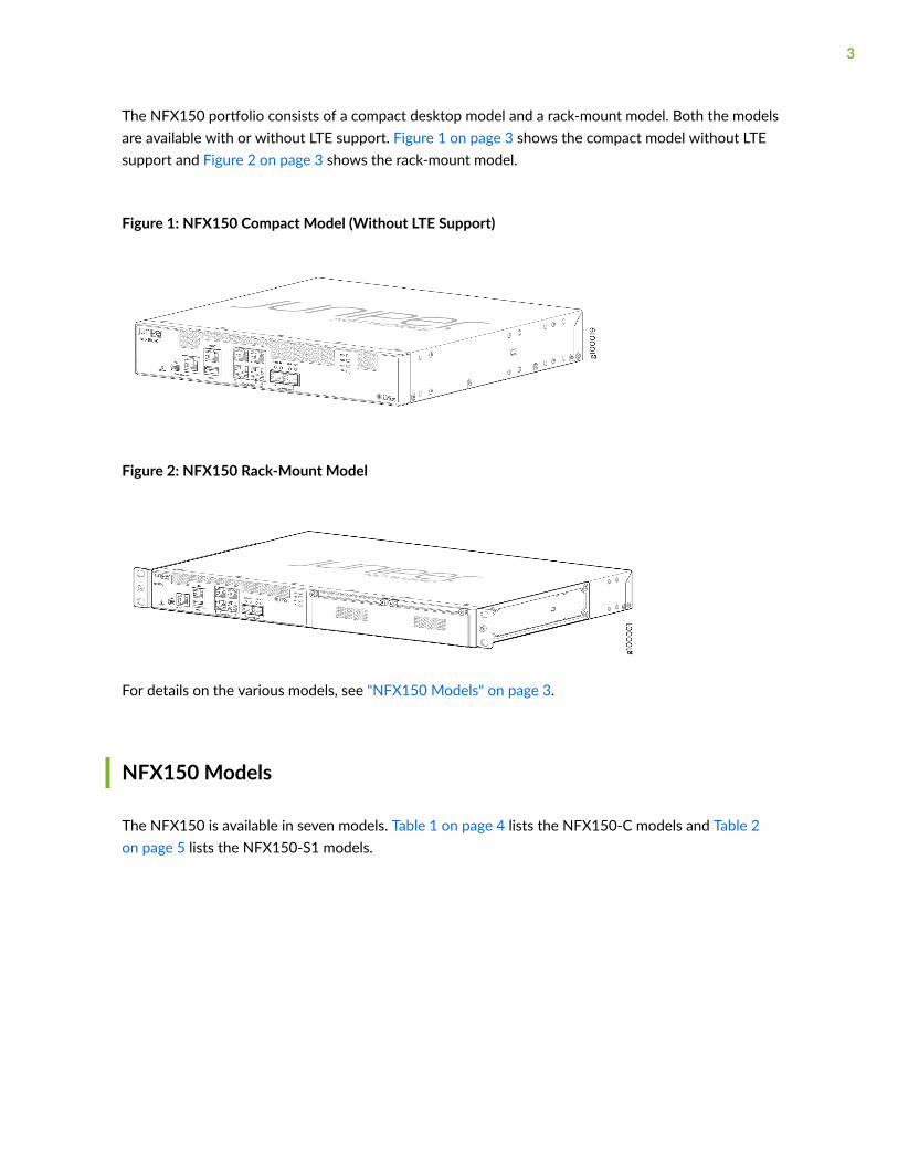
The NFX150 portfolio consists of a compact desktop model and a rack-mount model. Both the modelsare available with or without LTE support. Figure 1 on page 3 shows the compact model without LTEsupport and Figure 2 on page 3 shows the rack-mount model.
Figure 1: NFX150 Compact Model (Without LTE Support)
Figure 2: NFX150 Rack-Mount Model
For details on the various models, see "NFX150 Models" on page 3.
NFX150 Models
The NFX150 is available in seven models. Table 1 on page 4 lists the NFX150-C models and Table 2on page 5 lists the NFX150-S1 models.
3
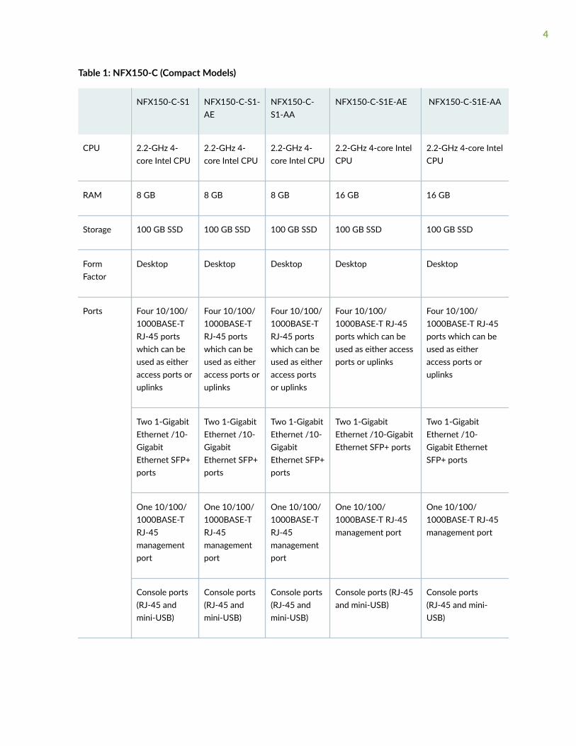
Table 1: NFX150-C (Compact Models)
NFX150-C-S1 NFX150-C-S1-AE
NFX150-C-S1-AA
NFX150-C-S1E-AE NFX150-C-S1E-AA
CPU 2.2-GHz 4-core Intel CPU
2.2-GHz 4-core Intel CPU
2.2-GHz 4-core Intel CPU
2.2-GHz 4-core IntelCPU
2.2-GHz 4-core IntelCPU
RAM 8 GB 8 GB 8 GB 16 GB 16 GB
Storage 100 GB SSD 100 GB SSD 100 GB SSD 100 GB SSD 100 GB SSD
FormFactor
Desktop Desktop Desktop Desktop Desktop
Ports Four 10/100/1000BASE-TRJ-45 portswhich can beused as eitheraccess ports oruplinks
Four 10/100/1000BASE-TRJ-45 portswhich can beused as eitheraccess ports oruplinks
Four 10/100/1000BASE-TRJ-45 portswhich can beused as eitheraccess portsor uplinks
Four 10/100/1000BASE-T RJ-45ports which can beused as either accessports or uplinks
Four 10/100/1000BASE-T RJ-45ports which can beused as eitheraccess ports oruplinks
Two 1-GigabitEthernet /10-GigabitEthernet SFP+ports
Two 1-GigabitEthernet /10-GigabitEthernet SFP+ports
Two 1-GigabitEthernet /10-GigabitEthernet SFP+ports
Two 1-GigabitEthernet /10-GigabitEthernet SFP+ ports
Two 1-GigabitEthernet /10-Gigabit EthernetSFP+ ports
One 10/100/1000BASE-TRJ-45managementport
One 10/100/1000BASE-TRJ-45managementport
One 10/100/1000BASE-TRJ-45managementport
One 10/100/1000BASE-T RJ-45management port
One 10/100/1000BASE-T RJ-45management port
Console ports(RJ-45 andmini-USB)
Console ports(RJ-45 andmini-USB)
Console ports(RJ-45 andmini-USB)
Console ports (RJ-45and mini-USB)
Console ports(RJ-45 and mini-USB)
4
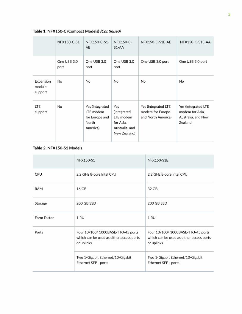
Table 1: NFX150-C (Compact Models) (Continued)
NFX150-C-S1 NFX150-C-S1-AE
NFX150-C-S1-AA
NFX150-C-S1E-AE NFX150-C-S1E-AA
One USB 3.0port
One USB 3.0port
One USB 3.0port
One USB 3.0 port One USB 3.0 port
Expansionmodulesupport
No No No No No
LTEsupport
No Yes (integratedLTE modemfor Europe andNorthAmerica)
Yes(integratedLTE modemfor Asia,Australia, andNew Zealand)
Yes (integrated LTEmodem for Europeand North America)
Yes (integrated LTEmodem for Asia,Australia, and NewZealand)
Table 2: NFX150-S1 Models
NFX150-S1 NFX150-S1E
CPU 2.2 GHz 8-core Intel CPU 2.2 GHz 8-core Intel CPU
RAM 16 GB 32 GB
Storage 200 GB SSD 200 GB SSD
Form Factor 1 RU 1 RU
Ports Four 10/100/ 1000BASE-T RJ-45 portswhich can be used as either access portsor uplinks
Four 10/100/ 1000BASE-T RJ-45 portswhich can be used as either access portsor uplinks
Two 1-Gigabit Ethernet/10-GigabitEthernet SFP+ ports
Two 1-Gigabit Ethernet/10-GigabitEthernet SFP+ ports
5
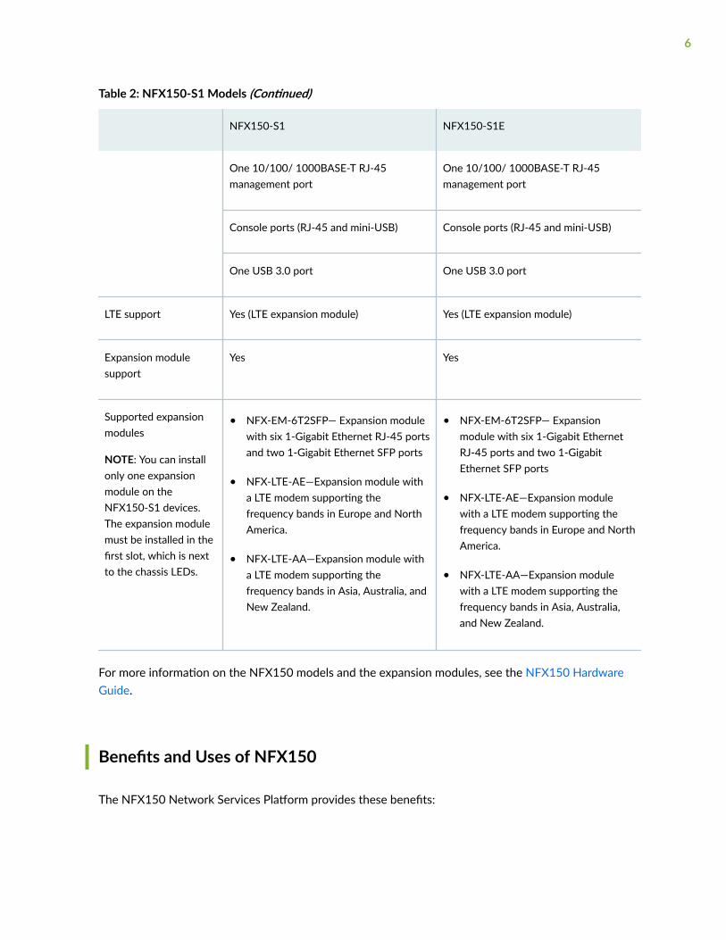
Table 2: NFX150-S1 Models (Continued)
NFX150-S1 NFX150-S1E
One 10/100/ 1000BASE-T RJ-45management port
One 10/100/ 1000BASE-T RJ-45management port
Console ports (RJ-45 and mini-USB) Console ports (RJ-45 and mini-USB)
One USB 3.0 port One USB 3.0 port
LTE support Yes (LTE expansion module) Yes (LTE expansion module)
Expansion modulesupport
Yes Yes
Supported expansionmodules
NOTE: You can installonly one expansionmodule on theNFX150-S1 devices.The expansion modulemust be installed in thefirst slot, which is nextto the chassis LEDs.
• NFX-EM-6T2SFP— Expansion modulewith six 1-Gigabit Ethernet RJ-45 portsand two 1-Gigabit Ethernet SFP ports
• NFX-LTE-AE—Expansion module witha LTE modem supporting thefrequency bands in Europe and NorthAmerica.
• NFX-LTE-AA—Expansion module witha LTE modem supporting thefrequency bands in Asia, Australia, andNew Zealand.
• NFX-EM-6T2SFP— Expansionmodule with six 1-Gigabit EthernetRJ-45 ports and two 1-GigabitEthernet SFP ports
• NFX-LTE-AE—Expansion modulewith a LTE modem supporting thefrequency bands in Europe and NorthAmerica.
• NFX-LTE-AA—Expansion modulewith a LTE modem supporting thefrequency bands in Asia, Australia,and New Zealand.
For more information on the NFX150 models and the expansion modules, see the NFX150 HardwareGuide.
Benefits and Uses of NFX150
The NFX150 Network Services Platform provides these benefits:
6
• Highly scalable, supporting multiple Juniper and third-party VNFs on a single device. The modularsoftware architecture provides high performance and scalability for routing, switching, and securityenhanced by carrier-class reliability.
• Integrated security, routing, and switching functionality in a single control plane simplifiesmanagement and deployment.
• Supports a variety of flexible deployments. A distributed services deployment model ensures highavailability, performance, and compliance. The NFX150 provides an open framework that supportsindustry standards, protocols, and seamless API integration.
• In addition to Ethernet connections, Wireless WAN support through the LTE module provides moreflexibility in deployments.
• Supports advanced security features such as IPsec connectivity, applications detection, and filteringfor malicious traffic.
• The Secure Boot feature safeguards device credentials, automatically authenticates system integrity,verifies system configuration, and enhances overall platform security.
• Automated configuration eliminates complex device setup and delivers a plug-and-play experience.
• Support of Open vSwitch (OVS) integrated with Data Plane Development Kit (DPDK) on NFX150device offers better network packet throughput and lower latencies.
RELATED DOCUMENTATION
NFX150 Feature Overview | 7
NFX150 Feature Overview
IN THIS SECTION
Software Architecture | 8
Interfaces | 9
Supported Features | 15
Performance Modes | 16
Licensing | 21
7
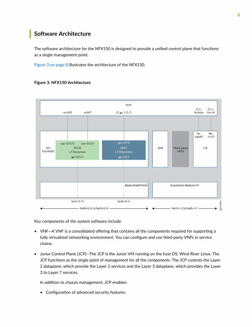
Software Architecture
The software architecture for the NFX150 is designed to provide a unified control plane that functionsas a single management point.
Figure 3 on page 8 illustrates the architecture of the NFX150.
Figure 3: NFX150 Architecture
Key components of the system software include:
• VNF—A VNF is a consolidated offering that contains all the components required for supporting afully virtualized networking environment. You can configure and use third-party VNFs in servicechains.
• Junos Control Plane (JCP)—The JCP is the Junos VM running on the host OS, Wind River Linux. TheJCP functions as the single point of management for all the components. The JCP controls the Layer2 dataplane, which provide the Layer 2 services and the Layer 3 dataplane, which provides the Layer3 to Layer 7 services.
In addition to chassis management, JCP enables:
• Configuration of advanced security features.
8
• Management of guest virtualized network functions (VNFs) during their life cycle.
• Installation of third-party VNFs.
• Creation of VNF service chains.
• Management of guest VNF images (their binary files).
• Management of the system inventory and resource usage.
• Management of the LTE interface.
• Juniper Device Manager (JDM)—An application container that manages VNFs and providesinfrastructure services. The JDM functions in the background and users cannot access JDM directly.
• L2 Dataplane—The Layer 2 dataplane that manages the Layer 2 traffic. The Layer 2 dataplaneforwards the LAN traffic to the NFV backplane, Open vSwitch (OVS). The Layer 2 dataplane ismapped to the virtual FPC0 on the JCP. By default, all the 1-Gigabit Ethernet physical ports aremapped to the virtual interfaces on the Layer 2 dataplane.
• L3 Dataplane—The Layer 3 dataplane that provides datapath functions for the Layer 3 to Layer 7services. The Layer 3 dataplane is mapped to the virtual FPC1 on the JCP. By default, the two SFP+ports on the NFX150 chassis are mapped to the virtual interfaces on the Layer 3 dataplane.
• Linux—The host OS, WindRiver Linux. In Junos OS Release 18.1R1, the WindRiver Linux version is 8.
• Open vSwitch (OVS) bridge—The OVS bridge is a VLAN-aware system bridge, which acts as the NFVbackplane to which the VNFs and FPCs connect. Additionally, you can create custom OVS bridges toisolate connectivity between different VNFs.
• LTE—A containerized driver that provides 4G LTE connectivity management. The LTE container isbound to the FPC1 for management.
Interfaces
IN THIS SECTION
Physical Interfaces | 10
Virtual Interfaces | 10
LTE Interface | 11
Interface Mapping | 11
9
The interfaces on the NFX150 devices comprise of physical interfaces, virtual interfaces, and the LTEinterface.
Physical Interfaces
The physical interfaces represent the physical ports on the NFX150 chassis and expansion module. Thephysical interfaces comprise of network and management ports:
• Network ports—Four 1-Gigabit Ethernet ports and two 10-Gigabit Ethernet SFP+ ports function asnetwork ports on the NFX150 chassis. The expansion modules consists of six 1-Gigabit Ethernetports and two 1-Gigabit Ethernet SFP ports.
The network ports follow the naming convention heth-slot number-port number, where:
• heth denotes host Ethernet
• slot number is 0 for the chassis ports and 1 for the expansion module ports. The ports on thechassis are named as heth-0-x and the ports on the expansion module are named heth-1-x.
• port number is the number of the port on the chassis or expansion module
Each physical port has four virtual functions (VFs) enabled by default.
NOTE: You cannot map a VF from a port which is mapped to the Layer 2 dataplane.
• Management port—The NFX150 device has a dedicated management port labeled MGMT (fxp0),which functions as the out-of-band management interface. The fxp0 interface is assigned an IPaddress in the 192.168.1.1/24 network.
Virtual Interfaces
The virtual FPCs running within the JCP, contain the virtual interfaces. The virtual interfaces on theNFX150 devices are categorized as follows:
• Virtual Layer 2 interfaces (FPC0)—Denoted as ge-0/0/x, where the value of x ranges from:
• 0 to 3 for NFX150 devices without an expansion module
• 0 to 11 for NFX150 devices with an expansion module
These interfaces are used to configure the following Ethernet switching features:
• Layer 2 switching of traffic, including support for both trunk and access ports
• Link Layer Discovery Protocol (LLDP)
10
• IGMP snooping
• Port Security features (MAC limiting, Persistent MAC learning)
• MVRP
• Ethernet OAM, CFM, and LFM
All the 1-Gigabit Ethernet physical ports (heth ports) are mapped to FPC0, by default.
• Virtual Layer 3 interfaces (FPC1)—Denoted as ge-1/0/x, where value of x ranges from 0 to 9. Theseinterfaces are used to configure Layer 3 features such as routing protocols and QoS.
In an NFX150 device, you can configure any of the ge-1/0/x interfaces as in-band managementinterfaces. In in-band management, you configure a network interface as a management interfaceand connect it to the management device. You can configure any number of interfaces for in-bandmanagement by assigning an IPv4 or IPv6 address to each of the ports, and an in-band managementVLAN.
NOTE: The NFX150 devices do not support integrated routing and bridging (IRB) interfaces.The IRB functionality is provided by ge-1/0/0, which is always mapped to the service chainingbackplane (OVS). Note that this mapping cannot be changed.
• Virtual SXE Interfaces—Two static interfaces, sxe-0/0/0 and sxe-0/0/1, connect the FPC0 (Layer 2dataplane) to the OVS backplane.
LTE Interface
The NFX150 device models with LTE support can be configured for wireless WAN connectivity over 3Gor 4G networks. The LTE physical interface uses the name cl-1/1/0. The dialer interface, dl0, is a logicalinterface, which is used to trigger calls.
Interface Mapping
Table 3 on page 12 summarizes the interfaces on the NFX150.
11
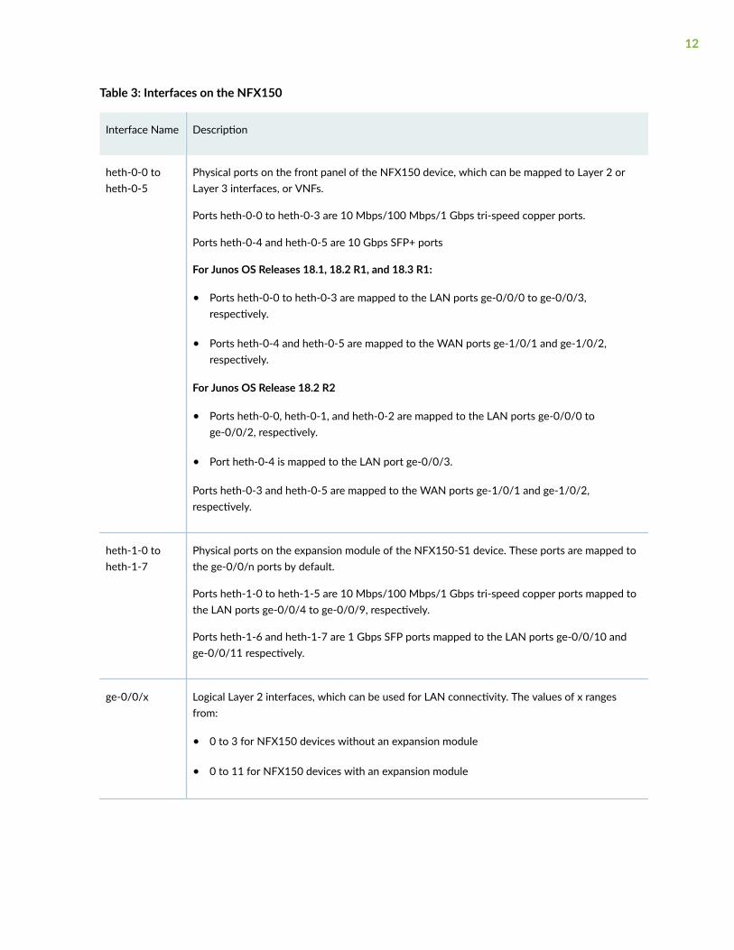
Table 3: Interfaces on the NFX150
Interface Name Description
heth-0-0 toheth-0-5
Physical ports on the front panel of the NFX150 device, which can be mapped to Layer 2 orLayer 3 interfaces, or VNFs.
Ports heth-0-0 to heth-0-3 are 10 Mbps/100 Mbps/1 Gbps tri-speed copper ports.
Ports heth-0-4 and heth-0-5 are 10 Gbps SFP+ ports
For Junos OS Releases 18.1, 18.2 R1, and 18.3 R1:
• Ports heth-0-0 to heth-0-3 are mapped to the LAN ports ge-0/0/0 to ge-0/0/3,respectively.
• Ports heth-0-4 and heth-0-5 are mapped to the WAN ports ge-1/0/1 and ge-1/0/2,respectively.
For Junos OS Release 18.2 R2
• Ports heth-0-0, heth-0-1, and heth-0-2 are mapped to the LAN ports ge-0/0/0 toge-0/0/2, respectively.
• Port heth-0-4 is mapped to the LAN port ge-0/0/3.
Ports heth-0-3 and heth-0-5 are mapped to the WAN ports ge-1/0/1 and ge-1/0/2,respectively.
heth-1-0 toheth-1-7
Physical ports on the expansion module of the NFX150-S1 device. These ports are mapped tothe ge-0/0/n ports by default.
Ports heth-1-0 to heth-1-5 are 10 Mbps/100 Mbps/1 Gbps tri-speed copper ports mapped tothe LAN ports ge-0/0/4 to ge-0/0/9, respectively.
Ports heth-1-6 and heth-1-7 are 1 Gbps SFP ports mapped to the LAN ports ge-0/0/10 andge-0/0/11 respectively.
ge-0/0/x Logical Layer 2 interfaces, which can be used for LAN connectivity. The values of x rangesfrom:
• 0 to 3 for NFX150 devices without an expansion module
• 0 to 11 for NFX150 devices with an expansion module
12
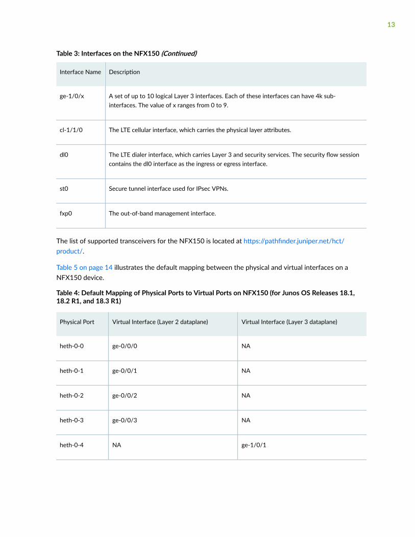
Table 3: Interfaces on the NFX150 (Continued)
Interface Name Description
ge-1/0/x A set of up to 10 logical Layer 3 interfaces. Each of these interfaces can have 4k sub-interfaces. The value of x ranges from 0 to 9.
cl-1/1/0 The LTE cellular interface, which carries the physical layer attributes.
dl0 The LTE dialer interface, which carries Layer 3 and security services. The security flow sessioncontains the dl0 interface as the ingress or egress interface.
st0 Secure tunnel interface used for IPsec VPNs.
fxp0 The out-of-band management interface.
The list of supported transceivers for the NFX150 is located at https://pathfinder.juniper.net/hct/product/.
Table 5 on page 14 illustrates the default mapping between the physical and virtual interfaces on aNFX150 device.
Table 4: Default Mapping of Physical Ports to Virtual Ports on NFX150 (for Junos OS Releases 18.1,18.2 R1, and 18.3 R1)
Physical Port Virtual Interface (Layer 2 dataplane) Virtual Interface (Layer 3 dataplane)
heth-0-0 ge-0/0/0 NA
heth-0-1 ge-0/0/1 NA
heth-0-2 ge-0/0/2 NA
heth-0-3 ge-0/0/3 NA
heth-0-4 NA ge-1/0/1
13
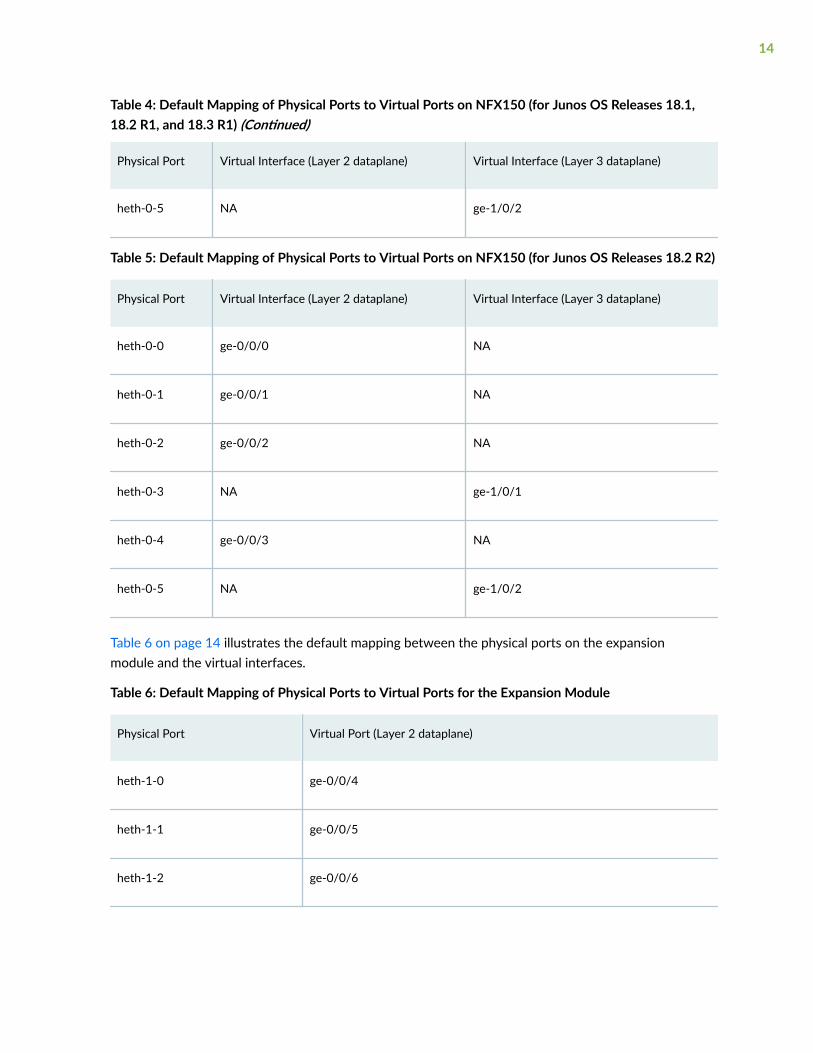
Table 4: Default Mapping of Physical Ports to Virtual Ports on NFX150 (for Junos OS Releases 18.1,18.2 R1, and 18.3 R1) (Continued)
Physical Port Virtual Interface (Layer 2 dataplane) Virtual Interface (Layer 3 dataplane)
heth-0-5 NA ge-1/0/2
Table 5: Default Mapping of Physical Ports to Virtual Ports on NFX150 (for Junos OS Releases 18.2 R2)
Physical Port Virtual Interface (Layer 2 dataplane) Virtual Interface (Layer 3 dataplane)
heth-0-0 ge-0/0/0 NA
heth-0-1 ge-0/0/1 NA
heth-0-2 ge-0/0/2 NA
heth-0-3 NA ge-1/0/1
heth-0-4 ge-0/0/3 NA
heth-0-5 NA ge-1/0/2
Table 6 on page 14 illustrates the default mapping between the physical ports on the expansionmodule and the virtual interfaces.
Table 6: Default Mapping of Physical Ports to Virtual Ports for the Expansion Module
Physical Port Virtual Port (Layer 2 dataplane)
heth-1-0 ge-0/0/4
heth-1-1 ge-0/0/5
heth-1-2 ge-0/0/6
14
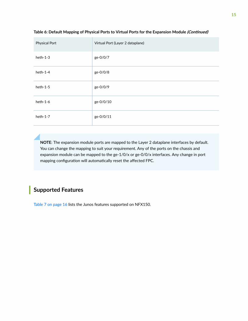
Table 6: Default Mapping of Physical Ports to Virtual Ports for the Expansion Module (Continued)
Physical Port Virtual Port (Layer 2 dataplane)
heth-1-3 ge-0/0/7
heth-1-4 ge-0/0/8
heth-1-5 ge-0/0/9
heth-1-6 ge-0/0/10
heth-1-7 ge-0/0/11
NOTE: The expansion module ports are mapped to the Layer 2 dataplane interfaces by default.You can change the mapping to suit your requirement. Any of the ports on the chassis andexpansion module can be mapped to the ge-1/0/x or ge-0/0/x interfaces. Any change in portmapping configuration will automatically reset the affected FPC.
Supported Features
Table 7 on page 16 lists the Junos features supported on NFX150.
15
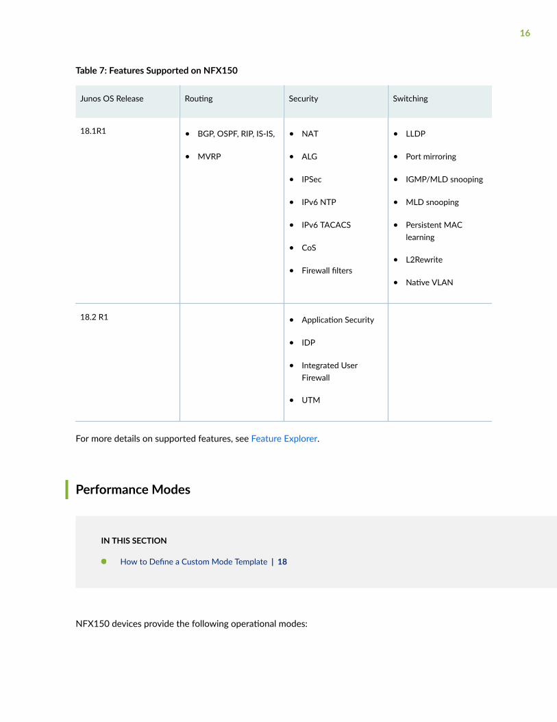
Table 7: Features Supported on NFX150
Junos OS Release Routing Security Switching
18.1R1 • BGP, OSPF, RIP, IS-IS,
• MVRP
• NAT
• ALG
• IPSec
• IPv6 NTP
• IPv6 TACACS
• CoS
• Firewall filters
• LLDP
• Port mirroring
• IGMP/MLD snooping
• MLD snooping
• Persistent MAClearning
• L2Rewrite
• Native VLAN
18.2 R1 • Application Security
• IDP
• Integrated UserFirewall
• UTM
For more details on supported features, see Feature Explorer.
Performance Modes
IN THIS SECTION
How to Define a Custom Mode Template | 18
NFX150 devices provide the following operational modes:
16
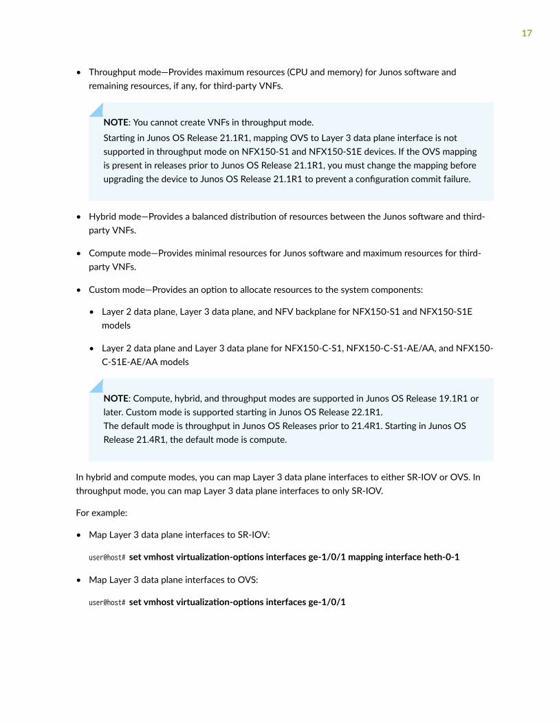
• Throughput mode—Provides maximum resources (CPU and memory) for Junos software andremaining resources, if any, for third-party VNFs.
NOTE: You cannot create VNFs in throughput mode.
Starting in Junos OS Release 21.1R1, mapping OVS to Layer 3 data plane interface is notsupported in throughput mode on NFX150-S1 and NFX150-S1E devices. If the OVS mappingis present in releases prior to Junos OS Release 21.1R1, you must change the mapping beforeupgrading the device to Junos OS Release 21.1R1 to prevent a configuration commit failure.
• Hybrid mode—Provides a balanced distribution of resources between the Junos software and third-party VNFs.
• Compute mode—Provides minimal resources for Junos software and maximum resources for third-party VNFs.
• Custom mode—Provides an option to allocate resources to the system components:
• Layer 2 data plane, Layer 3 data plane, and NFV backplane for NFX150-S1 and NFX150-S1Emodels
• Layer 2 data plane and Layer 3 data plane for NFX150-C-S1, NFX150-C-S1-AE/AA, and NFX150-C-S1E-AE/AA models
NOTE: Compute, hybrid, and throughput modes are supported in Junos OS Release 19.1R1 orlater. Custom mode is supported starting in Junos OS Release 22.1R1.The default mode is throughput in Junos OS Releases prior to 21.4R1. Starting in Junos OSRelease 21.4R1, the default mode is compute.
In hybrid and compute modes, you can map Layer 3 data plane interfaces to either SR-IOV or OVS. Inthroughput mode, you can map Layer 3 data plane interfaces to only SR-IOV.
For example:
• Map Layer 3 data plane interfaces to SR-IOV:
user@host# set vmhost virtualization-options interfaces ge-1/0/1 mapping interface heth-0-1
• Map Layer 3 data plane interfaces to OVS:
user@host# set vmhost virtualization-options interfaces ge-1/0/1
17
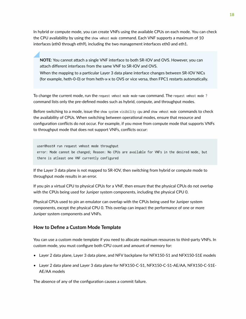
In hybrid or compute mode, you can create VNFs using the available CPUs on each mode. You can checkthe CPU availability by using the show vmhost mode command. Each VNF supports a maximum of 10interfaces (eth0 through eth9), including the two management interfaces eth0 and eth1.
NOTE: You cannot attach a single VNF interface to both SR-IOV and OVS. However, you canattach different interfaces from the same VNF to SR-IOV and OVS.
When the mapping to a particular Layer 3 data plane interface changes between SR-IOV NICs(for example, heth-0-0) or from heth-x-x to OVS or vice versa, then FPC1 restarts automatically.
To change the current mode, run the request vmhost mode mode-name command. The request vmhost mode ?command lists only the pre-defined modes such as hybrid, compute, and throughput modes.
Before switching to a mode, issue the show system visibility cpu and show vmhost mode commands to checkthe availability of CPUs. When switching between operational modes, ensure that resource andconfiguration conflicts do not occur. For example, if you move from compute mode that supports VNFsto throughput mode that does not support VNFs, conflicts occur:
user@host# run request vmhost mode throughputerror: Mode cannot be changed; Reason: No CPUs are available for VNFs in the desired mode, but there is atleast one VNF currently configured
If the Layer 3 data plane is not mapped to SR-IOV, then switching from hybrid or compute mode tothroughput mode results in an error.
If you pin a virtual CPU to physical CPUs for a VNF, then ensure that the physical CPUs do not overlapwith the CPUs being used for Juniper system components, including the physical CPU 0.
Physical CPUs used to pin an emulator can overlap with the CPUs being used for Juniper systemcomponents, except the physical CPU 0. This overlap can impact the performance of one or moreJuniper system components and VNFs.
How to Define a Custom Mode Template
You can use a custom mode template if you need to allocate maximum resources to third-party VNFs. Incustom mode, you must configure both CPU count and amount of memory for:
• Layer 2 data plane, Layer 3 data plane, and NFV backplane for NFX150-S1 and NFX150-S1E models
• Layer 2 data plane and Layer 3 data plane for NFX150-C-S1, NFX150-C-S1-AE/AA, NFX150-C-S1E-AE/AA models
The absence of any of the configuration causes a commit failure.
18

NOTE: You can opt to disable the Layer 2 data plane to free up CPU and memory resources indeployments that do not require Layer 2 software PFE services.
user@host# set vmhost mode custom custom-mode-name layer-2-infrastructure offline
If you disable the the Layer 2 data plane, you cannot configure the virtual interface mappings ofthe Layer 2 dataplane. For example:
set vmhost virtualization-options interfaces ge-0/0/0 mapping interface heth-0-0
Before you configure custom mode, note the following:
• If you disable the Layer 2 dataplane, then you cannot configure cpu count and memory size for the Layer2 dataplane.
If you do not disable the Layer 2 dataplane, then you must configure the cpu count and memory size forit. The CPU count and memory must not exceed the total CPU count and memory available on thesystem.
• You can opt to configure the CPU quota for the Layer 3 data plane by using the set vmhost mode customcustom-mode-name layer-3-infrastructure cpu colocation quota quota-value command, where quota-value canrange from 1 through 99. If you configure cpu colocation quota, then the sum total of the CPU quotasof the cpu colocation components must be less than or equal to 100. You must configure cpu countusing numeric values and not keywords like MIN as MIN can have different values for differentcomponents.
• The number of CPUs and the specific CPUs (by CPU ID) available for VNF usage in a custom mode isautomatically determined based on the cpu count and cpu colocation quota in the custom modeconfiguration and the internally fixed CPU allocation for other Juniper system components.
• The amount of memory, in terms of 1G units, available for VNF usage in a custom mode isautomatically determined based on the custom mode specific memory size configuration and theper-SKU internally fixed memory allocation for other Juniper system components. Note that thisnumber is only an approximate value and the actual maximum memory allocation for VNFs might beless than that.
• If you do not configure the memory size for a VNF, then the memory is considered as 1G (defaultvalue).
19
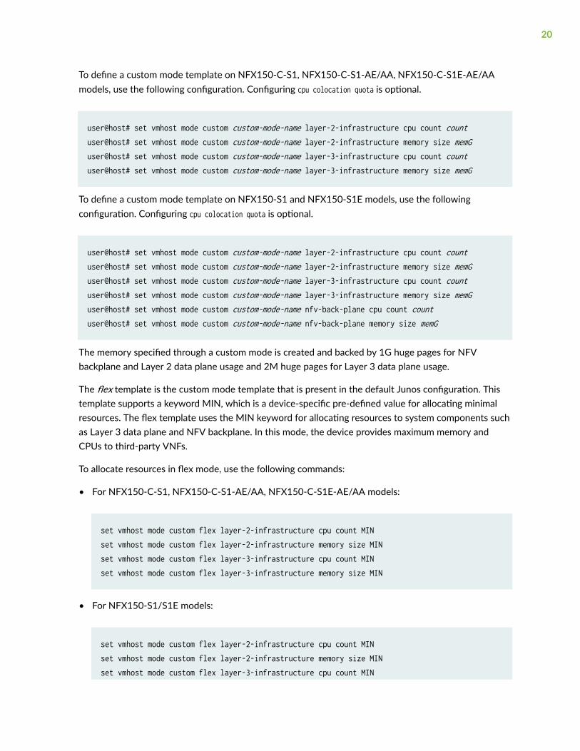
To define a custom mode template on NFX150-C-S1, NFX150-C-S1-AE/AA, NFX150-C-S1E-AE/AAmodels, use the following configuration. Configuring cpu colocation quota is optional.
user@host# set vmhost mode custom custom-mode-name layer-2-infrastructure cpu count countuser@host# set vmhost mode custom custom-mode-name layer-2-infrastructure memory size memGuser@host# set vmhost mode custom custom-mode-name layer-3-infrastructure cpu count countuser@host# set vmhost mode custom custom-mode-name layer-3-infrastructure memory size memG
To define a custom mode template on NFX150-S1 and NFX150-S1E models, use the followingconfiguration. Configuring cpu colocation quota is optional.
user@host# set vmhost mode custom custom-mode-name layer-2-infrastructure cpu count countuser@host# set vmhost mode custom custom-mode-name layer-2-infrastructure memory size memGuser@host# set vmhost mode custom custom-mode-name layer-3-infrastructure cpu count countuser@host# set vmhost mode custom custom-mode-name layer-3-infrastructure memory size memGuser@host# set vmhost mode custom custom-mode-name nfv-back-plane cpu count countuser@host# set vmhost mode custom custom-mode-name nfv-back-plane memory size memG
The memory specified through a custom mode is created and backed by 1G huge pages for NFVbackplane and Layer 2 data plane usage and 2M huge pages for Layer 3 data plane usage.
The flex template is the custom mode template that is present in the default Junos configuration. Thistemplate supports a keyword MIN, which is a device-specific pre-defined value for allocating minimalresources. The flex template uses the MIN keyword for allocating resources to system components suchas Layer 3 data plane and NFV backplane. In this mode, the device provides maximum memory andCPUs to third-party VNFs.
To allocate resources in flex mode, use the following commands:
• For NFX150-C-S1, NFX150-C-S1-AE/AA, NFX150-C-S1E-AE/AA models:
set vmhost mode custom flex layer-2-infrastructure cpu count MINset vmhost mode custom flex layer-2-infrastructure memory size MINset vmhost mode custom flex layer-3-infrastructure cpu count MINset vmhost mode custom flex layer-3-infrastructure memory size MIN
• For NFX150-S1/S1E models:
set vmhost mode custom flex layer-2-infrastructure cpu count MINset vmhost mode custom flex layer-2-infrastructure memory size MINset vmhost mode custom flex layer-3-infrastructure cpu count MIN
20
set vmhost mode custom flex layer-3-infrastructure memory size MINset vmhost mode custom flex nfv-back-plane cpu count MINset vmhost mode custom flex nfv-back-plane memory size MIN
When the device is operating in custom mode, you can make changes to the custom modeconfiguration. Reboot the device for the changes to take effect. The configuration of Layer 2 virtualinterfaces, Layer 3 virtual interfaces, VNF virtual CPU to physical CPU mapping, VNF emulator tophysical CPU mapping, and VNF memory size is validated during commit check against the currentlyactive custom mode's configuration parameters and the modified custom mode's configurationparameters that take effect after a reboot.
When the device is in custom mode only basic firewall features are supported. In flex mode, you canconfigure a maximum of:
• 8 IPSec VPN tunnels
• 16 IFL
• 4 IFD
Licensing
For features or scaling levels that require a license, you must install and properly configure the license tomeet the requirements for using the licensable feature or scale level. The device enables you to commita configuration that specifies a licensable feature or scale without a license for a 30-day grace period.The grace period is a short-term grant that enables you to start using features in the pack or scale up tothe system limits (regardless of the license key limit) without a license key installed. The grace periodbegins when the licensable feature or scaling level is actually used by the device (not when it is firstcommitted). In other words, you can commit licensable features or scaling limits to the deviceconfiguration, but the grace period does not begin until the device uses the licensable feature orexceeds a licensable scaling level.
For information about how to purchase software licenses, contact your Juniper Networks salesrepresentative. Junos OS software implements an honor-based licensing structure and provides you witha 30-day grace period to use the feature without a license key installed. The grace period begins whenyou configure the feature and your device uses the licensed feature for the first time, but not necessarilywhen you install the license. After the grace period expires, the system generates system log messagessaying that the feature requires a license. To clear the error message and use the licensed featureproperly, you must install and verify the required license.
21
NOTE: Configurations might include both licensed and nonlicensed features. For these situations,the license is enforced up to the point where the license can be clearly distinguished. Forexample, an authentication-order configuration is shared by both Authentication, Authorization,and Accounting (AAA), which is licensed, and by Layer 2 Tunneling Protocol (L2TP), which is notlicensed. When the configuration is committed, the device does not issue any license warnings,because it is not yet known whether AAA or L2TP is using the configuration. However, atruntime, the device checks for a license when AAA authenticates clients, but does not checkwhen L2TP authenticates clients.
The device reports any license breach as a warning log message whenever a configuration is committedthat contains a feature or scale limit usage that requires a license. Following the 30-day grace period, thedevice periodically reports the breach to syslog messages until a license is installed and properlyconfigured on the device to resolve the breach.
NOTE: Successful commitment of a licensable feature or scaling configuration does not implythat the required licenses are installed or not required. If a required license is not present, thesystem issues a warning message after it commits the configuration.
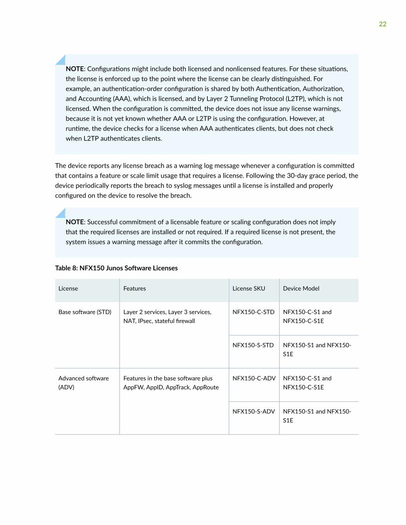
Table 8: NFX150 Junos Software Licenses
License Features License SKU Device Model
Base software (STD) Layer 2 services, Layer 3 services,NAT, IPsec, stateful firewall
NFX150-C-STD NFX150-C-S1 andNFX150-C-S1E
NFX150-S-STD NFX150-S1 and NFX150-S1E
Advanced software(ADV)
Features in the base software plusAppFW, AppID, AppTrack, AppRoute
NFX150-C-ADV NFX150-C-S1 andNFX150-C-S1E
NFX150-S-ADV NFX150-S1 and NFX150-S1E
22
RELATED DOCUMENTATION
Initial Configuration on NFX150 Devices | 29
Mapping Interfaces on NFX150 Devices | 45
Junos OS Releases Supported on NFX SeriesHardware
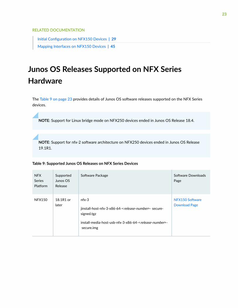
The Table 9 on page 23 provides details of Junos OS software releases supported on the NFX Seriesdevices.
NOTE: Support for Linux bridge mode on NFX250 devices ended in Junos OS Release 18.4.
NOTE: Support for nfx-2 software architecture on NFX250 devices ended in Junos OS Release19.1R1.
Table 9: Supported Junos OS Releases on NFX Series Devices
NFXSeriesPlatform
SupportedJunos OSRelease
Software Package Software DownloadsPage
NFX150 18.1R1 orlater
nfx-3
jinstall-host-nfx-3-x86-64-<release-number>- secure-signed.tgz
install-media-host-usb-nfx-3-x86-64-<release-number>- secure.img
NFX150 SoftwareDownload Page
23
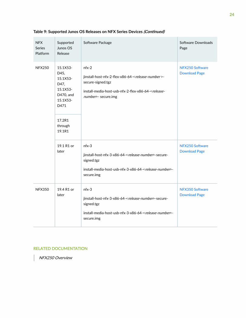
Table 9: Supported Junos OS Releases on NFX Series Devices (Continued)
NFXSeriesPlatform
SupportedJunos OSRelease
Software Package Software DownloadsPage
NFX250 15.1X53-D45,15.1X53-D47,15.1X53-D470, and15.1X53-D471
nfx-2
jinstall-host-nfx-2-flex-x86-64-<release-number >-secure-signed.tgz
install-media-host-usb-nfx-2-flex-x86-64-<release-number>- secure.img
NFX250 SoftwareDownload Page
17.2R1through19.1R1
19.1 R1 orlater
nfx-3
jinstall-host-nfx-3-x86-64-<release-number>-secure-signed.tgz
install-media-host-usb-nfx-3-x86-64-<release-number>-secure.img
NFX250 SoftwareDownload Page
NFX350 19.4 R1 orlater
nfx-3
jinstall-host-nfx-3-x86-64-<release-number>-secure-signed.tgz
install-media-host-usb-nfx-3-x86-64-<release-number>-secure.img
NFX350 SoftwareDownload Page
RELATED DOCUMENTATION
NFX250 Overview
24
NFX Product Compatibility
IN THIS SECTION
Hardware Compatibility | 25
Software Version Compatibility | 25
Hardware Compatibility
To obtain information about the components that are supported on your devices, and specialcompatibility guidelines with the release, see the Hardware Guide and the Interface Module Referencefor the product.
To determine the features supported on NFX Series devices in this release, use the Juniper NetworksFeature Explorer, a Web-based application that helps you to explore and compare Junos OS featureinformation to find the right software release and hardware platform for your network. Find FeatureExplorer at: https://pathfinder.juniper.net/feature-explorer/.
Hardware Compatibility Tool
For a hardware compatibility matrix for optical interfaces and transceivers supported across allplatforms, see the Hardware Compatibility Tool.
Software Version Compatibility
This section lists the vSRX and Cloud CPE Solution software releases that are compatible with the JunosOS releases on the NFX Series devices.
NOTE:
• Starting in Junos OS Release 18.1R1, NFX Series devices support the same version ofplatform software and vSRX. For example, see Table 10 on page 26.
25
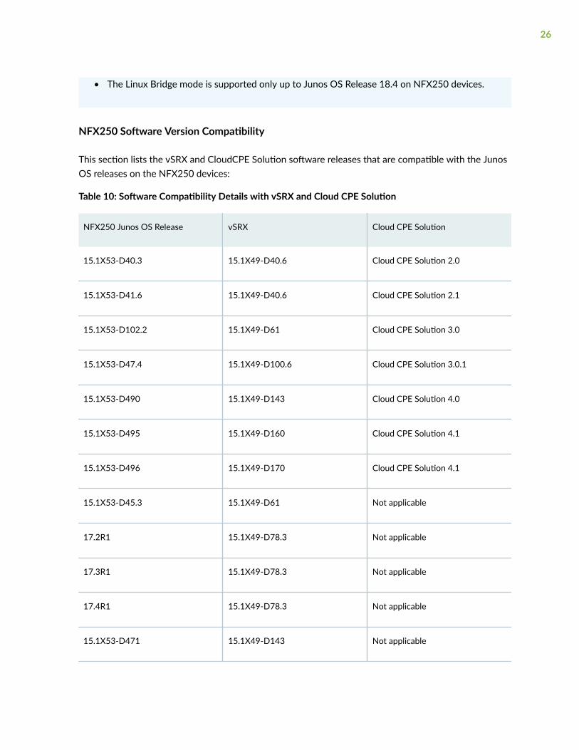
• The Linux Bridge mode is supported only up to Junos OS Release 18.4 on NFX250 devices.
NFX250 Software Version Compatibility
This section lists the vSRX and CloudCPE Solution software releases that are compatible with the JunosOS releases on the NFX250 devices:
Table 10: Software Compatibility Details with vSRX and Cloud CPE Solution
NFX250 Junos OS Release vSRX Cloud CPE Solution
15.1X53-D40.3 15.1X49-D40.6 Cloud CPE Solution 2.0
15.1X53-D41.6 15.1X49-D40.6 Cloud CPE Solution 2.1
15.1X53-D102.2 15.1X49-D61 Cloud CPE Solution 3.0
15.1X53-D47.4 15.1X49-D100.6 Cloud CPE Solution 3.0.1
15.1X53-D490 15.1X49-D143 Cloud CPE Solution 4.0
15.1X53-D495 15.1X49-D160 Cloud CPE Solution 4.1
15.1X53-D496 15.1X49-D170 Cloud CPE Solution 4.1
15.1X53-D45.3 15.1X49-D61 Not applicable
17.2R1 15.1X49-D78.3 Not applicable
17.3R1 15.1X49-D78.3 Not applicable
17.4R1 15.1X49-D78.3 Not applicable
15.1X53-D471 15.1X49-D143 Not applicable
26
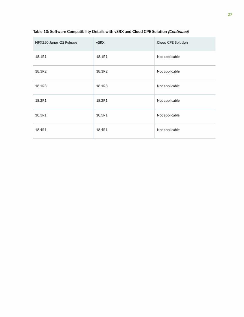
Table 10: Software Compatibility Details with vSRX and Cloud CPE Solution (Continued)
NFX250 Junos OS Release vSRX Cloud CPE Solution
18.1R1 18.1R1 Not applicable
18.1R2 18.1R2 Not applicable
18.1R3 18.1R3 Not applicable
18.2R1 18.2R1 Not applicable
18.3R1 18.3R1 Not applicable
18.4R1 18.4R1 Not applicable
27
2CHAPTER
Initial Configuration
Initial Configuration on NFX150 Devices | 29
Zero Touch Provisioning on NFX Series Devices | 34
Initial Configuration on NFX150 Devices
IN THIS SECTION
Factory-Default Settings | 29
Enabling Basic Connectivity | 31
Establishing the Connection | 33
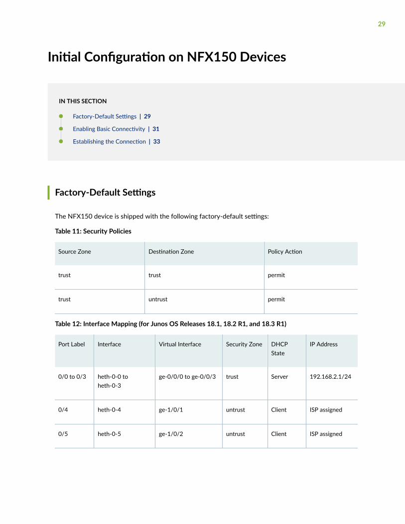
Factory-Default Settings
The NFX150 device is shipped with the following factory-default settings:
Table 11: Security Policies
Source Zone Destination Zone Policy Action
trust trust permit
trust untrust permit
Table 12: Interface Mapping (for Junos OS Releases 18.1, 18.2 R1, and 18.3 R1)
Port Label Interface Virtual Interface Security Zone DHCPState
IP Address
0/0 to 0/3 heth-0-0 toheth-0-3
ge-0/0/0 to ge-0/0/3 trust Server 192.168.2.1/24
0/4 heth-0-4 ge-1/0/1 untrust Client ISP assigned
0/5 heth-0-5 ge-1/0/2 untrust Client ISP assigned
29
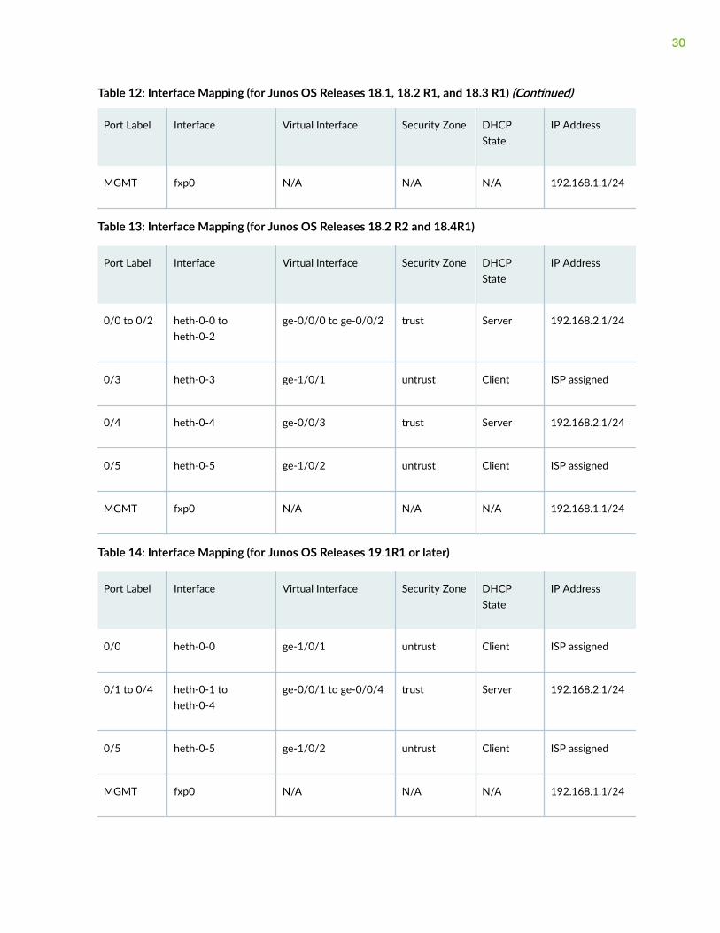
Table 12: Interface Mapping (for Junos OS Releases 18.1, 18.2 R1, and 18.3 R1) (Continued)
Port Label Interface Virtual Interface Security Zone DHCPState
IP Address
MGMT fxp0 N/A N/A N/A 192.168.1.1/24
Table 13: Interface Mapping (for Junos OS Releases 18.2 R2 and 18.4R1)
Port Label Interface Virtual Interface Security Zone DHCPState
IP Address
0/0 to 0/2 heth-0-0 toheth-0-2
ge-0/0/0 to ge-0/0/2 trust Server 192.168.2.1/24
0/3 heth-0-3 ge-1/0/1 untrust Client ISP assigned
0/4 heth-0-4 ge-0/0/3 trust Server 192.168.2.1/24
0/5 heth-0-5 ge-1/0/2 untrust Client ISP assigned
MGMT fxp0 N/A N/A N/A 192.168.1.1/24
Table 14: Interface Mapping (for Junos OS Releases 19.1R1 or later)
Port Label Interface Virtual Interface Security Zone DHCPState
IP Address
0/0 heth-0-0 ge-1/0/1 untrust Client ISP assigned
0/1 to 0/4 heth-0-1 toheth-0-4
ge-0/0/1 to ge-0/0/4 trust Server 192.168.2.1/24
0/5 heth-0-5 ge-1/0/2 untrust Client ISP assigned
MGMT fxp0 N/A N/A N/A 192.168.1.1/24
30
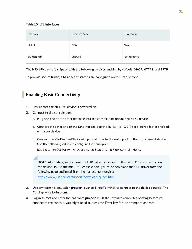
Table 15: LTE Interfaces
Interface Security Zone IP Address
cl-1/1/0 N/A N/A
dl0 (logical) untrust ISP assigned
The NFX150 device is shipped with the following services enabled by default: DHCP, HTTPS, and TFTP.
To provide secure traffic, a basic set of screens are configured on the untrust zone.
Enabling Basic Connectivity
1. Ensure that the NFX150 device is powered on.
2. Connect to the console port:
a. Plug one end of the Ethernet cable into the console port on your NFX150 device.
b. Connect the other end of the Ethernet cable to the RJ-45—to—DB-9 serial port adapter shippedwith your device.
c. Connect the RJ-45—to—DB-9 serial port adapter to the serial port on the management device.Use the following values to configure the serial port:
Baud rate—9600; Parity—N; Data bits—8; Stop bits—1; Flow control—None.
NOTE: Alternately, you can use the USB cable to connect to the mini-USB console port onthe device. To use the mini-USB console port, you must download the USB driver from thefollowing page and install it on the management device:
https://www.juniper.net/support/downloads/junos.html
3. Use any terminal emulation program, such as HyperTerminal, to connect to the device console. TheCLI displays a login prompt.
4. Log in as root and enter the password juniper123. If the software completes booting before youconnect to the console, you might need to press the Enter key for the prompt to appear:
31

NOTE: Starting with Junos OS Release 18.1R2 or later, the root password is not configuredfor initial configuration of the NFX150 devices.
login: rootpassword: juniper123
5. Start the CLI:
root@:~ # cliroot@>
6. Enter configuration mode:
root@> configure[edit]root@#
7. Change the password for the root administration user account:
[edit]root@# set system root-authentication plain-text-passwordNew password: passwordRetype new password: password
8. Enable SSH service for the root user:
[edit]root@# set system services ssh root-login allow
9. (Optional) Enable the Internet connection for devices connected on LAN by setting the DNS IP:
[edit]root@# set access address-assignment pool jdhcp-pool family inet dhcp-attributes name-server dns-server-ip
32
10. Commit the configuration:
[edit]root@# commit
Establishing the Connection
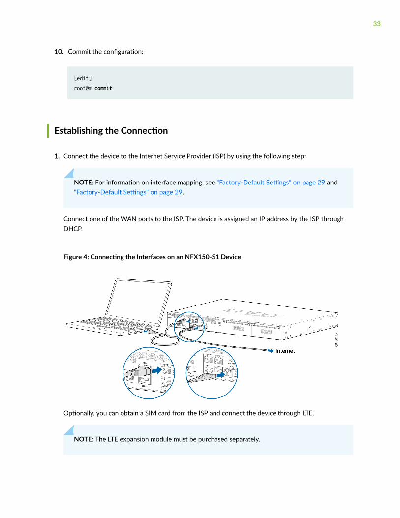
1. Connect the device to the Internet Service Provider (ISP) by using the following step:
NOTE: For information on interface mapping, see "Factory-Default Settings" on page 29 and"Factory-Default Settings" on page 29.
Connect one of the WAN ports to the ISP. The device is assigned an IP address by the ISP throughDHCP.
Figure 4: Connecting the Interfaces on an NFX150-S1 Device
Optionally, you can obtain a SIM card from the ISP and connect the device through LTE.
NOTE: The LTE expansion module must be purchased separately.
33
2. Connect the laptop to one of the front panel LAN ports. The laptop is assigned an IP address by theDHCP server running on the interface.
3. Open a browser on your laptop, navigate to https://www.juniper.net, and verify your connectivity.
RELATED DOCUMENTATION
Installing and Configuring the LTE Module
Zero Touch Provisioning on NFX Series Devices
IN THIS SECTION
Understanding Zero Touch Provisioning | 34
Pre-staging an NFX Series Device | 35
Provisioning an NFX Series Device | 38
Provisioning an NFX Series Device Using Sky Enterprise | 39
Understanding Zero Touch Provisioning
Zero Touch Provisioning (ZTP) allows you to provision and configure an NFX Series device in yournetwork automatically, with minimal manual intervention. ZTP allows you to make configurationchanges or software upgrades without logging into the device. NFX Series devices support ZTP with SkyEnterprise, which is a cloud-based network management application. For more information on SkyEnterprise, see Sky Enterprise Documentation.
The initial provisioning process involves the following components:
• NFX Series device—Sends requests to Juniper’s Redirect Server.
• Redirect server—Provides authentication and authorization for the devices in a network to accesstheir assigned central servers for the boot images and initial configuration files. The redirect serverresides at Juniper Networks.
34
Connectivity to the redirect server can be through IPv4 or IPv6 network. Depending on the sourceaddress, the redirect server redirects the ZTP to the corresponding Central Server with IPv4 or IPv6address.
The NFX Series device is shipped with a factory default configuration. The factory defaultconfiguration includes the URL of the redirect server, that is used to connect to the central servers byusing a secure encrypted connection.
• Central server—Manages the network and the NFX Series devices located remotely. The centralserver is located at a central geographical location. Alternately, you can use Contrail ServiceOrchestration (CSO) along with Sky Enterprise. CSO deploys the network services and Sky Enterprisemanages the devices in the network.
Pre-staging an NFX Series Device
Prestaging is an optional step for the device to by-pass Juniper’s Redirect Server and to connect to acustomer specific Redirect Server or a Regional Server for authentication and authorization in thenetwork. Prestaging involves copying and applying certificates and customer specific configuration froma specific directory in the device before the device is shipped to the customer site for installation.
The customer specific resources are stored internally. When the device boots up with the factory defaultconfiguration, the prestage resources are copied and the configuration is applied on the device.
35
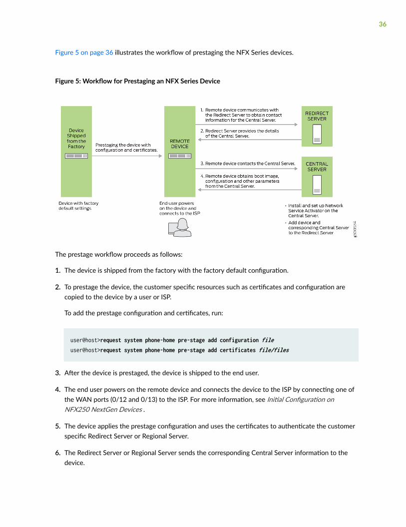
Figure 5 on page 36 illustrates the workflow of prestaging the NFX Series devices.
Figure 5: Workflow for Prestaging an NFX Series Device
The prestage workflow proceeds as follows:
1. The device is shipped from the factory with the factory default configuration.
2. To prestage the device, the customer specific resources such as certificates and configuration arecopied to the device by a user or ISP.
To add the prestage configuration and certificates, run:
user@host>request system phone-home pre-stage add configuration fileuser@host>request system phone-home pre-stage add certificates file/files
3. After the device is prestaged, the device is shipped to the end user.
4. The end user powers on the remote device and connects the device to the ISP by connecting one ofthe WAN ports (0/12 and 0/13) to the ISP. For more information, see Initial Configuration onNFX250 NextGen Devices .
5. The device applies the prestage configuration and uses the certificates to authenticate the customerspecific Redirect Server or Regional Server.
6. The Redirect Server or Regional Server sends the corresponding Central Server information to thedevice.
36
7. The device sends a provisioning request to the Central Server. The Central Server responds with theboot image and the configuration that is provisioned on the Central Server for that particular device.
8. The device fetches the boot image and configuration file from the Central Server.
9. The device upgrades to the boot image and applies the configuration to start the services andbecome operational.
To delete the prestage configuration and certificates, run:
user@host>request system phone-home pre-stage delete configuration fileuser@host>request system phone-home pre-stage delete certificate all | fileuser@host>request system phone-home pre-stage delete all
To verify the prestage configuration and certificates, run:
user@host>show system phone-home pre-stage configurationuser@host>show system phone-home pre-stage certificateuser@host>show system phone-home pre-stage
The prestage resources are not deleted when you upgrade the image by using the request system softwareadd image command or when you zeroize the device by using the request system zeroize command.
The default configuration for phone-home is:
user@jdm# set system phone-home server https://redirect.juniper.netuser@jdm# set system phone-home upgrade-image-before-configuration
To enable trace operation:
user@jdm# set system phone-home traceoptions file file-name size file-sizeuser@jdm# set system phone-home traceoptions flag [all | config | function | misc | socket | state-machine]
To disable trace operation:
user@jdm# set system phone-home traceoptions no-remote-trace
37
Provisioning an NFX Series Device
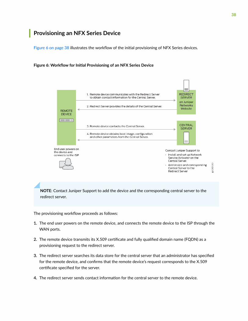
Figure 6 on page 38 illustrates the workflow of the initial provisioning of NFX Series devices.
Figure 6: Workflow for Initial Provisioning of an NFX Series Device
NOTE: Contact Juniper Support to add the device and the corresponding central server to theredirect server.
The provisioning workflow proceeds as follows:
1. The end user powers on the remote device, and connects the remote device to the ISP through theWAN ports.
2. The remote device transmits its X.509 certificate and fully qualified domain name (FQDN) as aprovisioning request to the redirect server.
3. The redirect server searches its data store for the central server that an administrator has specifiedfor the remote device, and confirms that the remote device’s request corresponds to the X.509certificate specified for the server.
4. The redirect server sends contact information for the central server to the remote device.
38
5. The remote device sends a request to the central server for the URL of the boot image and thelocation of the initial configuration file. The central server responds with the requested information.
6. The remote device fetches the boot image and configuration file from the central server.
7. The remote device upgrades to the boot image (if the boot image is different from the image runningon the NFX Series device), and applies the configuration to start the services and becomeoperational.
Provisioning an NFX Series Device Using Sky Enterprise
Figure 6 on page 38 illustrates the workflow of the initial provisioning of NFX Series devices using SkyEnterprise.
The provisioning workflow proceeds as follows:
1. The end user powers on the remote device, and connects the remote device to the ISP through theWAN ports.
2. The NFX Series device transmits its X.509 certificate and fully qualified domain name (FQDN) as aprovisioning request to the Redirect Server.
3. The Redirect Server connects the device to Sky Enterprise.
4. Click the link in the authorization e-mail that you receive from Sky Enterprise. Alternately, you canuse the Sky Enterprise application to authorize the device.
5. The NFX Series device registers with Sky Enterprise.
6. The initial configuration of the device begins. The initial configuration process takes about 60seconds.
39
3CHAPTER
Generating YANG Files
YANG files on NFX150 Devices | 41
YANG files on NFX150 Devices
IN THIS SECTION
Understanding YANG on NFX150 Devices | 41
Generating YANG Files | 42
Understanding YANG on NFX150 Devices
YANG is a standards-based, extensible data modeling language that is used to model the configurationand operational state data, remote procedure calls (RPCs), and server event notifications of networkdevices. The NETMOD working group in the IETF originally designed YANG to model networkmanagement data and to provide a standard for the content layer of the Network Configuration Protocol(NETCONF) model. However, YANG is protocol independent, and YANG data models can be usedindependent of the transport or RPC protocol and can be converted into any encoding format supportedby the network configuration protocol.
Juniper Networks provides YANG modules that define the Junos OS configuration hierarchy andoperational commands and Junos OS YANG extensions. You can generate the modules on the devicerunning Junos OS.
YANG uses a C-like syntax, a hierarchical organization of data, and provides a set of built-in types as wellas the capability to define derived types. YANG stresses readability, and it provides modularity andflexibility through the use of modules and submodules and reusable types and node groups.
A YANG module defines a single data model and determines the encoding for that data. A YANG moduledefines a data model through its data, and the hierarchical organization of and constraints on that data.A module can be a complete, standalone entity, or it can reference definitions in other modules andsubmodules as well as augment other data models with additional nodes.
A YANG module defines not only the syntax but also the semantics of the data. It explicitly definesrelationships between and constraints on the data. This enables you to create syntactically correctconfiguration data that meets constraint requirements and enables you to validate the data against themodel before uploading it and committing it on a device.
YANG uses modules to define configuration and state data, notifications, and RPCs for networkoperations in a manner similar to how the Structure of Management Information (SMI) uses MIBs tomodel data for SNMP operations. However, YANG has the benefit of being able to distinguish between
41
operational and configuration data. YANG maintains compatibility with SNMP’s SMI version 2 (SMIv2),and you can use libsmi to translate SMIv2 MIB modules into YANG modules and vice versa. Additionally,when you cannot use a YANG parser, you can translate YANG modules into YANG IndependentNotation (YIN), which is an equivalent XML syntax that can be read by XML parsers and XSLT scripts.
For information about YANG, see RFC 6020, YANG - A Data Modeling Language for the NetworkConfiguration Protocol (NETCONF), and related RFCs.
For more information, see YANG Modules Overview, Using Juniper Networks YANG Modules, and showsystem schema.
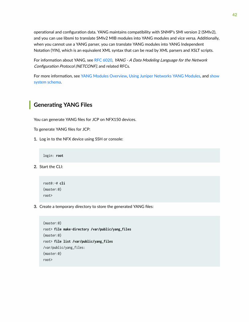
Generating YANG Files
You can generate YANG files for JCP on NFX150 devices.
To generate YANG files for JCP:
1. Log in to the NFX device using SSH or console:
login: root
2. Start the CLI:
root@:~# cli{master:0}root>
3. Create a temporary directory to store the generated YANG files:
{master:0}root> file make-directory /var/public/yang_files{master:0}root> file list /var/public/yang_files/var/public/yang_files:{master:0}root>
42
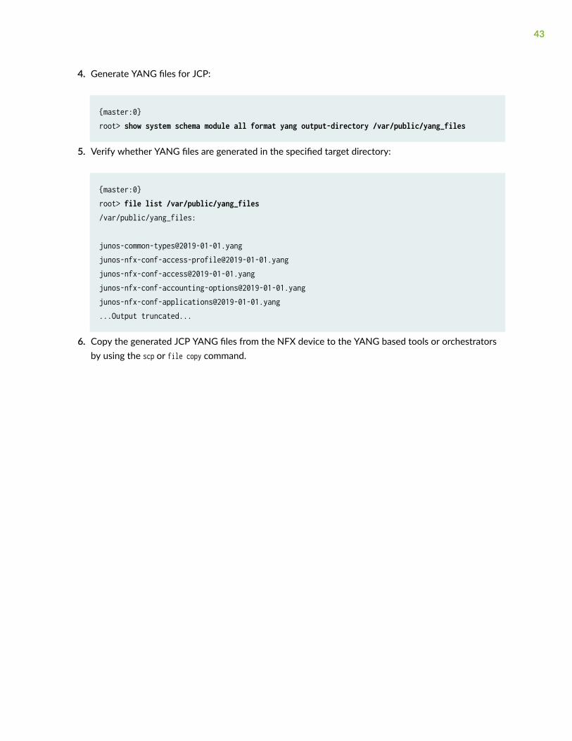
4. Generate YANG files for JCP:
{master:0}root> show system schema module all format yang output-directory /var/public/yang_files
5. Verify whether YANG files are generated in the specified target directory:
{master:0}root> file list /var/public/yang_files/var/public/yang_files:
[email protected]@2019-01-01.yangjunos-nfx-conf-access@2019-01-01.yangjunos-nfx-conf-accounting-options@2019-01-01.yangjunos-nfx-conf-applications@2019-01-01.yang...Output truncated...
6. Copy the generated JCP YANG files from the NFX device to the YANG based tools or orchestratorsby using the scp or file copy command.
43
4CHAPTER
Configuring Interfaces
Mapping Interfaces on NFX150 Devices | 45
Configuring the In-Band Management Interface | 47
ADSL2 and ADSL2+ Interfaces on NFX150 Devices | 48
VDSL2 Interfaces on NFX150 Devices | 54
Configuring the LTE Module on NFX Devices | 63
Upgrading the Modem Firmware on NFX Devices Through Over-the-Air (OTA) | 75
Mapping Interfaces on NFX150 Devices
IN THIS SECTION
Mapping Physical Interfaces to Virtual Interfaces on NFX150 Devices | 45
Mapping Physical Ports to VNF Interfaces Through SR-IOV | 46
Mapping Layer 3 Dataplane Interfaces to OVS | 46
Mapping Physical Interfaces to Virtual Interfaces on NFX150 Devices
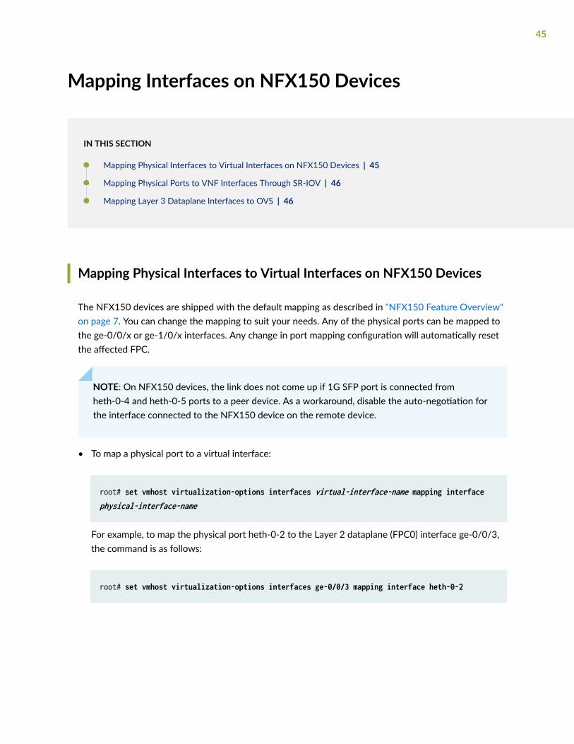
The NFX150 devices are shipped with the default mapping as described in "NFX150 Feature Overview"on page 7. You can change the mapping to suit your needs. Any of the physical ports can be mapped tothe ge-0/0/x or ge-1/0/x interfaces. Any change in port mapping configuration will automatically resetthe affected FPC.
NOTE: On NFX150 devices, the link does not come up if 1G SFP port is connected fromheth-0-4 and heth-0-5 ports to a peer device. As a workaround, disable the auto-negotiation forthe interface connected to the NFX150 device on the remote device.
• To map a physical port to a virtual interface:
root# set vmhost virtualization-options interfaces virtual-interface-name mapping interface physical-interface-name
For example, to map the physical port heth-0-2 to the Layer 2 dataplane (FPC0) interface ge-0/0/3,the command is as follows:
root# set vmhost virtualization-options interfaces ge-0/0/3 mapping interface heth-0-2
45
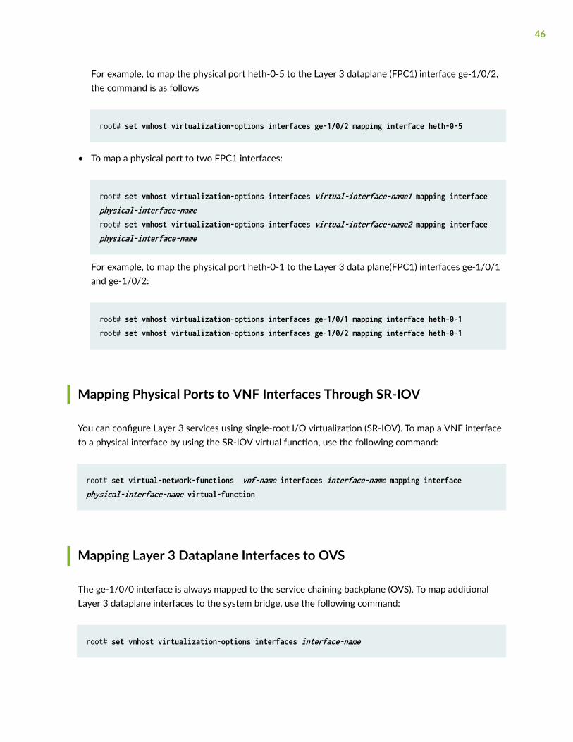
For example, to map the physical port heth-0-5 to the Layer 3 dataplane (FPC1) interface ge-1/0/2,the command is as follows
root# set vmhost virtualization-options interfaces ge-1/0/2 mapping interface heth-0-5
• To map a physical port to two FPC1 interfaces:
root# set vmhost virtualization-options interfaces virtual-interface-name1 mapping interface physical-interface-nameroot# set vmhost virtualization-options interfaces virtual-interface-name2 mapping interface physical-interface-name
For example, to map the physical port heth-0-1 to the Layer 3 data plane(FPC1) interfaces ge-1/0/1and ge-1/0/2:
root# set vmhost virtualization-options interfaces ge-1/0/1 mapping interface heth-0-1root# set vmhost virtualization-options interfaces ge-1/0/2 mapping interface heth-0-1
Mapping Physical Ports to VNF Interfaces Through SR-IOV
You can configure Layer 3 services using single-root I/O virtualization (SR-IOV). To map a VNF interfaceto a physical interface by using the SR-IOV virtual function, use the following command:
root# set virtual-network-functions vnf-name interfaces interface-name mapping interface physical-interface-name virtual-function
Mapping Layer 3 Dataplane Interfaces to OVS
The ge-1/0/0 interface is always mapped to the service chaining backplane (OVS). To map additionalLayer 3 dataplane interfaces to the system bridge, use the following command:
root# set vmhost virtualization-options interfaces interface-name
46
RELATED DOCUMENTATION
Configuring the In-Band Management Interface | 47
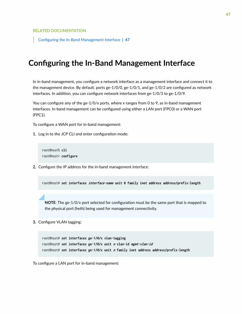
Configuring the In-Band Management Interface
In in-band management, you configure a network interface as a management interface and connect it tothe management device. By default. ports ge-1/0/0, ge-1/0/1, and ge-1/0/2 are configured as networkinterfaces. In addition, you can configure network interfaces from ge-1/0/3 to ge-1/0/9.
You can configure any of the ge-1/0/x ports, where x ranges from 0 to 9, as in-band managementinterfaces. In-band management can be configured using either a LAN port (FPC0) or a WAN port(FPC1).
To configure a WAN port for in-band management:
1. Log in to the JCP CLI and enter configuration mode:
root@host% cliroot@host> configure
2. Configure the IP address for the in-band management interface:
root@host# set interfaces interface-name unit 0 family inet address address/prefix-length
NOTE: The ge-1/0/x port selected for configuration must be the same port that is mapped tothe physical port (heth) being used for management connectivity.
3. Configure VLAN tagging:
root@host# set interfaces ge-1/0/x vlan-taggingroot@host# set interfaces ge-1/0/x unit n vlan-id mgmt-vlan-idroot@host# set interfaces ge-1/0/x unit n family inet address address/prefix-length
To configure a LAN port for in-band management:
47
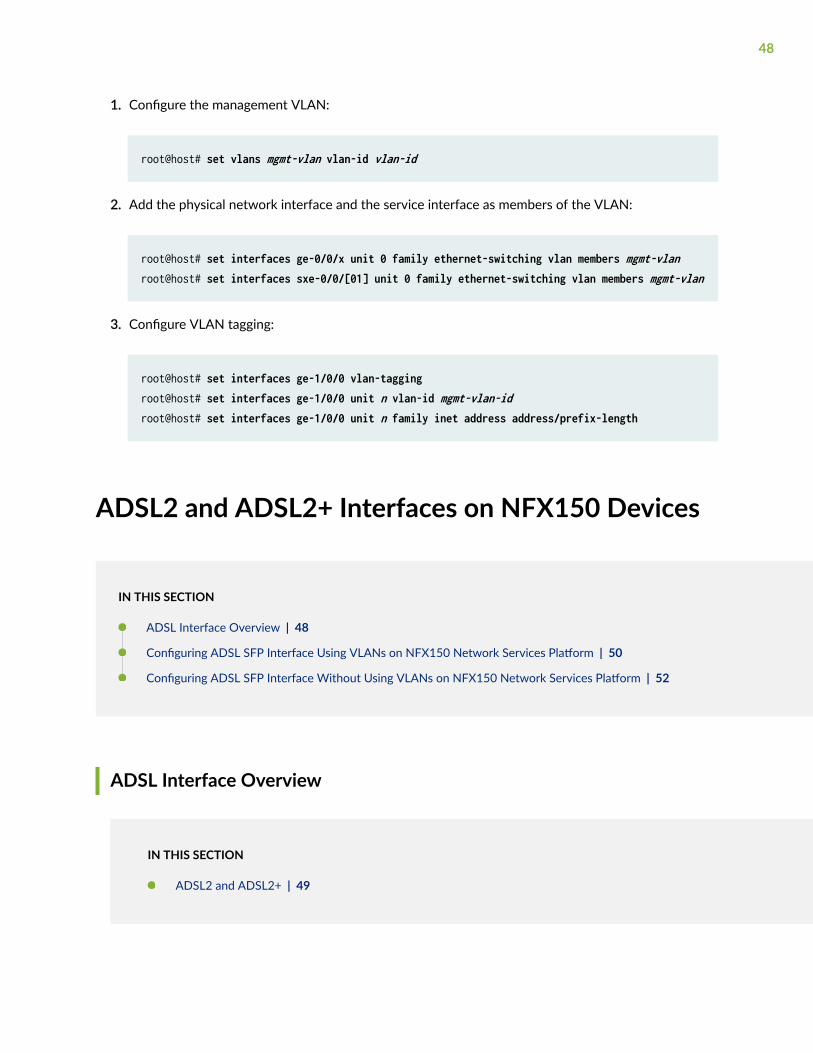
1. Configure the management VLAN:
root@host# set vlans mgmt-vlan vlan-id vlan-id
2. Add the physical network interface and the service interface as members of the VLAN:
root@host# set interfaces ge-0/0/x unit 0 family ethernet-switching vlan members mgmt-vlanroot@host# set interfaces sxe-0/0/[01] unit 0 family ethernet-switching vlan members mgmt-vlan
3. Configure VLAN tagging:
root@host# set interfaces ge-1/0/0 vlan-taggingroot@host# set interfaces ge-1/0/0 unit n vlan-id mgmt-vlan-idroot@host# set interfaces ge-1/0/0 unit n family inet address address/prefix-length
ADSL2 and ADSL2+ Interfaces on NFX150 Devices
IN THIS SECTION
ADSL Interface Overview | 48
Configuring ADSL SFP Interface Using VLANs on NFX150 Network Services Platform | 50
Configuring ADSL SFP Interface Without Using VLANs on NFX150 Network Services Platform | 52
ADSL Interface Overview
IN THIS SECTION
ADSL2 and ADSL2+ | 49
48
Asymmetric digital subscriber line (ADSL) technology is part of the xDSL family of modem technologiesthat use existing twisted-pair telephone lines to transport high-bandwidth data. ADSL lines connectservice provider networks and customer sites over the "last mile" of the network—the loop between theservice provider and the customer site.
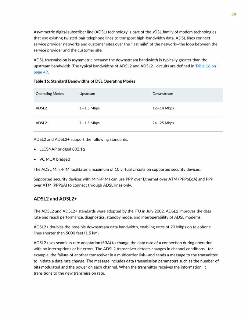
ADSL transmission is asymmetric because the downstream bandwidth is typically greater than theupstream bandwidth. The typical bandwidths of ADSL2 and ADSL2+ circuits are defined in Table 16 onpage 49.
Table 16: Standard Bandwidths of DSL Operating Modes
Operating Modes Upstream Downstream
ADSL2 1—1.5 Mbps 12—14 Mbps
ADSL2+ 1—1.5 Mbps 24—25 Mbps
ADSL2 and ADSL2+ support the following standards:
• LLCSNAP bridged 802.1q
• VC MUX bridged
The ADSL Mini-PIM facilitates a maximum of 10 virtual circuits on supported security devices.
Supported security devices with Mini-PIMs can use PPP over Ethernet over ATM (PPPoEoA) and PPPover ATM (PPPoA) to connect through ADSL lines only.
ADSL2 and ADSL2+
The ADSL2 and ADSL2+ standards were adopted by the ITU in July 2002. ADSL2 improves the datarate and reach performance, diagnostics, standby mode, and interoperability of ADSL modems.
ADSL2+ doubles the possible downstream data bandwidth, enabling rates of 20 Mbps on telephonelines shorter than 5000 feet (1.5 km).
ADSL2 uses seamless rate adaptation (SRA) to change the data rate of a connection during operationwith no interruptions or bit errors. The ADSL2 transceiver detects changes in channel conditions—forexample, the failure of another transceiver in a multicarrier link—and sends a message to the transmitterto initiate a data rate change. The message includes data transmission parameters such as the number ofbits modulated and the power on each channel. When the transmitter receives the information, ittransitions to the new transmission rate.
49
Configuring ADSL SFP Interface Using VLANs on NFX150 NetworkServices Platform
NOTE: Ensure that connectivity to the host is not lost during the configuration process.
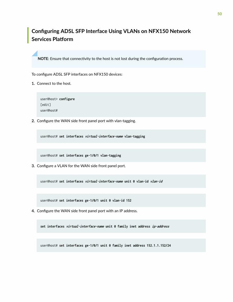
To configure ADSL SFP interfaces on NFX150 devices:
1. Connect to the host.
user@host> configure[edit]user@host#
2. Configure the WAN side front panel port with vlan-tagging.
user@host# set interfaces virtual-interface-name vlan-tagging
user@host# set interfaces ge-1/0/1 vlan-tagging
3. Configure a VLAN for the WAN side front panel port.
user@host# set interfaces virtual-interface-name unit 0 vlan-id vlan-id
user@host# set interfaces ge-1/0/1 unit 0 vlan-id 152
4. Configure the WAN side front panel port with an IP address.
set interfaces virtual-interface-name unit 0 family inet address ip-address
user@host# set interfaces ge-1/0/1 unit 0 family inet address 152.1.1.152/24
50
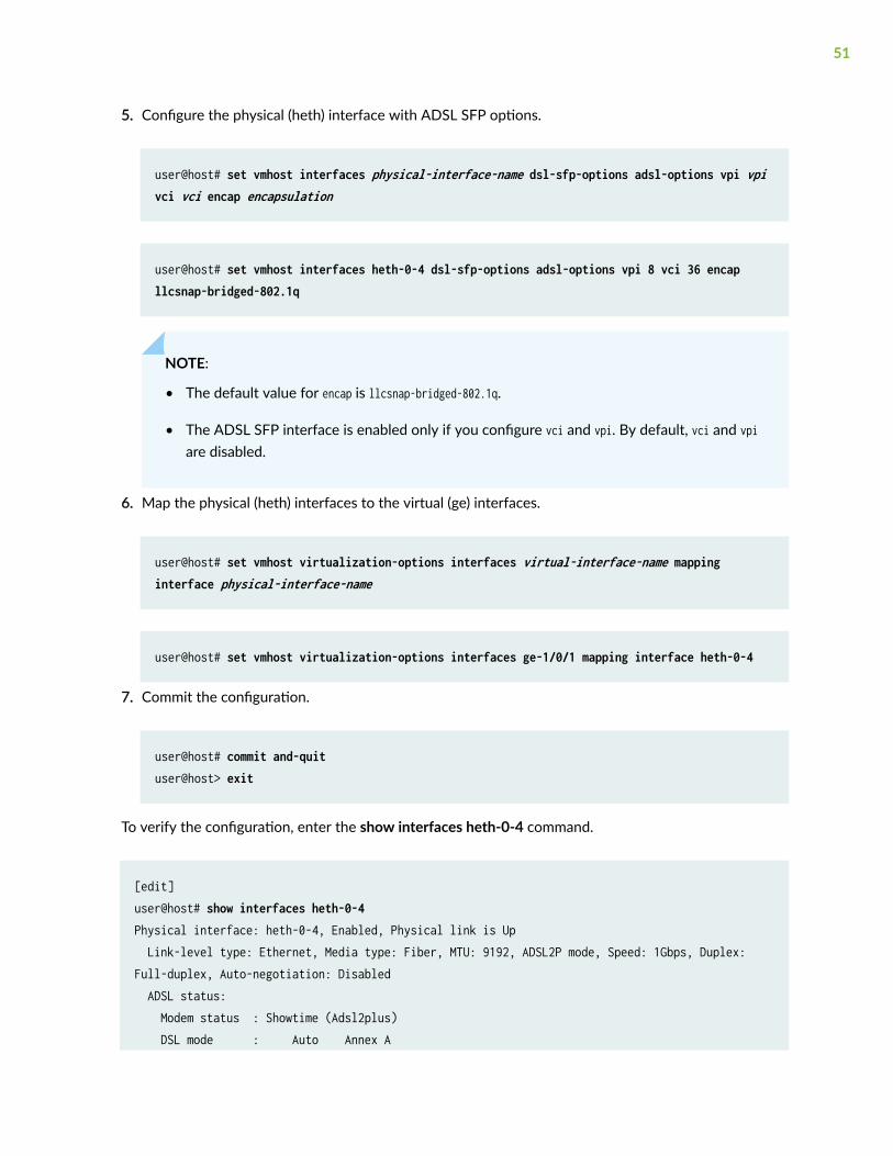
5. Configure the physical (heth) interface with ADSL SFP options.
user@host# set vmhost interfaces physical-interface-name dsl-sfp-options adsl-options vpi vpi vci vci encap encapsulation
user@host# set vmhost interfaces heth-0-4 dsl-sfp-options adsl-options vpi 8 vci 36 encap llcsnap-bridged-802.1q
NOTE:
• The default value for encap is llcsnap-bridged-802.1q.
• The ADSL SFP interface is enabled only if you configure vci and vpi. By default, vci and vpiare disabled.
6. Map the physical (heth) interfaces to the virtual (ge) interfaces.
user@host# set vmhost virtualization-options interfaces virtual-interface-name mapping interface physical-interface-name
user@host# set vmhost virtualization-options interfaces ge-1/0/1 mapping interface heth-0-4
7. Commit the configuration.
user@host# commit and-quituser@host> exit
To verify the configuration, enter the show interfaces heth-0-4 command.
[edit]user@host# show interfaces heth-0-4Physical interface: heth-0-4, Enabled, Physical link is Up Link-level type: Ethernet, Media type: Fiber, MTU: 9192, ADSL2P mode, Speed: 1Gbps, Duplex: Full-duplex, Auto-negotiation: Disabled ADSL status: Modem status : Showtime (Adsl2plus) DSL mode : Auto Annex A
51
Device flags : Present Running Current address: 58:00:bb:ac:c8:51, Hardware address: 58:00:bb:ac:c8:51
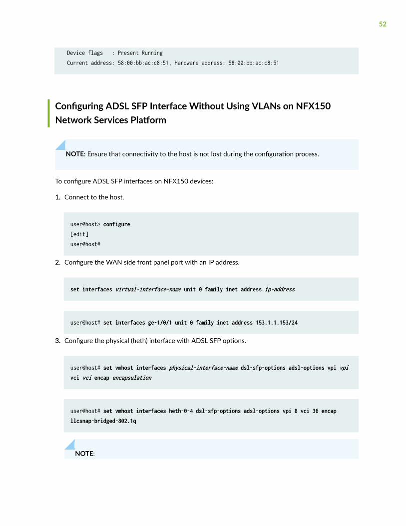
Configuring ADSL SFP Interface Without Using VLANs on NFX150Network Services Platform
NOTE: Ensure that connectivity to the host is not lost during the configuration process.
To configure ADSL SFP interfaces on NFX150 devices:
1. Connect to the host.
user@host> configure[edit]user@host#
2. Configure the WAN side front panel port with an IP address.
set interfaces virtual-interface-name unit 0 family inet address ip-address
user@host# set interfaces ge-1/0/1 unit 0 family inet address 153.1.1.153/24
3. Configure the physical (heth) interface with ADSL SFP options.
user@host# set vmhost interfaces physical-interface-name dsl-sfp-options adsl-options vpi vpi vci vci encap encapsulation
user@host# set vmhost interfaces heth-0-4 dsl-sfp-options adsl-options vpi 8 vci 36 encap llcsnap-bridged-802.1q
NOTE:
52
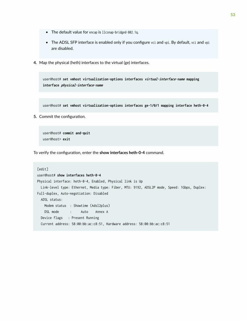
• The default value for encap is llcsnap-bridged-802.1q.
• The ADSL SFP interface is enabled only if you configure vci and vpi. By default, vci and vpiare disabled.
4. Map the physical (heth) interfaces to the virtual (ge) interfaces.
user@host# set vmhost virtualization-options interfaces virtual-interface-name mapping interface physical-interface-name
user@host# set vmhost virtualization-options interfaces ge-1/0/1 mapping interface heth-0-4
5. Commit the configuration.
user@host# commit and-quituser@host> exit
To verify the configuration, enter the show interfaces heth-0-4 command.
[edit]user@host# show interfaces heth-0-4Physical interface: heth-0-4, Enabled, Physical link is Up Link-level type: Ethernet, Media type: Fiber, MTU: 9192, ADSL2P mode, Speed: 1Gbps, Duplex: Full-duplex, Auto-negotiation: Disabled ADSL status: Modem status : Showtime (Adsl2plus) DSL mode : Auto Annex A Device flags : Present Running Current address: 58:00:bb:ac:c8:51, Hardware address: 58:00:bb:ac:c8:51
53
VDSL2 Interfaces on NFX150 Devices
IN THIS SECTION
VDSL Interface Overview | 54
VDSL2 Network Deployment Topology | 55
VDSL2 Interface Support on NFX Series Devices | 57
Configuring VDSL SFP Interface Using VLANs on NFX150 Network Services Platform | 59
Configuring VDSL SFP Interface Without Using VLANs on NFX150 Network Services Platform | 61
VDSL Interface Overview
IN THIS SECTION
VDSL2 Vectoring Overview | 55
Very-high-bit-rate digital subscriber line (VDSL) technology is part of the xDSL family of modemtechnologies that provide faster data transmission over a single flat untwisted or twisted pair of copperwires. The VDSL lines connect service provider networks and customer sites to provide high bandwidthapplications (triple-play services) such as high-speed Internet access, telephone services like VoIP, high-definition TV (HDTV), and interactive gaming services over a single connection.
VDSL2 is an enhancement to G.993.1 (VDSL) and permits the transmission of asymmetric (half-duplex)and symmetric (full-duplex) aggregate data rates up to 100 Mbps on short copper loops using abandwidth up to 17 MHz. The VDSL2 technology is based on the ITU-T G.993.2 (VDSL2) standard,which is the International Telecommunication Union standard describing a data transmission method forVDSL2 transceivers.
The VDSL2 uses discrete multitone (DMT) modulation. DMT is a method of separating a digitalsubscriber line signal so that the usable frequency range is separated into 256 frequency bands (orchannels) of 4.3125 KHz each. The DMT uses the Fast Fourier Transform (FFT) algorithm fordemodulation or modulation for increased speed.
54
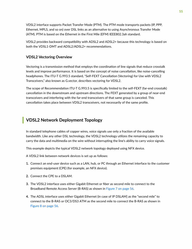
VDSL2 interface supports Packet Transfer Mode (PTM). The PTM mode transports packets (IP, PPP,Ethernet, MPLS, and so on) over DSL links as an alternative to using Asynchronous Transfer Mode(ATM). PTM is based on the Ethernet in the First Mile (EFM) IEEE802.3ah standard.
VDSL2 provides backward compatibility with ADSL2 and ADSL2+ because this technology is based onboth the VDSL1-DMT and ADSL2/ADSL2+ recommendations.
VDSL2 Vectoring Overview
Vectoring is a transmission method that employs the coordination of line signals that reduce crosstalklevels and improve performance. It is based on the concept of noise cancellation, like noise-cancellingheadphones. The ITU-T G.993.5 standard, "Self-FEXT Cancellation (Vectoring) for Use with VDSL2Transceivers,” also known as G.vector, describes vectoring for VDSL2.
The scope of Recommendation ITU-T G.993.5 is specifically limited to the self-FEXT (far-end crosstalk)cancellation in the downstream and upstream directions. The FEXT generated by a group of near-endtransceivers and interfering with the far-end transceivers of that same group is canceled. Thiscancellation takes place between VDSL2 transceivers, not necessarily of the same profile.
VDSL2 Network Deployment Topology
In standard telephone cables of copper wires, voice signals use only a fraction of the availablebandwidth. Like any other DSL technology, the VDSL2 technology utilizes the remaining capacity tocarry the data and multimedia on the wire without interrupting the line's ability to carry voice signals.
This example depicts the typical VDSL2 network topology deployed using NFX device.
A VDSL2 link between network devices is set up as follows:
1. Connect an end-user device such as a LAN, hub, or PC through an Ethernet interface to the customerpremises equipment (CPE) (for example, an NFX device).
2. Connect the CPE to a DSLAM.
3. The VDSL2 interface uses either Gigabit Ethernet or fiber as second mile to connect to theBroadband Remote Access Server (B-RAS) as shown in Figure 7 on page 56.
4. The ADSL interface uses either Gigabit Ethernet (in case of IP DSLAM] as the “second mile” toconnect to the B-RAS or OC3/DS3 ATM as the second mile to connect the B-RAS as shown inFigure 8 on page 56.
55
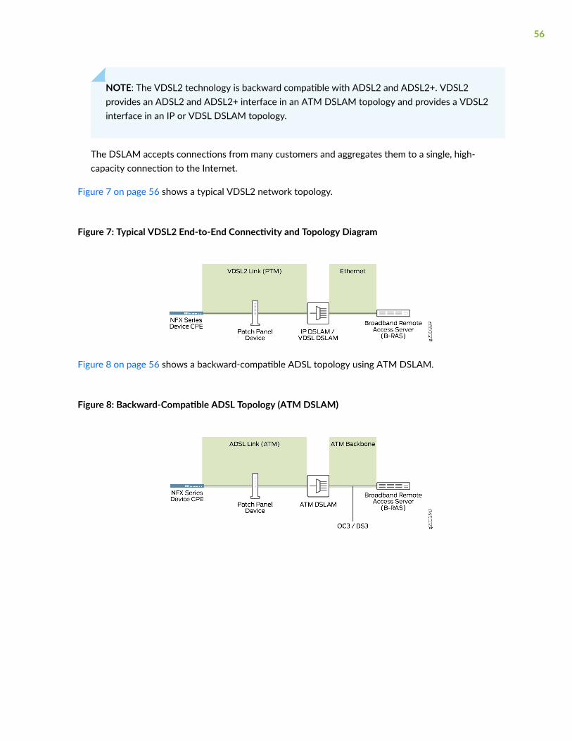
NOTE: The VDSL2 technology is backward compatible with ADSL2 and ADSL2+. VDSL2provides an ADSL2 and ADSL2+ interface in an ATM DSLAM topology and provides a VDSL2interface in an IP or VDSL DSLAM topology.
The DSLAM accepts connections from many customers and aggregates them to a single, high-capacity connection to the Internet.
Figure 7 on page 56 shows a typical VDSL2 network topology.
Figure 7: Typical VDSL2 End-to-End Connectivity and Topology Diagram
Figure 8 on page 56 shows a backward-compatible ADSL topology using ATM DSLAM.
Figure 8: Backward-Compatible ADSL Topology (ATM DSLAM)
56
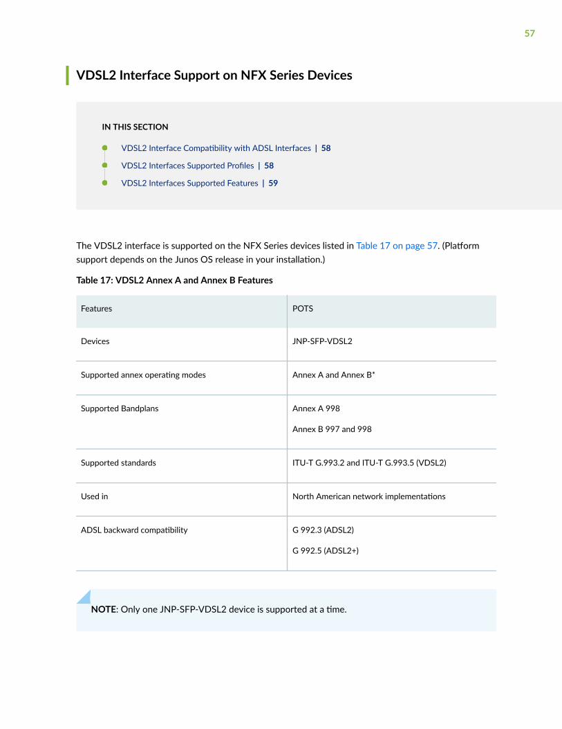
VDSL2 Interface Support on NFX Series Devices
IN THIS SECTION
VDSL2 Interface Compatibility with ADSL Interfaces | 58
VDSL2 Interfaces Supported Profiles | 58
VDSL2 Interfaces Supported Features | 59
The VDSL2 interface is supported on the NFX Series devices listed in Table 17 on page 57. (Platformsupport depends on the Junos OS release in your installation.)
Table 17: VDSL2 Annex A and Annex B Features
Features POTS
Devices JNP-SFP-VDSL2
Supported annex operating modes Annex A and Annex B*
Supported Bandplans Annex A 998
Annex B 997 and 998
Supported standards ITU-T G.993.2 and ITU-T G.993.5 (VDSL2)
Used in North American network implementations
ADSL backward compatibility G 992.3 (ADSL2)
G 992.5 (ADSL2+)
NOTE: Only one JNP-SFP-VDSL2 device is supported at a time.
57
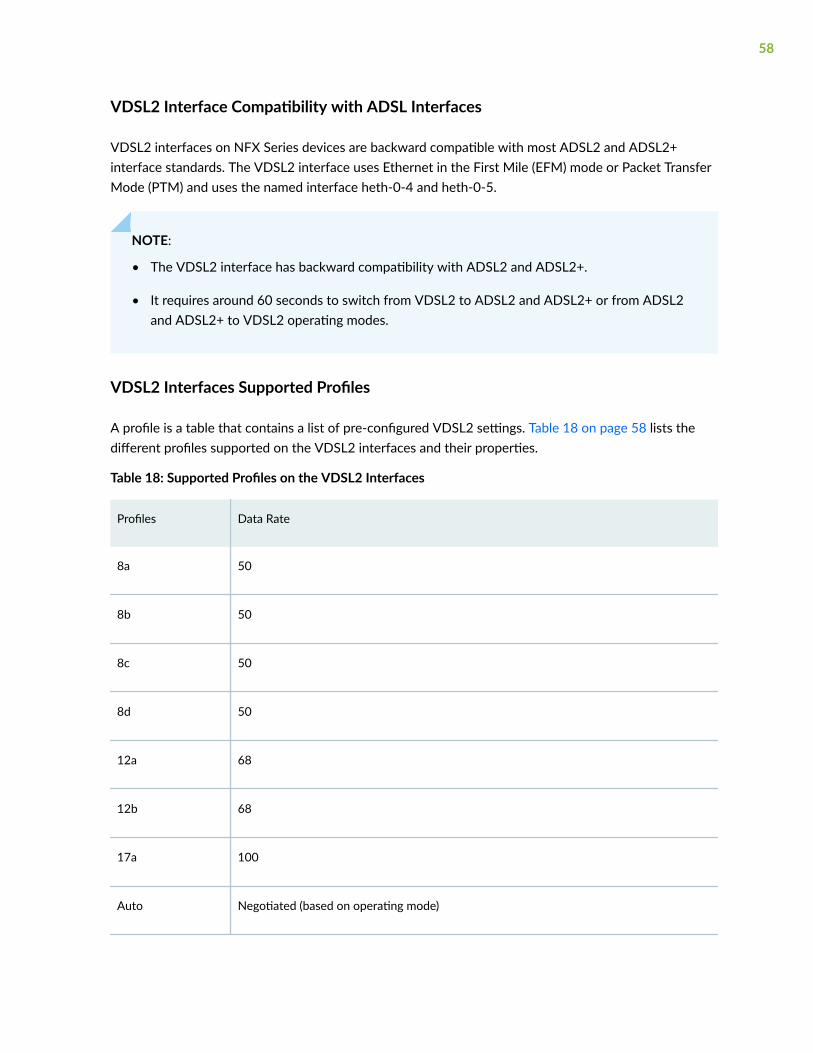
VDSL2 Interface Compatibility with ADSL Interfaces
VDSL2 interfaces on NFX Series devices are backward compatible with most ADSL2 and ADSL2+interface standards. The VDSL2 interface uses Ethernet in the First Mile (EFM) mode or Packet TransferMode (PTM) and uses the named interface heth-0-4 and heth-0-5.
NOTE:
• The VDSL2 interface has backward compatibility with ADSL2 and ADSL2+.
• It requires around 60 seconds to switch from VDSL2 to ADSL2 and ADSL2+ or from ADSL2and ADSL2+ to VDSL2 operating modes.
VDSL2 Interfaces Supported Profiles
A profile is a table that contains a list of pre-configured VDSL2 settings. Table 18 on page 58 lists thedifferent profiles supported on the VDSL2 interfaces and their properties.
Table 18: Supported Profiles on the VDSL2 Interfaces
Profiles Data Rate
8a 50
8b 50
8c 50
8d 50
12a 68
12b 68
17a 100
Auto Negotiated (based on operating mode)
58
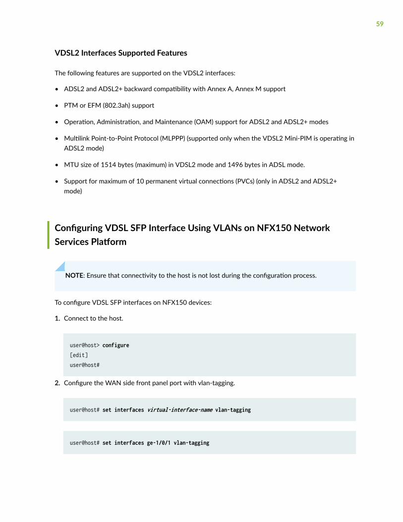
VDSL2 Interfaces Supported Features
The following features are supported on the VDSL2 interfaces:
• ADSL2 and ADSL2+ backward compatibility with Annex A, Annex M support
• PTM or EFM (802.3ah) support
• Operation, Administration, and Maintenance (OAM) support for ADSL2 and ADSL2+ modes
• Multilink Point-to-Point Protocol (MLPPP) (supported only when the VDSL2 Mini-PIM is operating inADSL2 mode)
• MTU size of 1514 bytes (maximum) in VDSL2 mode and 1496 bytes in ADSL mode.
• Support for maximum of 10 permanent virtual connections (PVCs) (only in ADSL2 and ADSL2+mode)
Configuring VDSL SFP Interface Using VLANs on NFX150 NetworkServices Platform
NOTE: Ensure that connectivity to the host is not lost during the configuration process.
To configure VDSL SFP interfaces on NFX150 devices:
1. Connect to the host.
user@host> configure[edit]user@host#
2. Configure the WAN side front panel port with vlan-tagging.
user@host# set interfaces virtual-interface-name vlan-tagging
user@host# set interfaces ge-1/0/1 vlan-tagging
59
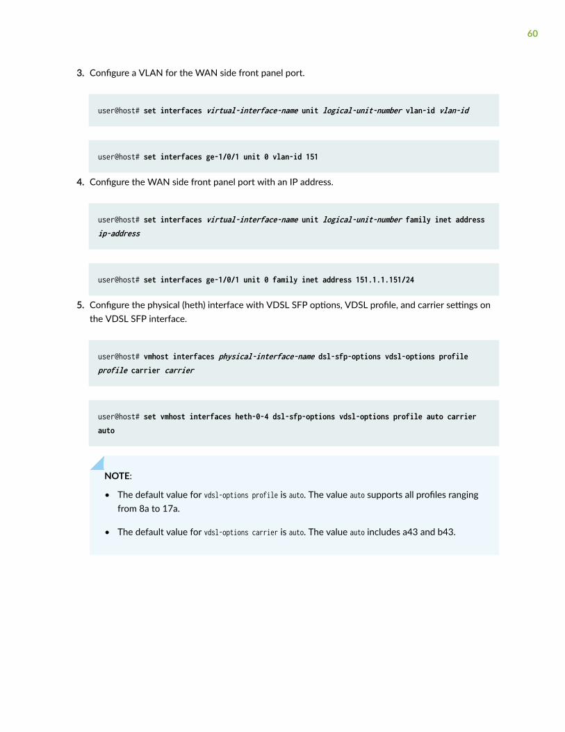
3. Configure a VLAN for the WAN side front panel port.
user@host# set interfaces virtual-interface-name unit logical-unit-number vlan-id vlan-id
user@host# set interfaces ge-1/0/1 unit 0 vlan-id 151
4. Configure the WAN side front panel port with an IP address.
user@host# set interfaces virtual-interface-name unit logical-unit-number family inet address ip-address
user@host# set interfaces ge-1/0/1 unit 0 family inet address 151.1.1.151/24
5. Configure the physical (heth) interface with VDSL SFP options, VDSL profile, and carrier settings onthe VDSL SFP interface.
user@host# vmhost interfaces physical-interface-name dsl-sfp-options vdsl-options profile profile carrier carrier
user@host# set vmhost interfaces heth-0-4 dsl-sfp-options vdsl-options profile auto carrier auto
NOTE:
• The default value for vdsl-options profile is auto. The value auto supports all profiles rangingfrom 8a to 17a.
• The default value for vdsl-options carrier is auto. The value auto includes a43 and b43.
60
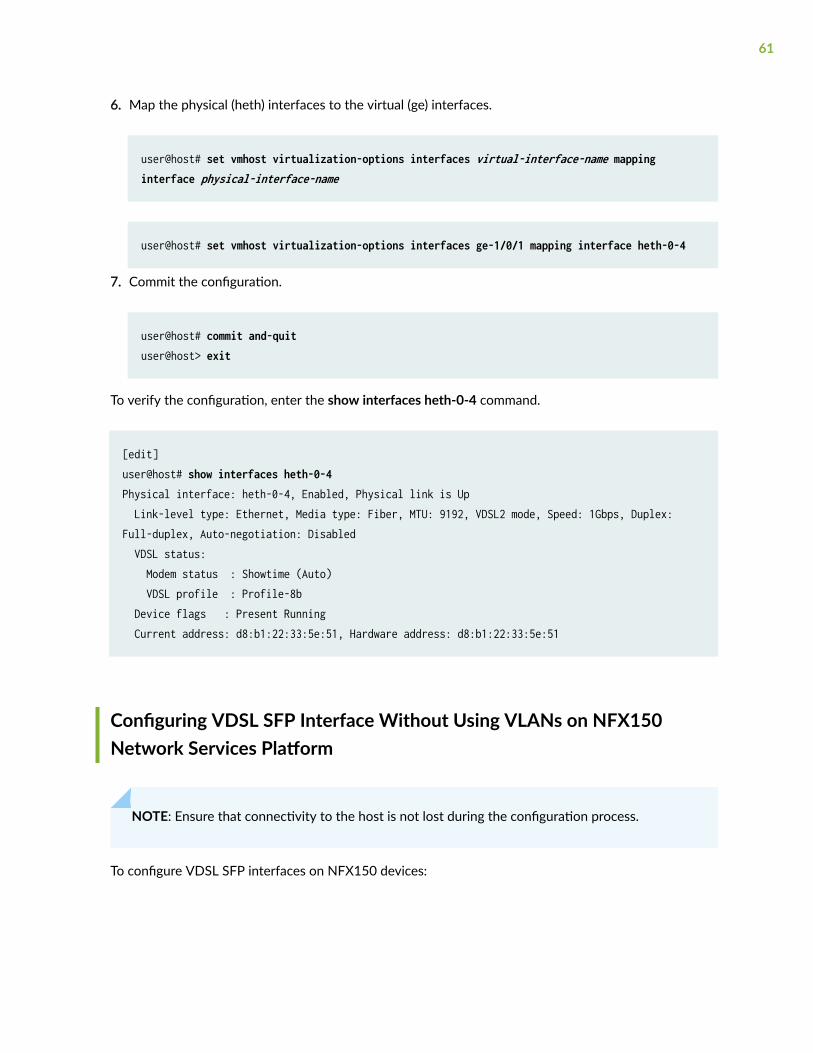
6. Map the physical (heth) interfaces to the virtual (ge) interfaces.
user@host# set vmhost virtualization-options interfaces virtual-interface-name mapping interface physical-interface-name
user@host# set vmhost virtualization-options interfaces ge-1/0/1 mapping interface heth-0-4
7. Commit the configuration.
user@host# commit and-quituser@host> exit
To verify the configuration, enter the show interfaces heth-0-4 command.
[edit]user@host# show interfaces heth-0-4Physical interface: heth-0-4, Enabled, Physical link is Up Link-level type: Ethernet, Media type: Fiber, MTU: 9192, VDSL2 mode, Speed: 1Gbps, Duplex: Full-duplex, Auto-negotiation: Disabled VDSL status: Modem status : Showtime (Auto) VDSL profile : Profile-8b Device flags : Present Running Current address: d8:b1:22:33:5e:51, Hardware address: d8:b1:22:33:5e:51
Configuring VDSL SFP Interface Without Using VLANs on NFX150Network Services Platform
NOTE: Ensure that connectivity to the host is not lost during the configuration process.
To configure VDSL SFP interfaces on NFX150 devices:
61
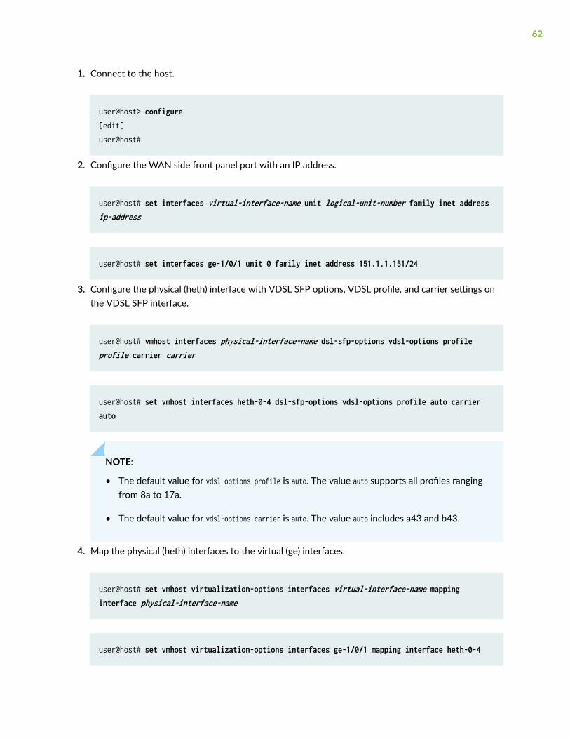
1. Connect to the host.
user@host> configure[edit]user@host#
2. Configure the WAN side front panel port with an IP address.
user@host# set interfaces virtual-interface-name unit logical-unit-number family inet address ip-address
user@host# set interfaces ge-1/0/1 unit 0 family inet address 151.1.1.151/24
3. Configure the physical (heth) interface with VDSL SFP options, VDSL profile, and carrier settings onthe VDSL SFP interface.
user@host# vmhost interfaces physical-interface-name dsl-sfp-options vdsl-options profile profile carrier carrier
user@host# set vmhost interfaces heth-0-4 dsl-sfp-options vdsl-options profile auto carrier auto
NOTE:
• The default value for vdsl-options profile is auto. The value auto supports all profiles rangingfrom 8a to 17a.
• The default value for vdsl-options carrier is auto. The value auto includes a43 and b43.
4. Map the physical (heth) interfaces to the virtual (ge) interfaces.
user@host# set vmhost virtualization-options interfaces virtual-interface-name mapping interface physical-interface-name
user@host# set vmhost virtualization-options interfaces ge-1/0/1 mapping interface heth-0-4
62

5. Commit the configuration.
user@host# commit and-quituser@host> exit
To verify the configuration, enter the show interfaces heth-0-4 command.
[edit]user@host# show interfaces heth-0-4Physical interface: heth-0-4, Enabled, Physical link is Up Link-level type: Ethernet, Media type: Fiber, MTU: 9192, VDSL2 mode, Speed: 1Gbps, Duplex: Full-duplex, Auto-negotiation: Disabled VDSL status: Modem status : Showtime (Auto) VDSL profile : Profile-8b Device flags : Present Running Current address: d8:b1:22:33:5e:51, Hardware address: d8:b1:22:33:5e:51
Configuring the LTE Module on NFX Devices
IN THIS SECTION
Configuring the LTE Module for Primary Mode | 64
Configuring the LTE Module for Dial-on-Demand Mode | 66
Configuring the LTE Module for Backup Mode | 68
Configuring the LTE Interface Module in an NFX Chassis Cluster | 70
The LTE module can be configured in three modes:
• Always-on—The LTE module connects to the 3G/4G network after booting. The connection is alwaysmaintained, as long as there are no network or connectivity problems.
63
NOTE: The default mode for LTE module is always-on. For the LTE module to be operational,you only need to install one SIM card on the LTE module before powering on the device.There is no additional configuration required.
• Dial-on-demand—The LTE module initiates a connection when it receives interesting traffic. Youdefine interesting traffic using the dialer filter. To configure dial-on-demand using a dialer filter, youfirst configure the dialer filter and then apply the filter to the dialer interface.
• Backup—The LTE module connects to the 3G/4G network when the primary connection fails.
You can configure the LTE module either as a primary interface or as a backup interface. Whenconfigured as the primary interface, the LTE module supports both the always-on and dial-on-demandmodes. When configured as the backup interface, the LTE module connects to the network only whenthe primary interface fails.
NOTE: Starting in Junos OS Release 19.1R1, you can configure LTE modules on both nodes in achassis cluster to provide backup WAN support.
Profile configuration is not needed in most scenarios, as LTE has a built-in database of many serviceproviders and can automatically select the profile to use. Occasionally, you might need to specify profilesexplicitly in the configuration, in which case, the automatic profile selection is disabled.
Before you begin the configuration, insert the Subscriber Identity Module (SIM) in the LTE module. TheSIM uses a profile to establish a connection with the network. You can configure up to 16 profiles foreach SIM card. The LTE module supports two SIM cards and so you can configure a total of 32 profiles,although only one profile can be active at a time. To configure the SIM profile, you will require thefollowing information from the service provider:
• Username and password
• Access Point Name (APN)
• Authentication (Challenge Handshake Authentication Protocol (CHAP) or Password AuthenticationProtocol (PAP))
Configuring the LTE Module for Primary Mode
Before you begin the procedure, ensure that the logical interface (dl0.0) is not configured as a backup. Ifdl0.0 is configured as a backup option for any interface on the device, then this configuration overridesthe configuration outlined in this procedure, and the LTE module will function as a backup interface.
64

Use the show interfaces | display set | match backup-option | match dl0.0 command to check whether anyinterface uses dl0.0 as a backup interface. If dl0.0 is configured as a backup interface, then delete theconfiguration by issuing the following command:delete interfaces interface-name unit 0 backup-options interface dl0.0
To configure the LTE module as a primary interface:
1. Configure the dialer interface:
user@host# set interfaces dl0 unit 0 family inet negotiate-addressuser@host# set interfaces dl0 unit 0 family inet6 negotiate-addressuser@host# set interfaces dl0 unit 0 dialer-options pool dialer-pool-numberuser@host# set interfaces dl0 unit 0 dialer-options dial-string dial-numberuser@host# set interfaces dl0 unit 0 dialer-options always-on
2. Configure the dialer pool for the LTE physical interface:
user@host# set interfaces cl-1/1/0 dialer-options pool dialer-pool-number
The dialer-pool-number is always 1 as there is only one LTE interface on the NFX150.
3. Configure the profile.
user@host# run request modem wireless create-profile profile-id profile-id cl-1/1/0 slot sim-slot-number access-point-name apn-name authentication-method none
NOTE: sim-slot-number is the slot on the module in which the SIM card is inserted.
4. Verify that the profile is configured successfully:
user@host# run show modem wireless profiles cl-1/1/0 slot 1
5. Activate the SIM card:
user@host# set interfaces cl-1/1/0 act-sim sim-slot-number
65
6. Select the profile and configure the radio access type for the SIM card:
user@host# set interfaces cl-1/1/0 cellular-options sim sim-slot-number select-profile profile-id profile-iduser@host# set interfaces cl-1/1/0 cellular-options sim sim-slot-number radio-access automatic
NOTE: If a SIM card is installed in the second slot, then select the profile and configure theradio access type for the SIM card in the second slot as well.
7. Verify the status of the wireless network and dialer interface:
user@host# run show modem wireless networkuser@host# run show interfaces dl0.0
Configuring the LTE Module for Dial-on-Demand Mode
When the LTE module is configured as a primary interface, it can function either in always-on mode or indial-on-demand mode. In always-on mode, the interface remains connected to the network whereas Indial-on-demand mode, the connection is established only when needed.
In dial-on-demand mode, the dialer interface is enabled only when network traffic configured as an“interesting traffic” arrives on the network. Interesting traffic triggers or activates the wireless WANconnection. You define an interesting packet by using the dialer filter. To configure dial-on-demand byusing a dialer filter, you first configure the dialer filter and then apply the filter to the dialer interface.
Once the traffic is sent over the network, an inactivity timer is triggered and the connection is closedafter the timer expires.
NOTE: The dial-on-demand mode is supported only if the LTE module is configured as a primaryinterface.
To configure the LTE module as a dial-on-demand interface:
66

1. Configure the dialer interface:
user@host# set interfaces dl0 unit 0 family inet negotiate-addressuser@host# set interfaces dl0 unit 0 family inet6 negotiate-addressuser@host# set interfaces dl0 unit 0 family inet filter dialer dialer-filter-nameuser@host# set interfaces dl0 unit 0 dialer-options pool dialer-pool-numberuser@host# set interfaces dl0 unit 0 dialer-options dial-string dial-number
2. (Optional) Configure the idle-timeout value, which determines the duration for which the connectionwill remain enabled in the absence of interesting traffic.
user@host# set interfaces dl0 unit 0 dialer-options idle-timeout idle-timeout-value
3. Configure the dialer pool for the LTE physical interface:
user@host# set interfaces cl-1/1/0 dialer-options pool dialer-pool-number
The dialer-pool-number is always 1 as there is only one LTE interface on the NFX150.
4. Create the dialer filter rule:
user@host# set firewall family inet dialer-filter dialer-filter-name term term1 from destination-address ip-address then note
5. Set the default route:
user@host# set routing-options static route ip-address next-hop dl0.0
6. Configure the profile.
user@host# run request modem wireless create-profile profile-id profile-id cl-1/1/0 slot sim-slot-number access-point-name apn-name authentication-method none
NOTE: sim-slot-number is the slot on the module in which the SIM card is inserted.
67
7. Verify that the profile is configured successfully:
user@host# run show modem wireless profiles cl-1/1/0 slot 1
8. Activate the SIM card:
user@host# set interfaces cl-1/1/0 act-sim sim-slot-number
9. Select the profile and configure the radio access type for the SIM card:
user@host# set interfaces cl-1/1/0 cellular-options sim sim-slot-number select-profile profile-id profile-iduser@host# set interfaces cl-1/1/0 cellular-options sim sim-slot-number radio-access automatic
NOTE: If a SIM card is installed in the second slot, then select the profile and configure theradio access type for the SIM card in the second slot as well.
10. Verify the configuration by sending traffic to the destination address. The traffic is routed to the dl0interface and if it matches the dialer filter rule, then the dl0 is triggered to dial.
11. Verify the status of the wireless network and dialer interface:
user@host# run show modem wireless networkuser@host# run show interfaces dl0.0
Configuring the LTE Module for Backup Mode
You can configure the LTE module as a backup interface. If the primary interface fails, the LTE moduleconnects to the network and remains online only until the primary interface becomes functional. Thedialer interface is enabled only when the primary interface fails.
To configure the LTE module as a backup interface:
1. Configure the dialer interface:
user@host# set interfaces dl0 unit 0 family inet negotiate-addressuser@host# set interfaces dl0 unit 0 family inet6 negotiate-address
68
user@host# set interfaces dl0 unit 0 dialer-options pool dialer-pool-numberuser@host# set interfaces dl0 unit 0 dialer-options dial-string dial-number
2. Configure the dialer pool for the LTE physical interface:
user@host# set interfaces cl-1/1/0 dialer-options pool dialer-pool-number
The dialer-pool-number is always 1 as there is only one LTE interface on the NFX150.
3. Configure the profile.
user@host# run request modem wireless create-profile profile-id profile-id cl-1/1/0 slot sim-slot-number access-point-name l3vpn.corp authentication-method none
NOTE: sim-slot-number is the slot on the LTE module in which the SIM card is inserted.
4. Verify that the profile is configured successfully:
user@host# run show modem wireless profiles cl-1/1/0 slot 1
5. Activate the SIM card:
user@host# set interfaces cl-1/1/0 act-sim sim-slot-number
6. Select the profile and configure the radio access type for the SIM card:
user@host# set interfaces cl-1/1/0 cellular-options sim sim-slot-number select-profile profile-id profile-iduser@host# set interfaces cl-1/1/0 cellular-options sim sim-slot-number radio-access automatic
NOTE: If a SIM card is installed in the second slot, then select the profile and configure theradio access type for the SIM card in the second slot as well.
69
7. Configure the Ethernet interface as the primary interface, which connects to the wireless network.Configure the dl0 interface as the backup interface.
user@host# set interfaces ge-1/0/2 unit 0 family inet address 192.168.2.1/24user@host# set interfaces ge-1/0/2 unit 0 backup-options interface dl0.0
8. Verify the status of the wireless network and dialer interface:
user@host# run show modem wireless networkuser@host# run show interfaces dl0.0
Configuring the LTE Interface Module in an NFX Chassis Cluster
An NFX150 chassis cluster supports two cl interfaces, cl-1/1/0 (primary node) and cl-8/1/0 (secondarynode).
To configure the LTE modules in a chassis cluster:
1. Configure the dialer interface (dl0):
{primary:node0}[edit]user@host# set interfaces dl0 unit 0 family inet negotiate-addressuser@host# set interfaces dl0 unit 0 family inet6 negotiate-addressuser@host# set interfaces dl0 unit 0 dialer-options pool dialer-pool-numberuser@host# set interfaces dl0 unit 0 dialer-options dial-string dial-numberuser@host# set interfaces dl0 unit 0 dialer-options always-on
Sample configuration for the dl0 interface:
set interfaces dl0 unit 0 family inet negotiate-addressset interfaces dl0 unit 0 dialer-options pool 1set interfaces dl0 unit 0 dialer-options always-onset interfaces dl0 unit 0 dialer-options dial-string 1234
2. Configure the LTE interface (cl-1/1/0) on the primary node:
70
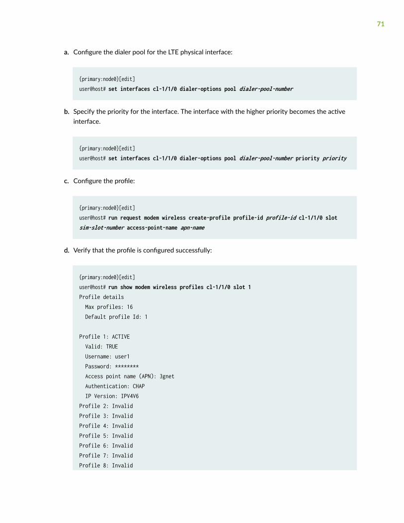
a. Configure the dialer pool for the LTE physical interface:
{primary:node0}[edit]user@host# set interfaces cl-1/1/0 dialer-options pool dialer-pool-number
b. Specify the priority for the interface. The interface with the higher priority becomes the activeinterface.
{primary:node0}[edit]user@host# set interfaces cl-1/1/0 dialer-options pool dialer-pool-number priority priority
c. Configure the profile:
{primary:node0}[edit]user@host# run request modem wireless create-profile profile-id profile-id cl-1/1/0 slot sim-slot-number access-point-name apn-name
d. Verify that the profile is configured successfully:
{primary:node0}[edit]user@host# run show modem wireless profiles cl-1/1/0 slot 1Profile details Max profiles: 16 Default profile Id: 1
Profile 1: ACTIVE Valid: TRUE Username: user1 Password: ******** Access point name (APN): 3gnet Authentication: CHAP IP Version: IPV4V6Profile 2: InvalidProfile 3: InvalidProfile 4: InvalidProfile 5: InvalidProfile 6: InvalidProfile 7: InvalidProfile 8: Invalid
71
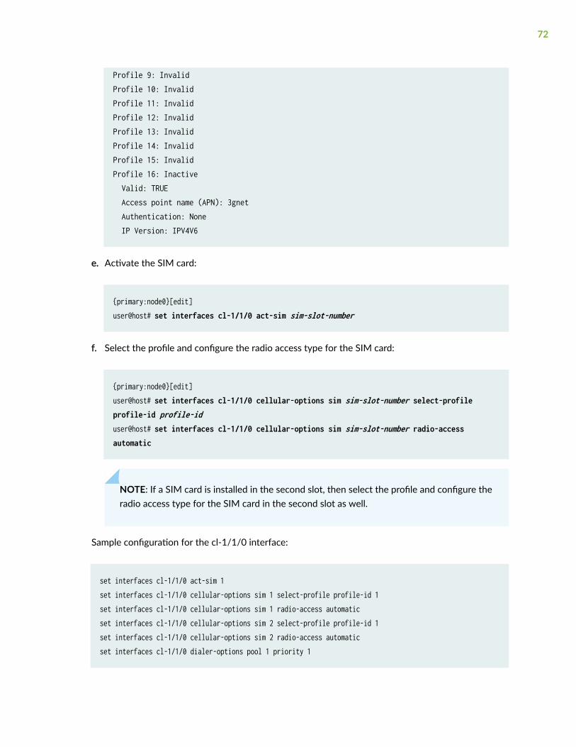
Profile 9: InvalidProfile 10: InvalidProfile 11: InvalidProfile 12: InvalidProfile 13: InvalidProfile 14: InvalidProfile 15: InvalidProfile 16: Inactive Valid: TRUE Access point name (APN): 3gnet Authentication: None IP Version: IPV4V6
e. Activate the SIM card:
{primary:node0}[edit]user@host# set interfaces cl-1/1/0 act-sim sim-slot-number
f. Select the profile and configure the radio access type for the SIM card:
{primary:node0}[edit]user@host# set interfaces cl-1/1/0 cellular-options sim sim-slot-number select-profile profile-id profile-iduser@host# set interfaces cl-1/1/0 cellular-options sim sim-slot-number radio-access automatic
NOTE: If a SIM card is installed in the second slot, then select the profile and configure theradio access type for the SIM card in the second slot as well.
Sample configuration for the cl-1/1/0 interface:
set interfaces cl-1/1/0 act-sim 1set interfaces cl-1/1/0 cellular-options sim 1 select-profile profile-id 1set interfaces cl-1/1/0 cellular-options sim 1 radio-access automaticset interfaces cl-1/1/0 cellular-options sim 2 select-profile profile-id 1set interfaces cl-1/1/0 cellular-options sim 2 radio-access automaticset interfaces cl-1/1/0 dialer-options pool 1 priority 1
72
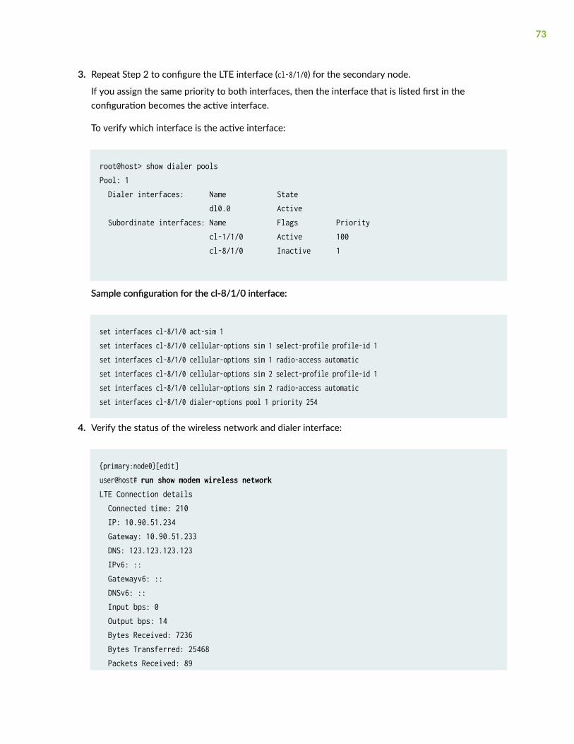
3. Repeat Step 2 to configure the LTE interface (cl-8/1/0) for the secondary node.
If you assign the same priority to both interfaces, then the interface that is listed first in theconfiguration becomes the active interface.
To verify which interface is the active interface:
root@host> show dialer pools Pool: 1 Dialer interfaces: Name State dl0.0 Active Subordinate interfaces: Name Flags Priority cl-1/1/0 Active 100 cl-8/1/0 Inactive 1
Sample configuration for the cl-8/1/0 interface:
set interfaces cl-8/1/0 act-sim 1set interfaces cl-8/1/0 cellular-options sim 1 select-profile profile-id 1set interfaces cl-8/1/0 cellular-options sim 1 radio-access automaticset interfaces cl-8/1/0 cellular-options sim 2 select-profile profile-id 1set interfaces cl-8/1/0 cellular-options sim 2 radio-access automaticset interfaces cl-8/1/0 dialer-options pool 1 priority 254
4. Verify the status of the wireless network and dialer interface:
{primary:node0}[edit]user@host# run show modem wireless network LTE Connection details Connected time: 210 IP: 10.90.51.234 Gateway: 10.90.51.233 DNS: 123.123.123.123 IPv6: :: Gatewayv6: :: DNSv6: :: Input bps: 0 Output bps: 14 Bytes Received: 7236 Bytes Transferred: 25468 Packets Received: 89
73
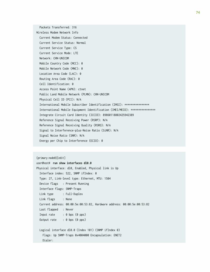
Packets Transferred: 316Wireless Modem Network Info Current Modem Status: Connected Current Service Status: Normal Current Service Type: CS Current Service Mode: LTE Network: CHN-UNICOM Mobile Country Code (MCC): 0 Mobile Network Code (MNC): 0 Location Area Code (LAC): 0 Routing Area Code (RAC): 0 Cell Identification: 0 Access Point Name (APN): ctnet Public Land Mobile Network (PLMN): CHN-UNICOM Physical Cell ID (PCI): N/A International Mobile Subscriber Identification (IMSI): **************** International Mobile Equipment Identification (IMEI/MEID): **************** Integrate Circuit Card Identity (ICCID): 89860118802425942389 Reference Signal Receiving Power (RSRP): N/A Reference Signal Receiving Quality (RSRQ): N/A Signal to Interference-plus-Noise Ratio (SiNR): N/A Signal Noise Ratio (SNR): N/A Energy per Chip to Interference (ECIO): 0
{primary:node0}[edit]user@host# run show interfaces dl0.0 Physical interface: dl0, Enabled, Physical link is Up Interface index: 522, SNMP ifIndex: 0 Type: 27, Link-level type: Ethernet, MTU: 1504 Device flags : Present Running Interface flags: SNMP-Traps Link type : Full-Duplex Link flags : None Current address: 00:00:5e:00:53:82, Hardware address: 00:00:5e:00:53:82 Last flapped : Never Input rate : 0 bps (0 pps) Output rate : 0 bps (0 pps)
Logical interface dl0.0 (Index 101) (SNMP ifIndex 0) Flags: Up SNMP-Traps 0x4004000 Encapsulation: ENET2 Dialer:
74
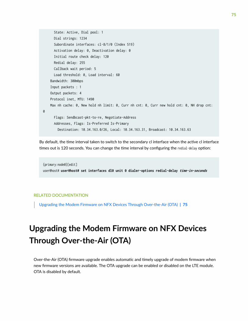
State: Active, Dial pool: 1 Dial strings: 1234 Subordinate interfaces: cl-8/1/0 (Index 519) Activation delay: 0, Deactivation delay: 0 Initial route check delay: 120 Redial delay: 255 Callback wait period: 5 Load threshold: 0, Load interval: 60 Bandwidth: 300mbps Input packets : 1 Output packets: 4 Protocol inet, MTU: 1490 Max nh cache: 0, New hold nh limit: 0, Curr nh cnt: 0, Curr new hold cnt: 0, NH drop cnt: 0 Flags: Sendbcast-pkt-to-re, Negotiate-Address Addresses, Flags: Is-Preferred Is-Primary Destination: 10.34.163.0/26, Local: 10.34.163.31, Broadcast: 10.34.163.63
By default, the time interval taken to switch to the secondary cl interface when the active cl interfacetimes out is 120 seconds. You can change the time interval by configuring the redial-delay option:
{primary:node0}[edit]user@host# user@host# set interfaces dl0 unit 0 dialer-options redial-delay time-in-seconds
RELATED DOCUMENTATION
Upgrading the Modem Firmware on NFX Devices Through Over-the-Air (OTA) | 75
Upgrading the Modem Firmware on NFX DevicesThrough Over-the-Air (OTA)
Over-the-Air (OTA) firmware upgrade enables automatic and timely upgrade of modem firmware whennew firmware versions are available. The OTA upgrade can be enabled or disabled on the LTE module.OTA is disabled by default.
75
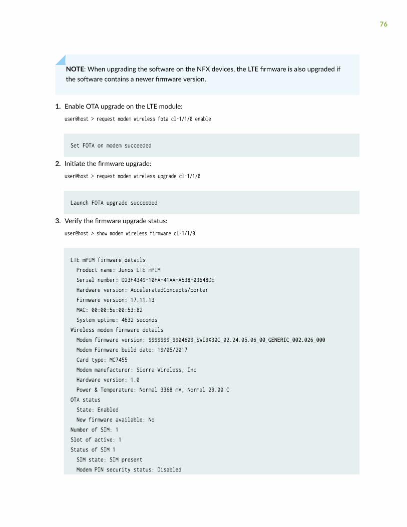
NOTE: When upgrading the software on the NFX devices, the LTE firmware is also upgraded ifthe software contains a newer firmware version.
1. Enable OTA upgrade on the LTE module:
user@host > request modem wireless fota cl-1/1/0 enable
Set FOTA on modem succeeded
2. Initiate the firmware upgrade:
user@host > request modem wireless upgrade cl-1/1/0
Launch FOTA upgrade succeeded
3. Verify the firmware upgrade status:
user@host > show modem wireless firmware cl-1/1/0
LTE mPIM firmware details Product name: Junos LTE mPIM Serial number: D23F4349-10FA-41AA-A538-03648DE Hardware version: AcceleratedConcepts/porter Firmware version: 17.11.13 MAC: 00:00:5e:00:53:82 System uptime: 4632 secondsWireless modem firmware details Modem firmware version: 9999999_9904609_SWI9X30C_02.24.05.06_00_GENERIC_002.026_000 Modem Firmware build date: 19/05/2017 Card type: MC7455 Modem manufacturer: Sierra Wireless, Inc Hardware version: 1.0 Power & Temperature: Normal 3368 mV, Normal 29.00 COTA status State: Enabled New firmware available: NoNumber of SIM: 1Slot of active: 1Status of SIM 1 SIM state: SIM present Modem PIN security status: Disabled
76
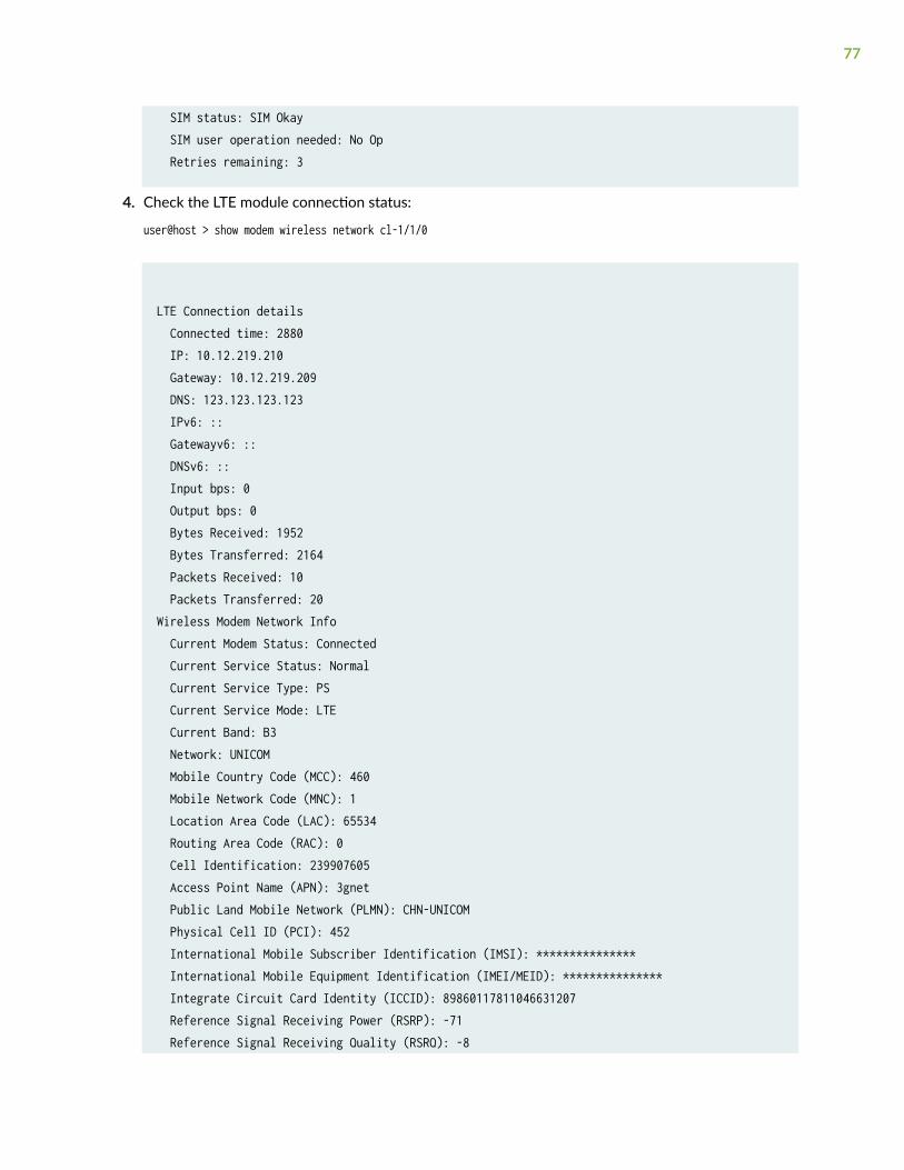
SIM status: SIM Okay SIM user operation needed: No Op Retries remaining: 3
4. Check the LTE module connection status:
user@host > show modem wireless network cl-1/1/0
LTE Connection details Connected time: 2880 IP: 10.12.219.210 Gateway: 10.12.219.209 DNS: 123.123.123.123 IPv6: :: Gatewayv6: :: DNSv6: :: Input bps: 0 Output bps: 0 Bytes Received: 1952 Bytes Transferred: 2164 Packets Received: 10 Packets Transferred: 20Wireless Modem Network Info Current Modem Status: Connected Current Service Status: Normal Current Service Type: PS Current Service Mode: LTE Current Band: B3 Network: UNICOM Mobile Country Code (MCC): 460 Mobile Network Code (MNC): 1 Location Area Code (LAC): 65534 Routing Area Code (RAC): 0 Cell Identification: 239907605 Access Point Name (APN): 3gnet Public Land Mobile Network (PLMN): CHN-UNICOM Physical Cell ID (PCI): 452 International Mobile Subscriber Identification (IMSI): *************** International Mobile Equipment Identification (IMEI/MEID): *************** Integrate Circuit Card Identity (ICCID): 89860117811046631207 Reference Signal Receiving Power (RSRP): -71 Reference Signal Receiving Quality (RSRQ): -8
77
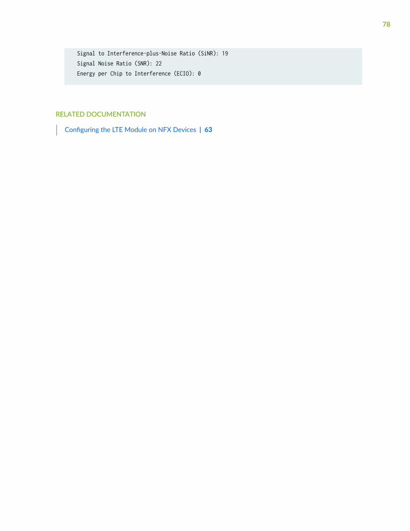
Signal to Interference-plus-Noise Ratio (SiNR): 19 Signal Noise Ratio (SNR): 22 Energy per Chip to Interference (ECIO): 0
RELATED DOCUMENTATION
Configuring the LTE Module on NFX Devices | 63
78
5CHAPTER
Configuring USB Pass-Through onNFX Series Devices
Supporting File Transfer from USB on NFX Series Devices | 80
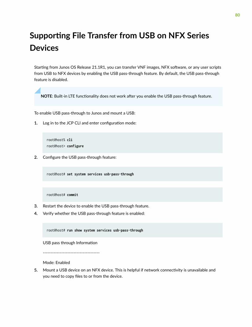
Supporting File Transfer from USB on NFX SeriesDevices
Starting from Junos OS Release 21.1R1, you can transfer VNF images, NFX software, or any user scriptsfrom USB to NFX devices by enabling the USB pass-through feature. By default, the USB pass-throughfeature is disabled.
NOTE: Built-in LTE functionality does not work after you enable the USB pass-through feature.
To enable USB pass-through to Junos and mount a USB:
1. Log in to the JCP CLI and enter configuration mode:
root@host% cliroot@host> configure
2. Configure the USB pass-through feature:
root@host# set system services usb-pass-through
root@host# commit
3. Restart the device to enable the USB pass-through feature.
4. Verify whether the USB pass-through feature is enabled:
root@host# run show system services usb-pass-through
USB pass through Information
-------------------------------------
Mode: Enabled
5. Mount a USB device on an NFX device. This is helpful if network connectivity is unavailable andyou need to copy files to or from the device.
80
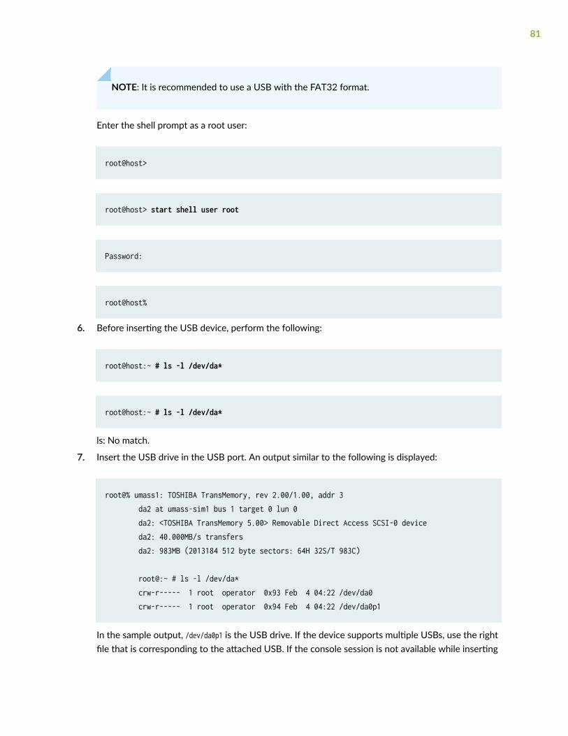
NOTE: It is recommended to use a USB with the FAT32 format.
Enter the shell prompt as a root user:
root@host>
root@host> start shell user root
Password:
root@host%
6. Before inserting the USB device, perform the following:
root@host:~ # ls -l /dev/da*
root@host:~ # ls -l /dev/da*
ls: No match.
7. Insert the USB drive in the USB port. An output similar to the following is displayed:
root@% umass1: TOSHIBA TransMemory, rev 2.00/1.00, addr 3 da2 at umass-sim1 bus 1 target 0 lun 0 da2: <TOSHIBA TransMemory 5.00> Removable Direct Access SCSI-0 device da2: 40.000MB/s transfers da2: 983MB (2013184 512 byte sectors: 64H 32S/T 983C)
root@:~ # ls -l /dev/da* crw-r----- 1 root operator 0x93 Feb 4 04:22 /dev/da0 crw-r----- 1 root operator 0x94 Feb 4 04:22 /dev/da0p1
In the sample output, /dev/da0p1 is the USB drive. If the device supports multiple USBs, use the rightfile that is corresponding to the attached USB. If the console session is not available while inserting
81

the USB, check the messages var log file for logs related to da (for example, show log messages | matchda). It logs the same four lines as shown on console if the USB is inserted.
8. Create a directory for the USB drive to mount to:
root@host% mkdir /var/tmp/usb
9. Mount the USB drive to the /var/tmp/usb directory:
NOTE: ls /var/tmp/usb directory shows all files that are present in the USB drive.
root@host% mount_msdosfs /dev/da0p1 /var/tmp/usb
root@host% ls /var/tmp/usb
images.tgz
10. Unmount the USB drive after the file is completely copied:
root@host% umount /var/tmp/usb
82
6CHAPTER
Configuring Security
IP Security on NFX Devices | 84
UTM on NFX Devices | 94
Application Security on NFX Devices | 95
Intrusion Detection and Prevention on NFX Devices | 96
Integrated User Firewall Support on NFX Devices | 97
IP Security on NFX Devices
IN THIS SECTION
Overview | 84
Configuring Security | 86
Overview
IPsec provides network-level data integrity, data confidentiality, data origin authentication, andprotection from replay. IPsec can protect any protocol running over IP on any medium or a mixture ofapplication protocols running on a complex combination of media. IPsec provides security services atthe network layer of the Open Systems Interconnection (OSI) model by enabling a system to selectrequired security protocols, determine the algorithms to use for the security services, and implementany cryptographic keys required to provide the requested services. IPsec is standardized by InternationalEngineering Task Force (IETF).
IPsec protects one or more paths between a pair of hosts or security gateways, or between a securitygateway and a host. It achieves this by providing a secure way to authenticate senders/receivers andencrypt IP version 4 (IPv4) and version 6 (IPv6) traffic between network devices.
The key concepts of IPsec include:
• Security associations (SAs)—An SA is a set of IPsec specifications negotiated between devices thatare establishing an IPsec relationship. These specifications include preferences for the type ofauthentication and encryption, and the IPsec protocol that is used to establish the IPsec connection.A security association is uniquely identified by a security parameter index (SPI), an IPv4 or IPv6destination address, and a security protocol (AH or ESP). IPsec security associations are establishedeither manually through configuration statements, or dynamically by IKE negotiation. For moreinformation about SAs, see Security Associations.
• IPsec key management—VPN tunnels are built using IPsec technology. Virtual private network (VPN)tunnels operate with three kinds of key creation mechanisms such as Manual Key, AutoKey InternetKey Exchange (IKE) , and Diffie-Hellman (DH) Exchange. NFX150 devices support IKEv1 and IKEv2.For more information about IPsec key management, see IPsec Key Management.
• IPsec security protocols—IPsec uses two protocols to secure communications at the IP layer:
84
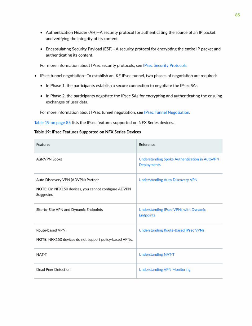
• Authentication Header (AH)—A security protocol for authenticating the source of an IP packetand verifying the integrity of its content.
• Encapsulating Security Payload (ESP)—A security protocol for encrypting the entire IP packet andauthenticating its content.
For more information about IPsec security protocols, see IPsec Security Protocols.
• IPsec tunnel negotiation—To establish an IKE IPsec tunnel, two phases of negotiation are required:
• In Phase 1, the participants establish a secure connection to negotiate the IPsec SAs.
• In Phase 2, the participants negotiate the IPsec SAs for encrypting and authenticating the ensuingexchanges of user data.
For more information about IPsec tunnel negotiation, see IPsec Tunnel Negotiation.
Table 19 on page 85 lists the IPsec features supported on NFX Series devices.
Table 19: IPsec Features Supported on NFX Series Devices
Features Reference
AutoVPN Spoke Understanding Spoke Authentication in AutoVPNDeployments
Auto Discovery VPN (ADVPN) Partner
NOTE: On NFX150 devices, you cannot configure ADVPNSuggester.
Understanding Auto Discovery VPN
Site-to-Site VPN and Dynamic Endpoints Understanding IPsec VPNs with DynamicEndpoints
Route-based VPN
NOTE: NFX150 devices do not support policy-based VPNs.
Understanding Route-Based IPsec VPNs
NAT-T Understanding NAT-T
Dead Peer Detection Understanding VPN Monitoring
85
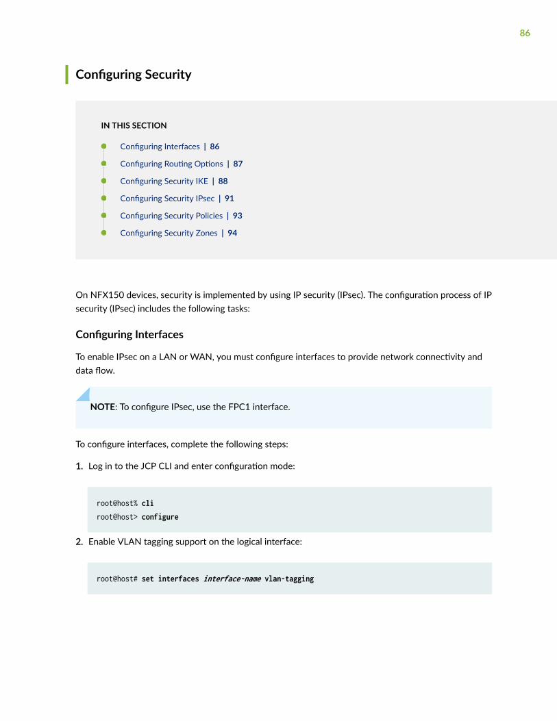
Configuring Security
IN THIS SECTION
Configuring Interfaces | 86
Configuring Routing Options | 87
Configuring Security IKE | 88
Configuring Security IPsec | 91
Configuring Security Policies | 93
Configuring Security Zones | 94
On NFX150 devices, security is implemented by using IP security (IPsec). The configuration process of IPsecurity (IPsec) includes the following tasks:
Configuring Interfaces
To enable IPsec on a LAN or WAN, you must configure interfaces to provide network connectivity anddata flow.
NOTE: To configure IPsec, use the FPC1 interface.
To configure interfaces, complete the following steps:
1. Log in to the JCP CLI and enter configuration mode:
root@host% cliroot@host> configure
2. Enable VLAN tagging support on the logical interface:
root@host# set interfaces interface-name vlan-tagging
86
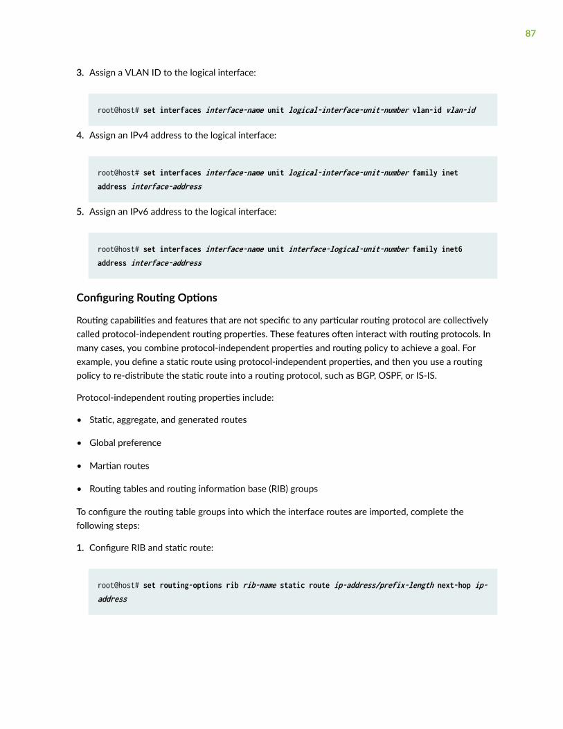
3. Assign a VLAN ID to the logical interface:
root@host# set interfaces interface-name unit logical-interface-unit-number vlan-id vlan-id
4. Assign an IPv4 address to the logical interface:
root@host# set interfaces interface-name unit logical-interface-unit-number family inet address interface-address
5. Assign an IPv6 address to the logical interface:
root@host# set interfaces interface-name unit interface-logical-unit-number family inet6 address interface-address
Configuring Routing Options
Routing capabilities and features that are not specific to any particular routing protocol are collectivelycalled protocol-independent routing properties. These features often interact with routing protocols. Inmany cases, you combine protocol-independent properties and routing policy to achieve a goal. Forexample, you define a static route using protocol-independent properties, and then you use a routingpolicy to re-distribute the static route into a routing protocol, such as BGP, OSPF, or IS-IS.
Protocol-independent routing properties include:
• Static, aggregate, and generated routes
• Global preference
• Martian routes
• Routing tables and routing information base (RIB) groups
To configure the routing table groups into which the interface routes are imported, complete thefollowing steps:
1. Configure RIB and static route:
root@host# set routing-options rib rib-name static route ip-address/prefix-length next-hop ip-address
87
2. Configure static route:
root@host# set routing-options static route ip-address/prefix-length next-hop ip-address
Configuring Security IKE
IPsec uses the Internet Key Exchange (IKE) protocol to authenticate the IPsec peers, to negotiate thesecurity association (SA) settings, and to exchange IPsec keys. The IKE configuration defines thealgorithms and keys used to establish the secure IKE connection with the peer security gateway.
You can configure IKE traceoptions for debugging and managing the IPsec IKE.
To configure IKE traceoptions, complete the following steps:
1. Specify the maximum size of the trace file:
root@host# set security ike traceoptions file size file-size
2. Specify the parameters to trace information for IKE:
root@host# set security ike traceoptions flag all
3. Specify the level of trace information for IKE:
root@host# set security ike traceoptions level level 7-15
You can configure one or more IKE proposals. Each proposal is a list of IKE attributes to protect the IKEconnection between the IKE host and its peer.
To configure IKE proposal, complete the following steps:
1. Configure pre-shared-keys as an authentication method for the IPsec IKE proposal:
NOTE: When you configure IPsec for secure communications in the network, the peerdevices in the network must have at least one common authentication method. Only oneauthentication method can be used between a pair of devices, regardless of the number ofauthentication methods configured.
root@host# set security ike proposal ike-proposal-name authentication-method pre-shared-keys
88

2. Define a Diffie-Hellman group (dh-group) for the IKE proposal:
root@host# set security ike proposal ike-proposal-name dh-group group14
3. Configure an authentication algorithm for the IKE proposal:
root@host# set security ike proposal ike-proposal-name authentication-algorithm sha-256
4. Define an encryption algorithm for the IKE proposal:
root@host# set security ike proposal ike-proposal-name encryption-algorithm aes-256-cbc
5. Set a lifetime for the IKE proposal in seconds:
root@host# set security ike proposal ike-proposal-name lifetime-seconds 180 to 86400 seconds
After configuring one or more IKE proposals, you must associate these proposals with an IKE policy. AnIKE policy defines a combination of security parameters (IKE proposals) to be used during IKEnegotiation. It defines a peer address and the proposals needed for that connection. Depending onwhich authentication method is used, it defines the preshared key for the given peer. During the IKEnegotiation, IKE looks for an IKE policy that is the same on both peers. The peer that initiates thenegotiation sends all its policies to the remote peer, and the remote peer tries to find a match.
To configure IKE policy, complete the following steps:
1. Define an IKE policy with first phase mode:
root@host# set security ike policy ike-policy-name mode aggressive
2. Define a set of IKE proposals:
root@host# set security ike policy ike-policy-name proposals proposal-name
3. Define a pre-shared key for IKE:
root@host# set security ike policy ike-policy-name pre-shared-key ascii-text text-format
89

Configure an IKE gateway to initiate and terminate network connections between a firewall and asecurity device.
To configure IKE gateway, complete the following steps:
1. Configure an IKE gateway with an IKE policy:
root@host# set security ike gateway gateway-name ike-policy ike-policy-name
2. Configure an IKE gateway with an address or hostname of the peer:
NOTE: Multiple IKE gateway address redundancy is not supported on NFX350 devices if thedeamon is IKED daemon. Only KMD daemon supports this functionality.
root@host# set security ike gateway gateway-name address address-or-hostname-of-peer
3. Enable dead peer detection (DPD) feature to send DPD messages periodically:
root@host# set security ike gateway gateway-name dead-peer-detection always-send
4. Configure the local IKE identity:
root@host# set security ike gateway gateway-name local-identity <inet | inet6 | key-id | hostname | user-at-hostname | distinguished-name>
5. Configure the remote IKE identity:
root@host# set security ike gateway gateway-name remote-identity <inet | inet6 | key-id | hostname | user-at-hostname | distinguished-name>
6. Configure an external interface for IKE negotiations:
root@host# set security ike gateway gateway-name external-interface ge-1/0/1.0
90
7. Configure username of the client:
root@host# set security ike gateway gateway-name client username client-username
8. Configure password of the client:
root@host# set security ike gateway gateway-name client password client-password
Configuring Security IPsec
IPsec is a suite of related protocols that provides network-level data integrity, data confidentiality, dataorigin authentication, and protection from replay. IPsec can protect any protocol running over IP on anymedium or a mixture of application protocols running on a complex combination of media.
Configure an IPsec proposal, which lists protocols and algorithms or security services to be negotiatedwith the remote IPsec peer.
To configure an IPsec proposal, complete the following steps:
1. Define an IPsec proposal and protocol for the proposal:
root@host# set security ipsec proposal ipsec-proposal-name protocol esp
2. Define an authentication algorithm for the IPsec proposal:
root@host# set security ipsec proposal ipsec-proposal-name authentication-algorithm hmac-sha-256-128
3. Define an encryption algorithm for the IPsec proposal:
root@host# set security ipsec proposal ipsec-proposal-name encryption-algorithm aes-256-cbc
4. Set a lifetime for the IPsec proposal in seconds:
root@host# set security ipsec proposal ipsec-proposal-name lifetime-seconds 180..86400 seconds
After configuring one or more IPsec proposals, you must associate these proposals with an IPsec policy.An IPsec policy defines a combination of security parameters (IPsec proposals) used during IPsecnegotiation. It defines Perfect Forward Secrecy (PFS) and the proposals needed for the connection.During the IPsec negotiation, IPsec searches for a proposal that is the same on both peers. The peer that
91

initiates the negotiation sends all its policies to the remote peer, and the remote peer tries to find amatch.
To configure IPsec policies, complete the following steps:
1. Define an IPsec policy, a perfect forward secrecy, and a Diffie-Hellman group for the policy:
root@host# set security ipsec policy ipsec-policy-name perfect-forward-secrecy keys group14
2. Define a set of IPsec proposals for the policy:
root@host# set security ipsec policy ipsec-policy-name proposals proposal-name
Configure an IPsec virtual private network (VPN) to provide a means for securely communicating amongremote computers across a public WAN such as the Internet. A VPN connection can link two LANs (site-to-site VPN) or a remote dial-up user and a LAN. The traffic that flows between these two points passesthrough shared resources such as routers, switches, and other network equipment that make up thepublic WAN. To secure VPN communication while passing through the WAN, the two participantscreate an IPsec tunnel. For more information, see IPsec VPN Overview.
To configure IPsec VPN, complete the following steps:
1. Define an IKE gateway for the IPsec VPN:
root@host# set security ipsec vpn vpn-name ike gateway remote-gateway-name
2. Define an IPsec policy for the IPsec VPN:
root@host# set security ipsec vpn vpn-name ike ipsec-policy ipsec-policy-name
3. Define a local traffic selector for the IPsec VPN:
root@host# set security ipsec vpn vpn-name traffic-selector traffic-selector-name local-ip local-traffic-selector-ip-address
92
4. Define a remote traffic selector for the IPsec VPN:
root@host# set security ipsec vpn vpn-name traffic-selector traffic-selector-name remote-ip remote-traffic-selector-ip-address
5. Define a criteria to establish IPsec VPN tunnels:
root@host# set security ipsec vpn vpn-name establish-tunnels on-traffic
Configuring Security Policies
A security policy controls the traffic flow from one zone to another zone by defining the kind of trafficpermitted from specified IP sources to specified IP destinations at scheduled times. Policies allow you todeny, permit, reject, encrypt and decrypt, authenticate, prioritize, schedule, filter, and monitor the trafficattempting to cross from one security zone to another. You can decide which users and what data canenter and exit, and when and where they can go.
To configure security policies, complete the following steps:
1. Configure security policy match criteria for the source address:
root@host# set security policies from-zone from-zone-name to-zone to-zone-name policy policy-name match source-address any
2. Configure security policy match criteria for the destination address:
root@host# set security policies from-zone from-zone-name to-zone to-zone-name policy policy-name match destination-address any
3. Configure security policy application:
root@host# set security policies from-zone from-zone-name to-zone to-zone-name policy policy-name match application any
4. Set security policy match criteria:
root@host# set security policies from-zone from-zone-name to-zone to-zone-name policy policy-name match then permit
93
Configuring Security Zones
Security zones are the building blocks for policies. They are logical entities to which one or moreinterfaces are bound. Security zones provide a means of distinguishing groups of hosts (user systemsand other hosts, such as servers) and their resources from one another in order to apply differentsecurity measures to them. For information, see Understanding Security Zones.
To configure security zones, complete the following steps:
1. Configure security zones with system services:
root@host# set security zones security-zone zone-name host-inbound-traffic system-services all
2. Define protocols for security zones:
root@host# set security zones security-zone zone-name host-inbound-traffic protocols all
3. Configure interfaces for security zones:
root@host# set security zones security-zone zone-name interfaces interface-name
UTM on NFX Devices
The Unified threat management (UTM) solution consolidates several security features to protect againstmultiple threat types. The UTM solution for NFX devices consists of the following security features:
• Antispam—Examines e-mail messages to identify spam. When the device detects an e-mail spam, itdrops the message or tags the message header or subject field with a preprogrammed string. Formore information, see Antispam Filtering Overview.
• Antivirus—Offers a less CPU-intensive alternative to the full file-based antivirus feature. Sophos usesa scanning engine and virus signature databases to protect against virus-infected files, worms,trojans, spyware, and other malware over POP3, HTTP, SMTP, IMAP, and FTP protocols. The viruspattern and malware database is located on external servers maintained by Sophos (SophosExtensible List) servers. For more information, see Sophos Antivirus Protection on NFX Devices(OBSOLETE).
• Content filtering—Blocks or permits certain types of traffic based on the MIME type, file extension,protocol command, and embedded object type. For more information, see Content Filtering.
94
• Web filtering—Allows you to manage Internet usage by preventing access to inappropriate Webcontent. The Web filtering solution consists of the following types:
• Redirect web filtering
• Local web filtering
• Enhanced Web filtering
For more information, see Web Filtering Overview.
NOTE: Antispam, Sophos antivirus, and enhanced web filtering are licensed features and will notfunction until you install the respective licenses.
RELATED DOCUMENTATION
Intrusion Detection and Prevention on NFX Devices | 96
Integrated User Firewall Support on NFX Devices | 97
Application Security on NFX Devices
The NFX150 devices support the AppSecure feature, which is a suite of application-aware securityservices that deliver security services to provide visibility and control over the types of applicationstraversing in the networks. AppSecure uses a sophisticated classification engine to accurately identifyapplications regardless of port or protocol, including nested applications that reside within trustednetwork services.
The AppSecure feature comprises of the following services:
• Application identification (AppID)- Recognizes traffic at different network layers using characteristicsother than port number. Once the application is determined, AppSecure service modules can beconfigured to monitor and control traffic for tracking, prioritization, access control, detection, andprevention based on the application ID of the traffic. For more information, see ApplicationIdentification.
• Application Tracking (AppTrack)—Tracks and reports applications passing through the device. Formore information, see Application Tracking on NFX Devices.
• Application Firewall (AppFW)—Implements an application firewall using application-based rules. Formore information, see Application Firewall on NFX Devices.
95
• Application Quality of Service (AppQoS)—Provides quality-of-service prioritization based onapplication awareness. For more information, see Application QoS.
• Advanced policy-based routing (APBR)— Classifies session based on applications and applies theconfigured rules to reroute the traffic. For more information, see Advanced Policy-Based Routing onNFX Devices.
AppSecure works with additional content security on the device through integrated unified threatmanagement (UTM), intrusion prevention systems (IPS), and Juniper Networks Sky Advanced ThreatPrevention (Sky ATP) for deeper protection against malware, spam, phishing, and application exploits.
RELATED DOCUMENTATION
Integrated User Firewall Support on NFX Devices | 97
Intrusion Detection and Prevention on NFX Devices
Intrusion detection is the process of monitoring the events occurring in your network and analyzingthem for signs of possible incidents, violations, or imminent threats to your security policies. Intrusionprevention is the process of performing intrusion detection and then stopping the detected incidents.These security measures are available as intrusion detection systems (IDS) and intrusion preventionsystems (IPS), which become part of your network to detect and stop potential incidents.
An Intrusion Detection and Prevention (IDP) policy lets you selectively enforce various attack detectionand prevention techniques on the network traffic passing through your device. Juniper devices offer thesame set of IDP signatures that are available on Juniper Networks IDP Series Intrusion Detection andPrevention Appliances to secure networks against attacks. The basic IDP configuration involves thefollowing tasks:
• Download and install the IDP license.
• Download and install the signature database—You must download and install the IDP signaturedatabase. The signature databases are available as a security package on the Juniper Networkswebsite. This database includes attack object and attack object groups that you can use in IDPpolicies to match traffic against known attacks.
• Configure recommended policy as the IDP policy—Juniper Networks provides predefined policytemplates to use as a starting point for creating your own policies. Each template is a set of rules of aspecific rulebase type that you can copy and then update according to your requirements.
To get started, we recommend you use the predefined policy named “Recommended”.
96
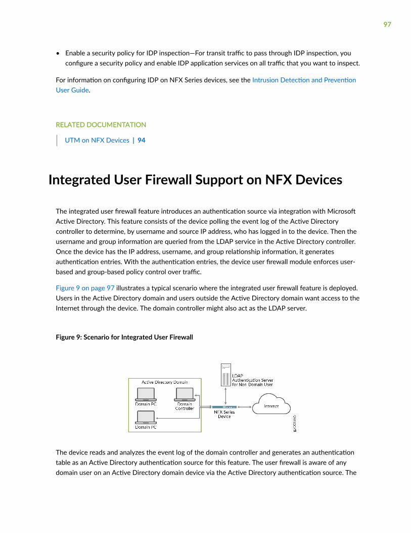
• Enable a security policy for IDP inspection—For transit traffic to pass through IDP inspection, youconfigure a security policy and enable IDP application services on all traffic that you want to inspect.
For information on configuring IDP on NFX Series devices, see the Intrusion Detection and PreventionUser Guide.
RELATED DOCUMENTATION
UTM on NFX Devices | 94
Integrated User Firewall Support on NFX Devices
The integrated user firewall feature introduces an authentication source via integration with MicrosoftActive Directory. This feature consists of the device polling the event log of the Active Directorycontroller to determine, by username and source IP address, who has logged in to the device. Then theusername and group information are queried from the LDAP service in the Active Directory controller.Once the device has the IP address, username, and group relationship information, it generatesauthentication entries. With the authentication entries, the device user firewall module enforces user-based and group-based policy control over traffic.
Figure 9 on page 97 illustrates a typical scenario where the integrated user firewall feature is deployed.Users in the Active Directory domain and users outside the Active Directory domain want access to theInternet through the device. The domain controller might also act as the LDAP server.
Figure 9: Scenario for Integrated User Firewall
The device reads and analyzes the event log of the domain controller and generates an authenticationtable as an Active Directory authentication source for this feature. The user firewall is aware of anydomain user on an Active Directory domain device via the Active Directory authentication source. The
97

device administrator configures a user firewall policy that enforces the desired user-based or group-based access control.
For information on configuring the integrated user firewall on NFX Series devices, see Authenticationand Integrated User Firewalls User Guide.
RELATED DOCUMENTATION
UTM on NFX Devices | 94
98
7CHAPTER
Configuring VNFs
Prerequisites to Onboard Virtual Network Functions on NFX150 Devices | 100
Configuring VNFs on NFX150 Devices | 101
Managing VNFs on NFX Series Devices | 115
Configuring Analyzer VNF and Port-mirroring | 120
Prerequisites to Onboard Virtual Network Functionson NFX150 Devices
IN THIS SECTION
Prerequisites for VNFs | 100
You can onboard and manage Juniper VNFs and third-party VNFs on NFX devices through the JunosControl Plane (JCP).
The number of VNFs that you can onboard on the device depends on the availability of systemresources such as the number of CPUs and system memory.
Before you onboard the VNFs, it is recommended to check the available system resources such as CPUs,memory, and storage for VNFs. For more information, see "Configuring VNFs on NFX150 Devices" onpage 101.
Prerequisites for VNFs
To instantiate VNFs, the NFX device supports:
• KVM based hypervisor deployment
• OVS or Virtio interface drivers
• raw or qcow2 VNF file types
• (Optional) SR-IOV
• (Optional) CD-ROM and USB configuration drives
• (Optional) Hugepages for memory requirements
100
Configuring VNFs on NFX150 Devices
IN THIS SECTION
Load the VNF Image | 101
Prepare the Bootstrap Configuration | 102
Allocate CPUs for a VNF | 103
Allocate Memory for a VNF | 105
(Optional) Attach a Config Drive to the VNF | 106
Configure Interfaces and VLANs for a VNF | 108
Configuring VNF Storage Devices | 112
Instantiating a VNF | 113
Verify that the VNF Instantiated Successfully | 114
The NFX150 devices enable you to instantiate and manage virtualized network functions (VNFs) fromthe Junos Control Plane (JCP). The JCP supports the creation and management of third-party VNFs.
To configure a VNF, log in to the JCP and perform the following tasks:
Load the VNF Image
Alternatively, you can use the NETCONF command file-put, to load a VNF image.
To load a VNF image on the device from a remote location, you can either use the file-copy command orcopy the image from a USB by using the usb-pass-through command.
To copy a VNF image from a USB, see "Supporting File Transfer from USB on NFX Series Devices" onpage 80.
Alternatively, you can use the NETCONF command file-put, to load a VNF image.
NOTE: You must save the VNF image in the /var/public directory.
101
Prepare the Bootstrap Configuration
You can bootstrap a VNF using an attached config drive that contains a bootstrap-config ISO file. Theconfig drive is a virtual drive, which can be a CD-ROM, USB drive or Disk drive associated to a VNF withthe configuration data. Configuration data can be files or folders, which are bundled in the ISO file thatmakes a virtual CD-ROM, USB drive, or Disk drive.
A bootstrap configuration file must contain an initial configuration that allows the VNF to be accessiblefrom an external controller, and accepts SSH, HTTP, or HTTPS connections from an external controllerfor further runtime configurations.
By attaching a config drive, you can pass the networking configurations such as the IP address, subnetmask, and gateway to the VNFs through a CLI. After receiving the configuration inputs, the devicegenerates a bootstrap-config ISO file, and attaches the file to the VNF as a CD-ROM, USB drive, or Diskdrive.
For more information about configuring and attaching a config drive, see "(Optional) Attach a ConfigDrive to the VNF " on page 106.
NOTE:
• The system saves the bootstrap-config ISO file in the /var/public folder. The file is saved onlyif the available space in the folder is more than double the total size of the contents in the file.If the available space in the folder is not sufficient, an error message is displayed when youcommit the configuration.
• When you reboot the system, the system generates a new bootstrap-config ISO file andreplaces the existing ISO file with the new ISO file on the VNF.
• The config drive is a read-only drive. Based on the VNF, you can specify the config drive as aread-only CD-ROM drive, USB drive, or a Disk drive.
The config drive supports the following data for VNFs:
• Static content as files—The device accepts one or more file paths through a CLI, converts these filesto an ISO image, and attaches it to the VNF. The config drive supports multiple static files in a VNFconfiguration.
• Jinja2 template and parameters—Jinja2 parameters consist of key-value pairs. The key is specified inthe template and the value replaces the key when the template is rendered. The system adds therendered output file to the ISO image, and attaches it to the VNF. The maximum number ofparameters for a template is 256 key-value pairs. The config drive supports multiple templates and itsparameters in a VNF configuration.
102
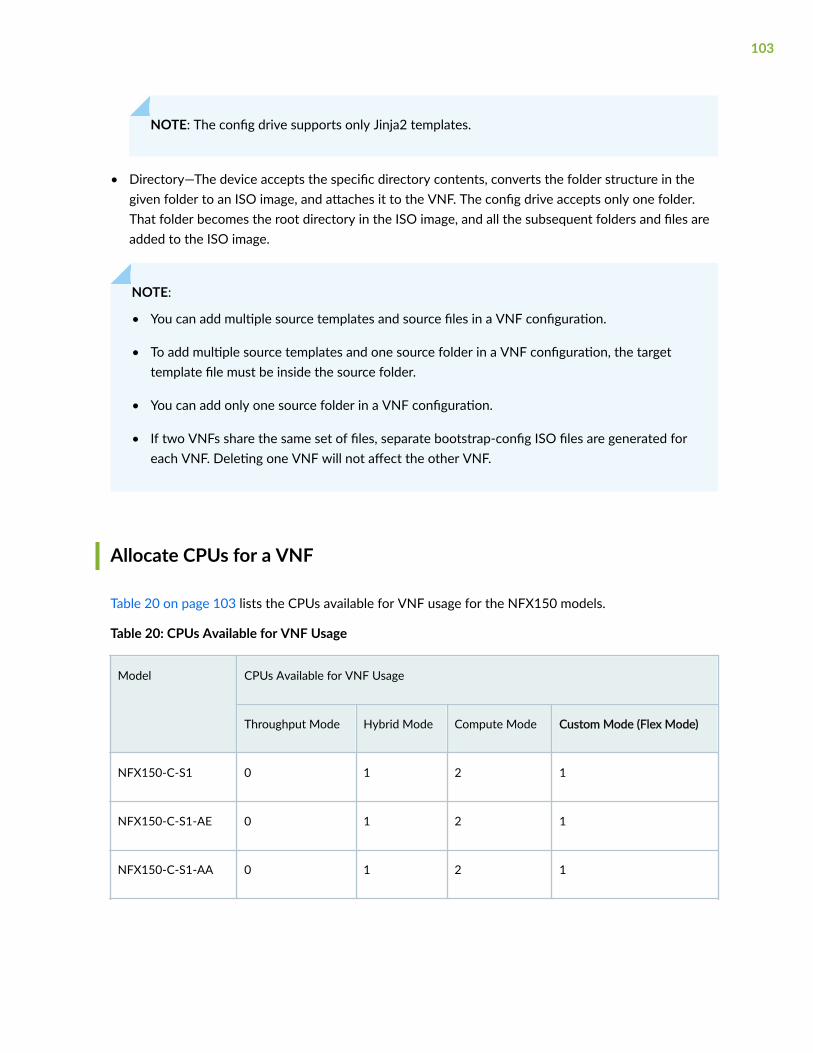
NOTE: The config drive supports only Jinja2 templates.
• Directory—The device accepts the specific directory contents, converts the folder structure in thegiven folder to an ISO image, and attaches it to the VNF. The config drive accepts only one folder.That folder becomes the root directory in the ISO image, and all the subsequent folders and files areadded to the ISO image.
NOTE:
• You can add multiple source templates and source files in a VNF configuration.
• To add multiple source templates and one source folder in a VNF configuration, the targettemplate file must be inside the source folder.
• You can add only one source folder in a VNF configuration.
• If two VNFs share the same set of files, separate bootstrap-config ISO files are generated foreach VNF. Deleting one VNF will not affect the other VNF.
Allocate CPUs for a VNF
Table 20 on page 103 lists the CPUs available for VNF usage for the NFX150 models.
Table 20: CPUs Available for VNF Usage
Model CPUs Available for VNF Usage
Throughput Mode Hybrid Mode Compute Mode Custom Mode (Flex Mode)
NFX150-C-S1 0 1 2 1
NFX150-C-S1-AE 0 1 2 1
NFX150-C-S1-AA 0 1 2 1
103
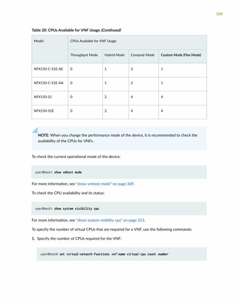
Table 20: CPUs Available for VNF Usage (Continued)
Model CPUs Available for VNF Usage
Throughput Mode Hybrid Mode Compute Mode Custom Mode (Flex Mode)
NFX150-C-S1E-AE 0 1 2 1
NFX150-C-S1E-AA 0 1 2 1
NFX150-S1 0 2 4 4
NFX150-S1E 0 2 4 4
NOTE: When you change the performance mode of the device, it is recommended to check theavailability of the CPUs for VNFs.
To check the current operational mode of the device:
user@host> show vmhost mode
For more information, see "show vmhost mode" on page 369.
To check the CPU availability and its status:
user@host> show system visibility cpu
For more information, see "show system visibility cpu" on page 313.
To specify the number of virtual CPUs that are required for a VNF, use the following commands:
1. Specify the number of CPUs required for the VNF:
user@host# set virtual-network-functions vnf-name virtual-cpu count number
104
2. Pin a virtual CPU to a physical CPU
user@host# set virtual-network-functions vnf-name virtual-cpu vcpu-number physical-cpu pcpu-number
3. Commit the configuration:
user@host# commit
The physical CPU number can either be a number or a range. By default, a VNF is allocated with onevirtual CPU that is not pinned to any physical CPU.
NOTE: You cannot change the CPU configuration of a VNF when the VNF is in running state.Restart the VNF for changes to take effect.
Starting in Junos OS Release 22.1 R1, you can pin the emulator to specific physical CPUs by using thefollowing command:
user@host# set virtual-network-functions vnf-name emulator physical-cpu cpu-range
You cannot use CPU 0 or offline CPUs for emulator pinning. If you do not pin the emulator to a specificphysical CPU, QEMU automatically pins it to a virtual CPU. Changes to emulator pinning take effectimmediately on a running VNF.
To enable hardware-virtualization or hardware-acceleration for VNF CPUs, type the following command:
user@host# set virtual-network-functions vnf-name virtual-cpu features hardware-virtualization
Allocate Memory for a VNF
On NFX150 devices running Junos OS Release 18.1R1, enabling hugepages for VNFs and pre-reservingof hugepages are not supported.
Table 21 on page 106 lists the possible memory availability for VNF usage for the NFX150 models.
105
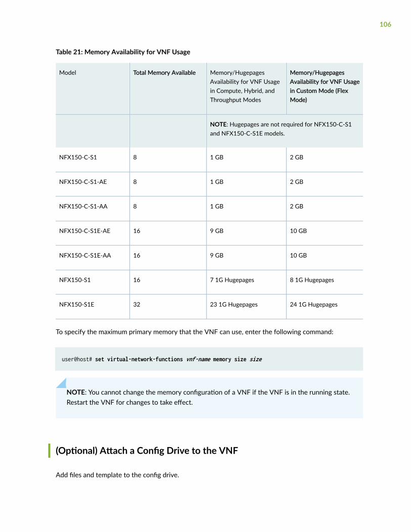
Table 21: Memory Availability for VNF Usage
Model Total Memory Available Memory/HugepagesAvailability for VNF Usagein Compute, Hybrid, andThroughput Modes
Memory/HugepagesAvailability for VNF Usagein Custom Mode (FlexMode)
NOTE: Hugepages are not required for NFX150-C-S1and NFX150-C-S1E models.
NFX150-C-S1 8 1 GB 2 GB
NFX150-C-S1-AE 8 1 GB 2 GB
NFX150-C-S1-AA 8 1 GB 2 GB
NFX150-C-S1E-AE 16 9 GB 10 GB
NFX150-C-S1E-AA 16 9 GB 10 GB
NFX150-S1 16 7 1G Hugepages 8 1G Hugepages
NFX150-S1E 32 23 1G Hugepages 24 1G Hugepages
To specify the maximum primary memory that the VNF can use, enter the following command:
user@host# set virtual-network-functions vnf-name memory size size
NOTE: You cannot change the memory configuration of a VNF if the VNF is in the running state.Restart the VNF for changes to take effect.
(Optional) Attach a Config Drive to the VNF
Add files and template to the config drive.
106

1. Specify the source file to add in the config drive:
user@host# set virtual-network-functions vnf-name config-data source file source-file1user@host# set virtual-network-functions vnf-name config-data source file source-file2
2. Specify the template file to add in the config drive:
user@host# set virtual-network-functions vnf-name config-data source template template-name file template-fileuser@host# set virtual-network-functions vnf-name config-data source template template-name parameters image_type image-typeuser@host# set virtual-network-functions vnf-name config-data source template template-name parameters memory-size memory-sizeuser@host# set virtual-network-functions vnf-name config-data source template template-name target target-filename
3. Specify the device name and type to add in the config drive:
user@host# set virtual-network-functions vnf-name config-data target device-name target-device-name
user@host# set virtual-network-functions vnf-name config-data target device-type target-device-type
The target device-type is optional. If you do not specify, it takes the device type as cd-rom.
user@host# set virtual-network-functions vnf-name config-data target device-label target-device-label
The target device-label is optional. If you do not specify, it takes the device label as config-data.
4. Commit the configuration:
user@host# commit
Add a directory to the config drive.
107
1. Specify the source directory to add in the config drive:
user@host# set virtual-network-functions vnf-name config-data source directory directory-name
2. Specify the device name and type to add in the config drive:
user@host# set virtual-network-functions vnf-name config-data target device-name target-device-name
user@host# set virtual-network-functions vnf-name config-data target device-type device-type user@host# set virtual-network-functions vnf-name config-data target device-label device-label
3. Commit the configuration:
user@host# commit
To verify whether the config drive is attached to the VNF, see the VNF Disk Information section in the"show system visibility vnf" on page 351 command output message.
Configure Interfaces and VLANs for a VNF
You can configure a VNF interface, map a VNF interface to a virtual function, and attach the interface toa physical NIC port, a management interface, or VLANs, assign a VLAN ID to it, and enable trust modeon it.
Prior to Junos OS Releases 21.3R1, 21.2R2, 21.2R1, 21.1R2, and 20.4R3, the step to configure an SR-IOV VNF interface and to assign a VLAN ID is as follows:
user@host# set virtual-network-functions vnf-name interfaces vnf-interface-name mapping interface physical-interface-name virtual-function vlan-id vlan-id
Starting from Junos OS Releases 21.3R1, 21.2R2, 21.2R1, 21.1R2, and 20.4R3, the steps to configure anSR-IOV VNF interface, to assign a VLAN ID, and to enable trust mode are as follows:
108
To map a VNF interface to a virtual function:
user@host# set virtual-network-functions vnf-name interfaces vnf-interface-name mapping interface physical-interface-name
To attach a VNF interface to a physical NIC port by using the SR-IOV virtual function and assign a VLANID:
user@host# set virtual-network-functions vnf-name interfaces vnf-interface-name mapping interface virtual-function vlan-id vlan-id
vlan-id is the VLAN ID of the port and is an optional value.
To enable trust mode:
user@host# set virtual-network-functions vnf-name interfaces vnf-interface-name mapping interface virtual-function trust
NOTE:
• Trust mode is supported on NFX Series devices from Junos OS Releases 21.3R1, 21.2R2,21.2R1, 21.1R2, and 20.4R3.
• If you enable trust mode on VNF SR-IOV interface, then the VNF interface goes intopromiscuous mode.
To attach a VNF interface to a VLAN:
• Create a VLAN:
user@host# set vmhost vlan vlan-name
• Attach a VNF interface to a VLAN:
user@host# set virtual-network-functions vnf-name interfaces interface-name mapping vlan members list-of-vlans [mode trunk|access]
109
A VNF interface can be mapped to one or more physical interface .You can enable this functionality byconfiguring the virtual port peer (VPP) feature. You can configure mappings between an OVS interfaceof a VNF to one or more front panel interfaces. The VNF interface becomes inactive if all of the mappedphysical interfaces are inactive. The VNF interface becomes active even if at least one of the mappedphysical interface is active.
NOTE:
• The mapped physical interface does not become inactive if a VNF interface is inactive.
• Before upgrading a software image that does not support trust mode to an image thatsupports trust mode, it is recommended to delete all VNF interface to virtual-functionmappings from the configuration.
• Before downgrading a software image that supports trust mode to an image that does notsupport trust mode, it is necessary to delete all VNF interface to virtual-function mappingsfrom the configuration. Else, the device goes into Amnesiac state after the downgrade.
The interface to the VNF is an OVS port and this mapping is defined in the configuration. If the mappingrules can view multiple physical ports before triggering the action, configuring the VPP feature allowsyou to manage multiple, redundant physical links.
You can configure a mapping between VNF virtual interfaces and JCP physical interfaces (ge-0/0/x andxe-0/0/x). One virtual interface can be mapped to one or more physical interfaces. There is no limit onthe number of physical interfaces to which a VNF virtual interface can be mapped to. You can map aVNF virtual interface to all the physical interfaces or you can map multiple VNF interfaces to a singlephysical interface.
To configure VPP:
root@host# set virtual-network-functions vnf-name interfaces interface-name mapping peer-interfaces physical-interface-name
For example:
root@host# set virtual-network-functions centos1 interfaces eth2 mapping peer-interfaces ge-0/0/6
To view mapping of the peer interfaces, run the show system visibility vnf vnf-name command.
NOTE:
110
• The interfaces attached to a VNF are persistent across VNF restarts.
• If the VNF supports hot-plugging, you can attach the interfaces while the VNF is running.Otherwise, you must add the interfaces, and then restart the VNF.
• You cannot change the mapping of a VNF interface while the VNF is running.
NOTE: You can prevent the VNF interface from sending or receiving traffic by using the deny-forwarding CLI option.
If the deny-forwarding option is enabled on an interface that is a part of cross-connect, then thecross-connect status goes down and drops all traffic.
set virtual-network-options vnf-name interface interface-name forwarding-options deny-forwarding
To specify the target PCI address for a VNF interface:
user@host# set virtual-network-functions vnf-name interfaces interface-name pci-address target-pci-address
You can use the target PCI address to rename or reorganize interfaces within the VNF.
For example, a Linux-based VNF can use udev rules within the VNF to name the interface based on thePCI address.
NOTE:
• The target PCI address string should be in the following format:
0000:00:<slot:>:0, which are the values for domain:bus:slot:function. The value for slot shouldbe different for each VNF interface. The values for domain, bus, and function should be zero.
• You cannot change the target PCI address of VNF interface while the VNF is running.
111
To delete a VNF interface:
user@host# delete virtual-network-functions vnf-name interfaces interface-nameuser@host# commit
NOTE:
• To delete a VNF interface, you must stop the VNF, delete the interface, and then restart theVNF.
• After attaching or detaching a virtual function, you must restart the VNF for the changes totake effect.
• eth0 and eth1 are reserved for the default VNF interfaces that are connected to the internalnetwork and the out-of-band management network. Therefore, the configurable VNFinterface names start from eth2.
• Within a VNF, the interface names can be different, based on guest OS naming conventions.VNF interfaces that are configured in the JCP might not appear in the same order within theVNF.
• You must use the target PCI addresses to map to the VNF interfaces that are configured inthe JCP and you must name them accordingly.
Configuring VNF Storage Devices
The NFX150 supports the following storage options for VNFs:
• CD-ROM
• Disk
• USB
To add a virtual CD or to update the source file of a virtual CD, enter the following command:
user@host# set virtual-network-functions vnf-name storage device-name type cdrom source file file-name
112
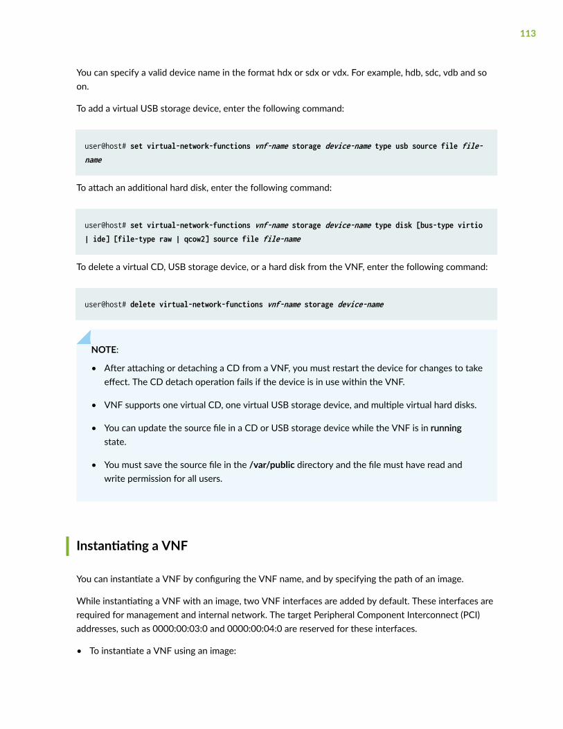
You can specify a valid device name in the format hdx or sdx or vdx. For example, hdb, sdc, vdb and soon.
To add a virtual USB storage device, enter the following command:
user@host# set virtual-network-functions vnf-name storage device-name type usb source file file-name
To attach an additional hard disk, enter the following command:
user@host# set virtual-network-functions vnf-name storage device-name type disk [bus-type virtio | ide] [file-type raw | qcow2] source file file-name
To delete a virtual CD, USB storage device, or a hard disk from the VNF, enter the following command:
user@host# delete virtual-network-functions vnf-name storage device-name
NOTE:
• After attaching or detaching a CD from a VNF, you must restart the device for changes to takeeffect. The CD detach operation fails if the device is in use within the VNF.
• VNF supports one virtual CD, one virtual USB storage device, and multiple virtual hard disks.
• You can update the source file in a CD or USB storage device while the VNF is in runningstate.
• You must save the source file in the /var/public directory and the file must have read andwrite permission for all users.
Instantiating a VNF
You can instantiate a VNF by configuring the VNF name, and by specifying the path of an image.
While instantiating a VNF with an image, two VNF interfaces are added by default. These interfaces arerequired for management and internal network. The target Peripheral Component Interconnect (PCI)addresses, such as 0000:00:03:0 and 0000:00:04:0 are reserved for these interfaces.
• To instantiate a VNF using an image:
113
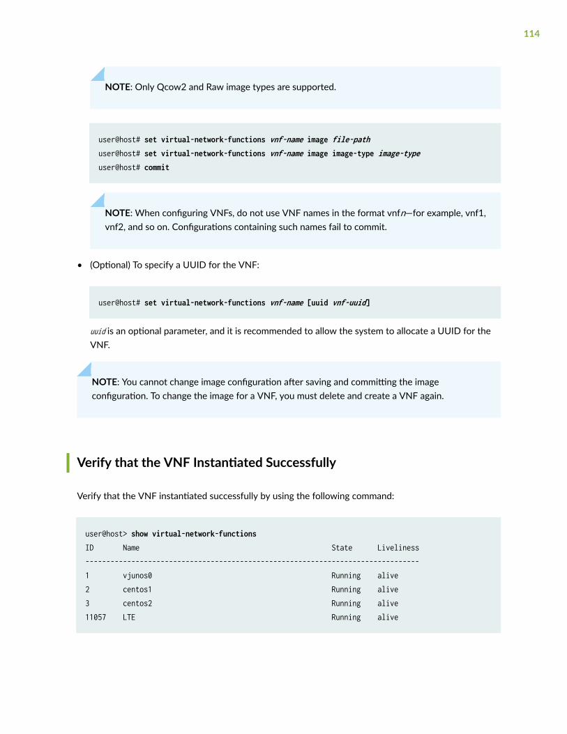
NOTE: Only Qcow2 and Raw image types are supported.
user@host# set virtual-network-functions vnf-name image file-pathuser@host# set virtual-network-functions vnf-name image image-type image-typeuser@host# commit
NOTE: When configuring VNFs, do not use VNF names in the format vnfn—for example, vnf1,vnf2, and so on. Configurations containing such names fail to commit.
• (Optional) To specify a UUID for the VNF:
user@host# set virtual-network-functions vnf-name [uuid vnf-uuid]
uuid is an optional parameter, and it is recommended to allow the system to allocate a UUID for theVNF.
NOTE: You cannot change image configuration after saving and committing the imageconfiguration. To change the image for a VNF, you must delete and create a VNF again.
Verify that the VNF Instantiated Successfully
Verify that the VNF instantiated successfully by using the following command:
user@host> show virtual-network-functions ID Name State Liveliness--------------------------------------------------------------------------------1 vjunos0 Running alive2 centos1 Running alive3 centos2 Running alive11057 LTE Running alive
114
The Liveliness output field of a VNF indicates whether the IP address of the VNF is reachable or notreachable over the internal management network. The default IP address of the liveliness bridge is192.0.2.1/24.
Managing VNFs on NFX Series Devices
IN THIS SECTION
Managing VNF States | 115
Managing VNF MAC Addresses | 116
Managing the MTU of a VNF Interface | 117
Accessing a VNF from the JCP | 118
Viewing the List of VNFs | 118
Displaying the Details of a VNF | 119
Deleting a VNF | 119
Managing VNF States
By default, a VNF automatically starts when the VNF configuration is committed.
• To disable autostart of a VNF when the VNF configuration is committed:
user@host# set virtual-network-functions vnf-name no-autostart
• To manually start a VNF:
user@host> request virtual-network-functions vnf-name start
• To stop a VNF:
user@host> request virtual-network-functions vnf-name stop
115
• To restart a VNF:
user@host> request virtual-network-functions vnf-name restart
• To access the console of an active VNF:
user@host> request virtual-network-functions vnf-name console
NOTE: The request virtual-network-functions vnf-name console command is supported only forroot login over ssh.
• To access a VNF through SSH:
user@host> request virtual-network-functions ssh vnf-name
• To access a VNF through Telnet:
user@host> request virtual-network-functions telnet vnf-name
Managing VNF MAC Addresses
VNF interfaces that are defined, either using the CLI or specified in an init-descriptor XML file, areassigned a globally unique and persistent MAC address. A common pool of 64 MAC addresses is used toassign MAC addresses to VNF interfaces. You can configure a MAC address other than what is availablein the common pool, and this address will not be overwritten.
There are 160 MAC addresses for the network interfaces on the VNF. These MAC addresses areautomatically allocated when a VNF is instantiated.
• To configure a specific MAC address for a VNF interface:
user@host# set virtual-network-functions vnf-name interfaces interface-name mac-address mac-address
116
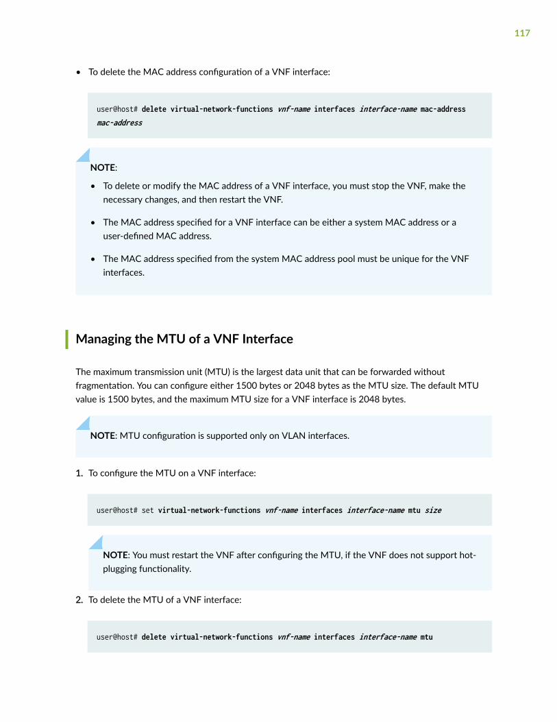
• To delete the MAC address configuration of a VNF interface:
user@host# delete virtual-network-functions vnf-name interfaces interface-name mac-address mac-address
NOTE:
• To delete or modify the MAC address of a VNF interface, you must stop the VNF, make thenecessary changes, and then restart the VNF.
• The MAC address specified for a VNF interface can be either a system MAC address or auser-defined MAC address.
• The MAC address specified from the system MAC address pool must be unique for the VNFinterfaces.
Managing the MTU of a VNF Interface
The maximum transmission unit (MTU) is the largest data unit that can be forwarded withoutfragmentation. You can configure either 1500 bytes or 2048 bytes as the MTU size. The default MTUvalue is 1500 bytes, and the maximum MTU size for a VNF interface is 2048 bytes.
NOTE: MTU configuration is supported only on VLAN interfaces.
1. To configure the MTU on a VNF interface:
user@host# set virtual-network-functions vnf-name interfaces interface-name mtu size
NOTE: You must restart the VNF after configuring the MTU, if the VNF does not support hot-plugging functionality.
2. To delete the MTU of a VNF interface:
user@host# delete virtual-network-functions vnf-name interfaces interface-name mtu
117
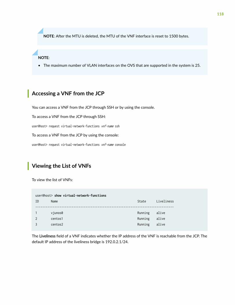
NOTE: After the MTU is deleted, the MTU of the VNF interface is reset to 1500 bytes.
NOTE:
• The maximum number of VLAN interfaces on the OVS that are supported in the system is 25.
Accessing a VNF from the JCP
You can access a VNF from the JCP through SSH or by using the console.
To access a VNF from the JCP through SSH:
user@host> request virtual-network-functions vnf-name ssh
To access a VNF from the JCP by using the console:
user@host> request virtual-network-functions vnf-name console
Viewing the List of VNFs
To view the list of VNFs:
user@host> show virtual-network-functions ID Name State Liveliness--------------------------------------------------------------------------------1 vjunos0 Running alive2 centos1 Running alive3 centos2 Running alive
The Liveliness field of a VNF indicates whether the IP address of the VNF is reachable from the JCP. Thedefault IP address of the liveliness bridge is 192.0.2.1/24.
118
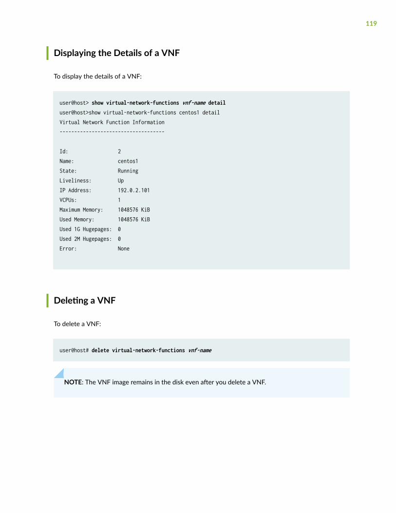
Displaying the Details of a VNF
To display the details of a VNF:
user@host> show virtual-network-functions vnf-name detailuser@host>show virtual-network-functions centos1 detailVirtual Network Function Information------------------------------------
Id: 2Name: centos1State: RunningLiveliness: UpIP Address: 192.0.2.101VCPUs: 1Maximum Memory: 1048576 KiBUsed Memory: 1048576 KiBUsed 1G Hugepages: 0Used 2M Hugepages: 0Error: None
Deleting a VNF
To delete a VNF:
user@host# delete virtual-network-functions vnf-name
NOTE: The VNF image remains in the disk even after you delete a VNF.
119
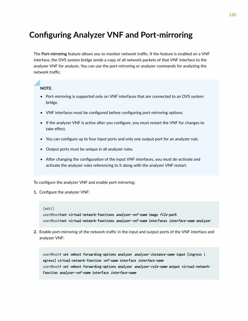
Configuring Analyzer VNF and Port-mirroring
The Port-mirroring feature allows you to monitor network traffic. If the feature is enabled on a VNFinterface, the OVS system bridge sends a copy of all network packets of that VNF interface to theanalyzer VNF for analysis. You can use the port-mirroring or analyzer commands for analyzing thenetwork traffic.
NOTE:
• Port-mirroring is supported only on VNF interfaces that are connected to an OVS systembridge.
• VNF interfaces must be configured before configuring port-mirroring options.
• If the analyzer VNF is active after you configure, you must restart the VNF for changes totake effect.
• You can configure up to four input ports and only one output port for an analyzer rule.
• Output ports must be unique in all analyzer rules.
• After changing the configuration of the input VNF interfaces, you must de-activate andactivate the analyzer rules referencing to it along with the analyzer VNF restart.
To configure the analyzer VNF and enable port-mirroring:
1. Configure the analyzer VNF:
[edit]user@host#set virtual-network-functions analyzer-vnf-name image file-path user@host#set virtual-network-functions analyzer-vnf-name interfaces interface-name analyzer
2. Enable port-mirroring of the network traffic in the input and output ports of the VNF interface andanalyzer VNF:
user@host# set vmhost forwarding-options analyzer analyzer-instance-name input [ingress | egress] virtual-network-function vnf-name interface interface-nameuser@host# set vmhost forwarding-options analyzer analyzer-rule-name output virtual-network-function analyzer-vnf-name interface interface-name
120
8CHAPTER
Configuring Mapping of Address andPort with Encapsulation (MAP-E)
Mapping of Address and Port with Encapsulation on NFX Series Devices | 122
Configuring MAP-E on NFX Series Devices | 125
Mapping of Address and Port with Encapsulation onNFX Series Devices
IN THIS SECTION
Overview | 122
Benefits of MAP-E | 122
MAP-E Terminology | 123
MAP-E Functionality | 124
Overview
Mapping of Address and Port with Encapsulation (MAP-E) is an IPv6 transition technique thatencapsulates an IPv4 packet in an IPv6 address and carries it over an IPv4-over-IPv6 tunnel from MAP-Ecustomer edge (CE) devices to MAP-E provider edge (PE) devices (also called as border relay [BR]devices) through an IPv6 routing topology, where the packets are detunneled for further processing.
MAP-E uses Network Address Port Translation (NAPT) features for restricting transport protocol ports,Internet Control Message Protocol (ICMP) identifiers, and fragment identifiers to the configured portsets. The existing NAPT features are enhanced to add MAP-E capability.
Benefits of MAP-E
In most cases, during IPv4 to IPv6 migration, only the IPv6 network is available. However, an IPv4network is required for all residual IPv4 deployment. In scenarios where service providers have an IPv6network and the LAN subscribers are not IPv6-capable, MAP-E supports IPv4 to IPv6 migration anddeployment. MAP-E transports IPv4 packets across an IPv6 network using IP encapsulation.Encapsulation is done based on the mapping of IPv6 addresses to IPv4 addresses and to transport layerports. Typically, during IPv6 transition, service providers might have a limited pool of public IPv4addresses. MAP-E enables the sharing of public IPv4 addresses among multiple CE devices.
122
MAP-E Terminology
Terminology Description
Border relay (BR) The MAP-E-enabled provider edge device in a MAP domain. A BR device hasat least one IPv6-enabled interface and one IPv4 interface connected to thenative IPv4 network.
Embedded address (EA) bits The EA bits in the IPv6 address identify an IPv4 prefix, IPv4 address, or ashared IPv4 address and a PSID.
MAP domain One or more MAP-E customer edge devices and BR devices connected to thesame virtual link.
MAP rule A set of parameters that describe the mapping of an IPv4 prefix, IPv4 address,or a shared IPv4 address with an IPv6 prefix or IPv6 address. Each domainuses a different mapping rule set.
Every MAP node must be provisioned with a basic mapping rule, which is usedby the node to configure its IPv4 address, IPv4 prefix, or shared IPv4 address.The basic mapping rule is a forwarding mapping rule that is used forforwarding, where an IPv4 destination address and optionally a destinationport is mapped to an IPv6 address.
MAP-E Customer Edge (CE) The MAP-E-enabled customer edge device in a MAP deployment.
Port set ID (PSID) Separate part of the transport layer port space that is denoted as the port setID.
Softwire Tunnel between two IPv6 endpoints to carry IPv4 packets or between twoIPv4 endpoints to carry IPv6 packets.
123
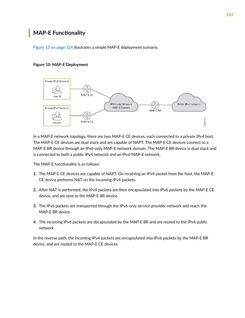
MAP-E Functionality
Figure 10 on page 124 illustrates a simple MAP-E deployment scenario.
Figure 10: MAP-E Deployment
In a MAP-E network topology, there are two MAP-E CE devices, each connected to a private IPv4 host.The MAP-E CE devices are dual stack and are capable of NAPT. The MAP-E CE devices connect to aMAP-E BR device through an IPv6-only MAP-E network domain. The MAP-E BR device is dual stack andis connected to both a public IPv4 network and an IPv6 MAP-E network.
The MAP-E functionality is as follows:
1. The MAP-E CE devices are capable of NAPT. On receiving an IPv4 packet from the host, the MAP-ECE device performs NAT on the incoming IPv4 packets.
2. After NAT is performed, the IPv4 packets are then encapsulated into IPv6 packets by the MAP-E CEdevice, and are sent to the MAP-E BR device.
3. The IPv6 packets are transported through the IPv6-only service provider network and reach theMAP-E BR device.
4. The incoming IPv6 packets are decapsulated by the MAP-E BR and are routed to the IPv4 publicnetwork.
In the reverse path, the incoming IPv4 packets are encapsulated into IPv6 packets by the MAP-E BRdevice, and are routed to the MAP-E CE devices.
124
Configuring MAP-E on NFX Series Devices
IN THIS SECTION
Overview | 125
Requirements | 125
Topology Overview | 125
Configure an NFX Series Device as a MAP-E CE Device | 126
Configure an MX Series Device as a BR Device | 129
Verify the MAP-E Configuration | 131
Overview
This example describes how to configure Mapping of Address and Port with Encapsulation (MAP-E)functionality on NFX Series devices. For more information about MAP-E, see "Mapping of Address andPort with Encapsulation on NFX Series Devices" on page 122.
Requirements
This example uses the following hardware and software components:
• NFX150 device running Junos OS Release 19.4R1, deployed as a customer edge (CE) device.
• MX480 device, deployed as a border relay (BR) device.
• Map physical interfaces to virtual interfaces. For more information, see Mapping Interfaces onNFX150 Devices.
Topology Overview
This topology shows how to configure MAP-E CE functionality on NFX Series devices. This topologyalso shows how the IPv4 packets from MAP-E CE devices are encapsulated and transported through an
125
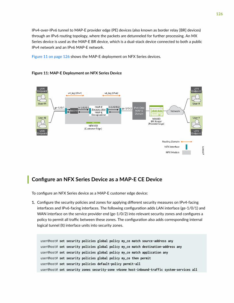
IPv4-over-IPv6 tunnel to MAP-E provider edge (PE) devices (also known as border relay [BR] devices)through an IPv6 routing topology, where the packets are detunneled for further processing. An MXSeries device is used as the MAP-E BR device, which is a dual-stack device connected to both a publicIPv4 network and an IPv6 MAP-E network.
Figure 11 on page 126 shows the MAP-E deployment on NFX Series devices.
Figure 11: MAP-E Deployment on NFX Series Device
Configure an NFX Series Device as a MAP-E CE Device
To configure an NFX Series device as a MAP-E customer edge device:
1. Configure the security policies and zones for applying different security measures on IPv4-facinginterfaces and IPv6-facing interfaces. The following configuration adds LAN interface (ge-1/0/1) andWAN interface on the service provider end (ge-1/0/2) into relevant security zones and configures apolicy to permit all traffic between these zones. The configuration also adds corresponding internallogical tunnel (lt) interface units into security zones.
user@host# set security policies global policy my_ce match source-address anyuser@host# set security policies global policy my_ce match destination-address anyuser@host# set security policies global policy my_ce match application any user@host# set security policies global policy my_ce then permituser@host# set security policies default-policy permit-alluser@host# set security zones security-zone v4zone host-inbound-traffic system-services all
126
user@host# set security zones security-zone v4zone host-inbound-traffic protocols alluser@host# set security zones security-zone v4zone interfaces ge-1/0/1.0user@host# set security zones security-zone v4zone interfaces lt-1/0/0.1user@host# set security zones security-zone v6zone host-inbound-traffic system-services alluser@host# set security zones security-zone v6zone host-inbound-traffic protocols alluser@host# set security zones security-zone v6zone interfaces ge-1/0/2.0user@host# set security zones security-zone v6zone interfaces lt-1/0/0.2
2. Configure the interfaces to provide network connectivity and data flow. The following configurationassigns IPv4 address on LAN side and IPv6 on WAN side. The MTU on the IPv6 side must supportmaximum MTU.
user@host# set interfaces ge-1/0/1 unit 0 family inet address 10.10.10.1/24user@host# set interfaces ge-1/0/2 mtu 9192user@host# set interfaces ge-1/0/2 unit 0 family inet6 address 2001:db8:ffff::1/64
3. Configure both the logical tunnel interfaces. The logical tunnel interfaces act as internal endpoints toMAP-E encapsulator or decapsulator block in NFX series box. This separates the network traffic forIPv4 and IPv6. Here, lt-1/0/0 unit 1 terminates IPv4 traffic that is received on ge-1/0/1 and lt-1/0/0unit 2 initiates IPv6 traffic to be sent out through ge-1/0/2. lt-1/0/0 unit 2 terminates IPv6 trafficthat is received on ge-1/0/2 and lt-1/0/0 unit 1 initiates IPv4 traffuc to be sent out throughge-1/0/1.
user@host# set interfaces lt-1/0/0 mtu 9192user@host# set interfaces lt-1/0/0 unit 1 encapsulation ethernetuser@host# set interfaces lt-1/0/0 unit 1 peer-unit 2user@host# set interfaces lt-1/0/0 unit 1 family inet address 172.16.100.1/24user@host# set interfaces lt-1/0/0 unit 1 family inet6 address 2001:db8:fffe::1/64
user@host# set interfaces lt-1/0/0 unit 2 encapsulation ethernetuser@host# set interfaces lt-1/0/0 unit 2 peer-unit 1user@host# set interfaces lt-1/0/0 unit 2 family inet address 172.16.100.2/24user@host# set interfaces lt-1/0/0 unit 2 family inet6 address 2001:db8:fffe::2/64
4. Configure the routing instances for the IPv4 and IPv6 network traffic domains inside NFX:
user@host# set routing-instances v4_leg routing-options rib v4_leg.inet.0 static route 198.51.100.0/24 next-hop 172.16.100.2user@host# set routing-instances v4_leg routing-options rib v4_leg.inet.0 static route 203.0.113.0/24 next-hop 172.16.100.2
127
user@host# set routing-instances v4_leg routing-options rib v4_leg.inet.0 static route 192.0.2.0/24 next-hop 172.16.100.2user@host# set routing-instances v4_leg instance-type virtual-routeruser@host# set routing-instances v4_leg interface lt-1/0/0.1
user@host# set routing-instances v4_leg interface ge-1/0/1.0user@host# set routing-instances v6_leg routing-options rib v6_leg.inet.0 static route 10.10.10.0/24 next-hop 172.16.100.1user@host# set routing-instances v6_leg routing-options rib v6_leg.inet6.0 static route 2001:db8::a/128 next-hop 2001:db8:ffff::9user@host# set routing-instances v6_leg routing-options rib v6_leg.inet6.0 static route 2001:db8:0012:3500::/56 next-hop 2001:db8:ffff::2user@host# set routing-instances v6_leg routing-options rib v6_leg.inet6.0 static route 2001:db8:0012:3400::/56 next-hop 2001:db8:fffe::1user@host# set routing-instances v6_leg instance-type virtual-routeruser@host# set routing-instances v6_leg interface lt-1/0/0.2user@host# set routing-instances v6_leg interface ge-1/0/2.0
5. Configure the MAP-E BMR and FMR rules to provide mapping between the IPv4 network and IPv6network:
user@host# set security softwires map-e mapce1 br-address 2001:db8::a/128user@host# set security softwires map-e mapce1 end-user-prefix 2001:db8:0012:3400::/56user@host# set security softwires map-e mapce1 rule bmr rule-type BMRuser@host# set security softwires map-e mapce1 rule bmr ipv4-prefix 192.0.2.0/24user@host# set security softwires map-e mapce1 rule bmr ipv6-prefix 2001:db8::/40user@host# set security softwires map-e mapce1 rule bmr ea-bits-length 16user@host# set security softwires map-e mapce1 rule bmr psid-offset 6user@host# set security softwires map-e mapce1 role CEuser@host# set security softwires map-e mapce1 version 3
6. (Optional) Configure the confidentiality option for MAP-E if you want to hide the MAP-E parametersin show command output for non-super users:
user@host# set security softwires map-e confidentiality
For more information, see confidentiality and show security softwires map-e confidentiality status.
128
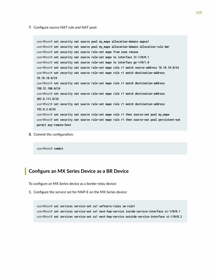
7. Configure source NAT rule and NAT pool:
user@host# set security nat source pool my_mape allocation-domain mapce1user@host# set security nat source pool my_mape allocation-domain allocation-rule bmruser@host# set security nat source rule-set mape from zone v4zoneuser@host# set security nat source rule-set mape to interface lt-1/0/0.1user@host# set security nat source rule-set mape to interface ge-1/0/1.0user@host# set security nat source rule-set mape rule r1 match source-address 10.10.10.0/24user@host# set security nat source rule-set mape rule r1 match destination-address 10.10.10.0/24user@host# set security nat source rule-set mape rule r1 match destination-address 198.51.100.0/24user@host# set security nat source rule-set mape rule r1 match destination-address 203.0.113.0/24user@host# set security nat source rule-set mape rule r1 match destination-address 192.0.2.0/24user@host# set security nat source rule-set mape rule r1 then source-nat pool my_mapeuser@host# set security nat source rule-set mape rule r1 then source-nat pool persistent-nat permit any-remote-host
8. Commit the configuration:
user@host# commit
Configure an MX Series Device as a BR Device
To configure an MX Series device as a border relay device:
1. Configure the service set for MAP-E on the MX Series device:
user@host# set services service-set ss1 softwire-rules sw-rule1user@host# set services service-set ss1 next-hop-service inside-service-interface si-1/0/0.1user@host# set services service-set ss1 next-hop-service outside-service-interface si-1/0/0.2
129
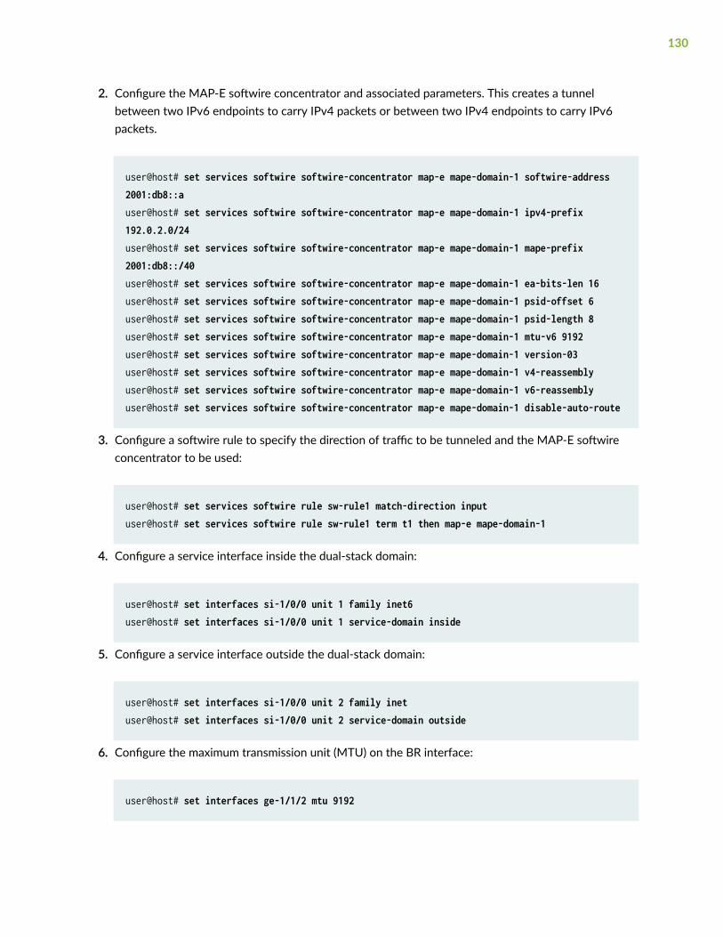
2. Configure the MAP-E softwire concentrator and associated parameters. This creates a tunnelbetween two IPv6 endpoints to carry IPv4 packets or between two IPv4 endpoints to carry IPv6packets.
user@host# set services softwire softwire-concentrator map-e mape-domain-1 softwire-address 2001:db8::auser@host# set services softwire softwire-concentrator map-e mape-domain-1 ipv4-prefix 192.0.2.0/24user@host# set services softwire softwire-concentrator map-e mape-domain-1 mape-prefix 2001:db8::/40user@host# set services softwire softwire-concentrator map-e mape-domain-1 ea-bits-len 16user@host# set services softwire softwire-concentrator map-e mape-domain-1 psid-offset 6user@host# set services softwire softwire-concentrator map-e mape-domain-1 psid-length 8user@host# set services softwire softwire-concentrator map-e mape-domain-1 mtu-v6 9192user@host# set services softwire softwire-concentrator map-e mape-domain-1 version-03user@host# set services softwire softwire-concentrator map-e mape-domain-1 v4-reassemblyuser@host# set services softwire softwire-concentrator map-e mape-domain-1 v6-reassemblyuser@host# set services softwire softwire-concentrator map-e mape-domain-1 disable-auto-route
3. Configure a softwire rule to specify the direction of traffic to be tunneled and the MAP-E softwireconcentrator to be used:
user@host# set services softwire rule sw-rule1 match-direction inputuser@host# set services softwire rule sw-rule1 term t1 then map-e mape-domain-1
4. Configure a service interface inside the dual-stack domain:
user@host# set interfaces si-1/0/0 unit 1 family inet6user@host# set interfaces si-1/0/0 unit 1 service-domain inside
5. Configure a service interface outside the dual-stack domain:
user@host# set interfaces si-1/0/0 unit 2 family inetuser@host# set interfaces si-1/0/0 unit 2 service-domain outside
6. Configure the maximum transmission unit (MTU) on the BR interface:
user@host# set interfaces ge-1/1/2 mtu 9192
130
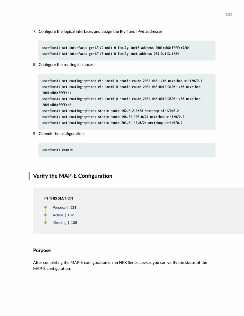
7. Configure the logical interfaces and assign the IPv4 and IPv6 addresses:
user@host# set interfaces ge-1/1/2 unit 0 family inet6 address 2001:db8:ffff::9/64user@host# set interfaces ge-1/1/3 unit 0 family inet address 203.0.113.1/24
8. Configure the routing instances:
user@host# set routing-options rib inet6.0 static route 2001:db8::/40 next-hop si-1/0/0.1user@host# set routing-options rib inet6.0 static route 2001:db8:0012:3400::/56 next-hop 2001:db8:ffff::1user@host# set routing-options rib inet6.0 static route 2001:db8:0012:3500::/56 next-hop 2001:db8:ffff::2user@host# set routing-options static route 192.0.2.0/24 next-hop si-1/0/0.2user@host# set routing-options static route 198.51.100.0/24 next-hop si-1/0/0.2user@host# set routing-options static route 203.0.113.0/24 next-hop si-1/0/0.2
9. Commit the configuration:
user@host# commit
Verify the MAP-E Configuration
IN THIS SECTION
Purpose | 131
Action | 132
Meaning | 135
Purpose
After completing the MAP-E configuration on an NFX Series device, you can verify the status of theMAP-E configuration.
131
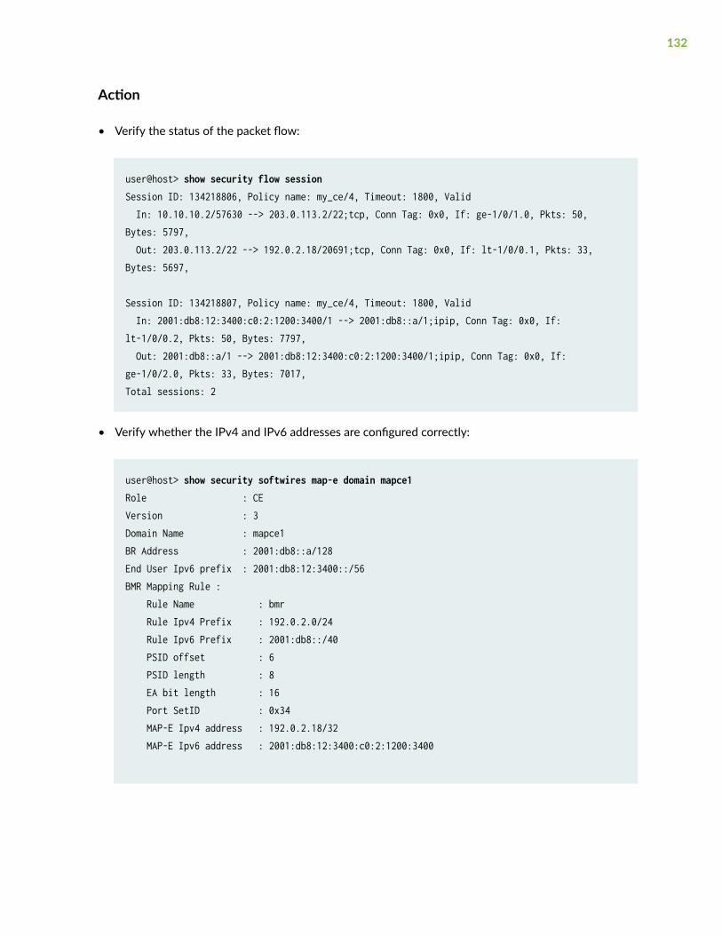
Action
• Verify the status of the packet flow:
user@host> show security flow sessionSession ID: 134218806, Policy name: my_ce/4, Timeout: 1800, Valid In: 10.10.10.2/57630 --> 203.0.113.2/22;tcp, Conn Tag: 0x0, If: ge-1/0/1.0, Pkts: 50, Bytes: 5797, Out: 203.0.113.2/22 --> 192.0.2.18/20691;tcp, Conn Tag: 0x0, If: lt-1/0/0.1, Pkts: 33, Bytes: 5697,
Session ID: 134218807, Policy name: my_ce/4, Timeout: 1800, Valid In: 2001:db8:12:3400:c0:2:1200:3400/1 --> 2001:db8::a/1;ipip, Conn Tag: 0x0, If: lt-1/0/0.2, Pkts: 50, Bytes: 7797, Out: 2001:db8::a/1 --> 2001:db8:12:3400:c0:2:1200:3400/1;ipip, Conn Tag: 0x0, If: ge-1/0/2.0, Pkts: 33, Bytes: 7017,Total sessions: 2
• Verify whether the IPv4 and IPv6 addresses are configured correctly:
user@host> show security softwires map-e domain mapce1Role : CEVersion : 3Domain Name : mapce1BR Address : 2001:db8::a/128End User Ipv6 prefix : 2001:db8:12:3400::/56BMR Mapping Rule : Rule Name : bmr Rule Ipv4 Prefix : 192.0.2.0/24 Rule Ipv6 Prefix : 2001:db8::/40 PSID offset : 6 PSID length : 8 EA bit length : 16 Port SetID : 0x34 MAP-E Ipv4 address : 192.0.2.18/32 MAP-E Ipv6 address : 2001:db8:12:3400:c0:2:1200:3400
132
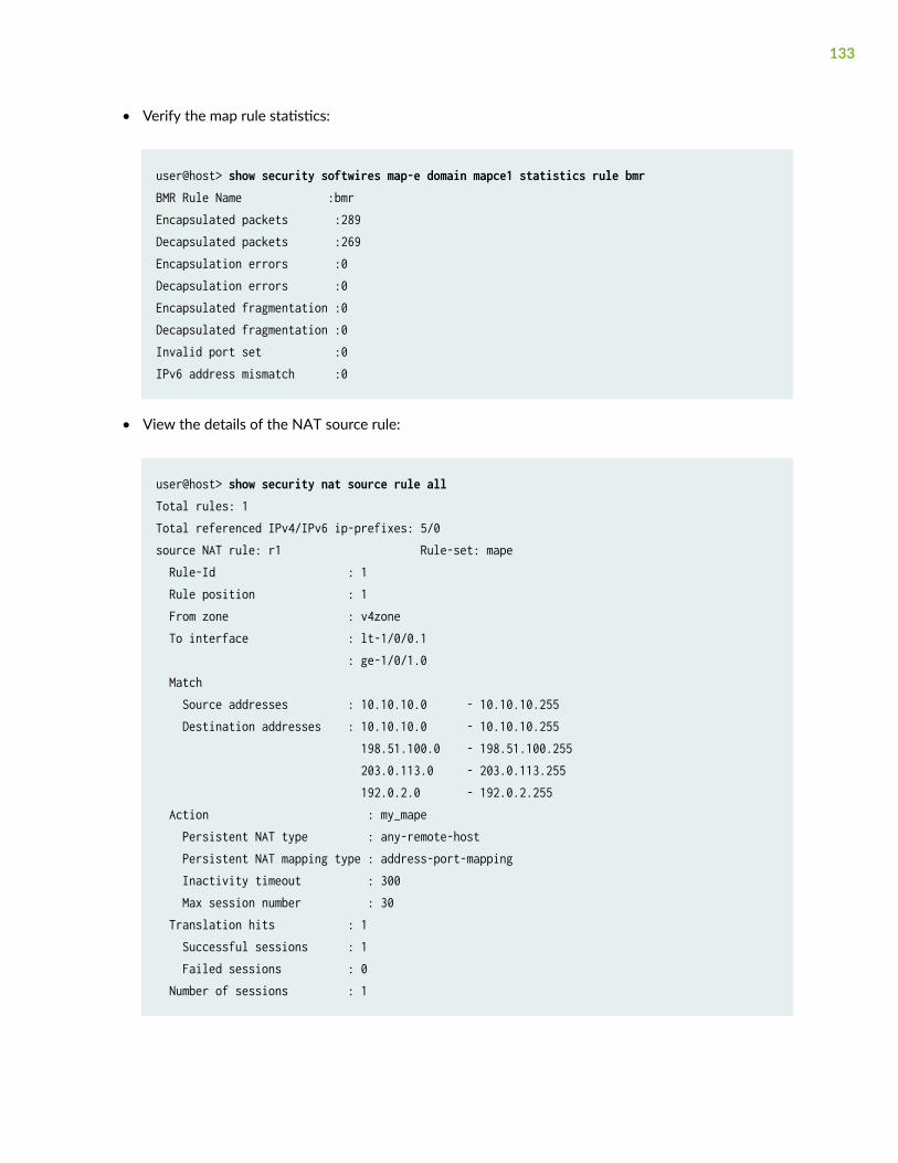
• Verify the map rule statistics:
user@host> show security softwires map-e domain mapce1 statistics rule bmrBMR Rule Name :bmrEncapsulated packets :289Decapsulated packets :269Encapsulation errors :0Decapsulation errors :0Encapsulated fragmentation :0Decapsulated fragmentation :0Invalid port set :0IPv6 address mismatch :0
• View the details of the NAT source rule:
user@host> show security nat source rule allTotal rules: 1Total referenced IPv4/IPv6 ip-prefixes: 5/0source NAT rule: r1 Rule-set: mape Rule-Id : 1 Rule position : 1 From zone : v4zone To interface : lt-1/0/0.1 : ge-1/0/1.0 Match Source addresses : 10.10.10.0 - 10.10.10.255 Destination addresses : 10.10.10.0 - 10.10.10.255 198.51.100.0 - 198.51.100.255 203.0.113.0 - 203.0.113.255 192.0.2.0 - 192.0.2.255 Action : my_mape Persistent NAT type : any-remote-host Persistent NAT mapping type : address-port-mapping Inactivity timeout : 300 Max session number : 30 Translation hits : 1 Successful sessions : 1 Failed sessions : 0 Number of sessions : 1
133
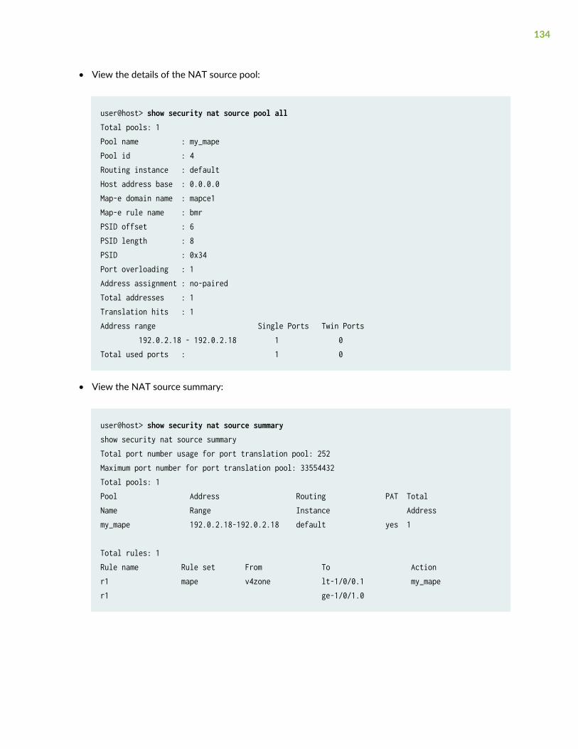
• View the details of the NAT source pool:
user@host> show security nat source pool allTotal pools: 1Pool name : my_mapePool id : 4Routing instance : defaultHost address base : 0.0.0.0Map-e domain name : mapce1Map-e rule name : bmrPSID offset : 6PSID length : 8PSID : 0x34Port overloading : 1Address assignment : no-pairedTotal addresses : 1Translation hits : 1Address range Single Ports Twin Ports 192.0.2.18 - 192.0.2.18 1 0Total used ports : 1 0
• View the NAT source summary:
user@host> show security nat source summaryshow security nat source summaryTotal port number usage for port translation pool: 252Maximum port number for port translation pool: 33554432Total pools: 1Pool Address Routing PAT TotalName Range Instance Addressmy_mape 192.0.2.18-192.0.2.18 default yes 1
Total rules: 1Rule name Rule set From To Actionr1 mape v4zone lt-1/0/0.1 my_maper1 ge-1/0/1.0
134
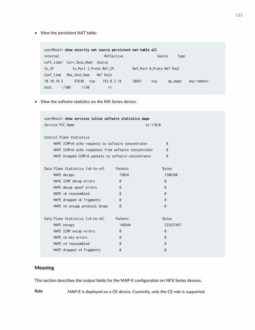
• View the persistent NAT table:
user@host> show security nat source persistent-nat-table allInternal Reflective Source Type Left_time/ Curr_Sess_Num/ SourceIn_IP In_Port I_Proto Ref_IP Ref_Port R_Proto NAT Pool Conf_time Max_Sess_Num NAT Rule10.10.10.2 57630 tcp 192.0.2.18 20691 tcp my_mape any-remote-host -/300 1/30 r1
• View the softwire statistics on the MX Series device:
user@host> show services inline softwire statistics mapeService PIC Name si-1/0/0
Control Plane Statistics MAPE ICMPv6 echo requests to softwire concentrator 0 MAPE ICMPv6 echo responses from softwire concentrator 0 MAPE Dropped ICMPv6 packets to softwire concentrator 0
Data Plane Statistics (v6-to-v4) Packets Bytes MAPE decaps 15034 1388760 MAPE ICMP decap errors 0 0 MAPE decap spoof errors 0 0 MAPE v6 reassembled 0 0 MAPE dropped v6 fragments 0 0 MAPE v6 unsupp protocol drops 0 0
Data Plane Statistics (v4-to-v6) Packets Bytes MAPE encaps 149544 223527457 MAPE ICMP encap errors 0 0 MAPE v6 mtu errors 0 0 MAPE v4 reassembled 0 0 MAPE dropped v4 fragments 0 0
Meaning
This section describes the output fields for the MAP-E configuration on NFX Series devices.
Role MAP-E is deployed on a CE device. Currently, only the CE role is supported.
135

Version MAP-E version: MAP-E draft-3.
BR address Border router address to be used as the destination address in the absence of amatching FMR rule.
Rule name Name of the BMR or FMR rule configured.
Rule IPv4 prefix IPv4 prefix in the BMR or FMR rule.
Rule IPv6 prefix IPv6 prefix in the BMR or FMR rule.
Port set ID Port set identifier, used to algorithmically identify a set of ports exclusively assignedto a CE device.
PSID offset Port set identifier offset, used to specify the range of excluded ports.
PSID length Port set identifier length, used to specify the sharing ratio.
EA bit length Embedded address bit length, used to specify part of the IPv4 address or the PSID.
136
9CHAPTER
Configuring High Availability
Chassis Cluster on NFX150 Devices | 138
Upgrading or Disabling a Chassis Cluster on NFX150 Devices | 152
Chassis Cluster on NFX150 Devices
IN THIS SECTION
NFX150 Chassis Cluster Overview | 138
Chassis Cluster Interfaces | 139
Chassis Cluster Limitation | 140
Example: Configuring a Chassis Cluster on NFX150 Devices | 140
A chassis cluster, where two devices operate as a single device, provides high availability on NFX150devices. Chassis clustering involves the synchronizing of configuration files and the dynamic runtimesession states between the devices, which are part of the chassis cluster setup.
NFX150 Chassis Cluster Overview
IN THIS SECTION
Chassis Cluster Modes | 139
You can configure NFX150 devices to operate in cluster mode by connecting and configuring a pair ofdevices to operate like a single node, providing redundancy at the device, interface, and service level.
When two devices are configured to operate as a chassis cluster, each device becomes a node of thatcluster. The two nodes back up each other, with one node acting as the primary device and the othernode acting as the secondary device, ensuring stateful failover of processes and services when thesystem or hardware fails. If the primary device fails, the secondary device takes over the processing oftraffic.
The nodes of a cluster are connected together through two links called control link and fabric link. Thedevices in a chassis cluster synchronize the configuration, kernel, and PFE session states across thecluster to facilitate high availability, failover of stateful services, and load balancing.
138
• Control link—Synchronizes the configuration between the nodes. When you submit configurationstatements to the cluster, the configuration is automatically synchronized over the control interface.
To create a control link in a chassis cluster, connect the heth-0-0 port on one node to the heth-0-0port on the second node.
NOTE: You can use only the heth-0-0 port to create a control link.
• Fabric link (data link)—Forwards traffic between the nodes. Traffic arriving on a node that needs to beprocessed on the other node is forwarded over the fabric link. Similarly, traffic processed on a nodethat needs to exit through an interface on the other node is forwarded over the fabric link.
You can use any port except the heth-0-0 to create a fabric link.
Chassis Cluster Modes
The chassis cluster can be configured in active/passive or active/active mode.
• Active/passive mode—In active/passive mode, the transit traffic passes through the primary nodewhile the backup node is used only in the event of a failure. When a failure occurs, the backup devicebecomes the primary device and takes over all forwarding tasks.
• Active/active mode—In active/active mode, the transit traffic passes through both nodes all the time.
Chassis Cluster Interfaces
The chassis cluster interfaces include:
• Redundant Ethernet (reth) interface—A pseudo-interface that includes a physical interface from eachnode of a cluster. The reth interface of the active node is responsible for passing the traffic in achassis cluster setup.
A reth interface must contain, at minimum, a pair of Fast Ethernet interfaces or a pair of GigabitEthernet interfaces that are referred to as child interfaces of the redundant Ethernet interface (theredundant parent). If two or more child interfaces from each node are assigned to the redundantEthernet interface, a redundant Ethernet interface link aggregation group can be formed.
NOTE: You can configure a maximum of 128 reth interfaces on NFX150 devices.
139
• Control interface—An interface that provides the control link between the two nodes in the cluster.This interface is used for routing updates and for control plane signal traffic, such as heartbeat andthreshold information that trigger node failover.
NOTE: By default, the heth-0-0 port is configured as the dedicated control interface onNFX150 devices. Therefore, you cannot map the heth-0-0 port to any other virtual interfaceif the device is part of a chassis cluster.
• Fabric interface—An interface that provides the physical connection between two nodes of a cluster.A fabric interface is formed by connecting a pair of Ethernet interfaces back-to-back (one from eachnode). The Packet Forwarding Engines of the cluster uses this interface to transmit transit traffic andto synchronize the runtime state of the data plane software. You must specify the physical interfacesto be used for the fabric interface in the configuration.
Chassis Cluster Limitation
Redundant LAG (RLAG) of reth member interfaces of the same node is not supported. A reth interfacewith more than one child interface per node is called RLAG.
Example: Configuring a Chassis Cluster on NFX150 Devices
IN THIS SECTION
Requirements | 140
Overview | 141
Configuration | 142
Verification | 148
This example shows how to set up chassis clustering on NFX150 devices.
Requirements
Before you begin:
140
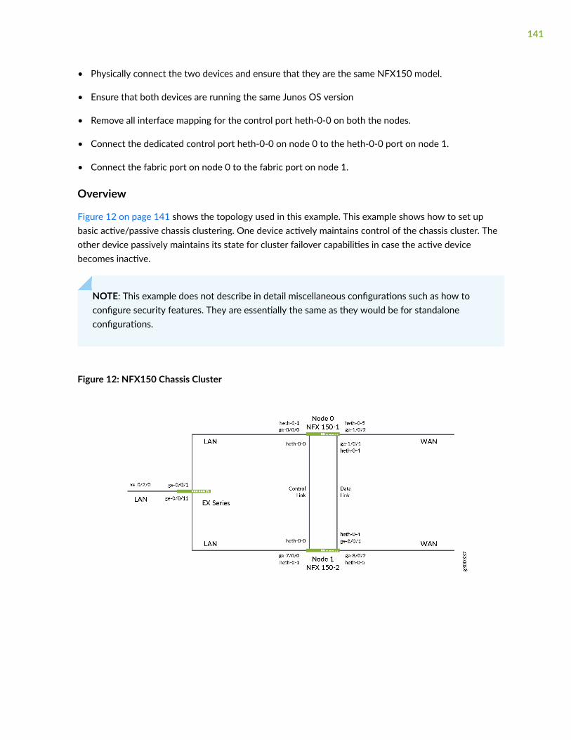
• Physically connect the two devices and ensure that they are the same NFX150 model.
• Ensure that both devices are running the same Junos OS version
• Remove all interface mapping for the control port heth-0-0 on both the nodes.
• Connect the dedicated control port heth-0-0 on node 0 to the heth-0-0 port on node 1.
• Connect the fabric port on node 0 to the fabric port on node 1.
Overview
Figure 12 on page 141 shows the topology used in this example. This example shows how to set upbasic active/passive chassis clustering. One device actively maintains control of the chassis cluster. Theother device passively maintains its state for cluster failover capabilities in case the active devicebecomes inactive.
NOTE: This example does not describe in detail miscellaneous configurations such as how toconfigure security features. They are essentially the same as they would be for standaloneconfigurations.
Figure 12: NFX150 Chassis Cluster
141
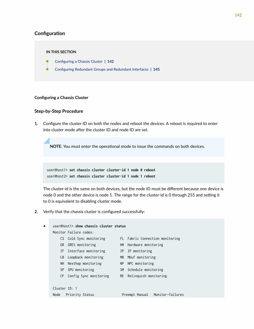
Configuration
IN THIS SECTION
Configuring a Chassis Cluster | 142
Configuring Redundant Groups and Redundant Interfaces | 145
Configuring a Chassis Cluster
Step-by-Step Procedure
1. Configure the cluster ID on both the nodes and reboot the devices. A reboot is required to enterinto cluster mode after the cluster ID and node ID are set.
NOTE: You must enter the operational mode to issue the commands on both devices.
user@host1> set chassis cluster cluster-id 1 node 0 rebootuser@host2> set chassis cluster cluster-id 1 node 1 reboot
The cluster-id is the same on both devices, but the node ID must be different because one device isnode 0 and the other device is node 1. The range for the cluster-id is 0 through 255 and setting itto 0 is equivalent to disabling cluster mode.
2. Verify that the chassis cluster is configured successfully:
• user@host1> show chassis cluster statusMonitor Failure codes: CS Cold Sync monitoring FL Fabric Connection monitoring GR GRES monitoring HW Hardware monitoring IF Interface monitoring IP IP monitoring LB Loopback monitoring MB Mbuf monitoring NH Nexthop monitoring NP NPC monitoring SP SPU monitoring SM Schedule monitoring CF Config Sync monitoring RE Relinquish monitoring
Cluster ID: 1Node Priority Status Preempt Manual Monitor-failures
142
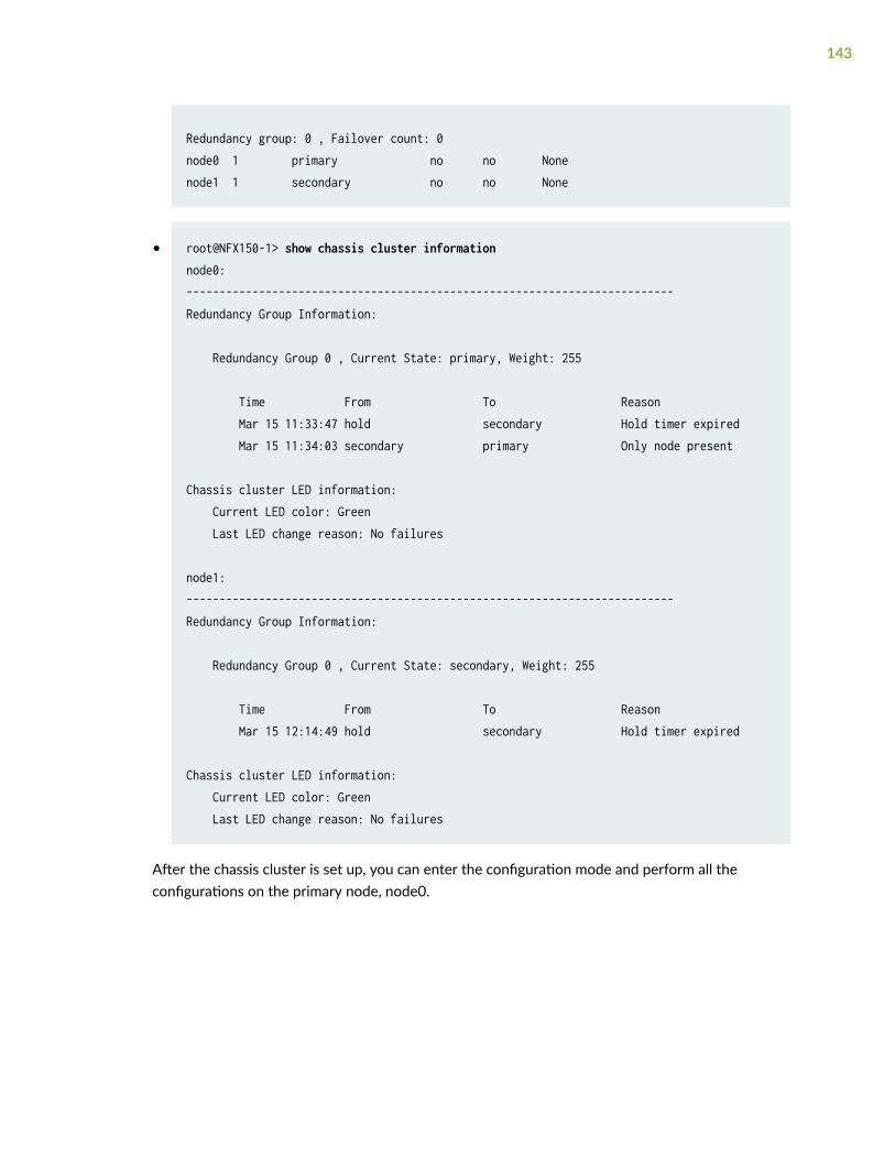
Redundancy group: 0 , Failover count: 0node0 1 primary no no Nonenode1 1 secondary no no None
• root@NFX150-1> show chassis cluster informationnode0:--------------------------------------------------------------------------Redundancy Group Information:
Redundancy Group 0 , Current State: primary, Weight: 255
Time From To Reason Mar 15 11:33:47 hold secondary Hold timer expired Mar 15 11:34:03 secondary primary Only node present
Chassis cluster LED information: Current LED color: Green Last LED change reason: No failures
node1:--------------------------------------------------------------------------Redundancy Group Information:
Redundancy Group 0 , Current State: secondary, Weight: 255
Time From To Reason Mar 15 12:14:49 hold secondary Hold timer expired
Chassis cluster LED information: Current LED color: Green Last LED change reason: No failures
After the chassis cluster is set up, you can enter the configuration mode and perform all theconfigurations on the primary node, node0.
143
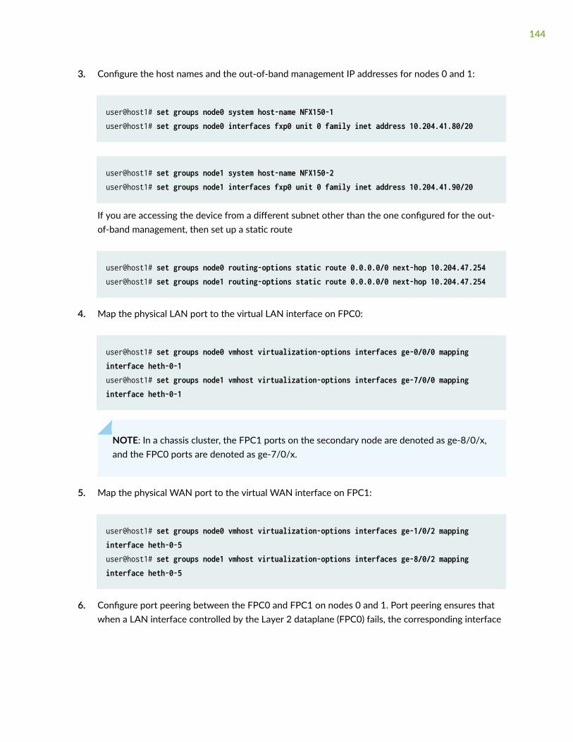
3. Configure the host names and the out-of-band management IP addresses for nodes 0 and 1:
user@host1# set groups node0 system host-name NFX150-1user@host1# set groups node0 interfaces fxp0 unit 0 family inet address 10.204.41.80/20
user@host1# set groups node1 system host-name NFX150-2user@host1# set groups node1 interfaces fxp0 unit 0 family inet address 10.204.41.90/20
If you are accessing the device from a different subnet other than the one configured for the out-of-band management, then set up a static route
user@host1# set groups node0 routing-options static route 0.0.0.0/0 next-hop 10.204.47.254 user@host1# set groups node1 routing-options static route 0.0.0.0/0 next-hop 10.204.47.254
4. Map the physical LAN port to the virtual LAN interface on FPC0:
user@host1# set groups node0 vmhost virtualization-options interfaces ge-0/0/0 mapping interface heth-0-1user@host1# set groups node1 vmhost virtualization-options interfaces ge-7/0/0 mapping interface heth-0-1
NOTE: In a chassis cluster, the FPC1 ports on the secondary node are denoted as ge-8/0/x,and the FPC0 ports are denoted as ge-7/0/x.
5. Map the physical WAN port to the virtual WAN interface on FPC1:
user@host1# set groups node0 vmhost virtualization-options interfaces ge-1/0/2 mapping interface heth-0-5user@host1# set groups node1 vmhost virtualization-options interfaces ge-8/0/2 mapping interface heth-0-5
6. Configure port peering between the FPC0 and FPC1 on nodes 0 and 1. Port peering ensures thatwhen a LAN interface controlled by the Layer 2 dataplane (FPC0) fails, the corresponding interface
144
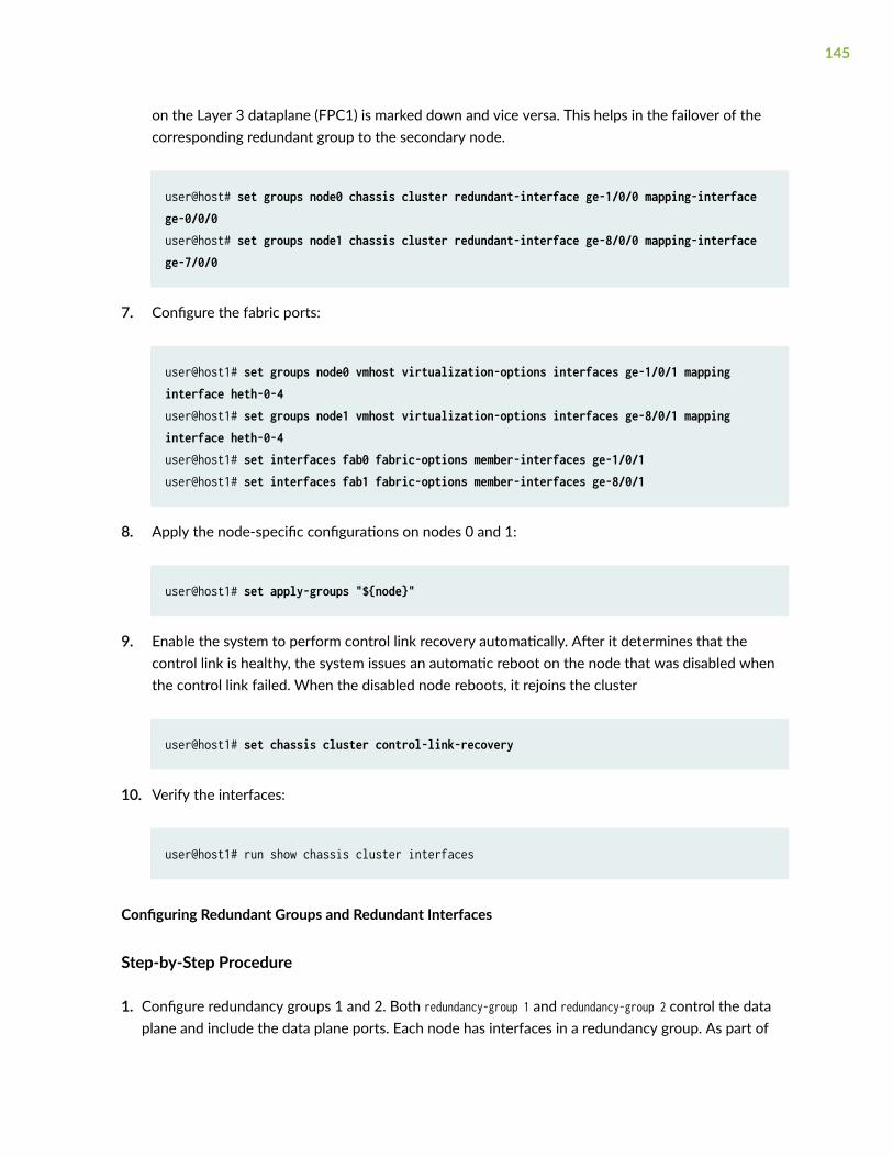
on the Layer 3 dataplane (FPC1) is marked down and vice versa. This helps in the failover of thecorresponding redundant group to the secondary node.
user@host# set groups node0 chassis cluster redundant-interface ge-1/0/0 mapping-interface ge-0/0/0user@host# set groups node1 chassis cluster redundant-interface ge-8/0/0 mapping-interface ge-7/0/0
7. Configure the fabric ports:
user@host1# set groups node0 vmhost virtualization-options interfaces ge-1/0/1 mapping interface heth-0-4user@host1# set groups node1 vmhost virtualization-options interfaces ge-8/0/1 mapping interface heth-0-4user@host1# set interfaces fab0 fabric-options member-interfaces ge-1/0/1user@host1# set interfaces fab1 fabric-options member-interfaces ge-8/0/1
8. Apply the node-specific configurations on nodes 0 and 1:
user@host1# set apply-groups "${node}"
9. Enable the system to perform control link recovery automatically. After it determines that thecontrol link is healthy, the system issues an automatic reboot on the node that was disabled whenthe control link failed. When the disabled node reboots, it rejoins the cluster
user@host1# set chassis cluster control-link-recovery
10. Verify the interfaces:
user@host1# run show chassis cluster interfaces
Configuring Redundant Groups and Redundant Interfaces
Step-by-Step Procedure
1. Configure redundancy groups 1 and 2. Both redundancy-group 1 and redundancy-group 2 control the dataplane and include the data plane ports. Each node has interfaces in a redundancy group. As part of
145
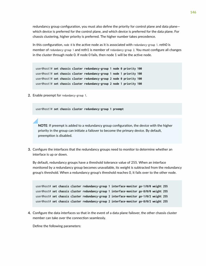
redundancy group configuration, you must also define the priority for control plane and data plane—which device is preferred for the control plane, and which device is preferred for the data plane. Forchassis clustering, higher priority is preferred. The higher number takes precedence.
In this configuration, node 0 is the active node as it is associated with redundancy-group 1. reth0 ismember of redundancy-group 1 and reth1 is member of redundancy-group 2. You must configure all changesin the cluster through node 0. If node 0 fails, then node 1 will be the active node.
user@host1# set chassis cluster redundancy-group 1 node 0 priority 100user@host1# set chassis cluster redundancy-group 1 node 1 priority 100user@host1# set chassis cluster redundancy-group 2 node 0 priority 100user@host1# set chassis cluster redundancy-group 2 node 1 priority 100
2. Enable preempt for redundancy-group 1.
user@host1# set chassis cluster redundancy-group 1 preempt
NOTE: If preempt is added to a redundancy group configuration, the device with the higherpriority in the group can initiate a failover to become the primary device. By default,preemption is disabled.
3. Configure the interfaces that the redundancy groups need to monitor to determine whether aninterface is up or down.
By default, redundancy groups have a threshold tolerance value of 255. When an interfacemonitored by a redundancy group becomes unavailable, its weight is subtracted from the redundancygroup's threshold. When a redundancy group's threshold reaches 0, it fails over to the other node.
user@host# set chassis cluster redundancy-group 1 interface-monitor ge-1/0/0 weight 255user@host# set chassis cluster redundancy-group 1 interface-monitor ge-8/0/0 weight 255user@host# set chassis cluster redundancy-group 2 interface-monitor ge-1/0/2 weight 255user@host# set chassis cluster redundancy-group 2 interface-monitor ge-8/0/2 weight 255
4. Configure the data interfaces so that in the event of a data plane failover, the other chassis clustermember can take over the connection seamlessly.
Define the following parameters:
146
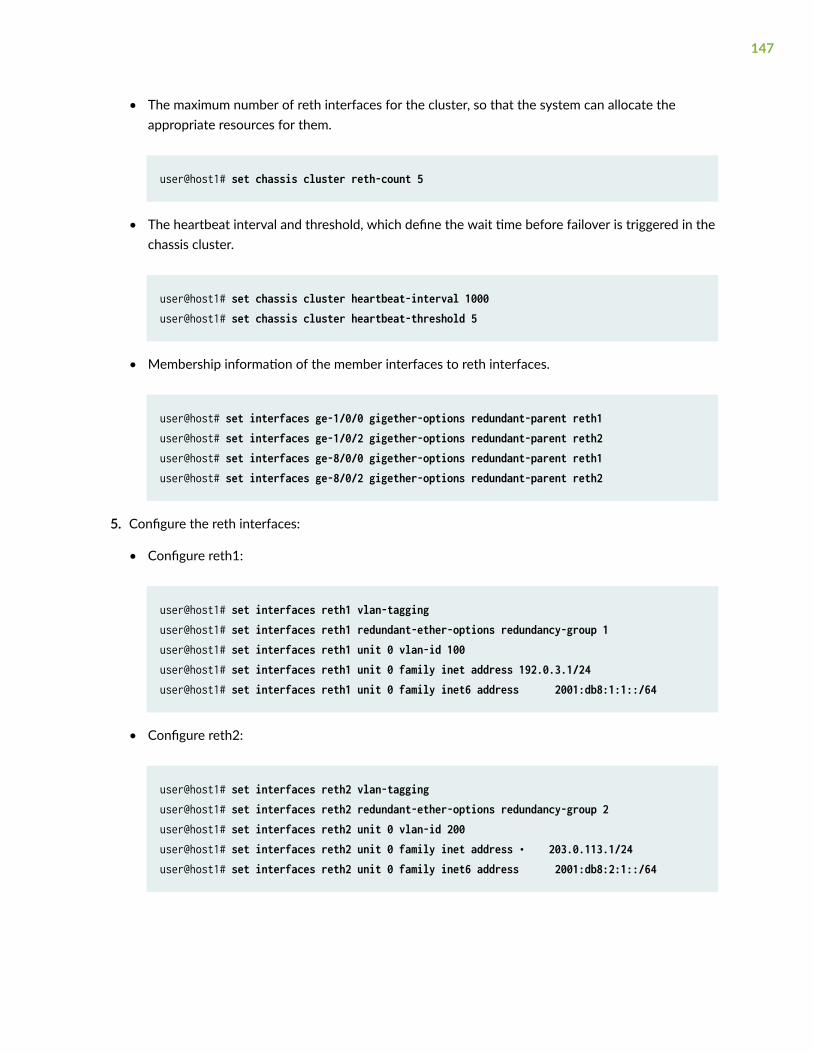
• The maximum number of reth interfaces for the cluster, so that the system can allocate theappropriate resources for them.
user@host1# set chassis cluster reth-count 5
• The heartbeat interval and threshold, which define the wait time before failover is triggered in thechassis cluster.
user@host1# set chassis cluster heartbeat-interval 1000user@host1# set chassis cluster heartbeat-threshold 5
• Membership information of the member interfaces to reth interfaces.
user@host# set interfaces ge-1/0/0 gigether-options redundant-parent reth1user@host# set interfaces ge-1/0/2 gigether-options redundant-parent reth2user@host# set interfaces ge-8/0/0 gigether-options redundant-parent reth1user@host# set interfaces ge-8/0/2 gigether-options redundant-parent reth2
5. Configure the reth interfaces:
• Configure reth1:
user@host1# set interfaces reth1 vlan-tagginguser@host1# set interfaces reth1 redundant-ether-options redundancy-group 1user@host1# set interfaces reth1 unit 0 vlan-id 100user@host1# set interfaces reth1 unit 0 family inet address 192.0.3.1/24user@host1# set interfaces reth1 unit 0 family inet6 address 2001:db8:1:1::/64
• Configure reth2:
user@host1# set interfaces reth2 vlan-tagginguser@host1# set interfaces reth2 redundant-ether-options redundancy-group 2user@host1# set interfaces reth2 unit 0 vlan-id 200user@host1# set interfaces reth2 unit 0 family inet address • 203.0.113.1/24user@host1# set interfaces reth2 unit 0 family inet6 address 2001:db8:2:1::/64
147
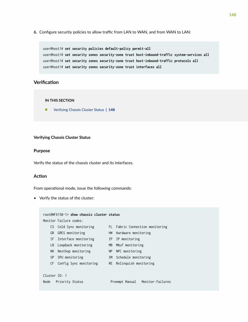
6. Configure security policies to allow traffic from LAN to WAN, and from WAN to LAN:
user@host1# set security policies default-policy permit-alluser@host1# set security zones security-zone trust host-inbound-traffic system-services alluser@host1# set security zones security-zone trust host-inbound-traffic protocols alluser@host1# set security zones security-zone trust interfaces all
Verification
IN THIS SECTION
Verifying Chassis Cluster Status | 148
Verifying Chassis Cluster Status
Purpose
Verify the status of the chassis cluster and its interfaces.
Action
From operational mode, issue the following commands:
• Verify the status of the cluster:
root@NFX150-1> show chassis cluster statusMonitor Failure codes: CS Cold Sync monitoring FL Fabric Connection monitoring GR GRES monitoring HW Hardware monitoring IF Interface monitoring IP IP monitoring LB Loopback monitoring MB Mbuf monitoring NH Nexthop monitoring NP NPC monitoring SP SPU monitoring SM Schedule monitoring CF Config Sync monitoring RE Relinquish monitoring
Cluster ID: 1Node Priority Status Preempt Manual Monitor-failures
148
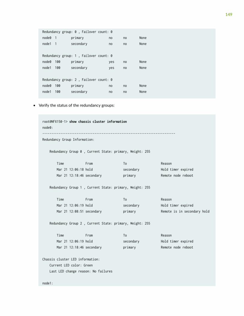
Redundancy group: 0 , Failover count: 0node0 1 primary no no Nonenode1 1 secondary no no None
Redundancy group: 1 , Failover count: 0node0 100 primary yes no Nonenode1 100 secondary yes no None
Redundancy group: 2 , Failover count: 0node0 100 primary no no Nonenode1 100 secondary no no None
• Verify the status of the redundancy groups:
root@NFX150-1> show chassis cluster informationnode0:--------------------------------------------------------------------------Redundancy Group Information:
Redundancy Group 0 , Current State: primary, Weight: 255
Time From To Reason Mar 21 12:06:18 hold secondary Hold timer expired Mar 21 12:18:46 secondary primary Remote node reboot
Redundancy Group 1 , Current State: primary, Weight: 255
Time From To Reason Mar 21 12:06:19 hold secondary Hold timer expired Mar 21 12:08:51 secondary primary Remote is in secondary hold
Redundancy Group 2 , Current State: primary, Weight: 255
Time From To Reason Mar 21 12:06:19 hold secondary Hold timer expired Mar 21 12:18:46 secondary primary Remote node reboot
Chassis cluster LED information: Current LED color: Green Last LED change reason: No failures
node1:
149
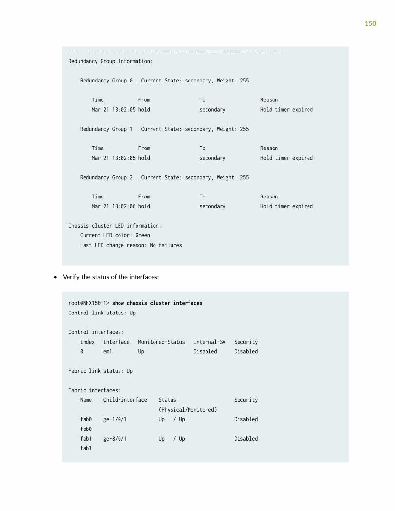
--------------------------------------------------------------------------Redundancy Group Information:
Redundancy Group 0 , Current State: secondary, Weight: 255
Time From To Reason Mar 21 13:02:05 hold secondary Hold timer expired
Redundancy Group 1 , Current State: secondary, Weight: 255
Time From To Reason Mar 21 13:02:05 hold secondary Hold timer expired
Redundancy Group 2 , Current State: secondary, Weight: 255
Time From To Reason Mar 21 13:02:06 hold secondary Hold timer expired
Chassis cluster LED information: Current LED color: Green Last LED change reason: No failures
• Verify the status of the interfaces:
root@NFX150-1> show chassis cluster interfacesControl link status: Up
Control interfaces: Index Interface Monitored-Status Internal-SA Security 0 em1 Up Disabled Disabled
Fabric link status: Up
Fabric interfaces: Name Child-interface Status Security (Physical/Monitored) fab0 ge-1/0/1 Up / Up Disabled fab0 fab1 ge-8/0/1 Up / Up Disabled fab1
150
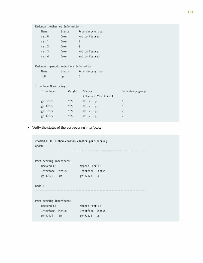
Redundant-ethernet Information: Name Status Redundancy-group reth0 Down Not configured reth1 Down 1 reth2 Down 2 reth3 Down Not configured reth4 Down Not configured
Redundant-pseudo-interface Information: Name Status Redundancy-group lo0 Up 0
Interface Monitoring: Interface Weight Status Redundancy-group (Physical/Monitored) ge-8/0/0 255 Up / Up 1 ge-1/0/0 255 Up / Up 1 ge-8/0/2 255 Up / Up 2 ge-1/0/2 255 Up / Up 2
• Verify the status of the port-peering interfaces:
root@NFX150-1> show chassis cluster port-peeringnode0:--------------------------------------------------------------------------
Port peering interfaces: Backend L3 Mapped Peer L2 Interface Status Interface Status ge-1/0/0 Up ge-0/0/0 Up
node1:--------------------------------------------------------------------------
Port peering interfaces: Backend L3 Mapped Peer L2 Interface Status Interface Status ge-8/0/0 Up ge-7/0/0 Up
151
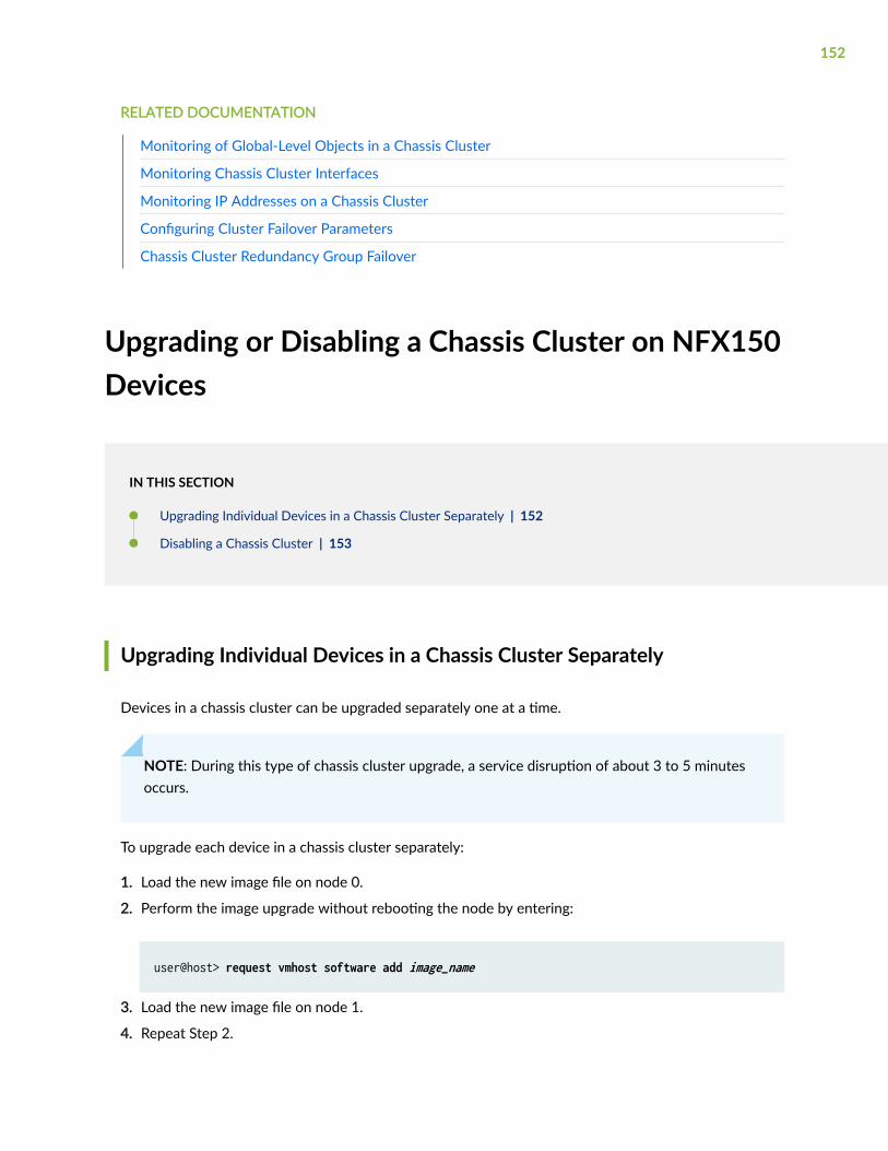
RELATED DOCUMENTATION
Monitoring of Global-Level Objects in a Chassis Cluster
Monitoring Chassis Cluster Interfaces
Monitoring IP Addresses on a Chassis Cluster
Configuring Cluster Failover Parameters
Chassis Cluster Redundancy Group Failover
Upgrading or Disabling a Chassis Cluster on NFX150Devices
IN THIS SECTION
Upgrading Individual Devices in a Chassis Cluster Separately | 152
Disabling a Chassis Cluster | 153
Upgrading Individual Devices in a Chassis Cluster Separately
Devices in a chassis cluster can be upgraded separately one at a time.
NOTE: During this type of chassis cluster upgrade, a service disruption of about 3 to 5 minutesoccurs.
To upgrade each device in a chassis cluster separately:
1. Load the new image file on node 0.
2. Perform the image upgrade without rebooting the node by entering:
user@host> request vmhost software add image_name
3. Load the new image file on node 1.
4. Repeat Step 2.
152
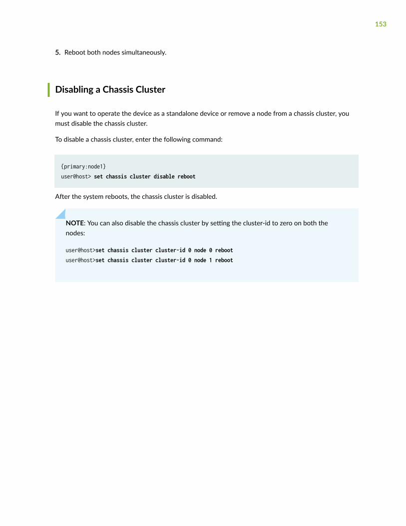
5. Reboot both nodes simultaneously.
Disabling a Chassis Cluster
If you want to operate the device as a standalone device or remove a node from a chassis cluster, youmust disable the chassis cluster.
To disable a chassis cluster, enter the following command:
{primary:node1}user@host> set chassis cluster disable reboot
After the system reboots, the chassis cluster is disabled.
NOTE: You can also disable the chassis cluster by setting the cluster-id to zero on both thenodes:
user@host>set chassis cluster cluster-id 0 node 0 rebootuser@host>set chassis cluster cluster-id 0 node 1 reboot
153
10CHAPTER
Configuring Service Chaining
Service Chaining on NFX150 Devices | 155
Example: Configuring Service Chaining Using VLANs on NFX150 NetworkServices Platform | 157
Example: Configuring Service Chaining Using SR-IOV on NFX150 NetworkServices Platform | 164
Example: Configuring Service Chaining Using a Custom Bridge | 168
Example: Configuring Service Chaining for LAN-WAN Routing | 177
Example: Configuring Cross Connect on NFX150 Devices | 183
Example: Configuring Service Chaining for LAN Routing | 193
Example: Configuring Cross-Connect Using a Custom Bridge on NFX150 Devices | 197
Service Chaining on NFX150 Devices
IN THIS SECTION
Understanding Service Chaining | 155
Configuring Service Chaining Using VLANs | 155
Configuring Service Chaining Using DHCP Services on VLANs | 156
Understanding Service Chaining
In many network environments, it is common for traffic to flow through several network services on theway to its destination. These services—firewalls, Network Address Translators (NAT), load balancers, andso on—are generally spread across multiple network elements. Each device is a separate piece ofhardware, providing a different service, and requiring separate operation and management. This methodof linking together multiple network functions could be thought of as physical service chaining.
A more efficient model for service chaining is to virtualize and consolidate network functions onto asingle device.
Virtualized service chaining is supported on NFX150 devices starting with Junos OS Release 18.1.Virtual network functions (VNFs) can be installed and linked together to provide L2, L3, and L4-L7services for traffic flowing through the device.
Configuring Service Chaining Using VLANs
NOTE: Ensure that connectivity to the host is not lost during the configuration process.
To configure service chaining:
1. Create a VLAN. Use one of the following commands:
155
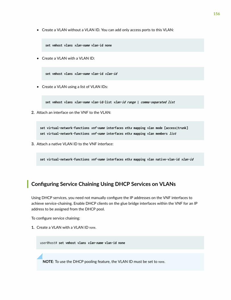
• Create a VLAN without a VLAN ID. You can add only access ports to this VLAN:
set vmhost vlans vlan-name vlan-id none
• Create a VLAN with a VLAN ID:
set vmhost vlans vlan-name vlan-id vlan-id
• Create a VLAN using a list of VLAN IDs:
set vmhost vlans vlan-name vlan-id-list vlan-id range | comma-separated list
2. Attach an interface on the VNF to the VLAN:
set virtual-network-functions vnf-name interfaces ethx mapping vlan mode [access|trunk]set virtual-network-functions vnf-name interfaces ethx mapping vlan members list
3. Attach a native VLAN ID to the VNF interface:
set virtual-network-functions vnf-name interfaces ethx mapping vlan native-vlan-id vlan-id
Configuring Service Chaining Using DHCP Services on VLANs
Using DHCP services, you need not manually configure the IP addresses on the VNF interfaces toachieve service-chaining. Enable DHCP clients on the glue bridge interfaces within the VNF for an IPaddress to be assigned from the DHCP pool.
To configure service chaining:
1. Create a VLAN with a VLAN ID none.
user@host# set vmhost vlans vlan-name vlan-id none
NOTE: To use the DHCP pooling feature, the VLAN ID must be set to none.
156
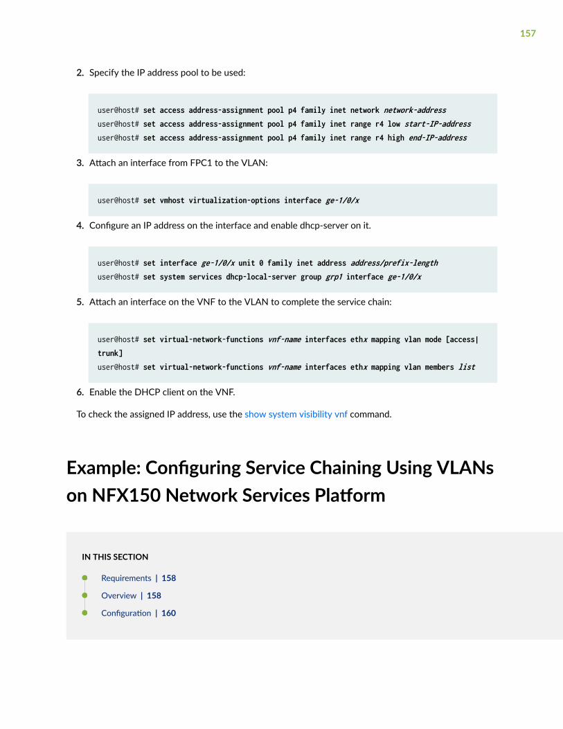
2. Specify the IP address pool to be used:
user@host# set access address-assignment pool p4 family inet network network-addressuser@host# set access address-assignment pool p4 family inet range r4 low start-IP-addressuser@host# set access address-assignment pool p4 family inet range r4 high end-IP-address
3. Attach an interface from FPC1 to the VLAN:
user@host# set vmhost virtualization-options interface ge-1/0/x
4. Configure an IP address on the interface and enable dhcp-server on it.
user@host# set interface ge-1/0/x unit 0 family inet address address/prefix-lengthuser@host# set system services dhcp-local-server group grp1 interface ge-1/0/x
5. Attach an interface on the VNF to the VLAN to complete the service chain:
user@host# set virtual-network-functions vnf-name interfaces ethx mapping vlan mode [access|trunk]user@host# set virtual-network-functions vnf-name interfaces ethx mapping vlan members list
6. Enable the DHCP client on the VNF.
To check the assigned IP address, use the show system visibility vnf command.
Example: Configuring Service Chaining Using VLANson NFX150 Network Services Platform
IN THIS SECTION
Requirements | 158
Overview | 158
Configuration | 160
157
This example shows how to configure service chaining using VLANs on the host bridge.
Requirements
This example uses the following hardware and software components:
• NFX150 running Junos OS Release 18.1R1
Before you configure service chaining, be sure you have:
• Installed and launched the relevant VNFs, assigned the corresponding interfaces, and configured theresources.
Overview
IN THIS SECTION
Topology | 159
Service chaining on a device running the disaggregated Junos OS allows multiple services, or virtualnetwork functions (VNFs), to be applied to traffic as it flows through the device. This example explainshow to configure the various layers of the device to enable traffic to enter the device, flow through twoservice VNFs, and exit the device.
158
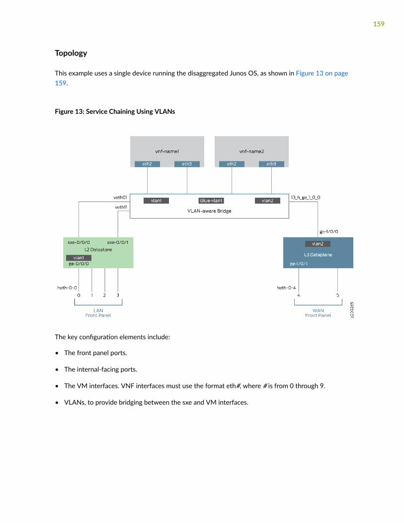
Topology
This example uses a single device running the disaggregated Junos OS, as shown in Figure 13 on page159.
Figure 13: Service Chaining Using VLANs
The key configuration elements include:
• The front panel ports.
• The internal-facing ports.
• The VM interfaces. VNF interfaces must use the format eth#, where # is from 0 through 9.
• VLANs, to provide bridging between the sxe and VM interfaces.
159
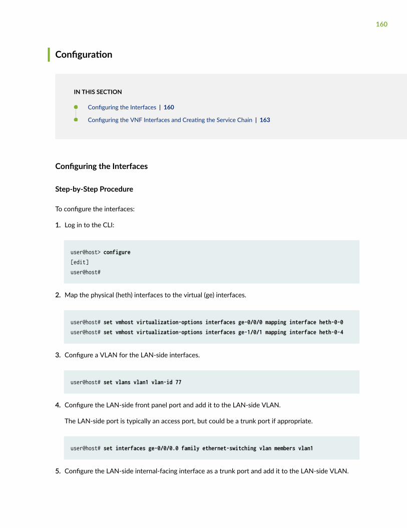
Configuration
IN THIS SECTION
Configuring the Interfaces | 160
Configuring the VNF Interfaces and Creating the Service Chain | 163
Configuring the Interfaces
Step-by-Step Procedure
To configure the interfaces:
1. Log in to the CLI:
user@host> configure[edit] user@host#
2. Map the physical (heth) interfaces to the virtual (ge) interfaces.
user@host# set vmhost virtualization-options interfaces ge-0/0/0 mapping interface heth-0-0user@host# set vmhost virtualization-options interfaces ge-1/0/1 mapping interface heth-0-4
3. Configure a VLAN for the LAN-side interfaces.
user@host# set vlans vlan1 vlan-id 77
4. Configure the LAN-side front panel port and add it to the LAN-side VLAN.
The LAN-side port is typically an access port, but could be a trunk port if appropriate.
user@host# set interfaces ge-0/0/0.0 family ethernet-switching vlan members vlan1
5. Configure the LAN-side internal-facing interface as a trunk port and add it to the LAN-side VLAN.
160
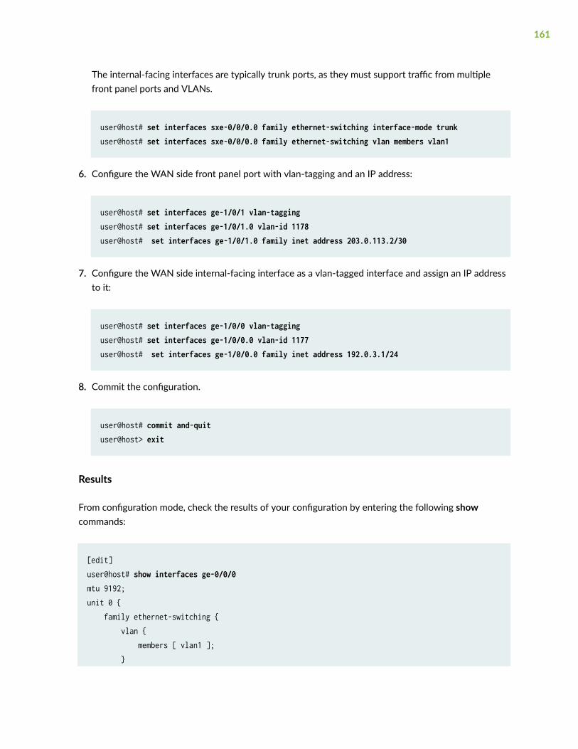
The internal-facing interfaces are typically trunk ports, as they must support traffic from multiplefront panel ports and VLANs.
user@host# set interfaces sxe-0/0/0.0 family ethernet-switching interface-mode trunkuser@host# set interfaces sxe-0/0/0.0 family ethernet-switching vlan members vlan1
6. Configure the WAN side front panel port with vlan-tagging and an IP address:
user@host# set interfaces ge-1/0/1 vlan-tagging user@host# set interfaces ge-1/0/1.0 vlan-id 1178user@host# set interfaces ge-1/0/1.0 family inet address 203.0.113.2/30
7. Configure the WAN side internal-facing interface as a vlan-tagged interface and assign an IP addressto it:
user@host# set interfaces ge-1/0/0 vlan-tagging user@host# set interfaces ge-1/0/0.0 vlan-id 1177user@host# set interfaces ge-1/0/0.0 family inet address 192.0.3.1/24
8. Commit the configuration.
user@host# commit and-quituser@host> exit
Results
From configuration mode, check the results of your configuration by entering the following showcommands:
[edit]user@host# show interfaces ge-0/0/0mtu 9192;unit 0 { family ethernet-switching { vlan { members [ vlan1 ]; }
161
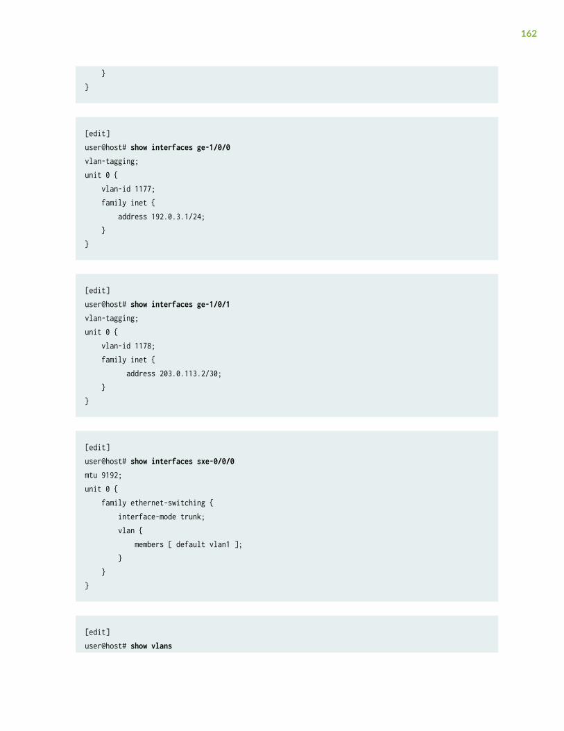
}}
[edit]user@host# show interfaces ge-1/0/0vlan-tagging;unit 0 { vlan-id 1177; family inet { address 192.0.3.1/24; }}
[edit]user@host# show interfaces ge-1/0/1vlan-tagging;unit 0 { vlan-id 1178; family inet { address 203.0.113.2/30; }}
[edit]user@host# show interfaces sxe-0/0/0mtu 9192;unit 0 { family ethernet-switching { interface-mode trunk; vlan { members [ default vlan1 ]; } }}
[edit]user@host# show vlans
162
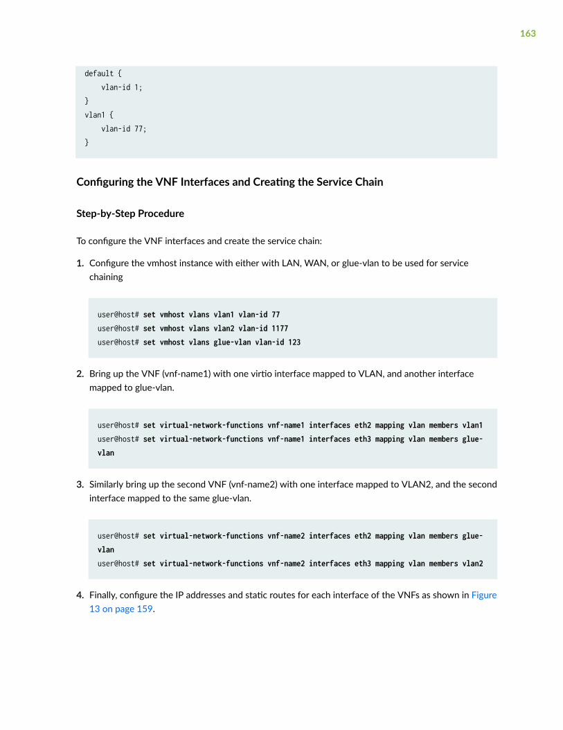
default { vlan-id 1;}vlan1 { vlan-id 77;}
Configuring the VNF Interfaces and Creating the Service Chain
Step-by-Step Procedure
To configure the VNF interfaces and create the service chain:
1. Configure the vmhost instance with either with LAN, WAN, or glue-vlan to be used for servicechaining
user@host# set vmhost vlans vlan1 vlan-id 77user@host# set vmhost vlans vlan2 vlan-id 1177user@host# set vmhost vlans glue-vlan vlan-id 123
2. Bring up the VNF (vnf-name1) with one virtio interface mapped to VLAN, and another interfacemapped to glue-vlan.
user@host# set virtual-network-functions vnf-name1 interfaces eth2 mapping vlan members vlan1user@host# set virtual-network-functions vnf-name1 interfaces eth3 mapping vlan members glue-vlan
3. Similarly bring up the second VNF (vnf-name2) with one interface mapped to VLAN2, and the secondinterface mapped to the same glue-vlan.
user@host# set virtual-network-functions vnf-name2 interfaces eth2 mapping vlan members glue-vlanuser@host# set virtual-network-functions vnf-name2 interfaces eth3 mapping vlan members vlan2
4. Finally, configure the IP addresses and static routes for each interface of the VNFs as shown in Figure13 on page 159.
163
RELATED DOCUMENTATION
Understanding Service Chaining on Disaggregated Junos OS Platforms
Disaggregated Junos OS VMs
Virtio and SR-IOV Usage
Example: Configuring Service Chaining Using SR-IOV on NFX150 Network Services Platform
IN THIS SECTION
Requirements | 164
Overview | 165
Configuration | 167
This example shows how to configure service chaining using SR-IOV on NFX150 platforms.
Requirements
This example uses the following hardware and software components:
• NFX150 running Junos OS Release 18.1R1
Before you configure service chaining, be sure you have:
• Installed and launched the relevant VNFs
164

Overview
IN THIS SECTION
Topology | 166
Service chaining on a device running the disaggregated Junos OS allows multiple services, or virtualnetwork functions (VNFs), to be applied to traffic as it flows through the device. This example explainshow to configure the various layers of the device to enable traffic to enter the device, flow through twoservice VNFs, and exit the device.
165
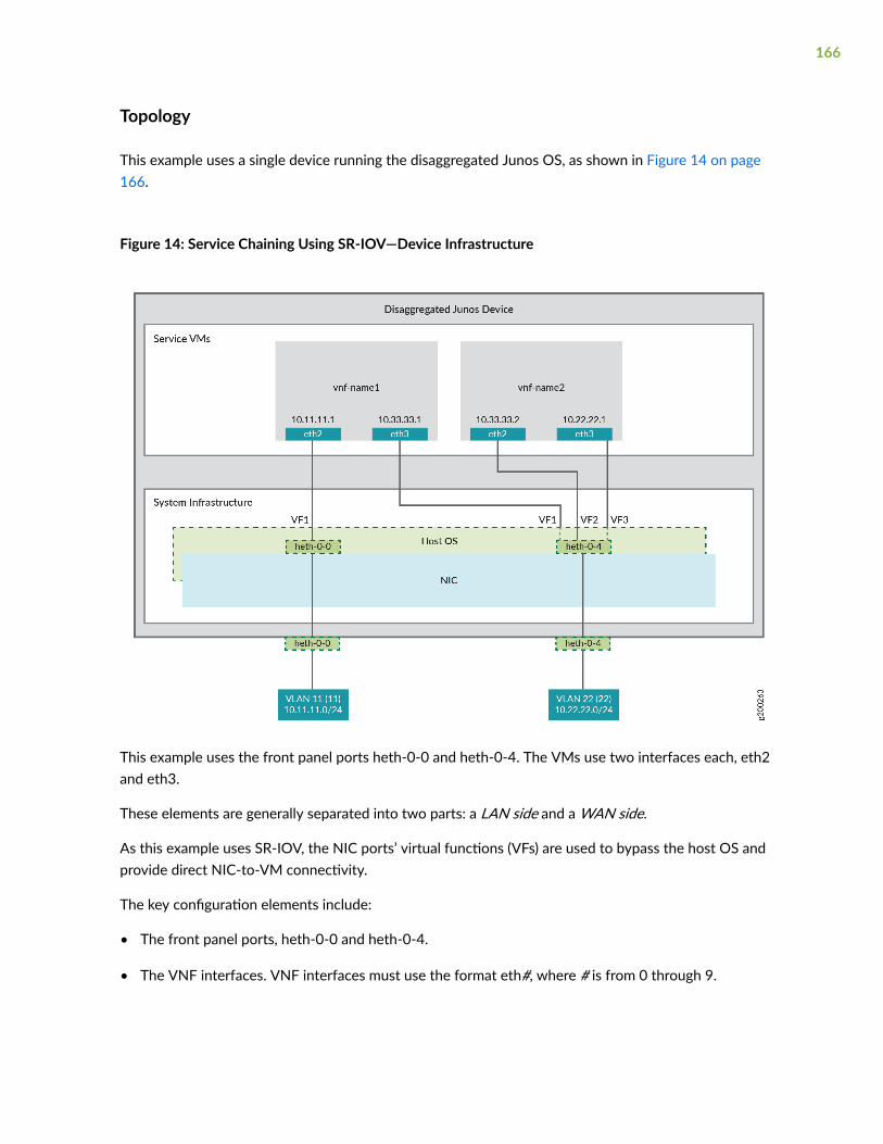
Topology
This example uses a single device running the disaggregated Junos OS, as shown in Figure 14 on page166.
Figure 14: Service Chaining Using SR-IOV—Device Infrastructure
This example uses the front panel ports heth-0-0 and heth-0-4. The VMs use two interfaces each, eth2and eth3.
These elements are generally separated into two parts: a LAN side and a WAN side.
As this example uses SR-IOV, the NIC ports’ virtual functions (VFs) are used to bypass the host OS andprovide direct NIC-to-VM connectivity.
The key configuration elements include:
• The front panel ports, heth-0-0 and heth-0-4.
• The VNF interfaces. VNF interfaces must use the format eth#, where # is from 0 through 9.
166
• The virtual function setting, to indicate SR-IOV is being used to provide direct access between thesxe and VNF interfaces.
Configuration
IN THIS SECTION
Creating the Service Chain | 167
Creating the Service Chain
Step-by-Step Procedure
To configure the VNF interfaces and create the service chain:
1. Configure vnf-name1’s LAN-side interface as a Layer 3 interface, and map it to the LAN-side NICinterface. Include the virtual function (VF) setting to specify direct NIC-to-VM connectivity. VNFmust use the interfaces from eth0 through eth9.
The heth interface is the configurable representation of the related NIC interface.
user@host> configure[edit]user@host# set virtual-network-functions vnf-name1 interfaces eth2 mapping heth-0-0 virtual-function
2. Configure the vnf-name1’s WAN-side interface from the eth3 VNF interface as shown in Figure 14on page 166.
user@host# set virtual-network-functions vnf-name1 interfaces eth3 mapping heth-0-4 virtual-function
167
3. Similarly bring up vnf-name2 with both interfaces eth2 and eth3 on heth-0-4.
user@host# set virtual-network-functions vnf-name2 interfaces eth2 mapping heth-0-4 virtual-functionuser@host# set virtual-network-functions vnf-name2 interfaces eth3 mapping heth-0-4 virtual-function
4. Finally, configure the IP addresses and static routes for each interface of the VNFs, and add routes toachieve the complete bidirectional path for the service chain.
RELATED DOCUMENTATION
Understanding Service Chaining on Disaggregated Junos OS Platforms
Disaggregated Junos OS VMs
Understanding SR-IOV Usage
Example: Configuring Service Chaining Using aCustom Bridge
IN THIS SECTION
Requirements | 169
Overview | 169
Configuration | 170
Verifying the Configuration | 173
This example shows how to configure service chaining using a custom bridge.
168

Requirements
This example uses the following hardware and software components:
• NFX150 running Junos OS Release 18.1R1
Overview
IN THIS SECTION
Topology | 170
The default system bridge is OVS. The OVS bridge is a VLAN-aware system bridge, which acts as theNFV backplane to which the VNFs and FPCs connect. However, you can choose to create a custombridge based on your requirement. This example explains how to configure service chaining using acustom bridge.
169
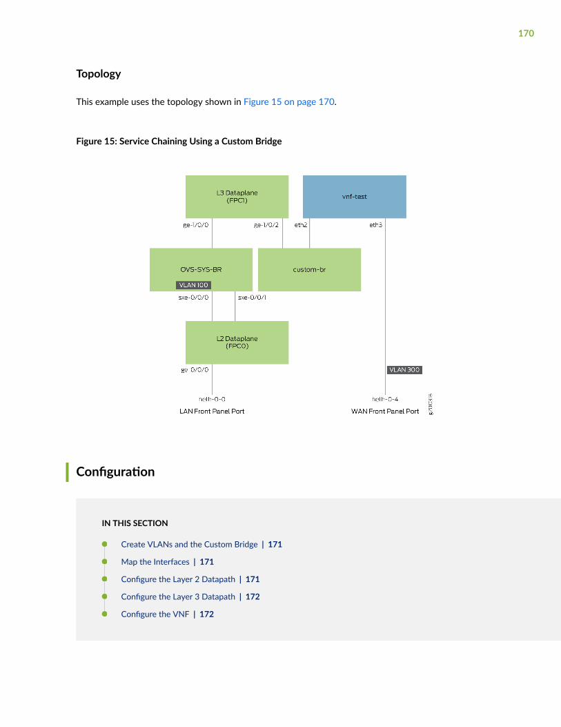
Topology
This example uses the topology shown in Figure 15 on page 170.
Figure 15: Service Chaining Using a Custom Bridge
Configuration
IN THIS SECTION
Create VLANs and the Custom Bridge | 171
Map the Interfaces | 171
Configure the Layer 2 Datapath | 171
Configure the Layer 3 Datapath | 172
Configure the VNF | 172
170
Create VLANs and the Custom Bridge
Step-by-Step Procedure
1. Configure VLANs for the LAN-side interfaces.
user@host# set vlans vlan100 vlan-id 100
2. Create a custom bridge:
user@host# set vmhost vlans custom-br vlan-id none
Map the Interfaces
Step-by-Step Procedure
1. Map the heth-0-0 physical port to the FPC0 interface.
user@host# set vmhost virtualization-options interfaces ge-0/0/0 mapping interface heth-0-0
2. Map the FPC1 interface ge-1/0/2 to the custom bridge.
user@host# set vmhost virtualization-options interfaces ge-1/0/2 mapping vlan custom-br
Configure the Layer 2 Datapath
Step-by-Step Procedure
1. Configure the LAN-side front panel ports and add them to the LAN-side VLAN.
user@host# set interfaces ge-0/0/0 unit 0 family ethernet-switching interface-mode trunkuser@host# set interfaces ge-0/0/0 unit 0 family ethernet-switching vlan members vlan100
171
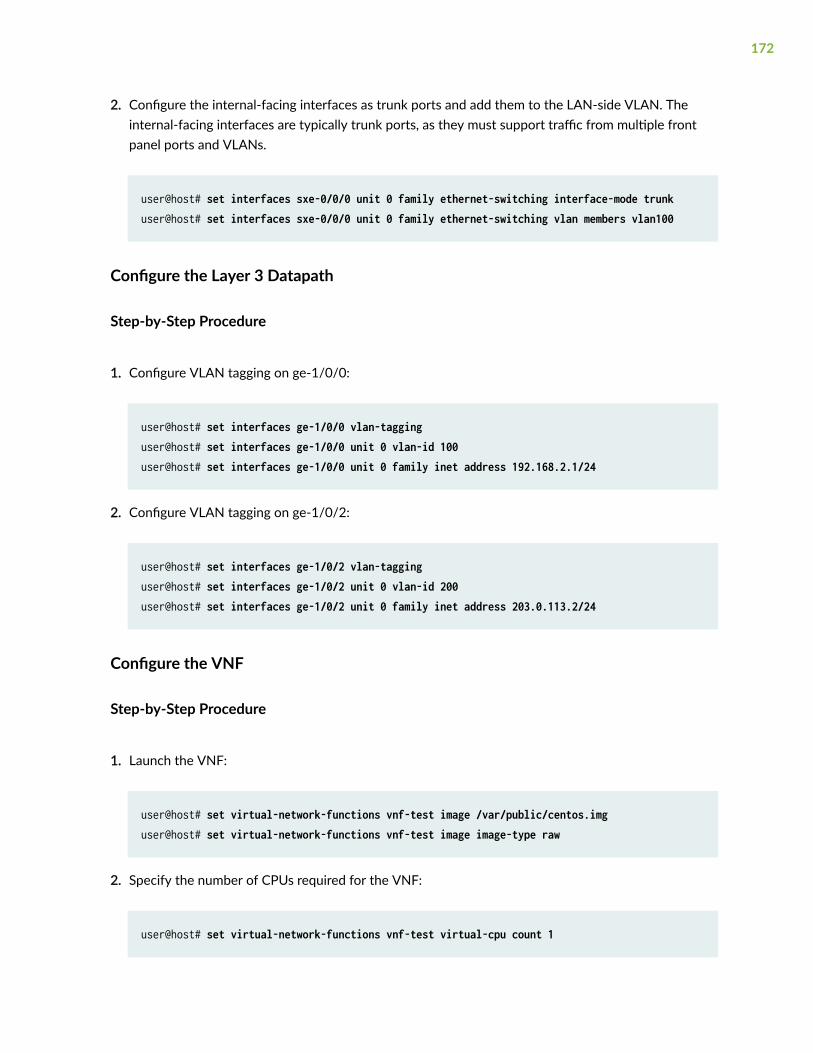
2. Configure the internal-facing interfaces as trunk ports and add them to the LAN-side VLAN. Theinternal-facing interfaces are typically trunk ports, as they must support traffic from multiple frontpanel ports and VLANs.
user@host# set interfaces sxe-0/0/0 unit 0 family ethernet-switching interface-mode trunkuser@host# set interfaces sxe-0/0/0 unit 0 family ethernet-switching vlan members vlan100
Configure the Layer 3 Datapath
Step-by-Step Procedure
1. Configure VLAN tagging on ge-1/0/0:
user@host# set interfaces ge-1/0/0 vlan-tagginguser@host# set interfaces ge-1/0/0 unit 0 vlan-id 100user@host# set interfaces ge-1/0/0 unit 0 family inet address 192.168.2.1/24
2. Configure VLAN tagging on ge-1/0/2:
user@host# set interfaces ge-1/0/2 vlan-tagginguser@host# set interfaces ge-1/0/2 unit 0 vlan-id 200user@host# set interfaces ge-1/0/2 unit 0 family inet address 203.0.113.2/24
Configure the VNF
Step-by-Step Procedure
1. Launch the VNF:
user@host# set virtual-network-functions vnf-test image /var/public/centos.imguser@host# set virtual-network-functions vnf-test image image-type raw
2. Specify the number of CPUs required for the VNF:
user@host# set virtual-network-functions vnf-test virtual-cpu count 1
172
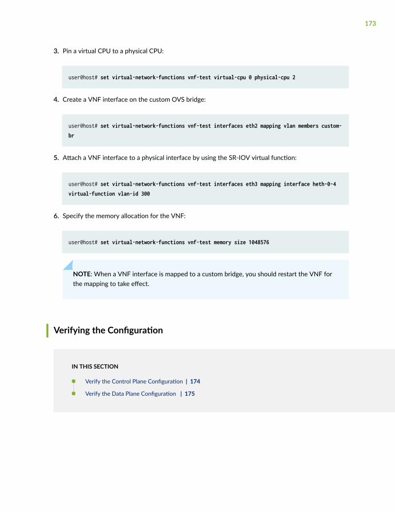
3. Pin a virtual CPU to a physical CPU:
user@host# set virtual-network-functions vnf-test virtual-cpu 0 physical-cpu 2
4. Create a VNF interface on the custom OVS bridge:
user@host# set virtual-network-functions vnf-test interfaces eth2 mapping vlan members custom-br
5. Attach a VNF interface to a physical interface by using the SR-IOV virtual function:
user@host# set virtual-network-functions vnf-test interfaces eth3 mapping interface heth-0-4 virtual-function vlan-id 300
6. Specify the memory allocation for the VNF:
user@host# set virtual-network-functions vnf-test memory size 1048576
NOTE: When a VNF interface is mapped to a custom bridge, you should restart the VNF forthe mapping to take effect.
Verifying the Configuration
IN THIS SECTION
Verify the Control Plane Configuration | 174
Verify the Data Plane Configuration | 175
173
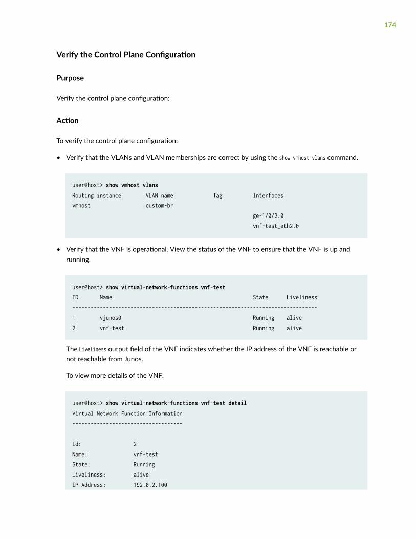
Verify the Control Plane Configuration
Purpose
Verify the control plane configuration:
Action
To verify the control plane configuration:
• Verify that the VLANs and VLAN memberships are correct by using the show vmhost vlans command.
user@host> show vmhost vlansRouting instance VLAN name Tag Interfacesvmhost custom-br ge-1/0/2.0 vnf-test_eth2.0
• Verify that the VNF is operational. View the status of the VNF to ensure that the VNF is up andrunning.
user@host> show virtual-network-functions vnf-test ID Name State Liveliness--------------------------------------------------------------------------------1 vjunos0 Running alive2 vnf-test Running alive
The Liveliness output field of the VNF indicates whether the IP address of the VNF is reachable ornot reachable from Junos.
To view more details of the VNF:
user@host> show virtual-network-functions vnf-test detailVirtual Network Function Information------------------------------------
Id: 2Name: vnf-testState: RunningLiveliness: aliveIP Address: 192.0.2.100
174
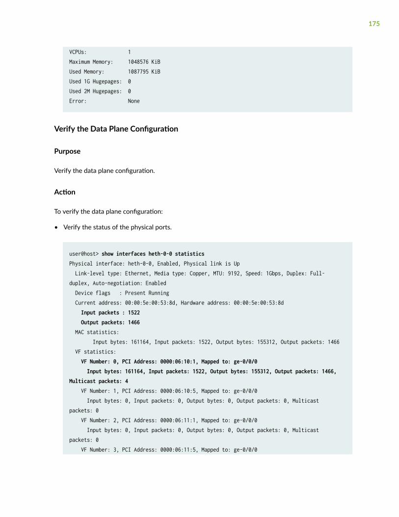
VCPUs: 1Maximum Memory: 1048576 KiBUsed Memory: 1087795 KiBUsed 1G Hugepages: 0Used 2M Hugepages: 0Error: None
Verify the Data Plane Configuration
Purpose
Verify the data plane configuration.
Action
To verify the data plane configuration:
• Verify the status of the physical ports.
user@host> show interfaces heth-0-0 statisticsPhysical interface: heth-0-0, Enabled, Physical link is Up Link-level type: Ethernet, Media type: Copper, MTU: 9192, Speed: 1Gbps, Duplex: Full-duplex, Auto-negotiation: Enabled Device flags : Present Running Current address: 00:00:5e:00:53:8d, Hardware address: 00:00:5e:00:53:8d Input packets : 1522 Output packets: 1466 MAC statistics: Input bytes: 161164, Input packets: 1522, Output bytes: 155312, Output packets: 1466 VF statistics: VF Number: 0, PCI Address: 0000:06:10:1, Mapped to: ge-0/0/0 Input bytes: 161164, Input packets: 1522, Output bytes: 155312, Output packets: 1466, Multicast packets: 4 VF Number: 1, PCI Address: 0000:06:10:5, Mapped to: ge-0/0/0 Input bytes: 0, Input packets: 0, Output bytes: 0, Output packets: 0, Multicast packets: 0 VF Number: 2, PCI Address: 0000:06:11:1, Mapped to: ge-0/0/0 Input bytes: 0, Input packets: 0, Output bytes: 0, Output packets: 0, Multicast packets: 0 VF Number: 3, PCI Address: 0000:06:11:5, Mapped to: ge-0/0/0
175
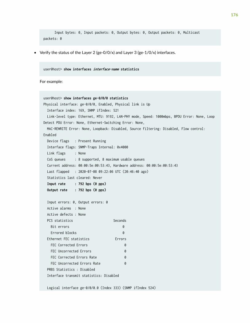
Input bytes: 0, Input packets: 0, Output bytes: 0, Output packets: 0, Multicast packets: 0
• Verify the status of the Layer 2 (ge-0/0/x) and Layer 3 (ge-1/0/x) interfaces.
user@host> show interfaces interface-name statistics
For example:
user@host> show interfaces ge-0/0/0 statisticsPhysical interface: ge-0/0/0, Enabled, Physical link is Up Interface index: 169, SNMP ifIndex: 521 Link-level type: Ethernet, MTU: 9192, LAN-PHY mode, Speed: 1000mbps, BPDU Error: None, Loop Detect PDU Error: None, Ethernet-Switching Error: None, MAC-REWRITE Error: None, Loopback: Disabled, Source filtering: Disabled, Flow control: Enabled Device flags : Present Running Interface flags: SNMP-Traps Internal: 0x4000 Link flags : None CoS queues : 8 supported, 8 maximum usable queues Current address: 00:00:5e:00:53:43, Hardware address: 00:00:5e:00:53:43 Last flapped : 2020-07-08 09:22:06 UTC (20:46:40 ago) Statistics last cleared: Never Input rate : 792 bps (0 pps) Output rate : 792 bps (0 pps)
Input errors: 0, Output errors: 0 Active alarms : None Active defects : None PCS statistics Seconds Bit errors 0 Errored blocks 0 Ethernet FEC statistics Errors FEC Corrected Errors 0 FEC Uncorrected Errors 0 FEC Corrected Errors Rate 0 FEC Uncorrected Errors Rate 0 PRBS Statistics : Disabled Interface transmit statistics: Disabled
Logical interface ge-0/0/0.0 (Index 333) (SNMP ifIndex 524)
176
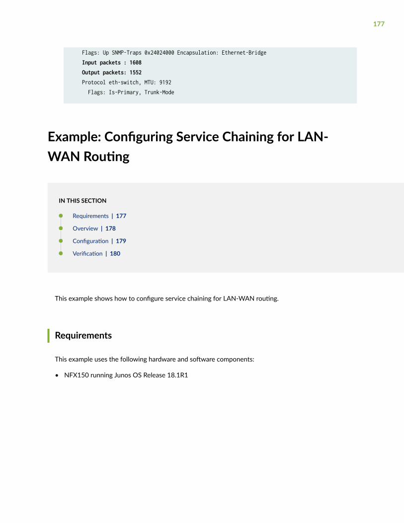
Flags: Up SNMP-Traps 0x24024000 Encapsulation: Ethernet-Bridge Input packets : 1608 Output packets: 1552 Protocol eth-switch, MTU: 9192 Flags: Is-Primary, Trunk-Mode
Example: Configuring Service Chaining for LAN-WAN Routing
IN THIS SECTION
Requirements | 177
Overview | 178
Configuration | 179
Verification | 180
This example shows how to configure service chaining for LAN-WAN routing.
Requirements
This example uses the following hardware and software components:
• NFX150 running Junos OS Release 18.1R1
177
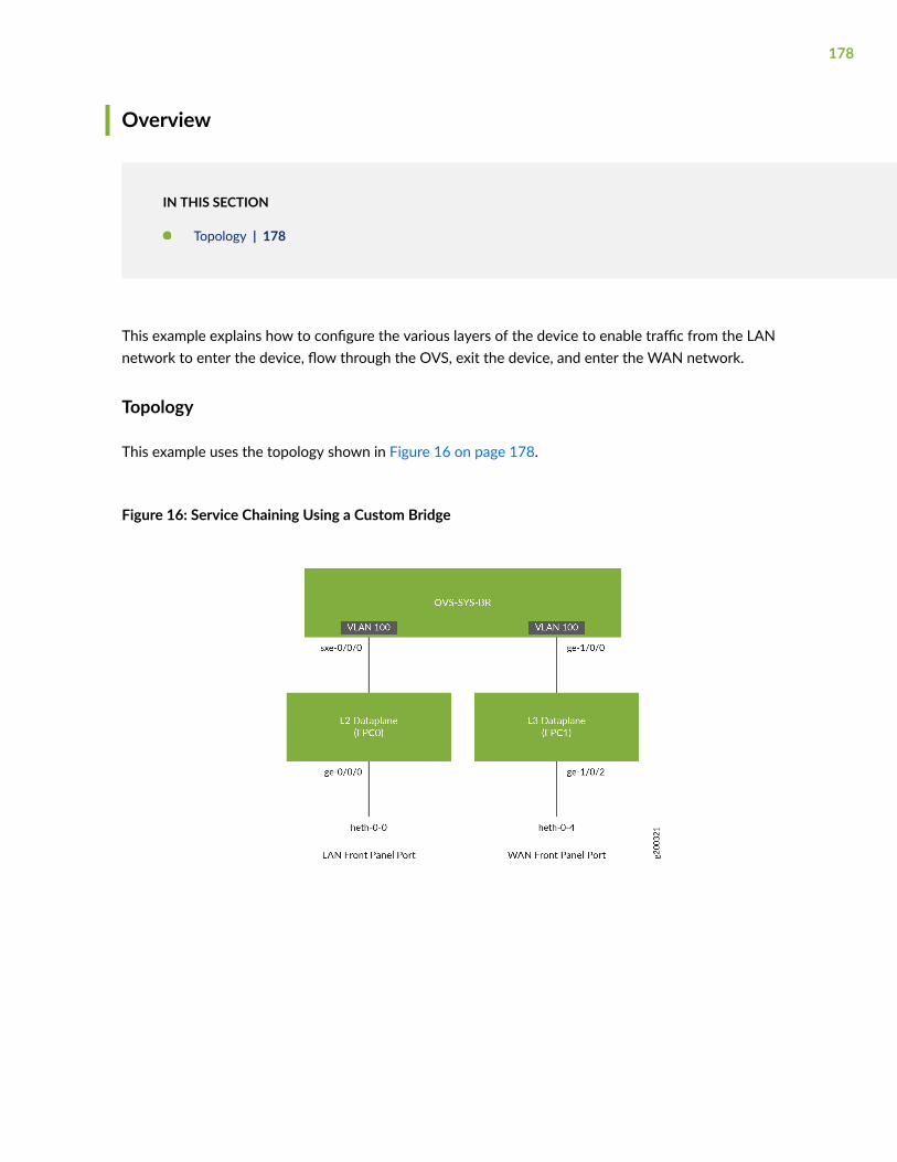
Overview
IN THIS SECTION
Topology | 178
This example explains how to configure the various layers of the device to enable traffic from the LANnetwork to enter the device, flow through the OVS, exit the device, and enter the WAN network.
Topology
This example uses the topology shown in Figure 16 on page 178.
Figure 16: Service Chaining Using a Custom Bridge
178
Configuration
IN THIS SECTION
Map the Interfaces | 179
Configure the Layer 2 Datapath | 179
Configure the Layer 3 Datapath | 180
Map the Interfaces
Step-by-Step Procedure
1. Map the heth-0-0 physical port to the FPC0 interface.
user@host# set vmhost virtualization-options interfaces ge-0/0/0 mapping interface heth-0-0
2. Map the FPC1 interface ge-1/0/2 to the physical port heth-0-4.
user@host# set vmhost virtualization-options interfaces ge-1/0/2 mapping interface heth-0-4
Configure the Layer 2 Datapath
Step-by-Step Procedure
1. Configure VLANs for the LAN-side interfaces.
user@host# set vlans vlan100 vlan-id 100
2. Configure the LAN-side front panel ports and add them to the LAN-side VLAN.
user@host# set interfaces ge-0/0/0 unit 0 family ethernet-switching interface-mode trunkuser@host# set interfaces ge-0/0/0 unit 0 family ethernet-switching vlan members vlan100
179
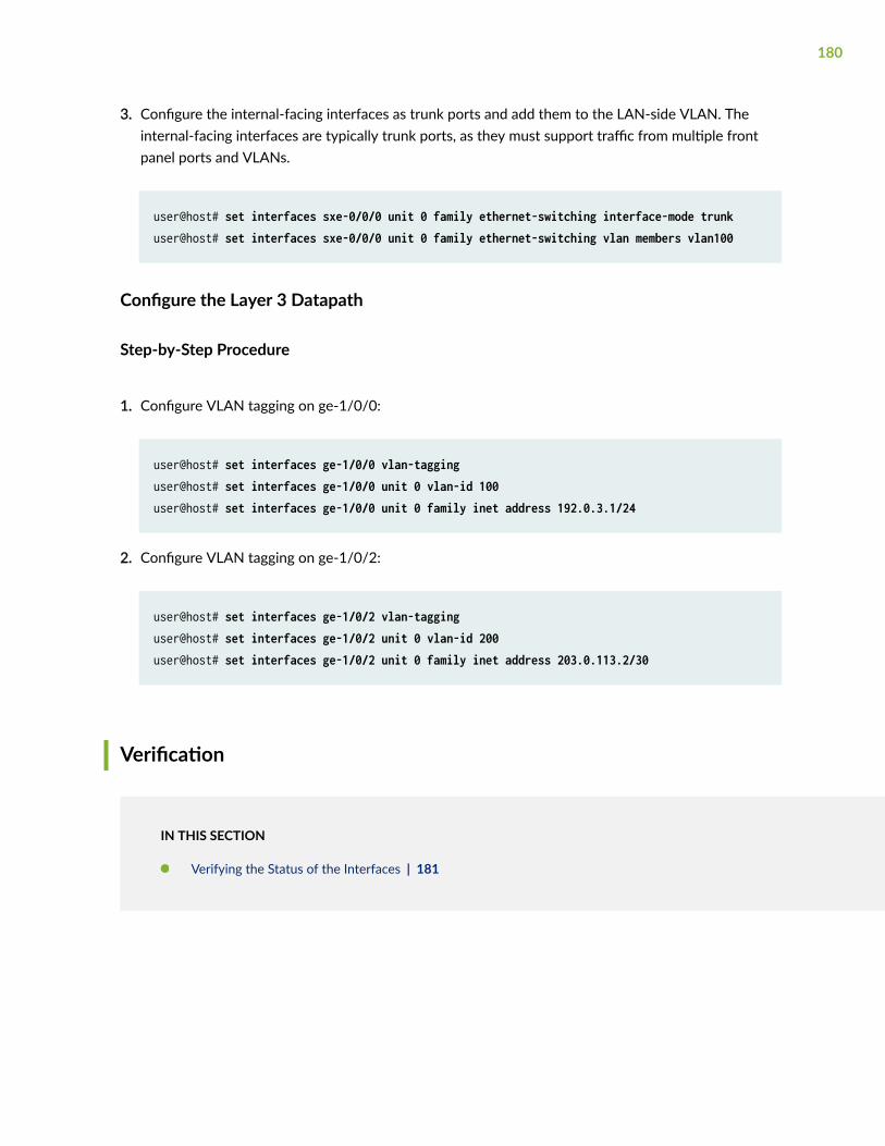
3. Configure the internal-facing interfaces as trunk ports and add them to the LAN-side VLAN. Theinternal-facing interfaces are typically trunk ports, as they must support traffic from multiple frontpanel ports and VLANs.
user@host# set interfaces sxe-0/0/0 unit 0 family ethernet-switching interface-mode trunkuser@host# set interfaces sxe-0/0/0 unit 0 family ethernet-switching vlan members vlan100
Configure the Layer 3 Datapath
Step-by-Step Procedure
1. Configure VLAN tagging on ge-1/0/0:
user@host# set interfaces ge-1/0/0 vlan-tagginguser@host# set interfaces ge-1/0/0 unit 0 vlan-id 100user@host# set interfaces ge-1/0/0 unit 0 family inet address 192.0.3.1/24
2. Configure VLAN tagging on ge-1/0/2:
user@host# set interfaces ge-1/0/2 vlan-tagginguser@host# set interfaces ge-1/0/2 unit 0 vlan-id 200user@host# set interfaces ge-1/0/2 unit 0 family inet address 203.0.113.2/30
Verification
IN THIS SECTION
Verifying the Status of the Interfaces | 181
180
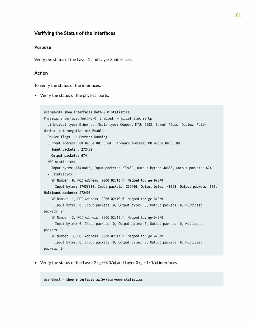
Verifying the Status of the Interfaces
Purpose
Verify the status of the Layer 2 and Layer 3 interfaces.
Action
To verify the status of the interfaces:
• Verify the status of the physical ports.
user@host> show interfaces heth-0-0 statisticsPhysical interface: heth-0-0, Enabled, Physical link is Up Link-level type: Ethernet, Media type: Copper, MTU: 9192, Speed: 1Gbps, Duplex: Full-duplex, Auto-negotiation: Enabled Device flags : Present Running Current address: 00:00:5e:00:53:8d, Hardware address: 00:00:5e:00:53:8d Input packets : 272469 Output packets: 674 MAC statistics: Input bytes: 17438016, Input packets: 272469, Output bytes: 48658, Output packets: 674 VF statistics: VF Number: 0, PCI Address: 0000:02:10:1, Mapped to: ge-0/0/0 Input bytes: 17433984, Input packets: 272406, Output bytes: 48658, Output packets: 674, Multicast packets: 272406 VF Number: 1, PCI Address: 0000:02:10:5, Mapped to: ge-0/0/0 Input bytes: 0, Input packets: 0, Output bytes: 0, Output packets: 0, Multicast packets: 0 VF Number: 2, PCI Address: 0000:02:11:1, Mapped to: ge-0/0/0 Input bytes: 0, Input packets: 0, Output bytes: 0, Output packets: 0, Multicast packets: 0 VF Number: 3, PCI Address: 0000:02:11:5, Mapped to: ge-0/0/0 Input bytes: 0, Input packets: 0, Output bytes: 0, Output packets: 0, Multicast packets: 0
• Verify the status of the Layer 2 (ge-0/0/x) and Layer 3 (ge-1/0/x) interfaces.
user@host > show interfaces interface-name statistics
181
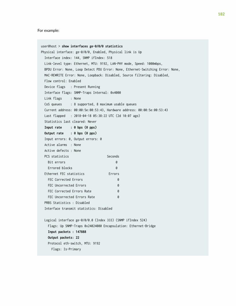
For example:
user@host > show interfaces ge-0/0/0 statisticsPhysical interface: ge-0/0/0, Enabled, Physical link is Up Interface index: 144, SNMP ifIndex: 518 Link-level type: Ethernet, MTU: 9192, LAN-PHY mode, Speed: 1000mbps, BPDU Error: None, Loop Detect PDU Error: None, Ethernet-Switching Error: None, MAC-REWRITE Error: None, Loopback: Disabled, Source filtering: Disabled, Flow control: Enabled Device flags : Present Running Interface flags: SNMP-Traps Internal: 0x4000 Link flags : None CoS queues : 8 supported, 8 maximum usable queues Current address: 00:00:5e:00:53:43, Hardware address: 00:00:5e:00:53:43 Last flapped : 2018-04-18 05:38:22 UTC (2d 10:07 ago) Statistics last cleared: Never Input rate : 0 bps (0 pps) Output rate : 0 bps (0 pps) Input errors: 0, Output errors: 0 Active alarms : None Active defects : None PCS statistics Seconds Bit errors 0 Errored blocks 0 Ethernet FEC statistics Errors FEC Corrected Errors 0 FEC Uncorrected Errors 0 FEC Corrected Errors Rate 0 FEC Uncorrected Errors Rate 0 PRBS Statistics : Disabled Interface transmit statistics: Disabled
Logical interface ge-0/0/0.0 (Index 333) (SNMP ifIndex 524) Flags: Up SNMP-Traps 0x24024000 Encapsulation: Ethernet-Bridge Input packets : 147888 Output packets: 22 Protocol eth-switch, MTU: 9192 Flags: Is-Primary
182
Example: Configuring Cross Connect on NFX150Devices
IN THIS SECTION
Requirements | 183
Overview | 183
Configuration | 185
Verifying the Configuration | 188
This example shows how to configure cross-connect on NFX150 devices.
Requirements
This example uses the following hardware and software components:
• NFX150 running Junos OS Release 18.1R1
Overview
IN THIS SECTION
Topology | 184
The Cross-connect feature enables traffic switching between any two VNF interfaces. You canbidirectionally switch either all traffic or traffic belonging to a particular VLAN between any two VNFinterfaces.
183
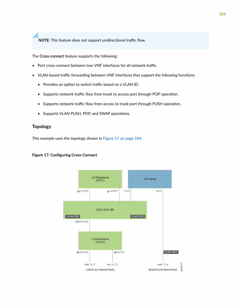
NOTE: This feature does not support unidirectional traffic flow.
The Cross-connect feature supports the following:
• Port cross-connect between two VNF interfaces for all network traffic.
• VLAN-based traffic forwarding between VNF interfaces that support the following functions:
• Provides an option to switch traffic based on a VLAN ID.
• Supports network traffic flow from trunk to access port through POP operation.
• Supports network traffic flow from access to trunk port through PUSH operation.
• Supports VLAN PUSH, POP, and SWAP operations.
Topology
This example uses the topology shown in Figure 17 on page 184.
Figure 17: Configuring Cross-Connect
184
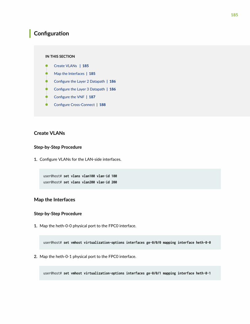
Configuration
IN THIS SECTION
Create VLANs | 185
Map the Interfaces | 185
Configure the Layer 2 Datapath | 186
Configure the Layer 3 Datapath | 186
Configure the VNF | 187
Configure Cross-Connect | 188
Create VLANs
Step-by-Step Procedure
1. Configure VLANs for the LAN-side interfaces.
user@host# set vlans vlan100 vlan-id 100user@host# set vlans vlan200 vlan-id 200
Map the Interfaces
Step-by-Step Procedure
1. Map the heth-0-0 physical port to the FPC0 interface.
user@host# set vmhost virtualization-options interfaces ge-0/0/0 mapping interface heth-0-0
2. Map the heth-0-1 physical port to the FPC0 interface.
user@host# set vmhost virtualization-options interfaces ge-0/0/1 mapping interface heth-0-1
185
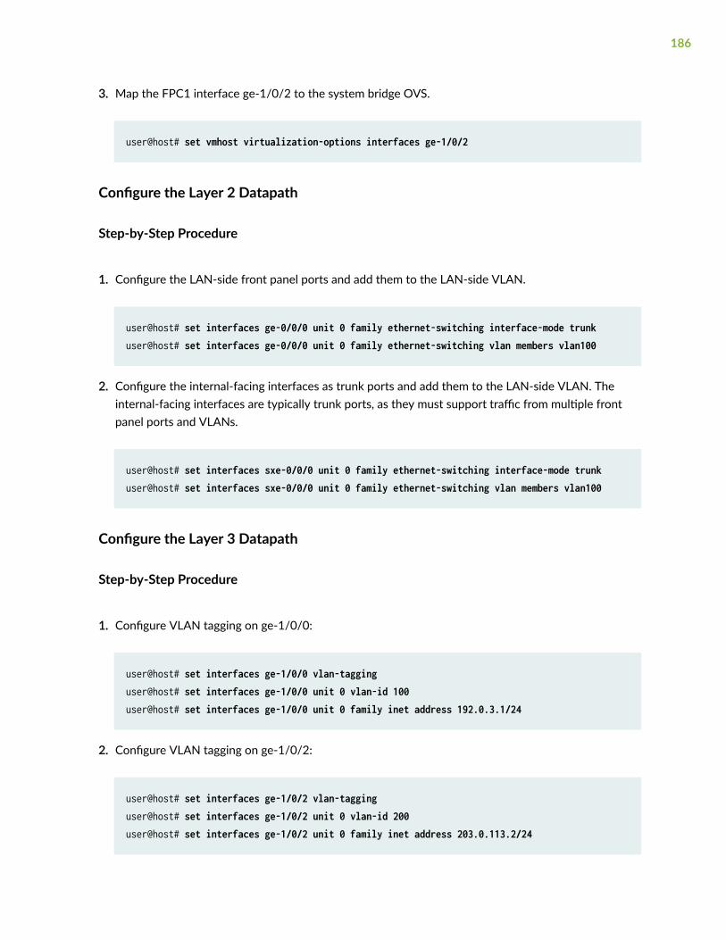
3. Map the FPC1 interface ge-1/0/2 to the system bridge OVS.
user@host# set vmhost virtualization-options interfaces ge-1/0/2
Configure the Layer 2 Datapath
Step-by-Step Procedure
1. Configure the LAN-side front panel ports and add them to the LAN-side VLAN.
user@host# set interfaces ge-0/0/0 unit 0 family ethernet-switching interface-mode trunkuser@host# set interfaces ge-0/0/0 unit 0 family ethernet-switching vlan members vlan100
2. Configure the internal-facing interfaces as trunk ports and add them to the LAN-side VLAN. Theinternal-facing interfaces are typically trunk ports, as they must support traffic from multiple frontpanel ports and VLANs.
user@host# set interfaces sxe-0/0/0 unit 0 family ethernet-switching interface-mode trunkuser@host# set interfaces sxe-0/0/0 unit 0 family ethernet-switching vlan members vlan100
Configure the Layer 3 Datapath
Step-by-Step Procedure
1. Configure VLAN tagging on ge-1/0/0:
user@host# set interfaces ge-1/0/0 vlan-tagginguser@host# set interfaces ge-1/0/0 unit 0 vlan-id 100user@host# set interfaces ge-1/0/0 unit 0 family inet address 192.0.3.1/24
2. Configure VLAN tagging on ge-1/0/2:
user@host# set interfaces ge-1/0/2 vlan-tagginguser@host# set interfaces ge-1/0/2 unit 0 vlan-id 200user@host# set interfaces ge-1/0/2 unit 0 family inet address 203.0.113.2/24
186
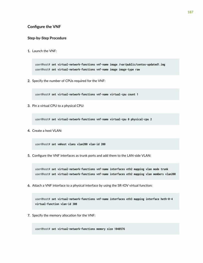
Configure the VNF
Step-by-Step Procedure
1. Launch the VNF:
user@host# set virtual-network-functions vnf-name image /var/public/centos-updated1.imguser@host# set virtual-network-functions vnf-name image image-type raw
2. Specify the number of CPUs required for the VNF:
user@host# set virtual-network-functions vnf-name virtual-cpu count 1
3. Pin a virtual CPU to a physical CPU:
user@host# set virtual-network-functions vnf-name virtual-cpu 0 physical-cpu 2
4. Create a host VLAN:
user@host# set vmhost vlans vlan200 vlan-id 200
5. Configure the VNF interfaces as trunk ports and add them to the LAN-side VLAN:
user@host# set virtual-network-functions vnf-name interfaces eth2 mapping vlan mode trunkuser@host# set virtual-network-functions vnf-name interfaces eth2 mapping vlan members vlan200
6. Attach a VNF interface to a physical interface by using the SR-IOV virtual function:
user@host# set virtual-network-functions vnf-name interfaces eth3 mapping interface heth-0-4 virtual-function vlan-id 300
7. Specify the memory allocation for the VNF:
user@host# set virtual-network-functions memory size 1048576
187
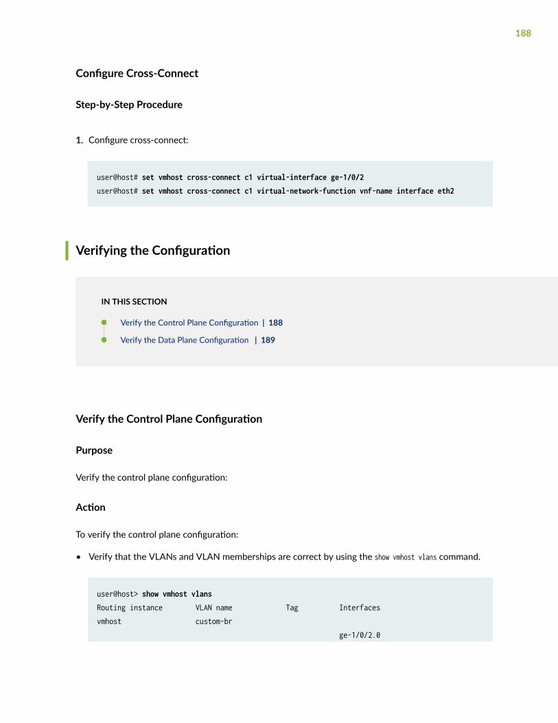
Configure Cross-Connect
Step-by-Step Procedure
1. Configure cross-connect:
user@host# set vmhost cross-connect c1 virtual-interface ge-1/0/2user@host# set vmhost cross-connect c1 virtual-network-function vnf-name interface eth2
Verifying the Configuration
IN THIS SECTION
Verify the Control Plane Configuration | 188
Verify the Data Plane Configuration | 189
Verify the Control Plane Configuration
Purpose
Verify the control plane configuration:
Action
To verify the control plane configuration:
• Verify that the VLANs and VLAN memberships are correct by using the show vmhost vlans command.
user@host> show vmhost vlansRouting instance VLAN name Tag Interfacesvmhost custom-br ge-1/0/2.0
188
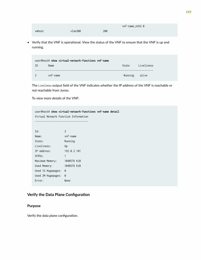
vnf-name_eth2.0vmhost vlan200 200
• Verify that the VNF is operational. View the status of the VNF to ensure that the VNF is up andrunning.
user@host# show virtual-network-functions vnf-name ID Name State Liveliness--------------------------------------------------------------------------------2 vnf-name Running alive
The Liveliness output field of the VNF indicates whether the IP address of the VNF is reachable ornot reachable from Junos.
To view more details of the VNF:
user@host# show virtual-network-functions vnf-name detailVirtual Network Function Information------------------------------------
Id: 2Name: vnf-nameState: RunningLiveliness: UpIP Address: 192.0.2.101VCPUs: 1Maximum Memory: 1048576 KiBUsed Memory: 1048576 KiBUsed 1G Hugepages: 0Used 2M Hugepages: 0Error: None
Verify the Data Plane Configuration
Purpose
Verify the data plane configuration.
189
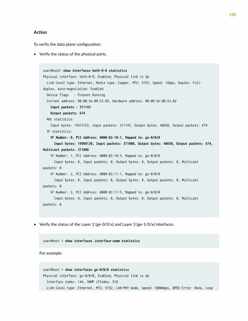
Action
To verify the data plane configuration:
• Verify the status of the physical ports.
user@host> show interfaces heth-0-0 statisticsPhysical interface: heth-0-0, Enabled, Physical link is Up Link-level type: Ethernet, Media type: Copper, MTU: 9192, Speed: 1Gbps, Duplex: Full-duplex, Auto-negotiation: Enabled Device flags : Present Running Current address: 00:00:5e:00:53:8d, Hardware address: 00:00:5e:00:53:8d Input packets : 311143 Output packets: 674 MAC statistics: Input bytes: 19913152, Input packets: 311143, Output bytes: 48658, Output packets: 674 VF statistics: VF Number: 0, PCI Address: 0000:02:10:1, Mapped to: ge-0/0/0 Input bytes: 19909120, Input packets: 311080, Output bytes: 48658, Output packets: 674, Multicast packets: 311080 VF Number: 1, PCI Address: 0000:02:10:5, Mapped to: ge-0/0/0 Input bytes: 0, Input packets: 0, Output bytes: 0, Output packets: 0, Multicast packets: 0 VF Number: 2, PCI Address: 0000:02:11:1, Mapped to: ge-0/0/0 Input bytes: 0, Input packets: 0, Output bytes: 0, Output packets: 0, Multicast packets: 0 VF Number: 3, PCI Address: 0000:02:11:5, Mapped to: ge-0/0/0 Input bytes: 0, Input packets: 0, Output bytes: 0, Output packets: 0, Multicast packets: 0
• Verify the status of the Layer 2 (ge-0/0/x) and Layer 3 (ge-1/0/x) interfaces.
user@host > show interfaces interface-name statistics
For example:
user@host > show interfaces ge-0/0/0 statisticsPhysical interface: ge-0/0/0, Enabled, Physical link is Up Interface index: 144, SNMP ifIndex: 518 Link-level type: Ethernet, MTU: 9192, LAN-PHY mode, Speed: 1000mbps, BPDU Error: None, Loop
190
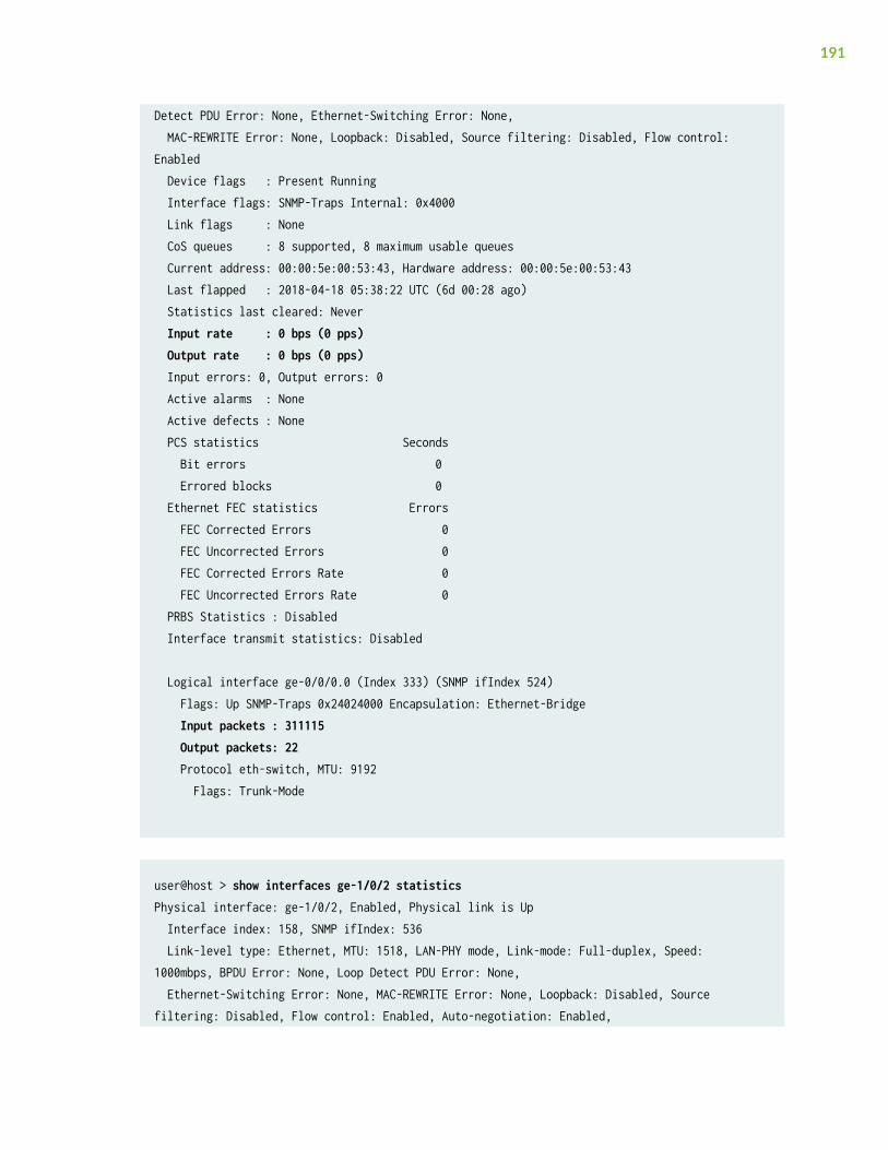
Detect PDU Error: None, Ethernet-Switching Error: None, MAC-REWRITE Error: None, Loopback: Disabled, Source filtering: Disabled, Flow control: Enabled Device flags : Present Running Interface flags: SNMP-Traps Internal: 0x4000 Link flags : None CoS queues : 8 supported, 8 maximum usable queues Current address: 00:00:5e:00:53:43, Hardware address: 00:00:5e:00:53:43 Last flapped : 2018-04-18 05:38:22 UTC (6d 00:28 ago) Statistics last cleared: Never Input rate : 0 bps (0 pps) Output rate : 0 bps (0 pps) Input errors: 0, Output errors: 0 Active alarms : None Active defects : None PCS statistics Seconds Bit errors 0 Errored blocks 0 Ethernet FEC statistics Errors FEC Corrected Errors 0 FEC Uncorrected Errors 0 FEC Corrected Errors Rate 0 FEC Uncorrected Errors Rate 0 PRBS Statistics : Disabled Interface transmit statistics: Disabled
Logical interface ge-0/0/0.0 (Index 333) (SNMP ifIndex 524) Flags: Up SNMP-Traps 0x24024000 Encapsulation: Ethernet-Bridge Input packets : 311115 Output packets: 22 Protocol eth-switch, MTU: 9192 Flags: Trunk-Mode
user@host > show interfaces ge-1/0/2 statisticsPhysical interface: ge-1/0/2, Enabled, Physical link is Up Interface index: 158, SNMP ifIndex: 536 Link-level type: Ethernet, MTU: 1518, LAN-PHY mode, Link-mode: Full-duplex, Speed: 1000mbps, BPDU Error: None, Loop Detect PDU Error: None, Ethernet-Switching Error: None, MAC-REWRITE Error: None, Loopback: Disabled, Source filtering: Disabled, Flow control: Enabled, Auto-negotiation: Enabled,
191
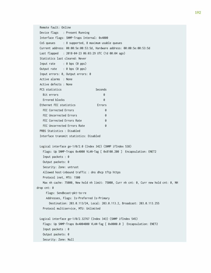
Remote fault: Online Device flags : Present Running Interface flags: SNMP-Traps Internal: 0x4000 CoS queues : 8 supported, 8 maximum usable queues Current address: 00:00:5e:00:53:5d, Hardware address: 00:00:5e:00:53:5d Last flapped : 2018-04-23 06:03:29 UTC (1d 00:04 ago) Statistics last cleared: Never Input rate : 0 bps (0 pps) Output rate : 0 bps (0 pps) Input errors: 0, Output errors: 0 Active alarms : None Active defects : None PCS statistics Seconds Bit errors 0 Errored blocks 0 Ethernet FEC statistics Errors FEC Corrected Errors 0 FEC Uncorrected Errors 0 FEC Corrected Errors Rate 0 FEC Uncorrected Errors Rate 0 PRBS Statistics : Disabled Interface transmit statistics: Disabled
Logical interface ge-1/0/2.0 (Index 342) (SNMP ifIndex 538) Flags: Up SNMP-Traps 0x4000 VLAN-Tag [ 0x8100.200 ] Encapsulation: ENET2 Input packets : 0 Output packets: 0 Security: Zone: untrust Allowed host-inbound traffic : dns dhcp tftp https Protocol inet, MTU: 1500 Max nh cache: 75000, New hold nh limit: 75000, Curr nh cnt: 0, Curr new hold cnt: 0, NH drop cnt: 0 Flags: Sendbcast-pkt-to-re Addresses, Flags: Is-Preferred Is-Primary Destination: 203.0.113/24, Local: 203.0.113.2, Broadcast: 203.0.113.255 Protocol multiservice, MTU: Unlimited
Logical interface ge-1/0/2.32767 (Index 343) (SNMP ifIndex 545) Flags: Up SNMP-Traps 0x4004000 VLAN-Tag [ 0x0000.0 ] Encapsulation: ENET2 Input packets : 0 Output packets: 0 Security: Zone: Null
192
Protocol multiservice, MTU: Unlimited Flags: None
RELATED DOCUMENTATION
Example: Configuring Cross-Connect Using a Custom Bridge on NFX150 Devices | 197
Example: Configuring Service Chaining for LANRouting
IN THIS SECTION
Requirements | 193
Overview | 194
Configuration | 195
This example shows how to configure service chaining for LAN routing.
Requirements
This example uses the following hardware and software components:
• NFX150 running Junos OS Release 18.1R1
193
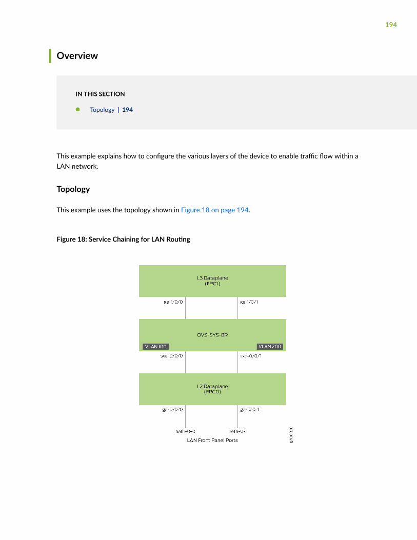
Overview
IN THIS SECTION
Topology | 194
This example explains how to configure the various layers of the device to enable traffic flow within aLAN network.
Topology
This example uses the topology shown in Figure 18 on page 194.
Figure 18: Service Chaining for LAN Routing
194
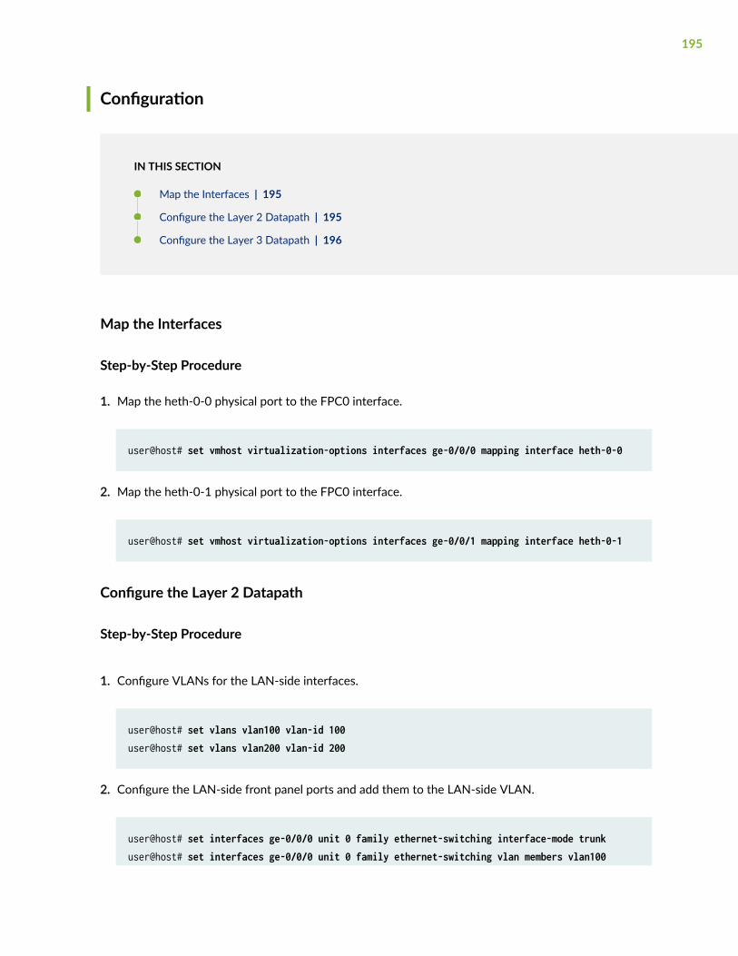
Configuration
IN THIS SECTION
Map the Interfaces | 195
Configure the Layer 2 Datapath | 195
Configure the Layer 3 Datapath | 196
Map the Interfaces
Step-by-Step Procedure
1. Map the heth-0-0 physical port to the FPC0 interface.
user@host# set vmhost virtualization-options interfaces ge-0/0/0 mapping interface heth-0-0
2. Map the heth-0-1 physical port to the FPC0 interface.
user@host# set vmhost virtualization-options interfaces ge-0/0/1 mapping interface heth-0-1
Configure the Layer 2 Datapath
Step-by-Step Procedure
1. Configure VLANs for the LAN-side interfaces.
user@host# set vlans vlan100 vlan-id 100user@host# set vlans vlan200 vlan-id 200
2. Configure the LAN-side front panel ports and add them to the LAN-side VLAN.
user@host# set interfaces ge-0/0/0 unit 0 family ethernet-switching interface-mode trunkuser@host# set interfaces ge-0/0/0 unit 0 family ethernet-switching vlan members vlan100
195
user@host# set interfaces ge-0/0/1 unit 0 family ethernet-switching interface-mode trunkuser@host# set interfaces ge-0/0/1 unit 0 family ethernet-switching vlan members vlan100
3. Configure the internal-facing interfaces as trunk ports and add them to the LAN-side VLAN. Theinternal-facing interfaces are typically trunk ports, as they must support traffic from multiple frontpanel ports and VLANs.
user@host# set interfaces sxe-0/0/0 unit 0 family ethernet-switching interface-mode trunkuser@host# set interfaces sxe-0/0/0 unit 0 family ethernet-switching vlan members vlan100user@host# set interfaces sxe-0/0/1 unit 0 family ethernet-switching interface-mode trunkuser@host# set interfaces sxe-0/0/1 unit 0 family ethernet-switching vlan members vlan200
Configure the Layer 3 Datapath
Step-by-Step Procedure
1. Map the ge-1/0/1 interface to the NFV backplane:
user@host# set vmhost virtualization-options interfaces ge-1/0/1
2. Configure VLAN tagging on ge-1/0/0:
user@host# set interfaces ge-1/0/0 vlan-tagginguser@host# set interfaces ge-1/0/0 unit 0 vlan-id 100user@host# set interfaces ge-1/0/0 unit 0 family inet address 192.0.3.1/24
3. Configure VLAN tagging on ge-1/0/1:
user@host# set interfaces ge-1/0/1 vlan-tagginguser@host# set interfaces ge-1/0/1 unit 0 vlan-id 200user@host# set interfaces ge-1/0/1 unit 0 family inet address 203.0.113.2/30
RELATED DOCUMENTATION
Example: Configuring Service Chaining for LAN-WAN Routing | 177
196
Example: Configuring Cross-Connect Using aCustom Bridge on NFX150 Devices
IN THIS SECTION
Requirements | 197
Overview | 197
Configuration | 199
Verifying the Configuration | 202
This example shows how to configure cross-connect using a custom bridge on NFX150 devices.
Requirements
This example uses the following hardware and software components:
• NFX150 running Junos OS Release 18.1R1
Overview
IN THIS SECTION
Topology | 198
The Cross-connect feature enables traffic switching between any two VNF interfaces. You canbidirectionally switch either all traffic or traffic belonging to a particular VLAN between any two VNFinterfaces.
197
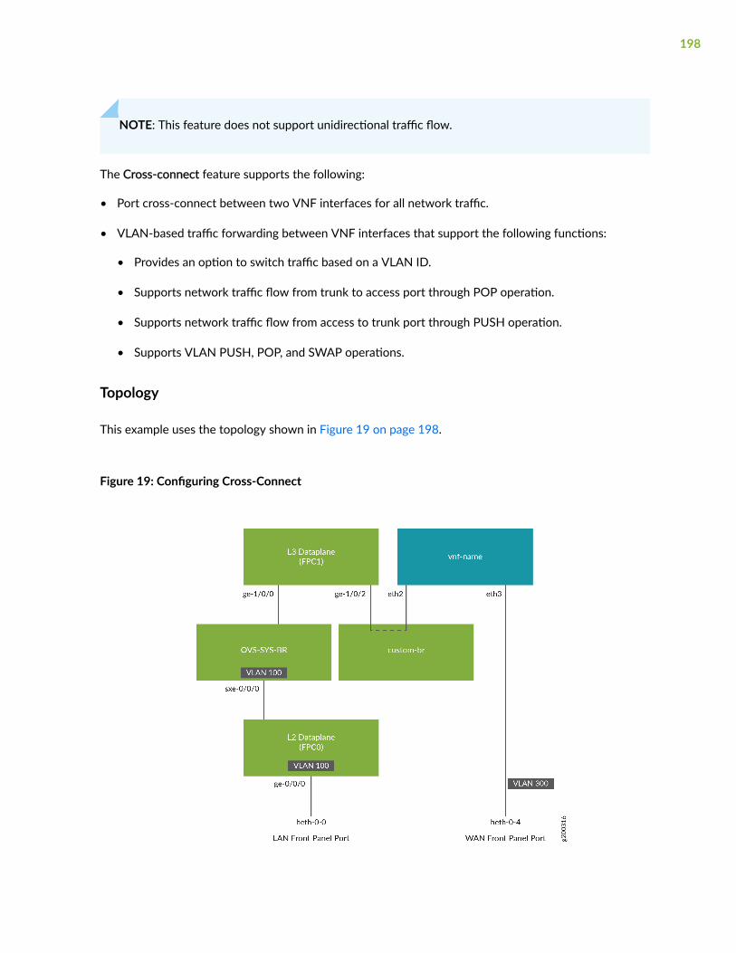
NOTE: This feature does not support unidirectional traffic flow.
The Cross-connect feature supports the following:
• Port cross-connect between two VNF interfaces for all network traffic.
• VLAN-based traffic forwarding between VNF interfaces that support the following functions:
• Provides an option to switch traffic based on a VLAN ID.
• Supports network traffic flow from trunk to access port through POP operation.
• Supports network traffic flow from access to trunk port through PUSH operation.
• Supports VLAN PUSH, POP, and SWAP operations.
Topology
This example uses the topology shown in Figure 19 on page 198.
Figure 19: Configuring Cross-Connect
198
Configuration
IN THIS SECTION
Create VLANs | 199
Map the Interfaces | 199
Configure the Layer 2 Datapath | 200
Configure the Layer 3 Datapath | 200
Configure the VNF | 201
Configure Cross-Connect | 201
Create VLANs
Step-by-Step Procedure
1. Configure VLANs for the LAN-side interfaces.
user@host# set vlans vlan100 vlan-id 100
Map the Interfaces
Step-by-Step Procedure
1. Map the heth-0-0 physical port to the FPC0 interface.
user@host# set vmhost virtualization-options interfaces ge-0/0/0 mapping interface heth-0-0
2. Create the custom bridge.
user@host# set vmhost vlans custom-br vlan-id none
199
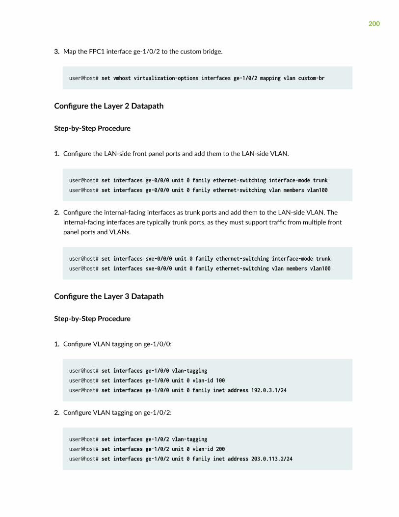
3. Map the FPC1 interface ge-1/0/2 to the custom bridge.
user@host# set vmhost virtualization-options interfaces ge-1/0/2 mapping vlan custom-br
Configure the Layer 2 Datapath
Step-by-Step Procedure
1. Configure the LAN-side front panel ports and add them to the LAN-side VLAN.
user@host# set interfaces ge-0/0/0 unit 0 family ethernet-switching interface-mode trunkuser@host# set interfaces ge-0/0/0 unit 0 family ethernet-switching vlan members vlan100
2. Configure the internal-facing interfaces as trunk ports and add them to the LAN-side VLAN. Theinternal-facing interfaces are typically trunk ports, as they must support traffic from multiple frontpanel ports and VLANs.
user@host# set interfaces sxe-0/0/0 unit 0 family ethernet-switching interface-mode trunkuser@host# set interfaces sxe-0/0/0 unit 0 family ethernet-switching vlan members vlan100
Configure the Layer 3 Datapath
Step-by-Step Procedure
1. Configure VLAN tagging on ge-1/0/0:
user@host# set interfaces ge-1/0/0 vlan-tagginguser@host# set interfaces ge-1/0/0 unit 0 vlan-id 100user@host# set interfaces ge-1/0/0 unit 0 family inet address 192.0.3.1/24
2. Configure VLAN tagging on ge-1/0/2:
user@host# set interfaces ge-1/0/2 vlan-tagginguser@host# set interfaces ge-1/0/2 unit 0 vlan-id 200user@host# set interfaces ge-1/0/2 unit 0 family inet address 203.0.113.2/24
200
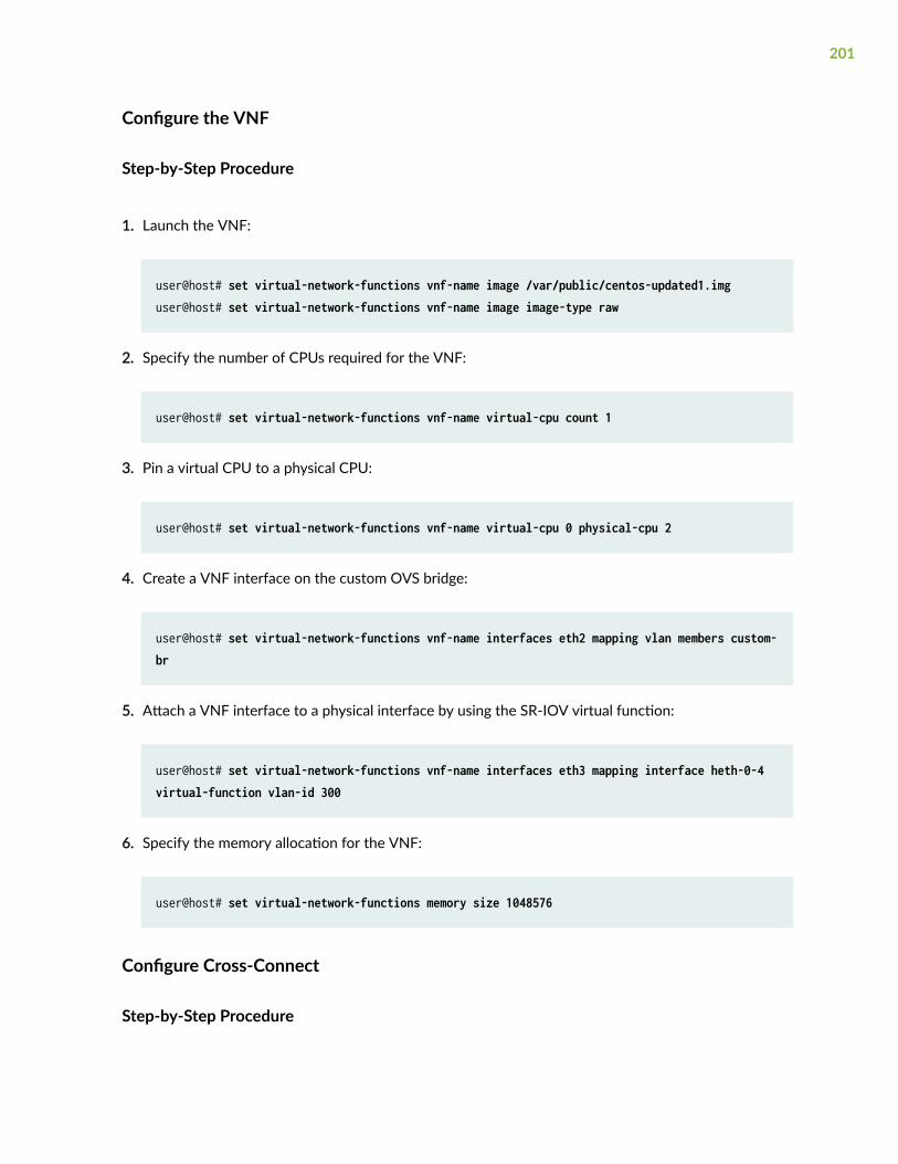
Configure the VNF
Step-by-Step Procedure
1. Launch the VNF:
user@host# set virtual-network-functions vnf-name image /var/public/centos-updated1.imguser@host# set virtual-network-functions vnf-name image image-type raw
2. Specify the number of CPUs required for the VNF:
user@host# set virtual-network-functions vnf-name virtual-cpu count 1
3. Pin a virtual CPU to a physical CPU:
user@host# set virtual-network-functions vnf-name virtual-cpu 0 physical-cpu 2
4. Create a VNF interface on the custom OVS bridge:
user@host# set virtual-network-functions vnf-name interfaces eth2 mapping vlan members custom-br
5. Attach a VNF interface to a physical interface by using the SR-IOV virtual function:
user@host# set virtual-network-functions vnf-name interfaces eth3 mapping interface heth-0-4 virtual-function vlan-id 300
6. Specify the memory allocation for the VNF:
user@host# set virtual-network-functions memory size 1048576
Configure Cross-Connect
Step-by-Step Procedure
201
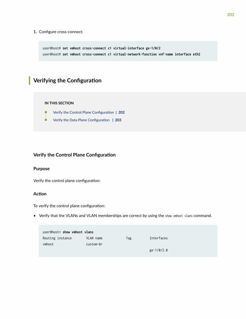
1. Configure cross-connect:
user@host# set vmhost cross-connect c1 virtual-interface ge-1/0/2user@host# set vmhost cross-connect c1 virtual-network-function vnf-name interface eth2
Verifying the Configuration
IN THIS SECTION
Verify the Control Plane Configuration | 202
Verify the Data Plane Configuration | 203
Verify the Control Plane Configuration
Purpose
Verify the control plane configuration:
Action
To verify the control plane configuration:
• Verify that the VLANs and VLAN memberships are correct by using the show vmhost vlans command.
user@host> show vmhost vlansRouting instance VLAN name Tag Interfacesvmhost custom-br ge-1/0/2.0
202
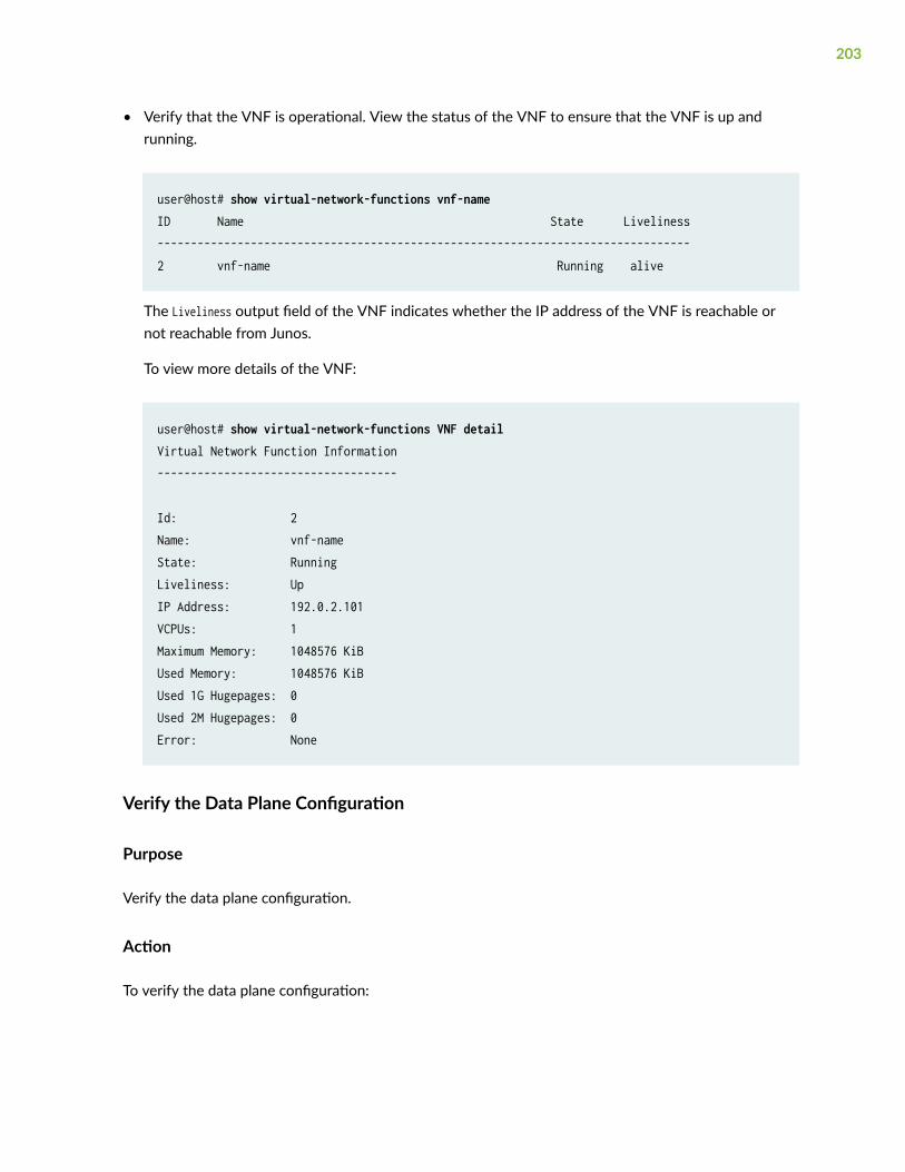
• Verify that the VNF is operational. View the status of the VNF to ensure that the VNF is up andrunning.
user@host# show virtual-network-functions vnf-name ID Name State Liveliness--------------------------------------------------------------------------------2 vnf-name Running alive
The Liveliness output field of the VNF indicates whether the IP address of the VNF is reachable ornot reachable from Junos.
To view more details of the VNF:
user@host# show virtual-network-functions VNF detailVirtual Network Function Information------------------------------------
Id: 2Name: vnf-nameState: RunningLiveliness: UpIP Address: 192.0.2.101VCPUs: 1Maximum Memory: 1048576 KiBUsed Memory: 1048576 KiBUsed 1G Hugepages: 0Used 2M Hugepages: 0Error: None
Verify the Data Plane Configuration
Purpose
Verify the data plane configuration.
Action
To verify the data plane configuration:
203
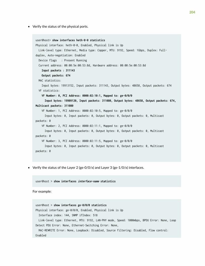
• Verify the status of the physical ports.
user@host> show interfaces heth-0-0 statisticsPhysical interface: heth-0-0, Enabled, Physical link is Up Link-level type: Ethernet, Media type: Copper, MTU: 9192, Speed: 1Gbps, Duplex: Full-duplex, Auto-negotiation: Enabled Device flags : Present Running Current address: 00:00:5e:00:53:8d, Hardware address: 00:00:5e:00:53:8d Input packets : 311143 Output packets: 674 MAC statistics: Input bytes: 19913152, Input packets: 311143, Output bytes: 48658, Output packets: 674 VF statistics: VF Number: 0, PCI Address: 0000:02:10:1, Mapped to: ge-0/0/0 Input bytes: 19909120, Input packets: 311080, Output bytes: 48658, Output packets: 674, Multicast packets: 311080 VF Number: 1, PCI Address: 0000:02:10:5, Mapped to: ge-0/0/0 Input bytes: 0, Input packets: 0, Output bytes: 0, Output packets: 0, Multicast packets: 0 VF Number: 2, PCI Address: 0000:02:11:1, Mapped to: ge-0/0/0 Input bytes: 0, Input packets: 0, Output bytes: 0, Output packets: 0, Multicast packets: 0 VF Number: 3, PCI Address: 0000:02:11:5, Mapped to: ge-0/0/0 Input bytes: 0, Input packets: 0, Output bytes: 0, Output packets: 0, Multicast packets: 0
• Verify the status of the Layer 2 (ge-0/0/x) and Layer 3 (ge-1/0/x) interfaces.
user@host > show interfaces interface-name statistics
For example:
user@host > show interfaces ge-0/0/0 statisticsPhysical interface: ge-0/0/0, Enabled, Physical link is Up Interface index: 144, SNMP ifIndex: 518 Link-level type: Ethernet, MTU: 9192, LAN-PHY mode, Speed: 1000mbps, BPDU Error: None, Loop Detect PDU Error: None, Ethernet-Switching Error: None, MAC-REWRITE Error: None, Loopback: Disabled, Source filtering: Disabled, Flow control: Enabled
204
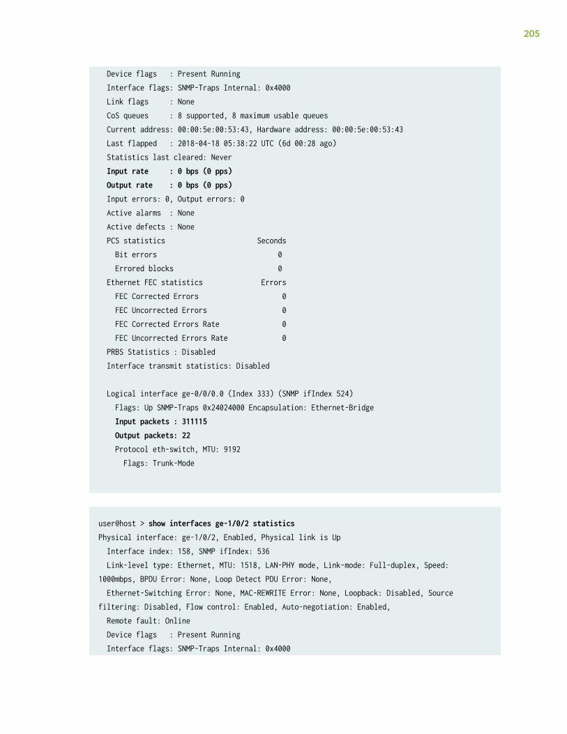
Device flags : Present Running Interface flags: SNMP-Traps Internal: 0x4000 Link flags : None CoS queues : 8 supported, 8 maximum usable queues Current address: 00:00:5e:00:53:43, Hardware address: 00:00:5e:00:53:43 Last flapped : 2018-04-18 05:38:22 UTC (6d 00:28 ago) Statistics last cleared: Never Input rate : 0 bps (0 pps) Output rate : 0 bps (0 pps) Input errors: 0, Output errors: 0 Active alarms : None Active defects : None PCS statistics Seconds Bit errors 0 Errored blocks 0 Ethernet FEC statistics Errors FEC Corrected Errors 0 FEC Uncorrected Errors 0 FEC Corrected Errors Rate 0 FEC Uncorrected Errors Rate 0 PRBS Statistics : Disabled Interface transmit statistics: Disabled
Logical interface ge-0/0/0.0 (Index 333) (SNMP ifIndex 524) Flags: Up SNMP-Traps 0x24024000 Encapsulation: Ethernet-Bridge Input packets : 311115 Output packets: 22 Protocol eth-switch, MTU: 9192 Flags: Trunk-Mode
user@host > show interfaces ge-1/0/2 statisticsPhysical interface: ge-1/0/2, Enabled, Physical link is Up Interface index: 158, SNMP ifIndex: 536 Link-level type: Ethernet, MTU: 1518, LAN-PHY mode, Link-mode: Full-duplex, Speed: 1000mbps, BPDU Error: None, Loop Detect PDU Error: None, Ethernet-Switching Error: None, MAC-REWRITE Error: None, Loopback: Disabled, Source filtering: Disabled, Flow control: Enabled, Auto-negotiation: Enabled, Remote fault: Online Device flags : Present Running Interface flags: SNMP-Traps Internal: 0x4000
205

CoS queues : 8 supported, 8 maximum usable queues Current address: 00:00:5e:00:53:5d, Hardware address: 00:00:5e:00:53:5d Last flapped : 2018-04-23 06:03:29 UTC (1d 00:04 ago) Statistics last cleared: Never Input rate : 0 bps (0 pps) Output rate : 0 bps (0 pps) Input errors: 0, Output errors: 0 Active alarms : None Active defects : None PCS statistics Seconds Bit errors 0 Errored blocks 0 Ethernet FEC statistics Errors FEC Corrected Errors 0 FEC Uncorrected Errors 0 FEC Corrected Errors Rate 0 FEC Uncorrected Errors Rate 0 PRBS Statistics : Disabled Interface transmit statistics: Disabled
Logical interface ge-1/0/2.0 (Index 342) (SNMP ifIndex 538) Flags: Up SNMP-Traps 0x4000 VLAN-Tag [ 0x8100.200 ] Encapsulation: ENET2 Input packets : 0 Output packets: 0 Security: Zone: untrust Allowed host-inbound traffic : dns dhcp tftp https Protocol inet, MTU: 1500 Max nh cache: 75000, New hold nh limit: 75000, Curr nh cnt: 0, Curr new hold cnt: 0, NH drop cnt: 0 Flags: Sendbcast-pkt-to-re Addresses, Flags: Is-Preferred Is-Primary Destination: 203.0.113/24, Local: 203.0.113.2, Broadcast: 203.0.113.255 Protocol multiservice, MTU: Unlimited
Logical interface ge-1/0/2.32767 (Index 343) (SNMP ifIndex 545) Flags: Up SNMP-Traps 0x4004000 VLAN-Tag [ 0x0000.0 ] Encapsulation: ENET2 Input packets : 0 Output packets: 0 Security: Zone: Null Protocol multiservice, MTU: Unlimited Flags: None
206

RELATED DOCUMENTATION
Example: Configuring Cross Connect on NFX150 Devices | 183
207
11CHAPTER
Monitoring and Troubleshooting
Configuring SNMP on NFX150, NFX250 NextGen, and NFX350 Devices | 209
Monitor NFX150 Device Health | 218
Recovering the Root Password for NFX150, NFX250 NextGen, and NFX350Devices | 230
Troubleshooting Interfaces on NFX Devices | 234
Configuring SNMP on NFX150, NFX250 NextGen,and NFX350 Devices
IN THIS SECTION
How to Configure SNMPv2c to Access Libvirt MIB Data | 209
How to Configure SNMPv3 to Access Libvirt MIB Data | 211
How to Query Libvirt MIB Data | 213
Supported Chassis MIBs and Traps | 215
Supported libvirt MIB Traps | 216
SNMP monitors network devices from a central location. NFX Series (NFX150, NFX250 NextGen, andNFX350) devices support querying of MIB data by using SNMPv2c and SNMPv3. Separate SNMPagents (known as the SNMP process or snmpd) reside on the vjunos0 and Host OS. The vjunos0 acts asthe proxy for the Host OS. The system and chassis related MIB data is available in vjunos0.
Starting in Junos OS Release 21.4R1, NFX Series devices support LM-SENSORS-MIB, ENTITY-SENSORS-MIB, and libvirt MIB. The LM-SENSORS-MIB and ENTITY-SENSORS-MIB data is available onvjunos0 whereas the libvirt MIB data is available on the Host OS. You can use the libvirt MIB to monitorvirtual machines. This topic discusses the SNMP implementation for the libvirt MIB.
How to Configure SNMPv2c to Access Libvirt MIB Data
SNMPv2c uses community strings, which act as passwords when determining the SNMP clients andhow clients can access the data in the SNMP agent. The community string is not pre-configured on NFXSeries devices. To access MIBs data using SNMPv2c, you must configure a community string and anSNMP proxy for the Host OS. The community string is added to the Host OS.
209
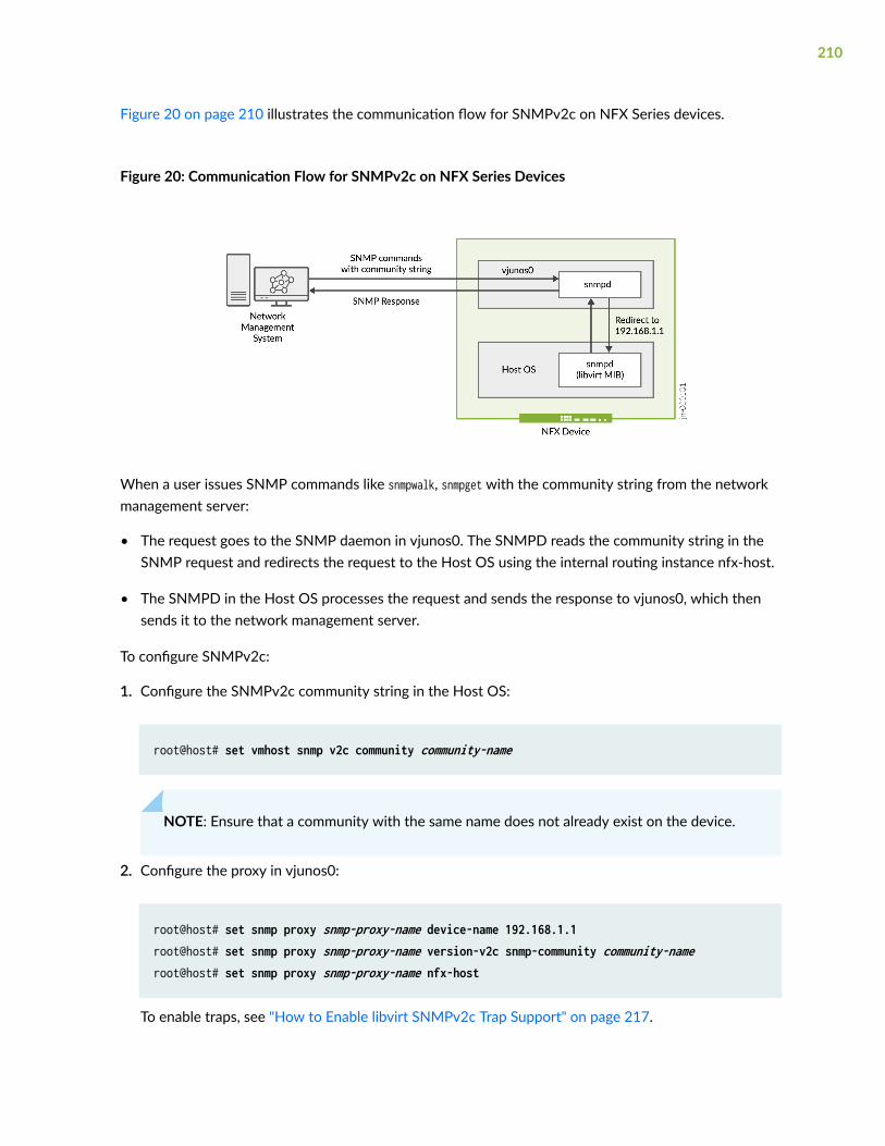
Figure 20 on page 210 illustrates the communication flow for SNMPv2c on NFX Series devices.
Figure 20: Communication Flow for SNMPv2c on NFX Series Devices
When a user issues SNMP commands like snmpwalk, snmpget with the community string from the networkmanagement server:
• The request goes to the SNMP daemon in vjunos0. The SNMPD reads the community string in theSNMP request and redirects the request to the Host OS using the internal routing instance nfx-host.
• The SNMPD in the Host OS processes the request and sends the response to vjunos0, which thensends it to the network management server.
To configure SNMPv2c:
1. Configure the SNMPv2c community string in the Host OS:
root@host# set vmhost snmp v2c community community-name
NOTE: Ensure that a community with the same name does not already exist on the device.
2. Configure the proxy in vjunos0:
root@host# set snmp proxy snmp-proxy-name device-name 192.168.1.1 root@host# set snmp proxy snmp-proxy-name version-v2c snmp-community community-nameroot@host# set snmp proxy snmp-proxy-name nfx-host
To enable traps, see "How to Enable libvirt SNMPv2c Trap Support" on page 217.
210
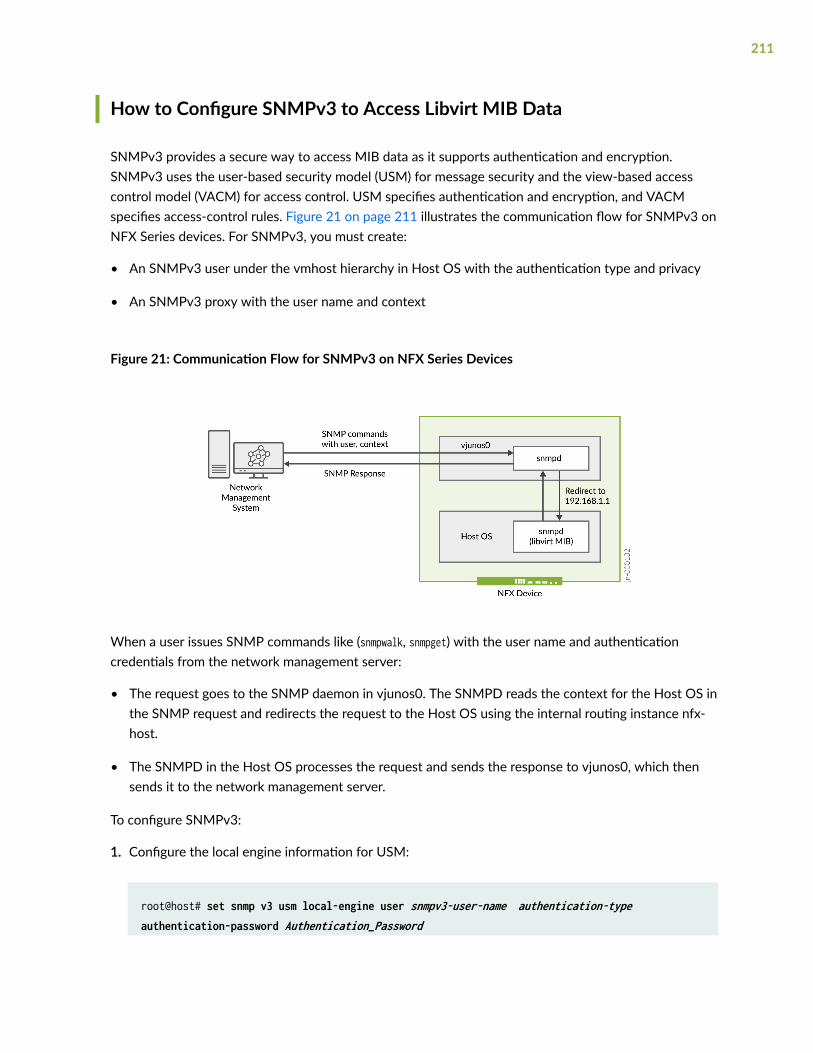
How to Configure SNMPv3 to Access Libvirt MIB Data
SNMPv3 provides a secure way to access MIB data as it supports authentication and encryption.SNMPv3 uses the user-based security model (USM) for message security and the view-based accesscontrol model (VACM) for access control. USM specifies authentication and encryption, and VACMspecifies access-control rules. Figure 21 on page 211 illustrates the communication flow for SNMPv3 onNFX Series devices. For SNMPv3, you must create:
• An SNMPv3 user under the vmhost hierarchy in Host OS with the authentication type and privacy
• An SNMPv3 proxy with the user name and context
Figure 21: Communication Flow for SNMPv3 on NFX Series Devices
When a user issues SNMP commands like (snmpwalk, snmpget) with the user name and authenticationcredentials from the network management server:
• The request goes to the SNMP daemon in vjunos0. The SNMPD reads the context for the Host OS inthe SNMP request and redirects the request to the Host OS using the internal routing instance nfx-host.
• The SNMPD in the Host OS processes the request and sends the response to vjunos0, which thensends it to the network management server.
To configure SNMPv3:
1. Configure the local engine information for USM:
root@host# set snmp v3 usm local-engine user snmpv3-user-name authentication-type authentication-password Authentication_Password
211
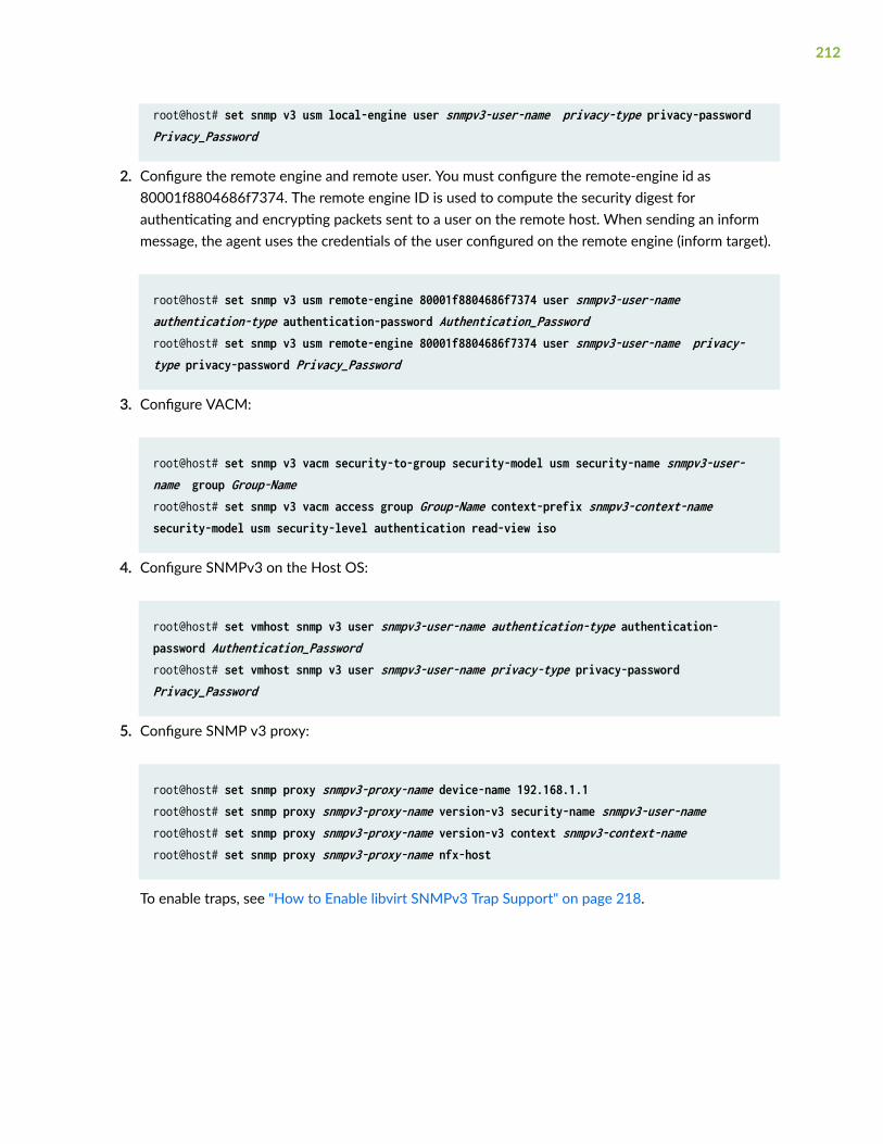
root@host# set snmp v3 usm local-engine user snmpv3-user-name privacy-type privacy-password Privacy_Password
2. Configure the remote engine and remote user. You must configure the remote-engine id as80001f8804686f7374. The remote engine ID is used to compute the security digest forauthenticating and encrypting packets sent to a user on the remote host. When sending an informmessage, the agent uses the credentials of the user configured on the remote engine (inform target).
root@host# set snmp v3 usm remote-engine 80001f8804686f7374 user snmpv3-user-name authentication-type authentication-password Authentication_Passwordroot@host# set snmp v3 usm remote-engine 80001f8804686f7374 user snmpv3-user-name privacy-type privacy-password Privacy_Password
3. Configure VACM:
root@host# set snmp v3 vacm security-to-group security-model usm security-name snmpv3-user-name group Group-Nameroot@host# set snmp v3 vacm access group Group-Name context-prefix snmpv3-context-name security-model usm security-level authentication read-view iso
4. Configure SNMPv3 on the Host OS:
root@host# set vmhost snmp v3 user snmpv3-user-name authentication-type authentication-password Authentication_Password root@host# set vmhost snmp v3 user snmpv3-user-name privacy-type privacy-password Privacy_Password
5. Configure SNMP v3 proxy:
root@host# set snmp proxy snmpv3-proxy-name device-name 192.168.1.1root@host# set snmp proxy snmpv3-proxy-name version-v3 security-name snmpv3-user-nameroot@host# set snmp proxy snmpv3-proxy-name version-v3 context snmpv3-context-nameroot@host# set snmp proxy snmpv3-proxy-name nfx-host
To enable traps, see "How to Enable libvirt SNMPv3 Trap Support" on page 218.
212
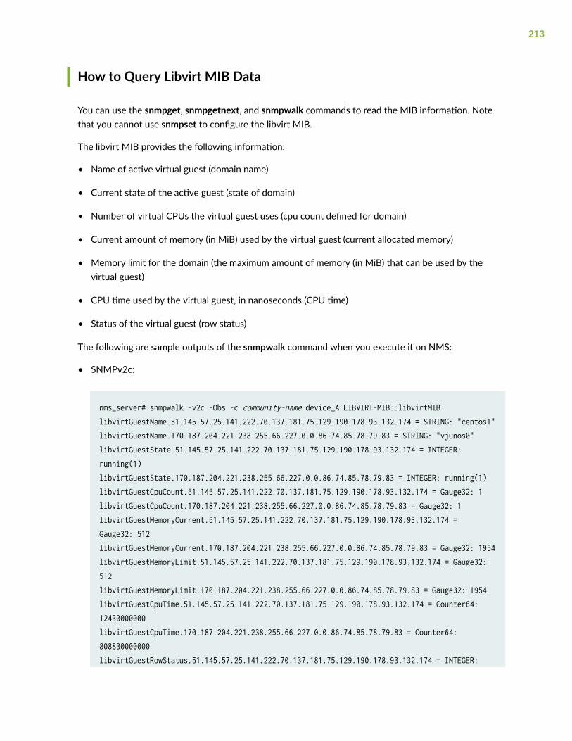
How to Query Libvirt MIB Data
You can use the snmpget, snmpgetnext, and snmpwalk commands to read the MIB information. Notethat you cannot use snmpset to configure the libvirt MIB.
The libvirt MIB provides the following information:
• Name of active virtual guest (domain name)
• Current state of the active guest (state of domain)
• Number of virtual CPUs the virtual guest uses (cpu count defined for domain)
• Current amount of memory (in MiB) used by the virtual guest (current allocated memory)
• Memory limit for the domain (the maximum amount of memory (in MiB) that can be used by thevirtual guest)
• CPU time used by the virtual guest, in nanoseconds (CPU time)
• Status of the virtual guest (row status)
The following are sample outputs of the snmpwalk command when you execute it on NMS:
• SNMPv2c:
nms_server# snmpwalk -v2c -Obs -c community-name device_A LIBVIRT-MIB::libvirtMIBlibvirtGuestName.51.145.57.25.141.222.70.137.181.75.129.190.178.93.132.174 = STRING: "centos1"libvirtGuestName.170.187.204.221.238.255.66.227.0.0.86.74.85.78.79.83 = STRING: "vjunos0"libvirtGuestState.51.145.57.25.141.222.70.137.181.75.129.190.178.93.132.174 = INTEGER: running(1)libvirtGuestState.170.187.204.221.238.255.66.227.0.0.86.74.85.78.79.83 = INTEGER: running(1)libvirtGuestCpuCount.51.145.57.25.141.222.70.137.181.75.129.190.178.93.132.174 = Gauge32: 1libvirtGuestCpuCount.170.187.204.221.238.255.66.227.0.0.86.74.85.78.79.83 = Gauge32: 1libvirtGuestMemoryCurrent.51.145.57.25.141.222.70.137.181.75.129.190.178.93.132.174 = Gauge32: 512libvirtGuestMemoryCurrent.170.187.204.221.238.255.66.227.0.0.86.74.85.78.79.83 = Gauge32: 1954libvirtGuestMemoryLimit.51.145.57.25.141.222.70.137.181.75.129.190.178.93.132.174 = Gauge32: 512libvirtGuestMemoryLimit.170.187.204.221.238.255.66.227.0.0.86.74.85.78.79.83 = Gauge32: 1954libvirtGuestCpuTime.51.145.57.25.141.222.70.137.181.75.129.190.178.93.132.174 = Counter64: 12430000000libvirtGuestCpuTime.170.187.204.221.238.255.66.227.0.0.86.74.85.78.79.83 = Counter64: 808830000000libvirtGuestRowStatus.51.145.57.25.141.222.70.137.181.75.129.190.178.93.132.174 = INTEGER:
213
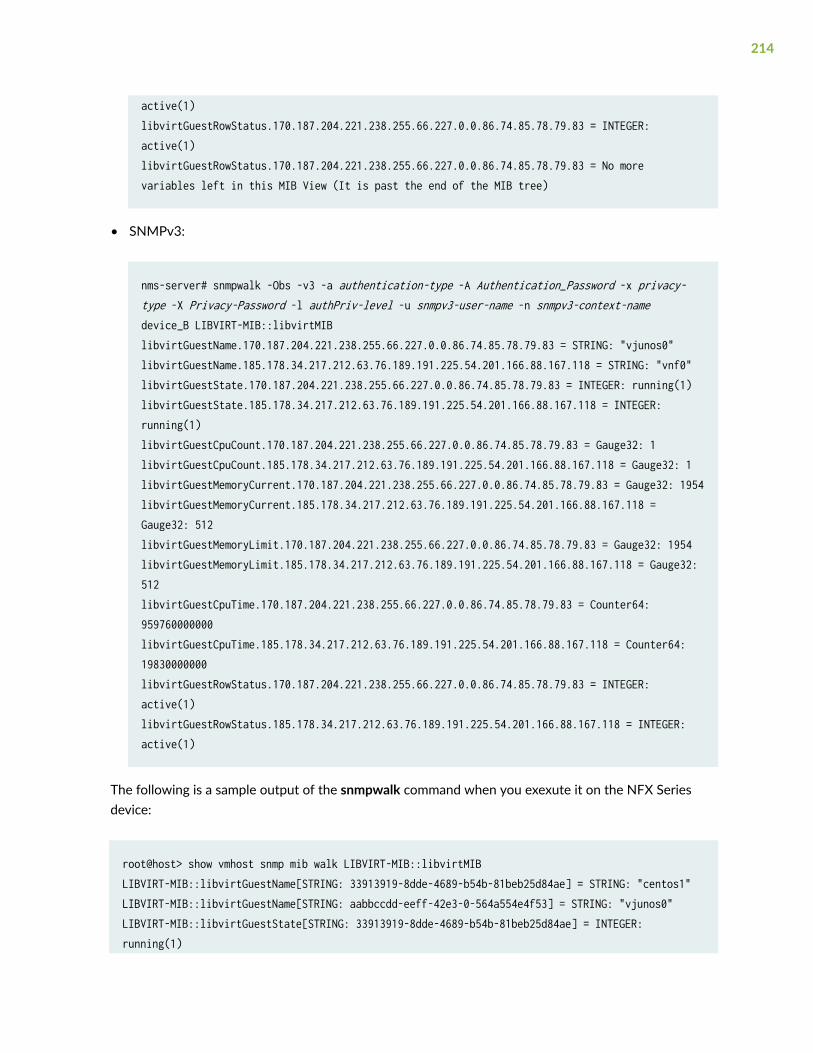
active(1)libvirtGuestRowStatus.170.187.204.221.238.255.66.227.0.0.86.74.85.78.79.83 = INTEGER: active(1)libvirtGuestRowStatus.170.187.204.221.238.255.66.227.0.0.86.74.85.78.79.83 = No more variables left in this MIB View (It is past the end of the MIB tree)
• SNMPv3:
nms-server# snmpwalk -Obs -v3 -a authentication-type -A Authentication_Password -x privacy-type -X Privacy-Password -l authPriv-level -u snmpv3-user-name -n snmpv3-context-name device_B LIBVIRT-MIB::libvirtMIBlibvirtGuestName.170.187.204.221.238.255.66.227.0.0.86.74.85.78.79.83 = STRING: "vjunos0"libvirtGuestName.185.178.34.217.212.63.76.189.191.225.54.201.166.88.167.118 = STRING: "vnf0"libvirtGuestState.170.187.204.221.238.255.66.227.0.0.86.74.85.78.79.83 = INTEGER: running(1)libvirtGuestState.185.178.34.217.212.63.76.189.191.225.54.201.166.88.167.118 = INTEGER: running(1)libvirtGuestCpuCount.170.187.204.221.238.255.66.227.0.0.86.74.85.78.79.83 = Gauge32: 1libvirtGuestCpuCount.185.178.34.217.212.63.76.189.191.225.54.201.166.88.167.118 = Gauge32: 1libvirtGuestMemoryCurrent.170.187.204.221.238.255.66.227.0.0.86.74.85.78.79.83 = Gauge32: 1954libvirtGuestMemoryCurrent.185.178.34.217.212.63.76.189.191.225.54.201.166.88.167.118 = Gauge32: 512libvirtGuestMemoryLimit.170.187.204.221.238.255.66.227.0.0.86.74.85.78.79.83 = Gauge32: 1954libvirtGuestMemoryLimit.185.178.34.217.212.63.76.189.191.225.54.201.166.88.167.118 = Gauge32: 512libvirtGuestCpuTime.170.187.204.221.238.255.66.227.0.0.86.74.85.78.79.83 = Counter64: 959760000000libvirtGuestCpuTime.185.178.34.217.212.63.76.189.191.225.54.201.166.88.167.118 = Counter64: 19830000000libvirtGuestRowStatus.170.187.204.221.238.255.66.227.0.0.86.74.85.78.79.83 = INTEGER: active(1)libvirtGuestRowStatus.185.178.34.217.212.63.76.189.191.225.54.201.166.88.167.118 = INTEGER: active(1)
The following is a sample output of the snmpwalk command when you exexute it on the NFX Seriesdevice:
root@host> show vmhost snmp mib walk LIBVIRT-MIB::libvirtMIBLIBVIRT-MIB::libvirtGuestName[STRING: 33913919-8dde-4689-b54b-81beb25d84ae] = STRING: "centos1"LIBVIRT-MIB::libvirtGuestName[STRING: aabbccdd-eeff-42e3-0-564a554e4f53] = STRING: "vjunos0"LIBVIRT-MIB::libvirtGuestState[STRING: 33913919-8dde-4689-b54b-81beb25d84ae] = INTEGER: running(1)
214
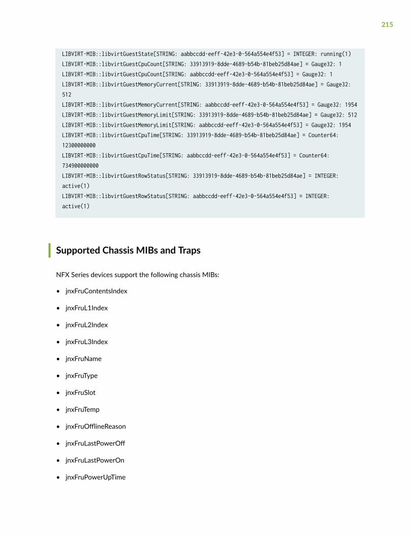
LIBVIRT-MIB::libvirtGuestState[STRING: aabbccdd-eeff-42e3-0-564a554e4f53] = INTEGER: running(1)LIBVIRT-MIB::libvirtGuestCpuCount[STRING: 33913919-8dde-4689-b54b-81beb25d84ae] = Gauge32: 1LIBVIRT-MIB::libvirtGuestCpuCount[STRING: aabbccdd-eeff-42e3-0-564a554e4f53] = Gauge32: 1LIBVIRT-MIB::libvirtGuestMemoryCurrent[STRING: 33913919-8dde-4689-b54b-81beb25d84ae] = Gauge32: 512LIBVIRT-MIB::libvirtGuestMemoryCurrent[STRING: aabbccdd-eeff-42e3-0-564a554e4f53] = Gauge32: 1954LIBVIRT-MIB::libvirtGuestMemoryLimit[STRING: 33913919-8dde-4689-b54b-81beb25d84ae] = Gauge32: 512LIBVIRT-MIB::libvirtGuestMemoryLimit[STRING: aabbccdd-eeff-42e3-0-564a554e4f53] = Gauge32: 1954LIBVIRT-MIB::libvirtGuestCpuTime[STRING: 33913919-8dde-4689-b54b-81beb25d84ae] = Counter64: 12300000000LIBVIRT-MIB::libvirtGuestCpuTime[STRING: aabbccdd-eeff-42e3-0-564a554e4f53] = Counter64: 734900000000LIBVIRT-MIB::libvirtGuestRowStatus[STRING: 33913919-8dde-4689-b54b-81beb25d84ae] = INTEGER: active(1)LIBVIRT-MIB::libvirtGuestRowStatus[STRING: aabbccdd-eeff-42e3-0-564a554e4f53] = INTEGER: active(1)
Supported Chassis MIBs and Traps
NFX Series devices support the following chassis MIBs:
• jnxFruContentsIndex
• jnxFruL1Index
• jnxFruL2Index
• jnxFruL3Index
• jnxFruName
• jnxFruType
• jnxFruSlot
• jnxFruTemp
• jnxFruOfflineReason
• jnxFruLastPowerOff
• jnxFruLastPowerOn
• jnxFruPowerUpTime
215
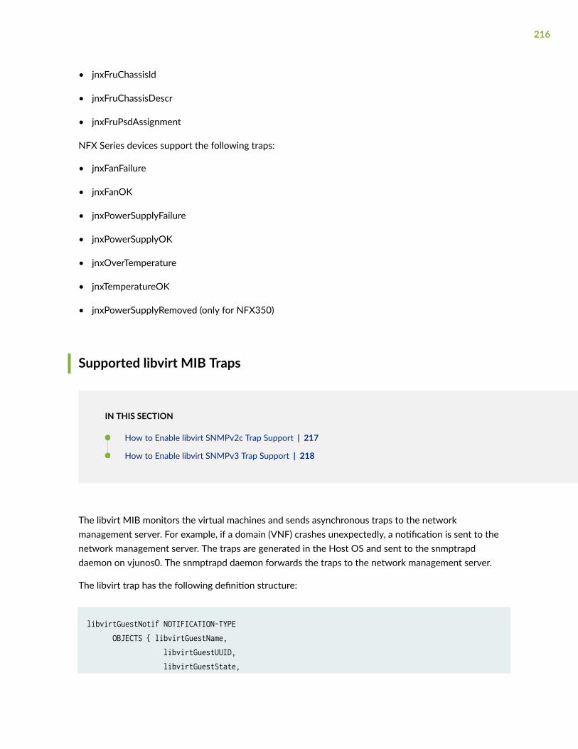
• jnxFruChassisId
• jnxFruChassisDescr
• jnxFruPsdAssignment
NFX Series devices support the following traps:
• jnxFanFailure
• jnxFanOK
• jnxPowerSupplyFailure
• jnxPowerSupplyOK
• jnxOverTemperature
• jnxTemperatureOK
• jnxPowerSupplyRemoved (only for NFX350)
Supported libvirt MIB Traps
IN THIS SECTION
How to Enable libvirt SNMPv2c Trap Support | 217
How to Enable libvirt SNMPv3 Trap Support | 218
The libvirt MIB monitors the virtual machines and sends asynchronous traps to the networkmanagement server. For example, if a domain (VNF) crashes unexpectedly, a notification is sent to thenetwork management server. The traps are generated in the Host OS and sent to the snmptrapddaemon on vjunos0. The snmptrapd daemon forwards the traps to the network management server.
The libvirt trap has the following definition structure:
libvirtGuestNotif NOTIFICATION-TYPE OBJECTS { libvirtGuestName, libvirtGuestUUID, libvirtGuestState,
216
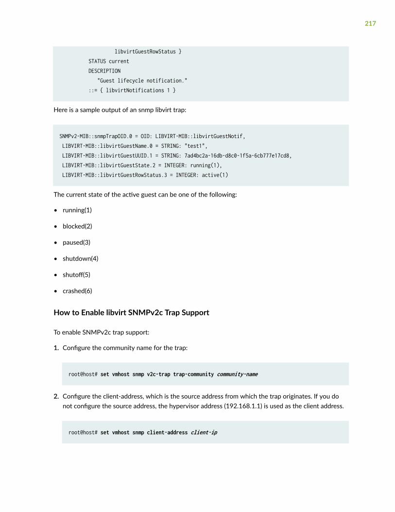
libvirtGuestRowStatus } STATUS current DESCRIPTION "Guest lifecycle notification." ::= { libvirtNotifications 1 }
Here is a sample output of an snmp libvirt trap:
SNMPv2-MIB::snmpTrapOID.0 = OID: LIBVIRT-MIB::libvirtGuestNotif, LIBVIRT-MIB::libvirtGuestName.0 = STRING: "test1", LIBVIRT-MIB::libvirtGuestUUID.1 = STRING: 7ad4bc2a-16db-d8c0-1f5a-6cb777e17cd8, LIBVIRT-MIB::libvirtGuestState.2 = INTEGER: running(1), LIBVIRT-MIB::libvirtGuestRowStatus.3 = INTEGER: active(1)
The current state of the active guest can be one of the following:
• running(1)
• blocked(2)
• paused(3)
• shutdown(4)
• shutoff(5)
• crashed(6)
How to Enable libvirt SNMPv2c Trap Support
To enable SNMPv2c trap support:
1. Configure the community name for the trap:
root@host# set vmhost snmp v2c-trap trap-community community-name
2. Configure the client-address, which is the source address from which the trap originates. If you donot configure the source address, the hypervisor address (192.168.1.1) is used as the client address.
root@host# set vmhost snmp client-address client-ip
217
3. Configure port-forwarding. You can configure multiple IP adresses.
root@host# set forwarding-options helpers port 162 server IP-address-of-trap-target
How to Enable libvirt SNMPv3 Trap Support
To enable SNMPv3 trap support:
1. Configure the user name for the trap:
root@host# set vmhost snmp v3-trap trap-user user-name
2. Configure the client-address, which is the source address from which the trap originates. If you donot configure the source address, the hypervisor address (192.168.1.1) is used as the client address.
root@host# set vmhost snmp client-address client-ip
3. Configure the AES and SHA passwords for the user:
root@host# set vmhost snmp v3 user user-name authentication-sha authentication-password passwordroot@host# set vmhost snmp v3 user user-name privacy-aes128 privacy-password password
4. Configure port-forwarding for libVirtMIB trap support. You can configure multiple IP adresses.
root@host# set forwarding-options helpers port 162 server IP-address-of-trap-target
Monitor NFX150 Device Health
IN THIS SECTION
Sample Output—show system visibility host | 220
218
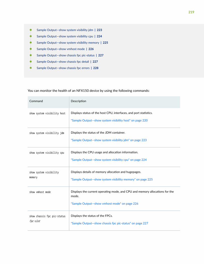
Sample Output—show system visibility jdm | 223
Sample Output—show system visibility cpu | 224
Sample Output—show system visibility memory | 225
Sample Output—show vmhost mode | 226
Sample Output—show chassis fpc pic-status | 227
Sample Output—show chassis fpc detail | 227
Sample Output—show chassis fpc errors | 228
You can monitor the health of an NFX150 device by using the following commands:
Command Description
show system visibility host Displays status of the host CPU, interfaces, and port statistics.
"Sample Output—show system visibility host" on page 220
show system visibility jdm Displays the status of the JDM container.
"Sample Output—show system visibility jdm" on page 223
show system visibility cpu Displays the CPU usage and allocation information.
"Sample Output—show system visibility cpu" on page 224
show system visibilitymemory
Displays details of memory allocation and hugepages.
"Sample Output—show system visibility memory" on page 225
show vmhost mode Displays the current operating mode, and CPU and memory allocations for themode.
"Sample Output—show vmhost mode" on page 226
show chassis fpc pic-statusfpc-slot
Displays the status of the FPCs.
"Sample Output—show chassis fpc pic-status" on page 227
219
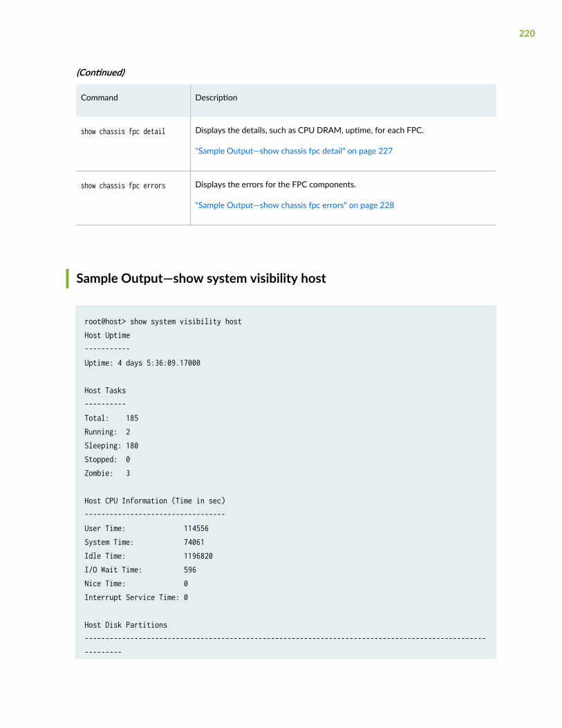
(Continued)
Command Description
show chassis fpc detail Displays the details, such as CPU DRAM, uptime, for each FPC.
"Sample Output—show chassis fpc detail" on page 227
show chassis fpc errors Displays the errors for the FPC components.
"Sample Output—show chassis fpc errors" on page 228
Sample Output—show system visibility host
root@host> show system visibility hostHost Uptime-----------Uptime: 4 days 5:36:09.17000
Host Tasks----------Total: 185Running: 2Sleeping: 180Stopped: 0Zombie: 3
Host CPU Information (Time in sec)----------------------------------User Time: 114556System Time: 74061Idle Time: 1196820I/O Wait Time: 596Nice Time: 0Interrupt Service Time: 0
Host Disk Partitions----------------------------------------------------------------------------------------------------------
220
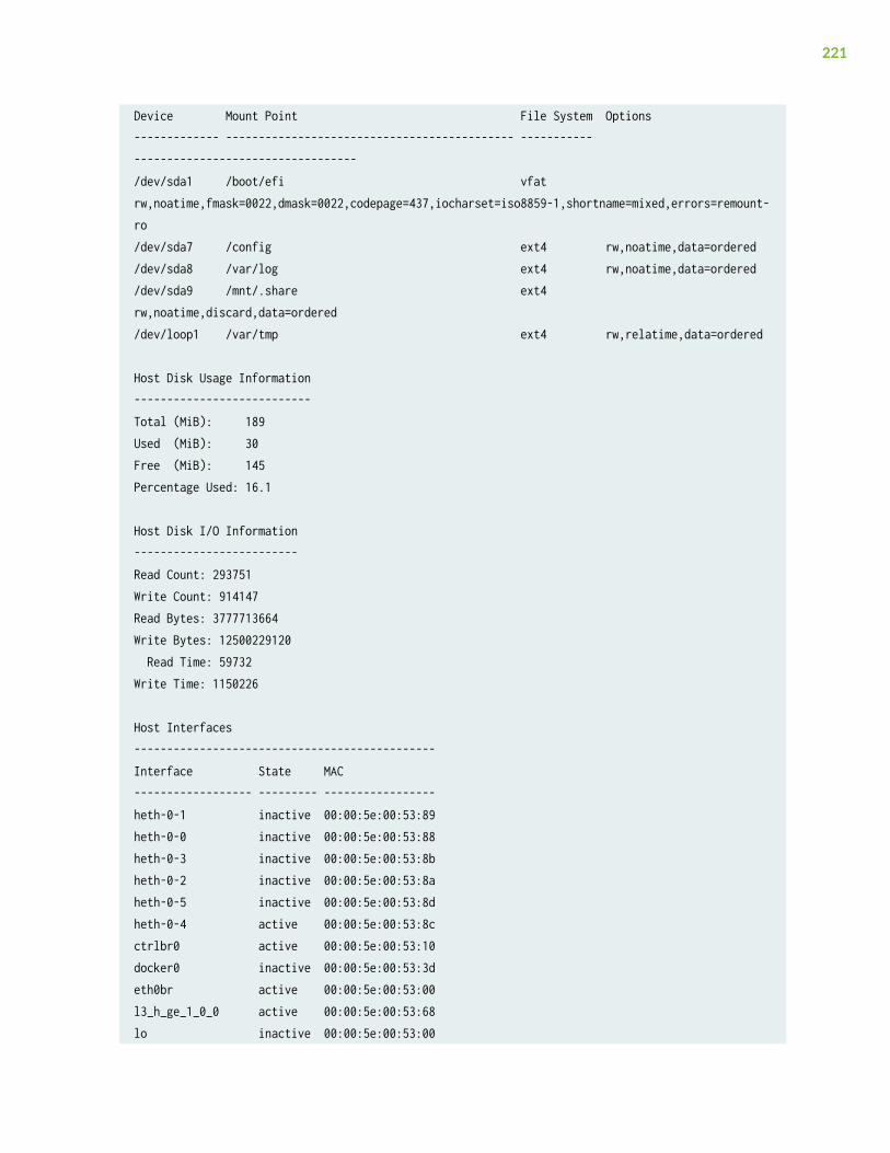
Device Mount Point File System Options------------- -------------------------------------------- ----------- ----------------------------------/dev/sda1 /boot/efi vfat rw,noatime,fmask=0022,dmask=0022,codepage=437,iocharset=iso8859-1,shortname=mixed,errors=remount-ro/dev/sda7 /config ext4 rw,noatime,data=ordered/dev/sda8 /var/log ext4 rw,noatime,data=ordered/dev/sda9 /mnt/.share ext4 rw,noatime,discard,data=ordered/dev/loop1 /var/tmp ext4 rw,relatime,data=ordered
Host Disk Usage Information---------------------------Total (MiB): 189Used (MiB): 30Free (MiB): 145Percentage Used: 16.1
Host Disk I/O Information-------------------------Read Count: 293751Write Count: 914147Read Bytes: 3777713664Write Bytes: 12500229120 Read Time: 59732Write Time: 1150226
Host Interfaces----------------------------------------------Interface State MAC------------------ --------- -----------------heth-0-1 inactive 00:00:5e:00:53:89heth-0-0 inactive 00:00:5e:00:53:88heth-0-3 inactive 00:00:5e:00:53:8bheth-0-2 inactive 00:00:5e:00:53:8aheth-0-5 inactive 00:00:5e:00:53:8dheth-0-4 active 00:00:5e:00:53:8cctrlbr0 active 00:00:5e:00:53:10docker0 inactive 00:00:5e:00:53:3deth0br active 00:00:5e:00:53:00l3_h_ge_1_0_0 active 00:00:5e:00:53:68lo inactive 00:00:5e:00:53:00
221
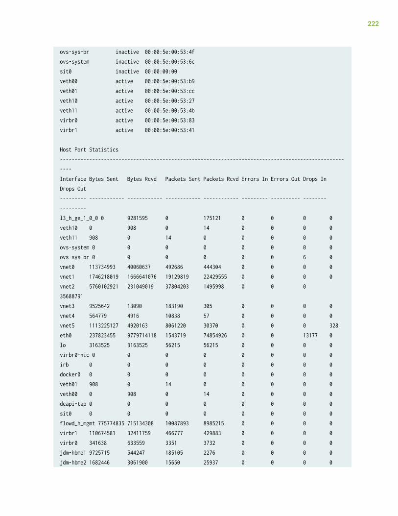
ovs-sys-br inactive 00:00:5e:00:53:4fovs-system inactive 00:00:5e:00:53:6csit0 inactive 00:00:00:00veth00 active 00:00:5e:00:53:b9veth01 active 00:00:5e:00:53:ccveth10 active 00:00:5e:00:53:27veth11 active 00:00:5e:00:53:4bvirbr0 active 00:00:5e:00:53:83virbr1 active 00:00:5e:00:53:41
Host Port Statistics-----------------------------------------------------------------------------------------------------Interface Bytes Sent Bytes Rcvd Packets Sent Packets Rcvd Errors In Errors Out Drops In Drops Out--------- ------------ ------------ ------------ ------------ --------- ---------- -------- ---------l3_h_ge_1_0_0 0 9281595 0 175121 0 0 0 0veth10 0 908 0 14 0 0 0 0veth11 908 0 14 0 0 0 0 0ovs-system 0 0 0 0 0 0 0 0ovs-sys-br 0 0 0 0 0 0 6 0vnet0 113734993 40060637 492686 444304 0 0 0 0vnet1 1746218019 1666641076 19129819 22429555 0 0 0 0vnet2 5760102921 231049019 37804203 1495998 0 0 0 35688791vnet3 9525642 13090 183190 305 0 0 0 0vnet4 564779 4916 10838 57 0 0 0 0vnet5 1113225127 4920163 8061220 30370 0 0 0 328eth0 237823455 9779714118 1543719 74854926 0 0 13177 0lo 3163525 3163525 56215 56215 0 0 0 0virbr0-nic 0 0 0 0 0 0 0 0irb 0 0 0 0 0 0 0 0docker0 0 0 0 0 0 0 0 0veth01 908 0 14 0 0 0 0 0veth00 0 908 0 14 0 0 0 0dcapi-tap 0 0 0 0 0 0 0 0sit0 0 0 0 0 0 0 0 0flowd_h_mgmt 775774835 715134308 10087893 8985215 0 0 0 0virbr1 110674581 32411759 466777 429883 0 0 0 0virbr0 341638 633559 3351 3732 0 0 0 0jdm-hbme1 9725715 544247 185105 2276 0 0 0 0jdm-hbme2 1682446 3061900 15650 25937 0 0 0 0
222
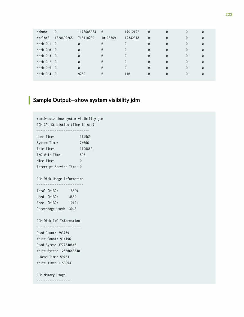
eth0br 0 1175685054 0 17912122 0 0 0 0ctrlbr0 1028692265 718118709 10108369 12342918 0 0 0 0heth-0-1 0 0 0 0 0 0 0 0heth-0-0 0 0 0 0 0 0 0 0heth-0-3 0 0 0 0 0 0 0 0heth-0-2 0 0 0 0 0 0 0 0heth-0-5 0 0 0 0 0 0 0 0heth-0-4 0 9762 0 110 0 0 0 0
Sample Output—show system visibility jdm
root@host> show system visibility jdmJDM CPU Statistics (Time in sec)-----------------------------User Time: 114569System Time: 74066Idle Time: 1196860I/O Wait Time: 596Nice Time: 0Interrupt Service Time: 0
JDM Disk Usage Information--------------------------Total (MiB): 15829Used (MiB): 4882Free (MiB): 10121Percentage Used: 30.8
JDM Disk I/O Information------------------------Read Count: 293759Write Count: 914196Read Bytes: 3777840640Write Bytes: 12500643840 Read Time: 59733Write Time: 1150254
JDM Memory Usage-------------------
223
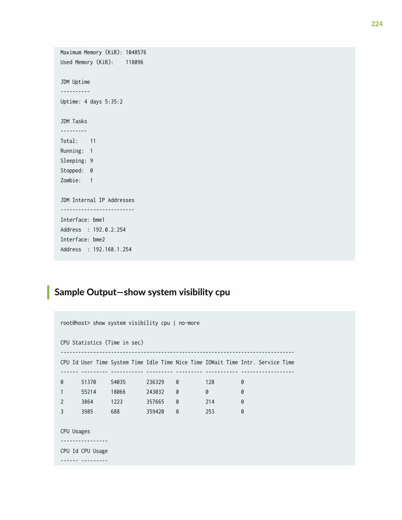
Maximum Memory (KiB): 1048576Used Memory (KiB): 118096
JDM Uptime----------Uptime: 4 days 5:35:2
JDM Tasks---------Total: 11Running: 1Sleeping: 9Stopped: 0Zombie: 1
JDM Internal IP Addresses-------------------------Interface: bme1Address : 192.0.2.254Interface: bme2Address : 192.168.1.254
Sample Output—show system visibility cpu
root@host> show system visibility cpu | no-more
CPU Statistics (Time in sec)-------------------------------------------------------------------------------CPU Id User Time System Time Idle Time Nice Time IOWait Time Intr. Service Time------ --------- ----------- --------- --------- ----------- ------------------0 51370 54035 236329 0 128 01 55214 18066 243032 0 0 02 3864 1223 357665 0 214 03 3985 688 359420 0 253 0
CPU Usages----------------CPU Id CPU Usage------ ---------
224
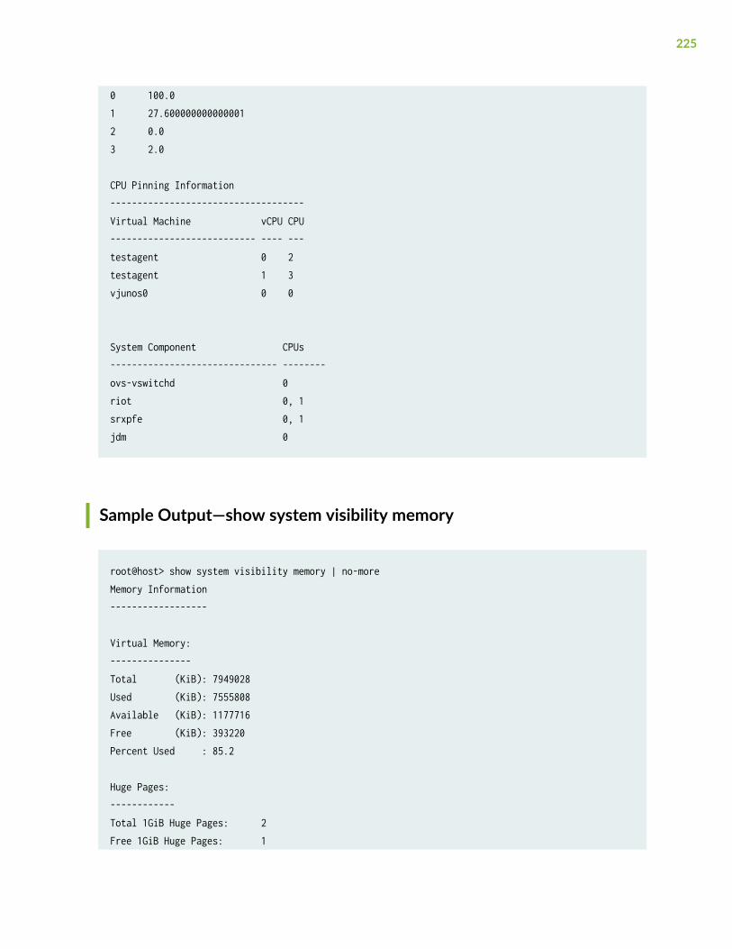
0 100.01 27.6000000000000012 0.03 2.0
CPU Pinning Information------------------------------------Virtual Machine vCPU CPU--------------------------- ---- ---testagent 0 2testagent 1 3vjunos0 0 0
System Component CPUs------------------------------- --------ovs-vswitchd 0riot 0, 1srxpfe 0, 1jdm 0
Sample Output—show system visibility memory
root@host> show system visibility memory | no-moreMemory Information------------------
Virtual Memory:---------------Total (KiB): 7949028Used (KiB): 7555808Available (KiB): 1177716Free (KiB): 393220Percent Used : 85.2
Huge Pages:------------Total 1GiB Huge Pages: 2Free 1GiB Huge Pages: 1
225
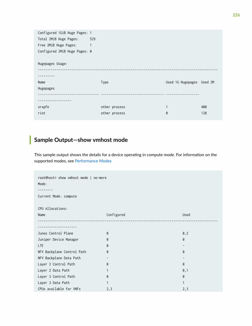
Configured 1GiB Huge Pages: 1Total 2MiB Huge Pages: 529Free 2MiB Huge Pages: 1Configured 2MiB Huge Pages: 0
Hugepages Usage:----------------------------------------------------------------------------------------------------------Name Type Used 1G Hugepages Used 2M Hugepages--------------------------------- ---------------------------------- ------------------ ------------------srxpfe other process 1 400riot other process 0 128
Sample Output—show vmhost mode
This sample output shows the details for a device operating in compute mode. For information on thesupported modes, see Performance Modes
root@host> show vmhost mode | no-moreMode:--------Current Mode: compute
CPU Allocations:Name Configured Used----------------------------------------------------------------------------------------------------------------------Junos Control Plane 0 0,2Juniper Device Manager 0 0LTE 0 -NFV Backplane Control Path 0 0NFV Backplane Data Path - -Layer 2 Control Path 0 0Layer 2 Data Path 1 0,1Layer 3 Control Path 0 0Layer 3 Data Path 1 1CPUs available for VNFs 2,3 2,3
226
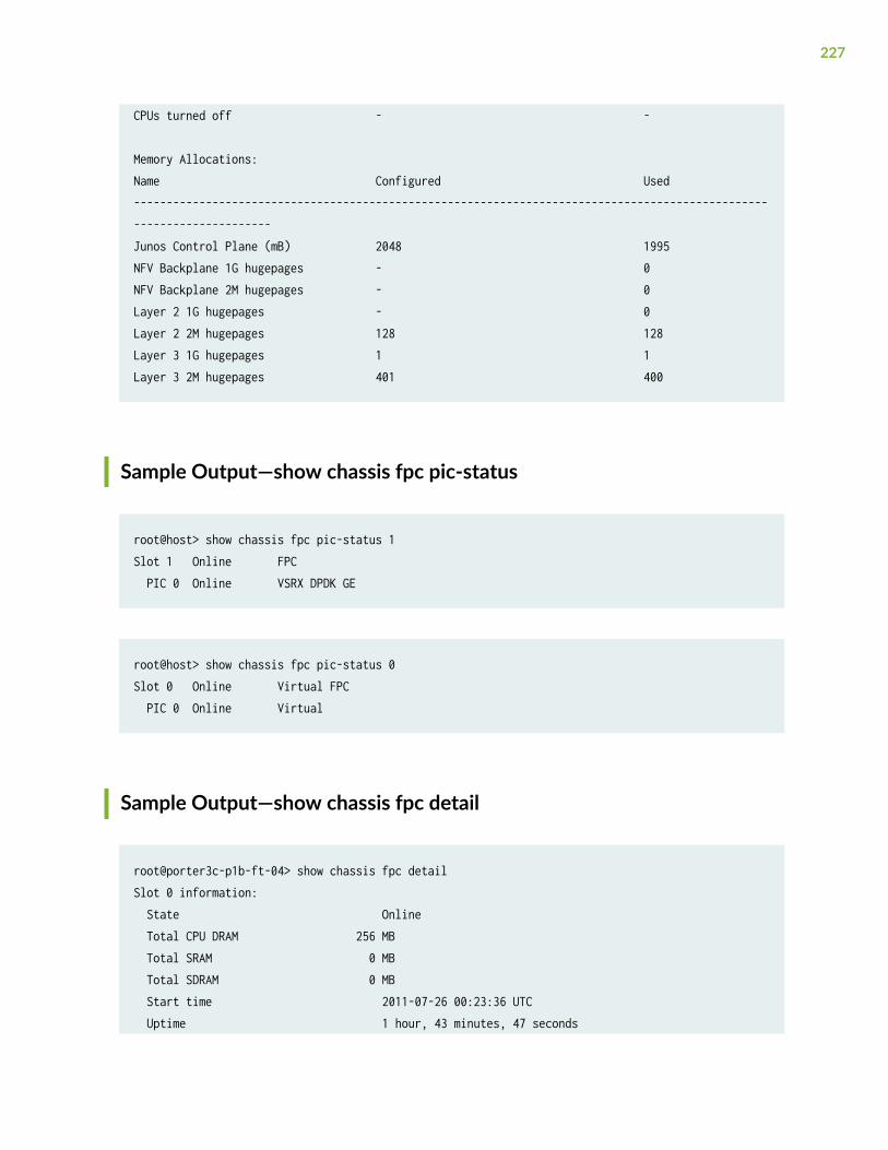
CPUs turned off - -
Memory Allocations:Name Configured Used----------------------------------------------------------------------------------------------------------------------Junos Control Plane (mB) 2048 1995NFV Backplane 1G hugepages - 0NFV Backplane 2M hugepages - 0Layer 2 1G hugepages - 0Layer 2 2M hugepages 128 128Layer 3 1G hugepages 1 1Layer 3 2M hugepages 401 400
Sample Output—show chassis fpc pic-status
root@host> show chassis fpc pic-status 1Slot 1 Online FPC PIC 0 Online VSRX DPDK GE
root@host> show chassis fpc pic-status 0Slot 0 Online Virtual FPC PIC 0 Online Virtual
Sample Output—show chassis fpc detail
root@porter3c-p1b-ft-04> show chassis fpc detailSlot 0 information: State Online Total CPU DRAM 256 MB Total SRAM 0 MB Total SDRAM 0 MB Start time 2011-07-26 00:23:36 UTC Uptime 1 hour, 43 minutes, 47 seconds
227
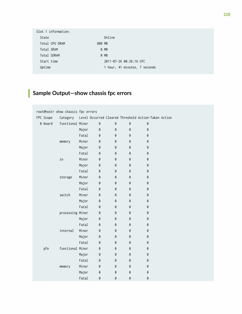
Slot 1 information: State Online Total CPU DRAM 800 MB Total SRAM 0 MB Total SDRAM 0 MB Start time 2011-07-26 00:26:16 UTC Uptime 1 hour, 41 minutes, 7 seconds
Sample Output—show chassis fpc errors
root@host> show chassis fpc errorsFPC Scope Category Level Occurred Cleared Threshold Action-Taken Action 0 board functional Minor 0 0 0 0 Major 0 0 0 0 Fatal 0 0 0 0 memory Minor 0 0 0 0 Major 0 0 0 0 Fatal 0 0 0 0 io Minor 0 0 0 0 Major 0 0 0 0 Fatal 0 0 0 0 storage Minor 0 0 0 0 Major 0 0 0 0 Fatal 0 0 0 0 switch Minor 0 0 0 0 Major 0 0 0 0 Fatal 0 0 0 0 processing Minor 0 0 0 0 Major 0 0 0 0 Fatal 0 0 0 0 internal Minor 0 0 0 0 Major 0 0 0 0 Fatal 0 0 0 0 pfe functional Minor 0 0 0 0 Major 0 0 0 0 Fatal 0 0 0 0 memory Minor 0 0 0 0 Major 0 0 0 0 Fatal 0 0 0 0
228
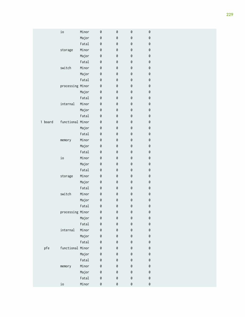
io Minor 0 0 0 0 Major 0 0 0 0 Fatal 0 0 0 0 storage Minor 0 0 0 0 Major 0 0 0 0 Fatal 0 0 0 0 switch Minor 0 0 0 0 Major 0 0 0 0 Fatal 0 0 0 0 processing Minor 0 0 0 0 Major 0 0 0 0 Fatal 0 0 0 0 internal Minor 0 0 0 0 Major 0 0 0 0 Fatal 0 0 0 0 1 board functional Minor 0 0 0 0 Major 0 0 0 0 Fatal 0 0 0 0 memory Minor 0 0 0 0 Major 0 0 0 0 Fatal 0 0 0 0 io Minor 0 0 0 0 Major 0 0 0 0 Fatal 0 0 0 0 storage Minor 0 0 0 0 Major 0 0 0 0 Fatal 0 0 0 0 switch Minor 0 0 0 0 Major 0 0 0 0 Fatal 0 0 0 0 processing Minor 0 0 0 0 Major 0 0 0 0 Fatal 0 0 0 0 internal Minor 0 0 0 0 Major 0 0 0 0 Fatal 0 0 0 0 pfe functional Minor 0 0 0 0 Major 0 0 0 0 Fatal 0 0 0 0 memory Minor 0 0 0 0 Major 0 0 0 0 Fatal 0 0 0 0 io Minor 0 0 0 0
229
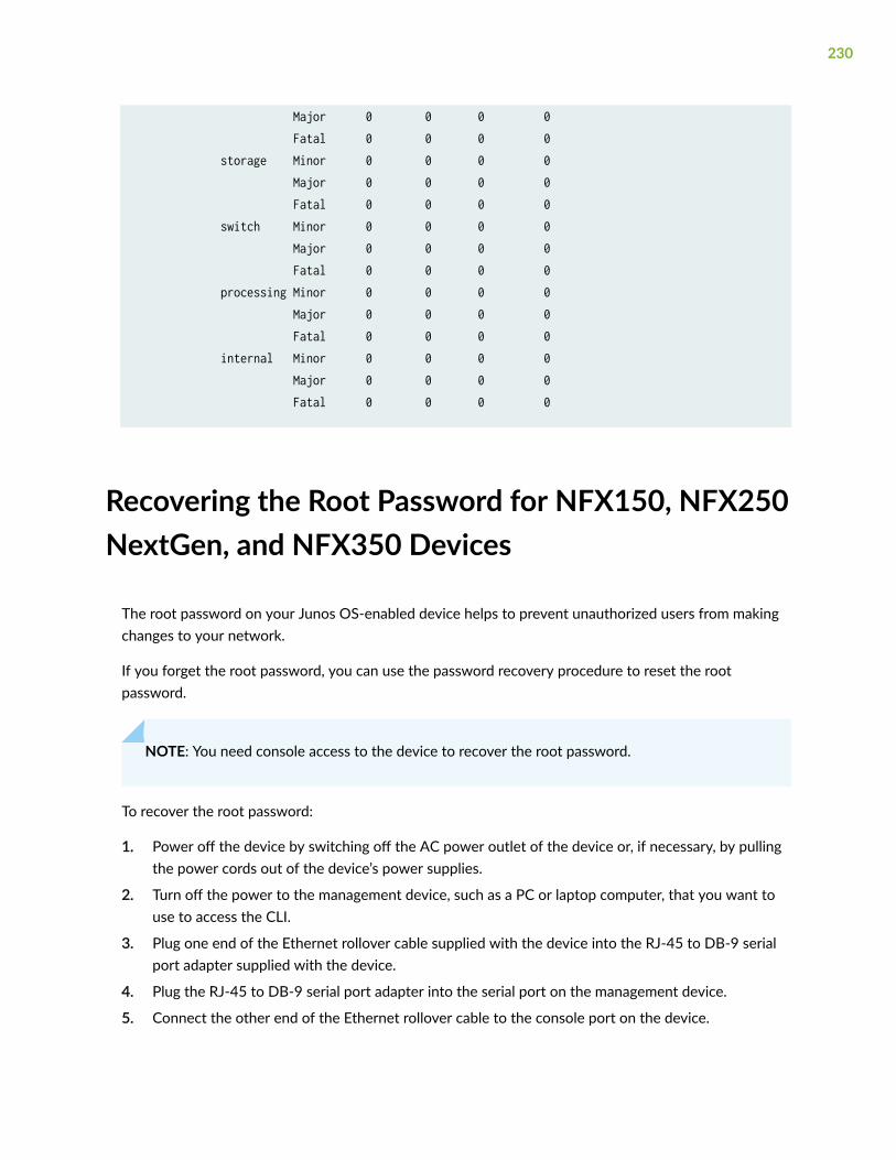
Major 0 0 0 0 Fatal 0 0 0 0 storage Minor 0 0 0 0 Major 0 0 0 0 Fatal 0 0 0 0 switch Minor 0 0 0 0 Major 0 0 0 0 Fatal 0 0 0 0 processing Minor 0 0 0 0 Major 0 0 0 0 Fatal 0 0 0 0 internal Minor 0 0 0 0 Major 0 0 0 0 Fatal 0 0 0 0
Recovering the Root Password for NFX150, NFX250NextGen, and NFX350 Devices
The root password on your Junos OS-enabled device helps to prevent unauthorized users from makingchanges to your network.
If you forget the root password, you can use the password recovery procedure to reset the rootpassword.
NOTE: You need console access to the device to recover the root password.
To recover the root password:
1. Power off the device by switching off the AC power outlet of the device or, if necessary, by pullingthe power cords out of the device’s power supplies.
2. Turn off the power to the management device, such as a PC or laptop computer, that you want touse to access the CLI.
3. Plug one end of the Ethernet rollover cable supplied with the device into the RJ-45 to DB-9 serialport adapter supplied with the device.
4. Plug the RJ-45 to DB-9 serial port adapter into the serial port on the management device.
5. Connect the other end of the Ethernet rollover cable to the console port on the device.
230
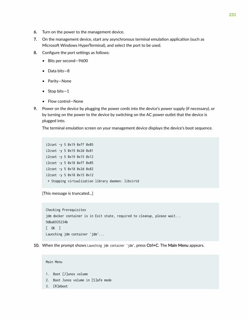
6. Turn on the power to the management device.
7. On the management device, start any asynchronous terminal emulation application (such asMicrosoft Windows HyperTerminal), and select the port to be used.
8. Configure the port settings as follows:
• Bits per second—9600
• Data bits—8
• Parity—None
• Stop bits—1
• Flow control—None
9. Power on the device by plugging the power cords into the device’s power supply (if necessary), orby turning on the power to the device by switching on the AC power outlet that the device isplugged into.
The terminal emulation screen on your management device displays the device’s boot sequence.
i2cset -y 5 0x19 0xff 0x05i2cset -y 5 0x19 0x2d 0x81i2cset -y 5 0x19 0x15 0x12i2cset -y 5 0x18 0xff 0x05i2cset -y 5 0x18 0x2d 0x82i2cset -y 5 0x18 0x15 0x12 * Stopping virtualization library daemon: libvirtd
[This message is truncated...]
Checking Prerequisitesjdm docker container is in Exit state, required to cleanup, please wait...9dba6935234b[ OK ]Launching jdm container 'jdm'...
10. When the prompt shows Launching jdm container 'jdm', press Ctrl+C. The Main Menu appears.
Main Menu
1. Boot [J]unos volume2. Boot Junos volume in [S]afe mode3. [R]eboot
231
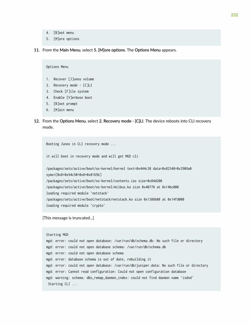
4. [B]oot menu5. [M]ore options
11. From the Main Menu, select 5. [M]ore options. The Options Menu appears.
Options Menu 1. Recover [J]unos volume2. Recovery mode - [C]LI 3. Check [F]ile system4. Enable [V]erbose boot5. [B]oot prompt6. [M]ain menu
12. From the Options Menu, select 2. Recovery mode - [C]LI. The device reboots into CLI recoverymode.
Booting Junos in CLI recovery mode ... it will boot in recovery mode and will get MGD cli /packages/sets/active/boot/os-kernel/kernel text=0x444c38 data=0x82348+0x2909a0 syms=[0x8+0x94c50+0x8+0x8165b]/packages/sets/active/boot/os-kernel/contents.izo size=0x84d200/packages/sets/active/boot/os-kernel/miibus.ko size 0x40778 at 0x14bc000loading required module 'netstack'/packages/sets/active/boot/netstack/netstack.ko size 0x1386b08 at 0x14fd000loading required module 'crypto'
[This message is truncated...]
Starting MGDmgd: error: could not open database: /var/run/db/schema.db: No such file or directorymgd: error: could not open database schema: /var/run/db/schema.dbmgd: error: could not open database schemamgd: error: database schema is out of date, rebuilding itmgd: error: could not open database: /var/run/db/juniper.data: No such file or directorymgd: error: Cannot read configuration: Could not open configuration databasemgd: warning: schema: dbs_remap_daemon_index: could not find daemon name 'isdnd' Starting CLI ...
232

13. Enter configuration mode in the CLI.
root> configureEntering configuration mode
14. Set the root password.
[edit]root# set system root-authentication plain-text-password
15. At the first prompt, enter the new root password:
New password:
16. At the second prompt, reenter the new root password.
Retype new password:
17. After you have finished configuring the password, commit the configuration.
[edit]root# commitcommit complete
18. Exit configuration mode in the CLI.
[edit]root@host# exitroot@host>
19. Exit operational mode in the CLI.
root@host> exitroot@host%
20. At the shell prompt, type exit to reboot the device.
root@host% exit
233
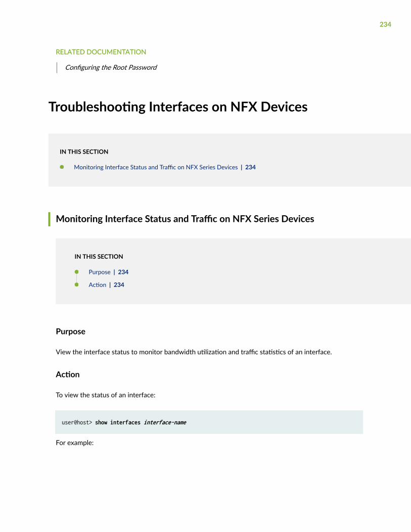
RELATED DOCUMENTATION
Configuring the Root Password
Troubleshooting Interfaces on NFX Devices
IN THIS SECTION
Monitoring Interface Status and Traffic on NFX Series Devices | 234
Monitoring Interface Status and Traffic on NFX Series Devices
IN THIS SECTION
Purpose | 234
Action | 234
Purpose
View the interface status to monitor bandwidth utilization and traffic statistics of an interface.
Action
To view the status of an interface:
user@host> show interfaces interface-name
For example:
234
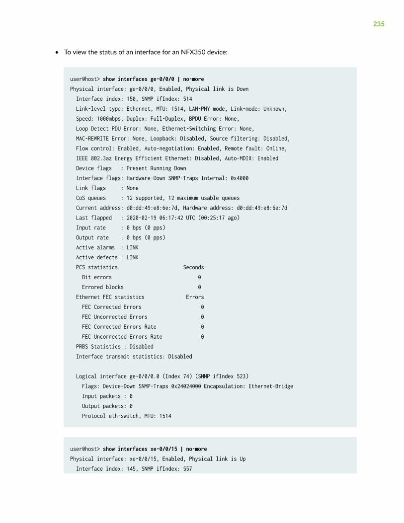
• To view the status of an interface for an NFX350 device:
user@host> show interfaces ge-0/0/0 | no-morePhysical interface: ge-0/0/0, Enabled, Physical link is Down Interface index: 150, SNMP ifIndex: 514 Link-level type: Ethernet, MTU: 1514, LAN-PHY mode, Link-mode: Unknown, Speed: 1000mbps, Duplex: Full-Duplex, BPDU Error: None, Loop Detect PDU Error: None, Ethernet-Switching Error: None, MAC-REWRITE Error: None, Loopback: Disabled, Source filtering: Disabled, Flow control: Enabled, Auto-negotiation: Enabled, Remote fault: Online, IEEE 802.3az Energy Efficient Ethernet: Disabled, Auto-MDIX: Enabled Device flags : Present Running Down Interface flags: Hardware-Down SNMP-Traps Internal: 0x4000 Link flags : None CoS queues : 12 supported, 12 maximum usable queues Current address: d0:dd:49:e8:6e:7d, Hardware address: d0:dd:49:e8:6e:7d Last flapped : 2020-02-19 06:17:42 UTC (00:25:17 ago) Input rate : 0 bps (0 pps) Output rate : 0 bps (0 pps) Active alarms : LINK Active defects : LINK PCS statistics Seconds Bit errors 0 Errored blocks 0 Ethernet FEC statistics Errors FEC Corrected Errors 0 FEC Uncorrected Errors 0 FEC Corrected Errors Rate 0 FEC Uncorrected Errors Rate 0 PRBS Statistics : Disabled Interface transmit statistics: Disabled
Logical interface ge-0/0/0.0 (Index 74) (SNMP ifIndex 523) Flags: Device-Down SNMP-Traps 0x24024000 Encapsulation: Ethernet-Bridge Input packets : 0 Output packets: 0 Protocol eth-switch, MTU: 1514
user@host> show interfaces xe-0/0/15 | no-morePhysical interface: xe-0/0/15, Enabled, Physical link is Up Interface index: 145, SNMP ifIndex: 557
235
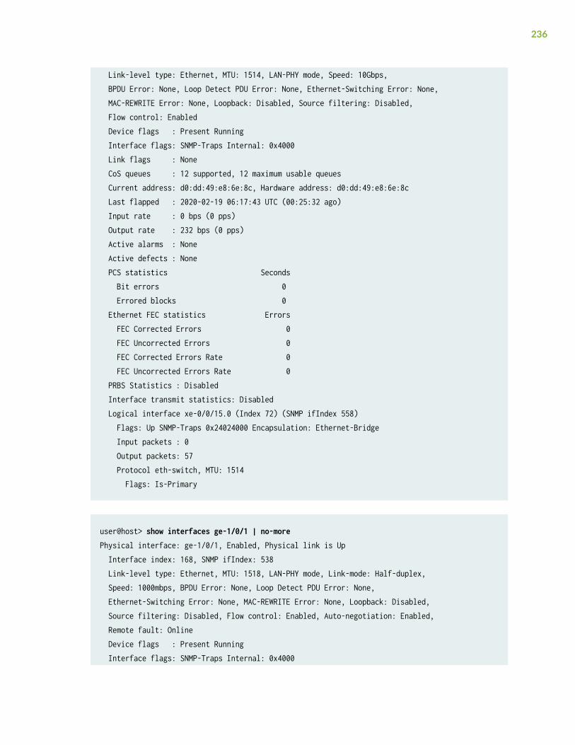
Link-level type: Ethernet, MTU: 1514, LAN-PHY mode, Speed: 10Gbps, BPDU Error: None, Loop Detect PDU Error: None, Ethernet-Switching Error: None, MAC-REWRITE Error: None, Loopback: Disabled, Source filtering: Disabled, Flow control: Enabled Device flags : Present Running Interface flags: SNMP-Traps Internal: 0x4000 Link flags : None CoS queues : 12 supported, 12 maximum usable queues Current address: d0:dd:49:e8:6e:8c, Hardware address: d0:dd:49:e8:6e:8c Last flapped : 2020-02-19 06:17:43 UTC (00:25:32 ago) Input rate : 0 bps (0 pps) Output rate : 232 bps (0 pps) Active alarms : None Active defects : None PCS statistics Seconds Bit errors 0 Errored blocks 0 Ethernet FEC statistics Errors FEC Corrected Errors 0 FEC Uncorrected Errors 0 FEC Corrected Errors Rate 0 FEC Uncorrected Errors Rate 0 PRBS Statistics : Disabled Interface transmit statistics: Disabled Logical interface xe-0/0/15.0 (Index 72) (SNMP ifIndex 558) Flags: Up SNMP-Traps 0x24024000 Encapsulation: Ethernet-Bridge Input packets : 0 Output packets: 57 Protocol eth-switch, MTU: 1514 Flags: Is-Primary
user@host> show interfaces ge-1/0/1 | no-morePhysical interface: ge-1/0/1, Enabled, Physical link is Up Interface index: 168, SNMP ifIndex: 538 Link-level type: Ethernet, MTU: 1518, LAN-PHY mode, Link-mode: Half-duplex, Speed: 1000mbps, BPDU Error: None, Loop Detect PDU Error: None, Ethernet-Switching Error: None, MAC-REWRITE Error: None, Loopback: Disabled, Source filtering: Disabled, Flow control: Enabled, Auto-negotiation: Enabled, Remote fault: Online Device flags : Present Running Interface flags: SNMP-Traps Internal: 0x4000
236
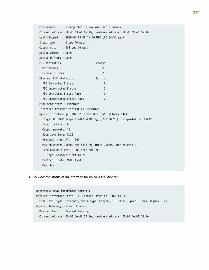
CoS queues : 8 supported, 8 maximum usable queues Current address: d0:dd:49:e8:6e:96, Hardware address: d0:dd:49:e8:6e:96 Last flapped : 2020-02-19 06:18:30 UTC (00:24:55 ago) Input rate : 0 bps (0 pps) Output rate : 208 bps (0 pps) Active alarms : None Active defects : None PCS statistics Seconds Bit errors 0 Errored blocks 0 Ethernet FEC statistics Errors FEC Corrected Errors 0 FEC Uncorrected Errors 0 FEC Corrected Errors Rate 0 FEC Uncorrected Errors Rate 0 PRBS Statistics : Disabled Interface transmit statistics: Disabled Logical interface ge-1/0/1.2 (Index 85) (SNMP ifIndex 544) Flags: Up SNMP-Traps 0x4000 VLAN-Tag [ 0x8100.2 ] Encapsulation: ENET2 Input packets : 0 Output packets: 19 Security: Zone: Null Protocol inet, MTU: 1500 Max nh cache: 75000, New hold nh limit: 75000, Curr nh cnt: 0, Curr new hold cnt: 0, NH drop cnt: 0 Flags: Sendbcast-pkt-to-re Protocol inet6, MTU: 1500 Max nh c
• To view the status of an interface for an NFX150 device:
user@host> show interfaces heth-0-1Physical interface: heth-0-1, Enabled, Physical link is Up Link-level type: Ethernet, Media type: Copper, MTU: 9192, Speed: 1Gbps, Duplex: Full-duplex, Auto-negotiation: Enabled Device flags : Present Running Current address: 00:00:5e:00:53:8e, Hardware address: 00:00:5e:00:53:8e
237
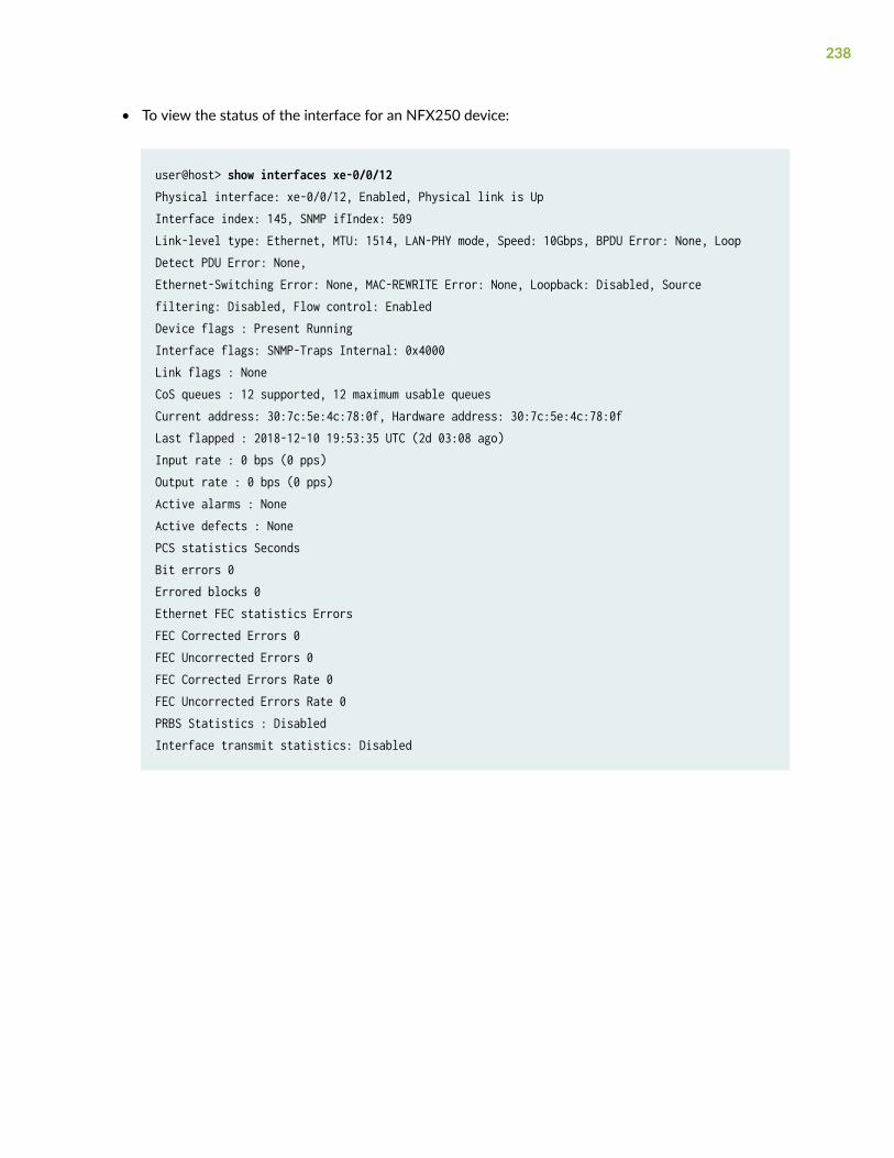
• To view the status of the interface for an NFX250 device:
user@host> show interfaces xe-0/0/12Physical interface: xe-0/0/12, Enabled, Physical link is UpInterface index: 145, SNMP ifIndex: 509Link-level type: Ethernet, MTU: 1514, LAN-PHY mode, Speed: 10Gbps, BPDU Error: None, Loop Detect PDU Error: None,Ethernet-Switching Error: None, MAC-REWRITE Error: None, Loopback: Disabled, Source filtering: Disabled, Flow control: EnabledDevice flags : Present RunningInterface flags: SNMP-Traps Internal: 0x4000Link flags : NoneCoS queues : 12 supported, 12 maximum usable queuesCurrent address: 30:7c:5e:4c:78:0f, Hardware address: 30:7c:5e:4c:78:0fLast flapped : 2018-12-10 19:53:35 UTC (2d 03:08 ago)Input rate : 0 bps (0 pps)Output rate : 0 bps (0 pps)Active alarms : NoneActive defects : NonePCS statistics SecondsBit errors 0Errored blocks 0Ethernet FEC statistics ErrorsFEC Corrected Errors 0FEC Uncorrected Errors 0FEC Corrected Errors Rate 0FEC Uncorrected Errors Rate 0PRBS Statistics : DisabledInterface transmit statistics: Disabled
238
12CHAPTER
Operational Commands
request chassis cluster failover node | 241
request chassis cluster failover redundancy-group | 243
request chassis cluster failover reset | 245
request chassis fpc | 247
request vmhost cleanup | 249
request vmhost file-copy | 250
request vmhost halt | 252
request vmhost mode | 254
request vmhost power-off | 256
request vmhost reboot | 257
request vmhost software add | 261
show chassis cluster control-plane statistics | 264
show chassis cluster data-plane interfaces | 268
show chassis cluster data-plane statistics | 270
show chassis cluster information | 273
show chassis cluster interfaces | 280
show chassis cluster port-peering | 289
show chassis cluster statistics | 291
show chassis cluster status | 297
show interfaces | 302

show system inventory hardware cpu | 306
show system visibility cpu | 313
show system visibility host | 320
show system visibility jcp | 330
show system visibility jdm | 335
show system visibility memory | 339
show system visibility network | 343
show system visibility vnf | 351
show vmhost connections | 359
show vmhost control-plane | 361
show vmhost crash | 364
show vmhost forwarding-options analyzer | 365
show vmhost memory | 367
show vmhost mode | 369
show vmhost snmp mib walk | 381
show vmhost status | 383
show vmhost storage | 385
show vmhost uptime | 392
show vmhost version | 394
show vmhost vlans | 397
request chassis cluster failover node
IN THIS SECTION
Syntax | 241
Description | 241
Options | 241
Required Privilege Level | 242
Output Fields | 242
Sample Output | 242
Release Information | 242
Syntax
request chassis cluster failover node node-number redundancy-group group-number
Description
For chassis cluster configurations, initiate manual failover in a redundancy group from one node to theother, which becomes the primary node, and automatically reset the priority of the group to 255. Thefailover stays in effect until the new primary node becomes unavailable, the threshold of the redundancygroup reaches 0, or you use the request chassis cluster failover reset command.
After a manual failover, you must use the request chassis cluster failover reset command before initiatinganother failover.
Options
• node node-number—Number of the chassis cluster node to which the redundancy group fails over.
241
• Range: 0 through 1
• redundancy-group group-number—Number of the redundancy group on which to initiate manual failover.Redundancy group 0 is a special group consisting of the two Routing Engines in the chassis cluster.
Range: 0 through 255
Required Privilege Level
maintenance
Output Fields
When you enter this command, you are provided feedback on the status of your request.
Sample Output
request chassis cluster failover node
user@host> request chassis cluster failover node 0 redundancy-group 1 Initiated manual failover for redundancy group 1
Release Information
Command introduced in Junos OS Release 9.0.
RELATED DOCUMENTATION
clear chassis cluster failover-count
request chassis cluster failover reset
show chassis cluster status
242
request chassis cluster failover redundancy-group
IN THIS SECTION
Syntax | 243
Description | 243
Options | 243
Required Privilege Level | 244
Output Fields | 244
Sample Output | 244
Release Information | 244
Syntax
request chassis cluster failover node node-number redundancy-group redundancy-group-number
Description
For chassis cluster configurations, initiate manual failover in a redundancy group from one node to theother, which becomes the primary node, and automatically reset the priority of the group to 255. Thefailover stays in effect until the new primary node becomes unavailable, the threshold of the redundancygroup reaches 0, or you use the request chassis cluster failover reset command.
After a manual failover, you must use the request chassis cluster failover reset command before initiatinganother failover.
Options
• node node-number—Number of the chassis cluster node to which the redundancy group fails over.
243
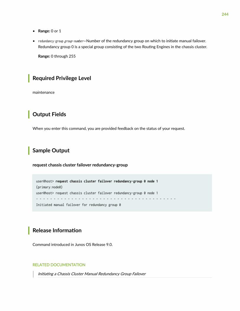
• Range: 0 or 1
• redundancy-group group-number—Number of the redundancy group on which to initiate manual failover.Redundancy group 0 is a special group consisting of the two Routing Engines in the chassis cluster.
Range: 0 through 255
Required Privilege Level
maintenance
Output Fields
When you enter this command, you are provided feedback on the status of your request.
Sample Output
request chassis cluster failover redundancy-group
user@host> request chassis cluster failover redundancy-group 0 node 1 {primary:node0}user@host> request chassis cluster failover redundancy-group 0 node 1- - - - - - - - - - - - - - - - - - - - - - - - - - - - - - - - - - - - - - - -Initiated manual failover for redundancy group 0
Release Information
Command introduced in Junos OS Release 9.0.
RELATED DOCUMENTATION
Initiating a Chassis Cluster Manual Redundancy Group Failover
244
Verifying Chassis Cluster Failover Status
request chassis cluster failover reset
IN THIS SECTION
Syntax | 245
Description | 245
Options | 245
Required Privilege Level | 246
Output Fields | 246
Sample Output | 246
Release Information | 246
Syntax
request chassis cluster failover resetredundancy-group group-number
Description
In chassis cluster configurations, undo the previous manual failover and return the redundancy group toits original settings.
Options
redundancy-group group-number—Number of the redundancy group on which to reset manual failover.Redundancy group 0 is a special group consisting of the two Routing Engines in the chassis cluster.
245
Range: 0 through 255
Required Privilege Level
maintenance
Output Fields
When you enter this command, you are provided feedback on the status of your request.
Sample Output
request chassis cluster failover reset
user@host> request chassis cluster failover reset redundancy-group 0
Release Information
Command introduced in Junos OS Release 9.0.
RELATED DOCUMENTATION
clear chassis cluster failover-count
request chassis cluster failover node
show chassis cluster status
246
request chassis fpc
IN THIS SECTION
Syntax | 247
Description | 247
Options | 247
Required Privilege Level | 248
Output Fields | 248
Sample Output | 248
Release Information | 248
Syntax
request chassis fpc (offline | online | restart) slot slot-number
Description
Control the operation of the Flexible PIC Concentrator (FPC).
NOTE: The SRX5K-SPC-2-10-40 (SPC1), SRX5K-SPC-4-15-320 (SPC2), and SRX5K-SPC3 doesnot support the request chassis fpc command.
Options
offline Take the FPC offline.
247
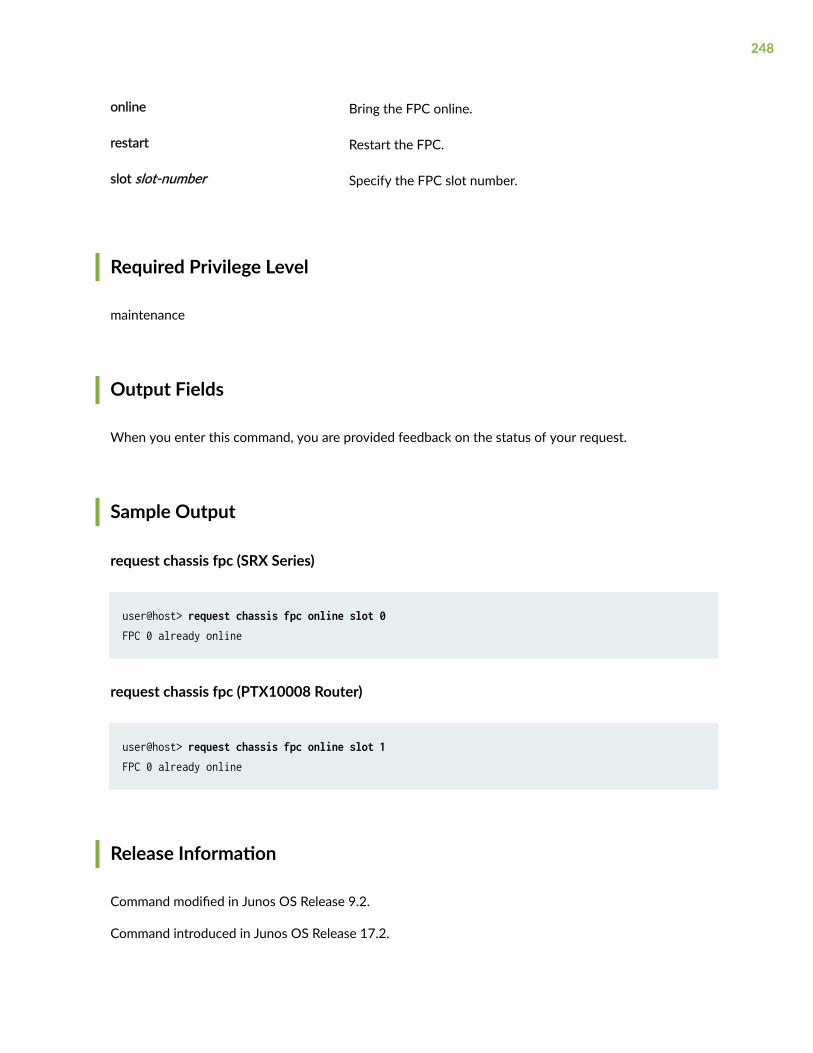
online Bring the FPC online.
restart Restart the FPC.
slot slot-number Specify the FPC slot number.
Required Privilege Level
maintenance
Output Fields
When you enter this command, you are provided feedback on the status of your request.
Sample Output
request chassis fpc (SRX Series)
user@host> request chassis fpc online slot 0FPC 0 already online
request chassis fpc (PTX10008 Router)
user@host> request chassis fpc online slot 1FPC 0 already online
Release Information
Command modified in Junos OS Release 9.2.
Command introduced in Junos OS Release 17.2.
248
RELATED DOCUMENTATION
show chassis fpc (View)
request vmhost cleanup
IN THIS SECTION
Syntax | 249
Description | 249
Required Privilege Level | 249
Output Fields | 250
Release Information | 250
Syntax
request vmhost cleanup
Description
Clean up temporary files, crash generated files, and log files located in the /var/tmp, /var/crash,and /var/log directories respectively on the host OS.
Required Privilege Level
maintenance
249
Output Fields
When you enter this command, you are provided feedback on the status of your request.
Release Information
Command introduced in Junos OS Release 18.1R1.
request vmhost file-copy
IN THIS SECTION
Syntax | 250
Description | 250
Options | 251
Additional Information | 251
Required Privilege Level | 251
Sample Output | 251
Release Information | 251
Syntax
request vmhost file-copy (crash|log) from-jnode host file-name to-vjunos host file-name
Description
Copy crash files or log files from the host OS to Junos OS. You can use these files for analysis anddebugging purposes.
250
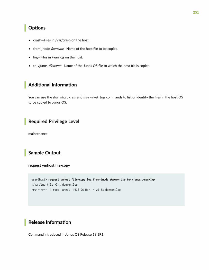
Options
• crash—Files in /var/crash on the host.
• from-jnode filename—Name of the host file to be copied.
• log—Files in /var/log on the host.
• to-vjunos filename—Name of the Junos OS file to which the host file is copied.
Additional Information
You can use the show vmhost crash and show vmhost logs commands to list or identify the files in the host OSto be copied to Junos OS.
Required Privilege Level
maintenance
Sample Output
request vmhost file-copy
user@host> request vmhost file-copy log from-jnode daemon.log to-vjunos /var/tmp :/var/tmp # ls -lrt daemon.log -rw-r--r-- 1 root wheel 1035126 Mar 4 20:33 daemon.log
Release Information
Command introduced in Junos OS Release 18.1R1.
251
request vmhost halt
IN THIS SECTION
Syntax | 252
Description | 252
Required Privilege Level | 252
Sample Output | 253
Release Information | 253
Syntax
request vmhost halt
Description
Stop the host OS and Junos OS running on the device.
Required Privilege Level
maintenance
252
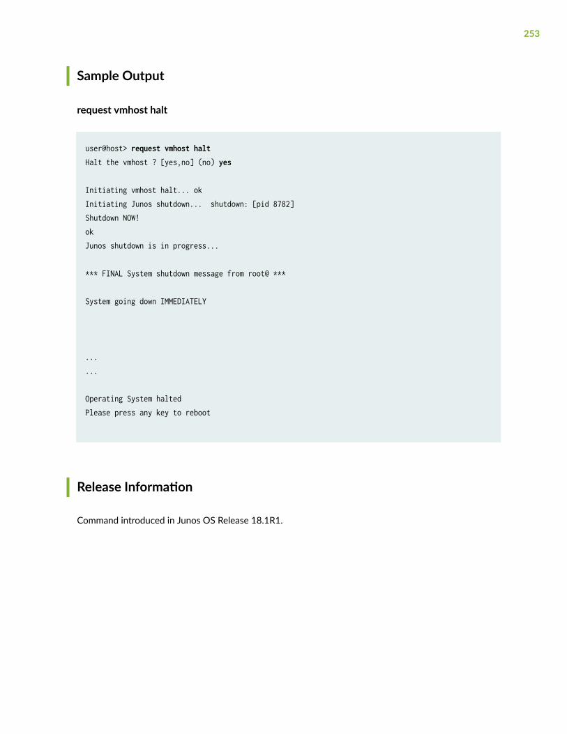
Sample Output
request vmhost halt
user@host> request vmhost haltHalt the vmhost ? [yes,no] (no) yes
Initiating vmhost halt... okInitiating Junos shutdown... shutdown: [pid 8782]Shutdown NOW!okJunos shutdown is in progress... *** FINAL System shutdown message from root@ ***
System going down IMMEDIATELY
......
Operating System haltedPlease press any key to reboot
Release Information
Command introduced in Junos OS Release 18.1R1.
253
request vmhost mode
IN THIS SECTION
Syntax | 254
Description | 254
Required Privilege Level | 255
Sample Output | 255
Release Information | 255
Syntax
request vmhost mode [compute | hybrid | throughput | mode-name]
Description
Select the operational mode of the device from a pre-defined list of modes (compute, hybrid, orthroughput) or specify a mode-name for a custom mode.
NOTE:
• Starting from Junos OS Release 19.3R1, if the same physical CPU is used for both VNFs andthe Junos OS or device components, the request to change the mode fails and an errormessage is displayed. For example:
root> request vmhost mode throughput error: Mode cannot be changed; Reason: Reserved CPUs conflict with VNF cpu pinnings: 3
254
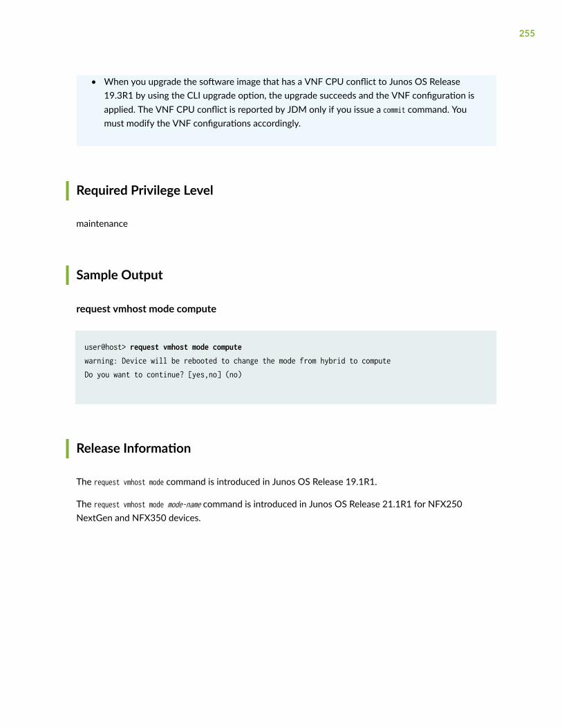
• When you upgrade the software image that has a VNF CPU conflict to Junos OS Release19.3R1 by using the CLI upgrade option, the upgrade succeeds and the VNF configuration isapplied. The VNF CPU conflict is reported by JDM only if you issue a commit command. Youmust modify the VNF configurations accordingly.
Required Privilege Level
maintenance
Sample Output
request vmhost mode compute
user@host> request vmhost mode computewarning: Device will be rebooted to change the mode from hybrid to computeDo you want to continue? [yes,no] (no)
Release Information
The request vmhost mode command is introduced in Junos OS Release 19.1R1.
The request vmhost mode mode-name command is introduced in Junos OS Release 21.1R1 for NFX250NextGen and NFX350 devices.
255
request vmhost power-off
IN THIS SECTION
Syntax | 256
Description | 256
Required Privilege Level | 256
Sample Output | 257
Release Information | 257
Syntax
request vmhost power-off
Description
Shut down the Junos OS software and the host OS.
Required Privilege Level
maintenance
256
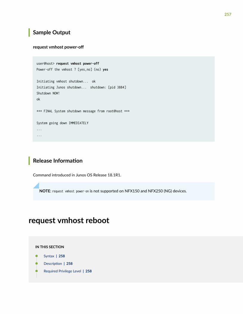
Sample Output
request vmhost power-off
user@host> request vmhost power-offPower-off the vmhost ? [yes,no] (no) yes
Initiating vmhost shutdown... okInitiating Junos shutdown... shutdown: [pid 3884]Shutdown NOW!ok *** FINAL System shutdown message from root@host ***
System going down IMMEDIATELY ......
Release Information
Command introduced in Junos OS Release 18.1R1.
NOTE: request vmhost power-on is not supported on NFX150 and NFX250 (NG) devices.
request vmhost reboot
IN THIS SECTION
Syntax | 258
Description | 258
Required Privilege Level | 258
257
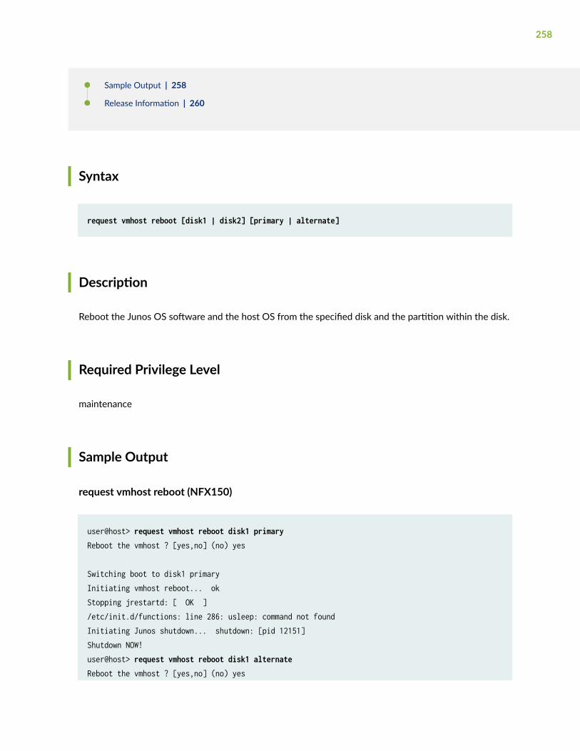
Sample Output | 258
Release Information | 260
Syntax
request vmhost reboot [disk1 | disk2] [primary | alternate]
Description
Reboot the Junos OS software and the host OS from the specified disk and the partition within the disk.
Required Privilege Level
maintenance
Sample Output
request vmhost reboot (NFX150)
user@host> request vmhost reboot disk1 primaryReboot the vmhost ? [yes,no] (no) yes
Switching boot to disk1 primaryInitiating vmhost reboot... okStopping jrestartd: [ OK ]/etc/init.d/functions: line 286: usleep: command not foundInitiating Junos shutdown... shutdown: [pid 12151]Shutdown NOW!user@host> request vmhost reboot disk1 alternateReboot the vmhost ? [yes,no] (no) yes
258
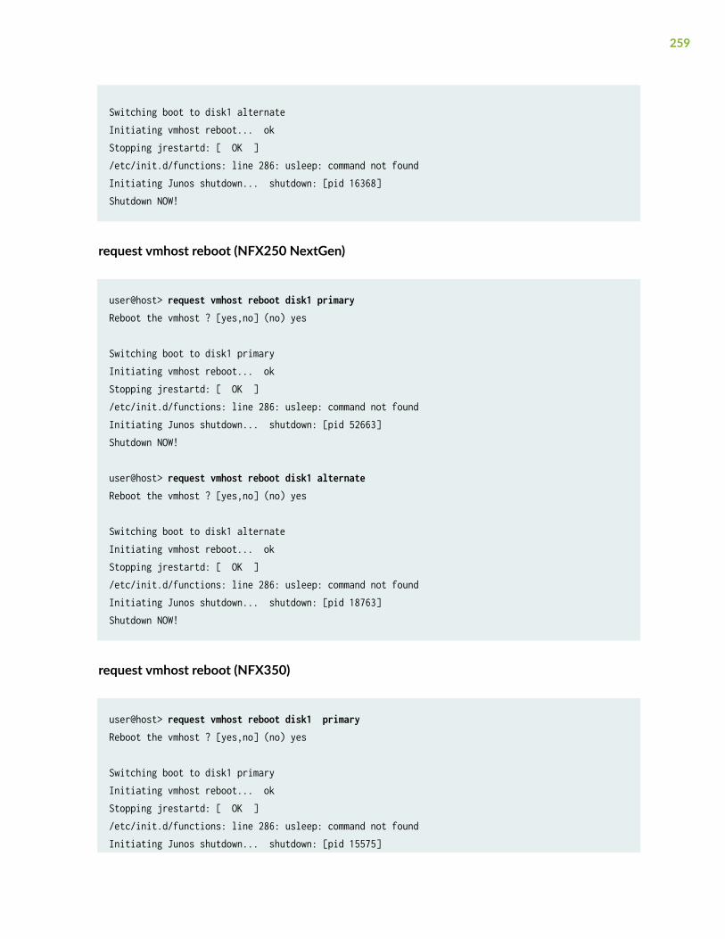
Switching boot to disk1 alternateInitiating vmhost reboot... okStopping jrestartd: [ OK ]/etc/init.d/functions: line 286: usleep: command not foundInitiating Junos shutdown... shutdown: [pid 16368]Shutdown NOW!
request vmhost reboot (NFX250 NextGen)
user@host> request vmhost reboot disk1 primaryReboot the vmhost ? [yes,no] (no) yes
Switching boot to disk1 primaryInitiating vmhost reboot... okStopping jrestartd: [ OK ]/etc/init.d/functions: line 286: usleep: command not foundInitiating Junos shutdown... shutdown: [pid 52663]Shutdown NOW!
user@host> request vmhost reboot disk1 alternateReboot the vmhost ? [yes,no] (no) yes
Switching boot to disk1 alternateInitiating vmhost reboot... okStopping jrestartd: [ OK ]/etc/init.d/functions: line 286: usleep: command not foundInitiating Junos shutdown... shutdown: [pid 18763]Shutdown NOW!
request vmhost reboot (NFX350)
user@host> request vmhost reboot disk1 primaryReboot the vmhost ? [yes,no] (no) yes
Switching boot to disk1 primaryInitiating vmhost reboot... okStopping jrestartd: [ OK ]/etc/init.d/functions: line 286: usleep: command not foundInitiating Junos shutdown... shutdown: [pid 15575]
259
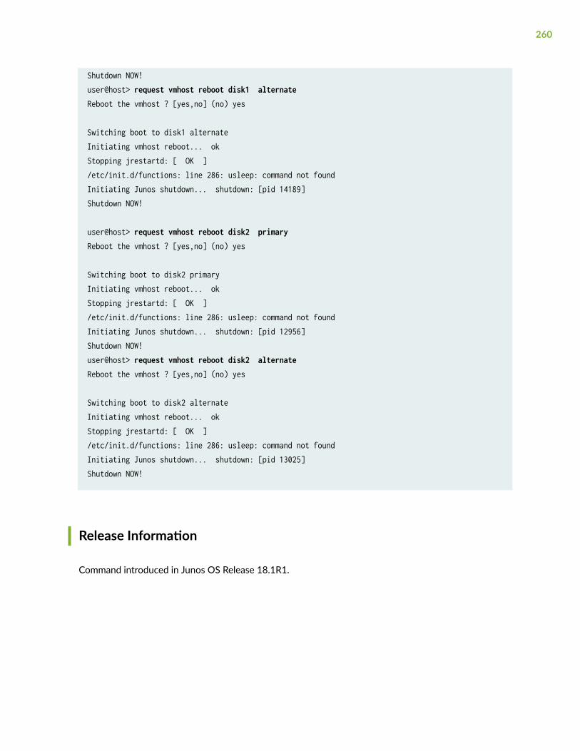
Shutdown NOW!user@host> request vmhost reboot disk1 alternateReboot the vmhost ? [yes,no] (no) yes
Switching boot to disk1 alternateInitiating vmhost reboot... okStopping jrestartd: [ OK ]/etc/init.d/functions: line 286: usleep: command not foundInitiating Junos shutdown... shutdown: [pid 14189]Shutdown NOW!
user@host> request vmhost reboot disk2 primaryReboot the vmhost ? [yes,no] (no) yes
Switching boot to disk2 primaryInitiating vmhost reboot... okStopping jrestartd: [ OK ]/etc/init.d/functions: line 286: usleep: command not foundInitiating Junos shutdown... shutdown: [pid 12956]Shutdown NOW!user@host> request vmhost reboot disk2 alternateReboot the vmhost ? [yes,no] (no) yes
Switching boot to disk2 alternateInitiating vmhost reboot... okStopping jrestartd: [ OK ]/etc/init.d/functions: line 286: usleep: command not foundInitiating Junos shutdown... shutdown: [pid 13025]Shutdown NOW!
Release Information
Command introduced in Junos OS Release 18.1R1.
260
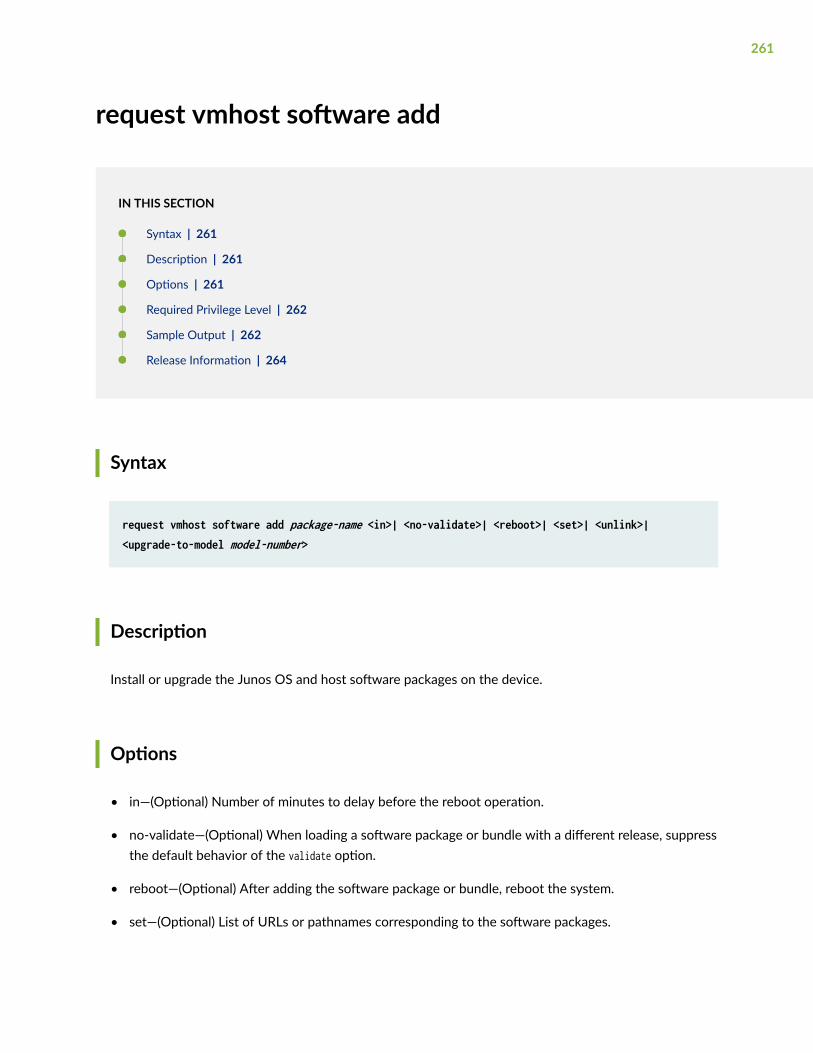
request vmhost software add
IN THIS SECTION
Syntax | 261
Description | 261
Options | 261
Required Privilege Level | 262
Sample Output | 262
Release Information | 264
Syntax
request vmhost software add package-name <in>| <no-validate>| <reboot>| <set>| <unlink>| <upgrade-to-model model-number>
Description
Install or upgrade the Junos OS and host software packages on the device.
Options
• in—(Optional) Number of minutes to delay before the reboot operation.
• no-validate—(Optional) When loading a software package or bundle with a different release, suppressthe default behavior of the validate option.
• reboot—(Optional) After adding the software package or bundle, reboot the system.
• set—(Optional) List of URLs or pathnames corresponding to the software packages.
261
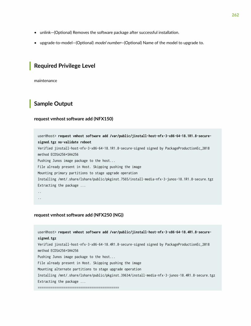
• unlink—(Optional) Removes the software package after successful installation.
• upgrade-to-model—(Optional) model number—(Optional) Name of the model to upgrade to.
Required Privilege Level
maintenance
Sample Output
request vmhost software add (NFX150)
user@host> request vmhost software add /var/public/jinstall-host-nfx-3-x86-64-18.1R1.8-secure-signed.tgz no-validate reboot Verified jinstall-host-nfx-3-x86-64-18.1R1.8-secure-signed signed by PackageProductionEc_2018 method ECDSA256+SHA256Pushing Junos image package to the host...File already present in Host. Skipping pushing the imageMounting primary partitions to stage upgrade operationInstalling /mnt/.share/lshare/public/pkginst.7565/install-media-nfx-3-junos-18.1R1.8-secure.tgzExtracting the package .......
request vmhost software add (NFX250 (NG))
user@host> request vmhost software add /var/public/jinstall-host-nfx-3-x86-64-18.4R1.8-secure-signed.tgzVerified jinstall-host-nfx-3-x86-64-18.4R1.8-secure-signed signed by PackageProductionEc_2018 method ECDSA256+SHA256Pushing Junos image package to the host...File already present in Host. Skipping pushing the imageMounting alternate partitions to stage upgrade operationInstalling /mnt/.share/lshare/public/pkginst.39634/install-media-nfx-3-junos-18.4R1.8-secure.tgzExtracting the package ...============================================
262
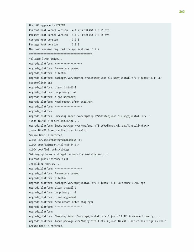
Host OS upgrade is FORCEDCurrent Host kernel version : 4.1.27-rt30-WR8.0.0.25_ovpPackage Host kernel version : 4.1.27-rt30-WR8.0.0.25_ovpCurrent Host version : 3.0.3Package Host version : 3.0.3Min host version required for applications: 3.0.2============================================Validate linux image...upgrade_platform: -------------------upgrade_platform: Parameters passed:upgrade_platform: silent=0upgrade_platform: package=/var/tmp/tmp.rV7S1sxWedjunos_cli_upg/jinstall-nfx-3-junos-18.4R1.8-secure-linux.tgzupgrade_platform: clean install=0upgrade_platform: on primary =0upgrade_platform: clean upgrade=0upgrade_platform: Need reboot after staging=1upgrade_platform: -------------------upgrade_platform:upgrade_platform: Checking input /var/tmp/tmp.rV7S1sxWedjunos_cli_upg/jinstall-nfx-3-junos-18.4R1.8-secure-linux.tgz ...upgrade_platform: Input package /var/tmp/tmp.rV7S1sxWedjunos_cli_upg/jinstall-nfx-3-junos-18.4R1.8-secure-linux.tgz is valid.Secure Boot is enforced.ALLOW:usr/secureboot/grub/BOOTX64.EFIALLOW:boot/bzImage-intel-x86-64.binALLOW:boot/initramfs.cpio.gzSetting up Junos host applications for installation ...Current junos instance is 0Installing Host OS ...upgrade_platform: -------------------upgrade_platform: Parameters passed:upgrade_platform: silent=0upgrade_platform: package=/var/tmp/jinstall-nfx-3-junos-18.4R1.8-secure-linux.tgzupgrade_platform: clean install=0upgrade_platform: on primary =0upgrade_platform: clean upgrade=0upgrade_platform: Need reboot after staging=0upgrade_platform: -------------------upgrade_platform:upgrade_platform: Checking input /var/tmp/jinstall-nfx-3-junos-18.4R1.8-secure-linux.tgz ...upgrade_platform: Input package /var/tmp/jinstall-nfx-3-junos-18.4R1.8-secure-linux.tgz is valid.Secure Boot is enforced.
263
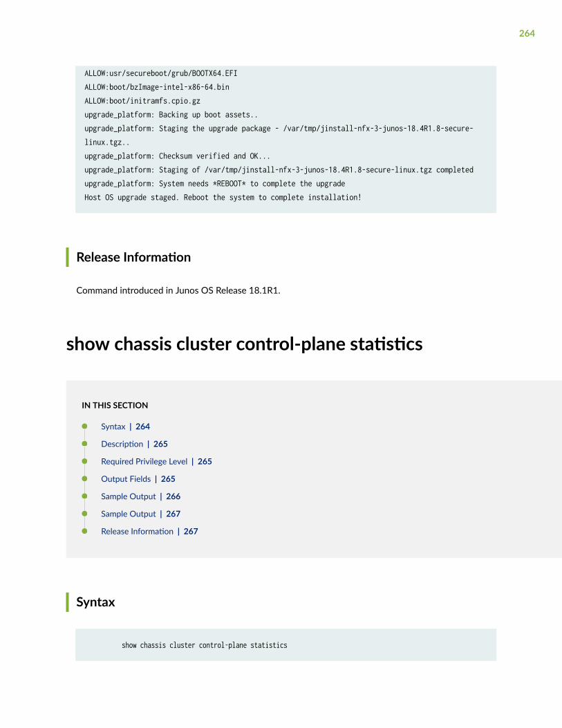
ALLOW:usr/secureboot/grub/BOOTX64.EFIALLOW:boot/bzImage-intel-x86-64.binALLOW:boot/initramfs.cpio.gzupgrade_platform: Backing up boot assets..upgrade_platform: Staging the upgrade package - /var/tmp/jinstall-nfx-3-junos-18.4R1.8-secure-linux.tgz..upgrade_platform: Checksum verified and OK...upgrade_platform: Staging of /var/tmp/jinstall-nfx-3-junos-18.4R1.8-secure-linux.tgz completedupgrade_platform: System needs *REBOOT* to complete the upgradeHost OS upgrade staged. Reboot the system to complete installation!
Release Information
Command introduced in Junos OS Release 18.1R1.
show chassis cluster control-plane statistics
IN THIS SECTION
Syntax | 264
Description | 265
Required Privilege Level | 265
Output Fields | 265
Sample Output | 266
Sample Output | 267
Release Information | 267
Syntax
show chassis cluster control-plane statistics
264
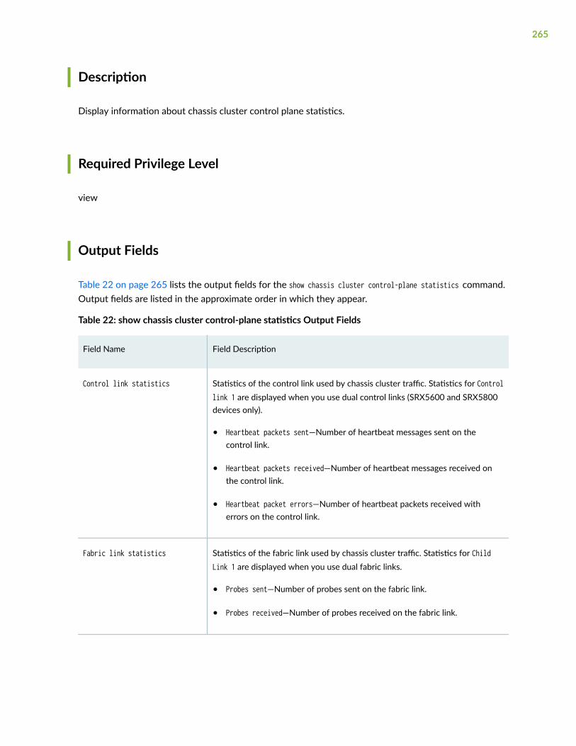
Description
Display information about chassis cluster control plane statistics.
Required Privilege Level
view
Output Fields
Table 22 on page 265 lists the output fields for the show chassis cluster control-plane statistics command.Output fields are listed in the approximate order in which they appear.
Table 22: show chassis cluster control-plane statistics Output Fields
Field Name Field Description
Control link statistics Statistics of the control link used by chassis cluster traffic. Statistics for Controllink 1 are displayed when you use dual control links (SRX5600 and SRX5800devices only).
• Heartbeat packets sent—Number of heartbeat messages sent on thecontrol link.
• Heartbeat packets received—Number of heartbeat messages received onthe control link.
• Heartbeat packet errors—Number of heartbeat packets received witherrors on the control link.
Fabric link statistics Statistics of the fabric link used by chassis cluster traffic. Statistics for ChildLink 1 are displayed when you use dual fabric links.
• Probes sent—Number of probes sent on the fabric link.
• Probes received—Number of probes received on the fabric link.
265
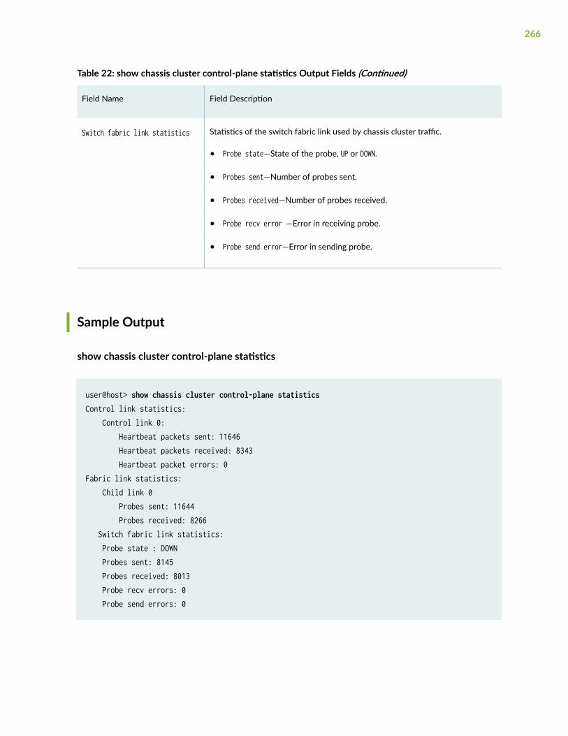
Table 22: show chassis cluster control-plane statistics Output Fields (Continued)
Field Name Field Description
Switch fabric link statistics Statistics of the switch fabric link used by chassis cluster traffic.
• Probe state—State of the probe, UP or DOWN.
• Probes sent—Number of probes sent.
• Probes received—Number of probes received.
• Probe recv error —Error in receiving probe.
• Probe send error—Error in sending probe.
Sample Output
show chassis cluster control-plane statistics
user@host> show chassis cluster control-plane statistics Control link statistics: Control link 0: Heartbeat packets sent: 11646 Heartbeat packets received: 8343 Heartbeat packet errors: 0Fabric link statistics: Child link 0 Probes sent: 11644 Probes received: 8266 Switch fabric link statistics: Probe state : DOWN Probes sent: 8145 Probes received: 8013 Probe recv errors: 0 Probe send errors: 0
266
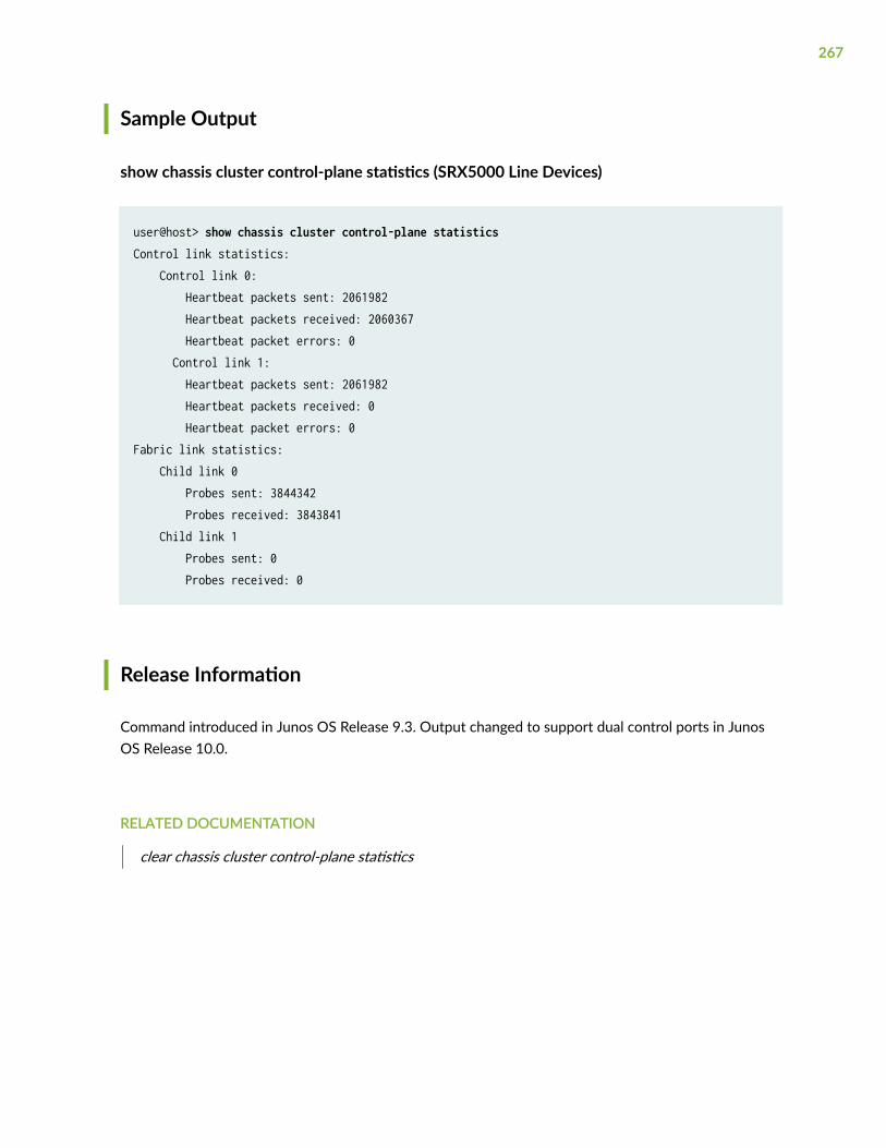
Sample Output
show chassis cluster control-plane statistics (SRX5000 Line Devices)
user@host> show chassis cluster control-plane statisticsControl link statistics: Control link 0: Heartbeat packets sent: 2061982 Heartbeat packets received: 2060367 Heartbeat packet errors: 0 Control link 1: Heartbeat packets sent: 2061982 Heartbeat packets received: 0 Heartbeat packet errors: 0Fabric link statistics: Child link 0 Probes sent: 3844342 Probes received: 3843841 Child link 1 Probes sent: 0 Probes received: 0
Release Information
Command introduced in Junos OS Release 9.3. Output changed to support dual control ports in JunosOS Release 10.0.
RELATED DOCUMENTATION
clear chassis cluster control-plane statistics
267

show chassis cluster data-plane interfaces
IN THIS SECTION
Syntax | 268
Description | 268
Required Privilege Level | 268
Output Fields | 268
Sample Output | 269
Release Information | 269
Syntax
show chassis cluster data-plane interfaces
Description
Display the status of the data plane interface (also known as a fabric interface) in a chassis clusterconfiguration.
Required Privilege Level
view
Output Fields
Table 23 on page 269 lists the output fields for the show chassis cluster data-plane interfaces command.Output fields are listed in the approximate order in which they appear.
268
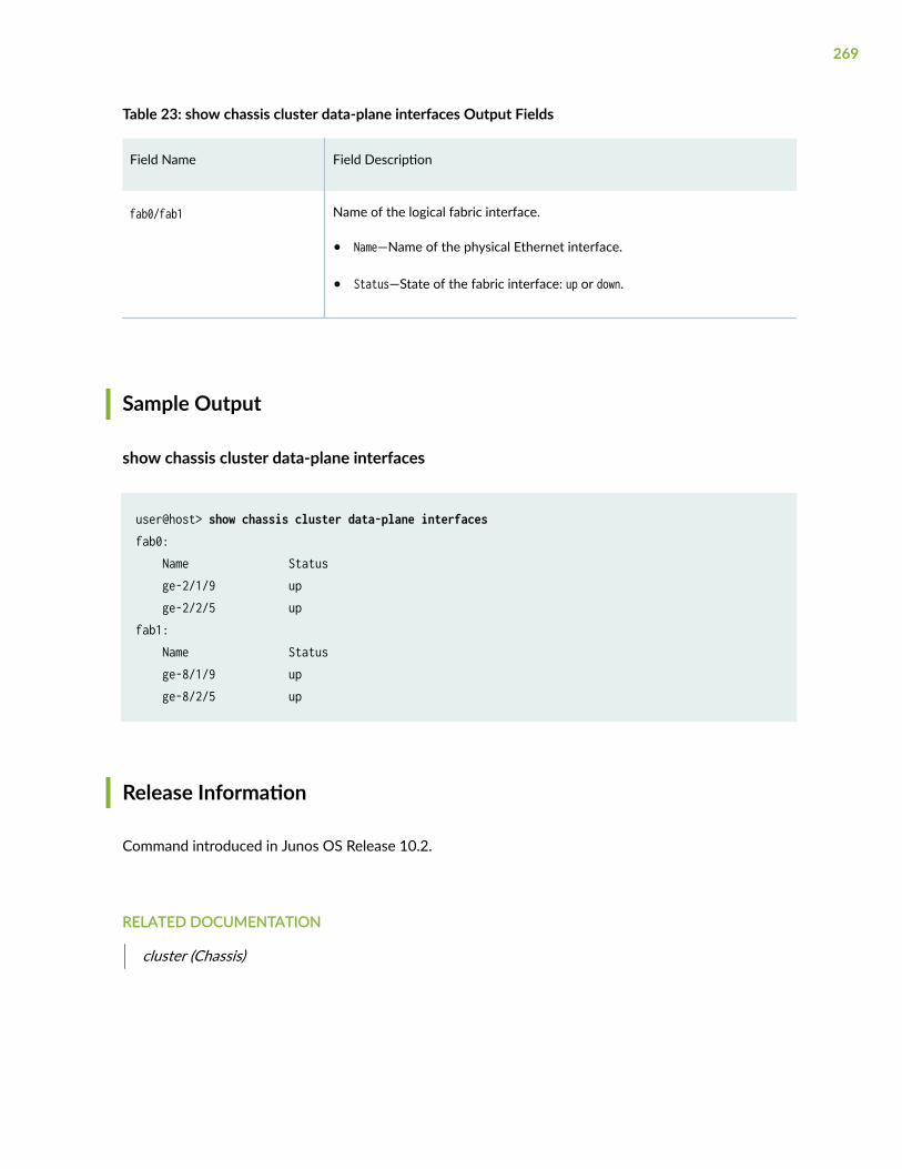
Table 23: show chassis cluster data-plane interfaces Output Fields
Field Name Field Description
fab0/fab1 Name of the logical fabric interface.
• Name—Name of the physical Ethernet interface.
• Status—State of the fabric interface: up or down.
Sample Output
show chassis cluster data-plane interfaces
user@host> show chassis cluster data-plane interfaces fab0: Name Status ge-2/1/9 up ge-2/2/5 up fab1: Name Status ge-8/1/9 up ge-8/2/5 up
Release Information
Command introduced in Junos OS Release 10.2.
RELATED DOCUMENTATION
cluster (Chassis)
269
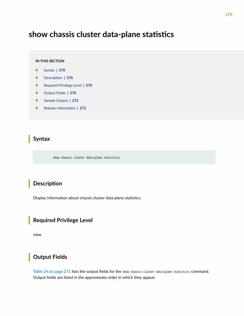
show chassis cluster data-plane statistics
IN THIS SECTION
Syntax | 270
Description | 270
Required Privilege Level | 270
Output Fields | 270
Sample Output | 272
Release Information | 272
Syntax
show chassis cluster data-plane statistics
Description
Display information about chassis cluster data plane statistics.
Required Privilege Level
view
Output Fields
Table 24 on page 271 lists the output fields for the show chassis cluster data-plane statistics command.Output fields are listed in the approximate order in which they appear.
270
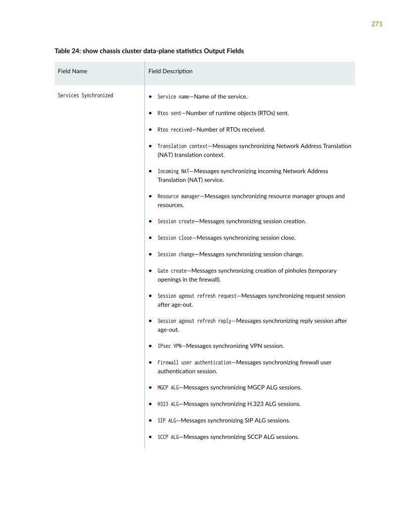
Table 24: show chassis cluster data-plane statistics Output Fields
Field Name Field Description
Services Synchronized • Service name—Name of the service.
• Rtos sent—Number of runtime objects (RTOs) sent.
• Rtos received—Number of RTOs received.
• Translation context—Messages synchronizing Network Address Translation(NAT) translation context.
• Incoming NAT—Messages synchronizing incoming Network AddressTranslation (NAT) service.
• Resource manager—Messages synchronizing resource manager groups andresources.
• Session create—Messages synchronizing session creation.
• Session close—Messages synchronizing session close.
• Session change—Messages synchronizing session change.
• Gate create—Messages synchronizing creation of pinholes (temporaryopenings in the firewall).
• Session ageout refresh request—Messages synchronizing request sessionafter age-out.
• Session ageout refresh reply—Messages synchronizing reply session afterage-out.
• IPsec VPN—Messages synchronizing VPN session.
• Firewall user authentication—Messages synchronizing firewall userauthentication session.
• MGCP ALG—Messages synchronizing MGCP ALG sessions.
• H323 ALG—Messages synchronizing H.323 ALG sessions.
• SIP ALG—Messages synchronizing SIP ALG sessions.
• SCCP ALG—Messages synchronizing SCCP ALG sessions.
271
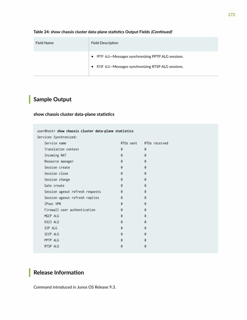
Table 24: show chassis cluster data-plane statistics Output Fields (Continued)
Field Name Field Description
• PPTP ALG—Messages synchronizing PPTP ALG sessions.
• RTSP ALG—Messages synchronizing RTSP ALG sessions.
Sample Output
show chassis cluster data-plane statistics
user@host> show chassis cluster data-plane statistics Services Synchronized: Service name RTOs sent RTOs received Translation context 0 0 Incoming NAT 0 0 Resource manager 0 0 Session create 0 0 Session close 0 0 Session change 0 0 Gate create 0 0 Session ageout refresh requests 0 0 Session ageout refresh replies 0 0 IPsec VPN 0 0 Firewall user authentication 0 0 MGCP ALG 0 0 H323 ALG 0 0 SIP ALG 0 0 SCCP ALG 0 0 PPTP ALG 0 0 RTSP ALG 0 0
Release Information
Command introduced in Junos OS Release 9.3.
272
RELATED DOCUMENTATION
clear chassis cluster data-plane statistics
show chassis cluster information
IN THIS SECTION
Syntax | 273
Description | 273
Required Privilege Level | 274
Output Fields | 274
Sample Output | 275
Sample Output | 276
Sample Output | 278
Release Information | 279
Syntax
show chassis cluster information
Description
Display chassis cluster messages. The messages indicate each node's health condition and details of themonitored failure.
273
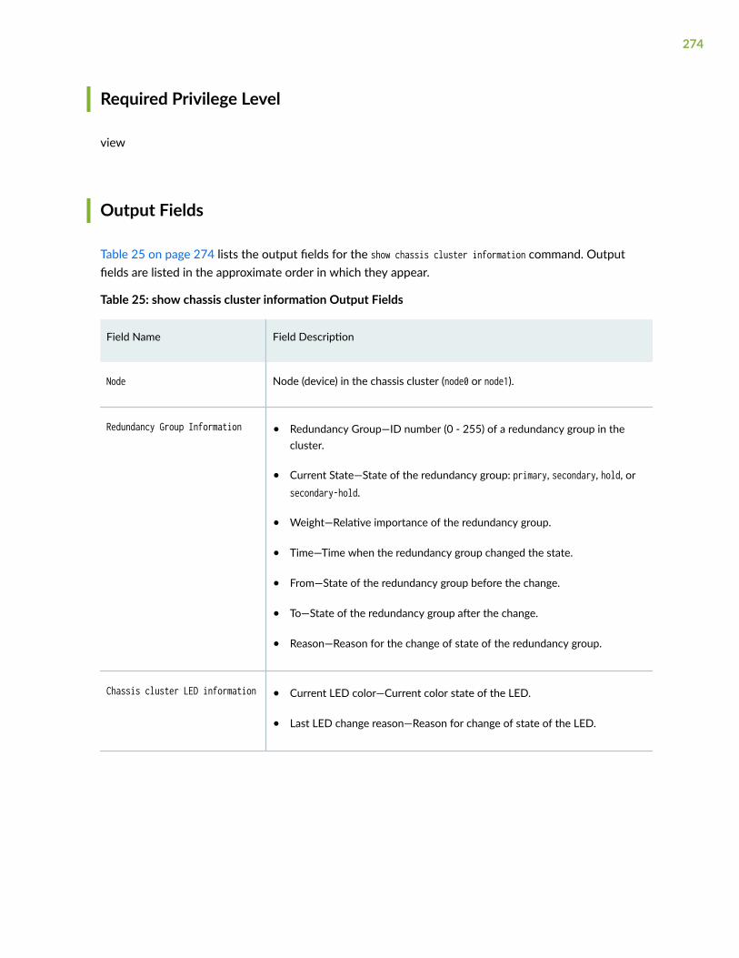
Required Privilege Level
view
Output Fields
Table 25 on page 274 lists the output fields for the show chassis cluster information command. Outputfields are listed in the approximate order in which they appear.
Table 25: show chassis cluster information Output Fields
Field Name Field Description
Node Node (device) in the chassis cluster (node0 or node1).
Redundancy Group Information • Redundancy Group—ID number (0 - 255) of a redundancy group in thecluster.
• Current State—State of the redundancy group: primary, secondary, hold, orsecondary-hold.
• Weight—Relative importance of the redundancy group.
• Time—Time when the redundancy group changed the state.
• From—State of the redundancy group before the change.
• To—State of the redundancy group after the change.
• Reason—Reason for the change of state of the redundancy group.
Chassis cluster LED information • Current LED color—Current color state of the LED.
• Last LED change reason—Reason for change of state of the LED.
274
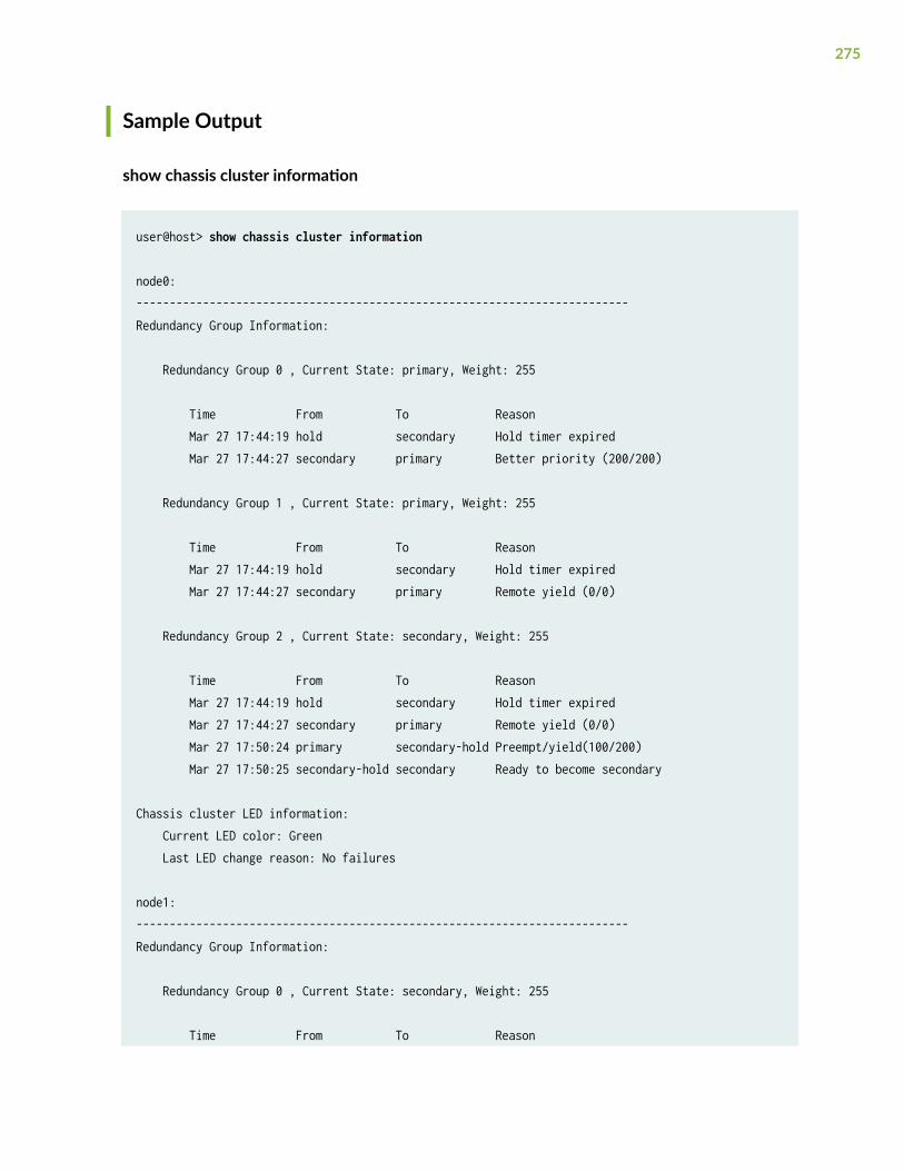
Sample Output
show chassis cluster information
user@host> show chassis cluster information
node0:--------------------------------------------------------------------------Redundancy Group Information:
Redundancy Group 0 , Current State: primary, Weight: 255
Time From To Reason Mar 27 17:44:19 hold secondary Hold timer expired Mar 27 17:44:27 secondary primary Better priority (200/200)
Redundancy Group 1 , Current State: primary, Weight: 255
Time From To Reason Mar 27 17:44:19 hold secondary Hold timer expired Mar 27 17:44:27 secondary primary Remote yield (0/0)
Redundancy Group 2 , Current State: secondary, Weight: 255
Time From To Reason Mar 27 17:44:19 hold secondary Hold timer expired Mar 27 17:44:27 secondary primary Remote yield (0/0) Mar 27 17:50:24 primary secondary-hold Preempt/yield(100/200) Mar 27 17:50:25 secondary-hold secondary Ready to become secondary
Chassis cluster LED information: Current LED color: Green Last LED change reason: No failures
node1:--------------------------------------------------------------------------Redundancy Group Information:
Redundancy Group 0 , Current State: secondary, Weight: 255
Time From To Reason
275
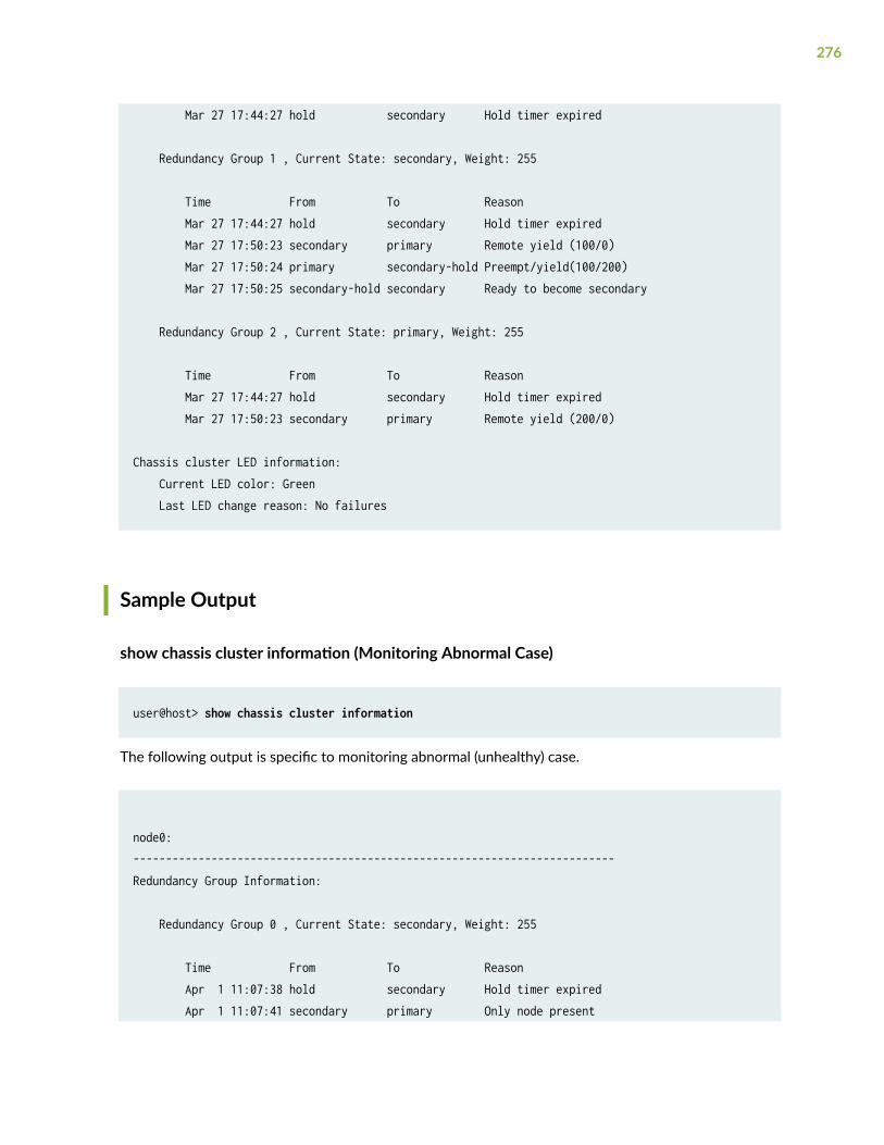
Mar 27 17:44:27 hold secondary Hold timer expired
Redundancy Group 1 , Current State: secondary, Weight: 255
Time From To Reason Mar 27 17:44:27 hold secondary Hold timer expired Mar 27 17:50:23 secondary primary Remote yield (100/0) Mar 27 17:50:24 primary secondary-hold Preempt/yield(100/200) Mar 27 17:50:25 secondary-hold secondary Ready to become secondary
Redundancy Group 2 , Current State: primary, Weight: 255
Time From To Reason Mar 27 17:44:27 hold secondary Hold timer expired Mar 27 17:50:23 secondary primary Remote yield (200/0)
Chassis cluster LED information: Current LED color: Green Last LED change reason: No failures
Sample Output
show chassis cluster information (Monitoring Abnormal Case)
user@host> show chassis cluster information
The following output is specific to monitoring abnormal (unhealthy) case.
node0:--------------------------------------------------------------------------Redundancy Group Information:
Redundancy Group 0 , Current State: secondary, Weight: 255
Time From To Reason Apr 1 11:07:38 hold secondary Hold timer expired Apr 1 11:07:41 secondary primary Only node present
276
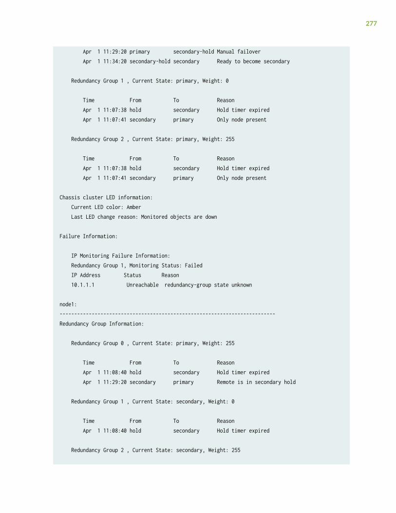
Apr 1 11:29:20 primary secondary-hold Manual failover Apr 1 11:34:20 secondary-hold secondary Ready to become secondary
Redundancy Group 1 , Current State: primary, Weight: 0
Time From To Reason Apr 1 11:07:38 hold secondary Hold timer expired Apr 1 11:07:41 secondary primary Only node present
Redundancy Group 2 , Current State: primary, Weight: 255
Time From To Reason Apr 1 11:07:38 hold secondary Hold timer expired Apr 1 11:07:41 secondary primary Only node present
Chassis cluster LED information: Current LED color: Amber Last LED change reason: Monitored objects are down
Failure Information:
IP Monitoring Failure Information: Redundancy Group 1, Monitoring Status: Failed IP Address Status Reason 10.1.1.1 Unreachable redundancy-group state unknown
node1:--------------------------------------------------------------------------Redundancy Group Information:
Redundancy Group 0 , Current State: primary, Weight: 255
Time From To Reason Apr 1 11:08:40 hold secondary Hold timer expired Apr 1 11:29:20 secondary primary Remote is in secondary hold
Redundancy Group 1 , Current State: secondary, Weight: 0
Time From To Reason Apr 1 11:08:40 hold secondary Hold timer expired
Redundancy Group 2 , Current State: secondary, Weight: 255
277
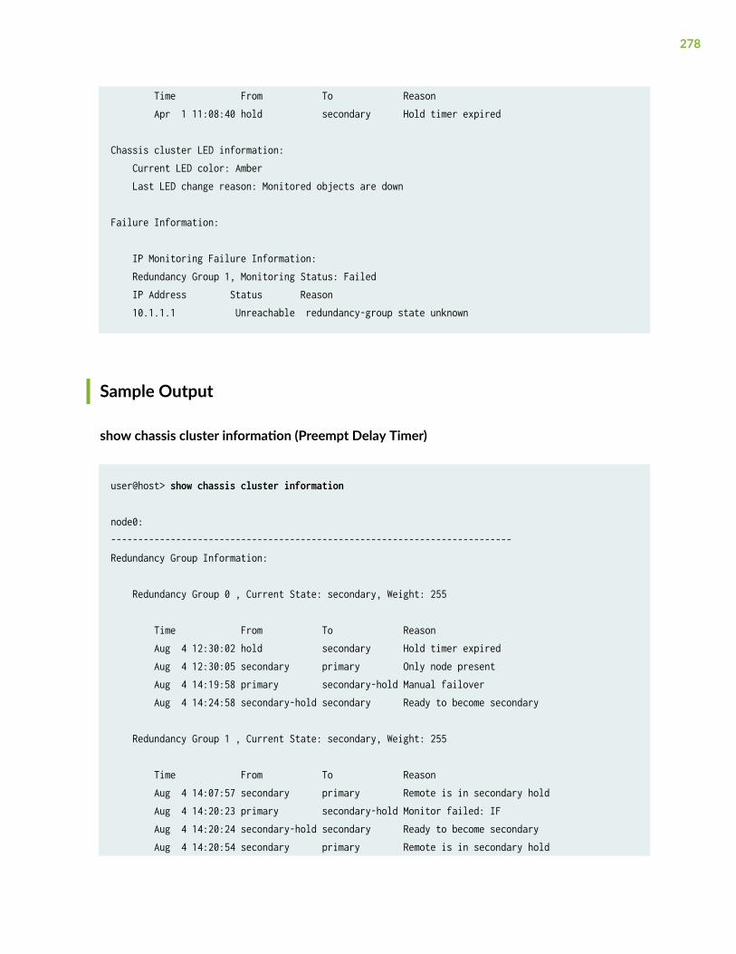
Time From To Reason Apr 1 11:08:40 hold secondary Hold timer expired
Chassis cluster LED information: Current LED color: Amber Last LED change reason: Monitored objects are down
Failure Information:
IP Monitoring Failure Information: Redundancy Group 1, Monitoring Status: Failed IP Address Status Reason 10.1.1.1 Unreachable redundancy-group state unknown
Sample Output
show chassis cluster information (Preempt Delay Timer)
user@host> show chassis cluster information
node0:--------------------------------------------------------------------------Redundancy Group Information:
Redundancy Group 0 , Current State: secondary, Weight: 255
Time From To Reason Aug 4 12:30:02 hold secondary Hold timer expired Aug 4 12:30:05 secondary primary Only node present Aug 4 14:19:58 primary secondary-hold Manual failover Aug 4 14:24:58 secondary-hold secondary Ready to become secondary
Redundancy Group 1 , Current State: secondary, Weight: 255
Time From To Reason Aug 4 14:07:57 secondary primary Remote is in secondary hold Aug 4 14:20:23 primary secondary-hold Monitor failed: IF Aug 4 14:20:24 secondary-hold secondary Ready to become secondary Aug 4 14:20:54 secondary primary Remote is in secondary hold
278

Aug 4 14:21:30 primary secondary-hold Monitor failed: IF Aug 4 14:21:31 secondary-hold secondary Ready to become secondary
Chassis cluster LED information: Current LED color: Green Last LED change reason: No failures
node1:--------------------------------------------------------------------------Redundancy Group Information:
Redundancy Group 0 , Current State: primary, Weight: 255
Time From To Reason Aug 4 12:33:47 hold secondary Hold timer expired Aug 4 14:19:57 secondary primary Remote is in secondary hold Redundancy Group 1 , Current State: primary, Weight: 255
Time From To Reason Aug 4 14:07:56 secondary-hold secondary Ready to become secondary Aug 4 14:20:22 secondary primary Remote is in secondary hold Aug 4 14:20:37 primary primary-preempt-hold Preempt (99/101) Aug 4 14:20:52 primary-preempt-hold secondary-hold Primary preempt hold timer e Aug 4 14:20:53 secondary-hold secondary Ready to become secondary Aug 4 14:21:28 secondary primary Remote yield (99/0) Chassis cluster LED information: Current LED color: Green Last LED change reason: No failures
Release Information
Command introduced in Junos OS Release 12.1X47-D10.
RELATED DOCUMENTATION
show chassis cluster status
279
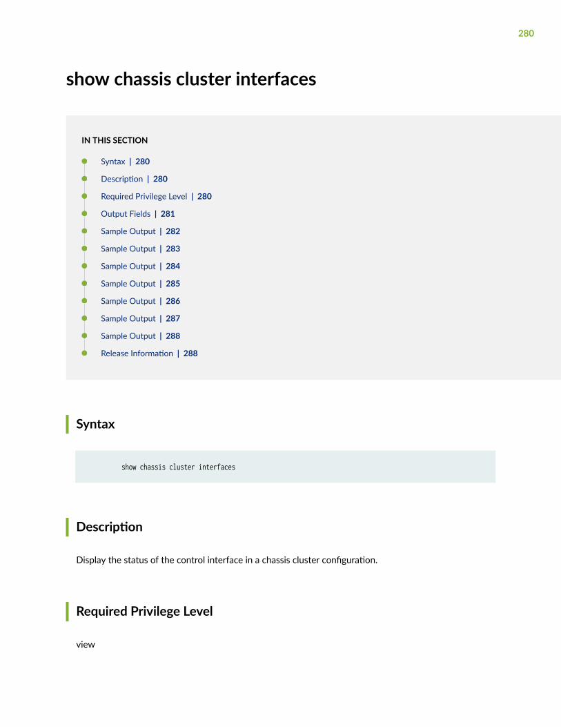
show chassis cluster interfaces
IN THIS SECTION
Syntax | 280
Description | 280
Required Privilege Level | 280
Output Fields | 281
Sample Output | 282
Sample Output | 283
Sample Output | 284
Sample Output | 285
Sample Output | 286
Sample Output | 287
Sample Output | 288
Release Information | 288
Syntax
show chassis cluster interfaces
Description
Display the status of the control interface in a chassis cluster configuration.
Required Privilege Level
view
280
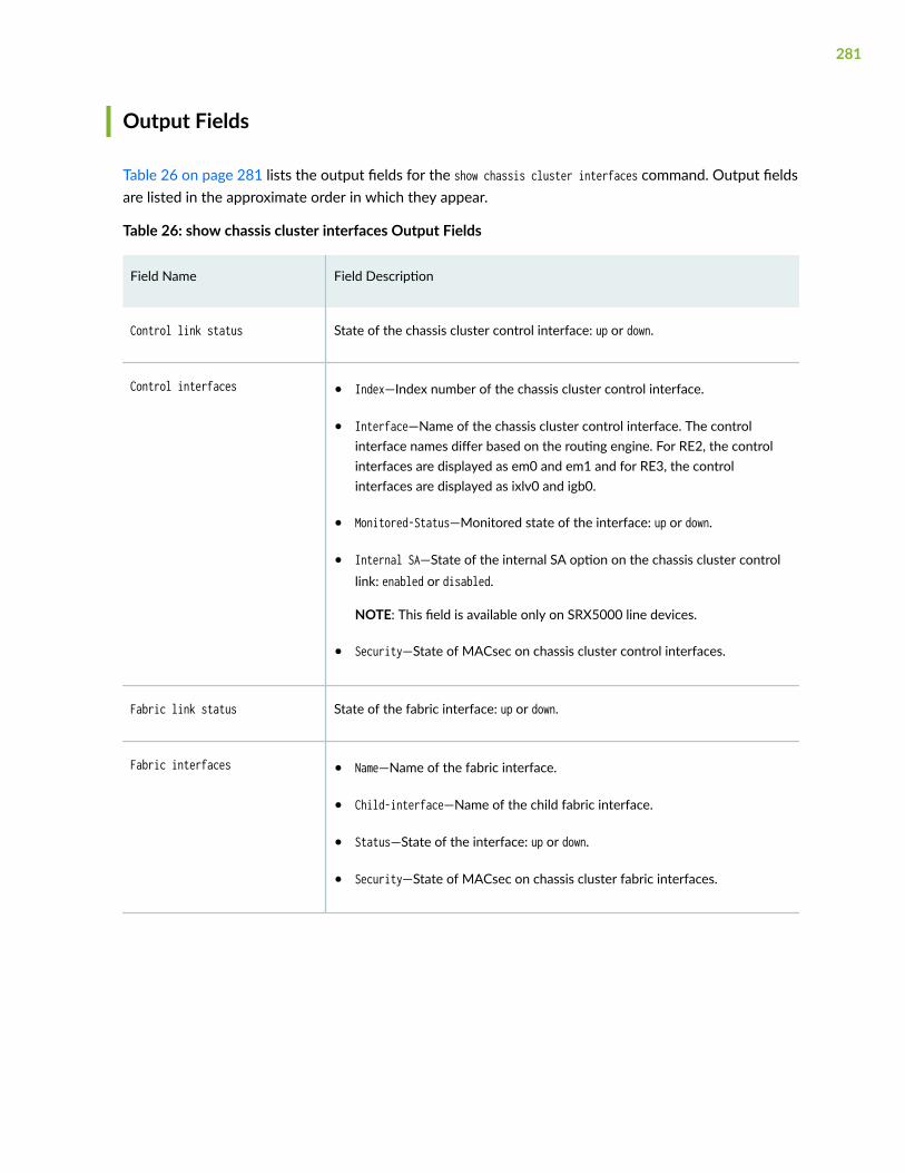
Output Fields
Table 26 on page 281 lists the output fields for the show chassis cluster interfaces command. Output fieldsare listed in the approximate order in which they appear.
Table 26: show chassis cluster interfaces Output Fields
Field Name Field Description
Control link status State of the chassis cluster control interface: up or down.
Control interfaces • Index—Index number of the chassis cluster control interface.
• Interface—Name of the chassis cluster control interface. The controlinterface names differ based on the routing engine. For RE2, the controlinterfaces are displayed as em0 and em1 and for RE3, the controlinterfaces are displayed as ixlv0 and igb0.
• Monitored-Status—Monitored state of the interface: up or down.
• Internal SA—State of the internal SA option on the chassis cluster controllink: enabled or disabled.
NOTE: This field is available only on SRX5000 line devices.
• Security—State of MACsec on chassis cluster control interfaces.
Fabric link status State of the fabric interface: up or down.
Fabric interfaces • Name—Name of the fabric interface.
• Child-interface—Name of the child fabric interface.
• Status—State of the interface: up or down.
• Security—State of MACsec on chassis cluster fabric interfaces.
281
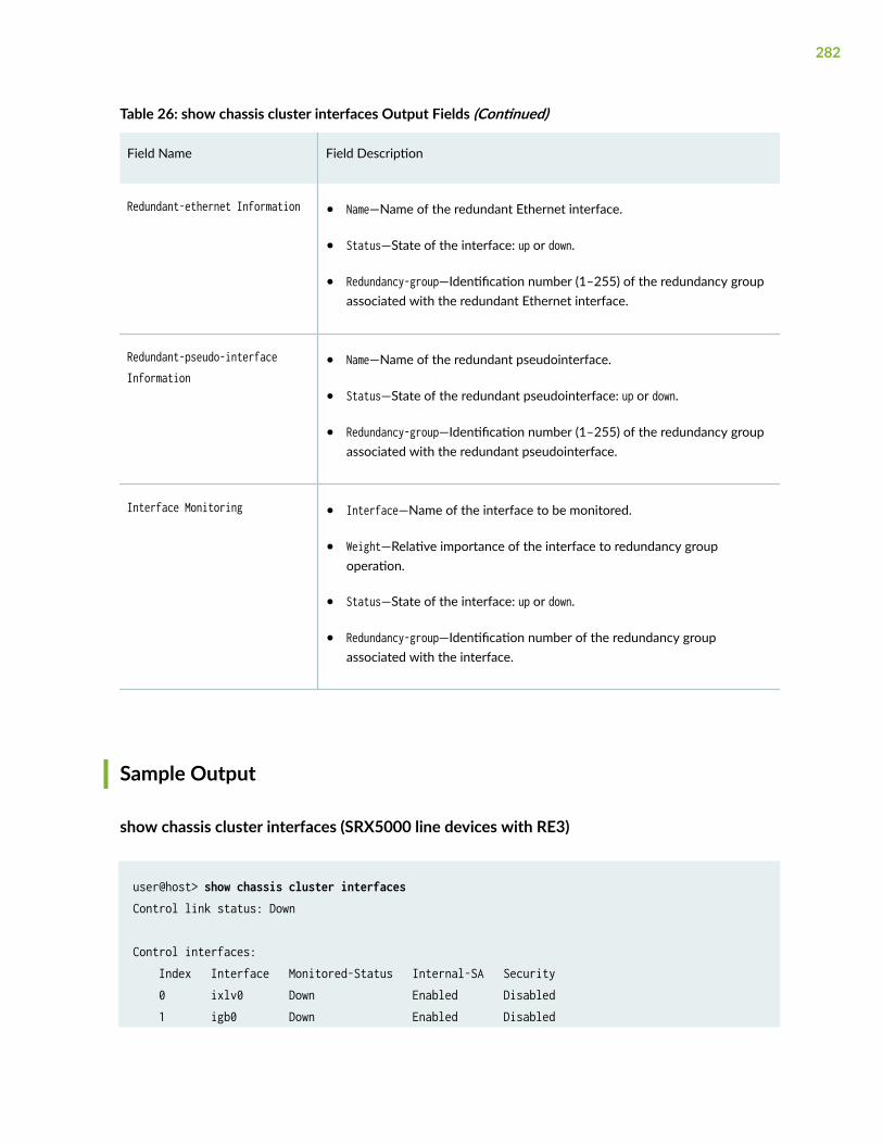
Table 26: show chassis cluster interfaces Output Fields (Continued)
Field Name Field Description
Redundant-ethernet Information • Name—Name of the redundant Ethernet interface.
• Status—State of the interface: up or down.
• Redundancy-group—Identification number (1–255) of the redundancy groupassociated with the redundant Ethernet interface.
Redundant-pseudo-interfaceInformation
• Name—Name of the redundant pseudointerface.
• Status—State of the redundant pseudointerface: up or down.
• Redundancy-group—Identification number (1–255) of the redundancy groupassociated with the redundant pseudointerface.
Interface Monitoring • Interface—Name of the interface to be monitored.
• Weight—Relative importance of the interface to redundancy groupoperation.
• Status—State of the interface: up or down.
• Redundancy-group—Identification number of the redundancy groupassociated with the interface.
Sample Output
show chassis cluster interfaces (SRX5000 line devices with RE3)
user@host> show chassis cluster interfacesControl link status: Down
Control interfaces: Index Interface Monitored-Status Internal-SA Security 0 ixlv0 Down Enabled Disabled 1 igb0 Down Enabled Disabled
282
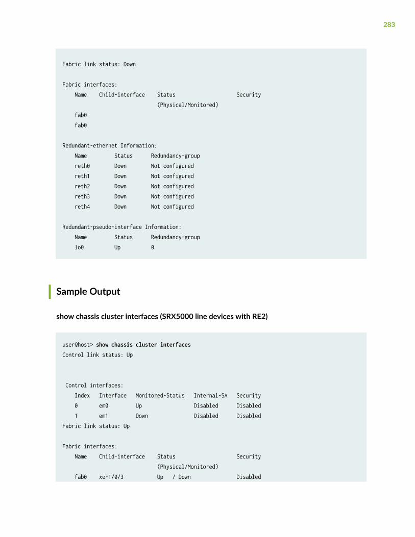
Fabric link status: Down
Fabric interfaces: Name Child-interface Status Security (Physical/Monitored) fab0 fab0
Redundant-ethernet Information: Name Status Redundancy-group reth0 Down Not configured reth1 Down Not configured reth2 Down Not configured reth3 Down Not configured reth4 Down Not configured
Redundant-pseudo-interface Information: Name Status Redundancy-group lo0 Up 0
Sample Output
show chassis cluster interfaces (SRX5000 line devices with RE2)
user@host> show chassis cluster interfaces Control link status: Up
Control interfaces: Index Interface Monitored-Status Internal-SA Security 0 em0 Up Disabled Disabled 1 em1 Down Disabled DisabledFabric link status: Up
Fabric interfaces: Name Child-interface Status Security (Physical/Monitored) fab0 xe-1/0/3 Up / Down Disabled
283
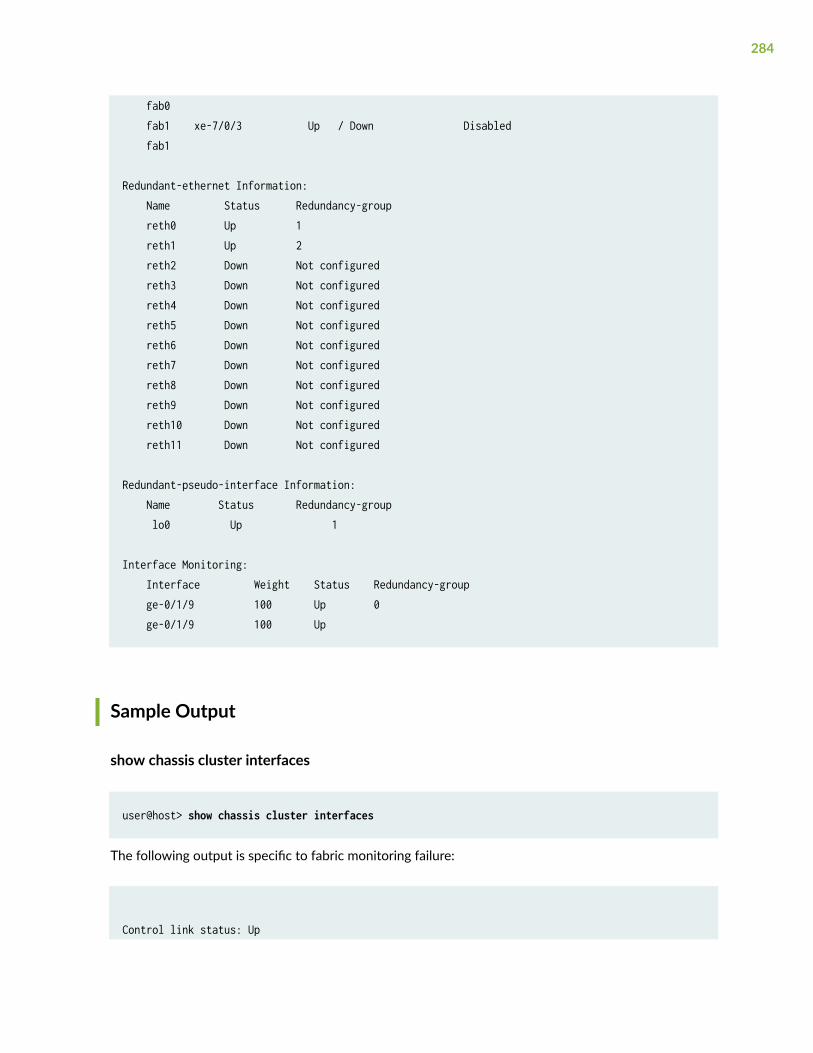
fab0 fab1 xe-7/0/3 Up / Down Disabled fab1
Redundant-ethernet Information: Name Status Redundancy-group reth0 Up 1 reth1 Up 2 reth2 Down Not configured reth3 Down Not configured reth4 Down Not configured reth5 Down Not configured reth6 Down Not configured reth7 Down Not configured reth8 Down Not configured reth9 Down Not configured reth10 Down Not configured reth11 Down Not configured
Redundant-pseudo-interface Information: Name Status Redundancy-group lo0 Up 1
Interface Monitoring: Interface Weight Status Redundancy-group ge-0/1/9 100 Up 0 ge-0/1/9 100 Up
Sample Output
show chassis cluster interfaces
user@host> show chassis cluster interfaces
The following output is specific to fabric monitoring failure:
Control link status: Up
284
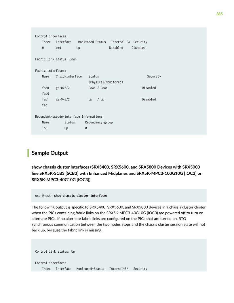
Control interfaces: Index Interface Monitored-Status Internal-SA Security 0 em0 Up Disabled Disabled
Fabric link status: Down
Fabric interfaces: Name Child-interface Status Security (Physical/Monitored) fab0 ge-0/0/2 Down / Down Disabled fab0 fab1 ge-9/0/2 Up / Up Disabled fab1 Redundant-pseudo-interface Information: Name Status Redundancy-group lo0 Up 0
Sample Output
show chassis cluster interfaces (SRX5400, SRX5600, and SRX5800 Devices with SRX5000line SRX5K-SCB3 [SCB3] with Enhanced Midplanes and SRX5K-MPC3-100G10G [IOC3] orSRX5K-MPC3-40G10G [IOC3])
user@host> show chassis cluster interfaces
The following output is specific to SRX5400, SRX5600, and SRX5800 devices in a chassis cluster cluster,when the PICs containing fabric links on the SRX5K-MPC3-40G10G (IOC3) are powered off to turn onalternate PICs. If no alternate fabric links are configured on the PICs that are turned on, RTOsynchronous communication between the two nodes stops and the chassis cluster session state will notback up, because the fabric link is missing.
Control link status: Up Control interfaces: Index Interface Monitored-Status Internal-SA Security
285
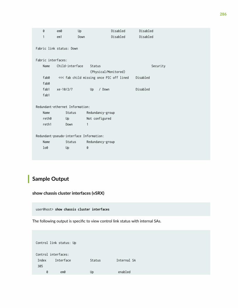
0 em0 Up Disabled Disabled 1 em1 Down Disabled Disabled Fabric link status: Down Fabric interfaces: Name Child-interface Status Security (Physical/Monitored) fab0 <<< fab child missing once PIC off lined Disabled fab0 fab1 xe-10/2/7 Up / Down Disabled fab1 Redundant-ethernet Information: Name Status Redundancy-group reth0 Up Not configured reth1 Down 1 Redundant-pseudo-interface Information: Name Status Redundancy-group lo0 Up 0
Sample Output
show chassis cluster interfaces (vSRX)
user@host> show chassis cluster interfaces
The following output is specific to view control link status with internal SAs.
Control link status: Up
Control interfaces: Index Interface Status Internal SA 305 0 em0 Up enabled
286
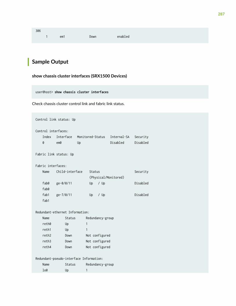
306 1 em1 Down enabled
Sample Output
show chassis cluster interfaces (SRX1500 Devices)
user@host> show chassis cluster interfaces
Check chassis cluster control link and fabric link status.
Control link status: Up
Control interfaces: Index Interface Monitored-Status Internal-SA Security 0 em0 Up Disabled Disabled
Fabric link status: Up
Fabric interfaces: Name Child-interface Status Security (Physical/Monitored) fab0 ge-0/0/11 Up / Up Disabled fab0 fab1 ge-7/0/11 Up / Up Disabled fab1
Redundant-ethernet Information: Name Status Redundancy-group reth0 Up 1 reth1 Up 1 reth2 Down Not configured reth3 Down Not configured reth4 Down Not configured
Redundant-pseudo-interface Information: Name Status Redundancy-group lo0 Up 1
287
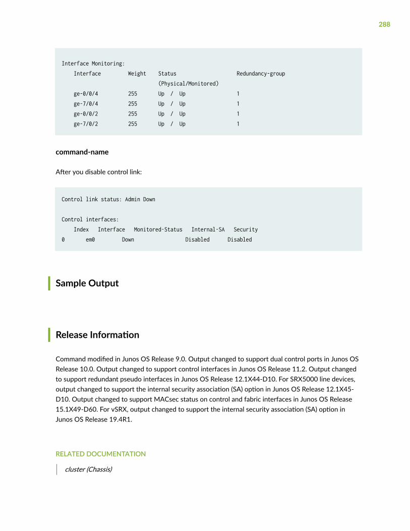
Interface Monitoring: Interface Weight Status Redundancy-group (Physical/Monitored) ge-0/0/4 255 Up / Up 1 ge-7/0/4 255 Up / Up 1 ge-0/0/2 255 Up / Up 1 ge-7/0/2 255 Up / Up 1
command-name
After you disable control link:
Control link status: Admin Down
Control interfaces: Index Interface Monitored-Status Internal-SA Security0 em0 Down Disabled Disabled
Sample Output
Release Information
Command modified in Junos OS Release 9.0. Output changed to support dual control ports in Junos OSRelease 10.0. Output changed to support control interfaces in Junos OS Release 11.2. Output changedto support redundant pseudo interfaces in Junos OS Release 12.1X44-D10. For SRX5000 line devices,output changed to support the internal security association (SA) option in Junos OS Release 12.1X45-D10. Output changed to support MACsec status on control and fabric interfaces in Junos OS Release15.1X49-D60. For vSRX, output changed to support the internal security association (SA) option inJunos OS Release 19.4R1.
RELATED DOCUMENTATION
cluster (Chassis)
288
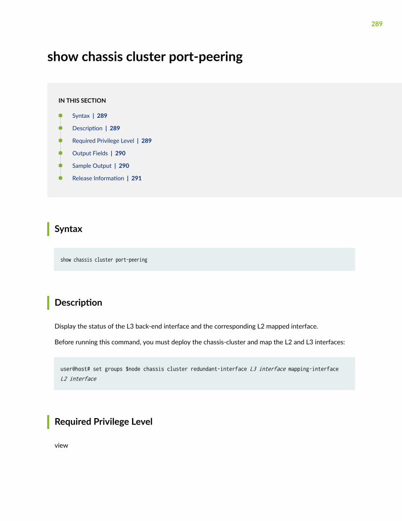
show chassis cluster port-peering
IN THIS SECTION
Syntax | 289
Description | 289
Required Privilege Level | 289
Output Fields | 290
Sample Output | 290
Release Information | 291
Syntax
show chassis cluster port-peering
Description
Display the status of the L3 back-end interface and the corresponding L2 mapped interface.
Before running this command, you must deploy the chassis-cluster and map the L2 and L3 interfaces:
user@host# set groups $node chassis cluster redundant-interface L3 interface mapping-interface L2 interface
Required Privilege Level
view
289
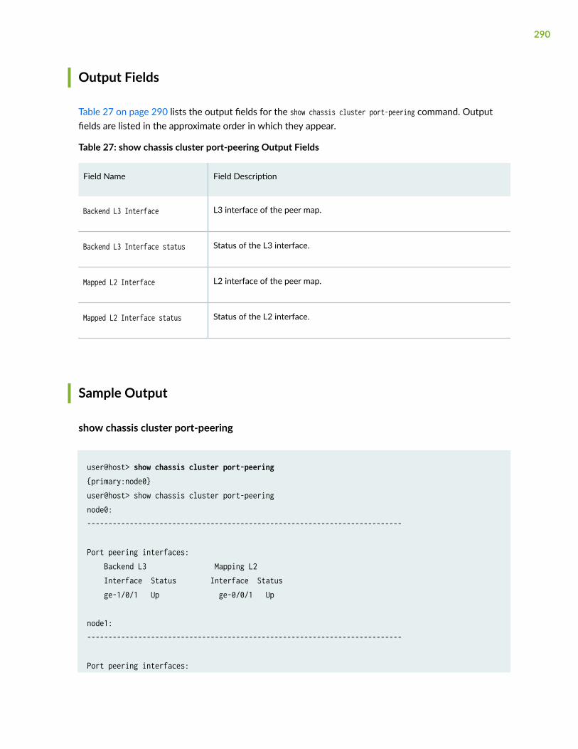
Output Fields
Table 27 on page 290 lists the output fields for the show chassis cluster port-peering command. Outputfields are listed in the approximate order in which they appear.
Table 27: show chassis cluster port-peering Output Fields
Field Name Field Description
Backend L3 Interface L3 interface of the peer map.
Backend L3 Interface status Status of the L3 interface.
Mapped L2 Interface L2 interface of the peer map.
Mapped L2 Interface status Status of the L2 interface.
Sample Output
show chassis cluster port-peering
user@host> show chassis cluster port-peering {primary:node0}user@host> show chassis cluster port-peeringnode0:--------------------------------------------------------------------------
Port peering interfaces: Backend L3 Mapping L2 Interface Status Interface Status ge-1/0/1 Up ge-0/0/1 Up
node1:--------------------------------------------------------------------------
Port peering interfaces:
290
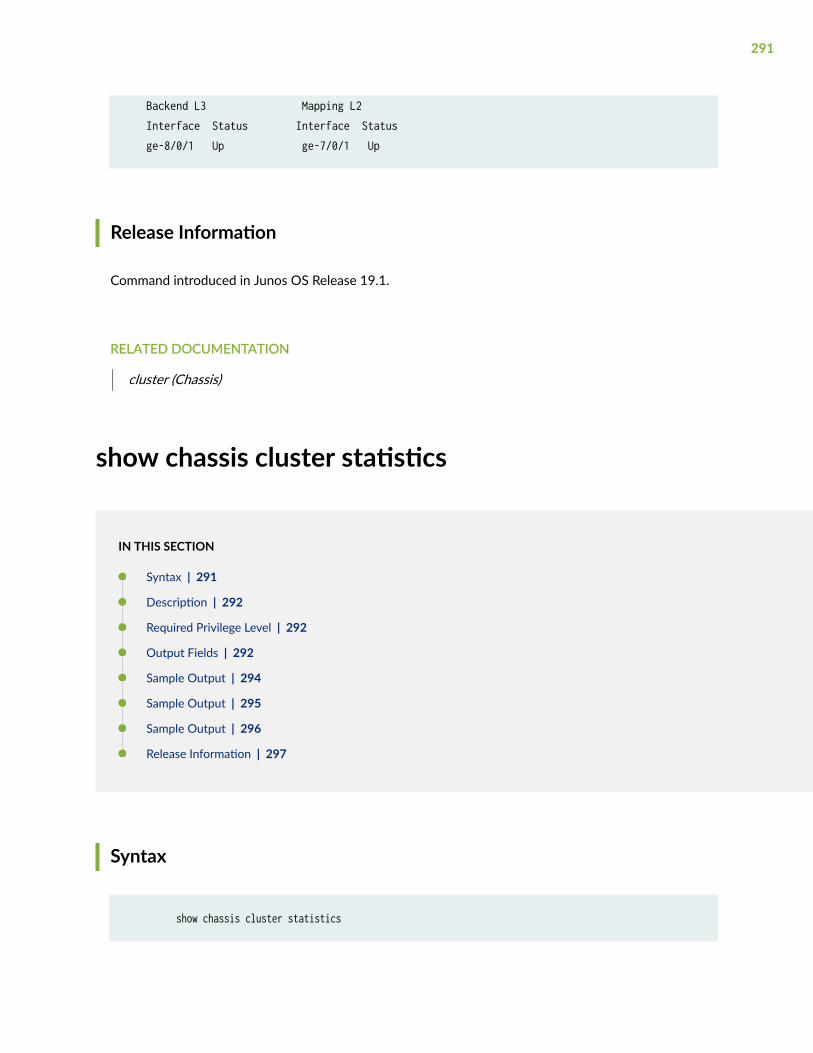
Backend L3 Mapping L2 Interface Status Interface Status ge-8/0/1 Up ge-7/0/1 Up
Release Information
Command introduced in Junos OS Release 19.1.
RELATED DOCUMENTATION
cluster (Chassis)
show chassis cluster statistics
IN THIS SECTION
Syntax | 291
Description | 292
Required Privilege Level | 292
Output Fields | 292
Sample Output | 294
Sample Output | 295
Sample Output | 296
Release Information | 297
Syntax
show chassis cluster statistics
291
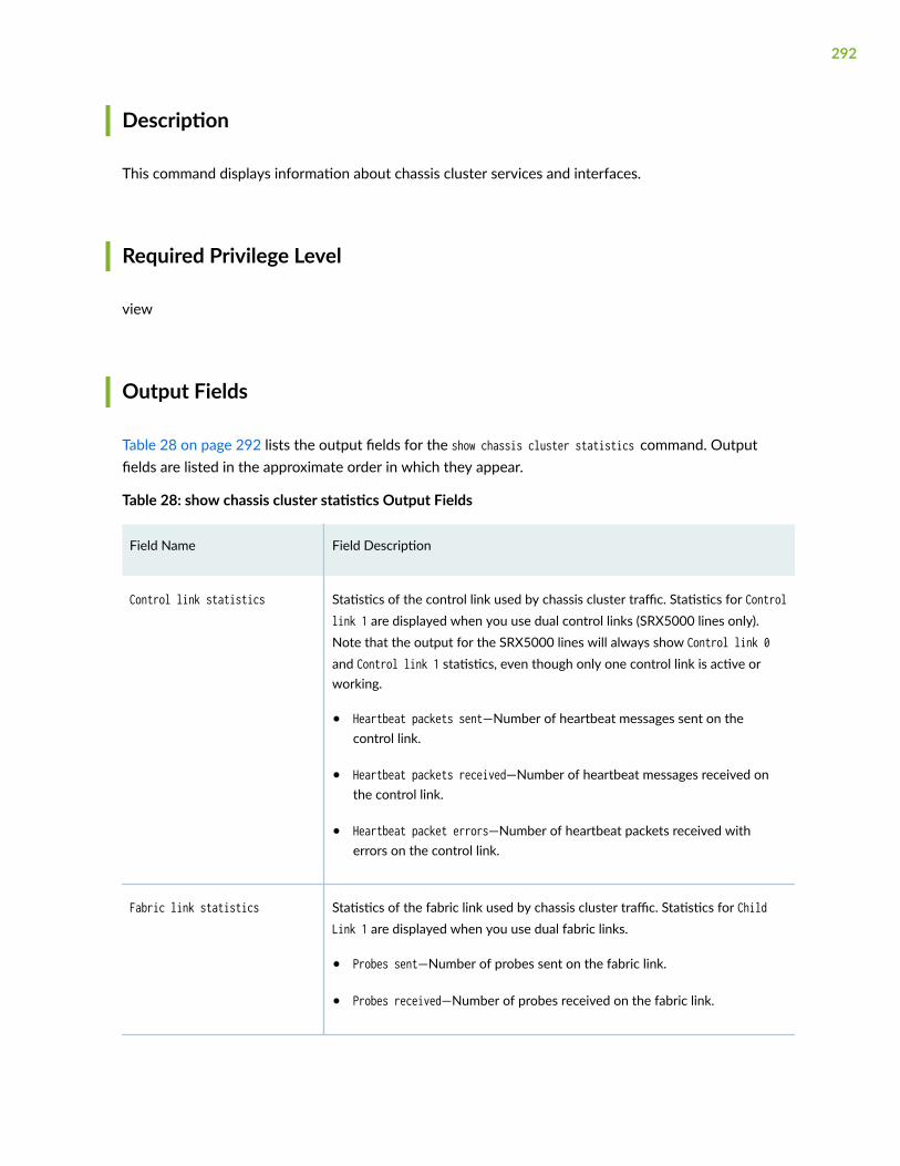
Description
This command displays information about chassis cluster services and interfaces.
Required Privilege Level
view
Output Fields
Table 28 on page 292 lists the output fields for the show chassis cluster statistics command. Outputfields are listed in the approximate order in which they appear.
Table 28: show chassis cluster statistics Output Fields
Field Name Field Description
Control link statistics Statistics of the control link used by chassis cluster traffic. Statistics for Controllink 1 are displayed when you use dual control links (SRX5000 lines only).Note that the output for the SRX5000 lines will always show Control link 0and Control link 1 statistics, even though only one control link is active orworking.
• Heartbeat packets sent—Number of heartbeat messages sent on thecontrol link.
• Heartbeat packets received—Number of heartbeat messages received onthe control link.
• Heartbeat packet errors—Number of heartbeat packets received witherrors on the control link.
Fabric link statistics Statistics of the fabric link used by chassis cluster traffic. Statistics for ChildLink 1 are displayed when you use dual fabric links.
• Probes sent—Number of probes sent on the fabric link.
• Probes received—Number of probes received on the fabric link.
292
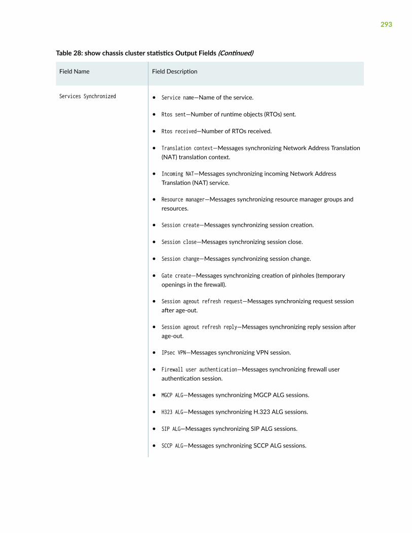
Table 28: show chassis cluster statistics Output Fields (Continued)
Field Name Field Description
Services Synchronized • Service name—Name of the service.
• Rtos sent—Number of runtime objects (RTOs) sent.
• Rtos received—Number of RTOs received.
• Translation context—Messages synchronizing Network Address Translation(NAT) translation context.
• Incoming NAT—Messages synchronizing incoming Network AddressTranslation (NAT) service.
• Resource manager—Messages synchronizing resource manager groups andresources.
• Session create—Messages synchronizing session creation.
• Session close—Messages synchronizing session close.
• Session change—Messages synchronizing session change.
• Gate create—Messages synchronizing creation of pinholes (temporaryopenings in the firewall).
• Session ageout refresh request—Messages synchronizing request sessionafter age-out.
• Session ageout refresh reply—Messages synchronizing reply session afterage-out.
• IPsec VPN—Messages synchronizing VPN session.
• Firewall user authentication—Messages synchronizing firewall userauthentication session.
• MGCP ALG—Messages synchronizing MGCP ALG sessions.
• H323 ALG—Messages synchronizing H.323 ALG sessions.
• SIP ALG—Messages synchronizing SIP ALG sessions.
• SCCP ALG—Messages synchronizing SCCP ALG sessions.
293
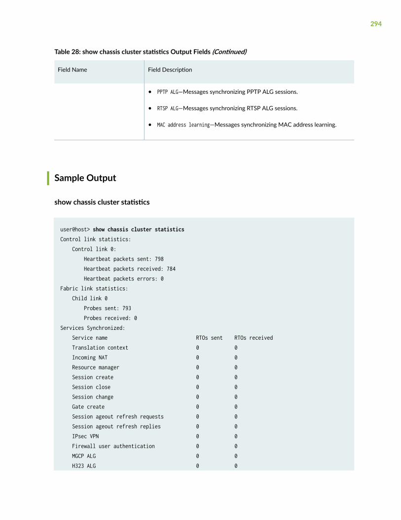
Table 28: show chassis cluster statistics Output Fields (Continued)
Field Name Field Description
• PPTP ALG—Messages synchronizing PPTP ALG sessions.
• RTSP ALG—Messages synchronizing RTSP ALG sessions.
• MAC address learning—Messages synchronizing MAC address learning.
Sample Output
show chassis cluster statistics
user@host> show chassis cluster statistics Control link statistics: Control link 0: Heartbeat packets sent: 798 Heartbeat packets received: 784 Heartbeat packets errors: 0Fabric link statistics: Child link 0 Probes sent: 793 Probes received: 0Services Synchronized: Service name RTOs sent RTOs received Translation context 0 0 Incoming NAT 0 0 Resource manager 0 0 Session create 0 0 Session close 0 0 Session change 0 0 Gate create 0 0 Session ageout refresh requests 0 0 Session ageout refresh replies 0 0 IPsec VPN 0 0 Firewall user authentication 0 0 MGCP ALG 0 0 H323 ALG 0 0
294
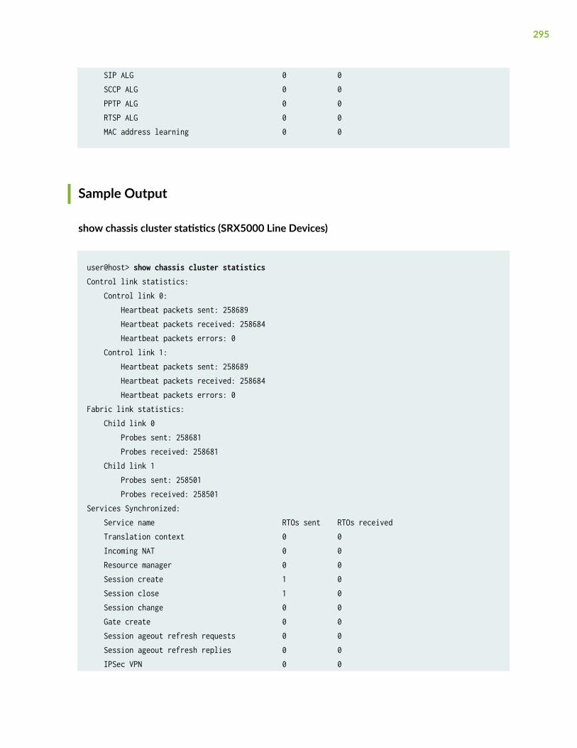
SIP ALG 0 0 SCCP ALG 0 0 PPTP ALG 0 0 RTSP ALG 0 0 MAC address learning 0 0
Sample Output
show chassis cluster statistics (SRX5000 Line Devices)
user@host> show chassis cluster statistics Control link statistics: Control link 0: Heartbeat packets sent: 258689 Heartbeat packets received: 258684 Heartbeat packets errors: 0 Control link 1: Heartbeat packets sent: 258689 Heartbeat packets received: 258684 Heartbeat packets errors: 0Fabric link statistics: Child link 0 Probes sent: 258681 Probes received: 258681 Child link 1 Probes sent: 258501 Probes received: 258501Services Synchronized: Service name RTOs sent RTOs received Translation context 0 0 Incoming NAT 0 0 Resource manager 0 0 Session create 1 0 Session close 1 0 Session change 0 0 Gate create 0 0 Session ageout refresh requests 0 0 Session ageout refresh replies 0 0 IPSec VPN 0 0
295
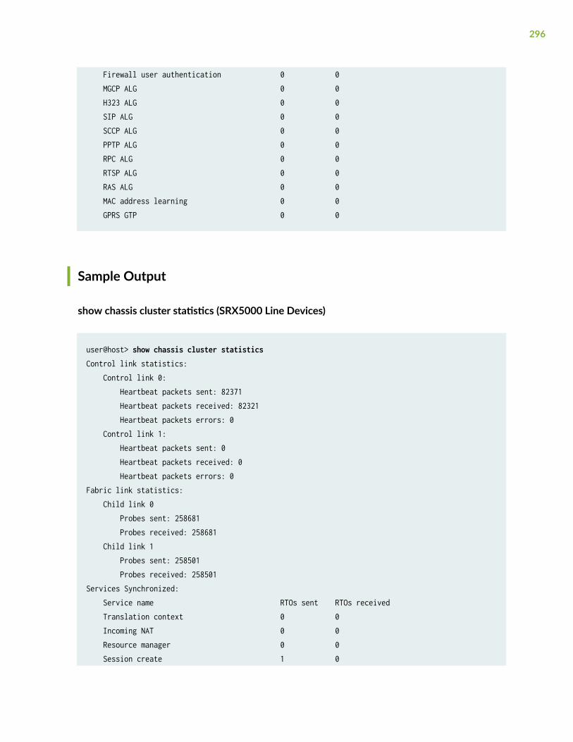
Firewall user authentication 0 0 MGCP ALG 0 0 H323 ALG 0 0 SIP ALG 0 0 SCCP ALG 0 0 PPTP ALG 0 0 RPC ALG 0 0 RTSP ALG 0 0 RAS ALG 0 0 MAC address learning 0 0 GPRS GTP 0 0
Sample Output
show chassis cluster statistics (SRX5000 Line Devices)
user@host> show chassis cluster statistics Control link statistics: Control link 0: Heartbeat packets sent: 82371 Heartbeat packets received: 82321 Heartbeat packets errors: 0 Control link 1: Heartbeat packets sent: 0 Heartbeat packets received: 0 Heartbeat packets errors: 0Fabric link statistics: Child link 0 Probes sent: 258681 Probes received: 258681 Child link 1 Probes sent: 258501 Probes received: 258501Services Synchronized: Service name RTOs sent RTOs received Translation context 0 0 Incoming NAT 0 0 Resource manager 0 0 Session create 1 0
296
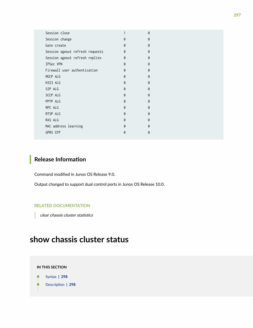
Session close 1 0 Session change 0 0 Gate create 0 0 Session ageout refresh requests 0 0 Session ageout refresh replies 0 0 IPSec VPN 0 0 Firewall user authentication 0 0 MGCP ALG 0 0 H323 ALG 0 0 SIP ALG 0 0 SCCP ALG 0 0 PPTP ALG 0 0 RPC ALG 0 0 RTSP ALG 0 0 RAS ALG 0 0 MAC address learning 0 0 GPRS GTP 0 0
Release Information
Command modified in Junos OS Release 9.0.
Output changed to support dual control ports in Junos OS Release 10.0.
RELATED DOCUMENTATION
clear chassis cluster statistics
show chassis cluster status
IN THIS SECTION
Syntax | 298
Description | 298
297
Options | 298
Required Privilege Level | 298
Output Fields | 299
Sample Output | 300
Sample Output | 301
Sample Output | 301
Release Information | 302
Syntax
show chassis cluster status <redundancy-group group-number >
Description
Display the current status of the Chassis Cluster. You can use this command to check the status ofchassis cluster nodes, redundancy groups, and failover status.
Options
• none—Display the status of all redundancy groups in the chassis cluster.
• redundancy-group group-number—(Optional) Display the status of the specified redundancy group.
Required Privilege Level
view
298
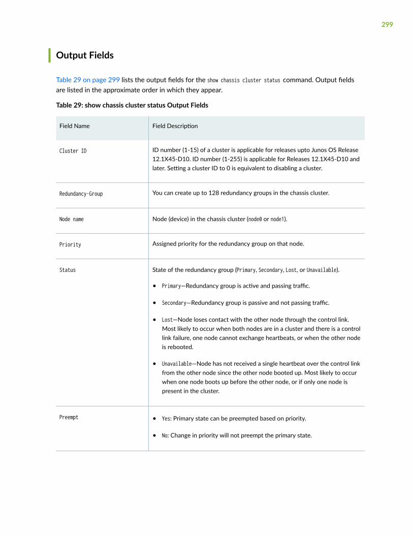
Output Fields
Table 29 on page 299 lists the output fields for the show chassis cluster status command. Output fieldsare listed in the approximate order in which they appear.
Table 29: show chassis cluster status Output Fields
Field Name Field Description
Cluster ID ID number (1-15) of a cluster is applicable for releases upto Junos OS Release12.1X45-D10. ID number (1-255) is applicable for Releases 12.1X45-D10 andlater. Setting a cluster ID to 0 is equivalent to disabling a cluster.
Redundancy-Group You can create up to 128 redundancy groups in the chassis cluster.
Node name Node (device) in the chassis cluster (node0 or node1).
Priority Assigned priority for the redundancy group on that node.
Status State of the redundancy group (Primary, Secondary, Lost, or Unavailable).
• Primary—Redundancy group is active and passing traffic.
• Secondary—Redundancy group is passive and not passing traffic.
• Lost—Node loses contact with the other node through the control link.Most likely to occur when both nodes are in a cluster and there is a controllink failure, one node cannot exchange heartbeats, or when the other nodeis rebooted.
• Unavailable—Node has not received a single heartbeat over the control linkfrom the other node since the other node booted up. Most likely to occurwhen one node boots up before the other node, or if only one node ispresent in the cluster.
Preempt • Yes: Primary state can be preempted based on priority.
• No: Change in priority will not preempt the primary state.
299
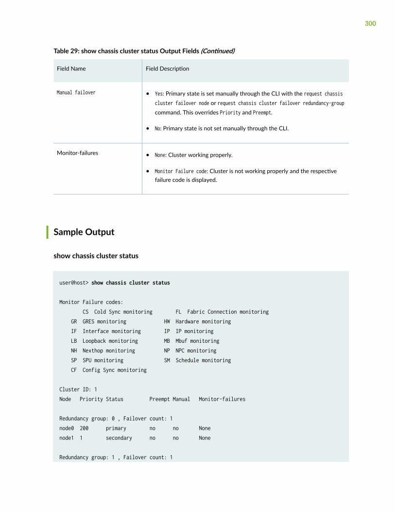
Table 29: show chassis cluster status Output Fields (Continued)
Field Name Field Description
Manual failover • Yes: Primary state is set manually through the CLI with the request chassiscluster failover node or request chassis cluster failover redundancy-groupcommand. This overrides Priority and Preempt.
• No: Primary state is not set manually through the CLI.
Monitor-failures • None: Cluster working properly.
• Monitor Failure code: Cluster is not working properly and the respectivefailure code is displayed.
Sample Output
show chassis cluster status
user@host> show chassis cluster status
Monitor Failure codes: CS Cold Sync monitoring FL Fabric Connection monitoring GR GRES monitoring HW Hardware monitoring IF Interface monitoring IP IP monitoring LB Loopback monitoring MB Mbuf monitoring NH Nexthop monitoring NP NPC monitoring SP SPU monitoring SM Schedule monitoring CF Config Sync monitoring
Cluster ID: 1Node Priority Status Preempt Manual Monitor-failures
Redundancy group: 0 , Failover count: 1node0 200 primary no no Nonenode1 1 secondary no no None
Redundancy group: 1 , Failover count: 1
300
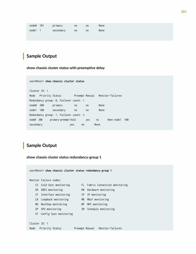
node0 101 primary no no Nonenode1 1 secondary no no None
Sample Output
show chassis cluster status with preemptive delay
user@host> show chassis cluster status
Cluster ID: 1Node Priority Status Preempt Manual Monitor-failuresRedundancy group: 0, Failover count: 1node0 200 primary no no Nonenode1 100 secondary no no NoneRedundancy group: 1, Failover count: 3node0 200 primary-preempt-hold yes no None node1 100 secondary yes no None
Sample Output
show chassis cluster status redundancy-group 1
user@host> show chassis cluster status redundancy-group 1
Monitor Failure codes: CS Cold Sync monitoring FL Fabric Connection monitoring GR GRES monitoring HW Hardware monitoring IF Interface monitoring IP IP monitoring LB Loopback monitoring MB Mbuf monitoring NH Nexthop monitoring NP NPC monitoring SP SPU monitoring SM Schedule monitoring CF Config Sync monitoring
Cluster ID: 1Node Priority Status Preempt Manual Monitor-failures
301
Redundancy group: 1 , Failover count: 1node0 101 primary no no Nonenode1 1 secondary no no None
Release Information
Support for monitoring failures added in Junos OS Release 12.1X47-D10.
RELATED DOCUMENTATION
redundancy-group (Chassis Cluster)
clear chassis cluster failover-count
request chassis cluster failover node
request chassis cluster failover reset
show interfaces
IN THIS SECTION
Syntax | 303
Description | 303
Required Privilege Level | 303
Sample Output | 303
Release Information | 306
302
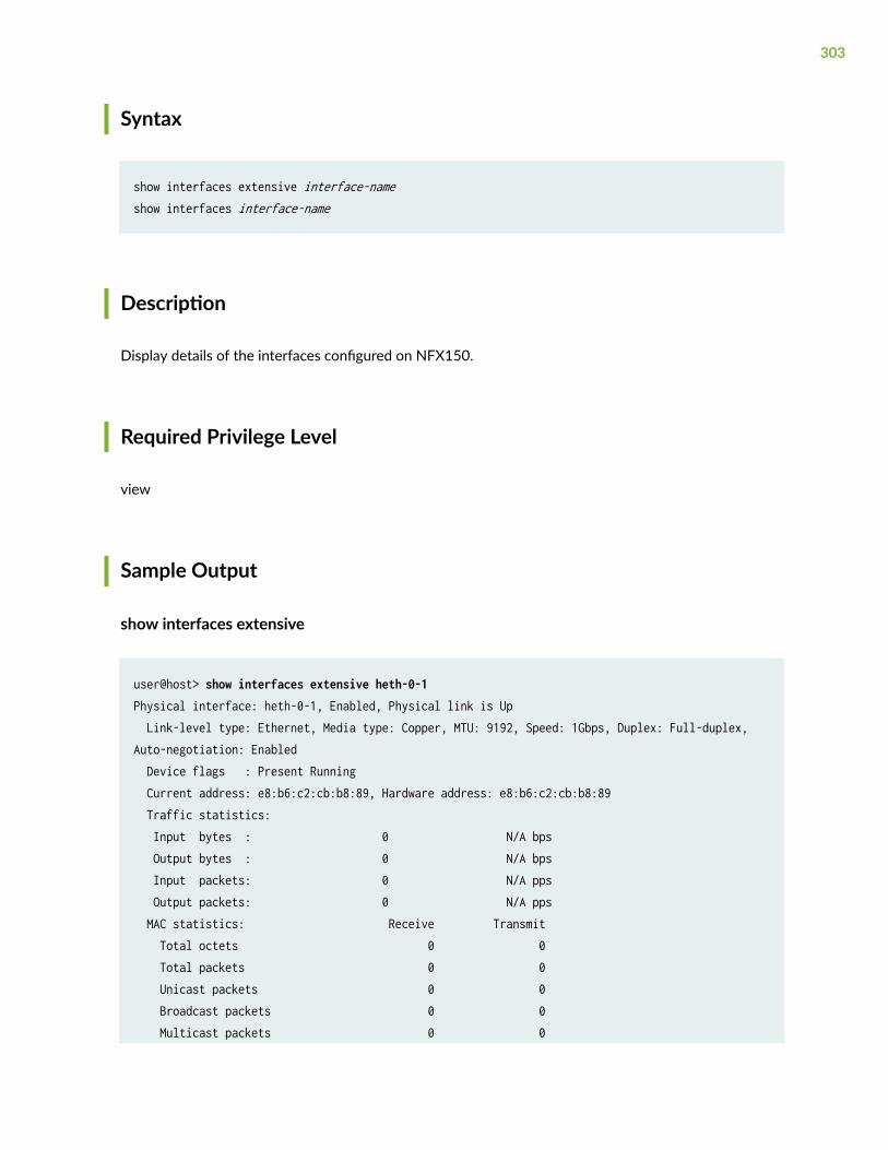
Syntax
show interfaces extensive interface-nameshow interfaces interface-name
Description
Display details of the interfaces configured on NFX150.
Required Privilege Level
view
Sample Output
show interfaces extensive
user@host> show interfaces extensive heth-0-1Physical interface: heth-0-1, Enabled, Physical link is Up Link-level type: Ethernet, Media type: Copper, MTU: 9192, Speed: 1Gbps, Duplex: Full-duplex, Auto-negotiation: Enabled Device flags : Present Running Current address: e8:b6:c2:cb:b8:89, Hardware address: e8:b6:c2:cb:b8:89 Traffic statistics: Input bytes : 0 N/A bps Output bytes : 0 N/A bps Input packets: 0 N/A pps Output packets: 0 N/A pps MAC statistics: Receive Transmit Total octets 0 0 Total packets 0 0 Unicast packets 0 0 Broadcast packets 0 0 Multicast packets 0 0
303
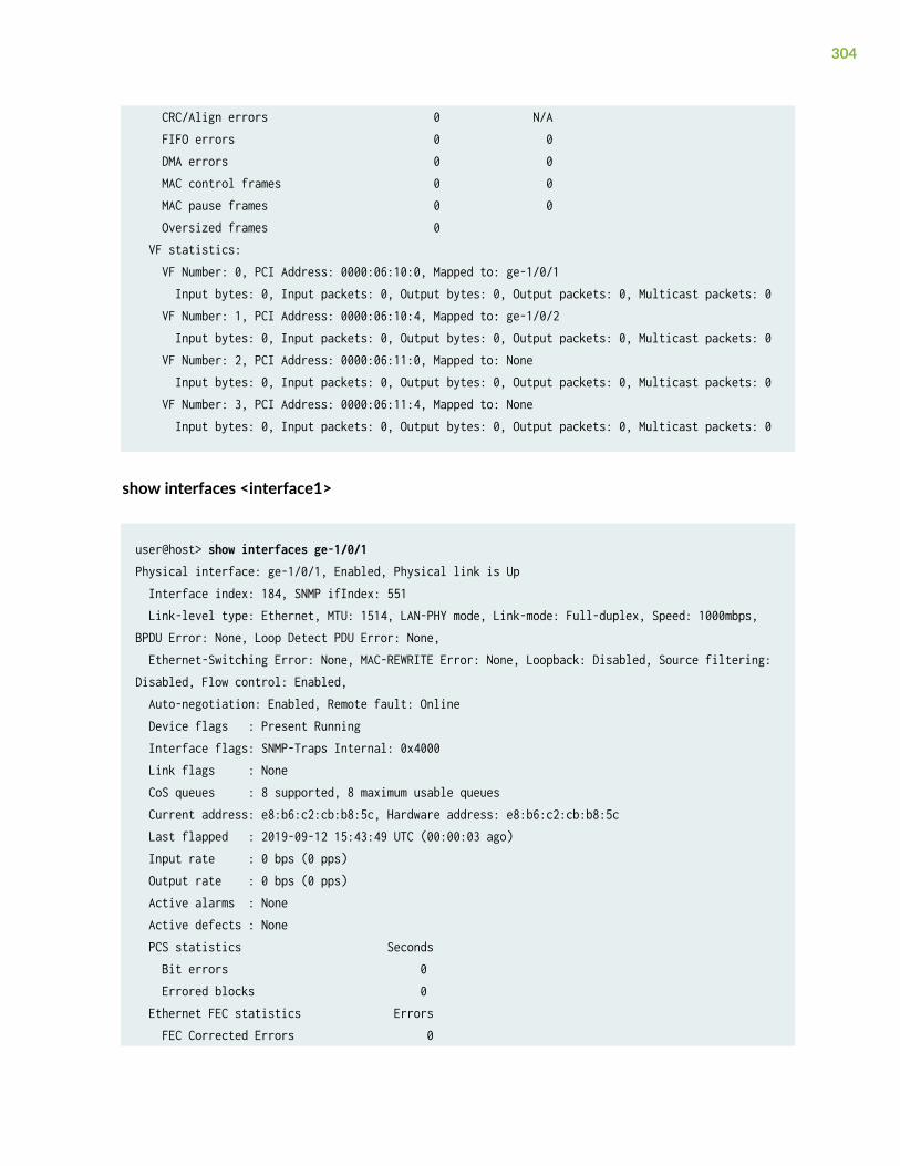
CRC/Align errors 0 N/A FIFO errors 0 0 DMA errors 0 0 MAC control frames 0 0 MAC pause frames 0 0 Oversized frames 0 VF statistics: VF Number: 0, PCI Address: 0000:06:10:0, Mapped to: ge-1/0/1 Input bytes: 0, Input packets: 0, Output bytes: 0, Output packets: 0, Multicast packets: 0 VF Number: 1, PCI Address: 0000:06:10:4, Mapped to: ge-1/0/2 Input bytes: 0, Input packets: 0, Output bytes: 0, Output packets: 0, Multicast packets: 0 VF Number: 2, PCI Address: 0000:06:11:0, Mapped to: None Input bytes: 0, Input packets: 0, Output bytes: 0, Output packets: 0, Multicast packets: 0 VF Number: 3, PCI Address: 0000:06:11:4, Mapped to: None Input bytes: 0, Input packets: 0, Output bytes: 0, Output packets: 0, Multicast packets: 0
show interfaces <interface1>
user@host> show interfaces ge-1/0/1Physical interface: ge-1/0/1, Enabled, Physical link is Up Interface index: 184, SNMP ifIndex: 551 Link-level type: Ethernet, MTU: 1514, LAN-PHY mode, Link-mode: Full-duplex, Speed: 1000mbps, BPDU Error: None, Loop Detect PDU Error: None, Ethernet-Switching Error: None, MAC-REWRITE Error: None, Loopback: Disabled, Source filtering: Disabled, Flow control: Enabled, Auto-negotiation: Enabled, Remote fault: Online Device flags : Present Running Interface flags: SNMP-Traps Internal: 0x4000 Link flags : None CoS queues : 8 supported, 8 maximum usable queues Current address: e8:b6:c2:cb:b8:5c, Hardware address: e8:b6:c2:cb:b8:5c Last flapped : 2019-09-12 15:43:49 UTC (00:00:03 ago) Input rate : 0 bps (0 pps) Output rate : 0 bps (0 pps) Active alarms : None Active defects : None PCS statistics Seconds Bit errors 0 Errored blocks 0 Ethernet FEC statistics Errors FEC Corrected Errors 0
304
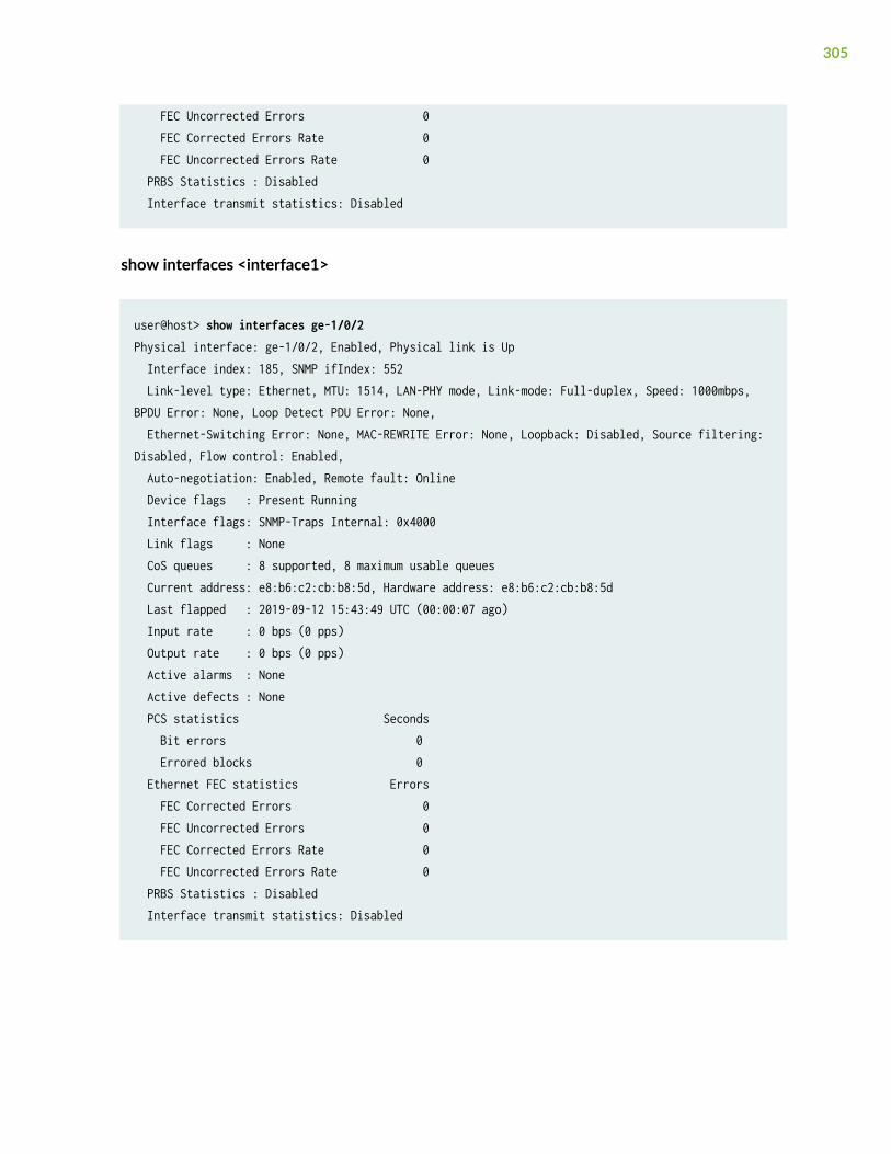
FEC Uncorrected Errors 0 FEC Corrected Errors Rate 0 FEC Uncorrected Errors Rate 0 PRBS Statistics : Disabled Interface transmit statistics: Disabled
show interfaces <interface1>
user@host> show interfaces ge-1/0/2Physical interface: ge-1/0/2, Enabled, Physical link is Up Interface index: 185, SNMP ifIndex: 552 Link-level type: Ethernet, MTU: 1514, LAN-PHY mode, Link-mode: Full-duplex, Speed: 1000mbps, BPDU Error: None, Loop Detect PDU Error: None, Ethernet-Switching Error: None, MAC-REWRITE Error: None, Loopback: Disabled, Source filtering: Disabled, Flow control: Enabled, Auto-negotiation: Enabled, Remote fault: Online Device flags : Present Running Interface flags: SNMP-Traps Internal: 0x4000 Link flags : None CoS queues : 8 supported, 8 maximum usable queues Current address: e8:b6:c2:cb:b8:5d, Hardware address: e8:b6:c2:cb:b8:5d Last flapped : 2019-09-12 15:43:49 UTC (00:00:07 ago) Input rate : 0 bps (0 pps) Output rate : 0 bps (0 pps) Active alarms : None Active defects : None PCS statistics Seconds Bit errors 0 Errored blocks 0 Ethernet FEC statistics Errors FEC Corrected Errors 0 FEC Uncorrected Errors 0 FEC Corrected Errors Rate 0 FEC Uncorrected Errors Rate 0 PRBS Statistics : Disabled Interface transmit statistics: Disabled
305
Release Information
Command introduced in Junos OS Release 18.1R1.
show system inventory hardware cpu
IN THIS SECTION
Syntax | 306
Description | 306
Required Privilege Level | 306
Output Fields | 307
Sample Output | 309
Release Information | 312
Syntax
show system inventory hardware cpu
Description
Display system CPU statistics.
Required Privilege Level
view
306
Output Fields
Table 30 on page 307 lists the output fields for the show system inventory hardware cpu command. Outputfields are listed in the approximate order in which they appear.
NOTE: Starting in Junos OS Release 22.1R1, the CPU allocations are displayed as a numberrange (for example, 4-7) instead of individual numbers (for example, 4,5,6,7).
Table 30: show system inventory hardware cpu Output Fields
Field Name Field Description
Fields for Inventory CPU Information
No of CPUs Total number of CPUs.
No of Logical CPUs/Hyperthreads
Total number of hyper threads.
No of CPU sockets Total number of CPU sockets.
No of Cores per socket Total number of cores per socket.
No of Hyper threads per core Total number of hyper threads per core.
CPU Vendor The name of the CPU vendor.
CPU Model The CPU model.
CPU Architecture The type of CPU architecture.
CPU Speed The CPU speed, in GHz.
CPU Cache The size of the CPU cache.
No of Max vCPUs The maximum number of allowed virtual CPUs.
Fields for CPU Statistics
307

Table 30: show system inventory hardware cpu Output Fields (Continued)
Field Name Field Description
CPU ID The CPU ID
User Time The amount of user time, in seconds.
System Time The amount of system time, in seconds.
Idle Time The amount of time spent in idle mode, in seconds.
Nice Time The amount of spent nice time, in seconds.
I/O Wait Time The amount of time spent waiting for input/output (I/O) operations, inseconds.
Interrupt Service Time The amount of interrupt service time, in seconds.
Fields for CPU Pinning Information
Virtual Machine The name of the virtual machine.
vCPU The ID of virtual CPUs used by the virtual machine.
CPU The ID of CPUs used by the virtual machine.
Fields for Emulator Thread Pinning Information (This section is displayed starting in Junos OS Release 22.1R1.)
Virtual Machine The name of the virtual machine.
CPU The ID of CPUs used by the virtual machine.
System Component The name of the system component.
308
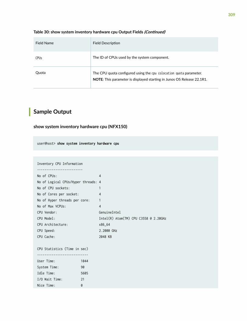
Table 30: show system inventory hardware cpu Output Fields (Continued)
Field Name Field Description
CPUs The ID of CPUs used by the system component.
Quota The CPU quota configured using the cpu colocation quota parameter.
NOTE: This parameter is displayed starting in Junos OS Release 22.1R1.
Sample Output
show system inventory hardware cpu (NFX150)
user@host> show system inventory hardware cpu
Inventory CPU Information-------------------------No of CPUs: 4No of Logical CPUs/Hyper threads: 4No of CPU sockets: 1No of Cores per socket: 4No of Hyper threads per core: 1No of Max VCPUs: 4CPU Vendor: GenuineIntelCPU Model: Intel(R) Atom(TM) CPU C3558 @ 2.20GHzCPU Architecture: x86_64CPU Speed: 2.2000 GHzCPU Cache: 2048 KB
CPU Statistics (Time in sec)----------------------------User Time: 1044System Time: 90Idle Time: 5605I/O Wait Time: 21Nice Time: 0
309
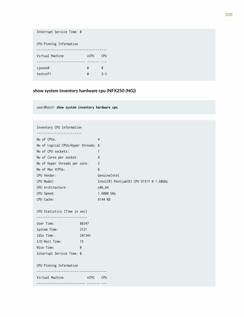
Interrupt Service Time: 0
CPU Pinning Information---------------------------------------Virtual Machine vCPU CPU--------------------------- ------- ---vjunos0 0 0testvnf1 0 2-3
show system inventory hardware cpu (NFX250 (NG))
user@host> show system inventory hardware cpu
Inventory CPU Information-------------------------No of CPUs: 4No of Logical CPUs/Hyper threads: 8No of CPU sockets: 1No of Cores per socket: 4No of Hyper threads per core: 2No of Max VCPUs: 8CPU Vendor: GenuineIntelCPU Model: Intel(R) Pentium(R) CPU D1517 @ 1.60GHzCPU Architecture: x86_64CPU Speed: 1.6000 GHzCPU Cache: 6144 KB
CPU Statistics (Time in sec)----------------------------User Time: 88347System Time: 2121Idle Time: 241343I/O Wait Time: 73Nice Time: 0Interrupt Service Time: 0
CPU Pinning Information---------------------------------------Virtual Machine vCPU CPU--------------------------- ------- ---
310
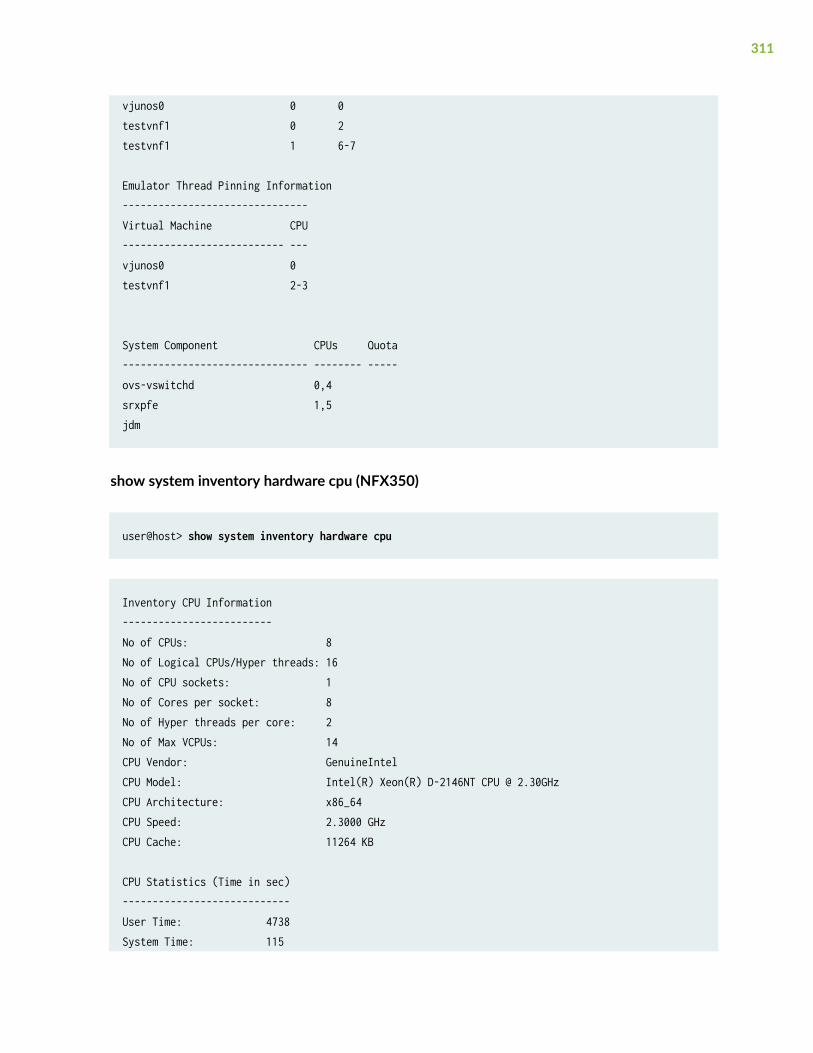
vjunos0 0 0testvnf1 0 2testvnf1 1 6-7
Emulator Thread Pinning Information-------------------------------Virtual Machine CPU--------------------------- ---vjunos0 0testvnf1 2-3
System Component CPUs Quota------------------------------- -------- -----ovs-vswitchd 0,4srxpfe 1,5jdm
show system inventory hardware cpu (NFX350)
user@host> show system inventory hardware cpu
Inventory CPU Information-------------------------No of CPUs: 8No of Logical CPUs/Hyper threads: 16No of CPU sockets: 1No of Cores per socket: 8No of Hyper threads per core: 2No of Max VCPUs: 14CPU Vendor: GenuineIntelCPU Model: Intel(R) Xeon(R) D-2146NT CPU @ 2.30GHzCPU Architecture: x86_64CPU Speed: 2.3000 GHzCPU Cache: 11264 KB
CPU Statistics (Time in sec)----------------------------User Time: 4738System Time: 115
311
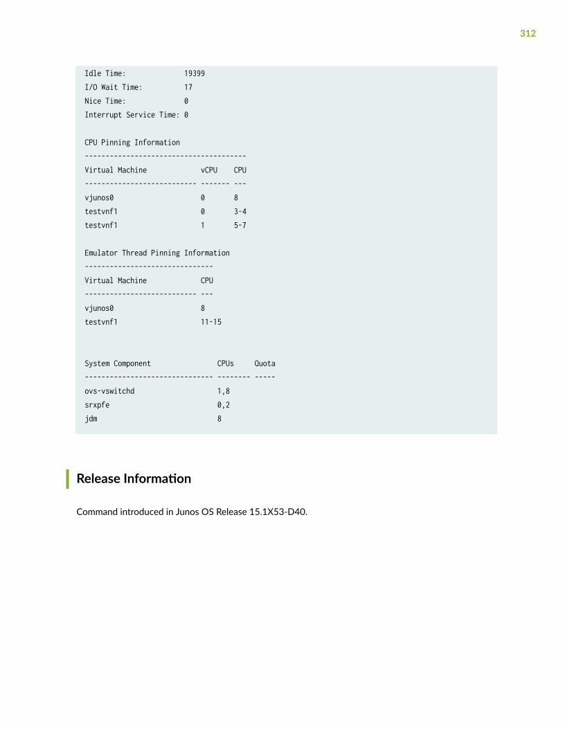
Idle Time: 19399I/O Wait Time: 17Nice Time: 0Interrupt Service Time: 0
CPU Pinning Information---------------------------------------Virtual Machine vCPU CPU--------------------------- ------- ---vjunos0 0 8testvnf1 0 3-4testvnf1 1 5-7
Emulator Thread Pinning Information-------------------------------Virtual Machine CPU--------------------------- ---vjunos0 8testvnf1 11-15
System Component CPUs Quota------------------------------- -------- -----ovs-vswitchd 1,8srxpfe 0,2jdm 8
Release Information
Command introduced in Junos OS Release 15.1X53-D40.
312
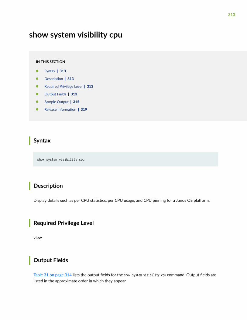
show system visibility cpu
IN THIS SECTION
Syntax | 313
Description | 313
Required Privilege Level | 313
Output Fields | 313
Sample Output | 315
Release Information | 319
Syntax
show system visibility cpu
Description
Display details such as per CPU statistics, per CPU usage, and CPU pinning for a Junos OS platform.
Required Privilege Level
view
Output Fields
Table 31 on page 314 lists the output fields for the show system visibility cpu command. Output fields arelisted in the approximate order in which they appear.
313
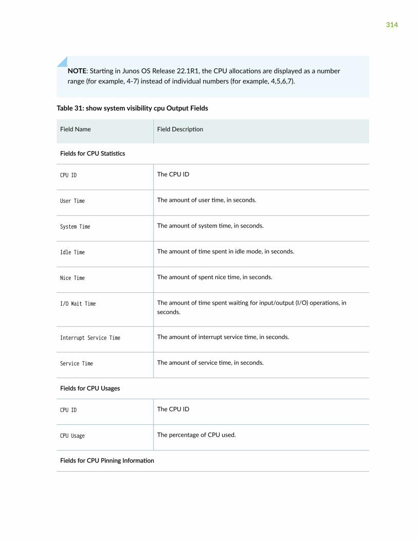
NOTE: Starting in Junos OS Release 22.1R1, the CPU allocations are displayed as a numberrange (for example, 4-7) instead of individual numbers (for example, 4,5,6,7).
Table 31: show system visibility cpu Output Fields
Field Name Field Description
Fields for CPU Statistics
CPU ID The CPU ID
User Time The amount of user time, in seconds.
System Time The amount of system time, in seconds.
Idle Time The amount of time spent in idle mode, in seconds.
Nice Time The amount of spent nice time, in seconds.
I/O Wait Time The amount of time spent waiting for input/output (I/O) operations, inseconds.
Interrupt Service Time The amount of interrupt service time, in seconds.
Service Time The amount of service time, in seconds.
Fields for CPU Usages
CPU ID The CPU ID
CPU Usage The percentage of CPU used.
Fields for CPU Pinning Information
314
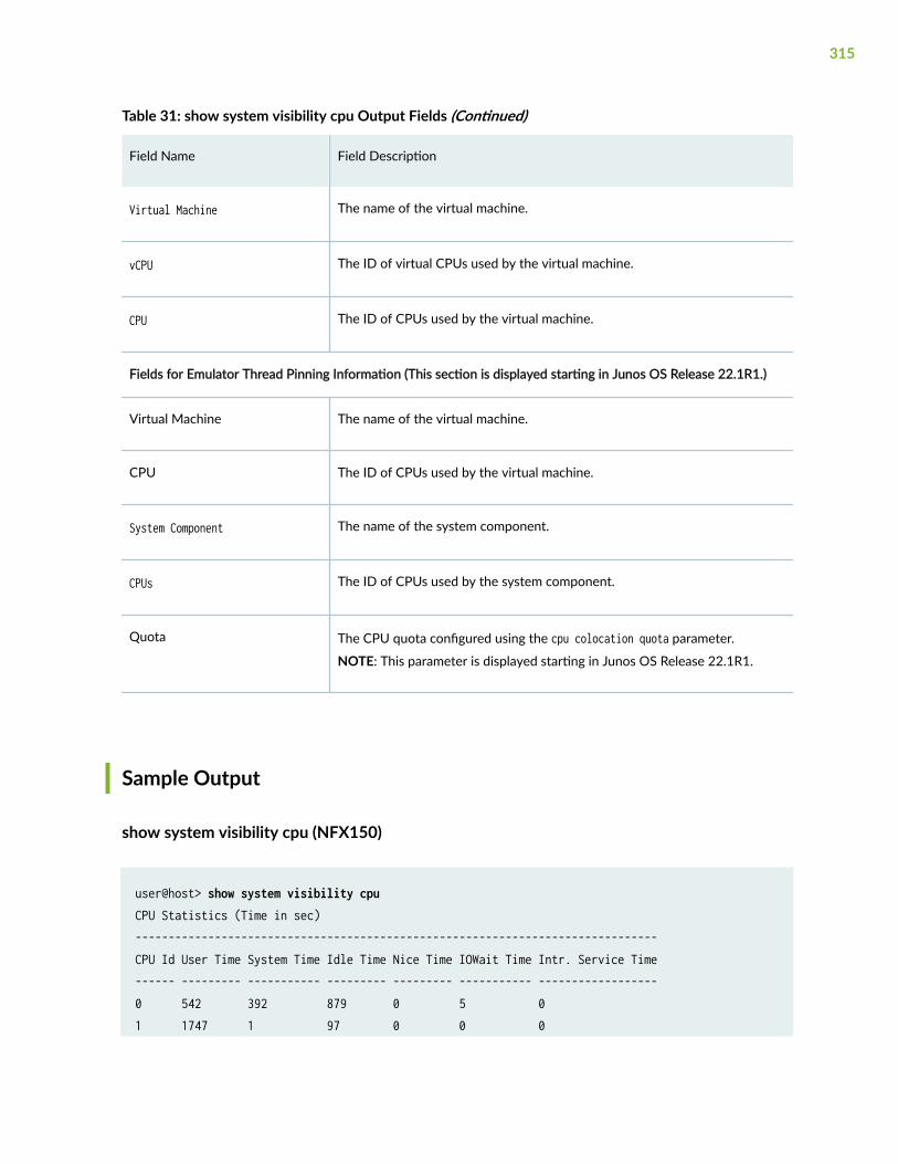
Table 31: show system visibility cpu Output Fields (Continued)
Field Name Field Description
Virtual Machine The name of the virtual machine.
vCPU The ID of virtual CPUs used by the virtual machine.
CPU The ID of CPUs used by the virtual machine.
Fields for Emulator Thread Pinning Information (This section is displayed starting in Junos OS Release 22.1R1.)
Virtual Machine The name of the virtual machine.
CPU The ID of CPUs used by the virtual machine.
System Component The name of the system component.
CPUs The ID of CPUs used by the system component.
Quota The CPU quota configured using the cpu colocation quota parameter.
NOTE: This parameter is displayed starting in Junos OS Release 22.1R1.
Sample Output
show system visibility cpu (NFX150)
user@host> show system visibility cpuCPU Statistics (Time in sec)-------------------------------------------------------------------------------CPU Id User Time System Time Idle Time Nice Time IOWait Time Intr. Service Time------ --------- ----------- --------- --------- ----------- ------------------0 542 392 879 0 5 01 1747 1 97 0 0 0
315
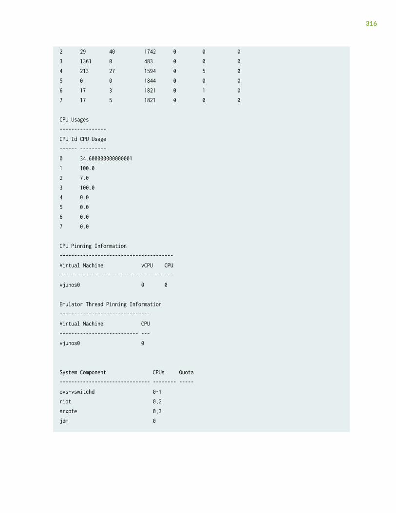
2 29 40 1742 0 0 03 1361 0 483 0 0 04 213 27 1594 0 5 05 0 0 1844 0 0 06 17 3 1821 0 1 07 17 5 1821 0 0 0
CPU Usages----------------CPU Id CPU Usage------ ---------0 34.6000000000000011 100.02 7.03 100.04 0.05 0.06 0.07 0.0
CPU Pinning Information---------------------------------------Virtual Machine vCPU CPU--------------------------- ------- ---vjunos0 0 0
Emulator Thread Pinning Information-------------------------------Virtual Machine CPU--------------------------- ---vjunos0 0
System Component CPUs Quota------------------------------- -------- -----ovs-vswitchd 0-1riot 0,2srxpfe 0,3jdm 0
316
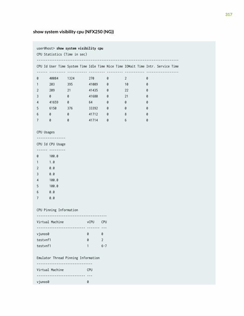
show system visibility cpu (NFX250 (NG))
user@host> show system visibility cpuCPU Statistics (Time in sec)-------------------------------------------------------------------------------CPU Id User Time System Time Idle Time Nice Time IOWait Time Intr. Service Time------ --------- ----------- --------- --------- ----------- ------------------0 40084 1324 270 0 2 01 203 395 41009 0 10 02 209 21 41435 0 22 03 0 0 41680 0 21 04 41659 0 64 0 0 05 6150 376 33392 0 0 06 0 0 41712 0 8 07 0 0 41714 0 6 0
CPU Usages----------------CPU Id CPU Usage------ ---------0 100.01 1.02 0.03 0.04 100.05 100.06 0.07 0.0
CPU Pinning Information---------------------------------------Virtual Machine vCPU CPU--------------------------- ------- ---vjunos0 0 0testvnf1 0 2testvnf1 1 6-7
Emulator Thread Pinning Information-------------------------------Virtual Machine CPU--------------------------- ---vjunos0 0
317
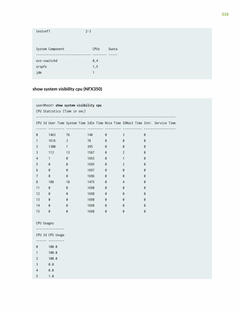
testvnf1 2-3
System Component CPUs Quota------------------------------- -------- -----ovs-vswitchd 0,4srxpfe 1,5jdm 1
show system visibility cpu (NFX350)
user@host> show system visibility cpuCPU Statistics (Time in sec)-------------------------------------------------------------------------------CPU Id User Time System Time Idle Time Nice Time IOWait Time Intr. Service Time------ --------- ----------- --------- --------- ----------- ------------------0 1463 76 148 0 3 01 1616 3 78 0 0 02 1300 1 395 0 0 03 112 13 1567 0 2 04 1 0 1693 0 1 05 0 0 1695 0 2 06 0 0 1697 0 0 07 0 0 1696 0 0 08 188 18 1475 0 4 011 0 0 1698 0 0 012 0 0 1698 0 0 013 0 0 1698 0 0 014 0 0 1698 0 0 015 0 0 1698 0 0 0
CPU Usages----------------CPU Id CPU Usage------ ---------0 100.01 100.02 100.03 0.04 0.05 1.0
318
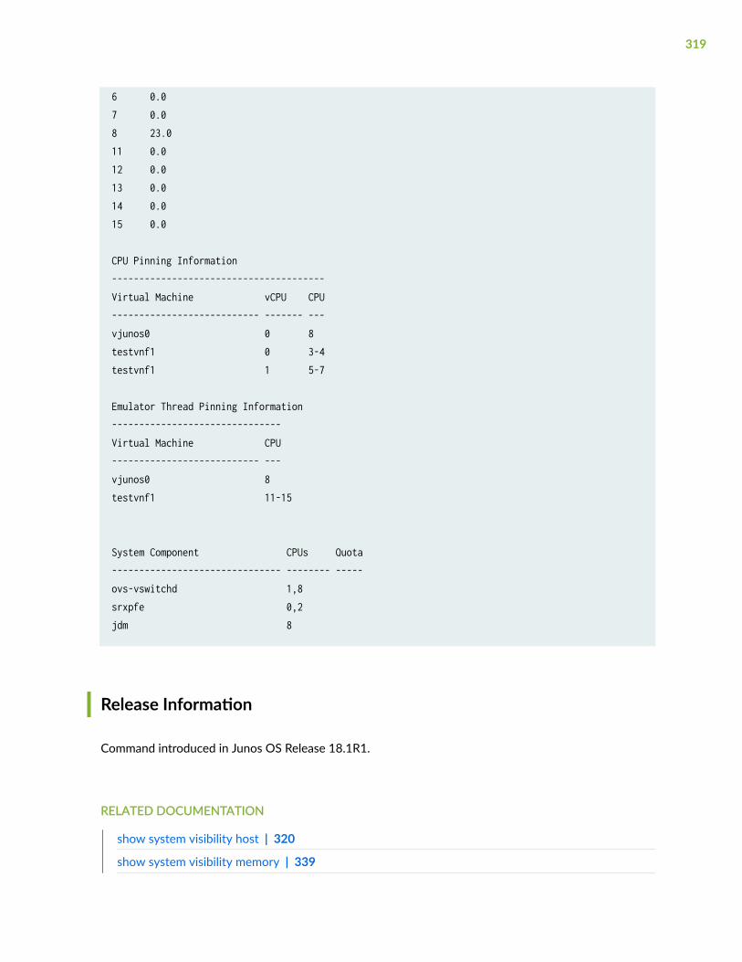
6 0.07 0.08 23.011 0.012 0.013 0.014 0.015 0.0
CPU Pinning Information---------------------------------------Virtual Machine vCPU CPU--------------------------- ------- ---vjunos0 0 8testvnf1 0 3-4testvnf1 1 5-7
Emulator Thread Pinning Information-------------------------------Virtual Machine CPU--------------------------- ---vjunos0 8testvnf1 11-15
System Component CPUs Quota------------------------------- -------- -----ovs-vswitchd 1,8srxpfe 0,2jdm 8
Release Information
Command introduced in Junos OS Release 18.1R1.
RELATED DOCUMENTATION
show system visibility host | 320
show system visibility memory | 339
319
show system visibility network | 343
show system visibility vnf | 351
show system visibility host
IN THIS SECTION
Syntax | 320
Description | 320
Required Privilege Level | 320
Output Fields | 321
Sample Output | 324
Release Information | 330
Syntax
show system visibility host
Description
Displays details such as the host uptime, number of tasks, CPU statistics, list of disk partitions, diskusage, disk I/O statistics, list of network interfaces, and per port statistics for a Junos OS platform.
Required Privilege Level
view
320
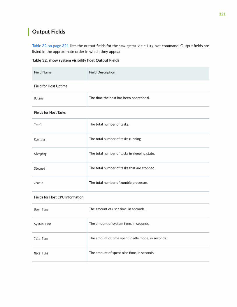
Output Fields
Table 32 on page 321 lists the output fields for the show system visibility host command. Output fields arelisted in the approximate order in which they appear.
Table 32: show system visibility host Output Fields
Field Name Field Description
Field for Host Uptime
Uptime The time the host has been operational.
Fields for Host Tasks
Total The total number of tasks.
Running The total number of tasks running.
Sleeping The total number of tasks in sleeping state.
Stopped The total number of tasks that are stopped.
Zombie The total number of zombie processes.
Fields for Host CPU Information
User Time The amount of user time, in seconds.
System Time The amount of system time, in seconds.
Idle Time The amount of time spent in idle mode, in seconds.
Nice Time The amount of spent nice time, in seconds.
321
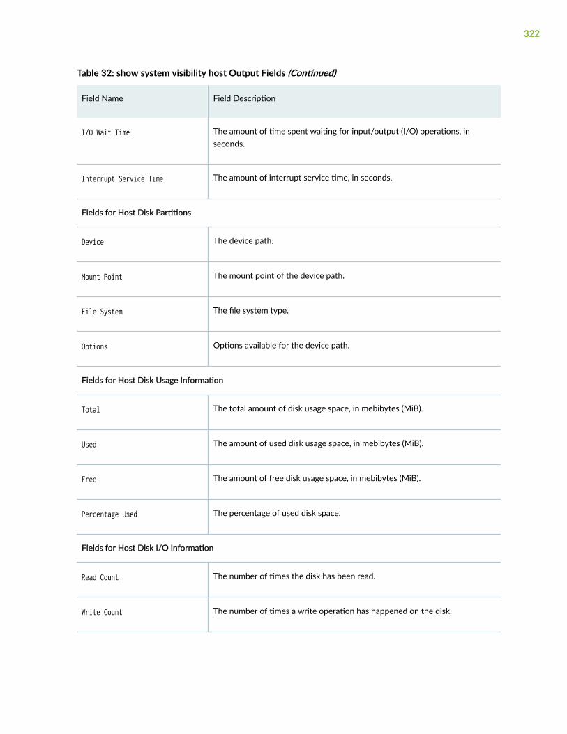
Table 32: show system visibility host Output Fields (Continued)
Field Name Field Description
I/O Wait Time The amount of time spent waiting for input/output (I/O) operations, inseconds.
Interrupt Service Time The amount of interrupt service time, in seconds.
Fields for Host Disk Partitions
Device The device path.
Mount Point The mount point of the device path.
File System The file system type.
Options Options available for the device path.
Fields for Host Disk Usage Information
Total The total amount of disk usage space, in mebibytes (MiB).
Used The amount of used disk usage space, in mebibytes (MiB).
Free The amount of free disk usage space, in mebibytes (MiB).
Percentage Used The percentage of used disk space.
Fields for Host Disk I/O Information
Read Count The number of times the disk has been read.
Write Count The number of times a write operation has happened on the disk.
322

Table 32: show system visibility host Output Fields (Continued)
Field Name Field Description
Read Bytes The number of bytes used in read operations on the disk.
Write Bytes The number of bytes used in write operations on the disk.
Read Time The amount of time the disk has been read, in milliseconds.
Write Time The amount of time write operations have been performed on the disk, inmilliseconds.
Fields for List of Host Interfaces
Interfaces The name of the interface.
State The state of the Host Interface.
MAC The MAC address of the interface.
Fields for List of Host Port Statistics
Interface The name of the interface.
Bytes Sent The number of bytes sent.
Bytes Received The number of bytes received.
Packets Sent The number of packets sent.
Packets Received The number of packets received.
Errors In The number of errors in.
323
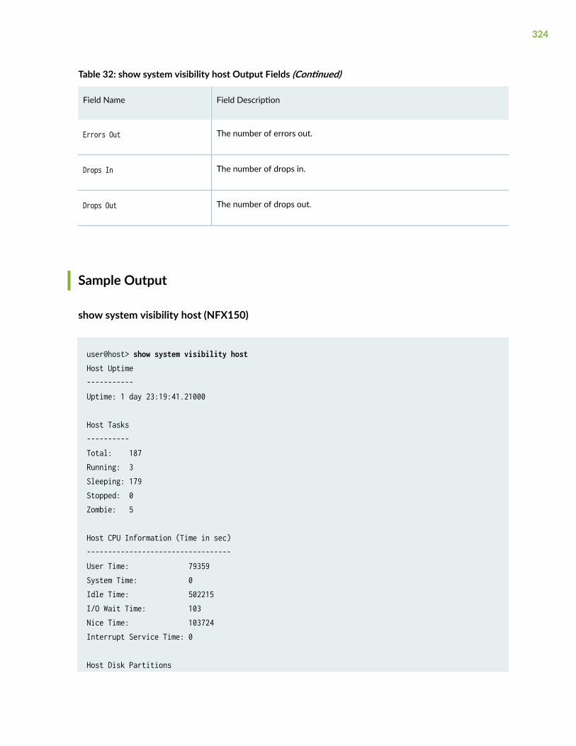
Table 32: show system visibility host Output Fields (Continued)
Field Name Field Description
Errors Out The number of errors out.
Drops In The number of drops in.
Drops Out The number of drops out.
Sample Output
show system visibility host (NFX150)
user@host> show system visibility hostHost Uptime-----------Uptime: 1 day 23:19:41.21000
Host Tasks----------Total: 187Running: 3Sleeping: 179Stopped: 0Zombie: 5
Host CPU Information (Time in sec)----------------------------------User Time: 79359System Time: 0Idle Time: 502215I/O Wait Time: 103Nice Time: 103724Interrupt Service Time: 0
Host Disk Partitions
324
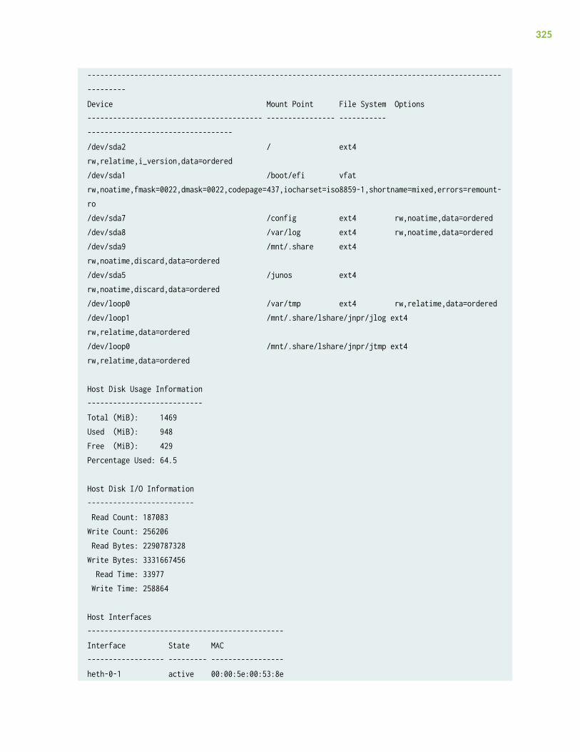
----------------------------------------------------------------------------------------------------------Device Mount Point File System Options----------------------------------------- ---------------- ----------- ----------------------------------/dev/sda2 / ext4 rw,relatime,i_version,data=ordered/dev/sda1 /boot/efi vfat rw,noatime,fmask=0022,dmask=0022,codepage=437,iocharset=iso8859-1,shortname=mixed,errors=remount-ro/dev/sda7 /config ext4 rw,noatime,data=ordered/dev/sda8 /var/log ext4 rw,noatime,data=ordered/dev/sda9 /mnt/.share ext4 rw,noatime,discard,data=ordered/dev/sda5 /junos ext4 rw,noatime,discard,data=ordered/dev/loop0 /var/tmp ext4 rw,relatime,data=ordered/dev/loop1 /mnt/.share/lshare/jnpr/jlog ext4 rw,relatime,data=ordered/dev/loop0 /mnt/.share/lshare/jnpr/jtmp ext4 rw,relatime,data=ordered
Host Disk Usage Information---------------------------Total (MiB): 1469Used (MiB): 948Free (MiB): 429Percentage Used: 64.5
Host Disk I/O Information------------------------- Read Count: 187083Write Count: 256206 Read Bytes: 2290787328Write Bytes: 3331667456 Read Time: 33977 Write Time: 258864
Host Interfaces----------------------------------------------Interface State MAC------------------ --------- -----------------heth-0-1 active 00:00:5e:00:53:8e
325
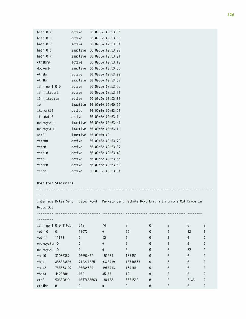
heth-0-0 active 00:00:5e:00:53:8dheth-0-3 active 00:00:5e:00:53:90heth-0-2 active 00:00:5e:00:53:8fheth-0-5 inactive 00:00:5e:00:53:92heth-0-4 inactive 00:00:5e:00:53:91ctrlbr0 active 00:00:5e:00:53:10docker0 inactive 00:00:5e:00:53:8ceth0br active 00:00:5e:00:53:00eth1br inactive 00:00:5e:00:53:67l3_h_ge_1_0_0 active 00:00:5e:00:53:6dl3_h_ltectrl active 00:00:5e:00:53:f1l3_h_ltedata active 00:00:5e:00:53:91lo inactive 00:00:00:00:00:00lte_crtl0 active 00:00:5e:00:53:91lte_data0 active 00:00:5e:00:53:fcovs-sys-br inactive 00:00:5e:00:53:4fovs-system inactive 00:00:5e:00:53:1bsit0 inactive 00:00:00:00veth00 active 00:00:5e:00:53:79veth01 active 00:00:5e:00:53:87veth10 active 00:00:5e:00:53:40veth11 active 00:00:5e:00:53:65virbr0 active 00:00:5e:00:53:83virbr1 active 00:00:5e:00:53:6f
Host Port Statistics-----------------------------------------------------------------------------------------------------Interface Bytes Sent Bytes Rcvd Packets Sent Packets Rcvd Errors In Errors Out Drops In Drops Out--------- ------------ ------------ ------------ ------------ --------- ---------- -------- ---------l3_h_ge_1_0_0 11025 648 74 8 0 0 0 0veth10 0 11673 0 82 0 0 12 0veth11 11673 0 82 0 0 0 0 0ovs-system 0 0 0 0 0 0 0 0ovs-sys-br 0 0 0 0 0 0 82 0vnet0 31080352 10698402 153074 136451 0 0 0 0vnet1 858553596 712231555 9325949 10546588 0 0 0 0vnet2 735033102 50689829 4956943 180168 0 0 0 0vnet3 4428680 602 85168 13 0 0 0 0eth0 50689829 1077880063 180168 5551593 0 0 6146 0eth1br 0 0 0 0 0 0 0 0
326
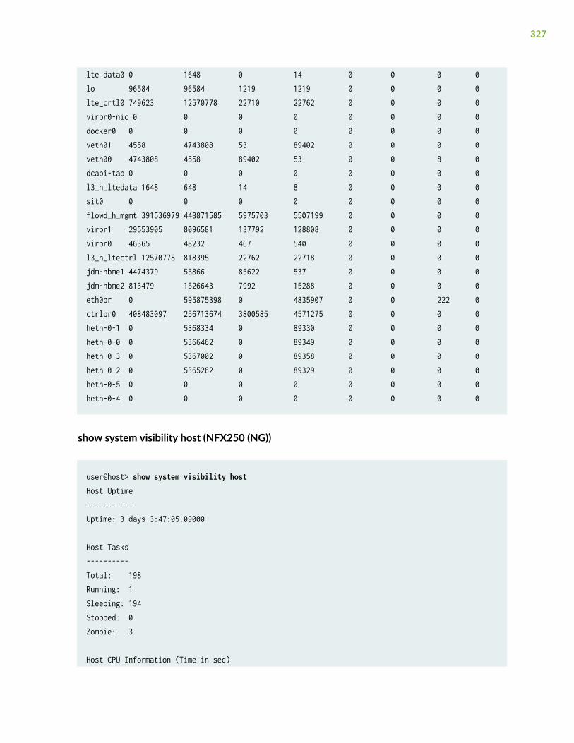
lte_data0 0 1648 0 14 0 0 0 0lo 96584 96584 1219 1219 0 0 0 0lte_crtl0 749623 12570778 22710 22762 0 0 0 0virbr0-nic 0 0 0 0 0 0 0 0docker0 0 0 0 0 0 0 0 0veth01 4558 4743808 53 89402 0 0 0 0veth00 4743808 4558 89402 53 0 0 8 0dcapi-tap 0 0 0 0 0 0 0 0l3_h_ltedata 1648 648 14 8 0 0 0 0sit0 0 0 0 0 0 0 0 0flowd_h_mgmt 391536979 448871585 5975703 5507199 0 0 0 0virbr1 29553905 8096581 137792 128808 0 0 0 0virbr0 46365 48232 467 540 0 0 0 0l3_h_ltectrl 12570778 818395 22762 22718 0 0 0 0jdm-hbme1 4474379 55866 85622 537 0 0 0 0jdm-hbme2 813479 1526643 7992 15288 0 0 0 0eth0br 0 595875398 0 4835907 0 0 222 0ctrlbr0 408483097 256713674 3800585 4571275 0 0 0 0heth-0-1 0 5368334 0 89330 0 0 0 0heth-0-0 0 5366462 0 89349 0 0 0 0heth-0-3 0 5367002 0 89358 0 0 0 0heth-0-2 0 5365262 0 89329 0 0 0 0heth-0-5 0 0 0 0 0 0 0 0heth-0-4 0 0 0 0 0 0 0 0
show system visibility host (NFX250 (NG))
user@host> show system visibility hostHost Uptime-----------Uptime: 3 days 3:47:05.09000
Host Tasks----------Total: 198Running: 1Sleeping: 194Stopped: 0Zombie: 3
Host CPU Information (Time in sec)
327
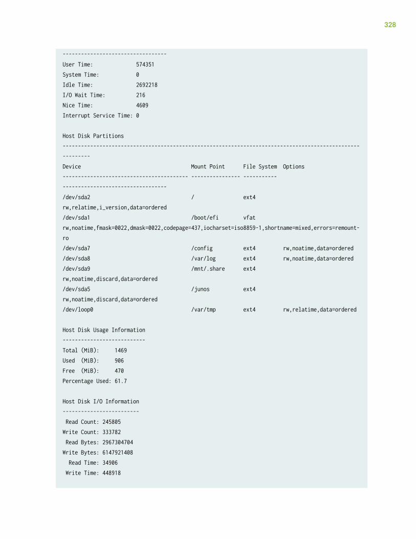
----------------------------------User Time: 574351System Time: 0Idle Time: 2692218I/O Wait Time: 216Nice Time: 4609Interrupt Service Time: 0
Host Disk Partitions----------------------------------------------------------------------------------------------------------Device Mount Point File System Options----------------------------------------- ---------------- ----------- ----------------------------------/dev/sda2 / ext4 rw,relatime,i_version,data=ordered/dev/sda1 /boot/efi vfat rw,noatime,fmask=0022,dmask=0022,codepage=437,iocharset=iso8859-1,shortname=mixed,errors=remount-ro/dev/sda7 /config ext4 rw,noatime,data=ordered/dev/sda8 /var/log ext4 rw,noatime,data=ordered/dev/sda9 /mnt/.share ext4 rw,noatime,discard,data=ordered/dev/sda5 /junos ext4 rw,noatime,discard,data=ordered/dev/loop0 /var/tmp ext4 rw,relatime,data=ordered
Host Disk Usage Information---------------------------Total (MiB): 1469Used (MiB): 906Free (MiB): 470Percentage Used: 61.7
Host Disk I/O Information------------------------- Read Count: 245805Write Count: 333782 Read Bytes: 2967304704Write Bytes: 6147921408 Read Time: 34906 Write Time: 448918
328
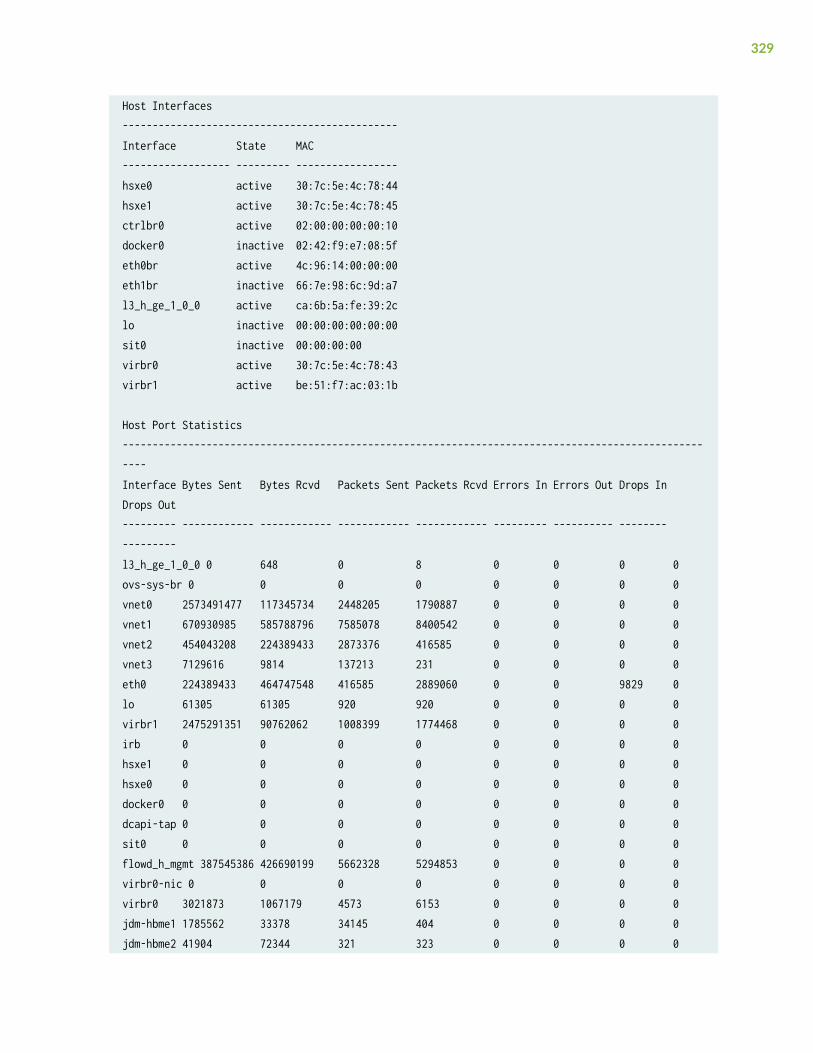
Host Interfaces----------------------------------------------Interface State MAC------------------ --------- -----------------hsxe0 active 30:7c:5e:4c:78:44hsxe1 active 30:7c:5e:4c:78:45ctrlbr0 active 02:00:00:00:00:10docker0 inactive 02:42:f9:e7:08:5feth0br active 4c:96:14:00:00:00eth1br inactive 66:7e:98:6c:9d:a7l3_h_ge_1_0_0 active ca:6b:5a:fe:39:2clo inactive 00:00:00:00:00:00sit0 inactive 00:00:00:00virbr0 active 30:7c:5e:4c:78:43virbr1 active be:51:f7:ac:03:1b
Host Port Statistics-----------------------------------------------------------------------------------------------------Interface Bytes Sent Bytes Rcvd Packets Sent Packets Rcvd Errors In Errors Out Drops In Drops Out--------- ------------ ------------ ------------ ------------ --------- ---------- -------- ---------l3_h_ge_1_0_0 0 648 0 8 0 0 0 0ovs-sys-br 0 0 0 0 0 0 0 0vnet0 2573491477 117345734 2448205 1790887 0 0 0 0vnet1 670930985 585788796 7585078 8400542 0 0 0 0vnet2 454043208 224389433 2873376 416585 0 0 0 0vnet3 7129616 9814 137213 231 0 0 0 0eth0 224389433 464747548 416585 2889060 0 0 9829 0lo 61305 61305 920 920 0 0 0 0virbr1 2475291351 90762062 1008399 1774468 0 0 0 0irb 0 0 0 0 0 0 0 0hsxe1 0 0 0 0 0 0 0 0hsxe0 0 0 0 0 0 0 0 0docker0 0 0 0 0 0 0 0 0dcapi-tap 0 0 0 0 0 0 0 0sit0 0 0 0 0 0 0 0 0flowd_h_mgmt 387545386 426690199 5662328 5294853 0 0 0 0virbr0-nic 0 0 0 0 0 0 0 0virbr0 3021873 1067179 4573 6153 0 0 0 0jdm-hbme1 1785562 33378 34145 404 0 0 0 0jdm-hbme2 41904 72344 321 323 0 0 0 0
329
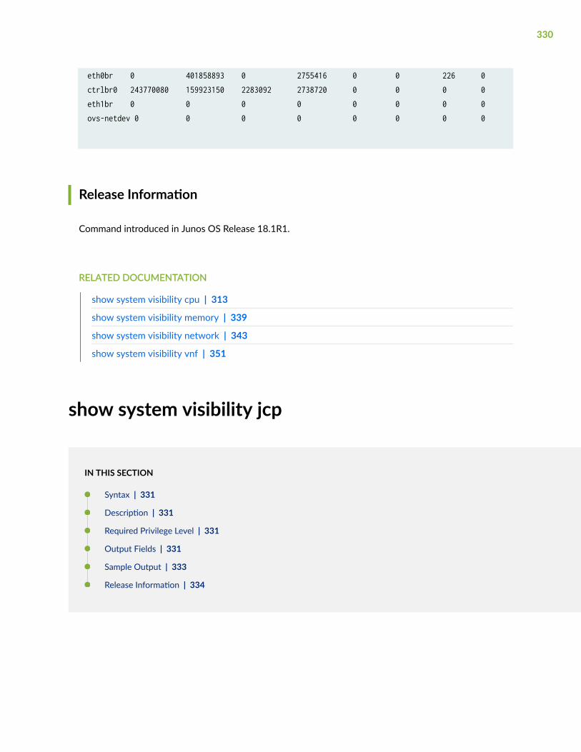
eth0br 0 401858893 0 2755416 0 0 226 0ctrlbr0 243770080 159923150 2283092 2738720 0 0 0 0eth1br 0 0 0 0 0 0 0 0ovs-netdev 0 0 0 0 0 0 0 0
Release Information
Command introduced in Junos OS Release 18.1R1.
RELATED DOCUMENTATION
show system visibility cpu | 313
show system visibility memory | 339
show system visibility network | 343
show system visibility vnf | 351
show system visibility jcp
IN THIS SECTION
Syntax | 331
Description | 331
Required Privilege Level | 331
Output Fields | 331
Sample Output | 333
Release Information | 334
330
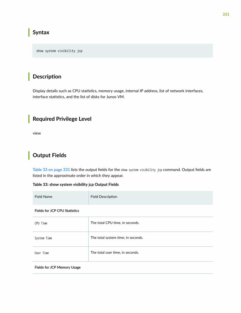
Syntax
show system visibility jcp
Description
Display details such as CPU statistics, memory usage, internal IP address, list of network interfaces,interface statistics, and the list of disks for Junos VM.
Required Privilege Level
view
Output Fields
Table 33 on page 331 lists the output fields for the show system visibility jcp command. Output fields arelisted in the approximate order in which they appear.
Table 33: show system visibility jcp Output Fields
Field Name Field Description
Fields for JCP CPU Statistics
CPU Time The total CPU time, in seconds.
System Time The total system time, in seconds.
User Time The total user time, in seconds.
Fields for JCP Memory Usage
331
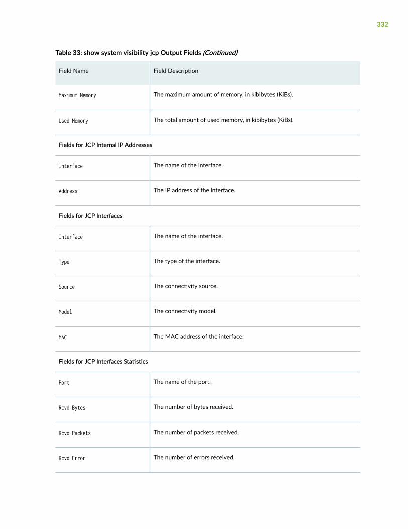
Table 33: show system visibility jcp Output Fields (Continued)
Field Name Field Description
Maximum Memory The maximum amount of memory, in kibibytes (KiBs).
Used Memory The total amount of used memory, in kibibytes (KiBs).
Fields for JCP Internal IP Addresses
Interface The name of the interface.
Address The IP address of the interface.
Fields for JCP Interfaces
Interface The name of the interface.
Type The type of the interface.
Source The connectivity source.
Model The connectivity model.
MAC The MAC address of the interface.
Fields for JCP Interfaces Statistics
Port The name of the port.
Rcvd Bytes The number of bytes received.
Rcvd Packets The number of packets received.
Rcvd Error The number of errors received.
332
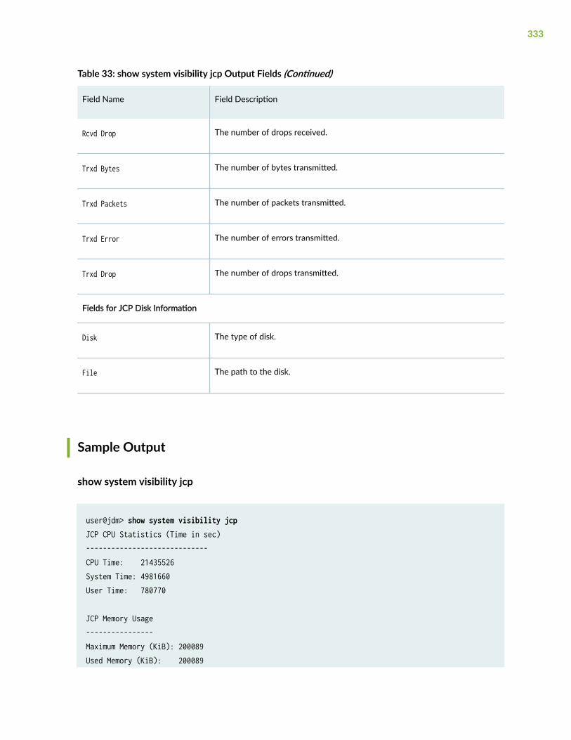
Table 33: show system visibility jcp Output Fields (Continued)
Field Name Field Description
Rcvd Drop The number of drops received.
Trxd Bytes The number of bytes transmitted.
Trxd Packets The number of packets transmitted.
Trxd Error The number of errors transmitted.
Trxd Drop The number of drops transmitted.
Fields for JCP Disk Information
Disk The type of disk.
File The path to the disk.
Sample Output
show system visibility jcp
user@jdm> show system visibility jcpJCP CPU Statistics (Time in sec)-----------------------------CPU Time: 21435526System Time: 4981660User Time: 780770
JCP Memory Usage----------------Maximum Memory (KiB): 200089Used Memory (KiB): 200089
333
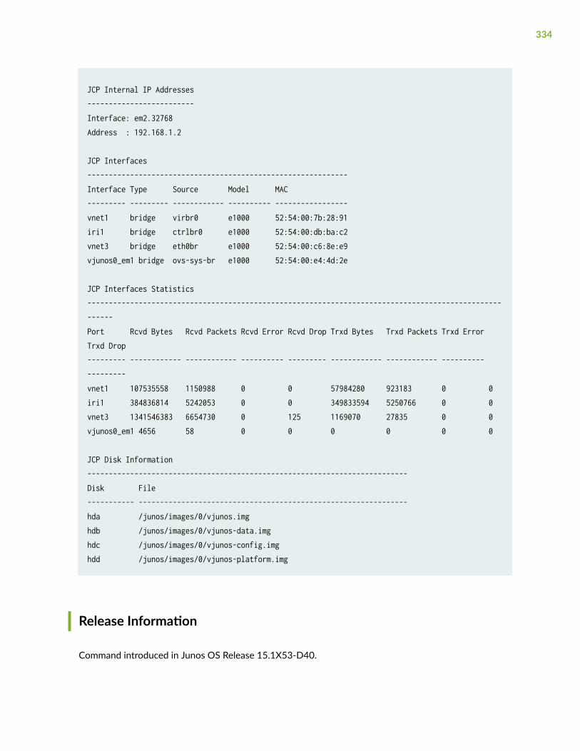
JCP Internal IP Addresses-------------------------Interface: em2.32768Address : 192.168.1.2
JCP Interfaces-------------------------------------------------------------Interface Type Source Model MAC--------- --------- ------------ ---------- -----------------vnet1 bridge virbr0 e1000 52:54:00:7b:28:91iri1 bridge ctrlbr0 e1000 52:54:00:db:ba:c2vnet3 bridge eth0br e1000 52:54:00:c6:8e:e9vjunos0_em1 bridge ovs-sys-br e1000 52:54:00:e4:4d:2e
JCP Interfaces Statistics-------------------------------------------------------------------------------------------------------Port Rcvd Bytes Rcvd Packets Rcvd Error Rcvd Drop Trxd Bytes Trxd Packets Trxd Error Trxd Drop--------- ------------ ------------ ---------- --------- ------------ ------------ ---------- ---------vnet1 107535558 1150988 0 0 57984280 923183 0 0iri1 384836814 5242053 0 0 349833594 5250766 0 0vnet3 1341546383 6654730 0 125 1169070 27835 0 0vjunos0_em1 4656 58 0 0 0 0 0 0
JCP Disk Information---------------------------------------------------------------------------Disk File----------- ---------------------------------------------------------------hda /junos/images/0/vjunos.imghdb /junos/images/0/vjunos-data.imghdc /junos/images/0/vjunos-config.imghdd /junos/images/0/vjunos-platform.img
Release Information
Command introduced in Junos OS Release 15.1X53-D40.
334
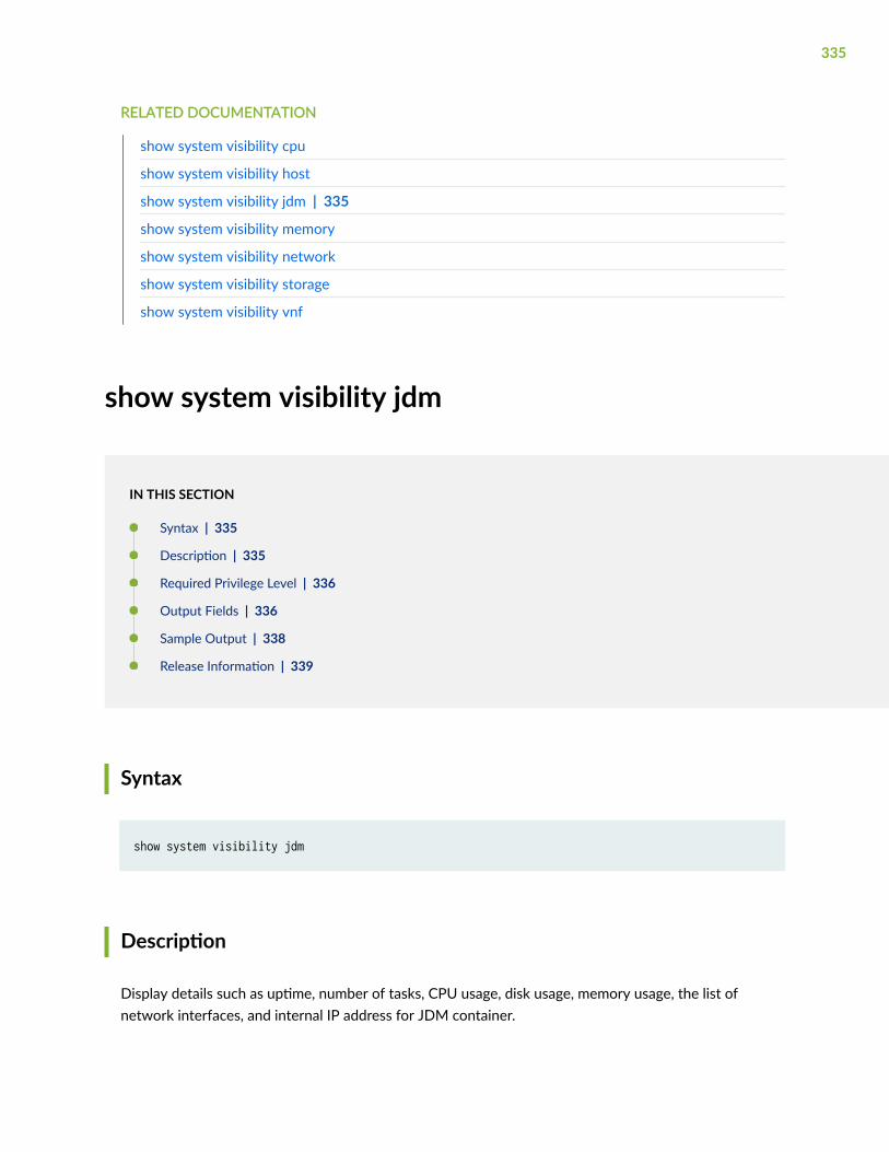
RELATED DOCUMENTATION
show system visibility cpu
show system visibility host
show system visibility jdm | 335
show system visibility memory
show system visibility network
show system visibility storage
show system visibility vnf
show system visibility jdm
IN THIS SECTION
Syntax | 335
Description | 335
Required Privilege Level | 336
Output Fields | 336
Sample Output | 338
Release Information | 339
Syntax
show system visibility jdm
Description
Display details such as uptime, number of tasks, CPU usage, disk usage, memory usage, the list ofnetwork interfaces, and internal IP address for JDM container.
335
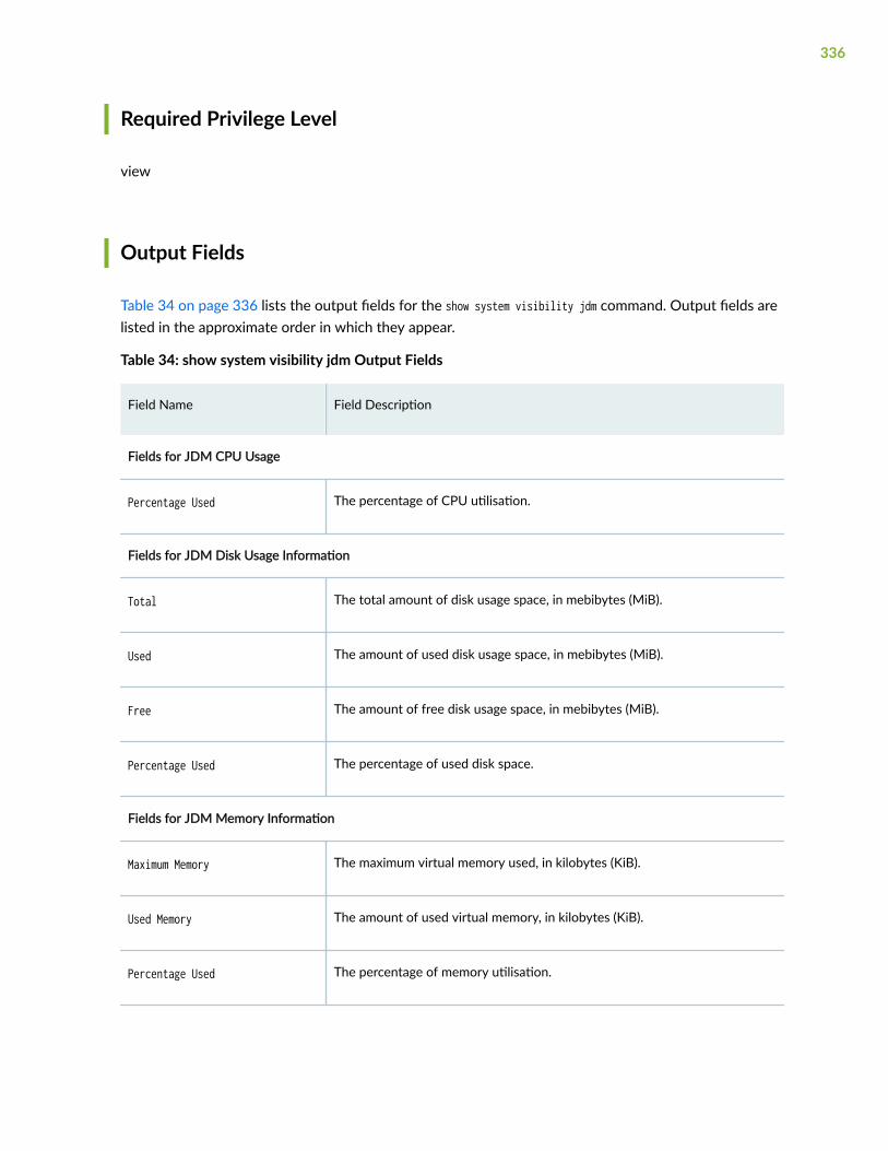
Required Privilege Level
view
Output Fields
Table 34 on page 336 lists the output fields for the show system visibility jdm command. Output fields arelisted in the approximate order in which they appear.
Table 34: show system visibility jdm Output Fields
Field Name Field Description
Fields for JDM CPU Usage
Percentage Used The percentage of CPU utilisation.
Fields for JDM Disk Usage Information
Total The total amount of disk usage space, in mebibytes (MiB).
Used The amount of used disk usage space, in mebibytes (MiB).
Free The amount of free disk usage space, in mebibytes (MiB).
Percentage Used The percentage of used disk space.
Fields for JDM Memory Information
Maximum Memory The maximum virtual memory used, in kilobytes (KiB).
Used Memory The amount of used virtual memory, in kilobytes (KiB).
Percentage Used The percentage of memory utilisation.
336
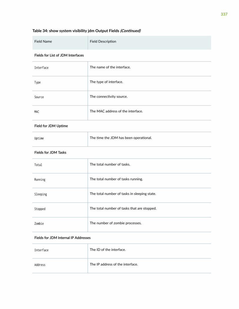
Table 34: show system visibility jdm Output Fields (Continued)
Field Name Field Description
Fields for List of JDM Interfaces
Interface The name of the interface.
Type The type of interface.
Source The connectivity source.
MAC The MAC address of the interface.
Field for JDM Uptime
Uptime The time the JDM has been operational.
Fields for JDM Tasks
Total The total number of tasks.
Running The total number of tasks running.
Sleeping The total number of tasks in sleeping state.
Stopped The total number of tasks that are stopped.
Zombie The number of zombie processes.
Fields for JDM Internal IP Addresses
Interface The ID of the interface.
Address The IP address of the interface.
337
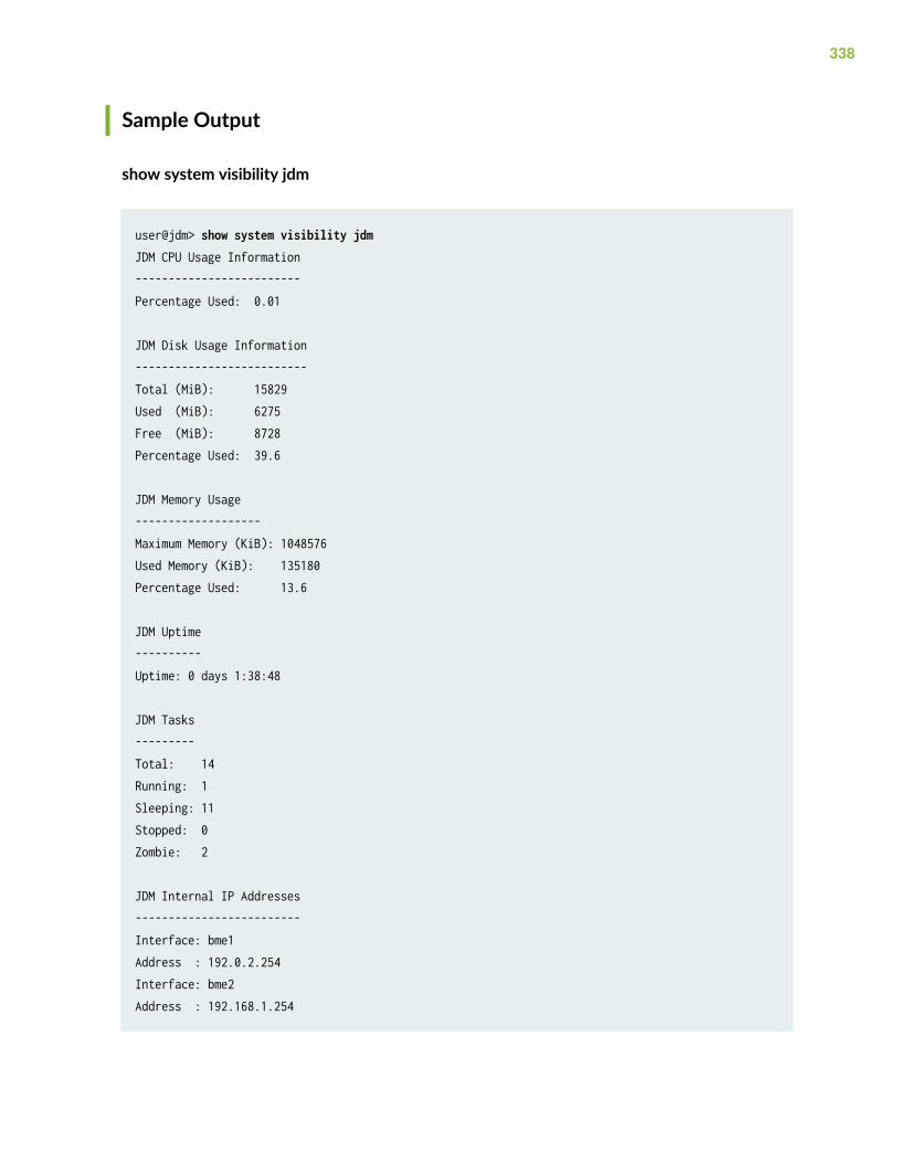
Sample Output
show system visibility jdm
user@jdm> show system visibility jdmJDM CPU Usage Information-------------------------Percentage Used: 0.01
JDM Disk Usage Information--------------------------Total (MiB): 15829Used (MiB): 6275Free (MiB): 8728Percentage Used: 39.6
JDM Memory Usage-------------------Maximum Memory (KiB): 1048576Used Memory (KiB): 135180Percentage Used: 13.6
JDM Uptime----------Uptime: 0 days 1:38:48
JDM Tasks---------Total: 14 Running: 1Sleeping: 11Stopped: 0Zombie: 2
JDM Internal IP Addresses-------------------------Interface: bme1Address : 192.0.2.254Interface: bme2Address : 192.168.1.254
338
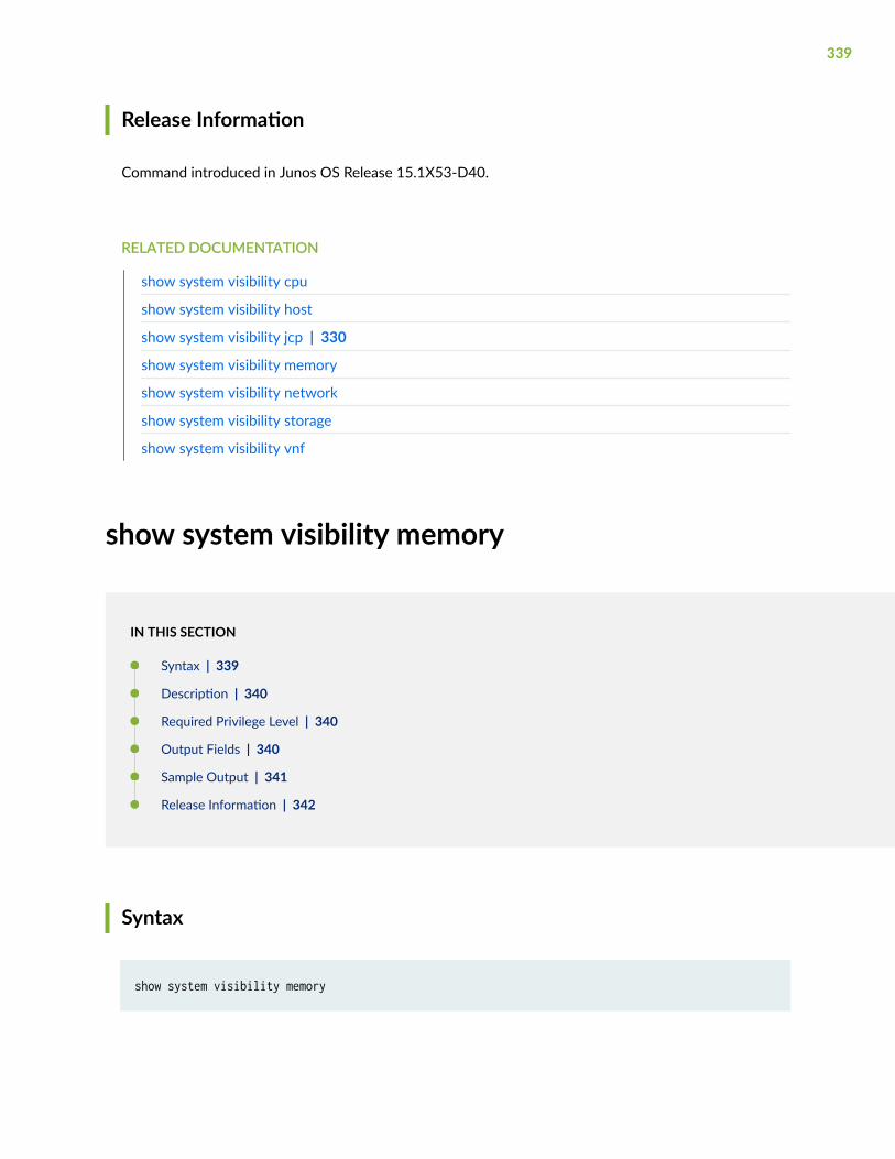
Release Information
Command introduced in Junos OS Release 15.1X53-D40.
RELATED DOCUMENTATION
show system visibility cpu
show system visibility host
show system visibility jcp | 330
show system visibility memory
show system visibility network
show system visibility storage
show system visibility vnf
show system visibility memory
IN THIS SECTION
Syntax | 339
Description | 340
Required Privilege Level | 340
Output Fields | 340
Sample Output | 341
Release Information | 342
Syntax
show system visibility memory
339
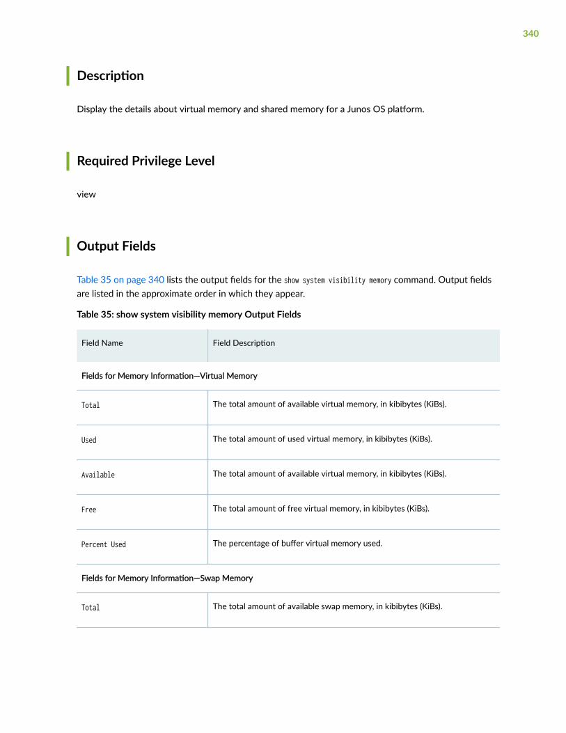
Description
Display the details about virtual memory and shared memory for a Junos OS platform.
Required Privilege Level
view
Output Fields
Table 35 on page 340 lists the output fields for the show system visibility memory command. Output fieldsare listed in the approximate order in which they appear.
Table 35: show system visibility memory Output Fields
Field Name Field Description
Fields for Memory Information—Virtual Memory
Total The total amount of available virtual memory, in kibibytes (KiBs).
Used The total amount of used virtual memory, in kibibytes (KiBs).
Available The total amount of available virtual memory, in kibibytes (KiBs).
Free The total amount of free virtual memory, in kibibytes (KiBs).
Percent Used The percentage of buffer virtual memory used.
Fields for Memory Information—Swap Memory
Total The total amount of available swap memory, in kibibytes (KiBs).
340
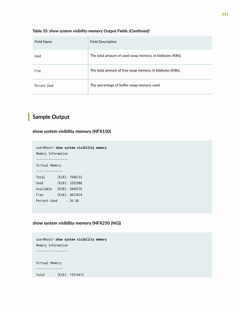
Table 35: show system visibility memory Output Fields (Continued)
Field Name Field Description
Used The total amount of used swap memory, in kibibytes (KiBs).
Free The total amount of free swap memory, in kibibytes (KiBs).
Percent Used The percentage of buffer swap memory used.
Sample Output
show system visibility memory (NFX150)
user@host> show system visibility memoryMemory Information------------------Virtual Memory:---------------Total (KiB): 7946732Used (KiB): 3292908Available (KiB): 5844376Free (KiB): 4653824Percent Used : 26.50
show system visibility memory (NFX250 (NG))
user@host> show system visibility memoryMemory Information------------------
Virtual Memory:---------------Total (KiB): 15914412
341
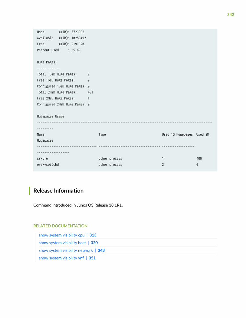
Used (KiB): 6723092Available (KiB): 10250492Free (KiB): 9191320Percent Used : 35.60
Huge Pages:------------Total 1GiB Huge Pages: 2Free 1GiB Huge Pages: 0Configured 1GiB Huge Pages: 0Total 2MiB Huge Pages: 401Free 2MiB Huge Pages: 1Configured 2MiB Huge Pages: 0
Hugepages Usage:----------------------------------------------------------------------------------------------------------Name Type Used 1G Hugepages Used 2M Hugepages--------------------------------- ---------------------------------- ------------------ ------------------srxpfe other process 1 400ovs-vswitchd other process 2 0
Release Information
Command introduced in Junos OS Release 18.1R1.
RELATED DOCUMENTATION
show system visibility cpu | 313
show system visibility host | 320
show system visibility network | 343
show system visibility vnf | 351
342
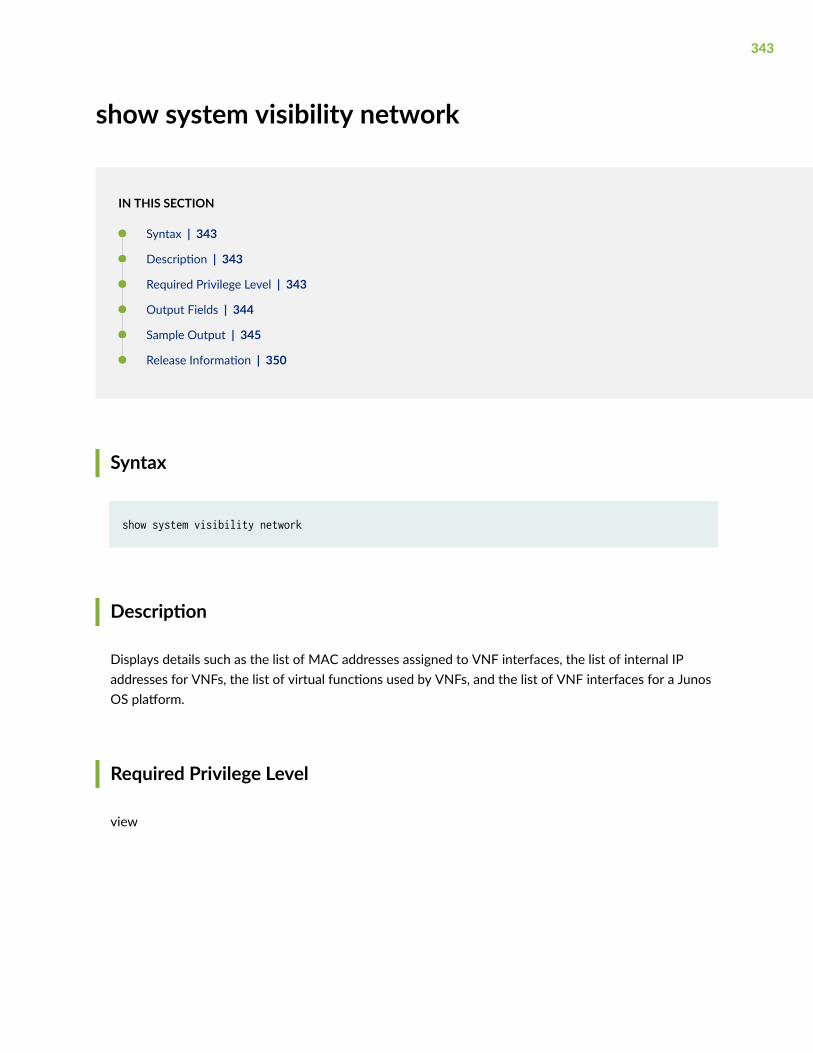
show system visibility network
IN THIS SECTION
Syntax | 343
Description | 343
Required Privilege Level | 343
Output Fields | 344
Sample Output | 345
Release Information | 350
Syntax
show system visibility network
Description
Displays details such as the list of MAC addresses assigned to VNF interfaces, the list of internal IPaddresses for VNFs, the list of virtual functions used by VNFs, and the list of VNF interfaces for a JunosOS platform.
Required Privilege Level
view
343
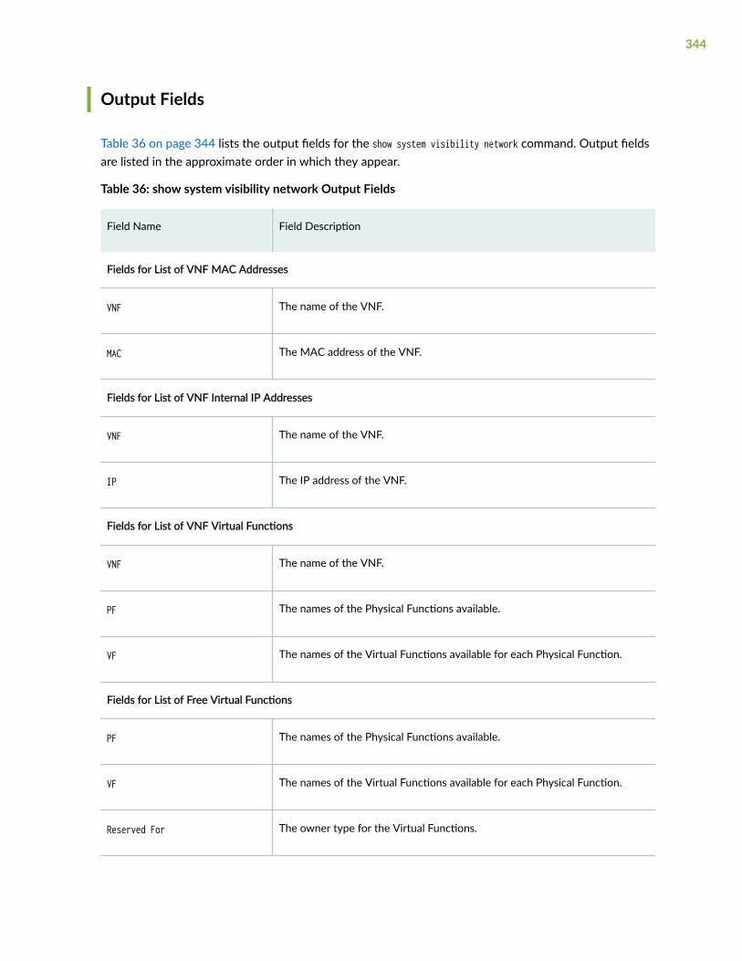
Output Fields
Table 36 on page 344 lists the output fields for the show system visibility network command. Output fieldsare listed in the approximate order in which they appear.
Table 36: show system visibility network Output Fields
Field Name Field Description
Fields for List of VNF MAC Addresses
VNF The name of the VNF.
MAC The MAC address of the VNF.
Fields for List of VNF Internal IP Addresses
VNF The name of the VNF.
IP The IP address of the VNF.
Fields for List of VNF Virtual Functions
VNF The name of the VNF.
PF The names of the Physical Functions available.
VF The names of the Virtual Functions available for each Physical Function.
Fields for List of Free Virtual Functions
PF The names of the Physical Functions available.
VF The names of the Virtual Functions available for each Physical Function.
Reserved For The owner type for the Virtual Functions.
344
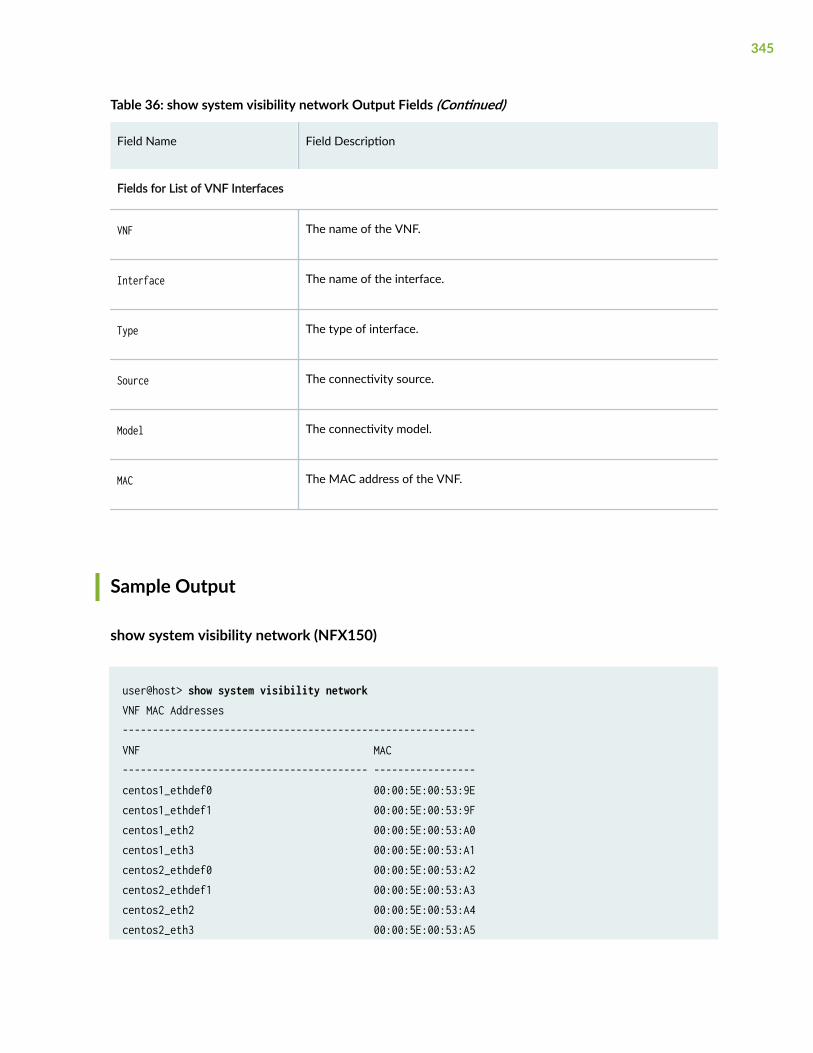
Table 36: show system visibility network Output Fields (Continued)
Field Name Field Description
Fields for List of VNF Interfaces
VNF The name of the VNF.
Interface The name of the interface.
Type The type of interface.
Source The connectivity source.
Model The connectivity model.
MAC The MAC address of the VNF.
Sample Output
show system visibility network (NFX150)
user@host> show system visibility networkVNF MAC Addresses-----------------------------------------------------------VNF MAC----------------------------------------- -----------------centos1_ethdef0 00:00:5E:00:53:9Ecentos1_ethdef1 00:00:5E:00:53:9Fcentos1_eth2 00:00:5E:00:53:A0centos1_eth3 00:00:5E:00:53:A1centos2_ethdef0 00:00:5E:00:53:A2centos2_ethdef1 00:00:5E:00:53:A3centos2_eth2 00:00:5E:00:53:A4centos2_eth3 00:00:5E:00:53:A5
345
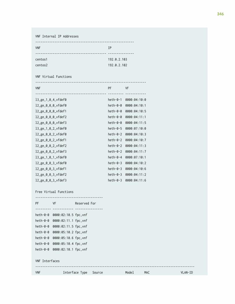
VNF Internal IP Addresses---------------------------------------------------------VNF IP----------------------------------------- ---------------centos1 192.0.2.103 centos2 192.0.2.102
VNF Virtual Functions----------------------------------------------------------------VNF PF VF----------------------------------------- --------- ------------l3_ge_1_0_4_vfdef0 heth-0-1 0000:04:10:0l2_ge_0_0_0_vfdef0 heth-0-0 0000:04:10:1l2_ge_0_0_0_vfdef1 heth-0-0 0000:04:10:5l2_ge_0_0_0_vfdef2 heth-0-0 0000:04:11:1l2_ge_0_0_0_vfdef3 heth-0-0 0000:04:11:5l3_ge_1_0_2_vfdef0 heth-0-5 0000:07:10:0l2_ge_0_0_2_vfdef0 heth-0-2 0000:04:10:3l2_ge_0_0_2_vfdef1 heth-0-2 0000:04:10:7l2_ge_0_0_2_vfdef2 heth-0-2 0000:04:11:3l2_ge_0_0_2_vfdef3 heth-0-2 0000:04:11:7l3_ge_1_0_1_vfdef0 heth-0-4 0000:07:10:1l2_ge_0_0_3_vfdef0 heth-0-3 0000:04:10:2l2_ge_0_0_3_vfdef1 heth-0-3 0000:04:10:6l2_ge_0_0_3_vfdef2 heth-0-3 0000:04:11:2l2_ge_0_0_3_vfdef3 heth-0-3 0000:04:11:6
Free Virtual Functions---------------------------------------PF VF Reserved For--------- ------------ ----------------heth-0-0 0000:02:10.5 fpc,vnfheth-0-0 0000:02:11.1 fpc,vnfheth-0-0 0000:02:11.5 fpc,vnfheth-0-0 0000:05:10.2 fpc,vnfheth-0-0 0000:05:10.6 fpc,vnfheth-0-0 0000:05:10.4 fpc,vnfheth-0-0 0000:02:10.1 fpc,vnf
VNF Interfaces--------------------------------------------------------------------------------------------VNF Interface Type Source Model MAC VLAN-ID
346
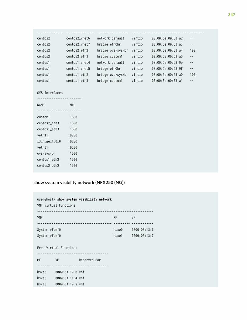
-------------- --------------- ----------------- ---------- -------------------- --------centos2 centos2_vnet6 network default virtio 00:00:5e:00:53:a2 -- centos2 centos2_vnet7 bridge eth0br virtio 00:00:5e:00:53:a3 -- centos2 centos2_eth2 bridge ovs-sys-br virtio 00:00:5e:00:53:a4 199 centos2 centos2_eth3 bridge custom1 virtio 00:00:5e:00:53:a5 -- centos1 centos1_vnet4 network default virtio 00:00:5e:00:53:9e -- centos1 centos1_vnet5 bridge eth0br virtio 00:00:5e:00:53:9f -- centos1 centos1_eth2 bridge ovs-sys-br virtio 00:00:5e:00:53:a0 100 centos1 centos1_eth3 bridge custom1 virtio 00:00:5e:00:53:a1 --
OVS Interfaces----------------- ------NAME MTU----------------- ------custom1 1500 centos2_eth3 1500 centos1_eth3 1500 veth11 9200 l3_h_ge_1_0_0 9200 veth01 9200 ovs-sys-br 1500 centos1_eth2 1500 centos2_eth2 1500
show system visibility network (NFX250 (NG))
user@host> show system visibility networkVNF Virtual Functions----------------------------------------------------------------VNF PF VF----------------------------------------- --------- ------------System_vfdef0 hsxe0 0000:03:13:6System_vfdef0 hsxe1 0000:03:13:7
Free Virtual Functions---------------------------------------PF VF Reserved For--------- ------------ ----------------hsxe0 0000:03:10.0 vnf hsxe0 0000:03:11.4 vnf hsxe0 0000:03:10.2 vnf
347
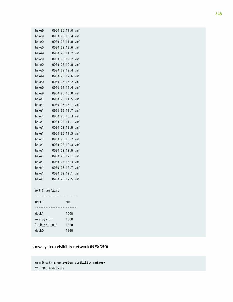
hsxe0 0000:03:11.6 vnf hsxe0 0000:03:10.4 vnf hsxe0 0000:03:11.0 vnf hsxe0 0000:03:10.6 vnf hsxe0 0000:03:11.2 vnf hsxe0 0000:03:12.2 vnf hsxe0 0000:03:12.0 vnf hsxe0 0000:03:13.4 vnf hsxe0 0000:03:12.6 vnf hsxe0 0000:03:13.2 vnf hsxe0 0000:03:12.4 vnf hsxe0 0000:03:13.0 vnf hsxe1 0000:03:11.5 vnf hsxe1 0000:03:10.1 vnf hsxe1 0000:03:11.7 vnf hsxe1 0000:03:10.3 vnf hsxe1 0000:03:11.1 vnf hsxe1 0000:03:10.5 vnf hsxe1 0000:03:11.3 vnf hsxe1 0000:03:10.7 vnf hsxe1 0000:03:12.3 vnf hsxe1 0000:03:13.5 vnf hsxe1 0000:03:12.1 vnf hsxe1 0000:03:13.3 vnf hsxe1 0000:03:12.7 vnf hsxe1 0000:03:13.1 vnf hsxe1 0000:03:12.5 vnf
OVS Interfaces------------------------NAME MTU----------------- ------dpdk1 1500ovs-sys-br 1500l3_h_ge_1_0_0 1500dpdk0 1500
show system visibility network (NFX350)
user@host> show system visibility networkVNF MAC Addresses
348

-----------------------------------------------------------VNF MAC----------------------------------------- -----------------new_ethdef0 78:4F:9B:2B:2E:4Bnew_ethdef1 78:4F:9B:2B:2E:4C
VNF Internal IP Addresses---------------------------------------------------------VNF IP----------------------------------------- ---------------new 192.0.2.100
VNF Virtual Functions----------------------------------------------------------------VNF PF VF----------------------------------------- --------- ------------new hsxe0 0000:b7:02.1new hsxe0 0000:b7:02.2
Free Virtual Functions---------------------------------------PF VF Reserved For--------- ------------ ----------------hsxe0 0000:b6:02.3 vnfhsxe0 0000:b6:03.5 fpchsxe0 0000:b6:02.1 vnfhsxe0 0000:b6:02.2 vnfhsxe0 0000:b6:03.6 fpchsxe0 0000:b6:02.4 vnfhsxe0 0000:b6:02.5 vnfhsxe0 0000:b6:02.6 vnfhsxe0 0000:b6:02.7 vnfhsxe1 0000:b6:06.4 vnfhsxe1 0000:b6:06.5 vnfhsxe1 0000:b6:06.6 vnfhsxe1 0000:b6:06.7 vnfhsxe1 0000:b6:06.1 vnfhsxe1 0000:b6:06.2 vnfhsxe1 0000:b6:06.3 vnfhsxe1 0000:b6:07.5 fpchsxe1 0000:b6:07.6 fpchsxe2 0000:b6:0b.5 fpchsxe2 0000:b6:0b.6 fpc
349
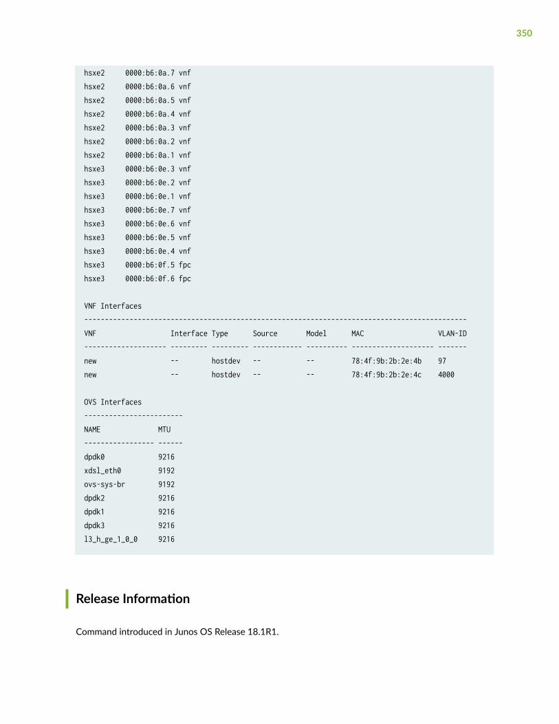
hsxe2 0000:b6:0a.7 vnfhsxe2 0000:b6:0a.6 vnfhsxe2 0000:b6:0a.5 vnfhsxe2 0000:b6:0a.4 vnfhsxe2 0000:b6:0a.3 vnfhsxe2 0000:b6:0a.2 vnfhsxe2 0000:b6:0a.1 vnfhsxe3 0000:b6:0e.3 vnfhsxe3 0000:b6:0e.2 vnfhsxe3 0000:b6:0e.1 vnfhsxe3 0000:b6:0e.7 vnfhsxe3 0000:b6:0e.6 vnfhsxe3 0000:b6:0e.5 vnfhsxe3 0000:b6:0e.4 vnfhsxe3 0000:b6:0f.5 fpchsxe3 0000:b6:0f.6 fpc
VNF Interfaces---------------------------------------------------------------------------------------------VNF Interface Type Source Model MAC VLAN-ID-------------------- --------- --------- ------------ ---------- -------------------- -------new -- hostdev -- -- 78:4f:9b:2b:2e:4b 97new -- hostdev -- -- 78:4f:9b:2b:2e:4c 4000
OVS Interfaces------------------------NAME MTU----------------- ------dpdk0 9216xdsl_eth0 9192ovs-sys-br 9192dpdk2 9216dpdk1 9216dpdk3 9216l3_h_ge_1_0_0 9216
Release Information
Command introduced in Junos OS Release 18.1R1.
350
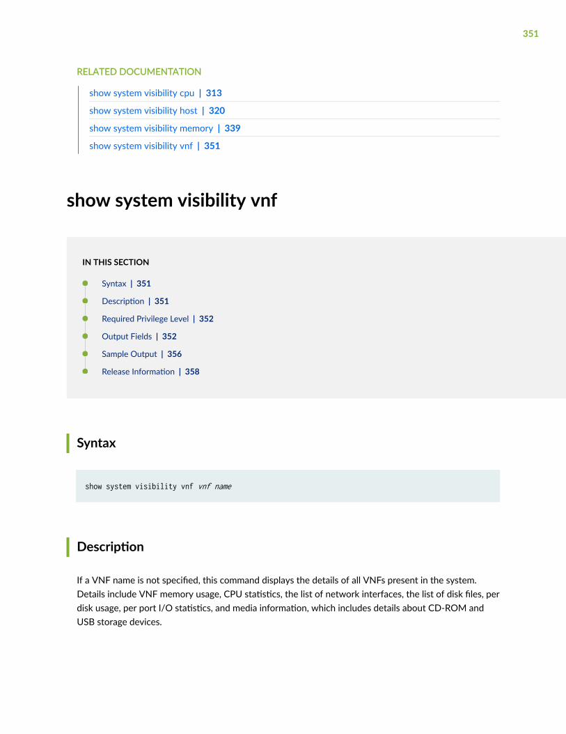
RELATED DOCUMENTATION
show system visibility cpu | 313
show system visibility host | 320
show system visibility memory | 339
show system visibility vnf | 351
show system visibility vnf
IN THIS SECTION
Syntax | 351
Description | 351
Required Privilege Level | 352
Output Fields | 352
Sample Output | 356
Release Information | 358
Syntax
show system visibility vnf vnf name
Description
If a VNF name is not specified, this command displays the details of all VNFs present in the system.Details include VNF memory usage, CPU statistics, the list of network interfaces, the list of disk files, perdisk usage, per port I/O statistics, and media information, which includes details about CD-ROM andUSB storage devices.
351
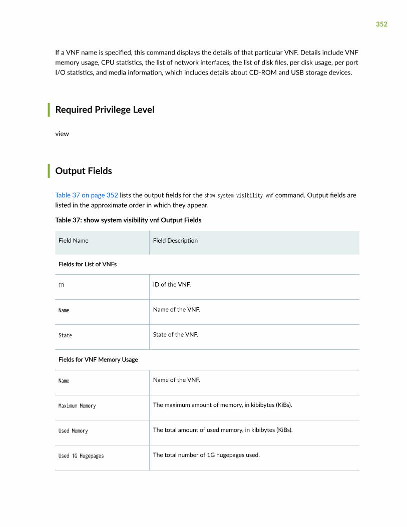
If a VNF name is specified, this command displays the details of that particular VNF. Details include VNFmemory usage, CPU statistics, the list of network interfaces, the list of disk files, per disk usage, per portI/O statistics, and media information, which includes details about CD-ROM and USB storage devices.
Required Privilege Level
view
Output Fields
Table 37 on page 352 lists the output fields for the show system visibility vnf command. Output fields arelisted in the approximate order in which they appear.
Table 37: show system visibility vnf Output Fields
Field Name Field Description
Fields for List of VNFs
ID ID of the VNF.
Name Name of the VNF.
State State of the VNF.
Fields for VNF Memory Usage
Name Name of the VNF.
Maximum Memory The maximum amount of memory, in kibibytes (KiBs).
Used Memory The total amount of used memory, in kibibytes (KiBs).
Used 1G Hugepages The total number of 1G hugepages used.
352
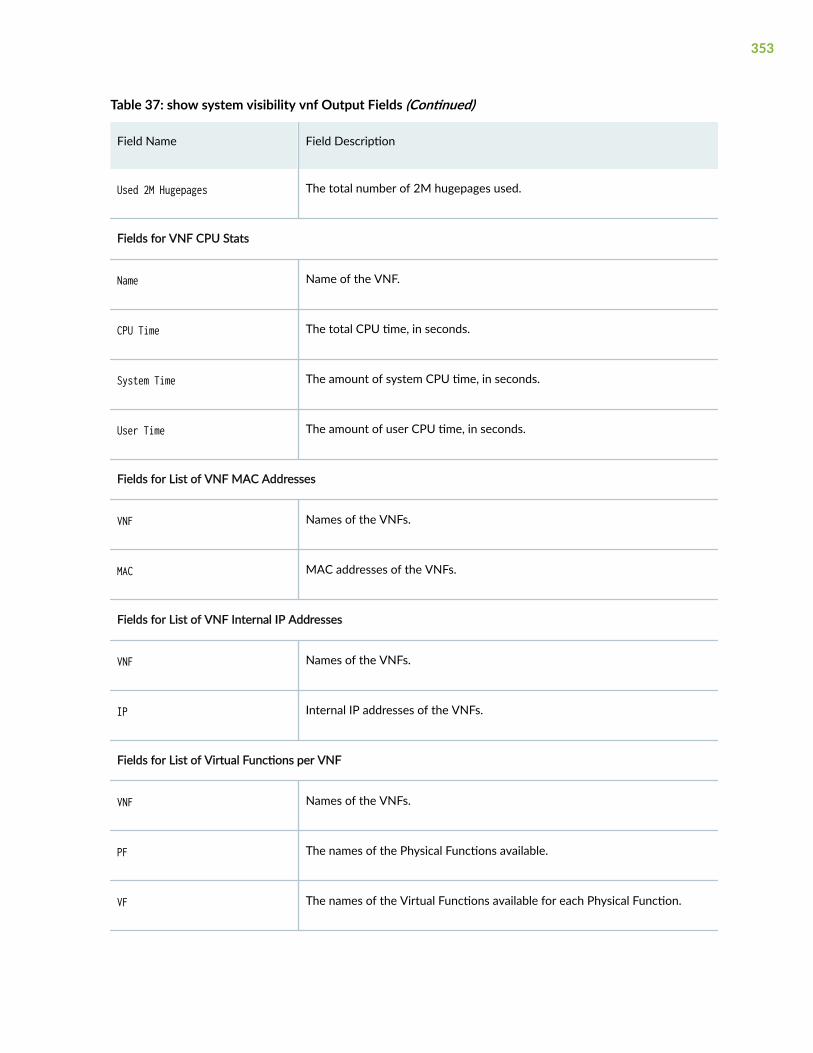
Table 37: show system visibility vnf Output Fields (Continued)
Field Name Field Description
Used 2M Hugepages The total number of 2M hugepages used.
Fields for VNF CPU Stats
Name Name of the VNF.
CPU Time The total CPU time, in seconds.
System Time The amount of system CPU time, in seconds.
User Time The amount of user CPU time, in seconds.
Fields for List of VNF MAC Addresses
VNF Names of the VNFs.
MAC MAC addresses of the VNFs.
Fields for List of VNF Internal IP Addresses
VNF Names of the VNFs.
IP Internal IP addresses of the VNFs.
Fields for List of Virtual Functions per VNF
VNF Names of the VNFs.
PF The names of the Physical Functions available.
VF The names of the Virtual Functions available for each Physical Function.
353
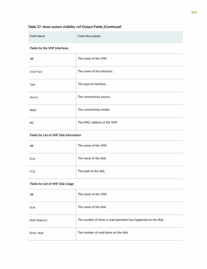
Table 37: show system visibility vnf Output Fields (Continued)
Field Name Field Description
Fields for the VNF Interfaces
VNF The name of the VNF.
Interface The name of the interface.
Type The type of interface.
Source The connectivity source.
Model The connectivity model.
MAC The MAC address of the VNF.
Fields for List of VNF Disk Information
VNF The name of the VNF.
Disk The name of the disk.
File The path to the disk.
Fields for List of VNF Disk Usage
VNF The name of the VNF.
Disk The name of the disk.
Read Requests The number of times a read operation has happened on the disk.
Bytes Read The number of read bytes on the disk.
354
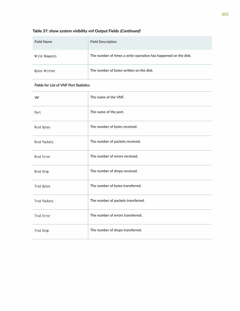
Table 37: show system visibility vnf Output Fields (Continued)
Field Name Field Description
Write Requests The number of times a write operation has happened on the disk.
Bytes Written The number of bytes written on the disk.
Fields for List of VNF Port Statistics
VNF The name of the VNF.
Port The name of the port.
Rcvd Bytes The number of bytes received.
Rcvd Packets The number of packets received.
Rcvd Error The number of errors received.
Rcvd Drop The number of drops received.
Trxd Bytes The number of bytes transferred.
Trxd Packets The number of packets transferred.
Trxd Error The number of errors transferred.
Trxd Drop The number of drops transferred.
355
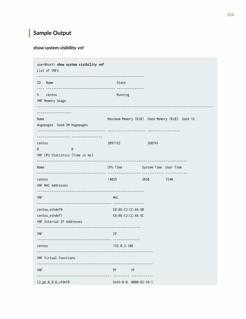
Sample Output
show system visibility vnf
user@host> show system visibility vnfList of VNFs ----------------------------------------------------------- ID Name State ---- -------------------------------------- --------------- 5 centos Running VNF Memory Usage -------------------------------------------------------------------------------------------------------------------- Name Maximum Memory (KiB) Used Memory (KiB) Used 1G Hugepages Used 2M Hugepages -------------------------------------- --------------------- ------------------ ------------------ ----------------- centos 2097152 260741 0 0 VNF CPU Statistics (Time in ms) ----------------------------------------------------------------------------------- Name CPU Time System Time User Time -------------------------------------- ------------------ ------------ ------------ centos 14029 3650 1540 VNF MAC Addresses ----------------------------------------------------------- VNF MAC ----------------------------------------- ----------------- centos_ethdef0 E8:B6:C2:CC:66:9B centos_ethdef1 E8:B6:C2:CC:66:9C VNF Internal IP Addresses --------------------------------------------------------- VNF IP ----------------------------------------- --------------- centos 192.0.2.100---------------------------------------------------------------- VNF Virtual Functions ---------------------------------------------------------------- VNF PF VF ----------------------------------------- --------- ------------ l2_ge_0_0_0_vfdef0 heth-0-0 0000:02:10:1
356
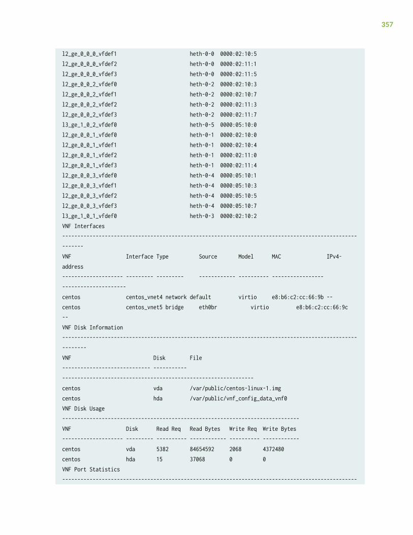
l2_ge_0_0_0_vfdef1 heth-0-0 0000:02:10:5 l2_ge_0_0_0_vfdef2 heth-0-0 0000:02:11:1 l2_ge_0_0_0_vfdef3 heth-0-0 0000:02:11:5 l2_ge_0_0_2_vfdef0 heth-0-2 0000:02:10:3 l2_ge_0_0_2_vfdef1 heth-0-2 0000:02:10:7 l2_ge_0_0_2_vfdef2 heth-0-2 0000:02:11:3 l2_ge_0_0_2_vfdef3 heth-0-2 0000:02:11:7 l3_ge_1_0_2_vfdef0 heth-0-5 0000:05:10:0 l2_ge_0_0_1_vfdef0 heth-0-1 0000:02:10:0 l2_ge_0_0_1_vfdef1 heth-0-1 0000:02:10:4 l2_ge_0_0_1_vfdef2 heth-0-1 0000:02:11:0 l2_ge_0_0_1_vfdef3 heth-0-1 0000:02:11:4 l2_ge_0_0_3_vfdef0 heth-0-4 0000:05:10:1 l2_ge_0_0_3_vfdef1 heth-0-4 0000:05:10:3 l2_ge_0_0_3_vfdef2 heth-0-4 0000:05:10:5 l2_ge_0_0_3_vfdef3 heth-0-4 0000:05:10:7 l3_ge_1_0_1_vfdef0 heth-0-3 0000:02:10:2 VNF Interfaces -------------------------------------------------------------------------------------------------------- VNF Interface Type Source Model MAC IPv4-address -------------------- --------- --------- ------------ ---------- ----------------- --------------------- centos centos_vnet4 network default virtio e8:b6:c2:cc:66:9b -- centos centos_vnet5 bridge eth0br virtio e8:b6:c2:cc:66:9c -- VNF Disk Information --------------------------------------------------------------------------------------------------------- VNF Disk File ----------------------------- ----------- --------------------------------------------------------------- centos vda /var/public/centos-linux-1.img centos hda /var/public/vnf_config_data_vnf0 VNF Disk Usage ------------------------------------------------------------------------------ VNF Disk Read Req Read Bytes Write Req Write Bytes -------------------- --------- ---------- ------------ ---------- ------------ centos vda 5382 84654592 2068 4372480 centos hda 15 37068 0 0 VNF Port Statistics -------------------------------------------------------------------------------------------------
357
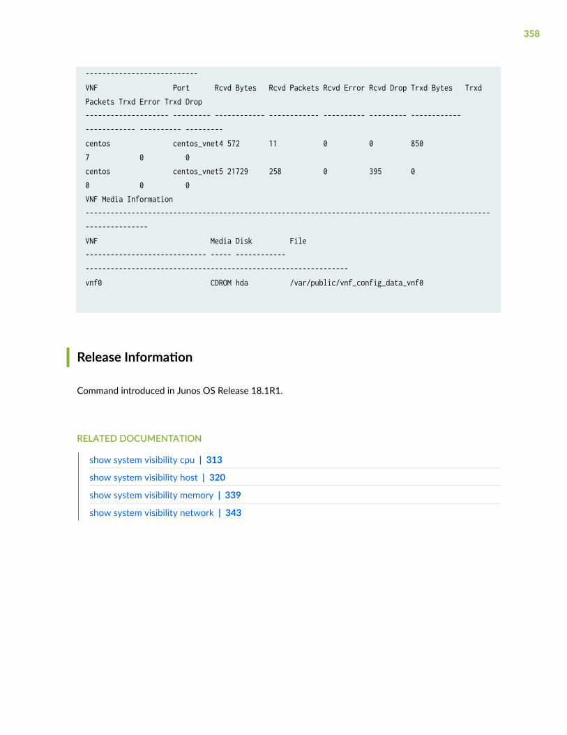
---------------------------VNF Port Rcvd Bytes Rcvd Packets Rcvd Error Rcvd Drop Trxd Bytes Trxd Packets Trxd Error Trxd Drop-------------------- --------- ------------ ------------ ---------- --------- ------------ ------------ ---------- ---------centos centos_vnet4 572 11 0 0 850 7 0 0 centos centos_vnet5 21729 258 0 395 0 0 0 0 VNF Media Information ---------------------------------------------------------------------------------------------------------------- VNF Media Disk File ----------------------------- ----- ------------ --------------------------------------------------------------- vnf0 CDROM hda /var/public/vnf_config_data_vnf0
Release Information
Command introduced in Junos OS Release 18.1R1.
RELATED DOCUMENTATION
show system visibility cpu | 313
show system visibility host | 320
show system visibility memory | 339
show system visibility network | 343
358
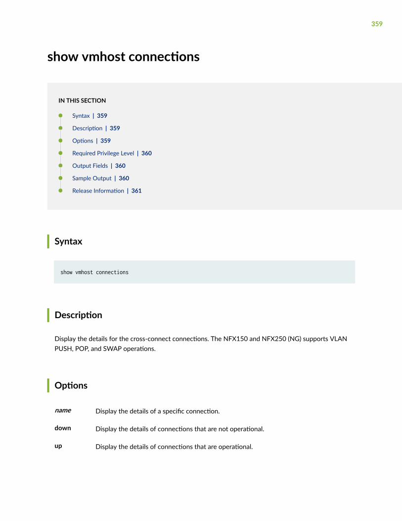
show vmhost connections
IN THIS SECTION
Syntax | 359
Description | 359
Options | 359
Required Privilege Level | 360
Output Fields | 360
Sample Output | 360
Release Information | 361
Syntax
show vmhost connections
Description
Display the details for the cross-connect connections. The NFX150 and NFX250 (NG) supports VLANPUSH, POP, and SWAP operations.
Options
name Display the details of a specific connection.
down Display the details of connections that are not operational.
up Display the details of connections that are operational.
359
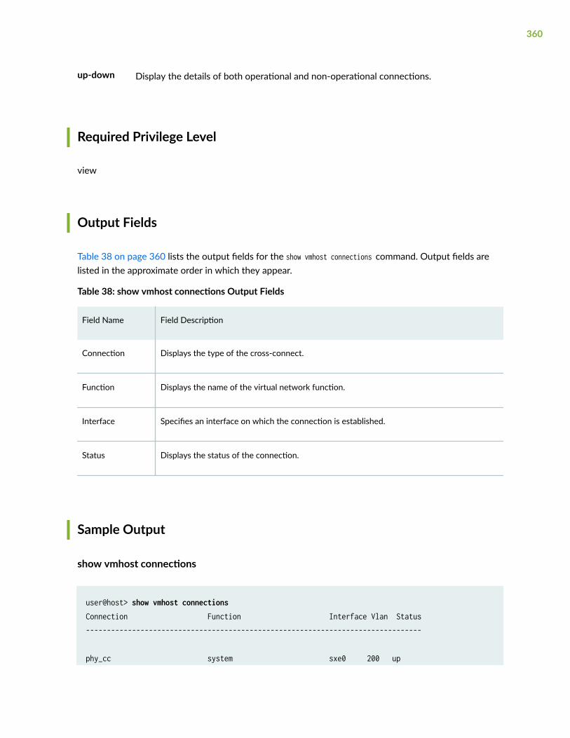
up-down Display the details of both operational and non-operational connections.
Required Privilege Level
view
Output Fields
Table 38 on page 360 lists the output fields for the show vmhost connections command. Output fields arelisted in the approximate order in which they appear.
Table 38: show vmhost connections Output Fields
Field Name Field Description
Connection Displays the type of the cross-connect.
Function Displays the name of the virtual network function.
Interface Specifies an interface on which the connection is established.
Status Displays the status of the connection.
Sample Output
show vmhost connections
user@host> show vmhost connectionsConnection Function Interface Vlan Status--------------------------------------------------------------------------------
phy_cc system sxe0 200 up
360
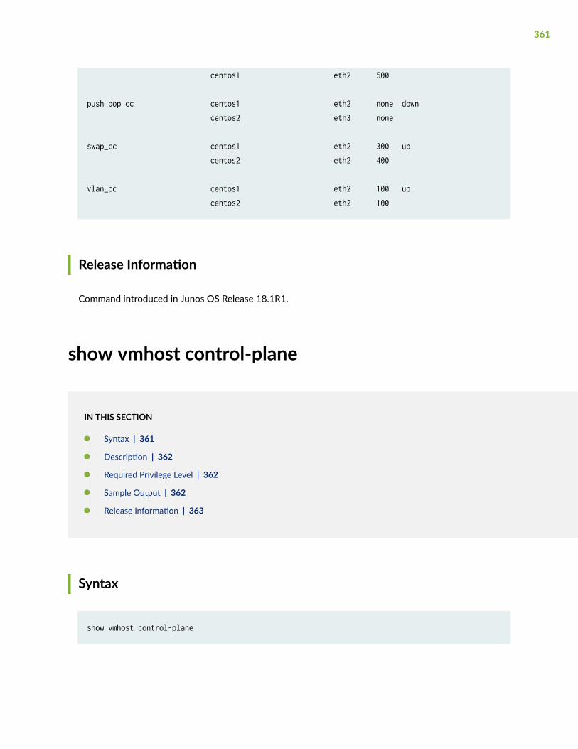
centos1 eth2 500
push_pop_cc centos1 eth2 none down centos2 eth3 none
swap_cc centos1 eth2 300 up centos2 eth2 400
vlan_cc centos1 eth2 100 up centos2 eth2 100
Release Information
Command introduced in Junos OS Release 18.1R1.
show vmhost control-plane
IN THIS SECTION
Syntax | 361
Description | 362
Required Privilege Level | 362
Sample Output | 362
Release Information | 363
Syntax
show vmhost control-plane
361
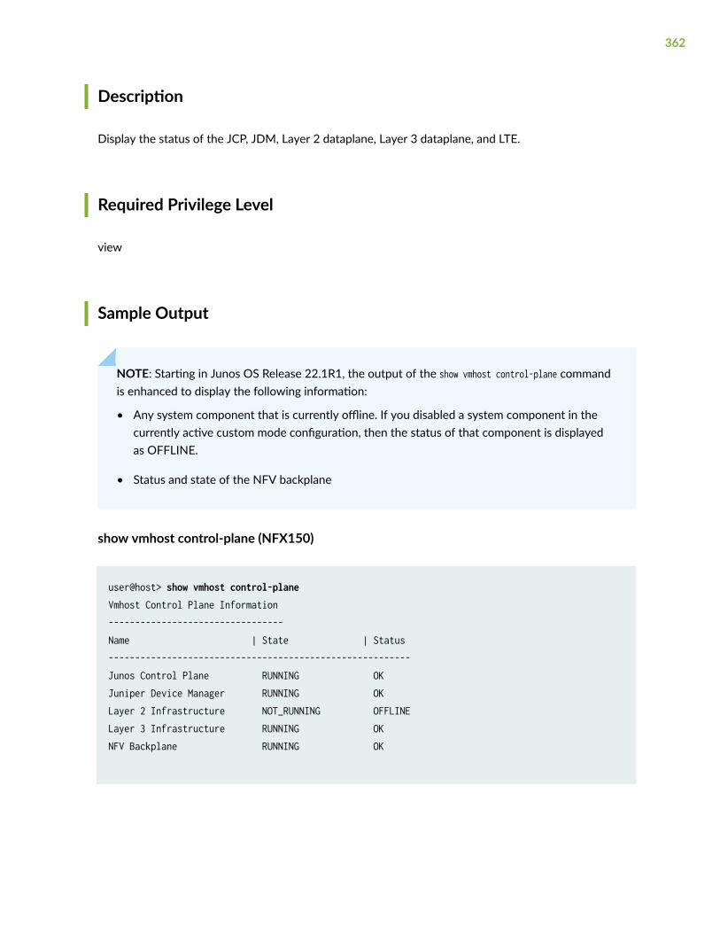
Description
Display the status of the JCP, JDM, Layer 2 dataplane, Layer 3 dataplane, and LTE.
Required Privilege Level
view
Sample Output
NOTE: Starting in Junos OS Release 22.1R1, the output of the show vmhost control-plane commandis enhanced to display the following information:
• Any system component that is currently offline. If you disabled a system component in thecurrently active custom mode configuration, then the status of that component is displayedas OFFLINE.
• Status and state of the NFV backplane
show vmhost control-plane (NFX150)
user@host> show vmhost control-planeVmhost Control Plane Information---------------------------------Name | State | Status---------------------------------------------------------Junos Control Plane RUNNING OKJuniper Device Manager RUNNING OKLayer 2 Infrastructure NOT_RUNNING OFFLINELayer 3 Infrastructure RUNNING OKNFV Backplane RUNNING OK
362
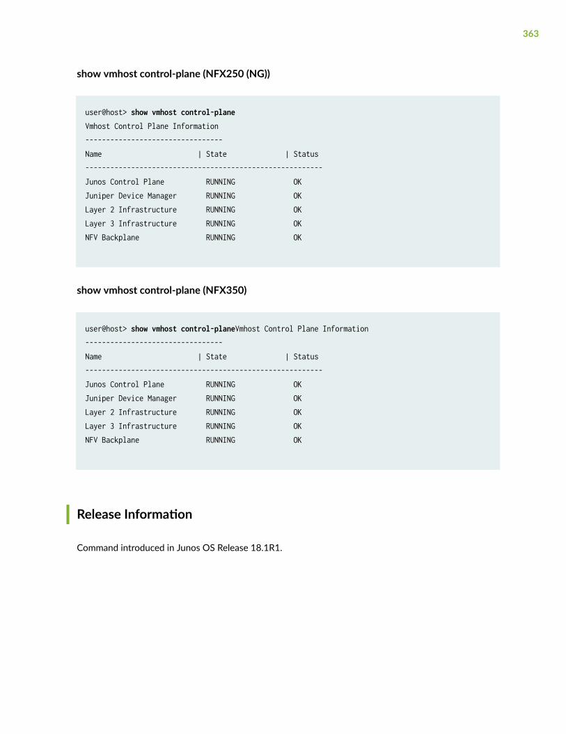
show vmhost control-plane (NFX250 (NG))
user@host> show vmhost control-planeVmhost Control Plane Information---------------------------------Name | State | Status---------------------------------------------------------Junos Control Plane RUNNING OKJuniper Device Manager RUNNING OKLayer 2 Infrastructure RUNNING OKLayer 3 Infrastructure RUNNING OKNFV Backplane RUNNING OK
show vmhost control-plane (NFX350)
user@host> show vmhost control-planeVmhost Control Plane Information---------------------------------Name | State | Status---------------------------------------------------------Junos Control Plane RUNNING OKJuniper Device Manager RUNNING OKLayer 2 Infrastructure RUNNING OKLayer 3 Infrastructure RUNNING OKNFV Backplane RUNNING OK
Release Information
Command introduced in Junos OS Release 18.1R1.
363
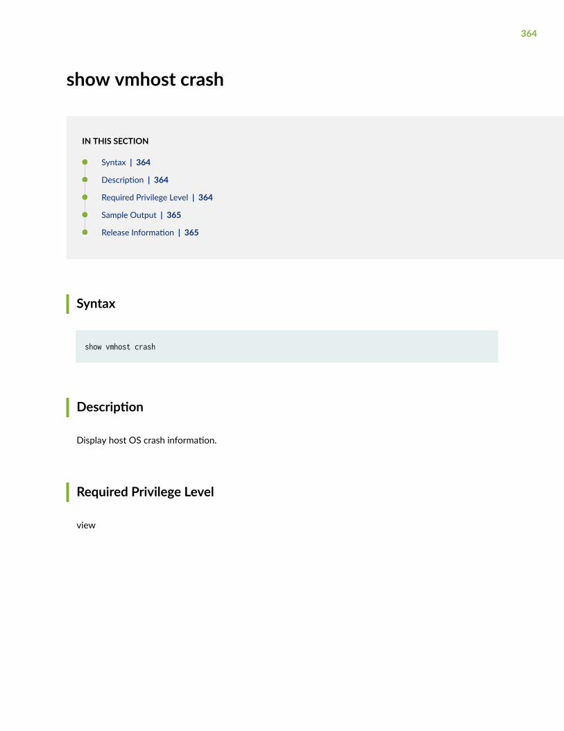
show vmhost crash
IN THIS SECTION
Syntax | 364
Description | 364
Required Privilege Level | 364
Sample Output | 365
Release Information | 365
Syntax
show vmhost crash
Description
Display host OS crash information.
Required Privilege Level
view
364
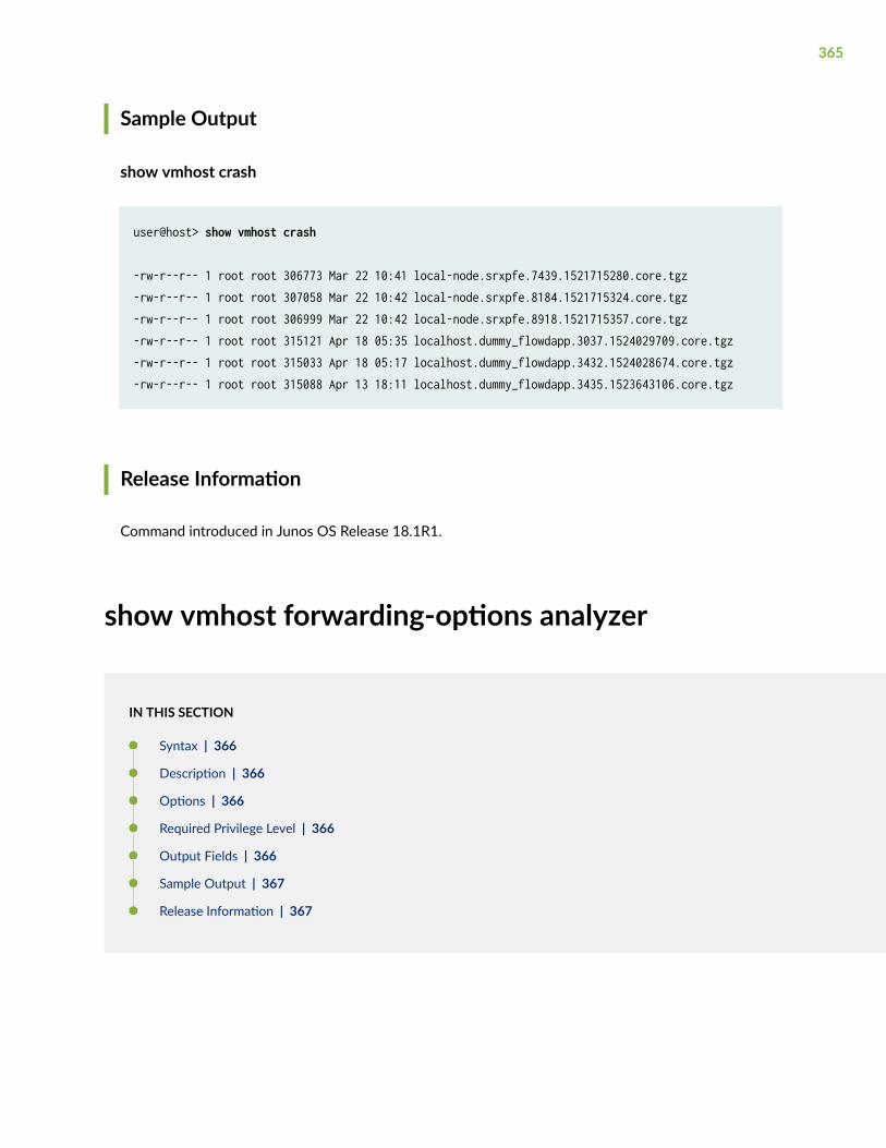
Sample Output
show vmhost crash
user@host> show vmhost crash
-rw-r--r-- 1 root root 306773 Mar 22 10:41 local-node.srxpfe.7439.1521715280.core.tgz-rw-r--r-- 1 root root 307058 Mar 22 10:42 local-node.srxpfe.8184.1521715324.core.tgz-rw-r--r-- 1 root root 306999 Mar 22 10:42 local-node.srxpfe.8918.1521715357.core.tgz-rw-r--r-- 1 root root 315121 Apr 18 05:35 localhost.dummy_flowdapp.3037.1524029709.core.tgz-rw-r--r-- 1 root root 315033 Apr 18 05:17 localhost.dummy_flowdapp.3432.1524028674.core.tgz-rw-r--r-- 1 root root 315088 Apr 13 18:11 localhost.dummy_flowdapp.3435.1523643106.core.tgz
Release Information
Command introduced in Junos OS Release 18.1R1.
show vmhost forwarding-options analyzer
IN THIS SECTION
Syntax | 366
Description | 366
Options | 366
Required Privilege Level | 366
Output Fields | 366
Sample Output | 367
Release Information | 367
365
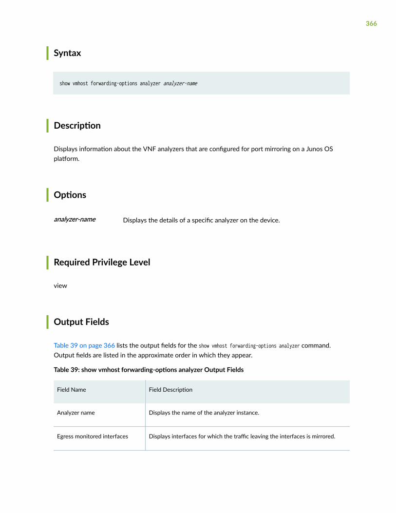
Syntax
show vmhost forwarding-options analyzer analyzer-name
Description
Displays information about the VNF analyzers that are configured for port mirroring on a Junos OSplatform.
Options
analyzer-name Displays the details of a specific analyzer on the device.
Required Privilege Level
view
Output Fields
Table 39 on page 366 lists the output fields for the show vmhost forwarding-options analyzer command.Output fields are listed in the approximate order in which they appear.
Table 39: show vmhost forwarding-options analyzer Output Fields
Field Name Field Description
Analyzer name Displays the name of the analyzer instance.
Egress monitored interfaces Displays interfaces for which the traffic leaving the interfaces is mirrored.
366
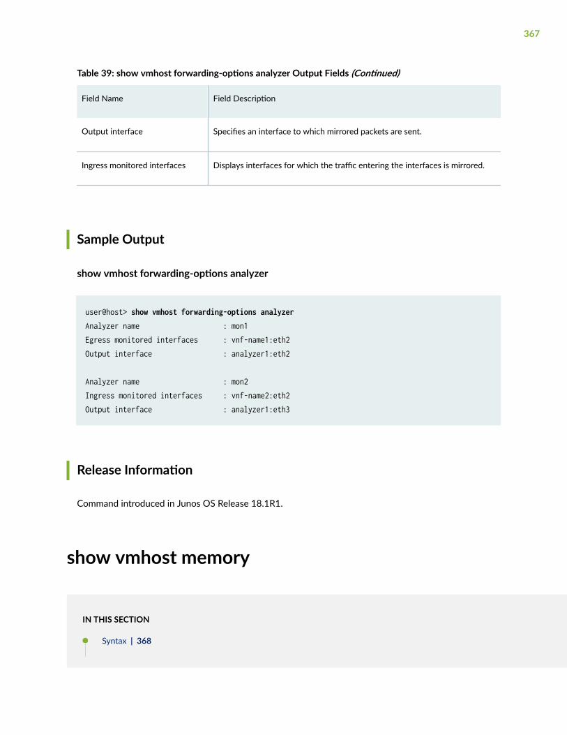
Table 39: show vmhost forwarding-options analyzer Output Fields (Continued)
Field Name Field Description
Output interface Specifies an interface to which mirrored packets are sent.
Ingress monitored interfaces Displays interfaces for which the traffic entering the interfaces is mirrored.
Sample Output
show vmhost forwarding-options analyzer
user@host> show vmhost forwarding-options analyzerAnalyzer name : mon1Egress monitored interfaces : vnf-name1:eth2Output interface : analyzer1:eth2
Analyzer name : mon2Ingress monitored interfaces : vnf-name2:eth2Output interface : analyzer1:eth3
Release Information
Command introduced in Junos OS Release 18.1R1.
show vmhost memory
IN THIS SECTION
Syntax | 368
367
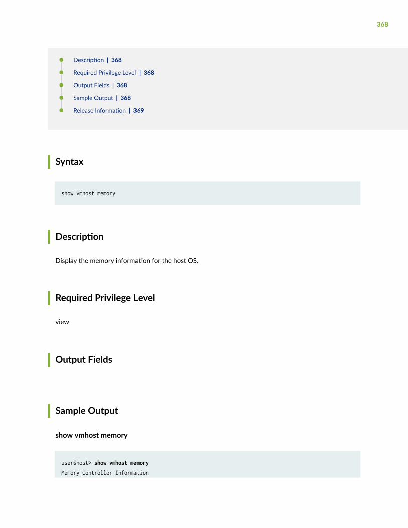
Description | 368
Required Privilege Level | 368
Output Fields | 368
Sample Output | 368
Release Information | 369
Syntax
show vmhost memory
Description
Display the memory information for the host OS.
Required Privilege Level
view
Output Fields
Sample Output
show vmhost memory
user@host> show vmhost memoryMemory Controller Information
368
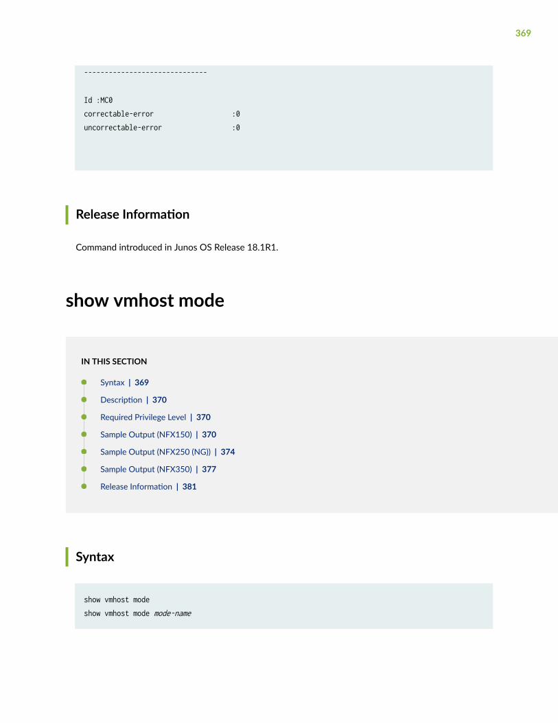
------------------------------
Id :MC0correctable-error :0uncorrectable-error :0
Release Information
Command introduced in Junos OS Release 18.1R1.
show vmhost mode
IN THIS SECTION
Syntax | 369
Description | 370
Required Privilege Level | 370
Sample Output (NFX150) | 370
Sample Output (NFX250 (NG)) | 374
Sample Output (NFX350) | 377
Release Information | 381
Syntax
show vmhost modeshow vmhost mode mode-name
369
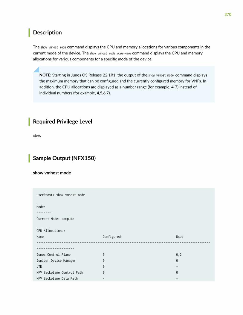
Description
The show vmhost mode command displays the CPU and memory allocations for various components in thecurrent mode of the device. The show vmhost mode mode-name command displays the CPU and memoryallocations for various components for a specific mode of the device.
NOTE: Starting in Junos OS Release 22.1R1, the output of the show vmhost mode command displaysthe maximum memory that can be configured and the currently configured memory for VNFs. Inaddition, the CPU allocations are displayed as a number range (for example, 4-7) instead ofindividual numbers (for example, 4,5,6,7).
Required Privilege Level
view
Sample Output (NFX150)
show vmhost mode
user@host> show vmhost mode
Mode:--------Current Mode: compute
CPU Allocations:Name Configured Used----------------------------------------------------------------------------------------------------------------------Junos Control Plane 0 0,2Juniper Device Manager 0 0LTE 0 -NFV Backplane Control Path 0 0NFV Backplane Data Path - -
370
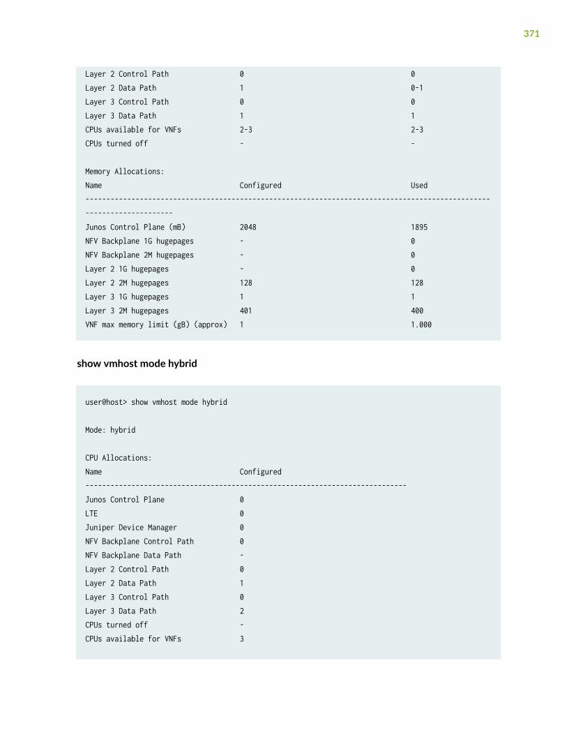
Layer 2 Control Path 0 0Layer 2 Data Path 1 0-1Layer 3 Control Path 0 0Layer 3 Data Path 1 1CPUs available for VNFs 2-3 2-3CPUs turned off - -
Memory Allocations:Name Configured Used----------------------------------------------------------------------------------------------------------------------Junos Control Plane (mB) 2048 1895NFV Backplane 1G hugepages - 0NFV Backplane 2M hugepages - 0Layer 2 1G hugepages - 0Layer 2 2M hugepages 128 128Layer 3 1G hugepages 1 1Layer 3 2M hugepages 401 400VNF max memory limit (gB) (approx) 1 1.000
show vmhost mode hybrid
user@host> show vmhost mode hybrid
Mode: hybrid
CPU Allocations:Name Configured-----------------------------------------------------------------------------Junos Control Plane 0LTE 0Juniper Device Manager 0NFV Backplane Control Path 0NFV Backplane Data Path -Layer 2 Control Path 0Layer 2 Data Path 1Layer 3 Control Path 0Layer 3 Data Path 2CPUs turned off -CPUs available for VNFs 3
371
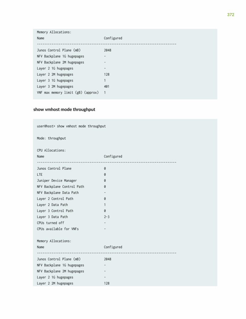
Memory Allocations:Name Configured-----------------------------------------------------------------------------Junos Control Plane (mB) 2048NFV Backplane 1G hugepages -NFV Backplane 2M hugepages -Layer 2 1G hugepages -Layer 2 2M hugepages 128Layer 3 1G hugepages 1Layer 3 2M hugepages 401VNF max memory limit (gB) (approx) 1
show vmhost mode throughput
user@host> show vmhost mode throughput
Mode: throughput
CPU Allocations:Name Configured-----------------------------------------------------------------------------Junos Control Plane 0LTE 0Juniper Device Manager 0NFV Backplane Control Path 0NFV Backplane Data Path -Layer 2 Control Path 0Layer 2 Data Path 1Layer 3 Control Path 0Layer 3 Data Path 2-3CPUs turned off -CPUs available for VNFs -
Memory Allocations:Name Configured-----------------------------------------------------------------------------Junos Control Plane (mB) 2048NFV Backplane 1G hugepages -NFV Backplane 2M hugepages -Layer 2 1G hugepages -Layer 2 2M hugepages 128
372
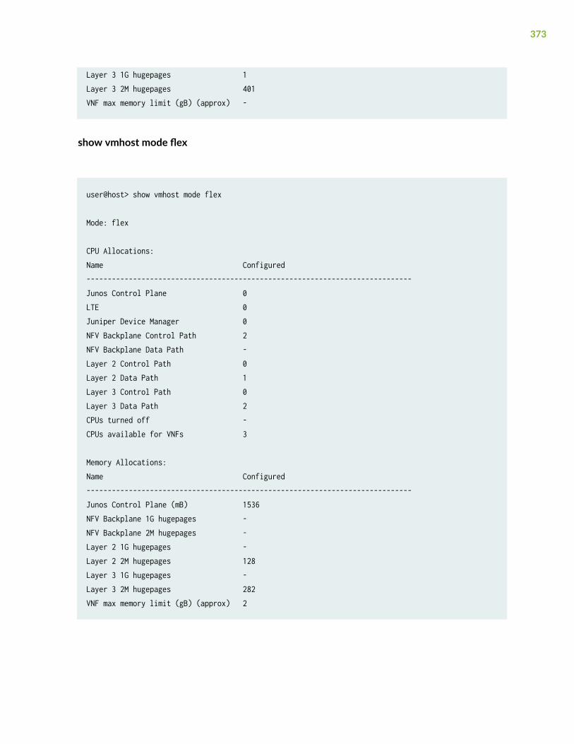
Layer 3 1G hugepages 1Layer 3 2M hugepages 401VNF max memory limit (gB) (approx) -
show vmhost mode flex
user@host> show vmhost mode flex
Mode: flex
CPU Allocations:Name Configured-----------------------------------------------------------------------------Junos Control Plane 0LTE 0Juniper Device Manager 0NFV Backplane Control Path 2NFV Backplane Data Path -Layer 2 Control Path 0Layer 2 Data Path 1Layer 3 Control Path 0Layer 3 Data Path 2CPUs turned off -CPUs available for VNFs 3
Memory Allocations:Name Configured-----------------------------------------------------------------------------Junos Control Plane (mB) 1536NFV Backplane 1G hugepages -NFV Backplane 2M hugepages -Layer 2 1G hugepages -Layer 2 2M hugepages 128Layer 3 1G hugepages -Layer 3 2M hugepages 282VNF max memory limit (gB) (approx) 2
373
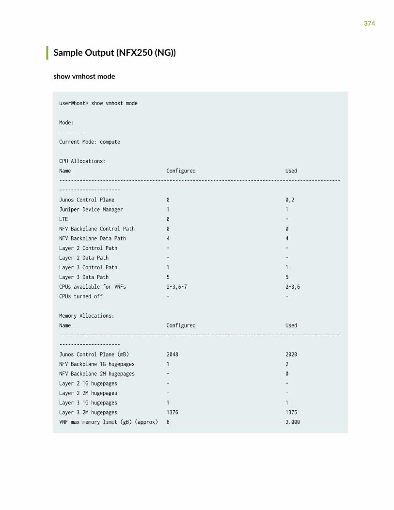
Sample Output (NFX250 (NG))
show vmhost mode
user@host> show vmhost mode
Mode:--------Current Mode: compute
CPU Allocations:Name Configured Used----------------------------------------------------------------------------------------------------------------------Junos Control Plane 0 0,2Juniper Device Manager 1 1LTE 0 -NFV Backplane Control Path 0 0NFV Backplane Data Path 4 4Layer 2 Control Path - -Layer 2 Data Path - -Layer 3 Control Path 1 1Layer 3 Data Path 5 5CPUs available for VNFs 2-3,6-7 2-3,6CPUs turned off - -
Memory Allocations:Name Configured Used----------------------------------------------------------------------------------------------------------------------Junos Control Plane (mB) 2048 2020NFV Backplane 1G hugepages 1 2NFV Backplane 2M hugepages - 0Layer 2 1G hugepages - -Layer 2 2M hugepages - -Layer 3 1G hugepages 1 1Layer 3 2M hugepages 1376 1375VNF max memory limit (gB) (approx) 6 2.000
374
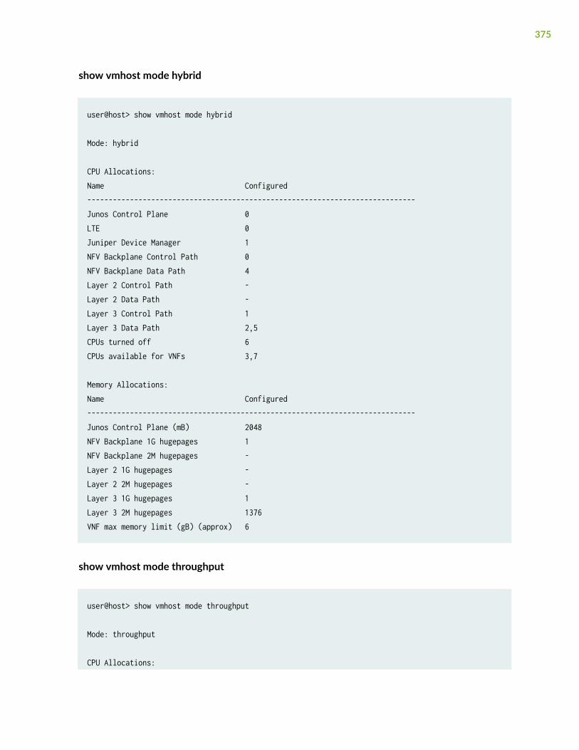
show vmhost mode hybrid
user@host> show vmhost mode hybrid
Mode: hybrid
CPU Allocations:Name Configured-----------------------------------------------------------------------------Junos Control Plane 0LTE 0Juniper Device Manager 1NFV Backplane Control Path 0NFV Backplane Data Path 4Layer 2 Control Path -Layer 2 Data Path -Layer 3 Control Path 1Layer 3 Data Path 2,5CPUs turned off 6CPUs available for VNFs 3,7
Memory Allocations:Name Configured-----------------------------------------------------------------------------Junos Control Plane (mB) 2048NFV Backplane 1G hugepages 1NFV Backplane 2M hugepages -Layer 2 1G hugepages -Layer 2 2M hugepages -Layer 3 1G hugepages 1Layer 3 2M hugepages 1376VNF max memory limit (gB) (approx) 6
show vmhost mode throughput
user@host> show vmhost mode throughput
Mode: throughput
CPU Allocations:
375
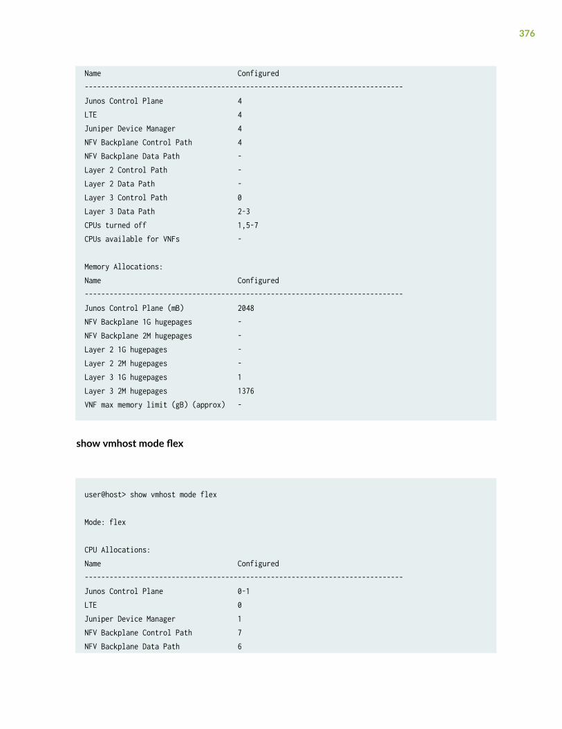
Name Configured-----------------------------------------------------------------------------Junos Control Plane 4LTE 4Juniper Device Manager 4NFV Backplane Control Path 4NFV Backplane Data Path -Layer 2 Control Path -Layer 2 Data Path -Layer 3 Control Path 0Layer 3 Data Path 2-3CPUs turned off 1,5-7CPUs available for VNFs -
Memory Allocations:Name Configured-----------------------------------------------------------------------------Junos Control Plane (mB) 2048NFV Backplane 1G hugepages -NFV Backplane 2M hugepages -Layer 2 1G hugepages -Layer 2 2M hugepages -Layer 3 1G hugepages 1Layer 3 2M hugepages 1376VNF max memory limit (gB) (approx) -
show vmhost mode flex
user@host> show vmhost mode flex
Mode: flex
CPU Allocations:Name Configured-----------------------------------------------------------------------------Junos Control Plane 0-1LTE 0Juniper Device Manager 1NFV Backplane Control Path 7NFV Backplane Data Path 6
376
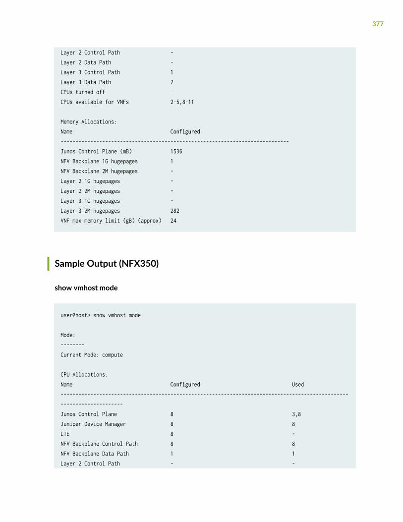
Layer 2 Control Path -Layer 2 Data Path -Layer 3 Control Path 1Layer 3 Data Path 7CPUs turned off -CPUs available for VNFs 2-5,8-11
Memory Allocations:Name Configured-----------------------------------------------------------------------------Junos Control Plane (mB) 1536NFV Backplane 1G hugepages 1NFV Backplane 2M hugepages -Layer 2 1G hugepages -Layer 2 2M hugepages -Layer 3 1G hugepages -Layer 3 2M hugepages 282VNF max memory limit (gB) (approx) 24
Sample Output (NFX350)
show vmhost mode
user@host> show vmhost mode
Mode:--------Current Mode: compute
CPU Allocations:Name Configured Used----------------------------------------------------------------------------------------------------------------------Junos Control Plane 8 3,8Juniper Device Manager 8 8LTE 8 -NFV Backplane Control Path 8 8NFV Backplane Data Path 1 1Layer 2 Control Path - -
377
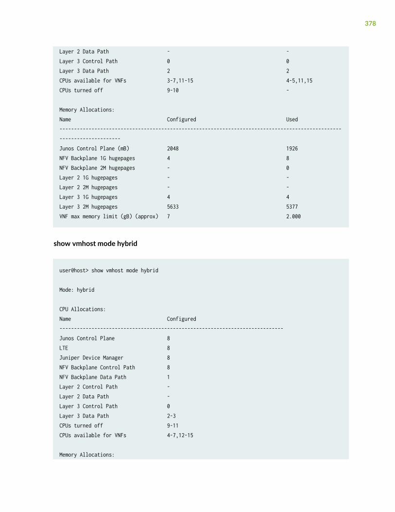
Layer 2 Data Path - -Layer 3 Control Path 0 0Layer 3 Data Path 2 2CPUs available for VNFs 3-7,11-15 4-5,11,15CPUs turned off 9-10 -
Memory Allocations:Name Configured Used----------------------------------------------------------------------------------------------------------------------Junos Control Plane (mB) 2048 1926NFV Backplane 1G hugepages 4 8NFV Backplane 2M hugepages - 0Layer 2 1G hugepages - -Layer 2 2M hugepages - -Layer 3 1G hugepages 4 4Layer 3 2M hugepages 5633 5377VNF max memory limit (gB) (approx) 7 2.000
show vmhost mode hybrid
user@host> show vmhost mode hybrid
Mode: hybrid
CPU Allocations:Name Configured-----------------------------------------------------------------------------Junos Control Plane 8LTE 8Juniper Device Manager 8NFV Backplane Control Path 8NFV Backplane Data Path 1Layer 2 Control Path -Layer 2 Data Path -Layer 3 Control Path 0Layer 3 Data Path 2-3CPUs turned off 9-11CPUs available for VNFs 4-7,12-15
Memory Allocations:
378
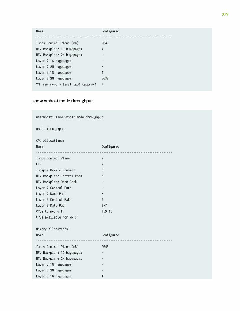
Name Configured-----------------------------------------------------------------------------Junos Control Plane (mB) 2048NFV Backplane 1G hugepages 4NFV Backplane 2M hugepages -Layer 2 1G hugepages -Layer 2 2M hugepages -Layer 3 1G hugepages 4Layer 3 2M hugepages 5633VNF max memory limit (gB) (approx) 7
show vmhost mode throughput
user@host> show vmhost mode throughput
Mode: throughput
CPU Allocations:Name Configured-----------------------------------------------------------------------------Junos Control Plane 8LTE 8Juniper Device Manager 8NFV Backplane Control Path 8NFV Backplane Data Path -Layer 2 Control Path -Layer 2 Data Path -Layer 3 Control Path 0Layer 3 Data Path 2-7CPUs turned off 1,9-15CPUs available for VNFs -
Memory Allocations:Name Configured-----------------------------------------------------------------------------Junos Control Plane (mB) 2048NFV Backplane 1G hugepages -NFV Backplane 2M hugepages -Layer 2 1G hugepages -Layer 2 2M hugepages -Layer 3 1G hugepages 4
379
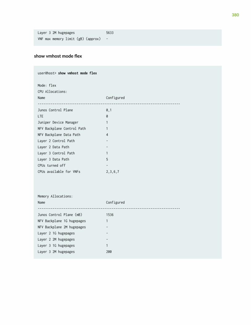
Layer 3 2M hugepages 5633VNF max memory limit (gB) (approx) -
show vmhost mode flex
user@host> show vmhost mode flex
Mode: flexCPU Allocations:Name Configured-----------------------------------------------------------------------------Junos Control Plane 0,1LTE 0Juniper Device Manager 1NFV Backplane Control Path 1NFV Backplane Data Path 4Layer 2 Control Path -Layer 2 Data Path -Layer 3 Control Path 1Layer 3 Data Path 5CPUs turned off -CPUs available for VNFs 2,3,6,7
Memory Allocations:Name Configured-----------------------------------------------------------------------------Junos Control Plane (mB) 1536NFV Backplane 1G hugepages 1NFV Backplane 2M hugepages -Layer 2 1G hugepages -Layer 2 2M hugepages -Layer 3 1G hugepages 1Layer 3 2M hugepages 200
380
Release Information
Command introduced in Junos OS Release 19.1R1.
show vmhost snmp mib walk
IN THIS SECTION
Syntax | 381
Description | 381
Required Privilege Level | 382
Sample Output | 382
Release Information | 382
Syntax
show vmhost snmp mib walk mib-name
Description
The show vmhost snmp mib walk mib-name command displays the libvirt SNMP object values that areassociated with the libvirt MIB.
NOTE: To view information for other MIBs, use the show snmp mib walk command.
381
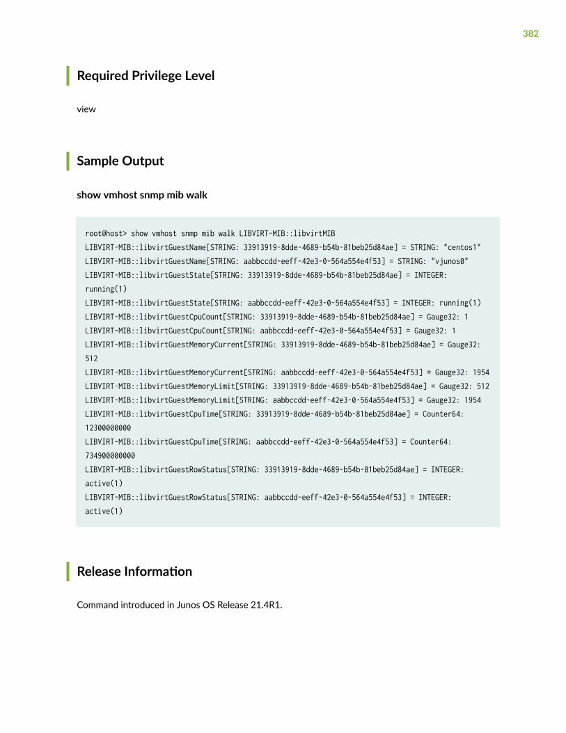
Required Privilege Level
view
Sample Output
show vmhost snmp mib walk
root@host> show vmhost snmp mib walk LIBVIRT-MIB::libvirtMIBLIBVIRT-MIB::libvirtGuestName[STRING: 33913919-8dde-4689-b54b-81beb25d84ae] = STRING: "centos1"LIBVIRT-MIB::libvirtGuestName[STRING: aabbccdd-eeff-42e3-0-564a554e4f53] = STRING: "vjunos0"LIBVIRT-MIB::libvirtGuestState[STRING: 33913919-8dde-4689-b54b-81beb25d84ae] = INTEGER: running(1)LIBVIRT-MIB::libvirtGuestState[STRING: aabbccdd-eeff-42e3-0-564a554e4f53] = INTEGER: running(1)LIBVIRT-MIB::libvirtGuestCpuCount[STRING: 33913919-8dde-4689-b54b-81beb25d84ae] = Gauge32: 1LIBVIRT-MIB::libvirtGuestCpuCount[STRING: aabbccdd-eeff-42e3-0-564a554e4f53] = Gauge32: 1LIBVIRT-MIB::libvirtGuestMemoryCurrent[STRING: 33913919-8dde-4689-b54b-81beb25d84ae] = Gauge32: 512LIBVIRT-MIB::libvirtGuestMemoryCurrent[STRING: aabbccdd-eeff-42e3-0-564a554e4f53] = Gauge32: 1954LIBVIRT-MIB::libvirtGuestMemoryLimit[STRING: 33913919-8dde-4689-b54b-81beb25d84ae] = Gauge32: 512LIBVIRT-MIB::libvirtGuestMemoryLimit[STRING: aabbccdd-eeff-42e3-0-564a554e4f53] = Gauge32: 1954LIBVIRT-MIB::libvirtGuestCpuTime[STRING: 33913919-8dde-4689-b54b-81beb25d84ae] = Counter64: 12300000000LIBVIRT-MIB::libvirtGuestCpuTime[STRING: aabbccdd-eeff-42e3-0-564a554e4f53] = Counter64: 734900000000LIBVIRT-MIB::libvirtGuestRowStatus[STRING: 33913919-8dde-4689-b54b-81beb25d84ae] = INTEGER: active(1)LIBVIRT-MIB::libvirtGuestRowStatus[STRING: aabbccdd-eeff-42e3-0-564a554e4f53] = INTEGER: active(1)
Release Information
Command introduced in Junos OS Release 21.4R1.
382

show vmhost status
IN THIS SECTION
Syntax | 383
Description | 383
Required Privilege Level | 383
Sample Output | 384
Release Information | 384
Syntax
show vmhost status
Description
Display the virtualization status and status of all the CPUs.
Required Privilege Level
view
383
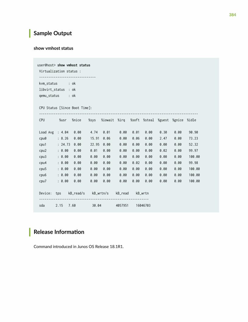
Sample Output
show vmhost status
user@host> show vmhost status Virtualization status : ------------------------------- kvm_status : ok libvirt_status : ok qemu_status : ok
CPU Status [Since Boot Time]: --------------------------------------------------------------------------------------- CPU %usr %nice %sys %iowait %irq %soft %steal %guest %gnice %idle
Load Avg : 4.04 0.00 4.74 0.01 0.00 0.01 0.00 0.30 0.00 90.90 cpu0 : 8.26 0.00 15.91 0.06 0.00 0.06 0.00 2.47 0.00 73.23 cpu1 : 24.73 0.00 22.95 0.00 0.00 0.00 0.00 0.00 0.00 52.32 cpu2 : 0.00 0.00 0.01 0.00 0.00 0.00 0.00 0.02 0.00 99.97 cpu3 : 0.00 0.00 0.00 0.00 0.00 0.00 0.00 0.00 0.00 100.00 cpu4 : 0.00 0.00 0.00 0.00 0.00 0.02 0.00 0.00 0.00 99.98 cpu5 : 0.00 0.00 0.00 0.00 0.00 0.00 0.00 0.00 0.00 100.00 cpu6 : 0.00 0.00 0.00 0.00 0.00 0.00 0.00 0.00 0.00 100.00 cpu7 : 0.00 0.00 0.00 0.00 0.00 0.00 0.00 0.00 0.00 100.00
Device: tps kB_read/s kB_wrtn/s kB_read kB_wrtn ------------------------------------------------------------ sda 2.15 7.60 30.04 4057951 16046703
Release Information
Command introduced in Junos OS Release 18.1R1.
384
show vmhost storage
IN THIS SECTION
Syntax | 385
Description | 385
Required Privilege Level | 385
Sample Output | 386
Sample Output | 387
Sample Output | 388
Release Information | 392
Syntax
show vmhost storage
Description
Display the vmhost storage information.
Required Privilege Level
view
385

Sample Output
show vmhost storage (NFX150)
user@host> show vmhost storageVmhost Storage Information------------------------------Storage Name : sdaSSD Description : Internal disk 1SSD Model Number : SFSA100GQ1AA4TO-C-LB-216-JUNSSD Serial Number : 000060124205B1000099SSD Firmware Version : SBR13025
ID Storage S.M.A.R.T attribute Raw value
1 Raw_Read_Error_Rate 0 5 Reallocated_Sector_Ct 0 9 Power_On_Hours 20792 12 Power_Cycle_Count 66 160 Uncorrectable_Sector_Count 0 161 Spare_Blocks 568 163 Number_of_Initial_Invalid_Blocks 18 164 Total_Erase_Count 163038 165 Maximum_Erase_Count 160 166 Minimum_Erase_Count 34 167 Average_Erase_Count 78 168 Maximum_Specified_Erase_Count 3000 169 Power-On_UECC_Count 54 192 Power-Off_Retract_Count 568 193 Dynamic_Remaps 0 194 Temperature_Celsius 32 195 Hardware_ECC_Recovered 1345461 196 Reallocated_Event_Count 0 198 Offline_Uncorrectable 0 199 UDMA_CRC_Error_Count 0 215 TRIM_Count 71048 235 Total_Flash_LBAs_Written 289438408 237 Total_Flash_LBAs_Written_Expanded 0 241 Total_LBAs_Written 13595913833 242 Total_LBAs_Read 6786635984 243 Total_Host_LBAs_Written_Expanded 0
386
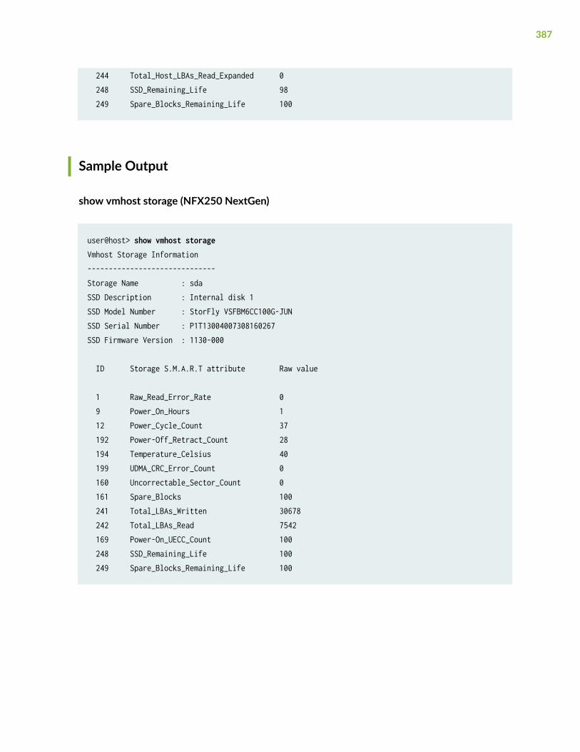
244 Total_Host_LBAs_Read_Expanded 0 248 SSD_Remaining_Life 98 249 Spare_Blocks_Remaining_Life 100
Sample Output
show vmhost storage (NFX250 NextGen)
user@host> show vmhost storageVmhost Storage Information------------------------------Storage Name : sdaSSD Description : Internal disk 1SSD Model Number : StorFly VSFBM6CC100G-JUNSSD Serial Number : P1T13004007308160267SSD Firmware Version : 1130-000
ID Storage S.M.A.R.T attribute Raw value
1 Raw_Read_Error_Rate 0 9 Power_On_Hours 1 12 Power_Cycle_Count 37 192 Power-Off_Retract_Count 28 194 Temperature_Celsius 40 199 UDMA_CRC_Error_Count 0 160 Uncorrectable_Sector_Count 0 161 Spare_Blocks 100 241 Total_LBAs_Written 30678 242 Total_LBAs_Read 7542 169 Power-On_UECC_Count 100 248 SSD_Remaining_Life 100 249 Spare_Blocks_Remaining_Life 100
387
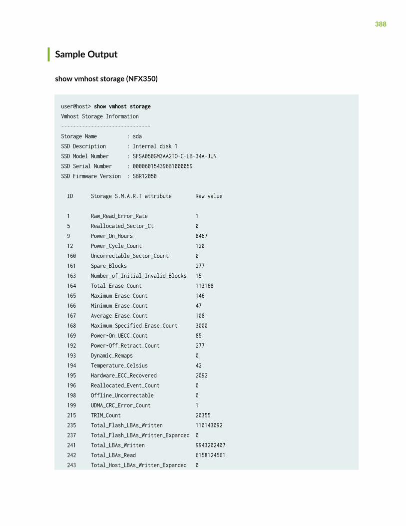
Sample Output
show vmhost storage (NFX350)
user@host> show vmhost storageVmhost Storage Information------------------------------Storage Name : sdaSSD Description : Internal disk 1SSD Model Number : SFSA050GM3AA2TO-C-LB-34A-JUNSSD Serial Number : 000060154396B1000059SSD Firmware Version : SBR12050
ID Storage S.M.A.R.T attribute Raw value
1 Raw_Read_Error_Rate 1 5 Reallocated_Sector_Ct 0 9 Power_On_Hours 8467 12 Power_Cycle_Count 120 160 Uncorrectable_Sector_Count 0 161 Spare_Blocks 277 163 Number_of_Initial_Invalid_Blocks 15 164 Total_Erase_Count 113168 165 Maximum_Erase_Count 146 166 Minimum_Erase_Count 47 167 Average_Erase_Count 108 168 Maximum_Specified_Erase_Count 3000 169 Power-On_UECC_Count 85 192 Power-Off_Retract_Count 277 193 Dynamic_Remaps 0 194 Temperature_Celsius 42 195 Hardware_ECC_Recovered 2092 196 Reallocated_Event_Count 0 198 Offline_Uncorrectable 0 199 UDMA_CRC_Error_Count 1 215 TRIM_Count 20355 235 Total_Flash_LBAs_Written 110143092 237 Total_Flash_LBAs_Written_Expanded 0 241 Total_LBAs_Written 9943202407 242 Total_LBAs_Read 6158124561 243 Total_Host_LBAs_Written_Expanded 0
388
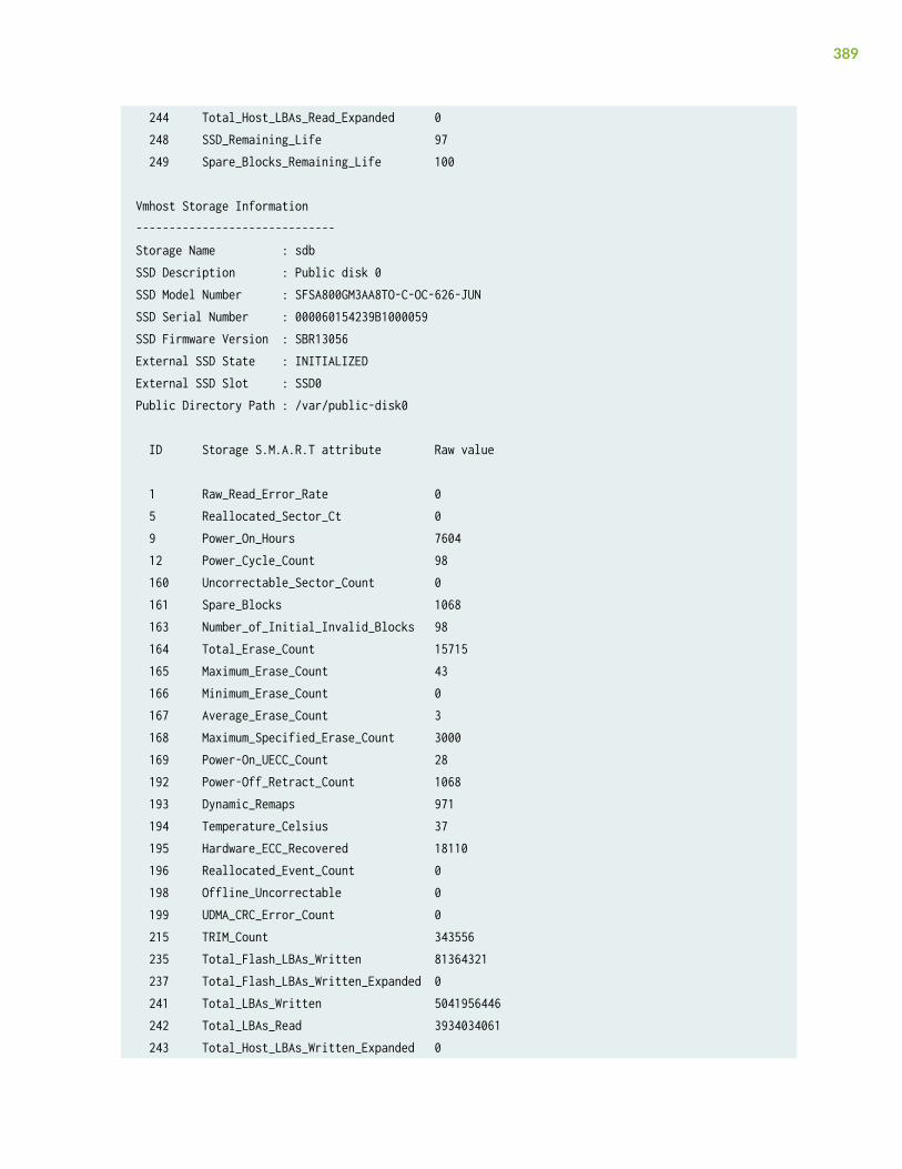
244 Total_Host_LBAs_Read_Expanded 0 248 SSD_Remaining_Life 97 249 Spare_Blocks_Remaining_Life 100
Vmhost Storage Information------------------------------Storage Name : sdbSSD Description : Public disk 0SSD Model Number : SFSA800GM3AA8TO-C-OC-626-JUNSSD Serial Number : 000060154239B1000059SSD Firmware Version : SBR13056External SSD State : INITIALIZEDExternal SSD Slot : SSD0Public Directory Path : /var/public-disk0
ID Storage S.M.A.R.T attribute Raw value
1 Raw_Read_Error_Rate 0 5 Reallocated_Sector_Ct 0 9 Power_On_Hours 7604 12 Power_Cycle_Count 98 160 Uncorrectable_Sector_Count 0 161 Spare_Blocks 1068 163 Number_of_Initial_Invalid_Blocks 98 164 Total_Erase_Count 15715 165 Maximum_Erase_Count 43 166 Minimum_Erase_Count 0 167 Average_Erase_Count 3 168 Maximum_Specified_Erase_Count 3000 169 Power-On_UECC_Count 28 192 Power-Off_Retract_Count 1068 193 Dynamic_Remaps 971 194 Temperature_Celsius 37 195 Hardware_ECC_Recovered 18110 196 Reallocated_Event_Count 0 198 Offline_Uncorrectable 0 199 UDMA_CRC_Error_Count 0 215 TRIM_Count 343556 235 Total_Flash_LBAs_Written 81364321 237 Total_Flash_LBAs_Written_Expanded 0 241 Total_LBAs_Written 5041956446 242 Total_LBAs_Read 3934034061 243 Total_Host_LBAs_Written_Expanded 0
389
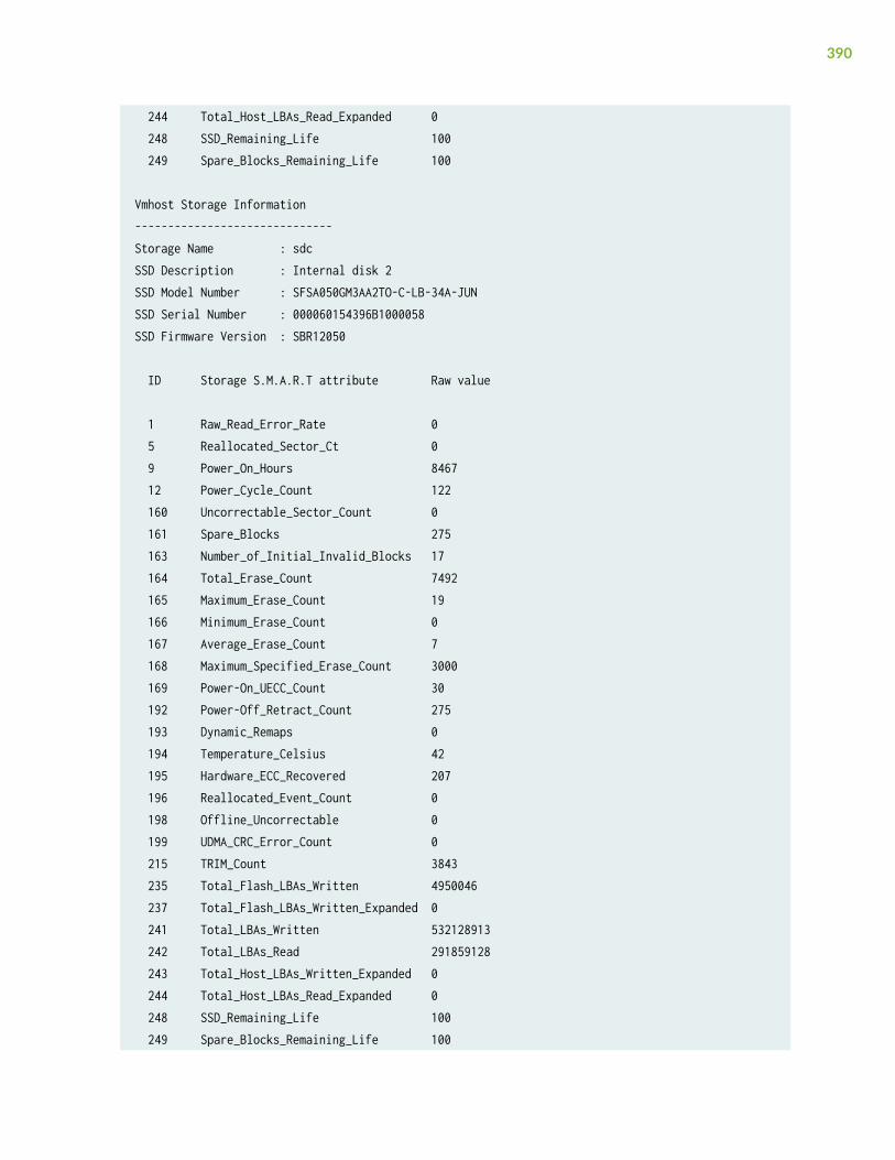
244 Total_Host_LBAs_Read_Expanded 0 248 SSD_Remaining_Life 100 249 Spare_Blocks_Remaining_Life 100
Vmhost Storage Information------------------------------Storage Name : sdcSSD Description : Internal disk 2SSD Model Number : SFSA050GM3AA2TO-C-LB-34A-JUNSSD Serial Number : 000060154396B1000058SSD Firmware Version : SBR12050
ID Storage S.M.A.R.T attribute Raw value
1 Raw_Read_Error_Rate 0 5 Reallocated_Sector_Ct 0 9 Power_On_Hours 8467 12 Power_Cycle_Count 122 160 Uncorrectable_Sector_Count 0 161 Spare_Blocks 275 163 Number_of_Initial_Invalid_Blocks 17 164 Total_Erase_Count 7492 165 Maximum_Erase_Count 19 166 Minimum_Erase_Count 0 167 Average_Erase_Count 7 168 Maximum_Specified_Erase_Count 3000 169 Power-On_UECC_Count 30 192 Power-Off_Retract_Count 275 193 Dynamic_Remaps 0 194 Temperature_Celsius 42 195 Hardware_ECC_Recovered 207 196 Reallocated_Event_Count 0 198 Offline_Uncorrectable 0 199 UDMA_CRC_Error_Count 0 215 TRIM_Count 3843 235 Total_Flash_LBAs_Written 4950046 237 Total_Flash_LBAs_Written_Expanded 0 241 Total_LBAs_Written 532128913 242 Total_LBAs_Read 291859128 243 Total_Host_LBAs_Written_Expanded 0 244 Total_Host_LBAs_Read_Expanded 0 248 SSD_Remaining_Life 100 249 Spare_Blocks_Remaining_Life 100
390
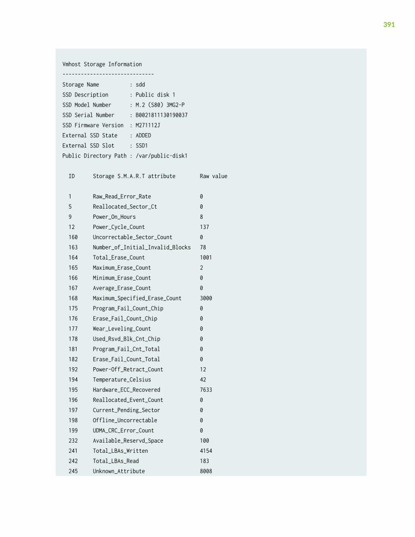
Vmhost Storage Information------------------------------Storage Name : sddSSD Description : Public disk 1SSD Model Number : M.2 (S80) 3MG2-PSSD Serial Number : B0021811130190037SSD Firmware Version : M271112JExternal SSD State : ADDEDExternal SSD Slot : SSD1Public Directory Path : /var/public-disk1
ID Storage S.M.A.R.T attribute Raw value
1 Raw_Read_Error_Rate 0 5 Reallocated_Sector_Ct 0 9 Power_On_Hours 8 12 Power_Cycle_Count 137 160 Uncorrectable_Sector_Count 0 163 Number_of_Initial_Invalid_Blocks 78 164 Total_Erase_Count 1001 165 Maximum_Erase_Count 2 166 Minimum_Erase_Count 0 167 Average_Erase_Count 0 168 Maximum_Specified_Erase_Count 3000 175 Program_Fail_Count_Chip 0 176 Erase_Fail_Count_Chip 0 177 Wear_Leveling_Count 0 178 Used_Rsvd_Blk_Cnt_Chip 0 181 Program_Fail_Cnt_Total 0 182 Erase_Fail_Count_Total 0 192 Power-Off_Retract_Count 12 194 Temperature_Celsius 42 195 Hardware_ECC_Recovered 7633 196 Reallocated_Event_Count 0 197 Current_Pending_Sector 0 198 Offline_Uncorrectable 0 199 UDMA_CRC_Error_Count 0 232 Available_Reservd_Space 100 241 Total_LBAs_Written 4154 242 Total_LBAs_Read 183 245 Unknown_Attribute 8008
391
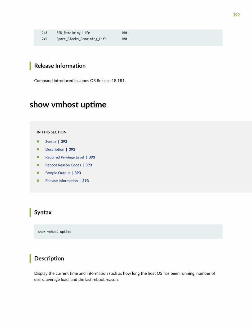
248 SSD_Remaining_Life 100 249 Spare_Blocks_Remaining_Life 100
Release Information
Command introduced in Junos OS Release 18.1R1.
show vmhost uptime
IN THIS SECTION
Syntax | 392
Description | 392
Required Privilege Level | 393
Reboot Reason Codes | 393
Sample Output | 393
Release Information | 393
Syntax
show vmhost uptime
Description
Display the current time and information such as how long the host OS has been running, number ofusers, average load, and the last reboot reason.
392
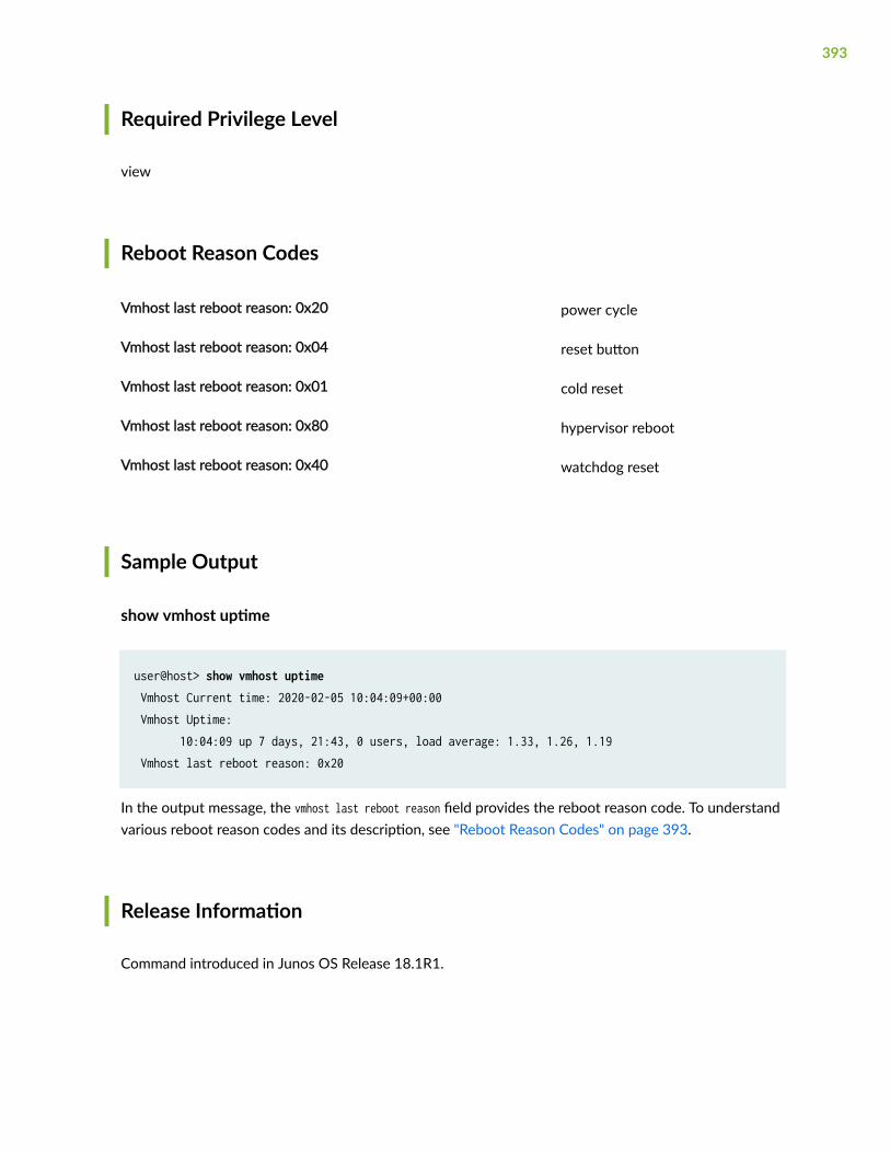
Required Privilege Level
view
Reboot Reason Codes
Vmhost last reboot reason: 0x20 power cycle
Vmhost last reboot reason: 0x04 reset button
Vmhost last reboot reason: 0x01 cold reset
Vmhost last reboot reason: 0x80 hypervisor reboot
Vmhost last reboot reason: 0x40 watchdog reset
Sample Output
show vmhost uptime
user@host> show vmhost uptime Vmhost Current time: 2020-02-05 10:04:09+00:00 Vmhost Uptime: 10:04:09 up 7 days, 21:43, 0 users, load average: 1.33, 1.26, 1.19 Vmhost last reboot reason: 0x20
In the output message, the vmhost last reboot reason field provides the reboot reason code. To understandvarious reboot reason codes and its description, see "Reboot Reason Codes" on page 393.
Release Information
Command introduced in Junos OS Release 18.1R1.
393
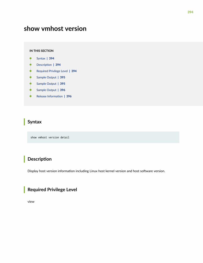
show vmhost version
IN THIS SECTION
Syntax | 394
Description | 394
Required Privilege Level | 394
Sample Output | 395
Sample Output | 395
Sample Output | 396
Release Information | 396
Syntax
show vmhost version detail
Description
Display host version information including Linux host kernel version and host software version.
Required Privilege Level
view
394
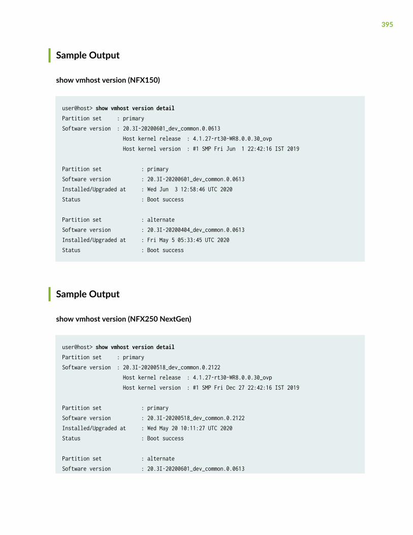
Sample Output
show vmhost version (NFX150)
user@host> show vmhost version detail Partition set : primarySoftware version : 20.3I-20200601_dev_common.0.0613 Host kernel release : 4.1.27-rt30-WR8.0.0.30_ovp Host kernel version : #1 SMP Fri Jun 1 22:42:16 IST 2019
Partition set : primarySoftware version : 20.3I-20200601_dev_common.0.0613Installed/Upgraded at : Wed Jun 3 12:58:46 UTC 2020Status : Boot success
Partition set : alternateSoftware version : 20.3I-20200404_dev_common.0.0613Installed/Upgraded at : Fri May 5 05:33:45 UTC 2020Status : Boot success
Sample Output
show vmhost version (NFX250 NextGen)
user@host> show vmhost version detailPartition set : primarySoftware version : 20.3I-20200518_dev_common.0.2122 Host kernel release : 4.1.27-rt30-WR8.0.0.30_ovp Host kernel version : #1 SMP Fri Dec 27 22:42:16 IST 2019
Partition set : primarySoftware version : 20.3I-20200518_dev_common.0.2122Installed/Upgraded at : Wed May 20 10:11:27 UTC 2020Status : Boot success
Partition set : alternateSoftware version : 20.3I-20200601_dev_common.0.0613
395
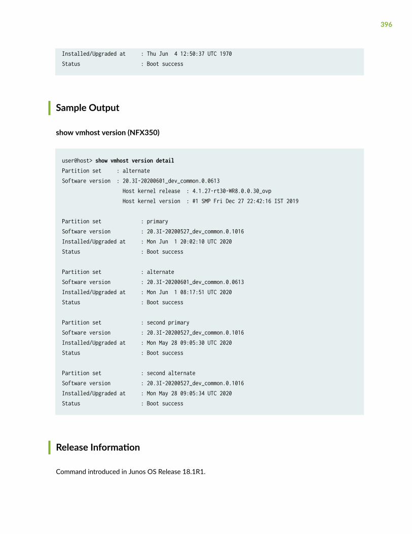
Installed/Upgraded at : Thu Jun 4 12:50:37 UTC 1970Status : Boot success
Sample Output
show vmhost version (NFX350)
user@host> show vmhost version detailPartition set : alternateSoftware version : 20.3I-20200601_dev_common.0.0613 Host kernel release : 4.1.27-rt30-WR8.0.0.30_ovp Host kernel version : #1 SMP Fri Dec 27 22:42:16 IST 2019
Partition set : primarySoftware version : 20.3I-20200527_dev_common.0.1016Installed/Upgraded at : Mon Jun 1 20:02:10 UTC 2020Status : Boot success
Partition set : alternateSoftware version : 20.3I-20200601_dev_common.0.0613Installed/Upgraded at : Mon Jun 1 08:17:51 UTC 2020Status : Boot success
Partition set : second primarySoftware version : 20.3I-20200527_dev_common.0.1016Installed/Upgraded at : Mon May 28 09:05:30 UTC 2020Status : Boot success
Partition set : second alternateSoftware version : 20.3I-20200527_dev_common.0.1016Installed/Upgraded at : Mon May 28 09:05:34 UTC 2020Status : Boot success
Release Information
Command introduced in Junos OS Release 18.1R1.
396
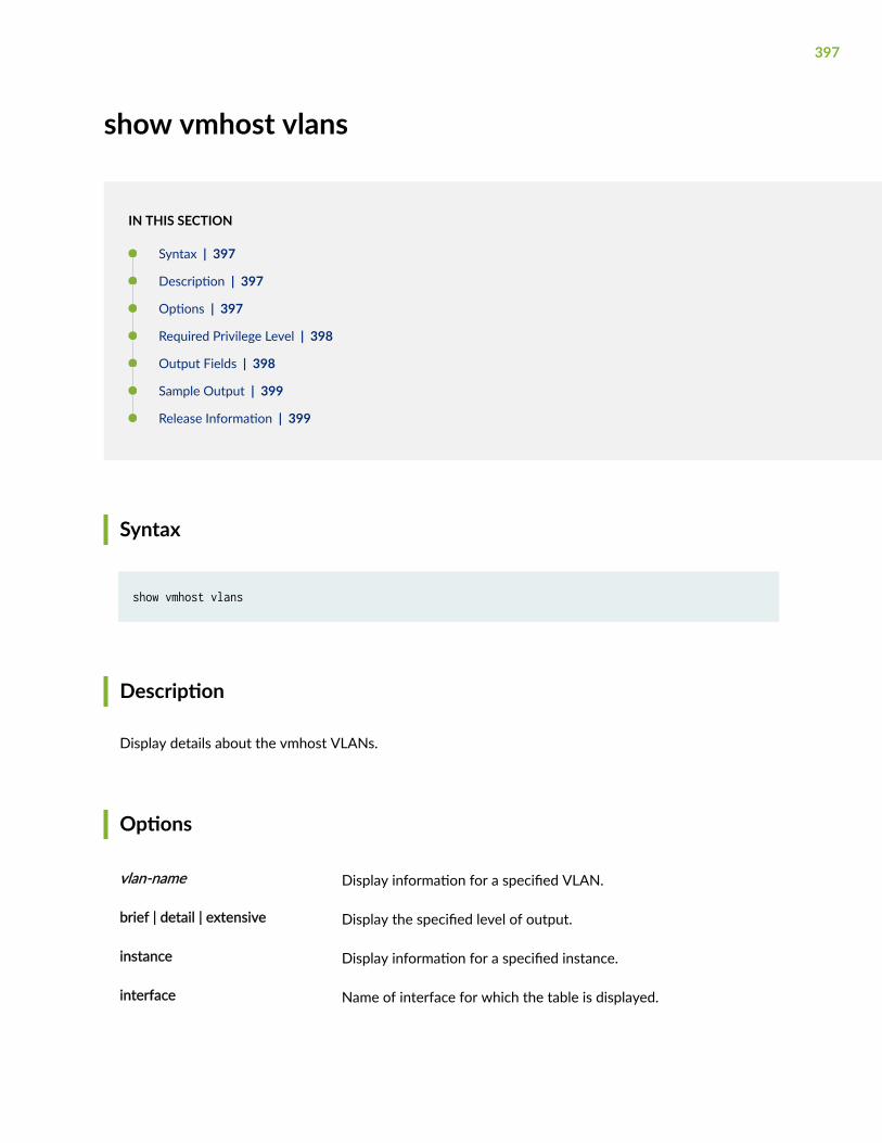
show vmhost vlans
IN THIS SECTION
Syntax | 397
Description | 397
Options | 397
Required Privilege Level | 398
Output Fields | 398
Sample Output | 399
Release Information | 399
Syntax
show vmhost vlans
Description
Display details about the vmhost VLANs.
Options
vlan-name Display information for a specified VLAN.
brief | detail | extensive Display the specified level of output.
instance Display information for a specified instance.
interface Name of interface for which the table is displayed.
397
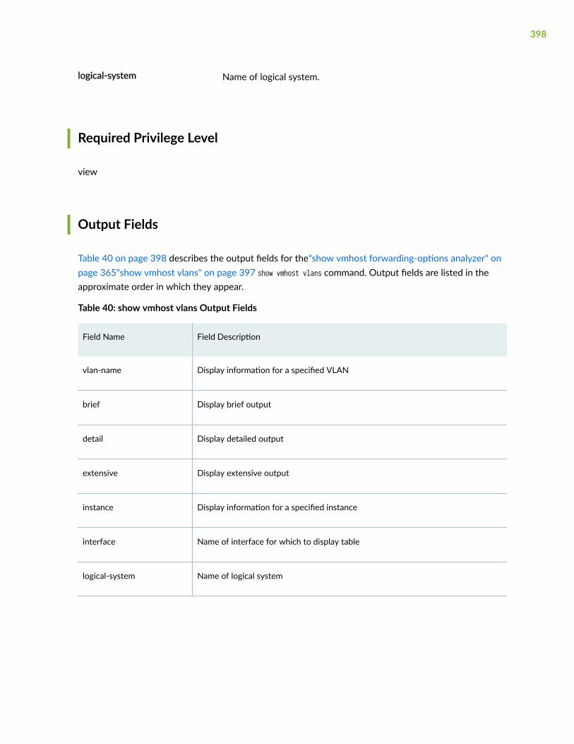
logical-system Name of logical system.
Required Privilege Level
view
Output Fields
Table 40 on page 398 describes the output fields for the"show vmhost forwarding-options analyzer" onpage 365"show vmhost vlans" on page 397 show vmhost vlans command. Output fields are listed in theapproximate order in which they appear.
Table 40: show vmhost vlans Output Fields
Field Name Field Description
vlan-name Display information for a specified VLAN
brief Display brief output
detail Display detailed output
extensive Display extensive output
instance Display information for a specified instance
interface Name of interface for which to display table
logical-system Name of logical system
398
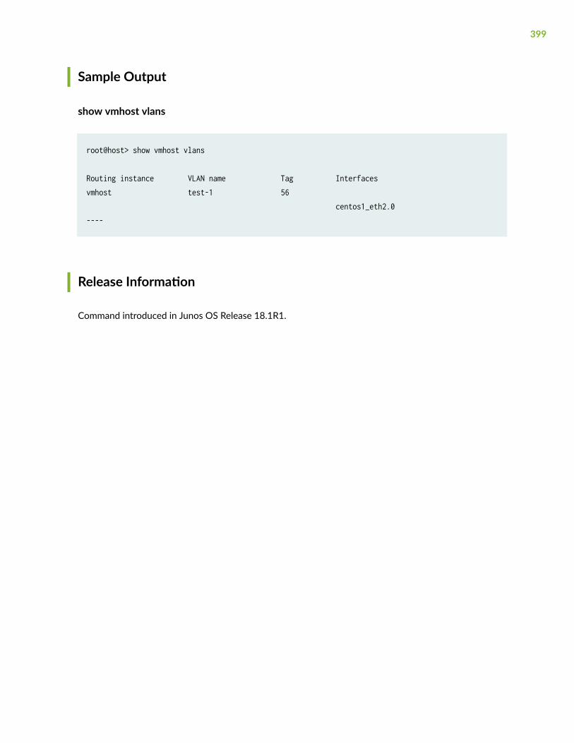
Sample Output
show vmhost vlans
root@host> show vmhost vlans
Routing instance VLAN name Tag Interfacesvmhost test-1 56 centos1_eth2.0 ----
Release Information
Command introduced in Junos OS Release 18.1R1.
399


