Embed Size (px)
Citation preview

Page 1
CES323303
Civil 3D on Steroids: How to best configure Civil 3D Brian Levendowski, PE CTC Software
Description
To work effectively, Civil 3D requires a myriad of data, including Templates, Libraries, Subassemblies, and more. Now add in a need for users to be mobile. How can someone possibly understand what all this data is, keep it up to date, and enable users to work off-network—all with company standards in place? That’s where this class comes in. We’ll summarize best practices on configuration of all files required to make Civil 3D run like clockwork, including easy Tool Palettes configuration and flexible AutoCAD Profile management. We’ll use scripts to set up a simple file-syncing system between users and the server, enabling them to work off-network with all company standards in place. When users log back in, they will automatically get any updates made to the standards. Sound like a dream? It’s not. The speaker has implemented this at many other firms, saving time and money, and bringing a new meaning to the phrase “CAD Standards”. All you need to do is show up to this class!
Speaker Bio
As a Civil Engineer, Brian Levendowski, PE is the Civil Product Manager for CTC Software. He spends his time developing custom applications and plugins for Civil 3D, AutoCAD and the Infrastructure industry. He is a highly-rated and seasoned Autodesk University Speaker, specializing in serving the civil infrastructure industry. He has lead many advanced implementations of BIM software, including Civil 3D. He speaks regularly at regional and local events, conferences, and professional association meetings. With a practical background as an airport design engineer and inspector, as well as a land surveyor, he has valuable real-world experience, and truly understands the application of Autodesk software in the civil engineering industry.
Learning Objectives
• Effectively set up all possible CAD content required for Civil 3D
• Configure mobile-friendly, local setup from scratch
• Build a standards setup that makes CAD content management a breeze
• Create Windows scripts to keep CAD content up to date for all users
Page 2
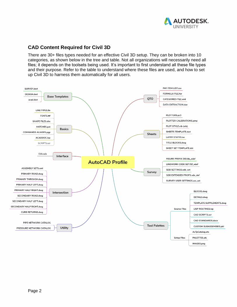
CAD Content Required for Civil 3D
There are 30+ files types needed for an effective Civil 3D setup. They can be broken into 10 categories, as shown below in the tree and table. Not all organizations will necessarily need all files; it depends on the toolsets being used. It’s important to first understand all these file types and their purpose. Refer to the table to understand where these files are used, and how to set up Civil 3D to harness them automatically for all users.
Page 3
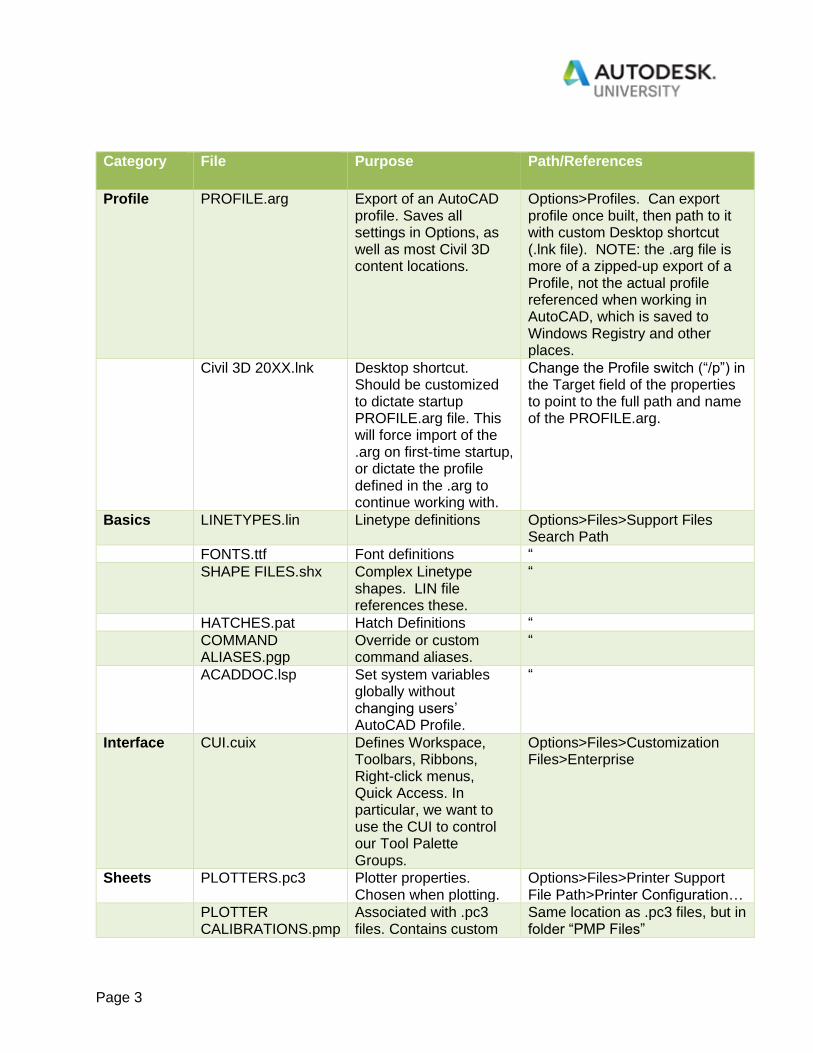
Category File Purpose Path/References
Profile PROFILE.arg Export of an AutoCAD profile. Saves all settings in Options, as well as most Civil 3D content locations.
Options>Profiles. Can export profile once built, then path to it with custom Desktop shortcut (.lnk file). NOTE: the .arg file is more of a zipped-up export of a Profile, not the actual profile referenced when working in AutoCAD, which is saved to Windows Registry and other places.
Civil 3D 20XX.lnk Desktop shortcut. Should be customized to dictate startup PROFILE.arg file. This will force import of the .arg on first-time startup, or dictate the profile defined in the .arg to continue working with.
Change the Profile switch (“/p”) in the Target field of the properties to point to the full path and name of the PROFILE.arg.
Basics LINETYPES.lin Linetype definitions Options>Files>Support Files Search Path
FONTS.ttf Font definitions “
SHAPE FILES.shx Complex Linetype shapes. LIN file references these.
“
HATCHES.pat Hatch Definitions “
COMMAND ALIASES.pgp
Override or custom command aliases.
“
ACADDOC.lsp Set system variables globally without changing users’ AutoCAD Profile.
“
Interface CUI.cuix Defines Workspace, Toolbars, Ribbons, Right-click menus, Quick Access. In particular, we want to use the CUI to control our Tool Palette Groups.
Options>Files>Customization Files>Enterprise
Sheets PLOTTERS.pc3 Plotter properties. Chosen when plotting.
Options>Files>Printer Support File Path>Printer Configuration…
PLOTTER CALIBRATIONS.pmp
Associated with .pc3 files. Contains custom
Same location as .pc3 files, but in folder “PMP Files”
Page 4
calibrations and paper sizes.
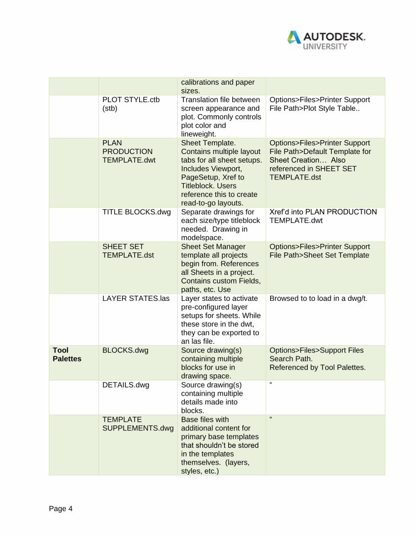
PLOT STYLE.ctb (stb)
Translation file between screen appearance and plot. Commonly controls plot color and lineweight.
Options>Files>Printer Support File Path>Plot Style Table..
PLAN PRODUCTION TEMPLATE.dwt
Sheet Template. Contains multiple layout tabs for all sheet setups. Includes Viewport, PageSetup, Xref to Titleblock. Users reference this to create read-to-go layouts.
Options>Files>Printer Support File Path>Default Template for Sheet Creation… Also referenced in SHEET SET TEMPLATE.dst
TITLE BLOCKS.dwg Separate drawings for each size/type titleblock needed. Drawing in modelspace.
Xref’d into PLAN PRODUCTION TEMPLATE.dwt
SHEET SET TEMPLATE.dst
Sheet Set Manager template all projects begin from. References all Sheets in a project. Contains custom Fields, paths, etc. Use
Options>Files>Printer Support File Path>Sheet Set Template
LAYER STATES.las Layer states to activate pre-configured layer setups for sheets. While these store in the dwt, they can be exported to an las file.
Browsed to to load in a dwg/t.
Tool Palettes
BLOCKS.dwg Source drawing(s) containing multiple blocks for use in drawing space.
Options>Files>Support Files Search Path. Referenced by Tool Palettes.
DETAILS.dwg Source drawing(s) containing multiple details made into blocks.
“
TEMPLATE SUPPLEMENTS.dwg
Base files with additional content for primary base templates that shouldn’t be stored in the templates themselves. (layers, styles, etc.)
“
Page 5
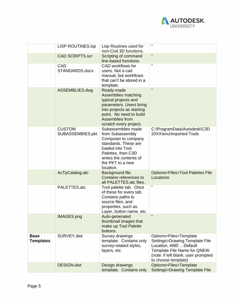
LISP ROUTINES.lsp Lisp Routines used for non-Civil 3D functions.
“
CAD SCRIPTS.scr Scripting of command line-based functions.
“
CAD STANDARDS.docx
CAD workflows for users. Not a cad manual, but workflows that can’t be stored in a template.
“
ASSEMBLIES.dwg Ready-made Assemblies matching typical projects and parameters. Users bring into projects as starting point. No need to build Assemblies from scratch every project.
“
CUSTOM SUBASSEMBIES.pkt
Subassemblies made from Subassembly Composer to company standards. These are loaded into Tool Palettes, then C3D writes the contents of the PKT to a new location.
C:\ProgramData\Autodesk\C3D 20XX\enu\Imported Tools
AcTpCatalog.atc Background file. Contains references to all PALETTES.atc files.
Options>Files>Tool Palettes File Locations
PALETTES.atc Tool palette tab. Once of these for every tab. Contains paths to source files, and properties, such as Layer, button name, etc.
“
IMAGES.png Auto-generated thumbnail images that make up Tool Palette buttons.
“
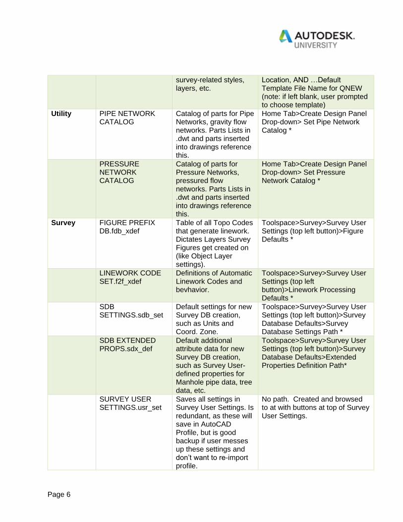
Base Templates
SURVEY.dwt Survey drawings template. Contains only survey-related styles, layers, etc.
Options>Files>Template Settings>Drawing Template File Location, AND …Default Template File Name for QNEW (note: if left blank, user prompted to choose template)
DESIGN.dwt Design drawings template. Contains only
Options>Files>Template Settings>Drawing Template File
Page 6
survey-related styles, layers, etc.
Location, AND …Default Template File Name for QNEW (note: if left blank, user prompted to choose template)
Utility PIPE NETWORK CATALOG
Catalog of parts for Pipe Networks, gravity flow networks. Parts Lists in .dwt and parts inserted into drawings reference this.
Home Tab>Create Design Panel Drop-down> Set Pipe Network Catalog *
PRESSURE NETWORK CATALOG
Catalog of parts for Pressure Networks, pressured flow networks. Parts Lists in .dwt and parts inserted into drawings reference this.
Home Tab>Create Design Panel Drop-down> Set Pressure Network Catalog *
Survey FIGURE PREFIX DB.fdb_xdef
Table of all Topo Codes that generate linework. Dictates Layers Survey Figures get created on (like Object Layer settings).
Toolspace>Survey>Survey User Settings (top left button)>Figure Defaults *
LINEWORK CODE SET.f2f_xdef
Definitions of Automatic Linework Codes and bevhavior.
Toolspace>Survey>Survey User Settings (top left button)>Linework Processing Defaults *
SDB SETTINGS.sdb_set
Default settings for new Survey DB creation, such as Units and Coord. Zone.
Toolspace>Survey>Survey User Settings (top left button)>Survey Database Defaults>Survey Database Settings Path *
SDB EXTENDED PROPS.sdx_def
Default additional attribute data for new Survey DB creation, such as Survey User-defined properties for Manhole pipe data, tree data, etc.
Toolspace>Survey>Survey User Settings (top left button)>Survey Database Defaults>Extended Properties Definition Path*
SURVEY USER SETTINGS.usr_set
Saves all settings in Survey User Settings. Is redundant, as these will save in AutoCAD Profile, but is good backup if user messes up these settings and don’t want to re-import profile.
No path. Created and browsed to at with buttons at top of Survey User Settings.
Page 7
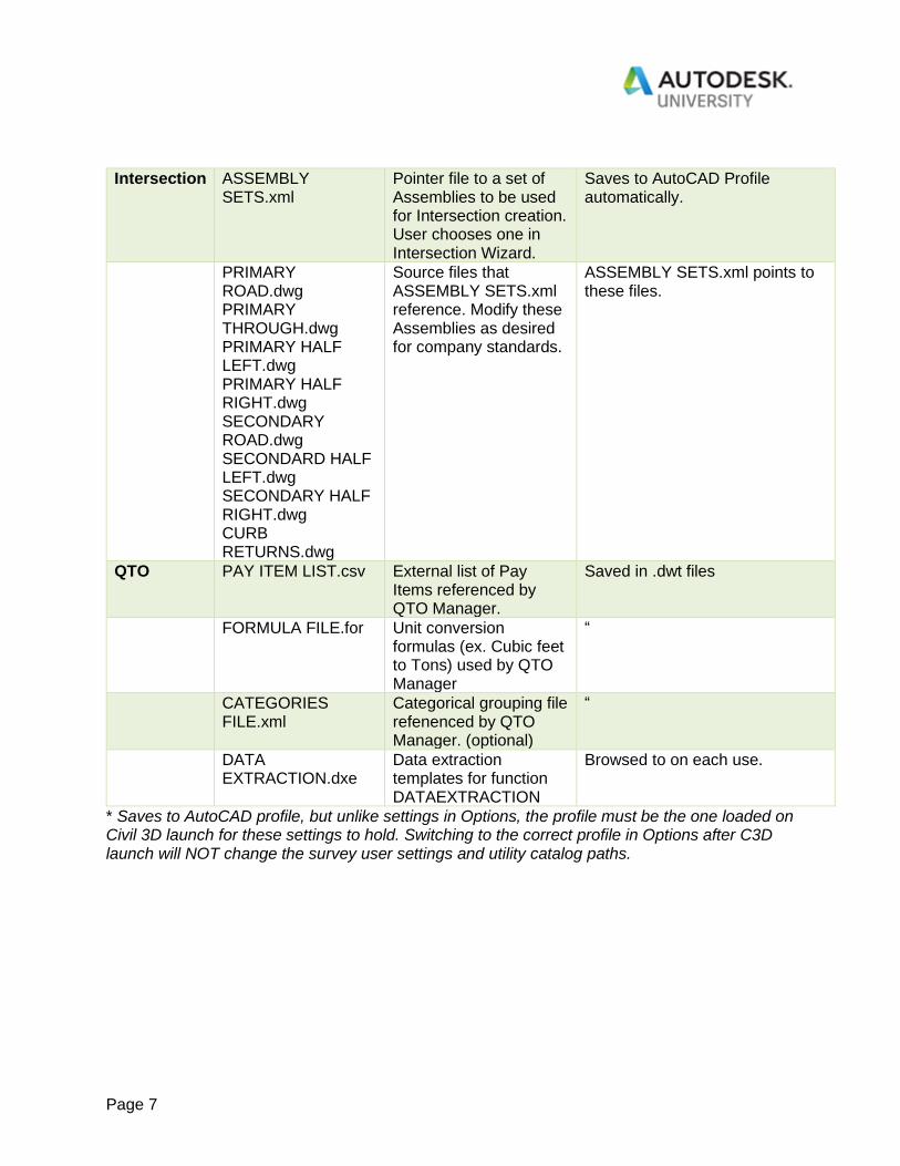
Intersection ASSEMBLY SETS.xml
Pointer file to a set of Assemblies to be used for Intersection creation. User chooses one in Intersection Wizard.
Saves to AutoCAD Profile automatically.
PRIMARY ROAD.dwg PRIMARY THROUGH.dwg PRIMARY HALF LEFT.dwg PRIMARY HALF RIGHT.dwg SECONDARY ROAD.dwg SECONDARD HALF LEFT.dwg SECONDARY HALF RIGHT.dwg CURB RETURNS.dwg
Source files that ASSEMBLY SETS.xml reference. Modify these Assemblies as desired for company standards.
ASSEMBLY SETS.xml points to these files.
QTO PAY ITEM LIST.csv External list of Pay Items referenced by QTO Manager.
Saved in .dwt files
FORMULA FILE.for Unit conversion formulas (ex. Cubic feet to Tons) used by QTO Manager
“
CATEGORIES FILE.xml
Categorical grouping file refenenced by QTO Manager. (optional)
“
DATA EXTRACTION.dxe
Data extraction templates for function DATAEXTRACTION
Browsed to on each use.
* Saves to AutoCAD profile, but unlike settings in Options, the profile must be the one loaded on Civil 3D launch for these settings to hold. Switching to the correct profile in Options after C3D launch will NOT change the survey user settings and utility catalog paths.
Page 8
Configuring a Local Setup
The main reasons for doing a local setup are: 1. Allow users access to all company content while off the network. 2. With the scripting setup described below, CAD managers can easily create a “master”
computer that is the exact replica of what all users get, allowing easy editing and maintenance of CAD content. CAD Managers can know exactly what the setup will look like before pushing it out to users because the “master” machine has the exact same setup. CAD Managers can also “try things out” on the “master” computer before pushing out the changes to the users.
3. Utilizing a local setup typically gives faster performance to the end user. This is a general process on how to set up a local configuration in Civil 3D. It’s not that different from the scenario of CAD content being on a server, but just local instead. The only addition is the use of Windows scripts to sync users’ local data to a master copy. 1. Establish a “master” computer, virtual or physical, and install Civil and other desired
design apps. 2. Create a local CAD content folder structure and place content in the appropriate places.
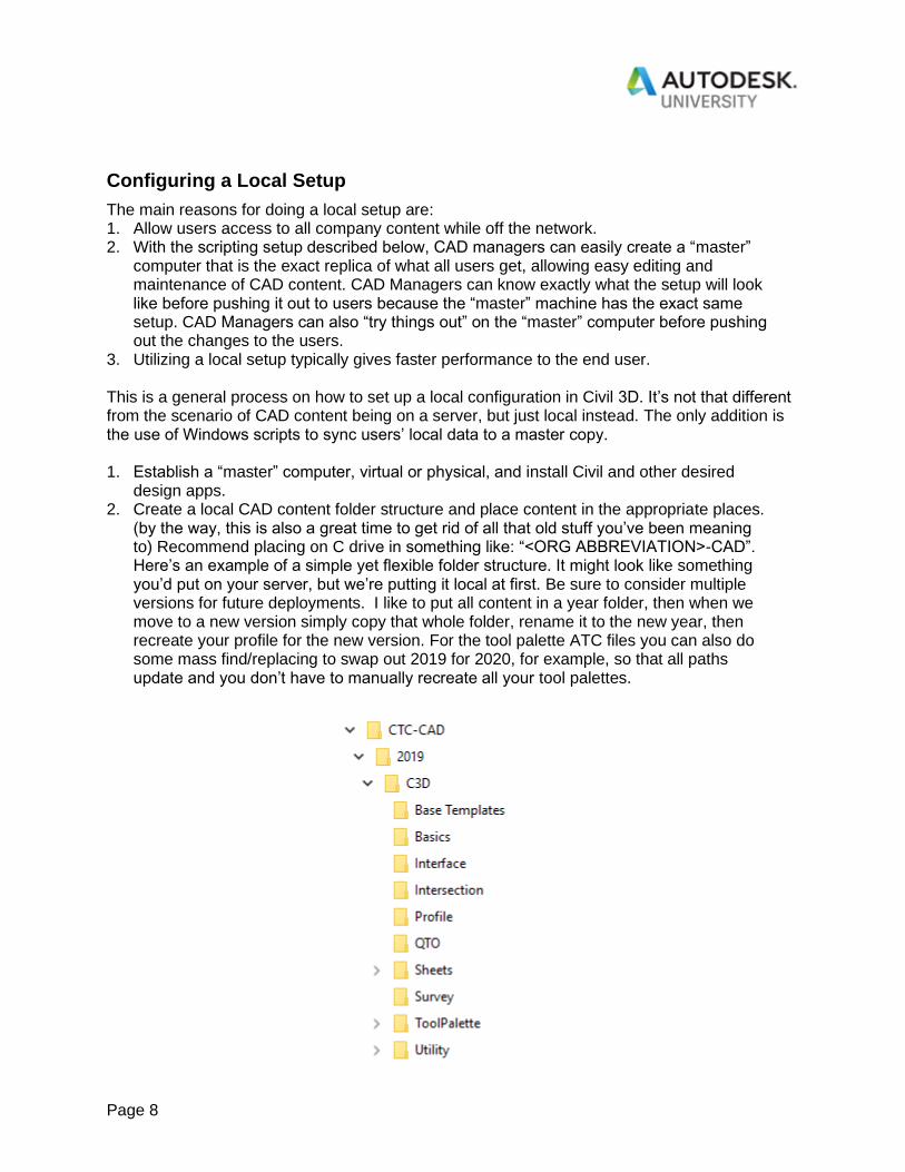
(by the way, this is also a great time to get rid of all that old stuff you’ve been meaning to) Recommend placing on C drive in something like: “<ORG ABBREVIATION>-CAD”. Here’s an example of a simple yet flexible folder structure. It might look like something you’d put on your server, but we’re putting it local at first. Be sure to consider multiple versions for future deployments. I like to put all content in a year folder, then when we move to a new version simply copy that whole folder, rename it to the new year, then recreate your profile for the new version. For the tool palette ATC files you can also do some mass find/replacing to swap out 2019 for 2020, for example, so that all paths update and you don’t have to manually recreate all your tool palettes.
Page 9
3. Open Civil 3D and create a new Profile in Options, ex. “C3D 20XX - <ORG ABBREV>”. Use Add to List with the C3D Imperial Profile current.
4. Path to all content, according to the table above. 5. Set up your ACADDOC.lsp to manage system variables separately from the acad profile.
If you don’t know how this lisp works, you simply place it in a Support Path in options and then Autocad will automatically run it upon startup of every drawing. While we could push out a new profile to update or change system variables for our users, we’d also be overwriting a lot of preferences, and that wouldn’t make them very happy. With the ACADDOC.lsp we can plug in settings for these variables, change them over time, and know that it will push out to users without changing their pink background or excessively
large pick box. Here’s some syntax examples of system variables you might put in
your ACADDOC.lsp.
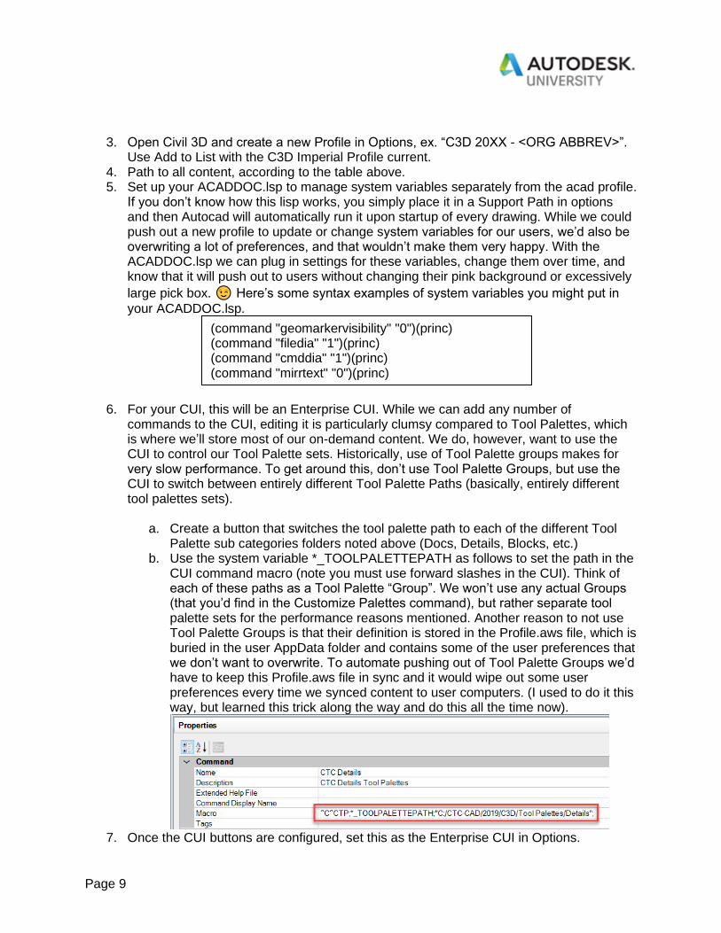
6. For your CUI, this will be an Enterprise CUI. While we can add any number of
commands to the CUI, editing it is particularly clumsy compared to Tool Palettes, which is where we’ll store most of our on-demand content. We do, however, want to use the CUI to control our Tool Palette sets. Historically, use of Tool Palette groups makes for very slow performance. To get around this, don’t use Tool Palette Groups, but use the CUI to switch between entirely different Tool Palette Paths (basically, entirely different tool palettes sets).
a. Create a button that switches the tool palette path to each of the different Tool Palette sub categories folders noted above (Docs, Details, Blocks, etc.)
b. Use the system variable *_TOOLPALETTEPATH as follows to set the path in the CUI command macro (note you must use forward slashes in the CUI). Think of each of these paths as a Tool Palette “Group”. We won’t use any actual Groups (that you’d find in the Customize Palettes command), but rather separate tool palette sets for the performance reasons mentioned. Another reason to not use Tool Palette Groups is that their definition is stored in the Profile.aws file, which is buried in the user AppData folder and contains some of the user preferences that we don’t want to overwrite. To automate pushing out of Tool Palette Groups we’d have to keep this Profile.aws file in sync and it would wipe out some user preferences every time we synced content to user computers. (I used to do it this way, but learned this trick along the way and do this all the time now).
7. Once the CUI buttons are configured, set this as the Enterprise CUI in Options.
(command "geomarkervisibility" "0")(princ) (command "filedia" "1")(princ) (command "cmddia" "1")(princ) (command "mirrtext" "0")(princ)
Page 10
8. Build your Tool Palettes, starting with the appropriate CUI button to configure the Tool Palette so the background files write to the correct location.
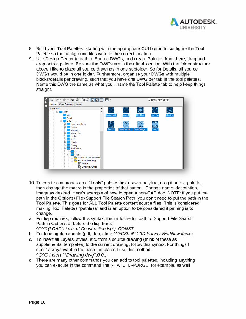
9. Use Design Center to path to Source DWGs, and create Palettes from there, drag and drop onto a palette. Be sure the DWGs are in their final location. With the folder structure above I like to place all source drawings in one subfolder. So for Details, all source DWGs would be in one folder. Furthermore, organize your DWGs with multiple blocks/details per drawing, such that you have one DWG per tab in the tool palettes. Name this DWG the same as what you’ll name the Tool Palette tab to help keep things straight.
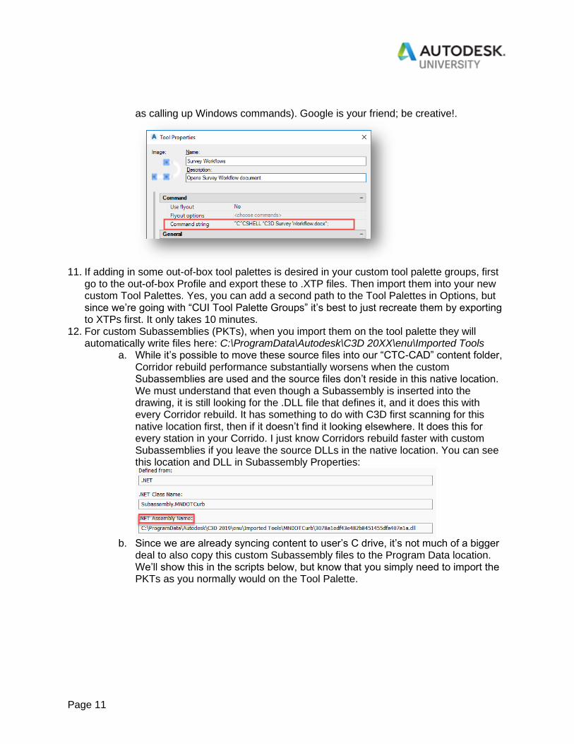
10. To create commands on a “Tools” palette, first draw a polyline, drag it onto a palette, then change the macro in the properties of that button. Change name, description, image as desired. Here’s example of how to open a non-CAD doc. NOTE: if you put the path in the Options>File>Support File Search Path, you don’t need to put the path in the Tool Palette. This goes for ALL Tool Palette content source files. This is considered making Tool Palettes “pathless” and is an option to be considered if pathing is to change.
a. For lisp routines, follow this syntax, then add the full path to Support File Search Path in Options or before the lisp here: ^C^C (LOAD"Limits of Construction.lsp"); CONST
b. For loading documents (pdf, doc, etc.): ^C^CShell “C3D Survey Workflow.docx";
c. To insert all Layers, styles, etc. from a source drawing (think of these as supplemental templates) to the current drawing, follow this syntax. For things I don’t’ always want in the base templates I use this method.
^C^C-insert "*Drawing.dwg";0,0;;; d. There are many other commands you can add to tool palettes, including anything
you can execute in the command line (-HATCH, -PURGE, for example, as well
Page 11
as calling up Windows commands). Google is your friend; be creative!.
11. If adding in some out-of-box tool palettes is desired in your custom tool palette groups, first
go to the out-of-box Profile and export these to .XTP files. Then import them into your new custom Tool Palettes. Yes, you can add a second path to the Tool Palettes in Options, but since we’re going with “CUI Tool Palette Groups” it’s best to just recreate them by exporting to XTPs first. It only takes 10 minutes.
12. For custom Subassemblies (PKTs), when you import them on the tool palette they will automatically write files here: C:\ProgramData\Autodesk\C3D 20XX\enu\Imported Tools
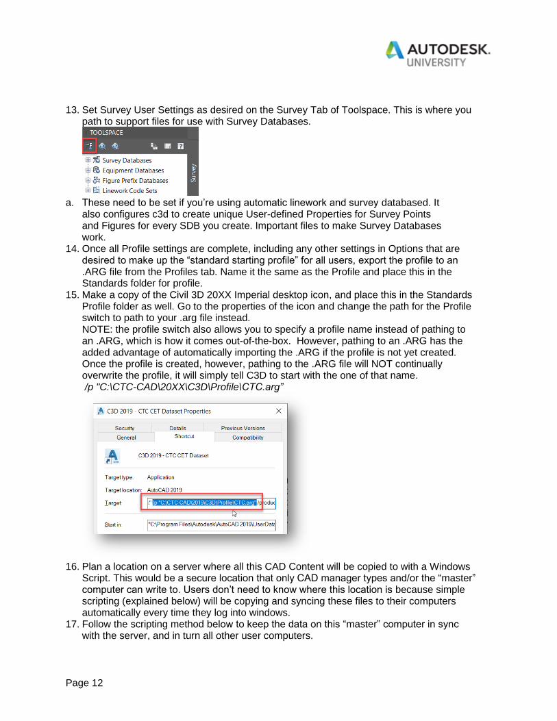
a. While it’s possible to move these source files into our “CTC-CAD” content folder, Corridor rebuild performance substantially worsens when the custom Subassemblies are used and the source files don’t reside in this native location. We must understand that even though a Subassembly is inserted into the drawing, it is still looking for the .DLL file that defines it, and it does this with every Corridor rebuild. It has something to do with C3D first scanning for this native location first, then if it doesn’t find it looking elsewhere. It does this for every station in your Corrido. I just know Corridors rebuild faster with custom Subassemblies if you leave the source DLLs in the native location. You can see this location and DLL in Subassembly Properties:
b. Since we are already syncing content to user’s C drive, it’s not much of a bigger
deal to also copy this custom Subassembly files to the Program Data location. We’ll show this in the scripts below, but know that you simply need to import the PKTs as you normally would on the Tool Palette.
Page 12
13. Set Survey User Settings as desired on the Survey Tab of Toolspace. This is where you path to support files for use with Survey Databases.
a. These need to be set if you’re using automatic linework and survey databased. It
also configures c3d to create unique User-defined Properties for Survey Points and Figures for every SDB you create. Important files to make Survey Databases work.
14. Once all Profile settings are complete, including any other settings in Options that are desired to make up the “standard starting profile” for all users, export the profile to an .ARG file from the Profiles tab. Name it the same as the Profile and place this in the Standards folder for profile.
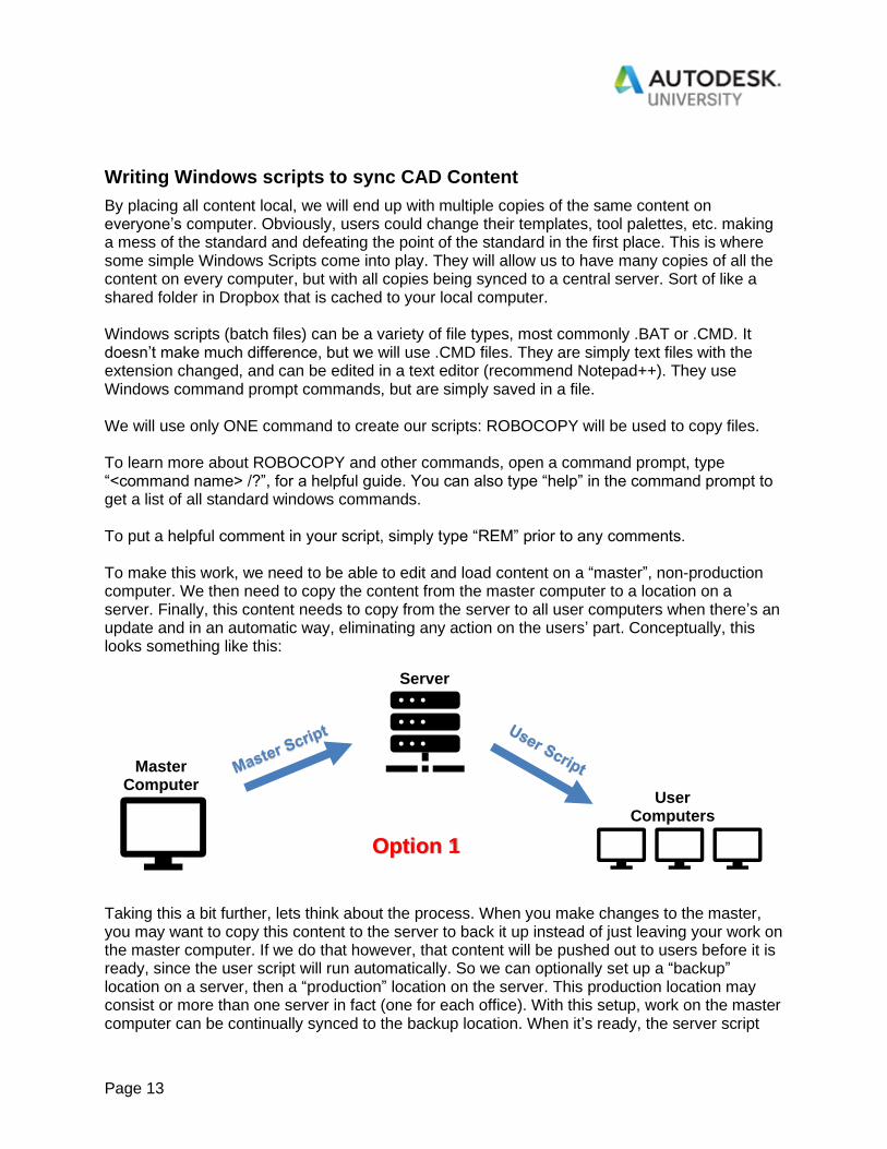
15. Make a copy of the Civil 3D 20XX Imperial desktop icon, and place this in the Standards Profile folder as well. Go to the properties of the icon and change the path for the Profile switch to path to your .arg file instead. NOTE: the profile switch also allows you to specify a profile name instead of pathing to an .ARG, which is how it comes out-of-the-box. However, pathing to an .ARG has the added advantage of automatically importing the .ARG if the profile is not yet created. Once the profile is created, however, pathing to the .ARG file will NOT continually overwrite the profile, it will simply tell C3D to start with the one of that name. /p "C:\CTC-CAD\20XX\C3D\Profile\CTC.arg”
16. Plan a location on a server where all this CAD Content will be copied to with a Windows
Script. This would be a secure location that only CAD manager types and/or the “master” computer can write to. Users don’t need to know where this location is because simple scripting (explained below) will be copying and syncing these files to their computers automatically every time they log into windows.
17. Follow the scripting method below to keep the data on this “master” computer in sync with the server, and in turn all other user computers.
Page 13
Writing Windows scripts to sync CAD Content
By placing all content local, we will end up with multiple copies of the same content on everyone’s computer. Obviously, users could change their templates, tool palettes, etc. making a mess of the standard and defeating the point of the standard in the first place. This is where some simple Windows Scripts come into play. They will allow us to have many copies of all the content on every computer, but with all copies being synced to a central server. Sort of like a shared folder in Dropbox that is cached to your local computer. Windows scripts (batch files) can be a variety of file types, most commonly .BAT or .CMD. It doesn’t make much difference, but we will use .CMD files. They are simply text files with the extension changed, and can be edited in a text editor (recommend Notepad++). They use Windows command prompt commands, but are simply saved in a file. We will use only ONE command to create our scripts: ROBOCOPY will be used to copy files. To learn more about ROBOCOPY and other commands, open a command prompt, type “<command name> /?”, for a helpful guide. You can also type “help” in the command prompt to get a list of all standard windows commands. To put a helpful comment in your script, simply type “REM” prior to any comments. To make this work, we need to be able to edit and load content on a “master”, non-production computer. We then need to copy the content from the master computer to a location on a server. Finally, this content needs to copy from the server to all user computers when there’s an update and in an automatic way, eliminating any action on the users’ part. Conceptually, this looks something like this:
Taking this a bit further, lets think about the process. When you make changes to the master, you may want to copy this content to the server to back it up instead of just leaving your work on the master computer. If we do that however, that content will be pushed out to users before it is ready, since the user script will run automatically. So we can optionally set up a “backup” location on a server, then a “production” location on the server. This production location may consist or more than one server in fact (one for each office). With this setup, work on the master computer can be continually synced to the backup location. When it’s ready, the server script
Master Computer
Server
User Computers
Option 1
Page 14
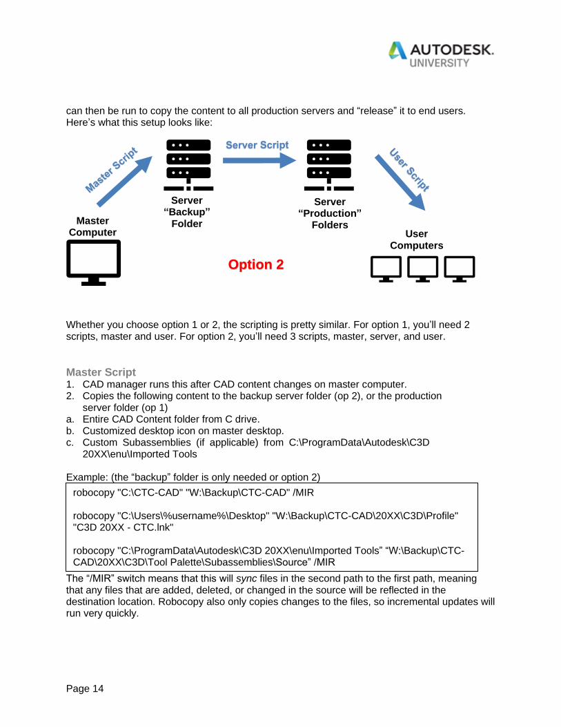
can then be run to copy the content to all production servers and “release” it to end users. Here’s what this setup looks like:
Whether you choose option 1 or 2, the scripting is pretty similar. For option 1, you’ll need 2 scripts, master and user. For option 2, you’ll need 3 scripts, master, server, and user.
Master Script 1. CAD manager runs this after CAD content changes on master computer. 2. Copies the following content to the backup server folder (op 2), or the production
server folder (op 1) a. Entire CAD Content folder from C drive. b. Customized desktop icon on master desktop. c. Custom Subassemblies (if applicable) from C:\ProgramData\Autodesk\C3D
20XX\enu\Imported Tools Example: (the “backup” folder is only needed or option 2)
The “/MIR” switch means that this will sync files in the second path to the first path, meaning that any files that are added, deleted, or changed in the source will be reflected in the destination location. Robocopy also only copies changes to the files, so incremental updates will run very quickly.
robocopy "C:\CTC-CAD" "W:\Backup\CTC-CAD" /MIR robocopy "C:\Users\%username%\Desktop" "W:\Backup\CTC-CAD\20XX\C3D\Profile" "C3D 20XX - CTC.lnk" robocopy "C:\ProgramData\Autodesk\C3D 20XX\enu\Imported Tools” “W:\Backup\CTC-CAD\20XX\C3D\Tool Palette\Subassemblies\Source” /MIR
Master Computer
Server “Backup”
Folder User
Computers
Server “Production”
Folders
Option 2
Page 15
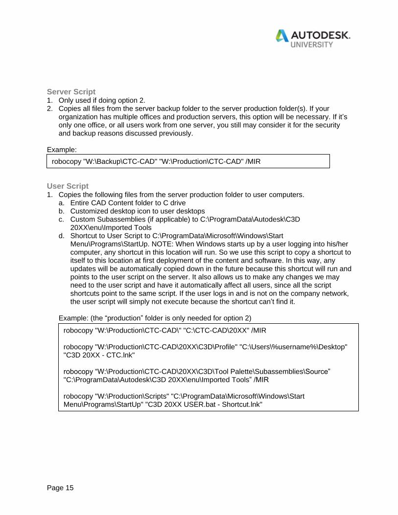
Server Script 1. Only used if doing option 2. 2. Copies all files from the server backup folder to the server production folder(s). If your
organization has multiple offices and production servers, this option will be necessary. If it’s only one office, or all users work from one server, you still may consider it for the security and backup reasons discussed previously.
Example:
User Script 1. Copies the following files from the server production folder to user computers.
a. Entire CAD Content folder to C drive b. Customized desktop icon to user desktops c. Custom Subassemblies (if applicable) to C:\ProgramData\Autodesk\C3D
20XX\enu\Imported Tools d. Shortcut to User Script to C:\ProgramData\Microsoft\Windows\Start
Menu\Programs\StartUp. NOTE: When Windows starts up by a user logging into his/her computer, any shortcut in this location will run. So we use this script to copy a shortcut to itself to this location at first deployment of the content and software. In this way, any updates will be automatically copied down in the future because this shortcut will run and points to the user script on the server. It also allows us to make any changes we may need to the user script and have it automatically affect all users, since all the script shortcuts point to the same script. If the user logs in and is not on the company network, the user script will simply not execute because the shortcut can’t find it.
Example: (the “production” folder is only needed for option 2)
robocopy "W:\Production\CTC-CAD\" "C:\CTC-CAD\20XX" /MIR robocopy "W:\Production\CTC-CAD\20XX\C3D\Profile" "C:\Users\%username%\Desktop" "C3D 20XX - CTC.lnk" robocopy “W:\Production\CTC-CAD\20XX\C3D\Tool Palette\Subassemblies\Source” "C:\ProgramData\Autodesk\C3D 20XX\enu\Imported Tools” /MIR robocopy "W:\Production\Scripts" "C:\ProgramData\Microsoft\Windows\Start Menu\Programs\StartUp" "C3D 20XX USER.bat - Shortcut.lnk"
robocopy "W:\Backup\CTC-CAD" "W:\Production\CTC-CAD" /MIR

Page 16
Maintenance of your content
Everything is in place for you to edit content on the master computer and push it out to users. Verify it works to your liking then change the log file on the master computer (if applicable), then copy the updates to the server by running your MASTER to SERVER script. With the new log file updated on the server, the SERVER to USER script will see that it does NOT match the user log file and copy over all the new files. While we have the ACADDOC.lsp in place to make changes to system variables without resetting user profiles, there may be a reason to push out a whole to new profile to users. It should be avoided whenever possible, but if need be, it can be done. You won’t be able to do this by simply making changes in Options and then exporting a new .ARG file. If you look at the first line in an ARG in a text editor you’ll see that actual name of the Profile that’s been created. While this can be the same name as the ARG, they are two different things. If you simply make changes to the MASTER profile, then export and overwrite a new ARG, the user computer won’t pick up the changes because the profile name is the same in their C3D compared to the new ARG you made. Meaning, if this profile already exists in the users C3D it won’t import these new settings. So you must create a new profile to have it pushed out to users. Follow these steps, but know that this will reset all user preferences found in Options. 1. Go to Options>Profiles 2. With your Profile current, click Add to List 3. Make the new name similar to the old, but add a date after it so that it has a different
name. 4. Set this Profile current, THEN make the changes you want to the profile settings. 5. Export this new profile to an ARG of the SAME name as the previous in your Profile
folder in your content. 6. That’s it, you’re done. When users login the next day with the new ARG synced to their computer, and they launch C3D, it will look at the first line in the ARG that’s pathed to in the Desktop icon and see that it’s a new profile name. C3D will then automatically create a whole new profile with all the new settings you specified. While it may be tempting to want to delete the old profiles on user machines, it’s not hurting anything and really just gives a record of past updates. Don’t waste your time trying to delete it out of the user registry.
Migrating to a new version of C3D
Using the folder structure recommended, keeping all content in year-specific folders, makes migration to the next version of C3D easy. We’ll be able to maintain both versions for users with the same script syncing system until we decide to finally pull away the older version. Below are the general steps on how to do this: 1. Install C3D 2020 on the master computer. Open it and make a new profile right away,
naming it appropriately, and export the ARG to the appropriate folder in the 2020 structure. Close C3D.
2. Make a copy of the C3D 2020 out-of-box desktop icon, and rename it to your company’s name. Open the properties in it and set the /p switch to point to the ARG you just exported.

Page 17
3. On the master computer, make a copy of the 2019 folder and all it’s contents in your CAD content folder. Rename it to 2020 or whatever the new version is.
4. Through file explorer, rename all files that have a year in them: templates, etc. 5. Remove any of the out-of-box tool palette content you may have added from 2019, from
the new 2020 content. 6. If custom subassemblies were used, make a copy of them to the new program data
folder for 2020 from the 2019 program data folder. 7. Update your tool palette metadata files: Open all the Tool Palette .atc files in Notepad++
and do a find and replace on 2019 for 2020. You can do this across multiple files at once.
8. Launch C3D 2020 with the new icon, then launch C3D 2019 and put it side by side with 2020.
9. Rename the CUI if needed, then open in the CUI Editor. Change the tool palette sets paths to reflect the 2020 version.
10. Set all paths in Options, Survey user settings, Pipe Catalog paths, etc. in 2020 by looking at 2019. Let the ACADDOC.lsp control as many sysvars as possible, though you can set them in Options as well.
11. Using your CUI buttons, check that each tool palette set loads appropriately. 12. Copy any 2020 out-of-box tool palettes you may want and add to your setup, as
described in the previous Tool Palettes section. 13. Open and save all templates in 2020 to migrate them. Depending on how many versions
you’re moving forward, you may have to do a lot of testing and bug fixing in your templates (potentially a large task, but not the focus of this session).
14. Migrate any other version-specific source content: dwg, pipe catalogs, etc. 15. Using the same scripts as before, we’ll simply add to them, copy any of the Robocopy
commands and paths that have 2019 in them, and change to 2020. Until you’re ready to roll out 2020, put “REM” in front of these 2020-specific commands in the User Script.
16. When fully tested and ready to roll out to users, first remove the “REM” command in front of your 2020-specific commands in the User Script. Then install C3D 2020 and run the user script for the user.
17. All set!
Conclusion
With this configuration in place you’ll enjoy all the benefits of an organized CAD configuration that’s easy to build and maintain. One primary goal of the CAD manager should always be to make things as easy as possible for users so they can focus on their job. If you can do some things that will help people save time every day you’re doing your job. If users don’t have to browse for something, ask someone where something is, or set up their own C3D configuration you’re doing something right. Happy CAD managing!