Embed Size (px)
Citation preview

Micra 223 E
24 SE
Quick guide
Technical Data
Installation, adjustingand maintenance instructions
User instructions
GAS BOILERS
2 User instructions
for t
he u
ser
QUICK GUIDEDear Customer,
we have intentionally inserted the Quick Guide at the beginning of the booklet in order to let youuse your boiler immediately.
This Quick Guide: 1) implicates that the boiler has already been subdued to the First Ignition and it has been preparedto the functioning and all the conditions for the correct functioning have been satisfied, the correct system pressure andthe hydric, gas and electrical supply included; 2) could be partially not valid in case of optional kits.
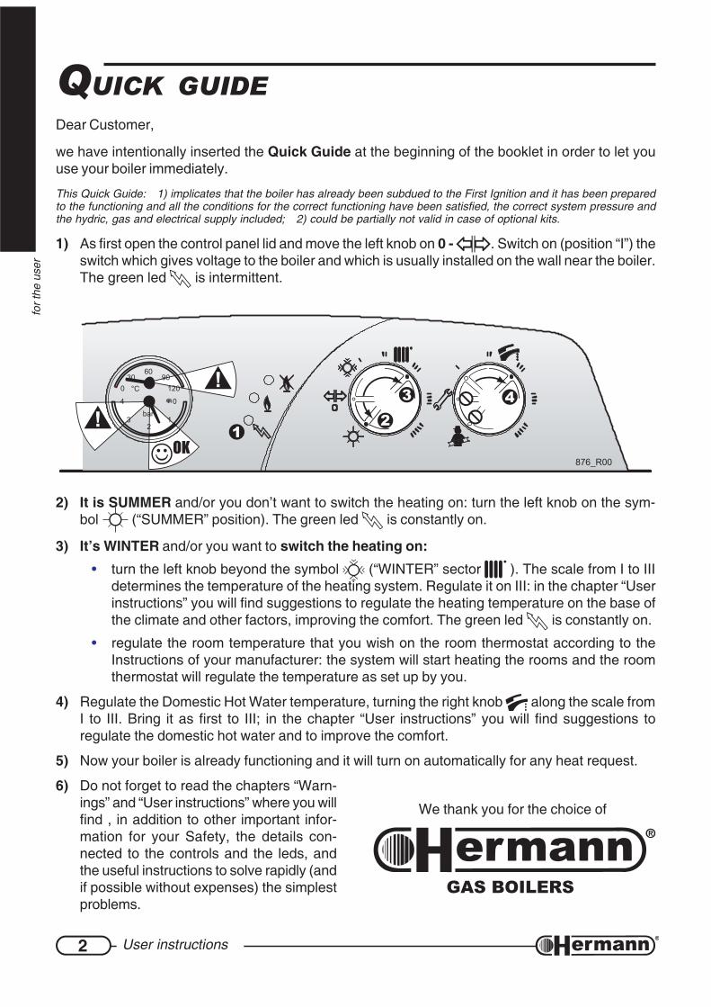
1) As first open the control panel lid and move the left knob on 0 - . Switch on (position “I”) theswitch which gives voltage to the boiler and which is usually installed on the wall near the boiler.The green led is intermittent.
4
876_R00
2
3
1
2) It is SUMMER and/or you don’t want to switch the heating on: turn the left knob on the sym-bol (“SUMMER” position). The green led is constantly on.
3) It’s WINTER and/or you want to switch the heating on:• turn the left knob beyond the symbol (“WINTER” sector ). The scale from I to III
determines the temperature of the heating system. Regulate it on III: in the chapter “Userinstructions” you will find suggestions to regulate the heating temperature on the base ofthe climate and other factors, improving the comfort. The green led is constantly on.
• regulate the room temperature that you wish on the room thermostat according to theInstructions of your manufacturer: the system will start heating the rooms and the roomthermostat will regulate the temperature as set up by you.
4) Regulate the Domestic Hot Water temperature, turning the right knob along the scale fromI to III. Bring it as first to III; in the chapter “User instructions” you will find suggestions toregulate the domestic hot water and to improve the comfort.
5) Now your boiler is already functioning and it will turn on automatically for any heat request.
6) Do not forget to read the chapters “Warn-ings” and “User instructions” where you willfind , in addition to other important infor-mation for your Safety, the details con-nected to the controls and the leds, andthe useful instructions to solve rapidly (andif possible without expenses) the simplestproblems.
We thank you for the choice of
GAS BOILERS
3
sect
ions
for t
he u
ser
sect
ions
for t
he te
chni
cian
Index
Quick guide ...................................2
Warnings .......................................4
Technical data ..............................6
Installation ..................................10Safety laws and rules referred to technicians
assigned to boilers installation ............ 10Laws and rules referred
to boilers installation ............................ 10Boiler location ............................................ 11Boiler hanging ........................................... 12
with standard connection kit ................................................ 12without standard connection kit ........................................... 14
Hydraulic connections ............................... 16System filling ............................................. 17Gas connection ......................................... 17Electrical connections ............................... 18Chimney connections
MICRA 2 E (natural draught) .............. 19Chimney connections
MICRA 2 SE (forced draught) ............. 20High capacity fan
MICRA 2 24 SE................................... 22Flue systems
MICRA 2 SE........................................ 23
Regulation and servicing...........26Access to the regulation devices .............. 26Preliminary GAS checkings ....................... 27Gas valve pressure regulation (MAX-MIN) 27Gaining access
to the main PCB .................................. 28ELECTRONIC settings .............................. 29Changing Gas type ................................... 30Combustion check ..................................... 31Hydraulic section ....................................... 31Warnings for servicing ............................... 32Components of the gas boiler
MICRA 2 23 E ................................... 34Components of the gas boiler
MICRA 2 24 SE ................................. 35Electric diagram for
MICRA 2 23 E ................................... 36Electric diagram for
MICRA 2 24 SE ................................. 37
User instructions ........................38Warnings for first starting up ..................... 38Useful advices ........................................... 38Warnings ................................................... 39Controls and indicators ............................. 40System pressure ....................................... 42Alarms ....................................................... 42Boiler inactivity .......................................... 45Incidental not functioning .......................... 46User warnings ........................................... 47
INDEX
4 Warnings
for t
he te
chni
cian
and
for t
he u
ser
ATTENTION(for forced draught models)
FOR DIAPHRAGM POSITIONING, CAREFULLY READ THE FLUE SYSTEMSINSTRUCTIONS IN THE “INSTALLATION” CHAPTER.
IMPORTANTTHE FIRST IGNITION OF THE BOILER MUST BE EXECUTED BY ANAUTHORIZED TECHNICIAN ACCORDING TO THE LAW 46/90.
Assigning all the operations for the first ignition to a Hermann Authorized ServiceCenter the particular and exclusive Hermann Conventional Warranty is activated.For further information consult the coupon which you can find in the boiler’sdocuments envelope.
Assigning all the operations for the first ignition to a Hermann Authorized Service Center the particular and exclusive Hermann Conven-tional Warranty is activated. For further information consult the coupon which you can find in the boiler’s documents envelope.
MANUFACTURER DECLARATION
Hermann boilers have obtained the CE certification (DM dtd. April 2nd 1998, Law 10/91, art. 32) andmeet minimum efficiency requirements, both at normal and 30% load, provided by DPR 412/93(according to Law 10/91, art. 4, sub-section 4). They are in conformity with following Directives: Directiveon appliances burning gaseous fuels (90/396), Directive on electro-magnetic compatibility (CE 89/336), Efficiency Directive (CE 92/42), Low Voltage Directive (CE 73/23), and relevant modifications.
SYMBOLS USED IN THIS HANDBOOK:DANGER: All warnings preceded by this symbol MUST be carefully respected so asto avoid any accident of mechanical (e.g. wounds or contusions) or general origin.
DANGER: All warnings preceded by this symbol MUST be carefully respected so asto avoid any accident of ELECTRICAL origin (fulguration).
DANGER: All warnings preceded by this symbol MUST be carefully respected so asto avoid any accident of THERMIC origin (scalds).
Attention: All warnings preceded by this symbol MUST be carefully respected so as to avoidany disfunctioning and/or damage to the appliance or other objects.
WARNINGS
5Warnings
for t
he te
chni
cian
and
for t
he u
ser
The instructions manual is an essential and complementary part of the product and it issupplied together with the boiler.
Carefully read the manual, achieving all important information for a safe installation,use and servicing.
— Carefully keep the manual for any further consultation you may need.
— The installation must be carried out by a qualified technician, in accordance withmanufacturer instructions and with the relevant requirements of the current issue.
— A qualified technician is a person with a specific technical competence in the field ofthe heating appliances for domestic use and domestic hot water production, as indicatedby the Law [ID of Your National rule, if any, regarding Technicians competence].
— User can ONLY make those operations that are specifically described in the “Quick gui-de” or “User instructions” sections.
— The manufacturer has no contractual and extra-contractual responsibility for any damagearising from wrong installation, wrong use and non-observance of current laws andinstructions given by the manufacturer himself.
— Important: this gas boiler is used to heat the water at a temperature lower than the boilingone, at atmospheric pressure; it must be connected to an heating system and/or to a domestichot water system, in accordance with its features and power.
— Packing items (cartons, nails, plastic bags and so on) must not be left within childreneasy reach, as they are potentially dangerous.
— Before any cleaning or servicing operation, switch off the main electrical switch of theheating system and/or any other suitable switch providing electrical disconnection ofthe gas boiler.
— In case of fault and/or bad operation of the appliance, disconnect it immediately and donot try to repair it by yourselves.
Boiler servicing and repair must be carried out exclusively by [HERMANN Authorized ServicingCentres] [qualified technicians], which will use original spare parts. Strictly observe the aboverequirement, avoiding any risk of compromising the appliance safety.
— If the appliance should be definitively disconnected, remove or cut off any potential dangerousitem.
— When selling the appliance or leaving it installed after a removal, make always sure that theinstructions manual is close to the boiler for the future use of new owners and/or installers.
— This appliance must be used for its clearly recommended utilization only. Any other utilizationmust be considered dangerous and incorrect.
— It is strictly forbidden to use the appliance for different purposes than the specified ones.
— This appliance must be installed exclusively to wall.

6 Technical data
for t
he te
chni
cian
ATADLACINHCET .M.U 2ARCIME32
2ARCIMES42
noitacifitrecEC °n 0173NB4960 0173NB4960ssalC II +3H2 II +3H2
epyT SB/11B 24C-23C-21C-22B28C-26C-25C
epytsaG 02G 13G/03G 02G 13G/03G
)iH(tupnitaehxaM Wk 6.52 6.52 6.52 6.52)iH(tupnitaehniM Wk 5.01 5.01 5.01 5.01
)iH(tuptuotaehxaM Wk 0.32 0.32 9.32 9.32)iH(tuptuotaehniM Wk 0.9 0.9 1.9 1.9
ON x ssalC 2 1 3 2ONdethgieW x hWk/gm 9.361 872 821 781
tupnilanimontaOC mpp 32 5.02 91 72OC 2 tupnilanimonta % 8.4 6.5 7.6 8.7
YCNEICIFFEycneiciffelanimoN % 6.09 2.39
daol%03taycneiciffE % 9.78 4.09GNITAEH
)xam÷nim(egnarnoitceleserutarepmeT C° 87÷53 87÷53lessevnoisnapxE l 8 8
erusserplessevnoisnapxE rab 1 1erusserpgnikrowxaM rab 3 3
erutarepmetmetsysxaM C° 38 38RETAWTOH
esirerutarepmetC°52taetarwolF nim/l 2.31 7.31esirerutarepmetC°03taetarwolF nim/l 0.11 4.11
wolfretawniM nim/l 3 3erusserpylppusxaM rab 6 6
erusserpytiroirprof(erusserpylppusniM)noitavitcahctiws rab 8.0 8.0
)xam÷nim(egnarnoitceleserutarepmeT C° 55÷03 55÷03ATADLACIRTCELE
ycneuqerf/egatloV zH/V 05/032 05/032noitpmusnocrewoP
)nafyticapachgihhtiw=PAV( W 011 )PAV261(241
noitcetorpfoleveL D4XPI D4XPISNOISNEMID
htpeD-thgieH-htdiW mm margaid"SNOISNEMID"otrefeRthgieW gk 13 63
)teltuO=S(SNOITCENNOCnruter/wolfgnitaeH hcnI "¾ "¾
teltuo/telniretaWcitsemoD hcnI "½ "½reliobehtotnoitcennocsaG hcnI "¾ "¾
kcocsagehtotnoitcennocsaGtiknoitcennocdradnatsfo hcnI "½ "½
ØteltuostcudorpeulF mm 031Øtelniria/teltuostcudorpeulflaixaoC mm 06/001xam/nim)latnoziroh(htgneleulflaixaoC m 4÷5.0
xam/nim)lacitrev(htgneleulflaixaoC m 5÷1Øtelniria/teltuostcudorpeulfetarapeS mm 08
xam/nimhtgneleulfetarapeS m 03÷2)02=Sxam(
xam/nimhtgneleulfetarapeShtiw nafyticapachgih m 06÷13
)04=Sxam(htgneleulfetarapeS
xam/nimtilps-sepiphtiw m 41÷2)31=Sxam(
ERUSSERPYLPPUSSAGepytsaG 02G 13G/03G 02G 13G/03G
erusserplanimoN rabm 02 73/92 02 73/92rebmunsrotcejnI 31 31 31 31
retemaidsrotcejnI Ømm001/1 021 57/57 021 57/57
NOITPMUSNOCSAG
xamQh/cm 17.2 17.2h/gk 89.1/10.2 89.1/10.2
nimQh/cm 11.1 11.1h/gk 18.0/38.0 18.0/38.0
TECHNICAL DATA

7Technical data
for t
he te
chni
cian
DIMENSIONS
1 Flue products outlet2 Air inlet for coaxial system3 Air inlet for separate system
400 300
700
936A_R00
207 193
180
1
93
7_
R0
0
MICRA 2E - SE
MICRA 2E
207 193
233 147
75
1
2
3
93
8_
R0
0
MICRA 2SE

8 Technical data
for t
he te
chni
cian
AVAILABLE PUMP CAPACITYModel MICRA 2 23 E / 24 SE
with selector in speed position I, II, III (automatic by-pass, not disconnectable)
0
0,5
1
1,5
2
2,5
3
3,5
4
4,5
5
5,5
6
0 200 400 1000 1200600 800 1400
711
R00
Water flow l/h
Pre
ssur
e m
. H2O
772R
01

9Technical data
for t
he te
chni
cian
BOILER SCHEMATIC MICRA 2 E
MICRA 2 SE
1 Drain valve2 Heating thermometer + gauge3 By-pass4 Pump5 Heating system safety valve 3 bar6 Expansion vessel7 Burner8 Primary heat exchanger9 Flue hood (“E” models)10 Flue thermostat (“E” models)11 Flue hood (“SE” models)12 Flue pressure switch (“SE” models)13 Fan (“SE” models)14 Safety thermostat15 Venting device16 NTC temperature sensor17 Hydraulic 3-way valve18 Priority pressure switch19 Domestic exchanger20 Filling valve21 Gas valve22 Loss of water switch
DOMESTICWATER
GAS
INLE
T
HEATING
FLOW
OUTL
ET
RETU
RN
WARNING: This scheme is made for in-formation only. To make boiler hydrau-lic connection either use fixing jig or thedrawing inserted in the section “Instal-lation” or the “Dimensions” drawing.
DOMESTICWATER
GAS
INLE
T
HEATING
FLOW
OUTL
ET
RETU
RN

10 Installation
for t
he te
chni
cian
INSTALLATION
Safety laws and rules referred to techniciansassigned to boilers installation
Place here all necessaryadvices according to national rules
about WORK SAFETYLaw number XXXX
“Actuation of 89/391/CEE; 89/655/CEE, 90/296/CEE, 90/934/CEE, 90/679/CEE, (work safety)”
Law number XXXX“Actuation of 89/686/CEE (21 Dec 1989)”
Other Law number XXXX (if any)“Other Law title and/or brief description”
Directives“Directive title and/or brief description”
Always proceed with caution when handling the boiler and carrying out instal-lation/maintenance work as metal parts may cause injuries such as cuts andabrasions. Wear gloves while doing the above mentioned operations.
Laws and rules referredto boilers installation
Place here all necessaryadvices according to national rules
about BOILER INSTALLATIONLaw number XXXX
“Law title and/or brief description”

11Installation
for t
he te
chni
cian
Boiler locationINSTALLATION ROOM
When having an heat ouput lower than 35 kw (about 30000 Kcal/h), particular features for theinstallation room are not required. Shortly, all installation rules assuring a safe and regular gasboiler operation, must be strictly respected.
Place here all necessaryadvices according to national rules about:
- Installation room requirements- Limitations in power and/or number of boilers and other appli-
ances in the same roomLaw number XXXX
“Law title and/or brief description”
ROOM VENTILATION (mod. MICRA 2 E – natural draught)
When a natural draught boiler is installed, permanent ventilation of the installationroom is mandatory and extremely important. Ventilation must be made and sized inaccordance with Laws and Rules in force.
INSTALLATION IN ROOMS WHERE TEMPERATURE CAN DROP DOWN TO 0°C:
When the installation place does not guarantee an adequate repair against atmospheric agents,the gas boiler must be completely protected through an adequate coverage as a safety measureagainst the above agents.
Thanks to its antifreeze system, inner components could never reach a temperature lower than5°C. This system is activated when the boiler is supplied by the electrical and gas lines, providedthat the pressure in the heating system is correct. On request, it is possible to install an antifreezeelectrical resistance device on the domestic exchanger, so as to protect boiler even in case of gaslack.
In case of boiler installation in rooms where temperature can drop down to 0°, it is advisable toprotect the heating circuit with an antifreeze liquid. See also “System filling” and “Boiler inactivity”.
This appliance is not suitable for outdoor installation.
12 Installation
for t
he te
chni
cian
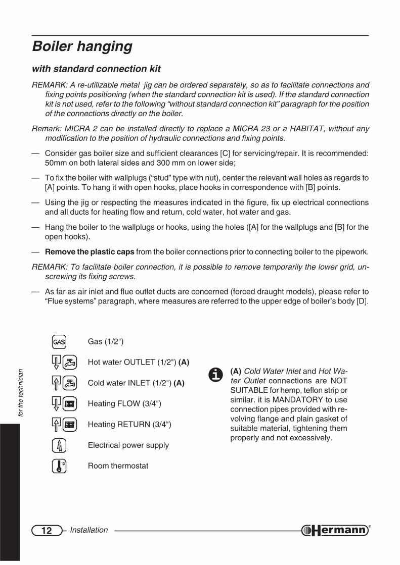
Boiler hangingwith standard connection kitREMARK: A re-utilizable metal jig can be ordered separately, so as to facilitate connections and
fixing points positioning (when the standard connection kit is used). If the standard connectionkit is not used, refer to the following “without standard connection kit” paragraph for the positionof the connections directly on the boiler.
Remark: MICRA 2 can be installed directly to replace a MICRA 23 or a HABITAT, without anymodification to the position of hydraulic connections and fixing points.
— Consider gas boiler size and sufficient clearances [C] for servicing/repair. It is recommended:50mm on both lateral sides and 300 mm on lower side;
— To fix the boiler with wallplugs (“stud” type with nut), center the relevant wall holes as regards to[A] points. To hang it with open hooks, place hooks in correspondence with [B] points.
— Using the jig or respecting the measures indicated in the figure, fix up electrical connectionsand all ducts for heating flow and return, cold water, hot water and gas.
— Hang the boiler to the wallplugs or hooks, using the holes ([A] for the wallplugs and [B] for theopen hooks).
— Remove the plastic caps from the boiler connections prior to connecting boiler to the pipework.
REMARK: To facilitate boiler connection, it is possible to remove temporarily the lower grid, un-screwing its fixing screws.
— As far as air inlet and flue outlet ducts are concerned (forced draught models), please refer to“Flue systems” paragraph, where measures are referred to the upper edge of boiler’s body [D].
Gas (1/2")
Hot water OUTLET (1/2") (A)
Cold water INLET (1/2") (A)
Heating FLOW (3/4")
Heating RETURN (3/4")
Electrical power supply
Room thermostat
(A) Cold Water Inlet and Hot Wa-ter Outlet connections are NOTSUITABLE for hemp, teflon strip orsimilar. it is MANDATORY to useconnection pipes provided with re-volving flange and plain gasket ofsuitable material, tightening themproperly and not excessively.

13Installation
for t
he te
chni
cian
785
70
0
88
1_
R0
0
32.5
35
14
330
52 52 88
22
39 40 30 46.5 52.5
14
35
335
400
32.5
36
11
14
39
665
A A
B B
C
D
A
B
14 Installation
for t
he te
chni
cian
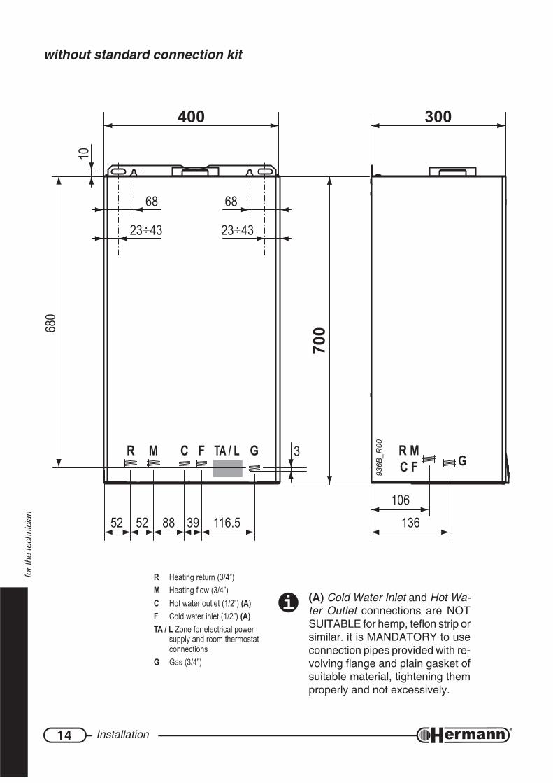
without standard connection kit
R Heating return (3/4”)M Heating flow (3/4”)C Hot water outlet (1/2”) (A)F Cold water inlet (1/2”) (A)TA / L Zone for electrical power
supply and room thermostatconnections
G Gas (3/4”)
680
10
23÷43
68
23÷43
68
3
136106
R MC F G
52 52 88 39 116.5
GTA / LFCMR
400 300
700
936B_R00
(A) Cold Water Inlet and Hot Wa-ter Outlet connections are NOTSUITABLE for hemp, teflon strip orsimilar. it is MANDATORY to useconnection pipes provided with re-volving flange and plain gasket ofsuitable material, tightening themproperly and not excessively.

15Installation
for t
he te
chni
cian
Notes
16 Installation
for t
he te
chni
cian
772R
01
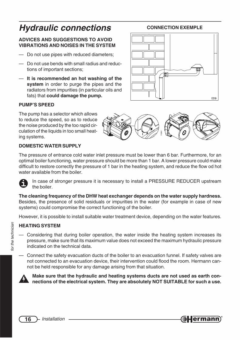
CONNECTION EXEMPLEHydraulic connectionsADVICES AND SUGGESTIONS TO AVOIDVIBRATIONS AND NOISES IN THE SYSTEM
— Do not use pipes with reduced diameters;
— Do not use bends with small radius and reduc-tions of important sections;
— It is recommended an hot washing of thesystem in order to purge the pipes and theradiators from impurities (in particular oils andfats) that could damage the pump.
PUMP’S SPEED
The pump has a selector which allowsto reduce the speed, so as to reducethe noise produced by the too rapid cir-culation of the liquids in too small heat-ing systems.
DOMESTIC WATER SUPPLY
The pressure of entrance cold water inlet pressure must be lower than 6 bar. Furthermore, for anoptimal boiler functioning, water pressure should be more than 1 bar. A lower pressure could makedifficult to restore correctly the pressure of 1 bar in the heating system, and reduce the flow od hotwater available from the boiler.
In case of stronger pressure it is necessary to install a PRESSURE REDUCER upstreamthe boiler.
The cleaning frequency of the DHW heat exchanger depends on the water supply hardness.Besides, the presence of solid residuals or impurities in the water (for example in case of newsystems) could compromise the correct functioning of the boiler.
However, it is possible to install suitable water treatment device, depending on the water features.
HEATING SYSTEM
— Considering that during boiler operation, the water inside the heating system increases itspressure, make sure that its maximum value does not exceed the maximum hydraulic pressureindicated on the technical data.
— Connect the safety evacuation ducts of the boiler to an evacuation funnel. If safety valves arenot connected to an evacuation device, their intervention could flood the room. Hermann can-not be held responsible for any damage arising from that situation.
Make sure that the hydraulic and heating systems ducts are not used as earth con-nections of the electrical system. They are absolutely NOT SUITABLE for such a use.

17Installation
for t
he te
chni
cian
System fillingOnce all system connections have been carried out,proceed with system filling. This operation should bemade with caution, respecting the following steps:
— Open the radiators venting devices;
— Gradually open the water supply valve (see figure“Boiler bottom view”), checking the correct func-tioning of automatic venting devices, eventuallyinstalled;
— Close the radiators venting devices as soon aswater flows;
— Make sure that pressure gauge reaches the opti-mal value of 1÷1.5 bar (minimum: 0.5 bar);
— Close the water supply valve and bleed each ra-diator;
In case the boiler is installed in rooms where temperature can drop down to 0°C, it is advis-able to fill up the system with an anti-frost liquid.
Gas connectionBoiler installation must be carried out from a qualified technician, [as indicated by the Law XXXXX]because an incorrect installation can cause damages to people, animals or things, for which themanufacturer cannot be held responsible.
Verify what follows:
a) cleaning of all system gas pipes in order to avoid the presence of residual combustion productsthat could compromise the correct boiler functioning;
b) gas line and ramp conformity with laws and rules actually in force (Laws UNI-CIG 7129/01 and7131/99 – DM 12/04/96);
c) internal and external tightness of the gas system and connections;
d) supply pipe must have a section greater than or equal to the boiler one;
e) supply gas must correspond to the one for which the boiler has been regulated; otherwise, call[an HERMANN Servicing Centre] [a qualified technician] for gas conversion;
f) an interception valve must be installed upstream the appliance;
Open the meter valve and purge the air that is inside the system pipes (including all the appli-ances).
890_
R00
BOILER BOTTOM VIEW
FILLINGVALVE

18 Installation
for t
he te
chni
cian
While connecting gas inlet pipe of the boiler to the pipe coming from gas network, itis MANDATORY to insert a TIGHT GASKET, whose dimensions and material must beadequate. Connection is NOT suitable for hemp, teflon strip or similar materials.
Using LPG, it is absolutely necessary to install a pressure reducer upstream the boiler.
Due to various installation possibilities, the gas cock supplied with Standard Connections Kit forMICRA 2 boilers has a simple male Ø ½” connection, facing the rear of the boiler. No gas pipes aresupplied.
Electrical connectionsThe link of the room thermostat works with a safety extra low voltage (SELV); connect it tothe voltage free terminals of the room thermostat/cronothermostat. On NO account mustany electrical voltage be applied to these terminals.
The boiler must be connected to an electrical line of 230V-50Hz, respecting the polarities L-N (Live-Neutral) and the earth connection.
PLACE UPSTREAM THE BOILER A BIPOLAR SWITCH in accordance with the rulesactually in force.
For the general electrical supply of the appliance, the use of adaptors, multiple taps and exten-sions is not allowed.
If the supply cable must be replaced, use one of the following wire types: H05VVF or H05-VVH2-F.It is mandatory the earth connection in accordance with the rules actually in force. To re-place the cable, release the cable fastener placed on the frame of the hydraulic connections, openthe back cover of the control panel and disconnect it from the terminals. Install the new cableworking in the reverse way. When connecting the cable to the boiler, it’s IMPORTANT:
— to leave the Earth wire about 2 cm longer than Live and Neutral wires;
— to lock tha cable in the cable fastener placed on the frame of the hydraulic connections.
Electrical safety of the appliance is only achieved when it is well connected to anefficient earthing system, executed as indicated by the safety rules actually in force.
A qualified technician must check that the electrical system is in line with the maximum powerallowed by the boiler, indicated on the data plate, with particular attention to the cables section.
Remark: HERMANN Ltd. declines any responsibility for damages to persons, animals orthings caused by the non-connection of the boiler earthing and by failure to comply withthe rules.
19Installation
for t
he te
chni
cian
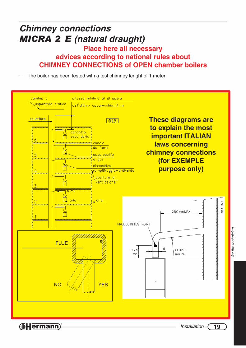
Chimney connectionsMICRA 2 E (natural draught)
Place here all necessaryadvices according to national rules about
CHIMNEY CONNECTIONS of OPEN chamber boilers— The boiler has been tested with a test chimney lenght of 1 meter.
PRODUCTS TEST POINT
2500 mm MAX
SLOPEmin 3%
2 x dmin
dFLUE
NO YES
These diagrams areto explain the mostimportant ITALIANlaws concerning
chimney connections(for EXEMPLEpurpose only)

20 Installation
for t
he te
chni
cian
Chimney connectionsMICRA 2 SE (forced draught)NOTE ON FLUE INSTALLATION
When fitting air inlet and flue outlet horizontalducts, it is necessary to make sure there is a slopeof 2÷5% downwards from the boiler to the out-side (see diagram). This is essential to guaran-tee correct boiler operation and reliability. Air in-let and flue outlet terminals should be protectedby suitable approved flue accessories, to avoidenvironmental elements penetration.
Place here all necessaryadvices according to national rules about
CHIMNEY CONNECTIONS of sealed chamber boilers
FLUE
NO YES
2% ÷ 5%
631R01
21Installation
for t
he te
chni
cian
AB
P
ON C
MF
E
DI
HL
G
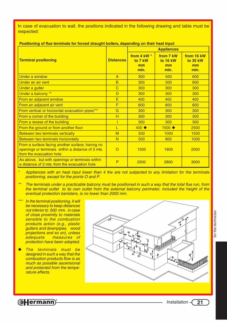
tupnitaehriehtnognidneped,sreliobthguarddecrofrofslanimreteulffogninoitisoP
gninoitisoplanimreT secnatsiD
secnailppA
*Wk4morfWk7ot
mm.nim
Wk7morfWk61ot
mm.nim
Wk61morfWk53ot
mm.nim
wodniwarednU A 003 005 006tnevrianarednU B 003 005 006
rettugarednU C 003 003 003**ynoclabarednU D 003 003 003
wodniwtnecajdanamorF E 004 004 004tnevriatnecajdanamorF F 006 006 006
***sepipnoitaucavelatnozirohrolacitrevmorF G 003 003 003gnidliubehtforenrocamorF H 003 003 003gnidliubehtfosseceramorF I 003 003 003
roolfrehtonamorfrodnuorgehtmorF L 004 0051 0052yllacitrevslanimretowtneewteB M 005 0001 0051
yllatnozirohslanimretowtneewteB N 005 008 0001ongnivah,ecafrusrehtonagnicafecafrusamorF.stm3foecnatsidanihtiwslanimretrosgninepo
elohnoitaucaveehtmorfO 0051 0081 0002
nihtiwslanimretrosgninepohtiwtub,evobasAelohnoitaucaveehtmorf.stm3foecnatsida P 0052 0082 0003
* Appliances with an heat input lower than 4 Kw are not subjected to any limitation for the terminalspositioning, except for the points O and P.
** The terminals under a practicable balcony must be positioned in such a way that the total flue run, fromthe terminal outlet to its own outlet from the external balcony perimeter, included the height of theeventual protection banisters, is no lower than 2000 mm.
*** In the terminal positioning, it willbe necessary to keep distancesnot inferior to 500 mm. in caseof close proximity to materialssensible to the combustionproducts action (e.g., plasticgutters and downpipes, woodprojections and so on), unlessadequate measures ofprotection have been adopted.
The terminals must bedesigned in such a way that thecombustion products flow is asmuch as possible ascensionaland protected from the tempe-rature effects.
In case of evacuation to wall, the positions indicated in the following drawing and table must berespected:
22 Installation
for t
he te
chni
cian
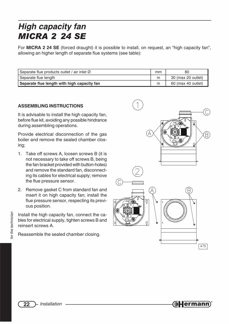
High capacity fanMICRA 2 24 SEFor MICRA 2 24 SE (forced draught) it is possible to install, on request, an “high capacity fan”,allowing an higher length of separate flue systems (see table):
Øtelniria/teltuostcudorpeulfetarapeS mm 08htgneleulfetarapeS m )teltuo02xam(03
nafyticapachgihhtiwhtgneleulfetarapeS m )teltuo04xam(06
ASSEMBLING INSTRUCTIONS
It is advisable to install the high capacity fan,before flue kit, avoiding any possible hindranceduring assembling operations.
Provide electrical disconnection of the gasboiler and remove the sealed chamber clos-ing;
1. Take off screws A, loosen screws B (it isnot necessary to take off screws B, beingthe fan bracket provided with button-holes)and remove the standard fan, disconnect-ing its cables for electrical supply; removethe flue pressure sensor.
2. Remove gasket C from standard fan andinsert it on high capacity fan; install theflue pressure sensor, respecting its previ-ous position.
Install the high capacity fan, connect the ca-bles for electrical supply, tighten screws B andreinsert screws A.
Reassemble the sealed chamber closing.
23Installation
for t
he te
chni
cian
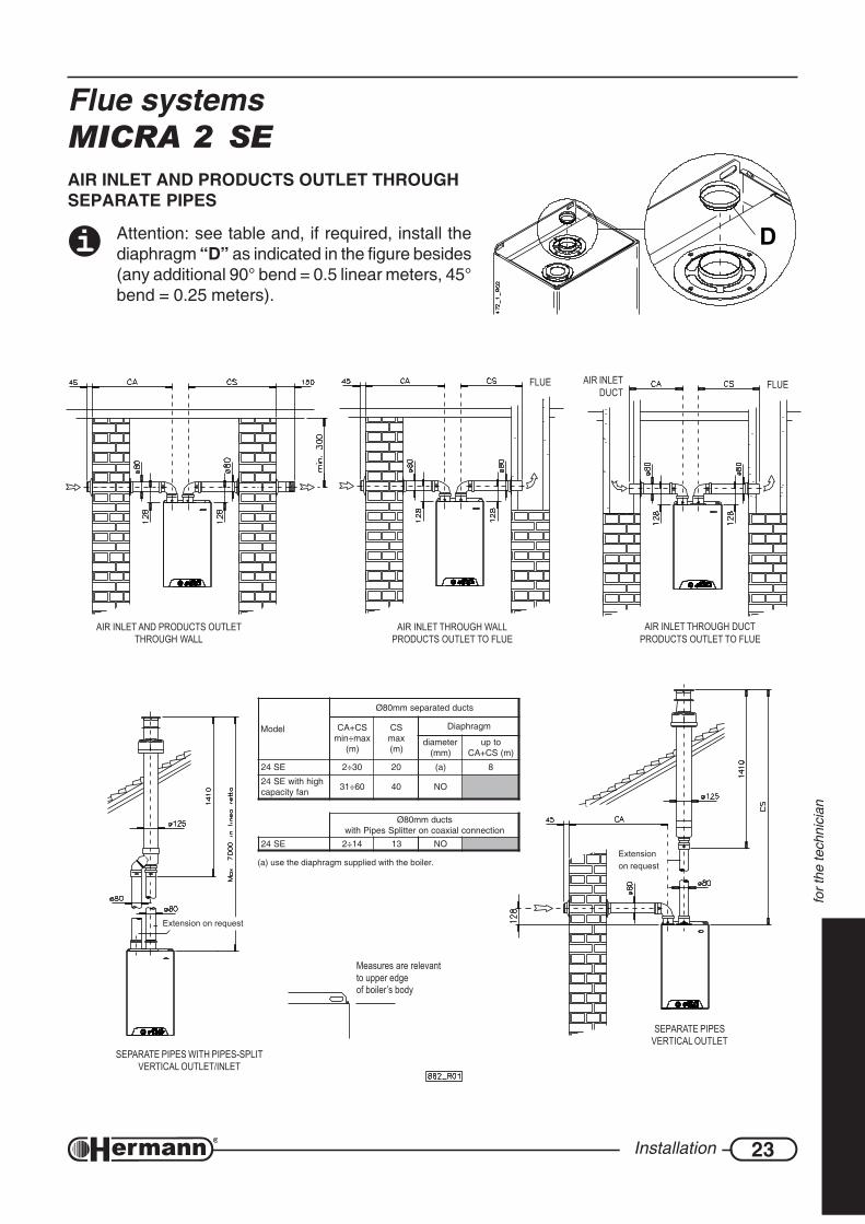
Flue systemsMICRA 2 SEAIR INLET AND PRODUCTS OUTLET THROUGHSEPARATE PIPES
Attention: see table and, if required, install thediaphragm “D” as indicated in the figure besides(any additional 90° bend = 0.5 linear meters, 45°bend = 0.25 meters).
FLUEAIR INLETDUCT
FLUE
AIR INLET THROUGH DUCTPRODUCTS OUTLET TO FLUE
AIR INLET THROUGH WALLPRODUCTS OUTLET TO FLUE
AIR INLET AND PRODUCTS OUTLETTHROUGH WALL
Measures are relevantto upper edgeof boiler’s body
SEPARATE PIPES WITH PIPES-SPLITVERTICAL OUTLET/INLET
SEPARATE PIPESVERTICAL OUTLET
Extension on request
Extensionon request
D
ledoM
stcuddetarapesmm08Ø
SC+ACxam÷nim
)m(
SCxam)m(
mgarhpaiD
retemaid)mm(
otpu)m(SC+AC
ES42 03÷2 02 )a( 8
hgihhtiwES42nafyticapac 06÷13 04 ON
stcudmm08ØnoitcennoclaixaocnorettilpSsepiPhtiw
ES42 41÷2 31 ON
(a) use the diaphragm supplied with the boiler.
24 Installation
for t
he te
chni
cian
IN STRAIGHT LINE IN STRAIGHT LINE
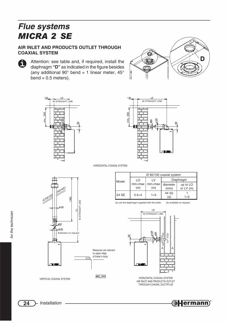
HORIZONTAL COAXIAL SYSTEM
Extension on request
Measures are relevantto upper edgeof boiler’s body
VERTICAL COAXIAL SYSTEM HORIZONTAL COAXIAL SYSTEMAIR INLET AND PRODUCTS OUTLET
THROUGH COAXIAL DUCT/FLUE
IN STRAIGHT LINE
IN S
TRA
IGH
T LI
NE
D
Flue systemsMICRA 2 SEAIR INLET AND PRODUCTS OUTLET THROUGHCOAXIAL SYSTEM
Attention: see table and, if required, install thediaphragm “D” as indicated in the figure besides(any additional 90° bend = 1 linear meter, 45°bend = 0.5 meters).
(a) use the diaphragm supplied with the boiler. (b) available on request.
ledoM
metsyslaixaoc001/06Ø
OLxam÷nim
)m(
VLxam÷nim
)m(
mgarhpaiD
retemaid)mm(
OLotpu)m(VLro
ES42 4÷5.0 5÷1 )b(44)a(
12÷1

25Installation
for t
he te
chni
cian
Notes
26 Regulation and servicing
for t
he te
chni
cian
REGULATION AND SERVICINGATTENTION: the operations described below must be carried out only by qualifiedpersonnel [authorized by HERMANN].
When regulation/measuring is over, remember to tighten pressure tapping point screwsand ALWAYS check for gas leaks!
Before boiler ignition, verify that pump is not blocked due to its inactivity: unscrew the pluglocated in the middle of the cap to gain access to the rotor shaft, and turn it manually using ascrewdriver or another suitable tool.
During the first ignition of the brand new boiler, it is necessary that burner works for at least30 minutes, before performing combustion checks. During this time, the fumes of the eventualresidual manufacturing materials are produced, and they could alter the measured values.
Remark: the knob on control panel has the position that is used during factory test only. Ithas no use with regard to first ignition, servicing or regulation. For information use only, we explain thatthis position activates the gas boiler, further to a request of hot water, at the minimum output set for this function.
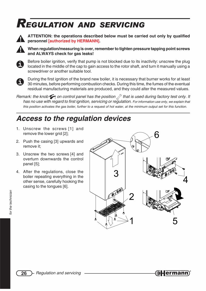
Access to the regulation devices1. Unscrew the screws [1] and
remove the lower grid [2];
2. Push the casing [3] upwards andremove it;
3. Unscrew the two screws [4] andoverturn downwards the controlpanel [5];
4. After the regulations, close theboiler repeating everything in theother sense, carefully hooking thecasing to the tongues [6].
1
6
3 4
5
2

27Regulation and servicing
for t
he te
chni
cian
Preliminary GAS checkingsAll boilers are tested and factory set during manufacture;however, it is advisable to check that the gas type and theburner pressures are correct. On the contrary, follow theprocedures described in this section.
To make burner pressures checking, insert pressure gaugesensors in the gas valve pressure tapping points (see fi-gure).
Remark: In order to check that pressure and gas inputare enough to guarantee the correct functioning of theappliance , make measurements while burner is on.
Gas valve pressureregulation (MAX-MIN)— Loosen (2-3 turns) the screw of pressure tapping point
for gas outlet [1] of the gas valve and insert themanometer sensor. In the “SE” models unthread fromthe “Vent” [3] the silicon tube coming from the sealedchamber;
— Activate the boiler to its maximum output notmodulated, using the “Chimney-sweeper” function.Proceed as it follows:
• Supply the boiler and turn the Summer/Winter knob to Summer position ;
• Provide that room thermostat contact is closed (activated) or open an hot water tap (theheat produced by the boiler will be drained consequently);
• Turn the Hot Water knob to the position Chimney-sweeper and wait (about 5seconds) that green lamp flashes with short lightnings. When this occurs, turn the HotWater knob on the scale from I to IIIII. The burner ignites at the maximum output notmodulated;
— verify that the measured pressure corresponds to the MAX value indicated in the table, withregard to the boiler model and gas type;
1 = Pressure tapping pointfor gas outlet
2 = Pressure tapping pointfor gas inlet
3 = Vent (mod. SE)
1
2
3 4
C
B
A
ledoM02GsaglarutaN 03GenahtuB 13GenaporP
rabm .g.wmm rabm .g.wmm rabm .g.wmm
E322ARCIMerusserpXAM 3.21 521 5.72 182 0.53 753
erusserpNIM 2.2 22 8.4 94 8.4 94
ES422ARCIMerusserpXAM 1.31 431 4.72 972 2.53 953
erusserpNIM 1.2 12 5.4 64 5.4 64
28 Regulation and servicing
for t
he te
chni
cian
1
893_
R00
— extract one of the connectors [4] that supply the modulation coil; verify that the measuredpressure corresponds to the MIN value indicated in the table, with regard to the boiler modeland gas type;
— reinsert the connector [4];
— if it is necessary to adjust the regulation, proceed as it follows, referring to the figure:
• take off the protection cap [C];
• adjust MAX pressure acting on the nut [B] (10 mm). Turn clockwise to increase pressure,counterclockwise to decrease pressure;
• extract again one of the connectors [4];
• adjust MIN pressure acting on the screw [A] (with a 4 mm screwdriver), paying attentionnot to contemporarily move the nut [B]. Turn clockwise to increase pressure,counterclockwise to decrease pressure;
• reinsert the connector [4] and check that MAX pressure is not changed;
• mount the cap [C];
Important: lock the adjustment device after any setting operation.
— For the “SE” models reinsert the tube in the “Vent” [3] of the gas valve. ATTENTION:after thisoperation, the value measured by the manometer could decrease due to pressure compensation.This fact is normal and does not require any change of the regulation;
— Screw the pressure tapping point screw for gas outlet [1] and verify that there is no gas leak.
— To switch off the burner, turn the Summer/Winter knob to the “0” position.
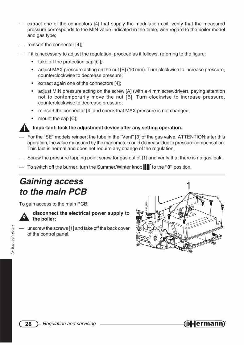
Gaining accessto the main PCBTo gain access to the main PCB:
disconnect the electrical power supply tothe boiler;
— unscrew the screws [1] and take off the back coverof the control panel.

29Regulation and servicing
for t
he te
chni
cian
ELECTRONIC settingsThe “MICRA 2” models are equipped with a digital PCB that can automatically manage ignition,slow opening, modulation and output in the heating function.
Disconnect the power supply before approaching the jumpers. Restore the powersupply only after you have closed the back cover of the control panel.
Any intervention on jumpers, if made when theelectrical supply is present, don’t have effect orhave unpredictable effets, and eventuallydamage the PCB.
It is possible to modify the following parameters:
Re-ignition delay - jumper CM1Normal delay (factory set) – leave the jumper
on TIMER 3’: in the heating function, whenthe set temperature is reached, the burnerwill switch off and could re-ignite, in case ofa new heating request, only after a delay of3 minutes.
Zero delay – move the jumper to TIMER O: inthe heating function, when the set tempera-ture is reached, the burner will switch off andcould re-ignite immediately in case of a newheating request (e.g. for systems with fan coilunits).
Type of gas - jumper CM2
Attention: gas type changing requires otherregulations and operations on the burner (see“Changing gas type” section) and it is not limitedto jumper moving.
Natural gas (G20) – jumper on METButhane (G30) or Propane (G31) – jumper on GPLFactory set depends from the type of gas for which the gas boiler is arranged.
Pump operation – jumper to be cut JPF1Normal operation (factory set) – do not cut the jumper
Excluded operation – cut the jumper. During the heating function, the pump is not activated.Use this function with external pumps only. The pump will be activated in all othercircumstances, e.g. for post-circulation (if present) or for anti-freezing or anti-lockoutfunctions.

30 Regulation and servicing
for t
he te
chni
cian
Changing Gas typeATTENTION: the operations described below must be carried out only by qualifiedpersonnel [authorized from HERMANN Ltd].
For gas conversion, use the nozzles supplied by boiler manufacturer only.
Using LPG, it is absolutely necessary to install a pressure reducer upstream the boiler.
1. Disconnect the boiler from the electrical supply.
2. gain access to the main PCB and move the jumper CM2 to the suitable gas position:
MET for Natural gas (G20),GPL for Buthane (G30) or Propane (G31)
3. Check that pressure and gas input are enough to guarantee the correct functioning of theappliance.
4. On “SE” models, open sealed combustion chamber.
5. Remove pipe between gas valve and injectors bar.
6. Remove injectors bar and replace the nozzles with theones suitable for the available gas type, using a 7 mm.spanner (see figure “BURNER”). Reassemble injectorsbar and pipe, replacing gaskets. Check, with burner ON,that there are no gas leaks. On “SE” models, close sealedcombustion chamber;
LEDOM selzzoNytitnauq
ØselzzonsaGlarutaNmm001/1
Øselzzon.G.P.Lmm001/1
E322ARCIM 31 021 57ES422ARCIM 31 021 57
7. Check, with burner ON, that there are no gas leaks and that the pressure upstream the boileris:
Natural gas: min.17 – max. 25 mbar
Buthane: min. 25 – max 35 mbar
Propane: min. 25 – max 37 mbar
8. Repeat the gas valve MAX-MIN pressure regulation, carefully following the instructions describedin the previous pages.
9. Check that there are no gas leaks.
10. apply the sticker indicating the type of gas (supplied with the kit) on the suitable area on “WARN-ING” label inside the boiler.
BURNER
31Regulation and servicing
for t
he te
chni
cian
Combustion checkThe boiler has the “chimney-sweeper” function, forcing burner ignition at the maximum output notmodulated. This function allows more reliable measurements of those obtained when the gas boileris activated through the room thermostat or hot water demands.
— Prepare the instruments for combustion checking;
— activate the “chimney-sweeper” function, following this simple procedure, studied to avoidaccidental activations of the user;
• supply the boiler and turn the Summer/Winter knob to Summer position ;
• provide that room thermostat contact is closed (activated) or open an hot water tap (theheat produced by the boiler will be drained consequently);
• turn the Hot Water knob to the position chimney-sweeper and wait (about 5 seconds)that green lamp flashes with short lightnings. When this occurs, turn the Hot Waterknob on the scale from I to IIIII. The burner ignites at the maximum output not modulated;
— make checkings and measurements;
— switch off the burner, by turning the Summer/Winter knob to the “0” position. The greenlamp flashes with long lightnings.
Remark: the burner will switch off automatically when reaching the maximum temperature, and inany case after 15 minutes.
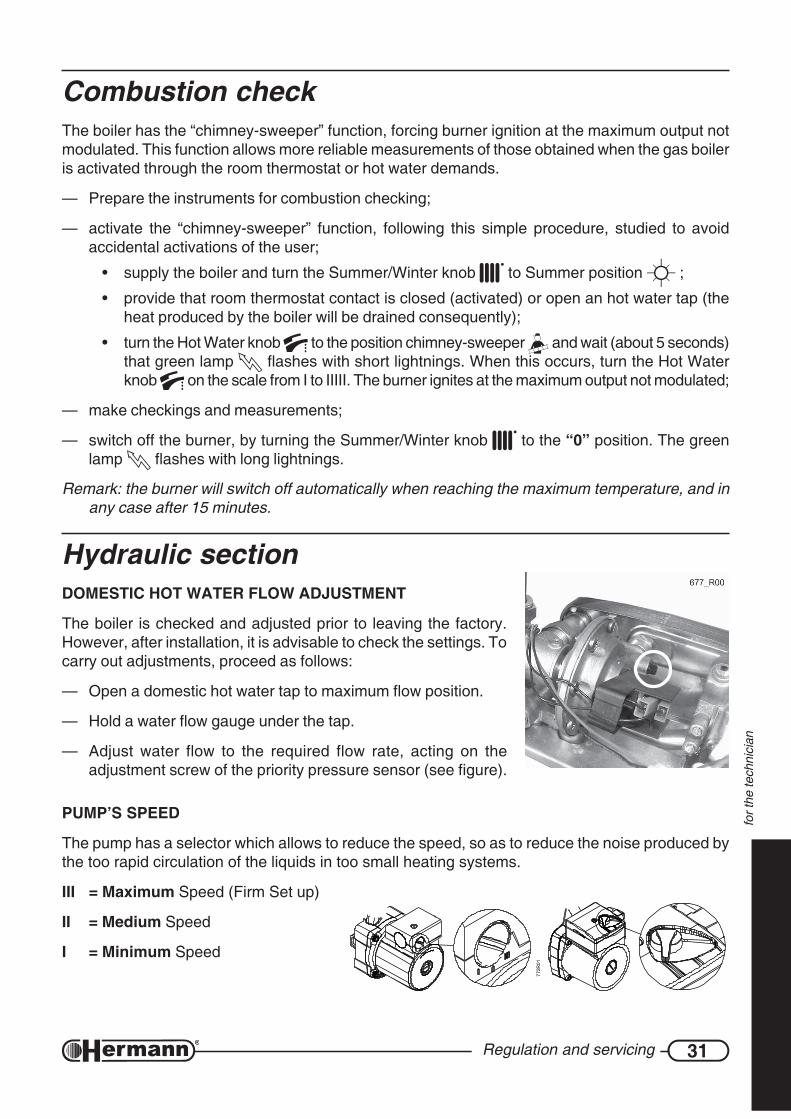
Hydraulic sectionDOMESTIC HOT WATER FLOW ADJUSTMENT
The boiler is checked and adjusted prior to leaving the factory.However, after installation, it is advisable to check the settings. Tocarry out adjustments, proceed as follows:
— Open a domestic hot water tap to maximum flow position.
— Hold a water flow gauge under the tap.
— Adjust water flow to the required flow rate, acting on theadjustment screw of the priority pressure sensor (see figure).
PUMP’S SPEED
The pump has a selector which allows to reduce the speed, so as to reduce the noise produced bythe too rapid circulation of the liquids in too small heating systems.
III = Maximum Speed (Firm Set up)
II = Medium Speed
I = Minimum Speed
772R
01

32 Regulation and servicing
for t
he te
chni
cian
Warnings for servicingAll servicing operations and gas conversions MUST BE CARRIED OUT BY QUALIFIEDTECHNICIANS, in accordance with the Law n°46 dtd. 05 March 1990 and with the rulesUNI-CIG 7129/01 and 7131/99 and revisions. Moreover, in accordance with art.11 section4 D.P.R. 412/93 and revisions, SERVICING operations must be carried out, at leastonce a year, by [HERMANN?] AUTHORIZED SERVICING CENTRES, and must be writtenin the appliance booklet, as indicated by the laws UNI and CEI presently in force.
At the end of each heating period, it is necessary to call a qualified technician to check the boiler, inorder to keep the system perfectly efficient.
A careful servicing is always a guarantee of safety and saving.
Normally, it will be necessary to execute the following operations:
— Remove any possible oxidization from burners and electrodes;
— Scale exchangers;
— Check integrity and stability of the ceramic fibre coverings in the combustion chamber andproceed eventually to substitution;
— Check boiler ignition, switching off and operation;
— Check water and gas connections tightness;
— Check gas consumption at the minimum and maximum output;
— Verify that safety devices are correctly working;
— Verify correct functioning of control and adjusting devices;
— Verify periodically good working and efficiency of the combustion product evacuation ductsand/or devices;
— In case of works or servicing of the structures placed near above mentioned ducts and /ordevices and their accessories, switch off the boiler;
— Do not leave any inflammable tanks and/or substances in the installation room;
— Do not clean the room where boiler is installed, while it is working.
— Clean casing with soapy water only. Do not clean casing, other painted or plastic surfaces withthinner.
— In any case of parts replacement, it is mandatory to use HERMANN original spare parts.
HERMANN declines any responsibility in case of non-original spare parts utilization.
Once all servicing operations have been carried out, it is mandatory to write a report for theuser, that should indicate state of the appliance, servicing interventions and eventual advicesand prescriptions.
33Regulation and servicing
for t
he te
chni
cian
Notes
34 Regulation and servicing
for t
he te
chni
cian
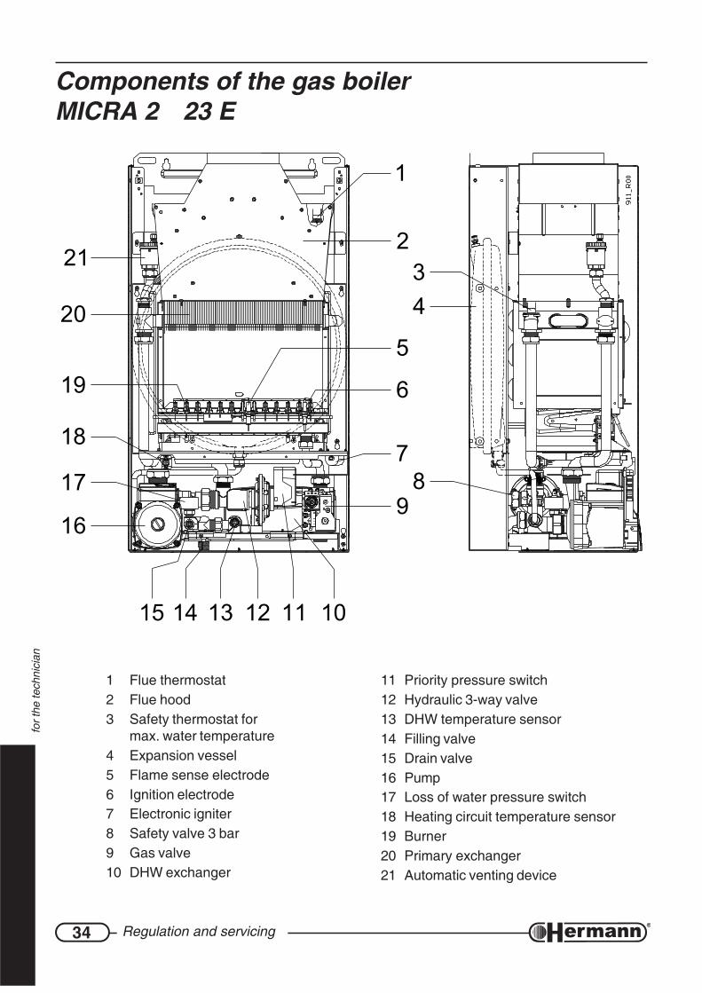
Components of the gas boilerMICRA 2 23 E
1 Flue thermostat2 Flue hood3 Safety thermostat for
max. water temperature4 Expansion vessel5 Flame sense electrode6 Ignition electrode7 Electronic igniter8 Safety valve 3 bar9 Gas valve10 DHW exchanger
11 Priority pressure switch12 Hydraulic 3-way valve13 DHW temperature sensor14 Filling valve15 Drain valve16 Pump17 Loss of water pressure switch18 Heating circuit temperature sensor19 Burner20 Primary exchanger21 Automatic venting device
18
16
21
19
20
1314 12 11
89
3
7
6
4
1
2
5
1015
17
35Regulation and servicing
for t
he te
chni
cian
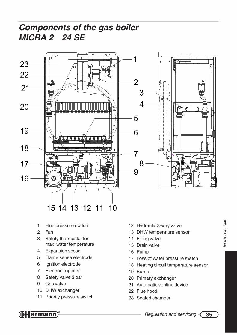
1 Flue pressure switch2 Fan3 Safety thermostat for
max. water temperature4 Expansion vessel5 Flame sense electrode6 Ignition electrode7 Electronic igniter8 Safety valve 3 bar9 Gas valve10 DHW exchanger11 Priority pressure switch
12 Hydraulic 3-way valve13 DHW temperature sensor14 Filling valve15 Drain valve16 Pump17 Loss of water pressure switch18 Heating circuit temperature sensor19 Burner20 Primary exchanger21 Automatic venting device22 Flue hood23 Sealed chamber
Components of the gas boilerMICRA 2 24 SE
5
10
16
15 111214 13
18
17
19
78
9
6
20
21 34
2
1
2223
36 Regulation and servicing
for t
he te
chni
cian
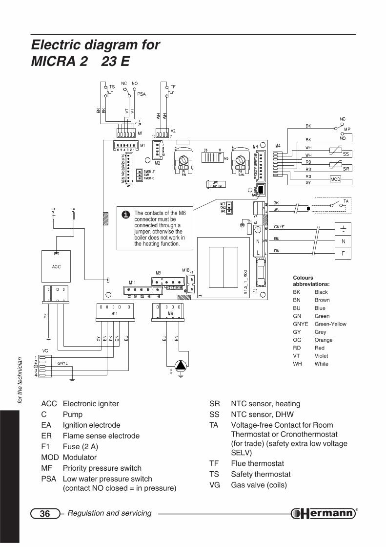
ACC Electronic igniterC PumpEA Ignition electrodeER Flame sense electrodeF1 Fuse (2 A)MOD ModulatorMF Priority pressure switchPSA Low water pressure switch
(contact NO closed = in pressure)
SR NTC sensor, heatingSS NTC sensor, DHWTA Voltage-free Contact for Room
Thermostat or Cronothermostat(for trade) (safety extra low voltageSELV)
TF Flue thermostatTS Safety thermostatVG Gas valve (coils)
Electric diagram forMICRA 2 23 E
The contacts of the M6connector must beconnected through ajumper, otherwise theboiler does not work inthe heating function.
Coloursabbreviations:BK BlackBN BrownBU BlueGN GreenGNYE Green-YellowGY GreyOG OrangeRD RedVT VioletWH White
37Regulation and servicing
for t
he te
chni
cian
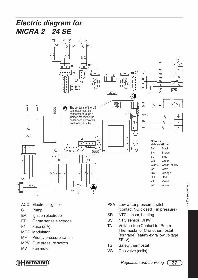
ACC Electronic igniterC PumpEA Ignition electrodeER Flame sense electrodeF1 Fuse (2 A)MOD ModulatorMF Priority pressure switchMPV Flue pressure switchMV Fan motor
PSA Low water pressure switch(contact NO closed = in pressure)
SR NTC sensor, heatingSS NTC sensor, DHWTA Voltage-free Contact for Room
Thermostat or Cronothermostat(for trade) (safety extra low voltageSELV)
TS Safety thermostatVG Gas valve (coils)
Electric diagram forMICRA 2 24 SE
The contacts of the M6connector must beconnected through ajumper, otherwise theboiler does not work inthe heating function.
Coloursabbreviations:BK BlackBN BrownBU BlueGN GreenGNYE Green-YellowGY GreyOG OrangeRD RedVT VioletWH White
38 User instructions
for t
he u
ser
USER INSTRUCTIONS
Warnings for first starting upThe first starting up must be done by a professionally qualified staff (for example theSERVICE CENTERS authorized by HERMANN).
Gas conversion from a specific gas (natural gas or LPG) to another gas, can be made also whenthe gas boiler is already installed, but only by a qualified technician. The technician will check that:
a) the label technical data of the gas boiler correspond to those of the gas, water and electricalsupply lines;
b) the main burner regulation is compatible with the gas boiler output;
c) the chimney works correctly, expelling the combustion products;
d) the air supply and the combustion products evacuation work correctly, in accordance with therequirements in force;
e) the conditions for a correct ventilation are guaranteed, also when the gas boiler is locatedinside a furniture.
Useful advicesWARNING for “E” models: The boiler is fitted with a safety thermostat for chimneydraught, operating in case of combustion products return in the installation room.This device must be always in function, because a combustion products return cancause chronic or acute intoxications with danger of death. If the thermostat must bereplaced, use the original spare part only. In case of repeated interventions of thedevice, check that the Flue Products Outlet System is efficient and made accordingto the laws in force (see examples in paragraph “Chimney connections”).
WARNING for “SE” models: The boiler is fitted with a safety flue pressure switch. Thisdevice must be always in function. In case of repeated interventions, call a qualifiedtechnician. If the pressure switch must be replaced, use the original spare part only.In case of repeated interventions of the device, check that the Air Flue Products Inlet/Outlet System is efficient and made according to the laws in force (see examples inparagraph “Chimney connections” and “Flue systems”).
INSTALLATION AND SERVICING
All installation, servicing and gas conversion operations MUST BE CARRIED OUT BY QUALIFIEDTECHNICIANS authorized by Law n. 46 dtd March 5th, 1990 and in accordance with UNI-CIG7129/01 and 7131/99 requirements and revisions.
Moreover, in accordance with art.11 section 4 of DPR 412/93 and revisions, boiler MAINTENANCEoperations must be made at least once a year and following manufacturer’s specifications and UNIand CEI rules in force.

39User instructions
for t
he u
ser
APPLIANCE BOOKLET OR CENTRAL PLANT BOOKLET
All appliances, even those installed before August 1st, 1994, must have an appliance booklet (foroutputs less or equal 35 kW) or a central plant booklet (for outputs more than 35 kW). All ordinaryand special servicing operations and combustion checkings must be written on the booklet, togetherwith the name of the person responsible for servicing.
COMBUSTION CHECKING
Combustion checking is made with a control of the boiler efficiency; this checking must be carriedout only by a person with the requirements of the Law 46/90. Boilers that, after the checking, willhave efficiency rates lower than the ones required and not changeable with suitable adjustments,must be replaced.
BOILER OPERATION AND SERVICING
The user (owner or tenant of the flat where the boiler is installed) or the administrator of the blockof flats (in case of a central heating system) are responsible for the appliance operation and servicing;they can both transfer the responsibility of the servicing and eventually of the operation to anotherperson, which must have the requirements indicated by the Law 46/90. Even if the user or theadministrator decide to assume personally this responsibility, ordinary servicing of the warm airheater and combustion checkings must be carried out by a qualified technician.
WarningsIn case of gas smell:
a) do not press electrical switches, use the telephone or other objects that can provokesparks;
b) open immediately the windows and the doors in order to cleanse the room air;c) close the gas supply taps;d) call a qualified technician.
Do not obstruct the ventilation openings of the gas boiler room, in order to avoidpossible dangerous situations as the creation of poisonous or explosive mixtures.
When the boiler is off for a long period see the Paragraph “Inactivity of the Boiler” forthe necessary precautions about the electrical supply, the gas supply and the protectionagainst freezing.

40 User instructions
for t
he u
ser
Controls and indicators1 Termometer (°C)
• It indicates the temperature of the water sent to the heating system. This temperature isinfluenced by the knob position [6].
2 Pressure gauge (bar)• It indicates the pressure of the water in the heating system. For a correct functioning, the
system pressure, COLD-measured, must be between 0,5 and 1,5 bar (optimal value:1÷1,5 bar).
• A correct pressure is important for the system good operation.
• In case of inferior pressures, reset the correct pressure (see “System Pressure” section).If the pressure should decrease under 0,5 bar, the boiler will stop working.
3 Lamp (electric supply)OFF: the boiler is without electric supply. The main supply switch (outside the boiler) could be
switched off or there could be a lack of mains voltage. It is not possible to execute anyfunction of the boiler, included the anti-freezing and anti-lockout functions.
ON: the boiler is working, ready to ignite the burner to supply heating and/or hot water.
NORMAL FLASHING: STAND-BY: the boiler is supplied but the Summer/Winter knob [6] isin position “0”. The boiler does not execute the main functions, but the anti-freezing andanti-lockout functions only (for details see “Boiler Inactivity”).
FLASHING WITH SHORT LIGHTNINGS: It has been activated accidentally the chimney-sweeper function (that is for the technician use only).
Exclude the Chimney-sweeper function, turning the Hot Water knob [7] between “I” and “IIIII”and momentarily move the knob [6] to 0 - , then move it [6] again to its previousposition.
4 Lamp (burner)OFF: the burner is switched off (there is no flame).
ON: the burner is switched on (the flame is present).
5 Lamp (lockout)OFF: the functioning is regular.
ON or FLASHING: the boiler is locked for a problem or a malfunctioning. See “Alarms” section.
895_R00
1
3
4
5
2
6 7
41User instructions
for t
he u
ser
6 “Summer/Winter” knob0 - (STAND-BY)
• When the knob is in this position, the boiler does not execute the main functions, butthe anti-freezing and anti-lockout functions only (for details see “Boiler Inactivity”).
• Use also this position to unlock the boiler after a problem or a malfunctioning. See“Alarms” section for details.
In case of a long period of absence of the user and/or boiler inactivity, see the “BoilerInactivity” section for the necessary precautions concerning electric supply, gas supplyand anti-freezing function.
SUMMER – In this position the boiler heats the water for the taps only. When opening anhot water tap, the burner ignites and, after a brief time (1), the hot water flows from the tap.(1) the time depends also from the features of the external system
WINTER – In this position the boiler heats the water for the taps, as in Summer mode. Moreover, it provides heating for the rooms.
The scale from I to IIIII, starting from the symbol determines the heating systemtemperature .
• If you make a continuous use of the heating system, regulate the knob to obtain thedesired room temperature;
• If you make a discontinuous use of the heating system, the temperature will be setthrough a room thermostat (or preferably through a chrono-thermostat). In this case,we suggest to regulate the knob in order to reach soon the set temperature value,avoiding the overheating of the rooms.
In both cases the optimal regulation must be found considering the climatic zone, the yearperiod and the heat insulation of the flat.
We remind you that rooms temperature must be regulated through a room thermostatwith two temperature levels. This is required with the DPR 26 August 1993 n° 412and further modifications.
7 “Hot Water” knob - The scale from I to IIIII, indicated with this symbol, determines the temperature of thehot water produced by the boiler.
· Consider that, due to heat losses all over the tubes, it is necessary a certain timebefore the temperature becomes stable at the tap exit, therefore the best evaluationis during a shower or a bath.
· With this type of boiler, it is suggested to regulate the knob to obtain a comfortabletemperature with a drawing of hot water only or a mix with a small quantity of coldwater. Avoid maximum values if not strictly necessary, because they would oblige tomix the water with a big quantity of cold water.
ATTENTION: the positions and are for the use of technicians only. Do not move theknob to these positions, because there could be a malfunctioning. If this will occur accidentally,move immediately the knob on the scale from I to IIIII.
42 User instructions
for t
he u
ser
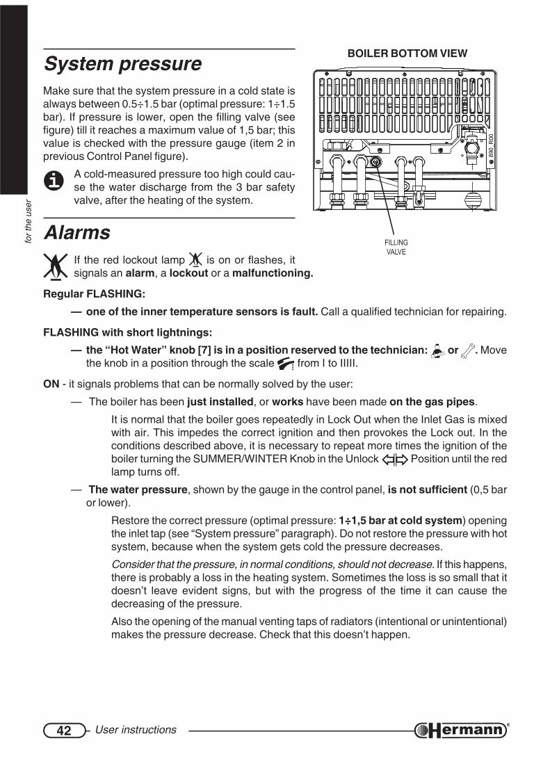
System pressureMake sure that the system pressure in a cold state isalways between 0.5÷1.5 bar (optimal pressure: 1÷1.5bar). If pressure is lower, open the filling valve (seefigure) till it reaches a maximum value of 1,5 bar; thisvalue is checked with the pressure gauge (item 2 inprevious Control Panel figure).
A cold-measured pressure too high could cau-se the water discharge from the 3 bar safetyvalve, after the heating of the system.
AlarmsIf the red lockout lamp is on or flashes, itsignals an alarm, a lockout or a malfunctioning.
Regular FLASHING:— one of the inner temperature sensors is fault. Call a qualified technician for repairing.
FLASHING with short lightnings:— the “Hot Water” knob [7] is in a position reserved to the technician: or . Move
the knob in a position through the scale from I to IIIII.
ON - it signals problems that can be normally solved by the user:
— The boiler has been just installed, or works have been made on the gas pipes.
It is normal that the boiler goes repeatedly in Lock Out when the Inlet Gas is mixedwith air. This impedes the correct ignition and then provokes the Lock out. In theconditions described above, it is necessary to repeat more times the ignition of theboiler turning the SUMMER/WINTER Knob in the Unlock Position until the redlamp turns off.
— The water pressure, shown by the gauge in the control panel, is not sufficient (0,5 baror lower).
Restore the correct pressure (optimal pressure: 1÷1,5 bar at cold system) openingthe inlet tap (see “System pressure” paragraph). Do not restore the pressure with hotsystem, because when the system gets cold the pressure decreases.
Consider that the pressure, in normal conditions, should not decrease. If this happens,there is probably a loss in the heating system. Sometimes the loss is so small that itdoesn’t leave evident signs, but with the progress of the time it can cause thedecreasing of the pressure.
Also the opening of the manual venting taps of radiators (intentional or unintentional)makes the pressure decrease. Check that this doesn’t happen.
890_
R00
BOILER BOTTOM VIEW
FILLINGVALVE
43User instructions
for t
he u
ser
— the boiler has an overheating and the Safety Thermostat has triggered;Turn the SUMMER/WINTER Knob in the Unlock Position until the red lampturns off (or eventually for a longer period to make the boiler cool), then bring againthe knob in the desired position (Summer or Winter ). If necessary, wait andtry again for few times. If the lockout persists or reappears, call the Servicing Centre.
— the burner hasn’t regularly switched on or the flame has suddenly turned off;incorrect combustion.Restore the service turning the SUMMER/WINTER knob in the Unlock Positionuntil the red lamp turns off. In case of frequent Locks:
• Call a technician to check the combustion and verify that the burner is clean and ingood conditions;
Moreover, for “SE” models with Sealed Combustion Chamber:• Check that the Inlet/Outlet Ducts and the respective terminals are clean and in good
condition, and that there are no leaks. During the Installation Process it is necessaryto respect the prescriptions included in the national and local regulations and laws, inaddition to the slopes and measurement included in the paragraphs “Chimneyconnections” and “Flue systems”.
Note for the TECHNICIAN: The burner flame is not detected by the control electronics because it has notturned on or it has suddenly turned off, or it has detached from the burner, because of an incorrectcombustion. This can be due, in example, to combustion product reflowing into inlet duct, leaks in inlet/outlet ducts or errors in sizing of ducts (ducts length above or below the allowed, and/or wrong use ofrestrictor on boiler’s outlet).
— the device which signals the wrong Flue Outlet has intervened;Exceptionally the cause can be a strong wind gust. Turn the SUMMER/WINTER knob inthe Unlock Position until the red lamp turns off, then move the knob to the desiredposition (Summer or Winter ). If necessary, wait and try again for few times. Incase of frequents lockouts:
• Call a technician to check the efficiency of chimney and Inlet/Outlet ducts.
• Call a technician to check the efficiency of the control device of fumes flow.
Moreover, for E models (natural draught):• Check that the outlet which communicates with the outdoor, compulsory according
to the law, is not obstructed by pieces of furniture against the wall or by other objects.It is however normal that the outlet is realized behind a radiator. The outlet must be ofthe dimension prescribed by the law and must be cleaned inside: some types havean anti-insects net which could have been dirtied by dust or by spider’s webs. Call aQualified Technician when it is necessary.
• If in the room where the boiler is installed there are mantelpieces, stoves, coal stovesor similar, fans for the Air Outlet, such as wall fans, aspiring cowls for cooking boardswith outlet pipe, let the technician check that the inlet is correctly OVERSIZED or thatthere are the ADDITIONAL Inlets as prescribed by the laws in force, because,otherwise, these devices interfere with the evacuation of the Boiler’s Flue.

44 User instructions
for t
he u
ser
Both RED and YELLOW lamps ON:— unexpected flame. This means that the control electronic has detected the flame on the
burner when this one should be off:
• the flame is effectively on, due to a gas valve malfuncion;
• otherwise the problem may be located on the control electronic, that detects theflame although it is off.
Restore the service turning the SUMMER/WINTER knob in the Unlock Positionuntil the red lamp turns off, or wait for the automatic reset (within 5 minutes). In case offrequent Locks, call the Service Centre.
45User instructions
for t
he u
ser
Boiler inactivityThe effects of the periods of inactivity can be relevant in particular situations such as in flats usedonly for some months per year, most of all in cold places.
The user will have to decide to put the boiler in the SAFETY LOCK OUT state disconnecting allthe supplies, or to leave it in stand-by and use the Anti Freezing Function. In general it is betterto use the SAFETY LOCK OUT. When there is the possibility of freezing it is convenient to chosebetween the advantages and the disadvantages of the SAFETY LOCK OUT and of the Stand By/Anti Freezing Way.
SAFETY LOCK OUT
— Turn off the general switch on the Electrical Supply Line of the Boiler;
— Close the Gas Tap;
When it is expected that the temperature is going to decrease under 0°C and the systemdoesn’t include the Anti Freezing Function, empty the heating system totally, or fill it with anAnti Freezing Solution.
Notice that if it had been necessary to restore the pressure (because of possible loss) in anheating system already filled with an Anti freezing solution, the concentration of the systemcould have decreased and it could not guarantee the Anti freezing Protection.
REMARK: the boiler is equipped with a system which protects the main components from theexceptional cases of LOCK OUT, due to the inactivity in presence of water and scale. The AntiLock out System can’t work during the Safety Lock Out Process, because of the lack of electricalsupply.
Before boiler re-ignition, call a technician to check if the burner is locked due to boiler inactivity(for the technician: unscrew the plug in the middle of the cap to gain access to the rotor shaftand turn it using a screwdriver or another suitable tool).
STAND-BY AND ANTI FREEZING/ANTI LOCK OUT FUNCTION
The boiler is equipped with an Anti freezing System which provides the ignition of the boiler wheneverthe temperature of the water in the heating circuit inside the boiler decreases under 5°C and whichprovides the turning off when the temperature reaches 30°C. In order to activate the Anti FreezingFunction:
• electrical power supply MUST be ON;
• boiler must be left in stand-by mode (Summer/Winter knob on 0, green lamp flashing);
• the gas must be left open;
• system pressure must be correct (1÷1.5 bar in a cold state, minimum 0.5 bar)
In case of lack of gas, the burner won’t turn on and the boiler will go in LOCK OUT state (red lampon or flashing). Nevertheless the pump will work, making the water circulate in the system andreducing in this way the possibility of freezing. It is available, on demand, an Anti freezing Electricalresistance kit which must be installed on the secondary exchanger to protect the boileralso in case of lack of gas.
46 User instructions
for t
he u
ser
Moreover, the boiler in stand-by activates periodically the main internal components to prevent theexceptional cases of Lock out due to the inactivity in presence of water and scale. This happensalso if the boiler goes in Lock Out state (red lamp on or flashing) provided that the pressure in theheating system is correct.
Note: if you want to use the “room anti-freeze” function that is often available in common roomthermostats or chronothermostats, it is necessary to leave the boiler in Winter mode andNOT in stand-by.
Incidental not functioningTHE BURNER DOESN’T TURN ON
— If the room thermostat is installed, check that this is regulated with an higher temperature inrespect of that of the place where it is installed;
— check that there is electrical supply and that the Summer/Winter Knob isn’t on 0 (stand-by) buton SUMMER or WINTER . The GREEN lamp must be constantly ON (see details inthe paragraph “Controls and Indicators”);
— if the Lock Out red lamp is on or flashing, see the paragraph “Alarms”;
— check on the gauge that the boiler pressure is correct (1÷1.5 bar in a cold state) or at least notlower than 0.5 bar;
— consult the notes of the “Electrical Diagram” Section.
SHORTAGE OF DOMESTIC HOT WATER PRODUCTION
— check that knob is not set on a too low value or to the position;
— call a qualified technician to check gas valve regulation;
— call a qualified technician to check, and eventually clean, d.h.w. exchanger.
Remark: where the water hardness value is too high, it is suggested the installation of asoftening device, in order to prevent the limestone precipitation; this operation avoids a frequentcleaning of the coil.
Do not try to repair the gas boiler by yourself.
For any intervention on the electrical, hydraulic or gas circuit exclusively call a qualifiedtechnician.
The gas boilers must be fitted with original accessories only.
HERMANN Ltd. is not responsible for damages caused by the incorrect, wrong orunreasonable use of non-original materials.

47User instructions
for t
he u
ser
User warnings— Check frequently water pressure on the hydrometer and verify that, when the system is cold,
water pressure values are in line with the manufacturer instructions.
— If water pressure is frequently dropping down, call a qualified technician to repair possibleleakages in the system.
— If the boiler is off for a very long period, see the Paragraph “Inactivity of the Boiler” for thenecessary precautions about the electrical supply, the gas supply and the protection againstfreezing.
Do not touch the heated surfaces of the boiler, as the doors, the flue, the chimneypipe, etc., also after the boiler operation because, for a certain time, these surfacesare oveheated. Any contact with them can cause dangerous scalds. It is then forbiddento let children or inexperienced people be close to the boiler, during its operation.
— Do not expose the wall hung gas boiler to water vapours directly coming from gas cookers/hobs.
— Do not wet the gas boiler with water or other liquids sprinklings.
— Do not put any object on the gas boiler.
— The gas boiler utilization is forbidden to children and to inexperienced people.
— If the gas boiler is going to be definitively unused, call a qualified technician to carry out allrequired operations, checking in particular disconnection of gas, water and electrical supplies.
— Only on “E” models (natural draught): the installation of aspirators, fireplaces or similarappliances in the boiler room (and in adjacent rooms in case of indirect ventilation), must bemade in compliance with all specific safety rules and laws (for example by augmenting thedimensions of ventilation openings), even in case of modifications or additions.
INSTRUCTIONS MANUAL
Make sure that the present manual is ALWAYS with the boiler, for any consultation of the user andservicing personnel.
HERMANN CONVENTIONAL GUARANTEE CONDITIONS
Hermann offers to the customer a particular and exclusive CONVENTIONAL GUARANTEE, whichis automatically activated asking the First Ignition to a Hermann Authorized Service Center. Theconditions of the HERMANN CONVENTIONAL GUARANTEE don’t prejudge nor invalidate therights indicated by the European Rule 1999/44/CE actuated with Italian Laws by the Decree 02Februar 2002 N°24 of which the User is the Owner.

05/20
05
COD.
982
.1600
89 / R
EV. 0
01(U
KENG
)
Her
man
n Lt
d. d
eclin
es a
ny re
spon
sibi
lity
for e
vent
ual p
rintin
g an
d/or
tran
scrip
tion
erro
rs in
the
pres
ent m
anua
l.In
ord
er to
con
stan
tly im
prov
e its
pro
duct
s, H
erm
ann
Ltd.
has
the
right
to c
hang
e fe
atur
es a
nd d
ata
writ
ten
in th
e pr
esen
t man
ual,
at a
ny ti
me
and
with
out
notic
e; th
eref
ore,
this
man
ual c
anno
t be
cons
ider
ed a
s a
cont
ract
tow
ards
third
par
ties.
HERMANN S.r.l. Via Salvo d’Acquisto29010 Pontenure (PIACENZA) ITALY - Tel. +39.0523.510341
E-MAIL: [email protected]
www.hermann.it
GAS BOILERS