Embed Size (px)
Citation preview
FCLHD 900 TC
HOOD
HOTTE DE CUSINE
CAMPANA DE COCINA
IT ISTRUZIONI PER L’INSTALLAZIONE E L’USO
EN INSTRUCTIONS FOR INSTALLATION AND USE
FR INSTRUCTIONS POUR L’INSTALLATION ET L’UTILISATION
DE INSTALLATION UND GEBRAUCH
ES INSTRUCCIONES PARA LA INSTALACIÓN Y USO
CAPPA DA CUCINA
KÜCHENHAUBE

2
1
3
2
3 4
5 6
7
4
8
12
10
11
9
5
13

INDICE
Avvertenze
Versioni d’uso
Installazione
Funzionamento
Manutenzione
IT
6
L’aria non deve essere sca-ricata in una canna fumaria utilizzata per scaricare i fumi dagli apparecchi che bruciano gas o altri combustibili (non applicabile agli apparecchi che scaricano l’aria nella stan-za);
Questo apparecchio e è pro-babile che le sue parti acces-sibili diventa molto caldo se usato in combinazione con di-spositivi di cottura.
In caso di installazione con piano cottura a gas la parte inferiore della cappa deve tro-varsi ad una distanza minima di 40 cm dal piano.
Per evacuare l’uscita dell’aria, si prega di rispettare le dispo-sizioni pertinenti e le regole impartite dalle autorità com-petenti.
Quando si eseguono i col-legamenti elettrici sull’ap-parecchio, assicurarsi che l’alimentazione sia dotata di collegamento a terra e che i va-lori di tensione corrispondano a quelli indicati sull’etichetta posta all’interno dell’apparec-chio stesso.
AVVERTENZE
L’apparecchio può essere uti-lizzato da bambini di età non inferiore a 8 anni e da persone con ridotte capacità fisiche, sensoriali o mentali, o prive di esperienza o della necessaria conoscenza, purché sotto sor-veglianza oppure dopo che le stesse abbiano ricevuto istru-zioni relative all’uso sicuro dell’apparecchio e alla com-prensione dei pericoli ad esso inerenti.
I bambini non devono giocare l’apparecchio.
La pulizia e la manutenzione dell’utente non devono essere eseguite da bambini senza su-pervisione.
Se il cavo di alimentazione è danneggiato, deve essere so-stituito dal produttore, dal suo agente di servizio o persone analogamente qualificate per evitare pericoli.
Sussiste il rischio di incendio se la pulizia non viene esegui-ta secondo le istruzioni;
Non cucinare cibi alla fiamma sotto la cappa.
7
Se il cavo di alimentazione è danneggiato, deve essere so-stituito dal produttore, dal suo agente di servizio o persone qualificate allo stesso modo per evitare un pericolo.
Prima di eseguire qualsiasi operazione di manutenzione o manutenzione, è necessario rimuovere l’apparecchio dalla rete elettrica. Se l’apparecchio non è dotato di cavo e spina flessibili non separabili o di un altro dispositivo che garanti-sca disconnessioni dalla rete, con una distanza di apertura tra i contatti di almeno 3 mm, tali dispositivi di disconnes-sione devono essere forniti all’interno dell’installazione fissa.
Se l’apparecchio fisso è dota-to di un cavo di alimentazione a spina, l’apparecchio deve essere collocato in un luogo in cui la spina può essere rag-giunto facilmente.
Prima di eseguire l’installazio-ne dell’apparecchio, verifica-re che tutti i componenti non siano danneggiato. In tal caso, mettersi in contatto con il pro-prio rivenditore e non proce-dere con installazione.
Se Il prodotto dovesse mostra-re qualsiasi anomalia, scolle-gare l’apparecchiatura dalla rete elettrica.
Quando la cappa e gli appa-recchi alimentati con energia diversa dall’elettricità sono contemporaneamente in fun-zione, la pressione negativa nella stanza non deve supera-re i 4 Pa (4 x 10⁵ bar).
8
VERSIONI D’USO
L’apparecchio è già predisposto sia per la versio-ne filtrante sia per la versione aspirante.
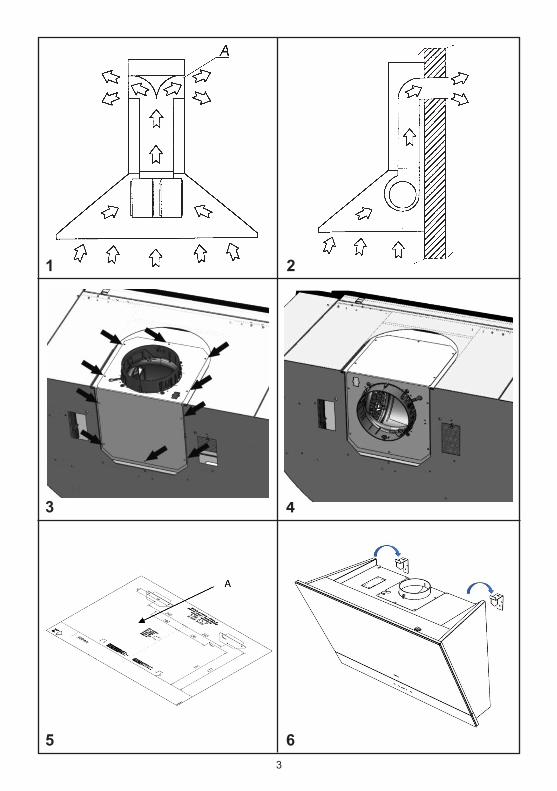
* Nella versione filtrante (dis.1) l’aria ed i vapori convogliati dall’apparecchio, vengono depurati sia da un filtro antigrasso sia da un filtro al car-bone attivo e rimessi in circolazione nell’ambien-te attraverso le griglie laterali del camino. Nella versione filtrante si consiglia l’uso di un deviatore aria (dis.1A), che posto nella parte superiore del tubo permetta il riciclo dell’aria nell’ambiente.
* Nella versione aspirante (dis. 2) i vapori ven-gono convogliati direttamente all’esterno dell’abi-tazione tramite l’uscita aria superiore o poste-riore. L’utilizzo sia del filtro al carbone sia del deviatore aria non è necessario.
Verificare che tutti i componenti non siano dan-neggiati, in caso contrario contattare il rivenditore e non proseguire con l’install zione.Prima di installare il prodotto leggere attentamen-te tutte le istruzioni di seguito riportate:- Utilizzare un tubo evacuazione aria che abbia la lunghezza minima possibile, limitato numero di curve, materiale approvato normativamente.- Evitare cambiamenti drastici di sezione (diame-tro costante consigliato Ø 150 mm o pari super-ficie).- Per il mancato rispetto delle precedenti istruzio-ni la ditta fornitrice non risponderà per problemi di portata o di rumorosità e nessuna garanzia sarà prestata.
Tutti i prodotti sono stati progettati con la possi-bilità di orientare l’uscita aria nel lato posteriore del prodotto; nel caso si intenda utilizzare questa funzione occorre rimuovere le n° 10 viti del sup-porto gruppo aspirazione (dis. 3 ), quindi estrarre il gruppo aspirazione e ruotarlo in modo da orien-tare il boccaglio uscita aria verso il lato posteriore del prodotto (dis. 4), successivamente ricollocare il gruppo aspirazione nella propria sede e ripristi-nare le viti rimosse in precedenza.
9
INSTALLAZIONE
Utilizzando l’apposita maschera di foratura (dis. 5A), effettuare i fori per l’installazione della staffa a muro; I prodotti devono essere posizionato a 400mm dal piano cottura.
Fissare le staffe a muro alla parete utilizzando i tasselli e le viti in dotazione.
Agganciare il corpo aspirante (dis. 6) alle staffe a muro precedentemente fissate.
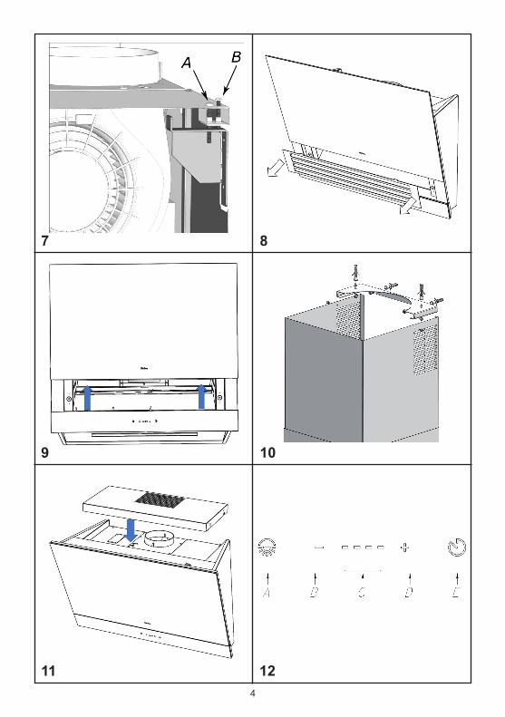
Installare le quattro viti di fissaggio in corrispon-denza dei fori posti nella parte superiore del pro-dotto (fig. 7). Avvitare la vite anteriore in modo da assicurare il prodotto alla parete, successiva-mente verificare che la cappa sia perfettamente in piano, in caso contrario agire sulle viti poste-riori avvitando quella di destra per alzare il lato destro della cappa, oppure avvitando quella di sinistra per alzare il lato sinistro della cappa.
Effettuare il collegamento elettrico.
Azionare la salita del pannello in vetro come indicato al capitolo funzionamento; a completa apertura del pannello, che avviene impostando la velocità di aspirazione IV, estrarre la griglia come da (fig. 8), rimuovere i filtri antigrasso e utilizzan-do le viti interne (dis. 9 ) assicurarsi che la cappa sia bloccata alla parete.Ripristinare il filtro antigrasso, la griglie e richiu-dere il pannello frontale impostando la funzione OFF come indicato nel capitolo funzionamento.
Versione aspirante (uscita superiore)Mediante i tasselli e le viti in dotazione fissare alla parete e/o al soffitto la staffa supporto tubo (dis. 10), in posizione centrale rispetto la cappa.Collegare la flangia uscita aria del motore al foro di evacuazione tramite un tubo adatto.Effettuare il collegamento elettrico. Posizionare i due tubi decorativi sopra al corpo aspirante; sollevare il tubo interno affinché arrivi al soffitto; quindi fissarlo alla staffa supporto tubo utilizzan-do n° 2 viti autofilettanti in dotazione.
10
Versione aspirante (uscita posteriore)Installare la griglia uscita aria in corrispondenza della relativa sede sopra la cappa (fig. 10). I tubi decorativi in acciaio non sono necessari.
Versione filtranteInstallare la griglia uscita aria in corrispondenza della relativa sede sopra la cappa (fig. 11). I tubi decorativi in acciaio non sono necessari.Nella versione filtrante è necessario installare an-che il filtro carbone.Dopo aver rimosso il filtro antigrasso, come in-dicato nel capitolo installazione a seconda del modello, installare i filtri antigrasso nell’apposita sede posta immediatamente dietro la sede del filtro antigrasso.
FUNZIONAMENTO
(dis. 12)A : ON/OFF luciB : riduzione velocità / OFF motoreC : indicatori velocitàD : ON motore/aumento velocitàE : temporizzatore 10 min.
La pulsantiera Touch control su vetro permette di impostare la funzione desiderata sfiorando il relativo simbolo. Se il prodotto rimane privo di alimentazione elettrica, al momento del ripristino delle funzioni richiede 15 secondi per l’autodia-gnosi, nel frattempo potrebbe non funzionare correttamente.
Il modello FCLHD oltre alle caratteristiche di fun-zionamento descritte nel punto precedente di-spone di un automatismo relativo all’apertura e chiusura del pannello in vetro.In funzione della velocità impostata del motore di aspirazione corrisponde una determinata apertu-ra del pannello in vetro.La chiusura del pannello avviene automatica-mente dopo aver spento il motore di aspirazione.
Un dispositivo di sicurezza inverte il senso di marcia del pannello in caso di urto con superfici estranee durante la normale corsa.
Tutti i prodotti sono dotati di un dispositivo elet-tronico che permette lo spegnimento automatico dopo quattro ore di funzionamento dall’ultima operazione eseguita.
11
TEMPORIZZAZIONICon l’entrata in vigore dal 1° Gennaio 2015 dei nuovi regolamenti della Commissione Europea EU65 “Energy label” e EU66 “ Ecodesign”, ab-biamo reso conforme i prodotti in base ai requisiti richiesti.Tutti i modelli nelle versioni energy label dispon-gono di una elettronica, con funzioni ditemporizzazione delle velocità di aspirazione, su-periore a 650m³/h.In effetti i modelli con motore a bordo, con porta-ta massima superiore a 650m³/h, prevedono la IVa velocità temporizzata dopo 5 minuti di funzio-namento, Trascorsi i tempi di cui sopra il motore di aspirazione passa alla IIIa velocità in maniera automatica.I prodotti in versione external motor, vengono ab-binati soltanto con motori remoti dove,come per la versione con motore a bordo, vengo-no temporizzate le velocità con portate superiori a 650m³/h. (Vedi istruzioni riportate nei motori remoti). 11
I motori remoti, che hanno una portata superio-re a 650m³/h sia alla IVa che alla IIIa velocità, vengono automaticamente temporizzate come segue: dalla IVa velocità, dopo 6 minuti di funzio-namento passa automaticamente alla II velocità.Se il prodotto viene impostato alla IIIa velocità, passa automaticamente alla II velocità dopo 7 minuti. Resta comunque possibile modificare le velocità in uso.Il prodotto in modalità stand-by ha un consumo inferiore a 0.5W.
Un’accurata manutenzione garantisce un buon funzionamento ed un buon rendimento nel tem-po.
Una cura particolare va rivolta al filtro antigrasso, la rimozione del filtro avviene come segue
Aprire il pannello frontale in vetro selezionando la velocità di aspirazione massima, rimuovere la griglia in acciaio tirandola verso l’estero (dis. 8) quindi intervenire sull’apposita maniglia del filtro e ruotarlo verso l’esterno.
Dopo 30 ore di esercizio della cappa verrà se-gnalata la saturazione del filtro mediante l’illumi-nazione simultanea degli indicatori di velocità; per il reset selezionare la funzione temporizzato-re a cappa spenta.
La pulizia del filtro antigrasso può essere esegui-ta a mano o in lavastoviglie.La pulizia avviene in rapporto all’uso, almeno una volta ogni due mesi.
* Nel caso d’uso dell’apparecchio in versione fil-trante, è necessario sostituire il filtro carbone atti-vo periodicamente.Il filtro carbone attivo si rimuove togliendo prima il filtro antigrasso, seguendo le istruzioni sopra descritte, successivamente tirando l’apposita lin-guetta in plastica del filtro carbone sganciando-lo dalla sua sede. Il filtro carbone viene inserito nell’operazione inversa.
Per la pulizia dell’apparecchio stesso viene con-sigliato l’uso di acqua tiepida e detersivo neutro, evitando l’uso di prodotti contenenti abrasivi.
La sostituzione del cavo alimentazione deve essere eseguita esclusivamente da personale autorizzato.
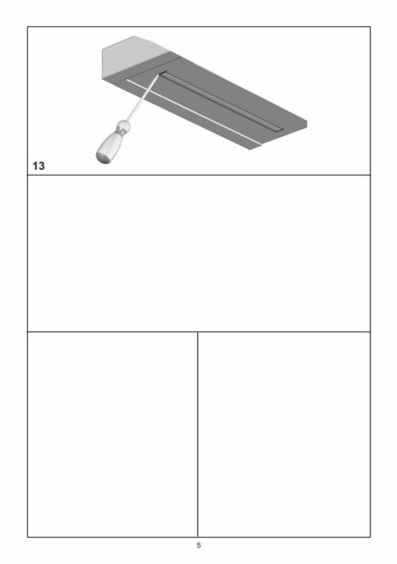
Sostituzione della barra LED:Utilizzando un utensile appropriato, rimuovere la barra led dalla sua sede (vedi figura 13) scolle-garla elettronicamente mediante l’apposito con-nettore quindi sostituirla con una di pari caratte-ristiche.
MANUTENZIONE
CONTENTS
Warnings
Uses
Installation
Working
Maintenance
EN
12
This appliance and its accessi-ble parts are likely to becomevery hot if used in combina-tion with cooking devices.
In case of installation with gas hobs the cooker surface and the inferior part of the cooker hood must be at a minimun di! stance of 40 cm.
To evacuate the air outlet, ple-ase comply with the pertainingrules given by competent au-thorities.
When performing the electrical connections on the appliance,please make sure that the po-wer supply is provided with earth connection and that vol-tage values correspond to tho-se indicated on the label pla-ced inside the appliance itself.
If the supply cord is damaged, it must be replaced by the ma-nufacturer, its service agent or similarly qualified persons in order to avoid a hazard.
WARNINGS
this appliance can be used by children aged from 8 years andabove and persons with redu-ced physical, sensory or men-tal capabilities or lack of expe-rience and knowledge if they have been given supervision or instruction concerning use of the appliance in a safe way and understand the hazards in-volved.
Children shall not play with the appliance.
Cleaning and user maintenan-ce shall not be made by chil-dren without supervision.
If the supply cord is damaged, it must be replaced by the ma-nufacturer, its service agent or similarly qualified persons in order to avoid a hazard.
There is a fire risk if cleaning is not carried out in accordancewith the instructions;
Do not flambé under the range hood.
The air must not be dischar-ged into a flue that is used for exhausting fumes from ap-pliances burning gas or other fuels (not applicable to applian-ces that only discharge the air back into the room);
13
Before carrying out any cle-aning or maintaining opera-tions, the appliance needs to be removed from the electric grid.If the appliance is not provided with a non-separable flexible cable and plug, or with ano-ther device ensuring discon-nections from the grid, with an opening distance between the contacts of at least 3 mm, then such disconnecting devices must be supplied within the fi-xed installation.
If the appliance is equipped with a power cable plug, the appliance must be placed in a place in which the plug can be easily reached.
Before carrying out the instal-lation of the appliance, pleasecheck that all components are not damaged. In such a case, make contact with your retai-ler and do not proceed with the installation.
Should the product show any anomaly, disconnect the ap-pliance from the power supply.
When the range hood and ap-pliances supplied with energyother than electricity are si-multaneously in operation, thenegative pressure in the room must not exceed 4 Pa (4 x 10⁻⁵bar).
14
USES
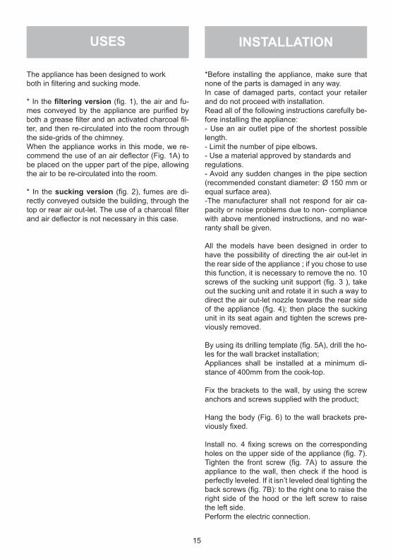
The appliance has been designed to workboth in filtering and sucking mode.
* In the filtering version (fig. 1), the air and fu-mes conveyed by the appliance are purified by both a grease filter and an activated charcoal fil-ter, and then re-circulated into the room through the side-grids of the chimney.When the appliance works in this mode, we re-commend the use of an air deflector (Fig. 1A) to be placed on the upper part of the pipe, allowing the air to be re-circulated into the room.
* In the sucking version (fig. 2), fumes are di-rectly conveyed outside the building, through the top or rear air out-let. The use of a charcoal filter and air deflector is not necessary in this case.
15
INSTALLATION
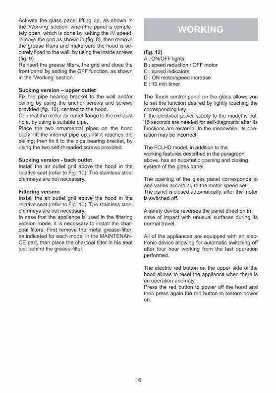
*Before installing the appliance, make sure that none of the parts is damaged in any way.In case of damaged parts, contact your retailer and do not proceed with installation.Read all of the following instructions carefully be-fore installing the appliance:- Use an air outlet pipe of the shortest possible length.- Limit the number of pipe elbows.- Use a material approved by standards andregulations.- Avoid any sudden changes in the pipe section (recommended constant diameter: Ø 150 mm or equal surface area).-The manufacturer shall not respond for air ca-pacity or noise problems due to non- compliance with above mentioned instructions, and no war-ranty shall be given.
All the models have been designed in order to have the possibility of directing the air out-let in the rear side of the appliance ; if you chose to use this function, it is necessary to remove the no. 10 screws of the sucking unit support (fig. 3 ), take out the sucking unit and rotate it in such a way to direct the air out-let nozzle towards the rear side of the appliance (fig. 4); then place the sucking unit in its seat again and tighten the screws pre-viously removed.
By using its drilling template (fig. 5A), drill the ho-les for the wall bracket installation;Appliances shall be installed at a minimum di-stance of 400mm from the cook-top.
Fix the brackets to the wall, by using the screw anchors and screws supplied with the product;
Hang the body (Fig. 6) to the wall brackets pre-viously fixed.
Install no. 4 fixing screws on the corresponding holes on the upper side of the appliance (fig. 7). Tighten the front screw (fig. 7A) to assure the appliance to the wall, then check if the hood is perfectly leveled. If it isn’t leveled deal tighting the back screws (fig. 7B): to the right one to raise the right side of the hood or the left screw to raise the left side.Perform the electric connection.
16
Activate the glass panel lifting up, as shown in the ‘Working’ section; when the panel is comple-tely open, which is done by setting the IV speed, remove the grid as shown in (fig. 8), then remove the grease filters and make sure the hood is se-curely fixed to the wall, by using the inside screws (fig. 9).Reinsert the grease filters, the grid and close the front panel by setting the OFF function, as shown in the ‘Working’ section.
Sucking version – upper outletFix the pipe bearing bracket to the wall and/or ceiling by using the anchor screws and screws provided (fig. 10), centred to the hood.Connect the motor air-outlet flange to the exhaust hole, by using a suitable pipe.Place the two ornamental pipes on the hood body; lift the internal pipe up until it reaches the ceiling; then fix it to the pipe bearing bracket, by using the two self-threaded screws provided.
Sucking version - back outletInstall the air outlet grill above the hood in the relative seat (refer to Fig. 10). The stainless steel chimneys are not necessary.
Filtering versionInstall the air outlet grill above the hood in the relative seat (refer to Fig. 10). The stainless steel chimneys are not necessary.In case that the appliance is used in the filtering version mode, it is necessary to install the char-coal filters. First remove the metal grease-filter, as indicated for each model in the MAINTENAN-CE part, then place the charcoal filter in his seat just behind the grease-filter.
WORKING
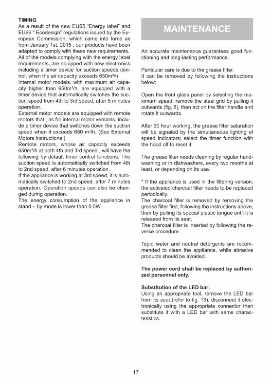
(fig. 12)A : ON/OFF lightsB : speed reduction / OFF motorC : speed indicatorsD : ON motor/speed increaseE : 10 min timer.
The Touch control panel on the glass allows you to set the function desired by lightly touching the corresponding key.If the electrical power supply to the model is cut, 15 seconds are needed for self-diagnostic after its functions are restored. In the meanwhile, its ope-ration may be incorrect.
The FCLHD model, in addition to theworking features described in the paragraphabove, has an automatic opening and closingsystem of the glass panel.
The opening of the glass panel corresponds to and varies according to the motor speed set.The panel is closed automatically, after the motor is switched off.
A safety device reverses the panel direction incase of impact with unusual surfaces during its normal travel.
All of the appliances are equipped with an elec-tronic device allowing for automatic switching off after four hour working from the last operation performed.
The electric red button on the upper side of the hood allows to reset the appliance when there is an operation anomaly.Press the red button to power off the hood and then press again the red button to restore power on.
TIMINGAs a result of the new EU65 “Energy label” and EU66 “ Ecodesign” regulations issued by the Eu-ropean Commission, which came into force as from January 1st, 2015 , our products have been adapted to comply with these new requirements.All of the models complying with the energy label requirements, are equipped with new electronics including a timer device for suction speeds con-trol, when the air capacity exceeds 650m³/h.Internal motor models, with maximum air capa-city higher than 650m³/h, are equipped with a timer device that automatically switches the suc-tion speed from 4th to 3rd speed, after 5 minutes operation.External motor models are equipped with remote motors that , as for internal motor versions, inclu-de a timer device that switches down the suction speed when it exceeds 650 mᵌ/h. (See External Motors Instructions ). Remote motors, whose air capacity exceeds 650m³/h at both 4th and 3rd speed , will have the following by default timer control functions: The suction speed is automatically switched from 4th to 2nd speed, after 6 minutes operation.If the appliance is working at 3rd speed, it is auto-matically switched to 2nd speed, after 7 minutes operation. Operation speeds can also be chan-ged during operation.The energy consumption of the appliance in stand – by mode is lower than 0.5W.
17
An accurate maintenance guarantees good fun-ctioning and long-lasting performance.
Particular care is due to the grease filter.It can be removed by following the instructions below:
Open the front glass panel by selecting the ma-ximum speed, remove the steel grid by pulling it outwards (fig. 8), then act on the filter handle and rotate it outwards.
After 30 hour working, the grease filter saturation will be signaled by the simultaneous lighting of speed indicators; select the timer function with the hood off to reset it.
The grease filter needs cleaning by regular hand-washing or in dishwashers, every two months at least, or depending on its use.
* If the appliance is used in the filtering version, the activated charcoal filter needs to be replaced periodically.The charcoal filter is removed by removing the grease filter first, following the instructions above, then by pulling its special plastic tongue until it is released from its seat.The charcoal filter is inserted by following the re-verse procedure.
Tepid water and neutral detergents are recom-mended to clean the appliance, while abrasive products should be avoided.
The power cord shall be replaced by authori-zed personnel only.
Substitution of the LED bar:Using an appropriate tool, remove the LED bar from its seat (refer to fig. 13), disconnect it elec-tronically using the appropriate connector then substitute it with a LED bar with same charac-teristics.
MAINTENANCE
INDEX
Conseils et suggestions
Version de l’appareil
Installation
Fonctionnement
Maintenance
FR
18
* Lors du raccordement électri-que assurezvous que la prise de courant soit munie de mise à la terre; vérifiez aussi que les va-leurs de tension correspondent à celles qui sont indiquées sur la plaque des caractéristiques de l’appareil, qui se trouve à l’in-térieur de celui-ci.
Avant de procéder à une opéra-tion d’entretien ou de nettoyage quelconque, il faut débrancher l’appareil.
Si votre appareil n’a pas pas de câble flexible qui ne peut pas être séparé, ni de prise ou bien d’autre dispositif qui garantisse le débranchement de tous les pôles du réseau,avec une distan-ce d’ouverture entre les contacts d’au moins 3mm., ces dispositif de séparation du réseau doivent alors être prévus dans l’installa-tion fixe.Si l’appareil fixé est pourvu du câ-ble de l’alimentation et une fiche, l’appareille doit être placé de ma-nière que la fiche soit facilement accessible.
* Evitez d’utiliser des matériaux qui causent des flambées à pro-ximité de l’appareil. Dans le cas de fritures, faites tout particulière-ment attention au danger d’incen-die que représentent les huiles et les corps gras.A cause de son inflammabilité l’huile usagée est particulièrement dangereuse.
CONSEILS ETSUGGESTIONS
Les enfants, les personnes dépendantes ou handicapée ne peuvent utiliser l’appareil que si elles sont sous la sur-veillance d’adultes.
* La distance entre la surface de la table de cuisson et la base de la hotte doit être de 400 mm au moins.
* L’air aspiré ne doit pas être cana-lisé dans un conduit qui est utilisé pour évacuer les fumées produ-ites par des appareils alimentés par des sources d’énergie autres que l’énergie électrique (installa-tions de chauffage central, radia-teurs, chauffe-eau, etc.).
* Pour évacuer l’air qui doit être éliminé respectez les prescrip-tions des autorités compétentes.
* Prévoyez une aération de la pièce adéquate quand une hot-te et des appareils alimentés par une énergie autre que l’énergie électrique (poêle à gaz, à charbon, etc.) sont utilisés en même temps. En effet, en évacuant l’air, la hotte pourrait créer une dépression dans la pièce. La pression négative de la pièce ne doit pas dépasser 0,04 mbar, évitant ainsi que la source de chaleurs provoque un appel des gaz qui doivent être évaqués. Il est donc nécessaire d’équiper la pièce de prises d’air alimentant un flux d’air frais constant.
19
VERSIONS DE L’APPAREIL
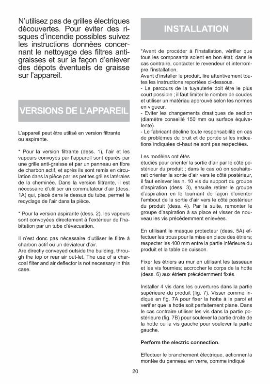
L’appareil peut être utilisé en version filtranteou aspirante.
* Pour la version filtrante (dess. 1), l’air et les vapeurs convoyés par l’appareil sont épurés par une grille anti-graisse et par un panneau en fibre de charbon actif, et après ils sont remis en circu-lation dans la pièce par les petites grilles latérales de la cheminée. Dans la version filtrante, il est nécessaire d’utiliser un commutateur d’air (dess. 1A) qui, placé dans le dessus du tube, permet le recyclage de l’air dans la pièce.
* Pour la version aspirante (dess. 2), les vapeurs sont convoyées directement à l’extérieur de l’ha-bitation par un tube d’évacuation.
Il n’est donc pas nécessaire d’utiliser le filtre à charbon actif ou un déviateur d’air.Are directly conveyed outside the building, throu-gh the top or rear air out-let. The use of a char-coal filter and air deflector is not necessary in this case.
N’utilisez pas de grilles électriques découvertes. Pour éviter des ri-sques d’incendie possibles suivez les instructions donnèes concer-nant le nettoyage des filtres anti-graisses et sur la façon d’enlever des dépots éventuels de graisse sur l’appareil.
20
INSTALLATION
*Avant de procéder à l’installation, vérifier que tous les composants soient en bon état; dans le cas contraire, contacter le revendeur et interrom-pre l’installation.Avant d’installer le produit, lire attentivement tou-tes les instructions reportées ci-dessous.- Le parcours de la tuyauterie doit être le plus court possible ; il faut limiter le nombre de coudes et utiliser un matériau approuvé selon les normes en vigueur.- Eviter les changements drastiques de section (diamètre conseillé 150 mm ou surface équiva-lente).- Le fabricant décline toute responsabilité en cas de problèmes de bruit et de portée si les indica-tions indiquées ci-haut ne sont pas respectées.
Les modèles ont étésétudiés pour orienter la sortie d’air par le côté po-stérieur du produit ; dans le cas où on souhaite-rait orienter la sortie d’air vers le côté postérieur, il faut enlever les n. 10 vis du support du groupe d’aspiration (dess. 3), ensuite retirer le groupe d’aspiration en le tournant de façon d’orienter l’embout de la sortie d’air vers le côté postérieur du produit (dess. 4). Par la suite, remonter le groupe d’aspiration à sa place et visser de nou-veau les vis précédemment enlevées.
En utilisant le masque protecteur (dess. 5A) ef-fectuer les trous pour la mise en place des étriers; respecter les 400 mm entre la partie inférieure du produit et la table de cuisson.
Fixer les étriers au mur en utilisant les tasseaux et les vis fournies; accrocher le corps de la hotte (dess. 6) aux étriers précédemment fixés.
Installer 4 vis dans les ouvertures dans la partie supérieure du produit (fig. 7). Visser comme in-diqué en fig. 7A pour fixer la hotte à la paroi et verifier que la hotte soit parfaitement plane. Dans le cas contraire utiliser les vis dans la partie po-stérieure (fig. 7B) pour soulever la partie droite de la hotte ou la vis gauche pour soulever la partie gauche.
Perform the electric connection.
Effectuer le branchement électrique, actionner la montée du panneau en verre, comme indiqué
21
au chapitre Fonctionnement ; le panneau s’ouvre complètement quand la vitesse d’aspiration est au maximum, vitesse IV.Retirer la grille, comme indiqué au dess. 10, et le filtre anti-graisse, puis serrer les vis qui se trou-vent à l’intérieure de la hotte (dess. 8) et s’assu-rer que la hotte soit bien fixée à la parois.
Remonter le filtre anti-graisse, la grille et refermer le panneau frontal en frappant la touche OFF, comme indiqué au chapitre Fonctionnement.Enlever les vis de fixation du plafonnier inférieur (dess. 20), tourner le plafonnier (dess. 21) et fixer bien le produit par les vis fournies, comme indi-qué au dess. 9.Remonter le plafonnier.
Sucking version – sortie dans la partie supérieure
Version aspirante.Fixer l’étrier support tube (dess. 10) sur la paroi/le plafond par les tasseaux et les vis fournies, en position centrale par rapport à la hotte.Raccorder le collet du tuyau sortie d’air du mo-teur avec le trou d’évacuation par un tube appro-prié. Effectuer la connexion électrique.Placer les tubes décoratifs sur le corps aspirant; soulever le tube intérieur jusqu’au plafond et le fixer à l’étrier support tube par les 2 vis autoper-ceuses fournies.Sucking version – sortie dans la partie arrière
Version aspirante.Fixer l’étrier support tube (dess. 10) sur la paroi/le plafond par les tasseaux et les vis fournies, en position centrale par rapport à la hotte.Raccorder le collet du tuyau sortie d’air du mo-teur avec le trou d’évacuation par un tube appro-prié. Effectuer la connexion électrique. Placer les tubes décoratifs sur le corps aspirant; soulever le tube intérieur jusqu’au plafond et le fixer à l’étrier support tube par les 2 vis autoperceuses fournies.Si utilisez la hotte en version filtrante merci d’uti-liser les filters charbons. Enlever les filters alumi-nium, comme montré dans la section MAINTE-NANCE , et installer les filters charbons derrière les filters aluminium.
FONCTIONNEMENT
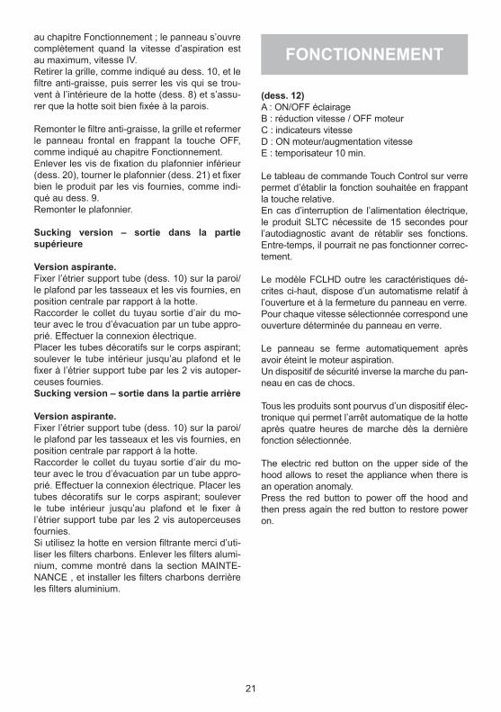
(dess. 12)A : ON/OFF éclairageB : réduction vitesse / OFF moteurC : indicateurs vitesseD : ON moteur/augmentation vitesseE : temporisateur 10 min.
Le tableau de commande Touch Control sur verre permet d’établir la fonction souhaitée en frappant la touche relative.En cas d’interruption de l’alimentation électrique, le produit SLTC nécessite de 15 secondes pour l’autodiagnostic avant de rétablir ses fonctions. Entre-temps, il pourrait ne pas fonctionner correc-tement.
Le modèle FCLHD outre les caractéristiques dé-crites ci-haut, dispose d’un automatisme relatif à l’ouverture et à la fermeture du panneau en verre.Pour chaque vitesse sélectionnée correspond une ouverture déterminée du panneau en verre.
Le panneau se ferme automatiquement après avoir éteint le moteur aspiration.Un dispositif de sécurité inverse la marche du pan-neau en cas de chocs.
Tous les produits sont pourvus d’un dispositif élec-tronique qui permet l’arrêt automatique de la hotte après quatre heures de marche dès la dernière fonction sélectionnée.
The electric red button on the upper side of the hood allows to reset the appliance when there is an operation anomaly.Press the red button to power off the hood and then press again the red button to restore power on.
22
TEMPORISATEURNos produits ont été adaptés pour se conformer aux nouvelles normes de l’Union Européenne en matière de l’EU65 « Étiquette-Énergie » et l’EU66 « Écoconception » (à partir du 1er janvier 2015).La nouvelle électronique des produits ayant l’ « Étiquette-Énergie » sont pourvus d’un dispositif de temporisation pour le contrôle de la vitesse d’aspi-ration si le débit d’air en évacuation dépasse les 650m³/h. En effet, les modèles avec moteur intégré ayant un débit d’air en évacuation supérieur à 650m³/h sont pourvus d’un dispositif qui réduit automati-quement la vitesse IV à la vitesse III après 5 mi-nutes de fonctionnement.Les modèles avec moteur extérieur (combiné seulement avec des moteurs à distance com-me pour les modèles avec moteur intégré) sont pourvus d’un dispositif qui réduit la vitesse si le débit d’air en évacuation dépasse les 650m³/h. (Voir section « Moteurs à distance »).Les moteurs extérieurs ayant un débit d’air en évacuation supérieur à 650m³/h à la vitesse IV et III sont temporisés comme suit :Automatiquement de la vitesse IV à la vitesse II après 6 minutes de fonctionnement.Si l’appareil est réglé à la vitesse III, il passe au-tomatiquement à la vitesse II après 7 minutes de fonctionnement. De toute façon il est possible de modifier la vitesse lors du fonctionnement.La consommation de appareil en mode veille est inférieure à 0.5 W.
An accurate maintenance guarantees good fun-ctioning and long-lasting performance.
Particular care is due to the grease filter.It can be removed by following the instructions below:
Open the front glass panel by selecting the ma-ximum speed, remove the steel grid by pulling it outwards (fig. 8), then act on the filter handle and rotate it outwards.
After 30 hour working, the grease filter saturation will be signaled by the simultaneous lighting of speed indicators; select the timer function with the hood off to reset it.
The grease filter needs cleaning by regular hand-washing or in dishwashers, every two months at least, or depending on its use.
* If the appliance is used in the filtering version, the activated charcoal filter needs to be replaced periodically.The charcoal filter is removed by removing the grease filter first, following the instructions above, then by pulling its special plastic tongue until it is released from its seat.The charcoal filter is inserted by following the re-verse procedure.
Tepid water and neutral detergents are recom-mended to clean the appliance, while abrasive products should be avoided.
The power cord shall be replaced by authori-zed personnel only.
Substitution of the LED bar :Using an appropriate tool, remove the LED bar from its seat (refer to fig. 13), disconnect it elec-tronically using the appropriate connector then substitute it with a LED bar with same charac-teristics.
MAINTENANCE
ÍNDICE
Advertencias
Versiones
Instalación
Funcionamiento
Manutención
ES
23
* En el conexionado eléctrico asegurarse que la toma de cor-riente esté provista de conexión a tierra y verificar que los valores de tensión se corresponden con los indicados en la etiqueta de características del aparado.
* Antes de proceder a cualquier operación de limpieza o man-tenimiento es necesario desco-nectar el aparato de la red. Si el aparato no está provisto de ca-ble flexible no removible y de co-nector, o de otro dispositivo queasegure la desconexión omnpo-lar de la red con una distancia de apertura de los contactos de al menos 3 mm. entonces este di-spositivo de separación de la red debe estar previsto en la instala-ción fija.
Si el aparato estáprovisto de ca-ble de alimentación y de conec-tor, el aparato debe sesituado de forma que la clavica resulte facil-mente aseguirle.
* Evitar el uso de materiales que causen llamarada cerca de la campana. En el caso de fritos prestar atención espe-cial al peligro de incendio que conlieven el aceite y la grasa. Particularmente peligroso por su inflamabilidad es el aceite ya usado. No utilizar parrillas eléctricas descubiertas. Para evitar un posible riesgo de in-cendio atenerse a las instru-ciones indicadas para la lim-pieza de los filtros antigrasa y la limpieza de eventules depó-sitos de grasa en el aparado.
ADVERTENCIAS
Los niños y las personas inca-pacitadas o minusválidas sólo deben utilizar el aparato bajo supervisión de un adulto.
* La distancia mínima entre el plano de cocción y la parte in-ferior de la campana debe ser de 400 mm.
* El aire y humos recogidos no pueden ser llevados a conduc-tos utilizados para la descarga de humos de aparatos alimen-tados con energia diferente de la eléctrica (calefacción, etc...).
* Para la descarga del aire a evacuar respetar las prescri-pciones de la autoridad com-petente.
* Preveer una adecuada airea-ción del local cuando se estén utilizando contempo-ráneamente una campana y aparatos alimen-tados con energía diferente de la eléctrica (estufas a gas, a acei-te, a carbón, etc...). La campana funcionando en versión aspiran-te podría crear una depresión en la sala. La presión negativa del local no debe superar los 0,04 mbar, evitando así la succión de los gases de descarga de la fuente de calor. Es, por lo tanto, necesario adecuar el local con to-mas de aire que provean un flujo costante de aire fresco.
24
VERSIONES
El aparato está ya dispuesto tanto para la ver-sión filtrante como para la versión con descarga al exterior.
* En la versión filtrante (dib. 1) el humo y los vapores encanalados por el aparato se depu-ran gracias a un filtro anti-grasa y a un filtro de carbón activo tras lo cual se vuelven a poner en circulación en el ambiente a través de las rejillas laterales de la chimenea. En la versión filtrante se aconseja el uso de un desviador de aire (dib. 1A) que se coloca en la parte superior del tubo y permite reciclar el aire en el ambiente.
* En la versión con descarga al exterior (dib. 2) los humos se encanalan directamente hacia el exterior del local, a través de una salida superior o posterior. El uso del filtro de carbón y del de-sviador de aire no son necesarios.
25
INSTALACIÓN
* Controlar que ningún componente esté dañado, en caso contrario contacte el revendedor y no siga con la instalación.Antes de iniciar la instalación leer con atención todas las instrucciones indicadas a continuación.- Usar un tubo de evacuación de humos lo más corto posible, limitando el número de curvas y de material aprobado según las normas.-Evitar los cambios drásticos de sección (diáme-tro constante aconsejado Ø 150 mm o de igual superficie).- Si no se respetan las instrucciones preceden-tes, la empresa proveedora no responderá por problemas de caudal o nivel de ruido y no pre-stará ninguna garantía.
Los modelos se han proyectado con la posibili-dad de orientar la salida de humos hacia la parte posterior del producto; si se opta por esta solu-ción hay que sacar los n°10 tornillos de soporte del grupo extractor (Dib. 3), luego sacar el grupo de extracción y darle la vuelta para colocar la boca de salida de humos hacia el lado posterior del producto (Dib. 4) y después, volver a colocar el grupo extractor en su posición y volver a colo-car los tornillos anteriormente sacados.
Usando la relativa máscara para perforar (dib. 5A) efectuar los orificios para la instalación de la brida en la pared. Los productos se deben colo-car a 400 mm de la encimera.
Fijar las bridas a la pared usando los tacos y los tornillos suministrados;
Enganchar el bloque de extracción (dib. 6) a las bridas de pared anteriormente fijadas.Enganchar la carcasa (Fig. 6) a la pared ya fijada.
Instalar 4 tornillos en los agujeros en la parte su-perior del producto (fig. 7). Apretar el tornillo fron-tal (fig. 7A) para fijar el product a la pared y com-probar que la unidad sea plana. Si no es plana apretar el tornillo atras (fig. 7B): el a la derecha para levanter la parte derecha o el a la izquierda para levanter la parte izquierda.Perform the electric connection.
Efectuar la conexión eléctrica, accionar la subida del panel de cristal como se indica en el capítulo Funcionamiento; cuando el panel esté completa-mente abierto, es decir seleccionando la veloci-
26
dad de extracción de humos IV, sacar la rejillacomo indicado en la (dib. 10), quitar los filtros anti-grasa y usando los tornillos internos (dib. 8) asegurarse de que la campana esté anclada a la pared.Volver a colocar el filtro anti-grasa, la rejilla y cer-rar el panel frontal seleccionando la función OFF como se indica en el capítulo Funcionamiento.Sacar los tornillos de fijación de la tapa inferior, girarla y fijar, todavía más, el producto a la pared mediante los tornillos suministrados como se ve en el (dib. 9).Volver a colocar la tapa the front panel by set-ting the OFF function, as shown in the ‘Working’ section.
Version aspirante – salida en la parte supe-rior.
Versión con descarga al exterior.Mediante los tacos y los tornillos suministrados fijar a la pared y/o al techo la brida de sostén del tubo (dib. 10), en posición central respecto a la campana.Conectar, con un tubo adecuado, la brida de sali-da de humos del motor con el orificio de evacua-ción. Efectuar la conexión eléctrica.Colocar los dos tubos decorativos encima del bloque de extracción; levantar el tubo interno para que llegue hasta el techo; luego fijarlo a la brida de soporte usando n°2 tornillos autorro-scantes suministrados.
Version aspirante – salida en la parte poste-rior.
Versión con descarga al exterior.Mediante los tacos y los tornillos suministrados fijar a la pared y/o al techo la brida de sostén del tubo (dib. 10), en posición central respecto a la campana.Conectar, con un tubo adecuado, la brida de sali-da de humos del motor con el orificio de evacua-ción. Efectuar la conexión eléctrica.Colocar los dos tubos decorativos encima del bloque de extracción; levantar el tubo interno para que llegue hasta el techo; luego fijarlo a la brida de soporte usando n°2 tornillos autorro-scantes suministrados.
Version filtrante.Install the air outlet grill above the hood in the relative seat (refer to Fig. 11). The stainless steel chimneys are not necessary.Cuando el product se utiliza en la version filtran-te, es necesario instalar el filtro de carbon. En principio sacar el filtro, como indicado en el capi-tulo MANUTENCION, y luego instalar el filtro de carbon atras del filtro anti-grasa.
FUNCIONAMIENTO
(dib. 12)A : ON/OFF lucesB : reducción velocidad / OFF motorC : indicadores velocidadD : ON motor/aumento velocidadE : temporizador 10 min.
El cuadro de mandos Touch control en el cristal permite seleccionar la función deseada rozando el relativo símbolo.Si el producto permanece sin alimentación elé-ctrica, cuando vuelve a conectarse, necesita 15 segundos para efectuar el autodiagnóstico y durante ese tiempo podría no funcionar correc-tamente.
El modelo FCLHD además de las características de funcionamiento descritas en el punto anterior, posee un dispositivo automático de apertura y cierre del panel de cristal.Según la velocidad seleccionada del motor, ten-drá una determinada apertura del panel de cri-stal.El cierre del panel es automático tras haber apa-gado el motor de extracción de humos.
Un dispositivo de seguridad invierte la dirección de marcha del panel si éste se topa con algo du-rante su recorrido.
Todos los productos están equipados con un dispositivo electrónico que apaga el aparato automáticamente tras cuatro horas de funciona-miento desde la última operación realizada.
El boton rojo en la parte superior de la campana consente de hacer el reset del product cuando hay una anomalia.Apretar el boton rojo para desconectar el produc-to y apretarlo otra vez para conectarlo.
27
TEMPORIZACIÓNA partir del 1° de enero 2015, con la entrada en vigor de la nueva normativa de la Comisión Eu-ropea EU65 “Energy label” y EU66 “ Ecodesign”, hemos adaptado los productos conforme a los requisitos establecidos.Todos los modelos con versión “Energy label” di-sponen de un equipo electrónico, con funciones de temporización de la velocidad de aspiración, superior a 650m³ / h.De hecho, todos los modelos con motores a bor-do, con caudal máximo a 650m³ / h, disponen de la IV° velocidad temporizada tras 5 minutos de funcionamiento. Transcurrido dicho tiempo el motor de aspiración pasa automáticamente a la III° velocidad. Los productos en versión con motor externo, se combinan exclusivamente con motores remotos donde, como también para la versión con motor a bordo, se temporizan las velocidades con caudales superiores a 650m³ / h. (Véanse las instrucciones mencionadas en losmotores remotos).Los motores remotos, que tienen un caudal su-perior a 650m³ / h , tanto en la IV° como en la III° velocidad, se temporizan automáticamente en el siguiente modo: A partir de la IV° velocidad , tras 6 minutos de funcionamiento pasa automática-mente a la segunda velocidad.Si el producto se configura en la III° velocidad, pasa automáticamente a la segunda velocidad tras 7 minutos. Se puede también cambiar la ve-locidad misma mientras se sta usando.El producto cuando está en modalidad “stand by” tiene un consumo inferior a 0.5W.
Una manutención cuidadosa es una garantía de buen funcionamiento y buen rendimiento de un aparato a lo largo del tiempo.Hay que prestar una especial atención al filtro anti-grasa, para sacarlo efectuar lo siguiente:
Abrir el panel frontal de cristal seleccionando la velocidad máxima de extracción de humos, sacar la rejilla de acero tirándola hacia afuera (dib.10) y agarrar el asa del filtro y girarla hacia afuera.
Para volver a colocar los filtros efectuar las ope-raciones inversas.
Tras 30 horas de funcionamiento los indicadores de velocidad se vuelven intermitentes todos a la vez para indicar la saturación de los filtros anti-grasa. Para desbloquear, seleccionar la función temporizador cuando la campana está apagada.
La limpieza de los filtros anti-grasa se puede rea-lizar manualmente o en el lavavajillas.La limpieza depende de cuanto se usa, pero de-berá hacerse al menos una vez cada dos meses.
Después de 30 horas de funcionamiento, todos los botones iniciaran un parpadeo simultánea-mente.
El filtro de carbón se quita quitando primero el filtro antigrasa (fig. 4A - 16B) y posteriormente tirando de la langueta de plástico del filtro de car-bón, desalojándolo de su sede. El filtro se intro-duce mediante la operativa inversa.
La sustitución del filtro de carbón se hará según el uso, pero como minimo una vez cada 6 meses Para la limpieza de la campana se aconseja el uso de agua templada y detergente neutro, evi-tando el uso de productos que contengan abra-sivos.
La sustitución del cable de alimentación debe ser realizada exclusivamente por personal autorizado.
Sustitución de la barra LED:Utilizando una herramienta adecuada, extraer la barra led de su alojamiento (véase figura 13), de-sconectarla electrónicamente mediante el corre-spondiente conector, y luego sustituirla con una con características equivalentes
MANUTENCIÓN

INHALTSVERZEICHNIS
Warnungen
Gebrauchsanweisungen
Installation
Working
Wartung
DE
28
wird und damit ein Rücksaugen der Feuerstättenabgase vermie-den wird.Daher sollte der Raum mit Lüf-tungsklappen, die eine konstante Lüftung ausüben, versehen sein.
* Vor dem Elektroanschluss ver-gewissern Sie sich, dass die Steckdose mit einer Erdung ver-sehen ist und überprüfen Sie, ob die Spannungswerte mit der der Etikette innerhalb des Geräts übereinstimmen.
Vor jeder Reinigungs- oder War-tungsarbeit muss das Gerät vom Stromnetz getrennt werden. Falls das Gerät nicht an eine immer gutzugängliche Steckdose angesch-lossen wird, ist in der Installation eine allpolige Trennvorrichtung vom Netz, mit einer Kontaktöf-fnungsweite von mindestens 3 mm pro Pol, vorzusehen.
Ist das Gerät mit einem Kabel und einem Stecker versehen, muss es so eingebaut werden, dass der Stecker leicht zugänglich ist.
* Materialen, die Stichflammen verursachen (flambiert) sollten nicht in unmittelbarer Nähe.
WARNUNGEN
Kinder, hilflose oder behinder-te Personen dürfen das Gerät nur unter Aufsicht von Erwach-senen betreiben.
* Der Mindestabstand zwischen de Kochplatte und der unteren Seite der Dunstabzugshaube muss 400 mm betragen.
* Die gesammelte Luft darf nicht in einem Rauchabluf-trohr geleitet werden, der für den Rauch anderer Geräte, die nicht mit elektrischer Energie versorgt werden, sorgt (Zen-tralheizungsanlagen, Heizkör-per, Boiler, usw.)
* Die Abdämpfe müssen die Vorschriftender zuständigen Behörden be-achten.
* Bei gleichzeitigem Betrieb einer Abluft-Dunstabzugshaube und einer raumluft- abhängigen Feu-erstätte (wie z.B. gas-, öl- oder kohlebetriebene Heizgeräte, Durchlauferhitzer, Warmwasser-bereiter) ist Vorsicht geboten, da beim Absaugen der Luft durch die Dunstabzugshaube dem Au-fstellraum die Luft entnommen wird, die die Feuerstätte zur Ver-brennung benötigt Ein gefahrlo-ser Betrieb ist möglich, wenn bei gleichzeitigem Betrieb von Haube und raumluft-abhängiger Feuerstätte im Aufstellraum der Feuerstätte ein Unterdruck von höchstens 0,04 mbar erreicht 29
30
GEBRAUCHSANWEISUNGEN
Das Gerät ist für den Umluft- als auch für den Abluftbetrieb ausgeführt.
* Im Umluftbetrieb (Abb. 1) wird die Luft zusät-zlich durch Fettfilter als auch durch Aktivkohlefilter geleitet und durch die seitlichen Lüftungsschlitze im Kaminoberteil in den Raum zurückgeführt. Für dieses Modell empfehlen wir einen Luftablei-ter (Abb. 1A), den man an der oberen Seite des Rohrs anschließt und der die gefilterte Luft wie-der ablässt.
* Im Abluftbetrieb (Abb. 2) wird der Kochdunst durch Abluftrohre direkt ins Freie geleitet – oberer oder unterer Abluftkanal.Der Einsatz eines Kohlefilters ist im Abluftbetrieb nicht erforderlich.
INSTALLATION
Vergewissern Sie sich, dass alle Bauteile nicht beschädigt sind, andernfalls den Verkäufer kon-taktieren und den Einbau abbrechen.Vor dem Einbau bitte die folgenden Anweisungen gut durchlesen:- Ein so kurz wie mögliches Abluftrohr mit be-schränkter Zahl von Rohrbogen verwenden und aus normgerechten Material.- Vermeiden Sie drastische Querschnittsveren-gungen (es empfiehlt sich ein konstanter Durch-messer von 150 mm bzw. gleichwertige Quersch-nittsfläche).- Bei Nichteinhaltung der Anweisungen haftet der Hersteller weder für schlechte Abzugsleistungen als auch für lautes Betriebsgeräusch und leistet keinerlei Garantie.
Die Modelle sind so entworfen worden, dass der Luftaustritt auf die hintere Seite des Geräts gerichtet werden kann. Soll sich der Luftau-stritt nach hinten richten, müssen zuerst die 10 Schrauben des Untersatzes des Absaugungsag-gregats entfernt werden (Abb. 3), dann den Ab-saugungsaggregat rausziehen und ihn so drehen bis die Luftaustrittdüse sich in die hintere Seite des Gerätes richtet (Abb. 4), danach das Sau-gaggregat wieder einsetzen und festschrauben.
Die Schutzmaske aufsetzen (Abb. 5A) und die Löcher für die Dübel in die Wand bohren. Der Mindestabstand zwischen dem Gerät und der Kochplatte muss 400 mm betragen Der Minde-stabstand zwischen die Geräte.
Die Mauerdübel mit den mitgelieferten Dübel und Schrauben befestigen; das Sauggerät (Abb. 6) an den im Voraus befestigten Mauerdübel hän-gen.
Den Elektroanschluss durchführen, den Aufstieg des Glaspaneels, wie in Kapitel „Funktionswei-se“ beschrieben ist, betätigen; nach kompletter Öffnung, wobei die Saugleistung IV eingestellt ist, das Gitter wie in Abb. 10 herausnehmen, die Fettfilter entfernen und kontrollieren, ob die Dun-stabzugshaube fest an der Mauer sitzt.Den Fettfilter und das Gitter wieder einsetzen und schließen, wobei die Funktion auf OFF eingestellt ist, wie im Kapitel „Funktionsweise“ beschrieben.
31
Die Befestigungsschrauben der unteren Deckplatte entfernen (Abb. 20), die Deckplatte drehen (Abb. 21) und das Gerät mit den mitgelie-ferten Schrauben an der Mauer weiterhin befesti-gen, wie in Abb. 9.Die Deckplatte wieder einsetzen Die 4 Schrau-ben auf die Höhle auf dem oberen Teil der Haube fixieren (Abb. 7). Die vordere Schraube zuschrau-ben, um die Haube auf dem Mauer festzustellen (Abb. 7). Danach passen Sie auf, dass die Haube flach sei. Wenn die Haube nicht flach ist, dann die hintere Schrauben anschrauben (Abb. 7B); indem die rechte Schraube anschrauben, um die rechte Seite der Haube aufzuheben; oder die Lin-ke anschrauben, um die linke Seite aufzuheben.Den Netzstrom verbinden.
Die Glassbende einschalten, wie erklärt am Punkt „Funktionsweise“: als der Paneel total geöffnet ist, durch dem 4.Die Grille entfernen. Danach, die Metallfiltern entfernen und sich entsichern, dass die Haube festgelegt an die Mauer ist (Fig.8), indem man die interne Schrauben nutzt (fig. 9).Die Fettfilter und die Grille wieder einstecken und den Glassfront wieder schließen, beim Drücken der taste OFF.Nach Erklärug an dem Punkt „Funktionsweise“.
Abluftbetrieb.Mit den mitgelieferten Dübel und Schrauben die Rohrschelle an der Wand und/oder Decke befe-stigen (Abb. 10); diese muss sich zentral gegenü-ber der Dunstabzugshaube befinden.Den Abluftflansch des Motors am Evakuierung-sloch mittels eines dazu geeigneten Rohrs verbin-den. Den Stromanschluss wieder herstellen. Die zwei Dekorrohre über den Saugkörper aufstellen; das innere Rohr bis zur Decke hochheben und an der Rohrschelle mit den 2 mitgelieferten.
Umluftbetrieb.Mit den mitgelieferten Schrauben die Umluftwei-che an der Rohrschelle befestigen. Mit den mit-gelieferten Dübel und Schrauben die Rohrschelle an der Wand und/oder Decke befestigen (Abb. 11); diese muss sich zentral gegenüber der Dun-stabzugshaube befinden.
Den Abluftflansch des Motors am Evakuierung-sloch mit einem dazu geeigneten Rohr verbin-den. Den Stromanschluss wieder herstellen. Die zwei Dekorrohre über den Saugkörper aufstellen; das innere Rohr bis zur Decke anheben und an der Rohrschelle mit den 2 mitgelieferten selbst-schneidenden Schrauben befestigen.
Wenn die Haube wird im Umluftbetrieb installiert, es ist notwendig die Kohlefitern zu installieren.Zunächst einmal, den Metalfilter entfernen, nach Beschreibung der Bedienungsanleitung, am Ka-pitel WARTUNG; danach, platzieren Sie den Ko-hlefilterhinten den Metallfilter.
WORKING
(dis. 12)A : ON/OFF BeleuchtungB : Reduzierung der Saugstärke / OFF MotorC : Anzeiger SaugstärkeD : ON Erhöhung SaugstärkeE : Nachlaufautomatik 10 Min.
Mithilfe des Bedienfelds Touch Control kann die gewünschte Funktion durch berühren der entsprechenden Taste eingestellt werden. Bei Unterbrechung der Stromzufuhr benötigt die Dunsthaube SLTC bei erneuter Inbetriebnahme 15 Sekunden für die Selbstdiagnose. In diesem kurzen Zeitabschnitt ist es möglich, dass die Dunsthaube nicht korrekt funkti niert.
Das Modell FCLHD verfügt nicht nur über die oben erwähnten Funktionen, sondern auch über eine Selbststeuerung, die automatisch das Glas-spaneel öffnet und schließt.Für jede eingestellte Leistungsstufe entspricht ei-ner bestimmten Öffnung des Glaspaneels.Nach Ausschaltung des Saugmotors schließt sich das Paneel automatisch.Eine Sicherung ändert die Laufrichtung des Pa-neels im Fall evt. Hindernisse.
Alle Geräte sind mit einer Elektronischen Vor-richtung ausgestattet, die das Gerät nach 4 Stunden Laufzeit nach der letzten Einstellung ausschaltet.
32
TIMERDie Produkte des Herstellers sind an die neuen Verordnungen der Europäischen Kommission (gültig ab 1. Januar 2015) EU65 “Energielabel” und EU66 “ Ökodesign” angepasst.
Die neue Elektronik schaltet die Geräte mit Ener-gielabel nach einer festgelegten Zeit automa-tisch auf einen Luftstrom von maximal 650 m³/h zurück.Dunstabzugshauben mit integriertem Motor und einem maximalen Luftstrom von mehr als 650 m³/h sind mit einem Timer ausgestattet, der die 4.-Leistungsstufe nach 5 Minuten Laufzeit auto-matisch auf die 3.-Leistungsstufe herabschaltet.Dunstabzugshauben mit externem Motor (nur mit Fernmotor ausgestattet, wie das Model mit inne-rem Motor), die mit einem maximalen Luftstrom von mehr als 650 m³/h betrieben werden sind mit einem Timer ausgestattet. (Siehe Gebrauchsan-leitung „Externer Motor”).Externe Motoren, die mit einem maximalen Luftstrom von mehr als 650 m³/h in der 4. und 3.Leistungsstufe betrieben werde, sind mit einem Timer wie folgt ausgestattet: Nach 6 Minuten Be-trieb schaltet sich die Saugleistung automatisch von der 4.- auf die 2.-Leistungsstufe zurück.Nach 7 Minuten Betrieb schaltet sich die Sau-gleistung automatisch von der 3.- auf die 2.-Lei-stungsstufe zurück. Sie können weiterhin die Lei-stungsstufen während des Betriebs regulieren.Das Gerät verbraucht im Stand-By-Betrieb weni-ger als 0,5 W.
Nur eine sorgfältige Pflege garantiert auf Dauer eine gute Leistung und Funktion des Geräts.Besonders wichtig ist die Reinigung des Fettfil-ters; die Entfernung des Fettfilters erfolgt in fol-gender Weise:
Das Glaspaneel öffnen und die Höchstgeschwin-digkeit einstellen; das Edelstahl-Gitter nach au-ßen ziehen (Abb. 10), dann am entsprechenden Griff den Filter nach außen drehen.
Nach 30 Betriebstunden zeigt die Dunstab-zugshaube die Filtersättigung durch das Blinken aller Led-Anzeige an. Für den Reset die Timerta-ste bei ausgeschaltetem Gerät betätigen.Wenn das Gerät wird als Umluft benutzt, muss die Kohlefilter regelmäßig ersetzt werden. Die Entfernung des Fettfilters erfolgt durch die vorhe-rige Entfernung des Fettfilters beim Aufpassen der Anweisungen. Danach, beim Drücken der Klappe, den Filter von der Stellung fortschaffen.Um den Kohlefilter wieder zu stellen, die um-gekehrte Prozedur folgen.Lauwarmes Wasser und neutrale Seife empfe-hlen, um die Haube zu putzen. Um Abrasivmitteln zu vermeiden.
Das Stromkabel darf nur von einem anerkann-ten Fachmann ausgewechselt werden.
Auswechseln der LED-Leiste:Mit einem geeigneten Werkzeug die Leiste en-tfernen (Abb.13), den Steckverbinder vom Strom-netz trennen und mit einer neuen geeigneten Lei-ste ersetzen.
WARTUNG
Il simbolo sul prodotto o sulla confezione indica che il prodotto non deve essere considerato come un normale rifiuto domestico, ma deve essere portato nel punto di raccolta appro-priato per il riciclaggio di apparecchiature elettriche ed elettroniche. Provvedendo a smal-tire questo prodotto in modo appropriato, si contribuisce a evitare potenziali conseguenze negative per l’ambiente e per la salute, che potrebbero derivare da uno smaltimento ina-deguato del prodotto. Per informazioni più dettagliate sul riciclaggio di questo prodotto, contattare l’ufficio comunale, il servizio locale di smaltimento rifiuti o il negozio in cui è sta-to acquistato il prodotto. Questo elettrodomestico è marcato conformemente alla Diretti-va Europea 2012/19/EC sui rifiuti da apparecchiature elettriche ed elettroniche (WEEE).
IT
The symbol on the product or on its packaging indicates that this product may not be treated as household waste. Instead it shall be handed over to the applicable collec-tion point for the recycling of electrical and electronic equipment. By ensuring this pro-duct is disposed of correctly, you will help prevent potential negative consequences for the environment and human health, which could otherwise be caused by inappropriate waste handling of this product. For more detailed information about recycling of this pro-duct, please contact your local city office, your household waste disposal service or the shop where you purchased the product. This appliance is marked according to the Eu-ropean directive 2012/19/EC on waste electrical and electronic equipment (WEEE).
EN
Le symbole sur le produit ou son emballage indique que ce produit ne peut être traité comme déchet ménager. Il doit plutôt être remis au point de ramassage concerné, se chargeant du re-cyclage du matériel électrique et électronique. En vous assurant que ce produit est éliminé cor-rectement, vous favorisez la prévention des conséquences négatives pour l’environnement et la santé humaine qui, sinon, seraient le résultat d’un traitement inapproprié des déchets de ce produit. Pour obtenir plus de détails sur le recyclage de ce produit, veuillez prendre contact avec le bureau municipal de votre région, votre service d’élimination des déchets ménagers ou le ma-gasin où vous avez acheté le produit. Cet appareil est commercialisé en accord avec la directive européenne 2012/19/EC sur les dèchets del équipments èlectriques et èlctroniques (WEEE).
FR
El símbolo en el producto o en su embalaje indica que este producto no se puede tratar como desperdicios normales del hogar. Este producto se debe entregar al punto de recolección de equipos eléctricos y electrónicos para reciclaje. Al asegurarse de que este producto se dese-che correctamente, usted ayudará a evitar posibles consecuencias negativas para el ambien-te y la salud pública, lo cual podría ocurrir si este producto no se manipula de forma adecua-da. Para obtener información más detallada sobre el reciclaje de este producto, póngase en contacto con la administración de su ciudad, con su servicio de desechos del hogar o con la tienda donde compró el producto. Este electrodomestico està marcado conforme a la direc-tiva Europea 2012/19/EC sobre los residuos de aparatos elèctricos y electrònicos (WEEE).
ES
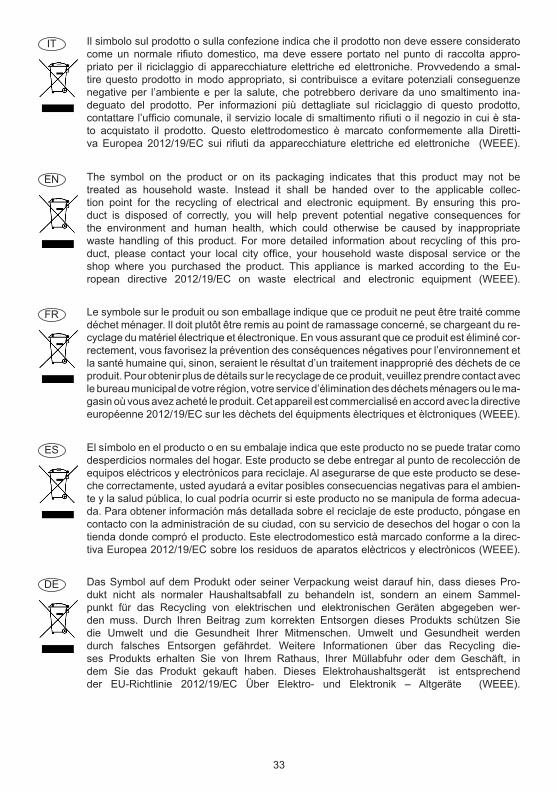
Das Symbol auf dem Produkt oder seiner Verpackung weist darauf hin, dass dieses Pro-dukt nicht als normaler Haushaltsabfall zu behandeln ist, sondern an einem Sammel-punkt für das Recycling von elektrischen und elektronischen Geräten abgegeben wer-den muss. Durch Ihren Beitrag zum korrekten Entsorgen dieses Produkts schützen Sie die Umwelt und die Gesundheit Ihrer Mitmenschen. Umwelt und Gesundheit werden durch falsches Entsorgen gefährdet. Weitere Informationen über das Recycling die-ses Produkts erhalten Sie von Ihrem Rathaus, Ihrer Müllabfuhr oder dem Geschäft, in dem Sie das Produkt gekauft haben. Dieses Elektrohaushaltsgerät ist entsprechend der EU-Richtlinie 2012/19/EC Über Elektro- und Elektronik – Altgeräte (WEEE).
DE
33

34

35
90007770075 - 01/20