Embed Size (px)
Citation preview

=PuoToFAcr' FolJ"r AUDIOMATIC
Jltt6o=It-
=oa3
cIo3J{r'l
3oE'trtF
GENERAL INFORMATION
The Audiomatic Modei A-900 is a dual-track monaural tape recorder and player. It wiliplay two or four track prerecorded stereophonic tapes.
Model A-900 features push-button control for each tape transport mode. These modesare: Rewind, Record, Stop, Play, and Fast Forward.
Double track recording is used, giving two fuli length recordings on a reel of tape. Anysize reel up to ?" can be used. A record level indicator is provided to simplify the recordlevel settlng. New recordings can be made on previously recorded tape since the erase headis automatically positioned when the record button is depressed. Monaural recordings can bemade from a radio, televj.sion receiver, or phonograph in addition to those made directly fromthe microphone.
This recorder has two tape speeds, ?.50 inches per second, and 3. ?4 inches per second.Using both tracks, the recording time is as follows:
Reel Size5" (600 ft. )?" (1200 ft. )
HCDWARD W. SAlUtS &The lieting of any available replacement part herein does
not constitute in any case a recommendation, warranty orguarantyby Howard W. Sams & Co,, Inc., as to the qualityand suitability of such replacement part. The numbers ofthese parts have been compiled from information furnishedto Howard W. Sams & Co., Inc., by the manufacturers ofcQ4??
3.75 SpeedI hour2 hours
?.50 Speedl/ 2 hourI hour
Connect this recorder to a ll? volt, 60 cycles, AC supply only.
Supplied By:
Continental lambic I nc.,6842 W. Archer,Chicago, lllinois
G O.r I N |E. lndianapolis 6, lndianathe particular t1rye of replacement part listed. Repro-duction or use, without express permission, of editorial orpictorial content, in any manner, le prohibited. No patentliability is assumed wlth reepect to the uee of the lnforma-tion contained herein. @ tgOt Howard W. Sams & Co. , Inc. ,
v,l-t-lctrcJre
.rrl€Et-r-tCJI
Indianapolis 6, Indiana.
DATI 12 - 61
Printed tn U.S. of Amerlca
rotDtR
-.U
sET 558

SPEED CONTROL
SPEAKERMONITOR
RECORD LOCK
LEFT CHANNELCONTROLS
RECORD LEVELINDICATOR
TONE
VOLUME
TAPE INDICATOR
REWIND RECORD STOP PLAY FAST FWD.
Fig. l. Audiomatic A-900 with cabinet top removed.
TECHN I CAL SPECIF I CATI ONS
AUDIOMATIC MODEL A.9OO
Amplifier Ext. spkrs:For earphone monitoring or operation of external
Stereo Input: speaker system. Also can be used as variableInSTOP position, both serve as low level inputs outputs for feeding external amplifier or built-for using the recorder as a complete amplifier' in Hi-Fi systems.For stereo, both are used; monaurally, eithercan be used. Volume Controls (Two):
Bothbass andtreble compensated. IndependentlyRecording Input: controls output of each channel.
For recordingdirectlyfrom radio or TV or fromthe Model P-902 phonograph. Output:
6 watts peak (stereo).
Sing A-Long InPut:Permits use of microphone when playing tape orreeords"
2

Fig. 2. Top View of mechanism with baseplate overlay removed.
Cgo
>=btgi=oE'rllF
Tube Complement:1--5y3, 2-- ECC82 /L2AV7, 2--ECL82/68M8.
Power Supp1y:Heavy duty, transformer type, hum and noiseshielded. 11?VAC, 112 watts.
Frequency Response:40 to 15,000 cps @ 7 L/2 ips + 3 db.
Record Indicator:Easy view, tube type (tuning eye).
Harmonic Distortion:5% at peak output.
Speakers:2--5" x 7" heavy permanent magnet, extendedrange matched speakers. Acoustically baffledwith On-Off monitoring switch"
Chassis:Heavy aluminum, fully shielded.
Signal To Noise Ratio:40 db minimum"
Bias Frequency:80r000 cycles, for distortion-free recording.
Tone Controls (Two):Full range, from maximum brilliance to richbass tone. Independent control of each channelfor best listening pleasure.
General
Size:L87/9"xg 3/4,'x15L/4"
Weight:39 lbs.
Storage Compartment:For tape, reels, AC cord, and microphone.
Public Address System:Can be used while recording.
AC Outlet:Located on rear panel. Provides AC outlet forphonograph, etc.
Duplicating Tapes:Using two units exact copies can be made.
.TloImv\JT

Standard Accessories:l-Humi-Seal Crystd Microphone, 1-?" emptyreel, 1-5" reel of tape, f-instruction bookr 1-warranty certificate.
Acces sories Available:Patch cords - for recording from radio, phono,TV. Duplicating cords - for copying tapes.
Tape.Transport d
Tape Speed:3 3/4 and 1 L/2 ips. Rapid forward and rewind.
Tape Reel Size:3tt, 5tt, or ?tt.
Record Lock:Safety feature to prevent accidental erasure.
Erase:Patented permanent magnet, diagonal gap, pos-itive, automatic.
Controls:Fult pushbutton operation, all modes.
Speeds:3-speed manual turntable-33 l/31 45.- and ?8 rpm.
Cartri{ge:Stereophonlc cartridge with turnover needle.
Neutral Fosition:To prevent drive wheel '{l.at spots'when not inuse.
Cables:For either monaural or stereophonic reproduc-tion.
Wow and Flutter:.35% or less-? t/2 ips speed.
Tape Indicator:By integral numbers, easily reset, giving in-stantaneous s election.
Record-Playback Head:Stacked in-Iine, combined t/4 or L/2 ftack,fully shielded .0002 gaps.
Motor:Dyn a m i c all y balanced, vibration free. Heavyduty, constant speed, 4-pole shaded--l?00 rpm.Contains lifetime, self-aligned, select fit oilitebearings. Motor mounted on special isolationtype floating mounts.
Flywheel:Balanced, zinc die cast.
Unit Mounting Plate:Sturdy one piece aluminum die-cast metal--other parts placed for protection.
Cooling:4" fan, forced ventilation.
Weight:Approximately 8 lbs.
Size:14tix8ttx5il.
Case:Portable with cover and handle.
SPECIFICATIONS
MODEL P-902 STEREOPHONIC PHONO DI SC.TURNTABLE( ACCESSoRY )
SPECIF ICATIONS
MODEL S-9OI DUAL EKTS{SION SPEAKIR5( ACCESSORY )
Carrying Case:Portable, separates into two separate tone bal-anced speakers.
Case Complement:Each unit consists of one-8" permanent magnetspeaker and one-3" tweeter. Crossover net-work used in each unit.
lO-Foot Leads:2-used, for plugging into Audiomatic extensionspeaker jacks.
4
E<tra Speaker jack:Erables use of both speakers monaurally forgreater volume and coverage.
Weight:Approximately 18 lbs.
Size:L5 l/2" x 14" x 12".

FUNCTIONS OF CONTROLS & PUSHBUTTONS
0n-0ff, Tone, Volume - Right Channel Rewind Button
This is a dual control located at the extremeIower right side of the top panel. The large outer rimcontrols the volumeof the sound from the right channelspeaker when playing stereo. The small inner knobturns the Audiomatic 'bn" and also is used to adjustthe tone from the right channel spealer.
Speaker Monitor
This controlislocated to the left of the ON-OFFswitch. Itservesas a monitor control so that Jrou czullisten to sound as it is being recorded monaurally.Turning this control to the right (clockwise) turns onthe left internal speaker. Turned to the left, the speakeris disconnected. TheSPEAKffi. MONITOR switch doesnot control the right internal speaker or extensionspeakers.
Tone, Volume - Left Channel
This, also, is a dual control, located at the ex-tre'meleft on the top panel. The large outer rim con-trols the volume of the left channel speaker. The smallinnerknobisusedtoadjustthe tone from the left chan-nel speaker.
Record Lock
This knob serves to prevent recordings frombeing accidentally erased by pressing the RECORDpushbutton by mistake.NOTE: THIS KNOB MI'ST BE TURNED TOTHERIGHT
(CLOCKWTSE) BEFORE THE RECORD BUT-TON CAN BE DEPRESSED.
Speed Control
The SPEED knob should point to ?.50 or 3.?5according to the speed desired. The Audiomatic hastwo tape speeds, 7.50-inches-per-second and 3.75-inches-per-second. Insofar as quality of recordingreproduction is concerned. Speed is an importantfactor. The higher the speed, generally, the greaterwill be the fidelity.
Caution: DonotturntheSPEED knob unless theSTOP button'is depressed.
REAR PANEL
Ext. Spkrs. - Left and Right
These jacks provide a connection for externalspeakers. When external speakers are used, the in-ternal speakers are automatically disconnected.
Sing A-Long
By inserting the microphone plug into the Sing
This button is used to transfer the tape rapidlyfrom the right (ta.ke-up) reel to the left (supply) reelat high speed.
Record Button
This button is used to start the Audiomatic re-cording any sound being fed to the tape from micro-phone, radio, TV, phonograph, or telephone.Note: TIIE RECORD LOCK MUST BE TURND BE-
FORE THE RECORD BUTTONCANBEDE-PRESSED.
Stop Button
This button is us ed to stop tape travel after beingineitherthePLAY, RECORD, FORWARD, or REWINDmodes. It is also a safety feature and must always beleft pressed down when the recorder is not in use.
Play Button
This buttonis used to start the Audiomatic play-ing back any recording that is on the tape, monauralor stereophonic.
Foruard Button
This button is used to transfer the tape rapidlyfrom the left reel to the right reel without recordingor playing back"
Tape I ndicator
Setthe counter to zero by turning its reset knobtoward the rear of the recorder when starting to re-cord or play back a reel of tape. If the reading of thecounter is nqted at various points in the tape travel,newprogram selections can be indexed, or previouslyrecorded selections can be located with great accuracy.
Record Level lndicator
The RECORD LEVEL indicator gives a visualanalysis of the correct volume setting for the RE-CORD function. Adjustthel EFT CHANNEL VOLIJMEcontrol to the point where the RECORD LEVEL in-dicator does not quite close on peak passages.
CONNECTIONS
A-'Long jack, the operator can aecompary phonographrecordsormonaural tapes without his voice being re-corded on the tape.
Mic. lnput
The microphone may be plugged into this jackfor recording or for public address use.
cIo
>=bT8;i
3oElltF
TToIrrtvvr

Recording lnput
This jaek is designed to connect the audio sig-nals from a radio, phonograph, or television receiverto the recorder for recording purposes.
Stereo lnput
These input jacks are designed for connectingthetwophonopick-up cables from a stereo phonographto the recorder for playing stereo records.
OPERATI NG I NSTRUCTIONS
Preparation For Operation
1. Remove the AC power cord, reel of tape, emptyreel, andthe microphone from the rear compartment.
2. Depress the STOP birtton.
3. Plug the AC cord into a convenient wall receptacleof the proper rating.
4. SetSPEEDcontrol lmob in the 3.75 or 7.50 positionas desired.
Caution: DonotturnSPEEDcontrol knob unless STOP
button is depressed.
When the forward or reverse buttons are de-pressed, the RECORD and PLAY buttons are lockedio that they cannot be pressed down, with, the possi-bility of spilling tape. The buttons should always be
pressed down firmly until they latch. The STOP but-ton must be depressed before changing functions orspeeds of the recorder.
Important: Always depress the STOP button when therecorder is not in use.
Threading The Tape
1. Placea reel of tape on the supply pan (left) makingcertainthereel slots catch the protrusions of the pan.
2. Place an empty reel, the same sizeor larger, on thetake-uppan (right). Again make certain the reel slotscatch the protrusions of the Pan.
3. Releasethe STOP button by pressing lightly on any
one of the other four pushbuttons so that all buttonsare in the released position. This releases the tapebrakes, simplifying tape threading.
4. Unwind about 14-inches of tape from the supplyreel. Hold a section of tape straight with both hands
and insert the tape in the tape slot making sure thatthe dull coated side of the tape faces away from theoperator (toward rear of unit).
5. Insert the free end of the tape into the slot in thehub of the empty reel. While holding the tape in place,give the reel two or three turns to secure the tape tothe reel.
Note: Do not route tape around tape post.
To Record From Microphone
1. Insert the microphone plug into the MIC. jack 1o-
cated on the rear Panel.
6
2. With the STOP button depressed, turn the ON-OFFTONE control to the right (clockwise) until a click isheard. Allow the recorder to warm-up until the RE-CORD LEVEL indicator glows green.
3. Place the SPEED knob in the position desired. Asa general rule, 3.?5-inches per second for voice, and
?.50-inches per second for music.
4. Turn the RECORD LOCK to the right with the lefthandandwiththe right hand depress the RECORD but-ton--then release the RECORD LOCK.
5" While holding the microphone about 3-4-inches awayfrom the mouth, speak in a normal tone of voice and
adjust the LEFT' CHANNEL-VOLUME control to thepoint where the RECORD LEVEL indicator does notquite close on Peak Passages.
Note: To monitor the sound being recorded, turn theSPEAKffiMOMTORcontroltothe right. Caremust be taken to keep the microphone f ar enough
from the recorder to prevent squeal due to a-coustic feedback.
Rayind (< ) 0r Fast Forward (>)When it is desirable to play a certain portion of
a tape over again, it is not necessary to revind theentire reel. By depressing the rewind (<) button thetapewill reverse at a rapid speed. By depressing the
fastforward (>) buttonthetapewilladvance at a rapidspeed.
To Record From Radio 0r TV
Whileitis possible to record sound from an ex-ternal source simply by placing the microphone infrontof thespeaker, thisis not recommended as back-groun<i noises will be recorded along with the desiredprogram material.
For noisefree recordings, record directly fromthe speaker voice coil terminals of the radio or TVreceiver. For this purpose, a patch cord is availablefrorn your Audiomatic dealer.
1. Insert the plug end of the patch cord into the RE-CORDING INPLII located on the rear panel of the Audio-matic.
2. Connect the patch cord alligator clips to the radioor TV receivers voice coil terminals.
3. Adjust the volume control of the radio or TV atnormal roomvolume. Setthe tone control of the radioor TV at full treble.

4. Proceedwithrecordingas described under rllo Re-cord From Microphone'i.
To Record From Phonograph
1. Plug one of the phono turntable output cables intotheRECORDINGINPU'I jacklocated on the rear panel.
2. Insert AC cordfromphonographinto 11?V"A.C. out-let on rear panel.
3. Start turntable and proceed with recording as des-cribed under rTo Record From Microphone".
Note: Themicrophone should not be connected to theAudio mati c when recording from anothersource. Also, when the recording is playedbacko thephonooutputcable should be removedfrom the RECORDING INPUT jack.
To Use Second Track
1. Depress the STOP button when the tape has beenwound onto the take-up reel.
2. Removetake-upreel, turn over, andplaceonsuppiypaJl.
3. Place empty reel on take-up pan.
4. Thread tape and proceed with recording as pre-viously described.
To Play Monaural Recordings
1. Thread tape as described under "Threading TheTape".
2. Set the SPED knob to the speed at which the re-cording was made.
3. Place SPEAKffi, MONITOR control in the "on"position.
4. Turn the RIGHT CHANNEL-VOLIjME control tominimum.
5. PressthePlAYbuttonand adjust the LEFT CHAN-NEL-VOL UME and TONE controls for desired listeningleveI.
To Play Stereophonic Tape
1. Thread tape as described under 'lThreading TheTape".
DISASSTMBLY
To Remove Unit From Case( Ref er to Exploded View)
1. Remove push-on type speed shift knob (3), the topand bottom of dual control knobs (14), (16), (22), and(23), and the dummy dual control knobs (20) and (2a).
2. Removethetwoscrews, (9) and (10), from the frontescutcheon (11). Remove escutcheon.
2. Set the SPEH) knob to the speed at which the re-cording was made.
3. Place SPEAKER MOMTOR control in the 'bn"position.
4. Adjust the RIGHT and LEFT VOLITME and TONEcontrols for desired listening level.
Sing A-Long Use With Phono
1. Place a record on the turntable and plug one of thephono output cables into the jack on the back panelmarked RECORDING INPUT.
2. Insert mic:rophone plug into the jack on the backpanel marked SIIIG A-LONG.
3. Starttheturntableand adjust the LEFT CHANNEL-VOLUME control for desired listening level.
4. Sing into the microphone and adjust the RIGHTCHANNEL-VOLUME control until the sounds comingfrom the right-hand speal<er blend rvith the musiccoming from the left-hand speaker.
Sing A-Long Use With Tape
In addition to accompanying phonograph records,you can record monaural selections, then play thetape and narrate at the same time.
1. Playthetapeinthenormal manner, adjusting LEFTCHANNEL-VOL IJME control.
2. Plug microphone into jack marked SING A-LONG,sing into microphone and advance RIGHT CHANNEL-VOLUME control to the point where your voice blendswith the music.
Caution: You cannot record your voice along with thetaped program. If the RECORD button isdepressed, the tape will be erased.
To Use As Public Address System
With the STOP button pressed down, speak di-rectly into the microphone, setting the LEFT CHAN-NEL-VOLIIME and TONE controls for desired listen-ing level and tone"
Caution: Holdthemicrophoneasfar away as possiblefrom the left speaker to prevent squeal dueto acoustic feedback.
INSTRUCTIONS
3. Remove screw (5) from rear escutcheon (6). Re-move escutcheon.
4. Remove tape guide post (15).
5. Remove screws (18) that mount the front escutcheonmounting brackets"
6. Remove the two scre\rrs holding the unit in the cabinet(located at top of storage compartment)"
cE
o>3.bIgi
=oImF
-rfo(tla1v\tr
?. Remove baseplate overlaY (12).
8. Remove the two serewsr located at front of base-plate, holding unit in cabinet.
9. Removethefour screqrs holding "U" shaped bracketin storage compartment. Remove "U" shaped bracketfrom storage comPartment.
10. Remove the four s crevfs holding the two sub-panelsto the rear panel"
11. Push the two sub-panels through the holes in the
rear of the ca.binet.
12. Lift tape transport and amplifier assembly part-ially out o] cabinet. Unplug four speaker leads and
speaker monitor plug before removing unit completely'
To Remove Amplifier From Transport Mechanism
1. Remove the motor and power transformer plug fromthe amplifier chassis"
2. Remove the four hea.d leads from the play-recordhead terminals.
3. Remove tnto screws from each end of amplifierchassis.
4. Carefullylifttheamplifier away from the transportmechanism and disconnect the play-record switch armlink (104).
MECHAN I CAL A DJ U STMENTS
Pressure Pad Adjustment( Refer to Exploded View)
1, Remove front escutcheon (11).
2. Depress the PLAY button. Do not turn the Audi-omatic tbn".
3. Useapenciltype postal scale and check the amount
of pressure necessary to just pull the right-hand pad
awayfrom the play-record head (57)" The test should
be made at the right-hand end of ttre pressure pad
mounting spring. If necessary, adjust locked adjust-ment scielv'(42iuntil a reading of t 3/4'oz. *l/4-oz'is obtained.
4" The guide post pressure pad (Ieft-hand pad) is ad-justed by bending the pressure pad spring (35). Ad-just for minimum pressure against tape.
Erase Head Adjustment
1. With tape properly thr eaded, turn r ecorder'bn " and
depress the RECORD button. Allow tape to run for af err seconds then turn recorder 'bff ", but leave RECORD
button depressed.
2. With front escutcheon (11) and rear escutcheon (6)
removed, checkerase tread (52) to see if it is parallelwith the taPe.
3" Check to see if the top edge of the tape coincidesrvith the top end of the diagonal slot in the erase head
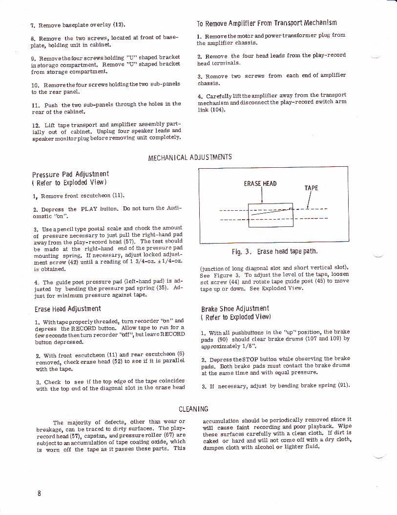
TAPE
I
Fig. 3. Erase head tape Path.
(junctionof long diagonat slot and short vertical slot).See Figure 3. To adjust the level of the tape, loosenset screw (44) and rotate tape guide post (45) to move
tape up or down. See H<Ploded View.
Brake Shoe Adjustment( Ref er to ExPloded View)
1. Withall pushbuttons in the 'tp" position, the brakepads (90) should clear brake drums (10? and 109) byapproximately t/8",
2. DepresstheSTOP button while observing the brakepads. Both brake pads must contact the brake drumsat the same time and with equal pressure.
3. If necessary, adjust by bending brake spring (91).
ING
accumulation should be periodically removed since itwill cause faint recording and poor playback' Wipe
these surfaces carefully with a clean cloth. If dirt iscaked or hard and will not come off with a dry cloth,
dampen cloth with alcohol or lighter fluid.
CLEAN
The majority of defects, other than wear orbreakage, can be traced to dirty surfaces. The play-recordtread (5?), capstan, andpressureroller (67) aresubjectto an accumulation of tape coating oxide, whichis worn off the tape as it passes these parts. This

7
Fig. 4. Bottom vi€r,v of transport mechanism.
LUBRICATION
All rotating parts are provided with generoussizeoilitebearings which are factory lubricated" Un-der normal use no further lubrication is necessary.In heavy duty service, the following parts should belubricated once a ye:rr with a drop of # 10 motor oil:
1. The top and bottom motor bearings"
2. The capstan bearing.
3" Pressure roller (67) bearings.
4. All idler and drive wheel bearings.
5. The reel pan bearings.
The basic rule is - do not over lubricate. Oilmustbekeptoff all rubber idlers, belts, and peripheryof flyrheelandoff partsthatmighttransfer oil to them.Always wipe excess lubricant from parts that have beenlubrieated.
An occasional cleaning out of foreign matter un-der the pushbuttons is desirable, and a drop of oil onthe sliding lever members is advisable.
CIo>-bIgi3oC'mF
?tc)(:'m7t\trFig. 5. Bottom view of transport mechanism - motor mounting plate removd.

fCG-)V
H
r#sj@:---@
Y-,c
ib iil@li[tl-i-@
t4t,',,At: I tit-L/," /Cr
ttrlt'
I
ltriI
r'
?*L_l
e/
@YII
hRI\v
,p,@6
A PHOTOFACT "EXPLODED" VIEW@Howrtd V. Srmr & Co., lnc. l96l
@.----.---@
E I PH [N II
..-4_\
Fig. 6A. Exploded vierv of parts above baseplate.
t0
CIo
btgi=oE,mF
-Tlc)rt3]?17\tl
-:"*-,
tl
/
O\(D
€oc --
3c ltt (D(D
M/{,/
6/d
A PHOTOFACT "EXPLODED' VIEWoHowrrd V. Srmc & Co., lnc. l96l
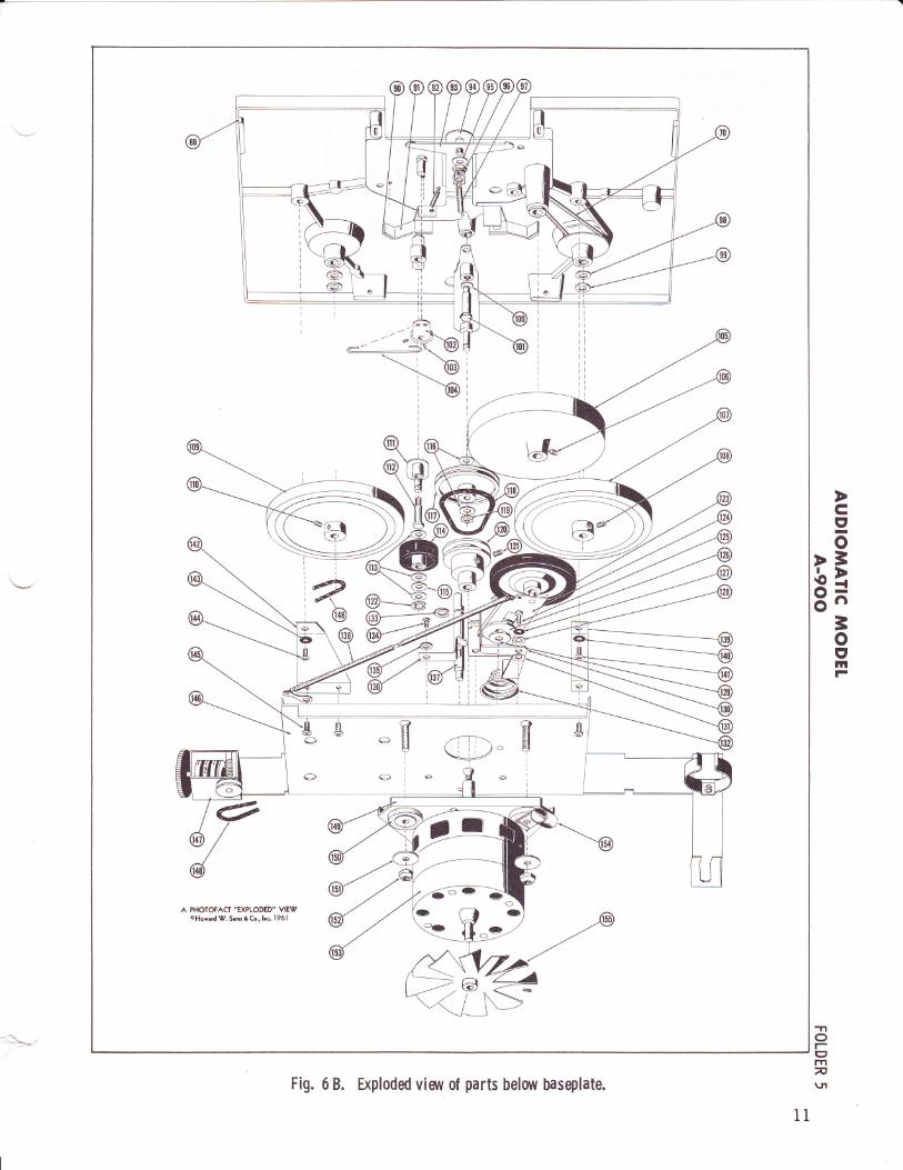
Fig. 6 B. Exploded visrt 0f parts below baseplate.

Fig. 7. Top vieuv of motor mounting plate.
ELECTR I CAL A DJU STMENTS
Hum Adjustment
Place unit in PLAY position; Left Channel-VOLUME at maximum and Left Channel-TONE at fullbass. Connect a VTVM to the LEFT Ext. Spkr. jack.Setthe VTVM to AC, 3 volt scale, with a 3.3 ohm loadresistor across the meter. Adjust hum control (R3)
for mininium deflection on meter.
Play-Record Head Alignment
1. Remove front escutcheon (11) and rear escutcheon(6),
2. Clean pole pieces of play-record head (5?) withalcohol or lighter fluid.
3. Thread alignment tape on recorder. Turn LeftChannel-VOLtIME to ma:rimum, ild Left Channel-TONE to full treble.
4" Conneet a VT\IM to LEFT Ert" Spkr. iack. Set themeter to AC, 3 volt seale,
5. Place reeorder in PLAY position, 7 t/Z-ineh persecond speed. DeereaseVOLUME to point where out-put is l-volt on meter. Turn play-record head ad-justment screw (57, Fig. 2) until manimum point ofdeflection on meter is obtained.
TROUBLE CHART
Symptom Cause Remedy
Push buttons fail to latchinto position.
1. Lock plate spring (80) disconneeted orbroken.
1o Connect or replacespring (80).
No drive in Play or Re-cord.
1. Idlertensionsprings (138) disconneetedor broken.
2. Idler slideplate (124) bindingon bushing(126), thus prwenting idler wheel (123)from moving forward.
1. Connect or replaeesprings (138).
2. Check slide plate (124)andbushing (126) for burrs.Clean with alcohol.
Tape fails to wind on take-up reel during Playor Re-cord"
1" Reel drive spring {70) loose, dismn-nected, or broken.
2. Reel pan shaft (2) binding.
1. Connect or replacespring (70).
2. Clean foreign matterfrom bearing surface andshaft with a clean cloth.Lubricate with one drop of# 10 motor oil.
No Fast Forward or Re-wind.
1. Idler lever tension spring (9?) discon-nected or broken, thereby not actuatingidler lever (100).
1. Connect or replacespring (97).
t2

TROUBLE CHART ( COnt,d}
Symptom Cause Remedy
2. Idlerdrivebelt(118)broken or not pro-perly connected.
2. Replace idler drive belt(118).
Tape spills whenStop but-ton is depressed duringfast Forward or Rewind.
1. Brake shoes out of adjustment.
2. Brake pads worn out or missing.
1. See "BrakeShoe Adjust-ment" under MechanicalAdjustments.
2. Replace brake pads.
'\ilow" during operationof recorder.
1. Brake return spring (92) disconnectedor broken.
2. Check all driving surfaces for oil orforeign matter"
1. Connect or replacespring (92).
2. Clean with a cloth andalcohol.
"Flutt er " duringoper-ation of recorder.
1. Dirty play-record head (57), pressurepads, capstan shaft or pressure roller (6?).
1. Clean as described un-der 'Cleaning".
No erase or erase is in-complete.
1. Erase head tension spring (40) discon-nected or broken.
2. Erase head (52) not adjusted properly"
1, Connect or replacespring (40).
2. See "Erase Head Adjust-ment" und er MechanicalAdjustments.
Does not record. 1. Faulty microphone or cord.
2. Faulty input jack.
Faulty tube.
Open piay-record head (5?).
1. Replace if necessaryeaf t er checking recorderwith another type of input,
2. Check and replace if ne-ce$sary.
3. Check tubes.
4. Check continuity. Afterchecking for continuity, de-magnetize head.
3.
4.
Cgo
>3.lo tti
3o('IrtF
Motor and amplifier in-operative"
1. Power supply defect.
Damaged power cord.
Defective On-Off switch.
2,
3.
1. Checkvoltages per sche-matic.
2. Repair or replace.
l. Replace switch.
AFAMP/OUTPUT -rroImv\n
13
Fig. 8. Top view of amplifier.

Fig. 9. Bottom view of amplifier showing capacitor locations'
t4
Fig. 10. Bottom viav of amplifier showing resistor locations.

tatoo=..o;oE
q-<Io3
bo-@.
EE
iirP
=E
5F
: i
\r
E€ lt eea
==
EE
Egi:E
Ji:siE
eEe 2.
€EE
:;*;E
OT
E? E
Ei E
E3 E
;se;E
E;: =
?;E
E€€H
EF
; ??E
SE
rg':EE
6;E
Ee E
: =E
E
qfss.H
*5E !=
5
; lirisri
<;
6T
@
<J
\zp@o=
Eoa
(9z.Eu@=z.FU:z(Jor60=ac5d;z.eFeu=q
EOa
0n
>(J
Cr
oatrt3-o
!za
cct
=/A
tsg/C
E
PE
sR
U(-)d,
oq
5@
i3 R
F=
OF
e(Ju
CJ
Z.
u z
-OF(')z.o
z(JF
Q
=z
oe,FoJqu-F4oz.oF6zoU-Fz.oc=(5?2.ooZ
.-
*;*;E
o>-
dua_o<
oN>
, e_
=H
-=
gr=2=
EE
aoLD
doad=
=
-22-uuF
==
o.c1
@,
()-
fi)si>drO@
(9z.6qd,u(JzFaUe
oro6to.:roec{o
aE@
o
U2)o
oue
cotsN
,ae\
\E,oN
6\\y\zoN
3€x
EE:/.4\tglvoNN
A\eEl
NE
NE
6N
:)k)
N?:zF Ga
zeo
@:
@
@UJcto
EY,
o-Fdil
€oEo€c.{
r-@=
Jg(J=
lll
o66@
FzF
=
a=
z,_
do-H
.o.zc:frE
=
vaN
vo
=8
v€OF
o:
@F>
l5;
Ar:
-JF-tt,'
€t*E\g/:
Eoo:
@388 :zoNNo
@@
r--IIIIIIIIIt__-
N=z
-o;EeQF..
=E =.=
6=E9
Aa 6
\erlo
d,oFc)Ez.:|flr
tltA
\OJg(9adrafr
\-/Glsl E
lzlt<
t :a
l3l I
tEt t5
oo
<)E
roE-o
@3E
E
- =
ll
k : Ere\,
L-r r ls:/
=@
EE
s o- -
nAr-+
S@VooO
Ndo
@oFN
o
x=
E=@
Iots
A\!1/
?:ztsuO
E@ ro
-\oNoi t'
tl
€= !OsF
6{E
g=
HC
r)
ecaa
o= o\oo{@L=
g=
<e
I-*'Jl=
?e; I
13 I
,ffi,€t
EEoooo0
?
CIo
blgi=oE'
mF
-nO1-gmn\rl
15
Fig. I I.
Schem
atic 0f Audiom
atic A-90C
.

Ref.
No.
PartNo.
Description
Nylon ReeI Pan & ShaJt IAssry. I
Nylon Reel Pan & Shaft IAssry. I
Speed Shift Knob I
FeIt Washer I
# 6-32 x 3,/8" O"H.IvlS. I
Rear Escutcheon I
Varnish Impregnated IWasher I
Varnish Impregnated IWasher I
# 8-32 x 1/4" T.H.IWS. I
# 8-32 x 1/4" T.H.M.S. I
Front Escutcheon Ass'y. I
Basepla.te Overlay SiIk I
Screen Assey. I
# 6-32 x 1" T.H.M.S" I
Dual Control Knob, Top I
Tape Guide Post I
Dual Control Knob, Bottom I
Front Escutcheon Mtg. Brkt. I
# 8-32 x 1/4" T.H"I\4S. I
FeIt Washer I
Control Knob, Dummy DuaI I
FeIt Washer I
DuaI Control Knob, ToP I
DuaI Control Knob, Bottom I
Control Knob, Dummy Dual I
Felt Washer I
Push Button Assty., Rewind I
Push Button Assey., Record I
Push Button Assry., Stop I
Push Button Assty., PIay I
Push Button Ass'?y., Fast IForward I
Push-On Stud Nut, 3/16" IStud I
FIat Washer I
Playback Actuating Lever ]
Record Slide Platei Pressure Pad SpringI r'"rt paa
I r"tt n"a, Play-Record Hd.
| + 0-rz x 3/16" B.H.M.S.I Plavback Slide PlateI E"as" Head Tension SpringI + o-rz Hex Nut
| + a-zz x 3,28" R.H.IvLS.I Record Actuating Lever Assry.
| + o-lz x8/16" Bristol Hd.
I Set Screw
I Tape Guide Post
I # 6-32 He)<. NutI Tape Guide Post Spacer
I ntase Head Return SpringI Erase Head Mtg. Plate| + o-sz x 13,/16" R.H.IWS.I #6Int.LockwasherI n"""" Head Assgy.
I einch Roller Plate Ass?yr
| + o-az x 3/16" B.H.M"s.
| *0Int.LockwasherI Tape Guide LugI t,/4 rract< Play-RecordI neaaI # 4-40 x 1/4" R.H.IvI.s"
I FIat washer, Steel
I Mounting Bracket, RecordI Head
I Spring, Record HeadI + O-fZ x 3/16" Bristol Hd.I s"t s"ruwI Tape-Guide Post, Right
1 I c-13.318-3 I
2 I c-1s.318-3 Itt3 I c-13.44s I+ | n-zzs+-s I
5 I 5?-4C-606-4 Io I o-rr.+so-r I7 I 73-2340-r IltI | 73-2340-1
I
9 | 57-1C-804-410 | sz-zc-ao+-+11 I C-35.1419-1t2 I n-gs"r+so-r
I
r3 | sz-oc-ors-s14 I c-rr"eez-r15 | a-sz.zoz16 I e-es.r+es-rr7 I e-rs"ross-r18 I SZ-ZC-AO+-r19 I zs-zzt+-szo I c-rr.+eozr I tz-zzt+-szz I c-rr"a+z-r23 I S-eS.r+gs-r24 I c-rs"alo25 I TS-ZZSq-S26 I e-sr"rros-r21 | n-ss"tros-z28 I B-35.1369-329 | e-er.reos-t30 | e-ss.rros-s
31 I r-rr.nuI
32 I Zt-ZZ+t-tAAp
il | u-,n.ruu35 I 8-19.89286 I e-sr.rs+s7 I s-sr.ss+38 I SZ-rC-OOr-r3e I c-rs.ars-z40 | n-sr.aor4r | 48-410-142 I 5?-16C-606-143 | n-u.eaz-r44 I 57-343e-0
I
45 | e-sz.aoo46 I 48-410-147 I e-:z.z6o48 I e-sr.++e-z4s I e-rs.rato-r50 | sz-ros-ers-o51 I Zr-ZZSr-eiz I c-ss.zso53 | a-as.rzrs54 I 57-1C-603-1
I ut I n-ro.zs+
I as I sz-toc-+oq-tI ss I ts-zz+t-ts+
I uo I n-rs.sas
I ut | "-rn.nnoI oz I sz-s+sg-o
B-32.30963
MECHANICAL PARTS LIST
82
83848586
ot888990919293949596
9?9899100101
102103
104105106
109
110
111tt2
113tl4115116tLlllg *119120t2l
t22I23*
t24
Pinch Roller TensionSpring"8" Ring, 3/16" ShaftLinen WasherPressure RollerShim Washer, BrassBaseplate & Bearing Assry.ReeI Drive Tension SpringRecord Lock ShaftRecord Lock LeverSet Screv,/, BristolHex NutHex NutPushbutton Retainer BracketPushbutton LeverPushbutton Hinge BracketPushbutton Return SPringLocking Plate Spring# 8-32 x 1/4" B"H.IVLS""Sems# 8-32 x 1/4" B"H.l4S.,SemsShouldered WasherRecord Lock LinkRecord LockRecord Lock ReturnSpringRecord Lock Mtg. Plate# I Int. Lockwasher# 8-32 x 3/8" R.H.]WS.Brake Pad, FeltBrake Spring Assey.Brake Return SpringShift Plate Ass'y.Brake Slide Plate Ass'y.FIat Washer, Steel# 10-32 Hex, Elastic Stop NutIdler Lever Tension SpringVarnish Impregnated WasherPhenolic WasherIdler Lever Ass'!y.# 8-32 Hex Hd. ShoulderedScrev,/Switch Lever Asssy"# 8-32 x 3,/16" Bristol Hd.Set ScrerfSwitch Arm Link-FlY'rheel
# 8-32 x 1/4" Bdstol Hd.Set ScrervBrake Drum & Bushing AssrY# 8-32 x 1/4" Bristol Hd.Set ScrertrBrake Drum & BushingAssry.# 8-32 x 1,/4" Bristol Hd.Set ScrewSub ldler Plate Assry.# 8-32 Hex Hd. ShoulderScrewLinen WasherSub IdlerFelt WasherLinen WasherSheave Pulley Assry.Idler Drive BeIt"E" Ring, 3/16 " Sha.ftMotor Pulley# 8-32 x 1/4" Bristol Hd.Set Screrv"E" Ring, 3/16 ShaftRubber Bonded Idler, 2 1/2"Dia.Idler Slide Plate Ass?y.
64 B- 31.360
B-33.418- 2
B- 28.16 3
B-33.404*B-16.104D- 35.1436-1B-31.351B-32.485
656667*6869707L1273
75767778?98081
B-19.858-1
B-19.859B-31.33?B- 31.34 3
5?-21C-804-1
5?-21C-804-1
B-32.291B- 31.498B-19.1699B-31.338
B-19"1 364-173-2231-557-6C-806-1
B-35"10?0-1B- 31.338B-35.1046B-35.83573-2241-148F48-222rB-31.33973-2340-173-2248-39B-35.1051B-32.2?5-1
B- 35-14525?-3698-0
B-31.333c-1 3.25?-15 7- 3589-1
c-35.1050-157-3589-1
c-35.1050-1
57-3589-1
B-35.1044B-32.275-l
B-28.163B- 33.40513-2254-6B-28.16 3
B-35.1066'B-28. 18I *
B-33.418-2B-32" 28857-3589-1
B- 33.41 8- 2
B-33.408*
B-35.1064-1
l6

Ref.
No.
PartNo.
Description
t25L26L27L28129130131t32
13313413513613?138
139
57-6C-806-1
73-2231-573-2241-t43
B-19.1431-1B-32.291-1B-31.32?
B-33.40?-15?-1 C-603-173-2231-4B-19.961c-35.816-1B-31.324
B-19.86 2
# 8-32 x 3/16r'R"ILM.S"Idler Slide Bushing# 8 Int. LockwasherFlat Washer, SteelFlat Washer, SteelIdler Throw-Out LeverShouldered WasherIdler Lift CompressionSpring'€"Washer# 6-32 x 3/16" B.IIM.S.# 6 Int. LockwasherSpring ClipSpeed Control Shaft Assey.Idler Tension Spring,(2 req.)Angle Brkt. for Mtg.Drive Assiy"
MECHANICAL PARTS LIST ( Cont,di
r Ref.* nef.* Ref.* Ref.
Handle Plate AssemblyHandle AssemblyMonitor Switch Harness Ass'y.Baffle AssemblyCabinet Fastener ClipsPlastic Beading, White5!r x 7" Speaker, 3.2 ohmPlastic Bumper, White, 3rl8"Plastic Bumper, White, 3/4"#L/4-20 Hex Nut#8-32 Tinnerman Push-On Nut#8-32 x L7/32Kqs Hex Nut# xL/2 F"H.W.S.#8 xl l/4 F.H.W.S.#6 x 3/4 R"H"W.S.#5 xL/2 R"H.S.lvr.S"ffi x 3/8 R.H.S.ilr"S"#8-32 x 1 1/4 Wing ShankFlat WasherCatch, BrassCovering Material (Outside)Covering Material (Inside)
Presgure Roller, WALSCO part #l4b?.Idler Drive Belt, WALSCO part #l4l0-0?.Rubber Bonded ldler, WALSCO part #1430."O" Rlng, WALSCO Part #1410-0?.
CABINET PARTS LIST
No. 67,No. U8,No. 123,No. 148,
cIo
>=,io !ti
=oIlltF
c-35.1 3?5-1c-35.1 3?6-1c-35.L417-2c-35.1450:1B-19.864-220-2089-1c-30.363-133.630-133.6 30-248-1C-20-048-215148-2220-r5?-43C-608-457-43C-8 20-057-46c-612-45?-66A-508-457-66A-606-05?-355073-224t-1318?-31 70-1503-l 93-1503-1 93- 2
503-1 93- 3503-193-4503-193-5503-1 93-6503-1 93-?503-193-850?-85 250?-102650?-102750?-1028509-231.510-6-49510-?8.51 5-1 34951 5-1 350515-1 351515-1 35251 5-1 35 3515-1 354518-65520-100537-83
Covering Material (Inside R.H.)Covering Material (Inside L.H.)Covering Material (Bottom)Covering Material (Case R.H.)Covering Material (Case L.H.)Covering Material (Inside Compt.Front Mounting RailSide Mounting Rail, R.H.Side Mounting Rail, L.H.Rear Mounting RailBlockGlue Block, L/2 x 1/2 x 4Glue Block, l/2 x L/2 x 4Front PanelSide Panel, R.H.Side Panel, L.H"Rear PanelTop PanelBottom PanelPartition PanelFillerSpeaker Baffle
'fto1-grflF\.n
'Ref.
No.
PartNo.
Description
140t41t42143
L44L45146
141148 rt49150151t52153L54155
73-223L-55?-6c-805-1B-19.86373-223t-557-6C-805-15?-6C-805-1D-35.1438
B- 33.5 36
B-28. 175 *
B-33.41 1
48-222L35.1053- 2B-33.534B-33.643
# 8 Int. Lockwasher# 8-32 x 5/16" R"H.M.S.Drive Mtg. Plate Bracket# 8 Int. Lockwasher# 8-32 x 5/16" R.H"M.S.# 8-32 x 5/16" R"H"M"S"
Drive Mtg. Plate &Bracket Assry.Digital Counter"O" RingMotor Mtg. PlateShock MountFlat Washer# 10-32 Eastic Stop NutMotor Assly.Nylon Cable Clamp4" Fan Blade
T7

ACCESSORY STEREO PHONO TURNTABLE
MODIL P-902 PARTS LIST
ACCESSORY DUAL EXTENSION SPEAKERS
MODEL S-9OI PARTS LIST
PartNo.
Description
Handle PlateMotor EloardSlide Switch, S.P.D"T.Line Cord w/Pl,tgr 6r, GraYTerminal StriPShielded Cord & ConcentricPlug, 60", GrayTone Arm Assembly (Black)3 Speed Motor w/8" TurntableP.G. Butt ConnectorHandle Plate AssemblYHandle AssemblYPlastic Beading (White)Plastic Bumper (White) 3/8"+l/4-20 Hex Nutlfr xr/2 F.H.W"S.#5 xl/2 R.II"S.IvtS"#5/8 FIat WasherTack, Brass Plt.Catch, Brass Plt.
B-19.1681504-25B-11.287B-20.241-tB-23.239B- 33.599-4
B- 33.618-2B-33"6 20-3t05-22235.13 ?2 - 1
c-35.13?6-320- 2089-133.630-148-1C-21-05?-43C-608-45?-66A-508-413-2241-t378?-3164-287- 31?0- 2
PartNo.
Description
503-192-1503-192- 2
503-192- 3
504-25507-100?-3s0?-100?-450?-100?-55L5-121451 5-1 2?5515-1 2?6515-1 3558-2499-1D-35.1446-157-44C-612-473-2240-L15B-3.108- 2
B- 3 3.5 28-1
Covering Material (ToP)
Covering Material (Inside Lid)Covering Material (Bottom)Motor BoardMounting Rail, RearMounting Rail, FrontMounting Rail, SidesRear PanelSide PanelTop & Bottom PanelFront PanelCabinet AssemblyMotor Board Final AssemblYffi x3/4 o"H.w.S.#6 Finishing WasherPaper Tubular Cap. 2.5 mfd@ 5ovJack, Open Circuit, 2 Cond.(1/4" Bushing)
PartNo.
Description
503-195-1514-8-2c-35.1 384-2B- 31.495B-32.4838-2500-1c- 35.1444-1
c-35.1445-1
1-33.572-148-221 3-1
57-44C-816-473-2240-L1673-2243-7048- 21 5157- 3549-0145-1 25-1537-8453?-85c-35.1443-1c-35.L442-tB-3.108- 2
.c- 30.356 - 3
Covering Material I
Dowel Rod 4 5/8" I
Dowel Rod Assembly I
Hinge PinHandle Mounting PostSpeaker Case AssemblYBaffle Board Final AssrY.(Left)Baffle Board Final Ass'Y.(night)lvlolded Plug Assembly (GraY)#3/8-32 Hex Nut, DoubleChamfered#8 x 1 O.H.W"S.#8 Finishing WasherFlat Washer#8-32 Tinnerman, Push-On#8-32 x 1 Wing Shank ScrewPlastic Grille (Gold)Speaker Baffle (Right)Speal<er Baffle (Left)Baffle Assembly (Left)Baffle Assembly (Right)Paper Tub. Cap.2.5 mfd @ 50 V3 l/2" 5q. P.NI. Speaker'_8 ohm
Part.No. Description
D- 30.366 - 248-1C-15-157-46C-506-1?3- 2231- 5
B-19.1680c- 35.1 3?6-235.1 379-133.630-248-1C-21-057-43C-608-45?-66A-508-473-2241-L3787-31?0-1503-19450?-973507-103750?-1038510-6-49515-1 21351 5-1 21 5
5L5-12L7515-1 218515-1 356537-84537-85
8" P"M. Speaker, 8 ohm#8-32 Hex Nut#5 x 3/8 R.H.W.S.#8 Int. LockwasherHandle PlateHandle AssemblyHandle Plate AssemblyPlastic Bumper (White) 3/4"#L/4-20 Hex Nut#6-1l2 F.H.W"S.+5 x1/2 R.H.s"rvI.s.FIat WasherCatchCovering MaterialLocating RailMounting RailMounting RailGlue Block, l/Nt' x L/2t' x 4"Bottom PanelFront & Rear PanelSide Parel, R.H.Side Panel, L.H.Top PanelBaffle Board, RightBaJfle Board, Left
18

ozii
.5
gFal
9<
6<
U2zE3
Dd
A
oz
@<
a*a:o.*@9*
@<
:-..:N
{r=z
ET
FozEF
jf.d2=o
:toEE
:J<p
6
uf
o
{:j
z{
qo E
=F
=^
be I
b
FE
x EgS
EX
EE
ssSggE
"g.xx@
x^6d.N:N
xrFF
o6dF=
==
o==
@N
NN
=d=
+*N
6mo<
==
6@F
OO
OiN
636@F
6OO
iNoS
c c dtr d !d d d td trcc tr ccdd trc dtr
oz:u
* E
hE
HE
ssgFiF
EX
cseCC
H:X
e!
s@oF
@oP
!89E99:E
gRF
NR
Xd ddd
d d d d dd dd d rdddd dd dd
cIo>
=bI8^-=oIE
4tlt= oG&,
ltt= d,othze,
I
x,V'
6L,
o=oEo."oS
Iad506
.,i -
vtEd
=
i dr
E
5 .
O;
5 ;
ry,i ur:-F
E
A
!9i
^-* ^-^ 19
t+ :i
". dH
E
6e*<
- g
s:
^ddd do:F
J
BeE
sEidsF
gs E
.,
l-F
H E
-Fv
A:
Fq:q€;:q
'8 3
F:-lotg-L@
i-
I:alaF
-!AF
6J
aJ
i Es=
'l E*-" E
B
Et4 ii!*
EIir <
i =
iada;FE
dPH
d:E
6t
trdge
?e k
-qo 3o
6F-
: dd
V!
5! =
e1-dq
=H
S6
Fe
o;.
6E
n9 t':
=e
9sFg*
t.
covtoczo(J
Fo!E!z
v,oe'"2'*o!e
3o
qEo3o.99bo>5Ai6i
zz
o
oa:o:F
E9E<
:A
.:'<
=U
Co
O*
uJ.:X
eL.:ooIo'oI
v,e,oEU4U()o4(,llllll
anlllrof
UI
zo-hAeIlarlloazFla- JUI
FEc4E
noFItn-lrr
FozzIFJz
6qEQ
d
F;E
q
.rE6i
E "he
!gXE
PF
A..E
c:=!
!: 6i6
); 6E
D
rj€<
az
ed
Uf
tr+
=>
o aF
F<r;
OF
_1fihz
zI
Sd:ctr
-r.ldi6tuC
,Vt Z
z
om
oz
i<8x.! E
€F
: B
=:
{;<
rao<rq
cd
FozzoJz
59oAd:d
>F
oz=5
H5I
u<i
tF
!:<
d@
F<c;
OF
<A
i2z3Uo-izOF
Et
pd
;o-l*EE
o
oz
F;;2!
itniln
Ex
;_d<
tQ
PA
GE
T9
z5
Hc;
o-5Eo--^
toooo^o R
a;;araassDail--s?-A
E;;R
;BB
B;fr
r**x*n;*H**H
***E*****rF
EH
*H*
oooAJE;UE"
.s'Eo9b3coeoD
.:.E
E6rio
gE.i.sO
aoc9o
ot=:
5 0
E-
:i 9gd9F
' o+
R=
=eii333E
s3fi ifi *F=
I=:n>
lAA
=A
'i?i?oqiiiiiioZoin-,,
rq a o n >o pa ntrnE
>
a >0>
ra tr o Q
tso tro otro
oz:
V
YX
Vi=
E
eFsE
F
qqqHsifF
FF
qFdllT
qeqqq 3*+
*q+ssaB
lAssssB
B;IgA
gBsB
s Assess
O O
O U
O$
O O
O o O
O O
O O
g O
O O
O O
a O
O oO
O
)a;€H
e:rg g gHH
gHcesH
Eqisg**gggs
g
EhehH
Sbahhhhfi
NH
3fi hiehlsbbhbe3,E
:3"
qqqq qFfF
F+
+:: :eqqqsqqF
*q+A
AA
A
AQ
AA
AA
AO
O
OQ
OO
OgA
AO
OO
OA
AO
O
OA
OO
AO
OF
F
FA
AA
AP
Ci
AA
AA
ii
y29E
oo6a,
s?:eE:qqqqeeE
BE
*€eHeq
Zqqeee
I O
a Ad H
A A
A q O
O <
i o 6 Fd
O o o o
= o o a o o
;Hfi figdH
f;frf,HA
gg5EgA
f;HB
E
HH
HH
H
=zz
z
ozl>F
-*sE
x eH
*t5-i=9
F=
i *
FO
rdHO
$ O
N^ro-
9???5? ??9IC?e
B $I=
????-:'.?9???t:Y
;ooeoo9:r9:99:=
gRdS
RX
SR
FF
RS
HS
ooooooooouoooooooooo00()00uuo
oz!F
l <
<<
od=z <Fr*
SE
Es*
id 'j*d>
o o6a
FT
4 F
iFE
r
e-9oLi!:Ji
AO
ktioooE
i Ei
ET
dY:
Z?E
6ifi
rFT
o tststs
x d6d
isz=
eEudx
oE
d@O
o4 6@
6
It9aE
a aaa
kc ctrc
<A
A
AA
Ei
3o9;od5<
i lT
Td
;;;o
oraE
ozlnu^-*
=Jzo-FeoaFJ)ezo
tsE
<<
6
6tt E
c;i ro2
E:5
3
r<<
d

FAoz4=
(tfotrlzlrlI
IlltYBT
o.
r̂ooftr-troIYlazo-FceIlautoazFtaIJlaF4oq=
Foz
oz:
a.2{.6ft
oFa
<zE-
i<oo
:oE
EA
A
NJ4 }(
fr:
Foz
?^-:&5Fir'5As6
o4ZE-
x<&
o
:zG
JJb'6b
ie=
5
fA.
3oIo3d.l'T= e,ovlzc,
oz
F^<Fz:
NN
od6<
;<.izzzoFO
<z
odfoo
Uzo:3eE
4F
PA
GE
20


