Embed Size (px)
Citation preview
DOCUMENT: BASTD1005
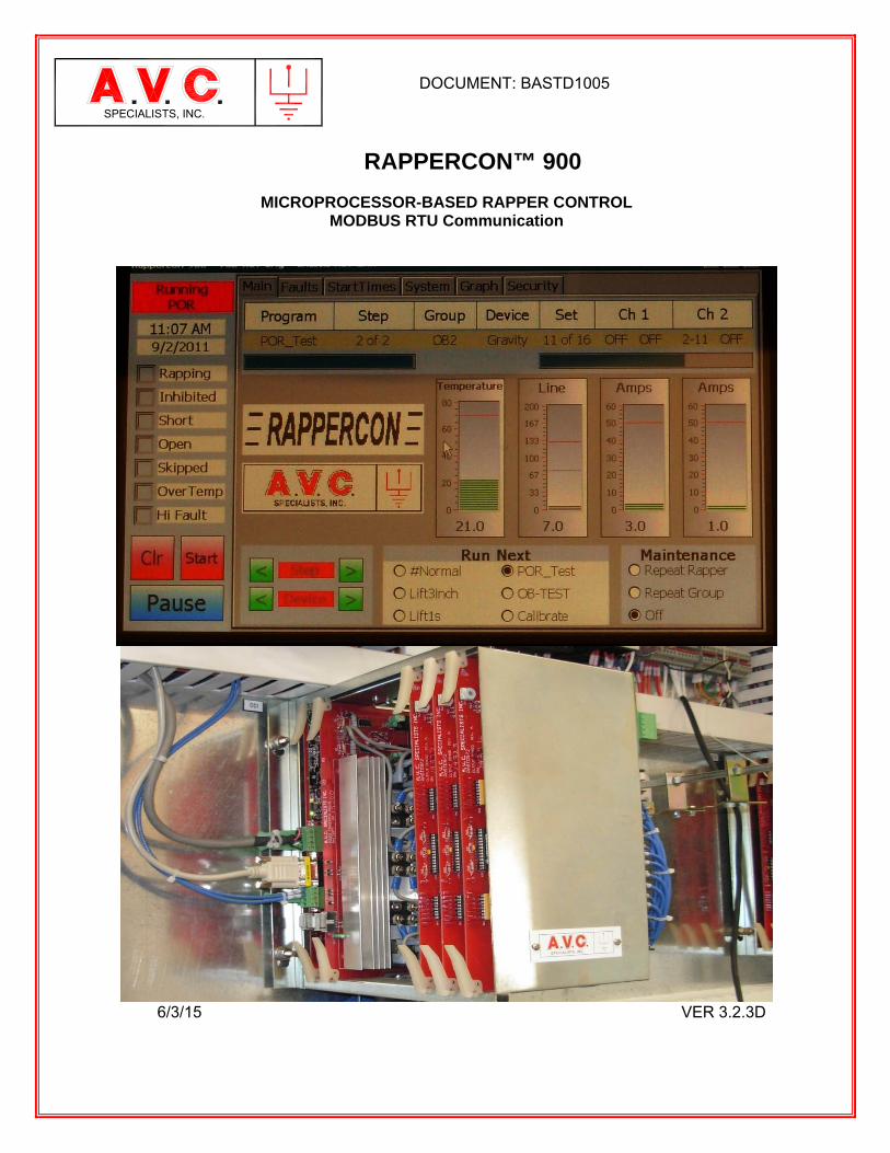
RAPPERCON™ 900
MICROPROCESSOR-BASED RAPPER CONTROL MODBUS RTU Communication
6/3/15 VER 3.2.3D
SPECIALISTS, INC.

INTENTIONALLY BLANK
A.V.C. Specialists, Inc. 5146-G Commerce Avenue Moorpark, CA 93021 (805) 531-8900 www.avcspecialists.com
Notices Limitation of Liability A.V.C. Specialists Inc. reserves the right to make changes in the devices or the device specifications identified in this Installation and Operating Manual without notice. A.V.C. Specialists advises customers to obtain the latest versions of device specification and operating firmware before installing this equipment. In the absence of written agreement to the contrary A.V.C. Specialists, Inc. assumes no liability for applications assistance, customer’s system design, or infringement of patents or copyrights of third parties by or arising from the use of devices described herein; nor does A.V.C. Specialists warrant or represent that any license, either expressed or implied, is granted under any patent right, copyright, or other intellectual property right of A.V.C. Specialists, Inc. covering any combination, machine, or process in which such device might be used. Except to the extent prohibited by applicable law, under no circumstances shall A.V.C. Specialists Inc. be liable for consequential damages sustained in connection with said product. A.V.C. Specialists, Inc. neither assumes nor authorizes any representative or other person to assume for it any obligation or liability other than such as is expressly set forth herein. POWERCONTM, RAPPERCON, PSS and HOPPER HAMMER are trademarks of A.V.C. Specialists Inc. All other trademarks are property of their respective owners. The information contained in this document is believed to be accurate at the time of publication, however, A.V.C. Specialists Inc. assumes no responsibility for any errors that may appear here and reserves the right to make changes without notice. Installation and Maintenance Considerations Installation and maintenance of the RAPPERCON control and auxiliary equipment should only be performed by qualified, competent personnel that have appropriate training and experience with electrical devices. Every effort
has been made to ensure the installation instructions presented in this document are clear and easy to understand; however, if you are not sure how to perform any of the instruction provided, DO NOT CONTINUE THE INSTALLATION, OPERATION OR REPAIR of this equipment. Mechanical installation instructions shown on page 56 must be followed or warranty will be voided. Warning Failure to observe the following information may result in severe injury or death: During normal operation of this device, hazardous voltages are present on the terminal strips, circuit boards, auxiliary equipment and external circuits. Follow standard safety precautions while performing any installation or service work. Warning This equipment should be installed in a switchgear cabinet or similar enclosure to ensure that the equipment is not accessible to non-qualified personnel. Do not use this device for primary protection functions. These include applications where the device performs energy limiting functions or provides protection of people from injury. Primary protective equipment includes but is not limited to circuit breakers, ground fault interrupters, fuses, etc. The RAPPERCON control may be used to provide secondary protection functions. Do not HIPOT or Dielectric test this equipment. Do not remove or install any circuit board with power applied to the control. The field devices operated by this equipment are often attached to equipment that operates at very high-voltages. Proper grounding of field devices is essential to provide protection of this equipment and service personnel.

INTENTIONALLY BLANK
Page i 5146-G COMMERCE AVENUE MOORPARK CA 93021 (805) 531-8900 FAX (805) 531-8903 www.AVCSPECIALISTS.COM
SPECIALISTS, INC.
RAPPERCON 900
OPERATING INSTRUCTIONS TABLE OF CONTENTS
1. GENERAL INFORMATION 1
1.1. INTRODUCTION 1 1.2 ENVIRONMENTAL SPECIFICATION 1
1.2.1 Barometric Pressure: 1 1.2.2 Air Temperature: 1 1.2.3 Relative Humidity: 1
1.3. APPLICATIONS 2 1.4. TYPES OF DEVICES OPERATED 2 1.5. FIELD WIRING CONFIGURATIONS 2 1.6 STANDARD FEATURES 2
1.6.1. Dual Channel Power Converter 2 1.6.2. Current Monitoring 3 1.6.3. Voltage Monitoring 3 1.6.4. Temperature Monitoring 3 1.6.5. Simultaneous Rapping 3 1.6.6. Intelligent Fault Memory 3 1.6.7. Multiple Programs 3 1.6.8. Security Access Code 3 1.6.9. Repeat Rapping (for Rapper Maintenance) 4 1.6.10 Program Start Time 4 1.6.11 Automatic Restart 4 1.6.12 Remote Program Select 4 1.6.13 On Demand Rapping (Hopper Rapping) 4 1.6.14 Power-Off-Rapping 4 1.6.15 Impact Limits 4 1.6.16 Demagnetization 5
2. DESCRIPTION OF THE COMPONENTS 6
2.1 CARD CAGE 6 2.2 CIRCUIT BOARDS 7
2.2.1 Interface Board (IFB) PAST974 8 2.2.2 Power Converter Board (PCB) PASTD973 12 2.2.3 Output Board (OB) PASTD972 15 2.2.4 Input Board (IB) PASTD773 17 2.2.5 Power-Off-Rapping Board (POR) PAST693 19 2.2.6 Cooling Fan (Optional) 20
2.3 DC POWER SUPPLY 20 2.3.1 PS1 (Card Cage / Circuit Board Power) 20 2.3.2 PS2 (TSD Power) 21
2.4 TOUCH SCREEN DISPLAY 22 2.4.1 TSD Reverse Side 22
Page ii 5146-G COMMERCE AVENUE MOORPARK CA 93021 (805) 531-8900 FAX (805) 531-8903 www.AVCSPECIALISTS.COM
SPECIALISTS, INC.
3. THEORY OF OPERATION 24
3.1. OPERATION SUMMARY 24 3.1.1 SEQUENTIAL Program Operation 24 3.1.2. #ROUND TRIP Program Operation 24
3.2 OPERATIONAL INTERRUPTS 25 3.2.1 Over Current (Short Circuit) 25 3.2.2 On Demand Mode (Hopper Rapping) 25 3.2.3 Programmed Start Time 25 3.2.4 Inhibit Field (GROUP) 25 3.2.5 Repeat Rapper 25 3.2.6 Remote Program Select 25
3.3 DETAILED OPERATIONAL THEORY 26 3.3.1 Common Rapping Devices 26
3.4 NORMAL OPERATION & EVENT LOGGING 29 3.5 POWER ROUTING 29 3.6 OUTPUT WIRING TO INDIVIDUAL RAPPERS 29
3.6.1 Direct Switching 29 3.6.2 Matrix Switching 30
3.7 POWER APPLICATION DETAILS 31 3.7.2 AC Output Power 34
3.8 RAPPING MODES 34 3.8.1 Normal Operation 34 3.8.2 On Demand Feature (Hopper Rapping) 35 3.8.3 Remote Program Select 36 3.8.4 Programmable Start Times 38
4. FUNDAMENTAL CONTROL OPERATIONS 40
4.1 START 40 4.1.1 Apply power to the control by closing the circuit breaker or disconnect switch. 40
4.2. SHUT DOWN 41 4.3 READ THE FAULT MEMORY 42 4.4 CHANGE OPERATING PROGRAMS 42 4.5 RAPPER MAINTENANCE 43
5. EDITING AND PROGRAMMING THE SYSTEM 45
5.1 BASIC EDITING 45 5.1.1 Methodology 45
5.2 CREATING PROGRAMS 46 5.3 CREATING GROUPS 47
5.3.1. GROUP TYPES (Names) 47 5.3,2 Creating a Group Using R-Editor 49
5.4 CREATE PROGRAMS 53 5.4.1 Sequential Program 54 5.4.2 #Round Trip Program 54 5.4.3 Create a SEQUENTIAL PROGRAM 55 5.4.4 Create a #ROUND TRIP PROGRAM 55
5.5 TRANSFERRING A PROGRAM TO/FROM RAPPERCON™ 900 TO LAPTOP VIA USB 56 5.5.1 Connection Laptop to RAPPERCON™ 900 56
Page iii 5146-G COMMERCE AVENUE MOORPARK CA 93021 (805) 531-8900 FAX (805) 531-8903 www.AVCSPECIALISTS.COM
SPECIALISTS, INC.
6. INSTALLATION INSTRUCTIONS 58
6.1 GENERAL INFORMATION 58 6.2 WIRING 58
6.2.1. Input Wiring Considerations 58 6.2.2. Output Wiring Considerations 58 6.2.3. Power Supplies 58 6.2.4 TSD 58 6.2.5 Rapper Installation 59
7. INITIAL STARTUP PROCEDURE 59
7.1. BASIC FUNCTION TEST 59 7.2. RAPPER OPERATING TEST 60 7.3 RAPPERCONTM 900 FAULT LIMIT CALIBRATION PROCEDURE 60
7.3.1. Overview 60 Skip Shorts 61 Calibration Specifics 61 Delete Faults 61 7.3.2 Calibration of the Rappercon 61 7.3.2. Setting the Voltage Offset 64 7.3.3 Voltage Scale Factor Adjustment 64 7.3.4. Setting the Current Offset 65 7.3.5 Current Scale Factor Adjustment: 65
8. TROUBLESHOOTING 66
8.1. TOUCH SCREEN DISPLAY MESSAGES 66 8.1.1. Status Messages 67 8.1.2. Error Messages 67
8.2 CONTROL TROUBLESHOOTING 68
9. POWER-OFF-RAPPING USING MODBUS COMMUNICATIONS 70
9.1 BASIC CONTROL CONFIGURATION 70 9.1.1 RAPPERCON™ 70 9.1.2 PSS™ 70 9.1.3 POWERCON™ 71
APPENDIX 72
A-1 RAPPERCONTM 900 SIMPLIFIED SCHEMATIC 72
A-2 ELECTROSTATIC PRECIPITATOR RAPPING OVERVIEW 73
A-2.1. RAPPING BASICS 73 A-2.2. CONSIDERATIONS 73
A-2.2.1 Preventing of excessive re-entrainment collected dust. 74 A-2.2.2 Creating ideal dust thickness (accumulation period). 74
A-2.3. EXAMPLE: RAPPING A THREE-FIELD PRECIPITATOR. 75 A-2.4 MECHANICAL DAMAGE 78 A-2.5 SUMMATION 78
A-3 HOPPER RAPPER CONTROL UNIT OVERVIEW 79
A-3.1. OPERATION OF A TYPICAL VACUUM TRANSPORT SYSTEM 79
Page iv 5146-G COMMERCE AVENUE MOORPARK CA 93021 (805) 531-8900 FAX (805) 531-8903 www.AVCSPECIALISTS.COM
SPECIALISTS, INC.
A-3.1.1 The basic operation of the vacuum transport system is as follows: 80 A-3.2 WIRING CONSIDERATIONS 80
A-3.2.1 Input Signals 80 A-3.2.2. Output Drives 83
A-4 SCREEN RAPPING CONTROL UNIT OVERVIEW 84
A-4.1 OVERVIEW 84 A-4.2 PROGRAMMING 84 A-4.3 PROGRAM SELECTION 85
A-4.4 Typical Configuration/Installation 86 A-4.5 WIRING CONSIDERATIONS 88
A-4.5.1 Input Signals 88 A-4.5.2 Output Rapper Drivers 88
A-5 RAPPER LIFT AND IMPACT TABLES 90
A-5.1 MODEL SR-A1 RAPPER IMPACT 90 A-5.2 MODEL GR-P1 GRAVITY RAPPER IMPACT 91
A-6 TIME & DATE SET ON THE TSD 92
A-7 DCS ENABLE/DISABLE OF TSD OPERATION –AEP WELSH SPECIFIC 94
Page 1
5146-G COMMERCE AVENUE MOORPARK CA 93021 (805) 531-8900 FAX (805) 531-8903 www.AVCSPECIALISTS.COM
SPECIALISTS, INC.
RAPPERCON 900
OPERATING INSTRUCTIONS
1. GENERAL INFORMATION 1.1. Introduction
The A.V.C. Specialists, Inc., RAPPERCON 900 is a control designed to operate various types of rapping devices. They may be associated with electrostatic precipitators, coal and feeder bunkers, LPA screen systems, hopper evacuation systems, etc. It is simple to use and easy to retrofit as a replacement for other controls. Effective rapping or vibrating of the collecting plates, discharge electrodes, feeder pipes, or hoppers is a key element in the performance of many types of industrial equipment. The control will allow the user to implement rapping programs that will dislodge material from precipitator plates and electrodes while minimizing entrainment of collected material back into the clean gas stream. It will clean the internal surface of hoppers and bunkers with discrete blows to free material from the sides of hopper and break material bridges.
This manual describes the installation, operation, and adjustment of the RAPPERCON 900 control and associated components that will apply and control power to a variety of rapping devices. The RAPPERCON control may be utilized as a stand-alone unit or integrated with the A.V.C. Specialists, Inc. Precipitator Supervisory System (PSS). When connected to the PSS, the RAPPERCON control will provide information for the real time graphic display of operating rappers and faults on the PSS displays, and from the PSS be remotely started, stopped, adjusted and reprogrammed.
1.2 Environmental Specification
The Power Converter Unit (where applicable) and the RAPPERCON Logic Cabinet are spec’d as follows:
1.2.1 Barometric Pressure:
Average 1015 mbar Minimum 965 mbar Maximum 1050 mbar
1.2.2 Air Temperature:
Minimum Designed -20 oC (-5 oF) Maximum Designed +45 oC (+113 oF)
1.2.3 Relative Humidity:
Minimum 40% Maximum 100%
Page 2
5146-G COMMERCE AVENUE MOORPARK CA 93021 (805) 531-8900 FAX (805) 531-8903 www.AVCSPECIALISTS.COM
SPECIALISTS, INC.
1.3. Applications The RAPPERCON control can be utilized for a variety of applications. It can be used as a traditional precipitator rapper control providing timing and impact control on a scheduled basis. The RAPPERCON may be used in an “ON DEMAND” mode to rap a specific rapper(s) (or vibrator(s)) only when activated by an external device. It will operate a specific rapper or group of rappers upon receipt of input from an external contact closure or remote communication associated with that rapper or group of rappers. This is very useful when rappers are used on hoppers or bunkers that are emptied on a cycled basis. This “ON DEMAND” feature may be utilized in conjunction with the traditional scheduled timed rapper operating programming.
1.4. Types of Devices Operated One control may operate many types of rapping devices such as DC rappers, AC vibrators, solenoid valves that control pneumatic rappers and motor driven tumbling hammers.
1.5. Field Wiring Configurations The control can be connected to operate field devices in two different fashions, “Direct” or “Matrix”. The “Direct” wiring method is most common. A single “Hot” lead is connected from a switched power output in the control to the device to be rapped. There is one output per field device. The “Neutral” return wire from the device may be connected with other neutral return wires and they also may be grounded. Up to 240 devices may be operated from one control. The matrix wiring method was used by a few OEMs to reduce the amount of wire and outputs needed to connect their control to the rappers. The A.V.C. Specialists RAPPERCON can be retrofitted in these locations. This method only works with DC devices and requires a series diode to be installed at each rapper. A “Hot’ lead is connected from one of switched outputs of an output board to a group of rappers designated as a row, typically no more than 16 rows but theoretically 128. The power returns to the control on wires attached to multiple rappers but one in a row. The returns are referred to as columns. The return leads are routed back to a second output board and one of the switched outputs. This creates a rectangular array in which two switched outputs must operate simultaneously to create the power out and the other to create a return path. The return wires cannot be grounded. The practical maximum number of devices that can be addressed using this wiring method is 256 although it is possible to address 14,336 discrete devices (see section 3.6.2).
1.6 Standard Features
1.6.1. Dual Channel Power Converter
Each RAPPERCON has two independent rapper power circuits (Channel 1 and Channel 2). Each circuit is powered from an AC supply voltage between 100 and 250 Volts (50 or 60 Hertz). Each channel may be externally configured (and reconfigured) to provide a DC or AC output of up to 50 amps. Both channels
Page 3
5146-G COMMERCE AVENUE MOORPARK CA 93021 (805) 531-8900 FAX (805) 531-8903 www.AVCSPECIALISTS.COM
SPECIALISTS, INC.
may be operated simultaneously. 1.6.2. Current Monitoring
The current of each channel is independently monitored (sample rate of 10 microseconds) and displayed by the control. If the current exceeds a user programmed value the current to the rapper will be shut off within 100 microseconds to prevent damage to the rapper or blowing any fuses. The current may also be displayed with the oscilloscope function of the RAPPERCON™ Touch Screen Display.
1.6.3. Voltage Monitoring
The output voltage of each channel is independently monitored (sample rate of 10 microseconds) and is displayed on the control. It may also be displayed with the oscilloscope function of the RAPPERCON™ Touch Screen Display.
1.6.4. Temperature Monitoring
The temperature of the Power Converter is monitored and may be viewed on the analog display screen. If the temperature exceeds 160°F (70°C) then the control will halt operation and provide an alarm output. If the temperature then falls below this set point the control will resume operation.
1.6.5. Simultaneous Rapping
Up to four rapping devices can be programmed to operate simultaneously, two per Channel.
1.6.6. Intelligent Fault Memory The control has a fault memory to identify bad rappers or field circuitry. In its memory the control will enter the ID of the rapper (Group Name and Output Set), open or short circuit indication, the output routing (board and terminal) with the control, and the real time and date that the fault was recorded to the memory. There is special logic that records only faults that have occurred on three successive attempts to operate that rapper circuit.
The user may select if the control is to continue to attempt to rap the faulty device or skip operating that device.
1.6.7. Multiple Programs
The control can store up to six different operating programs. Programs may be any combination of “Sequential” or “Round Trip” (described later) types.
1.6.8. Security Access Code
A four-digit security access code may be set so unauthorized individuals will not be able to change programs or operating parameters. However, anyone may still read all programs and parameter sets.
Page 4
5146-G COMMERCE AVENUE MOORPARK CA 93021 (805) 531-8900 FAX (805) 531-8903 www.AVCSPECIALISTS.COM
SPECIALISTS, INC.
1.6.9. Repeat Rapping (for Rapper Maintenance)
The control has two forms of repeat rapping cycles for maintenance purposes: Repeat Rapper and Repeat a Group of Rapper. Each of these cycles will run for 12 minutes and then revert to normal program operation.
1.6.10 Program Start Time
The Program Start Time feature allows the user to select a start time for any of the six programs in the memory. Later another program in the memory may be selected to operate at another time of the day. The control will allow the same program to be selected one, two or three times per day.
1.6.11 Automatic Restart
If power is interrupted the control will automatically start and begin operating rappers one minute after power is available. An external switch may be connected to prevent auto restart.
1.6.12 Remote Program Select
By using external signal inputs, either hardwired as a BCD input or via remote communications, one of the six operating programs may be selected to operate.
1.6.13 On Demand Rapping (Hopper Rapping)
By using external signal, either hardwired or via remote communication, the operation of the control may be interrupted and a specific rapper or group of rappers will immediately operated. If the signal is hardwired through an input board and that board is enabled then the control will operate that group repeatedly until the signal is removed. If more than two or more hardwire inputs are detected then the control will rotate between the external demands. When no inputs are detected, the control will resume normal operation from the point of interruption. If the demand interrupt is received via the network then the control will only service the interrupt for a programmed time but no longer then 30 seconds unless refreshed.
1.6.14 Power-Off-Rapping
If the control is operating a rapper or group of rappers that have been designated “Power-Off-Rapping, the control will provide an output either hardwired or via remote communication to annunciate to connected voltage controls.
1.6.15 Impact Limits
The control is capable of operating many different types of DC rappers that operate at different voltages, currents with different wiring distribution systems including wire gauge and length of runs. When the control is programmed, there are preloaded parameters values that the control applies to aid in the initial programming of the control. Later during the initial start-up, these valves are refined to adjust the rappers to the application. To prevent excessive energy from being applied to any type of rapper, an upper limit
Page 5
5146-G COMMERCE AVENUE MOORPARK CA 93021 (805) 531-8900 FAX (805) 531-8903 www.AVCSPECIALISTS.COM
SPECIALISTS, INC.
may be programmed for any type of DC rapper. 1.6.16 Demagnetization
Certain types of DC rappers are subject to magnetization of the plunger. This causes the plunger to stick to the strike anvil or rapper shaft and the electromagnetic forces need by the rapper coil to lift the plunger changes. This results in variations of impact from rapper to rapper and in the worst cases the plunger may not even lift. To demagnetize the plunger a brief AC current may be sent to the rapper.
Page 6
5146-G COMMERCE AVENUE MOORPARK CA 93021 (805) 531-8900 FAX (805) 531-8903 www.AVCSPECIALISTS.COM
SPECIALISTS, INC.
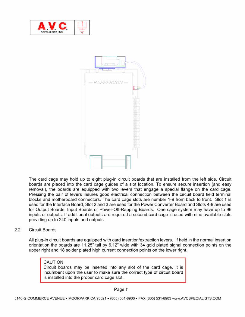
2. Description Of The Components The RAPPERCON control is comprised of three components: the card cage, DC power supply, and Keyboard/Display Unit (KDU). Additionally, power transformers, fuses and disconnect devices are required to provide power at the required voltage and with sufficient amperage to power the rappers.
2.1 Card Cage
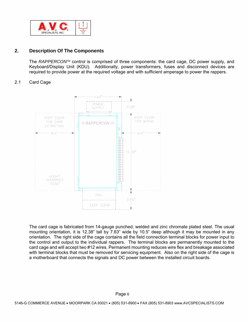
The card cage is fabricated from 14-gauge punched, welded and zinc chromate plated steel. The usual mounting orientation, it is 12.38” tall by 7.63” wide by 10.5” deep although it may be mounted in any orientation. The right side of the cage contains all the field connection terminal blocks for power input to the control and output to the individual rappers. The terminal blocks are permanently mounted to the card cage and will accept two #12 wires. Permanent mounting reduces wire flex and breakage associated with terminal blocks that must be removed for servicing equipment. Also on the right side of the cage is a motherboard that connects the signals and DC power between the installed circuit boards.
Page 7
5146-G COMMERCE AVENUE MOORPARK CA 93021 (805) 531-8900 FAX (805) 531-8903 www.AVCSPECIALISTS.COM
SPECIALISTS, INC.
The card cage may hold up to eight plug-in circuit boards that are installed from the left side. Circuit boards are placed into the card cage guides of a slot location. To ensure secure insertion (and easy removal), the boards are equipped with two levers that engage a special flange on the card cage. Pressing the pair of levers insures good electrical connection between the circuit board field terminal blocks and motherboard connectors. The card cage slots are number 1-9 from back to front. Slot 1 is used for the Interface Board, Slot 2 and 3 are used for the Power Converter Board and Slots 4-9 are used for Output Boards, Input Boards or Power-Off-Rapping Boards. One cage system may have up to 96 inputs or outputs. If additional outputs are required a second card cage is used with nine available slots providing up to 240 inputs and outputs.
2.2 Circuit Boards All plug-in circuit boards are equipped with card insertion/extraction levers. If held in the normal insertion orientation the boards are 11.25” tall by 6.12” wide with 34 gold plated signal connection points on the upper right and 18 solder plated high current connection points on the lower right.
CAUTION Circuit boards may be inserted into any slot of the card cage. It is incumbent upon the user to make sure the correct type of circuit board is installed into the proper card cage slot.
Page 8
5146-G COMMERCE AVENUE MOORPARK CA 93021 (805) 531-8900 FAX (805) 531-8903 www.AVCSPECIALISTS.COM
SPECIALISTS, INC.
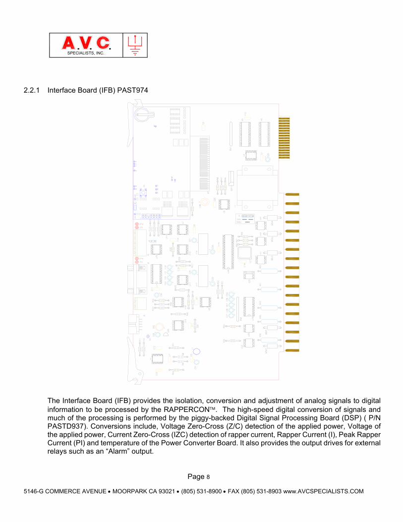
2.2.1 Interface Board (IFB) PAST974
The Interface Board (IFB) provides the isolation, conversion and adjustment of analog signals to digital information to be processed by the RAPPERCON. The high-speed digital conversion of signals and much of the processing is performed by the piggy-backed Digital Signal Processing Board (DSP) ( P/N PASTD937). Conversions include, Voltage Zero-Cross (Z/C) detection of the applied power, Voltage of the applied power, Current Zero-Cross (IZC) detection of rapper current, Rapper Current (I), Peak Rapper Current (PI) and temperature of the Power Converter Board. It also provides the output drives for external relays such as an “Alarm” output.
Page 9
5146-G COMMERCE AVENUE MOORPARK CA 93021 (805) 531-8900 FAX (805) 531-8903 www.AVCSPECIALISTS.COM
SPECIALISTS, INC.
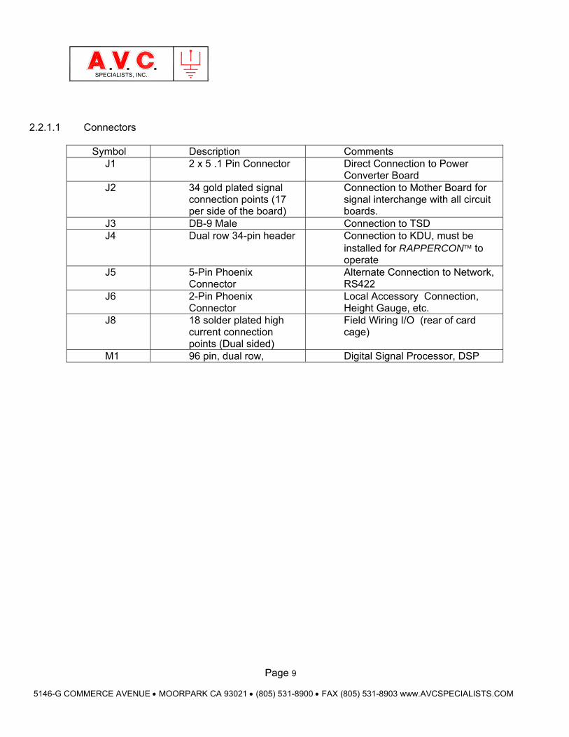
2.2.1.1 Connectors
Symbol Description Comments
J1 2 x 5 .1 Pin Connector Direct Connection to Power Converter Board
J2 34 gold plated signal connection points (17 per side of the board)
Connection to Mother Board for signal interchange with all circuit boards.
J3 DB-9 Male Connection to TSD J4 Dual row 34-pin header Connection to KDU, must be
installed for RAPPERCON to operate
J5 5-Pin Phoenix Connector
Alternate Connection to Network, RS422
J6 2-Pin Phoenix Connector
Local Accessory Connection, Height Gauge, etc.
J8 18 solder plated high current connection points (Dual sided)
Field Wiring I/O (rear of card cage)
M1 96 pin, dual row, Digital Signal Processor, DSP
Page 10
5146-G COMMERCE AVENUE MOORPARK CA 93021 (805) 531-8900 FAX (805) 531-8903 www.AVCSPECIALISTS.COM
SPECIALISTS, INC.
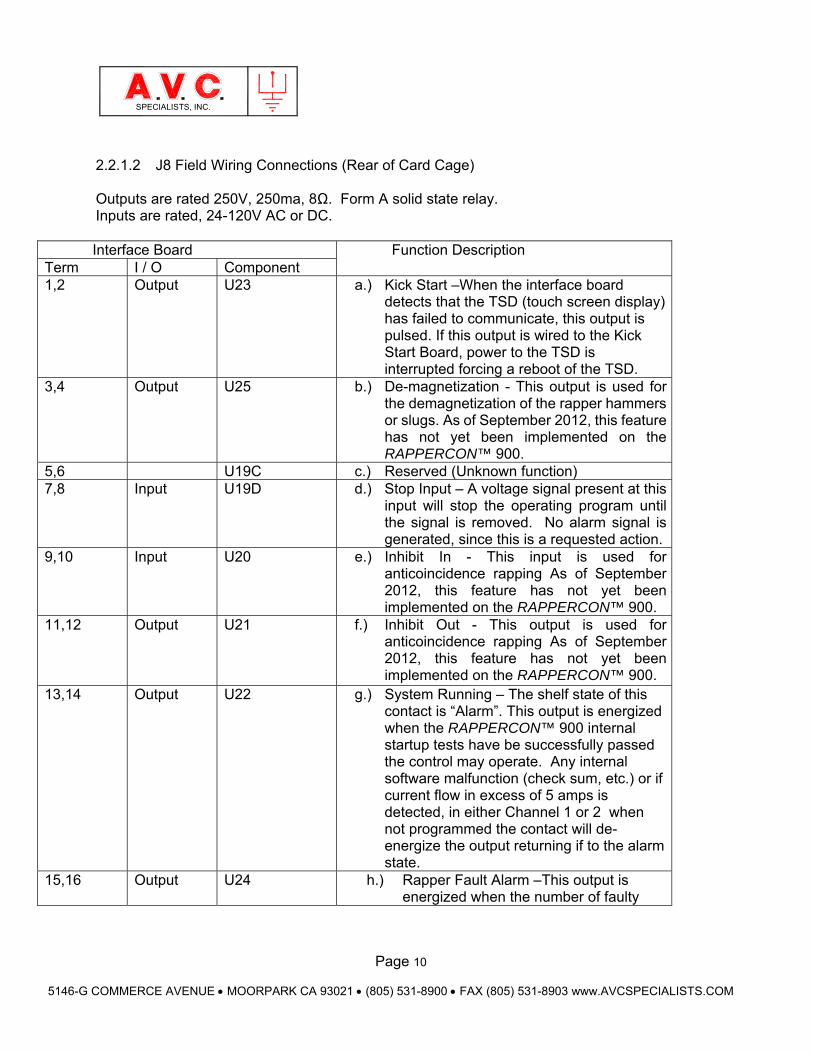
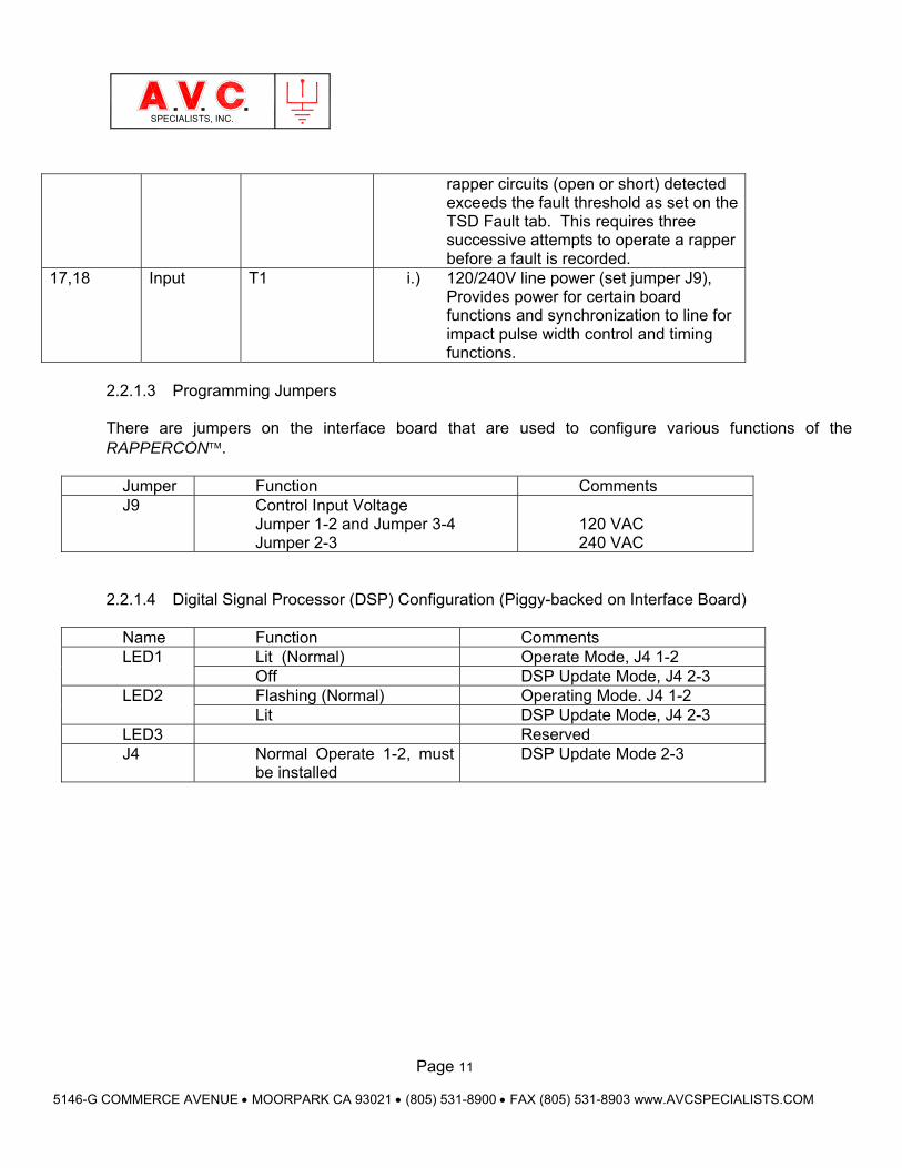
2.2.1.2 J8 Field Wiring Connections (Rear of Card Cage) Outputs are rated 250V, 250ma, 8Ω. Form A solid state relay. Inputs are rated, 24-120V AC or DC. Interface Board Function Description
Term I / O Component 1,2 Output U23 a.) Kick Start –When the interface board
detects that the TSD (touch screen display) has failed to communicate, this output is pulsed. If this output is wired to the Kick Start Board, power to the TSD is interrupted forcing a reboot of the TSD.
3,4 Output U25 b.) De-magnetization - This output is used for the demagnetization of the rapper hammers or slugs. As of September 2012, this feature has not yet been implemented on the RAPPERCON™ 900.
5,6 U19C c.) Reserved (Unknown function) 7,8 Input U19D d.) Stop Input – A voltage signal present at this
input will stop the operating program until the signal is removed. No alarm signal is generated, since this is a requested action.
9,10 Input U20 e.) Inhibit In - This input is used for anticoincidence rapping As of September 2012, this feature has not yet been implemented on the RAPPERCON™ 900.
11,12 Output U21 f.) Inhibit Out - This output is used for anticoincidence rapping As of September 2012, this feature has not yet been implemented on the RAPPERCON™ 900.
13,14 Output U22 g.) System Running – The shelf state of this contact is “Alarm”. This output is energized when the RAPPERCON™ 900 internal startup tests have be successfully passed the control may operate. Any internal software malfunction (check sum, etc.) or if current flow in excess of 5 amps is detected, in either Channel 1 or 2 when not programmed the contact will de-energize the output returning if to the alarm state.
15,16 Output U24 h.) Rapper Fault Alarm –This output is energized when the number of faulty
Page 11
5146-G COMMERCE AVENUE MOORPARK CA 93021 (805) 531-8900 FAX (805) 531-8903 www.AVCSPECIALISTS.COM
SPECIALISTS, INC.
rapper circuits (open or short) detected exceeds the fault threshold as set on the TSD Fault tab. This requires three successive attempts to operate a rapper before a fault is recorded.
17,18 Input T1 i.) 120/240V line power (set jumper J9), Provides power for certain board functions and synchronization to line for impact pulse width control and timing functions.
2.2.1.3 Programming Jumpers There are jumpers on the interface board that are used to configure various functions of the RAPPERCON.
Jumper Function Comments J9 Control Input Voltage
Jumper 1-2 and Jumper 3-4 Jumper 2-3
120 VAC 240 VAC
2.2.1.4 Digital Signal Processor (DSP) Configuration (Piggy-backed on Interface Board)
Name Function Comments LED1 Lit (Normal) Operate Mode, J4 1-2
Off DSP Update Mode, J4 2-3 LED2 Flashing (Normal) Operating Mode. J4 1-2
Lit DSP Update Mode, J4 2-3 LED3 Reserved J4 Normal Operate 1-2, must
be installed DSP Update Mode 2-3
Page 12
5146-G COMMERCE AVENUE MOORPARK CA 93021 (805) 531-8900 FAX (805) 531-8903 www.AVCSPECIALISTS.COM
SPECIALISTS, INC.
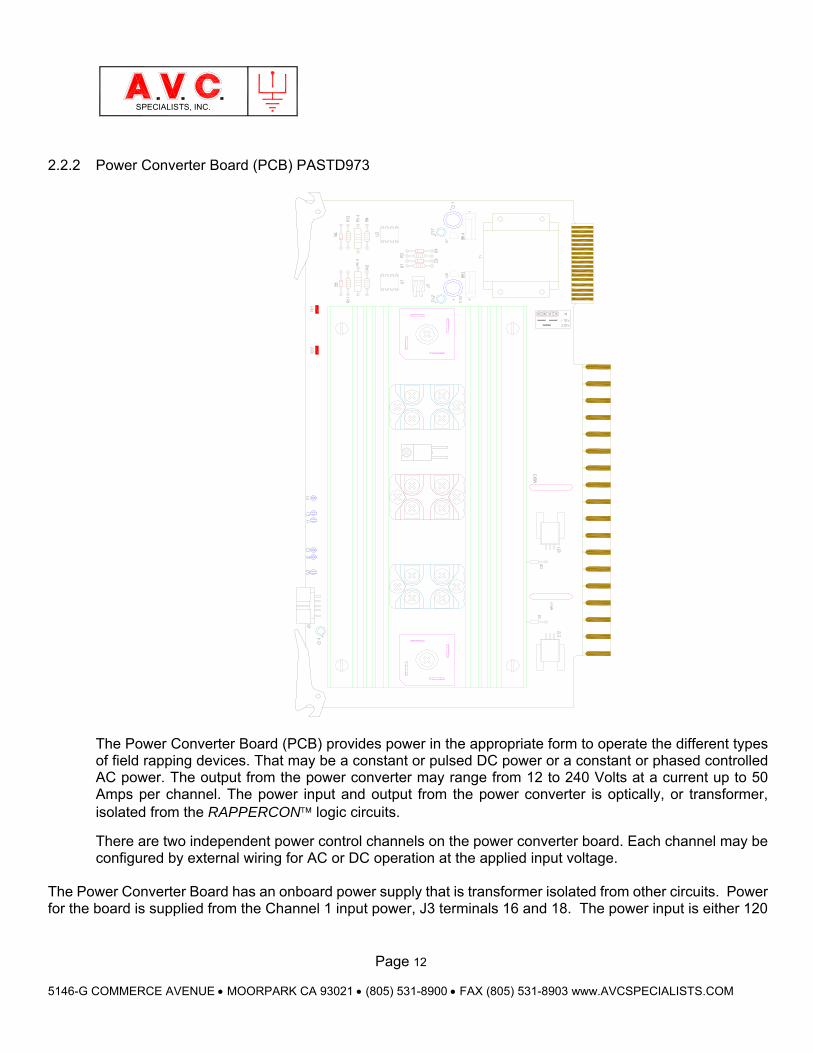
2.2.2 Power Converter Board (PCB) PASTD973
The Power Converter Board (PCB) provides power in the appropriate form to operate the different types of field rapping devices. That may be a constant or pulsed DC power or a constant or phased controlled AC power. The output from the power converter may range from 12 to 240 Volts at a current up to 50 Amps per channel. The power input and output from the power converter is optically, or transformer, isolated from the RAPPERCON logic circuits.
There are two independent power control channels on the power converter board. Each channel may be configured by external wiring for AC or DC operation at the applied input voltage.
The Power Converter Board has an onboard power supply that is transformer isolated from other circuits. Power for the board is supplied from the Channel 1 input power, J3 terminals 16 and 18. The power input is either 120
Page 13
5146-G COMMERCE AVENUE MOORPARK CA 93021 (805) 531-8900 FAX (805) 531-8903 www.AVCSPECIALISTS.COM
SPECIALISTS, INC.
or 240 volts and Jumper J4 must be set according.
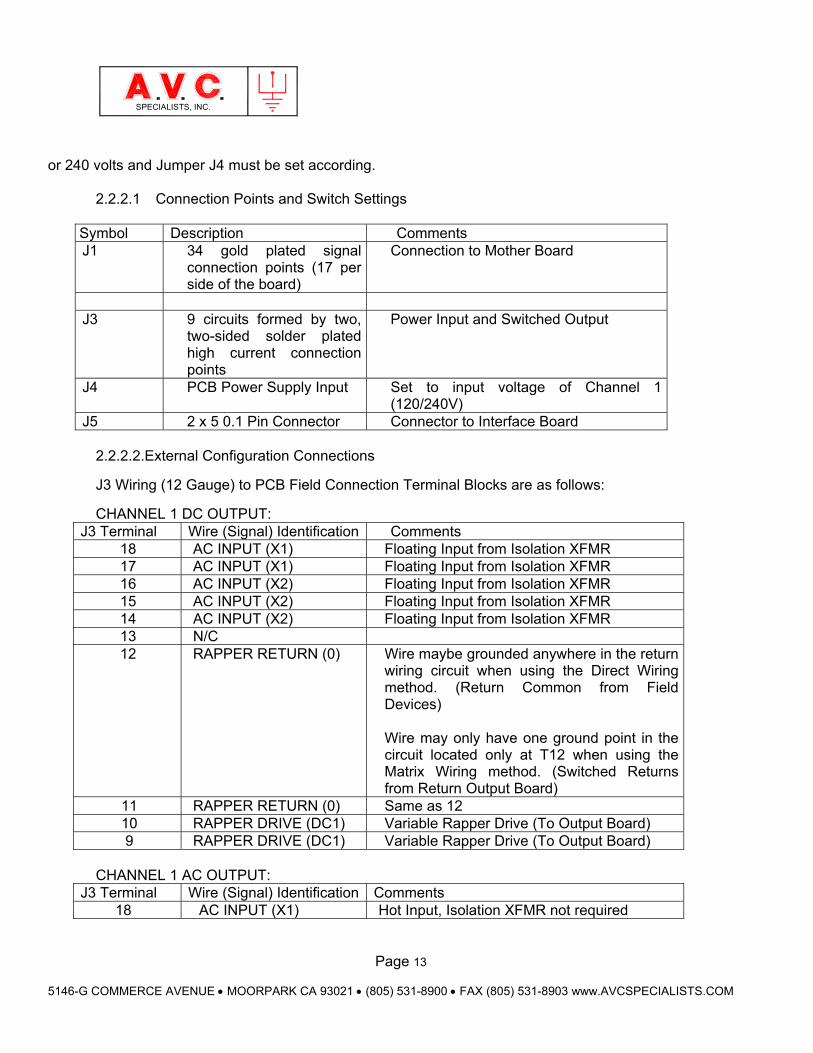
2.2.2.1 Connection Points and Switch Settings
Symbol Description Comments J1 34 gold plated signal
connection points (17 per side of the board)
Connection to Mother Board
J3 9 circuits formed by two,
two-sided solder plated high current connection points
Power Input and Switched Output
J4 PCB Power Supply Input Set to input voltage of Channel 1 (120/240V)
J5 2 x 5 0.1 Pin Connector Connector to Interface Board 2.2.2.2.External Configuration Connections
J3 Wiring (12 Gauge) to PCB Field Connection Terminal Blocks are as follows:
CHANNEL 1 DC OUTPUT: J3 Terminal Wire (Signal) Identification Comments
18 AC INPUT (X1) Floating Input from Isolation XFMR 17 AC INPUT (X1) Floating Input from Isolation XFMR 16 AC INPUT (X2) Floating Input from Isolation XFMR 15 AC INPUT (X2) Floating Input from Isolation XFMR 14 AC INPUT (X2) Floating Input from Isolation XFMR 13 N/C 12 RAPPER RETURN (0) Wire maybe grounded anywhere in the return
wiring circuit when using the Direct Wiring method. (Return Common from Field Devices) Wire may only have one ground point in the circuit located only at T12 when using the Matrix Wiring method. (Switched Returns from Return Output Board)
11 RAPPER RETURN (0) Same as 12 10 RAPPER DRIVE (DC1) Variable Rapper Drive (To Output Board) 9 RAPPER DRIVE (DC1) Variable Rapper Drive (To Output Board)
CHANNEL 1 AC OUTPUT:
J3 Terminal Wire (Signal) Identification Comments 18 AC INPUT (X1) Hot Input, Isolation XFMR not required
Page 14
5146-G COMMERCE AVENUE MOORPARK CA 93021 (805) 531-8900 FAX (805) 531-8903 www.AVCSPECIALISTS.COM
SPECIALISTS, INC.
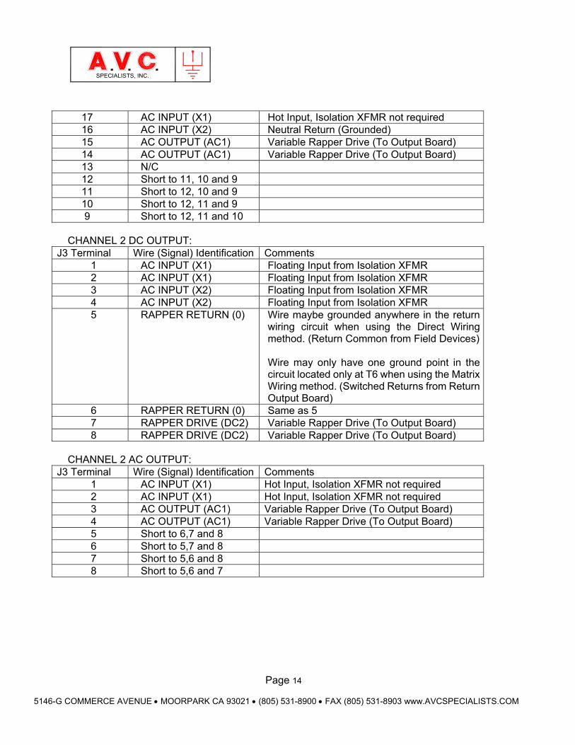
17 AC INPUT (X1) Hot Input, Isolation XFMR not required 16 AC INPUT (X2) Neutral Return (Grounded) 15 AC OUTPUT (AC1) Variable Rapper Drive (To Output Board) 14 AC OUTPUT (AC1) Variable Rapper Drive (To Output Board) 13 N/C 12 Short to 11, 10 and 9 11 Short to 12, 10 and 9 10 Short to 12, 11 and 9 9 Short to 12, 11 and 10
CHANNEL 2 DC OUTPUT:
J3 Terminal Wire (Signal) Identification Comments 1 AC INPUT (X1) Floating Input from Isolation XFMR 2 AC INPUT (X1) Floating Input from Isolation XFMR 3 AC INPUT (X2) Floating Input from Isolation XFMR 4 AC INPUT (X2) Floating Input from Isolation XFMR 5 RAPPER RETURN (0) Wire maybe grounded anywhere in the return
wiring circuit when using the Direct Wiring method. (Return Common from Field Devices) Wire may only have one ground point in the circuit located only at T6 when using the Matrix Wiring method. (Switched Returns from Return Output Board)
6 RAPPER RETURN (0) Same as 5 7 RAPPER DRIVE (DC2) Variable Rapper Drive (To Output Board) 8 RAPPER DRIVE (DC2) Variable Rapper Drive (To Output Board)
CHANNEL 2 AC OUTPUT:
J3 Terminal Wire (Signal) Identification Comments 1 AC INPUT (X1) Hot Input, Isolation XFMR not required 2 AC INPUT (X1) Hot Input, Isolation XFMR not required 3 AC OUTPUT (AC1) Variable Rapper Drive (To Output Board) 4 AC OUTPUT (AC1) Variable Rapper Drive (To Output Board) 5 Short to 6,7 and 8 6 Short to 5,7 and 8 7 Short to 5,6 and 8 8 Short to 5,6 and 7
Page 15
5146-G COMMERCE AVENUE MOORPARK CA 93021 (805) 531-8900 FAX (805) 531-8903 www.AVCSPECIALISTS.COM
SPECIALISTS, INC.
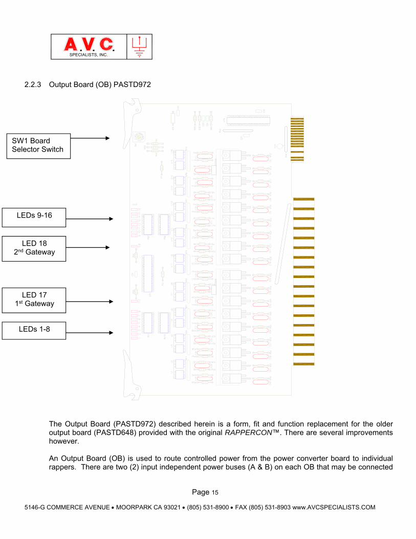
2.2.3 Output Board (OB) PASTD972
The Output Board (PASTD972) described herein is a form, fit and function replacement for the older output board (PASTD648) provided with the original RAPPERCON™. There are several improvements however.
An Output Board (OB) is used to route controlled power from the power converter board to individual rappers. There are two (2) input independent power buses (A & B) on each OB that may be connected
LED 18 2nd Gateway
SW1 Board Selector Switch
LED 17 1st Gateway
LEDs 9-16
LEDs 1-8
Page 16
5146-G COMMERCE AVENUE MOORPARK CA 93021 (805) 531-8900 FAX (805) 531-8903 www.AVCSPECIALISTS.COM
SPECIALISTS, INC.
to different Channels. Each bus has a gateway switched bi-directional triac that passes power to 8 identical parallel triac outputs. Up to 15 Output Boards may be installed in one RAPPERCON. Each output board installed is given an address using the rotary selector switch, SW1. Board address must be between 1 and 15 but not conflict with other board address. The RAPPERCON can simultaneously switch on up to 4 output triacs (bi-directional electronic switches) that may be located on one or more output boards. The control logic circuits are isolated from the output power by the use of optically isolated switch drivers. If an output triac is switched on, then a corresponding red colored LED on the output board is illuminated. Each of the independent power buses has a temperature monitor on the heat sink to protect the triacs from overheating. If the temperature exceeds 75°C the power bus gateway triac will not allow current to pass until the temperature is reduced. While the temperature exceeds the shutoff temperature the gateway LED will flash at a rate of 1 Hz. If power is blocked for an extended amount of time, an open circuit will be recorded in the memory.
Page 17
5146-G COMMERCE AVENUE MOORPARK CA 93021 (805) 531-8900 FAX (805) 531-8903 www.AVCSPECIALISTS.COM
SPECIALISTS, INC.
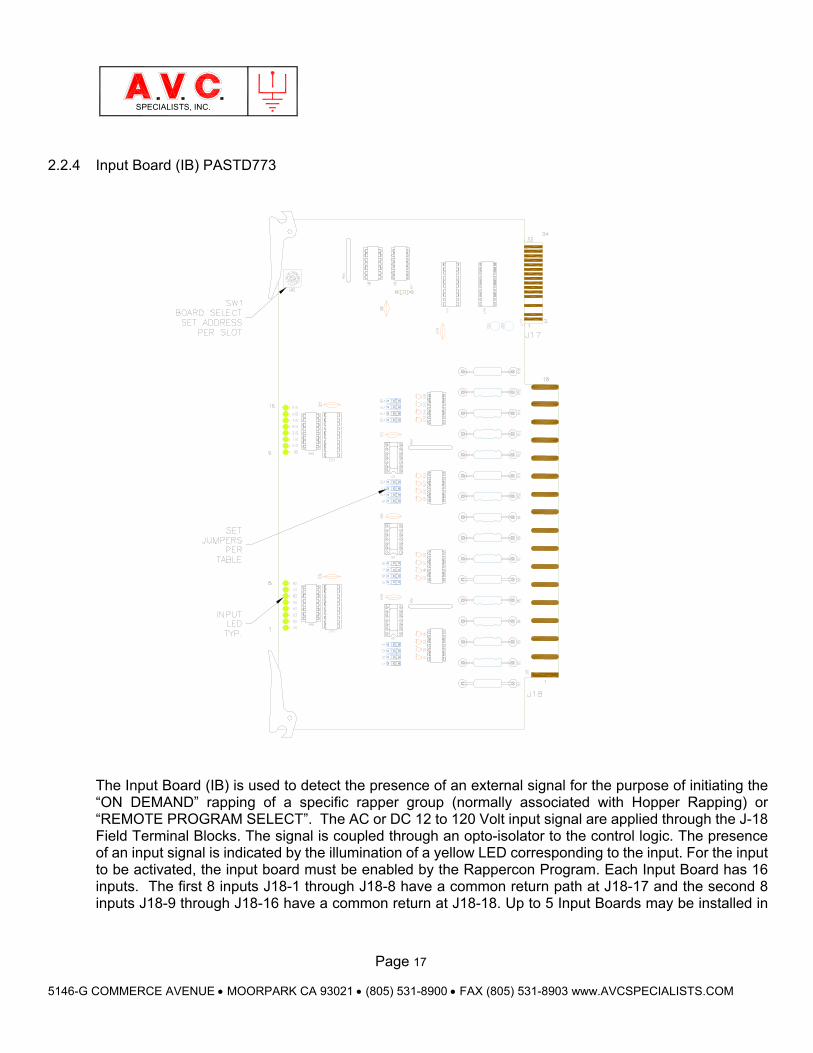
2.2.4 Input Board (IB) PASTD773
The Input Board (IB) is used to detect the presence of an external signal for the purpose of initiating the “ON DEMAND” rapping of a specific rapper group (normally associated with Hopper Rapping) or “REMOTE PROGRAM SELECT”. The AC or DC 12 to 120 Volt input signal are applied through the J-18 Field Terminal Blocks. The signal is coupled through an opto-isolator to the control logic. The presence of an input signal is indicated by the illumination of a yellow LED corresponding to the input. For the input to be activated, the input board must be enabled by the Rappercon Program. Each Input Board has 16 inputs. The first 8 inputs J18-1 through J18-8 have a common return path at J18-17 and the second 8 inputs J18-9 through J18-16 have a common return at J18-18. Up to 5 Input Boards may be installed in
Page 18
5146-G COMMERCE AVENUE MOORPARK CA 93021 (805) 531-8900 FAX (805) 531-8903 www.AVCSPECIALISTS.COM
SPECIALISTS, INC.
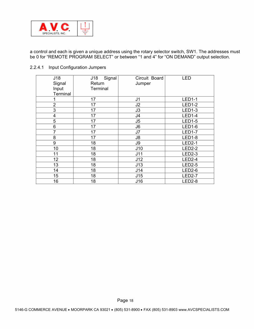
a control and each is given a unique address using the rotary selector switch, SW1. The addresses must be 0 for “REMOTE PROGRAM SELECT” or between “1 and 4” for “ON DEMAND” output selection. 2.2.4.1 Input Configuration Jumpers
J18 Signal Input Terminal
J18 Signal Return Terminal
Circuit Board Jumper
LED
1 17 J1 LED1-1 2 17 J2 LED1-2 3 17 J3 LED1-3 4 17 J4 LED1-4 5 17 J5 LED1-5 6 17 J6 LED1-6 7 17 J7 LED1-7 8 17 J8 LED1-8 9 18 J9 LED2-1 10 18 J10 LED2-2 11 18 J11 LED2-3 12 18 J12 LED2-4 13 18 J13 LED2-5 14 18 J14 LED2-6 15 18 J15 LED2-7 16 18 J16 LED2-8
Page 19
5146-G COMMERCE AVENUE MOORPARK CA 93021 (805) 531-8900 FAX (805) 531-8903 www.AVCSPECIALISTS.COM
SPECIALISTS, INC.
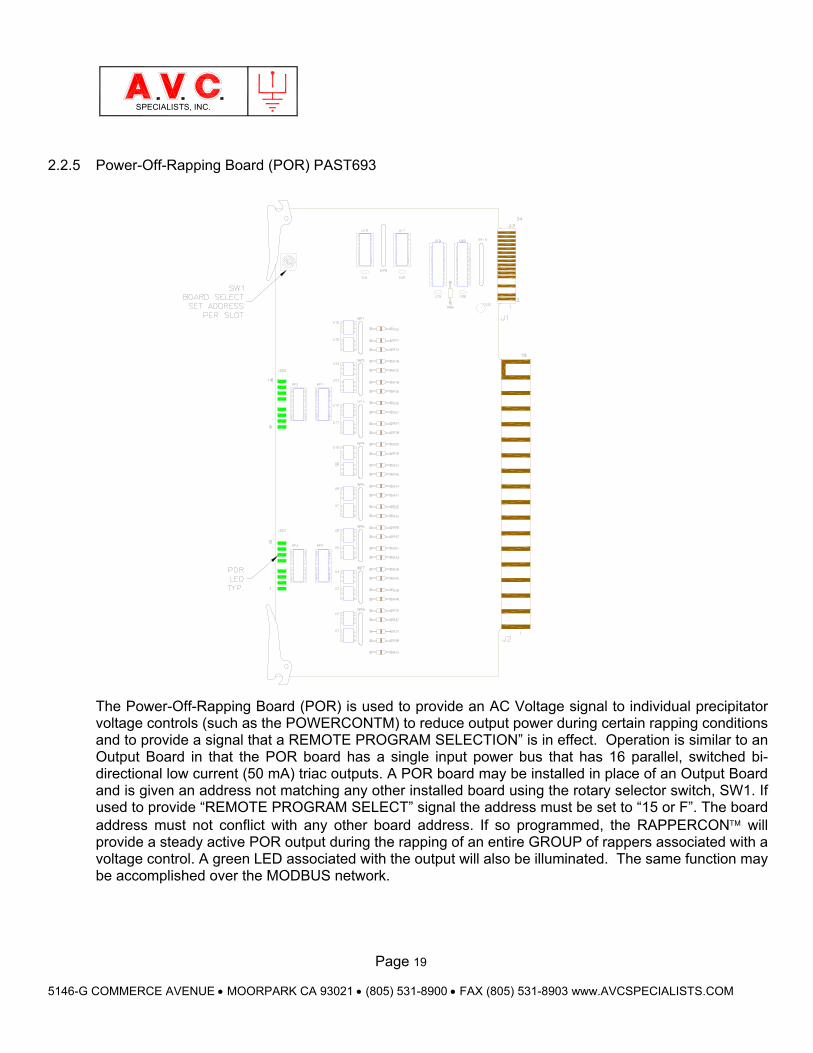
2.2.5 Power-Off-Rapping Board (POR) PAST693
The Power-Off-Rapping Board (POR) is used to provide an AC Voltage signal to individual precipitator voltage controls (such as the POWERCONTM) to reduce output power during certain rapping conditions and to provide a signal that a REMOTE PROGRAM SELECTION” is in effect. Operation is similar to an Output Board in that the POR board has a single input power bus that has 16 parallel, switched bi-directional low current (50 mA) triac outputs. A POR board may be installed in place of an Output Board and is given an address not matching any other installed board using the rotary selector switch, SW1. If used to provide “REMOTE PROGRAM SELECT” signal the address must be set to “15 or F”. The board address must not conflict with any other board address. If so programmed, the RAPPERCON will provide a steady active POR output during the rapping of an entire GROUP of rappers associated with a voltage control. A green LED associated with the output will also be illuminated. The same function may be accomplished over the MODBUS network.
Page 20
5146-G COMMERCE AVENUE MOORPARK CA 93021 (805) 531-8900 FAX (805) 531-8903 www.AVCSPECIALISTS.COM
SPECIALISTS, INC.
2.2.6 Cooling Fan (Optional)
The card cage is an open frame design to allow easy card insertion but more importantly adequate air circulation for component cooling. The Power Converter Card dissipates the greatest amount of heat. In certain application, convection cooling may prove inadequate and an external fan is mounted to the bottom of the card cage. The fan adds 3” of additional height to the card cage assembly.
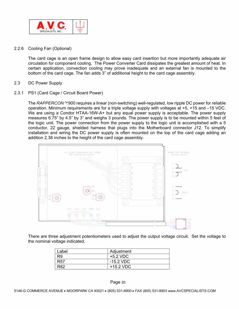
2.3 DC Power Supply 2.3.1 PS1 (Card Cage / Circuit Board Power)
The RAPPERCON 900 requires a linear (non-switching) well-regulated, low ripple DC power for reliable operation. Minimum requirements are for a triple voltage supply with voltages at +5, +15 and –15 VDC. We are using a Condor HTAA-16W-A+ but any equal power supply is acceptable. The power supply measures 6.75” by 4.5” by 3” and weighs 3 pounds. The power supply is to be mounted within 5 feet of the logic unit. The power connection from the power supply to the logic unit is accomplished with a 5 conductor, 22 gauge, shielded harness that plugs into the Motherboard connector J12. To simplify installation and wiring the DC power supply is often mounted on the top of the card cage adding an addition 2.38 inches to the height of the card cage assembly.
There are three adjustment potentiometers used to adjust the output voltage circuit. Set the voltage to the nominal voltage indicated.
Label Adjustment R9 +5.2 VDC R57 -15.2 VDC R82 +15.2 VDC
Page 21
5146-G COMMERCE AVENUE MOORPARK CA 93021 (805) 531-8900 FAX (805) 531-8903 www.AVCSPECIALISTS.COM
SPECIALISTS, INC.
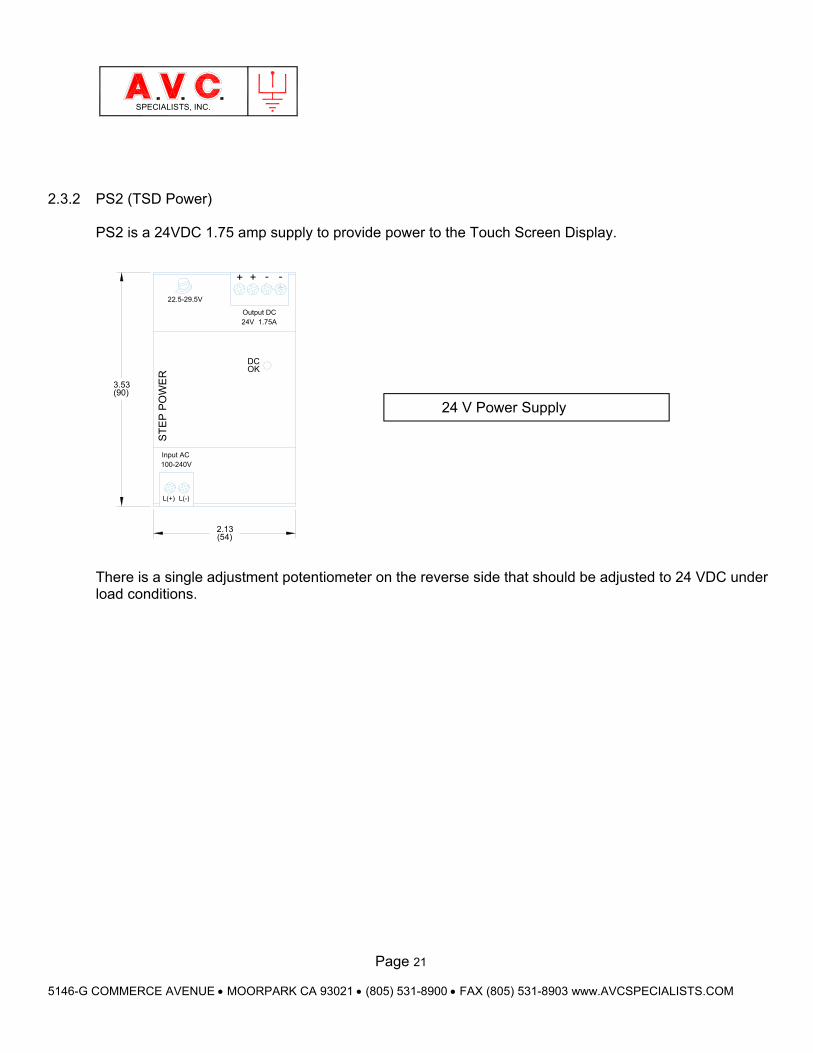
2.3.2 PS2 (TSD Power)
PS2 is a 24VDC 1.75 amp supply to provide power to the Touch Screen Display.
+ -+ -
Output DC24V 1.75A
Input AC100-240V
L(+) L(-)
DCOK
22.5-29.5V
ST
EP
PO
WE
R
3.53
2.13
(90)
(54)
There is a single adjustment potentiometer on the reverse side that should be adjusted to 24 VDC under load conditions.
24 V Power Supply
Page 22
5146-G COMMERCE AVENUE MOORPARK CA 93021 (805) 531-8900 FAX (805) 531-8903 www.AVCSPECIALISTS.COM
SPECIALISTS, INC.
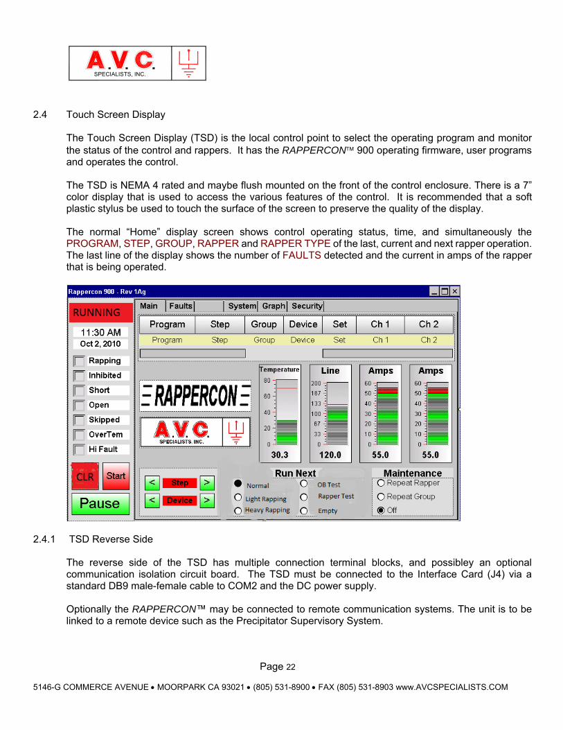
2.4 Touch Screen Display
The Touch Screen Display (TSD) is the local control point to select the operating program and monitor the status of the control and rappers. It has the RAPPERCON 900 operating firmware, user programs and operates the control. The TSD is NEMA 4 rated and maybe flush mounted on the front of the control enclosure. There is a 7” color display that is used to access the various features of the control. It is recommended that a soft plastic stylus be used to touch the surface of the screen to preserve the quality of the display. The normal “Home” display screen shows control operating status, time, and simultaneously the PROGRAM, STEP, GROUP, RAPPER and RAPPER TYPE of the last, current and next rapper operation. The last line of the display shows the number of FAULTS detected and the current in amps of the rapper that is being operated.
2.4.1 TSD Reverse Side
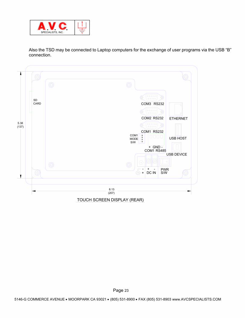
The reverse side of the TSD has multiple connection terminal blocks, and possibley an optional communication isolation circuit board. The TSD must be connected to the Interface Card (J4) via a standard DB9 male-female cable to COM2 and the DC power supply.
Optionally the RAPPERCON™ may be connected to remote communication systems. The unit is to be linked to a remote device such as the Precipitator Supervisory System.
Page 23
5146-G COMMERCE AVENUE MOORPARK CA 93021 (805) 531-8900 FAX (805) 531-8903 www.AVCSPECIALISTS.COM
SPECIALISTS, INC.
Also the TSD may be connected to Laptop computers for the exchange of user programs via the USB “B” connection.
PWRS/WDC IN
+ -
USB DEVICE
USB HOST
ETHERNET
RS485-+
COM1
COM1MODES/W
GND
RS232COM1
RS232COM2
RS232COM3SDCARD
+-
8.13
5.38
(207)
(137)
TOUCH SCREEN DISPLAY (REAR)
Page 24
5146-G COMMERCE AVENUE MOORPARK CA 93021 (805) 531-8900 FAX (805) 531-8903 www.AVCSPECIALISTS.COM
SPECIALISTS, INC.
3. Theory of Operation 3.1. Operation Summary
The RAPPERCON directs controlled pulses of electric power through power switching components to operate a variety of field devices. There are two methods of control operation that are automatically selected by the PROGRAM selected to operate. One is “SEQUENTIAL” and the other is “#ROUND TRIP”. Upon application of power or pressing the CLR key, the control software will perform a self-check, load from the non-volatile memory one of six PROGRAMS. The control will wait for one minute and then begin to operate rappers.
3.1.1 SEQUENTIAL Program Operation
If the program selected uses SEQUENTIAL Operation, then the control operates by following a sequence of STEPs. Starting at STEP 1 the control will read the name of the GROUP indicated and retrieve information about that GROUP from the non-volatile library. A GROUP contains between 1 and 32 (OUTPUT SET), one to four rappers that are operated simultaneously) that will be operated sequentially in the order listed within the GROUP. First the power routing is selected (Output Board Number and Output Terminal and return if using matrix wiring) to each rapper. Then controlled power is applied from the Power Converter Board, through the Output Board(s) to operate the rapper with the correct IMPACT, FREQUENCY (Raps per Second) ON-TIME (operating period in seconds) and OFF-TIME (rest time between rappers). The control will index through each rapper in the GROUP and after rapping the last rapper index to the next STEP. After completing the last step, the control will perform a self-check and again load the PROGRAM and begin to operate rappers immediately.
3.1.2. #ROUND TRIP Program Operation
If the program selected uses #ROUND TRIP Operation, the control operates all #GROUPS of rappers in the program simultaneously. The user will have programmed each #GROUP with a #ROUND TRIP time. Similar to the method above the user will select any number of OUTPUT SETS (rappers) from one to thirty-two, provide the power routing information about each rapper and the IMPACT, FREQUENCY, and ON-TIME but not the OFF-TIME between rappers. Instead the user will provide the total time (#ROUND TRIP) time required for the control to have rapped all the rappers in the group before starting the group again. The control will calculate an interval between rappers so that each rapper within the group operates at equal intervals. The control will interweave the operation rappers from the different #GROUPS, depending on the time interval between rappers but operate just one rapper at a time. In the event that two rappers are scheduled to operate at the same time, the control will prioritize the order by selecting the rapper from the #GROUP first listed in the program followed by the rapper from the next listed #GROUP.
#ROUND TRIP PROGRAMS and associated #GROUPS are identified by the number sign (#) as the first character in the #PROGRAM and #GROUP names.
Page 25
5146-G COMMERCE AVENUE MOORPARK CA 93021 (805) 531-8900 FAX (805) 531-8903 www.AVCSPECIALISTS.COM
SPECIALISTS, INC.
3.2 Operational Interrupts
There are several types of interrupts that will automatically cause the control to interrupt operation, perform the required request, than automatically resume operation. The following list of interrupts gives a brief overview of the interrupt. Details are described in other sections of this manual.
3.2.1 Over Current (Short Circuit)
The control monitors and displays the value of the current routed to the rapper. If the current exceeds a programmable value, current flow will be interrupted within 100 microseconds. If the over current occurs on three successive attempts to operate that rapper then the information is recorded in the fault memory. The control will then proceed to operate the next rapper.
3.2.2 On Demand Mode (Hopper Rapping)
If an input signal associated with a “HOPPER” GROUP is detected by the control (through an Input Card or over the MODBUS network), the control will halt operating the current program. The control will service the interrupt by jumping to operate a HOPPER GROUP of rappers associated with the input. When the input ceases the control will begin operating from the point of the interrupt. This function must be enabled using the Touch Screen Display (TSD).
3.2.3 Programmed Start Time
This is an interrupt generated by the control’s Real Time Clock. If so programmed at specific times during the day the control will stop operating the current program and load from memory a new selected PROGRAM. The new program will then start operating. See section 3.8.4
3.2.4 Inhibit Field (GROUP)
This is an interrupt that is negotiated between two or more RAPPERCON controls. It is used to prevent rapping of rappers within a GROUP designed as “INHIBITED” when another control is rapping a GROUP designed as “INHIBITED. There are four levels of “INHIBIT” and the control with the highest level will operate while the other controls will wait. The inhibited designation is usually associated with rappers in the outlet field of a precipitator.
3.2.5 Repeat Rapper
This is an operator-initiated interrupt at the TSD. The control will cease operating the current program and a specific rapper or group of rappers will continually operate for a period of 12 minutes, the control will resume the current program.
3.2.6 Remote Program Select
If a voltage signal is detected at terminals 14, 15 or 16 of Input Card, address “0” the control will then jump to and operate a specific program named in the range of “RSelect1 to RSelect6.
Page 26
5146-G COMMERCE AVENUE MOORPARK CA 93021 (805) 531-8900 FAX (805) 531-8903 www.AVCSPECIALISTS.COM
SPECIALISTS, INC.
3.3 Detailed Operational Theory
The function of the RAPPERCON control is to operate in an orderly fashion to deliver controlled power to various rapping devices.
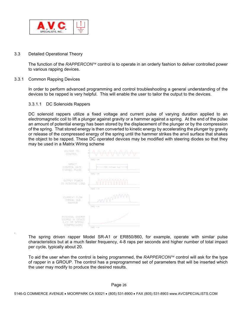
3.3.1 Common Rapping Devices In order to perform advanced programming and control troubleshooting a general understanding of the devices to be rapped is very helpful. This will enable the user to tailor the output to the devices. 3.3.1.1 DC Solenoids Rappers DC solenoid rappers utilize a fixed voltage and current pulse of varying duration applied to an electromagnetic coil to lift a plunger against gravity or a hammer against a spring. At the end of the pulse an amount of potential energy has been stored by the displacement of the plunger or by the compression of the spring. That stored energy is then converted to kinetic energy by accelerating the plunger by gravity or release of the compressed energy of the spring until the hammer strikes the anvil surface that shakes the object to be rapped. These DC operated devices may be modified with steering diodes so that they may be used in a Matrix Wiring scheme
. The spring driven rapper Model SR-A1 or ER850/860, for example, operate with similar pulse characteristics but at a much faster frequency, 4-8 raps per seconds and higher number of total impact per cycle, typically about 20. To aid the user when the control is being programmed, the RAPPERCON control will ask for the type of rapper in a GROUP. The control has a preprogrammed set of parameters that will be inserted which the user may modify to produce the desired results.
Page 27
5146-G COMMERCE AVENUE MOORPARK CA 93021 (805) 531-8900 FAX (805) 531-8903 www.AVCSPECIALISTS.COM
SPECIALISTS, INC.
3.3.1.2 Gravity Rappers
The GR (gravity rapper), also known by various other acronyms, MIGI (magnetic impulse, gravity impact), MIGR (magnetic impulse, gravity return), operate with a general set of characteristics. They are operated with a constant voltage pulse of between 40 and 200 milliseconds to lift the plunger followed by a return time when no power is applied to allow the plunger to fall against the rapper rod. The GR type rappers are typically operated at a frequency of 1 rap every 2 seconds with a total of 1 to 4 raps per cycle. There is a special optional feature of the RAPPERCON™ 900 is precise lift calibration for each specific rapper. Using the A.V.C. Specialists’ Height Gauge each rapper is calibrated automatically to within .05 inches of lift for each electric pulse. A chart is created for each location and the electric pulse width is adjusted for each location.
Page 28
5146-G COMMERCE AVENUE MOORPARK CA 93021 (805) 531-8900 FAX (805) 531-8903 www.AVCSPECIALISTS.COM
SPECIALISTS, INC.
3.3.1.3 AC Vibrators There are many brands of AC vibrators that provide vibration to the surface to be cleaned. The vibration provided by the AC vibrators can to a limited degree be varied in intensity but operates at a fixed rate of 60 hertz. Unlike the DC solenoid devices that provide sharp, quick accelerations of the surface to be rapped, the AC vibrators deliver a sinusoidal acceleration that follows the wave shape of the applied power. Vibrator construction varies widely among the manufactures. In general though they all rely on an electromagnetic coil to pull a mass of steel toward the coil and then allow the steel to spring back to the original position. The effectiveness of the vibrator is dependent upon maintaining the proper gap between the coil and steel. The RAPPERCON will provide phase-controlled power to operate the coil of the vibrator to vary the intensity of rapping but not the frequency. Depending upon the vibrator it may require either full or half wave application of power.
3.3.1.4 Motor Driven Devices There are many types of motor driven devices. The most commonly found motor applications in the precipitators are three phase motors driving a gear reducer that is in turn used to rotate a shaft with cam mechanism that lifts and drops hammers, rods or complete precipitator assemblies. Another common motor design found on precipitators and hoppers is a single-phase motor that quickly rotates an eccentric weight to provide vibration. The control will provide timing for these devices but no adjustment for impact or frequency.
3.3.1.5 Pneumatic Devices There are four types of pneumatic devices usually associated with cleaning operations that may be controlled with the control. Pneumatic impact rappers are operated by the application of dry, pressured air to move a piston back and forth. Impact energy and frequency of operation are dependent upon the volume and pressure of the air supply. Ball raceway vibrators utilize a heavy ball moving inside a circular raceway to create a sinusoidal vibration. The frequency and strength of vibration are directly related to the speed of the ball that is controlled to the air pressure available. Sonic horns are used to produce very strong, low frequency sound waves inside a confined space to vibrate the material to be dislodged from a surface rather than vibrating the surface to be cleaned. The energy delivered by the horns is again dependent on the pressure and volume of air supplied. The puffer system directs a quick burst of air directly at the material to be removed. This method of operation is usually associated with the pulse jet baghouses but has been successfully applied to points of specific material build-up. The RAPPERCON will operate various control valves with the correct timing to produce the desired

Page 29
5146-G COMMERCE AVENUE MOORPARK CA 93021 (805) 531-8900 FAX (805) 531-8903 www.AVCSPECIALISTS.COM
SPECIALISTS, INC.
cleaning.
3.4 Normal Operation & Event Logging There are two systems that will start up simultaneously upon applying power, the TSD and its microprocessor and the interface board with the DSP microcomputer board. The control will begin to function, and the selected PROGAM to operate will be loaded from memory to the TSD and Interface Board Digital Signal Processor. In order for the control to executing the program, it must receive time interval signals from the applied power. This timing is intervals of 8.333 milliseconds derived from the zero crossing (Z/C) of the power as monitored at terminals 17 and 18 of the interface board. If the Z/C is not present an alarm is generated and the message, “NO ZERO CROSS DETECT” is shown on the top line of the display. When Z/C is present the control will index from one device(s) to be rapped to the next. The order and timing of rappers and groups of rappers are determined by the operational mode of the program, SEQUENTIAL, ROUND TRIP or On DEMAND from an input signal. The control will create the correct path(s) for the power to the rapping devices and operate the Power Converter to produce the appropriate output for the device to be rapped. The temperature of the Power Converter is monitored and displayed. The instantaneous voltage and current of each channel is monitored and may be displayed on the TSD built in oscilloscope. If any “out of range” value is detected it is logged and time stamped. Absolute time is kept by the by the Real Time Clock (RTC) on the TSD. Its function is to provide date and time stamps for faulty rappers and change rapper programs automatically at specific times of the day.
3.5 Power Routing
The power output from one Channel of the Power Converter Board is wired to one or more Output Boards. Each Output Board has two inputs that have 8 parallel, switched bi-directional triac outputs. The two inputs are isolated from each other and may be connected to either Power Converter Channel. There are a total of 16 outputs. The power output from the second Channel may be wired to one or more different Output Boards. The wiring is made along the right side of the card cage(s) and is unique to any installation. Each Output Board is given a unique identity that matches its location by rotating the SW1 switch. The wiring may be rearranged to reconfigure the control for differing requirements. The control will read from the memory the path to be created and switch on the required output triacs. Routing for any device can always be verified by noting the LEDs that are illuminated for any OUTPUT SET. Additionally the Power Converter Channel also has an LED that will illuminate when power is applied.
3.6 Output Wiring To Individual Rappers 3.6.1 Direct Switching
Most applications of the control utilize Direct Wiring. There is one output triac per device to be operated.
Page 30
5146-G COMMERCE AVENUE MOORPARK CA 93021 (805) 531-8900 FAX (805) 531-8903 www.AVCSPECIALISTS.COM
SPECIALISTS, INC.
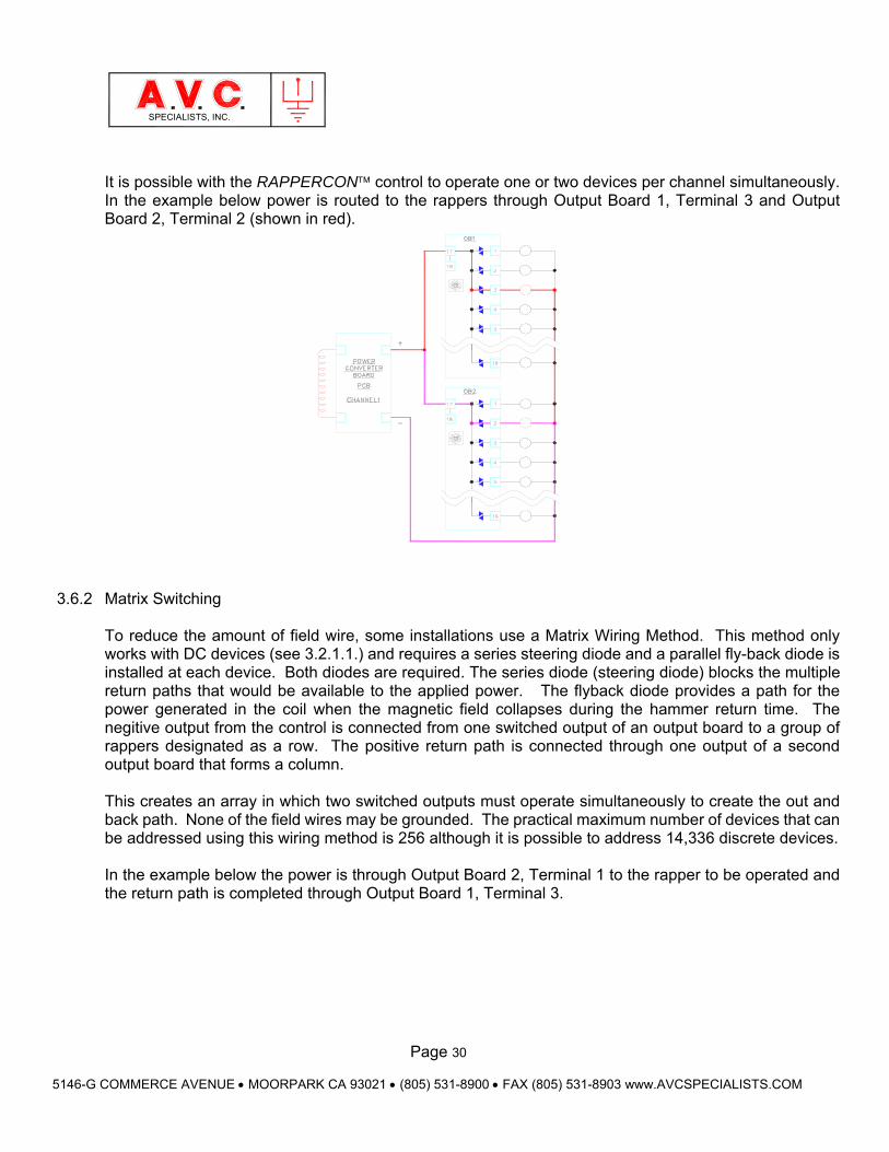
It is possible with the RAPPERCON control to operate one or two devices per channel simultaneously. In the example below power is routed to the rappers through Output Board 1, Terminal 3 and Output Board 2, Terminal 2 (shown in red).
3.6.2 Matrix Switching
To reduce the amount of field wire, some installations use a Matrix Wiring Method. This method only works with DC devices (see 3.2.1.1.) and requires a series steering diode and a parallel fly-back diode is installed at each device. Both diodes are required. The series diode (steering diode) blocks the multiple return paths that would be available to the applied power. The flyback diode provides a path for the power generated in the coil when the magnetic field collapses during the hammer return time. The negitive output from the control is connected from one switched output of an output board to a group of rappers designated as a row. The positive return path is connected through one output of a second output board that forms a column.
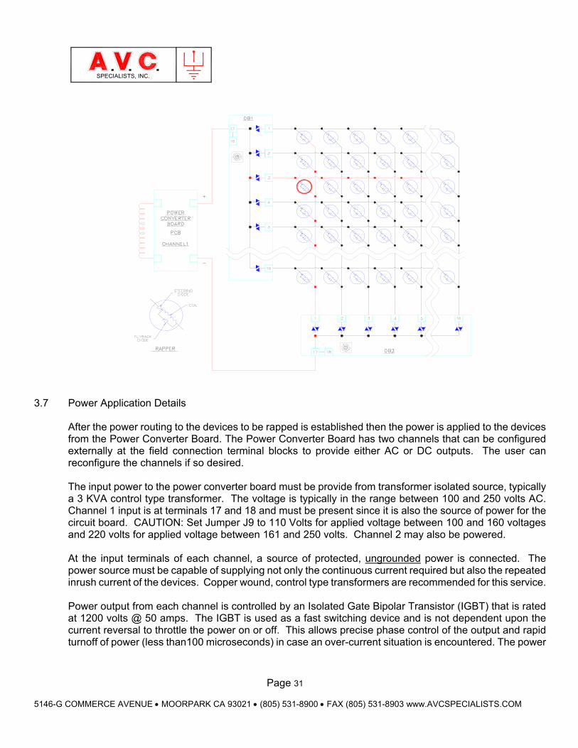
This creates an array in which two switched outputs must operate simultaneously to create the out and back path. None of the field wires may be grounded. The practical maximum number of devices that can be addressed using this wiring method is 256 although it is possible to address 14,336 discrete devices. In the example below the power is through Output Board 2, Terminal 1 to the rapper to be operated and the return path is completed through Output Board 1, Terminal 3.
Page 31
5146-G COMMERCE AVENUE MOORPARK CA 93021 (805) 531-8900 FAX (805) 531-8903 www.AVCSPECIALISTS.COM
SPECIALISTS, INC.
3.7 Power Application Details
After the power routing to the devices to be rapped is established then the power is applied to the devices from the Power Converter Board. The Power Converter Board has two channels that can be configured externally at the field connection terminal blocks to provide either AC or DC outputs. The user can reconfigure the channels if so desired. The input power to the power converter board must be provide from transformer isolated source, typically a 3 KVA control type transformer. The voltage is typically in the range between 100 and 250 volts AC. Channel 1 input is at terminals 17 and 18 and must be present since it is also the source of power for the circuit board. CAUTION: Set Jumper J9 to 110 Volts for applied voltage between 100 and 160 voltages and 220 volts for applied voltage between 161 and 250 volts. Channel 2 may also be powered. At the input terminals of each channel, a source of protected, ungrounded power is connected. The power source must be capable of supplying not only the continuous current required but also the repeated inrush current of the devices. Copper wound, control type transformers are recommended for this service. Power output from each channel is controlled by an Isolated Gate Bipolar Transistor (IGBT) that is rated at 1200 volts @ 50 amps. The IGBT is used as a fast switching device and is not dependent upon the current reversal to throttle the power on or off. This allows precise phase control of the output and rapid turnoff of power (less than100 microseconds) in case an over-current situation is encountered. The power

Page 32
5146-G COMMERCE AVENUE MOORPARK CA 93021 (805) 531-8900 FAX (805) 531-8903 www.AVCSPECIALISTS.COM
SPECIALISTS, INC.
circuit is isolated from the RAPPERCON logic circuitry by the use of opto-isolators to couple the switching commands. The current flow to the devices to be operated is monitored by the control. The current of each channel is measured at a sample rate of 10 microseconds per sample. It is important to set the current limit in each GROUP to reflect the total current flow that will occur in each channel. Current flow in the power circuit is monitored with an AC/DC Current Transformer that provides an isolated voltage signal to the interface board. That signal is processed into an instantaneous peak value (Shown on the display for each rapper) that will stop the output if it exceeds the programmed current limit. Unlike Silicon Control Rectifier (SCR) controlled systems, the IGBT is turned off within 100 microseconds of the detection of an over-current. DC rappers will, at the cessation of current flow through its coil, produce a very high voltage spike in order to maintain current flow that is generated by the collapse of the magnetic field. To help protect the IGBT a fast switching, flyback diode is used to shunt that generated current reducing the voltage spike. Another protection for the IGBT (and the flyback diodes) is temperature monitoring of the common heat sink. The temperature of the Power Converter heat sink is monitored and may be viewed on the analog display screen. If the temperature exceeds 160°F (70°C) then the control will cease operation, provide an alarm output. Then, if the temperature than falls below this set point, the control will resume operation.
Page 33
5146-G COMMERCE AVENUE MOORPARK CA 93021 (805) 531-8900 FAX (805) 531-8903 www.AVCSPECIALISTS.COM
SPECIALISTS, INC.
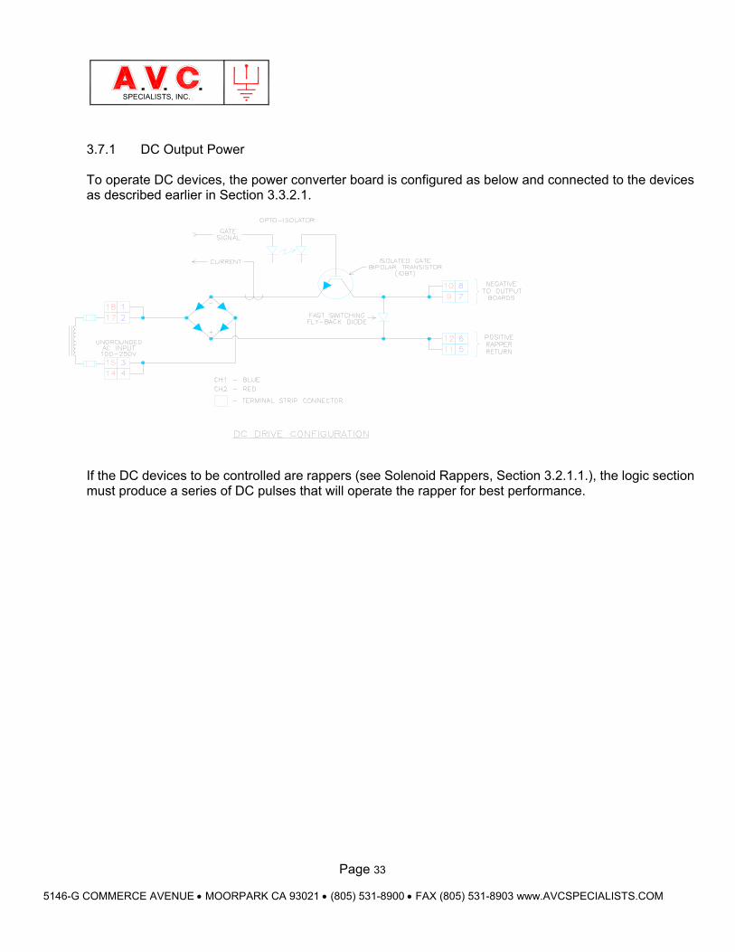
3.7.1 DC Output Power To operate DC devices, the power converter board is configured as below and connected to the devices as described earlier in Section 3.3.2.1.
If the DC devices to be controlled are rappers (see Solenoid Rappers, Section 3.2.1.1.), the logic section must produce a series of DC pulses that will operate the rapper for best performance.
Page 34
5146-G COMMERCE AVENUE MOORPARK CA 93021 (805) 531-8900 FAX (805) 531-8903 www.AVCSPECIALISTS.COM
SPECIALISTS, INC.
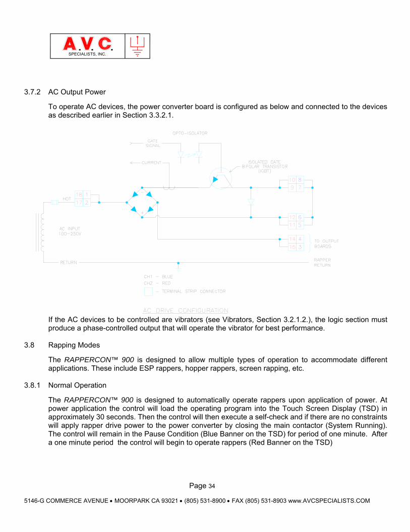
3.7.2 AC Output Power
To operate AC devices, the power converter board is configured as below and connected to the devices as described earlier in Section 3.3.2.1.
If the AC devices to be controlled are vibrators (see Vibrators, Section 3.2.1.2.), the logic section must produce a phase-controlled output that will operate the vibrator for best performance.
3.8 Rapping Modes
The RAPPERCON™ 900 is designed to allow multiple types of operation to accommodate different applications. These include ESP rappers, hopper rappers, screen rapping, etc.
3.8.1 Normal Operation
The RAPPERCON™ 900 is designed to automatically operate rappers upon application of power. At power application the control will load the operating program into the Touch Screen Display (TSD) in approximately 30 seconds. Then the control will then execute a self-check and if there are no constraints will apply rapper drive power to the power converter by closing the main contactor (System Running). The control will remain in the Pause Condition (Blue Banner on the TSD) for period of one minute. After a one minute period the control will begin to operate rappers (Red Banner on the TSD)
Page 35
5146-G COMMERCE AVENUE MOORPARK CA 93021 (805) 531-8900 FAX (805) 531-8903 www.AVCSPECIALISTS.COM
SPECIALISTS, INC.
3.8.2 On Demand Feature (Hopper Rapping) There is a very specific protocol for utilizing On Demand Rapping Feature. There is a one-for-one association between an input point and a specific GROUP of rappers. Inputs are detected using one or more 16-point Input Boards or Modbus Address. There may be up to four Input Boards installed in a control and each is given a unique address using the rotary selector switch, SW1. The first Input Board must be address “1” the second “2” and so forth.
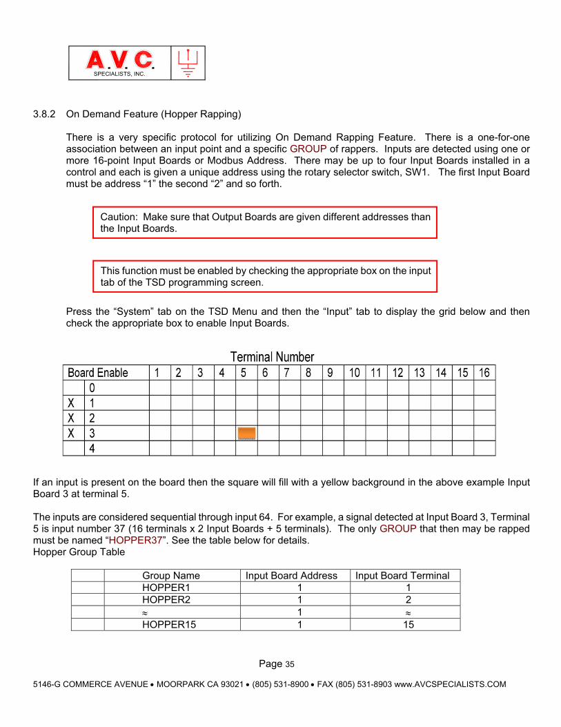
Press the “System” tab on the TSD Menu and then the “Input” tab to display the grid below and then check the appropriate box to enable Input Boards.
If an input is present on the board then the square will fill with a yellow background in the above example Input Board 3 at terminal 5. The inputs are considered sequential through input 64. For example, a signal detected at Input Board 3, Terminal 5 is input number 37 (16 terminals x 2 Input Boards + 5 terminals). The only GROUP that then may be rapped must be named “HOPPER37”. See the table below for details. Hopper Group Table
Group Name Input Board Address Input Board Terminal HOPPER1 1 1 HOPPER2 1 2 1 HOPPER15 1 15
Caution: Make sure that Output Boards are given different addresses than the Input Boards.
This function must be enabled by checking the appropriate box on the input tab of the TSD programming screen.
Page 36
5146-G COMMERCE AVENUE MOORPARK CA 93021 (805) 531-8900 FAX (805) 531-8903 www.AVCSPECIALISTS.COM
SPECIALISTS, INC.
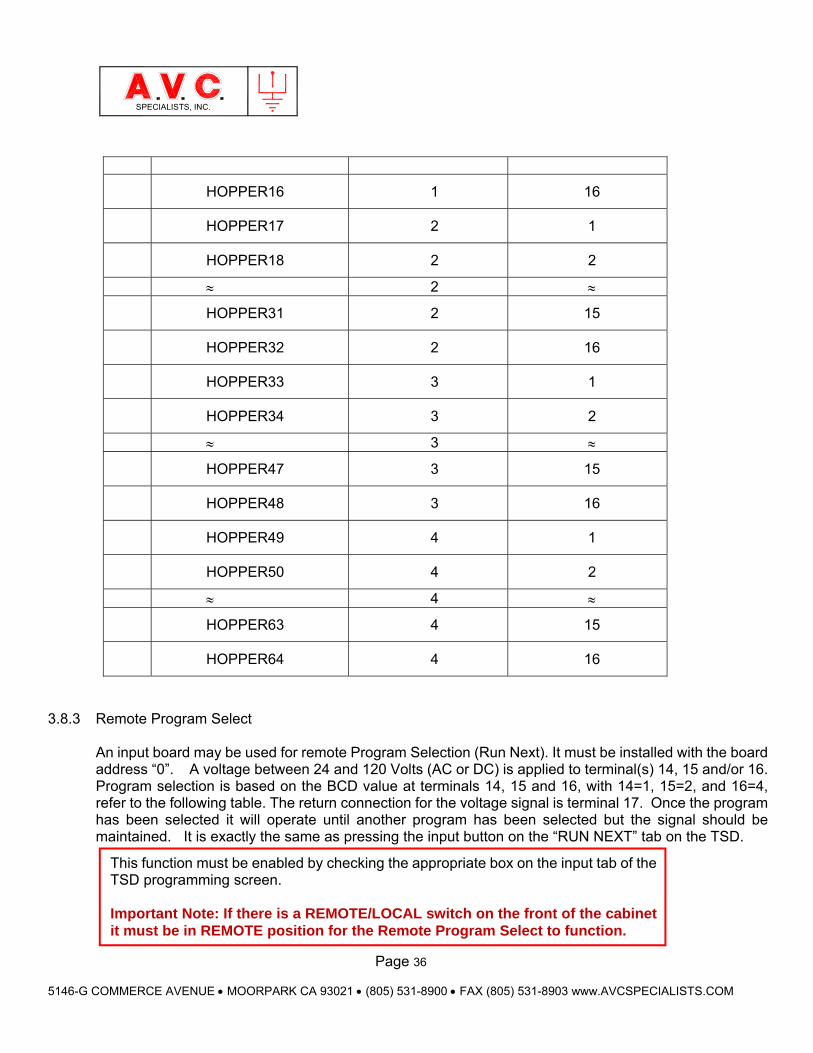
HOPPER16 1 16
HOPPER17 2 1
HOPPER18 2 2
2
HOPPER31 2 15
HOPPER32 2 16
HOPPER33 3 1
HOPPER34 3 2
3
HOPPER47 3 15
HOPPER48 3 16
HOPPER49 4 1
HOPPER50 4 2
4
HOPPER63 4 15
HOPPER64 4 16
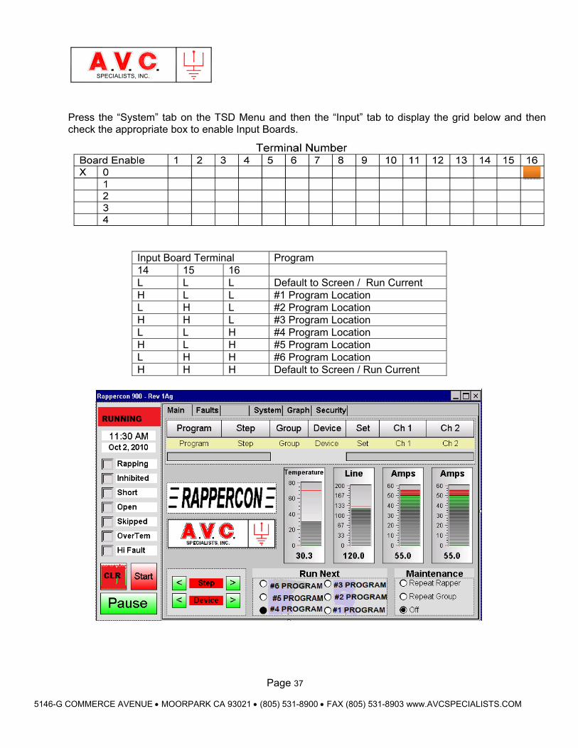
3.8.3 Remote Program Select An input board may be used for remote Program Selection (Run Next). It must be installed with the board address “0”. A voltage between 24 and 120 Volts (AC or DC) is applied to terminal(s) 14, 15 and/or 16. Program selection is based on the BCD value at terminals 14, 15 and 16, with 14=1, 15=2, and 16=4, refer to the following table. The return connection for the voltage signal is terminal 17. Once the program has been selected it will operate until another program has been selected but the signal should be maintained. It is exactly the same as pressing the input button on the “RUN NEXT” tab on the TSD.
This function must be enabled by checking the appropriate box on the input tab of the TSD programming screen.
Important Note: If there is a REMOTE/LOCAL switch on the front of the cabinet it must be in REMOTE position for the Remote Program Select to function.
Page 37
5146-G COMMERCE AVENUE MOORPARK CA 93021 (805) 531-8900 FAX (805) 531-8903 www.AVCSPECIALISTS.COM
SPECIALISTS, INC.
Press the “System” tab on the TSD Menu and then the “Input” tab to display the grid below and then check the appropriate box to enable Input Boards.
Input Board Terminal Program 14 15 16 L L L Default to Screen / Run Current H L L #1 Program Location L H L #2 Program Location H H L #3 Program Location L L H #4 Program Location H L H #5 Program Location L H H #6 Program Location H H H Default to Screen / Run Current
Page 38
5146-G COMMERCE AVENUE MOORPARK CA 93021 (805) 531-8900 FAX (805) 531-8903 www.AVCSPECIALISTS.COM
SPECIALISTS, INC.
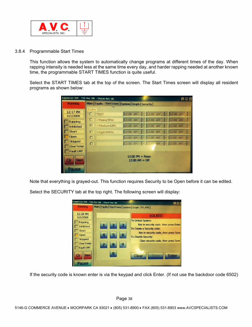
3.8.4 Programmable Start Times
This function allows the system to automatically change programs at different times of the day. When rapping intensity is needed less at the same time every day, and harder rapping needed at another known time, the programmable START TIMES function is quite useful. Select the START TIMES tab at the top of the screen. The Start Times screen will display all resident programs as shown below:
Note that everything is grayed-out. This function requires Security to be Open before it can be edited. Select the SECURITY tab at the top right. The following screen will display:
If the security code is known enter is via the keypad and click Enter. (If not use the backdoor code 6502)
Page 39
5146-G COMMERCE AVENUE MOORPARK CA 93021 (805) 531-8900 FAX (805) 531-8903 www.AVCSPECIALISTS.COM
SPECIALISTS, INC.
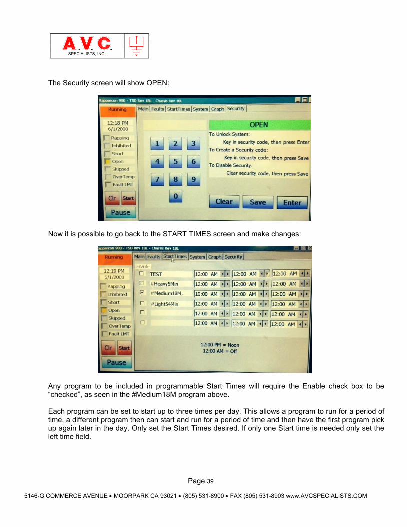
The Security screen will show OPEN:
Now it is possible to go back to the START TIMES screen and make changes:
Any program to be included in programmable Start Times will require the Enable check box to be “checked”, as seen in the #Medium18M program above. Each program can be set to start up to three times per day. This allows a program to run for a period of time, a different program then can start and run for a period of time and then have the first program pick up again later in the day. Only set the Start Times desired. If only one Start time is needed only set the left time field.
Page 40
5146-G COMMERCE AVENUE MOORPARK CA 93021 (805) 531-8900 FAX (805) 531-8903 www.AVCSPECIALISTS.COM
SPECIALISTS, INC.
4. Fundamental Control Operations
Operating the control may be accomplished from either locally using the TSD or remotely with a PC using the RCON Utility and RCON Editor. This manual describes in detail the use of the TSD. The writing of programs is accomplished by using the A.V.C. Specialists RCON Utility Program on a Laptop Computer and the program is transferred to the RAPPERCON™ 900 via a USB connection. Please see the programing Section 5.
An understanding of several control operations and user manipulations will greatly aid in performing basic operations with the control.
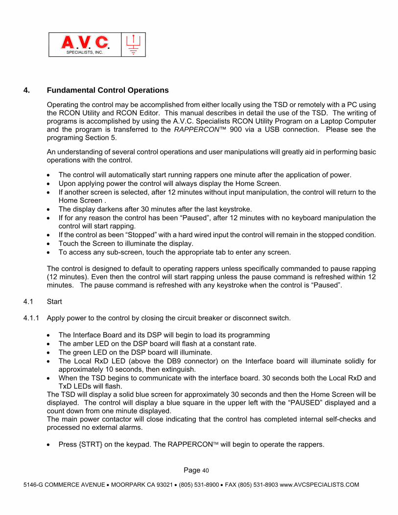
The control will automatically start running rappers one minute after the application of power. Upon applying power the control will always display the Home Screen. If another screen is selected, after 12 minutes without input manipulation, the control will return to the
Home Screen . The display darkens after 30 minutes after the last keystroke. If for any reason the control has been “Paused”, after 12 minutes with no keyboard manipulation the
control will start rapping. If the control as been “Stopped” with a hard wired input the control will remain in the stopped condition. Touch the Screen to illuminate the display. To access any sub-screen, touch the appropriate tab to enter any screen. The control is designed to default to operating rappers unless specifically commanded to pause rapping (12 minutes). Even then the control will start rapping unless the pause command is refreshed within 12 minutes. The pause command is refreshed with any keystroke when the control is “Paused”.
4.1 Start 4.1.1 Apply power to the control by closing the circuit breaker or disconnect switch.
The Interface Board and its DSP will begin to load its programming The amber LED on the DSP board will flash at a constant rate. The green LED on the DSP board will illuminate. The Local RxD LED (above the DB9 connector) on the Interface board will illuminate solidly for
approximately 10 seconds, then extinguish. When the TSD begins to communicate with the interface board. 30 seconds both the Local RxD and
TxD LEDs will flash. The TSD will display a solid blue screen for approximately 30 seconds and then the Home Screen will be displayed. The control will display a blue square in the upper left with the “PAUSED” displayed and a count down from one minute displayed. The main power contactor will close indicating that the control has completed internal self-checks and processed no external alarms.
Press STRT on the keypad. The RAPPERCON will begin to operate the rappers.

Page 41
5146-G COMMERCE AVENUE MOORPARK CA 93021 (805) 531-8900 FAX (805) 531-8903 www.AVCSPECIALISTS.COM
SPECIALISTS, INC.
-Or- Do nothing, one minute later; the RAPPERCON control will begin to operate the rappers.
The square in the upper right of the TSD will change color to Red indicating active rapping and the work “Running” will be displayed. The amber “Rap” LED will illuminate when any rapper is activated. The display will also change as the program progresses with different groups and rappers indicated and the amps and volts will update. The power converter board has an LED for both Channel 1 and 2 that will illuminate when a rapper is activated. After ½ hour the display backlight will extinguish (Operation will continue). To illuminate the display, touch the display.
4.2. Shut Down
Press PAUSE button on the TSD. Rapper operation will cease. If there is no other intervention, rapper will begin to operate in 12
minutes. Open the circuit breaker or disconnect switch. The green “Control Power” LED will extinguish. The display will extinguish.
Page 42
5146-G COMMERCE AVENUE MOORPARK CA 93021 (805) 531-8900 FAX (805) 531-8903 www.AVCSPECIALISTS.COM
SPECIALISTS, INC.
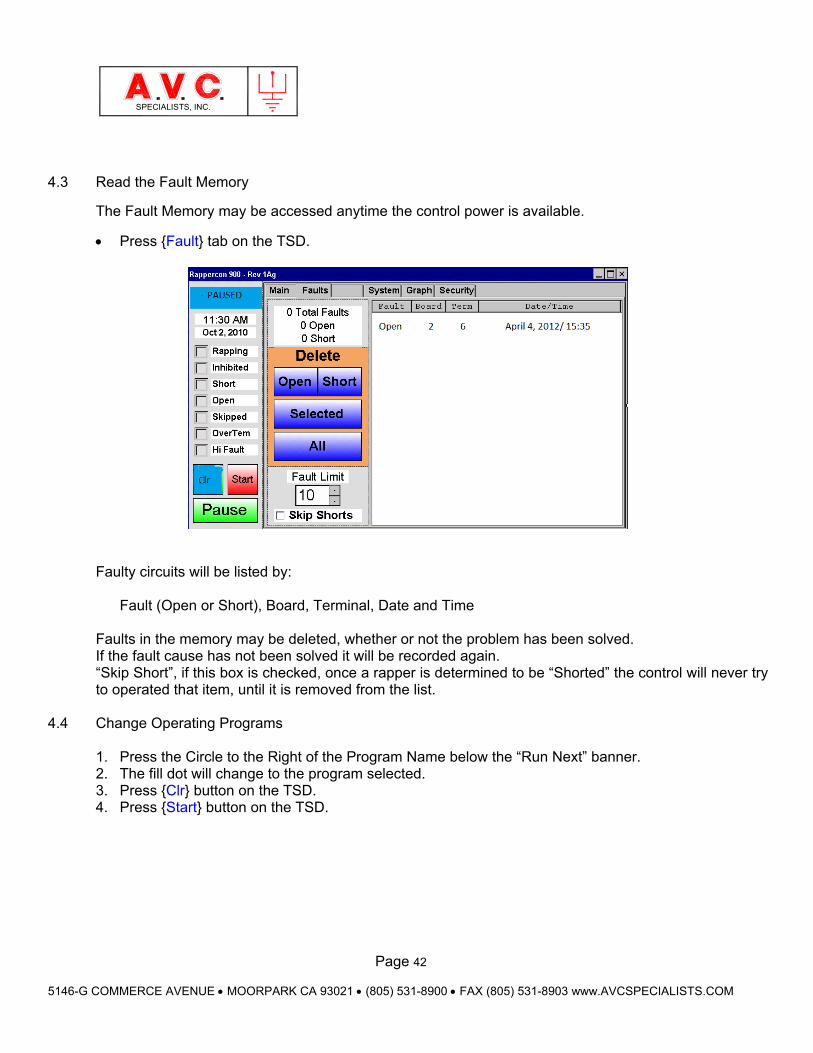
4.3 Read the Fault Memory
The Fault Memory may be accessed anytime the control power is available.
Press Fault tab on the TSD.
Faulty circuits will be listed by:
Fault (Open or Short), Board, Terminal, Date and Time
Faults in the memory may be deleted, whether or not the problem has been solved. If the fault cause has not been solved it will be recorded again. “Skip Short”, if this box is checked, once a rapper is determined to be “Shorted” the control will never try to operated that item, until it is removed from the list.
4.4 Change Operating Programs
1. Press the Circle to the Right of the Program Name below the “Run Next” banner. 2. The fill dot will change to the program selected. 3. Press Clr button on the TSD. 4. Press Start button on the TSD.
Page 43
5146-G COMMERCE AVENUE MOORPARK CA 93021 (805) 531-8900 FAX (805) 531-8903 www.AVCSPECIALISTS.COM
SPECIALISTS, INC.
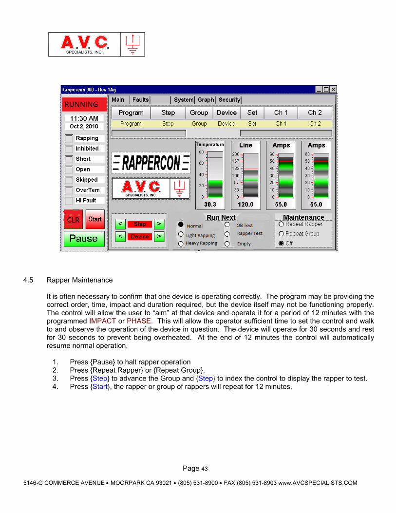
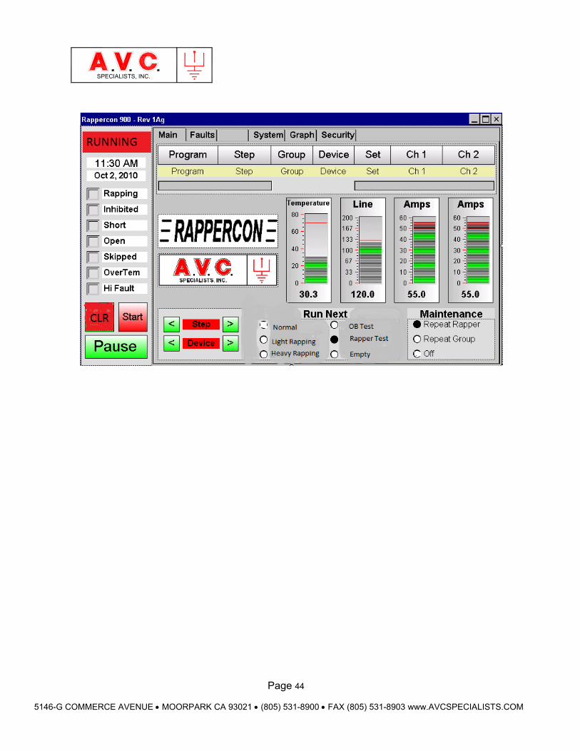
4.5 Rapper Maintenance
It is often necessary to confirm that one device is operating correctly. The program may be providing the correct order, time, impact and duration required, but the device itself may not be functioning properly. The control will allow the user to “aim” at that device and operate it for a period of 12 minutes with the programmed IMPACT or PHASE. This will allow the operator sufficient time to set the control and walk to and observe the operation of the device in question. The device will operate for 30 seconds and rest for 30 seconds to prevent being overheated. At the end of 12 minutes the control will automatically resume normal operation.
1. Press Pause to halt rapper operation 2. Press Repeat Rapper or Repeat Group. 3. Press Step to advance the Group and Step to index the control to display the rapper to test. 4. Press Start, the rapper or group of rappers will repeat for 12 minutes.
Page 44
5146-G COMMERCE AVENUE MOORPARK CA 93021 (805) 531-8900 FAX (805) 531-8903 www.AVCSPECIALISTS.COM
SPECIALISTS, INC.
Page 45
5146-G COMMERCE AVENUE MOORPARK CA 93021 (805) 531-8900 FAX (805) 531-8903 www.AVCSPECIALISTS.COM
SPECIALISTS, INC.
5. Editing and Programming The System
5.1 Basic Editing
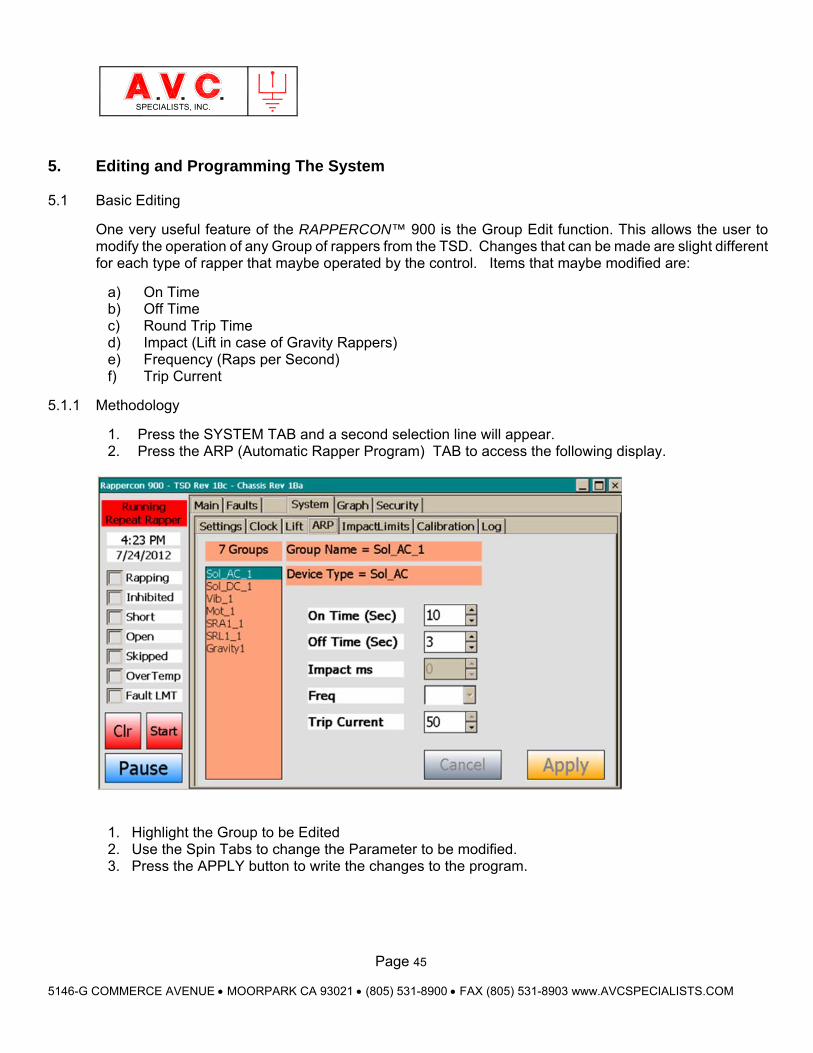
One very useful feature of the RAPPERCON™ 900 is the Group Edit function. This allows the user to modify the operation of any Group of rappers from the TSD. Changes that can be made are slight different for each type of rapper that maybe operated by the control. Items that maybe modified are:
a) On Time b) Off Time c) Round Trip Time d) Impact (Lift in case of Gravity Rappers) e) Frequency (Raps per Second) f) Trip Current
5.1.1 Methodology
1. Press the SYSTEM TAB and a second selection line will appear. 2. Press the ARP (Automatic Rapper Program) TAB to access the following display.
1. Highlight the Group to be Edited 2. Use the Spin Tabs to change the Parameter to be modified. 3. Press the APPLY button to write the changes to the program.
Page 46
5146-G COMMERCE AVENUE MOORPARK CA 93021 (805) 531-8900 FAX (805) 531-8903 www.AVCSPECIALISTS.COM
SPECIALISTS, INC.
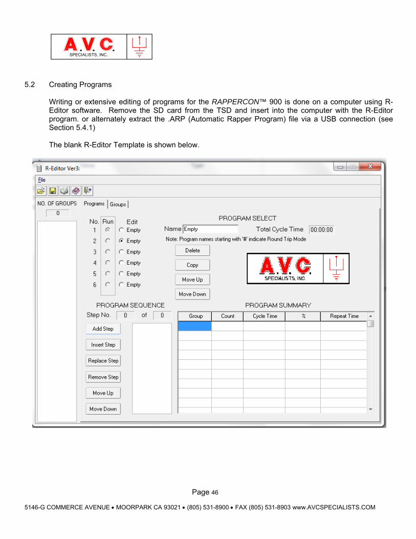
5.2 Creating Programs
Writing or extensive editing of programs for the RAPPERCON™ 900 is done on a computer using R-Editor software. Remove the SD card from the TSD and insert into the computer with the R-Editor program. or alternately extract the .ARP (Automatic Rapper Program) file via a USB connection (see Section 5.4.1) The blank R-Editor Template is shown below.
Page 47
5146-G COMMERCE AVENUE MOORPARK CA 93021 (805) 531-8900 FAX (805) 531-8903 www.AVCSPECIALISTS.COM
SPECIALISTS, INC.
5.3 Creating GROUPS
The GROUP is the fundamental software component required for any operation to occur. There may be up to 128 different GROUPS stored in the memory each must have a unique name up to 8 characters long. A GROUP contains between 1 and 32 OUTPUT SETS (one to four rappers that are operated simultaneously) that will be operated sequentially in the order listed within the GROUP. All devices within the GROUP must be identical type i.e. Model SR-A1, Gravity (MIGI), Vibrator (ERIEZ P-150), etc. All the devices listed in the GROUP will operate with the same parameters (IMPACT, FREQUENCY, ON-TIME (duration of operation), OFF TIME or ROUND TRIP TIME (depending on group type).
5.3.1. GROUP TYPES (Names)
There are three types of GROUPS used by the control. When creating (or editing) a GROUP the name determines the type of GROUP, how it is programmed and how it will operate. The PROGRAM that is operating (SEQUENTIAL or #ROUND TRIP) will only utilize certain type of groups as programmed or may modify the operation of a GROUP. All GROUPS have identical programming and operating parameters except for 1) how the interval between rappers in the group is programmed and utilized and 2) the structure of the GROUP Name. 5.3.1.1. SEQUENTIAL GROUP
A SEQUENTIAL GROUP must be inserted in a SEQUENTIAL PROGRAM to be used. It may have any 8 character name except the word “HOPPER**” or use the number character (#) in the first position of its name. When the SEQUENTIAL PROGRAM indexes to the next STEP, it calls the named SEQUENTIAL GROUP from memory. The GROUP will operate all OUTPUT SETS in order from one up to a maximum of thirty-two. An OUTPUT SET will operate for the ON-TIME (1-255 seconds), rest for the OFF-TIME (1-255 seconds) and then increment to the next OUTPUT SET. After completing the last OUTPUT SET the PROGRAM will then advance to the next STEP and retrieve a new SEQUENTIAL GROUP.
CAUTION When creating any Group or Program Name, only use alpha or numeric characters with the exception of the # sign to signify a Round Trip Group or Program. Never insert any spaces before, between, or after any name.
Page 48
5146-G COMMERCE AVENUE MOORPARK CA 93021 (805) 531-8900 FAX (805) 531-8903 www.AVCSPECIALISTS.COM
SPECIALISTS, INC.
5.3.1.2. DEMAND GROUP (HOPPER GROUP)
A DEMAND GROUP is a special case of SEQUENTIAL GROUP. It is written and programmed identically to a SEQUENTIAL GROUP. It is maintained in the memory but not inserted into either type of operating PROGRAM. It remains in the background and is called to operate only when a signal is detected at an Input Card. When a signal is detected, the operating program is halted and the DEMAND GROUP corresponding to the input is operated. Operation is maintained until the input ceases and then will resume normal operation. The DEMAND GROUP will operate in either a SEQUENTIAL or ROUND TRIP PROGRAM. The DEMAND GROUP must be named exactly “HOPPER**”. (**) is a number of one or two digits that matches the input of the Input Board terminal. There is a one for one association between an input point and a specific DEMAND GROUP of rappers. Inputs are detected using one or more 16-point Input Boards. There may be up to four Input Boards installed in a control and each is given a unique address using the rotary selector switch, SW1. The first Input Board must be address “1” the second “2” and so forth. The inputs are considered sequential through input 64. For example, a signal detected at Input Board 3, Terminal 5 is input number 37 (16 terminals x 2 Input Boards + 5 terminals). The only GROUP that then may be rapped must be named “HOPPER37”. This function must be enable by checking the appropriate box on the input screen tab on the TSD
5.3.1.3. #ROUND TRIP GROUP
A ROUND TRIP GROUP must be inserted in a ROUND TRIP PROGRAM to be used. The first character of the name must be the number sign (#) but the following 1 to 7 can be any combination of alpha-numeric characters, hyphen and underscore. All the timers in GROUPS in a ROUND TRIP PROGRAM will operate simultaneously. However rappers from only one group will operate at a time with a minimum one second delay until the rappers in another group rap. Each ROUND TRIP GROUP is programmed with a ROUND TRIP TIME (1-255 minutes). Similar to the method above the user will select any number of OUTPUT SETS (rappers) from one to thirty-two. The control will divide the ROUND TRIP TIME by the number of OUTPUT SETS to derive an interval between OUTPUT SETS. Each OUTPUT SET will operate at approximately the same interval between sets subject to the ROUNDTRIP PROGRAM priority. If ROUND TRIP GROUP is placed into a SEQUENTIAL PROGRAM it will operate as a SEQUENTIAL GROUP but the ROUND TRIP TIME (in minutes) will be converted to the OFF-TIME (in seconds).
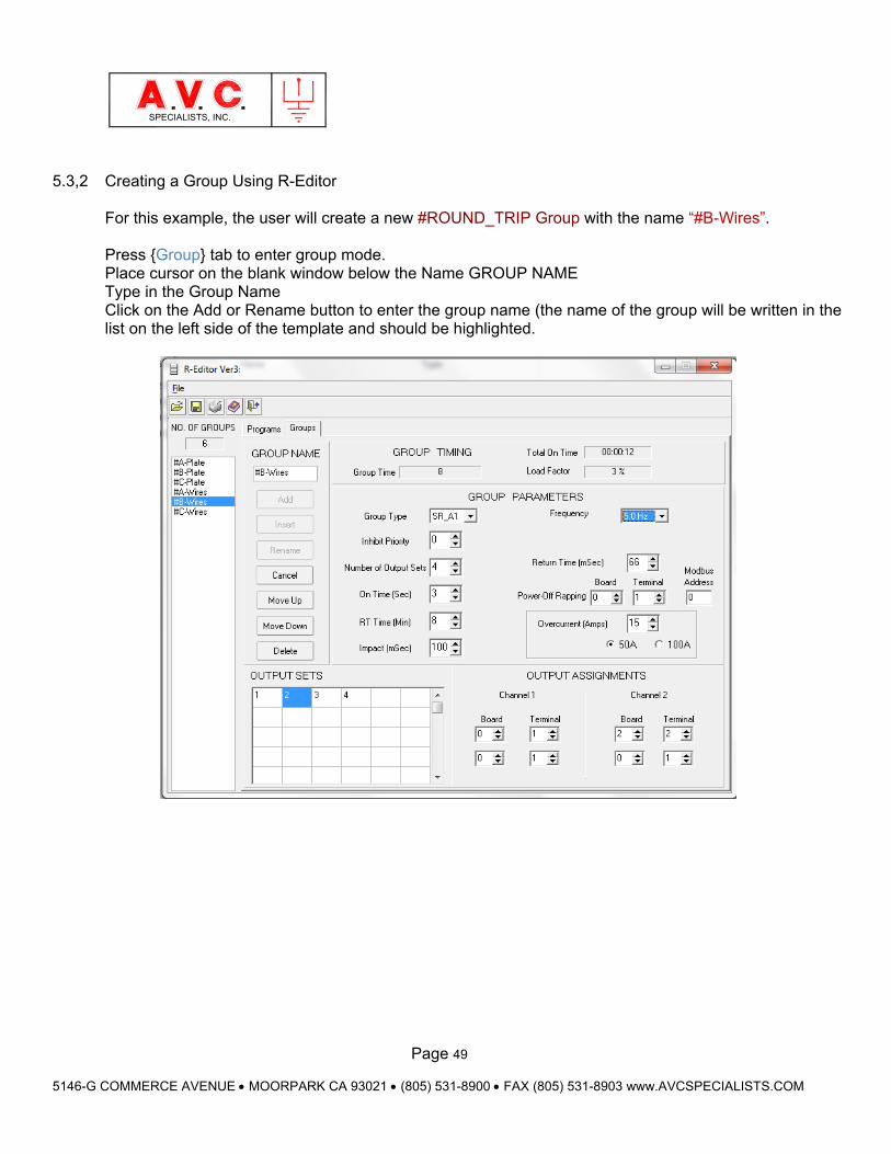
Page 49
5146-G COMMERCE AVENUE MOORPARK CA 93021 (805) 531-8900 FAX (805) 531-8903 www.AVCSPECIALISTS.COM
SPECIALISTS, INC.
5.3,2 Creating a Group Using R-Editor
For this example, the user will create a new #ROUND_TRIP Group with the name “#B-Wires”. Press Group tab to enter group mode. Place cursor on the blank window below the Name GROUP NAME Type in the Group Name Click on the Add or Rename button to enter the group name (the name of the group will be written in the list on the left side of the template and should be highlighted.
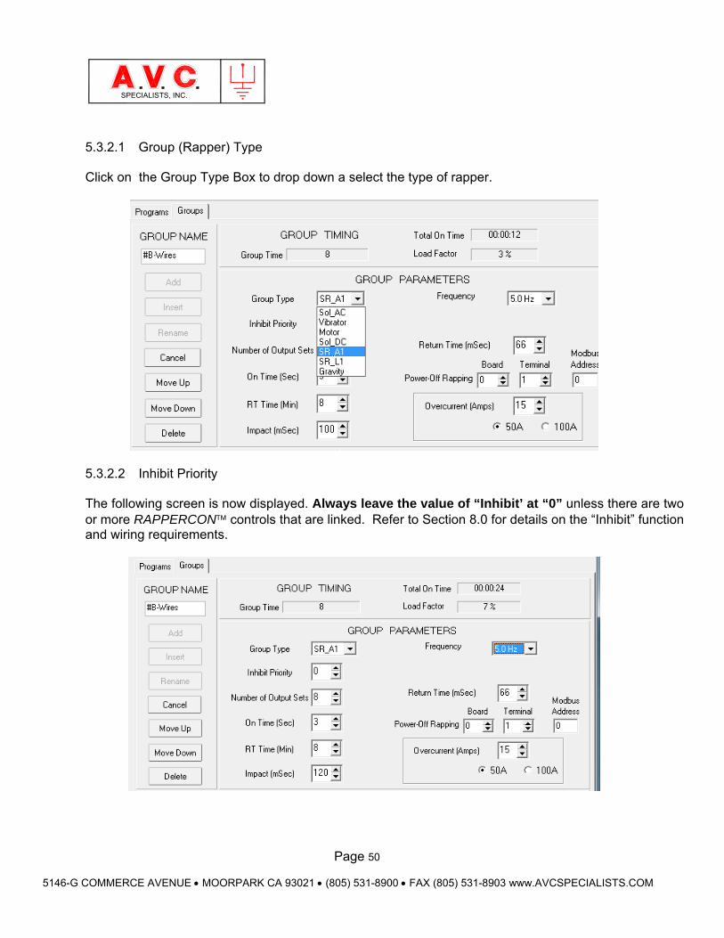
Page 50
5146-G COMMERCE AVENUE MOORPARK CA 93021 (805) 531-8900 FAX (805) 531-8903 www.AVCSPECIALISTS.COM
SPECIALISTS, INC.
5.3.2.1 Group (Rapper) Type
Click on the Group Type Box to drop down a select the type of rapper.
5.3.2.2 Inhibit Priority
The following screen is now displayed. Always leave the value of “Inhibit’ at “0” unless there are two or more RAPPERCON controls that are linked. Refer to Section 8.0 for details on the “Inhibit” function and wiring requirements.
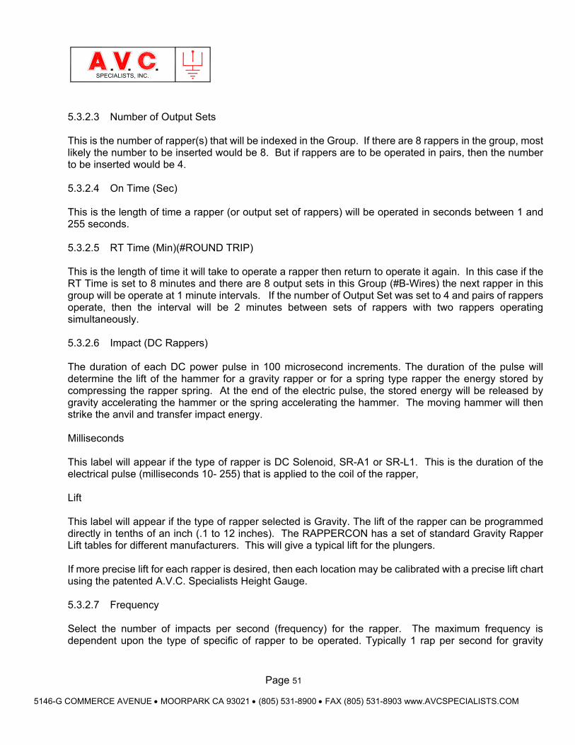
Page 51
5146-G COMMERCE AVENUE MOORPARK CA 93021 (805) 531-8900 FAX (805) 531-8903 www.AVCSPECIALISTS.COM
SPECIALISTS, INC.
5.3.2.3 Number of Output Sets
This is the number of rapper(s) that will be indexed in the Group. If there are 8 rappers in the group, most likely the number to be inserted would be 8. But if rappers are to be operated in pairs, then the number to be inserted would be 4.
5.3.2.4 On Time (Sec)
This is the length of time a rapper (or output set of rappers) will be operated in seconds between 1 and 255 seconds. 5.3.2.5 RT Time (Min)(#ROUND TRIP)
This is the length of time it will take to operate a rapper then return to operate it again. In this case if the RT Time is set to 8 minutes and there are 8 output sets in this Group (#B-Wires) the next rapper in this group will be operate at 1 minute intervals. If the number of Output Set was set to 4 and pairs of rappers operate, then the interval will be 2 minutes between sets of rappers with two rappers operating simultaneously.
5.3.2.6 Impact (DC Rappers)
The duration of each DC power pulse in 100 microsecond increments. The duration of the pulse will determine the lift of the hammer for a gravity rapper or for a spring type rapper the energy stored by compressing the rapper spring. At the end of the electric pulse, the stored energy will be released by gravity accelerating the hammer or the spring accelerating the hammer. The moving hammer will then strike the anvil and transfer impact energy.
Milliseconds This label will appear if the type of rapper is DC Solenoid, SR-A1 or SR-L1. This is the duration of the electrical pulse (milliseconds 10- 255) that is applied to the coil of the rapper, Lift This label will appear if the type of rapper selected is Gravity. The lift of the rapper can be programmed directly in tenths of an inch (.1 to 12 inches). The RAPPERCON has a set of standard Gravity Rapper Lift tables for different manufacturers. This will give a typical lift for the plungers. If more precise lift for each rapper is desired, then each location may be calibrated with a precise lift chart using the patented A.V.C. Specialists Height Gauge.
5.3.2.7 Frequency
Select the number of impacts per second (frequency) for the rapper. The maximum frequency is dependent upon the type of specific of rapper to be operated. Typically 1 rap per second for gravity
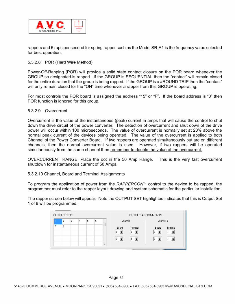
Page 52
5146-G COMMERCE AVENUE MOORPARK CA 93021 (805) 531-8900 FAX (805) 531-8903 www.AVCSPECIALISTS.COM
SPECIALISTS, INC.
rappers and 6 raps per second for spring rapper such as the Model SR-A1 is the frequency value selected for best operation.
5.3.2.8 POR (Hard Wire Method)
Power-Off-Rapping (POR) will provide a solid state contact closure on the POR board whenever the GROUP so designated is rapped. If the GROUP is SEQUENTIAL then the “contact” will remain closed for the entire duration that the group is being rapped. If the GROUP is a #ROUND TRIP then the “contact” will only remain closed for the “ON” time whenever a rapper from this GROUP is operating. For most controls the POR board is assigned the address “15” or “F”. If the board address is “0” then POR function is ignored for this group.
5.3.2.9 Overcurrent
Overcurrent is the value of the instantaneous (peak) current in amps that will cause the control to shut down the drive circuit of the power converter. The detection of overcurrent and shut down of the drive power will occur within 100 microseconds. The value of overcurrent is normally set at 20% above the normal peak current of the devices being operated. The value of the overcurrent is applied to both Channel of the Power Converter Board. If two rappers are operated simultaneously but are on different channels, then the normal overcurrent value is used. However, if two rappers will be operated simultaneously from the same channel then remember to double the value of the overcurrent. OVERCURRENT RANGE: Place the dot in the 50 Amp Range. This is the very fast overcurrent shutdown for instantaneous current of 50 Amps.
5.3.2.10 Channel, Board and Terminal Assignments
To program the application of power from the RAPPERCON control to the device to be rapped, the programmer must refer to the rapper layout drawing and system schematic for the particular installation. The rapper screen below will appear. Note the OUTPUT SET highlighted indicates that this is Output Set 1 of 8 will be programmed.

Page 53
5146-G COMMERCE AVENUE MOORPARK CA 93021 (805) 531-8900 FAX (805) 531-8903 www.AVCSPECIALISTS.COM
SPECIALISTS, INC.
Direct Wiring Method Trace the hot wire from the rapper to the Output Board (note the address) and Terminal to which it is connected. Then note from which Channel of the Power Converter Board that Output Board is connected. For this example, the 1st rapper is attached to Channel 1, Board 3, Terminal 5. Use the spin dials to set the Board and Terminal under the first row of Channel 1. The next example is for the 5th rapper and it is connected to Channel 2, Board 4, Terminal 6.
Matrix Wiring Matrix rapper wiring is done in a similar fashion to the direct wiring except that both the out (row) and return (column) must be programmed. For this example that the 3rd rapper in the Group #B-Wire, is attached to a row, connected to a powered Channel 1, Board 1, Terminal 3 and the Return path column is wired to an non powered Board 2, Terminal 2.
Please Note that a “0” in any Board Location skips that line as a valid input, effectively creating a “no-op” command
5.4 Create Programs
A program is an assembly of GROUPS set to operate in a logical sequence or time, for all rapping devices on a piece of equipment. The RAPPERCON™ may store up to 6 PROGRAMS in memory and each must have a unique name that may be up to 10 characters long.
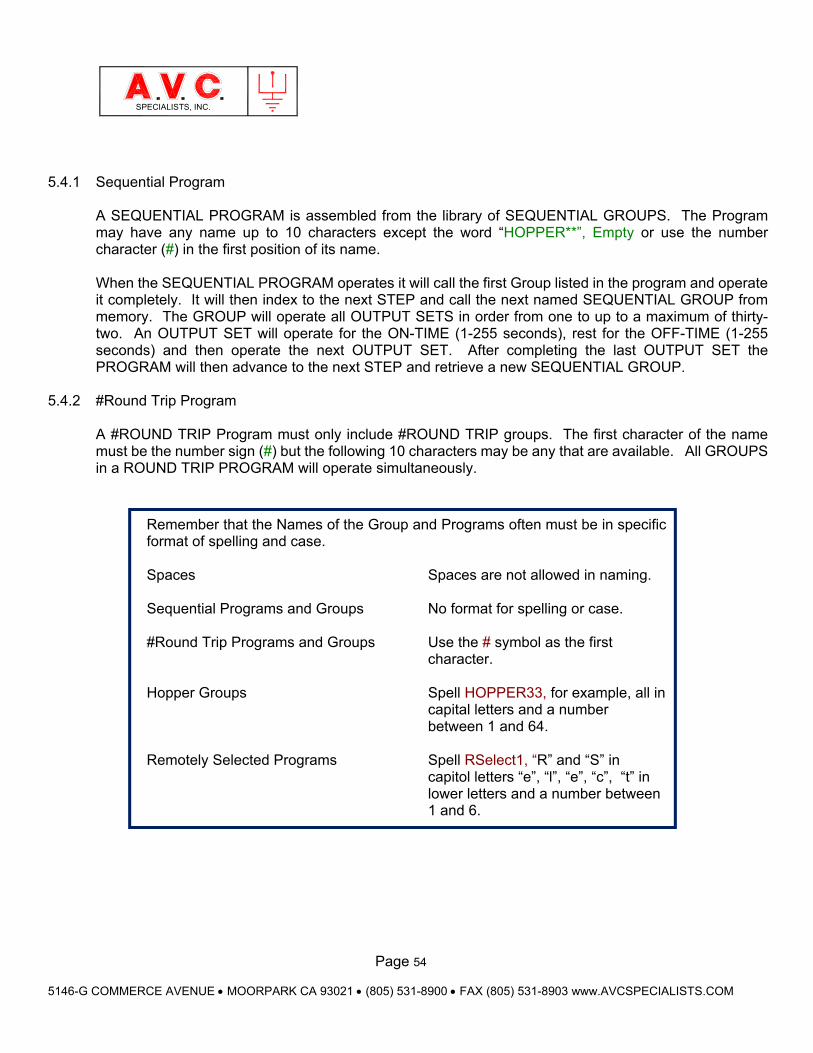
Page 54
5146-G COMMERCE AVENUE MOORPARK CA 93021 (805) 531-8900 FAX (805) 531-8903 www.AVCSPECIALISTS.COM
SPECIALISTS, INC.
5.4.1 Sequential Program
A SEQUENTIAL PROGRAM is assembled from the library of SEQUENTIAL GROUPS. The Program may have any name up to 10 characters except the word “HOPPER**”, Empty or use the number character (#) in the first position of its name. When the SEQUENTIAL PROGRAM operates it will call the first Group listed in the program and operate it completely. It will then index to the next STEP and call the next named SEQUENTIAL GROUP from memory. The GROUP will operate all OUTPUT SETS in order from one to up to a maximum of thirty-two. An OUTPUT SET will operate for the ON-TIME (1-255 seconds), rest for the OFF-TIME (1-255 seconds) and then operate the next OUTPUT SET. After completing the last OUTPUT SET the PROGRAM will then advance to the next STEP and retrieve a new SEQUENTIAL GROUP.
5.4.2 #Round Trip Program
A #ROUND TRIP Program must only include #ROUND TRIP groups. The first character of the name must be the number sign (#) but the following 10 characters may be any that are available. All GROUPS in a ROUND TRIP PROGRAM will operate simultaneously.
Remember that the Names of the Group and Programs often must be in specific format of spelling and case. Spaces Spaces are not allowed in naming. Sequential Programs and Groups No format for spelling or case. #Round Trip Programs and Groups Use the # symbol as the first character. Hopper Groups Spell HOPPER33, for example, all in capital letters and a number between 1 and 64. Remotely Selected Programs Spell RSelect1, “R” and “S” in capitol letters “e”, “l”, “e”, “c”, “t” in lower letters and a number between 1 and 6.
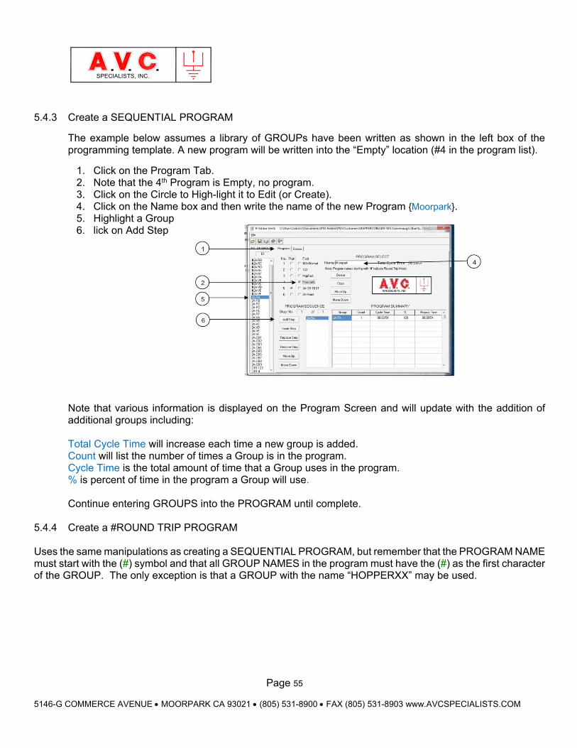
Page 55
5146-G COMMERCE AVENUE MOORPARK CA 93021 (805) 531-8900 FAX (805) 531-8903 www.AVCSPECIALISTS.COM
SPECIALISTS, INC.
5.4.3 Create a SEQUENTIAL PROGRAM
The example below assumes a library of GROUPs have been written as shown in the left box of the programming template. A new program will be written into the “Empty” location (#4 in the program list).
1. Click on the Program Tab. 2. Note that the 4th Program is Empty, no program. 3. Click on the Circle to High-light it to Edit (or Create). 4. Click on the Name box and then write the name of the new Program Moorpark. 5. Highlight a Group 6. lick on Add Step
Note that various information is displayed on the Program Screen and will update with the addition of additional groups including: Total Cycle Time will increase each time a new group is added. Count will list the number of times a Group is in the program. Cycle Time is the total amount of time that a Group uses in the program. % is percent of time in the program a Group will use. Continue entering GROUPS into the PROGRAM until complete.
5.4.4 Create a #ROUND TRIP PROGRAM
Uses the same manipulations as creating a SEQUENTIAL PROGRAM, but remember that the PROGRAM NAME must start with the (#) symbol and that all GROUP NAMES in the program must have the (#) as the first character of the GROUP. The only exception is that a GROUP with the name “HOPPERXX” may be used.
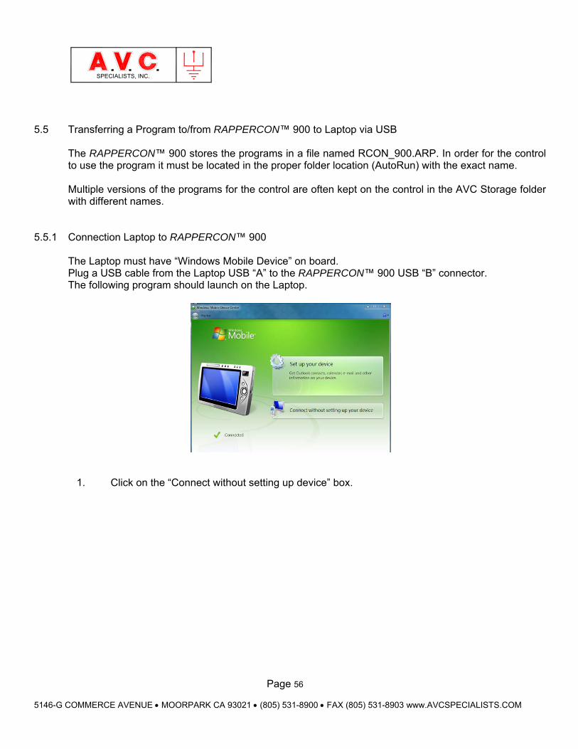
Page 56
5146-G COMMERCE AVENUE MOORPARK CA 93021 (805) 531-8900 FAX (805) 531-8903 www.AVCSPECIALISTS.COM
SPECIALISTS, INC.
5.5 Transferring a Program to/from RAPPERCON™ 900 to Laptop via USB
The RAPPERCON™ 900 stores the programs in a file named RCON_900.ARP. In order for the control to use the program it must be located in the proper folder location (AutoRun) with the exact name. Multiple versions of the programs for the control are often kept on the control in the AVC Storage folder with different names.
5.5.1 Connection Laptop to RAPPERCON™ 900
The Laptop must have “Windows Mobile Device” on board. Plug a USB cable from the Laptop USB “A” to the RAPPERCON™ 900 USB “B” connector. The following program should launch on the Laptop.
1. Click on the “Connect without setting up device” box.
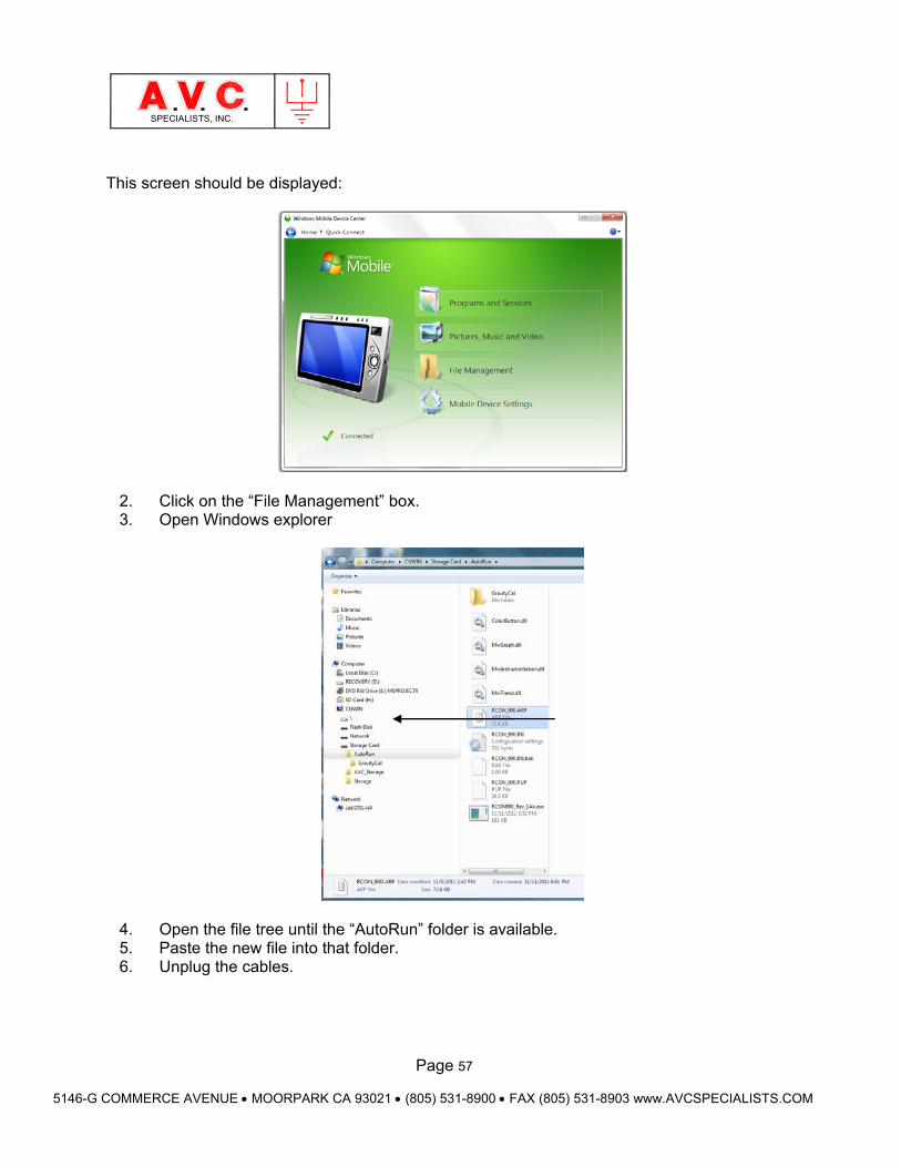
Page 57
5146-G COMMERCE AVENUE MOORPARK CA 93021 (805) 531-8900 FAX (805) 531-8903 www.AVCSPECIALISTS.COM
SPECIALISTS, INC.
This screen should be displayed:
2. Click on the “File Management” box. 3. Open Windows explorer
4. Open the file tree until the “AutoRun” folder is available. 5. Paste the new file into that folder. 6. Unplug the cables.
Page 58
5146-G COMMERCE AVENUE MOORPARK CA 93021 (805) 531-8900 FAX (805) 531-8903 www.AVCSPECIALISTS.COM
SPECIALISTS, INC.
6. Installation Instructions 6.1 General Information Before proceeding review all drawings as well as any specific installation instructions that were provided. After this preparation, insure that all power to the control enclosure (in 2-cabinet systems this will be the main power to the Power Conversion Unit) is OFF, using the proper established safety lockout procedures. It is very important to remember that hot signal from external sources may be present in the enclosure. 6.2 Wiring Review the Schematic and Wiring Diagrams provided. 6.2.1. Input Wiring Considerations All power for operating a RAPPERCON must be provided from one single-phase source. Multi-phase power may be switched through intermediate devices such as contactors. Transformers may be used to step up or down the voltage as required. All power connected to any channel of the power converter must be ungrounded. 6.2.2. Output Wiring Considerations Do not ground any output wires in a Matrix Wiring System. The return line of the DC devices using direct wiring may be grounded. The return line of single-phase AC devices may be grounded. 6.2.3. Power Supplies There is a permanently attached cable at the power supply to connect its triple DC voltage output (+5, +15 and –15) to a connection on the motherboard of the card cage. The 24 VDC supply will need to be connected to the TSD. 6.2.4 TSD The connection between the interface board installed in the card cage and the TSD is made with a standard DB9 Male to DB9 Female cable (non-modem).
NOTE: THE RAPPERCON 900 CABINET IS TO BE ONLY INSTALLED IN A LOCATION WHERE THE AMBIENT TEMPERATURE DOES NOT EXCEED +45 oC (+113 oF)!
IF THE CABINET IS INSTALLED OUTDOORS BE SURE TO INSTALL A RAIN COVER/ROOF TO PROTECT THE INTERIOR FROM RAIN OR WATER RUNOFF FROM ABOVE WHEN THE DOOR IS OPENED!
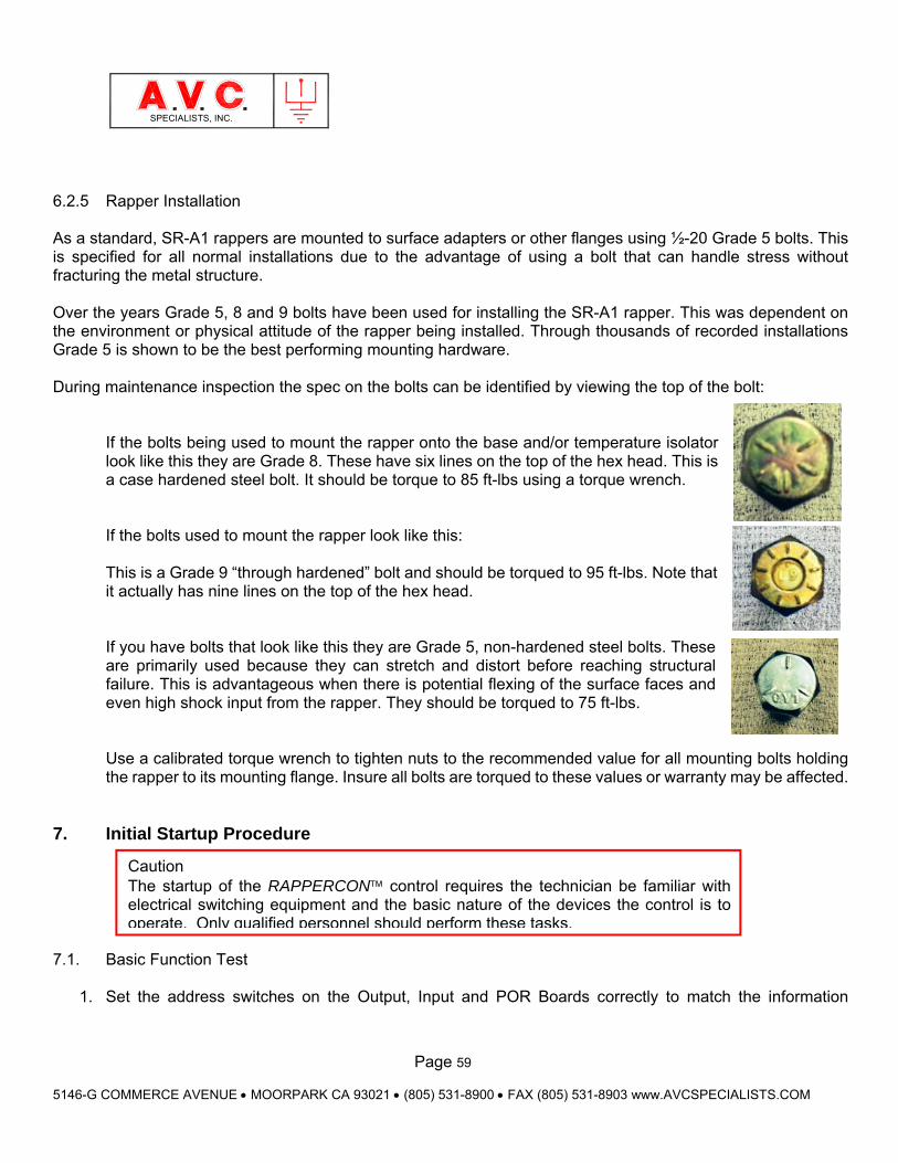
Page 59
5146-G COMMERCE AVENUE MOORPARK CA 93021 (805) 531-8900 FAX (805) 531-8903 www.AVCSPECIALISTS.COM
SPECIALISTS, INC.
6.2.5 Rapper Installation As a standard, SR-A1 rappers are mounted to surface adapters or other flanges using ½-20 Grade 5 bolts. This is specified for all normal installations due to the advantage of using a bolt that can handle stress without fracturing the metal structure. Over the years Grade 5, 8 and 9 bolts have been used for installing the SR-A1 rapper. This was dependent on the environment or physical attitude of the rapper being installed. Through thousands of recorded installations Grade 5 is shown to be the best performing mounting hardware. During maintenance inspection the spec on the bolts can be identified by viewing the top of the bolt:
If the bolts being used to mount the rapper onto the base and/or temperature isolator look like this they are Grade 8. These have six lines on the top of the hex head. This is a case hardened steel bolt. It should be torque to 85 ft-lbs using a torque wrench. If the bolts used to mount the rapper look like this: This is a Grade 9 “through hardened” bolt and should be torqued to 95 ft-lbs. Note that it actually has nine lines on the top of the hex head. If you have bolts that look like this they are Grade 5, non-hardened steel bolts. These are primarily used because they can stretch and distort before reaching structural failure. This is advantageous when there is potential flexing of the surface faces and even high shock input from the rapper. They should be torqued to 75 ft-lbs. Use a calibrated torque wrench to tighten nuts to the recommended value for all mounting bolts holding the rapper to its mounting flange. Insure all bolts are torqued to these values or warranty may be affected.
7. Initial Startup Procedure
7.1. Basic Function Test
1. Set the address switches on the Output, Input and POR Boards correctly to match the information
Caution The startup of the RAPPERCON control requires the technician be familiar with electrical switching equipment and the basic nature of the devices the control is to operate. Only qualified personnel should perform these tasks.
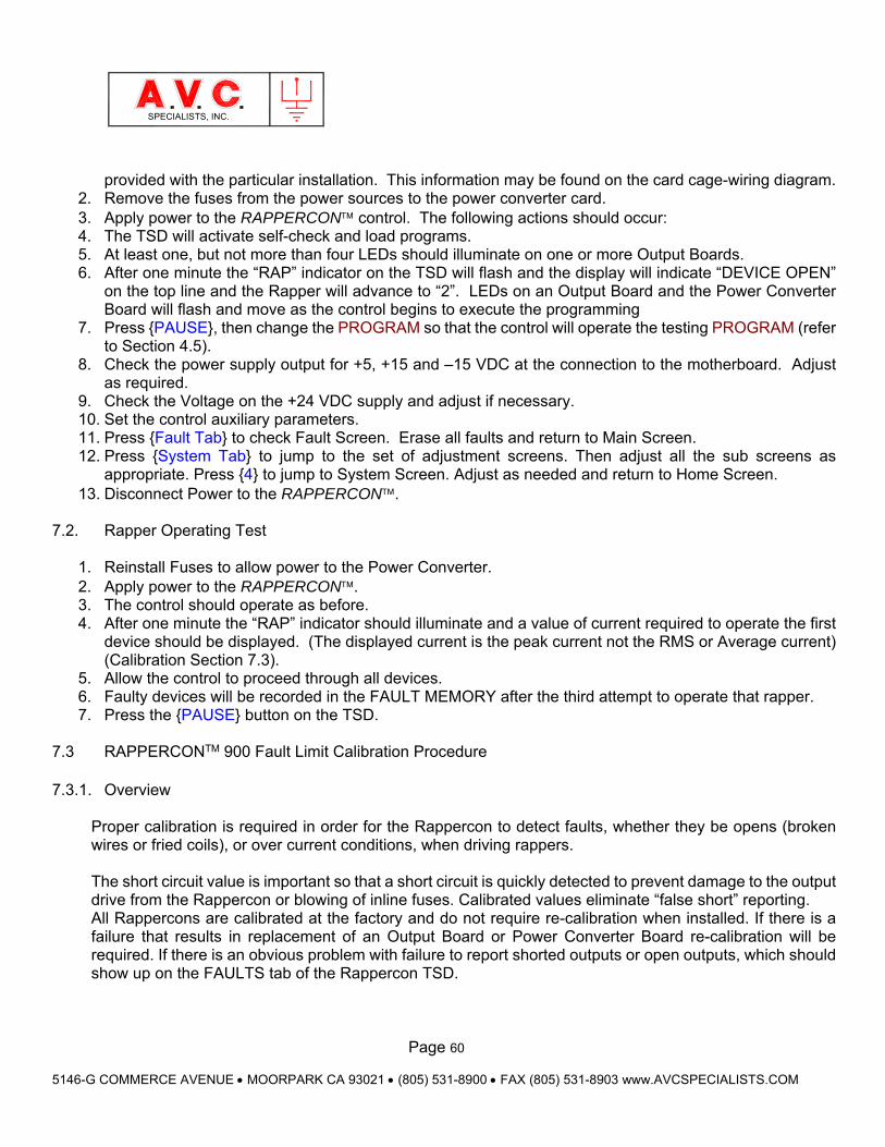
Page 60
5146-G COMMERCE AVENUE MOORPARK CA 93021 (805) 531-8900 FAX (805) 531-8903 www.AVCSPECIALISTS.COM
SPECIALISTS, INC.
provided with the particular installation. This information may be found on the card cage-wiring diagram. 2. Remove the fuses from the power sources to the power converter card. 3. Apply power to the RAPPERCON control. The following actions should occur: 4. The TSD will activate self-check and load programs. 5. At least one, but not more than four LEDs should illuminate on one or more Output Boards. 6. After one minute the “RAP” indicator on the TSD will flash and the display will indicate “DEVICE OPEN”
on the top line and the Rapper will advance to “2”. LEDs on an Output Board and the Power Converter Board will flash and move as the control begins to execute the programming
7. Press PAUSE, then change the PROGRAM so that the control will operate the testing PROGRAM (refer to Section 4.5).
8. Check the power supply output for +5, +15 and –15 VDC at the connection to the motherboard. Adjust as required.
9. Check the Voltage on the +24 VDC supply and adjust if necessary. 10. Set the control auxiliary parameters. 11. Press Fault Tab to check Fault Screen. Erase all faults and return to Main Screen. 12. Press System Tab to jump to the set of adjustment screens. Then adjust all the sub screens as
appropriate. Press 4 to jump to System Screen. Adjust as needed and return to Home Screen. 13. Disconnect Power to the RAPPERCON.
7.2. Rapper Operating Test
1. Reinstall Fuses to allow power to the Power Converter. 2. Apply power to the RAPPERCON. 3. The control should operate as before. 4. After one minute the “RAP” indicator should illuminate and a value of current required to operate the first
device should be displayed. (The displayed current is the peak current not the RMS or Average current) (Calibration Section 7.3).
5. Allow the control to proceed through all devices. 6. Faulty devices will be recorded in the FAULT MEMORY after the third attempt to operate that rapper. 7. Press the PAUSE button on the TSD.
7.3 RAPPERCONTM 900 Fault Limit Calibration Procedure 7.3.1. Overview
Proper calibration is required in order for the Rappercon to detect faults, whether they be opens (broken wires or fried coils), or over current conditions, when driving rappers. The short circuit value is important so that a short circuit is quickly detected to prevent damage to the output drive from the Rappercon or blowing of inline fuses. Calibrated values eliminate “false short” reporting. All Rappercons are calibrated at the factory and do not require re-calibration when installed. If there is a failure that results in replacement of an Output Board or Power Converter Board re-calibration will be required. If there is an obvious problem with failure to report shorted outputs or open outputs, which should show up on the FAULTS tab of the Rappercon TSD.
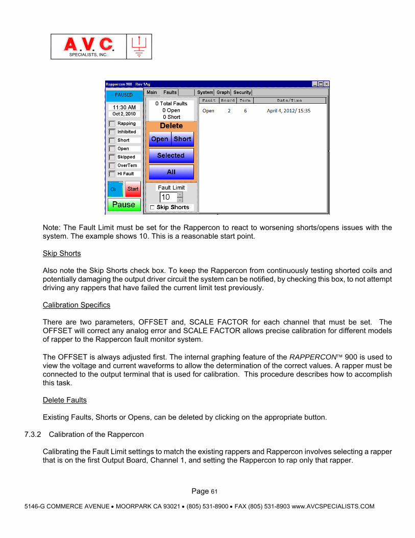
Page 61
5146-G COMMERCE AVENUE MOORPARK CA 93021 (805) 531-8900 FAX (805) 531-8903 www.AVCSPECIALISTS.COM
SPECIALISTS, INC.
Note: The Fault Limit must be set for the Rappercon to react to worsening shorts/opens issues with the system. The example shows 10. This is a reasonable start point. Skip Shorts Also note the Skip Shorts check box. To keep the Rappercon from continuously testing shorted coils and potentially damaging the output driver circuit the system can be notified, by checking this box, to not attempt driving any rappers that have failed the current limit test previously. Calibration Specifics There are two parameters, OFFSET and, SCALE FACTOR for each channel that must be set. The OFFSET will correct any analog error and SCALE FACTOR allows precise calibration for different models of rapper to the Rappercon fault monitor system. The OFFSET is always adjusted first. The internal graphing feature of the RAPPERCON 900 is used to view the voltage and current waveforms to allow the determination of the correct values. A rapper must be connected to the output terminal that is used for calibration. This procedure describes how to accomplish this task. Delete Faults Existing Faults, Shorts or Opens, can be deleted by clicking on the appropriate button.
7.3.2 Calibration of the Rappercon Calibrating the Fault Limit settings to match the existing rappers and Rappercon involves selecting a rapper that is on the first Output Board, Channel 1, and setting the Rappercon to rap only that rapper.
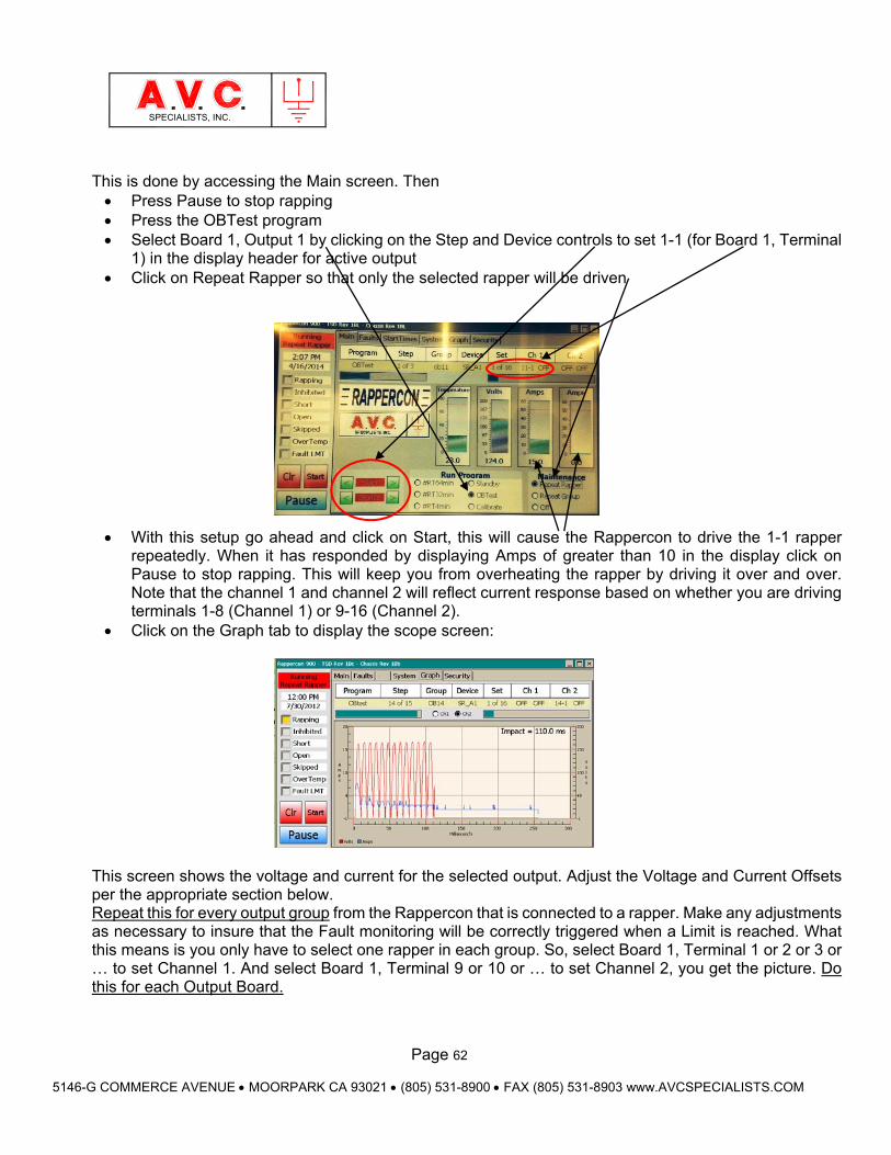
Page 62
5146-G COMMERCE AVENUE MOORPARK CA 93021 (805) 531-8900 FAX (805) 531-8903 www.AVCSPECIALISTS.COM
SPECIALISTS, INC.
This is done by accessing the Main screen. Then Press Pause to stop rapping Press the OBTest program Select Board 1, Output 1 by clicking on the Step and Device controls to set 1-1 (for Board 1, Terminal
1) in the display header for active output Click on Repeat Rapper so that only the selected rapper will be driven
With this setup go ahead and click on Start, this will cause the Rappercon to drive the 1-1 rapper
repeatedly. When it has responded by displaying Amps of greater than 10 in the display click on Pause to stop rapping. This will keep you from overheating the rapper by driving it over and over. Note that the channel 1 and channel 2 will reflect current response based on whether you are driving terminals 1-8 (Channel 1) or 9-16 (Channel 2).
Click on the Graph tab to display the scope screen:
This screen shows the voltage and current for the selected output. Adjust the Voltage and Current Offsets per the appropriate section below. Repeat this for every output group from the Rappercon that is connected to a rapper. Make any adjustments as necessary to insure that the Fault monitoring will be correctly triggered when a Limit is reached. What this means is you only have to select one rapper in each group. So, select Board 1, Terminal 1 or 2 or 3 or … to set Channel 1. And select Board 1, Terminal 9 or 10 or … to set Channel 2, you get the picture. Do this for each Output Board.
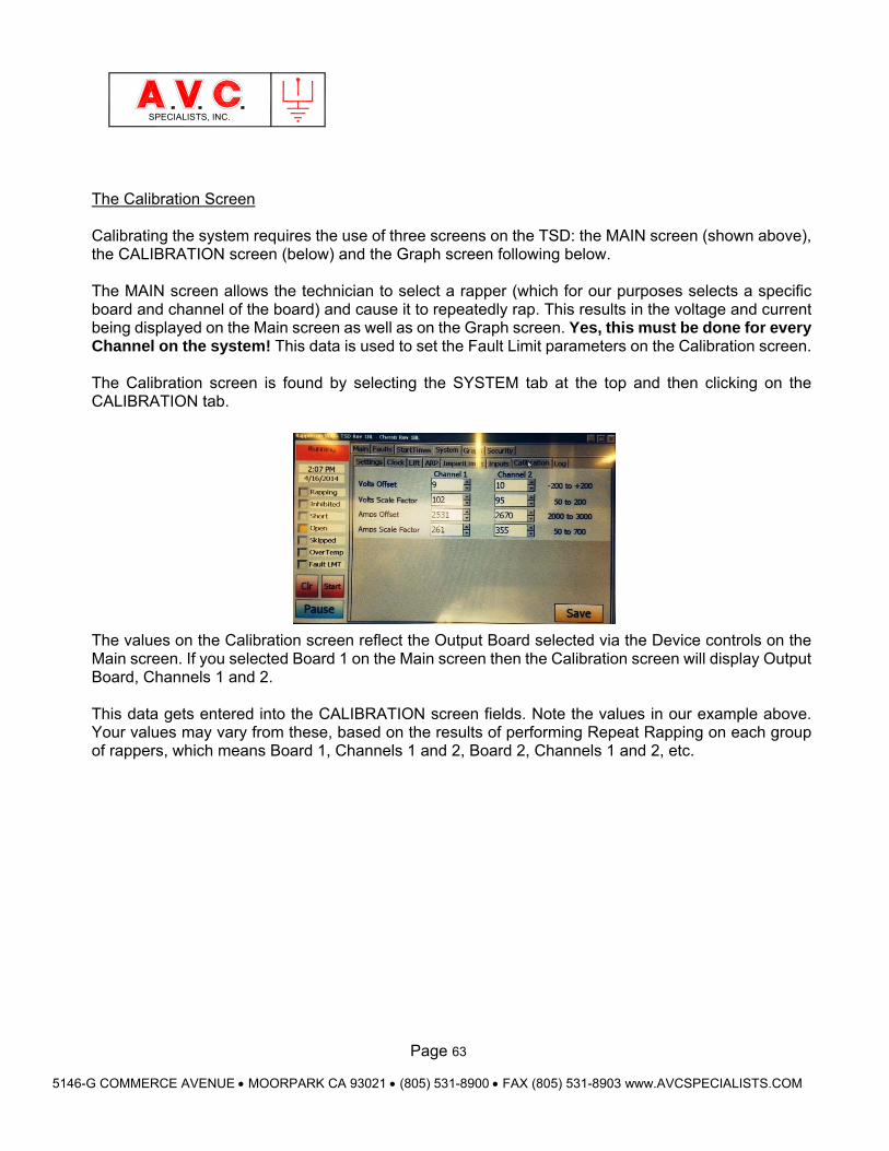
Page 63
5146-G COMMERCE AVENUE MOORPARK CA 93021 (805) 531-8900 FAX (805) 531-8903 www.AVCSPECIALISTS.COM
SPECIALISTS, INC.
The Calibration Screen Calibrating the system requires the use of three screens on the TSD: the MAIN screen (shown above), the CALIBRATION screen (below) and the Graph screen following below. The MAIN screen allows the technician to select a rapper (which for our purposes selects a specific board and channel of the board) and cause it to repeatedly rap. This results in the voltage and current being displayed on the Main screen as well as on the Graph screen. Yes, this must be done for every Channel on the system! This data is used to set the Fault Limit parameters on the Calibration screen. The Calibration screen is found by selecting the SYSTEM tab at the top and then clicking on the CALIBRATION tab. The values on the Calibration screen reflect the Output Board selected via the Device controls on the Main screen. If you selected Board 1 on the Main screen then the Calibration screen will display Output Board, Channels 1 and 2. This data gets entered into the CALIBRATION screen fields. Note the values in our example above. Your values may vary from these, based on the results of performing Repeat Rapping on each group of rappers, which means Board 1, Channels 1 and 2, Board 2, Channels 1 and 2, etc.
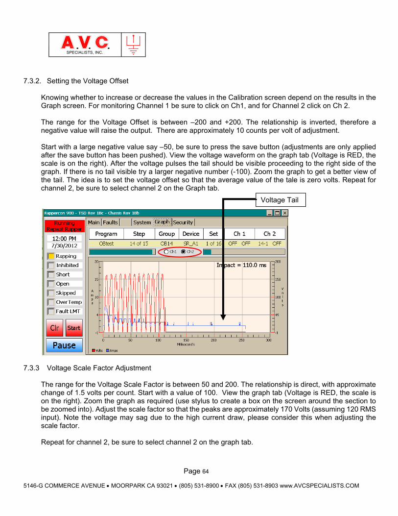
Page 64
5146-G COMMERCE AVENUE MOORPARK CA 93021 (805) 531-8900 FAX (805) 531-8903 www.AVCSPECIALISTS.COM
SPECIALISTS, INC.
7.3.2. Setting the Voltage Offset Knowing whether to increase or decrease the values in the Calibration screen depend on the results in the Graph screen. For monitoring Channel 1 be sure to click on Ch1, and for Channel 2 click on Ch 2.
The range for the Voltage Offset is between –200 and +200. The relationship is inverted, therefore a negative value will raise the output. There are approximately 10 counts per volt of adjustment. Start with a large negative value say –50, be sure to press the save button (adjustments are only applied after the save button has been pushed). View the voltage waveform on the graph tab (Voltage is RED, the scale is on the right). After the voltage pulses the tail should be visible proceeding to the right side of the graph. If there is no tail visible try a larger negative number (-100). Zoom the graph to get a better view of the tail. The idea is to set the voltage offset so that the average value of the tale is zero volts. Repeat for channel 2, be sure to select channel 2 on the Graph tab.
7.3.3 Voltage Scale Factor Adjustment
The range for the Voltage Scale Factor is between 50 and 200. The relationship is direct, with approximate change of 1.5 volts per count. Start with a value of 100. View the graph tab (Voltage is RED, the scale is on the right). Zoom the graph as required (use stylus to create a box on the screen around the section to be zoomed into). Adjust the scale factor so that the peaks are approximately 170 Volts (assuming 120 RMS input). Note the voltage may sag due to the high current draw, please consider this when adjusting the scale factor. Repeat for channel 2, be sure to select channel 2 on the graph tab.
Voltage Tail
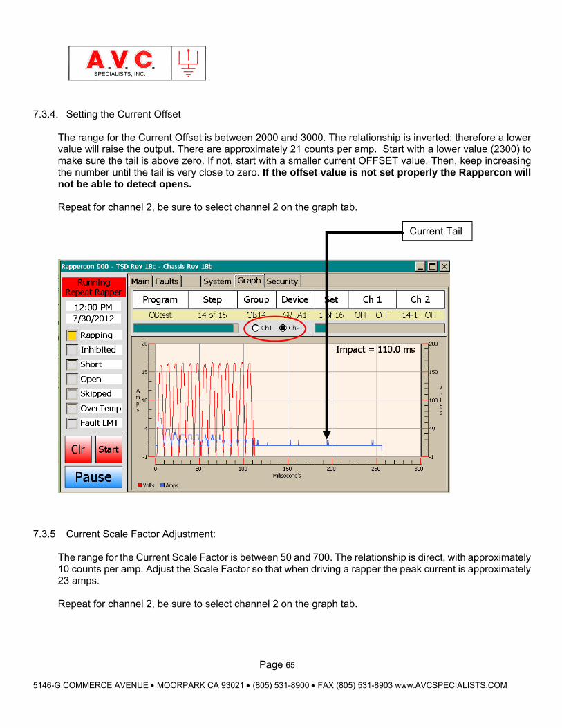
Page 65
5146-G COMMERCE AVENUE MOORPARK CA 93021 (805) 531-8900 FAX (805) 531-8903 www.AVCSPECIALISTS.COM
SPECIALISTS, INC.
7.3.4. Setting the Current Offset The range for the Current Offset is between 2000 and 3000. The relationship is inverted; therefore a lower value will raise the output. There are approximately 21 counts per amp. Start with a lower value (2300) to make sure the tail is above zero. If not, start with a smaller current OFFSET value. Then, keep increasing the number until the tail is very close to zero. If the offset value is not set properly the Rappercon will not be able to detect opens. Repeat for channel 2, be sure to select channel 2 on the graph tab.
7.3.5 Current Scale Factor Adjustment:
The range for the Current Scale Factor is between 50 and 700. The relationship is direct, with approximately 10 counts per amp. Adjust the Scale Factor so that when driving a rapper the peak current is approximately 23 amps. Repeat for channel 2, be sure to select channel 2 on the graph tab.
Current Tail
Page 66
5146-G COMMERCE AVENUE MOORPARK CA 93021 (805) 531-8900 FAX (805) 531-8903 www.AVCSPECIALISTS.COM
SPECIALISTS, INC.
8. Troubleshooting The RAPPERCON control is part of a precipitator operating system and must function continually or problems with precipitator collection efficiency will quickly become apparent. Troubleshooting system malfunctions require that the source of the malfunction must be determined, and the problem then corrected. Malfunctions during the initial start-up maybe caused by incorrect installation and calibration of the control. All wire terminations should be examined to ensure that they have been properly made. Control calibrations and operational adjustments should be carefully reviewed. Maintaining a record of past problems is also very useful.
8.1. Touch Screen Display Messages
The TSD will provide many useful messages that are an aid to troubleshooting the rapping system. The top line of the Home Screen will display the status of the control. From left to right the top line will display, “RAPPERCON”, a “STATUS” message and the “TIME”.
Warning Troubleshooting and repair of the RAPPERCON control should only be performed by qualified, competent personnel that have had appropriate training and experience. This equipment maybe connected with high-voltage and current devices installed on the precipitator.
Caution Do not HIPOT/Dielectric test the inputs/outputs, or communication terminals of this unit.
Caution Do not unplug or plug in any circuit card or harness with the power on. Damage will result to the electronic components.
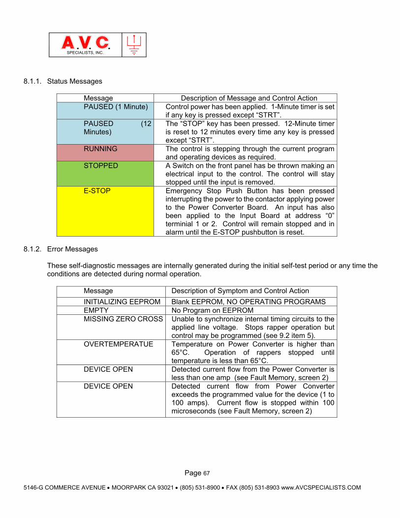
Page 67
5146-G COMMERCE AVENUE MOORPARK CA 93021 (805) 531-8900 FAX (805) 531-8903 www.AVCSPECIALISTS.COM
SPECIALISTS, INC.
8.1.1. Status Messages
Message Description of Message and Control Action PAUSED (1 Minute) Control power has been applied. 1-Minute timer is set
if any key is pressed except “STRT”. PAUSED (12 Minutes)
The “STOP” key has been pressed. 12-Minute timer is reset to 12 minutes every time any key is pressed except “STRT”.
RUNNING The control is stepping through the current program and operating devices as required.
STOPPED A Switch on the front panel has be thrown making an electrical input to the control. The control will stay stopped until the input is removed.
E-STOP Emergency Stop Push Button has been pressed interrupting the power to the contactor applying power to the Power Converter Board. An input has also been applied to the Input Board at address “0” terminial 1 or 2. Control will remain stopped and in alarm until the E-STOP pushbutton is reset.
8.1.2. Error Messages
These self-diagnostic messages are internally generated during the initial self-test period or any time the conditions are detected during normal operation.
Message Description of Symptom and Control Action
INITIALIZING EEPROM Blank EEPROM, NO OPERATING PROGRAMS EMPTY No Program on EEPROM MISSING ZERO CROSS Unable to synchronize internal timing circuits to the
applied line voltage. Stops rapper operation but control may be programmed (see 9.2 item 5).
OVERTEMPERATUE Temperature on Power Converter is higher than 65°C. Operation of rappers stopped until temperature is less than 65°C.
DEVICE OPEN Detected current flow from the Power Converter is less than one amp (see Fault Memory, screen 2)
DEVICE OPEN Detected current flow from Power Converter exceeds the programmed value for the device (1 to 100 amps). Current flow is stopped within 100 microseconds (see Fault Memory, screen 2)
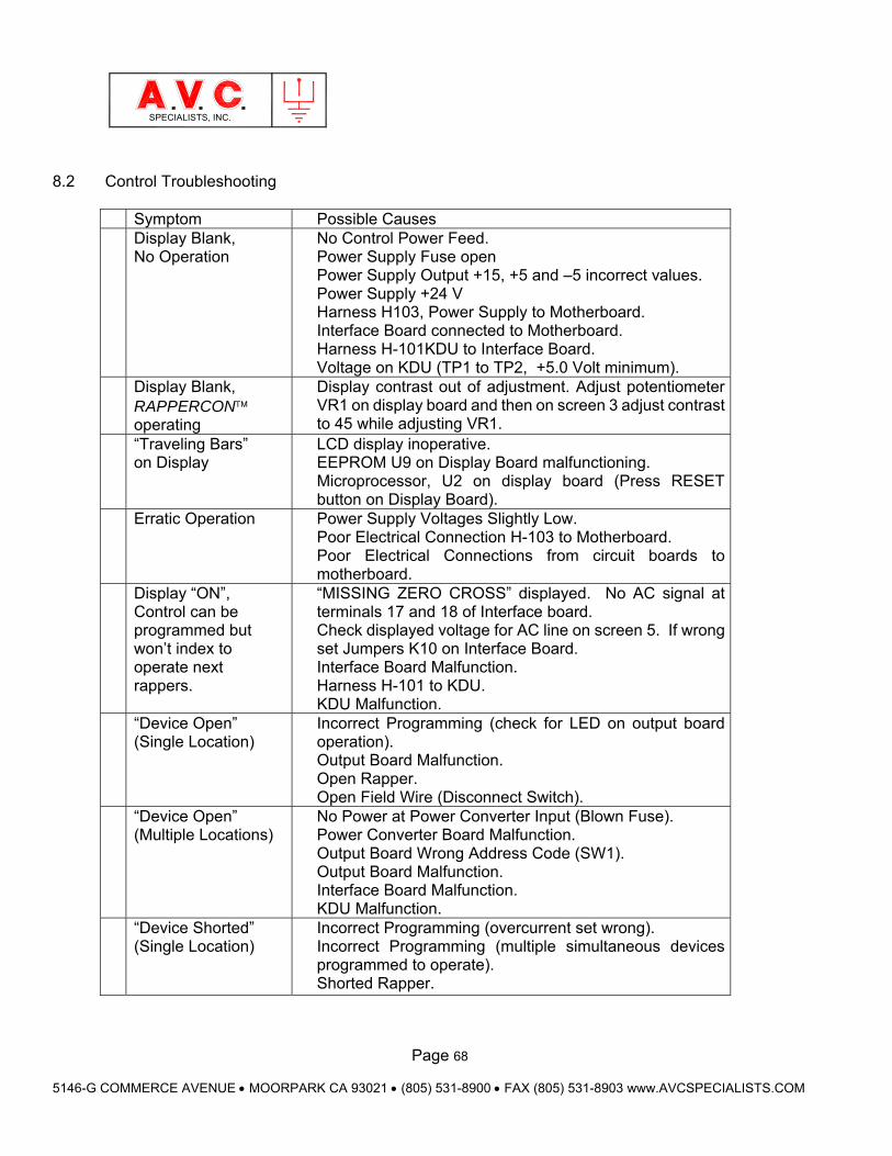
Page 68
5146-G COMMERCE AVENUE MOORPARK CA 93021 (805) 531-8900 FAX (805) 531-8903 www.AVCSPECIALISTS.COM
SPECIALISTS, INC.
8.2 Control Troubleshooting
Symptom Possible Causes Display Blank, No Operation
No Control Power Feed. Power Supply Fuse open Power Supply Output +15, +5 and –5 incorrect values. Power Supply +24 V Harness H103, Power Supply to Motherboard. Interface Board connected to Motherboard. Harness H-101KDU to Interface Board. Voltage on KDU (TP1 to TP2, +5.0 Volt minimum).
Display Blank, RAPPERCON operating
Display contrast out of adjustment. Adjust potentiometer VR1 on display board and then on screen 3 adjust contrast to 45 while adjusting VR1.
“Traveling Bars” on Display
LCD display inoperative. EEPROM U9 on Display Board malfunctioning. Microprocessor, U2 on display board (Press RESET button on Display Board).
Erratic Operation Power Supply Voltages Slightly Low. Poor Electrical Connection H-103 to Motherboard. Poor Electrical Connections from circuit boards to motherboard.
Display “ON”, Control can be programmed but won’t index to operate next rappers.
“MISSING ZERO CROSS” displayed. No AC signal at terminals 17 and 18 of Interface board. Check displayed voltage for AC line on screen 5. If wrong set Jumpers K10 on Interface Board. Interface Board Malfunction. Harness H-101 to KDU. KDU Malfunction.
“Device Open” (Single Location)
Incorrect Programming (check for LED on output board operation). Output Board Malfunction. Open Rapper. Open Field Wire (Disconnect Switch).
“Device Open” (Multiple Locations)
No Power at Power Converter Input (Blown Fuse). Power Converter Board Malfunction. Output Board Wrong Address Code (SW1). Output Board Malfunction. Interface Board Malfunction. KDU Malfunction.
“Device Shorted” (Single Location)
Incorrect Programming (overcurrent set wrong). Incorrect Programming (multiple simultaneous devices programmed to operate). Shorted Rapper.
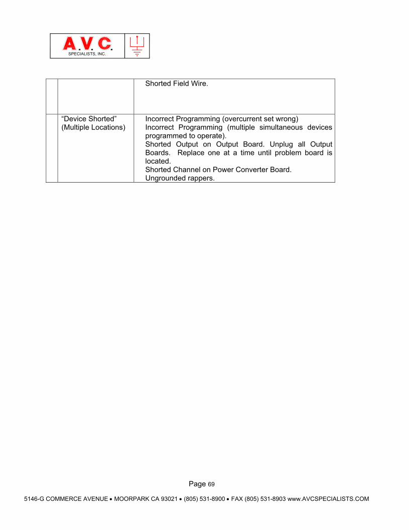
Page 69
5146-G COMMERCE AVENUE MOORPARK CA 93021 (805) 531-8900 FAX (805) 531-8903 www.AVCSPECIALISTS.COM
SPECIALISTS, INC.
Shorted Field Wire.
“Device Shorted” (Multiple Locations)
Incorrect Programming (overcurrent set wrong) Incorrect Programming (multiple simultaneous devices programmed to operate). Shorted Output on Output Board. Unplug all Output Boards. Replace one at a time until problem board is located. Shorted Channel on Power Converter Board. Ungrounded rappers.
Page 70
5146-G COMMERCE AVENUE MOORPARK CA 93021 (805) 531-8900 FAX (805) 531-8903 www.AVCSPECIALISTS.COM
SPECIALISTS, INC.
9. POWER-OFF-RAPPING Using MODBUS Communications Power-Off-Rapping (POR) using the PSS™ requires the correct configuration of the RAPPERCON™ that will initiate the process, the PSS™ that will communicate the commands and the POWERCON™ that will receive the instruction to reduce power. This is also true where a PSS™ is not used but, instead, a DCS system or ESP controller is communicating with the individual RAPPERCON™control. The Modbus protocol and addressing are provided in a separate document (RASTD890).
9.1 Basic Control Configuration
9.1.1 RAPPERCON™ Use of sequential type program only is recommended for RAPPERCON™ controls that operate more than 24 rappers. This is due to the added time before each rapper is operated due to the POR Time Delay when Round Trip Programming is used. With Sequential Program the POR Time Delay is only added at the beginning of the group to be rapped than all rappers are operated without further delay. POR is only transmitted to PSS™ when a GROUP has a POR address other than “0” in its GROUP Parameters. The MODBUS address in the GROUP Parameter must be carefully programmed to control the POWERCON™ associated with the rappers to be operated by that group. It is strongly recommended that special GROUPs be written for POR and that the GROUP only be associated with a specially named POR program only. Anytime a POR GROUP is operated the associated POWERCON™ will reduce power! Always use the START TIME Feature of the RAPPERCON™ to automatically stop POR program from operating too long. Set start times for a “Normal” rapping program to operate several times in a day. A start time for the POR does not need to be provided.
9.1.2 PSS™ The communications network cabling must be configured per the addressing scheme and terminated in the correct numbered ports. POR is communications port sensitive. That is all RAPPERCONs™ that send POR addresses and POWERCONs™ that will receive instructions must be on the same communications port. This is to prevent POR instructions being transmitted to another precipitator. Note that all the MODBUS addresses for any precipitator are blocked into groups of eight, Each POWERCON™ control must be programmed on the PSS™ with a POR TIMER Value (1-30 seconds). This value is only available on the Remote Programming Screen and only when the correct programming password has been entered. This POR TIMER Value is transmitted to the POWERCON™ and the POR is only active for the time. POR will operate any time a valid MODBUS address is received from a RAPPERCON™. POR cannot be disabled by the PSS™.

Page 71
5146-G COMMERCE AVENUE MOORPARK CA 93021 (805) 531-8900 FAX (805) 531-8903 www.AVCSPECIALISTS.COM
SPECIALISTS, INC.
9.1.3 POWERCON™ The POWERCON™, when it receives a POR command, will reduce operating power by reducing it Primary Current to a percentage of the programmed Primary Current Limit. Those values are programmed exactly the same way on the POWERCON™ for Default Mode operation and on the PSS™ for Remote Mode operation. . Percentage Reductions are programmed as follows: 0% of Primary Current Limit 25% of Primary Current Limit 50% of Primary Current Limit 100% of Primary Current Limit
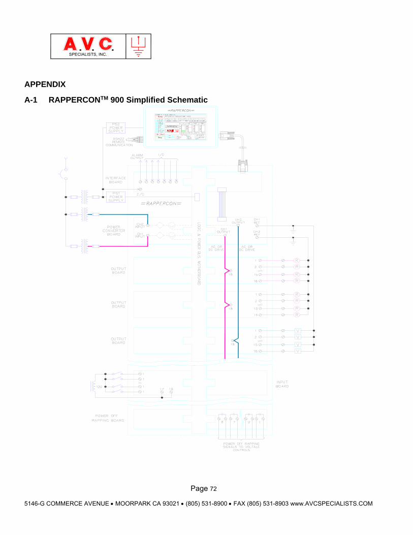
Page 72
5146-G COMMERCE AVENUE MOORPARK CA 93021 (805) 531-8900 FAX (805) 531-8903 www.AVCSPECIALISTS.COM
SPECIALISTS, INC.
APPENDIX
A-1 RAPPERCONTM 900 Simplified Schematic
Page 73
5146-G COMMERCE AVENUE MOORPARK CA 93021 (805) 531-8900 FAX (805) 531-8903 www.AVCSPECIALISTS.COM
SPECIALISTS, INC.
A-2 Electrostatic Precipitator Rapping Overview
A-2.1. Rapping Basics Electrostatic precipitators are used to remove particles, fumes and mists from gas streams by passing the material to be collected through an electrically ionizing shower that charges the material, then applying a strong electrode static field that attracts the material to collecting surfaces. A simplistic description of efficient collection of material in a precipitator occurs when: The highest electrostatic field strength (voltage) is maintained, The greatest number of charging ions are created (current), The nature of the material to be collected is: Easily charged, Retains the charge while in the gas stream, When collected, surrenders the charge to the collecting surface (resistivity). As material builds on the collecting surface, there is normally a reduction of the magnitude of the voltage and current. When a significant layer of material is collected, it must be removed from the collecting surface to restore good collecting efficiency of the precipitator. The method of removal depends on the physical design of the precipitator and the material collected. For plate type precipitators constructed of alternating rows of parallel collecting plates and discharge electrodes collecting dry material, the common method of cleaning is to periodically shake the collecting surfaces (rap). Rapping is accomplished by mechanically impacting the collecting surfaces (collecting plates and discharge electrode).
A-2.2. Considerations
There are several principal considerations in the design and operation of any rapping system including: Applying sufficient magnitude of force required to dislodge the dust from the collecting surface. The determining factor in initially shearing the dust from the rapped surface is the acceleration imparted by the rapping device. The acceleration required varies from dust to dust. Generally, the lowest range of acceleration required is 10 g’s and the highest over 100 g’s. For dry dusts, the easier to rap dusts tend to be spherical shaped or lower resistivity or larger particle sizes. Harder to rap dusts are generally irregular shaped, higher resistivity and smaller particle size.
The distribution of acceleration imparted by the rapping device is not distributed evenly about the entire rapped surface. Distance from the point of impact, resonance of object and damping by the accumulated material will all affect the acceleration at any point on the surface.
Page 74
5146-G COMMERCE AVENUE MOORPARK CA 93021 (805) 531-8900 FAX (805) 531-8903 www.AVCSPECIALISTS.COM
SPECIALISTS, INC.
A-2.2.1 Preventing of excessive re-entrainment collected dust.
Every time a surface is rapped, a percentage of the dust is re-entrained into the gas stream and carried toward the outlet of the precipitator. That portion of dust re-entrained from the outlet field will be obvious as a puff in the stack plume. The rapping impact must be sufficient to dislodge some of the dust from the collecting surface and allow gravity to move it downward. Ideally the path of the falling particles will be adjacent to the surface, in a dead zone of no gas flow provided by the shape of the collecting surface. The electrostatic force will tend to keep the particle adjacent to the surface and recapture it after it has fallen some distance. Several factors cause problems with this ideal scenario. Turbulence in the gas stream may scarf particles directly off the surface or capture particles in the dead zone. The aerodynamics of the falling dust to disperse from a vertical path the farther it drops (picture a straight trumpet standing on end). The light smaller particles are more susceptible to all of the above factors. Another detrimental factor is back corona discharges (high resistivity) where reverse currents at random times blast material from the collecting surface into the gas stream. Yet another problem is an avalanche of material caused by large particles falling from above and dislodging dust from lower portions of the precipitator collecting plates.
A-2.2.2 Creating ideal dust thickness (accumulation period).
The dust on the surface should accumulate to a minimum thickness before being rapped. Under the influence of the electrostatic field and resulting micro-current flows, the dust is deposited essentially one particle at a time with sufficient freedom of motion, it will tend to pack into denser particles. The flow of the micro-current will bind the particles together elephant style (+ - + -+ -) with electrical charges. This dust when rapped will sheet and slide as a “unit”. However, excessive accumulation of material on the surface has many detrimental effects. As the layer thickens, it creates an electrically resistive layer through which the precipitator current must flow. This requires a greater portion of the available electrostatic field to move current through the dust layer and less of the available field strength to produce ionizing electrons and deflect particles to the collecting surface. The dust layer reduces the clearance between the discharge electrodes and the collecting surface lowers the spark over voltage resulting in diminished effective voltage and current density.
The dust layer may become so thick that large sections then peel off the surface. This will then create uneven distribution of current in the precipitator with uneven collection.
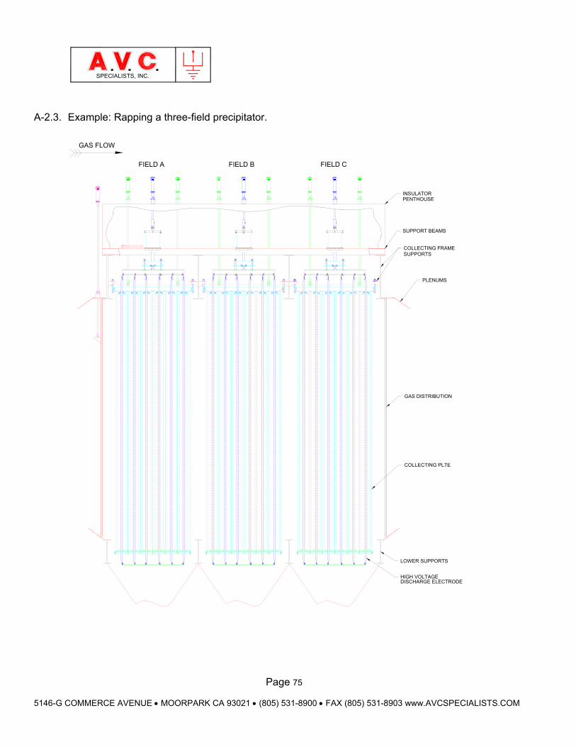
Page 75
5146-G COMMERCE AVENUE MOORPARK CA 93021 (805) 531-8900 FAX (805) 531-8903 www.AVCSPECIALISTS.COM
SPECIALISTS, INC.
A-2.3. Example: Rapping a three-field precipitator.
FIELD CFIELD A
GAS FLOW
FIELD B
COLLECTING PLTE
DISCHARGE ELECTRODEHIGH VOLTAGE
LOWER SUPPORTS
PLENUMS
GAS DISTRIBUTION
SUPPORT BEAMS
COLLECTING FRAMESUPPORTS
PENTHOUSEINSULATOR
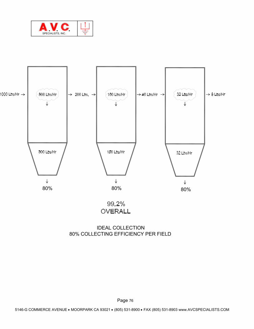
Page 76
5146-G COMMERCE AVENUE MOORPARK CA 93021 (805) 531-8900 FAX (805) 531-8903 www.AVCSPECIALISTS.COM
SPECIALISTS, INC.
80% COLLECTING EFFICIENCY PER FIELDIDEAL COLLECTION
80% 80% 80%
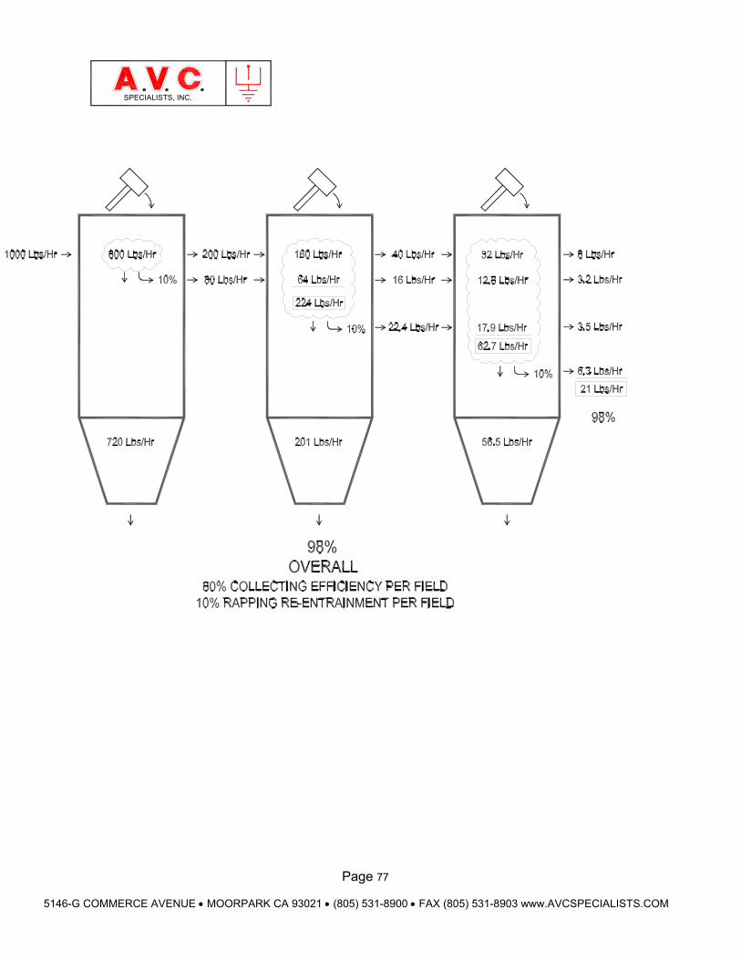
Page 77
5146-G COMMERCE AVENUE MOORPARK CA 93021 (805) 531-8900 FAX (805) 531-8903 www.AVCSPECIALISTS.COM
SPECIALISTS, INC.
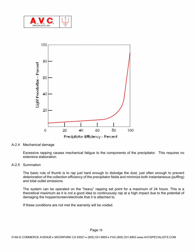
Page 78
5146-G COMMERCE AVENUE MOORPARK CA 93021 (805) 531-8900 FAX (805) 531-8903 www.AVCSPECIALISTS.COM
SPECIALISTS, INC.
A-2.4 Mechanical damage
Excessive rapping causes mechanical fatigue to the components of the precipitator. This requires no extensive elaboration.
A-2.5 Summation The basic rule of thumb is to rap just hard enough to dislodge the dust, just often enough to prevent deterioration of the collection efficiency of the precipitator fields and minimize both instantaneous (puffing) and total outlet emissions. The system can be operated on the “heavy” rapping set point for a maximum of 24 hours. This is a theoretical maximum as it is not a good idea to continuously rap at a high impact due to the potential of damaging the hopper/screen/electrode that it is attached to. If these conditions are not met the warranty will be voided.
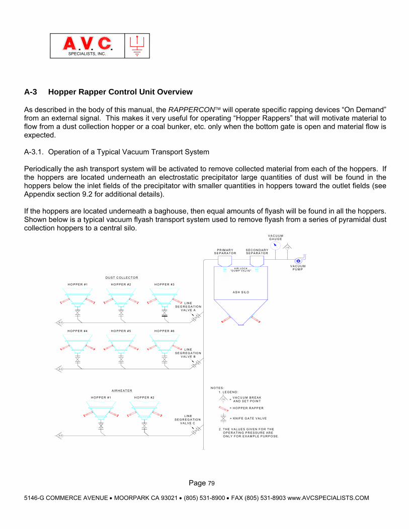
Page 79
5146-G COMMERCE AVENUE MOORPARK CA 93021 (805) 531-8900 FAX (805) 531-8903 www.AVCSPECIALISTS.COM
SPECIALISTS, INC.
A-3 Hopper Rapper Control Unit Overview As described in the body of this manual, the RAPPERCON will operate specific rapping devices “On Demand” from an external signal. This makes it very useful for operating “Hopper Rappers” that will motivate material to flow from a dust collection hopper or a coal bunker, etc. only when the bottom gate is open and material flow is expected. A-3.1. Operation of a Typical Vacuum Transport System Periodically the ash transport system will be activated to remove collected material from each of the hoppers. If the hoppers are located underneath an electrostatic precipitator large quantities of dust will be found in the hoppers below the inlet fields of the precipitator with smaller quantities in hoppers toward the outlet fields (see Appendix section 9.2 for additional details). If the hoppers are located underneath a baghouse, then equal amounts of flyash will be found in all the hoppers. Shown below is a typical vacuum flyash transport system used to remove flyash from a series of pyramidal dust collection hoppers to a central silo.
V A C U U M B R E A KA N D S E T P O IN T
2 . T H E V A LU E S G IV E N FO R T H E O P E R A T IN G P R E S S U R E A R E O N LY F O R E X A M P LE P U R P O S E .-8 .5
S E G R E G A TIO NV A LV E C
H O P P E R #2H O P P E R #1
A IR H E A T E R
-8.5
1 . LE G E N D :
-14 =
N O T E S :
V A C U U M
H O P P E R #4
-8 .5
H O P P E R #5
S E G R E G A TIO NV A LV E B
H O P P E R #6
H O P P E R #1
D U S T C O LLE C TO R
H O P P E R #2
S E G R E G A TIO NV A LV E A
H O P P E R #3
A S H S ILO
P U M P
S E P A R A TO RS E C O N D A R Y
S E P A R A TO RP R IM A R Y
-14
G A U G EV A C U U M
LIN E
L IN E
L IN E
= H O P P E R R A P P E R
= K N IF E G A TE V A LV E
A IR LO C K"D U M P V A LV E "
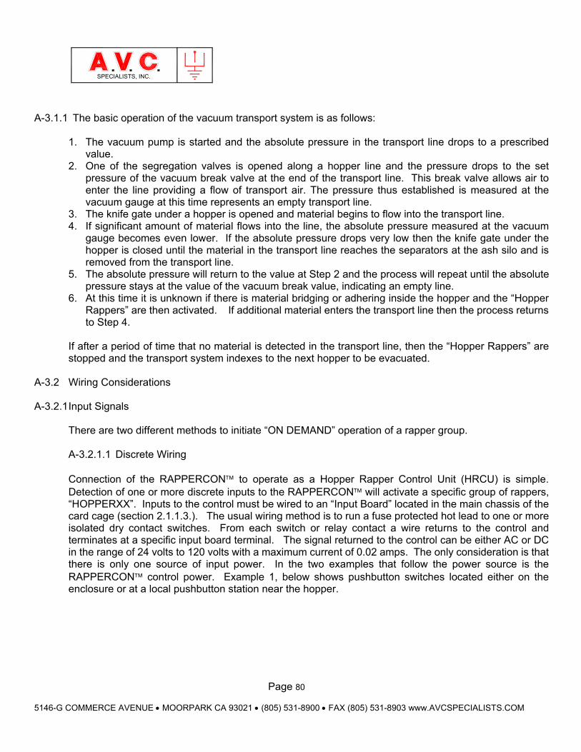
Page 80
5146-G COMMERCE AVENUE MOORPARK CA 93021 (805) 531-8900 FAX (805) 531-8903 www.AVCSPECIALISTS.COM
SPECIALISTS, INC.
A-3.1.1 The basic operation of the vacuum transport system is as follows:
1. The vacuum pump is started and the absolute pressure in the transport line drops to a prescribed value.
2. One of the segregation valves is opened along a hopper line and the pressure drops to the set pressure of the vacuum break valve at the end of the transport line. This break valve allows air to enter the line providing a flow of transport air. The pressure thus established is measured at the vacuum gauge at this time represents an empty transport line.
3. The knife gate under a hopper is opened and material begins to flow into the transport line. 4. If significant amount of material flows into the line, the absolute pressure measured at the vacuum
gauge becomes even lower. If the absolute pressure drops very low then the knife gate under the hopper is closed until the material in the transport line reaches the separators at the ash silo and is removed from the transport line.
5. The absolute pressure will return to the value at Step 2 and the process will repeat until the absolute pressure stays at the value of the vacuum break value, indicating an empty line.
6. At this time it is unknown if there is material bridging or adhering inside the hopper and the “Hopper Rappers” are then activated. If additional material enters the transport line then the process returns to Step 4.
If after a period of time that no material is detected in the transport line, then the “Hopper Rappers” are stopped and the transport system indexes to the next hopper to be evacuated.
A-3.2 Wiring Considerations
A-3.2.1 Input Signals There are two different methods to initiate “ON DEMAND” operation of a rapper group. A-3.2.1.1 Discrete Wiring Connection of the RAPPERCON to operate as a Hopper Rapper Control Unit (HRCU) is simple. Detection of one or more discrete inputs to the RAPPERCON will activate a specific group of rappers, “HOPPERXX”. Inputs to the control must be wired to an “Input Board” located in the main chassis of the card cage (section 2.1.1.3.). The usual wiring method is to run a fuse protected hot lead to one or more isolated dry contact switches. From each switch or relay contact a wire returns to the control and terminates at a specific input board terminal. The signal returned to the control can be either AC or DC in the range of 24 volts to 120 volts with a maximum current of 0.02 amps. The only consideration is that there is only one source of input power. In the two examples that follow the power source is the RAPPERCON control power. Example 1, below shows pushbutton switches located either on the enclosure or at a local pushbutton station near the hopper.
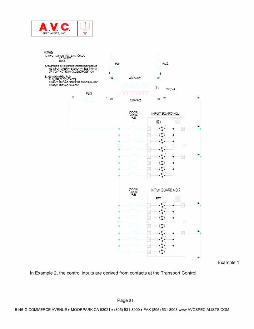
Page 81
5146-G COMMERCE AVENUE MOORPARK CA 93021 (805) 531-8900 FAX (805) 531-8903 www.AVCSPECIALISTS.COM
SPECIALISTS, INC.
Example 1 In Example 2, the control inputs are derived from contacts at the Transport Control.
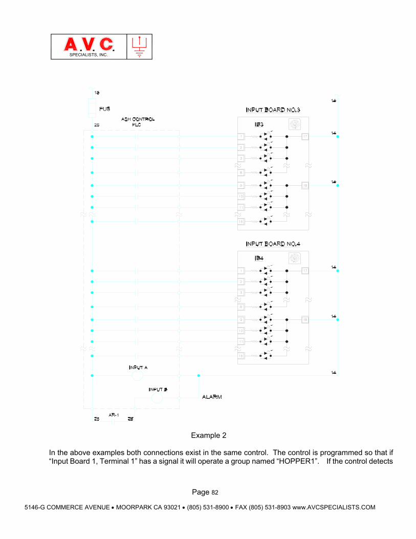
Page 82
5146-G COMMERCE AVENUE MOORPARK CA 93021 (805) 531-8900 FAX (805) 531-8903 www.AVCSPECIALISTS.COM
SPECIALISTS, INC.
Example 2
In the above examples both connections exist in the same control. The control is programmed so that if “Input Board 1, Terminal 1” has a signal it will operate a group named “HOPPER1”. If the control detects
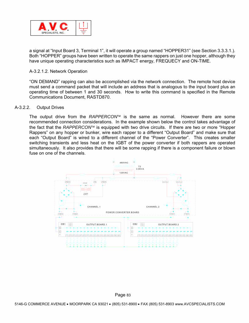
Page 83
5146-G COMMERCE AVENUE MOORPARK CA 93021 (805) 531-8900 FAX (805) 531-8903 www.AVCSPECIALISTS.COM
SPECIALISTS, INC.
a signal at “Input Board 3, Terminal 1”, it will operate a group named “HOPPER31” (see Section 3.3.3.1.). Both “HOPPER” groups have been written to operate the same rappers on just one hopper, although they have unique operating characteristics such as IMPACT energy, FREQUECY and ON-TIME. A-3.2.1.2. Network Operation
“ON DEMAND” rapping can also be accomplished via the network connection. The remote host device must send a command packet that will include an address that is analogous to the input board plus an operating time of between 1 and 30 seconds. How to write this command is specified in the Remote Communications Document, RASTD870.
A-3.2.2. Output Drives
The output drive from the RAPPERCON is the same as normal. However there are some recommended connection considerations. In the example shown below the control takes advantage of the fact that the RAPPERCON is equipped with two drive circuits. If there are two or more “Hopper Rappers” on any hopper or bunker, wire each rapper to a different “Output Board” and make sure that each “Output Board” is wired to a different channel of the “Power Converter”. This creates smaller switching transients and less heat on the IGBT of the power converter if both rappers are operated simultaneously. It also provides that there will be some rapping if there is a component failure or blown fuse on one of the channels.
P O W E R C O N V E R TE R B O A R D
18
17
J1
H1 480V A C
16
O U TP U T B O AR D 1
C H A N N E L 1
9
18 17
120-240
S W 1
P O W E RS U P P LY
12
1
O B 1
109
18
17
J1
11
2 3 54 6 7 8
X 1
15 14
120V AC
10 11 1312 14 15 16
H2
O U TPU T B O AR D 2
C H A N N E L 2
3 .0K V AT2
X 4
4 3
O B 2
1 32 4 75 6 8 9
2 1
8
15
65
1110 12
7
13 14 16
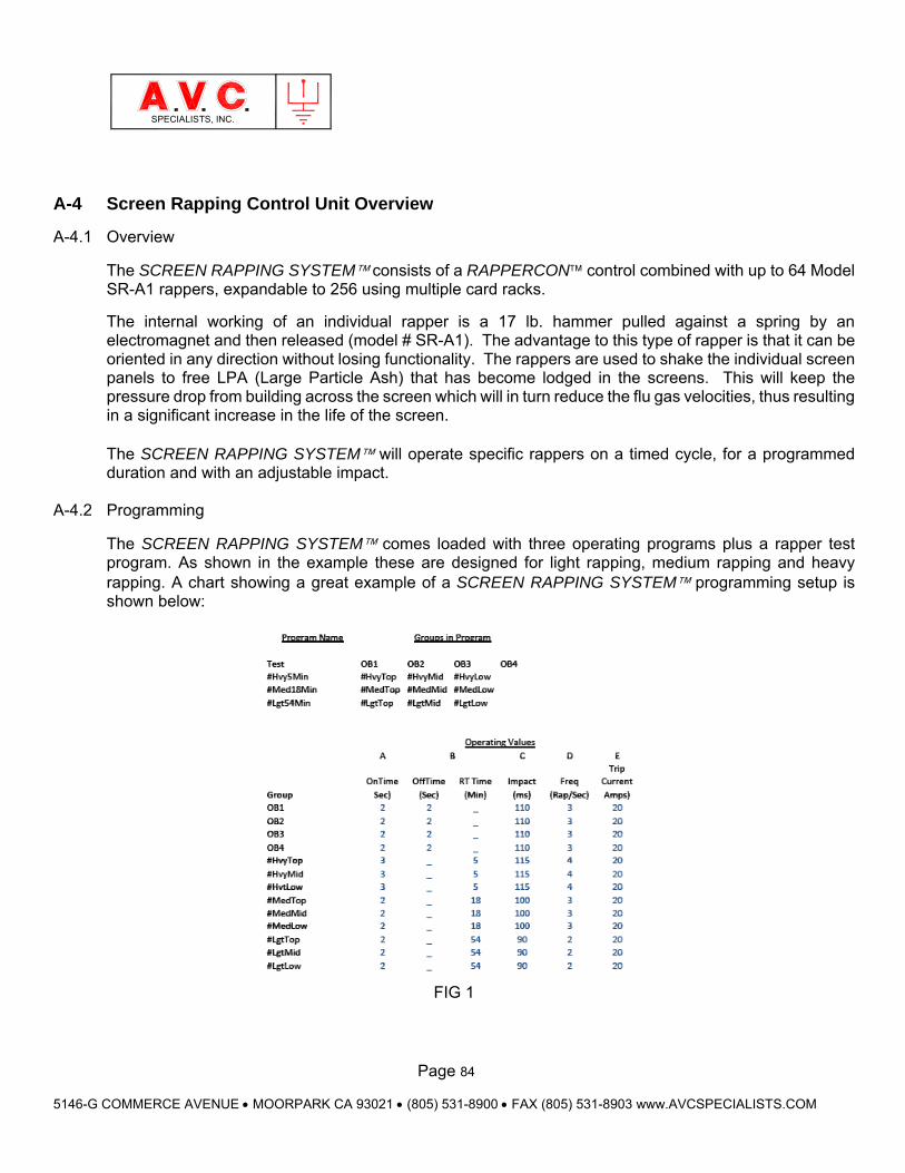
Page 84
5146-G COMMERCE AVENUE MOORPARK CA 93021 (805) 531-8900 FAX (805) 531-8903 www.AVCSPECIALISTS.COM
SPECIALISTS, INC.
A-4 Screen Rapping Control Unit Overview
A-4.1 Overview
The SCREEN RAPPING SYSTEM consists of a RAPPERCON control combined with up to 64 Model SR-A1 rappers, expandable to 256 using multiple card racks.
The internal working of an individual rapper is a 17 lb. hammer pulled against a spring by an electromagnet and then released (model # SR-A1). The advantage to this type of rapper is that it can be oriented in any direction without losing functionality. The rappers are used to shake the individual screen panels to free LPA (Large Particle Ash) that has become lodged in the screens. This will keep the pressure drop from building across the screen which will in turn reduce the flu gas velocities, thus resulting in a significant increase in the life of the screen. The SCREEN RAPPING SYSTEM will operate specific rappers on a timed cycle, for a programmed duration and with an adjustable impact.
A-4.2 Programming
The SCREEN RAPPING SYSTEM comes loaded with three operating programs plus a rapper test program. As shown in the example these are designed for light rapping, medium rapping and heavy rapping. A chart showing a great example of a SCREEN RAPPING SYSTEM programming setup is shown below:
FIG 1

Page 85
5146-G COMMERCE AVENUE MOORPARK CA 93021 (805) 531-8900 FAX (805) 531-8903 www.AVCSPECIALISTS.COM
SPECIALISTS, INC.
Ideally, when configuring a SCREEN RAPPING SYSTEM the operator should start with light rapping. The goal is to run with the lightest impact force possible without increasing the pressure drop through the screen. In other words, run the lightest impact program that keeps the screens clean. The system can be operated on the “heavy” rapping set point for a maximum of 24 hours. This is a theoretical maximum as it is not a good idea to continuously rap at a high impact due to the potential of damaging the hopper/screen/electrode that it is attached to. If these conditions are not met the warranty will be voided.
A-4.3 Program Selection
There are two methods for controlling which program is active. The first is by selecting the program from the operator interface running on the Touch Screen Display (TSD). This is discussed in greater detail in the Operating & Maintenace Manual.
The second method for controlling the active program is by setting three dedicated inputs of the SCREEN RAPPING SYSTEM to determine which program will run. This is designed to allow a DCS system to externally control the operation of the SCREEN RAPPING SYSTEM automatically while it monitors the pressure drop across the screens.
The following chart shows these three inputs and resulting action:
FIG 2
In addition to the three inputs the SCREEN RAPPING SYSTEM also has Normally-Closed contact outputs to tell the external controller that there is an alarm, advise that power is on and tell the remote controller that the system is running. These can be used by a DCS system to determine the operational
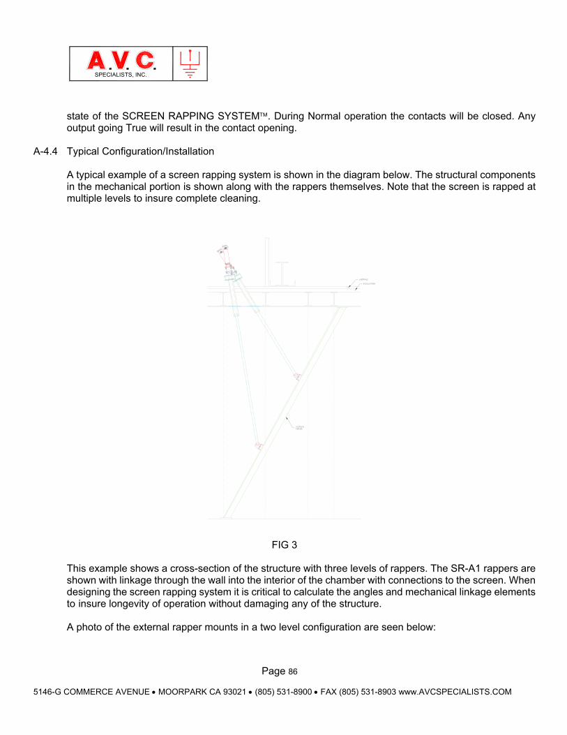
Page 86
5146-G COMMERCE AVENUE MOORPARK CA 93021 (805) 531-8900 FAX (805) 531-8903 www.AVCSPECIALISTS.COM
SPECIALISTS, INC.
state of the SCREEN RAPPING SYSTEM. During Normal operation the contacts will be closed. Any output going True will result in the contact opening.
A-4.4 Typical Configuration/Installation A typical example of a screen rapping system is shown in the diagram below. The structural components in the mechanical portion is shown along with the rappers themselves. Note that the screen is rapped at multiple levels to insure complete cleaning.
FIG 3
This example shows a cross-section of the structure with three levels of rappers. The SR-A1 rappers are shown with linkage through the wall into the interior of the chamber with connections to the screen. When designing the screen rapping system it is critical to calculate the angles and mechanical linkage elements to insure longevity of operation without damaging any of the structure. A photo of the external rapper mounts in a two level configuration are seen below:

Page 87
5146-G COMMERCE AVENUE MOORPARK CA 93021 (805) 531-8900 FAX (805) 531-8903 www.AVCSPECIALISTS.COM
SPECIALISTS, INC.
FIG 4
In this photograph note the SR-A1 rappers are attached using temperature isolators (required if the surface temperature exceeds 200 degrees F) and the linkage to the rapping shaft is housed in a boot seal to prevent flue gas from leaking and protect it from harm and contaminants. The mechanical details for this installation are shown below:
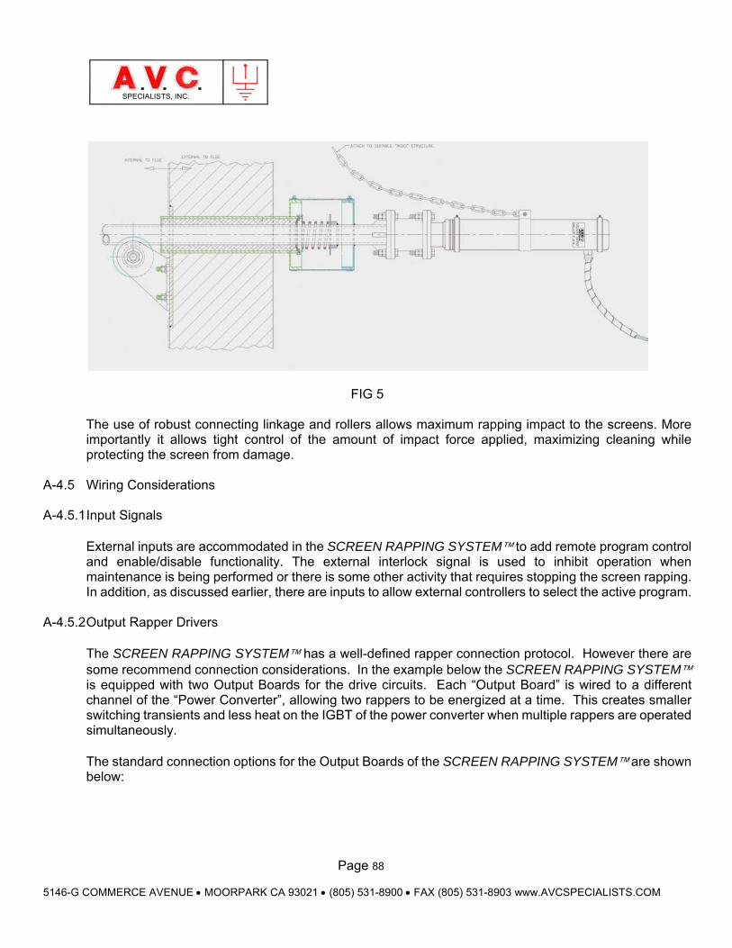
Page 88
5146-G COMMERCE AVENUE MOORPARK CA 93021 (805) 531-8900 FAX (805) 531-8903 www.AVCSPECIALISTS.COM
SPECIALISTS, INC.
FIG 5
The use of robust connecting linkage and rollers allows maximum rapping impact to the screens. More importantly it allows tight control of the amount of impact force applied, maximizing cleaning while protecting the screen from damage.
A-4.5 Wiring Considerations
A-4.5.1 Input Signals
External inputs are accommodated in the SCREEN RAPPING SYSTEM to add remote program control and enable/disable functionality. The external interlock signal is used to inhibit operation when maintenance is being performed or there is some other activity that requires stopping the screen rapping. In addition, as discussed earlier, there are inputs to allow external controllers to select the active program.
A-4.5.2 Output Rapper Drivers
The SCREEN RAPPING SYSTEM has a well-defined rapper connection protocol. However there are some recommend connection considerations. In the example below the SCREEN RAPPING SYSTEM is equipped with two Output Boards for the drive circuits. Each “Output Board” is wired to a different channel of the “Power Converter”, allowing two rappers to be energized at a time. This creates smaller switching transients and less heat on the IGBT of the power converter when multiple rappers are operated simultaneously. The standard connection options for the Output Boards of the SCREEN RAPPING SYSTEM are shown below:
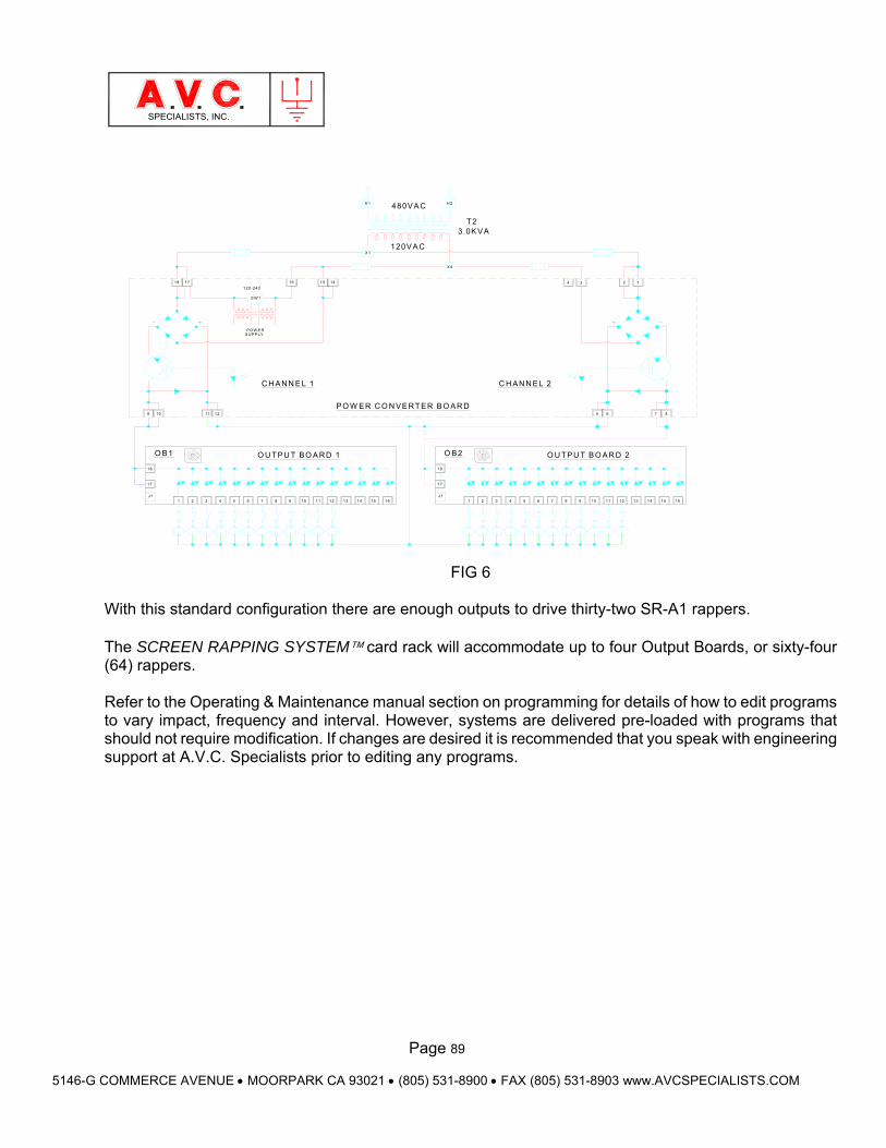
Page 89
5146-G COMMERCE AVENUE MOORPARK CA 93021 (805) 531-8900 FAX (805) 531-8903 www.AVCSPECIALISTS.COM
SPECIALISTS, INC.
PO W ER C O N VE R TER B O AR D
18
17
J1
H 1 480VA C
16
O U TPU T BO A R D 1
C H A N N E L 1
9
18 17
120-240
S W 1
PO W E RS U PPLY
12
1
O B1
109
18
17
J1
11
2 3 54 6 7 8
X1
15 14
120VA C
10 11 1312 14 15 16
H 2
O U TP U T B O AR D 2
C H AN N EL 2
3 .0K VAT2
X 4
4 3
O B2
1 32 4 75 6 8 9
2 1
8
15
65
1110 12
7
13 14 16
FIG 6
With this standard configuration there are enough outputs to drive thirty-two SR-A1 rappers. The SCREEN RAPPING SYSTEM card rack will accommodate up to four Output Boards, or sixty-four (64) rappers. Refer to the Operating & Maintenance manual section on programming for details of how to edit programs to vary impact, frequency and interval. However, systems are delivered pre-loaded with programs that should not require modification. If changes are desired it is recommended that you speak with engineering support at A.V.C. Specialists prior to editing any programs.
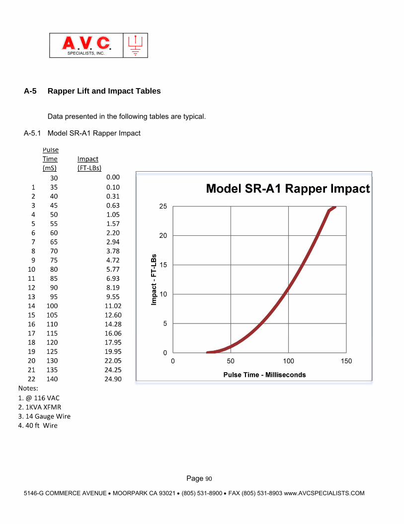
Page 90
5146-G COMMERCE AVENUE MOORPARK CA 93021 (805) 531-8900 FAX (805) 531-8903 www.AVCSPECIALISTS.COM
SPECIALISTS, INC.
A-5 Rapper Lift and Impact Tables
Data presented in the following tables are typical.
A-5.1 Model SR-A1 Rapper Impact
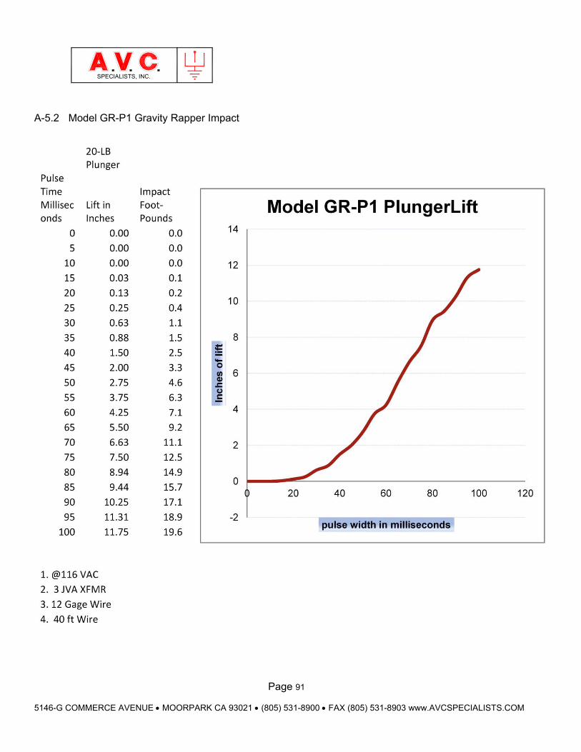
Page 91
5146-G COMMERCE AVENUE MOORPARK CA 93021 (805) 531-8900 FAX (805) 531-8903 www.AVCSPECIALISTS.COM
SPECIALISTS, INC.
A-5.2 Model GR-P1 Gravity Rapper Impact
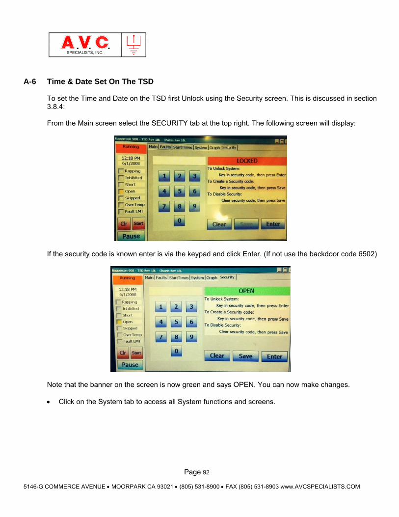
Page 92
5146-G COMMERCE AVENUE MOORPARK CA 93021 (805) 531-8900 FAX (805) 531-8903 www.AVCSPECIALISTS.COM
SPECIALISTS, INC.
A-6 Time & Date Set On The TSD To set the Time and Date on the TSD first Unlock using the Security screen. This is discussed in section 3.8.4: From the Main screen select the SECURITY tab at the top right. The following screen will display:
If the security code is known enter is via the keypad and click Enter. (If not use the backdoor code 6502)
Note that the banner on the screen is now green and says OPEN. You can now make changes. Click on the System tab to access all System functions and screens.
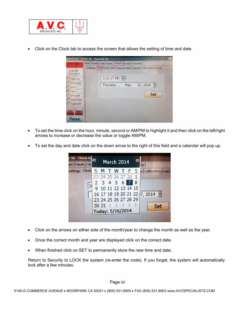
Page 93
5146-G COMMERCE AVENUE MOORPARK CA 93021 (805) 531-8900 FAX (805) 531-8903 www.AVCSPECIALISTS.COM
SPECIALISTS, INC.
Click on the Clock tab to access the screen that allows the setting of time and date.
To set the time click on the hour, minute, second or AM/PM to highlight it and then click on the left/right
arrows to increase or decrease the value or toggle AM/PM.
To set the day and date click on the down arrow to the right of this field and a calendar will pop up.
Click on the arrows on either side of the month/year to change the month as well as the year.
Once the correct month and year are displayed click on the correct date.
When finished click on SET to permanently store the new time and date. Return to Security to LOCK the system (re-enter the code). If you forget, the system will automatically lock after a few minutes.
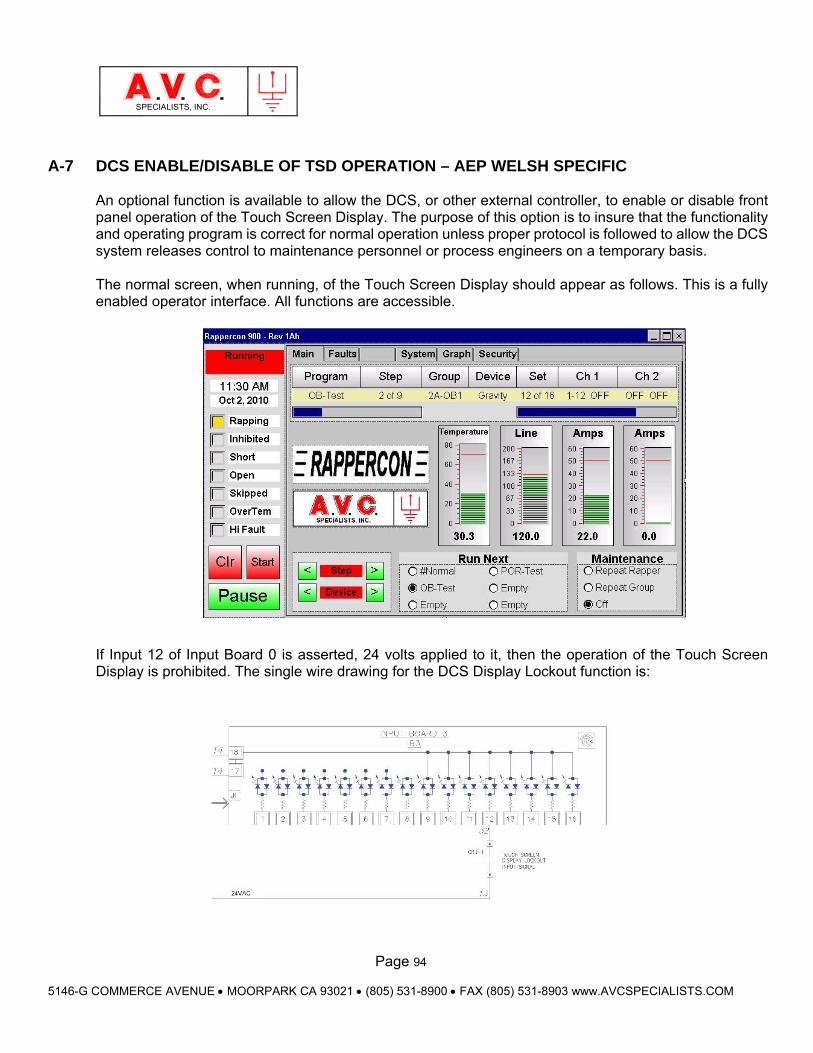
Page 94
5146-G COMMERCE AVENUE MOORPARK CA 93021 (805) 531-8900 FAX (805) 531-8903 www.AVCSPECIALISTS.COM
SPECIALISTS, INC.
A-7 DCS ENABLE/DISABLE OF TSD OPERATION – AEP WELSH SPECIFIC An optional function is available to allow the DCS, or other external controller, to enable or disable front panel operation of the Touch Screen Display. The purpose of this option is to insure that the functionality and operating program is correct for normal operation unless proper protocol is followed to allow the DCS system releases control to maintenance personnel or process engineers on a temporary basis. The normal screen, when running, of the Touch Screen Display should appear as follows. This is a fully enabled operator interface. All functions are accessible. If Input 12 of Input Board 0 is asserted, 24 volts applied to it, then the operation of the Touch Screen Display is prohibited. The single wire drawing for the DCS Display Lockout function is:
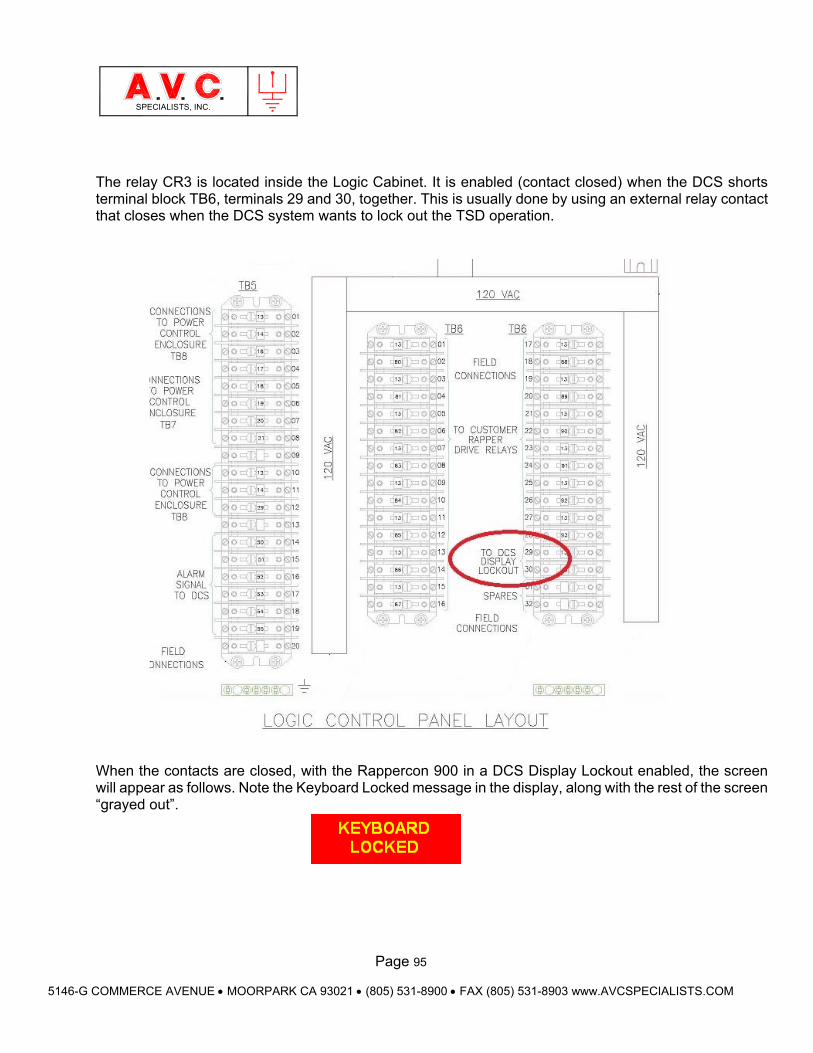
Page 95
5146-G COMMERCE AVENUE MOORPARK CA 93021 (805) 531-8900 FAX (805) 531-8903 www.AVCSPECIALISTS.COM
SPECIALISTS, INC.
The relay CR3 is located inside the Logic Cabinet. It is enabled (contact closed) when the DCS shorts terminal block TB6, terminals 29 and 30, together. This is usually done by using an external relay contact that closes when the DCS system wants to lock out the TSD operation. When the contacts are closed, with the Rappercon 900 in a DCS Display Lockout enabled, the screen will appear as follows. Note the Keyboard Locked message in the display, along with the rest of the screen “grayed out”.
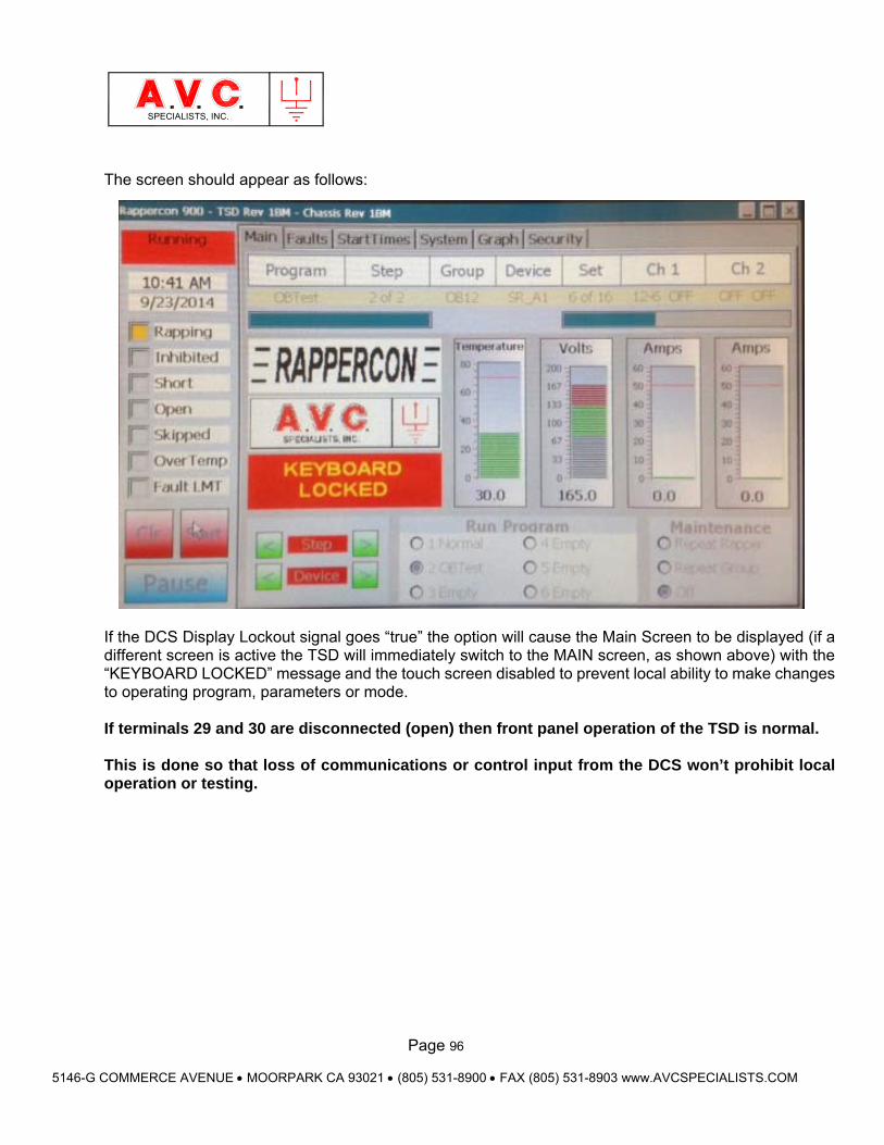
Page 96
5146-G COMMERCE AVENUE MOORPARK CA 93021 (805) 531-8900 FAX (805) 531-8903 www.AVCSPECIALISTS.COM
SPECIALISTS, INC.
The screen should appear as follows: If the DCS Display Lockout signal goes “true” the option will cause the Main Screen to be displayed (if a different screen is active the TSD will immediately switch to the MAIN screen, as shown above) with the “KEYBOARD LOCKED” message and the touch screen disabled to prevent local ability to make changes to operating program, parameters or mode. If terminals 29 and 30 are disconnected (open) then front panel operation of the TSD is normal. This is done so that loss of communications or control input from the DCS won’t prohibit local operation or testing.