Embed Size (px)
Citation preview
CHAPTER 13
ETHERNET AND TCP/IPNETWORKING
Illustration by Jeff Moores

13.0 INTRODUCTIONAlthough there are other types of networks and network protocol suites, the combi-nation of TCP/IP and Ethernet represents the vast majority of network connectivityand use today. Chapter 12 presented a careful introduction to the basic conceptsof networking, and introduced TCP/IP and Ethernet. In Chapter 13, we expand thediscussion to clarify many areas of importance and interest in the implementation ofTCP/IP and Ethernet networks. The goal in Chapter 12 was to help you to achieve abasic understanding of networking. The goal of Chapter 13 is to add richness and colorto the overall picture of how your e-mail and Web surfing and IMing retrieves yourWeb pages successfully most of the time and gets your messages to the right place.
This chapter focuses particularly on TCP/IP and Ethernet protocols that solve someof the more interesting and important problems—domain name translation, the for-mats of the packets, address resolution between IP and physical addresses, and the like.We also expand our discussion of TCP/IP and the Ethernet to improve your under-standing of the overall process of moving packets of data from one place to another.
For this chapter, we have taken a different approach. In Chapter 12 you studiedthe overall operation of the five layers of a TCP/IP-Ethernet network transaction,starting at the application layer of a source end node with a data request and workingdown to the lower layers, through a number of intermediate nodes, to the destinationend node. In this chapter, we review the overall process, stopping to raise variousissues of interest along the way.
Section 13.1 briefly reviews the application layer as background for the remainingdiscussion.
Section 13.2 raises the first important issue of interest: the method used to extractthe domain name from the URL and convert it to an IP address using DNS.
After obtaining the IP address from DNS, the application sends its request to thetransport layer. Section 13.3 discusses some of the features of the transport layer.
Section 13.4 addresses several issues that arise in the networking layer: the natureof IP addresses, DHCP, and ARP, the address resolution protocol.
Section 13.5 is concerned with the operation of the medium access control portionof the Ethernet data link layer.
In the final sections of the chapter, we briefly address two additional issues: qualityof service and network security, and also provide brief overviews of other importanttechnologies that are alternatives to TCP/IP and Ethernet.
13.1 INTRODUCING THE PROCESS—THEAPPLICATION LAYER
The TCP/IP protocol offers a large number of applications for use on a network.These include voice over IP telephoning, video conferencing, instant messaging (IM),
423
424 PART FOUR NETWORKS AND DATA COMMUNICATIONS
remote login, RSS news feeds, file transfer, remote program execution, and much more.Nonetheless, three applications: Web services, e-mail, and peer-to-peer music and videosharing account for the vast majority of the traffic on the Internet.
We remind you at the outset that a typical communication requires lots of littleoperations. Each operation is, in itself, fairly simple, but they all add up to a powerfuland elegant set of tools for communication. At the same time, trying to view the wholepicture at once can be somewhat intimidating. As you read through the description thatruns through this chapter, be sure that you always keep the simplicity in mind!
For this purpose, we assume that a user sitting at his computer types a URL intohis Web browser. The URL consists of a domain name. In Chapter 12, Figure 12.2 weshowed you the format of an HTTP message that is sent by the Web browser HTTP clientapplication to an HTTP server application in response to a user’s request for a Web page.As you are already aware from the previous chapter, the HTTP client initiates the processwith a request to the TCP socket to establish a logical connection with the HTTP serverat the destination site. Before it can do so, however, the HTTP client must first obtain theIP address of the computer that holds the Web server. For this purpose, the HTTP clientwill request the services of a domain name service application. This is the first step in theprocess of sending the HTTP message to the Web server.
13.2 DOMAIN NAMES AND DNS SERVICES
Domain Name System Directory Services
As a user you know that domain names serve as user address identifiers for most ofyour network transactions. Domain names are used throughout the Internet, as well ason local area networks, intranets, and extranets. As we noted in Chapter 12, networknavigation within the network itself relies on numeric IP addresses and physical addresses.The inventors of the Internet understood that the average user would have difficultyremembering the number groupings that are used as IP addresses, and created a hierarchicalsystem of domain names as an alternative. The decision to offer translation from domainnames to IP addresses as a basic Internet service is one of the cleverest and most successfulaspects in the original development of the TCP/IP protocol suite.
When an application requests services from TCP, UDP, or SCTP at the transport layer,it must supply a numerical IP address. TCP/IP provides a support application that fulfillsthe role of the Domain Name System (DNS) protocol, to translate domain names into IPaddresses. The DNS application uses a massive distributed database organized as a directorysystem of servers to obtain the required information. Each entry in the database consists ofa domain name and an associated IP address (plus some other information about the entrythat is not of concern to us here.)
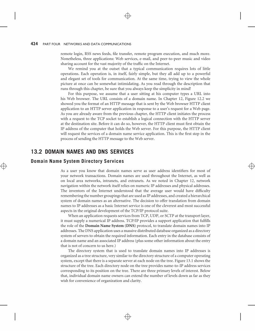
The directory system that is used to translate domain names into IP addresses isorganized as a tree structure, very similar to the directory structure of a computer operatingsystem, except that there is a separate server at each node on the tree. Figure 13.1 shows thestructure of the tree. Each directory node on the tree provides name-to-IP address servicescorresponding to its position on the tree. There are three primary levels of interest. Belowthat, individual domain name owners can extend the number of levels down as far as theywish for convenience of organization and clarity.
CHAPTER 13 ETHERNET AND TCP/IP NETWORKING 425
FIGURE 13.1
Domain Name System Server Hierarchy
Sub-domains& hosts
DNS ROOTSERVER
Genericdomain name servers
Country-codedomain name servers
Top-leveldomains
.COM .ORG .EDU
Localdomains
GOOGLE IBM
.DE .CH .UK .AU
AMAZON
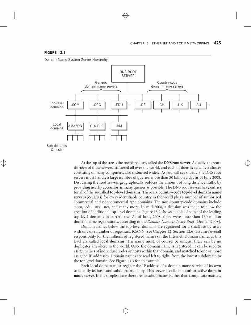
At the top of the tree is the root directory, called the DNS root server. Actually, there arethirteen of these servers, scattered all over the world, and each of them is actually a clusterconsisting of many computers, also disbursed widely. As you will see shortly, the DNS rootservers must handle a large number of queries, more than 50 billion a day as of June 2008.Disbursing the root servers geographically reduces the amount of long distance traffic byproviding nearby access for as many queries as possible. The DNS root servers have entriesfor all of the so-called top-level domains. There are country-code top-level domain nameservers (ccTLDs) for every identifiable country in the world plus a number of authorizedcommercial and noncommercial type domains. The non-country-code domains include.com, .edu, .org, .net, and many more. In mid-2008, a decision was made to allow thecreation of additional top-level domains. Figure 13.2 shows a table of some of the leadingtop-level domains in current use. As of June, 2008, there were more than 160 milliondomain name registrations, according to the Domain Name Industry Brief [Domain2008].
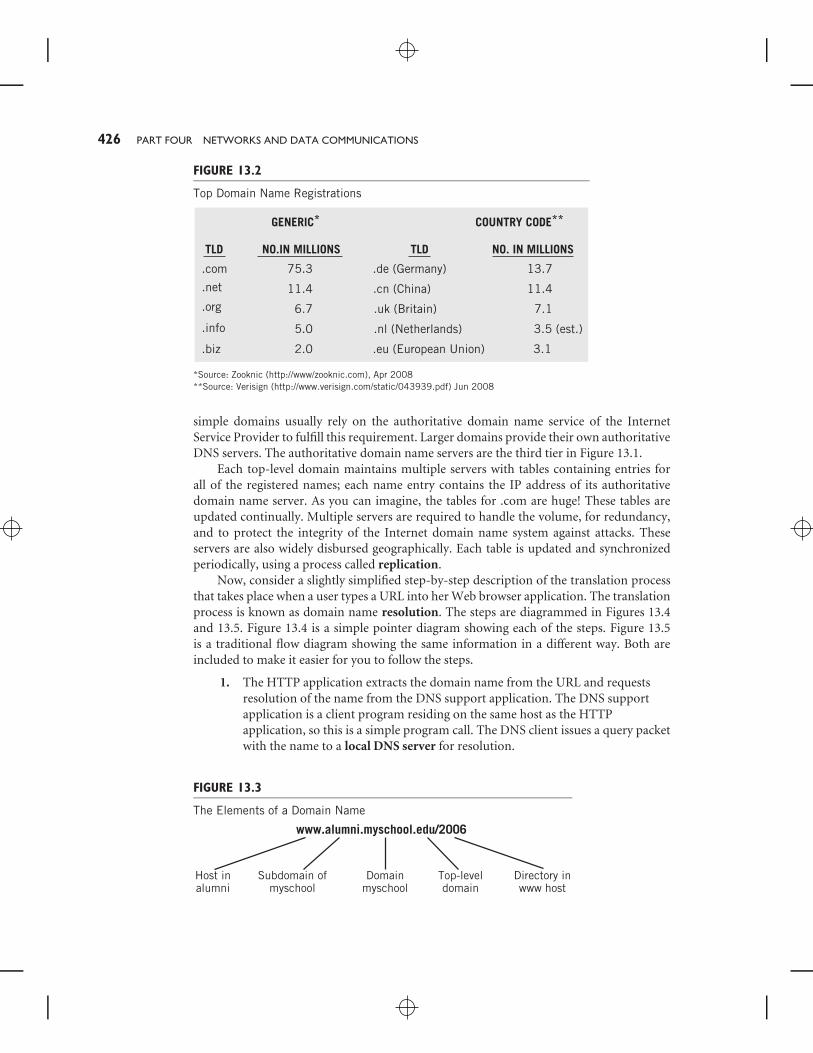
Domain names below the top-level domains are registered for a small fee by userswith one of a number of registrars. ICANN (see Chapter 12, Section 12.6) assumes overallresponsibility for the millions of registered names on the Internet. Domain names at thislevel are called local domains. The name must, of course, be unique; there can be noduplicates anywhere in the world. Once the domain name is registered, it can be used toassign names of individual nodes or hosts within that domain, and matched to one or moreassigned IP addresses. Domain names are read left to right, from the lowest subdomain tothe top level domain. See Figure 13.3 for an example.
Each local domain must register the IP address of a domain name service of its ownto identify its hosts and subdomains, if any. This server is called an authoritative domainname server. In the simplest case there are no subdomains. Rather than complicate matters,
426 PART FOUR NETWORKS AND DATA COMMUNICATIONS
FIGURE 13.2
Top Domain Name Registrations
GENERIC*
TLD
.com .de (Germany)
.cn (China)
.uk (Britain)
.nl (Netherlands)
.eu (European Union)
75.3 13.7
11.4
7.1
3.5 (est.)
3.1
11.4
6.7
5.0
2.0
.net
.org
.info
.biz
TLDNO.IN MILLIONS NO. IN MILLIONS
COUNTRY CODE**
*Source: Zooknic (http://www/zooknic.com), Apr 2008**Source: Verisign (http://www.verisign.com/static/043939.pdf) Jun 2008
simple domains usually rely on the authoritative domain name service of the InternetService Provider to fulfill this requirement. Larger domains provide their own authoritativeDNS servers. The authoritative domain name servers are the third tier in Figure 13.1.
Each top-level domain maintains multiple servers with tables containing entries forall of the registered names; each name entry contains the IP address of its authoritativedomain name server. As you can imagine, the tables for .com are huge! These tables areupdated continually. Multiple servers are required to handle the volume, for redundancy,and to protect the integrity of the Internet domain name system against attacks. Theseservers are also widely disbursed geographically. Each table is updated and synchronizedperiodically, using a process called replication.
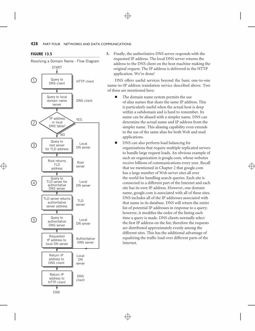
Now, consider a slightly simplified step-by-step description of the translation processthat takes place when a user types a URL into her Web browser application. The translationprocess is known as domain name resolution. The steps are diagrammed in Figures 13.4and 13.5. Figure 13.4 is a simple pointer diagram showing each of the steps. Figure 13.5is a traditional flow diagram showing the same information in a different way. Both areincluded to make it easier for you to follow the steps.
1. The HTTP application extracts the domain name from the URL and requestsresolution of the name from the DNS support application. The DNS supportapplication is a client program residing on the same host as the HTTPapplication, so this is a simple program call. The DNS client issues a query packetwith the name to a local DNS server for resolution.
FIGURE 13.3
The Elements of a Domain Name
www.alumni.myschool.edu/2006
Host inalumni
Subdomain ofmyschool
Domainmyschool
Top-leveldomain
Directory inwww host

CHAPTER 13 ETHERNET AND TCP/IP NETWORKING 427
FIGURE 13.4
Resolving a Domain Name to its IP Address
HTTPclientapp
DNSclientapp
LocalDNSserver
LocalDNStable
Authoritativeserver
IP address ofauthoritative
server
or
Requested IPaddress
IP addres
s of T
LS
Rootserver
Toplevelserver
1 1
33
2
22
5 5
4
4
5
5
The local DNS server is not part of the domain name server hierarchy. It could beon the host machine requesting service, or elsewhere. More commonly it islocated elsewhere, on the same LAN as the host or at an ISP’s site. Regardless ofwhere it is located, its IP address is already known by the DNS client application.Its task is simply to respond to requests from the DNS application with the IPaddress requested. Note that the DNS client request must follow the usual paththrough the layers of the network model. Since DNS request packets are simpleand small, UDP datagrams are used for packet transport.
2. The local DNS server table generally contains the addresses of its ownsubdomains. It also frequently contains the addresses of commonly used domainnames, such as www.google.com and www.yahoo.com, as well as addresses forvarious top-level servers. It also stores, on a more temporary basis, the namesand IP addresses resulting from other recently issued requests. If the informationis in the local DNS table, the information is returned to the DNS client by thelocal DNS server as a response to the query (again through all five layers, usingUDP as the transport mechanism.) The DNS client passes the IP address to theHTTP application. The DNS application’s job is done.
3. If the local DNS server does not have the information in its own table, theprocess continues. Unless the local server already has an IP address for theappropriate top-level DNS server, it must query one of the DNS root serversseeking that address. In that case, the root server responds with the IP address ofa nearby top-level server.
4. Next, the local DNS server issues a query to the DNS top-level server, requestingthe IP address of the authoritative DNS server associated with the requesteddomain name.
428 PART FOUR NETWORKS AND DATA COMMUNICATIONS
5. Finally, the authoritative DNS server responds with therequested IP address. The local DNS server returns theaddress to the DNS client on the host machine making theoriginal request. The IP address is delivered to the HTTPapplication. We’re done!
FIGURE 13.5
Resolving a Domain Name - Flow Diagram
HTTP client
DNS client
YES
LocalDN server
LocalDN server
AuthoritativeDNS server
Query toauthoritativeDNS server
RequestedIP address to local DN server
Return IPaddress toDNS client
Return IPaddress to
HTTP client
END
DNSclient
LocalDN
server
TLDserver
LocalDN server
Rootserver
NO
Query toDNS client
Query to localdomain name
server
IP addressin local
DNS table?
Query toroot server
for TLD address
Root returnsTLD
address
Query toTLD server forauthoritativeDNS server
TLD server returnsauthoritative
server address
START
1
3
2
4
5
DNS offers useful services beyond the basic one-to-onename-to-IP address translation service described above. Twoof these are mentioned here:
■ The domain name system permits the useof alias names that share the same IP address. Thisis particularly useful when the actual host is deepwithin a subdomain and is hard to remember. Itsname can be aliased with a simpler name. DNS candetermine the actual name and IP address from thesimpler name. This aliasing capability even extendsto the use of the same alias for both Web and mailapplications.
■ DNS can also perform load balancing fororganizations that require multiple replicated serversto handle large request loads. An obvious example ofsuch an organization is google.com, whose websitesreceive billions of communications every year. Recallthat we mentioned in Chapter 2 that google.comhas a large number of Web server sites all overthe world for handling search queries. Each site isconnected to a different part of the Internet and eachsite has its own IP address. However, one domainname, google.com is associated with all of these sites.DNS includes all of the IP addresses associated withthat name in its database. DNS will return the entirelist of potential IP addresses in response to a query;however, it modifies the order of the listing eachtime a query is made. DNS clients normally selectthe first IP address on the list, therefore the requestsare distributed approximately evenly among thedifferent sites. This has the additional advantage ofequalizing the traffic load over different parts of theInternet.
CHAPTER 13 ETHERNET AND TCP/IP NETWORKING 429
13.3 NEXT STEPS—TCP ANDTHE TRANSPORT LAYER
Once the HTTP application has obtained the IP address, it is ready to pass the request tothe transport layer for transmission through the network. HTTP issues a request askingTCP to open a connection to the desired website. Sockets (see Chapter 12 if you forgotwhat these are) are used for this purpose. Sockets are equivalent to an open door throughwhich messages can pass. The use of sockets makes it possible to create multiple openconnections through which data can flow simultaneously without losing track of whichis which. Obviously, a Web server must be able to handle many requests simultaneously.The HTTP request includes the IP address of the site and the port number of the serverapplication at the destination, presumably port 80 in this case.
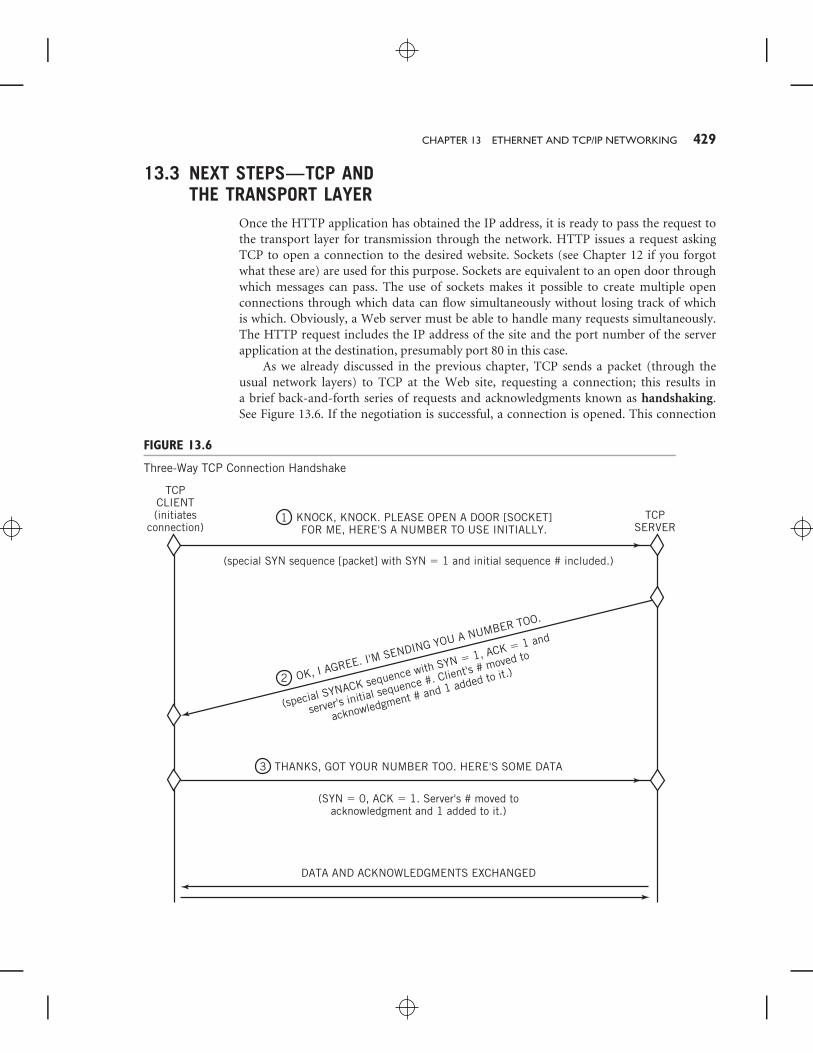
As we already discussed in the previous chapter, TCP sends a packet (through theusual network layers) to TCP at the Web site, requesting a connection; this results ina brief back-and-forth series of requests and acknowledgments known as handshaking.See Figure 13.6. If the negotiation is successful, a connection is opened. This connection
FIGURE 13.6
Three-Way TCP Connection Handshake
TCPCLIENT(initiates
connection)TCP
SERVERKNOCK, KNOCK. PLEASE OPEN A DOOR [SOCKET]FOR ME, HERE'S A NUMBER TO USE INITIALLY.
(special SYN sequence [packet] with SYN � 1 and initial sequence # included.)
(special SYNACK sequence with SYN � 1, ACK � 1 and
server's initial sequence #. Client's # moved to
acknowledgment # and 1 added to it.)
(SYN � 0, ACK � 1. Server's # moved toacknowledgment and 1 added to it.)
OK, I AGREE. I'M SENDING YOU A NUMBER TOO.
THANKS, GOT YOUR NUMBER TOO. HERE'S SOME DATA
DATA AND ACKNOWLEDGMENTS EXCHANGED
1
3
2
430 PART FOUR NETWORKS AND DATA COMMUNICATIONS
FIGURE 13.7
TCP Segment Format
Header
Source port # (16 bits)
Sequence # (32 bits)
Acknowledgment # (32 bits)
Headerlgth
4 bits
6 flag bitsincl. SYN, ACK,...
Window size(16 bits)
Error check (16 bits) Urgent ptr. (16 bits)
Options
Data
Size usually set to conform to lower layers.
(up to 10 additional32-bit words)
6 bits
resvd
Destination port # (16 bits)
is logically a full-duplex connection, both because Web page requests from the browserapplication at one end node will result in file transfers from the Web server at the other, andbecause TCP requires an acknowledgment packet be sent in return for every packet received.
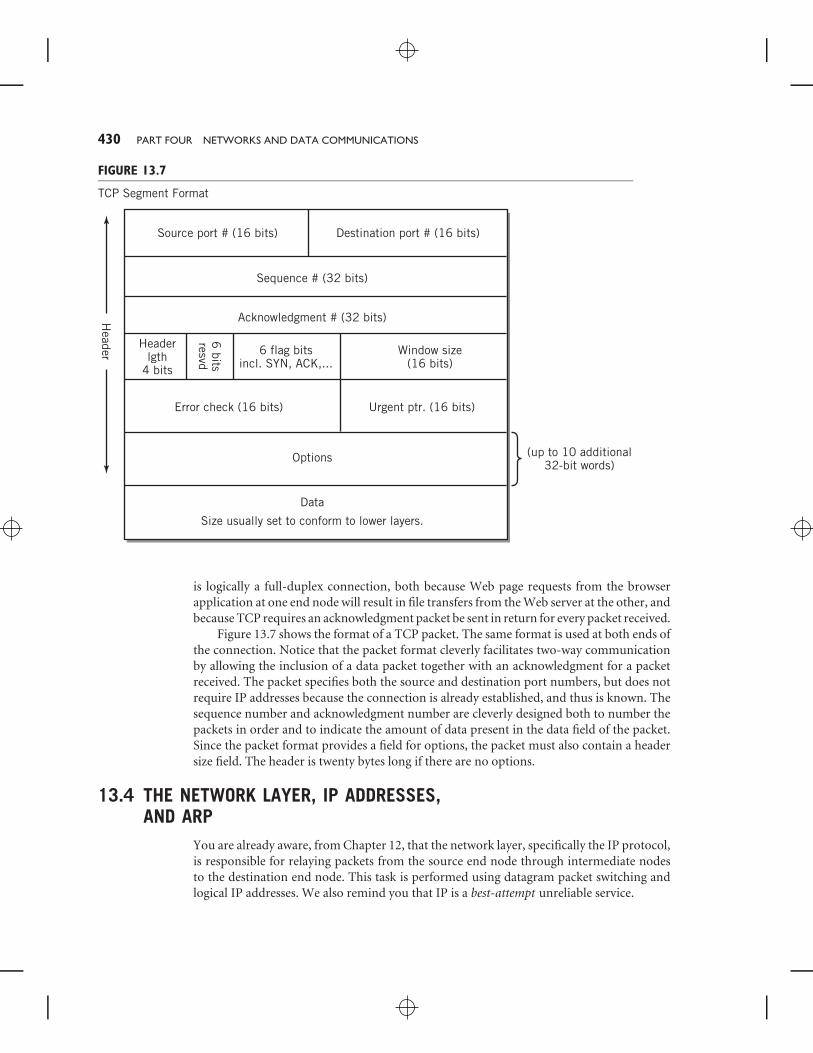
Figure 13.7 shows the format of a TCP packet. The same format is used at both ends ofthe connection. Notice that the packet format cleverly facilitates two-way communicationby allowing the inclusion of a data packet together with an acknowledgment for a packetreceived. The packet specifies both the source and destination port numbers, but does notrequire IP addresses because the connection is already established, and thus is known. Thesequence number and acknowledgment number are cleverly designed both to number thepackets in order and to indicate the amount of data present in the data field of the packet.Since the packet format provides a field for options, the packet must also contain a headersize field. The header is twenty bytes long if there are no options.
13.4 THE NETWORK LAYER, IP ADDRESSES,AND ARP
You are already aware, from Chapter 12, that the network layer, specifically the IP protocol,is responsible for relaying packets from the source end node through intermediate nodesto the destination end node. This task is performed using datagram packet switching andlogical IP addresses. We also remind you that IP is a best-attempt unreliable service.
CHAPTER 13 ETHERNET AND TCP/IP NETWORKING 431
FIGURE 13.8
IPv4 IP Datagram Format
Header
IPversion(4 bits)
Headerlength(4 bits)
Identifier 3flags
Fragmentationoffset (13 bits)
Header error check(16 bits)
Source IP address (32 bits)
Time-to-live(8 bits)
Upper-layerprotocol (8 bits)
Destination IP address (32 bits)
Type of serviceor QOS(8 bits)
Datagram length (16 bits)
Options
Data
(up to 65,535 bytes with header)
(up to 10 additional32-bit words)
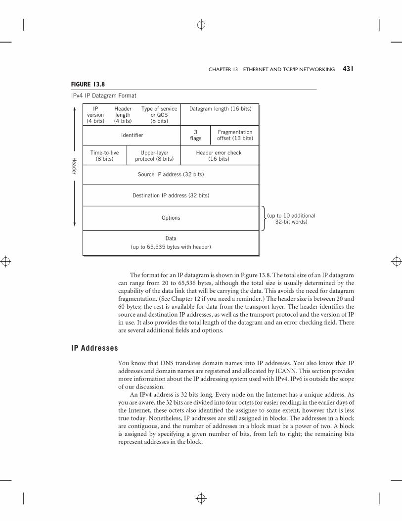
The format for an IP datagram is shown in Figure 13.8. The total size of an IP datagramcan range from 20 to 65,536 bytes, although the total size is usually determined by thecapability of the data link that will be carrying the data. This avoids the need for datagramfragmentation. (See Chapter 12 if you need a reminder.) The header size is between 20 and60 bytes; the rest is available for data from the transport layer. The header identifies thesource and destination IP addresses, as well as the transport protocol and the version of IPin use. It also provides the total length of the datagram and an error checking field. Thereare several additional fields and options.
IP Addresses
You know that DNS translates domain names into IP addresses. You also know that IPaddresses and domain names are registered and allocated by ICANN. This section providesmore information about the IP addressing system used with IPv4. IPv6 is outside the scopeof our discussion.
An IPv4 address is 32 bits long. Every node on the Internet has a unique address. Asyou are aware, the 32 bits are divided into four octets for easier reading; in the earlier days ofthe Internet, these octets also identified the assignee to some extent, however that is lesstrue today. Nonetheless, IP addresses are still assigned in blocks. The addresses in a blockare contiguous, and the number of addresses in a block must be a power of two. A blockis assigned by specifying a given number of bits, from left to right; the remaining bitsrepresent addresses in the block.
432 PART FOUR NETWORKS AND DATA COMMUNICATIONS
FIGURE 13.9
IP Block Addresses
Network address Host address
28 bits
202.66.31.138
4 bits
< Organization address 202.66.31.128 >
11001010 01000010 00011111 1000 1010
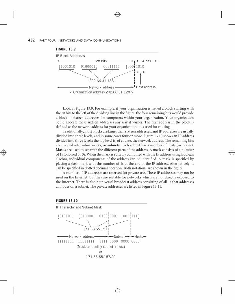
Look at Figure 13.9. For example, if your organization is issued a block starting withthe 28 bits to the left of the dividing line in the figure, the four remaining bits would providea block of sixteen addresses for computers within your organization. Your organizationcould allocate these sixteen addresses any way it wishes. The first address in the block isdefined as the network address for your organization; it is used for routing.
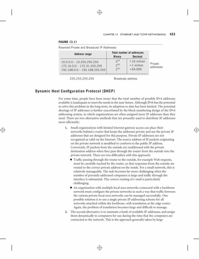
Traditionally, most blocks are larger than sixteen addresses, and IP addresses are usuallydivided into three levels, and in some cases four or more. Figure 13.10 shows an IP addressdivided into three levels; the top level is, of course, the network address. The remaining bitsare divided into subnetworks, or subnets. Each subnet has a number of hosts (or nodes).Masks are used to separate the different parts of the address. A mask consists of a numberof 1s followed by 0s. When the mask is suitably combined with the IP address using Booleanalgebra, individual components of the address can be identified. A mask is specified byplacing a slash mark with the number of 1s at the end of the IP address. Alternatively, itcan be specified in dotted decimal notation. Both notations are shown in the figure.
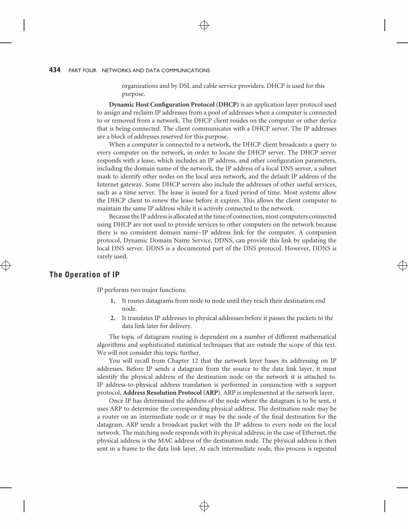
A number of IP addresses are reserved for private use. These IP addresses may not beused on the Internet, but they are suitable for networks which are not directly exposed tothe Internet. There is also a universal broadcast address consisting of all 1s that addressesall nodes on a subnet. The private addresses are listed in Figure 13.11.
FIGURE 13.10
IP Hierarchy and Subnet Mask
Network address HostsSubnet
or
10101011
11111111
00100001
11111111
0100 0001
1111 0000
171.33.65.157
171.33.65.157/20
1001 1110
0000
(Mask to identify subnet + host)
0000
CHAPTER 13 ETHERNET AND TCP/IP NETWORKING 433
FIGURE 13.11
Reserved Private and Broadcast IP Addresses
10.0.0.0 – 10.255.255.255172.16.0.0 – 172.31.255.255192.168.0.0 – 192.168.255.255
Broadcast address255.255.255.255
Address range Total number of addressesBinary Decimal
224
220
216
16 million1 million64,000
~~~~~~
Privateaddresses
Dynamic Host Configuration Protocol (DHCP)
For some time, people have been aware that the total number of possible IPv4 addressesavailable is inadequate to meet the needs in the near future. Although IPv6 has the potentialto solve this problem in the long term, its adoption to date has been limited. The potentialshortage of IP addresses is further exacerbated by the block numbering design of the IPv4addressing system, in which organizations are often assigned more IP addresses than theyneed. There are two alternative methods that are presently used to distribute IP addressesmore efficiently:
1. Small organizations with limited Internet gateway access can place theirnetworks behind a router that keeps the addresses private and use the private IPaddresses that are designed for this purpose. Private IP addresses are notrecognized as valid on the Internet. The source address of IP packets originatingon the private network is modified to conform to the public IP address.Conversely, IP packets from the outside are readdressed with the privatedestination address when they pass through the router from the outside into theprivate network. There are two difficulties with this approach:■ Traffic passing through the router to the outside, for example Web requests,
must be carefully tracked by the router, so that responses from the outside arerouted to the correct private address on the inside. For a small network, this isrelatively manageable. The task becomes far more challenging when thenumber of privately addressed computers is large and traffic through theinterface is substantial. The correct routing of e-mail is particularlychallenging.
■ An organization with multiple local area networks connected with a backbonenetwork must configure the private networks in such a way that traffic betweenthe various private local area networks can be managed successfully. Onepossible solution is to use a single private IP addressing scheme for allnetworks attached within the backbone, with translation at the edge router.Again, the problem of translation becomes large and difficult to manage.
2. The second alternative is to maintain a bank of available IP addresses, and assignthem dynamically to computers for use during the time that the computers areconnected to the network. This is the approach generally taken by large
434 PART FOUR NETWORKS AND DATA COMMUNICATIONS
organizations and by DSL and cable service providers. DHCP is used for thispurpose.
Dynamic Host Configuration Protocol (DHCP) is an application layer protocol usedto assign and reclaim IP addresses from a pool of addresses when a computer is connectedto or removed from a network. The DHCP client resides on the computer or other devicethat is being connected. The client communicates with a DHCP server. The IP addressesare a block of addresses reserved for this purpose.
When a computer is connected to a network, the DHCP client broadcasts a query toevery computer on the network, in order to locate the DHCP server. The DHCP serverresponds with a lease, which includes an IP address, and other configuration parameters,including the domain name of the network, the IP address of a local DNS server, a subnetmask to identify other nodes on the local area network, and the default IP address of theInternet gateway. Some DHCP servers also include the addresses of other useful services,such as a time server. The lease is issued for a fixed period of time. Most systems allowthe DHCP client to renew the lease before it expires. This allows the client computer tomaintain the same IP address while it is actively connected to the network.
Because the IP address is allocated at the time of connection, most computers connectedusing DHCP are not used to provide services to other computers on the network becausethere is no consistent domain name–IP address link for the computer. A companionprotocol, Dynamic Domain Name Service, DDNS, can provide this link by updating thelocal DNS server. DDNS is a documented part of the DNS protocol. However, DDNS israrely used.
The Operation of IP
IP performs two major functions:
1. It routes datagrams from node to node until they reach their destination endnode.
2. It translates IP addresses to physical addresses before it passes the packets to thedata link later for delivery.
The topic of datagram routing is dependent on a number of different mathematicalalgorithms and sophisticated statistical techniques that are outside the scope of this text.We will not consider this topic further.
You will recall from Chapter 12 that the network layer bases its addressing on IPaddresses. Before IP sends a datagram from the source to the data link layer, it mustidentify the physical address of the destination node on the network it is attached to.IP address-to-physical address translation is performed in conjunction with a supportprotocol, Address Resolution Protocol (ARP). ARP is implemented at the network layer.
Once IP has determined the address of the node where the datagram is to be sent, ituses ARP to determine the corresponding physical address. The destination node may bea router on an intermediate node or it may be the node of the final destination for thedatagram. ARP sends a broadcast packet with the IP address to every node on the localnetwork. The matching node responds with its physical address; in the case of Ethernet, thephysical address is the MAC address of the destination node. The physical address is thensent in a frame to the data link layer. At each intermediate node, this process is repeated
CHAPTER 13 ETHERNET AND TCP/IP NETWORKING 435
until the final destination is reached; the current destination MAC address is stripped fromthe frame and replaced with the new address. At the final destination, the packet is passedup to the transport layer for deployment to the application layer. ARP maintains a cacheof recently used IP address–physical address pairs to simplify the process. Only the firstpacket in a set of packets headed for the same destination requires use of the broadcastprocess.
13.5 THE DATA LINK LAYERThe task of the data link layer is to transmit the packet from the current node to the nextnode. In Chapter 12, we presented a brief overview of the Ethernet protocols. In this sectionwe take a closer look at the medium access protocol for wired Ethernet.
Node access for a particular network is defined by the medium access control protocol.The purposes of a medium access protocol are to steer data to its destination, to detecterrors, and to prevent multiple nodes from accessing the network simultaneously in sucha way that their messages become mixed together and garbled. Such an event is calleda collision. As you already know, the predominant medium-access protocol for localarea networks is Ethernet. MAC protocols are implemented primarily in hardware inthe NIC.
Local area networks are defined generally in the IEEE Standard 802 suite. Ethernetis defined in Standard 802.3. In Chapter 12, we introduced two different forms of wiredEthernet, based on hubs and switches. Technically, Ethernet is called the Carrier SenseMultiple Access with Collision Detection (CSMA/CD) protocol. Ethernet is a trade namefor this protocol. The trade name belongs to Xerox Corporation, who did the originaldevelopment on the protocol. Ethernet was originally based on bus topology. The nameCSMA/CD reflects that fact. Switched Ethernet, which is defined in the same specifi-cation, does not actually implement the CSMA/CD protocol, because connections arepoint-to-point and collisions are not possible. The 802.3 specifies many variations, whichdiffer in the type of wiring or fiber optic cable used, in the method used to connect to thephysical medium, in the signaling method used, and in the speed of operation. The addressfor each node on an Ethernet network is called a MAC address. It is set in the hardware.Addresses are permanently assigned by the IEEE organization to the manufacturers ofEthernet-attached equipment.
Every node on the network has equal access to the bus and is normally in ‘‘listening’’mode; that is, each node is listening for messages addressed to it. Remember that messageson the bus are broadcast; every node receives every message, but a node will ignore messagesthat are not addressed to it. The bus is silent when no node is transmitting.
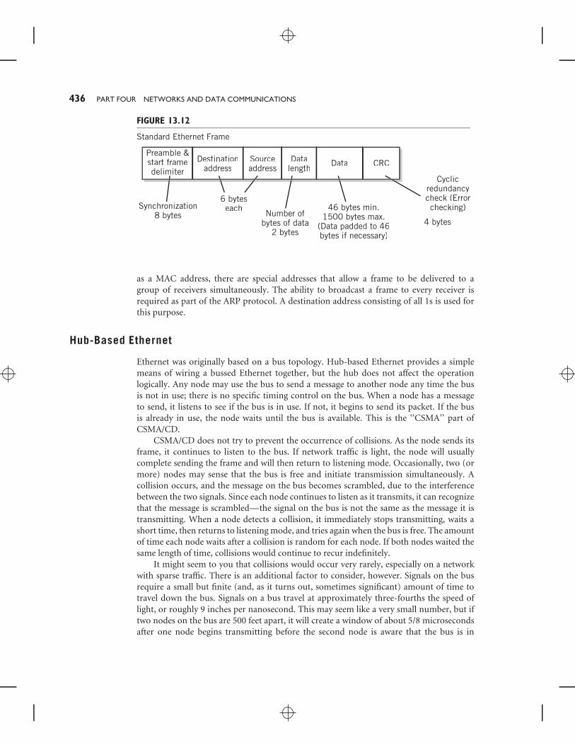
The standard Ethernet packet is a frame. The format of an Ethernet frame is shown inFigure 13.12. The frame consists of a preamble, used for timing synchronization betweenthe sender and receiver, a start frame delimiter to indicate the beginning of the framecontents, the destination and source addresses, specified as MAC addresses, a data lengthfield to indicate the amount of data in the frame, the data field itself, and a field that isused to confirm the integrity of the frame. The data field requires a minimum of 46 bytes,with padding if necessary; this value was originally selected to guarantee that collisionson the original Ethernet bus could be detected before the frame was accepted by thereceiver. The maximum data field is 1500 bytes. Although the destination field is specified
436 PART FOUR NETWORKS AND DATA COMMUNICATIONS
FIGURE 13.12
Standard Ethernet Frame
Preamble &start framedelimiter
Synchronization8 bytes
6 byteseach
Number ofbytes of data
2 bytes
Cyclicredundancycheck (Errorchecking)46 bytes min.
1500 bytes max.(Data padded to 46bytes if necessary)
Destinationaddress
Sourceaddress
Datalength
4 bytes
Data CRC
as a MAC address, there are special addresses that allow a frame to be delivered to agroup of receivers simultaneously. The ability to broadcast a frame to every receiver isrequired as part of the ARP protocol. A destination address consisting of all 1s is used forthis purpose.
Hub-Based Ethernet
Ethernet was originally based on a bus topology. Hub-based Ethernet provides a simplemeans of wiring a bussed Ethernet together, but the hub does not affect the operationlogically. Any node may use the bus to send a message to another node any time the busis not in use; there is no specific timing control on the bus. When a node has a messageto send, it listens to see if the bus is in use. If not, it begins to send its packet. If the busis already in use, the node waits until the bus is available. This is the ‘‘CSMA’’ part ofCSMA/CD.
CSMA/CD does not try to prevent the occurrence of collisions. As the node sends itsframe, it continues to listen to the bus. If network traffic is light, the node will usuallycomplete sending the frame and will then return to listening mode. Occasionally, two (ormore) nodes may sense that the bus is free and initiate transmission simultaneously. Acollision occurs, and the message on the bus becomes scrambled, due to the interferencebetween the two signals. Since each node continues to listen as it transmits, it can recognizethat the message is scrambled—the signal on the bus is not the same as the message it istransmitting. When a node detects a collision, it immediately stops transmitting, waits ashort time, then returns to listening mode, and tries again when the bus is free. The amountof time each node waits after a collision is random for each node. If both nodes waited thesame length of time, collisions would continue to recur indefinitely.
It might seem to you that collisions would occur very rarely, especially on a networkwith sparse traffic. There is an additional factor to consider, however. Signals on the busrequire a small but finite (and, as it turns out, sometimes significant) amount of time totravel down the bus. Signals on a bus travel at approximately three-fourths the speed oflight, or roughly 9 inches per nanosecond. This may seem like a very small number, but iftwo nodes on the bus are 500 feet apart, it will create a window of about 5/8 microsecondsafter one node begins transmitting before the second node is aware that the bus is in
CHAPTER 13 ETHERNET AND TCP/IP NETWORKING 437
use. In other words, the probability of collisions is higher than one would first assume.Particularly if bus traffic is heavy, a node may have to try several times before it sends apacket successfully. The amount of time that it takes for a packet to get from one end of thenetwork is called the network propagation delay.
Hub-based Ethernet is adequate for networks with light traffic, because of its simplicity.Every node is independent. Nodes may be added simply by plugging them into the hub.No central network control is required. However, Ethernet is unsuitable for networks withwidely separated nodes, due to the increase in the probability of collisions. Similarly, astraffic increases, the number of collisions and retransmissions also increases and Ethernetperformance deteriorates, making Ethernet less suitable also for networks that frequentlycarry heavy traffic.
Switched Ethernet
The desire to operate local area networks at higher speed and with longer ranges also makeshub-based Ethernet unusable in many circumstances. Instead, switched Ethernet permitsthe point-to-point connection of any pair of nodes. Multiple pairs can be connectedsimultaneously. Modern switches even provide a buffer to hold frames destined fora receiver already in use. Switching thus prevents collisions, and there is no need toimplement CSMA/CD in switched Ethernet systems. Switched Ethernet has two additionaladvantages: (1) it is possible to connect nodes together in full-duplex mode, which is notpossible with a single bus connection, and (2) each pair of connections can operate at themaximum bit rate of the network.
Wireless Ethernet is similar to hub-based Ethernet because of the nature of the medium.A variation on CSMA/CD is used for Wi-Fi. Wi-Fi protocols are presented in Chapter 14.
13.6 QUALITY OF SERVICECertain types of data are dependent on reliable end-to-end transport where packets arriveat the receiving host in order, with sufficient throughput, with minimum, or at least,consistent, delay, at precise, even time intervals, and with a low probability of errors andmissing packet failures. These necessary qualities are particularly important for streamingaudio and video applications, such as IPTV and VoIP, and for online gaming and virtualreality applications. In contrast, IP offers unreliable, best-effort service that provides limitedsupport for any of these qualities. Similarly, the basic Ethernet specifications do not indicateany level of quality support, although a number of alternative data link layer protocols doinclude such methods and measures in their specifications. These include Frame Relay,ATM, and MLSP, among others, as well as certain variants on Ethernet.
There is no simple, effective measure of the quality of packet switched delivery. Instead,Quality of Service (QoS) focuses on two parameters: (1) methods to reserve and prioritizechannel capacity to favor packets that require special treatment, and (2) service guaranteesfrom contracted carrier services that specify particular levels of throughput, delay, andjitter. Throughput is important to assure that the network can deliver the entire stream atthe required data rate. (Picture a favorite song that gets slower and slower as you listento it—not entirely accurate, but you get the idea.) Jitter is defined as the variation indelay from packet to packet. It is a particularly important parameter in the transmission of
438 PART FOUR NETWORKS AND DATA COMMUNICATIONS
video and audio because jitter causes large fluctuation in the image and sound. Note that alarge amount of jitter can actually cause the packets to arrive at the receiver in the wrongorder. Delay is somewhat less important, but only provided that the delay itself is constant.Generally, if there is substantial delay, it is due to network congestion, and the throughputand jitter will also suffer.
With the growing prominence of multimedia on the Internet the need for effective QoShas taken on increased importance. Various partial solutions have emerged. IP provides a6-bit field in its header which has been adapted for this purpose. This field is called thedifferentiated service (DS) field, usually abbreviated to DiffServ. (DS is actually an 8-bitfield, but the other 2 bits do not concern us here.) The DS field serves as an index into a tablethat defines various classes of service. For a particular set of packets, the DS field is set by theapplication at the sender or by the first node. Modern routers, sometimes called DiffServcapable nodes, can then prioritize and route packets based on the packet class. Interestingly,there are no ground rules on the basis for setting the DS field, nor for the way the routersmake decisions based on the class of service, but it is generally agreed that routers prioritizestreaming multimedia if they can do so without creating major congestion at the router’snode and beyond.
Currently, the DiffServ approach appears to be the most successful in practice.However, its success is contingent on a number of factors; the major factor is sufficientnetwork capacity to minimize congestion at router nodes.
QoS is a complex topic with many nuances and implications for the design and use ofnetworks. There are references to QoS in a number of networking specifications, and manybooks and articles written about various facets of QoS. A few of these are indicated in theFor Further Reading section at the end of this chapter.
13.7 NETWORK SECURITYThe words ‘‘network security’’ are an oxymoron. Networks are inherently insecure.Therefore, strong security measures must be taken independently of the network to protectthe components of the network as well as the data flowing through the network. Securitymeasures are an essential part of any system, large or small. The issue of computer systemand network security is a broad and extensive topic; it is often taught as a separatecourse. We shall only touch the surface in this discussion. Our focus is upon issues relatedspecifically to network security measures that are an essential part of the design of anynetwork infrastructure.
Network-related security issues are often placed into one or more of five categories,with specific types of measures required for each category:
■ Intrusion—Keeping network and system resources intact and free from theresults of intrusion. Intrusion includes the ability of an intruder to modify thesystem for future access, destroying system data and program files, injectingviruses, and more. The primary measures required are physical and circuitprotection of the network to the extent possible; firewalls on individualcomponents, including routers, where appropriate; and protection of passwordsthat traverse the network with encryption.
CHAPTER 13 ETHERNET AND TCP/IP NETWORKING 439
■ Confidentiality—Keeping the content of data traversing the network andinformation about the communication taking place private. Encryptionmeasures are required for this purpose.
■ Authentication—verifying the identity of a source of data being received. This issimilar to the concept of electronic signatures. Special encryption features areused for this purpose.
■ Data integrity and nonrepudiation—Protecting the content of datacommunication against changes and verifying the source of a message. Specialencryption features are also used for this purpose.
■ Assuring network availability and access control—Restricting access to networkresources to those permitted to use them and keeping network resourcesoperational and available.
Although there is obvious overlap between these requirements, the measures to betaken fall into three primary categories: physical and logical access to systems, firewalls(which are a type of logical access restriction), and encryption technology.
Physical and Logical Access Restriction
There are numerous ways to intrude into a networked system. The tools for packet sniffingare free and readily available to anyone. Packet sniffing is defined as the reading of the datain a packet as it passes through a network. With wired networks, packet sniffing can beachieved by physically tapping into the network itself or by reading packets as they passthrough a node. Hub-based networks are particularly vulnerable because anyone connectedto the ‘‘bus’’ at any point can read every packet that uses the bus. Wireless networks areeven worse. Anyone within range of a radio signal can receive the signal.
In general, it is safest to assume that it is possible to intercept and read any packet passingthrough a network. This makes passwords that travel through a network unencrypted uselessat protecting a network and its computers from intrusion.
The Internet provides an additional means of intrusion access. Any system on anynetwork that is publicly accessible from the Internet is susceptible to probing attacksthat seek IP address/port numbers combinations that will accept data packets. Speciallyconstructed packets can then be used to access and modify the host machine.
A number of measures are used to protect systems and networks from intrusion.Physical eavesdropping on local area networks is minimized by limiting access to networkwiring and network equipment to personnel who are responsible for the equipment.Logical access is limited with intelligent firewall design that blocks public access where itis not required and robust network applications that drop or repel packets that might beinvasive. Intelligent firewall design includes making port numbers that are not in active useunavailable, evaluating every packet according to a set of acceptability criteria, blocking orhiding local IP addresses and computers from the Internet, and more.
Logical access is also limited with the use of private networks. These make it difficultfor intruders to identify individual machines within the firewall/router that protects thenetwork.
440 PART FOUR NETWORKS AND DATA COMMUNICATIONS
Public MAN and WAN carrier networks are secured by using protocols that hide andseparate a user’s packets from other users. Stringent password policies are enforced andpasswords are never transmitted over unencrypted networks.
Encryption
Encryption provides security beyond that of other measures, provided that the security isstrong and effectively applied. Encryption in various forms is used to prevent intrusion,to protect privacy, for authentication, and to assure data integrity and nonrepudiation.There are a number of different algorithms for encryption, but they generally fall intoone or both of two categories. Symmetric key cryptography requires that the same keybe used for both encryption and decryption. This means that both users must haveaccess to the same key, which is often difficult to achieve securely. The second categoryis called public key–private key cryptography, in which two different keys, one publiclyavailable, the other private, are used together in various ways to achieve the different goalsmentioned above.
The reader is referred to a number of excellent books dealing with the details of thistopic.
13.8 ALTERNATIVE PROTOCOLSAlthough this chapter is focused primarily on TCP/IP and Ethernet, there are a numberof important alternative technologies in use, particularly by carriers providing widearea network services, and also for specialty purposes, such as Internet backbones andstorage area networking. New developments in this area occur frequently and rapidly. Atthis writing, the prevalent alternatives include Multi-Protocol Label Switching (MPLS),Asynchronous Transfer Mode (ATM), Sonet/SDH, and Frame Relay.
Each of these protocols can be implemented at different layers of the OSI or TCP/IPmodels, and each can serve as a carrier mechanism for IP datagrams and Ethernet frames.In typical use, wide area network service providers connect a TCP/IP or Ethernet gatewayto their service at the customer’s edge point. The alternate technology carries the packetsto another edge point where they are converted back to their original form.
What follows is a brief description of each. More information on these and otherprotocols can be found in various network text books and on the Web.
MPLS
The goal of MPLS (Multi-Protocol Label Switching) is to improve the forwarding speedof IP datagrams by creating virtual circuit capability over traditional packet switchednetworks, such as Ethernet. MPLS operates at the data link layer. MPLS is a relativelyrecent, but fast growing, technology. MPLS inserts a small, 32-bit fixed-length headerbetween the layer 2 and layer 3 headers in a packet. In the case of a TCP/IP-Ethernet frame,the header would be situated between the Ethernet header and the embedded IP header.The MPLS header contains a label that identifies a virtual circuit path. The label is addedinitially by a label edge router when it enters the network and removed by a correspondingedge label router at the exit point.
CHAPTER 13 ETHERNET AND TCP/IP NETWORKING 441
MPLS requires routers that are capable of reading and acting on the MPLS header. Sucha router is called a label-switched router. The label-switched router can route IP datagramsthrough the virtual circuit without the overhead of returning to the network layer, therebysimplifying routing speed. MPLS is sometimes called a layer 2.5 protocol because it workswith existing networks between the two layers.
ATM
ATM (Asynchronous Transfer Mode) is a partial-mesh network technology, in which datapasses through the network in cells. Data enters an ATM network at an ATM adaptionlayer. There, the data (which could be, for example an Ethernet frame or IP datagram)is combined with a header and broken into cells. The combination is called a protocoldata unit, and assigned a 28-bit virtual circuit number called a virtual circuit identifier thatis used throughout the network for routing. Cells are 53-byte packets, containing a 5-bitheader and 48 bits of data. At the exit point, a matching adaption layer recombines the cellsinto their original form.
ATM is well-suited for the transmission of multimedia because the combination ofmesh networking and small cell size makes it easier to control congestion and the qualityof service. Interestingly, the physical layer of ATM is loosely defined. ATM is used withdifferent media, including both wire and fiber-optic cable, and with different technologies.It was originally designed to operate over SONET/SDH (see below) as its physical layer.It is capable of extremely high performance, and is used for Internet backbones. To someextent it is being supplanted by MPLS, but ATM will probably be in use for some time tocome.
SONET/SDH
SONET (Synchronous Optical Network) and SDH (Synchronous Digital Hierarchy)are related protocols and architectures that are designed to take advantage of fiber optictechnology. The intention of both standards was to create wide area networks capable ofextremely high bit rates over long distances. The differences between the two standardsare minor. We shall refer to both as SONET for the remainder of this discussion. SONETis based on networks that are synchronized globally to a single clock. Electrical signalsfrom different sources are converted to light, then synchronously multiplexed and addedand removed from nodes by add/drop multiplexers as required to optimize the speed ofeach packet. To extend the distance, regenerators are built into the network. These recreatethe signal as it is attenuated within the fiber, to extend its range. SONET networks areconstructed as meshes, or rings, or point-to-point links.
SONET is frequently employed as a physical layer carrier, supporting other higher-levelprotocols. The technology, frame formats, and details of operation of SONET are complex.Further information is beyond the scope of this text.
Frame Relay
Frame Relay is a relatively slow, wide area network standard. It is included because it isstill in common use as an inexpensive on-ramp to wide area networks and to the Internet
442 PART FOUR NETWORKS AND DATA COMMUNICATIONS
through service providers, especially large telephone companies. Like the other protocolsdiscussed here, Frame Relay relies on edge connections to convert data between otherprotocols and frame relay frames for transmission over the network.
Frame Relay operates at the data link and physical layers, using its own switch designto forward frames through virtual circuits. Frame Relay allows the use of permanent virtualcircuits. These are circuits that route all packets between a source and destination by thesame route, which is advantageous for some private wide area network links. At the physicallayer, Frame Relay operates over a variety of networks.
SUMMARY AND REVIEWIn Chapter 13, we described each of the TCP/IP and Ethernet layers in more detail, focusingon specific areas of interest.
The domain name system translates, or resolves, user-friendly names into theircorresponding IP addresses. The domain name addressing system is hierarchical, witha root, generic and country-code top-level domains, local domains, and, sometimes,subdomains. DHCP is a protocol that allows the dynamic assignment of IP addresses on ashort-term lease basis.
The interface between the TCP/IP network layer and Ethernet data link layer requirestranslation between IP addresses and physical addresses. This task is performed by theAddress Resolution Protocol.
Local area Ethernet networks are either switched or hub-based. CSMA/CD managescollisions in a hub-based network.
Two issues of interest when discussing modern networks are quality of service andnetwork security. Quality of service attempts to measure and provide packet routing withspeeds and reliability sufficient for tasks such as multimedia. Network security identifiesthe problems that must be overcome to provide adequate protection, and the tools that areused for this purpose.
FOR FURTHER READINGFor the most part, the suggestions made in Chapter 12 apply to Chapter 13, as well. Thereare also a number of special topics in this chapter that deserve extra attention. Althoughthe QoS concept is vague, reasonable discussions of quality of service (usually abbreviatedQoS) can be found in the white paper by Hartmann [HART04] and in the QoS chapterof Cisco’s Internetworking Technology Handbook [INT08]. Two well-regarded books areby Armitage [ARM00] and Ferguson and Huston [HUST98]. Stallings [STAL09], Kurose[KUR08], and Forouzan [FOR07] all provide substantial coverage of network security.Forouzan is the most technical, offering detailed explanations of encryption techniques.There are numerous books devoted exclusively to network security. One of many readablechoices is Cheswick [CHES03].
CHAPTER 13 ETHERNET AND TCP/IP NETWORKING 443
KEY CONCEPTS AND TERMSAddress Resolution
Protocol (ARP)ATM (Asynchronous
Transfer Mode)authoritative domain name
serverCarrier Sense Multiple
Access with CollisionDetection (CSMA/CD)protocol
collisioncountry-code top-level
domain name server(ccTLD)
differentiated service (DS)field
DNS root serverDomain Name System
(DNS)Dynamic Host
Configuration Protocol(DHCP)
electronic signaturehandshakinglocal DNS serverlocal domainmaskMPLS (Multi-Protocol
Label Switching)network propagation delaypacket sniffing
public key–private keycryptography
Quality of Service (QoS)replicationresolution (of domain
name)SDH (Synchronous Digital
Hierarchy)SONET (Synchronous
Optical Network)subnetsymmetric key
cryptographytop-level domain
READING REVIEW QUESTIONS13.1 What is a domain name? How is it used on the Internet?
13.2 What task is performed by a DNS root server?
13.3 What does TLD stand for? What is a ccTLD? What other kinds of TLDs arethere? What is the function of a TLD?
13.4 What function is performed by a local domain name server? What two kinds ofaddresses would you expect to find stored in a local domain name server table?
13.5 What does ARP stand for? What task does an ARP perform?
13.6 What two major tasks are performed by IP?
13.7 Briefly explain CSMA/CD. What common name does this protocol go by? Whattopology does CSMA/CD apply to?
13.8 Explain how an Ethernet frame provides synchronization between sender andreceiver nodes.
13.9 What does the expression Quality of Service mean?
13.10 What is meant by data nonrepudiation?
13.11 What types of security problems does a firewall try to prevent?
EXERCISES13.1 Name at least four different application layer protocols other than HTTP. For
each, describe the purpose of the protocol, and give a brief overview of themethodology of its operation.
444 PART FOUR NETWORKS AND DATA COMMUNICATIONS
13.2 The DNS database is described as ‘‘a directory system of servers’’. Based upon yourunderstanding of DNS from the text, explain the meaning of this description.
13.3 Explain the purpose of an authoritative domain name server. How does itspurpose differ from that of a local DNS server.
13.4 What service is provided by a DNS root server? To whom is this service provided?
13.5 How does someone obtain a URL?
13.6 Explain the technique that is used by DNS to distribute the load of large websites.
13.7 Explain carefully the purpose and use of the sequence number and acknowledg-ment number in connection-oriented communications. Create a multi-packetexample that illustrates exactly how these packets are used by TCP.
13.8 Why does the IP datagram require separate fields for the header length and thetotal datagram length, instead of combining both into a single value?
13.9 What is the purpose of an IP address mask? Suppose an IP address is identifiedas 222.44.66.88/24. What is the network address in this case? What is the hostaddress? How many hosts can this network address support? Repeat this exercisefor the IP address 200.40.60.80/26.
13.10 Explain the concept of a DHCP lease. How is it obtained? How is it used? Whatdoes it provide?
13.11 Explain the operation of the Address Resolution Protocol.
13.12 The chapter notes that the physical layer is only concerned with the transmissionof a sequence of bits from one point to another. Suppose that the sequence110010011 is used as a synchronization sequence preamble to a data packet.Propose a method that can be used to allow the channel to distinguish thesynchronization sequence from an identical data sequence within the packet. Inwhat layer of the TCP/IP model would you implement your solution? Why?
13.13 Prior to the invention of Ethernet, researchers at the University of Hawaiiproposed a broadcast radio network called ALOHANet as a means to providewireless links between the Hawaiian islands. Each node had a radio transmitterwhich could be used to send data packets. When two stations attempted totransmit simultaneously, a collision occurred, and like Ethernet, each stationwould wait a random period of time, then try again.
Compare ALOHANet with Ethernet. What are the similarities? What arethe differences? What are the major factors contributing to the differences? Whateffects do the differences have upon performance? Under what conditions wouldyou expect ALOHANet to perform satisfactorily? Less satisfactorily?
13.14 Discuss the trade-offs between bus-based and switched Ethernet. State the variousconditions under which one or the other would be preferred and explain why.
13.15 Find and read a good article that describes ATM in more detail than is providedin this text. Compare ATM methodology with the other networking topologiesthat we have discussed. What characteristics of ATM make it capable of highperformance compared to other networking techniques?
13.16 Before effective Ethernet switching existed, some network designers used analternative bus collision avoidance protocol known as the token bus protocol.With the token bus protocol, a ‘‘token’’ made up of a short, standard string of
CHAPTER 13 ETHERNET AND TCP/IP NETWORKING 445
1s and 0s was circulated constantly in a round robin fashion among the NIUsattached to the bus. NIUs did not hold the token; they simply passed it withoutdelay to the next NIU in the chain. An NIU was only allowed to place a messageon the bus when it possessed the token. After the message was delivered, thetoken was again put into circulation. No NIU was allowed to use the token againuntil the token had circulated to every other NIU at least once.
Under what conditions would this protocol perform more satisfactorily thanCSMA/CD? Explain. Under what conditions is CSMA/CD preferable? Explain.
13.17 Consider again the network described in Exercise 12.14. For each of the links inthis network, describe a technology (medium and signaling method) that wouldbe suited to this application.
13.18 The governments of Freedonia and Sylvania need to set up data communicationsto prevent the possibility of war. Discuss the security implications of fiber opticversus coaxial wire versus satellite as a means of communication.
13.19 Explain the differences between TCP and UDP in the context of ordering anumber of items from an online seller such as amazon.com.
13.20 What are the specific so-called ‘‘qualities’’ that quality of service attempts tomeasure and achieve? Describe the two methods that are normally used as anattempt to achieve this quality.
13.21 Explain the purpose of repudiation. How does repudiation differ from authenti-cation? Create a business scenario that illustrates the importance of each.
13.22 Locate, download, and install a packet-sniffing software package, such as Wire-Shark (formerly known as Ethereal). Experiment with this software until youunderstand how it works and the range of its capabilities. Write a brief paperdescribing several of its most important capabilities and the potential securitydangers that those capabilities create.