Embed Size (px)
Citation preview
P. Cuenca and L. Orozco-Barbosa (Eds.): PWC 2006, LNCS 4217, pp. 284 – 296, 2006. © IFIP International Federation for Information Processing 2006
Experimental Assessment of a Cross-Layer Solution for TCP/IP Traffic Optimization on Heterogeneous Personal
Networking Environments
Luis Sánchez*, Jorge Lanza, and Luis Muñoz
University of Cantabria, E.T.S. Ingenieros Industriales y de Telecomunicación, Avda. de Los Castros s/n, 39004, Santander, Spain
{lsanchez, jlanza, luis}@tlmat.unican.es Departamento Ingeniería de Comunicaciones, E.T.S. Ingenieros Industriales y de
Telecomunicación, Avda. de Los Castros s/n, 39004, Santander, Spain [email protected]
Abstract. Future wireless communication scenarios will be characterized by the heterogeneity in terms of coexisting wireless access technologies. Many mobile terminals will support different air interfaces and in order to provide true multi-mode operation, the sole use of IP protocol is not enough. We present in this document the Universal Convergence Layer that residing on top of the different air interfaces offers a single interface to IP while supporting the cross-layer optimization of user data flows as well as many other key functionalities in personal networks communications. This document describes and discusses the implementation of this framework over real platforms. Furthermore, the results of the measurement campaign carried out to assess the benefits introduced by the dynamic interface selection mechanism implemented at the UCL will be also presented. The results obtained will allow us to extract conclusions about the appropriateness of the solution adopted.
Keywords: Cross-layer optimization, Measurement campaign, Validation results, Convergence layer.
1 Introduction
Next generation wireless systems should provide to the user access to a broad range of services in a transparent way, making the technology embedded in the natural surroundings. Accomplishing this goal requires efficient cooperation between heterogeneous networking technologies and different frameworks. A large number of wireless access technologies are envisaged to coexist in future wireless communica-tion spaces. So, the necessary methods for them to interwork seamlessly have to be deployed. In this sense, the corresponding MAC and link layer protocol(s) should be accessed from upper layer protocols and applications independently of the type of technology that is being used (in the same way upper layer protocols and applications access the underlying protocol stack through the socket interface for data purposes). * Corresponding author.
Experimental Assessment of a Cross-Layer Solution for TCP/IP Traffic Optimization 285
The concept of isolating the upper-layers from underlying wireless technologies and thus providing real multi-mode can be achieved by introducing a Universal Convergence Layer (UCL) [1]. The UCL can be seen in a twofold approach. It mainly will act as an enabler for backward and forward compatibility by defining a common interface towards the network layer while managing several different wireless access technologies independently of their PHY and MAC layers. On the other hand, the UCL can also enable the cross-layer optimization paradigm. Its privileged location within the protocol stack gives the UCL the possibility to support the information to flow both bottom-up (e.g. use of SNR information for enriching the decision process in an ad hoc routing algorithm) and top-down (e.g. tune of MAC parameters depending on the battery status or QoS requirements).
Although the flexibility of the solution proposed in [1] regarding the UCL is broad and presents a framework which represents a foothold for many schemes aiming at optimizing the overall system performance, this paper is focused on the implementation work carried out and the characterization and validation of a dynamic interface selection mechanism that exploits the cross-layer optimization paradigm to enhance the performance of TCP/IP data flows over heterogeneous wireless environments.
The paper briefly introduces in Section 2 the high-level protocol stack specifying the main requirements and challenges the UCL must tackle. It also sketches the UCL’s implementation framework over Linux-based laptops. In Section 3, the validation analyses made to the UCL are presented. The scenario where the measurement campaign was carried out will be presented. In this section, both the location and the communication equipment will be described providing a rationale to its selection and the fundaments by which the results obtained can be extrapolated to other situations. The performance that would be obtained without the UCL will be firstly analyzed and then compared with the behavior exhibited when the UCL is loaded. Finally, Section 5 presents some conclusions derived from the evaluation carried out.
2 Protocol Architecture and Implementation Aspects
The capability of working in a heterogeneous environment is a must for future personal networks. This heterogeneity will be mainly reflected in terms of the different air interfaces that will coexist and need to cooperate to provide the users with services located at their neighborhood and beyond. Additionally, multimode devices (i.e. supporting several wireless interfaces) will be common in these scenarios requiring additional schemes to handle this heterogeneity.
Moreover, secure communications has to be granted. Authenticity and privacy are the main issues that are to be assured for personal communications.
The purpose of the UCL is to house not only the mechanisms in order to interact with the underlying technologies in a transparent way, but also those schemes based on the cross-layer optimization paradigm which could benefit themselves by the direct communication with the lower and upper layers.
286 L. Sánchez, J. Lanza, and L. Muñoz
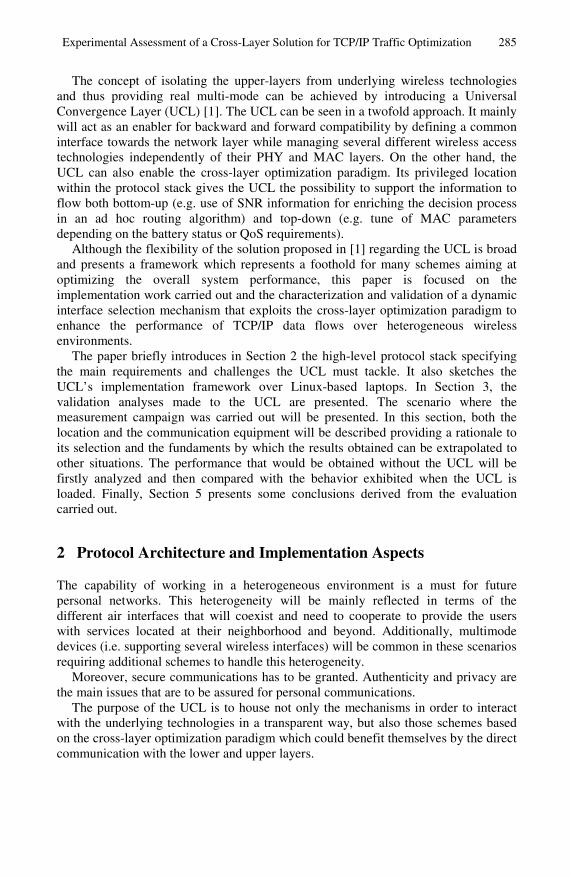
Fig. 1. UCL High-Level architecture (a); UCL low level architecture specification (b)
The architecture shown in Fig. 1 aims at fulfilling the requirements aforementioned while enabling the settlement of some machinery that exploits the cross-layer paradigm in order to optimize the overall system behavior. Note that its design is foreseen as being highly scalable and thus it is based on a common skeleton to which different modules could be added in order to provide with specific functionalities. The two main building blocks that currently form the UCL architecture are:
• Overlay DLC & Path Optimization UCL’s privilege location in the network stack offers the possibility of defining a common interface towards the network layer, hiding the complexity of the different wireless access technologies, and providing the mechanisms to handle data transmission over different interfaces, taking responsibility away from the network layer.
Additionally, the different wireless access technologies will present a different behavior depending on the channel conditions. While IEEE 802.15.3 [2] or IEEE 802.11n [3] offer very high throughputs over short ranges, other technologies are able to reach higher coverage reducing their maximum binary rate. Taking this into account, it has been implemented within the UCL a mechanism to dynamically select the most appropriate air interface to use for communicating with another device whenever multiple choices are possible. The selection has been based on the status of the channel and the maximum available bandwidth following a cross-layer optimization approach.
• Security The security systems of the various radio technologies differ not only in terms of the encryption algorithms used, but also on the security information they require from the upper layers. The UCL will be a common framework where the deployment of different security strategies could be housed. In this sense, the security requirements imposed will be realized and enforced using the available radio interfaces.
The following sections will depict more in depth the Linux features that has been used in the UCL implementation.
2.1 Linux Ethernet Virtual Device
The idea of a virtual interface can be useful to implement special-purpose processing on data packets while avoiding hacking the network subsystem of the kernel. In this
Experimental Assessment of a Cross-Layer Solution for TCP/IP Traffic Optimization 287
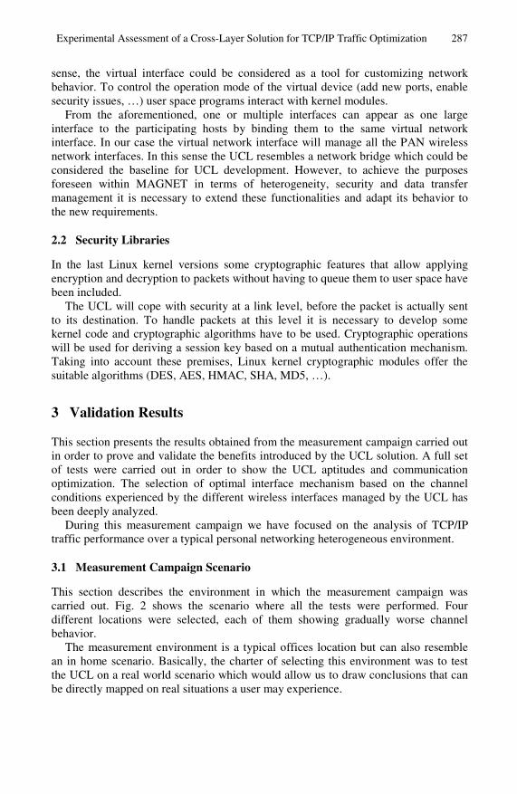
sense, the virtual interface could be considered as a tool for customizing network behavior. To control the operation mode of the virtual device (add new ports, enable security issues, …) user space programs interact with kernel modules.
From the aforementioned, one or multiple interfaces can appear as one large interface to the participating hosts by binding them to the same virtual network interface. In our case the virtual network interface will manage all the PAN wireless network interfaces. In this sense the UCL resembles a network bridge which could be considered the baseline for UCL development. However, to achieve the purposes foreseen within MAGNET in terms of heterogeneity, security and data transfer management it is necessary to extend these functionalities and adapt its behavior to the new requirements.
2.2 Security Libraries
In the last Linux kernel versions some cryptographic features that allow applying encryption and decryption to packets without having to queue them to user space have been included.
The UCL will cope with security at a link level, before the packet is actually sent to its destination. To handle packets at this level it is necessary to develop some kernel code and cryptographic algorithms have to be used. Cryptographic operations will be used for deriving a session key based on a mutual authentication mechanism. Taking into account these premises, Linux kernel cryptographic modules offer the suitable algorithms (DES, AES, HMAC, SHA, MD5, …).
3 Validation Results
This section presents the results obtained from the measurement campaign carried out in order to prove and validate the benefits introduced by the UCL solution. A full set of tests were carried out in order to show the UCL aptitudes and communication optimization. The selection of optimal interface mechanism based on the channel conditions experienced by the different wireless interfaces managed by the UCL has been deeply analyzed.
During this measurement campaign we have focused on the analysis of TCP/IP traffic performance over a typical personal networking heterogeneous environment.
3.1 Measurement Campaign Scenario
This section describes the environment in which the measurement campaign was carried out. Fig. 2 shows the scenario where all the tests were performed. Four different locations were selected, each of them showing gradually worse channel behavior.
The measurement environment is a typical offices location but can also resemble an in home scenario. Basically, the charter of selecting this environment was to test the UCL on a real world scenario which would allow us to draw conclusions that can be directly mapped on real situations a user may experience.
288 L. Sánchez, J. Lanza, and L. Muñoz
XMetallic obstacles
· Location 1· Location 1· Location 2· Location 2
· Location 3· Location 3· Location 4· Location 4
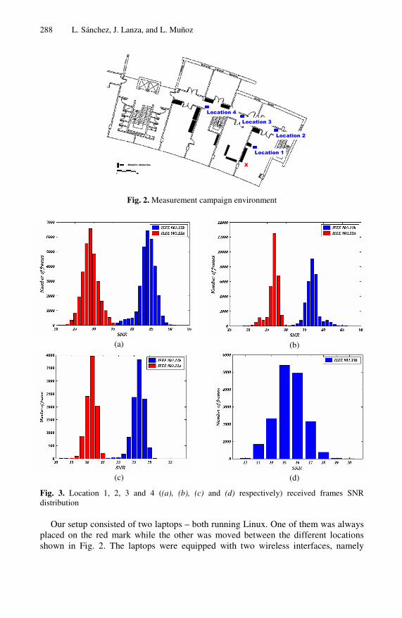
Fig. 2. Measurement campaign environment
(a)
(b)
(c)
(d)
Fig. 3. Location 1, 2, 3 and 4 ((a), (b), (c) and (d) respectively) received frames SNR distribution
Our setup consisted of two laptops – both running Linux. One of them was always placed on the red mark while the other was moved between the different locations shown in Fig. 2. The laptops were equipped with two wireless interfaces, namely
Experimental Assessment of a Cross-Layer Solution for TCP/IP Traffic Optimization 289
IEEE 802.11a cards based on the Atheros chipset, and built-in IEEE 802.11b/g cards based on the Intel chipset.
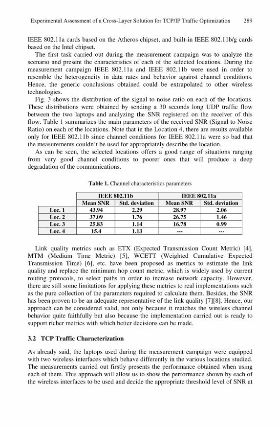
The first task carried out during the measurement campaign was to analyze the scenario and present the characteristics of each of the selected locations. During the measurement campaign IEEE 802.11a and IEEE 802.11b were used in order to resemble the heterogeneity in data rates and behavior against channel conditions. Hence, the generic conclusions obtained could be extrapolated to other wireless technologies.
Fig. 3 shows the distribution of the signal to noise ratio on each of the locations. These distributions were obtained by sending a 30 seconds long UDP traffic flow between the two laptops and analyzing the SNR registered on the receiver of this flow. Table 1 summarizes the main parameters of the received SNR (Signal to Noise Ratio) on each of the locations. Note that in the Location 4, there are results available only for IEEE 802.11b since channel conditions for IEEE 802.11a were so bad that the measurements couldn’t be used for appropriately describe the location.
As can be seen, the selected locations offers a good range of situations ranging from very good channel conditions to poorer ones that will produce a deep degradation of the communications.
Table 1. Channel characteristics parameters
IEEE 802.11b IEEE 802.11a Mean SNR Std. deviation Mean SNR Std. deviation
Loc. 1 43.94 2.29 28.97 2.06 Loc. 2 37.09 1.76 26.75 1.46 Loc. 3 25.83 1.14 16.78 0.99 Loc. 4 15.4 1.13 --- ---
Link quality metrics such as ETX (Expected Transmission Count Metric) [4], MTM (Medium Time Metric) [5], WCETT (Weighted Cumulative Expected Transmission Time) [6], etc. have been proposed as metrics to estimate the link quality and replace the minimum hop count metric, which is widely used by current routing protocols, to select paths in order to increase network capacity. However, there are still some limitations for applying these metrics to real implementations such as the pure collection of the parameters required to calculate them. Besides, the SNR has been proven to be an adequate representative of the link quality [7][8]. Hence, our approach can be considered valid, not only because it matches the wireless channel behavior quite faithfully but also because the implementation carried out is ready to support richer metrics with which better decisions can be made.
3.2 TCP Traffic Characterization
As already said, the laptops used during the measurement campaign were equipped with two wireless interfaces which behave differently in the various locations studied. The measurements carried out firstly presents the performance obtained when using each of them. This approach will allow us to show the performance shown by each of the wireless interfaces to be used and decide the appropriate threshold level of SNR at
290 L. Sánchez, J. Lanza, and L. Muñoz
which change the output interface to send the traffic through. At the end of the section some mobility scenarios will be presented where the output interface is changed dynamically depending on the SNR experienced in each moment.
The tests performed in this section shows the performance obtained in each of the different locations when an FTP session is established for transferring a 10 Mbytes file from one laptop to the other.
TCP traffic is highly affected by packet loss. Since TCP was designed for wired networks where packet loss is always assumed as collisions provoked by channel congestions, the congestion avoidance mechanisms of TCP forces the transmitter to stop when these situations are detected. Nevertheless, in wireless channels, normally, packet loss is due to channel impairments for which stopping the transmitter is pointless.
During the TCP traffic characterization several parameters will be studied in order to have the most accurate picture of the communication performance. Basically, these parameters refer to the TCP retransmissions as they are the main responsible of performance degradation.
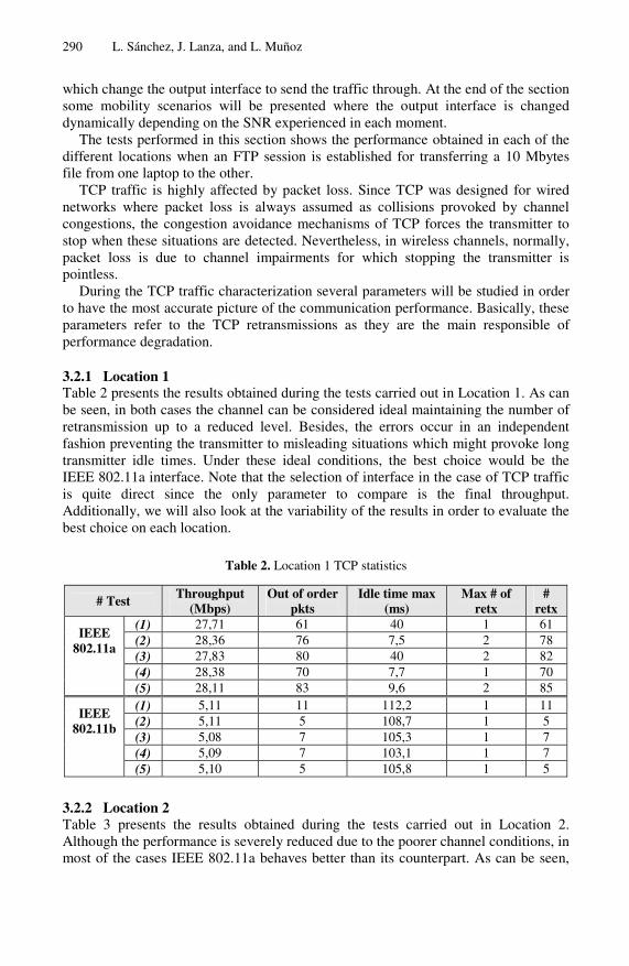
3.2.1 Location 1 Table 2 presents the results obtained during the tests carried out in Location 1. As can be seen, in both cases the channel can be considered ideal maintaining the number of retransmission up to a reduced level. Besides, the errors occur in an independent fashion preventing the transmitter to misleading situations which might provoke long transmitter idle times. Under these ideal conditions, the best choice would be the IEEE 802.11a interface. Note that the selection of interface in the case of TCP traffic is quite direct since the only parameter to compare is the final throughput. Additionally, we will also look at the variability of the results in order to evaluate the best choice on each location.
Table 2. Location 1 TCP statistics
# Test Throughput (Mbps)
Out of order pkts
Idle time max (ms)
Max # of retx
# retx
(1) 27,71 61 40 1 61 (2) 28,36 76 7,5 2 78 (3) 27,83 80 40 2 82 (4) 28,38 70 7,7 1 70
IEEE 802.11a
(5) 28,11 83 9,6 2 85 (1) 5,11 11 112,2 1 11 (2) 5,11 5 108,7 1 5 (3) 5,08 7 105,3 1 7 (4) 5,09 7 103,1 1 7
IEEE 802.11b
(5) 5,10 5 105,8 1 5
3.2.2 Location 2 Table 3 presents the results obtained during the tests carried out in Location 2. Although the performance is severely reduced due to the poorer channel conditions, in most of the cases IEEE 802.11a behaves better than its counterpart. As can be seen,
Experimental Assessment of a Cross-Layer Solution for TCP/IP Traffic Optimization 291
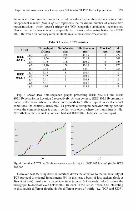
the number of retransmissions is increased considerably, but they still occur in a quite independent manner (Max # of retx represents the maximum number of consecutive retransmissions) which doesn’t trigger the TCP congestion avoidance mechanisms. Hence, the performance is not completely tear down and remains better than IEEE 802.11b, which on contrary remains stable in an almost error-free channel.
Table 3. Location 2 TCP statistics
# Test Throughput (Mbps)
Out of order pkts
Idle time max (ms)
Max # of retx
# retx
(1) 9,01 238 411,9 3 272 (2) 11,56 285 231,7 2 301 (3) 9,72 406 409,9 2 425 (4) 13,70 159 401,9 3 173
IEEE 802.11a
(5) 3,43 311 6431 7 356 (1) 5,13 8 108,9 1 8 (2) 5,12 7 109,7 1 7 (3) 5,11 2 108,8 1 2 (4) 5,11 6 104,2 1 6
IEEE 802.11b
(5) 4,94 8 118,1 1 8
Fig. 4 shows two time-sequence graphs presenting IEEE 802.11a and IEEE 802.11b behavior in Location 2 respectively. As can be seen, IEEE 802.11b presents a linear performance where the slope corresponds to 5 Mbps, typical in ideal channel conditions. On contrary, IEEE 802.11a presents a disrupted behavior mixing periods where the communication is almost perfect with others where the transmitter is idle. Nevertheless, the channel is not such bad and IEEE 802.11a beats its counterpart.
(a)
(b)
Fig. 4. Location 2 TCP traffic time-sequence graphs (a) for IEEE 802.11a and (b) for IEEE 802.11b
However, test #5 using 802.11a interface draws the attention to the vulnerability of TCP protocol to channel impairments [9]. In this test, a burst of lost packets (look at Max # of retx) results on a large idle time (almost 6.5 seconds) which makes the throughput to decrease even below 802.11b level. In this sense, it would be interesting to distinguish different thresholds for different types of traffic (e.g. TCP and UDP).
292 L. Sánchez, J. Lanza, and L. Muñoz
The UCL enables this possibility, allowing also the definition of more complex QoS functions which would allow to the decision to be taken to not only take into account the transport layer protocol but also application specific requirements and not only SNR but also other link layer parameters.
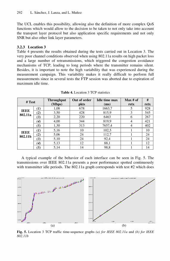
3.2.3 Location 3 Table 4 presents the results obtained during the tests carried out in Location 3. The very poor channel conditions observed when using 802.11a results on high packet loss and a large number of retransmissions, which triggered the congestion avoidance mechanisms of TCP, leading to long periods where the transmitter remains silent. Besides, it is important to note the high variability that was experienced during the measurement campaign. This variability makes it really difficult to perform full measurements since in several tests the FTP session was aborted due to expiration of maximum idle time.
Table 4. Location 3 TCP statistics
# Test Throughput (Mbps)
Out of order pkts
Idle time max (ms)
Max # of retx
# retx
(1) 1,08 678 1663,7 5 928 (2) 3,50 428 815,9 3 545 (3) 2,20 220 6463 6 267 (4) 4,00 344 819,9 4 421
IEEE 802.11a
(5) 1,30 313 7657,4 4 402 (1) 5,16 10 102,5 1 10 (2) 5,06 24 112,7 1 24 (3) 5,10 24 92,4 1 24 (4) 5,13 12 88,1 1 12
IEEE 802.11b
(5) 5,14 14 98,8 1 14
A typical example of the behavior of each interface can be seen in Fig. 5. The transmissions over IEEE 802.11a presents a poor performance spotted continuously with transmitter idle periods. The 802.11a graph corresponds with test #2 which does
(a)
(b)
Fig. 5. Location 3 TCP traffic time-sequence graphs (a) for IEEE 802.11a and (b) for IEEE 802.11b
Experimental Assessment of a Cross-Layer Solution for TCP/IP Traffic Optimization 293
not have a really long maximum idle time (see for example test #5) but the amount of retransmissions needed prevents from achieving higher throughputs. It is clear that under these circumstances the most suitable choice should be the 802.11b interface.
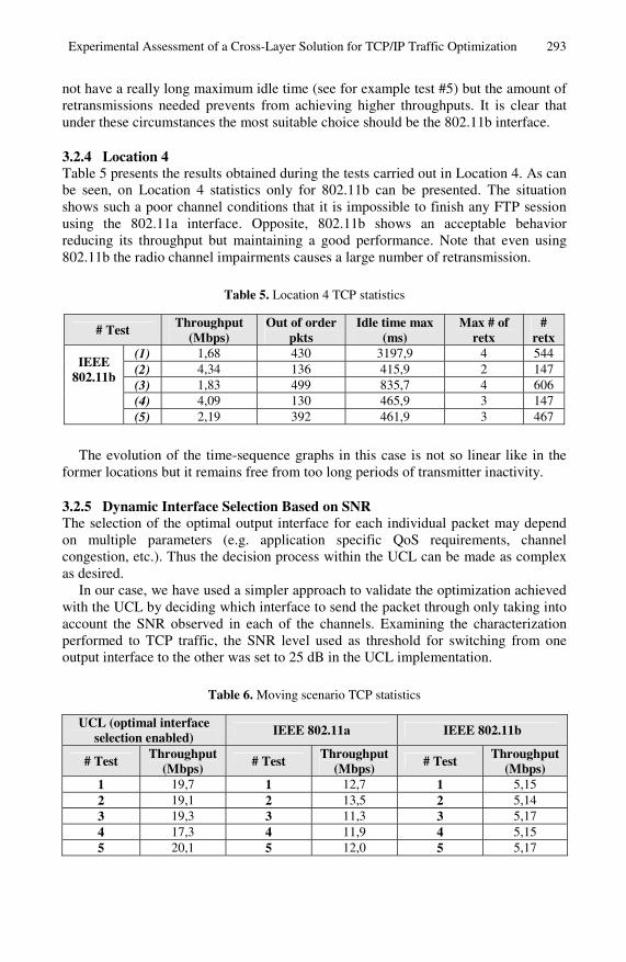
3.2.4 Location 4 Table 5 presents the results obtained during the tests carried out in Location 4. As can be seen, on Location 4 statistics only for 802.11b can be presented. The situation shows such a poor channel conditions that it is impossible to finish any FTP session using the 802.11a interface. Opposite, 802.11b shows an acceptable behavior reducing its throughput but maintaining a good performance. Note that even using 802.11b the radio channel impairments causes a large number of retransmission.
Table 5. Location 4 TCP statistics
# Test Throughput (Mbps)
Out of order pkts
Idle time max (ms)
Max # of retx
# retx
(1) 1,68 430 3197,9 4 544 (2) 4,34 136 415,9 2 147 (3) 1,83 499 835,7 4 606 (4) 4,09 130 465,9 3 147
IEEE 802.11b
(5) 2,19 392 461,9 3 467
The evolution of the time-sequence graphs in this case is not so linear like in the former locations but it remains free from too long periods of transmitter inactivity.
3.2.5 Dynamic Interface Selection Based on SNR The selection of the optimal output interface for each individual packet may depend on multiple parameters (e.g. application specific QoS requirements, channel congestion, etc.). Thus the decision process within the UCL can be made as complex as desired.
In our case, we have used a simpler approach to validate the optimization achieved with the UCL by deciding which interface to send the packet through only taking into account the SNR observed in each of the channels. Examining the characterization performed to TCP traffic, the SNR level used as threshold for switching from one output interface to the other was set to 25 dB in the UCL implementation.
Table 6. Moving scenario TCP statistics
UCL (optimal interface selection enabled) IEEE 802.11a IEEE 802.11b
# Test Throughput (Mbps) # Test Throughput
(Mbps) # Test Throughput (Mbps)
1 19,7 1 12,7 1 5,15 2 19,1 2 13,5 2 5,14 3 19,3 3 11,3 3 5,17 4 17,3 4 11,9 4 5,15 5 20,1 5 12,0 5 5,17
294 L. Sánchez, J. Lanza, and L. Muñoz
The tests performed for validating the optimal selection of the output interface consisted on moving one of the laptops from Location 1 to Location 4 and back again while the other remained fixed on the red mark in Fig. 2. This test was run using first the UCL with its optimal interface selection option enabled, then the IEE 802.11a interface only and finally the IEEE 802.11b interface only. Each case was repeated five times.
Table 6 presents the results from the different tests carried out. In these tests, a 1500 bytes TCP packets flow lasting 40 seconds was exchanged between the two laptops.
It is important to note, that in all the tests performed we have tried to repeat exactly the same movements maintaining the same speed all along the path. Nevertheless, the results might vary slightly from one to the other due to the impossibility of replicating exactly the movement. However, the different repetitions of the same experiment allow us to extract valid conclusions.
0 10 20 30 40 50 600
0.5
1
1.5
2
2.5
3
3.5x 10
7
Time (sec)
Th
rou
ghp
ut
(bp
s)
(a)
0 10 20 30 40 50 600
0.5
1
1.5
2
2.5
3
3.5x 10
7
Time (sec)
Th
rou
ghp
ut
(bp
s)
(b)
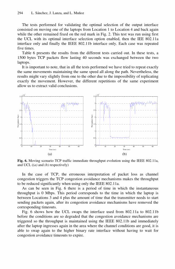
Fig. 6. Moving scenario TCP traffic immediate throughput evolution using the IEEE 802.11a, and UCL ((a) and (b) respectively)
In the case of TCP, the erroneous interpretation of packet loss as channel congestion triggers the TCP congestion avoidance mechanisms makes the throughput to be reduced significantly when using only the IEEE 802.11a.
As can be seen in Fig. 6 there is a period of time in which the instantaneous throughput is 0 Mbps. This period corresponds to the time in which the laptop is between Locations 3 and 4 plus the amount of time that the transmitter needs to start sending packets again, after its congestion avoidance mechanisms have removed the corresponding timeouts.
Fig. 6 shows how the UCL swaps the interface used from 802.11a to 802.11b before the conditions are so degraded that the congestion avoidance mechanisms are triggered so the throughput is maintained using the IEEE 802.11b and immediately after the laptop ingresses again in the area where the channel conditions are good, it is able to swap again to the higher binary rate interface without having to wait for congestion avoidance timeouts to expire.
Experimental Assessment of a Cross-Layer Solution for TCP/IP Traffic Optimization 295
When the transmission is forced to go through the 802.11b the throughput is always maintained stable around 5 Mbps.
As can be seen, the UCL always selects the most appropriate interface in each moment exploiting the advantages of the two options. When the channel is good uses the interface which offers higher bandwidth but when it detects that the channel is starting to deteriorate switches to the interface that offers stronger behavior against radio channel impairments.
4 Conclusions
In the above sections we have presented a complete set of results obtained from different measurements campaigns that have proven the feasibility of the implemented UCL and the optimization achieved through its use.
This work has presented a complete experimental assessment of the benefits that a cross-layer optimization approach can bring up in the field of wireless communica-tions. The optimizations introduced by the UCL, through the selection of the most appropriate output interface based on channel status have been presented in the case of using TCP traffic.
Although there has been a lot of interest on this sort of solutions, they lack from an experimental evaluation. In this sense, one of the main contributions of this work is that it presents the results of a purely experimental approach, showing that, in spite of the shortcomings of current available “off-the-shelf” technologies, it is possible to practically consider and integrate cross-layer optimization concepts over these technologies.
It has been proven how the UCL enables the dynamic adaptation to the channel conditions resulting on a substantial performance enhancement.
During the different validation tests, they have been identified possible enhancements that can be supported by the UCL although they have not been already implemented. In this sense, and although the SNR has proven to give interesting results, future work will add new parameters to the decision process, such as network load or trust relationships between different nodes; investigating on optimal link cost functions.
References
[1] IST-507102, My Personal Adaptive Global NET, MAGNET, Deliverable D.3.3.2a, “MAC/RRM Schemes for PANs”, July 2004.
[2] IEEE std 802.15.3, Part 15.3: Wireless Medium Access Control (MAC) and Physical Layer (PHY) Specifications for High Rate Wireless Personal Area Networks (WPANs).
[3] IEEE std 802.11n. IEEE Standard for Information technology—Telecommunications and information exchange between systems-Local and metropolitan area networks-Specific requirements-Part 11: Wireless LAN Medium Access Control (MAC) and Physical Layer (PHY) specifications Amendment: Higher throughput improvements.
[4] D. S. J. De Couto, D. Aguayo, J. Bicket, and R. Morris, “A High-Throughput Path Metric for Multi-Hop Wireless Routing”, 9th ACM International Conference on Mobile Computing and Networking, San Diego, California, September 2003
296 L. Sánchez, J. Lanza, and L. Muñoz
[5] B. Awerbuch, D. Holmer, H. Rubens, “High Throughput Route Selection in Multi-Rate Ad Hoc Wireless Networks”, First Working Conference on Wireless On-demand Network Systems 2004.
[6] R. Draves, J. Padhye, and B. Zill, “Routing in Multi-radio, Multi-hop Wireless Mesh Networks”, ACM International Conference on Mobile Computing and Networking 2004
[7] J.P. Pavon and S. Choi, "Link adaptation strategy for IEEE 802.11 WLAN via received signal strength measurement," IEEE ICC 2003, vol.2, pp.1108–1113, May 2003.
[8] K. Balachandran, S. R. Kadaba, and S. Nanda "Channel Quality Estimation and Rate Adaptation for Cellular Mobile Radio". IEEE Journal on Selected Areas in Communications, Vol. 17, No. 7, pp. 1244-1256, 1999.
[9] L. Muñoz, M. Garcia, J. Choque, R. Aguero and P. Mähönen, “Optimizing internet flows over IEEE 802.11b wireless local area networks: A performance-enhancing proxy based on forward error correction,” IEEE Communication Magazine, pp. 60–67, December, 2001.