Embed Size (px)
Citation preview
Abstract A majority of the current and next generation server applications (web services, e-commerce, storage, etc.) employ TCP/IP as the communication protocol of choice. As a result, the performance of these applications is heavily dependent on the efficient TCP/IP packet processing within the termination nodes. This dependency becomes even greater as the bandwidth needs of these applications grow from 100 Mbps to 1Gbps to 10Gbps in the near future. Motivated by this, our work presented in this paper focuses on the following: (a) to understand the performance behavior of the various modes of TCP/IP processing, (b) to analyze the underlying architectural characteristics of TCP/IP packet processing and (c) to quantify the computational requirements of the TCP/IP packet processing component within realistic workloads. We achieve these goals by performing an in-depth analysis of packet processing performance on Intel’s state-of-the-art low power Pentium® M microprocessor running the Microsoft Windows* Server 2003 operating system. Some of our key observations are – (i) that the mode of TCP/IP operation can significantly affect the performance requirements, (ii) that transmit-side processing is largely compute-intensive as compared to receive-side processing which is more memory-bound and (iii) that the computational requirements for sending/receiving packets can form a substantial component (28% to 40%) of commercial server workloads. From our analysis, we also discuss architectural as well as stack-related improvements that can help achieve higher server network throughput and result in improved application performance.
I. INTRODUCTION As Internet presence and connectivity continues to increase at a rapid pace, there is a growing need to increase the available end-to-end communication bandwidth and performance. TCP/IP [18] over Ethernet is the most prevalent form of communication that exists today in various environments. One of the well-recognized issues with TCP/IP communication is the significant computational requirements of protocol stack processing at the termination nodes (clients and servers). Motivated by this, several research projects contemplate the potential of using a TCP offload engine (TOE) or a packet processing engine (PPE) [1, 2, 5, 9, 13, 19, 20] to offload protocol stack processing from the host CPU. The relevance of packet processing [16, 17, 23] grows stronger as Storage over IP becomes popular with the help of working groups for iSCSI [10], RDMA [21] and DDP [22]. While these efforts provide valuable information, there seems to be very little information in the existing literature on the micro-architectural
characteristics and bottlenecks specific to stack processing [3, 4, 6]. Such a study is critical to help assist the architectural considerations and design choices for a PPE. Another direction of research that is equally important is the need to identify architectural improvements to general purpose cores that could also help improve the efficiency and performance of packet processing. The overall contributions of this paper are as follows. We perform an in-depth measurement and evaluation of packet processing on Intel’s state-of-the-art low power Pentium® M microprocessor [7] running Microsoft’s Server 2003 Enterprise Edition operating system. The primary focus of this study is to do the following: (a) to understand the performance behavior of various modes of TCP/IP processing, (b) to expose the architectural characteristics of packet processing and (c) to quantify the computational requirements of TCP/IP packet processing component within realistic workloads. In this paper, we start by describing the measurement-based methodology used to achieve these goals. We then present an in-depth analysis of the performance data (CPI, path length, cache misses, branch prediction accuracy, etc) collected through application-level measurements and the use of in-built performance counters available on the Pentium® M microprocessor. Finally, we compare the requirements of packet processing to the overall characteristics of commercial server workloads (SPECweb99 & TPC-C) and discuss the potential opportunities for optimizing packet processing performance.
II. OVERVIEW OF TCP/IP PACKET PROCESSING In this section, we will discuss the components of interest when evaluating TCP/IP packet processing. We will also discuss the available modes of TCP/IP operation based on the available features on the NIC and the Windows* O/S stack.
A. Components of TCP/IP Communication TCP/IP processing can be generally divided into two parts: (1) connection management and (2) data path processing. Connection management involves setting up and tearing down the connections. The TCP/IP data path processing consists of transmit and receive paths (also known as data paths); both of which can be quite different in their requirements as we will
Architectural Characterization of TCP/IP Packet Processing on the Pentium® M microprocessor
Srihari Makineni and Ravi Iyer Communications Technology Laboratory
Intel Corporation {srihari.makineni, ravishankar.iyer}@intel.com
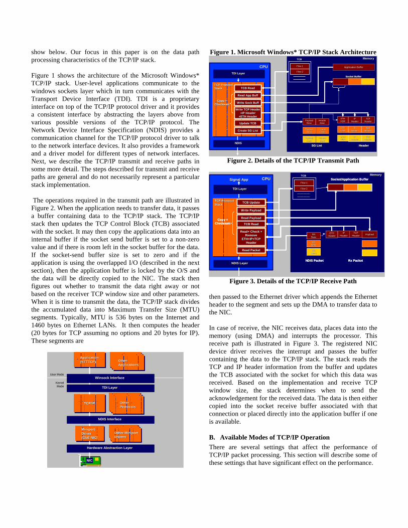
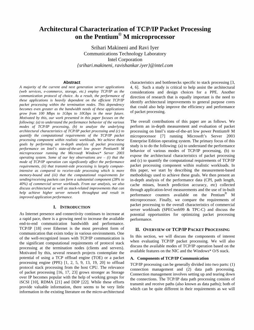
show below. Our focus in this paper is on the data path processing characteristics of the TCP/IP stack. Figure 1 shows the architecture of the Microsoft Windows* TCP/IP stack. User-level applications communicate to the windows sockets layer which in turn communicates with the Transport Device Interface (TDI). TDI is a proprietary interface on top of the TCP/IP protocol driver and it provides a consistent interface by abstracting the layers above from various possible versions of the TCP/IP protocol. The Network Device Interface Specification (NDIS) provides a communication channel for the TCP/IP protocol driver to talk to the network interface devices. It also provides a framework and a driver model for different types of network interfaces. Next, we describe the TCP/IP transmit and receive paths in some more detail. The steps described for transmit and receive paths are general and do not necessarily represent a particular stack implementation. The operations required in the transmit path are illustrated in Figure 2. When the application needs to transfer data, it passes a buffer containing data to the TCP/IP stack. The TCP/IP stack then updates the TCP Control Block (TCB) associated with the socket. It may then copy the applications data into an internal buffer if the socket send buffer is set to a non-zero value and if there is room left in the socket buffer for the data. If the socket-send buffer size is set to zero and if the application is using the overlapped I/O (described in the next section), then the application buffer is locked by the O/S and the data will be directly copied to the NIC. The stack then figures out whether to transmit the data right away or not based on the receiver TCP window size and other parameters. When it is time to transmit the data, the TCP/IP stack divides the accumulated data into Maximum Transfer Size (MTU) segments. Typically, MTU is 536 bytes on the Internet and 1460 bytes on Ethernet LANs. It then computes the header (20 bytes for TCP assuming no options and 20 bytes for IP). These segments are
NICNIC
Miniport Driver(GbE NIC)
Miniport Miniport DriverDriver((GbEGbE NIC)NIC)
TCP/IPTCP/IPTCP/IP
User ModeUser Mode
Kernel Kernel ModeMode
Application(NTTTCP) ApplicationApplication(NTTTCP) (NTTTCP)
TCP/IPTCP/IPTCP/IPTCP/IPTCP/IPTCP/IPOther ProtocolsOther Other ProtocolsProtocols
Miniport DriverMiniport DriverMiniport DriverMiniport DriverMiniport DriverMiniport DriverOther Miniport
DriversOther Miniport Other Miniport DriversDrivers
Hardware Abstraction LayerHardware Abstraction LayerHardware Abstraction Layer
NDIS InterfaceNDIS InterfaceNDIS Interface
TDI LayerTDI LayerTDI Layer
Winsock InterfaceWinsock InterfaceWinsock Interface
Application(TTCP) ApplicationApplication(TTCP) (TTCP) Application
(TTCP) ApplicationApplication(TTCP) (TTCP) Other ApplicationsOther Other ApplicationsApplications
NICNICNICNIC
Miniport Driver(GbE NIC)
Miniport Miniport DriverDriver((GbEGbE NIC)NIC)
TCP/IPTCP/IPTCP/IP
User ModeUser Mode
Kernel Kernel ModeMode
Application(NTTTCP) ApplicationApplication(NTTTCP) (NTTTCP)
TCP/IPTCP/IPTCP/IPTCP/IPTCP/IPTCP/IPOther ProtocolsOther Other ProtocolsProtocols
Miniport DriverMiniport DriverMiniport DriverMiniport DriverMiniport DriverMiniport DriverOther Miniport
DriversOther Miniport Other Miniport DriversDrivers
Hardware Abstraction LayerHardware Abstraction LayerHardware Abstraction Layer
NDIS InterfaceNDIS InterfaceNDIS Interface
TDI LayerTDI LayerTDI Layer
Winsock InterfaceWinsock InterfaceWinsock Interface
Application(TTCP) ApplicationApplication(TTCP) (TTCP) Application
(TTCP) ApplicationApplication(TTCP) (TTCP) Other ApplicationsOther Other ApplicationsApplications
Figure 1. Microsoft Windows* TCP/IP Stack Architecture
CPUCPU
TCP ProtocolStackTCP ProtocolTCP ProtocolStackStack
MemoryMemoryMemory
Create SG ListCreate SG ListCreate SG ListCreate SG List
Flow 1Flow 1
Flow 2Flow 2
TCBTCB
TX DataTX Data
Socket BufferSocket Buffer
TX DataTX Data
Socket BufferSocket Buffer
HeaderHeaderSG ListSG List HeaderHeaderSG ListSG List
TCB ReadTCB ReadTCB ReadTCB Read
Read App BuffRead App BuffRead App BuffRead App Buff
PayloadPayloadDescDesc
PayloadPayloadDescDesc
Header Header DescDesc
Header Header DescDesc
PayloadPayloadDescDesc
Header Header DescDesc
IP IP HeaderHeader
TCP TCP HeaderHeader
ETHETHHDRHDRPayloadPayload
DescDescHeader Header DescDesc
IP IP HeaderHeader
TCP TCP HeaderHeader
IP IP HeaderHeader
TCP TCP HeaderHeader
ETHETHHDRHDR
PayloadPayloadDescDesc
Header Header DescDesc
IP IP HeaderHeader
TCP TCP HeaderHeader
ETHETHHDRHDRPayloadPayload
DescDescHeader Header DescDesc
IP IP HeaderHeader
TCP TCP HeaderHeader
ETHETHHDRHDR
IP IP HeaderHeader
TCP TCP HeaderHeader
IP IP HeaderHeader
TCP TCP HeaderHeader
ETHETHHDRHDR
NDISNDISNDIS
TDI LayerTDI LayerTDI Layer
Application BufferApplication Buffer
Update TCBUpdate TCBUpdate TCBUpdate TCB
Copy + Copy + ChecksumChecksum
Copy + Copy + ChecksumChecksum Write Sock BuffWrite Sock BuffWrite Sock BuffWrite Sock Buff
ETHETHHDRHDRETHETHHDRHDR
TCP TCP HeaderHeader
Write TCP HeaderWrite TCP Header+IP Header+IP Header
+ETH Header+ETH HeaderTCP TCP
HeaderHeader
Write TCP HeaderWrite TCP Header+IP Header+IP Header
+ETH Header+ETH HeaderIP IP
HeaderHeaderIP IP
HeaderHeader
Figure 2. Details of the TCP/IP Transmit Path
MemoryMemoryMemory
CPUCPU
TCP ProtocolStackTCP ProtocolTCP ProtocolStackStack
NDIS LayerNDIS LayerNDIS Layer
TDI LayerTDI LayerTDI Layer
Copy + Checksum
Copy + Checksum
Flow 1Flow 1
Flow 2Flow 2
TCBTCB
Rx PacketNDIS Packet Rx PacketNDIS Packet
TCB ReadTCB ReadTCB ReadTCB Read
RXRXDescDesc
RXRXDescDesc
Rx PacketRx PacketRXRXDescDesc
RXRXDescDesc
RXRXDescDesc
Rx PacketRx PacketRXRXDescDesc
RXRXDescDesc
RXRXDescDesc
Rx PacketRx PacketRXRXDescDesc
Read PacketRead PacketRead PacketRead Packet
TCP TCP HeaderHeader
TCP TCP HeaderHeader
Read PayloadRead Payload
PayloadPayload
Read PayloadRead Payload
PayloadPayloadPayloadPayload
TCB UpdateTCB UpdateTCB UpdateTCB Update
ETHETHHeaderHeader
Read+ Check + Read+ Check + Remove Remove
ETH+IP+TCP ETH+IP+TCP HeaderHeader
ETHETHHeaderHeader
Read+ Check + Read+ Check + Remove Remove
ETH+IP+TCP ETH+IP+TCP HeaderHeader
IP IP HeaderHeader
IP IP HeaderHeader
Socket/Application BufferSocket/Application Buffer
Write PayloadWrite PayloadWrite PayloadWrite Payload
Signal AppSignal App
Figure 3. Details of the TCP/IP Receive Path
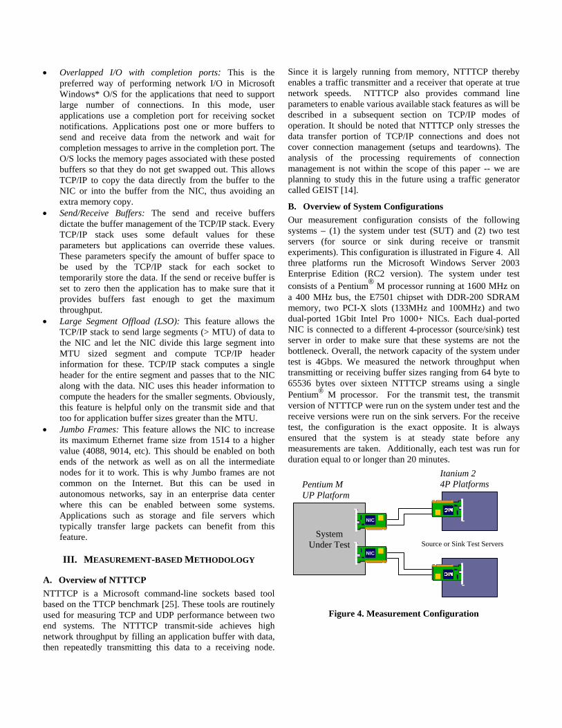
then passed to the Ethernet driver which appends the Ethernet header to the segment and sets up the DMA to transfer data to the NIC. In case of receive, the NIC receives data, places data into the memory (using DMA) and interrupts the processor. This receive path is illustrated in Figure 3. The registered NIC device driver receives the interrupt and passes the buffer containing the data to the TCP/IP stack. The stack reads the TCP and IP header information from the buffer and updates the TCB associated with the socket for which this data was received. Based on the implementation and receive TCP window size, the stack determines when to send the acknowledgement for the received data. The data is then either copied into the socket receive buffer associated with that connection or placed directly into the application buffer if one is available.
B. Available Modes of TCP/IP Operation There are several settings that affect the performance of TCP/IP packet processing. This section will describe some of these settings that have significant effect on the performance.
• Overlapped I/O with completion ports: This is the preferred way of performing network I/O in Microsoft Windows* O/S for the applications that need to support large number of connections. In this mode, user applications use a completion port for receiving socket notifications. Applications post one or more buffers to send and receive data from the network and wait for completion messages to arrive in the completion port. The O/S locks the memory pages associated with these posted buffers so that they do not get swapped out. This allows TCP/IP to copy the data directly from the buffer to the NIC or into the buffer from the NIC, thus avoiding an extra memory copy.
• Send/Receive Buffers: The send and receive buffers dictate the buffer management of the TCP/IP stack. Every TCP/IP stack uses some default values for these parameters but applications can override these values. These parameters specify the amount of buffer space to be used by the TCP/IP stack for each socket to temporarily store the data. If the send or receive buffer is set to zero then the application has to make sure that it provides buffers fast enough to get the maximum throughput.
• Large Segment Offload (LSO): This feature allows the TCP/IP stack to send large segments (> MTU) of data to the NIC and let the NIC divide this large segment into MTU sized segment and compute TCP/IP header information for these. TCP/IP stack computes a single header for the entire segment and passes that to the NIC along with the data. NIC uses this header information to compute the headers for the smaller segments. Obviously, this feature is helpful only on the transmit side and that too for application buffer sizes greater than the MTU.
• Jumbo Frames: This feature allows the NIC to increase its maximum Ethernet frame size from 1514 to a higher value (4088, 9014, etc). This should be enabled on both ends of the network as well as on all the intermediate nodes for it to work. This is why Jumbo frames are not common on the Internet. But this can be used in autonomous networks, say in an enterprise data center where this can be enabled between some systems. Applications such as storage and file servers which typically transfer large packets can benefit from this feature.
III. MEASUREMENT-BASED METHODOLOGY
A. Overview of NTTTCP NTTTCP is a Microsoft command-line sockets based tool based on the TTCP benchmark [25]. These tools are routinely used for measuring TCP and UDP performance between two end systems. The NTTTCP transmit-side achieves high network throughput by filling an application buffer with data, then repeatedly transmitting this data to a receiving node.
Since it is largely running from memory, NTTTCP thereby enables a traffic transmitter and a receiver that operate at true network speeds. NTTTCP also provides command line parameters to enable various available stack features as will be described in a subsequent section on TCP/IP modes of operation. It should be noted that NTTTCP only stresses the data transfer portion of TCP/IP connections and does not cover connection management (setups and teardowns). The analysis of the processing requirements of connection management is not within the scope of this paper -- we are planning to study this in the future using a traffic generator called GEIST [14].
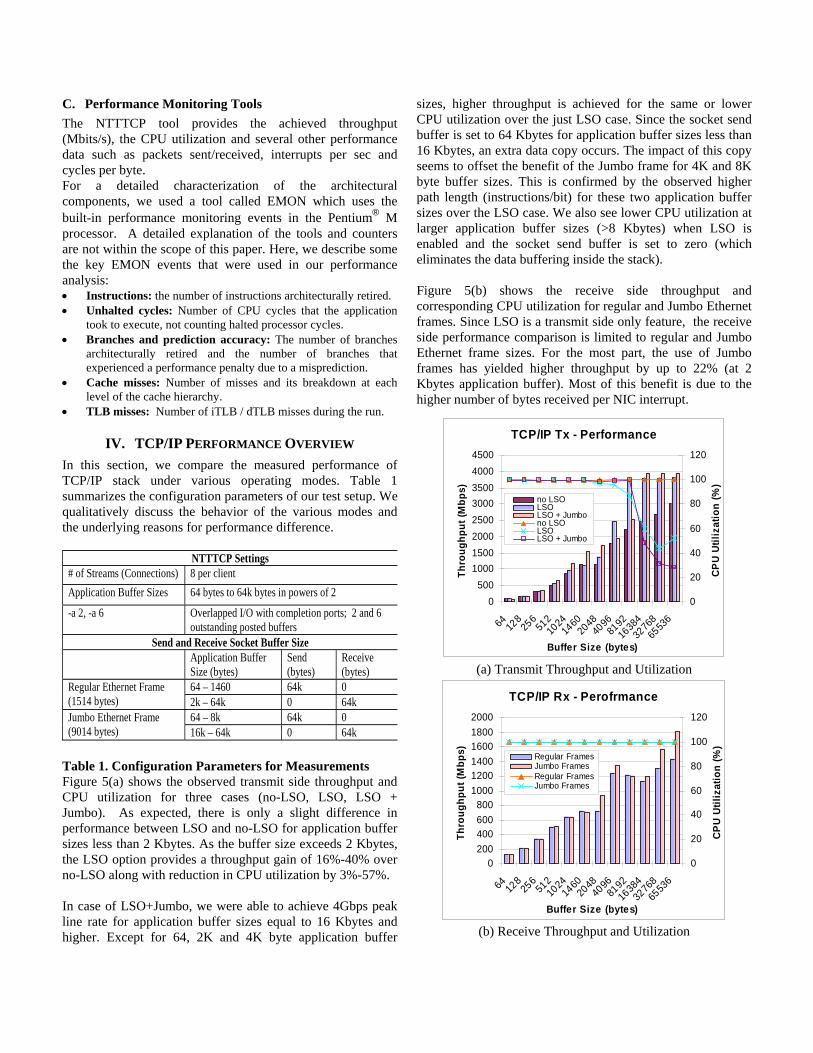
B. Overview of System Configurations Our measurement configuration consists of the following systems – (1) the system under test (SUT) and (2) two test servers (for source or sink during receive or transmit experiments). This configuration is illustrated in Figure 4. All three platforms run the Microsoft Windows Server 2003 Enterprise Edition (RC2 version). The system under test consists of a Pentium® M processor running at 1600 MHz on a 400 MHz bus, the E7501 chipset with DDR-200 SDRAM memory, two PCI-X slots (133MHz and 100MHz) and two dual-ported 1Gbit Intel Pro 1000+ NICs. Each dual-ported NIC is connected to a different 4-processor (source/sink) test server in order to make sure that these systems are not the bottleneck. Overall, the network capacity of the system under test is 4Gbps. We measured the network throughput when transmitting or receiving buffer sizes ranging from 64 byte to 65536 bytes over sixteen NTTTCP streams using a single Pentium® M processor. For the transmit test, the transmit version of NTTTCP were run on the system under test and the receive versions were run on the sink servers. For the receive test, the configuration is the exact opposite. It is always ensured that the system is at steady state before any measurements are taken. Additionally, each test was run for duration equal to or longer than 20 minutes.
Figure 4. Measurement Configuration
System Under Test Source or Sink Test Servers
Itanium 2 4P Platforms Pentium M
UP Platform
NICNICNICNIC
NICNICNICNIC
C. Performance Monitoring Tools The NTTTCP tool provides the achieved throughput (Mbits/s), the CPU utilization and several other performance data such as packets sent/received, interrupts per sec and cycles per byte. For a detailed characterization of the architectural components, we used a tool called EMON which uses the built-in performance monitoring events in the Pentium® M processor. A detailed explanation of the tools and counters are not within the scope of this paper. Here, we describe some the key EMON events that were used in our performance analysis: • Instructions: the number of instructions architecturally retired. • Unhalted cycles: Number of CPU cycles that the application
took to execute, not counting halted processor cycles. • Branches and prediction accuracy: The number of branches
architecturally retired and the number of branches that experienced a performance penalty due to a misprediction.
• Cache misses: Number of misses and its breakdown at each level of the cache hierarchy.
• TLB misses: Number of iTLB / dTLB misses during the run.
IV. TCP/IP PERFORMANCE OVERVIEW In this section, we compare the measured performance of TCP/IP stack under various operating modes. Table 1 summarizes the configuration parameters of our test setup. We qualitatively discuss the behavior of the various modes and the underlying reasons for performance difference.
NTTTCP Settings # of Streams (Connections) 8 per client Application Buffer Sizes 64 bytes to 64k bytes in powers of 2
-a 2, -a 6 Overlapped I/O with completion ports; 2 and 6 outstanding posted buffers
Send and Receive Socket Buffer Size Application Buffer
Size (bytes) Send (bytes)
Receive (bytes)
64 – 1460 64k 0 Regular Ethernet Frame (1514 bytes) 2k – 64k 0 64k
64 – 8k 64k 0 Jumbo Ethernet Frame (9014 bytes) 16k – 64k 0 64k
Table 1. Configuration Parameters for Measurements Figure 5(a) shows the observed transmit side throughput and CPU utilization for three cases (no-LSO, LSO, LSO + Jumbo). As expected, there is only a slight difference in performance between LSO and no-LSO for application buffer sizes less than 2 Kbytes. As the buffer size exceeds 2 Kbytes, the LSO option provides a throughput gain of 16%-40% over no-LSO along with reduction in CPU utilization by 3%-57%. In case of LSO+Jumbo, we were able to achieve 4Gbps peak line rate for application buffer sizes equal to 16 Kbytes and higher. Except for 64, 2K and 4K byte application buffer
sizes, higher throughput is achieved for the same or lower CPU utilization over the just LSO case. Since the socket send buffer is set to 64 Kbytes for application buffer sizes less than 16 Kbytes, an extra data copy occurs. The impact of this copy seems to offset the benefit of the Jumbo frame for 4K and 8K byte buffer sizes. This is confirmed by the observed higher path length (instructions/bit) for these two application buffer sizes over the LSO case. We also see lower CPU utilization at larger application buffer sizes (>8 Kbytes) when LSO is enabled and the socket send buffer is set to zero (which eliminates the data buffering inside the stack). Figure 5(b) shows the receive side throughput and corresponding CPU utilization for regular and Jumbo Ethernet frames. Since LSO is a transmit side only feature, the receive side performance comparison is limited to regular and Jumbo Ethernet frame sizes. For the most part, the use of Jumbo frames has yielded higher throughput by up to 22% (at 2 Kbytes application buffer). Most of this benefit is due to the higher number of bytes received per NIC interrupt.
TCP/IP Tx - Performance
0500
10001500200025003000350040004500
64 128
256
51210
2414
6020
4840
9681
9216
38432
76865
536
Buffer Size (bytes)
Thro
ughp
ut (M
bps)
0
20
40
60
80
100
120
CPU
Utili
zatio
n (%
)
no LSOLSO LSO + Jumbono LSOLSO LSO + Jumbo
(a) Transmit Throughput and Utilization
TCP/IP Rx - Perofrmance
0200400600800
100012001400160018002000
64 128
256
51210
2414
6020
4840
9681
9216
38432
76865
536
Buffer Size (bytes)
Thro
ughp
ut (M
bps)
0
20
40
60
80
100
120CP
U Ut
iliza
tion
(%)
Regular FramesJumbo FramesRegular FramesJumbo Frames
(b) Receive Throughput and Utilization
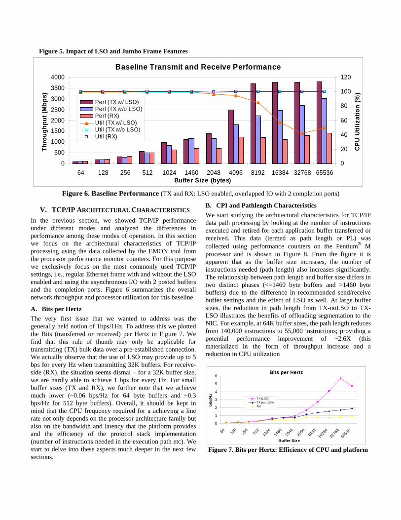
Figure 5. Impact of LSO and Jumbo Frame Features
Baseline Transmit and Receive Performance
0
500
1000
15002000
2500
3000
3500
4000
64 128 256 512 1024 1460 2048 4096 8192 16384 32768 65536Buffer Size (bytes)
Thro
ughp
ut (M
bps)
0
20
40
60
80
100
120
CPU
Util
izat
ion
(%)
Perf (TX w/ LSO)Perf (TX w/o LSO)Perf (RX)Util (TX w/ LSO)Util (TX w/o LSO)Util (RX)
Figure 6. Baseline Performance (TX and RX: LSO enabled, overlapped IO with 2 completion ports)
V. TCP/IP ARCHITECTURAL CHARACTERISTICS In the previous section, we showed TCP/IP performance under different modes and analyzed the differences in performance among these modes of operation. In this section we focus on the architectural characteristics of TCP/IP processing using the data collected by the EMON tool from the processor performance monitor counters. For this purpose we exclusively focus on the most commonly used TCP/IP settings, i.e., regular Ethernet frame with and without the LSO enabled and using the asynchronous I/O with 2 posted buffers and the completion ports. Figure 6 summarizes the overall network throughput and processor utilization for this baseline.
A. Bits per Hertz The very first issue that we wanted to address was the generally held notion of 1bps/1Hz. To address this we plotted the Bits (transferred or received) per Hertz in Figure 7. We find that this rule of thumb may only be applicable for transmitting (TX) bulk data over a pre-established connection. We actually observe that the use of LSO may provide up to 5 bps for every Hz when transmitting 32K buffers. For receive-side (RX), the situation seems dismal – for a 32K buffer size, we are hardly able to achieve 1 bps for every Hz. For small buffer sizes (TX and RX), we further note that we achieve much lower (~0.06 bps/Hz for 64 byte buffers and ~0.3 bps/Hz for 512 byte buffers). Overall, it should be kept in mind that the CPU frequency required for a achieving a line rate not only depends on the processor architecture family but also on the bandwidth and latency that the platform provides and the efficiency of the protocol stack implementation (number of instructions needed in the execution path etc). We start to delve into these aspects much deeper in the next few sections.
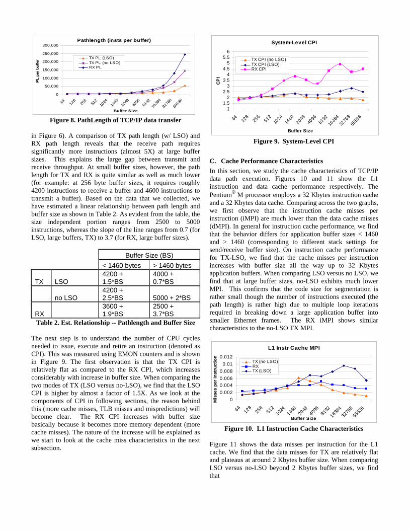
B. CPI and Pathlength Characteristics We start studying the architectural characteristics for TCP/IP data path processing by looking at the number of instructions executed and retired for each application buffer transferred or received. This data (termed as path length or PL) was collected using performance counters on the Pentium® M processor and is shown in Figure 8. From the figure it is apparent that as the buffer size increases, the number of instructions needed (path length) also increases significantly. The relationship between path length and buffer size differs in two distinct phases (<=1460 byte buffers and >1460 byte buffers) due to the difference in recommended send/receive buffer settings and the effect of LSO as well. At large buffer sizes, the reduction in path length from TX-noLSO to TX-LSO illustrates the benefits of offloading segmentation to the NIC. For example, at 64K buffer sizes, the path length reduces from 140,000 instructions to 55,000 instructions; providing a potential performance improvement of ~2.6X (this materialized in the form of throughput increase and a reduction in CPU utilization
Bits per Hertz
0
1
2
3
4
5
6
64128 256 512
1024
1460
204840
9681
9216384
3276865536
Buffer Size
bits
/Hz
TX (LSO)TX (no LSO)RX
Figure 7. Bits per Hertz: Efficiency of CPU and platform
Pathlength (insts per buffer)
0
50,000
100,000
150,000
200,000
250,000
300,000
64 128
256
512
1024
1460
2048
4096
8192
1638
4
3276
8
6553
6
Buffer Size
PL p
er b
uffe
r TX PL (LSO)TX PL (no LSO)RX PL
Figure 8. PathLength of TCP/IP data transfer
in Figure 6). A comparison of TX path length (w/ LSO) and RX path length reveals that the receive path requires significantly more instructions (almost 5X) at large buffer sizes. This explains the large gap between transmit and receive throughput. At small buffer sizes, however, the path length for TX and RX is quite similar as well as much lower (for example: at 256 byte buffer sizes, it requires roughly 4200 instructions to receive a buffer and 4600 instructions to transmit a buffer). Based on the data that we collected, we have estimated a linear relationship between path length and buffer size as shown in Table 2. As evident from the table, the size independent portion ranges from 2500 to 5000 instructions, whereas the slope of the line ranges from 0.7 (for LSO, large buffers, TX) to 3.7 (for RX, large buffer sizes).
Buffer Size (BS) < 1460 bytes > 1460 bytes
TX LSO 4200 + 1.5*BS
4000 + 0.7*BS
no LSO 4200 + 2.5*BS 5000 + 2*BS
RX 3600 + 1.9*BS
2500 + 3.7*BS
Table 2. Est. Relationship -- Pathlength and Buffer Size The next step is to understand the number of CPU cycles needed to issue, execute and retire an instruction (denoted as CPI). This was measured using EMON counters and is shown in Figure 9. The first observation is that the TX CPI is relatively flat as compared to the RX CPI, which increases considerably with increase in buffer size. When comparing the two modes of TX (LSO versus no-LSO), we find that the LSO CPI is higher by almost a factor of 1.5X. As we look at the components of CPI in following sections, the reason behind this (more cache misses, TLB misses and mispredictions) will become clear. The RX CPI increases with buffer size basically because it becomes more memory dependent (more cache misses). The nature of the increase will be explained as we start to look at the cache miss characteristics in the next subsection.
System-Level CPI
11.5
22.5
33.5
44.5
55.5
6
64 128
256
512
1024
1460
2048
4096
8192
1638
432
768
6553
6
Buffer Size
CPI
TX CPI (no LSO)TX CPI (LSO)RX CPI
Figure 9. System-Level CPI
C. Cache Performance Characteristics In this section, we study the cache characteristics of TCP/IP data path execution. Figures 10 and 11 show the L1 instruction and data cache performance respectively. The Pentium® M processor employs a 32 Kbytes instruction cache and a 32 Kbytes data cache. Comparing across the two graphs, we first observe that the instruction cache misses per instruction (iMPI) are much lower than the data cache misses (dMPI). In general for instruction cache performance, we find that the behavior differs for application buffer sizes < 1460 and > 1460 (corresponding to different stack settings for send/receive buffer size). On instruction cache performance for TX-LSO, we find that the cache misses per instruction increases with buffer size all the way up to 32 Kbytes application buffers. When comparing LSO versus no LSO, we find that at large buffer sizes, no-LSO exhibits much lower MPI. This confirms that the code size for segmentation is rather small though the number of instructions executed (the path length) is rather high due to multiple loop iterations required in breaking down a large application buffer into smaller Ethernet frames. The RX iMPI shows similar characteristics to the no-LSO TX MPI.
L1 Instr Cache MPI
00.0020.0040.0060.008
0.010.012
6412
825
6512
1024
1460
2048
4096
8192163
8432
768
6553
6
Buffer Size
Mis
ses
per I
nstru
ctio
n
TX (no LSO)RXTX (LSO)
Figure 10. L1 Instruction Cache Characteristics
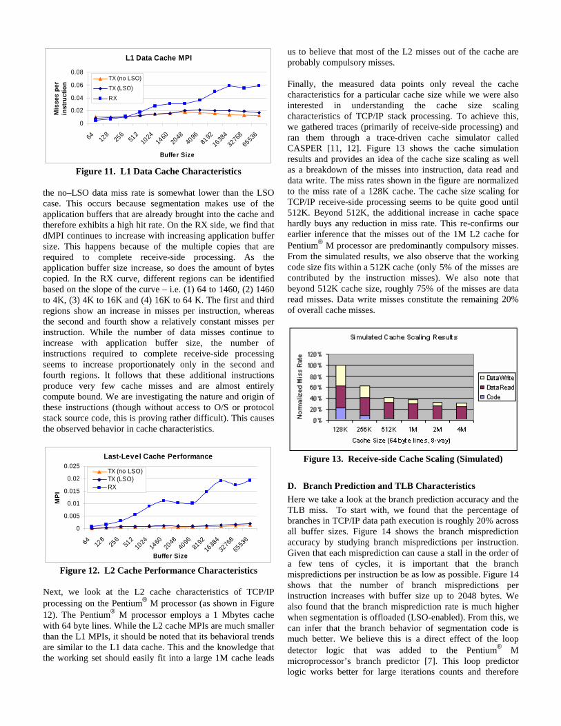
Figure 11 shows the data misses per instruction for the L1 cache. We find that the data misses for TX are relatively flat and plateaus at around 2 Kbytes buffer size. When comparing LSO versus no-LSO beyond 2 Kbytes buffer sizes, we find that
L1 Data Cache MPI
0
0.02
0.04
0.06
0.08
64 128
256
512
1024
1460
2048
4096
8192
1638
432
768
6553
6
Buffer Size
Mis
ses
per
inst
ruct
ion
TX (no LSO)
TX (LSO)
RX
Figure 11. L1 Data Cache Characteristics
the no–LSO data miss rate is somewhat lower than the LSO case. This occurs because segmentation makes use of the application buffers that are already brought into the cache and therefore exhibits a high hit rate. On the RX side, we find that dMPI continues to increase with increasing application buffer size. This happens because of the multiple copies that are required to complete receive-side processing. As the application buffer size increase, so does the amount of bytes copied. In the RX curve, different regions can be identified based on the slope of the curve – i.e. (1) 64 to 1460, (2) 1460 to 4K, (3) 4K to 16K and (4) 16K to 64 K. The first and third regions show an increase in misses per instruction, whereas the second and fourth show a relatively constant misses per instruction. While the number of data misses continue to increase with application buffer size, the number of instructions required to complete receive-side processing seems to increase proportionately only in the second and fourth regions. It follows that these additional instructions produce very few cache misses and are almost entirely compute bound. We are investigating the nature and origin of these instructions (though without access to O/S or protocol stack source code, this is proving rather difficult). This causes the observed behavior in cache characteristics.
Last-Level Cache Performance
0
0.005
0.01
0.015
0.02
0.025
64 128
256
512
1024
1460
2048
4096
8192
1638
432
768
6553
6
Buffer Size
MP
I
TX (no LSO)TX (LSO)RX
Figure 12. L2 Cache Performance Characteristics
Next, we look at the L2 cache characteristics of TCP/IP processing on the Pentium® M processor (as shown in Figure 12). The Pentium® M processor employs a 1 Mbytes cache with 64 byte lines. While the L2 cache MPIs are much smaller than the L1 MPIs, it should be noted that its behavioral trends are similar to the L1 data cache. This and the knowledge that the working set should easily fit into a large 1M cache leads
us to believe that most of the L2 misses out of the cache are probably compulsory misses. Finally, the measured data points only reveal the cache characteristics for a particular cache size while we were also interested in understanding the cache size scaling characteristics of TCP/IP stack processing. To achieve this, we gathered traces (primarily of receive-side processing) and ran them through a trace-driven cache simulator called CASPER [11, 12]. Figure 13 shows the cache simulation results and provides an idea of the cache size scaling as well as a breakdown of the misses into instruction, data read and data write. The miss rates shown in the figure are normalized to the miss rate of a 128K cache. The cache size scaling for TCP/IP receive-side processing seems to be quite good until 512K. Beyond 512K, the additional increase in cache space hardly buys any reduction in miss rate. This re-confirms our earlier inference that the misses out of the 1M L2 cache for Pentium® M processor are predominantly compulsory misses. From the simulated results, we also observe that the working code size fits within a 512K cache (only 5% of the misses are contributed by the instruction misses). We also note that beyond 512K cache size, roughly 75% of the misses are data read misses. Data write misses constitute the remaining 20% of overall cache misses.
Figure 13. Receive-side Cache Scaling (Simulated)
D. Branch Prediction and TLB Characteristics Here we take a look at the branch prediction accuracy and the TLB miss. To start with, we found that the percentage of branches in TCP/IP data path execution is roughly 20% across all buffer sizes. Figure 14 shows the branch misprediction accuracy by studying branch mispredictions per instruction. Given that each misprediction can cause a stall in the order of a few tens of cycles, it is important that the branch mispredictions per instruction be as low as possible. Figure 14 shows that the number of branch mispredictions per instruction increases with buffer size up to 2048 bytes. We also found that the branch misprediction rate is much higher when segmentation is offloaded (LSO-enabled). From this, we can infer that the branch behavior of segmentation code is much better. We believe this is a direct effect of the loop detector logic that was added to the Pentium® M microprocessor’s branch predictor [7]. This loop predictor logic works better for large iterations counts and therefore
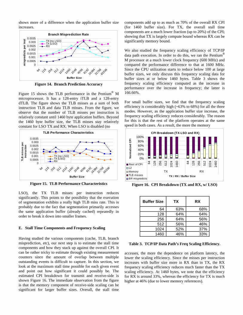
shows more of a difference when the application buffer size increases.
Branch Misprediction Rate
00.0005
0.0010.0015
0.0020.0025
0.0030.0035
64 128
256
512
1024
1460
2048
4096
8192
1638
432
768
6553
6
Buffer Size
mis
pred
icts
per
inst TX (no LSO)
TX (LSO)RX
Figure 14. Branch Prediction Accuracy
Figure 15 shows the TLB performance in the Pentium® M microprocessor. It has a 128-entry iTLB and a 128-entry dTLB. The figure shows the TLB misses as a sum of both instruction TLB and data TLB misses. From the figure, we observe that the number of TLB misses per instruction is relatively constant until 1460 byte application buffers. Beyond the 1460 byte buffer size, the TLB misses stay relatively constant for LSO TX and RX. When LSO is disabled (no
TLB Performance Characteristics
00.0005
0.0010.0015
0.0020.0025
0.0030.0035
64 128
256
512
1024
1460
2048
4096
8192
1638
432
768
6553
6
Buffer Size
TLB
mis
ses
per
inst
ruct
ion
TX (no LSO)TX (LSO)RX
Figure 15. TLB Performance Characteristics
LSO), the TX TLB misses per instruction reduces significantly. This points to the possibility that the execution of segmentation exhibits a really high TLB miss rate. This is probably due to the fact that segmentation primarily accesses the same application buffer (already cached) repeatedly in order to break it down into smaller frames.
E. Stall Time Components and Frequency Scaling Having studied the various components (cache, TLB, branch misprediction, etc), our next step is to estimate the stall time components and how they stack up against the overall CPI. It can be rather tricky to estimate through existing measurement counters since the amount of overlap between multiple outstanding events is difficult to capture. In this section, we look at the maximum stall time possible for each given event and point out how significant it could possibly be. The estimated CPI breakdown for transmit and receive-side is shown Figure 16. The immediate observation from the figure is that the memory component of receive-side scaling can be significant for larger buffer sizes. Overall, the stall time
components add up to as much as 70% of the overall RX CPI (for 1460 buffer size). For TX, the overall stall time components are a much lower fraction (up to 20%) of the CPI; showing that TX is largely compute bound whereas RX can be significantly memory bound. We also studied the frequency scaling efficiency of TCP/IP data path execution. In order to do this, we ran the Pentium® M processor at a much lower clock frequency (600 MHz) and compared the performance difference to that at 1600 MHz. Since the CPU utilization starts to reduce below 100 at large buffer sizes, we only discuss this frequency scaling data for buffer sizes at or below 1460 bytes. Table 3 shows the frequency scaling efficiency computed as the increase in performance over the increase in frequency; the latter is 166.66%. For small buffer sizes, we find that the frequency scaling efficiency is considerably high (~63% to 68%) for all the three modes. However, as the application buffer size increase, the frequency scaling efficiency reduces considerably. The reason for this is that the rest of the platform operates at the same speed in both cases. As a result, the more the memory
CPI Breakdown (TX-LSO and RX)
0%20%40%60%80%
100%
64 128
256
512
1024
1460 64 12
8
256
512
1024
1460
TX RXTX / RX / Buffer Size
Nor
mal
ized
CP
I
Rest of CPIL2MemoryTLB missesBR mispredicts
Figure 16. CPI Breakdown (TX and RX, w/ LSO)
Buffer Size TX RX
64 63% 68%128 64% 64%256 64% 56%512 56% 46%
1024 52% 37%1460 46% 33%
Table 3. TCP/IP Data Path’s Freq Scaling Efficiency.
accesses, the more the dependence on platform latency, the lower the scaling efficiency. Since the misses per instruction increases with buffer size more in RX than in TX, the RX frequency scaling efficiency reduces much faster than the TX scaling efficiency. At 1460 bytes, we note that the efficiency for RX is around 33%, whereas the efficiency for TX is much higher at 46% (due to lower memory references).
VI. PACKET PROCESSING IN COMMERCIAL WORKLOADS
In the previous few sections, we discussed the overall processing requirements of TCP/IP data path. To understand the network bandwidth requirements and packet processing components of server workload execution, we have chosen two commercial benchmarks (SPECweb99 [24] and TPC-C [26]) that are considered representative of front-end and back-end server applications.
A. Networking Requirements in Commercial Workloads SPECweb99 is a benchmark that mimics the load in a web server environment. The benchmark setup uses multiple client systems to generate aggregate load (70% static and 30% dynamic) to a web server. SPECweb99 also makes use of persistent connections in order to minimize connect setups and teardowns. The benchmark measures performance in terms of the number of simultaneous connections that the system under test can support. A primary requirement for SPECweb99 is that the network rate needs to be within 320Kbps and 400Kbps per connection. Based on measurement and tuning experiments in our labs, we find that the network data rate that we generally observe on a DP Xeon system is 330kbps. It should be noted that SPECweb99’s network traffic is dominant on the transmit side, with an average application buffer size (average file size) of a little over 14 Kbytes. TPC-C is an online-transaction processing (back-end) benchmark that is based on fulfilling database transactions in an order-entry environment. The purpose of using TPC-C here is to study the potential networking requirement for back-end servers that access storage devices using iSCSI protocol which is based on TCP/IP. The performance is measured in terms of transactions per minute (tpmc). The database server sends or receives data from the storage server in sizes equal to that of a physical page size (set to 8 Kbytes in our measured configurations).
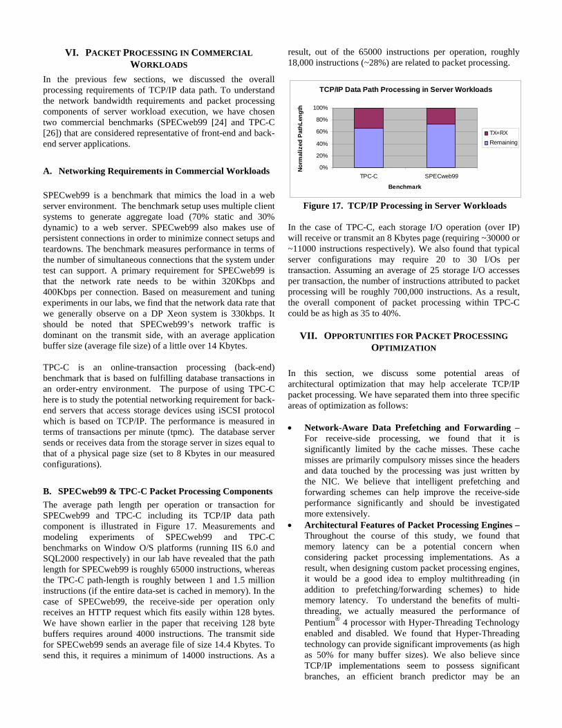
B. SPECweb99 & TPC-C Packet Processing Components The average path length per operation or transaction for SPECweb99 and TPC-C including its TCP/IP data path component is illustrated in Figure 17. Measurements and modeling experiments of SPECweb99 and TPC-C benchmarks on Window O/S platforms (running IIS 6.0 and SQL2000 respectively) in our lab have revealed that the path length for SPECweb99 is roughly 65000 instructions, whereas the TPC-C path-length is roughly between 1 and 1.5 million instructions (if the entire data-set is cached in memory). In the case of SPECweb99, the receive-side per operation only receives an HTTP request which fits easily within 128 bytes. We have shown earlier in the paper that receiving 128 byte buffers requires around 4000 instructions. The transmit side for SPECweb99 sends an average file of size 14.4 Kbytes. To send this, it requires a minimum of 14000 instructions. As a
result, out of the 65000 instructions per operation, roughly 18,000 instructions (~28%) are related to packet processing.
TCP/IP Data Path Processing in Server Workloads
0%
20%
40%
60%
80%
100%
TPC-C SPECweb99
Benchmark
Nor
mal
ized
Pat
hLen
gth
TX+RXRemaining
Figure 17. TCP/IP Processing in Server Workloads
In the case of TPC-C, each storage I/O operation (over IP) will receive or transmit an 8 Kbytes page (requiring ~30000 or ~11000 instructions respectively). We also found that typical server configurations may require 20 to 30 I/Os per transaction. Assuming an average of 25 storage I/O accesses per transaction, the number of instructions attributed to packet processing will be roughly 700,000 instructions. As a result, the overall component of packet processing within TPC-C could be as high as 35 to 40%.
VII. OPPORTUNITIES FOR PACKET PROCESSING OPTIMIZATION
In this section, we discuss some potential areas of architectural optimization that may help accelerate TCP/IP packet processing. We have separated them into three specific areas of optimization as follows: • Network-Aware Data Prefetching and Forwarding –
For receive-side processing, we found that it is significantly limited by the cache misses. These cache misses are primarily compulsory misses since the headers and data touched by the processing was just written by the NIC. We believe that intelligent prefetching and forwarding schemes can help improve the receive-side performance significantly and should be investigated more extensively.
• Architectural Features of Packet Processing Engines – Throughout the course of this study, we found that memory latency can be a potential concern when considering packet processing implementations. As a result, when designing custom packet processing engines, it would be a good idea to employ multithreading (in addition to prefetching/forwarding schemes) to hide memory latency. To understand the benefits of multi-threading, we actually measured the performance of Pentium® 4 processor with Hyper-Threading Technology enabled and disabled. We found that Hyper-Threading technology can provide significant improvements (as high as 50% for many buffer sizes). We also believe since TCP/IP implementations seem to possess significant branches, an efficient branch predictor may be an
important requirement. Other aspects include efficient DMA, light-weight interrupts and light-weight context switching.
VIII. CONCLUSIONS AND FUTURE WORK In this paper, we presented a detailed analysis of TCP/IP data path performance. We accomplished this through detailed measurements on a state-of-the-art low power Intel’s Pentium® M microprocessor. We also used the performance monitoring events on the Pentium® M processor to understand the architectural characteristics of TCP/IP packet processing. We first showed that TCP/IP packet processing performance in terms of CPU utilization and throughput across several modes of operation. We then concentrated on a commonly used mode of operation and showed how the architectural characteristics change with increasing buffer size. We discussed the performance characteristics by studying CPI, path length, cache performance, TLB performance and branch mis-prediction rates. We showed that transmit performance is largely compute bound, whereas receive throughput is largely memory bound. Finally, we presented an estimated breakdown of the CPI in terms of the components mentioned above. We related the path length required for packet processing to the overall path length required for each transaction (or operation) in a commercial server workload (TPC-C and SPECweb99). We showed that up to 40% of TPC-C and 28% of SPECweb99 may constitute TCP/IP packet processing. This provides a good idea of the potential benefits of TCP/IP data path offload. Finally, we touched upon three areas of packet processing optimization opportunities. Future work in this area is multi-fold. We plan to study the performance characteristics of connection management (set-ups and teardowns) also. We plan to accomplish this by modifying a traffic generator that we built called GEIST [14]. Finally, we would also like to quantify the amount of packet processing in several other real-world server workloads. We are also experimenting with prototype implementations of TCP/IP offloading based on ETA [20].
ACKNOWLEDGEMENTS We would like to express our thanks to Michael Espig for providing us the necessary system infrastructure to be able to performance these measurements. We would also like to thank Dave Minturn and Ramesh Illikkal for their insight into the TCP/IP protocol stacks and other members of our team for their helpful input on this study.
NOTICES ® is a trademark or registered trademark of Intel Corporation or its subsidiaries in the United States and other countries.
* Other names and brands may be claimed as the property of others.
REFERENCES [1] “Alacritech SLIC: A Data Path TCP Offload
methodology”, http://www.alacritech.com/html/techreview.html
[2] J. Chase et. al., “End System Optimizations for High-Speed TCP”, IEEE Communications, Special Issue on High-Speed TCP, June 2000.
[3] D. Clark et. al., “An analysis of TCP Processing overhead”, IEEE Communications, June 1989.
[4] D. Clark et. al., “Architectural Considerations for a new generation of Protocols”, ACM SIGCOMM, September 1990.
[5] A. Earls, “TCP Offload Engines Finally Arrive”, Storage Magazine, March 2002.
[6] A. Foong et al., “TCP Performance Analysis Re-visited,” IEEE International Symposium on Performance Analysis of Software and Systems, March 2003.
[7] S. Gochman, et al., “The Intel® Pentium® M Processor: Microarchitecture and Performance.” Intel Technology Journal. http://developer.intel.com/technology/itj/, May 2003.
[8] “High Performance Network Adapters and Drivers in Windows”, http://www.microsoft.com/hwdec/tech/, Dec 2001.
[9] Y. Hoskote, et al., “A 10GHz TCP Offload Accelerator for 10Gb/s Ethernet in 90nm Dual-Vt CMOS,” IEEE International Solid-State Circuits Conference (ISSCC), San Francisco, 2003.
[10] iSCSI, IP Storage Working Group, Internet Draft, available at http://www.ietf.org/internet-drafts/draft-ietf-ips-iscsi-20.txt
[11] R. Iyer, “CASPER: Cache Architecture Simulation and Performance Exploration using Refstreams”, Intel Design and Test Technology Conference (DTTC), July 2002.
[12] R. Iyer, “On Modeling and Analyzing Cache Hierarchies using CASPER”, 11th IEEE/ACM Symposium on Modeling, Analysis and Simulation of Computer and Telecom Systems, Oct 2003.
[13] K. Kant, “TCP offload performance for front-end servers,” to appear in Globecom, San Francisco, 2003.
[14] K. Kant, V. Tewari and R. Iyer, “GEIST – A Generator for E-commerce and Internet Server Traffic,” 2001 IEEE International Symposium on Performance Analysis of Systems and Software (ISPASS), Oct 2001
[15] H. Kim, V. Pai and S. Rixner, “Increasing Web Server Throughput with Network Interface Data Caching,” Int’l Conference on Architectural Support for Programming Languages and Operating Systems (ASPLOS), Oct, 2002.
[16] D. McConnell, “IP Storage: A Technology Overview”, http://www.dell.com/us/en/biz/topics/vectors_2001-ipstorage.htm
[17] J. Mogul, “TCP offload is a dumb idea whose time has come,” A Symposium on Hot Operating Systems (HOT OS), 2003.
[18] J. B. Postel, “Transmission Control Protocol”, RFC 793, Information Sciences Institute, Sept. 1981.
[19] M. Rangarajan et al., “TCP Servers: Offloading TCP/IP Processing in Internet Servers. Design, Implementation, and Performance,” Rutgers University, Department of Computer Science Technical Report, DCS-TR-481, March 2002.
[20] G. Regnier et al., “ETA: Experience with an Intel Xeon Processor as a Packet Processing Engine,” A Symposium on High Performance Interconnects (HOT Interconnects), 2003.
[21] RDMA Consortium. http://www.rdmaconsortium.org. [22] Remote Direct Data Placement Working Group.
http://www.ietf.org/html.charters/rddp-charter.html. [23] P. Sarkar, et al., “Storage over IP: Does hardware support
help?” In Proc. 2nd USENIX Conf. on File and Storage Technologies, pages 231-244, San Francisco, CA, March 2003.
[24] “SPECweb99 Design Document”, available online at http://www.specbench.org/osg/web99/docs/whitepaper.html
[25] “The TTTCP Benchmark”, http://ftp.arl.mil/~mike/ttcp.html
[26] “TPC-C Design Document”, available online on the TPC website at www.tpc.org/tpcc/