Embed Size (px)
Citation preview
Triconex Ethernet Driver
© 2021 PTC Inc. All Rights Reserved.
Triconex Ethernet Driver
Table of Contents
Triconex Ethernet Driver 1
Table of Contents 2
Triconex Ethernet Driver 4
Overview 4
Setup 5
Channel Properties — General 5
Channel Properties — Write Optimizations 6
Channel Properties — Advanced 7
Channel Properties — Network Interface 8
Device Properties — General 8
Operating Mode 9
Device Properties — Scan Mode 10
Device Properties — Timing 11
Device Properties — Auto-Demotion 12
Device Properties — Tag Generation 12
Device Properties — CM Configuration 14
Device Properties — Communications 15
Device Properties — Tag Import 16
Network Redundancy 17
Optimizing Communications 19
Automatic Tag Database Generation 21
Data Types Description 22
Address Descriptions 23
Tricon Addressing 23
Tricon Extended Addressing 25
Trident Addressing 28
Device System Tags 30
Error Descriptions 31
Address '<address>' is out of range for the specified device or register 32
Data Type '<type>' is not valid for device address '<address>' 32
Device address '<address>' contains a syntax error 32
Device address '<address>' is not supported by model '<model name>' 32
Device address '<address>' is Read Only 32
Missing address 33
Could not detect available network adapters for <primary/secondary> network 33
www.ptc.com
2
Triconex Ethernet Driver
Device '<device name>' is not responding 33
Failed to load Winsock or related library 34
Tag import error - invalid bin in item path: '<item path>' 34
Tag import error - invalid item path format\: '<item path>' 34
Tag import error - invalid name: '<tag name>' 34
Tag import error - invalid offset in item path: '<item path>' 35
Tag import failed. Could not find data for node '<node>' 35
Tag import failed. Could not open file '<file>' 35
Tag import failed due to unexpected XML format in '<file>' 36
Tag import failed. No import file name or system tags specified 36
Unable to process data update on device '<device>'. CRC error 36
Unable to process data update on device '<device>'. Unexpected message format 37
Unable to process data update on device '<device>'. Unexpected model 37
Unable to process data update on device '<device>'. Unexpected node number 37
Unable to use network redundancy on channel '<channel>' 37
Unable to use specified primary network adapter '<adapter>' on channel '<channel>' 38
Unable to use specified secondary network adapter '<adapter>' on channel '<channel>' 38
Winsock initialization failed (OS Error = <error code>) 39
Winsock V1.1 or higher must be installed to use the Triconex Ethernet device driver 39
Write failed for tag '<address>' on device '<device>'. CRC error 39
Write failed for tag '<address>' on device '<device>'. No data for Read/Modify/Write 40
Write failed for tag '<address>' on device '<device>'. Timeout 40
Write failed for tag '<address>' on device '<device>'. TSAA Response Code: <code> 40
Write failed for tag '<address>' on device '<device>'. Unexpected model 41
Write failed for tag '<address>' on device '<device>'. Unexpected node number 41
Write failed for tag '<address>' on device '<device>'. Unexpected response format 42
Index 43
www.ptc.com
3
Triconex Ethernet Driver
Triconex Ethernet DriverHelp version 1.021
CONTENTS
OverviewWhat is the Triconex Ethernet Driver?
SetupHow do I configure a device for use with this driver?
Network RedundancyHow can I use a redundant network with this driver?
Optimizing Communicat ionsHow can I configure this driver for optimum performance?
Automat ic Tag Database Generat ionHow can I import tags from a Triconex TriStation project?
Data Types Descript ionWhat data types does this driver support?
Address Descript ionsHow do I address a data location on a Triconex Ethernet device?
Error Descript ionsWhat error messages does the Triconex Ethernet Driver produce?
OverviewThe Triconex Ethernet Driver provides an easy and reliable way to connect Triconex Ethernet devices to OPC
Client applications, including HMI, SCADA, Historian, MES, ERP and countless custom applications. It is inten-
ded for use with Triconex Tricon and Trident devices equipped with Ethernet communications modules. Net-
work redundancy is supported.
www.ptc.com
4
Triconex Ethernet Driver
Setup
Supported DevicesTriconTrident
Communication ProtocolTriconex System Access Application (TSAA)
Channel and Device LimitsThe maximum number of channels supported by this driver is 32. The maximum number of devices sup-
ported by this driver is 31 per channel.
Request TimeoutThis property specifies the number of milliseconds that the driver will wait for a response before retrying.
Users may specify a request timeout between 100 to 30000 milliseconds. For this driver, request timeouts
only apply to Write operations. The device may take up to four scan cycles to complete a Write request. The
controller may be programmed to use a scan period as large as 400 milliseconds. Setting the request
timeout too low may cause the driver to assume a write has failed when it hasn't been processed by the con-
troller yet. Available in the Timing properties group.
Note: Data is read from cache, which is updated at a regular interval. For more information, refer to Com-
munications.
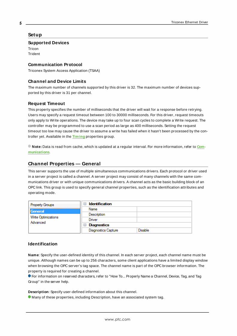
Channel Propert ies — GeneralThis server supports the use of multiple simultaneous communications drivers. Each protocol or driver used
in a server project is called a channel. A server project may consist of many channels with the same com-
munications driver or with unique communications drivers. A channel acts as the basic building block of an
OPC link. This group is used to specify general channel properties, such as the identification attributes and
operating mode.
Identification
Name: Specify the user-defined identity of this channel. In each server project, each channel name must be
unique. Although names can be up to 256 characters, some client applications have a limited display window
when browsing the OPC server's tag space. The channel name is part of the OPC browser information. The
property is required for creating a channel.For information on reserved characters, refer to "How To... Properly Name a Channel, Device, Tag, and Tag
Group" in the server help.
Description: Specify user-defined information about this channel.
Many of these properties, including Description, have an associated system tag.
www.ptc.com
5
Triconex Ethernet Driver
Driver: Specify the protocol / driver for this channel. This property specifies the device driver that was selec-
ted during channel creation. It is a disabled setting in the channel properties. The property is required for cre-
ating a channel.Note: With the server's online full-time operation, these properties can be changed at any time. This
includes changing the channel name to prevent clients from registering data with the server. If a client has
already acquired an item from the server before the channel name is changed, the items are unaffected. If,
after the channel name has been changed, the client application releases the item and attempts to re-
acquire using the old channel name, the item is not accepted. Changes to the properties should not be made
once a large client application has been developed. Utilize proper user role and privilege management to
prevent operators from changing properties or accessing server features.
Diagnostics
Diagnostics Capture: When enabled, this option makes the channel's diagnostic information available to
OPC applications. Because the server's diagnostic features require a minimal amount of overhead pro-
cessing, it is recommended that they be utilized when needed and disabled when not. The default is dis-
abled.Note: This property is not available if the driver does not support diagnostics.For more information, refer to "Communication Diagnostics" and "Statistics Tags" in the server help.
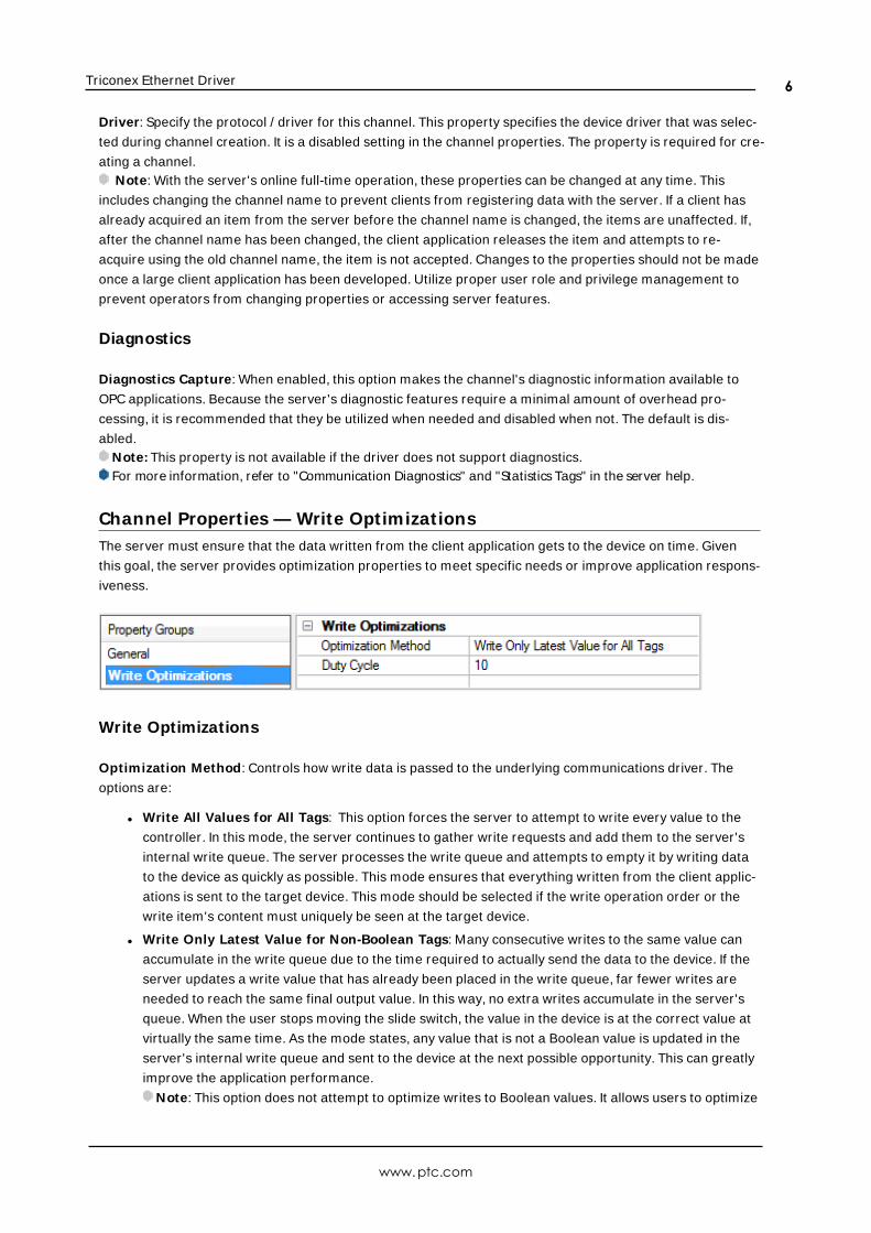
Channel Propert ies — Write OptimizationsThe server must ensure that the data written from the client application gets to the device on time. Given
this goal, the server provides optimization properties to meet specific needs or improve application respons-
iveness.
Write Optimizations
Optimization Method: Controls how write data is passed to the underlying communications driver. The
options are:
l Write All Values for All Tags: This option forces the server to attempt to write every value to the
controller. In this mode, the server continues to gather write requests and add them to the server's
internal write queue. The server processes the write queue and attempts to empty it by writing data
to the device as quickly as possible. This mode ensures that everything written from the client applic-
ations is sent to the target device. This mode should be selected if the write operation order or the
write item's content must uniquely be seen at the target device.
l Write Only Latest Value for Non-Boolean Tags: Many consecutive writes to the same value can
accumulate in the write queue due to the time required to actually send the data to the device. If the
server updates a write value that has already been placed in the write queue, far fewer writes are
needed to reach the same final output value. In this way, no extra writes accumulate in the server's
queue. When the user stops moving the slide switch, the value in the device is at the correct value at
virtually the same time. As the mode states, any value that is not a Boolean value is updated in the
server's internal write queue and sent to the device at the next possible opportunity. This can greatly
improve the application performance.
Note: This option does not attempt to optimize writes to Boolean values. It allows users to optimize
www.ptc.com
6
Triconex Ethernet Driver
the operation of HMI data without causing problems with Boolean operations, such as a momentary
push button.
l Write Only Latest Value for All Tags: This option takes the theory behind the second optimization
mode and applies it to all tags. It is especially useful if the application only needs to send the latest
value to the device. This mode optimizes all writes by updating the tags currently in the write queue
before they are sent. This is the default mode.
Duty Cycle: is used to control the ratio of write to read operations. The ratio is always based on one read for
every one to ten writes. The duty cycle is set to ten by default, meaning that ten writes occur for each read
operation. Although the application is performing a large number of continuous writes, it must be ensured
that read data is still given time to process. A setting of one results in one read operation for every write
operation. If there are no write operations to perform, reads are processed continuously. This allows optim-
ization for applications with continuous writes versus a more balanced back and forth data flow.Note: It is recommended that the application be characterized for compatibility with the write optimization
enhancements before being used in a production environment.
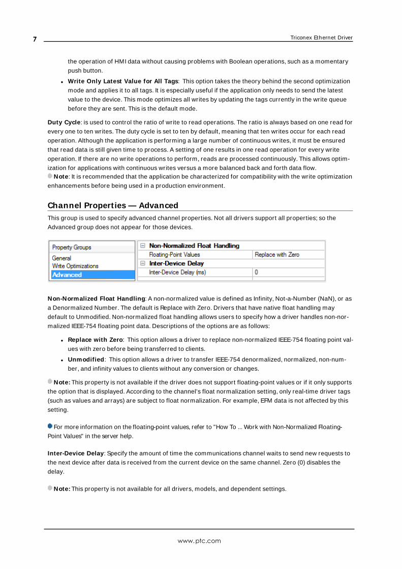
Channel Propert ies — AdvancedThis group is used to specify advanced channel properties. Not all drivers support all properties; so the
Advanced group does not appear for those devices.
Non-Normalized Float Handling: A non-normalized value is defined as Infinity, Not-a-Number (NaN), or as
a Denormalized Number. The default is Replace with Zero. Drivers that have native float handling may
default to Unmodified. Non-normalized float handling allows users to specify how a driver handles non-nor-
malized IEEE-754 floating point data. Descriptions of the options are as follows:
l Replace with Zero: This option allows a driver to replace non-normalized IEEE-754 floating point val-
ues with zero before being transferred to clients.
l Unmodified: This option allows a driver to transfer IEEE-754 denormalized, normalized, non-num-
ber, and infinity values to clients without any conversion or changes.
Note: This property is not available if the driver does not support floating-point values or if it only supports
the option that is displayed. According to the channel's float normalization setting, only real-time driver tags
(such as values and arrays) are subject to float normalization. For example, EFM data is not affected by this
setting.
For more information on the floating-point values, refer to "How To ... Work with Non-Normalized Floating-
Point Values" in the server help.
Inter-Device Delay: Specify the amount of time the communications channel waits to send new requests to
the next device after data is received from the current device on the same channel. Zero (0) disables the
delay.
Note: This property is not available for all drivers, models, and dependent settings.
www.ptc.com
7
Triconex Ethernet Driver
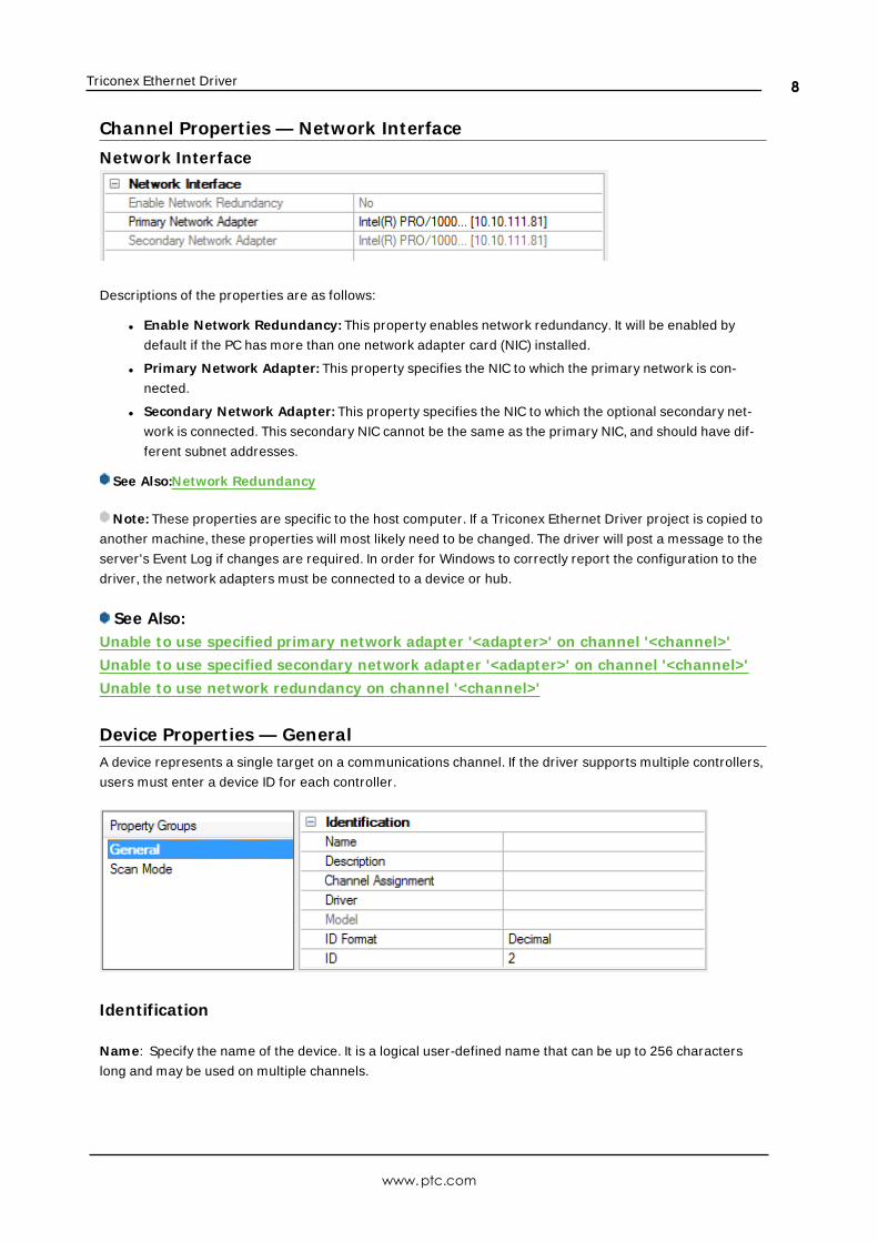
Channel Propert ies — Network Interface
Network Interface
Descriptions of the properties are as follows:
l Enable Network Redundancy: This property enables network redundancy. It will be enabled by
default if the PC has more than one network adapter card (NIC) installed.
l Primary Network Adapter: This property specifies the NIC to which the primary network is con-
nected.
l Secondary Network Adapter: This property specifies the NIC to which the optional secondary net-
work is connected. This secondary NIC cannot be the same as the primary NIC, and should have dif-
ferent subnet addresses.
See Also:Network Redundancy
Note: These properties are specific to the host computer. If a Triconex Ethernet Driver project is copied to
another machine, these properties will most likely need to be changed. The driver will post a message to the
server's Event Log if changes are required. In order for Windows to correctly report the configuration to the
driver, the network adapters must be connected to a device or hub.
See Also:Unable to use specified primary network adapter '<adapter>' on channel '<channel>'
Unable to use specified secondary network adapter '<adapter>' on channel '<channel>'
Unable to use network redundancy on channel '<channel>'
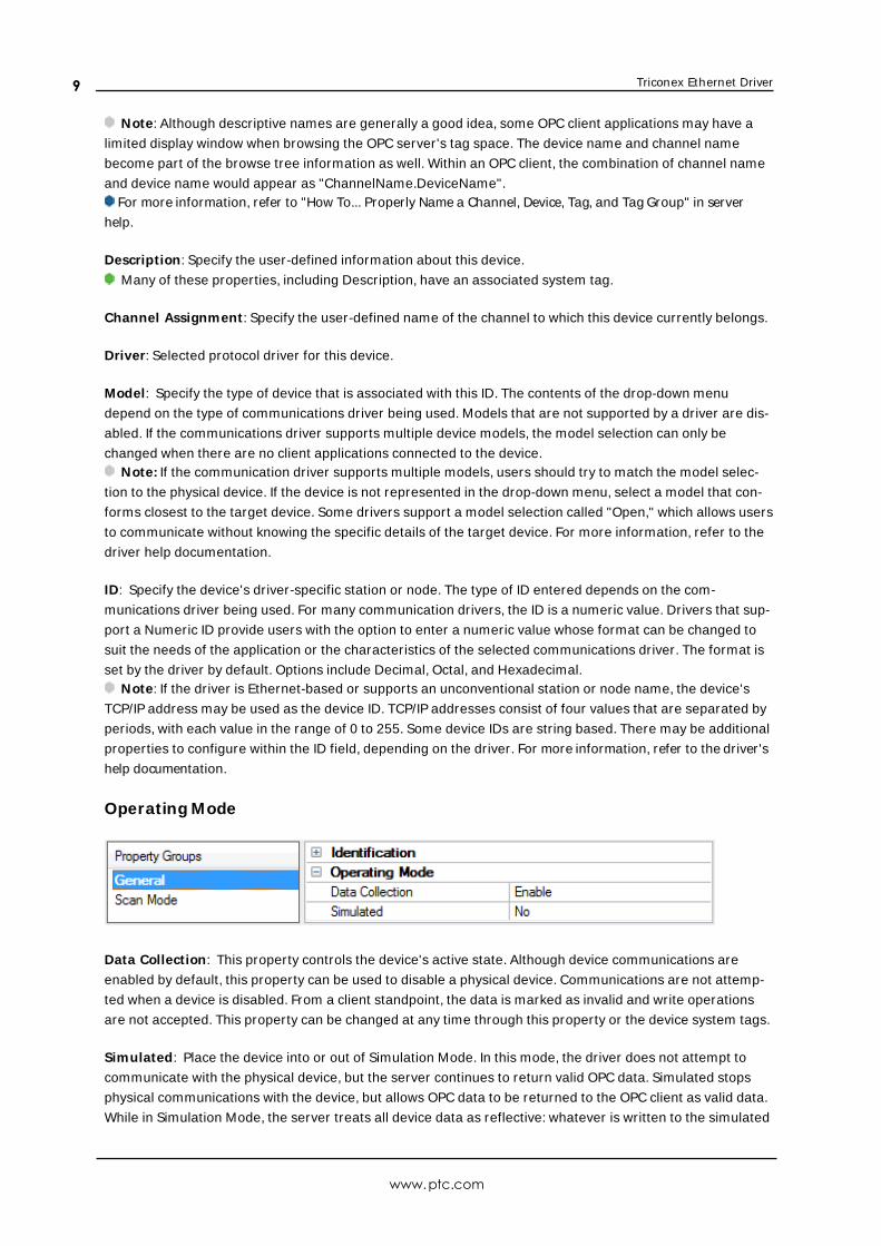
Device Propert ies — GeneralA device represents a single target on a communications channel. If the driver supports multiple controllers,
users must enter a device ID for each controller.
Identification
Name: Specify the name of the device. It is a logical user-defined name that can be up to 256 characters
long and may be used on multiple channels.
www.ptc.com
8
Triconex Ethernet Driver
Note: Although descriptive names are generally a good idea, some OPC client applications may have a
limited display window when browsing the OPC server's tag space. The device name and channel name
become part of the browse tree information as well. Within an OPC client, the combination of channel name
and device name would appear as "ChannelName.DeviceName".For more information, refer to "How To... Properly Name a Channel, Device, Tag, and Tag Group" in server
help.
Description: Specify the user-defined information about this device.
Many of these properties, including Description, have an associated system tag.
Channel Assignment : Specify the user-defined name of the channel to which this device currently belongs.
Driver: Selected protocol driver for this device.
Model: Specify the type of device that is associated with this ID. The contents of the drop-down menu
depend on the type of communications driver being used. Models that are not supported by a driver are dis-
abled. If the communications driver supports multiple device models, the model selection can only be
changed when there are no client applications connected to the device.Note: If the communication driver supports multiple models, users should try to match the model selec-
tion to the physical device. If the device is not represented in the drop-down menu, select a model that con-
forms closest to the target device. Some drivers support a model selection called "Open," which allows users
to communicate without knowing the specific details of the target device. For more information, refer to the
driver help documentation.
ID: Specify the device's driver-specific station or node. The type of ID entered depends on the com-
munications driver being used. For many communication drivers, the ID is a numeric value. Drivers that sup-
port a Numeric ID provide users with the option to enter a numeric value whose format can be changed to
suit the needs of the application or the characteristics of the selected communications driver. The format is
set by the driver by default. Options include Decimal, Octal, and Hexadecimal.Note: If the driver is Ethernet-based or supports an unconventional station or node name, the device's
TCP/IP address may be used as the device ID. TCP/IP addresses consist of four values that are separated by
periods, with each value in the range of 0 to 255. Some device IDs are string based. There may be additional
properties to configure within the ID field, depending on the driver. For more information, refer to the driver's
help documentation.
Operating Mode
Data Collection: This property controls the device's active state. Although device communications are
enabled by default, this property can be used to disable a physical device. Communications are not attemp-
ted when a device is disabled. From a client standpoint, the data is marked as invalid and write operations
are not accepted. This property can be changed at any time through this property or the device system tags.
Simulated: Place the device into or out of Simulation Mode. In this mode, the driver does not attempt to
communicate with the physical device, but the server continues to return valid OPC data. Simulated stops
physical communications with the device, but allows OPC data to be returned to the OPC client as valid data.
While in Simulation Mode, the server treats all device data as reflective: whatever is written to the simulated
www.ptc.com
9
Triconex Ethernet Driver
device is read back and each OPC item is treated individually. The item's memory map is based on the group
Update Rate. The data is not saved if the server removes the item (such as when the server is reinitialized).
The default is No.Notes:
1. This System tag (_Simulated) is read only and cannot be written to for runtime protection. The System
tag allows this property to be monitored from the client.
2. In Simulation mode, the item's memory map is based on client update rate(s) (Group Update Rate for
OPC clients or Scan Rate for native and DDE interfaces). This means that two clients that reference
the same item with different update rates return different data.
Simulation Mode is for test and simulation purposes only. It should never be used in a production envir-
onment.
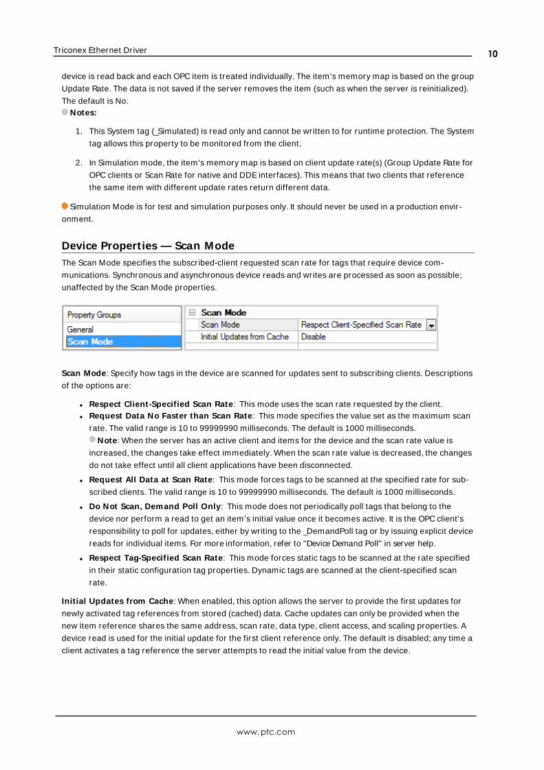
Device Propert ies — Scan ModeThe Scan Mode specifies the subscribed-client requested scan rate for tags that require device com-
munications. Synchronous and asynchronous device reads and writes are processed as soon as possible;
unaffected by the Scan Mode properties.
Scan Mode: Specify how tags in the device are scanned for updates sent to subscribing clients. Descriptions
of the options are:
l Respect Client-Specified Scan Rate: This mode uses the scan rate requested by the client.l Request Data No Faster than Scan Rate: This mode specifies the value set as the maximum scan
rate. The valid range is 10 to 99999990 milliseconds. The default is 1000 milliseconds.
Note: When the server has an active client and items for the device and the scan rate value is
increased, the changes take effect immediately. When the scan rate value is decreased, the changes
do not take effect until all client applications have been disconnected.
l Request All Data at Scan Rate: This mode forces tags to be scanned at the specified rate for sub-
scribed clients. The valid range is 10 to 99999990 milliseconds. The default is 1000 milliseconds.
l Do Not Scan, Demand Poll Only: This mode does not periodically poll tags that belong to the
device nor perform a read to get an item's initial value once it becomes active. It is the OPC client's
responsibility to poll for updates, either by writing to the _DemandPoll tag or by issuing explicit device
reads for individual items. For more information, refer to "Device Demand Poll" in server help.
l Respect Tag-Specified Scan Rate: This mode forces static tags to be scanned at the rate specified
in their static configuration tag properties. Dynamic tags are scanned at the client-specified scan
rate.
Initial Updates from Cache: When enabled, this option allows the server to provide the first updates for
newly activated tag references from stored (cached) data. Cache updates can only be provided when the
new item reference shares the same address, scan rate, data type, client access, and scaling properties. A
device read is used for the initial update for the first client reference only. The default is disabled; any time a
client activates a tag reference the server attempts to read the initial value from the device.
www.ptc.com
10
Triconex Ethernet Driver
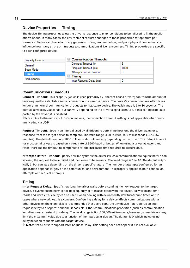
Device Propert ies — TimingThe device Timing properties allow the driver's response to error conditions to be tailored to fit the applic-
ation's needs. In many cases, the environment requires changes to these properties for optimum per-
formance. Factors such as electrically generated noise, modem delays, and poor physical connections can
influence how many errors or timeouts a communications driver encounters. Timing properties are specific
to each configured device.
Communications TimeoutsConnect Timeout : This property (which is used primarily by Ethernet based drivers) controls the amount of
time required to establish a socket connection to a remote device. The device's connection time often takes
longer than normal communications requests to that same device. The valid range is 1 to 30 seconds. The
default is typically 3 seconds, but can vary depending on the driver's specific nature. If this setting is not sup-
ported by the driver, it is disabled.Note: Due to the nature of UDP connections, the connection timeout setting is not applicable when com-
municating via UDP.
Request Timeout : Specify an interval used by all drivers to determine how long the driver waits for a
response from the target device to complete. The valid range is 50 to 9,999,999 milliseconds (167.6667
minutes). The default is usually 1000 milliseconds, but can vary depending on the driver. The default timeout
for most serial drivers is based on a baud rate of 9600 baud or better. When using a driver at lower baud
rates, increase the timeout to compensate for the increased time required to acquire data.
Attempts Before Timeout : Specify how many times the driver issues a communications request before con-
sidering the request to have failed and the device to be in error. The valid range is 1 to 10. The default is typ-
ically 3, but can vary depending on the driver's specific nature. The number of attempts configured for an
application depends largely on the communications environment. This property applies to both connection
attempts and request attempts.
TimingInter-Request Delay: Specify how long the driver waits before sending the next request to the target
device. It overrides the normal polling frequency of tags associated with the device, as well as one-time
reads and writes. This delay can be useful when dealing with devices with slow turnaround times and in
cases where network load is a concern. Configuring a delay for a device affects communications with all
other devices on the channel. It is recommended that users separate any device that requires an inter-
request delay to a separate channel if possible. Other communications properties (such as communication
serialization) can extend this delay. The valid range is 0 to 300,000 milliseconds; however, some drivers may
limit the maximum value due to a function of their particular design. The default is 0, which indicates no
delay between requests with the target device.Note: Not all drivers support Inter-Request Delay. This setting does not appear if it is not available.
www.ptc.com
11
Triconex Ethernet Driver
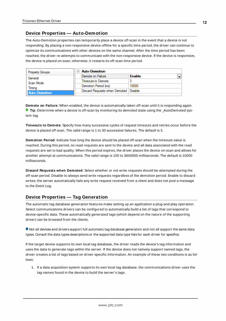
Device Propert ies — Auto-DemotionThe Auto-Demotion properties can temporarily place a device off-scan in the event that a device is not
responding. By placing a non-responsive device offline for a specific time period, the driver can continue to
optimize its communications with other devices on the same channel. After the time period has been
reached, the driver re-attempts to communicate with the non-responsive device. If the device is responsive,
the device is placed on-scan; otherwise, it restarts its off-scan time period.
Demote on Failure: When enabled, the device is automatically taken off-scan until it is responding again.Tip: Determine when a device is off-scan by monitoring its demoted state using the _AutoDemoted sys-
tem tag.
Timeouts to Demote: Specify how many successive cycles of request timeouts and retries occur before the
device is placed off-scan. The valid range is 1 to 30 successive failures. The default is 3.
Demotion Period: Indicate how long the device should be placed off-scan when the timeouts value is
reached. During this period, no read requests are sent to the device and all data associated with the read
requests are set to bad quality. When this period expires, the driver places the device on-scan and allows for
another attempt at communications. The valid range is 100 to 3600000 milliseconds. The default is 10000
milliseconds.
Discard Requests when Demoted: Select whether or not write requests should be attempted during the
off-scan period. Disable to always send write requests regardless of the demotion period. Enable to discard
writes; the server automatically fails any write request received from a client and does not post a message
to the Event Log.
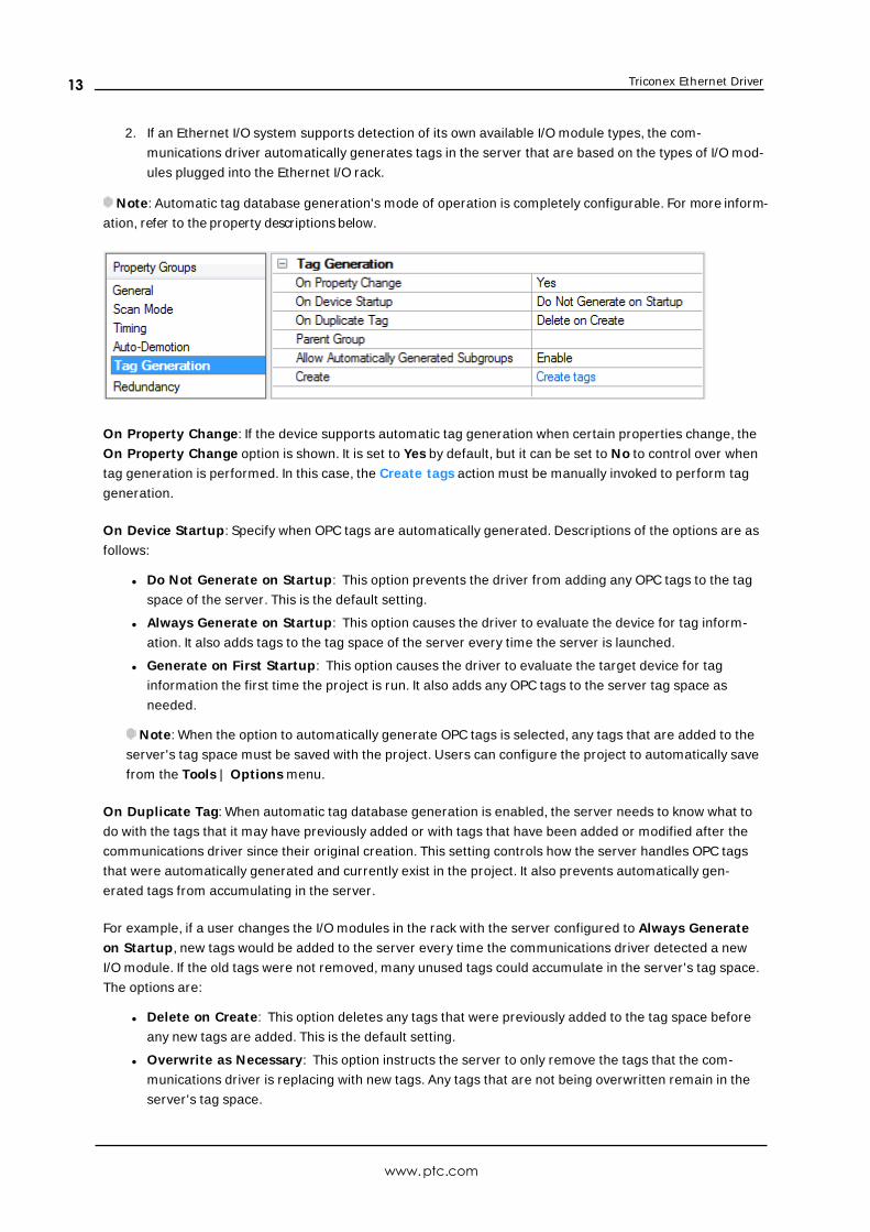
Device Propert ies — Tag GenerationThe automatic tag database generation features make setting up an application a plug-and-play operation.
Select communications drivers can be configured to automatically build a list of tags that correspond to
device-specific data. These automatically generated tags (which depend on the nature of the supporting
driver) can be browsed from the clients.
Not all devices and drivers support full automatic tag database generation and not all support the same data
types. Consult the data types descriptions or the supported data type lists for each driver for specifics.
If the target device supports its own local tag database, the driver reads the device's tag information and
uses the data to generate tags within the server. If the device does not natively support named tags, the
driver creates a list of tags based on driver-specific information. An example of these two conditions is as fol-
lows:
1. If a data acquisition system supports its own local tag database, the communications driver uses the
tag names found in the device to build the server's tags.
www.ptc.com
12
Triconex Ethernet Driver
2. If an Ethernet I/O system supports detection of its own available I/O module types, the com-
munications driver automatically generates tags in the server that are based on the types of I/O mod-
ules plugged into the Ethernet I/O rack.
Note: Automatic tag database generation's mode of operation is completely configurable. For more inform-
ation, refer to the property descriptions below.
On Property Change: If the device supports automatic tag generation when certain properties change, the
On Property Change option is shown. It is set to Yes by default, but it can be set to No to control over when
tag generation is performed. In this case, the Create tags action must be manually invoked to perform tag
generation.
On Device Startup: Specify when OPC tags are automatically generated. Descriptions of the options are as
follows:
l Do Not Generate on Startup: This option prevents the driver from adding any OPC tags to the tag
space of the server. This is the default setting.
l Always Generate on Startup: This option causes the driver to evaluate the device for tag inform-
ation. It also adds tags to the tag space of the server every time the server is launched.
l Generate on First Startup: This option causes the driver to evaluate the target device for tag
information the first time the project is run. It also adds any OPC tags to the server tag space as
needed.
Note: When the option to automatically generate OPC tags is selected, any tags that are added to the
server's tag space must be saved with the project. Users can configure the project to automatically save
from the Tools | Options menu.
On Duplicate Tag: When automatic tag database generation is enabled, the server needs to know what to
do with the tags that it may have previously added or with tags that have been added or modified after the
communications driver since their original creation. This setting controls how the server handles OPC tags
that were automatically generated and currently exist in the project. It also prevents automatically gen-
erated tags from accumulating in the server.
For example, if a user changes the I/O modules in the rack with the server configured to Always Generate
on Startup, new tags would be added to the server every time the communications driver detected a new
I/O module. If the old tags were not removed, many unused tags could accumulate in the server's tag space.
The options are:
l Delete on Create: This option deletes any tags that were previously added to the tag space before
any new tags are added. This is the default setting.
l Overwrite as Necessary: This option instructs the server to only remove the tags that the com-
munications driver is replacing with new tags. Any tags that are not being overwritten remain in the
server's tag space.
www.ptc.com
13
Triconex Ethernet Driver
l Do not Overwrite: This option prevents the server from removing any tags that were previously gen-
erated or already existed in the server. The communications driver can only add tags that are com-
pletely new.
l Do not Overwrite, Log Error: This option has the same effect as the prior option, and also posts an
error message to the server's Event Log when a tag overwrite would have occurred.
Note: Removing OPC tags affects tags that have been automatically generated by the com-
munications driver as well as any tags that have been added using names that match generated tags.
Users should avoid adding tags to the server using names that may match tags that are automatically
generated by the driver.
Parent Group: This property keeps automatically generated tags from mixing with tags that have been
entered manually by specifying a group to be used for automatically generated tags. The name of the group
can be up to 256 characters. This parent group provides a root branch to which all automatically generated
tags are added.
Allow Automatically Generated Subgroups: This property controls whether the server automatically cre-
ates subgroups for the automatically generated tags. This is the default setting. If disabled, the server gen-
erates the device's tags in a flat list without any grouping. In the server project, the resulting tags are named
with the address value. For example, the tag names are not retained during the generation process.Note: If, as the server is generating tags, a tag is assigned the same name as an existing tag, the system
automatically increments to the next highest number so that the tag name is not duplicated. For example, if
the generation process creates a tag named "AI22" that already exists, it creates the tag as "AI23" instead.
Create: Initiates the creation of automatically generated OPC tags. If the device's configuration has been
modified, Create tags forces the driver to reevaluate the device for possible tag changes. Its ability to be
accessed from the System tags allows a client application to initiate tag database creation.Note: Create tags is disabled if the Configuration edits a project offline.
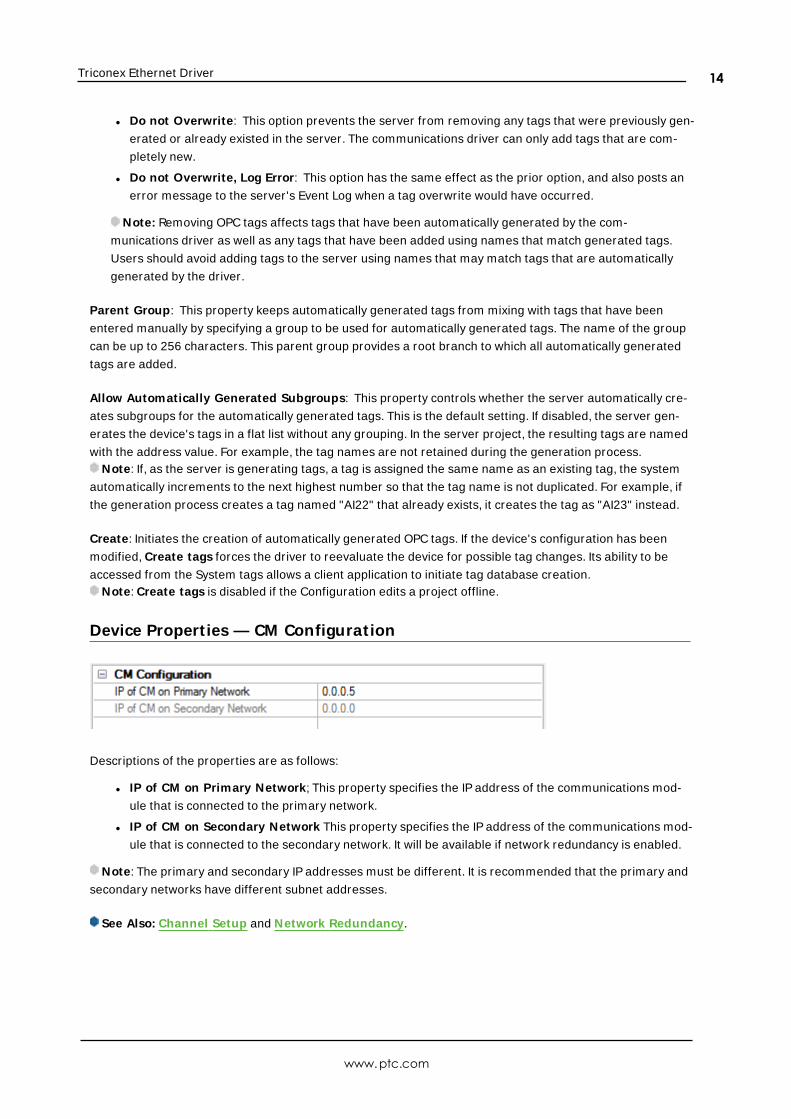
Device Propert ies — CM Configuration
Descriptions of the properties are as follows:
l IP of CM on Primary Network; This property specifies the IP address of the communications mod-
ule that is connected to the primary network.
l IP of CM on Secondary Network This property specifies the IP address of the communications mod-
ule that is connected to the secondary network. It will be available if network redundancy is enabled.
Note: The primary and secondary IP addresses must be different. It is recommended that the primary and
secondary networks have different subnet addresses.
See Also: Channel Setup and Network Redundancy.
www.ptc.com
14
Triconex Ethernet Driver
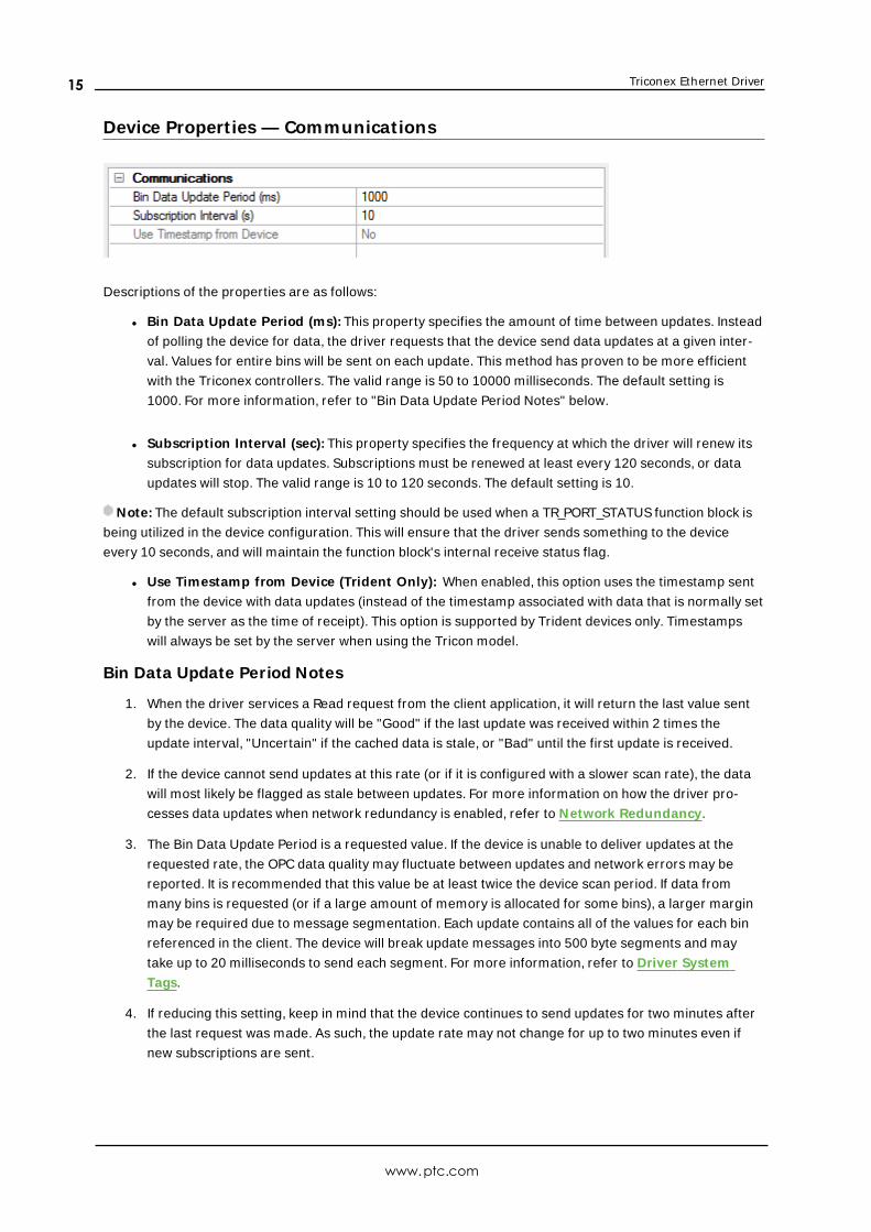
Device Propert ies — Communications
Descriptions of the properties are as follows:
l Bin Data Update Period (ms): This property specifies the amount of time between updates. Instead
of polling the device for data, the driver requests that the device send data updates at a given inter-
val. Values for entire bins will be sent on each update. This method has proven to be more efficient
with the Triconex controllers. The valid range is 50 to 10000 milliseconds. The default setting is
1000. For more information, refer to "Bin Data Update Period Notes" below.
l Subscription Interval (sec): This property specifies the frequency at which the driver will renew its
subscription for data updates. Subscriptions must be renewed at least every 120 seconds, or data
updates will stop. The valid range is 10 to 120 seconds. The default setting is 10.
Note: The default subscription interval setting should be used when a TR_PORT_STATUS function block is
being utilized in the device configuration. This will ensure that the driver sends something to the device
every 10 seconds, and will maintain the function block's internal receive status flag.
l Use Timestamp from Device (Trident Only): When enabled, this option uses the timestamp sent
from the device with data updates (instead of the timestamp associated with data that is normally set
by the server as the time of receipt). This option is supported by Trident devices only. Timestamps
will always be set by the server when using the Tricon model.
Bin Data Update Period Notes
1. When the driver services a Read request from the client application, it will return the last value sent
by the device. The data quality will be "Good" if the last update was received within 2 times the
update interval, "Uncertain" if the cached data is stale, or "Bad" until the first update is received.
2. If the device cannot send updates at this rate (or if it is configured with a slower scan rate), the data
will most likely be flagged as stale between updates. For more information on how the driver pro-
cesses data updates when network redundancy is enabled, refer to Network Redundancy.
3. The Bin Data Update Period is a requested value. If the device is unable to deliver updates at the
requested rate, the OPC data quality may fluctuate between updates and network errors may be
reported. It is recommended that this value be at least twice the device scan period. If data from
many bins is requested (or if a large amount of memory is allocated for some bins), a larger margin
may be required due to message segmentation. Each update contains all of the values for each bin
referenced in the client. The device will break update messages into 500 byte segments and may
take up to 20 milliseconds to send each segment. For more information, refer to Driver System
Tags.
4. If reducing this setting, keep in mind that the device continues to send updates for two minutes after
the last request was made. As such, the update rate may not change for up to two minutes even if
new subscriptions are sent.
www.ptc.com
15
Triconex Ethernet Driver
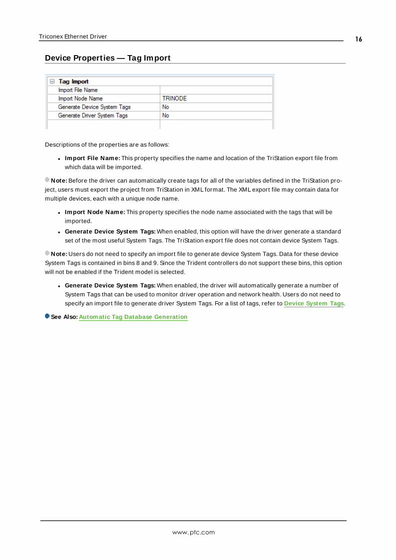
Device Propert ies — Tag Import
Descriptions of the properties are as follows:
l Import File Name: This property specifies the name and location of the TriStation export file from
which data will be imported.
Note: Before the driver can automatically create tags for all of the variables defined in the TriStation pro-
ject, users must export the project from TriStation in XML format. The XML export file may contain data for
multiple devices, each with a unique node name.
l Import Node Name: This property specifies the node name associated with the tags that will be
imported.
l Generate Device System Tags: When enabled, this option will have the driver generate a standard
set of the most useful System Tags. The TriStation export file does not contain device System Tags.
Note: Users do not need to specify an import file to generate device System Tags. Data for these device
System Tags is contained in bins 8 and 9. Since the Trident controllers do not support these bins, this option
will not be enabled if the Trident model is selected.
l Generate Device System Tags: When enabled, the driver will automatically generate a number of
System Tags that can be used to monitor driver operation and network health. Users do not need to
specify an import file to generate driver System Tags. For a list of tags, refer to Device System Tags.
See Also: Automatic Tag Database Generation
www.ptc.com
16
Triconex Ethernet Driver
Network Redundancy
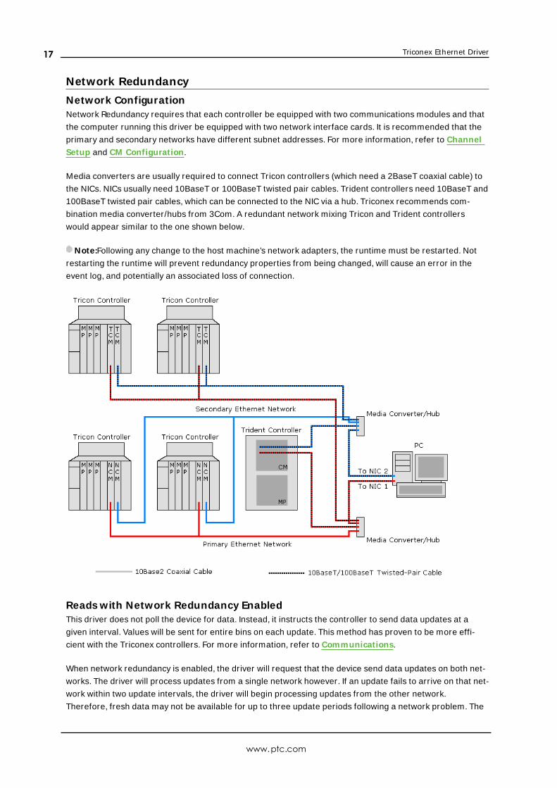
Network ConfigurationNetwork Redundancy requires that each controller be equipped with two communications modules and that
the computer running this driver be equipped with two network interface cards. It is recommended that the
primary and secondary networks have different subnet addresses. For more information, refer to Channel
Setup and CM Configuration.
Media converters are usually required to connect Tricon controllers (which need a 2BaseT coaxial cable) to
the NICs. NICs usually need 10BaseT or 100BaseT twisted pair cables. Trident controllers need 10BaseT and
100BaseT twisted pair cables, which can be connected to the NIC via a hub. Triconex recommends com-
bination media converter/hubs from 3Com. A redundant network mixing Tricon and Trident controllers
would appear similar to the one shown below.
Note:Following any change to the host machine’s network adapters, the runtime must be restarted. Not
restarting the runtime will prevent redundancy properties from being changed, will cause an error in the
event log, and potentially an associated loss of connection.
Reads with Network Redundancy EnabledThis driver does not poll the device for data. Instead, it instructs the controller to send data updates at a
given interval. Values will be sent for entire bins on each update. This method has proven to be more effi-
cient with the Triconex controllers. For more information, refer to Communications.
When network redundancy is enabled, the driver will request that the device send data updates on both net-
works. The driver will process updates from a single network however. If an update fails to arrive on that net-
work within two update intervals, the driver will begin processing updates from the other network.
Therefore, fresh data may not be available for up to three update periods following a network problem. The
www.ptc.com
17
Triconex Ethernet Driver
UpdatesFromPrimary and UpdatesFromSecondary driver System Tags can be used to monitor the network
from which the driver is processing updates.
Though the driver processes updates from a single network, it does monitor incoming traffic from both net-
works. If nothing has been received on a network for over two update periods, the driver will flag that net-
work as being in error. The PrimaryNetworkError and SecondaryNetworkError driver System Tags can be
used to monitor the network error state.
See Also: Device System Tags
Writes with Network Redundancy EnabledThe driver will send a Write request over a single network, which network will be the primary unless the
primary is known to be in error and the secondary is not. In that case, the request will go out the secondary.
If a Write acknowledgement is not received within the request timeout period, the request will be retried on
the other network. If a Write acknowledgement is still not received after another request timeout period, the
driver will send the request again to both networks. The driver will continue to retry the request on both net-
works until an acknowledgement is received or the maximum number of retry attempts have been per-
formed.
Note: The device may take up to four scan cycles to complete a write request. The controller may be pro-
grammed to use a scan period as large as 400 milliseconds. Setting the request timeout too low may cause
the driver to assume a Write has failed when it hasn't been processed by the controller yet.
www.ptc.com
18
Triconex Ethernet Driver
Optimizing CommunicationsThe Triconex Ethernet Driver has been designed to provide the best performance with the least amount of
impact on the system's overall performance. While the Triconex Ethernet Driver is fast, there are a couple of
guidelines that can be used in order to control and optimize the application and gain maximum per-
formance.
The server refers to communications protocols like Triconex Ethernet as a channel. Each channel defined in
the application represents a separate path of execution in the server. Once a channel has been defined, a
series of devices must then be defined under that channel. Each of these devices represents a single
Triconex controller from which data will be collected. While this approach to defining the application will
provide a high level of performance, it will not take advantage of the Triconex Ethernet Driver or the net-
work.
It's important to understand how the Triconex Ethernet Driver reads and writes data. This driver is unique in
the two following ways:
1. Instead of sending Read requests to the devices, the driver tells each device to send periodic data
updates whose data is then stored in cache. When the server asks the driver to read a piece of data,
the driver will return the last value stored in cache. This method is more efficient than polling for
Triconex controllers.
2. The Triconex Ethernet Driver can service Write requests to multiple devices on a channel sim-
ultaneously. The driver must, however, wait for the last Write request pending on that channel to be
completed before allowing the next set of writes to be issued (or any Reads to be performed). Since a
Triconex device can take up to 4 scan cycles to complete a Write, and the scan period can be as large
as 400 milliseconds, Writes can have a tremendous effect on overall performance.
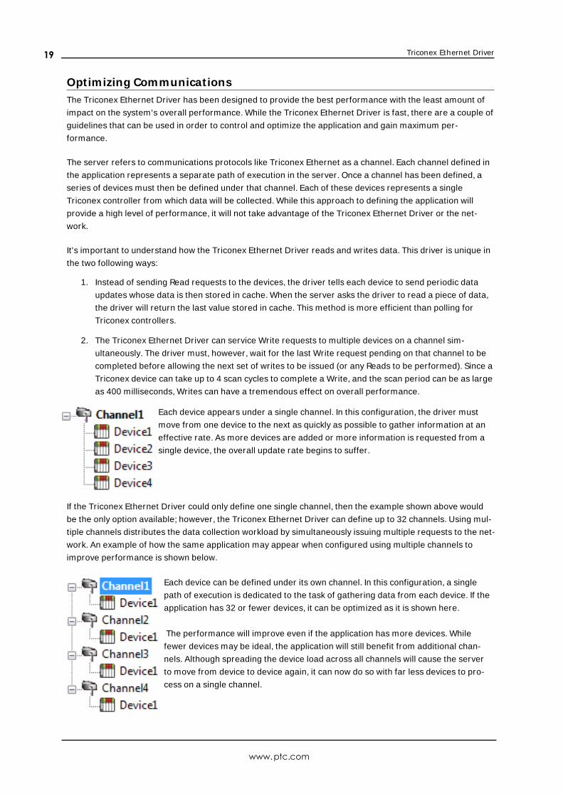
Each device appears under a single channel. In this configuration, the driver must
move from one device to the next as quickly as possible to gather information at an
effective rate. As more devices are added or more information is requested from a
single device, the overall update rate begins to suffer.
If the Triconex Ethernet Driver could only define one single channel, then the example shown above would
be the only option available; however, the Triconex Ethernet Driver can define up to 32 channels. Using mul-
tiple channels distributes the data collection workload by simultaneously issuing multiple requests to the net-
work. An example of how the same application may appear when configured using multiple channels to
improve performance is shown below.
Each device can be defined under its own channel. In this configuration, a single
path of execution is dedicated to the task of gathering data from each device. If the
application has 32 or fewer devices, it can be optimized as it is shown here.
The performance will improve even if the application has more devices. While
fewer devices may be ideal, the application will still benefit from additional chan-
nels. Although spreading the device load across all channels will cause the server
to move from device to device again, it can now do so with far less devices to pro-
cess on a single channel.
www.ptc.com
19

Triconex Ethernet Driver
Because Writes control the overall performance of the Triconex Ethernet Driver, it is important to consider
how the client application writes to the server. If many writes must be performed, it may be better to send
them at the same time so that the driver can block them together. As previously mentioned, writes can be
sent to multiple devices even if they are on the same channel. Writes to multiple points in a given device can
also be blocked in a single request, if the client issues them at nearly the same time. Users should be famil-
iar with the server's Write Optimization features, which can be accessed from the Channel Properties.
Note: For an application where writes never occur, there is little advantage to distributing the devices over
multiple channels because the devices are not polled.
www.ptc.com
20
Triconex Ethernet Driver
Automatic Tag Database GenerationThe Triconex Ethernet Driver can automatically create tags for all of the variables in the TriStation project.
For information on how to automatically generate tags, refer to the instructions below.
1. To start, export the project from TriStation using XML Format. Then, save the file on the computer
that will be running the driver.
2. Next, create a new Triconex OPC server project or load an existing project.
3. Then, right-click on the device for which tags will be generated and select Properties | Tag Import .
Enter the file's name and path, and specify the node name associated with the tags that will be impor-
ted.
4. Click OK.
5. Next, click Device Properties | Database Creation and then select Auto Create. The driver will
read the XML file and then generate the required tags.
6. Once finished, save the OPC server project.
See Also: Tag Import
www.ptc.com
21
Triconex Ethernet Driver
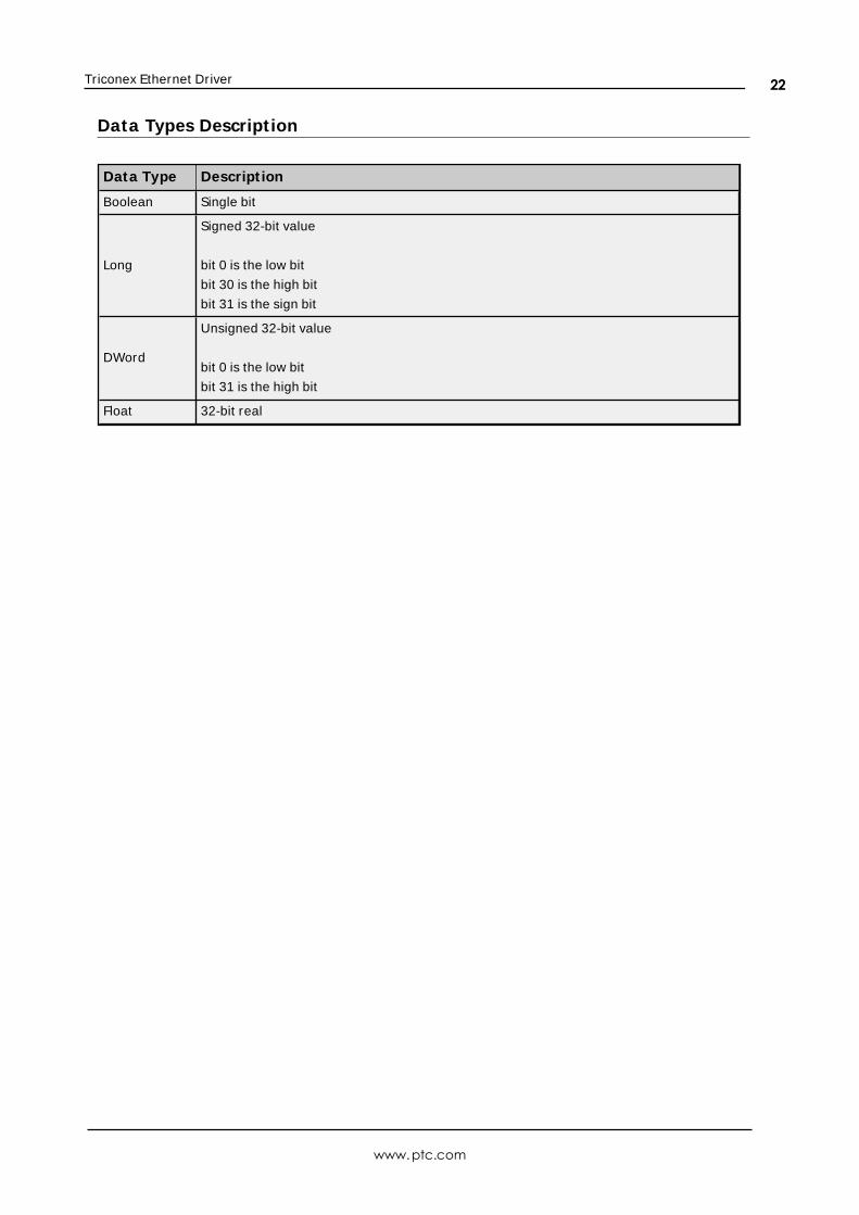
Data Types Descript ion
Data Type Descript ion
Boolean Single bit
Long
Signed 32-bit value
bit 0 is the low bit
bit 30 is the high bit
bit 31 is the sign bit
DWord
Unsigned 32-bit value
bit 0 is the low bit
bit 31 is the high bit
Float 32-bit real
www.ptc.com
22
Triconex Ethernet Driver
Address Descript ionsAddress specifications vary depending on the model in use. To obtain address information for the model of
interest, select a link from the list below.
Tricon Addressing
Tricon Extended Addressing
Trident Addressing
Note: The driver has several System Tags that can be used to monitor the driver's operation. For more
information, refer to Driver System Tags.
Tricon AddressingThe Tricon model supports the following addresses. Memory may be addressed using either Bin:Offset syn-
tax or Modbus aliases. The default data types for dynamically defined tags are shown in bold where appro-
priate.
Bin:Offset Addressing
Variable Type Address Range Data Type Access
Output (BOOL) 00:0000-00:1999 Boolean Read/Write
Memory (BOOL) 01:0000-01:1999 Boolean Read/Write
Input (BOOL) 02:0000-02:1999 Boolean Read Only
Memory (BOOL) 03:0000-03:1999 Boolean Read Only
Input (DINT)04:0000-04:0999
04:xxxx.00-04:xxxx.31
DWord, Long, Float
BooleanRead Only
Memory (DINT)05:0000-05:0999
05:xxxx.00-05:xxxx.31
DWord, Long, Float
BooleanRead Only
Input (DINT)06:0000-06:0119
06:xxxx.00-06:xxxx.31
DWord, Long, Float
BooleanRead Only
Memory (REAL)07:0000-07:0999
07:xxxx.00-07:xxxx.31
DWord, Long, Float
BooleanRead Only
System Status (BOOL) 08:0000-08:5998 Boolean Read Only
System Status (DINT)09:0000-09:0368
09:xxxx.00-09:xxxx.31
DWord, Long, Float
BooleanRead Only
Output (DINT)10:0000-10:0249
10:xxxx.00-10:xxxx.31
DWord, Long, Float
BooleanRead/Write
Memory (DINT)11:0000-11:0749
11:xxxx.00-11:xxxx.31
DWord, Long, Float
BooleanRead/Write
Memory (REAL)12:0000-12:0999
12:xxxx.00-12:xxxx.31
DWord, Long, Float
BooleanRead/Write
Modbus Alias Addressing
Variable Type Address Range Data Type Access
Output (BOOL) 00001-02000 Boolean Read/Write
Memory (BOOL) 02001-04000 Boolean Read/Write
www.ptc.com
23
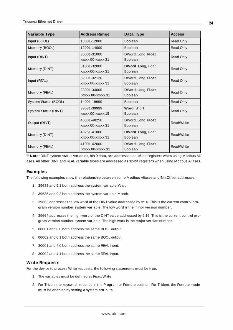
Triconex Ethernet Driver
Variable Type Address Range Data Type Access
Input (BOOL) 10001-12000 Boolean Read Only
Memory (BOOL) 12001-14000 Boolean Read Only
Input (DINT)30001-31000
xxxxx.00-xxxxx.31
DWord, Long, Float
BooleanRead Only
Memory (DINT)31001-32000
xxxxx.00-xxxxx.31
DWord, Long, Float
BooleanRead Only
Input (REAL)32001-32120
xxxxx.00-xxxxx.31
DWord, Long, Float
BooleanRead Only
Memory (REAL)33001-34000
xxxxx.00-xxxxx.31
DWord, Long, Float
BooleanRead Only
System Status (BOOL) 14001-19999 Boolean Read Only
System Status (DINT)39631-39999
xxxxx.00-xxxxx.15
Word, Short
BooleanRead Only
Output (DINT)40001-40250
xxxxx.00-xxxxx.31
DWord, Long, Float
BooleanRead/Write
Memory (DINT)40251-41000
xxxxx.00-xxxxx.31
DWord, Long, Float
BooleanRead/Write
Memory (REAL)41001-42000
xxxxx.00-xxxxx.31
DWord, Long, Float
BooleanRead/Write
Note: DINT system status variables, bin 9 data, are addressed as 16-bit registers when using Modbus Ali-
ases. All other DINT and REAL variable types are addressed as 32-bit registers when using Modbus Aliases.
ExamplesThe following examples show the relationship between some Modbus Aliases and Bin:Offset addresses.
1. 39633 and 9:1 both address the system variable Year.
2. 39635 and 9:2 both address the system variable Month.
3. 39663 addresses the low word of the DINT value addressed by 9:16. This is the current control pro-
gram version number system variable. The low word is the minor version number.
4. 39664 addresses the high word of the DINT value addressed by 9:16. This is the current control pro-
gram version number system variable. The high work is the major version number.
5. 00001 and 0:0 both address the same BOOL output.
6. 00002 and 0:1 both address the same BOOL output.
7. 30001 and 4:0 both address the same REAL input.
8. 30002 and 4:1 both address the same REAL input.
Write RequestsFor the device to process Write requests, the following statements must be true.
1. The variables must be defined as Read/Write.
2. For Tricon, the keyswitch must be in the Program or Remote position. For Trident, the Remote mode
must be enabled by setting a system attribute.
www.ptc.com
24
Triconex Ethernet Driver
3. The TriStation configuration setting (Disable Remote Changes to Outputs) which was downloaded to
the controller must allow remote changes.
Note: This setting only affects changes to discrete outputs and analog outputs.
4. The TriStation configuration for the ACM or NCM (Tricon) and CM (Trident) must be configured as
Read/Write.
Note: If the controller cannot write the data, it sends as reject response coded. For more information, refer
to Write failed for tag '<address>' on device '<device>'. TSAA Response Code: <code>.
Basic Address ExampleUsers may address values using the Bin:Offset syntax or with a Modbus Alias.
10:0012 addresses the bin 10 float value with offset 12.The same value can be addressed using the Modbus Alias 40013.
Bit Address ExampleIndividual bits in DINT types may be addressed by appending the "dot bit number" to a basic address.
05:0010.2 addresses bit 2 of the bin 5 DINT value with offset 10.The same bit can be addressed using the Modbus Alias 31011.2.
Array Address ExamplesMultiple data points may be accessed as array data.
1. 05:0010 [4] addresses bin 5 DINT values with offsets 10, 11, 12, and 13.The same range of values can be addressed using the Modbus Alias 31011 [4].
2. 05:0010 [4][5] addresses bin 5 DINT values with offsets from 10, to 29 as a 2-D array.The same range of values can be addressed using the Modbus Alias 31011 [4][5].
Tricon Extended AddressingThe Tricon Extended model supports the following addresses. Memory may be addressed using either
Bin:Offset syntax or Modbus aliases. The default data types for dynamically defined tags are shown in bold
where appropriate.
Bin:Offset Addressing
Variable
TypeAddress Range Data Type Access
Output (BOOL) 00:0000-00:4095 Boolean Read/Write
Memory (BOOL) 01:0000-01:4095 Boolean Read/Write
Input (BOOL) 02:0000-02:4095 Boolean Read Only
Memory (BOOL) 03:0000-03:4095 Boolean Read Only
Input (DINT)04:0000-04:2047
04:xxxx.00-04:xxxx.31
DWord, Long,
Float,
Boolean
Read Only
Memory (DINT)05:0000-05:2047
05:xxxx.00-05:xxxx.31
DWord, Long,
Float,Read Only
www.ptc.com
25
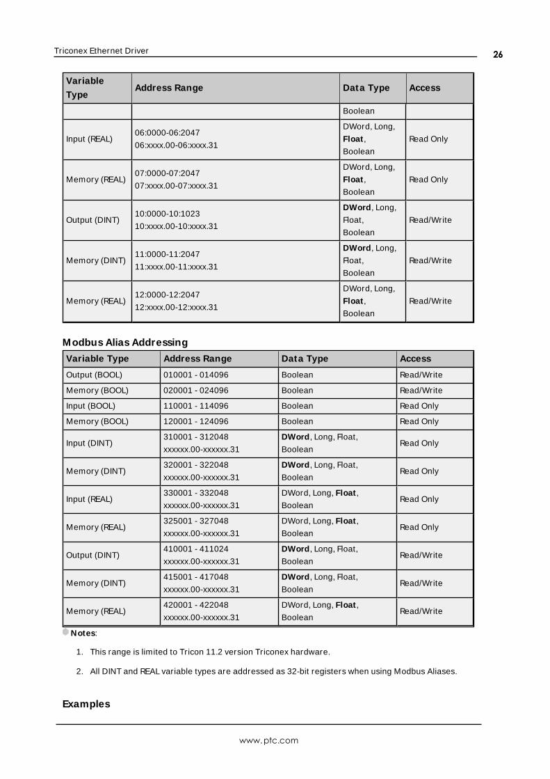
Triconex Ethernet Driver
Variable
TypeAddress Range Data Type Access
Boolean
Input (REAL)06:0000-06:2047
06:xxxx.00-06:xxxx.31
DWord, Long,
Float ,
Boolean
Read Only
Memory (REAL)07:0000-07:2047
07:xxxx.00-07:xxxx.31
DWord, Long,
Float ,
Boolean
Read Only
Output (DINT)10:0000-10:1023
10:xxxx.00-10:xxxx.31
DWord, Long,
Float,
Boolean
Read/Write
Memory (DINT)11:0000-11:2047
11:xxxx.00-11:xxxx.31
DWord, Long,
Float,
Boolean
Read/Write
Memory (REAL)12:0000-12:2047
12:xxxx.00-12:xxxx.31
DWord, Long,
Float ,
Boolean
Read/Write
Modbus Alias Addressing
Variable Type Address Range Data Type Access
Output (BOOL) 010001 - 014096 Boolean Read/Write
Memory (BOOL) 020001 - 024096 Boolean Read/Write
Input (BOOL) 110001 - 114096 Boolean Read Only
Memory (BOOL) 120001 - 124096 Boolean Read Only
Input (DINT)310001 - 312048
xxxxxx.00-xxxxxx.31
DWord, Long, Float,
BooleanRead Only
Memory (DINT)320001 - 322048
xxxxxx.00-xxxxxx.31
DWord, Long, Float,
BooleanRead Only
Input (REAL)330001 - 332048
xxxxxx.00-xxxxxx.31
DWord, Long, Float ,
BooleanRead Only
Memory (REAL)325001 - 327048
xxxxxx.00-xxxxxx.31
DWord, Long, Float ,
BooleanRead Only
Output (DINT)410001 - 411024
xxxxxx.00-xxxxxx.31
DWord, Long, Float,
BooleanRead/Write
Memory (DINT)415001 - 417048
xxxxxx.00-xxxxxx.31
DWord, Long, Float,
BooleanRead/Write
Memory (REAL)420001 - 422048
xxxxxx.00-xxxxxx.31
DWord, Long, Float ,
BooleanRead/Write
Notes:
1. This range is limited to Tricon 11.2 version Triconex hardware.
2. All DINT and REAL variable types are addressed as 32-bit registers when using Modbus Aliases.
Examples
www.ptc.com
26
Triconex Ethernet Driver
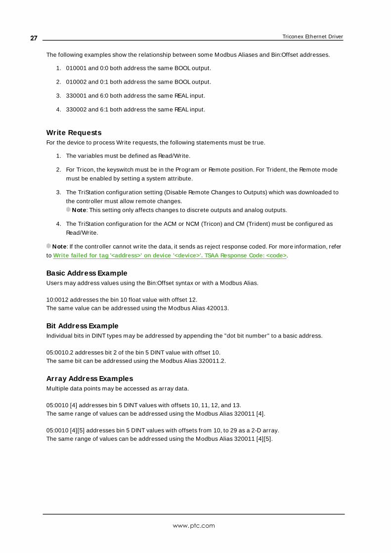
The following examples show the relationship between some Modbus Aliases and Bin:Offset addresses.
1. 010001 and 0:0 both address the same BOOL output.
2. 010002 and 0:1 both address the same BOOL output.
3. 330001 and 6:0 both address the same REAL input.
4. 330002 and 6:1 both address the same REAL input.
Write RequestsFor the device to process Write requests, the following statements must be true.
1. The variables must be defined as Read/Write.
2. For Tricon, the keyswitch must be in the Program or Remote position. For Trident, the Remote mode
must be enabled by setting a system attribute.
3. The TriStation configuration setting (Disable Remote Changes to Outputs) which was downloaded to
the controller must allow remote changes.
Note: This setting only affects changes to discrete outputs and analog outputs.
4. The TriStation configuration for the ACM or NCM (Tricon) and CM (Trident) must be configured as
Read/Write.
Note: If the controller cannot write the data, it sends as reject response coded. For more information, refer
to Write failed for tag '<address>' on device '<device>'. TSAA Response Code: <code>.
Basic Address ExampleUsers may address values using the Bin:Offset syntax or with a Modbus Alias.
10:0012 addresses the bin 10 float value with offset 12.The same value can be addressed using the Modbus Alias 420013.
Bit Address ExampleIndividual bits in DINT types may be addressed by appending the "dot bit number" to a basic address.
05:0010.2 addresses bit 2 of the bin 5 DINT value with offset 10.The same bit can be addressed using the Modbus Alias 320011.2.
Array Address ExamplesMultiple data points may be accessed as array data.
05:0010 [4] addresses bin 5 DINT values with offsets 10, 11, 12, and 13.The same range of values can be addressed using the Modbus Alias 320011 [4].
05:0010 [4][5] addresses bin 5 DINT values with offsets from 10, to 29 as a 2-D array.The same range of values can be addressed using the Modbus Alias 320011 [4][5].
www.ptc.com
27
Triconex Ethernet Driver
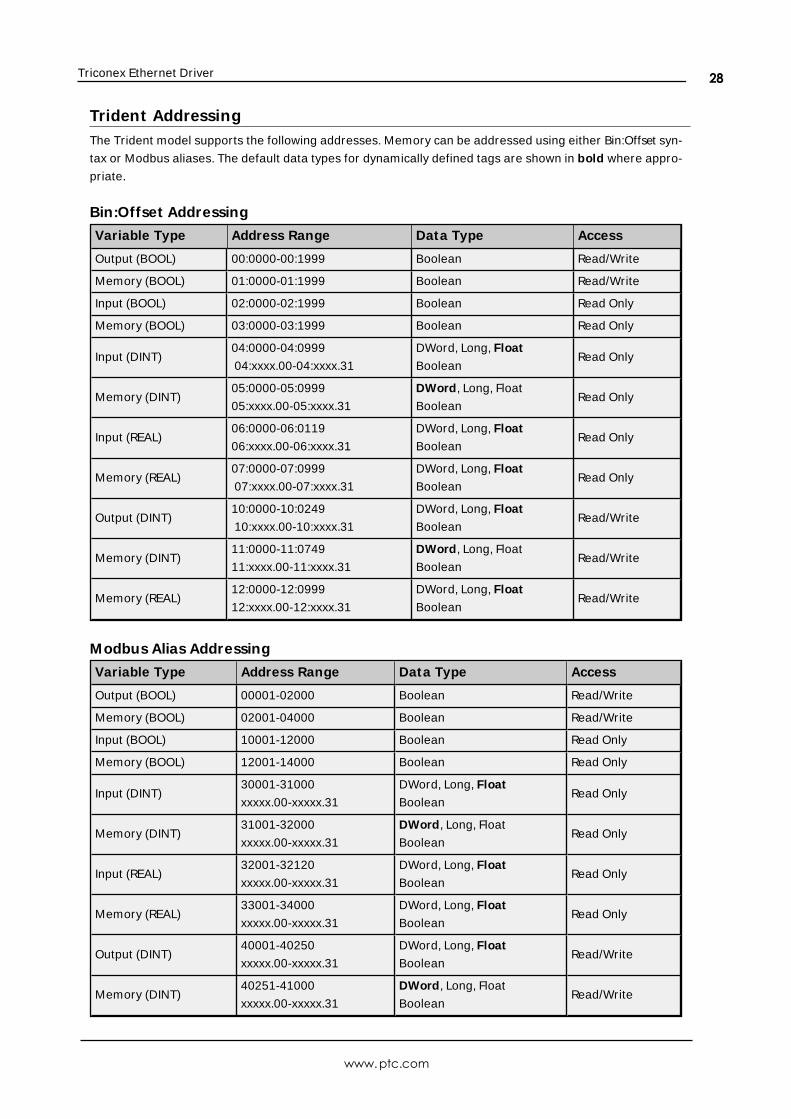
Trident AddressingThe Trident model supports the following addresses. Memory can be addressed using either Bin:Offset syn-
tax or Modbus aliases. The default data types for dynamically defined tags are shown in bold where appro-
priate.
Bin:Offset Addressing
Variable Type Address Range Data Type Access
Output (BOOL) 00:0000-00:1999 Boolean Read/Write
Memory (BOOL) 01:0000-01:1999 Boolean Read/Write
Input (BOOL) 02:0000-02:1999 Boolean Read Only
Memory (BOOL) 03:0000-03:1999 Boolean Read Only
Input (DINT)04:0000-04:0999
04:xxxx.00-04:xxxx.31
DWord, Long, Float
BooleanRead Only
Memory (DINT)05:0000-05:0999
05:xxxx.00-05:xxxx.31
DWord, Long, Float
BooleanRead Only
Input (REAL)06:0000-06:0119
06:xxxx.00-06:xxxx.31
DWord, Long, Float
BooleanRead Only
Memory (REAL)07:0000-07:0999
07:xxxx.00-07:xxxx.31
DWord, Long, Float
BooleanRead Only
Output (DINT)10:0000-10:0249
10:xxxx.00-10:xxxx.31
DWord, Long, Float
BooleanRead/Write
Memory (DINT)11:0000-11:0749
11:xxxx.00-11:xxxx.31
DWord, Long, Float
BooleanRead/Write
Memory (REAL)12:0000-12:0999
12:xxxx.00-12:xxxx.31
DWord, Long, Float
BooleanRead/Write
Modbus Alias Addressing
Variable Type Address Range Data Type Access
Output (BOOL) 00001-02000 Boolean Read/Write
Memory (BOOL) 02001-04000 Boolean Read/Write
Input (BOOL) 10001-12000 Boolean Read Only
Memory (BOOL) 12001-14000 Boolean Read Only
Input (DINT)30001-31000
xxxxx.00-xxxxx.31
DWord, Long, Float
BooleanRead Only
Memory (DINT)31001-32000
xxxxx.00-xxxxx.31
DWord, Long, Float
BooleanRead Only
Input (REAL)32001-32120
xxxxx.00-xxxxx.31
DWord, Long, Float
BooleanRead Only
Memory (REAL)33001-34000
xxxxx.00-xxxxx.31
DWord, Long, Float
BooleanRead Only
Output (DINT)40001-40250
xxxxx.00-xxxxx.31
DWord, Long, Float
BooleanRead/Write
Memory (DINT)40251-41000
xxxxx.00-xxxxx.31
DWord, Long, Float
BooleanRead/Write
www.ptc.com
28
Triconex Ethernet Driver
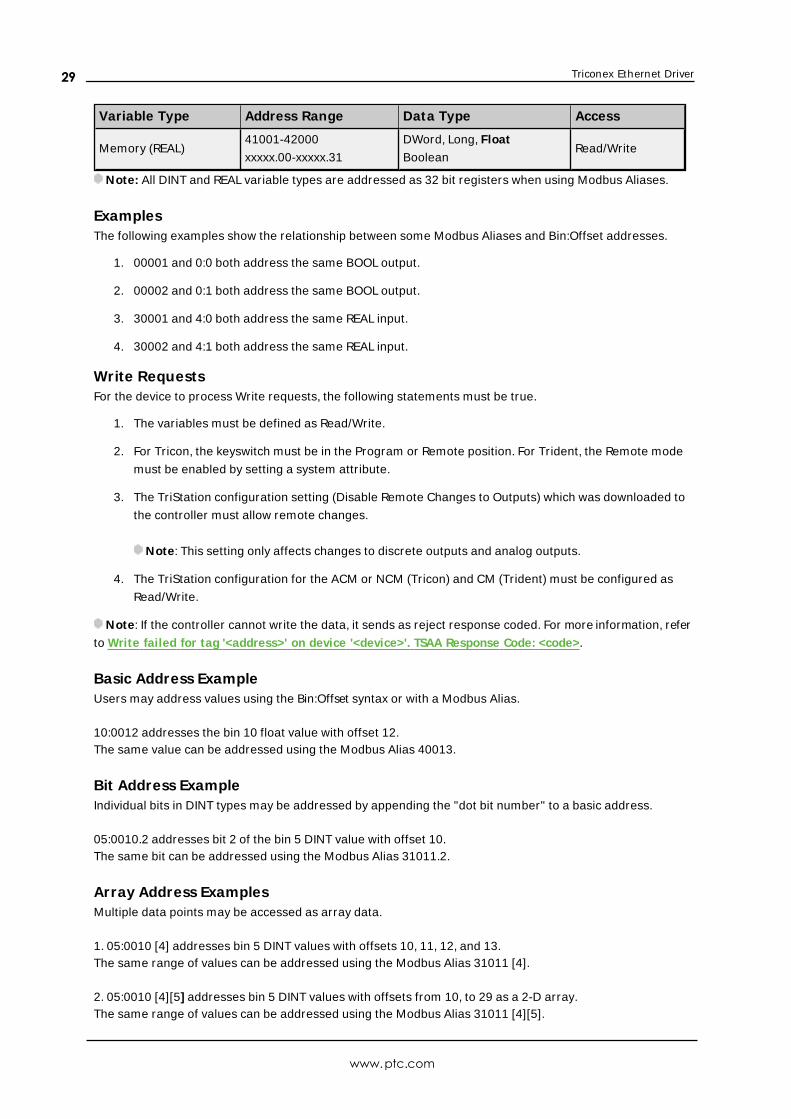
Variable Type Address Range Data Type Access
Memory (REAL)41001-42000
xxxxx.00-xxxxx.31
DWord, Long, Float
BooleanRead/Write
Note: All DINT and REAL variable types are addressed as 32 bit registers when using Modbus Aliases.
ExamplesThe following examples show the relationship between some Modbus Aliases and Bin:Offset addresses.
1. 00001 and 0:0 both address the same BOOL output.
2. 00002 and 0:1 both address the same BOOL output.
3. 30001 and 4:0 both address the same REAL input.
4. 30002 and 4:1 both address the same REAL input.
Write RequestsFor the device to process Write requests, the following statements must be true.
1. The variables must be defined as Read/Write.
2. For Tricon, the keyswitch must be in the Program or Remote position. For Trident, the Remote mode
must be enabled by setting a system attribute.
3. The TriStation configuration setting (Disable Remote Changes to Outputs) which was downloaded to
the controller must allow remote changes.
Note: This setting only affects changes to discrete outputs and analog outputs.
4. The TriStation configuration for the ACM or NCM (Tricon) and CM (Trident) must be configured as
Read/Write.
Note: If the controller cannot write the data, it sends as reject response coded. For more information, refer
to Write failed for tag '<address>' on device '<device>'. TSAA Response Code: <code>.
Basic Address ExampleUsers may address values using the Bin:Offset syntax or with a Modbus Alias.
10:0012 addresses the bin 10 float value with offset 12.The same value can be addressed using the Modbus Alias 40013.
Bit Address ExampleIndividual bits in DINT types may be addressed by appending the "dot bit number" to a basic address.
05:0010.2 addresses bit 2 of the bin 5 DINT value with offset 10.The same bit can be addressed using the Modbus Alias 31011.2.
Array Address ExamplesMultiple data points may be accessed as array data.
1. 05:0010 [4] addresses bin 5 DINT values with offsets 10, 11, 12, and 13.The same range of values can be addressed using the Modbus Alias 31011 [4].
2. 05:0010 [4][5] addresses bin 5 DINT values with offsets from 10, to 29 as a 2-D array.The same range of values can be addressed using the Modbus Alias 31011 [4][5].
www.ptc.com
29
Triconex Ethernet Driver
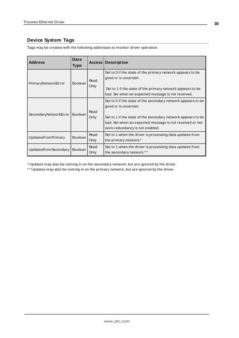
Device System TagsTags may be created with the following addresses to monitor driver operation.
AddressData
TypeAccess Descript ion
PrimaryNetworkError BooleanRead
Only
Set to 0 if the state of the primary network appears to be
good or is uncertain.
Set to 1 if the state of the primary network appears to be
bad. Set when an expected message is not received.
SecondaryNetworkError BooleanRead
Only
Set to 0 if the state of the secondary network appears to be
good or is uncertain.
Set to 1 if the state of the secondary network appears to be
bad. Set when an expected message is not received or net-
work redundancy is not enabled.
UpdatesFromPrimary BooleanRead
Only
Set to 1 when the driver is processing data updates from
the primary network.*
UpdatesFromSecondary BooleanRead
Only
Set to 1 when the driver is processing data updates from
the secondary network.* *
* Updates may also be coming in on the secondary network, but are ignored by the driver.* * Updates may also be coming in on the primary network, but are ignored by the driver.
www.ptc.com
30
Triconex Ethernet Driver
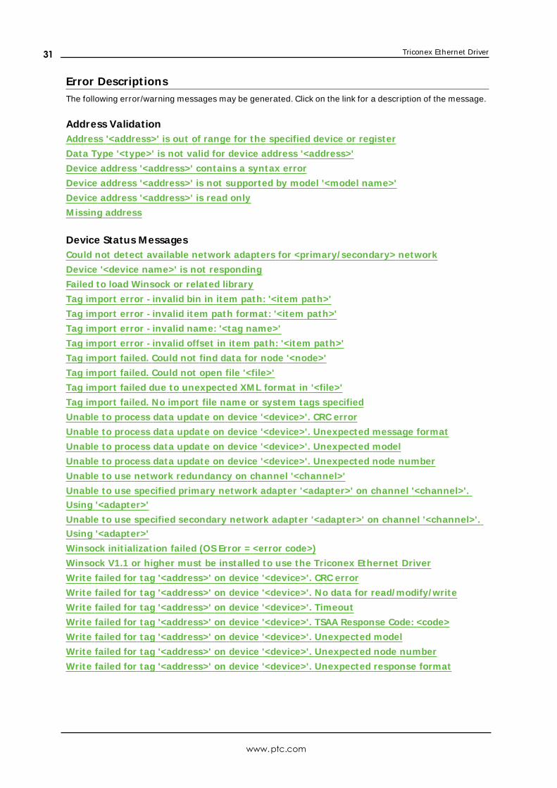
Error Descript ionsThe following error/warning messages may be generated. Click on the link for a description of the message.
Address ValidationAddress '<address>' is out of range for the specified device or register
Data Type '<type>' is not valid for device address '<address>'
Device address '<address>' contains a syntax error
Device address '<address>' is not supported by model '<model name>'
Device address '<address>' is read only
M issing address
Device Status MessagesCould not detect available network adapters for <primary/ secondary> network
Device '<device name>' is not responding
Failed to load Winsock or related library
Tag import error - invalid bin in item path: '<item path>'
Tag import error - invalid item path format: '<item path>'
Tag import error - invalid name: '<tag name>'
Tag import error - invalid offset in item path: '<item path>'
Tag import failed. Could not find data for node '<node>'
Tag import failed. Could not open file '<file>'
Tag import failed due to unexpected XM L format in '<file>'
Tag import failed. No import file name or system tags specified
Unable to process data update on device '<device>'. CRC error
Unable to process data update on device '<device>'. Unexpected message format
Unable to process data update on device '<device>'. Unexpected model
Unable to process data update on device '<device>'. Unexpected node number
Unable to use network redundancy on channel '<channel>'
Unable to use specified primary network adapter '<adapter>' on channel '<channel>'.
Using '<adapter>'
Unable to use specified secondary network adapter '<adapter>' on channel '<channel>'.
Using '<adapter>'
Winsock init ializat ion failed (OS Error = <error code>)
Winsock V1.1 or higher must be installed to use the Triconex Ethernet Driver
Write failed for tag '<address>' on device '<device>'. CRC error
Write failed for tag '<address>' on device '<device>'. No data for read/ modify/ write
Write failed for tag '<address>' on device '<device>'. Timeout
Write failed for tag '<address>' on device '<device>'. TSAA Response Code: <code>
Write failed for tag '<address>' on device '<device>'. Unexpected model
Write failed for tag '<address>' on device '<device>'. Unexpected node number
Write failed for tag '<address>' on device '<device>'. Unexpected response format
www.ptc.com
31
Triconex Ethernet Driver
Address '<address>' is out of range for the specified device or register
Error Type:Warning
Possible Cause:A tag address that has been specified dynamically references a location that is beyond the range of sup-
ported locations for the device.
Solution:Verify the address is correct; if it is not, re-enter it in the client application.
Data Type '<type>' is not valid for device address '<address>'
Error Type:Warning
Possible Cause:A tag address that has been specified dynamically has been assigned an invalid data type.
Solution:Modify the requested data type in the client application.
Device address '<address>' contains a syntax error
Error Type:Warning
Possible Cause:A tag address that has been specified dynamically contains one or more invalid characters.
Solution:Re-enter the address in the client application.
Device address '<address>' is not supported by model '<model name>'
Error Type:Warning
Possible Cause:A tag address that has been specified dynamically references a location that is valid for the communications
protocol but not supported by the target device.
Solution:
1. Verify that the address is correct; if it is not, re-enter it in the client application.
2. Verify that the selected model name for the device is correct.
Device address '<address>' is Read Only
Error Type:
www.ptc.com
32
Triconex Ethernet Driver
Warning
Possible Cause:A tag address that has been specified dynamically has a requested access mode that is not compatible with
what the device supports for that address.
Solution:Change the access mode in the client application.
Missing address
Error Type:Warning
Possible Cause:A tag address that has been specified dynamically has no length.
Solution:Re-enter the address in the client application.
Could not detect available network adapters for <primary/ secondary> net-work
Error Type:Serious
Possible Cause:The network adapters are not connected to a hub or other device.
Solution:The network adapters must be connected to a device or hub in order for Windows to correctly report their
configuration to the driver. Verify the network connection.
Device '<device name>' is not responding
Error Type:Serious
Possible Cause:
1. The network connection between the device and the Host PC is broken.
2. The named device may have been assigned an incorrect IP, Device ID, or model.
3. An expected data update was late.
4. The response from the device took longer to receive than the amount of time specified in the Request
Timeout.
Solution:
www.ptc.com
33
Triconex Ethernet Driver
1. Verify the cabling between the PC and the PLC.
2. Verify the Device Properties.
3. Consider increasing the Bin Data Update Period if the device is not capable of sending updates at the
requested rate.
4. Increase the Request Timeout setting so that the entire response can be handled.
See Also:Communicat ions
Failed to load Winsock or related library
Error Type:Fatal
Possible Cause:The driver could not load Winsock (winsock.dll) or the IP Helper API dll (iphlpapi.dll).
Solution:These libraries are normally installed with Windows. Verify that these files exist in the system folder.
Tag import error - invalid bin in item path: '<item path>'
Error Type:Warning
Possible Cause:An entry in the import file had an item path with an invalid bin number.
Solution:Verify that the item path has the format <node name>:<bin>:<offset> and that the bin number is between 0
and 12.
Tag import error - invalid item path format\ : '<item path>'
Error Type:Warning
Possible Cause:An entry in the import file had an unexpected item path format.
Solution:Verify that the item paths in the export file have the format <node name>:<bin>:<offset>.
Tag import error - invalid name: '<tag name>'
Error Type:Warning
www.ptc.com
34
Triconex Ethernet Driver
Possible Cause:The PST alias name value does not conform to the server's tag naming rules.
Solution:
1. Verify that the name contains only alphanumeric characters and underscores.
2. Verify that the first character is not an underscore, editing the import file if necessary.
Note:There should be two entries for each tag. The first entry gives the tag name and the second gives the Mod-
bus alias. The driver skips the entries with Modbus alias values.
Tag import error - invalid offset in item path: '<item path>'
Error Type:Warning
Possible Cause:An entry in the import file had an item path with an invalid offset value.
Solution:Verify that the item path has the format <node name>:<bin>:<offset> and that the offset is within the valid
range for the bin.
See Also:Address Descript ions
Tag import failed. Could not find data for node '<node>'
Error Type:Warning
Possible Cause:The driver did not find any entires in the import file with the specified node name.
Solution:Verify that the correct node name has been specified.
Note:The node name is given by the PSTAliasGroup name.
Tag import failed. Could not open file '<file>'
Error Type:Warning
Possible Cause:The driver could not find or open the import file specified on the Tag Import page in Device Properties.
www.ptc.com
35
Triconex Ethernet Driver
Solution:
1. Verify that the file exists and that the specified path is correct.
2. Make sure that no other application has opened the file.
See Also:Tag Import
Tag import failed due to unexpected XML format in '<file>'
Error Type:Warning
Possible Cause:The driver could not process the import file because it did not have the expected format.
Solution:Verify that the data is exported from TriStation in XML format.
Tag import failed. No import file name or system tags specified
Error Type:Warning
Possible Cause:No tag import options were specified in the Tag Import page in Device Properties when the driver attempted
to generate a tag database.
Solution:Verify that an import file name is specified or that one of the system tag options is selected when tag gen-
eration is started.
See Also:Tag Import
Unable to process data update on device '<device>'. CRC error
Error Type:Warning
Possible Cause:The driver rejected a data update message because its CRC checksum was not valid.
Solution:This error implies noise in the network. If this error is persistent, efforts should be made to improve network
reliability.
www.ptc.com
36
Triconex Ethernet Driver
Unable to process data update on device '<device>'. Unexpected messageformat
Error Type:Warning
Possible Cause:The driver rejected a data update message because it did not have the expected format.
Solution:If the problem persists and does not appear to be network related, perform a Channel Diagnostics capture
of the incoming update messages and contact Technical Support.
Unable to process data update on device '<device>'. Unexpected model
Error Type:Warning
Possible Cause:The driver rejected a data update message because it did not have the expected model number.
Solution:Verify the model setting.
See Also:Device Setup
Unable to process data update on device '<device>'. Unexpected node num-ber
Error Type:Warning
Possible Cause:The driver rejected a data update message because it did not have the expected node number.
Solution:Verify the Device ID setting.
See Also:Device Setup
Unable to use network redundancy on channel '<channel>'
Error Type:Warning
Possible Cause:
www.ptc.com
37
Triconex Ethernet Driver
1. The driver loaded a project that was created on a computer that had multiple network interface
cards.
2. The network adapter cards are not connected to a device or hub.
Solution:
1. Reset the Network Interface in Channel Properties to be compatible with the host computer. To use
network redundancy, the host computer must have two network interface cards (NICs) installed. Save
the adjusted setting.
2. The network adapters must be connected to a device or hub in order for Windows to correctly report
their configuration to the driver. Ensure that the adapters are connected.
See Also:Channel Setup
Network Redundancy
Unable to use specified primary network adapter '<adapter>' on channel'<channel>'
Error Type:Warning
Possible Cause:
1. The driver loaded a project that was created on another computer with different network interface
hardware or IP address.
2. The network adapter cards are not connected to a device or hub.
Solution:
1. Reset the Network Interface in Channel Properties to be compatible with the host computer. To use
network redundancy, the host computer must have two network interface cards (NICs) installed. Save
the adjusted setting.
2. The network adapters must be connected to a device or hub in order for Windows to correctly report
their configuration to the driver. Ensure that the adapters are connected.
See Also:Channel Setup
Network Redundancy
Unable to use specified secondary network adapter '<adapter>' on chan-nel '<channel>'
Error Type:Warning
Possible Cause:
www.ptc.com
38
Triconex Ethernet Driver
1. The driver loaded a project that was created on another computer with different network interface
hardware or IP address.
2. The network adapter cards are not connected to a device or hub.
Solution:
1. Reset the Network Interface in Channel Properties to be compatible with the host computer. To use
network redundancy, the host computer must have two network interface cards (NICs) installed. Save
the adjusted setting.
2. The network adapters must be connected to a device or hub in order for Windows to correctly report
the configuration to the driver. Ensure that the adapters are connected.
See Also:Channel Setup
Network Redundancy
Winsock init ializat ion failed (OS Error = <error code>)
Error Type:Fatal
OS Error Indicat ion Possible Solut ion
10091 Indicates that the underlying network sub-
system is not ready for network communication.
Wait a few seconds and restart the
driver.
10067 Limit on the number of tasks supported by the
Windows Sockets implementation has been
reached.
Close one or more applications that
may be using Winsock and restart the
driver.
Winsock V1.1 or higher must be installed to use the Triconex Ethernetdevice driver
Error Type:Fatal
Possible Cause:The version number of the Winsock DLL found on the system is less than 1.1.
Solution:Upgrade Winsock to version 1.1 or higher.
Write failed for tag '<address>' on device '<device>'. CRC error
Error Type:Warning
Possible Cause:The driver rejected a write complete message because its CRC checksum was not valid.
www.ptc.com
39
Triconex Ethernet Driver
Solution:This error implies noise in the network. If this error is persistent, efforts should be made to improve network
reliability.
Write failed for tag '<address>' on device '<device>'. No data for Read/ Modi-fy/ Write
Error Type:Warning
Possible Cause:Bit writes require a read/modify/write procedure. The last known value has bad quality.
Solution:Ensure that the driver has had time to receive a data update for the value in question before bit writes are
performed. Failure can occur before an initial data update has been received or following a network failure.
Write failed for tag '<address>' on device '<device>'. Timeout
Error Type:Warning
Possible Cause:The driver did not receive a write complete message after the request timeout period and number of retries.
Solution:Triconex devices can take a long time to process Writes. Thus, a timeout error does not necessarily mean
the device did not receive the write request or has failed to process it. Ensure that an ample request timeout
period has been specified that is consistent with the device's scan rate.
Note:Other reasons for timeout errors could be related to hardware or network failure.
See Also:Device Setup
Write failed for tag '<address>' on device '<device>'. TSAA Response Code:<code>
Error Type:Warning
Possible Cause:The device could not complete the write request for the reason given by the response code.
Solution:Proper solution depend on failure reason. For more information, refer to the table below.
www.ptc.com
40
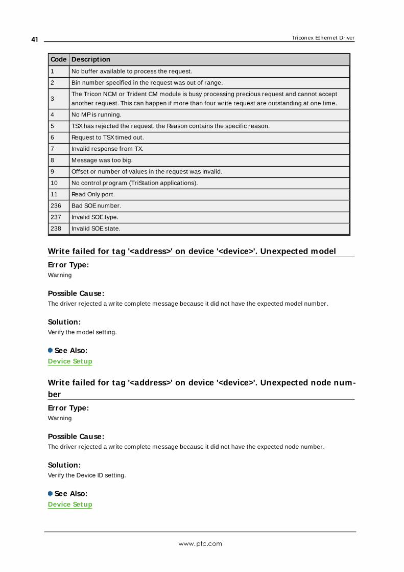
Triconex Ethernet Driver
Code Descript ion
1 No buffer available to process the request.
2 Bin number specified in the request was out of range.
3The Tricon NCM or Trident CM module is busy processing precious request and cannot accept
another request. This can happen if more than four write request are outstanding at one time.
4 No MP is running.
5 TSX has rejected the request. the Reason contains the specific reason.
6 Request to TSX timed out.
7 Invalid response from TX.
8 Message was too big.
9 Offset or number of values in the request was invalid.
10 No control program (TriStation applications).
11 Read Only port.
236 Bad SOE number.
237 Invalid SOE type.
238 Invalid SOE state.
Write failed for tag '<address>' on device '<device>'. Unexpected model
Error Type:Warning
Possible Cause:The driver rejected a write complete message because it did not have the expected model number.
Solution:Verify the model setting.
See Also:Device Setup
Write failed for tag '<address>' on device '<device>'. Unexpected node num-ber
Error Type:Warning
Possible Cause:The driver rejected a write complete message because it did not have the expected node number.
Solution:Verify the Device ID setting.
See Also:Device Setup
www.ptc.com
41
Triconex Ethernet Driver
Write failed for tag '<address>' on device '<device>'. Unexpected responseformat
Error Type:Warning
Possible Cause:The driver rejected a write complete message because it did not have the expected format.
Solution:If the problem persists and does not appear to be network related, perform a Channel Diagnostics capture
of the incoming update messages and contact Technical Support.
www.ptc.com
42
Triconex Ethernet Driver
Index
A
Address '<address>' is out of range for the specified device or register 32
Address Descriptions 23
Allow Sub Groups 14
Array Address 25, 29
Attempts Before Timeout 11
Auto-Demotion 12
Automatic Tag Database Generation 21
B
Bit Address 25, 29
Boolean 22
C
Channel Assignment 9
CM Configuration 14
Communication Protocol 5
Communications 15
Communications Timeouts 11
Connect Timeout 11
Could not detect available network adapters for <primary/secondary> network 33
Create 14
D
Data Collection 9
Data Type '<type>' is not valid for device address '<address>' 32
Data Types Description 22
Delete 13
Demote on Failure 12
Demotion Period 12
Device '<device name>' is not responding 33
Device address '<address>' contains a syntax error 32
www.ptc.com
43
Triconex Ethernet Driver
Device address '<address>' is not supported by model '<model name>' 32
Device address '<address>' is Read Only 32
Device Properties — Tag Generation 12
Device System Tags 16, 30
Discard Requests when Demoted 12
Do Not Scan, Demand Poll Only 10
Driver 9
Driver System Tags 18
DWord 22
E
Error Descriptions 31
F
Failed to load Winsock or related library 34
Float 22
G
General 8
Generate 13
I
ID 9
Identification 8
Import File 16
Initial Updates from Cache 10
Inter-Request Delay 11
L
Long 22
www.ptc.com
44
Triconex Ethernet Driver
M
Missing address 33
Model 9
N
Name 8
Network Interface 8
Network Redundancy 17
Node Name 16
O
On Device Startup 13
On Duplicate Tag 13
On Property Change 13
OPC Data Quality 15
Operating Mode 9
Optimizing Communications 19
Overview 4
Overwrite 13
P
Parent Group 14
R
Reads 17
Request Timeout 5, 11
Respect Tag-Specified Scan Rate 10
S
Scan Mode 10
Setup 5
Simulated 10
www.ptc.com
45
Triconex Ethernet Driver
T
Tag Generation 12
Tag Import 16
Tag import error - invalid bin in item path/
'<item path>' 34
Tag import error - invalid item path format: '<item path>' 34
Tag import error - invalid name: '<tag name>' 34
Tag import error - invalid offset in item path: '<item path>' 35
Tag import failed due to unexpected XML format in '<file>' 36
Tag import failed. Could not find data for node '<node>' 35
Tag import failed. Could not open file '<file>' 35
Tag import failed. No import file name or system tags specified 36
Timeouts to Demote 12
Timestamp 15
Tricon Addressing 23
Triconex Addressing 25
Triconex System Access Application (TSAA) 5
Trident Addressing 28
TriStation 21
U
Unable to process data update on device '<device>'. CRC error 36
Unable to process data update on device '<device>'. Unexpected message format 37
Unable to process data update on device '<device>'. Unexpected model 37
Unable to process data update on device '<device>'. Unexpected node number 37
Unable to use network redundancy on channel '<channel>' 37
Unable to use specified primary network adapter '<adapter>' on channel '<channel>' 38
Unable to use specified secondary network adapter '<adapter>' on channel '<channel>' 38
Update Rate 15
W
Winsock initialization failed (OS Error = <error code>) 39
Winsock V1.1 or higher must be installed to use the Triconex Ethernet device driver 39
Write failed for tag '<address>' on device '<device>'. CRC error 39
Write failed for tag '<address>' on device '<device>'. No data for Read/Modify/Write 40
Write failed for tag '<address>' on device '<device>'. Timeout 40
www.ptc.com
46

Triconex Ethernet Driver
Write failed for tag '<address>' on device '<device>'. TSAA Response Code: <code> 40
Write failed for tag '<address>' on device '<device>'. Unexpected model 41
Write failed for tag '<address>' on device '<device>'. Unexpected node number 41
Write failed for tag '<address>' on device '<device>'. Unexpected response format 42
Writes 18
www.ptc.com
47