Embed Size (px)
Citation preview
Simatic / TI 505 Ethernet Driver
© 2021 PTC Inc. All Rights Reserved.
Simatic / TI 505 Ethernet Driver
Table of Contents
Simatic / TI 505 Ethernet Driver 1
Table of Contents 2
Simatic / TI 505 Ethernet Driver 4
Overview 4
Setup 5
Channel Properties — General 6
Channel Properties — Ethernet Communications 7
Channel Properties — Write Optimizations 7
Channel Properties — Advanced 8
Device Properties — General 9
Operating Mode 10
Device Properties — Scan Mode 10
Device Properties — Timing 11
Device Properties — 505 Protocol 12
Device Properties — Addressing Options 13
Device Properties — Communications Parameters 15
Device Properties — Redundancy 15
Optimizing Communications 16
Data Types Description 17
Address Descriptions 18
Addressing 18
Common Data Type Addressing 18
Status Words 24
Alarm Addressing 31
AVF Bit Definitions 33
ACFBit Definitions 34
Loop Addressing 35
LVF Bit Definitions 38
LCFBit Definitions 39
LRSF Bit Definitions 40
Find Forced Addressing 42
Error Descriptions 44
Address <address> is out of range for the specified device or register. 44
Array size is out of range for address <address>. 44
Array Support is not available for the specified address: <address>. 45
Data type <type> is not valid for device address <address>. 45
www.ptc.com
2
Simatic / TI 505 Ethernet Driver
Device address <address> contains a syntax error. 45
Device address <address> is read only. 45
Device <device name> cannot execute a read request (<address>, <size>). 46
Device <device name> cannot execute a write request (<address>, <size>). 46
Device <device name> detected a NITP protocol error (tag <address>, size <size>). 46
Device <device name> detected a Task Code error <error> (tag <address>, size <size>). 46
Device <device name> input queue is full. The module is receiving requests faster than it can pro-
cess requests. 47
Device <device name> is not responding. 47
Device <device name> responded with Extended error <error> (tag <address>, size <size>). 47
Device <device name>, write value not in range 1-->65536. (Tag 'FFSTART'). 48
Missing address. 48
Unable to write to <address> on device <device name>. 48
Winsock initialization failed (OS error = n). 49
Winsock V1.1 or higher must be installed to use the Simatic / TI 505 Ethernet Driver. 49
Task Code Error Codes 50
Index 51
www.ptc.com
3
Simatic / TI 505 Ethernet Driver
Simatic / TI 505 Ethernet DriverHelp version 1.047
CONTENTS
OverviewWhat is the Simatic / TI 505 Ethernet Driver?
SetupHow do I configure a device for use with this driver?
Optimizing Communicat ionsHow do I get the best performance from the Simatic / TI 505 Ethernet Driver?
Data Types Descript ionWhat data types does this driver support?
Address Descript ionsHow do I address a data location on a Simatic / TI 505 Ethernet device?
Error Descript ionsWhat error messages does the Simatic / TI 505 Ethernet Driver produce?
OverviewThe Simatic / TI 505 Ethernet Driver provides a reliable way to connect Simatic / TI 505 Ethernet devices to
OPC client applications; including HMI, SCADA, Historian, MES, ERP, and countless custom applications. It is
intended for use in communicating with Simatic 505 Programmable Logic Controllers that may be accessed
via either the Siemens Simatic 505-CP2572 Ethernet module, the Siemens 505-CP1434-TCP card, the Con-
trol Technology Inc. CTI CP2572 and CTI 2572-A Ethernet cards card, and a CTI 2500 Series CPU module. The
driver supports both TCP / IP and UDP transport protocols while using both CAMP and CAMP Packed Task
Code messaging protocols for efficient data transfer.
Note: The CTI 2500 Series CPUs are direct replacements for the legacy Simatic TI 500 / 505 CPUs.
www.ptc.com
4
Simatic / TI 505 Ethernet Driver
Setup
Supported DevicesCTI Interface CardsCTI 2572, CTI 2572-A, and CP2572 Ethernet interface cards on TI series CPUs TI545, 555, and 565. Sim-
ultaneous device connections are allowed. The model should be set to 505-CP2572. For more information,
refer to "Connection Limitations" below.
Siemens Interface Cards505-CP1434-TCP Ethernet host card on TI Series CPUs TI545 and 565. Simultaneous device connections are
allowed.For more information, refer to the Siemens 505-CP1434-TCP User Guide.
CTI 2500 Controller Local Ethernet PortThe CTI 2500 controller's port supports up to three TCP connections (no UDP). Users can connect using the
TCP port 4450 or 1505. The model should be set to 505-CP2572.Note: This affects all CTI 2500 controller models.
Supported Protocols505: CAMP and CAMP Packed Task CodeIP: UDP and TCP / IP
Channel and Device LimitsThe maximum number of channels supported by this driver is 100. The maximum number of devices sup-
ported by this driver is 2048 per channel.Each device on the channel must be uniquely identified by its own IP address as the Device ID.
Connections
1. The default number of TCP connections allowed for the CTI 2572 / 2752-A and CP2572 cards is 8.
When configured from the PLC, this number may be set to a higher or lower number through the
Start Network Server command. In the CTI 2572 and CP2572 cards, this can be configured when star-
ted from PLC logic. In the CTI 2572-A card, this can be configured when automatically started from
EEPROM.
2. DIP Switch 3 in Switch Block 2 enables and disables the Data Share feature. When enabled, the num-
ber of TCP server connections is automatically limited to two.
3. To connect to the PLC via the 505-CP1434-TCP card, configure a UDP Server Job in the card.
www.ptc.com
5
Simatic / TI 505 Ethernet Driver
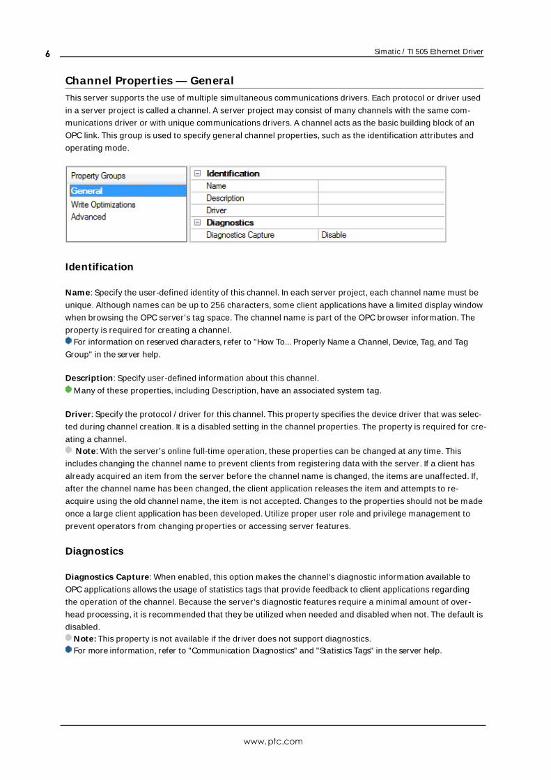
Channel Propert ies — GeneralThis server supports the use of multiple simultaneous communications drivers. Each protocol or driver used
in a server project is called a channel. A server project may consist of many channels with the same com-
munications driver or with unique communications drivers. A channel acts as the basic building block of an
OPC link. This group is used to specify general channel properties, such as the identification attributes and
operating mode.
Identification
Name: Specify the user-defined identity of this channel. In each server project, each channel name must be
unique. Although names can be up to 256 characters, some client applications have a limited display window
when browsing the OPC server's tag space. The channel name is part of the OPC browser information. The
property is required for creating a channel.For information on reserved characters, refer to "How To... Properly Name a Channel, Device, Tag, and Tag
Group" in the server help.
Description: Specify user-defined information about this channel.
Many of these properties, including Description, have an associated system tag.
Driver: Specify the protocol / driver for this channel. This property specifies the device driver that was selec-
ted during channel creation. It is a disabled setting in the channel properties. The property is required for cre-
ating a channel.Note: With the server's online full-time operation, these properties can be changed at any time. This
includes changing the channel name to prevent clients from registering data with the server. If a client has
already acquired an item from the server before the channel name is changed, the items are unaffected. If,
after the channel name has been changed, the client application releases the item and attempts to re-
acquire using the old channel name, the item is not accepted. Changes to the properties should not be made
once a large client application has been developed. Utilize proper user role and privilege management to
prevent operators from changing properties or accessing server features.
Diagnostics
Diagnostics Capture: When enabled, this option makes the channel's diagnostic information available to
OPC applications allows the usage of statistics tags that provide feedback to client applications regarding
the operation of the channel. Because the server's diagnostic features require a minimal amount of over-
head processing, it is recommended that they be utilized when needed and disabled when not. The default is
disabled.Note: This property is not available if the driver does not support diagnostics.For more information, refer to "Communication Diagnostics" and "Statistics Tags" in the server help.
www.ptc.com
6
Simatic / TI 505 Ethernet Driver
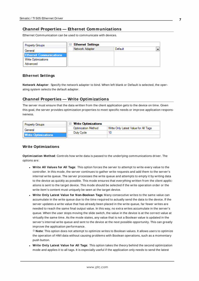
Channel Propert ies — Ethernet CommunicationsEthernet Communication can be used to communicate with devices.
Ethernet Settings
Network Adapter: Specify the network adapter to bind. When left blank or Default is selected, the oper-
ating system selects the default adapter.
Channel Propert ies — Write OptimizationsThe server must ensure that the data written from the client application gets to the device on time. Given
this goal, the server provides optimization properties to meet specific needs or improve application respons-
iveness.
Write Optimizations
Optimization Method: Controls how write data is passed to the underlying communications driver. The
options are:
l Write All Values for All Tags: This option forces the server to attempt to write every value to the
controller. In this mode, the server continues to gather write requests and add them to the server's
internal write queue. The server processes the write queue and attempts to empty it by writing data
to the device as quickly as possible. This mode ensures that everything written from the client applic-
ations is sent to the target device. This mode should be selected if the write operation order or the
write item's content must uniquely be seen at the target device.
l Write Only Latest Value for Non-Boolean Tags: Many consecutive writes to the same value can
accumulate in the write queue due to the time required to actually send the data to the device. If the
server updates a write value that has already been placed in the write queue, far fewer writes are
needed to reach the same final output value. In this way, no extra writes accumulate in the server's
queue. When the user stops moving the slide switch, the value in the device is at the correct value at
virtually the same time. As the mode states, any value that is not a Boolean value is updated in the
server's internal write queue and sent to the device at the next possible opportunity. This can greatly
improve the application performance.
Note: This option does not attempt to optimize writes to Boolean values. It allows users to optimize
the operation of HMI data without causing problems with Boolean operations, such as a momentary
push button.
l Write Only Latest Value for All Tags: This option takes the theory behind the second optimization
mode and applies it to all tags. It is especially useful if the application only needs to send the latest
www.ptc.com
7
Simatic / TI 505 Ethernet Driver
value to the device. This mode optimizes all writes by updating the tags currently in the write queue
before they are sent. This is the default mode.
Duty Cycle: is used to control the ratio of write to read operations. The ratio is always based on one read for
every one to ten writes. The duty cycle is set to ten by default, meaning that ten writes occur for each read
operation. Although the application is performing a large number of continuous writes, it must be ensured
that read data is still given time to process. A setting of one results in one read operation for every write
operation. If there are no write operations to perform, reads are processed continuously. This allows optim-
ization for applications with continuous writes versus a more balanced back and forth data flow.Note: It is recommended that the application be characterized for compatibility with the write optimization
enhancements before being used in a production environment.
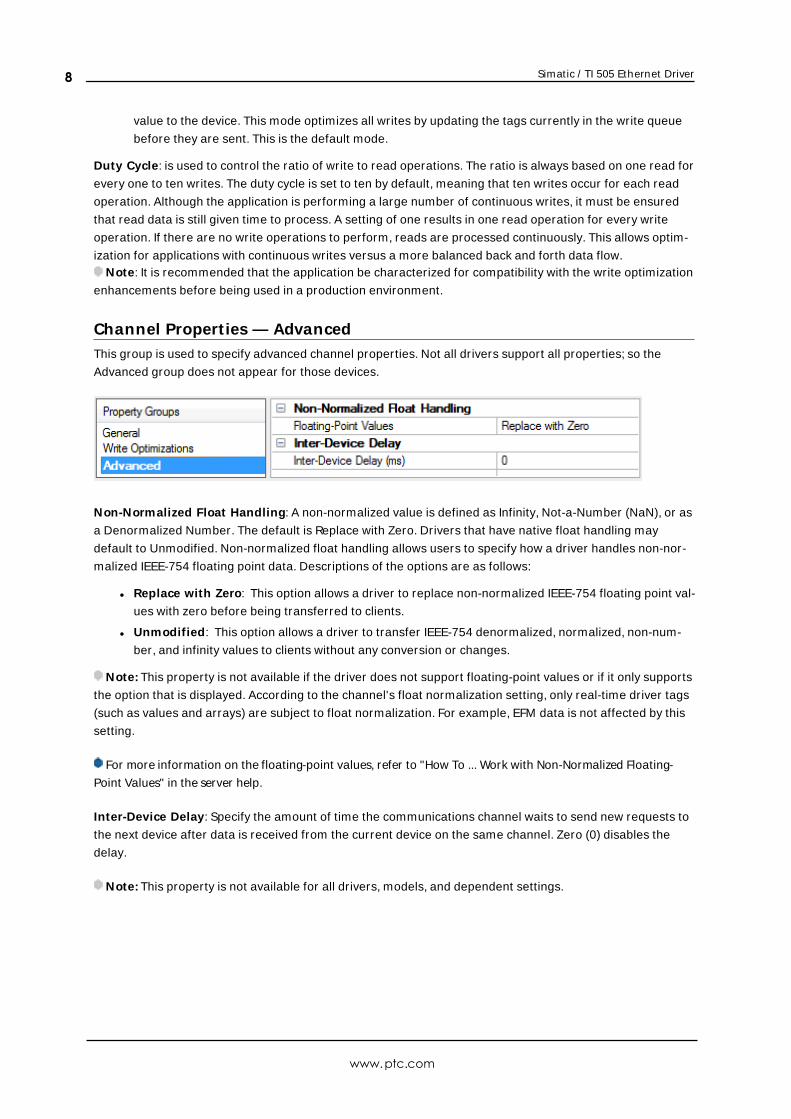
Channel Propert ies — AdvancedThis group is used to specify advanced channel properties. Not all drivers support all properties; so the
Advanced group does not appear for those devices.
Non-Normalized Float Handling: A non-normalized value is defined as Infinity, Not-a-Number (NaN), or as
a Denormalized Number. The default is Replace with Zero. Drivers that have native float handling may
default to Unmodified. Non-normalized float handling allows users to specify how a driver handles non-nor-
malized IEEE-754 floating point data. Descriptions of the options are as follows:
l Replace with Zero: This option allows a driver to replace non-normalized IEEE-754 floating point val-
ues with zero before being transferred to clients.
l Unmodified: This option allows a driver to transfer IEEE-754 denormalized, normalized, non-num-
ber, and infinity values to clients without any conversion or changes.
Note: This property is not available if the driver does not support floating-point values or if it only supports
the option that is displayed. According to the channel's float normalization setting, only real-time driver tags
(such as values and arrays) are subject to float normalization. For example, EFM data is not affected by this
setting.
For more information on the floating-point values, refer to "How To ... Work with Non-Normalized Floating-
Point Values" in the server help.
Inter-Device Delay: Specify the amount of time the communications channel waits to send new requests to
the next device after data is received from the current device on the same channel. Zero (0) disables the
delay.
Note: This property is not available for all drivers, models, and dependent settings.
www.ptc.com
8
Simatic / TI 505 Ethernet Driver
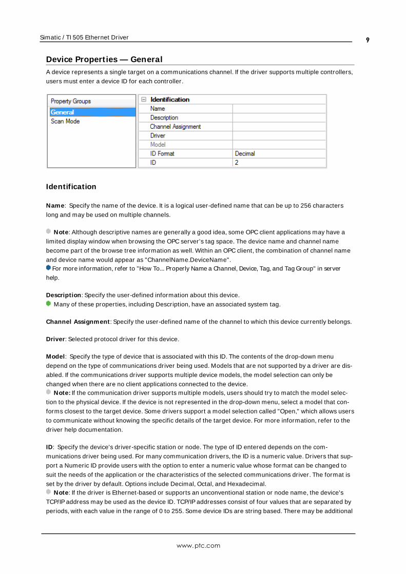
Device Propert ies — GeneralA device represents a single target on a communications channel. If the driver supports multiple controllers,
users must enter a device ID for each controller.
Identification
Name: Specify the name of the device. It is a logical user-defined name that can be up to 256 characters
long and may be used on multiple channels.
Note: Although descriptive names are generally a good idea, some OPC client applications may have a
limited display window when browsing the OPC server's tag space. The device name and channel name
become part of the browse tree information as well. Within an OPC client, the combination of channel name
and device name would appear as "ChannelName.DeviceName".For more information, refer to "How To... Properly Name a Channel, Device, Tag, and Tag Group" in server
help.
Description: Specify the user-defined information about this device.
Many of these properties, including Description, have an associated system tag.
Channel Assignment : Specify the user-defined name of the channel to which this device currently belongs.
Driver: Selected protocol driver for this device.
Model: Specify the type of device that is associated with this ID. The contents of the drop-down menu
depend on the type of communications driver being used. Models that are not supported by a driver are dis-
abled. If the communications driver supports multiple device models, the model selection can only be
changed when there are no client applications connected to the device.Note: If the communication driver supports multiple models, users should try to match the model selec-
tion to the physical device. If the device is not represented in the drop-down menu, select a model that con-
forms closest to the target device. Some drivers support a model selection called "Open," which allows users
to communicate without knowing the specific details of the target device. For more information, refer to the
driver help documentation.
ID: Specify the device's driver-specific station or node. The type of ID entered depends on the com-
munications driver being used. For many communication drivers, the ID is a numeric value. Drivers that sup-
port a Numeric ID provide users with the option to enter a numeric value whose format can be changed to
suit the needs of the application or the characteristics of the selected communications driver. The format is
set by the driver by default. Options include Decimal, Octal, and Hexadecimal.Note: If the driver is Ethernet-based or supports an unconventional station or node name, the device's
TCP/IP address may be used as the device ID. TCP/IP addresses consist of four values that are separated by
periods, with each value in the range of 0 to 255. Some device IDs are string based. There may be additional
www.ptc.com
9
Simatic / TI 505 Ethernet Driver
properties to configure within the ID field, depending on the driver. For more information, refer to the driver's
help documentation.
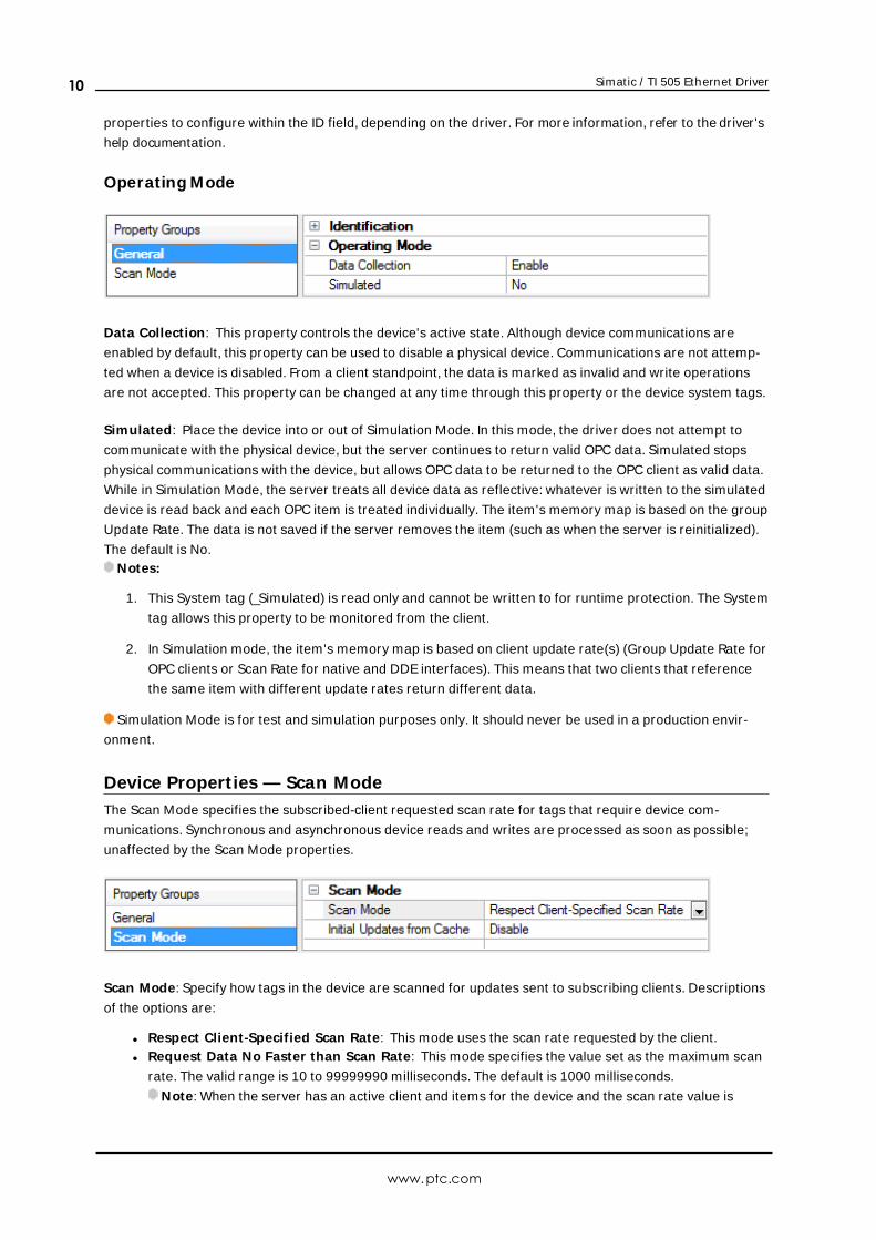
Operating Mode
Data Collection: This property controls the device's active state. Although device communications are
enabled by default, this property can be used to disable a physical device. Communications are not attemp-
ted when a device is disabled. From a client standpoint, the data is marked as invalid and write operations
are not accepted. This property can be changed at any time through this property or the device system tags.
Simulated: Place the device into or out of Simulation Mode. In this mode, the driver does not attempt to
communicate with the physical device, but the server continues to return valid OPC data. Simulated stops
physical communications with the device, but allows OPC data to be returned to the OPC client as valid data.
While in Simulation Mode, the server treats all device data as reflective: whatever is written to the simulated
device is read back and each OPC item is treated individually. The item's memory map is based on the group
Update Rate. The data is not saved if the server removes the item (such as when the server is reinitialized).
The default is No.Notes:
1. This System tag (_Simulated) is read only and cannot be written to for runtime protection. The System
tag allows this property to be monitored from the client.
2. In Simulation mode, the item's memory map is based on client update rate(s) (Group Update Rate for
OPC clients or Scan Rate for native and DDE interfaces). This means that two clients that reference
the same item with different update rates return different data.
Simulation Mode is for test and simulation purposes only. It should never be used in a production envir-
onment.
Device Propert ies — Scan ModeThe Scan Mode specifies the subscribed-client requested scan rate for tags that require device com-
munications. Synchronous and asynchronous device reads and writes are processed as soon as possible;
unaffected by the Scan Mode properties.
Scan Mode: Specify how tags in the device are scanned for updates sent to subscribing clients. Descriptions
of the options are:
l Respect Client-Specified Scan Rate: This mode uses the scan rate requested by the client.l Request Data No Faster than Scan Rate: This mode specifies the value set as the maximum scan
rate. The valid range is 10 to 99999990 milliseconds. The default is 1000 milliseconds.
Note: When the server has an active client and items for the device and the scan rate value is
www.ptc.com
10
Simatic / TI 505 Ethernet Driver
increased, the changes take effect immediately. When the scan rate value is decreased, the changes
do not take effect until all client applications have been disconnected.
l Request All Data at Scan Rate: This mode forces tags to be scanned at the specified rate for sub-
scribed clients. The valid range is 10 to 99999990 milliseconds. The default is 1000 milliseconds.
l Do Not Scan, Demand Poll Only: This mode does not periodically poll tags that belong to the
device nor perform a read to get an item's initial value once it becomes active. It is the OPC client's
responsibility to poll for updates, either by writing to the _DemandPoll tag or by issuing explicit device
reads for individual items. For more information, refer to "Device Demand Poll" in server help.
l Respect Tag-Specified Scan Rate: This mode forces static tags to be scanned at the rate specified
in their static configuration tag properties. Dynamic tags are scanned at the client-specified scan
rate.
Initial Updates from Cache: When enabled, this option allows the server to provide the first updates for
newly activated tag references from stored (cached) data. Cache updates can only be provided when the
new item reference shares the same address, scan rate, data type, client access, and scaling properties. A
device read is used for the initial update for the first client reference only. The default is disabled; any time a
client activates a tag reference the server attempts to read the initial value from the device.
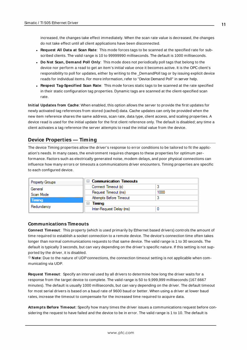
Device Propert ies — TimingThe device Timing properties allow the driver's response to error conditions to be tailored to fit the applic-
ation's needs. In many cases, the environment requires changes to these properties for optimum per-
formance. Factors such as electrically generated noise, modem delays, and poor physical connections can
influence how many errors or timeouts a communications driver encounters. Timing properties are specific
to each configured device.
Communications TimeoutsConnect Timeout : This property (which is used primarily by Ethernet based drivers) controls the amount of
time required to establish a socket connection to a remote device. The device's connection time often takes
longer than normal communications requests to that same device. The valid range is 1 to 30 seconds. The
default is typically 3 seconds, but can vary depending on the driver's specific nature. If this setting is not sup-
ported by the driver, it is disabled.Note: Due to the nature of UDP connections, the connection timeout setting is not applicable when com-
municating via UDP.
Request Timeout : Specify an interval used by all drivers to determine how long the driver waits for a
response from the target device to complete. The valid range is 50 to 9,999,999 milliseconds (167.6667
minutes). The default is usually 1000 milliseconds, but can vary depending on the driver. The default timeout
for most serial drivers is based on a baud rate of 9600 baud or better. When using a driver at lower baud
rates, increase the timeout to compensate for the increased time required to acquire data.
Attempts Before Timeout : Specify how many times the driver issues a communications request before con-
sidering the request to have failed and the device to be in error. The valid range is 1 to 10. The default is
www.ptc.com
11
Simatic / TI 505 Ethernet Driver
typically 3, but can vary depending on the driver's specific nature. The number of attempts configured for an
application depends largely on the communications environment. This property applies to both connection
attempts and request attempts.
TimingInter-Request Delay: Specify how long the driver waits before sending the next request to the target
device. It overrides the normal polling frequency of tags associated with the device, as well as one-time
reads and writes. This delay can be useful when dealing with devices with slow turnaround times and in
cases where network load is a concern. Configuring a delay for a device affects communications with all
other devices on the channel. It is recommended that users separate any device that requires an inter-
request delay to a separate channel if possible. Other communications properties (such as communication
serialization) can extend this delay. The valid range is 0 to 300,000 milliseconds; however, some drivers may
limit the maximum value due to a function of their particular design. The default is 0, which indicates no
delay between requests with the target device.Note: Not all drivers support Inter-Request Delay. This setting does not appear if it is not available.
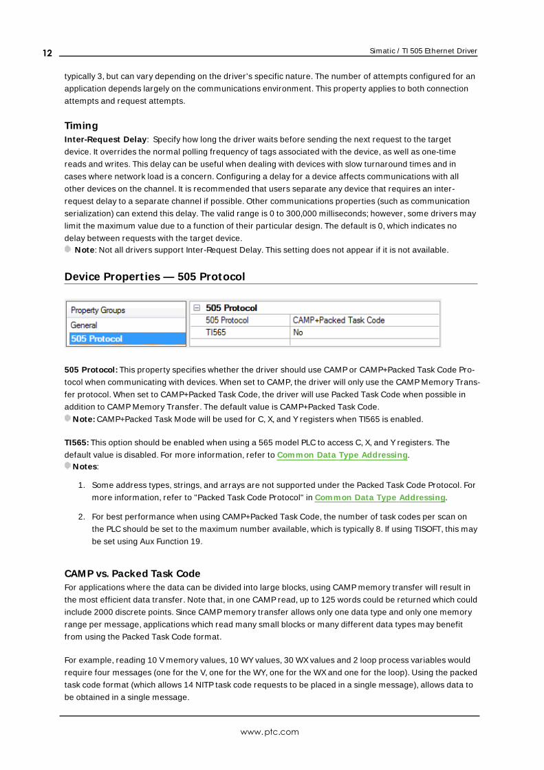
Device Propert ies — 505 Protocol
505 Protocol: This property specifies whether the driver should use CAMP or CAMP+Packed Task Code Pro-
tocol when communicating with devices. When set to CAMP, the driver will only use the CAMP Memory Trans-
fer protocol. When set to CAMP+Packed Task Code, the driver will use Packed Task Code when possible in
addition to CAMP Memory Transfer. The default value is CAMP+Packed Task Code.
Note: CAMP+Packed Task Mode will be used for C, X, and Y registers when TI565 is enabled.
TI565: This option should be enabled when using a 565 model PLC to access C, X, and Y registers. The
default value is disabled. For more information, refer to Common Data Type Addressing.Notes:
1. Some address types, strings, and arrays are not supported under the Packed Task Code Protocol. For
more information, refer to "Packed Task Code Protocol" in Common Data Type Addressing.
2. For best performance when using CAMP+Packed Task Code, the number of task codes per scan on
the PLC should be set to the maximum number available, which is typically 8. If using TISOFT, this may
be set using Aux Function 19.
CAMP vs. Packed Task CodeFor applications where the data can be divided into large blocks, using CAMP memory transfer will result in
the most efficient data transfer. Note that, in one CAMP read, up to 125 words could be returned which could
include 2000 discrete points. Since CAMP memory transfer allows only one data type and only one memory
range per message, applications which read many small blocks or many different data types may benefit
from using the Packed Task Code format.
For example, reading 10 V memory values, 10 WY values, 30 WX values and 2 loop process variables would
require four messages (one for the V, one for the WY, one for the WX and one for the loop). Using the packed
task code format (which allows 14 NITP task code requests to be placed in a single message), allows data to
be obtained in a single message.
www.ptc.com
12
Simatic / TI 505 Ethernet Driver
Optimum Performance RecommendationsAll devices on a channel should be set to the same 505 Protocol mode. When possible, the project's data
should be divided into the following categories:
1. Items that are capable of utilizing Packed Task Code.
2. Items that are not capable of utilizing Packed Task Code. This includes the following:
l Arrays
l Strings
l Address types that are not supported with Packed Task Code.
l Contiguous address ranges > 36 Words. For example, V1, V2, V3, ... V36, V37, V38.
All items in Category 1 should be placed into a device that is set to CAMP+Packed Task Code 505 Protocol
mode on a different channel from Category 2 items. It is recommended that the request size be set to 64 or
128.
All items in Category 2 should be placed into a device that is set to CAMP 505 Protocol mode on a different
channel from Category 1 items. It is recommended that the Request Size be set to 250.
Note: When reading a project file prior to addition of 505 Protocol option, the default value is set to CAMP.
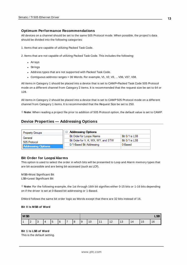
Device Propert ies — Addressing Options
Bit Order for Loops/AlarmsThis option is used to select the order in which bits will be presented to Loop and Alarm memory types that
are bit-accessible and are being bit-accessed (such as LCF).
MSB=Most Significant BitLSB=Least Significant Bit
Note: For the following example, the 1st through 16th bit signifies either 0-15 bits or 1-16 bits depending
on if the driver is set at 0-Based bit addressing or 1-Based.
DWord follows the same bit order logic as Words except that there are 32 bits instead of 16.
Bit 0 Is MSB of Word
M SB LSB
1 2 3 4 5 6 7 8 9 10 11 12 13 14 15 16
Bit 1 Is LSB of WordThis is the default setting.
www.ptc.com
13
Simatic / TI 505 Ethernet Driver
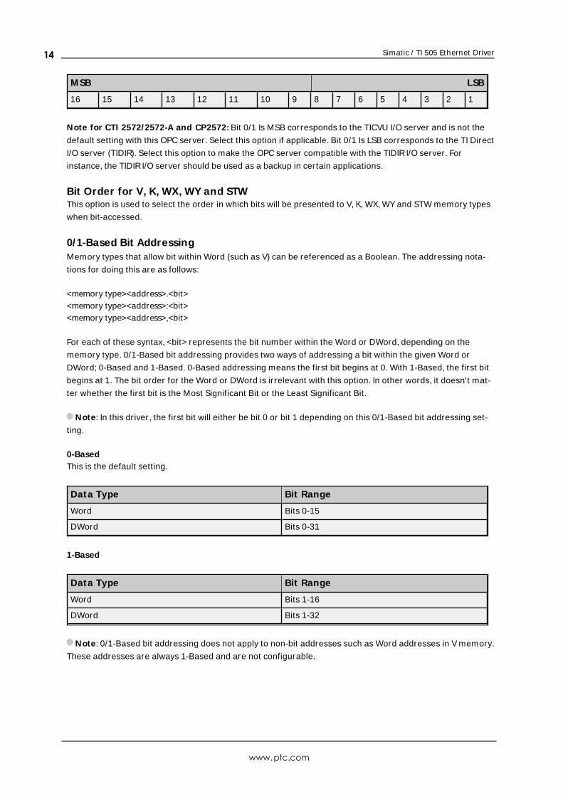
M SB LSB
16 15 14 13 12 11 10 9 8 7 6 5 4 3 2 1
Note for CTI 2572/2572-A and CP2572: Bit 0/1 Is MSB corresponds to the TICVU I/O server and is not the
default setting with this OPC server. Select this option if applicable. Bit 0/1 Is LSB corresponds to the TI Direct
I/O server (TIDIR). Select this option to make the OPC server compatible with the TIDIRI/O server. For
instance, the TIDIRI/O server should be used as a backup in certain applications.
Bit Order for V, K, WX, WY and STWThis option is used to select the order in which bits will be presented to V, K, WX, WY and STW memory types
when bit-accessed.
0/1-Based Bit AddressingMemory types that allow bit within Word (such as V) can be referenced as a Boolean. The addressing nota-
tions for doing this are as follows:
<memory type><address>.<bit><memory type><address>:<bit><memory type><address>,<bit>
For each of these syntax, <bit> represents the bit number within the Word or DWord, depending on the
memory type. 0/1-Based bit addressing provides two ways of addressing a bit within the given Word or
DWord; 0-Based and 1-Based. 0-Based addressing means the first bit begins at 0. With 1-Based, the first bit
begins at 1. The bit order for the Word or DWord is irrelevant with this option. In other words, it doesn't mat-
ter whether the first bit is the Most Significant Bit or the Least Significant Bit.
Note: In this driver, the first bit will either be bit 0 or bit 1 depending on this 0/1-Based bit addressing set-
ting.
0-BasedThis is the default setting.
Data Type Bit Range
Word Bits 0-15
DWord Bits 0-31
1-Based
Data Type Bit Range
Word Bits 1-16
DWord Bits 1-32
Note: 0/1-Based bit addressing does not apply to non-bit addresses such as Word addresses in V memory.
These addresses are always 1-Based and are not configurable.
www.ptc.com
14
Simatic / TI 505 Ethernet Driver
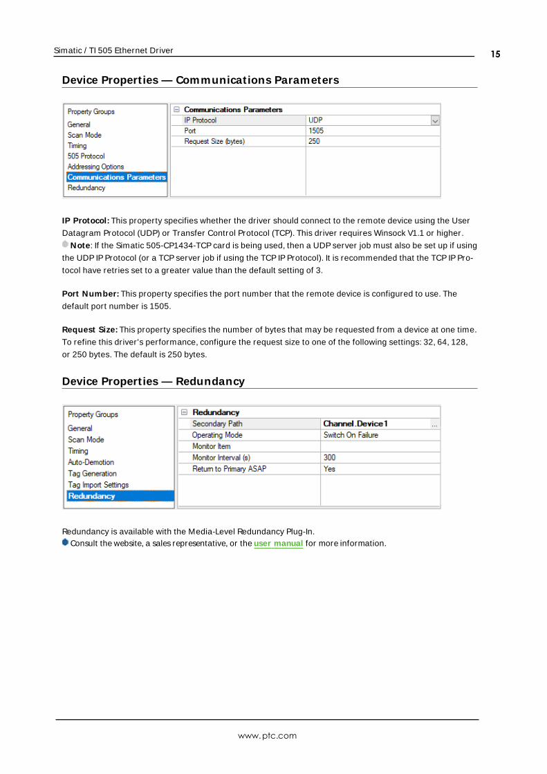
Device Propert ies — Communications Parameters
IP Protocol: This property specifies whether the driver should connect to the remote device using the User
Datagram Protocol (UDP) or Transfer Control Protocol (TCP). This driver requires Winsock V1.1 or higher.
Note: If the Simatic 505-CP1434-TCP card is being used, then a UDP server job must also be set up if using
the UDP IP Protocol (or a TCP server job if using the TCP IP Protocol). It is recommended that the TCP IP Pro-
tocol have retries set to a greater value than the default setting of 3.
Port Number: This property specifies the port number that the remote device is configured to use. The
default port number is 1505.
Request Size: This property specifies the number of bytes that may be requested from a device at one time.
To refine this driver's performance, configure the request size to one of the following settings: 32, 64, 128,
or 250 bytes. The default is 250 bytes.
Device Propert ies — Redundancy
Redundancy is available with the Media-Level Redundancy Plug-In.Consult the website, a sales representative, or the user manual for more information.
www.ptc.com
15
Simatic / TI 505 Ethernet Driver
Optimizing CommunicationsThe Simatic / TI 505 Ethernet Driver has been designed to provide the best performance with the least
amount of impact on the system's overall performance. While the Simatic / TI 505 Ethernet Driver is fast,
there are a couple of guidelines that can be used to control and optimize the application and gain maximum
performance.
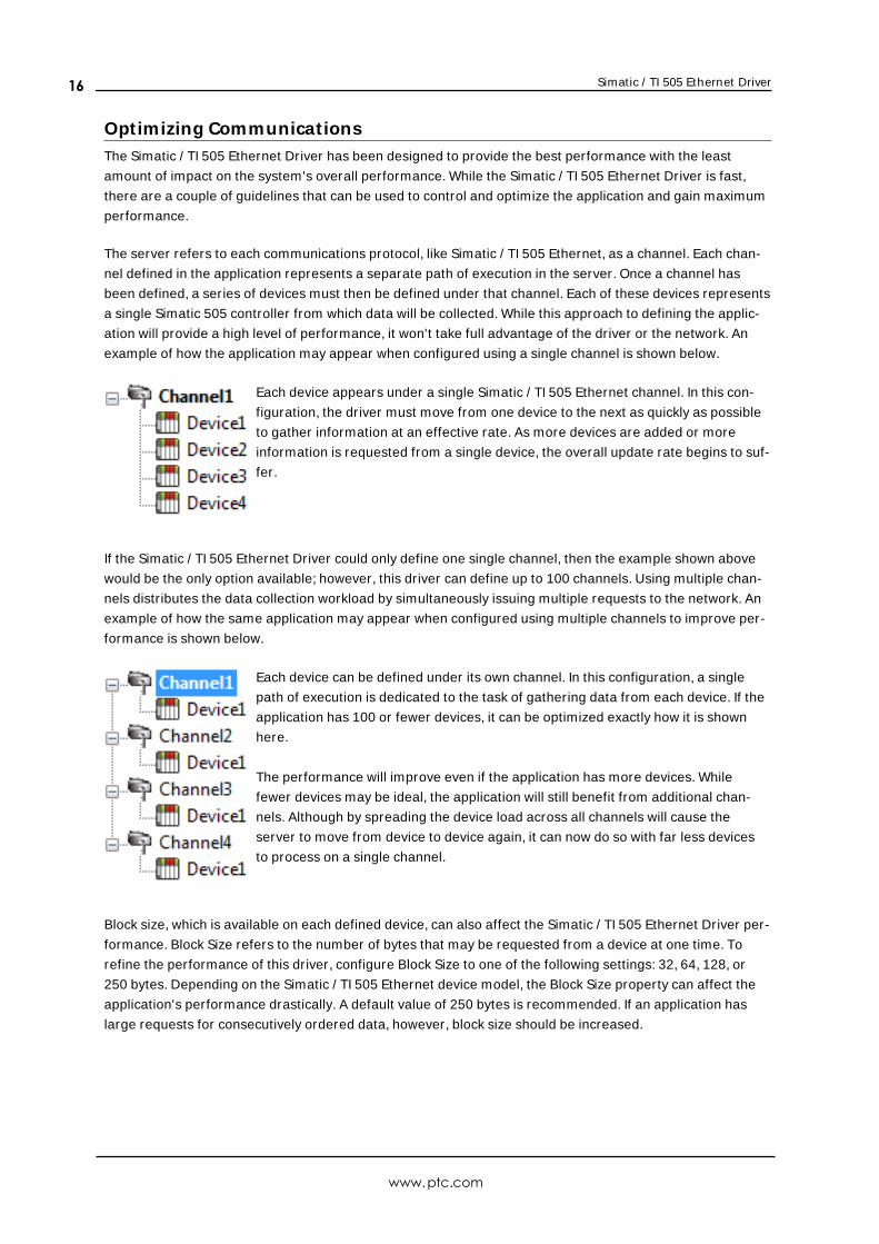
The server refers to each communications protocol, like Simatic / TI 505 Ethernet, as a channel. Each chan-
nel defined in the application represents a separate path of execution in the server. Once a channel has
been defined, a series of devices must then be defined under that channel. Each of these devices represents
a single Simatic 505 controller from which data will be collected. While this approach to defining the applic-
ation will provide a high level of performance, it won't take full advantage of the driver or the network. An
example of how the application may appear when configured using a single channel is shown below.
Each device appears under a single Simatic / TI 505 Ethernet channel. In this con-
figuration, the driver must move from one device to the next as quickly as possible
to gather information at an effective rate. As more devices are added or more
information is requested from a single device, the overall update rate begins to suf-
fer.
If the Simatic / TI 505 Ethernet Driver could only define one single channel, then the example shown above
would be the only option available; however, this driver can define up to 100 channels. Using multiple chan-
nels distributes the data collection workload by simultaneously issuing multiple requests to the network. An
example of how the same application may appear when configured using multiple channels to improve per-
formance is shown below.
Each device can be defined under its own channel. In this configuration, a single
path of execution is dedicated to the task of gathering data from each device. If the
application has 100 or fewer devices, it can be optimized exactly how it is shown
here.
The performance will improve even if the application has more devices. While
fewer devices may be ideal, the application will still benefit from additional chan-
nels. Although by spreading the device load across all channels will cause the
server to move from device to device again, it can now do so with far less devices
to process on a single channel.
Block size, which is available on each defined device, can also affect the Simatic / TI 505 Ethernet Driver per-
formance. Block Size refers to the number of bytes that may be requested from a device at one time. To
refine the performance of this driver, configure Block Size to one of the following settings: 32, 64, 128, or
250 bytes. Depending on the Simatic / TI 505 Ethernet device model, the Block Size property can affect the
application's performance drastically. A default value of 250 bytes is recommended. If an application has
large requests for consecutively ordered data, however, block size should be increased.
www.ptc.com
16
Simatic / TI 505 Ethernet Driver
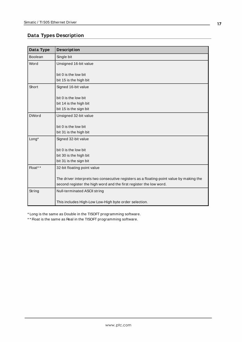
Data Types Descript ion
Data Type Descript ion
Boolean Single bit
Word Unsigned 16-bit value
bit 0 is the low bit
bit 15 is the high bit
Short Signed 16-bit value
bit 0 is the low bit
bit 14 is the high bit
bit 15 is the sign bit
DWord Unsigned 32-bit value
bit 0 is the low bit
bit 31 is the high bit
Long* Signed 32-bit value
bit 0 is the low bit
bit 30 is the high bit
bit 31 is the sign bit
Float* * 32-bit floating point value
The driver interprets two consecutive registers as a floating-point value by making the
second register the high word and the first register the low word.
String Null-terminated ASCII string
This includes High-Low Low-High byte order selection.
* Long is the same as Double in the TISOFT programming software.* * Float is the same as Real in the TISOFT programming software.
www.ptc.com
17
Simatic / TI 505 Ethernet Driver
Address Descript ionsAddress specifications vary depending on the model in use. Select a link from the following list to obtain spe-
cific address information for the model of interest.
Addressing
Common Data Type Addressing
Status Words
AddressingThe following sections define addressing.
Common Data Type Addressing
Alarm Addressing
Loop Addressing
Find Forced Addressing
For information on the Event Log, refer the server help documentation.
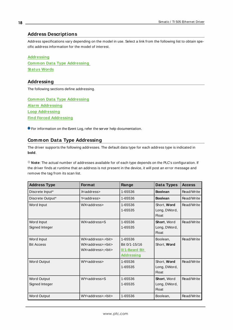
Common Data Type AddressingThe driver supports the following addresses. The default data type for each address type is indicated in
bold.
Note: The actual number of addresses available for of each type depends on the PLC's configuration. If
the driver finds at runtime that an address is not present in the device, it will post an error message and
remove the tag from its scan list.
Address Type Format Range Data Types Access
Discrete Input* X<address> 1-65536 Boolean Read/Write
Discrete Output* Y<address> 1-65536 Boolean Read/Write
Word Input WX<address> 1-65536
1-65535
Short, Word
Long, DWord,
Float
Read/Write
Word Input
Signed Integer
WX<address>S 1-65536
1-65535
Short , Word
Long, DWord,
Float
Read/Write
Word Input
Bit Access
WX<address>.<bit>
WX<address>:<bit>
WX<address>,<bit>
1-65536
Bit 0/1-15/16
0/1-Based Bit
Addressing
Boolean,
Short, Word
Read/Write
Word Output WY<address> 1-65536
1-65535
Short, Word
Long, DWord,
Float
Read/Write
Word Output
Signed Integer
WY<address>S 1-65536
1-65535
Short , Word
Long, DWord,
Float
Read/Write
Word Output WY<address>.<bit> 1-65536 Boolean, Read/Write
www.ptc.com
18
Simatic / TI 505 Ethernet Driver
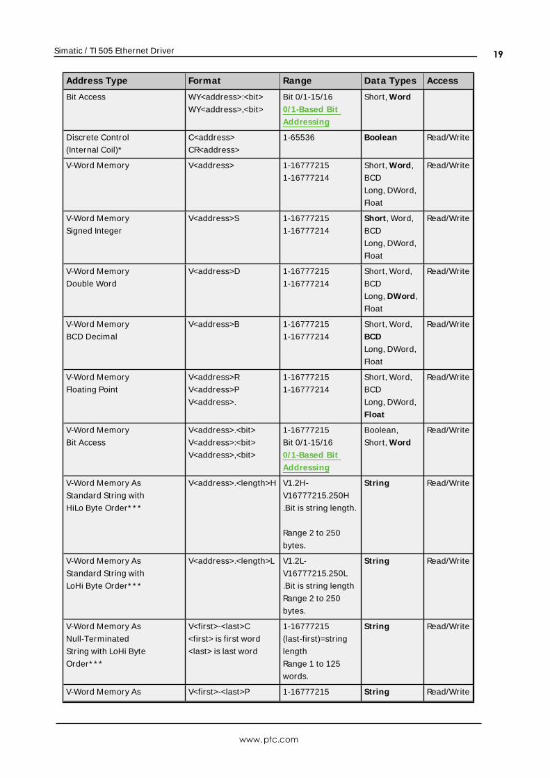
Address Type Format Range Data Types Access
Bit Access WY<address>:<bit>
WY<address>,<bit>
Bit 0/1-15/16
0/1-Based Bit
Addressing
Short, Word
Discrete Control
(Internal Coil)*
C<address>
CR<address>
1-65536 Boolean Read/Write
V-Word Memory V<address> 1-16777215
1-16777214
Short, Word,
BCD
Long, DWord,
Float
Read/Write
V-Word Memory
Signed Integer
V<address>S 1-16777215
1-16777214
Short , Word,
BCD
Long, DWord,
Float
Read/Write
V-Word Memory
Double Word
V<address>D 1-16777215
1-16777214
Short, Word,
BCD
Long, DWord,
Float
Read/Write
V-Word Memory
BCD Decimal
V<address>B 1-16777215
1-16777214
Short, Word,
BCD
Long, DWord,
Float
Read/Write
V-Word Memory
Floating Point
V<address>R
V<address>P
V<address>.
1-16777215
1-16777214
Short, Word,
BCD
Long, DWord,
Float
Read/Write
V-Word Memory
Bit Access
V<address>.<bit>
V<address>:<bit>
V<address>,<bit>
1-16777215
Bit 0/1-15/16
0/1-Based Bit
Addressing
Boolean,
Short, Word
Read/Write
V-Word Memory As
Standard String with
HiLo Byte Order* * *
V<address>.<length>H V1.2H-
V16777215.250H
.Bit is string length.
Range 2 to 250
bytes.
String Read/Write
V-Word Memory As
Standard String with
LoHi Byte Order* * *
V<address>.<length>L V1.2L-
V16777215.250L
.Bit is string length
Range 2 to 250
bytes.
String Read/Write
V-Word Memory As
Null-Terminated
String with LoHi Byte
Order* * *
V<first>-<last>C
<first> is first word
<last> is last word
1-16777215
(last-first)=string
length
Range 1 to 125
words.
String Read/Write
V-Word Memory As V<first>-<last>P 1-16777215 String Read/Write
www.ptc.com
19
Simatic / TI 505 Ethernet Driver
Address Type Format Range Data Types Access
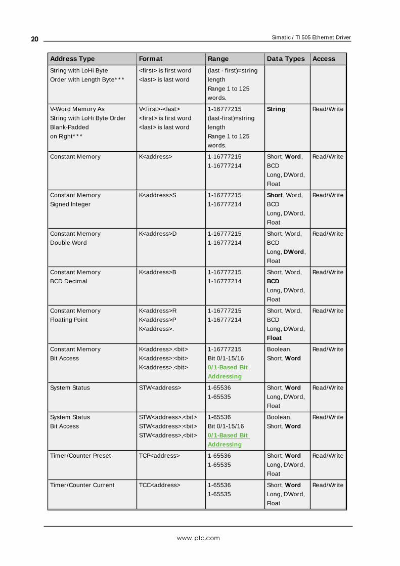
String with LoHi Byte
Order with Length Byte* * *
<first> is first word
<last> is last word
(last - first)=string
length
Range 1 to 125
words.
V-Word Memory As
String with LoHi Byte Order
Blank-Padded
on Right* * *
V<first>-<last>
<first> is first word
<last> is last word
1-16777215
(last-first)=string
length
Range 1 to 125
words.
String Read/Write
Constant Memory K<address> 1-16777215
1-16777214
Short, Word,
BCD
Long, DWord,
Float
Read/Write
Constant Memory
Signed Integer
K<address>S 1-16777215
1-16777214
Short , Word,
BCD
Long, DWord,
Float
Read/Write
Constant Memory
Double Word
K<address>D 1-16777215
1-16777214
Short, Word,
BCD
Long, DWord,
Float
Read/Write
Constant Memory
BCD Decimal
K<address>B 1-16777215
1-16777214
Short, Word,
BCD
Long, DWord,
Float
Read/Write
Constant Memory
Floating Point
K<address>R
K<address>P
K<address>.
1-16777215
1-16777214
Short, Word,
BCD
Long, DWord,
Float
Read/Write
Constant Memory
Bit Access
K<address>.<bit>
K<address>:<bit>
K<address>,<bit>
1-16777215
Bit 0/1-15/16
0/1-Based Bit
Addressing
Boolean,
Short, Word
Read/Write
System Status STW<address> 1-65536
1-65535
Short, Word
Long, DWord,
Float
Read/Write
System Status
Bit Access
STW<address>.<bit>
STW<address>:<bit>
STW<address>,<bit>
1-65536
Bit 0/1-15/16
0/1-Based Bit
Addressing
Boolean,
Short, Word
Read/Write
Timer/Counter Preset TCP<address> 1-65536
1-65535
Short, Word
Long, DWord,
Float
Read/Write
Timer/Counter Current TCC<address> 1-65536
1-65535
Short, Word
Long, DWord,
Float
Read/Write
www.ptc.com
20
Simatic / TI 505 Ethernet Driver
Address Type Format Range Data Types Access
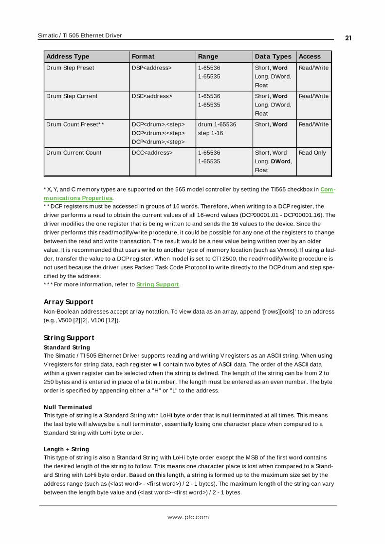
Drum Step Preset DSP<address> 1-65536
1-65535
Short, Word
Long, DWord,
Float
Read/Write
Drum Step Current DSC<address> 1-65536
1-65535
Short, Word
Long, DWord,
Float
Read/Write
Drum Count Preset* * DCP<drum>.<step>
DCP<drum>:<step>
DCP<drum>,<step>
drum 1-65536
step 1-16
Short, Word Read/Write
Drum Current Count DCC<address> 1-65536
1-65535
Short, Word
Long, DWord,
Float
Read Only
* X, Y, and C memory types are supported on the 565 model controller by setting the TI565 checkbox in Com-
munications Properties.* * DCP registers must be accessed in groups of 16 words. Therefore, when writing to a DCP register, the
driver performs a read to obtain the current values of all 16-word values (DCP00001.01 - DCP00001.16). The
driver modifies the one register that is being written to and sends the 16 values to the device. Since the
driver performs this read/modify/write procedure, it could be possible for any one of the registers to change
between the read and write transaction. The result would be a new value being written over by an older
value. It is recommended that users write to another type of memory location (such as Vxxxxx). If using a lad-
der, transfer the value to a DCP register. When model is set to CTI 2500, the read/modify/write procedure is
not used because the driver uses Packed Task Code Protocol to write directly to the DCP drum and step spe-
cified by the address.* * * For more information, refer to String Support .
Array SupportNon-Boolean addresses accept array notation. To view data as an array, append '[rows][cols]' to an address
(e.g., V500 [2][2], V100 [12]).
String SupportStandard StringThe Simatic / TI 505 Ethernet Driver supports reading and writing V registers as an ASCII string. When using
V registers for string data, each register will contain two bytes of ASCII data. The order of the ASCII data
within a given register can be selected when the string is defined. The length of the string can be from 2 to
250 bytes and is entered in place of a bit number. The length must be entered as an even number. The byte
order is specified by appending either a "H" or "L" to the address.
Null TerminatedThis type of string is a Standard String with LoHi byte order that is null terminated at all times. This means
the last byte will always be a null terminator, essentially losing one character place when compared to a
Standard String with LoHi byte order.
Length + StringThis type of string is also a Standard String with LoHi byte order except the MSB of the first word contains
the desired length of the string to follow. This means one character place is lost when compared to a Stand-
ard String with LoHi byte order. Based on this length, a string is formed up to the maximum size set by the
address range (such as (<last word> - <first word>) / 2 - 1 bytes). The maximum length of the string can vary
between the length byte value and (<last word>-<first word>) / 2 - 1 bytes.
www.ptc.com
21
Simatic / TI 505 Ethernet Driver
Note: Any null terminators in the string can cut the length short of these maximum lengths. If a string to
be written is less than this maximum length, it will be padded on the right with blank-spaces until all max-
imum bytes contain a non-NULL value.
Blank-Padded on RightThis type of string is a Standard String with LoHi byte order except the string length is always the maximum
because the string is padded with blank spaces on the right until its length becomes the maximum (no
NULLs). Recall the maximum length of the string is (<last word> - <first word>) / 2 bytes in the address. If a
string to be written is less than this maximum length, it too will be padded on the right with blank-spaces
until all maximum bytes contain a non-NULL value.
Example 1: Standard StringTo address a string starting at V200 with a length of 50 bytes and HiLo byte order, enter V200.50H.
Example 2: Standard StringTo address a string starting at V500 with a length of 38 bytes and LoHi byte order, enter V500.38L.
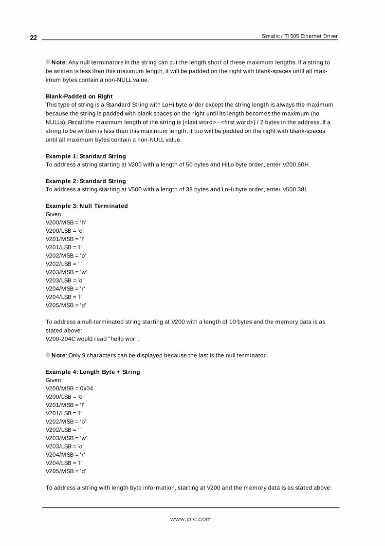
Example 3: Null TerminatedGiven:V200/MSB = 'h'V200/LSB = 'e'V201/MSB = 'l'V201/LSB = 'l'V202/MSB = 'o'V202/LSB = ' 'V203/MSB = 'w'V203/LSB = 'o'V204/MSB = 'r'V204/LSB = 'l'V205/MSB = 'd'
To address a null-terminated string starting at V200 with a length of 10 bytes and the memory data is as
stated above:V200-204C would read "hello wor".
Note: Only 9 characters can be displayed because the last is the null terminator.
Example 4: Length Byte + StringGiven:V200/MSB = 0x04V200/LSB = 'e'V201/MSB = 'l'V201/LSB = 'l'V202/MSB = 'o'V202/LSB = ' 'V203/MSB = 'w'V203/LSB = 'o'V204/MSB = 'r'V204/LSB = 'l'V205/MSB = 'd'
To address a string with length byte information, starting at V200 and the memory data is as stated above:
www.ptc.com
22
Simatic / TI 505 Ethernet Driver
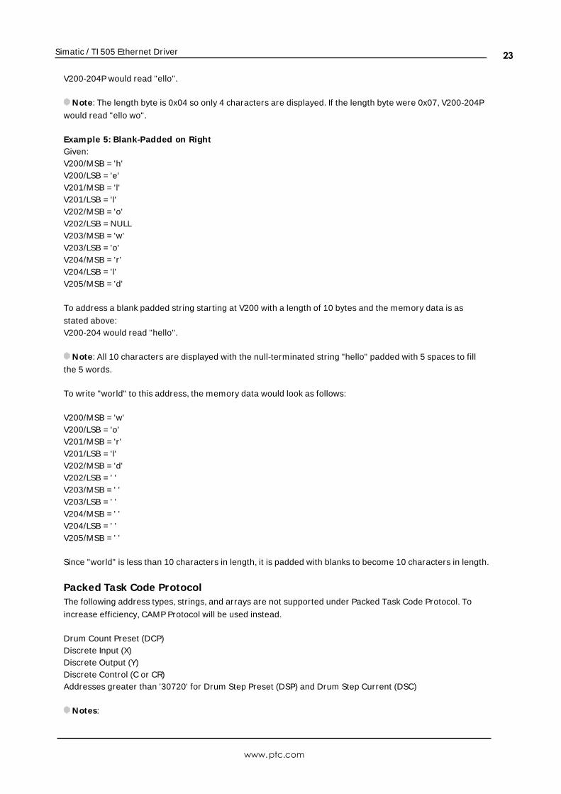
V200-204P would read "ello".
Note: The length byte is 0x04 so only 4 characters are displayed. If the length byte were 0x07, V200-204P
would read "ello wo".
Example 5: Blank-Padded on RightGiven:V200/MSB = 'h'V200/LSB = 'e'V201/MSB = 'l'V201/LSB = 'l'V202/MSB = 'o'V202/LSB = NULLV203/MSB = 'w'V203/LSB = 'o'V204/MSB = 'r'V204/LSB = 'l'V205/MSB = 'd'
To address a blank padded string starting at V200 with a length of 10 bytes and the memory data is as
stated above:V200-204 would read "hello".
Note: All 10 characters are displayed with the null-terminated string "hello" padded with 5 spaces to fill
the 5 words.
To write "world" to this address, the memory data would look as follows:
V200/MSB = 'w'V200/LSB = 'o'V201/MSB = 'r'V201/LSB = 'l'V202/MSB = 'd'V202/LSB = ' 'V203/MSB = ' 'V203/LSB = ' 'V204/MSB = ' 'V204/LSB = ' 'V205/MSB = ' '
Since "world" is less than 10 characters in length, it is padded with blanks to become 10 characters in length.
Packed Task Code ProtocolThe following address types, strings, and arrays are not supported under Packed Task Code Protocol. To
increase efficiency, CAMP Protocol will be used instead.
Drum Count Preset (DCP)Discrete Input (X)Discrete Output (Y)Discrete Control (C or CR)Addresses greater than '30720' for Drum Step Preset (DSP) and Drum Step Current (DSC)
Notes:
www.ptc.com
23
Simatic / TI 505 Ethernet Driver
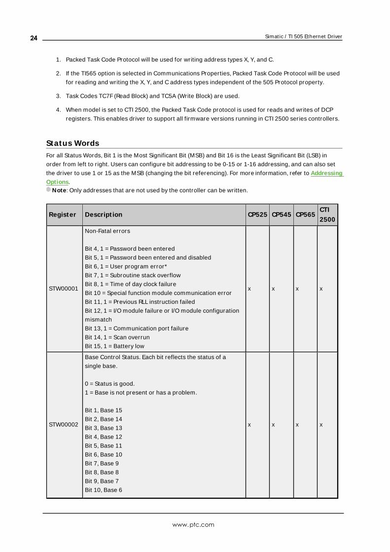
1. Packed Task Code Protocol will be used for writing address types X, Y, and C.
2. If the TI565 option is selected in Communications Properties, Packed Task Code Protocol will be used
for reading and writing the X, Y, and C address types independent of the 505 Protocol property.
3. Task Codes TC7F (Read Block) and TC5A (Write Block) are used.
4. When model is set to CTI 2500, the Packed Task Code protocol is used for reads and writes of DCP
registers. This enables driver to support all firmware versions running in CTI 2500 series controllers.
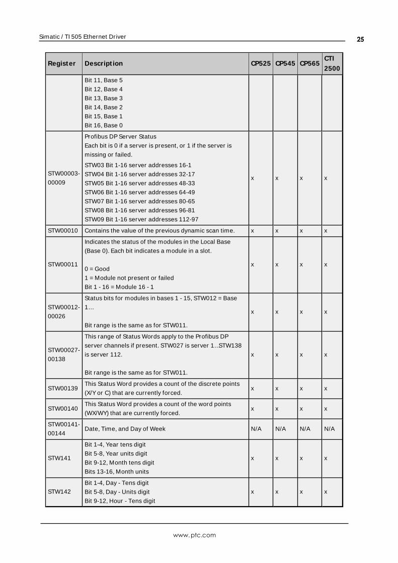
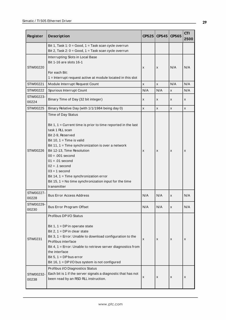
Status WordsFor all Status Words, Bit 1 is the Most Significant Bit (MSB) and Bit 16 is the Least Significant Bit (LSB) in
order from left to right. Users can configure bit addressing to be 0-15 or 1-16 addressing, and can also set
the driver to use 1 or 15 as the MSB (changing the bit referencing). For more information, refer to Addressing
Options.Note: Only addresses that are not used by the controller can be written.
Register Descript ion CP525 CP545 CP565CTI
2500
STW00001
Non-Fatal errors
Bit 4, 1 = Password been entered
Bit 5, 1 = Password been entered and disabled
Bit 6, 1 = User program error*
Bit 7, 1 = Subroutine stack overflow
Bit 8, 1 = Time of day clock failure
Bit 10 = Special function module communication error
Bit 11, 1 = Previous RLL instruction failed
Bit 12, 1 = I/O module failure or I/O module configuration
mismatch
Bit 13, 1 = Communication port failure
Bit 14, 1 = Scan overrun
Bit 15, 1 = Battery low
x x x x
STW00002
Base Control Status. Each bit reflects the status of a
single base.
0 = Status is good.
1 = Base is not present or has a problem.
Bit 1, Base 15
Bit 2, Base 14
Bit 3, Base 13
Bit 4, Base 12
Bit 5, Base 11
Bit 6, Base 10
Bit 7, Base 9
Bit 8, Base 8
Bit 9, Base 7
Bit 10, Base 6
x x x x
www.ptc.com
24
Simatic / TI 505 Ethernet Driver
Register Descript ion CP525 CP545 CP565CTI
2500
Bit 11, Base 5
Bit 12, Base 4
Bit 13, Base 3
Bit 14, Base 2
Bit 15, Base 1
Bit 16, Base 0
STW00003-
00009
Profibus DP Server Status
Each bit is 0 if a server is present, or 1 if the server is
missing or failed.
STW03 Bit 1-16 server addresses 16-1
STW04 Bit 1-16 server addresses 32-17
STW05 Bit 1-16 server addresses 48-33
STW06 Bit 1-16 server addresses 64-49
STW07 Bit 1-16 server addresses 80-65
STW08 Bit 1-16 server addresses 96-81
STW09 Bit 1-16 server addresses 112-97
x x x x
STW00010 Contains the value of the previous dynamic scan time. x x x x
STW00011
Indicates the status of the modules in the Local Base
(Base 0). Each bit indicates a module in a slot.
0 = Good
1 = Module not present or failed
Bit 1 - 16 = Module 16 - 1
x x x x
STW00012-
00026
Status bits for modules in bases 1 - 15, STW012 = Base
1…
Bit range is the same as for STW011.
x x x x
STW00027-
00138
This range of Status Words apply to the Profibus DP
server channels if present. STW027 is server 1…STW138
is server 112.
Bit range is the same as for STW011.
x x x x
STW00139This Status Word provides a count of the discrete points
(X/Y or C) that are currently forced.x x x x
STW00140This Status Word provides a count of the word points
(WX/WY) that are currently forced.x x x x
STW00141-
00144Date, Time, and Day of Week N/A N/A N/A N/A
STW141
Bit 1-4, Year tens digit
Bit 5-8, Year units digit
Bit 9-12, Month tens digit
Bits 13-16, Month units
x x x x
STW142
Bit 1-4, Day - Tens digit
Bit 5-8, Day - Units digit
Bit 9-12, Hour - Tens digit
x x x x
www.ptc.com
25
Simatic / TI 505 Ethernet Driver
Register Descript ion CP525 CP545 CP565CTI
2500
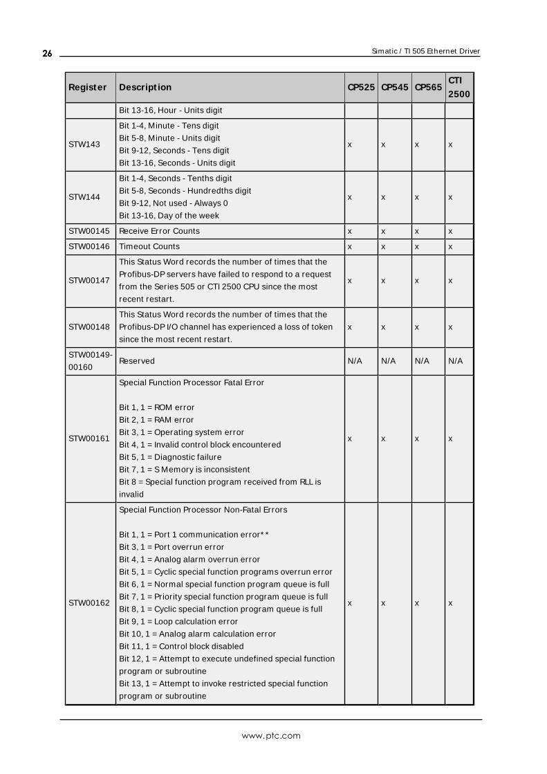
Bit 13-16, Hour - Units digit
STW143
Bit 1-4, Minute - Tens digit
Bit 5-8, Minute - Units digit
Bit 9-12, Seconds - Tens digit
Bit 13-16, Seconds - Units digit
x x x x
STW144
Bit 1-4, Seconds - Tenths digit
Bit 5-8, Seconds - Hundredths digit
Bit 9-12, Not used - Always 0
Bit 13-16, Day of the week
x x x x
STW00145 Receive Error Counts x x x x
STW00146 Timeout Counts x x x x
STW00147
This Status Word records the number of times that the
Profibus-DP servers have failed to respond to a request
from the Series 505 or CTI 2500 CPU since the most
recent restart.
x x x x
STW00148
This Status Word records the number of times that the
Profibus-DP I/O channel has experienced a loss of token
since the most recent restart.
x x x x
STW00149-
00160Reserved N/A N/A N/A N/A
STW00161
Special Function Processor Fatal Error
Bit 1, 1 = ROM error
Bit 2, 1 = RAM error
Bit 3, 1 = Operating system error
Bit 4, 1 = Invalid control block encountered
Bit 5, 1 = Diagnostic failure
Bit 7, 1 = S Memory is inconsistent
Bit 8 = Special function program received from RLL is
invalid
x x x x
STW00162
Special Function Processor Non-Fatal Errors
Bit 1, 1 = Port 1 communication error* *
Bit 3, 1 = Port overrun error
Bit 4, 1 = Analog alarm overrun error
Bit 5, 1 = Cyclic special function programs overrun error
Bit 6, 1 = Normal special function program queue is full
Bit 7, 1 = Priority special function program queue is full
Bit 8, 1 = Cyclic special function program queue is full
Bit 9, 1 = Loop calculation error
Bit 10, 1 = Analog alarm calculation error
Bit 11, 1 = Control block disabled
Bit 12, 1 = Attempt to execute undefined special function
program or subroutine
Bit 13, 1 = Attempt to invoke restricted special function
program or subroutine
x x x x
www.ptc.com
26
Simatic / TI 505 Ethernet Driver
Register Descript ion CP525 CP545 CP565CTI
2500
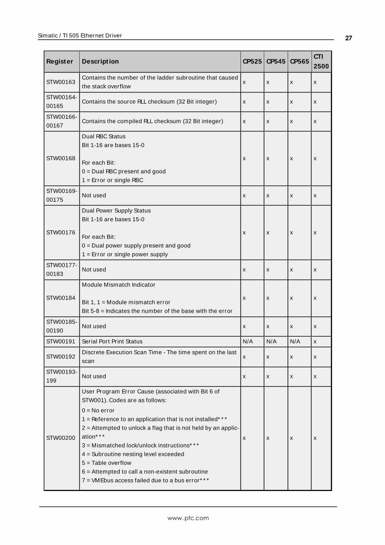
STW00163Contains the number of the ladder subroutine that caused
the stack overflowx x x x
STW00164-
00165Contains the source RLL checksum (32 Bit integer) x x x x
STW00166-
00167Contains the compiled RLL checksum (32 Bit integer) x x x x
STW00168
Dual RBC Status
Bit 1-16 are bases 15-0
For each Bit:
0 = Dual RBC present and good
1 = Error or single RBC
x x x x
STW00169-
00175Not used x x x x
STW00176
Dual Power Supply Status
Bit 1-16 are bases 15-0
For each Bit:
0 = Dual power supply present and good
1 = Error or single power supply
x x x x
STW00177-
00183Not used x x x x
STW00184
Module Mismatch Indicator
Bit 1, 1 = Module mismatch error
Bit 5-8 = Indicates the number of the base with the error
x x x x
STW00185-
00190Not used x x x x
STW00191 Serial Port Print Status N/A N/A N/A x
STW00192Discrete Execution Scan Time - The time spent on the last
scanx x x x
STW00193-
199Not used x x x x
STW00200
User Program Error Cause (associated with Bit 6 of
STW001). Codes are as follows:
0 = No error
1 = Reference to an application that is not installed* * *
2 = Attempted to unlock a flag that is not held by an applic-
ation* * *
3 = Mismatched lock/unlock instructions* * *
4 = Subroutine nesting level exceeded
5 = Table overflow
6 = Attempted to call a non-existent subroutine
7 = VMEbus access failed due to a bus error* * *
x x x x
www.ptc.com
27
Simatic / TI 505 Ethernet Driver
Register Descript ion CP525 CP545 CP565CTI
2500
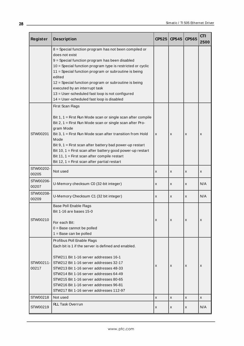
8 = Special function program has not been compiled or
does not exist
9 = Special function program has been disabled
10 = Special function program type is restricted or cyclic
11 = Special function program or subroutine is being
edited
12 = Special function program or subroutine is being
executed by an interrupt task
13 = User-scheduled fast loop is not configured
14 = User-scheduled fast loop is disabled
STW00201
First Scan Flags
Bit 1, 1 = First Run Mode scan or single scan after compile
Bit 2, 1 = First Run Mode scan or single scan after Pro-
gram Mode
Bit 3, 1 = First Run Mode scan after transition from Hold
Mode
Bit 9, 1 = First scan after battery bad power-up restart
Bit 10, 1 = First scan after battery good power-up restart
Bit 11, 1 = First scan after compile restart
Bit 12, 1 = First scan after partial restart
x x x x
STW00202-
00205Not used x x x x
STW00206-
00207U-Memory checksum C0 (32-bit integer) x x x N/A
STW00208-
00209U-Memory Checksum C1 (32 bit integer) x x x N/A
STW00210
Base Poll Enable Flags
Bit 1-16 are bases 15-0
For each Bit:
0 = Base cannot be polled
1 = Base can be polled
x x x x
STW00211-
00217
Profibus Poll Enable Flags
Each bit is 1 if the server is defined and enabled.
STW211 Bit 1-16 server addresses 16-1
STW212 Bit 1-16 server addresses 32-17
STW213 Bit 1-16 server addresses 48-33
STW214 Bit 1-16 server addresses 64-49
STW215 Bit 1-16 server addresses 80-65
STW216 Bit 1-16 server addresses 96-81
STW217 Bit 1-16 server addresses 112-97
x x x x
STW00218 Not used x x x x
STW00219RLL Task Overrun
x x x N/A
www.ptc.com
28
Simatic / TI 505 Ethernet Driver
Register Descript ion CP525 CP545 CP565CTI
2500
Bit 1, Task 1: 0 = Good, 1 = Task scan cycle overrun
Bit 2, Task 2: 0 = Good, 1 = Task scan cycle overrun
STW00220
Interrupting Slots in Local Base
Bit 1-16 are slots 16-1
For each Bit:
1 = Interrupt request active at module located in this slot
x x N/A N/A
STW00221 Module Interrupt Request Count x x N/A N/A
STW00222 Spurious Interrupt Count N/A N/A x N/A
STW00223-
00224Binary Time of Day (32 bit integer) x x x x
STW00225 Binary Relative Day (with 1/1/1984 being day 0) x x x x
STW00226
Time of Day Status
Bit 1, 1 = Current time is prior to time reported in the last
task 1 RLL scan
Bit 2-9, Reserved
Bit 10, 1 = Time is valid
Bit 11, 1 = Time synchronization is over a network
Bit 12-13, Time Resolution
00 = .001 second
01 = .01 second
02 = .1 second
03 = 1 second
Bit 14, 1 = Time synchronization error
Bit 15, 1 = No time synchronization input for the time
transmitter
x x x x
STW00227-
00228Bus Error Access Address N/A N/A x N/A
STW00229-
00230Bus Error Program Offset N/A N/A x N/A
STW0231
Profibus DP I/O Status
Bit 1, 1 = DP in operate state
Bit 2, 1 = DP in clear state
Bit 3, 1 = Error: Unable to download configuration to the
Profibus interface
Bit 4, 1 = Error: Unable to retrieve server diagnostics from
the interface
Bit 5, 1 = DP bus error
Bit 16, 1 = DP I/O bus system is not configured
x x x x
STW00232-
00238
Profibus I/O Diagnostics Status
Each bit is 1 if the server signals a diagnostic that has not
been read by an RSD RLL instruction. x x x x
www.ptc.com
29
Simatic / TI 505 Ethernet Driver
Register Descript ion CP525 CP545 CP565CTI
2500
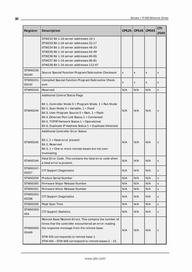
STW232 Bit 1-16 server addresses 16-1
STW233 Bit 1-16 server addresses 32-17
STW234 Bit 1-16 server addresses 48-33
STW235 Bit 1-16 server addresses 64-49
STW236 Bit 1-16 server addresses 80-65
STW237 Bit 1-16 server addresses 96-81
STW238 Bit 1-16 server addresses 112-97
STW00239-
00240Source Special Function Program/Subroutine Checksum x x x x
STW00241-
00242
Compiled Special Function Program/Subroutine Check-
sumx x x x
STW00243 Reserved N/A N/A N/A x
STW00244
Additional Control Status Flags
Bit 1, Controller Mode 0 = Program Mode, 1 = Run Mode
Bit 2, Scan Mode 0 = Variable, 1 = Fixed
Bit 3, User Program Source 0 = Ram, 1 = Flash
Bit 4, Ethernet Port Link Status 1 = Connected
Bit 5, TCP/IP Network Status 1 = Operational
Bit 6, Duplicate IP Address Status 1 = Duplicate Detected
N/A N/A N/A x
STW00245
Additional Controller Error Status
Bit 1, 1 = Fatal error present
Bit 2, Reserved
Bit 3, 1 = One or more remote bases are not com-
municating
N/A N/A N/A x
STW00246Fatal Error Code. This contains the fatal error code when
a fatal error is present.N/A N/A N/A x
STW00247-
00257CTI Support Diagnostics N/A N/A N/A x
STW00259 Product Serial Number N/A N/A N/A x
STW00260 Firmware Major Release Number N/A N/A N/A x
STW00261 Firmware Minor Release Number N/A N/A N/A x
STW00262-
00298CTI Support Diagnostics N/A N/A N/A x
STW00299 Peak Scan Time N/A N/A N/A x
STW00300-
454CTI Support Statistics N/A N/A N/A x
STW00455-
00469
Remote Base Receive Errors. This contains the number of
times that the controller encountered an error reading
the response message from the remote base.
STW 455 corresponds to remote base 1.
STW 456 – STW 469 correspond to remote bases 2 – 15.
N/A N/A N/A x
www.ptc.com
30
Simatic / TI 505 Ethernet Driver
Register Descript ion CP525 CP545 CP565CTI
2500
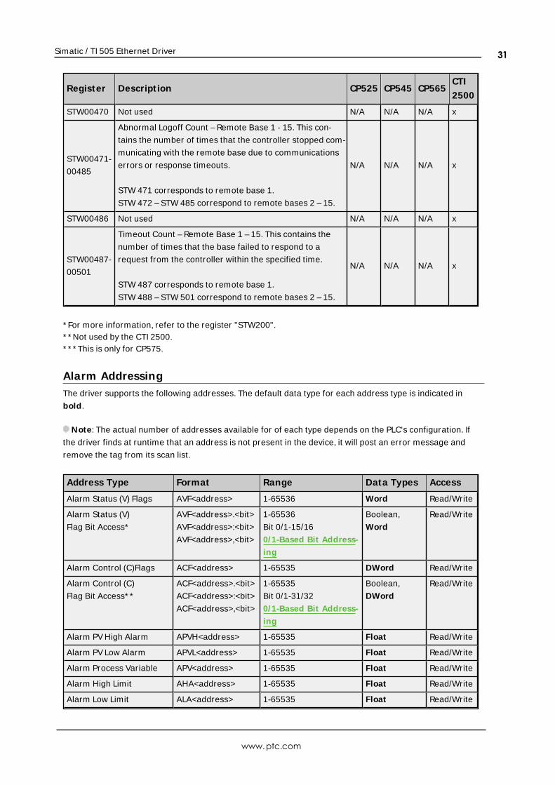
STW00470 Not used N/A N/A N/A x
STW00471-
00485
Abnormal Logoff Count – Remote Base 1 - 15. This con-
tains the number of times that the controller stopped com-
municating with the remote base due to communications
errors or response timeouts.
STW 471 corresponds to remote base 1.
STW 472 – STW 485 correspond to remote bases 2 – 15.
N/A N/A N/A x
STW00486 Not used N/A N/A N/A x
STW00487-
00501
Timeout Count – Remote Base 1 – 15. This contains the
number of times that the base failed to respond to a
request from the controller within the specified time.
STW 487 corresponds to remote base 1.
STW 488 – STW 501 correspond to remote bases 2 – 15.
N/A N/A N/A x
* For more information, refer to the register "STW200".* * Not used by the CTI 2500.* * * This is only for CP575.
Alarm AddressingThe driver supports the following addresses. The default data type for each address type is indicated in
bold.
Note: The actual number of addresses available for of each type depends on the PLC's configuration. If
the driver finds at runtime that an address is not present in the device, it will post an error message and
remove the tag from its scan list.
Address Type Format Range Data Types Access
Alarm Status (V) Flags AVF<address> 1-65536 Word Read/Write
Alarm Status (V)
Flag Bit Access*
AVF<address>.<bit>
AVF<address>:<bit>
AVF<address>,<bit>
1-65536
Bit 0/1-15/16
0/1-Based Bit Address-
ing
Boolean,
Word
Read/Write
Alarm Control (C)Flags ACF<address> 1-65535 DWord Read/Write
Alarm Control (C)
Flag Bit Access* *
ACF<address>.<bit>
ACF<address>:<bit>
ACF<address>,<bit>
1-65535
Bit 0/1-31/32
0/1-Based Bit Address-
ing
Boolean,
DWord
Read/Write
Alarm PV High Alarm APVH<address> 1-65535 Float Read/Write
Alarm PV Low Alarm APVL<address> 1-65535 Float Read/Write
Alarm Process Variable APV<address> 1-65535 Float Read/Write
Alarm High Limit AHA<address> 1-65535 Float Read/Write
Alarm Low Limit ALA<address> 1-65535 Float Read/Write
www.ptc.com
31
Simatic / TI 505 Ethernet Driver
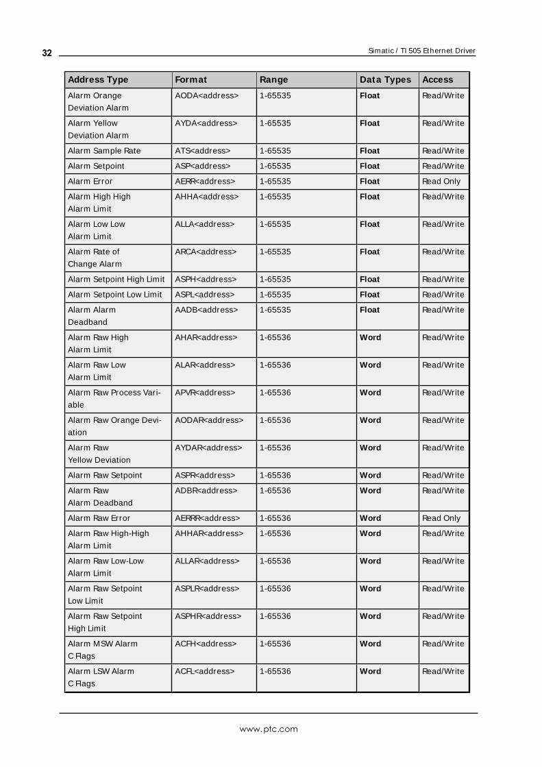
Address Type Format Range Data Types Access
Alarm Orange
Deviation Alarm
AODA<address> 1-65535 Float Read/Write
Alarm Yellow
Deviation Alarm
AYDA<address> 1-65535 Float Read/Write
Alarm Sample Rate ATS<address> 1-65535 Float Read/Write
Alarm Setpoint ASP<address> 1-65535 Float Read/Write
Alarm Error AERR<address> 1-65535 Float Read Only
Alarm High High
Alarm Limit
AHHA<address> 1-65535 Float Read/Write
Alarm Low Low
Alarm Limit
ALLA<address> 1-65535 Float Read/Write
Alarm Rate of
Change Alarm
ARCA<address> 1-65535 Float Read/Write
Alarm Setpoint High Limit ASPH<address> 1-65535 Float Read/Write
Alarm Setpoint Low Limit ASPL<address> 1-65535 Float Read/Write
Alarm Alarm
Deadband
AADB<address> 1-65535 Float Read/Write
Alarm Raw High
Alarm Limit
AHAR<address> 1-65536 Word Read/Write
Alarm Raw Low
Alarm Limit
ALAR<address> 1-65536 Word Read/Write
Alarm Raw Process Vari-
able
APVR<address> 1-65536 Word Read/Write
Alarm Raw Orange Devi-
ation
AODAR<address> 1-65536 Word Read/Write
Alarm Raw
Yellow Deviation
AYDAR<address> 1-65536 Word Read/Write
Alarm Raw Setpoint ASPR<address> 1-65536 Word Read/Write
Alarm Raw
Alarm Deadband
ADBR<address> 1-65536 Word Read/Write
Alarm Raw Error AERRR<address> 1-65536 Word Read Only
Alarm Raw High-High
Alarm Limit
AHHAR<address> 1-65536 Word Read/Write
Alarm Raw Low-Low
Alarm Limit
ALLAR<address> 1-65536 Word Read/Write
Alarm Raw Setpoint
Low Limit
ASPLR<address> 1-65536 Word Read/Write
Alarm Raw Setpoint
High Limit
ASPHR<address> 1-65536 Word Read/Write
Alarm MSW Alarm
C Flags
ACFH<address> 1-65536 Word Read/Write
Alarm LSW Alarm
C Flags
ACFL<address> 1-65536 Word Read/Write
www.ptc.com
32
Simatic / TI 505 Ethernet Driver
Address Type Format Range Data Types Access
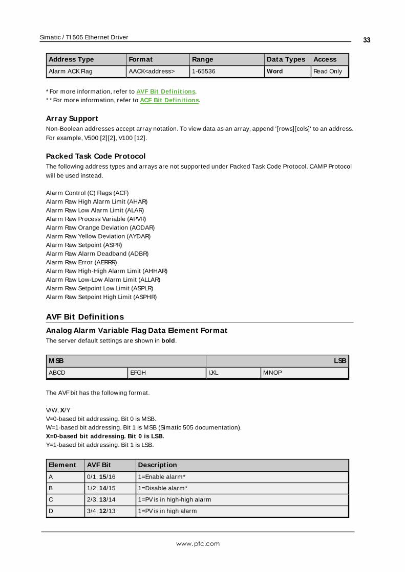
Alarm ACK Flag AACK<address> 1-65536 Word Read Only
* For more information, refer to AVF Bit Definitions.* * For more information, refer to ACF Bit Definitions.
Array SupportNon-Boolean addresses accept array notation. To view data as an array, append '[rows][cols]' to an address.
For example, V500 [2][2], V100 [12].
Packed Task Code ProtocolThe following address types and arrays are not supported under Packed Task Code Protocol. CAMP Protocol
will be used instead.
Alarm Control (C) Flags (ACF)Alarm Raw High Alarm Limit (AHAR)Alarm Raw Low Alarm Limit (ALAR)Alarm Raw Process Variable (APVR)Alarm Raw Orange Deviation (AODAR)Alarm Raw Yellow Deviation (AYDAR)Alarm Raw Setpoint (ASPR)Alarm Raw Alarm Deadband (ADBR)Alarm Raw Error (AERRR)Alarm Raw High-High Alarm Limit (AHHAR)Alarm Raw Low-Low Alarm Limit (ALLAR)Alarm Raw Setpoint Low Limit (ASPLR)Alarm Raw Setpoint High Limit (ASPHR)
AVF Bit Definit ions
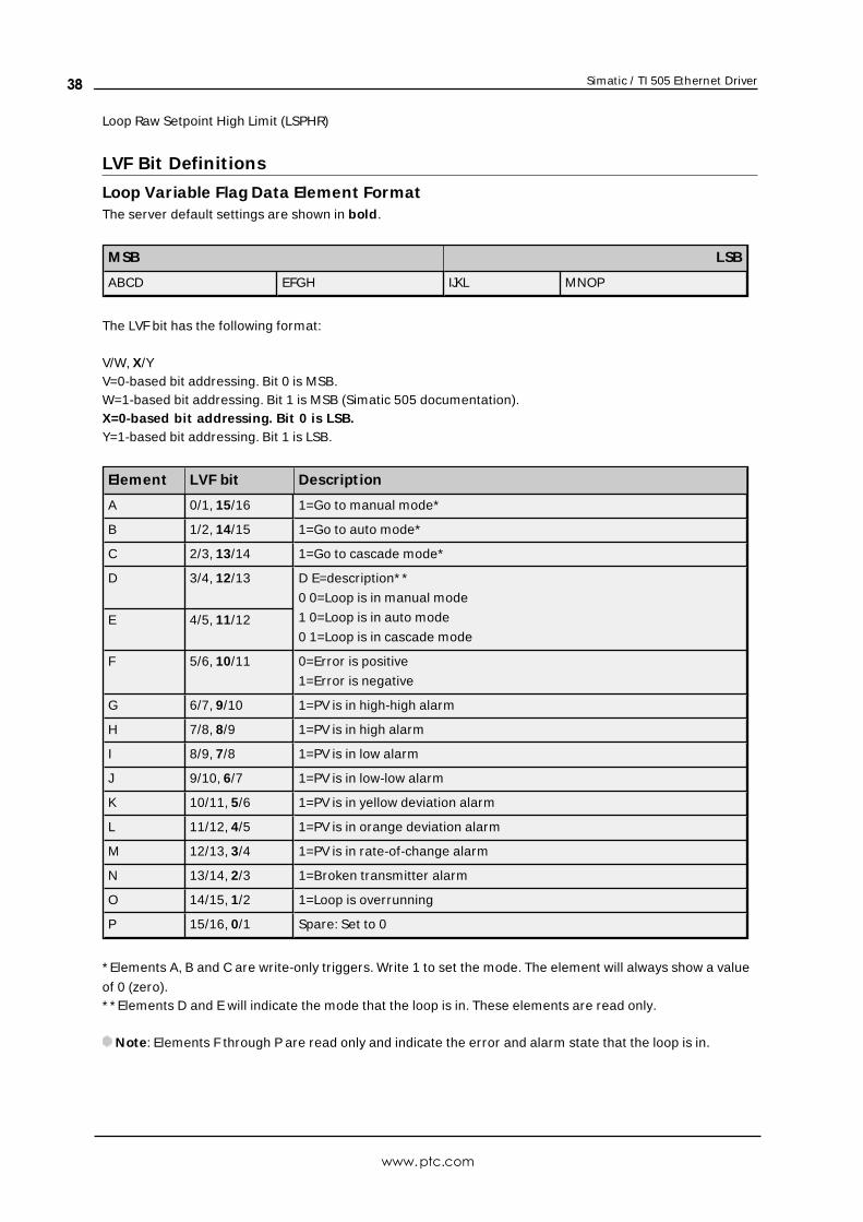
Analog Alarm Variable Flag Data Element FormatThe server default settings are shown in bold.
M SB LSB
ABCD EFGH IJKL MNOP
The AVF bit has the following format.
V/W, X/YV=0-based bit addressing. Bit 0 is MSB.W=1-based bit addressing. Bit 1 is MSB (Simatic 505 documentation).X=0-based bit addressing. Bit 0 is LSB.Y=1-based bit addressing. Bit 1 is LSB.
Element AVF Bit Descript ion
A 0/1, 15/16 1=Enable alarm*
B 1/2, 14/15 1=Disable alarm*
C 2/3, 13/14 1=PV is in high-high alarm
D 3/4, 12/13 1=PV is in high alarm
www.ptc.com
33
Simatic / TI 505 Ethernet Driver
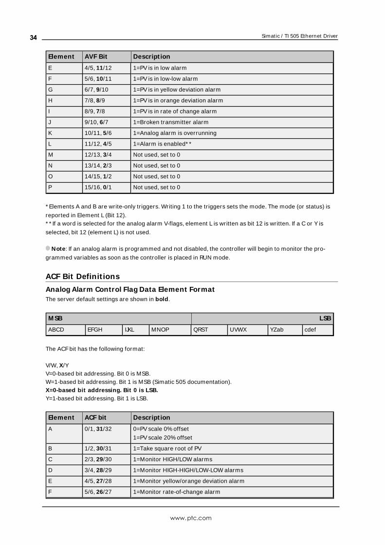
Element AVF Bit Descript ion
E 4/5, 11/12 1=PV is in low alarm
F 5/6, 10/11 1=PV is in low-low alarm
G 6/7, 9/10 1=PV is in yellow deviation alarm
H 7/8, 8/9 1=PV is in orange deviation alarm
I 8/9, 7/8 1=PV is in rate of change alarm
J 9/10, 6/7 1=Broken transmitter alarm
K 10/11, 5/6 1=Analog alarm is overrunning
L 11/12, 4/5 1=Alarm is enabled* *
M 12/13, 3/4 Not used, set to 0
N 13/14, 2/3 Not used, set to 0
O 14/15, 1/2 Not used, set to 0
P 15/16, 0/1 Not used, set to 0
* Elements A and B are write-only triggers. Writing 1 to the triggers sets the mode. The mode (or status) is
reported in Element L (Bit 12).* * If a word is selected for the analog alarm V-flags, element L is written as bit 12 is written. If a C or Y is
selected, bit 12 (element L) is not used.
Note: If an analog alarm is programmed and not disabled, the controller will begin to monitor the pro-
grammed variables as soon as the controller is placed in RUN mode.
ACF Bit Definit ions
Analog Alarm Control Flag Data Element FormatThe server default settings are shown in bold.
M SB LSB
ABCD EFGH IJKL MNOP QRST UVWX YZab cdef
The ACFbit has the following format:
V/W, X/YV=0-based bit addressing. Bit 0 is MSB.W=1-based bit addressing. Bit 1 is MSB (Simatic 505 documentation).X=0-based bit addressing. Bit 0 is LSB.Y=1-based bit addressing. Bit 1 is LSB.
Element ACF bit Descript ion
A 0/1, 31/32 0=PV scale 0% offset
1=PV scale 20% offset
B 1/2, 30/31 1=Take square root of PV
C 2/3, 29/30 1=Monitor HIGH/LOW alarms
D 3/4, 28/29 1=Monitor HIGH-HIGH/LOW-LOW alarms
E 4/5, 27/28 1=Monitor yellow/orange deviation alarm
F 5/6, 26/27 1=Monitor rate-of-change alarm
www.ptc.com
34
Simatic / TI 505 Ethernet Driver
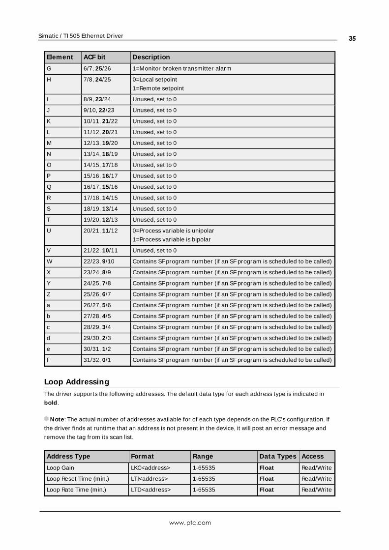
Element ACF bit Descript ion
G 6/7, 25/26 1=Monitor broken transmitter alarm
H 7/8, 24/25 0=Local setpoint
1=Remote setpoint
I 8/9, 23/24 Unused, set to 0
J 9/10, 22/23 Unused, set to 0
K 10/11, 21/22 Unused, set to 0
L 11/12, 20/21 Unused, set to 0
M 12/13, 19/20 Unused, set to 0
N 13/14, 18/19 Unused, set to 0
O 14/15, 17/18 Unused, set to 0
P 15/16, 16/17 Unused, set to 0
Q 16/17, 15/16 Unused, set to 0
R 17/18, 14/15 Unused, set to 0
S 18/19, 13/14 Unused, set to 0
T 19/20, 12/13 Unused, set to 0
U 20/21, 11/12 0=Process variable is unipolar
1=Process variable is bipolar
V 21/22, 10/11 Unused, set to 0
W 22/23, 9/10 Contains SF program number (if an SF program is scheduled to be called)
X 23/24, 8/9 Contains SF program number (if an SF program is scheduled to be called)
Y 24/25, 7/8 Contains SF program number (if an SF program is scheduled to be called)
Z 25/26, 6/7 Contains SF program number (if an SF program is scheduled to be called)
a 26/27, 5/6 Contains SF program number (if an SF program is scheduled to be called)
b 27/28, 4/5 Contains SF program number (if an SF program is scheduled to be called)
c 28/29, 3/4 Contains SF program number (if an SF program is scheduled to be called)
d 29/30, 2/3 Contains SF program number (if an SF program is scheduled to be called)
e 30/31, 1/2 Contains SF program number (if an SF program is scheduled to be called)
f 31/32, 0/1 Contains SF program number (if an SF program is scheduled to be called)
Loop AddressingThe driver supports the following addresses. The default data type for each address type is indicated in
bold.
Note: The actual number of addresses available for of each type depends on the PLC's configuration. If
the driver finds at runtime that an address is not present in the device, it will post an error message and
remove the tag from its scan list.
Address Type Format Range Data Types Access
Loop Gain LKC<address> 1-65535 Float Read/Write
Loop Reset Time (min.) LTI<address> 1-65535 Float Read/Write
Loop Rate Time (min.) LTD<address> 1-65535 Float Read/Write
www.ptc.com
35
Simatic / TI 505 Ethernet Driver
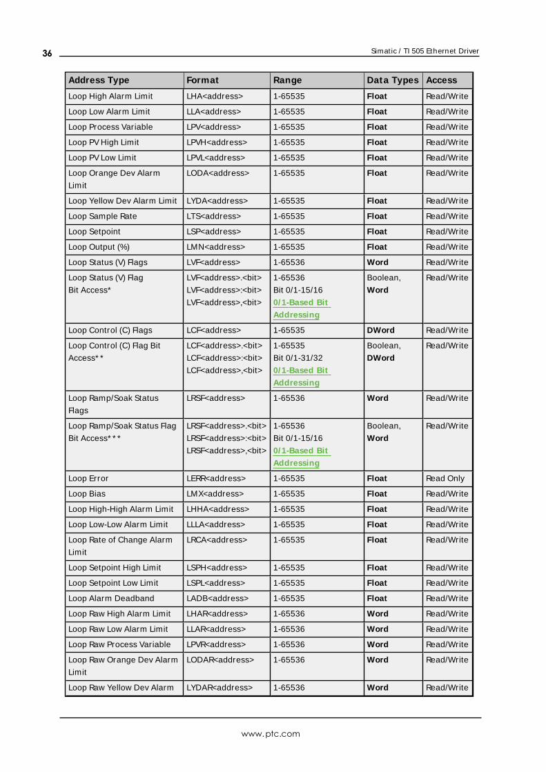
Address Type Format Range Data Types Access
Loop High Alarm Limit LHA<address> 1-65535 Float Read/Write
Loop Low Alarm Limit LLA<address> 1-65535 Float Read/Write
Loop Process Variable LPV<address> 1-65535 Float Read/Write
Loop PV High Limit LPVH<address> 1-65535 Float Read/Write
Loop PV Low Limit LPVL<address> 1-65535 Float Read/Write
Loop Orange Dev Alarm
Limit
LODA<address> 1-65535 Float Read/Write
Loop Yellow Dev Alarm Limit LYDA<address> 1-65535 Float Read/Write
Loop Sample Rate LTS<address> 1-65535 Float Read/Write
Loop Setpoint LSP<address> 1-65535 Float Read/Write
Loop Output (%) LMN<address> 1-65535 Float Read/Write
Loop Status (V) Flags LVF<address> 1-65536 Word Read/Write
Loop Status (V) Flag
Bit Access*
LVF<address>.<bit>
LVF<address>:<bit>
LVF<address>,<bit>
1-65536
Bit 0/1-15/16
0/1-Based Bit
Addressing
Boolean,
Word
Read/Write
Loop Control (C) Flags LCF<address> 1-65535 DWord Read/Write
Loop Control (C) Flag Bit
Access* *
LCF<address>.<bit>
LCF<address>:<bit>
LCF<address>,<bit>
1-65535
Bit 0/1-31/32
0/1-Based Bit
Addressing
Boolean,
DWord
Read/Write
Loop Ramp/Soak Status
Flags
LRSF<address> 1-65536 Word Read/Write
Loop Ramp/Soak Status Flag
Bit Access* * *
LRSF<address>.<bit>
LRSF<address>:<bit>
LRSF<address>,<bit>
1-65536
Bit 0/1-15/16
0/1-Based Bit
Addressing
Boolean,
Word
Read/Write
Loop Error LERR<address> 1-65535 Float Read Only
Loop Bias LMX<address> 1-65535 Float Read/Write
Loop High-High Alarm Limit LHHA<address> 1-65535 Float Read/Write
Loop Low-Low Alarm Limit LLLA<address> 1-65535 Float Read/Write
Loop Rate of Change Alarm
Limit
LRCA<address> 1-65535 Float Read/Write
Loop Setpoint High Limit LSPH<address> 1-65535 Float Read/Write
Loop Setpoint Low Limit LSPL<address> 1-65535 Float Read/Write
Loop Alarm Deadband LADB<address> 1-65535 Float Read/Write
Loop Raw High Alarm Limit LHAR<address> 1-65536 Word Read/Write
Loop Raw Low Alarm Limit LLAR<address> 1-65536 Word Read/Write
Loop Raw Process Variable LPVR<address> 1-65536 Word Read/Write
Loop Raw Orange Dev Alarm
Limit
LODAR<address> 1-65536 Word Read/Write
Loop Raw Yellow Dev Alarm LYDAR<address> 1-65536 Word Read/Write
www.ptc.com
36
Simatic / TI 505 Ethernet Driver
Address Type Format Range Data Types Access
Limit
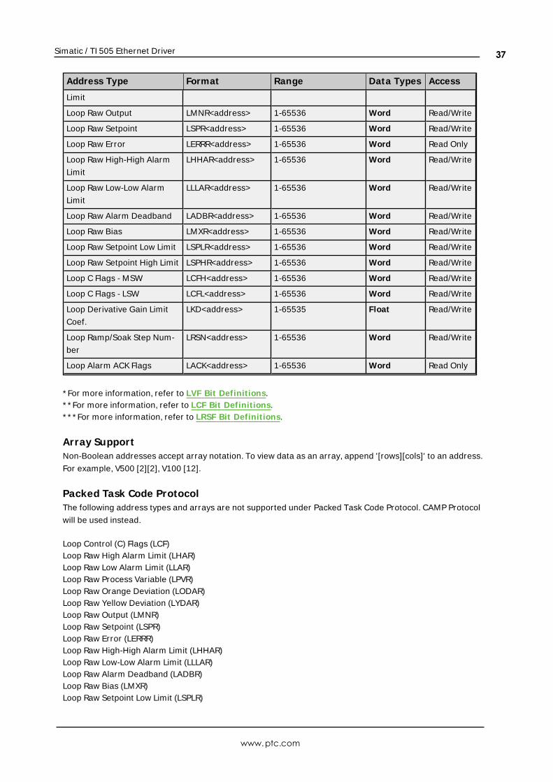
Loop Raw Output LMNR<address> 1-65536 Word Read/Write
Loop Raw Setpoint LSPR<address> 1-65536 Word Read/Write
Loop Raw Error LERRR<address> 1-65536 Word Read Only
Loop Raw High-High Alarm
Limit
LHHAR<address> 1-65536 Word Read/Write
Loop Raw Low-Low Alarm
Limit
LLLAR<address> 1-65536 Word Read/Write
Loop Raw Alarm Deadband LADBR<address> 1-65536 Word Read/Write
Loop Raw Bias LMXR<address> 1-65536 Word Read/Write
Loop Raw Setpoint Low Limit LSPLR<address> 1-65536 Word Read/Write
Loop Raw Setpoint High Limit LSPHR<address> 1-65536 Word Read/Write
Loop C Flags - MSW LCFH<address> 1-65536 Word Read/Write
Loop C Flags - LSW LCFL<address> 1-65536 Word Read/Write
Loop Derivative Gain Limit
Coef.
LKD<address> 1-65535 Float Read/Write
Loop Ramp/Soak Step Num-
ber
LRSN<address> 1-65536 Word Read/Write
Loop Alarm ACK Flags LACK<address> 1-65536 Word Read Only
* For more information, refer to LVF Bit Definitions.* * For more information, refer to LCF Bit Definitions.* * * For more information, refer to LRSF Bit Definitions.
Array SupportNon-Boolean addresses accept array notation. To view data as an array, append '[rows][cols]' to an address.
For example, V500 [2][2], V100 [12].
Packed Task Code ProtocolThe following address types and arrays are not supported under Packed Task Code Protocol. CAMP Protocol
will be used instead.
Loop Control (C) Flags (LCF)Loop Raw High Alarm Limit (LHAR)Loop Raw Low Alarm Limit (LLAR)Loop Raw Process Variable (LPVR)Loop Raw Orange Deviation (LODAR)Loop Raw Yellow Deviation (LYDAR)Loop Raw Output (LMNR)Loop Raw Setpoint (LSPR)Loop Raw Error (LERRR)Loop Raw High-High Alarm Limit (LHHAR)Loop Raw Low-Low Alarm Limit (LLLAR)Loop Raw Alarm Deadband (LADBR)Loop Raw Bias (LMXR)Loop Raw Setpoint Low Limit (LSPLR)
www.ptc.com
37
Simatic / TI 505 Ethernet Driver
Loop Raw Setpoint High Limit (LSPHR)
LVF Bit Definit ions
Loop Variable Flag Data Element FormatThe server default settings are shown in bold.
M SB LSB
ABCD EFGH IJKL MNOP
The LVF bit has the following format:
V/W, X/YV=0-based bit addressing. Bit 0 is MSB.W=1-based bit addressing. Bit 1 is MSB (Simatic 505 documentation).X=0-based bit addressing. Bit 0 is LSB.Y=1-based bit addressing. Bit 1 is LSB.
Element LVF bit Descript ion
A 0/1, 15/16 1=Go to manual mode*
B 1/2, 14/15 1=Go to auto mode*
C 2/3, 13/14 1=Go to cascade mode*
D 3/4, 12/13 D E=description* *
0 0=Loop is in manual mode
1 0=Loop is in auto mode
0 1=Loop is in cascade modeE 4/5, 11/12
F 5/6, 10/11 0=Error is positive
1=Error is negative
G 6/7, 9/10 1=PV is in high-high alarm
H 7/8, 8/9 1=PV is in high alarm
I 8/9, 7/8 1=PV is in low alarm
J 9/10, 6/7 1=PV is in low-low alarm
K 10/11, 5/6 1=PV is in yellow deviation alarm
L 11/12, 4/5 1=PV is in orange deviation alarm
M 12/13, 3/4 1=PV is in rate-of-change alarm
N 13/14, 2/3 1=Broken transmitter alarm
O 14/15, 1/2 1=Loop is overrunning
P 15/16, 0/1 Spare: Set to 0
* Elements A, B and C are write-only triggers. Write 1 to set the mode. The element will always show a value
of 0 (zero).* * Elements D and E will indicate the mode that the loop is in. These elements are read only.
Note: Elements F through P are read only and indicate the error and alarm state that the loop is in.
www.ptc.com
38
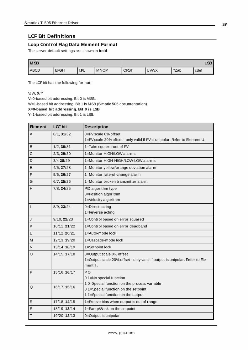
Simatic / TI 505 Ethernet Driver
LCF Bit Definit ions
Loop Control Flag Data Element FormatThe server default settings are shown in bold.
M SB LSB
ABCD EFGH IJKL MNOP QRST UVWX YZab cdef
The LCFbit has the following format:
V/W, X/YV=0-based bit addressing. Bit 0 is MSB.W=1-based bit addressing. Bit 1 is MSB (Simatic 505 documentation).X=0-based bit addressing. Bit 0 is LSB.Y=1-based bit addressing. Bit 1 is LSB.
Element LCF bit Descript ion
A 0/1, 31/32 0=PV scale 0% offset
1=PV scale 20% offset - only valid if PV is unipolar. Refer to Element U.
B 1/2, 30/31 1=Take square root of PV
C 2/3, 29/30 1=Monitor HIGH/LOW alarms
D 3/4 28/29 1=Monitor HIGH-HIGH/LOW-LOW alarms
E 4/5, 27/28 1=Monitor yellow/orange deviation alarm
F 5/6, 26/27 1=Monitor rate-of-change alarm
G 6/7, 25/26 1=Monitor broken transmitter alarm
H 7/8, 24/25 PID algorithm type
0=Position algorithm
1=Velocity algorithm
I 8/9, 23/24 0=Direct acting
1=Reverse acting
J 9/10, 22/23 1=Control based on error squared
K 10/11, 21/22 1=Control based on error deadband
L 11/12, 20/21 1=Auto-mode lock
M 12/13, 19/20 1=Cascade-mode lock
N 13/14, 18/19 1=Setpoint lock
O 14/15, 17/18 0=Output scale 0% offset
1=Output scale 20% offset - only valid if output is unipolar. Refer to Ele-
ment T.
P 15/16, 16/17 P Q
0 1=No special function
1 0=Special function on the process variable
0 1=Special function on the setpoint
1 1=Special function on the output
Q 16/17, 15/16
R 17/18, 14/15 1=Freeze bias when output is out of range
S 18/19, 13/14 1=Ramp/Soak on the setpoint
T 19/20, 12/13 0=Output is unipolar
www.ptc.com
39
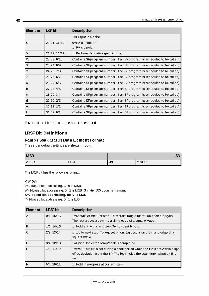
Simatic / TI 505 Ethernet Driver
Element LCF bit Descript ion
1=Output is bipolar
U 20/21, 11/12 0=PV is unipolar
1=PV is bipolar
V 21/22, 10/11 1=Perform derivative gain limiting
W 22/23, 9/10 Contains SF program number (if an SF program is scheduled to be called)
X 23/24, 8/9 Contains SF program number (if an SF program is scheduled to be called)
Y 24/25, 7/8 Contains SF program number (if an SF program is scheduled to be called)
Z 25/26, 6/7 Contains SF program number (if an SF program is scheduled to be called)
a 26/27, 5/6 Contains SF program number (if an SF program is scheduled to be called)
b 27/28, 4/5 Contains SF program number (if an SF program is scheduled to be called)
c 28/29, 3.4 Contains SF program number (if an SF program is scheduled to be called)
d 29/30, 2/3 Contains SF program number (if an SF program is scheduled to be called)
e 30/31, 1/2 Contains SF program number (if an SF program is scheduled to be called)
f 31/32, 0/1 Contains SF program number (if an SF program is scheduled to be called)
Note: If the bit is set to 1, the option is enabled.
LRSF Bit Definit ions
Ramp / Soak Status Data Element FormatThe server default settings are shown in bold.
M SB LSB
ABCD EFGH IJKL MNOP
The LRSF bit has the following format:
V/W, X/YV=0-based bit addressing. Bit 0 is MSB.W=1-based bit addressing. Bit 1 is MSB (Simatic 505 documentation).X=0-based bit addressing. Bit 0 is LSB.Y=1-based bit addressing. Bit 1 is LSB.
Element LRSF bit Descript ion
A 0/1, 15/16 1=Restart at the first step. To restart, toggle bit off, on, then off again.
The restart occurs on the trailing edge of a square wave.
B 1/2, 14/15 1=Hold at the current step. To hold, set bit on.
C 2/3, 13/14 1=Jog to next step. To jog, set bit on. Jog occurs on the rising edge of a
square wave.
D 3/4, 12/13 1=Finish. Indicates ramp/soak is completed.
E 4/5, 11/12 1=Wait. This bit is set during a soak period when the PV is not within a spe-
cified deviation from the SP. The loop holds the soak timer when bit 5 is
set.
F 5/6, 10/11 1=Hold in progress at current step
www.ptc.com
40
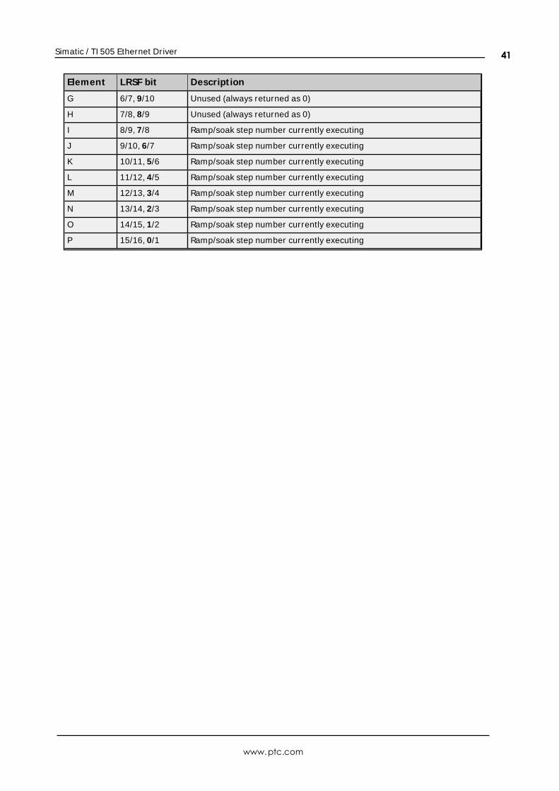
Simatic / TI 505 Ethernet Driver
Element LRSF bit Descript ion
G 6/7, 9/10 Unused (always returned as 0)
H 7/8, 8/9 Unused (always returned as 0)
I 8/9, 7/8 Ramp/soak step number currently executing
J 9/10, 6/7 Ramp/soak step number currently executing
K 10/11, 5/6 Ramp/soak step number currently executing
L 11/12, 4/5 Ramp/soak step number currently executing
M 12/13, 3/4 Ramp/soak step number currently executing
N 13/14, 2/3 Ramp/soak step number currently executing
O 14/15, 1/2 Ramp/soak step number currently executing
P 15/16, 0/1 Ramp/soak step number currently executing
www.ptc.com
41
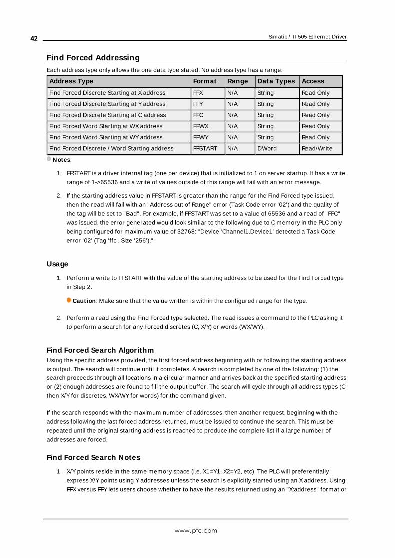
Simatic / TI 505 Ethernet Driver
Find Forced AddressingEach address type only allows the one data type stated. No address type has a range.
Address Type Format Range Data Types Access
Find Forced Discrete Starting at X address FFX N/A String Read Only
Find Forced Discrete Starting at Y address FFY N/A String Read Only
Find Forced Discrete Starting at C address FFC N/A String Read Only
Find Forced Word Starting at WX address FFWX N/A String Read Only
Find Forced Word Starting at WY address FFWY N/A String Read Only
Find Forced Discrete / Word Starting address FFSTART N/A DWord Read/Write
Notes:
1. FFSTART is a driver internal tag (one per device) that is initialized to 1 on server startup. It has a write
range of 1->65536 and a write of values outside of this range will fail with an error message.
2. If the starting address value in FFSTART is greater than the range for the Find Forced type issued,
then the read will fail with an "Address out of Range" error (Task Code error '02') and the quality of
the tag will be set to "Bad". For example, if FFSTART was set to a value of 65536 and a read of "FFC"
was issued, the error generated would look similar to the following due to C memory in the PLC only
being configured for maximum value of 32768: "Device 'Channel1.Device1' detected a Task Code
error '02' (Tag 'ffc', Size '256')."
Usage
1. Perform a write to FFSTART with the value of the starting address to be used for the Find Forced type
in Step 2.
Caution: Make sure that the value written is within the configured range for the type.
2. Perform a read using the Find Forced type selected. The read issues a command to the PLC asking it
to perform a search for any Forced discretes (C, X/Y) or words (WX/WY).
Find Forced Search AlgorithmUsing the specific address provided, the first forced address beginning with or following the starting address
is output. The search will continue until it completes. A search is completed by one of the following: (1) the
search proceeds through all locations in a circular manner and arrives back at the specified starting address
or (2) enough addresses are found to fill the output buffer. The search will cycle through all address types (C
then X/Y for discretes, WX/WY for words) for the command given.
If the search responds with the maximum number of addresses, then another request, beginning with the
address following the last forced address returned, must be issued to continue the search. This must be
repeated until the original starting address is reached to produce the complete list if a large number of
addresses are forced.
Find Forced Search Notes
1. X/Y points reside in the same memory space (i.e. X1=Y1, X2=Y2, etc). The PLC will preferentially
express X/Y points using Y addresses unless the search is explicitly started using an X address. Using
FFX versus FFY lets users choose whether to have the results returned using an "X:address" format or
www.ptc.com
42
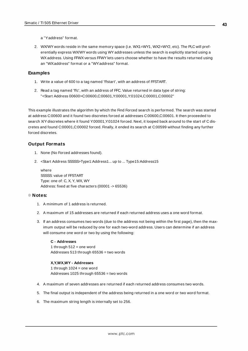
Simatic / TI 505 Ethernet Driver
a "Y:address" format.
2. WX/WY words reside in the same memory space (i.e. WX1=WY1, WX2=WY2, etc). The PLC will pref-
erentially express WX/WY words using WY addresses unless the search is explicitly started using a
WX address. Using FFWX versus FFWY lets users choose whether to have the results returned using
an "WX:address" format or a "WY:address" format.
Examples
1. Write a value of 600 to a tag named 'ffstart', with an address of FFSTART.
2. Read a tag named 'ffc', with an address of FFC. Value returned in data type of string:
"<Start Address 00600>C:00600,C:00601,Y:00001,Y:01024,C:00001,C:00002"
This example illustrates the algorithm by which the Find Forced search is performed. The search was started
at address C:00600 and it found two discretes forced at addresses C:00600,C:00601. It then proceeded to
search X/Y discretes where it found Y:00001,Y:01024 forced. Next, it looped back around to the start of C dis-
cretes and found C:00001,C:00002 forced. Finally, it ended its search at C:00599 without finding any further
forced discretes.
Output Formats
1. None (No Forced addresses found).
2. <Start Address SSSSS>Type1:Address1... up to ... Type15:Address15
whereSSSSS: value of FFSTARTType: one of: C, X, Y, WX, WYAddress: fixed at five characters (00001 -> 65536)
Notes:
1. A minimum of 1 address is returned.
2. A maximum of 15 addresses are returned if each returned address uses a one word format.
3. If an address consumes two words (due to the address not being within the first page), then the max-
imum output will be reduced by one for each two-word address. Users can determine if an address
will consume one word or two by using the following:
C - Addresses1 through 512 = one wordAddresses 513 through 65536 = two words
X,Y,WX,WY - Addresses1 through 1024 = one wordAddresses 1025 through 65536 = two words
4. A maximum of seven addresses are returned if each returned address consumes two words.
5. The final output is independent of the address being returned in a one word or two word format.
6. The maximum string length is internally set to 256.
www.ptc.com
43
Simatic / TI 505 Ethernet Driver
Error Descript ionsThe following messages may be generated. Click on the link for a description of the message.
Address <address> is out of range for the specified device or register.
Array size is out of range for address <address>.
Array support is not available for the specified address: <address>.
Data type <type> is not valid for device address <address>.
Device address <address> contains a syntax error.
Device address <address> is read only.
Device <device name> cannot execute a read request (<address>, <size>).
Device <device name> cannot execute a write request (<address>, <size>).
Device <device name> detected a NITP protocol error (tag <address>, size <size>).
Device <device name> detected a Task Code error <error> (tag <address>, size <size>).
Device <device name> input queue is full. The module is receiving requests faster than it
can process requests.
Device <device name> is not responding.
Device <device name> responded with Extended error <error> (tag <address>, size
<size>).
Device <device name>, write value not in range 1-->65536. (Tag 'FFSTART').
M issing address.
Unable to write to <address> on device <device name>.
Winsock init ializat ion failed (OS error = n).
Winsock V1.1 or higher must be installed to use the Simat ic / TI 505 Ethernet device
driver.
See Also:Task Error Codes
Address <address> is out of range for the specified device or register.
Error Type:Warning
Possible Cause:A tag address that has been specified dynamically references a location that is beyond the range of sup-
ported locations for the device.
Solution:Verify the address is correct; if it is not, re-enter it in the client application.
Array size is out of range for address <address>.
Error Type:Warning
Possible Cause:
www.ptc.com
44
Simatic / TI 505 Ethernet Driver
A tag address that has been specified dynamically is requesting an array size that is too large for the
address type or block size of the driver.
Solution:Re-enter the address in the client application to specify a smaller value for the array or a different starting
point.
Array Support is not available for the specified address: <address>.
Error Type:Warning
Possible Cause:A tag address that has been specified dynamically contains an array reference for an address type that
doesn't support arrays.
Solution:Re-enter the address in the client application to remove the array reference or correct the address type.
Data type <type> is not valid for device address <address>.
Error Type:Warning
Possible Cause:A tag address that has been specified dynamically has been assigned an invalid data type.
Solution:Modify the requested data type in the client application.
Device address <address> contains a syntax error.
Error Type:Warning
Possible Cause:A tag address that has been specified dynamically contains one or more invalid characters.
Solution:Re-enter the address in the client application.
Device address <address> is read only.
Error Type:Warning
Possible Cause:A tag address that has been specified dynamically has a requested access mode that is not compatible with
what the device supports for that address.
Solution:
www.ptc.com
45
Simatic / TI 505 Ethernet Driver
Change the access mode in the client application.
Device <device name> cannot execute a read request (<address>, <size>).
Error Type:Serious
Possible Cause:The device is unable to return the amount of read data requested in one request.
Solution:Adjust the requested block size on the device so that the driver makes smaller requests.
Device <device name> cannot execute a write request (<address>, <size>).
Error Type:Serious
Possible Cause:The device is unable to receive the amount of write data sent in one request.
Solution:Adjust the array size on the address so that a smaller amount of data is sent to the device in one trans-
action.
Device <device name> detected a NITP protocol error (tag <address>, size<size>).
Error Type:Serious
Possible Cause:This error may occur when sending Packed Task Code messages. The device is experiencing network errors.
Solution:Check network connections.
Device <device name> detected a Task Code error <error> (tag <address>,size <size>).
Error Type:Serious
Possible Cause:This error may occur when sending Packed Task Code messages.The device is experiencing network errors or PLC encountered an error when processing a task code.
Solution:
www.ptc.com
46
Simatic / TI 505 Ethernet Driver
1. Check network connections.
2. Refer to the specific error code.
See Also:Task Error Codes
Device <device name> input queue is full. The module is receivingrequests faster than it can process requests.
Error Type:Serious
Possible Cause:The device is handling requests from more than one PC at a time.
Solution:Using the device programming software, make sure that the "task codes per scan time" property is set to 8.
Adjusting the scan time may also improve device performance. It is recommended that users set the scan
time to Variable. For more information on adjusting these properties, refer to the device's documentation.
Device <device name> is not responding.
Error Type:Serious
Possible Cause:
1. The connection between the device and the host PC is broken.
2. The IP address assigned to the device is incorrect.
3. The response from the device took longer to receive than the amount of time specified in the
"Request Timeout" device property.
Solution:
1. Verify the cabling between the PC and the PLC device.
2. Verify that the IP address given to the named device matches that of the actual device.
3. Increase the Request Timeout property so that the entire response can be handled.
Device <device name> responded with Extended error <error> (tag<address>, size <size>).
Error Type:Informational
Possible Cause:The device is unable to receive the amount of write data sent in one request.
www.ptc.com
47
Simatic / TI 505 Ethernet Driver
Note:This error is used for extended error information by some error responses.
See Also: Device <device name> cannot execute a write request (<address>, <size>).
Device <device name>, write value not in range 1-->65536. (Tag 'FFSTART').
Error Type:Warning
Possible Cause:Value written outside of range specified.
Solution:Write a value in the range of 1-65536.
Missing address.
Error Type:Warning
Possible Cause:A tag address that has been specified dynamically has no length.
Solution:Re-enter the address in the client application.
Unable to write to <address> on device <device name>.
Error Type:Serious
Possible Cause:
1. The connection between the device and the host PC is broken.
2. The IP address assigned to the device is incorrect.
Solution:
1. Verify the cabling between the PC and the PLC device.
2. Verify that the IP address given to the named device matches that of the actual device.
www.ptc.com
48
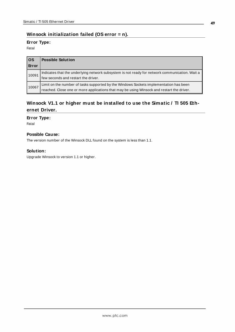
Simatic / TI 505 Ethernet Driver
Winsock init ializat ion failed (OS error = n).
Error Type:Fatal
OS
Error
Possible Solut ion
10091Indicates that the underlying network subsystem is not ready for network communication. Wait a
few seconds and restart the driver.
10067Limit on the number of tasks supported by the Windows Sockets implementation has been
reached. Close one or more applications that may be using Winsock and restart the driver.
Winsock V1.1 or higher must be installed to use the Simatic / TI 505 Eth-ernet Driver.
Error Type:Fatal
Possible Cause:The version number of the Winsock DLL found on the system is less than 1.1.
Solution:Upgrade Winsock to version 1.1 or higher.
www.ptc.com
49
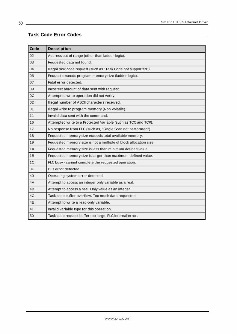
Simatic / TI 505 Ethernet Driver
Task Code Error Codes
Code Descript ion
02 Address out of range (other than ladder logic).
03 Requested data not found.
04 Illegal task code request (such as "Task Code not supported").
05 Request exceeds program memory size (ladder logic).
07 Fatal error detected.
09 Incorrect amount of data sent with request.
0C Attempted write operation did not verify.
0D Illegal number of ASCII characters received.
0E Illegal write to program memory (Non Volatile).
11 Invalid data sent with the command.
16 Attempted write to a Protected Variable (such as TCC and TCP).
17 No response from PLC (such as, "Single Scan not performed").
18 Requested memory size exceeds total available memory.
19 Requested memory size is not a multiple of block allocation size.
1A Requested memory size is less than minimum defined value.
1B Requested memory size is larger than maximum defined value.
1C PLC busy - cannot complete the requested operation.
3F Bus error detected.
40 Operating system error detected.
4A Attempt to access an integer only variable as a real.
4B Attempt to access a real. Only value as an integer.
4C Task code buffer overflow. Too much data requested.
4E Attempt to write a read-only variable.
4F Invalid variable type for this operation.
50 Task code request buffer too large. PLC internal error.
www.ptc.com
50
Simatic / TI 505 Ethernet Driver
Index
5
505 Protocol 12
A
ACFBit Definitions 34
Address <address> is out of range for the specified device or register. 44
Address Descriptions 18
Addressing 18
Addressing Options 13
Alarm Addressing 31
Array size is out of range for address <address>. 44
Array support is not available for the specified address:<address>. 45
Attempts Before Timeout 12
AVF Bit Definitions 33
B
Boolean 17
C
CAMP 12
Channel Assignment 9
Common Data Type Addressing 18
Communications Parameters 15
Communications Timeouts 11-12
Connect Timeout 11
D
Data Collection 10
Data type <type> is not valid for device address <address>. 45
Data Types Description 17
www.ptc.com
51
Simatic / TI 505 Ethernet Driver
Device <device name> cannot execute a read request (<address>:<size>). 46
Device <device name> cannot execute a write request (<address>:<size>). 46
Device <device name> detected a NITP Protocol error (tag <address>, size <size>). 46
Device <device name> detected a Task Code error <error> (tag <address>, size <size>). 46
Device <device name> input queue is full. The module is receiving requests faster than it can process
requests. 47
Device <device name> is not responding. 47
Device <device name> responded with Extended error <error> (tag <address>, size <size>). 47
Device <device name>, write value not in range1-->65536. (Tag 'FFSTART'). 48
Device address <address> contains a syntax error. 45
Device address <address> is read only. 45
Device ID 5
Do Not Scan, Demand Poll Only 11
Driver 9
DWord 17
E
Error Descriptions 44
F
Find Forced Addressing 42
Float 17
G
General 9
I
ID 9
Identification 9
Initial Updates from Cache 11
Inter-Request Delay 12
www.ptc.com
52
Simatic / TI 505 Ethernet Driver
L
LCFBit Definitions 39
Long 17
Loop Addressing 35
LRSF Bit Definitions 40
LVF Bit Definitions 38
M
Missing address. 48
Model 9
N
Name 9
NITP 12
O
Operating Mode 10
Optimizing Communications 16
Overview 4
P
Packed Task Code 12
R
Redundancy 15
Request Timeout 11
Respect Tag-Specified Scan Rate 11
S
Scan Mode 10
www.ptc.com
53
Simatic / TI 505 Ethernet Driver
Setup 5
Short 17
Simulated 10
Status Words 24
T
Task Code Error Codes 50
TISOFT 12
U
Unable to write tag <address> on device <device name>. 48
W
Winsock initialization failed (OS Error = n). 49
Winsock V1.1 or higher must be installed to use the Simatic/TI 505 Ethernet device driver. 49
Word 17
www.ptc.com
54


