Embed Size (px)
Citation preview

ACCEPTED FOR PUBLICATION IN IEEE/ASME TRANS. ON MECHATRONICS, 2015 1
Energy-Efficient and Fault-Tolerant Control ofMultiphase Nonsinusoidal PM Synchronous
MachinesFarhad Aghili, Senior Member, IEEE,
Abstract—This paper presents development of energy-efficientand fault-tolerant control of multiphase nonsinusoidal PM syn-chronous machines by making use of the Hamiltonian of op-timal control theory. An analytical solution for the optima l-linearization control is derived in a closed-form from the max-imum principle formulation to linearize the machines and atsame time to maximize machine efficiency for non-constantoperational torque and speed while automatically deferringoutput voltage saturation. The controller can achieve voltage-to-torque linearization even for faulty motors with open-circuitedphase(s) making it suitable for high-risk applications. This workis complemented by presenting an optimal indirect-torque controlscheme based on internal current feedback loop with finitebandwidth. Simulation and experimental results are appendedto underpin the performance of the energy-efficient and fault-tolerant controller.
Index Terms—electric motor drives, permanent-magnet syn-chronous machines, burshless motors, fault-tolerant control, opti-mal control, energy-efficient control, motor torque ripple, motioncontrol
INTRODUCTION
Permanent-magnet synchronous machines(PMSMs) arecommonly used for high-performance and high-efficiency mo-tor drives in a huge range of applications: from silicon wafermanufacturers, robotics, industrial automation, machinetools,and electric vehicles to aerospace and military. Precise andfast torque tracking or torque regulation performance overtheentire speed/torque range of the machine is highly requiredin some of these applications [1], whereas energy-efficiencyor fault tolerance becomes important in the others [2], [3].The underlying torque control schemes are usually adoptedbased on the way the machine’s windings are constructedto produce sinusoidal or nonsinusoidal flux density in theairgap. Nevertheless, in either cases, the machine torque canbe controlled either directly by controlling the PWM voltageof phases or indirectly by controlling the phase currents usinginternal current feedback loop [4]–[14].
Park’s transformation, also known as d-q transform, is thecornerstone of direct torque control of 3-phase sinusoidalPMSMs. This physically intuitive technique simplifies thecontrol calculations of balanced three-phase motors and hasbeen used for development of a variety of classical nonlinearcontrol laws to sinusoidal PMSMs. Although this formula-tion leads to perfect voltage-torque linearization of sinusoidal
F. Aghili is a research scientist with Canadian Space Agency, Saint-Hubert,Quebec, Canada, J3Y 8Y9, tel: (450) 926-5771, email: [email protected].
electric machines, some researchers attempted to extend thePark’s transformation for particular kinds of electric machinewith nonsinusoidal flux distribution [14], [15] [14]. Field-oriented control (FOC), also known as vector control, is themost popular direct control technique for 3-phase sinusoidalPMSMs that allows separate control of the magnetic fluxand the torque through elegant decomposition of the fieldgenerating part and torque generating part of the stator current.Nevertheless, there are other direct control possibilities such asstate feedback linearization [16]–[18] or direct torque control(DTC) [19]–[23]. The DTC schemes have been further devel-oped to minimize copper loss or to defer voltage saturationusing flux-weakening control in order to extend the range ofoperational speed of sinusoidal PMSMs [24]–[27].
Nonlinear optimal speed controller based on a state-dependent Riccati equation for PMSMs with sinusoidal fluxdistribution was presented in [28]. It is also shown in [29] thatin the presence of a significant time delay in the closed loop,a feedback linearization control technique cannot yield exactlinearization of the dynamics of electric motors but a residualterm depending on incremental position remains in the closed-loop dynamics. The motor torque control problem is radicallysimplified in the indirect approach, in which internal currentfeedback loops impose sinusoidal current repartition dictatedby an electronically controlled commutator [30], [31]. Ideal3-phase sinusoidal PMSMs perform optimally when simplydriven by sinusoidal commutation waveforms. However, theshortcoming of this approach is that the phase lag introducedby the current controller may lead to pulsation torque athigh velocity unless a large bandwidth controller is used tominimize the phase shift [32], [33]. The performance of theindirect torque controller is satisfactory only if the significantharmonics of current commands are well below the bandwidthof the closed-loop current controller, e.g., less than one-tenth.
Applications of the above controllers to unideal PMSMs inthe presence of harmonics in their flux density distributionwill result in torque pulsation. Although several motor designtechniques exist that can be used in development of the statoror rotor of PMSMs to minimize the back-EMF harmonics [34],[35], such machines tend to be costly and with relatively lowtorque/mass capacity [34], [36]. Therefore, advanced controltechniques capable of reducing residual torque ripples arecon-sidered for unideal PMSMs for high performance applications[28], [36]–[41]. Direct torque control is proposed for nonsi-nusoidal brushless DC motors using Park-like transformation[15]. The controller achieves minimization of copper losses but
ACCEPTED FOR PUBLICATION IN IEEE/ASME TRANS. ON MECHATRONICS, 2015 2
only for torque regulation, i.e., constant torque, plus voltagesaturation limit is not taken into account. Various optimalor non-optimal indirect torque control of unideal PMSMs bytaking into account the presence of harmonics in the back-EMF [42]. Various techniques are presented in [7], [43]–[49]for torque-ripple minimization of nonsinusoidal PMSMs bymaking use of individual harmonics of the back-EMF to obtainstator currents. Optimal-current determination for mutiphasenonsinusoidal PMSMs in real time are reported in [7], [9],[50]. Optimal and ripple-free torque control of servo motors inthe presence of back-EMF harmonics is derived in [38] basedon Lagrangian optimization to minimize power dissipationand deferring voltage saturation. Reduction of torque ripple innonsinusoidal PMSMs through optimal current calculation andusing artificial neural networks is presented in [42]. Sincetheseindirect optimal torque control schemes do not take dynamicsof the current feedback loop into account, either a largebandwidth current controller or sufficiently low operationalspeed range are the required conditions in order to be able toinject currents into the inductive windings without introducingsignificant phase lag for smooth torque production.
Another aspect of PMSM control is the problem regardingsaturation of motor terminal voltage. The counter back-EMFvoltage increases as the speed of rotation increases while thepower supply voltage is fixed. In the velocity limit when theduty ratio of the PWM control of the inverter reaches 100% thevoltage saturation occurs and therefore exceeding the vlaue theelectric current demands can not be tracked and torque ripplesgrow as a result. That may limit the available voltage spanto inject currents for torque control and thus restricting themaximum speed of the motor to a certain level. To extend therange of operational speed of the motor, many authors haveproposed different algorithms to accomplish flux-weakeningcontrol for 3-phase sinusoidal PMSMs [24]–[26].
This work presents energy efficient and fault-tolerant torquecontrol of multiphase nonsinusoidal PMSMs for accuratetorque production over entire operational speed/torque range.An optimal feedback linearization torque controller is pro-posed that is capable of producing ripple-free torque whilemaximizing machine efficiency subject to maintaining phasevoltages below the voltage saturation limit. The optimal con-trol problem is cast in themaximum principleformulation andsubsequently a closed form solution is analytically obtainedmaking the controller suitable for real-time implementation.The important features of the optimal controller are: i) thecontrol solution is applicable for general PMSMs with anynumber of phases or back-EMF waveforms; ii) the optimalcontrol solution is valid for time-varying torque or variable-speed drive applications such as robotics or electric vehicles.Furthermore, the torque controller can recover from a faultdue to open-circuited phase(s) and therefore can achievevoltage-to-torque linearization even for a faulty motor. Forcompleteness, a indirect torque controller is proposed thatsolves the shortcoming of the conventional controller of thiskind relating to the phase lag introduced by the internal currentfeedback loop that can lead to significant torque ripples at highspeed. This is made possible by incorporating current loopdynamics model in the electrically controlled commutator,
which converts the desired torque into the required stator phasecurrents according to operating speed.
I. M ODELLING OF MULTIPHASE NONSINUSOIDAL PMSMS
USING PROJECTIONMATRIX AND FOURIER SERIES
Consider a general PMSM withp phases andq pole pairsand denotei = [i1, · · · , ip]T and v = [v1, · · · , vp]T as thecurrent and voltage vectors, respectively. Then, according tothe Faraday’s and Ohm’s laws, the voltage across terminalscan be described by
v = Ldi
dt+Ri+ λ(θ)ω (1)
whereθ is the rotor angular position,ω is the angular velocity,λ is the partial derivative of total flux linkage with respect tothe angular position,R is the coil resistance, andL is theinductance matrix. The inductance matrix can be constructedin terms of the self-inductance,Ls, and mutual-inductance,Ms, of the stator coils as follows
L =
Ls Ms · · · Ms
Ms Ls · · · Ms
......
. . ....
Ms Ms · · · Ls
Given the structure of the inductance matrix, it can be alsowritten in this compact form
L = (Ls −Ms)I +MsJ (2)
whereI is the identity matrix, andJ = 11T is the matrix
of one with1 = [1, 1, · · · , 1]. One can readily verify that theinverse of the inductance matrix (2) takes the form
L−1 =1
Ls −MsD, where D , I − αJ , (3)
and the dimensionless scalerα is given by
α =Ms
(p− 1)Ms + Ls(4)
Let us define the sum of phase currents by
io , 1T i (5)
Then, the voltage equation (1) can be equivalently rewrittenby the following differential equations
µdi
dt+ i − αio1 =
1
RD(v − ωλ) (6a)
µodiodt
+ io =1
R1T (v − ωλ) (6b)
where
µ =Ls −Ms
Rand µo =
Ls + (p− 1)Ms
R
are the machine time-constants. For star connected machineswith no neutral point line, the following constraint must beimposed on the phase currents
io = 0. (7)
ACCEPTED FOR PUBLICATION IN IEEE/ASME TRANS. ON MECHATRONICS, 2015 3
Let us define the following projection matrix
P ,1
p
p− 1 −1 · · · −1−1 p− 1 · · · −1...
.... . .
...−1 −1 · · · p− 1
, (8)
which removes the mean-value (average) of any vectorx ∈Rp, i.e., i = Pi.
It is evident from (6b) that the current constraint can bemaintained if the following constraint at the voltage levelisrespected
1T (v − λω) = 0 (9)
Clearly, identity (9) implies exponential stability of theinternalstate io, i.e., io(t) = io(0)e
−µot. In this case, theio termin (6a) vanishes and therefore the dynamic equation of PMsynchronous motors with no neutral point line is simplified asfollowing
µdi
dt+ i =
1
RP (v − λω), (10)
which is obtained by using the following property
DP = P . (11)
On the other hand, the electromagnetic torqueτ producedby electric motors is the result of converting electrical tomechanical energy, and hence it can be found from theprinciple of virtual work [51]
τ = λT i = λ′T i (12)
where vectorλ′ = Pλ is projected version ofλ.Equation (10) together with (12) completely represent para-
metric modeling of multiphase nonsinusoidal PMSMs in termsof function λ(θ). For ideal synchronous machine,λ(θ) is asinusoidal function of rotor angle. In general, however,λ(θ) isa periodic function with spacial frequency2π/q. Therefore, itcan be effectively approximated through the truncated complexFourier series
λk(θ) =
N∑
m=−N
amφmkejmqθ ∀k = 1, · · · , p (13)
where j =√−1, ams are the corresponding Fourier coeffi-
cients,N can be chosen arbitrary large, and phase shift
φmk = e2jπm(k−1)/p
is because successive phase windings are shifted by2π/p.Notice thatλk(θ) is a real valued function and hence its nega-tive Fourier coefficients are the conjugate of the correspondingpositive ones, that isa−m = am where the bar sign denotesthe conjugate of a complex number. Furthermore, since themagnetic force is a conservative field for linear magneticsystems, the average torque over a period must be zero, andthusa0 = 0.
By the virtue of the projection matrix, the expression ofλ′k
can be written as
λ′k(θ) =
N∑
m=−N
amφmkejmqθ
− 1
p
N∑
m=−N
p∑
k=1
ame2jπm(k−1)/pejmqθ , (14)
where the whole second term in RHS of (14) is the vectoraverage. From the following identity
p∑
k=1
e2jπm(k−1)/p =
p if m = ±p,±2p,±3p, · · ·0 otherwise.
(15)one can show that the expression in RHS of (14) vanisheswhenm is not a multiple ofp. Thus
λ′k(θ) =
N∑
m = −Nm 6∈ P
amφmkejmqθ, (16)
whereP = 0,±p,±2p,±3p, · · ·.
Since the trivial zeros of the Fourier coefficients occur atthose harmonics which are multiple ofp, we define vectora containing only the nontrivial-zero Fourier coefficients
a =[
a1, · · · , ap−1, ap+1, · · · , a2p−1, a2p+1, · · · , aN ′
]T
(17)whereN ′ = ⌊N(p− 1)/p⌋.
The time-derivative of the toque expression (12) yields
τ = λ′T di
dt+ iT
∂λ
∂θω (18)
Using the expression of the time-derivative of phase currentsfrom (10) in (18) gives
τ + µτ =1
Rλ′Tv − 1
R‖λ′‖2ω + µωiTλθ (19)
where
λθ =∂λ(θ)
∂θ
Here, thek-th elements of vectorλθ(θ) can be calculated fromthe following Fourier series
λθk(θ) =
N∑
m = −Nm
a′mφmkejmqθ
where a′m = jmqam. Differential equation (19) describesexplicitly the torque-voltage relationship of multiphasenonsi-nusoidal PMSMs that will be served as a basis for our controland analysis purposes.
Remark 1:It is clear from (19) that the voltage componentperpendicular to vectorλ′ does not contribute to the torqueproduction.In view of Remark 1, the voltage vector is considered asprimary and secondary control inputs
v = vp + vq. (20)
ACCEPTED FOR PUBLICATION IN IEEE/ASME TRANS. ON MECHATRONICS, 2015 4
where the the secondary control input satisfies
λ′Tvq = 0 (21)
The primary control inputvp receives a main control signalthat controls the electromagnetic torque whereas the secondarycontrol inputvq will be utilized to minimize power dissipationfor achieving maximum machine efficiency and at the sametime to defer phase voltages saturation for enhancing theoperational speed.
II. OPTIMAL FEEDBACK L INEARIZATION TORQUE
CONTROL
A. Linearization Control Input
Assume that the primary control input is dictated by thefollowing control law
vp = λω +R(
u− µωiTλθ(θ))
η(θ) (22)
whereη(θ) = [η1(θ), · · · , ηp(θ)]T ∈ Cp andu is an auxiliarycontrol input. Knowing thatλ′Tλ = ‖λ′‖2 and substitutingthe control law (22) into the motor torque equation (19), weget the differential equation of the closed-loop torque system
τ + µτ = ωµiTλθ(θ) +(
u− ωµiTλθ(θ))
λ′T (θ)η(θ).
The above expression is drastically simplified to the followingfirst-order linear differential equation
τ + µτ = u, (23)
only if the following identity is held
λ′T (θ)η(θ) = 1 ∀θ ∈ R (24)
There are more than one solution to (24), but the minimumnorm solution is given by
η(θ) =λ′(θ)
‖λ′‖2 ← min ‖η‖ (25)
Finally by substituting functionη(θ) from (25) into (22) wearrive at explicit expression of the feedback linearization con-trol law of multiphase nonsinusoidal synchronous machines
vp = λω +R(
u− µωiTλθ
)
‖λ′‖2 λ′ (26)
Clearly, (26) satisfies the voltage constraint (9) and thereforeapplying the voltage control to a star-connected machine willresult in zero current at the neutral line.
B. Optimal Control Input
The feedback linearizing control (26) takes neither mini-mization of copper losses nor saturation of terminal voltageinto account. On the other hand, these are important issues asminimization of the power dissipation could lead to enhance-ment of machine’s efficiency and continuous torque capability.Moreover, an increasing rotor speed gives rise to back-EMFportion of the terminal voltage, which should be remainedwithin the output voltage limit of the inverter. In the maximumspeed limit when instantaneous voltage saturation occurs,the
duty ratio of inverter PWM control reaches 100%, then theinverter can not inject more current at some instances and thatwill result in torque ripples. To extend the operating speedrange of PMSMs, it is possible to shift the burdens from thesaturated phase(s) to the remaining phases in such a way tomaintain smooth torque production. To this end, the outputvoltage limit of the invertervmax is imposed in the optimalcontrol design, i.e.,
−vmax1 ≤ v ≤ vmax1 (27)
In the following development, we seek optimal control inputvq complement so as to achieve minimum power dissipationwhile maintaining the overall voltage limit (27). Recall fromRemark 1 thatvq does not contribute to the torque productionand therefore the linearization outcome (23) will not beaffected by adding the voltage complementvq to vp. Clearly,vectorvq should be with zero average, i.e.,
1Tvq = 0 or Pvq = vq (28)
so that the overall voltage constraint can be still maintained.By substituting the linearization control law (26) into the
machine voltage equation (10) and then using identity (28),wearrive at the following time-varying linear system describingthe current dynamics in response to the optimal inputvq
µdi
dt+(
I + µωΛ)
i =u(t)
‖λ′‖2λ′ +
1
Rvq, (29)
where matrixΛ is defined as
Λ =λ′λT
θ
‖λ′‖2
Assuming that the copper loss is the main source of power dis-sipation, then minimizing of the copper loss is tantamount tomaximum machine efficiency. The cost function to minimizeis the copper loss over intervalh, i.e.,
J =
∫ T
t
‖i(ζ)‖2dζ (30)
where T = t + h is the terminal time of the system. Wecan now treatvp as a known variable and that allows usto determine lower- and upper-bounds of the optimal controlinput, i.e.,
vlb ≤ vq ≤ vub (31a)
where
vlb = −vp − 1vmax
vub = −vp + 1vmax
(31b)
are the corresponding bounds. In summary, the equality con-straints (21) and (28) together with inequalities (31a) representthe set of all permissible optimal controls,vq ∈ V .
We are now ready to formulate the optimal control problembased on themaximum principlefrom equations (29) and(30) in conjunction with the constraint for permissible optimalcontrols represented by setV . To obtain an analytical solutionfor the optimal controlvq, let us supposep be the vector ofcostate variables of the same dimension as the state vectori.

ACCEPTED FOR PUBLICATION IN IEEE/ASME TRANS. ON MECHATRONICS, 2015 5
Then, theHamiltonian function can be constructed from (29)and (30) as
H = po‖i‖2 + pT di
dt(32)
= po‖i‖2 − pT( 1
µI + ωΛ
)
i+u(t)
µ‖λ′‖2pTλ′ +
1
µRpTvq
Clearly po > 0 is a constant scaler for normalization of theHamiltonian that can be arbitrary selected as multiplying thecost function with any positive number will not change theoptimization outcome. The optimality condition stipulates thatthe time-derivative of costate satisfies
p = −∂H
∂i(33)
Therefore, the evolution of the costate is governed by thefollowing time-varying differential equation
p =( 1
µI + ωΛT
)
p− 2poi (34)
and thetransversally conditiondictates
p(T ) = 0. (35)
From the identitiesPΛT = Λ
T andPi = i and the boundarycondition (35), one can infer that trajectories of the costategoverned by (34) must also satisfy
Pp = p or 1Tp = 0, (36)
meaning that the costate is indeed a zero-average vector.The equivalent discrete-time model of the continuous sys-
tem (34) can be derived via the Euler’s method
1
h(pk+1 − pk) =
( 1
µI + ωkΛ
Tk
)
pk − 2poik (37)
Using the boundary conditionpk+1 = 0 in (37) and rearrang-ing the resultant equation, one can show that the values of thestate and the costate are relate to each other at any given timethrough the following matrix equation
pk =(
I + σµωkΛTk
)−1ik, (38)
where scalerσ is defined by
σ =h
h+ µ(39)
and po = 12σµ is selected for simplicity of the resultant
equation. Notice that computation of the costate from (38)does not involve its time-history. Therefore, for the sake ofnotational simplicity, we will drop thek subscript of thevariables in the following analysis without causing ambiguity.It is worth noting that for sufficiently smallσ, i.e.,
σµ≪ |ω|maxθ‖Λ‖ (40)
the inverse matrix in the RHS of (38) can be effectivelyapproximated byI−σωΛT . Therefore the optimal trajectoriesof the costate vector can be computed from
p ≈(
I − σµωΛT)
i,
which is numerically preferred because the latter equationdoesn’t involve matrix inversion.
According to thePontryagin’s minimum principle, the op-timal control input minimizes the Hamiltonian over the set ofall permissible controls and over optimal trajectories of thestatei∗ and costatep∗, i.e.,
vq = argminvq∈V
H(i∗,p∗,vq, t) (41)
It can be inferred from the expression of Hamiltonian (32)and identity (11) that (41) is tantamount to minimizingpTvq
subject to the equality and inequality constraints of admissiblevq. Let us define another projection matrix
Q = I − λ′λ′T
‖λ′‖2 (42)
which project vector fromRp to a vector space perpendiculartoλ′, i.e.,vq = Qvq. Subsequently, suppose directional vectork is defined as the component of costate vector which isperpendicular toλ′. Then,k can be readily obtained fromthe newly defined projection matrix
k = Qp (43)
On can verify thatk is indeed a zero-average vector because(43) satisfies1Tk = 0. Therefore, if the voltage limit con-straint is ignored, then the problem of finding optimalvq
minimizing the Hamiltonian can be equivalently written as
vq = argminvq
kTvq (44)
It is evidenced from (44) that an optimal control inputvq
should be aligned with vectork at opposite direction. That is
vq = −γk (45)
whereγ > 0 can be selected as large as possible but not largerthan what leads to saturation of the terminal voltagevmax. Itshould be pointed out that (45) automatically satisfies the con-dition 1
Tk = 0 and therefore (45) gives permissible solution.Alternatively, the problem of finding optimal permissiblevq
satisfying the voltage limit can betranscribedto the followingconstrained linear programming
minimum pTvq (46)
subject to Evq = 0
vlb ≤ vq ≤ vub
where
E =
[
1T
λ′T
]
and the values ofvlb andvub are obtained from instantaneousvalue of the linearization control inputvp according to (31b).
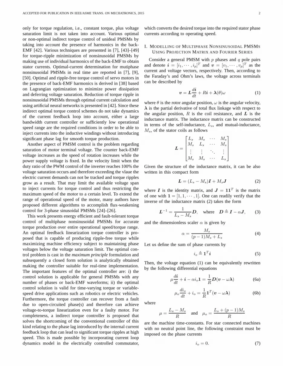
1) Composite Linearization/Optimal Control:Fig. 1 illus-trates the composite optimal-linearization torque controller.The linearization controlvp is computed based on auxiliaryinput u(t) and the full state vector according to (26), whilethe optimizing controlvq is computed from the values of thelinearization control voltage and the state vector according toeither (45) or (46). The input/output of the linearized systemin the Laplace domain is simply given by
τ(s)
u(s)=
1
µs+ 1(47)
ACCEPTED FOR PUBLICATION IN IEEE/ASME TRANS. ON MECHATRONICS, 2015 6
..
+
+
v
vp
vq
u(t)
i,λ,λθ, ω Linearization
Optimalcontrol
Fig. 1. The block diagram of the composite linearization/optmal controller.
+
_M
λθ
λ
τ∗
τ
θ
u
ω
OptimalFeedback
Linearization
λT i
PWMInverter
PI
Fourierseries
positionvelocitycurrent
sensorsensorsensor
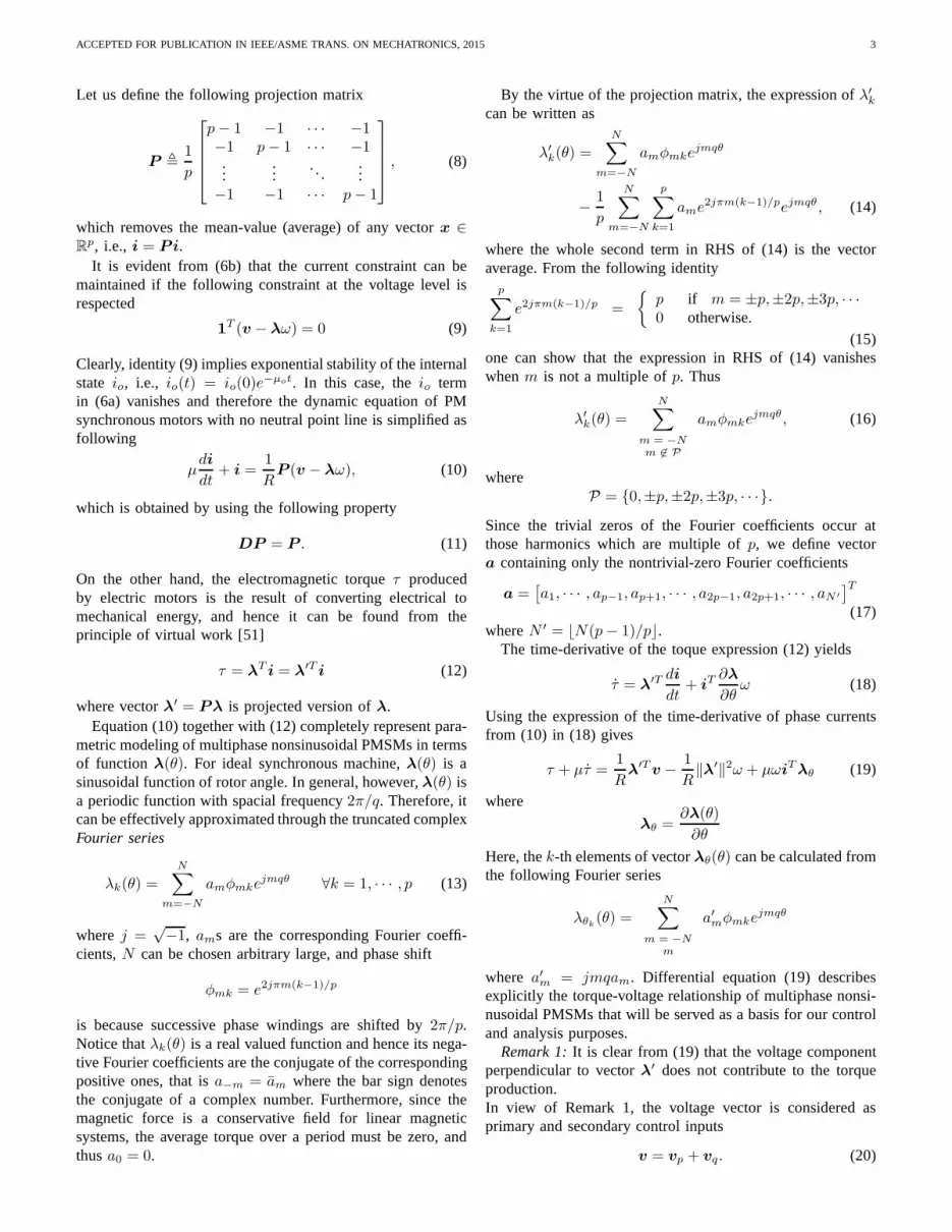
Fig. 2. The architecture of the optimal torque controller.
wheres is the Laplace variable and recall thatµ is the machinetime-constant. Since the linearized system (47) is strictlystable, the proposed feedback linearization control scheme isinherently robust without recurring to external torque feedbackloop. Nevertheless in order to increase the bandwidth of thelinearized system, one may consider the following PI feedbackloop closed around the linearized system
u = K(s)(τ − τ∗) = K(s)(λ′T i− τ∗)
whereτ∗ is the desired input torque andK(s) represent thetransfer function of the PI filter as
K(s) =kps+ ki
s(48)
SupposeΩ =√
ki/µ is the bandwidth of the closed-loopsystem, and the proportional gain is selected askp = 2µΩ−1to achieve critically damped system. Then, the input/outputtransfer function of the closed-loop system becomes
τ(s)
τ∗(s)=
βs+Ω2
(s+Ω)2(49)
where β = 2Ω − 1/µ. Fig. 2 illustrates schematically theoptimal torque control of three-phase nonsinusoidal PMSMsthat can be used for a motion servo system.
C. Fault-Tolerant Feedback Linearization Torque Control
This section presents extension of the feedback linearizationtorque control as described earlier in Section II for the case offaulty motors with open circuited phase(s). This provides themotor drive system with fault-tolerant capability for accuratetorque production even if one of motor phases or inverter legsfails (multi stream fault condition can be dealt with if themotor has more than three phases).
The torque controller should not energize phases which areisolated due to a fault. Therefore, one can define signature
vectorφ = [φ1, · · · , φp]T for the control design purpose as
follow
φk =
1 healty phase0 open-circut phase
∀k = 1, · · · , p
Then, it can be shown that the motor current dynamicswith open-circuited phase(s) is governed by the followingdifferential equation
µdi
dt+ i− αioφ =
1
RD(v − ωλ) (50)
whereD = diag(φ)− αφφT ,
and scalerα is given by
α =Ms
(1Tφ− 1)Ms + Ls
It is important to note that in the case of open-circuitedphase(s), it may be not always possible to balance the currentsof the remaining phases for zero sum to get a stable torque(at least for the case of three-phase motors). Therefore, thecurrent constraint (7) is no longer imposed in the fault-tolerantcontrol law. From practical a point of view, this means thateither the motor’s neutral point must be connected to the drivesystem or phase voltages should be individually controlledbyindependent amplifiers in order to be able to control the torqueof a faulty motor. Consequently, in a development similar to(18)-(19), the torque dynamics equation under open-circuitedphase(s) can be obtained by substituting the time-derivative ofthe current from (50) into (18)
τ +µτ =1
R(Dλ)Tv+
ω
RλT Dλ+µωλT
θ i+ αφTλio (51)
Now consider the following feedback linearization law
vp = λω +R(
u− µωλTθ i− αφTλio
)
‖Dλ‖2Dλ (52)
Then, one can show that substituting the torque control law(52) in (51) still yields the desired input/output linearization(23). Therefore, the controller (52) is able to fully recoverfrom the open-circuit fault condition.
III. I NDIRECT TORQUE CONTROL
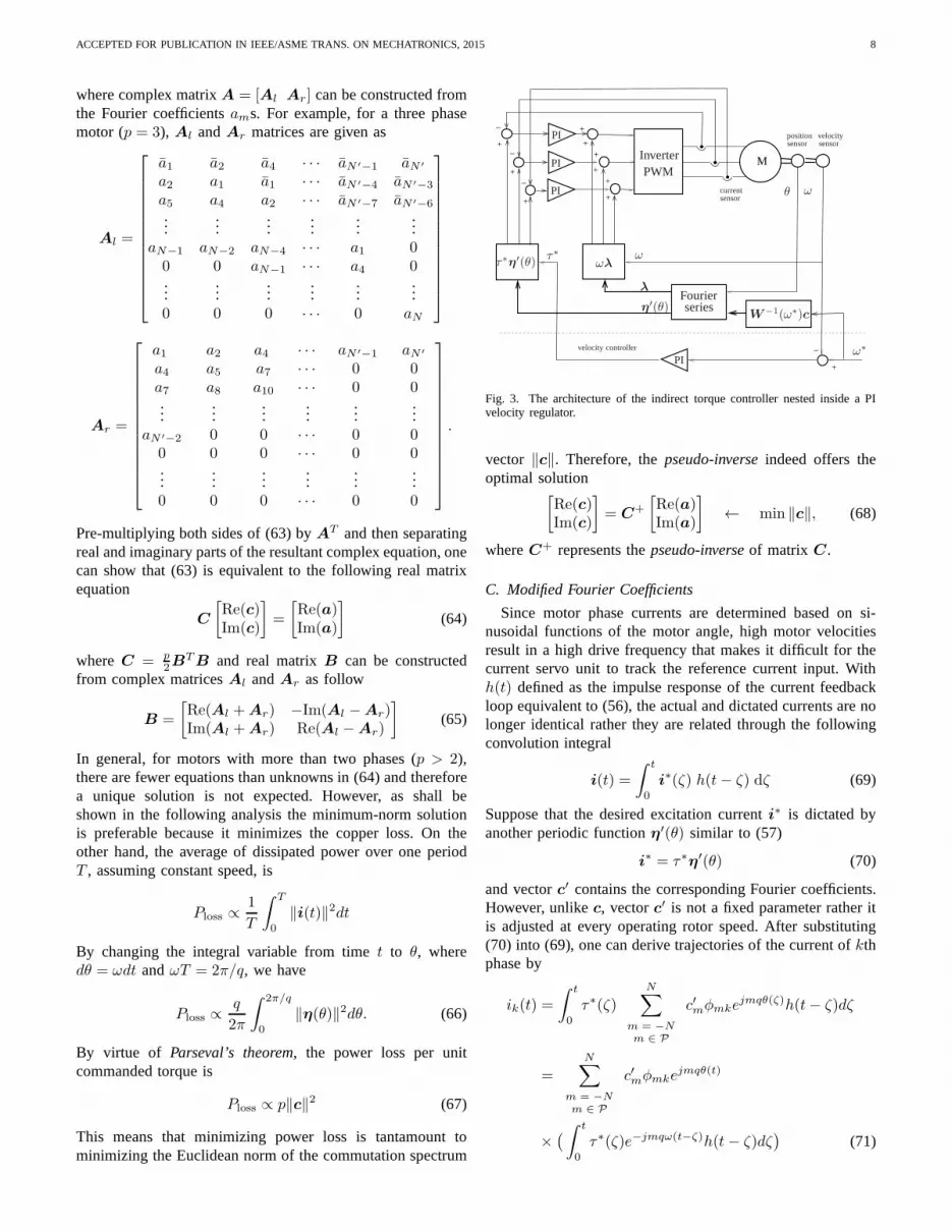
Another control strategy is based on an open-loop feedfor-ward torque controller which maps the desired torque into therequired phase currents to be tracked by a high-performanceinternal current loop. Fig.3 schematically illustrates such anindirect torque controller, which is basically comprised ofinternal current feedback loops of individual phases and anelectronically controlled commutator.
This section presents a feedforward torque controller thatpermits a multiphase nonsinusoidal PMSM to generate accu-rate torque at any operational speed by taking into account thedynamic characteristics of the current controller. Fourier anal-ysis is used for derivation of the phase current commutationasa function of desired torque, angular position, and speed. Westart off by assuming that the dynamics of the inner currentloop is negligible and then relate the Fourier coefficients of
ACCEPTED FOR PUBLICATION IN IEEE/ASME TRANS. ON MECHATRONICS, 2015 7
the waveforms associated with the commutator and the motorback-EMF. This assumption is later relaxed in section III-C,where we show that the Fourier coefficients of the phasecurrent waveforms can be modified at any given operationalspeed to cancel out the speed-induced torque ripple.
A. Inner Current Feedback Loop
For controlling the phase currents of electric machines,there are three major classes of controllers reported in theliterature: linear PI controllers, hysteresis controllers, and pre-dictive dead-beat controllers [32], [33]. The variable switchingfrequency controllers such as hysteresis controllers providesrelatively fast repose time, but they have several shortcomingsassociated with the converter switching frequency that dependslargely on the load parameters and varies with the bus voltage[33]. The current controller we consider herein uses three PIerror compensators accompanied with back-EMF feedforwardcompensators to produce the voltage commands for a multi-phase PWM converter. This control configuration allows us toexploit the advantages of open-loop modulators which run atconstant switching frequency.
Consider the phase voltage and current as input and outputof the inner current loop system. From (10), the open-loop in-put/output relationship in the Laplace domain can be describedby
i =1
R
1
1 + µsP (v − e), (53)
where vectore = λω represents the back-EMF. The controlobjective is that the motor phase currents track their desiredtrajectoriesi∗. Likewise to actual current, we assume that thevector of command current has a zero average and thus
i∗ = Pi∗ (54)
Consider the following PI feedback controller together withback-emk feedforward compensator
v = RK(s)(
i− i∗)
+ e (55)
whereK(s) is the same PI filter as described earlier in (48)and the gains are selected similarly. Notice that (54) ensuresvoltage input (55) is consistent with constraint (9) for star-connected machines with no natural line. From (53) and (55),the input/output transfer function of the closed-loop system isreadily given by
i(s) = H(s)i∗(s),
where
H(s) =βs+Ω2
(s+Ω)2. (56)
Now, suppose that the machine time-constantµ is suffi-ciently small so that the dynamics of the current loop can beignored, i.e.,i ≈ i∗ (this assumption will be later relaxed).Also suppose that the desired phase currents are dictated bymodulating the desired torqueτ∗ with periodic vector functionη(θ)
i∗ = τ∗η(θ) (57)
In this case, the motor torque is trivially given by
τ = τ∗λ′T (θ)η(θ) (58)
From identity λ′Tη = λ′TPη, one can inferη = Pη
meaning thatη is a zero-average vector. Therefore, thek-th element of vectorη can be described by the Fourier seriessimilar to (16)
ηk(θ) =N∑
m = −Nm 6∈ P
cmφmkejmqθ (59)
wherecms are the corresponding Fourier coefficients. We seekdirect solution for the Fourier coefficients ofη(θ) so that theidentity τ = τ∗ is held and copper losses are minimized.The resultant Fourier coefficients will be modified later inSection III-C to compensate for the dynamics of the innercurrent loop, which is usually manifested at high rotor speed.
B. Fourier Analysis
The Fourier coefficients of the product of two periodicfunctionsλk(θ) and ηk(θ) can found by the convolution oftheir Fourier coefficients. With that in mind, we can say from(58) that
τ = τ∗N∑
n=−N
bnejnqθ (60a)
where the Fourier coefficientsbns are associated with motortorque ripple and they are obtained by the convolution ofFourier coefficientsans andcms
bn =
p∑
k=1
N∑
m = −Nm 6∈ P
an−mcme2jπn(k−1)/p (60b)
In view of identity (15), one can realize that expression (60b)can be further simplified by noting that the first summationvanishes whenn is not a multiple ofp. Therefore, the actualFourier coefficients of the motor torque are:
bn =
p
N∑
m = −Nm 6∈ P
an−mcm if n = ±p,±2p,±3p, · · ·
0 otherwise.(60c)
Likewise to definition of vectora in (17), let us define vectorc containing Fourier coefficientscms which are not triviallyzero
c =[
c1, · · · , cp−1, cp+1, · · · , c2p−1, c2p+1, · · · , cN ′
]T(61)
In the following, we seek a particular vectorc for a givenmotor spectrum vectora so that identityτ = τ∗ is alwayssatisfied regardless of the motor angleθ. As far as spectrumsa and c are concerned, this goal can be achieved if allcoefficientsbns exceptb0 are zero andb0 = 1. In other words,
Find c ∋ bn =
1 if n = 00 otherwise
(62)
Consideringc as the set of unknown variables, then (60c)together with (62) constitute a system of linear equations thatcan be written in the following matrix form
[
Al Ar
]
[
c
c
]
=
[
1/p0
]
(63)
ACCEPTED FOR PUBLICATION IN IEEE/ASME TRANS. ON MECHATRONICS, 2015 8
where complex matrixA = [Al Ar] can be constructed fromthe Fourier coefficientsams. For example, for a three phasemotor (p = 3), Al andAr matrices are given as
Al =
a1 a2 a4 · · · aN ′−1 aN ′
a2 a1 a1 · · · aN ′−4 aN ′−3
a5 a4 a2 · · · aN ′−7 aN ′−6
......
......
......
aN−1 aN−2 aN−4 · · · a1 00 0 aN−1 · · · a4 0...
......
......
...0 0 0 · · · 0 aN
Ar =
a1 a2 a4 · · · aN ′−1 aN ′
a4 a5 a7 · · · 0 0a7 a8 a10 · · · 0 0...
......
......
...aN ′−2 0 0 · · · 0 0
0 0 0 · · · 0 0...
......
......
...0 0 0 · · · 0 0
.
Pre-multiplying both sides of (63) byAT and then separatingreal and imaginary parts of the resultant complex equation,onecan show that (63) is equivalent to the following real matrixequation
C
[
Re(c)Im(c)
]
=
[
Re(a)Im(a)
]
(64)
whereC = p2B
TB and real matrixB can be constructedfrom complex matricesAl andAr as follow
B =
[
Re(Al +Ar) −Im(Al −Ar)Im(Al +Ar) Re(Al −Ar)
]
(65)
In general, for motors with more than two phases (p > 2),there are fewer equations than unknowns in (64) and thereforea unique solution is not expected. However, as shall beshown in the following analysis the minimum-norm solutionis preferable because it minimizes the copper loss. On theother hand, the average of dissipated power over one periodT , assuming constant speed, is
Ploss ∝1
T
∫ T
0
‖i(t)‖2dt
By changing the integral variable from timet to θ, wheredθ = ωdt andωT = 2π/q, we have
Ploss ∝q
2π
∫ 2π/q
0
‖η(θ)‖2dθ. (66)
By virtue of Parseval’s theorem, the power loss per unitcommanded torque is
Ploss ∝ p‖c‖2 (67)
This means that minimizing power loss is tantamount tominimizing the Euclidean norm of the commutation spectrum
+
_
+
++
+
+
+
+
+
+
_
_
_
M
ωλτ∗η′(θ)
η′(θ)
θ
W−1(ω∗)c
ω
ω
λ
ω∗
τ∗
PWMInverter
PI
PI
PI
PI
Fourierseries
position velocity
current
sensorsensor
sensor
velocity controller
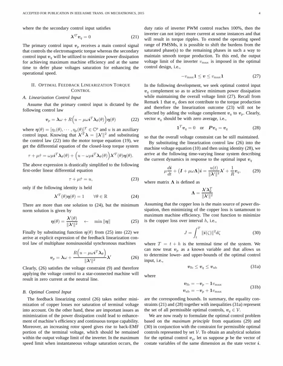
Fig. 3. The architecture of the indirect torque controller nested inside a PIvelocity regulator.
vector ‖c‖. Therefore, thepseudo-inverseindeed offers theoptimal solution
[
Re(c)Im(c)
]
= C+
[
Re(a)Im(a)
]
← min ‖c‖, (68)
whereC+ represents thepseudo-inverseof matrix C.
C. Modified Fourier Coefficients
Since motor phase currents are determined based on si-nusoidal functions of the motor angle, high motor velocitiesresult in a high drive frequency that makes it difficult for thecurrent servo unit to track the reference current input. Withh(t) defined as the impulse response of the current feedbackloop equivalent to (56), the actual and dictated currents are nolonger identical rather they are related through the followingconvolution integral
i(t) =
∫ t
0
i∗(ζ) h(t− ζ) dζ (69)
Suppose that the desired excitation currenti∗ is dictated byanother periodic functionη′(θ) similar to (57)
i∗ = τ∗η′(θ) (70)
and vectorc′ contains the corresponding Fourier coefficients.However, unlikec, vectorc′ is not a fixed parameter rather itis adjusted at every operating rotor speed. After substituting(70) into (69), one can derive trajectories of the current ofkthphase by
ik(t) =
∫ t
0
τ∗(ζ)
N∑
m = −Nm ∈ P
c′mφmkejmqθ(ζ)h(t− ζ)dζ
=N∑
m = −Nm ∈ P
c′mφmkejmqθ(t)
×(
∫ t
0
τ∗(ζ)e−jmqω(t−ζ)h(t− ζ)dζ)
(71)
ACCEPTED FOR PUBLICATION IN IEEE/ASME TRANS. ON MECHATRONICS, 2015 9
where (71) is obtained by making use of expressionθ(ζ) =θ(t)−ω(t− ζ) assuming a constant velocity. The convolutionintegrals in the RHS of (71) are expressed in terms of inputtorque commandτ∗ and virtual systemse−jqωmth(t) associ-ated with themth harmonics. Then, the corresponding steady-state response to the step torque input is given byτ∗H(jqωm),whereH(s) is the equivalent Laplace transform of functionh(t) that was already defined in (56). Consequently, the motorcurrent response can be expressed by
ik(t) = τ∗N∑
m = −Nm ∈ P
c′mH(jqωm)φmkejmqθ(t) (72)
wherec′mH(jqωm)’s can be treated as the new Fourier coef-ficients of the current modulating function at every operatingspeedω,
cm = c′mH(jqωm) ∀m ∈ P , (73)
In this case, the expression of phase currents in (72) isequivalent to (57) and (59) combined if coefficientsc′ms arereplaced bycms according to (73). It should be noted thatthe angular velocity variableω in (73) should not be confusedwith the frequency. The reciprocal of (73) in the vectorial formcan be written as
c′ = W−1(ω)c (74)
where
W (ω) = diag(
H(jqω), H(j2qω), · · · , H(jN ′ω))
In other words, the Fourier coefficients of all modulating func-tions η′(θ) that yield ripple-free torques at constant velocityω must satisfy
AW (ω)
[
c′
c′
]
= A
[
c
c
]
=
[
1/p0
]
(75)
Furthermore, in view of (72) and from a development similarto (66)- (67), one can readily show that the power dissipationin the presence of current-loop dynamics at any given velocityω is proportional to
Ploss ∝ p‖W (ω)c′‖2 = p‖c‖2 (76)
This means that if vectorc obtained from (68) is used toconstructc′ at any specific speed according to (74), then theresultant modulating functionη′(θ) provides ripple-free torqueat that rotor speed and the copper losses are minimized.
Fig. 3 illustrates the proposed indirect torque controllernested inside a velocity control loop for a thee-phase syn-chronous machine. The current controller constitutes the mostinner feedback loop, which drives the phase currents dictatedby modulating the torque command with periodic functionη′(θ).
IV. SIMULATION RESULTS
This section presents simulation results obtained from asimple motion control system in which the servomotor is underthe proposed optimal torque controls.
We assume that the electric motor is with 4 pole pairs andthree phases and it drives a mechanical load (including the
0 20 40 60 80 100 120−8
−6
−4
−2
0
2
4
6
8
Mechanical angle (deg)
λ(θ),λ′ (θ)
(Nm
/Am
p)
λλ′
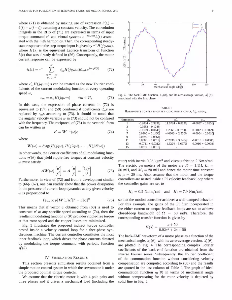
Fig. 4. The back-EMF function,λ1(θ), and its zero-average version,λ′
1(θ),
associated with the first phase.
TABLE IHARMONICS CONTENTS OF PERIODIC FUNCTIONSλ, λ′
θ, AND η.
Harmonics am a′m cm1 -0.2034 - 2.9931j 11.9724 - 0.8136j -0.0037 - 0.0556j3 -0.0582 - 0.1248j - -5 -0.0189 - 0.0648j 1.2960 - 0.3780j 0.0012 + 0.0029j7 0.0900 + 0.1450j -4.0600 + 2.5200j -0.0004 - 0.0010j9 0.0795 + 0.0864j - -11 0.0806 + 0.0519j -2.2836 + 3.5464j -0.0013 + 0.0005j13 -0.0711 + 0.0312j -1.6224 - 3.6972j 0.0016 + 0.0008j15 0.0319 + 0.0810j - -
rotor) with inertia0.05 kgm2 and viscous friction2 Nm.s/rad.The electric parameters of the motor areR = 1.5Ω, Ls =50 mH, andMs = 20 mH and hence the motor time constantis µ = 20 ms. Also, assume that the motor and the torquecontrollers are nested inside a PI velocity feedback loop wherethe controller gains are set to
Kp = 0.5 Nm.s/rad and Ki = 7.9 Nm/rad,
so that the motion controller achieves a well-damped behavior.For this example, the gains of the PI filer incorporated inthe either current or torque feedback loops are set to achieveclosed-loop bandwidth ofΩ = 50 rad/s. Therefore, thecorresponding transfer function is given by
H(s) =s+ 50
0.02s2 + 2s+ 50
The back-EMF waveform of a motor phase as a function of themechanical angle,λ1(θ), with its zero-average version,λ′
1(θ),are plotted in Fig. 4. The corresponding complex Fouriercoefficients of the back-emf function are obtained from theinverse Fourier series. Subsequently, the Fourier coefficientof the commutation function without considering velocitycompensation are computed according to (68) and the resultsare quoted in the last column of Table I. The graph of idealcommutation functionη1(θ) in terms of mechanical anglewithout compensating for the rotor velocity is depicted bysolid line in Fig. 5.
ACCEPTED FOR PUBLICATION IN IEEE/ASME TRANS. ON MECHATRONICS, 2015 10
TABLE IIFOURIER COEFFICIENTS OFη′(θ) FUNCTIONS COMPUTED AT DIFFERENT
MOTOR SPEED.
Harmonics c′m c′m c′mω = 0.5 ω = 2.5 ω = 5.0
1 -0.0015 - 0.0558j 0.0186 - 0.0571j 0.0074 - 0.0564j5 0.0007 + 0.0031j -0.0045 + 0.0054j -0.0016 + 0.0041j7 -0.0001 - 0.0011j 0.0024 - 0.0021j 0.0010 - 0.0015j11 -0.0015 - 0.0000j -0.0035 - 0.0050j -0.0024 - 0.0022j13 0.0012 + 0.0016j -0.0023 + 0.0091j -0.0003 + 0.0049j
The control objective is to follow speed set-pointsω∗ whichchanges from0.5 rad/s to 5.0 rad/s and then reduced to2.5 rad/s in three 2-second intervals. The Fourier coefficientsof the current modulation function as a function of the desiredoperating speed are calculated and the results are listed inTable II. The corresponding waveforms of phase currentmodulation at different speed set-points are shown in Fig. 5.
For a comparison, we applied three different motor torquecontrol strategies at a time:
i) The conventional indirect torque control based on thefixed Fourier coefficients.
ii) The proposed indirect torque control where the Fouriercoefficients of the commutator are modified based onthe desired operating speed.
iii) The proposed optimal-linearization torque controller.Trajectories of the motor’s torque and velocity obtained
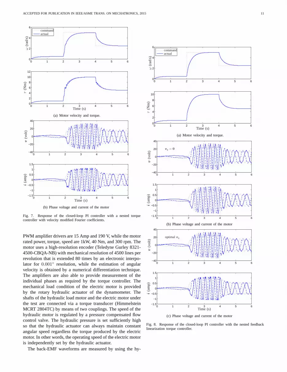
from the step-input response of the closed-loop system withthe conventional and the modified indirect torque controllersare illustrated in Fig. 6 and Fig. 7, respectively. It is apparentfrom the graphs that the conventional indirect torque con-troller is able to eliminate the pulsation torque and velocityonly at low velocity whereas the modified indirect torquecontroller does so at every given velocity albeit pulsationappears during the transition from one operating point toanother. The responses of the servo motor under the optimallinearization torque controller are shown in Fig. 8. It is ap-parent from Fig. 8(a) that the linearization torque controller isable to completely eliminate the pulsate toque/velocity duringboth transition and steady-state phases. Figs. 8(b) and 8(c)illustrates the time histories of phase currents and voltages,respectively, for two cases: i)vq = 0, ii) optimal voltagecomponentvq is added to achieve energy efficiency. The timehistories of the voltage componentvq to minimize powerdissipation is shown in Fig. IV. The figure also comparativelyshows the evolution of energy dissipation withvq set to zeroand with optimalvq. It is apparent that the optimal controlinput vq succeeded to reduce the power dissipation by 12%.
V. EXPERIMENTAL RESULTS
In order to evaluate the performance of the energy-effacement torque controller to track time-varying torquecommands, experiments were conducted on a three-phasesynchronous with electric time-constant isµ = 5 ms. Theexperimental setup is illustrated in Fig. 10. Three independentPWM servo amplifiers (Advanced Motion Control 30A20AC)control the motor’s phase voltages as specified by the torquecontroller. The rated current and voltage of the independent
0 20 40 60 80 100 120−0.2
−0.15
−0.1
−0.05
0
0.05
0.1
0.15
0.2
Mechanical angle (deg)
η′ (θ),η
′ (θ)
(A/N
m)
ω∗ = 0.0ω∗ = 0.5
ω∗ = 5.0ω∗ = 2.5
Fig. 5. The wave forms of the commutation function corresponding todifferent rotor velocities.
0 1 2 3 4 5 60
2
4
6
0 1 2 3 4 5 60
2
4
6
8
10
12
Time (s)
τ(N
m)
ω(r
ad/s
) actualcommand
(a) Motor velocity and torque.
0 1 2 3 4 5 6−40
−20
0
20
40
0 1 2 3 4 5 6−1.5
−1
−0.5
0
0.5
1
1.5
Time (s)
v(v
olt)
i(a
mp
)
(b) Phase voltage and current of the motor
Fig. 6. Response of the closed-loop PI controller with a nested torquecontroller with fixed Fourier coefficients.
ACCEPTED FOR PUBLICATION IN IEEE/ASME TRANS. ON MECHATRONICS, 2015 11
0 1 2 3 4 5 60
2
4
6
0 1 2 3 4 5 60
2
4
6
8
10
12
Time (s)
τ(N
m)
ω(r
ad/s
) actualcommand
(a) Motor velocity and torque.
0 1 2 3 4 5 6−40
−20
0
20
40
0 1 2 3 4 5 6−1.5
−1
−0.5
0
0.5
1
1.5
Time (s)
v(v
olt)
i(a
mp
)
(b) Phase voltage and current of the motor
Fig. 7. Response of the closed-loop PI controller with a nested torquecontroller with velocity modified Fourier coefficients.
PWM amplifier drivers are 15 Amp and 190 V, while the motorrated power, torque, speed are 1kW, 40 Nm, and 300 rpm. Themotor uses a high-resolution encoder (Teledyne Gurley 8321-4500-CBQA-NB) with mechanical resolution of 4500 lines perrevolution that is extended 80 times by an electronic interpo-lator for 0.001 resolution, while the estimation of angularvelocity is obtained by a numerical differentiation technique.The amplifiers are also able to provide measurement of theindividual phases as required by the torque controller. Themechanical load condition of the electric motor is providedby the rotary hydraulic actuator of the dynamometer. Theshafts of the hydraulic load motor and the electric motor underthe test are connected via a torque transducer (HimmelsteinMCRT 2804TC) by means of two couplings. The speed of thehydraulic motor is regulated by a pressure compensated flowcontrol valve. The hydraulic pressure is set sufficiently highso that the hydraulic actuator can always maintain constantangular speed regardless the torque produced by the electricmotor. In other words, the operating speed of the electric motoris independently set by the hydraulic actuator.
The back-EMF waveforms are measured by using the hy-
0 1 2 3 4 5 60
2
4
6
0 1 2 3 4 5 60
2
4
6
8
10
Time (s)
τ(N
m)
ω(r
ad/s
) actualcommand
(a) Motor velocity and torque.
0 1 2 3 4 5 6−40
−20
0
20
40
0 1 2 3 4 5 6−1.5
−1
−0.5
0
0.5
1
1.5
v(v
olt)
i(a
mp
)vq = 0
(b) Phase voltage and current of the motor
0 1 2 3 4 5 6−40
−20
0
20
40
0 1 2 3 4 5 6−1.5
−1
−0.5
0
0.5
1
1.5
Time (s)
v(v
olt)
i(a
mp
)
optimalvq
(c) Phase voltage and current of the motor
Fig. 8. Response of the closed-loop PI controller with the nested feedbacklinearization torque controller.
ACCEPTED FOR PUBLICATION IN IEEE/ASME TRANS. ON MECHATRONICS, 2015 12
0 1 2 3 4 5 6−2
−1
0
1
2
0 1 2 3 4 5 60
2
4
6
8
Time (s)
optimalvq
vq
(Vo
lt)C
op
per
loss
es(J
ou
le)
vq = 0
Fig. 9. Auxiliary voltage inputvq for copper losses minimizing (top);comparison of copper losses with and without optimal control input.
Fig. 10. The experimental setup.
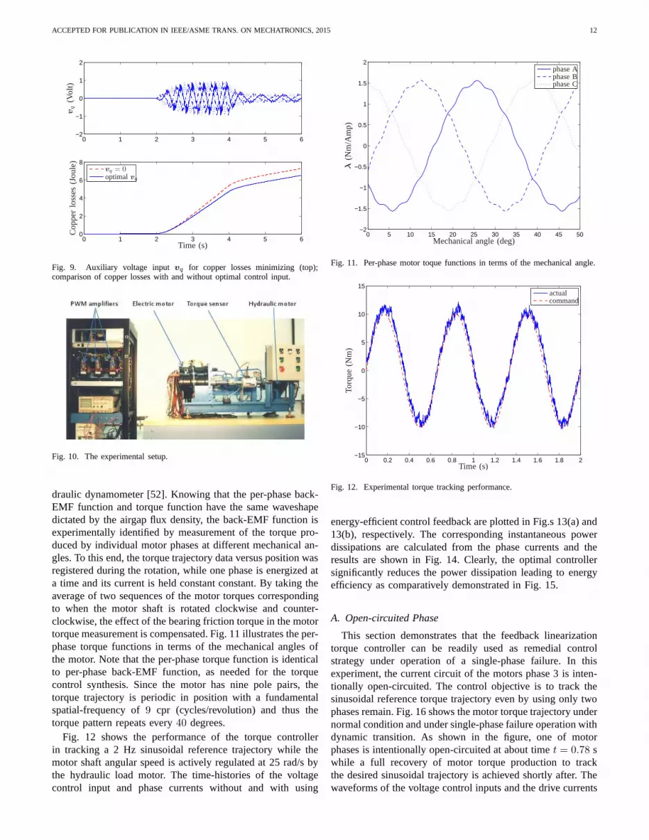
draulic dynamometer [52]. Knowing that the per-phase back-EMF function and torque function have the same waveshapedictated by the airgap flux density, the back-EMF function isexperimentally identified by measurement of the torque pro-duced by individual motor phases at different mechanical an-gles. To this end, the torque trajectory data versus position wasregistered during the rotation, while one phase is energized ata time and its current is held constant constant. By taking theaverage of two sequences of the motor torques correspondingto when the motor shaft is rotated clockwise and counter-clockwise, the effect of the bearing friction torque in the motortorque measurement is compensated. Fig. 11 illustrates theper-phase torque functions in terms of the mechanical angles ofthe motor. Note that the per-phase torque function is identicalto per-phase back-EMF function, as needed for the torquecontrol synthesis. Since the motor has nine pole pairs, thetorque trajectory is periodic in position with a fundamentalspatial-frequency of9 cpr (cycles/revolution) and thus thetorque pattern repeats every40 degrees.
Fig. 12 shows the performance of the torque controllerin tracking a 2 Hz sinusoidal reference trajectory while themotor shaft angular speed is actively regulated at 25 rad/s bythe hydraulic load motor. The time-histories of the voltagecontrol input and phase currents without and with using
0 5 10 15 20 25 30 35 40 45 50−2
−1.5
−1
−0.5
0
0.5
1
1.5
2
Mechanical angle (deg)
λ(N
m/A
mp
)
phase Aphase Bphase C
Fig. 11. Per-phase motor toque functions in terms of the mechanical angle.
0 0.2 0.4 0.6 0.8 1 1.2 1.4 1.6 1.8 2−15
−10
−5
0
5
10
15
Time (s)
actualcommand
Torq
ue
(Nm
)
Fig. 12. Experimental torque tracking performance.
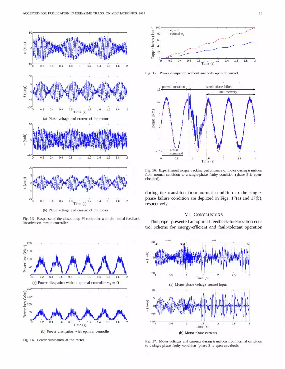
energy-efficient control feedback are plotted in Fig.s 13(a) and13(b), respectively. The corresponding instantaneous powerdissipations are calculated from the phase currents and theresults are shown in Fig. 14. Clearly, the optimal controllersignificantly reduces the power dissipation leading to energyefficiency as comparatively demonstrated in Fig. 15.
A. Open-circuited Phase
This section demonstrates that the feedback linearizationtorque controller can be readily used as remedial controlstrategy under operation of a single-phase failure. In thisexperiment, the current circuit of the motors phase 3 is inten-tionally open-circuited. The control objective is to trackthesinusoidal reference torque trajectory even by using only twophases remain. Fig. 16 shows the motor torque trajectory undernormal condition and under single-phase failure operationwithdynamic transition. As shown in the figure, one of motorphases is intentionally open-circuited at about timet = 0.78 swhile a full recovery of motor torque production to trackthe desired sinusoidal trajectory is achieved shortly after. Thewaveforms of the voltage control inputs and the drive currents
ACCEPTED FOR PUBLICATION IN IEEE/ASME TRANS. ON MECHATRONICS, 2015 13
0 0.2 0.4 0.6 0.8 1 1.2 1.4 1.6 1.8 2−50
0
50
0 0.2 0.4 0.6 0.8 1 1.2 1.4 1.6 1.8 2−10
−5
0
5
10
Time (s)
v(v
olt)
i(a
mp
)
(a) Phase voltage and current of the motor
0 0.2 0.4 0.6 0.8 1 1.2 1.4 1.6 1.8 2−50
0
50
0 0.2 0.4 0.6 0.8 1 1.2 1.4 1.6 1.8 2−10
−5
0
5
10
Time (s)
v(v
olt)
i(a
mp
)
(b) Phase voltage and current of the motor
Fig. 13. Response of the closed-loop PI controller with the nested feedbacklinearization torque controller.
0 0.2 0.4 0.6 0.8 1 1.2 1.4 1.6 1.8 20
50
100
150
200
Pow
erlo
ss(W
att)
(a) Power dissipation without optimal controllervq = 0
0 0.2 0.4 0.6 0.8 1 1.2 1.4 1.6 1.8 20
50
100
150
200
Time (s)
Pow
erlo
ss(W
att)
(b) Power dissipation with optimal controller
Fig. 14. Power dissipation of the motor.
0 0.2 0.4 0.6 0.8 1 1.2 1.4 1.6 1.8 20
20
40
60
80
100
Time (s)
vq = 0optimalvq
Co
pp
erlo
sses
(Jo
ule
)
Fig. 15. Power dissipation without and with optimal control.
0 0.5 1 1.5 2 2.5 3
−10
−5
0
5
10
15
Time (s)
actualcommand
Torq
ue
(Nm
)
normal operation single-phase failure
fault recovery
Fig. 16. Experimental torque tracking performance of motorduring transitionfrom normal condition to a single-phase faulty condition (phase 3 is open-circuited).
during the transition from normal condition to the single-phase failure condition are depicted in Figs. 17(a) and 17(b),respectively.
VI. CONCLUSIONS
This paper presented an optimal feedback-linearization con-trol scheme for energy-efficient and fault-tolerant operation
0 0.5 1 1.5 2 2.5 3−50
0
50normal fault
Time (s)
v(v
olt)
(a) Motor phase voltage control input
0 0.5 1 1.5 2 2.5 3−10
−5
0
5
10
Time (s)
i(a
mp
)
(b) Motor phase currents
Fig. 17. Motor voltages and currents during transition fromnormal conditionto a single-phase faulty condition (phase 3 is open-circuited).

ACCEPTED FOR PUBLICATION IN IEEE/ASME TRANS. ON MECHATRONICS, 2015 14
of multiphase nonsinusoidal PMSMs subject to time-varyingoperational speed/torque and voltage limit. Analytical solutionfor the optimal control problem has been found based onthemaximum principleformulation. The optimal-linearizationcontrol scheme eliminates the pulsation torque through lin-earization of motor voltage-torque even with phase failure,maximizes power efficiency, and maintains the phase voltagesbelow the saturation level of a PWM voltage source inverter.The important feature of the optimal controller is that it admitsnon-constant reference torque (or velocity) as oppose to theconventional optimal control approaches requiring the motor tooperate at constant torque or velocity (regulation). Therefore,the optimal controller automatically perform a role similarto the field weakening control technique but for nonsiusoidalsynchronous machines to expand the range of operating speedin addition to maximizing machine efficiency. The controllercan also achieve voltage-to-torque linearization even if oneor more phases (the latter is applicable only if the motorhas more than three phases) are open-circuited and henceit is suitable for fault-tolerant applications. This work wascomplemented by modifying the conventional indirect torquecontroller consisting of an internal current feedback loopandan electronic commutator. The proposed control approachsolved the shortcoming of the conventional indirect torquecontroller relating to the speed-induced torque-ripple and al-lowed high-performance and smooth torque control over entirespeed range of the motor regardless of the current controllerbandwidth. Simulations and experimental results demonstratedthe energy efficiency and fault-tolerant capabilities of theproposed optimal-linearization torque controller.
ACKNOWLEDGMENTS
This work was supported by Canadian Space Agency (CSA)and Natural Science and Engineering Council of Canada(NSERC) under grant RGPIN/288255-2011.
REFERENCES
[1] H. van de Straete, P. Degezelle, J. De Schutter, and R. J. M. Belmans,“Servo motor selection criterion for mechatronic applications,” Mecha-tronics, IEEE/ASME Transactions on, vol. 3, no. 1, pp. 43–50, Mar1998.
[2] Y. Chen and J. Wang, “Design and experimental evaluations on energyefficient control allocation methods for overactuated electric vehicles:Longitudinal motion case,”Mechatronics, IEEE/ASME Transactions on,vol. 19, no. 2, pp. 538–548, April 2014.
[3] G. Foo, X. Zhang, and D. Vilathgamuwa, “Sensor fault-resilient controlof interior permanent-magnet synchronous motor drives,”Mechatronics,IEEE/ASME Transactions on, vol. 20, no. 2, pp. 855–864, April 2015.
[4] D. G. Taylor, “Nonlinear control of electric machines: An overview,”IEEE Control Systems Magazine, vol. 14, no. 6, pp. 41–51, 1994.
[5] C. French and P. Acarnley, “Direct torque control of permanent magnetdrives,” IEEE Trans. on Industry Applications, vol. 32, no. 5, pp. 1080–1088, Sep.–Oct. 1996.
[6] J.-K. Kang and S.-K. Sul, “New direct torque control of induction motorfor minimum torque ripple and constant switching frequency,” IEEETrans. on Industry Applications, vol. 35, no. 5, pp. 1076–1082, Sep.–Oct. 1999.
[7] F. Aghili, M. Buehler, and J. M. Hollerbach, “Optimal commutationlaws in the frequency domain for PM synchronous direct-drive motors,”IEEE Transactions on Power Electronics, vol. 15, no. 6, pp. 1056–1064,Nov. 2000.
[8] S. J. Park, H. W. Park, M. H. Lee, and F. Harashima, “A new approachfor minimum-torque-ripple maximum-efficiency control of BLDC mo-tor,” IEEE Trans. on Industrial Electronics, vol. 47, no. 1, pp. 109–114,Feb. 2000.
[9] F. Aghili, M. Buehler, and J. M. Hollerbach, “Experimental character-ization and quadratic programming-based control of brushless-motors,”IEEE Trans. on Control Systems Technology, vol. 11, no. 1, pp. 139–146,2003.
[10] Y. Wang, D. Cheng, C. Li, and Y. Ge, “Dissipative Hamiltonianrealization and energy-based L2-disturbance attenuationcontrol of mul-timachine power systems,”IEEE Trans. on Automatic Control, vol. 48,no. 8, pp. 1428–1433, Aug. 2003.
[11] Z. Xu and M. F. Rahman, “A variable structure torque and flux controllerfor a DTC IPM synchronous motor drive,” inIEEE 35th Annual PowerElectronics Specialists Conference, PESC 04., Jun. 2004, pp. 445–450,Vol. 1.
[12] L. Bascetta, P. Rocco, and G. Magnani, “Force ripple compensation inlinear motors based on closed-loop position-dependent identification,”Mechatronics, IEEE/ASME Transactions on, vol. 15, no. 3, pp. 349–359, June 2010.
[13] R. Ortega, L. Praly, A. Astolfi, J. Lee, and K. Nam, “Estimation ofrotor position and speed of permanent magnet synchronous motors withguaranteed stability,”Control Systems Technology, IEEE Transactionson, vol. 19, no. 3, pp. 601–614, May 2011.
[14] S. Ozturk and H. Toliyat, “Direct torque and indirect flux controlof brushless dc motor,”Mechatronics, IEEE/ASME Transactions on,vol. 16, no. 2, pp. 351–360, April 2011.
[15] D. Grenier, L.-A. Dessaint, O. Akhrif, and J.-P. Louis,“A park-liketransformation for the study and the control of a nonsinusoidal brushlessdc motor,” inIndustrial Electronics, Control, and Instrumentation, 1995.,Proceedings of the 1995 IEEE IECON 21st International Conference on,vol. 2, Nov 1995, pp. 836–843 vol.2.
[16] A. Kaddouri, O. Akhrif, H. Le-Huy, and M. Ghribi, “Nonlinear feedbackcontrol of a permanent magnet synchronous motors,” inElectrical andComputer Engineering, 1994. Conference Proceedings. 1994CanadianConference on, Sep 1994, pp. 77–80 vol.1.
[17] M. Bodson, J. Chiasson, R. Novotnak, and R. Rekowski, “High-performance nonlinear feedback control of a permanent magnet steppermotor,” Control Systems Technology, IEEE Transactions on, vol. 1, no. 1,pp. 5–14, Mar 1993.
[18] D. Grenier, L.-A. Dessaint, O. Akhrif, Y. Bonnassieux,and B. Le Pi-oufle, “Experimental nonlinear torque control of a permanent-magnetsynchronous motor using saliency,”Industrial Electronics, IEEE Trans-actions on, vol. 44, no. 5, pp. 680–687, Oct 1997.
[19] I. Takahashi and T. Noguchi, “A new quick-response and high-efficiencycontrol strategy of an induction motor,”Industry Applications, IEEETransactions on, vol. IA-22, no. 5, pp. 820–827, Sept 1986.
[20] L. Zhong, M. Rahman, W. Y. Hu, and K. W. Lim, “Analysis of directtorque control in permanent magnet synchronous motor drives,” PowerElectronics, IEEE Transactions on, vol. 12, no. 3, pp. 528–536, May1997.
[21] Y. Zhang and J. Zhu, “Direct torque control of permanentmagnet syn-chronous motor with reduced torque ripple and commutation frequency,”Power Electronics, IEEE Transactions on, vol. 26, no. 1, pp. 235–248,Jan 2011.
[22] K. Gulez, A. Adam, and H. Pastaci, “A novel direct torquecontrolalgorithm for ipmsm with minimum harmonics and torque ripples,”Mechatronics, IEEE/ASME Transactions on, vol. 12, no. 2, pp. 223–227, April 2007.
[23] Y. Cho, D.-H. Kim, K.-B. Lee, Y. I. Lee, and J.-H. Song, “Torque ripplereduction and fast torque response strategy of direct torque control forpermanent-magnet synchronous motor,” inIndustrial Electronics (ISIE),2013 IEEE International Symposium on, May 2013, pp. 1–6.
[24] J.-J. Chen and K.-P. Chin, “Automatic flux-weakening control of per-manent magnet synchronous motors using a reduced-order controller,”Power Electronics, IEEE Transactions on, vol. 15, no. 5, pp. 881–890,Sep 2000.
[25] Z. Zhu, Y. Chen, and D. Howe, “Online optimal flux-weakening controlof permanent-magnet brushless ac drives,”Industry Applications, IEEETransactions on, vol. 36, no. 6, pp. 1661–1668, Nov 2000.
[26] J.-J. Chen and K.-P. Chin, “Minimum copper loss flux-weakening controlof surface mounted permanent magnet synchronous motors,”PowerElectronics, IEEE Transactions on, vol. 18, no. 4, pp. 929–936, July2003.
[27] H.-H. Chiang, K.-C. Hsu, and I.-H. Li, “Optimized adaptive motioncontrol through an sopc implementation for linear induction motordrives,” Mechatronics, IEEE/ASME Transactions on, vol. 20, no. 1, pp.348–360, Feb 2015.
[28] T. D. Do, H. H. Choi, and J.-W. Jung, “Sdre-based near optimal controlsystem design for pm synchronous motor,”Industrial Electronics, IEEETransactions on, vol. 59, no. 11, pp. 4063–4074, Nov 2012.
ACCEPTED FOR PUBLICATION IN IEEE/ASME TRANS. ON MECHATRONICS, 2015 15
[29] P. Krishnamurthy and F. Khorrami, “An analysis of the effects of closed-loop commutation delay on stepper motor control and application toparameter estimation,”Control Systems Technology, IEEE Transactionson, vol. 16, no. 1, pp. 70–77, Jan 2008.
[30] S. H. Chu and I. J. Ha, “Control of hybrid step motors via asimplifiedlinearization technique,”Int. Journal of Control, vol. 61, no. 5, pp. 1143–1167, 1995.
[31] H. Le-Huy, K. Slimani, and P. Viarouge, “Analysis and implementationof a real-time predictive current controller for permanent-magnet syn-chronous servo drives,” inIndustry Applications Society Annual Meeting,1991., Conference Record of the 1991 IEEE, Sept 1991, pp. 996–1002vol.1.
[32] S. Buso, L. Malesani, and P. Mattavelli, “Comparison ofcurrent controltechniques for active filter applications,”Industrial Electronics, IEEETransactions on, vol. 45, no. 5, pp. 722–729, Oct 1998.
[33] M. Kazmierkowski and L. Malesani, “Current control techniques forthree-phase voltage-source pwm converters: a survey,”Industrial Elec-tronics, IEEE Transactions on, vol. 45, no. 5, pp. 691–703, Oct 1998.
[34] T. Jahns and W. Soong, “Pulsating torque minimization techniques forpermanent magnet ac motor drives-a review,”Industrial Electronics,IEEE Transactions on, vol. 43, no. 2, pp. 321–330, Apr 1996.
[35] D. Wang, X. Wang, Y. Yang, and R. Zhang, “Optimization ofmagneticpole shifting to reduce cogging torque in solid-rotor permanent-magnetsynchronous motors,”Magnetics, IEEE Transactions on, vol. 46, no. 5,pp. 1228–1234, May 2010.
[36] D. Grenier, S. Yala, O. Akhrif, and L.-A. Dessaint, “Direct torquecontrol of pm ac motor with non-sinusoidal flux distributionusing state-feedback linearization techniques,” inIndustrial Electronics Society,1998. IECON ’98. Proceedings of the 24th Annual Conference of theIEEE, vol. 3, Aug 1998, pp. 1515–1520 vol.3.
[37] X. Feipeng, L. Tiecai, and T. Pinghua, “A low cost drive strategy forBLDC motor with low torque ripples,” inIEEE Int. Conf. on IndustrialElectronics and Applications, Singapore, June 2008, pp. 2499–2502.
[38] F. Aghili, “Optimal and fault-tolerant torque controlof servo motorssubject to voltage and current limits,”IEEE Trans. on Control SystemTechnology, vol. 21, no. 4, pp. 1440–1448, July 2013.
[39] ——, “Velocity fluctuation suppression of non-ideal pm synchronousmotors,” in IEEE/ASME International Conference on Advanced Intelli-gent Mechatronics, Besancon, France, July 8–11 2014, pp. 806–811.
[40] K. Bai and K.-M. Lee, “Direct field-feedback control of aball-joint-like permanent-magnet spherical motor,”Mechatronics, IEEE/ASMETransactions on, vol. 19, no. 3, pp. 975–986, June 2014.
[41] B. Sencer and E. Shamoto, “Effective torque ripple compensation infeed drive systems based on the adaptive sliding-mode controller,”Mechatronics, IEEE/ASME Transactions on, vol. 19, no. 6, pp. 1764–1772, Dec 2014.
[42] D. Flieller, N. K. Nguyen, P. Wira, G. Sturtzer, D. Abdeslam, andJ. Merckle, “A self-learning solution for torque ripple reduction fornonsinusoidal permanent-magnet motor drives based on artificial neuralnetworks,” Industrial Electronics, IEEE Transactions on, vol. 61, no. 2,pp. 655–666, Feb 2014.
[43] H. Le-Huy, R. Perret, and R. Feuillet, “Minimization oftorque ripplein brushless dc motor drives,”Industry Applications, IEEE Transactionson, vol. IA-22, no. 4, pp. 748–755, July 1986.
[44] H. Melkote and F. Khorrami, “Nonlinear adaptive control of direct-drive brushless dc motors and applications to robotic manipulators,”Mechatronics, IEEE/ASME Transactions on, vol. 4, no. 1, pp. 71–81,Mar 1999.
[45] J. Hung and Z. Ding, “Minimization of torque ripple in permanentmagnet motors: a closed form solution,” inIndustrial Electronics,Control, Instrumentation, and Automation, 1992. Power Electronics andMotion Control., Proceedings of the 1992 International Conference on,Nov 1992, pp. 459–463 vol.1.
[46] S. Clenet, Y. Lefevre, N. Sadowski, S. Astier, and M. Lajoie-Mazenc,“Compensation of permanent magnet motors torque ripple by meansof current supply waveshapes control determined by finite elementmethod,” Magnetics, IEEE Transactions on, vol. 29, no. 2, pp. 2019–2023, Mar 1993.
[47] K. y. Cho, J.-D. Bae, S.-K. Chung, and M. J. Youn, “Torqueharmonicsminimization in pm synchronous motor with back emf estimation,” inTENCON ’93. Proceedings. Computer, Communication, Control andPower Engineering.1993 IEEE Region 10 Conference on, no. 0, Oct1993, pp. 589–593 vol.5.
[48] A. Wu and P. Chapman, “Simple expressions for optimal currentwaveforms for permanent-magnet synchronous machine drives,” EnergyConversion, IEEE Transactions on, vol. 20, no. 1, pp. 151–157, March2005.
[49] R. Shanmugasundram, K. Zakariah, and N. Yadaiah, “Implementationand performance analysis of digital controllers for brushless dc motordrives,” Mechatronics, IEEE/ASME Transactions on, vol. 19, no. 1, pp.213–224, Feb 2014.
[50] X. Kestelyn and E. Semail, “A vectorial approach for generation of op-timal current references for multiphase permanent-magnetsynchronousmachines in real time,”Industrial Electronics, IEEE Transactions on,vol. 58, no. 11, pp. 5057–5065, Nov 2011.
[51] P. C. Krause,Analysis of Electric Machinery. McGraw-Hill, 1986.[52] F. Aghili, J. M. Hollerbach, and M. Buehler, “A modular and high-
precision motion control system with an integrated motor,”IEEE/ASMETrans. on Mechatronics, vol. 12, no. 3, pp. 317–329, Jun. 2007.
Farhad Aghili (SM’07) received the B.Sc. in Me-chanical Engineering (’88) and M.Sc. in BiomedicalEngineering (’91) both from Sharif University ofTechnology, and Ph.D. in Mechanical Engineering(’98) from McGill University. Since 1998, Dr. Aghilihas been Mission Operation Engineer, Systems Engi-neer, and Federal Research Scientist at the CanadianSpace Agency (CSA), where he contributed to theCanadian Space Exploration and the InternationalSpace Station (ISS) programs in various capacities.During 1994-1998, he was a Research Engineer at
MPB Technologies of Montreal, and he is Affiliate Associate Professor atConcordia University.
Dr. Aghili has established a robust research and development programleading to many technology transfers to industry by applying his expertise inthe areas of robotics, dynamics and controls, and mechatronics. His researchresulted in over 130 scientific papers, 3 book chapters, 10 patents in US andCanada, 6 trade secretes, and several technology transfersto industry. Healso chaired and been otherwise involved in several international conferencesand professional activities as well as being the recipient of the best paperaward and invited keynote speaker in international conferences. Dr. Aghili isTechnical Editor of the IEEE/ASME Transactions on Mechatronics (TMech)and the Chair of IEEE Montreal Robotics & Automation Chapter.


![[Management of synchronous colorectal liver metastases]](https://img.dokumen.tips/doc/110x75/633c816a1a818810c60e59c2/management-of-synchronous-colorectal-liver-metastases.jpg)


