Embed Size (px)
Citation preview
SYNCHRONOUS COUNTERS• In the previous tutorial, we have learned about asynchronous counters. Though they
are easily built, however there are several challenges.
• There is no propagation delay and ripple effect in synchronous counters.
• In synchronous counters, each and every flip-flop receives the exact same clock
pulse at the exact same time. This means, the synchronous counter depends on the
clock input to change their state value.
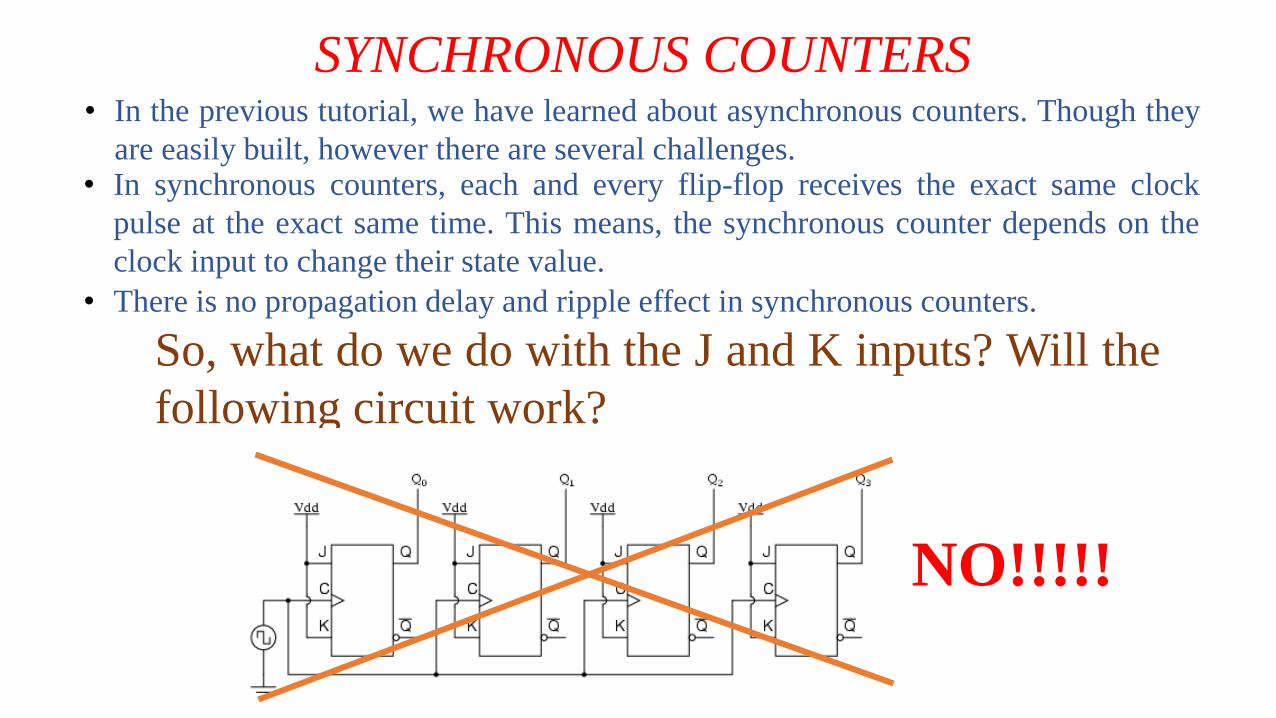
So, what do we do with the J and K inputs? Will the
following circuit work?
NO!!!!!
SYNCHRONOUS COUNTERS• For synchronous counters, all the flip-flops are using the same CLOCK signal. Thus,
the output would change synchronously.
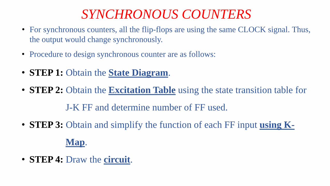
• Procedure to design synchronous counter are as follows:
• STEP 1: Obtain the State Diagram.
• STEP 2: Obtain the Excitation Table using the state transition table for
J-K FF and determine number of FF used.
• STEP 3: Obtain and simplify the function of each FF input using K-
Map.
• STEP 4: Draw the circuit.
SYNCHRONOUS COUNTERS
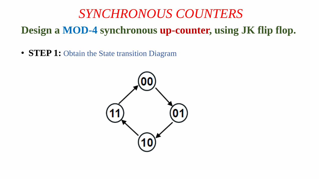
Design a MOD-4 synchronous up-counter, using JK flip flop.
• STEP 1: Obtain the State transition Diagram
SYNCHRONOUS COUNTERS
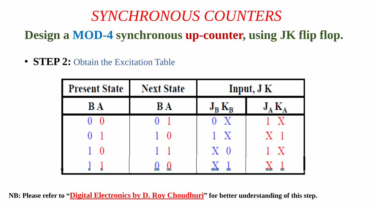
Design a MOD-4 synchronous up-counter, using JK flip flop.
• STEP 2: Obtain the Excitation Table
NB: Please refer to “Digital Electronics by D. Roy Choudhuri” for better understanding of this step.
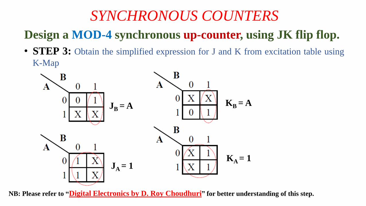
KB = A
KA = 1
SYNCHRONOUS COUNTERS
Design a MOD-4 synchronous up-counter, using JK flip flop.
• STEP 3: Obtain the simplified expression for J and K from excitation table using
K-Map
NB: Please refer to “Digital Electronics by D. Roy Choudhuri” for better understanding of this step.
JB = A
JA = 1
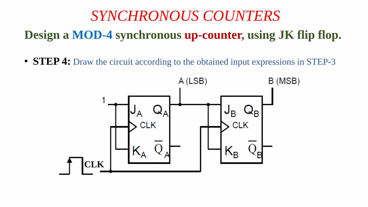
SYNCHRONOUS COUNTERS
Design a MOD-4 synchronous up-counter, using JK flip flop.
• STEP 4: Draw the circuit according to the obtained input expressions in STEP-3
CLK
SYNCHRONOUS COUNTERS
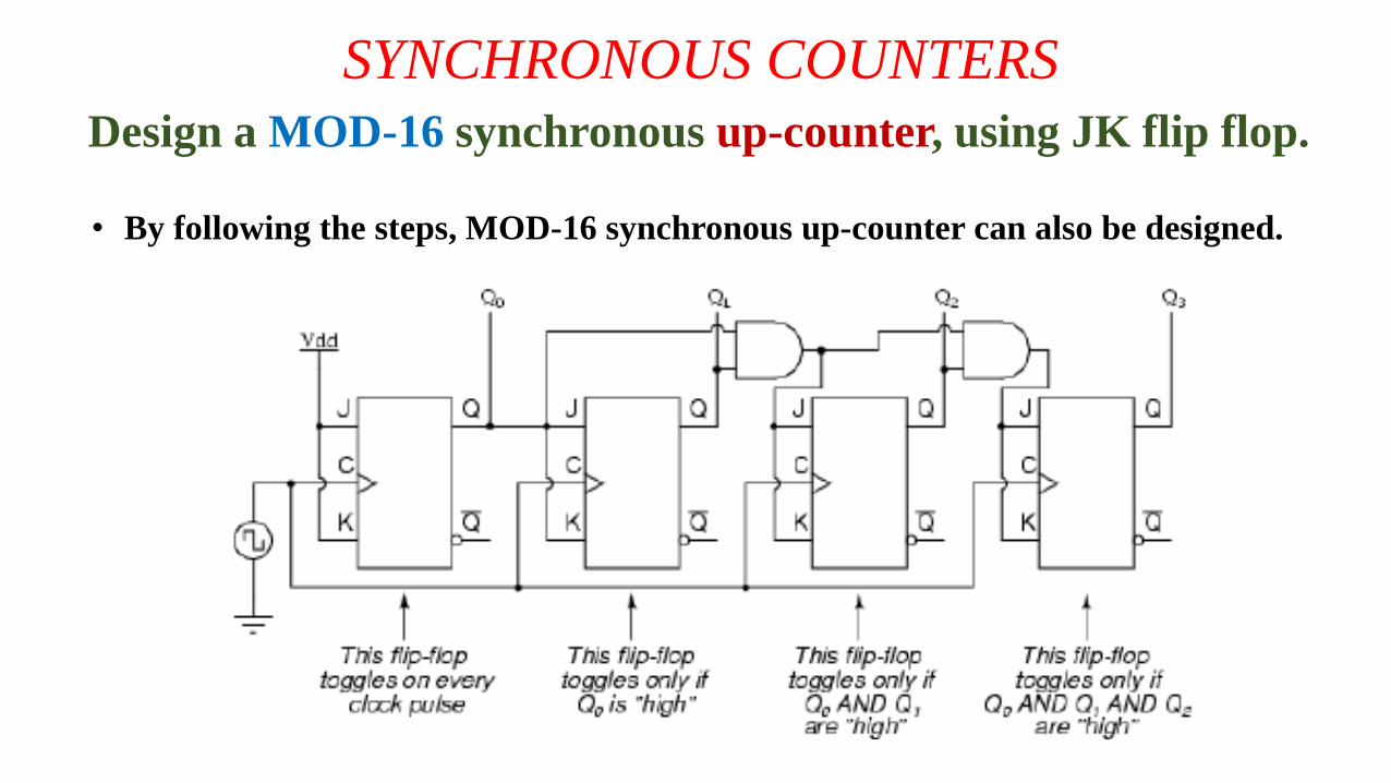
Design a MOD-16 synchronous up-counter, using JK flip flop.
• By following the steps, MOD-16 synchronous up-counter can also be designed.
SYNCHRONOUS COUNTERS
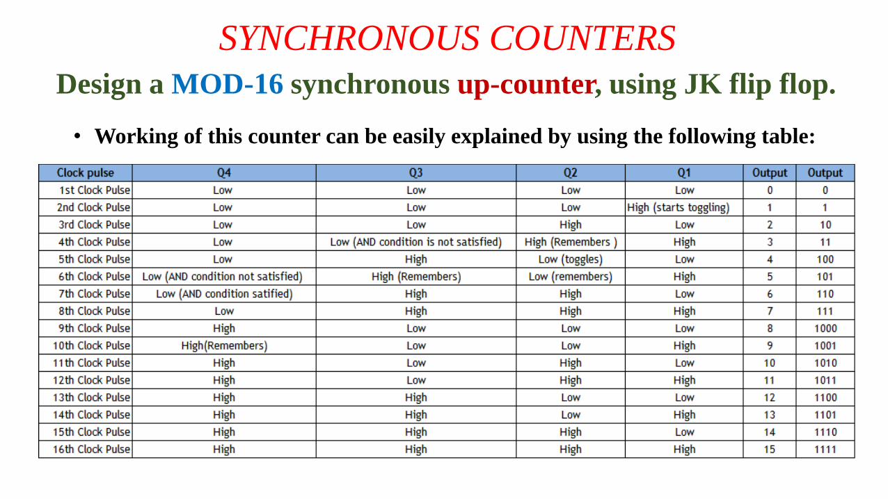
Design a MOD-16 synchronous up-counter, using JK flip flop.
• Working of this counter can be easily explained by using the following table:
SYNCHRONOUS COUNTERS
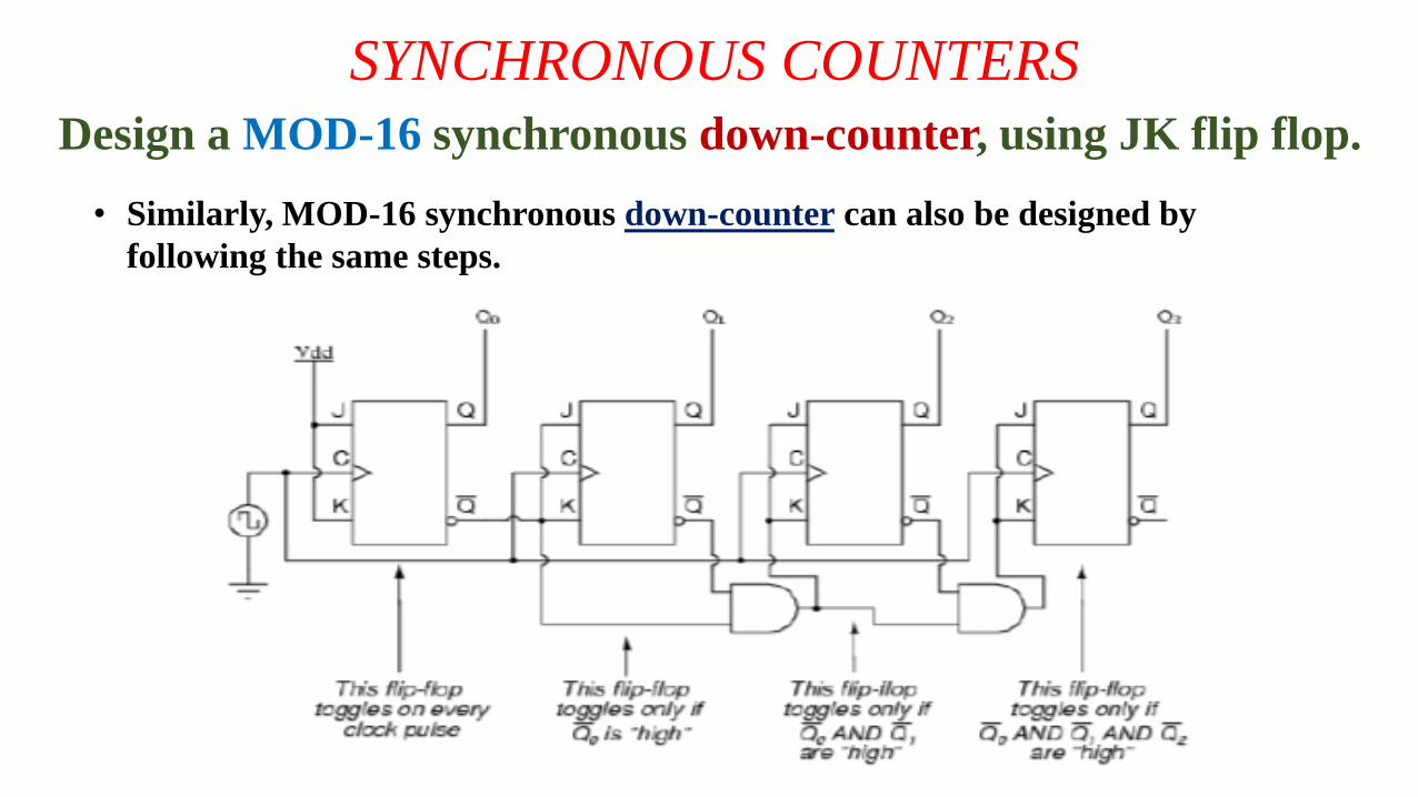
Design a MOD-16 synchronous down-counter, using JK flip flop.
• Similarly, MOD-16 synchronous down-counter can also be designed by
following the same steps.
SYNCHRONOUS COUNTERS
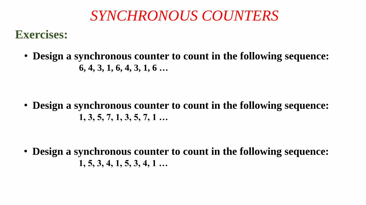
Exercises:
• Design a synchronous counter to count in the following sequence:6, 4, 3, 1, 6, 4, 3, 1, 6 …
• Design a synchronous counter to count in the following sequence:1, 3, 5, 7, 1, 3, 5, 7, 1 …
• Design a synchronous counter to count in the following sequence:1, 5, 3, 4, 1, 5, 3, 4, 1 …
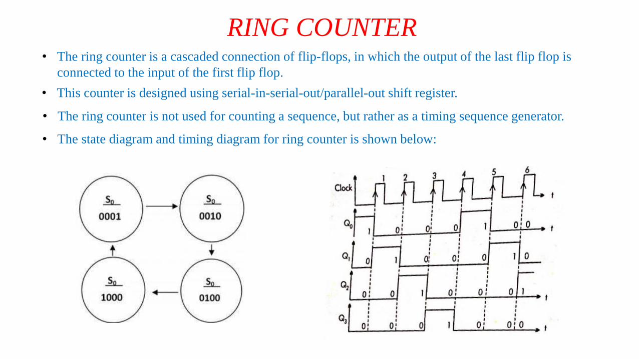
RING COUNTER• The ring counter is a cascaded connection of flip-flops, in which the output of the last flip flop is
connected to the input of the first flip flop.
• This counter is designed using serial-in-serial-out/parallel-out shift register.
• The ring counter is not used for counting a sequence, but rather as a timing sequence generator.
• The state diagram and timing diagram for ring counter is shown below:
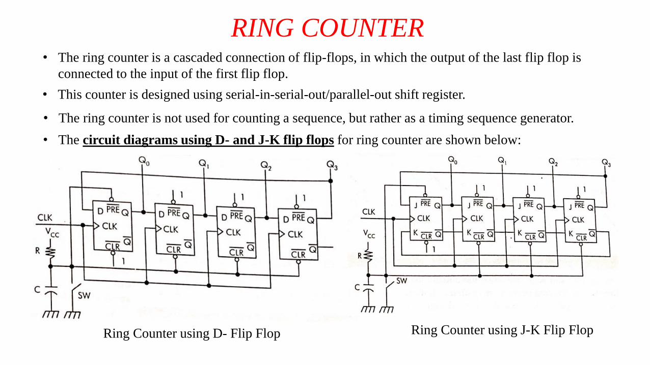
RING COUNTER• The ring counter is a cascaded connection of flip-flops, in which the output of the last flip flop is
connected to the input of the first flip flop.
• This counter is designed using serial-in-serial-out/parallel-out shift register.
• The ring counter is not used for counting a sequence, but rather as a timing sequence generator.
• The circuit diagrams using D- and J-K flip flops for ring counter are shown below:
Ring Counter using D- Flip Flop Ring Counter using J-K Flip Flop
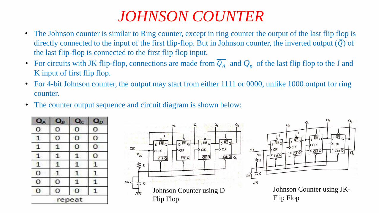
JOHNSON COUNTER• The Johnson counter is similar to Ring counter, except in ring counter the output of the last flip flop is
directly connected to the input of the first flip-flop. But in Johnson counter, the inverted output ( 𝑄) of
the last flip-flop is connected to the first flip flop input.
• For circuits with JK flip-flop, connections are made from 𝑄𝑛 and Qn of the last flip flop to the J and
K input of first flip flop.
• For 4-bit Johnson counter, the output may start from either 1111 or 0000, unlike 1000 output for ring
counter.
• The counter output sequence and circuit diagram is shown below:
Johnson Counter using D-
Flip Flop
Johnson Counter using JK-
Flip Flop
For further information, go through the books of the following authors thoroughly:
Digital Electronics:
• Diptiman Roy Chowdhuri (Vol. II)
• Salivanan
• Floyd
• Mano


