Embed Size (px)
Citation preview
MOBILE ROBOT
APPLICATION
By:
RAKIMI
1
Localization and Navigation
2
What is the importance of localization and navigation task in mobile robots?
�For any mobile device, the ability to navigate in its environment is important. Avoiding dangerous situations such as collisions and unsafe conditions comes first, but if the robot has a purpose that relates to specific places in the robot environment, it must find those places.
�We want to know where we are, and we need to be able to make a plan for how to reach a goal destination.
�Mobile Robot navigation means the robot's ability to determine its own position in its frame of reference and then to plan a path towards some goal location.
�Robots may or may not have prior knowledge of the environments where they are expected to operate.
� LOCALIZATION ���� mengesan dengan tepat�NAVIGATION ���� direction finding @ pemanduan arah3
∗ A mobile robot must be able to follow the planned path closely and avoid any dynamic or unforeseen obstacles during its journey to the goal.
∗ In order to navigate in its environment, the robot requires representation, i.e. a map of the environment and the ability to interpret that representation.
∗ Navigation can be defined as the combination of the three fundamental competences:
∗ Self-localization
∗ Path-planning
∗ Map-building and map interpretation
4
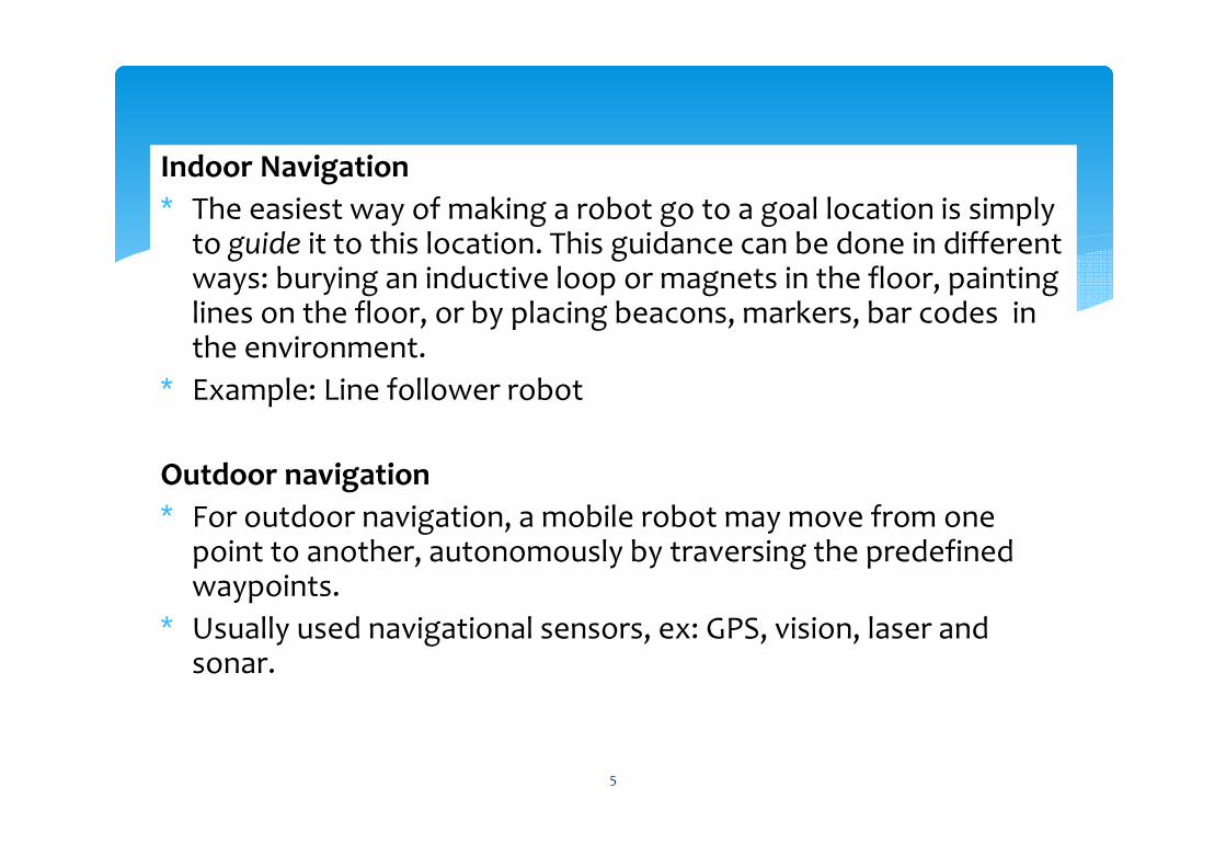
Indoor Navigation
∗ The easiest way of making a robot go to a goal location is simply to guide it to this location. This guidance can be done in different ways: burying an inductive loop or magnets in the floor, painting lines on the floor, or by placing beacons, markers, bar codes in the environment.
∗ Example: Line follower robot
Outdoor navigation
∗ For outdoor navigation, a mobile robot may move from one point to another, autonomously by traversing the predefined waypoints.
∗ Usually used navigational sensors, ex: GPS, vision, laser and sonar.
5
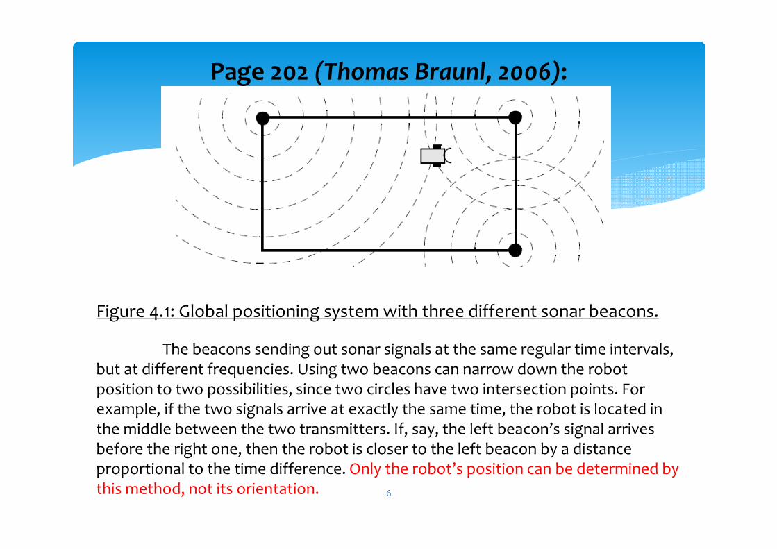
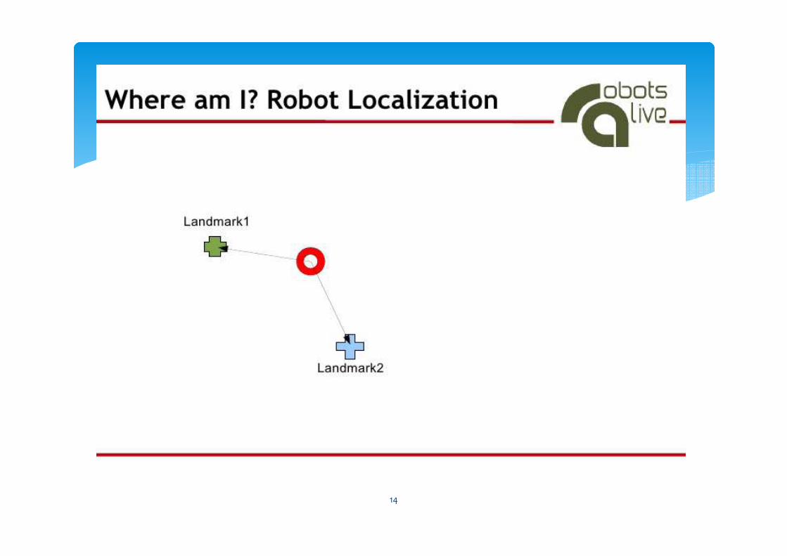
Page 202 (Thomas Braunl, 2006):
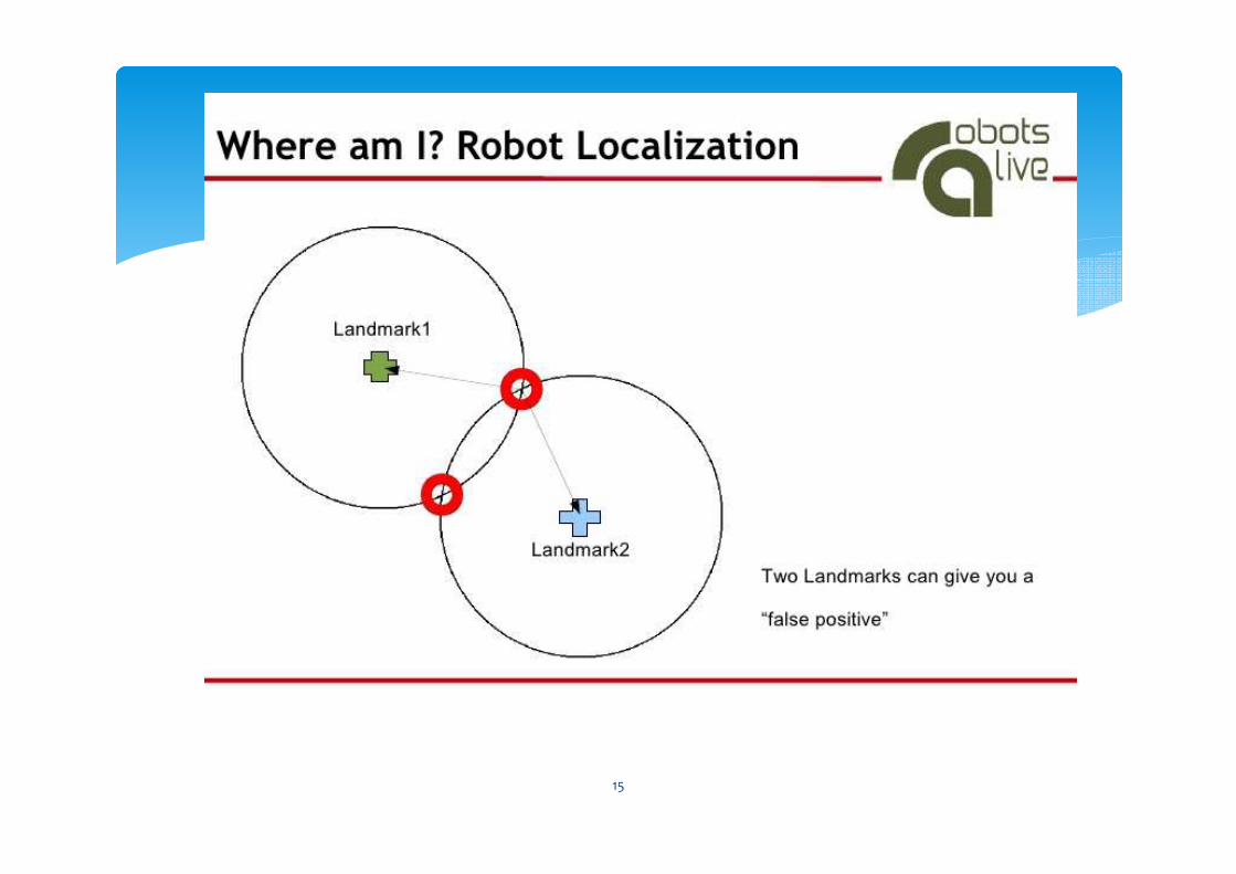
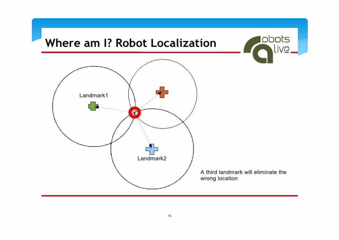
Figure 4.1: Global positioning system with three different sonar beacons.
The beacons sending out sonar signals at the same regular time intervals, but at different frequencies. Using two beacons can narrow down the robot position to two possibilities, since two circles have two intersection points. For example, if the two signals arrive at exactly the same time, the robot is located in the middle between the two transmitters. If, say, the left beacon’s signal arrives before the right one, then the robot is closer to the left beacon by a distance proportional to the time difference. Only the robot’s position can be determined by this method, not its orientation. 6
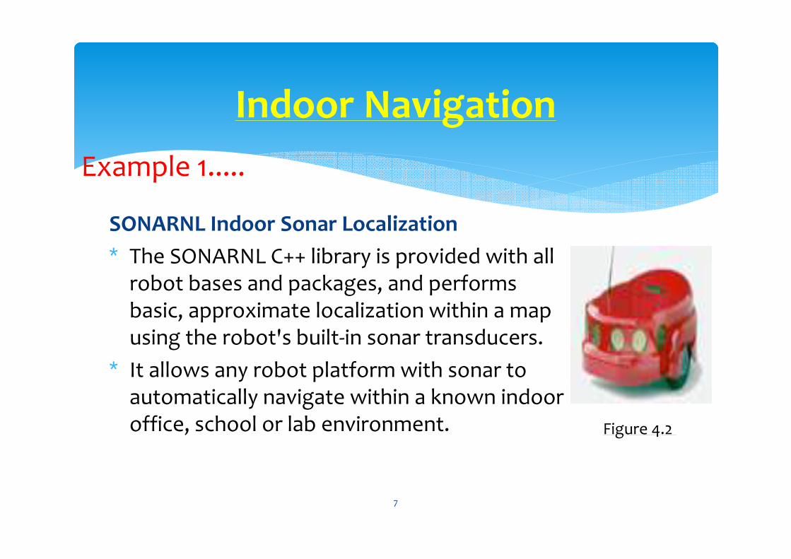
SONARNL Indoor Sonar Localization
∗ The SONARNL C++ library is provided with all robot bases and packages, and performs basic, approximate localization within a map using the robot's built-in sonar transducers.
∗ It allows any robot platform with sonar to automatically navigate within a known indoor office, school or lab environment.
Indoor Navigation
Example 1.....
Figure 4.2
7
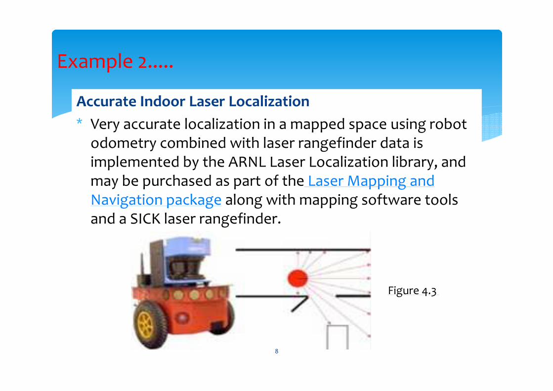
Accurate Indoor Laser Localization
∗ Very accurate localization in a mapped space using robot odometry combined with laser rangefinder data is implemented by the ARNL Laser Localization library, and may be purchased as part of the Laser Mapping and Navigation package along with mapping software tools and a SICK laser rangefinder.
Example 2.....
Figure 4.3
8
∗ Mobile robot should navigate through desire route and avoid the obstacle within the path.
∗ For outdoor navigation, a mobile robot may move from one point to another autonomously by traversing the predefined waypoints.
∗ Global Positioning System (GPS) is widely use in navigation and localization.
∗ From the GPS user can determine which direction they should follow with time and other data such as bearing.
∗ The accuracy of typical GPS device is in the range of 6 – 12 meters.
Outdoor Navigation
9
∗ GPS was developed as a Joint Services Program by the Department of Defense.
∗ The system comprises 24 satellites (including three spares) which transmit encoded RF signals.
∗ Using advanced trilateration methods, ground-based receivers can compute their position by measuring the travel time of the satellites' RF signals, which include information about the satellites' momentary location.
∗ Knowing the exact distance from the ground receiver to three satellites theoretically allows for calculation of receiver latitude, longitude, and altitude.
Info….
10
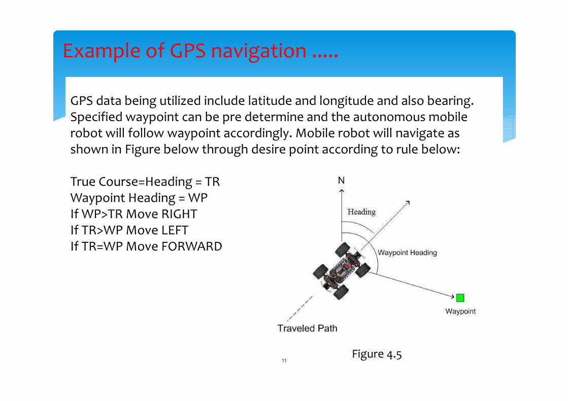
GPS data being utilized include latitude and longitude and also bearing. Specified waypoint can be pre determine and the autonomous mobile robot will follow waypoint accordingly. Mobile robot will navigate as shown in Figure below through desire point according to rule below:
True Course=Heading = TRWaypoint Heading = WPIf WP>TR Move RIGHTIf TR>WP Move LEFTIf TR=WP Move FORWARD
Example of GPS navigation .....
Figure 4.5 11

∗ Basic principle of movement of mobile robot is avoid the obstacle and after successfully avoid the particular obstacle mobile robot will correct the waypoint from the current position.
∗ Therefore, sonar sensor utilization is needed. ∗ The combination GPS and Sonar will determine the position and
obstacle avoidance for the mobile robot.
∗ Example: On the mobile robot four sonar sensors implemented in front of mobile robot for obstacle avoidance system.
∗ The left and right sensor will detect the obstacle on each side and the centre sensor will detect the opposite obstacle of mobile robot.
∗ Usually, the system did not include back sensor because mobile robot only avoid obstacle by moving left and right only.
Obstacle Avoidance System
12
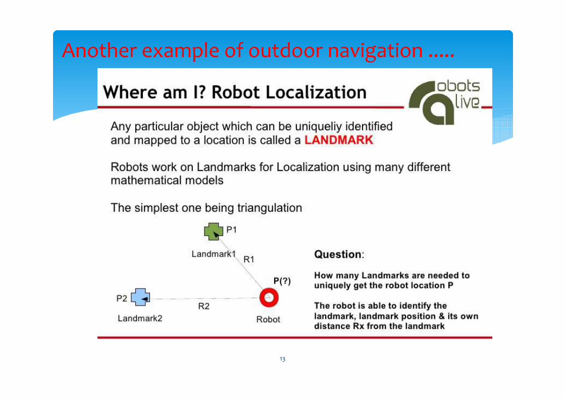
Another example of outdoor navigation .....
13
14
15
16
REAL TIME IMAGE PROCESSING (RTIP)
17
� Image processing means processing the stored images for
improving their quality. But, Real Time Image Processing means
processing the video signals spontaneously at real time.
� The significance of image processing in mobile robotic:
1. Used for object detection (ex: detection of color and shape of
an object)
2. Used for motion detection (ex: ball’s changing positions and
directions of move in robot soccer game)
3. Used for robot localization (ex: robot’s position and heading
angle)
18
�Machine vision studies how useful information of a scene can
be extracted from the images of the scene.
� The information refers to the features of objects found in the
scene.
� Examples of object’s features include it’s position, heading
angle, contours and colors.
� The kind of information to be extracted depends on the
application.
� In robot soccer game, real-time information about the robots’
and the ball’s dynamically changing coordinate positions and
directions of move is vital.
�Vision processing in a robot soccer system is therefore color-
based.
19
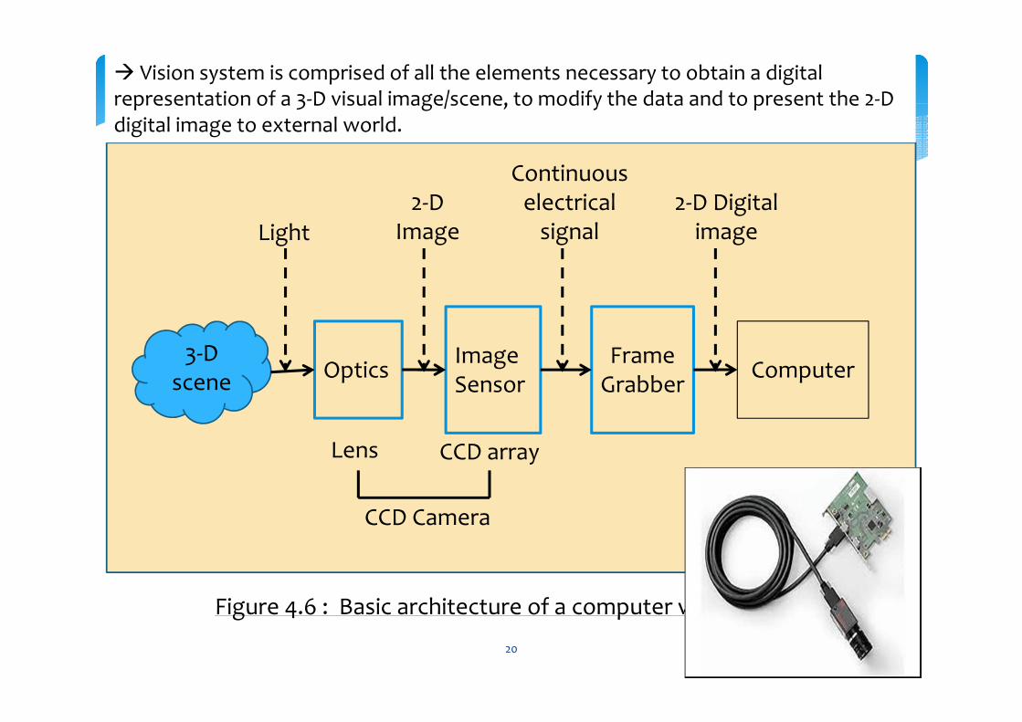
3-D scene
OpticsImage Sensor
Frame Grabber
Computer
Light2-D
Image
Continuous electrical
signal2-D Digital
image
Lens CCD array
CCD Camera
Figure 4.6 : Basic architecture of a computer vision system
� Vision system is comprised of all the elements necessary to obtain a digital representation of a 3-D visual image/scene, to modify the data and to present the 2-D digital image to external world.
20
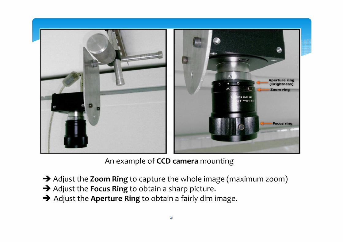
� Adjust the Zoom Ring to capture the whole image (maximum zoom)� Adjust the Focus Ring to obtain a sharp picture.� Adjust the Aperture Ring to obtain a fairly dim image.
An example of CCD camera mounting
21
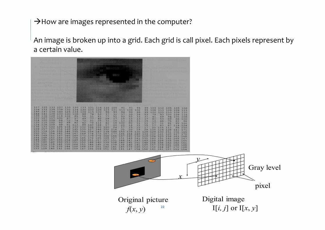
�How are images represented in the computer?
An image is broken up into a grid. Each grid is call pixel. Each pixels represent by a certain value.
22
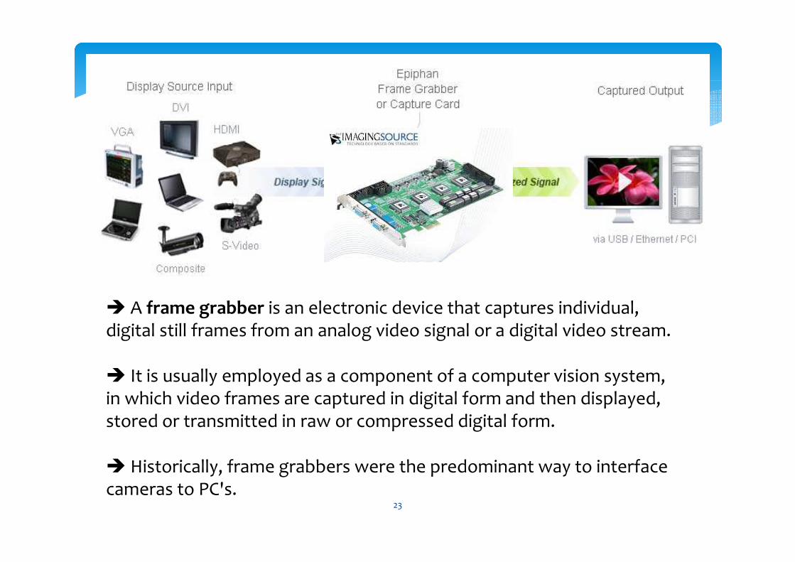
� A frame grabber is an electronic device that captures individual, digital still frames from an analog video signal or a digital video stream.
� It is usually employed as a component of a computer vision system, in which video frames are captured in digital form and then displayed, stored or transmitted in raw or compressed digital form.
� Historically, frame grabbers were the predominant way to interface cameras to PC's.
23
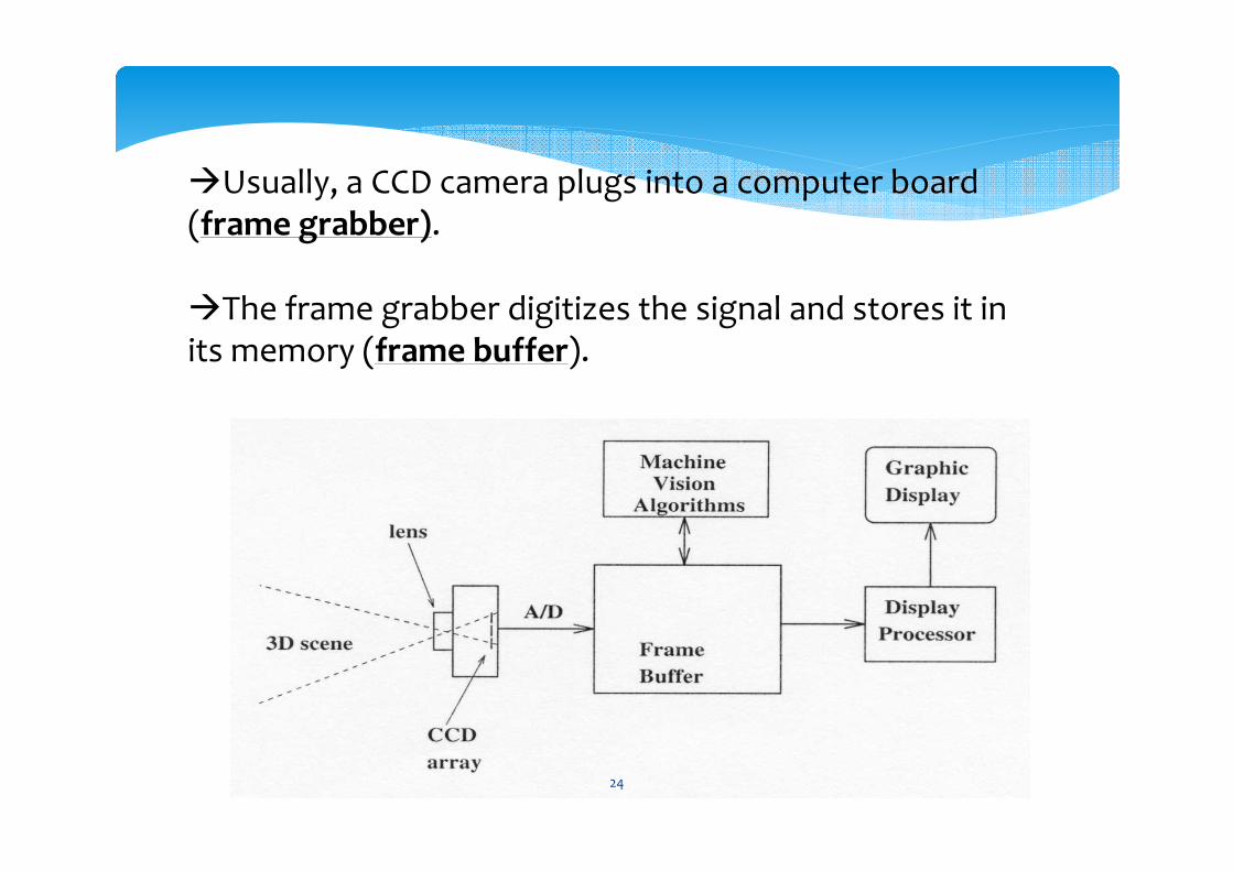
�Usually, a CCD camera plugs into a computer board (frame grabber).
�The frame grabber digitizes the signal and stores it in its memory (frame buffer).
24
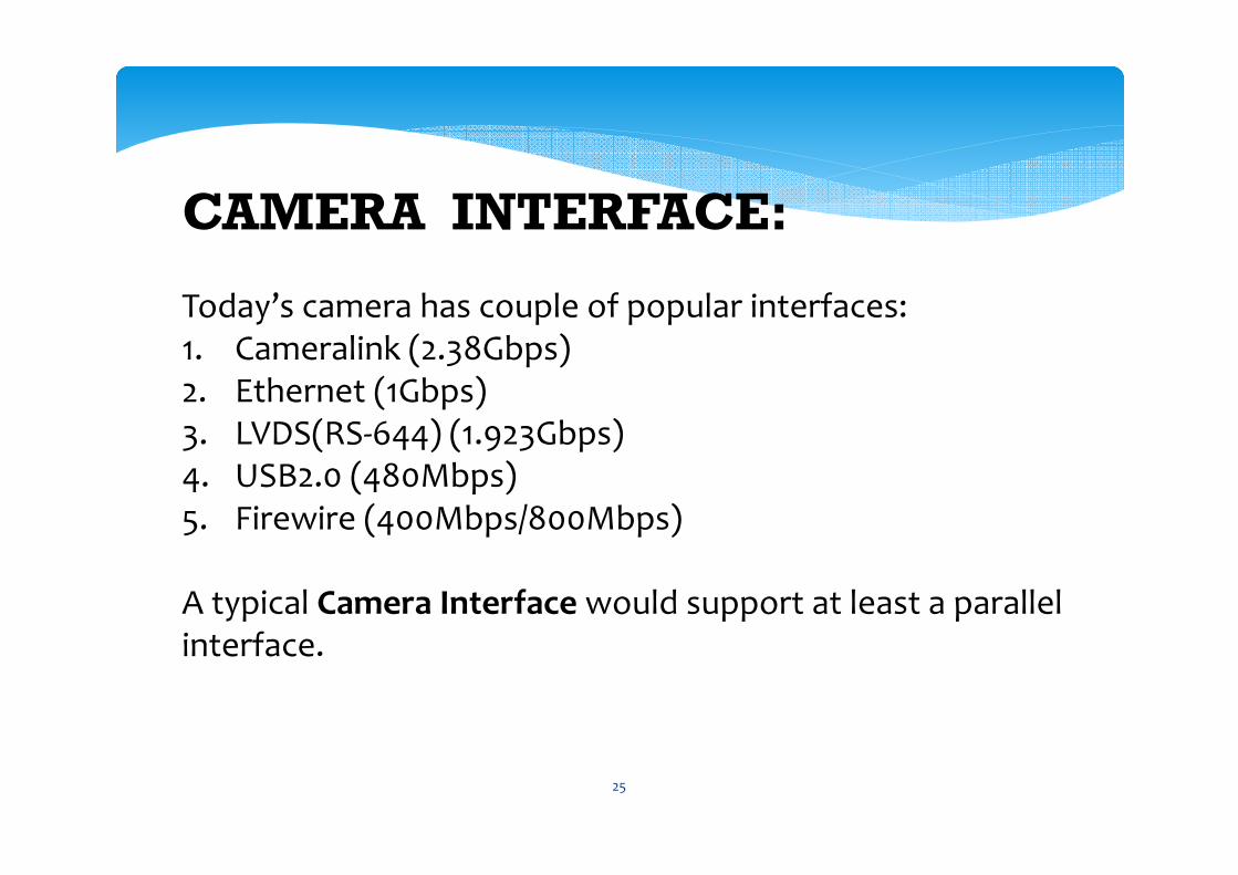
CAMERA INTERFACE:
Today’s camera has couple of popular interfaces:1. Cameralink (2.38Gbps)2. Ethernet (1Gbps)3. LVDS(RS-644) (1.923Gbps)4. USB2.0 (480Mbps)5. Firewire (400Mbps/800Mbps)
A typical Camera Interface would support at least a parallel interface.
25
The camera interface's parallel interface consists of the following lines :-
8 to 12 bits parallel data lineThese are parallel data lines that carry pixel data. The data transmitted on these lines change with every Pixel Clock (PCLK).
Horizontal Sync (HSYNC)This is a special signal that goes from the camera sensor or ISP to the camera interface. An HSYNC indicates that one line of the frame is transmitted.
Vertical Sync (VSYNC)This signal is transmitted after the entire frame is transferred. This signal is often a way to indicate that one entire frame is transmitted.
Pixel Clock (PCLK)This is the pixel clock and it would change on every pixel.
26
Image Processing Operations…
27
1) EDGE DETECTION:
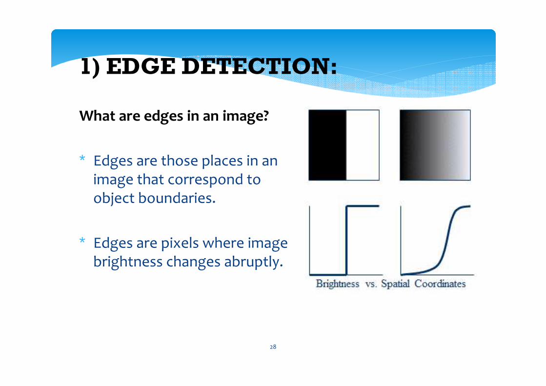
What are edges in an image?
∗ Edges are those places in an image that correspond to object boundaries.
∗ Edges are pixels where image brightness changes abruptly.
28
Edge Detection
∗ Edge information in an image is found by looking at the relationship a pixel has with its neighborhoods.
∗ If a pixel’s gray-level value is similar to those around it, there is probably not an edge at that point.
∗ If a pixel’s has neighbors with widely varying gray levels, it may present an edge point.
29
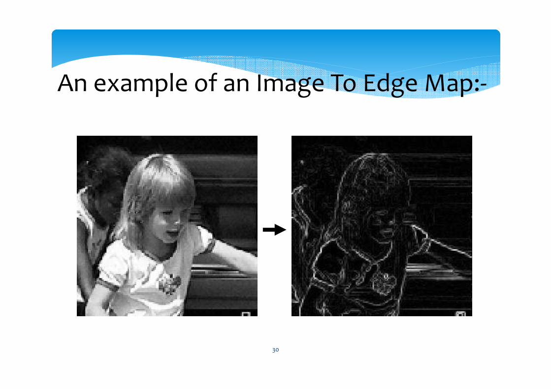
An example of an Image To Edge Map:-
30
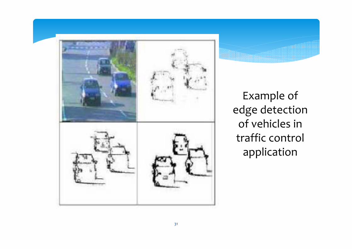
Example of edge detection
of vehicles in traffic control
application
31
2) MOTION DETECTION
∗ WHY motion detection?
∗ First, the world is dynamic, and motion information is one of the keys to many practical applications such as video mining, Robot navigation, intelligent traffic system, etc.
∗ Motion Detection is also a basic step to machine learning, pattern recognition in dynamic context.
32
Motion Detection
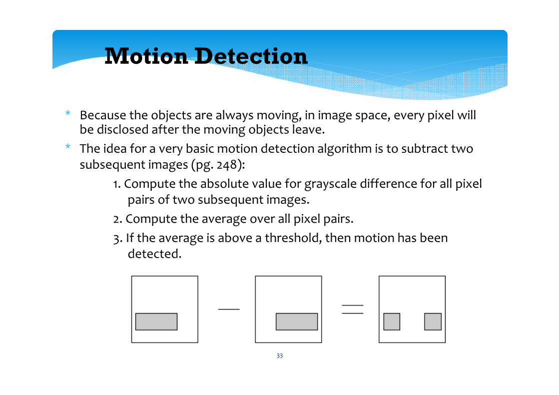
∗ Because the objects are always moving, in image space, every pixel will be disclosed after the moving objects leave.
∗ The idea for a very basic motion detection algorithm is to subtract two subsequent images (pg. 248):
1. Compute the absolute value for grayscale difference for all pixel pairs of two subsequent images.
2. Compute the average over all pixel pairs.
3. If the average is above a threshold, then motion has been detected.
33
3) COLOR
DETECTION:
(RGB)
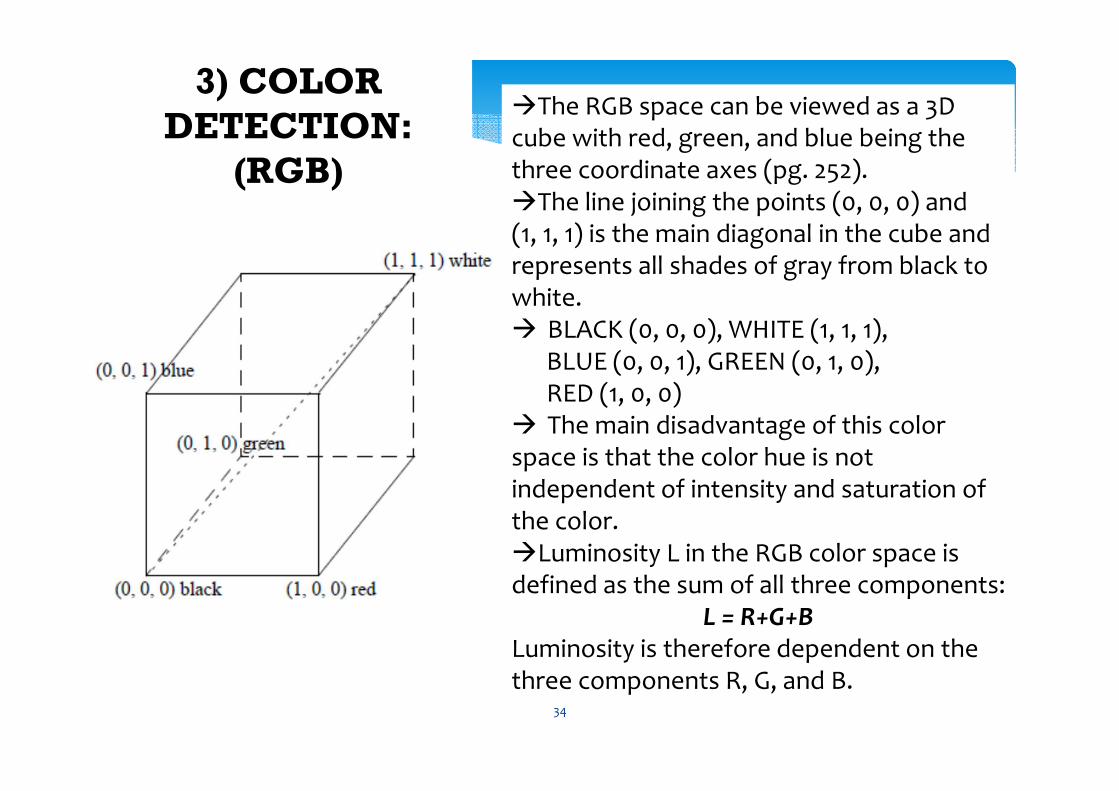
�The RGB space can be viewed as a 3D cube with red, green, and blue being the three coordinate axes (pg. 252). �The line joining the points (0, 0, 0) and (1, 1, 1) is the main diagonal in the cube and represents all shades of gray from black to white. � BLACK (0, 0, 0), WHITE (1, 1, 1),
BLUE (0, 0, 1), GREEN (0, 1, 0), RED (1, 0, 0)
� The main disadvantage of this color space is that the color hue is not independent of intensity and saturation of the color.�Luminosity L in the RGB color space is defined as the sum of all three components:
L = R+G+BLuminosity is therefore dependent on the three components R, G, and B.
34
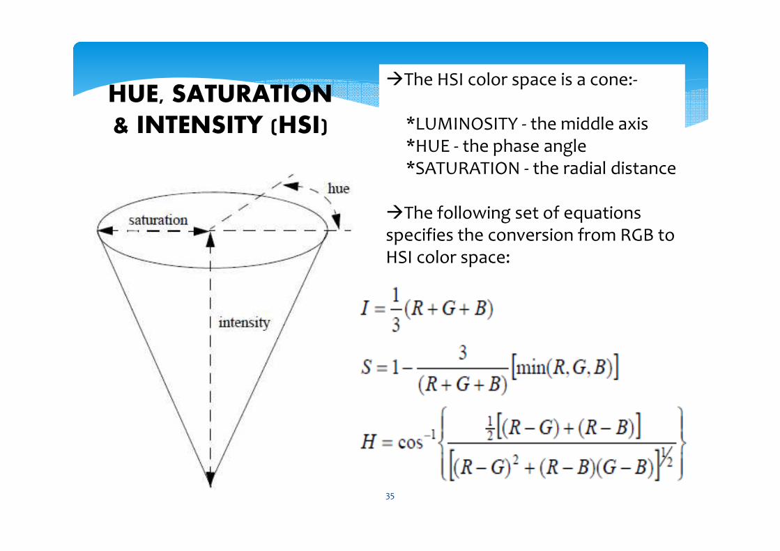
�The HSI color space is a cone:-
*LUMINOSITY - the middle axis *HUE - the phase angle *SATURATION - the radial distance
�The following set of equations specifies the conversion from RGB to HSI color space:
HUE, SATURATION
& INTENSITY (HSI)
35
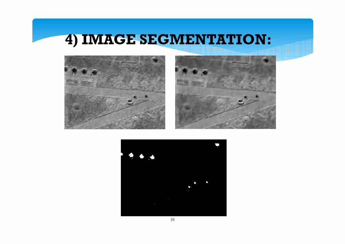
4) IMAGE SEGMENTATION:
36
This color segmentation approach transforms all images from RGB to rgb (normalized RGB) as a pre-processing step.
Then, a color class lookup table is constructed that translates each rgb value to a “color class”, where different color classes ideally represent different objects.
This table is a three-dimensional array with (rgb) as indices. Each entry is a reference number for a certain“color class”.
37
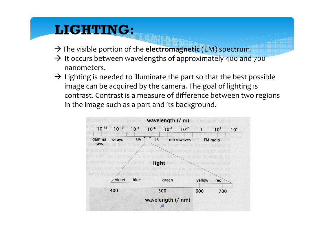
LIGHTING:
�The visible portion of the electromagnetic (EM) spectrum.� It occurs between wavelengths of approximately 400 and 700
nanometers.� Lighting is needed to illuminate the part so that the best possible
image can be acquired by the camera. The goal of lighting is contrast. Contrast is a measure of difference between two regions in the image such as a part and its background.
38
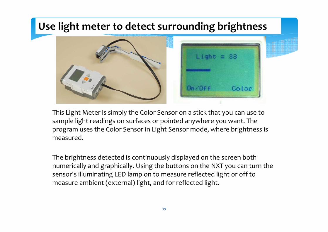
This Light Meter is simply the Color Sensor on a stick that you can use to sample light readings on surfaces or pointed anywhere you want. The program uses the Color Sensor in Light Sensor mode, where brightness is measured.
The brightness detected is continuously displayed on the screen both numerically and graphically. Using the buttons on the NXT you can turn the sensor's illuminating LED lamp on to measure reflected light or off to measure ambient (external) light, and for reflected light.
Use light meter to detect surrounding brightness
39
∗ There are a number of tasks where a self-configuring network based on wireless communication is helpful for a group of autonomous mobile robots or a single robot and a host computer:
∗ 1. To allow robots to communicate with each other
∗ 2. To remote-control one or several robots
∗ 3. To monitor robot sensor data
∗ 4. To run a robot with off-line processing
∗ 5. To create a monitoring console for single or multiple robots
WIRELESS COMMUNICATION
40

ROBOT SOCCER
41
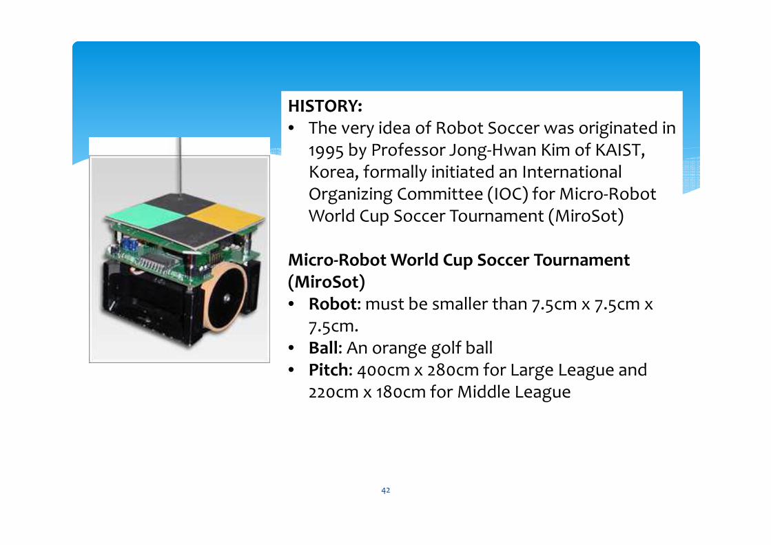
HISTORY:• The very idea of Robot Soccer was originated in
1995 by Professor Jong-Hwan Kim of KAIST, Korea, formally initiated an International Organizing Committee (IOC) for Micro-Robot World Cup Soccer Tournament (MiroSot)
Micro-Robot World Cup Soccer Tournament (MiroSot)• Robot: must be smaller than 7.5cm x 7.5cm x
7.5cm. • Ball: An orange golf ball • Pitch: 400cm x 280cm for Large League and
220cm x 180cm for Middle League
42
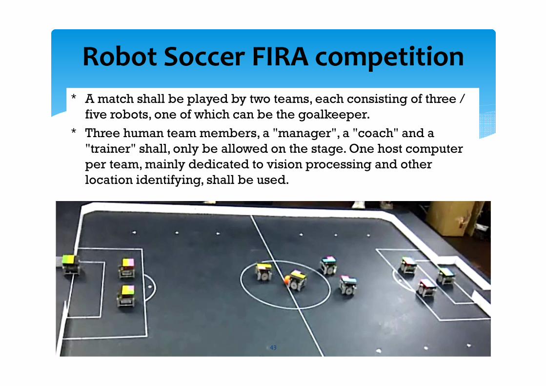
∗ A match shall be played by two teams, each consisting of three /
five robots, one of which can be the goalkeeper.
∗ Three human team members, a "manager", a "coach" and a
"trainer" shall, only be allowed on the stage. One host computer
per team, mainly dedicated to vision processing and other
location identifying, shall be used.
Robot Soccer FIRA competition
43
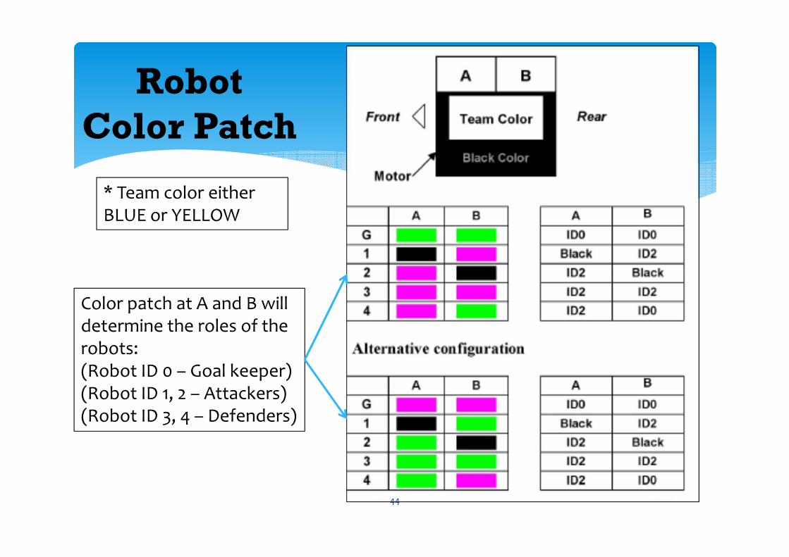
Robot
Color Patch
Color patch at A and B will determine the roles of the robots: (Robot ID 0 – Goal keeper)(Robot ID 1, 2 – Attackers)(Robot ID 3, 4 – Defenders)
* Team color either BLUE or YELLOW
44
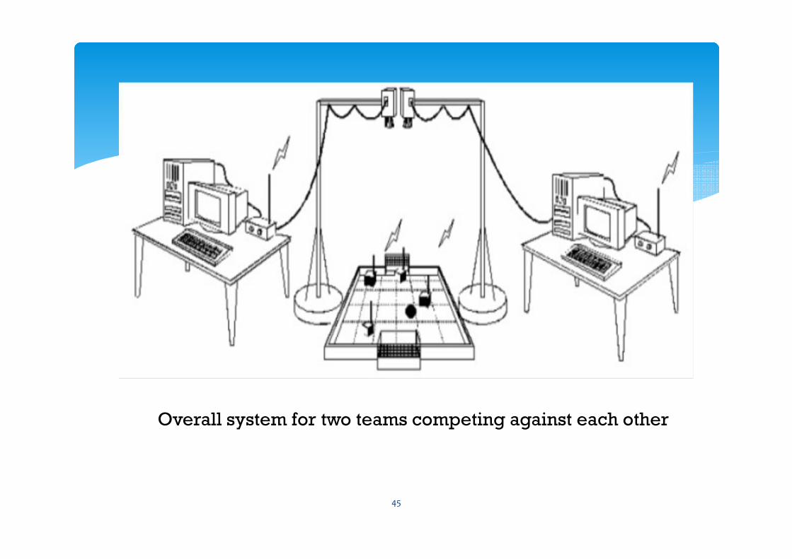
Overall system for two teams competing against each other
45
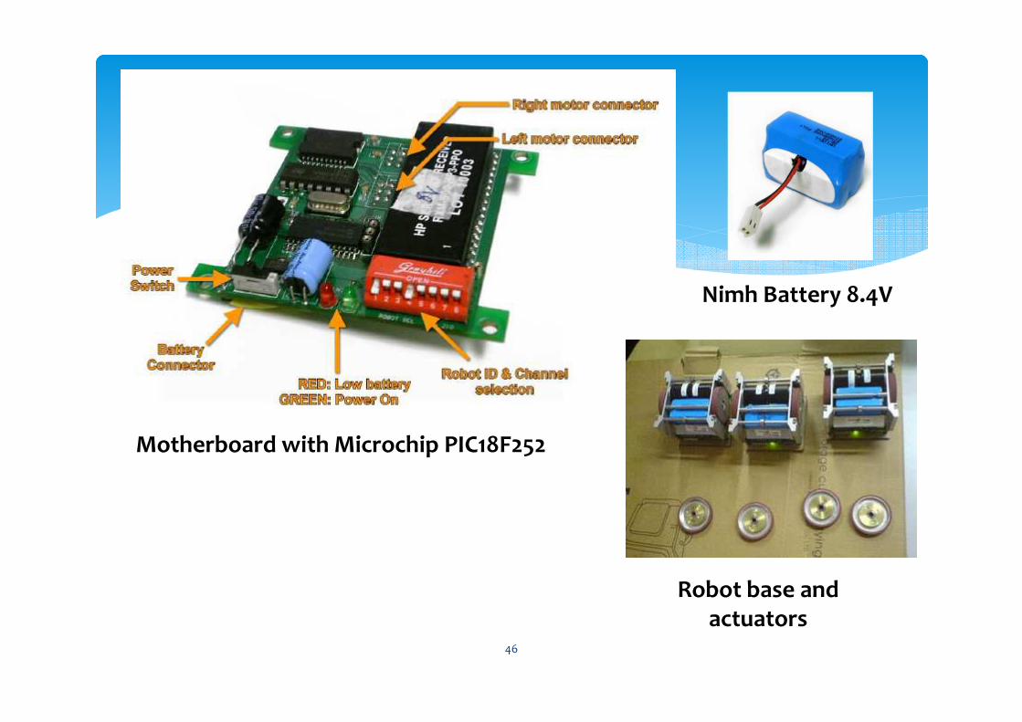
Nimh Battery 8.4V
Motherboard with Microchip PIC18F252
Robot base and actuators
46
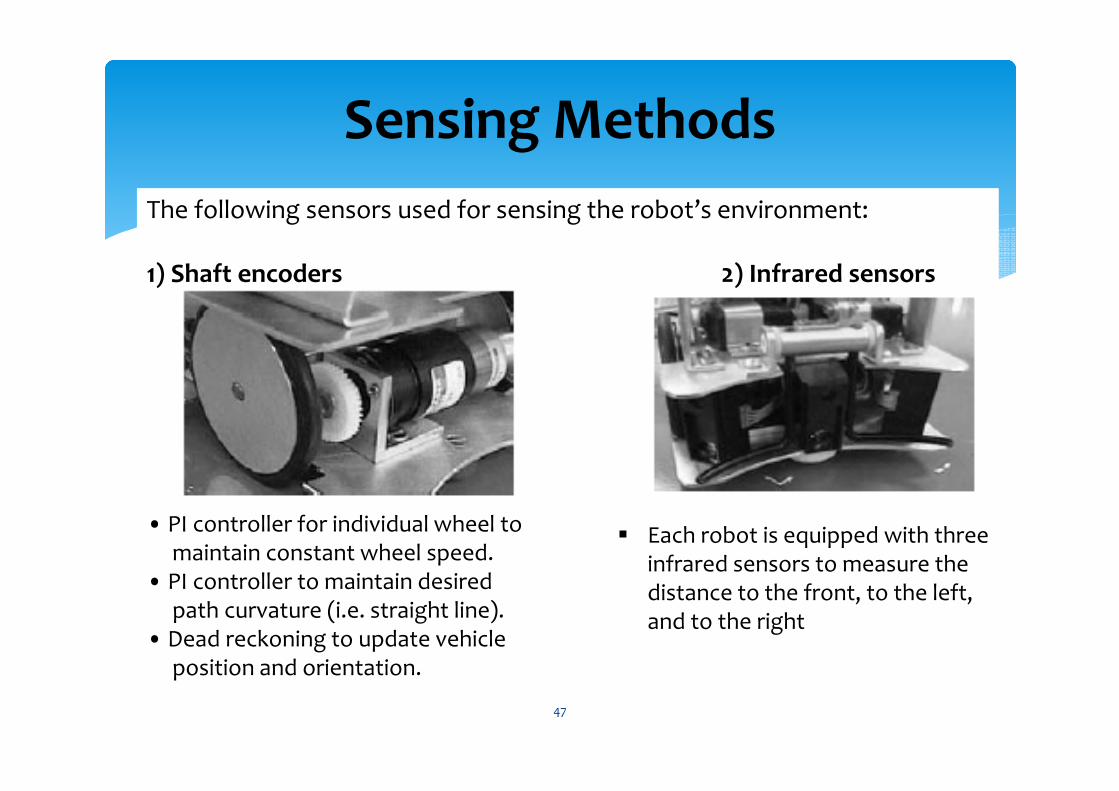
Sensing Methods
The following sensors used for sensing the robot’s environment:
1) Shaft encoders 2) Infrared sensors
• PI controller for individual wheel to maintain constant wheel speed.
• PI controller to maintain desired path curvature (i.e. straight line).
• Dead reckoning to update vehicle position and orientation.
� Each robot is equipped with three infrared sensors to measure the distance to the front, to the left, and to the right
47
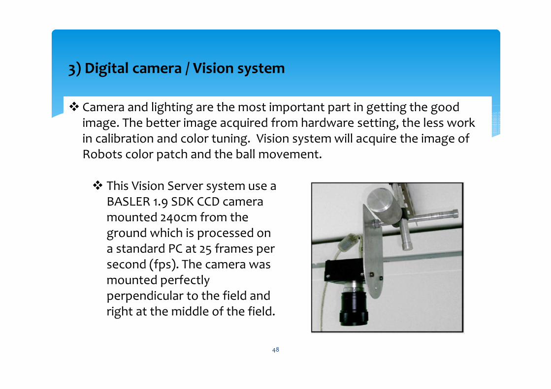
� Camera and lighting are the most important part in getting the good image. The better image acquired from hardware setting, the less work in calibration and color tuning. Vision system will acquire the image of Robots color patch and the ball movement.
� This Vision Server system use a BASLER 1.9 SDK CCD camera mounted 240cm from the ground which is processed on a standard PC at 25 frames per second (fps). The camera was mounted perfectly perpendicular to the field and right at the middle of the field.
3) Digital camera / Vision system
48
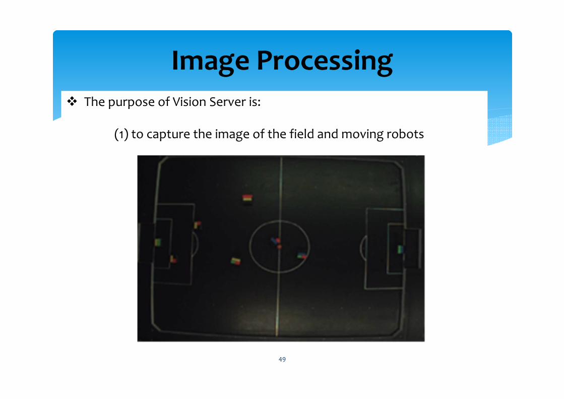
Image Processing� The purpose of Vision Server is:
(1) to capture the image of the field and moving robots
49
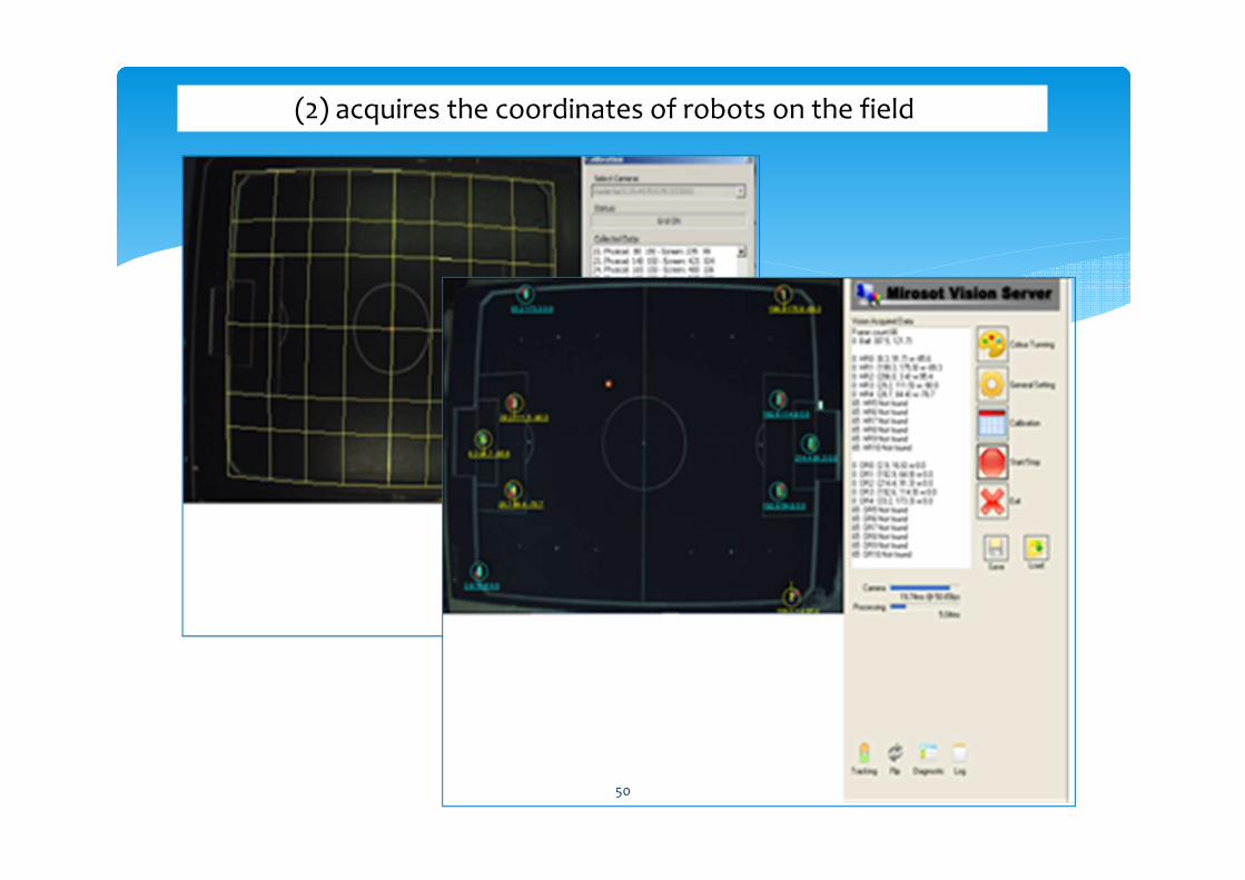
(2) acquires the coordinates of robots on the field
50
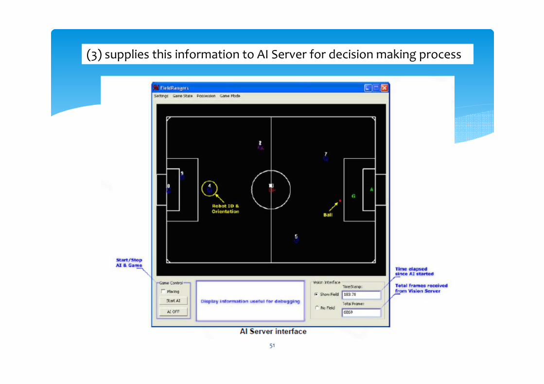
(3) supplies this information to AI Server for decision making process
51
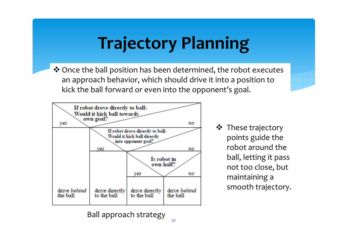
� Once the ball position has been determined, the robot executes an approach behavior, which should drive it into a position to kick the ball forward or even into the opponent’s goal.
Trajectory Planning
Ball approach strategy
� These trajectory points guide the robot around the ball, letting it pass not too close, but maintaining a smooth trajectory.
52


