Embed Size (px)
Citation preview
E-Series Networked Display
Reference ManualDocument number: 81244_1Date: December 2004
81244_1.book Page i Wednesday, December 1, 2004 11:41 AM

ii E-Series Reference Manual
Trademarks and registered trademarksAutohelm, HSB, Raymarine, RayTech Navigator, Sail Pilot, SeaTalk and Sportpilot are registered trademarks of Raymarine Limited. Apelco is a registered trademark of Raymarine Holdings Limited.(Registered in all Major marketing territories.
AST, Autoadapt, Auto GST, Autoseastate, Autotrim, Bidata, Marine Intelligence, Maxiview, On Board, Raychart, Raynav, Raypilot, Raystar, ST40, ST60, Seaclutter, Smart Route, Tridata and Waypoint Navigation are trademarks of Raymarine Limited.
Navionics is a registered trademark of Navionics Company, Italy.
All other product names are trademarks or registered trademarks of their respective owners.
Software in this product is based in part on the work of the Independent JPEG Group.
Contents of this handbook ©Raymarine 2004
81244_1.book Page ii Wednesday, December 1, 2004 11:41 AM
Contents i
ContentsChapter 1: Overview ...............................................................................................1.1
1.1 What will my E-Series integrate with? ...............................................................1.1
1.2 What can the E-Series Display do? .....................................................................1.2
1.3 The Simulator .....................................................................................................1.4
Chapter 2: General Operation ...............................................................................2.1
2.1 Introduction .......................................................................................................2.1
2.2 How do I power the display ON/OFF? ................................................................2.1Power ON .....................................................................................................2.1Power OFF ....................................................................................................2.1
2.3 Using the controls ..............................................................................................2.2The control panel .........................................................................................2.2Buttons and soft keys ...................................................................................2.3The cursor ....................................................................................................2.4
2.4 How are the applications displayed? .................................................................2.4
2.5 How is additional information displayed on the screen? ....................................2.5Accessing menus ..........................................................................................2.6Editing the dialog box information ...............................................................2.7
2.6 What initial setup procedures should I do? ........................................................2.8Selecting the data master (Networked E-Series only) ...................................2.8Setting the language, date/time format and units of measurement .............2.8How do I adjust the display lighting? .........................................................2.10
2.7 How do I use CompactFlash cards? .................................................................2.11Cautions .....................................................................................................2.11How do I insert a card? ...............................................................................2.12How do I remove a card? ............................................................................2.12How do I write/retrieve data to a CompactFlash card? ...............................2.13
2.8 How do I send and receive information using my PC? ......................................2.15
2.9 Operating a networked E-Series Display ..........................................................2.15What does a networked system do? ...........................................................2.15How is the network controlled? .................................................................2.15Are there any functions that only affect the display in use? ........................2.16
2.10 Emergencies and warnings ..............................................................................2.17How do I mark a Man Overboard position? ................................................2.17
81244_1.book Page i Wednesday, December 1, 2004 11:41 AM
ii E-Series Networked Display Reference Manual
What alarms will my display sound? ..........................................................2.18
Chapter 3: Working with Waypoints ....................................................................3.1
3.1 What is a waypoint? ..........................................................................................3.1
3.2 How are waypoints represented? ......................................................................3.2
3.3 Where can I place a waypoint? ..........................................................................3.2
3.4 How do I place a waypoint? ...............................................................................3.3
3.5 How do I navigate to a waypoint? .....................................................................3.4...using the cursor .........................................................................................3.4...via the WPTS MOB button .........................................................................3.4.... by selecting the GOTO option ..................................................................3.4Stop navigating to a waypoint .....................................................................3.5
3.6 How do I view waypoint information? ...............................................................3.6
3.7 How can I edit a waypoint? ................................................................................3.7Changing waypoint details ..........................................................................3.7Moving a waypoint ......................................................................................3.8Erasing a waypoint .......................................................................................3.8Changing the default symbol and group ......................................................3.9
3.8 How can I sort waypoints in the waypoint list? ..................................................3.9
3.9 How can I organize my waypoints into groups? ...............................................3.10Making a new waypoint group ..................................................................3.10Moving waypoints between groups ...........................................................3.11Renaming an existing group ......................................................................3.12Erasing a group ..........................................................................................3.12
3.10 How can I control how waypoints are displayed? ............................................3.12Display by symbol or group ........................................................................3.13Display waypoint names ............................................................................3.13
Chapter 4: Using the Chart .....................................................................................4.1
4.1 Important ..........................................................................................................4.1Chart functionality .......................................................................................4.1Safety ...........................................................................................................4.1
4.2 What can I use the chart application for? ...........................................................4.2
4.3 Viewing the chart ...............................................................................................4.2
4.4 The chart display ................................................................................................4.3
4.5 Where am I on the chart? ...................................................................................4.3
4.6 How do I move around the chart? ......................................................................4.4
81244_1.book Page ii Wednesday, December 1, 2004 11:41 AM
Contents iii
4.7 What additional information can my chart show? .............................................4.5Displaying details of objects and features ....................................................4.5Finding nearby features and services ...........................................................4.6Displaying details of tides ............................................................................4.6Displaying details of currents .......................................................................4.7Displaying details of port services ................................................................4.8
4.8 How do I measure distances on the chart? .......................................................4.10
4.9 How do I navigate to a specific point? .............................................................4.11Go to the cursor position ............................................................................4.11Go to a waypoint ........................................................................................4.12
4.10 How do I build and follow a route? ..................................................................4.13What is a route? .........................................................................................4.13Building a route ..........................................................................................4.13Following a route .......................................................................................4.17Viewing details of routes ............................................................................4.20
4.11 How do I monitor where I am going? ...............................................................4.21... using chart vectors .................................................................................4.21... using the Course Deviation Indicator (CDI) .............................................4.22
4.12 How does my chart warn me of potential dangers? .........................................4.23
4.13 How can I use radar with the chart? .................................................................4.23Synchronizing the chart with radar range ..................................................4.23Viewing MARPA targets on the chart .........................................................4.24Distinguishing between fixed and moving objects .....................................4.24
4.14 How do I record where I have been? ................................................................4.26What is a track? .........................................................................................4.26How can I use tracks? .................................................................................4.26Creating a track ..........................................................................................4.26Creating a route from a track .....................................................................4.27
4.15 How do I edit my routes and tracks? ................................................................4.29Selecting a route or track for editing ..........................................................4.29Reversing a route .......................................................................................4.30Changing the course of a route ..................................................................4.30Changing the name or color of a route or track ..........................................4.34Erasing a route or track ..............................................................................4.35
4.16 How does my chart warn me of potential dangers? .........................................4.35
4.17 How do I define how chart windows are presented? .......................................4.35
81244_1.book Page iii Wednesday, December 1, 2004 11:41 AM
iv E-Series Networked Display Reference Manual
Working with multiple chart views .............................................................4.35Setting the orientation of the chart ............................................................4.36Setting the motion mode ...........................................................................4.37
4.18 How do I alter the level of chart detail displayed? ............................................4.39Showing or hiding the chart grid ................................................................4.39Showing or hiding waypoints/waypoint information .................................4.39Showing or hiding a route or a track ..........................................................4.41Showing or hiding cartographic features ...................................................4.41
4.19 How do I set up my chart and its cartography? ................................................4.42Chart Setup ................................................................................................4.42Cartography set up .....................................................................................4.44
Chapter 5: Using the Radar ....................................................................................5.1
5.1 Introduction .......................................................................................................5.1
5.2 What is radar? ...................................................................................................5.1Detecting targets .........................................................................................5.1What is the maximum range of my radar? ...................................................5.2What factors can impair a radar picture? .....................................................5.2
5.3 How do I power on/off the various scanner operating modes? ..........................5.6
5.4 What does the radar picture show me? .............................................................5.7What does the status bar tell me? ................................................................5.8
5.5 How can I change what I see in the radar window? ...........................................5.8Setting the orientation of the radar ..............................................................5.8Setting the motion mode .............................................................................5.9Showing or hiding the range rings .............................................................5.10Changing the bearing mode for EBLs .........................................................5.11
5.6 How can I get the best picture? ........................................................................5.11Using the GAIN functions ...........................................................................5.11
5.7 How do I change the displayed range? ............................................................5.14Radar range and chart scale synchronization .............................................5.15
5.8 How do I measure distances, ranges and bearings? .........................................5.15... Using the range rings .............................................................................5.15... Using the cursor .....................................................................................5.16... Using VRMs and EBLs .............................................................................5.16... Using floating VRMs/EBLs ......................................................................5.17
5.9 How do I use radar to avoid a collision? ...........................................................5.18Guard Zones ..............................................................................................5.18
81244_1.book Page iv Wednesday, December 1, 2004 11:41 AM
Contents v
MARPA ......................................................................................................5.21Setting up MARPA ......................................................................................5.24How do I acquire targets to track? ..............................................................5.25How do I cancel targets? ............................................................................5.25How do I display the range and bearing of a target? ..................................5.25
5.10 How do I mark a position on the radar screen? ................................................5.26
5.11 How do I set up my radar? ...............................................................................5.26
5.12 How does my radar warn me of potential dangers? .........................................5.27
Chapter 6: Using the Fishfinder .............................................................................6.1
6.1 Introduction .......................................................................................................6.1
6.2 How does the Fishfinder work? ..........................................................................6.1
6.3 What can the fishfinder show me? .....................................................................6.2How do I interpret the bottom structure? .....................................................6.3How are targets displayed? ..........................................................................6.3What factors can impair a fishfinder picture? ...............................................6.4How do I see a live image? ...........................................................................6.5
6.4 How can I enhance what I see? ..........................................................................6.6Changing the range .....................................................................................6.6Shifting the image ........................................................................................6.6Zooming in on the bottom ............................................................................6.7Simplifying the bottom image ......................................................................6.8Isolating bottom fish ..................................................................................6.10Changing how the image scrolls ................................................................6.11Changing how the depth digit is displayed ................................................6.12
6.5 How do I mark a position? ...............................................................................6.13
6.6 How do I determine depths and distances of targets? .....................................6.14Using VRMs ...............................................................................................6.15
6.7 What alarms does my fishfinder have? ............................................................6.16
6.8 How do I set up my fishfinder? .........................................................................6.16Transducer Calibration ...............................................................................6.17DSM Setup .................................................................................................6.18Controlling the image ................................................................................6.19
6.9 What other settings affect the fishfinder image? .............................................6.20Operating frequency modes .......................................................................6.20Gain modes ................................................................................................6.22Adjusting the power setting .......................................................................6.24
81244_1.book Page v Wednesday, December 1, 2004 11:41 AM
vi E-Series Networked Display Reference Manual
Chapter 7: Using the Course Deviation Indicator ...............................................7.1
7.1 Introduction .......................................................................................................7.1
7.2 How do I display the CDI application? ...............................................................7.1What do the steering instructions tell me? ...................................................7.2
Chapter 8: Using the digital data application .....................................................8.1
8.1 Introduction .......................................................................................................8.1
8.2 How do I display a digital data application? ......................................................8.2
8.3 How do I select the panel of my choice? ............................................................8.2
Chapter 9: Using the Engine Monitor ...................................................................9.1
9.1 Introduction .......................................................................................................9.1
9.2 How do I display and setup the engine monitor? ...............................................9.1
9.3 What information does the engine monitor display? .........................................9.2
9.4 What should I do when an alarm is triggered? ...................................................9.2
Chapter 10: Video ....................................................................................................10.1
10.1 Introduction .....................................................................................................10.1
10.2 How do I set up my video application? ............................................................10.1How do I edit the input source type? ..........................................................10.2How do I edit the name of a video source? .................................................10.2How do I cycle through my video inputs? ...................................................10.3How do I adjust the image? ........................................................................10.4
Chapter 11: System setup and customizing ........................................................11.1
11.1 How do I change the data master? ..................................................................11.1
11.2 How do I customize the page sets? ..................................................................11.1Reconfiguring the application and page layout ..........................................11.1Rename a page set .....................................................................................11.2
11.3 How do I change the data bar? ........................................................................11.2Changing the data bar position/size ...........................................................11.2Customizing the content of the data bar ....................................................11.2
11.4 How do I change Setup Menu options? ...........................................................11.4System Setup .............................................................................................11.5Date/Time Setup Menu ..............................................................................11.6Alarm Setup Menu .....................................................................................11.8GPS Status ...............................................................................................11.11Compass Setup ........................................................................................11.11
81244_1.book Page vi Wednesday, December 1, 2004 11:41 AM
Contents vii
Display Setup ..........................................................................................11.12Databar Setup ..........................................................................................11.12Select Page Set .........................................................................................11.12System Diagnostics ..................................................................................11.12Remove CF Card .......................................................................................11.12
Chapter 12: Maintenance & Troubleshooting .....................................................12.1
12.1 Introduction .....................................................................................................12.1
12.2 What maintenance can I do? ...........................................................................12.1Servicing and Safety ...................................................................................12.1Routine checks ...........................................................................................12.2Cleaning the display ...................................................................................12.2
12.3 How do I reset a Display? .................................................................................12.2Settings reset .............................................................................................12.2Settings and data reset ..............................................................................12.3
12.4 How can I troubleshoot my Display? ................................................................12.3What are the common problems and how do I solve them? .......................12.3
12.5 How can I get Technical Support? ....................................................................12.4World wide web .........................................................................................12.4Help us to help you .....................................................................................12.4How can I contact Raymarine in the US? ....................................................12.4How can I contact Raymarine in Europe? ...................................................12.6
Appendix A: Specification for the E80 and E120 Displays ...................................A.1General ........................................................................................................A.1Radar ...........................................................................................................A.3Chartplotter Features ...................................................................................A.4Fishfinder .....................................................................................................A.5Digital data ..................................................................................................A.5Engine monitor ............................................................................................A.5Video ............................................................................................................A.5Interfacing ...................................................................................................A.6
Appendix B: List of Abbreviations .......................................................................... B.1
Appendix C: List of cursor labels ............................................................................. C.1
81244_1.book Page vii Wednesday, December 1, 2004 11:41 AM

viii E-Series Networked Display Reference Manual
81244_1.book Page viii Wednesday, December 1, 2004 11:41 AM
Important information ix
Important Information
Intended useThe display units detailed in this handbook may form part of marine navigational radar system or GPS system intended for use on (non-IMO/SOLAS class) leisure vessels or small workboats.
This handbook contains important information on the operation and maintenance of your E-Series Display. To get the best results in operation and performance, please take the time to read this handbook thoroughly.
For full details of installation and system integration, please refer to the E-Series System Integration and Installation Guide supplied with the display.
Safety noticesWARNING:Navigation AidThis device is intended to be used as an aid to navigation. Its accuracy can be affected by many factors, including equipment failure or defects, environmental conditions and incorrect handling or use. It is the users responsibility to exercise common prudence and navigational judgement. This device should not be relied upon as a substitute for such prudence and judgement.
WARNING:Product installationThis equipment must be installed in accordance with the instructions in The E-Series System Integration and Installation Guide. Failure to do so could result in poor product performance, personal injury and/or damage to the vessel.
WARNING:High voltageThe display unit and scanner unit contain high voltages. Adjustments require specialized service procedures and tools only available to qualified service technicians - there are no user serviceable parts or adjustments. The operator should never remove the display unit cover or attempt to service the equipment.
WARNING:Electromagnetic energyThe radar scanner transmits electromagnetic energy. Ensure that the scanner has been installed according to the recommendations given in the relevant scanner handbook. Avoid looking directly at the antenna.
81244_1.book Page ix Wednesday, December 1, 2004 11:41 AM
x E-Series Networked Display Reference Manual
WARNING:Fishfinder sounder moduleRemoving the transducer cable from the rear of the fishfinder sounder module whilst it is switched on can cause sparks. Only remove the transducer cable after power has been switched off. Ensure that the sounder module is mounted where it is well ventilated and in an area free from flammable vapors.
CAUTION: Water IngressTo prevent the ingress of water and consequent damage to the display, ensure that the chart card door is firmly closed. This can be confirmed by an audible click.
CAUTION: CompactFlash Cards• Removing the CompactFlash card whilst information is being written to or
read from it may cause damage to the card and loss of all data. A warning on the display indicates when the card is being accessed.
• Only one CompactFlash card per display can be used at any one time.• Do not save data (waypoints, routes etc.) to a Navionics card as the charts
may be overwritten. When archiving use a different CompactFlash card.• DO NOT use a metallic instrument such as a screwdriver or pliers to help you
remove a card, as doing this can cause irreparable damage.
CAUTION: Global Positioning System AntennaDo not connect or disconnect the GPS antenna from the display unit whilst power is switched on. Doing this may result in irreparable damage.
EMC conformanceAll Raymarine equipment and accessories are designed to the best industry standards for use in the recreational marine environment. Their design and manufacture conforms to the appropriate Electromagnetic Compatibility (EMC) standards, but correct installation is required to ensure that performance is not compromised.
Multi-media chart cardsTo use your E-Series Display as a navigation aid, charts with the appropriate level of detail for the geographic area you wish to navigate are required. The charts are available in electronic format on Navionics® Gold Chart cards.
To obtain Navionics Chart cards, contact your local dealer or visit www.navionics.com or www.navionics.it.
Alternatively, anywhere in North America call Navionics toll-free on 1-800-848-5896 Outside of North America, contact your local dealer or Navionics SpA on:
Phone: (+39) 0584 961696 or Fax: (+39) 0584 961309)
When archiving data, Raymarine recommend that you only use SanDisk chart cards. Other makes of CompactFlash cards may not work in your E-Series Display.
81244_1.book Page x Wednesday, December 1, 2004 11:41 AM
Chapter 1: Overview 1-1
Chapter 1: OverviewThis chapter gives an overview of the E- Series display system and its features.
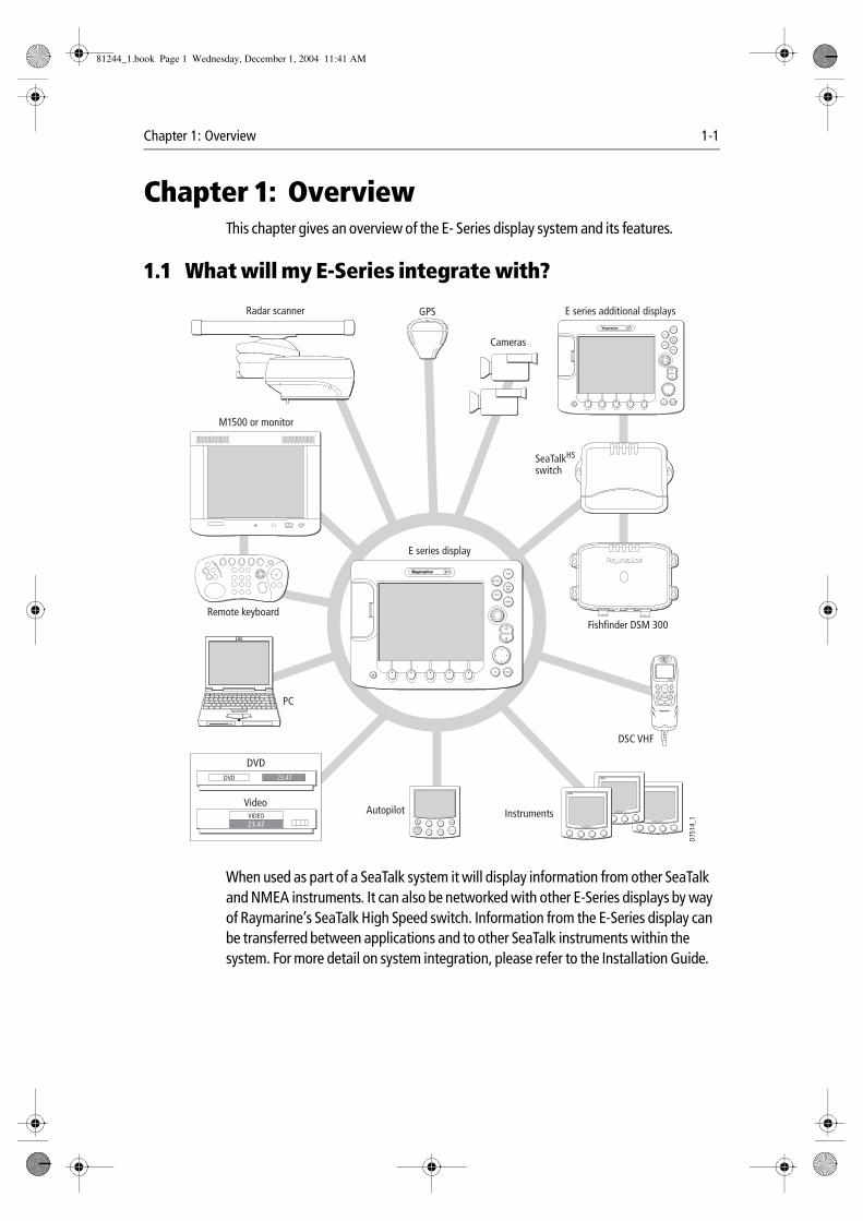
1.1 What will my E-Series integrate with?
When used as part of a SeaTalk system it will display information from other SeaTalk and NMEA instruments. It can also be networked with other E-Series displays by way of Raymarine’s SeaTalk High Speed switch. Information from the E-Series display can be transferred between applications and to other SeaTalk instruments within the system. For more detail on system integration, please refer to the Installation Guide.
CANCELOK
RANGE
IN
OUT
PAGE
ACTIVE
WPTSMOB
MENU
DATA
CANCELOK
RANGE
IN
OUT
PAGE
ACTIVE
WPTSMOB
MENU
DATA
DVD 23.47
VIDEO23.47
DVD
Video
Radar scanner GPS
M1500 or monitor
Remote keyboard
PC
Fishfinder DSM 300
SeaTalkHS
switch
InstrumentsAutopilot
DSC VHF
E series display
E series additional displays
Cameras
MENUCH
OK
16/9 HI/LO
SCAN WATCH
SQ
RAY240
WX
11.18.02
D751
4_1
81244_1.book Page 1 Wednesday, December 1, 2004 11:41 AM
1-2 E-Series Networked Display Reference Manual
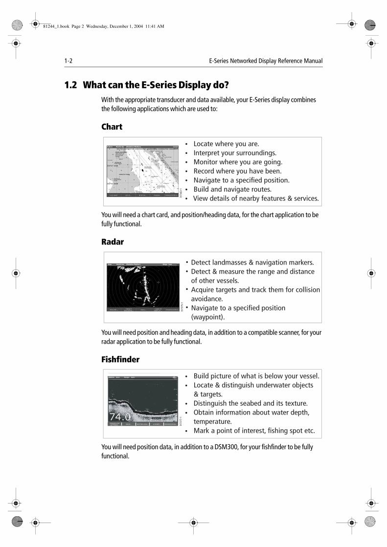
1.2 What can the E-Series Display do?With the appropriate transducer and data available, your E-Series display combines the following applications which are used to:
Chart
You will need a chart card, and position/heading data, for the chart application to be fully functional.
Radar
You will need position and heading data, in addition to a compatible scanner, for your radar application to be fully functional.
Fishfinder
You will need position data, in addition to a DSM300, for your fishfinder to be fully functional.
0.5nm North-Up (Relative Motion) Local
D73
63-1
Locate where you are. Interpret your surroundings. Monitor where you are going. Record where you have been. Navigate to a specified position. Build and navigate routes. View details of nearby features & services.
VRM/EBL... GAIN...TARGETSDISPLAY...
PRESENTATION...TARGET
TRACKING...
6nm North-Up (Relative Motion) Rings 1nm Detect landmasses & navigation markers.Detect & measure the range and distance of other vessels.Acquire targets and track them for collision avoidance.Navigate to a specified position (waypoint).
D73
75-1
D73
77-1
Build picture of what is below your vessel.Locate & distinguish underwater objects & targets.Distinguish the seabed and its texture.Obtain information about water depth, temperature.Mark a point of interest, fishing spot etc.
TRANSDUCERSETTINGS…
ZOOM… BOTTOM LOCK… A-SCOPE… PRESENTATION…
200kHz: Auto Range: Auto
81244_1.book Page 2 Wednesday, December 1, 2004 11:41 AM
Chapter 1: Overview 1-3
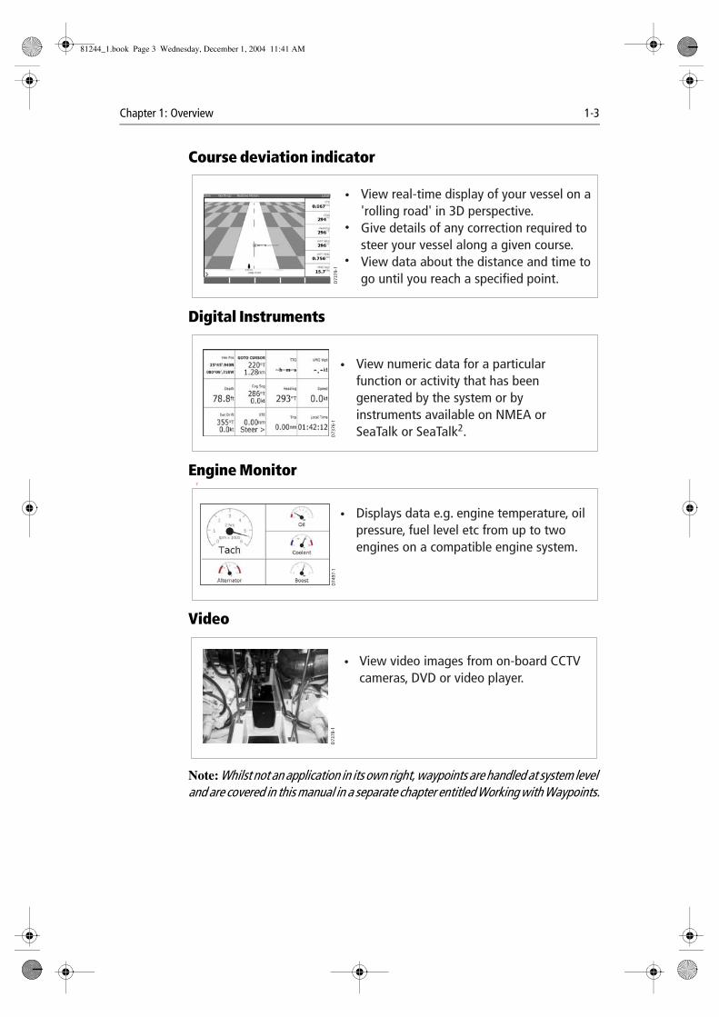
Course deviation indicator
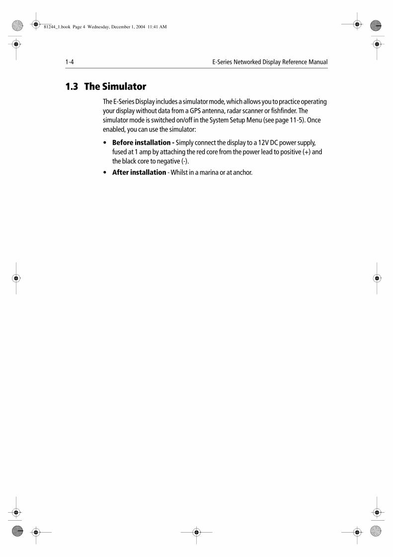
Digital Instruments
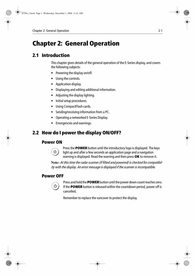
Engine Monitor T
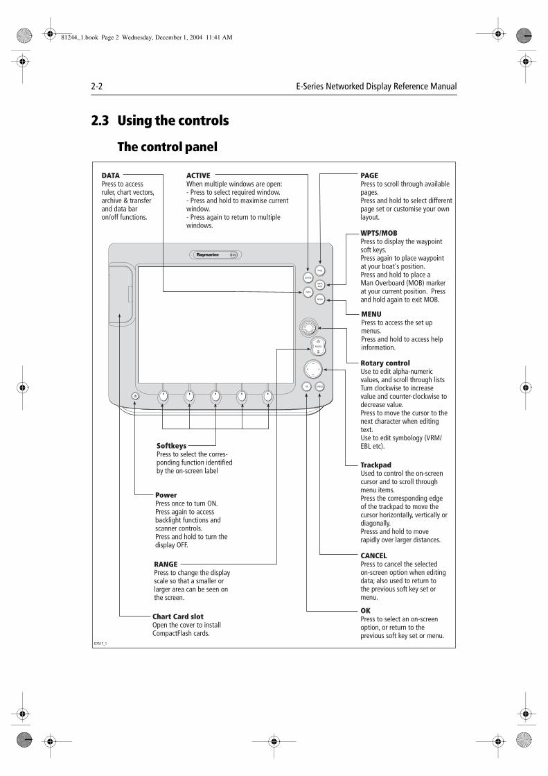
Video
Note: Whilst not an application in its own right, waypoints are handled at system level and are covered in this manual in a separate chapter entitled Working with Waypoints.
D73
79-1
View real-time display of your vessel on a 'rolling road' in 3D perspective.Give details of any correction required to steer your vessel along a given course.View data about the distance and time to go until you reach a specified point.
3nm North-Up Relative Motion Local
D73
76-1
View numeric data for a particular function or activity that has been generated by the system or by instruments available on NMEA or SeaTalk or SeaTalk2.
D74
97-1
Displays data e.g. engine temperature, oil pressure, fuel level etc from up to two engines on a compatible engine system.
D73
78-1
View video images from on-board CCTV cameras, DVD or video player.
Draft
81244_1.book Page 3 Wednesday, December 1, 2004 11:41 AM
1-4 E-Series Networked Display Reference Manual
1.3 The SimulatorThe E-Series Display includes a simulator mode, which allows you to practice operating your display without data from a GPS antenna, radar scanner or fishfinder. The simulator mode is switched on/off in the System Setup Menu (see page 11-5). Once enabled, you can use the simulator:
• Before installation - Simply connect the display to a 12V DC power supply, fused at 1 amp by attaching the red core from the power lead to positive (+) and the black core to negative (-).
• After installation - Whilst in a marina or at anchor.
81244_1.book Page 4 Wednesday, December 1, 2004 11:41 AM
Chapter 2: General Operation 2-1
Chapter 2: General Operation
2.1 IntroductionThis chapter gives details of the general operation of the E-Series display, and covers the following subjects:
• Powering the display on/off.
• Using the controls.
• Application display.
• Displaying and editing additional information.
• Adjusting the display lighting.
• Initial setup procedures.
• Using CompactFlash cards.
• Sending/receiving information from a PC.
• Operating a networked E-Series Display.
• Emergencies and warnings.
2.2 How do I power the display ON/OFF?
Power ON
Press the POWER button until the introductory logo is displayed. The keys light up and after a few seconds an application page and a navigation warning is displayed. Read the warning and then press OK to remove it.
Note: At this time the radar scanner (if fitted and powered) is checked for compatibil-ity with the display. An error message is displayed if the scanner is incompatible.
Power OFF
Press and hold the POWER button until the power down count reaches zero. If the POWER button is released within the countdown period, power off is cancelled.
Remember to replace the suncover to protect the display.
D6577-1
D6577-1
81244_1.book Page 1 Wednesday, December 1, 2004 11:41 AM
2-2 E-Series Networked Display Reference Manual
2.3 Using the controls
The control panel
PAGE
ACTIVE
WPTSMOB
MENU
DATA
CANCELOK
RANGE
IN
OUT
OKPress to select an on-screen option, or return to the previous soft key set or menu.
DATAPress to access ruler, chart vectors, archive & transfer and data bar on/off functions.
TrackpadUsed to control the on-screen cursor and to scroll through menu items.Press the corresponding edge of the trackpad to move the cursor horizontally, vertically or diagonally.Presss and hold to move rapidly over larger distances.
CANCELPress to cancel the selected on-screen option when editing data; also used to return to the previous soft key set or menu.
MENUPress to access the set up menus.Press and hold to access help information.
ACTIVEWhen multiple windows are open:- Press to select required window.- Press and hold to maximise current window.- Press again to return to multiple windows.
PAGEPress to scroll through available pages.Press and hold to select different page set or customise your own layout.
WPTS/MOBPress to display the waypoint soft keys.Press again to place waypoint at your boat's position.Press and hold to place a Man Overboard (MOB) marker at your current position. Press and hold again to exit MOB.
RANGEPress to change the display scale so that a smaller or larger area can be seen on the screen.
PowerPress once to turn ON.Press again to access backlight functions and scanner controls. Press and hold to turn the display OFF.
Chart Card slot Open the cover to install CompactFlash cards.
SoftkeysPress to select the corres-ponding function identified by the on-screen label
D7517_1
Rotary controlUse to edit alpha-numeric values, and scroll through listsTurn clockwise to increase value and counter-clockwise to decrease value.Press to move the cursor to the next character when editing text. Use to edit symbology (VRM/EBL etc).
81244_1.book Page 2 Wednesday, December 1, 2004 11:41 AM
Chapter 2: General Operation 2-3
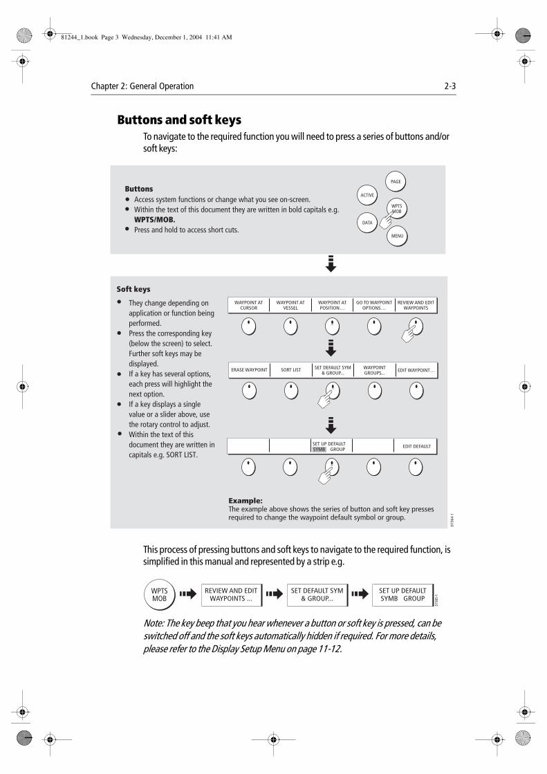
Buttons and soft keysTo navigate to the required function you will need to press a series of buttons and/or soft keys:
This process of pressing buttons and soft keys to navigate to the required function, is simplified in this manual and represented by a strip e.g.
Note: The key beep that you hear whenever a button or soft key is pressed, can be switched off and the soft keys automatically hidden if required. For more details, please refer to the Display Setup Menu on page 11-12.
WAYPOINT ATCURSOR
WAYPOINT ATVESSEL
WAYPOINT ATPOSITION…
GO TO WAYPOINTOPTIONS…
REVIEW AND EDITWAYPOINTS
ERASE WAYPOINT SORT LIST SET DEFAULT SYM& GROUP...
WAYPOINTGROUPS... EDIT WAYPOINT…
EDIT DEFAULTSET UP DEFAULT SYMB GROUP
D73
64-1
WPTSMOB
PAGE
ACTIVE
MENU
DATA
Example:The example above shows the series of button and soft key presses required to change the waypoint default symbol or group.
Access system functions or change what you see on-screen.Within the text of this document they are written in bold capitals e.g. WPTS/MOB.Press and hold to access short cuts.
They change depending on application or function being performed.Press the corresponding key (below the screen) to select.Further soft keys may be displayed.If a key has several options, each press will highlight the next option.If a key displays a single value or a slider above, use the rotary control to adjust.Within the text of this document they are written in capitals e.g. SORT LIST.
Buttons
Soft keys
WPTSMOB
D736
5-1
REVIEW AND EDITWAYPOINTS ...
SET DEFAULT SYM& GROUP...
SET UP DEFAULTSYMB GROUP
81244_1.book Page 3 Wednesday, December 1, 2004 11:41 AM
2-4 E-Series Networked Display Reference Manual
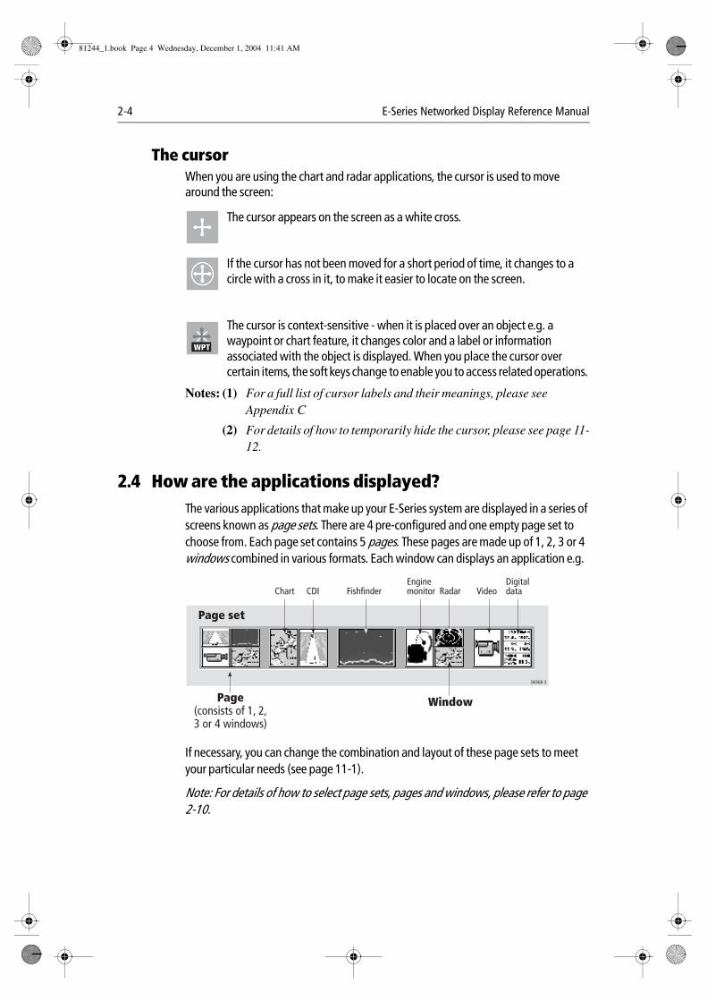
The cursorWhen you are using the chart and radar applications, the cursor is used to move around the screen:
The cursor appears on the screen as a white cross.
If the cursor has not been moved for a short period of time, it changes to a circle with a cross in it, to make it easier to locate on the screen.
The cursor is context-sensitive - when it is placed over an object e.g. a waypoint or chart feature, it changes color and a label or information associated with the object is displayed. When you place the cursor over certain items, the soft keys change to enable you to access related operations.
Notes: (1) For a full list of cursor labels and their meanings, please see Appendix C
(2) For details of how to temporarily hide the cursor, please see page 11-12.
2.4 How are the applications displayed?The various applications that make up your E-Series system are displayed in a series of screens known as page sets. There are 4 pre-configured and one empty page set to choose from. Each page set contains 5 pages. These pages are made up of 1, 2, 3 or 4 windows combined in various formats. Each window can displays an application e.g.
If necessary, you can change the combination and layout of these page sets to meet your particular needs (see page 11-1).
Note: For details of how to select page sets, pages and windows, please refer to page 2-10.
D736
6-1
D736
8-1
D736
9-1
WPT
Page set
Page(consists of 1, 2,3 or 4 windows)
Window
D6568-3
CDIChart RadarFishfinder VideoEnginemonitor
Digitaldata
81244_1.book Page 4 Wednesday, December 1, 2004 11:41 AM
Chapter 2: General Operation 2-5
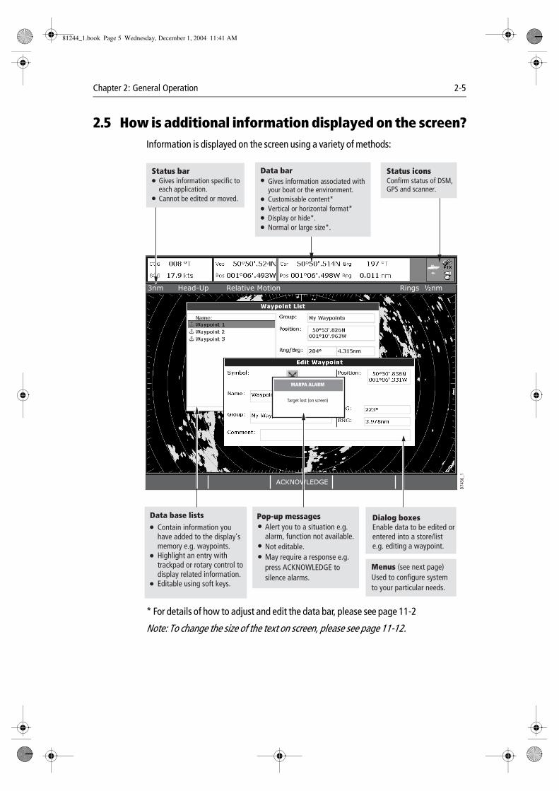
2.5 How is additional information displayed on the screen?Information is displayed on the screen using a variety of methods:
* For details of how to adjust and edit the data bar, please see page 11-2
Note: To change the size of the text on screen, please see page 11-12.
3nm Head-Up Relative Motion Rings ½nm
ACKNOWLEDGE
Status iconsConfirm status of DSM, GPS and scanner.
Status bar Gives information specific to each application. Cannot be edited or moved.
Gives information associated withyour boat or the environment.Customisable content* Vertical or horizontal format*Display or hide*.Normal or large size*.
Data bar
D745
6_1
Contain information you have added to the display's memory e.g. waypoints.Highlight an entry with trackpad or rotary control to display related information.Editable using soft keys.
Dialog boxesEnable data to be edited or entered into a store/list e.g. editing a waypoint.
Alert you to a situation e.g. alarm, function not available.Not editable.May require a response e.g. press ACKNOWLEDGE to silence alarms.
Pop-up messages
MARPA ALARM
Target lost (on screen)
Data base lists
Menus (see next page)Used to configure system to your particular needs.
81244_1.book Page 5 Wednesday, December 1, 2004 11:41 AM
2-6 E-Series Networked Display Reference Manual
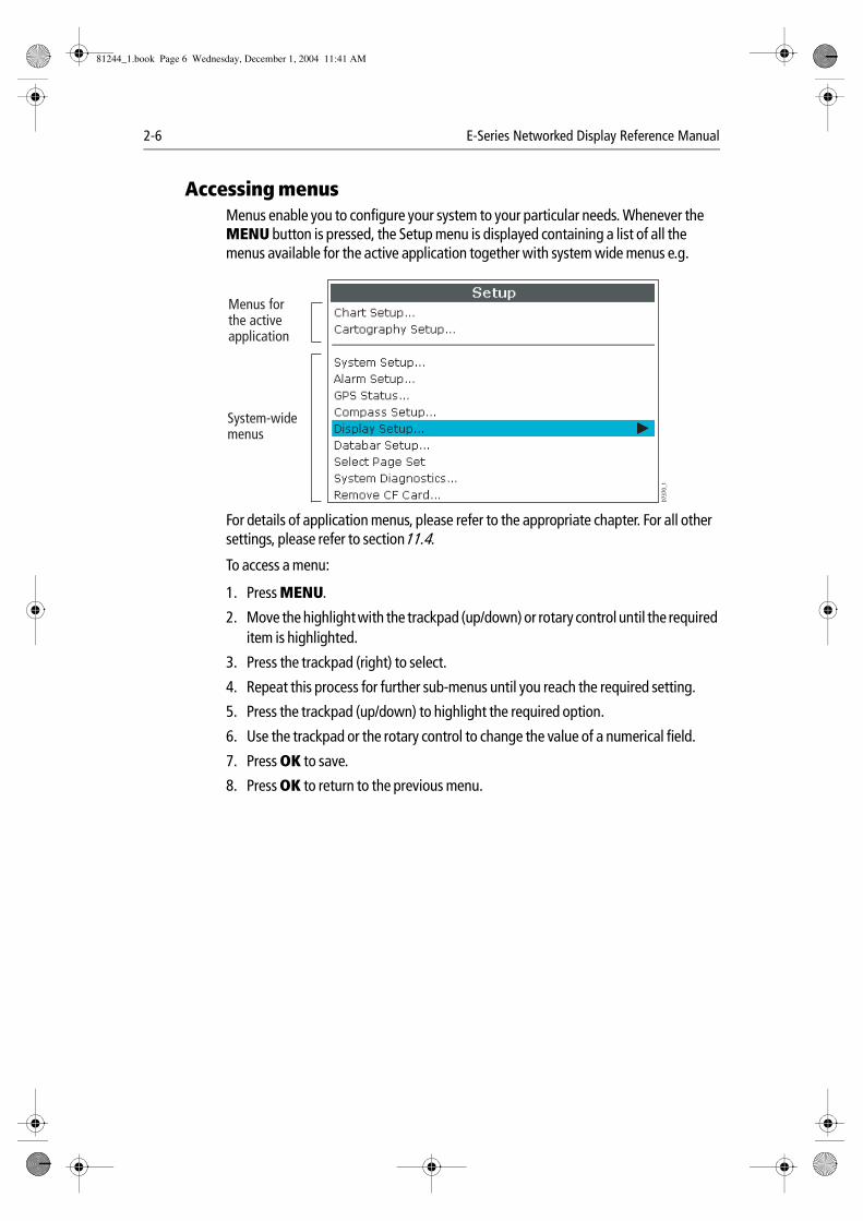
Accessing menusMenus enable you to configure your system to your particular needs. Whenever the MENU button is pressed, the Setup menu is displayed containing a list of all the menus available for the active application together with system wide menus e.g.
For details of application menus, please refer to the appropriate chapter. For all other settings, please refer to section11.4.
To access a menu:
1. Press MENU.
2. Move the highlight with the trackpad (up/down) or rotary control until the required item is highlighted.
3. Press the trackpad (right) to select.
4. Repeat this process for further sub-menus until you reach the required setting.
5. Press the trackpad (up/down) to highlight the required option.
6. Use the trackpad or the rotary control to change the value of a numerical field.
7. Press OK to save.
8. Press OK to return to the previous menu.
D737
0_1
Menus for the active application
System-wide menus
81244_1.book Page 6 Wednesday, December 1, 2004 11:41 AM

Chapter 2: General Operation 2-7
Editing the dialog box informationDialog boxes enable data to be edited or entered into a list e.g.
1. Select the field you want to edit using the trackpad.
2. Press EDIT. The first entry of the selected field will be highlighted.
3. Use either the rotary control or trackpad (up/down) together with the various soft keys, to change the character or selection in the list. Character text can be entered in upper or lower case. (although the system is not case sensitive e.g. WAYPOINT 1, Waypoint 1are considered to be the same name). If you need to use special or accented characters (e.g. ~ ̀ ́ ), the Extended Character Set should be changed to ON in the System Setup Menu (see page 11-5).
4. Use the trackpad (left/right), or rotary end push to move to the next character to be edited.
5. Repeat Steps 3 and 4 until you have edited the selected field.
6. Press OK when the field is edited. CANCEL will revert back to the previous value.
7. Use the trackpad to move to the next field that you want to edit.
8. Repeat Steps 2 to 7 until you have finished editing everything you want to in the dialog box.
9. Press OK to accept all the new values, and clear the dialog box from the screen.
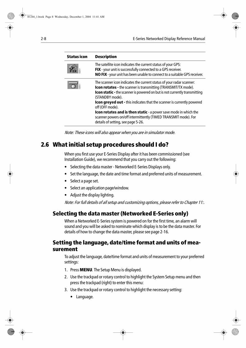
What do the status icons tell me?The status icons on the data bar confirm whether the appropriate connections to your E-Series system have been made:
Status icon Description
The boat and fish icon indicates the current status of your fishfinder:Icon animated - connection to a DSM has been successful.Icon static - the DSM is connected but not transmitting.Icon greyed-out - no DSM is connected.
D656
1-1
D689
2-1
81244_1.book Page 7 Wednesday, December 1, 2004 11:41 AM
2-8 E-Series Networked Display Reference Manual
Note: These icons will also appear when you are in simulator mode.
2.6 What initial setup procedures should I do?When you first use your E-Series Display after it has been commissioned (see Installation Guide), we recommend that you carry out the following:
• Selecting the data master - Networked E-Series Displays only.
• Set the language, the date and time format and preferred units of measurement.
• Select a page set.
• Select an application page/window.
• Adjust the display lighting.
Note: For full details of all setup and customizing options, please refer to Chapter 11:.
Selecting the data master (Networked E-Series only)When a Networked E-Series system is powered on for the first time, an alarm will sound and you will be asked to nominate which display is to be the data master. For details of how to change the data master, please see page 2-16.
Setting the language, date/time format and units of mea-surement
To adjust the language, date/time format and units of measurement to your preferred settings:
1. Press MENU. The Setup Menu is displayed.
2. Use the trackpad or rotary control to highlight the System Setup menu and then press the trackpad (right) to enter this menu:
3. Use the trackpad or rotary control to highlight the necessary setting:
• Language.
The satellite icon indicates the current status of your GPS:FIX - your unit is successfully connected to a GPS receiver.NO FIX - your unit has been unable to connect to a suitable GPS receiver.
The scanner icon indicates the current status of your radar scanner:Icon rotates - the scanner is transmitting (TRANSMIT/TX mode).Icon static - the scanner is powered on but is not currently transmitting (STANDBY mode).Icon greyed out - this indicates that the scanner is currently powered off (OFF mode).Icon rotates and is then static - a power save mode in which the scanner powers on/off intermittently (TIMED TRANSMIT mode). For details of setting, see page 5-26.
Status icon Description
D6893-1
D689
4-1
81244_1.book Page 8 Wednesday, December 1, 2004 11:41 AM
Chapter 2: General Operation 2-9
• Date/Time Setup.
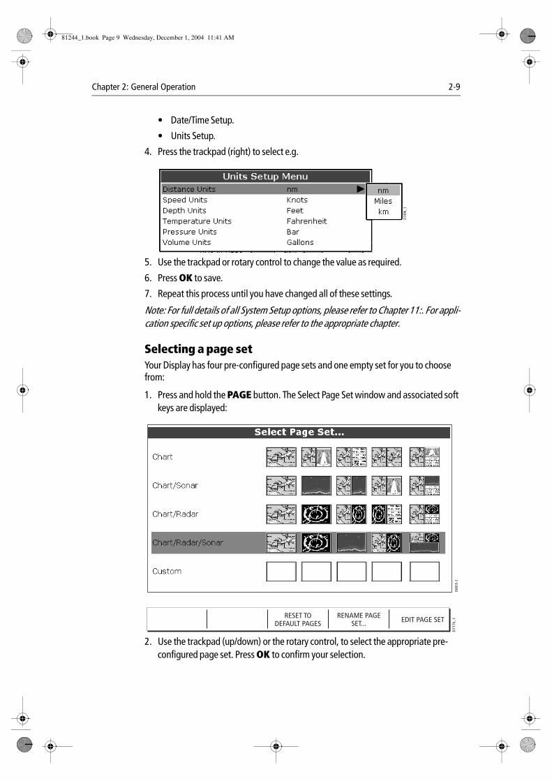
• Units Setup.
4. Press the trackpad (right) to select e.g.
5. Use the trackpad or rotary control to change the value as required.
6. Press OK to save.
7. Repeat this process until you have changed all of these settings.
Note: For full details of all System Setup options, please refer to Chapter 11:. For appli-cation specific set up options, please refer to the appropriate chapter.
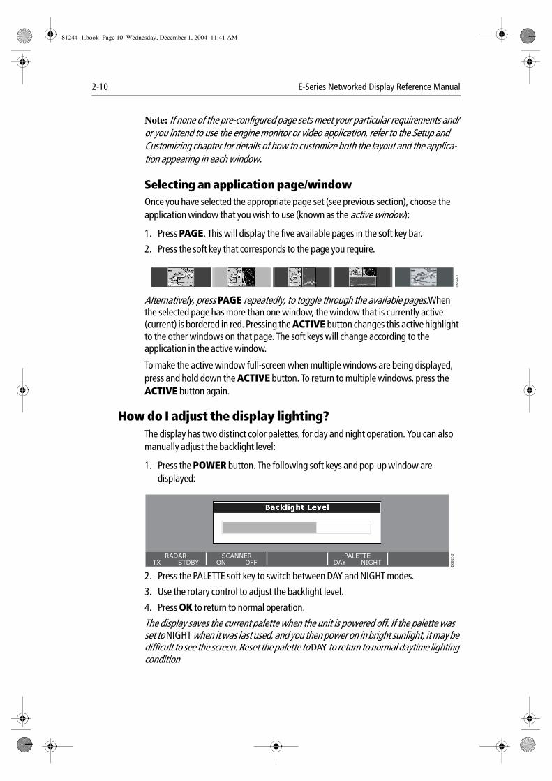
Selecting a page setYour Display has four pre-configured page sets and one empty set for you to choose from:
1. Press and hold the PAGE button. The Select Page Set window and associated soft keys are displayed:
2. Use the trackpad (up/down) or the rotary control, to select the appropriate pre-configured page set. Press OK to confirm your selection.
D749
6_1
D665
5-3
RESET TODEFAULT PAGES
D71
76_1EDIT PAGE SETRENAME PAGE
SET...
81244_1.book Page 9 Wednesday, December 1, 2004 11:41 AM
2-10 E-Series Networked Display Reference Manual
Note: If none of the pre-configured page sets meet your particular requirements and/or you intend to use the engine monitor or video application, refer to the Setup and Customizing chapter for details of how to customize both the layout and the applica-tion appearing in each window.
Selecting an application page/window Once you have selected the appropriate page set (see previous section), choose the application window that you wish to use (known as the active window):
1. Press PAGE. This will display the five available pages in the soft key bar.
2. Press the soft key that corresponds to the page you require.
Alternatively, press PAGE repeatedly, to toggle through the available pages.When the selected page has more than one window, the window that is currently active (current) is bordered in red. Pressing the ACTIVE button changes this active highlight to the other windows on that page. The soft keys will change according to the application in the active window.
To make the active window full-screen when multiple windows are being displayed, press and hold down the ACTIVE button. To return to multiple windows, press the ACTIVE button again.
How do I adjust the display lighting?The display has two distinct color palettes, for day and night operation. You can also manually adjust the backlight level:
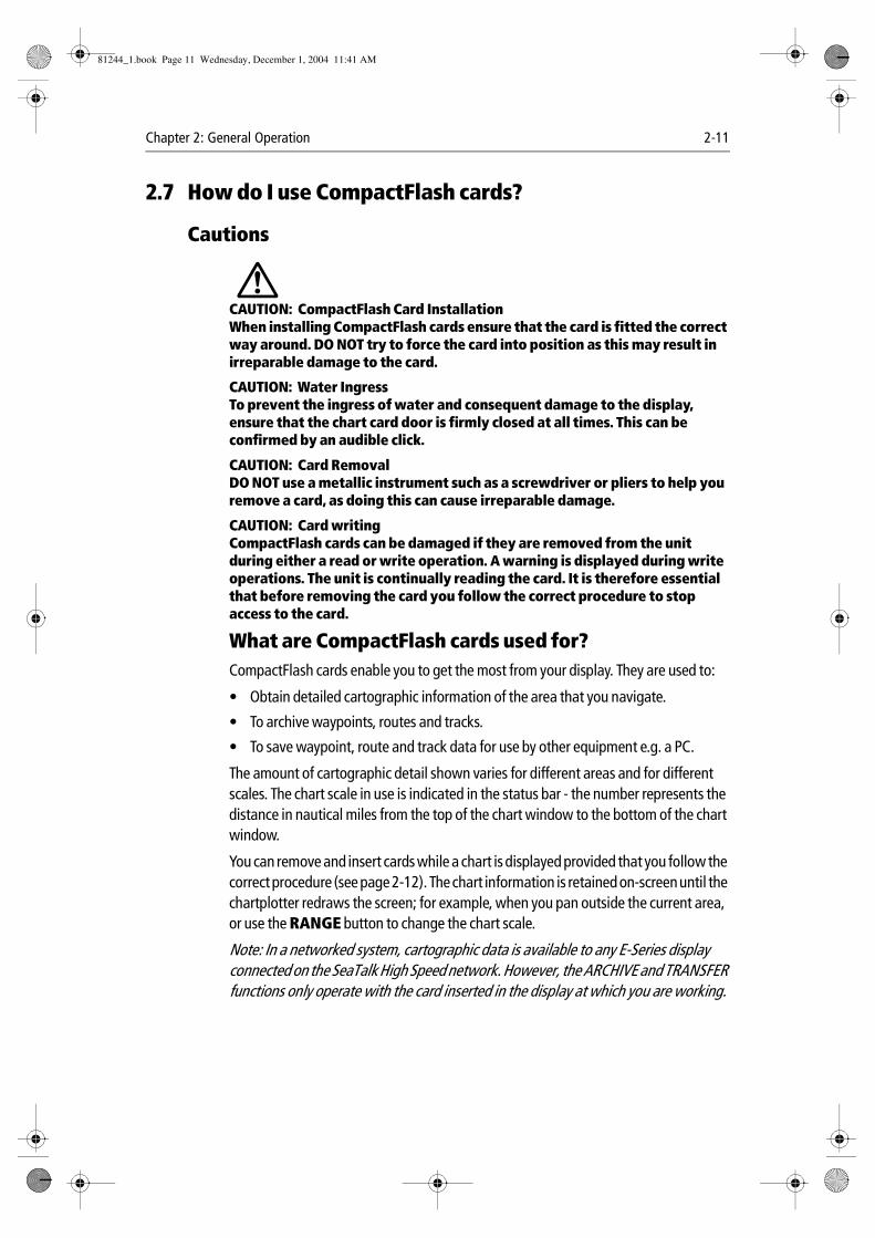
1. Press the POWER button. The following soft keys and pop-up window are displayed:
2. Press the PALETTE soft key to switch between DAY and NIGHT modes.
3. Use the rotary control to adjust the backlight level.
4. Press OK to return to normal operation.
The display saves the current palette when the unit is powered off. If the palette was set to NIGHT when it was last used, and you then power on in bright sunlight, it may be difficult to see the screen. Reset the palette to DAY to return to normal daytime lighting condition
D665
4-3
RADARTX STDBY
SCANNERON OFF
PALETTEDAY NIGHT
D68
02-2
81244_1.book Page 10 Wednesday, December 1, 2004 11:41 AM
Chapter 2: General Operation 2-11
2.7 How do I use CompactFlash cards?
Cautions
CAUTION: CompactFlash Card InstallationWhen installing CompactFlash cards ensure that the card is fitted the correct way around. DO NOT try to force the card into position as this may result in irreparable damage to the card.
CAUTION: Water IngressTo prevent the ingress of water and consequent damage to the display, ensure that the chart card door is firmly closed at all times. This can be confirmed by an audible click.
CAUTION: Card RemovalDO NOT use a metallic instrument such as a screwdriver or pliers to help you remove a card, as doing this can cause irreparable damage.
CAUTION: Card writingCompactFlash cards can be damaged if they are removed from the unit during either a read or write operation. A warning is displayed during write operations. The unit is continually reading the card. It is therefore essential that before removing the card you follow the correct procedure to stop access to the card.
What are CompactFlash cards used for?CompactFlash cards enable you to get the most from your display. They are used to:
• Obtain detailed cartographic information of the area that you navigate.
• To archive waypoints, routes and tracks.
• To save waypoint, route and track data for use by other equipment e.g. a PC.
The amount of cartographic detail shown varies for different areas and for different scales. The chart scale in use is indicated in the status bar - the number represents the distance in nautical miles from the top of the chart window to the bottom of the chart window.
You can remove and insert cards while a chart is displayed provided that you follow the correct procedure (see page 2-12). The chart information is retained on-screen until the chartplotter redraws the screen; for example, when you pan outside the current area, or use the RANGE button to change the chart scale.
Note: In a networked system, cartographic data is available to any E-Series display connected on the SeaTalk High Speed network. However, the ARCHIVE and TRANSFER functions only operate with the card inserted in the display at which you are working.
81244_1.book Page 11 Wednesday, December 1, 2004 11:41 AM
2-12 E-Series Networked Display Reference Manual
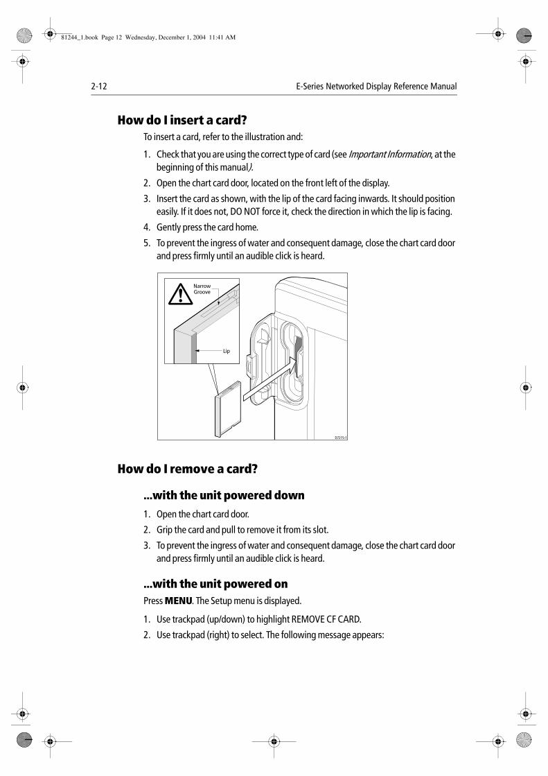
How do I insert a card?To insert a card, refer to the illustration and:
1. Check that you are using the correct type of card (see Important Information, at the beginning of this manual).
2. Open the chart card door, located on the front left of the display.
3. Insert the card as shown, with the lip of the card facing inwards. It should position easily. If it does not, DO NOT force it, check the direction in which the lip is facing.
4. Gently press the card home.
5. To prevent the ingress of water and consequent damage, close the chart card door and press firmly until an audible click is heard.
How do I remove a card?
...with the unit powered down
1. Open the chart card door.
2. Grip the card and pull to remove it from its slot.
3. To prevent the ingress of water and consequent damage, close the chart card door and press firmly until an audible click is heard.
...with the unit powered onPress MENU. The Setup menu is displayed.
1. Use trackpad (up/down) to highlight REMOVE CF CARD.
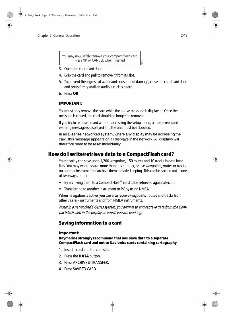
2. Use trackpad (right) to select. The following message appears:
D7215-1
NarrowGroove
Lip
81244_1.book Page 12 Wednesday, December 1, 2004 11:41 AM
Chapter 2: General Operation 2-13
3. Open the chart card door.
4. Grip the card and pull to remove it from its slot.
5. To prevent the ingress of water and consequent damage, close the chart card door and press firmly until an audible click is heard.
6. Press OK.
IMPORTANT:
You must only remove the card while the above message is displayed. Once the message is closed, the card should no longer be removed.
If you try to remove a card without accessing the setup menu, a blue screen and warning message is displayed and the unit must be rebooted.
In an E-series networked system, where any display may be accessing the card, this message appears on all displays in the network. All displays will therefore need to be reset individually.
How do I write/retrieve data to a CompactFlash card?Your display can save up to 1,200 waypoints, 150 routes and 10 tracks in data base lists. You may want to save more than this number, or use waypoints, routes or tracks on another instrument or archive them for safe-keeping. This can be carried out in one of two ways, either
• By archiving them to a CompactFlash® card to be retrieved again later, or:
• Transferring to another instrument or PC by using NMEA.
When navigation is active, you can also receive waypoints, routes and tracks from other SeaTalk instruments and from NMEA instruments.
Note: In a networked E-Series system, you archive to and retrieve data from the Com-pactFlash card in the display on which you are working.
Saving information to a card
Important:Raymarine strongly recommend that you save data to a separate CompactFlash card and not to Navionics cards containing cartography.
1. Insert a card into the card slot.
2. Press the DATA button.
3. Press ARCHIVE & TRANSFER.
4. Press SAVE TO CARD.
You may now safely remove your compact flash cardPress OK or CANCEL when finished
D680
6-1
81244_1.book Page 13 Wednesday, December 1, 2004 11:41 AM
2-14 E-Series Networked Display Reference Manual
5. Toggle SELECT LIST to WPT (Waypoint), RTE (Route), or TRK (Track).
6. The database list for your selection appears on the screen.
7. Press the SAVE ALL or SAVE GROUP/ROUTE/TRACK as appropriate. A message box appears to show that the information is being written to the card.
8. When the transfer is complete a message will appear on the screen.
Note: Pressing the SAVE ALL soft key will save all of a Database list to a card.
Retrieving information from a card
1. Insert a card into the card slot. See page 2-12.
2. Press the DATA button.
3. Press ARCHIVE & TRANSFER.
4. Press RETRIEVE FROM CARD.
5. From SELECT LIST, choose WPT (Waypoint), RTE (Route), or TRK (Track).
6. The card contents for your selection appears on the screen.
7. Use the trackpad (up/down) to select what you want to retrieve.
8. Press RETRIEVE ALL or RETRIEVE GROUP/ROUTE/TRACK as appropriate. A message box appears to show that the information is being written to the display.
9. When the transfer is complete a message will appear on the screen.
Note: Pressing the RETRIEVE ALL soft key, will retrieve all of a Database list to the dis-play.
If whilst retrieving information a selection is already found to exist on the display, a warning message will appear:
The soft keys will change to give you the options of:
• RETRIEVE AS NEW
• REPLACE
• CANCEL RETRIEVE
Select which option you want by pressing the corresponding soft key.
Erasing information from a cardIf you wish to remove information from a card, for example you no longer need it, or the card is full, it can be erased by using the DELETE or DELETE ALL soft keys that can be found on the Retrieve soft key bar. A message will be displayed on screen asking you to confirm that you want to delete the item(s), before it takes place.
81244_1.book Page 14 Wednesday, December 1, 2004 11:41 AM
Chapter 2: General Operation 2-15
2.8 How do I send and receive information using my PC?You can transfer and retrieve waypoints or routes to and from another instrument or PC by:
To transfer or receive information using NMEA:
1. Press the DATA button.
2. Press the ARCHIVE AND TRANSFER.
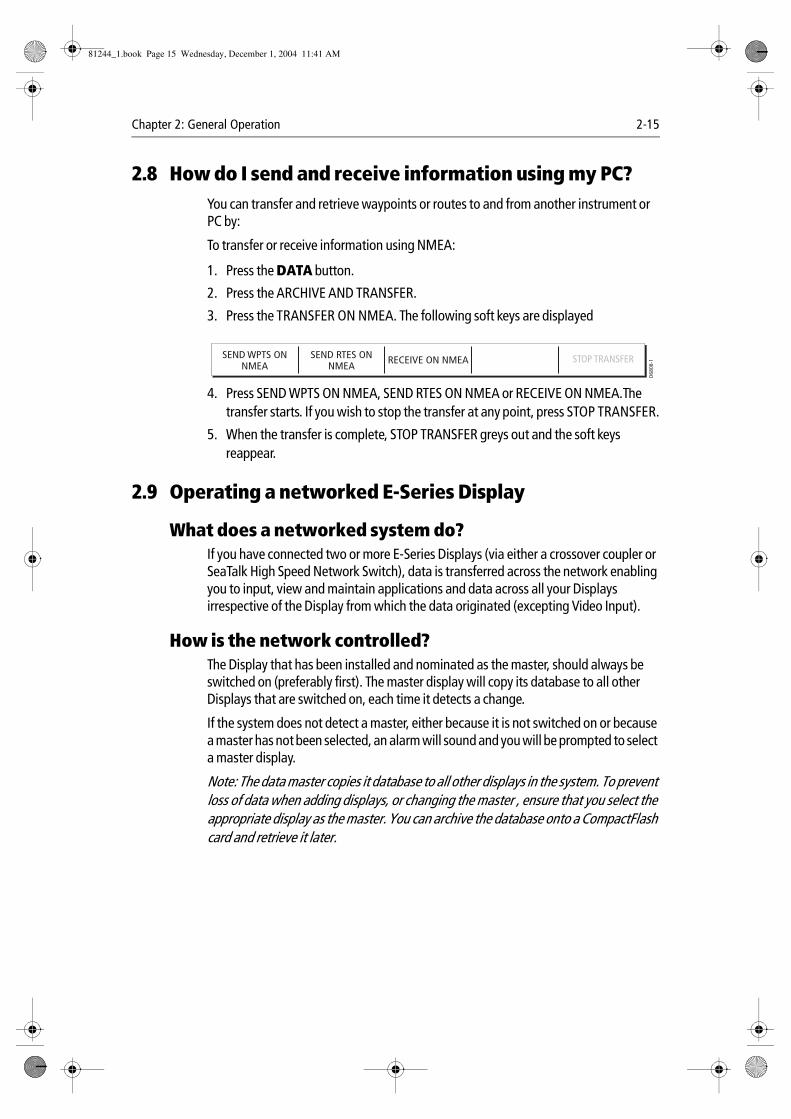
3. Press the TRANSFER ON NMEA. The following soft keys are displayed
4. Press SEND WPTS ON NMEA, SEND RTES ON NMEA or RECEIVE ON NMEA.The transfer starts. If you wish to stop the transfer at any point, press STOP TRANSFER.
5. When the transfer is complete, STOP TRANSFER greys out and the soft keys reappear.
2.9 Operating a networked E-Series Display
What does a networked system do?If you have connected two or more E-Series Displays (via either a crossover coupler or SeaTalk High Speed Network Switch), data is transferred across the network enabling you to input, view and maintain applications and data across all your Displays irrespective of the Display from which the data originated (excepting Video Input).
How is the network controlled?The Display that has been installed and nominated as the master, should always be switched on (preferably first). The master display will copy its database to all other Displays that are switched on, each time it detects a change.
If the system does not detect a master, either because it is not switched on or because a master has not been selected, an alarm will sound and you will be prompted to select a master display.
Note: The data master copies it database to all other displays in the system. To prevent loss of data when adding displays, or changing the master , ensure that you select the appropriate display as the master. You can archive the database onto a CompactFlash card and retrieve it later.
SEND WPTS ONNMEA
SEND RTES ONNMEA
RECEIVE ON NMEA
D68
08-1STOP TRANSFER
81244_1.book Page 15 Wednesday, December 1, 2004 11:41 AM
2-16 E-Series Networked Display Reference Manual
How do I change the master display?On the display that you wish to nominate as the master:
1. Press MENU.
2. Use the trackpad to highlight and select System Setup/System Integration/Data Master.
3. Select ON.
Any such changes that you make to the nominated master will be saved when you power off.
Are there any functions that only affect the display in use?The majority of functions, settings, additions and changes that you perform on a single Display are ‘seen’ by all other Displays connected to your network. There are however some local settings that will only affect the individual display on which you are working.
These local settings are summarized as follows:
• Power on/off key (including Day/night setting).
• The ACTIVE window.
• Selecting a panel in the digital data or engine monitoring application.
• Radar and Fishfinder presentation settings.
• Radar VRMs, EBLs and Wakes.
• Chart presentation settings when the Chart View is set to LOCAL.
• Show/hide waypoints, routes or tracks.
• Fishfinder Setup Menu options (top half of menu only).
• Video, Databar and Display Setup Menus.
• Databar on/off and configuration.
• Ruler settings.
• Page set - selecting a set, name and applications configuration.
81244_1.book Page 16 Wednesday, December 1, 2004 11:41 AM
Chapter 2: General Operation 2-17
2.10Emergencies and warningsYou can use your E-Series display to mark the position of a man overboard or to sound an alarm when a particular situation occurs e.g when a depth limit is reached, a specified period of time has elapsed etc.
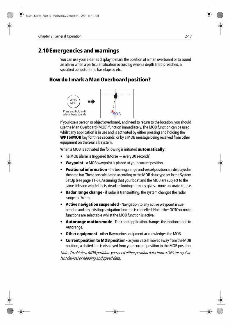
How do I mark a Man Overboard position?
If you lose a person or object overboard, and need to return to the location, you should use the Man Overboard (MOB) function immediately. The MOB function can be used whilst any application is in use and is activated by either pressing and holding the WPTS/MOB key for three seconds, or by a MOB message being received from other equipment on the SeaTalk system.
When a MOB is activated the following is initiated automatically:
• he MOB alarm is triggered (Morse --- every 30 seconds)
• Waypoint - a MOB waypoint is placed at your current position.
• Positional information - the bearing, range and vessel position are displayed in the data bar. These are calculated according to the MOB data type set in the System SetUp (see page 11-5). Assuming that your boat and the MOB are subject to the same tide and wind effects, dead reckoning normally gives a more accurate course.
• Radar range change - if radar is transmitting, the system changes the radar range to 1/8 nm.
• Active navigation suspended - Navigation to any active waypoint is sus-pended and any existing navigation function is cancelled. No further GOTO or route functions are selectable whilst the MOB function is active.
• Autorange motion mode - The chart application changes the motion mode to Autorange.
• Other equipment - other Raymarine equipment acknowledges the MOB.
• Current position to MOB position - as your vessel moves away from the MOB position, a dotted line is displayed from your current position to the MOB position.
Note: To obtain a MOB position, you need either position data from a GPS (or equiva-lent device) or heading and speed data.
D6652-1
WPTSMOB
Press and hold untila long beep sounds
81244_1.book Page 17 Wednesday, December 1, 2004 11:41 AM
2-18 E-Series Networked Display Reference Manual
How do I clear a MOB?You can clear a MOB and its data by either pressing and holding the WPTS/MOB key or via any instrument on SeaTalk. Once cleared, your chart and radar applications will return to the motion mode that applied prior to the MOB alarm and the GOTO and route functions will once more be available.
What alarms will my display sound?You get warning of a hazard or a particular situation via in-built alarms which are generated for the system as a whole or for individual applications. When an alarm sounds, a message box is displayed explaining the cause of the alarm.
You can specify what alarms will operate and the parameters within which they will sound, via the Alarm Setup Menu (see page 11-8).
How do I cancel an alarm?
Display alarmsBy pressing the ACKNOWLEDGE soft key, the alarm is silenced and any message box is cleared. If the alarm has been generated by the chartplotter, the appropriate action is taken. For example, following an arrival alarm, the next route leg is activated.
Please note:
• Although you can change the configuration of the arrival alarm, it cannot be turned off.
• To cancel a MOB alarm, press and hold the WPTS/MOB until the MOB symbol dis-appears from the screen.
• If an anchor alarm is silenced, but the alarm condition persists, the alarm is repeated every 30 seconds
External alarmsIf an instrument that is connected to the display on SeaTalk generates alarms, these will sound on your E-Series display accompanied by a pop-up message box. You can cancel these alarms by pressing the ACKNOWLEDGE soft key. The alarm will be silenced, but no other action will be taken by the E-Series display.
81244_1.book Page 18 Wednesday, December 1, 2004 11:41 AM

Chapter 3: Working with Waypoints 3-1
Chapter 3: Working with WaypointsThis chapter gives details of how to place, edit, manage and navigate to a waypoint using the dedicated WPTS/MOB button.
3.1 What is a waypoint?A waypoint is a position marked on a chart, radar or fishfinder window to indicate a site (for fishing, diving etc.) or as a place to navigate to. By default, all waypoints are indicated on screen by a waypoint symbol - x. This symbol can however be changed if you wish.
Waypoints are a core feature of the E-series display. They can be created in any application and are displayed on the radar, chart and fishfinder windows. A series of waypoints can be combined together to form a route. If you have networked several E-Series Displays, any waypoints that are created on one display are ‘seen’ by all the other displays.
The details of all waypoints, irrespective of the application they were created in, are stored in a dedicated waypoint list which will hold up to 1200 waypoints. All waypoints are by default, placed in the MY WAYPOINTS group. If required, you can create new groups and change the default group if required. If necessary, waypoints can be archived to a CompactFlash card or transferred to another NMEA compatible instrument. If the system receives an active waypoint over SeaTalk or NMEA, it is displayed but cannot be edited.
Note: You can only archive and transfer waypoints to a CompactFlash card/NMEA link installed at the display on which you are working.
81244_1.book Page 1 Wednesday, December 1, 2004 11:41 AM
3-2 E-Series Networked Display Reference Manual
3.2 How are waypoints represented?
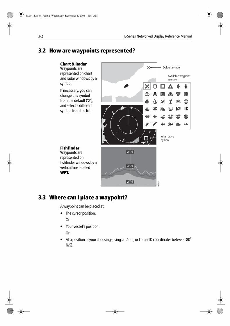
Chart & RadarWaypoints are represented on chart and radar windows by a symbol.
If necessary, you can change this symbol from the default (‘X’), and select a different symbol from the list.
FishfinderWaypoints are represented on fishfinder windows by a vertical line labeled WPT.
3.3 Where can I place a waypoint?A waypoint can be placed at:
• The cursor position.
Or:
• Your vessel’s position.
Or:
• At a position of your choosing (using lat./long or Loran TD coordinates between 800
N/S).
D655
4-1
Available waypoint symbols
Default symbol
WPT
WPT
WPT
wpt 1
Alternative symbol
81244_1.book Page 2 Wednesday, December 1, 2004 11:41 AM
Chapter 3: Working with Waypoints 3-3
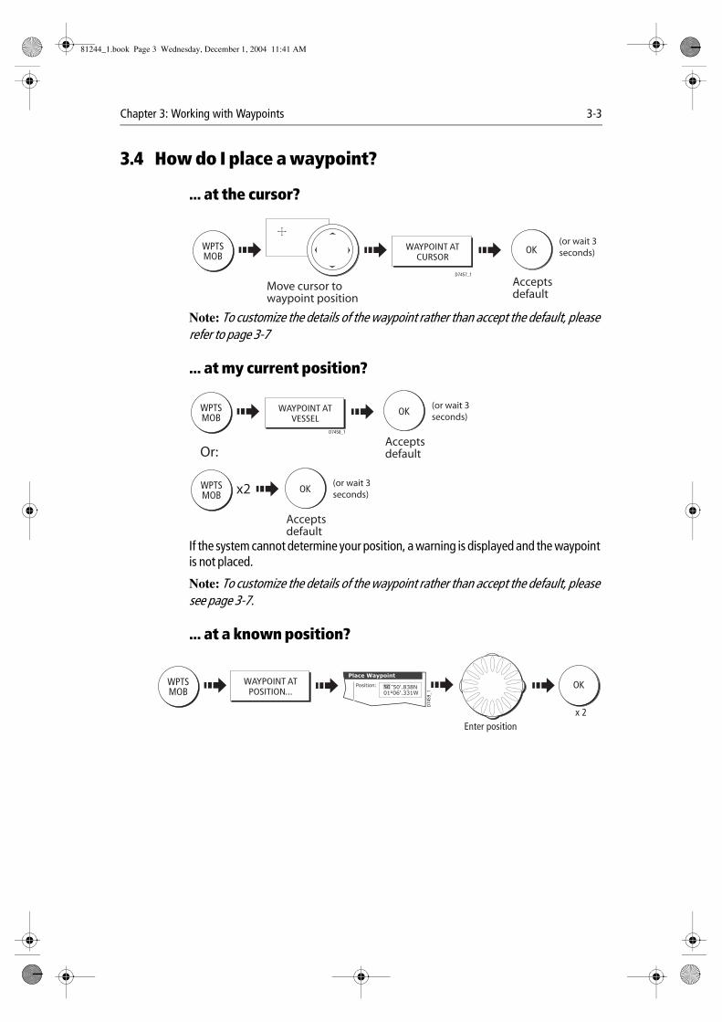
3.4 How do I place a waypoint?
... at the cursor?
Note: To customize the details of the waypoint rather than accept the default, please refer to page 3-7
... at my current position?
If the system cannot determine your position, a warning is displayed and the waypoint is not placed.
Note: To customize the details of the waypoint rather than accept the default, please see page 3-7.
... at a known position?
WPTSMOB
WAYPOINT ATCURSOR
D7457_1
OK
Acceptsdefault
(or wait 3seconds)
Move cursor to waypoint position
WAYPOINT ATVESSEL
WPTSMOB
D7458_1
OK
Acceptsdefault
(or wait 3seconds)
WPTSMOB
OK
Acceptsdefault
(or wait 3seconds)
Or:
x2
WPTSMOB
WAYPOINT ATPOSITION...
50'.838N01o06'.331W
Position:
Place Waypoint
50
D745
9_1
OK
Enter positionx 2
81244_1.book Page 3 Wednesday, December 1, 2004 11:41 AM
3-4 E-Series Networked Display Reference Manual
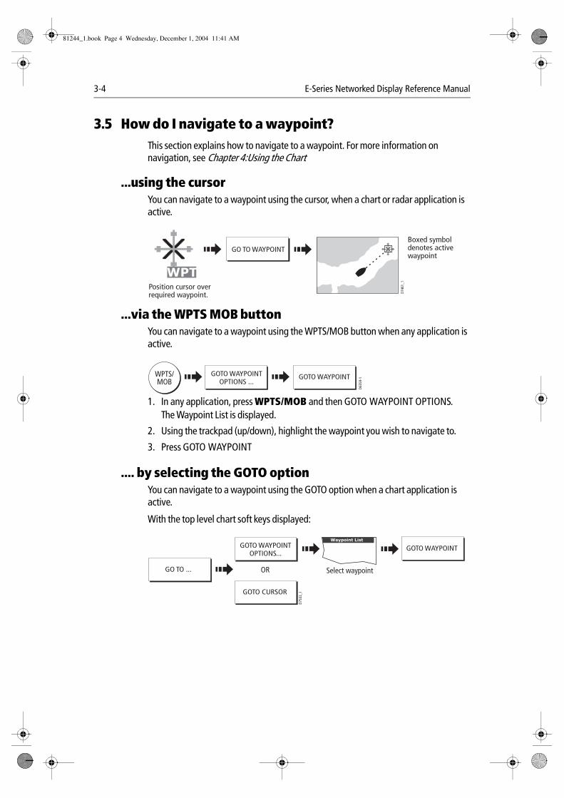
3.5 How do I navigate to a waypoint?This section explains how to navigate to a waypoint. For more information on navigation, see Chapter 4:Using the Chart
...using the cursorYou can navigate to a waypoint using the cursor, when a chart or radar application is active.
...via the WPTS MOB buttonYou can navigate to a waypoint using the WPTS/MOB button when any application is active.
1. In any application, press WPTS/MOB and then GOTO WAYPOINT OPTIONS.The Waypoint List is displayed.
2. Using the trackpad (up/down), highlight the waypoint you wish to navigate to.
3. Press GOTO WAYPOINT
.... by selecting the GOTO optionYou can navigate to a waypoint using the GOTO option when a chart application is active.
With the top level chart soft keys displayed:
GO TO WAYPOINT
D746
1_1
WPTPosition cursor over required waypoint.
Boxed symbol denotes active waypoint
D655
9-1WPTS/
MOBGOTO WAYPOINT
OPTIONS ...GOTO WAYPOINT
GO TO ...
Waypoint List
D750
3_1
Select waypoint
GOTO CURSOR
GOTO WAYPOINTOPTIONS...
GOTO WAYPOINT
OR
81244_1.book Page 4 Wednesday, December 1, 2004 11:41 AM
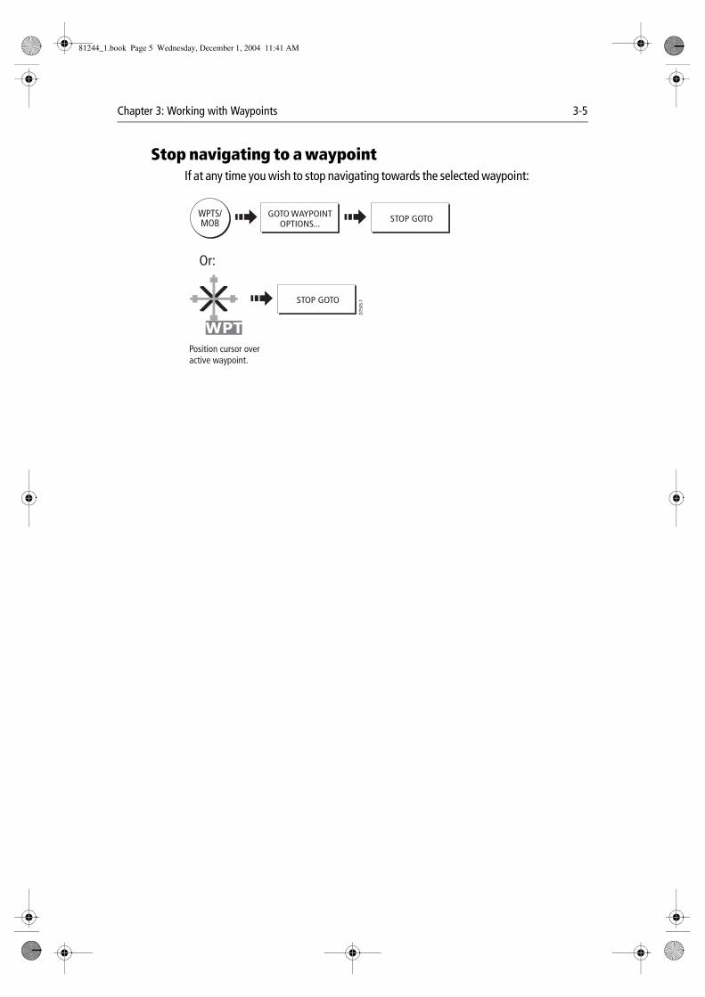
Chapter 3: Working with Waypoints 3-5
Stop navigating to a waypointIf at any time you wish to stop navigating towards the selected waypoint:
D750
5-1
WPTS/MOB
GOTO WAYPOINTOPTIONS... STOP GOTO
WPT
Or:
Position cursor over active waypoint.
STOP GOTO
81244_1.book Page 5 Wednesday, December 1, 2004 11:41 AM
3-6 E-Series Networked Display Reference Manual
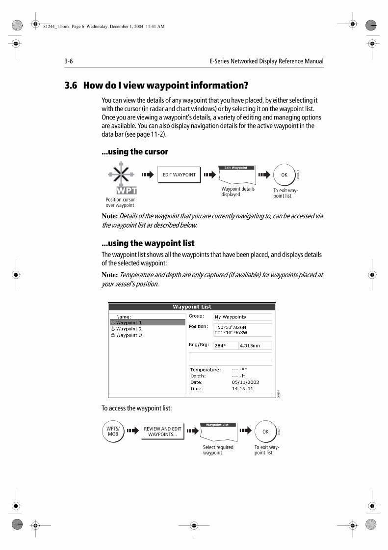
3.6 How do I view waypoint information?You can view the details of any waypoint that you have placed, by either selecting it with the cursor (in radar and chart windows) or by selecting it on the waypoint list. Once you are viewing a waypoint’s details, a variety of editing and managing options are available. You can also display navigation details for the active waypoint in the data bar (see page 11-2).
...using the cursor
Note: Details of the waypoint that you are currently navigating to, can be accessed via the waypoint list as described below.
...using the waypoint listThe waypoint list shows all the waypoints that have been placed, and displays details of the selected waypoint:
Note: Temperature and depth are only captured (if available) for waypoints placed at your vessel’s position.
To access the waypoint list:
EDIT WAYPOINT
D750
6_1
WPT
Edit Waypoint
Waypoint detailsdisplayed
Position cursorover waypoint
OK
To exit way-point list
D656
0-1
D750
7-1WPTS/
MOBREVIEW AND EDIT
WAYPOINTS...
Waypoint List
Select requiredwaypoint
OK
To exit way-point list
81244_1.book Page 6 Wednesday, December 1, 2004 11:41 AM
Chapter 3: Working with Waypoints 3-7
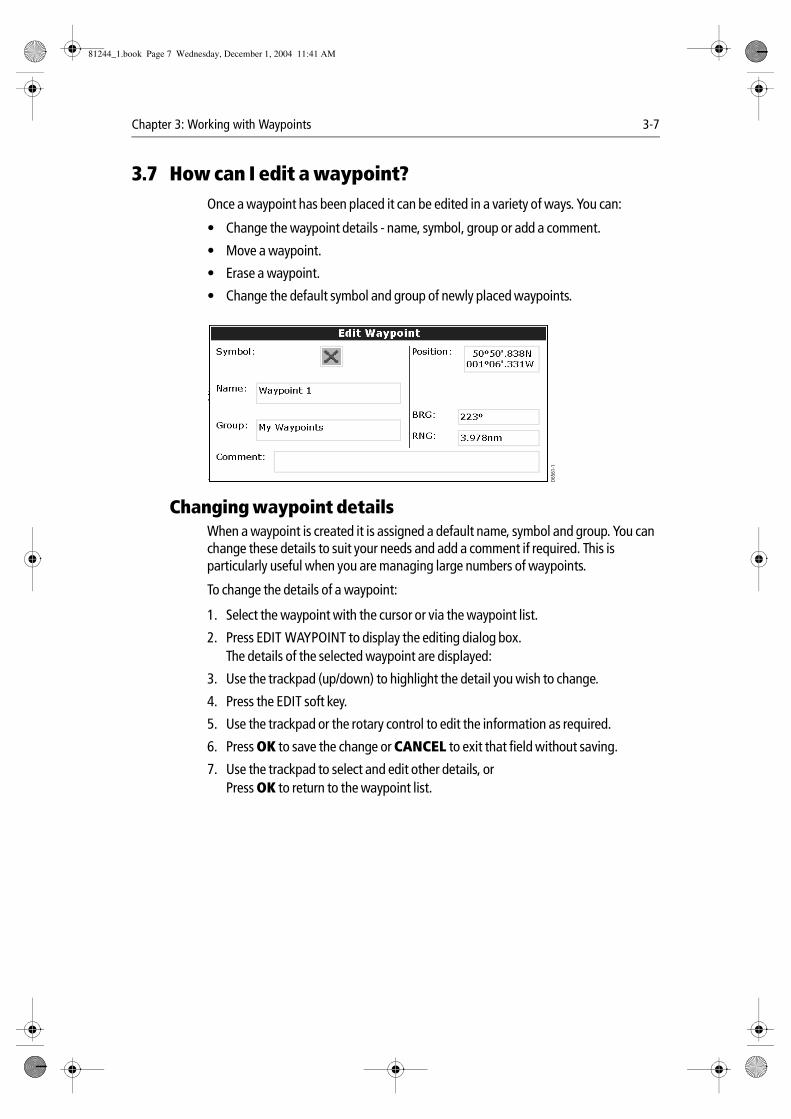
3.7 How can I edit a waypoint?Once a waypoint has been placed it can be edited in a variety of ways. You can:
• Change the waypoint details - name, symbol, group or add a comment.
• Move a waypoint.
• Erase a waypoint.
• Change the default symbol and group of newly placed waypoints.
Changing waypoint detailsWhen a waypoint is created it is assigned a default name, symbol and group. You can change these details to suit your needs and add a comment if required. This is particularly useful when you are managing large numbers of waypoints.
To change the details of a waypoint:
1. Select the waypoint with the cursor or via the waypoint list.
2. Press EDIT WAYPOINT to display the editing dialog box.The details of the selected waypoint are displayed:
3. Use the trackpad (up/down) to highlight the detail you wish to change.
4. Press the EDIT soft key.
5. Use the trackpad or the rotary control to edit the information as required.
6. Press OK to save the change or CANCEL to exit that field without saving.
7. Use the trackpad to select and edit other details, orPress OK to return to the waypoint list.
D656
1-1
81244_1.book Page 7 Wednesday, December 1, 2004 11:41 AM
3-8 E-Series Networked Display Reference Manual
Moving a waypointYou can move any waypoint to a new position. If, however, you are navigating to a waypoint and you wish it to be moved, you will need to stop navigation (Press STOP GOTO). There are two methods of moving a waypoint:
...by entering new coordinatesIf you know the new co-ordinates, bearing or range for the particular waypoint, you can enter this information by editing the waypoint as described above.
...by dragging the waypoint to a new position
1. Use the cursor to select the waypoint that you want to move.
2. Press MOVE WAYPOINT.
3. Use the trackpad to drag the waypoint to the new location.
4. Press PLACE WAYPOINT or OK to save.
Note: Press CANCEL to abandon the move.
CAUTION: It is possible to move waypoints that are used in routes. In such instances, the stored route will include the Waypoint in its new position. Ensure that this does not present a navigation hazard.
Erasing a waypointYou can erase any waypoint on the system (including groups of waypoints) except:
• The waypoint that you are currently navigating to.
OR:
• Any waypoint used in a route.
Note: Routes may be hidden but its waypoints can still be displayed. If you attempt to erase such a waypoint, a warning message will be displayed
...using the cursor
1. Move the cursor over the waypoint that you want to erase.
2. Press ERASE WAYPOINT.
3. You will then be asked to confirm this. Press YES to confirm, or NO to cancel.
...using the waypoint list
1. Select the waypoint in the waypoint list.
2. Press ERASE WAYPOINT.
3. You will then be asked to confirm this. Press YES to confirm, or NO to cancel.
Note: For details of erasing groups of waypoints, see page 3-12.
81244_1.book Page 8 Wednesday, December 1, 2004 11:41 AM
Chapter 3: Working with Waypoints 3-9
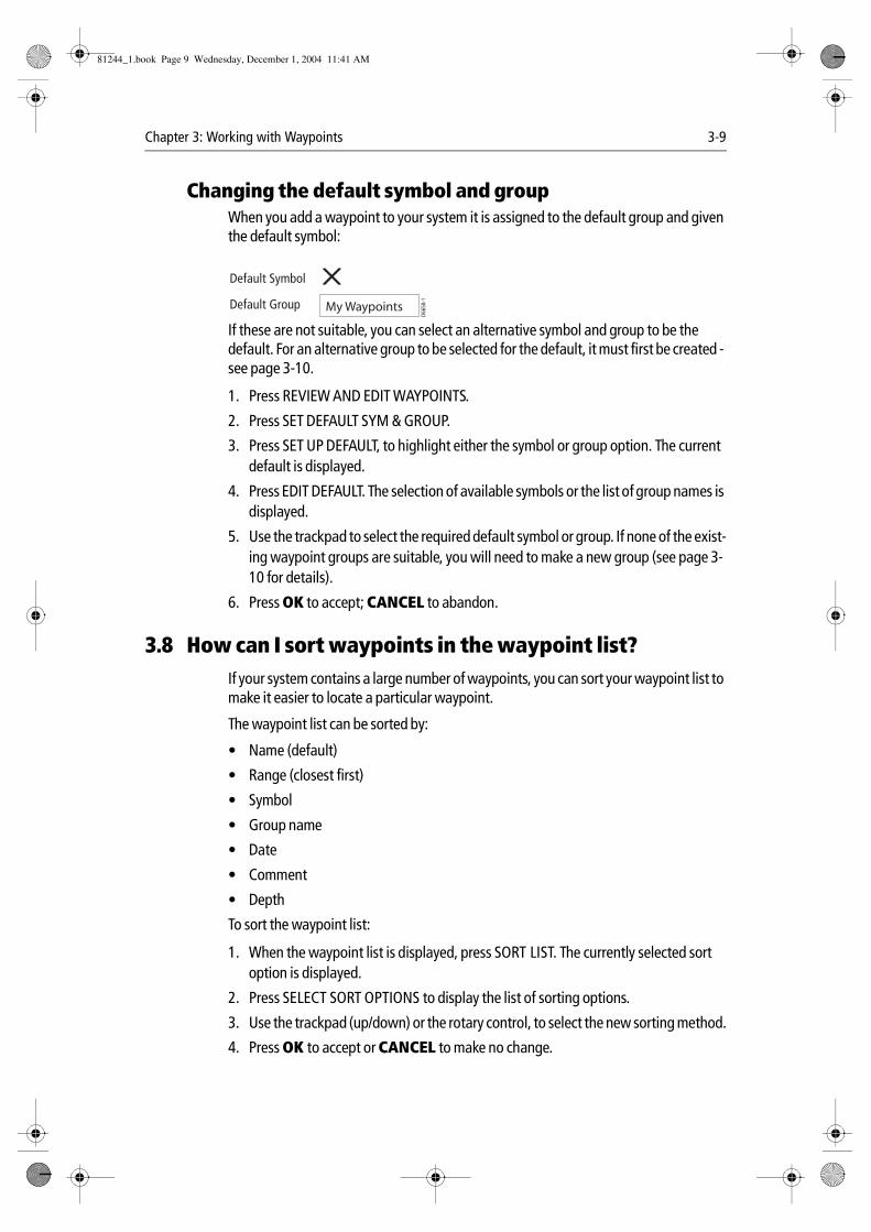
Changing the default symbol and groupWhen you add a waypoint to your system it is assigned to the default group and given the default symbol:
If these are not suitable, you can select an alternative symbol and group to be the default. For an alternative group to be selected for the default, it must first be created - see page 3-10.
1. Press REVIEW AND EDIT WAYPOINTS.
2. Press SET DEFAULT SYM & GROUP.
3. Press SET UP DEFAULT, to highlight either the symbol or group option. The current default is displayed.
4. Press EDIT DEFAULT. The selection of available symbols or the list of group names is displayed.
5. Use the trackpad to select the required default symbol or group. If none of the exist-ing waypoint groups are suitable, you will need to make a new group (see page 3-10 for details).
6. Press OK to accept; CANCEL to abandon.
3.8 How can I sort waypoints in the waypoint list?If your system contains a large number of waypoints, you can sort your waypoint list to make it easier to locate a particular waypoint.
The waypoint list can be sorted by:
• Name (default)
• Range (closest first)
• Symbol
• Group name
• Date
• Comment
• Depth
To sort the waypoint list:
1. When the waypoint list is displayed, press SORT LIST. The currently selected sort option is displayed.
2. Press SELECT SORT OPTIONS to display the list of sorting options.
3. Use the trackpad (up/down) or the rotary control, to select the new sorting method.
4. Press OK to accept or CANCEL to make no change.
D665
8-1
Default Symbol
Default Group My Waypoints
81244_1.book Page 9 Wednesday, December 1, 2004 11:41 AM
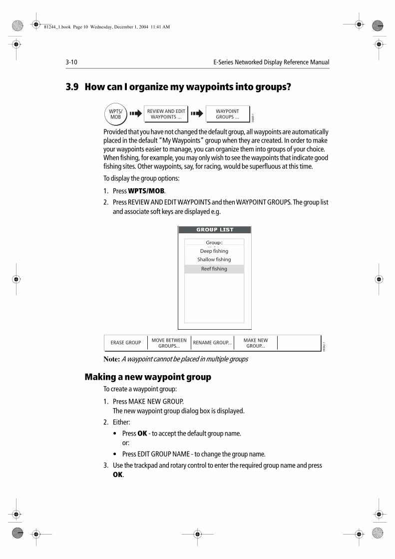
3-10 E-Series Networked Display Reference Manual
3.9 How can I organize my waypoints into groups?
Provided that you have not changed the default group, all waypoints are automatically placed in the default “My Waypoints” group when they are created. In order to make your waypoints easier to manage, you can organize them into groups of your choice. When fishing, for example, you may only wish to see the waypoints that indicate good fishing sites. Other waypoints, say, for racing, would be superfluous at this time.
To display the group options:
1. Press WPTS/MOB.
2. Press REVIEW AND EDIT WAYPOINTS and then WAYPOINT GROUPS. The group list and associate soft keys are displayed e.g.
Note: A waypoint cannot be placed in multiple groups
Making a new waypoint groupTo create a waypoint group:
1. Press MAKE NEW GROUP.The new waypoint group dialog box is displayed.
2. Either:
• Press OK - to accept the default group name.or:
• Press EDIT GROUP NAME - to change the group name.
3. Use the trackpad and rotary control to enter the required group name and press OK.
D688
5-1WPTS/
MOBREVIEW AND EDIT
WAYPOINTS ...WAYPOINTGROUPS ...
ERASE GROUP MOVE BETWEENGROUPS...
RENAME GROUP... MAKE NEWGROUP...
D65
62-1
Deep fishing
Shallow fishing
Reef fishing
81244_1.book Page 10 Wednesday, December 1, 2004 11:41 AM
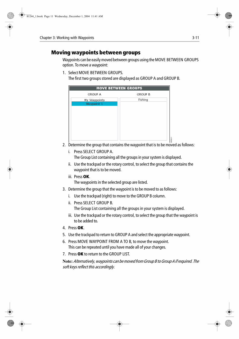
Chapter 3: Working with Waypoints 3-11
Moving waypoints between groupsWaypoints can be easily moved between groups using the MOVE BETWEEN GROUPS option. To move a waypoint:
1. Select MOVE BETWEEN GROUPS.The first two groups stored are displayed as GROUP A and GROUP B.
2. Determine the group that contains the waypoint that is to be moved as follows:
i. Press SELECT GROUP A.The Group List containing all the groups in your system is displayed.
ii. Use the trackpad or the rotary control, to select the group that contains the waypoint that is to be moved.
iii. Press OK.The waypoints in the selected group are listed.
3. Determine the group that the waypoint is to be moved to as follows:
i. Use the trackpad (right) to move to the GROUP B column.
ii. Press SELECT GROUP B.The Group List containing all the groups in your system is displayed.
iii. Use the trackpad or the rotary control, to select the group that the waypoint is to be added to.
4. Press OK.
5. Use the trackpad to return to GROUP A and select the appropriate waypoint.
6. Press MOVE WAYPOINT FROM A TO B, to move the waypoint.This can be repeated until you have made all of your changes.
7. Press OK to return to the GROUP LIST.
Note: Alternatively, waypoints can be moved from Group B to Group A if required. The soft keys reflect this accordingly.
D65
63-1
Fishing
81244_1.book Page 11 Wednesday, December 1, 2004 11:41 AM
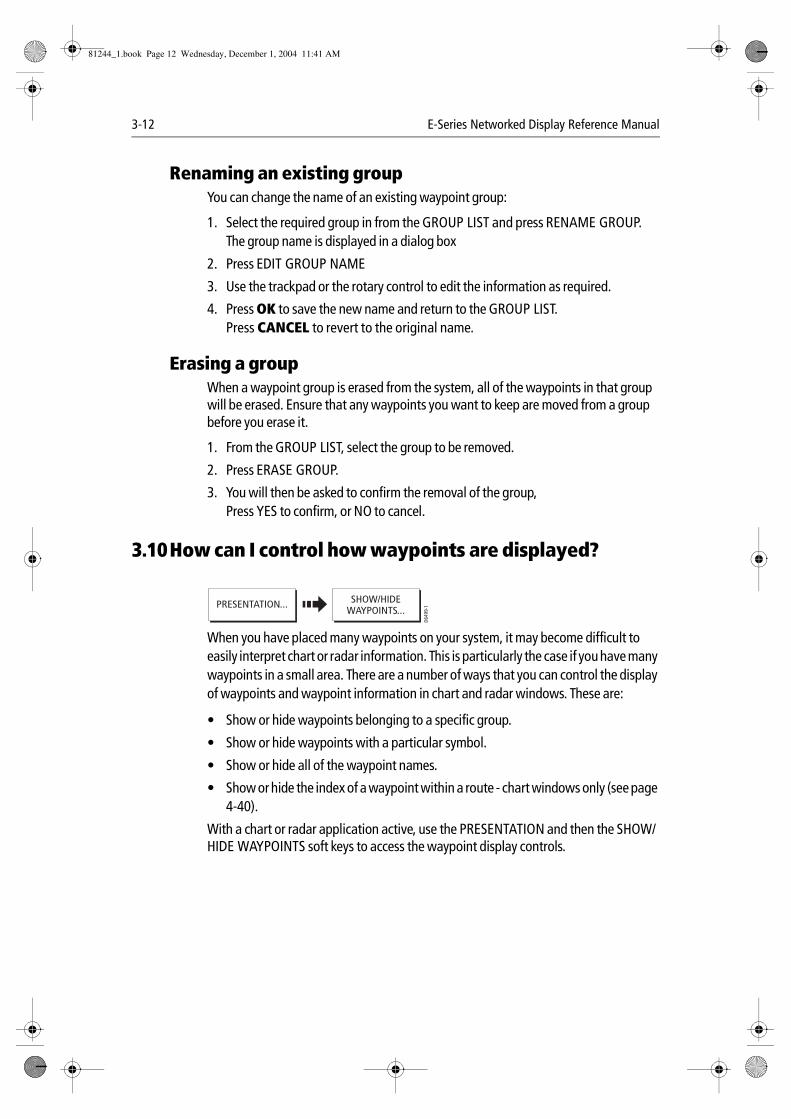
3-12 E-Series Networked Display Reference Manual
Renaming an existing groupYou can change the name of an existing waypoint group:
1. Select the required group in from the GROUP LIST and press RENAME GROUP.The group name is displayed in a dialog box
2. Press EDIT GROUP NAME
3. Use the trackpad or the rotary control to edit the information as required.
4. Press OK to save the new name and return to the GROUP LIST.Press CANCEL to revert to the original name.
Erasing a groupWhen a waypoint group is erased from the system, all of the waypoints in that group will be erased. Ensure that any waypoints you want to keep are moved from a group before you erase it.
1. From the GROUP LIST, select the group to be removed.
2. Press ERASE GROUP.
3. You will then be asked to confirm the removal of the group, Press YES to confirm, or NO to cancel.
3.10How can I control how waypoints are displayed?
When you have placed many waypoints on your system, it may become difficult to easily interpret chart or radar information. This is particularly the case if you have many waypoints in a small area. There are a number of ways that you can control the display of waypoints and waypoint information in chart and radar windows. These are:
• Show or hide waypoints belonging to a specific group.
• Show or hide waypoints with a particular symbol.
• Show or hide all of the waypoint names.
• Show or hide the index of a waypoint within a route - chart windows only (see page 4-40).
With a chart or radar application active, use the PRESENTATION and then the SHOW/HIDE WAYPOINTS soft keys to access the waypoint display controls.
D649
9-1
SHOW/HIDEWAYPOINTS...
PRESENTATION...
81244_1.book Page 12 Wednesday, December 1, 2004 11:41 AM
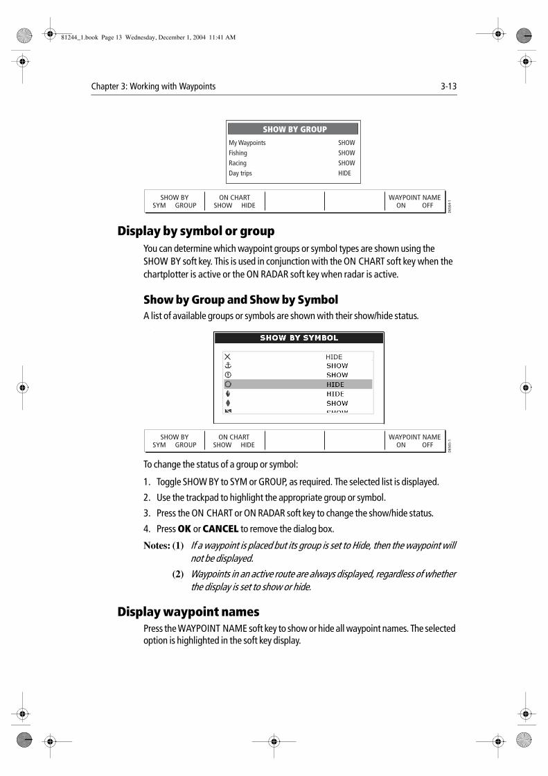
Chapter 3: Working with Waypoints 3-13
Display by symbol or groupYou can determine which waypoint groups or symbol types are shown using the SHOW BY soft key. This is used in conjunction with the ON CHART soft key when the chartplotter is active or the ON RADAR soft key when radar is active.
Show by Group and Show by SymbolA list of available groups or symbols are shown with their show/hide status. .
To change the status of a group or symbol:
1. Toggle SHOW BY to SYM or GROUP, as required. The selected list is displayed.
2. Use the trackpad to highlight the appropriate group or symbol.
3. Press the ON CHART or ON RADAR soft key to change the show/hide status.
4. Press OK or CANCEL to remove the dialog box.
Notes: (1) If a waypoint is placed but its group is set to Hide, then the waypoint will not be displayed.
(2) Waypoints in an active route are always displayed, regardless of whether the display is set to show or hide.
Display waypoint namesPress the WAYPOINT NAME soft key to show or hide all waypoint names. The selected option is highlighted in the soft key display.
My Waypoints SHOWFishing SHOWRacing SHOWDay trips HIDE
SHOW BY GROUP
SHOW BYSYM GROUP
ON CHARTSHOW HIDE
WAYPOINT NAMEON OFF
D65
64-1
SHOW BYSYM GROUP
ON CHARTSHOW HIDE
WAYPOINT NAMEON OFF
D65
65-1
HIDE
81244_1.book Page 13 Wednesday, December 1, 2004 11:41 AM

3-14 E-Series Networked Display Reference Manual
81244_1.book Page 14 Wednesday, December 1, 2004 11:41 AM
Chapter 4: Using the Chart 4-1
Chapter 4: Using the Chart
4.1 Important
Chart functionality1. To access full functionality, your chart application requires position and heading
data from your boat’s Global Positioning System (GPS).
2. Your E-Series Display has a built in world map, but to use your Display as a naviga-tion aid, you will need detailed information for the area you wish to navigate. This information comes in the form of a chart card and is available from Navionics (see the Important Information section at the front of this manual for details). For full information on installing and removing chart cards refer to page 2- 11. If you have a network of E-Series Displays, the chart card data is accessible from any Display on the network, provided that the unit with the card is powered on. Data from more than one chart card can be shown simultaneously.
3. For your GPS and chart to correlate accurately with your paper charts, they will need to be using the same datum. The default datum for your display is WGS1984. If this is not suitable, you can change the setting via the Chart Setup menu (see page 4-42). When you adjust the datum of the E-Series Display, a Raymarine GPS will automatically correlate. If you have a third party GPS, you will need to correlate this separately.
SafetyWhen using your chartplotter you should always check that a route is safe. Zoom in to check for hazards, such as small shoals, that may not be shown on a larger scale chart.
Until you are familiar with interpreting the chart display, you should take every opportunity to compare the displayed objects with visual targets, such as buoys and coastal structures. You should practice harbour and coastal navigation during daylight and in clear weather conditions. The simulator mode can also be used to help you gain experience.
It is strongly recommended that before you use your chart application, that you read and understand Chapter 3:Working with Waypoints.
CAUTION: The equipment should not be used as a substitute for good navigational practice nor for official government paper charts. Do not use the chart before you have read the chapter.
81244_1.book Page 1 Wednesday, December 1, 2004 11:41 AM
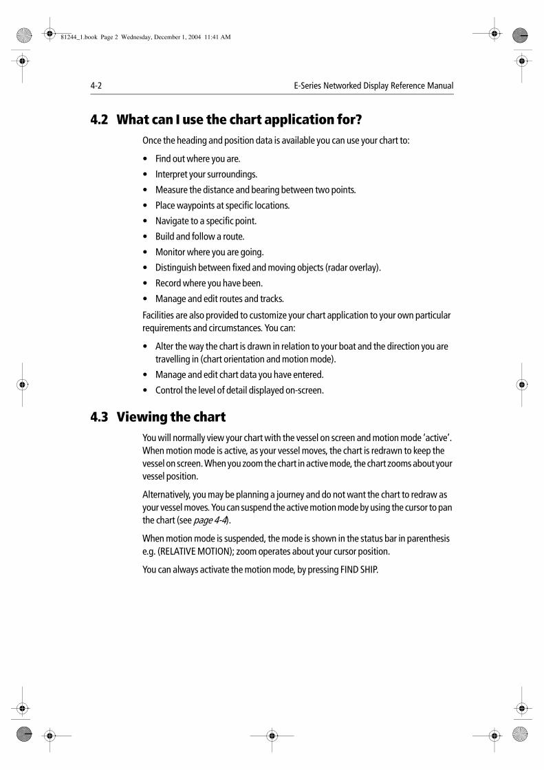
4-2 E-Series Networked Display Reference Manual
4.2 What can I use the chart application for?Once the heading and position data is available you can use your chart to:
• Find out where you are.
• Interpret your surroundings.
• Measure the distance and bearing between two points.
• Place waypoints at specific locations.
• Navigate to a specific point.
• Build and follow a route.
• Monitor where you are going.
• Distinguish between fixed and moving objects (radar overlay).
• Record where you have been.
• Manage and edit routes and tracks.
Facilities are also provided to customize your chart application to your own particular requirements and circumstances. You can:
• Alter the way the chart is drawn in relation to your boat and the direction you are travelling in (chart orientation and motion mode).
• Manage and edit chart data you have entered.
• Control the level of detail displayed on-screen.
4.3 Viewing the chartYou will normally view your chart with the vessel on screen and motion mode ‘active’. When motion mode is active, as your vessel moves, the chart is redrawn to keep the vessel on screen. When you zoom the chart in active mode, the chart zooms about your vessel position.
Alternatively, you may be planning a journey and do not want the chart to redraw as your vessel moves. You can suspend the active motion mode by using the cursor to pan the chart (see page 4-4).
When motion mode is suspended, the mode is shown in the status bar in parenthesis e.g. (RELATIVE MOTION); zoom operates about your cursor position.
You can always activate the motion mode, by pressing FIND SHIP.
81244_1.book Page 2 Wednesday, December 1, 2004 11:41 AM
Chapter 4: Using the Chart 4-3
4.4 The chart displayThe main features of the chart display are as follows:
4.5 Where am I on the chart?
Your current position is represented on screen by a boat symbol. If positional data has been selected for display (see page 11-2), your position will be displayed in the data bar under VES POS.
Note: If neither heading nor COG data is available, the vessel is shown as a solid circle.
If you cannot see your boat, press FIND SHIP. The chart is redrawn with your boat on screen. To change the amount of chart ahead of your boat see page 38.
To mark your current position with a waypoint, press WPTS/MOB twice. For more information on waypoints, please refer to the waypoint chapter.
FIND SHIP GOTO... ROUTES... TRACKS... PRESENTATION...
4nm North-Up (Relative Motion) Local
Gully Ridge
Creek point
Port point
Portside
Chart boundary
Chart range Chart orientation Motion mode
Status bar
Cursor
Route
Waypoint
Current position
Track
Cartographic object
Active waypoint
Soft keys
D660
5-1
Chart view
D6627-1 Boat symbol
81244_1.book Page 3 Wednesday, December 1, 2004 11:41 AM
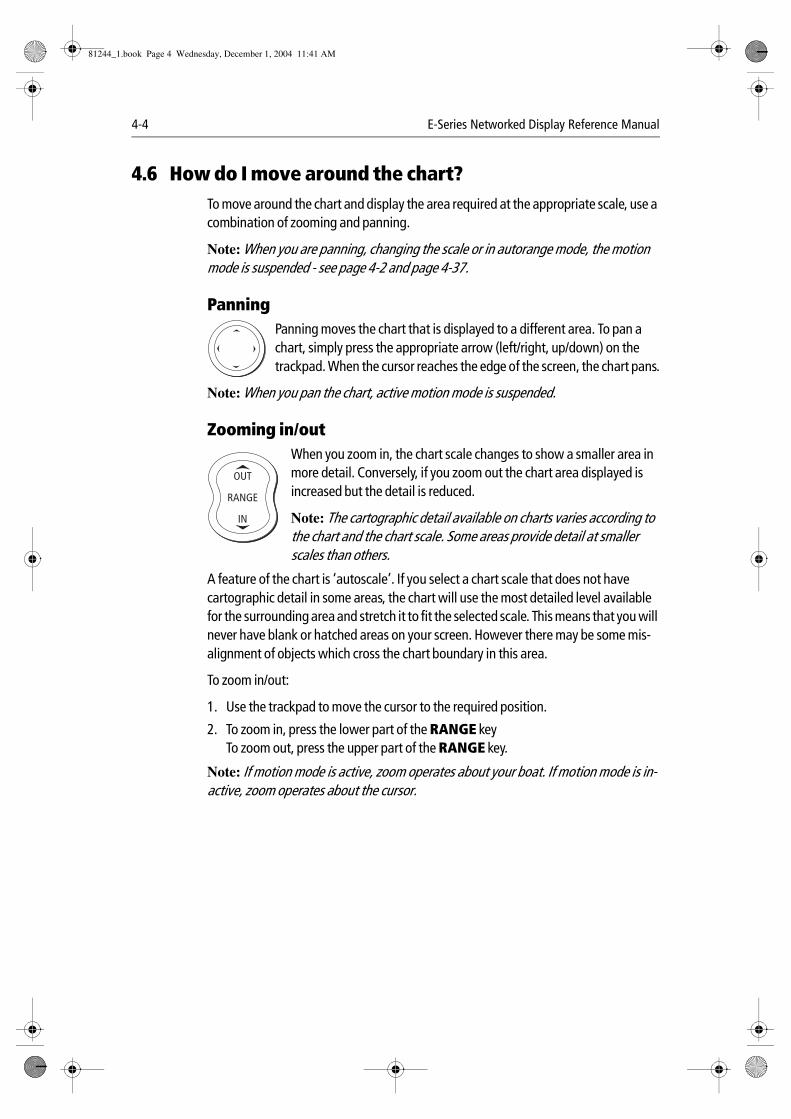
4-4 E-Series Networked Display Reference Manual
4.6 How do I move around the chart?To move around the chart and display the area required at the appropriate scale, use a combination of zooming and panning.
Note: When you are panning, changing the scale or in autorange mode, the motion mode is suspended - see page 4-2 and page 4-37.
Panning
Panning moves the chart that is displayed to a different area. To pan a chart, simply press the appropriate arrow (left/right, up/down) on the trackpad. When the cursor reaches the edge of the screen, the chart pans.
Note: When you pan the chart, active motion mode is suspended.
Zooming in/out
When you zoom in, the chart scale changes to show a smaller area in more detail. Conversely, if you zoom out the chart area displayed is increased but the detail is reduced.
Note: The cartographic detail available on charts varies according to the chart and the chart scale. Some areas provide detail at smaller scales than others.
A feature of the chart is ‘autoscale’. If you select a chart scale that does not have cartographic detail in some areas, the chart will use the most detailed level available for the surrounding area and stretch it to fit the selected scale. This means that you will never have blank or hatched areas on your screen. However there may be some mis-alignment of objects which cross the chart boundary in this area.
To zoom in/out:
1. Use the trackpad to move the cursor to the required position.
2. To zoom in, press the lower part of the RANGE keyTo zoom out, press the upper part of the RANGE key.
Note: If motion mode is active, zoom operates about your boat. If motion mode is in-active, zoom operates about the cursor.
D6583-2
D6585-1
RANGE
IN
OUT
81244_1.book Page 4 Wednesday, December 1, 2004 11:41 AM
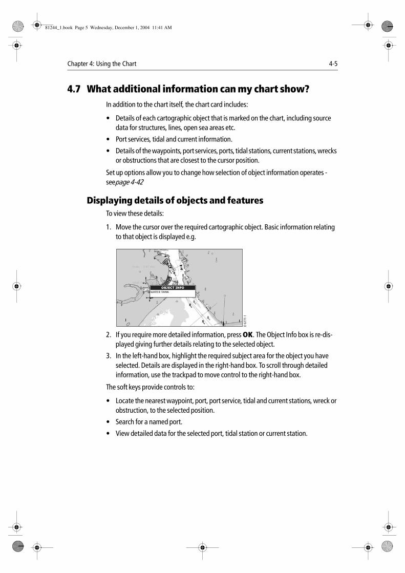
Chapter 4: Using the Chart 4-5
4.7 What additional information can my chart show?In addition to the chart itself, the chart card includes:
• Details of each cartographic object that is marked on the chart, including source data for structures, lines, open sea areas etc.
• Port services, tidal and current information.
• Details of the waypoints, port services, ports, tidal stations, current stations, wrecks or obstructions that are closest to the cursor position.
Set up options allow you to change how selection of object information operates - seepage 4-42
Displaying details of objects and featuresTo view these details:
1. Move the cursor over the required cartographic object. Basic information relating to that object is displayed e.g.
2. If you require more detailed information, press OK. The Object Info box is re-dis-played giving further details relating to the selected object.
3. In the left-hand box, highlight the required subject area for the object you have selected. Details are displayed in the right-hand box. To scroll through detailed information, use the trackpad to move control to the right-hand box.
The soft keys provide controls to:
• Locate the nearest waypoint, port, port service, tidal and current stations, wreck or obstruction, to the selected position.
• Search for a named port.
• View detailed data for the selected port, tidal station or current station.
D 67
71-1
81244_1.book Page 5 Wednesday, December 1, 2004 11:41 AM
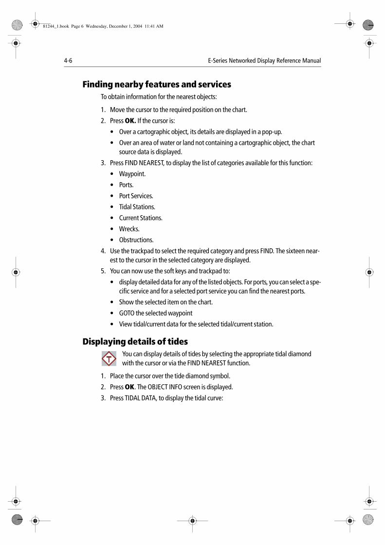
4-6 E-Series Networked Display Reference Manual
Finding nearby features and servicesTo obtain information for the nearest objects:
1. Move the cursor to the required position on the chart.
2. Press OK. If the cursor is:
• Over a cartographic object, its details are displayed in a pop-up.
• Over an area of water or land not containing a cartographic object, the chart source data is displayed.
3. Press FIND NEAREST, to display the list of categories available for this function:
• Waypoint.
• Ports.
• Port Services.
• Tidal Stations.
• Current Stations.
• Wrecks.
• Obstructions.
4. Use the trackpad to select the required category and press FIND. The sixteen near-est to the cursor in the selected category are displayed.
5. You can now use the soft keys and trackpad to:
• display detailed data for any of the listed objects. For ports, you can select a spe-cific service and for a selected port service you can find the nearest ports.
• Show the selected item on the chart.
• GOTO the selected waypoint
• View tidal/current data for the selected tidal/current station.
Displaying details of tides
You can display details of tides by selecting the appropriate tidal diamond with the cursor or via the FIND NEAREST function.
1. Place the cursor over the tide diamond symbol.
2. Press OK. The OBJECT INFO screen is displayed.
3. Press TIDAL DATA, to display the tidal curve:
D67
79_1
81244_1.book Page 6 Wednesday, December 1, 2004 11:41 AM
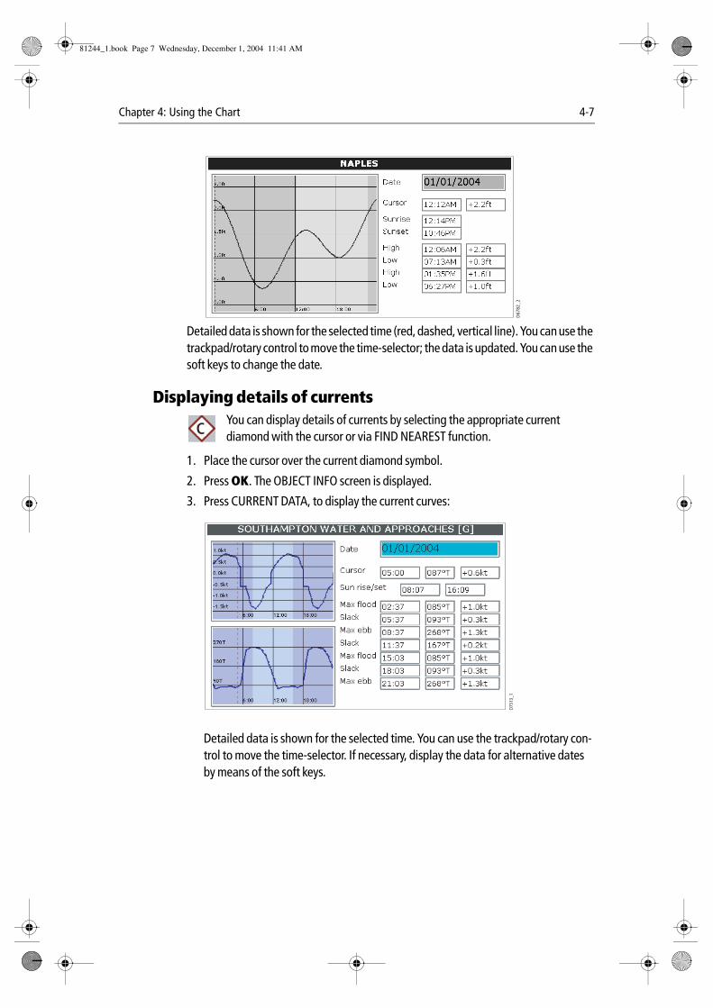
Chapter 4: Using the Chart 4-7
Detailed data is shown for the selected time (red, dashed, vertical line). You can use the trackpad/rotary control to move the time-selector; the data is updated. You can use the soft keys to change the date.
Displaying details of currents
You can display details of currents by selecting the appropriate current diamond with the cursor or via FIND NEAREST function.
1. Place the cursor over the current diamond symbol.
2. Press OK. The OBJECT INFO screen is displayed.
3. Press CURRENT DATA, to display the current curves:
Detailed data is shown for the selected time. You can use the trackpad/rotary con-trol to move the time-selector. If necessary, display the data for alternative dates by means of the soft keys.
D67
82_2
D75
11_1c
D751
3_1
81244_1.book Page 7 Wednesday, December 1, 2004 11:41 AM
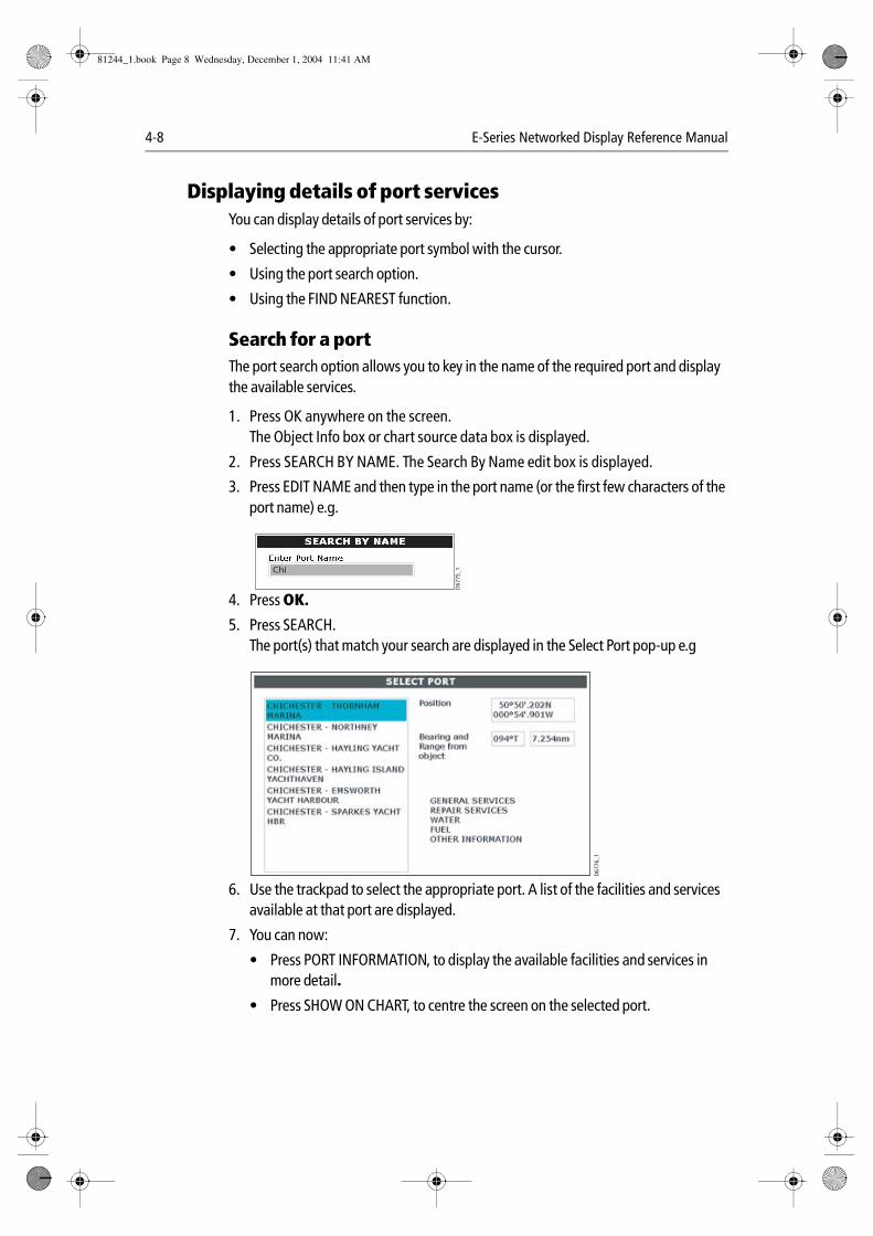
4-8 E-Series Networked Display Reference Manual
Displaying details of port servicesYou can display details of port services by:
• Selecting the appropriate port symbol with the cursor.
• Using the port search option.
• Using the FIND NEAREST function.
Search for a portThe port search option allows you to key in the name of the required port and display the available services.
1. Press OK anywhere on the screen.The Object Info box or chart source data box is displayed.
2. Press SEARCH BY NAME. The Search By Name edit box is displayed.
3. Press EDIT NAME and then type in the port name (or the first few characters of the port name) e.g.
4. Press OK.
5. Press SEARCH.The port(s) that match your search are displayed in the Select Port pop-up e.g
.
6. Use the trackpad to select the appropriate port. A list of the facilities and services available at that port are displayed.
7. You can now:
• Press PORT INFORMATION, to display the available facilities and services in more detail.
• Press SHOW ON CHART, to centre the screen on the selected port.
D67
75_1Chi
D67
76_1
81244_1.book Page 8 Wednesday, December 1, 2004 11:41 AM
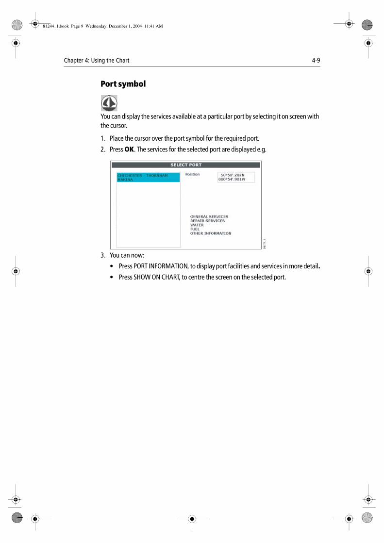
Chapter 4: Using the Chart 4-9
Port symbol
You can display the services available at a particular port by selecting it on screen with the cursor.
1. Place the cursor over the port symbol for the required port.
2. Press OK. The services for the selected port are displayed e.g.
3. You can now:
• Press PORT INFORMATION, to display port facilities and services in more detail.
• Press SHOW ON CHART, to centre the screen on the selected port.
D67
76_1
D67
77_1
81244_1.book Page 9 Wednesday, December 1, 2004 11:41 AM
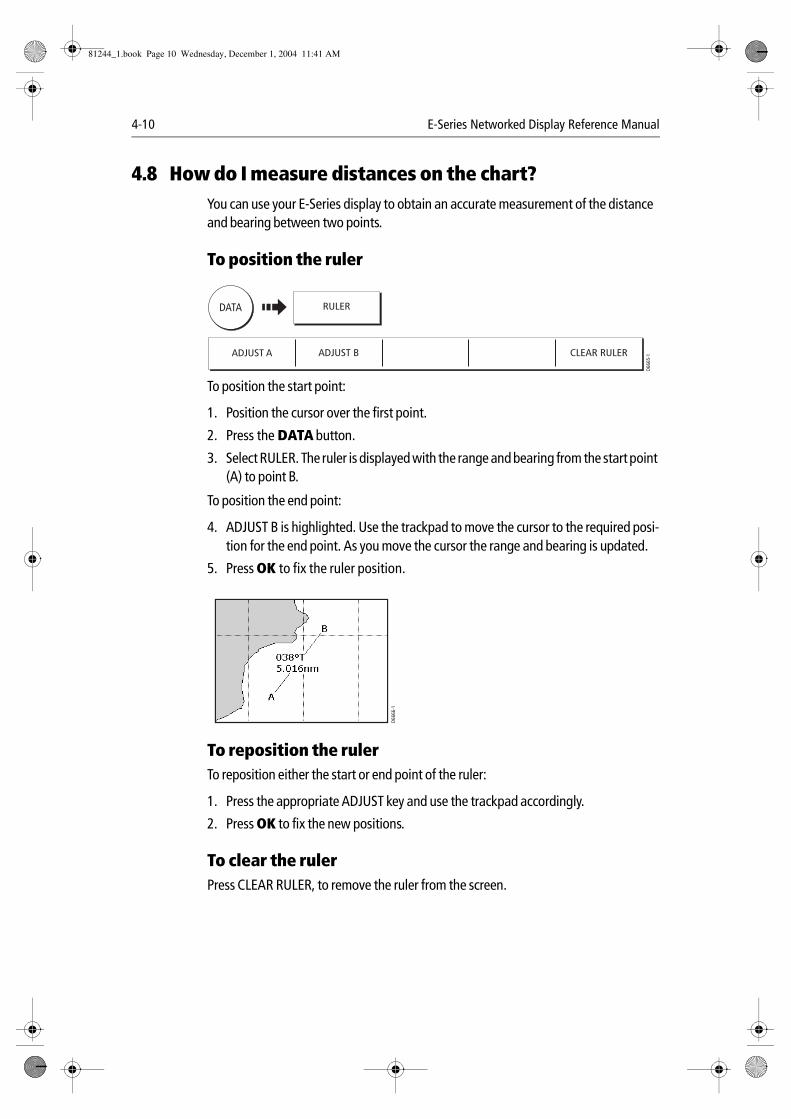
4-10 E-Series Networked Display Reference Manual
4.8 How do I measure distances on the chart?You can use your E-Series display to obtain an accurate measurement of the distance and bearing between two points.
To position the ruler
To position the start point:
1. Position the cursor over the first point.
2. Press the DATA button.
3. Select RULER. The ruler is displayed with the range and bearing from the start point (A) to point B.
To position the end point:
4. ADJUST B is highlighted. Use the trackpad to move the cursor to the required posi-tion for the end point. As you move the cursor the range and bearing is updated.
5. Press OK to fix the ruler position.
To reposition the rulerTo reposition either the start or end point of the ruler:
1. Press the appropriate ADJUST key and use the trackpad accordingly.
2. Press OK to fix the new positions.
To clear the rulerPress CLEAR RULER, to remove the ruler from the screen.
ADJUST A ADJUST B CLEAR RULER
D666
5-1
DATA RULER
D666
6-1
81244_1.book Page 10 Wednesday, December 1, 2004 11:41 AM
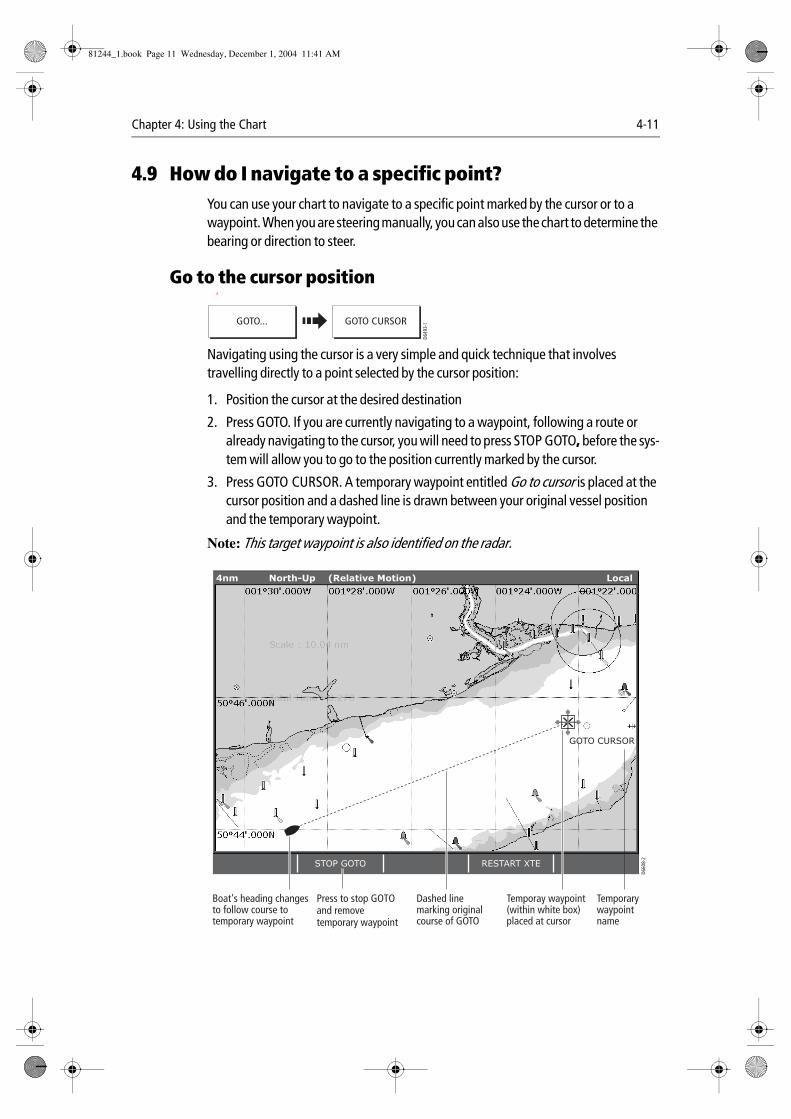
Chapter 4: Using the Chart 4-11
4.9 How do I navigate to a specific point?You can use your chart to navigate to a specific point marked by the cursor or to a waypoint. When you are steering manually, you can also use the chart to determine the bearing or direction to steer.
Go to the cursor position A
Navigating using the cursor is a very simple and quick technique that involves travelling directly to a point selected by the cursor position:
1. Position the cursor at the desired destination
2. Press GOTO. If you are currently navigating to a waypoint, following a route or already navigating to the cursor, you will need to press STOP GOTO, before the sys-tem will allow you to go to the position currently marked by the cursor.
3. Press GOTO CURSOR. A temporary waypoint entitled Go to cursor is placed at the cursor position and a dashed line is drawn between your original vessel position and the temporary waypoint.
Note: This target waypoint is also identified on the radar.
GOTO...
D649
3-1GOTO CURSOR
D660
8-2
GOTO CURSOR
STOP GOTO RESTART XTE
4nm North-Up (Relative Motion) Local
Boat's heading changes to follow course to temporary waypoint
Press to stop GOTO and remove temporary waypoint
Dashed line marking original course of GOTO
Temporay waypoint (within white box) placed at cursor
Temporary waypoint name
81244_1.book Page 11 Wednesday, December 1, 2004 11:41 AM
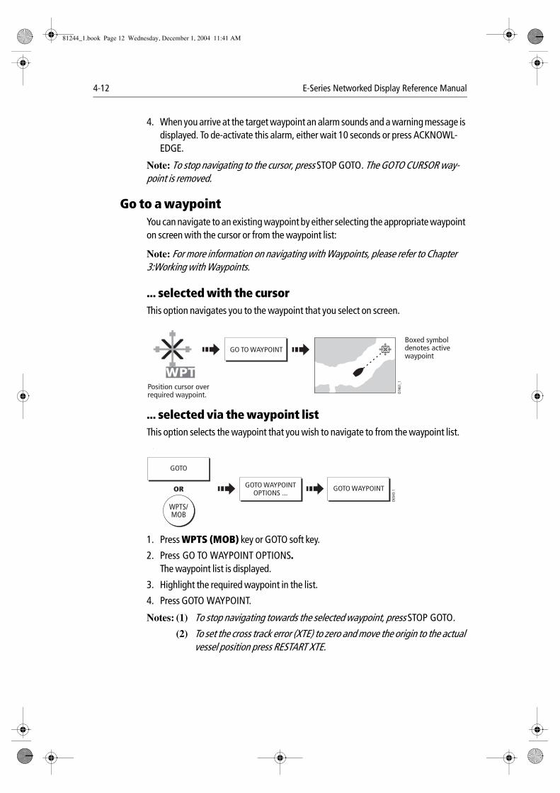
4-12 E-Series Networked Display Reference Manual
4. When you arrive at the target waypoint an alarm sounds and a warning message is displayed. To de-activate this alarm, either wait 10 seconds or press ACKNOWL-EDGE.
Note: To stop navigating to the cursor, press STOP GOTO. The GOTO CURSOR way-point is removed.
Go to a waypointYou can navigate to an existing waypoint by either selecting the appropriate waypoint on screen with the cursor or from the waypoint list:
Note: For more information on navigating with Waypoints, please refer to Chapter 3:Working with Waypoints.
... selected with the cursorThis option navigates you to the waypoint that you select on screen.
... selected via the waypoint listThis option selects the waypoint that you wish to navigate to from the waypoint list. :
1. Press WPTS (MOB) key or GOTO soft key.
2. Press GO TO WAYPOINT OPTIONS.The waypoint list is displayed.
3. Highlight the required waypoint in the list.
4. Press GOTO WAYPOINT.
Notes: (1) To stop navigating towards the selected waypoint, press STOP GOTO.
(2) To set the cross track error (XTE) to zero and move the origin to the actual vessel position press RESTART XTE.
GO TO WAYPOINT
D746
1_1
WPTPosition cursor over required waypoint.
Boxed symbol denotes active waypoint
WPTS/MOB
D654
3-1
GOTO WAYPOINTOPTIONS ...
GOTO WAYPOINT
GOTO
OR
81244_1.book Page 12 Wednesday, December 1, 2004 11:41 AM
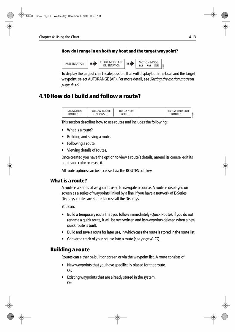
Chapter 4: Using the Chart 4-13
How do I range in on both my boat and the target waypoint?
To display the largest chart scale possible that will display both the boat and the target waypoint, select AUTORANGE (AR). For more detail, see Setting the motion mode on page 4-37.
4.10How do I build and follow a route?
This section describes how to use routes and includes the following:
• What is a route?
• Building and saving a route.
• Following a route.
• Viewing details of routes.
Once created you have the option to view a route’s details, amend its course, edit its name and color or erase it.
All route options can be accessed via the ROUTES soft key.
What is a route?A route is a series of waypoints used to navigate a course. A route is displayed on screen as a series of waypoints linked by a line. If you have a network of E-Series Displays, routes are shared across all the Displays.
You can:
• Build a temporary route that you follow immediately (Quick Route). If you do not rename a quick route, it will be overwritten and its waypoints deleted when a new quick route is built.
• Build and save a route for later use, in which case the route is stored in the route list.
• Convert a track of your course into a route (see page 4- 27).
Building a routeRoutes can either be built on screen or via the waypoint list. A route consists of:
• New waypoints that you have specifically placed for that route.Or:
• Existing waypoints that are already stored in the system.Or:
PRESENTATION
D750
9-1
MOTION MODECHART MODE ANDORIENTATION AR
SHOW/HIDEROUTES ...
FOLLOW ROUTEOPTIONS ...
BUILD NEWROUTE ...
REVIEW AND EDITROUTES ...
D65
34-1
81244_1.book Page 13 Wednesday, December 1, 2004 11:41 AM
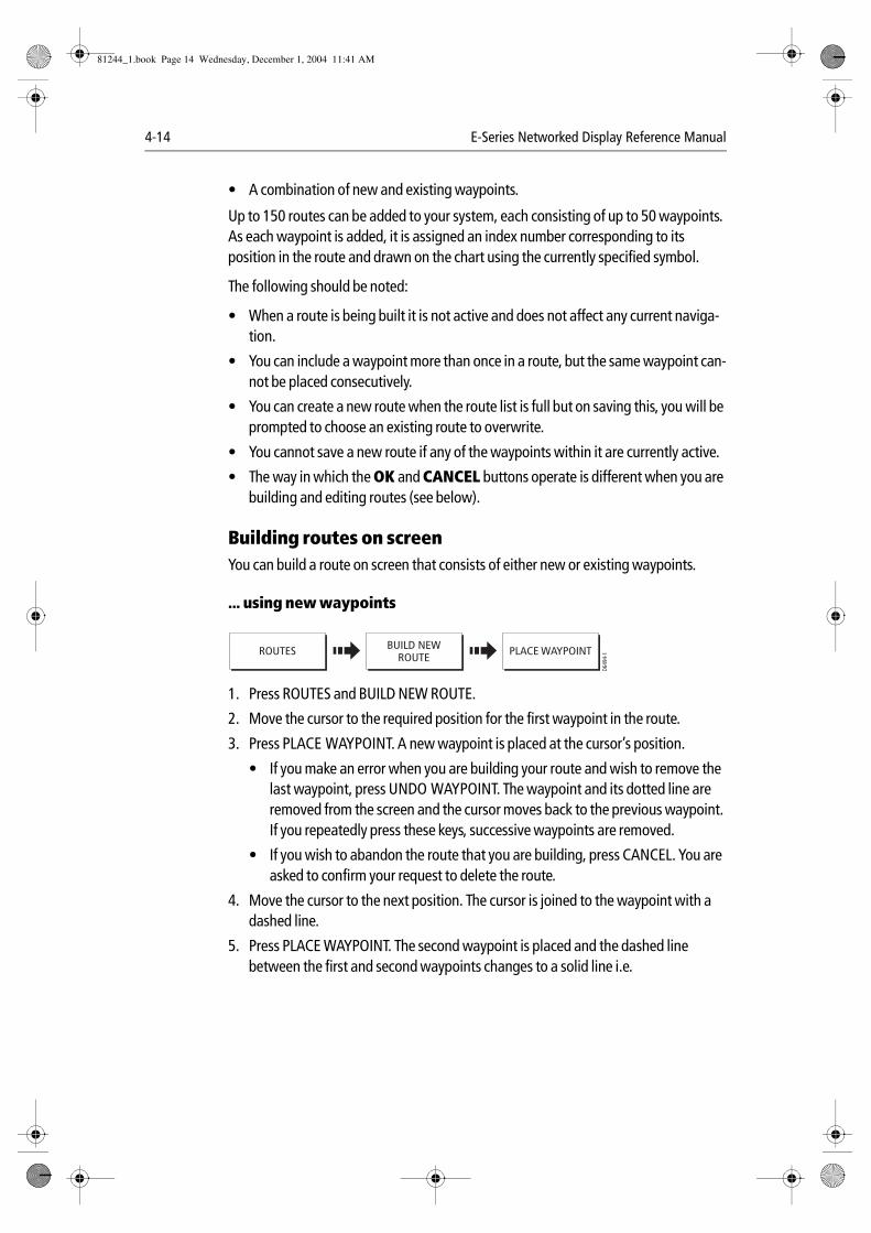
4-14 E-Series Networked Display Reference Manual
• A combination of new and existing waypoints.
Up to 150 routes can be added to your system, each consisting of up to 50 waypoints. As each waypoint is added, it is assigned an index number corresponding to its position in the route and drawn on the chart using the currently specified symbol.
The following should be noted:
• When a route is being built it is not active and does not affect any current naviga-tion.
• You can include a waypoint more than once in a route, but the same waypoint can-not be placed consecutively.
• You can create a new route when the route list is full but on saving this, you will be prompted to choose an existing route to overwrite.
• You cannot save a new route if any of the waypoints within it are currently active.
• The way in which the OK and CANCEL buttons operate is different when you are building and editing routes (see below).
Building routes on screenYou can build a route on screen that consists of either new or existing waypoints.
... using new waypoints
1. Press ROUTES and BUILD NEW ROUTE.
2. Move the cursor to the required position for the first waypoint in the route.
3. Press PLACE WAYPOINT. A new waypoint is placed at the cursor’s position.
• If you make an error when you are building your route and wish to remove the last waypoint, press UNDO WAYPOINT. The waypoint and its dotted line are removed from the screen and the cursor moves back to the previous waypoint. If you repeatedly press these keys, successive waypoints are removed.
• If you wish to abandon the route that you are building, press CANCEL. You are asked to confirm your request to delete the route.
4. Move the cursor to the next position. The cursor is joined to the waypoint with a dashed line.
5. Press PLACE WAYPOINT. The second waypoint is placed and the dashed line between the first and second waypoints changes to a solid line i.e.
ROUTES
D649
4-1PLACE WAYPOINTBUILD NEW
ROUTE
81244_1.book Page 14 Wednesday, December 1, 2004 11:41 AM
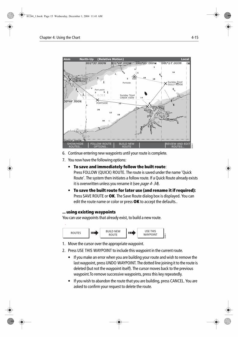
Chapter 4: Using the Chart 4-15
6. Continue entering new waypoints until your route is complete.
7. You now have the following options:
• To save and immediately follow the built route:Press FOLLOW (QUICK) ROUTE. The route is saved under the name ‘Quick Route’. The system then initiates a follow route. If a Quick Route already exists it is overwritten unless you rename it (see page 4- 34).
• To save the built route for later use (and rename it if required):Press SAVE ROUTE or OK. The Save Route dialog box is displayed. You can edit the route name or color or press OK to accept the defaults..
... using existing waypointsYou can use waypoints that already exist, to build a new route. A
1. Move the cursor over the appropriate waypoint.
2. Press USE THIS WAYPOINT to include this waypoint in the current route.
• If you make an error when you are building your route and wish to remove the last waypoint, press UNDO WAYPOINT. The dotted line joining it to the route is deleted (but not the waypoint itself). The cursor moves back to the previous waypoint.To remove successive waypoints, press this key repeatedly.
• If you wish to abandon the route that you are building, press CANCEL. You are asked to confirm your request to delete the route.
Sunday Trip#GULLY RIDGE
Sunday Trip#PORT POINT
Sunday Trip#CREEK VIEW
CREEK POINT
PORTSIDE
Port point
Portside
D654
6-1
RTE
SHOW/HIDEROUTES…
FOLLOW ROUTEOPTIONS…
BUILD NEWROUTE
REVIEW AND EDITROUTES…
4nm North-Up (Relative Motion) Local
ROUTES
D649
6-1
BUILD NEWROUTE
USE THISWAYPOINT
81244_1.book Page 15 Wednesday, December 1, 2004 11:41 AM
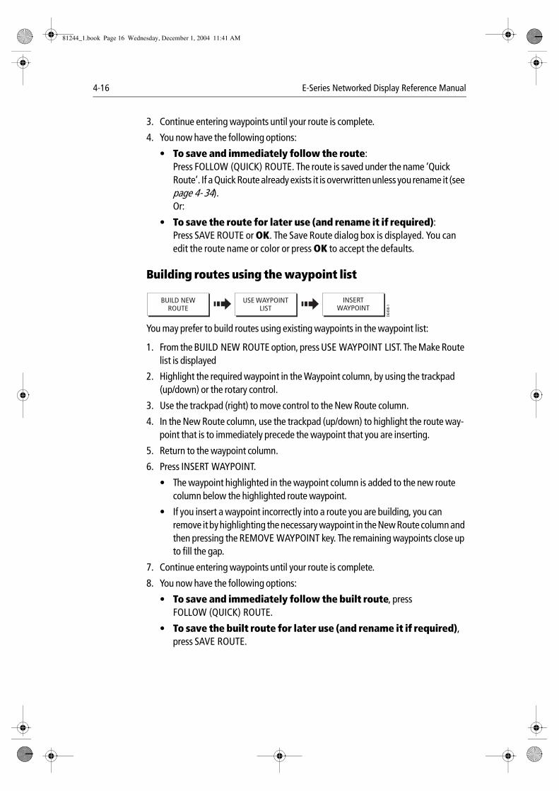
4-16 E-Series Networked Display Reference Manual
3. Continue entering waypoints until your route is complete.
4. You now have the following options:
• To save and immediately follow the route:Press FOLLOW (QUICK) ROUTE. The route is saved under the name ‘Quick Route’. If a Quick Route already exists it is overwritten unless you rename it (see page 4- 34). Or:
• To save the route for later use (and rename it if required):Press SAVE ROUTE or OK. The Save Route dialog box is displayed. You can edit the route name or color or press OK to accept the defaults.
Building routes using the waypoint list :
You may prefer to build routes using existing waypoints in the waypoint list:
1. From the BUILD NEW ROUTE option, press USE WAYPOINT LIST. The Make Route list is displayed
2. Highlight the required waypoint in the Waypoint column, by using the trackpad (up/down) or the rotary control.
3. Use the trackpad (right) to move control to the New Route column.
4. In the New Route column, use the trackpad (up/down) to highlight the route way-point that is to immediately precede the waypoint that you are inserting.
5. Return to the waypoint column.
6. Press INSERT WAYPOINT.
• The waypoint highlighted in the waypoint column is added to the new route column below the highlighted route waypoint.
• If you insert a waypoint incorrectly into a route you are building, you can remove it by highlighting the necessary waypoint in the New Route column and then pressing the REMOVE WAYPOINT key. The remaining waypoints close up to fill the gap.
7. Continue entering waypoints until your route is complete.
8. You now have the following options:
• To save and immediately follow the built route, press FOLLOW (QUICK) ROUTE.
• To save the built route for later use (and rename it if required), press SAVE ROUTE.
D649
8-1
USE WAYPOINTLIST
INSERTWAYPOINT
BUILD NEWROUTE
81244_1.book Page 16 Wednesday, December 1, 2004 11:41 AM
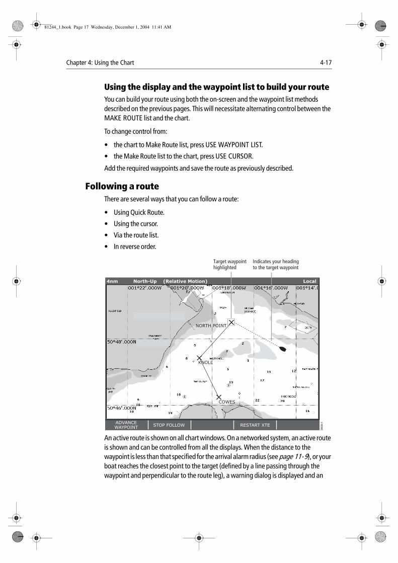
Chapter 4: Using the Chart 4-17
Using the display and the waypoint list to build your routeYou can build your route using both the on-screen and the waypoint list methods described on the previous pages. This will necessitate alternating control between the MAKE ROUTE list and the chart.
To change control from:
• the chart to Make Route list, press USE WAYPOINT LIST.
• the Make Route list to the chart, press USE CURSOR.
Add the required waypoints and save the route as previously described.
Following a routeThere are several ways that you can follow a route:
• Using Quick Route.
• Using the cursor.
• Via the route list.
• In reverse order.
An active route is shown on all chart windows. On a networked system, an active route is shown and can be controlled from all the displays. When the distance to the waypoint is less than that specified for the arrival alarm radius (see page 11- 9), or your boat reaches the closest point to the target (defined by a line passing through the waypoint and perpendicular to the route leg), a warning dialog is displayed and an
NORTH POINT
KNOLL
COWES
4nm North-Up (Relative Motion) Local
D660
6-1ADVANCE
WAYPOINTSTOP FOLLOW RESTART XTE
Target waypoint highlighted
Indicates your heading to the target waypoint
81244_1.book Page 17 Wednesday, December 1, 2004 11:41 AM
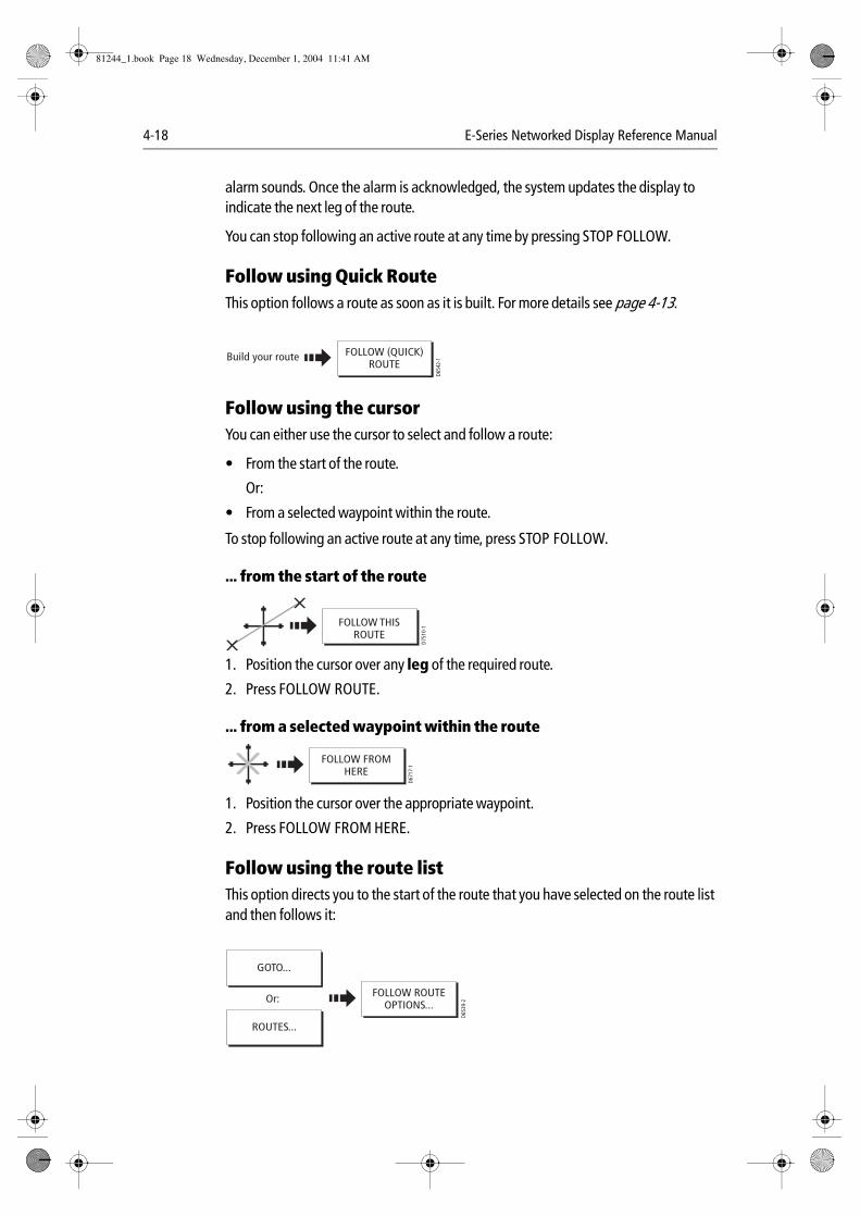
4-18 E-Series Networked Display Reference Manual
alarm sounds. Once the alarm is acknowledged, the system updates the display to indicate the next leg of the route.
You can stop following an active route at any time by pressing STOP FOLLOW.
Follow using Quick RouteThis option follows a route as soon as it is built. For more details see page 4-13.
Follow using the cursorYou can either use the cursor to select and follow a route:
• From the start of the route.
Or:
• From a selected waypoint within the route.
To stop following an active route at any time, press STOP FOLLOW.
... from the start of the route
1. Position the cursor over any leg of the required route.
2. Press FOLLOW ROUTE.
... from a selected waypoint within the route
1. Position the cursor over the appropriate waypoint.
2. Press FOLLOW FROM HERE.
Follow using the route listThis option directs you to the start of the route that you have selected on the route list and then follows it:
D654
2-1Build your route FOLLOW (QUICK)
ROUTE
FOLLOW THISROUTE
D751
0-1
FOLLOW FROMHERE
D671
7-1
D653
9-2
FOLLOW ROUTEOPTIONS...
ROUTES...
GOTO...
Or:
81244_1.book Page 18 Wednesday, December 1, 2004 11:41 AM
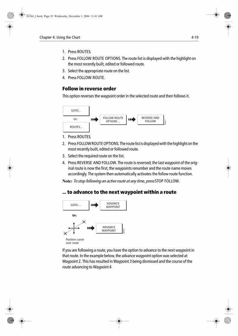
Chapter 4: Using the Chart 4-19
1. Press ROUTES.
2. Press FOLLOW ROUTE OPTIONS. The route list is displayed with the highlight on the most recently built, edited or followed route.
3. Select the appropriate route on the list.
4. Press FOLLOW ROUTE.
Follow in reverse orderThis option reverses the waypoint order in the selected route and then follows it.
1. Press ROUTES.
2. Press FOLLOW ROUTE OPTIONS. The route list is displayed with the highlight on the most recently built, edited or followed route.
3. Select the required route on the list.
4. Press REVERSE AND FOLLOW. The route is reversed; the last waypoint of the orig-inal route is now the first, the waypoints renumber and the route name moves accordingly. The system then automatically activates the follow route function.
Note: To stop following an active route at any time, press STOP FOLLOW.
... to advance to the next waypoint within a route
If you are following a route, you have the option to advance to the next waypoint in that route. In the example below, the advance waypoint option was selected at Waypoint 2. This has resulted in Waypoint 3 being dismissed and the course of the route advancing to Waypoint 4
D687
8-2
FOLLOW ROUTEOPTIONS ...
REVERSE ANDFOLLOW
ROUTES...
GOTO...
Or:D6
499-
2
ADVANCEWAYPOINT
GOTO…
ADVANCEWAYPOINT
Position cursor over route
Or:
81244_1.book Page 19 Wednesday, December 1, 2004 11:41 AM
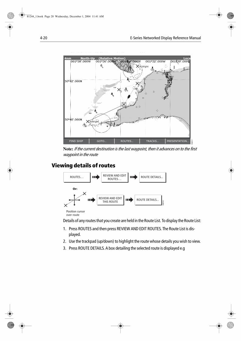
4-20 E-Series Networked Display Reference Manual
Note: If the current destination is the last waypoint, then it advances on to the first waypoint in the route
Viewing details of routes
Details of any routes that you create are held in the Route List. To display the Route List:
1. Press ROUTES and then press REVIEW AND EDIT ROUTES. The Route List is dis-played.
2. Use the trackpad (up/down) to highlight the route whose details you wish to view.
3. Press ROUTE DETAILS. A box detailing the selected route is displayed e.g
D660
3-1
2
3
4
W.Wight1
W.Wight5
FIND SHIP GOTO… ROUTES… TRACKS… PRESENTATION…
4nm North-Up (Relative Motion) Local
D687
6-2
REVIEW AND EDITROUTES…
ROUTE DETAILS... ROUTES…
Position cursor over route
Or:
REVIEW AND EDITTHIS ROUTE
ROUTE DETAILS...
81244_1.book Page 20 Wednesday, December 1, 2004 11:41 AM
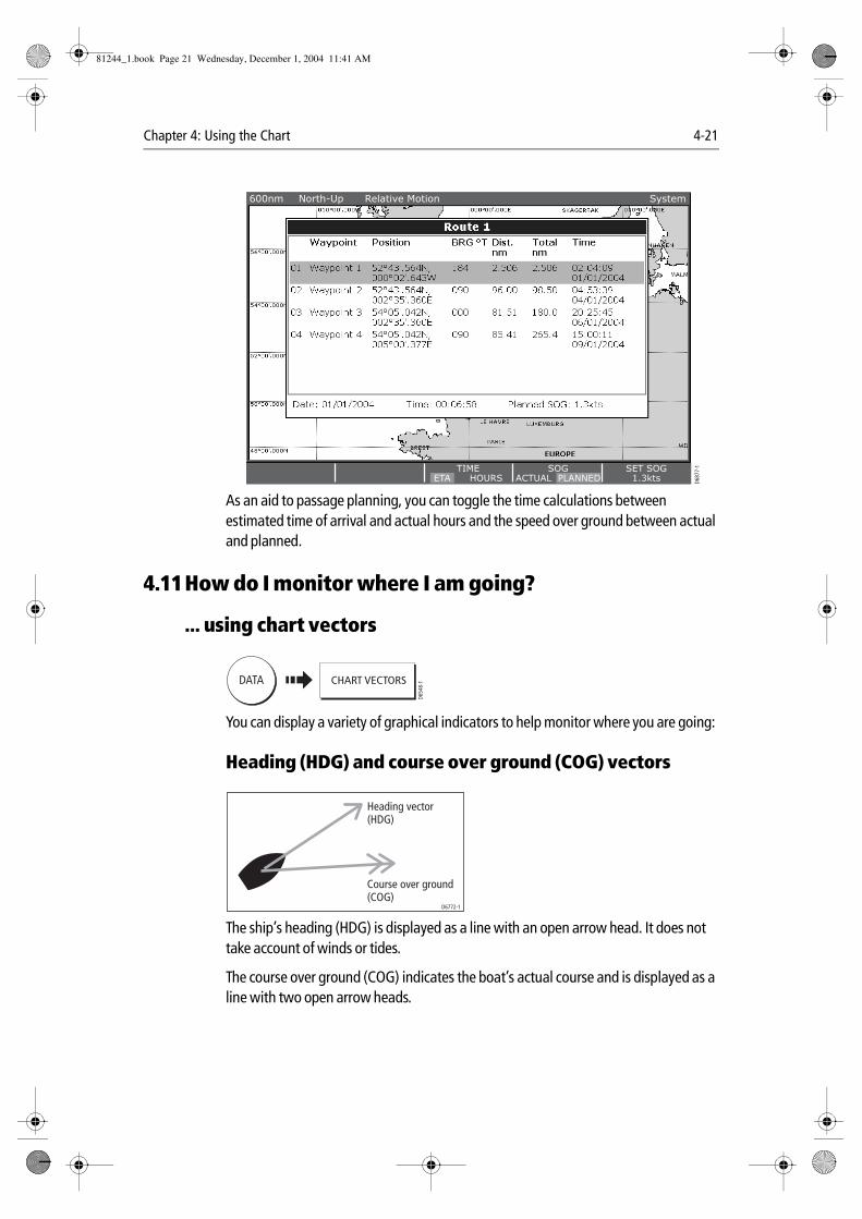
Chapter 4: Using the Chart 4-21
As an aid to passage planning, you can toggle the time calculations between estimated time of arrival and actual hours and the speed over ground between actual and planned.
4.11How do I monitor where I am going?
... using chart vectors
You can display a variety of graphical indicators to help monitor where you are going:
Heading (HDG) and course over ground (COG) vectors
The ship’s heading (HDG) is displayed as a line with an open arrow head. It does not take account of winds or tides.
The course over ground (COG) indicates the boat’s actual course and is displayed as a line with two open arrow heads.
D687
7-1SET SOG
1.3ktsTIME
ETA HOURSSOG
ACTUAL PLANNED
600nm North-Up Relative Motion System
DATA
D654
8-1CHART VECTORS
D6772-1
Heading vector(HDG)
Course over ground(COG)
81244_1.book Page 21 Wednesday, December 1, 2004 11:41 AM
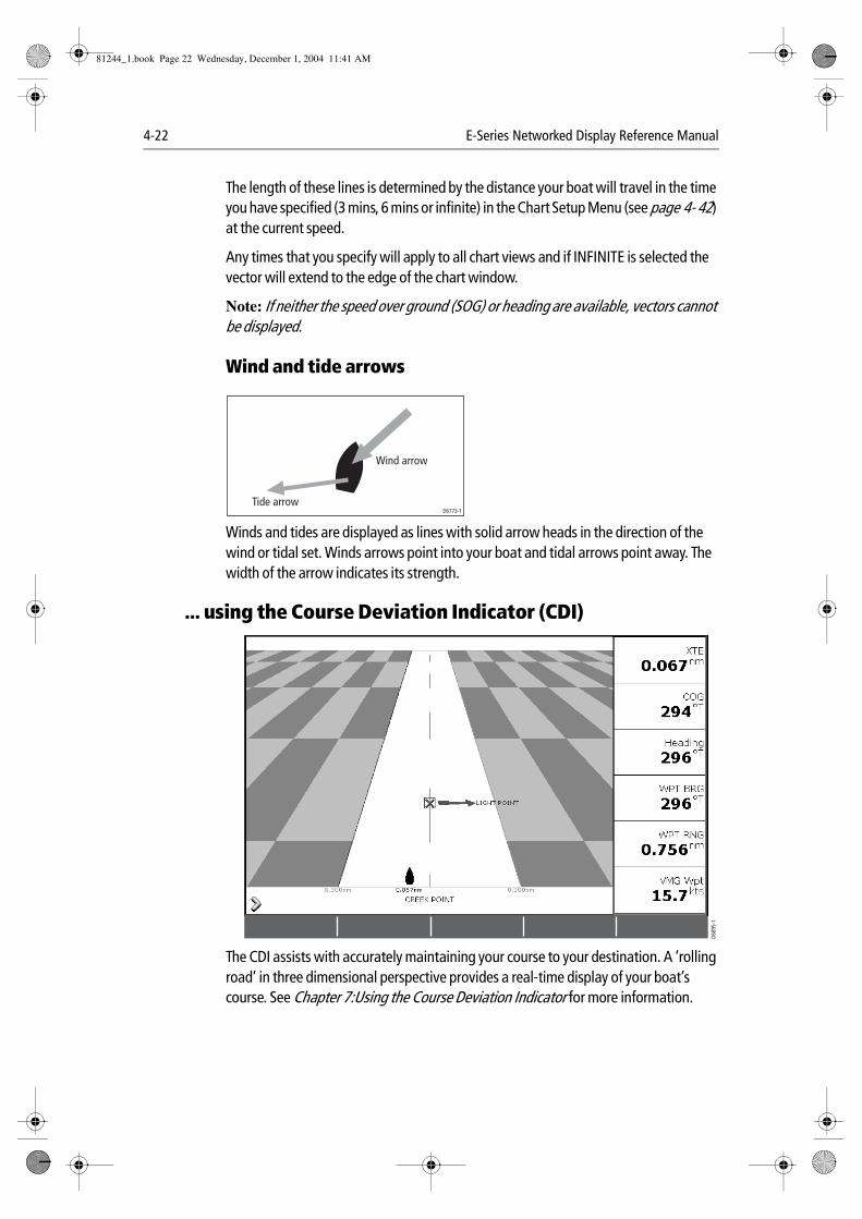
4-22 E-Series Networked Display Reference Manual
The length of these lines is determined by the distance your boat will travel in the time you have specified (3 mins, 6 mins or infinite) in the Chart Setup Menu (see page 4- 42) at the current speed.
Any times that you specify will apply to all chart views and if INFINITE is selected the vector will extend to the edge of the chart window.
Note: If neither the speed over ground (SOG) or heading are available, vectors cannot be displayed.
Wind and tide arrows
Winds and tides are displayed as lines with solid arrow heads in the direction of the wind or tidal set. Winds arrows point into your boat and tidal arrows point away. The width of the arrow indicates its strength.
... using the Course Deviation Indicator (CDI)
The CDI assists with accurately maintaining your course to your destination. A ‘rolling road’ in three dimensional perspective provides a real-time display of your boat’s course. See Chapter 7:Using the Course Deviation Indicator for more information.
D6773-1Tide arrow
Wind arrow
D689
5-1
81244_1.book Page 22 Wednesday, December 1, 2004 11:41 AM
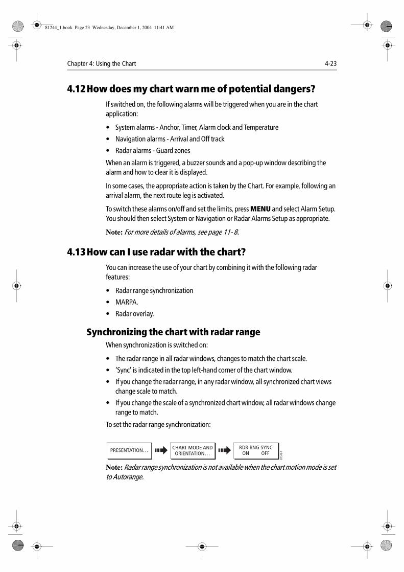
Chapter 4: Using the Chart 4-23
4.12How does my chart warn me of potential dangers?If switched on, the following alarms will be triggered when you are in the chart application:
• System alarms - Anchor, Timer, Alarm clock and Temperature
• Navigation alarms - Arrival and Off track
• Radar alarms - Guard zones
When an alarm is triggered, a buzzer sounds and a pop-up window describing the alarm and how to clear it is displayed.
In some cases, the appropriate action is taken by the Chart. For example, following an arrival alarm, the next route leg is activated.
To switch these alarms on/off and set the limits, press MENU and select Alarm Setup. You should then select System or Navigation or Radar Alarms Setup as appropriate.
Note: For more details of alarms, see page 11- 8.
4.13How can I use radar with the chart?You can increase the use of your chart by combining it with the following radar features:
• Radar range synchronization
• MARPA.
• Radar overlay.
Synchronizing the chart with radar rangeWhen synchronization is switched on:
• The radar range in all radar windows, changes to match the chart scale.
• ‘Sync’ is indicated in the top left-hand corner of the chart window.
• If you change the radar range, in any radar window, all synchronized chart views change scale to match.
• If you change the scale of a synchronized chart window, all radar windows change range to match.
To set the radar range synchronization:
Note: Radar range synchronization is not available when the chart motion mode is set to Autorange.
D757
8-1
CHART MODE ANDORIENTATION…
RDR RNG SYNCON OFFPRESENTATION…
81244_1.book Page 23 Wednesday, December 1, 2004 11:41 AM
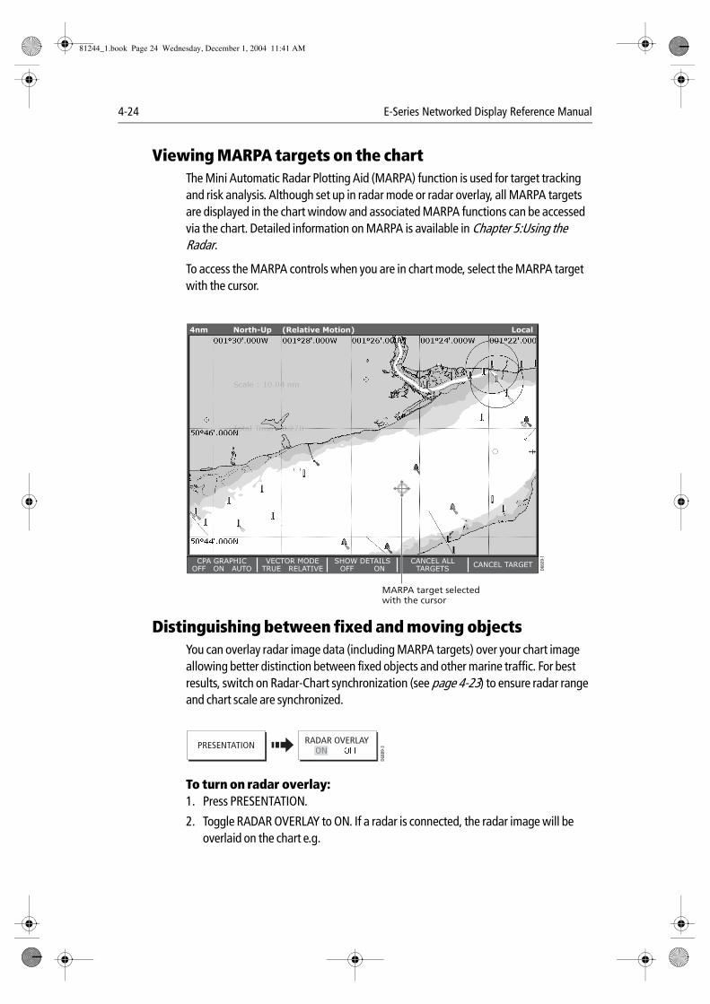
4-24 E-Series Networked Display Reference Manual
Viewing MARPA targets on the chartThe Mini Automatic Radar Plotting Aid (MARPA) function is used for target tracking and risk analysis. Although set up in radar mode or radar overlay, all MARPA targets are displayed in the chart window and associated MARPA functions can be accessed via the chart. Detailed information on MARPA is available in Chapter 5:Using the Radar.
To access the MARPA controls when you are in chart mode, select the MARPA target with the cursor.
Distinguishing between fixed and moving objectsYou can overlay radar image data (including MARPA targets) over your chart image allowing better distinction between fixed objects and other marine traffic. For best results, switch on Radar-Chart synchronization (see page 4-23) to ensure radar range and chart scale are synchronized.
To turn on radar overlay:1. Press PRESENTATION.
2. Toggle RADAR OVERLAY to ON. If a radar is connected, the radar image will be overlaid on the chart e.g.
D660
9-1
4nm North-Up (Relative Motion) Local
CPA GRAPHICOFF ON AUTO
VECTOR MODETRUE RELATIVE
SHOW DETAILSOFF ON
CANCEL ALLTARGETS
CANCEL TARGET
MARPA target selectedwith the cursor
PRESENTATION RADAR OVERLAY
D688
9-3
ON
81244_1.book Page 24 Wednesday, December 1, 2004 11:41 AM
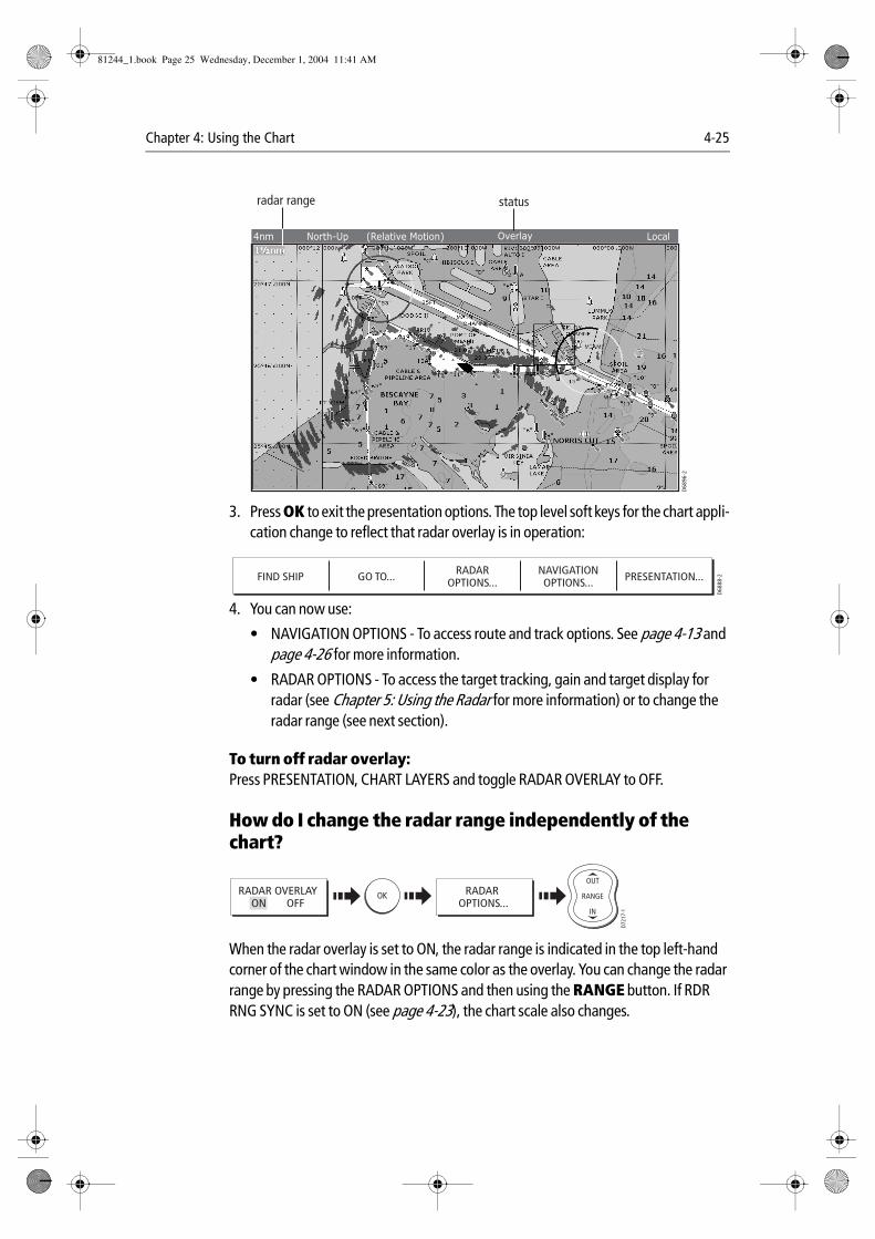
Chapter 4: Using the Chart 4-25
3. Press OK to exit the presentation options. The top level soft keys for the chart appli-cation change to reflect that radar overlay is in operation:
4. You can now use:
• NAVIGATION OPTIONS - To access route and track options. See page 4-13 and page 4-26 for more information.
• RADAR OPTIONS - To access the target tracking, gain and target display for radar (see Chapter 5: Using the Radar for more information) or to change the radar range (see next section).
To turn off radar overlay:Press PRESENTATION, CHART LAYERS and toggle RADAR OVERLAY to OFF.
How do I change the radar range independently of the chart?
When the radar overlay is set to ON, the radar range is indicated in the top left-hand corner of the chart window in the same color as the overlay. You can change the radar range by pressing the RADAR OPTIONS and then using the RANGE button. If RDR RNG SYNC is set to ON (see page 4-23), the chart scale also changes.
radar range
D68
96-2
4nm North-Up (Relative Motion) LocalOverlay
status
FIND SHIP GO TO... RADAROPTIONS...
NAVIGATIONOPTIONS... PRESENTATION...
D68
88-2
D721
7-1D6577-1
OKD6585-1
RANGE
IN
OUTRADAR
OPTIONS...RADAR OVERLAY
ON OFF
81244_1.book Page 25 Wednesday, December 1, 2004 11:41 AM
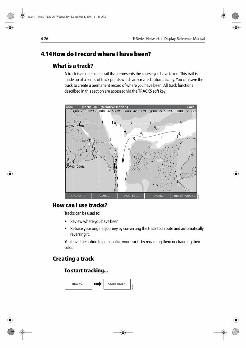
4-26 E-Series Networked Display Reference Manual
4.14How do I record where I have been?
What is a track?A track is an on-screen trail that represents the course you have taken. This trail is made up of a series of track points which are created automatically. You can save the track to create a permanent record of where you have been. All track functions described in this section are accessed via the TRACKS soft key .
How can I use tracks?Tracks can be used to:
• Review where you have been.
• Retrace your original journey by converting the track to a route and automatically reversing it.
You have the option to personalize your tracks by renaming them or changing their color.
Creating a track
To start tracking...
D660
7-1
FIND SHIP GOTO… ROUTES… TRACKS… PRESENTATION…
4nm North-Up (Relative Motion) Local
D650
0-1TRACKS… START TRACK
81244_1.book Page 26 Wednesday, December 1, 2004 11:41 AM
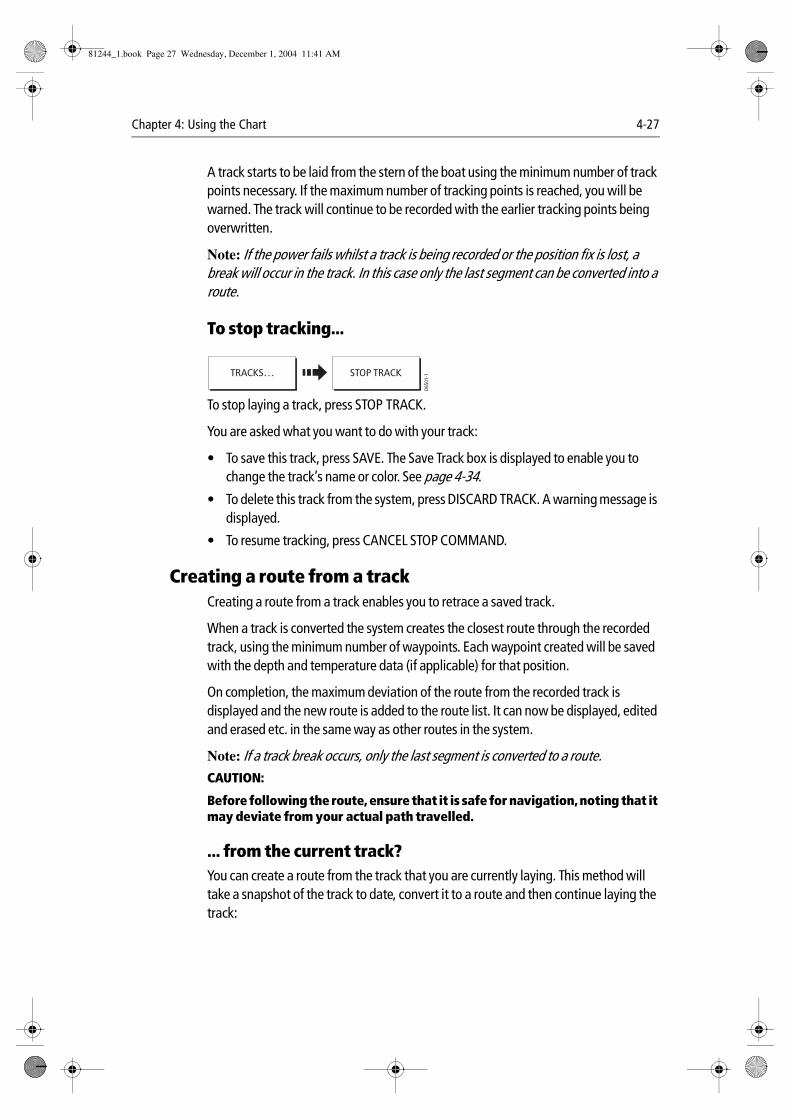
Chapter 4: Using the Chart 4-27
A track starts to be laid from the stern of the boat using the minimum number of track points necessary. If the maximum number of tracking points is reached, you will be warned. The track will continue to be recorded with the earlier tracking points being overwritten.
Note: If the power fails whilst a track is being recorded or the position fix is lost, a break will occur in the track. In this case only the last segment can be converted into a route.
To stop tracking...
To stop laying a track, press STOP TRACK.
You are asked what you want to do with your track:
• To save this track, press SAVE. The Save Track box is displayed to enable you to change the track’s name or color. See page 4-34.
• To delete this track from the system, press DISCARD TRACK. A warning message is displayed.
• To resume tracking, press CANCEL STOP COMMAND.
Creating a route from a trackCreating a route from a track enables you to retrace a saved track.
When a track is converted the system creates the closest route through the recorded track, using the minimum number of waypoints. Each waypoint created will be saved with the depth and temperature data (if applicable) for that position.
On completion, the maximum deviation of the route from the recorded track is displayed and the new route is added to the route list. It can now be displayed, edited and erased etc. in the same way as other routes in the system.
Note: If a track break occurs, only the last segment is converted to a route.CAUTION:
Before following the route, ensure that it is safe for navigation, noting that it may deviate from your actual path travelled.
... from the current track?You can create a route from the track that you are currently laying. This method will take a snapshot of the track to date, convert it to a route and then continue laying the track:
D650
1-1TRACKS… STOP TRACK
81244_1.book Page 27 Wednesday, December 1, 2004 11:41 AM
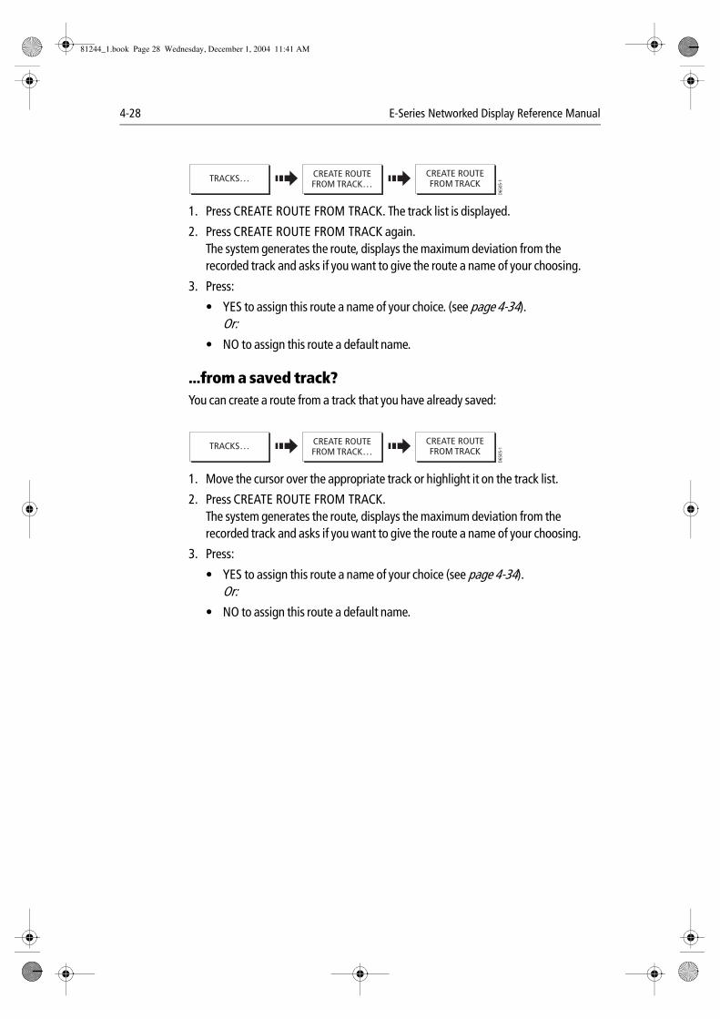
4-28 E-Series Networked Display Reference Manual
1. Press CREATE ROUTE FROM TRACK. The track list is displayed.
2. Press CREATE ROUTE FROM TRACK again.The system generates the route, displays the maximum deviation from the recorded track and asks if you want to give the route a name of your choosing.
3. Press:
• YES to assign this route a name of your choice. (see page 4-34).Or:
• NO to assign this route a default name.
...from a saved track?You can create a route from a track that you have already saved:
1. Move the cursor over the appropriate track or highlight it on the track list.
2. Press CREATE ROUTE FROM TRACK.The system generates the route, displays the maximum deviation from the recorded track and asks if you want to give the route a name of your choosing.
3. Press:
• YES to assign this route a name of your choice (see page 4-34).Or:
• NO to assign this route a default name.
D650
5-1
CREATE ROUTEFROM TRACK…
CREATE ROUTEFROM TRACKTRACKS…
D650
5-1
CREATE ROUTEFROM TRACK…
CREATE ROUTEFROM TRACKTRACKS…
81244_1.book Page 28 Wednesday, December 1, 2004 11:41 AM
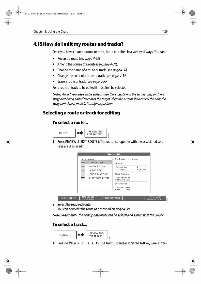
Chapter 4: Using the Chart 4-29
4.15How do I edit my routes and tracks?Once you have created a route or track, it can be edited in a variety of ways. You can:
• Reverse a route (see page 4-19)
• Amend the course of a route (see page 4-30).
• Change the name of a route or track (see page 4-34).
• Change the color of a route or track (see page 4-34).
• Erase a route or track (see page 4-35).
For a route or track to be edited it must first be selected
Note: An active route can be edited, with the exception of the target waypoint. If a waypoint being edited becomes the target, then the system shall cancel the edit; the waypoint shall remain in its original position.
Selecting a route or track for editing
To select a route...
1. Press REVIEW & EDIT ROUTES. The route list together with the associated soft keys are displayed:
2. Select the required route.You can now edit the route as described on page 4-30.
Note: Alternately, the appropriate route can be selected on screen with the cursor.
To select a track...
1. Press REVIEW & EDIT TRACKS. The track list and associated soft keys are shown:
D655
1-1ROUTES ...
REVIEW ANDEDIT ROUTES ...
50°45'.368N001°31'.728W
50°44'.029N001°29'.960W
End Position:
Start Position:
Summary:
Route List
On Chart:Colour Name Shown
Waypoints: 9
Distance: 4.561nm
COASTAL TRIP
HARBOUR TOUR
ISLAND HOP
LONG ROUND TRIP
SHORT ROUND TRIP
ERASE ROUTE ROUTE DETAILS…AMEND ROUTECOURSE…
EDIT NAME AND COLOUR… D6
659-
1
D655
2-1TRACKS ...
REVIEW ANDEDIT TRACKS ...
81244_1.book Page 29 Wednesday, December 1, 2004 11:41 AM
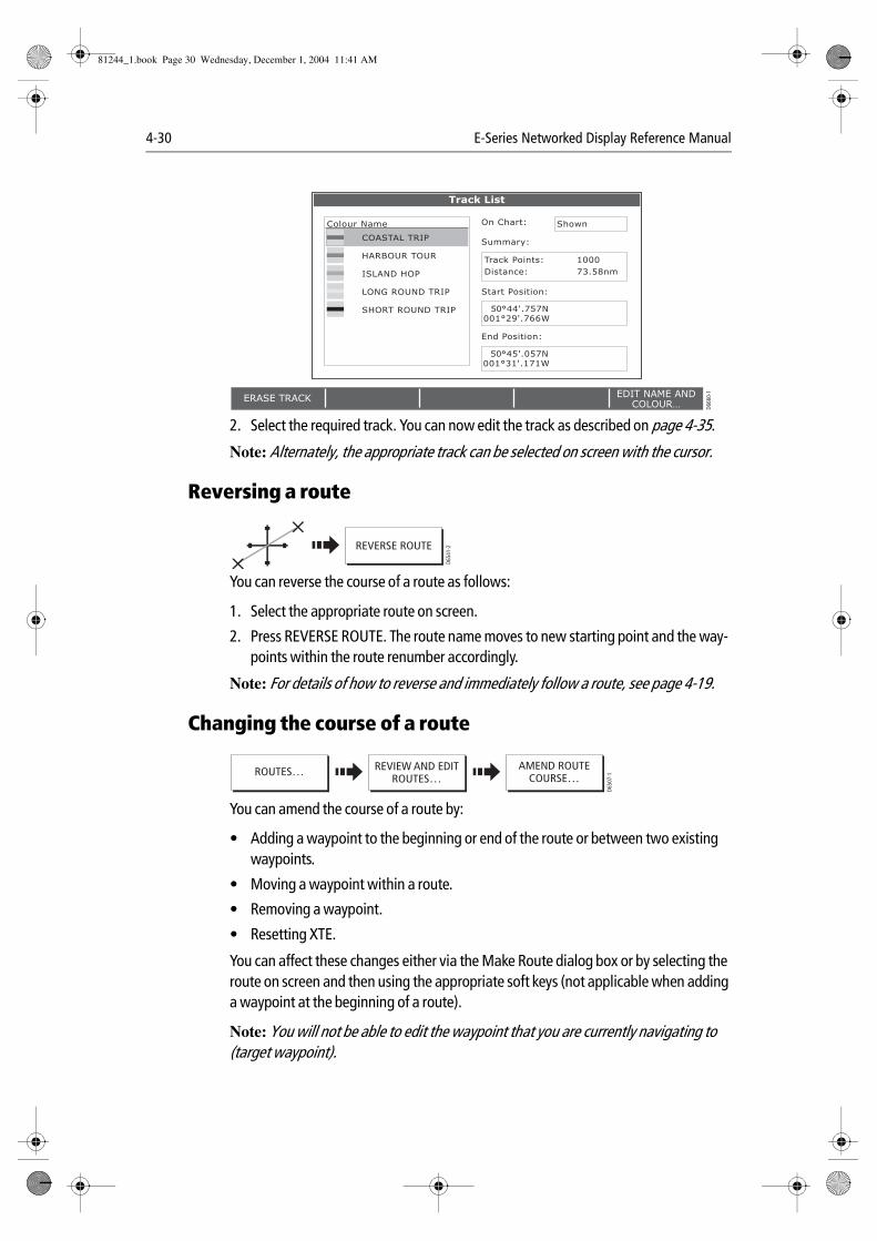
4-30 E-Series Networked Display Reference Manual
2. Select the required track. You can now edit the track as described on page 4-35.
Note: Alternately, the appropriate track can be selected on screen with the cursor.
Reversing a route
You can reverse the course of a route as follows:
1. Select the appropriate route on screen.
2. Press REVERSE ROUTE. The route name moves to new starting point and the way-points within the route renumber accordingly.
Note: For details of how to reverse and immediately follow a route, see page 4-19.
Changing the course of a route
You can amend the course of a route by:
• Adding a waypoint to the beginning or end of the route or between two existing waypoints.
• Moving a waypoint within a route.
• Removing a waypoint.
• Resetting XTE.
You can affect these changes either via the Make Route dialog box or by selecting the route on screen and then using the appropriate soft keys (not applicable when adding a waypoint at the beginning of a route).
Note: You will not be able to edit the waypoint that you are currently navigating to (target waypoint).
50°45'.057N001°31'.171W
50°44'.757N001°29'.766W
End Position:
Start Position:
Summary:
Track List
On Chart:Colour Name Shown
Track Points: 1000
Distance: 73.58nm
COASTAL TRIP
HARBOUR TOUR
ISLAND HOP
LONG ROUND TRIP
SHORT ROUND TRIP
ERASE TRACK EDIT NAME ANDCOLOUR… D6
660-
1
REVERSE ROUTE
D654
1-2
D650
7-1
REVIEW AND EDITROUTES…
AMEND ROUTECOURSE…
ROUTES…
81244_1.book Page 30 Wednesday, December 1, 2004 11:41 AM
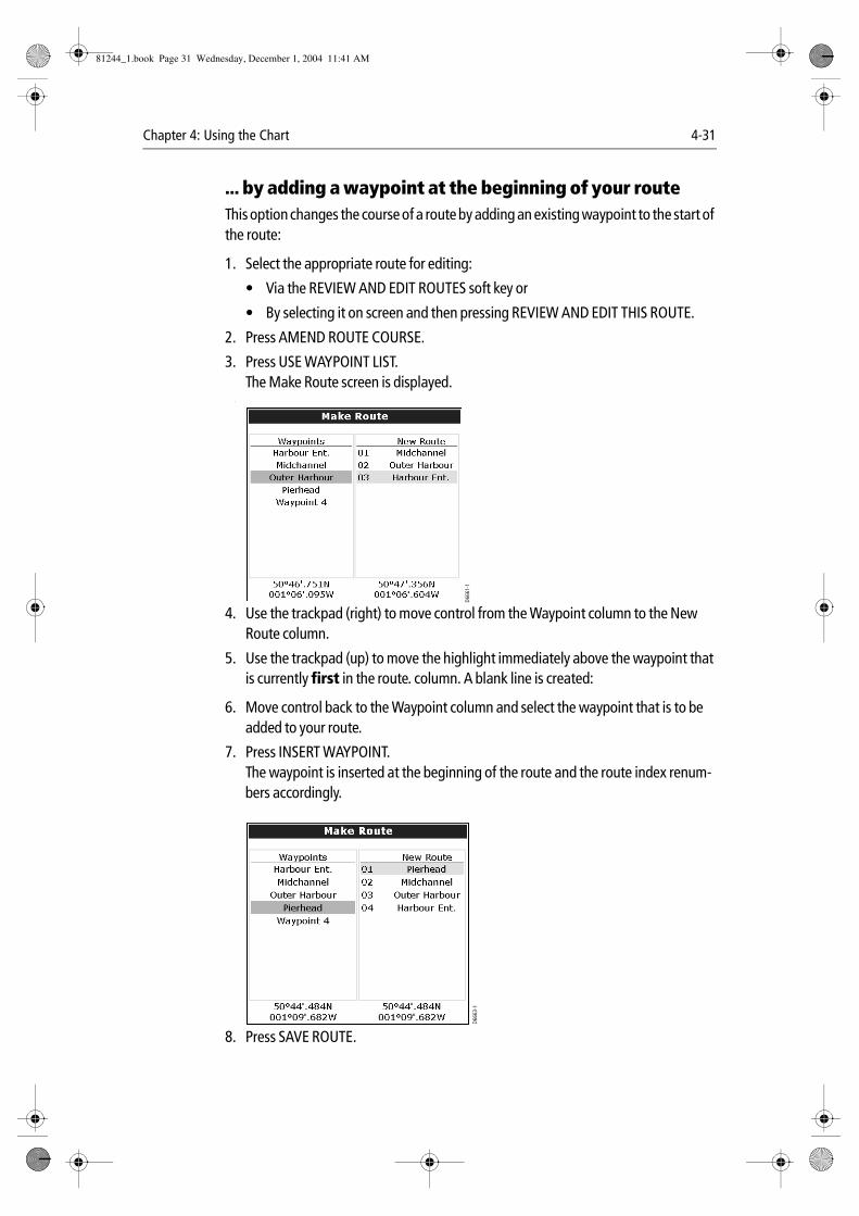
Chapter 4: Using the Chart 4-31
... by adding a waypoint at the beginning of your routeThis option changes the course of a route by adding an existing waypoint to the start of the route:
1. Select the appropriate route for editing:
• Via the REVIEW AND EDIT ROUTES soft key or
• By selecting it on screen and then pressing REVIEW AND EDIT THIS ROUTE.
2. Press AMEND ROUTE COURSE.
3. Press USE WAYPOINT LIST.The Make Route screen is displayed.
‘
4. Use the trackpad (right) to move control from the Waypoint column to the New Route column.
5. Use the trackpad (up) to move the highlight immediately above the waypoint that is currently first in the route. column. A blank line is created:
6. Move control back to the Waypoint column and select the waypoint that is to be added to your route.
7. Press INSERT WAYPOINT.The waypoint is inserted at the beginning of the route and the route index renum-bers accordingly.
8. Press SAVE ROUTE.
D666
1-1
D666
3-1
81244_1.book Page 31 Wednesday, December 1, 2004 11:41 AM
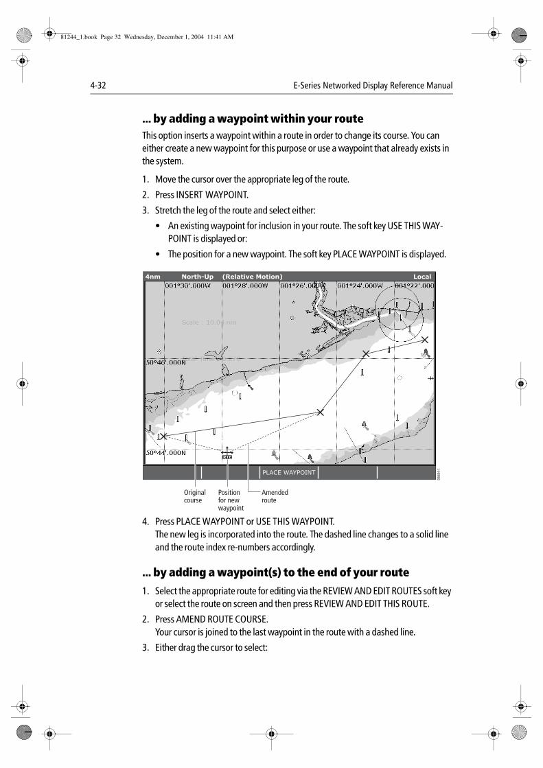
4-32 E-Series Networked Display Reference Manual
... by adding a waypoint within your routeThis option inserts a waypoint within a route in order to change its course. You can either create a new waypoint for this purpose or use a waypoint that already exists in the system.
1. Move the cursor over the appropriate leg of the route.
2. Press INSERT WAYPOINT.
3. Stretch the leg of the route and select either:
• An existing waypoint for inclusion in your route. The soft key USE THIS WAY-POINT is displayed or:
• The position for a new waypoint. The soft key PLACE WAYPOINT is displayed.
4. Press PLACE WAYPOINT or USE THIS WAYPOINT.The new leg is incorporated into the route. The dashed line changes to a solid line and the route index re-numbers accordingly.
... by adding a waypoint(s) to the end of your route
1. Select the appropriate route for editing via the REVIEW AND EDIT ROUTES soft key or select the route on screen and then press REVIEW AND EDIT THIS ROUTE.
2. Press AMEND ROUTE COURSE.Your cursor is joined to the last waypoint in the route with a dashed line.
3. Either drag the cursor to select:
D660
4-1
RTE
PLACE WAYPOINT
4nm North-Up (Relative Motion) Local
Originalcourse
Positionfor newwaypoint
Amendedroute
81244_1.book Page 32 Wednesday, December 1, 2004 11:41 AM

Chapter 4: Using the Chart 4-33
• An existing waypoint. The soft key USE THIS WAYPOINT is displayed.Or:
• The position where you want a new waypoint to be placed. The soft key PLACE WAYPOINT is displayed.
4. Press USE THIS WAYPOINT or PLACE WAYPOINT.The dashed line changes to a solid line to indicate that the new leg has been added to the end of your route.
5. If required, you can add further waypoints to the end of the route by repeating steps (3) and (4) above.
... by moving a waypoint within a route
1. Move the cursor over the waypoint that is to be repositioned within the route.
2. Press MOVE WAYPOINT.The route legs connected to the selected waypoint are now represented by a dashed line.
3. Drag the cursor to the new position.
4. Press OK.The waypoint is fixed at the new location and the route legs connected to it revert to a solid line.
Note: A waypoint’s new position will be reflected in all other routes that make use of it.
... by removing a waypoint within a route
1. Move the cursor over the waypoint that is to be removed.
2. Press REMOVE WAYPOINT.Provided that this waypoint was created as part of that route, and it has not been used in another route, the system deletes it from the system. If the waypoint is used in another route, the system will warn you that it cannot be removed.
Using cross track error (XTE)
When you are following a route or going to a waypoint, you can restart the XTE. This sets the XTE to zero and moves the origin to the actual vessel position.
Restarting XTE is useful if you find yourself off track and want to go straight to your target, rather than get back onto the original track.
Although RESTART XTE causes your vessel to change course, it does not affect the saved route.
D654
9-1Following a route RESTART XTE
81244_1.book Page 33 Wednesday, December 1, 2004 11:41 AM
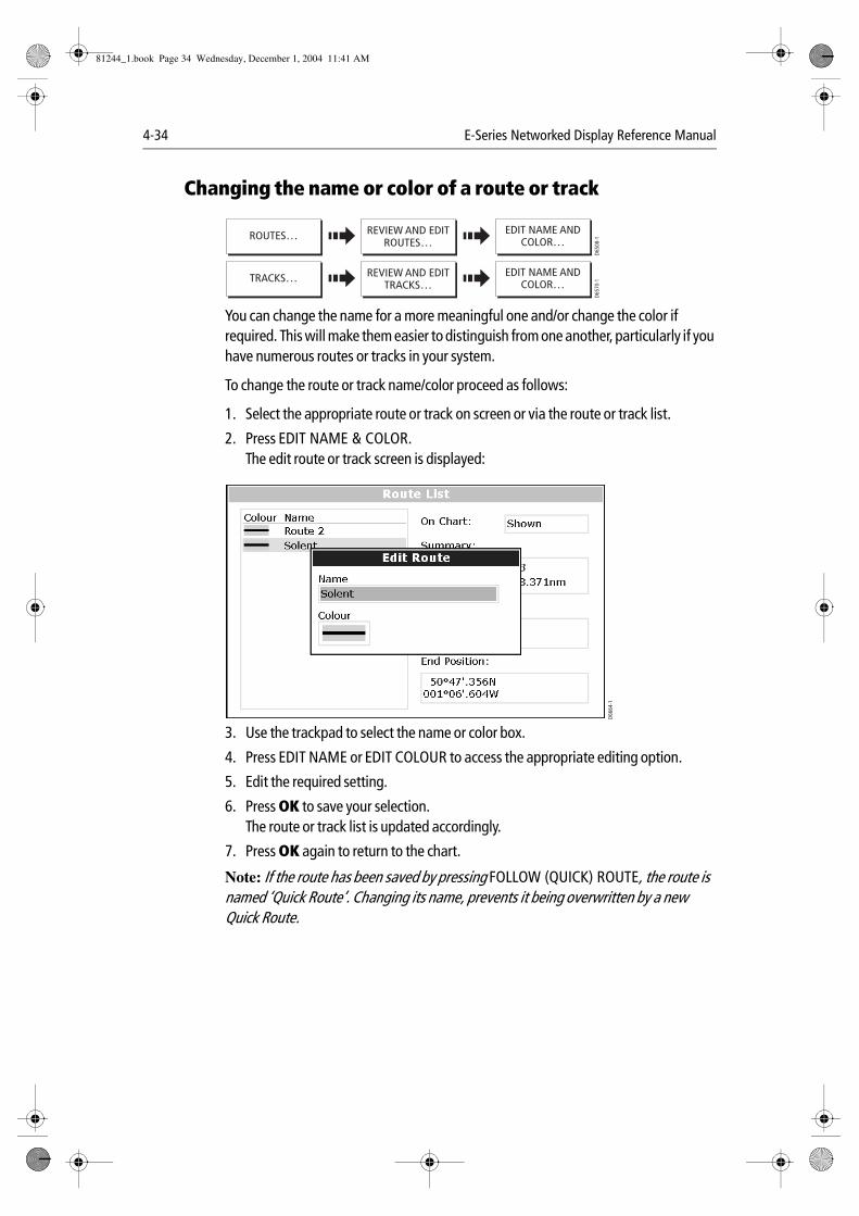
4-34 E-Series Networked Display Reference Manual
Changing the name or color of a route or track
You can change the name for a more meaningful one and/or change the color if required. This will make them easier to distinguish from one another, particularly if you have numerous routes or tracks in your system.
To change the route or track name/color proceed as follows:
1. Select the appropriate route or track on screen or via the route or track list.
2. Press EDIT NAME & COLOR.The edit route or track screen is displayed:
3. Use the trackpad to select the name or color box.
4. Press EDIT NAME or EDIT COLOUR to access the appropriate editing option.
5. Edit the required setting.
6. Press OK to save your selection.The route or track list is updated accordingly.
7. Press OK again to return to the chart.
Note: If the route has been saved by pressing FOLLOW (QUICK) ROUTE, the route is named ‘Quick Route’. Changing its name, prevents it being overwritten by a new Quick Route.
D650
8-1
REVIEW AND EDITROUTES…
EDIT NAME ANDCOLOR…
ROUTES…
D657
0-1
REVIEW AND EDITTRACKS…
EDIT NAME ANDCOLOR…
TRACKS…
D666
4-1
81244_1.book Page 34 Wednesday, December 1, 2004 11:41 AM
Chapter 4: Using the Chart 4-35
Erasing a route or track
You can delete any route or track in your system except for the one that you are traveling to.
1. Select the appropriate route or track.
2. Press ERASE ROUTE or ERASE TRACK.A warning box is displayed asking you whether you want to proceed.
3. If you choose to proceed, the route or track is erased.
Note: Routes only - when you erase a route the system deletes only those waypoints created with this particular route. Waypoints that have been created separately or are used in other routes, are not deleted.
4.16How does my chart warn me of potential dangers?All system alarms are triggered when you are in a chart application. When an alarm is triggered, a buzzer sounds and a pop-up window describing the alarm and how to clear it is displayed.
To switch these alarms on/off and set the limits, press MENU and select Alarm Setup. You should then select the appropriate sub-menu.
Note: For more details of alarms, see page 2-18 and page 11-8.
4.17How do I define how chart windows are presented?Each chart window can be tailored to meet your particular needs. You can:
• Set the chart view for individual windows or system wide (see below).
• Change how the chart is orientated (see page 4-36).
• Change the way your chart is drawn in relation to your boat movement (see page 4-37).
Working with multiple chart views
If you have more than one chart window, you can either share the presentation or present each window independently. The option you have chosen is indicated on the
D650
9-1
REVIEW AND EDITROUTES…
ERASE ROUTE ROUTES…
D657
1-1
REVIEW AND EDITTRACKS…
ERASE TRACK TRACKS…
PRESENTATION CHART VIEWLOCAL SYSTEM
D658
6_2
81244_1.book Page 35 Wednesday, December 1, 2004 11:41 AM
4-36 E-Series Networked Display Reference Manual
chart status bar as LOCAL or SYSTEM. The system view is shared across networked E-Series displays.
Note: Whenever you initially open a chart window, its chart presentation will be sys-tem. If you want to display two chart windows with different presentation, you need to change the view to be LOCAL and then adjust the presentation as required.
Local chart viewWhen local chart view is selected the presentation for each window is set independently.
System chart viewAny windows set to system view, will have the same presentation as other system windows for:
• Chart mode and orientation.
• Radar/chart overlay.
• Radar/chart synchronization.
• Show/hide waypoints, routes and tracks.
• Declutter.
• Vectors.
If you change any of these options in one window, ALL system windows will update. When a chart application is started it defaults to system view.
Note: The motion mode will be set but not synchronized across windows when the chart view is set to system.
Setting the orientation of the chart
The orientation of a chart refers to the relationship between the chart and the direction that you are travelling in. It is used in conjunction with motion mode (see page 4-37) to control how your boat and chart relate to one another and how they are displayed on screen. The mode that you choose is restored at power up. The following options are available:
North Up (N-up)In North Up mode, the chart orientation is fixed with true north upwards. As your heading changes the boat symbol moves accordingly. This is the default mode for the chart application.
D651
1-1
CHART MODE ANDORIENTATION…
PRESENTATION… ORIENTATIONH-UP N-UP C-UP
81244_1.book Page 36 Wednesday, December 1, 2004 11:41 AM
Chapter 4: Using the Chart 4-37
Head Up (H-up)
Head Up mode displays the chart with your boat’s current heading upwards. As the heading changes the boat symbol remains fixed and the chart picture rotates accord-ingly.Notes: (1) To prevent continuous backwards and forwards rotations as the boat
yaws from side-to-side, the chart will not update unless the heading changes by at least 10 degrees from the last displayed orientation.
(2) It is not possible to select Head Up when the motion mode is set to True.
Course Up (C-UP)In Course Up mode, the chart picture is stabilized and shown with your current course upwards. As your boat’s heading changes, the ship symbol moves accordingly. If you select a new course, the picture will reset to display the new course upwards.
The reference used for Course-Up depends upon the information available at a given time. The system always prioritizes this information in the following order.:
1. Bearing from origin to destination, i.e. intended course.
2. Locked heading from an Autopilot.
3. Bearing to waypoint.
4. Instantaneous heading.
If heading data becomes unavailable whilst in this mode, a warning message will be shown and the chart uses 0° heading in relative motion.
Setting the motion mode
The motion mode controls the relationship between the chart and your boat. Whilst motion mode is active, as your boat moves, the chart is redrawn to keep the boat on-screen. The three motion modes are:
• Relative motion.
• True motion.
• Autorange.
When you pan the chart, the motion mode is suspended. This is indicated in the status bar by ‘( )’ around the motion mode and enables you to view another area of the chart whilst navigating. To reset the motion mode and return your boat to the screen, press FIND SHIP. Manually changing the range in autorange also suspends motion mode.
The default setting is relative motion with zero offset. The mode that you select is restored at power up.
D651
2-1
CHART MODE ANDORIENTATION…
PRESENTATION… MOTION MODETM RM AR
81244_1.book Page 37 Wednesday, December 1, 2004 11:41 AM
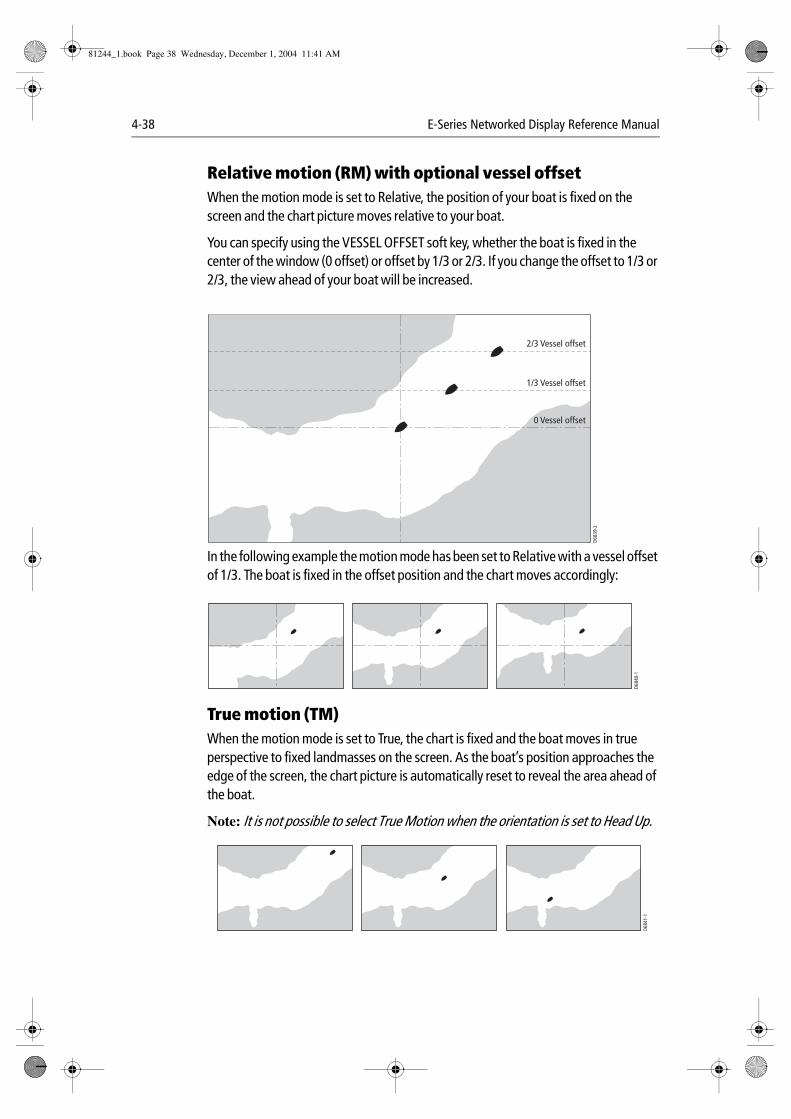
4-38 E-Series Networked Display Reference Manual
Relative motion (RM) with optional vessel offsetWhen the motion mode is set to Relative, the position of your boat is fixed on the screen and the chart picture moves relative to your boat.
You can specify using the VESSEL OFFSET soft key, whether the boat is fixed in the center of the window (0 offset) or offset by 1/3 or 2/3. If you change the offset to 1/3 or 2/3, the view ahead of your boat will be increased.
In the following example the motion mode has been set to Relative with a vessel offset of 1/3. The boat is fixed in the offset position and the chart moves accordingly:
True motion (TM)When the motion mode is set to True, the chart is fixed and the boat moves in true perspective to fixed landmasses on the screen. As the boat’s position approaches the edge of the screen, the chart picture is automatically reset to reveal the area ahead of the boat.
Note: It is not possible to select True Motion when the orientation is set to Head Up.
D683
9-2
0 Vessel offset
1/3 Vessel offset
2/3 Vessel offset
D684
0-1
D684
1-1
81244_1.book Page 38 Wednesday, December 1, 2004 11:41 AM
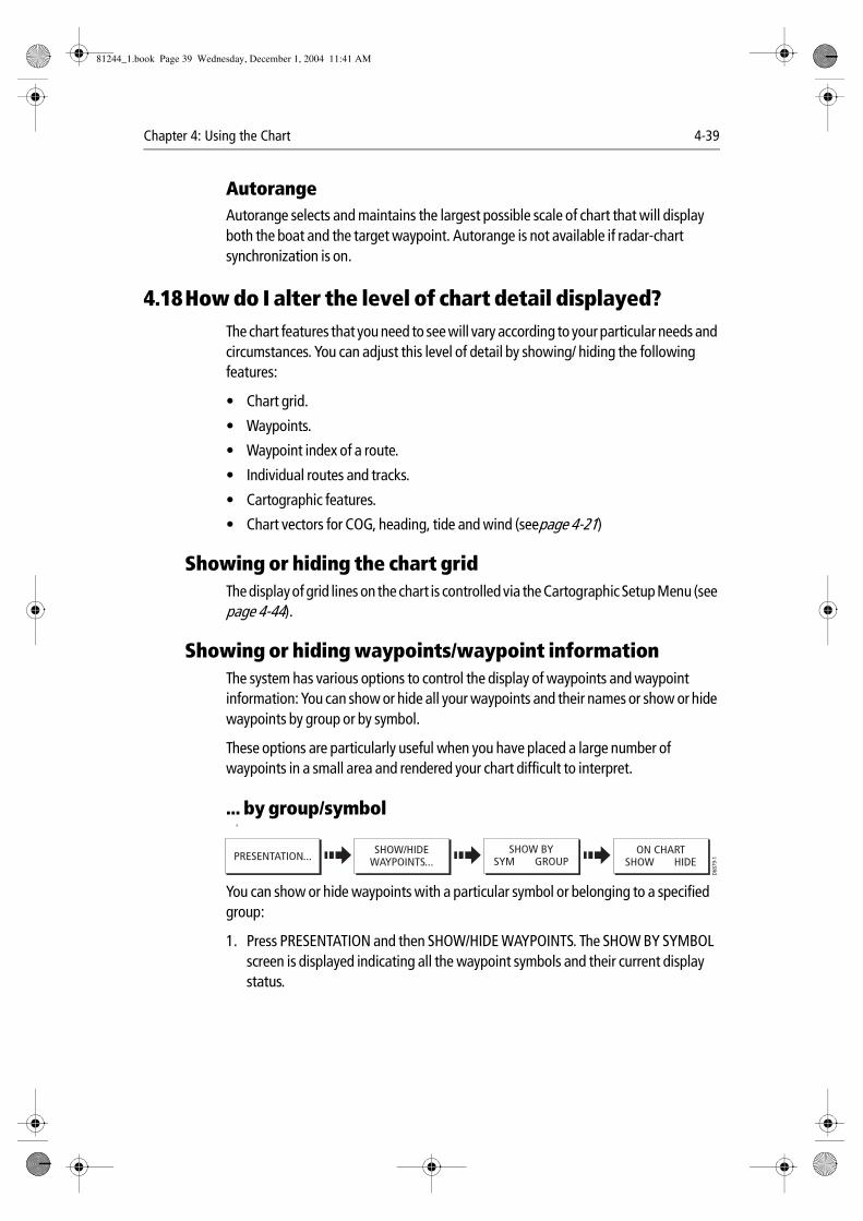
Chapter 4: Using the Chart 4-39
AutorangeAutorange selects and maintains the largest possible scale of chart that will display both the boat and the target waypoint. Autorange is not available if radar-chart synchronization is on.
4.18How do I alter the level of chart detail displayed?The chart features that you need to see will vary according to your particular needs and circumstances. You can adjust this level of detail by showing/ hiding the following features:
• Chart grid.
• Waypoints.
• Waypoint index of a route.
• Individual routes and tracks.
• Cartographic features.
• Chart vectors for COG, heading, tide and wind (seepage 4-21)
Showing or hiding the chart gridThe display of grid lines on the chart is controlled via the Cartographic Setup Menu (see page 4-44).
Showing or hiding waypoints/waypoint informationThe system has various options to control the display of waypoints and waypoint information: You can show or hide all your waypoints and their names or show or hide waypoints by group or by symbol.
These options are particularly useful when you have placed a large number of waypoints in a small area and rendered your chart difficult to interpret.
... by group/symbol A
You can show or hide waypoints with a particular symbol or belonging to a specified group:
1. Press PRESENTATION and then SHOW/HIDE WAYPOINTS. The SHOW BY SYMBOL screen is displayed indicating all the waypoint symbols and their current display status.
SHOW/HIDEWAYPOINTS...
SHOW BYSYM GROUPPRESENTATION...
ON CHARTSHOW HIDE
D687
9-1
81244_1.book Page 39 Wednesday, December 1, 2004 11:41 AM
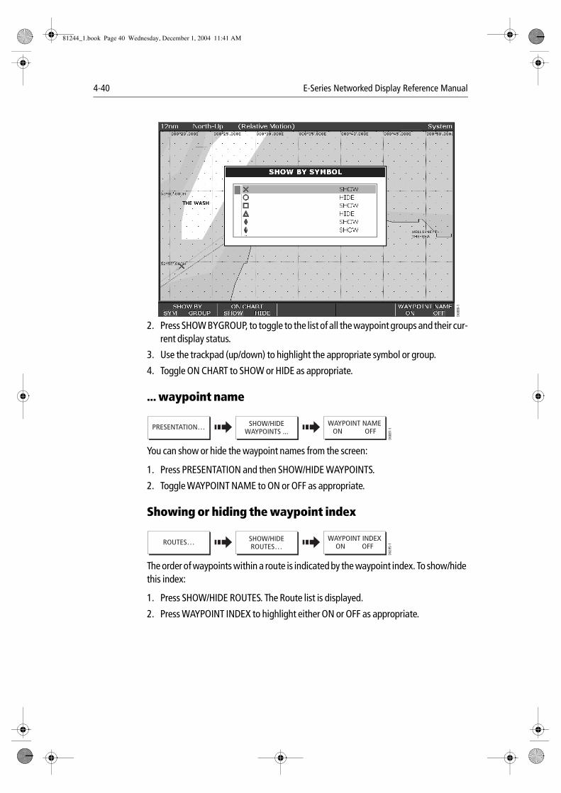
4-40 E-Series Networked Display Reference Manual
2. Press SHOW BYGROUP, to toggle to the list of all the waypoint groups and their cur-rent display status.
3. Use the trackpad (up/down) to highlight the appropriate symbol or group.
4. Toggle ON CHART to SHOW or HIDE as appropriate.
... waypoint name
You can show or hide the waypoint names from the screen:
1. Press PRESENTATION and then SHOW/HIDE WAYPOINTS.
2. Toggle WAYPOINT NAME to ON or OFF as appropriate.
Showing or hiding the waypoint index
The order of waypoints within a route is indicated by the waypoint index. To show/hide this index:
1. Press SHOW/HIDE ROUTES. The Route list is displayed.
2. Press WAYPOINT INDEX to highlight either ON or OFF as appropriate.
D6880-1
D688
1-1
SHOW/HIDEWAYPOINTS ...
WAYPOINT NAMEON OFF
PRESENTATION…
WAYPOINT INDEXON OFF
D659
5-1
SHOW/HIDEROUTES…
ROUTES…
81244_1.book Page 40 Wednesday, December 1, 2004 11:41 AM
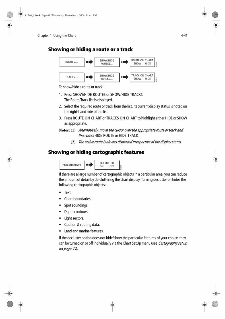
Chapter 4: Using the Chart 4-41
Showing or hiding a route or a track
To show/hide a route or track:
1. Press SHOW/HIDE ROUTES or SHOW/HIDE TRACKS.The Route/Track list is displayed.
2. Select the required route or track from the list. Its current display status is noted on the right-hand side of the list.
3. Press ROUTE ON CHART or TRACKS ON CHART to highlight either HIDE or SHOW as appropriate.
Notes: (1) Alternatively, move the cursor over the appropriate route or track and then press HIDE ROUTE or HIDE TRACK.
(2) The active route is always displayed irrespective of the display status.
Showing or hiding cartographic features
If there are a large number of cartographic objects in a particular area, you can reduce the amount of detail by de-cluttering the chart display. Turning declutter on hides the following cartographic objects:
• Text.
• Chart boundaries.
• Spot soundings.
• Depth contours.
• Light sectors.
• Caution & routing data.
• Land and marine features.
If the declutter option does not hide/show the particular features of your choice, they can be turned on or off individually via the Chart SetUp menu (see Cartography set up on page 44).
ROUTE ON CHARTSHOW HIDE
D651
4-1
SHOW/HIDEROUTES…
ROUTES…
TRACK ON CHARTSHOW HIDE
D659
3-1
SHOW/HIDETRACKS…
TRACKS…
PRESENTATION
D649
2-1
DECLUTTERON OFF
81244_1.book Page 41 Wednesday, December 1, 2004 11:41 AM
4-42 E-Series Networked Display Reference Manual
4.19How do I set up my chart and its cartography?The set up for your chart and its cartography can be changed from the standard configuration to suit your particular needs. Although you will probably only do this when you first use the chart, you may decide to make subsequent adjustments once you become more familiar with the system. Any settings that you change are retained even when you power off.
To select the chart set up menus, press MENU and then select either Chart Setup or Cartography Setup.
Chart Setup
DatumFor your GPS and chart to correlate accurately with your paper charts, they will need to be using the same datum. The default datum for your display is WGS1984. If this is not suitable, you can change the setting. When you adjust the datum of the E-Series Display, a Raymarine GPS will automatically correlate. If you have a third party GPS, you will need to correlate this separately.
CAUTION:* Changing the chart datum does not cause any waypoint or routes stored in the chartplotter to move on the display, although their latitude and longitude changes to reflect the new datum. When adding waypoints numerically to the waypoint list, or via SeaTalk or NMEA, it is important that they are referenced to the same datum to which the display is currently set.
FUNCTIONDescription
OPTIONS(Default in bold)
Object InformationOFF - No info pop-up is displayed but detailed data can still be dis-played by pressing OK.ALL ON - the info pop-up for all cartographic areas (including objects) is displayed.Points ON - the info pop-up only displayed for objects selected with the cursor.
OFFAll ONPoints ON
Vector LengthThe time period specified for drawing COG and Heading vectors.
3 Mins6 MinsInfinite
DatumGrid moves according to datum selected and the lat/long of carto-graphic features change. System attempts to set up any GPS to the new mode and indicates whether successful or not. See additional information below.
WGS 84List of datum provided
Chart OffsetMoves the position of the chart in order to correct for position errors in the cartography. See page 43 for further information.
ONOFF
81244_1.book Page 42 Wednesday, December 1, 2004 11:41 AM
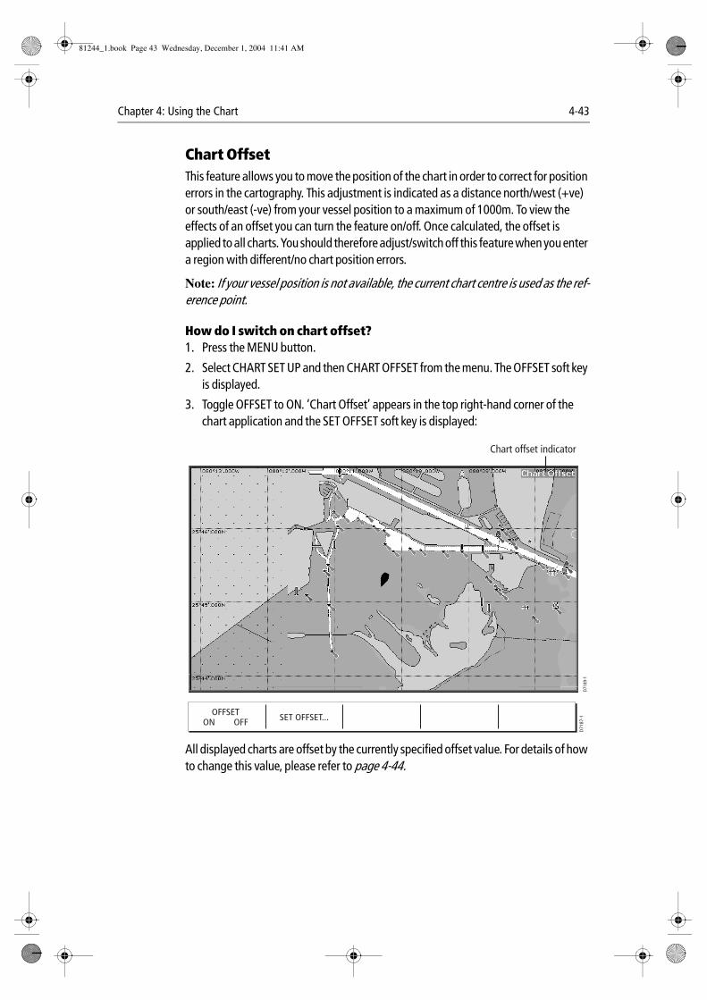
Chapter 4: Using the Chart 4-43
Chart Offset This feature allows you to move the position of the chart in order to correct for position errors in the cartography. This adjustment is indicated as a distance north/west (+ve) or south/east (-ve) from your vessel position to a maximum of 1000m. To view the effects of an offset you can turn the feature on/off. Once calculated, the offset is applied to all charts. You should therefore adjust/switch off this feature when you enter a region with different/no chart position errors.
Note: If your vessel position is not available, the current chart centre is used as the ref-erence point.
How do I switch on chart offset?1. Press the MENU button.
2. Select CHART SET UP and then CHART OFFSET from the menu. The OFFSET soft key is displayed.
3. Toggle OFFSET to ON. ‘Chart Offset’ appears in the top right-hand corner of the chart application and the SET OFFSET soft key is displayed:
All displayed charts are offset by the currently specified offset value. For details of how to change this value, please refer to page 4-44.
D718
9-1
Chart offset indicator
OFFSETON OFF SET OFFSET...
D71
87-1
81244_1.book Page 43 Wednesday, December 1, 2004 11:41 AM
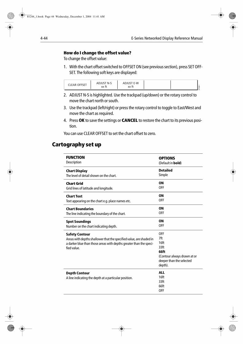
4-44 E-Series Networked Display Reference Manual
How do I change the offset value?To change the offset value:
1. With the chart offset switched to OFFSET ON (see previous section), press SET OFF-SET. The following soft keys are displayed:
2. ADJUST N-S is highlighted. Use the trackpad (up/down) or the rotary control to move the chart north or south.
3. Use the trackpad (left/right) or press the rotary control to toggle to East/West and move the chart as required.
4. Press OK to save the settings or CANCEL to restore the chart to its previous posi-tion.
You can use CLEAR OFFSET to set the chart offset to zero.
Cartography set up
FUNCTIONDescription
OPTIONS(Default in bold)
Chart DisplayThe level of detail shown on the chart.
DetailedSimple
Chart GridGrid lines of latitude and longitude.
ONOFF
Chart TextText appearing on the chart e.g. place names etc.
ONOFF
Chart BoundariesThe line indicating the boundary of the chart.
ONOFF
Spot SoundingsNumber on the chart indicating depth.
ONOFF
Safety ContourAreas with depths shallower that the specified value, are shaded in a darker blue than those areas with depths greater than the speci-fied value.
OFF7ft16ft33ft66ft(Contour always drawn at or deeper than the selected depth).
Depth ContourA line indicating the depth at a particular position.
ALL16ft33ft66ftOFF
ADJUST N-Sxx ft
ADJUST E-Wxx ft
D718
8-1CLEAR OFFSET
81244_1.book Page 44 Wednesday, December 1, 2004 11:41 AM
Chapter 4: Using the Chart 4-45
Nav. Marks ONOFF
Nav. Marks SymbolsThe set of symbology used for navigation marks.Corresponds to paper charts.
InternationalUS
Light SectorsThe sector of light cast by a fixed beacon.
ONOFF
Caution & Routing Data ONOFF
Marine FeaturesThe cartographic features that are displayed on the water.
ONOFF
Land FeaturesThe cartographic features that are displayed on the land.
ONOFF
FUNCTIONDescription
OPTIONS(Default in bold)
81244_1.book Page 45 Wednesday, December 1, 2004 11:41 AM

4-46 E-Series Networked Display Reference Manual
81244_1.book Page 46 Wednesday, December 1, 2004 11:41 AM
Chapter 5: Using the Radar 5-1
Chapter 5:Using the Radar
5.1 IntroductionThis chapter describes the basics of radar and the things that can affect your radar picture. It then shows you how to use your radar and its various functions including:
• Changing orientation and motion mode.
• Getting the best radar picture.
• Measuring distances and bearings.
• Collision avoidance using Guard Zones and MARPA.
• Using waypoints to mark positions.
• Setting up the radar display.
• Radar alarms.
5.2 What is radar?Radio Detection And Ranging (RADAR) is something that is in use all around us, although it is normally invisible. One of the most common uses of radar at sea is to detect the presence of objects, known as ‘targets’ at a distance, and if they are moving, detect their speed.
This chapter of the Reference manual provides the information and instructions to enable you to start using the radar so that you know what is around you and use the in-built Mini Automatic Radar Plotting Aid (MARPA) functions to help in collision avoidance.
Until you are familiar with interpreting the radar display, every opportunity should be taken to compare the radar screen patterns with visual targets, such as other boats, buoys and coastal structures. You should practise harbor and coastal navigation during daylight hours and in clear weather conditions.
Detecting targetsRadar works by transmitting radio pulses, then detecting reflections of these pulses (echoes) from objects in the area and displaying the reflections as targets on your display.
81244_1.book Page 1 Wednesday, December 1, 2004 11:41 AM
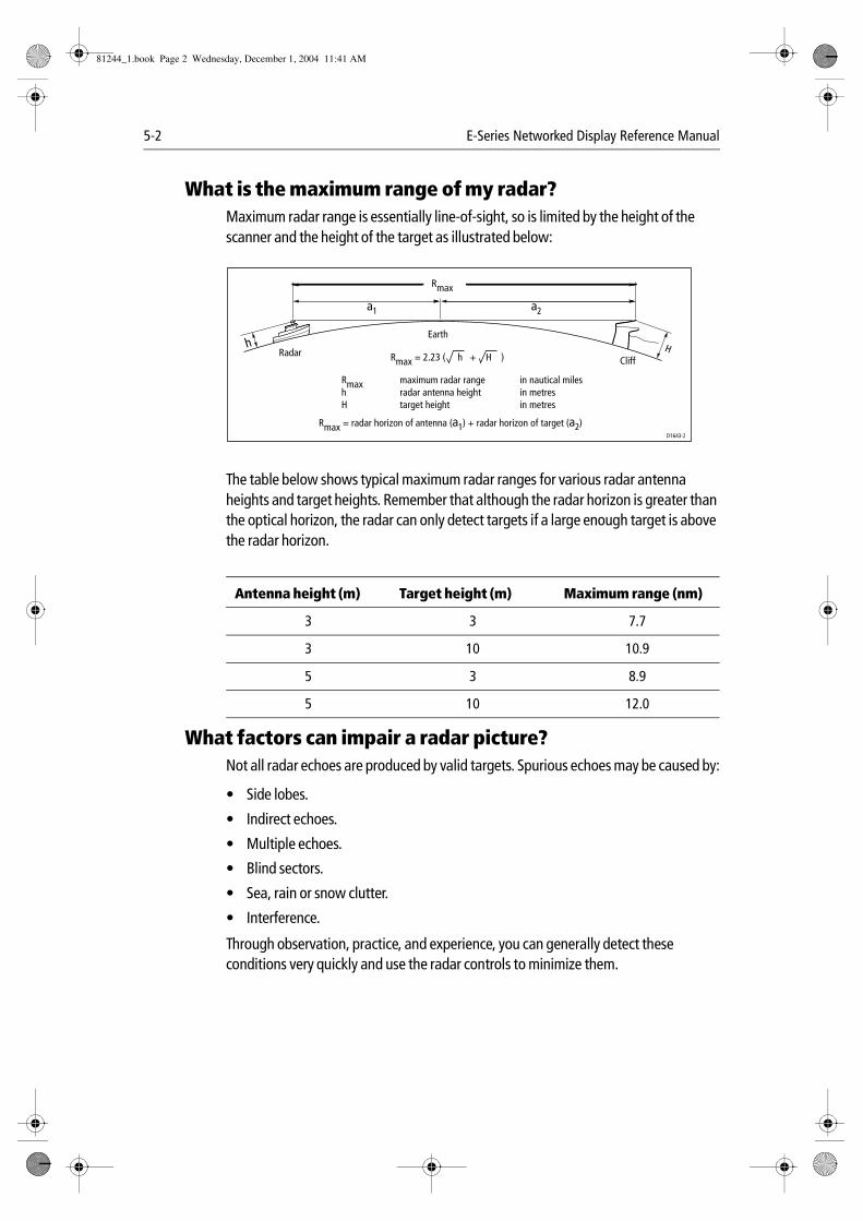
5-2 E-Series Networked Display Reference Manual
What is the maximum range of my radar?Maximum radar range is essentially line-of-sight, so is limited by the height of the scanner and the height of the target as illustrated below:
The table below shows typical maximum radar ranges for various radar antenna heights and target heights. Remember that although the radar horizon is greater than the optical horizon, the radar can only detect targets if a large enough target is above the radar horizon.
What factors can impair a radar picture?Not all radar echoes are produced by valid targets. Spurious echoes may be caused by:
• Side lobes.
• Indirect echoes.
• Multiple echoes.
• Blind sectors.
• Sea, rain or snow clutter.
• Interference.
Through observation, practice, and experience, you can generally detect these conditions very quickly and use the radar controls to minimize them.
Antenna height (m) Target height (m) Maximum range (nm)
3 3 7.7
3 10 10.9
5 3 8.9
5 10 12.0
a1 a2
Earthh H
CliffRadar
D1643-2
Rmax
Rmax = 2.23 ( h + H )
RmaxhH
maximum radar rangeradar antenna heighttarget height
in nautical milesin metresin metres
Rmax = radar horizon of antenna (a1) + radar horizon of target (a2)
81244_1.book Page 2 Wednesday, December 1, 2004 11:41 AM
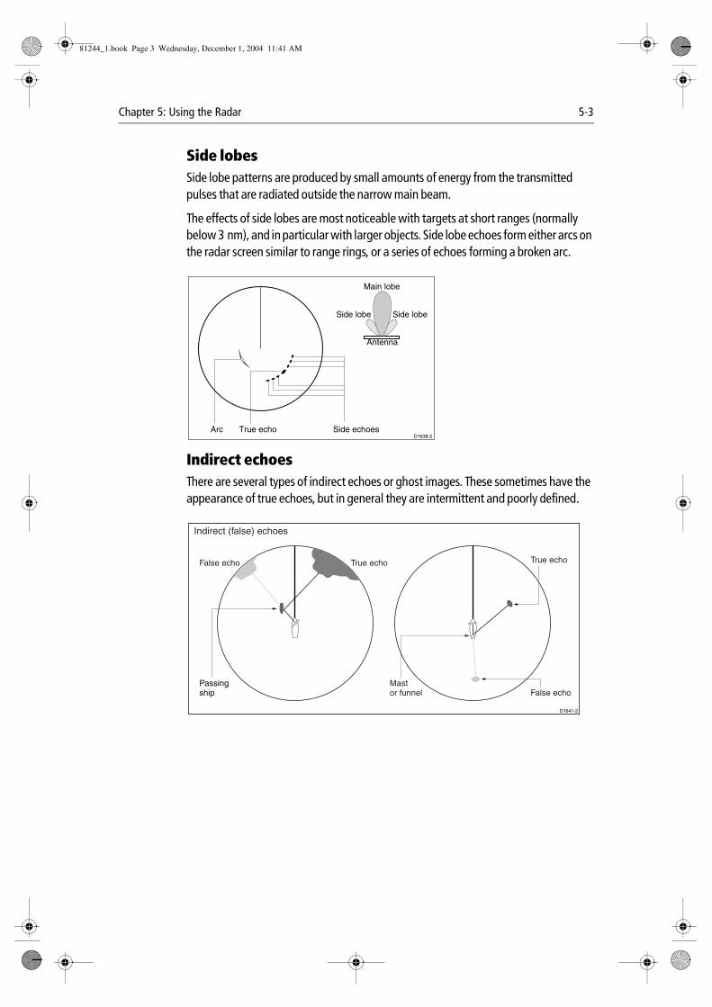
Chapter 5: Using the Radar 5-3
Side lobesSide lobe patterns are produced by small amounts of energy from the transmitted pulses that are radiated outside the narrow main beam.
The effects of side lobes are most noticeable with targets at short ranges (normally below 3 nm), and in particular with larger objects. Side lobe echoes form either arcs on the radar screen similar to range rings, or a series of echoes forming a broken arc.
Indirect echoesThere are several types of indirect echoes or ghost images. These sometimes have the appearance of true echoes, but in general they are intermittent and poorly defined.
True echo Side echoes
Main lobe
Antenna
Arc
Side lobe Side lobe
D1638-2
False echo True echo
Passingship
True echo
False echo
D1641-2
Mastor funnel
Indirect (false) echoes
81244_1.book Page 3 Wednesday, December 1, 2004 11:41 AM
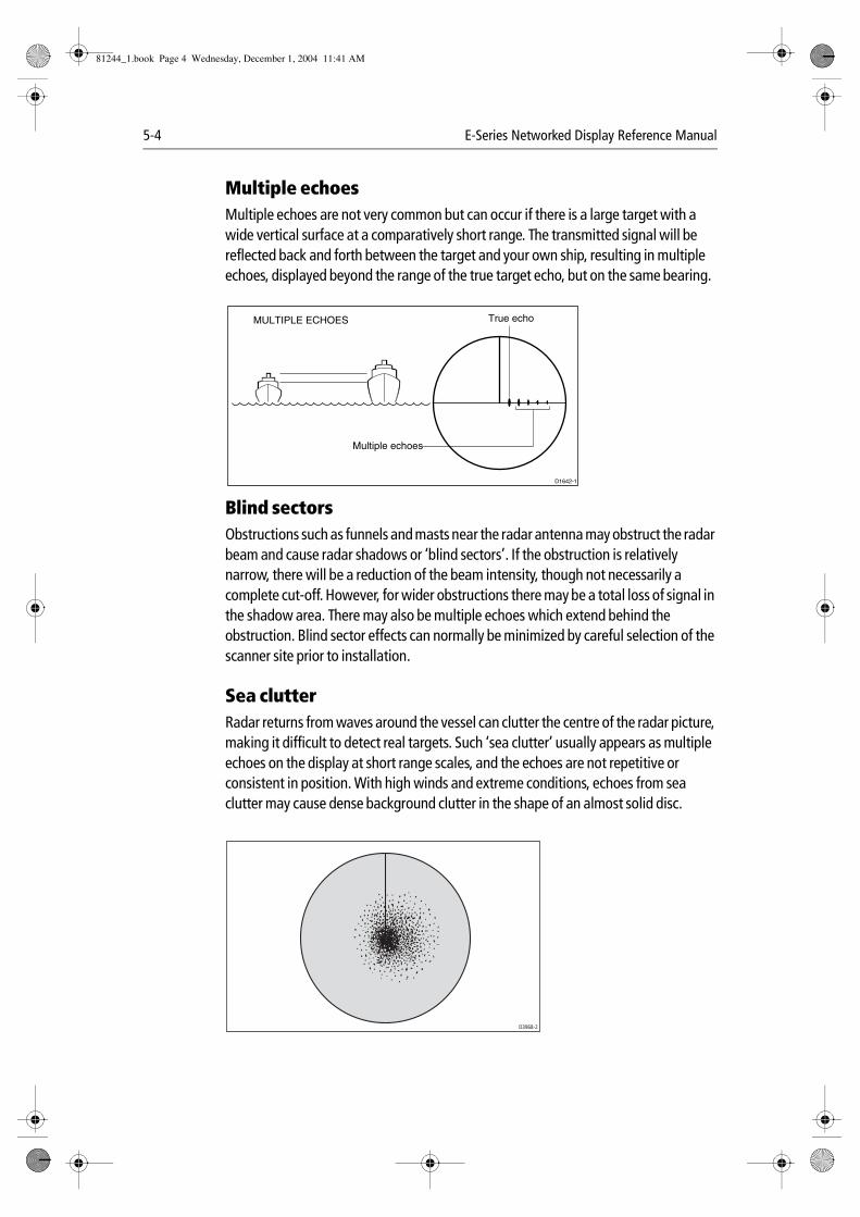
5-4 E-Series Networked Display Reference Manual
Multiple echoesMultiple echoes are not very common but can occur if there is a large target with a wide vertical surface at a comparatively short range. The transmitted signal will be reflected back and forth between the target and your own ship, resulting in multiple echoes, displayed beyond the range of the true target echo, but on the same bearing.
Blind sectors Obstructions such as funnels and masts near the radar antenna may obstruct the radar beam and cause radar shadows or ‘blind sectors’. If the obstruction is relatively narrow, there will be a reduction of the beam intensity, though not necessarily a complete cut-off. However, for wider obstructions there may be a total loss of signal in the shadow area. There may also be multiple echoes which extend behind the obstruction. Blind sector effects can normally be minimized by careful selection of the scanner site prior to installation.
Sea clutterRadar returns from waves around the vessel can clutter the centre of the radar picture, making it difficult to detect real targets. Such ‘sea clutter’ usually appears as multiple echoes on the display at short range scales, and the echoes are not repetitive or consistent in position. With high winds and extreme conditions, echoes from sea clutter may cause dense background clutter in the shape of an almost solid disc.
D1642-1
True echo
Multiple echoes
MULTIPLE ECHOES
D3968-2
81244_1.book Page 4 Wednesday, December 1, 2004 11:41 AM
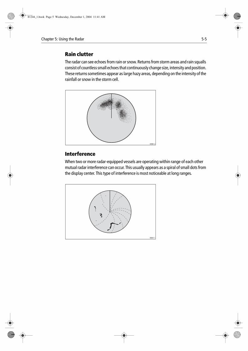
Chapter 5: Using the Radar 5-5
Rain clutterThe radar can see echoes from rain or snow. Returns from storm areas and rain squalls consist of countless small echoes that continuously change size, intensity and position. These returns sometimes appear as large hazy areas, depending on the intensity of the rainfall or snow in the storm cell.
InterferenceWhen two or more radar-equipped vessels are operating within range of each other mutual radar interference can occur. This usually appears as a spiral of small dots from the display center. This type of interference is most noticeable at long ranges.
D3967-2
D6601-1
81244_1.book Page 5 Wednesday, December 1, 2004 11:41 AM
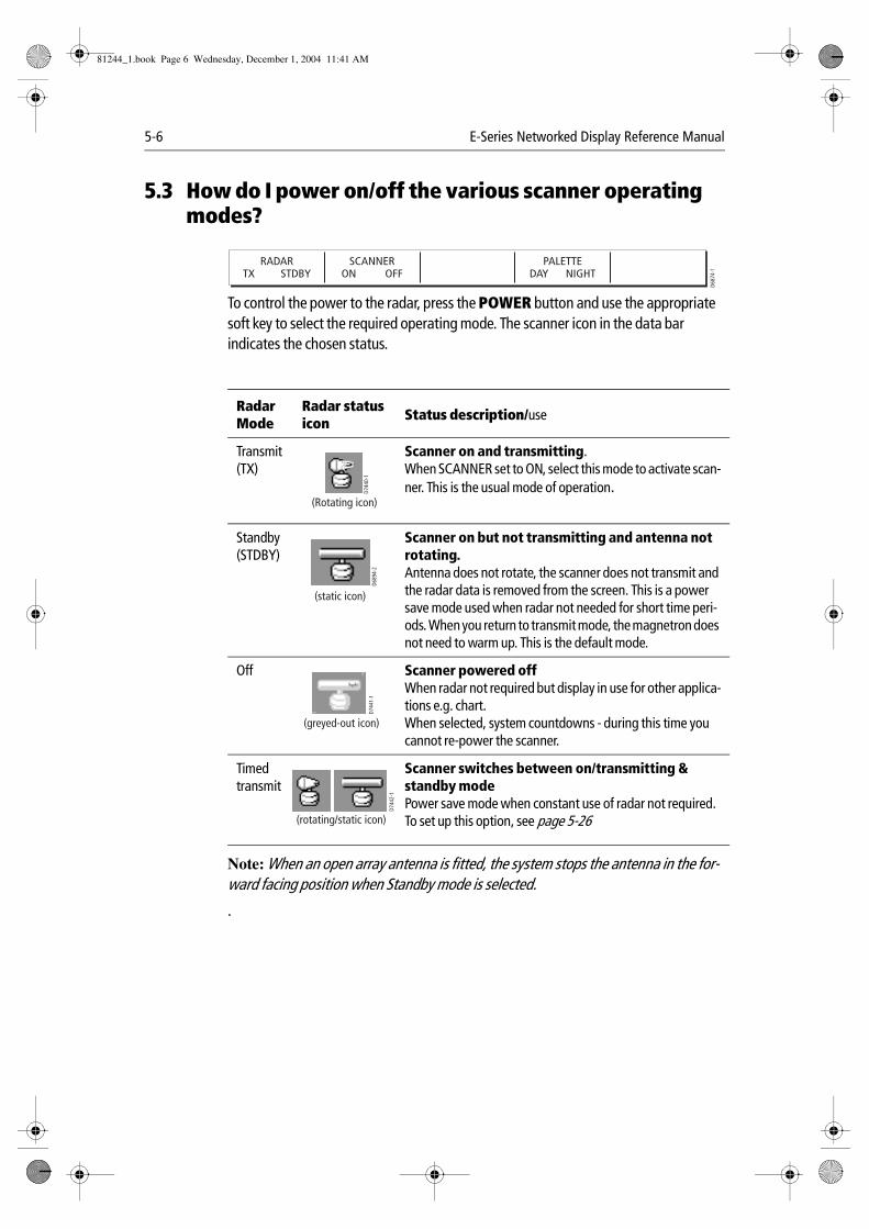
5-6 E-Series Networked Display Reference Manual
5.3 How do I power on/off the various scanner operating modes?
To control the power to the radar, press the POWER button and use the appropriate soft key to select the required operating mode. The scanner icon in the data bar indicates the chosen status.
Note: When an open array antenna is fitted, the system stops the antenna in the for-ward facing position when Standby mode is selected.
.
RadarMode
Radar status icon Status description/use
Transmit(TX)
Scanner on and transmitting.When SCANNER set to ON, select this mode to activate scan-ner. This is the usual mode of operation.
Standby (STDBY)
Scanner on but not transmitting and antenna not rotating. Antenna does not rotate, the scanner does not transmit and the radar data is removed from the screen. This is a power save mode used when radar not needed for short time peri-ods. When you return to transmit mode, the magnetron does not need to warm up. This is the default mode.
Off Scanner powered offWhen radar not required but display in use for other applica-tions e.g. chart.When selected, system countdowns - during this time you cannot re-power the scanner.
Timed transmit
Scanner switches between on/transmitting & standby mode Power save mode when constant use of radar not required. To set up this option, see page 5-26
RADARTX STDBY
SCANNERON OFF
PALETTEDAY NIGHT
D687
4-1
D744
0-1
(Rotating icon)
D689
4-2
(static icon)
D744
1-1
(greyed-out icon)
D744
2-1
(rotating/static icon)
81244_1.book Page 6 Wednesday, December 1, 2004 11:41 AM
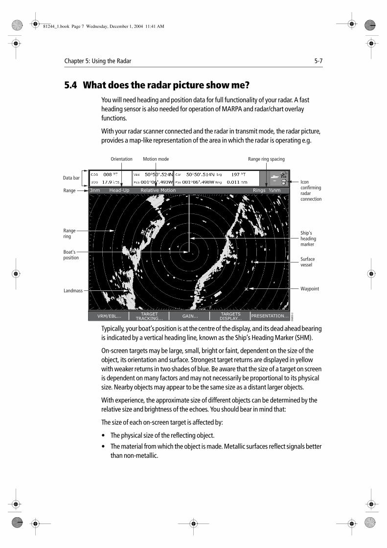
Chapter 5: Using the Radar 5-7
5.4 What does the radar picture show me?You will need heading and position data for full functionality of your radar. A fast heading sensor is also needed for operation of MARPA and radar/chart overlay functions.
With your radar scanner connected and the radar in transmit mode, the radar picture, provides a map-like representation of the area in which the radar is operating e.g.
Typically, your boat’s position is at the centre of the display, and its dead ahead bearing is indicated by a vertical heading line, known as the Ship’s Heading Marker (SHM).
On-screen targets may be large, small, bright or faint, dependent on the size of the object, its orientation and surface. Strongest target returns are displayed in yellow with weaker returns in two shades of blue. Be aware that the size of a target on screen is dependent on many factors and may not necessarily be proportional to its physical size. Nearby objects may appear to be the same size as a distant larger objects.
With experience, the approximate size of different objects can be determined by the relative size and brightness of the echoes. You should bear in mind that:
The size of each on-screen target is affected by:
• The physical size of the reflecting object.
• The material from which the object is made. Metallic surfaces reflect signals better than non-metallic.
3nm Head-Up Relative Motion Rings ½nm
VRM/EBL... GAIN... PRESENTATION...TARGETTRACKING...
TARGETSDISPLAY... D6
803-
2
Orientation
Data bar
Surfacevessel
Waypoint
Ship'sheadingmarker
Iconconfirmingradarconnection
Rangering
Landmass
Boat'sposition
Range
Motion mode Range ring spacing
81244_1.book Page 7 Wednesday, December 1, 2004 11:41 AM

5-8 E-Series Networked Display Reference Manual
• Vertical objects such as cliffs reflect signals better than sloping ones such as sand-banks
• High coastlines and mountainous coastal regions can be observed at longer radar ranges. Therefore, the first sight of land may be a mountain several miles inland from the coastline. Although the coastline may be much nearer, it may not appear on the radar until the vessel is closer to shore.
• Some targets, such as buoys and small boats, can be difficult to discern, because they do not present a consistent reflecting surface as they bob and toss about in the waves. Consequently, these echoes tend to fade and brighten and at times, to dis-appear momentarily.
• Buoys and small boats often resemble each other, but boats can often be distin-guished by their motion.
What does the status bar tell me?The status bar at the top of the radar picture provides at-a-glance information about the picture and your selected settings.
5.5 How can I change what I see in the radar window?The radar screen can be tailored to your particular needs. You can:
• Change how the radar is orientated (see page 5-8).
• Change where your boat is positioned (motion mode) in relation to the radar (see page 5-9).
• Show or hide waypoints (see page 4-13).
• Show or hide range rings (see page 5-10).
• Change the bearing mode for EBLs (see page 5-11).
Setting the orientation of the radar
The orientation of the radar refers to the relationship between the radar and the direction that you are travelling in. It is used in conjunction with motion mode (see page 5-9) to control how your boat and radar relate to one another and how they are displayed on screen. Any changes that you make to the orientation of the radar are retained when you switch off. There are three orientation modes to choose from:
Head Up (H-UP)Head Up mode displays the radar picture with your boat’s current heading (SHM) upwards. As the heading changes the radar picture rotates accordingly.
D659
2-2
RADAR MODE &ORIENTATION…
PRESENTATION… ORIENTATIONH-UP N-UP C-UP
81244_1.book Page 8 Wednesday, December 1, 2004 11:41 AM

Chapter 5: Using the Radar 5-9
This is the default mode for the radar application.
North Up (N-UP)In North Up mode, the radar picture is fixed with true north upwards. As your boat changes its heading, the SHM will move accordingly.
Notes: (1) If heading data becomes unavailable whilst in this mode, a warning mes-sage will be shown and the radar uses 0° heading in relative motion. When heading data becomes available once more, North-Up mode is re-instated.
(2) It is not possible to select Head Up mode when the motion mode is set to True.
Course Up (C-UP)In Course Up mode, the radar picture is stabilized and shown with your current course upwards. As your boat’s heading changes, the SHM moves accordingly. If you select a new course, the picture will reset to display the new course upwards.
The reference used for Course-Up depends upon the information available at a given time. The system always prioritizes this information in the following order.:
1. Bearing from origin to destination, i.e. intended course.
2. Locked heading from an Autopilot.
3. Bearing to waypoint.
4. Instantaneous heading.
Note: If heading data becomes unavailable whilst in this mode, a warning message will be shown and the radar uses 0° heading in relative motion. When heading data becomes available once more, Course-Up mode is reinstated.
Setting the motion mode A
The motion mode controls the relationship between the radar and your boat. There are two modes:
• Relative motion.
• True motion.
The selected motion mode is displayed in the status bar. The default setting is relative motion with zero offset
D683
8-1
RADAR MODE &ORIENTATION…
PRESENTATION… MOTION MODETM RM
81244_1.book Page 9 Wednesday, December 1, 2004 11:41 AM
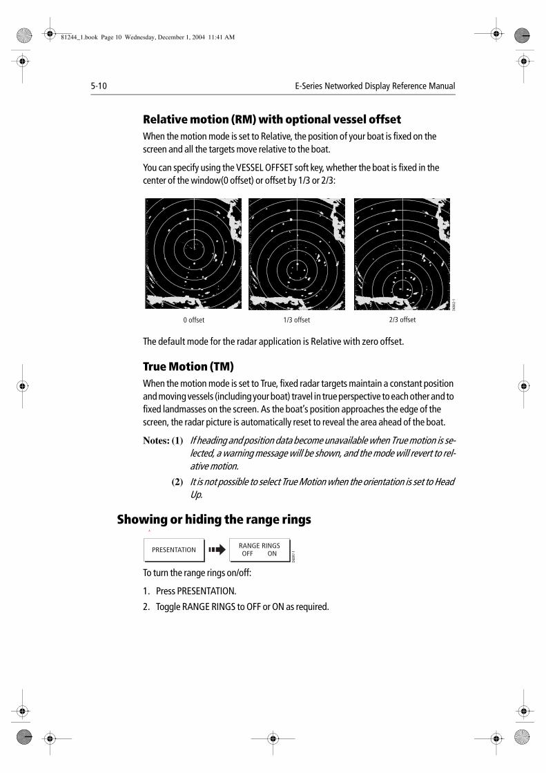
5-10 E-Series Networked Display Reference Manual
Relative motion (RM) with optional vessel offsetWhen the motion mode is set to Relative, the position of your boat is fixed on the screen and all the targets move relative to the boat.
You can specify using the VESSEL OFFSET soft key, whether the boat is fixed in the center of the window(0 offset) or offset by 1/3 or 2/3:
The default mode for the radar application is Relative with zero offset.
True Motion (TM)When the motion mode is set to True, fixed radar targets maintain a constant position and moving vessels (including your boat) travel in true perspective to each other and to fixed landmasses on the screen. As the boat’s position approaches the edge of the screen, the radar picture is automatically reset to reveal the area ahead of the boat.
Notes: (1) If heading and position data become unavailable when True motion is se-lected, a warning message will be shown, and the mode will revert to rel-ative motion.
(2) It is not possible to select True Motion when the orientation is set to Head Up.
Showing or hiding the range rings A
To turn the range rings on/off:
1. Press PRESENTATION.
2. Toggle RANGE RINGS to OFF or ON as required.
D684
2-1
0 offset 1/3 offset 2/3 offset
PRESENTATION
D689
7-1
RANGE RINGSOFF ON
81244_1.book Page 10 Wednesday, December 1, 2004 11:41 AM
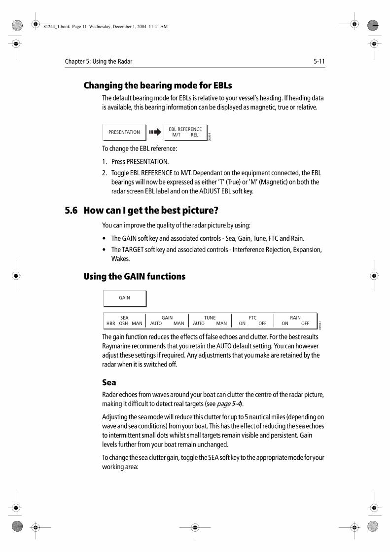
Chapter 5: Using the Radar 5-11
Changing the bearing mode for EBLsThe default bearing mode for EBLs is relative to your vessel’s heading. If heading data is available, this bearing information can be displayed as magnetic, true or relative.
To change the EBL reference:
1. Press PRESENTATION.
2. Toggle EBL REFERENCE to M/T. Dependant on the equipment connected, the EBL bearings will now be expressed as either ‘T’ (True) or ‘M’ (Magnetic) on both the radar screen EBL label and on the ADJUST EBL soft key.
5.6 How can I get the best picture?You can improve the quality of the radar picture by using:
• The GAIN soft key and associated controls - Sea, Gain, Tune, FTC and Rain.
• The TARGET soft key and associated controls - Interference Rejection, Expansion, Wakes.
Using the GAIN functions
The gain function reduces the effects of false echoes and clutter. For the best results Raymarine recommends that you retain the AUTO default setting. You can however adjust these settings if required. Any adjustments that you make are retained by the radar when it is switched off.
SeaRadar echoes from waves around your boat can clutter the centre of the radar picture, making it difficult to detect real targets (see page 5-4).
Adjusting the sea mode will reduce this clutter for up to 5 nautical miles (depending on wave and sea conditions) from your boat. This has the effect of reducing the sea echoes to intermittent small dots whilst small targets remain visible and persistent. Gain levels further from your boat remain unchanged.
To change the sea clutter gain, toggle the SEA soft key to the appropriate mode for your working area:
PRESENTATION
D689
8-1
EBL REFERENCEM/T REL
GAIN
SEAHBR OSH MAN
GAINAUTO MAN
TUNEAUTO MAN
FTCON OFF
RAINON OFF
D659
4-1
81244_1.book Page 11 Wednesday, December 1, 2004 11:41 AM

5-12 E-Series Networked Display Reference Manual
• HBR (Automatic Harbor mode) - this takes account of the effects of land clut-ter so that small targets are not lost. It should be used when you are in harbor or in close proximity to land.
• OSH (Automatic Offshore mode) - the system continually calculates the required level of sea clutter control.
• MAN (Manual mode) - this enables you to select the sea clutter level and then adjust the settings to ensure that all close small targets are visible. On short range scales, do not set the SEA control so high that all clutter is removed, since this could stop you seeing echoes from close targets. This should be used in conjunction with the GAIN function (described below).
Any changes that you make are retained when you power off your system.
GainThe gain function makes the radar picture clearer by changing the sensitivity of radar reception.
If you set the GAIN to MAN (manual), you should check it every time you change the range scale:
• For long ranges - select a sensitivity level that gives a slight speckle in the back-ground. Be careful not to set the gain too low, or you may miss weak or small tar-gets
• For shorter ranges - reduce the gain slightly to reduce the speckle and therefore improve target definition.
TuneThe TUNE function is used to fine tune the receiver in the scanner for maximum target returns on the display. In AUTO mode, the radar tunes itself automatically on all range scales. It is recommended that you leave the TUNE function in AUTO mode, to ensure that the radar receiver is always tuned to receive the maximum signal.
If you do set the TUNE function to MANUAL, you will need to adjust it about 10 minutes after you have turned on the radar, since the required setting will change after the magnetron has warmed up. You should adjust the control to obtain the maximum signal strength (indicated by the eight step horizontal bar.). If you cannot tune the radar successfully, refer to the Installation Guide.
FTCYou can use the Fast Time Constant (FTC) function to remove areas of clutter at a distance from your boat or to distinguish between two very close echoes on the same bearing, which may otherwise merge and appear as one echo
81244_1.book Page 12 Wednesday, December 1, 2004 11:41 AM
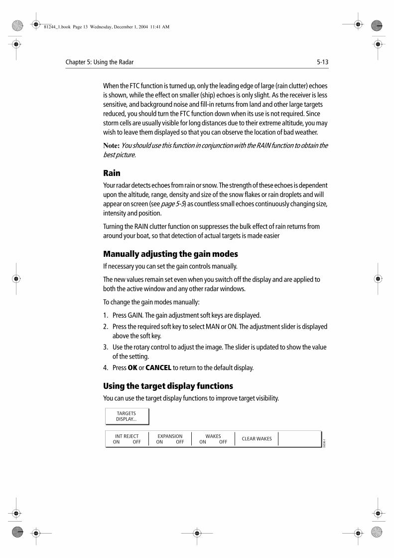
Chapter 5: Using the Radar 5-13
When the FTC function is turned up, only the leading edge of large (rain clutter) echoes is shown, while the effect on smaller (ship) echoes is only slight. As the receiver is less sensitive, and background noise and fill-in returns from land and other large targets reduced, you should turn the FTC function down when its use is not required. Since storm cells are usually visible for long distances due to their extreme altitude, you may wish to leave them displayed so that you can observe the location of bad weather.
Note: You should use this function in conjunction with the RAIN function to obtain the best picture.
RainYour radar detects echoes from rain or snow. The strength of these echoes is dependent upon the altitude, range, density and size of the snow flakes or rain droplets and will appear on screen (see page 5-5) as countless small echoes continuously changing size, intensity and position.
Turning the RAIN clutter function on suppresses the bulk effect of rain returns from around your boat, so that detection of actual targets is made easier
Manually adjusting the gain modesIf necessary you can set the gain controls manually.
The new values remain set even when you switch off the display and are applied to both the active window and any other radar windows.
To change the gain modes manually:
1. Press GAIN. The gain adjustment soft keys are displayed.
2. Press the required soft key to select MAN or ON. The adjustment slider is displayed above the soft key.
3. Use the rotary control to adjust the image. The slider is updated to show the value of the setting.
4. Press OK or CANCEL to return to the default display.
Using the target display functionsYou can use the target display functions to improve target visibility.
TARGETSDISPLAY...
INT REJECTON OFF
EXPANSIONON OFF
WAKESON OFF
D659
6-1CLEAR WAKES
81244_1.book Page 13 Wednesday, December 1, 2004 11:41 AM
5-14 E-Series Networked Display Reference Manual
Interference RejectionThe interference rejection function automatically reduces any mutual radar interference when two radar equipped vessels are operating within range of each other (see Interference on page 5-5). This function is normally left switched on, however, if you wish to detect the presence of other radars in the vicinity, you can turn off the interference rejection.
The two levels of interference rejection (NORMAL or HIGH) are selected in Radar Setup Menu, see page 5-26. To access this menu, press and hold the INT. REJECT key.
ExpansionThe expansion function overrides the pulse length if the magnification level is set to HIGH in the Radar Setup Menu (see page 5-26). If the LOW setting is selected, the processing is altered to give larger returns. This will make targets easier to see but may compromise target resolution.
To access the Radar Setup Menu, press and hold the EXPANSION key.
WakesYou can see the direction and speed of moving targets relative to your boat, by selecting the wakes function.
When wakes is switched on, the target is displayed in yellow; as the signal diminishes with time it is shown in paler shades of blue. You can select, via the Radar Setup Menu, (see page 5-26) whether these wakes are shown for periods of 10 seconds, 30, seconds, 1 minute, 5 minutes or 10 minutes. To access this menu, press and hold the WAKES key.
When the currently displayed wakes are no longer required, press CLEAR WAKES to remove them from your screen.
5.7 How do I change the displayed range?You can zoom in or out to view your radar picture at varying scales. The scale is measured from the centre to the top of the window and is displayed in the left-hand corner of the status bar.
The scale you will need is dependent upon where you are navigating and the level of detail that you wish to see:
• Short range scales - provide greater detail of radar echoes close to the vessel, and are most suited for use as you approach coastlines, habors or other vessels in the area. The shortest range scale available is 1/8 nautical miles (or the equivalent in the chosen unit).
81244_1.book Page 14 Wednesday, December 1, 2004 11:41 AM
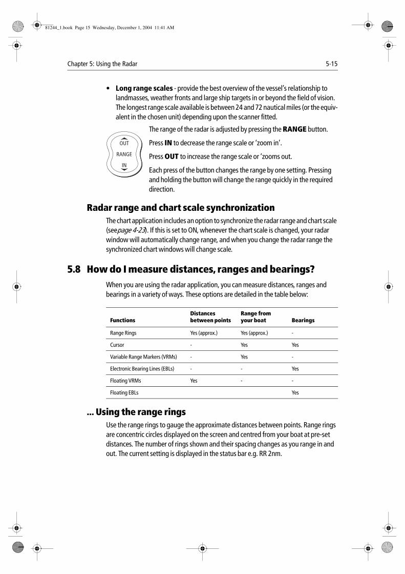
Chapter 5: Using the Radar 5-15
• Long range scales - provide the best overview of the vessel’s relationship to landmasses, weather fronts and large ship targets in or beyond the field of vision. The longest range scale available is between 24 and 72 nautical miles (or the equiv-alent in the chosen unit) depending upon the scanner fitted.
The range of the radar is adjusted by pressing the RANGE button.
Press IN to decrease the range scale or ‘zoom in’.
Press OUT to increase the range scale or ‘zooms out.
Each press of the button changes the range by one setting. Pressing and holding the button will change the range quickly in the required direction.
Radar range and chart scale synchronizationThe chart application includes an option to synchronize the radar range and chart scale (seepage 4-23). If this is set to ON, whenever the chart scale is changed, your radar window will automatically change range, and when you change the radar range the synchronized chart windows will change scale.
5.8 How do I measure distances, ranges and bearings?When you are using the radar application, you can measure distances, ranges and bearings in a variety of ways. These options are detailed in the table below:
... Using the range ringsUse the range rings to gauge the approximate distances between points. Range rings are concentric circles displayed on the screen and centred from your boat at pre-set distances. The number of rings shown and their spacing changes as you range in and out. The current setting is displayed in the status bar e.g. RR 2nm.
FunctionsDistances between points
Range from your boat Bearings
Range Rings Yes (approx.) Yes (approx.) -
Cursor - Yes Yes
Variable Range Markers (VRMs) - Yes -
Electronic Bearing Lines (EBLs) - - Yes
Floating VRMs Yes - -
Floating EBLs Yes
D6585-1
RANGE
IN
OUT
81244_1.book Page 15 Wednesday, December 1, 2004 11:41 AM
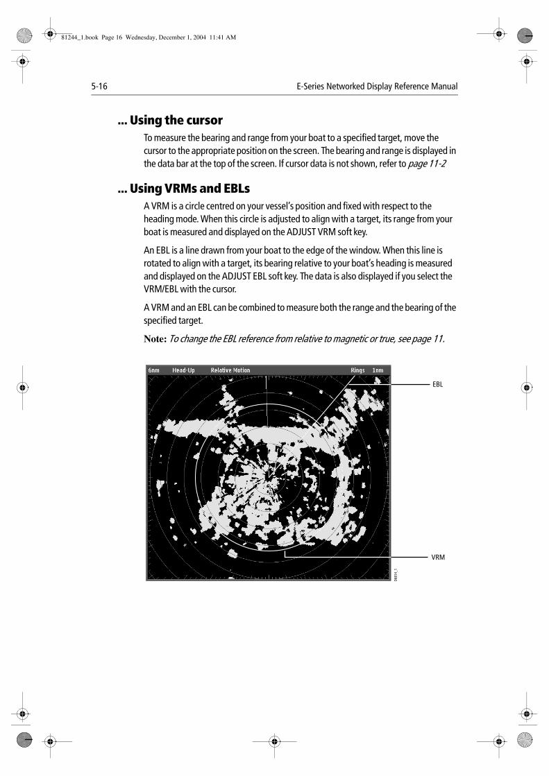
5-16 E-Series Networked Display Reference Manual
... Using the cursorTo measure the bearing and range from your boat to a specified target, move the cursor to the appropriate position on the screen. The bearing and range is displayed in the data bar at the top of the screen. If cursor data is not shown, refer to page 11-2
... Using VRMs and EBLsA VRM is a circle centred on your vessel’s position and fixed with respect to the heading mode. When this circle is adjusted to align with a target, its range from your boat is measured and displayed on the ADJUST VRM soft key.
An EBL is a line drawn from your boat to the edge of the window. When this line is rotated to align with a target, its bearing relative to your boat’s heading is measured and displayed on the ADJUST EBL soft key. The data is also displayed if you select the VRM/EBL with the cursor.
A VRM and an EBL can be combined to measure both the range and the bearing of the specified target.
Note: To change the EBL reference from relative to magnetic or true, see page 11.
D681
4_1
EBL
VRM
81244_1.book Page 16 Wednesday, December 1, 2004 11:41 AM
Chapter 5: Using the Radar 5-17
How do I create a VRM/EBL?
The first VRM/EBL will be placed at a location of 1/3 of the current range and 030° relative to your boat’s head. If this setting is adjusted, the display will retain the adjustments and use them when the VRM/EBL is next turned on.
To use VRMs/EBLs to tell you the range/bearing of a target:
1. Toggle VRM/EBL soft key to ON. The VRM/EBL will be shown on the radar picture with your boat at its center.
2. ADJUST VRM and VRM are highlighted to indicate it can be adjusted.
3. Use the rotary control to adjust the VRM to the required size.
4. Press the rotary control or press ADJUST EBL. This will highlight the EBL.
5. Use the rotary control to place the EBL over the required target.
6. Press OK to remove the highlight and retain the adjustment.
The distance and bearing of the target is now shown in the ADJUST VRM and ADJUST EBL soft key labels. You will be able to tell which way the target is traveling by watching how it moves in relation to the EBL. If it continues traveling directly along the EBL, it shows that it is on a possible collision course with your boat - take the appropriate action.
To place a second VRM/EBL use the SET UP VRM/EBL 2 soft key and repeat steps 1 to 7 above. This VRM/EBL will be placed at a location of 2/3 of current range and a bearing of 330°.
... Using floating VRMs/EBLsYou can use the VRM/EBL float function to measure the range and bearing between any two points on the radar screen. This function allows you to move the VRM/EBL away from your boat’s position and onto a target. You can then change the radius of the VRM to determine the distance between two points and change the angle of the EBL, relative to its new origin, to obtain the bearing.
How do I float a VRM/EBL?
1. Create the VRM/EBL as described previously.
2. Press FLOATING EBL. This will highlight the VRM/EBL.
3. Press ADJUST FLOAT. The cursor is positioned at the center.
4. To set the origin to a different position:
VRM/EBL
VRM/EBL 1ON OFF
ADJUST VRM1.991nm
ADJUST EBL124ºP
FLOATINGEBL...
SET UPVRM/EBL 2
D659
7-1
81244_1.book Page 17 Wednesday, December 1, 2004 11:41 AM
5-18 E-Series Networked Display Reference Manual
i. Use the trackpad to move the centre of the VRM/EBL over the first target.
ii. Press OK to retain the adjustment and remove the highlight.
5. To adjust the VRM:
i. Press OK to access the soft keys.
ii. Press ADJUST VRM to highlight the VRM.
iii. Use the rotary control to move the VRM over the second target. The distance between the first and second target is shown on the ADJUST VRM soft key.
6. To adjust the EBL, press the rotary control or press ADJUST EBL, to highlight the EBL.
7. Use the rotary control to adjust the EBL over the second target. The bearing between the first and second target is shown on the ADJUST EBL soft key.
8. Press OK to retain the adjustment.
9. If required, you can float a second VRM/EBL:
i. Press SET UP VRM/EBL 2.
ii. Toggle the VRM/EBL 2 to ON.
iii. Repeat steps 1 to 8 above.
Unfloating a VRM/EBL• To unfloat VRM/EBL 1, toggle VRM/EBL 1 to CENTER.
• To unfloat VRM/EBL 2, press SET UP VRM/EBL 2 and repeat the above.
5.9 How do I use radar to avoid a collision?Your radar includes numerous functions to help you avoid a collision. You can:
• Assess how far away a target is and its bearing (VRMs/EBLs).
• Set an alarm to trigger when a target is within a specified zone (Guard Zones).
• Display detailed information on tracked targets (MARPA).
• Display the range and bearing of a target.
Guard ZonesGuard zones are fixed with respect to the SHM, moving as it moves. They also move if the center is offset or the range scale is changed, so that the pre-marked area is maintained. A guard zone only operates when the whole zone is displayed on the screen. An audible alarm sounds to alert you when a target enters the zone.
Guard zones are inactive for 10 seconds after being placed or re-sized, to avoid inappropriate alarms whilst they are being positioned.
You can set up guard zones to be either sector zones or 360° (circular) zones. Your radar can be set up using one or two zones.
81244_1.book Page 18 Wednesday, December 1, 2004 11:41 AM
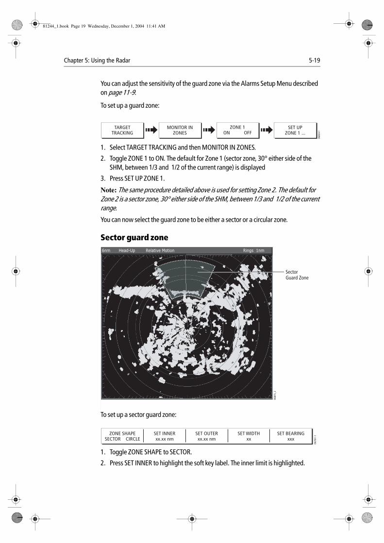
Chapter 5: Using the Radar 5-19
You can adjust the sensitivity of the guard zone via the Alarms Setup Menu described on page 11-9.
To set up a guard zone:
1. Select TARGET TRACKING and then MONITOR IN ZONES.
2. Toggle ZONE 1 to ON. The default for Zone 1 (sector zone, 30° either side of the SHM, between 1/3 and 1/2 of the current range) is displayed
3. Press SET UP ZONE 1.
Note: The same procedure detailed above is used for setting Zone 2. The default for Zone 2 is a sector zone, 30° either side of the SHM, between 1/3 and 1/2 of the current range.
You can now select the guard zone to be either a sector or a circular zone.
Sector guard zone
To set up a sector guard zone:
1. Toggle ZONE SHAPE to SECTOR.
2. Press SET INNER to highlight the soft key label. The inner limit is highlighted.
MONITOR INZONES
ZONE 1ON OFF
TARGETTRACKING
SET UPZONE 1 ...
D683
4-1
6nm Head-Up Relative Motion Rings 1nm
D681
5_2
SectorGuard Zone
ZONE SHAPESECTOR CIRCLE
SET INNERxx.xx nm
SET OUTERxx.xx nm
SET WIDTHxx
SET BEARINGxxx
D67
61-1
81244_1.book Page 19 Wednesday, December 1, 2004 11:41 AM
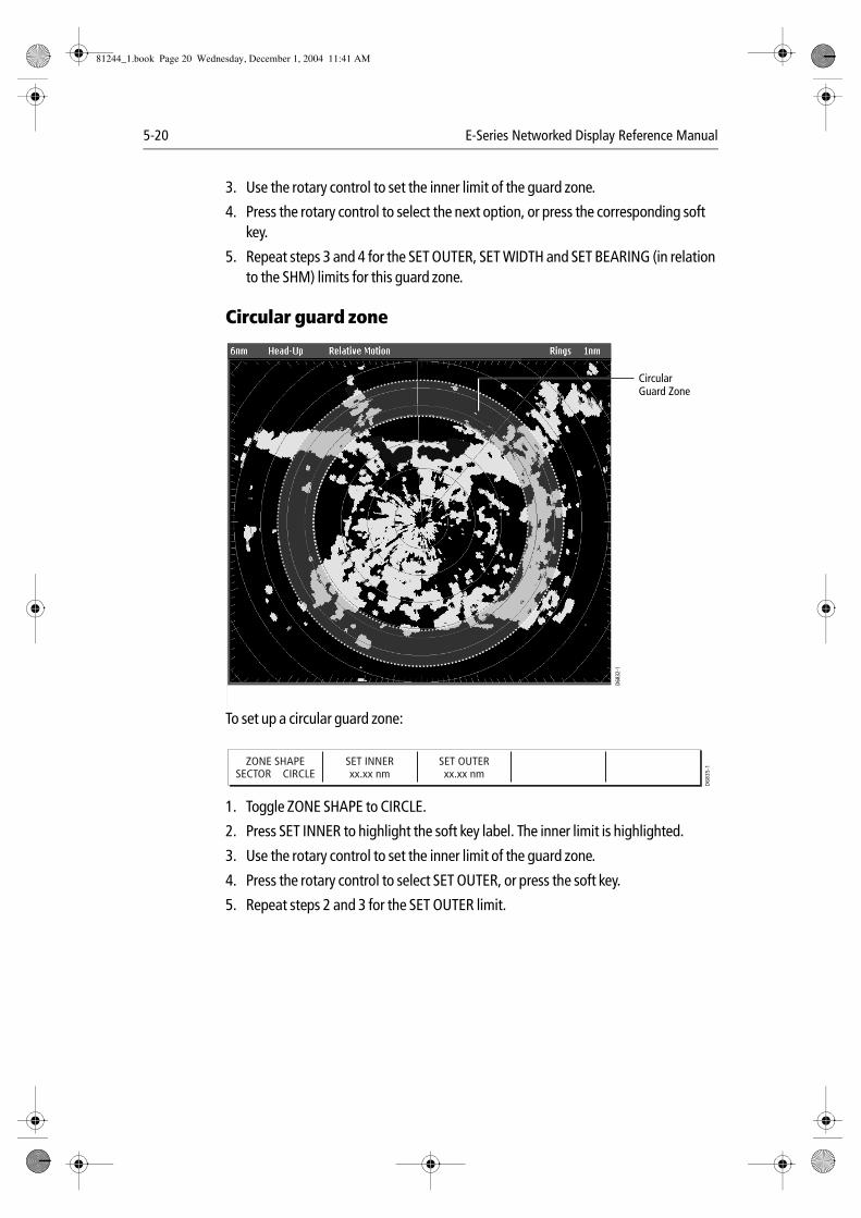
5-20 E-Series Networked Display Reference Manual
3. Use the rotary control to set the inner limit of the guard zone.
4. Press the rotary control to select the next option, or press the corresponding soft key.
5. Repeat steps 3 and 4 for the SET OUTER, SET WIDTH and SET BEARING (in relation to the SHM) limits for this guard zone.
Circular guard zone
To set up a circular guard zone:
1. Toggle ZONE SHAPE to CIRCLE.
2. Press SET INNER to highlight the soft key label. The inner limit is highlighted.
3. Use the rotary control to set the inner limit of the guard zone.
4. Press the rotary control to select SET OUTER, or press the soft key.
5. Repeat steps 2 and 3 for the SET OUTER limit.
D683
2-1
Circular Guard Zone
ZONE SHAPESECTOR CIRCLE
SET INNERxx.xx nm
SET OUTERxx.xx nm
D68
35-1
81244_1.book Page 20 Wednesday, December 1, 2004 11:41 AM
Chapter 5: Using the Radar 5-21
MARPA
SAFETY NOTICESMARPA can improve collision avoidance when used wisely. It is the User’s responsibility to exercise common prudence and navigational judgements.
There are conditions where acquiring a target may become difficult. These same conditions may be a factor in successfully tracking a target. Some of the conditions are:
• The target echo is weak. The target is very close to land, buoys or other large tar-gets.
• The target or your own ship is making rapid manoeuvres.
• Choppy sea state conditions exist and the target is buried in excessive sea clutter or in deep swells.
• Choppy sea state conditions exist yielding poor stability; own boat’s heading data is very unstable.
• Inadequate heading data.
Symptoms of such conditions are that acquisition is difficult and the MARPA vectors are unstable; the symbol wanders away from the target, locks on to another target or changes to a lost symbol target.
If any of these conditions are present, acquisition and tracking may need to be re-initiated or, in some cases be impossible to maintain. Improving the quality of the heading data will reduce the effect of the other conditions.
Introduction to MARPAYou can use the Mini Automatic Radar Plotting Aid (MARPA) functions for target tracking and risk analysis. MARPA improves collision avoidance by obtaining detailed information for up to 10 automatically tracked targets and provides continuous, accurate and rapid situation evaluation.
MARPA automatically tracks acquired targets, calculates target bearing and range, true speed and course, Closest Point of Approach (CPA), and Time to Closest Point of Approach (TCPA).
Each target tracked can be displayed with a CPA graphic which shows the target vessel, course and speed (as a vector) and indicates the CPA. The calculated target data can also be shown on your screen. Each target is continually assessed and an audible alarm is sounded if a target becomes dangerous, or is lost.
Effective MARPA operation is dependant on accurate own-ship’s heading plus Speed Over Ground (SOG) and Course Over Ground (COG) information. The better the quality of the heading data, the better MARPA will perform. MARPA will function without SOG and COG, but only relative vector, CPA, and TCPA are shown. Target course and
81244_1.book Page 21 Wednesday, December 1, 2004 11:41 AM
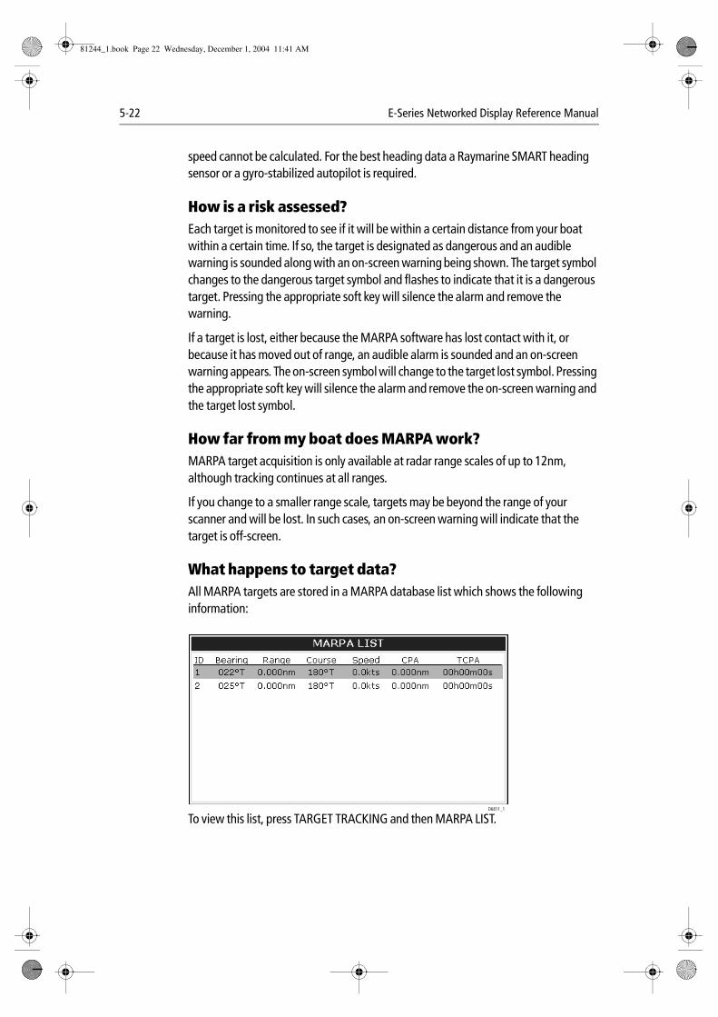
5-22 E-Series Networked Display Reference Manual
speed cannot be calculated. For the best heading data a Raymarine SMART heading sensor or a gyro-stabilized autopilot is required.
How is a risk assessed?Each target is monitored to see if it will be within a certain distance from your boat within a certain time. If so, the target is designated as dangerous and an audible warning is sounded along with an on-screen warning being shown. The target symbol changes to the dangerous target symbol and flashes to indicate that it is a dangerous target. Pressing the appropriate soft key will silence the alarm and remove the warning.
If a target is lost, either because the MARPA software has lost contact with it, or because it has moved out of range, an audible alarm is sounded and an on-screen warning appears. The on-screen symbol will change to the target lost symbol. Pressing the appropriate soft key will silence the alarm and remove the on-screen warning and the target lost symbol.
How far from my boat does MARPA work?MARPA target acquisition is only available at radar range scales of up to 12nm, although tracking continues at all ranges.
If you change to a smaller range scale, targets may be beyond the range of your scanner and will be lost. In such cases, an on-screen warning will indicate that the target is off-screen.
What happens to target data?All MARPA targets are stored in a MARPA database list which shows the following information:
To view this list, press TARGET TRACKING and then MARPA LIST.D6811_1
81244_1.book Page 22 Wednesday, December 1, 2004 11:41 AM

Chapter 5: Using the Radar 5-23
How are targets displayed on screen?Each target is displayed as a symbol which indicates its status:
What are CPA graphics and what do they show me?CPA graphics show vectors for your vessel and a selected target. A vector is a line on-screen showing the predicted courses of your vessel and the selected target if you both remain on your present course. These vectors vary in length due to boat speed and vector length set in the MARPA Setup menu.
remain on your present course. These vectors are infinite and extend to the edges of the screen. These graphics can be shown in either TRUE or RELATIVE modes.
The CPA graphic and associated soft keys are displayed when you select a target with the cursor. You can change the settings as follows:
• AUTO - when you place the cursor over any part of a MARPA symbol, the CPA graphic is displayed.
• ON - the CPA graphic will be displayed for as long as the target is being tracked.
• OFF - no CPA graphic is shown.
D754
2_1
Dangerous target
Safe target
Target being acquired
Lost target
MARPA targets
D681
0_1
1
2
CPA GRAPHICOFF ON AUTO
CANCELALL TARGETS
SHOW DETAILSOFF ON
CANCEL TARGET
D659
9-2
81244_1.book Page 23 Wednesday, December 1, 2004 11:41 AM
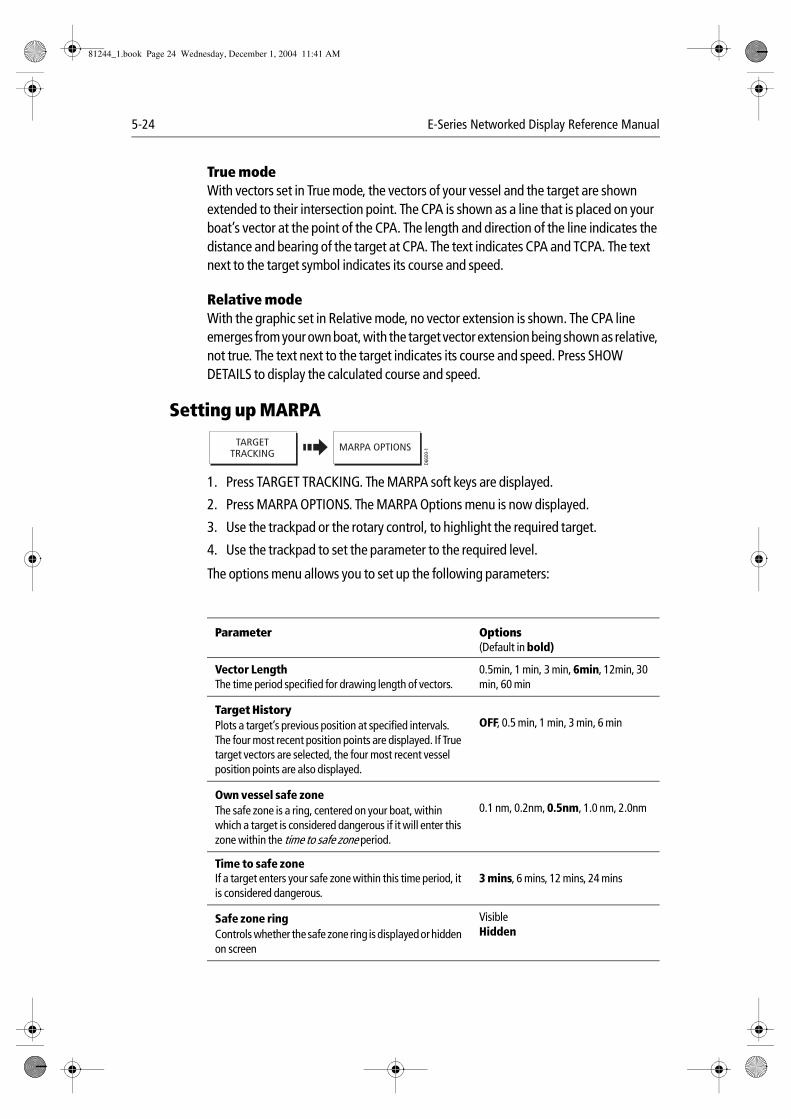
5-24 E-Series Networked Display Reference Manual
True modeWith vectors set in True mode, the vectors of your vessel and the target are shown extended to their intersection point. The CPA is shown as a line that is placed on your boat’s vector at the point of the CPA. The length and direction of the line indicates the distance and bearing of the target at CPA. The text indicates CPA and TCPA. The text next to the target symbol indicates its course and speed.
Relative modeWith the graphic set in Relative mode, no vector extension is shown. The CPA line emerges from your own boat, with the target vector extension being shown as relative, not true. The text next to the target indicates its course and speed. Press SHOW DETAILS to display the calculated course and speed.
Setting up MARPA
1. Press TARGET TRACKING. The MARPA soft keys are displayed.
2. Press MARPA OPTIONS. The MARPA Options menu is now displayed.
3. Use the trackpad or the rotary control, to highlight the required target.
4. Use the trackpad to set the parameter to the required level.
The options menu allows you to set up the following parameters:
Parameter Options(Default in bold)
Vector LengthThe time period specified for drawing length of vectors.
0.5min, 1 min, 3 min, 6min, 12min, 30 min, 60 min
Target HistoryPlots a target’s previous position at specified intervals. The four most recent position points are displayed. If True target vectors are selected, the four most recent vessel position points are also displayed.
OFF, 0.5 min, 1 min, 3 min, 6 min
Own vessel safe zoneThe safe zone is a ring, centered on your boat, within which a target is considered dangerous if it will enter this zone within the time to safe zone period.
0.1 nm, 0.2nm, 0.5nm, 1.0 nm, 2.0nm
Time to safe zoneIf a target enters your safe zone within this time period, it is considered dangerous.
3 mins, 6 mins, 12 mins, 24 mins
Safe zone ringControls whether the safe zone ring is displayed or hidden on screen
VisibleHidden
D660
0-1
TARGETTRACKING
MARPA OPTIONS
81244_1.book Page 24 Wednesday, December 1, 2004 11:41 AM
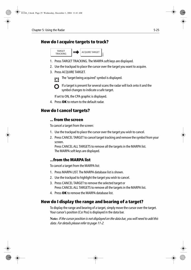
Chapter 5: Using the Radar 5-25
How do I acquire targets to track?
1. Press TARGET TRACKING. The MARPA soft keys are displayed.
2. Use the trackpad to place the cursor over the target you want to acquire.
3. Press ACQUIRE TARGET. The ‘target being acquired’ symbol is displayed.
If a target is present for several scans the radar will lock onto it and the symbol changes to indicate a safe target.
If set to ON, the CPA graphic is displayed.
4. Press OK to return to the default radar.
How do I cancel targets?
... from the screenTo cancel a target from the screen:
1. Use the trackpad to place the cursor over the target you wish to cancel.
2. Press CANCEL TARGET to cancel target tracking and remove the symbol from your screen.Press CANCEL ALL TARGETS to remove all the targets in the MARPA list.The MARPA soft keys are displayed.
...from the MARPA listTo cancel a target from the MARPA list:
1. Press MARPA LIST. The MARPA database list is shown.
2. Use the trackpad to highlight the target you wish to cancel.
3. Press CANCEL TARGET to remove the selected target orPress CANCEL ALL TARGETS to remove all the targets in the MARPA list.
4. Press OK to remove the MARPA database list.
How do I display the range and bearing of a target?To display the range and bearing of a target, simply move the cursor over the target. Your cursor’s position (Csr Pos) is displayed in the data bar.
Note: If the cursor position is not displayed on the data bar, you will need to add this data. For details please refer to page 11-2.
D682
9-1
TARGETTRACKING
ACQUIRE TARGET
D754
3_1
D754
2_1
81244_1.book Page 25 Wednesday, December 1, 2004 11:41 AM
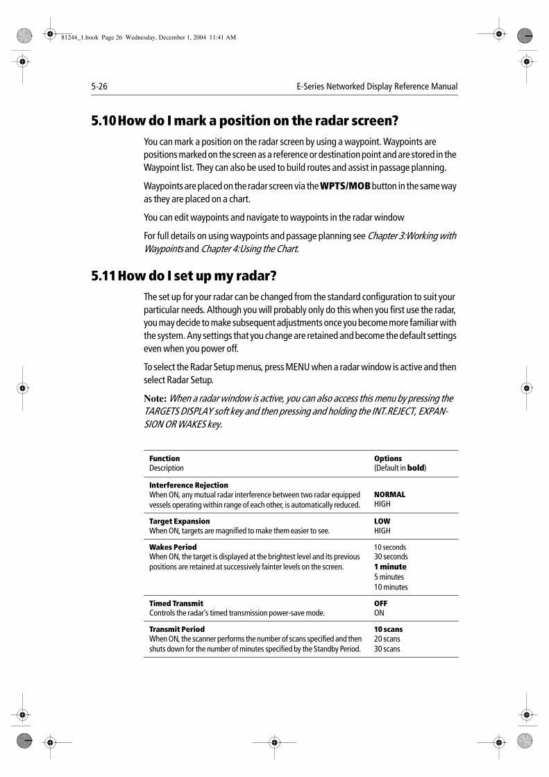
5-26 E-Series Networked Display Reference Manual
5.10How do I mark a position on the radar screen?You can mark a position on the radar screen by using a waypoint. Waypoints are positions marked on the screen as a reference or destination point and are stored in the Waypoint list. They can also be used to build routes and assist in passage planning.
Waypoints are placed on the radar screen via the WPTS/MOB button in the same way as they are placed on a chart.
You can edit waypoints and navigate to waypoints in the radar window
For full details on using waypoints and passage planning see Chapter 3:Working with Waypoints and Chapter 4:Using the Chart.
5.11How do I set up my radar?The set up for your radar can be changed from the standard configuration to suit your particular needs. Although you will probably only do this when you first use the radar, you may decide to make subsequent adjustments once you become more familiar with the system. Any settings that you change are retained and become the default settings even when you power off.
To select the Radar Setup menus, press MENU when a radar window is active and then select Radar Setup.
Note: When a radar window is active, you can also access this menu by pressing the TARGETS DISPLAY soft key and then pressing and holding the INT.REJECT, EXPAN-SION OR WAKES key.
FunctionDescription
Options(Default in bold)
Interference RejectionWhen ON, any mutual radar interference between two radar equipped vessels operating within range of each other, is automatically reduced.
NORMALHIGH
Target ExpansionWhen ON, targets are magnified to make them easier to see.
LOWHIGH
Wakes PeriodWhen ON, the target is displayed at the brightest level and its previous positions are retained at successively fainter levels on the screen.
10 seconds30 seconds1 minute5 minutes10 minutes
Timed TransmitControls the radar’s timed transmission power-save mode.
OFFON
Transmit PeriodWhen ON, the scanner performs the number of scans specified and then shuts down for the number of minutes specified by the Standby Period.
10 scans20 scans30 scans
81244_1.book Page 26 Wednesday, December 1, 2004 11:41 AM
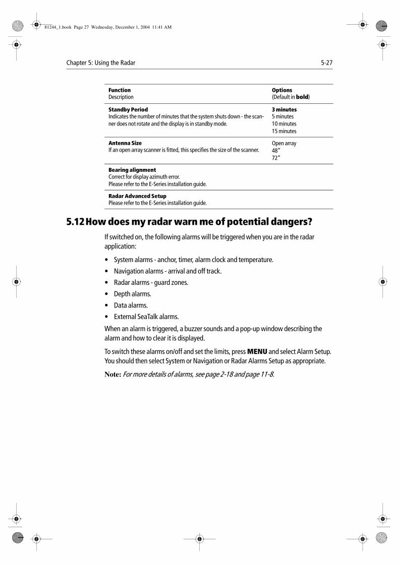
Chapter 5: Using the Radar 5-27
5.12How does my radar warn me of potential dangers?If switched on, the following alarms will be triggered when you are in the radar application:
• System alarms - anchor, timer, alarm clock and temperature.
• Navigation alarms - arrival and off track.
• Radar alarms - guard zones.
• Depth alarms.
• Data alarms.
• External SeaTalk alarms.
When an alarm is triggered, a buzzer sounds and a pop-up window describing the alarm and how to clear it is displayed.
To switch these alarms on/off and set the limits, press MENU and select Alarm Setup. You should then select System or Navigation or Radar Alarms Setup as appropriate.
Note: For more details of alarms, see page 2-18 and page 11-8.
Standby PeriodIndicates the number of minutes that the system shuts down - the scan-ner does not rotate and the display is in standby mode.
3 minutes5 minutes10 minutes15 minutes
Antenna SizeIf an open array scanner is fitted, this specifies the size of the scanner.
Open array48”72”
Bearing alignmentCorrect for display azimuth error.Please refer to the E-Series installation guide.
Radar Advanced SetupPlease refer to the E-Series installation guide.
FunctionDescription
Options(Default in bold)
81244_1.book Page 27 Wednesday, December 1, 2004 11:41 AM

5-28 E-Series Networked Display Reference Manual
81244_1.book Page 28 Wednesday, December 1, 2004 11:41 AM

Chapter 6: Using the Fishfinder 6-1
Chapter 6: Using the Fishfinder
6.1 IntroductionThis chapter describes the how Fishfinder uses sonar to see fish, bottom structure and texture, and underwater obstructions such as wrecks.
The standard fishfinder image is a historical, scrolling bottom graph at an automatically selected range and frequency. Various functions are provided to improve the underwater view, select what is displayed and sound an alarm including:
• Changing the view displayed (A-Scope, Zoom or Bottom Lock).
• Adjusting the range and zoom.
• Shifting the image.
• Simplifying the bottom image and isolating bottom fish.
• Pausing the scrolling image.
• Switching the depth digit on/off.
• Using waypoints to mark a position.
• Determining depths and distances of targets.
• Fishfinder alarms (fish, depth or water temperature).
• Setting up the fishfinder application including manually adjusting the frequency and adjusting the gain values.
Note: Please refer to the Installation Guide for fishfinder calibration information.
6.2 How does the Fishfinder work?The fishfinder application uses a Digital Sounder Module (DSM) to process sonar signals from a suitable transducer and provide a detailed underwater view.
The transducer located on the bottom of the boat sends pulses of sound waves into the water and measures the time it takes for the sound wave to travel to the bottom and back. The returning sound echoes are affected by bottom structure and by any other objects in their path, e.g. fish, wrecks, reefs.
The Digital Sounder Module (DSM) processes these echoes and sends data to the fishfinder which displays a visual interpretation of the underwater view. The strength of echoes is indicated on the display by different colors. You can use this information to determine the bottom structure, the size of fish and other objects in the water e.g. debris, air bubbles.
Notes: (1) The DSM will operate at a frequency of 50 kHz or 200 kHz.
(2) Some transducers will also enable the fishfinder to display water temperature and/or speed.
81244_1.book Page 1 Wednesday, December 1, 2004 11:41 AM
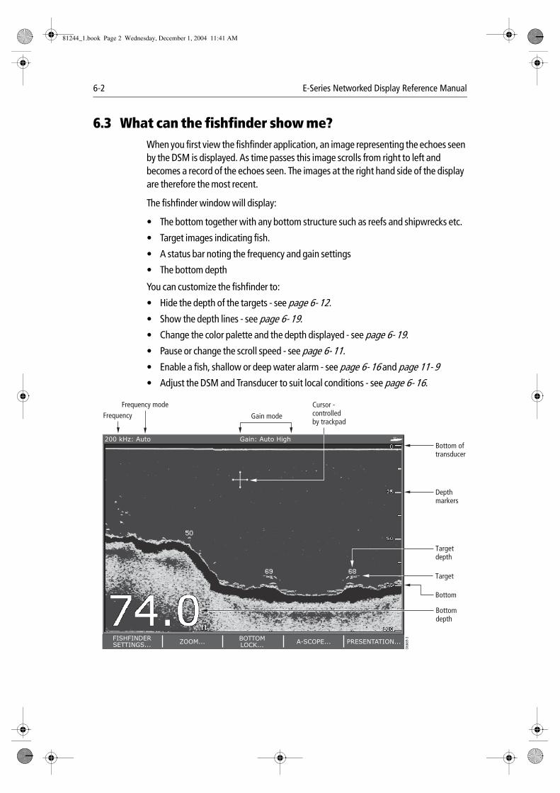
6-2 E-Series Networked Display Reference Manual
6.3 What can the fishfinder show me?When you first view the fishfinder application, an image representing the echoes seen by the DSM is displayed. As time passes this image scrolls from right to left and becomes a record of the echoes seen. The images at the right hand side of the display are therefore the most recent.
The fishfinder window will display:
• The bottom together with any bottom structure such as reefs and shipwrecks etc.
• Target images indicating fish.
• A status bar noting the frequency and gain settings
• The bottom depth
You can customize the fishfinder to:
• Hide the depth of the targets - see page 6- 12.
• Show the depth lines - see page 6- 19.
• Change the color palette and the depth displayed - see page 6- 19.
• Pause or change the scroll speed - see page 6- 11.
• Enable a fish, shallow or deep water alarm - see page 6- 16 and page 11- 9• Adjust the DSM and Transducer to suit local conditions - see page 6- 16.
6869
50
FISHFINDERSETTINGS...
ZOOM...BOTTOMLOCK...
A-SCOPE... PRESENTATION...
200 kHz: Auto Gain: Auto High
Cursor -controlledby trackpad
D666
9-3
Depthmarkers
Target
Bottom
Bottom oftransducer
Frequency Gain mode
Frequency mode
Targetdepth
Bottomdepth
81244_1.book Page 2 Wednesday, December 1, 2004 11:41 AM
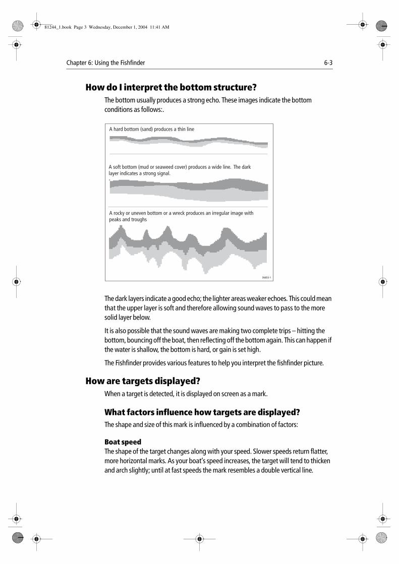
Chapter 6: Using the Fishfinder 6-3
How do I interpret the bottom structure?The bottom usually produces a strong echo. These images indicate the bottom conditions as follows:.
The dark layers indicate a good echo; the lighter areas weaker echoes. This could mean that the upper layer is soft and therefore allowing sound waves to pass to the more solid layer below.
It is also possible that the sound waves are making two complete trips – hitting the bottom, bouncing off the boat, then reflecting off the bottom again. This can happen if the water is shallow, the bottom is hard, or gain is set high.
The Fishfinder provides various features to help you interpret the fishfinder picture.
How are targets displayed?When a target is detected, it is displayed on screen as a mark.
What factors influence how targets are displayed?The shape and size of this mark is influenced by a combination of factors:
Boat speedThe shape of the target changes along with your speed. Slower speeds return flatter, more horizontal marks. As your boat’s speed increases, the target will tend to thicken and arch slightly; until at fast speeds the mark resembles a double vertical line.
D6855-1
A hard bottom (sand) produces a thin line
A soft bottom (mud or seaweed cover) produces a wide line. The darklayer indicates a strong signal.-
A rocky or uneven bottom or a wreck produces an irregular image withpeaks and troughs
81244_1.book Page 3 Wednesday, December 1, 2004 11:41 AM
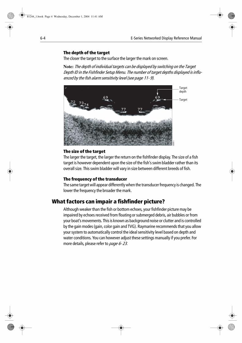
6-4 E-Series Networked Display Reference Manual
The depth of the targetThe closer the target to the surface the larger the mark on screen.
Note: The depth of individual targets can be displayed by switching on the Target Depth ID in the Fishfinder Setup Menu. The number of target depths displayed is influ-enced by the fish alarm sensitivity level (see page 11- 9).
The size of the targetThe larger the target, the larger the return on the fishfinder display. The size of a fish target is however dependent upon the size of the fish’s swim bladder rather than its overall size. This swim bladder will vary in size between different breeds of fish.
The frequency of the transducerThe same target will appear differently when the transducer frequency is changed. The lower the frequency the broader the mark.
What factors can impair a fishfinder picture?Although weaker than the fish or bottom echoes, your fishfinder picture may be impaired by echoes received from floating or submerged debris, air bubbles or from your boat’s movements. This is known as background noise or clutter and is controlled by the gain modes (gain, color gain and TVG). Raymarine recommends that you allow your system to automatically control the ideal sensitivity level based on depth and water conditions. You can however adjust these settings manually if you prefer. For more details, please refer to page 6- 23.
Target
Targetdepth
D689
0-1
81244_1.book Page 4 Wednesday, December 1, 2004 11:41 AM
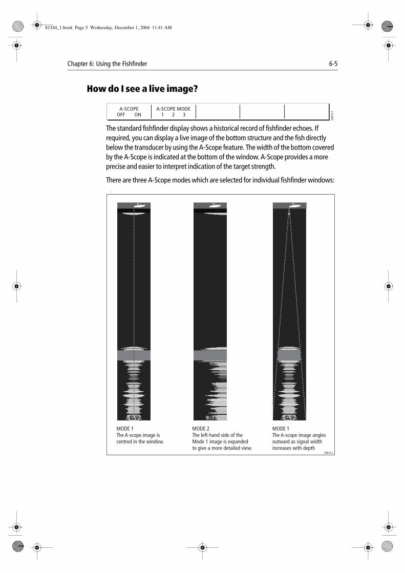
Chapter 6: Using the Fishfinder 6-5
How do I see a live image?
The standard fishfinder display shows a historical record of fishfinder echoes. If required, you can display a live image of the bottom structure and the fish directly below the transducer by using the A-Scope feature. The width of the bottom covered by the A-Scope is indicated at the bottom of the window. A-Scope provides a more precise and easier to interpret indication of the target strength.
There are three A-Scope modes which are selected for individual fishfinder windows: I
A-SCOPEOFF ON
A-SCOPE MODE1 2 3
D66
75-1
MODE 1The A-scope image iscentred in the window.
MODE 1The A-scope image anglesoutward as signal widthincreases with depth
MODE 2The left-hand side of theMode 1 image is expandedto give a more detailed view.
D6674-2
81244_1.book Page 5 Wednesday, December 1, 2004 11:41 AM
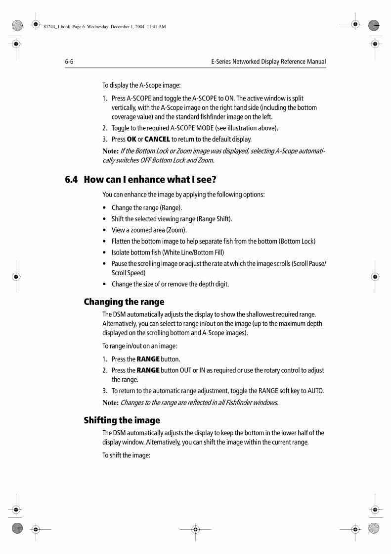
6-6 E-Series Networked Display Reference Manual
To display the A-Scope image:
1. Press A-SCOPE and toggle the A-SCOPE to ON. The active window is split vertically, with the A-Scope image on the right hand side (including the bottom coverage value) and the standard fishfinder image on the left.
2. Toggle to the required A-SCOPE MODE (see illustration above).
3. Press OK or CANCEL to return to the default display.
Note: If the Bottom Lock or Zoom image was displayed, selecting A-Scope automati-cally switches OFF Bottom Lock and Zoom.
6.4 How can I enhance what I see?You can enhance the image by applying the following options:
• Change the range (Range).
• Shift the selected viewing range (Range Shift).
• View a zoomed area (Zoom).
• Flatten the bottom image to help separate fish from the bottom (Bottom Lock)
• Isolate bottom fish (White Line/Bottom Fill)
• Pause the scrolling image or adjust the rate at which the image scrolls (Scroll Pause/Scroll Speed)
• Change the size of or remove the depth digit.
Changing the rangeThe DSM automatically adjusts the display to show the shallowest required range. Alternatively, you can select to range in/out on the image (up to the maximum depth displayed on the scrolling bottom and A-Scope images).
To range in/out on an image:
1. Press the RANGE button.
2. Press the RANGE button OUT or IN as required or use the rotary control to adjust the range.
3. To return to the automatic range adjustment, toggle the RANGE soft key to AUTO.
Note: Changes to the range are reflected in all Fishfinder windows.
Shifting the imageThe DSM automatically adjusts the display to keep the bottom in the lower half of the display window. Alternatively, you can shift the image within the current range.
To shift the image:
81244_1.book Page 6 Wednesday, December 1, 2004 11:41 AM
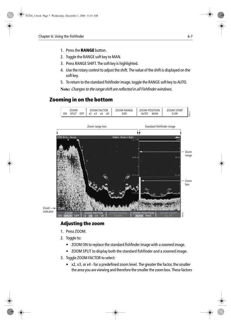
Chapter 6: Using the Fishfinder 6-7
1. Press the RANGE button.
2. Toggle the RANGE soft key to MAN.
3. Press RANGE SHIFT. The soft key is highlighted.
4. Use the rotary control to adjust the shift. The value of the shift is displayed on the soft key.
5. To return to the standard fishfinder image, toggle the RANGE soft key to AUTO.
Note: Changes to the range shift are reflected in all Fishfinder windows.
Zooming in on the bottom
Adjusting the zoom
1. Press ZOOM.
2. Toggle to:
• ZOOM ON to replace the standard fishfinder image with a zoomed image.
• ZOOM SPLIT to display both the standard fishfinder and a zoomed image.
3. Toggle ZOOM FACTOR to select:
• x2, x3, or x4 - for a predefined zoom level. The greater the factor, the smaller the area you are viewing and therefore the smaller the zoom box. These factors
ZOOMON SPLIT OFF
ZOOM FACTORx2 x3 x4 xR
ZOOM RANGE20ft
ZOOM POSITIONAUTO MAN
ZOOM START0.0ft
D66
77.2
ZxRZOOM START
52.7ftZOOM RANGE
4500ftZOOM FACTOR
x2 x3 x4 xRZOOM POSITION
AUTO MANZOOM
ON SPLIT OFF
Zoombox
Zoomindicator
Standard fishfinder imageZoom range box
D667
6-2
Zoomrange
81244_1.book Page 7 Wednesday, December 1, 2004 11:41 AM
6-8 E-Series Networked Display Reference Manual
are proportioned to the range. Therefore, as the range increases, the area shown in the zoom window also increases.
Or:
• xR - to adjust manually the range shown in the Zoom window. When using Ranged Zoom, the area shown in the zoom window does not change when the range changes. Press ZOOM RANGE and use the rotary control to adjust the range as required.
If you have chosen the split screen option, the zoomed section is indicated on the standard fishfinder screen by a zoom box (see illustration above).
4. Press OK or CANCEL to return to the standard fishfinder soft keys.
Adjusting the position of the zoomed area
1. Press ZOOM.
2. Toggle to:
• ZOOM ON to replace the standard fishfinder image with a zoomed image.
• ZOOM SPLIT to display both the standard fishfinder and a zoomed image.
3. Toggle ZOOM POSITION to:
• AUTO to automatically select the zoom position so that the bottom details are always in the lower half of the display.
• MAN and select ZOOM START. You can now use the rotary control to select the portion of the image to be zoomed.
4. Press OK or CANCEL to return to the default display.
Note: Selecting Zoom automatically switches off Bottom Lock and A-Scope images.
Simplifying the bottom image
When you are looking for fish that feed close to the bottom, you can use the Bottom Lock function to filter out and flatten the bottom structure and display the fish (or any other objects directly above the bottom) more clearly.
Bottom Lock is selected for individual fishfinder windows and can either replace or appear alongside the standard fishfinder image.
BOTTOM LOCKOFF ON SPLIT
B-LOCK RANGE20ft
BOTTOM SHIFT10%
D66
73-1
81244_1.book Page 8 Wednesday, December 1, 2004 11:41 AM
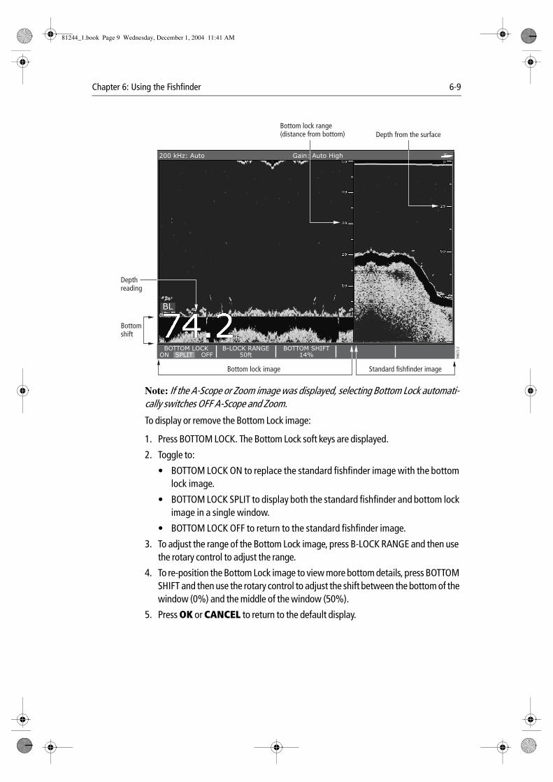
Chapter 6: Using the Fishfinder 6-9
Note: If the A-Scope or Zoom image was displayed, selecting Bottom Lock automati-cally switches OFF A-Scope and Zoom.
To display or remove the Bottom Lock image:
1. Press BOTTOM LOCK. The Bottom Lock soft keys are displayed.
2. Toggle to:
• BOTTOM LOCK ON to replace the standard fishfinder image with the bottom lock image.
• BOTTOM LOCK SPLIT to display both the standard fishfinder and bottom lock image in a single window.
• BOTTOM LOCK OFF to return to the standard fishfinder image.
3. To adjust the range of the Bottom Lock image, press B-LOCK RANGE and then use the rotary control to adjust the range.
4. To re-position the Bottom Lock image to view more bottom details, press BOTTOM SHIFT and then use the rotary control to adjust the shift between the bottom of the window (0%) and the middle of the window (50%).
5. Press OK or CANCEL to return to the default display.
BL
B-LOCK RANGE50ft
BOTTOM SHIFT14%
BOTTOM LOCKON SPLIT OFF
200 kHz: Auto Gain: Auto High
Depth from the surface
D667
2-2
Bottom lock range(distance from bottom)
Bottomshift
Depthreading
Bottom lock image Standard fishfinder image
81244_1.book Page 9 Wednesday, December 1, 2004 11:41 AM
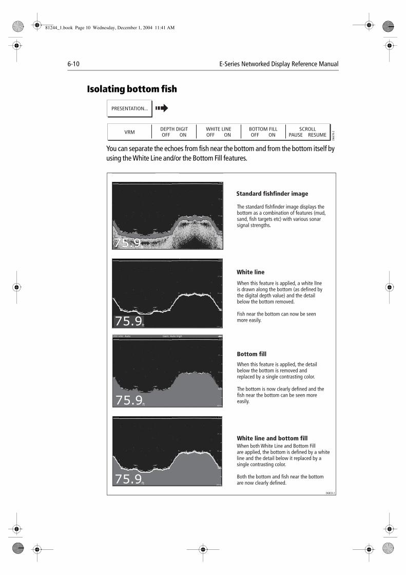
6-10 E-Series Networked Display Reference Manual
Isolating bottom fish
You can separate the echoes from fish near the bottom and from the bottom itself by using the White Line and/or the Bottom Fill features.
VRMDEPTH DIGITOFF ON
WHITE LINEOFF ON
BOTTOM FILLOFF ON
SCROLLPAUSE RESUME
D66
78-2
PRESENTATION...
75.9ft100
75
200 kHz: Auto Gain: Auto High
75.9ft100
75
200 kHz: Auto Gain: Auto High
75.9ft
200 kHz: Auto Gain: Auto High
75.9ft
75
200 kHz: Auto Gain: Auto High
Standard fishfinder image
D6833-2
White line
Bottom fill
White line and bottom fill
The standard fishfinder image displays the bottom as a combination of features (mud, sand, fish targets etc) with various sonar signal strengths.
When this feature is applied, a white lIne is drawn along the bottom (as defined by the digital depth value) and the detail below the bottom removed.
Fish near the bottom can now be seen more easily.
When this feature is applied, the detail below the bottom is removed and replaced by a single contrasting color.
The bottom is now clearly defined and the fish near the bottom can be seen more easily.
When both White Line and Bottom Fill are applied, the bottom is defined by a white line and the detail below it replaced by a single contrasting color.
Both the bottom and fish near the bottom are now clearly defined.
81244_1.book Page 10 Wednesday, December 1, 2004 11:41 AM
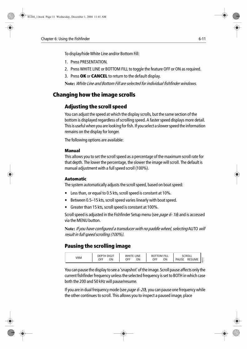
Chapter 6: Using the Fishfinder 6-11
To display/hide White Line and/or Bottom Fill:
1. Press PRESENTATION.
2. Press WHITE LINE or BOTTOM FILL to toggle the feature OFF or ON as required.
3. Press OK or CANCEL to return to the default display.
Note: White Line and Bottom Fill are selected for individual fishfinder windows.
Changing how the image scrolls
Adjusting the scroll speedYou can adjust the speed at which the display scrolls, but the same section of the bottom is displayed regardless of scrolling speed. A faster speed displays more detail. This is useful when you are looking for fish. If you select a slower speed the information remains on the display for longer.
The following options are available:
ManualThis allows you to set the scroll speed as a percentage of the maximum scroll rate for that depth. The lower the percentage, the slower the image will scroll. The default is manual adjustment with a full speed scroll (100%).
Automatic The system automatically adjusts the scroll speed, based on boat speed:
• Less than, or equal to 0.5 kts, scroll speed is constant at 10%.
• Between 0.5–15 kts, scroll speed varies linearly with boat speed.
• Greater than 15 kts, scroll speed is constant at 100%.
Scroll speed is adjusted in the Fishfinder Setup menu (see page 6- 16) and is accessed via the MENU button.
Note: If you have configured a transducer with no paddle wheel, selecting AUTO will result in full speed scrolling (100%).
Pausing the scrolling image
You can pause the display to see a ‘snapshot’ of the image. Scroll pause affects only the current fishfinder frequency unless the selected frequency is set to BOTH in which case both the 200 and 50 kHz will pause/resume.
If you are in dual frequency mode (see page 6- 20), you can pause one frequency while the other continues to scroll. This allows you to inspect a paused image, place
VRMDEPTH DIGITOFF ON
WHITE LINEOFF ON
BOTTOM FILLOFF ON
SCROLLPAUSE RESUME
D66
78-1
81244_1.book Page 11 Wednesday, December 1, 2004 11:41 AM
6-12 E-Series Networked Display Reference Manual
waypoints or VRMs, while the other frequency continues to scroll and detect fish etc. When in automatic frequency mode and the depth changes, the new frequency will NOT be paused.
To pause or resume scrolling, proceed as follows:
1. Press PRESENTATION.
2. Toggle SCROLL to select PAUSE. The display stops scrolling but the depth indication continues to be updated.
3. To resume the scrolling bottom display, toggle SCROLL to select RESUME.
4. Press OK or CANCEL to return to the default display.
Changing how the depth digit is displayedThe depth under the boat is displayed in the upper or lower left hand corner of the fishfinder window. The size of this depth digit can be adjusted or it can be switched on/off for individual fishfinder windows.
Changing the size of the depth digitYou can decrease the size of the depth digit (to small or medium) and you can change its position to the top of the screen. The size and position of the Depth Digit are adjusted in the Fishfinder Setup menu as described page 6- 19.
Note: No matter what size is selected, the Depth Digits will auto-shrink (when neces-sary) to fit in the available space.
Removing the depth digit
Note: When multiple fishfinder windows are displayed, we recommend that the depth digit is always displayed in at least one window.
To remove or display the depth digit:
1. Press PRESENTATION.
2. Press DEPTH DIGIT and select OFF or ON as required.
3. Press OK or CANCEL to return to the default display.
VRMDEPTH DIGITOFF ON
WHITE LINEOFF ON
BOTTOM FILLOFF ON
SCROLLPAUSE RESUME
D66
78-1
81244_1.book Page 12 Wednesday, December 1, 2004 11:41 AM
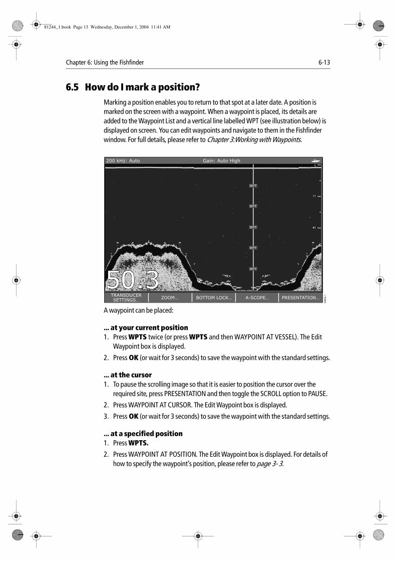
Chapter 6: Using the Fishfinder 6-13
6.5 How do I mark a position?Marking a position enables you to return to that spot at a later date. A position is marked on the screen with a waypoint. When a waypoint is placed, its details are added to the Waypoint List and a vertical line labelled WPT (see illustration below) is displayed on screen. You can edit waypoints and navigate to them in the Fishfinder window. For full details, please refer to Chapter 3:Working with Waypoints.
A waypoint can be placed:
... at your current position1. Press WPTS twice (or press WPTS and then WAYPOINT AT VESSEL). The Edit
Waypoint box is displayed.
2. Press OK (or wait for 3 seconds) to save the waypoint with the standard settings.
... at the cursor1. To pause the scrolling image so that it is easier to position the cursor over the
required site, press PRESENTATION and then toggle the SCROLL option to PAUSE.
2. Press WAYPOINT AT CURSOR. The Edit Waypoint box is displayed.
3. Press OK (or wait for 3 seconds) to save the waypoint with the standard settings.
... at a specified position1. Press WPTS.
2. Press WAYPOINT AT POSITION. The Edit Waypoint box is displayed. For details of how to specify the waypoint’s position, please refer to page 3- 3.
WPT
WPT
WPT
WPT
WPT
D685
6-1TRANSDUCER
SETTINGS…ZOOM… BOTTOM LOCK… A-SCOPE… PRESENTATION…
200 kHz: Auto Gain: Auto High
81244_1.book Page 13 Wednesday, December 1, 2004 11:41 AM
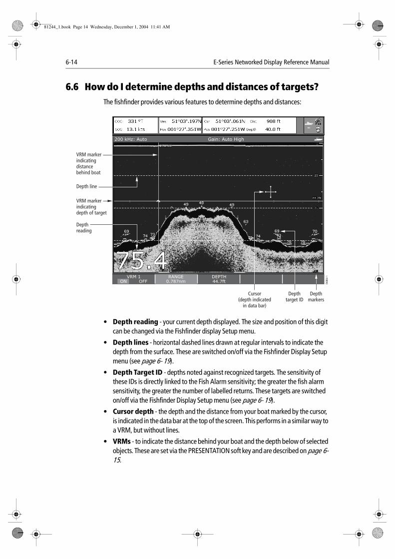
6-14 E-Series Networked Display Reference Manual
6.6 How do I determine depths and distances of targets?The fishfinder provides various features to determine depths and distances:
• Depth reading - your current depth displayed. The size and position of this digit can be changed via the Fishfinder display Setup menu.
• Depth lines - horizontal dashed lines drawn at regular intervals to indicate the depth from the surface. These are switched on/off via the Fishfinder Display Setup menu (see page 6- 19).
• Depth Target ID - depths noted against recognized targets. The sensitivity of these IDs is directly linked to the Fish Alarm sensitivity; the greater the fish alarm sensitivity, the greater the number of labelled returns. These targets are switched on/off via the Fishfinder Display Setup menu (see page 6- 19).
• Cursor depth - the depth and the distance from your boat marked by the cursor, is indicated in the data bar at the top of the screen. This performs in a similar way to a VRM, but without lines.
• VRMs - to indicate the distance behind your boat and the depth below of selected objects. These are set via the PRESENTATION soft key and are described on page 6- 15.
78 78
7069
74
63
6973
494849
74 74
200 kHz: Auto Gain: Auto High
VRM 1ON OFF
RANGE0.787nm
DEPTH44.7ft
VRM markerindicatingdepth of target
VRM markerindicatingdistancebehind boat
Depthreading
Depth line
Depthmarkers
Depthtarget ID
Cursor(depth indicated
in data bar)
D686
4-1
81244_1.book Page 14 Wednesday, December 1, 2004 11:41 AM
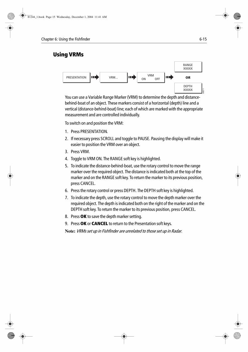
Chapter 6: Using the Fishfinder 6-15
Using VRMs
You can use a Variable Range Marker (VRM) to determine the depth and distance-behind-boat of an object. These markers consist of a horizontal (depth) line and a vertical (distance-behind-boat) line; each of which are marked with the appropriate measurement and are controlled individually.
To switch on and position the VRM:
1. Press PRESENTATION.
2. If necessary press SCROLL and toggle to PAUSE. Pausing the display will make it easier to position the VRM over an object.
3. Press VRM.
4. Toggle to VRM ON. The RANGE soft key is highlighted.
5. To indicate the distance-behind-boat, use the rotary control to move the range marker over the required object. The distance is indicated both at the top of the marker and on the RANGE soft key. To return the marker to its previous position, press CANCEL.
6. Press the rotary control or press DEPTH. The DEPTH soft key is highlighted.
7. To indicate the depth, use the rotary control to move the depth marker over the required object. The depth is indicated both on the right of the marker and on the DEPTH soft key. To return the marker to its previous position, press CANCEL.
8. Press OK to save the depth marker setting.
9. Press OK or CANCEL to return to the Presentation soft keys.
Note: VRMs set up in Fishfinder are unrelated to those set up in Radar.
VRMON OFFPRESENTATION VRM...
DEPTHXXXXX
OR
RANGEXXXXX
D685
7-1
81244_1.book Page 15 Wednesday, December 1, 2004 11:41 AM
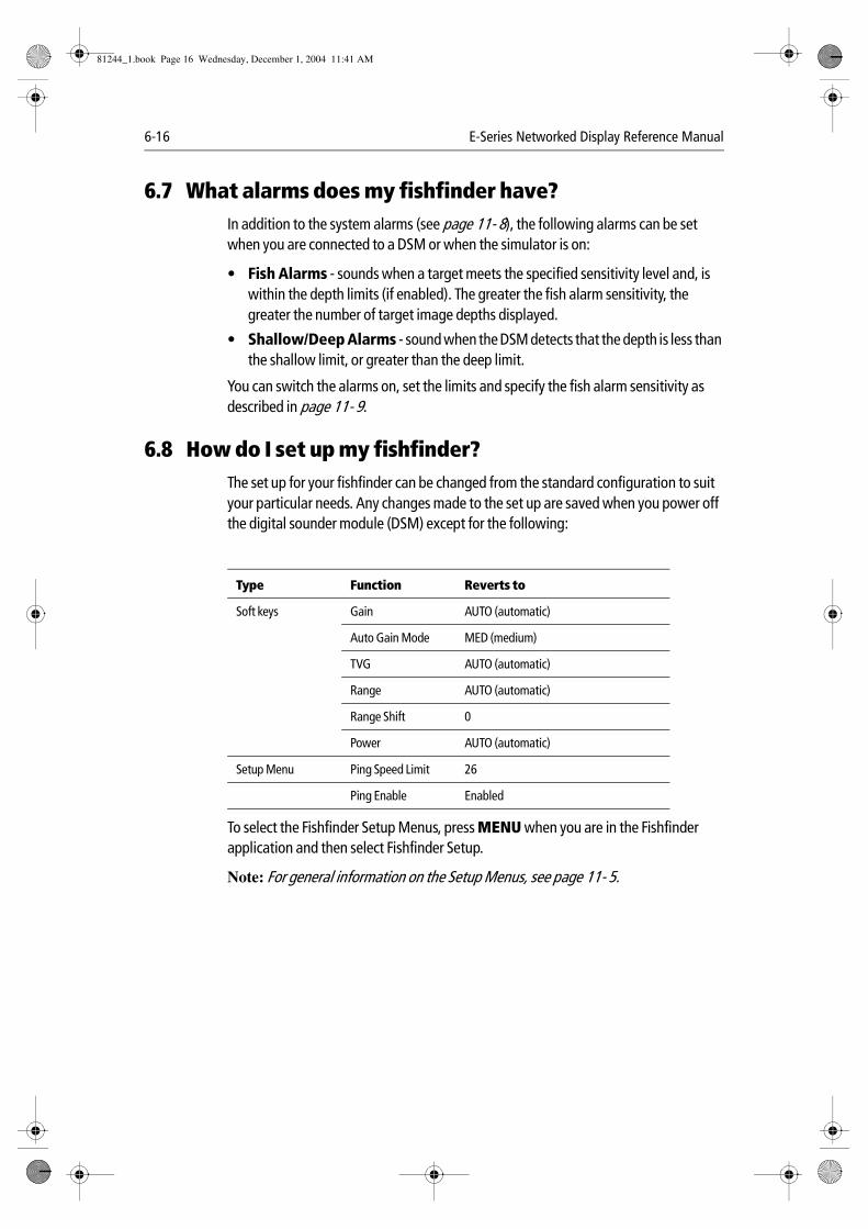
6-16 E-Series Networked Display Reference Manual
6.7 What alarms does my fishfinder have?In addition to the system alarms (see page 11- 8), the following alarms can be set when you are connected to a DSM or when the simulator is on:
• Fish Alarms - sounds when a target meets the specified sensitivity level and, is within the depth limits (if enabled). The greater the fish alarm sensitivity, the greater the number of target image depths displayed.
• Shallow/Deep Alarms - sound when the DSM detects that the depth is less than the shallow limit, or greater than the deep limit.
You can switch the alarms on, set the limits and specify the fish alarm sensitivity as described in page 11- 9.
6.8 How do I set up my fishfinder?The set up for your fishfinder can be changed from the standard configuration to suit your particular needs. Any changes made to the set up are saved when you power off the digital sounder module (DSM) except for the following:
To select the Fishfinder Setup Menus, press MENU when you are in the Fishfinder application and then select Fishfinder Setup.
Note: For general information on the Setup Menus, see page 11- 5.
Type Function Reverts to
Soft keys Gain AUTO (automatic)
Auto Gain Mode MED (medium)
TVG AUTO (automatic)
Range AUTO (automatic)
Range Shift 0
Power AUTO (automatic)
Setup Menu Ping Speed Limit 26
Ping Enable Enabled
81244_1.book Page 16 Wednesday, December 1, 2004 11:41 AM
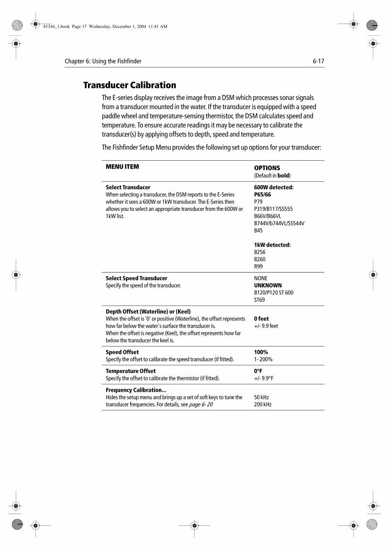
Chapter 6: Using the Fishfinder 6-17
Transducer CalibrationThe E-series display receives the image from a DSM which processes sonar signals from a transducer mounted in the water. If the transducer is equipped with a speed paddle wheel and temperature-sensing thermistor, the DSM calculates speed and temperature. To ensure accurate readings it may be necessary to calibrate the transducer(s) by applying offsets to depth, speed and temperature.
The Fishfinder Setup Menu provides the following set up options for your transducer:
MENU ITEM OPTIONS(Default in bold)
Select TransducerWhen selecting a transducer, the DSM reports to the E-Series whether it sees a 600W or 1kW transducer. The E-Series then allows you to select an appropriate transducer from the 600W or 1kW list.
600W detected:P65/66P79P319/B117/SS555B66V/B66VLB744V/b744VL/SS544VB45
1kW detected:B256B260R99
Select Speed TransducerSpecify the speed of the transducer.
NONEUNKNOWNB120/P120 ST 600ST69
Depth Offset (Waterline) or (Keel)When the offset is '0' or positive (Waterline), the offset represents how far below the water's surface the transducer is.When the offset is negative (Keel), the offset represents how far below the transducer the keel is.
0 feet+/- 9.9 feet
Speed OffsetSpecify the offset to calibrate the speed transducer (if fitted).
100%1- 200%
Temperature OffsetSpecify the offset to calibrate the thermistor (if fitted).
0°F+/- 9.9°F
Frequency Calibration...Hides the setup menu and brings up a set of soft keys to tune the transducer frequencies. For details, see page 6- 20
50 kHz200 kHz
81244_1.book Page 17 Wednesday, December 1, 2004 11:41 AM
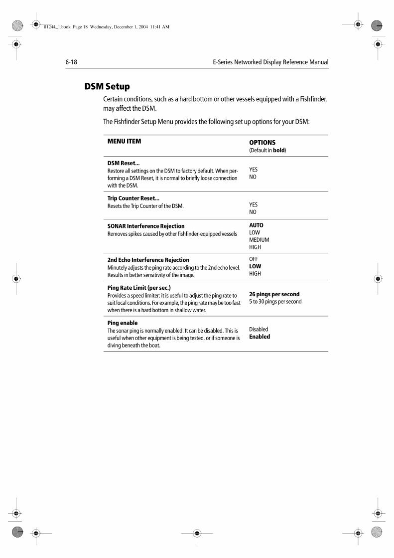
6-18 E-Series Networked Display Reference Manual
DSM SetupCertain conditions, such as a hard bottom or other vessels equipped with a Fishfinder, may affect the DSM.
The Fishfinder Setup Menu provides the following set up options for your DSM:
MENU ITEM OPTIONS(Default in bold)
DSM Reset...Restore all settings on the DSM to factory default. When per-forming a DSM Reset, it is normal to briefly loose connection with the DSM.
YESNO
Trip Counter Reset...Resets the Trip Counter of the DSM. YES
NO
SONAR Interference RejectionRemoves spikes caused by other fishfinder-equipped vessels
AUTOLOWMEDIUMHIGH
2nd Echo Interference RejectionMinutely adjusts the ping rate according to the 2nd echo level. Results in better sensitivity of the image.
OFFLOWHIGH
Ping Rate Limit (per sec.)Provides a speed limiter; it is useful to adjust the ping rate to suit local conditions. For example, the ping rate may be too fast when there is a hard bottom in shallow water.
26 pings per second5 to 30 pings per second
Ping enableThe sonar ping is normally enabled. It can be disabled. This is useful when other equipment is being tested, or if someone is diving beneath the boat.
DisabledEnabled
81244_1.book Page 18 Wednesday, December 1, 2004 11:41 AM
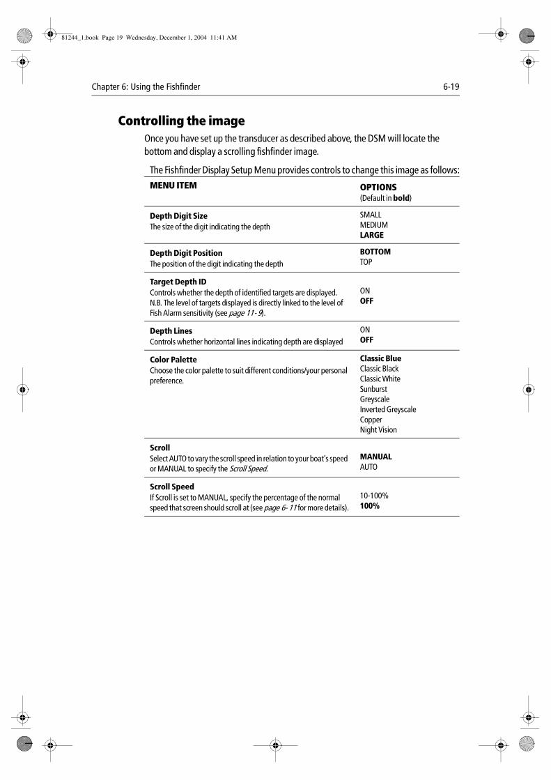
Chapter 6: Using the Fishfinder 6-19
Controlling the imageOnce you have set up the transducer as described above, the DSM will locate the bottom and display a scrolling fishfinder image.
The Fishfinder Display Setup Menu provides controls to change this image as follows:
MENU ITEM OPTIONS(Default in bold)
Depth Digit SizeThe size of the digit indicating the depth
SMALLMEDIUMLARGE
Depth Digit PositionThe position of the digit indicating the depth
BOTTOMTOP
Target Depth IDControls whether the depth of identified targets are displayed. N.B. The level of targets displayed is directly linked to the level of Fish Alarm sensitivity (see page 11- 9).
ONOFF
Depth LinesControls whether horizontal lines indicating depth are displayed
ONOFF
Color PaletteChoose the color palette to suit different conditions/your personal preference.
Classic BlueClassic BlackClassic WhiteSunburstGreyscaleInverted GreyscaleCopperNight Vision
ScrollSelect AUTO to vary the scroll speed in relation to your boat’s speed or MANUAL to specify the Scroll Speed.
MANUALAUTO
Scroll SpeedIf Scroll is set to MANUAL, specify the percentage of the normal speed that screen should scroll at (see page 6- 11 for more details).
10-100%100%
81244_1.book Page 19 Wednesday, December 1, 2004 11:41 AM
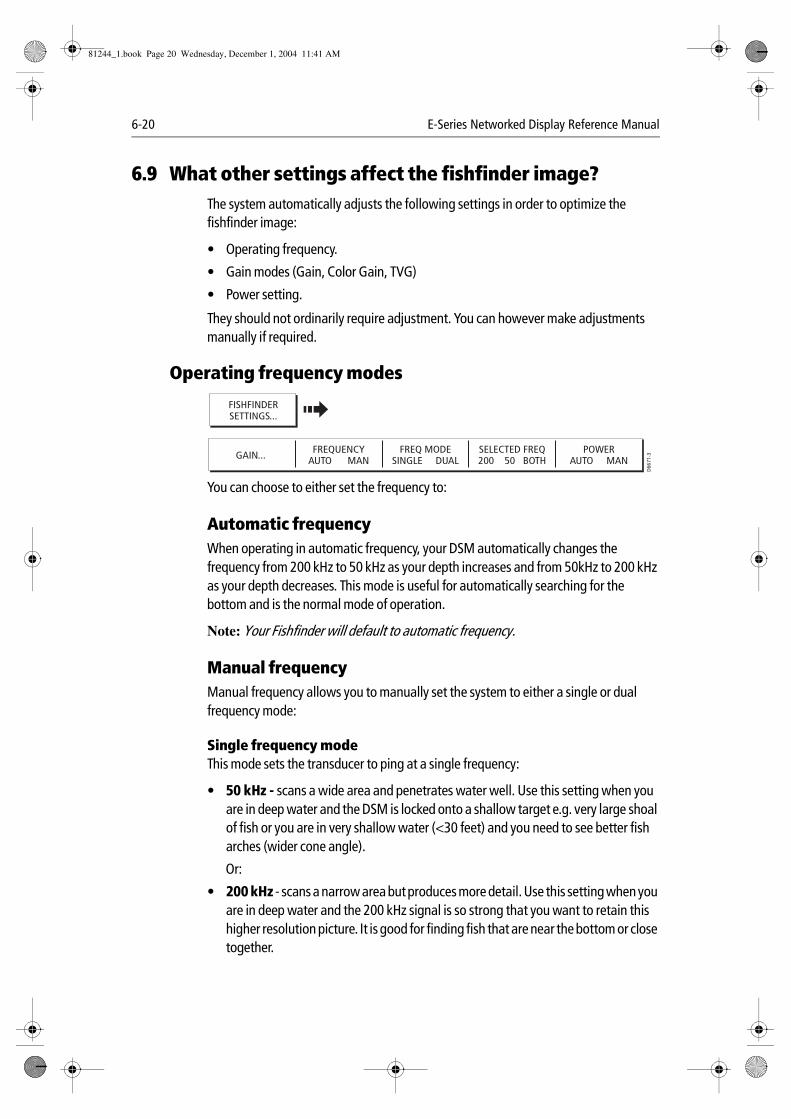
6-20 E-Series Networked Display Reference Manual
6.9 What other settings affect the fishfinder image?The system automatically adjusts the following settings in order to optimize the fishfinder image:
• Operating frequency.
• Gain modes (Gain, Color Gain, TVG)
• Power setting.
They should not ordinarily require adjustment. You can however make adjustments manually if required.
Operating frequency modes
You can choose to either set the frequency to:
Automatic frequency When operating in automatic frequency, your DSM automatically changes the frequency from 200 kHz to 50 kHz as your depth increases and from 50kHz to 200 kHz as your depth decreases. This mode is useful for automatically searching for the bottom and is the normal mode of operation.
Note: Your Fishfinder will default to automatic frequency.
Manual frequencyManual frequency allows you to manually set the system to either a single or dual frequency mode:
Single frequency modeThis mode sets the transducer to ping at a single frequency:
• 50 kHz - scans a wide area and penetrates water well. Use this setting when you are in deep water and the DSM is locked onto a shallow target e.g. very large shoal of fish or you are in very shallow water (<30 feet) and you need to see better fish arches (wider cone angle).
Or:
• 200 kHz - scans a narrow area but produces more detail. Use this setting when you are in deep water and the 200 kHz signal is so strong that you want to retain this higher resolution picture. It is good for finding fish that are near the bottom or close together.
FREQUENCYAUTO MAN
FREQ MODESINGLE DUAL
SELECTED FREQ200 50 BOTH
POWERAUTO MAN
D66
71-3GAIN...
FISHFINDERSETTINGS...
81244_1.book Page 20 Wednesday, December 1, 2004 11:41 AM
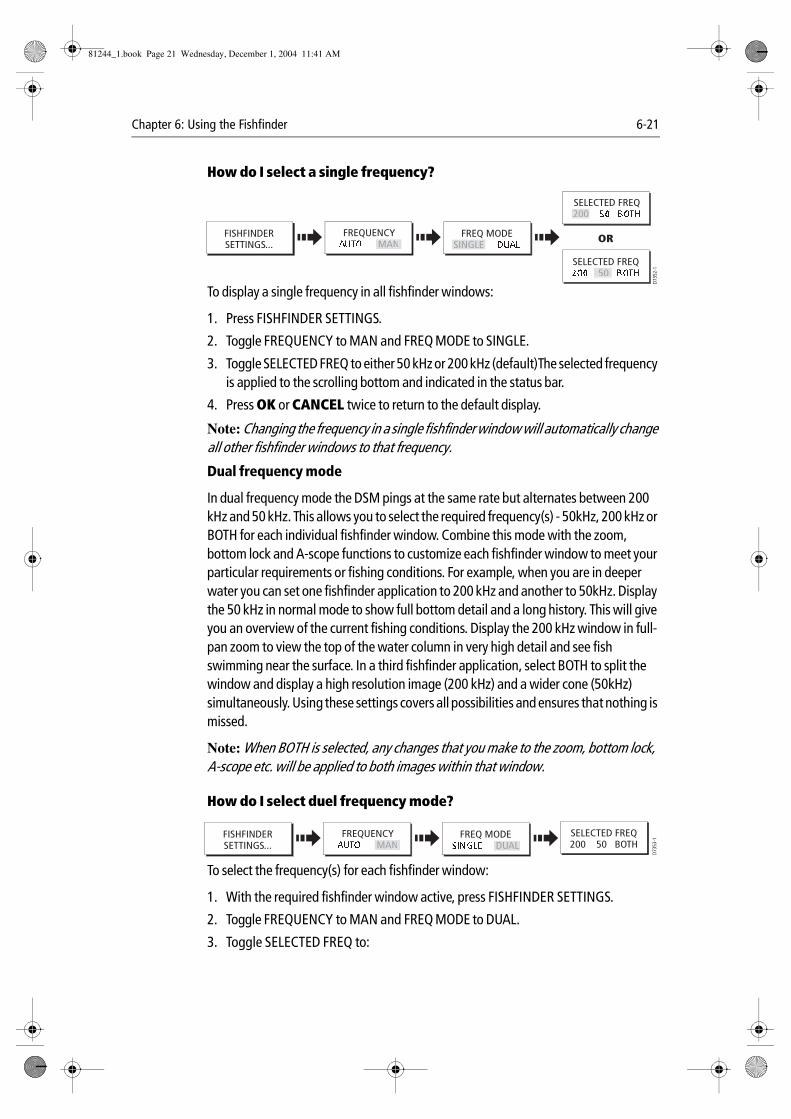
Chapter 6: Using the Fishfinder 6-21
How do I select a single frequency?
To display a single frequency in all fishfinder windows:
1. Press FISHFINDER SETTINGS.
2. Toggle FREQUENCY to MAN and FREQ MODE to SINGLE.
3. Toggle SELECTED FREQ to either 50 kHz or 200 kHz (default)The selected frequency is applied to the scrolling bottom and indicated in the status bar.
4. Press OK or CANCEL twice to return to the default display.
Note: Changing the frequency in a single fishfinder window will automatically change all other fishfinder windows to that frequency.
Dual frequency mode
In dual frequency mode the DSM pings at the same rate but alternates between 200 kHz and 50 kHz. This allows you to select the required frequency(s) - 50kHz, 200 kHz or BOTH for each individual fishfinder window. Combine this mode with the zoom, bottom lock and A-scope functions to customize each fishfinder window to meet your particular requirements or fishing conditions. For example, when you are in deeper water you can set one fishfinder application to 200 kHz and another to 50kHz. Display the 50 kHz in normal mode to show full bottom detail and a long history. This will give you an overview of the current fishing conditions. Display the 200 kHz window in full-pan zoom to view the top of the water column in very high detail and see fish swimming near the surface. In a third fishfinder application, select BOTH to split the window and display a high resolution image (200 kHz) and a wider cone (50kHz) simultaneously. Using these settings covers all possibilities and ensures that nothing is missed.
Note: When BOTH is selected, any changes that you make to the zoom, bottom lock, A-scope etc. will be applied to both images within that window.
How do I select duel frequency mode?
To select the frequency(s) for each fishfinder window:
1. With the required fishfinder window active, press FISHFINDER SETTINGS.
2. Toggle FREQUENCY to MAN and FREQ MODE to DUAL.
3. Toggle SELECTED FREQ to:
OR
D735
2-1
FREQUENCY FREQ MODE
SELECTED FREQ
FISHFINDERSETTINGS...
SELECTED FREQ
200
50
SINGLE MAN
D735
3-1FREQUENCY FREQ MODEFISHFINDER
SETTINGS...SELECTED FREQ200 50 BOTHDUALMAN
81244_1.book Page 21 Wednesday, December 1, 2004 11:41 AM
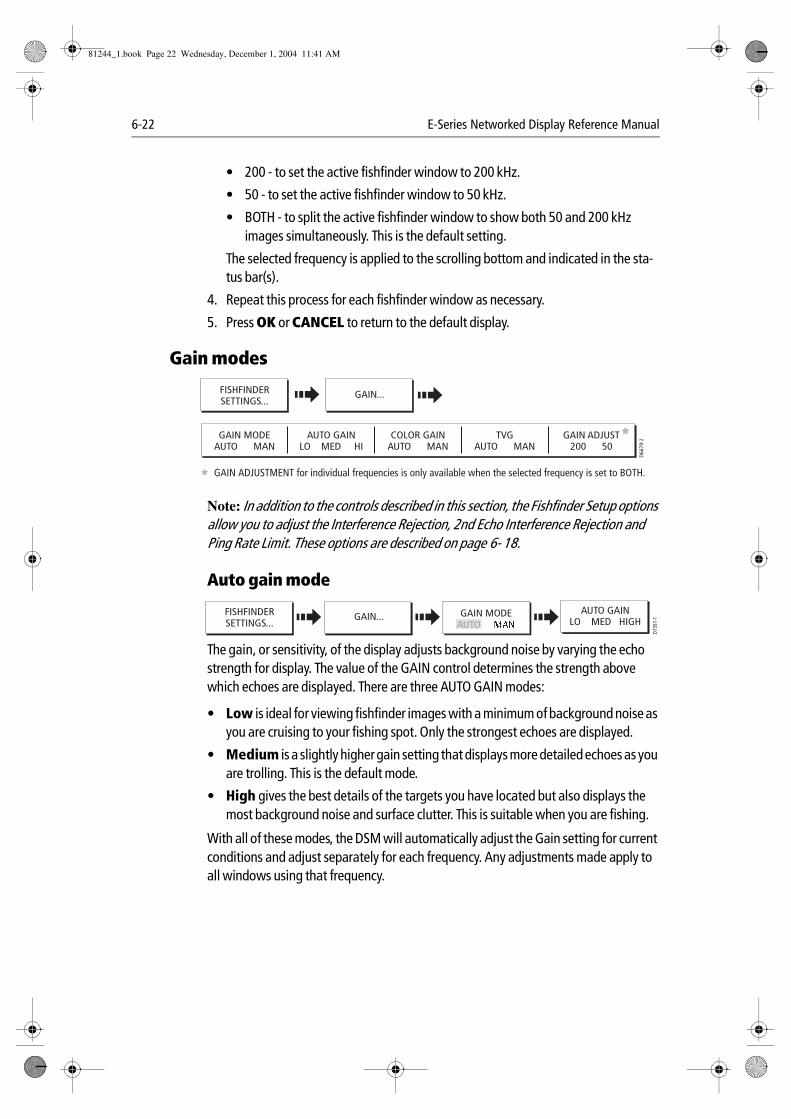
6-22 E-Series Networked Display Reference Manual
• 200 - to set the active fishfinder window to 200 kHz.
• 50 - to set the active fishfinder window to 50 kHz.
• BOTH - to split the active fishfinder window to show both 50 and 200 kHz images simultaneously. This is the default setting.
The selected frequency is applied to the scrolling bottom and indicated in the sta-tus bar(s).
4. Repeat this process for each fishfinder window as necessary.
5. Press OK or CANCEL to return to the default display.
Gain modes
Note: In addition to the controls described in this section, the Fishfinder Setup options allow you to adjust the Interference Rejection, 2nd Echo Interference Rejection and Ping Rate Limit. These options are described on page 6- 18.
Auto gain mode
The gain, or sensitivity, of the display adjusts background noise by varying the echo strength for display. The value of the GAIN control determines the strength above which echoes are displayed. There are three AUTO GAIN modes:
• Low is ideal for viewing fishfinder images with a minimum of background noise as you are cruising to your fishing spot. Only the strongest echoes are displayed.
• Medium is a slightly higher gain setting that displays more detailed echoes as you are trolling. This is the default mode.
• High gives the best details of the targets you have located but also displays the most background noise and surface clutter. This is suitable when you are fishing.
With all of these modes, the DSM will automatically adjust the Gain setting for current conditions and adjust separately for each frequency. Any adjustments made apply to all windows using that frequency.
GAIN MODEAUTO MAN
AUTO GAINLO MED HI
COLOR GAINAUTO MAN
TVGAUTO MAN
D66
79-2
GAIN ADJUST200 50
FISHFINDERSETTINGS...
GAIN...
GAIN ADJUSTMENT for individual frequencies is only available when the selected frequency is set to BOTH.
D735
7-1GAIN MODEFISHFINDER
SETTINGS... AUTO GAIN...
AUTO GAINLO MED HIGH
81244_1.book Page 22 Wednesday, December 1, 2004 11:41 AM
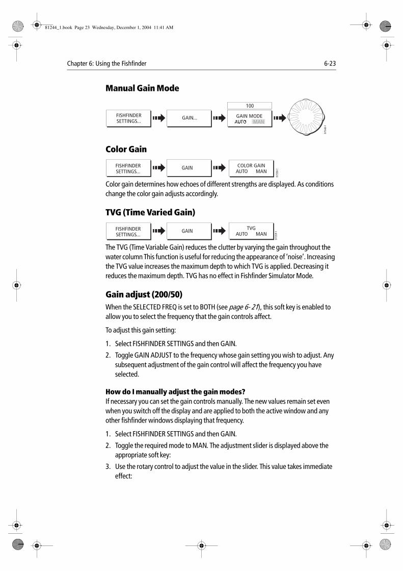
Chapter 6: Using the Fishfinder 6-23
Manual Gain Mode
Color Gain
Color gain determines how echoes of different strengths are displayed. As conditions change the color gain adjusts accordingly.
TVG (Time Varied Gain)
The TVG (Time Variable Gain) reduces the clutter by varying the gain throughout the water column This function is useful for reducing the appearance of ‘noise’. Increasing the TVG value increases the maximum depth to which TVG is applied. Decreasing it reduces the maximum depth. TVG has no effect in Fishfinder Simulator Mode.
Gain adjust (200/50)When the SELECTED FREQ is set to BOTH (see page 6- 21), this soft key is enabled to allow you to select the frequency that the gain controls affect.
To adjust this gain setting:
1. Select FISHFINDER SETTINGS and then GAIN.
2. Toggle GAIN ADJUST to the frequency whose gain setting you wish to adjust. Any subsequent adjustment of the gain control will affect the frequency you have selected.
How do I manually adjust the gain modes?If necessary you can set the gain controls manually. The new values remain set even when you switch off the display and are applied to both the active window and any other fishfinder windows displaying that frequency.
1. Select FISHFINDER SETTINGS and then GAIN.
2. Toggle the required mode to MAN. The adjustment slider is displayed above the appropriate soft key:
3. Use the rotary control to adjust the value in the slider. This value takes immediate effect:
D754
8-1
GAIN MODEFISHFINDERSETTINGS... MAN
GAIN...
100
D735
8-1
COLOR GAINAUTO MAN
FISHFINDERSETTINGS...
GAIN
D735
9-1
TVGAUTO MAN
FISHFINDERSETTINGS...
GAIN
81244_1.book Page 23 Wednesday, December 1, 2004 11:41 AM
6-24 E-Series Networked Display Reference Manual
• GAIN MODE - This should be set high enough to see fish and bottom detail but without too much background noise. Generally, a high gain is used in deep and/or clear water; a low gain in shallow and/or murky water.
• COLOR GAIN - This sets the lower limit for the strongest echo color. All echoes with a signal strength above this value are displayed in the strongest color. Those with a weaker value are divided equally between the remaining colors. Setting a low value produces wide band for the weakest color, but a small signal band for the other colors; setting a high value gives a wide band for the strongest color, but a small signal band for the other colors.
• TVG - A low TVG value has little effect on gain in shallow water; a high value decreases the gain in shallow water so that only the strongest echoes are displayed.
4. Press OK or CANCEL twice to return to the default display.
Adjusting the power settingThe Power control provides adjustment of the transducer signal. When AUTO is selected (default), the DSM automatically determines the required power setting based on the current depth, speed, and (bottom) signal strength.
If, however, you wish to manually adjust the power to suit current conditions, you can adjust the power level between 0 and 100%, in 10% increments. Lower power levels are normally used in depth ranges less than 8 ft. (2.4 m) and higher power levels are typically selected for depths greater than 12 ft. (3.7 m).
To adjust the Power Setting:
1. Press FISHFINDER SETTINGS.
2. Press POWER.
3. Toggle POWER to either AUTO or MAN. If MAN mode is set the power adjustment slider is displayed. Use the rotary control to adjust the power value. There is a short delay whilst the new setting takes effect.
4. Press OK or CANCEL to return to the default display.
81244_1.book Page 24 Wednesday, December 1, 2004 11:41 AM
Chapter 7: Using the Course Deviation Indicator 7-1
Chapter 7: Using the Course Deviation Indicator
7.1 IntroductionWith your display receiving accurate heading and position information, you can use the Course Deviation Indicator (CDI) to monitor your course and accurately steer to a target waypoint.
7.2 How do I display the CDI application?To select the CDI application:
1. Press and hold the PAGE button. The Select Page Set screen is displayed.
2. Use the trackpad to scroll to the appropriate page set.
3. Press OK.
4. Press the PAGE button to display at the bottom of the screen, the applications available in that set.
Notes: (1) Press the soft key that corresponds to the CDI display of your choice or press PAGE until your choice is displayed.Once the CDI application is displayed, no use is made of the soft keys. You will therefore need to open a radar, chart or fishfinder window in order to access any func-tions activated via the soft keys.
(2) If the CDI application is placed in multiple windows, the same data is displayed in each.
What does the screen show me?
The CDI gives a graphical representation of yours boat’s course in a ‘rolling road’ format.
The ‘rolling road’ represents a width of sea equal to the Cross Track Error (XTE) limits that you have specified in the Setup menu. As you travel towards the target waypoint, the checkered pattern and the waypoint will move down the screen at a rate proportional to your boat’s speed.
Navigation data is displayed alongside or below the rolling road.
81244_1.book Page 1 Wednesday, December 1, 2004 11:41 AM
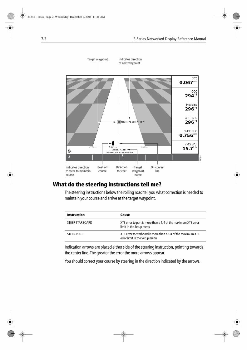
7-2 E-Series Networked Display Reference Manual
What do the steering instructions tell me?The steering instructions below the rolling road tell you what correction is needed to maintain your course and arrive at the target waypoint.
Indication arrows are placed either side of the steering instruction, pointing towards the center line. The greater the error the more arrows appear.
You should correct your course by steering in the direction indicated by the arrows.
Instruction Cause
STEER STARBOARD XTE error to port is more than a 1/4 of the maximum XTE error limit in the Setup menu
STEER PORT XTE error to starboard is more than a 1/4 of the maximum XTE error limit in the Setup menu
D677
8-2
3nm North-Up Relative Motion Local
Boat offcourse
On courseline
Targetwaypoint
name
Indicates directionof next waypoint
Target waypoint
Indicates directionto steer to maintaincourse
STEER TO STARBOARD
Directionto steer
81244_1.book Page 2 Wednesday, December 1, 2004 11:41 AM
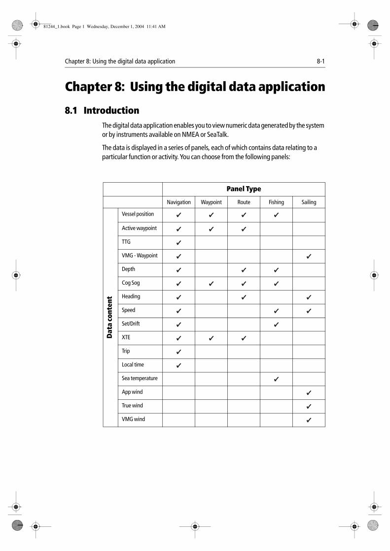
Chapter 8: Using the digital data application 8-1
Chapter 8: Using the digital data application
8.1 IntroductionThe digital data application enables you to view numeric data generated by the system or by instruments available on NMEA or SeaTalk.
The data is displayed in a series of panels, each of which contains data relating to a particular function or activity. You can choose from the following panels:
Panel Type
Navigation Waypoint Route Fishing Sailing
Dat
a co
nten
t
Vessel position
Active waypoint
TTG
VMG - Waypoint
Depth
Cog Sog
Heading
Speed
Set/Drift
XTE
Trip
Local time
Sea temperature
App wind
True wind
VMG wind
81244_1.book Page 1 Wednesday, December 1, 2004 11:41 AM
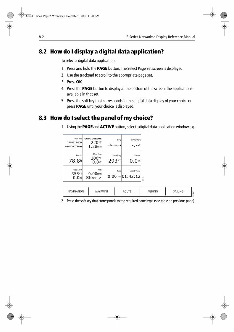
8-2 E-Series Networked Display Reference Manual
8.2 How do I display a digital data application?To select a digital data application:
1. Press and hold the PAGE button. The Select Page Set screen is displayed.
2. Use the trackpad to scroll to the appropriate page set.
3. Press OK.
4. Press the PAGE button to display at the bottom of the screen, the applications available in that set.
5. Press the soft key that corresponds to the digital data display of your choice or press PAGE until your choice is displayed.
8.3 How do I select the panel of my choice?1. Using the PAGE and ACTIVE button, select a digital data application window e.g.
2. Press the soft key that corresponds to the required panel type (see table on previous page).
D71
77-1
NAVIGATION WAYPOINT ROUTE FISHING SAILINGD
7186
-1
81244_1.book Page 2 Wednesday, December 1, 2004 11:41 AM
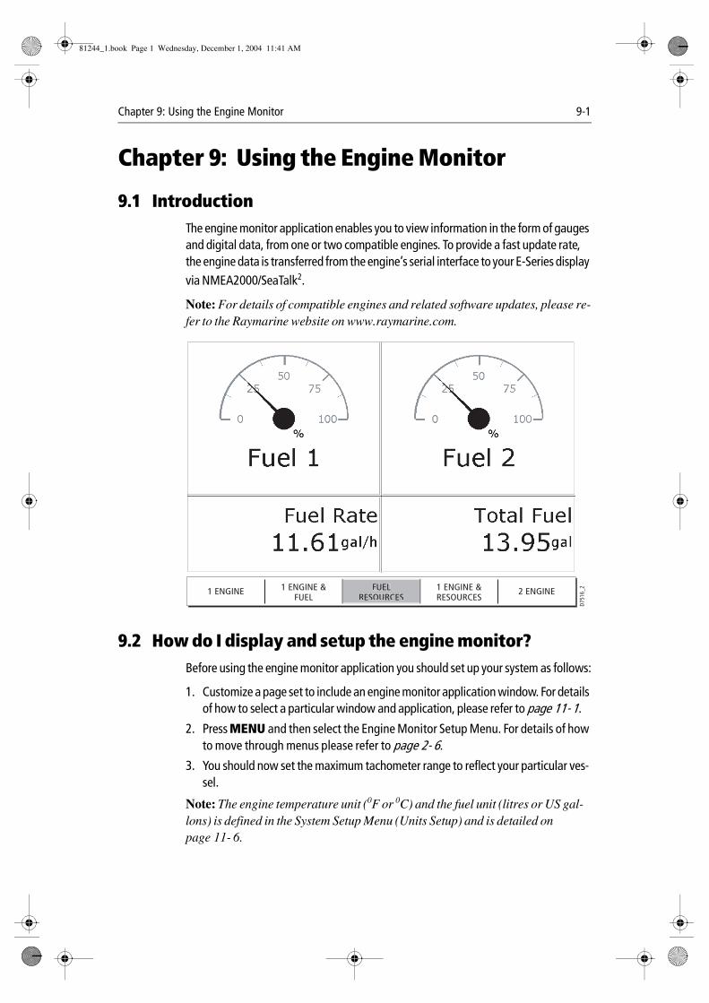
Chapter 9: Using the Engine Monitor 9-1
Chapter 9: Using the Engine Monitor
9.1 IntroductionThe engine monitor application enables you to view information in the form of gauges and digital data, from one or two compatible engines. To provide a fast update rate, the engine data is transferred from the engine’s serial interface to your E-Series display via NMEA2000/SeaTalk2.
Note: For details of compatible engines and related software updates, please re-fer to the Raymarine website on www.raymarine.com.
9.2 How do I display and setup the engine monitor?Before using the engine monitor application you should set up your system as follows:
1. Customize a page set to include an engine monitor application window. For details of how to select a particular window and application, please refer to page 11- 1.
2. Press MENU and then select the Engine Monitor Setup Menu. For details of how to move through menus please refer to page 2- 6.
3. You should now set the maximum tachometer range to reflect your particular ves-sel.
Note: The engine temperature unit (0F or 0C) and the fuel unit (litres or US gal-lons) is defined in the System Setup Menu (Units Setup) and is detailed on page 11- 6.
D751
6_2
1 ENGINE 1 ENGINE &FUEL
1 ENGINE &RESOURCES
2 ENGINEFUELRESOURCES
81244_1.book Page 1 Wednesday, December 1, 2004 11:41 AM
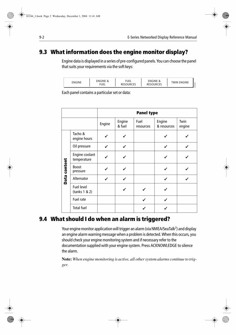
9-2 E-Series Networked Display Reference Manual
9.3 What information does the engine monitor display?Engine data is displayed in a series of pre-configured panels. You can choose the panel that suits your requirements via the soft keys:
Each panel contains a particular set or data:
9.4 What should I do when an alarm is triggered?
Your engine monitor application will trigger an alarm (via NMEA/SeaTalk2) and display an engine alarm warning message when a problem is detected. When this occurs, you should check your engine monitoring system and if necessary refer to the documentation supplied with your engine system. Press ACKNOWLEDGE to silence the alarm.
Note: When engine monitoring is active, all other system alarms continue to trig-ger.
Panel type
EngineEngine & fuel
Fuel resources
Engine& resources
Twin engine
Dat
a co
nten
t
Tacho & engine hours
Oil pressure
Engine coolanttemperature
Boostpressure
Alternator
Fuel level(tanks 1 & 2)
Fuel rate
Total fuel
ENGINE ENGINE &FUEL
FUELRESOURCES
ENGINE &RESOURCES
TWIN ENGINE
D74
78-1
81244_1.book Page 2 Wednesday, December 1, 2004 11:41 AM
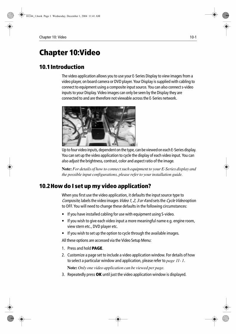
Chapter 10: Video 10-1
Chapter 10:Video
10.1IntroductionThe video application allows you to use your E-Series Display to view images from a video player, on board camera or DVD player. Your Display is supplied with cabling to connect to equipment using a composite input source. You can also connect s-video inputs to your Display. Video images can only be seen by the Display they are connected to and are therefore not viewable across the E-Series network.
Up to four video inputs, dependent on the type, can be viewed on each E-Series display. You can set up the video application to cycle the display of each video input. You can also adjust the brightness, contrast, color and aspect ratio of the image.
Note: For details of how to connect such equipment to your E-Series display and the possible input configurations, please refer to your installation guide.
10.2How do I set up my video application?When you first use the video application, it defaults the input source type to Composite, labels the video images Video 1, 2, 3 or 4 and sets the Cycle Video option to OFF. You will need to change these defaults in the following circumstances:
• If you have installed cabling for use with equipment using S-video.
• If you wish to give each video input a more meaningful name e.g. engine room, view stern etc., DVD player etc.
• If you wish to set up the option to cycle through the available images.
All these options are accessed via the Video Setup Menu:
1. Press and hold PAGE.
2. Customize a page set to include a video application window. For details of how to select a particular window and application, please refer to page 11- 1.
Note: Only one video application can be viewed per page.
3. Repeatedly press OK until just the video application window is displayed.
D749
3_1
81244_1.book Page 1 Wednesday, December 1, 2004 11:41 AM
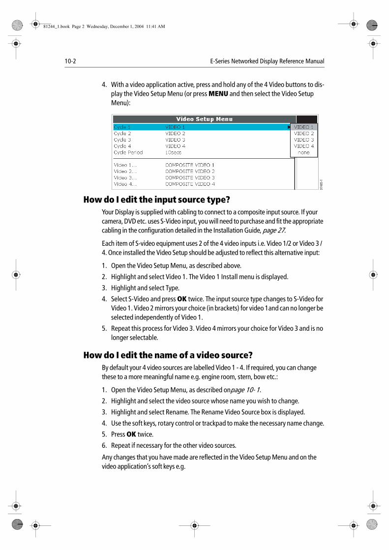
10-2 E-Series Networked Display Reference Manual
4. With a video application active, press and hold any of the 4 Video buttons to dis-play the Video Setup Menu (or press MENU and then select the Video Setup Menu):
How do I edit the input source type?Your Display is supplied with cabling to connect to a composite input source. If your camera, DVD etc. uses S-Video input, you will need to purchase and fit the appropriate cabling in the configuration detailed in the Installation Guide, page 27.
Each item of S-video equipment uses 2 of the 4 video inputs i.e. Video 1/2 or Video 3 /4. Once installed the Video Setup should be adjusted to reflect this alternative input:
1. Open the Video Setup Menu, as described above.
2. Highlight and select Video 1. The Video 1 Install menu is displayed.
3. Highlight and select Type.
4. Select S-Video and press OK twice. The input source type changes to S-Video for Video 1. Video 2 mirrors your choice (in brackets) for video 1and can no longer be selected independently of Video 1.
5. Repeat this process for Video 3. Video 4 mirrors your choice for Video 3 and is no longer selectable.
How do I edit the name of a video source?By default your 4 video sources are labelled Video 1 - 4. If required, you can change these to a more meaningful name e.g. engine room, stern, bow etc.:
1. Open the Video Setup Menu, as described onpage 10- 1.
2. Highlight and select the video source whose name you wish to change.
3. Highlight and select Rename. The Rename Video Source box is displayed.
4. Use the soft keys, rotary control or trackpad to make the necessary name change.
5. Press OK twice.
6. Repeat if necessary for the other video sources.
Any changes that you have made are reflected in the Video Setup Menu and on the video application’s soft keys e.g.
D748
5-1
81244_1.book Page 2 Wednesday, December 1, 2004 11:41 AM
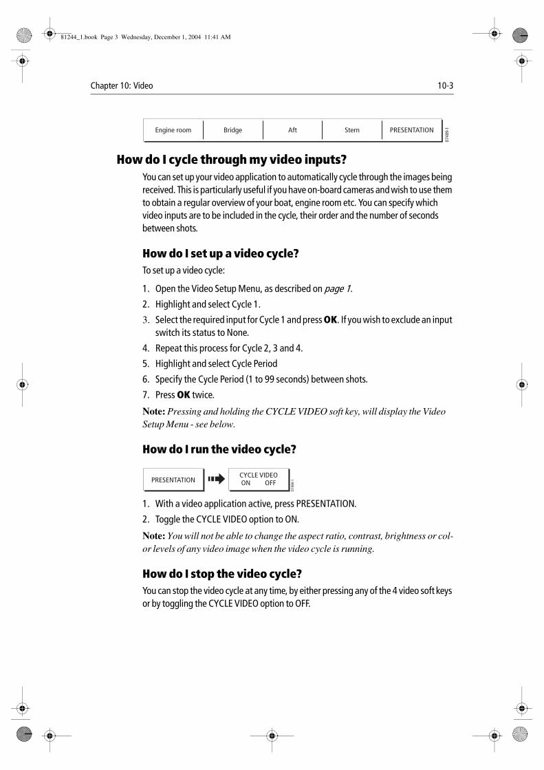
Chapter 10: Video 10-3
How do I cycle through my video inputs?You can set up your video application to automatically cycle through the images being received. This is particularly useful if you have on-board cameras and wish to use them to obtain a regular overview of your boat, engine room etc. You can specify which video inputs are to be included in the cycle, their order and the number of seconds between shots.
How do I set up a video cycle?To set up a video cycle:
1. Open the Video Setup Menu, as described on page 1.
2. Highlight and select Cycle 1.
3. Select the required input for Cycle 1 and press OK. If you wish to exclude an input switch its status to None.
4. Repeat this process for Cycle 2, 3 and 4.
5. Highlight and select Cycle Period
6. Specify the Cycle Period (1 to 99 seconds) between shots.
7. Press OK twice.
Note: Pressing and holding the CYCLE VIDEO soft key, will display the Video Setup Menu - see below.
How do I run the video cycle?
1. With a video application active, press PRESENTATION.
2. Toggle the CYCLE VIDEO option to ON.
Note: You will not be able to change the aspect ratio, contrast, brightness or col-or levels of any video image when the video cycle is running.
How do I stop the video cycle?You can stop the video cycle at any time, by either pressing any of the 4 video soft keys or by toggling the CYCLE VIDEO option to OFF.
D748
9-1Engine room Bridge Aft Stern PRESENTATION
D749
0-1PRESENTATION
CYCLE VIDEOON OFF
81244_1.book Page 3 Wednesday, December 1, 2004 11:41 AM
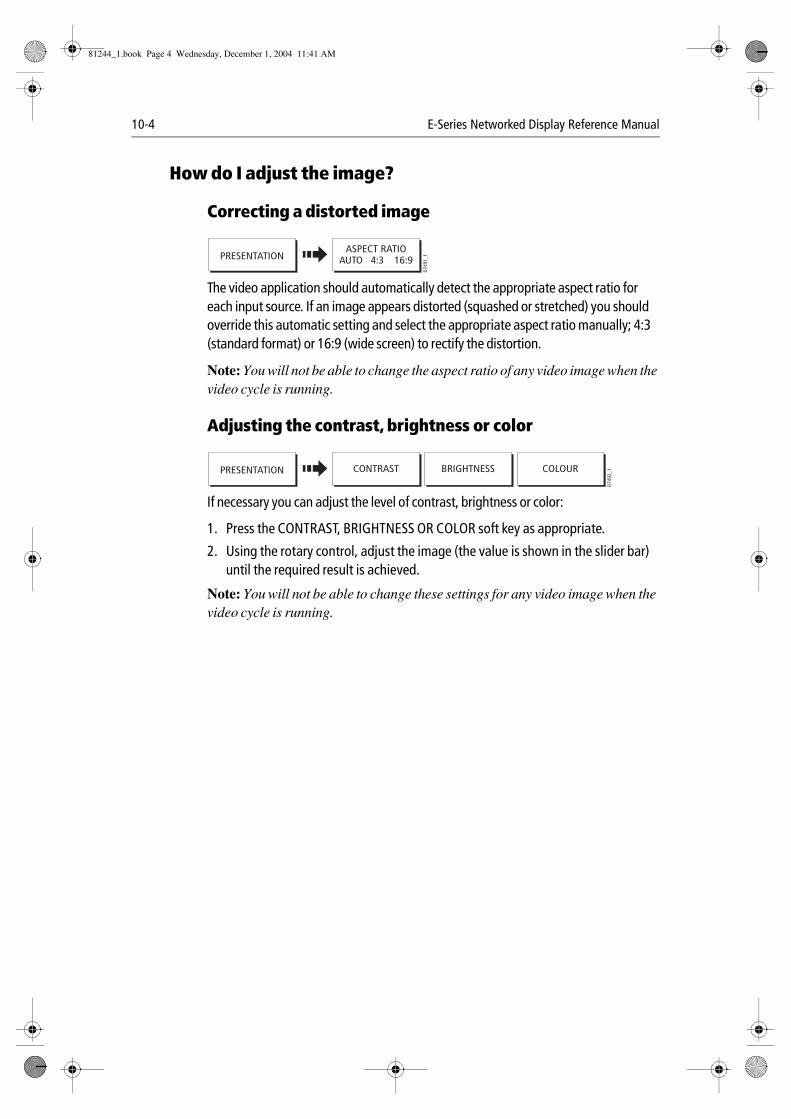
10-4 E-Series Networked Display Reference Manual
How do I adjust the image?
Correcting a distorted image
The video application should automatically detect the appropriate aspect ratio for each input source. If an image appears distorted (squashed or stretched) you should override this automatic setting and select the appropriate aspect ratio manually; 4:3 (standard format) or 16:9 (wide screen) to rectify the distortion.
Note: You will not be able to change the aspect ratio of any video image when the video cycle is running.
Adjusting the contrast, brightness or color
If necessary you can adjust the level of contrast, brightness or color:
1. Press the CONTRAST, BRIGHTNESS OR COLOR soft key as appropriate.
2. Using the rotary control, adjust the image (the value is shown in the slider bar) until the required result is achieved.
Note: You will not be able to change these settings for any video image when the video cycle is running.
D749
1_1PRESENTATION
ASPECT RATIOAUTO 4:3 16:9
D749
2_1PRESENTATION CONTRAST COLOURBRIGHTNESS
81244_1.book Page 4 Wednesday, December 1, 2004 11:41 AM
Chapter 11: System setup and customizing 11-1
Chapter 11:System setup and customizingThis chapter describes how to setup and customize your E-Series display. Any settings that you change will be stored by the display and shown each time you power on. You can, of course change these settings as many times as you wish.
11.1How do I change the data master? For Networked E-Series systems only:
To change the data master from that already specified, please see page 2- 16.
11.2How do I customize the page sets?The E-Series Display has 4 pre-configured page sets for you to choose from and one is left blank for you to customize. Each page can display up to four application windows. With the exception of Video, you can view multiple windows of the same application. For example you could have two chart application on one page - one to view a large scale chart, the other for a detailed view of your immediate surroundings.
If none of these meet your particular requirements you can edit the page sets to display the application and page layout that suits your particular needs. This process should also be used if you wish to run a video or engine monitor application.
In addition, you can rename of any of the page sets to a title that is more meaningful. A control is also provided to reset the selected page set to the factory default configuration.
Reconfiguring the application and page layoutTo change the configuration of applications and/or page layout:
1. Press and hold the PAGE button or select Select Page Set from the setup menu.
2. Use the trackpad or the rotary control to highlight the page set that you wish to edit.
3. Press EDIT PAGE SET. The soft keys display the pages within the selected page set.
4. Follow the on-screen instructions to edit the page layout and/or application, using the trackpad to move up/down the options.
Note: Only one video application can be viewed per page.
5. Press OK.
The page, window and application layout that you have defined will now be available each time you open the Select Page Set screen. If you wish to return to the default layout and name, press RESET TO DEFAULT PAGES.
If you do not want to use all 5 pages in a page set, you can switch off individual pages. When you use PAGE to toggle through the pages, the system will now skip any pages that are set to OFF.
81244_1.book Page 1 Wednesday, December 1, 2004 11:41 AM
11-2 E-Series Networked Display Reference Manual
Rename a page setIf required, you can customize the names of the page sets:
1. Press and hold the PAGE button or press MENU and then select Select Page Set.
2. Use the trackpad or the rotary control to highlight the page set that you wish to rename.
3. Press RENAME PAGE SET.
4. Use the soft keys, rotary control and trackpad to make the appropriate changes.
11.3How do I change the data bar?The data bar can either be displayed vertically at the right-hand side of your screen or horizontally across the top. If you select the top position you have the option to display either a normal or large bar size. The large bar provides more data.
If the data displayed in the data bar does not meet your particular requirements it can be reconfigured to show alternative data for your vessel, environment etc.
Note: Choosing a side position for your data bar, will allow you to display more data.
Changing the data bar position/size1. Press DATA then press and hold DATABAR ON/OFF or select Databar Setup from
the setup menu.
2. Highlight and then select Position.
3. Select either Top or Side.
4. Press OK.
When the data bar is positioned at the top of your screen, you have the option via the same menu, of displaying the bar in either a Large or Normal format.
Customizing the content of the data barYou can customize your data bar so that it contains the particular information that you require. The table that follows, shows the available data.
To configure the data bar:
1. To display the data available, press DATA and then press and hold DATA BAR ON/OFF or select Databar Setup from the setup menu.
2. Select the Configuration option. You now have the following data groups/data to choose from.
81244_1.book Page 2 Wednesday, December 1, 2004 11:41 AM
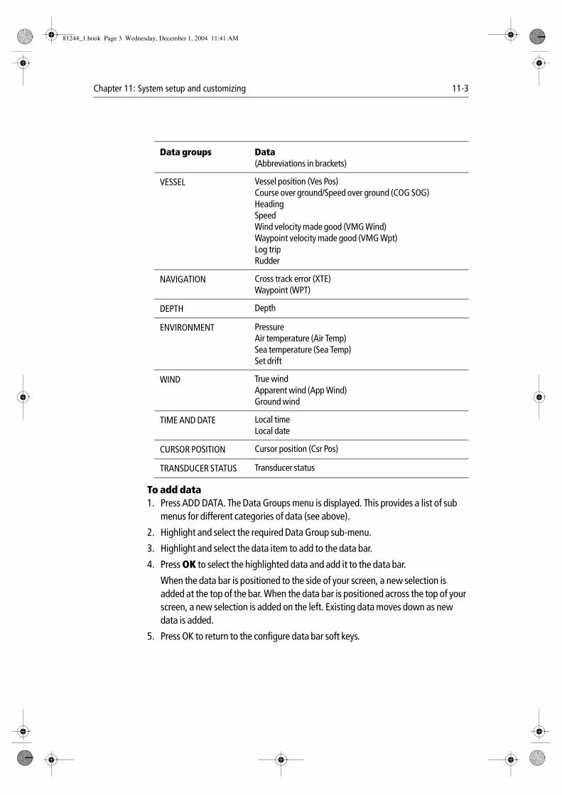
Chapter 11: System setup and customizing 11-3
To add data1. Press ADD DATA. The Data Groups menu is displayed. This provides a list of sub
menus for different categories of data (see above).
2. Highlight and select the required Data Group sub-menu.
3. Highlight and select the data item to add to the data bar.
4. Press OK to select the highlighted data and add it to the data bar.
When the data bar is positioned to the side of your screen, a new selection is added at the top of the bar. When the data bar is positioned across the top of your screen, a new selection is added on the left. Existing data moves down as new data is added.
5. Press OK to return to the configure data bar soft keys.
Data groups Data(Abbreviations in brackets)
VESSEL Vessel position (Ves Pos)Course over ground/Speed over ground (COG SOG)HeadingSpeedWind velocity made good (VMG Wind)Waypoint velocity made good (VMG Wpt)Log tripRudder
NAVIGATION Cross track error (XTE)Waypoint (WPT)
DEPTH Depth
ENVIRONMENT PressureAir temperature (Air Temp)Sea temperature (Sea Temp)Set drift
WIND True windApparent wind (App Wind)Ground wind
TIME AND DATE Local timeLocal date
CURSOR POSITION Cursor position (Csr Pos)
TRANSDUCER STATUS Transducer status
81244_1.book Page 3 Wednesday, December 1, 2004 11:41 AM
11-4 E-Series Networked Display Reference Manual
To move data1. Use the trackpad to highlight the data you want to move.
2. Press MOVE DATA. The soft key is highlighted.
3. Use the trackpad to move the data to the required position.
4. Press OK to accept the new position.
To remove data1. Use the trackpad to highlight the item you want to remove.
2. Press REMOVE DATA. The remaining data shuffles up to fill the space.
11.4How do I change Setup Menu options?The Setup Menu contains the following sub-menus:
• Application specific Setup Menus for the active window i.e. Chart and Carto-graphic, Radar, Fishfinder, Video and Engine Monitor Setup. For further details please refer to the appropriate chapter.
• System Setup.
• Alarm Setup.
• GPS Status.
• Compass Setup.
• Display Setup.
• Databar Setup.
• Select Page Set.
• System Diagnostics.
• Remove CF Card
When you first power on your display the default values are used. The tables that follow show the sub-menus, default settings and options available. In an E-Series Networked system, changes you make on one display affect all displays in the network, with the exception of:
• Display Setup.
• Databar Setup.
• Select Page set.
81244_1.book Page 4 Wednesday, December 1, 2004 11:41 AM
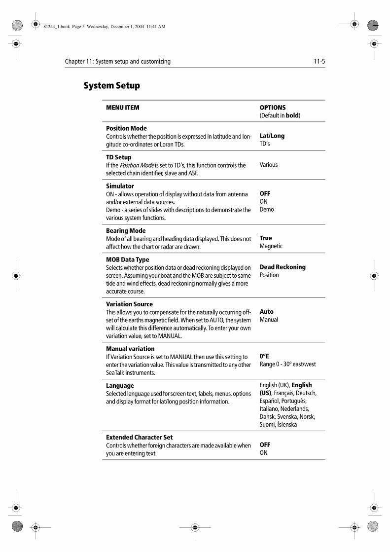
Chapter 11: System setup and customizing 11-5
System Setup
MENU ITEM OPTIONS(Default in bold)
Position ModeControls whether the position is expressed in latitude and lon-gitude co-ordinates or Loran TDs.
Lat/LongTD’s
TD Setup If the Position Mode is set to TD’s, this function controls the selected chain identifier, slave and ASF.
Various
SimulatorON - allows operation of display without data from antenna and/or external data sources. Demo - a series of slides with descriptions to demonstrate the various system functions.
OFFONDemo
Bearing ModeMode of all bearing and heading data displayed. This does not affect how the chart or radar are drawn.
TrueMagnetic
MOB Data TypeSelects whether position data or dead reckoning displayed on screen. Assuming your boat and the MOB are subject to same tide and wind effects, dead reckoning normally gives a more accurate course.
Dead ReckoningPosition
Variation SourceThis allows you to compensate for the naturally occurring off-set of the earths magnetic field. When set to AUTO, the system will calculate this difference automatically. To enter your own variation value, set to MANUAL.
AutoManual
Manual variationIf Variation Source is set to MANUAL then use this setting to enter the variation value. This value is transmitted to any other SeaTalk instruments.
0°ERange 0 - 30º east/west
LanguageSelected language used for screen text, labels, menus, options and display format for lat/long position information.
English (UK), English (US), Français, Deutsch, Español, Português,Italiano, Nederlands, Dansk, Svenska, Norsk, Suomi, Íslenska
Extended Character SetControls whether foreign characters are made available when you are entering text.
OFFON
81244_1.book Page 5 Wednesday, December 1, 2004 11:41 AM
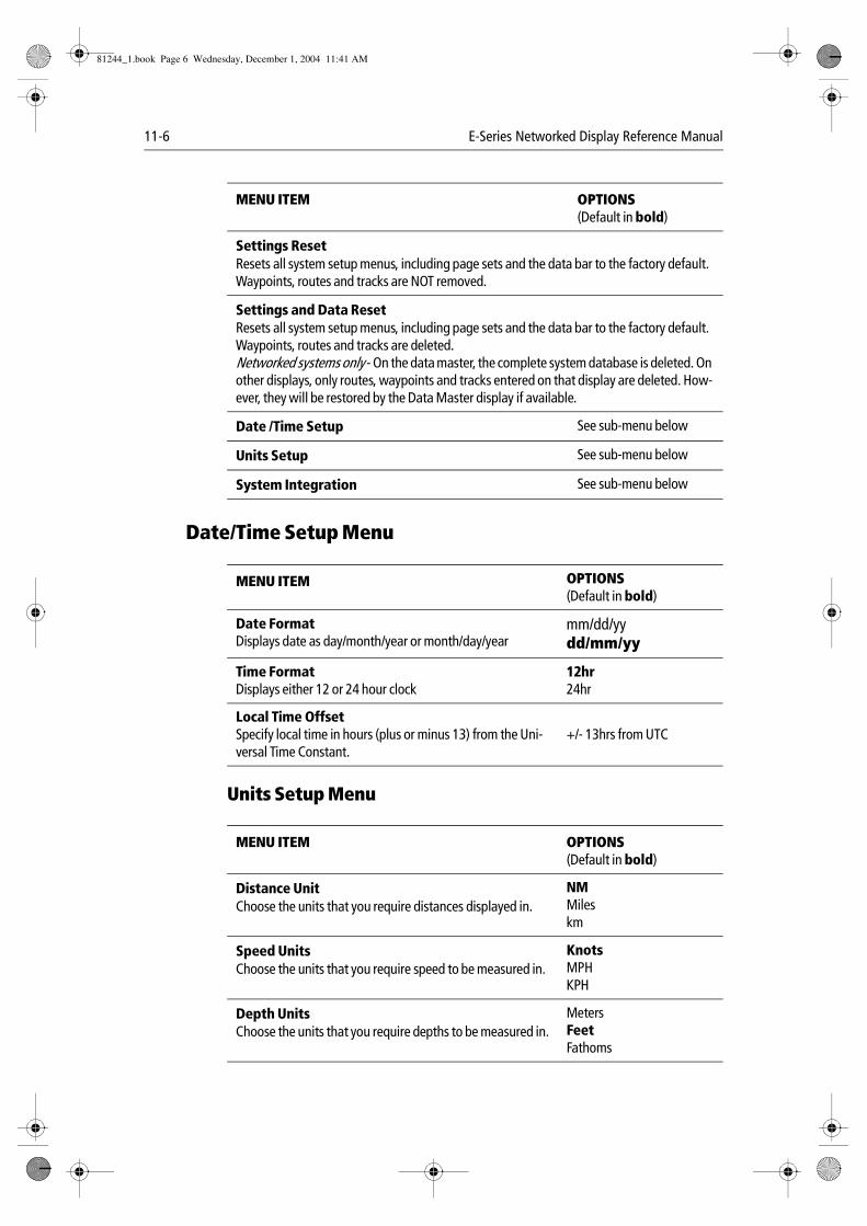
11-6 E-Series Networked Display Reference Manual
Date/Time Setup Menu
Units Setup Menu
Settings ResetResets all system setup menus, including page sets and the data bar to the factory default. Waypoints, routes and tracks are NOT removed.
Settings and Data ResetResets all system setup menus, including page sets and the data bar to the factory default. Waypoints, routes and tracks are deleted.Networked systems only - On the data master, the complete system database is deleted. On other displays, only routes, waypoints and tracks entered on that display are deleted. How-ever, they will be restored by the Data Master display if available.
Date /Time Setup See sub-menu below
Units Setup See sub-menu below
System Integration See sub-menu below
MENU ITEM OPTIONS(Default in bold)
Date FormatDisplays date as day/month/year or month/day/year
mm/dd/yydd/mm/yy
Time FormatDisplays either 12 or 24 hour clock
12hr24hr
Local Time OffsetSpecify local time in hours (plus or minus 13) from the Uni-versal Time Constant.
+/- 13hrs from UTC
MENU ITEM OPTIONS(Default in bold)
Distance UnitChoose the units that you require distances displayed in.
NMMileskm
Speed UnitsChoose the units that you require speed to be measured in.
KnotsMPHKPH
Depth UnitsChoose the units that you require depths to be measured in.
MetersFeetFathoms
MENU ITEM OPTIONS(Default in bold)
81244_1.book Page 6 Wednesday, December 1, 2004 11:41 AM
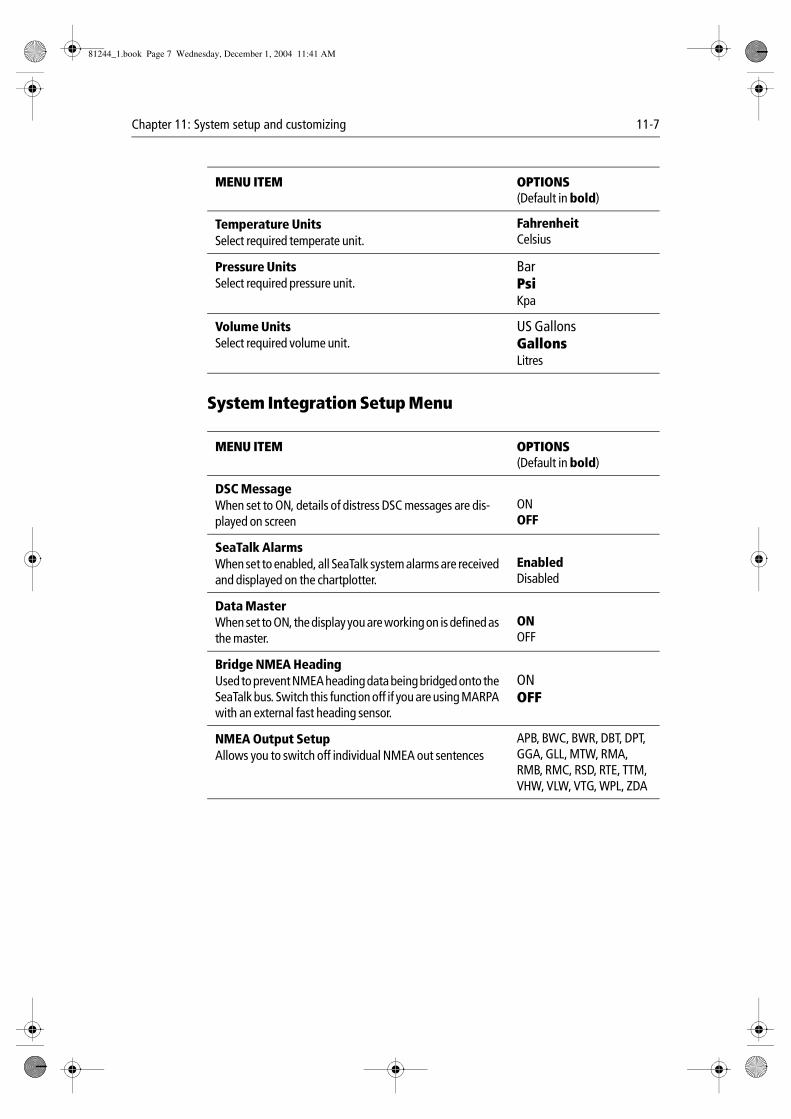
Chapter 11: System setup and customizing 11-7
System Integration Setup Menu
Temperature UnitsSelect required temperate unit.
FahrenheitCelsius
Pressure UnitsSelect required pressure unit.
BarPsiKpa
Volume UnitsSelect required volume unit.
US GallonsGallonsLitres
MENU ITEM OPTIONS(Default in bold)
DSC MessageWhen set to ON, details of distress DSC messages are dis-played on screen
ONOFF
SeaTalk AlarmsWhen set to enabled, all SeaTalk system alarms are received and displayed on the chartplotter.
EnabledDisabled
Data MasterWhen set to ON, the display you are working on is defined as the master.
ONOFF
Bridge NMEA HeadingUsed to prevent NMEA heading data being bridged onto the SeaTalk bus. Switch this function off if you are using MARPA with an external fast heading sensor.
ONOFF
NMEA Output SetupAllows you to switch off individual NMEA out sentences
APB, BWC, BWR, DBT, DPT, GGA, GLL, MTW, RMA, RMB, RMC, RSD, RTE, TTM, VHW, VLW, VTG, WPL, ZDA
MENU ITEM OPTIONS(Default in bold)
81244_1.book Page 7 Wednesday, December 1, 2004 11:41 AM
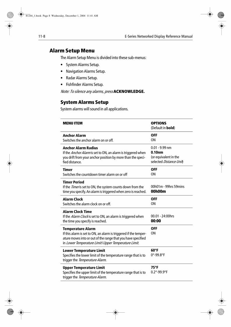
11-8 E-Series Networked Display Reference Manual
Alarm Setup MenuThe Alarm Setup Menu is divided into these sub-menus:
• System Alarms Setup.
• Navigation Alarms Setup.
• Radar Alarms Setup.
• Fishfinder Alarms Setup.
Note: To silence any alarms, press ACKNOWLEDGE.
System Alarms SetupSystem alarms will sound in all applications.
MENU ITEM OPTIONS(Default in bold)
Anchor AlarmSwitches the anchor alarm on or off.
OFFON
Anchor Alarm RadiusIf the Anchor Alarm is set to ON, an alarm is triggered when you drift from your anchor position by more than the speci-fied distance.
0.01 - 9.99 nm0.10nm(or equivalent in the selected Distance Unit)
TimerSwitches the countdown timer alarm on or off
OFFON
Timer PeriodIf the Timer is set to ON, the system counts down from the time you specify. An alarm is triggered when zero is reached.
00h01m - 99hrs 59mins00h00m
Alarm ClockSwitches the alarm clock on or off.
OFFON
Alarm Clock TimeIf the Alarm Clock is set to ON, an alarm is triggered when the time you specify is reached.
00.01 - 24:00hrs00:00
Temperature AlarmIf this alarm is set to ON, an alarm is triggered if the temper-ature moves into or out of the range that you have specified in Lower Temperature Limit /Upper Temperature Limit.
OFFON
Lower Temperature LimitSpecifies the lower limit of the temperature range that is to trigger the Temperature Alarm.
60°F0°-99.8°F
Upper Temperature LimitSpecifies the upper limit of the temperature range that is to trigger the Temperature Alarm.
75°F0.2°-99.9°F
81244_1.book Page 8 Wednesday, December 1, 2004 11:41 AM
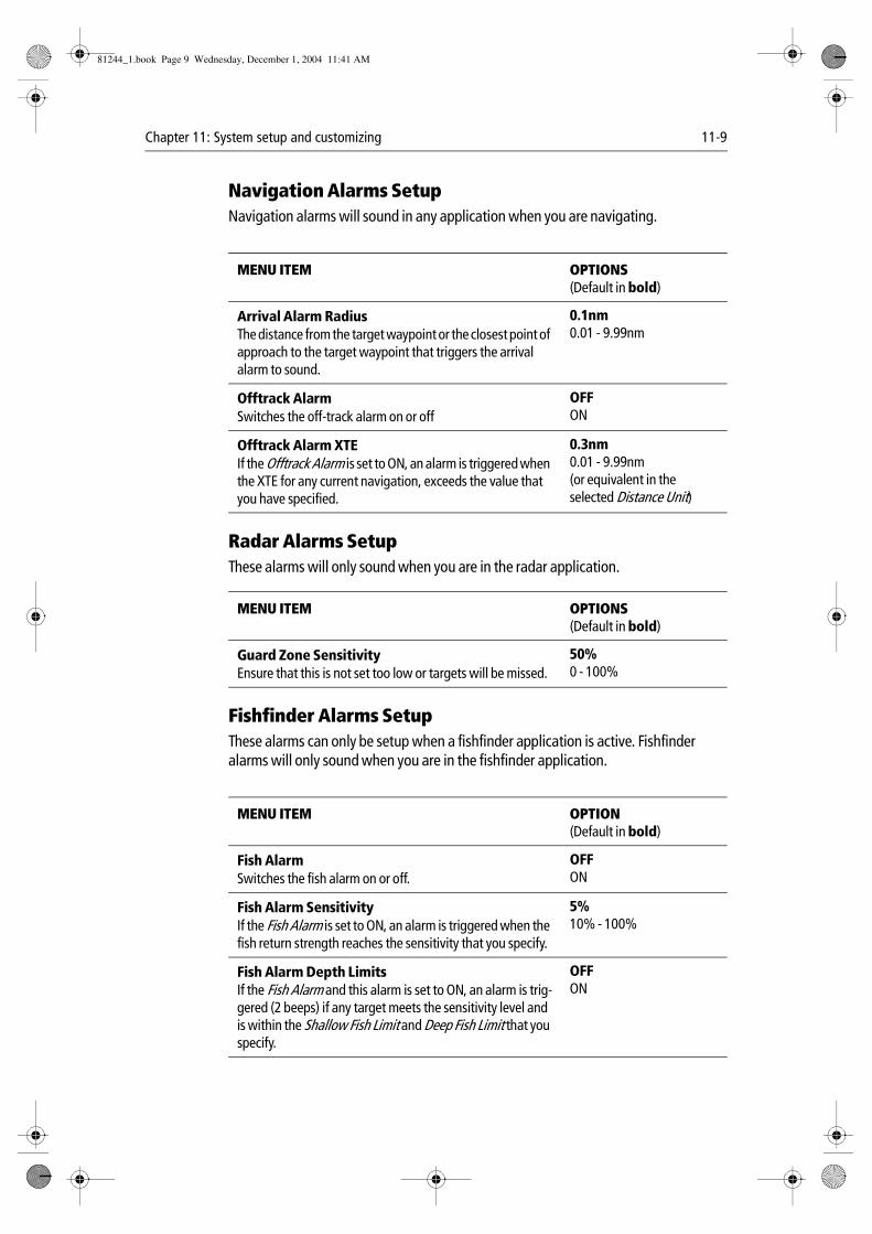
Chapter 11: System setup and customizing 11-9
Navigation Alarms SetupNavigation alarms will sound in any application when you are navigating.
Radar Alarms SetupThese alarms will only sound when you are in the radar application.
Fishfinder Alarms SetupThese alarms can only be setup when a fishfinder application is active. Fishfinder alarms will only sound when you are in the fishfinder application.
MENU ITEM OPTIONS(Default in bold)
Arrival Alarm RadiusThe distance from the target waypoint or the closest point of approach to the target waypoint that triggers the arrival alarm to sound.
0.1nm0.01 - 9.99nm
Offtrack AlarmSwitches the off-track alarm on or off
OFFON
Offtrack Alarm XTEIf the Offtrack Alarm is set to ON, an alarm is triggered when the XTE for any current navigation, exceeds the value that you have specified.
0.3nm0.01 - 9.99nm(or equivalent in the selected Distance Unit)
MENU ITEM OPTIONS(Default in bold)
Guard Zone SensitivityEnsure that this is not set too low or targets will be missed.
50%0 - 100%
MENU ITEM OPTION(Default in bold)
Fish AlarmSwitches the fish alarm on or off.
OFFON
Fish Alarm SensitivityIf the Fish Alarm is set to ON, an alarm is triggered when the fish return strength reaches the sensitivity that you specify.
5%10% - 100%
Fish Alarm Depth LimitsIf the Fish Alarm and this alarm is set to ON, an alarm is trig-gered (2 beeps) if any target meets the sensitivity level and is within the Shallow Fish Limit and Deep Fish Limit that you specify.
OFFON
81244_1.book Page 9 Wednesday, December 1, 2004 11:41 AM
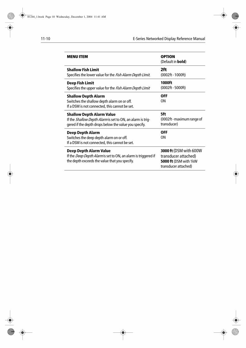
11-10 E-Series Networked Display Reference Manual
Shallow Fish LimitSpecifies the lower value for the Fish Alarm Depth LImit.
2ft(0002ft - 1000ft)
Deep Fish LimitSpecifies the upper value for the Fish Alarm Depth LImit
1000ft(0002ft - 5000ft)
Shallow Depth AlarmSwitches the shallow depth alarm on or off.If a DSM is not connected, this cannot be set.
OFFON
Shallow Depth Alarm ValueIf the Shallow Depth Alarm is set to ON, an alarm is trig-gered if the depth drops below the value you specify.
5ft (0002ft - maximum range of transducer)
Deep Depth AlarmSwitches the deep depth alarm on or off.If a DSM is not connected, this cannot be set.
OFFON
Deep Depth Alarm ValueIf the Deep Depth Alarm is set to ON, an alarm is triggered if the depth exceeds the value that you specify.
3000 ft (DSM with 600W transducer attached)5000 ft (DSM with 1kW transducer attached)
MENU ITEM OPTION(Default in bold)
81244_1.book Page 10 Wednesday, December 1, 2004 11:41 AM
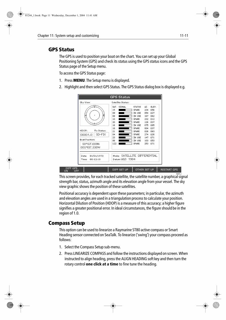
Chapter 11: System setup and customizing 11-11
GPS StatusThe GPS is used to position your boat on the chart. You can set up your Global Positioning System (GPS) and check its status using the GPS status icons and the GPS Status page of the Setup menu.
To access the GPS Status page:
1. Press MENU. The Setup menu is displayed.
2. Highlight and then select GPS Status. The GPS Status dialog box is displayed e.g.
This screen provides, for each tracked satellite, the satellite number, a graphical signal strength bar, status, azimuth angle and its elevation angle from your vessel. The sky view graphic shows the position of these satellites.
Positional accuracy is dependent upon these parameters; in particular, the azimuth and elevation angles are used in a triangulation process to calculate your position. Horizontal Dilution of Position (HDOP) is a measure of this accuracy; a higher figure signifies a greater positional error. In ideal circumstances, the figure should be in the region of 1.0.
Compass SetupThis option can be used to linearize a Raymarine ST80 active compass or Smart Heading sensor connected on SeaTalk. To linearize (‘swing’) your compass proceed as follows:
1. Select the Compass Setup sub-menu.
2. Press LINEARIZE COMPASS and follow the instructions displayed on screen. When instructed to align heading, press the ALIGN HEADING soft key and then turn the rotary control one click at a time to fine tune the heading.
DIFF SET UP OTHER SET UP RESTART GPSDIFF GPS
ON OFF
0
0
0
0
0
0
0
0
0
0
0
0
FIX STATUSHDOP
122
00001.0 SD-FIX
D6809_2
SATELLITE DIFFERENTIAL
WGS 1984
81244_1.book Page 11 Wednesday, December 1, 2004 11:41 AM
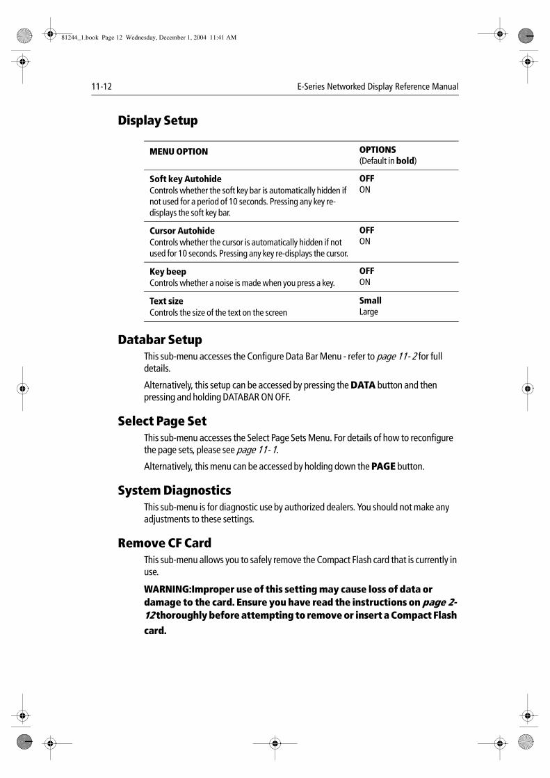
11-12 E-Series Networked Display Reference Manual
Display Setup
Databar SetupThis sub-menu accesses the Configure Data Bar Menu - refer to page 11- 2 for full details.
Alternatively, this setup can be accessed by pressing the DATA button and then pressing and holding DATABAR ON OFF.
Select Page SetThis sub-menu accesses the Select Page Sets Menu. For details of how to reconfigure the page sets, please see page 11- 1.
Alternatively, this menu can be accessed by holding down the PAGE button.
System DiagnosticsThis sub-menu is for diagnostic use by authorized dealers. You should not make any adjustments to these settings.
Remove CF CardThis sub-menu allows you to safely remove the Compact Flash card that is currently in use.
WARNING:Improper use of this setting may cause loss of data or damage to the card. Ensure you have read the instructions on page 2- 12 thoroughly before attempting to remove or insert a Compact Flash
card.
MENU OPTION OPTIONS(Default in bold)
Soft key AutohideControls whether the soft key bar is automatically hidden if not used for a period of 10 seconds. Pressing any key re-displays the soft key bar.
OFFON
Cursor AutohideControls whether the cursor is automatically hidden if not used for 10 seconds. Pressing any key re-displays the cursor.
OFFON
Key beepControls whether a noise is made when you press a key.
OFFON
Text sizeControls the size of the text on the screen
SmallLarge
81244_1.book Page 12 Wednesday, December 1, 2004 11:41 AM
Chapter 12: Maintenance & Troubleshooting 12-1
Chapter 12:Maintenance & Troubleshooting
12.1IntroductionThis chapter provides information on maintaining and troubleshooting your Raymarine E-Series Display, and also information on how to get assistance from Raymarine.
12.2What maintenance can I do?At regular intervals, carry out the following servicing procedures:
• Routine checks.
• Cleaning the Display.
Do not attempt any other servicing procedures.
Servicing and Safety• Raymarine equipment should be serviced only by authorized Raymarine service
technicians. They will ensure that service procedures and any replacement parts used will not affect performance. There are no user serviceable parts in any Rayma-rine product.
• Some products generate high voltages, so never handle the cables or connectors when power is being supplied to the equipment.
• When powered on, all electrical equipment produces electromagnetic fields. These can cause adjacent pieces of electrical equipment to interact with one another, with a consequent adverse effect on operation. In order to minimize these effects and enable you to get the best possible performance from your Raymarine equip-ment, guidelines are given in the installations manual, to enable you to ensure min-imum interaction between different items of equipment, i.e. ensure optimum Electromagnetic Compatibility (EMC).
• Always report any EMC-related problem to your nearest Raymarine dealer. We use such information to improve our quality standards.
• In some installations, it may not be possible to prevent the equipment from being affected by external influences. In general this will not damage the equipment, but it can lead to spurious re-setting action, or momentarily may result in faulty opera-tion.
• At the end of the useful working life of this product, it should disposed of in accor-dance with local regulations.
81244_1.book Page 1 Wednesday, December 1, 2004 11:41 AM
12-2 E-Series Networked Display Reference Manual
Routine checksCarry out the following tasks on a regular basis:
• Examine all cables for signs of damage, such as chafing, cuts or nicks.
• Check that all cables are securely connected.
Cleaning the displayCAUTION: Cleaning the displayTake care when cleaning the display, to avoid damaging it.(1) Do NOT wipe the display screen with a dry cloth, as this could scratch
the screen coating.(2) Do NOT use acid, ammonia based or abrasive products.
Regularly clean your Display as follows:
1. Switch off the power to the Display.
2. Wipe the Display with a clean soft cloth. To remove oily finger marks use a spray cleaning agent of the type used for cleaning eyeglasses.
A suitable micro-fibre cloth is supplied with your display and spray can be purchased from your local optician.
12.3How do I reset a Display?You can reset the E-Series Display in one of three ways:
• Settings reset.
• Settings and data reset.
Settings reset
What is a settings reset?All system set-up menus, including page sets and the data bar are reset to the factory default, when you apply a settings reset. Your waypoints, routes and tracks are NOT removed.
How do I carry out a settings reset?To carry out a settings reset:
1. Press MENU.
2. Highlight and select System Setup.
3. Highlight and select Settings Reset. You will be asked to confirm whether you wish to proceed.
4. Press YES. The system resets and returns you to the power on procedure.
81244_1.book Page 2 Wednesday, December 1, 2004 11:41 AM
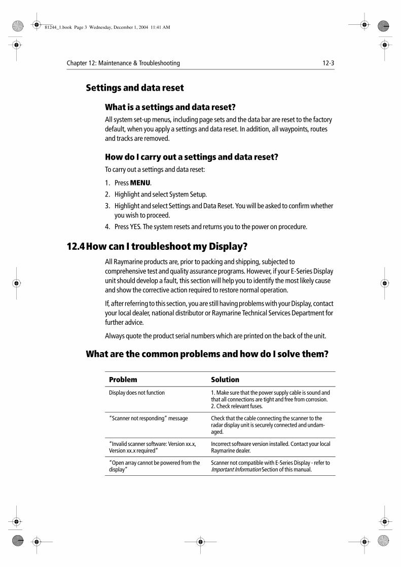
Chapter 12: Maintenance & Troubleshooting 12-3
Settings and data reset
What is a settings and data reset?All system set-up menus, including page sets and the data bar are reset to the factory default, when you apply a settings and data reset. In addition, all waypoints, routes and tracks are removed.
How do I carry out a settings and data reset?To carry out a settings and data reset:
1. Press MENU.
2. Highlight and select System Setup.
3. Highlight and select Settings and Data Reset. You will be asked to confirm whether you wish to proceed.
4. Press YES. The system resets and returns you to the power on procedure.
12.4How can I troubleshoot my Display?All Raymarine products are, prior to packing and shipping, subjected to comprehensive test and quality assurance programs. However, if your E-Series Display unit should develop a fault, this section will help you to identify the most likely cause and show the corrective action required to restore normal operation.
If, after referring to this section, you are still having problems with your Display, contact your local dealer, national distributor or Raymarine Technical Services Department for further advice.
Always quote the product serial numbers which are printed on the back of the unit.
What are the common problems and how do I solve them?
Problem Solution
Display does not function 1. Make sure that the power supply cable is sound and that all connections are tight and free from corrosion.2. Check relevant fuses.
“Scanner not responding” message Check that the cable connecting the scanner to the radar display unit is securely connected and undam-aged.
“Invalid scanner software: Version xx.x, Version xx.x required”
Incorrect software version installed. Contact your local Raymarine dealer.
“Open array cannot be powered from the display”
Scanner not compatible with E-Series Display - refer to Important Information Section of this manual.
81244_1.book Page 3 Wednesday, December 1, 2004 11:41 AM
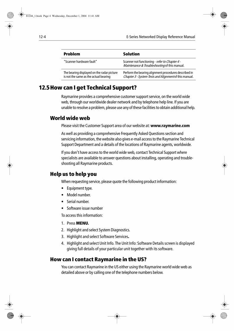
12-4 E-Series Networked Display Reference Manual
12.5How can I get Technical Support?Raymarine provides a comprehensive customer support service, on the world wide web, through our worldwide dealer network and by telephone help line. If you are unable to resolve a problem, please use any of these facilities to obtain additional help.
World wide webPlease visit the Customer Support area of our website at: www.raymarine.com
As well as providing a comprehensive Frequently Asked Questions section and servicing information, the website also gives e-mail access to the Raymarine Technical Support Department and a details of the locations of Raymarine agents, worldwide.
If you don’t have access to the world wide web, contact Technical Support where specialists are available to answer questions about installing, operating and trouble-shooting all Raymarine products.
Help us to help youWhen requesting service, please quote the following product information:
• Equipment type.
• Model number.
• Serial number.
• Software issue number
To access this information:
1. Press MENU.
2. Highlight and select System Diagnostics.
3. Highlight and select Software Services.
4. Highlight and select Unit Info. The Unit Info: Software Details screen is displayed giving full details of your particular unit together with its software.
How can I contact Raymarine in the US?You can contact Raymarine in the US either using the Raymarine world wide web as detailed above or by calling one of the telephone numbers below.
“Scanner hardware fault” Scanner not functioning - refer to Chapter 4 - Maintenance & Troubleshooting of this manual.
The bearing displayed on the radar picture is not the same as the actual bearing
Perform the bearing alignment procedures described in Chapter 3 - System Tests and Alignment of this manual.
Problem Solution
81244_1.book Page 4 Wednesday, December 1, 2004 11:41 AM
Chapter 12: Maintenance & Troubleshooting 12-5
Who do I contact for accessories and parts?You can obtain many Raymarine accessories and parts directly from your authorized Raymarine dealer. However, if your dealer does not have the item you want, contact Raymarine Technical Services at:
1-800-539-5539 extension 2333, or
(603) - 881 - 5200
You can use these numbers Monday to Friday 0815 to 1700 Eastern Standard Time or Eastern Daylight Savings Time.
If you are not sure which item is appropriate for your unit, you should first contact the Technical Support Department at:
1-800-539-5539 extension 2444, or
(603)-881 -5200
to verify your requirements.
Who do I contact for product repair and service?In the unlikely event that your Raymarine unit should develop a problem, contact your authorized Raymarine dealer for assistance. The dealer is best equipped to handle your service requirements and can offer timesaving help in getting your equipment back into normal operation.
If repairs cannot be obtained conveniently, obtain product service by returning the unit to:
Raymarine Product Repair Center
22 Cotton Road, Unit D,
Nashua,
NH03603-4219
The Product Repair Center is open Monday to Friday 0815 to 1700 Eastern Standard Time or Eastern Daylight Savings Time.
All products returned to the Repair Center are registered upon receipt and a confirmation letter is sent to acknowledge the repair status and the reference number of the product.
We will make every effort to carry out the repair and return your unit as quickly as possible.
If you wish to enquire about the repair status of your unit, contact the Repair Center at:
1-800-539-5539
81244_1.book Page 5 Wednesday, December 1, 2004 11:41 AM

12-6 E-Series Networked Display Reference Manual
How can I contact Raymarine in Europe?You can obtain Technical Support, service and accessories from your authorized Raymarine dealer, or by contacting:
Raymarine Limited
Anchorage Park, Portsmouth
PO3 5TD, England
Tel +44 (0)23 9271 4713
Fax +44 (0)23 9269 4642
81244_1.book Page 6 Wednesday, December 1, 2004 11:41 AM
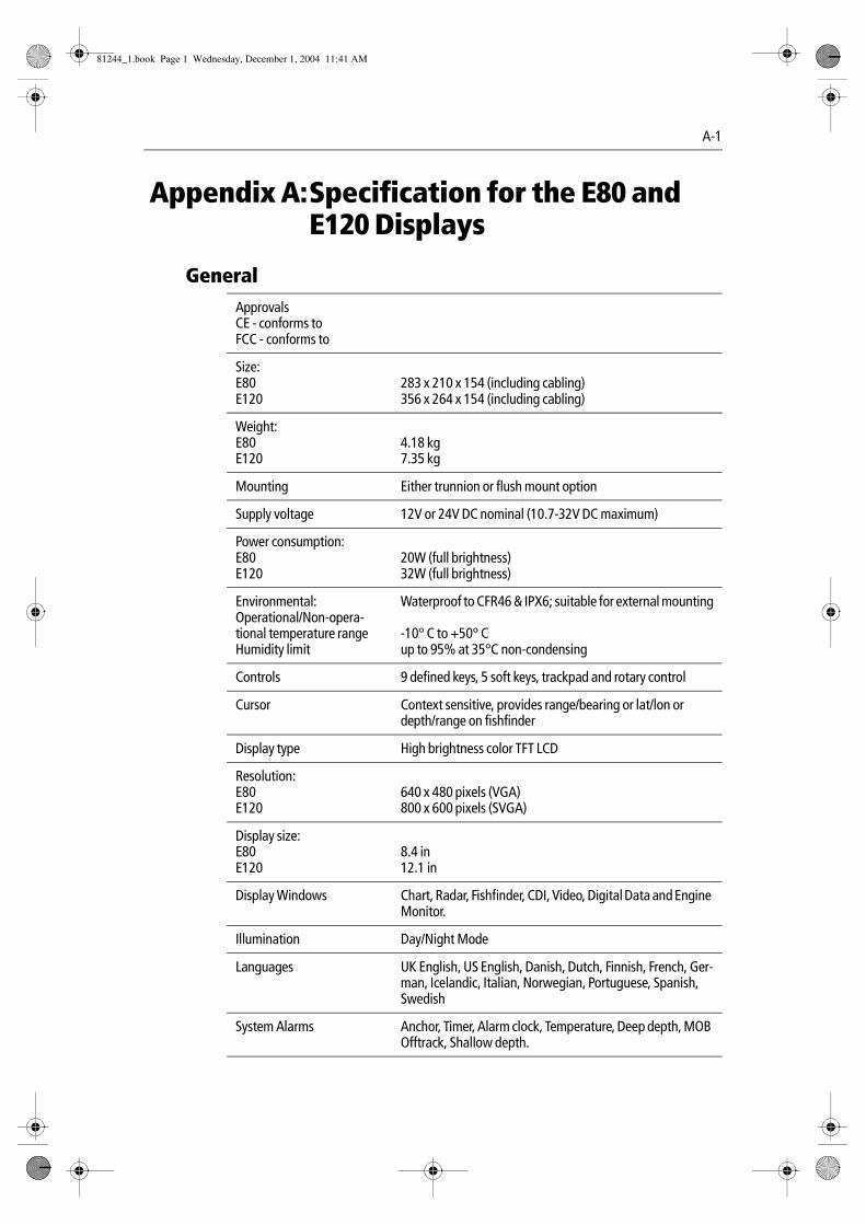
A-1
Appendix A:Specification for the E80 and E120 Displays
GeneralApprovalsCE - conforms toFCC - conforms to
Size:E80E120
283 x 210 x 154 (including cabling)356 x 264 x 154 (including cabling)
Weight:E80E120
4.18 kg7.35 kg
Mounting Either trunnion or flush mount option
Supply voltage 12V or 24V DC nominal (10.7-32V DC maximum)
Power consumption:E80E120
20W (full brightness)32W (full brightness)
Environmental:Operational/Non-opera-tional temperature rangeHumidity limit
Waterproof to CFR46 & IPX6; suitable for external mounting
-10° C to +50° Cup to 95% at 35°C non-condensing
Controls 9 defined keys, 5 soft keys, trackpad and rotary control
Cursor Context sensitive, provides range/bearing or lat/lon or depth/range on fishfinder
Display type High brightness color TFT LCD
Resolution:E80E120
640 x 480 pixels (VGA)800 x 600 pixels (SVGA)
Display size:E80E120
8.4 in12.1 in
Display Windows Chart, Radar, Fishfinder, CDI, Video, Digital Data and Engine Monitor.
Illumination Day/Night Mode
Languages UK English, US English, Danish, Dutch, Finnish, French, Ger-man, Icelandic, Italian, Norwegian, Portuguese, Spanish, Swedish
System Alarms Anchor, Timer, Alarm clock, Temperature, Deep depth, MOB Offtrack, Shallow depth.
81244_1.book Page 1 Wednesday, December 1, 2004 11:41 AM
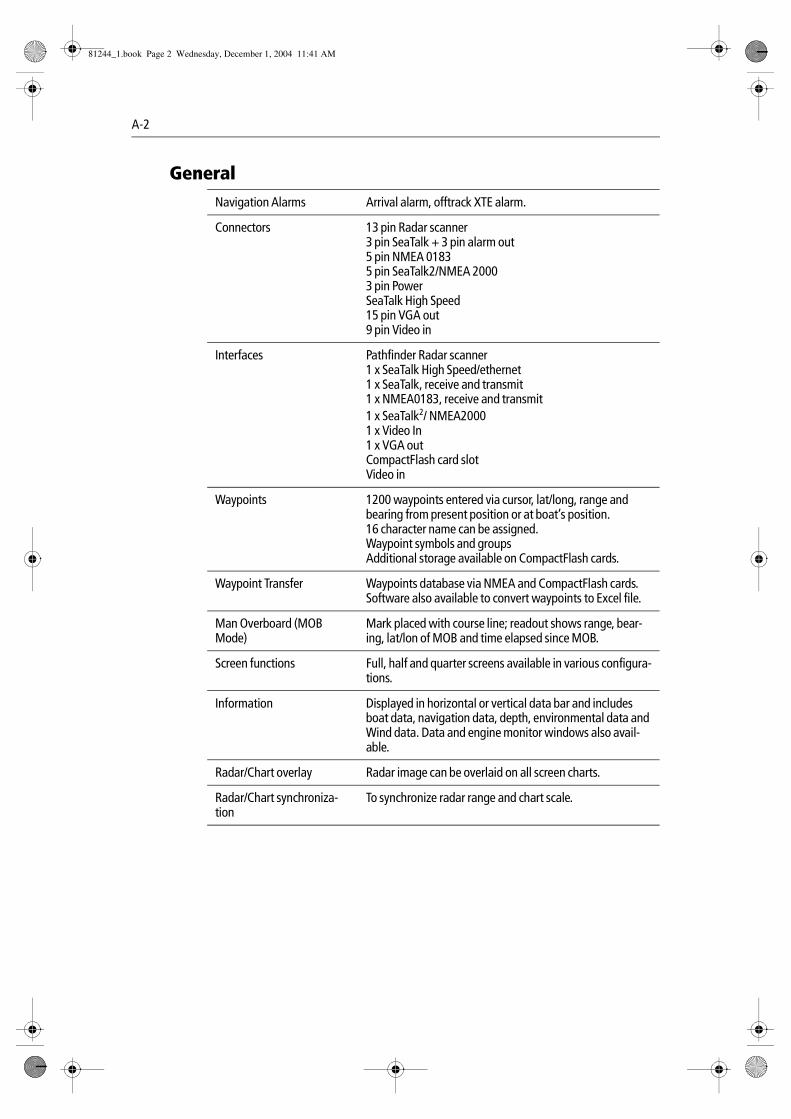
A-2
Navigation Alarms Arrival alarm, offtrack XTE alarm.
Connectors 13 pin Radar scanner3 pin SeaTalk + 3 pin alarm out5 pin NMEA 01835 pin SeaTalk2/NMEA 20003 pin PowerSeaTalk High Speed15 pin VGA out9 pin Video in
Interfaces Pathfinder Radar scanner1 x SeaTalk High Speed/ethernet1 x SeaTalk, receive and transmit1 x NMEA0183, receive and transmit1 x SeaTalk2/ NMEA20001 x Video In1 x VGA outCompactFlash card slotVideo in
Waypoints 1200 waypoints entered via cursor, lat/long, range and bearing from present position or at boat’s position.16 character name can be assigned.Waypoint symbols and groupsAdditional storage available on CompactFlash cards.
Waypoint Transfer Waypoints database via NMEA and CompactFlash cards. Software also available to convert waypoints to Excel file.
Man Overboard (MOB Mode)
Mark placed with course line; readout shows range, bear-ing, lat/lon of MOB and time elapsed since MOB.
Screen functions Full, half and quarter screens available in various configura-tions.
Information Displayed in horizontal or vertical data bar and includes boat data, navigation data, depth, environmental data and Wind data. Data and engine monitor windows also avail-able.
Radar/Chart overlay Radar image can be overlaid on all screen charts.
Radar/Chart synchroniza-tion
To synchronize radar range and chart scale.
General
81244_1.book Page 2 Wednesday, December 1, 2004 11:41 AM
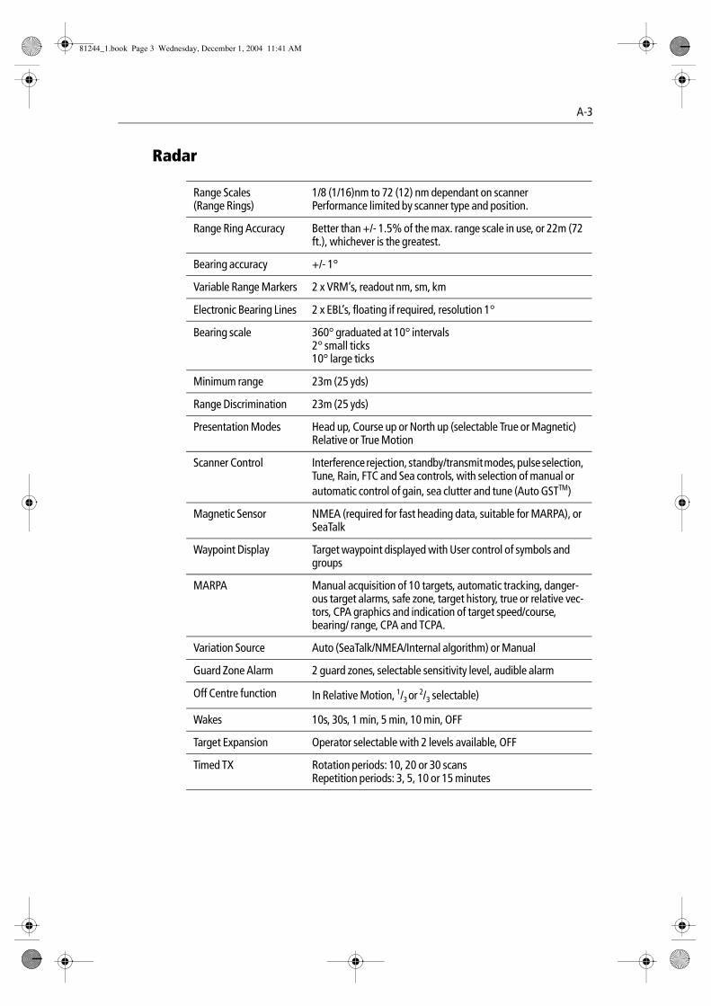
A-3
Radar
Range Scales(Range Rings)
1/8 (1/16)nm to 72 (12) nm dependant on scannerPerformance limited by scanner type and position.
Range Ring Accuracy Better than +/- 1.5% of the max. range scale in use, or 22m (72 ft.), whichever is the greatest.
Bearing accuracy +/- 1°
Variable Range Markers 2 x VRM’s, readout nm, sm, km
Electronic Bearing Lines 2 x EBL’s, floating if required, resolution 1°
Bearing scale 360° graduated at 10° intervals2° small ticks10° large ticks
Minimum range 23m (25 yds)
Range Discrimination 23m (25 yds)
Presentation Modes Head up, Course up or North up (selectable True or Magnetic)Relative or True Motion
Scanner Control Interference rejection, standby/transmit modes, pulse selection, Tune, Rain, FTC and Sea controls, with selection of manual or automatic control of gain, sea clutter and tune (Auto GSTTM)
Magnetic Sensor NMEA (required for fast heading data, suitable for MARPA), or SeaTalk
Waypoint Display Target waypoint displayed with User control of symbols and groups
MARPA Manual acquisition of 10 targets, automatic tracking, danger-ous target alarms, safe zone, target history, true or relative vec-tors, CPA graphics and indication of target speed/course, bearing/ range, CPA and TCPA.
Variation Source Auto (SeaTalk/NMEA/Internal algorithm) or Manual
Guard Zone Alarm 2 guard zones, selectable sensitivity level, audible alarm
Off Centre function In Relative Motion, 1/3 or 2/3 selectable)
Wakes 10s, 30s, 1 min, 5 min, 10 min, OFF
Target Expansion Operator selectable with 2 levels available, OFF
Timed TX Rotation periods: 10, 20 or 30 scansRepetition periods: 3, 5, 10 or 15 minutes
81244_1.book Page 3 Wednesday, December 1, 2004 11:41 AM
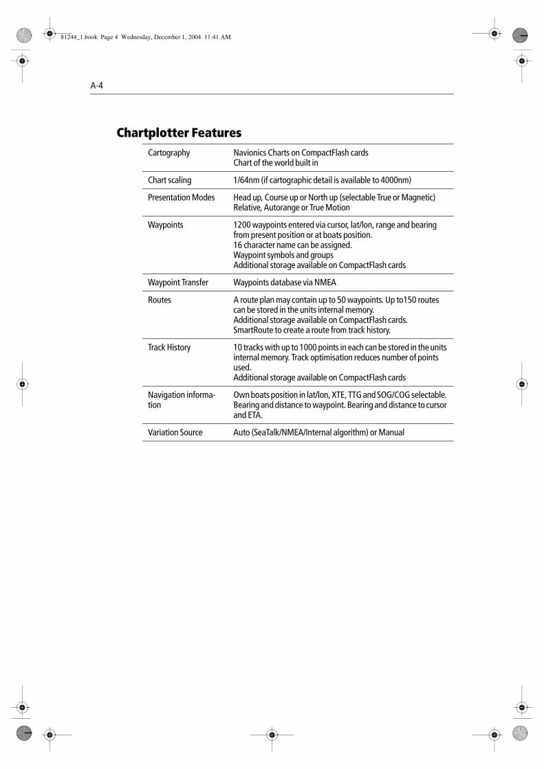
A-4
Chartplotter FeaturesCartography Navionics Charts on CompactFlash cards
Chart of the world built in
Chart scaling 1/64nm (if cartographic detail is available to 4000nm)
Presentation Modes Head up, Course up or North up (selectable True or Magnetic)Relative, Autorange or True Motion
Waypoints 1200 waypoints entered via cursor, lat/lon, range and bearing from present position or at boats position.16 character name can be assigned.Waypoint symbols and groupsAdditional storage available on CompactFlash cards
Waypoint Transfer Waypoints database via NMEA
Routes A route plan may contain up to 50 waypoints. Up to150 routes can be stored in the units internal memory.Additional storage available on CompactFlash cards.SmartRoute to create a route from track history.
Track History 10 tracks with up to 1000 points in each can be stored in the units internal memory. Track optimisation reduces number of points used.Additional storage available on CompactFlash cards
Navigation informa-tion
Own boats position in lat/lon, XTE, TTG and SOG/COG selectable. Bearing and distance to waypoint. Bearing and distance to cursor and ETA.
Variation Source Auto (SeaTalk/NMEA/Internal algorithm) or Manual
81244_1.book Page 4 Wednesday, December 1, 2004 11:41 AM
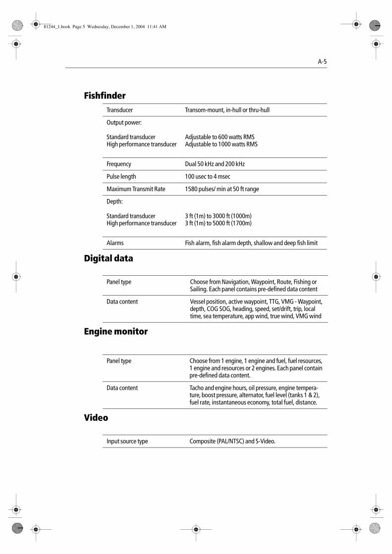
A-5
Digital data
Engine monitor
Video
FishfinderTransducer Transom-mount, in-hull or thru-hull
Output power:
Standard transducerHigh performance transducer
Adjustable to 600 watts RMSAdjustable to 1000 watts RMS
Frequency Dual 50 kHz and 200 kHz
Pulse length 100 usec to 4 msec
Maximum Transmit Rate 1580 pulses/ min at 50 ft range
Depth:
Standard transducerHigh performance transducer
3 ft (1m) to 3000 ft (1000m)3 ft (1m) to 5000 ft (1700m)
Alarms Fish alarm, fish alarm depth, shallow and deep fish limit
Panel type Choose from Navigation, Waypoint, Route, Fishing or Sailing. Each panel contains pre-defined data content
Data content Vessel position, active waypoint, TTG, VMG - Waypoint, depth, COG SOG, heading, speed, set/drift, trip, local time, sea temperature, app wind, true wind, VMG wind
Panel type Choose from 1 engine, 1 engine and fuel, fuel resources, 1 engine and resources or 2 engines. Each panel contain pre-defined data content.
Data content Tacho and engine hours, oil pressure, engine tempera-ture, boost pressure, alternator, fuel level (tanks 1 & 2), fuel rate, instantaneous economy, total fuel, distance.
Input source type Composite (PAL/NTSC) and S-Video.
81244_1.book Page 5 Wednesday, December 1, 2004 11:41 AM
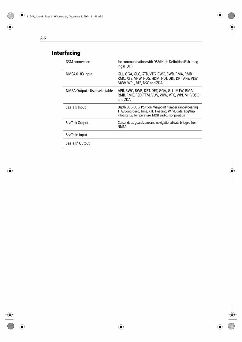
A-6
InterfacingDSM connection for communication with DSM High Definition Fish Imag-
ing (HDFI)
NMEA 0183 Input GLL, GGA, GLC, GTD, VTG, BWC, BWR, RMA, RMB, RMC, XTE, VHW, HDG, HDM, HDT, DBT, DPT, APB, VLW, MWV, WPL, RTE, DSC and ZDA
NMEA Output - User selectable APB, BWC, BWR, DBT, DPT, GGA, GLL, MTW, RMA, RMB, RMC, RSD, TTM, VLW, VHW, VTG, WPL, VHF/DSC and ZDA
SeaTalk Input Depth,SOG,COG, Position, Waypoint number, range/ bearing, TTG, Boat speed, Time, XTE, Heading, Wind, data, Log/Trip, Pilot status, Temperature, MOB and cursor position
SeaTalk Output Cursor data, guard zone and navigational data bridged from NMEA
SeaTalk2 Input
SeaTalk2 Output
81244_1.book Page 6 Wednesday, December 1, 2004 11:41 AM
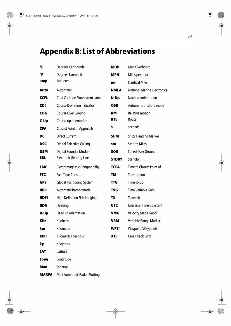
B-1
Appendix B: List of Abbreviations
°C Degrees Centigrade MOB Man Overboard
°F Degrees Farenheit MPH Miles per hour
amp Amperes nm Nautical Mile
Auto Automatic NMEA National Marine Electronics
CCFL Cold Cathode Fluorescent Lamp N-Up North up orientation
CDI Course Deviation Indicator OSH Automatic offshore mode
COG Course Over Ground RM Relative motion
C-Up Course up orientation RTE Route
CPA Closest Point of Approach s seconds
DC Direct Current SHM Ships Heading Marker
DSC Digital Selective Calling sm Statute Miles
DSM Digital Sounder Module SOG Speed Over Ground
EBL Electronic Bearing Line STDBY Standby
EMC Electromagnetic Compatibility TCPA Time to Closest Point of
FTC Fast Time Constant TM True motion
GPS Global Positioning System TTG Time To Go
HBR Automatic harbor mode TVG Time Variable Gain
HDFI High Definition Fish Imaging TX Transmit
HDG Heading UTC Universal Time Constant
H-Up Head up orientation VMG Velocity Made Good
KHz Kilohertz VRM Variable Range Marker
km Kilometer WPT/ Waypoint/Waypoints
KPH Kilometers per hour XTE Cross Track Error
ky Kiloyards
LAT Latitude
Long Longitude
Man Manual
MARPA Mini Automatic Radar Plotting
81244_1.book Page 1 Wednesday, December 1, 2004 11:41 AM

B-2 C-Series Display Reference Manual
81244_1.book Page 2 Wednesday, December 1, 2004 11:41 AM
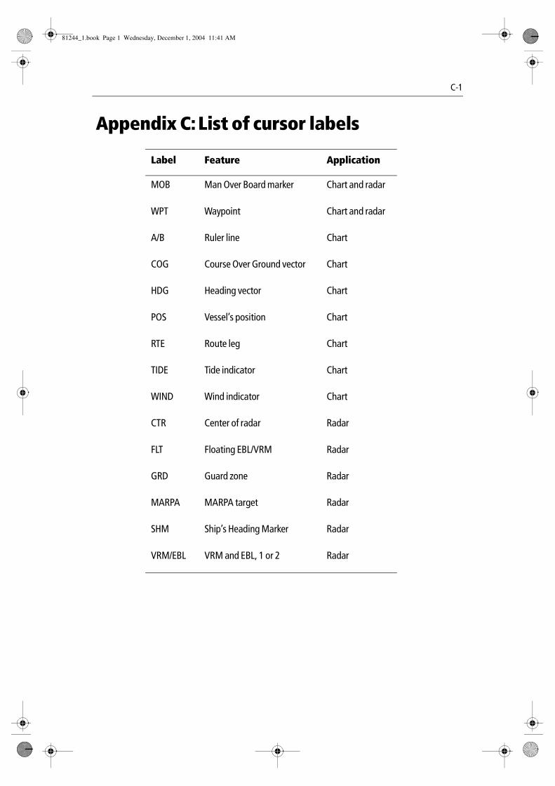
C-1
Appendix C: List of cursor labels
Label Feature Application
MOB Man Over Board marker Chart and radar
WPT Waypoint Chart and radar
A/B Ruler line Chart
COG Course Over Ground vector Chart
HDG Heading vector Chart
POS Vessel’s position Chart
RTE Route leg Chart
TIDE Tide indicator Chart
WIND Wind indicator Chart
CTR Center of radar Radar
FLT Floating EBL/VRM Radar
GRD Guard zone Radar
MARPA MARPA target Radar
SHM Ship’s Heading Marker Radar
VRM/EBL VRM and EBL, 1 or 2 Radar
81244_1.book Page 1 Wednesday, December 1, 2004 11:41 AM

C-2 C-Series Display Reference Manual
81244_1.book Page 2 Wednesday, December 1, 2004 11:41 AM
Index 1
Index
AAbbreviations B-1, C-1Accessing menus 2-6Acquiring MARPA targets 5-25Adjusting power setting 6-24Air temperature, in data bar 11-3Alarm clock 11-8Alarms 2-18
acting on an alarm 9-2alarm clock 11-8arrival alarm radius 11-9cancelling
display alarms 2-18external alarms 2-18
deep depthalarm 11-10alarm value 11-10
deep fish limit 11-10fish alarm 11-9
depth limits 11-9sensitivity 11-9
fishfinderdeep 6-16fish 6-16shallow 6-16
guard zonessensitivity 11-9
lower temperature limit 11-8man overboard (MOB) 2-17offtrack alarm 11-9setup menu 4-23, 4-35, 11-8
anchor alarm 11-8anchor alarm radius 11-8fishfinder 11-9navigation alarms setup 11-9radar 11-9
shallowdepth alarm 11-10fish limit 11-10
system alarms setup 11-8temperature alarm 11-8timer 11-8upper temperature limit 11-8
Anchor alarm 11-8Apparent wind, in data bar 11-3Applications
displaying 2-4reconfiguring 11-1selecting 2-9, 2-10
Archivingto a CompactFlash card 2-13to a PC 2-15
Arrival alarm radius 11-9A-Scope 6-5Automatic
gain mode 6-22harbor mode 5-11offshore mode 5-12operating frequency 6-20
Autorange 4-38
BBearing
alignment 5-26measuring 5-15mode 11-5
for EBLs 5-10Blind sectors 5-4Boat symbol 4-3Bottom
fill 6-10lock 6-8simplifying image 6-8
Bridge NMEA heading 11-7Buttons 2-3
CCancelling
alarmsdisplay alarms 2-18external alarms 2-18
MARPA targets 5-25Cards
erasing information from 2-14inserting 2-12removing 2-12retrieving information from 2-14saving information to 2-13
Cartographyfeatures
show/hide 4-41setup 4-42, 4-44
Caution and routing data 4-45show/hide 4-41
CDIdisplaying 7-1
81244_1.book Page 1 Wednesday, December 1, 2004 11:41 AM
2 E-Series Networked Display Reference Manual
steering instructions 7-2Chart
additional information 4-5autorange 4-38boundaries
show/hide 4-41cards Preface-x, 2-11cartography setup menu 4-44COG indication 4-21combining with radar 4-23course deviation indicator (CDI) 4-22current position 4-3display 4-2
change features displayed 4-41detailed/simple 4-44
editroutes 4-29
change color 4-34change course 4-30change name 4-34
tracks 4-29change color 4-34change name 4-34
gridshow/hide 4-39
grounding alarm 4-23, 4-35heading indication 4-21local information 4-7MARPA 4-24measuring distances 4-9moving around 4-3navigate to waypoint
using cursor 3-4, 4-12using GOTO 3-4using the waypoint list 4-12via WPTS MOB button 3-4
objects and features 4-5off track alarm 4-23, 4-35offset 4-42, 4-43
changing 4-43on/off 4-43
orientation 4-36panning around the chart 4-4ports and services information 4-7presentation 4-35radar
overlay 4-24synchronization 5-15
routesadvance to next waypoint in route 4-19
build 4-13edit
change color 4-34change course 4-30change name 4-34
erasing 4-34follow
in reverse order 4-19using cursor 4-18using Quick Route 4-18using route list 4-18
safety 4-1settings
chart orientation 4-36motion mode 4-37
relative motion 4-38true motion 4-38
orientationcourse up 4-37head up 4-37north up 4-36
setupcartography 4-42
show/hidechart grid 4-39route 4-41track 4-41waypoint 4-39
index 4-40information 4-39name 4-40
synchronizing with radar range 4-23tide information 4-22tracks
create route from track 4-27create track 4-26definition 4-26edit tracks
change color 4-34change name 4-34
stop tracking 4-27vectors
COG 4-21heading and course over ground 4-21tide 4-22wind 4-22
viewing the chart 4-2views 4-35
local 4-36multiple 4-35
81244_1.book Page 2 Wednesday, December 1, 2004 11:41 AM
Index 3
system 4-36waypoint arrival alarm 4-23, 4-35wind indication 4-22XTE restart 4-33zooming 4-4
chart scale synchronization 5-15Circular guard zones 5-20Cleaning, the display 12-2Clearing
alarms 2-18MOB 2-17
COG 4-21in data bar 11-3
Collision avoidance 5-18guard zones 5-18
circular 5-20sector 5-19
using MARPA 5-21using VRMs and EBLs 5-16
Colorgain 6-23palette 2-10, 6-19
CompactFlash cards Preface-x, 2-11cautions 2-11erasing information 2-14inserting 2-12removing 2-12retrieving information 2-14use of 2-11writing to 2-13
Compass Setup 11-11Contact
Raymarine in Europe 12-5Raymarine in US 12-4
Control panel 2-2Course
course up mode 5-9deviation indicator 4-22over ground indication 4-21up mode 4-37
CPA vectors 5-23Create
route from track 4-27track 4-26
Cross track errorin data bar 11-3restart 4-33
C-UP 5-9Cursor 2-4
autohide 11-12position
in data bar 11-3Cycling
video inputs 10-3
DData bar 2-5
changing position/size 11-2customizing content 11-2
adding data 11-3moving data 11-3removing data 11-4
data groupscursor position 11-3depth 11-3environment 11-3navigation 11-3time and date 11-3transducer status 11-3vessel 11-3wind 11-3
Data base lists 2-5Data master 11-7
changing 11-1selecting 2-8
Dateformat 2-8, 11-6in data bar 11-3
Datum 4-42Day operation
adjusting the display lighting 2-10Declutter option 4-41Deep
alarm 6-16depth alarm 11-10
value 11-10fish limit 11-10
Depthcontours
show/hide 4-41deep alarm 6-16digit 6-12
position 6-19removing 6-12resizing 6-12size 6-19
lines 6-14, 6-19of cursor (fishfinder) 6-14of targets 6-3, 6-14
81244_1.book Page 3 Wednesday, December 1, 2004 11:41 AM
4 E-Series Networked Display Reference Manual
offset 6-17ranges 6-24reading 6-14safety contours 4-44shallow alarm 6-16spot soundings 4-44target ID 6-14, 6-19
Detecting targets 5-1Dialog boxes 2-5
editing 2-7Digital data application
data content 8-1panel type 8-1selecting a panel 8-2
Displayadjust lighting
day operation 2-10night operation 2-10
alarmscancelling 2-18
application 2-4CDI application 7-1chart application 4-2chart detail
overview 4-39control waypoint display 3-12current details 4-7digital data application 8-1engine monitor application 9-1fishfinder 6-19
screen 6-2targets 6-3
man overboard 2-17MOB 2-17object and feature details 4-5reset 12-2selecting master 2-15setup
cursor autohide 11-12key beep 11-12menu 11-12soft key autohide 11-12text size 11-12
show/hide cartographic features 4-41target range and bearing 5-25tide details 4-6video application 10-1waypoint
groups 3-13names 3-13
symbols 3-13Distances, measuring 5-15DSC message 11-7DSM
reset 6-18setup 6-18
Dual frequency mode 6-21
EEBLs 5-16
bearing mode 5-10floating 5-17unfloating 5-18
Editdialog boxes 2-7routes 4-29
change color 4-34change course 4-30
by adding waypointat beginning of route 4-30at end of route 4-32within route 4-31, 4-33
by removing waypoint 4-33change name 4-34
select route for editing 4-29select track for editing 4-29tracks 4-29
change color 4-34change name 4-34
videosource name 10-2
waypointsdefault symbol and group 3-9details 3-7moving 3-7
drag to new position 3-8enter new coordinates 3-8
EMC conformance Preface-xEmergencies
man overboard 2-17Engine monitor
acting on an alarm 9-2data content 9-2overview 9-1panel type 9-2
Eraseinformation from a CompactFlash card 2-14routes 4-34tracks 4-34waypoint 3-8
81244_1.book Page 4 Wednesday, December 1, 2004 11:41 AM
Index 5
using cursor 3-8using waypoint list 3-8
waypoint groups 3-12Expansion, target 5-14Extended character set 11-5External alarm
cancelling 2-18
FFast time constant 5-12Fish alarm 11-9
depth limits 11-9sensitivity 11-9
Fishfinder2nd echo interference rejection 6-18alarms setup 11-9A-Scope 6-5bottom
fill 6-10lock 6-8structure 6-2
change displayed range 6-6color
gain 6-23palette 6-19
cursor depth 6-14deep alarm 6-16depth
cursor 6-14digit 6-12
position 6-19removing 6-12resizing 6-12size 6-19
lines 6-14, 6-19offset 6-17reading 6-14target IFD 6-14
displaydescription 6-2
DSM reset 6-18factors that impair performance 6-3, 6-4fish alarm 6-16frequency
automatic 6-20calibration 6-17manual 6-20
dual mode 6-21single mode 6-20
operating 6-20
gain controls 6-23auto 6-22manual 6-22
interpreting the bottom structure 6-2isolating bottom fish 6-10
white line 6-10live image 6-5marking a position 6-12operating frequencies 6-20optimizing displayed image
by adjusting power setting 6-24overview 6-1ping
enable/disable 6-18rate limit 6-18
principles 6-1scroll 6-19
pausing 6-11speed 6-11, 6-19
setup 6-16display 6-19DSM 6-18transducer 6-17
shifting the image 6-6SONAR interference rejection 6-18speed offset 6-17target
depth ID 6-19depths 6-14distances 6-14
target display 6-3temperature offset 6-17time varied gain (TVG) 6-23trip counter reset 6-18VRMs 6-14, 6-15white line 6-10zooming 6-7
Floating VRMs/EBLs 5-17Follow
route 4-17in reverse order 4-19using cursor 4-18using Quick Route 4-18using route list 4-18
Frequency calibration 6-17FTC 5-12
GGain 5-12
adjustment 6-23
81244_1.book Page 5 Wednesday, December 1, 2004 11:41 AM
6 E-Series Networked Display Reference Manual
controls 5-13Glossary B-1, C-1GOTO function 4-12GPS Preface-x
status 11-9Grid
show/hide 4-39Groundwind, in data bar 11-3Guard zones 5-18
sensitivity 11-9
HHazard warnings 2-18HBR 5-11HDG, see heading indication 4-21Head up mode 4-37, 5-8Heading
in data bar 11-3indication 4-21
H-UP 5-8
IImage shift 6-6Indirect echoes 5-3Inserting, CompactFlash cards 2-12Integration 1-1Intended use Preface-ixInterference rejection 5-14, 5-26
2nd echo 6-18SONAR interference rejection 6-18
KKey beep 11-12
LLand features 4-45
show/hide 4-41Language 2-8, 11-5Light sectors
show/hide 4-41Lighting, adjusting 2-10Live image 6-5Local
chart view 4-36information 4-7
Log trip, in data bar 11-3
MMaintenance 12-1Man overboard (MOB) 2-17
Managing waypoint list 3-9Manual
gain mode 6-22operating frequency 6-20variation 11-5
Marine features 4-45show/hide 4-41
MARPAacquiring targets 5-25cancelling targets 5-25collision avoidance 5-21CPA vectors 5-23
relative mode 5-24true mode 5-23
on chart 4-24operating ranges 5-22overview 5-21risk assessment 5-22setup 5-24symbols 5-22target
data 5-22symbols 5-22
Master displaychanging 2-15
Measuringbearings 5-15distances 4-9, 5-15ranges 5-15
Menusaccessing 2-6alarm setup 11-8
fishfinder alarms 11-9navigation alarms 11-9radar alarms 11-9system alarms 11-8
cartography setup 4-44chart
setup 4-42date/time setup 11-6display setup 11-12fishfinder 6-18, 6-19
2nd echo interference rejection 6-18color
palette 6-19counter reset 6-18depth
digitposition 6-19
81244_1.book Page 6 Wednesday, December 1, 2004 11:41 AM
Index 7
digit resizing 6-19lines 6-19
DSM reset 6-18ping
enable/disable 6-18rate limit 6-18
scroll 6-19speed 6-19
SONAR interference rejection 6-18target
depth ID 6-19radar setup
bearing alignment 5-26interference rejection 5-26standby 5-26target expansion 5-26timed transmit 5-26wakes period 5-26
system integration setup 11-7bridge NMEA heading 11-7data master 11-7DSC message 11-7NMEA output setup 11-7SeaTalk alarms 11-7
system setup 11-5units setup 11-6
depth 11-6distance 11-6pressure 11-7speed 11-6temperature 11-7volume 11-7
MOB 2-17clearing 2-17data type 11-5
Motion mode 4-37autorange 4-38relative 4-38, 5-10true 5-10true motion 4-38
Movingaround the chart 4-3waypoints between groups 3-11
Multi-media cards Preface-x, 2-11cautions 2-11use of 2-11
Multiple echoes 5-4
NNavigate 4-10
stop navigating to a waypoint 3-5to a waypoint 3-3to cursor position 4-11to waypoint 4-12
using cursor 3-4, 4-12using GOTO option 3-4using the waypoint list 3-4, 4-12
Navigationalarms setup 11-9marks symbols 4-45
Navionicscontact Preface-x
Nearestobstruction 4-6port 4-5port service 4-5tidal station 4-6tidal stations 4-5waypoint 4-5wreck 4-6
Networked systemcontrolling 2-15, 2-16functionality 2-16overview 2-15
Night operationadjusting the display lighting 2-10
NMEAbridge heading 11-7output setup 11-7
North up mode 4-36, 5-9N-UP 5-9
OObject information 4-42
box 4-5Obstructions
find nearest 4-6Offset
depth 6-17speed 6-17temperature 6-17vessel 4-38
Offtrack alarm 11-9Operating frequencies 6-20Orientation
course up 4-37head up 4-37north up 4-36radar 5-8
81244_1.book Page 7 Wednesday, December 1, 2004 11:41 AM
8 E-Series Networked Display Reference Manual
OSH 5-12Overlay
radar on chart 4-24Own vessel safezone 5-24
PPage
layout, reconfiguring 11-1selecting 2-10sets
customizing 11-1reconfiguring 11-1selecting 2-9
Panning chart 4-4PC
archiving information 2-15transferring information 2-15
Pingenable 6-18rate limit 6-18
Pop-up messages 2-5Port services
find nearest 4-6Ports
find nearest 4-5search 4-8symbol 4-8
Positionmode 11-5where am I? 4-3
Power on/off 2-1Presentation
chart windows 4-35Pressure, in data bar 11-3
QQuick Route 4-18
RRadar 5-15
acquiring targets 5-25alarm setup menu 11-9automatic harbor mode 5-11automatic offshore mode 5-12cancelling targets 5-25changing the window 5-8circular guard zones 5-20collision avoidance 5-18
guard zones 5-18circular 5-20
sector 5-19using MARPA 5-21using VRMs and EBLs 5-16
combining with chart 4-23course up mode 5-9detecting targets 5-1EBLs 5-16
bearing mode 5-10expansion 5-14factors that impair radar performance
Interference 5-5floating VRMs/EBLs 5-17FTC 5-12gain 5-12, 5-13getting the best picture
FTC 5-12interference rejection 5-14rain clutter 5-13sea clutter 5-11setting gain 5-12target expansion 5-14tune radar 5-12using gain controls 5-11, 5-13wakes 5-14
guard zones 5-18head up mode 5-8impaired radar performance 5-2
blind sectors 5-4indirect echoes 5-3multiple echoes 5-4rain clutter 5-5sea clutter 5-4side lobes 5-3
interference 5-5rejection 5-14
manual mode 5-12MARP A 5-21MARPA
CPA vectors 5-23relative 5-24true 5-23
on chart 4-24operating ranges 5-22overview 5-21target
data 5-22symbols 5-22
maximum range 5-2measuring
bearings 5-15
81244_1.book Page 8 Wednesday, December 1, 2004 11:41 AM
Index 9
distances 5-15ranges 5-15
motion mode 5-9north up mode 5-9orientation 5-8
course up 5-9head up 5-8north up 5-9
overlay on chart 4-24picture
overview 5-6power off/on 5-5principles 5-1rain clutter 5-13range 5-14
independently of chart 4-25rings 5-10synchronizing with chart 4-23
relative motion mode 5-10risk assessment 5-22safezone 5-24scanner operating modes
standby 5-5timed transmit 5-5transmit 5-5
sector guard zones 5-19settings
changing ranges 5-15MARPA 5-24
safezone 5-24target history 5-24vector length 5-24
setupbearing alignment 5-26interference rejection 5-26standby 5-26target expansion 5-26timed transmit 5-26wakes period 5-26
status bar 5-8synchronizing radar range with chart 4-23target 5-1
history 5-24MARPA
on chart 4-24targets
displaying range and bearing 5-25true motion 5-10tune 5-12unfloating VRMs/EBLs 5-18
vector length 5-24vessel offset 5-10VRMs 5-16wakes 5-14with chart synchronization 5-15
Rain clutter 5-5, 5-13Range
change displayed range 6-6measuring 5-15rings 5-10
Relative mode CPA vectors 5-24Relative motion 4-38, 5-10Removing
CompactFlash card 2-12Renaming
waypoint groupsexisting 3-12
Resettingsettings and data reset 12-2the display 12-2the system 11-6
Retrieving information from CompactFlash card 2-14Reversing
a route 4-30Risk assessment 5-22RM 5-10Rolling road 7-1Routes
advance to next waypoint in route 4-19building routes 4-13
on screen 4-14using new waypoints 4-14
using waypoint list 4-16create route from track 4-27
using current track 4-27using saved track 4-28
definition 4-13edit 4-29
change color 4-34change course 4-30change name 4-34
erasing 4-34follow 4-17
in reverse order 4-19using cursor 4-18using Quick Route 4-18using route list 4-18
overview 4-13
81244_1.book Page 9 Wednesday, December 1, 2004 11:41 AM
10 E-Series Networked Display Reference Manual
reversing 4-30selecting 4-29show/hide 4-41viewing details 4-20
Rudder, in data bar 11-3Ruler 4-9
clearing 4-10repositioning 4-10
SSafety 12-1
notices Preface-ixSafezone 5-24Saving
information to a card 2-13Scanner operating modes
standby 5-5timed transmit 5-5transmit 5-5
Scroll 6-19pause 6-11speed 6-11, 6-19
Seaclutter 5-4, 5-11temperature, in data bar 11-3
SeaTalk alarms 11-7Second echo interference rejection 6-18Sector guard zones 5-19Select
applications 2-9, 2-10data master 2-8page sets 2-9pages 2-10route for editing 4-29speed transduced 6-17track for editing 4-29transducer 6-17windows 2-10
Servicingcleaning the display 12-2routine checks 12-1
Set drift, in data bar 11-3Settings
alarm setupalarm clock 11-8anchor alarm 11-8lower temperature limit 11-8temperature 11-8timer 11-8
upper temperature limit 11-8bearing mode 11-5cartography 4-42chart
cartography 4-42course up mode 4-37head up mode 4-37motion modes 4-37, 4-38north up mode 4-36relative motion 4-38true motion 4-38
customizing the page sets 11-1data bar
changing position and size 11-2customizing content 11-2
data master 11-1date format 2-8, 11-6date/time format 11-6depth units 11-6display setup
cursor autohide 11-12key beep 11-12soft key autohide 11-12text size 11-12
distance unit 11-6extended character set 11-5fishfinder 6-16
6-17depth
offset 6-17frequency
calibration 6-17operating frequencies 6-20speed offset 6-17temperature offset 6-17
fishfinder alarm setupdeep depth
alarm 11-10deep depth alarm value 11-10deep fish limit 11-10fish
alarm depth limits 11-9alarm sensitivity 11-9
fish alarm 11-9shallow
depth alarm 11-10fish limit 11-10
shallow depth alarm 11-10fishfinder alarms setup 11-9language 2-8, 11-5
81244_1.book Page 10 Wednesday, December 1, 2004 11:41 AM
Index 11
local time offset 11-6manual variation 11-5MARPA 5-24
own vessel safezone 5-24target history 5-24vector length 5-24
MOB data type 11-5navigation alarm setup
arrival alarm radius 11-9offtrack alarm 11-9
position mode 11-5pressure units 11-7radar 5-26
bearing alignment 5-26FTC 5-12gain 5-12gain control 5-13interference rejection 5-26motion mode 5-9orientation 5-8
course up 5-9head up 5-8north up 5-9
rain clutter 5-13range scale 5-14relative motion 5-10standby 5-26target expansion 5-26timed transmit 5-26true motion mode 5-10tune 5-12vessel offset 5-10wakes period 5-26
radar alarm setupguard zone sensitivity 11-9
reconfiguring application and page layout 11-1
renaming a page set 11-1Settings and data reset 12-2settings reset 12-2show/hide
chart grid 4-39waypoint information 4-39waypoints 4-39
simulator 11-5speed units 11-6system
alarms 11-8integration 11-6
TD setup 11-5
temperature units 11-7time format 2-8, 11-6units 11-6
of measurement 2-8setup 11-6
variation source 11-5volume units 11-7
Settings and data reset 11-6Settings reset 11-6Setup
compass 11-11fishfinder 6-18menu
overview 11-4procedure 2-8video cycle 10-3
Shallowalarm 6-16depth alarm 11-10fish limit 11-10
Show/hidecartographic feature 4-41caution and routing information 4-41chart
boundaries 4-41grid 4-39
depth contours 4-41land and marine features 4-41light sectors 4-41range rings 5-10route or track 4-41spot soundings 4-41text 4-41waypoint 4-39
group 4-39index 4-40information 4-39name 4-40symbol 4-39
Side lobes 5-3Simulator 1-4, 11-5Single frequency mode 6-20Size
of target 6-4Soft keys 2-3
autohide 11-12SOG
in data bar 11-3SONAR interference rejection 6-18
81244_1.book Page 11 Wednesday, December 1, 2004 11:41 AM
12 E-Series Networked Display Reference Manual
Sortingwaypoints 3-9
Speedin data bar 11-3offset 6-17
Spot soundingsshow/hide 4-41
Standby 5-26Status
bar 2-5radar 5-8
icons 2-5, 2-7Steering
using CDI 7-2Stop
tracking 4-27Symbols
boat 4-3MARPA 5-22port 4-8show/hide
waypointsymbol 4-39
Synchronizing chart with radar range 4-23System
chart view 4-36integration 11-6
setup menu 11-7bridge NMEA heading 11-7data master 11-7DSC message 11-7NMEA output setup 11-7SeaTalk alarms 11-7
setup menuunits setup 11-6
System alarms setup 11-8System setup menu 11-5
bearing mode 11-5date/time format 11-6extended character set 11-5language 11-5manual variation 11-5MOB data type 11-5position mode 11-5settings and data reset 11-6settings reset 11-6simulator 11-5TD Setup 11-5variation source 11-5
TTarget
acquiring 5-25cancelling 5-25depth ID 6-19depths 6-14displaying range and bearing 5-25distances 6-14expansion 5-14, 5-26
TD Setup 11-5Technical support 12-3Temperature
alarm 11-8lower limit 11-8upper limit 11-8
offset 6-17Text
show/hide 4-41size 11-12
Tidalinformation 4-6, 4-22
Tidal stationfind nearest 4-6tide details 4-6
Timeformat 2-8, 11-6in data bar 11-3
Timed transmit 5-26Timer 11-8TM 5-10Tracks
create route from track 4-27create track 4-26definition 4-26edit tracks 4-29
change color 4-34change name track 4-34
erasing 4-34selecting 4-29show/hide 4-41stop tracking 4-27
Transducercalibration 6-17status, in data bar 11-3
Transferringinformation from a PC 2-15
Trip counter reset 6-18Troubleshooting 12-3True
81244_1.book Page 12 Wednesday, December 1, 2004 11:41 AM
Index 13
mode CPA vectors 5-23motion mode 4-38, 5-10wind, in data bar 11-3
Tune radar 5-12TVG 6-23
UUnfloating VRMs/EBLs 5-18Units
measurement 2-8setup menu 11-6
depth 11-6distance 11-6measurement 2-8pressure 11-7speed 11-6temperature 11-7volume 11-7
VVariation source 11-5Vectors
CPA 5-23length 4-42, 5-24
Vesseloffset 4-38, 5-10position, in data bar 11-3
Videoadjusting the image 10-3
correcting distortion 10-4cycle 10-3cycling inputs 10-3displaying 10-1edit
name 10-2source type 10-2
overview 10-1run cycle 10-3stop cycle 10-3
Viewingchart windows 4-35route details 4-20
VMG Wind/Waypoint, in data bar 11-3VRMs 6-14
floating 5-17unfloating 5-18using with fishfinder 6-15using with radar 5-16
WWakes 5-14
period 5-26Waypoints
add to beginning of route 4-30change
default symbol and group 3-9details 3-7
drag to new position 3-8enter new coordinates 3-8
controlling how display 3-12display
by symbol or group 3-13waypoint names 3-13
erase 3-8using cursor 3-8using waypoint list 3-8
find nearest 4-6fishfinder
marking a position 6-12groups 3-10
assign waypoint to group 3-10erase group 3-12make new group 3-10move waypoint between groups 3-11rename group 3-12show/hide 4-39
in new routes 4-14index
show/hide 4-40moving 3-7name
show/hide 4-40navigate to 3-3, 4-12
using cursor 3-4using the waypoint list 3-4using waypoint list 4-12with cursor 4-12
number of 3-1overview 3-1placing 3-2
at current position 3-3at known position 3-3at the cursor 3-3
radarmarking a position 5-25
representation 3-2show/hide 4-39
name 4-40waypoint
group 4-39sort waypoint list 3-9
81244_1.book Page 13 Wednesday, December 1, 2004 11:41 AM
14 E-Series Networked Display Reference Manual
stop navigating to 3-5symbols
display 3-13show/hide 4-39
viewing waypoint informationusing cursor 3-6using the waypoint list 3-6
White line 6-10Wind
data in data bar 11-3indication 4-22
Windowsselecting 2-10
Wrecksfind nearest 4-6
www 12-4
XXTE
in data bar 11-3restart 4-33
ZZoom
Chart 4-4fishfinder 6-7
81244_1.book Page 14 Wednesday, December 1, 2004 11:41 AM


