Embed Size (px)
Citation preview
i n t e r n a t i o n a l j o u r n a l o f h y d r o g e n e n e r g y 3 5 ( 2 0 1 0 ) 1 2 5 7 – 1 2 6 6
Avai lab le a t www.sc iencedi rec t .com
j ourna l homepage : www.e lsev ier . com/ loca te /he
Dynamic synthesis of ternary Mg2FeH6
M. Polanski a, T. P1ocinski b, I. Kunce a, J. Bystrzycki a,*a Faculty of Advanced Technology and Chemistry, Military University of Technology, 2 Kaliskiego Str., 00-908 Warsaw, Polandb Faculty of Materials Science and Engineering, Warsaw University of Technology, 141 Wołoska Str., 02-507 Warsaw, Poland
a r t i c l e i n f o
Article history:
Received 10 June 2009
Received in revised form
5 September 2009
Accepted 5 September 2009
Available online 4 December 2009
Keywords:
Magnesium-iron ternary hydride
Mechanical (ball) milling
Dynamic synthesis
Decomposition
Structure
Hydriding/dehydriding properties
* Corresponding author. Tel.: þ48 (22) 683 71E-mail address: [email protected] (J
0360-3199/$ – see front matter ª 2009 Profesdoi:10.1016/j.ijhydene.2009.09.010
a b s t r a c t
This work presents new results on the dynamic synthesis and decomposition of ternary
Mg2FeH6. A novel synthesis method was applied for the rapid and effective synthesis of
a ternary Mg–Fe hydride. This method consists of two processing routes. The first route
involves high-energy ball milling of the initial MgH2–Fe powder mixture, while the second
is composed of a unique pressurizing and heating cycle route to obtain a full phase
transformation within half an hour. The structural investigations carried out by X-ray
diffraction revealed that almost all of the initial powder mixture transforms into the
ternary hydride. Furthermore, the sample, which was synthesized, was also decomposed
and reloaded with hydrogen. The formation of Mg2FeH6 consists of two steps that involve
MgH2 as an intermediate compound. In contrast, the decomposition of Mg2FeH6 consists of
only one step and does not follow the inverse route. Some traces of iron were found in the
reaction products. TDP results show that a desorption peak occurs at 315 �C, and this is in
good agreement with DSC measurements showing only a single endothermic peak around
340 �C. Microstructural examinations revealed that the synthesized Mg2FeH6 powder
generally exhibits a duplex structure that consists of plate-like particles larger than 1 mm in
diameter and spherical particles smaller than 50 nm that show a tendency to agglomerate
and form larger particles exhibiting a sponge-like structure. The formation of Mg2FeH6
takes place at the phase boundary between Fe seeds and the growing hydride phase. In
contrast, the decomposition of the Mg2FeH6 phase takes place with the formation of the
separate nanosized Mg and Fe phases. The dehydrogenated powder sample shows oval Fe
precipitates of 10–100 nm in size that are embedded in the Mg-based matrix.
ª 2009 Professor T. Nejat Veziroglu. Published by Elsevier Ltd. All rights reserved.
1. Introduction Mg2FeH6 from the elements Mg and Fe, due to the absence of
The ternary hydride Mg2FeH6 is an attractive material for
hydrogen storage for fuel cell applications or for thermo-
chemical thermal energy storage near 500 �C. Mg2FeH6 has the
highest volumetric hydrogen density, 150 kg/m3, among all
the known complex hydrides, and it possesses a gravimetric
hydrogen density of 5.4 wt.% [27]. Furthermore, this hydride is
based on inexpensive metallic elements such as Mg and Fe;
therefore, its cost should be competitive with that of other
complex hydrides. However, it is difficult to synthesize
35; fax: þ48 (22) 683 9445. Bystrzycki).sor T. Nejat Veziroglu. Pu
an Mg2Fe intermetallic compound in the binary Mg–Fe system
(Mg and Fe are immiscible). Only in the ternary Mg–Fe–H
system does hydrogen act as a binding component to form
Mg2FeH6 with a cubic K2PtCl6-type structure in which the
octahedral [FeH6]�4 complexes of anions are surrounded by
Mg in an eight-fold cubic configuration [4].
Thus far, several fabrication methods have been developed
to produce Mg2FeH6, which usually involve either sintering at
elevated temperatures (w500 �C) under high hydrogen pres-
sure (20–120 bar) over several days or simply mechanical
.
blished by Elsevier Ltd. All rights reserved.
i n t e r n a t i o n a l j o u r n a l o f h y d r o g e n e n e r g y 3 5 ( 2 0 1 0 ) 1 2 5 7 – 1 2 6 61258
alloying/milling (MA/M) in an inert atmosphere or under
a hydrogen atmosphere (reactive mechanical alloying – RMA)
combined (or not) with sintering techniques [1], [3], [4–6], [7,8],
Konstanchuk et al., 1987 [9], [11,12], [15–22], [24–26] . The yield
of Mg2FeH6 fabricated by sintering, MA/M or RMA depends on
both the initial material properties and the processing
conditions. A recent comprehensive review of synthesis
methods of Mg2FeH6 and of other ternary transition metal
complex hydrides is given by Varin et al. [27]. Progress
regarding the yield has been made by using optimized sin-
tering and/or RMA conditions and, more recently, by hydrid-
ing combustion synthesis [10] or sintering of metal
nanoparticles produced by a hydrogen plasma metal reaction
[23]. However, one main drawback of the processing methods
with yields over 90% is the very long processing time involved,
which is usually 10 h. Additionally, the retained Fe is usually
present in the synthesized material; for this reason, a purifi-
cation process is necessary.
The difficulties related to the synthesis of Mg2FeH6 are
probably responsible for the limited knowledge regarding
synthesis and decomposition mechanisms of this ternary
hydride. Bogdanovic et al. [2] carried out exhaustive thermo-
dynamic and microstructural investigations of Mg2FeH6. They
studied the initial formation and the subsequent de- and
rehydrogenation process of Mg2FeH6 on a micro- and nano-
scale level by using combined HRTEM-EDX (HRTEM - High-
Resolution Transmission Electron Microscopy; EDX - Energy
Dispersive X-ray) investigations. Zhou et al. [28] studied the
energy and electronic structure of Mg2FeH6 by using the first-
principles plane-wave pseudopotential method to calculate
heats of formation and the following formation mechanism.
More research has been devoted to the study of hydriding/
dehydriding kinetics and thermodynamic properties [15–17],
[10], [2]
In this work, we present new results on the dynamic
synthesis and decomposition of ternary Mg2FeH6. Most
recently, our research group successively synthesized
Mg2FeH6 by a novel processing route using combined high-
energy mechanical ball milling of the starting 2MgH2–Fe
powder mixture under argon and subsequent sintering under
high hydrogen pressure (85–100 bar) at elevated temperatures
(up to 500 �C). The Mg2FeH6 yield of this processing route is
greater than 90%, leaving some Fe as an unreacted phase.
Moreover, it must be emphasized that the total time of the
applied processing route (including milling and dynamic sin-
tering) is less than 2 h. To the best of our knowledge, the results
presented here are the first example in which the rapid and
effective synthesis of the ternary Mg2FeH6 is shown. Addi-
tionally, the obtained experimental results are supported by
the microstructural and hydriding/dehydriding investigations.
2. Experimental procedure
The binary MgH2 powder (ABCR, 98.0%) and the elemental Fe
powder (ABCR, 99.9%) were mechanically milled at a molar
ratio of 2:1 in a planetary ball mill (Fritsch P6) in an 80-ml
stainless steel vessel with 30 stainless steel balls (10 mm in
diameter) for 1 h under argon. An inert hydrocarbon working
as a lubricant was added in the course of the milling process.
The total mass of each powder mixture was 5 g. The rotation
rate of the milling container was set to 650 rpm. All handling
of the powders was conducted in a Labmaster Glovebox
Workstation (MBraun) under a continuously purified argon
atmosphere. The amounts of oxygen and water were below
0.1 ppm.
The 350 mg ball milled powder samples were used to
perform the dynamic synthesis using an automated Sievert’s
apparatus (HTP1-S, Hiden Isochema). During the loading
procedure, the samples were not exposed to air. The direct
synthesis of each hydride began at 85 bar of hydrogen pres-
sure, which increased to almost 100 bar when the system
reached 500 �C. This processing route was carried out to
hinder MgH2 from decomposing to elemental magnesium at
a high temperature. Afterwards, the temperature was set to
500 �C with a linear heating ramp rate of 20 �C/min.
The X-ray diffraction profiles for all of the investigated
powder samples were recorded with a Seifert 3003 diffrac-
tometer using Co Ka radiation (l¼ 1.79 A) with operating
parameters of 30 mA and 50 kV and a step size of 0.02�/5 s.
The morphology and microstructure of the synthesized
and decomposed samples were examined with a high-reso-
lution field emission scanning electron microscope (HITACHI
S5500), equipped with a backscattered electron detector, an
energy dispersive X-ray spectrometer (EDS) and a duo-STEM
bright/dark field (BF/DF) detector. A transmission electron
microscope (JEOL JEM 1200EX) with an accelerating voltage of
120 kV was also used to investigate diffraction patterns for
phase identification. Since the investigated samples included
both nano- and microcrystalline structures, thin foils for
electron microscopy were prepared by the focused ion beam
(FIB) technique using the FB-2100 Hitachi system. A liquid ion
metal source was used as the source of the gallium ion beam.
The accelerating voltage used was 40 kV. Tungsten was used
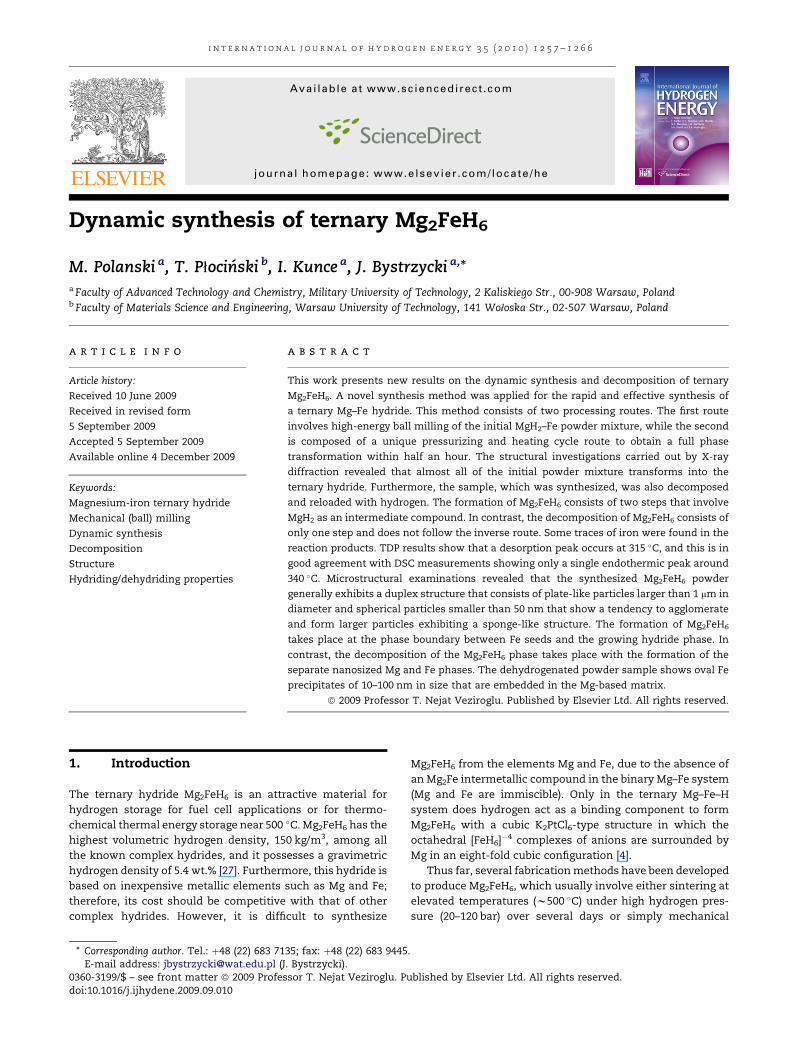
as a protective layer. Fig. 1a presents a sample SEM micro-
graph showing a thin Mg2FeH6 sample cut from the largest
particle visible in Fig. 1b using the FIB technique.
To determine the dehydrogenation properties of the
synthesized samples, temperature programmed desorption
(TPD) tests were carried out using the same HTP1-S analyzer
coupled with a quadrupole mass spectrometer. The
measurements were performed under a high purity (99.999%)
helium flow, and heating rates of 1, 2 and 5 �C/min were
applied in order to determine the activation energy of the
hydride decomposition. Additionally, DSC measurements
were performed on samples of about 5 mg with a Setaram
Labsys apparatus. The experiments were performed under an
argon flow in an Al2O3 crucible in the range of 20–500 �C at
heating rates of 1, 2 and 5 �C/min.
3. Results and discussion
3.1. Synthesis of Mg2FeH6
As mentioned above, our dynamic synthesis method of
Mg2FeH6 generally consists of two processing routes:
mechanical (ball) milling and subsequent sintering under high
hydrogen pressure at elevated temperatures. Initially, our
preparation method of Mg2FeH6 appears to be very similar to
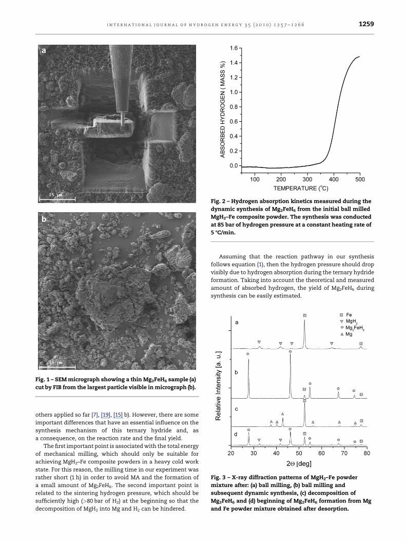
Fig. 1 – SEM micrograph showing a thin Mg2FeH6 sample (a)
cut by FIB from the largest particle visible in micrograph (b).
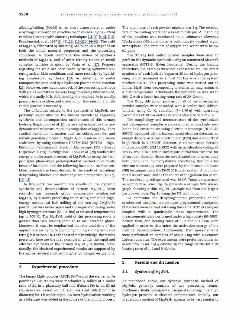
Fig. 2 – Hydrogen absorption kinetics measured during the
dynamic synthesis of Mg2FeH6 from the initial ball milled
MgH2–Fe composite powder. The synthesis was conducted
at 85 bar of hydrogen pressure at a constant heating rate of
5 8C/min.
Fig. 3 – X-ray diffraction patterns of MgH2–Fe powder
mixture after: (a) ball milling, (b) ball milling and
subsequent dynamic synthesis, (c) decomposition of
Mg2FeH6 and (d) beginning of Mg2FeH6 formation from Mg
and Fe powder mixture obtained after desorption.
i n t e r n a t i o n a l j o u r n a l o f h y d r o g e n e n e r g y 3 5 ( 2 0 1 0 ) 1 2 5 7 – 1 2 6 6 1259
others applied so far [7], [19], [15] b). However, there are some
important differences that have an essential influence on the
synthesis mechanism of this ternary hydride and, as
a consequence, on the reaction rate and the final yield.
The first important point is associated with the total energy
of mechanical milling, which should only be suitable for
achieving MgH2–Fe composite powders in a heavy cold work
state. For this reason, the milling time in our experiment was
rather short (1 h) in order to avoid MA and the formation of
a small amount of Mg2FeH6. The second important point is
related to the sintering hydrogen pressure, which should be
sufficiently high (>80 bar of H2) at the beginning so that the
decomposition of MgH2 into Mg and H2 can be hindered.
Assuming that the reaction pathway in our synthesis
follows equation (1), then the hydrogen pressure should drop
visibly due to hydrogen absorption during the ternary hydride
formation. Taking into account the theoretical and measured
amount of absorbed hydrogen, the yield of Mg2FeH6 during
synthesis can be easily estimated.
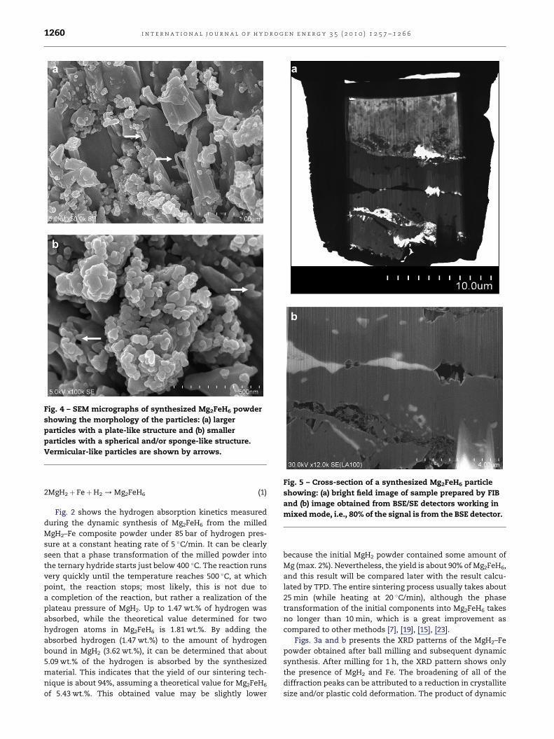
Fig. 4 – SEM micrographs of synthesized Mg2FeH6 powder
showing the morphology of the particles: (a) larger
particles with a plate-like structure and (b) smaller
particles with a spherical and/or sponge-like structure.
Vermicular-like particles are shown by arrows.
Fig. 5 – Cross-section of a synthesized Mg2FeH6 particle
showing: (a) bright field image of sample prepared by FIB
and (b) image obtained from BSE/SE detectors working in
mixed mode, i.e., 80% of the signal is from the BSE detector.
i n t e r n a t i o n a l j o u r n a l o f h y d r o g e n e n e r g y 3 5 ( 2 0 1 0 ) 1 2 5 7 – 1 2 6 61260
2MgH2þ FeþH2 / Mg2FeH6 (1)
Fig. 2 shows the hydrogen absorption kinetics measured
during the dynamic synthesis of Mg2FeH6 from the milled
MgH2–Fe composite powder under 85 bar of hydrogen pres-
sure at a constant heating rate of 5 �C/min. It can be clearly
seen that a phase transformation of the milled powder into
the ternary hydride starts just below 400 �C. The reaction runs
very quickly until the temperature reaches 500 �C, at which
point, the reaction stops; most likely, this is not due to
a completion of the reaction, but rather a realization of the
plateau pressure of MgH2. Up to 1.47 wt.% of hydrogen was
absorbed, while the theoretical value determined for two
hydrogen atoms in Mg2FeH6 is 1.81 wt.%. By adding the
absorbed hydrogen (1.47 wt.%) to the amount of hydrogen
bound in MgH2 (3.62 wt.%), it can be determined that about
5.09 wt.% of the hydrogen is absorbed by the synthesized
material. This indicates that the yield of our sintering tech-
nique is about 94%, assuming a theoretical value for Mg2FeH6
of 5.43 wt.%. This obtained value may be slightly lower
because the initial MgH2 powder contained some amount of
Mg (max. 2%). Nevertheless, the yield is about 90% of Mg2FeH6,
and this result will be compared later with the result calcu-
lated by TPD. The entire sintering process usually takes about
25 min (while heating at 20 �C/min), although the phase
transformation of the initial components into Mg2FeH6 takes
no longer than 10 min, which is a great improvement as
compared to other methods [7], [19], [15], [23].
Figs. 3a and b presents the XRD patterns of the MgH2–Fe
powder obtained after ball milling and subsequent dynamic
synthesis. After milling for 1 h, the XRD pattern shows only
the presence of MgH2 and Fe. The broadening of all of the
diffraction peaks can be attributed to a reduction in crystallite
size and/or plastic cold deformation. The product of dynamic
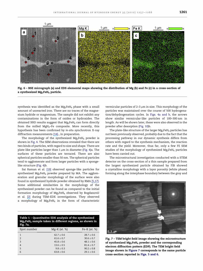
Fig. 6 – BSE micrograph (a) and EDS elemental maps showing the distribution of Mg (b) and Fe (c) in a cross-section of
a synthesized Mg2FeH6 particle.
i n t e r n a t i o n a l j o u r n a l o f h y d r o g e n e n e r g y 3 5 ( 2 0 1 0 ) 1 2 5 7 – 1 2 6 6 1261
synthesis was identified as the Mg2FeH6 phase with a small
amount of unreacted iron. There are no traces of the magne-
sium hydride or magnesium. The sample did not exhibit any
contaminations in the form of oxides or hydroxides. The
obtained XRD results suggest that Mg2FeH6 can form directly
from the milled MgH2–Fe composite. More recently, this
hypothesis has been confirmed by in-situ synchrotron X-ray
diffraction measurements [14]., in preparation.
The morphology of the synthesized Mg2FeH6 powder is
shown in Fig. 4. The SEM observations revealed that there are
two kinds of particles, with regard to size and shape. There are
plate-like particles larger than 1 mm in diameter (Fig. 4)a. The
surfaces of these particles are terraced. There are also
spherical particles smaller than 50 nm. The spherical particles
tend to agglomerate and form larger particles with a sponge-
like structure (Fig. 4)b.
Sai Raman et al. [19] observed sponge-like particles for
synthesized Mg2FeH6 powder prepared by MA. The agglom-
eration and granular morphology of the surface were also
found in synthesized hydride powder obtained by RMA [5,17].
Some additional similarities in the morphology of the
synthesized powder can be found as compared to the initial
formation morphology of Mg2FeH6 observed by Bogdanovic
et al. [2] during TEM–EDX investigations. They observed
a morphology of Mg2FeH6 in the form of characteristic
Table 1 – Quantitative EDS analysis of the synthesizedMg2FeH6 sample taken in different regions, as shown inFig. 7a.
Spot number Mg–K (at. %) Fe–K (at. %)
1 62.7� 0.6 28.7� 0.6
2 61.6� 0.7 30.6� 0.7
3 45.8� 0.6 48.1� 0.6
4 13.6� 0.5 81.4� 0.7
5 9.8� 0.3 90.2� 0.8
6 63.8� 0.6 29.1� 0.6
vermicular particles of 2–3 mm in size. This morphology of the
particles was maintained over the course of 500 hydrogena-
tion/dehydrogenation cycles. In Figs. 4a and b, the arrows
show similar vermicular-like particles of 100–300 nm in
length. As will be shown later, these were also observed in the
powder after desorption (Fig. 10)b.
The plate-like structure of the larger Mg2FeH6 particles has
not been previously observed, probably due to the fact that the
processing pathway in our dynamic synthesis differs from
others with regard to the synthesis mechanism, the reaction
rate and the yield. Moreover, thus far, only a few FE SEM
studies of the morphology of synthesized Mg2FeH6 particles
have been carried out.
The microstructural investigation conducted with a STEM
detector on the cross-section of a thin sample prepared from
the largest synthesized particle obtained by FIB showed
a crystalline morphology with a layer porosity (white phase)
forming along the interphase boundary between the gray and
Fig. 7 – TEM bright field image showing the microstructure
of synthesized Mg2FeH6 powder and the corresponding
electron diffraction pattern (EDP). The TEM bright field
image shown in Figure 7 corresponds to the same particle
cross-section reported in Figs. 5 and 6.
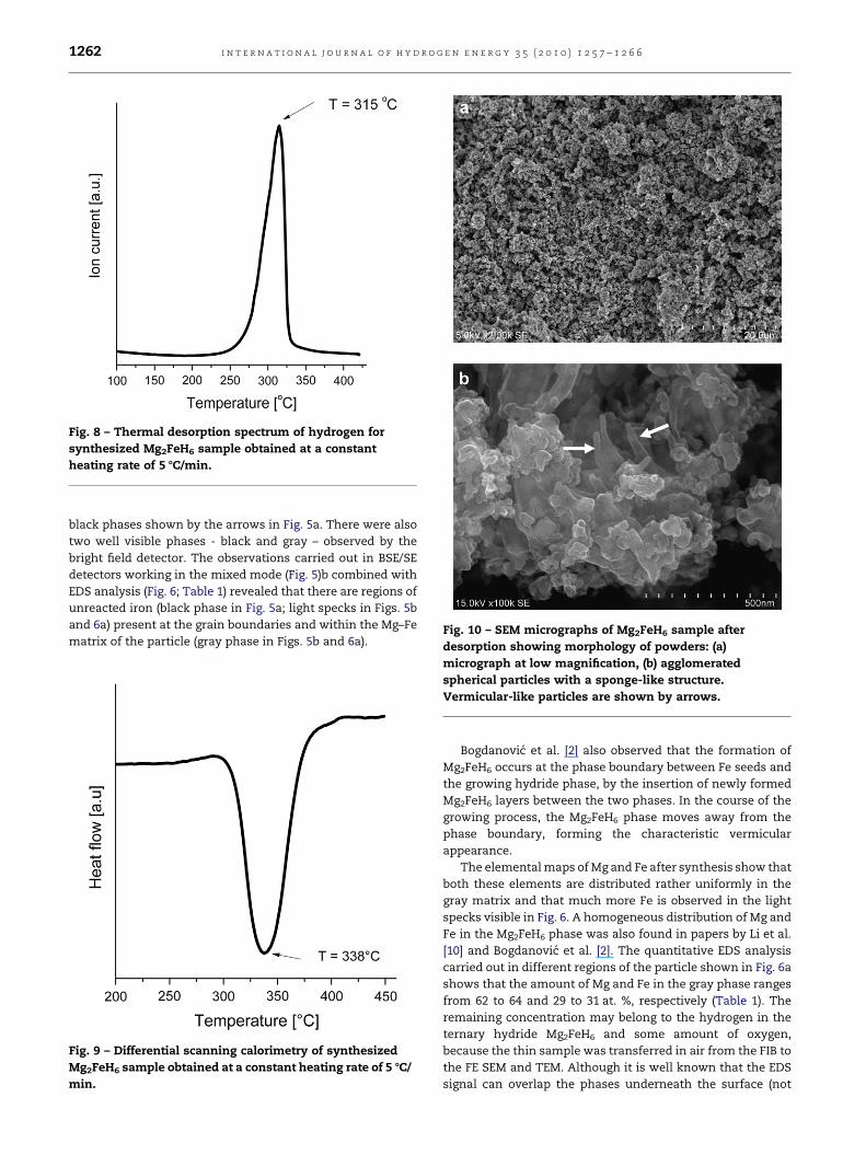
Fig. 8 – Thermal desorption spectrum of hydrogen for
synthesized Mg2FeH6 sample obtained at a constant
heating rate of 5 8C/min.
Fig. 10 – SEM micrographs of Mg2FeH6 sample after
desorption showing morphology of powders: (a)
i n t e r n a t i o n a l j o u r n a l o f h y d r o g e n e n e r g y 3 5 ( 2 0 1 0 ) 1 2 5 7 – 1 2 6 61262
black phases shown by the arrows in Fig. 5a. There were also
two well visible phases - black and gray – observed by the
bright field detector. The observations carried out in BSE/SE
detectors working in the mixed mode (Fig. 5)b combined with
EDS analysis (Fig. 6; Table 1) revealed that there are regions of
unreacted iron (black phase in Fig. 5a; light specks in Figs. 5b
and 6a) present at the grain boundaries and within the Mg–Fe
matrix of the particle (gray phase in Figs. 5b and 6a).
Fig. 9 – Differential scanning calorimetry of synthesized
Mg2FeH6 sample obtained at a constant heating rate of 5 8C/
min.
micrograph at low magnification, (b) agglomerated
spherical particles with a sponge-like structure.
Vermicular-like particles are shown by arrows.
Bogdanovic et al. [2] also observed that the formation of
Mg2FeH6 occurs at the phase boundary between Fe seeds and
the growing hydride phase, by the insertion of newly formed
Mg2FeH6 layers between the two phases. In the course of the
growing process, the Mg2FeH6 phase moves away from the
phase boundary, forming the characteristic vermicular
appearance.
The elemental maps of Mg and Fe after synthesis show that
both these elements are distributed rather uniformly in the
gray matrix and that much more Fe is observed in the light
specks visible in Fig. 6. A homogeneous distribution of Mg and
Fe in the Mg2FeH6 phase was also found in papers by Li et al.
[10] and Bogdanovic et al. [2]. The quantitative EDS analysis
carried out in different regions of the particle shown in Fig. 6a
shows that the amount of Mg and Fe in the gray phase ranges
from 62 to 64 and 29 to 31 at. %, respectively (Table 1). The
remaining concentration may belong to the hydrogen in the
ternary hydride Mg2FeH6 and some amount of oxygen,
because the thin sample was transferred in air from the FIB to
the FE SEM and TEM. Although it is well known that the EDS
signal can overlap the phases underneath the surface (not
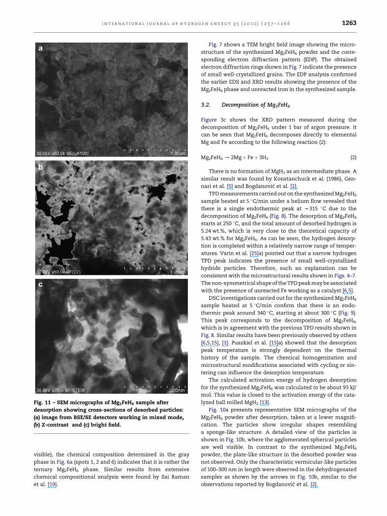
Fig. 11 – SEM micrographs of Mg2FeH6 sample after
desorption showing cross-sections of desorbed particles:
(a) image from BSE/SE detectors working in mixed mode,
(b) Z-contrast and (c) bright field.
i n t e r n a t i o n a l j o u r n a l o f h y d r o g e n e n e r g y 3 5 ( 2 0 1 0 ) 1 2 5 7 – 1 2 6 6 1263
visible), the chemical composition determined in the gray
phase in Fig. 6a (spots 1, 2 and 6) indicates that it is rather the
ternary Mg2FeH6 phase. Similar results from extensive
chemical compositional analysis were found by Sai Raman
et al. [19].
Fig. 7 shows a TEM bright field image showing the micro-
structure of the synthesized Mg2FeH6 powder and the corre-
sponding electron diffraction pattern (EDP). The obtained
electron diffraction rings shown in Fig. 7 indicate the presence
of small well-crystallized grains. The EDP analysis confirmed
the earlier EDS and XRD results showing the presence of the
Mg2FeH6 phase and unreacted iron in the synthesized sample.
3.2. Decomposition of Mg2FeH6
Figure 3c shows the XRD pattern measured during the
decomposition of Mg2FeH6 under 1 bar of argon pressure. It
can be seen that Mg2FeH6 decomposes directly to elemental
Mg and Fe according to the following reaction (2):
Mg2FeH6 / 2Mgþ Feþ 3H2 (2)
There is no formation of MgH2 as an intermediate phase. A
similar result was found by Konstanchuck et al. (1986), Gen-
nari et al. [5] and Bogdanovic et al. [2].
TPD measurements carried out on the synthesized Mg2FeH6
sample heated at 5 �C/min under a helium flow revealed that
there is a single endothermic peak at w315 �C due to the
decomposition of Mg2FeH6 (Fig. 8). The desorption of Mg2FeH6
starts at 250 �C, and the total amount of desorbed hydrogen is
5.24 wt.%, which is very close to the theoretical capacity of
5.43 wt.% for Mg2FeH6. As can be seen, the hydrogen desorp-
tion is completed within a relatively narrow range of temper-
atures. Varin et al. [25]a) pointed out that a narrow hydrogen
TPD peak indicates the presence of small well-crystallized
hydride particles. Therefore, such an explanation can be
consistent with the microstructural results shown in Figs. 4–7.
The non-symmetrical shape of the TPD peak may be associated
with the presence of unreacted Fe working as a catalyst [6,5].
DSC investigations carried out for the synthesized Mg2FeH6
sample heated at 5 �C/min confirm that there is an endo-
thermic peak around 340 �C, starting at about 300 �C (Fig. 9).
This peak corresponds to the decomposition of Mg2FeH6,
which is in agreement with the previous TPD results shown in
Fig. 8. Similar results have been previously observed by others
[6,5,15], [1]. Puszkiel et al. [15]a) showed that the desorption
peak temperature is strongly dependent on the thermal
history of the sample. The chemical homogenization and
microstructural modifications associated with cycling or sin-
tering can influence the desorption temperature.
The calculated activation energy of hydrogen desorption
for the synthesized Mg2FeH6 was calculated to be about 93 kJ/
mol. This value is closed to the activation energy of the cata-
lyzed ball milled MgH2 [13].
Fig. 10a presents representative SEM micrographs of the
Mg2FeH6 powder after desorption, taken at a lower magnifi-
cation. The particles show irregular shapes resembling
a sponge-like structure. A detailed view of the particles is
shown in Fig. 10b, where the agglomerated spherical particles
are well visible. In contrast to the synthesized Mg2FeH6
powder, the plate-like structure in the desorbed powder was
not observed. Only the characteristic vermicular-like particles
of 100–300 nm in length were observed in the dehydrogenated
samples as shown by the arrows in Fig. 10b, similar to the
observations reported by Bogdanovic et al. [2].
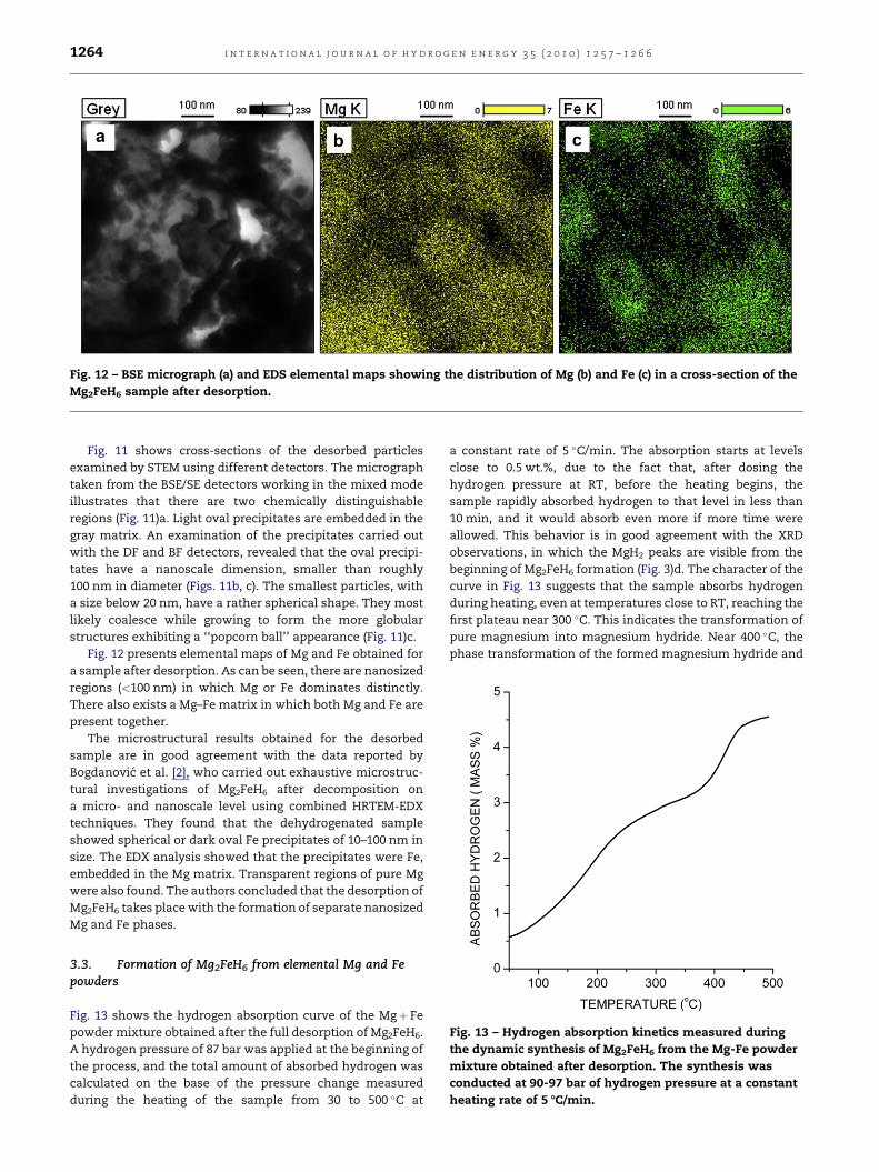
Fig. 12 – BSE micrograph (a) and EDS elemental maps showing the distribution of Mg (b) and Fe (c) in a cross-section of the
Mg2FeH6 sample after desorption.
i n t e r n a t i o n a l j o u r n a l o f h y d r o g e n e n e r g y 3 5 ( 2 0 1 0 ) 1 2 5 7 – 1 2 6 61264
Fig. 11 shows cross-sections of the desorbed particles
examined by STEM using different detectors. The micrograph
taken from the BSE/SE detectors working in the mixed mode
illustrates that there are two chemically distinguishable
regions (Fig. 11)a. Light oval precipitates are embedded in the
gray matrix. An examination of the precipitates carried out
with the DF and BF detectors, revealed that the oval precipi-
tates have a nanoscale dimension, smaller than roughly
100 nm in diameter (Figs. 11b, c). The smallest particles, with
a size below 20 nm, have a rather spherical shape. They most
likely coalesce while growing to form the more globular
structures exhibiting a ‘‘popcorn ball’’ appearance (Fig. 11)c.
Fig. 12 presents elemental maps of Mg and Fe obtained for
a sample after desorption. As can be seen, there are nanosized
regions (<100 nm) in which Mg or Fe dominates distinctly.
There also exists a Mg–Fe matrix in which both Mg and Fe are
present together.
The microstructural results obtained for the desorbed
sample are in good agreement with the data reported by
Bogdanovic et al. [2], who carried out exhaustive microstruc-
tural investigations of Mg2FeH6 after decomposition on
a micro- and nanoscale level using combined HRTEM-EDX
techniques. They found that the dehydrogenated sample
showed spherical or dark oval Fe precipitates of 10–100 nm in
size. The EDX analysis showed that the precipitates were Fe,
embedded in the Mg matrix. Transparent regions of pure Mg
were also found. The authors concluded that the desorption of
Mg2FeH6 takes place with the formation of separate nanosized
Mg and Fe phases.
Fig. 13 – Hydrogen absorption kinetics measured during
the dynamic synthesis of Mg2FeH6 from the Mg-Fe powder
mixture obtained after desorption. The synthesis was
conducted at 90-97 bar of hydrogen pressure at a constant
heating rate of 5 8C/min.
3.3. Formation of Mg2FeH6 from elemental Mg and Fepowders
Fig. 13 shows the hydrogen absorption curve of the Mgþ Fe
powder mixture obtained after the full desorption of Mg2FeH6.
A hydrogen pressure of 87 bar was applied at the beginning of
the process, and the total amount of absorbed hydrogen was
calculated on the base of the pressure change measured
during the heating of the sample from 30 to 500 �C at
a constant rate of 5 �C/min. The absorption starts at levels
close to 0.5 wt.%, due to the fact that, after dosing the
hydrogen pressure at RT, before the heating begins, the
sample rapidly absorbed hydrogen to that level in less than
10 min, and it would absorb even more if more time were
allowed. This behavior is in good agreement with the XRD
observations, in which the MgH2 peaks are visible from the
beginning of Mg2FeH6 formation (Fig. 3)d. The character of the
curve in Fig. 13 suggests that the sample absorbs hydrogen
during heating, even at temperatures close to RT, reaching the
first plateau near 300 �C. This indicates the transformation of
pure magnesium into magnesium hydride. Near 400 �C, the
phase transformation of the formed magnesium hydride and
i n t e r n a t i o n a l j o u r n a l o f h y d r o g e n e n e r g y 3 5 ( 2 0 1 0 ) 1 2 5 7 – 1 2 6 6 1265
iron into Mg2FeH6 occurs, which can easily be observed by an
increase in the slope of the absorption curve. The total
amount of absorbed hydrogen is 4.55 wt.%. (the theoretical
capacity of Mg2FeH6 is 5.43 wt.%). No magnesium hydride
residues were found in the synthesized mixture. This suggests
that the reaction yield is about 84%. However, taking into
account the fact that the obtained curve is not saturated at the
end of the synthesis, the yield can probably be increased to
values close to that obtained during the first absorption
(starting from the milled MgH2–Fe composite powder; Fig. 2)
by using a longer annealing time at 500 �C.
The obtained results can indicate that, after the desorption
of Mg2FeH6, rehydrogenation occurred according to the
following reactions (3,4):
MgþH2 / MgH2 (3)
2MgH2þ FeþH2 / Mg2FeH6 (4)
As can be seen from our studies, the reconstruction of the
Mg2FeH6 phase from the nanosized Mg and Fe proceeds
according to the same mechanism shown in reactions (1) and
(4), where the MgH2 phase acts as a precursor to the phase
transformation of the MgH2–Fe mixture into the ternary
Mg2FeH6 phase.
Our results are in good agreement with those reported
recently by Shao et al. [23] regarding the synthesis of the
Mg2FeH6 phase obtained while sintering elemental Mg and Fe
nanopowders under a hydrogen atmosphere. The earlier
suggestions of Bogdanovic et al. [2] related to the synthesis and
decomposition mechanisms are also well within in the frame
of our findings. In contrast, the hypothetical model previously
given by Gennari et al. [5] and Puszkiel et al. [15,16], critically
discussed by Varin et al. [25], is not confirmed by our structural
studies showing that free Mg is not found in the formation of
ternary Mg2FeH6. The MgH2 phase is a precursor to the phase
transformation of the MgH2–Fe mixture into Mg2FeH6.
4. Conclusions
We have applied a novel synthesis method for the rapid and
effective synthesis of the ternary Mg–Fe hydride. This method
consists of two processing routes. The first route involves
high-energy ball milling of the initial MgH2–Fe powder
mixture, while the second consists of a unique pressurizing
and heating cycle route to obtain a full phase transformation
within half an hour.
Moreover, in the present work, we have reported the
mechanisms of Mg2FeH6 synthesis and decomposition. The
formation of Mg2FeH6 consists of two steps that involve MgH2
as an intermediate compound. Mg does not participate in the
formation of ternary Mg2FeH6. The MgH2 phase is a precursor
to the phase transformation of the MgH2–Fe mixture into
Mg2FeH6. In contrast, the decomposition of Mg2FeH6 consists
of only one step and does not follow the inverse route. Traces
of iron were found in the reaction products.
The TDP results showed that the desorption onset
temperature is as low as 250 �C. The desorption peak
temperature is 315 �C. This indicates that the hydrogen
desorption is completed within a relatively narrow range of
temperatures and that it can be related to the presence of
small well-crystallized hydride particles. The DSC curve
shows only a single endothermic peak around 340 �C, and it is
consistent with the obtained TPD results.
The microstructural investigations carried out on the
Mg2FeH6 phase revealed that the synthesized powder gener-
ally exhibits a duplex structure that consists of plate-like
particles larger than 1 mm and spherical particles smaller than
50 nm with a tendency to agglomerate and form larger parti-
cles exhibiting a sponge-like structure. The formation of
Mg2FeH6 takes place at the phase boundary between Fe seeds
and the growing hydride phase. In contrast, the decomposi-
tion of the Mg2FeH6 phase takes place with the formation of
the separate nanosized Mg and Fe phases. The dehydro-
genated powder sample shows oval Fe precipitates of 10–
100 nm in size that are embedded in the Mg-based matrix.
Vermicular-like particles of 100–300 nm in length were
observed in both the synthesized and decomposed samples.
Acknowledgments
This work was supported by the Polish Ministry of Science and
Higher Education (Grant No PBZ-KBN-117/T08/01). The TPD
and DSC investigations in this work have been done in 2009
year under financial support the Polish Ministry of Sciences
and Higher Education, Key Project POIG.01.03.01-14-016/08.
r e f e r e n c e s
[1] Baum LA, Meyer M, Mendoza-Zelis L. Complex Mg-basedhydrides obtained by mechanosynthesis: characterizationand formation kinetics. Int J Hydrogen Energy 2008;33:3442–6.
[2] Bogdanovic B, Reiser A, Schlichte K, Spliethoff B, Tesche B.Thermodynamics and dynamics of the Mg–Fe–H system andits potential for thermochemical thermal energy storage. JAlloys Compd 2002;345:77–89.
[3] Castro FJ, Gennari FC. Effect of the nature of the startingmaterials on the formation of Mg2FeH6. J Alloys Compd 2004;375:292–6.
[4] Didisheim JJ, Zolliker P, Yvon K, Fisher P, Schefer J,Gubelman M, et al. Dimagnesium iron hydride, Mg2FeH6,containing octahedral FeH64- anions. Inorg Chem. 1984;23:1953–7.
[5] Gennari FC, Castro FJ, Gomboa Andrade, J.J. Synthesis ofMg2FeH6 by reactive mechanical alloying: formation anddecomposition properties. J Alloys Compd 2002;339:261–7.
[6] Herrich M, Ismail N, Lyubina J, Handstein A, Pratt A,Gutfleisch O. Synthesis and decomposition of Mg2FeH6
prepared by reactive milling. Mater Sci Eng B 2004;108:28–32.[7] Huot J, Hayakawa H, Akiba E. Preparation of the hydrides
Mg2FeH6 and Mg2CoH5 by mechanical alloying followed bysintering. J Alloys Compd 1997;248:164–7.
[8] Huot J, Boily S, Akiba E, Schulz R. Direct synthesis of Mg2FeH6
by mechanical alloying. J Alloys Compd 1998;280:306–9.[9] Konstanchuk IG, Ivanov E, Pezat M, Darriet B, Boldyrev VV,
Hagenmuller P. Hydriding properties of a mechanical alloywith composition Mg-25%Fe. J Less-Common Met 1987;131:181–9.
i n t e r n a t i o n a l j o u r n a l o f h y d r o g e n e n e r g y 3 5 ( 2 0 1 0 ) 1 2 5 7 – 1 2 6 61266
[10] Li Q, Liu J, Chou KCh, Lin GW, Xu KD. Synthesis anddehydrogenation behavior of Mg–Fe–H system preparedunder an external magnetic field. J Alloys Compd 2008;466:146–52.
[11] Li S, Varin RA, Morozova O, Khomenko T. Controlledmechano-chemical synthesis of nanostructured ternarycomplex hydride Mg2FeH6 under low-energy impact modewith and without pre-milling. J Alloys Compd 2004;384:231–48.
[12] Li S, Varin RA, Morozova O, Khomenko T. Corrigendum toControlled mechano-chemical synthesis of nanostructuredternary complex hydride Mg2FeH6 under low-energy impactmode with and without pre-milling. J Alloys Comp 2004;384:231–48. J. Alloys Compd. 385, 318.
[13] Polanski M, Bystrzycki J, Plocinski T. The effect of millingconditions on microstructure and hydrogen absorption/desorption properties of magnesium hydride (MgH2) withoutand with Cr2O3 nanoparticles. Int J Hydrogen Energy 2008;33:1859–67.
[14] Polanski, M., Bystrzycki, J., Nielsen, T.K., Cerenius, Y., Jensen,T.R.. Synthesis and decomposition mechanisms of Mg2FeH6studied by in-situ synchrotron X-ray diffraction and highpressure DSC – to be submitted.
[15] Puszkiel JA, Arneodo Larochette P, Gennari FC.Thermodynamic and kinetic studies of Mg–Fe–H aftermechanical milling followed by sintering. J Alloys Compd2008;463:134–42.
[16] Puszkiel JA, Arneodo Larochette P, Gennari FC.Thermodynamic–kinetic characterization of the synthesizedMg2FeH6–MgH2 hydrides mixture. Int J Hydrogen Energy2008;33:3555–60.
[17] Puszkiel JA, Arneodo Larochette P, Gennari FC. Hydrogenstorage properties of MgxFe (x: 2, 3 and 15) compoundsproduced by reactive ball milling. J Power Sourc 2009;186:185–93.
[18] Reiser A, Bogdanovic B, Schlichte K. The application of Mg-based metal-hydrides as heat energy storage systems. Int JHydrogen Energy 2000;25:425–30.
[19] Raman Sai, Davidson SS, Bobet DJ, Srivastava JL, O.N.Investigations on the synthesis, structural andmicrostructural characterizations of Mg-based K2PtCl6 type(Mg2FeH6) hydrogen storage material prepared bymechanical alloying. J Alloys Compd 2002;333:282–90.
[20] Saita I, Saito K, Akiyama T. Hydriding combustion synthesisof Mg2Ni1-xFex hydride. J Alloys Compd 2005;390:265–9.
[21] Selvam P, Yvon K. Synthesis of Mg2FeH6, Mg2CoH5 andMg2NiH4 by high-pressure sintering of elements. Int JHydrogen Energy 1991;16:615–7.
[22] Shang SX, Bououdina M, Guo ZX. Direct mechanicalsynthesis and characterization of Mg2Fe(Cu)H6. J AlloysCompd 2003;626:356–7.
[23] Shao H, Liu T, Wang Y, Xu H, Li X. Preparation of Mg-basedhydrogen storage materials from metal nanoparticles. JAlloys Compd 2008;465:527–33.
[24] Varin RA, Li S, Calka A, Wexler D. Formation andenvironmental stability of nanocrystalline and amorphoushydrides in the 2Mg–Fe mixture processed by controlledreactive mechanical alloying (CRMA). J. Alloys Compd 2004;373:270–86.
[25] Varin RA, Li S, Wronski Z, Morozova O, Khomenko T. Theeffect of sequential and continuous high-energy impactmode on the mechano-chemical synthesis ofnanostructured complex hydride Mg2FeH6. J Alloys Compd2005;390:282–96.
[26] Varin RA, Li S, Chiu Ch, Guo L, Morozova O, Khomenko T,et al. Nanocrystalline and non-crystalline hydridessynthesized by controlled reactive mechanical alloying/milling of Mg and Mg–X (X ¼ Fe, Co, Mn, B) systems. J AlloysCompd 2005;404–406:494–8.
[27] Varin RA, Czujko T, Wronski Z. Nanomaterials for solid statehydrogen storage. New York: Springer; 2009.
[28] Zhou DW, Li SL, Varin RA, Peng P, Liu JS, Yang F. Mechanicalalloying and electronic simulations of 2Mg–Fe mixturepowders for hydrogen storage. Mater Sci. Eng A 2006;427:306–15.


