Embed Size (px)
Citation preview
Construction and Building Materials 64 (2014) 246–252
Contents lists available at ScienceDirect
Construction and Building Materials
journal homepage: www.elsevier .com/locate /conbui ldmat
Technical Note
Determination of causes of accelerated local corrosion of austeniticsteels in water supply systems
http://dx.doi.org/10.1016/j.conbuildmat.2014.04.0580950-0618/� 2014 Elsevier Ltd. All rights reserved.
⇑ Corresponding author. Tel./fax: +48 583471092.E-mail address: [email protected] (J. Ryl).
J. Ryl ⇑, J. Wysocka, K. DarowickiDepartment of Electrochemistry, Corrosion and Materials Engineering, Gdansk University of Technology, Narutowicza 11/12, 80-952 Gdansk, Poland
h i g h l i g h t s
� This research presents a case study of accelerated local corrosion of water supply system pipeline.� Presence of weld decay on AISI 304 steel was shown and its consequences were revealed.� Formation of galvanic cells related to chromium depletion as a result of sensitisation was studied.
a r t i c l e i n f o
Article history:Received 8 January 2014Received in revised form 21 March 2014Accepted 4 April 2014
Keywords:Pitting corrosionIntergranular attackWeld decayStainless steel
a b s t r a c t
This paper concerns an inspection of a water supply system, made of AISI 304 steel, which showed signsof local corrosion at the weld. Such corrosion caused material perforation after very short periods of oper-ation. It was revealed that steel was sensitised during the welding process. It was also proven that chro-mium micro-segregation occurred in the alloy leading to galvanic cell formation which initialised theprocess of pitting corrosion. This paper is a study of corrosion attack types due to negligence duringand after the process of welding of the system.
� 2014 Elsevier Ltd. All rights reserved.
1. Introduction
Austenitic steel such as AISI 304 and AISI 316 are most oftenused as elements of industrial structures operated in conditionscharacterised by higher corrosion aggressiveness. Such steels areexpected to be very resistant, in particular in water with a low con-tent of chloride ions. For many water supply systems, however,accelerated degradation due to corrosive factors can be observed.Such resistance is ensured by a thin passive layer on the steel sur-face. Degradation of the passive layer, which is usually caused byexternal factors, can result in enhanced susceptibility of steel tolocal corrosion.
A key factor that causes the occurrence of local corrosion is thepresence of chloride ions. There are many theories pertaining totheir influence on pitting corrosion [1–3]. Most of them suggestadsorption of Cl� ions on the layer surface which later becomesoxide-depleted. Safe concentrations of chloride ions that do notcause pitting corrosion of austenitic steels are conditioned by thegrade of steel as well as many environmental factors. The Langelier
Saturation Index (LSI) is a popular method of evaluating waterquality data to determine if the water has a tendency to formchemical scale. In order to use this index, the following laboratoryanalyses are needed: pH, conductivity, total dissolved solids, alka-linity, and total hardness.
Local corrosion can be often observed along sections of pipe-lines with a very limited flow and in standing water, e.g. in fire pro-tection or potable water systems. In such cases, crevice corrosion isparticularly hazardous. This type of corrosion is also hazardous forconnections of elements [4] or in areas where organic coating isloosening [5]. Further, anaerobic areas also contribute to corrosiondue to microbiological activity where e.g. sulphate-reducing bacte-ria (SRB) and/or iron-oxidising bacteria (IOB) can grow [6,7]. It isbelieved that even up to 10% of all corrosion damage can be causedby such microbiological activity.
Buried elements of steel structures, arranged in urbanised areas,are even more exposed to sources of chloride ions from salt usedby road services to sprinkle roads. Conducted research has proventhat even up to 50% of salt penetrates locally to surface waters [8],and the content of chloride ions can reach even up to 2700 mg/l[9].
J. Ryl et al. / Construction and Building Materials 64 (2014) 246–252 247
Due to high temperatures associated with the welding process,where such temperatures can cause structural changes in steel, theheat-affected zone at the weld is often the area where acceleratedlocal corrosion occurs. After welding, it is important that the sur-face that could be in contact with water has a homogeneous com-position. Any crevices formed during the process should also beremoved. Due to steel sensitisation during the welding process,areas of higher susceptibility to intergranular corrosion are oftencreated. Such corrosion is often associated with pitting corrosionresulting from concentration cells in the alloy created due touneven distribution of chromium. Once a pit has been created, itacts as an anode depolarised by an extensive cathodic area aroundthe pit, and causes intensive degradation. Most often pitting occursin heterogeneous materials. This complex corrosion process in theheat-affected zone, causing material loss along the weld, is referredto as weld decay [10–12]. Degradation due to local corrosion canbe much faster than could be expected for the construction mate-rials used and corrosive aggressiveness of the environment.
In addition, a combination of corrosive and mechanical factorssuch as erosion or cavitation erosion–corrosion can have a synergyeffect that usually enhances the rate of material degradation. Thistype of hazard occurs particularly in systems with a turbulent flowof liquid [13–16].
This paper is a case study relating to the causes of local corro-sion in the water supply system.
2. Experimental
The structure being the subject of this investigation is an element of a watersupply system, described in the next chapter. Corrosion causes pipeline perforationresulting in the appearance of corrosion products on the outer walls. This effect canbe observed in the vicinity of welded joints. For experimental purposes, a section ofthe pipeline, including the weld and the parent material at a distance of around5 cm from the welded joint, was sampled. The inner diameter of the pipe underexamination was equal to 30 cm and its thickness was 0.4 cm. Weld bead widthwas around 1.2 cm while effect of welding in the form of discoloration was visibleup to 1.5 cm from the weld bead. Also for the purpose of the experiment, the film ofcorrosion products on the inner side, was etched in a mixture of organic acids andcorrosion inhibitors used for cleaning chromium–nickel steel.
Within the testing procedure, the grade of the steel subjected to testing wasidentified by optical emission spectrometry with glow discharge and with the useof spectroscope LECO GDS850A. In addition, physical and chemical parameters ofwater flowing through the pipeline were analysed to determine the LSI index. Ana-lytical tests of water were carried out by means of the colorimetric method with theuse of a Palintest Photometer 5000 system offering an instrumental method of awide range of water tests. Determination of dry residue was carried out in accor-dance with standard PN-EN 12880:2004. Other parameters determined included:pH – with a microcomputer meter CP-551, conductivity – with a microcomputerconductometer CC-315, oxygen – with an oxygen meter CO-411.
An analysis by means of the cyclic polarisation method carried out within thisstudy was conducted with the use of a three-electrode system where the testedpipeline section was the working electrode. Its surface area was 2 cm2. A saturatedcalomel electrode (SCE) was used as a reference electrode, whereas platinum gauzeserved as the counter electrode. A 150 ml solution of water transported in the pipe-line and polarisation rate of 1 mV/s were applied. For the purpose of tests, a poten-tiostat manufactured by GAMRY International was used.
Topography analysis of sample was carried out on Hitachi S-3400N scanningelectron microscope with a tungsten source and variable chamber pressure (VP-SEM). Pictures were taken in the secondary electrons mode (SE), under 20 kV accel-erating voltage and 10 mm working distance, proven as the optimal conditions. Themicroscope was equipped with an energy-dispersive spectroscope EDX, manufac-tured by ThermoScientific, as an attachment.
3. Results and discussion
3.1. Inspection of the water supply system
Various areas of the system were inspected, corrosion had thesame character and origin for every element of the pipeline. Mostoften corrosion occurred just at the weld or in its vicinity, notfurther than 3 cm away from the weld. Washed-away corrosionproducts flow slowly out of the perforation areas. The photos in
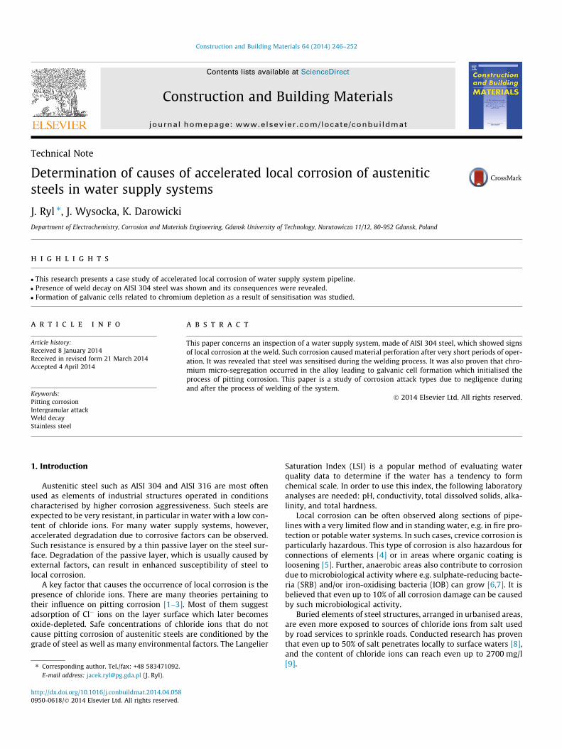
Fig. 1 illustrate corrosion damage of different pipelines withinthe water supply system, in particular: pumping station (Fig. 1Aand B), rinsing water system (Fig. 1C), water filtration system(Fig. 1D). In addition, it was found that there were attempts toremove perforation due to corrosion by pad welding (Fig. 1D).
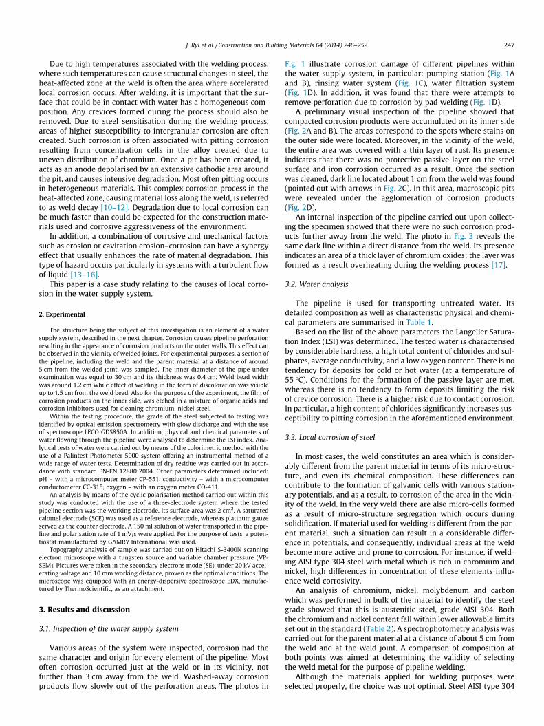
A preliminary visual inspection of the pipeline showed thatcompacted corrosion products were accumulated on its inner side(Fig. 2A and B). The areas correspond to the spots where stains onthe outer side were located. Moreover, in the vicinity of the weld,the entire area was covered with a thin layer of rust. Its presenceindicates that there was no protective passive layer on the steelsurface and iron corrosion occurred as a result. Once the sectionwas cleaned, dark line located about 1 cm from the weld was found(pointed out with arrows in Fig. 2C). In this area, macroscopic pitswere revealed under the agglomeration of corrosion products(Fig. 2D).
An internal inspection of the pipeline carried out upon collect-ing the specimen showed that there were no such corrosion prod-ucts further away from the weld. The photo in Fig. 3 reveals thesame dark line within a direct distance from the weld. Its presenceindicates an area of a thick layer of chromium oxides; the layer wasformed as a result overheating during the welding process [17].
3.2. Water analysis
The pipeline is used for transporting untreated water. Itsdetailed composition as well as characteristic physical and chemi-cal parameters are summarised in Table 1.
Based on the list of the above parameters the Langelier Satura-tion Index (LSI) was determined. The tested water is characterisedby considerable hardness, a high total content of chlorides and sul-phates, average conductivity, and a low oxygen content. There is notendency for deposits for cold or hot water (at a temperature of55 �C). Conditions for the formation of the passive layer are met,whereas there is no tendency to form deposits limiting the riskof crevice corrosion. There is a higher risk due to contact corrosion.In particular, a high content of chlorides significantly increases sus-ceptibility to pitting corrosion in the aforementioned environment.
3.3. Local corrosion of steel
In most cases, the weld constitutes an area which is consider-ably different from the parent material in terms of its micro-struc-ture, and even its chemical composition. These differences cancontribute to the formation of galvanic cells with various station-ary potentials, and as a result, to corrosion of the area in the vicin-ity of the weld. In the very weld there are also micro-cells formedas a result of micro-structure segregation which occurs duringsolidification. If material used for welding is different from the par-ent material, such a situation can result in a considerable differ-ence in potentials, and consequently, individual areas at the weldbecome more active and prone to corrosion. For instance, if weld-ing AISI type 304 steel with metal which is rich in chromium andnickel, high differences in concentration of these elements influ-ence weld corrosivity.
An analysis of chromium, nickel, molybdenum and carbonwhich was performed in bulk of the material to identify the steelgrade showed that this is austenitic steel, grade AISI 304. Boththe chromium and nickel content fall within lower allowable limitsset out in the standard (Table 2). A spectrophotometry analysis wascarried out for the parent material at a distance of about 5 cm fromthe weld and at the weld joint. A comparison of composition atboth points was aimed at determining the validity of selectingthe weld metal for the purpose of pipeline welding.
Although the materials applied for welding purposes wereselected properly, the choice was not optimal. Steel AISI type 304
Fig. 1. Inspection of pipeline system, at: (A and B) pumping station pipeline, (C) rinsing water system pipeline, and (D) water filtration system pipeline.
Fig. 2. Pipeline element taken for further analysis. (A) specimen, (B) a view of corrosion products on the inner side, (C) the sample after immersing in inhibitors, and (D)corrosion pits.
248 J. Ryl et al. / Construction and Building Materials 64 (2014) 246–252
should be welded with the use of steel with molybdenum withinthe range of 2–2.5% or with 2–3% more chromium. Based on thesamples of the weld and the parent material collected for the test,a higher content of chromium in the weld and a slightly highercontent of molybdenum can be observed. However, the contentof the latter element is too low to regard it as welding with theuse of AISI 316 steel.
An analysis of chemical composition of the sample in a directvicinity of the weld, within oxidised area (as presented inFig. 2C), was carried out. The oxidised area width is up to 1 cm.Fig. 4 presents relative information on the surface gradient of chro-mium and oxygen concentration with the use of Energy Dispersive
X-ray Spectrometry (EDX). The obtained results prove an increasedcontent of chromium and oxygen within the oxidised area, as com-pared to the weld and the area of the parent material (on the outersides of the diagram). However, the results obtained with the helpof the EDX method with reference to thin films should be regardedas demonstrative because the area subject to the analysis is greaterthan the thickness of the passive layer; therefore just a part of thesignal corresponds to it, whereas the rest corresponds to the bulkof the material. Still, the diagrams illustrate changes in the ana-lysed parameters accurately.
The welding process, in particular in the case of low-quality gasarc welding, can lead to considerable differences in passive film
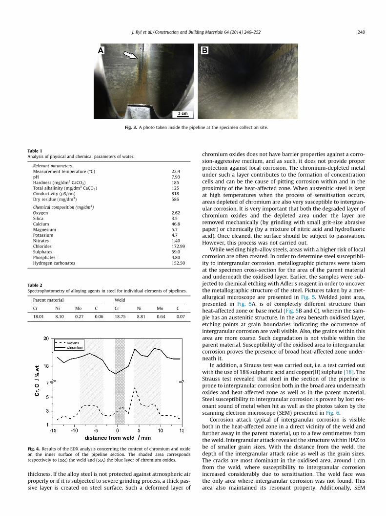
Fig. 3. A photo taken inside the pipeline at the specimen collection site.
Table 1Analysis of physical and chemical parameters of water.
Relevant parametersMeasurement temperature (�C) 22.4pH 7.93Hardness (mg/dm3 CaCO3) 185Total alkalinity (mg/dm3 CaCO3) 125Conductivity (lS/cm) 818Dry residue (mg/dm3) 586
Chemical composition (mg/dm3)Oxygen 2.62Silica 3.5Calcium 46.8Magnesium 5.7Potassium 4.7Nitrates 1.40Chlorides 172.99Sulphates 59.0Phosphates 4.80Hydrogen carbonates 152.50
Table 2Spectrophotometry of alloying agents in steel for individual elements of pipelines.
Parent material Weld
Cr Ni Mo C Cr Ni Mo C
18.01 8.10 0.27 0.06 18.75 8.81 0.64 0.07
Fig. 4. Results of the EDX analysis concerning the content of chromium and oxideon the inner surface of the pipeline section. The shaded area correspondsrespectively to ( ) the weld and ( ) the blue layer of chromium oxides.
J. Ryl et al. / Construction and Building Materials 64 (2014) 246–252 249
thickness. If the alloy steel is not protected against atmospheric airproperly or if it is subjected to severe grinding process, a thick pas-sive layer is created on steel surface. Such a deformed layer of
chromium oxides does not have barrier properties against a corro-sion-aggressive medium, and as such, it does not provide properprotection against local corrosion. The chromium-depleted metalunder such a layer contributes to the formation of concentrationcells and can be the cause of pitting corrosion within and in theproximity of the heat-affected zone. When austenitic steel is keptat high temperatures when the process of sensitisation occurs,areas depleted of chromium are also very susceptible to intergran-ular corrosion. It is very important that both the degraded layer ofchromium oxides and the depleted area under the layer areremoved mechanically (by grinding with small grit-size abrasivepaper) or chemically (by a mixture of nitric acid and hydrofluoricacid). Once cleaned, the surface should be subject to passivation.However, this process was not carried out.
While welding high-alloy steels, areas with a higher risk of localcorrosion are often created. In order to determine steel susceptibil-ity to intergranular corrosion, metallographic pictures were takenat the specimen cross-section for the area of the parent materialand underneath the oxidised layer. Earlier, the samples were sub-jected to chemical etching with Adler’s reagent in order to uncoverthe metallographic structure of the steel. Pictures taken by a met-allurgical microscope are presented in Fig. 5. Welded joint area,presented in Fig. 5A, is of completely different structure thanheat-affected zone or base metal (Fig. 5B and C), wherein the sam-ple has an austenitic structure. In the area beneath oxidised layer,etching points at grain boundaries indicating the occurrence ofintergranular corrosion are well visible. Also, the grains within thisarea are more coarse. Such degradation is not visible within theparent material. Susceptibility of the oxidised area to intergranularcorrosion proves the presence of broad heat-affected zone under-neath it.
In addition, a Strauss test was carried out, i.e. a test carried outwith the use of 18% sulphuric acid and copper(II) sulphate [18]. TheStrauss test revealed that steel in the section of the pipeline isprone to intergranular corrosion both in the broad area underneathoxides and heat-affected zone as well as in the parent material.Steel susceptibility to intergranular corrosion is proven by lost res-onant sound of metal when hit as well as the photos taken by thescanning electron microscope (SEM) presented in Fig. 6.
Corrosion attack typical of intergranular corrosion is visibleboth in the heat-affected zone in a direct vicinity of the weld andfurther away in the parent material, up to a few centimetres fromthe weld. Intergranular attack revealed the structure within HAZ tobe of smaller grain sizes. With the distance from the weld, thedepth of the intergranular attack raise as well as the grain sizes.The cracks are most dominant in the oxidised area, around 1 cmfrom the weld, where susceptibility to intergranular corrosionincreased considerably due to sensitisation. The weld face wasthe only area where intergranular corrosion was not found. Thisarea also maintained its resonant property. Additionally, SEM
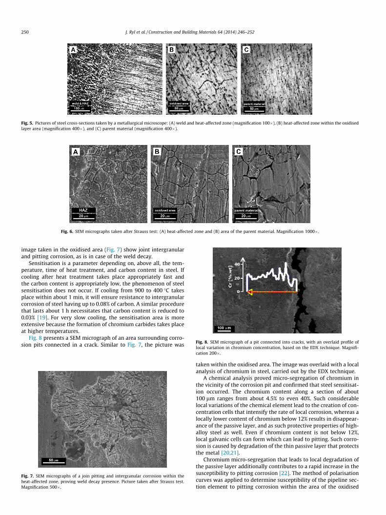
Fig. 5. Pictures of steel cross-sections taken by a metallurgical microscope: (A) weld and heat-affected zone (magnification 100�), (B) heat-affected zone within the oxidisedlayer area (magnification 400�), and (C) parent material (magnification 400�).
Fig. 6. SEM micrographs taken after Strauss test: (A) heat-affected zone and (B) area of the parent material. Magnification 1000�.
Fig. 8. SEM micrograph of a pit connected into cracks, with an overlaid profile oflocal variation in chromium concentration, based on the EDX technique. Magnifi-
250 J. Ryl et al. / Construction and Building Materials 64 (2014) 246–252
image taken in the oxidised area (Fig. 7) show joint intergranularand pitting corrosion, as is in case of the weld decay.
Sensitisation is a parameter depending on, above all, the tem-perature, time of heat treatment, and carbon content in steel. Ifcooling after heat treatment takes place appropriately fast andthe carbon content is appropriately low, the phenomenon of steelsensitisation does not occur. If cooling from 900 to 400 �C takesplace within about 1 min, it will ensure resistance to intergranularcorrosion of steel having up to 0.08% of carbon. A similar procedurethat lasts about 1 h necessitates that carbon content is reduced to0.03% [19]. For very slow cooling, the sensitisation area is moreextensive because the formation of chromium carbides takes placeat higher temperatures.
Fig. 8 presents a SEM micrograph of an area surrounding corro-sion pits connected in a crack. Similar to Fig. 7, the picture was
Fig. 7. SEM micrographs of a join pitting and intergranular corrosion within theheat-affected zone, proving weld decay presence. Picture taken after Strauss test.Magnification 500�.
cation 200�.
taken within the oxidised area. The image was overlaid with a localanalysis of chromium in steel, carried out by the EDX technique.
A chemical analysis proved micro-segregation of chromium inthe vicinity of the corrosion pit and confirmed that steel sensitisat-ion occurred. The chromium content along a section of about100 lm ranges from about 4.5% to even 40%. Such considerablelocal variations of the chemical element lead to the creation of con-centration cells that intensify the rate of local corrosion, whereas alocally lower content of chromium below 12% results in disappear-ance of the passive layer, and as such protective properties of high-alloy steel as well. Even if chromium content is not below 12%,local galvanic cells can form which can lead to pitting. Such corro-sion is caused by degradation of the thin passive layer that protectsthe metal [20,21].
Chromium micro-segregation that leads to local degradation ofthe passive layer additionally contributes to a rapid increase in thesusceptibility to pitting corrosion [22]. The method of polarisationcurves was applied to determine susceptibility of the pipeline sec-tion element to pitting corrosion within the area of the oxidised
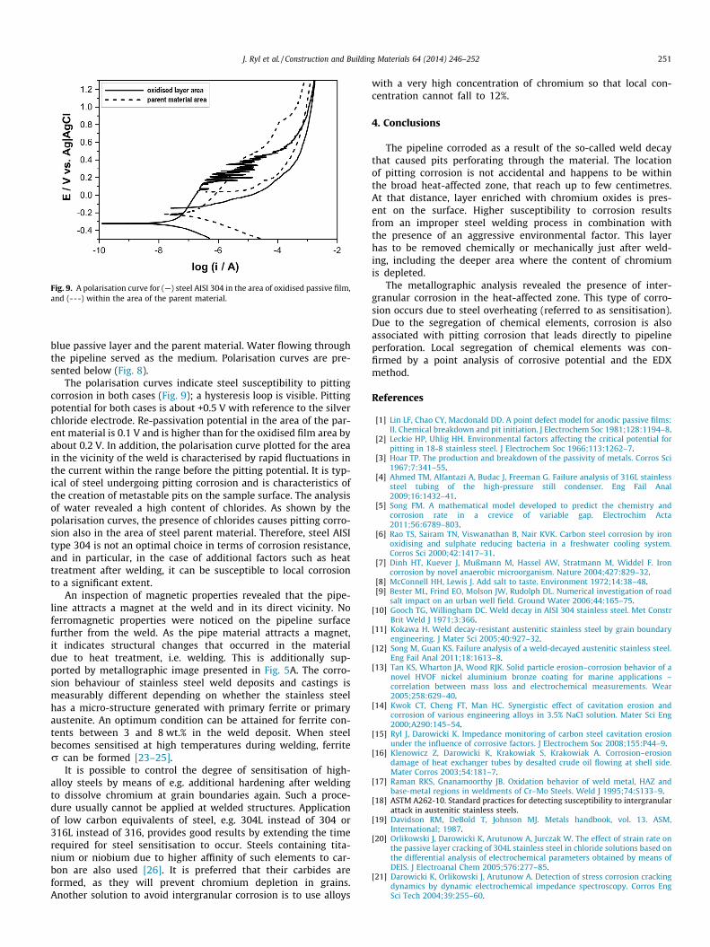
Fig. 9. A polarisation curve for (—) steel AISI 304 in the area of oxidised passive film,and (---) within the area of the parent material.
J. Ryl et al. / Construction and Building Materials 64 (2014) 246–252 251
blue passive layer and the parent material. Water flowing throughthe pipeline served as the medium. Polarisation curves are pre-sented below (Fig. 8).
The polarisation curves indicate steel susceptibility to pittingcorrosion in both cases (Fig. 9); a hysteresis loop is visible. Pittingpotential for both cases is about +0.5 V with reference to the silverchloride electrode. Re-passivation potential in the area of the par-ent material is 0.1 V and is higher than for the oxidised film area byabout 0.2 V. In addition, the polarisation curve plotted for the areain the vicinity of the weld is characterised by rapid fluctuations inthe current within the range before the pitting potential. It is typ-ical of steel undergoing pitting corrosion and is characteristics ofthe creation of metastable pits on the sample surface. The analysisof water revealed a high content of chlorides. As shown by thepolarisation curves, the presence of chlorides causes pitting corro-sion also in the area of steel parent material. Therefore, steel AISItype 304 is not an optimal choice in terms of corrosion resistance,and in particular, in the case of additional factors such as heattreatment after welding, it can be susceptible to local corrosionto a significant extent.
An inspection of magnetic properties revealed that the pipe-line attracts a magnet at the weld and in its direct vicinity. Noferromagnetic properties were noticed on the pipeline surfacefurther from the weld. As the pipe material attracts a magnet,it indicates structural changes that occurred in the materialdue to heat treatment, i.e. welding. This is additionally sup-ported by metallographic image presented in Fig. 5A. The corro-sion behaviour of stainless steel weld deposits and castings ismeasurably different depending on whether the stainless steelhas a micro-structure generated with primary ferrite or primaryaustenite. An optimum condition can be attained for ferrite con-tents between 3 and 8 wt.% in the weld deposit. When steelbecomes sensitised at high temperatures during welding, ferriter can be formed [23–25].
It is possible to control the degree of sensitisation of high-alloy steels by means of e.g. additional hardening after weldingto dissolve chromium at grain boundaries again. Such a proce-dure usually cannot be applied at welded structures. Applicationof low carbon equivalents of steel, e.g. 304L instead of 304 or316L instead of 316, provides good results by extending the timerequired for steel sensitisation to occur. Steels containing tita-nium or niobium due to higher affinity of such elements to car-bon are also used [26]. It is preferred that their carbides areformed, as they will prevent chromium depletion in grains.Another solution to avoid intergranular corrosion is to use alloys
with a very high concentration of chromium so that local con-centration cannot fall to 12%.
4. Conclusions
The pipeline corroded as a result of the so-called weld decaythat caused pits perforating through the material. The locationof pitting corrosion is not accidental and happens to be withinthe broad heat-affected zone, that reach up to few centimetres.At that distance, layer enriched with chromium oxides is pres-ent on the surface. Higher susceptibility to corrosion resultsfrom an improper steel welding process in combination withthe presence of an aggressive environmental factor. This layerhas to be removed chemically or mechanically just after weld-ing, including the deeper area where the content of chromiumis depleted.
The metallographic analysis revealed the presence of inter-granular corrosion in the heat-affected zone. This type of corro-sion occurs due to steel overheating (referred to as sensitisation).Due to the segregation of chemical elements, corrosion is alsoassociated with pitting corrosion that leads directly to pipelineperforation. Local segregation of chemical elements was con-firmed by a point analysis of corrosive potential and the EDXmethod.
References
[1] Lin LF, Chao CY, Macdonald DD. A point defect model for anodic passive films:II. Chemical breakdown and pit initiation. J Electrochem Soc 1981;128:1194–8.
[2] Leckie HP, Uhlig HH. Environmental factors affecting the critical potential forpitting in 18-8 stainless steel. J Electrochem Soc 1966;113:1262–7.
[3] Hoar TP. The production and breakdown of the passivity of metals. Corros Sci1967;7:341–55.
[4] Ahmed TM, Alfantazi A, Budac J, Freeman G. Failure analysis of 316L stainlesssteel tubing of the high-pressure still condenser. Eng Fail Anal2009;16:1432–41.
[5] Song FM. A mathematical model developed to predict the chemistry andcorrosion rate in a crevice of variable gap. Electrochim Acta2011;56:6789–803.
[6] Rao TS, Sairam TN, Viswanathan B, Nair KVK. Carbon steel corrosion by ironoxidising and sulphate reducing bacteria in a freshwater cooling system.Corros Sci 2000;42:1417–31.
[7] Dinh HT, Kuever J, Mußmann M, Hassel AW, Stratmann M, Widdel F. Ironcorrosion by novel anaerobic microorganism. Nature 2004;427:829–32.
[8] McConnell HH, Lewis J. Add salt to taste. Environment 1972;14:38–48.[9] Bester ML, Frind EO, Molson JW, Rudolph DL. Numerical investigation of road
salt impact on an urban well field. Ground Water 2006;44:165–75.[10] Gooch TG, Willingham DC. Weld decay in AISI 304 stainless steel. Met Constr
Brit Weld J 1971;3:366.[11] Kokawa H. Weld decay-resistant austenitic stainless steel by grain boundary
engineering. J Mater Sci 2005;40:927–32.[12] Song M, Guan KS. Failure analysis of a weld-decayed austenitic stainless steel.
Eng Fail Anal 2011;18:1613–8.[13] Tan KS, Wharton JA, Wood RJK. Solid particle erosion–corrosion behavior of a
novel HVOF nickel aluminium bronze coating for marine applications –correlation between mass loss and electrochemical measurements. Wear2005;258:629–40.
[14] Kwok CT, Cheng FT, Man HC. Synergistic effect of cavitation erosion andcorrosion of various engineering alloys in 3.5% NaCl solution. Mater Sci Eng2000;A290:145–54.
[15] Ryl J, Darowicki K. Impedance monitoring of carbon steel cavitation erosionunder the influence of corrosive factors. J Electrochem Soc 2008;155:P44–9.
[16] Klenowicz Z, Darowicki K, Krakowiak S, Krakowiak A. Corrosion–erosiondamage of heat exchanger tubes by desalted crude oil flowing at shell side.Mater Corros 2003;54:181–7.
[17] Raman RKS, Gnanamoorthy JB. Oxidation behavior of weld metal, HAZ andbase-metal regions in weldments of Cr–Mo Steels. Weld J 1995;74:S133–9.
[18] ASTM A262-10. Standard practices for detecting susceptibility to intergranularattack in austenitic stainless steels.
[19] Davidson RM, DeBold T, Johnson MJ. Metals handbook, vol. 13. ASM,International; 1987.
[20] Orlikowski J, Darowicki K, Arutunow A, Jurczak W. The effect of strain rate onthe passive layer cracking of 304L stainless steel in chloride solutions based onthe differential analysis of electrochemical parameters obtained by means ofDEIS. J Electroanal Chem 2005;576:277–85.
[21] Darowicki K, Orlikowski J, Arutunow A. Detection of stress corrosion crackingdynamics by dynamic electrochemical impedance spectroscopy. Corros EngSci Tech 2004;39:255–60.

252 J. Ryl et al. / Construction and Building Materials 64 (2014) 246–252
[22] ASTM G46-76. Recommended practice for evaluation of pitting corrosion.[23] Wahid A, Olson DL, Matlo DK. Corrosion of weldments. ASM handbook:
welding, brazing, and soldering, vol. 6. ASM, International; 1993.[24] Backman A, Lundqvist B. Properties of a fully austenitic stainless steel weld
metal for severe corrosion environments. Weld J 1977;56:23s–8s.
[25] Menendez H, Devine TM. The influence of microstructure on the sensitizationbehavior of duplex stainless steel welds. Corrosion 1990;46:410–8.
[26] Cihal V. Intergranular corrosion of steels and alloys. Elsevier SciencePublishers: BV; 1984.