Embed Size (px)
Citation preview
Controlling Hazardous EnergyDe-Energization and Lockout
About WorkSafeBC
At WorkSafeBC, we’re dedicated to promoting safe and healthy workplaces across B.C. We partner with workers and employers to save lives and prevent injury, disease, and disability. When work-related injuries or diseases occur, we provide compensation and support injured workers in their recovery, rehabilitation, and safe return to work. We also provide no-fault insurance and work diligently to sustain our workers’ compensation system for today and future generations. We’re honoured to serve the workers and employers in our province.
Prevention Information Line
We provide information and assistance with health and safety issues in the workplace.
Call the information line 24 hours a day, 7 days a week to report unsafe working conditions, a serious incident, or a major chemical release. Your call can be made anonymously. We can provide assistance in almost any language.
If you have questions about workplace health and safety or the Occupational Health and Safety Regulation, call during our office hours (8:05 a.m. to 4:30 p.m.) to speak to a WorkSafeBC officer.
If you’re in the Lower Mainland, call 604.276.3100. Elsewhere in Canada, call toll-free at 1.888.621.7233 (621.SAFE).
Health and safety resources
You can find our health and safety resources on worksafebc.com, and many of them can be ordered from the WorkSafeBC Store at worksafebcstore.com.
In addition to books, you’ll find other types of resources at the WorkSafeBC Store, including DVDs, posters, and brochures. If you have any questions about placing an order online, please contact a customer service representative at 604.232.9704 or toll-free at 1.866.319.9704.

Controlling Hazardous EnergyDe-Energization and Lockout

Acknowledgements
WorkSafeBC would like to thank everyone who assisted in the development of this revised edition, including the following organizations and their representatives: • Manufacturing Safety Alliance of BC • Kruger Products • UBSafe Inc.
Special thanks to CSA Group for permission to include standards in this publication.
Copyright
This resource is protected by Canadian and international intellectual property laws and treaties, including copyright and trademark laws, and is owned by the Workers’ Compensation Board (“WorkSafeBC”). We encourage you to use this resource for non-commercial, personal, or educational purposes to help promote occupational health and safety, provided that you do not modify any of the content and do not remove any copyright or other notices from it. In addition, if you are a trainer and wish to use this and any other WorkSafeBC resources as part of your training, you cannot, either directly or indirectly through a course or training fee, charge participants for WorkSafeBC resources. To request copyright permission, please send an email to [email protected]. You can find our full copyright terms at worksafebc.com.
Use of WorkSafeBC’s intellectual property does not constitute an endorsement, express or implied, of any person, service provider, service, or product.
Use of WorkSafeBC publications and materials is at your own risk. WorkSafeBC does not warrant the quality, accuracy, or completeness of any information contained in the publications and materials, which are provided “as is” without warranty or condition of any kind.
ISSN 1712-4719
© 1999, 2005, 2019, Workers’ Compensation Board (WorkSafeBC). All rights reserved.
With the permission of Canadian Standards Association, (operating as “CSA Group”), 178 Rexdale Blvd., Toronto, ON, M9W 1R3, material is reproduced from CSA Z460–13 (R2018) Control of hazardous energy — Lockout and other methods (© 2013 Canadian Standards Association) and CSA Z432–16 — Safeguarding of machinery (© 2016 Canadian Standards Association). This material is not the complete and official position of CSA Group on the referenced subject, which is represented solely by the Document in its entirety. While use of the material has been authorized, CSA Group is not responsible for the manner in which the data is presented, nor for any representations and interpretations. No further reproduction is permitted. For more information or to purchase standard(s) from CSA Group, please visit store.csagroup.org or call 1-800-463-6727.
Controlling Hazardous Energy: De-Energization and Lockout iii
ContentsWhy is controlling hazardous energy important? . . . . . . . . . . . .1Who should use this manual? . . . . . . . . . . . . . . . . . . . . . . . . . . .2Using this manual . . . . . . . . . . . . . . . . . . . . . . . . . . . . . . . . . . . . .3Terminology . . . . . . . . . . . . . . . . . . . . . . . . . . . . . . . . . . . . . . . . .4
Introduction to hazardous energy control . . . . . . . . . . . . .5The relationship between hazardous energy and de-energization and lockout . . . . . . . . . . . . . . . . . . . . . . . . . . . .6Types of hazardous energy . . . . . . . . . . . . . . . . . . . . . . . . . . . . .9Identifying hazardous energy and assessing the risk . . . . . . . .13The hierarchy of controls . . . . . . . . . . . . . . . . . . . . . . . . . . . . . .16How safeguarding and de-energization and lockout co-exist .18Normal production versus maintenance work . . . . . . . . . . . . .20Five basic steps to a de-energization and lockout procedure . .22Energy isolation verification process . . . . . . . . . . . . . . . . . . . . .23Main power versus control power . . . . . . . . . . . . . . . . . . . . . . .26
Responsibilities . . . . . . . . . . . . . . . . . . . . . . . . . . . . . . . . 31
De-energization and lockout policy, program, and procedures . . . . . . . . . . . . . . . . . . . . . . . . . . . . . . . . 35
Policy and program . . . . . . . . . . . . . . . . . . . . . . . . . . . . . . . . . .36Creating a de-energization and lockout program . . . . . . . . . . .37De-energization and lockout procedures . . . . . . . . . . . . . . . . .39Identifying energy-isolating devices . . . . . . . . . . . . . . . . . . . . .40Applying lockout devices . . . . . . . . . . . . . . . . . . . . . . . . . . . . . .41Continuity of lockout . . . . . . . . . . . . . . . . . . . . . . . . . . . . . . . . .45Removing the last lock . . . . . . . . . . . . . . . . . . . . . . . . . . . . . . . .46Emergency procedures and lockout . . . . . . . . . . . . . . . . . . . . .47
Alternative methods of hazardous energy control . . . . . . 49Hazardous energy isolation using control system isolating devices . . . . . . . . . . . . . . . . . . . . . . . . . . . . . . . . . . . . .52Remotely activated electromechanical lockout . . . . . . . . . . . .54Working on energized equipment . . . . . . . . . . . . . . . . . . . . . . .55Locks not required (exclusive and immediate control of the energy-isolating device) . . . . . . . . . . . . . . . . . . . . . . . . . .56Restraint systems . . . . . . . . . . . . . . . . . . . . . . . . . . . . . . . . . . . .58Mobile equipment lockout . . . . . . . . . . . . . . . . . . . . . . . . . . . . .61Isolation . . . . . . . . . . . . . . . . . . . . . . . . . . . . . . . . . . . . . . . . . . . .62
Controlling Hazardous Energy: De-Energization and Lockoutiv
Trapped-key interlock systems . . . . . . . . . . . . . . . . . . . . . . . . .63Blanks and blinds . . . . . . . . . . . . . . . . . . . . . . . . . . . . . . . . . . . .64Double block and bleed . . . . . . . . . . . . . . . . . . . . . . . . . . . . . . .65Freeze plug technology . . . . . . . . . . . . . . . . . . . . . . . . . . . . . . .66Power authorities . . . . . . . . . . . . . . . . . . . . . . . . . . . . . . . . . . . .67
Automation technology and hazardous energy control . . . 69Robotics . . . . . . . . . . . . . . . . . . . . . . . . . . . . . . . . . . . . . . . . . . .70Equipment modifications — change management and verification . . . . . . . . . . . . . . . . . . . . . . . . . . . . . . . . . . . . . . . . .72Imported equipment and used equipment . . . . . . . . . . . . . . . .73
Appendixes . . . . . . . . . . . . . . . . . . . . . . . . . . . . . . . . . . . 75Appendix 1: Supporting resources . . . . . . . . . . . . . . . . . . . . . .76Appendix 2: Elements of a de-energization and lockout program . . . . . . . . . . . . . . . . . . . . . . . . . . . . . . . . .78Appendix 3: How to request written approval for using control system isolating devices (CSIDs) . . . . . . . . . . . . .82Appendix 4: Relevant resources . . . . . . . . . . . . . . . . . . . . . . . . .84Appendix 5: Examples of lockout procedures . . . . . . . . . . . . .86
Controlling Hazardous Energy: De-Energization and Lockout 1
Every year, workers in British Columbia are killed or seriously injured because machinery or equipment was not properly de-energized and locked out. For example, accidents where workers are caught in machinery can result in severed fingers, crushed limbs, or death. Electrical equipment that is not properly locked out can cause electric shock, burns, and electrocution. These accidents can be prevented by locking out machinery properly before any maintenance work is done.
WorkSafeBC takes lockout seriously. Employers who don’t implement and follow lockout requirements will face penalties, including fines.
This manual doesn’t replace the Occupational Health and Safety Regulation
This manual is meant to give you a basic understanding of your health and safety requirements, but you should also refer to the Regulation to be sure you’re meeting your legal responsibilities for workplace health and safety. You can find a searchable version of the Regulation and its accompanying OHS Guidelines at worksafebc.com/law-policy.
Why is controlling hazardous energy important?
Controlling Hazardous Energy: De-Energization and Lockout2
This manual is mainly for employers. However, it contains useful information for anyone who owns, operates, maintains, or sells machinery and equipment.
Employers — You will find information to help you comply with the Occupational Health and Safety Regulation and the Workers Compensation Act so you can create a safe work environment for your employees.
Supervisors — You will find information to help you assess risks to workers from hazardous energy. This manual will also help you develop lockout solutions that meet the needs of safety, production, and quality assurance.
Workers — This manual will increase your awareness of the hazards associated with equipment operation and maintenance. It also outlines your rights to protection from hazardous energy in the workplace. Use this guide only as a supplement to WorkSafeBC requirements and company lockout procedures. You must follow your company’s lockout procedures and the lockout requirements of the Regulation at all times. Note: In the Regulation, the word worker includes supervisors, managers, and other workers.
Suppliers — This manual will help you understand how to provide machinery and equipment that conform to the Act and the Regulation. You can use it as a quick reference on different options for doing so.
This manual can also be used by joint health and safety committees, safety professionals, and workers in risk assessment and operations management.
Who should use this manual?
Controlling Hazardous Energy: De-Energization and Lockout 3
Must versus should
In this manual, the word must indicates a specific requirement from the Regulation or a referenced standard. The word should indicates an action that will improve safety in the workplace even though it is not specified in the Regulation.
Where to find hazardous energy control requirements and standards
Part 10 of the Regulation specifies requirements for de-energizing and locking out machinery and equipment. Part 10 also has guidelines and policies that help to interpret and apply the requirements. You will also find other de-energization and lockout requirements in Part 9, Confined Spaces; Part 19, Electrical Safety; and Part 16, Mobile Equipment.
Standards organizations around the world have produced written standards for almost all types of powered machinery. These publications can help determine how to de-energize and lock out equipment not mentioned in the Regulation. For a list of standards related to hazardous energy control, see Appendix 4.
Using this manual
Controlling Hazardous Energy: De-Energization and Lockout4
Hazardous energy
Hazardous energy is any energy source that could cause injury or death to workers. Some energy sources are obvious, such as electricity, heat in a furnace, or something that might fall. Others may be hidden hazards, such as air pressure in a system or a tightly wound spring.
Employers and workers often think of electrical power when considering hazardous energy, since lockout is frequently used with machinery or equipment powered by electricity. However, it is essential to identify and control any energy source that could cause injury. In this document, the term energy refers to anything that can provide power to a system to allow it to perform work. It also refers to the effects of gravity as a type of potential energy. The term system refers to machinery, equipment, and/or processes.
Lockout
Lockout is the use of a lock or locks to make machinery or equipment inoperable or to isolate an energy source. The purpose of lockout is to prevent an energy-isolating device (such as a circuit breaker or valve) from accidentally or inadvertently being operated while workers are performing maintenance on machinery or equipment. Lockout makes sure machinery or equipment won’t start and injure a worker.
De-energization
De-energization is removing the energy from equipment or a machine before locking it out. For example, you might shut off the machine and unplug it, or you might use a disconnect switch before you apply a lock to prevent the machine from being started up accidentally. De-energization also includes using restraint devices, such as pins or chains, to secure machine parts that may drop.
Terminology

Introduction to hazardous energy control
Controlling Hazardous Energy: De-Energization and Lockout6
The purpose of de-energization and lockout is to prevent the release of energy that poses a hazard to workers. If this hazardous energy could cause injury, the energy source must be isolated and controlled (by using locks, for example).
The terms hazardous energy control and de-energization and lockout are sometimes used interchangeably, but they are not the same thing: • Hazardous energy control describes the use of designs,
methods, and procedures to protect workers from injury resulting from the release of hazardous energy.
• De-energization is a process used to disconnect and isolate a system from a source of energy to prevent the release of that energy. De-energizing the system eliminates the chance that it could cause harm to a person through movement or through the release of radiation, electricity, chemicals, heat, light, or sound.
• Lockout is the placement of a lock on an energy-isolating device according to an established procedure. It indicates that the energy-isolating device must not be operated until the lock is removed. Lockout is one way to achieve hazardous energy control.
• De-energization and lockout is a procedure for preventing the release of energy that could injure a worker performing maintenance work.
First, all forms of hazardous energy must be removed or controlled. Then the worker places a lock on each energy-isolating device to prevent the machinery or equipment from inadvertently being re-energized. Effective lockout also includes verifying that the equipment is de-energized. This ensures that machinery or equipment won’t operate and injure a worker.
When de-energization and lockout is required
If machinery could unexpectedly activate or if the release of an energy source could cause injury, the energy source must be isolated and controlled. This is done through the de-energization and lockout procedure.
The relationship between hazardous energy and de-energization and lockout
Controlling Hazardous Energy: De-Energization and Lockout 7
If machinery or equipment is shut down for maintenance, workers may not perform work until they have done the following: • Secured all parts and attachments against inadvertent movement • Controlled the hazard wherever the work will expose workers to
energy sources • Locked out the energy-isolating devices (such as switches or
valves) • Checked the equipment to verify that all energy has been
isolated and controlled
When de-energization and lockout is not required
During normal production work, workers may need to perform some production-related tasks. De-energization and lockout may not be required in every case. This exception applies only to normal production work, not to maintenance tasks. Follow these steps to decide whether de-energization and lockout is required during normal production work:1. Decide whether there is a risk of injury to workers from the
movement of the machinery or equipment, ejection of material from the equipment, or exposure to an energy source while the activity is carried out. When assessing the risk of injury, imagine what will happen if the unexpected occurs. Consider all sources of hazardous energy, such as compressed springs and suspended equipment that could roll or fall.
2. If there is absolutely no risk of injury, de-energization and lockout is not required. Expecting workers to stay away from the hazard does not constitute no risk of injury.
3. If there is a risk of injury, decide whether the machinery or equipment is effectively safeguarded to protect workers from the risk. If effective safeguards are in place, de-energization and lockout is not required for the production tasks. An assessment may be required to determine whether safeguarding is effective.
Always follow safe work procedures during the activity.
What is an energy-isolating device?
This manual and the Regulation use the term energy-isolating device. This is a device that physically prevents the transmission or release of an energy source to machinery or equipment.
Controlling Hazardous Energy: De-Energization and Lockout8
Examples of typical energy-isolating devices include the following: • A manually operated electrical circuit breaker • A disconnect switch • A line valve
Stop buttons or selector switches (whether or not they involve a key) and programmable logic controllers (PLCs) that operate on control circuits are not energy-isolating devices and cannot be used for lockout.
All machines, equipment, and processes must include suitable energy-isolating devices for effective de-energization and lockout. The energy-isolating device should be designed for the intended use of the machinery or equipment under normal operating conditions. It should also anticipate upset conditions and maintenance.
To be an energy-isolating device, the device must operate on a main power source. For more information, see “Main power versus control power” on page 26.
What is a zero-energy state?
To be effective, de-energization and lockout must place the machine, equipment, or process in a zero-energy state. A zero-energy state is when all energy sources have been removed or controlled, and all stored or residual energy has been discharged.
Controlling Hazardous Energy: De-Energization and Lockout 9
Electrical energy is the most common form of energy used in workplaces. It can be available live through power lines or conductors, or it can be stored (for example, in batteries or capacitors). Electricity can harm people in three ways: • By electrical shock • By secondary injury • By exposure to an electrical arc
Capacitors, motors, and generators are sources of electrical energy. Both low-voltage and high-voltage equipment and conductors can injure or kill workers. Maintenance work on lighting systems or electrical panels, for example, requires de-energization and lockout.
Chemical energy is the energy released when a substance undergoes a chemical reaction. The energy is normally released as heat, but it could be released in other forms, such as pressure. A common result of a hazardous chemical reaction is fire or explosion. Hazardous chemical energy can be released with flammable, combustible, and corrosive substances. For example, fertilizer stored near diesel fuel is a potential source of an explosion.
Thermal energy is the energy in heat, which is found in steam, hot water, fire, gases, and liquefied gases. It can come from an explosion, a flame, objects with high or low temperatures, or radiation from heat sources. Common injuries include burns, scales, dehydration, and frostbite. For example, a steam pipe that supplies heat or that carries steam under pressure to drive a turbine has hazardous thermal energy and may take time to cool down.
Radiation energy is energy from electromagnetic sources, including laser, microwave, infrared, ultraviolet, and x-ray. Radiation can cause negative health effects, such as skin and eye damage (from non-ionizing sources, such as lasers and ultraviolet light) or cancer (from ionizing sources, such as x-rays).
Types of hazardous energy
Controlling Hazardous Energy: De-Energization and Lockout10
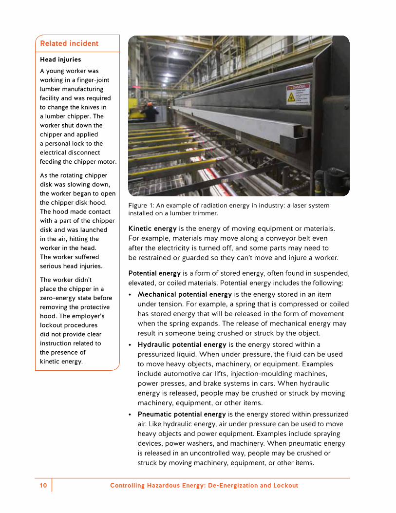
Figure 1: An example of radiation energy in industry: a laser system installed on a lumber trimmer.
Kinetic energy is the energy of moving equipment or materials. For example, materials may move along a conveyor belt even after the electricity is turned off, and some parts may need to be restrained or guarded so they can’t move and injure a worker.
Potential energy is a form of stored energy, often found in suspended, elevated, or coiled materials. Potential energy includes the following: • Mechanical potential energy is the energy stored in an item
under tension. For example, a spring that is compressed or coiled has stored energy that will be released in the form of movement when the spring expands. The release of mechanical energy may result in someone being crushed or struck by the object.
• Hydraulic potential energy is the energy stored within a pressurized liquid. When under pressure, the fluid can be used to move heavy objects, machinery, or equipment. Examples include automotive car lifts, injection-moulding machines, power presses, and brake systems in cars. When hydraulic energy is released, people may be crushed or struck by moving machinery, equipment, or other items.
• Pneumatic potential energy is the energy stored within pressurized air. Like hydraulic energy, air under pressure can be used to move heavy objects and power equipment. Examples include spraying devices, power washers, and machinery. When pneumatic energy is released in an uncontrolled way, people may be crushed or struck by moving machinery, equipment, or other items.
Related incident
Head injuries
A young worker was working in a finger-joint lumber manufacturing facility and was required to change the knives in a lumber chipper. The worker shut down the chipper and applied a personal lock to the electrical disconnect feeding the chipper motor.
As the rotating chipper disk was slowing down, the worker began to open the chipper disk hood. The hood made contact with a part of the chipper disk and was launched in the air, hitting the worker in the head. The worker suffered serious head injuries.
The worker didn’t place the chipper in a zero-energy state before removing the protective hood. The employer’s lockout procedures did not provide clear instruction related to the presence of kinetic energy.
Controlling Hazardous Energy: De-Energization and Lockout 11
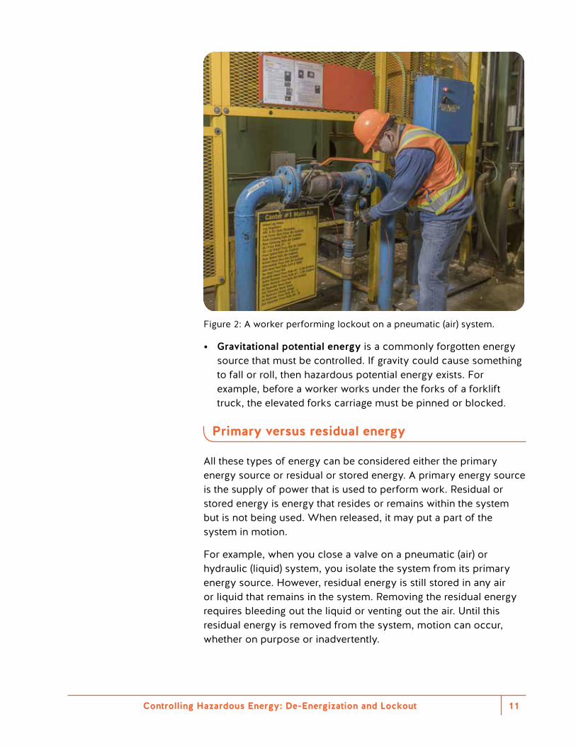
Figure 2: A worker performing lockout on a pneumatic (air) system.
• Gravitational potential energy is a commonly forgotten energy source that must be controlled. If gravity could cause something to fall or roll, then hazardous potential energy exists. For example, before a worker works under the forks of a forklift truck, the elevated forks carriage must be pinned or blocked.
Primary versus residual energy
All these types of energy can be considered either the primary energy source or residual or stored energy. A primary energy source is the supply of power that is used to perform work. Residual or stored energy is energy that resides or remains within the system but is not being used. When released, it may put a part of the system in motion.
For example, when you close a valve on a pneumatic (air) or hydraulic (liquid) system, you isolate the system from its primary energy source. However, residual energy is still stored in any air or liquid that remains in the system. Removing the residual energy requires bleeding out the liquid or venting out the air. Until this residual energy is removed from the system, motion can occur, whether on purpose or inadvertently.
Controlling Hazardous Energy: De-Energization and Lockout12
Not properly assessing and dissipating stored energy is one of the most common causes of workplace incidents that involve hazardous energy. Controlling hazardous energy includes isolating the system from its primary power source and removing or blocking residual energy.
According to CSA Group standard Z460–13 (R2018) Control of hazardous energy — Lockout and other methods, every energy source shall have “a mechanical device that physically prevents the transmission or release of energy, including but not limited to the following: a manually operated electrical circuit breaker; a disconnect switch; a manually operated switch by which the conductors of a circuit can be disconnected from all ungrounded supply conductors; a line valve; a block; a blank; and any similar device used to block or isolate energy.”
Important: Push-buttons, selector switches, and other control-type devices are not energy-isolation devices.
Source: Figure D.1 (p. 80), CSA Z460–13 (R2018) Control of hazardous energy — Lockout and other methods. © 2013 Canadian Standards Association.
Controlling Hazardous Energy: De-Energization and Lockout 13
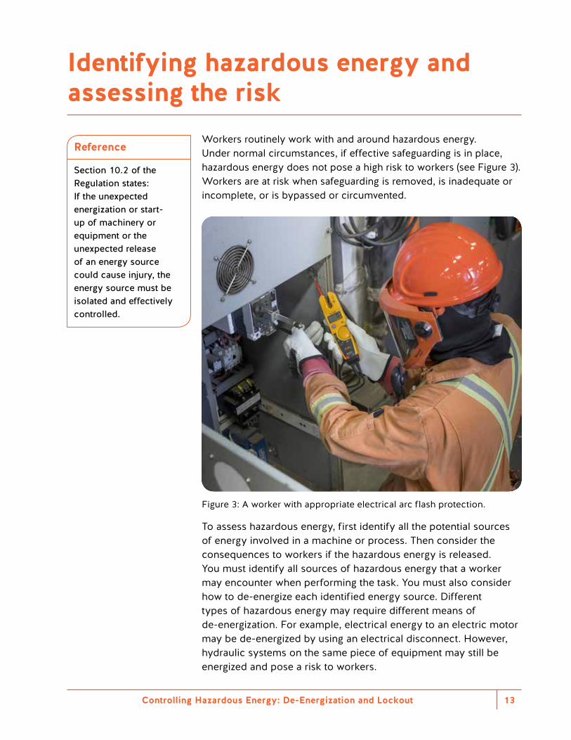
Workers routinely work with and around hazardous energy. Under normal circumstances, if effective safeguarding is in place, hazardous energy does not pose a high risk to workers (see Figure 3). Workers are at risk when safeguarding is removed, is inadequate or incomplete, or is bypassed or circumvented.
Figure 3: A worker with appropriate electrical arc flash protection.
To assess hazardous energy, first identify all the potential sources of energy involved in a machine or process. Then consider the consequences to workers if the hazardous energy is released. You must identify all sources of hazardous energy that a worker may encounter when performing the task. You must also consider how to de-energize each identified energy source. Different types of hazardous energy may require different means of de-energization. For example, electrical energy to an electric motor may be de-energized by using an electrical disconnect. However, hydraulic systems on the same piece of equipment may still be energized and pose a risk to workers.
Reference
Section 10.2 of the Regulation states: If the unexpected energization or start-up of machinery or equipment or the unexpected release of an energy source could cause injury, the energy source must be isolated and effectively controlled.
Identifying hazardous energy and assessing the risk
Controlling Hazardous Energy: De-Energization and Lockout14
Follow these steps to identify hazards and assess risks:1. Identify all the tasks to be performed. Consider normal operations
as well as non-standard events such as maintenance, shutdowns, power outages, emergencies, extreme weather, and so on. A task hazard assessment focuses on tasks associated with the intended use. It should also anticipate misuse of machines, equipment, and processes.
2. For each piece of equipment or machinery, complete a hazard identification worksheet. It should list the tasks and hazards posed by inadvertent startup, inadvertent movement, or the release of energy. It should also state the type of energy that must be controlled.
3. Assess the risk level for each task and corresponding hazard.4. Develop lockout procedures that minimize or eliminate each
significant risk.5. Define de-energization work procedures. List steps for each
de-energized energy control device that must be locked out.
Many stakeholders may be involved in the risk assessment process. This includes operators, supervisors, joint health and safety committee members, maintenance workers, consultants, and equipment manufacturers. A worker qualified in safeguarding design can also help determine effective controls.
Task hazard identification
A task hazard assessment focuses on tasks associated with the intended use — and foreseeable misuse — of machines, equipment, and processes. Use a step-by-step process to identify machine hazards and evaluate associated risks. Then take appropriate measures to reduce those risks to an acceptable level.
One approach is to begin by listing all tasks. Consider tasks for machine or process set-up, all modes of operations, teaching and programming, tryout and startup, and more. Identify who performs each task. Then identify all potential hazards associated with the release of energy or unexpected startup. Consider all movement- and energy-related hazards, including human factors associated with each task. These include all servicing and maintenance activities. They also include production-related tasks such as operating, adjusting, cleaning, troubleshooting, and programming.
Reference
For guidance on identifying hazards and their associated risks, see CSA Z460–13 (R2018) Control of hazardous energy — Lockout and other methods and CSA Group standard Z432–16 — Safeguarding of machinery.
Controlling Hazardous Energy: De-Energization and Lockout 15
To assess the risk for each task, evaluate the hazards as if no risk controls are being used (see the next section, “The hierarchy of controls”). Then specify the risk controls required for each task before re-rating the task with the specific risk controls in place.
For example, the hazards of touching a rotating blade in a table saw should have corresponding de-energization and lockout controls. This might include an electrical disconnect device, the de-energization and lockout procedure, and worker training. These are in addition to effective safeguards (saw guards) that must be in place while operating the table saw.
Most importantly, be honest and detailed in your assessment. If someone could be injured despite the risk controls, you must use other risk controls.
See Appendix 1 for a sample risk assessment decision matrix.
Controlling Hazardous Energy: De-Energization and Lockout16
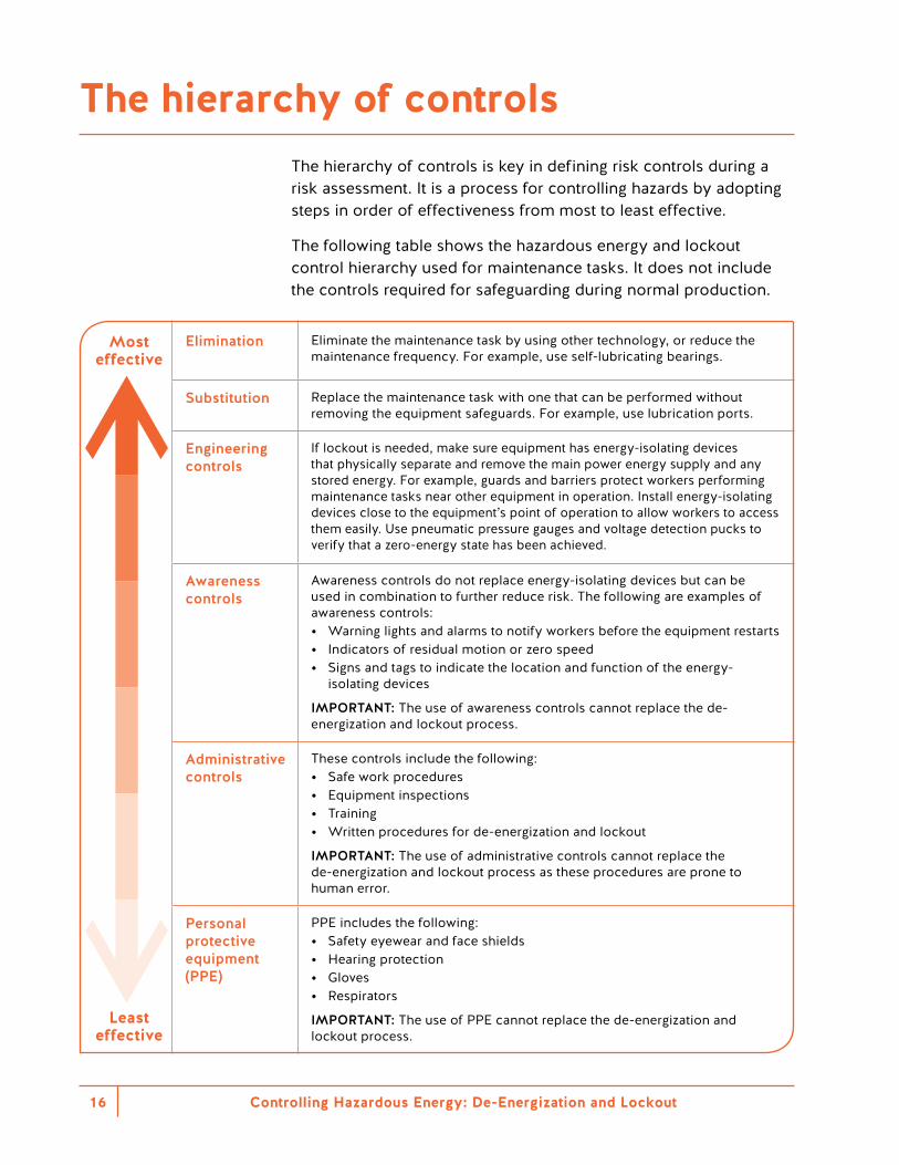
The hierarchy of controls is key in defining risk controls during a risk assessment. It is a process for controlling hazards by adopting steps in order of effectiveness from most to least effective.
The following table shows the hazardous energy and lockout control hierarchy used for maintenance tasks. It does not include the controls required for safeguarding during normal production.
Most effective
Elimination Eliminate the maintenance task by using other technology, or reduce the maintenance frequency. For example, use self-lubricating bearings.
Substitution Replace the maintenance task with one that can be performed without removing the equipment safeguards. For example, use lubrication ports.
Engineering controls
If lockout is needed, make sure equipment has energy-isolating devices that physically separate and remove the main power energy supply and any stored energy. For example, guards and barriers protect workers performing maintenance tasks near other equipment in operation. Install energy-isolating devices close to the equipment’s point of operation to allow workers to access them easily. Use pneumatic pressure gauges and voltage detection pucks to verify that a zero-energy state has been achieved.
Awareness controls
Awareness controls do not replace energy-isolating devices but can be used in combination to further reduce risk. The following are examples of awareness controls: • Warning lights and alarms to notify workers before the equipment restarts • Indicators of residual motion or zero speed • Signs and tags to indicate the location and function of the energy-
isolating devices
IMPORTANT: The use of awareness controls cannot replace the de-energization and lockout process.
Administrative controls
These controls include the following: • Safe work procedures • Equipment inspections • Training • Written procedures for de-energization and lockout
IMPORTANT: The use of administrative controls cannot replace the de-energization and lockout process as these procedures are prone to human error.
Least effective
Personal protective equipment (PPE)
PPE includes the following: • Safety eyewear and face shields • Hearing protection • Gloves • Respirators
IMPORTANT: The use of PPE cannot replace the de-energization and lockout process.
The hierarchy of controls
Controlling Hazardous Energy: De-Energization and Lockout 17
An effective de-energization and lockout program will combine various levels of controls. Each time a risk assessment is done, employers should look for the best options available for risk control and strive to reduce the risk to the minimum level. When choosing controls, also make sure they don’t introduce any new hazards.
Effective de-energization and lockout through design
Good design of machinery and processes is key in de-energization and lockout. The design should consider the reasons a worker may need to de-energize and lock out, rather than focusing on the operational needs of the machine. This can reduce both the frequency and complexity of de-energization and lockout.
For example, an automated system for lubricating a machine reduces the need for a worker to interact with that machine. This lowers the risk to workers and reduces downtime.
Even small measures reduce human error and increase efficiency in performing de-energization and lockout. For example, locate energy-isolating devices conveniently and label them well.
For more information, see “Creating a de-energization and lockout program” on page 37.
Reference
Although not cited in the Regulation, CSA Z460–13 (R2018) Control of hazardous energy — Lockout and other methods provides guidance on reducing risk through design and engineering controls.
It states: “Risk reduction should first attempt to eliminate the hazard through design. The primary objective in implementing design features is to eliminate hazards, or reduce their risks by substitution.”
Source: Clause B.3.2 (p. 54), CSA Z460–13 (R2018) Control of hazardous energy — Lockout and other methods. © 2013 Canadian Standards Association.
Controlling Hazardous Energy: De-Energization and Lockout18
Safeguarding
Safeguarding is an umbrella term for measures used to protect workers from the hazards of machinery, equipment, and processes. Typical safeguarding protects workers under all anticipated conditions of operation using a combination of the following: • Physical guards • Barriers • Electronic devices • Procedures • Signage
All machinery, equipment, and processes must have safeguarding to protect workers from accessing hazardous components or being struck by ejected materials. Safeguarding is needed during normal operating and upset conditions. Safeguarding protects workers when machinery or equipment is in operation. For more information, see Part 12 of the Regulation and the WorkSafeBC publication Safeguarding Machinery and Equipment.
De-energization and lockout
When maintenance work is being done or if safeguarding is removed, bypassed, or circumvented, the machinery, equipment, or process must be de-energized and locked out.
Effective de-energization and lockout puts a system in a zero-energy state and eliminates the hazard, so no hazardous energy exists. However, in some cases de-energization and lockout is not practicable. For example, workers may need energy to perform troubleshooting, testing, or calibration. In such cases, you can use other controls as long as the risk of the hazard is adequately reduced. For this type of control, you must follow a full set of steps to determine the hazards and risks of each task being performed. Then determine which controls can be used to minimize risk. If risk can’t be reduced to an adequate level, de-energization and lockout is the default method of control.
Reference
CSA Z460–13 (R2018) Control of hazardous energy — Lockout and other methods provides guidance on performing minor servicing using safeguards for protection, without de-energizing and locking out. However, under the Regulation, this approach cannot replace the use of de-energization and lockout without prior written approval from WorkSafeBC.
How safeguarding and de-energization and lockout co-exist
Controlling Hazardous Energy: De-Energization and Lockout 19
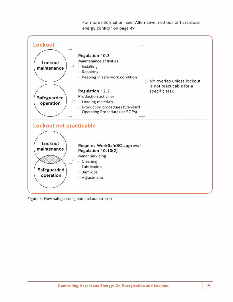
For more information, see “Alternative methods of hazardous energy control” on page 49.
Lockout maintenance
Lockout
Lockout not practicable
Safeguarded operation
Lockout maintenance
Safeguarded operation
Regulation 10.3Maintenance activities• Installing• Repairing• Keeping in safe work condition
Regulation 12.2Production activities• Loading materials• Production procedures (Standard
Operating Procedures or SOPs)
Requires WorkSafeBC approvalRegulation 10.10(2)Minor servicing• Cleaning• Lubrication• Jam-ups• Adjustments
No overlap unless lockout is not practicable for a specific task
Figure 4: How safeguarding and lockout co-exist.
Controlling Hazardous Energy: De-Energization and Lockout20
It’s important to understand the difference between normal production work and maintenance work. These two types of work require different approaches to de-energization and lockout.
Normal production is defined in the Regulation as “work that is routine, repetitive, and integral to the normal use of machinery or equipment for production.”
Maintenance is defined as “work performed to keep the machinery or equipment in a safe operating condition, including installing, repairing, cleaning, lubricating, and the clearing of obstructions to the normal flow of material.”
Understanding which category of work a worker is doing helps determine what precautions are required. Under normal operations, workers must be protected from hazardous energy through safeguarding. When a worker has to circumvent, bypass, or remove safeguarding to perform a maintenance task, the worker must use de-energization and lockout.
Keep in mind that it is the nature of the task that determines the type of work. It’s not as simple as assuming that production workers do production work and maintenance workers do maintenance work. Maintenance work includes tasks that workers sometimes overlook when determining when de-energization and lockout is required.
For example, a worker may remove the guards on a machine to perform troubleshooting or diagnostics. Since the worker is no longer protected by the guards, the worker is at risk of injury from the energized machinery. Troubleshooting meets the definition of “work performed to keep the machine in safe operating condition.” Therefore, de-energization and lockout is required, unless the worker is following section 10.12 of the Regulation, Work on energized equipment. For more information, see “Working on energized equipment” on page 55.
Normal production versus maintenance work
Controlling Hazardous Energy: De-Energization and Lockout 21
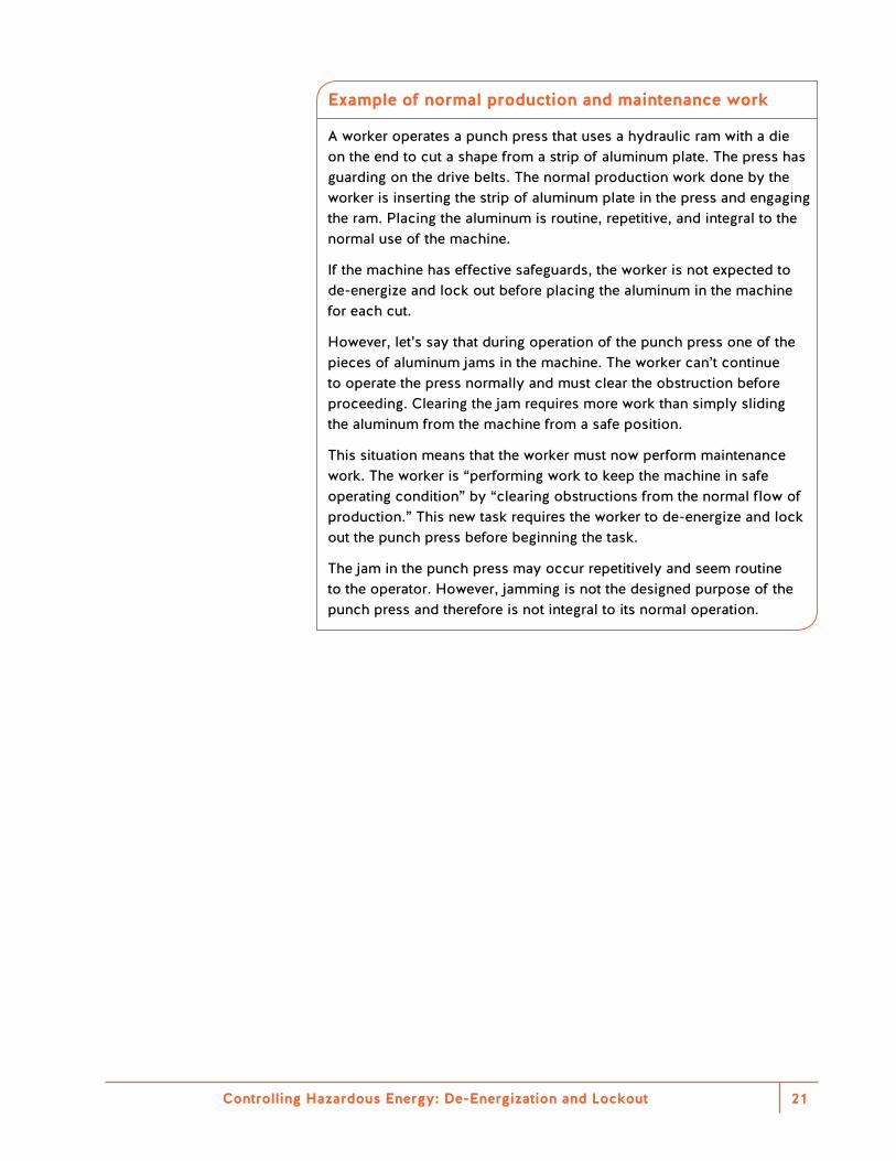
Example of normal production and maintenance work
A worker operates a punch press that uses a hydraulic ram with a die on the end to cut a shape from a strip of aluminum plate. The press has guarding on the drive belts. The normal production work done by the worker is inserting the strip of aluminum plate in the press and engaging the ram. Placing the aluminum is routine, repetitive, and integral to the normal use of the machine.
If the machine has effective safeguards, the worker is not expected to de-energize and lock out before placing the aluminum in the machine for each cut.
However, let’s say that during operation of the punch press one of the pieces of aluminum jams in the machine. The worker can’t continue to operate the press normally and must clear the obstruction before proceeding. Clearing the jam requires more work than simply sliding the aluminum from the machine from a safe position.
This situation means that the worker must now perform maintenance work. The worker is “performing work to keep the machine in safe operating condition” by “clearing obstructions from the normal flow of production.” This new task requires the worker to de-energize and lock out the punch press before beginning the task.
The jam in the punch press may occur repetitively and seem routine to the operator. However, jamming is not the designed purpose of the punch press and therefore is not integral to its normal operation.
Controlling Hazardous Energy: De-Energization and Lockout22
To de-energize and lock out machinery or equipment, workers must de-energize the equipment, apply enough personal locks, and keep the keys to those locks in their possession. These locks ensure personal lockout protection.
For example, a worker places a lock on the switch that controls the machine being worked on. Only that worker (or a supervisor following the requirements of section 10.8 of the Regulation) can remove the lock when the work is finished. Since no other worker has a key for that lock, the lock can’t be removed inadvertently. If more than one worker is working on the machinery, each worker must place a personal lock on the switch. Combination locks must not be used for lockout.
Every de-energization and lockout process will involve the same five steps regardless of the scope of work or the complexity of the machinery or equipment. Every worker must know these steps.1. Identify the machinery or equipment that needs to be locked out.2. Shut off the machinery or equipment. Make sure that all moving
parts have come to a complete stop. Also ensure that the act of shutting off equipment does not cause a hazard for other workers.
3. Identify and de-energize all hazardous energy sources.4. Apply a personal lock to the energy-isolating device for
each hazardous energy source. Check that the machinery or equipment is in a zero-energy state.
5. Verify the effectiveness of the de-energization and lockout process. First ensure that all workers are clear of the hazards and that no hazard will be created if the process is not effective. Test de-energization and lockout after each energy-isolating device is locked out or after a group of nearby devices is locked out.
For more information, see “De-energization and lockout procedures” on page 39.
Five basic steps to a de-energization and lockout procedure
Controlling Hazardous Energy: De-Energization and Lockout 23
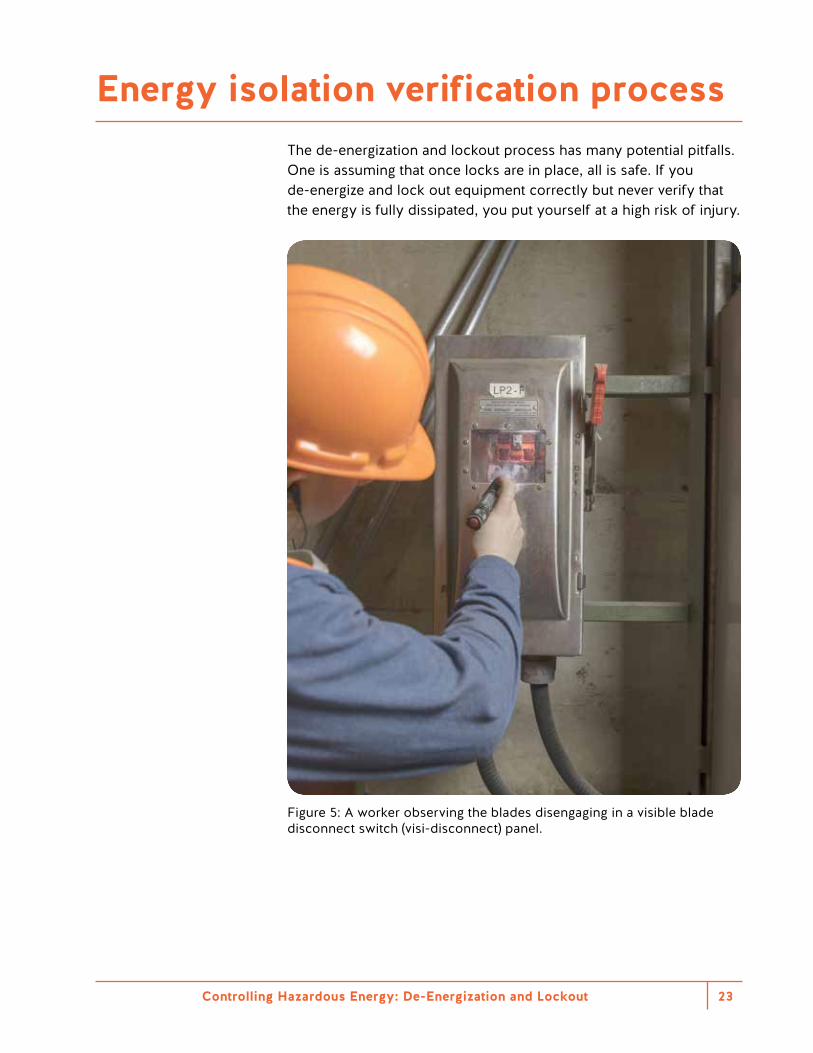
The de-energization and lockout process has many potential pitfalls. One is assuming that once locks are in place, all is safe. If you de-energize and lock out equipment correctly but never verify that the energy is fully dissipated, you put yourself at a high risk of injury.
Figure 5: A worker observing the blades disengaging in a visible blade disconnect switch (visi-disconnect) panel.
Energy isolation verification process
Controlling Hazardous Energy: De-Energization and Lockout24
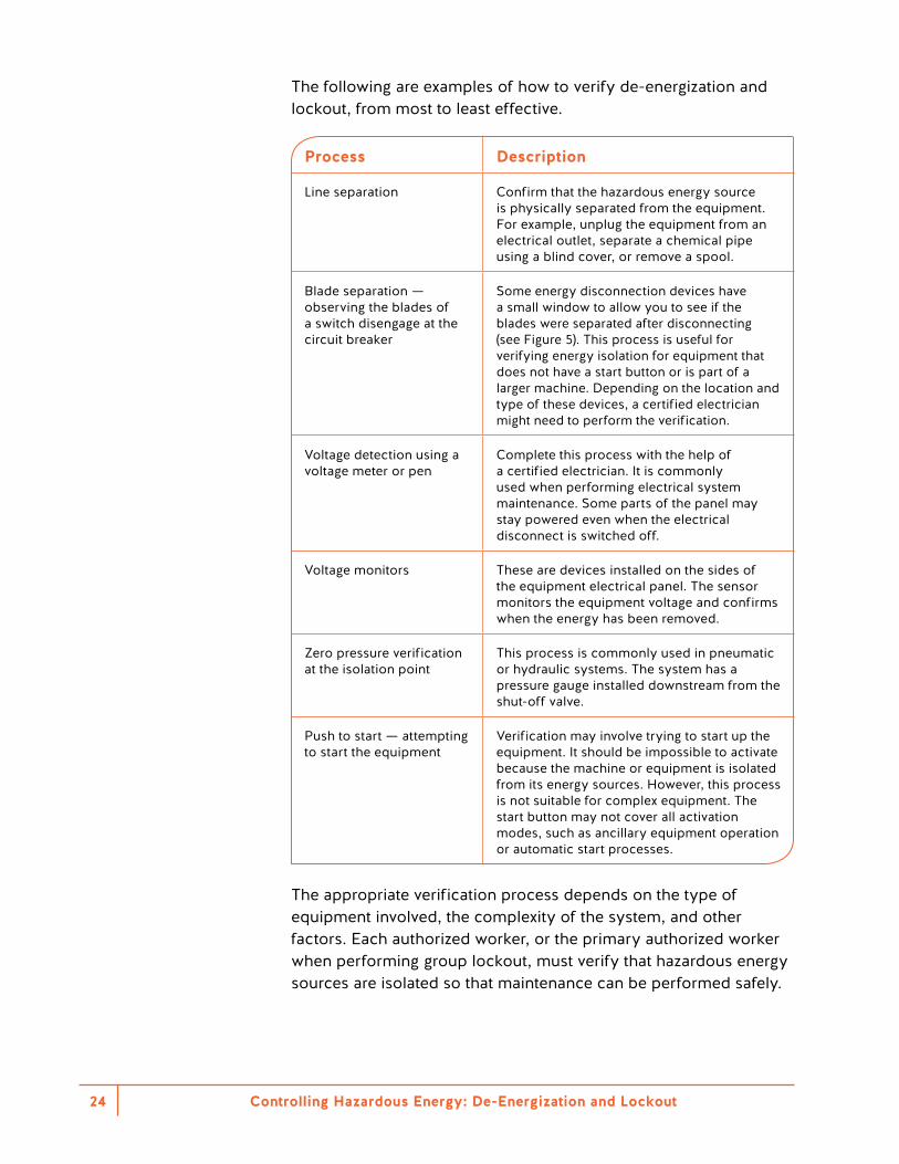
The following are examples of how to verify de-energization and lockout, from most to least effective.
Process Description
Line separation Confirm that the hazardous energy source is physically separated from the equipment. For example, unplug the equipment from an electrical outlet, separate a chemical pipe using a blind cover, or remove a spool.
Blade separation — observing the blades of a switch disengage at the circuit breaker
Some energy disconnection devices have a small window to allow you to see if the blades were separated after disconnecting (see Figure 5). This process is useful for verifying energy isolation for equipment that does not have a start button or is part of a larger machine. Depending on the location and type of these devices, a certified electrician might need to perform the verification.
Voltage detection using a voltage meter or pen
Complete this process with the help of a certified electrician. It is commonly used when performing electrical system maintenance. Some parts of the panel may stay powered even when the electrical disconnect is switched off.
Voltage monitors These are devices installed on the sides of the equipment electrical panel. The sensor monitors the equipment voltage and confirms when the energy has been removed.
Zero pressure verification at the isolation point
This process is commonly used in pneumatic or hydraulic systems. The system has a pressure gauge installed downstream from the shut-off valve.
Push to start — attempting to start the equipment
Verification may involve trying to start up the equipment. It should be impossible to activate because the machine or equipment is isolated from its energy sources. However, this process is not suitable for complex equipment. The start button may not cover all activation modes, such as ancillary equipment operation or automatic start processes.
The appropriate verification process depends on the type of equipment involved, the complexity of the system, and other factors. Each authorized worker, or the primary authorized worker when performing group lockout, must verify that hazardous energy sources are isolated so that maintenance can be performed safely.
Controlling Hazardous Energy: De-Energization and Lockout 25
Never perform verification on automated equipment solely by attempting to start the equipment. Assessing potential stored energy requires a detailed technical review of actuators, schematics, and circuits.
Automated equipment sometimes has software- and hardware-based interlocks. These may be challenging to verify for disconnection as the number of inputs and outputs increases. The equipment may also have a PLC testing routine. This will attempt to start the equipment and will provide a positive confirmation once it has verified that the equipment is de-energized.
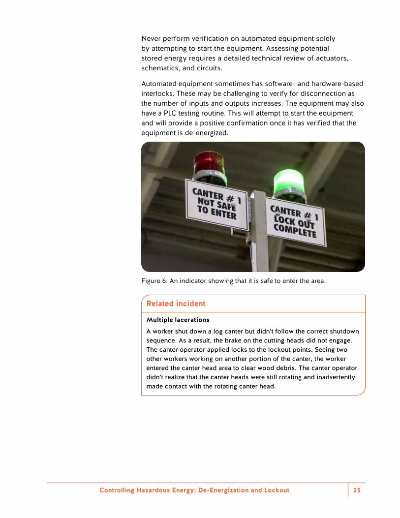
Figure 6: An indicator showing that it is safe to enter the area.
Related incident
Multiple lacerations
A worker shut down a log canter but didn’t follow the correct shutdown sequence. As a result, the brake on the cutting heads did not engage. The canter operator applied locks to the lockout points. Seeing two other workers working on another portion of the canter, the worker entered the canter head area to clear wood debris. The canter operator didn’t realize that the canter heads were still rotating and inadvertently made contact with the rotating canter head.
Controlling Hazardous Energy: De-Energization and Lockout26
Understanding the difference between main power and control power is essential for de-energization and lockout. These terms most commonly describe electrical circuits. However, the concepts also exist for other energy sources, such as hydraulic and pneumatic systems.
To comply with Part 10 of the Regulation, energy-isolating devices must be used on the main power circuit, not on a control power circuit.
Main power
A main power circuit is the circuit that gives the machine its life. It provides operating power to the machine to allow it to perform its intended function. Without main power, the machine is lifeless.
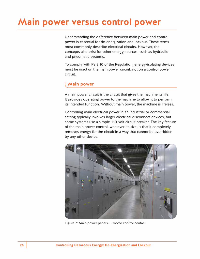
Controlling main electrical power in an industrial or commercial setting typically involves larger electrical disconnect devices, but some systems use a simple 110-volt circuit breaker. The key feature of the main power control, whatever its size, is that it completely removes energy for the circuit in a way that cannot be overridden by any other device.
Figure 7: Main power panels — motor control centre.
Main power versus control power
Controlling Hazardous Energy: De-Energization and Lockout 27
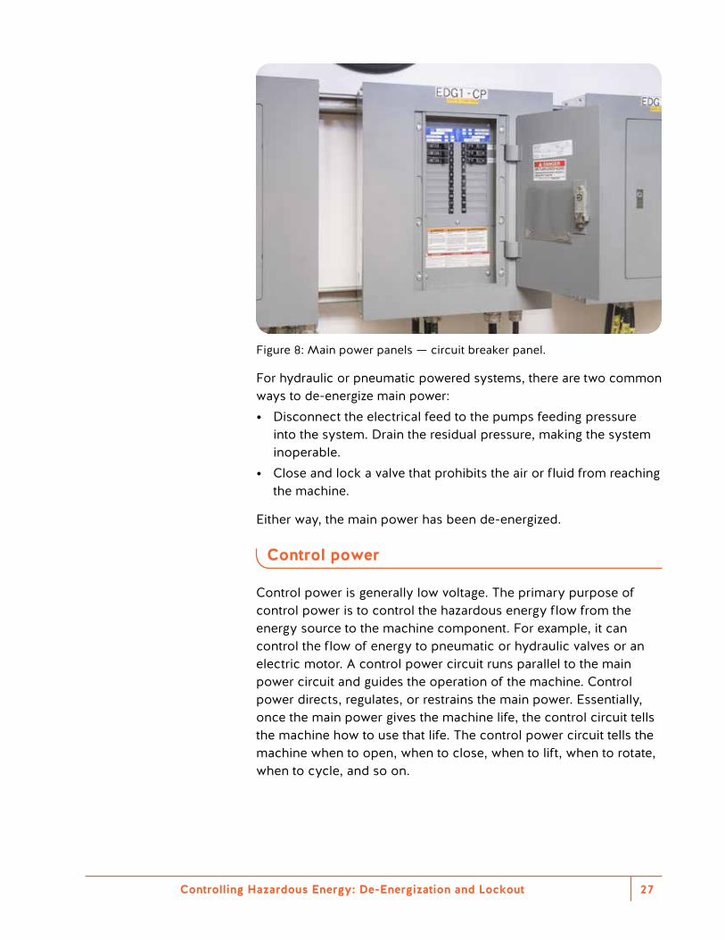
Figure 8: Main power panels — circuit breaker panel.
For hydraulic or pneumatic powered systems, there are two common ways to de-energize main power: • Disconnect the electrical feed to the pumps feeding pressure
into the system. Drain the residual pressure, making the system inoperable.
• Close and lock a valve that prohibits the air or fluid from reaching the machine.
Either way, the main power has been de-energized.
Control power
Control power is generally low voltage. The primary purpose of control power is to control the hazardous energy flow from the energy source to the machine component. For example, it can control the flow of energy to pneumatic or hydraulic valves or an electric motor. A control power circuit runs parallel to the main power circuit and guides the operation of the machine. Control power directs, regulates, or restrains the main power. Essentially, once the main power gives the machine life, the control circuit tells the machine how to use that life. The control power circuit tells the machine when to open, when to close, when to lift, when to rotate, when to cycle, and so on.
A
Controlling Hazardous Energy: De-Energization and Lockout28
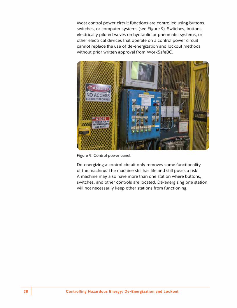
Most control power circuit functions are controlled using buttons, switches, or computer systems (see Figure 9). Switches, buttons, electrically piloted valves on hydraulic or pneumatic systems, or other electrical devices that operate on a control power circuit cannot replace the use of de-energization and lockout methods without prior written approval from WorkSafeBC.
Figure 9: Control power panel.
De-energizing a control circuit only removes some functionality of the machine. The machine still has life and still poses a risk. A machine may also have more than one station where buttons, switches, and other controls are located. De-energizing one station will not necessarily keep other stations from functioning.
Controlling Hazardous Energy: De-Energization and Lockout 29
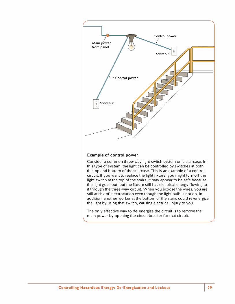
Main power from panel
Switch 1
Switch 2
Control power
Control power
Example of control powerConsider a common three-way light switch system on a staircase. In this type of system, the light can be controlled by switches at both the top and bottom of the staircase. This is an example of a control circuit. If you want to replace the light fixture, you might turn off the light switch at the top of the stairs. It may appear to be safe because the light goes out, but the fixture still has electrical energy flowing to it through the three-way circuit. When you expose the wires, you are still at risk of electrocution even though the light bulb is not on. In addition, another worker at the bottom of the stairs could re-energize the light by using that switch, causing electrical injury to you.
The only effective way to de-energize the circuit is to remove the main power by opening the circuit breaker for that circuit.


Responsibilities
Controlling Hazardous Energy: De-Energization and Lockout32
Everyone has a role to play when it comes to de-energization and lockout. The following sections provide a summary of the duties of manufacturers and suppliers, employers, supervisors, workers, and contractors.
Manufacturers and suppliers
• Must ensure that any tool, equipment, machine, or device supplied complies with the Act and the Regulation, and is safe when used according to the directions provided by the supplier
• Should design and install equipment and processes so that workers are not exposed to hazardous energy during operation, servicing, and maintenance
• Must design, manufacture, and install equipment with energy-isolating devices capable of controlling and/or dissipating hazardous energy
• Should include in the instructions recommendations for the type and location of energy-isolating devices when such devices are not integral to the equipment
• Should provide a manual with operating and maintenance instructions, including procedures for using energy-isolating devices
• Should include in operating and maintenance documents hazard identification and control measures
Employers
• Must put in place de-energization and lockout procedures in the worksite, including preplanning by identifying all energy sources, switches, and so on
• Must provide to workers the procedures for performing de-energization and lockout
• Must make sure that each worker who must lock out machinery or equipment has access to enough personal locks
• Must provide information, instruction, training, and supervision to workers on proper lockout procedures for each piece of equipment they operate
• Should prepare a written checklist for the steps involved in de-energization and lockout when lockout is complex
• Must ensure that all contractors meet the company and WorkSafeBC de-energization and lockout requirements before they begin a job
Controlling Hazardous Energy: De-Energization and Lockout 33
Supervisors
• Must enforce the use of lockout devices when workers do service or maintenance work
• Should participate in developing equipment-specific de-energization and lockout procedures
• Should ensure procedures are applied in their area of operations • Must ensure that workers have received training on the
de-energization and lockout program • Should confirm the availability of locks, lockout boxes, and
equipment-specific lockout procedures for all workers who are required to use them
• Should determine who will be responsible for each part of the procedure
• Should conduct inspections of the de-energization and lockout program to ensure that it is being followed
• Should ensure that contractors have a de-energization and lockout policy and program that complies with WorkSafeBC requirements
• Should notify all workers affected by the de-energization and lockout
Workers
• Must follow their employer’s de-energization and lockout procedures and policies
• Must, if they work on machinery or equipment, do the following: – Lock out the energy-isolating device or place a personal lock
on the key-securing system in a group lockout procedure – Remove their personal locks on the completion of their work – Keep control of the keys to personal locks throughout the
duration of the work • Should check with a supervisor or other knowledgeable person if
in doubt about which energy sources may need to be controlled • Must, if they work in areas where lockout procedures are used,
understand the purpose of the lockout procedures • Must not attempt to restart equipment or machines that are
locked out
Related incident
Multiple lacerations and amputation at elbow
A worker who needed to clean inside a board edger turned off the machine and locked out before opening the cover. The worker opened the saw box lid to see whether the saws had stopped rotating. Without realizing that they were still rotating, the worker reached inside to remove a wooden strip sticking out from the back of the box. The worker’s shirt and arm were pulled into the rotating saw blades.
Contractors
• Should work with the employer to understand their roles and responsibilities in the de-energization and lockout program
• Must ensure that their workers have adequate knowledge of the employer’s de-energization and lockout program
Controlling Hazardous Energy: De-Energization and Lockout34
De-energization and lockout policy, program, and procedures
Controlling Hazardous Energy: De-Energization and Lockout36
Policy
Employers are not required to develop a de-energization and lockout policy under the Regulation. However, most employers should do so. Such policies explain when de-energization and lockout must occur. They also cover how it is performed and what is expected of workers.
Some employers believe that if they don’t operate a factory or manufacturing facility, de-energization and lockout does not apply at their workplace. In fact, many small, simple businesses require workers to interact with machinery at some point. When this is the case, a clear policy is necessary to guide and instruct workers.
In more complex workplaces, employers should consider developing a comprehensive de-energization and lockout program.
Program
Employers are also not required to develop a de-energization and lockout program under the Regulation. However, many employers find that a program helps manage de-energization and lockout more effectively.
A de-energization and lockout program helps workers understand expectations related to de-energization and lockout. It also allows the employer to address the issue in a structured and organized way. When developing a program, start with a task and hazard identification that considers the following: • Types of machinery present • The nature of the work involved • The ways a worker may interact with the machinery
Reference
For guidance on developing a de-energization and lockout program, see Section 7 of CSA Z460–13 (R2018) Control of hazardous energy — Lockout and other methods. The elements for a comprehensive de-energization and lockout program are also outlined in Appendix 2.
Policy and program
Controlling Hazardous Energy: De-Energization and Lockout 37
Creating a de-energization and lockout program involves five general steps:1. Gather information2. Perform a task analysis 3. Perform a hazard and risk analysis 4. Implement controls 5. Communicate and provide training
1 . Gather information
Determine all types of hazardous energy within your workplace that should be covered by the program. Next, gather documentation from the manufacturer or designer of each system about the following: • Where energy-isolating devices are located and how to use them • How to service or maintain the system, step by step • How to safely address malfunctions, jams, misfeeds, or other
planned and unplanned interruptions in operations • How to install, move, and remove any or all parts of the system
safely
This information will allow you to understand the system’s intended use and ways to perform the tasks safely.
2 . Perform a task analysis
To perform a task analysis, examine all the intended uses of the system from the perspective of both the manufacturer and the user. List all tasks and steps required to accomplish each task. This analysis should also include tasks related to any possible misuse of the system. At a minimum, consider the following categories: • Machine and process set-up • Teaching and programming machinery • Tryout and startup • All modes of operation • Product feeding into machine or process • Product takeoff from machine or process
Creating a de-energization and lockout program
Controlling Hazardous Energy: De-Energization and Lockout38
• Process and tool changeover • Normal stoppages and restart • Unscheduled stoppages (control failure or jam) and restart • Emergency stoppages and restart • Unexpected startup • Fault-finding and troubleshooting • Cleaning and housekeeping • Planned maintenance and repair • Unplanned maintenance and repair
Source: Task Identification (p. 21), CSA Z460–13 (R2018) Control of hazardous energy — Lockout and other methods. © 2013 Canadian Standards Association.
3 . Perform a hazard and risk analysis
Based on the information from the first two steps, perform a hazard and risk analysis of how workers will interact with the system. This analysis should outline where possible hazards exist and the associated risk of each. For more information, see “Identifying hazardous energy and assessing the risk” on page 13.
4 . Implement controls
For each hazard identified, implement a suitable corresponding control. The types of hazardous energy in a system will determine the types of energy-isolating devices required. You’ll need a technical review when establishing hazards and controls, to ensure a zero-energy state and to make sure you’re using the right devices. A knowledgeable technical reviewer will examine schematics and evaluate the equipment power sources and control systems.
5 . Communicate and provide training
Communicate with, educate, and train workers on how the program works, their role in the program, and their responsibilities. Employers must provide basic de-energization and lockout training to any worker who may be exposed to a situation where hazardous energy control is needed. Such training must include basic de-energization and lockout concepts and explain when locks are required.
For some operations, such as group lockout and working with energized equipment, you must authorize workers to perform the task in addition to training them.
The following are examples of situations where a worker could be exposed to hazards: • A press cycles
accidentally while a worker is changing a die.
• An injection-moulding machine gate closes while a worker is in it.
• A robot moves while a worker is trying to program it.
• A hydraulic hose releases pressurized fluid when it is removed for maintenance purposes.
• A barrier or guard has been removed or bypassed.
Controlling Hazardous Energy: De-Energization and Lockout 39
An important element of the de-energization and lockout program is developing lockout procedures and training. These must be defined for each unique machine, piece of equipment, or process.
The procedures must outline how to effectively isolate the machine, equipment, or process. These procedures must include the following: • Identification of the machine, equipment, or process • A list of all required energy-isolating devices and their locations • Steps for shutting down, isolating, blocking, securing, and
relieving stored or residual energy • Steps for placing and removing lockout devices • Requirements for verifying isolation and de-energization • Requirements for verifying that all workers have been cleared
from the worksite • Requirements for verifying that the machine, equipment, or
process has been inspected and is ready to return to service
Managing de-energization and lockout procedures
Employers should develop a process for creating or revising de-energization and lockout procedures. This process should address new equipment, changes to existing equipment, correction of deficiencies in the procedure, and improvements.
The process should also include ways to ensure that the procedures accurately describe the de-energization and lockout process. For example, it might include a requirement to review the procedures every year.
The de-energization and lockout procedures should be readily accessible and may be stored in print or electronically, close to the machine, equipment, or process.
See also “Regulatory reference checklist for de-energization and lockout” in Appendix 1.
De-energization and lockout procedures
Reference
For more information and examples, see Appendix 5.
Controlling Hazardous Energy: De-Energization and Lockout40
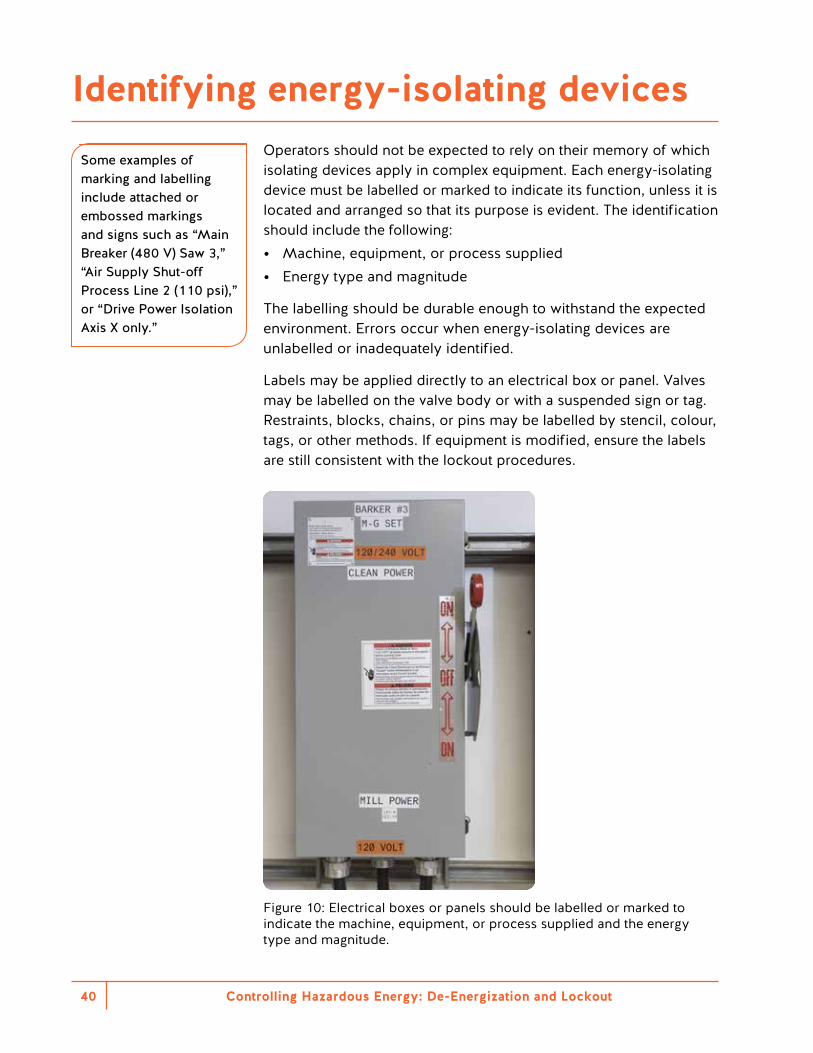
Operators should not be expected to rely on their memory of which isolating devices apply in complex equipment. Each energy-isolating device must be labelled or marked to indicate its function, unless it is located and arranged so that its purpose is evident. The identification should include the following: • Machine, equipment, or process supplied • Energy type and magnitude
The labelling should be durable enough to withstand the expected environment. Errors occur when energy-isolating devices are unlabelled or inadequately identified.
Labels may be applied directly to an electrical box or panel. Valves may be labelled on the valve body or with a suspended sign or tag. Restraints, blocks, chains, or pins may be labelled by stencil, colour, tags, or other methods. If equipment is modified, ensure the labels are still consistent with the lockout procedures.
Figure 10: Electrical boxes or panels should be labelled or marked to indicate the machine, equipment, or process supplied and the energy type and magnitude.
Identifying energy-isolating devices
Some examples of marking and labelling include attached or embossed markings and signs such as “Main Breaker (480 V) Saw 3,” “Air Supply Shut-off Process Line 2 (110 psi),” or “Drive Power Isolation Axis X only.”
Controlling Hazardous Energy: De-Energization and Lockout 41
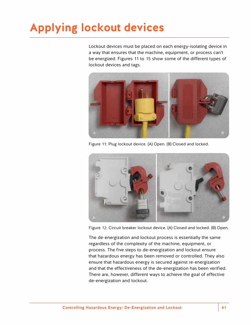
Lockout devices must be placed on each energy-isolating device in a way that ensures that the machine, equipment, or process can’t be energized. Figures 11 to 15 show some of the different types of lockout devices and tags.
A B
Figure 11: Plug lockout device. (A) Open. (B) Closed and locked.
BA
Figure 12: Circuit breaker lockout device. (A) Closed and locked. (B) Open.
The de-energization and lockout process is essentially the same regardless of the complexity of the machine, equipment, or process. The five steps to de-energization and lockout ensure that hazardous energy has been removed or controlled. They also ensure that hazardous energy is secured against re-energization and that the effectiveness of the de-energization has been verified. There are, however, different ways to achieve the goal of effective de-energization and lockout.
Applying lockout devices
Controlling Hazardous Energy: De-Energization and Lockout42
Individual
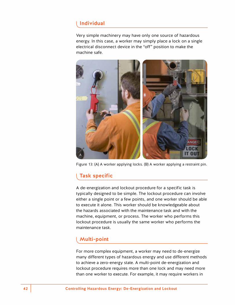
Very simple machinery may have only one source of hazardous energy. In this case, a worker may simply place a lock on a single electrical disconnect device in the “off” position to make the machine safe.
A B
Figure 13: (A) A worker applying locks. (B) A worker applying a restraint pin.
Task specific
A de-energization and lockout procedure for a specific task is typically designed to be simple. The lockout procedure can involve either a single point or a few points, and one worker should be able to execute it alone. This worker should be knowledgeable about the hazards associated with the maintenance task and with the machine, equipment, or process. The worker who performs this lockout procedure is usually the same worker who performs the maintenance task.
Multi-point
For more complex equipment, a worker may need to de-energize many different types of hazardous energy and use different methods to achieve a zero-energy state. A multi-point de-energization and lockout procedure requires more than one lock and may need more than one worker to execute. For example, it may require workers in
Controlling Hazardous Energy: De-Energization and Lockout 43
different disciplines, such as an electrician for high-voltage de-energization and a power engineer to de-energize and isolate a steam supply. The multi-point procedure may be simple or complex, depending on the maintenance task to be performed.
Each person working with the equipment must place a lock on each energy-isolating device. For example, if three workers are performing the task and the equipment has two energy-isolating devices, six locks are required. The three workers must all place their personal locks on each energy-isolating device.
If a multi-point procedure requires more personal locks than those available, a group lockout procedure should be used.
Zone
Zone lockout refers to de-energization and lockout of an entire machine or set of machines, regardless of the work being done. The main difference between zone lockout and individual lockout is that zone lockout can be used for a wider range of tasks. It de-energizes and locks out an entire machine or system.
Zone lockout allows multiple tasks to be performed under one procedure. However, it can be challenging to assess the different tasks for all possible hazardous energies. Tasks may require elements of the machine, equipment, or process to be locked out in different states. Therefore, it is critical to identify and document which activities can or cannot be performed under the zone lockout. A worker may presume the entire zone has been de-energized, when in fact parts of the zone may be intentionally energized.
When using zone lockout, each authorized worker should review the procedure before applying personal locks, to ensure that the work activity is adequately protected against all hazardous energies.
Group
The group de-energization and lockout procedure was formerly known as the key-box procedure. This procedure reduces the number of locks required and saves time. If several workers are working on machinery or equipment — particularly if many energy-isolating devices must be locked out — you can use a group lockout procedure. Before using a group lockout, a knowledgeable person must plan and develop a written group lockout procedure. Post this written procedure conspicuously at the place where the system is in use.
Controlling Hazardous Energy: De-Energization and Lockout44
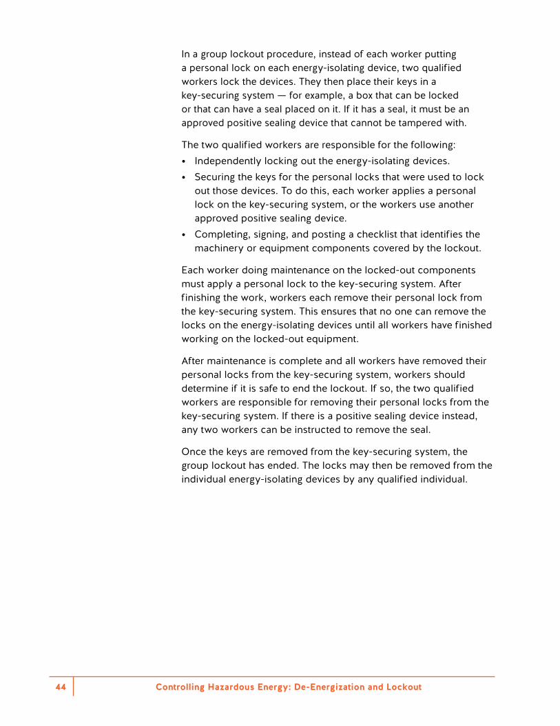
In a group lockout procedure, instead of each worker putting a personal lock on each energy-isolating device, two qualified workers lock the devices. They then place their keys in a key-securing system — for example, a box that can be locked or that can have a seal placed on it. If it has a seal, it must be an approved positive sealing device that cannot be tampered with.
The two qualified workers are responsible for the following: • Independently locking out the energy-isolating devices. • Securing the keys for the personal locks that were used to lock
out those devices. To do this, each worker applies a personal lock on the key-securing system, or the workers use another approved positive sealing device.
• Completing, signing, and posting a checklist that identifies the machinery or equipment components covered by the lockout.
Each worker doing maintenance on the locked-out components must apply a personal lock to the key-securing system. After finishing the work, workers each remove their personal lock from the key-securing system. This ensures that no one can remove the locks on the energy-isolating devices until all workers have finished working on the locked-out equipment.
After maintenance is complete and all workers have removed their personal locks from the key-securing system, workers should determine if it is safe to end the lockout. If so, the two qualified workers are responsible for removing their personal locks from the key-securing system. If there is a positive sealing device instead, any two workers can be instructed to remove the seal.
Once the keys are removed from the key-securing system, the group lockout has ended. The locks may then be removed from the individual energy-isolating devices by any qualified individual.
Controlling Hazardous Energy: De-Energization and Lockout 45
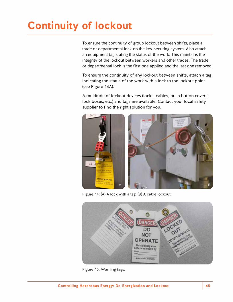
To ensure the continuity of group lockout between shifts, place a trade or departmental lock on the key-securing system. Also attach an equipment tag stating the status of the work. This maintains the integrity of the lockout between workers and other trades. The trade or departmental lock is the first one applied and the last one removed.
To ensure the continuity of any lockout between shifts, attach a tag indicating the status of the work with a lock to the lockout point (see Figure 14A).
A multitude of lockout devices (locks, cables, push button covers, lock boxes, etc.) and tags are available. Contact your local safety supplier to find the right solution for you.
BA
Figure 14: (A) A lock with a tag. (B) A cable lockout.
Figure 15: Warning tags.
Continuity of lockout
Removing the last lock The last worker removing a personal lock is responsible for the following: • Inspecting the machine, equipment, or process to ensure that:
– All work is complete – It is safe to remove the locks – All guards are replaced and secured – All controls are off or stopped
• Ensuring that all workers are in safe locations where they will not be exposed to unexpected energization, startup, or release of hazardous energy when the system is de-locked
• If the integrity or intent of the de-energization and lockout procedure is changed or altered as a result of the work activity, flagging the existing procedure as “unapproved” and ensuring that a new procedure is developed and published to preserve the continuity of the lockout process
• Notifying the machine, equipment, or process operator that the work is complete
Controlling Hazardous Energy: De-Energization and Lockout46
A worker may get caught in a machine or otherwise be injured by a hazardous release of energy. The de-energization and lockout procedure should include provisions for worker rescue and extraction. Such procedures require a risk assessment. They should include the de-energization and lockout process needed to perform the rescue. On some occasions, power may be needed to extricate a worker during a rescue.
In a worker rescue or extraction, the area must be made safe for the rescuer and the injured workers. Qualified and authorized individuals familiar with the machinery, equipment, or process must complete a hazardous energy assessment to identify and lock out the energy-isolating devices.
To keep the scene safe and to keep machinery from moving during a rescue, rescuers may need to act outside of the de-energization and lockout procedures already in place.
Emergency procedures and lockout
Controlling Hazardous Energy: De-Energization and Lockout 47


Alternative methods of hazardous energy control
Controlling Hazardous Energy: De-Energization and Lockout50
Introduction
The default and preferred method to protect workers from the unexpected release of hazardous energy during maintenance activities is by bringing the machine, equipment, or process to a zero-energy state and performing lockout.
Occasionally it is not practicable to bring an entire machine, equipment, or process to a zero-energy state. The next option is to evaluate alternative methods to control the energy and perform the task safely. The Regulation defines the term practicable as something that is reasonably capable of being done. This means you must consider all reasonable options before choosing any alternative methods. Time savings or convenience is not an acceptable reason to use alternative methods for hazardous energy control.
An example of a task where a zero-energy state cannot be achieved is one where equipment functions such as settings, data, temperature, and motion are needed for alignment or testing. Another example is troubleshooting of electrical circuits or pressurized systems that requires examining the problem from close up.
Controlling Hazardous Energy: De-Energization and Lockout 51
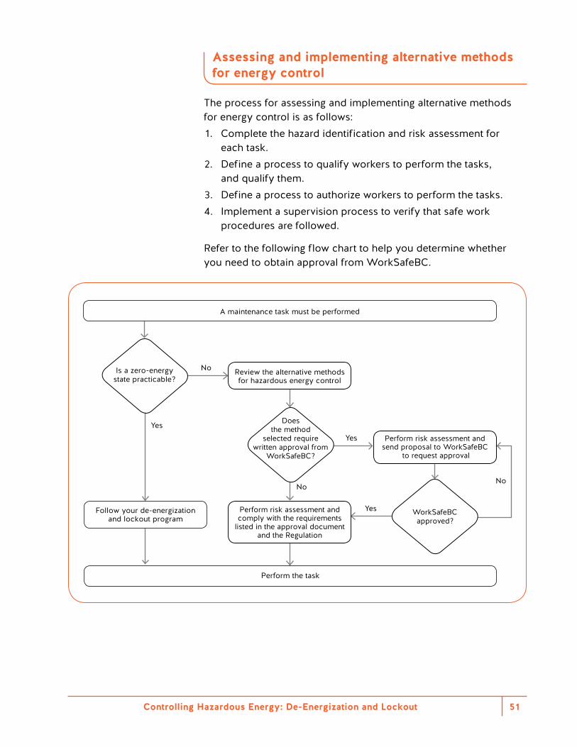
Assessing and implementing alternative methods for energy control
The process for assessing and implementing alternative methods for energy control is as follows:1. Complete the hazard identification and risk assessment for
each task. 2. Define a process to qualify workers to perform the tasks,
and qualify them. 3. Define a process to authorize workers to perform the tasks. 4. Implement a supervision process to verify that safe work
procedures are followed.
Refer to the following flow chart to help you determine whether you need to obtain approval from WorkSafeBC.
Yes
YesYes
NoNo
No
Does the method
selected require written approval from
WorkSafeBC?
WorkSafeBC approved?
A maintenance task must be performed
Perform the task
Is a zero-energy state practicable?
Review the alternative methods for hazardous energy control
Perform risk assessment and send proposal to WorkSafeBC
to request approval
Follow your de-energization and lockout program
Perform risk assessment and comply with the requirements
listed in the approval document and the Regulation
Controlling Hazardous Energy: De-Energization and Lockout52
This alternative method for hazardous energy control relies on control systems that can isolate hazardous energy using safety-related parts of a control system (SRP/CS). These are known in the Regulation as control system isolating devices (CSIDs). These are specialized electromechanical devices that, because they are highly reliable, can be used to manage hazardous energy. They work by controlling the main power of the equipment, machine, or process, rather than de-energizing it.
Over the last decade, these types of devices have become more common in many industries. Some countries have now accepted these devices. However, in British Columbia they cannot replace the use of de-energization and lockout methods without prior written approval from WorkSafeBC.
These devices should comply with a number of different performance levels (levels of protection), based on how reliable a safety-rated device or circuit is. Given that these devices do not remove the energy, but rather control it, they need to withstand millions of cycles without failing. If they do fail, the equipment should not be able to restart until the fault is fixed. Determining the performance level of a safety-rated circuit or device is not simple. Employers are advised to consult a qualified person to determine the level.
The performance level must meet or exceed the level of risk determined by the risk assessment. Performance level requirements can be found in ISO 13849–1 — Safety-related parts of control systems — Part 1: General principles for design and CSA Z460–13 (R2018) Control of hazardous energy — Lockout and other methods. These systems are very complex. Employers should consult a qualified professional before designing and implementing one.
Hazardous energy isolation using control system isolating devices
What is a CSID?
Section 10.1 of the Regulation defines a control system isolating device as a device that physically prevents activation of a system used for controlling the operation of machinery or equipment. The system in this definition means the control system used for controlling the operation of machinery or equipment where work is being undertaken. These are commonly known in industry and other standards as safety-related parts of a control system.
These systems can be complex and difficult to design. Employers should consult with a qualified professional to ensure that the requirements of standards are met.

Controlling Hazardous Energy: De-Energization and Lockout 53
Safety PLCs as part of an SRP/CS
Safety-related parts of a control system have traditionally required hard wiring and electromechanical components to ensure the system is reliable enough to control safety applications. Advances in technology have made it possible to achieve the same level of reliability using electronic systems. A safety programmable logic controller (PLC) has redundant microprocessors and input-output systems that are continuously monitored. This ensures the system will automatically acknowledge system failures and bring the equipment to a safe state. Safety PLCs control safeguarding systems such as emergency stops, guarding interlocks, and light barriers. Under certain circumstances, safety PLCs can be used for lockout. However, these devices cannot replace the use of de-energization and lockout methods without prior written approval from WorkSafeBC.
The redundancy and self-checking features of safety PLCs are expensive. Safety PLCs cost more than standard PLCs. However, the extra cost is offset by reduced wiring costs and panel space, as well as improved flexibility.
Figure 16: An electronic gate safeguard. The gate is controlled by the SRP/CS and will not open if the system detects energy or motion.
Controlling Hazardous Energy: De-Energization and Lockout54
Remotely activated electromechanical lockout allows workers to operate an energy-isolating device from remote lockout stations. This allows them to safely isolate the main electrical, hydraulic, and pneumatic circuits of a machine or plant. These remote lockout stations command the main power energy-isolating device in the same way as the CSID devices discussed in the previous section.
These devices are an alternative to use in cases where equipment is very long or main power isolating devices are inaccessible or in inconvenient locations. They commonly use redundant circuits and are monitored by safety interface modules to make circuits more reliable. If this system fails, it cannot be reactivated until the fault is fixed. Qualified workers must install and maintain these devices according to manufacturers’ guidelines.
These devices cannot replace the use of de-energization and lockout methods without prior written approval from WorkSafeBC.
Remotely activated electromechanical lockout
How to request written approval
Under subsection 10.10(2) of the Regulation, you must submit a request to use a CSID or remotely activated electromechanical lockout as an isolation device. You must submit the request in writing to the WorkSafeBC Prevention Practices and Quality Department. Appendix 3 outlines how to request written approval. After reviewing the application, WorkSafeBC will issue a decision letter regarding the approval of the CSID and the associated procedures.
Controlling Hazardous Energy: De-Energization and Lockout 55
Section 10.12 of the Regulation permits maintenance work on energized equipment if all the following conditions are met: • Only the parts of the machine that are vital to the process remain
energized. • The work is being done by workers who are qualified to do the
work. • The workers have been authorized by the employer to do the work. • The workers have been provided with and follow written safe
work procedures.
When working on energized equipment, workers are outside the protection of both safeguarding and lockout.
Related incident
Arm amputation at shoulder
A new worker and a trainer had turned off and locked out a ripsaw to unjam a block that had gotten stuck inside the saw box. Because an infeed belt had to be reversed to unjam the block, they re-energized the system. After the belt was reversed, they turned off and locked out the system again. The workers did not know that by re-energizing the machine, they had caused the saws to start rotating. Without realizing that the saws were rotating, a worker reached into the saw box to grab a piece of material. The still-rotating saws made contact with the worker’s arm and amputated it.
Working on energized equipment
Controlling Hazardous Energy: De-Energization and Lockout56
Locks not required (exclusive and immediate control of the energy-isolating device)
Section 10.11 of the Regulation identifies two situations where de-energization and lockout may be performed without applying a personal lock: • The energy-isolating device is under the exclusive and immediate
control of the worker at all times. • The tool or machine receives power through a readily
disconnected supply. This may be an electrical cord or quick release air or hydraulic line that can be placed in the immediate vicinity of the worker doing the work.
Deviating from traditional lockout processes can cause significant risk to workers. It’s important that employers and workers clearly understand this section and its limitations.
OHS Guideline G10.11 provides guidance on this issue. WorkSafeBC accepts that a worker has exclusive and immediate control if all the following criteria have been met: • The machine or equipment has only one set of operating controls. • The equipment is stopped. • All potential sources of energy are reduced to a zero-energy state. • The energy-isolating device remains in the field of vision of the
worker at all times while the task is being done. That is, it is located so any move by another worker to activate the control will be immediately obvious to the worker doing the work.
• Written safe work procedures exist for the task. The affected workers are trained in and follow those procedures.
• The written safe work procedures are specific about what tasks can be done without applying a personal lock. Any other maintenance or servicing activities must be done as prescribed by sections 10.3 and 10.4 of the Regulation.
Plugged-in equipment
These provisions are intended to address issues related to maintaining plugged-in equipment. For example, they allow workers to do routine tasks such as tool changes without a personal lock.
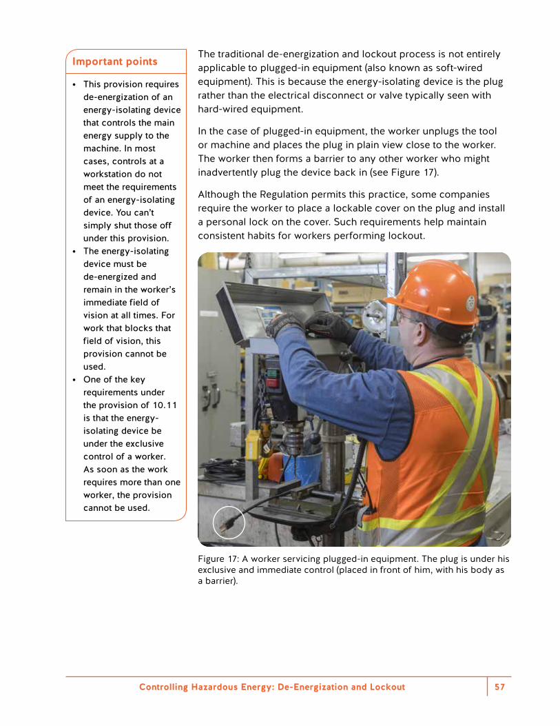
Controlling Hazardous Energy: De-Energization and Lockout 57
The traditional de-energization and lockout process is not entirely applicable to plugged-in equipment (also known as soft-wired equipment). This is because the energy-isolating device is the plug rather than the electrical disconnect or valve typically seen with hard-wired equipment.
In the case of plugged-in equipment, the worker unplugs the tool or machine and places the plug in plain view close to the worker. The worker then forms a barrier to any other worker who might inadvertently plug the device back in (see Figure 17).
Although the Regulation permits this practice, some companies require the worker to place a lockable cover on the plug and install a personal lock on the cover. Such requirements help maintain consistent habits for workers performing lockout.
Figure 17: A worker servicing plugged-in equipment. The plug is under his exclusive and immediate control (placed in front of him, with his body as a barrier).
Important points
• This provision requires de-energization of an energy-isolating device that controls the main energy supply to the machine. In most cases, controls at a workstation do not meet the requirements of an energy-isolating device. You can’t simply shut those off under this provision.
• The energy-isolating device must be de-energized and remain in the worker’s immediate field of vision at all times. For work that blocks that field of vision, this provision cannot be used.
• One of the key requirements under the provision of 10.11 is that the energy-isolating device be under the exclusive control of a worker. As soon as the work requires more than one worker, the provision cannot be used.
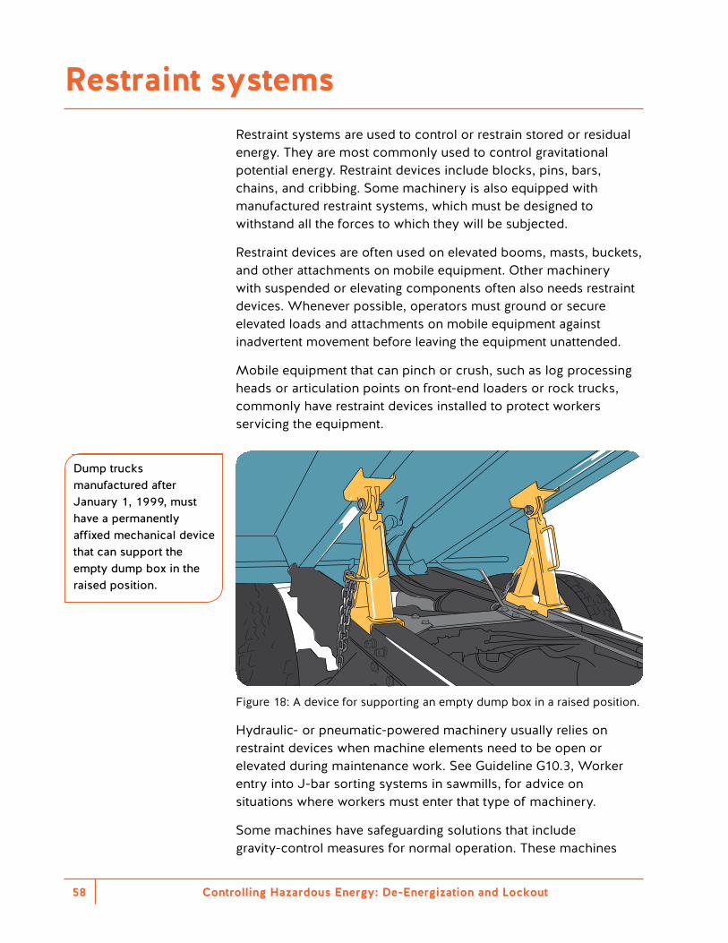
Controlling Hazardous Energy: De-Energization and Lockout58
Restraint systems are used to control or restrain stored or residual energy. They are most commonly used to control gravitational potential energy. Restraint devices include blocks, pins, bars, chains, and cribbing. Some machinery is also equipped with manufactured restraint systems, which must be designed to withstand all the forces to which they will be subjected.
Restraint devices are often used on elevated booms, masts, buckets, and other attachments on mobile equipment. Other machinery with suspended or elevating components often also needs restraint devices. Whenever possible, operators must ground or secure elevated loads and attachments on mobile equipment against inadvertent movement before leaving the equipment unattended.
Mobile equipment that can pinch or crush, such as log processing heads or articulation points on front-end loaders or rock trucks, commonly have restraint devices installed to protect workers servicing the equipment.
Figure 18: A device for supporting an empty dump box in a raised position.
Hydraulic- or pneumatic-powered machinery usually relies on restraint devices when machine elements need to be open or elevated during maintenance work. See Guideline G10.3, Worker entry into J-bar sorting systems in sawmills, for advice on situations where workers must enter that type of machinery.
Some machines have safeguarding solutions that include gravity-control measures for normal operation. These machines
Dump trucks manufactured after January 1, 1999, must have a permanently affixed mechanical device that can support the empty dump box in the raised position.
Reference
For guidance on using physical restraint devices, see CSA Z460–13 (R2018) Control of hazardous energy — Lockout and other methods.
Restraint systems
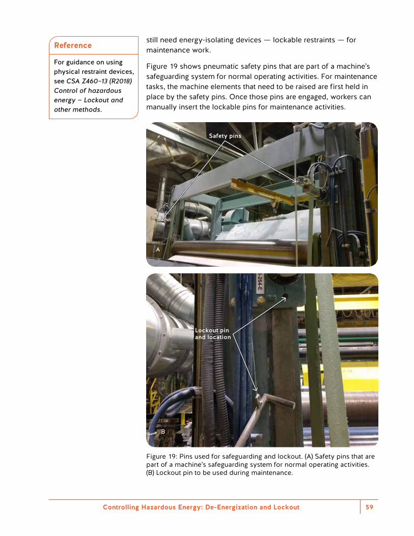
Controlling Hazardous Energy: De-Energization and Lockout 59
Restraint systems are used to control or restrain stored or residual energy. They are most commonly used to control gravitational potential energy. Restraint devices include blocks, pins, bars, chains, and cribbing. Some machinery is also equipped with manufactured restraint systems, which must be designed to withstand all the forces to which they will be subjected.
Restraint devices are often used on elevated booms, masts, buckets, and other attachments on mobile equipment. Other machinery with suspended or elevating components often also needs restraint devices. Whenever possible, operators must ground or secure elevated loads and attachments on mobile equipment against inadvertent movement before leaving the equipment unattended.
Mobile equipment that can pinch or crush, such as log processing heads or articulation points on front-end loaders or rock trucks, commonly have restraint devices installed to protect workers servicing the equipment.
Figure 18: A device for supporting an empty dump box in a raised position.
Hydraulic- or pneumatic-powered machinery usually relies on restraint devices when machine elements need to be open or elevated during maintenance work. See Guideline G10.3, Worker entry into J-bar sorting systems in sawmills, for advice on situations where workers must enter that type of machinery.
Some machines have safeguarding solutions that include gravity-control measures for normal operation. These machines
Dump trucks manufactured after January 1, 1999, must have a permanently affixed mechanical device that can support the empty dump box in the raised position.
Reference
For guidance on using physical restraint devices, see CSA Z460–13 (R2018) Control of hazardous energy — Lockout and other methods.
still need energy-isolating devices — lockable restraints — for maintenance work.
Figure 19 shows pneumatic safety pins that are part of a machine’s safeguarding system for normal operating activities. For maintenance tasks, the machine elements that need to be raised are first held in place by the safety pins. Once those pins are engaged, workers can manually insert the lockable pins for maintenance activities.
Safety pins
A
Lockout pin and location
Figure 19: Pins used for safeguarding and lockout. (A) Safety pins that are part of a machine’s safeguarding system for normal operating activities. (B) Lockout pin to be used during maintenance.
B
Controlling Hazardous Energy: De-Energization and Lockout60
In most cases, a restraint device will not replace the de-energization and lockout of the powered functions (pumps, motors, etc.) of a machine. Rather, it will be used in conjunction with the de-energization and lockout of other energy-isolating devices. Restraint devices must be applied with the de-energization and lockout procedures.
Restraint devices must be designed so they can be applied by a worker in a safe location. The worker must be able to install the restraining device without being exposed to the hazard.
Although the Regulation does not require restraint devices to be locked in place, they should be designed to do so whenever possible. If a restraint device is not lockable, it should have suitable markings to identify it as a safety device.
Related incident
Fatal crush injury
A contract welder had to repair a weld on a vertical swing gate at the planer infeed tilt-hoist. The swing gate separates dunnage and strips from the lumber loads, which fall onto a conveyor below. The welder had turned off the system and locked it out while the swing gate was in the upright position. However, the welder didn’t secure the gate with a chain. The swing gate fell and crushed the welder.
Controlling Hazardous Energy: De-Energization and Lockout 61
Section 10.10(1)(b) of the Regulation specifies mobile equipment lockout requirements. In most cases, it is practicable to lock out and de-energize mobile equipment (according to manufacturer’s instructions). If the machine doesn’t come with energy-isolating devices, after-market solutions are available.
However, depending on the task, traditional lockout to a zero-energy state may not always be practicable. Consider the hazards associated with the tasks before choosing the method of hazardous energy control. The following are some methods used to control hazardous energy of mobile equipment: • Using a battery power disconnect switch • Disabling start circuits • Mechanical blocking • Chocking wheels • Dissipating thermal and stored energy
Always lock out mobile equipment according to the manufacturer’s instructions.
Mobile equipment lockout
Controlling Hazardous Energy: De-Energization and Lockout62
The use of the term isolation in this section is distinct from previous discussions of energy-isolating devices. In both cases, the aim is to separate the worker from the release of hazardous energy. This section, however, is about using isolation when traditional de-energization and lockout is not practicable.
Isolation involves physically separating a worker from energy. It must do so in ways that keep the worker safe even though the hazardous process is still energized. Isolation is most commonly used in complex process facilities, municipalities, or other workplaces where it is not practicable to shut down and de-energize a process.
For example, workers may need to perform work on a municipal sewer system that involves disconnecting a main sewer pipe. Shutting off the sewer system to the entire city is not a practicable option. Instead, workers can use a procedure that isolates a small section of the sewer where the work will occur. Different isolation methods exist. In this case, the workers isolate the sewer using inflatable bladders. This procedure allows the work to progress safely while most of the sewer system can still operate normally.
Another common use of isolation is for a confined space entry in a process facility.
For example, work is planned inside a storage tank that normally contains a hazardous chemical. As part of the confined space entry procedures, workers reroute supply to this tank to another tank. They empty the first tank and pump clean water through to remove any residual chemicals in the tank. Workers then close and lock all supply line valves to the tank and install blanks into the supply piping to the tank. They follow the remaining requirements of the confined space entry procedures, such as atmospheric testing and providing continual ventilation. Once all the pre-entry procedures have been satisfied, workers are permitted to enter the tank.
In this case, the rest of the facility is still operating. However, effective steps have been taken to physically separate the workers performing work inside the tank from the hazardous energy. The workers have been isolated from the hazards.
As with any form of energy control, the isolation must be effective. Significant planning and testing are necessary when relying on isolation from hazardous energy.
Reference
For more information about isolation and confined space entry, see the WorkSafeBC publication Confined Space Entry Program: A Reference Manual.
Isolation
Controlling Hazardous Energy: De-Energization and Lockout 63
A trapped-key (or key-transfer) interlock system is a system of mechanical interlocking devices used to protect workers and equipment. These interlocking devices typically work with energy-isolating devices and machine safeguards. They prevent workers from accessing hazardous parts of machines or equipment before the equipment is locked out.
Trapped-key interlocks typically work by releasing trapped keys from an energy-isolating device. The key is then used to access locked points of machinery.
For example, a single worker has access to a machine that has only one hazardous energy source. The worker can’t access the machine until the energy-isolating device is locked out. This releases the trapped key that unlocks the machine access guard. Once the machine guard door is unlocked, the key remains trapped in the guard door until the door is closed and locked.
More complex versions of this system can be used to enforce a specific sequence so that a machine or process is shut down and isolated in the correct order before workers can access the hazardous parts.
Trapped-key interlock systems
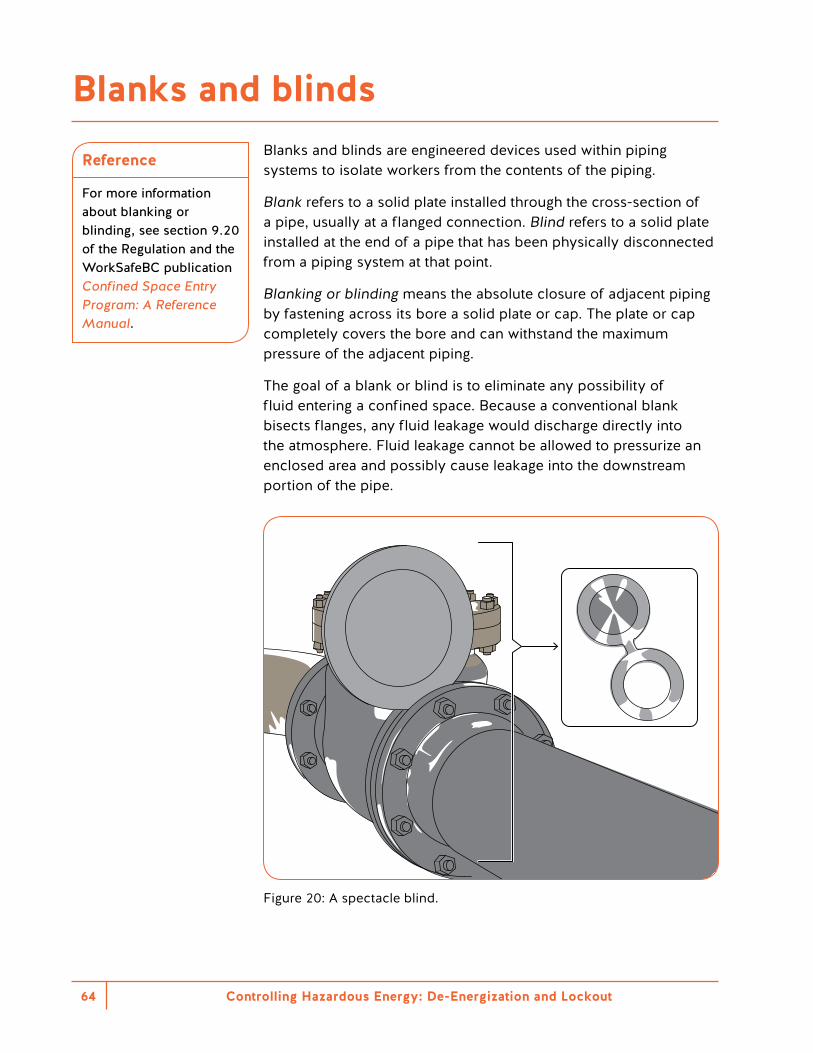
Controlling Hazardous Energy: De-Energization and Lockout64
Blanks and blinds are engineered devices used within piping systems to isolate workers from the contents of the piping.
Blank refers to a solid plate installed through the cross-section of a pipe, usually at a flanged connection. Blind refers to a solid plate installed at the end of a pipe that has been physically disconnected from a piping system at that point.
Blanking or blinding means the absolute closure of adjacent piping by fastening across its bore a solid plate or cap. The plate or cap completely covers the bore and can withstand the maximum pressure of the adjacent piping.
The goal of a blank or blind is to eliminate any possibility of fluid entering a confined space. Because a conventional blank bisects flanges, any fluid leakage would discharge directly into the atmosphere. Fluid leakage cannot be allowed to pressurize an enclosed area and possibly cause leakage into the downstream portion of the pipe.
Figure 20: A spectacle blind.
Reference
For more information about blanking or blinding, see section 9.20 of the Regulation and the WorkSafeBC publication Confined Space Entry Program: A Reference Manual.
Blanks and blinds
Controlling Hazardous Energy: De-Energization and Lockout 65
Workers must be protected from harmful substances (solids, liquids, and gases) that could be discharged from pipes or conduits adjacent to or leading to a confined space. If adjacent piping contains (or has contained) a harmful substance that could enter the confined space, the substance must be controlled using isolation procedures. Isolating means ensuring contaminants inside the piping will not enter a confined space.
Double block and bleed is an isolation method that can be used in certain circumstances. It involves locking out a drain or vent valve in the open position between two locked-out valves in the closed position. Closing one or more valves and locking them in the “off” position is not considered adequate isolation (except when it is used as part of a double block and bleed system).
The written lockout procedures for double block and bleed must identify the specific lockout points and valves by name. The names on the procedure must match the markings on the piping system.
You may use a double block and bleed system if the harmful substance in the piping is not one of the following: • A gas • A vapour • A liquid volatile enough to produce a hazardous concentration
of an air contaminant from the discharge from the piping
Work in confined spaces is just one instance where double block and bleed isolation is used. Confined space entry must be done in compliance with Part 9 of the Regulation. For more information, see section 9.21 of the Regulation and the WorkSafeBC publication Confined Space Entry Program: A Reference Manual.
Double block and bleed
Controlling Hazardous Energy: De-Energization and Lockout66
Guideline G10.4(6) states that a cryogenic system is an approved alternative to lockout for cases where freezing of the pipe contents to form a plug in the pipe (freeze plug) is used to block piping and isolate equipment.
This technology provides a non-intrusive way to isolate piping systems. Line freezing does not require permanent modification or welding of the piping system. Piping systems containing water, or any fluid with a suitable freeze point that will not flow after freezing, can be isolated with freeze plugs.
Pipe freezing can isolate work zones in order to replace, repair, and maintain critical systems without shutting down the whole system. This alternative is to be used by qualified and trained workers using appropriate safe work procedures.
Freeze plug technology
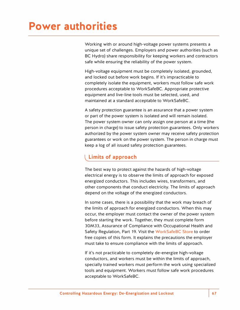
Controlling Hazardous Energy: De-Energization and Lockout 67
Working with or around high-voltage power systems presents a unique set of challenges. Employers and power authorities (such as BC Hydro) share responsibility for keeping workers and contractors safe while ensuring the reliability of the power system.
High-voltage equipment must be completely isolated, grounded, and locked out before work begins. If it’s impracticable to completely isolate the equipment, workers must follow safe work procedures acceptable to WorkSafeBC. Appropriate protective equipment and live-line tools must be selected, used, and maintained at a standard acceptable to WorkSafeBC.
A safety protection guarantee is an assurance that a power system or part of the power system is isolated and will remain isolated. The power system owner can only assign one person at a time (the person in charge) to issue safety protection guarantees. Only workers authorized by the power system owner may receive safety protection guarantees or work on the power system. The person in charge must keep a log of all issued safety protection guarantees.
Limits of approach
The best way to protect against the hazards of high-voltage electrical energy is to observe the limits of approach for exposed energized conductors. This includes wires, transformers, and other components that conduct electricity. The limits of approach depend on the voltage of the energized conductors.
In some cases, there is a possibility that the work may breach of the limits of approach for energized conductors. When this may occur, the employer must contact the owner of the power system before starting the work. Together, they must complete form 30M33, Assurance of Compliance with Occupational Health and Safety Regulation, Part 19. Visit the WorkSafeBC Store to order free copies of this form. It explains the precautions the employer must take to ensure compliance with the limits of approach.
If it’s not practicable to completely de-energize high-voltage conductors, and workers must be within the limits of approach, specially trained workers must perform the work using specialized tools and equipment. Workers must follow safe work procedures acceptable to WorkSafeBC.
Power authorities
Controlling Hazardous Energy: De-Energization and Lockout68
Unqualified workers must stay outside the limits of approach specified in table 19-1A of the Regulation. When working with tools or equipment, consider their reach. The minimum approach distance should be measured from the outside edge of any tools, mobile equipment, or materials. The risk of injury increases the closer a worker or piece of equipment gets to an energized conductor.
Some types of workers, such as certified utility arborists, may need to work near energized overhead conductors. In this example, the arborist must contact the owner of the power system before beginning the work to obtain an assurance of non-reclose.
Accidental violation of the limits of approach
The limits of approach may occasionally be accidentally violated. For example, inadvertent movement by a worker or piece of equipment may breach the limits of approach, or equipment may be prematurely re-energized while work is still in progress.
Before re-energizing the system, the employer must confirm that the work has been safely moved outside the limits of approach.
Coordinating power authorities and customer work
On rare occasions, workers may need to perform maintenance on the boundary of electric utilities and a customer site. In these cases, lockout procedures are not adequate. A guarantee of isolation from the power authority is required for work protection.
This type of isolation applies to large buildings that have an existing operating order with a power authority. A guarantee of isolation is required when maintenance will be performed on the building’s vault. This maintenance is performed by an electrical contractor chosen by the customer. For BC Hydro, the isolation is coordinated through the BC Hydro Control Centre and requires a minimum of five days’ notice.
Reference
For more information about working on or around power systems, see the following WorkSafeBC publications: • Working Safely
Around Electricity • Safe Work Practices
and Responsibilities for Power Producers
Automation technology and hazardous energy control
Controlling Hazardous Energy: De-Energization and Lockout70
Robotic applications can expose workers to hazardous energy in many routine situations. For example, hazards exist in robot teaching, robot servicing, minor tool changes, removing jams, and troubleshooting. Most incidents related to robots occur during set-up, troubleshooting, and maintenance.
When workers perform any maintenance tasks inside a restricted space around a robot, all energy sources and main power circuits must be de-energized and locked out. Accidental or inadvertent operation could cause injury. Exceptions may apply for robot grippers or end-of-arm tooling, which may need to remain powered to hold the work piece. Lockout procedures must describe how to isolate any hazards related to drifting or gravity of the end-of-arm tooling. They must also consider the potential dropping of the piece in material handling applications. Failsafe brakes, blocks, or pins are acceptable methods to isolate the energy in these cases. All these provisions should be part of the equipment risk assessment process.
Remember that stop buttons or selector switches (whether or not they involve a key) are not energy-isolating devices and cannot be used for lockout. Neither are PLCs that operate on control circuits. To prevent long startup times or loss of programming when a robot cell’s main power is disconnected, employers should do the following: • Follow the manufacturer’s instructions for shutting down the
equipment. • Maintain the memory backup batteries. • Wire the PLC power in a separate circuit.
Working on energized equipment — robot teaching mode
To observe a robot’s movements from close up or to manually set the robotic arm position, workers may need to temporarily access a robot’s restricted space while the robot is still energized. For these tasks, most robots are equipped with what is commonly known as “teaching mode.” This operation mode disables the automatic task routine to allow a worker to enter the robot’s restricted space. The worker can then manually set the robotic arm position through the desired path. Because the worker is within the robot’s restricted space, any programming mistake or failure may result in injury.
Robotics
With respect to hazardous energy control, all robotic systems should meet or exceed the requirements of CSA Group standard CAN/CSA–Z434 — Industrial robots and robot systems, which is an adoption of ISO 10218–1 Robots and robotic devices — Safety requirements for industrial robots — Part 1: Robots and ISO 10218–2 Robots and robotic devices — Safety requirements for industrial robots — Part 2: Robot systems and integration, available at the time the equipment was built.
For this reason, a robot running in teaching mode must only move with a restricted speed of 250 mm/s (as specified in CAN/CSA–Z434 — Industrial robots and robot systems). All workers inside the robot’s restricted space must maintain control of robot motion by using a hold-to-run enabling device. Some robots will be equipped with a manual high-speed mode where the robotic arm can move at speeds higher than 250 mm/s. Wherever possible, this mode should be used only when all workers are outside the robot’s restricted space.
Only use teaching mode when it is not practicable to perform the task without an energized system. Often, workers can avoid entering the area by ensuring good visibility through safeguarding or by using video cameras. Section 10.12 of the Regulation states the requirements for working on energized equipment. Workers must be qualified to do the work, authorized by the employer to do it, and provided with written job procedures.
Emerging technologies: Collaborative robotics
Collaborative robots (co-robots or cobots) operate in a collaborative human environment. This means the robots are installed without barriers around them, depending on the risk assessment and safeguarding options available. Technology advances in power and force sensors and controls make this possible. These sensors stop the robot in case it makes contact with a worker, so that the worker is not injured. This feature is limited to low- or medium-risk situations.
Collaborative robotics applications require a detailed risk assessment to ensure that the robotic arm’s maximum force, stopping distance, work area layout, and tools are safe to use in a collaborative environment. The same robotic arm could be used for different applications, such as moving small boxes or welding. However, different applications require different safeguards and de-energization procedures. Robot manufacturers’ marketing claims need to be taken within the context and risks of the tasks specific to the application.
Other options for collaborative robotics may include the use of laser scanners or safety-rated cameras to define zones where the robot may slow down or stop completely if a worker enters the area. These applications are also required to comply with the Regulation lockout requirements for maintenance tasks.
Controlling Hazardous Energy: De-Energization and Lockout 71
Controlling Hazardous Energy: De-Energization and Lockout72
The ongoing modification of machinery, equipment, and processes is one of the greatest challenges for maintaining de-energization and lockout procedures. Modifications are often made without considering how they will affect existing procedures.
Before modifying equipment, assess how the changes will impact the isolation of hazardous energy. For example, changing the model of an actuator could change the settings of the control system. This could create additional hazards. It is important to review all hazardous energy control elements regularly and correct them when required.
Equipment modifications — change management and verification
Imported equipment and used equipment
Safeguarding and lockout regulations vary by country and province. This means that equipment from outside of British Columbia may not comply with the Regulation. Employers need to consider the Regulation requirements when selecting new or used equipment. The application, design, construction, and use of safeguards must meet the requirements of CSA Z432–94 — Safeguarding of machinery. However, there is an updated version of the standard (i.e., CSA Z432–16). This standard applies to newly manufactured and newly installed machinery, as well as rebuilt or redeployed machinery. The de-energization and lockout procedures must comply with Part 10 of the Regulation, regardless of the equipment’s country of origin.
Controlling Hazardous Energy: De-Energization and Lockout 73


Appendixes
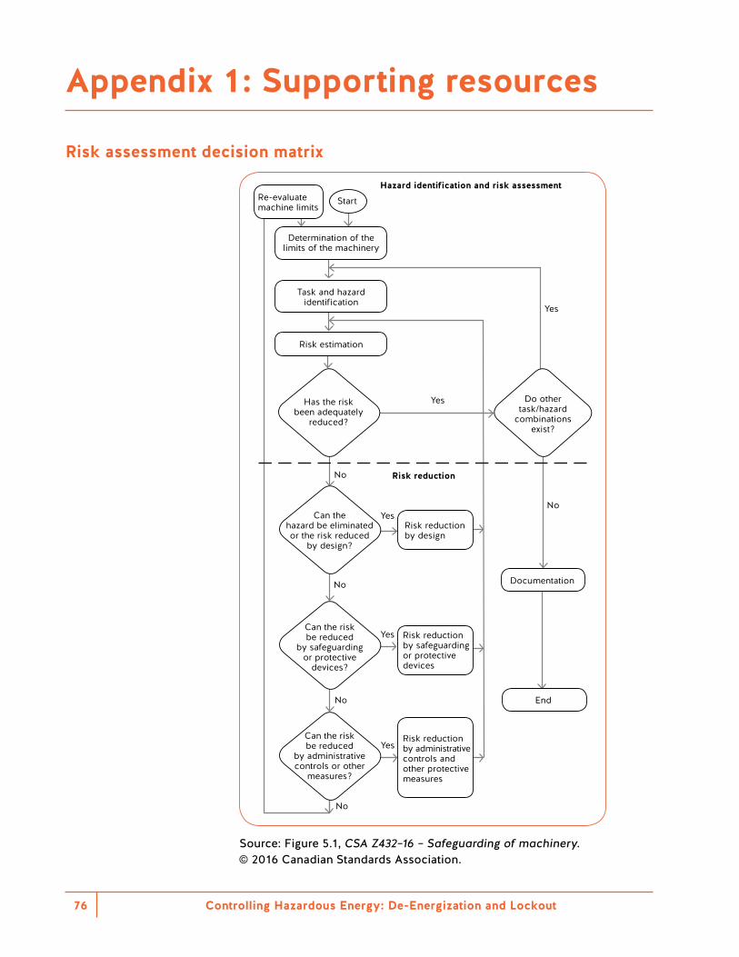
Controlling Hazardous Energy: De-Energization and Lockout76
Appendix 1: Supporting resources
Risk assessment decision matrixRisk assessment process
Re-evaluate machine limits
Start
Risk reduction
Hazard identification and risk assessment
Determination of the limits of the machinery
Task and hazard identification
Risk estimation
Risk reduction by design
Yes
Yes
Yes
Yes
Yes
No
No
No
No
No
Can thehazard be eliminatedor the risk reduced
by design?
Has the riskbeen adequately
reduced?
Do othertask/hazard
combinationsexist?
Documentation
End
Can the riskbe reduced
by safeguardingor protective
devices?
Can the riskbe reduced
by administrativecontrols or other
measures?
Risk reductionby safeguarding or protective devices
Risk reduction by administrative controls and other protective measures
Source: Figure 5.1, CSA Z432–16 – Safeguarding of machinery. © 2016 Canadian Standards Association.
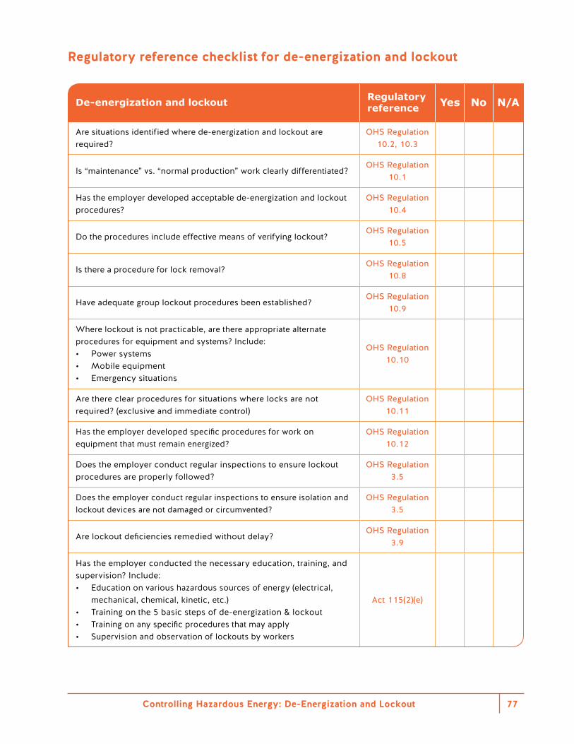
Regulatory reference checklist for de-energization and lockout
De-energization and lockout Regulatory reference Yes No N/A
Are situations identified where de-energization and lockout are required?
OHS Regulation 10.2, 10.3
Is “maintenance” vs. “normal production” work clearly differentiated?OHS Regulation
10.1
Has the employer developed acceptable de-energization and lockout procedures?
OHS Regulation 10.4
Do the procedures include effective means of verifying lockout?OHS Regulation
10.5
Is there a procedure for lock removal?OHS Regulation
10.8
Have adequate group lockout procedures been established?OHS Regulation
10.9
Where lockout is not practicable, are there appropriate alternate procedures for equipment and systems? Include:• Power systems• Mobile equipment• Emergency situations
OHS Regulation 10.10
Are there clear procedures for situations where locks are not required? (exclusive and immediate control)
OHS Regulation 10.11
Has the employer developed specific procedures for work on equipment that must remain energized?
OHS Regulation 10.12
Does the employer conduct regular inspections to ensure lockout procedures are properly followed?
OHS Regulation 3.5
Does the employer conduct regular inspections to ensure isolation and lockout devices are not damaged or circumvented?
OHS Regulation 3.5
Are lockout deficiencies remedied without delay?OHS Regulation
3.9
Has the employer conducted the necessary education, training, and supervision? Include:• Education on various hazardous sources of energy (electrical,
mechanical, chemical, kinetic, etc.)• Training on the 5 basic steps of de-energization & lockout• Training on any specific procedures that may apply• Supervision and observation of lockouts by workers
Act 115(2)(e)
Controlling Hazardous Energy: De-Energization and Lockout 77
Appendix 2: Elements of a de-energization and lockout program
Although program elements vary, a comprehensive de-energization and lockout program should consist of the following:1. Lockout policy2. Identification of hazardous energy sources3. Identification of tasks that need de-energization and lockout4. Identification of energy-isolating devices5. Specific de-energization and lockout procedures6. Lock assignment7. Lock identification8. Worker training9. Emergency lock removal10. Continuity of lockout across shifts11. Group lockout12. Working on energized equipment13. Lockout during emergencies14. Commissioning of equipment15. Auditing of program elements
Following is a brief description of each element:1. Lockout policy — The policy expresses the company’s
expectations related to de-energization and lockout. It provides guidance on when and how to perform lockout.
2. Identification of hazardous energy sources — Hazardous energy comes in many forms. Identifying all the hazardous energy types at a workplace is the first step in risk identification and assessment.
3. Identification of tasks that need de-energization and lockout — The second step in the risk identification process is to assess the various ways in which a worker may interact with machinery. This includes the nature, scope, and frequency of interactions.
4. Identification of energy-isolating devices — All energy-isolating devices must be labelled using a standard naming system to indicate their function. The program should outline how energy-isolating devices are labelled. It should also assign responsibility for ensuring that labelling is correct, accurate, and amended as needed.
Controlling Hazardous Energy: De-Energization and Lockout78
5. Specific de-energization and lockout procedures — Section 10.4(1) of the Regulation requires lockout to be performed by workers “in accordance with procedures that are made available to workers.” Effective lockout procedures contain the following elements: • Identification of the machine, equipment, or process • A list of all required energy-isolating devices and their
locations • Steps for shutting down, isolating, blocking, securing, and
relieving stored or residual energy • Steps for placing and removing lockout devices • Requirements for verifying isolation and de-energization • Requirements for verifying that all workers have been
cleared from the worksite • Requirements for verifying that the machine, equipment, or
process has been inspected and is ready to return to service
The program should also provide guidance on the following: • A consistent format for lockout procedures • How de-energization and lockout procedures are developed • Who participates or provides consultation in their development • Who is responsible for ensuring their accuracy • How procedures are made available to workers • When procedures are reviewed to ensure they remain up to
date • How changes to machinery or processes trigger the
development of a new procedure6. Lock assignment — The program should specify the types of
locks issued, who is issued locks, how many locks are issued to each worker, and so on.
7. Lock identification — The program should specify the ways in which the locks are uniquely identified by user. Stamping names, assigning numbers, and affixing identification tags are common methods. Whichever method is used, it must effectively and legibly identify the individual user of each lock. Numbering systems require a legend to be immediately available at all times. Locks used by external contractors are to be identified with individual users. Some facilities use colour coding to identify locks belonging to specific departments or teams. Although effective in grouping locks, a colour-coding system alone is not sufficient identification.
Controlling Hazardous Energy: De-Energization and Lockout 79
Controlling Hazardous Energy: De-Energization and Lockout80
8. Worker training — The program should specify the nature, scope, and extent of training for workers who perform, oversee, and supervise de-energization and lockout. It should also describe the criteria for and provision of refresher training.
9. Emergency lock removal — This is the procedure for safely removing a lockout lock left in place when the worker who applied it has left the workplace and the machinery needs to be re-energized. The procedure should explain the steps to be followed. It should also identify the persons who have the authority to remove a lock.
10. Continuity of lockout across shifts — This process is followed whenever the de-energization and lockout of machinery extends beyond a single workshift. It is especially important when workers come and go from the workplace over multiple shifts. This process is usually managed by applying a continuity lock. This lock remains in place to ensure lockout continuity regardless of workers adding or removing their individual locks from energy-isolating devices.
11. Group lockout — Section 10.9 of the Regulation specifies the steps for a group lockout procedure. Group lockout is typically used in complex process facilities where maintenance work involves the de-energization and lockout of many energy-isolating devices by a large number of workers. This procedure includes the specific steps to be followed at the workplace and provides guidance on the following: • Who is considered a qualified person for group lockout? • Who is an authorized person for group lockout? • Who is responsible for developing the group de-energization
and lockout procedures? • How will the effectiveness of the group lockout be verified? • Who is responsible for ensuring the safe re-energization of
machinery?12. Working on energized equipment — Section 10.12 of the
Regulation provides a deviation from the usual de-energization and lockout procedure. It is for workers who must perform a specific maintenance function while equipment remains energized. Typically this type of work involves diagnostic work and troubleshooting. This process describes the specific tasks that workers may perform while equipment is energized. It identifies workers who are qualified and authorized for this type of work. It also explains how to develop procedures for working on energized equipment and how to communicate them to workers.
Controlling Hazardous Energy: De-Energization and Lockout 81
13. Lockout during emergencies — This procedure describes the steps to take during an emergency response when an injured worker requires rescue from machinery or equipment. In some cases, the urgency of the rescue will make it impracticable for each member of a rescue team to individually lock out. An effective process must be in place to protect rescue workers from the hazardous release of energy. There may also be occasions when power is needed to extricate a worker during a rescue. The procedure considers and lays out steps for managing these circumstances.
14. Commissioning of equipment — At a critical point during the installation of new machinery or equipment, the machinery becomes energized. At this point it may release hazardous energy. Identifying this point is especially important during large construction or renovation projects when the machinery has been dormant for a long period. Workers may have grown accustomed to it being non-energized. Section 4.11 of the Regulation provides guidance on starting up any equipment or machinery. This is the procedure for commissioning equipment, identifying when de-energization and lockout becomes a requirement, and communicating this to affected workers.
15. Auditing of program elements — As with all programs, regular reviews or audits of the program elements are required. The procedure for the audit should indicate how often it will occur and who will complete it. The procedure should also include details of the audit report and how to implement any needed improvements.

Controlling Hazardous Energy: De-Energization and Lockout82
OHS Guideline G10.10(2) provides step-by-step instructions on how to request written approval for using CSIDs as an isolation device. CSIDs are also known as safety-rated parts of a control system (SRP/CS). After reviewing the application, WorkSafeBC will issue a decision letter with respect to approval of the CSID and the associated procedure.
The documentation should include the following: • A description of operation of the SRP/CS from a functional
standpoint. • A list of the safety devices forming the SRP/CS, their relevant
performance level claim limit, and the certifying body. • A statement on the achieved performance level of the SRP/CS
by a third party (either internal or external) to the designer. • A list of all safety functions showing the required performance
level based on the task and hazard combination and the achieved performance level. The actual performance level must be equal to or higher than the required performance level.
• Documented site testing, including fault injection as required by the safety device manufacturer showing that common cause failures (where foreseeable) have been accounted for and that the system operates as intended. – Also include how often the user will perform this functional test
to ensure that the system continues to operate as expected. – If the application is being submitted before the designed
SRP/CS has been implemented, provide the intended test matrix and expected results. Supply the actual site testing documentation within two weeks (14 days) of completion of commissioning of the system.
• Schematics of the process control system and the SRP/CS, including revision information.
• If a safety PLC is used as the logic element of the SRP/CS, a PDF version of the logic and hardware set-up. The cyclic redundancy check (CRC) or safety signature (a unique revision identifier generated in the safety PLC code compilation) must also be noted to identify the logic revision.
Appendix 3: How to request written approval for using control system isolating devices (CSIDs)
Controlling Hazardous Energy: De-Energization and Lockout 83
• If changes in the system result in any of the following, you must update the validation documentation and notify WorkSafeBC of the modifications: – Addition of safety functions – Modifications to safety PLC logic that generate a new safety
signature – Modifications to SRP/CS related schematics (must be
reflected in revision of schematics) – Change to the process that affects or could affect the
functional safety of the users of the machinery, equipment, or process
Consult a WorkSafeBC officer if the changes are significant enough to require resubmitting the approval request.
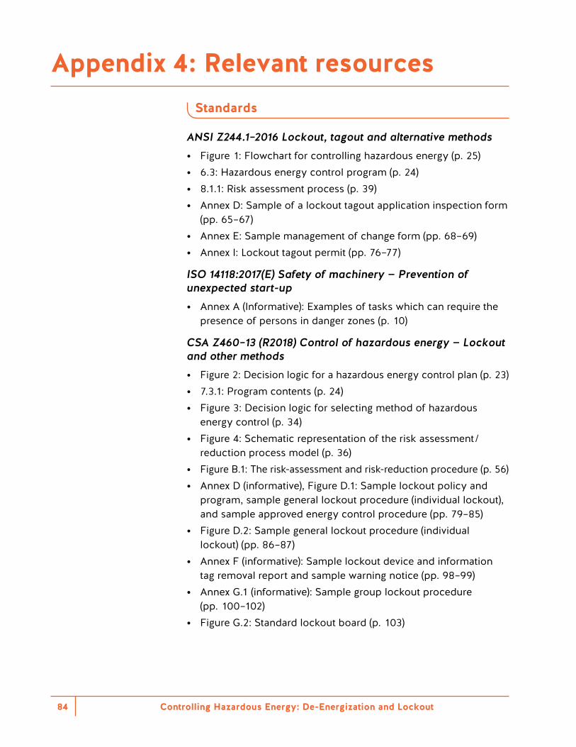
Controlling Hazardous Energy: De-Energization and Lockout84
Standards
ANSI Z244.1–2016 Lockout, tagout and alternative methods • Figure 1: Flowchart for controlling hazardous energy (p. 25) • 6.3: Hazardous energy control program (p. 24) • 8.1.1: Risk assessment process (p. 39) • Annex D: Sample of a lockout tagout application inspection form
(pp. 65–67) • Annex E: Sample management of change form (pp. 68–69) • Annex I: Lockout tagout permit (pp. 76–77)
ISO 14118:2017(E) Safety of machinery — Prevention of unexpected start-up • Annex A (Informative): Examples of tasks which can require the
presence of persons in danger zones (p. 10)
CSA Z460–13 (R2018) Control of hazardous energy — Lockout and other methods • Figure 2: Decision logic for a hazardous energy control plan (p. 23) • 7.3.1: Program contents (p. 24) • Figure 3: Decision logic for selecting method of hazardous
energy control (p. 34) • Figure 4: Schematic representation of the risk assessment /
reduction process model (p. 36) • Figure B.1: The risk-assessment and risk-reduction procedure (p. 56) • Annex D (informative), Figure D.1: Sample lockout policy and
program, sample general lockout procedure (individual lockout), and sample approved energy control procedure (pp. 79–85)
• Figure D.2: Sample general lockout procedure (individual lockout) (pp. 86–87)
• Annex F (informative): Sample lockout device and information tag removal report and sample warning notice (pp. 98–99)
• Annex G.1 (informative): Sample group lockout procedure (pp. 100–102)
• Figure G.2: Standard lockout board (p. 103)
Appendix 4: Relevant resources
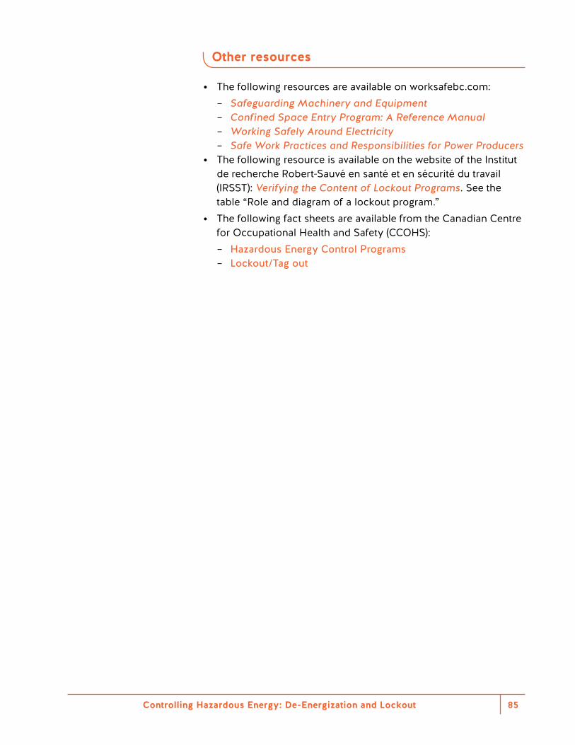
Controlling Hazardous Energy: De-Energization and Lockout 85
Other resources
• The following resources are available on worksafebc.com: – Safeguarding Machinery and Equipment – Confined Space Entry Program: A Reference Manual – Working Safely Around Electricity – Safe Work Practices and Responsibilities for Power Producers
• The following resource is available on the website of the Institut de recherche Robert-Sauvé en santé et en sécurité du travail (IRSST): Verifying the Content of Lockout Programs. See the table “Role and diagram of a lockout program.”
• The following fact sheets are available from the Canadian Centre for Occupational Health and Safety (CCOHS): – Hazardous Energy Control Programs – Lockout/Tag out
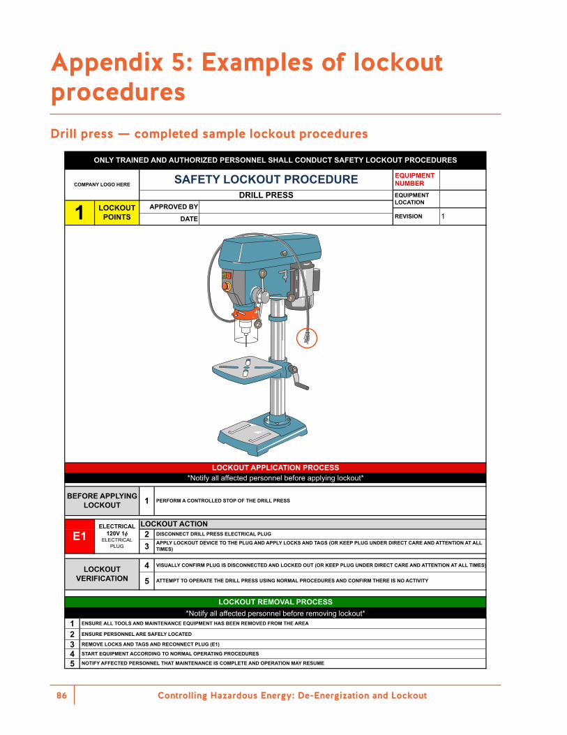
Controlling Hazardous Energy: De-Energization and Lockout86
Appendix 5: Examples of lockout procedures Drill press — completed sample lockout procedures
23
4
5
12345
ONLY TRAINED AND AUTHORIZED PERSONNEL SHALL CONDUCT SAFETY LOCKOUT PROCEDURES
COMPANY LOGO HERE SAFETY LOCKOUT PROCEDUREDRILL PRESS
1 LOCKOUT POINTS
APPROVED BY
DATE 1REVISION
EQUIPMENT NUMBEREQUIPMENT LOCATION
START EQUIPMENT ACCORDING TO NORMAL OPERATING PROCEDURES
NOTIFY AFFECTED PERSONNEL THAT MAINTENANCE IS COMPLETE AND OPERATION MAY RESUME
LOCKOUT REMOVAL PROCESS*Notify all affected personnel before removing lockout*
LOCKOUT VERIFICATION
ENSURE ALL TOOLS AND MAINTENANCE EQUIPMENT HAS BEEN REMOVED FROM THE AREA
ENSURE PERSONNEL ARE SAFELY LOCATED
REMOVE LOCKS AND TAGS AND RECONNECT PLUG (E1)
VISUALLY CONFIRM PLUG IS DISCONNECTED AND LOCKED OUT (OR KEEP PLUG UNDER DIRECT CARE AND ATTENTION AT ALL TIMES)
ATTEMPT TO OPERATE THE DRILL PRESS USING NORMAL PROCEDURES AND CONFIRM THERE IS NO ACTIVITY
*Notify all affected personnel before applying lockout*LOCKOUT APPLICATION PROCESS
E1ELECTRICAL
120V 1ϕELECTRICAL
PLUG
LOCKOUT ACTIONDISCONNECT DRILL PRESS ELECTRICAL PLUG
APPLY LOCKOUT DEVICE TO THE PLUG AND APPLY LOCKS AND TAGS (OR KEEP PLUG UNDER DIRECT CARE AND ATTENTION AT ALL TIMES)
BEFORE APPLYING LOCKOUT 1 PERFORM A CONTROLLED STOP OF THE DRILL PRESS
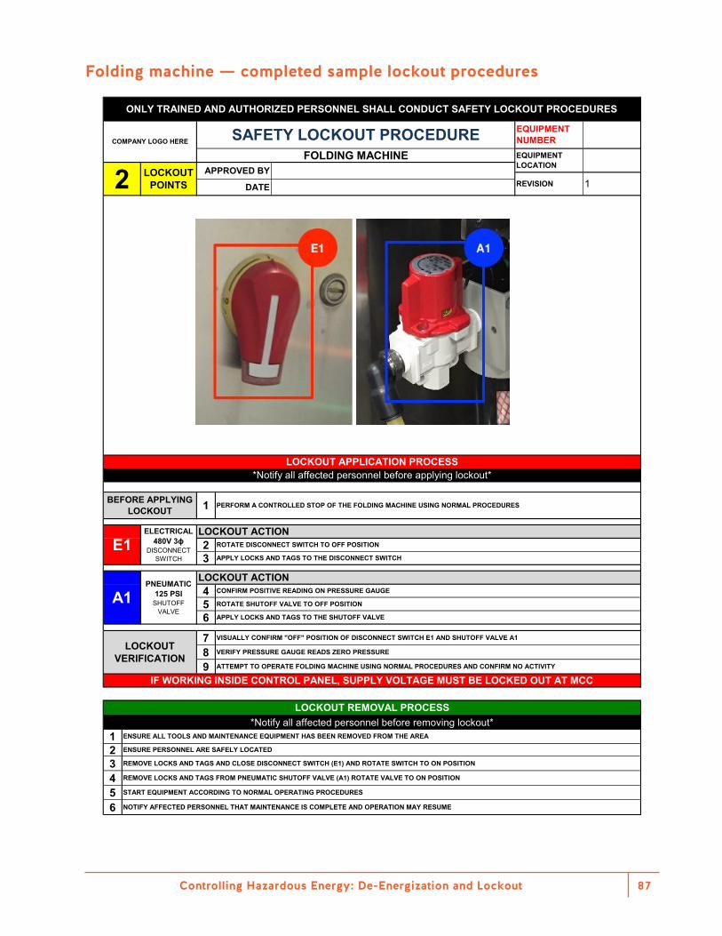
Controlling Hazardous Energy: De-Energization and Lockout 87
Folding machine — completed sample lockout procedures
23
456
789
123456
LOCKOUT APPLICATION PROCESS
APPLY LOCKS AND TAGS TO THE DISCONNECT SWITCHE1
ELECTRICAL480V 3ϕ
DISCONNECT SWITCH
LOCKOUT ACTIONROTATE DISCONNECT SWITCH TO OFF POSITION
BEFORE APPLYING LOCKOUT
PERFORM A CONTROLLED STOP OF THE FOLDING MACHINE USING NORMAL PROCEDURES1
IF WORKING INSIDE CONTROL PANEL, SUPPLY VOLTAGE MUST BE LOCKED OUT AT MCC
APPLY LOCKS AND TAGS TO THE SHUTOFF VALVE
A1
*Notify all affected personnel before applying lockout*
ATTEMPT TO OPERATE FOLDING MACHINE USING NORMAL PROCEDURES AND CONFIRM NO ACTIVITY
LOCKOUT VERIFICATION
VISUALLY CONFIRM "OFF" POSITION OF DISCONNECT SWITCH E1 AND SHUTOFF VALVE A1
VERIFY PRESSURE GAUGE READS ZERO PRESSURE
ROTATE SHUTOFF VALVE TO OFF POSITION
LOCKOUT ACTIONCONFIRM POSITIVE READING ON PRESSURE GAUGE
PNEUMATIC 125 PSI
SHUTOFF VALVE
ONLY TRAINED AND AUTHORIZED PERSONNEL SHALL CONDUCT SAFETY LOCKOUT PROCEDURES
COMPANY LOGO HERE SAFETY LOCKOUT PROCEDUREFOLDING MACHINE
2 LOCKOUT POINTS
APPROVED BY
DATE 1REVISION
EQUIPMENT NUMBEREQUIPMENT LOCATION
START EQUIPMENT ACCORDING TO NORMAL OPERATING PROCEDURES
NOTIFY AFFECTED PERSONNEL THAT MAINTENANCE IS COMPLETE AND OPERATION MAY RESUME
LOCKOUT REMOVAL PROCESS*Notify all affected personnel before removing lockout*
ENSURE ALL TOOLS AND MAINTENANCE EQUIPMENT HAS BEEN REMOVED FROM THE AREA
ENSURE PERSONNEL ARE SAFELY LOCATED
REMOVE LOCKS AND TAGS AND CLOSE DISCONNECT SWITCH (E1) AND ROTATE SWITCH TO ON POSITION
REMOVE LOCKS AND TAGS FROM PNEUMATIC SHUTOFF VALVE (A1) ROTATE VALVE TO ON POSITION
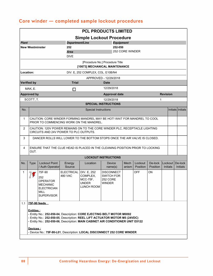
Controlling Hazardous Energy: De-Energization and Lockout88
Core winder — completed sample lockout procedures
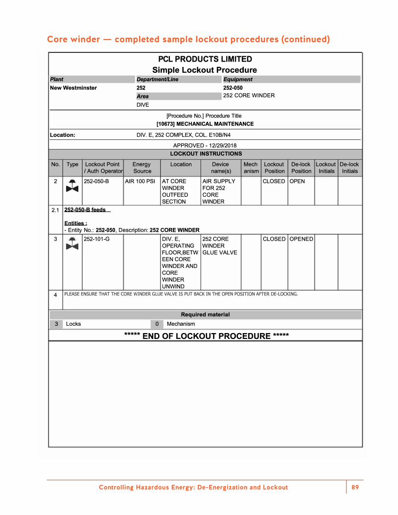
Controlling Hazardous Energy: De-Energization and Lockout 89
Core winder — completed sample lockout procedures (continued)
PCL PRODUCTS LIMITED Simple Lockout Procedure
IP/ant l Del'_artment/Line I r,Eguil'_ment I New Westminster 252 252-050
!Area 1252 CORE WINDER DIVE
[Procedure No.] Procedure Title [10673] MECHANICAL MAINTENANCE
Location: DIV. E, 252 COMPLEX, COL. E10B/N4
APPROVED - 12/29/2018 LOCKOUT INSTRUCTIONS
No. Type Lockout Point Energy Location Device Mech Lockout De-lock Lockout De-lock / Auth Operator Source name{s) anism Position Position Initials Initials
2 .;t. 252-050-8 AIR 100 PSI AT CORE AIR SUPPLY CLOSED OPEN WINDER FOR 252 OUTFEED CORE SECTION WINDER
2.1 2s2-oso-a feeds
Entities· - Entity No.: 252-050, Description: 252 CORE WINDER
3 .;t. 252-101-G DIV. E, 252 CORE CLOSED OPENED OPERATING WINDERFLOOR,BETW GLUE VALVEEEN COREWINDER ANDCOREWINDERUNWIND
4 PLEASE ENSURE THAT THE CORE WINDER GLUE VALVE IS PUT BACK IN THE OPEN POSmON AFTER DE-LOCKING.
I Required material
r 3 Locks O l Mechanism
***** f
END OF LOCKOUT PROCEDURE *****
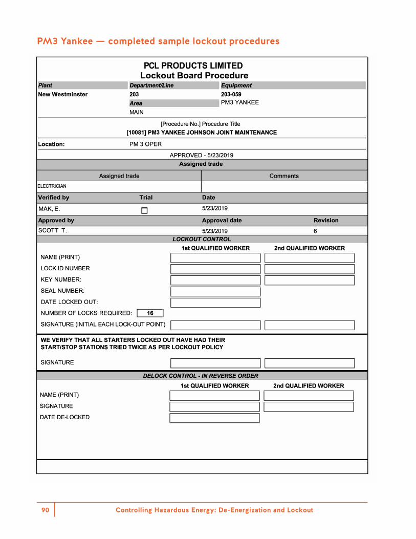
Controlling Hazardous Energy: De-Energization and Lockout90
PM3 Yankee — completed sample lockout procedures
PCL PRODUCTS LIMITED Lockout Board Procedure
Plant l De/l_artment/Line I r,Egui/l_ment I New Westminster 203 203-059
!Area I PM3 YANKEE MAIN
[Procedure No.] Procedure Title [10081] PM3 YANKEE JOHNSON JOINT MAINTENANCE
Location: PM 3 OPER
APPROVED - 5/23/2019 Assigned trade
Assigned trade Comments ELECTRICIAN
Verified by Trial Date
MAK,E. □ 5/23/2019
Approved by Approval date Revision
SCOTT T. 5/23/2019 6 LOCKOUT CONTROL
1st QUALIFIED WORKER 2nd QUALIFIED WORKER NAME (PRINT) I 11 I LOCK ID NUMBER I 11 I KEY NUMBER: I 11 I SEAL NUMBER: I I DATE LOCKED OUT: I I
11 I NUMBER OF LOCKS REQUIRED: I 16 I SIGNATURE (INITIAL EACH LOCK-OUT POINT) I WE VERIFY THAT ALL STARTERS LOCKED OUT HAVE HAD THEIR START/STOP STATIONS TRIED TWICE AS PER LOCKOUT POLICY
SIGNATURE I 11 I DELOCK CONTROL - IN REVERSE ORDER
1st QUALIFIED WORKER 2nd QUALIFIED WORKER NAME (PRINT) I 11 I SIGNATURE I 11 I DATE DE-LOCKED I I
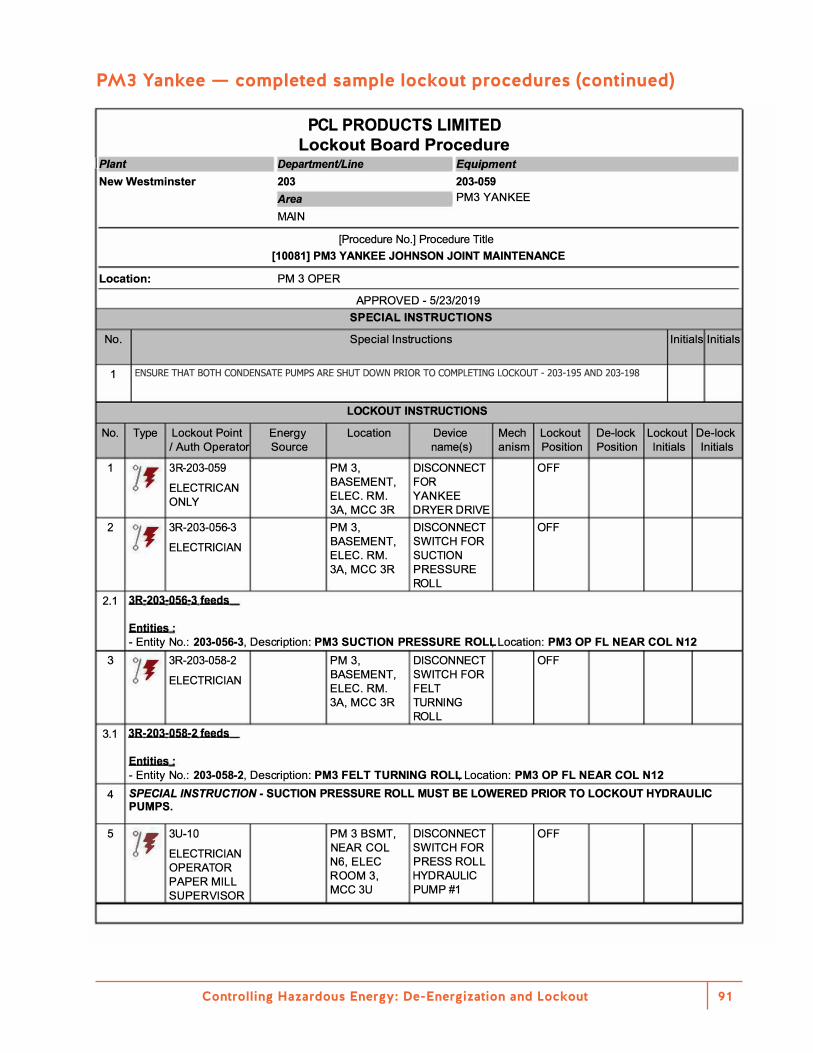
Controlling Hazardous Energy: De-Energization and Lockout 91
PM3 Yankee — completed sample lockout procedures (continued)
PCL PRODUCTS LIMITED Lockout Board Procedure
IP/ant l Del'_artment/Line I r,Eguil'_ment I New Westminster 203 203-059
!Area I PM3 YANKEEMAIN
[Procedure No.] Procedure Title [10081] PM3 YANKEE JOHNSON JOINT MAINTENANCE
Location: PM 3 OPER
APPROVED - 5/23/201 9 SPECIAL INSTRUCTIONS
No. Special Instructions Initials Initials
1 ENSURE THAT BOTH CONDENSATE PUMPS ARE SHUT DOWN PRIOR TO COMPLETING LOCKOUT - 203-195 AND 203-198
LOCKOUT INSTRUCTIONS
No. Type Lockout Point Energy Location Device Mech Lockout De-lock Lockout De-lock / Auth Operator Source name(s) anism Position Position Initials Initials
1 ]f 3R-203-059 PM3, DISCONNECT OFF
ELECTRICAN BASEMENT, FOR
ONLY ELEC. RM. YANKEE 3A, MCC3R DRYER DRIVE
2 ]f 3R-203-056-3 PM3, DISCONNECT OFF
ELECTRICIAN BASEMENT, SWITCH FOR ELEC. RM. SUCTION
3A, MCC3R PRESSURE ROLL
2 .1 38-203-056-3 feeds
Entities· - Entity No.: 203-056-3, Description: PM3 SUCTION PRESSURE ROLl,.Location: PM3 OP FL NEAR COL N12
3 ]f 3R-203-058-2 PM3, DISCONNECT OFF
ELECTRICIAN BASEMENT, SWITCH FOR ELEC. RM. FELT
3A, MCC3R TURNING ROLL
3.1 38-203-058-2 feeds
Entities· - Entity No.: 203-058-2, Description: PM3 FELT TURNING ROLi,. Location: PM3 OP FL NEAR COL N12
4 SPECIAL INSTRUCTION - SUCTION PRESSURE ROLL MUST BE LOWERED PRIOR TO LOCKOUT HYDRAULIC PUMPS.
5 ]J 3U-10 PM 3 BSMT, OFF
ELECTRICIAN NEAR COL
OPERATOR N6, ELEC
PAPER MILL ROOM 3,
SUPERVISOR MCC3U
DISCONNECT SWITCH FOR PRESS ROLL HYDRAULIC PUMP#1
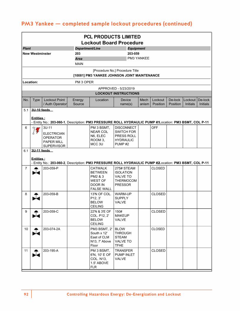
Controlling Hazardous Energy: De-Energization and Lockout92
PM3 Yankee — completed sample lockout procedures (continued)
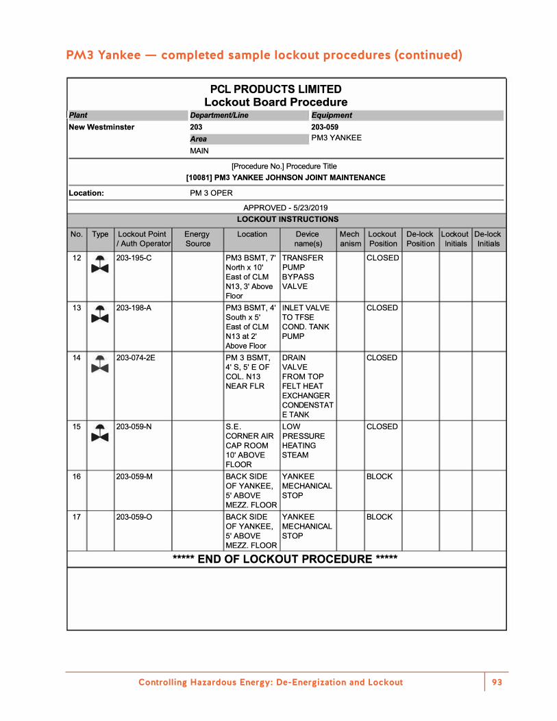
Controlling Hazardous Energy: De-Energization and Lockout 93
PM3 Yankee — completed sample lockout procedures (continued)
PCL PRODUCTS LIMITED Lockout Board Procedure
IP/ant l Del'_artment/Line I r,Eguil'_ment I New Westminster 203 203-059
!Area I PM3 YANKEE MAIN
[Procedure No.] Procedure Title [10081] PM3 YANKEE JOHNSON JOINT MAINTENANCE
Location: PM 3 OPER
APPROVED - 5/23/2019 LOCKOUT INSTRUCTIONS
No. Type Lockout Point Energy Location Device Mech Lockout De-lock Lockout De-lock / Auth Operator Source name{s) anism Position Position Initials Initials
12 .;t. 203-195-C PM3 BSMT, 7' TRANSFER CLOSED North x 10' PUMP East of CLM BYPASS N 13, 3' Above VALVE Floor
13 .;t. 203-198-A PM3 BSMT, 4' INLET VALVE CLOSED South x 5' TO TFSE East of CLM COND. TANK N13 at 2' PUMP Above Floor
14 .;t. 203-074-2E PM 3 BSMT, DRAIN CLOSED 4' S, 5' E OF VALVE COL. N13 FROM TOP NEAR FLR FELT HEAT
EXCHANGER CONDENSTAT E TANK
15 .;t. 203-059-N S.E. LOW CLOSED CORNER AIR PRESSURE CAP ROOM HEATING 10' ABOVE STEAM FLOOR
16 203-059-M BACK SIDE YANKEE BLOCK OF YANKEE, MECHANICAL 5' ABOVE STOP MEZZ. FLOOR
17 203-059-0 BACK SIDE YANKEE BLOCK OF YANKEE, MECHANICAL 5' ABOVE STOP MEZZ. FLOOR
***** END OF LOCKOUT PROCEDURE *****

Notes

Notes

Notes


BK21 Printed in Canada R07/19