Embed Size (px)
Citation preview

STATE OF DELAWARE
DEPARTMENT OF TRANSPORTATION
BID PROPOSAL
for
CONTRACT T200811301.01
FEDERAL AID PROJECT NO. NH-2015 (20)
US 301, MARYLAND STATE LINE TO LEVELS ROAD NEW CASTLE COUNTY
ADVERTISEMENT DATE: November 10, 2015
COMPLETION TIME: 850 Calendar Days
SPECIFICATIONS FOR ROAD AND BRIDGE CONSTRUCTIONDELAWARE DEPARTMENT OF TRANSPORTATION
AUGUST 2001
Bids will be received in the Bidder's Room at the Delaware Department of Transportation's AdministrationBuilding, 800 Bay Road, Dover, Delaware until 2:00 P.M. local time December 22, 2015
This Copy is for information only.You must request a CD fromDelDOT in order to bid.

Contract No.T200811301.01 Federal Aid Project No. NH-2015 (20)
US 301, MARYLAND STATE LINE TO LEVELS ROADNEW CASTLE COUNTY
GENERAL DESCRIPTION
LOCATION These improvements are located in NEW CASTLE County more specifically shown on the LocationMap(s) of the enclosed Plans.
DESCRIPTION
The improvements consist of furnishing all labor and materials for construction of a divided highwayincluding: clearing and grubbing; excavation, hauling and placing embankment for roadway constructionP.C.C. roadway pavement and shoulders; P.C.C./asphalt ramps; asphalt side roads; toll facilities; intelligenttransportation systems including CVISN and WIM; drainage improvements; stormwater managementfacilities; guardrail; fencing; archeology resource protection areas; erosion and sediment controls; signing; lighting; pavement markings; traffic signal work; landscaping; mechanically stabilized earth retainingwalls; reinforced concrete bridges with prestressed reinforced concrete girders; furnishing and installingpiles; maintenance of traffic; utility relocations; and other incidental construction in accordance with thelocation, notes and details shown on the plans and as directed by the engineer. This contract includes workwithin the state of Maryland. This contract is also referred to as Contract 3.
COMPLETION TIME All work on this contract must be complete within 850 Calendar Days. The Contract Time includes anallowance for 120 Weather Days. It is the Department's intent to issue a Notice to Proceed such that workstarts on or about February 18, 2016.
PROSPECTIVE BIDDERS NOTES:
1. BIDDERS MUST BE REGISTERED with DelDOT and request an official Bid Proposal that containsplans and specifications in order to submit a bid. Contact DelDOT at [email protected] or phone302-760-2031 to request Bid Documents.
2. QUESTIONS regarding this project are to be e-mailed to [email protected] no less than sixbusiness days prior to the proposal opening date in order to receive a response. Responses to inquiriesare posted on-line at http://www.bids.delaware.gov.
3. THE BID PROPOSAL incorporates a cd containing Expedite, version 5.9a and its installation file.Bidders are to use the cd provided to enter their bid amounts into the Expedite file. The Expedite bid fileis to be printed and submitted in paper form along with the cd and other required documents prior to theBid due date and time.
4. BONDS: Each proposal must be accompanied by a deposit of either surety bond or security for a sumequal to at least 10% of the bid. The Bid Bond form submitted must be the form included with thisproposal, or the identical form located here. The successful bidder will be required to present aPayment/Performance Bond in the amount of 100% of their bid prior to contract execution.
5. PREQUALIFICATION. As a prequalification to submit a bid on the US 301 project, all Contractorsand Subcontractors must certify that their company, either independently or through agreement with otherorganizations, is providing craft training for journeyman and apprentice levels through a bona fideprogram approved by and registered with the State of Delaware and/or United States Department ofLabor, to comply with 29 Del C. 6962(c)(11). The provided form, "Prequalification for US 301Contracts", is required to be completed and submitted by each prime contractor and their subcontractorsno later than 10 a.m. local time on the date of bid opening along with supporting program documentation.DelDOT will review this information to prequalify bidders in advance of the bid opening. If theprequalification package is missing any portion of the certification or program documentation, the bidderwill be deemed not have met the prequalification requirement and their bid will not be accepted. Thecontact for certified craft training programs is Kevin Calio, Delaware DOL, 302-451-3419 or,[email protected]. A Delaware Business License is not needed as part of the pre-qualification tobid. A Delaware Business License will be required as part of the Contract award and execution process.
i
Contract No. T200811301.01
In order to establish a bona fide Apprenticeship & Training program approved by and registered with theDelaware Department of Labor (DDOL):
Step 1 - The contractor and/or subcontractor will submit a completed Sponsor Application form alongwith their Worker's Compensation Insurance Declaration page to DDOL. The contractor and/orsubcontractor can also become a sponsor as part of a Joint Apprenticeship Committee (JAC), whichis a group of contractors establishing an Apprenticeship & Training program.
Step 2 - DDOL will review the information provided to confirm the truth/accuracy of all informationprovided on the application.
Step 3 - Once DDOL has approved the application, they work with the sponsor to execute theStandards of Agreement, either with the contractor and/or subcontractor or with the JAC. Once theStandards of Agreement are signed by all parties, the sponsor and/or JAC has a bona fide programrecognized by DOL and will receive a Certificate of Registration. If the contractor and/orsubcontractor provide all of the required information, Steps 2 and 3 are expected to take one to twoweeks to complete.
Along with the "Prequalification for US 301 Contracts" form, the Certificate of Registration should besubmitted as the supporting documentation. A letter from the DDOL stating that the contractor and/orsubcontractor is not eligible for the Apprenticeship and Training Program due to the nature of thecontractor's and/or subcontractor's work should also be submitted as the supporting documentation whenapplicable.
“Prequalification for US 301 Contracts” forms and documentation can be sent via hardcopy or electronicsubmission:
Send electronic submissions to: [email protected] Subject: QUAL DOCS
Send hardcopy overnight delivery to: DelDOT Contract Administration; 800 Bay Road, Dover, DE19901 RE: *QUAL DOCS*.
If a contractor has previously submitted the Prequalification information to DelDOT for other US 301contracts, and the information has been accepted, then the contractor does not need to resubmit thePrequalification information to DelDOT for this contract. A list of contractors that have submitteda c c e p t a b l e P r e q u a l i f i c a t i o n i n f o r m a t i o n c a n b e f o u n d a t : http://www.deldot.gov/information/business/bids/const_proj_bid_info.shtml
6. WORK IN THE STATE OF MARYLAND. Work shall be performed within the State of Maryland andCecil County, Maryland jurisdictions. The contractor shall be responsible for obtaining and paying alllicenses, taxes, fees, wage rates, and any other requirements for performing work within thosejurisdictions. The contractor shall be responsible for ensuring that all subcontractors performing workin the State of Maryland and Cecil County have obtained and paid all licenses, taxes, fees, wage rates andany other requirements for performing work within those jurisdictions. Items and quantities for the workwithin the State of Maryland and Cecil County, Maryland jurisdictions are in Section 0009 of the BidProposal Schedule of Items.
a. As shown in the Contract Documents, this contract involves work within the State of Maryland. Thestormwater management and the erosion and sediment control practices within the State of Marylandare subject to oversight by the Maryland State Highway Administration (MDSHA) as delegated toMDSHA by the Maryland Department of the Environment (MDE). The Contractor shall follow allrequirements in the MDE permit and as shown in the Contract documents, including the preparation,submission and tracking of daily work logs. DelDOT shall prepare as-built surveys of the permanentstormwater management facilities constructed in the State of Maryland. Item 900500 EnvironmentalPerformance Incentive (Disincentive) shall be based on a review of the entire project limits, includingwork within the State of Maryland.
b. Grading Permit from Cecil County, Maryland is required for the work within Cecil County,Maryland. DelDOT will submit the application for this permit after the T200811301 Contract hasbeen fully executed. The Contractor shall coordinate with DelDOT to supply all required informationand signatures. DelDOT shall pay any application fees.
ii

Contract No. T200811301.01
7. ALTERNATE BID ITEMS. This contract contains options for Alternate Bid Items. There are twochoices for the Pile Alternate group for Bridge 1-486 (Strawberry Lane over US 301) and three choicesfor the Pile Alternate group for Bridge 1-482 (Levels Road over US 301). Bid only one of the choicesin each ALT GROUP. For Bridge 1-486, one Section Choice is titled PILE ALTERNATIVE 1 and theother Section is title PILE ALTERNATIVE 2. Bid only one of these sections and leave the other sectionblank. For Bridge 1-482, one Section Choice is titled PILE ALTERNATIVE 1, one Section Choice istitled PILE ALTERNATIVE 2, and one Section Choice is titled PILE ALTERNATIVE 3. Bid only oneof these sections and leave the other sections blank. (NOTE. In the event of a bidder error mistakenlybidding more than one Alternative, the Alternative that is fully completed and contains the lowest pricewill be utilized for the bid.)
8. BREAKOUT SHEETS MUST be submitted either with your bid documents; or within seven (7)calendar days following the bid due date by the lowest apparent bidder. Refer to instructions adjacentto the Breakout Sheets in his document.
9. FUEL COST OPTION. Bidders are advised that a "Diesel Fuel Cost Price Adjustment Option" isincluded as referenced in Special Provision 763626, and that the form should be completed and submittedwith the bid.
10. DESIGN FILE AVAILABLE. Upon request, a design file will be made available to the Contractorduring the bid period upon email submission of the provided form titles "3 Electronic File SharingRelease." The form must be signed by a person having authority to enter into contracts for the company. The signed form can be included with the Request for Bid Proposal, or may be sent via email [email protected]. The file will be shipped regular mail. A UPS or FED-EX account number maybe provided for faster shipment.
In addition to the electronic project files listed under the general notes in the construction plans, theDelaware Department of Transportation (DelDOT) will provide the contractor with a design file, inmicrostation .dgn format, that contains 3D feature lines for the proposed design. The 3D feature linesare for the final proposed top surface elevation only. These electronic files may only be used per therequirements for Machine Control Grading in Item 763501-Construction Engineering.
Upon request, the design file will be made available to the contractor during the bid period after theelectronic file sharing release form has been signed and submitted to DelDOT by the contractor.
It is the contractor's responsibility to convert the design file to a file format that is compatible with thesoftware used on the contractor's machine grade control equipment. It is also the contractor'sresponsibility to verify that the 3D information is correct after any and all software conversions. DelDOTwill not be responsible for checking any of the contractor's software conversions. There may be someareas of the project not included in the design file. It is the contractor's responsibility to review the designfile and determine the limits of the project included.
11. For protection of the threatened Northern Long-Eared Bat (NLEB), there shall be no clearing of treesbetween 12:01 AM on April 15 and 11:59 PM on August 30 within the limits of the 'woods line' symbolwithin areas of the project that have been identified as potential NLEB habitat.
DelDOT anticipates that the potential NLEB habitat areas will be cleared under a separate AdvanceClearing Contract that will be complete before April 15, 2016. The Advance Clearing Contract will onlyperform clearing and not grubbing and the cleared materials shall be left within the limits of the projectat the locations where they are cleared and the Contractor for Contract T200811301 shall be responsiblefor removing and properly disposing of the cleared materials with all costs included under Item201000-Clearing and Grubbing. The Advance Clearing Contractor shall cut trees 3 inches and larger indiameter at breast height (DBH) and leave a stump that is approximately two to four feet above theexisting ground. Coordination between the Advance Clearing Contractor and the Contractor for ContractT200811301 shall also include:
a. The Contractor for Contract T200811301 shall review with the Engineer all Resource ProtectionFence (RPF) that has been installed by the Advance Clearing Contract. The Engineer shall identifythe limits of the existing RPF that shall become the responsibility of the Contractor for ContractT200811301 to maintain and repair during the construction period in accordance with therequirements of Item 727552. The Contractor for Contract T200811301 shall also remove and
iii
Contract No. T200811301.01
dispose of the existing RPF after it is no longer required as determined by the Engineer and at thetime of the removal the existing RPF shall be measured for payment under Item 727552 ResourceProtection Fence. All costs to maintain and repair the existing RPF and salvaging and delivering thesigns to the DelDOT sign shop shall be included in the unit bid price for Item 727552. There willbe approximately four thousand five hundred (4,500) linear feet of existing RPF installed by theAdvance Clearing Contract.
The approximate areas bounded within the woods line symbol and the limit of construction symbol onthe construction plans that have been identified as potential NLEB habitat and that are anticipated to becleared by the Advance Clearing Contract include:a. US301 Station 104+20 Rt. to US301 Station 110+50 Rt.b. US301 Station 120+85 Rt. to US301 Station 124+40 Rt. c. US301 Station 125+00 Rt. to US301 Station 131+15 Rt. d. US301 Station 133+00 Rt. to US301 Station 134+50 Rt. e. US301 Station 122+50 Lt. to US301 Station 126+40, 120' Lt. f. US301 Station 126+10 Lt. to US301 Station 137+40, 110' Lt. g. Strawberry Lane, US301 Station 135+60, 600' Lt. to US301 Station 135+60, 610' Lt, to US301
Station 136+55, 610' Lt. to US301 Station 136+55, 600' Lt. h. Strawberry Lane, US301 Station 137+40, 110' Lt to US301Station 136+70, 600' Lt. to US301 Station
137+40, 575' Lt. to US301 Station 137+95, 155' Lt. to US301 Station 137+40, 110' Lt. i. Strawberry Lane, US301 Station 137+80, 550' Rt. to US301 Station 137+90, 270' Rt., to US301
Station 138+20, 320' Rt., to US301 Station 138+11, 550' Rt. j. Strawberry Lane, US301 Station 140+00, 850' Rt., to US301 Station 139+50, 280' Rt., to US301
Station 141+90, 300' Rt., to US301 Station 142+50, 280' Rt., to US301 Station 139+70, 375' Rt. k. Strawberry Lane, US301 Station 138+80, 120' Lt. to US301 Station 138+17, 990' Lt., to US301
Station 140+05, 165' Lt. US301 Station 143+50, 10' Rt. to US301 Station 143+50, 10' Lt. to US301Station 152+20, 215' Lt. to US301 Station 154+30, 140' Lt. to US301 Station 160+50, 85' Rt. toUS301 Station 160+90, 15' Lt.
l. US301 Station 161+50, 65' Rt. to US301 Station 165+40, 40' Rt. to US301 Station 165+40, 115' Rt. m. US301 Station 178+70, 15' Rt. to US301 Station 178+95, 150' Lt. to US301 Station 170+90, 145'
Lt. to US301 Station 171+10, 45' Rt. n. US301 Station 144+00, 295' Rt. to US301 Station 144+50, 130' Rt. to US301 Station 138+30, 325'
Rt., to US301 Station 152+65, 210' Rt. to US301 Station 158+50, 450' Rt. o. US301 Station 159+25, 220' Rt. to US301 Station 160+20, 470' Rt. to US301 Station 160+50, 200'
Rt. to US301 Station 160+85, 440' Rt. p. US301 Ramp E Station 1279+15, to US301 Ramp E Station 1278+50, 280' Rt., to US301 Ramp E
Station 1280+25.q. US301 Ramp E Station 1279+15, to US301 Ramp E Station 1280+00, 110' Lt to US301 Ramp E
Station 1280+70, 110' Lt. to US301 Ramp E Station 1283+20, 295' Lt to US301 Ramp E Station1280+25.
12. The Contractor shall name the following as an Additional Insured on all insurance certificates: "UnitedStates Department of Transportation, acting by and through the Federal Highway Administration - TIFIALender." The Department will also be sharing copies of the final executed contract documents with theFederal Highway Administration - TIFIA Lender.
13. The Contractor shall submit to the Department legible copies of the Bid Documentation as set forth inSection 103.09 Escrow of Bid Documentation.
14. Upon execution of the contract, the Department will provide the Contractor with .pdf files of the awardedContract Plans and Special Provisions. The Contractor shall be responsible for making all printed copiesof these documents for his use and the use of his subcontractors. In the case of any plan revisions thatthe Department may issue, the Department will provide the Contractor up to five (5) full size sets and five(5) half size sets of the revised plans and specifications. The Department shall also provide the Contractor.pdf files of the revised plans and specifications and the Contractor shall be responsible for making anyadditional printed copies for his use and the use of his subcontractors.
15. The Contractor shall make available at least one employee to attend and represent the firm at allscheduled job progress meetings, project working group meetings or other public informational meetingsas requested by the Engineer. The person attending shall be knowledgeable of current job progress, theanticipated construction schedule and any ongoing or potential construction or contract issues. Costs areincidental to Item 743000-Maintenance of Traffic.
iv
Contract No. T200811301.01
16. Any unacceptable shifting or movement in MSE wall panels resulting from adjoining pile driving or otherContractor activity shall be corrected to the satisfaction of the Engineer. The Contractor shall submit aplan detailing the repair procedure to the Engineer for approval prior to beginning any required repairs. Costs for preparation and submittal of the plan and for performing the repairs if required are to beincidental to Item 602772 Mechanically Stabilized Earth Walls.
17. Any requirement to utilize Borrow Types A, B, C, D, F, or MSE wall backfill (or materials meeting therequirements of Borrow Types A, B, C, D, F, or MSE wall backfill) shall be met by using only soil forthese materials. Crushed concrete, millings, stone dust, or other non-soil materials will not be accepted,regardless of their gradation.
18. The following earthwork related survey information is critical to computing pay item quantities. TheContractor shall give the Project Resident at least two Working Days' notice whenever any of the listedsurfaces are ready for elevations to be taken by the Engineer's Survey crew. No additional excavationor backfill may be performed in these areas until the required survey information has been acquired bythe Engineer's crew. Prior to notifying the Project Resident, areas to be surveyed shall be roughly leveledand cleared of debris or obstructions in order to collect accurate data. The Contractor is encouraged tomake their survey crew available to take elevations jointly with the Engineer's crew in order to avoid anylater quantity disputes. If the Contractor elects not to acquire survey data for the critical elements listed,then the Engineer's survey data will be considered the binding record regarding the pay item quantitycomputations. The Contractor shall share with the Engineer, upon request, any survey data takenindependently that may assist in the pay item quantity computations. The critical elements include, butare not limited to the list below. Other critical elements that are identified by the Engineer shall alsofollow the above procedure.a. Surface elevations following Clearing and Grubbing of all roadway, structure, stormwater pond,
wetland mitigation, and on-site borrow excavation areas.b. Top surface (in areas not requiring clearing and grubbing) and bottom surface of topsoil to be
stripped in fill areas.c. Top surface of topsoil to be stripped in cut areas if no Clearing and Grubbing is required.d. Top and bottom surfaces of undercut areas not measured by the inspection staff.e. Bottom surfaces of excavations such as ditches, stormwater ponds, mitigation sites, and on-site
borrow areas prior to placement of any topsoil or other materials.f. Interim and final surfaces of infiltration stormwater facilities.g. Top surfaces (following Clearing and Grubbing if applicable) and bottom surfaces of all structure
excavation areas.h. Top and bottom surfaces (following Clearing and Grubbing if applicable) of other excavation items
such as muck excavation, channel excavation, etc.i. Top surface (following clearing, grubbing, topsoil removal, and overburden removal) and bottom
surface prior to placing any backfill or topsoil at any off-site borrow source to be measured bycross section.
19. Under Item 763501 Construction Engineering, Machine Control Grading, the Contractor shall providethe Engineer a total of three (3) Rovers. Each Rover shall be of the same manufacture as the Contractor'sbase station, shall be dual frequency, and shall be provided with: a survey program that has the baselinesof construction pre-loaded; a two (2) meter fixed height rover pole; and a clamp to affix the surveycontroller to the Rover pole. The contractor will be responsible for localizing each Rover on the jobspecific control points.
The automatic level to be provided by the Contractor shall be an automatic (self-leveling) level with aminimum 25X magnification. The Contractor shall also provide a tripod for the automatic level whichshall be of wood or wood and fiberglass construction (aluminum legs will not be accepted) and a 25 footfiberglass survey rod, graduated in tenths and hundredths of a foot.
20. Unless directed otherwise by the Engineer, backfill dry undercut areas with soil material meeting Borrow,Type A and backfill wet undercut areas with soil material meeting Borrow, Type B requirements.
21. Measurement for depth of pipe trench excavation (Item 208000) will be made to the bottom of the mainportion of the pipe, not the bell or spigot. Measurement for width of pipe trench excavation will be alsobe made 18 inches on either side, outside the main portion of pipe, not the bell or spigot. Any additionalexcavation required for the bell end of the pipe or for the pipe bedding is incidental to the item and willnot be measured for payment.
v
Contract No. T200811301.01
22. Completion dates and Interim Completion dates identified in the Contract documents shall be identifiedin the Contractor's CPM schedule as Milestones.
23. When the Engineer has determined that substantial completion of the contract has been achieved, asdefined by Standard Specification 101.03, for any milestones and the completion of the contract, timecharges will be suspended relative to that milestone or completion of the contract and a semi-finalinspection will be scheduled. If a semi-final inspection punchlist is generated for completion by theContractor, a timeframe to complete the list will be established by the Engineer. Failure to complete thelist within the required timeframe will result in the resumption of time charges relative to that milestoneor completion of the contract until all items on the semi-final punchlist have been completed. Similarly,a Final Inspection will be held following completion of the semi-final punchlist. Any punchlist generatedat the Final Inspection will also have a timeframe established for completion. If the Final Punchlist isnot completed within the specified timeframe, time charges will again resume relative to that milestoneor completion of the contract until all items on the Final Punchlist have been completed by theContractor.
24. Construction conflicts occur when a contractor elects to use a crane of sufficient height that violatesairport airspace or exceeds 200 feet in height. Contractors are responsible to conform to the appropriateFAA requirements. Contractors can check the equipment that they will be using to determine if they needto notify the FAA using the notice criteria tool at the following web address:https://oeaaa.faa.gov/oeaaa/external/gisTools/gisAction.jsp
25. Concrete for Items 602013 P.C.C. Masonry, Superstructure Class D, 602017 P.C.C. Masonry, Parapet,Class A and 720626 Concrete Single Face Barrier, Type I shall include a shrinkagereducing/compensating admixture. The admixture may be one product or two separate products thatprovide both expansion and pore water surface tension. The admixture(s) shall have the followingcharacteristics: 1) Expands at a rate that closely compensates for the shrinkage of the concrete mix; 2)Reduces capillary surface tension of the concrete pore water; 3) Provides at least 80% shrinkagereduction as measured and documented by field performance; and 4) is formulated for use in freezingand thawing weather. All admixtures must be compatible with the overall concrete mix design. Calciumchloride is not permitted and no chemical admixtures containing more than 0.1% chloride by weight arepermitted. Dosage shall be as recommended by the manufacturer. All costs shall be included in the bidprice for the respective items.
26. Delete Standard Specification Section 602.20 (c) and replace with the following:
Texturing. Texture bridge deck, approach slab, and transition slab surfaces by first dragging a fabricover the final screeded concrete and then by sawing longitudinal grooves in the cured concrete. Afterfinal screeding of the surface, drag multiple-ply damp fabric over the surface to provide a gritty texture. After the bridge deck or approach slab has been cured and attained at least 75% of the 28-day designcompressive strength, saw uniformly pronounced grooves parallel to the centerlines without damagingthe concrete deck surface. Complete a longitudinal grooving operation that results in a uniformlygrooved deck surface.
Saw grooves approximately 1/8" + 0", - 1/16" wide, 3/16" ± 1/16" deep, and on 3/4" ± 1/16" (nominal)centers. Terminate grooves 18"± 1" from the face of the parapet or curb line. If metal drainage inletsextend more than 18" from the parapet or curb line, all grooves on the bridge deck surface are to endwithin 6" of the drainage inlet perimeter. At skewed metal edged expansion joints, end all grooveswithin 6" of the joint leaving no ungrooved surface adjacent to each side of the joint greater than 6" inwidth on the deck side of the expansion joints. Produce grooves that are continuous across constructionjoints or other joints in the concrete deck surface less than ½" wide. Do not saw grooves for a widthof 10 inches, ± 1 inch at locations of permanent striping lines in order to provide a smooth surface forplacement of permanent roadway striping. Perform continuous removal of all waste materials,including slurry, resulting from the grooving operations in accordance with Standard Specificationsubsections 106.09 and 110.17, leaving all surfaces in a washed and clean condition.
Delete the last paragraph of Standard Specification Section 602.20 (b) and replace with the following:
After the concrete has cured, test the surfaces of all decks, approach slabs, and transition slabs forsmoothness using an Inertial Profiler. Testing and corrective work shall conform to the requirementsof Special Provision Section 501.14, Pavement Smoothness Testing. Seal or repair any cracks in the
vi
Contract No. T200811301.01
decks, approach slabs, or transition slabs which occur prior to opening to traffic, in a manner approvedby the Engineer at no cost to the Department. Sound the riding surfaces, then remove and replace anydelaminated areas in a manner approved by the Engineer at no cost to the Department.
27. Standard Notes for Traffic Officer Usage: a. For night-time closures of any road or ramp, provide one traffic officer at each closure point shown
in the applicable detour plans. Traffic Officer shall be placed behind the closure barricade with thefront of vehicle facing approaching traffic and all emergency lights shall be activated. Traffic Officershall provide a report to the Contractor at the end of the day's activity identifying the number ofvehicles that attempted to not follow the detour.
b. The Contractor shall provide three traffic officers for a four-hour period twice per month to performspeed enforcement along roadways within the project limits. At the end of the day's enforcementactivity, the Traffic Officers shall provide a report to the Contractor identifying the number ofvehicles stopped, number and type of citations given and the range of speeds of those vehiclesstopped. Enforcement locations will be determined by the Engineer.
c. The Contractor shall provide one Traffic Officer for nighttime mobile pavement marking operationson US 301.
d. The Contractor shall provide one Traffic Officer for major phase change traffic switches on existingUS 301.
e. The Contractor shall provide two Traffic Officers for any rolling road block operation in accordancewith TA-35H.
f. See project detour plans for additional Traffic Officer requirements.g. The Contractor shall provide one Traffic Officer for any operation where an existing signalized
intersection is placed in flash-mode. The Traffic Officer is the only individual that can place a trafficsignal in flash-mode and the Traffic Officer must stay on location until the signal is placed back instop-and-go operation in accordance with DelDOT's Temporary Traffic Control within Intersectionsmemorandum (www.mutcd.deldot.gov).
h. Additional usage of Traffic Officers outside of the above requirements shall be approved by theEngineer in consultation with the Traffic Safety Section.
28. At the Levels Road Borrow Site, this site is also being utilized under the adjacent Contract T200911303. The Contractor for Contract T200811301 shall coordinate access to the areas of the Borrow Site as notedelsewhere in the contract documents. In addition, Contract T200811301 will be responsible for erosionand sediment control measures in Area 2 and Area 3 of the Borrow Site as shown on the plans and shallbe responsible for the erosion and sediment control measures for the durations noted unless otherwiseapproved by the Engineer. The Contractor for Contract T200911303 shall assume responsibility for theerosion and sediment control devices installed by Contract T200811301 when Contract T200911303moves into an area where Contract T200811301 had been working. This responsibility shall begin at least14 calendar days prior to the end of the responsibility period for the specific area by ContractT200811301 unless otherwise approved by the engineer. The Contractor for Contract T200911303 shallreplace the erosion and sediment control measures with his own material or enter into an agreement topurchase the erosion and sediment control measures from the Contractor for Contract T200811301. TheContractor for Contract T200811301 shall coordinate the replacement with the Contractor for ContractT200911303 so that continuous erosion and sediment control is provided. The Contractor for ContractT200811301 shall remove all erosion and sediment control measures that the Contractor for ContractT200911303 does not agree to purchase. All costs associated with removing the erosion and sedimentcontrol measures and coordinating any replacement shall be incidental to Item 900501 Borrow AreaErosion and Sediment Control and Dewatering.
29. At the Levels Road Borrow Site, the Contractor for Contract T200811301 shall only perform work withinArea 2 and Area 3 as designated on the plans. In addition:
a. The Contractor for Contract T200811301 shall have access to Area 2 and responsibility for theerosion and sediment control measures for the first two hundred and eight (208) calendar days fromthe first chargeable day identified in the Notice to Proceed for Contract T200811301 after whichContract T200911303 shall have exclusive access to Area 2.
b. The Contractor for Contract T200811301 shall have access to Area 3 and responsibility for theerosion and sediment control measures for the first three hundred and forty-four (344) calendar daysfrom the first chargeable day identified in the Notice to Proceed for Contract T200811301 afterwhich Contract T200911303 shall have exclusive access to Area 3.
c. If the Contractor for Contract T200811301 has not completed the excavations in Area 2 or Area 3
vii
Contract No. T200811301.01
within the timeframes noted to obtain the quantities of materials needed for the project as identifiedin the contract documents, the Contractor for Contract T200811301 shall provide the materialsneeded for the project that he was not able to obtain from Area 2 or Area 3 from an approved outsidesource at the unit price bid for Item 202000-Excavation and Embankment.
30. DelDOT will be advertising a separate contract to construct the toll equipment huts and gantries withinthe limits of construction for this Contract. The Contractor for T200811301 shall coordinate their Workand cooperate with this Toll Equipment Hut and Gantries Contractor per Section 105.08 Cooperationbetween Contractors. For informational purposed only, the anticipated work to be performed by the TollEquipment Hut and Gantries Contractor is included in the Contract Plans.
31. The Completion Date for all of the work in this contract is identified elsewhere in the contract documents. In addition, the following Interim Completion Dates and coordination are associated with the separateToll Equipment Hut and Gantries Contract:a. An Interim Completion Date of five hundred seventy (570) Calendar Days is established for
completion and acceptance by the Engineer of all work required to be complete by the Contractorfor Contract T200811301 in order for the Toll Equipment Hut and Gantries Contractor to access andconstruct the Toll Equipment Hut and Gantries. This will include completing all paving along theentire baseline of the US 301 mainline from Station to Station 201+00 to Station 210+00, completionof the gantry foundations, and the installation of all ITMS underground facilities throughout theentire contract. The contractor for Contract T200811301 shall provide unrestricted access to the TollEquipment Hut and Gantry work areas on the US 301 mainline for the construction of thoseimprovements for a period of one-hundred sixty (160) calendar days after the work just described iscompleted or after 570 Calendar Days, whichever is later. If the work just described is not completedwithin 570 Calendar Days, then for each and every Calendar Day charged beyond the 570 CalendarDays, Liquidated Damages shall be assessed and deducted from monies due the contractor perSection 108.08 in the amount of seventy-five percent (75%) of the value shown in Section 108.09until such time as the described work is complete and accepted by the Engineer.
b. An Interim Completion Date of forty-five (45) Calendar Days is established for completion andacceptance by the Engineer of all work required to be complete by the contractor for ContractT200811301 in order for the Toll Integrator to install and test all toll equipment at the US 301mainline toll locations, both northbound and southbound. This work shall include: pavement on theUS301 mainline from Station 186+00 to Station 246+00; guardrail and end treatment installation;final grading and stabilization; installing conduits and junction wells connecting to the TollEquipment Hut and Gantries; and installing any electric and communication connections to the TollEquipment Hut and Gantries. The contractor for Contract T200811303 shall then provide unrestrictedaccess to the US301 mainline for the Toll Integrator to install and test the toll collection facilities forthe remaining duration of Contract T200811301 after the work just described is completed. Thisforty-five Calendar Day period shall begin upon completion and acceptance by the Engineer of thework being constructed under the separate Toll Equipment Hut and Gantries contract. The Engineershall notify the contractor for Contract T200811301 when the work under the Toll Equipment Hutand Gantries contract has been accepted. If the work just described is not completed within theproscribed 45 Calendar Days, then for each and every Calendar Day charged beyond the 45 CalendarDays, Liquidated Damages shall be assessed and deducted from monies due the contractor perSection 108.08 in the amount of ninety percent (90%) of the value shown in Section 108.09 untilsuch time as the described work is complete and accepted by the Engineer.
c. These liquidated damages for Interim Completion Dates are in addition to and do not void or alterany liquidated damages that may be assessed if work for other Interim Completion Dates is notcompleted and accepted by the Engineer within the identified Interim Completion Date or if all ofthe work in the contract is not completed and accepted by the Engineer within the identifiedCompletion Date for the entire contract.
32. The entire US301 mainline project from the Maryland State Line to SR1 is being constructed undermultiple contracts that will be under construction concurrently with this Contract. As shown in the plans,various traffic control measures will be installed under this Contract to prevent access to the completedsections of roadway until the entire US301 mainline is ready to be open to traffic. The Contractor shallbe responsible for these traffic control measures until the end of the contract completion time or until theproject is accepted by the Engineer, whichever is later. The Contractor for Contract T200911303, US301Levels Road to Summit Bridge Road, will be responsible for performing the work to open the entireUS301 mainline section to traffic. If directed by the Engineer, the Contractor shall coordinate with theContractor for Contract T200911303 to have the traffic control measures replaced with devices ownedby the Contractor for Contract T200911303 so that continuous maintenance of traffic is provided. All
viii
Contract No. T200811301.01
costs associated with replacing the traffic control devices and coordinating the replacement shall beincluded in the unit price bid for the appropriate traffic control device and operation.
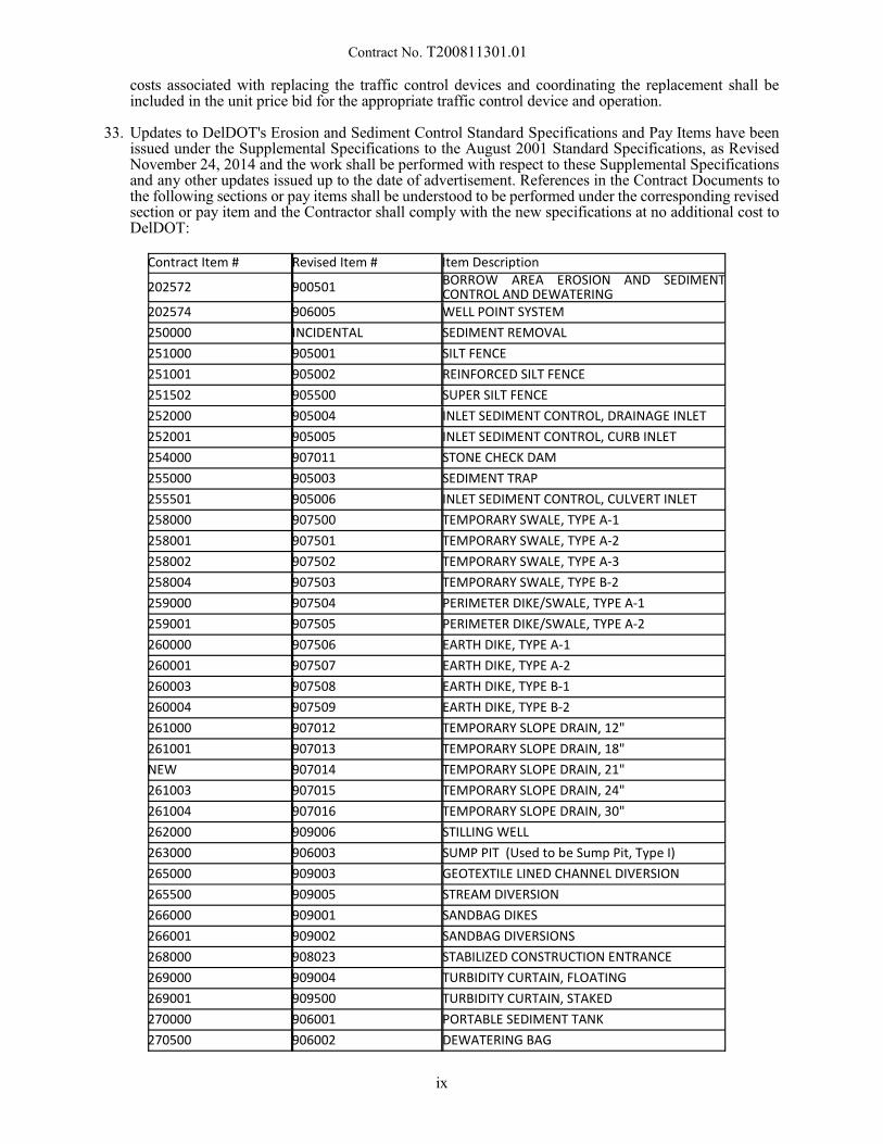
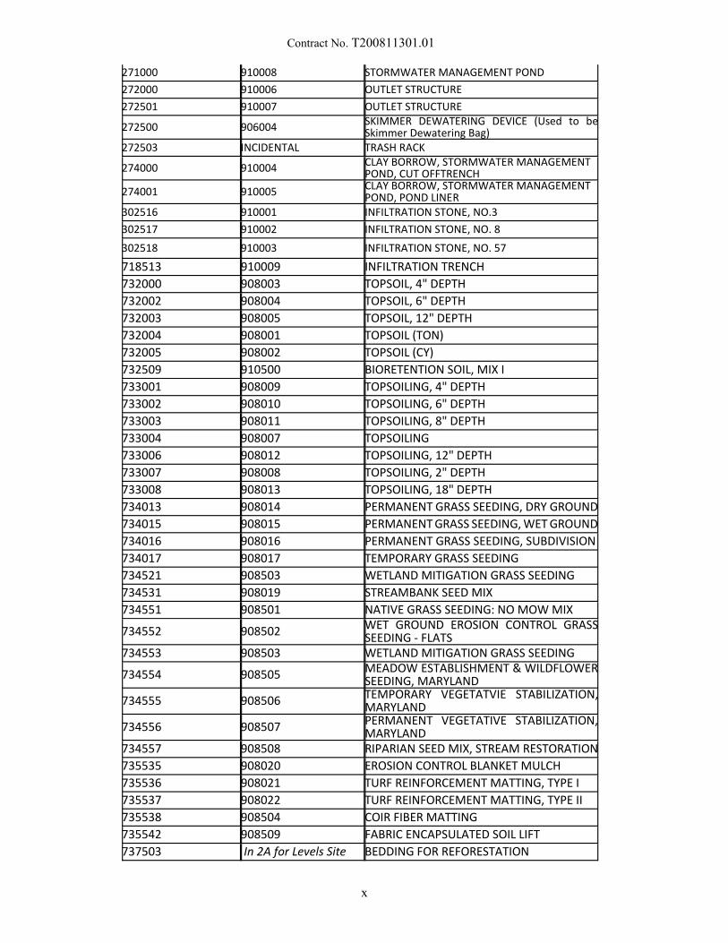
33. Updates to DelDOT's Erosion and Sediment Control Standard Specifications and Pay Items have beenissued under the Supplemental Specifications to the August 2001 Standard Specifications, as RevisedNovember 24, 2014 and the work shall be performed with respect to these Supplemental Specificationsand any other updates issued up to the date of advertisement. References in the Contract Documents tothe following sections or pay items shall be understood to be performed under the corresponding revisedsection or pay item and the Contractor shall comply with the new specifications at no additional cost toDelDOT:
Contract Item # Revised Item # Item Description
202572 900501 BORROW AREA EROSION AND SEDIMENTCONTROL AND DEWATERING
202574 906005 WELL POINT SYSTEM
250000 INCIDENTAL SEDIMENT REMOVAL
251000 905001 SILT FENCE
251001 905002 REINFORCED SILT FENCE
251502 905500 SUPER SILT FENCE
252000 905004 INLET SEDIMENT CONTROL, DRAINAGE INLET
252001 905005 INLET SEDIMENT CONTROL, CURB INLET
254000 907011 STONE CHECK DAM
255000 905003 SEDIMENT TRAP
255501 905006 INLET SEDIMENT CONTROL, CULVERT INLET
258000 907500 TEMPORARY SWALE, TYPE A-1
258001 907501 TEMPORARY SWALE, TYPE A-2
258002 907502 TEMPORARY SWALE, TYPE A-3
258004 907503 TEMPORARY SWALE, TYPE B-2
259000 907504 PERIMETER DIKE/SWALE, TYPE A-1
259001 907505 PERIMETER DIKE/SWALE, TYPE A-2
260000 907506 EARTH DIKE, TYPE A-1
260001 907507 EARTH DIKE, TYPE A-2
260003 907508 EARTH DIKE, TYPE B-1
260004 907509 EARTH DIKE, TYPE B-2
261000 907012 TEMPORARY SLOPE DRAIN, 12"
261001 907013 TEMPORARY SLOPE DRAIN, 18"
NEW 907014 TEMPORARY SLOPE DRAIN, 21"
261003 907015 TEMPORARY SLOPE DRAIN, 24"
261004 907016 TEMPORARY SLOPE DRAIN, 30"
262000 909006 STILLING WELL
263000 906003 SUMP PIT (Used to be Sump Pit, Type I)
265000 909003 GEOTEXTILE LINED CHANNEL DIVERSION
265500 909005 STREAM DIVERSION
266000 909001 SANDBAG DIKES
266001 909002 SANDBAG DIVERSIONS
268000 908023 STABILIZED CONSTRUCTION ENTRANCE
269000 909004 TURBIDITY CURTAIN, FLOATING
269001 909500 TURBIDITY CURTAIN, STAKED
270000 906001 PORTABLE SEDIMENT TANK
270500 906002 DEWATERING BAG
ix
Contract No. T200811301.01
271000 910008 STORMWATER MANAGEMENT POND
272000 910006 OUTLET STRUCTURE
272501 910007 OUTLET STRUCTURE
272500 906004SKIMMER DEWATERING DEVICE (Used to beSkimmer Dewatering Bag)
272503 INCIDENTAL TRASH RACK
274000 910004CLAY BORROW, STORMWATER MANAGEMENTPOND, CUT OFFTRENCH
274001 910005CLAY BORROW, STORMWATER MANAGEMENTPOND, POND LINER
302516 910001 INFILTRATION STONE, NO.3
302517 910002 INFILTRATION STONE, NO. 8
302518 910003 INFILTRATION STONE, NO. 57
718513 910009 INFILTRATION TRENCH
732000 908003 TOPSOIL, 4" DEPTH
732002 908004 TOPSOIL, 6" DEPTH
732003 908005 TOPSOIL, 12" DEPTH
732004 908001 TOPSOIL (TON)
732005 908002 TOPSOIL (CY)
732509 910500 BIORETENTION SOIL, MIX I
733001 908009 TOPSOILING, 4" DEPTH
733002 908010 TOPSOILING, 6" DEPTH
733003 908011 TOPSOILING, 8" DEPTH
733004 908007 TOPSOILING
733006 908012 TOPSOILING, 12" DEPTH
733007 908008 TOPSOILING, 2" DEPTH
733008 908013 TOPSOILING, 18" DEPTH
734013 908014 PERMANENT GRASS SEEDING, DRY GROUND
734015 908015 PERMANENT GRASS SEEDING, WET GROUND
734016 908016 PERMANENT GRASS SEEDING, SUBDIVISION
734017 908017 TEMPORARY GRASS SEEDING
734521 908503 WETLAND MITIGATION GRASS SEEDING
734531 908019 STREAMBANK SEED MIX
734551 908501 NATIVE GRASS SEEDING: NO MOW MIX
734552 908502 WET GROUND EROSION CONTROL GRASSSEEDING - FLATS
734553 908503 WETLAND MITIGATION GRASS SEEDING
734554 908505 MEADOW ESTABLISHMENT & WILDFLOWERSEEDING, MARYLAND
734555 908506 TEMPORARY VEGETATVIE STABILIZATION,MARYLAND
734556 908507 PERMANENT VEGETATIVE STABILIZATION,MARYLAND
734557 908508 RIPARIAN SEED MIX, STREAM RESTORATION
735535 908020 EROSION CONTROL BLANKET MULCH
735536 908021 TURF REINFORCEMENT MATTING, TYPE I
735537 908022 TURF REINFORCEMENT MATTING, TYPE II
735538 908504 COIR FIBER MATTING
735542 908509 FABRIC ENCAPSULATED SOIL LIFT
737503 In 2A for Levels Site BEDDING FOR REFORESTATION
x
Contract No. T200811301.01
34. No retainage will be withheld on this contract.
35. The Department's External Complaint Procedure can be viewed on DelDOT’s Website at;http://www.deldot.gov/information/business/, or you may request a copy by calling (302) 760-2555.
36. This project incorporates Appendix A TECHNICAL SPECIFICATIONS, which is a part of thiscontract. Appendix A contains additional specifications required for this project.
37. PLEASE NOTE federal requirements for the DBE program under 49CFR §26.53(b)(3)(i)(B) havechanged effective November 3, 2014. Submission of DBE participation information is now required from the lowest apparent bidder no later than seven (7) days after bid opening (formerly 10 days).
38. PROPOSSED TRAINEE PLANS as required. Number of required programs is listed in the TrainingSpecial Provisions within Contract General Notices. The program(s) must be submitted within 10Calendar Days of notification of apparent low bidder status. Contract Award will not take place untilacceptable On-the-Job (OJT) program plans are received by the Civil Rights Group of the Department.
Failure of the apparent low bidder to present copies of an acceptable OJT Trainee Programs within ten(10) calendar days of notification of apparent low bidder status, shall create a rebuttable presumption thatthe bid is not responsive.
xi
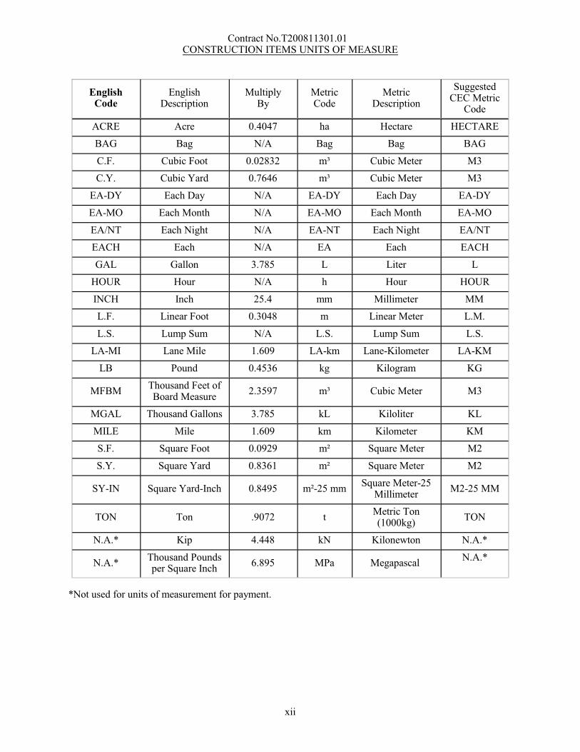
Contract No.T200811301.01 CONSTRUCTION ITEMS UNITS OF MEASURE
EnglishCode
EnglishDescription
MultiplyBy
MetricCode
MetricDescription
SuggestedCEC Metric
Code
ACRE Acre 0.4047 ha Hectare HECTARE
BAG Bag N/A Bag Bag BAG
C.F. Cubic Foot 0.02832 m³ Cubic Meter M3
C.Y. Cubic Yard 0.7646 m³ Cubic Meter M3
EA-DY Each Day N/A EA-DY Each Day EA-DY
EA-MO Each Month N/A EA-MO Each Month EA-MO
EA/NT Each Night N/A EA-NT Each Night EA/NT
EACH Each N/A EA Each EACH
GAL Gallon 3.785 L Liter L
HOUR Hour N/A h Hour HOUR
INCH Inch 25.4 mm Millimeter MM
L.F. Linear Foot 0.3048 m Linear Meter L.M.
L.S. Lump Sum N/A L.S. Lump Sum L.S.
LA-MI Lane Mile 1.609 LA-km Lane-Kilometer LA-KM
LB Pound 0.4536 kg Kilogram KG
MFBMThousand Feet ofBoard Measure
2.3597 m³ Cubic Meter M3
MGAL Thousand Gallons 3.785 kL Kiloliter KL
MILE Mile 1.609 km Kilometer KM
S.F. Square Foot 0.0929 m² Square Meter M2
S.Y. Square Yard 0.8361 m² Square Meter M2
SY-IN Square Yard-Inch 0.8495 m²-25 mmSquare Meter-25
MillimeterM2-25 MM
TON Ton .9072 tMetric Ton(1000kg)
TON
N.A.* Kip 4.448 kN Kilonewton N.A.*
N.A.*Thousand Poundsper Square Inch
6.895 MPa Megapascal N.A.*
*Not used for units of measurement for payment.
xii
Contract No. T200811301.01
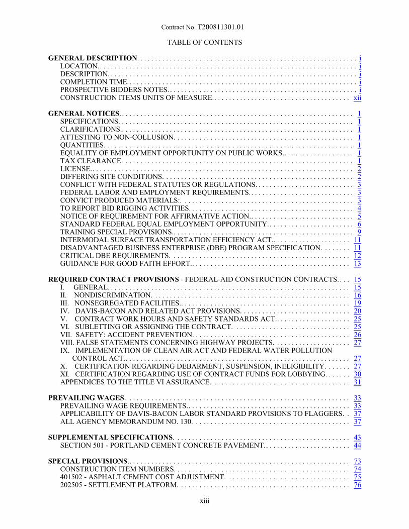
TABLE OF CONTENTS
GENERAL DESCRIPTION. . . . . . . . . . . . . . . . . . . . . . . . . . . . . . . . . . . . . . . . . . . . . . . . . . . . . . . . . . . . iLOCATION.. . . . . . . . . . . . . . . . . . . . . . . . . . . . . . . . . . . . . . . . . . . . . . . . . . . . . . . . . . . . . . . . . . . . . . iDESCRIPTION. . . . . . . . . . . . . . . . . . . . . . . . . . . . . . . . . . . . . . . . . . . . . . . . . . . . . . . . . . . . . . . . . . . . iCOMPLETION TIME.. . . . . . . . . . . . . . . . . . . . . . . . . . . . . . . . . . . . . . . . . . . . . . . . . . . . . . . . . . . . . . iPROSPECTIVE BIDDERS NOTES. . . . . . . . . . . . . . . . . . . . . . . . . . . . . . . . . . . . . . . . . . . . . . . . . . . . iCONSTRUCTION ITEMS UNITS OF MEASURE.. . . . . . . . . . . . . . . . . . . . . . . . . . . . . . . . . . . . . xii
GENERAL NOTICES. . . . . . . . . . . . . . . . . . . . . . . . . . . . . . . . . . . . . . . . . . . . . . . . . . . . . . . . . . . . . . . . 1SPECIFICATIONS. . . . . . . . . . . . . . . . . . . . . . . . . . . . . . . . . . . . . . . . . . . . . . . . . . . . . . . . . . . . . . . . 1CLARIFICATIONS.. . . . . . . . . . . . . . . . . . . . . . . . . . . . . . . . . . . . . . . . . . . . . . . . . . . . . . . . . . . . . . . 1ATTESTING TO NON-COLLUSION. . . . . . . . . . . . . . . . . . . . . . . . . . . . . . . . . . . . . . . . . . . . . . . . . 1QUANTITIES. . . . . . . . . . . . . . . . . . . . . . . . . . . . . . . . . . . . . . . . . . . . . . . . . . . . . . . . . . . . . . . . . . . . 1EQUALITY OF EMPLOYMENT OPPORTUNITY ON PUBLIC WORKS.. . . . . . . . . . . . . . . . . . . 1TAX CLEARANCE. . . . . . . . . . . . . . . . . . . . . . . . . . . . . . . . . . . . . . . . . . . . . . . . . . . . . . . . . . . . . . . 1LICENSE.. . . . . . . . . . . . . . . . . . . . . . . . . . . . . . . . . . . . . . . . . . . . . . . . . . . . . . . . . . . . . . . . . . . . . . . 2DIFFERING SITE CONDITIONS. . . . . . . . . . . . . . . . . . . . . . . . . . . . . . . . . . . . . . . . . . . . . . . . . . . . 2CONFLICT WITH FEDERAL STATUTES OR REGULATIONS. . . . . . . . . . . . . . . . . . . . . . . . . . . 3FEDERAL LABOR AND EMPLOYMENT REQUIREMENTS.. . . . . . . . . . . . . . . . . . . . . . . . . . . . 3CONVICT PRODUCED MATERIALS:. . . . . . . . . . . . . . . . . . . . . . . . . . . . . . . . . . . . . . . . . . . . . . . 3TO REPORT BID RIGGING ACTIVITIES. . . . . . . . . . . . . . . . . . . . . . . . . . . . . . . . . . . . . . . . . . . . . 4NOTICE OF REQUIREMENT FOR AFFIRMATIVE ACTION.. . . . . . . . . . . . . . . . . . . . . . . . . . . . 5STANDARD FEDERAL EQUAL EMPLOYMENT OPPORTUNITY.. . . . . . . . . . . . . . . . . . . . . . . 6TRAINING SPECIAL PROVISIONS.. . . . . . . . . . . . . . . . . . . . . . . . . . . . . . . . . . . . . . . . . . . . . . . . . 9INTERMODAL SURFACE TRANSPORTATION EFFICIENCY ACT.. . . . . . . . . . . . . . . . . . . . . 11DISADVANTAGED BUSINESS ENTERPRISE (DBE) PROGRAM SPECIFICATION. . . . . . . . 11CRITICAL DBE REQUIREMENTS. . . . . . . . . . . . . . . . . . . . . . . . . . . . . . . . . . . . . . . . . . . . . . . . . 12GUIDANCE FOR GOOD FAITH EFFORT.. . . . . . . . . . . . . . . . . . . . . . . . . . . . . . . . . . . . . . . . . . . 13
REQUIRED CONTRACT PROVISIONS - FEDERAL-AID CONSTRUCTION CONTRACTS. . . . 15I. GENERAL. . . . . . . . . . . . . . . . . . . . . . . . . . . . . . . . . . . . . . . . . . . . . . . . . . . . . . . . . . . . . . . . . . 15II. NONDISCRIMINATION. . . . . . . . . . . . . . . . . . . . . . . . . . . . . . . . . . . . . . . . . . . . . . . . . . . . . . 16III. NONSEGREGATED FACILITIES.. . . . . . . . . . . . . . . . . . . . . . . . . . . . . . . . . . . . . . . . . . . . . . 19IV. DAVIS-BACON AND RELATED ACT PROVISIONS. . . . . . . . . . . . . . . . . . . . . . . . . . . . . . 20V. CONTRACT WORK HOURS AND SAFETY STANDARDS ACT.. . . . . . . . . . . . . . . . . . . . 25VI. SUBLETTING OR ASSIGNING THE CONTRACT. . . . . . . . . . . . . . . . . . . . . . . . . . . . . . . . 25VII. SAFETY: ACCIDENT PREVENTION. . . . . . . . . . . . . . . . . . . . . . . . . . . . . . . . . . . . . . . . . . . 26VIII. FALSE STATEMENTS CONCERNING HIGHWAY PROJECTS. . . . . . . . . . . . . . . . . . . . . 27IX. IMPLEMENTATION OF CLEAN AIR ACT AND FEDERAL WATER POLLUTION
CONTROL ACT.. . . . . . . . . . . . . . . . . . . . . . . . . . . . . . . . . . . . . . . . . . . . . . . . . . . . . . . . . . . . . 27X. CERTIFICATION REGARDING DEBARMENT, SUSPENSION, INELIGIBILITY. . . . . . . 27XI. CERTIFICATION REGARDING USE OF CONTRACT FUNDS FOR LOBBYING. . . . . . . 30APPENDICES TO THE TITLE VI ASSURANCE. . . . . . . . . . . . . . . . . . . . . . . . . . . . . . . . . . . . . . 31
PREVAILING WAGES. . . . . . . . . . . . . . . . . . . . . . . . . . . . . . . . . . . . . . . . . . . . . . . . . . . . . . . . . . . . . 33PREVAILING WAGE REQUIREMENTS.. . . . . . . . . . . . . . . . . . . . . . . . . . . . . . . . . . . . . . . . . . . . 33APPLICABILITY OF DAVIS-BACON LABOR STANDARD PROVISIONS TO FLAGGERS. . 37ALL AGENCY MEMORANDUM NO. 130. . . . . . . . . . . . . . . . . . . . . . . . . . . . . . . . . . . . . . . . . . . 37
SUPPLEMENTAL SPECIFICATIONS. . . . . . . . . . . . . . . . . . . . . . . . . . . . . . . . . . . . . . . . . . . . . . . . 43SECTION 501 - PORTLAND CEMENT CONCRETE PAVEMENT.. . . . . . . . . . . . . . . . . . . . . . . 44
SPECIAL PROVISIONS.. . . . . . . . . . . . . . . . . . . . . . . . . . . . . . . . . . . . . . . . . . . . . . . . . . . . . . . . . . . . 73CONSTRUCTION ITEM NUMBERS. . . . . . . . . . . . . . . . . . . . . . . . . . . . . . . . . . . . . . . . . . . . . . . . 74401502 - ASPHALT CEMENT COST ADJUSTMENT. . . . . . . . . . . . . . . . . . . . . . . . . . . . . . . . . . 75202505 - SETTLEMENT PLATFORM. . . . . . . . . . . . . . . . . . . . . . . . . . . . . . . . . . . . . . . . . . . . . . . 76
xiii
Contract No. T200811301.01
202515 - COMPACTING INSITU MATERIAL. . . . . . . . . . . . . . . . . . . . . . . . . . . . . . . . . . . . . . . . 80202569 – POND ACCESS ROAD, MARYLAND.. . . . . . . . . . . . . . . . . . . . . . . . . . . . . . . . . . . . . . 82202572 - BORROW AREA EROSION AND SEDIMENT CONTROL AND DEWATERING.. . . 86211521 – ABANDONMENT OF WELLS. . . . . . . . . . . . . . . . . . . . . . . . . . . . . . . . . . . . . . . . . . . . . 88255502 - GABION OUTLET STRUCTURE, MARYLAND.. . . . . . . . . . . . . . . . . . . . . . . . . . . . . . 89272511 – POND OUTLET STRUCTURE, CONCRETE MARYLAND.. . . . . . . . . . . . . . . . . . . . . 93304501 - PERMEABLE TREATED BASE, 4". . . . . . . . . . . . . . . . . . . . . . . . . . . . . . . . . . . . . . . . . 95304502 - SOIL CEMENT BASE COURSE 6". . . . . . . . . . . . . . . . . . . . . . . . . . . . . . . . . . . . . . . . . . 99304506 - PORTLAND CEMENT. . . . . . . . . . . . . . . . . . . . . . . . . . . . . . . . . . . . . . . . . . . . . . . . . . . . 99401699 - QUALITY CONTROL/QUALITY ASSURANCE OF BITUMINOUS CONCRETE. . . 104401752 – SAFETY EDGE FOR ROADWAY PAVEMENT. . . . . . . . . . . . . . . . . . . . . . . . . . . . . . 118401801 - BITUMINOUS CONCRETE, TYPE C, 160 GYRATIONS, PG 64-22 (CARBONATE
STONE). . . . . . . . . . . . . . . . . . . . . . . . . . . . . . . . . . . . . . . . . . . . . . . . . . . . . . . . . . . . . . . . . . . 119401810 - BITUMINOUS CONCRETE, SUPERPAVE, TYPE B, 160 GYRATIONS, PG 64-22. . 119401819 - BITUMINOUS CONCRETE, SUPERPAVE, BITUMINOUS CONCRETE BASE
COURSE, 160 GYRATIONS, PG 64-22. . . . . . . . . . . . . . . . . . . . . . . . . . . . . . . . . . . . . . . . . . 119401825 - BITUMINOUS CONCRETE, SUPERPAVE, TYPE B, 160 GYRATIONS, PG-64-22,
WEDGE. . . . . . . . . . . . . . . . . . . . . . . . . . . . . . . . . . . . . . . . . . . . . . . . . . . . . . . . . . . . . . . . . . . 119401827 -BITUMINOUS CONCRETE, SUPERPAVE, TYPE C, 160 GYRATIONS, PG 64-22,
(NON-CARBONATE STONE). . . . . . . . . . . . . . . . . . . . . . . . . . . . . . . . . . . . . . . . . . . . . . . . . 120602772 - MECHANICALLY STABILIZED EARTH WALLS. . . . . . . . . . . . . . . . . . . . . . . . . . . . 131605755 - OVERHEAD SIGN SUPPORT AND FOUNDATIONS. . . . . . . . . . . . . . . . . . . . . . . . . 139612505 - PVC PIPE, 12". . . . . . . . . . . . . . . . . . . . . . . . . . . . . . . . . . . . . . . . . . . . . . . . . . . . . . . . . . 145612526 - CORRUGATED POLYETHYLENE PIPE, TYPE S, 36".. . . . . . . . . . . . . . . . . . . . . . . . 146612535 - CLEANING DRAINAGE PIPE, 15" - 24" DIA.. . . . . . . . . . . . . . . . . . . . . . . . . . . . . . . . 148612536 - CLEANING DRAINAGE PIPE, GREATER THAN 24" DIA... . . . . . . . . . . . . . . . . . . . 148617519 – CONCRETE END SECTION, 24", MARYLAND.. . . . . . . . . . . . . . . . . . . . . . . . . . . . . 149617520 – CONCRETE END SECTION, 19” X 30”, MARYLAND. . . . . . . . . . . . . . . . . . . . . . . . 149617521 – CONCRETE END SECTION, 22” x 34”, MARYLAND.. . . . . . . . . . . . . . . . . . . . . . . . 149618552 – FURNISH PIPE PILE, SCHEDULE 40, OPEN END, 14”.. . . . . . . . . . . . . . . . . . . . . . . 151618557 – FURNISH TEST PIPE PILE, SCHEDULE 40, OPEN END, 14”. . . . . . . . . . . . . . . . . . 151619501 - PRODUCTION PILE RESTRIKE.. . . . . . . . . . . . . . . . . . . . . . . . . . . . . . . . . . . . . . . . . . 152619502 - TEST PILE RESTRIKE. . . . . . . . . . . . . . . . . . . . . . . . . . . . . . . . . . . . . . . . . . . . . . . . . . . 152619519 –DYNAMIC PILE TESTING BY CONTRACTOR. . . . . . . . . . . . . . . . . . . . . . . . . . . . . . 154619539 – SIGNAL MATCHING ANALYSIS BY CONTRACTOR. . . . . . . . . . . . . . . . . . . . . . . . 154619540 – INSTALL PIPE PILE, SCHEDULE 40, OPEN END, 14”. . . . . . . . . . . . . . . . . . . . . . . . 157619558 – INSTALL TEST PIPE PILE, SCHEDULE 40, OPEN END, 14”.. . . . . . . . . . . . . . . . . . 157708583 - PERSONAL GRATE FOR PIPE INLET.. . . . . . . . . . . . . . . . . . . . . . . . . . . . . . . . . . . . . 158708585 - JUNCTION BOX, 48" X 30". . . . . . . . . . . . . . . . . . . . . . . . . . . . . . . . . . . . . . . . . . . . . . . 159708658 – DRAINAGE INLETS, MODIFIED. . . . . . . . . . . . . . . . . . . . . . . . . . . . . . . . . . . . . . . . . 160708659 – DRAINAGE MANHOLES, MODIFIED. . . . . . . . . . . . . . . . . . . . . . . . . . . . . . . . . . . . . 160617518 – DRAINAGE HEADWALLS, MODIFIED. . . . . . . . . . . . . . . . . . . . . . . . . . . . . . . . . . . . 160708660 – DRAINAGE INLET, TYPE K, SINGLE, MARYLAND. . . . . . . . . . . . . . . . . . . . . . . . . 162712531 - CHANNEL BED FILL.. . . . . . . . . . . . . . . . . . . . . . . . . . . . . . . . . . . . . . . . . . . . . . . . . . . 164712552 - RIPRAP SLOPE PROTECTION, MARYLAND. . . . . . . . . . . . . . . . . . . . . . . . . . . . . . . 165715500 - UNDERDRAIN OUTLET PIPE, 6". . . . . . . . . . . . . . . . . . . . . . . . . . . . . . . . . . . . . . . . . 168720585 - GUARDRAIL END TREATMENT ATTENUATOR, TYPE 1 - 31. . . . . . . . . . . . . . . . 169720586 - GUARDRAIL END TREATMENT ATTENUATOR, TYPE 2 - 31. . . . . . . . . . . . . . . . 169720588 - GUARDRAIL END TREATMENT ATTENUATOR, TYPE 3 - 31. . . . . . . . . . . . . . . . 169720611 - FLEXIBLE DELINEATOR, PERMANENT.. . . . . . . . . . . . . . . . . . . . . . . . . . . . . . . . . . 171720626 – CONCRTE SINGLE FACE BARRIER, TYPE 1. . . . . . . . . . . . . . . . . . . . . . . . . . . . . . . 172727507 - BRIDGE SAFETY FENCE. . . . . . . . . . . . . . . . . . . . . . . . . . . . . . . . . . . . . . . . . . . . . . . . 173727552 - RESOURCE PROTECTION FENCE. . . . . . . . . . . . . . . . . . . . . . . . . . . . . . . . . . . . . . . . 174727553 – DIVERSION FENCE, MARYLAND. . . . . . . . . . . . . . . . . . . . . . . . . . . . . . . . . . . . . . . . 176734555 - TEMPORARY VEGETATIVE STABILIZATION, MARYLAND. . . . . . . . . . . . . . . . . 177734556 - PERMANENT VEGETATIVE STABILIZATION, MARYLAND. . . . . . . . . . . . . . . . . 180735501 - HERBICIDE APPLICATION, NOXIOUS WEEDS. . . . . . . . . . . . . . . . . . . . . . . . . . . . . 191
xiv
Contract No. T200811301.01
737523 - PLANTINGS. . . . . . . . . . . . . . . . . . . . . . . . . . . . . . . . . . . . . . . . . . . . . . . . . . . . . . . . . . . 192737531 - PLANTINGS, MARYLAND.. . . . . . . . . . . . . . . . . . . . . . . . . . . . . . . . . . . . . . . . . . . . . . 201744506 - CONDUIT JUNCTION WELL, TYPE 7, PRECAST POLYMER CONCRETE. . . . . . . 218744520 - CONDUIT JUNCTION WELL, TYPE 1, PRECAST CONCRETE. . . . . . . . . . . . . . . . . 218744523 - CONDUIT JUNCTION WELL, TYPE 4, PRECAST CONCRETE. . . . . . . . . . . . . . . . . 218744530 - CONDUIT JUNCTION WELL, TYPE 11, PRECAST CONCRETE/POLYMER LID-
FRAME.. . . . . . . . . . . . . . . . . . . . . . . . . . . . . . . . . . . . . . . . . . . . . . . . . . . . . . . . . . . . . . . . . . . 218744531 - CONDUIT JUNCTION WELL, TYPE 14, PRECAST CONCRETE/POLYMER LID-
FRAME.. . . . . . . . . . . . . . . . . . . . . . . . . . . . . . . . . . . . . . . . . . . . . . . . . . . . . . . . . . . . . . . . . . . 218744519 - RELOCATION OF EXISTING JUNCTION WELL.. . . . . . . . . . . . . . . . . . . . . . . . . . . . 220744541 - FURNISH & INSTALL FRAME AND LID FOR JUNCTION WELL, TYPE 11. . . . . . 221744542 - FURNISH & INSTALL FRAME AND LID FOR JUNCTION WELL, TYPE 14. . . . . . 221744544 – ADJUST OR REPAIR EXISTING CONDUIT JUNCTION WELL. . . . . . . . . . . . . . . . 222745602 - FURNISH & INSTALL UP TO 4” SCHEDULE 80 HDPE CONDUIT (BORE). . . . . . . 223745604 - FURNISH & INSTALL UP TO 4” SCHEDULE 80 PVC CONDUIT (TRENCH). . . . . 223745606 - FURNISH & INSTALL UP TO 4” GALVANIZED STEEL CONDUIT (TRENCH). . . 223745609 - FURNISH & INSTALL UP TO 4” GALVANIZED STEEL CONDUIT (ON
STRUCTURE). . . . . . . . . . . . . . . . . . . . . . . . . . . . . . . . . . . . . . . . . . . . . . . . . . . . . . . . . . . . . . 223746509 - RELOCATING LIGHT POLE.. . . . . . . . . . . . . . . . . . . . . . . . . . . . . . . . . . . . . . . . . . . . . 227746511 - CABLES, 1/#4 AWG. . . . . . . . . . . . . . . . . . . . . . . . . . . . . . . . . . . . . . . . . . . . . . . . . . . . . 228746512 - CABLES, 1/#6 AWG. . . . . . . . . . . . . . . . . . . . . . . . . . . . . . . . . . . . . . . . . . . . . . . . . . . . . 228746513 - CABLES, 1/#8 AWG. . . . . . . . . . . . . . . . . . . . . . . . . . . . . . . . . . . . . . . . . . . . . . . . . . . . . 228746515 - INSULATED GROUND CABLE, 1/#6. . . . . . . . . . . . . . . . . . . . . . . . . . . . . . . . . . . . . . 228746527 - CABLES, 1/#2 AWG. . . . . . . . . . . . . . . . . . . . . . . . . . . . . . . . . . . . . . . . . . . . . . . . . . . . . 228746564 - INSULATED GROUND CABLE, 1/#4. . . . . . . . . . . . . . . . . . . . . . . . . . . . . . . . . . . . . . 228746577 - INSULATED GROUND CABLE, 1/#8. . . . . . . . . . . . . . . . . . . . . . . . . . . . . . . . . . . . . . 228746598 - INSULATED GROUND CABLE, 1/#2. . . . . . . . . . . . . . . . . . . . . . . . . . . . . . . . . . . . . . 228746622 - CABLES, 1/#4/0 AWG. . . . . . . . . . . . . . . . . . . . . . . . . . . . . . . . . . . . . . . . . . . . . . . . . . . 228746817 - CABLES, 1/#2/0 AWG. . . . . . . . . . . . . . . . . . . . . . . . . . . . . . . . . . . . . . . . . . . . . . . . . . . 228746861 - INSULATED GROUND CABLES, 1/350 KCMIL.. . . . . . . . . . . . . . . . . . . . . . . . . . . . . 228746903 - INSULATED GROUND CABLES, 1/#2/0. . . . . . . . . . . . . . . . . . . . . . . . . . . . . . . . . . . . 228746904 - INSULATED GROUND CABLES, 1/#4/0. . . . . . . . . . . . . . . . . . . . . . . . . . . . . . . . . . . . 228746517 - ALUMINUM LIGHTING STANDARD WITH SINGLE DAVIT ARM, 30' POLE. . . . 229746519 - ALUMINUM LIGHTING STANDARD WITH SINGLE DAVIT ARM, 40' POLE. . . . 229746541 - INSTALLATION OF ELECTRICAL WIRE OR CABLE IN EMPTY CONDUITS. . . . 233746586 - RELOCATE SIGN.. . . . . . . . . . . . . . . . . . . . . . . . . . . . . . . . . . . . . . . . . . . . . . . . . . . . . . 235746590 - FURNISH & INSTALL GROUND ROD. . . . . . . . . . . . . . . . . . . . . . . . . . . . . . . . . . . . . 236746594 - LUMINAIRE (HPS) 250 WATT. . . . . . . . . . . . . . . . . . . . . . . . . . . . . . . . . . . . . . . . . . . . 237746595 - ALUMINUM LIGHTING STANDARD, 40' POLE. . . . . . . . . . . . . . . . . . . . . . . . . . . . . 238746615 – PVC SCHEDULE 40 DUCT, 6". . . . . . . . . . . . . . . . . . . . . . . . . . . . . . . . . . . . . . . . . . . . 240746653 - ELECTRICAL TESTING. . . . . . . . . . . . . . . . . . . . . . . . . . . . . . . . . . . . . . . . . . . . . . . . . 241746669 - LUMINAIRE (HPS) 150 WATT. . . . . . . . . . . . . . . . . . . . . . . . . . . . . . . . . . . . . . . . . . . . 244746717 - ELECTRIC SERVICE ON RACK WITH SERVICE RISER. . . . . . . . . . . . . . . . . . . . . . 245746847 - POLE BASE, TYPE 3. . . . . . . . . . . . . . . . . . . . . . . . . . . . . . . . . . . . . . . . . . . . . . . . . . . . 246746850 - POLE BASE, TYPE 4A.. . . . . . . . . . . . . . . . . . . . . . . . . . . . . . . . . . . . . . . . . . . . . . . . . . 246746852 - POLE BASE, TYPE 6 .. . . . . . . . . . . . . . . . . . . . . . . . . . . . . . . . . . . . . . . . . . . . . . . . . . . 246746872 - LIGHTING CONTROL AND DISTRIBUTION ENCLOSURE.. . . . . . . . . . . . . . . . . . . 248746924 - FURNISH & INSTALL LOOP WIRE 1 - CONDUCTOR #14 AWG CABLE ENCASED
IN ¼” FLEXIBLE TUBING IN A LOOP SAWCUT.. . . . . . . . . . . . . . . . . . . . . . . . . . . . . . . . 250746951 - RELOCATING POLE AND MAST ARM. . . . . . . . . . . . . . . . . . . . . . . . . . . . . . . . . . . . 253747515 - CABINET BASE TYPE M. . . . . . . . . . . . . . . . . . . . . . . . . . . . . . . . . . . . . . . . . . . . . . . . 257747516 - CABINET BASE TYPE P. . . . . . . . . . . . . . . . . . . . . . . . . . . . . . . . . . . . . . . . . . . . . . . . . 257748502 - RAISED/RECESSED PAVEMENT MARKER. . . . . . . . . . . . . . . . . . . . . . . . . . . . . . . . 258748548 - PERMANENT PAVEMENT STRIPING, EPOXY RESIN PAINT, WHITE/YELLOW, 5"
. . . . . . . . . . . . . . . . . . . . . . . . . . . . . . . . . . . . . . . . . . . . . . . . . . . . . . . . . . . . . . . . . . . . . . . . . . 259748549 -PERMANENT PAVEMENT STRIPING, EPOXY RESIN PAINT, WHITE/YELLOW, 10"
. . . . . . . . . . . . . . . . . . . . . . . . . . . . . . . . . . . . . . . . . . . . . . . . . . . . . . . . . . . . . . . . . . . . . . . . . . 259
xv
Contract No. T200811301.01
748557 - PERMANENT PAVEMENT STRIPING, EPOXY RESIN PAINT, BLACK, 3".. . . . . . 259748566 - RETROREFLECTIVE PREFORMED PATTERNED CONTRAST MARKINGS, 8". . 269748567 - RETROREFLECTIVE PREFORMED PATTERNED CONTRAST MARKINGS, 13"
. . . . . . . . . . . . . . . . . . . . . . . . . . . . . . . . . . . . . . . . . . . . . . . . . . . . . . . . . . . . . . . . . . . . . . . . . . 269748525 - TEMPORARY MARKINGS, TAPE, 4". . . . . . . . . . . . . . . . . . . . . . . . . . . . . . . . . . . . . . 274748527 - TEMPORARY MARKINGS, TAPE, WORDS/SYMBOLS. . . . . . . . . . . . . . . . . . . . . . . 274748530 - REMOVAL OF PAVEMENT STRIPING.. . . . . . . . . . . . . . . . . . . . . . . . . . . . . . . . . . . . 277748553 - PREFORMED RETROREFLECTIVE THERMOPLASTIC PAVEMENT MARKINGS,
BIKE SYMBOL. . . . . . . . . . . . . . . . . . . . . . . . . . . . . . . . . . . . . . . . . . . . . . . . . . . . . . . . . . . . . 278748560 - 5" PERMANENT PREFORMED PATTERNED REFLECTIVE PAVEMENT
MARKINGS, MARYLAND. . . . . . . . . . . . . . . . . . . . . . . . . . . . . . . . . . . . . . . . . . . . . . . . . . . 282748563 – SNOWPLOWABLE RAISED PAVEMENT MARKERS, MARYLAND.. . . . . . . . . . . 286749500 – SIGN PANEL. . . . . . . . . . . . . . . . . . . . . . . . . . . . . . . . . . . . . . . . . . . . . . . . . . . . . . . . . . 289749516 – REINFORCED CONCRETE SIGN FOUNDATION, W. . . . . . . . . . . . . . . . . . . . . . . . . 294749517 – REINFORCED CONCRETE SIGN FOUNDATION, W-8. . . . . . . . . . . . . . . . . . . . . . . 294749518 – REINFORCED CONCRETE SIGN FOUNDATION, W-10. . . . . . . . . . . . . . . . . . . . . . 294749581 - REINFORCED CONCRETE SIGN FOUNDATION, W-18.. . . . . . . . . . . . . . . . . . . . . . 294749521 - SUPPLY OF BREAKAWAY I-BEAM SIGN POSTS, W-6.. . . . . . . . . . . . . . . . . . . . . . 295749522 - SUPPLY OF BREAKAWAY I-BEAM SIGN POSTS, W-8.. . . . . . . . . . . . . . . . . . . . . . 295749523 - SUPPLY OF BREAKAWAY I-BEAM SIGN POSTS, W-10. . . . . . . . . . . . . . . . . . . . . . 295749582 - SUPPLY OF BREAKAWAY I-BEAM SIGN POSTS, W-18. . . . . . . . . . . . . . . . . . . . . . 295749532 – SUPPLY OF FLAT SHEET ALUMINUM SIGN PANEL TYPE IX RETROREFLECTIVE
SHEETING. . . . . . . . . . . . . . . . . . . . . . . . . . . . . . . . . . . . . . . . . . . . . . . . . . . . . . . . . . . . . . . . . 297749550 - INSTALLATION OF BREAKAWAY I-BEAM SIGN POSTS. . . . . . . . . . . . . . . . . . . . 303749687 - INSTALLATION OR REMOVAL OF TRAFFIC SIGN ON SINGLE SIGN POST. . . . 304749688 - INSTALLATION OF 4” DIAMETER HOLE, LESS THAN OR EQUAL TO 6” IN DEPTH
. . . . . . . . . . . . . . . . . . . . . . . . . . . . . . . . . . . . . . . . . . . . . . . . . . . . . . . . . . . . . . . . . . . . . . . . . . 305749689 - INSTALLATION OF 4” DIAMETER HOLE, GREATER THAN 6” IN DEPTH. . . . . . 305749690 - INSTALLATION OR REMOVAL OF TRAFFIC SIGN ON MULTIPLE SIGN POSTS
. . . . . . . . . . . . . . . . . . . . . . . . . . . . . . . . . . . . . . . . . . . . . . . . . . . . . . . . . . . . . . . . . . . . . . . . . . 306753503 - INSTALLING SANITARY SEWER, PVC 12". . . . . . . . . . . . . . . . . . . . . . . . . . . . . . . . 307759506 - FIELD OFFICE, TYPE II.22 SPECIAL COMPLEX. . . . . . . . . . . . . . . . . . . . . . . . . . . . 311760507 - PROFILE MILLING, HOT-MIX. . . . . . . . . . . . . . . . . . . . . . . . . . . . . . . . . . . . . . . . . . . . 318763501 - CONSTRUCTION ENGINEERING. . . . . . . . . . . . . . . . . . . . . . . . . . . . . . . . . . . . . . . . . 320763503 - TRAINEE.. . . . . . . . . . . . . . . . . . . . . . . . . . . . . . . . . . . . . . . . . . . . . . . . . . . . . . . . . . . . . 328763508 - PROJECT CONTROL SYSTEM DEVELOPMENT PLAN.. . . . . . . . . . . . . . . . . . . . . . 329763509 - CPM SCHEDULE UPDATES AND/OR REVISED UPDATES. . . . . . . . . . . . . . . . . . . 329763573 - SIGN, MARYLAND. . . . . . . . . . . . . . . . . . . . . . . . . . . . . . . . . . . . . . . . . . . . . . . . . . . . . 334763597 - UTILITY CONSTRUCTION ENGINEERING.. . . . . . . . . . . . . . . . . . . . . . . . . . . . . . . . 335763619 – WEIGH IN MOTION SYSTEM (WIM). . . . . . . . . . . . . . . . . . . . . . . . . . . . . . . . . . . . . . 336763626 - DIESEL FUEL COST PRICE ADJUSTMENT.. . . . . . . . . . . . . . . . . . . . . . . . . . . . . . . . 337763656 – AS-BUILT CERTIFICATION, MARYLAND. . . . . . . . . . . . . . . . . . . . . . . . . . . . . . . . . 341763686 – TRAFFIC OFFICER, MARYLAND. . . . . . . . . . . . . . . . . . . . . . . . . . . . . . . . . . . . . . . . 345763689 - STRUCTURAL WORK, GANTRY. . . . . . . . . . . . . . . . . . . . . . . . . . . . . . . . . . . . . . . . . 346763691 - FLAGGER, MARYLAND, STATE. . . . . . . . . . . . . . . . . . . . . . . . . . . . . . . . . . . . . . . . . 347763692 - FLAGGER, MARYLAND, STATE, OVERTIME. . . . . . . . . . . . . . . . . . . . . . . . . . . . . . 347900500 - ENVIRONMENTAL PERFORMANCE INCENTIVE (DISINCENTIVE). . . . . . . . . . . 349905500 - SUPER SILT FENCE. . . . . . . . . . . . . . . . . . . . . . . . . . . . . . . . . . . . . . . . . . . . . . . . . . . . 351908503 - WETLAND MITIGATION GRASS SEEDING. . . . . . . . . . . . . . . . . . . . . . . . . . . . . . . . 353910500 - BIO-RETENTION SOIL, MIX I. . . . . . . . . . . . . . . . . . . . . . . . . . . . . . . . . . . . . . . . . . . . 355
UTILITY STATEMENT. . . . . . . . . . . . . . . . . . . . . . . . . . . . . . . . . . . . . . . . . . . . . . . . . . . . . . . . . . . . 357
RIGHT OF WAY CERTIFICATE.. . . . . . . . . . . . . . . . . . . . . . . . . . . . . . . . . . . . . . . . . . . . . . . . . . . 375
ENVIRONMENTAL STATEMENT. . . . . . . . . . . . . . . . . . . . . . . . . . . . . . . . . . . . . . . . . . . . . . . . . . 376
xvi

Contract No. T200811301.01
RAILROAD STATEMENT. . . . . . . . . . . . . . . . . . . . . . . . . . . . . . . . . . . . . . . . . . . . . . . . . . . . . . . . . 384
BID PROPOSAL FORMS. . . . . . . . . . . . . . . . . . . . . . . . . . . . . . . . . . . . . . . . . . . . . . . . . . . . . . . . . . 385Diesel Fuel Cost Price Adjustment Option. . . . . . . . . . . . . . . . . . . . . . . . . . . . . . . . . . . . . . . . . . . . 429BREAKOUT SHEET. . . . . . . . . . . . . . . . . . . . . . . . . . . . . . . . . . . . . . . . . . . . . . . . . . . . . . . . . . . . 430Prequalification form. . . . . . . . . . . . . . . . . . . . . . . . . . . . . . . . . . . . . . . . . . . . . . . . . . . . . . . . . . . . . 444
CERTIFICATION. . . . . . . . . . . . . . . . . . . . . . . . . . . . . . . . . . . . . . . . . . . . . . . . . . . . . . . . . . . . . . . . . 445
BID BOND. . . . . . . . . . . . . . . . . . . . . . . . . . . . . . . . . . . . . . . . . . . . . . . . . . . . . . . . . . . . . . . . . . . . . . . 447
xvii
Contract No. T200811301.01
GENERAL NOTICESSPECIFICATIONS:
The specifications entitled "Delaware Standard Specifications for Road and Bridge Construction, August, 2001", hereinafter referred to as the Standard Specifications; Supplemental Standard Specifications; theSpecial Provisions; notes on the Plans; this Bid Proposal; and any addenda thereto, shall govern the work tobe performed under this contract.
CLARIFICATIONS:
Under any Section or Item included in the Contract, the Contractor shall be aware that when requirements,responsibilities, and furnishing of materials are outlined in the details and notes on the Plans and in theparagraphs preceding the " Basis of Payment" paragraph in the Standard Specifications or Special Provisions,no interpretation shall be made that such stipulations are excluded because reiteration is not made in the"Basis of Payment" paragraph.
ATTESTING TO NON-COLLUSION:
The Department requires as a condition precedent to acceptance of bids a sworn statement executed by, oron behalf of, the person, firm, association, or corporation to whom such contract is to be awarded, certifyingthat such person, firm, association, or corporation has not, either directly or indirectly, entered into anyagreement, participated in any collusion, or otherwise taken any action in restraint of free competitive biddingin connection with such contract. The form for this sworn statement is included in the proposal and must beproperly executed in order to have the bid considered.
QUANTITIES:
The quantities shown are for comparison of bids only. The Department may increase or decrease any quantityor quantities without penalty or change in the bid price.
EQUALITY OF EMPLOYMENT OPPORTUNITY ON PUBLIC WORKS:
Delaware Code, Title 29, Chapter 69, Section 6962, Paragraph (d), Subsection (7)
"a. As a condition of the awarding of any contract for public works financed in whole or in part byState appropriation, such contracts shall include the following provisions:
`During the performance of this contract, the contractor agrees as follows:
1. The contractor will not discriminate against any employee or applicant for employment because ofrace, creed, color, sex, sexual orientation or natural origin. The contractor will take positive stepsto ensure that applicants are employed, and that employees are treated during employment, withoutregard to their race, creed, color, sex, sexual orientation or national origin. Such action shall include,but not be limited to, the following: employment, upgrading, demotion or transfer; recruitment orrecruitment advertising; layoff or termination; rates of pay or other forms of compensation; andselection for training, including apprenticeship. The contractor agrees to post in conspicuous placesavailable to employees and applicants for employment notices to be provided by the contractingagency setting forth this nondiscrimination clause.
2. The contractor will, in all solicitations or advertisements for employees placed by or on behalf of thecontractor, state that all qualified applicants will receive consideration for employment withoutregard to race, creed, color, sex or national origin.'
TAX CLEARANCE:
As payments to each vendor or contractor aggregate $2,000, the Division of Accounting will report suchvendor or contractor to the Division of Revenue, who will then check the vendor or contractor's compliancewith tax requirements and take such further action as may be necessary to insure compliance.
1

Contract No. T200811301.01
LICENSE:
A person desiring to engage in business in this State as a contractor shall obtain a license upon makingapplication to the Division of Revenue. Proof of said license compliance to be made prior to, or inconjunction with, the execution of a contract to which he has been named.
SUBCONTRACTOR LICENSE: 29 DEL. C. §6967:
(c) Any contractor that enters a public works contract must provide to the agency to which it is contracting,within 30 days of entering such public works contract, copies of all occupational and business licenses ofsubcontractors and/or independent contractors that will perform work for such public works contract.However, if a subcontractor or independent contractor is hired or contracted more than 20 days after thecontractor entered the public works contract the occupational or business license of such subcontractor orindependent contractor shall be provided to the agency within 10 days of being contracted or hired.
DIFFERING SITE CONDITIONS,
SUSPENSIONS OF WORK and SIGNIFICANT CHANGES IN THE CHARACTER OF WORK:
Differing site conditions: During the progress of the work, if subsurface or latent physical conditions areencountered at the site differing materially from those indicated in the contract of if unknown physicalconditions of an unusual nature, differing materially from those ordinarily encountered and generallyrecognized as inherent in the work provided for in the contract are encountered at the site, the partydiscovering such conditions shall promptly notify the other party in writing of the specific differingconditions before they are disturbed and before the affected work is performed.
Upon written notification, the engineer will investigate the conditions, and if he/she determines that theconditions materially differ and cause an increase or decrease in the cost or time required for the performanceof any work under the contract, an adjustment, excluding loss of anticipated profits, will be made and thecontract modified in writing accordingly. The engineer will notify the contractor of his/her determinationwhether or not an adjustment of the contract is warranted.
No contract adjustment which results in a benefit to the contractor will be allowed unless the contractor hasprovided the required written notice.
No contract adjustment will be allowed under their clause for any effects caused on unchanged work.
Suspensions of work ordered by the engineer: If the performance of all or any portion of the work issuspended or delayed by the engineer in writing for an unreasonable period of time (not originally anticipated,customary or inherent to the construction industry) and the contractor believes that additional compensationand/or contract time is due as a result of such suspension or delay, the contractor shall submit to the engineerin writing a request for adjustment within 7 calendar days of receipt of the notice to resume work. Therequest shall set fourth the reasons and support for such adjustment.
Upon receipt, the engineer will evaluate the contractor's request. If the engineer agrees that the cost and/ortime required for the performance of the contract has increased as a result of such suspension and thesuspension was caused by conditions beyond the control of and not the fault of the contractor, its suppliers,or subcontractors at any approved tier, and not caused by weather, the engineer will make an adjustment(excluding profit) and modify the contract in writing accordingly. The engineer will notify the contractor ofhis/her determination whether or not an adjustment of the contract is warranted.
No contract adjustment will be allowed unless the contractor has submitted the request for adjustment withinthe time prescribed.
2
Contract No. T200811301.01
No contract adjustment will be allowed under this clause to the extent that performance would have beensuspended or delayed by any other cause, or for which an adjustment is provided for or excluded under anyother term or condition of this contract.
Significant changes in the character of work: The engineer reserves the right to make, in writing, at any timeduring the work, such changes in quantities and such alterations in the work as are necessary to satisfactorilycomplete the project. Such changes in quantities and alterations shall not invalidate the contract nor releasethe surety, and the contractor agrees to perform the work as altered.
If the alterations or changes in quantities significantly change the character of the work under the contract,whether or not changed by any such different quantities or alterations, an adjustment, excluding loss ofanticipated profits, will be made to the contract. The basis for the adjustment shall be agreed upon prior tothe performance of the work. If a basis cannot be agreed upon, then an adjustment will be made either foror against the contractor in such amount as the engineer may determine to be fair and equitable.
The term "significant change" shall be construed to apply only to the following circumstances:(A) When the character of the work as altered differs materially in kind or nature from that involved
or included in the original proposed construction or
(B) When a major item of work, as defined elsewhere in the contract, is increased in excess of 125percent or decreased below 75 percent of the original contract quantity. Any allowance for anincrease in quantity shall apply only to that portion in excess of 125 percent of original contractitem quantity, or in case of a decrease below 75 percent, to the actual amount of work performed.
CONFLICT WITH FEDERAL STATUTES OR REGULATIONS:
Delaware Code, Title 29, Chapter 69, Section 6904, Paragraph (a):
"If any provision of this subchapter conflicts or is inconsistent with any statute, rule or regulation of thefederal government applicable to a project or activity, the cost of which is to be paid or reimbursed inwhole or in part by the federal government, and due to such conflict or inconsistency the availability offederal funds may be jeopardized, such provision shall not apply to such project or activity."
FEDERAL LABOR AND EMPLOYMENT REQUIREMENTS
Federal Regulation 23 CFR § 635.117(b) Labor and employment, states:
"No procedures or requirement shall be imposed by any State which will operate to discriminate againstthe employment of labor from any other State, possession or territory of the United States, in theconstruction of a Federal-aid project."
CONVICT PRODUCED MATERIALS:
(a) Materials produced after July 1, 1991, by convict labor may only be incorporated in a Federal-aidhighway construction project if such materials have been:
(1) Produced by convicts who are on parole, supervised release, or probation from a prison or(2) Produced in a qualified prison facility and the cumulative annual production amount of such
materials for use in Federal-aid highway construction does not exceed the amount of suchmaterials produced in such facility for use in Federal-aid highway construction during the 12-month period ending July 1, 1987.
(b) Qualified prison facility means any prison facility in which convicts, during the 12-month periodending July 1, 1987, produced materials for use in Federal-aid highway construction projects.
3

Contract No. T200811301.01
TO REPORT BID RIGGING ACTIVITIES:
The U. S. Department of Transportation (DOT) operates the below toll-free "hotline" Monday through Friday,8:00 a.m. to 5:00 p.m. eastern time. Anyone with knowledge of possible bid rigging, bidder collusion, orother fraudulent activities should use the "hotline" to report such activities.
The "hotline" is part of the DOT's continuing effort to identify and investigate highway construction contractfraud and abuse and is operated under the direction of the DOT Inspector General. All information will betreated confidentially and caller anonymity will be respected.
TO REPORT BID RIGGING ACTIVITIES CALL 1-800-424-9071
4
Contract No. T200811301.01
NOTICE OF REQUIREMENT FOR AFFIRMATIVE ACTIONTO ENSURE EQUAL EMPLOYMENT OPPORTUNITY
(EXECUTIVE ORDER 11246)
1. The Offeror's or Bidder's attention is called to the "Equal Opportunity Clause" and the "Standard FederalEqual Employment Specifications" set forth herein.
2. The goals and timetables for minority and female participation, expressed in percentage terms for theContractor's aggregate work force in each trade on all construction work in the covered area, are asfollows:
Goals for Minority Participation InEach Trade
Goals for Female Participation InEach Trade
12.3% (New Castle County)14.5% (Kent & Sussex Counties)
6.9% (Entire State)
These goals are applicable to all the Contractor's construction work (whether or not it is Federal orfederally assisted) performed in the covered area. If the contractor performs construction work in ageographical area located outside of the covered area, it shall apply the goals established for suchgeographical area where the work is actually performed. With regard to this second area, the contractoralso is subject to the goals for both its federally involved and non-federally involved construction.
The Contractor's compliance with the Executive Order and the Executive Order and the regulations inCFR Part 60-4 shall be based on its implementation of the Equal Opportunity Clause, specific affirmativeaction obligations required by the specifications set forth in 41 CFR 60-4.3(a), and its efforts to meet thegoals. The hours of minority and female employment and training must be substantially uniformthroughout the length of the contract, and in each trade, and the contractor shall make a good faith effortto employ minorities and women evenly on each of its projects. The transfer of minority or femaleemployees or trainees from Contractor to Contractor or from project to project for the sole purpose ofmeeting the Contractor's goals shall be a violation of the contract, the Executive Order, and theregulations in 41 CFR Part 60-4. Compliance with the goals will be measured against the total workhours performed.
3. The Contractor shall provide written notification to the Director of the Office of Federal ContractCompliance Programs within 10 working days of award of any construction subcontract in excess of$10,000 at any tier for construction work under the contract resulting from this solicitation. Thenotification shall list the name, address, and telephone number of the subcontractor; employeridentification number of the subcontractor; estimated dollar amount of the subcontract; estimated startingand completion dates of the subcontract; and the geographical area in which the subcontract is to beperformed.
4. As used in this Notice, and in the contract resulting from this solicitation, the "covered area" is NEWCASTLE County.
REV. 11-3-80
5
Contract No. T200811301.01
STANDARD FEDERAL EQUAL EMPLOYMENT OPPORTUNITY CONSTRUCTION CONTRACT SPECIFICATIONS (EXECUTIVE ORDER 11246)
1. As used in these specifications:
a. "Covered area" means the geographical area described in the solicitation from which this contractresulted;
b. "Director" means Director, Office of Federal Contract Compliance Programs, United StatesDepartment of Labor, or any person to whom the Director delegates authority;
c. "Employer identification number" means the Federal Social Security number used on the Employer'sQuarterly Federal Tax Return, U.S. Treasury Department Form 941.
d. "Minority" includes:i. Black (all persons having origins in any of the Black African racial groups not of Hispanic
origin);ii. Hispanic (all persons of Mexican, Puerto Rican, Cuban, Central or South American or other
Spanish Culture or origin, regardless of race);iii. Asian and Pacific Islander (all persons having origins in any of the original peoples of the Far
East, Southeast Asia, the Indian Subcontinent, or the Pacific Islands); andiv. American Indian or Alaskan Native (all persons having origins in any of the original peoples of
North America and maintaining identifiable tribal affiliations through membership andparticipation or community identification).
2. Whenever the Contractor, or any Subcontractor at any tier, subcontracts a portion of the work involvingany construction trade, it shall physically include in each subcontract in excess of $10,000 the provisionsof these specifications and the Notice which contains the applicable goals for minority and femaleparticipation and which is set forth in the solicitations from which this contract resulted.
3. If the Contractor is participating (pursuant to 41 CFR 60-4.5) in a Hometown Plan approved by the U.S.Department of Labor in the covered area either individually or through an association, its affirmativeaction obligations on all work in the Plan area (including goals and timetables) shall be in accordancewith that Plan for those trades which have unions participating in the Plan. Contractors must be able todemonstrate their participation in and compliance with the provisions of any such Hometown Plan. EachContractor or Subcontractor participating in an approved Plan is individually required to comply withits obligations under the EEO clause, and to make a good faith effort to achieve each goal under the Planin each trade in which it has employees. The overall good faith performance by other Contractors orSubcontractors toward a goal in an approved plan does not excuse any covered Contractor's orSubcontractor's failure to take good faith efforts to achieve the Plan goals and timetables.
4. The Contractor shall implement the specific affirmative action standards provided in paragraphs 7athrough 7p of these specifications. The goals set forth in the solicitation from which this contract resultedare expressed as percentages of the total hours of employment and training of minority and femaleutilization the Contractor should reasonably be able to achieve in each construction trade in which it hasemployees in the covered area. Covered Construction contractors performing construction work ingeographical areas where they do not have a Federal or federally assisted construction contract shallapply the minority and female goals established for the geographical area where the work is beingperformed. Goals are published periodically in the Federal Register in notice form, and such notices maybe obtained from any Office of Federal Contract Compliance Program Office or from the Federalprocurement contracting offices. The Contractor is expected to make substantially uniform progress inmeeting its goals in each craft during the period specified.
5. Neither the provisions of any collective bargaining agreement, nor the failure by a union with whom theContractor has a collective bargaining agreement, to refer either minorities or women shall excuse theContractor's obligations under these specifications, Executive Order 11246, or the regulationspromulgated pursuant thereto.
6. In order for the nonworking training hours of apprentices and trainees to be counted in meeting the goals,such apprentices and trainees must be employed by the Contractor during the training period, and the
6
Contract No. T200811301.01
Contractor must have made a commitment to employ the apprentices and trainees at the completion oftheir training, subject to the availability of employment opportunities. Trainees must be trained pursuantto training programs approved by the U.S. Department of Labor.
7. The Contractor shall take specific affirmative actions to ensure equal employment opportunity. Theevaluation of the Contractor's compliance with these specifications shall be based upon its effort toachieve maximum results from its actions. The Contractor shall document these efforts fully, and shallimplement affirmative action steps at least as extensive as the following:
a. Ensure and maintain a working environment free of harassment, intimidation, and coercion at allsites, and in all facilities at which the Contractor's employees are assigned to work. The Contractor,where possible, will assign two or more women to each construction project. The Contractor shallspecifically ensure that all foremen, superintendents, and other on-site supervisory personnel areaware of and carry out the Contractor's obligation to maintain such a working environment, withspecific attention to minority or female individuals working at such sites or in such facilities.
b. Establish and maintain a current list of minority and female recruitment sources, provide writtennotification to minority and female recruitment sources and to community organizations when theContractor or its unions have employment opportunities available, and maintain a record of theorganizations' responses.
c. Maintain a current file of the names, addresses and telephone numbers of each minority and femaleoff-the-street applicant and minority or female referral from a union, a recruitment source orcommunity organization and of what action was taken with respect to each such individual. If suchindividual was sent to the union hiring hall for referral and was not referred back to the Contractorby the union or, if referred, not employed by the Contractor, this shall be documented in the file withthe reason therefor, along with whatever additional actions the Contractor may have taken.
d. Provide immediate written notification to the Director when the union or unions with which theContractor has a collective bargaining agreement has not referred to the Contractor a minority personor woman sent by the Contractor, or when the Contractor has other information that the union referralprocess has impeded the Contractor's efforts to meet its obligations.
e. Develop on-the-job training opportunities and/or participate in training programs for the area whichexpressly include minorities and women, including upgrading programs and apprenticeship andtrainee programs relevant to the Contractor's employment needs, especially those programs fundedor approved by the Department of Labor. The Contractor shall provide notice of these programs tothe sources compiled under 7b above.
f. Disseminate the Contractor's EEO policy by providing notice of the policy to unions and trainingprograms and requesting their cooperation in assisting the Contractor in meeting its EEO obligations;by including it in any policy manual and collective bargaining agreement; by publicizing it in thecompany newspaper, annual report, etc.; by specific review of the policy with all managementpersonnel and with all minority and female employees at least once a year; and by posting thecompany EEO policy on bulletin boards accessible to all employees at each location whereconstruction work is performed.
g. Review, at least annually, the company's EEO policy and affirmative action obligations under thesespecifications with all employees having any responsibility for hiring, assignment, layoff, terminationor other employment decisions including specific review of these items with on-site supervisorypersonnel such as Superintendents, General Foreman, etc., prior to the initiation of construction workat any job site. A written record shall be made and maintained identifying the time and place of thesemeetings, persons attending, subject matter discussed, and disposition of the subject matter.
h. Disseminate the Contractor's EEO policy externally by including it in any advertising in the newsmedia, specifically including minority and female news media, and providing written notification toand discussing the Contractor's EEO policy with other Contractors and Subcontractors with whomthe Contractor does or anticipates doing business.
i. Direct its recruitment efforts, both oral and written, to minority, female and communityorganizations, to schools with minority and female students and to minority and female recruitmentand training organizations serving the Contractor's recruitment area and employment needs. Not laterthan one month prior to the date for the acceptance of applications for apprenticeship or other training
7
Contract No. T200811301.01
by any recruitment source, the Contractor shall send written notification to organizations such as theabove, describing the openings, screening procedures, and tests to be used in the selection process.
j. Encourage present minority and female employees to recruit other minority persons and women and,where reasonable, provide after school, summer and vacation employment to minority and femaleyouth both on the site and in other areas of a Contractor's work force.
k. Validate all tests and other selection requirements where there is an obligation to do so under 41 CFRPart 60-3.
l. Conduct, at least annually, an inventory and evaluation at least of all minority and female personnelfor promotional opportunities and encourage these employees to seek or to prepare for, throughappropriate training, etc., such opportunities.
m. Ensure that seniority practices, job classifications, work assignments and other personnel practices,do not have a discriminatory effect by continually monitoring all personnel and employment relatedactivities to ensure that the EEO policy and the Contractor's obligations under these specificationsare being carried out.
n. Ensure that all facilities and company activities are nonsegregated except that separate or single-usertoilet and necessary changing facilities shall be provided to assure privacy between the sexes.
o. Document and maintain a record of all solicitations of offers for subcontractors from minority andfemale construction contractors and suppliers, including circulation of solicitations to minority andfemale contractor associations and other business associations.
p. Conduct a review, at least annually, of all supervisors' adherence to and performance under theContractor's EEO policies and affirmative action obligations.
8. Contractors are encouraged to participate in voluntary associations which assist in fulfilling one or moreof their affirmative action obligations (7a through p). The efforts of a contractor association, jointcontractor-union, contractor-community, or other similar group of which the Contractor is a member andparticipant, may be asserted as fulfilling any one or more of its obligations under 7a through p of theseSpecifications provided that the Contractor actively participates in the group, makes every effort to assurethat the group has a positive impact on the employment of minorities and women in the industry, ensuresthat the concrete benefits of the program are reflected in the Contractor's minority and female work forceparticipating, makes a good faith effort to meet its individual goals and timetables, and can provide accessto documentation which demonstrates the effectiveness of actions taken on behalf of the Contractor. Theobligation to comply, however, is the Contractor's and failure of such a group to fulfill an obligation shallnot be a defense for the Contractor's noncompliance.
9. A single goal for minorities and a separate single goal for women have been established. The Contractor,however, is required to provide equal employment opportunity and to take affirmative action for allminority groups, both male and female, and all women, both minority and non-minority. Consequently,the Contractor may be in violation of the Executive Order if a particular group is employed in asubstantially disparate manner (for example, even though the Contractor has achieved its goals forwomen generally, the Contractor may be in violation of the Executive Order if a specific minority groupof women is under utilized).
10. The Contractor shall not use the goals and timetables or affirmative action standards to discriminateagainst any person because of race, color, religion, sex, or national origin.
11. The Contractor shall not enter into any Subcontract with any person or firm debarred from Governmentcontracts pursuant to Executive Order 11246.
12. The Contractor shall carry out such sanctions and penalties for violation of these specifications and ofthe Equal Opportunity Clause, including suspension, termination and cancellation of existing subcontractsas may be imposed or ordered pursuant to Executive Order 11246, as amended, and its implementingregulations, by the Order of Federal Contract Compliance Programs. Any Contractor who fails to carryout such sanctions and penalties shall be in violation of these specifications and Executive Order 11246,as amended.
8
Contract No. T200811301.01
13. The Contractor, in fulfilling its obligations under these specifications, shall implement specificaffirmative action steps, at least as extensive as those standards prescribed in paragraph 7 of thesespecifications, so as to achieve maximum results from its efforts to ensure equal employment opportunity. If the Contractor fails to comply with the requirements of the Executive Order, the implementingregulations, or these specifications, the Director shall proceed in accordance with 41 CFR 60-4.8.
14. The Contractor shall designate a responsible official to monitor all employment-related activity to ensurethat the company EEO policy is being carried out, to submit reports relating to the provisions hereof asmay be required by the Government, and to keep records. Records shall at least include for eachemployee the name, address, telephone numbers, construction trade, union affiliation if any, employeeidentification number when assigned, social security number, race, sex, status (e.g., mechanic, apprentice,trainee, helper, or laborer), dates of changes in status, hours worked per week in the indicated trade, rateof pay, and locations at which the work was performed. Records shall be maintained in an easilyunderstandable and retrievable form; however, to the degree that existing records satisfy this requirement,contractors shall not be required to maintain separate records.
15. Nothing herein provided shall be construed as a limitation upon the application of other laws whichestablish different standards of compliance or upon the application of requirements for the hiring of localor other area residents (e.g., those under the Public Works Employment Act of 1977 and the CommunityDevelopment Block Grant Program).
* * * * *TRAINING SPECIAL PROVISIONS
This Training Special Provision supersedes subparagraph 7b of the Special Provision entitled "Specific EqualEmployment Opportunity Responsibilities", (Attachment 1), and is in implementation of 23 U.S.C. 140(a).As part of the contractor's equal employment opportunity affirmative action program, training shall beprovided as follows:
The contractor shall provide on-the-job training aimed at developing full journeyman in the type of trade orjob classification involved.
The number of trainees to be trained under the special provision will be 2 . In the event the contractorsubcontracts a portion of the contract work, he shall determine how many, if any, of the trainees are to betrained by the subcontractor, provided however, that the contractor shall retain the primary responsibility formeeting the training requirements imposed by this special provision. The contractor shall also insure that thisTraining Special Provision is made applicable to such subcontract. Where feasible, 25 percent of apprenticesor trainees in each occupation shall be in their first year apprenticeship or training.
The number of trainees shall be distributed among the work classification on the basis of the contractor'sneeds and the availability of journeymen in the various classifications within a reasonable area of recruitment. Prior to commencing construction, the contractor shall submit to the Department of Highways andTransportation for approval the number of trainees to be trained in each selected classification and trainingprogram to be used. Furthermore, the contractor shall specify the starting time for training in each of theclassifications. The contractor will be credited for each trainee employed by him on the contract work whois currently enrolled or becomes enrolled in an approved program and will be reimbursed for such traineesas provided hereinafter.
Training and upgrading of minorities and women toward journeyman status is a primary objective of thisTraining Special Provision. Accordingly, the contractor shall make every effort to enroll minority traineesand women (e.g., by conducting systematic and direct recruitment through public and private sources likelyto yield minority and women trainees) to the extent that such persons are available within a reasonable areaof recruitment. The contractor will be responsible for demonstrating the steps that he has taken in pursuancethereof, prior to a determination as to whether the contractor is in compliance with this Training SpecialProvision. This training commitment is not intended, and not be used, to discriminate against any applicantfor training, whether a member of a minority group or not.
9
Contract No. T200811301.01
No employee shall be employed as a trainee in any classification in which he has successfully completed atraining course leading to journeyman status or in which he has been employed as a journeyman. Thecontractor should satisfy this requirement by including appropriate questions in the employee application orby other suitable means. Regardless of the method used the contractor's records should document the findingsin each case.
The minimum length and type of training for each classification will be as established in the training programselected by the contractor and approved by the Department of Highways and Transportation and the FederalHighway Administration. The Department of Highways and Transportation and the Federal HighwayAdministration shall approve a program if it is reasonably calculated to meet the equal employmentopportunity obligations of the contractor and to qualify the average trainee for journeyman status in theclassification concerned by the end of the training period. Furthermore, apprenticeship programs registeredwith the U.S. Department of Labor, Bureau of Apprenticeship and Training, or with a State apprenticeshipagency recognized by the Bureau and training programs approved but not necessarily sponsored by the U.S.Department of Labor, Manpower Administration, Bureau of Apprenticeship and Training shall also beconsidered acceptable provided it is being administered in a manner consistent with the equal employmentobligations of Federal-aid highway construction contracts. Approval or acceptance of a training programshall be obtained from the State prior to commencing work the classification covered by the program. It isthe intention of these provisions that the training is to be provided in the construction crafts rather than clerk-typists or secretarial-type positions. Training is permissible in lower level management positions such asoffice engineers, estimators, timekeepers, etc., where the training is oriented toward construction applications. Training in the laborer classification may be permitted provided that significant and meaningful training isprovided and approved by the division office. Some off-site training is permissible as long as the trainingis an integral part of an approved training program and does not comprise a significant part of the overalltraining.
Except as otherwise noted below, the contractor will be reimbursed 80 cents per hour of training given anemployee on this contract in accordance with an approved training program. As approved by the engineer,reimbursement will be made for training persons in excess of the number specified herein. Thisreimbursement will be made even though the contractor receives additional training program funds from othersources, provided such other sources does not specifically prohibit the contractor from receiving otherreimbursement. Reimbursement for off-site training indicated above may only be made to the contractorwhere he does one or more of the following and the trainees are concurrently employed on a Federal-aidproject; contributes to the cost of the training; provides the instruction of the trainee; or pays the trainee'swages during the off-site training period.
No payment shall be made to the contractor if either the failure to provide the required training, or the failureto hire the trainees as a journeyman, is caused by the contractor and evidences a lack of good faith on the partof the contractor in meeting the requirements of this Training Special Provision. It is normally expected thata trainee will begin his training on the project as soon as feasible after start of work utilizing the skill involvedand remain on the project as long as training opportunities exist in his work classification or until he hascompleted his training program. It is not required that all trainees be on board for the entire length of thecontract. A contractor will have fulfilled his responsibilities under this Training Special Provision if he hasprovided acceptable training to the number of trainees specified. The number trained shall be determined onthe basis of the total number enrolled on the contract for a significant period.
Trainees will be paid a least 60 percent of the appropriate minimum journeymen's rate specified in thecontract for the first half of the of the training period, 75 percent for the third quarter of the training period,and 90 percent for the last quarter of the training period, unless apprentices or trainees is an approved existingprogram are enrolled as trainees on this project. In fact case, the appropriate rates approved by theDepartment of Labor or Transportation in connection with the existing program shall apply to all traineesbeing trained for the same classification who are covered by this Training Special Provisions.
The contractor shall furnish the trainee a copy of the program he will follow in providing the training.
The contractor shall provide each trainee with a certification showing the type and length of trainingsatisfactorily completed.
10

Contract No. T200811301.01
The contractor will provide for the maintenance of records and furnish periodic reports documenting hisperformance under this Training Special Provision.
* * * * *INTERMODAL SURFACE TRANSPORTATION EFFICIENCY ACT
& TRANSPORTATION EQUITY ACT
Recipients of Federal-aid highway funds authorized under Titles I (other than Part B) and V of the IntermodalSurface Transportation Efficiency Act of 1991 (ISTEA), or Titles I, III, and V of the Transportation EquityAct for the 21st Century (TEA-21) are required to comply with the regulations of 49 Code of FederalRegulations (CFR) Part 26 - Participation by Disadvantaged Business Enterprises in Department ofTransportation Financial Assistance Programs.
DISADVANTAGED BUSINESS ENTERPRISE (DBE) PROGRAM SPECIFICATION
The U.S. Department of Transportation (DOT) requires that the Delaware Department of Transportationcontinue the established Disadvantaged Business Enterprise (DBE) Program for participation in U.S. DOTprograms and that the program follow the final rules as stated in 49 CFR Part 26 and the Department'sapproved DBE Program plan.
The following definitions apply to this subpart:
Disadvantaged Business Enterprise or DBE means a for-profit small business concern (1) that is at least 51percent owned by one or more individuals who are both socially and economically disadvantaged or, in thecase of a corporation, in which 51 percent of the stock is owned by one or more such individuals; and, (2)whose management and daily business operations are controlled by one or more of the socially andeconomically disadvantaged individuals who own it.
DOT-assisted contract means any contract between a recipient and a contractor (at any tier) funded in wholeor in part with DOT financial assistance, including letters of credit or loan guarantees, except a contract solelyfor the purchase of land.
Good Faith Efforts means efforts to achieve a DBE goal or other requirement of this part which, by theirscope, intensity, and appropriateness to the objective, can reasonably be expected to fulfill the programrequirement.
Joint Venture means an association of a DBE firm and one or more other firms to carry out a single, for-profitbusiness enterprise, for which the parties combine their property, capital, efforts, skills and knowledge, andin which the DBE is responsible for a distinct, clearly defined portion of the work of the contract and whoseshare in the capital contribution, control, management, risks, and profits of the joint venture arecommensurate with its ownership interest.
Race-conscious measure or program is one that is focused specifically on assisting only DBEs, includingwomen-owned DBEs.
Race-neutral measure or program is one that is, or can be, used to assist all small businesses. For the purposesof this part, race-neutral includes gender neutrality.
Small Business concern means, with respect to firms seeking to participate as DBEs in DOT-assistedcontracts, a small business concern as defined pursuant to section 3 of the Small Business Act and SmallBusiness Administration regulations implementing it (13 CFR part 121) that also does not exceed the cap onaverage annual gross receipts specified in 49 CFR §26.65(b).
Socially and economically disadvantaged individuals means any individual who is a citizen (or lawfullyadmitted permanent resident) of the United States and who is - (1) any individual who a recipient finds to bea socially and economically disadvantaged individual on a case-by-case basis; (2) any individual in thefollowing groups, members of which are rebuttably presumed to be socially and economically disadvantaged:
(i) Black Americans which includes persons having origins in any of the Black racial groups of Africa;(ii) Hispanic Americans which includes persons of Mexican, Puerto Rican, Cuban, Dominican, Central
or South American, or other Spanish or Portuguese culture or origin, regardless of race;
11
Contract No. T200811301.01
(iii) Native Americans which includes persons who are American Indians, Eskimos, Aluets, or NativeHawaiians;
(iv) Asian-Pacific Americans which includes persons whose origins are from Japan, China, Taiwan,Korea, Burma (Myanmar), Vietnam, Laos, Cambodia (Kampuchea), Thailand, Malaysia, Indonesia,the Philippines, Brunei, Samoa, Guam, the U.S. Trust Territories of the Pacific Islands (Republicof Palau), the Commonwealth of the Northern Marianas Islands, Macao, Fiji, Tonga, Kirbati, Juvalu,Nauru, Federated States of Micronesia, or Hong Kong;
(v) Subcontinent Asian Americans which includes persons whose origins are from India, Pakistan,Bangladesh, Bhutan, the Maldives Islands, Nepal or Sri Lanka;
(vi) Women;(vii) Any additional groups whose members are designated as socially and economically disadvantaged
by the SBA, at such time as the SBA designation becomes effective.
DelDOT will establish specific goals for each particular DOT-assisted project which will be expressed as apercentage of the total dollar amount of contract bid. The specific contract goals for this contract are:
Disadvantaged Business Enterprise 8 % PercentDelDOT continues to reserve the right to approve DBE subcontractors and all substitutions of DBEsubcontractors prior to award and during the time of the contract.
Bidders are required to submit with their bids the completed DBE Program Assurance portion of theCertification document which will state the bidders intent of meeting the goals established for this contract;or in the instance where a contractor cannot meet the assigned DBE Goals for this contract, he/she shall atthe time of bid submit documentation required to verify that he/she has made a Good Faith Effort to meet theDBE Goals. Guidance for submitting a Good Faith Effort is identified in the next section and in the DBEProgram Plan. Further, the apparent low bidder must submit to DelDOT within seven (7) calendar days afterthe bid opening, executed originals of each and every DBE subcontract to satisfy contract goals consistentwith the DBE Program Assurance submitted as part of the bid package.
No contract work shall be performed by a DBE subcontractor until the executed DBE subcontract is approvedin writing by DelDOT and the Department has issued the required Notice to Proceed. Any DBE subcontractrelating to work to be performed pursuant to this contract, which is submitted to DelDOT for approval, mustcontain all DBE subcontractor information, the requirements contained in this contract, and must be fullyexecuted by the contractor and DBE subcontractor.
Each contract between the prime contractor and each DBE subcontractor shall at the minimum include thefollowing:
1. All pertinent provisions and requirements of the prime contract.2. Description of the work to be performed by the DBE subcontractor.3. The dollar value of each item of work to be completed by the DBE subcontractor and the bid price
of each item of work to be completed by the DBE subcontractor.
* * * * *CRITICAL DBE REQUIREMENTS
A bid may be held to be non-responsive and not considered if the required DBE information is notprovided. In addition, the bidder may lose its bidding capability on Department projects and such othersanctions as the Department may impose. It is critical that the bidder understands:
1. In the event that the bidder cannot meet the DBE goal as set forth in this specification, he/she shall at thetime of bid submit to the Department that percentage of the DBE Goal that will be met, if any, on thewritten and notarized assurance made a part of this contract. The contractor shall also at the time of bidsubmit all documentation that the contractor wishes to have the Department consider in determining thatthe contractor made a Good Faith Effort to meet contract DBE Goals. The Department will not acceptGood Faith Effort documentation other than on the scheduled date and time of the bid opening. However,the Department may ask for clarification of information submitted should the need arise.
12
Contract No. T200811301.01
2. A bid which does not contain either a completely executed DBE Program Assurance and/or Good FaithEffort documentation, where appropriate, shall be declared non-responsive and shall not be consideredby the Department.
3. Failure of the apparent low bidder to present originals of all DBE subcontracts to substantiate the volumeof work to be performed by DBE's as indicated in the bid within seven (7) calendar days after the bidopening shall create a rebuttable presumption that the bid is not responsive.
4. Bidders are advised that failure to meet DBE Goals during the term of the contract may subject them toDepartment sanctions as identified in the DBE Program Plan.
5. In the execution of this contract, the successful bidder agrees to comply with the following contractclauses:
Prompt Payment: The prime contractor/consultant receiving payments shall, within 30 days of receiptof any payment, file a statement with the Department on a form to be determined by the Department thatall subcontractors furnishing labor or material have been paid the full sum due them at the stage of thecontract, except any funds withheld under the terms of the contract as required by Chapter 8, Title 17 ofthe Delaware Code, annotated and as amended. Any delay or postponement of payment from the abovereferenced time frame may occur only for good cause following written approval of DelDOT. Thisclause applies to both DBE and non-DBE subcontractors.
Retainage: The prime contractor agrees to return retainage to each subcontractor within 15 calendar daysafter the subcontractor's work is satisfactorily completed. Any delay or postponement of payment fromthe above referenced time frame may occur only for good cause following written approval of DelDOT. This clause covers both DBE and non-DBE subcontractors. As guidance, once a subcontractor hassatisfactorily completed the physical work, and has given to the prime contractor a certified statementthat all laborers, lower tier contractors, and materialmen who have furnished labor and materials to thesubcontractor have been paid all monies due them, the prime contractor shall return retainage to thesubcontractor within 15 calendar days.
6. In the execution of this contract, the successful bidder agrees to comply with the following contractassurance and will include this same language in each subcontractor contract:
"The contractor or subcontractor shall not discriminate on the basis of race, color, national origin, or sexin the performance of this contract. The contractor shall carry out applicable requirements of 49 CFRPart 26 in the award and administration of DOT-assisted contracts. Failure by the contractor to carry outthese requirements is a material breach of this contract, which may result in the termination of thiscontract or such remedy as the recipient deems appropriate." 49 CFR Section 26.13
7. In addition to this specification, bidders must comply with all provisions of the rules and regulationsadopted by the U.S. Department of Transportation for DBE participation in U.S. DOT and DelDOTPrograms (49 CFR Part 26) and the Delaware Department of Transportation Disadvantaged BusinessEnterprise Program Plan; each of which is hereby incorporated and made part of this specification. Bidders are also reminded that they must be responsible and responsive bidders in all other aspects asidefrom the DBE Program in order to be awarded the contract.
8. In accordance with 49 CFR 26.53(f)(1), DelDOT requires that a prime contractor not terminate a DBEsubcontractor without prior written consent from the DelDOT Civil Rights Office. This includes, but isnot limited to, instances in which a prime contractor seeks to perform work originally designated for aDBE subcontractor with its own forces or those of an affiliate, a non-DBE firm, or with another DBEfirm.
* * * * *GUIDANCE FOR GOOD FAITH EFFORT
When the DBE Goals established for a contract by DelDOT are not met, the contractor shall demonstrategood faith efforts to meet the DBE contract goals. The contractor shall demonstrate that the efforts madewere those that a contractor actively and aggressively seeking to meet the goals established by DelDOT wouldmake, given all relevant circumstances. Evidence of this good faith effort will be submitted with the bid atthe time of the bid opening.
13
Contract No. T200811301.01
The contractor is expected to demonstrate good faith efforts by actively and aggressively seeking out DBEparticipation in the project to the maximum extent, given all relevant circumstances. Following are the kindsof efforts that may be taken but are not deemed to be exclusive or exhaustive and DelDOT will consider otherfactors and types of efforts that may be relevant:
1. Efforts made to select portions of the work proposed to be performed by DBEs in order to increase thelikelihood of achieving the stated goal. Selection of portions of work are required to at least equal thegoal for DBE utilization specified in this contract.
2. Written notification at least ten (10) calendar days prior to the opening of a bid soliciting DBE interestin participating in the contract as a subcontractor or supplier and for specific items of work.
3. Efforts made to obtain and negotiate with DBE firms for specific items of work:a. Description of the means by which firms were solicited (i.e. by telephone, e-mail, written notice,
advertisement).b. The names, addresses, telephone numbers of DBE's contacted, the dates of initial contact; and
whether initial solicitations of interest were followed-up by contacting the DBEs to determine withcertainty whether the DBEs were interested.
c. A description of the information provided to DBE firms regarding the plans, specifications andestimated quantities for portions of the work to be performed.
d. A statement of why additional agreements with DBE's were not reached in order to meet theprojected goal.
e. Listing of each DBE contacted but not contracted and the reasons for not entering a contract.
4. Efforts made to assist DBEs that need assistance in obtaining bonding, insurance, or lines of creditrequired by the contractor.
5. Reasons why certified DBEs are not available or not interested.
6. Efforts to effectively use the services of available disadvantaged community organizations; disadvantagedcontractor's groups; local, state and federal DBE assistance offices; and other organizations that provideassistance in recruitment and placement of DBEs.
The following are examples of actions that may not be used as justification by the contractor for failure tomeet DBE contract goals:
1. Failure to contract with a DBE solely because the DBE was unable to provide performance and/orpayment bonds.
2. Rejection of a DBE bid or quotation based on price alone.
3. Rejection of a DBE because of its union or non-union status.
4. Failure to contract with a DBE because the contractor normally would perform all or most of the workin the contract.
Administrative reconsideration:
Within five (5) days of being informed by DelDOT that it is not responsive because it has notdocumented sufficient good faith efforts, a bidder may request administrative reconsideration. Biddershould make this request in writing to the following reconsideration official: Director of Administration,DelDOT, P. O. Box 778, Dover, Delaware 19903. The reconsideration official will not have played anyrole in the original determination that the bidder did not document sufficient good faith efforts.
As part of this reconsideration, the bidder will have the opportunity to provide written documentation orargument concerning the issue of whether it met the goal or made adequate good faith efforts to do so. The bidder will have the opportunity to meet in person with the reconsideration official, explaining thebasis for finding that the bidder did or did not meet the goal or make adequate good faith efforts to doso. The final decision made by the reconsideration official will be communicated to the bidder in writing. The result of the reconsideration process is not administratively appealable to the U.S. Department ofTransportation.
* * * * *
14
Contract No. T200811301.01
REQUIRED CONTRACT PROVISIONS - FEDERAL-AID CONSTRUCTION CONTRACTS(Exclusive of Appalachian Contracts)
FHWA-1273 -- Revised May 1, 2012 http://www.fhwa.dot.gov/programadmin/contracts/1273/1273.docx
I. General II. NondiscriminationIII. Nonsegregated FacilitiesIV. Davis-Bacon and Related Act ProvisionsV. Contract Work Hours and Safety Standards Act ProvisionsVI. Subletting or Assigning the ContractVII. Safety: Accident PreventionVIII. False Statements Concerning Highway ProjectsIX. Implementation of Clean Air Act and Federal Water Pollution Control ActX. Compliance with Governmentwide Suspension and Debarment RequirementsXI. Certification Regarding Use of Contract Funds for Lobbying
I. GENERAL
1. Form FHWA-1273 must be physically incorporated in each construction contract funded under Title 23(excluding emergency contracts solely intended for debris removal). The contractor (or subcontractor)must insert this form in each subcontract and further require its inclusion in all lower tier subcontracts(excluding purchase orders, rental agreements and other agreements for supplies or services).
The applicable requirements of Form FHWA-1273 are incorporated by reference for work done under anypurchase order, rental agreement or agreement for other services. The prime contractor shall be responsiblefor compliance by any subcontractor, lower-tier subcontractor or service provider.
Form FHWA-1273 must be included in all Federal-aid design-build contracts, in all subcontracts and inlower tier subcontracts (excluding subcontracts for design services, purchase orders, rental agreements andother agreements for supplies or services). The design-builder shall be responsible for compliance by anysubcontractor, lower-tier subcontractor or service provider.
Contracting agencies may reference Form FHWA-1273 in bid proposal or request for proposal documents,however, the Form FHWA-1273 must be physically incorporated (not referenced) in all contracts,subcontracts and lower-tier subcontracts (excluding purchase orders, rental agreements and otheragreements for supplies or services related to a construction contract).
2. Subject to the applicability criteria noted in the following sections, these contract provisions shall applyto all work performed on the contract by the contractor's own organization and with the assistance ofworkers under the contractor's immediate superintendence and to all work performed on the contract bypiecework, station work, or by subcontract.
3. A breach of any of the stipulations contained in these Required Contract Provisions may be sufficientgrounds for withholding of progress payments, withholding of final payment, termination of the contract,suspension / debarment or any other action determined to be appropriate by the contracting agency andFHWA.
4. Selection of Labor: During the performance of this contract, the contractor shall not use convict labor forany purpose within the limits of a construction project on a Federal-aid highway unless it is laborperformed by convicts who are on parole, supervised release, or probation. The term Federal-aid highwaydoes not include roadways functionally classified as local roads or rural minor collectors.
15
Contract No. T200811301.01
II. NONDISCRIMINATION
The provisions of this section related to 23 CFR Part 230 are applicable to all Federal-aid constructioncontracts and to all related construction subcontracts of $10,000 or more. The provisions of 23 CFR Part 230are not applicable to material supply, engineering, or architectural service contracts.
In addition, the contractor and all subcontractors must comply with the following policies: Executive Order11246, 41 CFR 60, 29 CFR 1625-1627, Title 23 USC Section 140, the Rehabilitation Act of 1973, asamended (29 USC 794), Title VI of the Civil Rights Act of 1964, as amended, and related regulationsincluding 49 CFR Parts 21, 26 and 27; and 23 CFR Parts 200, 230, and 633.
The contractor and all subcontractors must comply with: the requirements of the Equal Opportunity Clausein 41 CFR 60-1.4(b) and, for all construction contracts exceeding $10,000, the Standard Federal EqualEmployment Opportunity Construction Contract Specifications in 41 CFR 60-4.3.
Note: The U.S. Department of Labor has exclusive authority to determine compliance with Executive Order11246 and the policies of the Secretary of Labor including 41 CFR 60, and 29 CFR 1625-1627. Thecontracting agency and the FHWA have the authority and the responsibility to ensure compliance with Title23 USC Section 140, the Rehabilitation Act of 1973, as amended (29 USC 794), and Title VI of the CivilRights Act of 1964, as amended, and related regulations including 49 CFR Parts 21, 26 and 27; and 23 CFRParts 200, 230, and 633.
The following provision is adopted from 23 CFR 230, Appendix A, with appropriate revisions to conformto the U.S. Department of Labor (US DOL) and FHWA requirements.
1. Equal Employment Opportunity: Equal employment opportunity (EEO) requirements not to discriminateand to take affirmative action to assure equal opportunity as set forth under laws, executive orders, rules,regulations (28 CFR 35, 29 CFR 1630, 29 CFR 1625-1627, 41 CFR 60 and 49 CFR 27) and orders of theSecretary of Labor as modified by the provisions prescribed herein, and imposed pursuant to 23 U.S.C.140 shall constitute the EEO and specific affirmative action standards for the contractor's project activitiesunder this contract. The provisions of the Americans with Disabilities Act of 1990 (42 U.S.C. 12101 etseq.) set forth under 28 CFR 35 and 29 CFR 1630 are incorporated by reference in this contract. In theexecution of this contract, the contractor agrees to comply with the following minimum specificrequirement activities of EEO:
a. The contractor will work with the contracting agency and the Federal Government to ensure that it hasmade every good faith effort to provide equal opportunity with respect to all of its terms and conditionsof employment and in their review of activities under the contract.
b. The contractor will accept as its operating policy the following statement:"It is the policy of this Company to assure that applicants are employed, and that employees are treatedduring employment, without regard to their race, religion, sex, color, national origin, age or disability.Such action shall include: employment, upgrading, demotion, or transfer; recruitment or recruitmentadvertising; layoff or termination; rates of pay or other forms of compensation; and selection fortraining, including apprenticeship, pre-apprenticeship, and/or on-the-job training."
2. EEO Officer: The contractor will designate and make known to the contracting officers an EEO Officerwho will have the responsibility for and must be capable of effectively administering and promoting anactive EEO program and who must be assigned adequate authority and responsibility to do so.
3. Dissemination of Policy: All members of the contractor's staff who are authorized to hire, supervise,promote, and discharge employees, or who recommend such action, or who are substantially involved insuch action, will be made fully cognizant of, and will implement, the contractor's EEO policy andcontractual responsibilities to provide EEO in each grade and classification of employment. To ensure thatthe above agreement will be met, the following actions will be taken as a minimum:
16
Contract No. T200811301.01
a. Periodic meetings of supervisory and personnel office employees will be conducted before the start ofwork and then not less often than once every six months, at which time the contractor's EEO policy andits implementation will be reviewed and explained. The meetings will be conducted by the EEOOfficer.
b. All new supervisory or personnel office employees will be given a thorough indoctrination by the EEOOfficer, covering all major aspects of the contractor's EEO obligations within thirty days followingtheir reporting for duty with the contractor.
c. All personnel who are engaged in direct recruitment for the project will be instructed by the EEOOfficer in the contractor's procedures for locating and hiring minorities and women.
d. Notices and posters setting forth the contractor's EEO policy will be placed in areas readily accessibleto employees, applicants for employment and potential employees.
e. The contractor's EEO policy and the procedures to implement such policy will be brought to theattention of employees by means of meetings, employee handbooks, or other appropriate means.
4. Recruitment: When advertising for employees, the contractor will include in all advertisements foremployees the notation: "An Equal Opportunity Employer." All such advertisements will be placed inpublications having a large circulation among minorities and women in the area from which the projectwork force would normally be derived.
a. The contractor will, unless precluded by a valid bargaining agreement, conduct systematic and directrecruitment through public and private employee referral sources likely to yield qualified minoritiesand women. To meet this requirement, the contractor will identify sources of potential minority groupemployees, and establish with such identified sources procedures whereby minority and womenapplicants may be referred to the contractor for employment consideration.
b. In the event the contractor has a valid bargaining agreement providing for exclusive hiring hallreferrals, the contractor is expected to observe the provisions of that agreement to the extent that thesystem meets the contractor's compliance with EEO contract provisions. Where implementation of suchan agreement has the effect of discriminating against minorities or women, or obligates the contractorto do the same, such implementation violates Federal nondiscrimination provisions.
c. The contractor will encourage its present employees to refer minorities and women as applicants foremployment. Information and procedures with regard to referring such applicants will be discussedwith employees.
5. Personnel Actions: Wages, working conditions, and employee benefits shall be established andadministered, and personnel actions of every type, including hiring, upgrading, promotion, transfer,demotion, layoff, and termination, shall be taken without regard to race, color, religion, sex, nationalorigin, age or disability. The following procedures shall be followed:
a. The contractor will conduct periodic inspections of project sites to insure that working conditions and
employee facilities do not indicate discriminatory treatment of project site personnel. b. The contractor will periodically evaluate the spread of wages paid within each classification to
determine any evidence of discriminatory wage practices.
c. The contractor will periodically review selected personnel actions in depth to determine whether thereis evidence of discrimination. Where evidence is found, the contractor will promptly take correctiveaction. If the review indicates that the discrimination may extend beyond the actions reviewed, suchcorrective action shall include all affected persons.
d. The contractor will promptly investigate all complaints of alleged discrimination made to the contractorin connection with its obligations under this contract, will attempt to resolve such complaints, and willtake appropriate corrective action within a reasonable time. If the investigation indicates that the
17
Contract No. T200811301.01
discrimination may affect persons other than the complainant, such corrective action shall include suchother persons. Upon completion of each investigation, the contractor will inform every complainantof all of their avenues of appeal.
6. Training and Promotion:
a. The contractor will assist in locating, qualifying, and increasing the skills of minorities and women whoare applicants for employment or current employees. Such efforts should be aimed at developing fulljourney level status employees in the type of trade or job classification involved.
b. Consistent with the contractor's work force requirements and as permissible under Federal and Stateregulations, the contractor shall make full use of training programs, i.e., apprenticeship, and on-the-jobtraining programs for the geographical area of contract performance. In the event a special provisionfor training is provided under this contract, this subparagraph will be superseded as indicated in thespecial provision. The contracting agency may reserve training positions for persons who receivewelfare assistance in accordance with 23 U.S.C. 140(a).
c. The contractor will advise employees and applicants for employment of available training programsand entrance requirements for each.
d. The contractor will periodically review the training and promotion potential of employees who areminorities and women and will encourage eligible employees to apply for such training and promotion.
7. Unions: If the contractor relies in whole or in part upon unions as a source of employees, the contractorwill use good faith efforts to obtain the cooperation of such unions to increase opportunities for minoritiesand women. Actions by the contractor, either directly or through a contractor's association acting as agent,will include the procedures set forth below:
a. The contractor will use good faith efforts to develop, in cooperation with the unions, joint trainingprograms aimed toward qualifying more minorities and women for membership in the unions andincreasing the skills of minorities and women so that they may qualify for higher paying employment.
b. The contractor will use good faith efforts to incorporate an EEO clause into each union agreement tothe end that such union will be contractually bound to refer applicants without regard to their race,color, religion, sex, national origin, age or disability.
c. The contractor is to obtain information as to the referral practices and policies of the labor union exceptthat to the extent such information is within the exclusive possession of the labor union and such laborunion refuses to furnish such information to the contractor, the contractor shall so certify to thecontracting agency and shall set forth what efforts have been made to obtain such information.
d. In the event the union is unable to provide the contractor with a reasonable flow of referrals within thetime limit set forth in the collective bargaining agreement, the contractor will, through independentrecruitment efforts, fill the employment vacancies without regard to race, color, religion, sex, nationalorigin, age or disability; making full efforts to obtain qualified and/or qualifiable minorities andwomen. The failure of a union to provide sufficient referrals (even though it is obligated to provideexclusive referrals under the terms of a collective bargaining agreement) does not relieve the contractorfrom the requirements of this paragraph. In the event the union referral practice prevents the contractorfrom meeting the obligations pursuant to Executive Order 11246, as amended, and these specialprovisions, such contractor shall immediately notify the contracting agency.
8. Reasonable Accommodation for Applicants / Employees with Disabilities: The contractor must be familiarwith the requirements for and comply with the Americans with Disabilities Act and all rules andregulations established there under. Employers must provide reasonable accommodation in allemployment activities unless to do so would cause an undue hardship.
18
Contract No. T200811301.01
9. Selection of Subcontractors, Procurement of Materials and Leasing of Equipment: The contractor shallnot discriminate on the grounds of race, color, religion, sex, national origin, age or disability in theselection and retention of subcontractors, including procurement of materials and leases of equipment. Thecontractor shall take all necessary and reasonable steps to ensure nondiscrimination in the administrationof this contract.
a. The contractor shall notify all potential subcontractors and suppliers and lessors of their EEOobligations under this contract.
b. The contractor will use good faith efforts to ensure subcontractor compliance with their EEOobligations.
10. Assurance Required by 49 CFR 26.13(b):
a. The requirements of 49 CFR Part 26 and the State DOT’s U.S. DOT-approved DBE program areincorporated by reference.
b. The contractor or subcontractor shall not discriminate on the basis of race, color, national origin,or sex in the performance of this contract. The contractor shall carry out applicable requirementsof 49 CFR Part 26 in the award and administration of DOT-assisted contracts. Failure by thecontractor to carry out these requirements is a material breach of this contract, which may result inthe termination of this contract or such other remedy as the contracting agency deems appropriate.
11. Records and Reports: The contractor shall keep such records as necessary to document compliance withthe EEO requirements. Such records shall be retained for a period of three years following the date ofthe final payment to the contractor for all contract work and shall be available at reasonable times andplaces for inspection by authorized representatives of the contracting agency and the FHWA.
a. The records kept by the contractor shall document the following:
(1) The number and work hours of minority and non-minority group members and womenemployed in each work classification on the project;
(2) The progress and efforts being made in cooperation with unions, when applicable, toincrease employment opportunities for minorities and women; and
(3) The progress and efforts being made in locating, hiring, training, qualifying, and upgradingminorities and women;
b. The contractors and subcontractors will submit an annual report to the contracting agency eachJuly for the duration of the project, indicating the number of minority, women, and non-minoritygroup employees currently engaged in each work classification required by the contract work.This information is to be reported on Form FHWA-1391. The staffing data should represent theproject work force on board in all or any part of the last payroll period preceding the end of July.If on-the-job training is being required by special provision, the contractor will be required tocollect and report training data. The employment data should reflect the work force on boardduring all or any part of the last payroll period preceding the end of July.
III. NONSEGREGATED FACILITIES
This provision is applicable to all Federal-aid construction contracts and to all related constructionsubcontracts of $10,000 or more.
The contractor must ensure that facilities provided for employees are provided in such a manner thatsegregation on the basis of race, color, religion, sex, or national origin cannot result. The contractor mayneither require such segregated use by written or oral policies nor tolerate such use by employee custom. Thecontractor's obligation extends further to ensure that its employees are not assigned to perform their servicesat any location, under the contractor's control, where the facilities are segregated. The term "facilities"includes waiting rooms, work areas, restaurants and other eating areas, time clocks, restrooms, washrooms,locker rooms, and other storage or dressing areas, parking lots, drinking fountains, recreation or entertainment
19
Contract No. T200811301.01
areas, transportation, and housing provided for employees. The contractor shall provide separate orsingle-user restrooms and necessary dressing or sleeping areas to assure privacy between sexes.
IV. DAVIS-BACON AND RELATED ACT PROVISIONS
This section is applicable to all Federal-aid construction projects exceeding $2,000 and to all relatedsubcontracts and lower-tier subcontracts (regardless of subcontract size). The requirements apply to allprojects located within the right-of-way of a roadway that is functionally classified as Federal-aid highway.This excludes roadways functionally classified as local roads or rural minor collectors, which are exempt.Contracting agencies may elect to apply these requirements to other projects.
The following provisions are from the U.S. Department of Labor regulations in 29 CFR 5.5 “Contractprovisions and related matters” with minor revisions to conform to the FHWA-1273 format and FHWAprogram requirements.
1. Minimum wages
a. All laborers and mechanics employed or working upon the site of the work, will be paidunconditionally and not less often than once a week, and without subsequent deduction or rebate onany account (except such payroll deductions as are permitted by regulations issued by the Secretary ofLabor under the Copeland Act (29 CFR part 3)), the full amount of wages and bona fide fringe benefits(or cash equivalents thereof) due at time of payment computed at rates not less than those containedin the wage determination of the Secretary of Labor which is attached hereto and made a part hereof,regardless of any contractual relationship which may be alleged to exist between the contractor andsuch laborers and mechanics.
Contributions made or costs reasonably anticipated for bona fide fringe benefits under section 1(b)(2)of the Davis-Bacon Act on behalf of laborers or mechanics are considered wages paid to such laborersor mechanics, subject to the provisions of paragraph 1.d. of this section; also, regular contributionsmade or costs incurred for more than a weekly period (but not less often than quarterly) under plans,funds, or programs which cover the particular weekly period, are deemed to be constructively madeor incurred during such weekly period. Such laborers and mechanics shall be paid the appropriate wagerate and fringe benefits on the wage determination for the classification of work actually performed,without regard to skill, except as provided in 29 CFR 5.5(a)(4). Laborers or mechanics performingwork in more than one classification may be compensated at the rate specified for each classificationfor the time actually worked therein: Provided, That the employer's payroll records accurately set forththe time spent in each classification in which work is performed. The wage determination (includingany additional classification and wage rates conformed under paragraph 1.b. of this section) and theDavis-Bacon poster (WH–1321) shall be posted at all times by the contractor and its subcontractors atthe site of the work in a prominent and accessible place where it can be easily seen by the workers.
b. (1)The contracting officer shall require that any class of laborers or mechanics, including helpers,which is not listed in the wage determination and which is to be employed under the contract shallbe classified in conformance with the wage determination. The contracting officer shall approve anadditional classification and wage rate and fringe benefits therefore only when the following criteriahave been met:
(i) The work to be performed by the classification requested is not performed by a classificationin the wage determination; and
(ii) The classification is utilized in the area by the construction industry; and
(iii) The proposed wage rate, including any bona fide fringe benefits, bears a reasonablerelationship to the wage rates contained in the wage determination.
(2)If the contractor and the laborers and mechanics to be employed in the classification (if known), ortheir representatives, and the contracting officer agree on the classification and wage rate (includingthe amount designated for fringe benefits where appropriate), a report of the action taken shall be
20
Contract No. T200811301.01
sent by the contracting officer to the Administrator of the Wage and Hour Division, EmploymentStandards Administration, U.S. Department of Labor, Washington, DC 20210. The Administrator,or an authorized representative, will approve, modify, or disapprove every additional classificationaction within 30 days of receipt and so advise the contracting officer or will notify the contractingofficer within the 30-day period that additional time is necessary.
(3)In the event the contractor, the laborers or mechanics to be employed in the classification or theirrepresentatives, and the contracting officer do not agree on the proposed classification and wage rate(including the amount designated for fringe benefits, where appropriate), the contracting officershall refer the questions, including the views of all interested parties and the recommendation of thecontracting officer, to the Wage and Hour Administrator for determination. The Wage and HourAdministrator, or an authorized representative, will issue a determination within 30 days of receiptand so advise the contracting officer or will notify the contracting officer within the 30-day periodthat additional time is necessary.
(4)The wage rate (including fringe benefits where appropriate) determined pursuant to paragraphs1.b.(2) or 1.b.(3) of this section, shall be paid to all workers performing work in the classificationunder this contract from the first day on which work is performed in the classification.
c. Whenever the minimum wage rate prescribed in the contract for a class of laborers or mechanicsincludes a fringe benefit which is not expressed as an hourly rate, the contractor shall either pay thebenefit as stated in the wage determination or shall pay another bona fide fringe benefit or an hourlycash equivalent thereof.
d. If the contractor does not make payments to a trustee or other third person, the contractor may consideras part of the wages of any laborer or mechanic the amount of any costs reasonably anticipated inproviding bona fide fringe benefits under a plan or program, Provided, That the Secretary of Labor hasfound, upon the written request of the contractor, that the applicable standards of the Davis-Bacon Acthave been met. The Secretary of Labor may require the contractor to set aside in a separate accountassets for the meeting of obligations under the plan or program.
2. Withholding
The contracting agency shall upon its own action or upon written request of an authorized representativeof the Department of Labor, withhold or cause to be withheld from the contractor under this contract, orany other Federal contract with the same prime contractor, or any other federally-assisted contract subjectto Davis-Bacon prevailing wage requirements, which is held by the same prime contractor, so much of theaccrued payments or advances as may be considered necessary to pay laborers and mechanics, includingapprentices, trainees, and helpers, employed by the contractor or any subcontractor the full amount ofwages required by the contract. In the event of failure to pay any laborer or mechanic, including anyapprentice, trainee, or helper, employed or working on the site of the work, all or part of the wagesrequired by the contract, the contracting agency may, after written notice to the contractor, take such actionas may be necessary to cause the suspension of any further payment, advance, or guarantee of funds untilsuch violations have ceased.
3. Payrolls and basic records
a. Payrolls and basic records relating thereto shall be maintained by the contractor during the course ofthe work and preserved for a period of three years thereafter for all laborers and mechanics workingat the site of the work. Such records shall contain the name, address, and social security number of eachsuch worker, his or her correct classification, hourly rates of wages paid (including rates ofcontributions or costs anticipated for bona fide fringe benefits or cash equivalents thereof of the typesdescribed in section 1(b)(2)(B) of the Davis-Bacon Act), daily and weekly number of hours worked,deductions made and actual wages paid. Whenever the Secretary of Labor has found under 29 CFR5.5(a)(1)(iv) that the wages of any laborer or mechanic include the amount of any costs reasonablyanticipated in providing benefits under a plan or program described in section 1(b)(2)(B) of theDavis-Bacon Act, the contractor shall maintain records which show that the commitment to provide
21
Contract No. T200811301.01
such benefits is enforceable, that the plan or program is financially responsible, and that the plan orprogram has been communicated in writing to the laborers or mechanics affected, and records whichshow the costs anticipated or the actual cost incurred in providing such benefits. Contractors employingapprentices or trainees under approved programs shall maintain written evidence of the registration ofapprenticeship programs and certification of trainee programs, the registration of the apprentices andtrainees, and the ratios and wage rates prescribed in the applicable programs.
b. (1)The contractor shall submit weekly for each week in which any contract work is performed a copyof all payrolls to the contracting agency. The payrolls submitted shall set out accurately andcompletely all of the information required to be maintained under 29 CFR 5.5(a)(3)(i), except thatfull social security numbers and home addresses shall not be included on weekly transmittals.Instead the payrolls shall only need to include an individually identifying number for each employee( e.g. , the last four digits of the employee's social security number). The required weekly payrollinformation may be submitted in any form desired. Optional Form WH–347 is available for thisp u r p o s e f r o m t h e W a g e a n d H o u r D i v i s i o n W e b s i t e a thttp://www.dol.gov/esa/whd/forms/wh347instr.htm or its successor site. The prime contractor isresponsible for the submission of copies of payrolls by all subcontractors. Contractors andsubcontractors shall maintain the full social security number and current address of each coveredworker, and shall provide them upon request to the contracting agency for transmission to the StateDOT, the FHWA or the Wage and Hour Division of the Department of Labor for purposes of aninvestigation or audit of compliance with prevailing wage requirements. It is not a violation of thissection for a prime contractor to require a subcontractor to provide addresses and social securitynumbers to the prime contractor for its own records, without weekly submission to the contractingagency..
(2)Each payroll submitted shall be accompanied by a “Statement of Compliance,” signed by thecontractor or subcontractor or his or her agent who pays or supervises the payment of the personsemployed under the contract and shall certify the following:
(i) That the payroll for the payroll period contains the information required to be provided under§5.5 (a)(3)(ii) of Regulations, 29 CFR part 5, the appropriate information is beingmaintained under §5.5 (a)(3)(i) of Regulations, 29 CFR part 5, and that such information iscorrect and complete;
(ii) That each laborer or mechanic (including each helper, apprentice, and trainee) employed onthe contract during the payroll period has been paid the full weekly wages earned, withoutrebate, either directly or indirectly, and that no deductions have been made either directly orindirectly from the full wages earned, other than permissible deductions as set forth inRegulations, 29 CFR part 3;
(iii)That each laborer or mechanic has been paid not less than the applicable wage rates andfringe benefits or cash equivalents for the classification of work performed, as specified inthe applicable wage determination incorporated into the contract.
(3)The weekly submission of a properly executed certification set forth on the reverse side of OptionalForm WH–347 shall satisfy the requirement for submission of the “Statement of Compliance”required by paragraph 3.b.(2) of this section.
(4)The falsification of any of the above certifications may subject the contractor or subcontractor tocivil or criminal prosecution under section 1001 of title 18 and section 231 of title 31 of the UnitedStates Code.
c. The contractor or subcontractor shall make the records required under paragraph 3.a. of this sectionavailable for inspection, copying, or transcription by authorized representatives of the contractingagency, the State DOT, the FHWA, or the Department of Labor, and shall permit such representativesto interview employees during working hours on the job. If the contractor or subcontractor fails tosubmit the required records or to make them available, the FHWA may, after written notice to thecontractor, the contracting agency or the State DOT, take such action as may be necessary to cause the
22
Contract No. T200811301.01
suspension of any further payment, advance, or guarantee of funds. Furthermore, failure to submit therequired records upon request or to make such records available may be grounds for debarment actionpursuant to 29 CFR 5.12.
4. Apprentices and trainees
a. Apprentices (programs of the USDOL).
Apprentices will be permitted to work at less than the predetermined rate for the work they performedwhen they are employed pursuant to and individually registered in a bona fide apprenticeship programregistered with the U.S. Department of Labor, Employment and Training Administration, Office ofApprenticeship Training, Employer and Labor Services, or with a State Apprenticeship Agencyrecognized by the Office, or if a person is employed in his or her first 90 days of probationaryemployment as an apprentice in such an apprenticeship program, who is not individually registered inthe program, but who has been certified by the Office of Apprenticeship Training, Employer and LaborServices or a State Apprenticeship Agency (where appropriate) to be eligible for probationaryemployment as an apprentice.
The allowable ratio of apprentices to journeymen on the job site in any craft classification shall not begreater than the ratio permitted to the contractor as to the entire work force under the registeredprogram. Any worker listed on a payroll at an apprentice wage rate, who is not registered or otherwiseemployed as stated above, shall be paid not less than the applicable wage rate on the wagedetermination for the classification of work actually performed. In addition, any apprentice performingwork on the job site in excess of the ratio permitted under the registered program shall be paid not lessthan the applicable wage rate on the wage determination for the work actually performed. Where acontractor is performing construction on a project in a locality other than that in which its program isregistered, the ratios and wage rates (expressed in percentages of the journeyman's hourly rate)specified in the contractor's or subcontractor's registered program shall be observed.
Every apprentice must be paid at not less than the rate specified in the registered program for theapprentice's level of progress, expressed as a percentage of the journeymen hourly rate specified in theapplicable wage determination. Apprentices shall be paid fringe benefits in accordance with theprovisions of the apprenticeship program. If the apprenticeship program does not specify fringebenefits, apprentices must be paid the full amount of fringe benefits listed on the wage determinationfor the applicable classification. If the Administrator determines that a different practice prevails forthe applicable apprentice classification, fringes shall be paid in accordance with that determination.
In the event the Office of Apprenticeship Training, Employer and Labor Services, or a StateApprenticeship Agency recognized by the Office, withdraws approval of an apprenticeship program,the contractor will no longer be permitted to utilize apprentices at less than the applicablepredetermined rate for the work performed until an acceptable program is approved.
b. Trainees (programs of the USDOL).
Except as provided in 29 CFR 5.16, trainees will not be permitted to work at less than thepredetermined rate for the work performed unless they are employed pursuant to and individuallyregistered in a program which has received prior approval, evidenced by formal certification by theU.S. Department of Labor, Employment and Training Administration.
The ratio of trainees to journeymen on the job site shall not be greater than permitted under the planapproved by the Employment and Training Administration.
Every trainee must be paid at not less than the rate specified in the approved program for the trainee'slevel of progress, expressed as a percentage of the journeyman hourly rate specified in the applicablewage determination. Trainees shall be paid fringe benefits in accordance with the provisions of thetrainee program. If the trainee program does not mention fringe benefits, trainees shall be paid the fullamount of fringe benefits listed on the wage determination unless the Administrator of the Wage andHour Division determines that there is an apprenticeship program associated with the corresponding
23
Contract No. T200811301.01
journeyman wage rate on the wage determination which provides for less than full fringe benefits forapprentices. Any employee listed on the payroll at a trainee rate who is not registered and participatingin a training plan approved by the Employment and Training Administration shall be paid not less thanthe applicable wage rate on the wage determination for the classification of work actually performed.In addition, any trainee performing work on the job site in excess of the ratio permitted under theregistered program shall be paid not less than the applicable wage rate on the wage determination forthe work actually performed.
In the event the Employment and Training Administration withdraws approval of a training program,the contractor will no longer be permitted to utilize trainees at less than the applicable predeterminedrate for the work performed until an acceptable program is approved.
c. Equal employment opportunity. The utilization of apprentices, trainees and journeymen under this partshall be in conformity with the equal employment opportunity requirements of Executive Order 11246,as amended, and 29 CFR part 30.
d. Apprentices and Trainees (programs of the U.S. DOT).Apprentices and trainees working under apprenticeship and skill training programs which have beencertified by the Secretary of Transportation as promoting EEO in connection with Federal-aid highwayconstruction programs are not subject to the requirements of paragraph 4 of this Section IV. Thestraight time hourly wage rates for apprentices and trainees under such programs will be establishedby the particular programs. The ratio of apprentices and trainees to journeymen shall not be greater thanpermitted by the terms of the particular program.
5. Compliance with Copeland Act requirements. The contractor shall comply with the requirements of 29CFR part 3, which are incorporated by reference in this contract.
6. Subcontracts. The contractor or subcontractor shall insert Form FHWA-1273 in any subcontracts and alsorequire the subcontractors to include Form FHWA-1273 in any lower tier subcontracts. The primecontractor shall be responsible for the compliance by any subcontractor or lower tier subcontractor withall the contract clauses in 29 CFR 5.5.
7. Contract termination: debarment. A breach of the contract clauses in 29 CFR 5.5 may be grounds fortermination of the contract, and for debarment as a contractor and a subcontractor as provided in 29 CFR5.12.
8. Compliance with Davis-Bacon and Related Act requirements. All rulings and interpretations of theDavis-Bacon and Related Acts contained in 29 CFR parts 1, 3, and 5 are herein incorporated by referencein this contract.
9. Disputes concerning labor standards. Disputes arising out of the labor standards provisions of this contractshall not be subject to the general disputes clause of this contract. Such disputes shall be resolved inaccordance with the procedures of the Department of Labor set forth in 29 CFR parts 5, 6, and 7. Disputeswithin the meaning of this clause include disputes between the contractor (or any of its subcontractors)and the contracting agency, the U.S. Department of Labor, or the employees or their representatives.
10. Certification of eligibility.
a. By entering into this contract, the contractor certifies that neither it (nor he or she) nor any person orfirm who has an interest in the contractor's firm is a person or firm ineligible to be awardedGovernment contracts by virtue of section 3(a) of the Davis-Bacon Act or 29 CFR 5.12(a)(1).
b. No part of this contract shall be subcontracted to any person or firm ineligible for award of aGovernment contract by virtue of section 3(a) of the Davis-Bacon Act or 29 CFR 5.12(a)(1).
c. The penalty for making false statements is prescribed in the U.S. Criminal Code, 18 U.S.C. 1001.
24
Contract No. T200811301.01
V. CONTRACT WORK HOURS AND SAFETY STANDARDS ACT
The following clauses apply to any Federal-aid construction contract in an amount in excess of $100,000 andsubject to the overtime provisions of the Contract Work Hours and Safety Standards Act. These clauses shallbe inserted in addition to the clauses required by 29 CFR 5.5(a) or 29 CFR 4.6. As used in this paragraph,the terms laborers and mechanics include watchmen and guards.
1. Overtime requirements. No contractor or subcontractor contracting for any part of the contract work whichmay require or involve the employment of laborers or mechanics shall require or permit any such laboreror mechanic in any workweek in which he or she is employed on such work to work in excess of fortyhours in such workweek unless such laborer or mechanic receives compensation at a rate not less than oneand one-half times the basic rate of pay for all hours worked in excess of forty hours in such workweek.
2. Violation; liability for unpaid wages; liquidated damages. In the event of any violation of the clause setforth in paragraph (1.) of this section, the contractor and any subcontractor responsible therefor shall beliable for the unpaid wages. In addition, such contractor and subcontractor shall be liable to the UnitedStates (in the case of work done under contract for the District of Columbia or a territory, to such Districtor to such territory), for liquidated damages. Such liquidated damages shall be computed with respect toeach individual laborer or mechanic, including watchmen and guards, employed in violation of the clauseset forth in paragraph (1.) of this section, in the sum of $10 for each calendar day on which such individualwas required or permitted to work in excess of the standard workweek of forty hours without payment ofthe overtime wages required by the clause set forth in paragraph (1.) of this section.
3. Withholding for unpaid wages and liquidated damages. The FHWA or the contacting agency shall uponits own action or upon written request of an authorized representative of the Department of Labor withholdor cause to be withheld, from any moneys payable on account of work performed by the contractor orsubcontractor under any such contract or any other Federal contract with the same prime contractor, or anyother federally-assisted contract subject to the Contract Work Hours and Safety Standards Act, which isheld by the same prime contractor, such sums as may be determined to be necessary to satisfy anyliabilities of such contractor or subcontractor for unpaid wages and liquidated damages as provided in theclause set forth in paragraph (2.) of this section.
4. Subcontracts. The contractor or subcontractor shall insert in any subcontracts the clauses set forth inparagraph (1.) through (4.) of this section and also a clause requiring the subcontractors to include theseclauses in any lower tier subcontracts. The prime contractor shall be responsible for compliance by anysubcontractor or lower tier subcontractor with the clauses set forth in paragraphs (1.) through (4.) of thissection.
VI. SUBLETTING OR ASSIGNING THE CONTRACT
This provision is applicable to all Federal-aid construction contracts on the National Highway System.
1. The contractor shall perform with its own organization contract work amounting to not less than 30percent (or a greater percentage if specified elsewhere in the contract) of the total original contract price,excluding any specialty items designated by the contracting agency. Specialty items may be performedby subcontract and the amount of any such specialty items performed may be deducted from the totaloriginal contract price before computing the amount of work required to be performed by the contractor'sown organization (23 CFR 635.116).
a. The term “perform work with its own organization” refers to workers employed or leased by the primecontractor, and equipment owned or rented by the prime contractor, with or without operators. Suchterm does not include employees or equipment of a subcontractor or lower tier subcontractor, agentsof the prime contractor, or any other assignees. The term may include payments for the costs of hiringleased employees from an employee leasing firm meeting all relevant Federal and State regulatoryrequirements. Leased employees may only be included in this term if the prime contractor meets all ofthe following conditions:
25
Contract No. T200811301.01
(1) the prime contractor maintains control over the supervision of the day-to-day activities of theleased employees;
(2) the prime contractor remains responsible for the quality of the work of the leased employees;
(3) the prime contractor retains all power to accept or exclude individual employees from work onthe project; and
(4) the prime contractor remains ultimately responsible for the payment of predetermined minimumwages, the submission of payrolls, statements of compliance and all other Federal regulatoryrequirements.
b. "Specialty Items" shall be construed to be limited to work that requires highly specialized knowledge,abilities, or equipment not ordinarily available in the type of contracting organizations qualified andexpected to bid or propose on the contract as a whole and in general are to be limited to minorcomponents of the overall contract.
2. The contract amount upon which the requirements set forth in paragraph (1) of Section VI is computedincludes the cost of material and manufactured products which are to be purchased or produced by thecontractor under the contract provisions.
3. The contractor shall furnish (a) a competent superintendent or supervisor who is employed by the firm,has full authority to direct performance of the work in accordance with the contract requirements, and isin charge of all construction operations (regardless of who performs the work) and (b) such other of itsown organizational resources (supervision, management, and engineering services) as the contractingofficer determines is necessary to assure the performance of the contract.
4. No portion of the contract shall be sublet, assigned or otherwise disposed of except with the writtenconsent of the contracting officer, or authorized representative, and such consent when given shall not beconstrued to relieve the contractor of any responsibility for the fulfillment of the contract. Written consentwill be given only after the contracting agency has assured that each subcontract is evidenced in writingand that it contains all pertinent provisions and requirements of the prime contract.
5. The 30% self-performance requirement of paragraph (1) is not applicable to design-build contracts;however, contracting agencies may establish their own self-performance requirements.
VII. SAFETY: ACCIDENT PREVENTION
This provision is applicable to all Federal-aid construction contracts and to all related subcontracts.
1. In the performance of this contract the contractor shall comply with all applicable Federal, State, and locallaws governing safety, health, and sanitation (23 CFR 635). The contractor shall provide all safeguards,safety devices and protective equipment and take any other needed actions as it determines, or as thecontracting officer may determine, to be reasonably necessary to protect the life and health of employeeson the job and the safety of the public and to protect property in connection with the performance of thework covered by the contract.
2. It is a condition of this contract, and shall be made a condition of each subcontract, which the contractorenters into pursuant to this contract, that the contractor and any subcontractor shall not permit anyemployee, in performance of the contract, to work in surroundings or under conditions which areunsanitary, hazardous or dangerous to his/her health or safety, as determined under construction safety andhealth standards (29 CFR 1926) promulgated by the Secretary of Labor, in accordance with Section 107of the Contract Work Hours and Safety Standards Act (40 U.S.C. 3704).
3. Pursuant to 29 CFR 1926.3, it is a condition of this contract that the Secretary of Labor or authorizedrepresentative thereof, shall have right of entry to any site of contract performance to inspect or investigate
26
Contract No. T200811301.01
the matter of compliance with the construction safety and health standards and to carry out the duties ofthe Secretary under Section 107 of the Contract Work Hours and Safety Standards Act (40 U.S.C.3704).
VIII. FALSE STATEMENTS CONCERNING HIGHWAY PROJECTS
This provision is applicable to all Federal-aid construction contracts and to all related subcontracts.
In order to assure high quality and durable construction in conformity with approved plans and specificationsand a high degree of reliability on statements and representations made by engineers, contractors, suppliers,and workers on Federal-aid highway projects, it is essential that all persons concerned with the projectperform their functions as carefully, thoroughly, and honestly as possible. Willful falsification, distortion, ormisrepresentation with respect to any facts related to the project is a violation of Federal law. To prevent anymisunderstanding regarding the seriousness of these and similar acts, Form FHWA-1022 shall be posted oneach Federal-aid highway project (23 CFR 635) in one or more places where it is readily available to allpersons concerned with the project:
18 U.S.C. 1020 reads as follows:
"Whoever, being an officer, agent, or employee of the United States, or of any State or Territory, orwhoever, whether a person, association, firm, or corporation, knowingly makes any false statement, falserepresentation, or false report as to the character, quality, quantity, or cost of the material used or to beused, or the quantity or quality of the work performed or to be performed, or the cost thereof in connectionwith the submission of plans, maps, specifications, contracts, or costs of construction on any highway orrelated project submitted for approval to the Secretary of Transportation; or
Whoever knowingly makes any false statement, false representation, false report or false claim withrespect to the character, quality, quantity, or cost of any work performed or to be performed, or materialsfurnished or to be furnished, in connection with the construction of any highway or related projectapproved by the Secretary of Transportation; or Whoever knowingly makes any false statement or falserepresentation as to material fact in any statement, certificate, or report submitted pursuant to provisionsof the Federal-aid Roads Act approved July 1, 1916, (39 Stat. 355), as amended and supplemented;
Shall be fined under this title or imprisoned not more than 5 years or both."
IX. IMPLEMENTATION OF CLEAN AIR ACT AND FEDERAL WATER POLLUTIONCONTROL ACT
This provision is applicable to all Federal-aid construction contracts and to all related subcontracts.
By submission of this bid/proposal or the execution of this contract, or subcontract, as appropriate, the bidder,proposer, Federal-aid construction contractor, or subcontractor, as appropriate, will be deemed to havestipulated as follows:
1. That any person who is or will be utilized in the performance of this contract is not prohibited fromreceiving an award due to a violation of Section 508 of the Clean Water Act or Section 306 of the CleanAir Act.
2. That the contractor agrees to include or cause to be included the requirements of paragraph (1) of thisSection X in every subcontract, and further agrees to take such action as the contracting agency may directas a means of enforcing such requirements.
X. CERTIFICATION REGARDING DEBARMENT, SUSPENSION, INELIGIBILITY ANDVOLUNTARY EXCLUSION
This provision is applicable to all Federal-aid construction contracts, design-build contracts, subcontracts,lower-tier subcontracts, purchase orders, lease agreements, consultant contracts or any other coveredtransaction requiring FHWA approval or that is estimated to cost $25,000 or more – as defined in 2 CFR Parts180 and 1200.
27
Contract No. T200811301.01
1. Instructions for Certification – First Tier Participants:
a. By signing and submitting this proposal, the prospective first tier participant is providing thecertification set out below.
b. The inability of a person to provide the certification set out below will not necessarily result in denialof participation in this covered transaction. The prospective first tier participant shall submit anexplanation of why it cannot provide the certification set out below. The certification or explanationwill be considered in connection with the department or agency's determination whether to enter intothis transaction. However, failure of the prospective first tier participant to furnish a certification or anexplanation shall disqualify such a person from participation in this transaction.
c. The certification in this clause is a material representation of fact upon which reliance was placed whenthe contracting agency determined to enter into this transaction. If it is later determined that theprospective participant knowingly rendered an erroneous certification, in addition to other remediesavailable to the Federal Government, the contracting agency may terminate this transaction for causeof default.
d. The prospective first tier participant shall provide immediate written notice to the contracting agencyto whom this proposal is submitted if any time the prospective first tier participant learns that itscertification was erroneous when submitted or has become erroneous by reason of changedcircumstances.
e. The terms "covered transaction," "debarred," "suspended," "ineligible," "participant," "person,""principal," and "voluntarily excluded," as used in this clause, are defined in 2 CFR Parts 180 and 1200.“First Tier Covered Transactions” refers to any covered transaction between a grantee or subgranteeof Federal funds and a participant (such as the prime or general contract). “Lower Tier CoveredTransactions” refers to any covered transaction under a First Tier Covered Transaction (such assubcontracts). “First Tier Participant” refers to the participant who has entered into a coveredtransaction with a grantee or subgrantee of Federal funds (such as the prime or general contractor).“Lower Tier Participant” refers any participant who has entered into a covered transaction with a FirstTier Participant or other Lower Tier Participants (such as subcontractors and suppliers).
f. The prospective first tier participant agrees by submitting this proposal that, should the proposedcovered transaction be entered into, it shall not knowingly enter into any lower tier covered transactionwith a person who is debarred, suspended, declared ineligible, or voluntarily excluded fromparticipation in this covered transaction, unless authorized by the department or agency entering intothis transaction.
g. The prospective first tier participant further agrees by submitting this proposal that it will include theclause titled "Certification Regarding Debarment, Suspension, Ineligibility and VoluntaryExclusion-Lower Tier Covered Transactions," provided by the department or contracting agency,entering into this covered transaction, without modification, in all lower tier covered transactions andin all solicitations for lower tier covered transactions exceeding the $25,000 threshold.
h. A participant in a covered transaction may rely upon a certification of a prospective participant in alower tier covered transaction that is not debarred, suspended, ineligible, or voluntarily excluded fromthe covered transaction, unless it knows that the certification is erroneous. A participant is responsiblefor ensuring that its principals are not suspended, debarred, or otherwise ineligible to participate incovered transactions. To verify the eligibility of its principals, as well as the eligibility of any lower tierprospective participants, each participant may, but is not required to, check the Excluded Parties ListSystem website (https://www.epls.gov/), which is compiled by the General Services Administration.
i. Nothing contained in the foregoing shall be construed to require the establishment of a system ofrecords in order to render in good faith the certification required by this clause. The knowledge andinformation of the prospective participant is not required to exceed that which is normally possessedby a prudent person in the ordinary course of business dealings.
28
Contract No. T200811301.01
j. Except for transactions authorized under paragraph (f) of these instructions, if a participant in a coveredtransaction knowingly enters into a lower tier covered transaction with a person who is suspended,debarred, ineligible, or voluntarily excluded from participation in this transaction, in addition to otherremedies available to the Federal Government, the department or agency may terminate this transactionfor cause or default.
* * * * *2. Certification Regarding Debarment, Suspension, Ineligibility and Voluntary Exclusion – First Tier
Participants:
a. The prospective first tier participant certifies to the best of its knowledge and belief, that it and itsprincipals:
(1)Are not presently debarred, suspended, proposed for debarment, declared ineligible, or voluntarilyexcluded from participating in covered transactions by any Federal department or agency;
(2)Have not within a three-year period preceding this proposal been convicted of or had a civiljudgment rendered against them for commission of fraud or a criminal offense in connection withobtaining, attempting to obtain, or performing a public (Federal, State or local) transaction orcontract under a public transaction; violation of Federal or State antitrust statutes or commission ofembezzlement, theft, forgery, bribery, falsification or destruction of records, making falsestatements, or receiving stolen property;
(3)Are not presently indicted for or otherwise criminally or civilly charged by a governmental entity(Federal, State or local) with commission of any of the offenses enumerated in paragraph (a)(2) ofthis certification; and
(4)Have not within a three-year period preceding this application/proposal had one or more publictransactions (Federal, State or local) terminated for cause or default.
b. Where the prospective participant is unable to certify to any of the statements in this certification, suchprospective participant shall attach an explanation to this proposal.
2. Instructions for Certification - Lower Tier Participants:
(Applicable to all subcontracts, purchase orders and other lower tier transactions requiring prior FHWAapproval or estimated to cost $25,000 or more - 2 CFR Parts 180 and 1200)
a. By signing and submitting this proposal, the prospective lower tier is providing the certification set outbelow.
b. The certification in this clause is a material representation of fact upon which reliance was placed whenthis transaction was entered into. If it is later determined that the prospective lower tier participantknowingly rendered an erroneous certification, in addition to other remedies available to the FederalGovernment, the department, or agency with which this transaction originated may pursue availableremedies, including suspension and/or debarment.
c. The prospective lower tier participant shall provide immediate written notice to the person to whichthis proposal is submitted if at any time the prospective lower tier participant learns that its certificationwas erroneous by reason of changed circumstances.
d. The terms "covered transaction," "debarred," "suspended," "ineligible," "participant," "person,""principal," and "voluntarily excluded," as used in this clause, are defined in 2 CFR Parts 180 and 1200.You may contact the person to which this proposal is submitted for assistance in obtaining a copy ofthose regulations. “First Tier Covered Transactions” refers to any covered transaction between agrantee or subgrantee of Federal funds and a participant (such as the prime or general contract). “LowerTier Covered Transactions” refers to any covered transaction under a First Tier Covered Transaction
29
Contract No. T200811301.01
(such as subcontracts). “First Tier Participant” refers to the participant who has entered into a coveredtransaction with a grantee or subgrantee of Federal funds (such as the prime or general contractor).“Lower Tier Participant” refers any participant who has entered into a covered transaction with a FirstTier Participant or other Lower Tier Participants (such as subcontractors and suppliers).
e. The prospective lower tier participant agrees by submitting this proposal that, should the proposedcovered transaction be entered into, it shall not knowingly enter into any lower tier covered transactionwith a person who is debarred, suspended, declared ineligible, or voluntarily excluded fromparticipation in this covered transaction, unless authorized by the department or agency with which thistransaction originated.
f. The prospective lower tier participant further agrees by submitting this proposal that it will include thisclause titled "Certification Regarding Debarment, Suspension, Ineligibility and VoluntaryExclusion-Lower Tier Covered Transaction," without modification, in all lower tier coveredtransactions and in all solicitations for lower tier covered transactions exceeding the $25,000 threshold.
g. A participant in a covered transaction may rely upon a certification of a prospective participant in alower tier covered transaction that is not debarred, suspended, ineligible, or voluntarily excluded fromthe covered transaction, unless it knows that the certification is erroneous. A participant is responsiblefor ensuring that its principals are not suspended, debarred, or otherwise ineligible to participate incovered transactions. To verify the eligibility of its principals, as well as the eligibility of any lower tierprospective participants, each participant may, but is not required to, check the Excluded Parties ListSystem website (https://www.epls.gov/), which is compiled by the General Services Administration.
h. Nothing contained in the foregoing shall be construed to require establishment of a system of recordsin order to render in good faith the certification required by this clause. The knowledge and informationof participant is not required to exceed that which is normally possessed by a prudent person in theordinary course of business dealings.
i. Except for transactions authorized under paragraph e of these instructions, if a participant in a coveredtransaction knowingly enters into a lower tier covered transaction with a person who is suspended,debarred, ineligible, or voluntarily excluded from participation in this transaction, in addition to otherremedies available to the Federal Government, the department or agency with which this transactionoriginated may pursue available remedies, including suspension and/or debarment.
* * * * *
Certification Regarding Debarment, Suspension, Ineligibility and Voluntary Exclusion--Lower TierParticipants:
1. The prospective lower tier participant certifies, by submission of this proposal, that neither it nor itsprincipals is presently debarred, suspended, proposed for debarment, declared ineligible, or voluntarilyexcluded from participating in covered transactions by any Federal department or agency.
2. Where the prospective lower tier participant is unable to certify to any of the statements in thiscertification, such prospective participant shall attach an explanation to this proposal.
* * * * *
XI. CERTIFICATION REGARDING USE OF CONTRACT FUNDS FOR LOBBYING
This provision is applicable to all Federal-aid construction contracts and to all related subcontracts whichexceed $100,000 (49 CFR 20).
1. The prospective participant certifies, by signing and submitting this bid or proposal, to the best of his orher knowledge and belief, that:
a. No Federal appropriated funds have been paid or will be paid, by or on behalf of the undersigned, toany person for influencing or attempting to influence an officer or employee of any Federal agency,
30
Contract No. T200811301.01
a Member of Congress, an officer or employee of Congress, or an employee of a Member of Congressin connection with the awarding of any Federal contract, the making of any Federal grant, the makingof any Federal loan, the entering into of any cooperative agreement, and the extension, continuation,renewal, amendment, or modification of any Federal contract, grant, loan, or cooperative agreement.
b. If any funds other than Federal appropriated funds have been paid or will be paid to any person forinfluencing or attempting to influence an officer or employee of any Federal agency, a Member ofCongress, an officer or employee of Congress, or an employee of a Member of Congress in connectionwith this Federal contract, grant, loan, or cooperative agreement, the undersigned shall complete andsubmit Standard Form-LLL, "Disclosure Form to Report Lobbying," in accordance with itsinstructions.
2. This certification is a material representation of fact upon which reliance was placed when this transactionwas made or entered into. Submission of this certification is a prerequisite for making or entering into thistransaction imposed by 31 U.S.C. 1352. Any person who fails to file the required certification shall besubject to a civil penalty of not less than $10,000 and not more than $100,000 for each such failure.
3. The prospective participant also agrees by submitting its bid or proposal that the participant shall requirethat the language of this certification be included in all lower tier subcontracts, which exceed $100,000and that all such recipients shall certify and disclose accordingly.
* * * * * APPENDICES TO THE TITLE VI ASSURANCE
APPENDIX ADuring the performance of this contract, the contractor, for itself, its assignees, and successors in interest(hereinafter referred to as the "contractor") agrees as follows: 1. Compliance with Regulations: The contractor (hereinafter includes consultants) will comply with the Acts
and the Regulations relative to Non-discrimination in Federally-assisted programs of the U.S. Departmentof Transportation, (Federal Highway Administration (FHWA), or Federal Transit Authority (FTA ), asthey may be amended from time to time, which are herein incorporated by reference and made a part ofthis contract.
2. Non-discrimination: The contractor, with regard to the work performed by it during the contract, will not
discriminate on the grounds of race, color, or national origin in the selection and retention ofsubcontractors, including procurements of materials and leases of equipment. The contractor will notparticipate directly or indirectly in the discrimination prohibited by the Acts and the Regulations, includingemployment practices when the contract covers any activity, project, or program set forth in Appendix Bof 49 CFR Part 21.
3. Solicitations for Subcontracts, Including Procurements of Materials and Equipment: In all solicitations,either by competitive bidding, or negotiation made by the contractor for work to be performed under asubcontract, including procurements of materials, or leases of equipment, each potential subcontractor orsupplier will be notified by the contractor of the contractor's obligations under this contract and the Actsand the Regulations relative to Non-discrimination on the grounds of race, color, or national origin.
4. Information and Reports: The contractor will provide all information and reports required by the Acts andthe Regulations, and will permit access to its books, records, accounts, other sources of information, andits facilities as may be determined by the Recipient or the Federal Highway Administration (FHWA), orFederal Transit Authority (FTA) to be pertinent to ascertain compliance with such Acts, Regulations,and instructions. Where any information required of a contractor is in the exclusive possession of anotherwho fails or refuses to furnish the information, the contractor will so certify to the Recipient or the FederalHighway Administration (FHWA), or Federal Transit Authority (FTA), as appropriate, and will set forthwhat efforts ithas made to obtain the information.
5. Sanctions for Noncompliance: In the event of a contractor's noncompliance with the Non-discrimination
provisions of this contract, the Recipient will impose such contract sanctions as it or the Federal Highway Administration (FHWA), or Federal Transit Authority (FTA) may determine to be appropriate, including,but not limited to:
31
Contract No. T200811301.01
withholding payments to the contractor under the contract until the contractor complies;and/or cancelling, terminating, or suspending a contract, in whole or in part.
6. Incorporation of Provisions: The contractor will include the provisions of paragraphs one through five inevery subcontract, including procurements of materials and leases of equipment, unless exempt by the Actsand the Regulations . The contractor will take action with respect to any subcontract or procurement asthe Recipient or the Federal Highway Administration (FHWA), or Federal Transit Authority (FTA) maydirect as a means of enforcing such provisions including sanctions for noncompliance. Provided, that ifthe contractor becomes involved in, or is threatened with litigation by a subcontractor, or supplier becauseof such direction, the contractor may request the Recipient to enter into any litigation to protect theinterests of the Recipient. In addition, the contractor may request the United States to enter into thelitigation to protect the interests of the United States.
APPENDIX E During the performance of this contract, the contractor or consultant, for itself, its assignees, and successorsin interest (hereinafter referred to as the "contractor") agrees to comply with the following nondiscriminationstatutes and authorities; including but not limited to:
Pertinent Non-Discrimination Authorities:
Title VI of the Civil Rights Act of 1964 (42 U.S.C. $ 2000d et seq., 78 stat. 252), (prohibits discriminationon the basis of race, color, national origin); and 49 CFR Part 21.
The Uniform Relocation Assistance and Real Property Acquisition Policies Act of 1970,(42 U.S.C. $ 460I), (prohibits unfair treatment of persons displaced or whose property has been acquired because of Federalor Federal-aid programs and projects);
Federal-Aid Highway Act of 1973, (23 U.S.C. $ 324 et seq.), (prohibits discrimination on the basis ofsex);
Section 504 of the Rehabilitation Act of 1973, (29 U.S.C. $ 794 et seq.), as amended, (prohibitsdiscrimination on the basis of disability); and 49 CFR Part27;
The Age Discrimination Act of 1975, as amended, (42 U.S.C. $ 6101 et seq.), (prohibits discriminationon the basis of age); Airport and Airway Improvement Act of 1982,(49 USC $471, Section 47123), asamended, (prohibits discrimination based on race, creed, color, national origin, or sex);
The Civil Rights Restoration Act of 1987,(PL 100-209), (Broadened the scope, coverage and applicabilityof Title VI of the Civil Rights Act of l964,The AgeDiscrimination Act of 1975and Section 504 of theRehabilitation Act of l973,by expanding the defrnition of the terms "programs or activities" to include allof the programs or activities of the Federal-aid recipients, sub-recipients and contractors, whether suchprograms or activities are Federally funded or not);
Titles II and III of the Americans with Disabilities Act, which prohibit discrimination on the basis ofdisability in the operation of public entities, public and private transportation systems, places of publicaccommodation, and certain testing entities (42 U.S.C. $$ 12131 - 12189) as implemented by Departmentof Transportation regulations at 49 C.F.R. parts 37 and 38;
The Federal Aviation Administration's Non-discrimination statute (49 U.S.C. S 41123) (prohibitsdiscrimination on the basis of race, color, national origin, and sex);
Executive Order 12898, Federal Actions to Address Environmental Justice in Minority Populations andLow-Income Populations, which ensures nondiscrimination against minority populations by discouragingprograms; policies, and activities with disproportionately high and adverse human health or environmentaleffects on minority and low-income populations;
Executive Order 13166, Improving Access to Services for Persons with Limited English Proficiency, andresulting agency guidance, national origin discrimination includes discrimination because of limitedEnglish proficiency (LEP). To ensure compliance with Title VI, you must take reasonable steps to ensurethat LEP persons have meaningful access to your programs (70 Fed. Reg. at 74087 to 74100);
Title IX of the Education Amendments of 1972, as amended, which prohibits you from discriminatingbecause of sex in education programs or activities (20 U.S.C. 1681 et seq).
32

Contract No. T200811301.01
PREVAILING WAGES
Included in this proposal are the minimum wages to be paid various classes of laborers and mechanics asdetermined by the Department of Labor of the State of Delaware in accordance with Title 29 Del.C. §6960,relating to wages and the regulations implementing that Section.
REQUIREMENT BY DEPARTMENT OF LABOR FOR SWORN PAYROLL INFORMATION
Title 29 Del.C. §6960 stipulates;
(b) Every contract based upon these specifications shall contain a stipulation that the employer shall payall mechanics and laborers employed directly upon the site of the work, unconditionally and not less oftenthan once a week and without subsequent deduction or rebate on any account, the full amounts accruedat time of payment, computed at wage rates not less than those stated in the specifications, regardless ofany contractual relationship which may be alleged to exist between the employer and such laborers andmechanics. The specifications shall further stipulate that the scale of wages to be paid shall be posted bythe employer in a prominent and easily accessible place at the site of the work, and that there may bewithheld from the employer so much of accrued payments as may be considered necessary by theDepartment of Labor to pay to laborers and mechanics employed by the employer the difference betweenthe rates of wages required by the contract to be paid laborers and mechanics on the work and rates ofwages received by such laborers and mechanics to be remitted to the Department of Labor for distributionupon resolution of any claims.
(c) Every contract based upon these specifications shall contain a stipulation that sworn payrollinformation, as required by the Department of Labor, be furnished weekly. The Department of Labor shallkeep and maintain the sworn payroll information for a period of 6 months from the last day of the workweek covered by the payroll.
Bidders are specifically directed to note the Department of Labor's prevailing wage regulations implementing§6960 relating to the effective date of the wage rates, at Part VI., Section C., which in relevant part states:
"Public agencies (covered by the provisions of 29 Del.C. §6960) are required to use the rates which arein effect on the date of the publication of specifications for a given project. In the event that a contractis not executed within one hundred twenty (120) days from the date the specifications were published, therates in effect at the time of the execution of the contract shall be the applicable rates for the project."
PREVAILING WAGE REQUIREMENTS
It is DelDOT's understanding that the Davis-Bacon Act is not a preemptive statute in the broad sense, anddoes not preempt or displace State of Delaware prevailing wage requirements.
When a contract for a project contains both Federal Davis-Bacon and State of Delaware prevailing wagestandards because of concurrent Federal and State coverage, the employer's minimum wage obligations aredetermined by whichever standards are higher.
33
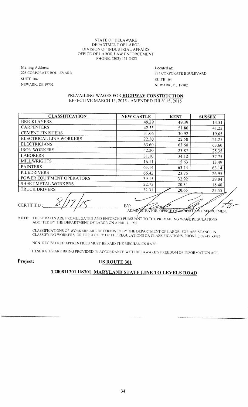
34
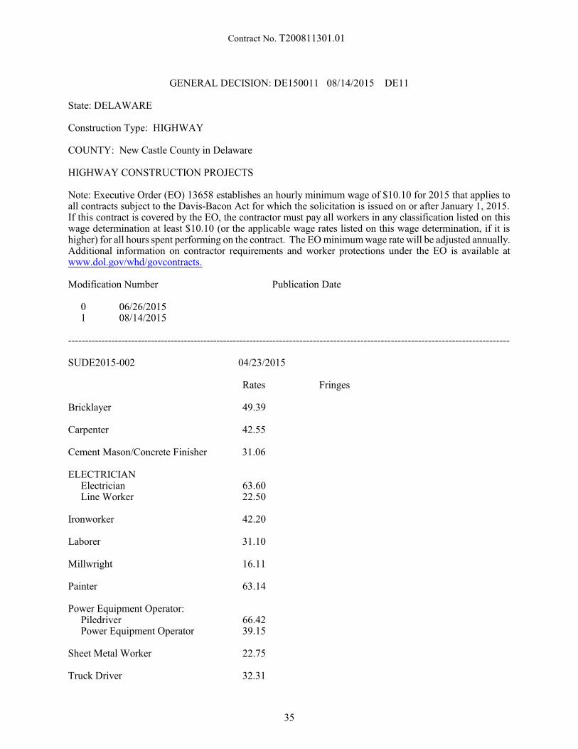
Contract No. T200811301.01
GENERAL DECISION: DE150011 08/14/2015 DE11
State: DELAWARE
Construction Type: HIGHWAY
COUNTY: New Castle County in Delaware
HIGHWAY CONSTRUCTION PROJECTS
Note: Executive Order (EO) 13658 establishes an hourly minimum wage of $10.10 for 2015 that applies toall contracts subject to the Davis-Bacon Act for which the solicitation is issued on or after January 1, 2015. If this contract is covered by the EO, the contractor must pay all workers in any classification listed on this wage determination at least $10.10 (or the applicable wage rates listed on this wage determination, if it ishigher) for all hours spent performing on the contract. The EO minimum wage rate will be adjusted annually. Additional information on contractor requirements and worker protections under the EO is available atwww.dol.gov/whd/govcontracts.
Modification Number Publication Date
0 06/26/20151 08/14/2015
------------------------------------------------------------------------------------------------------------------------------------
SUDE2015-002 04/23/2015
Rates Fringes
Bricklayer 49.39
Carpenter 42.55
Cement Mason/Concrete Finisher 31.06
ELECTRICIANElectricianLine Worker
63.6022.50
Ironworker 42.20
Laborer 31.10
Millwright 16.11
Painter 63.14
Power Equipment Operator:PiledriverPower Equipment Operator
66.4239.15
Sheet Metal Worker 22.75
Truck Driver 32.31
35
Contract No. T200811301.01
-------------------------------------------------------------------------------------------------------------------------------WELDERS - Receive rate prescribed for craft performing operation to which welding is incidental.-------------------------------------------------------------------------------------------------------------------------------
Unlisted classifications needed for work not included within the scope of the classifications listed may beadded after award only as provided in the labor standards contract clauses (29 CFR 5.5(a) (1) (ii)).
The body of each wage determination lists the classification and wage rates that have been found to beprevailing for the cited type(s) of construction in the area covered by the wage determination. Theclassifications are listed in alphabetical order of “identifiers” that indicate whether the particular rate is aunion rate (current union negotiated rate for local), a survey rate (weighted average rate) or a union averagerate (weighted union average rate).
Union Rate Identifiers
A four letter classification abbreviation identifier enclosed in dotted lines beginning with characters other than“SU” or “UAVG” denotes that the union classification and rate were prevailing for that classification in thesurvey. Example: PLUM0198-005 07/01/2014. PLUM is an abbreviation identifier of the union whichprevailed in the survey for this classification, which in this example would be Plumbers. 0198 indicates thelocal union number or district council number where applicable, i.e., Plumbers Local 0198. The next number,005 in the example, is an internal number used in processing the wage determination. 07/01/2014 is theeffective date of the most current negotiated rate, which in this example is July 1, 2014.
Union prevailing wage rates are updated to reflect all rate changes in the collective bargaining agreement(CBA) governing this classification and rate.
Survey Rate Identifiers
Classifications listed under an “SU” identifier indicated that no one rate prevailed for this classification inthe survey and the published rate is derived by computing a weighted average rate based on all the ratesreported in the survey for that classification. As this weighted average rate includes all rates reported in thesurvey, it may include both union and non-union rates. Example: SULA2012-007 5/13/2014. SU indicatesthe rates are survey rates based on a weighted average calculation of rates and are not majority rates. LAindicates the State of Louisiana. 2012 is the year of survey on which these classifications and rates are based. The next number, 007 in the example, is an internal number used in producing the wage determination. 5/13/2014 indicates the survey completion date for the classifications and rates under that identifier.
Survey wage rates are not updated and remain in effect until a new survey is conducted.
Union Average Rate Identifiers
Classification(s) listed under the UAVG identifier indicate that no single majority rate prevailed for thoseclassifications; however, 100% of the data reported for the classifications was union data. EXAMPLE:UAVG-OH-0010 08/29/2014. UAVG indicates that the rate is a weighted union average rate. OH indicatesthe state. The next number, 0010 in the example, is an internal number used in producing the wagedetermination. 08/29/2014 indicates the survey completion date for the classifications and rates under thatidentifier.
A UAVG rate will be updated once a year, usually in January of each year, to reflect a weighted average ofthe current negotiated/CBA rate of the union locals from which the rate is based.
WAGE DETERMINATION APPEALS PROCESS
1.) Has there been an initial decision in the matter? This can be:
* an existing published wage determination* a survey underlying a wage determination
36
Contract No. T200811301.01
* a Wage and Hour Division letter setting forth a position on a wage determination matter* a conformance (additional classification and rate) ruling
On survey related matters, initial contact, including requests for summaries of surveys, should be with theWage and Hour Regional Office for the area in which the survey was conducted because those RegionalOffices have responsibility for the Davis-Bacon survey program. If the response from this initial contact isnot satisfactory, then the process described in 2.) and 3.) should be followed.
With regard to any other matter not yet ripe for the formal process described here, initial contact should bewith the Branch of Construction Wage Determinations. Write to:
Branch of Construction Wage DeterminationsWage and Hour DivisionU.S. Department of Labor
200 Constitution Avenue, N. W.Washington, D. C. 20210
2.) If the answer to the question in 1.) is yes, then an interested party (those affected by the action) canrequest review and reconsideration from the Wage and Hour Administrator (See 29 CFR Part 1.8 and 29 CFRPart 7). Write to:
Wage and Hour AdministratorU.S. Department of Labor
200 Constitution Avenue, N. W.Washington, D. C. 20210
The request should be accompanied by a full statement of the interested party's position and by anyinformation (wage payment data, project description, area practice material, etc.) that the requestor considersrelevant to the issue.
3.) If the decision of the Administrator is not favorable, an interested party may appeal directly to theAdministrative Review Board (formerly the Wage Appeals Board). Write to:
Administrative Review BoardU. S. Department of Labor
200 Constitution Avenue, N. W.Washington, D. C. 20210
4.) All decisions by the Administrative Review Board are final.
END OF GENERAL DECISION
APPLICABILITY OF DAVIS-BACON LABOR STANDARD PROVISIONS TO FLAGGERS
The U.S. Department of Labor has established that the duties of flaggers working on contracts coveredby the Davis-Bacon Act, are manual and physical in nature. Accordingly, all employees performing thework of flaggers on Davis-Bacon covered contracts shall be entitled to receive applicable prevailing wagerates.
* * * * *ALL AGENCY MEMORANDUM NO. 130
U.S. DEPARTMENT OF LABOREMPLOYMENT STANDARDS ADMINISTRATION
WAGE AND HOUR DIVISIONWASHINGTON, DC 20210
37
Contract No. T200811301.01
GUIDELINES
HIGHWAY CONSTRUCTION
Highway projects include the construction, alteration, or repair of roads, streets, highways, runways,taxiways, alleys, trails, paths, parking areas, and other similar projects not incidental to building or heavyconstruction.
EXAMPLES: Alleys, Base Courses, Bituminous treatments, Bridle Paths, Concrete pavement, Curbs,Excavation and embankment (for road construction), Fencing (highway), Grade crossing elimination(overpasses and underpasses), Guard rails on highway, Highway signs, Highway bridges (overpasses,underpasses, grade separation), Medians, Parking lots, Parkways, Resurfacing streets and highways,Roadbeds, Roadways, Runways, Shoulders, Stabilizing courses, Storm sewers incidental to road construction,Street paving, Surface courses, Taxiways, and Trails.
ANY QUESTIONS REGARDING THE APPLICATION OF THE GUIDELINES ABOVE TO APARTICULAR PROJECT OR ANY DISPUTES REGARDING THE APPLICATION OF THE WAGESCHEDULES ARE TO BE REFERRED TO THE WAGE AND HOUR DIVISION, U.S. DEPARTMENTOF LABOR FOR RESOLUTION, AND THE INSTRUCTIONS OF THE WAGE AND HOUR DIVISIONARE TO BE OBSERVED IN ALL INSTANCES.
* ALL AGENCY MEMORANDUM NO. 130U.S. DEPARTMENT OF LABOREMPLOYMENT STANDARDS ADMINISTRATIONWAGE AND HOUR DIVISIONWASHINGTON, DC 20210
38
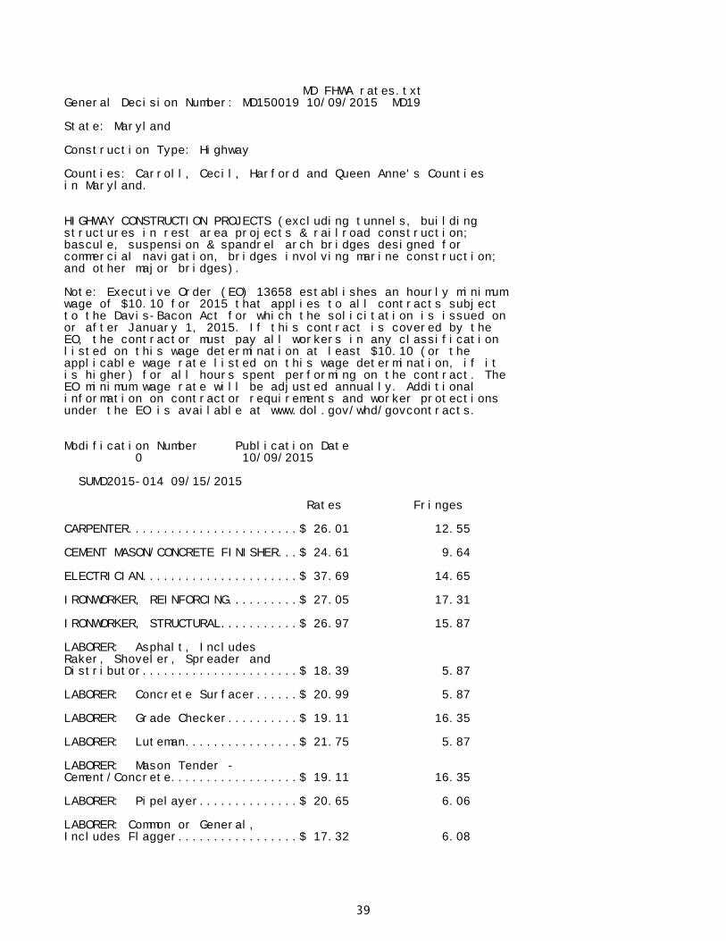
MD FHWA rates.txtGeneral Decision Number: MD150019 10/09/2015 MD19
State: Maryland
Construction Type: Highway
Counties: Carroll, Cecil, Harford and Queen Anne's Counties in Maryland.
HIGHWAY CONSTRUCTION PROJECTS (excluding tunnels, building structures in rest area projects & railroad construction;bascule, suspension & spandrel arch bridges designed for commercial navigation, bridges involving marine construction; and other major bridges).
Note: Executive Order (EO) 13658 establishes an hourly minimumwage of $10.10 for 2015 that applies to all contracts subjectto the Davis-Bacon Act for which the solicitation is issued onor after January 1, 2015. If this contract is covered by theEO, the contractor must pay all workers in any classificationlisted on this wage determination at least $10.10 (or theapplicable wage rate listed on this wage determination, if itis higher) for all hours spent performing on the contract. TheEO minimum wage rate will be adjusted annually. Additionalinformation on contractor requirements and worker protectionsunder the EO is available at www.dol.gov/whd/govcontracts.
Modification Number Publication Date0 10/09/2015
SUMD2015-014 09/15/2015
Rates Fringes
CARPENTER........................$ 26.01 12.55
CEMENT MASON/CONCRETE FINISHER...$ 24.61 9.64
ELECTRICIAN......................$ 37.69 14.65
IRONWORKER, REINFORCING..........$ 27.05 17.31
IRONWORKER, STRUCTURAL...........$ 26.97 15.87
LABORER: Asphalt, Includes Raker, Shoveler, Spreader and Distributor......................$ 18.39 5.87
LABORER: Concrete Surfacer......$ 20.99 5.87
LABORER: Grade Checker..........$ 19.11 16.35
LABORER: Luteman................$ 21.75 5.87
LABORER: Mason Tender - Cement/Concrete..................$ 19.11 16.35
LABORER: Pipelayer..............$ 20.65 6.06
LABORER: Common or General, Includes Flagger.................$ 17.32 6.08
39
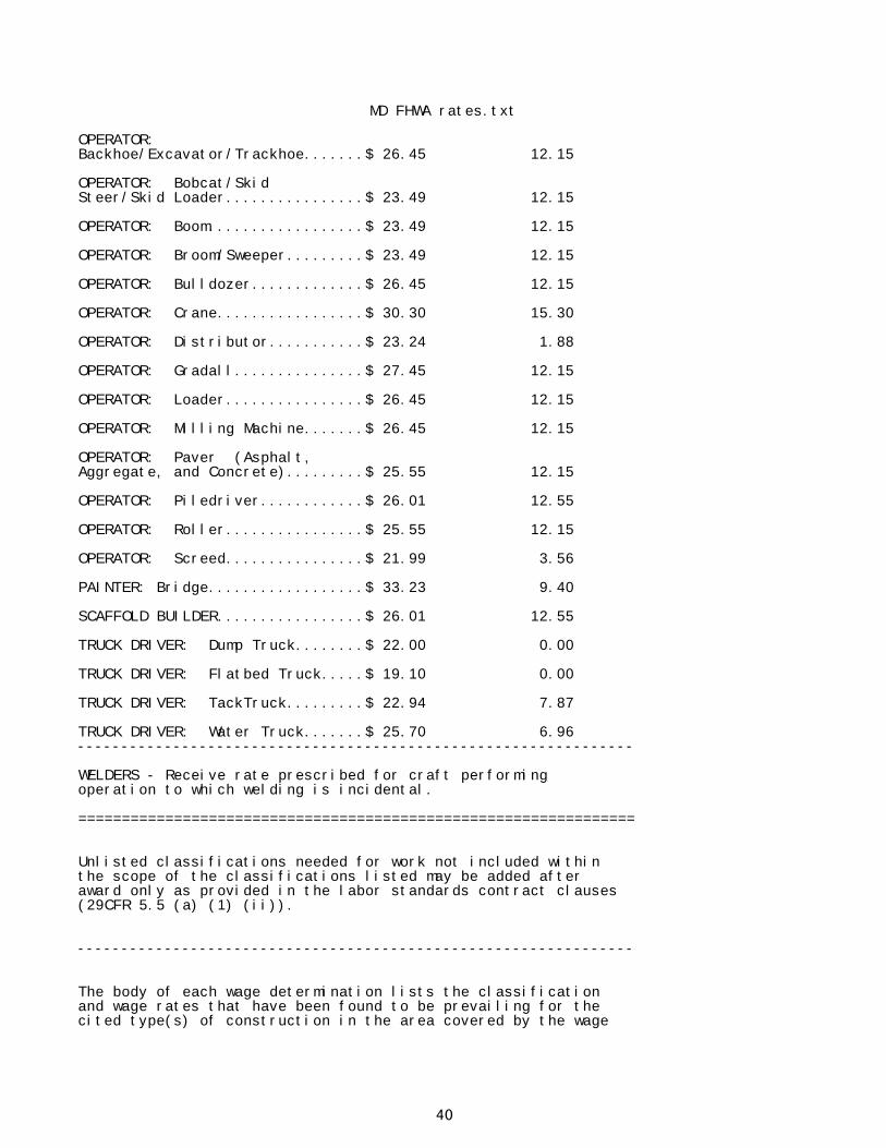
MD FHWA rates.txt
OPERATOR: Backhoe/Excavator/Trackhoe.......$ 26.45 12.15
OPERATOR: Bobcat/Skid Steer/Skid Loader................$ 23.49 12.15
OPERATOR: Boom..................$ 23.49 12.15
OPERATOR: Broom/Sweeper.........$ 23.49 12.15
OPERATOR: Bulldozer.............$ 26.45 12.15
OPERATOR: Crane.................$ 30.30 15.30
OPERATOR: Distributor...........$ 23.24 1.88
OPERATOR: Gradall...............$ 27.45 12.15
OPERATOR: Loader................$ 26.45 12.15
OPERATOR: Milling Machine.......$ 26.45 12.15
OPERATOR: Paver (Asphalt, Aggregate, and Concrete).........$ 25.55 12.15
OPERATOR: Piledriver............$ 26.01 12.55
OPERATOR: Roller................$ 25.55 12.15
OPERATOR: Screed................$ 21.99 3.56
PAINTER: Bridge..................$ 33.23 9.40
SCAFFOLD BUILDER.................$ 26.01 12.55
TRUCK DRIVER: Dump Truck........$ 22.00 0.00
TRUCK DRIVER: Flatbed Truck.....$ 19.10 0.00
TRUCK DRIVER: TackTruck.........$ 22.94 7.87
TRUCK DRIVER: Water Truck.......$ 25.70 6.96----------------------------------------------------------------
WELDERS - Receive rate prescribed for craft performingoperation to which welding is incidental.
================================================================
Unlisted classifications needed for work not included withinthe scope of the classifications listed may be added afteraward only as provided in the labor standards contract clauses(29CFR 5.5 (a) (1) (ii)).
----------------------------------------------------------------
The body of each wage determination lists the classificationand wage rates that have been found to be prevailing for thecited type(s) of construction in the area covered by the wage
40
MD FHWA rates.txtdetermination. The classifications are listed in alphabeticalorder of "identifiers" that indicate whether the particularrate is a union rate (current union negotiated rate for local),a survey rate (weighted average rate) or a union average rate(weighted union average rate).
Union Rate Identifiers
A four letter classification abbreviation identifier enclosedin dotted lines beginning with characters other than "SU" or"UAVG" denotes that the union classification and rate wereprevailing for that classification in the survey. Example:PLUM0198-005 07/01/2014. PLUM is an abbreviation identifier ofthe union which prevailed in the survey for thisclassification, which in this example would be Plumbers. 0198indicates the local union number or district council numberwhere applicable, i.e., Plumbers Local 0198. The next number,005 in the example, is an internal number used in processingthe wage determination. 07/01/2014 is the effective date of themost current negotiated rate, which in this example is July 1,2014.
Union prevailing wage rates are updated to reflect all ratechanges in the collective bargaining agreement (CBA) governingthis classification and rate.
Survey Rate Identifiers
Classifications listed under the "SU" identifier indicate thatno one rate prevailed for this classification in the survey andthe published rate is derived by computing a weighted averagerate based on all the rates reported in the survey for thatclassification. As this weighted average rate includes allrates reported in the survey, it may include both union andnon-union rates. Example: SULA2012-007 5/13/2014. SU indicatesthe rates are survey rates based on a weighted averagecalculation of rates and are not majority rates. LA indicatesthe State of Louisiana. 2012 is the year of survey on whichthese classifications and rates are based. The next number, 007in the example, is an internal number used in producing thewage determination. 5/13/2014 indicates the survey completiondate for the classifications and rates under that identifier.
Survey wage rates are not updated and remain in effect until anew survey is conducted.
Union Average Rate Identifiers
Classification(s) listed under the UAVG identifier indicatethat no single majority rate prevailed for thoseclassifications; however, 100% of the data reported for theclassifications was union data. EXAMPLE: UAVG-OH-001008/29/2014. UAVG indicates that the rate is a weighted unionaverage rate. OH indicates the state. The next number, 0010 inthe example, is an internal number used in producing the wagedetermination. 08/29/2014 indicates the survey completion datefor the classifications and rates under that identifier.
A UAVG rate will be updated once a year, usually in January ofeach year, to reflect a weighted average of the currentnegotiated/CBA rate of the union locals from which the rate isbased.
41
MD FHWA rates.txt
----------------------------------------------------------------
WAGE DETERMINATION APPEALS PROCESS
1.) Has there been an initial decision in the matter? This canbe:
* an existing published wage determination* a survey underlying a wage determination* a Wage and Hour Division letter setting forth a position on
a wage determination matter* a conformance (additional classification and rate) ruling
On survey related matters, initial contact, including requestsfor summaries of surveys, should be with the Wage and HourRegional Office for the area in which the survey was conductedbecause those Regional Offices have responsibility for theDavis-Bacon survey program. If the response from this initialcontact is not satisfactory, then the process described in 2.)and 3.) should be followed.
With regard to any other matter not yet ripe for the formalprocess described here, initial contact should be with theBranch of Construction Wage Determinations. Write to:
Branch of Construction Wage DeterminationsWage and Hour DivisionU.S. Department of Labor200 Constitution Avenue, N.W.Washington, DC 20210
2.) If the answer to the question in 1.) is yes, then aninterested party (those affected by the action) can requestreview and reconsideration from the Wage and Hour Administrator(See 29 CFR Part 1.8 and 29 CFR Part 7). Write to:
Wage and Hour AdministratorU.S. Department of Labor200 Constitution Avenue, N.W.Washington, DC 20210
The request should be accompanied by a full statement of theinterested party's position and by any information (wagepayment data, project description, area practice material,etc.) that the requestor considers relevant to the issue.
3.) If the decision of the Administrator is not favorable, aninterested party may appeal directly to the AdministrativeReview Board (formerly the Wage Appeals Board). Write to:
Administrative Review BoardU.S. Department of Labor200 Constitution Avenue, N.W.Washington, DC 20210
4.) All decisions by the Administrative Review Board are final.
================================================================
END OF GENERAL DECISION
42
Contract No. T200811301.01
SUPPLEMENTAL SPECIFICATIONSTO THE
AUGUST 2001 STANDARD SPECIFICATIONS
EFFECTIVE AS OF THE ADVERTISEMENTDATE OF THIS PROPOSAL
AND INCLUDED BY REFERENCE
The Supplemental Specifications can be viewed and printed fromthe Department's Website.
To access the Website;- in your internet browser, enter; http://www.deldot.gov - on the left side of the page under 'INFORMATION', Click; 'Publications' - scroll down under 'MANUALS' and Click; "Standard Specifications 2001"
The full Website Link is;http://www.deldot.gov/information/pubs_forms/manuals/standard_specifications/index.shtml
Printed copies of the Supplemental Specifications are available upon request. A printed copy ofthe above referenced Supplemental Specifications will be included in the final contractdocuments upon award.
The Contractor shall make himself aware of these revisions and corrections (SupplementalSpecifications), and apply them to the applicable item(s) of this contract.
43
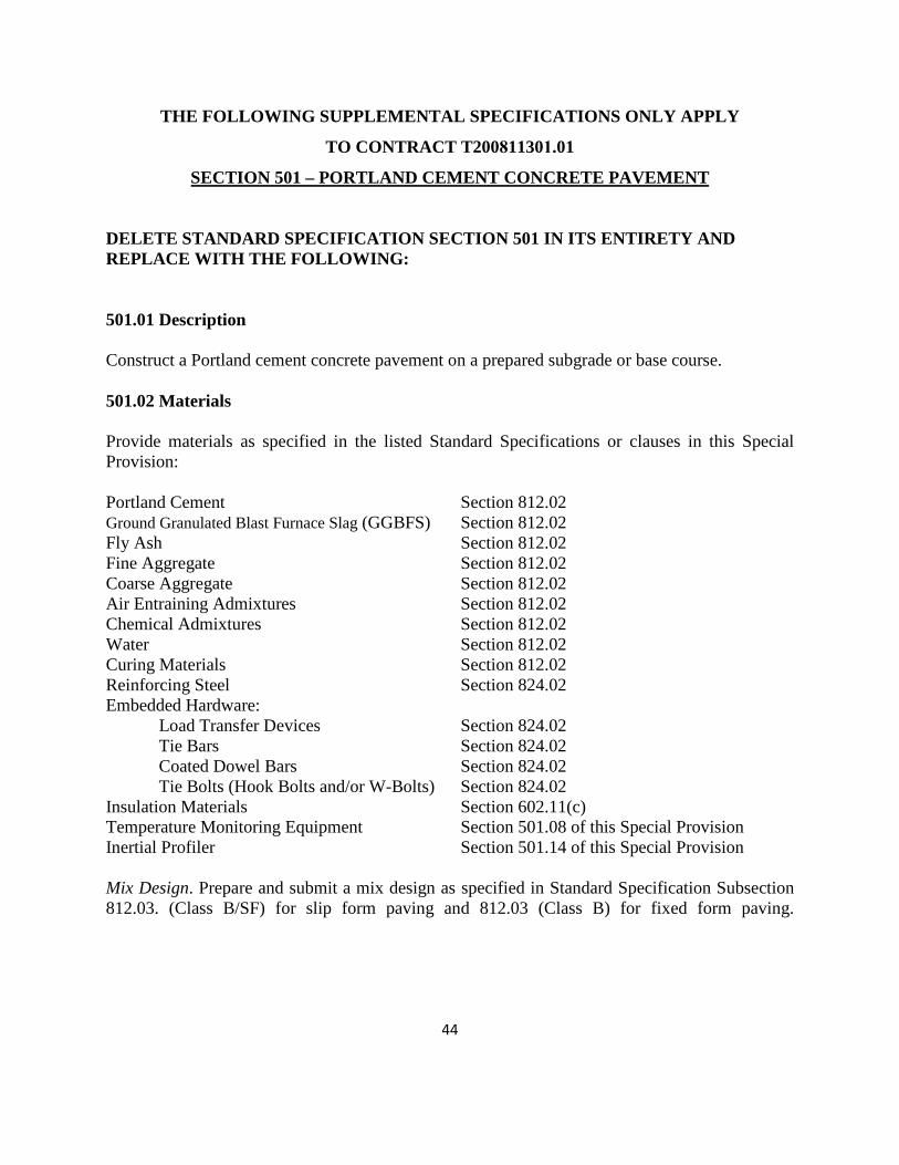
THE FOLLOWING SUPPLEMENTAL SPECIFICATIONS ONLY APPLY
TO CONTRACT T200811301.01
SECTION 501 – PORTLAND CEMENT CONCRETE PAVEMENT
DELETE STANDARD SPECIFICATION SECTION 501 IN ITS ENTIRETY AND REPLACE WITH THE FOLLOWING:
501.01 Description
Construct a Portland cement concrete pavement on a prepared subgrade or base course.
501.02 Materials
Provide materials as specified in the listed Standard Specifications or clauses in this Special Provision:
Portland Cement Ground Granulated Blast Furnace Slag (GGBFS) Fly Ash Fine Aggregate Coarse Aggregate Air Entraining Admixtures Chemical Admixtures Water Curing Materials Reinforcing Steel Embedded Hardware: Load Transfer Devices Tie Bars Coated Dowel Bars Tie Bolts (Hook Bolts and/or W-Bolts) Insulation Materials Temperature Monitoring Equipment Inertial Profiler
Section 812.02 Section 812.02 Section 812.02 Section 812.02 Section 812.02 Section 812.02 Section 812.02 Section 812.02 Section 812.02 Section 824.02
Section 824.02 Section 824.02 Section 824.02 Section 824.02Section 602.11(c) Section 501.08 of this Special Provision Section 501.14 of this Special Provision
Mix Design. Prepare and submit a mix design as specified in Standard Specification Subsection 812.03. (Class B/SF) for slip form paving and 812.03 (Class B) for fixed form paving.
44
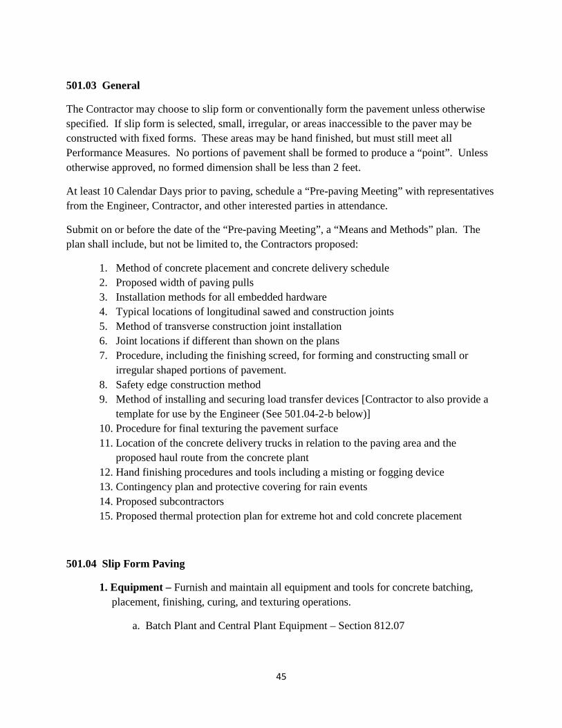
501.03 General
The Contractor may choose to slip form or conventionally form the pavement unless otherwise specified. If slip form is selected, small, irregular, or areas inaccessible to the paver may be constructed with fixed forms. These areas may be hand finished, but must still meet all Performance Measures. No portions of pavement shall be formed to produce a “point”. Unless otherwise approved, no formed dimension shall be less than 2 feet.
At least 10 Calendar Days prior to paving, schedule a “Pre-paving Meeting” with representatives from the Engineer, Contractor, and other interested parties in attendance.
Submit on or before the date of the “Pre-paving Meeting”, a “Means and Methods” plan. The plan shall include, but not be limited to, the Contractors proposed:
1. Method of concrete placement and concrete delivery schedule2. Proposed width of paving pulls3. Installation methods for all embedded hardware4. Typical locations of longitudinal sawed and construction joints5. Method of transverse construction joint installation6. Joint locations if different than shown on the plans7. Procedure, including the finishing screed, for forming and constructing small or
irregular shaped portions of pavement.8. Safety edge construction method9. Method of installing and securing load transfer devices [Contractor to also provide a
template for use by the Engineer (See 501.04-2-b below)]10. Procedure for final texturing the pavement surface11. Location of the concrete delivery trucks in relation to the paving area and the
proposed haul route from the concrete plant12. Hand finishing procedures and tools including a misting or fogging device13. Contingency plan and protective covering for rain events14. Proposed subcontractors15. Proposed thermal protection plan for extreme hot and cold concrete placement
501.04 Slip Form Paving
1. Equipment – Furnish and maintain all equipment and tools for concrete batching,placement, finishing, curing, and texturing operations.
a. Batch Plant and Central Plant Equipment – Section 812.07
45
b. Place concrete with a track operated, self-propelled, slip-form paver that canindependently, or in conjunction with an advance concrete spreader:
1) Strike-off
2) Screed
3) Adjust to produce the specified cross slope and pavement width
4) Place a minimum width pavement of 24 feet in one pull
5) Operate using electronic grade controls for both horizontal and verticalalignment
6) Provide a vertical pavement edge with slump off not exceeding ¼ inch,exclusive of edge rounding, when checked under a 10 foot straightedge
7) Vibrate and consolidate the concrete for the full width being placed.Vibrators are to be attached to the paving equipment or mounted on aseparate carriage. Vibrators shall not contact load transfer devices,embedded hardware, or forms. The Contractor is responsible for thenumber and frequency setting of the vibrators to achieve uniformconsolidation of the concrete throughout the entire slab thickness andwidth. Vibration must automatically stop when forward movement ofthe unit is interrupted.
8) Provide a smooth, uniform concrete surface finish requiring minimal orno floating or hand finishing
9) A paver equipped with a Dowel Bar Inserter (DBI) may be utilized ifapproved in advance by the Engineer.
c. Concrete Saws – Provide mechanical saws capable of producing the specifiedjoint details. The Contractor shall determine the number of saws needed based on weather, temperature, and amount of pavement placed. Backup equipment and lighting (if necessary) must be on site prior to beginning concrete placement.
d. Work Bridge(s) – Provide platforms spanning the full width of the paving pullso that workers can perform necessary finishing, texturing, and/or curing. Thework bridge(s) shall not come in direct contact with the pavement surface.
e. Texturing – Provide independently powered, self propelled texturingequipment capable of adjusting the depth of tine penetration to produce the
46
specified pavement surface texture. For formed pavement, the texturing equipment shall ride on the forms or rails.
f. Curing – Provide mechanically powered equipment to place curing compoundat the specified rate to the pavement surface and all exposed edges. Use a fully atomized mechanical sprayer equipped with a tank agitator and wind guard.
g. Diamond Grinding – Provide self-propelled machines equipped with gangmounted diamond blades having a minimum cutting head width of 3 feet, capable of producing a “corduroy type” pavement surface texture consisting of parallel grooves between 3/32” and 5/32” wide and 1/16” deep. 50 to 60 diamond blades per foot of cutting head are required.
2. Construction Methods –
a. No hardware may be placed on the grade in contact with the concretepavement until the Engineer has given approval to do so. Place and grade the base course to tolerance as specified under the applicable item.
b. Furnish and install load transfer devices. Clearly mark, on both sides of thepavement, the center of each assembly using paint, stakes or other agreedupon method so that the transverse sawed joints can be properly located.Unless otherwise specified in the contract documents, construct load transferassemblies, typically spaced at 15 feet, center to center. If the approveddowels are AASHTO M254, Type A, no additional coating is required. Ifthey are AASHTO M254, Type B (fusion bonded epoxy), then a graphitecoating shall manually be applied to each dowel just prior to concrete placement. Securely stake or otherwise fasten the load transfer device to the subgrade to prevent movement during concrete placement. Do not use load transfer assemblies that are damaged in any way. Verify horizontal and vertical alignment of the devices not to exceed ¼ inch from parallel to line and grade. Locate dowels at a pavement depth of T/2, (T = pavement thickness) plus or minus 1 inch. Check initial dowel placement on grade with a template or other approved tool supplied by the Contractor for use by the Engineer. The Engineer may elect to check the location of dowels at any time throughout the duration of the contract with a pachometer or other non-destructive testing device.
c. Furnish Hook Bolts (or W-Bolts) for use when additional lanes willlongitudinally abut the pavement being placed, and #5 standard rebars for tie
47
bars used under longitudinal sawed joints or for tying into concrete lanes placed under previous contracts. Install these items during or prior to concrete placement. The method of installation must be approved prior to beginning concrete placement.
d. Install lines, wires, or other devices of the Contractor’s choice as needed forelectronic grade control.
e. Placing Concrete –
1) Minimize or eliminate stopping the forward movement of the paver.Sufficient number and proper scheduling of concrete delivery trucks isrequired in this regard.
2) Maintain a vertical pavement edge. If necessary, use extra finishers,temporary forms, or trailing forms as part of the paver.
3) Maintain a uniform level of concrete feeding the paver screed,allowing sufficient concrete to completely fill the void under thescreed for the entire width of pavement placed. A roll of concretecovering approximately half of the distributing augers is desirable.Spreaders in advance of the paver may be used to control the concretesupplied to the paver.
4) Wet the base course just prior to contact by the concrete using a hoseor other spray device for uniform water application. The applicationrate should not cause any pooling of water on the grade.
5) As the concrete is being placed, install tie bars under longitudinalsawed joints and Hook or W-Bolts along longitudinal pavement edgesrequiring abutting pavement to be placed in the future.
6) Build a transverse construction joint at the end of the day’s paving runin accordance with the previously approved details.
7) Prior to placing adjoining concrete paving lanes or shoulders, seal thepreviously sawed joint opening along the edges of the existingconcrete using duct tape, caulk, or other approved material to preventstones or grout from entering the sawcut.
8) When placing concrete in lanes adjoining previously constructedpavement, locate the full width of the paver tracks over the pavementwith no overhang across the edge, in order to prevent breaking. Userubber facing, wood, or other approved protection when the paver
48
tracks will be in contact with the existing pavement surface. Concrete in the completed lane must have achieved a compressive strength of at least 2,000 psi prior to placing any adjoining pavement.
9) For small, irregular sections, or areas of pavement inaccessible to thepaver:
a) Use wooden or steel forms. Depth of the forms must be at leastthat of the required pavement thickness. Form faces shall notdeviate from a true plane by any more that 1/8 inch in 10 feet.Provide pins or other bracing to prevent movement of the formsunder the weight of the concrete.
b) Place concrete directly onto a previously approved, moistenedgrade. Consolidate with hand vibrators paying particularattention not to dislodge the load transfer devices or come incontact with the forms.
c) Finish with a pre-approved screed. Hand float or otherwisefinish any areas as necessary. Pull a damp burlap draglongitudinally along the placement area. Texture and cure inaccordance with sections 501.06 and 501.07 below.
d) If forms are stripped prior to 5 calendar days following concreteplacement, apply curing compound or extend other curingmethods immediately after patching any “honey-combed” areasto completely cure the exposed edge. Forms must remain inplace at least 12 hours following initial concrete placement,except for areas immediately adjacent sawcut transverse joints.Forms at these joints must be removed when required in order tocomplete the sawcut through the entire pavement surface.Maintain curing methods in place until the full five day time haselapsed or the compressive strength of the concrete has reached2,000 psi.
10) Safety Edge – Construct a safety edge as specified in the contractdocuments. The safety edge is required longitudinally along the outermost pavement edge (generally a shoulder) on all mainline and ramp paving unless otherwise approved by the Engineer.
f. Finishing –
1) Produce a smooth, uniform concrete surface with the paver screedconforming to the specified pavement cross slope and width.
49
2) Hand finishing to be limited to sealing any surface tears, supportingany non-vertical pavement edges, and to assist in the surface finish ofsmall, irregular, or other areas inaccessible to the paver.
3) Finish all longitudinal pavement edges with a ¼ inch rounded edgingtool.
4) Do not add surface water as an aid to finishing. If absolutelynecessary, an evaporation retardant may be added through the use of amisting or fogging device approved prior to beginning pavingoperations. Water shaken from brushes or applied through a hose isnot permitted.
5) Finish the final pavement surface prior to texturing by pulling a wetburlap drag in the longitudinal direction. Keep the burlap in a moistcondition throughout the paving operation in order to prevent surfacetearing.
6) Texture and cure the pavement per subsections 501.06 and 501.07below.
501.05 Fixed Form Paving
1. Forms –
a. Use straight, metal forms having adequate strength to support the equipment.Each section shall be a minimum of 10 feet in length. Use forms with a depth equal to or greater than the prescribed edge thickness of the concrete, a base width at least equal to the depth of the forms, but not required to exceed 8 inches for deeper forms, and without a horizontal joint. Use flexible or curved forms of proper radius for curves of 150 foot radius or less, except approved straight forms of 5 foot lengths may be used for curves of a radius from 75 to 150 feet. Flexible or curved forms must be approved by the Engineer. The Engineer may approve the use of wood forms in areas requiring hand finishing [see Subsection 501.04-2-e-9) above]. Secure the forms in place to withstand the impact and vibration of the consolidating and finishing equipment without visible spring or settlement. Extend flange braces outward on the base a minimum of ⅔ the height of the form. Remove forms with battered top surfaces or bent, twisted or broken forms. Do not use repaired forms until they have been inspected and approved by the Engineer. Do not use buildup forms, except where the total area of pavement of any specified thickness on the project is less than 2,000 square yards. Do not vary the top face of the
50
form from a true plane more than ⅛ inch in 10 feet, and do not vary the vertical face of the form by more than ¼ inch. Make provisions for locking the ends of abutting form sections together tightly, and for secure setting.
b. Supplementary Rails -
1) Provide suitable metal rails capable of being securely attached to thetop of the side forms to provide a track which will allow spreading,finishing, and curing equipment to back over the end of the previousday’s run.
2) Ensure metal rail length is sufficient to accommodate all equipmentwhich must be backed out of the way. Also ensure the rails are of sucha height that all wheels and flanges of wheels will clear the previouslyplaced concrete by at least 1/2 inch.
c. Base Support - Provide a foundation under the forms so that the whole lengthof the form will be set firmly in contact with the grade.
d. Form Setting - Set forms sufficiently in advance of the point where concrete isbeing placed so that line and grade may be checked. Stake forms into placewith a minimum of 3 pins for each 10 feet section. Place a pin at each side ofevery joint. Tightly lock form sections, free from play or movement in anydirection. Do not deviate the form from true line by more than ¼ inch at anypoint. No excessive settlement or springing of forms under the finishingmachine is permitted. Clean and oil forms before the placing of concrete.
e. Grade and Alignment - Check the alignment and grade elevations of the formsimmediately before placing the concrete and make any necessary corrections. When any form has been disturbed or any grade has become unstable, reset and recheck the form.
f. Removing Forms - Unless otherwise provided, do not remove forms fromfreshly placed concrete until it has set for a minimum of 12 hours, exceptauxiliary forms used temporarily in widened areas and forms againsttransverse sawcut joint locations. Remove forms carefully to avoid damage tothe pavement.
2. Equipment - Furnish and maintain all equipment and tools for concrete batching,placement, finishing, curing, and texturing operations.
a. In addition to the equipment included in this section, all equipment listedunder Subsection 501.04-1 above is required except that section 501.04-1-b isreplaced with the following for fixed form paving:
51
b. Place concrete with a finishing machine designed for fixed form paving thatcan ride on previously set forms and can independently, or in conjunction withan advance concrete spreader:
1) Strike-off
2) Screed
3) Adjust to produce the specified cross slope and pavement width
4) Place a minimum width pavement of 12 feet in one pull
5) Provide a smooth, uniform concrete surface finish requiring minimal orno floating or hand finishing
c. Vibration –
Vibrate and consolidate the concrete for the full placement width. Vibrators are to be attached to the paving equipment or mounted on a separate carriage. Only operate the vibrators when the machine they are mounted on is moving forward. Do not operate hand vibrators more than 10 seconds, or less than 5 seconds in any one location unless approved otherwise by the Engineer. Place vibrators in and withdraw from concrete vertically in a slow deliberate manner. In order to obtain concrete consolidation in the vicinity of joint assemblies, the Engineer may require that these areas be hand vibrated with an immersion spud vibrator. Vibrators shall not contact load transfer devices, embedded hardware, or forms. The Contractor is responsible for the number and frequency setting of the vibrators to achieve uniform consolidation of the concrete throughout the entire slab thickness and width.
d. Form Line Excavating Machine –
Excavate form lines for all forms supporting mechanical finishing equipmentto line and grade by a machine designed for this purpose and approved by theEngineer, or an approved machine which concurrently trims the subgrade orsubbase to grade.
e. If, during the operation of paving equipment, it is necessary to operate one orboth sets of wheels or tracks on previously placed concrete, adjust or alter the wheels or tracks so that the bearing on the concrete will not be closer than 3 inches from the pavement edge. When operating with one side of the machine on pavement and the other side on forms, the wheels operating on the forms may be double flanged. Use flangeless, rubber faced wheels on the pavement. When operating over the edge of concrete less than 2 months old, support the ends of the finishing machine screeds with an approved device to provide
52
from 1/16 to 1/8 inch clearance between the screed and previously placed pavement.
3. Construction Methods
a. No hardware may be placed on the grade in contact with the concretepavement until the Engineer has given approval to do so. Place and grade the base course to the tolerance specified under the applicable item.
b. Furnish and install load transfer devices. Clearly mark, on both sides, thecenter of each assembly using paint, stakes or other agreed upon method sothat the transverse sawed joints can be properly located. Unless otherwisespecified, space load transfer assemblies at 15 feet, center to center. If theapproved dowels are AASHTO M254, Type A, no additional coating isrequired. If they are AASHTO M254, Type B (fusion bonded epoxy), thenmanually apply a graphite coating to each dowel just prior to concreteplacement. Securely stake or otherwise fasten the load transfer device to thesubgrade to prevent movement during concrete placement. Do not use loadtransfer assemblies that are damaged in any way. Verify horizontal andvertical alignment of the devices not to exceed ¼ inch from parallel to lineand grade. Locate dowels at a pavement depth of T/2, (T = pavementthickness) plus or minus 1 inch. Check dowel placement with a template orother approved tool supplied by the Contractor for use by the Engineer. TheEngineer may elect to check the location of dowels at any time throughout theduration of the contract with a pachometer or other non-destructive testingdevice.
c. Furnish Hook Bolts (or W-Bolts) for use when lanes will longitudinally abutthe pavement being placed, and #5 standard rebars for tie bars used under longitudinal sawed joints or for tying into concrete lanes placed under previous contracts. Install these items prior to or during concrete placement. The method of installation must be approved prior to beginning concrete placement.
d. Placing Concrete –
1) Minimize or eliminate stopping the forward movement of the paver.Sufficient number and proper scheduling of concrete delivery trucks isrequired in this regard.
2) Maintain a uniform level of concrete feeding the paver screed,allowing sufficient concrete to completely fill the void under the
53
screed for the entire width of pavement placed. Spreaders in advance of the paver may be used to control the concrete supplied to the paver.
3) Wet the base course just prior to contact by the concrete using a hoseor other spray device for uniform water application. The applicationrate should not cause any pooling of water on the grade.
4) As the concrete is being placed, install tie bars under longitudinalsawed joints and Hook or W-Bolts along longitudinal pavement edgesrequiring abutting pavement to be placed in the future.
5) Build a transverse construction joint at the end of the day’s paving runin accordance with the previously approved details.
6) Prior to placing adjoining concrete paving lanes or shoulders, seal thepreviously sawed joint opening along the edges of the existingconcrete using duct tape, caulk, or other approved material to preventstones or grout from entering the sawcut.
7) When placing concrete in lanes adjoining previously constructedpavement, the paver tracks must be fully in contact with the completedpavement surface to prevent breaking of the edge. Use rubber facing,wood, or other approved protection if the paver tracks will be incontact with the existing pavement surface. Concrete in the completedlane must have achieved a compressive strength of at least 2,000 psiprior to placing any adjoining pavement.
8) For small, irregular sections, or areas of pavement inaccessible to thepaver:
a) Use wooden or steel forms. Depth of the forms must be at leastthat of the required pavement thickness. Form faces shall notdeviate from a true plane by any more that 1/8 inch in 10 feet.Provide pins or other bracing to prevent movement of the formsunder the weight of the concrete.
b) Place concrete directly onto a previously approved, moistenedgrade. Consolidate with hand vibrators paying particularattention not to dislodge the load transfer devices or come incontact with the forms.
c) Finish with a pre-approved screed. Hand float or otherwisefinish any areas as necessary. Pull a damp burlap drag
54
longitudinally along the placement area. Texture and cure in accordance with sections 501.06 and 501.07 below.
d) If forms are stripped prior to 5 calendar days following concreteplacement, apply curing compound or extend other curingmethods immediately after patching any “honey-combed” areasto completely cure the exposed edge. Forms must remain inplace at least 12 hours following initial concrete placement,except for areas immediately adjacent sawcut transverse joints.Forms at these joints must be removed when required in order tocomplete the sawcut through the entire pavement surface.Curing methods shall remain in place until the full five day timehas elapsed or the compressive strength of the concrete hasreached 2,000 psi.
9) Safety Edge – Construct a safety edge as specified in the contractdocuments. The safety edge is required longitudinally along theoutermost pavement edge (generally a shoulder) on all mainline andramp paving unless otherwise approved by the Engineer.
e. Finishing –
1) The paver screed shall produce a smooth, uniform concrete surfaceconforming to the specified pavement cross slope and width.
2) Limit hand finishing to sealing any surface tears, supporting any non-vertical pavement edges, and to assist in the surface finish of small,irregular, or other areas inaccessible to the paver.
3) Finish all longitudinal pavement edges with a ¼ inch rounded edgingtool.
4) Do not add surface water as an aid to finishing. If absolutelynecessary, an evaporation retardant may be added through the use of amisting or fogging device approved prior to beginning pavingoperations. Water shaken from brushes or applied through a hose isnot permitted.
5) Create a final pavement surface prior to texturing by pulling a wetburlap drag in the longitudinal direction. Keep the burlap in a moistcondition throughout the paving operation in order to prevent surfacetearing.
6) Texture and cure the pavement per subsections 501.06 and 501.07.
55
501.06 Texturing
1. Texture the finished pavement for the entire placement width with an approved tiningdevice. Flat steel wire tines are required and shall be 3/32 inches wide and 5 to 6inches in length unless otherwise approved, having a ¾ inch spacing between thetines. The tines shall form rectangular shaped grooves 1/16 inch to 3/16 inches indepth. Do not texture portions of the pavement that will receive permanent pavementmarkings. In these areas, maintain a 10 inch wide flat surface to accommodate thestriping and raised pavement markers. The burlap drag finish is acceptable for theseareas.
2. The Contractor may elect to diamond grind all surfaces of concrete pavement to createa final texture. If so, the grinding shall not be performed until the concrete hasobtained a compressive strength of at least 3,500 psi.
3. Tining shall be pulled in the longitudinal direction, parallel to the centerline of thepavement, in one pass without dragging or tearing the mortar.
4. The Contractor is responsible to determine the proper time to install the tining. Thetining should not pull excessive mortar or aggregate from the pavement (too early) orfail to penetrate the surface by the minimum 1/16 inch (too late).
5. Make available hand tining devices at least 4 feet in width equipped with tinesidentical to those specified above for use in areas inaccessible to the mechanicaldevice.
6. Immediately follow the tining operation with approved curing.
501.07 Curing – Use one of the methods listed below
1. White Membrane Curing Compound
a. Spray the curing material on the pavement surface and all exposed edgesimmediately following the texturing operation.
b. Continuously agitate the material during application to keep it thoroughlymixed.
c. Uniformly apply 2 applications of spray to the entire surface at a rate coveringno more than 200 square feet (22.2 square yards) per gallon per each of the two applications. Apply the first coat immediately following the tining operation and the second coat no more than 30 minutes after the first.
56
d. If necessary, use hand sprayers for pavement edges or small and irregular areasinaccessible to the larger mechanical applicator. The rate of applicationremains no more than 200 sq. ft. per gallon per each of two applications.
e. No equipment or traffic (other than joint saws, foot traffic and pick up typevehicles) is permitted on the pavement until the compressive strength has reached at least 2,000 psi.
2. Polyethylene Film –
a. Extend the polyethylene beyond the slab edges by at least twice the pavementthickness and add weight to secure the material against wind and weather.
b. Maintain the polyethylene in place for at least 5 calendar days or until theconcrete compressive strength has reached at least 2,000 psi. At sawed jointlocations, remove as little polyethylene as possible just prior to the sawingoperation. Re-cover the area over the sawed joint immediately uponcompletion of the sawing operation and maintain for the remainder of thecuring period.
501.08 Temperature Limitations
Concrete will not be placed when the evaporation rate is greater than or equal to 0.15 lb per square foot per hour as published in the ACI 305 chart developed by Delmar Bloem. DelDOT Materials and Research Section can provide copies of the chart upon request.
The contractor will submit, for approval, a “Thermal Plan” for protection of concrete pavement to address both hot and cold placement temperatures (as defined by ACI 305 and 306 respectively). The plan must incorporate, as a minimum, the following restrictions:
1. Cold Weather –a. Do not place concrete when the ambient air temperature in the shade, and away
from artificial heat, is less than 35° F. Resume placement when the ambientair temperature is 35° F and rising.
b. Do not place concrete on frozen grade.
c. Maintain temperatures of not less than 50º F surrounding the concretepavement for a curing period of five calendar days following placement of theconcrete. Provide all necessary monitoring devices (High-Low thermometersor other tools) and a plan for monitoring the temperature during the five day
57
period ensuring placed concrete is not damaged by the temperatures. Use of insulating blankets, straw, polyethylene, or other protection subject to the approval of the Engineer must be addressed in the plan.
2. Hot Weather
a. If plastic concrete temperatures reach 80º F, give additional attention todampening the subgrade immediately in advance of the concreteplacement. Perform finishing, texturing, and curing operations as soon aspossible. Should the pavement surface dry out to the extent that it cannot besealed without the application of surface water, paving shall be suspended.
b. No concrete may be placed when the temperature of the plastic concreteexceeds 85º F at the production facility.
3. Regardless of the protection methods selected, the Contractor is responsible to protectthe concrete from freezing or other thermal damage. Any removal, replacement,and/or repairs resulting from thermal damage will be made at the Contractor’sexpense.
501.09 Joints –
1. Transverse Sawed Joints –
a. Saw the joints at the specified spacing (typically 15 feet) to a depth of T/3 +¼” (T = Pavement Thickness) and a width of 1/8”.
b. Begin joint sawing as soon as the concrete can support the saw and operatorwith no damage to the pavement surface.
c. Time the sawing so that the concrete does not ravel behind the blade and sothat random cracking does not occur.
d. Determine the timing of the sawcutting based on weather, temperature, andhis/her judgment. Center the sawcuts over the load transfer dowels.Following transverse sawcutting, provide crack free pavement except for thecracks under the designed sawcut joints.
2. Longitudinal Sawed Joints –
a. Following the transverse joint sawcutting, perform longitudinal sawcutting onpavement placed in multi-lane (or lane and shoulder) pulls. Saw the joints to
58
a depth of T/3 + ¼” and to a width of 1/8” over the tie bars spaced at 30 inches center to center.
b. Determine the timing of the sawcutting based on weather, temperature, andhis/her judgment. Center the sawcuts over the tie-bars. The resultingpavement following longitudinal sawcutting shall be crack free except for thecracks under the designed sawcut joints.
3. Transverse Construction Joints –
a. Construct this joint at the end of a day’s paving run, or when tying intoexisting concrete pavement
b. Prior to beginning paving operations, a formed bulkhead must be provided foruse in an emergency necessitating a non-planned paving stoppage exceeding30 minutes.
c. Submit for approval the proposed method of building the transverseconstruction joint. The resulting joint must create a vertical face perpendicular to the pavement conforming to the designed cross slope having load transfer dowels spaced the same as the load transfer devices. The top edge shall be finished with a ¼” rounded edging tool. If the proposed construction method involves drilling and grouting load transfer dowels, they must be of the same material and dimensions as those provided as part of the load transfer devices. Drilling and grouting procedures, and related materials must accompany the submission if applicable. A grout retainer ring will be required if dowels will be installed by drilling and grouting.
d. When placing concrete pavement abutting the transverse construction joint,use a ¼” rounded edging tool to finish the top edge of the concrete in contactwith the previously constructed joint. If tying into a non-rounded edge ofexisting pavement, sawcut a ¼" bevel on the existing pavement edge prior toplacing the new adjoining concrete pavement.
4. Longitudinal Construction Joints –
a. Construct these joints directly over Hook Bolts or W-Bolts installed in apreviously placed run of pavement. If tying into concrete placed under a previous contract, drill and grout tie-bars (#5 rebars) into the existing concrete pavement if so noted in the Contract Documents.
b. Form the joint by finishing the concrete abutting the existing concrete with a¼” rounded edging tool. If tying into a non-rounded edge of existing
59
pavement, sawcut a ¼" bevel on the existing pavement edge prior to placing the new adjoining concrete pavement.
5. Unless detailed otherwise in the Contract Documents, no joint sealant material isrequired in any of the joints covered in this section.
501.10 Opening the Road to Traffic –
No sooner than 14 calendar days after initial placement or when the compressive concrete strength has reached at least 3,500 psi.
501.11 Performance Measures
Acceptance and final payment for this item will be based on the Contractor’s ability to acceptably construct a concrete pavement meeting the following criteria:
1. Alignment and cross-slopea. Maintain a pavement edge within 0.15 feet of the specified horizontal
alignment. Pavement width provided must be no less than that specified.
b. Provide the cross-slope at the specified percent plus or minus 0.5%.
2. Consolidation as verified by visual observation of pavement edges, pavement cores,and/or other non-destructive testing devices as determined by the Engineer.
3. Thickness as verified by cores. Payment to be adjusted in accordance withSubsection 501.16-2 below.
4. Ride Quality as specified in Subsection 501.16-3 below with payment adjustments asspecified therein.
5. Pavement free of Random Cracks – Any uncontrolled random cracks must berepaired or removed and replaced prior to final acceptance and payment. Remove andreplace areas of pavement with uncontrolled random cracks per the Full DepthPavement Patching Standard Construction Details.
6. Provide a vertical pavement edge having no more than ¼ inch edge slump, exclusiveof rounding of the finishing tool, when measured under a 10 foot straight edge.
7. Provide load transfer dowels located as specified in Subsection 501.04-2-b above.
60
8. Provide concrete meeting the required compressive strength requirements subject topayment adjustment as outlined in Subsection 501.16-4 below.
501.12 Test Strip to Verify Performance (unless otherwise noted, applies only to projects having 3,000 Square Yards or more of concrete paving, exclusive of ramps)
1. Initially place approximately 500 linear feet of representative mainline multiple lanepaving or lane plus shoulder width concrete paving. The dimensions may vary basedon project details if approved by the Engineer. The test strip may be a section ofpermanent pavement. Upon completion of the test strip paving including sawing ofapplicable transverse and longitudinal joints, the Engineer will perform the followingperformance measure evaluation:
a. Verify specification compliance of horizontal alignment, cross slope, pavementwidth, and vertical edge slump using survey or other means determined by the Engineer.
b. Verify specified consolidation and thickness by drilling 2 ea, 2 inch diametercores at random locations selected by the Engineer. The cores mustdemonstrate uniform consolidation and thickness within specificationrequirements. (See Subsection 501.13 below) These cores will be consideredinformational only and will not be used to determine final payment based onthickness. Independent cores will be taken for this purpose at a later time.Core holes will be patched by the Engineer.
c. Verify specification compliance of Load Transfer Dowel Bar location andalignment using non-destructive testing devices.
2. Performance Testing by the Engineer for the items listed in 501.12-1 above –Start performance testing as soon as possible following sawing of required transverse and longitudinal joints in the test strip pavement. Clear the pavement of all construction debris, dirt, and equipment. Notify the Engineer in writing that the pavement is ready for performance testing to begin. All testing will be completed by the Engineer no more than 5 Working Days (exclusive of weekends and Holidays) following notification. Immediately schedule a field meeting with the Contractor and the Department to review the testing results. Do not place any additional concrete pavement until the performance testing has been completed and approval to continue is received from the Engineer. Work may continue on load transfer device placement or other related activities not requiring concrete placement.
61
3. If corrective work is required, provide a repair method and, upon approval by theEngineer, make repairs to the test strip to demonstrate acceptable results.
4. Following acceptable testing results as determined at the field meeting, and followingacceptance by the Engineer of any required repairs, paving may continue inaccordance with the Contractor’s schedule. The Engineer reserves the right to spotcheck for any of the above listed performance measures at any time, but will nothinder the Contractor’s paving schedule unless results verify the pavement to be outof specification compliance on an item that cannot be readily repaired.
5. The Engineer reserves the right to request additional test strips if changes are made tothe concrete mix design, major paving equipment, or other parameters that clearlyalter the performance characteristics of the finished pavement.
6. The Test Strip requirement may be waived by the Engineer if the concrete pavingContractor has paved an adjoining DelDOT contract having the same or similarpavement details as the current contract and if the same equipment and concrete mixare being utilized.
7. No costs for delay of any kind related to construction of the test strip, or time inobtaining test results will be considered by the Engineer unless such delays arebeyond the timeframes specified above.
501.13 Tolerance in Pavement Thickness
1. The Engineer will divide the PCC Pavement for the entire contract into 1,000 S.Y.(square yard) lots, determine the random core locations, drill the cores, determinepavement thickness according to AASHTO T 148, and patch the resulting holes in thePCC Pavement.
2. Uneven lots less than 1,000 S.Y. may occur due to the pavement geometry. If this isthe case, these irregular lots will be considered a complete lot when evaluating thepavement thickness, regardless of their actual size.
If a random core measurement is deficient by more than 0.20" when compared to the plan pavement thickness, two additional randomly selected cores will be taken within the same lot. Cores measuring 0.20" or more in excess of the plan pavement thickness will be considered to measure exactly 0.20" greater than the planned thickness when computing the average of the three cores. The average thickness of the three cores will be considered the pavement thickness for the lot being evaluated.
62
This lot thickness will be used to determine payment for the entire lot in accordance with Table 501.16-A.
3. Remove and replace the entire lot represented by the short cores when any average lotthickness is deficient by more than 1" when compared to the plan pavementthickness. The Engineer will provide the limits of the lot in question.
501.14 Pavement Smoothness Testing
1. General Description – Test finished surfaces of concrete pavements, bridge decks,approach slabs, and transition slabs using an Inertial Profiler unless otherwise statedin the Contract. Correct surface variations that exceed the tolerances specified inSubsections 501.14-7-a and 501.14-7-d below, and correct excessive roughnessbefore accepting the work. Perform all smoothness testing, except for “QualityAssurance” as specified in Subsection 501.14-8 below, that will be performed by theEngineer.
a. Inertial Profiler Testing - For the purpose of measuring pavement smoothness,the Contractor shall have available a high speed or lightweight inertialprofiling system meeting the standards set forth in AASHTO M-328 that iscapable of simultaneously collecting data in both wheelpaths of a travel lane.Use the data collected by the inertial profiling system to calculate both IRIand deviation locations using on-board computer software. Paymentadjustments, both plus and minus, are described under Subsection 501.16-3below. Calculate deviations, as defined in this Special Provision, using arolling 10' straight edge simulation program capable of isolating deviationsgreater than or equal to 0.25" in 10'. If software is not available to calculatethe parameters for a rolling 10' straight edge simulation, then use, at theEngineer’s discretion, a rolling 10' straightedge capable of isolating deviationsgreater than or equal to 0.25" in 10'.
b. Straight Edge Surface Testing – In the absence of the requirement for InertialProfiler smoothness testing, surface testing will be performed with a rollingstraightedge or a conventional straightedge furnished by the Contractor.Finished concrete pavement and/or bridge surfaces will be tested by theContractor and witnessed by the Engineer for trueness in each wheel lane atthe completion of the required curing or protection period. Test the surfacewith a rolling 10′ straightedge, or a 10′ straightedge placed parallel to thecenter line of the pavement, parallel to the grade line, and touching thesurface. Surface variations of the pavement measured by the 10′ rollingstraightedge or measured from the base of the straightedge to the surface of
63
the pavement shall not exceed 0.25″. An approved 10 foot long straight edge shall be available at all times during concrete paving operations.
2. Surface Corrections –
Use Diamond Grinding to remove deviations exceeding 0.25” in 10 feet and/or to improve ride quality. The Contractor shall submit, for review, similar types of work performed with the proposed equipment, including references if requested by the Engineer.
3. Definitions
a. ERD File – a file storing numbers in tabular form for plotting and processingpurposes. The ERD file format was developed by the Engineering Research Division of the University of Michigan Transportation Institute (UMTRI).
b. Inertial Profiler – a high speed or lightweight device used to measure thepavement profile with an accelerometer to form an inertial reference and aheight sensor to measure pavement height relative to that reference.
c. International Roughness Index (IRI) – a statistic, based on computations froma measured longitudinal profile using a quarter-car simulation, calculated to represent the amount of roughness in a pavement surface.
d. Rolling Ten Foot Straightedge - a rigid 10' straightedge mounted tomeasurement wheels and used to indicate both high and low deviations.
e. Deviation – a hump or depression found to exceed the tolerances defined inthis Special Provision within a 10' straightedge.
4. Concrete Surfaces Subject to Smoothness Testing, unless otherwise noted on theplans:
a. Test all finished surfaces of concrete pavement, bridge decks, approach slabs,and transition slabs for smoothness except for those listed in the following paragraph (Subsection 501.14-4-b).
b. Areas not subject to surface smoothness testing are shoulders not intended foruse as future travel lanes, driveways, parking areas, tapers, gore areas,sidewalks, or Bike Paths separated from mainline pavement. Any areas ofriding surfaces not subject to surface testing using the inertial profiler remainsubject to other surface smoothness requirements of this Section.
64
5. Documentation Required –
Prior to the start of smoothness testing, the Contractor shall provide to the Engineer: a. Manufacturer, Make, and Model of the test systemb. Equipment Owner (if not the Prime Contractor)c. Relevant Certificationsd. Manufacturer Calibration Procedurese. Relevant Operator Training information.
Testing cannot take place until the Engineer has received this information and provided approval of the proposed test equipment and Maintenance of Traffic plan (if applicable).
6. Calibration by Contractor –
Prior to testing, verify that the inertial profiling equipment is calibrated by following the manufacturer’s calibration procedure in the presence of the Engineer. Vertical and longitudinal calibrations shall be performed. The Engineer will provide calibration blocks for the Contractor’s use at the time of calibration. If the equipment does not pass the calibration procedure, it will not be permitted for use.
7. Testing by Contractor –
Testing of the pavement surface includes measurement and calculation of the IRI parameters and deviations in the longitudinal and transverse directions. Notify the Engineer at least three (3) working days prior to proposed data collection for both initial and final testing.
a. Transverse Directions / Cross SlopeAfter the PCC pavement has cured sufficiently and at the Engineer’s discretion, test the surface for deviations in the transverse direction. Provide, have available at all times, and use appropriately, an approved 10’ straightedge to be placed perpendicular to the centerline for checking cross slope. Deviations in the transverse direction shall not equal or exceed 0.25”. Either correct such deviations in the transverse direction or be assessed a deviation discount charge (in accordance with the “Acceptance and Payment” portion of this Special Provision) at the discretion of the Engineer.
b. General Testing Requirements for IRI Data Collection
65
Collect data used for calculation of the IRI by measuring each wheel path using an approved inertial profiling system operated in accordance with ASTM E950 and this special provision. Use longitudinal spacing no greater than 6 inches to collect data for IRI calculation. Remove wavelengths exceeding 300 feet using long wavelength filters. Calculate the International Roughness Index using this data and report it in 0.1 mile (528 foot) segments. Make three (3) passes in each lane and direction requiring testing. Give the data set a filename including the contract number, the location number, the lane tested and direction tested. For example, the Eastbound left lane of Contract XX-XXX-XX, Location 1, run 3 shall be named:
XXXXXXXLoc1LEBr3
Perform testing within fourteen (14) days of the completion of project paving operations.
Perform testing in accordance with the following procedures (to be completed by the Contractor):
1) Clean the roadway path to be measured of all debris and other loosematerial. Ensure that the roadway surface is dry and free of anystanding water.
2) Locate the start of the project limits and mark them to enableautomatic start sensors to be activated.
3) Locate the end of the project limits and mark them to enableautomatic stop sensors to be activated.
4) Locate any obstructions in the wheelpath / test area and mark themwith reflective tape to enable automatic event marking.
5) Establish a pre-test length (150' or the manufacturer’srecommended pre-test length, whichever is greater) prior to thestart of the project limits.
6) Position the left wheelpath sensor three feet (3') from the left edgemarking of each lane tested.
7) Attain a test speed that is within the manufacturersrecommendations for the equipment and maintain that test speedthroughout the test.
For the initial testing, provide the Department the plot of one profile trace per tested lane and a summary report containing IRI values for each of the
66
three test runs performed in each direction. Submit the reports for the entire job in a single submission, unless agreed otherwise by the Engineer. Following review by the Engineer, and prior to grinding for smoothness improvement or deviation removal, a meeting to discuss the initial profile traces will be held with DelDOT Materials and Research and DelDOT Construction representatives to agree on the Contractor’s proposed means and methods for smoothness improvement.
c. Final TestingTest the final surface, after all smoothness operations have been completed, in accordance with “General Testing Requirements for IRI Data Collection”, above. Submit results of final testing to the Engineer within five (5) working days of test completion in the format specified by the Engineer. Make one submission for the entire project unless otherwise agreed by the Engineer. Results not received within the allotted time frame will be assessed a charge of $1,000.00 per day. Take three measurements for each lane to meet the requirements of this Special Provision. If the pavement surface is longitudinally grooved or tined, more tests may be required in accordance with “General Testing Requirements for IRI Data Collection” of this special provision.
d. Final Testing for Excessive DeviationsAll paved areas, whether subject to IRI testing or not, must be tested to locate deviations in each wheelpath in the longitudinal direction and in the transverse direction. A deviation is considered to be a hump or depression greater than or equal to 0.25" within 10'. Locate longitudinal deviations using data collected by an inertial profiling system and processed through a rolling 10'- straightedge simulation, a rolling 10' straightedge, or a rigid 10' straightedge. Locate transverse deviations using a rigid 10' straightedge at the discretion of the Engineer. Perform testing within seven (7) calendar days of the completion of paving.
8. Quality Assurance Testing:
Provide a lane closure at no cost to the contract if the Engineer chooses to perform comparison testing. Determine the length of the lane closure for each project location based on site conditions. Close at least 0.25 mile of roadway, but no more than 1 mile. Close the lane at either end of the project limits as determined on a project basis at the Engineer’s discretion. If comparison testing indicates a difference greater than 6 in/mi in IRI measurements per 0.1 mile
67

section, the Contractor and Engineer shall work to resolve the differences. If the differences cannot be resolved, then reject the equipment for use on the project and all data collected to that point will be deemed invalid for that contract. At that point, the Contractor must propose an alternative piece of testing equipment for use.
9. Data Reporting:
Provide test results to the Department within five (5) working days of the completion of testing. Results not received within the allotted time frame will be assessed a charge of $1,000.00 per day. The Department recognizes that inertial profiler manufacturers use different formats for reporting capabilities. Printouts on 8 ½" by 11" paper or strip charts are acceptable. Provide data collected using the inertial profiling system to the Engineer with the following information clearly displayed on the printout:
a. Profiling Company Nameb. Date of Pavingc. Date of Testd. Parameters used in the calculatione. Data file namef. Testing Personnel
A printout of the pavement profile is required for one (1) of the three (3) runs for each lane and direction tested. Submit a summary chart for the remaining test runs. If excessive deviations are calculated using inertial profiling data runs submitted for IRI analysis, then submit a summary chart as well. Include the station and wheelpath for deviation reporting. If excessive deviations are manually determined (using a rolling ten-foot straightedge or rigid 10' straightedge), the Engineer will be present during testing and will record the data on site. Inertial profiling systems have the capability of producing ERD files. An ERD file is requested for each run performed and can be submitted electronically (via email) or on external media (CD). More information about the format of ERD files can be obtained through the Engineer.
501.15 Method of Measurement
1. Square Yard. Pavement width measurement not to exceed that shown on the plansunless otherwise approved. Longitudinal dimension measured along the centerline ofpavement.
68
2. Areas requiring repairs due to random cracking or failure to meet other performancemeasures will not be measured for payment until the repairs have been successfullycompleted. In these cases, the actual repair area (dimensions of the patch or other repair) will be the quantity withheld from payment. In addition, payment for the Test Strip pavement will not be made until testing has been completed and jointly reviewed and accepted by the Contractor and Engineer.
501.16 Basis of Payment
1. Payment includes furnishing all equipment, materials, and incidentals; placing,finishing, texturing, and curing concrete pavement meeting the performance measuresoutlined in subsection 501.11. Incidental to the item are:
a. Repairs to random crack areas
b. Repairs required to meet performance measures
c. Furnishing a “Thermal Plan” and any accompanying testing equipment
d. Any added costs for construction of the Test Strip and evaluation by theEngineer (Note that SY payment for the Test Strip will be made at theapplicable concrete pavement unit bid price following acceptance by theEngineer of all testing, corrections, repairs, etc.)
e. Furnishing inertial profiling system, operator, and straight edge, forsmoothness testing; provide specified results for same
f. Performing diamond grinding for specification compliance and/or ride qualityimprovement
g. Sawing and constructing all pavement joints
h. Sealing sawed joints along the completed pavement edge prior to placingadjoining pavement
i. Constructing the Safety Edge
j. Cold weather curing materials if necessary
h. Lighting for work after dark if needed
i. Template or other approved device for checking dowel bar assemblyinstallation prior to concrete placement. This to be supplied to the Engineer
69
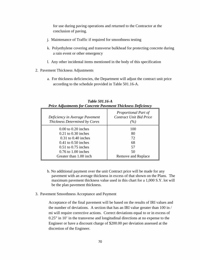
for use during paving operations and returned to the Contractor at the conclusion of paving.
j. Maintenance of Traffic if required for smoothness testing
k. Polyethylene covering and transverse bulkhead for protecting concrete duringa rain event or other emergency
l. Any other incidental items mentioned in the body of this specification
2. Pavement Thickness Adjustments
a. For thickness deficiencies, the Department will adjust the contract unit priceaccording to the schedule provided in Table 501.16-A.
Table 501.16-A Price Adjustments for Concrete Pavement Thickness Deficiency
Deficiency in Average Pavement Thickness Determined by Cores
Proportional Part of Contract Unit Bid Price
(%)
0.00 to 0.20 inches 0.21 to 0.30 inches 0.31 to 0.40 inches 0.41 to 0.50 inches 0.51 to 0.75 inches 0.76 to 1.00 inches
Greater than 1.00 inch
100 80 72 68 57 50
Remove and Replace
b. No additional payment over the unit Contract price will be made for anypavement with an average thickness in excess of that shown on the Plans. Themaximum pavement thickness value used in this chart for a 1,000 S.Y. lot willbe the plan pavement thickness.
3. Pavement Smoothness Acceptance and Payment
Acceptance of the final pavement will be based on the results of IRI values and the number of deviations. A section that has an IRI value greater than 100 in / mi will require corrective actions. Correct deviations equal to or in excess of 0.25” in 10’ in the transverse and longitudinal directions at no expense to the Engineer or have a discount charge of $200.00 per deviation assessed at the discretion of the Engineer.
70
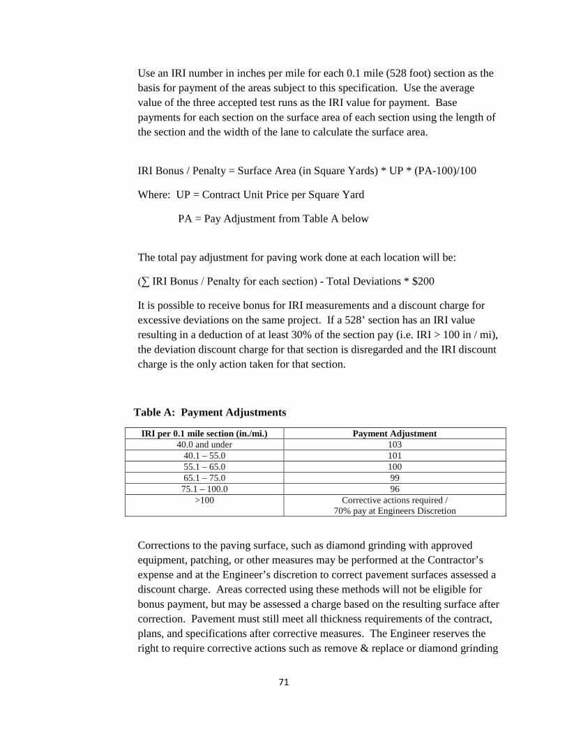
Use an IRI number in inches per mile for each 0.1 mile (528 foot) section as the basis for payment of the areas subject to this specification. Use the average value of the three accepted test runs as the IRI value for payment. Base payments for each section on the surface area of each section using the length of the section and the width of the lane to calculate the surface area.
IRI Bonus / Penalty = Surface Area (in Square Yards) * UP * (PA-100)/100
Where: UP = Contract Unit Price per Square Yard
PA = Pay Adjustment from Table A below
The total pay adjustment for paving work done at each location will be:
(∑ IRI Bonus / Penalty for each section) - Total Deviations * $200
It is possible to receive bonus for IRI measurements and a discount charge for excessive deviations on the same project. If a 528’ section has an IRI value resulting in a deduction of at least 30% of the section pay (i.e. IRI > 100 in / mi), the deviation discount charge for that section is disregarded and the IRI discount charge is the only action taken for that section.
Table A: Payment Adjustments
IRI per 0.1 mile section (in./mi.) Payment Adjustment 40.0 and under 103
40.1 – 55.0 101 55.1 – 65.0 100 65.1 – 75.0 99
75.1 – 100.0 96 >100 Corrective actions required /
70% pay at Engineers Discretion
Corrections to the paving surface, such as diamond grinding with approved equipment, patching, or other measures may be performed at the Contractor’s expense and at the Engineer’s discretion to correct pavement surfaces assessed a discount charge. Areas corrected using these methods will not be eligible for bonus payment, but may be assessed a charge based on the resulting surface after correction. Pavement must still meet all thickness requirements of the contract, plans, and specifications after corrective measures. The Engineer reserves the right to require corrective actions such as remove & replace or diamond grinding
71

if conditions dictate. The Contractor shall be responsible for retesting any and all areas that were subject to corrective actions in accordance to the testing practices defined in this Special Provision.
4. Price Adjustment for Low Strength Concrete.
Concrete which fails to reach full 28 day design strength (f 'c) shall be subject to remedial action and prorated payment as specified in Categories A and B of Section 602.25 of the Standard Specifications. Make prorated payment in accordance with Section 602.27(b). Concrete having compressive strength of 500 psi or more below the designed f 'c of the pavement shall be removed and replaced at the Contractor’s expense.
5-6-2015
72

Contract No. T200811301.01
SPECIAL PROVISIONS
73
Contract No. T200811301.01
CONSTRUCTION ITEM NUMBERS
All construction pay items are assigned a six (6) digit number, shown as Item Number on the Plans and/orin the Special Provisions, and shall be interpreted in accordance with the following:
Standard Item Number:
The first three digits of the construction item numbers indicates the Section number as described in theStandard Specifications, and all applicable requirements of the Section shall remain effective unless otherwisemodified by the Special Provisions. The last three digits of the construction item identifies the item bysequential number under that Section. Sequential numbers for all items covered under Standard Specificationsrange from 000 to 499. A comprehensive list of construction item numbers begins on page 421 of theStandard Specifications. Additions to this list will be made as required.
Special Provisions Item Number:
The first three digits of the construction items, covered under Special Provisions, indicates the applicableSection number of the Standard Specifications, and shall be governed fully by the requirements of the SpecialProvisions. The last three digit of the items covered under Special Provisions identifies the item by sequentialnumber. Sequential numbers for Special Provision items, range from 500 to 999.
Examples
Standard Item Number - 202000 Excavation and Embankment
202 Indicates Section Number
000 Indicates Sequential Number
Special Provision Item Number - 202500 Grading and Reshaping Roadway
202 Indicates Section Number
500 Indicates Sequential Number
NOTE:
PLEASE NOTE revised Supplemental Specifications to the August 2001 Standard Specifications wereissued November 24, 2014 and apply to this project. They can be viewed here and at www.deldot.gov.
SPECIFICATIONS: The Department is currently updating the August 2001 Specifications for Road andBridge Construction. Through this update, some Divisions were renumbered and some new ones werecreated and added. The Specifications Note document is for the use by the bidders to reference the newnumbers to the past numbers used for bidding purposes on previous Department contracts.
74
Contract No. T200811301.01
401502 - ASPHALT CEMENT COST ADJUSTMENT
For Sections 304, 401, 402, 403, 404, and 405, payments to the Contractor shall be adjusted to reflectincreases or decreases in the Delaware Posted Asphalt Cement Price when compared to the Project AsphaltCement Base Price, as defined in these Special Provisions.
The Delaware Posted Asphalt Cement Price will be issued monthly by the Department and will be theindustry posted price for Asphalt Cement, F.O.B. Philadelphia, Pennsylvania. The link for the posting ishttp://www.deldot.gov/information/business/bids/asphalt_cement_english.shtml.
The Project Asphalt Cement Base Price will be the Delaware Posted Asphalt Cement Price in effect onthe date of advertisement.
All deviations of the Delaware Posted Asphalt Cement Price from the Project Asphalt Cement Base Priceare eligible for cost adjustment. No minimum increases or decreases or corresponding percentages arerequired to qualify for cost adjustment.
Actual quantity of asphalt cement qualifying for any Asphalt Cement Cost Adjustment will be computedusing the weight of eligible asphalt that is shown on the QA/QC pay sheets as a percentage for the deliveredmaterial.
If the mix was not inspected and no QA/QC pay sheet was generated, then the asphalt percentage will beobtained from the job mix formula for that mix ID.
The asphalt percentage eligible for cost adjustment shall only be the virgin asphalt cement added to themix.
There shall be no separate payment per ton cost of asphalt cement. That cost shall be included in thevarious unit prices bid per ton for those bid items that contain asphalt cement (mentioned above).
The Asphalt cement cost adjustment will be calculated on grade PG 64-22 asphalt regardless of the actualgrade of asphalt used. The Project Asphalt Cement Base Price per ton for the project will be the DelawarePosted Asphalt Cement Price in effect on the date of project advertisement.
If the Contractor exceeds the authorized allotted completion time, the price of asphalt cement on the lastauthorized allotted work day, shall be the prices used for cost adjustment during the time liquidated damagesare assessed. However, if the industry posted price for asphalt cement goes down, the asphalt-cement costshall be adjusted downward accordingly.
NOTE:
Application of Asphalt Cement Cost Adjustment requirements as indicated above shall apply only to thosecontracts involving items related to bituminous base and pavements, and with bitumen, having a total of 1,000tons or more of hot-mix bid quantity in case of Sections 401, 402 and 403; and 15,000 gallons or more in caseof Sections 304, 404 and 405.
5/05/15
75
Contract No. T200811301.01
202505 - SETTLEMENT PLATFORM202518 - SETTLEMENT MONUMENT
Description:
The work of this section includes furnishing, installing, protecting and maintaining settlement monitoringplates (SMP), pipe extensions, and monument settlement points conforming to the design and at the locationsshown on the Plans or as directed by the Department. All labor, materials, equipment and incidentalsnecessary to complete this work shall be considered part of this item required to provide devices to observeground movement during and after construction. The Contractor shall perform the monitoring, recording andreporting of the settlement.
Submittals:
1. Qualifying Experience
The Contractor shall submit proof of three or more projects of similar size and complexity on which thefirm and personnel assigned to the project have successfully installed similar instrumentation within the lastthree years. The Contractor shall present the following information for each project listed as a reference ator prior to any preconstruction meetings:
1. Project Name, Location, Project Description, and Completion Date.
2. Surface and Subsurface Conditions.
3. Type and number of instruments installed.
4. Installation equipment and techniques utilized when applicable.
5. Provide names, current phone numbers, and current business addresses for the owner/designer,geotechnical consultant, and contract manager.
2 Settlement surveying and monitoring plan for review prior to construction. The plan shall identify thedetailed location of settlement monitoring points, reference benchmarks, survey schedules and proceduresand reporting formats.
3. Description of the surveying equipment to be used.
4. Settlement Plate Layout and Installation Details: Within two days after the installation of each settlementplate, the Contractor shall submit an installation record sheet including appropriate items from thefollowing list.
i. Project name.ii. Contract name and number.iii. Settlement plate number.iv. Material sizes and compositions.v. Planned location in horizontal position and elevation.vi. Planned orientation.vii. Personnel responsible for installation.viii. Date and time of start and completion.ix. Weather conditions at the time of installation.x. Notes of importance on the installation including problems encountered, delays, unusual features of
the installation, and details of any events that may have a bearing on settlement plate behavior.
76
Contract No. T200811301.01
Schedule for Settlement Platform Installations and Readings:
The Contractor shall provide settlement monitoring plates, pipe extensions and monument settlementpoints to monitor settlement of new fill embankments. The Contractor shall make regular readings of thesettlement as indicated on the plans.
Settlement monitoring plates shall be installed as shown on the plans. Settlement monitoring plates shallbe located by repeatable survey (locations and elevations) and referenced to permanent benchmarks.Locations of benchmarks are to be determined by the Contractor and approved by the Engineer, and shall belocated outside the zone of influence of the construction activity. Settlement monitoring plates shall be placedlevel and the risers shall be plumb.
The approximate locations of each instrument to be installed by the Contractor are shown on the projectplans and include the following types: settlement plates and settlement monuments. Other locations may needto be added as directed by the Engineer.
Protection of Instrumentation and Repair of Damage
a. The Contractor shall protect all instruments and appurtenant fixtures, leads, connections, and othercomponents of instrumentation systems from damage due to construction operations.
b. If an instrument is damaged or made inoperative due to the Contractor's operations or the operation ofsubcontractors under the direction of the Contractor, the Contractor shall notify the Engineerimmediately. The Engineer will be the sole judge of whether repair or replacement is required. Foreach instrument that is abandoned for these reasons, the Contractor shall replace that instrument at noadditional cost to the Department.
c. Should any instrument become damaged or inoperative through no fault of the Contractor, the damagedor inoperative instrument shall be repaired or replaced at the contract unit prices for that instrument.
d. The Engineer will advise the Contractor immediately upon discovery of damage to instruments as tothe necessary schedule for replacement and the times of required access. Damaged instruments shallbe repaired or replaced within 24 hours of initial damage. The Contractor's construction operations inthe area of a damaged instrument(s) may be halted during repair or replacement of each damagedinstrument at the request of the Department.
Materials:
Settlement Plates
a. Settlement plates are sub-surface displacement reference platforms placed on the prepared groundsurface prior to embankment fill placement. Risers are extended from the settlement plate as the fill isplaced. A casing is placed around the riser for protection. Settlement plates are monitored by opticalsurvey methods to determine vertical displacements occurring during and after embankmentconstruction.
b. The base plate shall be made from steel conforming to the requirements of ASTM A36. The riser pipeand outer casing shall be steel pipe conforming to the requirements of ASTM A53, Grade B, standardweight. The casing and the risers shall be as shown on the attached detail. The casing pipe shall havea minimum wall thickness of 0.375 inches. The riser pipe shall be galvanized and have a minimum wallthickness of 0.25 inches. Couplings, pipe caps, etc. shall conform to the requirements of ASTM A865.Threaded pipes shall be used for riser and casing pipe extensions.
c. Sand shall conform to the requirements of ASTM C33.
77
Contract No. T200811301.01
Settlement Monuments
a. Materials for the construction of the Settlement Monument shall conform to the applicable sections ofSection 812 for the Concrete, Class C of the Standard Specifications.
b. The Reinforcement Bar shall conform to Section 824 of the Standard Specifications.
Construction Methods:
1. Readings on the settlement platforms and settlement monuments shall be performed by the Contractor. The Contractor is fully responsible for establishing benchmarks, submittals, and furnishing, installing andmaintaining the settlement platforms.
2. The settlement monuments shall be installed at locations indicated on the plans or as directed by theDepartment.
3. The settlement plates shall be installed as indicated on the plans after all clearing and grubbing and topsoilremoval has been completed. The sand base shall be tamped to provide a firm, level, and unyieldingbearing surface for the base plate. The riser pipe shall be marked in 1-foot increments and labeled at 5-foot increments to indicate the distances above the plate extending up through the embankment fill. Settlement plates shall be fabricated as shown on the attached detail.
4. The initial casing and riser pipes shall have a maximum length of 4 feet for each section. Spacers shallbe provided between the riser pipe and the casing at a minimum of 4-foot intervals to ensure concentricity. The spacers shall not be directly attached to the riser pipe or otherwise installed that would impede theindependent movement of the riser pipe.
5. As the height of fill above the settlement plate changes, the casing and riser pipes shall be increased ordecreased in a maximum of 4-foot intervals to maintain the top of the riser pipe and casing above theembankment. As each additional length of pipe is added or removed, the pipe cap on the casing shall beimmediately transferred to the top section on the settlement plate so as to prevent fill material fromentering the casing. At other times, the cap shall only be removed to check settlement.
6. The casing pipe shall be marked by flags or other approved method to clearly show its location and towarn equipment operators and others of its location. The Contractor shall maintain the flags during theentire length of the Contract and replace those flags that are missing. At no time shall the settlement platerisers and casings extend higher than 5 feet above the ground surface elevation. Sections shall be addedor removed as necessary during embankment construction to maintain the tops of the risers and casingsat least 1-foot above the surface of the embankment.
7. The Contractor is responsible for maintaining the settlement plates in working order during the length ofthe Contract. Settlement Plates which are to be abandoned at the completion of the project shall have theirriser pipes cut off two feet below roadway subgrade level and capped. If an instrument is damaged,moved, or disturbed due to causes other than settlement, the Contractor shall repair, reset, or replace thedamaged instrument at no additional cost to the Department within three days after being damaged. TheEngineer will be the sole judge of whether repair, resetting, or replacement is required. No additional fillsshall be placed within fifty (50) feet of a damaged settlement platform until the damage has been correctedto the satisfaction of the Engineer. The Engineer may impose a work stoppage in the vicinity of thedamaged instrument until it is again operational at no additional cost to the Department. Any repairs orreplacements required will be at the Contractor’s expense.
8. By the end of the first work day in each week, the Contractor shall submit to the Engineer a descriptionof the work performed during the previous week. This description shall include at a minimum: a plan viewlocation of the placed embankment, the volume of embankment placed, and in-situ density test results inaccordance with Standard Specification sections 202 and 209.
78
Contract No. T200811301.01
9. The use of the settlement platforms for collecting data related to embankment foundation response willextend beyond the time of completion of the Contractor's embankment placement operations. TheContractor shall be responsible for assuring that all platforms are in working order until the time ofcompletion of the Contract.
10. Readings on all settlement monitoring devices shall be taken at a minimum of 3 calendar day intervals.
11. For vertical deformation monitoring, runs shall be performed by a single run beginning and ending ontwo different benchmarks installed in accordance with NGS standards. Settlement monitoring pointsshall be used as turning points or as intermediate foresights from two different turning points, allowingelevations to be adjusted and eliminating significant observational errors. The maximum length of lineof sight shall be 150 feet, and the imbalance between backsight and foresight shall not exceed 30 feet.Allowable level loop misclosure shall not exceed ±0.033 times the square root of M feet (where M isthe distance of the level run in miles) for a single run between two benchmarks. A formal initial readingon a settlement monitoring point will consist of the average of three elevations, from three independentlevel runs, which meet the closure specified herein. Elevations established subsequent to a formal initialreading shall be determined by a single run as specified herein. The least count (without estimation)of the rod and level combination shall read to 0.003 foot or less, such that the accuracy of an elevationmeasurement shall be ±0.01 foot (at 95 percent level of confidence).
12. Data shall be recorded in U.S. survey feet or inches.
13. Instruments used for vertical deformation monitoring shall have a minimum accuracy of plus or minus0.005 of a foot (standard deviation for 3300 feet of double run leveling) and a minimum settingaccuracy of plus or minus 1.0 arc seconds. Leveling rods shall be non-telescopic in design (i.e.“Chicago” style leveling rod). A bull’s eye bubble shall be used to plumb the leveling rod. The use offiberglass rods will need approval of Engineer prior to use.
14. All data recorded by the Contractor shall be of the following form:a. Raw and reduced data shall be on summary tables in printed tabular format on 8-1/2 inch x 11 inch
sheets of paper.b. Reduced data for up to six like instruments that are located in the same geographical area shall be
plotted on the same graphical plot. Each plot shall be submitted on an 8-1/2 inch x 11 inch sheet or 11inch by 17 inch sheet.
c. Plots of deformation data at Settlement Monitoring Plates shall show absolute vertical deformationversus time with height or elevation of fill placed at time of reading. Plots of settlement monument datashall show absolute vertical deformation versus time and shall show the height or elevation of fillplaced at the time of reading. Deformation plots shall also be provided in electronic data file format.
d. Survey data reports prepared by the Contractor shall be signed and sealed by either a ProfessionalEngineer or Professional Land Surveyor licensed in the State of Delaware.
Method of Measurement:
The number of Settlement Platforms measured will be the actual number of platforms set in place and/ormaintained as shown on the Plans or as directed by the Engineer. No measurement for payment will be madefor pipe extensions. The number of Settlement Monuments measured will be the actual number ofmonuments set in place and/or maintained as shown on the Plans or as directed by the Engineer.
Basis of Payment:
Settlement Platforms and Settlement Monuments will be paid for at the Contract unit price per Each,complete in place, which price shall be full compensation for all materials, tools, labor, and work incidentalthereto including pipe extensions, steel plate, sand, couplings, spacers, welding, protection of the plate andpipe extensions during construction, all labor tools, equipment, and necessary incidentals including settlementreadings, settlement plots and survey data reports required to complete the work.
3/20/15
79
Contract No. T200811301.01
202515 - COMPACTING INSITU MATERIAL
Description:
Compacting in situ material shall consist of pre-grading and compacting in-place soils which conform tothe requirements of Subsection 209.04. Material for use as a component of the pavement section shall becompacted in accordance with Subsection 202.05. Material for use as a footing subgrade shall be compactedin accordance with Subsection 207.05.
Construction Methods:
Borrow Type A:
The in-place soils, after being tested by DelDOT and found to be in conformance with the requirementsof Borrow, Type A for the depth specified shall be initially graded to an elevation sufficiently above (approx.2-inches) the planned top elevation of Borrow, Type A to provide an acceptable surface elevation whenproperly compacted.
Following the initial grading operations, the in-place soils shall be scarified, plowed, or otherwiseacceptably loosened for a depth of 4 to 6 inches unless otherwise directed by the Engineer. The in-place soilsshall then be compacted with a sheepsfoot roller commencing at the edges of the Borrow, Type A andprogressing toward the center. Compaction shall continue until the roller acceptably "walks out" of the soil. Compaction tests to evaluate the lower portion of the Borrow, Type A shall then be made by the Department. Providing acceptable compaction of the lower portion is obtained, the remaining Borrow, Type A shall begraded and rolled with an approved smooth steel wheel roller, or approved alternate, until this portion of theBorrow, Type A has been acceptably compacted.
Borrow, Type A for the depth specified shall be compacted to 95% of the maximum dry density asoutlined in Subsection 202.05 of the Standard Specifications. If an adjustment of the moisture content isnecessary to obtain the required compaction, water shall be incorporated as directed by the Engineer.
Borrow Type C:
The in-place soils, after being tested by DelDOT and found to be in conformance with the requirementsof Borrow, Type C, shall be initially graded to an elevation sufficiently above (approx. 2 inches) the plannedbottom of footing.
Following the initial grading operations, the in-place soils shall be compacted with a sheepsfoot roller todensify the lower portion of the subgrade soils to the satisfaction of the Engineer. Compaction tests toevaluate the lower portion of the subgrade shall be made by the Department. The footing area shall then beregraded and the upper portion of subgrade soils compacted with a vibratory steel-wheel roller. Compactiontests to evaluate this portion of the subgrade shall be made by the Department.
Subgrade shall be compacted to 95% of the maximum dry density determined, as outlined in Subsection202.05 of the Standard Specifications. If an adjustment of the moisture content is necessary to obtain therequired compaction, water shall be incorporated as directed by the Engineer.
Method of Measurement:
The quantity of compacting in situ material to be paid under this item shall be the number of square yardswithin the lines and grades shown on the plans and accepted by the Engineer.
80

Contract No. T200811301.01
Basis of Payment:
The quantity of compacting in situ material, as measured above, shall be paid at the contract unit bid priceper Square Yard for compacting of in situ material, which price and payment shall be full compensation forfurnishing all labor, tools, equipment, etc. for preparation, grading, scarification, moisture adjustment,blending, compaction, and other incidentals necessary to complete the item.
11/23/11
81
Contract No. T200811301.01
202569 – POND ACCESS ROAD, MARYLAND
Description:
This work shall consist of furnishing and constructing an access road with a cellular confinement loadsupport system in accordance with the details and locations shown on the Plans and as directed by theEngineer, for locations in Maryland.
Materials:
Topsoil: Topsoil shall conform to the requirements of Section 732 and Section 733 of the StandardSpecifications.
Stone: Shall be in conformance with AASHTO M 43, No. 7 for a ¼” to ¾” inch stone.
Mulch Binder: Mulch binder shall conform to the requirements of Item 734556 – Permanent VegetativeStabilization, Maryland. Also see Landscape Plans and Erosion Control Plans.
Fertilizer: Fertilizer shall conform to the requirements of Item 734556 – Permanent Vegetative Stabilization,Maryland. Also see Landscape Plans and Erosion Control Plans.
Seed: Seed shall conform to the requirements of Item 734556 – Permanent Vegetative Stabilization,Maryland. Also see Landscape Plans and Erosion Control Plans.
Mulch: Mulch shall conform to the requirements of Item 734556 – Permanent Vegetative Stabilization,Maryland. Also see Landscape Plans and Erosion Control Plans.
Geotextile: Class SE
Geotextile Requirements. All geotextiles shall be listed in the National Transportation Product EvaluationProgram (NTPEP) for geotextiles. The geotextile shall be manufactured from fibers consisting of long chainsynthetic polymers, composed of a minimum 95 percent by weight of polyolefins or polyesters. The fibersshall be formed into a stable network so that the filaments or yarns retain their dimensional stability relativeto each other, including selvages. The geotextile shall meet the following:
82
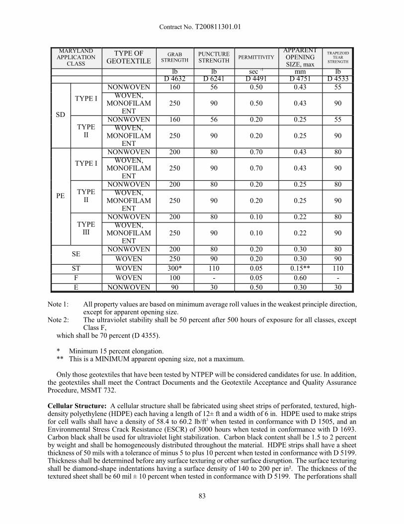
Contract No. T200811301.01
MARYLANDAPPLICATION
CLASS
TYPE OFGEOTEXTILE
GRABSTRENGTH
PUNCTURESTRENGTH
PERMITTIVITY
APPARENTOPENINGSIZE, max
TRAPEZOIDTEAR
STRENGTH
lb lb sec -1 mm lbD 4632 D 6241 D 4491 D 4751 D 4533
SD
TYPE I
NONWOVEN 160 56 0.50 0.43 55WOVEN,
MONOFILAMENT
250 90 0.50 0.43 90
TYPEII
NONWOVEN 160 56 0.20 0.25 55WOVEN,
MONOFILAMENT
250 90 0.20 0.25 90
PE
TYPE I
NONWOVEN 200 80 0.70 0.43 80WOVEN,
MONOFILAMENT
250 90 0.70 0.43 90
TYPEII
NONWOVEN 200 80 0.20 0.25 80WOVEN,
MONOFILAMENT
250 90 0.20 0.25 90
TYPEIII
NONWOVEN 200 80 0.10 0.22 80WOVEN,
MONOFILAMENT
250 90 0.10 0.22 90
SENONWOVEN 200 80 0.20 0.30 80
WOVEN 250 90 0.20 0.30 90
ST WOVEN 300* 110 0.05 0.15** 110
F WOVEN 100 - 0.05 0.60 -
E NONWOVEN 90 30 0.50 0.30 30
Note 1: All property values are based on minimum average roll values in the weakest principle direction,except for apparent opening size.
Note 2: The ultraviolet stability shall be 50 percent after 500 hours of exposure for all classes, exceptClass F,
which shall be 70 percent (D 4355).
* Minimum 15 percent elongation.** This is a MINIMUM apparent opening size, not a maximum.
Only those geotextiles that have been tested by NTPEP will be considered candidates for use. In addition,the geotextiles shall meet the Contract Documents and the Geotextile Acceptance and Quality AssuranceProcedure, MSMT 732.
Cellular Structure: A cellular structure shall be fabricated using sheet strips of perforated, textured, high-density polyethylene (HDPE) each having a length of 12± ft and a width of 6 in. HDPE used to make stripsfor cell walls shall have a density of 58.4 to 60.2 lb/ft3 when tested in conformance with D 1505, and anEnvironmental Stress Crack Resistance (ESCR) of 3000 hours when tested in conformance with D 1693. Carbon black shall be used for ultraviolet light stabilization. Carbon black content shall be 1.5 to 2 percentby weight and shall be homogeneously distributed throughout the material. HDPE strips shall have a sheetthickness of 50 mils with a tolerance of minus 5 to plus 10 percent when tested in conformance with D 5199. Thickness shall be determined before any surface texturing or other surface disruption. The surface texturingshall be diamond-shape indentations having a surface density of 140 to 200 per in². The thickness of thetextured sheet shall be 60 mil ± 10 percent when tested in conformance with D 5199. The perforations shall
83
Contract No. T200811301.01
consist of horizontal rows of 0.4 in diameter holes on 0.75 in centers. Horizontal rows of perforations shallbe staggered and separated by 0.5 inches relative to the hole centers. The dimension from the edge of thestrip to the nearest edge of perforation shall be 0.3 in.
The HDPE strips shall be connected in series to form a honey-comb-like cellular structure, using full depthultrasonic spot welded seams, aligned perpendicular to the longitudinal axis of the strips. Weld spacing shallbe 14± in. The ultrasonic weld melt-pool width shall not exceed 1 in. When expanded, the interconnectedstrips shall form the walls of a flexible, three-dimensional cellular confinement structure into which the No.7 Aggregate shall be placed. HDPE cell dimensions shall have an expanded length ranging from 8.02 to9.65 in and an expanded width ranging from 9.20 to 11.07 in. The number of cells in a manufactured sectionmay vary according to site conditions. The minimum expanded section width shall be 9.2 ft and the minimumexpanded section length shall be 12 ft.
HDPE cell seam strength shall be uniform over the full depth of the cell. Short-term seam strength shallbe tested in conformance with the U.S. Army Corps of Engineers Technical Report GL-86-19, Appendix A. Minimum short-term seam peel strength shall be 480 lb. A long-term seam peel strength test shall beperformed for a period of 7 days minimum in a temperature controlled environment that undergoes changeon a one hour cycle from room temperature to 130°F. Room temperature shall be as defined in E 41. Testsamples shall be made by welding four HDPE strips together to produce a 2-cell structure. Individual weldsshall be tested by cutting them from the 2-cell structure such that 4 in of material exist on each side of theweld. Samples shall be cut to a 4 in width and tested by securing one end to a stationary upper clamp andattaching a weight to the free lower end. The test sample shall support a 160 lb load for the test period.
The cellular confinement load support system shall include stake anchors in the form of steel J-pin stakesfabricated in conformance with the Contract Plans and ½ in. staples. Steel for J-pin stakes shall conform toA 36 or A 709, Grade 36.
Construction Methods:
Subgrade Preparation. Subgrade soils shall be grubbed and cleared of all trees, brush, debris, and rootmatter. Cut the area where the geotextile is to be placed to the depth shown or as directed. Bring the area tothe specified line, grade, and cross section. Provide a grade that is smooth as practical and free of debris.Minimize construction traffic on the grade. Remove ruts by reshaping, but do not overwork the grade. Havethe grade approved prior to placement of the geotextile. Maintain adequate surface drainage by using openbleeder ditches along the subgrade at all times to keep the area thoroughly drained. The Engineer may waivecompaction and moisture requirements for the underlying soil. When directed, test the foundation by rollingwith a 35 ton pneumatic tired roller, or as approved. Remove and dispose of all soft and unstable materialand any other portions of the subgrade that will not properly compact. Replace with suitable material andcompact.
Geotextile Placement. Place geotextile on the prepared surface for the full width of the area to be treated. In areas where longitudinal underdrain is to be placed, place the geotextile up to the edge of the proposedlongitudinal underdrain trench, but not where the trench is to be excavated. Unroll the geotextile parallel tothe base line. Do not drag the geotextile across the grade. Remove wrinkles and folds by stretching andpinning. Overlap the geotextile at least 30 in. at roll edges and ends. Overlap the end of the roll in thedirection of aggregate placement, with the roll being covered by aggregate on top of the next roll. Pin all rollends and roll end overlaps a maximum of 5 ft on center. Pin roll edges and roll edge overlaps a maximumof 50 ft on center. For curves, fold or cut the geotextile and overlap in the direction of the turn. Pin folds inthe geotextile a maximum of 5 ft on center. Immediately repair or replace damaged geotextile as directed. Overlap geotextile patches at least 3 ft into undamaged geotextile. Do not allow traffic, includingconstruction equipment, on the bare geotextile.
Cellular Structure Placement. Sections of HDPE cells shall be placed within three working days ofgeotextile placement. Sections shall be expanded into position and anchored with steel J-pins prior to placingthe No. 7 Aggregate. The number and layout of the J-pins shall be according to the Contract Plans withadditional pins as required to hold the shape and specified dimensions of the expanded cell sections. The J-pin diameter and length shall be suitable to hold the expanded cell sections in tension for the subgrade
84
Contract No. T200811301.01
condition at the site. At manholes or other obstructions, the cell section shall be stretched into position andcut out around the perimeter of the obstruction to allow the cell section to fit around the obstruction and beanchored flat on the prepared surface.
The upper surfaces of adjoining cell sections shall be flush at the joint. Interleaf sides and abut ends ofadjoining cell sections. Secure adjoining sections to each other using a pneumatic stapler. Welded edgeseams shall be aligned when stapling sides of adjoining sections. Abutting sections shall be stapled at the cellwall contact point and be aligned at longitudinal center lines.
Placement of Infill. Place the No. 7 Aggregate into the expanded HDPE cells to a level at least 2 in. abovethe top of the cell walls. The drop height of infill shall be limited to three feet. A front end loader may beused to place the infill provided that it only traffics over cell sections that have been filled and covered withthe minimum 2 in. of additional material. The infill material shall be compacted to a minimum density of95 percent of the standard proctor dry density or as specified by the Engineer.
Placement of topsoil, seed, and mulch. After the aggregate has been graded and approved by the Engineer,6 in. of topsoil shall be placed over the surface to a depth sufficiently greater than that specified on the plans,so that after natural settlement has taken place the work shall conform to the elevations on the plans. Afterthe topsoil has been graded and approved by the Engineer, seed and mulch shall be placed in conformancewith Item 734556, Permanent Vegetative Stabilization, Maryland, and as shown on the Landscape Plans andErosion Control Plans.
Method of Measurement:
Access Road with Cellular Confinement Load Support System will be measured per square yard. Measurements for calculating the number of square yards needed will be made along the surface of the areacovered. Overlaps of materials of any kind will not be measured.
Basis of Payment:
Payment for Access Road with Cellular Confinement Load Support System as measured above will be atthe Contract unit price per square yard. Payment will be full compensation for all excavation, geotextile,HDPE cells, J-pins, staples, fasteners, aggregate, subgrade preparation, hauling, removal, replacement, anddisposal of unsuitable material, anchoring, grading, backfilling, test rolling, compacting, and for all material,labor, equipment, tools, and incidentals necessary to complete the work. Topsoil, seed, mulch, and fertilizerwill be paid separately.
8/13/12
85
Contract No. T200811301.01
202572 - BORROW AREA EROSION AND SEDIMENT CONTROL AND DEWATERING
Description:
Prepare and implement plans for erosion and sediment controls (ESC), including dewatering operations,for each proposed phase of construction in compliance with Subsections 107.01 and 107.02.
Furnish and maintain all ESC measures until the final stabilization is accepted by the Engineer.
Design:
Submittal and Review:
Submit to the Engineer and Stormwater Engineer prior to implementation the proposed erosion andsediment control plans, including dewatering operations for each phase of construction proposed by thecontractor. At a minimum, include these phases of construction:
1. Initial clearing, grubbing and removal of topsoil.2. Operations from original ground to final grade.3. Final grades until stabilization is achieved and the site is accepted by the Engineer.
The Plans will be used by the Department for informational purposes, not approval.
Design Specifications:
In accordance with the following Subsections; 110.01–110.03, 110.07, 110.11, 110.14-110.19. Alldewatering operations in accordance with Section 111, except Subsection 111.10.
General Requirements:
Provide erosion and sediment control measures such that in the receiving stream at a point directly downstream of any borrow site discharge point(s) the Nephelometric Turbidity Units (NTU) do not increaseby more than 10% at any time as compared to a point directly upstream of the furthest upstream borrow sitedischarge point.
Maintain and protect all discharge outfalls until a point where a clean, stabilized outfall location isestablished. For any discharge points not draining directly to a stream, the turbidity at the discharge can notexceed 300 NTU.
Maintain dust control during all phases of construction as required in Section 202.09. Failure to maintainadequate dust control measures during borrow pit earth moving operations will result in stoppage of Workuntil the dust control has been acceptably addressed. All costs associated with dust control are incidentalto Item No. 202000.
Testing:
Turbidity testing will be performed by DelDOT during DelDOT’s normal working hours and at locationsdetermined by the Stormwater Engineer
Compliance:
Submit a plan of action to the Stormwater and Construction Engineers to reduce the turbidity of thedischarge to acceptable levels within 24 hours of receiving the test results if the turbidity testing exceeds theturbidity standards and/or if an erosive condition exists due to dewatering operations.
86
Contract No. T200811301.01
Implement the plan of action within 48 hours of receiving the test. Failure to acceptably remedyunsatisfactory conditions within the time frame established will result in the Engineer proceeding withadequate forces and equipment to implement or maintain the necessary erosion and sediment control itemsto bring the project into compliance. The entire cost of work for correcting unsatisfactory conditions by theEngineer will be deducted from monies due the Contractor on this Contract.
Failure to acceptably remedy unsatisfactory conditions within the time frame established will result instoppage of Work until the unsatisfactory conditions have been acceptably addressed.
Method of Measurement:
The quantity of Borrow Area Erosion and Sediment Control and Dewatering Operations is not measured. Basis of Payment:
Payment will be made at the lump sum price bid for the item Borrow Area Erosion and Sediment Controland Dewatering paid on a monthly basis pro-rated per the total number of months in the Contract. The bidprice includes, but is not limited to the following; preparing, submitting and updating erosion sedimentcontrol plans, including dewatering operations; installation, maintenance and removal of all erosion andsediment control and dewatering devices; removal and disposal of all sediment; corrections to damages insideor outside of the borrow source due to the Contractor’s operations; and all materials, labor, equipment andincidentals required to complete the work.
If the work is acceptably completed by the Engineer prior to the end of the contract time, the remainderof the Lump Sum will be paid.
Permanent topsoiling and seeding on final slopes will be paid in accordance with contract items asindicated in the contract documents.
NOTE:
When Item 202572- Borrow Area Erosion and Sediment Control and Dewatering is applicable to morethan one location, the Contractor shall submit a cost breakdown of his Lump Sum price bid for this itemshowing the dollar value amount for each location, the sum of which is to equal the lump sum price bid. Therequired breakdown of the Lump Sum price is shown on a breakout sheet attached to the proposal. Thecomplete breakout sheet shall be attached to the submitted Bid Proposal. Failure to submit the breakout sheetwith the Bid Proposal will result in the Bid Proposal being declared non-responsive and rejected.
The Department reserves the right to delete from the Contract the application of this item at one or moreof the locations. The lump sum to be paid will be adjusted in accordance with the Contractor's costbreakdown as required above. There will be no extra compensation to the Contractor if such deletions aremade.
10/23/12
87
Contract No. T200811301.01
211521 – ABANDONMENT OF WELLS
Description:
This work shall consist of furnishing equipment, materials, and labor to seal geotechnical monitoring wellspreviously installed within the limits of the construction included in this contract. This item shall only beused when specified in the Contract Documents or as directed by the Department. The wells to be removedin this contract are designated on the Construction Plans. The location of the wells shown on the drawingsis approximate and must be verified by the Contractor.
Submittals:
(a) Master Well Driller’s Certificate. Twenty (20) working days prior to abandoning the monitoring wellthe Contractor will submit to the Department the Master Well Driller’s Certificate for review. (b) Abandoned Well Report. When the well has been abandoned, the person abandoning it, shall notifythe Approving Authority of this action by completing an Abandoned Well Report form provided by theApproving Authority. This report shall be submitted not later than 30 days after abandonment of the well ortest hole. A copy of the Abandoned Well Report and the transmittal shall be submitted to the Engineer within30 days after abandonment.
Materials:
Materials for well sealing including concrete, Portland cement grout, sodium-based bentonite clay grout,and other materials approved by the Department shall be in accordance with the Delaware RegulationsGoverning the Construction and Use of Wells, 1997.
Drill cuttings, clay, silt, sand, gravel, and crusher run are considered fill material and may only be usedin the abandonment of wells in accordance with Section 9.03 of the Regulations.
Portland cement grout and sodium-base bentonite clay grout shall meet the requirements of 4.07(J) (1) and(2) of the Regulations.
Construction Methods:
Abandonment of Wells shall be in accordance with the Delaware Regulations Governing the Constructionand Use of Wells, 1997. Prior to the well abandonment, the Contractor shall verify the location, diameter,depth, and condition of the well and the type of construction. Well abandonment shall be performed by amaster well driller licensed by the Delaware State Board of Well Drillers.
Method of Measurement:
Abandonment of Wells will be measured per Each well abandoned, including sealing the monitoring welland furnishing all material, labor, equipment, tools, and incidentals necessary to complete the work.
Basis of Payment:
Abandonment of Wells will be paid for at the Contract unit price per Each well abandoned. The paymentwill be full compensation for furnishing and sealing the monitoring well and for all material, labor,equipment, tools, and incidentals necessary to complete the work.
7/10/12
88
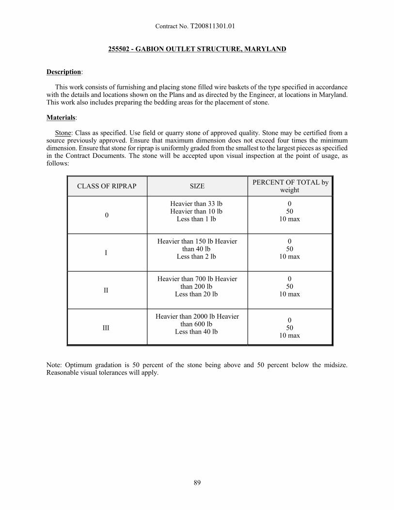
Contract No. T200811301.01
255502 - GABION OUTLET STRUCTURE, MARYLAND
Description:
This work consists of furnishing and placing stone filled wire baskets of the type specified in accordancewith the details and locations shown on the Plans and as directed by the Engineer, at locations in Maryland. This work also includes preparing the bedding areas for the placement of stone.
Materials:
Stone: Class as specified. Use field or quarry stone of approved quality. Stone may be certified from asource previously approved. Ensure that maximum dimension does not exceed four times the minimumdimension. Ensure that stone for riprap is uniformly graded from the smallest to the largest pieces as specifiedin the Contract Documents. The stone will be accepted upon visual inspection at the point of usage, asfollows:
CLASS OF RIPRAP SIZEPERCENT OF TOTAL by
weight
0
Heavier than 33 lb Heavier than 10 lb
Less than 1 lb
0 50
10 max
I
Heavier than 150 lb Heavierthan 40 lb
Less than 2 lb
0 50
10 max
II
Heavier than 700 lb Heavierthan 200 lb
Less than 20 lb
0 50
10 max
III
Heavier than 2000 lb Heavierthan 600 lb
Less than 40 lb
0 50
10 max
Note: Optimum gradation is 50 percent of the stone being above and 50 percent below the midsize.Reasonable visual tolerances will apply.
89
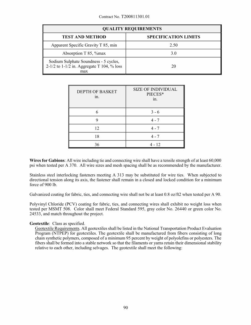
Contract No. T200811301.01
QUALITY REQUIREMENTS
TEST AND METHOD SPECIFICATION LIMITS
Apparent Specific Gravity T 85, min 2.50
Absorption T 85, %max 3.0
Sodium Sulphate Soundness - 5 cycles,2-1/2 to 1-1/2 in. Aggregate T 104, % loss
max20
DEPTH OF BASKETin.
SIZE OF INDIVIDUALPIECES*
in.
6 3 - 6
9 4 - 7
12 4 - 7
18 4 - 7
36 4 - 12
Wires for Gabions: All wire including tie and connecting wire shall have a tensile strength of at least 60,000psi when tested per A 370. All wire sizes and mesh spacing shall be as recommended by the manufacturer.
Stainless steel interlocking fasteners meeting A 313 may be substituted for wire ties. When subjected todirectional tension along its axis, the fastener shall remain in a closed and locked condition for a minimumforce of 900 lb.
Galvanized coating for fabric, ties, and connecting wire shall not be at least 0.8 oz/ft2 when tested per A 90.
Polyvinyl Chloride (PCV) coating for fabric, ties, and connecting wires shall exhibit no weight loss whentested per MSMT 508. Color shall meet Federal Standard 595, gray color No. 26440 or green color No.24533, and match throughout the project.
Geotextile: Class as specified. Geotextile Requirements. All geotextiles shall be listed in the National Transportation Product EvaluationProgram (NTPEP) for geotextiles. The geotextile shall be manufactured from fibers consisting of longchain synthetic polymers, composed of a minimum 95 percent by weight of polyolefins or polyesters. Thefibers shall be formed into a stable network so that the filaments or yarns retain their dimensional stabilityrelative to each other, including selvages. The geotextile shall meet the following:
90
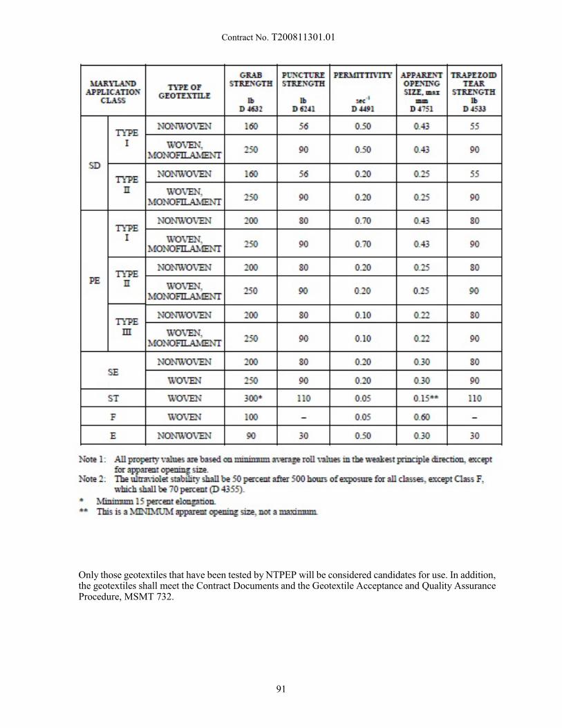
Contract No. T200811301.01
Only those geotextiles that have been tested by NTPEP will be considered candidates for use. In addition,the geotextiles shall meet the Contract Documents and the Geotextile Acceptance and Quality AssuranceProcedure, MSMT 732.
91
Contract No. T200811301.01
Construction:
Construction requirements shall be in accordance with the detail shown in the contract plans. The areashall be graded and stabilized immediately after removal of the structure.
Excavation. Excavate to the specified lines and grades. Ensure that the subgrade is smooth, firm, and freefrom protruding objects or voids that would affect the proper placement of the wire baskets or damage thegeotextile. Geotextile. Place geotextile on the prepared subgrade. Overlap adjacent strips at least 2 ft. Replace or repairgeotextile damaged during placement of the wire baskets.
Wire Baskets. Set the empty units on the geotextile and bind the vertical ends together with wire ties orinterlocking fasteners spaced to permit stretching of the units to remove kinks. Use stretching methods thatdo not damage the baskets. Use stakes, pins, or other methods approved by the Engineer to ensure properalignment.
Stone. Carefully fill the basket units with stone placed by hand or machine to ensure good alignment witha minimum of voids between stones. Avoid bulging of the mesh. Do not drop the stone from a height greaterthan 36 in. Place the stone to provide a minimum of two courses. Place the top layer of stone to a uniformsurface. Avoid any bulging of the lid mesh. After a basket unit is filled, bend the lid over until it meets theends of the unit. Secure the lid to the sides and ends with wire ties or interlocking fasteners. When acomplete basket unit cannot be installed because of space limitations, cut the basket unit to fit as directed.
Backfill. Backfill any excavation voids existing along the edges of the completed gabions and compactin an acceptable manner.
Method of Measurement:
The quantity of Gabion Outlet Structure, Maryland will be measured as each placed and accepted inMaryland.
Basis of Payment:
The quantity of Gabion Outlet Structure, Maryland will be paid for at the Contract unit price per each. Price and payment will constitute full compensation for all excavation, geotextile, stone, ties or fasteners,backfill, compaction, disposal of excess material, and for all labor, equipment, tools, and incidentalsnecessary to complete the work.
3/31/15
92

Contract No. T200811301.01
272511 – POND OUTLET STRUCTURE, CONCRETE MARYLAND
Description:
This work consists of furnishing, fabricating, and constructing a pond outlet structure and outlet facilitiesin accordance with the details and locations shown on the Plans and as directed by the Engineer, at locationsin Maryland. Construct cast-in-place concrete weir walls or install them as pre-cast concrete structures. Thiswork shall also consist of applying integral color admixture to the concrete mixture for drainage structuresas specified in the contract documents. A sandblast finish shall be applied to the completed, colored drainagestructures.
Materials and Construction Methods:
Materials and construction methods shall conform to the applicable requirements of Section 602, 603, and604 of the Standard Specifications, and notes and details on the Plan.
The Contractor shall submit shop drawings showing the fabrication details for prior approval.
Alternate cast-in-place and precast drainage structure alternatives may be permitted but require an alternatedesign submission for review and approval by the Engineer. Alternate design submissions, includingcomplete design calculations and drawings, shall meet the requirements of Sections 105.04
Alternate designs shall be in accordance with the current edition of AASHTO LRFD Bridge DesignSpecifications with interims and shall meet the following minimum requirements:
- Minimum Unit Weight of Soil and Soil Surcharge = 110 pounds per cubic foot- Minimum Unit Weight of Reinforced Concrete = 150 pounds per cubic foot - Maximum Soil Friction Angle = 30 degrees- Water is present to the top of the wall- Lateral soil pressures are Active for non-restrained walls and At-Rest when braced at top of wall- Design for Strength- Design for Temperature and Shrinkage- Design for Shear- Check Maximum and Minimum Reinforcement Limitations- Check development of reinforcement.- Walls are solid- Full Live Load- Soil Reaction is uniform
Contractor alternates, as well as review time by the Department, will not justify a delay in the progressschedule. All costs involved in preparing plan revision documents for changes proposed by the Contractorshall be the responsibility of the Contractor.
Pipe Connections. Set or cut low flow pipe flush with the outside face of the weir wall. Extend the pipe asufficient distance beyond the inside face of the weir wall to provide for making proper connections. Completely and neatly close the joint around the pipe in the structure wall with mortar or other specifiedmaterials.
Integral Concrete Color Pigment Admixture. The admixture shall be a colored, water reducing, admixturecontaining no calcium chloride with coloring agents that are lime proof and UV resistant. The admixtureshall conform to C979, C494 and M194.
The color shall meet Federal Standard 595B. The manufacturer shall choose from the following colors: 30277, 30145, and 30219. The same color shall be used throughout the project. It may be necessary to usewhite portland cement to achieve the color. Compromising the color will not be acceptable in order to avoid
93
Contract No. T200811301.01
using white cement. The pigment admixture shall be added to the concrete as specified by the manufacturer. Care should be taken to ensure uniform coloration throughout the structure.
Sandblasted Finish. All colored drainage structures shall be textured with a sandblast finish. Allowconcrete to cure to sufficient strength so that is will not be damaged by blasting but not less than seven days. The finish shall be Class 1 (Brush) involving a one pass brush blast which will remove the cement matrix andexpose the fine aggregates only. No part of the coarse aggregates shall be exposed.
The contractor shall be responsible for meeting all local air pollution regulations. The contractor shallensure the safety of the workers, ensuring that each blaster is equipped with an air-fed helmet.
The Sandblast contractor shall be responsible for clean-up of immediately adjacent areas to the sand-blasting operation.
Sample Panel. Whenever the contract documents specify that drainage structures be cast with integralconcrete color pigment admixture, prior to casting the structures a 2 ft. by 2 ft. by 4 in. sample panel shall becast, sandblasted and made available to the Engineer at the construction site for color and finish approval. All subsequent structures requiring integral color shall match the sample panel. The sample shall remain atthe construction site to be used by the Engineer as a basis for comparison for the structures.
Method of Measurement:
Payment for this item will be made on a lump sum basis wherein no measurement will be made.
Basis of Payment:
The quantity of Pond Outlet Structure, Concrete, Maryland will be paid for at the Contract lump sum price. Price and payment will constitute full compensation for excavation, dewatering, ground preparation,furnishing and placing all materials including reinforcing steel, concrete, pipes, gaskets, grout, pipe bedding,backfill, and all other materials required for pond outlet structure, concrete, for welding and for all labor,equipment, tools, and incidentals necessary to complete the work.
NOTE:
When more than one structure is required, the Contractor shall submit a cost breakdown of his Lump Sumprice bid for this item showing the dollar value amount for each pond outlet structure, the sum of which toequal the lump sum price bid. The breakout sheet attached to the proposal shows all items proposed for thisitem. The complete breakout sheet shall be attached to the Bid Proposal. Failure to submit the breakout sheetwith the Bid Proposal will result in the Bid Proposal being declared non-responsive and rejected.
The Department reserves the right to delete from the Contract, construction of one or more individualoutlet structure(s), and the lump sum price to be paid will be reduced in accordance with the Contractor'sitemized bid price list for that individual outlet structure. There shall be no extra compensation to theContractor if such deletion is made.
11/23/11
94

Contract No. T200811301.01
304501 - PERMEABLE TREATED BASE, 4"
Description:
This work consists of furnishing all materials and constructing permeable treated base on a preparedsubbase in accordance with these specifications and in reasonably close conformity with the lines and gradesshown on the Plans or established by the Engineer. This base course shall consist of a mixture of graded,crushed aggregate and a binder material of asphalt cement or portland cement. Unless otherwise shown onthe Plans, the Contractor may use either asphalt cement or portland cement as the base course binder, afterobtaining approval of the Engineer.
Materials:
Written approval of all materials shall be obtained prior to delivery. Samples of each source shall besubmitted as directed by the Engineer. Materials and their use shall conform to the following requirements.
A. Aggregate - The aggregate shall be comprised of clean, hard, durable crushed stone meeting therequirements of AASHTO M43, size number 57, and AASHTO M283, Class B. Adherent coating onaggregate after the initial dry sieving on 3 mils sieve shall not exceed 0.5 percent when tested when inaccordance with the requirements of AASHTO T11 - Determining the minus 3 mils sieve fraction bywashing.
B. Asphalt Cement - The asphalt for the permeable treated base shall be AC-20 viscosity grade pavingasphalt conforming to the requirements of AASHTO M226 Table 2 and Sections 823.02 of theStandard Specifications. In addition, an approved heatstable anti-strip additive conforming to therequirements of Section 829 of the Standard Specifications shall be added to all asphalt cement usedin the production of permeable base treated with asphalt.
C. Portland Cement - Portland cement used as the binder for the permeable base shall be Type I or TypeII conforming to the requirements of Section 801 of the Standard Specifications. In addition, amembrane curing compound shall be used in conjunction with the portland cement treated aggregatebase and shall conform to AASHTO M148, Type 2, Class A - White Pigmented Wax Base CuringCompound. Other curing methods may be used if approved by the Engineer.
Proportioning Stabilized Mixtures - The Contractor shall submit or shall have his source of supply submit,for the Engineers approval, a job mix for the asphalt treated base mixture (Permeable Asphalt Treated Base)in accordance with Section 823.19 or a mix design for the portland cement treated base (Permeable CementTreated Base). The composition of the mixture shall be within the requirements specified herein and shallproduce a stable mix having a minimum coefficient of permeability of 2950 ft/day determined by the fallinghead or constant head test method. Coefficient of permeability data shall be submitted with job mix/mixdesign information to the Materials and Research Section.
Permeable Asphalt Treated Base - Permeable asphalt treated base shall be a hot, plant-mixture of pavinggrade asphalt cement with a heat-stable anti-strip adhesive and #57 crushed aggregate within the followingmixture requirements:
The asphalt cement shall be 2%-2.5% AC-20 by weight of the total mix. The target temperature of themix leaving the mixer shall be established by the Materials and Research Section on the basis of laboratorytests. A target temperature of 250oF + 40oF is typical. The aggregate for the mixture shall be dried and heatedto the required temperature but not to exceed 325oF. Flames used for drying and heating shall be properlyadjusted to avoid damage to the aggregate and to avoid soot on the aggregate. The temperature of theaggregates as introduced into the mixer shall not exceed a temperature which causes segregation of the asphaltand aggregate during transportation. The temperature shall not be lower than is required to obtain completecoating and uniform distribution on the aggregate particles and to provide a mixture of satisfactoryworkability.
95
Contract No. T200811301.01
B. Testing Methods - The following standards shall be used to test the qualities of the mixture:
AASHTO T164, Method A - Quantitative Extraction of Bitumen from Bituminous Paving Mixtures.
AASHTO T166 - Bulk Specific Gravity of Compacted Bituminous Mixtures.
AASHTO T209 - Maximum Specific Gravity of Bituminous Paving Mixtures.
AASHTO T269 - Percent Air Voids in Compacted Bituminous Mixtures.
Samples of the actual mixture in use will be taken as many times daily as required by the Engineer andthe mixture must be maintained uniform throughout the project within the above tolerances. Should the mixproduced not meet the above requirements or project field performance needs, changes in the mix design ormixing procedure shall be make immediately in a manner approved by the Engineer. Mixing of permeableasphalt treated base shall be in accordance with Section 401 of the Standard Specifications.
Permeable Cement Treated Base - Permeable cement treated base shall consist of a mixture of portlandcement, #57 crushed aggregate and water. Portland cement content shall be 8.3 lb/ft³ ± .37 lb/ft³. Themixture shall have a minimum water/cement ratio to provide for 100% cement paste coverage of theaggregate material without significant runoff during hauling and sufficient workability during placement toprovide a uniform texture without loss of the required void system. However, a maximum water/cement ratioshall not exceed 0.40. An air entraining admixture will not be required for this mixture.
Mixing shall be in accordance with the requirements of Section 812 and shall be accomplished throughan approved central mix concrete plant, unless otherwise permitted by the Engineer.
Construction Methods:
The permeable treated base course shall be transported to the project for placement in accordance with theappropriate requirements of Sections 401 or 812 of the Standard Specifications. Equipment used forplacement shall be tracked, self propelled pavers, spreaders or other combinations of equipment which willplace the stabilized mix at a uniform thickness without segregation. Placement by use of graders or dozerswill not be permitted.
Permeable treated base course shall not be placed when weather or surface conditions are such thatmaterial can not be properly handled, compacted or finished. Permeable treated base course shall be placedonly when the ambient temperature is above 36oF and shall not be placed on any frozen surface. Permeablecement treated base shall be subject to the temperature limitations of Section 501.04.
Permeable treated base shall not be placed until the surface upon which it is to be placed has beenapproved by the Engineer. Preparation shall include provision for directing surface drainage away from thebase to prevent contamination from surface runoff in the event of rainfall.
Following placement of the permeable asphalt treated base to be specified line, grade, and thickness bya bituminous paver conforming to the requirements of Section 401 of the Standard Specifications or otherapproved equipment, rolling shall then begin when the paving mat has cooled sufficiently to support theweight of a 4 to 10 tons steel wheel tandem roller. Mat temperature at time of initial rolling shall be between150oF and 175oF, unless otherwise directed. The purpose of the rolling is to compact the base sufficientlyto support the weight of the equipment that will place the next layer of pavement. The compacted base is tobe porous, so that water will drain through it. The base is not to be compacted to the point that it is not freedraining or that the aggregate is crushed. No rubbertired or vibratory rollers shall be permitted on thepermeable asphalt treated base.
Permeable cement treated base shall be delivered to the project in such a manner that a uniform, adequatesupply is available for the placing equipment. An approved mechanical spreader or slipform paverconforming to the requirements of Section 502, or other approved spreading equipment, shall be used to placethe base course. Screed or plate vibrators shall be used to consolidate the base course to a consistent finish
96
Contract No. T200811301.01
across the width of placement. If, in the opinion of the Engineer, the placing equipment does not provideadequate consolidation, the base course shall be further compacted with one to three passes on an 8 - 10 tonssteel-wheeled roller, or to the satisfaction of the Engineer. The base course shall not be vibrated orcompacted to the point that it is not free draining or the aggregate is crushed. Necessary hand spreading shallbe performed using square-faced shovels. After initial set of the base course, or when directed by theEngineer, a white pigmented, wax base concrete curing compound shall be applied to the base course surfaceat a rate not to exceed 150 square feet per gallon and in accordance with the requirements of Section 501.11of the Standard Specifications.
When necessary to form a transverse joint between old and new permeable treated base or betweensuccessive day's work, the joint shall be made by placing a bulk head or by cutting back the base as necessaryto provide a full-depth vertical face. Regardless of the method of joint construction, a satisfactory ridingsurface shall be maintained.
To avoid longitudinal cold joints, all adjoining permeable treated base shall be placed to the plan widthwithin 30 minutes after the final compaction of the initial spread.
No traffic, construction or otherwise, shall be allowed to travel on the permeable treated base. The onlyexception will be for the paving train equipment necessary to place the next layer of pavement as directed bythe Engineer. The Contractor shall be required to complete, protect, and maintain all permeable treated basecourses during extended periods of construction inactivity such as those associated with adverse weatherconditions or any other extended work interruptions.
All permeable treated base placed during any one construction season shall be covered with P.C.C.Pavement and adjoining shoulder Hot-Mix Bituminous Asphalt Paving by the end of the construction season. Any permeable treated base which has not been paved over at the end of the construction season must beentirely covered with polyethylene film meeting the requirements of AASHTO M171. The film shall befirmly anchored and lapped a minimum of 18". The film will be maintained by the Contractor to insurecoverage of the permeable treated base until removal is authorized by the Engineer just prior to thecommencement of paving operations.
Any permeable treated base that becomes damaged for any reason shall be removed and replaced asdirected by the Engineer with no additional cost to the Department.
Tolerances:
A. Thickness: The thickness of the permeable treated base shall be within +/- 1/2" of the plan thicknessand shall be determined from the field measurements taken through the permeable treated base atintervals not exceeding 500' per lane or shoulder width, or as directed by the Engineer. Measurementsshall be made to the nearest 1/8". If the measured thickness is not within the specified thicknesstolerance, additional measurements shall be made at intervals not to exceed 50' forward and backwarduntil at least two consecutive measurements in each direction are within tolerance. When directed bythe Engineer, areas represented by measurements exceeding the specified tolerance shall be removedand reconstructed at the Contractor's expense. Sections to be removed shall include the full lane orshoulder width and not less than the total length of base course deficient in thickness or as directed bythe Engineer. When permitted by the Engineer, low areas may be filled with the next pavement coursein the same operation in which that pavement is placed at no cost to the Department. Removal of highareas exceeding the specified tolerance by grading, milling or grinding to achieve plan thickness willnot be permitted.
The specified tolerance allowance does not relieve the Contractor of the responsibility of placing thepermeable treated base at the elevation necessary to place the next pavement course at plan thicknessand plan elevation. The Contractor shall establish the plane of elevation of the completed PermeableTreated Base through surveyed elevation measurements at 25' intervals along lane lines and at breaksin cross-slope. The cost of surveying is to be included in the unit cost bid for Construction Engineering. Nominal adjustments to final pavement elevation will be permitted by the Engineer, however, deviationin final pavement cross-slope greater than +/- 0.1% will not be permitted.
97
Contract No. T200811301.01
B. Surface: The surface smoothness of the permeable treated base course shall be subject to therequirements of Subsection 401.13 for Bituminous Base Courses: Lower Courses. These requirementsshall apply to permeable treated base constructed with either asphalt cement or portland cement.
Method of Measurement:
The quantity of permeable treated base will be measured as the actual number of square yards of surfacearea at the specified thickness completed and accepted according to Plans and cross-section. Material placedbeyond the designated lines and grades as shown on the Plans or beyond the limits established by theEngineer will not be measured for payment.
Basis of Payment:
The quantity of permeable treated base will be paid for at the Contract unit price per square yard. Priceand payment will constitute full compensation for furnishing all materials, mixing, hauling, and compactingall materials for production and construction of an asphalt treated or cement treated permeable base, and forrequired protection of placed materials, removal and replacement of any damaged or contaminated permeabletreated base, and for all labor, equipment, tools, and incidentals necessary to complete the work.
10/6/2015
98

Contract No. T200811301.01
304502 - SOIL CEMENT BASE COURSE 6"304506 - PORTLAND CEMENT
Description:
This work consists of preparing a foundation and constructing a mixture of soil and Portland Cement basein accordance with these specifications and in reasonably close conformity with the lines, grades, thicknesses,and typical cross-sections shown on the Plans or established by the Engineer.
Materials:
Portland Cement: Portland cement shall meet the requirements and tests of the Standard Specificationsfor Portland Cement, AASHTO M 85, Type I or Type II and shall be approved prior to use.
Water: The water shall be free from minerals or organic substances deleterious to the soil cement andshall meet the requirements of Section 803.
Soil: The soil for the soil cement base course shall consist of borrow material which meets therequirements of Section 209, Borrow Type D. The borrow material must be tested and approved prior to use. Any material retained on a 3" sieve and other unsuitable material such as roots, vegetation, etc., shall beremoved by acceptable methods prior to use. The maximum density and optimum moisture will bedetermined by AASHTO T 99, Method C, Modified. Maximum density and optimum moisture values willbe determined at 1/2 hour time increments up to a maximum of 2 hours after addition of cement to themixture. Field density determinations will be made in accordance with AASHTO T 238 or other approvedmethods.
Asphalt: The asphalt used as a curing film for the soil cement base course shall be RC 70, RC 250, RS1 or RS 2 meeting the requirements of AASHTO M 81 and M 140 respectively and shall be approved priorto use.
Preconstruction:
It shall be the Contractor's responsibility to notify the Materials and Research Section of Department atleast 30 calendar days prior to the anticipated processing date in order to determine the required proportionsof cement and water for the soil cement mixture. This notification shall be made after a stockpile of soil hasbeen formed of material representative of the approved source to the satisfaction of the Engineer.
Construction:
Mixing of the soil, cement and water shall be accomplished by the Central Mix method.
A) Central Mixing Plants: The plant may be either a batch or continuous flow type equipped withbatching or metering devices designed to regulate the specified quantities of the respective materialsand which has been inspected and approved prior to use. The plant shall be of a design that willproduce a thorough mixture of soil, cement, and water of proper proportions. The mixer shall be in anapproved mechanical condition and shall have a capacity of at least 100 tons per hour. Approval shallnot be granted for use of a mix plant that permits added water to come in contact with the cementbefore the cement has been mixed with the soil. All controls shall be synchronized so that the water,soil, and cement feeds start and stop simultaneously. The cement shall be fed automatically anduniformly. The soil must be fed in a manner which will insure as even a flow as possible. The plantshall maintain an adequate and acceptable cement storage, an approved stockpile of soil, and anadequate water supply. The Contractor shall be required to demonstrate that the plant is capable ofproducing a uniform mixture of soil, cement, and water prior to approval and use.
99
Contract No. T200811301.01
B) Field Laboratory: The Contractor and/or producer shall provide suitable quarters at central mixingplants for the purpose of housing laboratory testing equipment. The quarters shall be approximately8'L x 8'W x 8'H with a work counter approximately 8'L x 2'W, or other acceptable dimensions. Thequarters shall be entirely enclosed, water and dust proofed, and shall be provided with electricity, water,storage, screened windows and an entrance with satisfactory locks. The field laboratory shall also beair conditioned and heated. The quarters shall be located convenient to the plant. The quarters will beconsidered part of the central mixing plant and no additional compensation will be made.
C) Mixing: Before any soil is processed through the plant, it shall be uniform in texture and tested forconformance to specifications, and approved.
The percentage of moisture in the soil, at the time of cement application, shall not exceed the quantitythat will permit a uniform and intimate mixture of soil and cement during the mixing operations, andit shall not exceed the specified optimum moisture content for the soil cement mixture.
Mixing operations shall not start when the soil or the foundation soils, on which the mixture is to beplaced, are frozen.
The method of calibrating the mixing plant to ensure adequate cement flow shall be the responsibilityof the Contractor. Plant calibrations shall be performed daily or as necessary to produce a soil-cementmixture at the design cement content and within a tolerance of +0.5%.
The air temperature shall be at least 40oF. in the shade and rising prior to the start of mixing operations.
D) Cement Content: The cement content for the soil-cement mixture shall be the percentage of cementon a dry-weight basis of soil required to produce a compressive strength of 500 psi minimum at 7 dayswhen tested in accordance with ASTM D 1633, "Compressive Strength of Molded Soil-CementCylinders." A cement content of 7%+1% by weight is anticipated; however, the actual design cementcontent to achieve the specified 500 psi 7-day strength will be established by the Department.
Cement content shall be checked during soil cement operations by the Department on a random basis,in an effort to insure proper compliance with mix design specifications. Cement content shall bedetermined in accordance with ASTM D 2901, "Cement Content of Freshly Mixed Soil-Cement."
E) Hauling: The mixture shall be hauled to the roadway in vehicles free of foreign material and coveredto protect the mixture from loss of moisture.
F) Spreading and Finishing: The foundation material shall be in a moist condition and free of waterpuddles prior to the spreading operation. The mixture shall be placed in a uniform layer by anapproved spreader. The layer of soil cement shall be uniform in thickness and surface contour. Thethickness will be such that the mixture when compacted will conform to the tolerances of the requiredgrades and cross sections. Dumping of the mixture in piles or windrows on the foundation materialshall not be permitted without the prior approval of the Engineer. Not more than 30 minutes shallelapse between the placement of soil cement in adjacent lanes, unless forms are used to constructlongitudinal joints. In lieu of using forms, the Contractor may submit an alternate method ofconstruction and protection of the longitudinal joints. Any alternate method must be approved priorto use. After the mixture has been compacted, the surface of the soil cement shall be shaped, ifnecessary, to the lines, grades, and cross sections given on the Plans. Final grading shall be performedby use of an autograder controlled by a stringline and an electronic guidance system or an approvedequal. The surface shall be smoothly and uniformly compacted to the specified density. The surfacematerial shall be maintained within two (2) percentage points of the specified optimum moisturecontent during finishing operations.
Surface compacting and finishing may be varied as necessary to produce a smooth, dense surface, freeof compaction planes, cracks, ridges, or loose material.
100
Contract No. T200811301.01
G) Compaction: Prior to the beginning of compaction, the mixture shall be in a loose condition atsufficient thickness to achieve the required Plan thickness. At the beginning of compaction thepercentage of moisture in the mixture shall be within 2 percentage points of the specified optimummoisture content or at a moisture content which will not cause an unstable condition in the soil cementmixture. If, due to rain, the average moisture content exceeds the tolerances given above, the entiresection shall be corrected, at the Contractor's expense, by removal and replacement. The loose mixtureshall, within 2 hours from the time mixed, be uniformly compacted to not less than 97% of themaximum dry density. Material used to determine the maximum dry density shall be sampled at thecompletion of compaction or within the above time limit, whichever occurs first. Field density testsshall be performed on each day's construction. During compaction operations, shaping may be requiredto obtain uniform compaction and the required grade and cross section. Not more than 60 minutes shallelapse between the start of mixing and the start of compaction of the soil cement mixtures. Anymixture of soil, cement, and water that has been spread and not been compacted shall not be leftundisturbed for more than 30 minutes.
H) Construction Joints: The end of each completed section shall be cut back to a point where it meetsthe line, grade, crown, and specified quality of soil cement mixture and shall be trimmed to a verticalface at right angles to the centerline of roadway for the full width and depth. The trimmed vertical faceshall be protected until compacting operations begin on the adjacent section. The use of a woodenbulkhead to construct a true vertical face and cross section shall be required by the Engineer.
I) Protection and Cover: After the soil cement mixture has been completed as specified herein, it shallbe protected against drying by applying RC 70, RC 250, RS 1, or RS 2 asphalt at the minimum rate of.02 gallons per square foot. Just prior to the application of asphalt the soil cement shall be broomedfree of all loose and foreign material, and sufficient water added with pressurized distributingequipment to fill the surface voids only. The finished soil cement shall be kept moist until the asphaltis applied. This asphalt shall be applied within 24 hours following the finished operation or as soonas weather conditions permit.
The asphaltic curing film shall be maintained by the Contractor until the mixture is protected by asubsequent course.
A water cure may be used in lieu of the asphalt if approved by the Engineer. The water cure shall beapplied within two hours after compaction and acceptance of any portion of the soil cement. The watercure shall be applied every two hours unless otherwise directed by the Engineer. The water cure shallbe applied for a minimum period of 120 hours or until the soil cement has cured to the satisfaction ofthe Engineer.
A white pigmented curing compound may be used in lieu of the asphalt if approved by the Engineer. The material shall conform to the requirements of Subsection 501.11. The material shall be appliedat a rate not to exceed 150 square feet per gallon.
Any finished portion of the soil cement base course adjacent to construction which is traveled on byequipment used in constructing an adjoining section shall be protected in such a manner as to preventequipment from marring or damaging the completed work.
At any time when the air temperature may be expected to reach the freezing point during the day ornight, sufficient protection shall be given the soil cement to prevent its freezing for 7 days aftercompacting.
Tolerances:
A) Thickness: The thickness of the soil cement mixture shall be within 1/2" of the Plan thickness andshall be determined from the average of a set of measurements taken through holes made through thefinished soil cement mixture at intervals not to exceed 500' per lane. A set of measurements consistsof three holes spaced 5' apart in a triangular pattern with the thickness measured to the nearest 1/4". Measurements will be made immediately following the finishing operation.
101
Contract No. T200811301.01
If the average thickness shown by a set of measurements is not within the tolerances specified,additional sets of measurements shall be made at 25' intervals forward and backward until at least twoconsecutive sets of measurements in each direction are within the tolerance specified. Areasrepresented by averages exceeding the tolerances specified shall be required to be reconstructed at theContractor's expense.
B) Surface: The surface smoothness of the soil cement base course mixture during and after thecompaction and finishing operations shall be tested with a 10' straightedge. Cross slopes shall be testedusing the straightedge laid perpendicular to the centerline. Longitudinal slopes shall be tested usingthe straightedge laid parallel to the centerline. Any irregularities greater than ± 1/2" shall be correctedor removed and replaced at the direction of the Engineer and at the Contractor's expense. The 10'straightedge shall be provided by the Contractor.
C) Density: Any portion of the soil cement base course which show less than 97% of the maximum drydensity shall be required to be removed and replaced at the Contractors expense.
D) Time Limitations: Soil cement base course in areas where time limitations were not adhered to shallbe required to be reconstructed at the Contractor's expense.
The completed sections shall not be used by the Contractor as a haul road or by any other associatedconstruction traffic.
Only construction equipment necessary for placement of the "Permeable Treated Base" or otheroverlaying pavement courses shall be allowed on completed soil cement sections. This traffic shallonly be allowed on the completed sections provided the soil cement has hardened to a minimum of 500psi compressive strength or has cured for 7 days.
Maintenance:
The Contractor shall be required within the limits of his/her Contract, to maintain the entire soil cementbase course in good condition from the time he/she first starts work until all work has been completed andthe soil cement base course is covered with the next subsequent paving material. Maintenance shall includeimmediate repairs of any defects that may occur either before or after the cement is applied, this work shallbe done by the Contractor at his/her own expense, and repeated as often as may be necessary to keep the areacontinuously intact until the placement and acceptance of the materials covering the soil cement. Faulty workshall be remedied by replacing the material for the full depth of treatment rather than adding a thin layer ofsoil cement to the completed work.
The Contractor shall also be required to complete, protect and, maintain all soil cement sections duringthe winter shut down period or other extended periods of time caused by unsuitable weather.
Method of Measurement:
The quantity of soil cement base course will be measured as the number of square yards completed andaccepted.
The quantity of cement will be measured as the number of tons of cement used in the completed andaccepted soil cement base course not to exceed in the proportion of the mix for payment purposes more than10 percent of the theoretical design percentage. The theoretical design percentage of the cement shall bedetermined by the Department using the PCA short cut method on actual soils used to complete the work. A conversion factor indicating the number of pounds of cement per square yard of soil cement base coursewill be determined by the Department based on the approved job mix formula, and will be used to determinethe quantity of cement to be paid.
Borrow, Type D shall be provided from excavated on-site material. Payment will be made under item no.202000 at the time of excavation. Hauling, stockpiling, mixing, etc. is incidental to item no. 202000.
102

Contract No. T200811301.01
Basis of Payment:
The quantity of soil cement base course will be paid for at the Contract unit price per square yard. Priceand payment will constitute full compensation for preparing the foundation, mixing, spreading, compacting,water, asphalt used as curing film and all labor, tools, equipment and incidentals necessary to complete thework.
The quantity of cement will be paid for at the Contract unit price per ton. Price and payment willconstitute full compensation for furnishing the cement, for storage and for all labor, equipment, tools andincidentals required up to the incorporation of the cement in the soil cement mixture.
The quantity of borrow type D will be paid under a separate item of this Contract.
No payment for soil cement base course or cement will be made prior to final acceptance of the in-placematerial.
7/27/2015
103
Contract No. T200811301.01
401699 - QUALITY CONTROL/QUALITY ASSURANCE OF BITUMINOUS CONCRETE
.01 Description
This item shall govern the Quality Assurance Testing for supplying bituminous asphalt plant materials andconstructing bituminous asphalt pavements and the calculation for incentives and disincentives for materialsand construction. The Engineer will evaluate all materials and construction for acceptance. The proceduresfor acceptance are described in this Section. Include the costs for all materials, labor, equipment, tools, andincidentals necessary to meet the requirements of this specification in the bid price per ton for the bituminousasphalt. Payment to the Contractor for the bituminous asphalt item(s) will be based on the Contract priceper ton and the pay adjustments described in this specification.
.02 Bituminous Concrete Production – Quality Acceptance
(a) Material Production - Tests and Evaluations.
All acceptance tests shall be performed by qualified technicians at qualified laboratories followingAASHTO or DelDOT procedures, and shall be evaluated using Quality Level Analysis. The Engineer willconduct acceptance tests. The Engineer will directly base acceptance on the acceptance test results, theasphalt cement quality, the Contractor’s QC Plan work, and the comparisons of the acceptance test resultsto the QC test results. The Engineer may elect to utilize test results of the Contractor in some situationstoward judging acceptance.
Supply and capture samples, as directed by the Engineer under the purview of the Engineer from deliverytrucks before the trucks leave the production plant. Hand samples to the Engineer to be marked accordingly. The sample shall represent the material produced by the Contractor, and shall be of sufficient size to allowthe Engineer to complete all required acceptance tests. The Engineer will direct the Contractor when tocapture these samples, on a statistically random, unbiased basis, established before production begins eachday based upon the anticipated production tonnage. The captured sample shall be from the Engineer specifieddelivery truck. The Contractor may visually inspect the specified delivery load during sampling and elect toreject the load. If the contractor elects to reject the specified delivery truck, each subsequent load will beinspected until a visually acceptable load is produced for acceptance testing. All visually rejected loads shallnot be sent to a Department project.
The first sample of the production day will be randomly generated by the Engineer between loads 0 and12 (0-250 tons). Subsequent samples will be randomly generated by the Engineer on 500-ton sub-lots for theproduction day. Samples not retrieved in accordance with the Contractor’s QC plan will be deemedunacceptable and may be a basis for rejection of material produced. Parallel tests or dispute resolution testswill only be performed on material captured at the same time and location as the acceptance test sample. Parallel test samples or Dispute Resolution samples will be created by splitting a large sample or obtainingmultiple samples that equally represent the material. The Engineer will perform all splitting and handlingof material after it is obtained by the Contractor.
The Contractor may retain dispute resolution samples or perform parallel tests with the Engineer on anyacceptance sample.
The Engineer will evaluate and accept the material on a lot basis. All the material within a lot shall havethe same JMF (mixture ID). The lot size shall be targeted for 2000 tons or a maximum period of three days,whichever is reached first. If the 2000th ton target lot size is achieved during a production day, the lot sizeshall extend to the end of that production day. The Contractor may interrupt the production of one JMF inorder to produce different material; this type of interruption will not alter the determination of the size orlimits of material represented by a lot. The Engineer will evaluate each lot on a sublot basis. The size for eachsublot shall be 100 to 500 tons and testing for the sub lots will be completed on a daily basis. For each sublot,the Engineer will evaluate one sample.
104
Contract No. T200811301.01
The target size of sub-lots within each lot, except for the first sample of the production day, is equal-sized500 ton sub lots and will be based upon anticipated production, however, more or fewer sublots, withdiffering sizes, may result due to the production schedule and conditions. If the actual production is less thananticipated, and it’s determined a sample will not be obtained (based upon the anticipated tonnage), a newsample location will be determined on a statistically random, unbiased basis based upon the new actualproduction. If the actual production is going to be 50 tons or greater over the anticipated sub lot production,a new sample location will be determined on a statistically random, unbiased basis based upon the new actualproduction. The Engineer will combine the evaluation and test results for all of the applicable sublots in orderto evaluate each individual lot.
If the Engineer is present, and the quantity exceeds 25 tons, a statistically random sample will be used foranalysis. When the anticipated production is less than 100 tons and greater than 25 tons, and the Engineer isnot present, the contractor shall randomly select a sample using the Engineer’s random location program. The captured sample shall be placed in a suitable box, marked to the attention of the Engineer, and submittedto the Engineer for testing. A box sample shall also be obtained by the contractor at the same time and willbe used as the Dispute Resolution sample if requested by the Engineer. The Contractor shall also obtain oneliquid asphalt sample (1 pint) per grade of asphalt used per day and properly label it with all pertinentinformation.
The Engineer will conduct the following tests in order to characterize the material for the pavementcompaction quality and to judge acceptance and the pay adjustment for the material:
- AASHTO T312 - Preparing and Determining the Density of Hot Mix Asphalt (HMA) Specimens byMeans of the Superpave Gyratory Compactor
- AASHTO T166, Method C (Rapid Method) - Bulk Specific Gravity of Compacted Hot Mix Asphalt(HMA) Using Saturated Surface Dry Specimens
- AASHTO T308 - Determining the Asphalt Binder Content of Hot Mix Asphalt (HMA) by the IgnitionMethod
- AASHTO T30 - Mechanical Analysis of Extracted Aggregate - AASHTO T209 - Theoretical Maximum Specific Gravity and Density of Hot Mix Asphalt (HMA)- ASTM D7227 - Standard Practice for Rapid Drying of Compacted Asphalt Specimens using Vacuum
Drying Apparatus
(b) Pavement Construction - Tests and Evaluations.
The Engineer will directly base acceptance on the compaction acceptance test results, and on the inspectionof the construction, the Contractor’s QC Plan work, ride smoothness as referenced in the contract documents,lift thickness as referenced in the contract documents, joint quality as referenced in the contract documents,surface texture as referenced in the contract documents, and possibly the comparisons of the acceptance testresults to the independent test results. For the compaction acceptance testing, the Engineer will sample thework on a statistically random basis, and will test and evaluate the work based on daily production.
Notify the Engineer of any locations within that road segment that may not be suitable to achieveminimum (93%) compaction due to existing conditions prior to paving the road segment. Schedule and holda meeting in the field with the Engineer in order to discuss all areas that may potentially be applicable toTable 5a before paving starts. Areas that will be considered for Table 5a will be investigated in accordanceto the method described in Appendix B. If this meeting is not held prior to paving, no areas will beconsidered for Table 5a. Areas of allowable exemptions that will not be cored include the following: partial-depth patch areas, driveway entrances, paving locations of less than 100 tons, areas around manholes anddriveway entrances, and areas of paving that are under 400 feet in continuous total length and/or 5 feet inwidth.
The exempt areas around manholes will be a maximum of 4 feet transversely on either side from the centerof the manhole, and 20 feet longitudinally on either side from the center of the manhole. The exempt areasaround driveway entrances shall be the entire width of the driveway, and 3 feet from the edge of thelongitudinal joint next to the driveway. Areas of exemption that will be cored for informational purposes onlyinclude: areas where the mat thickness is less than three times the nominal maximum aggregate size as
105
Contract No. T200811301.01
directed by the Engineer, violations of Section 401.08 in the Standard Specifications as directed by theEngineer, and areas shown to contain questionable subgrade properties as proven by substantial yieldingunder a fully legally loaded truck. Failure to obtain core samples in these areas will result in zero paymentfor compaction regardless of the exempt status.
The Engineer will evaluate and accept the compaction work on a daily basis. Payment for the compactionwill be calculated by using the material production lots as referenced in .02 Acceptance Plan (a) MaterialProduction - B Tests and Evaluation and analyzing the compaction results over the individual days coveredin the material production lot. The compaction results will be combined with the material results to obtaina payment for this item.
The minimum size of a compaction lot shall be 100 tons. If the compaction lot is between 101 and 1000tons, the Engineer shall randomly determine four compaction acceptance test locations. If the compaction lotis between 1001 and 1500 tons, the Engineer shall randomly determine six compaction acceptance testlocations. If the compaction lot is between 1501 and 2000 tons, the Engineer shall randomly determine eightcompaction acceptance test locations. If the compaction lot is greater than 2000 tons, the Engineer shallrandomly determine two compaction acceptance test locations per 500 tons.
If a randomly selected area falls within an Engineer approved exemption area, the Engineer will select onemore randomly generated location to be tested per the requirements of this Specification. If that cannot beaccomplished, or if an entire location has been declared exempt, the compaction testing shall be performedas per these Specifications but a note will be added to the results that the location was an Engineer approvedexempt location.
Testing locations will be a minimum of 1.0 feet from the newly placed longitudinal joint and 50 feet froma new transverse joint.
Cut one six (6) inch diameter core through the full lift depth at the exact location marked by the Engineer.Cores submitted that are not from the location designated by the Engineer will not be tested and will be paidat zero pay.
Notify the Engineer prior to starting paving operations with approximate tonnage to be placed. TheContractor is then responsible for notifying the appropriate Engineer test personnel within 12 hours ofmaterial placement. The Engineer will mark core locations within 24 hours of notification. Afterdetermination of locations, the Contractor shall complete testing within two operational days of the locationsbeing marked. If the cores are not cut within two operational days, the area in question will be paid at zeropay for compaction testing.
Provide any traffic control required for the structural number investigation, sampling, and testing workat no additional cost to the Department.
Commence coring of the pavement after the pavement has cooled to a temperature of 140EF or less. Cuteach core with care in order to prevent damaging the core. Damaged cores will not be tested. Label each corewith contract number, date of construction, and number XX of XX upon removal from the roadway Placecores in a 6-inch diameter plastic concrete cylinder mold or approved substitute for protection. Separate coresin the same cylinder mold with paper. Attach a completed QC test record for the represented area with thecorresponding cores. The Engineer will also complete a test record for areas tested for the QA report andprovide to Materials & Research. Deliver the cores to the Engineer for testing, processing, and reportdistribution at the end of each production day.
Repair core holes per Appendix A, Repairing Core Holes in Bituminous Asphalt Pavements. Core holesshall be filled immediately. Failure to repair core holes at the time of coring will result in zero pay forcompaction testing for the area in question.
The Engineer will conduct the following tests on the applicable portion of the cores in order to evaluatetheir quality:
106

Contract No. T200811301.01
- AASHTO T166, Method C (Rapid Method) B Bulk Specific Gravity of Compacted Hot Mix Asphalt(HMA) Using Saturated Surface Dry Specimens
- AASHTO T209 - Theoretical Maximum Specific Gravity and Density of Hot Mix Asphalt- ASTM D7227 - Standard Practice for Rapid Drying of Compacted Asphalt Specimens using Vacuum
Drying Apparatus
The Engineer will use the average of the last five test values of the same JMF (mixture ID) material at theproduction plant in order to calculate the average theoretical maximum specific gravity of the cores. Theaverage will be based on the production days test results and as many test results needed from previous daysproduction to have an average of five samples. If there are less than five values available, the Engineer willuse the JMF design value in addition to the available values to calculate the average theoretical maximumspecific gravity.
.03 Payment and Pay Adjustment Factors.
The Engineer will determine pay adjustments for the bituminous asphalt item(s) in accordance with thisspecification. The Engineer will determine a pay adjustment factor for the material produced and a payadjustment factor for the pavement construction. Pay adjustments for material and construction will becalculated independently. When the pay adjustment calculation for either material or construction falls tozero payment per tables 4, 5, or 5a, the maximum pay adjustment for the other factor will not exceed 100.
Pay Adjustment factors will only be calculated on in place material. Removed material will not be usedin payment adjustment calculations.
Material Production Pay Adjustments will be calculated based upon 70% of the contract unit price andcalculated according to section .03(a) of this specification. Pavement construction Pay Adjustments will becalculated based upon 30% of the contract unit price and calculated according to section .03(b) of thisspecification.
(a) Material Production - Pay Adjustment.
Calculate the material pay adjustment by evaluating the production material based on the followingparameters:
Table 2 - Material Parameter Weight Factors
Material Parameter Single Test Tolerance (+/-) Weight Factor
Asphalt Content 0.4 0.30
#8 Sieve (>=19.0 mm) 7.0 0.30
#8 Sieve (<=12.5 mm) 5.0 0.30
#200 Sieve (0.075mm Sieve) 2.0 0.30
Air Voids (4.0% Target) 2.0 0.10
Using the JMF target value, the single test tolerance (from Table 2), and the test values, the Engineer will usethe following steps to determine the material pay adjustment factor for each lot of material:
1. For each parameter, calculate the mean value and the standard deviation of the test values for the lotto the nearest 0.1 unit.
2. For each parameter, calculate the Upper Quality Index (QU): QU = ((JMF target) + (single test tolerance) - (mean value)) / (standard deviation).
3. For each parameter, calculate the Lower Quality Index (QL):QL = ((mean value) - (JMF target) + (single test tolerance)) / (standard deviation).
107
Contract No. T200811301.01
4. For each parameter, locate the values for the Upper Payment Limit (PU) and the Lower Payment Limit(PL) from Table 3 - Quality Level Analysis by the Standard Deviation Method. (Use the column for“n” representing the number of sublots in the lot. Use the closest value on the table when the exactvalue is not listed).
5. Calculate the PWL for each parameter from the values located in the previous step: PWL = PU + PL - 100.
6. Calculate each parameter’s contribution to the payment adjustment by multiplying its PWL by theweight factor shown in Table 2 for that parameter.
7. Add the calculated adjustments of all the parameters together to determine the Composite PWL for thelot.
8. From Table 4, locate the value of the Pay Adjustment Factor corresponding to the calculated PWL. When all properties of a single test are within the single test tolerance of Table 2, Pay Adjustmentfactors shall be determined by Column B. When any property of a single test is outside of the SingleTest Tolerance parameters defined in Table 2, the Material Pay Adjustment factor shall be determinedby Column C
9. For each lot, determine the final material price adjustment:
Final Material Pay Adjustment = (Lot Quantity) x (Item Bid Price) x (Pay Adjustment Factor) x 70%. This final pay calculation will be paid
to the cent.
In lieu of being assessed a pay adjustment penalty, the Contractor may choose to remove and replace thematerial at no additional cost to the Department. When the PWL of any material parameter in Table 2 isbelow 60, the Engineer may require the removal and replacement of the material at no additional cost to theDepartment. Test results on removed material shall not be used in calculation of future PWL calculations forMixture ID.
The test results from the Engineer on production that is less than 100 tons will be combined with the twomost recently completed Engineer tests with the same Mixture ID to calculate payment for the lotencompassing the single test. If that cannot be accomplished, the approved JMF will be used to calculatepayment for the lot encompassing the single test. Payment for previously closed lots will not be affected bythe analysis.
When a sample is outside of the allowable single test tolerance for any Materials criteria in Table 2, thatsample will be isolated. For payment purposes, the test result of the out of acceptable tolerance sample willbe combined with the two previous acceptable samples of the same JMF and analyzed per this specification. The material that is considered out of the acceptable tolerance will only include the material within therepresented sub-lot (i.e., a maximum of 500 tons). If the previous acceptable test result is from the previousproduction day, only the material produced on the second production day will be considered out of tolerance. All future sub lots will not include the isolated test. The pay factors for the out of tolerance sample lot willbe calculated using column C of table 4.
If, during production, a QA sample test result does not meet the acceptable tolerances and the ContractorsQC sample duplicates the QA sample test result, the Contractor can make an appropriate change to themixture (within the JMF boundaries), and request to have that sample further isolated. After the Contractorhas made appropriate changes, the Contractor will visually inspect each produced load. The first visuallyacceptable load will be sampled and tested. If that sample test result shows compliance with thespecifications, the material that is considered out of the acceptable tolerance will include the material fromthe previous acceptable test result to the third load after the initially sampled and tested sample. If the sampledoes not meet the specification requirements, the Engineer will no longer accept material. Production mayresume when changes have been made and an acceptable sample and test result is obtained.
108
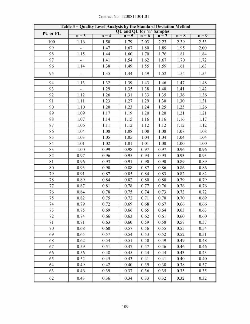
Contract No. T200811301.01
Table 3 B Quality Level Analysis by the Standard Deviation Method
PU or PL QU and QL for An@ Samplesn = 3 n = 4 n = 5 n = 6 n = 7 n = 8 n = 9
100 1.16 1.50 1.79 2.03 2.23 2.39 2.53
99 - 1.47 1.67 1.80 1.89 1.95 2.00
98 1.15 1.44 1.60 1.70 1.76 1.81 1.84
97 - 1.41 1.54 1.62 1.67 1.70 1.72
96 1.14 1.38 1.49 1.55 1.59 1.61 1.63
95 - 1.35 1.44 1.49 1.52 1.54 1.55
94 1.13 1.32 1.39 1.43 1.46 1.47 1.48
93 - 1.29 1.35 1.38 1.40 1.41 1.42
92 1.12 1.26 1.31 1.33 1.35 1.36 1.36
91 1.11 1.23 1.27 1.29 1.30 1.30 1.31
90 1.10 1.20 1.23 1.24 1.25 1.25 1.26
89 1.09 1.17 1.19 1.20 1.20 1.21 1.21
88 1.07 1.14 1.15 1.16 1.16 1.16 1.17
87 1.06 1.11 1.12 1.12 1.12 1.12 1.12
86 1.04 1.08 1.08 1.08 1.08 1.08 1.08
85 1.03 1.05 1.05 1.04 1.04 1.04 1.04
84 1.01 1.02 1.01 1.01 1.00 1.00 1.00
83 1.00 0.99 0.98 0.97 0.97 0.96 0.96
82 0.97 0.96 0.95 0.94 0.93 0.93 0.93
81 0.96 0.93 0.91 0.90 0.90 0.89 0.89
80 0.93 0.90 0.88 0.87 0.86 0.86 0.86
79 0.91 0.87 0.85 0.84 0.83 0.82 0.82
78 0.89 0.84 0.82 0.80 0.80 0.79 0.79
77 0.87 0.81 0.78 0.77 0.76 0.76 0.76
76 0.84 0.78 0.75 0.74 0.73 0.73 0.72
75 0.82 0.75 0.72 0.71 0.70 0.70 0.69
74 0.79 0.72 0.69 0.68 0.67 0.66 0.66
73 0.75 0.69 0.66 0.65 0.64 0.63 0.63
72 0.74 0.66 0.63 0.62 0.61 0.60 0.60
71 0.71 0.63 0.60 0.59 0.58 0.57 0.57
70 0.68 0.60 0.57 0.56 0.55 0.55 0.54
69 0.65 0.57 0.54 0.53 0.52 0.52 0.51
68 0.62 0.54 0.51 0.50 0.49 0.49 0.48
67 0.59 0.51 0.47 0.47 0.46 0.46 0.46
66 0.56 0.48 0.45 0.44 0.44 0.43 0.43
65 0.52 0.45 0.43 0.41 0.41 0.40 0.40
64 0.49 0.42 0.40 0.39 0.38 0.38 0.37
63 0.46 0.39 0.37 0.36 0.35 0.35 0.35
62 0.43 0.36 0.34 0.33 0.32 0.32 0.32
109
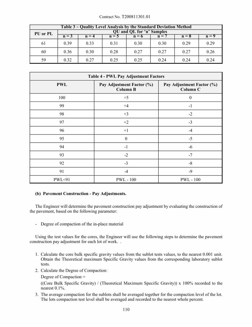
Contract No. T200811301.01
Table 3 B Quality Level Analysis by the Standard Deviation Method
PU or PL QU and QL for An@ Samplesn = 3 n = 4 n = 5 n = 6 n = 7 n = 8 n = 9
61 0.39 0.33 0.31 0.30 0.30 0.29 0.29
60 0.36 0.30 0.28 0.27 0.27 0.27 0.26
59 0.32 0.27 0.25 0.25 0.24 0.24 0.24
Table 4 - PWL Pay Adjustment Factors
PWL Pay Adjustment Factor (%)Column B
Pay Adjustment Factor (%)Column C
100 +5 0
99 +4 -1
98 +3 -2
97 +2 -3
96 +1 -4
95 0 -5
94 -1 -6
93 -2 -7
92 -3 -8
91 -4 -9
PWL<91 PWL - 100 PWL - 100
(b) Pavement Construction - Pay Adjustments.
The Engineer will determine the pavement construction pay adjustment by evaluating the construction ofthe pavement, based on the following parameter:
- Degree of compaction of the in-place material
Using the test values for the cores, the Engineer will use the following steps to determine the pavementconstruction pay adjustment for each lot of work. .
1. Calculate the core bulk specific gravity values from the sublot tests values, to the nearest 0.001 unit. Obtain the Theoretical maximum Specific Gravity values from the corresponding laboratory sublottests.
2. Calculate the Degree of Compaction:
Degree of Compaction =
((Core Bulk Specific Gravity) / (Theoretical Maximum Specific Gravity)) x 100% recorded to thenearest 0.1%.
3. The average compaction for the sublots shall be averaged together for the compaction level of the lot. The lots compaction test level shall be averaged and recorded to the nearest whole percent.
110
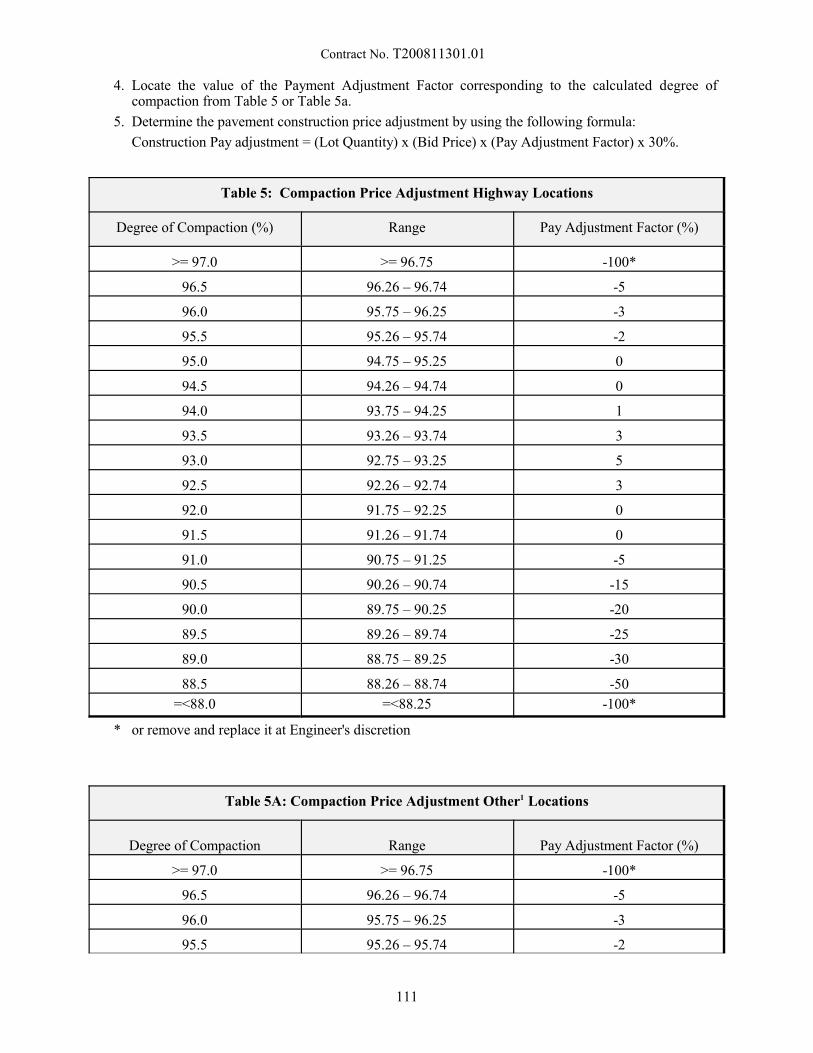
Contract No. T200811301.01
4. Locate the value of the Payment Adjustment Factor corresponding to the calculated degree ofcompaction from Table 5 or Table 5a.
5. Determine the pavement construction price adjustment by using the following formula:
Construction Pay adjustment = (Lot Quantity) x (Bid Price) x (Pay Adjustment Factor) x 30%.
Table 5: Compaction Price Adjustment Highway Locations
Degree of Compaction (%) Range Pay Adjustment Factor (%)
>= 97.0 >= 96.75 -100*
96.5 96.26 – 96.74 -5
96.0 95.75 – 96.25 -3
95.5 95.26 – 95.74 -2
95.0 94.75 – 95.25 0
94.5 94.26 – 94.74 0
94.0 93.75 – 94.25 1
93.5 93.26 – 93.74 3
93.0 92.75 – 93.25 5
92.5 92.26 – 92.74 3
92.0 91.75 – 92.25 0
91.5 91.26 – 91.74 0
91.0 90.75 – 91.25 -5
90.5 90.26 – 90.74 -15
90.0 89.75 – 90.25 -20
89.5 89.26 – 89.74 -25
89.0 88.75 – 89.25 -30
88.5 88.26 – 88.74 -50
=<88.0 =<88.25 -100*
* or remove and replace it at Engineer's discretion
Table 5A: Compaction Price Adjustment Other1 Locations
Degree of Compaction Range Pay Adjustment Factor (%)
>= 97.0 >= 96.75 -100*
96.5 96.26 – 96.74 -5
96.0 95.75 – 96.25 -3
95.5 95.26 – 95.74 -2
111
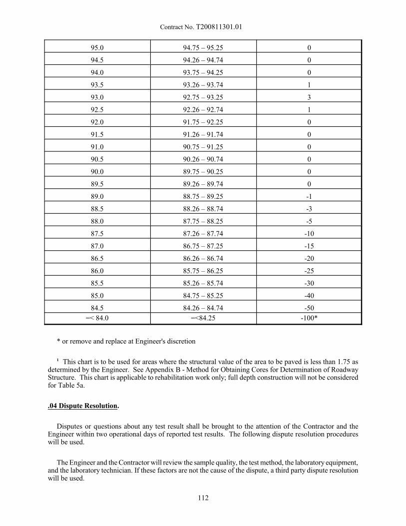
Contract No. T200811301.01
95.0 94.75 – 95.25 0
94.5 94.26 – 94.74 0
94.0 93.75 – 94.25 0
93.5 93.26 – 93.74 1
93.0 92.75 – 93.25 3
92.5 92.26 – 92.74 1
92.0 91.75 – 92.25 0
91.5 91.26 – 91.74 0
91.0 90.75 – 91.25 0
90.5 90.26 – 90.74 0
90.0 89.75 – 90.25 0
89.5 89.26 – 89.74 0
89.0 88.75 – 89.25 -1
88.5 88.26 – 88.74 -3
88.0 87.75 – 88.25 -5
87.5 87.26 – 87.74 -10
87.0 86.75 – 87.25 -15
86.5 86.26 – 86.74 -20
86.0 85.75 – 86.25 -25
85.5 85.26 – 85.74 -30
85.0 84.75 – 85.25 -40
84.5 84.26 – 84.74 -50
=< 84.0 =<84.25 -100*
* or remove and replace at Engineer's discretion
1 This chart is to be used for areas where the structural value of the area to be paved is less than 1.75 asdetermined by the Engineer. See Appendix B - Method for Obtaining Cores for Determination of RoadwayStructure. This chart is applicable to rehabilitation work only; full depth construction will not be consideredfor Table 5a.
.04 Dispute Resolution.
Disputes or questions about any test result shall be brought to the attention of the Contractor and theEngineer within two operational days of reported test results. The following dispute resolution procedureswill be used.
The Engineer and the Contractor will review the sample quality, the test method, the laboratory equipment,and the laboratory technician. If these factors are not the cause of the dispute, a third party dispute resolutionwill be used.
112

Contract No. T200811301.01
Third party resolution testing can be performed at either another Contractor’s laboratory, the Engineer’slaboratory, or an independent accredited laboratory. Unless otherwise mutually agreed upon by DAPA andthe Engineer, the Engineer’s qualified laboratory in Dover and qualified personnel shall conduct the necessarytesting for third party Dispute Resolution after the Engineer has provided reasonable notice to allow theContractor to witness this testing.
When disputes over production testing occur, the samples used for Dispute Resolution testing will be thosesamples the properly captured, labeled, and stored, as described in the second paragraph of the section ofthese specifications titled .02 Acceptance Plan, (a) Material Production - Tests and Evaluations. If nosamples are available, the original testing results will be used for payment calculations.
Dispute Resolution samples for air void content will be heated by a microwave oven.
If there is a discrepancy between the Engineer’s acceptance test result and the Contractor’s test result, theContractor may ask for the Dispute Resolution sample to be tested. The Contractor may request up to twodispute resolution samples be tested per calendar year without charge. Any additional Dispute Resolutionsamples run at the Contractors request where the results substantiate the acceptance test result will be assesseda fee of $125. Any additional Dispute Resolution samples that substantiate the Contractors test result willnot be assessed the fee.
When disputes over compaction core test results occur, the Engineer’s acceptance core will be used forthe dispute resolution sample. The Contractor will be advised on when the testing will occur as referencedabove to witness the testing.
The results of the dispute resolution testing shall replace all of the applicable disputed test results forpayment purposes.
113
Contract No. T200811301.01
Appendix A - Repairing Core Holes in Bituminous Asphalt Pavement
Description.
This appendix describes the procedure required to repair core holes in a bituminous concrete pavement.
Materials and Equipment.
The following material shall be available to complete this work:
- Patch Material - DelDOT approved High Performance Cold Patch material shall be used.
The following equipment shall be available to complete this work:
- Sponge or other absorbent material - Used to extract water from the hole.
- Compaction Hammer - mechanical (electrical, pneumatic, or gasoline driven) tamping device with aflat, circular tamping face smaller than 6 inches in diameter.
Construction Method.
After core removal from the hole, remove all excess water from within the hole, and prevent water fromre-entering the hole.
Place the patch material in lifts no greater than 3 inches and compact with mechanical tamping device. If the hole is deeper than 3 inches, use two lifts of approximately equal depths so that optimum compactionis achieved. Make sure that the patch surface matches the grade of the existing roadway. Make every effortto achieve the greatest possible compaction
Performance Requirements.
The Engineer will judge the patch on the following basis:
- The patch shall be well compacted
- The patch surface shall match the grade of the surrounding roadway surface.
Basis of Payment.
No measurement or payment will be made for the patching work. The Contractor must gain the Engineer’sacceptance of the patching work before the Engineer will accept the material represented by the core.
114
Contract No. T200811301.01
Appenidx B - Method for Obtaining Cores for Determination of Roadway Structure
The Contractor is responsible for obtaining cores in areas that they propose are eligible for compactionprice adjustments according to Table 5a in this specification. Table 5a is not applicable for new full-depthpavement box construction. Cores submitted for this process shall be obtained according to the followingprocess.
1. Contact Materials & Research (M&R) personnel to determine if information about the area is alreadyavailable. If M&R has already obtained cores in the location that is being investigated, the contractormay opt to use the laboratory information for the investigation and not core the area on their own.
2. If M&R does not have information concerning the section of the roadway, the contractor needs tocontact M&R to arrange for verification of coring operations. Arrangements shall be made to allowfor an individual from M&R to be on the site when the cores are obtained. Cores will be turned overto M&R for evaluation.
3. The Contractor is responsible for providing all traffic control and repairing core holes in accordanceto 401699 Appendix A - Repairing Core Holes in Bituminous Asphalt Pavements.
4. Cores are to be taken throughout the entire project for the area in question. Cores will be spaced, fromthe start of the project in increments determined based on field and project specifics. Cores will beevenly distributed throughout the project location. The cores will be taken in the center of the lane inquestion.
5. Additional cores may be taken at other locations, if surface conditions indicate that there may be asubstantial difference in the underlying section. The location of these cores should be documented andsubmitted to M&R.
6. Cores shall be full depth and include underlying materials. If there is a stone base included in thepavement section, at a minimum 1 core must have information concerning the thickness of the base. This is determined by augering to the subgrade surface.
7. The calculations used to determine the structural capacity of the roadway is as follows. If thecontractor finds, upon starting the coring process, that the areas are of greater thickness than applicableto Table 5a, they may terminate the coring process on their own and retract the request.
115
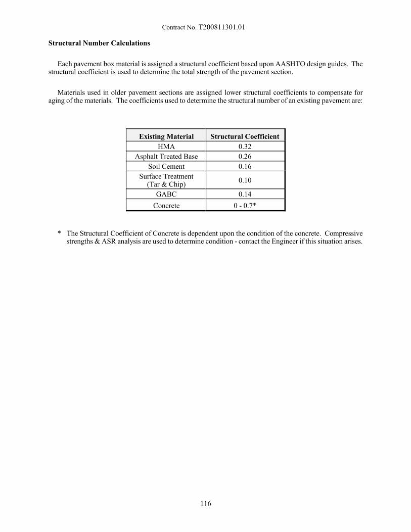
Contract No. T200811301.01
Structural Number Calculations
Each pavement box material is assigned a structural coefficient based upon AASHTO design guides. Thestructural coefficient is used to determine the total strength of the pavement section.
Materials used in older pavement sections are assigned lower structural coefficients to compensate foraging of the materials. The coefficients used to determine the structural number of an existing pavement are:
Existing Material Structural Coefficient
HMA 0.32
Asphalt Treated Base 0.26
Soil Cement 0.16
Surface Treatment(Tar & Chip)
0.10
GABC 0.14
Concrete 0 - 0.7*
* The Structural Coefficient of Concrete is dependent upon the condition of the concrete. Compressivestrengths & ASR analysis are used to determine condition - contact the Engineer if this situation arises.
116
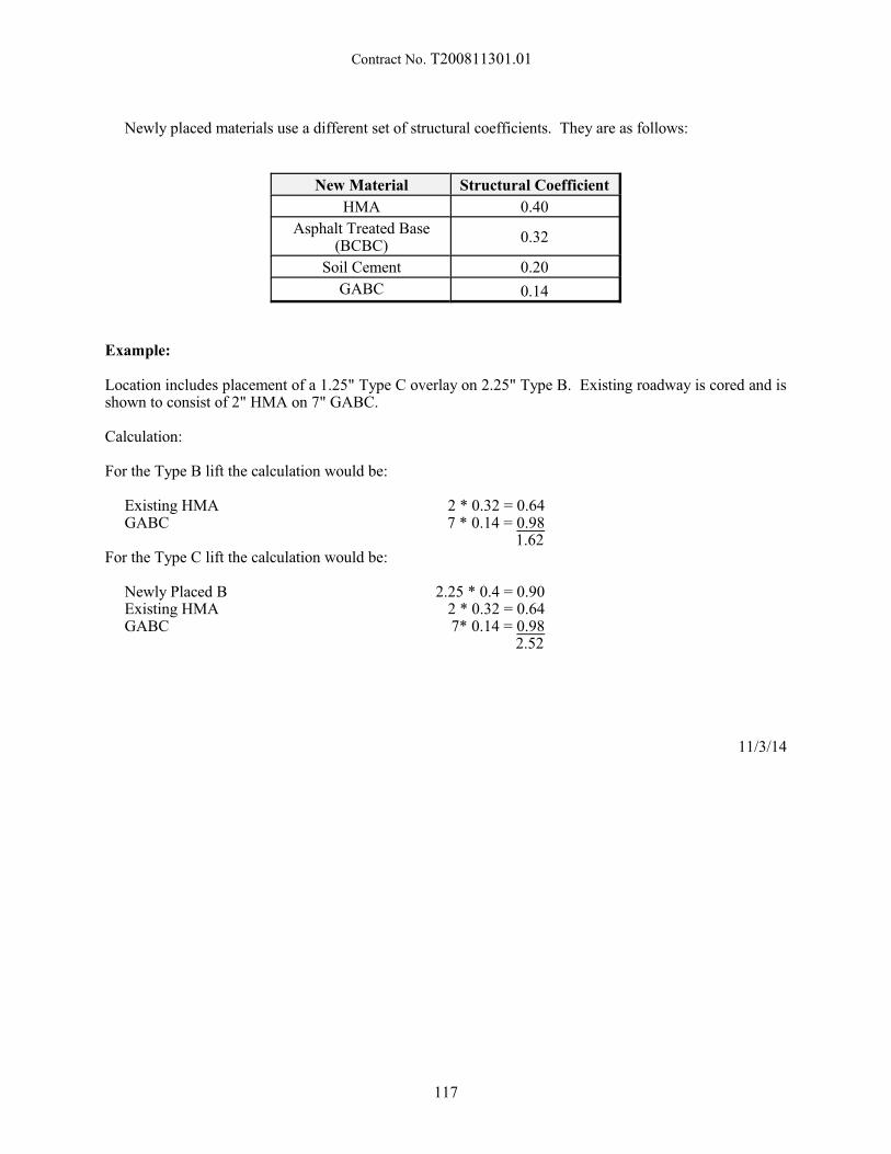
Contract No. T200811301.01
Newly placed materials use a different set of structural coefficients. They are as follows:
New Material Structural Coefficient
HMA 0.40
Asphalt Treated Base(BCBC)
0.32
Soil Cement 0.20
GABC 0.14
Example:
Location includes placement of a 1.25" Type C overlay on 2.25" Type B. Existing roadway is cored and isshown to consist of 2" HMA on 7" GABC.
Calculation:
For the Type B lift the calculation would be:
Existing HMA 2 * 0.32 = 0.64GABC 7 * 0.14 = 0.98
1.62For the Type C lift the calculation would be:
Newly Placed B 2.25 * 0.4 = 0.90Existing HMA 2 * 0.32 = 0.64GABC 7* 0.14 = 0.98
2.52
11/3/14
117
Contract No. T200811301.01
401752 – SAFETY EDGE FOR ROADWAY PAVEMENT
Description:
This work consists of the construction of safety edge(s) along bituminous concrete pavement or P.C.C.pavement in accordance with the details and notes on the Plans and as directed by the Engineer.
Construction Methods:
The safety edge shall not be constructed adjacent to curb or in front of guardrail sections.
In bituminous concrete pavement sections, prior to the construction of the safety edge, the fill or in situmaterial at the edge of pavement shall be compacted so that it is level with the top of the pavement, prior tothe final surface overlay.
In bituminous concrete pavement sections, the contractor shall attach a device to the screed of the paverunit that confines the material at the end of the gate and extrudes the asphalt material in such a way thatresults in a compacted wedge shape pavement edge of 32 degrees (+/- 2 degrees). Contact shall bemaintained between the device and the road shoulder surface. The device shall be manufactured so that it canbe easily adjusted to transition at cross roads, driveways and obstructions without stopping the paver unit. The device’s shape shall constrain the asphalt and cause compaction, as well as increase the density of theextruded profile. In bituminous concrete pavement sections, the Transtech Shoulder Wedge Maker, CarlsonSafety Edge End Gate or an approved equal shall be used to produce the safety edge. Contact informationfor these wedge shape compaction devices is listed below:
Transtech Systems, Inc.1594 State StreetSchenectady, NY 123041-800-724-6306www.transtechsys.com
or
Carlson Paving Products18425 50th Ave. ETacoma, WA 984461-253-278-9426www.carlsonpavingproducts.com
or an approved equal.
In P.C.C. pavement sections, the paver screed shall be modified to provide a chamfer at the end of theP.C.C. pavement in accordance with the details and notes on the Plans, or as directed by the Engineer.
Method of Measurement:
Safety Edge will not be measured for payment.
Basis of Payment:
The cost associated with the construction of safety edge(s), including but not limited to the wedgedevice, preparation and compaction of the fill or in situ material, and placement of the safety edge inaccordance with the Plans and Details shall be incidental to the bituminous concrete pavement or P.C.C.pavement item being placed.
10/15/2013
118
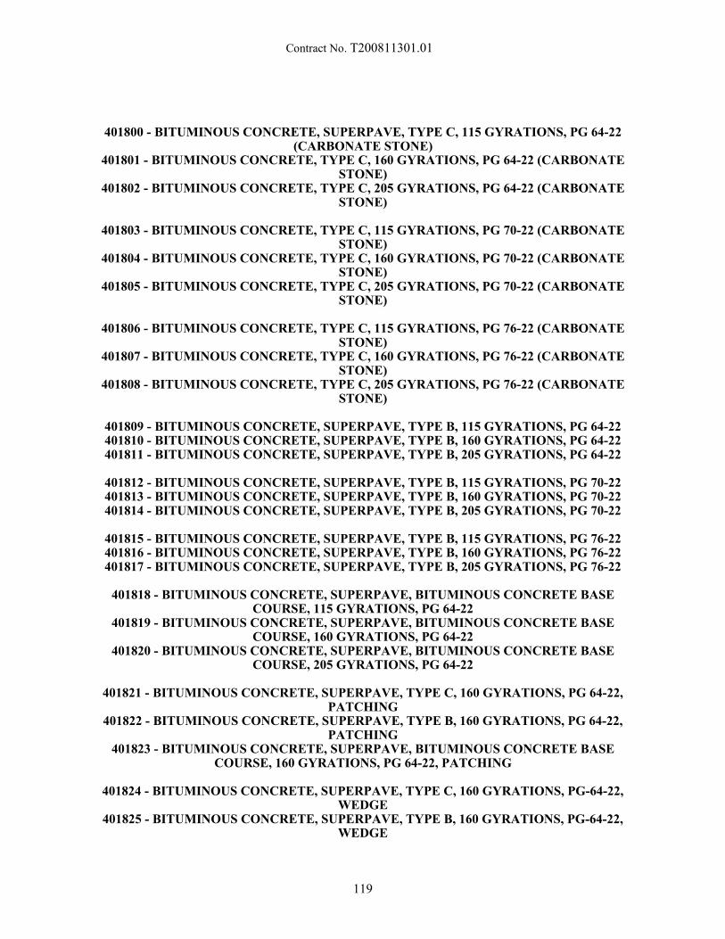
Contract No. T200811301.01
401800 - BITUMINOUS CONCRETE, SUPERPAVE, TYPE C, 115 GYRATIONS, PG 64-22
(CARBONATE STONE)401801 - BITUMINOUS CONCRETE, TYPE C, 160 GYRATIONS, PG 64-22 (CARBONATE
STONE)401802 - BITUMINOUS CONCRETE, TYPE C, 205 GYRATIONS, PG 64-22 (CARBONATE
STONE)
401803 - BITUMINOUS CONCRETE, TYPE C, 115 GYRATIONS, PG 70-22 (CARBONATESTONE)
401804 - BITUMINOUS CONCRETE, TYPE C, 160 GYRATIONS, PG 70-22 (CARBONATESTONE)
401805 - BITUMINOUS CONCRETE, TYPE C, 205 GYRATIONS, PG 70-22 (CARBONATESTONE)
401806 - BITUMINOUS CONCRETE, TYPE C, 115 GYRATIONS, PG 76-22 (CARBONATESTONE)
401807 - BITUMINOUS CONCRETE, TYPE C, 160 GYRATIONS, PG 76-22 (CARBONATESTONE)
401808 - BITUMINOUS CONCRETE, TYPE C, 205 GYRATIONS, PG 76-22 (CARBONATESTONE)
401809 - BITUMINOUS CONCRETE, SUPERPAVE, TYPE B, 115 GYRATIONS, PG 64-22401810 - BITUMINOUS CONCRETE, SUPERPAVE, TYPE B, 160 GYRATIONS, PG 64-22401811 - BITUMINOUS CONCRETE, SUPERPAVE, TYPE B, 205 GYRATIONS, PG 64-22
401812 - BITUMINOUS CONCRETE, SUPERPAVE, TYPE B, 115 GYRATIONS, PG 70-22401813 - BITUMINOUS CONCRETE, SUPERPAVE, TYPE B, 160 GYRATIONS, PG 70-22401814 - BITUMINOUS CONCRETE, SUPERPAVE, TYPE B, 205 GYRATIONS, PG 70-22
401815 - BITUMINOUS CONCRETE, SUPERPAVE, TYPE B, 115 GYRATIONS, PG 76-22401816 - BITUMINOUS CONCRETE, SUPERPAVE, TYPE B, 160 GYRATIONS, PG 76-22401817 - BITUMINOUS CONCRETE, SUPERPAVE, TYPE B, 205 GYRATIONS, PG 76-22
401818 - BITUMINOUS CONCRETE, SUPERPAVE, BITUMINOUS CONCRETE BASECOURSE, 115 GYRATIONS, PG 64-22
401819 - BITUMINOUS CONCRETE, SUPERPAVE, BITUMINOUS CONCRETE BASECOURSE, 160 GYRATIONS, PG 64-22
401820 - BITUMINOUS CONCRETE, SUPERPAVE, BITUMINOUS CONCRETE BASECOURSE, 205 GYRATIONS, PG 64-22
401821 - BITUMINOUS CONCRETE, SUPERPAVE, TYPE C, 160 GYRATIONS, PG 64-22,PATCHING
401822 - BITUMINOUS CONCRETE, SUPERPAVE, TYPE B, 160 GYRATIONS, PG 64-22,PATCHING
401823 - BITUMINOUS CONCRETE, SUPERPAVE, BITUMINOUS CONCRETE BASECOURSE, 160 GYRATIONS, PG 64-22, PATCHING
401824 - BITUMINOUS CONCRETE, SUPERPAVE, TYPE C, 160 GYRATIONS, PG-64-22,WEDGE
401825 - BITUMINOUS CONCRETE, SUPERPAVE, TYPE B, 160 GYRATIONS, PG-64-22,WEDGE
119
Contract No. T200811301.01
401826 - BITUMINOUS CONCRETE, SUPERPAVE, TYPE C, 115 GYRATIONS, PG 64-22,(NON-CARBONATE STONE)
401827 -BITUMINOUS CONCRETE, SUPERPAVE, TYPE C, 160 GYRATIONS, PG 64-22,(NON-CARBONATE STONE)
401828 - BITUMINOUS CONCRETE, SUPERPAVE, TYPE C, 205 GYRATIONS, PG 64-22,(NON-CARBONATE STONE)
401829 - BITUMINOUS CONCRETE, SUPERPAVE, TYPE C, 115 GYRATIONS, PG 70-22,(NON-CARBONATE STONE)
401830 - BITUMINOUS CONCRETE, SUPERPAVE, TYPE C, 160 GYRATIONS, PG 70-22,(NON-CARBONATE STONE)
401831 - BITUMINOUS CONCRETE, SUPERPAVE, TYPE C, 205 GYRATIONS, PG 70-22,(NON-CARBONATE STONE)
401832 - BITUMINOUS CONCRETE, SUPERPAVE, TYPE C, 115 GYRATIONS, PG 76-22,(NON-CARBONATE STONE)
401833 -BITUMINOUS CONCRETE, SUPERPAVE, TYPE C, 160 GYRATIONS, PG 76-22,(NON-CARBONATE STONE)
401834 - BITUMINOUS CONCRETE, SUPERPAVE, TYPE C, 205 GYRATIONS, PG 76-22,(NON-CARBONATE STONE)
401835 - THIN BITUMINOUS CONCRETE, SUPERPAVE, TYPE C, 115 GYRATIONS, PG 64-22401836 - THIN BITUMINOUS CONCRETE, SUPERPAVE, TYPE C, 160 GYRATIONS, PG 64-22401837 - THIN BITUMINOUS CONCRETE, SUPERPAVE, TYPE C, 115 GYRATIONS, PG 70-22401838 - THIN BITUMINOUS CONCRETE, SUPERPAVE, TYPE C, 160 GYRATIONS, PG 70-22401839 - THIN BITUMINOUS CONCRETE, SUPERPAVE, TYPE C, 115 GYRATIONS, PG 76-22401840 - THIN BITUMINOUS CONCRETE, SUPERPAVE, TYPE C, 160 GYRATIONS, PG 76-22
.01 Description:
This specification shall govern the production and construction of bituminous concrete pavement. Thefollowing Subsections of the Standard Specifications shall be applicable: 401.01, 401.03 - 401.10, 401.12,and 401.13. All other subsections have been modified herein.
Payment for bituminous concrete shall be in accordance with item 401699. The Contractor shall read andthoroughly understand the requirements of the QA/QC specification as defined in item 401699. It is theresponsibility of the Contractor to determine all costs associated with meeting these requirements and toinclude them in the per ton bids for the various Superpave bituminous concrete items. Payment adjustmentfactors will be calculated in accordance with the latest version of item 401699.
Bituminous concrete may be produced by one or a combination of several technologies involving asphaltfoaming processes and equipment or additives that facilitate the reduction of the temperature at which the mixcan be placed and satisfactorily compacted thereby permitting the mix to be produced at reducedtemperatures.
.02 Materials:
Use materials conforming to standard specifications 823.
Materials for bituminous concrete shall conform to the requirements of Subsections 823.01, 823.05-823.17, and 823.25 - 823.28 of the Standard Specifications and the following. If the Contractor proposes touse a combination of materials that are not covered by this Specification, the mix design shall be submittedand reviewed by the Engineer 30 calendar days prior to use.
a) Asphalt Binder:
120
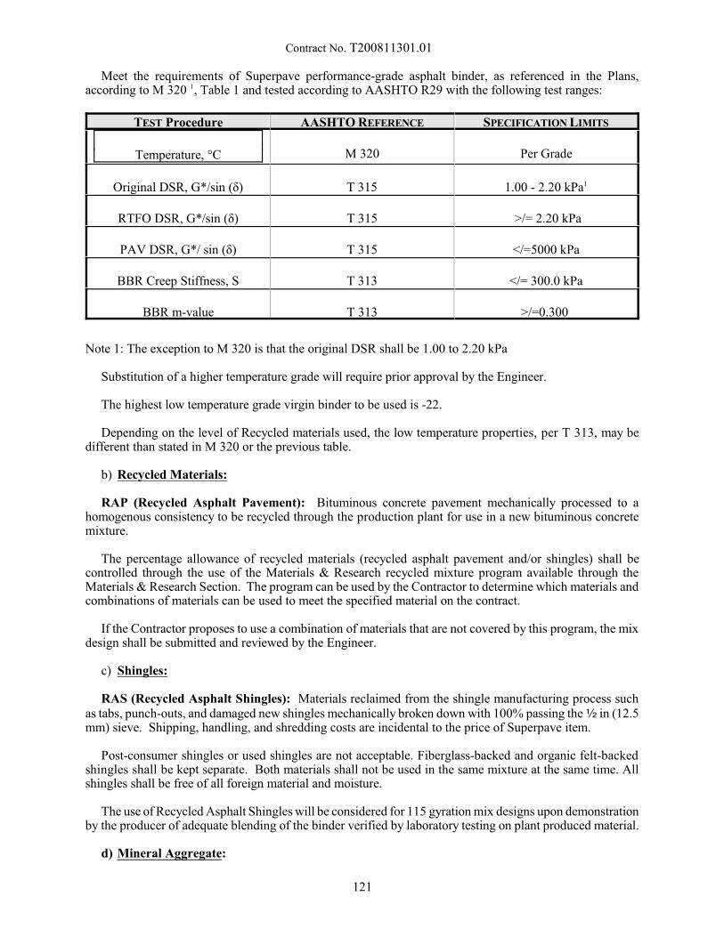
Contract No. T200811301.01
Meet the requirements of Superpave performance-grade asphalt binder, as referenced in the Plans,according to M 320 1, Table 1 and tested according to AASHTO R29 with the following test ranges:
TEST Procedure AASHTO REFERENCE SPECIFICATION LIMITS
Temperature, °C M 320 Per Grade
Original DSR, G*/sin (ä) T 315 1.00 - 2.20 kPa1
RTFO DSR, G*/sin (ä) T 315 >/= 2.20 kPa
PAV DSR, G*/ sin (ä) T 315 </=5000 kPa
BBR Creep Stiffness, S T 313 </= 300.0 kPa
BBR m-value T 313 >/=0.300
Note 1: The exception to M 320 is that the original DSR shall be 1.00 to 2.20 kPa
Substitution of a higher temperature grade will require prior approval by the Engineer.
The highest low temperature grade virgin binder to be used is -22.
Depending on the level of Recycled materials used, the low temperature properties, per T 313, may bedifferent than stated in M 320 or the previous table.
b) Recycled Materials:
RAP (Recycled Asphalt Pavement): Bituminous concrete pavement mechanically processed to ahomogenous consistency to be recycled through the production plant for use in a new bituminous concretemixture.
The percentage allowance of recycled materials (recycled asphalt pavement and/or shingles) shall becontrolled through the use of the Materials & Research recycled mixture program available through theMaterials & Research Section. The program can be used by the Contractor to determine which materials andcombinations of materials can be used to meet the specified material on the contract.
If the Contractor proposes to use a combination of materials that are not covered by this program, the mixdesign shall be submitted and reviewed by the Engineer.
c) Shingles:
RAS (Recycled Asphalt Shingles): Materials reclaimed from the shingle manufacturing process suchas tabs, punch-outs, and damaged new shingles mechanically broken down with 100% passing the 2 in (12.5mm) sieve. Shipping, handling, and shredding costs are incidental to the price of Superpave item.
Post-consumer shingles or used shingles are not acceptable. Fiberglass-backed and organic felt-backedshingles shall be kept separate. Both materials shall not be used in the same mixture at the same time. Allshingles shall be free of all foreign material and moisture.
The use of Recycled Asphalt Shingles will be considered for 115 gyration mix designs upon demonstrationby the producer of adequate blending of the binder verified by laboratory testing on plant produced material.
d) Mineral Aggregate:
121
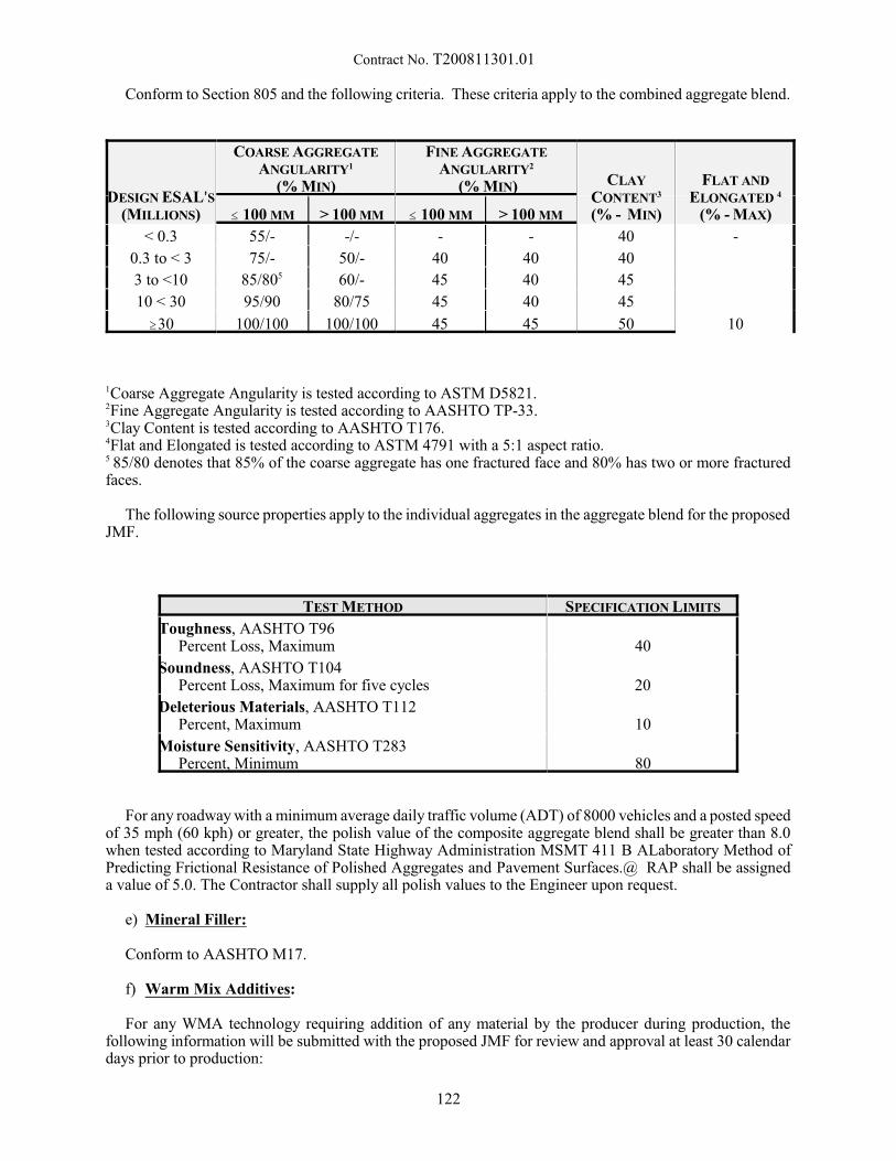
Contract No. T200811301.01
Conform to Section 805 and the following criteria. These criteria apply to the combined aggregate blend.
DESIGN ESAL=S(MILLIONS)
COARSE AGGREGATE
ANGULARITY1
(% MIN)
FINE AGGREGATE
ANGULARITY2
(% MIN) CLAY
CONTENT3
(% - MIN)
FLAT AND
ELONGATED 4
(% - MAX)# 100 MM > 100 MM # 100 MM > 100 MM
< 0.3 55/- -/- - - 40 -
0.3 to < 3 75/- 50/- 40 40 40
10
3 to <10 85/805 60/- 45 40 45
10 < 30 95/90 80/75 45 40 45
$30 100/100 100/100 45 45 50
1Coarse Aggregate Angularity is tested according to ASTM D5821.2Fine Aggregate Angularity is tested according to AASHTO TP-33.3Clay Content is tested according to AASHTO T176.4Flat and Elongated is tested according to ASTM 4791 with a 5:1 aspect ratio.5 85/80 denotes that 85% of the coarse aggregate has one fractured face and 80% has two or more fracturedfaces.
The following source properties apply to the individual aggregates in the aggregate blend for the proposedJMF.
TEST METHOD SPECIFICATION LIMITS
Toughness, AASHTO T96 Percent Loss, Maximum 40
Soundness, AASHTO T104 Percent Loss, Maximum for five cycles 20
Deleterious Materials, AASHTO T112 Percent, Maximum 10
Moisture Sensitivity, AASHTO T283 Percent, Minimum 80
For any roadway with a minimum average daily traffic volume (ADT) of 8000 vehicles and a posted speedof 35 mph (60 kph) or greater, the polish value of the composite aggregate blend shall be greater than 8.0when tested according to Maryland State Highway Administration MSMT 411 B ALaboratory Method ofPredicting Frictional Resistance of Polished Aggregates and Pavement Surfaces.@ RAP shall be assigneda value of 5.0. The Contractor shall supply all polish values to the Engineer upon request.
e) Mineral Filler:
Conform to AASHTO M17.
f) Warm Mix Additives:
For any WMA technology requiring addition of any material by the producer during production, thefollowing information will be submitted with the proposed JMF for review and approval at least 30 calendardays prior to production:
122

Contract No. T200811301.01
1. WMA technology and/or additive information.2. WMA technology manufacturer’s recommendation for usage.3. WMA technology target dosage rate and tolerance envelope. Support tolerance envelope with test data
demonstrating acceptable mix production properties conforming to all sections of this specification.4. WMA technology manufacturer’s material safety data sheets (MSDS).5. Documentation of past WMA technology field application including points of contact.6. Temperature ranges for mixing and compacting.7. Laboratory test data, samples, and sources of all mix components, and asphalt binder viscosity-
temperature relationships.
Follow the manufacturer’s recommendation for incorporating additives and WMA technologies into themix. Comply with the manufacturer’s recommendation regarding receiving, storage, and delivery ofadditives.
If the producer performs blending of the WMA technology in their tank, a separate Quality Control planshall be submitted by the producer to the Department for review and approval at least 30 calendar days priorto production.
g) Anti-stripping additives
Conform to standard specifications Section 829 and blend with the asphalt cement in accordance with thisspecification. Incorporate anti-stripping additives when the Tensile Strength Ratio (TSR) as determined inaccordance with AASHTO T283 is less than 80 or when specified for use by the Engineer.
.03 Bituminous Concrete Production – Quality Control (a) Process Control - Material Production Quality Control.
Submit through electronic mail a QC Plan from each proposed production plant to the Engineer; no hot-mix asphalt material will be accepted until the Engineer approves the QC Plan. This plan must be submittedto the Engineer on an annual basis for review and approval prior to material production. The Engineer willsend a signed copy back to the Contractor stating that it is approved. The approved QC Plan shall governcontractor operations.
The QC Plan shall include actions that will assure all materials and products will conform to thespecifications, whether manufactured or processed by the Contractor, or procured from suppliers,subcontractors, or vendors. The Contractor shall perform the inspection and tests required to substantiateproduct conformance to contract requirements. The Contractor shall document QC inspections and tests, andprovide copies to the Engineer when requested. The Contractor shall maintain records of all inspections andtests for at least one year. The records shall include the date, time, and nature of deficiency or deficienciesfound; the quantities of material involved until the deficiency was corrected; and the date, time, and natureof corrective actions taken.
In the QC Plan shall detail the type and frequency of inspection, sampling, and testing deemed necessaryto measure and control the various properties of material and construction governed by the Specifications. The QC Plan shall include the following elements as a minimum:
- Production Plant - make, type, capacity, and location.- Production Plant Calibration - components and schedule; address documentation. - Personnel - include name and telephone number for the following individuals: - Person responsible for quality control. - Qualified technician(s) responsible for performing the inspection, sampling, and testing. - Person who has the authority to make corrective actions on behalf of the Contractor. - Testing Laboratory - state the frequency of accuracy checks and calibrations of the equipment used for
testing; address documentation.- Load number of QC samples (1-10 if QA sample is not within trucks 1-10)- Locations where samples will be obtained and the sampling techniques for each test- Tests to be performed and their normal frequency; the following, at a minimum, shall be conducted:
123
Contract No. T200811301.01
- Mixture Temperature: each of the first five trucks, and each load that is sampled for QC oracceptance testing.
- Gradation analysis of aggregate (and RAP) stockpiles - one washed gradations per week for eachaggregate stockpile; RAP: five gradations and asphalt cement contents for dedicated stockpileswhere new material is not being added; one gradation and asphalt cement content test per week forstockpiles where material is continually being added to the stockpile.
- Gradation analysis of non-payment sieves- Dust to effective asphalt calculation- Moisture content analysis of aggregates - daily. - Gradation analysis of the combined aggregate cold feed - one per year per mixture.- Bulk specific gravity and absorption of blended material - one per year per mixture.- Ignition Oven calibration - one per year per mixture.- Hot-Bins: one per year per mixture.- Others, as appropriate.
- Procedures for reporting the results of inspection and tests (include schedule).- Procedures for dealing with non-compliant material or work.- Presentation of control charts. The contractor shall plot the results of testing on individual control
charts for each characteristic. The control charts shall be updated within on working day as test resultsfor each sublot become available. The control charts shall be easily and readily accessible at the plantlaboratory. The following parameters shall be plotted from the testing:- Asphalt cement content.- Volumetrics (air voids, voids in mineral aggregates [VMA])- Gradation values for the following sieves:
- 4.75 mm (#4).- 2.36 mm (#8). - 0.075 mm (#200). - Operational guidelines (trigger points) to address times when the following actions would be
considered:- Increased frequency of sampling and testing.- Plant control/settings/operations change.- JMF adjustment.- JMF change (See 401644 Section .04(a)(1)).- Change in the source of the component materials.- Calibration of material production equipment (asphalt pump, belt feeders, etc.).- Rejection of material.
When any point of non-compliance with the QC plan, or material not meeting the Specifications, comesto the attention of either the Contractor or the Engineer, the other party shall be notified immediately, and theContractor shall take appropriate corrective actions. Failure to take corrective actions immediately shall because for rejection of material or work by the Engineer.
The following are considered significant violations to the Contractor’s QC Plan:
- Using testing equipment that is knowingly out of calibration or is not working properly.- Reporting false information such as test data, JMF information, or any info requested by DelDOT- Failure to perform materials testing per their approved QC Plan - Deviating from AASHTO or DelDOT testing procedures.- Use of any material or the use of a JMF component in a proportion that exceeds the allowable tolerance
as specified in section 04(a)(1) of this specification not listed in the JMF.- Use of the wrong PG graded asphalt.- Failure to take corrective action per action points in the Contractors approved QC plan.
The following steps will be taken for violations listed above:
1. First offence: Written notice of violation to the Contractor2. Second offence: Written notice of violation and forfeiture of any bonus (material production or
pavement construction) payment eligibility under 401699 section .03 for that production shift.
124

Contract No. T200811301.01
3. Third offence: Written notice of violation, forfeiture of bonus payment eligibility, and a 5% deductionof payment based upon contract unit price in addition to any calculated pay adjustment factors per401699 Section 03.
4. Fourth offence: Written notice of violation, forfeiture of bonus payment eligibility, 50% deduction ofpayment based upon contract unit price in addition to any calculated payment adjustment factor per401699 Section 03, and immediate suspension of the Contractor until corrective actions are taken. Corrective actions shall be submitted in writing to the Engineer for approval. The Engineer mayrequest a meeting with the Contractor to discuss proposed changes prior to lifting suspension.
Violations of Contractor QC plans shall be kept on record for a period of 1 year from the date of violationat the Central Lab.
(b) Material Production Test Equipment.
Establish, maintain, and operate a qualified testing laboratory at the production plant site of sufficient sizeand layout that will accommodate the testing operations of both the Contractor and the Engineer.
Facilities for the use of the Engineer and inspectors shall be a minimum of 600 square feet of floor spaceconditioned to maintain constant temperature of 77F with two windows and a door equipped with functionallocks and latches, located such that plant activities are plainly visible from one window of the building. Workspace shall be furnished with illumination, tables, chairs, desks, telephone, and water including drinkingwater, sanitary facilities, fuel, and power necessary to conduct all necessary tests.
Maintain all the equipment used for handling, preparing, and testing materials in proper operatingcondition. For any laboratory equipment malfunction, the Contractor shall remedy the situation within oneworking day or the Engineer may suspend production. In the case of an equipment malfunction, the Engineermay elect to test the material at another qualified testing laboratory while waiting for repairs to equipment.
Maintain minimum calibration records for the referenced equipment:- SUPERPAVER Gyratory Compactor: once every year; verified once every month by the Engineer.- Ovens: once every three months, verified once every month.- Vacuum Container and Gauge (Rice Bowls): once every three months, verified once every month.- Balances and Scales: once every year, verified once every month. - Thermometers: once a year; verified once every month. - Gyratory Compactor molds and base plates: once every year- Mechanical Shakers: once every year- Sieve Verifications: once every year
All calibrations shall be documented and on file for review by the Engineer at any time.
(c) Material Production Test Methods
- AASHTO T312 - Preparing and Determining the Density of Hot Mix Asphalt (HMA) Specimens byMeans of the Superpave Gyratory Compactor
- AASHTO T166, Method C (Rapid Method) - Bulk Specific Gravity of Compacted Hot Mix Asphalt(HMA) Using Saturated Surface Dry Specimens
- AASHTO T308 - Determining the Asphalt Binder Content of Hot Mix Asphalt (HMA) by the IgnitionMethod
- AASHTO T30 - Mechanical Analysis of Extracted Aggregate - AASHTO T209 - Theoretical Maximum Specific Gravity and Density of Hot Mix Asphalt (HMA)- ASTM D7227 - Standard Practice for Rapid Drying of Compacted Asphalt Specimens using Vacuum
Drying Apparatus
125
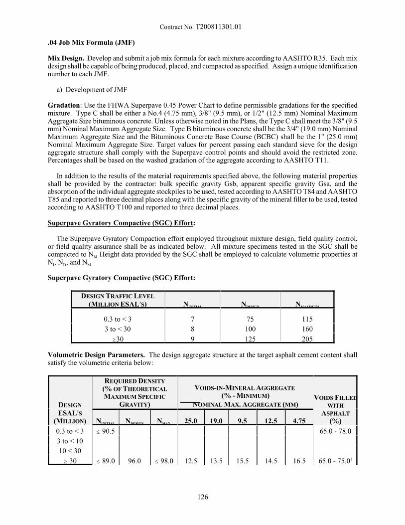
Contract No. T200811301.01
.04 Job Mix Formula (JMF)
Mix Design. Develop and submit a job mix formula for each mixture according to AASHTO R35. Each mixdesign shall be capable of being produced, placed, and compacted as specified. Assign a unique identificationnumber to each JMF.
a) Development of JMF
Gradation: Use the FHWA Superpave 0.45 Power Chart to define permissible gradations for the specifiedmixture. Type C shall be either a No.4 (4.75 mm), 3/8" (9.5 mm), or 1/2" (12.5 mm) Nominal MaximumAggregate Size bituminous concrete. Unless otherwise noted in the Plans, the Type C shall meet the 3/8" (9.5mm) Nominal Maximum Aggregate Size. Type B bituminous concrete shall be the 3/4" (19.0 mm) NominalMaximum Aggregate Size and the Bituminous Concrete Base Course (BCBC) shall be the 1" (25.0 mm)Nominal Maximum Aggregate Size. Target values for percent passing each standard sieve for the designaggregate structure shall comply with the Superpave control points and should avoid the restricted zone. Percentages shall be based on the washed gradation of the aggregate according to AASHTO T11.
In addition to the results of the material requirements specified above, the following material propertiesshall be provided by the contractor: bulk specific gravity Gsb, apparent specific gravity Gsa, and theabsorption of the individual aggregate stockpiles to be used, tested according to AASHTO T84 and AASHTOT85 and reported to three decimal places along with the specific gravity of the mineral filler to be used, testedaccording to AASHTO T100 and reported to three decimal places.
Superpave Gyratory Compactive (SGC) Effort:
The Superpave Gyratory Compaction effort employed throughout mixture design, field quality control,or field quality assurance shall be as indicated below. All mixture specimens tested in the SGC shall becompacted to NM Height data provided by the SGC shall be employed to calculate volumetric properties atNI, ND, and NM
Superpave Gyratory Compactive (SGC) Effort:
DESIGN TRAFFIC LEVEL
(MILLION ESAL=S) NINITIAL NDESIGN NMAXIMUM
0.3 to < 3 7 75 115
3 to < 30 8 100 160
$30 9 125 205
Volumetric Design Parameters. The design aggregate structure at the target asphalt cement content shallsatisfy the volumetric criteria below:
DESIGN
ESAL=S(MILLION)
REQUIRED DENSITY
(% OF THEORETICAL
MAXIMUM SPECIFIC
GRAVITY)
VOIDS-IN-MINERAL AGGREGATE
(% - MINIMUM)NOMINAL MAX. AGGREGATE (MM)
VOIDS FILLED
WITH
ASPHALT
(%)NINITIAL NDESIGN NMAX 25.0 19.0 9.5 12.5 4.75
0.3 to < 3 # 90.5
96.0 # 98.0 12.5 13.5 15.5 14.5 16.5
65.0 - 78.0
3 to < 10
# 89.0 65.0 - 75.01
10 < 30
$ 30
126
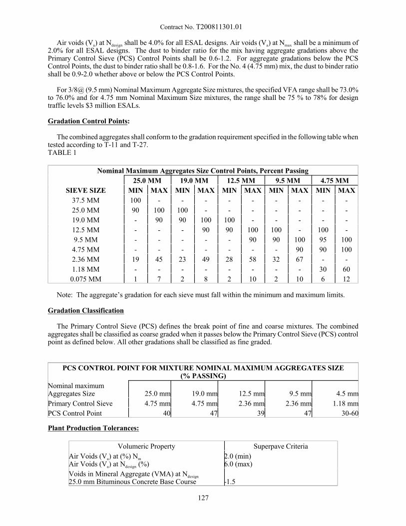
Contract No. T200811301.01
Air voids (Va) at Ndesign shall be 4.0% for all ESAL designs. Air voids (Va) at Nmax shall be a minimum of2.0% for all ESAL designs. The dust to binder ratio for the mix having aggregate gradations above thePrimary Control Sieve (PCS) Control Points shall be 0.6-1.2. For aggregate gradations below the PCSControl Points, the dust to binder ratio shall be 0.8-1.6. For the No. 4 (4.75 mm) mix, the dust to binder ratioshall be 0.9-2.0 whether above or below the PCS Control Points.
For 3/8@ (9.5 mm) Nominal Maximum Aggregate Size mixtures, the specified VFA range shall be 73.0%to 76.0% and for 4.75 mm Nominal Maximum Size mixtures, the range shall be 75 % to 78% for designtraffic levels $3 million ESALs.
Gradation Control Points:
The combined aggregates shall conform to the gradation requirement specified in the following table whentested according to T-11 and T-27.TABLE 1
Nominal Maximum Aggregates Size Control Points, Percent Passing
25.0 MM 19.0 MM 12.5 MM 9.5 MM 4.75 MM
SIEVE SIZE MIN MAX MIN MAX MIN MAX MIN MAX MIN MAX
37.5 MM 100 - - - - - - - - -
25.0 MM 90 100 100 - - - - - - -
19.0 MM - 90 90 100 100 - - - - -
12.5 MM - - - 90 90 100 100 - 100 -
9.5 MM - - - - - 90 90 100 95 100
4.75 MM - - - - - - - 90 90 100
2.36 MM 19 45 23 49 28 58 32 67 - -
1.18 MM - - - - - - - - 30 60
0.075 MM 1 7 2 8 2 10 2 10 6 12
Note: The aggregate’s gradation for each sieve must fall within the minimum and maximum limits.
Gradation Classification
The Primary Control Sieve (PCS) defines the break point of fine and coarse mixtures. The combinedaggregates shall be classified as coarse graded when it passes below the Primary Control Sieve (PCS) controlpoint as defined below. All other gradations shall be classified as fine graded.
PCS CONTROL POINT FOR MIXTURE NOMINAL MAXIMUM AGGREGATES SIZE(% PASSING)
Nominal maximumAggregates Size 25.0 mm 19.0 mm 12.5 mm 9.5 mm 4.5 mm
Primary Control Sieve 4.75 mm 4.75 mm 2.36 mm 2.36 mm 1.18 mm
PCS Control Point 40 47 39 47 30-60
Plant Production Tolerances:
Volumeric Property Superpave Criteria
Air Voids (Va) at (%) Nm
Air Voids (Va) at Ndesign (%)2.0 (min)6.0 (max)
Voids in Mineral Aggregate (VMA) at Ndesign
25.0 mm Bituminous Concrete Base Course -1.5
127
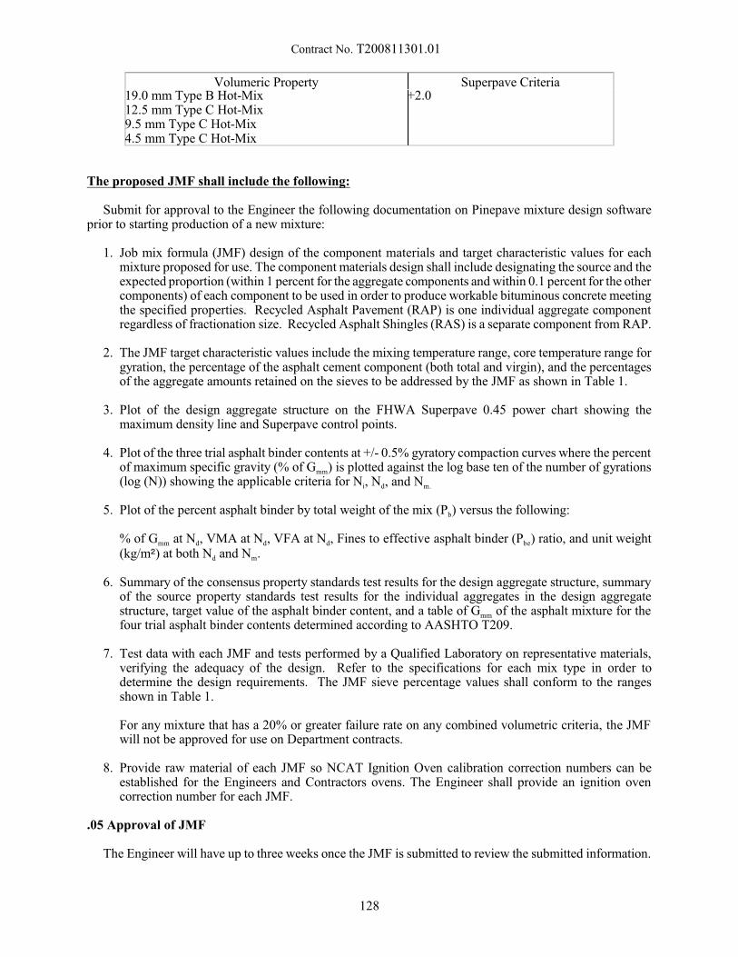
Contract No. T200811301.01
Volumeric Property Superpave Criteria19.0 mm Type B Hot-Mix12.5 mm Type C Hot-Mix9.5 mm Type C Hot-Mix4.5 mm Type C Hot-Mix
+2.0
The proposed JMF shall include the following:
Submit for approval to the Engineer the following documentation on Pinepave mixture design softwareprior to starting production of a new mixture:
1. Job mix formula (JMF) design of the component materials and target characteristic values for eachmixture proposed for use. The component materials design shall include designating the source and theexpected proportion (within 1 percent for the aggregate components and within 0.1 percent for the othercomponents) of each component to be used in order to produce workable bituminous concrete meetingthe specified properties. Recycled Asphalt Pavement (RAP) is one individual aggregate componentregardless of fractionation size. Recycled Asphalt Shingles (RAS) is a separate component from RAP.
2. The JMF target characteristic values include the mixing temperature range, core temperature range forgyration, the percentage of the asphalt cement component (both total and virgin), and the percentagesof the aggregate amounts retained on the sieves to be addressed by the JMF as shown in Table 1.
3. Plot of the design aggregate structure on the FHWA Superpave 0.45 power chart showing themaximum density line and Superpave control points.
4. Plot of the three trial asphalt binder contents at +/- 0.5% gyratory compaction curves where the percentof maximum specific gravity (% of Gmm) is plotted against the log base ten of the number of gyrations(log (N)) showing the applicable criteria for Ni, Nd, and Nm.
5. Plot of the percent asphalt binder by total weight of the mix (Pb) versus the following:
% of Gmm at Nd, VMA at Nd, VFA at Nd, Fines to effective asphalt binder (Pbe) ratio, and unit weight(kg/m5) at both Nd and Nm.
6. Summary of the consensus property standards test results for the design aggregate structure, summaryof the source property standards test results for the individual aggregates in the design aggregatestructure, target value of the asphalt binder content, and a table of Gmm of the asphalt mixture for thefour trial asphalt binder contents determined according to AASHTO T209.
7. Test data with each JMF and tests performed by a Qualified Laboratory on representative materials,verifying the adequacy of the design. Refer to the specifications for each mix type in order todetermine the design requirements. The JMF sieve percentage values shall conform to the rangesshown in Table 1.
For any mixture that has a 20% or greater failure rate on any combined volumetric criteria, the JMFwill not be approved for use on Department contracts.
8. Provide raw material of each JMF so NCAT Ignition Oven calibration correction numbers can beestablished for the Engineers and Contractors ovens. The Engineer shall provide an ignition ovencorrection number for each JMF.
.05 Approval of JMF
The Engineer will have up to three weeks once the JMF is submitted to review the submitted information.
128
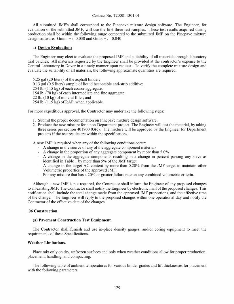
Contract No. T200811301.01
All submitted JMF=s shall correspond to the Pinepave mixture design software. The Engineer, forevaluation of the submitted JMF, will use the first three test samples. These test results acquired duringproduction shall be within the following range compared to the submitted JMF on the Pinepave mixturedesign software: Gmm: + / -0.030 and Gmb: + / - 0.040
a) Design Evaluation:
The Engineer may elect to evaluate the proposed JMF and suitability of all materials through laboratorytrial batches. All materials requested by the Engineer shall be provided at the contractor’s expense to theCentral Laboratory in Dover in a timely manner upon request. To verify the complete mixture design andevaluate the suitability of all materials, the following approximate quantities are required:
5.25 gal (20 liters) of the asphalt binder;0.13 gal (0.5 liters) sample of liquid heat-stable anti-strip additive;254 lb. (115 kg) of each coarse aggregate; 154 lb. (70 kg) of each intermediate and fine aggregate;22 lb. (10 kg) of mineral filler; and 254 lb. (115 kg) of RAP, when applicable.
For more expeditious approval, the Contractor may undertake the following steps:
1. Submit the proper documentation on Pinepave mixture design software.2. Produce the new mixture for a non-Department project. The Engineer will test the material, by taking
three series per section 401800 03(c). The mixture will be approved by the Engineer for Departmentprojects if the test results are within the specifications.
A new JMF is required when any of the following conditions occur:- A change in the source of any of the aggregate component materials- A change in the proportion of any aggregate component by more than 5.0%- A change in the aggregate components resulting in a change in percent passing any sieve as
identified in Table 1 by more than 5% of the JMF target.- A change in the target AC content by more than 0.20% from the JMF target to maintain other
Volumetric properties of the approved JMF.- For any mixture that has a 20% or greater failure rate on any combined volumetric criteria.
Although a new JMF is not required, the Contractor shall inform the Engineer of any proposed changesto an existing JMF. The Contractor shall notify the Engineer by electronic mail of the proposed changes. Thisnotification shall include the total change made from the approved JMF proportions, and the effective timeof the change. The Engineer will reply to the proposed changes within one operational day and notify theContractor of the effective date of the changes.
.06 Construction.
(a) Pavement Construction Test Equipment.
The Contractor shall furnish and use in-place density gauges, and/or coring equipment to meet therequirements of these Specifications.
Weather Limitations.
Place mix only on dry, unfrozen surfaces and only when weather conditions allow for proper production,placement, handling, and compacting.
The following table of ambient temperatures for various binder grades and lift thicknesses for placementwith the following parameters:
129
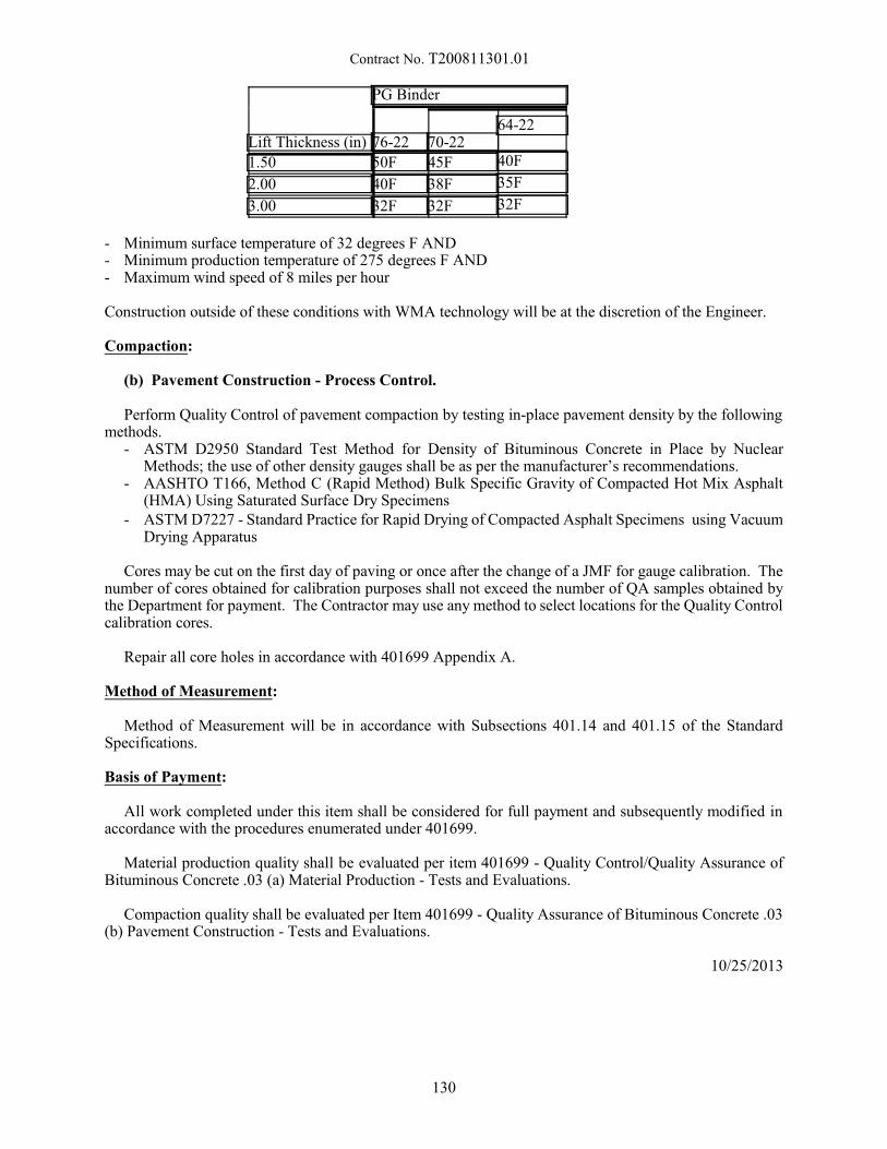
Contract No. T200811301.01
Lift Thickness (in)
PG Binder
76-22 70-2264-22
1.50 50F 45F 40F
2.00 40F 38F 35F
3.00 32F 32F 32F
- Minimum surface temperature of 32 degrees F AND- Minimum production temperature of 275 degrees F AND- Maximum wind speed of 8 miles per hour
Construction outside of these conditions with WMA technology will be at the discretion of the Engineer.
Compaction:
(b) Pavement Construction - Process Control.
Perform Quality Control of pavement compaction by testing in-place pavement density by the followingmethods.
- ASTM D2950 Standard Test Method for Density of Bituminous Concrete in Place by NuclearMethods; the use of other density gauges shall be as per the manufacturer’s recommendations.
- AASHTO T166, Method C (Rapid Method) Bulk Specific Gravity of Compacted Hot Mix Asphalt(HMA) Using Saturated Surface Dry Specimens
- ASTM D7227 - Standard Practice for Rapid Drying of Compacted Asphalt Specimens using VacuumDrying Apparatus
Cores may be cut on the first day of paving or once after the change of a JMF for gauge calibration. Thenumber of cores obtained for calibration purposes shall not exceed the number of QA samples obtained bythe Department for payment. The Contractor may use any method to select locations for the Quality Controlcalibration cores.
Repair all core holes in accordance with 401699 Appendix A.
Method of Measurement:
Method of Measurement will be in accordance with Subsections 401.14 and 401.15 of the StandardSpecifications.
Basis of Payment:
All work completed under this item shall be considered for full payment and subsequently modified inaccordance with the procedures enumerated under 401699.
Material production quality shall be evaluated per item 401699 - Quality Control/Quality Assurance ofBituminous Concrete .03 (a) Material Production - Tests and Evaluations.
Compaction quality shall be evaluated per Item 401699 - Quality Assurance of Bituminous Concrete .03(b) Pavement Construction - Tests and Evaluations.
10/25/2013
130

Contract No. T200811301.01
602772 - MECHANICALLY STABILIZED EARTH WALLS
Description:
This work shall consist of the design, furnishing all materials, fabrication and construction ofmechanically stabilized earth (MSE) retaining walls in accordance with the AASHTO definitions ofmechanically stabilized earth walls employing tensile reinforcements in the soil mass. The MSE retainingwall shall be constructed in conformance with these specifications and to the lines, grades, and dimensionsshown on the Plans or as established by the Engineer. Acceptance of a proprietary MSE wall system will bebased on review and approval of design and specifications submitted by the Contractor for his chosen system. Deviations from these specifications must be approved by the Engineer.
Design Requirements:
The MSE retaining wall shall be designed in conformance with the AASHTO LRFD Bridge DesignSpecifications, 7th Edition including all current Interims at the time of advertisement and the requirementsspecified on the Plans.
The following additional specific design requirements shall be met by the developed plans:
a. All retaining wall components shall be designed for a minimum service life of 100 years.
b. Completed walls shall have a concrete facing with a finish or aesthetic treatment as described hereinor noted on the plans.
The design of the internal stability of the MSE wall shall be the responsibility of the wall manufacturer. Determining the minimum length of reinforcing elements, as set forth herein, shall be the responsibility ofthe Contractor.
The Contractor will submit Shop Drawings in accordance with the requirements of Section 105 of theStandard Specifications bearing the fabricator’s or supplier’s title block and design calculations sealed by aprofessional engineer registered in the State of Delaware for review and approval by the Engineer at least4 weeks before work is to begin. Shop Drawings and design calculations shall include the following:
(a) Existing ground elevations that have been verified by the Contractor for each location involvingconstruction wholly or partially in original ground.
(b)Layout of wall that will effectively retain the earth but not less in height or length than that shown forthe wall system in the Plans.
(c) Complete design calculations substantiating that the proposed design satisfies the design parametersin the Plans and in the special provisions.
(d)Complete details of all elements required for the proper construction of the system, including completematerial specifications.
(e) Complete plans, details and a description of the means and methods to repair or replace MSE wallelements that are damaged during construction, that are damaged after acceptance of the work and toaddress loss of backfill behind the walls. These plans, details and descriptions should define how todetermine if a damaged MSE wall element can be repaired or when the element would need to bereplaced and assume that traffic is to continue operating on any adjacent and supported facilities.
No work or ordering of materials shall commence until approval of the working drawings has been givenby the Engineer. Acceptance of the Contractor’s working drawings shall not relieve the Contractor of hisresponsibility under the contract for the successful completion of the work. All work pertaining to WorkingDrawings for MSE retaining walls shall be done at no additional cost to the Department.
131
Contract No. T200811301.01
Internal Stability: The internal stability of a mechanically stabilized earth structure shall be theresponsibility of the wall supplier. Internal stability issues include, but are not limited to, pullout (orgeotechnical) failure of the soil reinforcing elements, tensile failure of the soil reinforcing elements, failureof panel/reinforcement connections, failure through the backfill material within the reinforced mass, andfailure along a reinforcing element surface within the reinforced soil mass.
Sliding, overturning, and bearing capacity shall be evaluated by the wall supplier. The allowable bearingcapacity at the MSE walls shall be determined by the Contractor and submitted for approval by the Engineer.
Failure Plane: The so-called failure plane shall be taken as coincident with the locus of the points ofmaximum tensile force which separates the reinforced mass into an active zone between the face of the walland the line of maximum tensile forces, and a resistant zone behind the maximum tensile forces line. Thelocation of the so-called failure plane shall be adjusted, where necessary, to account for the effects ofsignificant externally applied loads, such as those due to a bridge abutment footing supported directly on themechanically stabilized backfill or due to the placement of construction equipment and any lifted loads.
Panel/Reinforcement Connections: All connections shall be positive structural connections subject to thegalvanizing and metal loss rates, for metal reinforcing elements, and allowable tensile stresses given inStresses in Reinforcing Elements. The structural adequacy and pullout capacity of the connections shall bedemonstrated by test data from pullout and flexural tests on full size panels in which all connections areloaded simultaneously. The test data shall be provided by the manufacturer.
Drainage: Drainage shall be as designed by the Contractor or as directed by the Engineer. Internal andexternal drainage shall be evaluated for all structures to prevent saturation of the backfill or to intercept anysurface flows containing aggressive elements such as de-icing salts. Internal drainage of the mechanicallystabilized backfill shall be considered where the anticipated rate of surface infiltration due to precipitationexceeds the vertical permeability of the backfill material.
Length of Reinforcing Elements: The length of the reinforcing elements shall be constant over the entireheight of any wall section. The minimum reinforcement length shall be as shown on the plans and not lessthan eight (8) feet in accordance with AASHTO. In addition, the length of the reinforcing elements shall besufficient to satisfy all the design criteria with respect to both internal and external stability.
Stresses in Reinforcing Elements: The reinforcing elements shall be designed to have a minimum designlife of 100 years with all material and other resistance factors intact at the end of the design life of themechanically stabilized earth structure.
Unless otherwise approved by the Engineer, the following metal loss rates shall be used in determiningthe useful area of metal soil reinforcement remaining at the end of the nominal service life:
Loss of Galvanizing (first 2 years): 0.58 mil./yearLoss of Galvanizing (2 years - depletion): 0.16 mil./yearCarbon steel (after zinc depletion): 0.47 mil./year
The allowable tensile stress in the longitudinal wires of the mesh reinforcing elements shall not exceedfifty-five (55) percent of the nominal yield stress of the steel, provided that the yield stress does not exceed65 kips/sq.in. The maximum tension in any reinforcing element shall not exceed the product of the maximumallowable tensile stress and the area of steel remaining at the end of the nominal service life.
Stresses at Panel/Reinforcement Connections. The horizontal earth pressure used to design theconnections and facing panels shall be equal to the maximum horizontal stress computed at eachreinforcement level, but in no case shall it be less than eighty-five (85) percent of the maximum horizontalpressure. In the case of rigid panel/reinforcement connections the allowable stress in the reinforcement atthe connection shall be reduced to allow for bending stresses induced in the connection due to relative verticalmovement between the facing panels and the reinforced backfill.
132

Contract No. T200811301.01
Internal Horizontal Stresses: For MSE wall systems with quasi-inextensible reinforcing elements, thehorizontal stress at each reinforcement level shall be computed by multiplying the corresponding verticalstress by an earth pressure coefficient, K. The vertical stress shall be computed using a layer-by-layerapproach following Meyerhof’s analysis for eccentrically loaded footings; i.e., the resulting vertical stressat any reinforcement level is a function of the vertical stress due to the self weight of the overlying backfillmaterial and the increase in vertical stress due to the overturning effects of the lateral load from the randomfill retained by the mass of reinforced backfill.
The value of the earth pressure coefficient, K, shall be assumed equal to the at-rest (Ko) value at the topof the wall decreasing linearly to the Rankine active value (Ka) at a depth of 20 feet. At depths in excess of20 feet, the value of K shall be taken as Ka. For normally consolidated soils, Ko =1-sin v, where v is the angleof shearing resistance of the backfill material. For typical values of v, Ko may be assumed equal to 1.5Ka.
Pullout Resistance (Anchorage) Factors: Non-dimensional anchorage factors (denoted as Ac) asdetermined by laboratory or field pullout tests on reinforcing elements shall be based on the interpreted failureload at a maximum displacement of three-quarters (3/4) of an inch. The anchorage factor, Ac, shall becomputed from the expression:
Ac = (Load at 3/4-inch displacement)/pvdbN
where pv = vertical stress (due to self weight of backfill only) at the reinforcement level, d = diameter oftransverse wires, b = width of transverse wires for a 6-inch spacing of longitudinal wires, N = number oftransverse wires.
The spacing between transverse wires shall not be less than six (6) inches. The non-dimensionalanchorage factor shall be assumed to decrease linearly from 40 at the top of the wall to 15 at a depth of 20feet. At depths greater than 20 feet the anchorage factor shall be taken equal to 15.
Architectural Treatment
All walls within the contract shall have the same shape and sized panels except as necessary to maintaingrade and length. All panels shall be equal in planar dimensions recommended at 5 feet vertical by 10 feethorizontal. The final dimensions need to be coordinated with the Manufacturer and the site-specificgeometric constraints (if any). The color and final finish of the concrete panels shall match the adjacentconcrete structures and in accordance with the applicable aesthetic guidelines for this project. Panels shallbe in a stacked bond pattern with horizontal joints staggered one-half the height of the panel.
Retaining Walls longer than 80 feet shall have a rectangular panel pilaster. Abutment faces in a singleparallel line greater than 80 feet do not require pilasters. Pilasters shall be placed at each abutment cornerand then at equal intervals along the wall (approximately 80 foot intervals). The abutment corner shall splitthe panel evenly. The pilaster panel shall be flush with the remaining wall. In addition to the requirementsby the Manufacturer (if any), the following aesthetic guidelines are recommended:
- The width of the pilasters shall be 4 feet.
All wall panels shall have a fractured granite finish. The contractor shall submit sample drawings of atypical wall elevation along with details of the typical and pilaster panel. The contractor shall submit asample panel for approval by the engineer before panel fabrication can begin.
Materials:
The Contractor shall make arrangements to purchase or manufacture the concrete facing panels,reinforcing mesh or strips, attachment devices, and all other necessary components. Materials not conformingto this section of the specifications shall not be used without written consent from the Engineer.
Steel Reinforcing Mesh. Reinforcing mesh shall be shop fabricated of cold drawn steel wire conformingto the minimum requirements of ASTM A 82 and shall be welded into the finished mesh fabric in accordance
133
Contract No. T200811301.01
with ASTM A 185. Galvanization shall be applied after the mesh is fabricated and conform to the minimumrequirements of ASTM A 123.
Steel Reinforcing Strips. Reinforcing strips shall conform to the physical and mechanical properties ofASTM A 572, Grade 65 steel. Galvanizing shall conform to the minimum requirements of AASHTO M111(ASTM A 123).
Steel Connectors. Connectors/Abutment Anchors shall be fabricated from cold drawn steel wireconforming to the minimum requirements of ASTM A 82. Pins shall be fabricated from ASTM A 36 steel. Connectors and pins shall be galvanized to conform to the minimum requirements of ASTM A 123.
Structural Geosythetics shall be made of polypropylene, select high density polyethylene or high-tenacitypolyester fibers having a cross-section sufficient to permit significant mechanical interlock with thesoil/backfill. Use geosynthetics having a high tensile modulus in relation to the soil/backfill. Usegeosynthetics having high resistance to deformation under sustained long term design load while in serviceand resistant to ultraviolet degradation, to damage under normal construction practices and to all forms ofbiological or chemical degradation normally encountered in the material being reinforced.
Store the geosynthetics in conditions above 20°F and not greater than 140°F. Prevent mud, wet cement,epoxy, and like materials from coming into contact with and affixing to the goesynthetic material. Rolledgeosynthetic may be laid flat or stood on end for storage. Cover the geosynthetic and protect from sunlightprior to placement in the wall system.
Carefully inspect all reinforcement, steel and geosynthetics to ensure they are the proper size and free fromdefects that may impair their strength and durability.
Filter Fabric (Separation/Retention Fabric). Where required by design, filter fabric shall be placed behindthe facing units. Filter fabric shall be woven polypropylene fabric, meeting the requirements of M 288 fora Class I geotextile having an Ultraviolet Stability of 70% strength retention after 500 hours as tested byASTM D 4355. Slit film geotextile shall not be allowed.
Bond Breaker. 6 mil polyethelyne sheeting, 30-pound asphalt saturated felt, or otherwise stated in theplans, Bond breakers shall be chemically inert and resistant to oils, gasoline, solvents, and primer, ifrequired. The bond breaker shall not stain or adhere to the sealant.
Compressible Foam. Closed Cell Polyethylene foam, non-absorbent, waterproof, meeting therequirements of ASTM D 3204 Type 1. (Density ASTM D-1622, Strength ASTM D-1623, AbsorptionASTM C-509)
Temporary Support of Embankment. The contractor shall submit to the engineer for approval theanticipated means of Temporary Support of Embankment during the quarantine. The means and methodsare to be determined by the contractor. Non-galvanized, welded wire wall is an acceptable means oftemporary support.
Pile Casing. Permanent, protective cylindrical shape, installed by placing at the proposed pile locationsas depicted in the plans. Casing shall be at least 2-inches larger in diameter than the widest pile dimension,unless stated otherwise in the plans. Casing may be corrugated or smooth pipe able to withstand theanticipated construction pressures without deforming. Casing shall remain free of debris until pile is driveninto its permanent position.
Casing Backfill Shall be sand in accordance with Section 756 of the Standard Specifications or anaggregate, as specified on the plans and small enough to pass the smallest dimension between the permanentpile and casing. The backfill does not need to be compacted. Backfill shall be placed to the proposed bottomof pile cap elevation as shown on the plans.
Backfill. Multiple types of backfill may be required for the construction of the MSE walls. All backfillmaterial used in the structure volume shall be free draining, reasonably free from organic or otherwise
134
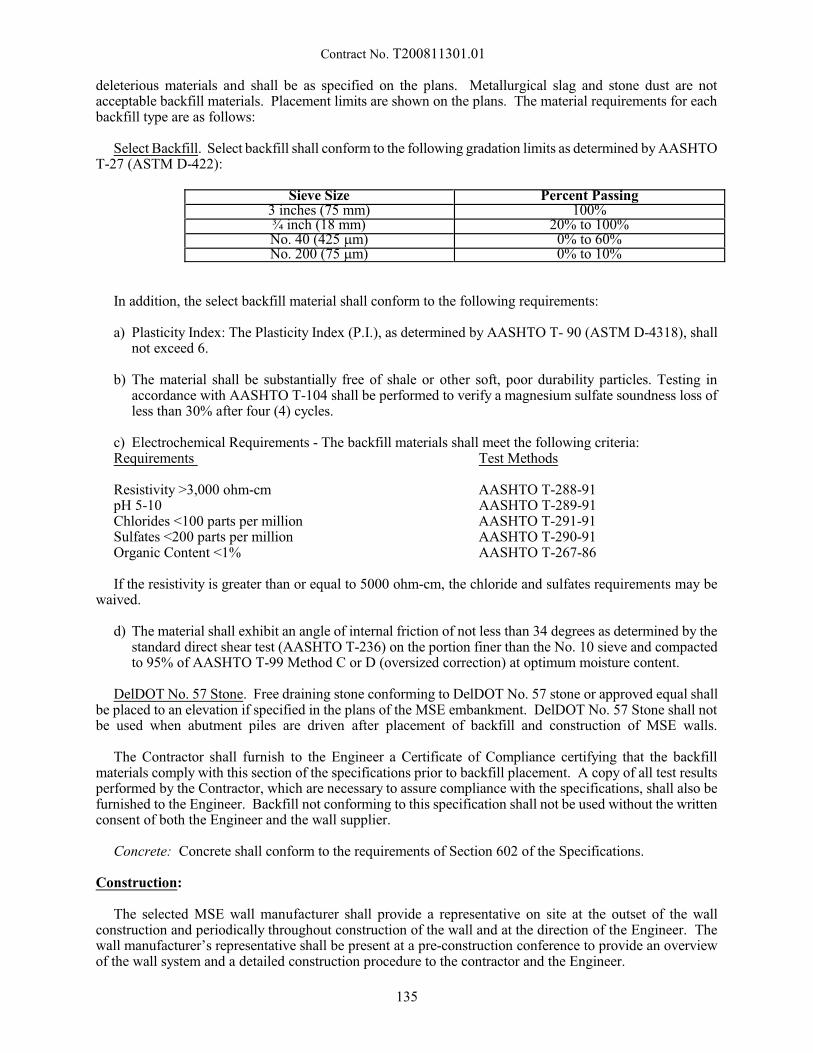
Contract No. T200811301.01
deleterious materials and shall be as specified on the plans. Metallurgical slag and stone dust are notacceptable backfill materials. Placement limits are shown on the plans. The material requirements for eachbackfill type are as follows:
Select Backfill. Select backfill shall conform to the following gradation limits as determined by AASHTOT-27 (ASTM D-422):
Sieve Size Percent Passing3 inches (75 mm) 100%¾ inch (18 mm) 20% to 100%No. 40 (425 mm) 0% to 60%No. 200 (75 mm) 0% to 10%
In addition, the select backfill material shall conform to the following requirements:
a) Plasticity Index: The Plasticity Index (P.I.), as determined by AASHTO T- 90 (ASTM D-4318), shallnot exceed 6.
b) The material shall be substantially free of shale or other soft, poor durability particles. Testing inaccordance with AASHTO T-104 shall be performed to verify a magnesium sulfate soundness loss ofless than 30% after four (4) cycles.
c) Electrochemical Requirements - The backfill materials shall meet the following criteria:Requirements Test Methods
Resistivity >3,000 ohm-cm AASHTO T-288-91pH 5-10 AASHTO T-289-91Chlorides <100 parts per million AASHTO T-291-91Sulfates <200 parts per million AASHTO T-290-91Organic Content <1% AASHTO T-267-86
If the resistivity is greater than or equal to 5000 ohm-cm, the chloride and sulfates requirements may bewaived.
d) The material shall exhibit an angle of internal friction of not less than 34 degrees as determined by thestandard direct shear test (AASHTO T-236) on the portion finer than the No. 10 sieve and compactedto 95% of AASHTO T-99 Method C or D (oversized correction) at optimum moisture content.
DelDOT No. 57 Stone. Free draining stone conforming to DelDOT No. 57 stone or approved equal shallbe placed to an elevation if specified in the plans of the MSE embankment. DelDOT No. 57 Stone shall notbe used when abutment piles are driven after placement of backfill and construction of MSE walls.
The Contractor shall furnish to the Engineer a Certificate of Compliance certifying that the backfillmaterials comply with this section of the specifications prior to backfill placement. A copy of all test resultsperformed by the Contractor, which are necessary to assure compliance with the specifications, shall also befurnished to the Engineer. Backfill not conforming to this specification shall not be used without the writtenconsent of both the Engineer and the wall supplier.
Concrete: Concrete shall conform to the requirements of Section 602 of the Specifications.
Construction:
The selected MSE wall manufacturer shall provide a representative on site at the outset of the wallconstruction and periodically throughout construction of the wall and at the direction of the Engineer. Thewall manufacturer’s representative shall be present at a pre-construction conference to provide an overviewof the wall system and a detailed construction procedure to the contractor and the Engineer.
135
Contract No. T200811301.01
Wall Excavation. Excavation shall be in accordance with the requirements of the DelDOT specificationsand in reasonably close conformity with the limits shown on the Plans. Temporary excavation support asrequired shall be the responsibility of the Contractor. The base of the excavation shall be completed to within+/- 3 inches of the staked elevations unless otherwise directed by the Engineer.
Foundation Preparation. The foundation for the structure shall be graded level for a width 1 foot beyondthe length of the reinforcement elements or as shown on the Plans. Prior to wall construction, the foundationshall be test-rolled under the observation of the Engineer in accordance with Section 202.02. Any unsuitablefoundation material as determined by the Engineer shall be excavated to the determined depth and replacedwith Borrow Type B, conforming to Section 209, and shall be compacted in accordance with BackfillPlacement as described below.
At each panel foundation level, a precast reinforced or a cast-in-place unreinforced concrete leveling padof the type shown on the plans shall be provided.
Installation of Casing. Casing shall be placed at the ground surface after all excavation has taken placeand shall be long enough to extend through the MSE embankment fill plus 1-one additional foot. Casing shallbe centered at the location of each pile as shown in the plans. Casing shall be plumb in its final position. MSE reinforcing straps shall be adjusted to avoid conflicts with pile casing.
Wall Erection. The wall system components shall be constructed in accordance with the wall systemsupplier's recommendations and construction manual. The wall shall be constructed vertical and within thespecified tolerances. The overall vertical tolerance of the wall and the horizontal alignment tolerance shallnot exceed 3/4-inch per 10 feet. Bulging in the vertical or horizontal direction shall be limited to 2 inches asmeasured from the theoretical wall line. The Engineer shall be notified of any bulging areas that exceed thislimit.
Filter Fabric (Separation/Retention Fabric). Where a Filter Fabric (Separation/Retention Fabric) is shownon the plans to be placed along the MSE wall joints, the fabric shall extend a minimum twelve inches oneither side of the wall joint. Filter Fabric overlaps shall be a minimum of twelve inches and shall beoverlapped so that the fabric on top is pointing downward. An adhesive approved by the Engineer shall beused to fasten the fabric to the back of the wall and along all overlaps. In addition, a continuous layer of thefilter fabric shall be placed along the back of all MSE walls from the bottom of the footer to the top of thewall in a vertical orientation. Bury the bottom and top of the filter fabric a minimum of twelve inches intothe backfill behind the wall. Overlaps between adjacent vertical strips of the filter fabric shall be a minimumof twelve inches and along all overlaps an adhesive approved by the Engineer shall be used to fasten thefabric to the wall and the overlapping fabric to the underlying fabric. Slits in this filter fabric to attach thereinforcing strips shall be minimal and adhesive shall be used to secure the slit fabric to the back of the wall.
Backfill Placement. Backfill placement shall closely follow erection of each course of concrete facingunits. Backfill shall be placed in such a manner as to avoid any damage or disturbance to the wall materialsor misalignment of the facing. Any wall materials that become damaged or disturbed during backfillplacement shall be removed and replaced at the Contractor's expense or corrected as directed by the Engineer.The Engineer will be the sole authority as to the acceptability of any repairs to damaged wall materials. Anymisalignment or distortion of the wall elements due to placement of backfill outside the limits of thisspecification shall be corrected as directed by the Engineer.
Backfill within the zone of soil reinforcements shall be compacted to 95% of the laboratory determinedmaximum dry density and optimum moisture content, as determined by AASHTO T 99, by at least four (4)passes of a heavy roller having a minimum dynamic force of 20 tons impact per vibration and a minimumfrequency of 16 hertz.
The moisture content of the backfill material prior to and during compaction shall be uniformly distributedthroughout each layer. The water content of the wall backfill shall not deviate from the optimum watercontent by more than 2%. Backfill material with a placement moisture content in excess of the optimummoisture content shall be removed and reworked until the moisture content is uniformly acceptablethroughout the entire lift.
136
Contract No. T200811301.01
The maximum lift thickness after compaction shall not exceed 8 inches regardless of the vertical spacingbetween layers of soil reinforcements. The Contractor shall decrease this lift thickness as required to obtainthe specified density.
Prior to placement of the soil reinforcements, the backfill elevation after compaction within the zone ofsoil reinforcements shall be 2 inches above the connection elevation from a point approximately 24 inchesbehind the facing to the free end of the soil reinforcements unless otherwise shown on the Plans.
Compaction within 3 feet of the facing shall be achieved by at least three (3) passes of a lightweightmechanical tamper, roller or vibratory system. Care shall be exercised in the compaction process to avoidmisalignment of the facing. Heavy compaction equipment shall not be used to compact backfill within 3 feetof the wall face. At the end of each day's operation, the Contractor shall slope the last level of backfill awayfrom the wall facing to direct runoff of rainwater away from the wall face. In addition, the Contractor shallnot allow surface runoff from adjacent areas to enter the wall construction site.
Leveling Pad. The concrete leveling pad at the concrete facing shall be unreinforced and constructed tothe elevation and width shown on the Plans. The leveling pad shall be constructed on compacted, drainedsubgrade. Leveling pad shall be embedded a minimum of 36” from finish grade to the bottom of the levelingpad.
Utilities. The contractor shall accommodate the passage of utilities, including drainage inlets and pipes,through the reinforced embankment material or MSE wall if shown on the plans. The soil reinforcementsshall be placed to permit the installation and operation of, and access to, the utilities constructed within theembankment while satisfying the design requirements of the MSE wall. The MSE wall manufacturer shallprovide a construction sequence for installation of utilities within the reinforced embankment which does notjeopardize the integrity and stability of the reinforced soil mass.
Obstructions in the Reinforced Soil Zone. Where settlement platforms, foundation elements, etc., interferewith the soil reinforcement, specific methods for field installation must be developed and presented on theshop drawings. The design of the MSE Wall near the obstruction shall be modified using one of thefollowing alternatives:
1. Design reinforcing layers to carry additional loads that would have been carried by reinforcing layersthat were partially or fully severed in order to install the obstruction.
2. Place a structural frame around the obstruction capable of carrying the load from the reinforcement infront of the obstruction to reinforcement connected to the structural frame behind the obstruction.
3. If discrete strips are used splay the reinforcement around the obstruction.
Moment Slab and Barrier. The moment slab and barrier shall be constructed according to the detailsshown on the plans.
Toe protection. The toe of the wall shall be embedded in accordance with the Plans and shall be protectedas required for the life of the structure to avoid undermining the wall face.
Method of Measurement:
The quantity of Mechanically Stabilized Earth Walls will not be measured.
Basis of Payment:
The payment will be full compensation for all components of the MSE Wall, leveling pad and coping andshall include full compensation for designing, development of shop drawings, fabricating, furnishing,excavating, backfilling, furnishing backfill material, pile casing, casing backfill, installing, testing and for allmaterials, labor, tools, equipment, and incidentals necessary to complete the installation in conformance withthe plans and Specifications.
137
Contract No. T200811301.01
Excavation of unsuitable material, below the bottom of the leveling pad, will be measured and paid foras described under Standard Specification 207.07, Table 207-A and backfilling with Borrow Type B will bemeasured and paid for under Item 209002. The concrete and reinforcement for the moment slab and barrierwill be measured separately and will be paid for as a separate item(s) as indicated in the plans.
NOTE:
When more than one MSE Wall is required at a location, the Contractor shall submit a cost breakdownof his Lump Sum price bid for this item showing the dollar value amount for each MSE Wall, the sum ofwhich is to equal the lump sum price bid. The required breakdown of the Lump Sum price is shown on abreakout sheet attached to the proposal.
The Department reserves the right to delete from the Contract the furnishing and installing of one or moreof the MSE walls listed. The lump sum to be paid will be adjusted in accordance with the Contractor's unitprices as required above. In the event that an increase or decrease in the area of the wall elevation is required,the increase or decrease in the lump sum bid shall equal the increased or decreased area multiplied by thelump sum price divided by the original elevation area. The “original elevation area” shall include the below-grade area of the concrete fascia but does not include the concrete footer. There will be no extra compensationto the Contractor if such additions and/or deletions are made beyond this adjustment.
7/21/15
138

Contract No. T200811301.01
605755 - OVERHEAD SIGN SUPPORT AND FOUNDATIONS
Description:
This work consists of furnishing all materials, fabricating and installing four-chord truss type overheadsign support structures including foundations as specified in the Contract Documents, in accordance with thelocations and details shown on the Plans and as directed by the Engineer.
General
The main support and truss members of the sign support structures shall be fabricated from tubular steelwhose diameters, wall thicknesses and lengths shall conform with the requirements and details shown on theContract Plans, or as shown on approved alternate design drawings.
Alternate designs utilizing structural shapes for the main support and truss members, which form astructure of sufficient strength as required by AASHTO standard and Plans will also be considered forapproval when submitted in accordance with the provisions of these specifications. All submissions forapproval including material specifications and alternate designs must be signed by a registered ProfessionalEngineer registered in the State of Delaware. Any alternate designs may be rejected by the Engineer for anyreason, including reasons not related to structural equivalency. Additionally, the following conditions andrequirements must be met:
- VMS shall not be permitted on cantilever structures;- The use of aluminum in these structures shall not be permitted; and- Square members shall not be used in main supports or trusses.
The Contractor is informed that consideration will be given to aesthetics for all of the sign supportsincluding, but not limited to, the general appearance, methods of fabrication and assembly, material selection,arrangement, end finishes of the proposed structural shapes, welding, and surface finishes as required. Thespan type structure shall be 4-chord structure.
If the bidder elects to furnish sign supports alternate to those shown in the Contract Plans, the alternatedesign shall meet the requirements of the approved drawings and any other requirements specified on thePlans and these specifications.
If the bidder elects to furnish sign supports alternate to those shown in the Contract Plans, it is arequirement that as an end result, the alternate will satisfy the requirements of the proposal.
Sign panels are not included under this item.
Materials:
Structural
Main Tubes: ASTM A 53, Grade B, Type E or S or API 5L, PSL2, Grade BMinimum Yield Stress = 35,000 psi
Other Tubes: ASTM A 501Minimum Yield Stress = 36,000 psi
Structural Shapes, Plates and Bars: ASTM A 709, Grade 36Minimum Yield Stress = 36,000 psi
139
Contract No. T200811301.01
Fasteners
Anchor Bolts: ASTM F 1554, Grade 55Anchor Nuts: ASTM A 563, Grade DH or ASTM A 194, Grade 2HAnchor Washers: ASTM F 436
Connection Bolts: ASTM A 325
Heavy Hex Nuts: ASTM A 563, Grade DH or ASTM A 194, Grade 2HWashers: ASTM F 436
Finish
Structural: Galvanized finish ASTM A 123
Fasteners and anchor bolts: Galvanized finish ASTM A 153
Galvanizing shall comply with ASTM A 143 and A 385
Foundations
Undercut Excavation: Section 212.
Borrow, Types B & F: Section 209.04.
Geotextile: Sections 713 and 827.06.
Reinforcement: Section 603.
Concrete: Class B per Sections 602 and 812.
Construction Methods:
Shop Drawings
Shop drawings shall be submitted in accordance with Subsection 105.04 of the Standard Specifications. Minor variations in details may be permitted; however, any major departure from the design will not beaccepted.
The Contractor may at his/her option elect to prepare alternate design plans and specifications for the boxtruss type overhead sign support structures in place of the Plan construction. Detail plans, designcomputations, and specifications for the proposed structures shall be submitted to the Engineer for approval;and no work shall begin until the alternate design plans have been reviewed and approved, in principle, bythe Engineer. No additional time will be added to the contract duration for the approval process of thealternate design.
The requirements for the preparation of shop drawings for an approved alternate design (or designs), shallbe similar to those specified for the Plan construction.
Prior to any fabrication, the Contractor shall stake out the proposed sign structure locations at thecenterline of the proposed foundation. The stake out information shall contain, but not be limited to, theexisting and finished ground elevation at the centerline of the foundation and highest point of the traveledroadway and the shoulder elevation for the finished condition directly under the overhead portion of theproposed sign structure. This information, along with the proposed top of concrete pedestal elevation, shallbe shown on the shop drawings.
140
Contract No. T200811301.01
Fabrication
Loading, transporting, unloading and erection of structural materials shall be done so that the metal willbe kept clean and free from injury in handling.
Structural materials shall be stored above the ground upon platforms, skids, or other supports and shallbe kept free form accumulation of dirt, oil, acids or other foreign matter.
Structural material which has been deformed shall be straightened before being laid out, punched, drilledor otherwise worked upon in the shop. Sharp kinks or bends will be cause for rejection.
When sign support structures are subcontracted, the subcontract shall be in accordance with Subsection108.01 of the Standard Specifications except that the value of the subcontract will be based on the value ofthe work for fabrication.
Cutting, Punching, Drilling and Finishing
Material ½” (12 mm) thick or less may be sheared, sawed or cut with a router, unless noted otherwise onthe Plans. Material more than ½” (12 mm) thick shall be sawed or routed.
Cut edges shall be true and smooth and free from excessive burrs or ragged breaks.
Edges of plates carrying calculated stresses shall be planed to a depth of ¼” (6 mm) except in the case ofsawed or routed edges of a quality equivalent to a planed edge.
Re-entrant cuts shall be avoided wherever possible. If used, they shall be filleted by drilling prior tocutting.
Structural material shall not be heated except to facilitate bending; then the structural material may beheated to a temperature not exceeding 400° F (204° C) for a period not exceeding 30 minutes. Such heatingshall be done only when temperature and time requirements are observed.
Bolt holes in main members shall be subpunched or subdrilled and reamed to finished size after the partsare firmly bolted together. The amount by which the diameter of subpunched holes is less than that of thefinished hole shall be at least 1/4 the thickness of the piece and in no case less than 1/32” (0.8 mm). If themetal thickness is greater than the diameter of the hole, punching shall not be used.
Bolt holes in secondary material not carrying calculated stress may be punched or drilled to finished sizebefore assembly.
All holes shall be cylindrical and perpendicular to the principal surface. Holes shall not be drilled in sucha manner as to distort the metal. All chips lodged between contacting surfaces shall be removed beforeassembly.
All assemblies and tubular members shall be detailed to permit hot dip galvanizing. All cutting, punching,drilling, finishing, and welding shall be complete prior to hot dip galvanizing.
End Post Assemblies
End post assemblies shall be of galvanized steel. After fabrication the steel end post assemblies shall behot-dip galvanized in accordance with AASHTO M111. The average thickness of coating (each side) shallbe at least 5 mils (125 µm), but in no case less than 4 mils (100 µm) thickness at any location. Inspection ofcoating will be by magnetic thickness gauge measurements as specified in AASHTO M111 paragraph 9.3,except that 25 percent of the horizontal and diagonal struts will be measured, and the posts will be measuredat the fifth points of the length at three locations around the circumference. The average thickness will bearrived at by the fifth points of the length at three locations around the circumference. The average thicknesswill be arrived at by the summation of all readings.
141
Contract No. T200811301.01
Truss Spans
Truss spans shall be galvanized steel. Galvanizing shall be as specified above for end post assemblies.Galvanizing of each truss unit shall be by a single dip process. Magnetic thickness gauge measurements shallbe made on each chord of each truss unit at approximately the third points of the chord length at threelocations around the circumferences. Prior to shipping, the completed and accepted truss units shall beassembled in the shop and the truss span checked for dimensions, straightness, alignment and camber.
Welding
Welding shall be done in the shop before galvanizing. All welding work shall be done in accordance withthe requirements of AASHTO/AWS D1.5M/D1.5:2008 Bridge Welding Code, and shall be inspected atContractor's expense. Welding not covered in the above shall conform to AWS D1.1:2008 Structural WeldingCode. The inspection results shall be submitted to the Engineer for approval.
Repair Galvanizing
Galvanized areas damaged during shipping or erection shall be repaired by any of the three methodsspecified under ASTM A780. In all cases, the repair shall achieve the minimum coating thickness specified.However, the repair of galvanized items having one or more damaged areas larger than 1 square inch (650square millimeters) will not be allowed.
All threading and dimensional requirements shall be in accordance with the "Fastener Standards";published by the Industrial Fasteners Institute. All threads shall be UNC-2 and, where hot-dip galvanized,internal threads shall be oversized as specified in AASHTO M 291 to provide for proper assembly.
Erection
Material shall not be dropped, thrown or dragged over the ground. The Contractor shall supply detailed,written instructions and drawings for the erection of all sign structure components.
End posts shall be erected in position to engage the leveling nuts on the anchor bolts above the top of theconcrete pedestal or barrier. During the erection of the sign structure, adjustments for plumbness, grades andalignment shall be made by manipulation of the leveling nuts on the anchor bolts.
The installation and tightening of the anchor bolts shall be performed in strict conformance with thesequence outlined in Appendix A, Part 1 and 2, Section 5.2 of the National Cooperative Highway ResearchProgram (NCHRP) Report 469 – Fatigue Resistance Design of Cantilevered Signal, Sign and Light Supports.
Before final acceptance, all metal surfaces shall be cleaned free of oil, grease, soil or other discoloration. Cleaning shall be done with suitable solvents or by other approved means, and shall be to the satisfaction ofthe Engineer. If cleaning is necessary after erection over roadways in use, approved suitable means shall beprovided for the protection of traffic during cleaning operation.
Foundations
General
Prior to excavation for the overhead sign structures foundations, the contactor shall obtain the Engineer’sapproval regarding their location. End posts shall not be erected upon the completed footing until authorized,but the minimum time allowed for the hardening of the concrete before any load is placed thereon shall be7 calendar days. The truss span and sign panels shall not be erected upon the end posts until the concrete forthe foundation and pedestal has achieved the minimum concrete strength specified. Anchor bolts shall beset to template for alignment and elevation and shall be secured in position to prevent displacement whileconcrete is being placed. The steel reinforcement and conduit elbows shall have been placed and securedbefore the placing of concrete.
142
Contract No. T200811301.01
The top surface of the concrete pedestal shall be leveled off at a distance below the bottom of the baseplate so as to provide room for the lower leveling nuts and washers as shown on the Plans. The distancebetween the bottom of the leveling nuts and the top of the concrete pedestal shall not exceed one boltdiameter. The top surface of the concrete pedestal shall be edged and have a broom finish.
The following construction tolerances shall be maintained in constructing drilled shafts.
1. The top elevation of the concrete pedestal shall be within 1-inch of the top of pedestal elevation shownon the Plans.
2. The reinforcing steel shall be placed so that the outer edges of the reinforcing cage are located so asto provide the clear dimension shown on the Plans.
Shop Drawings
Shop drawings shall be submitted in accordance with subsection 105.04 of the Standard Specifications. Shop drawings shall be submitted for the formwork and the reinforcement steel associated with the concretefoundations.
The shop drawings shall show the proposed top of pedestal elevation for each sign structure, taking intoconsideration the stake out survey information required for the fabrication of the sign structure.
Formwork
All formwork shall conform to the requirements of Section 602 of the Standard Specifications.
Spread Footing Foundations
Excavation & Backfill
Excavation: Section 202.03.
Undercut Excavation: Section 212.
Backfill: Backfilling around and over structures shall be performed with material conforming to therequirements of Section 209.04, Borrow Type F. Backfill in accordance with Section207.05.
Borrow: Section 209.05.
Geotextile: Sections 713 and 827.06.
Concrete Placement, Curing, and Protection
All concrete placement, consolidation and curing activities shall conform to the recommendations ofSection 602 and 812, of the Standard Specifications, except as otherwise specified herein.
Reinforcing Steel Placement
All reinforcing steel shall be placed in conformance with the requirements of Section 603 of the StandardSpecifications.
Basis of Payment:
The quantity of four-chord truss sign supports and foundations will be paid for at the Contract lump sumprice. Price and payment will constitute full compensation for furnishing all materials, fabricating anderecting the structure(s) at designated location(s), including excavation in accordance with Section 207,
143
Contract No. T200811301.01
geotextile, concrete and reinforcing bars, construction spread footing foundations, backfilling andcompaction, grading, for all labor, equipment, tools, and all incidentals necessary to complete the work.
NOTE:
When more than one structure is required, the Contractor shall submit a cost breakdown of his Lump Sumprice bid for this item showing the dollar value amount for each type of overhead sign support structure andconcrete footings, the sum of which to equal the lump sum price bid. The breakout sheet attached to theproposal shows all items proposed for this item. The complete breakout sheet shall be attached to the BidProposal. Failure to submit the breakout sheet with the Bid Proposal will result in the Bid Proposal beingdeclared non-responsive and rejected.
The Department reserves the right to delete from the Contract, construction of one or more individual signstructure(s), and the lump sum price to be paid will be reduced in accordance with the Contractor's itemizedbid price list for that individual sign structure. There shall be no extra compensation to the Contractor if suchdeletion is made.
11/23/11
144
Contract No. T200811301.01
612501 - PVC PIPE, 4"612502 - PVC PIPE, 6"612503 - PVC PIPE, 8"
612504 - PVC PIPE, 10"612505 - PVC PIPE, 12"612506 - PVC PIPE, 15"612507 - PVC PIPE, 18"612518 - PVC PIPE, 21"
Description:
This work consists of furnishing and installing PVC pipe, including all fittings, in accordance with thelocations, details, notes on the Plans and as directed by the Engineer. The PVC pipe shall be used forsubsurface drainage or for serving as conduit as specified on the Contract Plans.
Materials and Construction Methods:
The PVC pipe and fittings shall be free from defects and shall conform to the applicable requirements ofASTM D3034 Type PSM, and pipe shall be of SDR-35 or SDR-41 or SDR-42 for subsurface drainage pipeof the nominal size required by the Plans.
The PVC pipe and fittings shall be free from defects and shall conform to the applicable requirements ofASTM D2466 PVC Pipe Fitting, Schedule 40 for conduit of the size required by the Plans.
The excavation and backfill for the pipe shall be performed in accordance with the applicable requirementsof Section 612 of the Standard Specifications, unless otherwise modified on the Plans. The pipe shall beinstalled at the locations and to the lines, grades, and dimensions shown on the Plans or as directed by theEngineer.
Method of Measurement:
The quantity of PVC pipe will be measured as the actual number of linear feet of each size of pipe placedand accepted, measured from end to end of pipe, including structure wall thickness, but excluding structureinterior.
Basis of Payment:
The quantity of PVC pipe will be paid for at the Contract unit price per linear foot for each size of pipe. Price and payment will constitute full compensation for furnishing, hauling, and installing pipe, for allcribbing or foundation treatment necessary to prevent settlement, for all shoring and sheeting, for thereplacement of any pipe which is not true in alignment or which shows any settlement after laying, and forall material, labor, equipment, tools, and incidentals required to complete the work.
For pipe under 24" nominal inside diameter, the excavation, bedding, backfill and backfilling will beincluded in the price for this work. For pipe of nominal inside diameter 24", payment for excavation,bedding, backfill and backfilling will be in accordance with Section 208.
11/4/15
145
Contract No. T200811301.01
612520 - CORRUGATED POLYETHYLENE PIPE, TYPE S, 15"612522 - CORRUGATED POLYETHYLENE PIPE, TYPE S, 12"612523 - CORRUGATED POLYETHYLENE PIPE, TYPE S, 18"612524 - CORRUGATED POLYETHYLENE PIPE, TYPE S, 24"612525 - CORRUGATED POLYETHYLENE PIPE, TYPE S, 30"612526 - CORRUGATED POLYETHYLENE PIPE, TYPE S, 36"
612530 - CORRUGATED POLYETHYLENE PIPE, TYPE S OR D, 42"612531 - CORRUGATED POLYETHYLENE PIPE, TYPE S OR D, 48"
612534 - CORRUGATED POLYETHYLENE PIPE, TYPE S, 8"612544 - CORRUGATED POLYETHYLENE PIPE, TYPE S, 60"
Description:
This work consists of furnishing and installing corrugated polyethylene pipe with a smooth interior in areasonably close conformity with lines and grades indicated on the Plans, and as directed by the Engineer.
Materials:
Pipes, couplings and fittings shall be made of polyethylene compounds, and shall meet all applicablerequirements of AASHTO M294 current edition Type S or Type D for pipe sizes 12" and larger. Polyethylene pipes, couplings and fittings less than 12" in diameter shall meet the requirements of AASHTOM252 current edition. The pipes and fittings shall be free of foreign inclusions and visible defects and pipeshall be cut squarely and cleanly so as to not adversely affect joining or connecting. Visible defects such ascracks, creases, unpigmented or nonuniformly pigmented pipe are not permissible in the pipe as furnished.
Joints for all pipe and fittings shall use gasketed watertight bell/spigot or bell/bell couplers. The gasketsshall meet the requirements of ASTM F477 and the joint system shall be certified to meet a 10.8 psilaboratory test per ASTM D3212. In addition, the joint system shall provide sufficient longitudinal strengthto preserve pipe alignment and prevent separation at the joint.
The Contractor shall provide a manufacturer's certificate signed by the manufacturer's representativestating the product was manufactured, tested and supplied in accordance with all the applicable requirementsof AASHTO M-294 (or ASSHTO M252 as applicable), ASTM F477 and ASTM D3212. The manufacturershall verify compliance with AASHTO M294 through the National Transportation Product EvaluationProgram.
Construction Methods:
General. The pipe shall be installed per the notes and details shown on the plans and in accordance withthe requirements of ASTM D2321 or the manufactures published guidelines whichever is more stringent. Themanufactures representative must be present at the beginning of the installation unless the engineer isconfident in the contractors work. Having a representative on the site or not does not dismiss the contractor'sliability.
Excavation. The trench in which the pipe is laid shall be excavated in accordance with Section 208 andThe Standard Construction Details to the required depth. The width of the trench shall provide a minimumclearance of 18" between the trench wall and the O.D. of the pipe. If flowable fill is used, trench width shallprovide 6" between the trench wall and O.D. of the pipe. Floating of pipe must be controlled. Whenmultiple pipes are place side by side, a minimum of 18" shall be allowed between pipes or 6" if flowable fillis used. Minimum cover for pipe under pavement, including local roads, subdivision roads and non-residential driveways, shall be 1' measured from the top of pipe to bottom of pavement. The minimum coverfor pipe under the travel way of roads with higher classifications shall be 2' measured from the top of pipeto the bottom of pavement. Otherwise, the cover shall be 1' measured from the top of pipe to top of gradeunless otherwise recommended by the manufacturer to prevent pipe flotation.
146
Contract No. T200811301.01
Bedding of Pipe. Unless noted otherwise, all pipes shall be placed on Class C bedding as shown on TheStandard Construction Details. The outside thirds of the bedding material shall be compacted. The areasaround the joints shall be hand excavated to accommodate the bell when the outside diameter if the bell isgreater than the pipe.
Joints. The spigot of the pipe shall be fully inserted into the bell to ensure a tight joint.
Laying Pipe. All pipe shall be laid in an upgrade direction unless otherwise directed. The pipe shall belaid with the lowest point of the inside diameter conforming to the flow line shown on the Plans. All pipeshall be carefully laid with the bell ends upgrade, with the spigot ends fully entered into the adjoining bell,and true to the lines and grades shown on the Plans, or as directed. Any pipe which is not in true alignment,or which shows any settlement after laying, shall be taken up and re-laid. Unsuitable material encounteredbelow the flow line of the pipe shall be removed to a depth and replaced, as directed.
Backfill. Placement of backfill shall conform to Section 208 except as follows:
The initial backfill lift shall not exceed 12" of loose material or be higher than the spring line of the pipe.The material shall be sliced into the haunches of the pipe using a shovel. A maximum of 8" of loose materialshall be placed for each remaining lift. Caution shall be taken not to hit the pipe with any mechanicalcompaction equipment. Caution shall also be taken not to disturb the pipes alignment. Where heavyconstruction equipment is expected to travel over the shallow buried pipe the pipe shall be protected bytemporarily placing a cover of material as recommended by the manufacturer.
Video Inspection:
Video inspection will be performed by DelDOT. If deflection in the pipe is clearly visible it will beassumed to be more than 5% and will have to be corrected. If the contractor wishes to challenge this decisionthey may do so either by direct internal measurement or by the use of a go-no-go mandrel with a minimumof nine points.
Method of Measurement:
The quantity of polyethylene pipe will be measured as the actual number of linear feet of each type of pipeplaced and accepted, measured from end to end of pipe, including structure wall thickness, but excludingstructure interior.
Basis of Payment:
The quantity of polyethylene pipe will be paid for at the Contract unit price per linear foot for each typeof pipe. Price and payment will constitute full compensation for furnishing, hauling, and installing pipe; forexcavation and backfill, for furnishing and placing Type C Borrow, (#57 stone may be substituted underroadway), for all cribbing or foundation treatment (Class C bedding) necessary to prevent settlement; for allshoring and sheeting; for the replacement of any pipe which is not true in alignment or which shows anysettlement after laying; for verifying and correcting deflection, for protection of shallow buried pipe and forall material, labor, equipment, tools, and incidentals required to complete the work. Payment for excavationand replacement of unsuitable material encountered below the Class C bedding will be provided for underSection 208.
For round pipe under 24" nominal inside diameter, the excavation (excluding rock), backfill, andbackfilling will be included in the price for this work. For pipe of nominal inside diameter or horizontaldimension of 24" and over, payment for excavation and backfill will be in accordance with Section 208.Furnishing of Borrow Type C for pipe of nominal inside diameter or horizontal dimension of 24" and over,will be paid for under Section 210. Payment for excavation and replacement of unsuitable materialencountered below the flow line of pipe will be provided for under Section 208.
3/20/15
147
Contract No. T200811301.01
612535 - CLEANING DRAINAGE PIPE, 15" - 24" DIA.612536 - CLEANING DRAINAGE PIPE, GREATER THAN 24" DIA.
Description:
This work consists of cleaning existing drainage pipe. It is the intent that equipment and cleaning methodsused to perform this work conform to Specification Guidelines prepared by the National Association of SewerService Companies (NASSCO) hereinafter referred to as the NASSCO Specifications.
Materials and Construction Methods:
Water used for cleaning shall be safe for all downstream environments. The source for the cleaning watershall be approved by the Engineer.
Equipment and construction methods shall be in accordance with the requirements under Sewer LineCleaning, High-Velocity Jet (Hydrocleaning) found in the NASSCO Specifications. Equipment shall beoperated in accordance with the manufacturer's instructions. The cleaning operation shall consist of up tothree passes of the hydrocleaning equipment. If three passes do not adequately clean the pipe, the Engineermay direct the Contractor to use other procedures covered by other item(s) of work.
Material removed during the pipe cleaning operation shall be disposed by the Contractor at a site approvedby the Engineer.
Method of Measurement:
The quantity of drainage pipe cleaned will be measured as the actual number of linear feet of pipe cleanedand accepted measured from end to end.
Basis of Payment:
The quantity of pipe cleaned will be paid for at the Contract unit price per linear foot. Price and paymentwill constitute full compensation for furnishing equipment and water, disposing of removed material and forall labor, equipment, tools and incidentals to complete the work.
11/4/15
148
Contract No. T200811301.01
617519 – CONCRETE END SECTION, 24", MARYLAND
617520 – CONCRETE END SECTION, 19” X 30”, MARYLAND617521 – CONCRETE END SECTION, 22” x 34”, MARYLAND
Description:
This work consists of furnishing, fabricating, and constructing concrete end sections of the type specifiedin accordance with the details and locations shown on the Plans and as directed by the Engineer, at locationsin Maryland. This work shall also consist of applying integral color admixture to the concrete mixture fordrainage structures as specified in the contract documents. A sandblast finish shall be applied to thecompleted, colored drainage structures.
Materials and Construction Methods:
Materials and construction methods shall conform to the applicable requirements of Section 617 of theStandard Specifications, and notes and details on the Plan.
Integral Concrete Color Pigment Admixture. The admixture shall be a colored, water reducing, admixturecontaining no calcium chloride with coloring agents that are lime proof and UV resistant. The admixtureshall conform to C979, C494 and M194.
The color shall meet Federal Standard 595B. The manufacturer shall choose from the following colors: 30277, 30145, and 30219. The same color shall be used throughout the project. It may be necessary to usewhite portland cement to achieve the color. Compromising the color will not be acceptable in order to avoidusing white cement. The pigment admixture shall be added to the concrete as specified by the manufacturer. Care should be taken to ensure uniform coloration throughout the structure.
Sandblasted Finish. All colored drainage structures shall be textured with a sandblast finish. Allowconcrete to cure to sufficient strength so that is will not be damaged by blasting but not less than seven days. The finish shall be Class 1 (Brush) involving a one pass brush blast which will remove the cement matrix andexpose the fine aggregates only. No part of the coarse aggregates shall be exposed.
The Contractor shall be responsible for meeting all local air pollution regulations. The contractor shallensure the safety of the workers, ensuring that each blaster is equipped with an air-fed helmet.
The Sandblast contractor shall be responsible for clean-up of immediately adjacent areas to the sand-blasting operation.
Sample Panel. Whenever the contract documents specify that drainage structures be cast with integralconcrete color pigment admixture, prior to casting the structures a 2 ft. by 2 ft. by 4 in. sample panel shall becast, sandblasted and made available to the Engineer at the construction site for color and finish approval. All subsequent structures requiring integral color shall match the sample panel. The sample shall remain atthe construction site to be used by the Engineer as a basis for comparison for the structures.
Method of Measurement:
The quantity of concrete end sections will be measured as the number of concrete end sections furnishedof each type, installed and accepted in Maryland, in accordance with the Plans.
Integral colored concrete will not be measured but will be incidental to the contract item Concrete EndSection, Maryland. Integral colored concrete will include pigment admixture, sandblast finish, clean-up andall material, labor, equipment, tools and incidentals necessary to complete the work.
149

Contract No. T200811301.01
Basis of Payment:
The quantity of concrete end sections will be paid for at the contract unit price for each concrete endsection furnished, installed and accepted in Maryland. Price and payment will constitute full compensationfor furnishing, hauling, and installing materials, including bar reinforcement; for excavating, backfilling, andcompacting; for cribbing, shoring, sheeting, coating, and paving; and for all labor, equipment, tools, andincidentals required to complete the work.
11/23/11
150
Contract No. T200811301.01
618552 – FURNISH PIPE PILE, SCHEDULE 40, OPEN END, 14”
618557 – FURNISH TEST PIPE PILE, SCHEDULE 40, OPEN END, 14”
Description:
This work consists of furnishing steel pipe piles and test piles.
Materials:
In accordance with Sections 618.15 and 618.21 of the Standard Specifications and as follows.
Steel Pipe Piles and Splice Back-up Plate: ASTM A 252, Grade 2
The pipe piles shall have a minimum wall thickness of 0.5 inch.
Concrete: Portland Cement Concrete shall be 4500 psi minimum and shall conform to the materialrequirements of Class A, Section 812, Portland Cement Concrete of the Standard Specifications.
Bar Reinforcements: Bar reinforcements shall be epoxy coated and meet the requirements of ASTM A 615,Grade 60 and conform to Subsection 604.02 of the Standard Specifications.
Construction Methods:
Installation of piles shall conform to the requirements of Install Pipe Pile, Schedule 40, Open End, 14”,Item 619540.
Method of Measurement:
In accordance with Sections 618.22 of the Standard Specifications.
Basis of Payment:
In accordance with Sections 618.23 of the Standard Specifications.
11/23/11
151
Contract No. T200811301.01
619501 - PRODUCTION PILE RESTRIKE
619502 - TEST PILE RESTRIKE
Description:
Under certain pile driving conditions it may become necessary to restrike various production piles and testpiles, of the sizes and type called for by the Contract, in order to verify the pile capacities. Some of the piledriving conditions that could result in the need for pile restrikes include; bearing capacities are not achievedby the initial driving, Contract Plans for driving based on tip elevation (bearing achieved by freeze), anddynamic analysis procedures require extended waiting times for restrike.
Note: These Special Provisions replace Subsection 619.14 of the Standard Specifications.
Procedure:
All test piles shall be restruck and dynamically tested by the Contractor. The Engineer may direct theContractor to restrike selected production piles to verify capacities.
The Engineer will attempt to schedule the pile restrike so as to cause minimal, if any, delay to the overalldriving operation.
Prior to restrike, the Contractor shall mark the pile in 1-inch increments for the first 1-foot and 1-footincrements thereafter. The piles restrikes shall be in accordance with the plans.
All restrikes shall be performed using the same pile hammer, helmet, and cushion material used to installthe piles during initial driving. The pile hammer shall be fully warmed up and operated at full stroke, or asotherwise specified by the Engineer, during the pile restrike. The warm-up procedure shall consist of aminimum of 25 blows of the hammer at full stroke at locations other than the piles to be restruck.
The elevation of the top of the pile shall be established prior to performing the restrike.
The hammer shall be carefully lowered and positioned on the pile. The hammer shall restrike the pile 20blows at the required stroke height.
The hammer shall be removed from the pile, and the new top of the pile elevation shall be established.
If for any reason, the pile hammer malfunctions, the helmet fails, the cushioning materials fail, or any othercomponent of the pile driving system does not function properly during the pile restrike, the Contractor shallwait up to two (2) calendar days and perform additional restrikes at no additional cost to the Engineer or TheDepartment until the pile driving system operates properly through a complete continuous restrike procedure.
Method of Measurement/Basis of Payment:
Production Pile Restrike:
This item shall be measured and paid for on a per each basis and payment will constitute full compensationfor performing restrikes of selected production piles. The Engineer will work jointly with the Contractor toestablish a sequencing of production pile restrikes to minimize impact to the Contractor's driving schedule. Any perceived mobilization costs, set-up costs, delay costs, etc. anticipated by the Contractor shall beincidental to the price for this item.
Payment for "Production Pile Restrikes" shall be made at the fixed price of $500.00 Each if it is requestedby the Department within five (5) working days of the completion of the initial driving of the pile to berestruck. Payment for “Production Pile Restrikes” with requested restrike wait time exceeding five (5)working days will be made at the fixed price of $500.00 Each for each working day exceeded, starting on the
152
Contract No. T200811301.01
sixth day, in addition to the fixed price of $500.00 Each. An example of this case would be, if the Engineerdirects a production pile restrike to be performed six (6) working days following the completion of the initialdriving, two (2) unit will be paid. Similarly, if the restrike is ordered to be performed eight (8) working daysfollowing the completion of the initial driving, four (4) units will be paid. No payment will be made foradditional days if the Contractor elects to wait longer to perform the restrike than the time frame as directedby the Engineer. Any overlapping days due to multiple production piles will be paid for only one day.
Test Pile Restrike:
This item will be measured on an Each Day basis. Test pile restrikes will not be paid for under this itemunless the restrike waiting time is greater than five (5) working days following the completion of the initialdriving. All test pile restrikes requested by the Department within the first five (5) working days followingthe completion of the initial driving shall be incidental to the installation of the test pile. An example of thiscase would be, if the Engineer directs a test pile restrike to be performed six (6) working days following thecompletion of the initial driving, one (1) unit will be paid. Similarly, if the restrike is ordered to be performedeight (8) working days following the completion of the initial driving, three (3) units will be paid. Nopayment will be made for additional days if the Contractor elects to wait longer to perform the restrike thanthe time frame as directed by the Engineer.
Payment for "Test Pile Restrike" on test piles with requested restrike wait time exceeding five (5) workingdays will be made at the fixed price of $1,000.00 per Each Day. Any overlapping days due to multiple testpiles will be paid for only one day.
Price and payment will constitute full compensation for all equipment, labor and materials necessary toperform a Test Pile Restrike as described above. Also included in the payment is the cost of any idleequipment, labor, etc. during the prescribed waiting period between initial driving and performance of therestrike.
11/23/11
153
Contract No. T200811301.01
619519 –DYNAMIC PILE TESTING BY CONTRACTOR
619539 – SIGNAL MATCHING ANALYSIS BY CONTRACTOR
Description:
This item shall consist of furnishing all materials, equipment, access, reporting of results, and qualifiedpersonnel necessary to perform all wave equation analysis, high-strain dynamic testing and signal matching,and monitoring of driven piles at the locations designated on the Plans or as directed by the Engineer. Thework shall also include analysis and report preparation in accordance with this Special Provision.
High-strain dynamic testing and signal matching shall be performed on all test piles for the entire durationof the test pile installation, re-strikes, and as indicated in the Plans.
The Contractor shall notify the Engineer of the proposed pile driving schedule at least two working daysprior to driving piles at any location where high-strain dynamic testing will be conducted.
Submittals:
The Contractor shall engage the services of a specialty subcontractor, the Dynamic Testing Consultant(DTC), experienced in high-strain dynamic monitoring of driven piles to perform dynamic testing and signalmatching analysis and to evaluate and report results to the Department. The Dynamic Testing Consultantshall have at least five (5) years of documented experience in the performance and interpretation of dynamicpile testing, including dynamic pile testing on open ended pipe piles. The Dynamic Testing Consultant’s fieldengineer or technician, who will be operating the instrumentation and collecting the data, shall havedocumented experience on at least ten (10) prior projects with similar pile requirements, including pipe piles. All projects submitted as evidence of experience shall include the client and owner, points of contact, and adescription of the pile type. The field engineer or technician responsible for operating the instrumentationshall be fully capable of understanding and interpreting the data being collected during driving. The DynamicTesting Consultant shall be selected by the Contractor and submitted at the pre-construction meeting forapproval by the Department.
a. Qualifying Experience
The Contractor shall submit proof of three or more projects of similar size and complexity where the DTCand personnel assigned to this project have successfully performed similar services and analyses withinthe last three years. The Contractor shall present the following information for each project listed as areference at or prior to any preconstruction meetings:
1. Project Name, Location, Project Description, and Completion Date.
2. Surface and Subsurface Conditions.
3. Type and number of instruments installed.
4. Installation equipment and techniques utilized when applicable.
5. Provide names, current phone numbers, and current business addresses for the owner/designer,geotechnical consultant, and contract manager.
b. Wave Equation Analysis
The Contractor shall submit the completed Pile and Driving Equipment data form to the Department 30to 45-days before mobilization to the site. The wave equation analysis of the proposed driving systemshall be submitted to the Department at least 10-days prior to driving of the piles. The results of the waveequation analysis using the GRLWEAP program or other software approved by the Department shall be
154
Contract No. T200811301.01
submitted in a bound report for review and approval. The wave equation analysis shall be performed ateach test pile location and for each test pile type and driving equipment. Approval of the proposed drivingsystem by the Department will be based on DelDOT Standard Specifications for Road and BridgeConstruction, 2001, Section 619.09, Bearing Values.
c. Reports
The Dynamic Testing Consultant shall direct the progress of the testing work and shall obtain and recordthe test data. The Dynamic Testing Consultant shall prepare a daily field report summarizing the high-strain dynamic test results and pile driving data. At a minimum, the daily report shall include thecalculated driving stresses, transferred energy, and estimated pile capacity at the time of testing. Piledriving logs shall be included with the submittal. Variations from previous trends in the dynamic test datashall also be noted. Daily field reports shall be faxed or transmitted electronically to the Engineer within24-hours of the end of the shift.
The Dynamic Testing Consultant shall prepare a written report presenting the results of the pile programin accordance with the requirements of ASTM D4945 including specific discussion of the pile capacityobtained from the dynamic testing, the performance of the hammer and driving system, driving stresslevels, and pile integrity. The following data shall also be provided in the report for the full length ofdriving at intervals of not more than 10 hammer blows: bearing capacity from the Case Goble method,bearing capacity from at least one additional recognized method, input and reflection values of force andvelocity, maximum transferred energy, maximum compressive stress, maximum tensile stress, blows perminute, values of upward and downward traveling force wave, ram stroke, pile penetration depth andcorresponding blow sequence.
Signal matching analyses shall be performed for all initial drives and restrikes of dynamically tested piles. A minimum of one (1) signal matching analysis shall be performed for a representative blow near the endof each initial drive and a minimum of one (1) representative blows shall be analyzed towards thebeginning of the restrike.
Within three (3) working days of the completion of each dynamic test, the Contractor's specialtysubcontractor shall submit to the Department a report meeting the requirements of this Special Provisionthat is signed and sealed by a Professional Engineer licensed in the State of Delaware. In addition to theraw data and ASTM D4945 requirements, the report shall include detailed results of the signal matchinganalyses including, but not limited to, pile driving log, all extrema tables; pile profile and pile modeltables; simulated load test curves for the tip and top of the pile; the soil parameters used in the analysisby matching the measured and computed values of forces, velocities, and displacements; and staticresistance distribution along the length of the pile, in a format approved by the Department. TheContractor is to develop the driving criteria for the production piles based on the results of the high straindynamic testing with signal matching analysis. The Contractor shall submit the driving criteria for reviewand approval of the Engineer prior to installation of production piles. The driving criteria shall besummarized in the format provided by the Engineer after award of the contract.
All raw data and computer analyses shall be provided in electronic format to the Department for additionalanalysis.
Materials and Construction Methods:
All equipment, testing and reporting procedures shall be provided and performed in strict accordance withASTM D4945 - Standard Test Method for High-Strain Dynamic Testing of Piles.
The Contractor shall maintain a stock of at least four working accelerometers and strain transducers at thejob site whenever high-strain testing is being performed. All repair or replacement costs shall be performedat no additional cost to the Engineer or The Department. The Contractor shall provide the Engineer and TheDepartment reasonable inspection access along the full length and circumference of all piles prepared forinstrumentation attachment prior to the piles being lifted and located in the leads.
155
Contract No. T200811301.01
Dynamic monitoring instrumentation, including all gages and cables, shall not be installed on the pile untilthe pile has been lifted and aligned in the leads and the hammer and helmet have been properly set.
The Dynamic Testing Consultant shall perform dynamic testing during the entire initial drive and restrikeof all piles so designated on the Plans or as otherwise directed by the Engineer or The Department. Thedynamic testing firm shall continuously monitor the tensile and compressive stresses during driving to ensurethat the permissible stress limits provided by the Engineer are not exceeded during driving. Should thedriving operation result in stresses that approach or exceed the permissible limits, the dynamic testing firm'sequipment operator shall immediately have the hammer stroke reduced or the driving operation stopped inorder to prevent pile damage. If non-axial driving is indicated by dynamic test measurements, pile drivingshall be stopped immediately and the Contractor shall realign the driving system or take other correctiveaction, as necessary, before resuming driving.
If the top of pile is damaged or becomes deformed at any time during the dynamic testing of the piles, piledriving shall be stopped and the damaged area cut off in accordance with Section 619 of the StandardSpecifications. The remaining pile section shall be properly prepared for gauge installation and inspectedby the Department prior to the continuation of driving.
All dynamically tested piles shall be driven in accordance with the Plans. Should the field data indicatethe hammer system is not transferring to the pile the full energy anticipated at the end of initial drive, theContractor shall increase the hammer stroke and/or driving resistance until the minimum initial drive capacityis displayed on the dynamic testing apparatus. However, in no case shall the permissible stress limits beexceeded.
The Contractor shall maintain a minimum distance of 1-foot between the pile monitoring gages and theground surface, water surface, or pile template. If additional ground penetration is required, the driving shallbe halted, the gages removed and the pile spliced before proceeding with additional driving and monitoring. Prior to splicing, the pile splice segment shall be properly prepared for gage installation in accordance withASTM D4945 and made accessible to the Department for inspection. After the pile has been properly splicedand the hammer and leads have been reset, the gages shall be reattached to the new pile segment and the drivecontinued.
Restriking of all test piles as indicated on the plans or directed by the Department shall be dynamicallytested by the Contractor. Dynamic testing of production piles shall be at the request of the Department basedon actual field conditions. Method of Measurement:
High-Strain Dynamic Pile Testing by Contractor authorized and found acceptable by the Department willbe measured on an Each basis upon receipt and acceptance of the associated dynamic testing report(s). Eachinitial drive and each restrike dynamically monitored by the Contractor shall be measured as separate units.
Signal Matching Analysis will be measured for at the Contract unit price per each.
Basis of Payment:
Payment for High-Strain Dynamic Pile Testing by Contractor authorized and found acceptable by theDepartment will be made at the Contract unit price per Each for Item 619519. Payment for Signal MatchingAnalysis by Contractor and found acceptable by the Engineer will be made at the Contract unit price per Eachfor Item 619539. The payment will also be full compensation for preparing the preconstruction waveequation analyses, and preparation of reports. Price and Payment will constitute full compensation forfurnishing tools, labor, specialty subcontractor, materials, equipment, analyses, reports, and incidental workrequired to perform high-strain dynamic pile testing during initial driving and restrikes including providinginspection access to the Engineer and the Department.
11/23/11
156
Contract No. T200811301.01
619540 – INSTALL PIPE PILE, SCHEDULE 40, OPEN END, 14”
619558 – INSTALL TEST PIPE PILE, SCHEDULE 40, OPEN END, 14”
Description:
This work consists of installing steel pipe production and test piles. This work also consists of extracting,removing, and disposing of any test pile where required.
Materials:
In accordance with Section 619.02 except revise the first sentence as follows: Pile materials shall conformto the requirements of Item 618552 - Furnish Pipe Pile, Schedule 40, Open End, 14”, and Item 618557 -Furnish Test Pipe Pile, Schedule 40, Open End, 14".
Construction Methods:
Equipment: In accordance with Sections 619.03, 619.04, 619.05, 619.06, and 619.07 of the StandardSpecifications.
Construction Methods: In accordance with Sections 619.08, 619.09, 619.10, 619.11, 619.12, 619.14,619.16, 619.17, and 619.18 of the Standard Specifications.
Method of Measurement:
In accordance with Section 619.19 of the Standard Specifications.
Basis of Payment:
In accordance with Section 619.20 of the Standard Specifications.
8/15/12
157

Contract No. T200811301.01
708583 - PERSONAL GRATE FOR PIPE INLET
Description:
This work consists of furnishing all materials, fabricating, delivering and constructing personnel gratesfor pipe inlets as shown on the details in the Plans, as directed by the Engineer and as required by theseSpecial Provisions.
Materials:
Materials shall conform to the requirements of Sections 603 and 612 and shall be galvanized in accordancewith Subsection 826.07 including all rebar, hardware and fasteners as shown on the Plans.
Working drawings shall be submitted in accordance with Subsection 105.04.
Construction Methods:
Personnel grates for pipe inlets shall be constructed based on the details shown in the Plans and at the sizeand locations shown on the Plans.
Method of Measurement:
The number of inlet grates to be paid for under this item shall be the actual number of inlet grates installedand accepted.
Basis of Payment:
The quantity of personal grate for pipe inlet will be paid for at the Contract unit price per each. Price andpayment will constitute full compensation for furnishing, hauling and installing materials, including barreinforcement; for excavating including removal and disposal of existing end sections, backfilling, andcompacting; for cribbing, shoring, sheeting, coating, and paving; and for all labor, materials, equipment,tools, and incidentals required to complete the work. Design services for the personnel grate for pipe inletincluding the preparation and submittal of working drawings shall be incidental to this item.
9/26/07
158

Contract No. T200811301.01
708585 - JUNCTION BOX, 48" X 30"708586 - JUNCTION BOX, 48" X 48"708587 - JUNCTION BOX, 66" X 30"708588 - JUNCTION BOX, 66" X 48"708589 - JUNCTION BOX, 66" X 66"
Description:
This work consists of furnishing materials and constructing a junction box of the type specified on thePlans, and as directed. It includes excavation, placing of pipe, concrete masonry, reinforcing and forms allin conformity with the Standard Construction Details, the Plans, and these specifications.
Materials:
Materials used in the construction of the junction box shall conform to Subsections 708.02, 708.03, and708.04 of the Standard Specifications.
Construction Methods:
Construction methods shall conform to Standard Construction Details and applicable requirements ofSection 708 of the Standard Specifications.
Method of Measurement:
The quantity of junction boxes will be measured as the actual number of junction boxes constructed inaccordance with these special provisions, complete in place and accepted.
Basis of Payment:
The quantity of junction boxes will be paid for at the Contract unit price for each. Price and payment shallconstitute full compensation for furnishing and placing all materials, including bar reinforcement; for allexcavation and backfilling around the structures, for the disposal of surplus materials; and for all labor,equipment, tools, and incidentals necessary to complete the item.
6/27/01
159

Contract No. T200811301.01
708658 – DRAINAGE INLETS, MODIFIED
708659 – DRAINAGE MANHOLES, MODIFIED617518 – DRAINAGE HEADWALLS, MODIFIED
Description:
This work consists of designing, furnishing, and constructing modified drainage inlets, manholes, andheadwalls in accordance with locations, notes, details on Plans and as directed by the Engineer.
Materials and Construction Methods:
Materials and construction methods for modified drainage inlets shall conform to the applicablerequirements of Section 708 of the Standard Specifications, and notes with details on the Plans.
The Contractor shall submit shop drawings showing the details for fabrication of the structure for priorapproval.
Alternate cast-in-place and precast drainage structure alternatives may be permitted but require an alternatedesign submission for review and approval by the Engineer. Alternate design submissions, includingcomplete design calculations and drawings, shall meet the requirements of Sections 105.04
Design shall be in accordance with the current edition of AASHTO LRFD Bridge Design Specificationswith interims and shall meet the following minimum requirements as applicable:
- Minimum Unit Weight of Soil and Soil Surcharge = 125 pounds per cubic foot- Minimum Submerged Unit Weight of Soil = 70 pounds per cubic foot- Minimum Unit Weight of Reinforced Concrete = 150 pounds per cubic foot - Maximum Soil Friction Angle = 30 degrees- Water is present to the top of the wall- Lateral soil pressures are At-Rest when braced at top of wall- Lateral soil pressures are active for non-restrained walls- Live Load shall be HL-93- For inlet and manhole boxes, Live Load surcharge shall be determined assuming box is a retaining
wall with the traffic against the back face of the wall- Design for Strength- Design for Service- Design for Temperature and Shrinkage- Design for Shear- Check Fatigue (Top Slabs Only)- Check Maximum and Minimum Reinforcement Limitations- Check development of reinforcement.- For inlet and manhole boxes, wall Sections act as simple spans between corners- Bottom 3’ of wall acts as cantilever- Bottom Slabs acts 1-way as a simple span- Walls are solid- Full Live Load- Soil Reaction is uniform- For inlet and manhole boxes, no water is in box
Contractor alternates, as well as review time by the Department, will not justify a delay in the progressschedule. All costs involved in preparing plan revision documents for changes proposed by the Contractorshall be the responsibility of the Contractor.
160
Contract No. T200811301.01
Basis of Payment:
The quantity of drainage inlets, drainage manholes, and drainage headwalls will be paid for at the Contractlump sum price. Price and payment will constitute full compensation for furnishing and placing all materials,including any necessary fittings, metal frames, gratings, covers, top units, and hoods; for fabricating anderecting the structure(s) at designated location(s), including concrete and reinforcing bars; for excavating,geotextile, backfill, backfilling, compacting, disposing of surplus materials; and for all labor, equipment,tools, and incidentals required to complete the work. If rock is encountered, rock excavation will be paidunder Section 206.
Inlet and outlet pipe will be paid for under the appropriate Section for the size and type of pipe installed.
NOTE:
When more than one structure is required, the Contractor shall submit a cost breakdown of his Lump Sumprice bid for this item showing the dollar value amount for each drainage inlet, drainage manhole, or drainageheadwall, the sum of which to equal the lump sum price bid. The breakout sheet attached to the proposalshows all items proposed for this item. The complete breakout sheet shall be attached to the Bid Proposal. Failure to submit the breakout sheet with the Bid Proposal will result in the Bid Proposal being declared non-responsive and rejected.
The Department reserves the right to delete from the Contract, construction of one or more drainagestructure(s), and the lump sum price to be paid will be reduced in accordance with the Contractor's itemizedbid price list for that individual drainage structure. There shall be no extra compensation to the Contractorif such deletion is made.
11/23/11
161

Contract No. T200811301.01
708660 – DRAINAGE INLET, TYPE K, SINGLE, MARYLAND
Description:
This work consists of furnishing, fabricating, and constructing drainage inlets of the type specified inaccordance with the details and locations shown on the Plans and as directed by the Engineer, at locationsin Maryland. Construct cast-in-place inlets or install them as pre-cast concrete structures. This work shall alsoconsist of applying integral color admixture to the concrete mixture for drainage structures as specified in thecontract documents. A sandblast finish shall be applied to the completed, colored drainage structures.
Materials and Construction:
Materials and construction methods for modified drainage inlets shall conform to the applicablerequirements of Section 708 of the Standard Specifications, and notes with details on the Plans.
The Contractor shall submit detail drawings showing the details for fabrications of the panels and supportconnections for prior approval.
Alternate cast-in-place and precast drainage structure alternatives may be permitted but require an alternatedesign submission for review and approval by the Engineer. Alternate design submissions, includingcomplete design calculations and drawings, shall meet the requirements of Sections 105.04
Design shall be in accordance with the current edition of AASHTO LRFD Bridge Design Specificationswith interims and shall meet the following minimum requirements as applicable:
- Minimum Unit Weight of Soil and Soil Surcharge = 125 pounds per cubic foot- Minimum Submerged Unit Weight of Soil = 70 pounds per cubic foot- Minimum Unit Weight of Reinforced Concrete = 150 pounds per cubic foot - Maximum Soil Friction Angle = 30 degrees- Water is present to the top of the wall- Lateral soil pressures are At-Rest when braced at top of wall- Lateral soil pressures are active for non-restrained walls- Live Load shall be HL-93- For inlet and manhole boxes, Live Load surcharge shall be determined assuming box is a retaining
wall with the traffic against the back face of the wall- Design for Strength- Design for Service- Design for Temperature and Shrinkage- Design for Shear- Check Fatigue (Top Slabs Only)- Check Maximum and Minimum Reinforcement Limitations- Check development of reinforcement.- For inlet and manhole boxes, wall Sections act as simple spans between corners- Bottom 3’ of wall acts as cantilever- Bottom Slabs acts 1-way as a simple span- Walls are solid- Full Live Load- Soil Reaction is uniform- For inlet and manhole boxes, no water is in box
Contractor alternates, as well as review time by the Department, will not justify a delay in the progressschedule. All costs involved in preparing plan revision documents for changes proposed by the Contractorshall be the responsibility of the Contractor.
162
Contract No. T200811301.01
Pipe Connections. Set or cut inlet and outlet pipes flush with the inside face of the structure Extend thema sufficient distance beyond the outside face of these walls to provide for making proper connections.Completely and neatly close the joint around the pipe in the structure wall with mortar or other specifiedmaterials.
Integral Concrete Color Pigment Admixture. The admixture shall be a colored, water reducing, admixturecontaining no calcium chloride with coloring agents that are lime proof and UV resistant. The admixtureshall conform to C979, C494 and M194.
The color shall meet Federal Standard 595B. The manufacturer shall choose from the following colors: 30277, 30145, and 30219. The same color shall be used throughout the project. It may be necessary to usewhite portland cement to achieve the color. Compromising the color will not be acceptable in order to avoidusing white cement. The pigment admixture shall be added to the concrete as specified by the manufacturer. Care should be taken to ensure uniform coloration throughout the structure.
Sandblasted Finish. All colored drainage structures shall be textured with a sandblast finish. Allow concreteto cure to sufficient strength so that is will not be damaged by blasting but not less than seven days. Thefinish shall be Class 1 (Brush) involving a one pass brush blast which will remove the cement matrix andexpose the fine aggregates only. No part of the coarse aggregates shall be exposed.
The Contractor shall be responsible for meeting all local air pollution regulations. The contractor shallensure the safety of the workers, ensuring that each blaster is equipped with an air-fed helmet. The Sandblastcontractor shall be responsible for clean-up of immediately adjacent areas to the sand-blasting operation.
Sample Panel. Whenever the contract documents specify that drainage structures be cast with integralconcrete color pigment admixture, prior to casting the structures a 2 ft. by 2 ft. by 4 in. sample panel shall becast, sandblasted and made available to the Engineer at the construction site for color and finish approval. All subsequent structures requiring integral color shall match the sample panel. The sample shall remain atthe construction site to be used by the Engineer as a basis for comparison for the structures.
Method of Measurement:
The quantity of inlets will be measured as the number of inlets furnished of each type, installed andaccepted in Maryland, in accordance with the Plans.
Integral colored concrete will not be measured but will be incidental to the contract item Drainage Inlet,Type K, Maryland. Integral colored concrete will include pigment admixture, sandblast finish, clean-up andall material, labor, equipment, tools and incidentals necessary to complete the work.
Basis of Payment:
The quantity of inlets will be paid for at the contract unit price for each inlet furnished, installed andaccepted in Maryland. Price and payment will constitute full compensation for excavation, dewatering,ground preparation, furnishing and placing all materials including reinforcing steel, concrete, pipes, gaskets,grout, pipe bedding, backfill, and all other materials required for inlet installation, for welding and for alllabor, equipment, tools, and incidentals necessary to complete the work.
11/29/11
163
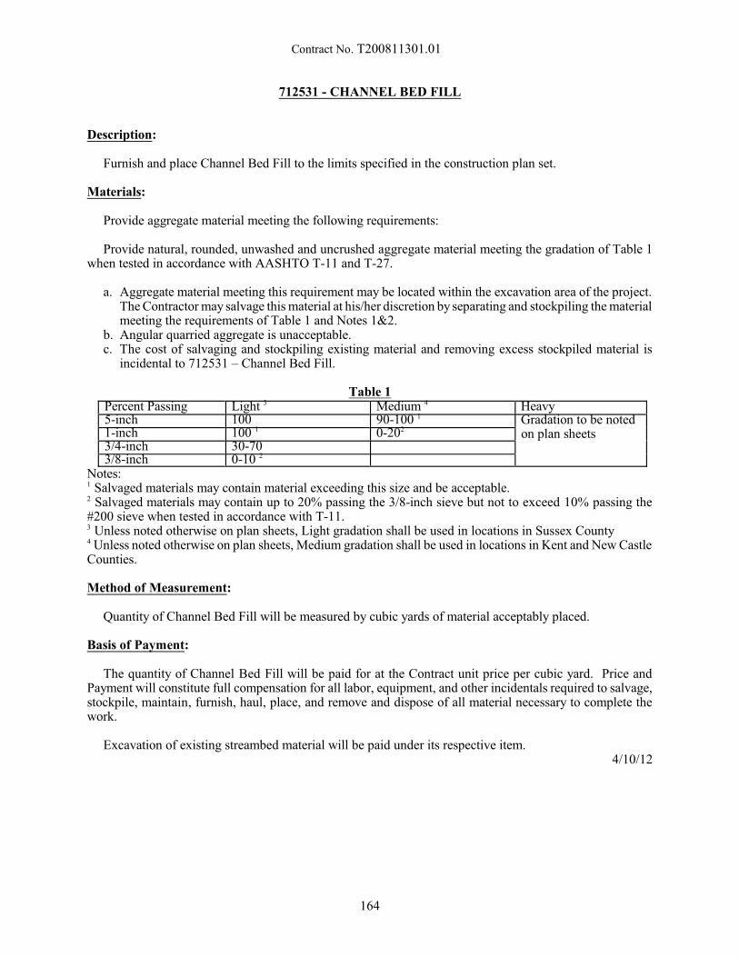
Contract No. T200811301.01
712531 - CHANNEL BED FILL
Description:
Furnish and place Channel Bed Fill to the limits specified in the construction plan set.
Materials:
Provide aggregate material meeting the following requirements:
Provide natural, rounded, unwashed and uncrushed aggregate material meeting the gradation of Table 1when tested in accordance with AASHTO T-11 and T-27.
a. Aggregate material meeting this requirement may be located within the excavation area of the project. The Contractor may salvage this material at his/her discretion by separating and stockpiling the materialmeeting the requirements of Table 1 and Notes 1&2.
b. Angular quarried aggregate is unacceptable.c. The cost of salvaging and stockpiling existing material and removing excess stockpiled material is
incidental to 712531 – Channel Bed Fill.
Table 1Percent Passing Light 3 Medium 4 Heavy5-inch 100 90-100 1 Gradation to be noted
on plan sheets1-inch 100 1 0-202
3/4-inch 30-703/8-inch 0-10 2
Notes:1 Salvaged materials may contain material exceeding this size and be acceptable.2 Salvaged materials may contain up to 20% passing the 3/8-inch sieve but not to exceed 10% passing the#200 sieve when tested in accordance with T-11.3 Unless noted otherwise on plan sheets, Light gradation shall be used in locations in Sussex County4 Unless noted otherwise on plan sheets, Medium gradation shall be used in locations in Kent and New CastleCounties.
Method of Measurement:
Quantity of Channel Bed Fill will be measured by cubic yards of material acceptably placed.
Basis of Payment:
The quantity of Channel Bed Fill will be paid for at the Contract unit price per cubic yard. Price andPayment will constitute full compensation for all labor, equipment, and other incidentals required to salvage,stockpile, maintain, furnish, haul, place, and remove and dispose of all material necessary to complete thework.
Excavation of existing streambed material will be paid under its respective item.4/10/12
164
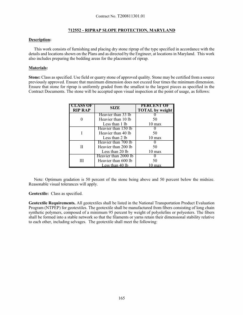
Contract No. T200811301.01
712552 - RIPRAP SLOPE PROTECTION, MARYLAND
Description:
This work consists of furnishing and placing dry stone riprap of the type specified in accordance with thedetails and locations shown on the Plans and as directed by the Engineer, at locations in Maryland. This workalso includes preparing the bedding areas for the placement of riprap.
Materials:
Stone: Class as specified. Use field or quarry stone of approved quality. Stone may be certified from a sourcepreviously approved. Ensure that maximum dimension does not exceed four times the minimum dimension.Ensure that stone for riprap is uniformly graded from the smallest to the largest pieces as specified in theContract Documents. The stone will be accepted upon visual inspection at the point of usage, as follows:
CLASS OFRIP RAP
SIZEPERCENT OF
TOTAL by weight
0Heavier than 33 lbHeavier than 10 lb
Less than 1 lb
050
10 max
IHeavier than 150 lbHeavier than 40 lb
Less than 2 lb
050
10 max
IIHeavier than 700 lbHeavier than 200 lb
Less than 20 lb
050
10 max
IIIHeavier than 2000 lbHeavier than 600 lb
Less than 40 lb
050
10 max
Note: Optimum gradation is 50 percent of the stone being above and 50 percent below the midsize.Reasonable visual tolerances will apply.
Geotextile: Class as specified.
Geotextile Requirements. All geotextiles shall be listed in the National Transportation Product EvaluationProgram (NTPEP) for geotextiles. The geotextile shall be manufactured from fibers consisting of long chainsynthetic polymers, composed of a minimum 95 percent by weight of polyolefins or polyesters. The fibersshall be formed into a stable network so that the filaments or yarns retain their dimensional stability relativeto each other, including selvages. The geotextile shall meet the following:
165
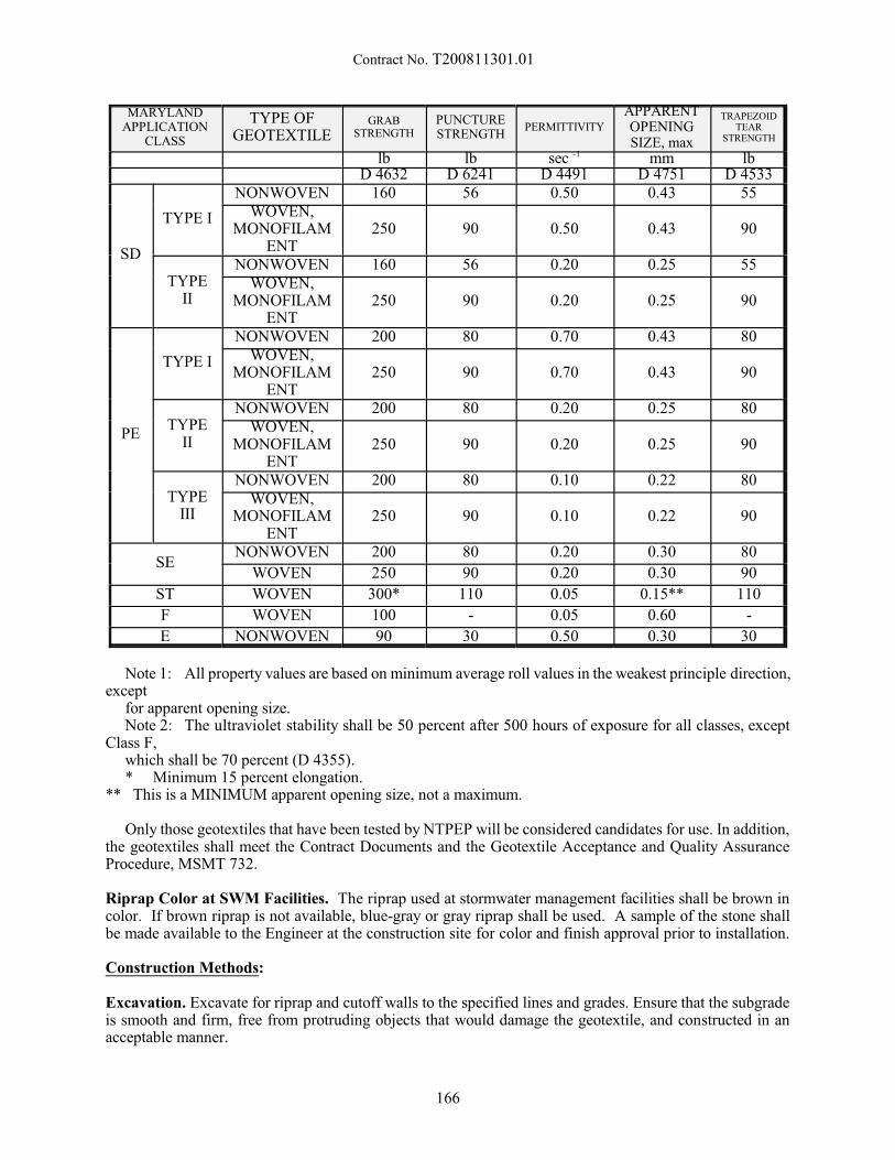
Contract No. T200811301.01
MARYLANDAPPLICATION
CLASS
TYPE OFGEOTEXTILE
GRABSTRENGTH
PUNCTURESTRENGTH
PERMITTIVITY
APPARENTOPENINGSIZE, max
TRAPEZOIDTEAR
STRENGTH
lb lb sec -1 mm lbD 4632 D 6241 D 4491 D 4751 D 4533
SD
TYPE I
NONWOVEN 160 56 0.50 0.43 55WOVEN,
MONOFILAMENT
250 90 0.50 0.43 90
TYPEII
NONWOVEN 160 56 0.20 0.25 55WOVEN,
MONOFILAMENT
250 90 0.20 0.25 90
PE
TYPE I
NONWOVEN 200 80 0.70 0.43 80WOVEN,
MONOFILAMENT
250 90 0.70 0.43 90
TYPEII
NONWOVEN 200 80 0.20 0.25 80WOVEN,
MONOFILAMENT
250 90 0.20 0.25 90
TYPEIII
NONWOVEN 200 80 0.10 0.22 80WOVEN,
MONOFILAMENT
250 90 0.10 0.22 90
SENONWOVEN 200 80 0.20 0.30 80
WOVEN 250 90 0.20 0.30 90
ST WOVEN 300* 110 0.05 0.15** 110
F WOVEN 100 - 0.05 0.60 -
E NONWOVEN 90 30 0.50 0.30 30
Note 1: All property values are based on minimum average roll values in the weakest principle direction,except
for apparent opening size.Note 2: The ultraviolet stability shall be 50 percent after 500 hours of exposure for all classes, except
Class F,which shall be 70 percent (D 4355).* Minimum 15 percent elongation.
** This is a MINIMUM apparent opening size, not a maximum.
Only those geotextiles that have been tested by NTPEP will be considered candidates for use. In addition,the geotextiles shall meet the Contract Documents and the Geotextile Acceptance and Quality AssuranceProcedure, MSMT 732. Riprap Color at SWM Facilities. The riprap used at stormwater management facilities shall be brown incolor. If brown riprap is not available, blue-gray or gray riprap shall be used. A sample of the stone shallbe made available to the Engineer at the construction site for color and finish approval prior to installation.
Construction Methods:
Excavation. Excavate for riprap and cutoff walls to the specified lines and grades. Ensure that the subgradeis smooth and firm, free from protruding objects that would damage the geotextile, and constructed in anacceptable manner.
166
Contract No. T200811301.01
Geotextile. Place the geotextile on the prepared subgrade with the adjacent edges overlapping at least 2 ft.Replace or repair damaged geotextile as directed.
Riprap Placement. Ensure that the underlying surface is free of brush, trees, and stumps, and is acceptableto the Engineer. Place the first section of riprap consisting of at least 5 tons, which will be inspected by theEngineer for conformance to gradation and placement requirements. If approved, this section will be usedto evaluate quality control for the remainder of the project. If the material is rejected, remove it from theproject and place additional sections, each at least 5 tons.
Begin the placement of the riprap with the bottom cutoff walls or toe sections. Place the larger stones inthe cutoff walls and along the outside edges of the limits of slope and channel protection. Place the riprapwith equipment that produces a uniformly graded mass of stones.
Ensure that the surface elevation of completed riprap installations is flush with adjacent channel bed orbank slope elevations, and does not create an obstacle to the flow. Ensure that the outer riprap surfaces areeven and present a generally neat appearance. The plus or minus tolerance of the surface of the finished riprapinstallation is 3 in. for Class I Riprap and 6 in. for Class II and III Riprap from the lines and grades shownon the Contract Documents when measured perpendicular to the exterior surface of the stonework.
Place and distribute the stone so the resulting layer will contain a minimum of voids and there will be nopockets of same size material. Place the stone to its full course thickness in one operation in a manner thatthe underlying material is not be displaced or worked into the course of riprap being placed. When anaggregate filter blanket is used, proceed with the placement of the riprap in a controlled manner to avoiddisruption or damage to the layer of bedding material.
Backfill. Backfill any excavation voids existing along the edges of the completed slope and channelprotection, and compact it in an acceptable manner.
Method of Measurement:
The quantity of riprap stone protection will be measured as either the actual number of square yards ofriprap placed and accepted in Maryland. Quantity will be determined by computations based on fieldmeasurements taken on and along the completed finished surfaces (no horizontal projection) and the specifiedplacement thickness for the type specified.
Basis of Payment:
The quantity of riprap stone protection will be paid for at the Contract unit price per square yard. Priceand payment will constitute full compensation for excavating and preparing the bedding areas if applicable;for furnishing, preparing, and placing all materials, including geotextile; and for all labor, equipment, tools,and incidentals required to complete the work.
8/13/12
167
Contract No. T200811301.01
715500 - UNDERDRAIN OUTLET PIPE, 6"715504 - UNDERDRAIN OUTLET PIPE, 8"
Description:
This work consists of furnishing and placing underdrain outlet pipe in accordance with the locations, notesand details shown on the Plans and as directed by the Engineer.
Materials and Construction Methods:
The materials and construction methods for underdrain outlet pipe shall conform to the applicablerequirements of Section 715 of the Standard Specifications, except there shall be no requirements for filterfabric and Del. No. 8 stone around the pipe and the pipe shall not be perforated. The material for underdrainoutlet pipe shall be the same as for perforated pipe underdrains.
The installed under drain outlet pipe shall be video inspected in accordance with Subsection 715.07 of theStandard Specifications.
Method of Measurement:
The quantity of underdrain outlet pipe will be measured from end to end in linear feet (linear meters) ofpipe completed and accepted.
Basis of Payment:
The quantity of underdrain outlet pipe will be paid for at the Contract unit price per linear foot (linearmeter) of the diameter as specified on the Plans. Price and payment will constitute full compensation forfurnishing all materials, excavation and backfilling, connectors, bolts to block outlet opening to prevent smallanimals from entering, video inspection for all labor, tools, equipment and incidentals to complete the item.
10/29/01
168
Contract No. T200811301.01
720585 - GUARDRAIL END TREATMENT ATTENUATOR, TYPE 1 - 31720586 - GUARDRAIL END TREATMENT ATTENUATOR, TYPE 2 - 31720588 - GUARDRAIL END TREATMENT ATTENUATOR, TYPE 3 - 31
Description:
This work consists of furnishing and installing an impact attenuating guardrail end treatment in accordancewith the locations, notes and details on the Plans, the Standard Construction Details, these Special Provisions,and as directed by the Engineer.
Materials:
The end treatment system shall meet the requirements of NCHRP Report No. 350 Test Level 3. TheGuardrail End Treatment, Type 1 shall be designed for installation parallel to the roadway. The GuardrailEnd Treatment, Type 2 shall be designed for installation with the end flared back from the roadway. TheGuardrail End Treatment, Type 3 shall be designed for installation where 2 runs of guardrail come together.
The entire end treatment shall be designed for quick and easy replacement after an impact.
Guardrail End Treatment Attenuator Type 1 shall have a minimum of 2 square feet of yellowretroreflective material on the nose. Guardrail End Treatment Attenuator, Type 2 and Type 3 shall have aminimum of 3 square feet of yellow retroreflective material on the nose.
The Contractor shall submit shop drawings, the manufacturer's certification, and the manufacturer'sinstallation instructions to the Engineer. Installation cannot begin until these submissions have been approvedby the Engineer.
Construction Methods:
The end treatment system shall be fabricated and installed in accordance with the manufacturer'srecommendations and details shown on the Plans.
The end treatment system shall be installed so that there is no rigid object projecting more 4" above groundlevel in that portion of the attenuator impacted and broken away by an errant vehicle. It is the intent that theerrant vehicle not be snagged by an embedded component of the end treatment attenuator.
The grading between the edge of pavement and the end treatment shall be 10:1 or flatter for the length ofthe end treatment.
Reflectorized washers are not to be used on attenuators unless specified and/or approved by themanufacturer.
The Guardrail End Treatment Attenuator, Type 1 shall be installed with steel tubes and soil plates for thefirst 4" (min.) wood post. As an alternate, the first 4" (min.) post may be hinged, breakaway steel post if themanufacturer's specifications permit.
Unless otherwise noted on the Plans, the Guardrail End Treatment Attenuator, Type 1 shall be installedwith a 50:1 taper beginning 50' from the end of the end treatment.
Method of Measurement:
The quantity of guardrail end treatment attenuators will be measured as the number of each type fabricated,installed and accepted.
Note: All guardrail end treatment attenuators will be considered as 50 feet long. The 50' length will beginat the center of the nose post and extend back along the attenuator and guardrail to which it is attached. Any
169
Contract No. T200811301.01
guardrail within the 50' length will be considered as part of the guardrail end treatment attenuator and not bemeasured separately. Measurement for the guardrail will begin 50' from the center of the nose post of theattenuator.
Basis of Payment:
The quantity of guardrail end treatment attenuators will be paid for at the Contract unit price per each typeof guardrail end treatment attenuator. Price and payment will constitute full compensation for furnishing allmaterials, fabrication and installation and for all materials, labor, equipment, tools and incidentals requiredto complete the work.
Note: When this item is completely installed, the Contractor may notify the Engineer and request acceptance. The Engineer will make an inspection of the installation and the Contractor shall correct any deficiencies. Once the corrective work is completed to the satisfaction of the Engineer, the installation will be acceptedand the Contractor will be relieved from the responsibility for this item. If this item is damaged before thefinal acceptance of the project, and the damage is not the result of the Contractor's negligence, the Engineerwill notify the Contractor to make repairs, and the Contractor will make repairs at the unit price bid (in thecase of complete replacement) or at a negotiated price (in the case of partial replacement or repair). Damagecaused by the Contractor shall be repaired at no cost to the Department.
4/7/11
170
Contract No. T200811301.01
720611 - FLEXIBLE DELINEATOR, PERMANENT
Description:
This work consists of supplying and placing tubular markers on the road surface to help channelize traffic.
Materials:
Tubular markers should be predominantly orange, other colors are acceptable depending on where theyare being placed. They shall be not be less than 28" high (700 mm) and 2" wide (50 mm) facing road users. They shall be made of a material that can be struck without causing damage to the impacting vehicle. Fornighttime use, tubular markers shall be retroreflectorized. Retroreflectorization of 28" (700 mm) or largertubular markers shall be provided by two 3" (75 mm) wide white or yellow bands placed a maximum of 2"(50 mm) from the top with a maximum of 6" (150 mm) between the bands.
Construction Methods:
The Contractor shall remove all loose debris from road surface, the road surface must be dry. The tubularmarker must be anchored to the pavement using a method that is approved by the product manufacturer. There are several different methods of anchoring tubular markers, the exact method used shall be at thediscretion of the project coordinator.
Method of Measurement:
The quantity will be measured as the actual number of tubular markers installed.
Basis of Payment:
The quantity of tubular markers installed will be paid for at the Contract unit price of each. Price andpayment will constitute full compensation for all labor, equipment, tools, materials, and incidentals requiredto complete the work.
7/2/10
171
Contract No. T200811301.01
720626 – CONCRTE SINGLE FACE BARRIER, TYPE 1
720627 – CONCRETE SINGLE FACE BARRIER, TYPE 2720628 – CONCRETE SINGLE FACE BARRIER, TYPE 3
720629 - CONCRETE BIFURCATED CONCRETE MEDIAN BARRIER
Description:
This work consists of furnishing all materials and constructing permanent Portland cement concrete safetybarrier in accordance with the locations, details, notes shown on the Plans, and/or as directed by the Engineer.
Materials:
Material shall conform to the requirements listed on the Plans, the applicable subsections of Sections 602& 603 of the Standard Specifications, and as noted herein. Portland cement concrete shall be 4500 psiminimum and shall conform to the material requirements of Class A, Section 812, Portland Cement Concreteof the Standard Specifications.
Bar reinforcement shall be epoxy coated meeting the requirements Section 604 Grade 60 (Grade 400).
Construction Methods:
Construction shall conform with the applicable subsections of Sections 602 and 603 of the StandardSpecifications, details shown on the Plans, and as noted herein.
The Contractor shall have the option of constructing the permanent safety barriers by selecting Cast-In-Place or Slip-form methods. The Contractor shall submit his/her plans for the selected method to theDepartment's Materials and Research Section for approval. In case of selecting the Slip-form method, theContractor shall be able to demonstrate his/her ability to successfully accomplish the item by his/her pastinvolvement in doing such work. Slip-form plans shall show the sawing of 3” deep contraction joints at amaximum of 20-ft. intervals. The Contractor shall provide joints to ensure crack-free concrete. Any crackingdue to the Contractor’s operations will be repaired at no additional cost to the Department.
Method of Measurement:
The quantity of permanent Portland cement concrete safety barrier will be measured by the linear footalong one continuous front toe of the barrier, installed in place and accepted including all barrier transitionsand end sections.
Basis of Payment:
The quantity of concrete barrier will be paid for at the Contract unit price per linear foot for each type ofbarrier. Price and payment will constitute full compensation for all materials, formwork, sawing of joints,joint seals and fillers, reinforcement bars, weep holes, and concrete all complete in place and accepted, forall labor, equipment, tools and incidentals necessary to complete the work. Payment for excavation and theP.C.C. footer portion of the barrier are included in this item.
11/19/12
172

Contract No. T200811301.01
727507 - BRIDGE SAFETY FENCE
Description:
The work consists of furnishing all materials and constructing bridge safety fence in accordance with thesespecifications, notes and details on the Plans and as directed by the Engineer.
Materials:
All material shall meet the applicable requirements of Section 727 and shall be as noted below unlessshown otherwise on the Plans:
Chain-link fence shall be either galvanized steel fabric fence or aluminum-coated steel fabric fence,conforming to the appropriate requirements of AASHTO M 181.
Tubular steel posts, braces, fittings and hardware shall conform to the requirements of AASHTO M 281and shall be galvanized in accordance with AASHTO M 111.
All base plates shall be steel conforming to the requirements of AASHTO M 270, Grade 36.
Material for anchor studs or anchor bolts shall meet ASTM A276, Type 430 or Type 304 Stainless SteelAnnealed, Hot-Finished, Ultimate Strength 70,000 PSI minimum, 20% elongation. Threads may be rolledor cut.
Construction Methods:
Construction methods shall conform to the applicable requirements of Section 727 of the StandardSpecifications, notes and details on the Plans, and as described herein.
All longitudinal rails shall be parallel to the top of parapet. All posts shall be set normal to the top ofparapet for roadway grades 6% or less; and for grades over 6% posts shall be set plumb.
The chain link fence shall be true to line, taut and shall comply with the best practice for fenceconstruction of this type. Parts and rails shall be permanently positioned before fabric is placed. Any defectsuncovered during the process of inspection of welds on base plates and/or poles and/or elsewhere shall berepaired or replaced at the sole expense of the Contractor.
Method of Measurement:
The quantity of bridge safety fence will be measured in linear feet along the line of the fence from end toend. Any anti-climb shields or other appurtenances shall not be measured for payment but shall be includedin the linear feet cost of the bridge safety fence.
Basis of Payment:
The quantity of bridge safety fence will be paid for at the Contract unit price per linear foot. Price andpayment will constitute full compensation for furnishing and placing all materials including posts, rails, anti-climb shields, all accessories; for all labor, tools, equipment and necessary incidentals to complete the work.
11/29/11
173
Contract No. T200811301.01
727552 - RESOURCE PROTECTION FENCE
Description:
This work consists of furnishing all materials, erecting resource protection fence at location(s) as notedon the Plans or as directed, relocating if required and maintaining/repairing during the construction period. The resource protection fence shall be removed and disposed of after no longer required as determined bythe Engineer.
Materials:
A. Submit source of supply for all fencing materials including the posts for approval by the Engineer priorto installation.
B. Resource Protection Fence: 1. 4' high, U.V. stabilized high visibility orange, high density polyethylene. 2. Standard mesh opening size of approximately 1 1/2". 3. Tensile Strength Min. 5000 PSI4. MD Break Load Min. 900 lbs/ft5. MD Yield Strength Min. 1,100 lbs/ft
C. Fence Post: 1. Length sufficient for 18" embedment in the ground.
a. T-Section steel 1.25" x 1.00". 2. If the fence is to be installed on bituminous and/or concrete surface, use posts that can be anchored
by placing sand bags at their base without damaging pavement.
D. Bottom Rail Edging: 1. If the fence is to be installed along a pedestrian sidewalk, provide bottom rail edging of wood or
metal for cane detection.
E. Protection Signs: 1. Protection signs shall be provided by the Engineer and installed by the Contractor. The Contractor
shall pick up the signs from the DelDOT sign shop and deliver to the project without any damageto the materials.
Construction Methods:
A. The Contractor shall stakeout the location of the resource protection fence for approval by the Engineerprior to installation. Resource protection fence shall be installed by hand. Grubbing shall not bepermitted for the installation of resource protection fence. Where clearing is necessary for fenceinstallation, vegetation shall be cut flush with the ground. Vegetation disturbance shall be kept to aminimum when installing resource protection fence.
B. Space posts no more than 10' . 1. Alternate spacing may be approved only if specified by the fence manufacturer.
C. Use 8" self-locking nylon safety ties for securing the fence to the post.
D. Signs shall be located along the fence facing the construction work area. Signs shall be located no morethan 100 feet apart and a minimum of two signs shall be installed along a continuous fence segment.The top and bottom of the signs shall be secured to the top of the fence posts with 8" self-locking nylonsafety ties using the existing holes in the sign.
174
Contract No. T200811301.01
E. Near streams, resource protection fence shall be installed so as not to interfere with base flow. Ifnecessary, a gap in the fencing shall be created such that the resource protection fence terminates at thetop of bank on both the right and left stream banks.
F. Install bottom rail edging for cane detection must be at least 6 inches above the surface of the sidewalkor pathway, with the bottom of the edging a maximum of 2.5 inches above the surface.
G. Maintain, repair, or replace resource protection fence as necessary when damaged, missing, or wornout.
H. The resource protection fence shall be removed when the Engineer determines that it is no longerrequired, typically at the very end of the construction contract. Removal of the resource protectionfence shall be done by hand and vegetation disturbance shall be kept to a minimum. Removal shall beincidental to the item. Signs shall be salvaged and returned to the DelDOT sign shop. All other fencingmaterials shall be disposed of by the Contractor.
Method of Measurement:
The quantity of resource protection fence will be measured as the actual number of linear feet of resourceprotection fence furnished, installed and accepted.
Basis of Payment:
The quantity of resource protection fence will be paid for at the Contract unit price per linear foot. Priceand payment will constitute full compensation for furnishing, placing, maintaining, clearing, pick-up anddelivery of sign materials, salvaging and drop-off of sign materials, removal and disposal of the fence andrelated accessories, furnishing all labor, equipment, tools and all incidentals necessary to complete the work. Stolen or damaged resource protection fencing and signs shall be replaced at the Contractor's expense.
9/9/15
175
Contract No. T200811301.01
727553 – DIVERSION FENCE, MARYLAND
Description:
This work consists of furnishing, constructing, maintaining, and ultimately removing, Diversion Fenceas a temporary measure to control sedimentation within the limits of construction. Diversion fence shall beconstructed as shown on Standard Construction Detail, Diversion Fence, at the locations shown on the Plans,and as directed by the Engineer, for locations in Maryland.
Materials:
All materials shall confirm to the standard detail for Diversion Fence in the contract drawings.
Construction:
Trench double 6 mil polyethylene sheeting at least 6 in. into the ground, cover at least 4 ft. from the trenchline to the fence posts, extend at least 20 in. above the ground, and wrap over the fence posts to grade.
Method of Measurement:
The quantity of diversion fence will be measured per linear foot installed and accepted in accordance withthe Plan at locations in Maryland. Overlaps of materials of any kind will not be measured.
Basis of Payment:
The quantity of diversion fence will be paid for at the Contract unit price per linear foot. Price andpayment will constitute full compensation for furnishing all materials; for excavating and backfillingassociated with the construction of the fence; for maintaining the fence during the Project construction period;for removing the fence with all related hardware after completion of the Project; for restoring the site; andfor all labor, equipment, tools and incidentals required to complete the work.
11/29/11
176
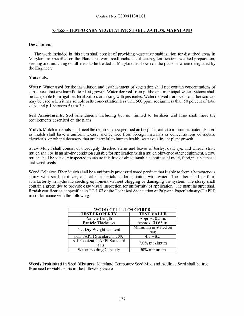
Contract No. T200811301.01
734555 - TEMPORARY VEGETATIVE STABILIZATION, MARYLAND
Description:
The work included in this item shall consist of providing vegetative stabilization for disturbed areas inMaryland as specified on the Plan. This work shall include soil testing, fertilization, seedbed preparation,seeding and mulching on all areas to be treated in Maryland as shown on the plans or where designated bythe Engineer.
Materials:
Water. Water used for the installation and establishment of vegetation shall not contain concentrations ofsubstances that are harmful to plant growth. Water derived from public and municipal water systems shallbe acceptable for irrigation, fertilization, or mixing with pesticides. Water derived from wells or other sourcesmay be used when it has soluble salts concentration less than 500 ppm, sodium less than 50 percent of totalsalts, and pH between 5.0 to 7.8.
Soil Amendments. Soil amendments including but not limited to fertilizer and lime shall meet therequirements described on the plans
Mulch. Mulch materials shall meet the requirements specified on the plans, and at a minimum, materials usedas mulch shall have a uniform texture and be free from foreign materials or concentrations of metals,chemicals, or other substances that are harmful to human health, water quality, or plant growth.
Straw Mulch shall consist of thoroughly threshed stems and leaves of barley, oats, rye, and wheat. Strawmulch shall be in an air-dry condition suitable for application with a mulch blower or other equipment. Strawmulch shall be visually inspected to ensure it is free of objectionable quantities of mold, foreign substances,and weed seeds.
Wood Cellulose Fiber Mulch shall be a uniformly processed wood product that is able to form a homogenousslurry with seed, fertilizer, and other materials under agitation with water. The fiber shall performsatisfactorily in hydraulic seeding equipment without clogging or damaging the system. The slurry shallcontain a green dye to provide easy visual inspection for uniformity of application. The manufacturer shallfurnish certification as specified in TC-1.03 of the Technical Association of Pulp and Paper Industry (TAPPI)in conformance with the following:
WOOD CELLULOSE FIBERTEST PROPERTY TEST VALUE
Particle Length Approx. 0.5 in.Particle Thickness Approx. 0.063 in.
Net Dry Weight ContentMinimum as stated on
bagpH, TAPPI Standard T 509, 4.0 – 8.5
Ash Content, TAPPI StandardT 413
7.0% maximum
Water Holding Capacity 90% minimum
Weeds Prohibited in Seed Mixtures. Maryland Temporary Seed Mix, and Additive Seed shall be freefrom seed or viable parts of the following species:
177
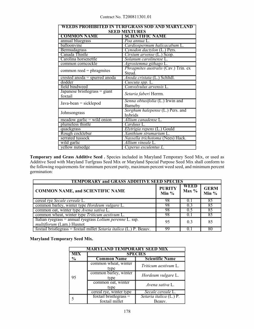
Contract No. T200811301.01
WEEDS PROHIBITED IN TURFGRASS SOD AND MARYLANDSEED MIXTURES
COMMON NAME SCIENTIFIC NAME annual bluegrass Poa annua L. balloonvine Cardiospermum halicacabum L. Bermudagrass Cynodon dactylon (L.) Pers. Canada Thistle Cirsium arvense (L.) Scop. Carolina horsenettle Solanum carolinense L. common corncockle Agrostemma githago L.
common reed = phragmites Phragmites australis (Cav.) Trin. exSteud.
crested anoda = spurred anoda Anoda cristata (L.) Schltdl. dodder Cuscuta spp. L. field bindweed Convolvulus arvensis L. Japanese bristlegrass = giantfoxtail
Setaria faberi Herrm.
Java-bean = sicklepod Senna obtusifolia (L.) Irwin andBarneby
Johnsongrass Sorghum halepense (L.) Pers. andhybrids
meadow garlic = wild onion Allium canadense L. plumeless thistle Carduus L. quackgrass Elytrigia repens (L.) Gould Rough cocklebur Xanthium strumarium L. serrated tussock Nassella trichotoma (Nees) Hack. wild garlic Allium vineale L. yellow nutsedge Cyperus esculentus L.
Temporary and Grass Additive Seed . Species included in Maryland Temporary Seed Mix, or used asAdditive Seed with Maryland Turfgrass Seed Mix or Maryland Special Purpose Seed Mix shall conform tothe following requirements for minimum percent purity, maximum percent weed seed, and minimum percentgermination:
TEMPORARY and GRASS ADDITIVE SEED SPECIES
COMMON NAME, and SCIENTIFIC NAME PURITYMin %
WEEDMax %
GERMMin %
cereal rye Secale cereale L. 98 0.1 85 common barley, winter type Hordeum vulgare L. 98 0.3 85 common oat, winter type Avena sativa L. 98 0.5 85 common wheat, winter type Triticum aestivum L. 98 0.1 85 Italian ryegrass = annual ryegrass Lolium perenne L. ssp.multiflorum (Lam.) Husnot
95 0.3 85
foxtail bristlegrass = foxtail millet Setaria italica (L.) P. Beauv. 99 0.1 80
Maryland Temporary Seed Mix.
MARYLAND TEMPORARY SEED MIXMIX%
SPECIESCommon Name Scientific Name
95
common wheat, wintertype
Triticum aestivum L.
common barley, wintertype
Hordeum vulgare L.
common oat, wintertype
Avena sativa L.
cereal rye, winter type Secale cereale L.
5 foxtail bristlegrass =
foxtail milletSetaria italica (L.) P.
Beauv.
178
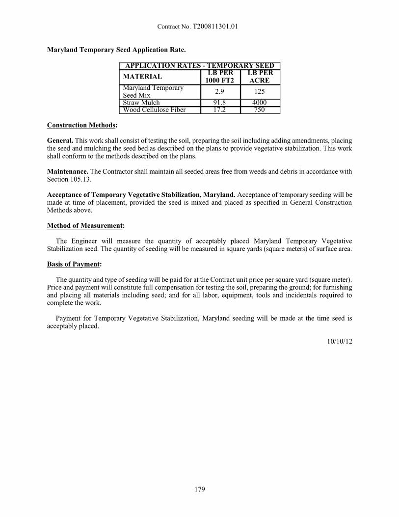
Contract No. T200811301.01
Maryland Temporary Seed Application Rate.
APPLICATION RATES - TEMPORARY SEED
MATERIAL LB PER
1000 FT2 LB PERACRE
Maryland TemporarySeed Mix
2.9 125
Straw Mulch 91.8 4000 Wood Cellulose Fiber 17.2 750
Construction Methods:
General. This work shall consist of testing the soil, preparing the soil including adding amendments, placingthe seed and mulching the seed bed as described on the plans to provide vegetative stabilization. This workshall conform to the methods described on the plans.
Maintenance. The Contractor shall maintain all seeded areas free from weeds and debris in accordance withSection 105.13.
Acceptance of Temporary Vegetative Stabilization, Maryland. Acceptance of temporary seeding will bemade at time of placement, provided the seed is mixed and placed as specified in General ConstructionMethods above.
Method of Measurement:
The Engineer will measure the quantity of acceptably placed Maryland Temporary VegetativeStabilization seed. The quantity of seeding will be measured in square yards (square meters) of surface area.
Basis of Payment:
The quantity and type of seeding will be paid for at the Contract unit price per square yard (square meter).Price and payment will constitute full compensation for testing the soil, preparing the ground; for furnishingand placing all materials including seed; and for all labor, equipment, tools and incidentals required tocomplete the work.
Payment for Temporary Vegetative Stabilization, Maryland seeding will be made at the time seed isacceptably placed.
10/10/12
179
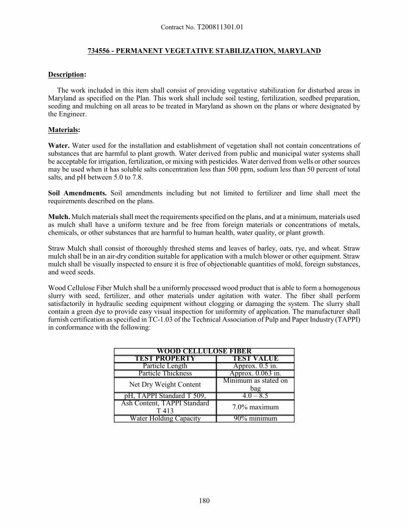
Contract No. T200811301.01
734556 - PERMANENT VEGETATIVE STABILIZATION, MARYLAND
Description:
The work included in this item shall consist of providing vegetative stabilization for disturbed areas inMaryland as specified on the Plan. This work shall include soil testing, fertilization, seedbed preparation,seeding and mulching on all areas to be treated in Maryland as shown on the plans or where designated bythe Engineer.
Materials:
Water. Water used for the installation and establishment of vegetation shall not contain concentrations ofsubstances that are harmful to plant growth. Water derived from public and municipal water systems shallbe acceptable for irrigation, fertilization, or mixing with pesticides. Water derived from wells or other sourcesmay be used when it has soluble salts concentration less than 500 ppm, sodium less than 50 percent of totalsalts, and pH between 5.0 to 7.8.
Soil Amendments. Soil amendments including but not limited to fertilizer and lime shall meet therequirements described on the plans.
Mulch. Mulch materials shall meet the requirements specified on the plans, and at a minimum, materials usedas mulch shall have a uniform texture and be free from foreign materials or concentrations of metals,chemicals, or other substances that are harmful to human health, water quality, or plant growth.
Straw Mulch shall consist of thoroughly threshed stems and leaves of barley, oats, rye, and wheat. Strawmulch shall be in an air-dry condition suitable for application with a mulch blower or other equipment. Strawmulch shall be visually inspected to ensure it is free of objectionable quantities of mold, foreign substances,and weed seeds.
Wood Cellulose Fiber Mulch shall be a uniformly processed wood product that is able to form a homogenousslurry with seed, fertilizer, and other materials under agitation with water. The fiber shall performsatisfactorily in hydraulic seeding equipment without clogging or damaging the system. The slurry shallcontain a green dye to provide easy visual inspection for uniformity of application. The manufacturer shallfurnish certification as specified in TC-1.03 of the Technical Association of Pulp and Paper Industry (TAPPI)in conformance with the following:
WOOD CELLULOSE FIBERTEST PROPERTY TEST VALUE
Particle Length Approx. 0.5 in.Particle Thickness Approx. 0.063 in.
Net Dry Weight ContentMinimum as stated on
bagpH, TAPPI Standard T 509, 4.0 – 8.5
Ash Content, TAPPI StandardT 413
7.0% maximum
Water Holding Capacity 90% minimum
180
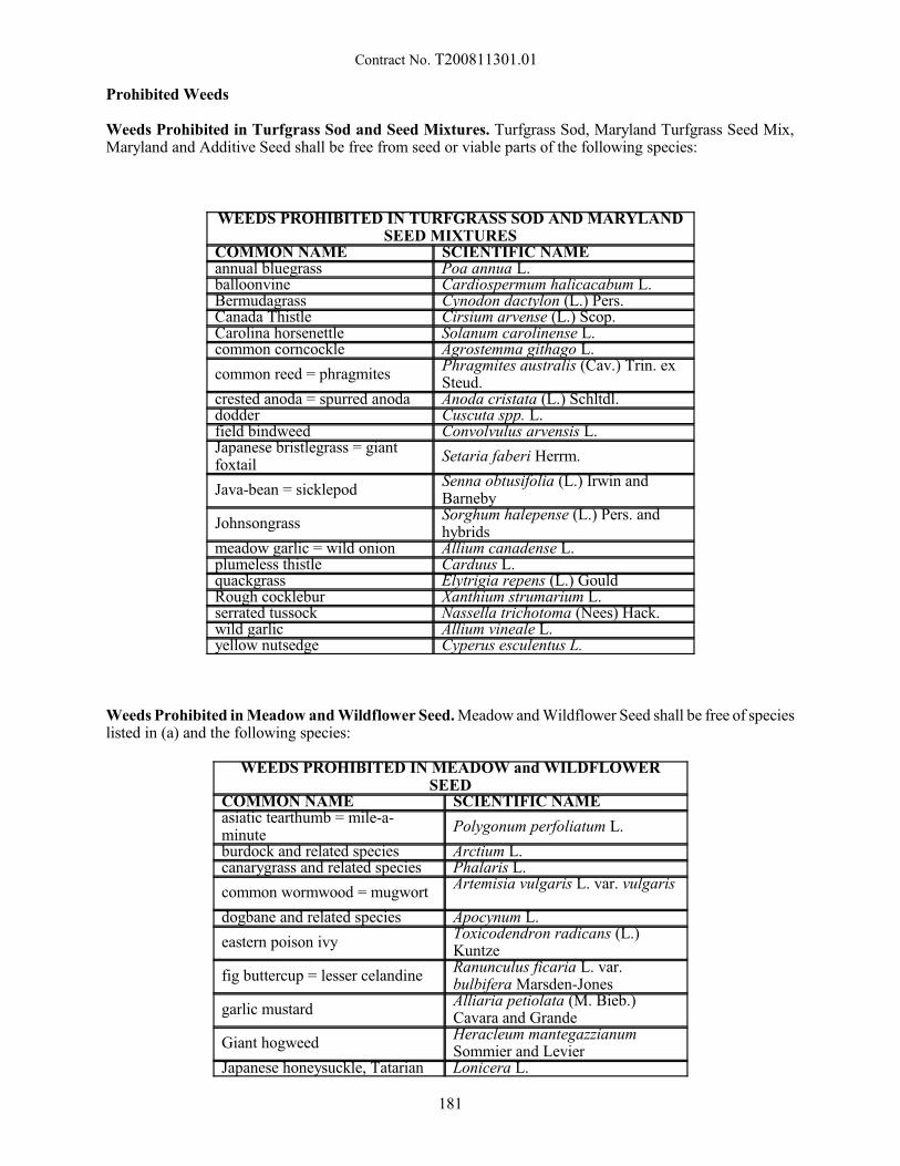
Contract No. T200811301.01
Prohibited Weeds
Weeds Prohibited in Turfgrass Sod and Seed Mixtures. Turfgrass Sod, Maryland Turfgrass Seed Mix,Maryland and Additive Seed shall be free from seed or viable parts of the following species:
WEEDS PROHIBITED IN TURFGRASS SOD AND MARYLANDSEED MIXTURES
COMMON NAME SCIENTIFIC NAME annual bluegrass Poa annua L. balloonvine Cardiospermum halicacabum L. Bermudagrass Cynodon dactylon (L.) Pers. Canada Thistle Cirsium arvense (L.) Scop. Carolina horsenettle Solanum carolinense L. common corncockle Agrostemma githago L.
common reed = phragmites Phragmites australis (Cav.) Trin. exSteud.
crested anoda = spurred anoda Anoda cristata (L.) Schltdl. dodder Cuscuta spp. L. field bindweed Convolvulus arvensis L. Japanese bristlegrass = giantfoxtail
Setaria faberi Herrm.
Java-bean = sicklepod Senna obtusifolia (L.) Irwin andBarneby
Johnsongrass Sorghum halepense (L.) Pers. andhybrids
meadow garlic = wild onion Allium canadense L. plumeless thistle Carduus L. quackgrass Elytrigia repens (L.) Gould Rough cocklebur Xanthium strumarium L. serrated tussock Nassella trichotoma (Nees) Hack. wild garlic Allium vineale L. yellow nutsedge Cyperus esculentus L.
Weeds Prohibited in Meadow and Wildflower Seed. Meadow and Wildflower Seed shall be free of specieslisted in (a) and the following species:
WEEDS PROHIBITED IN MEADOW and WILDFLOWERSEED
COMMON NAME SCIENTIFIC NAME asiatic tearthumb = mile-a-minute
Polygonum perfoliatum L.
burdock and related species Arctium L. canarygrass and related species Phalaris L.
common wormwood = mugwort Artemisia vulgaris L. var. vulgaris
dogbane and related species Apocynum L.
eastern poison ivy Toxicodendron radicans (L.)Kuntze
fig buttercup = lesser celandine Ranunculus ficaria L. var.bulbifera Marsden-Jones
garlic mustard Alliaria petiolata (M. Bieb.)Cavara and Grande
Giant hogweed Heracleum mantegazzianumSommier and Levier
Japanese honeysuckle, Tatarian Lonicera L.
181
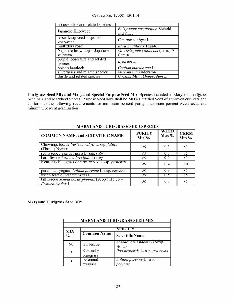
Contract No. T200811301.01
honeysuckle and related species
Japanese Knotweed Polygonum cuspidatum Sieboldand Zucc.
lesser knapweed = spottedknapweed
Centaurea nigra L.
multiflora rose Rosa multiflora Thunb. Nepalese browntop = Japanesestiltgrass
Microstegium vimineum (Trin.) A.Camus
purple loosestrife and relatedspecies
Lythrum L.
poison hemlock Conium maculatum L. silvergrass and related species Miscanthus Andersson thistle and related species Cirsium Mill., Onopordum L.
Turfgrass Seed Mix and Maryland Special Purpose Seed Mix. Species included in Maryland TurfgrassSeed Mix and Maryland Special Purpose Seed Mix shall be MDA Certified Seed of approved cultivars andconform to the following requirements for minimum percent purity, maximum percent weed seed, andminimum percent germination:
MARYLAND TURFGRASS SEED SPECIES
COMMON NAME, and SCIENTIFIC NAME PURITYMin %
WEEDMax %
GERMMin %
Chewings fescue Festuca rubra L. ssp. fallax(Thuill.) Nyman
98 0.5 85
red fescue Festuca rubra L. ssp. rubra 98 0.5 85 hard fescue Festuca brevipila Tracey 98 0.5 85 Kentucky bluegrass Poa pratensis L. ssp. pratensis
95 0.4 80
perennial ryegrass Lolium perenne L. ssp. perenne 98 0.5 85 sheep fescue Festuca ovina L. 98 0.5 85 tall fescue Schedonorus phoenix (Scop.) Holub =Festuca elatior L.
98 0.5 85
Maryland Turfgrass Seed Mix.
MARYLAND TURFGRASS SEED MIX
MIX%
SPECIESCommon Name
Scientific Name
90 tall fescue Schedonorus phoenix (Scop.)Holub
5 Kentuckybluegrass
Poa pratensis L. ssp. pratensis
5 perennialryegrass
Lolium perenne L. ssp.perenne
182
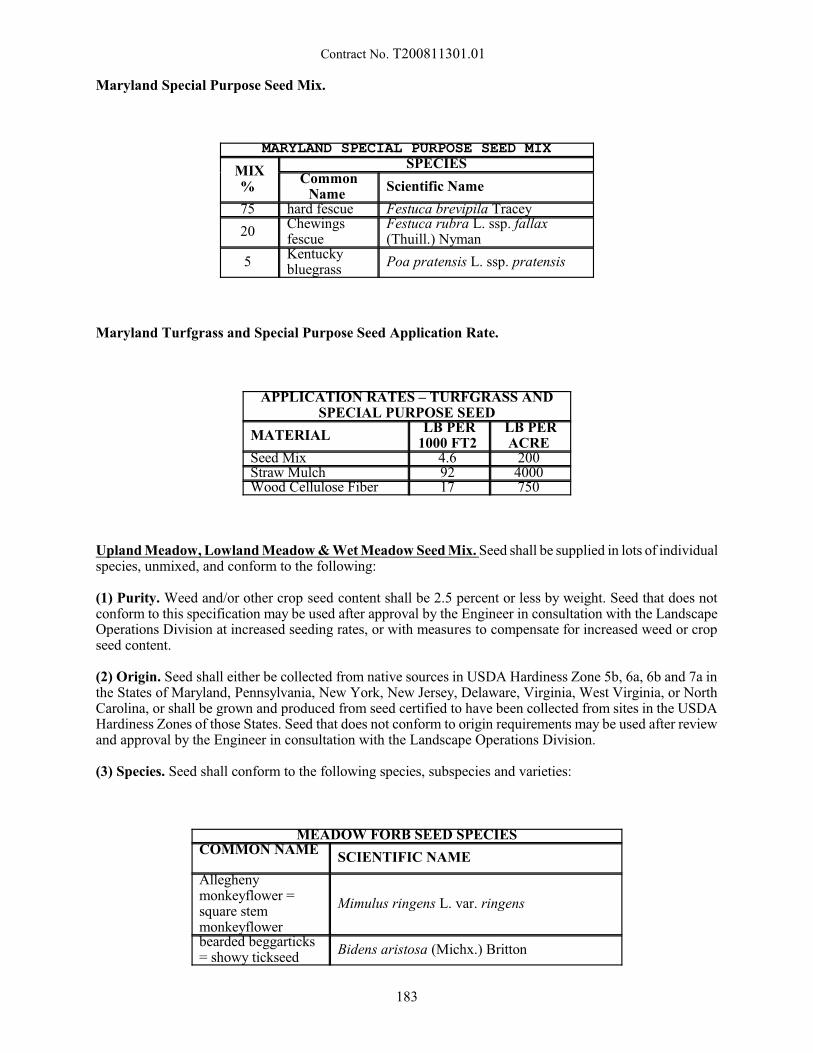
Contract No. T200811301.01
Maryland Special Purpose Seed Mix.
MARYLAND SPECIAL PURPOSE SEED MIX
MIX%
SPECIESCommon
Name Scientific Name
75 hard fescue Festuca brevipila Tracey
20 Chewingsfescue
Festuca rubra L. ssp. fallax(Thuill.) Nyman
5 Kentuckybluegrass
Poa pratensis L. ssp. pratensis
Maryland Turfgrass and Special Purpose Seed Application Rate.
APPLICATION RATES – TURFGRASS ANDSPECIAL PURPOSE SEED
MATERIAL LB PER
1000 FT2 LB PERACRE
Seed Mix 4.6 200 Straw Mulch 92 4000 Wood Cellulose Fiber 17 750
Upland Meadow, Lowland Meadow & Wet Meadow Seed Mix. Seed shall be supplied in lots of individualspecies, unmixed, and conform to the following:
(1) Purity. Weed and/or other crop seed content shall be 2.5 percent or less by weight. Seed that does notconform to this specification may be used after approval by the Engineer in consultation with the LandscapeOperations Division at increased seeding rates, or with measures to compensate for increased weed or cropseed content.
(2) Origin. Seed shall either be collected from native sources in USDA Hardiness Zone 5b, 6a, 6b and 7a inthe States of Maryland, Pennsylvania, New York, New Jersey, Delaware, Virginia, West Virginia, or NorthCarolina, or shall be grown and produced from seed certified to have been collected from sites in the USDAHardiness Zones of those States. Seed that does not conform to origin requirements may be used after reviewand approval by the Engineer in consultation with the Landscape Operations Division.
(3) Species. Seed shall conform to the following species, subspecies and varieties:
MEADOW FORB SEED SPECIESCOMMON NAME
SCIENTIFIC NAME
Alleghenymonkeyflower =square stemmonkeyflower
Mimulus ringens L. var. ringens
bearded beggarticks= showy tickseed
Bidens aristosa (Michx.) Britton
183
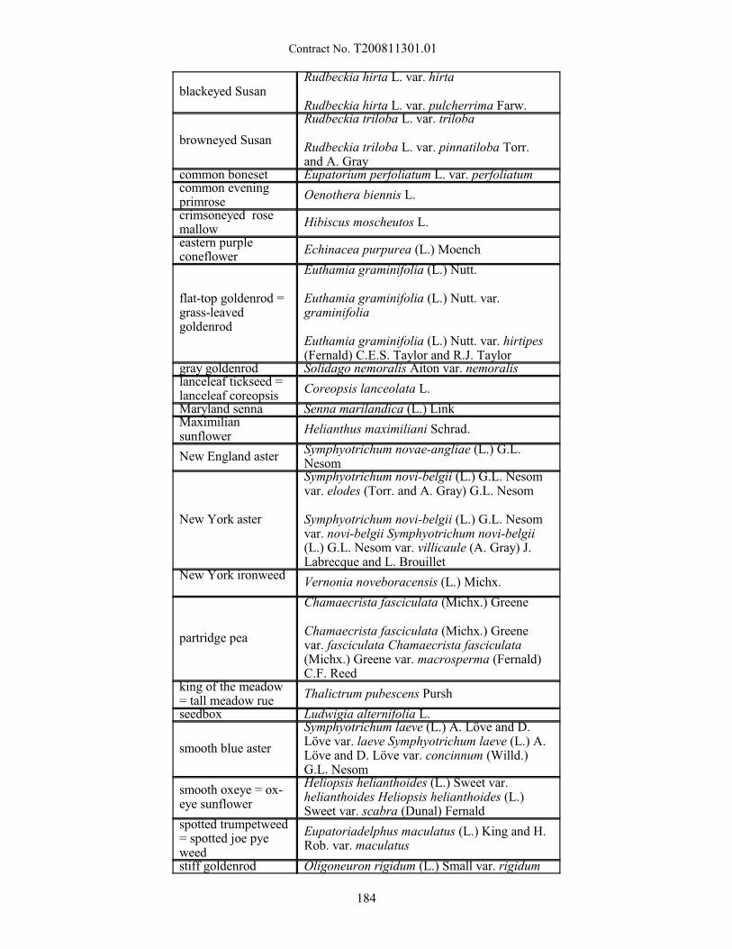
Contract No. T200811301.01
blackeyed Susan Rudbeckia hirta L. var. hirta
Rudbeckia hirta L. var. pulcherrima Farw.
browneyed Susan
Rudbeckia triloba L. var. triloba
Rudbeckia triloba L. var. pinnatiloba Torr.and A. Gray
common boneset Eupatorium perfoliatum L. var. perfoliatum common eveningprimrose
Oenothera biennis L.
crimsoneyed rosemallow
Hibiscus moscheutos L.
eastern purpleconeflower
Echinacea purpurea (L.) Moench
flat-top goldenrod =grass-leavedgoldenrod
Euthamia graminifolia (L.) Nutt.
Euthamia graminifolia (L.) Nutt. var.graminifolia
Euthamia graminifolia (L.) Nutt. var. hirtipes(Fernald) C.E.S. Taylor and R.J. Taylor
gray goldenrod Solidago nemoralis Aiton var. nemoralis lanceleaf tickseed =lanceleaf coreopsis
Coreopsis lanceolata L.
Maryland senna Senna marilandica (L.) Link Maximiliansunflower
Helianthus maximiliani Schrad.
New England aster Symphyotrichum novae-angliae (L.) G.L.Nesom
New York aster
Symphyotrichum novi-belgii (L.) G.L. Nesomvar. elodes (Torr. and A. Gray) G.L. Nesom
Symphyotrichum novi-belgii (L.) G.L. Nesomvar. novi-belgii Symphyotrichum novi-belgii(L.) G.L. Nesom var. villicaule (A. Gray) J.Labrecque and L. Brouillet
New York ironweedVernonia noveboracensis (L.) Michx.
partridge pea
Chamaecrista fasciculata (Michx.) Greene
Chamaecrista fasciculata (Michx.) Greenevar. fasciculata Chamaecrista fasciculata(Michx.) Greene var. macrosperma (Fernald)C.F. Reed
king of the meadow= tall meadow rue
Thalictrum pubescens Pursh
seedbox Ludwigia alternifolia L.
smooth blue aster
Symphyotrichum laeve (L.) A. Löve and D.Löve var. laeve Symphyotrichum laeve (L.) A.Löve and D. Löve var. concinnum (Willd.)G.L. Nesom
smooth oxeye = ox-eye sunflower
Heliopsis helianthoides (L.) Sweet var.helianthoides Heliopsis helianthoides (L.)Sweet var. scabra (Dunal) Fernald
spotted trumpetweed= spotted joe pyeweed
Eupatoriadelphus maculatus (L.) King and H.Rob. var. maculatus
stiff goldenrod Oligoneuron rigidum (L.) Small var. rigidum
184
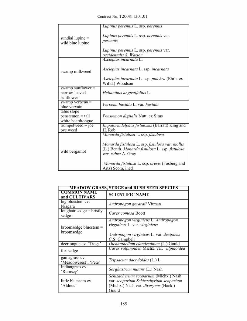
Contract No. T200811301.01
sundial lupine =wild blue lupine
Lupinus perennis L. ssp. perennis
Lupinus perennis L. ssp. perennis var.perennis
Lupinus perennis L. ssp. perennis var.occidentalis S. Watson
swamp milkweed
Asclepias incarnata L.
Asclepias incarnata L. ssp. incarnata
Asclepias incarnata L. ssp. pulchra (Ehrh. exWilld.) Woodson
swamp sunflower =narrow-leavedsunflower
Helianthus angustifolius L.
swamp verbena =blue vervain
Verbena hastata L. var. hastata
talus slopepenstemon = tallwhite beardtongue
Penstemon digitalis Nutt. ex Sims
trumpetweed = joepye weed
Eupatoriadelphus fistulosus (Barratt) King andH. Rob.
wild bergamot
Monarda fistulosa L. ssp. fistulosa
Monarda fistulosa L. ssp. fistulosa var. mollis(L.) Benth. Monarda fistulosa L. ssp. fistulosavar. rubra A. Gray
Monarda fistulosa L. ssp. brevis (Fosberg andArtz) Scora, ined.
MEADOW GRASS, SEDGE and RUSH SEED SPECIESCOMMON NAMEand CULTIVARS
SCIENTIFIC NAME
big bluestem cv.Niagara
Andropogon gerardii Vitman
longhair sedge = bristlysedge
Carex comosa Boott
broomsedge bluestem =broomsedge
Andropogon virginicus L. Andropogonvirginicus L. var. virginicus
Andropogon virginicus L. var. decipiensC.S. Campbell
deertongue cv. ‘Tioga’ Dichanthelium clandestinum (L.) Gould
fox sedge Carex vulpinoidea Michx. var. vulpinoidea
gamagrass cv.‘Meadowcrest’, ‘Pete’
Tripsacum dactyloides (L.) L.
Indiangrass cv.‘Rumsey’
Sorghastrum nutans (L.) Nash
little bluestem cv.‘Aldous’
Schizachyrium scoparium (Michx.) Nashvar. scoparium Schizachyrium scoparium(Michx.) Nash var. divergens (Hack.)Gould
185
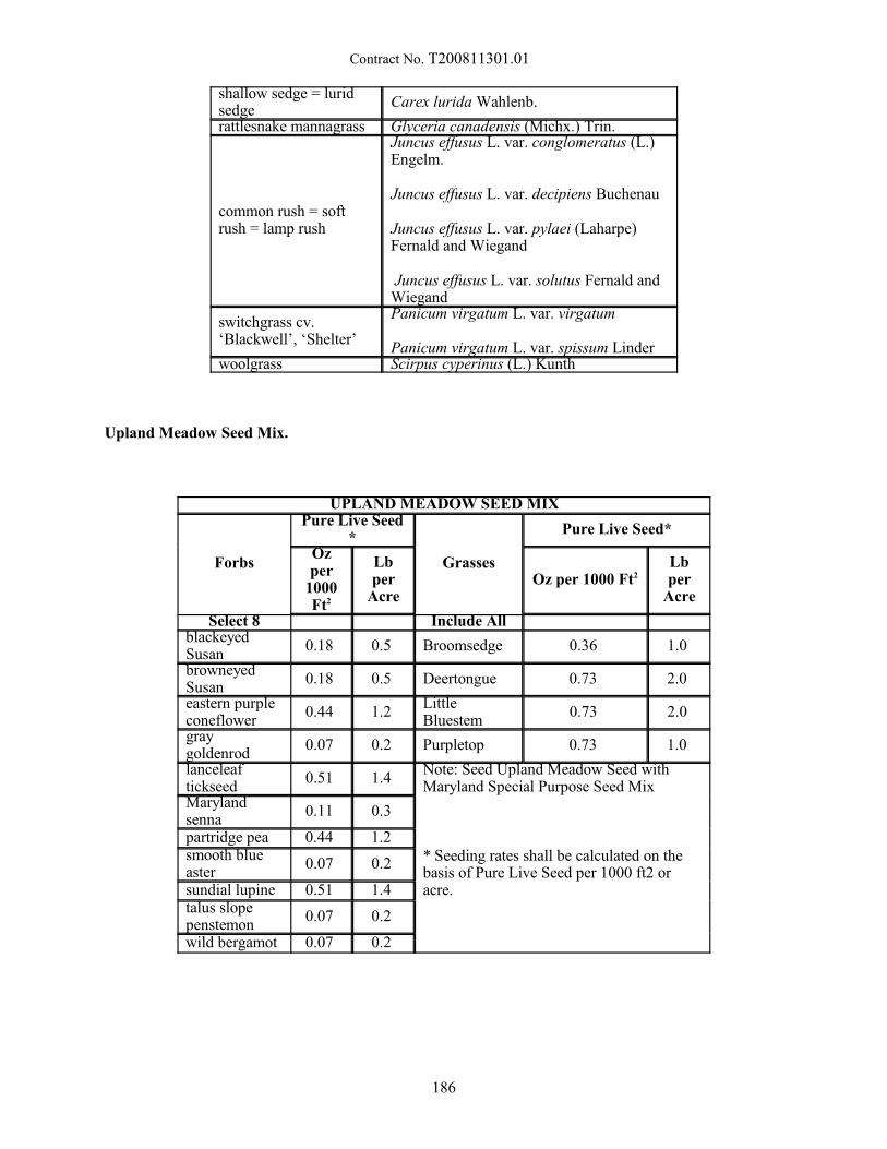
Contract No. T200811301.01
shallow sedge = luridsedge
Carex lurida Wahlenb.
rattlesnake mannagrass Glyceria canadensis (Michx.) Trin.
common rush = softrush = lamp rush
Juncus effusus L. var. conglomeratus (L.)Engelm.
Juncus effusus L. var. decipiens Buchenau
Juncus effusus L. var. pylaei (Laharpe)Fernald and Wiegand
Juncus effusus L. var. solutus Fernald andWiegand
switchgrass cv.‘Blackwell’, ‘Shelter’
Panicum virgatum L. var. virgatum
Panicum virgatum L. var. spissum Linder woolgrass Scirpus cyperinus (L.) Kunth
Upland Meadow Seed Mix.
UPLAND MEADOW SEED MIX
Forbs
Pure Live Seed*
Grasses
Pure Live Seed*
Ozper
1000Ft2
Lbper
AcreOz per 1000 Ft2
Lbper
Acre
Select 8 Include AllblackeyedSusan
0.18 0.5 Broomsedge 0.36 1.0
browneyedSusan
0.18 0.5 Deertongue 0.73 2.0
eastern purpleconeflower
0.44 1.2 LittleBluestem
0.73 2.0
graygoldenrod
0.07 0.2 Purpletop 0.73 1.0
lanceleaftickseed
0.51 1.4 Note: Seed Upland Meadow Seed withMaryland Special Purpose Seed Mix
* Seeding rates shall be calculated on thebasis of Pure Live Seed per 1000 ft2 oracre.
Marylandsenna
0.11 0.3
partridge pea 0.44 1.2 smooth blueaster
0.07 0.2
sundial lupine 0.51 1.4 talus slopepenstemon
0.07 0.2
wild bergamot 0.07 0.2
186
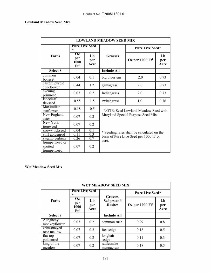
Contract No. T200811301.01
Lowland Meadow Seed Mix
LOWLAND MEADOW SEED MIX
Forbs
Pure Live Seed*
Grasses
Pure Live Seed*
Ozper
1000Ft2
Lbper
AcreOz per 1000 Ft2
Lbper
Acre
Select 8 Include Allcommonboneset
0.04 0.1 big bluestem 2.0 0.73
eastern purpleconeflower
0.44 1.2 gamagrass 2.0 0.73
eveningprimrose
0.07 0.2 Indiangrass 2.0 0.73
lanceleaftickseed
0.55 1.5 switchgrass 1.0 0.36
Maximiliansunflower
0.18 0.5 NOTE: Seed Lowland Meadow Seed withMaryland Special Purpose Seed MixNew England
aster0.07 0.2
New Yorkironweed
0.07 0.2
* Seeding rates shall be calculated on thebasis of Pure Live Seed per 1000 ft2 oracre.
showy tickseed 0.04 0.1 stiff goldenrod 0.11 0.3 swamp verbena 0.26 0.7 trumpetweed orspottedtrumpetweed
0.07 0.2
Wet Meadow Seed Mix
WET MEADOW SEED MIX
Forbs
Pure Live Seed* Grasses,
Sedges andRushes
Pure Live Seed*
Ozper
1000Ft2
Lbper
AcreOz per 1000 Ft2
Lbper
Acre
Select 8 Include AllAlleghenymonkeyflower
0.07 0.2 common rush 0.29 0.8
crimsoneyedrose mallow
0.07 0.2 fox sedge 0.18 0.5
flat-topgoldenrod
0.07 0.2 longhairsedge
0.11 0.3
king of themeadow
0.07 0.2 rattlesnakemannagrass
0.18 0.5
187
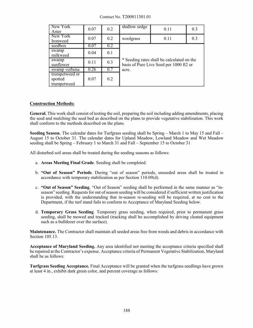
Contract No. T200811301.01
New YorkAster
0.07 0.2 shallow sedge
0.11 0.3
New YorkIronweed
0.07 0.2 woolgrass 0.11 0.3
seedbox 0.07 0.2
* Seeding rates shall be calculated on thebasis of Pure Live Seed per 1000 ft2 oracre.
swampmilkweed
0.04 0.1
swampsunflower
0.11 0.3
swamp verbena 0.26 0.7 trumpetweed orspottedtrumpetweed
0.07 0.2
Construction Methods:
General. This work shall consist of testing the soil, preparing the soil including adding amendments, placingthe seed and mulching the seed bed as described on the plans to provide vegetative stabilization. This workshall conform to the methods described on the plans.
Seeding Season. The calendar dates for Turfgrass seeding shall be Spring – March 1 to May 15 and Fall –August 15 to October 31. The calendar dates for Upland Meadow, Lowland Meadow and Wet Meadowseeding shall be Spring – February 1 to March 31 and Fall – September 15 to October 31
All disturbed soil areas shall be treated during the seeding seasons as follows:
a. Areas Meeting Final Grade. Seeding shall be completed.
b. “Out of Season” Periods. During “out of season” periods, unseeded areas shall be treated inaccordance with temporary stabilization as per Section 110.09(d).
c. “Out of Season” Seeding. “Out of Season” seeding shall be performed in the same manner as “in-season” seeding. Requests for out of season seeding will be considered if sufficient written justificationis provided, with the understanding that in-season re-seeding will be required, at no cost to theDepartment, if the turf stand fails to conform to Acceptance of Maryland Seeding below.
d. Temporary Grass Seeding. Temporary grass seeding, when required, prior to permanent grassseeding, shall be mowed and tracked (tracking shall be accomplished by driving cleated equipmentsuch as a bulldozer over the surface).
Maintenance. The Contractor shall maintain all seeded areas free from weeds and debris in accordance withSection 105.13.
Acceptance of Maryland Seeding. Any area identified not meeting the acceptance criteria specified shallbe repaired at the Contractor’s expense. Acceptance criteria of Permanent Vegetative Stabilization, Marylandshall be as follows:
Turfgrass Seeding Acceptance. Final Acceptance will be granted when the turfgrass seedlings have grownat least 4 in., exhibit dark green color, and percent coverage as follows:
188
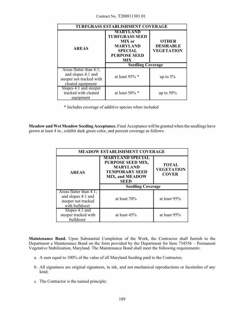
Contract No. T200811301.01
TURFGRASS ESTABLISHMENT COVERAGE
AREAS
MARYLANDTURFGRASS SEED
MIX orMARYLAND
SPECIALPURPOSE SEED
MIX
OTHERDESIRABLE
VEGETATION
Seedling Coverage Areas flatter than 4:1;
and slopes 4:1 andsteeper not tracked with
cleated equipment
at least 95% * up to 5%
Slopes 4:1 and steepertracked with cleated
equipment at least 50% * up to 50%
* Includes coverage of additive species when included
Meadow and Wet Meadow Seeding Acceptance. Final Acceptance will be granted when the seedlings havegrown at least 4 in., exhibit dark green color, and percent coverage as follows:
MEADOW ESTABLISHMENT COVERAGE
AREAS
MARYLAND SPECIALPURPOSE SEED MIX,
MARYLANDTEMPORARY SEEDMIX, and MEADOW
SEED
TOTALVEGETATION
COVER
Seedling Coverage Areas flatter than 4:1;
and slopes 4:1 andsteeper not tracked
with bulldozer
at least 70% at least 95%
Slopes 4:1 andsteeper tracked with
bulldozer at least 45% at least 95%
Maintenance Bond. Upon Substantial Completion of the Work, the Contractor shall furnish to theDepartment a Maintenance Bond on the form provided by the Department for Item 734556 – PermanentVegetative Stabilization, Maryland. The Maintenance Bond shall meet the following requirements:
a. A sum equal to 100% of the value of all Maryland Seeding paid to the Contractor;
b. All signatures are original signatures, in ink, and not mechanical reproductions or facsimiles of anykind;
c. The Contractor is the named principle;
189

Contract No. T200811301.01
d. The term of the bond is for one full year;
e. When Item 734556 – Permanent Vegetative Stabilization, Maryland requires completion aftersubstantial completion of the Project, the term of the Maintenance Bond will be extended for a periodof one year beyond the completion of the permanent seeding work; and
f. Written by a Surety or insurance company that is in good standing and currently licensed to write suretybonds in the State of Delaware by the Delaware Department of Insurance.
Method of Measurement:
The Engineer will measure the quantity of acceptably placed Maryland Permanent Vegetative Stabilizationseed. The quantity of seeding will be measured in square yards (square meters) of surface area.
Basis of Payment:
The quantity and type of seeding will be paid for at the Contract unit price per square yard (square meter).Price and payment will constitute full compensation for preparing the ground; for furnishing and placing allmaterials including seed; and for all labor, equipment, tools, maintenance bond and incidentals required tocomplete the work.
Payment for Permanent Vegetative Stabilization, Maryland seeding will be made at the time seed isacceptably placed. The maintenance bond covering permanent seeding items will only be released when thepermanent seeding meets the requirements of Acceptance of Maryland Seeding above.
10/10/12
190

Contract No. T200811301.01
735501 - HERBICIDE APPLICATION, NOXIOUS WEEDS
Description:
This work consists of furnishing and applying the herbicides to vegetation on the soil surface as directedby the Engineer.
Materials:
The herbicide (s) for treatment shall be selected by the contractor. Labels and Material Safety Data Sheetsfor the selected materials shall be submitted to thr Engineer 30 days prior to application.
Construction Methods:
All herbicides shall be applied in accordance with the EPA approved label. The herbicides shall not beapplied within six (6) hours of rainfall.
Method of Measurement:
The quantity of herbicide application will be measured by the acre of surface area treated with herbicidematerial.
Basis of Payment:
The quantity of herbicide application will be paid for at the Contract price per acre. Price and paymentwill constitute full compensation for furnishing all materials, applying the herbicide in aqueous solution, forall labor, equipment, tools, and incidentals to complete the work.
7/20/15
191
Contract No. T200811301.01
737523 - PLANTINGS
737.01 Description.
This work consists of furnishing and planting specified plants, shrubs, and trees and the replacement andcultural care of the material.
MATERIALS.
737.02 Plant Material.
a. Quality. All plants shall be true to type and nomenclature and typical of their species or variety. Theyshall have a normal habit of growth with well-developed branch systems and vigorous root systems.They shall be sound, healthy, and vigorous plants, free from defects, disfiguration, injury, disease ofany kind, insect eggs, borers, and any infestation. All plants shall be nursery grown. They shall havebeen growing under similar climatic conditions to those of the locality of the Project for at least twoyears prior to planting. All plant material shall have been grown in a soil that is similar to this area andshall not have been grown in a muck type soil or other foreign type. It shall be the responsibility of theContractor to inspect the plants before removal from the nursery where they have been grown to makesure that the plants meet these requirements. All plants shall be freshly dug, and no heeled-in or coldstorage plants will be accepted, with the exception of plant material delivered prior to planting asoutlined in Subsection 737.14.
b. Measurements. All plants shall conform to all sizes and measurements specified in the Plant List. Plantsthat conform to the requirements specified in the Plant List but do not have a normal balance betweenheight and spread will not be accepted. Where any requirement or exact measurement is omitted, theplants furnished shall be normal for the species and variety as listed in AAN's "USA Standards forNursery Stock". Plants for use where symmetry is required shall be matched as close as possible. Allplants shall be measured for height and spread with the branches in their normal position. The trunkdiameter of all trees shall be taken 6" above the ground level for up to and including 4" diameter sizes,and 12" above the ground level for larger sizes. The height of the branches on the tree trunks need notbe as specified if the required height can be obtained by pruning the lower branches without leavingunsightly scars and damaging the trunk. No pruning of branches for this effect shall be done beforedelivery to the site unless approved. Plants larger in size than specified may be used. Larger plants,when selected for use over that which is specified, shall be dug with an earth ball or root spreadproportionate to the increased size. With plants smaller than specified, credit shall be offered to theDepartment for approval. The basis of a credit shall be the average wholesale value based on thedifference between the specified size and the next smaller size. The average wholesale value shall besubstantiated with written submissions in accordance with Subsection 737.02 (e).
c. Inspection. The Contractor shall be responsible for all certificates of inspection of plant materials thatmay be required by Federal, State, or other authorities to accompany shipment of plants. TheContractor shall furnish complete information as to the location of all plants which it intends to supplyand use. The right is reserved to inspect, tag, and approve all plants at the source of supply. Thisinspection and tagging shall not in any way eliminate the right of rejection at the site. All plants mustbe inspected and approved before they are planted. Any plants placed without prior inspection at thesite will be rejected at the discretion of the Engineer. The Plant materials shall be protected accordingto best horticultural practice while in transit in such a way as to prevent the drying or possibledesiccation of plant tissue. All plant material arriving at the site with broken or loose balls, or dry orinsufficiently developed roots, and plants which are weak or thin, damaged or defective, or which donot comply with the specifications, will not be accepted. The Engineer reserves the right to reject allstock that is found to be unsatisfactory. All plant material determined as unsatisfactory by the Engineer
192
Contract No. T200811301.01
shall not be planted under any circumstances and shall be removed from the Project site by the closeof the working day. Failure on the part of the Contractor to comply with any of the above procedureswill require an immediate suspension of all work.
d. Nomenclature. Plants shall conform to the nomenclature of "Standard Plant Names" as accepted by theAmerican Joint Commission of Horticulture Nomenclature, 1942 Edition. Names of varieties notincluded shall conform to names accepted in nursery trade. Size and grading shall conform to thoselisted in AAN's "USA Standards for Nursery Stock". No substitution will be permitted except bywritten permission of the Engineer.
e. Availability. The Engineer, after receiving written request from the Contractor for substitution, willverify and establish the non-availability of the specified plant and size to this satisfaction. Upondetermining that a substitution is justified, the Contractor will be directed to provide certification in theform of five letters from five independent growers who list the specified plant form in their mostcurrent catalog, stating that the item in question is not available as specified.
f. Experience. Under Special Condition No. 22 of the U.S. Army Corps of Engineers 404 Permit, it isstipulated that: The mitigation and post-planting monitoring plans shall be developed and implementedby a firm with demonstrated expertise in wetland creation activities.
Therefore, the firm that does the actual planting and seeding of the mitigation site shall possess a recordof successful wetland woody and wetland herbaceous and seeding programs that have received finalapproval by the U.S. Army Corps of Engineers, or have on-site staff personnel who have managedsuccessful wetland woody and herbaceous planting and seeding programs that have received finalapproval by the U.S. Army Corps of Engineers. At the request of the Department, informationindicating compliance with this "Special Condition" shall be forwarded within 14 days.
737.03 Trees. Trees shall have straight trunks according to their habit of growth and shall be well branchedand rooted. Shade trees of standard variety shall have a single leader and shall be branched at 6 to 8' heightunless otherwise directed.
737.04 Shrubs. Shrubs shall be well branched, with full and compact growth and have ample well branchedroot systems capable of sustaining vigorous plant growth.
a. Woody Shrub Cuttings Cuttings shall be fresh 24" long stems of woody plants. Each cutting shall havea living terminal bud (end bud). Prior to installation, the cutting shall be kept cool and moist to preventdesiccation of the material. Degraded, rotting, or dried out material will not be accepted.
737.05 Ground Cover and Herbaceous Perennials.
Ground cover shall be one year old, container grown plants, unless otherwise approved or specified in theContract documents and shall have been growing for at least six months in the size specified as verified bythe Department's inspection representative.
Herbaceous plant material shall be at least six months old and shall have been growing for at least threemonths in the size specified unless otherwise detailed in the plans, and as verified by the Department'sinspection representative.
737.06 Soil Mix.
a. Topsoil. Planting topsoil shall consist of natural surface soil from well drained areas from which notopsoil has previously been stripped. The topsoil shall be free of subsoil, heavy clay, hard clods, weeds,roots, sticks, toxic substances, or any other extraneous material. The topsoil shall have a pH range offrom 5.5 to 6.8 and contain not less than 2% nor more than 10% organic matter. The topsoil shallexhibit the following grading analysis:
193

Contract No. T200811301.01
Sieve Size Minimum Percent Passing
2" 100
No. 4 90
No. 10 80
The Contractor shall take the necessary action to ensure that the topsoil meets the sieve analysis,acidity, and organic matter requirements. A certificate of analysis of soil samples shall be provided tothe Engineer and approved prior to delivery of topsoil to the Project site.
b. Peat Moss and Peat Humus.
i. Peat Moss. Peat moss shall be from sphagnum peat bogs. All peat moss shall be shredded, notdusty, and free of twigs, stones, hard lumps, roots, or any other undesirable materials. All peat mossmust be moistened before using, but not watered to a saturated or puddled, unworkable condition.Peat moss shall show an acid reaction of 3.5 to 5.5 pH. The Contractor shall provide writtencertification from the manufacturer that the peat moss was obtained from sphagnum peat bogs.
ii. Peat Humus. Peat humus shall be a natural peat or peat humus from fresh water saturated areas,consisting of sedge, sphagnum, or reed peat and be of such physical condition that it passes througha 2" sieve. The humus shall be free from sticks, stones, roots, and other objectionable materials.Samples taken at the source of supply shall have the following analysis:
Acidity Range 4.0 to 7.5 pH
Minimum Water Absorbing Ability 200% by weight on oven-dry basis
Minimum Organic Content 60% when dried at 221 EF (105 EC)
c. Composted leaf mulch free of wood, metallic substances, glass or other contaminates may be usedin lieu of peat moss or peat humus.
737.07 Fertilizer. Fertilizer shall be a 20-10-5 analysis or approved equal in accordance with thefollowing minimum guaranteed analysis:
Total Nitrogen (N) 20.00%
Derived from urea-formaldehyde
7.0% water soluble nitrogen
13.0% water insoluble nitrogen
Available Phosphoric Acid (P2O5) 10.00%
Derived from calcium phosphate
Soluble Potash (K2O) 5.00%
Derived from potassium sulfate
194
Contract No. T200811301.01
Combined Calcium (Ca) 2.60%
Derived from calcium phosphate
Combined Sulfur (S) 1.60%
Derived from ferrous and potassium sulfates
Iron (expressed as elemental Fe) 0.35%
Derived from ferrous sulfate
The fertilizer shall be formulated in tablet form weighing a minimum of 20g per tablet.
The fertilizer shall conform to all State and Federal regulations. The Engineer will require the Contractorto furnish an affidavit from the vendor or a testing laboratory as to the available nutrients contained therein.
Fertilizer shall be furnished in new, clean, sealed, and properly labeled packages or containers. Fertilizerfailing to meet the specified analysis may be used as determined by the Engineer, providing sufficientmaterials are applied to comply with the specified nutrients per unit of measure.
737.09 Mulch. Mulch shall be shredded hardwood bark or wood chips, or an approved equal as accepted bythe Engineer. All mulching materials will be visually inspected by the Engineer prior to delivery at theplanting site and shall conform to the following requirements:
a. Shredded hardwood bark shall be from a deciduous hardwood source and be mechanically ground to amaximum size of 6". In addition, the bark shall be relatively free of bark fines dust and shall exclude allforeign and toxic substances.
b. Wood chips must be stockpiled for at least one year prior to placement as verified by the Department'sinspection representative and shall not contain leaves, twigs, wood shavings and sawdust, or any foreignor toxic substances. In addition, loose, non-pelletized fertilizer with analysis in accordance withSubsection 737.07 shall be applied at the rate of 0.5 lb/yd2 prior to wood chip placement.
Only one of the above mulches will be selected and approved for use throughout the entire Project, andwritten certification for the above listed requirements of the mulch shall be submitted by the Contractor.
737.10 Stakes, Guys, and Related Materials. Staking and guying shall be as per the Standard ConstructionDetails or alternate method approved by the Engineer.
a. Tree Stakes. Hardwood stakes shall be at least 2” by 2" rough sawed to the length required. Stakes shallbe free from knots, rot or other defects that impair strength.
b. Guying straps. Guying straps shall be one and one-half to two inches (1.5-2.0”) wide, of polymer or nylonconstruction, with grommets at both ends to accept wire or heavy twine.
c. Anchoring systems. Anchors for guy wire shall be malleable iron or aluminum alloy with 3000 lb holdingcapacity designed to be inserted with a driving rod to a depth specified by the manufacturer. The anchorassembly shall be designed to turn, once located at the proper depth, at a right angle to the line of forceapplied. All manufacturers’ recommendations shall be followed for installing ground anchoring systems.
195
Contract No. T200811301.01
737.11 Water. Conform to the requirements of Section 803.
CONSTRUCTION METHODS.
737.12 Planting Periods. Plant during the following planting period with the exceptions as noted:
Balled or Burlapped and Potted or Container Grown Plant Material:
March 1 to May 15; September 1 to November 30:
(1) All planting of broadleaf evergreens during the fall season shall be completed by November 1.
(2) All material planted from May 16 to August 31 must be treated with an approved antitranspirant in amanner recommended by the manufacturer, and written approval for moving plants within this period mustfirst be obtained from the Engineer.
(3)Woody Shrub Cuttings Install as dormant materials between October 30 and December 1 or betweenMarch 1 and April 1.
The above mentioned periods may be extended or reduced according to weather and soil conditions at thetime and upon written request from the Contractor to the Engineer for approval. Planting outside the plantingwindow does not relieve the contractor of his guarantee. The Engineer reserves the right to stop plantingoperations at any time.
The Contractor shall not plant when weather conditions are unfavorable for proper work or when the soilis in a frozen condition.
737.13 Soil Mixture. Soil mixtures for the various plantings shall consist of the following:
a. All Plants Except Ericaceous Material. For each cubic yard of baled peat moss, or approved equal, addfrom 43 to 54 yd3; of planting topsoil.
b. Ericaceous Plants. For each cubic yard of baled peat moss, or approved equal, add from 36 to 45 yd3; of planting topsoil. If peat humus is furnished in lieu of peat moss in the above mix, the mixture shall bebased in the proportion of 1.8 yd3; of peat humus for each cubic yard (cubic meter) bale of peat mossspecified for the above soil mix. Other approved equal materials shall be mixed according tomanufacturer's printed recommendations which shall be submitted to the Engineer for written approval.
The above soil mixtures shall be mixed as specified in an area approved by the Engineer. No mix shall beprepared prior to notification of the Engineer at least 48 hours in advance of the
mixing operation. Where ground covers or herbaceous perennials are specified, the soil mix
may be mixed in place providing the existing topsoil conforms to the requirements of subsection
737.06.
The fertilizer as specified in accordance with Subsection 737.07 shall be placed according to the followingrequirements:
a. Balled and Burlapped, or Container Stock. Position the plant in the hole, and backfill no higher thanhalfway up the root ball. Place the recommended number of tablets evenly around the perimeter of andimmediately adjacent to the root ball. Complete the backfilling, tamping, and watering.
196
Contract No. T200811301.01
b. Small Ground Cover Plants and Herbaceous Perennials. Position the plant in the hole, and backfill nohigher than halfway up the root ball. Place the recommended number of tablets evenly around theperimeter of and immediately adjacent to the root ball. Complete the backfilling, tamping, and watering.
c. Trees. Use one 20 g tablet for each 1/2" of tree trunk diameter based on size specified for planting.
d. Shrubs. Use one 20 g tablet for each 12" of height or spread based on size specified for planting.
e. Ground Cover and Herbaceous Perennials. Use one 20 g tablet for each plant.
No backfill shall be placed in any pit until the excavation has been inspected. Excess
excavated material shall be removed from the Project site.
737.14 Digging and Handling. All precautions customary in good trade practice shall be taken in preparingplants for transplanting. Plants transplanted with workmanship that fails to meet the highest standards willbe rejected. All balled and burlapped plants shall have firm, natural balls of earth of ample proportions anddiameter not less than as specified in AAN's "USA Standards for Nursery Stock". Plants with cracked,broken, or crushed balls, which occur either before or during planting operations, will be rejected or shall beremoved from the site immediately. All plants shall be handled so that roots are adequately protected andmoist at all times. Material that cannot be planted immediately after delivery shall be adequately protectedby covering with canvas, wet straw, burlap, moss, or other suitable material and kept covered until ready tobe planted. Trees should not be planted with frozen earth balls. Containerized plant material shall be growingin the specified size container for at least six months and shall not display signs of being root bound orunnatural ratio of planting medium vs. root mass.
737.15 Location of Plants. Plants shall be located as indicated on the Plans, but may be shifted to avoidutilities subject to the approval of the Engineer. No excavation shall commence until locations are approved.
737.16 Planting. All trees and shrubs shall be planted in pits as detailed on the Standard Construction Details.Pits shall not be excavated with vertical sides. Pits shall be of such a depth that, when planted and settled, thecrown of the plant shall bear the same relation to finished grade as it did to soil surface in its place of growth.With the approval of the Engineer, the Contractor may elect to plant wetland grown containerized shrubs onsmall mounds raised no more than 2" above the final grading elevation shown on the Plans. Open plant pitsshall not be allowed overnight in residential areas or in any location where it is determined by the Engineerto pose a potential hazard to pedestrians or traffic.
All backfill topsoil shall be covered with a waterproof material after mixing. Pits shall be backfilled withspecified soil mix and compacted firmly under ball of roots to establish a firm foundation. Plants shall be setin the center of pits in a vertical position so that the crown of the plant is level with the finished grade afterallowing for watering and settling of soil. The "Soil Mixture" shall be carefully and firmly worked andtamped under and around the base of the ball to fill all voids. When partially backfilled and compacted, theburlap and any wire baskets shall be removed from the sides and tops of the balls and cut away to prevent airpockets, but no burlap shall be pulled from under the balls. All burlap, wire baskets and other containers shallbe removed from the jobsite at the end of the workday. The balance of the planting hole shall be filled withthe planting mixture and a ring of earth shall be formed around the plant to produce a dish for watering. Allplants shall be thoroughly watered immediately after planting as directed by the Engineer. This initialwatering shall mean complete saturation of all backfill in the pits and beds during the same day of planting.Care shall be taken during all planting operations to ensure that no excavated material is dumped on anygrassed area unless a suitable type of matting or protective underlay is used. The Contractor shall beresponsible for all damage to any grassed, planted, or other landscaped area caused by its operations and shallrepair any damage so caused in a manner satisfactory to the Engineer.
Ground cover and herbaceous perennial areas shall be prepared by rototilling to a minimum depth of 10".The mixing of peat moss, peat humus, or approved equal may be performed separately in order to obtain theproportion of ground cover or herbaceous perennial soil mixture as specified. Beyond the minimum
197
Contract No. T200811301.01
excavation as stated above for soil mixing, the root system of the plant shall determine the actual depth forindividual plant excavation. Plants shall be backfilled with the soil mixture and compact firmly around roots.All areas shall have a smooth and uniform grade and a minimum of 2" of approved mulch.
a. Pruning. All plants shall be pruned immediately after planting or transplanting to remove all injured ordead wood. All trees inspected and tagged at the nursery shall conform to AAN Standards, and anysubsequent pruning by the Contractor shall in no way alter the natural habit or shape of the plant. Allpruning shall be done with sharp tools by workers skilled in this operation. All cuts shall be made flush,leaving no stubs. On all cuts over 3/4" in diameter and bruises or scars on the bark, the injured cambiumshall be traced back to living tissue and removed; wounds shall be smoothed and shaped so as to preservethe branch bark ridge.
b. Watering. Plants shall be watered on the same day as planting unless otherwise approved by the Engineer. Quantity of water per plant shall be as detailed in Section 737.17.
c. Mulching. Trees and shrubs shall be mulched with at least a 4" cover of mulch. Mulch shall be placedthe same day of planting, unless otherwise approved by the Engineer.
d. Wire baskets, nylon binding and treated burlap shall be cut away and removed from the top half of theroot ball.
e. Staking and Guying. Unless approved by the Engineer, all staking and guying specified shall becompleted the same day as planting and mulching.
f. Cleaning Up. Throughout the course of planting, excess and waste materials shall be immediatelyremoved from the site, seeded areas kept clean, and all precautions taken to avoid damage to existingstructures, trees, shrubs, plants, and grass. When planting in an area that has been otherwise completed,the area shall, upon completion of the planting, be immediately and thoroughly cleared of all debris,rubbish, subsoil, and all waste materials removed from the site. All ground surfaces shall be raked smooth.All sodded areas disturbed as a result of construction shall be repaired by the Contractor.
737.17 Plant Establishment. The plant establishment period for all planting shall begin immediately afterall planting and replacements (as specified under Section 737.16, Planting) are complete and acceptable tothe Engineer. The plant establishment period will consist of one full growing season during which time theContractor shall be responsible for all work necessary to keep the plants in a live and healthy condition. Agrowing season is defined as the period from May 1 through September 30. If the Contractor completes allplanting (as specified under Planting) by May 1, the inspection will be held on or about October 1 of thatyear. In the event the Contractor does not complete all planting by May 1, the inspection will be held on orabout October 1 of the following year. All replacement plant material determined to be necessary at theinspection must then be approved at the replacement plant source by October 15. At this time, the Engineerwill direct the Contractor to replace those plants determined to be dead or unhealthy by December 1. TheContractor will notify the Engineer in writing that all replacement planting has been accomplished. TheEngineer will conduct an inspection within 15 days after such notification to determine the acceptability ofthe replacements. If all replacements are determined satisfactory by the Engineer, the Contractor will berelieved of all further responsibility for care and replacement.
All planting areas shall be kept free of weeds and grass during the life of the Contract. The Contractormay utilize a pre- or post-emergent herbicide to control such grass and broadleaf weeds incidental to the costof planting and be totally responsible for the proper use and placement of any such herbicide. As requestedin writing by the Engineer, the Contractor shall be responsible to weed within all plant beds and within thesaucer limits of individual plants, beginning 10 calendar days after the date of notification. The Contractorshall prune and apply insecticides or fungicides as required, repair or replace stakes and guy wires, tightenguy cable or wire and repair plant saucer washouts when and as specified by the Engineer.
198
Contract No. T200811301.01
Any plants that settle below or rise above the desired finished grades shall be reset at the proper grades.
If dead or unhealthy plants are discovered, they shall be removed within 10 calendar days and replacedwith the next appropriate planting season.
All replacements shall be plants of the same kind, size and quality as originally specified in the Contractand they shall be furnished, planted, mulched, guyed, watered, etc. as specified herein for new plant material.
The Contractor shall warrant all plant material against defects including death and unsatisfactory growth,except for defects resulting from incidents beyond the Contractor’s control, such as vehicular impacts orvandalism. Submission of appropriate police reports or other approved evidence verifying the cause of thedamage shall be required to relieve the Contractor of responsibility for replacement.
The cost of the above described work shall be incidental to Section 737, Planting.
Contractor shall be required to water all major and minor trees, shrubs and all herbaceous beds bi-weeklyduring the period from June 15 through October 1. Watering, once initiated, shall continue withoutinterruption until all plants on the project have been watered. Payment shall be per 1,000 gals of waterapplied and shall be based on the following schedule: Major trees-15 gals per tree, minor trees-10 gals pertree, shrubs-5 gals per shrub, perennials-10 gals per 100 square feet of planting bed. Water used for this itemshall meet the requirements of Section 803 of the Standard Specifications. Tree watering bags, if utilized,shall be filled as a part of the watering operation; payment shall be as detailed herein. Tree watering bagsshall remain the property of the contractor and shall be removed prior to final inspection.
737.18 Method of Measurement. The quantity of planting will not be measured.
737.19 Maintenance Bond. Upon Substantial Completion of the Work, the Contractor shall furnish to theDepartment a Maintenance Bond on the form provided by the Department for item 737523 - Planting. TheMaintenance Bond shall meet the following requirements:
A sum equal to 100% of the value of all Planting Items paid to the Contractor, as detailed in the BreakoutSheet; All signatures are original signatures, in ink, and not mechanical reproductions or facsimiles of anykind; The Contractor is the named principle; Section 737.17 – Plant Establishment Work items associatedwith this section requires completion after substantial completion of the Project. The term of the MaintenanceBond will be for a period of one full growing season, as defined in the section, beyond the completion ofpermanent planting Work; and, Written by a Surety or insurance company that is in good standing andcurrently licensed to write surety bonds in the State of Delaware by the Delaware Department of Insurance.
737.20 Basis of Payment.
The quantity of planting will be paid for at the Contract lump sum. Price and payment will constitute fullcompensation for furnishing and placing all materials, including plants, soil mixes, and mulch; for protectingplants after digging and prior to planting; for staking, excavating plant pits, pruning, and guying; for thecultural care of the plants until the completion and acceptance of all landscape work; for disposing of excessand waste materials; for replacement planting; for cleanup; for repairs to plant material, tree protection, wire,or staking; for repairs to damaged grassed, planted, or other landscaped area due to the Contractor'soperations; for ensuring that topsoil meets the sieve analysis, acidity, and organic matter requirements; forapplying sufficient materials to fertilizer that originally failed to meet the specified analysis; for using pre-or post-emergent herbicide to control grass and weeds; for the work outlined under Subsection 737.17; andfor all labor, equipment, tools and incidentals required to complete the work. The quantity of watering willbe paid for in accordance with the price bid for, “Watering,” as detailed on the breakout sheet. Payment shallbe by the M/Gal (1,000 gallons) of water applied at each watering operation. The breakout sheet attachedto the proposal shows all plant material and the anticipated amount of water proposed for this Contract. TheContractor shall fill in the per each unit price and the cost (unit price times the proposed quantity) for eachitem listed. The lump sum price bid for 737523 - Planting shall be the sum of the total cost for all speciesand sizes listed.
199
Contract No. T200811301.01
The Department reserves the right to delete from the Contract the furnishing and installing of one or moreof the species and/or sizes listed and the right to add or subtract from the quantity of each species and sizelisted. The lump sum to be paid will be adjusted in accordance with the Contractor's unit prices as requiredabove. There will be no extra compensation to the Contractor if such additions and/or deletion are made.Watering item shall be paid separately for watering completed at the bid price indicated on the BreakoutSheet. Payment for the planting as described above may be processed if, in the opinion of the Engineer allwork required, except that specified under Subsection 737.17 is satisfactorily completed. No partial paymentwill be made for any living plant until and unless planted in accordance with these specifications. Noadditional payment will be made for using plants larger than specified.
On contracts where assessment of time is in working days, the Contractor will be charged working dayswhile engaged in actual planting and directly related work such as plant pit excavation, staking, wrapping,and mulching. The Contractor will not be charged time for indirectly related work such as watering, weedcontrol, pruning, and other responsibilities as described under Subsection 737.17
The cost to remove and replace plants that settle below or rise above the desired finished grades, or thatdie or are unhealthy as described in Subsection 737.17 shall be the responsibility of the Contractor.
7/29/15
200
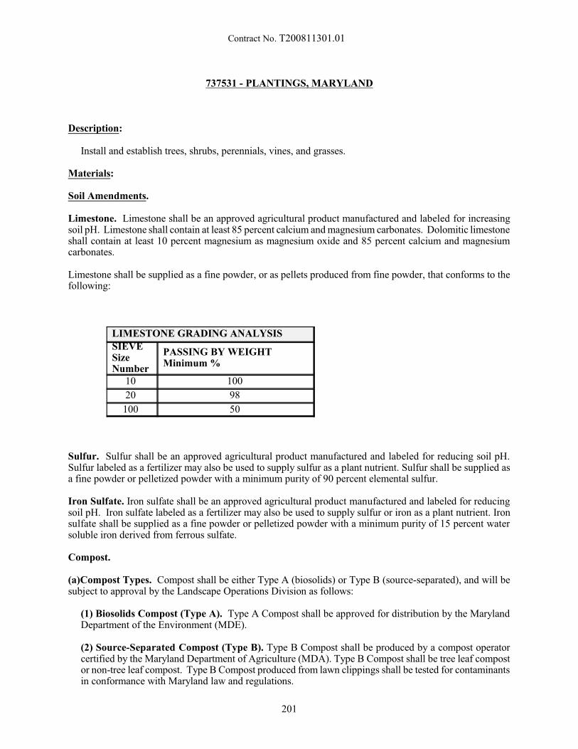
Contract No. T200811301.01
737531 - PLANTINGS, MARYLAND
Description:
Install and establish trees, shrubs, perennials, vines, and grasses.
Materials:
Soil Amendments.
Limestone. Limestone shall be an approved agricultural product manufactured and labeled for increasingsoil pH. Limestone shall contain at least 85 percent calcium and magnesium carbonates. Dolomitic limestoneshall contain at least 10 percent magnesium as magnesium oxide and 85 percent calcium and magnesiumcarbonates.
Limestone shall be supplied as a fine powder, or as pellets produced from fine powder, that conforms to thefollowing:
LIMESTONE GRADING ANALYSIS SIEVESizeNumber
PASSING BY WEIGHTMinimum %
10 100
20 98
100 50
Sulfur. Sulfur shall be an approved agricultural product manufactured and labeled for reducing soil pH. Sulfur labeled as a fertilizer may also be used to supply sulfur as a plant nutrient. Sulfur shall be supplied asa fine powder or pelletized powder with a minimum purity of 90 percent elemental sulfur.
Iron Sulfate. Iron sulfate shall be an approved agricultural product manufactured and labeled for reducingsoil pH. Iron sulfate labeled as a fertilizer may also be used to supply sulfur or iron as a plant nutrient. Ironsulfate shall be supplied as a fine powder or pelletized powder with a minimum purity of 15 percent watersoluble iron derived from ferrous sulfate.
Compost.
(a)Compost Types. Compost shall be either Type A (biosolids) or Type B (source-separated), and will besubject to approval by the Landscape Operations Division as follows:
(1) Biosolids Compost (Type A). Type A Compost shall be approved for distribution by the MarylandDepartment of the Environment (MDE).
(2) Source-Separated Compost (Type B). Type B Compost shall be produced by a compost operatorcertified by the Maryland Department of Agriculture (MDA). Type B Compost shall be tree leaf compostor non-tree leaf compost. Type B Compost produced from lawn clippings shall be tested for contaminantsin conformance with Maryland law and regulations.
201
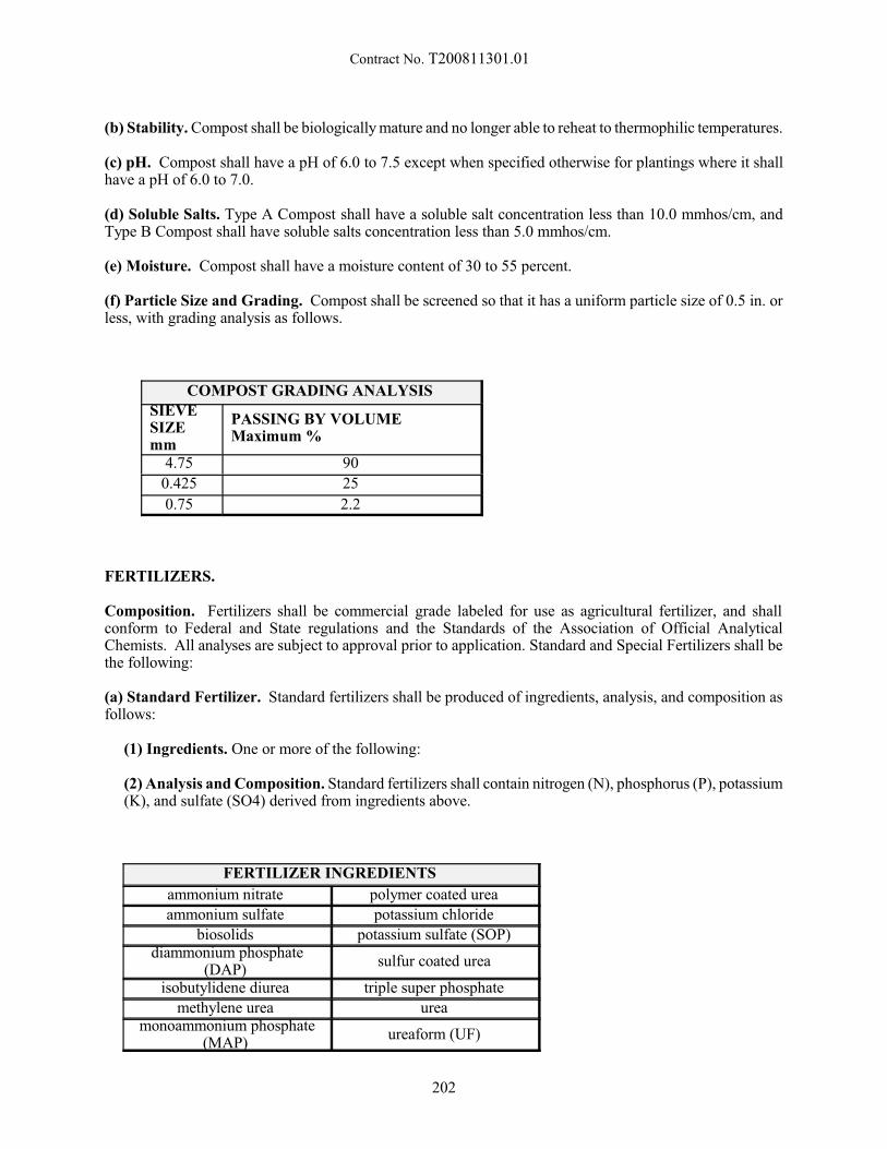
Contract No. T200811301.01
(b) Stability. Compost shall be biologically mature and no longer able to reheat to thermophilic temperatures.
(c) pH. Compost shall have a pH of 6.0 to 7.5 except when specified otherwise for plantings where it shallhave a pH of 6.0 to 7.0.
(d) Soluble Salts. Type A Compost shall have a soluble salt concentration less than 10.0 mmhos/cm, andType B Compost shall have soluble salts concentration less than 5.0 mmhos/cm.
(e) Moisture. Compost shall have a moisture content of 30 to 55 percent.
(f) Particle Size and Grading. Compost shall be screened so that it has a uniform particle size of 0.5 in. orless, with grading analysis as follows.
COMPOST GRADING ANALYSIS SIEVESIZEmm
PASSING BY VOLUMEMaximum %
4.75 90
0.425 25
0.75 2.2
FERTILIZERS.
Composition. Fertilizers shall be commercial grade labeled for use as agricultural fertilizer, and shallconform to Federal and State regulations and the Standards of the Association of Official AnalyticalChemists. All analyses are subject to approval prior to application. Standard and Special Fertilizers shall bethe following:
(a) Standard Fertilizer. Standard fertilizers shall be produced of ingredients, analysis, and composition asfollows:
(1) Ingredients. One or more of the following:
(2) Analysis and Composition. Standard fertilizers shall contain nitrogen (N), phosphorus (P), potassium(K), and sulfate (SO4) derived from ingredients above.
FERTILIZER INGREDIENTS
ammonium nitrate polymer coated urea
ammonium sulfate potassium chloride
biosolids potassium sulfate (SOP) diammonium phosphate
(DAP) sulfur coated urea
isobutylidene diurea triple super phosphate
methylene urea urea monoammonium phosphate
(MAP) ureaform (UF)
202
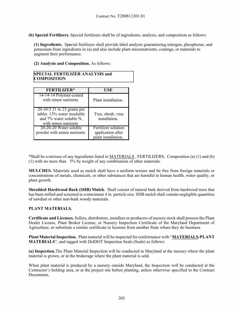
Contract No. T200811301.01
(b) Special Fertilizers. Special fertilizers shall be of ingredients, analysis, and composition as follows:
(1) Ingredients. Special fertilizers shall provide label analysis guaranteeing nitrogen, phosphorus, andpotassium from ingredients in (a) and also include plant micronutrients, coatings, or materials toaugment their performance.
(2) Analysis and Composition. As follows:
SPECIAL FERTILIZER ANALYSIS andCOMPOSITION
FERTILIZER* USE 14-14-14 Polymer-coated
with minor nutrients Plant installation.
20-10-5 21 to 23 grams pertablet. 13% water insoluble
and 7% water soluble N,with minor nutrients
Tree, shrub, vineinstallation.
20-20-20 Water solublepowder with minor nutrients
Fertilizer solutionapplication after
plant installation.
*Shall be a mixture of any ingredients listed in MATERIALS , FERTILIZERS, Composition (a) (1) and (b)(1) with no more than 5% by weight of any combination of other materials.
MULCHES. Materials used as mulch shall have a uniform texture and be free from foreign materials orconcentrations of metals, chemicals, or other substances that are harmful to human health, water quality, orplant growth.
Shredded Hardwood Bark (SHB) Mulch. Shall consist of natural bark derived from hardwood trees thathas been milled and screened to a maximum 4 in. particle size. SHB mulch shall contain negligible quantitiesof sawdust or other non-bark woody materials.
PLANT MATERIALS.
Certificate and Licenses. Sellers, distributors, installers or producers of nursery stock shall possess the PlantDealer License, Plant Broker License, or Nursery Inspection Certificate of the Maryland Department ofAgriculture, or substitute a similar certificate or licenses from another State where they do business.
Plant Material Inspection. Plant material will be inspected for conformance with “MATERIALS-PLANTMATERIALS”, and tagged with DelDOT Inspection Seals (Seals) as follows:
(a) Inspection.The Plant Material Inspection will be conducted in Maryland at the nursery where the plantmaterial is grown, or at the brokerage where the plant material is sold.
When plant material is produced by a nursery outside Maryland, the Inspection will be conducted at theContractor’s holding area, or at the project site before planting, unless otherwise specified in the ContractDocuments.
203

Contract No. T200811301.01
The Contractor shall ensure that the plant material is present for inspection on the scheduled date, and thatit meets the requirements of “MATERIALS-PLANT MATERIALS”. The condition and identity of plantmaterial will be subject to re-inspection for the duration of the Contract.
(b) Scheduling. The Inspection will be scheduled by the Engineer. At least 14 days notice to schedule anInspection within Delaware, and at least 45 days notice to schedule an Inspection outside Delaware.
(c) Seals. DelDOT will determine which plants, if any, will be tagged with Seals.
When Seals are placed upon representative plants within a block of plant material, the plant material deliveredfor installation shall be similar in size, shape and character to the plant material that received Seals.
Plant material that is delivered with broken or missing Seals, or that is not similar to the plant material withinthe block that was tagged with Seals will be rejected.
(d) Rejected Plants. Plant materials which do not meet these requirements will be rejected. Plant materialrejected at the nursery or holding area shall not be delivered to the project; if delivered, it shall immediatelybe removed. Plants shall not be installed until the Plant Material Inspection has been completed andsatisfactory identification has been provided.
Plant Material Standards. Plant material shall be grown, identified, graded, and delivered in good conditionas specified in this section.
(a) Hardiness Zones of Origin. Plant material shall be nursery grown within plant hardiness zones 5, 6, or7 according to the ‘USDA Plant Hardiness Zone Map’ unless otherwise specified. Plant material shall be dugand transported in conformance ANSI Z60.1. Bare root deciduous plants shall be delivered in a dormantcondition. Roots shall be adequately protected and kept moist.
(b) Names and Identification. Plant material shall be clearly and correctly identified by the grower ordistributor. Plant materials that are misidentified, or not satisfactorily tagged or labeled, or do not conformto the accepted characteristics of the species or cultivar, will be rejected.
(c) ANSI Standards. Plant material shall conform to ‘American Standard for Nursery Stock (ANSI Z60.1)of the American Nursery and Landscape Association. Plant grades shall be those established in ANSI Z60.1,and shall include plants from that size up to but not including the next larger grade size. When specimenplants are specified by the Contract documents, the specimen requirement shall also be met. Plant materialwhich does not meet the standards of this section shall be rejected.
(d) Health and Sanitation. Plant material shall be in good health and be declared and certified free fromdisease and insects as required by law for transportation, and shall be free from pest-related stress and pestdamage.
Plants shall be healthy, free from physical defects and stresses, and have well-developed branches and avigorous root system. Plants that exhibit wilt, shriveling, insufficient root mass, broken or loose root balls,or inadequate protection will be rejected.
Container grown plants shall be well rooted, vigorous and established in the size pot specified, shall have wellbalanced tops for their pot size, and shall not be root bound.
Plants grown in fields or containers which include Ailanthus, Canada thistle, Johnsongrass, or yellownutsedge will be rejected.
(e) Shade and Flowering Trees. Shade and flowering trees shall be symmetrically balanced. Major branchunions shall not have ‘V’ shaped crotches, bark inclusion or unions derived from water sprouts (epicormicgrowth) capable of causing structural weakness.
204

Contract No. T200811301.01
Trees shall be free of unhealed branch removal wounds greater than 1 in. diameter, or wounds or scars causedby staking, wire or ties, or any other defect which could cause structural failure or disfigurement.
Shade trees and central leader flowering trees shall have a single main trunk. Trunk height to the lowestbranch shall conform to the following:
HEIGHT TO LOWEST BRANCH
CALIPER in. HEIGHT ft
1-1/2 and 1-3/4 4
2 to 2-1/2 5
3 6
(f) Unacceptable Plants. Plant material that becomes unacceptable after installation shall be rejected asspecified in “CONSTRUCTION -General-Unacceptable Plants and Replacement Plants”.
American Holly (Ilex opaca Aiton). Each lot of plants shall include 90 percent female plants and 10 percentmale plants of cultivars selected from the following:
AMERICAN HOLLY CULTIVARS
FEMALE MALE
Angelica Miss Helen David
Arlene Leach Old Heavy
Berry Jersey Knight
B and O Patterson Leather Leaf
Dan Fenton Satyr Hill Nelson West
Jersey Princess Wyetta North Wind
Plant Storage and Handling. Adequate facilities shall be provided for plant storage. Plants shall be handledwith care to avoid damage.
(a) Bulbs. Bulbs shall be stored under appropriate climate control.
(b) Annual Plants. Annual plants shall be kept moist.
(c) Bare Root Plants. Bare root plants shall be kept moist and heeled into moist soil or other suitablematerial until installed. During transport, the roots shall be covered with canvas, burlap or straw.
(d) Balled and Burlapped and Container Grown Plants. Balled and burlapped plants and container grownplants shall be kept moist and installed within seven days of delivery, or the root balls or containers shall becovered with mulch or straw until removed for installation.
205
Contract No. T200811301.01
MARKING AND STAKING MATERIALS.
Outline Stakes. Outline stakes shall be full cut 1.75 x 1.75 in. sound hardwood, 48 in. long, as approved.
Stakes. Stakes for supporting trees shall be rough sawn, straight grain hardwood reasonably free from bark,knot holes, excessive warping, or other imperfections. Stakes shall be full cut 2.0 x 2.0 in. thickness.
Wire. Wire shall be No. 12 and 14 gauge new annealed galvanized wire.
Wire Rope. Wire rope shall be 0.25 in. zinc coated steel wire seven strand as commonly used for guyinglarge trees.
Cable Clamps. Cable clamps shall be zinc galvanized steel.
Hose. Hose shall be 5/8 in. inside diameter corded synthetic rubber hose.
Turnbuckles. Turnbuckles shall be zinc galvanized with 4.5 in. openings and 5/16 in. threaded ends withscrew eyes.
Anchors. Tree anchors shall be earth anchors of a type commonly used for anchoring large trees.
WATER, PESTICIDES, AND ADJUVANTS.
Water. Water used for the installation and establishment of vegetation shall not contain concentrations ofsubstances that are harmful to plant growth.
Water derived from public and municipal water systems shall be acceptable for irrigation, fertilization, ormixing with pesticides. Water derived from wells or other sources may be used when it has soluble saltsconcentration less than 500 ppm, sodium less than 50 percent of total salts, and pH between 5.0 to 7.8.
Pesticides. Pesticides shall be EPA-approved and registered for use in Maryland to control plants, fungi,insects or other pests. Pesticides shall be approved for use, and acceptable application rates established bythe Landscape Operations Division as follows:
(a) Herbicide. Herbicide shall control or prevent regrowth of plants or vegetation.
(b) Insecticide. Insecticide shall control or protect against insect or other arthropod pests.
(c) Fungicide. Fungicide shall control or protect against fungal or bacterial pests.
(d) Other Pesticides. Other pesticides shall control or protect against other pests.
Marking Dye. Marking dyes shall be used to color spray solutions, be nonphytotoxic, oil or water soluble,and compatible with the pesticide products they are applied with. Marking dye products and application ratesshall be approved by the Engineer.
Spray Adjuvant and Wetting Agent. Spray adjuvant and wetting agents shall be mixable with water andcompatible with the pesticides or other products they are applied with.
206
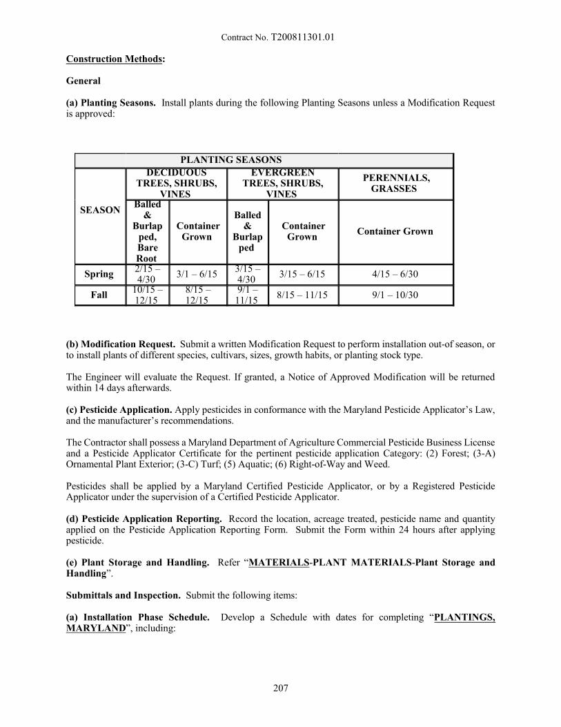
Contract No. T200811301.01
Construction Methods:
General
(a) Planting Seasons. Install plants during the following Planting Seasons unless a Modification Requestis approved:
PLANTING SEASONS
SEASON
DECIDUOUSTREES, SHRUBS,
VINES
EVERGREENTREES, SHRUBS,
VINES
PERENNIALS,GRASSES
Balled&
Burlapped,BareRoot
ContainerGrown
Balled&
Burlapped
ContainerGrown
Container Grown
Spring 2/15 –4/30
3/1 – 6/15 3/15 –4/30
3/15 – 6/15 4/15 – 6/30
Fall 10/15 –12/15
8/15 –12/15
9/1 –11/15
8/15 – 11/15 9/1 – 10/30
(b) Modification Request. Submit a written Modification Request to perform installation out-of season, orto install plants of different species, cultivars, sizes, growth habits, or planting stock type.
The Engineer will evaluate the Request. If granted, a Notice of Approved Modification will be returnedwithin 14 days afterwards.
(c) Pesticide Application. Apply pesticides in conformance with the Maryland Pesticide Applicator’s Law,and the manufacturer’s recommendations.
The Contractor shall possess a Maryland Department of Agriculture Commercial Pesticide Business Licenseand a Pesticide Applicator Certificate for the pertinent pesticide application Category: (2) Forest; (3-A)Ornamental Plant Exterior; (3-C) Turf; (5) Aquatic; (6) Right-of-Way and Weed.
Pesticides shall be applied by a Maryland Certified Pesticide Applicator, or by a Registered PesticideApplicator under the supervision of a Certified Pesticide Applicator.
(d) Pesticide Application Reporting. Record the location, acreage treated, pesticide name and quantityapplied on the Pesticide Application Reporting Form. Submit the Form within 24 hours after applyingpesticide.
(e) Plant Storage and Handling. Refer “MATERIALS-PLANT MATERIALS-Plant Storage andHandling”.
Submittals and Inspection. Submit the following items:
(a) Installation Phase Schedule. Develop a Schedule with dates for completing “PLANTINGS,MARYLAND”, including:
207

Contract No. T200811301.01
OPERATIONS IN INSTALLATION PHASE SCHEDULE1 Layout, utilities review and marking.
2 Undesirable vegetation removal and herbicide application.
3 Planting pit excavation, soil preparation, and plant installation.
4 Planting beds rototilling and soil preparation, applying shredded hardwood bark (SHB)mulch, and plant installation.
5 Applying fertilizer solution after installation, and cleanup.
Submit the written Schedule at least 30 days before beginning landscape work. The Schedule will bereviewed by the Engineer for completeness and feasibility, and will be approved or returned for correction.
(b) Plant Material Inspection and Approval. The Inspection will be conducted by the Engineer asspecified in “MATERIALS-PLANT MATERIALS-Plant Material Standards”.
(c) Establishment Phase Schedule & IPM Program. Develop a Schedule with dates for completing“CONSTRUCTION -Establishment Phase”. Include an Integrated Pest Management (IPM) Plan withmethods of pest monitoring (weeds, diseases, insects, mammals, etc.), pesticide selection, application rates,and scheduling.
Submit the written Establishment Phase Schedule & IPM Program at the Installation Phase Inspection.
The Schedule will be reviewed by the Engineer, and will be approved or returned for correction.
Utilities Marking, Layout, and Inspection.
(a) Utilities Marking. Contact ‘Miss Utility’ or another approved service to identify and mark utilities in therights-of-way. Contact the District Utilities Engineer to mark utilities on Administration property.
(b) Conflicts. Notify the Engineer of conflicts that may involve design changes. Conflicts will be reviewedby the Engineer and resolved within 14 days after notice.
(c) Planting Layout. Provide the necessary materials and lay out the locations of planting pits and plantingbeds specified in the Contract Documents, or as adjusted by the Engineer.
(d) Inspection. At least 7 days notice will be required to schedule each stage of a layout inspection inconsultation with the Engineer. Proceed with operations after layout approval.
Preparing Planting Pits. Perform the following operations when preparing planting pits for individualplants:
(a) Undesirable Vegetation. Eliminate undesirable vegetation as follows:
(1) Non-Selective Herbicide. Apply non-selective herbicide in water with wetting agent and dye at least14 days before plant installation as follows:
208
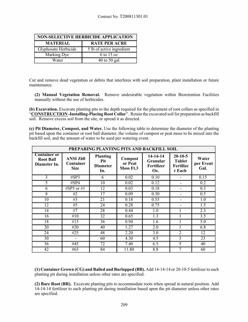
Contract No. T200811301.01
NON-SELECTIVE HERBICIDE APPLICATION
MATERIAL RATE PER ACRE
Glyphosate Herbicide 5 lb of active ingredient Marking Dye 6 to 15 oz
Water 40 to 50 gal
Cut and remove dead vegetation or debris that interferes with soil preparation, plant installation or futuremaintenance.
(2) Manual Vegetation Removal. Remove undesirable vegetation within Bioretention Facilitiesmanually without the use of herbicides.
(b) Excavation. Excavate planting pits to the depth required for the placement of root collars as specified in“CONSTRUCTION -Installing-Placing Root Collar”. Retain the excavated soil for preparation as backfillsoil. Remove excess soil from the site, or spread it as directed.
(c) Pit Diameter, Compost, and Water. Use the following table to determine the diameter of the plantingpit based upon the container or root ball diameter, the volume of compost or peat moss to be mixed into thebackfill soil, and the amount of water to be used per watering event.
PREPARING PLANTING PITS AND BACKFILL SOIL
Container orRoot Ball
Diameter In.
ANSI Z60Container
Size
PlantingPit
DiameterIn.
Compostor Peat
Moss Ft.3
14-14-14GranularFertilizer
Oz.
20-10-5Tablet
Fertilizer Each
Waterper Event
Gal.
3 #SP3 6 0.02 0.10 - 0.15 5 #SP4 10 0.02 0.12 - 0.2 6 #SP5 or #1 12 0.03 0.18 - 0.3 8 #2 17 0.09 0.30 - 0.5
10 #3 21 0.18 0.55 - 1.0 12 #5 24 0.28 0.75 - 1.5 14 #7 28 0.44 1.0 1 2.3 16 #10 32 0.65 1.3 1 3.5 18 #15 36 0.94 1.6 1 5.0 20 #20 40 1.27 2.0 1 6.8 24 #25 48 2.20 3.0 2 12 30 - 60 4.30 4.5 3 23 36 #45 72 7.40 6.5 5 40 42 #65 84 11.80 8.8 7 60
(1) Container Grown (CG) and Balled and Burlapped (BB). Add 14-14-14 or 20-10-5 fertilizer to eachplanting pit during installation unless other rates are specified.
(2) Bare Root (BR). Excavate planting pits to accommodate roots when spread in natural position. Add14-14-14 fertilizer to each planting pit during installation based upon the pit diameter unless other ratesare specified.
209
Contract No. T200811301.01
(d) Compost or Peat Moss. Mix compost into the backfill soil as specified in “CONSTRUCTION -Preparing Planting Pits-(c) Pit Diameter, Compost, and Water” when installing all plants exceptEricaceous species, which shall be amended with the same volume of peat moss.
(e) pH Adjustment. Adjust soil pH to pH 6.0 to 6.5 for all plants except Ericaceous species, which shallbe adjusted to pH 5.0 to 5.5. Use limestone to raise soil pH and iron sulfate to lower soil pH as specified.
(f) Fertilizer. At the time of installation, mix 14-14-14 fertilizer into the backfill soil of trees, shrubs, vines,perennials and grasses, or place 20-10-5 fertilizer into the backfill soil near the mid-point depth of theplanting pit of trees, shrubs and vines in lieu of 14-14-14 fertilizer. Use a scale with 0.01 oz accuracy tocalibrate measures and verify application rates of 14-14-14 fertilizer.
Preparing Planting Beds. Perform the following operations when preparing planting beds:
(a) Undesirable Vegetation. Eliminate undesirable vegetation as specified in “CONSTRUCTION -Preparing Planting Pits-(a) Undesirable Vegetation”. Cut or mow dead vegetation to a height of 1 in. andremove the debris.
(b) Fertilizer and Soil Amendments. Uniformly apply fertilizer and soil amendments (limestone, ironsulfate, compost, peat moss) at rates specified in ”CONSTRUCTION -Preparing Planting Pits-(c) PitDiameter, Compost, and Water” unless other rates are specified. Mix 14-14-14 fertilizer or place 20-10-5fertilizer into the backfill soil of each planting pit within the planting bed. Refer to “CONSTRUCTION -Preparing Planting Pits-(f) Fertilizer” and the following:
(1) Areas Flatter than 4:1. Apply compost to the soil surface of the bed to a 2 in. depth.
(2) Slopes 4:1 and Steeper. Mix compost or peat moss into the backfill soil of each planting pit withinthe bed.
(c) Rototilling. Rototill the soil of the bed as follows:
(1) Areas Flatter than 4:1. Rototill to a depth of 6 in. to thoroughly mix compost and specified fertilizeror soil amendments into the soil.
(2) Slopes 4:1 and Steeper. Do not rototill.
(3) Bioretention Soil Mixture. Do not rototill.
(d) Debris Removal. Remove debris, stones, and soil clods with a length or width greater than 2 in. that areuncovered during rototilling.
(e) Leveling. Level the soil surface after rototilling, and leave it in a condition ready for shredded hardwoodbark (SHB) mulching and plant installation.
Plant Acclimation. Ensure that container grown plants are acclimated to prevailing weather conditions beforeinstalling. Install bare root plants while dormant when soil and air temperatures are above freezing.
Plant Care. Begin plant care at the time each plant is installed, and continue until Installation PhaseAcceptance is granted.
Pruning. Prune to preserve the natural appearance of trees and shrubs.
Remove water sprouts manually with pruners. Remove damaged or undesirable wood of deciduous trees tallerthan 6 ft before installation. Prune deciduous trees and shrubs 6 ft or shorter at the time of installation.
210
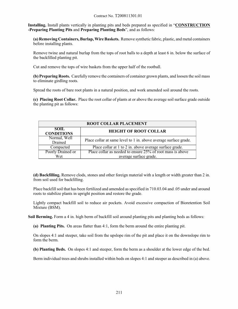
Contract No. T200811301.01
Installing. Install plants vertically in planting pits and beds prepared as specified in “CONSTRUCTION-Preparing Planting Pits and Preparing Planting Beds”, and as follows:
(a) Removing Containers, Burlap, Wire Baskets. Remove synthetic fabric, plastic, and metal containersbefore installing plants.
Remove twine and natural burlap from the tops of root balls to a depth at least 6 in. below the surface ofthe backfilled planting pit.
Cut and remove the tops of wire baskets from the upper half of the rootball.
(b) Preparing Roots. Carefully remove the containers of container grown plants, and loosen the soil massto eliminate girdling roots.
Spread the roots of bare root plants in a natural position, and work amended soil around the roots.
(c) Placing Root Collar. Place the root collar of plants at or above the average soil surface grade outsidethe planting pit as follows:
ROOT COLLAR PLACEMENT SOIL
CONDITIONS HEIGHT OF ROOT COLLAR
Normal, WellDrained
Place collar at same level to 1 in. above average surface grade.
Compacted Place collar at 1 to 2 in. above average surface grade. Poorly Drained or
Wet Place collar as needed to ensure 25% of root mass is above
average surface grade.
(d) Backfilling. Remove clods, stones and other foreign material with a length or width greater than 2 in.from soil used for backfilling.
Place backfill soil that has been fertilized and amended as specified in 710.03.04 and .05 under and aroundroots to stabilize plants in upright position and restore the grade.
Lightly compact backfill soil to reduce air pockets. Avoid excessive compaction of Bioretention SoilMixture (BSM).
Soil Berming. Form a 4 in. high berm of backfill soil around planting pits and planting beds as follows:
(a) Planting Pits. On areas flatter than 4:1, form the berm around the entire planting pit.
On slopes 4:1 and steeper, take soil from the upslope rim of the pit and place it on the downslope rim toform the berm.
(b) Planting Beds. On slopes 4:1 and steeper, form the berm as a shoulder at the lower edge of the bed.
Berm individual trees and shrubs installed within beds on slopes 4:1 and steeper as described in (a) above.
211
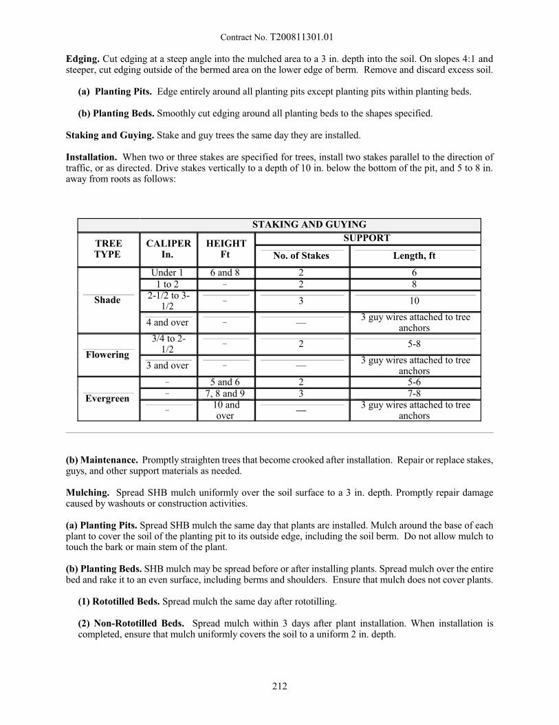
Contract No. T200811301.01
Edging. Cut edging at a steep angle into the mulched area to a 3 in. depth into the soil. On slopes 4:1 andsteeper, cut edging outside of the bermed area on the lower edge of berm. Remove and discard excess soil.
(a) Planting Pits. Edge entirely around all planting pits except planting pits within planting beds.
(b) Planting Beds. Smoothly cut edging around all planting beds to the shapes specified.
Staking and Guying. Stake and guy trees the same day they are installed.
Installation. When two or three stakes are specified for trees, install two stakes parallel to the direction oftraffic, or as directed. Drive stakes vertically to a depth of 10 in. below the bottom of the pit, and 5 to 8 in.away from roots as follows:
STAKING AND GUYING
TREETYPE
CALIPERIn.
HEIGHTFt
SUPPORT
No. of Stakes Length, ft
Shade
Under 1 6 and 8 2 6 1 to 2 ! 2 8
2-1/2 to 3-1/2
! 3 10
4 and over ! — 3 guy wires attached to tree
anchors
Flowering
3/4 to 2-1/2
! 2 5-8
3 and over ! — 3 guy wires attached to tree
anchors
Evergreen
! 5 and 6 2 5-6 ! 7, 8 and 9 3 7-8
! 10 andover
— 3 guy wires attached to tree
anchors
(b) Maintenance. Promptly straighten trees that become crooked after installation. Repair or replace stakes,guys, and other support materials as needed.
Mulching. Spread SHB mulch uniformly over the soil surface to a 3 in. depth. Promptly repair damagecaused by washouts or construction activities.
(a) Planting Pits. Spread SHB mulch the same day that plants are installed. Mulch around the base of eachplant to cover the soil of the planting pit to its outside edge, including the soil berm. Do not allow mulch totouch the bark or main stem of the plant.
(b) Planting Beds. SHB mulch may be spread before or after installing plants. Spread mulch over the entirebed and rake it to an even surface, including berms and shoulders. Ensure that mulch does not cover plants.
(1) Rototilled Beds. Spread mulch the same day after rototilling.
(2) Non-Rototilled Beds. Spread mulch within 3 days after plant installation. When installation iscompleted, ensure that mulch uniformly covers the soil to a uniform 2 in. depth.
212
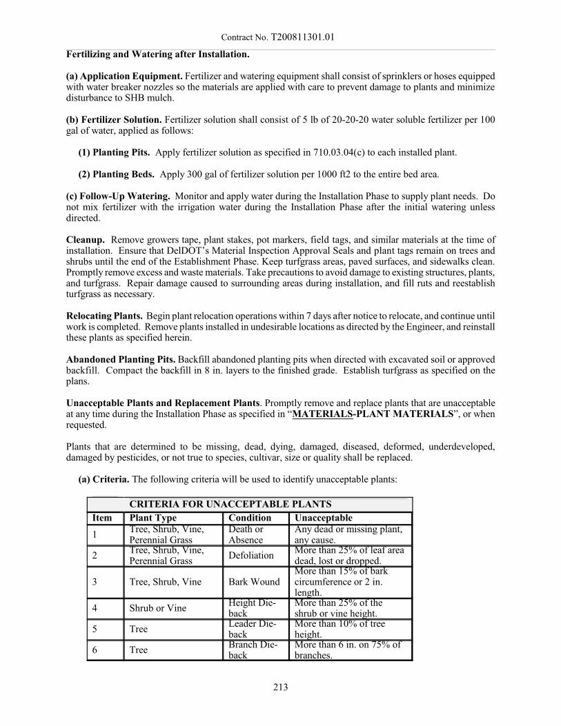
Contract No. T200811301.01
Fertilizing and Watering after Installation.
(a) Application Equipment. Fertilizer and watering equipment shall consist of sprinklers or hoses equippedwith water breaker nozzles so the materials are applied with care to prevent damage to plants and minimizedisturbance to SHB mulch.
(b) Fertilizer Solution. Fertilizer solution shall consist of 5 lb of 20-20-20 water soluble fertilizer per 100gal of water, applied as follows:
(1) Planting Pits. Apply fertilizer solution as specified in 710.03.04(c) to each installed plant.
(2) Planting Beds. Apply 300 gal of fertilizer solution per 1000 ft2 to the entire bed area.
(c) Follow-Up Watering. Monitor and apply water during the Installation Phase to supply plant needs. Donot mix fertilizer with the irrigation water during the Installation Phase after the initial watering unlessdirected.
Cleanup. Remove growers tape, plant stakes, pot markers, field tags, and similar materials at the time ofinstallation. Ensure that DelDOT’s Material Inspection Approval Seals and plant tags remain on trees andshrubs until the end of the Establishment Phase. Keep turfgrass areas, paved surfaces, and sidewalks clean.Promptly remove excess and waste materials. Take precautions to avoid damage to existing structures, plants,and turfgrass. Repair damage caused to surrounding areas during installation, and fill ruts and reestablishturfgrass as necessary.
Relocating Plants. Begin plant relocation operations within 7 days after notice to relocate, and continue untilwork is completed. Remove plants installed in undesirable locations as directed by the Engineer, and reinstallthese plants as specified herein.
Abandoned Planting Pits. Backfill abandoned planting pits when directed with excavated soil or approvedbackfill. Compact the backfill in 8 in. layers to the finished grade. Establish turfgrass as specified on theplans.
Unacceptable Plants and Replacement Plants. Promptly remove and replace plants that are unacceptableat any time during the Installation Phase as specified in “MATERIALS-PLANT MATERIALS”, or whenrequested.
Plants that are determined to be missing, dead, dying, damaged, diseased, deformed, underdeveloped,damaged by pesticides, or not true to species, cultivar, size or quality shall be replaced.
(a) Criteria. The following criteria will be used to identify unacceptable plants:
CRITERIA FOR UNACCEPTABLE PLANTS
Item Plant Type Condition Unacceptable
1 Tree, Shrub, Vine,Perennial Grass
Death orAbsence
Any dead or missing plant,any cause.
2 Tree, Shrub, Vine,Perennial Grass
Defoliation More than 25% of leaf areadead, lost or dropped.
3 Tree, Shrub, Vine Bark Wound More than 15% of barkcircumference or 2 in.length.
4 Shrub or Vine Height Die-back
More than 25% of theshrub or vine height.
5 Tree Leader Die-back
More than 10% of treeheight.
6 Tree Branch Die-back
More than 6 in. on 75% ofbranches.
213

Contract No. T200811301.01
(b) Replacement Plants. Replacement plants shall be true to species, cultivar, size, and quality as specifiedin the Contract Documents unless a Substitution Request is approved.
Install replacement plants as soon as feasible during the current Planting Season, or if between PlantingSeasons, during the next Planting Season.
Promptly submit a Modification Request as specified “CONSTRUCTION -General-(b) ModificationRequest” when it is not possible to obtain plants that meet specifications.
Replacement plants shall meet the specifications of “MATERIALS-PLANT MATERIALS”, and beinstalled and established as specified for 12 months, until Final Acceptance.
Installation Phase Inspection. Submit a request for Installation Phase Inspection when operations arecompleted, and provide the Establishment Phase Schedule as specified “CONSTRUCTION -Submittals andInspection-(d) Establishment Phase Schedule & IPM Program”.
The Installation Phase Inspection will be scheduled by the Engineer at the project with the Contractor toverify completion. At least 14 days notice will be provided before the scheduled Inspection so that it maybe completed in the company of the Contractor.
Installation Phase Punch List. The Engineer in consultation with the Contractor will develop the InstallationPhase Punch List and list of plants to be replaced. Complete the Punch List requirements and replace plantsas required.
Installation Phase Acceptance. Re-inspection will be performed as needed. Installation Phase Acceptancewill be granted when the Punch List and all Installation Phase requirements are completed.
The following list includes key Installation Phase requirements:
REQUIREMENTS FOR INSTALLATION PHASE ACCEPTANCE
ItemRequirement Section
a Submittals are accepted andInspections are completed.
CONSTRUCTION. General (b) ModificationRequest, and Submittals and Inspection, andMATERIALS. PLANT MATERIALS
b Damaging pests are controlled. CONSTRUCTION. Submittals and Inspection (c)Plant Material Inspection and Approval
c Layouts are inspected and approved. CONSTRUCTION. Utilities Marking, Layout, andInspection
d Fertilizer and soil amendments areapplied.
CONSTRUCTION. Preparing Planting Pits andPreparing Planting Beds
e Planting pits and planting beds areweed free.
CONSTRUCTION. Preparing Planting Pits (a)Undesirable Vegetation and Preparing PlantingBeds (a) Undesirable Vegetation
f Trees and shrubs are pruned. CONSTRUCTION. Pruning
g Trees are installed vertically andstraightened.
CONSTRUCTION. Installing
h Planting pits and beds are bermed andedged.
CONSTRUCTION. Soil Berming and Edging
i Staking and guying are repaired orreplaced.
CONSTRUCTION. Staking and Guying
j SHB mulch is uniformly spread to thespecified depth.
CONSTRUCTION. Mulching
k Washouts in planting pits and beds arerepaired.
CONSTRUCTION. Mulching
214
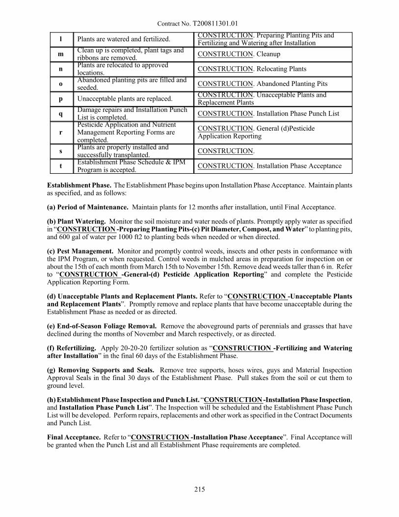
Contract No. T200811301.01
l Plants are watered and fertilized. CONSTRUCTION. Preparing Planting Pits andFertilizing and Watering after Installation
m Clean up is completed, plant tags andribbons are removed.
CONSTRUCTION. Cleanup
n Plants are relocated to approvedlocations.
CONSTRUCTION. Relocating Plants
o Abandoned planting pits are filled andseeded.
CONSTRUCTION. Abandoned Planting Pits
p Unacceptable plants are replaced. CONSTRUCTION. Unacceptable Plants andReplacement Plants
q Damage repairs and Installation PunchList is completed.
CONSTRUCTION. Installation Phase Punch List
r Pesticide Application and NutrientManagement Reporting Forms arecompleted.
CONSTRUCTION. General (d)PesticideApplication Reporting
s Plants are properly installed andsuccessfully transplanted.
CONSTRUCTION.
t Establishment Phase Schedule & IPMProgram is accepted.
CONSTRUCTION. Installation Phase Acceptance
Establishment Phase. The Establishment Phase begins upon Installation Phase Acceptance. Maintain plantsas specified, and as follows:
(a) Period of Maintenance. Maintain plants for 12 months after installation, until Final Acceptance.
(b) Plant Watering. Monitor the soil moisture and water needs of plants. Promptly apply water as specifiedin “CONSTRUCTION -Preparing Planting Pits-(c) Pit Diameter, Compost, and Water” to planting pits,and 600 gal of water per 1000 ft2 to planting beds when needed or when directed.
(c) Pest Management. Monitor and promptly control weeds, insects and other pests in conformance withthe IPM Program, or when requested. Control weeds in mulched areas in preparation for inspection on orabout the 15th of each month from March 15th to November 15th. Remove dead weeds taller than 6 in. Referto “CONSTRUCTION -General-(d) Pesticide Application Reporting” and complete the PesticideApplication Reporting Form.
(d) Unacceptable Plants and Replacement Plants. Refer to “CONSTRUCTION -Unacceptable Plantsand Replacement Plants”. Promptly remove and replace plants that have become unacceptable during theEstablishment Phase as needed or as directed.
(e) End-of-Season Foliage Removal. Remove the aboveground parts of perennials and grasses that havedeclined during the months of November and March respectively, or as directed.
(f) Refertilizing. Apply 20-20-20 fertilizer solution as “CONSTRUCTION -Fertilizing and Wateringafter Installation” in the final 60 days of the Establishment Phase.
(g) Removing Supports and Seals. Remove tree supports, hoses wires, guys and Material InspectionApproval Seals in the final 30 days of the Establishment Phase. Pull stakes from the soil or cut them toground level.
(h) Establishment Phase Inspection and Punch List. “CONSTRUCTION -Installation Phase Inspection,and Installation Phase Punch List”. The Inspection will be scheduled and the Establishment Phase PunchList will be developed. Perform repairs, replacements and other work as specified in the Contract Documentsand Punch List.
Final Acceptance. Refer to “CONSTRUCTION -Installation Phase Acceptance”. Final Acceptance willbe granted when the Punch List and all Establishment Phase requirements are completed.
215
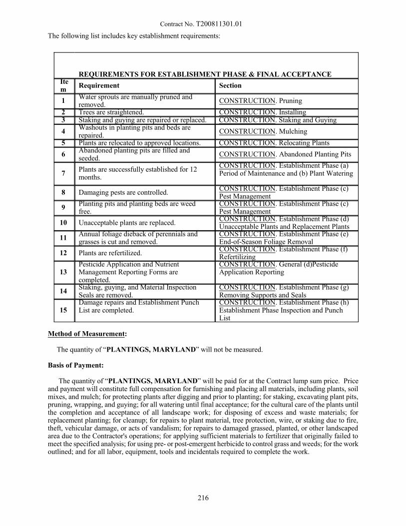
Contract No. T200811301.01
The following list includes key establishment requirements:
REQUIREMENTS FOR ESTABLISHMENT PHASE & FINAL ACCEPTANCE Item
Requirement Section
1 Water sprouts are manually pruned andremoved.
CONSTRUCTION. Pruning
2 Trees are straightened. CONSTRUCTION. Installing 3 Staking and guying are repaired or replaced. CONSTRUCTION. Staking and Guying
4 Washouts in planting pits and beds arerepaired.
CONSTRUCTION. Mulching
5 Plants are relocated to approved locations. CONSTRUCTION. Relocating Plants
6 Abandoned planting pits are filled andseeded.
CONSTRUCTION. Abandoned Planting Pits
7 Plants are successfully established for 12months.
CONSTRUCTION. Establishment Phase (a)Period of Maintenance and (b) Plant Watering
8 Damaging pests are controlled. CONSTRUCTION. Establishment Phase (c)Pest Management
9 Planting pits and planting beds are weedfree.
CONSTRUCTION. Establishment Phase (c)Pest Management
10 Unacceptable plants are replaced. CONSTRUCTION. Establishment Phase (d)Unacceptable Plants and Replacement Plants
11 Annual foliage dieback of perennials andgrasses is cut and removed.
CONSTRUCTION. Establishment Phase (e)End-of-Season Foliage Removal
12 Plants are refertilized. CONSTRUCTION. Establishment Phase (f)Refertilizing
13 Pesticide Application and NutrientManagement Reporting Forms arecompleted.
CONSTRUCTION. General (d)PesticideApplication Reporting
14 Staking, guying, and Material InspectionSeals are removed.
CONSTRUCTION. Establishment Phase (g)Removing Supports and Seals
15 Damage repairs and Establishment PunchList are completed.
CONSTRUCTION. Establishment Phase (h)Establishment Phase Inspection and PunchList
Method of Measurement:
The quantity of “PLANTINGS, MARYLAND” will not be measured.
Basis of Payment:
The quantity of “PLANTINGS, MARYLAND” will be paid for at the Contract lump sum price. Priceand payment will constitute full compensation for furnishing and placing all materials, including plants, soilmixes, and mulch; for protecting plants after digging and prior to planting; for staking, excavating plant pits,pruning, wrapping, and guying; for all watering until final acceptance; for the cultural care of the plants untilthe completion and acceptance of all landscape work; for disposing of excess and waste materials; forreplacement planting; for cleanup; for repairs to plant material, tree protection, wire, or staking due to fire,theft, vehicular damage, or acts of vandalism; for repairs to damaged grassed, planted, or other landscapedarea due to the Contractor's operations; for applying sufficient materials to fertilizer that originally failed tomeet the specified analysis; for using pre- or post-emergent herbicide to control grass and weeds; for the workoutlined; and for all labor, equipment, tools and incidentals required to complete the work.
216
Contract No. T200811301.01
NOTE:
When more than one planting material is required, the Contractor shall submit a cost breakdown of hisLump Sum price bide for this item showing the dollar value amount for each planting material, the sum ofwhich is to equal the lump sum price bid. The breakout sheet attached to the proposal shows all materialsproposed for this item.
The Department reserves the right to delete from the Contract the furnishing and installing of one or moreof the materials listed and the right to add or subtract from the quantity of each material listed. The lump sumto be paid will be adjusted in accordance with the Contractor's unit prices as required above. There will beno extra compensation to the Contractor if such additions and/or deletion are made.
Payment for the planting as described above may be processed if, in the opinion of the Engineer all workrequired, is satisfactorily completed. No partial payment will be made for any living plant until and unlessplanted in accordance with these specifications. No additional payment will be made for using plants largerthan specified.
10/10/12
217
Contract No. T200811301.01
744500 - CONDUIT JUNCTION WELL, TYPE 6, PRECAST POLYMER CONCRETE744506 - CONDUIT JUNCTION WELL, TYPE 7, PRECAST POLYMER CONCRETE744507 - CONDUIT JUNCTION WELL, TYPE 8, PRECAST POLYMER CONCRETE744508 - CONDUIT JUNCTION WELL, TYPE 9, PRECAST POLYMER CONCRETE
744509 - CONDUIT JUNCTION WELL, TYPE 10, PRECAST POLYMER CONCRETE744520 - CONDUIT JUNCTION WELL, TYPE 1, PRECAST CONCRETE744523 - CONDUIT JUNCTION WELL, TYPE 4, PRECAST CONCRETE744524 - CONDUIT JUNCTION WELL, TYPE 5, PRECAST CONCRETE
744530 - CONDUIT JUNCTION WELL, TYPE 11, PRECAST CONCRETE/POLYMER LID-FRAME
744531 - CONDUIT JUNCTION WELL, TYPE 14, PRECAST CONCRETE/POLYMER LID-FRAME
744532 - CONDUIT JUNCTION WELL, TYPE 15, PRECAST CONCRETE/POLYMER LID-FRAME
Description:
This work consists of supplying, constructing and installing conduit junction wells as shown on theapplicable Plan Sheets or Standard Construction details
Materials:
Concrete shall conform to Section 812, Class B of the Standard Specifications.
Castings shall conform to Section 708.05 of the Standard Specifications.
Frames and lids shall be in accordance with Sections 708 and 744 of the Standard Specifications.
All required hardware and wire for Bonding and Grounding as shown on the Standard Construction orapplicable Plan details.
Types 6, 7, 8 and 10 are precast polymer concrete stackable boxes with no base.
Precast polymer concrete is reinforced by heavy-weave fiberglass with a compressive strength of 9,000-15,000 psi, impact energy of 30-72 ft. lbs. and a tensile strength of 800-1,100 psi. Precast polymer concreteshould be tested according to the requirements of ASTM Method D-543, Section 7, Procedure 1 for chemicalresistance.
All precast polymer concrete covers shall be the heavy-duty type with a design load of 15,000 lbs. overa 10" square. The coefficient of friction should be greater than 0.5. The precast polymer concrete cover logoshall bear the inscription "DelDOT" (Types 6, 8, and 10) or "DelDOT TRAFFIC FIBER OPTICS" (Type 7).
Types 11, 14, and 15 are precast polymer frame and lids installed on a precast concrete base. Precastpolymer concrete frame and lids shall be the heavy-duty nonconductive type with a design load of 15,000 lbs.over a 10" square. The coefficient of friction should be greater than 0.5. The precast polymer concrete lidlogo shall bear the inscription "DelDOT ELECTRIC"(Types 11, 14, and 15)
Construction Methods:
The conduit junction well shall conform to the dimensions shown on the Standard Construction orapplicable Plan Details, or on the manufacturer’s specifications and shall be built so as to ensure that the castiron frame and lid or polymer concrete box and cover are set level with the surrounding surface whenconstructed within pavement, sidewalks, pedestrian curb ramps, etc., and set above grade and graded to drainaway from the junction well when constructed in unpaved areas. More than one conduit may extend intothe well and shall conform to the dimensions shown on the applicable plan sheets or Standard Construction
218
Contract No. T200811301.01
Details. A stone base shall be built for all types of junction wells. Grounding and bonding of the units shallbe performed as shown on the plans or Standard Construction details.
Method of Measurement:
The quantity of junction wells shall be the actual number of conduit junction wells by type, that aresupplied, constructed, complete in place, and accepted, including cast iron frames and lids with groundinglugs, precast polymer concrete frame and covers, or precast polymer concrete covers, stone base, bonding,grounding, and splicing if required. Frames and lids or precast polymer concrete covers must be installedprior to acceptance of this item.
Payment for all conduits extending into the junction well shall be included in the items for conduitinstallation.
The length of ALL conduits within a junction well shall conform to the Standard Construction orapplicable Plan Details or as directed by Engineer. Payment for cutting existing conduit as directed byEngineer, where a junction well is replaced with a larger type of junction well is included in the bid price. The removal and replacement of cables within the conduits to be shortened shall be handled under other itemsof this contract.
Basis of Payment:
Payment for conduit junction wells as measured above shall be made at the Contract unit price per eachjunction well of the type indicated, completely installed and constructed, including excavation, backfilling,and stone base. Price and payment will constitute full compensation for all labor, equipment, tools, andincidentals required to complete the work.
2/29/12
219
Contract No. T200811301.01
744519 - RELOCATION OF EXISTING JUNCTION WELL
Description:
This work consists of relocating an existing Type 1, Type 4, Type 5, Type 6, Type 7, Type 8, or Type 10junction well to clear utilities or other construction work. This item may consist of moving a junction wellfrom a few inches (centimeters) to no more than six feet (1.8 m) in any direction in sodded or dirt areas only. Moves of more than six feet (1.8 m ) shall be paid under other items in this contract.
Construction Methods:
The junction well shall be relocated in a manner so as not to damage the junction well, frame and lid, orprecast polymer concrete cover. Any conduit or cables that need to be removed or installed shall be paidunder separate items in this contract.
If the conduit that is connected to the junction well needs to be moved with the junction well, the conduitis to be exposed to the distance necessary to move the junction well, caution is to be used as not to placeexcessive stress on the conduit or its couplings.
The entire work area where the junction well and conduits are relocated shall be backfilled and tampedas directed by the Engineer. Any extra fill needed to complete the backfill shall be considered part of thisitem.
Method of Measurement:
The quantity of relocated junction wells to be measured under this item shall be the actual number ofjunction wells relocated complete, in place, and accepted.
Any conduits that need to be added to extend into the junction well shall be paid for under "Supply ofConduit".
Basis of Payment:
The number of junction wells relocated, as determined above, shall be paid for at the Contract unit priceper each. Price and payment will constitute full compensation for all labor, equipment, tools, and incidentalsrequired to complete the work.
01/15/03
220
Contract No. T200811301.01
744533 - FURNISH & INSTALL FRAME AND LID FOR JUNCTION WELL, TYPE 1744534 - FURNISH & INSTALL FRAME AND LID FOR JUNCTION WELL, TYPE 4744535 - FURNISH & INSTALL FRAME AND LID FOR JUNCTION WELL, TYPE 5
744536 - FURNISH & INSTALL PRECAST POLYMER COVER FOR JUNCTION WELL, TYPE6
744537 - FURNISH & INSTALL PRECAST POLYMER COVER FOR JUNCTION WELL, TYPE7
744538 - FURNISH & INSTALL PRECAST POLYMER COVER FOR JUNCTION WELL, TYPE8
744539 - FURNISH & INSTALL PRECAST POLYMER COVER FOR JUNCTION WELL, TYPE9
744540 - FURNISH & INSTALL PRECAST POLYMER COVER FOR JUNCTION WELL, TYPE10
744541 - FURNISH & INSTALL FRAME AND LID FOR JUNCTION WELL, TYPE 11744542 - FURNISH & INSTALL FRAME AND LID FOR JUNCTION WELL, TYPE 14744543 - FURNISH & INSTALL FRAME AND LID FOR JUNCTION WELL, TYPE 15
Description:
This work consists of furnishing and installing cast iron frames and lids or precast polymer concrete coversfor existing junction wells only. The item shall not be used when furnishing new junction wells as the framesand lids are included in the price for the new units. The frames and lids are as shown on the StandardConstruction or applicable Plan Details. The work includes furnishing and installing all required materialsand hardware to properly ground the unit, including wire and splicing if required and as shown on theStandard Construction or applicable Plan Details.
Materials:
Castings for frames, lids, and ½” dia. x 1 ¼” grounding lugs shall conform to Section 708.05 of theStandard Specifications and Standard Construction Details or applicable Plan Details.
Precast polymer concrete covers shall be reinforced by heavy-weave fiberglass. All precast polymerconcrete covers shall be the heavy-duty type with a design load of 15,000 lbs. over a 10" square and acoefficient of friction greater than 0.5. The precast polymer concrete cover logo shall bear the inscription"DelDOT Traffic" for Types 6, 8, and 10 and "DelDOT Traffic Fiber Optics" for Type 7. The precastpolymer concrete cover Type 11, 14, and 15 logo shall bear the inscription “DelDOT ELECTRIC”.
Material for Grounding, bonding, and all related hardware and wire (including splicing if required) shallbe as shown on the Standard Construction or applicable Plan Details.
Method of Measurement:
The quantity of spare frames and lids or precast polymer concrete covers shall be the actual number offrames and lids or precast polymer concrete covers by type furnished, installed, bonded, grounded andaccepted.
Basis of Payment:
The item shall be paid for at the Contract unit price per each. Price and payment will constitute fullcompensation for all labor, equipment, tools, and incidentals required to complete the work.
2/29/12
221
Contract No. T200811301.01
744544 – ADJUST OR REPAIR EXISTING CONDUIT JUNCTION WELL
Description:
This work consists of adjusting or repairing existing conduit junction wells, including furnishing allmaterials, in accordance with this specification, notes and details on the applicable Plans, the StandardConstruction Details, and as directed by the Engineer. If Bonding and Grounding of the unit is required, thatwork will be paid for under “Bonding and Grounding Existing Junction Well”.
Materials:
Portland cement concrete shall conform to the requirements of Section 812, Class B. Mortar shall conform to the requirements of Section 611.Brick shall conform to the requirements of Section 611.Concrete block shall conform to the requirements of Section 819.
Construction Methods:
Repair of conduit junction wells includes repairing/patching the masonry walls and resetting existingframes and lids or precast polymer concrete covers.
Adjusting involves raising the elevation of the frame and lid to match the grade of the surrounding area.
Method of Measurement:
The quantity of conduit junction wells adjusted or repaired will be measured as the actual number ofconduit junction wells adjusted or repaired and accepted. If a new frame and lid or precast polymer concretecover is needed, it will be supplied under a separate item.
Basis of Payment:
The quantity of conduit junction wells will be paid for at the Contract unit price per each junction well. Price and payment will constitute full compensation for excavating, backfilling, compacting and disposingof excess materials, for furnishing and placing all materials and for all labor equipment, tools and incidentalsrequired to complete the work.
2/29/12
222
Contract No. T200811301.01
745601 – FURNISH & INSTALL UP TO 3” FLEXIBLE METALLIC-LIQUIDTIGHT CONDUIT
745602 - FURNISH & INSTALL UP TO 4” SCHEDULE 80 HDPE CONDUIT (BORE)745603 - FURNISH & INSTALL UP TO 4” SCHEDULE 80 PVC CONDUIT (OPEN CUT)745604 - FURNISH & INSTALL UP TO 4” SCHEDULE 80 PVC CONDUIT (TRENCH)
745605 - FURNISH & INSTALL UP TO 4” SCHEDULE 80 PVC CONDUIT (ON STRUCTURE)745606 - FURNISH & INSTALL UP TO 4” GALVANIZED STEEL CONDUIT (TRENCH)
745607 - FURNISH & INSTALL UP TO 4” GALVANIZED STEEL CONDUIT (BORE)745608 - FURNISH & INSTALL UP TO 4” GALVANIZED STEEL CONDUIT (OPEN CUT)
745609 - FURNISH & INSTALL UP TO 4” GALVANIZED STEEL CONDUIT (ONSTRUCTURE)
745610 - FURNISH & INSTALL UP TO 4” NONMETALLIC POLE RISER SHIELD
Description:
Furnish and install HDPE, PVC, or Galvanized steel conduits of any size less than or equal to 4 inches indiameter (3 inches or less for Flexible Metallic Liquidtight Conduit) as described below.
Materials:
All conduits shall be UL listed.
HDPE Conduit - 4" or less diameter, high density polyethylene (HDPE) schedule 80, smooth wall conduitwith permanently pre-lubricated lining, meeting ASTM D2447, ASTM D3035 and NEMA TC7specifications.
PVC Conduit - 4" or less diameter, schedule 80 rigid polyvinyl chloride (PVC) conduit, meeting CommercialStandard CS-272-65 (PVC), ASTM D-1785 and U.C. Standard 651 specifications.
Galvanized Steel Conduit - 4" or less diameter, rigid galvanized steel conduit meeting National ElectricCode 2002, Article 344.
Nonmetallic Pole Riser Shield – 4” diameter or less nonmetallic pole riser shield with belled ends meetingNEMA TC-19 specifications.
Flexible Metallic-Liquidtight Conduit – meets National Electric Code 2002, Article 350
Weatherhead for galvanized or PVC conduit – material shall match the adjoining conduit
Insulated grounding bushing with knockouts - meet or exceed UL 514 B
Condulets for conduit sizes - material shall match the adjoining conduit
Anchors - A 307, Galvanized per A 153
One hole conduit hangers - Steel City Series 6H or 6H-B, CADDY CD3B Rigid Conduit Hanger, orapproved equal
End caps - material shall match the adjoining conduit
LONG sweep sections for conduit sizes - material shall match the adjoining conduit, and shall bemanufactured 90 degree sweeping bends.
Construction Methods:
General Installation Requirements - The Department has the right to reject any installation method
223
Contract No. T200811301.01
proposed for a given work site. PVC shall not be installed under existing pavement unless it is on acontinuous roll or with the Engineer’s written approval.
Conduit installed underground shall be installed in a straight line between terminal points. In straight runs,junction well spacing shall be no more than 600 feet for fiber optic conduit or no more than 300 feet forcopper in conduit, or as directed by the Engineer. If bends are required during installation, they must bemanufactured sweeping bends. The Engineer will be consulted before any bends are installed to ensure thatthe proper arc is provided.
Conduit shall have a minimum cover as measured from the finished grade of 24 inches and a maximumcover of 48 inches.
The opening shall be filled half way with the cover material, and tamped down firmly before filling in theremainder of the opening. Additional lifts shall be used as required to install the metallic warning tape at thespecified depth. All cover material shall be free of rocks, debris, vegetation or other deleterious material thatmay damage the conduit. An underground utility warning tape shall be installed as specified in this sectionand the remainder of the fill shall be added, tamping down the top layer.
Conduit not terminated to a base or in a junction well shall be terminated 2 feet beyond the edge of thepavement unless otherwise directed by the Engineer, and properly capped. Tape is NOT an approved method. Conduit shall not extend more than 3 inches inside a junction well. See Standard Construction Details orapplicable Plan Details for typical methods of termination.
All underground conduits shall be marked in the ground with a metallic warning tape. The marking tapeshall be buried directly above the conduit run that it identifies, at a depth of approximately 12 inches belowfinal grade. The tape identifying ALL conduits shall be at least 6 inches wide, and have a minimum thicknessof 3 mils and 500 percent elongation.
The color of the metallic warning tape identifying fiber optic cable should be bright orange (preferablyAULCC orange), and shall read "WARNING - OPTICAL CABLE" or other wording approved by theEngineer that conveys the same message. The color of the tape identifying all other cables shall be brightred, and shall read "WARNING —BURIED ELECTRIC BELOW" or other wording approved by theEngineer that conveys the same message.
Using conduit tools, rigid metallic conduit shall be cut, reamed, and threaded. The thread length shall beas necessary to ensure that the sections of conduits when screwed into a coupling and tightened correctly willbutt together and the joint will be watertight. A three-piece threaded union, as approved by the Engineer,shall be used to join two threaded lengths of conduit in the case where a standard coupling will not work. A threaded union shall not be used in a conduit run that is to be driven. At no time is a threadless couplingor a split-bolt coupling to be used for direct buried conduit.
All lengths of HDPE conduit shall be connected with irreversible fusion couplings. Mechanical andremovable couplings will not be accepted.
All lengths of PVC conduit shall be connected by one conduit end fitting inside the flared end of the otherconduit section. If this is not possible, then a coupling may be used. Regardless of how connection is made,all joints shall be sealed with the appropriate epoxy to ensure that the two conduit pieces bond to one anotherto form a solid waterproof link. Using conduit tools, the conduit shall be cut and prepared. If approved bythe Engineer, a coupler module may be used where conduit segments do not align properly to allow the flaredend of one conduit segment to mate with the normal end of the other segment.
Sealed end caps (with knockouts if empty) shall be placed on the ends of all conduits, after compressedair has been used to clear all foreign matter. If not already pre-installed by the manufacturer, a polyester orpolypropylene pulling rope or tape (fish wire) with a minimum rated strength of 1250 pounds shall beinstalled in each conduit for future use. In instances where the Contractor installs the cable, the fish wire maybe eliminated.
224
Contract No. T200811301.01
All PVC and HDPE conduits shall have a continuous metallic trace wire installed for the entire length ofthe conduit run for all fiber installations.
Installation Of Conduit Under Existing Pavement, Directional Bore -
Directional bore shall be used for installation of conduits under existing pavement with a conduit diameternot less than 1-1/2". The size of a bore shall not exceed the outside diameter of the conduit by more than 1inch. If it does, cement grout shall be pumped into the void. Only HDPE and/or Galvanized Steel conduitmay be installed by Directional Bore methods.
Installation Of Conduit Under Existing Pavement, Open Cut -
Installation by sawcutting the full pavement depth and removing the existing pavement with an excavatoror by hand methods, shall be used only for conduits not less than 1-1/2" diameter. The Engineer must firstapprove all open cutting of roadways. The width and length of open cut and patch restoration materials shallbe as shown on the plan details. The Contractor shall be responsible for the removal of all cut pavement andsurplus excavation, and for the replacement and correction of any damaged pavement outside the sawcutlimits after the conduit(s) are installed. Asphalt pavement, concrete, base course, sawcutting, and/or borrowfrom an outside source as required to restore the roadway will be paid for separately under their respectivebid items.
Installation Of Conduit Under New Pavement, Unpaved Trench -
Trenching or other approved method shall be used for installation of conduit in unpaved trench or undernew pavement. Backfill in conduit trenches shall be compacted thoroughly as it is being placed. At thediscretion of the Engineer, sod, that must be removed for the placement of conduit, shall be removed eitherby the use of an approved sod cutter and then replaced, or 6 inches of topsoil shall be placed and the surfaceseeded in accordance with Section 908 - Seeding. In areas where new pavement is to be placed or in areaswhere total reconstruction is taking place, sodding or seeding may not be required by the Engineer. Soddingand/or topsoil from an outside source if required will be paid for separately under their respective bid items. Seeding is considered incidental to the conduit item.
Installation Of Conduit On Structure -
Conduit installed on structure shall consist of drilling anchors into concrete, brick, stone, steel or woodand mounting the conduit with the proper clamps or hangers. The conduit shall be attached to the structureby use of one-hole conduit hangers and approved anchors not more than 36 inches apart. Any 90-degree turnsin the conduit run shall be accomplished by placing the proper size and type manufactured sweeping bendsfor the application needed.
Installation of Nonmetallic Riser Shield or Flexible Metallic Liquidtight Conduit -
Riser Shield and/or Flexible Metallic Liquidtight Conduit installed on wood poles, metal poles, structures,and/or mast arms shall be installed in a straight line. The conduit, when attached to poles, shall be attachedwith 2-hole straps spaced not more than 36 inches apart with the top-most strap being 12 inches from theweatherhead and the lower-most being 12 inches from the condulet. A weatherhead matching the diameterof the conduit shall be installed on the upper end of the conduit. A condulet of the same size as the conduitbeing installed, but not smaller than 2 inches shall be placed 48 inches above finished grade. Install two, 2-hole straps of the proper size, evenly spaced below the condulet. Nonmetallic pole risers (U-guard) shall beinstalled on poles to allow interduct to be connected directly to messenger cable. The underground conduitshall be as close to the base of the pole as possible. If the nonmetallic pole riser or metallic liquidtightconduit is not the same size as the conduit, an adapter shall be used at no additional cost to the Department. The nonmetallic pole riser or metallic liquidtight conduit shall be attached to the pole with 1/4" x 1-1/2"galvanized lag bolts with washers. Lag bolts will be used every 36 inches on BOTH sides of the nonmetallicpole riser or liquidtight conduit, and in the top most and bottom most set of slots. Flexible metallic liquidtightconduit shown on the plans to be installed on mast arms or on metal structure shall also include stainless steelbanding placed at a maximum of 5 feet intervals.
225
Contract No. T200811301.01
Method of Measurement:
The quantity of conduit or riser shield installed as specified, shall be measured as the number of linear feetof each conduit or riser shield installed as specified, complete in place, and accepted.
The length of each conduit installed under existing pavement by a directional bore or by open cutting thepavement shall be measured along the path of the bore or open cut, from the point that cannot be trenchedto the point that trenching can resume. The length of any conduit that is reduced or divided (with a junctionwell or conduit body) shall be measured as part of the larger conduit.
Basis of Payment:
The quantity of conduit or riser shield will be paid for at the Contract unit price per linear foot. Price andpayment shall include full compensation for furnishing all conduit and/or riser shield materials, equipment,labor, and incidentals necessary to complete the item.
For conduit installed by Directional Bore, the linear foot payment also includes excavation and backfillingfor Bore Equipment, placing the conduit, caps if required, and all other requirements and incidentals listedin the body of this specification.
For conduit installed by Open Cutting existing pavement, the linear foot payment also includes excavating,backfilling, placing the conduit, disposal of excess materials, and all other requirements and incidentals listedin the body of this specification.
For conduit installed in an Unpaved Trench, the linear foot payment also includes excavating, removal ofsod if required, backfilling, placing the conduit, disposal of excess materials, replacing excavated on-site sodif required, seeding if required, and all other requirements and incidentals listed in the body of thisspecification. Sod and/or topsoil furnished from an outside source, will be paid for separately.
For conduit installed on a structure, the linear foot payment also includes furnishing and installing anchorsand hangers, removal of excess materials, and all other requirements and incidentals listed in the body of thisspecification.
For riser shield or flexible metallic conduit installed on poles, mast arms, or structures the linear footpayment also includes furnishing and installing straps, weatherhead, condulet, lag bolts and washers, anyother required mounting hardware, and all other requirements and incidentals listed in the body of thisspecification.
7/20/15
226
Contract No. T200811301.01
746509 - RELOCATING LIGHT POLE
Description:
This work consists of relocating the existing light pole(s) with illumination assemblies at the location(s)shown on the Plans and/or as directed by the Engineer. Unless shown otherwise on the Plan, the newfoundations provided shall be a Pole Base, Type 6 constructed in accordance with Special Provision 746852and details on the Plans.
Materials and Construction Methods:
All materials furnished by the Contractor under these items shall be in accordance with the details shownon the Plans, and/or as required by the Standards and Specifications of the owner of the light-pole. In absenceof such details, standards, and specifications, requirements of the National Electrical Code shall be applicable. The concrete for the foundation shall be Class B, and shall conform to Section 812 of the Delaware Standardspecifications.
The illumination assemblies shall be carefully removed from the poles to avoid any damage. Should anydamage occur to the illumination assemblies, and in the opinion of the Engineer adequate precaution was notexercised by the Contractor during the relocation operation, the Contractor shall at his expense replace thedamaged assembly in kind or better as determined by the Engineer. Where salvage of any material is requiredin accordance with the notes on Plans, the cost shall be included in this item.
Final acceptance of the light pole assembly unit shall be made only after its satisfactory operation asdetermined by the Engineer, and/or by the owner of the light pole. The Contractor shall make every effortto avoid excessive delay in relocating the light pole.
Method of Measurement:
The quantity of light poles relocated will be measured as the actual number of light poles relocated andaccepted.
Basis of Payment:
The quantity of light poles relocated will be paid for at the Contract unit price per each. Price and paymentwill constitute full compensation for relocating the existing light pole, erecting and connecting illuminationassemblies, furnishing all materials including lamp(s), for salvaging the materials specified in the Contract,fordisposing of the discarded materials, and for all labor, tools, equipment, and incidentals to complete the work.
NOTE
This work shall also include the adjustment and/or relocation of the affected electrical conduits that supplypower to the light poles.
8/25/2015
227
Contract No. T200811301.01
746511 - CABLES, 1/#4 AWG746512 - CABLES, 1/#6 AWG746513 - CABLES, 1/#8 AWG
746514 - CABLES, 1/#10 AWG746515 - INSULATED GROUND CABLE, 1/#6
746527 - CABLES, 1/#2 AWG746543 - CABLES, 1/#9 AWG
746546 - CABLES, 1/#12 AWG746564 - INSULATED GROUND CABLE, 1/#4
746565 - CABLES, 1/#3/0 AWG746566 - CABLES, 1/#1 AWG
746567 - CABLES, 1/#1/0 AWG746577 - INSULATED GROUND CABLE, 1/#8746598 - INSULATED GROUND CABLE, 1/#2
746605 - INSULATED GROUND CABLE, 1/#10746622 - CABLES, 1/#4/0 AWG
746658 - INSULATED GROUND CABLE, 1/#1/0746690 - INSULATED GROUND CABLE 1/#12
746817 - CABLES, 1/#2/0 AWG746861 - INSULATED GROUND CABLES, 1/350 KCMIL
746903 - INSULATED GROUND CABLES, 1/#2/0746904 - INSULATED GROUND CABLES, 1/#4/0
Description:
This work consists of furnishing all cables of the size(s) required by the Contract in accordance with thenotes and details shown on the Plans and/or as directed by the Engineer.
Materials and Construction Methods:
All wire(s) to be used in this contract shall be manufactured in conformance with the National ElectricalCode, insulated for 600 volts, and be of the type USE and/or RHW.
Method of Measurement:
The quantity of cables will be measured as the number of linear feet (linear meters) of each size along thelongitudinal axis of each cable.
Basis of Payment:
The quantity of cables will be paid for at the Contract price per linear foot (linear meter). Price andpayment will constitute full compensation for furnishing the cables.
No separate payment will be made for furnishing the connector kits with #10 AWG wiring of the type asindicated on the plan for the lighting standards as shall be included in the items for lighting standards.
9/09/2010
228
Contract No. T200811301.01
746517 - ALUMINUM LIGHTING STANDARD WITH SINGLE DAVIT ARM, 30' POLE746518 - ALUMINUM LIGHTING STANDARD WITH SINGLE DAVIT ARM, 35' POLE746519 - ALUMINUM LIGHTING STANDARD WITH SINGLE DAVIT ARM, 40' POLE746520 - ALUMINUM LIGHTING STANDARD WITH DOUBLE DAVIT ARM, 30' POLE746521 - ALUMINUM LIGHTING STANDARD WITH DOUBLE DAVIT ARM, 35' POLE746522 - ALUMINUM LIGHTING STANDARD WITH DOUBLE DAVIT ARM, 40' POLE746618 - ALUMINUM LIGHTING STANDARD WITH SINGLE DAVIT ARM, 45' POLE
Description:
The work consists of furnishing and installing Aluminum Lighting Standard with Single Davit Armbreakaway transformer base, luminaires, in accordance with the details on the Plans, and/or as directed bythe Engineer to make a functional street lighting system. The foundation will be provided under other itemsin the Contract.
Materials and Construction Methods:
All materials shall be of the best quality and free from all defects. No materials shall be installed untilapproved by the Engineer. Any material not specifically covered in these specifications shall be inaccordance with accepted standards and as directed by the Engineer. Any materials deemed unsatisfactoryby the Engineer, shall be replaced by the Contractor.
Lighting standards shall meet or exceed the requirements of the latest edition of AASHTO "StandardSpecifications for Structural Supports for Highway Signs, Luminaires and Traffic Signals" based on 90 mphwind loads, luminaire weight of 70 lb and luminaire projected area of 3 ft². Computations confirmingconformance with AASHTO Specifications, with the year of the edition specified, shall be submitted to theDelaware Department of Transportation.
All electrical materials shall conform to the requirements of the National Electrical Code of the nationalFire Protection Association, and shall conform to all local and special laws and/or ordinances governing suchinstallations. Where these requirements do not govern, and where not otherwise specified, electrical materialsshall conform to the Standardization Rules of the Institute of Electrical and Electronic Engineers.
Shop drawings and catalog cuts for all electrical and related materials shall be submitted by the Contractorfor approval.
The bolts are to be supplied by the Contractor. The bolts will be installed using a template, and set so thatluminaire arm is perpendicular to the roadway.
Anchor bolts, nuts, couplings, washers, and cap screws shall be of carbon steel conforming to therequirements of ASTM A307, and hot-dip galvanized in accordance with AASHTO M 232/M 232M.
Also included in the foundations will be ground rods which shall be copper clad steel 3/4" diameter 26'long, complete with ground clamp and square head bolt equal to Joslyn's Cat. No. J8350, Line Materials Cat.No. 119960 or A. B. Chance Co. Cat. No. 8450, or approved equal.
New aluminum lighting standards shall consist of a tapered aluminum shaft having a base welded to thelower end. The pole shaft, pole extensions, and davit arms shall each be spun from one piece of seamlesstubing, the strut and arm plates shall be extruded, all of which conform to the requirements of ASTM B221aluminum alloy 6063-T6. The shaft shall have no circumferential welds, except at the lower end joining theshaft to the base and shall conform to the dimensions listed in the chart below. The shaft shall contain aninternal vibration dampening device positioned approximately 2/3 the height of the pole. The top of thelighting standard shaft shall be drilled for two 1/2" (13 mm) lockbolts to secure the davit bracket to thelighting standard shaft. If the pole is not placed on a transformer base, it will have one 3" x 5" (75 mm x 125mm) handhole which after pole is set should face so that maintainer may view oncoming traffic.
229
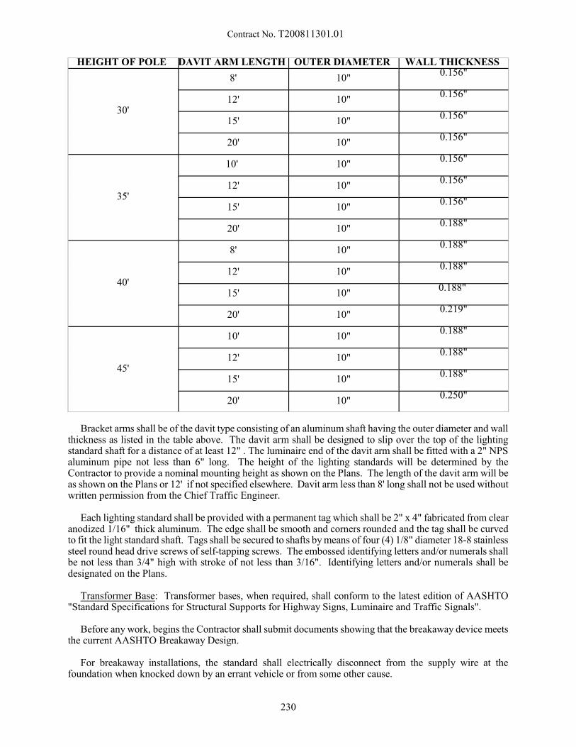
Contract No. T200811301.01
HEIGHT OF POLE DAVIT ARM LENGTH OUTER DIAMETER WALL THICKNESS
30'
8' 10"0.156"
12' 10"0.156"
15' 10"0.156"
20' 10"0.156"
35'
10' 10"0.156"
12' 10"0.156"
15' 10"0.156"
20' 10"0.188"
40'
8' 10"0.188"
12' 10"0.188"
15' 10"0.188"
20' 10"0.219"
45'
10' 10"0.188"
12' 10"0.188"
15' 10"0.188"
20' 10"0.250"
Bracket arms shall be of the davit type consisting of an aluminum shaft having the outer diameter and wallthickness as listed in the table above. The davit arm shall be designed to slip over the top of the lightingstandard shaft for a distance of at least 12" . The luminaire end of the davit arm shall be fitted with a 2" NPSaluminum pipe not less than 6" long. The height of the lighting standards will be determined by theContractor to provide a nominal mounting height as shown on the Plans. The length of the davit arm will beas shown on the Plans or 12' if not specified elsewhere. Davit arm less than 8' long shall not be used withoutwritten permission from the Chief Traffic Engineer.
Each lighting standard shall be provided with a permanent tag which shall be 2" x 4" fabricated from clearanodized 1/16" thick aluminum. The edge shall be smooth and corners rounded and the tag shall be curvedto fit the light standard shaft. Tags shall be secured to shafts by means of four (4) 1/8" diameter 18-8 stainlesssteel round head drive screws of self-tapping screws. The embossed identifying letters and/or numerals shallbe not less than 3/4" high with stroke of not less than 3/16". Identifying letters and/or numerals shall bedesignated on the Plans.
Transformer Base: Transformer bases, when required, shall conform to the latest edition of AASHTO"Standard Specifications for Structural Supports for Highway Signs, Luminaire and Traffic Signals".
Before any work, begins the Contractor shall submit documents showing that the breakaway device meetsthe current AASHTO Breakaway Design.
For breakaway installations, the standard shall electrically disconnect from the supply wire at thefoundation when knocked down by an errant vehicle or from some other cause.
230
Contract No. T200811301.01
Luminaire: The luminaire shall have a precision die cast aluminum housing with an optical assembly, aremovable mounting door and of wattage and type as specified on the Plans. The luminaire shall be of themulti-voltage ballast regulator type.
The refractor of the optical assembly shall be attached to the luminaire housing thru a hinge and latcharrangement. The optical assembly shall consist of a highly polished aluminum reflector, and a heat resistantshatter resistant borosilicate glass refractor. The refractor door shall be tightly sealed with an appropriategasket. The latch for the refractor door shall be of sufficient size to enable easy handling and constructed ofrust resistant materials; the latch shall produce an audible click when it is properly locked.
The luminaire shall be equipped with a porcelain, corrosion resistant socket. The socket shall be easilyadjustable to give one of twelve different light distributions; such adjustments shall be accomplished throughadjusting not more than two screws within the optical assembly. The socket in this installation shall be presetto provide a distribution pattern as indicated on the Plans or type III distribution pattern of luminaire if notindicated.
The luminaire shall have a 2 bolt slipfitting suitable for mounting on 1/2" to 2" pipe. The luminaire shallbe designed with a leveling pad and capable of being adjusted +5 degrees for proper leveling.
The luminaire shall be completely wired so that it shall require only the connection of the power supplycables to a terminal block for energizing the entire fixture.
In order to provide for normal exchange of air between the inside and outside of the optical system, aventilating channel shall be provided.The channel shall contain a charcoal filter which will prevent theentrance of flying insects and other small animal life forms, as well as provide a cleaning action on the airto remove smoke and dust particles.
All major electrical components, including ballast and the photoelectric control, shall be mounted on aremovable door assembly and connected to the fixture electrically through a quick disconnect plug. Theremoval of the door shall be accomplished by loosening the captive screw and unplugging the quickdisconnect plug. The luminaire shall employ solderless push-on type connectors for all wiring connectionsto facilitate the replacement of any component.
The unit shall contain an integral ballast capable of maintaining the wattage of the H.P.S. lamp throughoutthe life of the lamp. The ballast and the photoelectric control shall be suitable for operating the units in thewattage as shown on the Plans. The wattage of the luminaires for this Contract are listed on the quantitysheet.
No luminaire shall be installed until the lamp socket position has been inspected and approved by theEngineer. If no light distribution pattern is given the socket position shall produce a light pattern as indicatedon the Plans, then type III as designated in the specification for the luminaire. All luminaires shall beadjusted up or down on the slipfitter to provide maximum light on the roadway to be lighted. The connectionsbetween the luminaire and service cable shall be made with a connector kit using #10 AWG single wire. Installation of the connector kit shall be in accordance with the manufacturers recommendations.
The Contractor shall furnish and install one or more of the following luminaires or an approved equal asspecified on the Plans and/or as required by the Utility owner.
STANDARD MATERIALS
LUMINAIRE 250 Watt High Pressure Sodium Roadway, with Photo Cell Receptacle and Field Replaceable9110-60-26 Regulated Multi-Voltage Ballast, Type III Light Pattern, or as shown on Plans, 38 mm - 50 mmSlipfitter
Cat. #OVY25SWN3ET4 (Multi Tap 277V)Cooper/Crouse-Hinds OVY Swing-down Cat. #OVY25SWW3ET4 (Multi Tap 120V)GE M-250 A2 Power/Door Cat. #M2AC25S0A2GMC32 (Multi Volt)
231
Contract No. T200811301.01
LUMINAIRE 150 Watt High Pressure Sodium Roadway, with Photo Cell Receptacle and Field Replaceable9110-60-27 Regulated Multi Voltage Ballast, Type III Light Pattern, or as shown on Plans, 1 1/2" - 2" (36mm - 50 mm) Slipfitter
Cat. # OVY15SWW3ET4 (Multi Tap 120V)Cooper/Crouse-Hinds OVX Swing-down Cat. #OVY155WN3ET4 (Multi Tap 277V)
GE M-250A2 Power/Door Cat. #M2AC15SOA2GMC32
Foundations: Foundations shall be cast-in-place monolithically at the prescribed locations as shown indetail on Plans. If, not otherwise specified, a Type 6 Base as shown in the Standard Construction Details willbe used. Exact locations of the bases will be determined in the field in order to avoid existing obstructionssuch as utilities or existing pole bases.
Installations of Lighting Standards: Lighting Standards shall be installed and located in accordance withthe Plans, to provide continuously aligned lighting.
The bracket arms shall be set perpendicular to the edge of the roadway unless otherwise ordered orspecified. If necessary aluminum shims may be used to plumb the pole.
Method of Measurement:
The quantity of aluminum lighting standards with single arm of the size(s) specified will be measured asthe actual number installed and accepted.
Basis of Payment:
The quantity of aluminum lighting standards with single arm will be paid for at the Contract unit price pereach. Price and payment will constitute full compensation for furnishing all materials including concrete,labor, equipment, hardware, anchor bolts, ground rods, washers, shims and nuts for the foundations,excavation and backfilling, supply and installation of the transformer base, supply and installation of polesand davit arm(s), and supply and installation of the luminaires. This price will also include all miscellaneoushardware, connector kits, and wiring from the supply cables to the luminaire(s), labor, tools, equipment, andincidentals necessary to complete the work.
4/22/13
232
Contract No. T200811301.01
746541 - INSTALLATION OF ELECTRICAL WIRE OR CABLE IN EMPTY CONDUITS746542 - INSTALLATION OF ELECTRICAL WIRE OR CABLE IN CONDUITS WITH
EXISTING CABLE
Description:
This item consists of installing various types and sizes of electrical wire or cable in existing conduits whichmay or may not have existing wire or cable in them.
Materials:
All cable will be supplied by the Contractor under a separate item in this contract. All cable must betransported and unreeled by employing the use of cable trailers. The laying of cable reels on the ground andsubsequent removal of cable from this position will not be permitted.
The weight of cable reels will range from 150 lbs (150#) (70 kg) to 2,000 lbs (2000#) (900 kg). Thediameter of cable reels will range from 2N (.6 m) to 6' (1.8 m). The width of cable reels will range from 1' (.3m) to 4' (1.2 m).
All wire will be supplied by the Contractor under a separate item in this contract.
The following are the basic types and sizes of cable to be used under this item, however, under specialcircumstances other types and sizes may be used:
1. XHHW #14 single conductor detector wire.2. TW or THWN or bare copper lighting cabe #2, #4, #6, or 8 - 1 conductor, copper or aluminum.3. Underground Feeder Cable4. Signal Cable #18 through #14 with 4 through 26 conductors diameters: 1/4" to 1" approxmiate.5. Direct Burial Telephone Cable #19 - 6 pairs, 12 pairs w/integral messenger diameter: 1/2" (12 mm)
approximate; 3/4" (19 mm) respectively.
Construction Methods:
General: The installation of electrical wire or cable in existing conduits shall be accomplished by pullingthe cable through conduits of 1 1/2" (38 mm) or larger, using the hand method of pulling. If approved byField Engineer, a power assisted method may be used. This method must have a short piece of material thatwill part if the strain exceeds 150 lbs (70 kg). The material will be fastened to a pulling grip, kellems orequal, on one end and the pulling medium from power winch on the other end. These cables are to be handfed into conduit. The number of cables to be pulled through each conduit will be as shown on the Plans oras directed by the Field Engineer. The Contractor shall be responsible for any damage to the cable resultingfrom the pulling operation. The cost of damaged cable shall be deducted from monies due to the contractor. When, in the opinion of the Engineer, additional radius is required to prevent damage to the cable, it will benecessary to use a sleeve. Where the use of this sleeve is deemed necessary, there will be no additionalpayment made for sleeves or their use.
Signal Cable: For signal cable, all cable runs shall be a continuous run and will not be splices in junctionwells. The pulling of all cable for a complete intersection shall begin at the control box location. For cableruns other than a complete intersection, the pulling procedure shall be as directed by the Field Engineer. When the cables are pulled through junction wells, there will be 10N (3 m) of spare cable left in each junctionwell. At the control box there will be 6N (1.8 m) of spare cable left on each cable. At the end of each cablerun, there will be 5N (1.5 m) of spare cable left at each termination point.
Lighting Cable: The procedure for cable installation for highway lighting and sign lighting will be asshown on the plans or as directed by the Engineer. However, the general rules as stated in thesespecifications shall apply.
233
Contract No. T200811301.01
Existing Cable: When cables already exist in a conduit, the contractor shall ensure that the placement ofa fish does not damage or entangle the existing cables. The lead end of a fish shall contain a blunt terminal. Bending and/or taping the end of the fish shall not be satisfactory nor shall any termination which containsrough edges or any sort of hook that might engage an existing cable when the fish is extracted.
The above stated specifications shall also apply when any additional cables are being pulled into theconduit.
Method of Measurement:
The number of linear feet (meters) of wire or cable actually pulled through a conduit in accordance withthese specifications shall be the measured quantity under this item. The number of cables pulled through aconduit may vary from one (1) to four (4) or more.
Basis of Payment:
The number of linear feet (meters) of wire or cable pulled through a conduit measured as provided aboveshall be paid for at the unit prices bid per foot (meter) for "Installation of Electrical Wire or Cable in EmptyConduits" and "Installation of Electrical Wire or Cable in Conduits with Existing Cable", which price andpayment shall constitute full compensation for placing all materials, for all labor, equipment, tools, andincidentals necessary to complete the item(s) as required by the contract.
8/25/06
234
Contract No. T200811301.01
746586 - RELOCATE SIGN
Description:
This work consists of relocating the existing sign to the location shown on the Plans and as directed bythe Engineer.
Materials and Construction Methods:
The Contractor shall carefully relocate and reinstall the existing sign. The Contractor shall safely storethe sign, if necessary, until it can be reinstalled. The sign shall be set in Class B concrete conforming to therequirements of Section 812 of the Standard Specifications at the same elevations as the original installation.
If the sign is damaged during the relocation process, the Contractor shall furnish a new sign with no costto the Department.
Method of Measurements:
The quantity of relocated signs will be measured as the total square footage of signs relocated andaccepted.
Basis of Payment:
The quantity of relocated signs will be paid for at the Contract unit price per square foot. Price andpayment will constitute full compensation for all of the work necessary to relocate the sign, includingremoving the existing sign, relocating the sign, re-installing the sign and for all labor, tools, equipment andincidentals necessary to complete the work.
10/30/2009
235
Contract No. T200811301.01
746590 - FURNISH & INSTALL GROUND ROD
Description:
This item consists of furnishing and installing ground rods at locations shown on the plans or as directedby the Engineer. The item will be used only when an individual ground rod is to be replaced or added as asingular item. Costs for Ground Rods installed as part of other items (Pole Bases, Junction Wells, MeteredService Pedestals, etc.) will not be paid separately, but will be included in those respective pay items.
Material:
Each Ground Rod shall be copper clad, approved by the Underwriter's Laboratory and be supplied withapproved clamps for connecting the grounding conductor to the rod. The Ground Rod shall be ¾” Diameterand shall have a minimum length of 10’, unless detailed otherwise in the contract documents.
Construction Methods:
When installing the Ground Rod, a length of at least 8 feet shall be embedded into undisturbed soil.Measure the ground resistance of each rod before connecting the rod to the grounding conductor. If themeasured resistance exceeds 25 ohms, exothermically weld a 10 ft. extension to the top of the first rod anddrive to its full depth. Measure the earth resistance again. If it still exceeds 25 ohms, contact the engineer forinstruction.
Where rock is encountered and an acceptable earth ground cannot be accomplished by driving as describedabove, the Engineer may direct the use of a grounding grid. Direct buried rods are exothermically weldedend to end to bond lighting standards and structures in continuous series to some point where an acceptableground can be obtained.
Maintain continuity of the equipment grounding system throughout the project.Connection to equipment grounding systems shall be made with suitable lugs at all grounding bushingsspecified, and at the ground lugs in lighting or traffic signal structure access holes or in a breakaway base. Make connections to ground rods as specified in the contract documents. Connections to neutral groundingsystems shall be made with grounding lugs.
Measurement and Payment:
Ground Rods will be paid on a per each 10 ft. length. Price and payment includes furnishing, installing,labor, grounding lugs, welding, excavation, backfill, and connecting the ground rod as shown on the plans,standard details, or as directed by the Engineer.
2/29/12
236
Contract No. T200811301.01
746594 - LUMINAIRE (HPS) 250 WATT
Description:
This work consists of furnishing and installing 250 watt high pressure sodium fixtures on poles, inaccordance with these specifications and as shown on the Plans.
Materials:
The complete luminaire shall be a 250 watt high pressure sodium type powered from a nominal 120 or 240volt, 60 hertz source. The luminaire shall have a heavy-duty die-cast aluminum housing with an electrocoatgray finish and a hinged and removable door assembly with a heat/impact resistant glass prismatic lens. Theluminaire shall be provided with internal two-inch slipfitter mounting and photocell control. The ballast shallbe a multi-tap (120/208/240/277 volt) auto-regulating type, capable of starting and operating the lamp downto temperatures of 78EF (28EC). The optical assembly shall be sealed with a perimeter gasket and activatedcharcoal filter.
The fixture shall have medium, cutoff NEMA Type 3 distribution and shall be General Electric CatalogNumber MSCL-25-S-0-M-2-G-MC3-C or approved equal.
Method of Measurement:
The quantity of 250 watt (HPS) luminaires will be measured as the actual number of luminaires providedcomplete in place and accepted.
Basis of Payment:
The quantity of 250 watt (HPS) luminaires will be paid for at the Contract unit price per each. Price andpayment will constitute full compensation for furnishing all materials, and for all labor, tools, equipment, andincidentals necessary to complete the item installation.
3/10/14
237
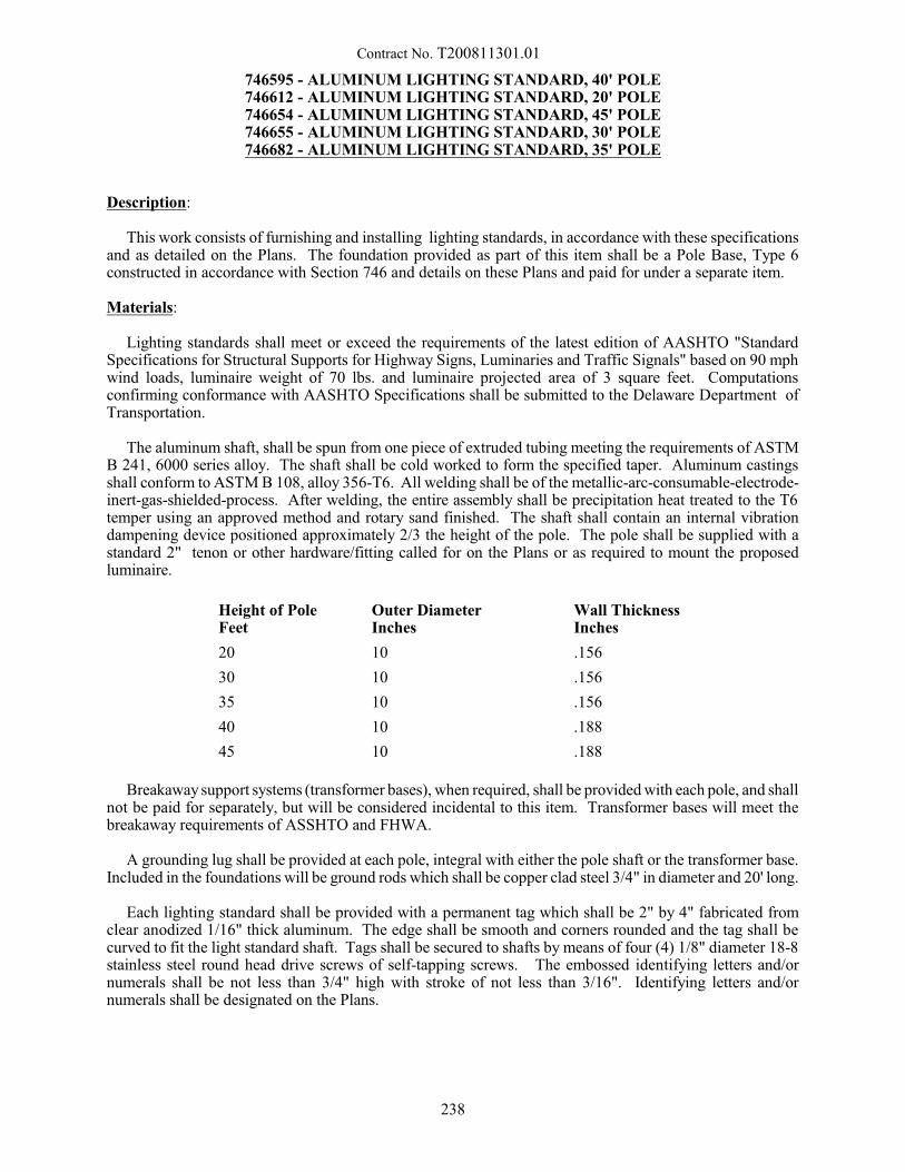
Contract No. T200811301.01
746595 - ALUMINUM LIGHTING STANDARD, 40' POLE746612 - ALUMINUM LIGHTING STANDARD, 20' POLE746654 - ALUMINUM LIGHTING STANDARD, 45' POLE746655 - ALUMINUM LIGHTING STANDARD, 30' POLE746682 - ALUMINUM LIGHTING STANDARD, 35' POLE
Description:
This work consists of furnishing and installing lighting standards, in accordance with these specificationsand as detailed on the Plans. The foundation provided as part of this item shall be a Pole Base, Type 6constructed in accordance with Section 746 and details on these Plans and paid for under a separate item.
Materials:
Lighting standards shall meet or exceed the requirements of the latest edition of AASHTO "StandardSpecifications for Structural Supports for Highway Signs, Luminaries and Traffic Signals" based on 90 mphwind loads, luminaire weight of 70 lbs. and luminaire projected area of 3 square feet. Computationsconfirming conformance with AASHTO Specifications shall be submitted to the Delaware Department ofTransportation.
The aluminum shaft, shall be spun from one piece of extruded tubing meeting the requirements of ASTMB 241, 6000 series alloy. The shaft shall be cold worked to form the specified taper. Aluminum castingsshall conform to ASTM B 108, alloy 356-T6. All welding shall be of the metallic-arc-consumable-electrode-inert-gas-shielded-process. After welding, the entire assembly shall be precipitation heat treated to the T6temper using an approved method and rotary sand finished. The shaft shall contain an internal vibrationdampening device positioned approximately 2/3 the height of the pole. The pole shall be supplied with astandard 2" tenon or other hardware/fitting called for on the Plans or as required to mount the proposedluminaire.
Height of PoleFeet
Outer DiameterInches
Wall ThicknessInches
20 10 .156
30 10 .156
35 10 .156
40 10 .188
45 10 .188
Breakaway support systems (transformer bases), when required, shall be provided with each pole, and shallnot be paid for separately, but will be considered incidental to this item. Transformer bases will meet thebreakaway requirements of ASSHTO and FHWA.
A grounding lug shall be provided at each pole, integral with either the pole shaft or the transformer base. Included in the foundations will be ground rods which shall be copper clad steel 3/4" in diameter and 20' long.
Each lighting standard shall be provided with a permanent tag which shall be 2" by 4" fabricated fromclear anodized 1/16" thick aluminum. The edge shall be smooth and corners rounded and the tag shall becurved to fit the light standard shaft. Tags shall be secured to shafts by means of four (4) 1/8" diameter 18-8stainless steel round head drive screws of self-tapping screws. The embossed identifying letters and/ornumerals shall be not less than 3/4" high with stroke of not less than 3/16". Identifying letters and/ornumerals shall be designated on the Plans.
238

Contract No. T200811301.01
Method of Measurement:
The quantity of aluminum lighting standards will be measured as the actual number of poles complete inplace and accepted.
Basis of Payment:
The quantity of aluminum lighting standards, will be paid for at the Contract unit price per each. Priceand payment will constitute full compensation for, furnishing and placing/erecting all materials; and for alllabor , equipment, tools and incidentals necessary to complete the item.
8/24/06
239
Contract No. T200811301.01
746615 – PVC SCHEDULE 40 DUCT, 6"
Description:
This work consists of furnishing all materials required and extending the existing 6” schedule 40 PVCencasement around the 1½” schedule 40 PVC effluent pipe in accordance with locations, notes, and detailsshown on the Plans and as directed by the Engineer. This work shall be coordinated with Delaware StatePolice that occupy the Weigh Station Administration Building. If a shutdown of the weigh station sanitarysewer facilities is required, work shall be performed when the weigh station building is not occupied, unlessotherwise directed by the Engineer.
Materials:
Material shall conform to the requirements listed on the Plans, and as noted herein. All pipe and fittingsshall be free from defects, and the defective materials as determined by the Engineer, shall be rejected andreplaced.
Warning tape for sanitary sewer or force main shall be printed polyethylene plastic tape with a metalliccore, manufactured specifically for warning and identification of buried utility lines. The tape shall be of aroll type, 2" (50 mm) minimum width, and color coded for sewer (green), with warning and identificationimprinted in bold black letters continuously and repeatedly over entire length of tape. The code and lettercolor shall be permanent and unaffected by moisture and other substances contained in trench backfillmaterials. Imprinted on the tape shall be "Caution, Buried Sewer Line Below", or a similar message asapproved by the Engineer.
Delaware No. 57 Stone shall conform to the requirements of Section 813 of the Standard Specifications. Sand shall conform to the requirements of Section 804. Geotextiles shall conform to the requirements ofSection 713.
Construction Methods:
The Contractor shall apply for and obtain all necessary permits required for the alteration of an existingseptic system prior to starting work. All pipes shall be thoroughly cleaned before they are laid and shall bekept clean until the completed work is accepted. The excavation and backfill for the pipe shall be performedin accordance with the Construction Details. The pipe shall be re-installed in its original location or asdirected by the Engineer. Sand shall be blown between the 1½” PVC pipe and the 6” PVC sleeve to fill theannulus. During backfill of the sewer or force main the Contractor shall install the specified warning tapeas per the Construction Details or as directed and approved by the Engineer.
Method of Measurement:
The quantity of PVC Schedule 40 Duct, 6” will be measured from end to end in linear feet of pipecompleted and accepted.
Basis of Payment:
The quantity of PVC Schedule 40 Duct, 6” will be paid for at the Contract unit price per linear foot. Priceand payment will constitute full compensation for furnishing and installing sanitary sewer pipes (includingall connections); for furnishing and installing warning tape; for excavation; for furnishing and placingDelaware No. 57 stone, sand and geotextiles; for all labor, tools, equipment, permits, permit fees, testing andincidentals to complete the work and make the sewer system functional. Payment for Borrow Type F, BorrowType C, topsoil, and seeding will be made under their respective items.
8/28/12
240
Contract No. T200811301.01
746653 - ELECTRICAL TESTING
Description:
This work consists of furnishing all materials, equipment, tools, and labor necessary to perform electricaltesting in accordance with these special provisions, notes and details on the plans, and as directed by theEngineer.
When this item is required to test a highway lighting system constructed as part of the Contract, the itemshall also include a one year warranty of the highway lighting system. The highway lighting system isunderstood to include all items of work performed under this Contract to provide lighting of roadways,bikepaths, parking lots, signs, etc.
Construction Methods:
Ground Resistance Testing
The ground resistance shall be measured with a three-terminal, fall-of-potential, direct-reading, battery-powered earth tester with a 0.50 to 500 ohm scale or digital read-out. The 25 ohm reading shall beapproximately at mid scale.
The test shall be performed according to the manufacturer's instructions and OSHA requirements. Thetest shall be performed when the soil is dry. The Contractor shall not add any chemical or salt solutionsto any portion of the grounding system. All grounding rods and foundation grounds to be tested shall beinstalled a minimum of ten days prior to testing unless otherwise determined by the Engineer in the field.
Two auxiliary copper clad ground rods shall be driven into the ground at a minimum distance of 3 feet(one meter). The lateral spacing for each test rod shall be given in writing on the test report form and thespacing shall be approved by the Engineer.
Each ground rod or foundation ground shall be isolated with the bond wires disconnected when the testis being performed. The resistance to ground shall be 25 ohms or less.
Unless noted otherwise on the plans, there shall be two ground resistance tests performed under this itemof work.
System Testing
Insulation from ground and roadway lighting circuits shall be tested as follows:
(1)Insulation from Ground. All underground circuits shall be tested for resistance to ground with amegger both before and after the conduit and wiring have been buried and all ground rods have beeninstalled and connected. No circuit shall measure less than 10 megohms to ground. Circuits that failwill be inspected, repaired, and retested.
(2)Roadway Lighting Circuits. The Contractor shall connect field wiring to the load center terminals. Theentire lighting system shall be energized for ten consecutive days for ten hours each day at the timedirected by the Engineer prior to initial acceptance. Failures occurring during this test period shall becorrected. The Contractor shall repair or replace any equipment, components, or system that failsduring this test. A retest shall be performed on the repaired portion at the Engineer's direction.
All tests shall be performed in the presence of the Engineer, and test results shall be written, dated, andgiven to the Engineer for approval.
241
Contract No. T200811301.01
Highway Lighting System Warranty:
The Contractor shall secure the manufacturer’s warranties and/or guarantees on electrical and/ormechanical equipment. These warranties and/or guarantees shall be submitted to the Department upon finalacceptance of the completed highway lighting system. In addition to the manufacturer’s warranties and/orguarantees, the Contractor shall warrant to the Department the complete, installed highway lighting systemto be free of defects, as hereafter defined, for one calendar year beginning at the initial acceptance of thehighway lighting system by the Department. The initial acceptance of the highway lighting system will occurupon the satisfactory correction of all deficiencies noted in the lighting system during the final inspection ofthe project.
The highway lighting system will be considered defective if any of the following conditions are discoveredby visual inspection or by inspection with testing equipment within the warranty period:
1. Defective lamps or ballasts.2. Failure to operate, in whole or in part.3. Power wire grounding less than ten mega-ohms.4. Shifts in pole/foundation alignment.5. Short circuits or open circuits anywhere within the system.6. Deterioration of finishes, plating, or paint not normal and customary in the environment in which the
equipment is installed.7. Settlement of trench backfill.8. Defective fuses.9. Defective or improperly installed splices.
These conditions listed shall not be considered all inclusive.
The highway lighting system is comprised of all Contract items for lighting, including but not limited toconduits, junction wells, cables, load centers, transformers, cabinet pads, pole bases, poles, high mast poles,light standards with and without davit arms, luminaires, sign lighting, service installations, andreworked/relocated existing lighting facilities.
There will be initial and periodic highway lighting system performance inspections after the Contractorhas completed all the work. The initial inspection, to be conducted during the final construction inspection,will be to determine if the initial performance requirements are met. Periodic reviews will be conducted atmonthly intervals through the warranty period to determine the sustained ability of the highway lightingsystem to meet the stated performance requirements.
The Department review team will be responsible for evaluating the highway lighting system within theproject limits for both day and night acceptability considering all the possible defects listed above. If thehighway lighting system is considered defective because of abnormal operation or deterioration (as listedabove), the Department will require repair or replacement of the defective portion at its sole option.
All defective areas, which may include all highway lighting systems and components within the projectlimits, identified by the Department during initial or periodic inspections shall be repaired by the Contractorin accordance with this Section. All highway lighting system repair shall begin immediately following thenotice to the Contractor of the lighting system defect unless weather limitations prevent the corrective work. The Department shall be given notification before the Contractor begins corrective work and shall be allowedfull inspection of all operations and provided safe access to the areas being repaired.
If at any time during the warranty period, the highway lighting system or any portion thereof is rendereddefective as a result of other than a manufacturing design or construction defect, the Department will repair,replace or revise said system at its sole option. The Contractor will not be held responsible for the cost tocorrect failures due to design defects in the highway lighting system.
242

Contract No. T200811301.01
Method of Measurement:
The quantity of electrical testing will not be measured.
Basis of Payment:
The quantity of testing will be paid for at the Contract lump sum price. Price and payment will constitutefull compensation for furnishing all testing equipment, including ground rods; performing the tests; preparingthe reports; and for all labor, equipment, tools, and incidentals required to complete the work. For highwaylighting systems, price and payment will also constitute full compensation for providing the warranties.
5/24/02
243
Contract No. T200811301.01
746669 - LUMINAIRE (HPS) 150 WATT
Description:
This work consists of furnishing and installing Type A and Type B 150 watt high pressure sodium fixtureson poles, in accordance with these specifications and as shown on the Plans.
Materials:
The complete Type A or Type B luminaire shall be a 150 watt high pressure sodium type powered froma nominal 240 or 277 volt, 60 hertz source. The luminaire shall have a heavy-duty die-cast aluminumhousing with an electrocoat gray finish and a hinged and removable door assembly with a heat/impactresistant glass prismatic lens. The luminaire shall be provided with internal two-inch slipfitter mounting andphotocell control. The ballast shall be a multi-tap (120/208/240/277 volt) auto-regulating type, capable ofstarting and operating the lamp down to temperatures of 78EF (28EC). The optical assembly shall be sealedwith a perimeter gasket and activated charcoal filter.
The Type A fixture shall have medium, semi-cutoff NEMA Type 3 distribution and shall be GeneralElectric Catalog Number M4AR-25-S-0-M-2-G-MS3-2, Lithonia Lighting CHLD-250S-R3-DLG-TB-MRB-PEU-CF or approved equal.
The Type B fixture shall have medium, non-cutoff NEMA Type 4 distribution and shall be GeneralElectric Catalog Number M4AR-25-S-0-M-2-G-MN4-2-F or Holophane Vector Model No.HL2A250HPMTKGR-PR or approved equal.
Method of Measurement:
The quantity of 150 watt (HPS) luminaires will be measured as the actual number of luminaires providedcomplete in place and accepted.
Basis of Payment:
The quantity of 150 watt (HPS) luminaires will be paid for at the Contract unit price per each. Price andpayment will constitute full compensation for furnishing all materials, and for all labor, tools, equipment, andincidentals necessary to complete the item installation.
12/21/10
244
Contract No. T200811301.01
746717 - ELECTRIC SERVICE ON RACK WITH SERVICE RISER
Description:
This work consists of the installation of an electrical service, underground, on a galvanized C channelRack with service riser as indicated on the contract drawings and as required.
Materials:
Concrete. Concrete used for the C Channel footing shall be Class B conforming to the requirements ofSection 812.
Shop drawings and catalog cuts shall be submitted for the pedestal support members for approval.
All electrical materials shall conform to the requirements of the National Electric Code of the National FireProtection Association, to all local and special laws, and/or to ordinances governing such installation. Whenthese requirements do not govern, and where not otherwise specified, electrical materials shall conform tothe Standardization Rules of the Institute of Electrical and Electronic Engineers. Shop drawings and catalogcuts for all electrical and related materials shall be submitted by the Contractor for approval.
Construction Methods:
Electric Service on Rack with Service Riser:
Install the Rack on concrete footings as shown on plans. The Rack will be installed within 10 feet (3 m)of the utility company's wood pole. If the distance from the Rack to the utility company's wood pole exceeds10 feet (3 m), the additional work and material will be covered under other items of this contract. Install alength of 1 ¼" galvanized conduit under the meter pan, so that the conduit will have 2 feet (0.6 m) of coverafter a 1 ¼" (32 mm) galvanized elbow is installed. Connect the required length of 1 ¼" (32 mm) conduitto the elbow and install a second 1 ¼" (32 mm) galvanized elbow so that it is in direct contact with the utilitycompany's wood pole. Install a 1 ¼" x 3' (50 mm x 0.9 m) nipple to the elbow. Reduce the 1 ¼" (32 mm)conduit to 3/4" (19 mm) with an approved reducing bushing. Install 30 feet (9 m) of 3/4" (19 mm) galvanizedconduit above the conduit reducer, securing it to the wood pole within 12" (300 mm) of the conduit reducerand then at intervals not exceeding 3 feet (0.9 m). On the top of the 3/4" (19 mm) aluminum conduit installa 3/4" (19 mm) weatherhead, and secure the conduit to the wood pole within 12" (300 mm) of theweatherhead.
Install 3 (three) THHN (size as shown on the plans) stranded conductors {1 red, 1 black and 1 white}from the line side of the meter pan to the weatherhead, leaving 5 feet (1.5 m) coiled and taped outside forconnection by others. Connect the other end inside the meter pan using an anti oxidation
Method of Measurement:
The quantity of electrical services will be measured as the number of services installed in accordance withthese specifications, complete in place, and accepted.
Basis of Payment:
The quantity of electrical services will be paid for at the Contract unit price per each. Price and paymentshall include full compensation for installing the service, all utility permits, all materials and for all labor,tools, equipment, and incidentals necessary to complete the item.
11/21/11
245
Contract No. T200811301.01
746843 - POLE BASE, TYPE 1746844 - POLE BASE, TYPE 2
746845 - POLE BASE, TYPE 2A746846 - POLE BASE, TYPE 2B746847 - POLE BASE, TYPE 3 746848 - POLE BASE, TYPE 3A746849 - POLE BASE, TYPE 3B746850 - POLE BASE, TYPE 4A 746851 - POLE BASE, TYPE 4B746852 - POLE BASE, TYPE 6
Description:
This work consists of constructing and furnishing round or square pole bases Types 1, 2, 2A, 2B, 3, 3A,3B, 4A, 4B, and 6 for poles in accordance with the Standard Construction Details and at locations as directedby the Engineer.
Materials:
The concrete for pole bases shall conform to Section 812, Class B.
Bar reinforcement shall meet the requirements of Section 603 Grade 60.
Ground rods shall be copper clad, approved by the Underwriter's Laboratory and be supplied withapproved clamps for connecting the grounding conductor to the rod.
Conduit for sweeps shall meet the requirements for galvanized rigid steel conduit in Section 745.
Anchor bolts will be supplied by the same entity that supplies the poles.
“Drop-in” Expansion Anchors and Bolts for Type 4A Pole Bases shall be provided by the Contractor. Theanchors shall be stainless steel and shall accept 1/2" diameter stainless steel bolts. Anchors shall be ConcreteFastener Systems Model DIS 12, Hilti HDI SS 303, or approved equal.
Construction Methods:
The bases shall conform to the dimensions as indicated on the Standard Construction Details. A groundrod shall be installed as shown. A minimum of 8 feet of the ground rod must be driven into undisturbed soil.
If a utility or a right-of-way conflict is found when a Type 2 or Type 3 base is specified in the Plans, analternate base of equivalent strength may be used as directed by the Engineer. A Type 2 base has twoequivalents, namely Types 2A and 2B. A Type 3 base has two equivalents, namely Types 3A and 3B.
Though the contract calls for the use of a round pole base, the Contractor may use a square base at itsdiscretion.
The end of the conduit sweeps in the ground shall be extended outside the concrete and any forms orsheeting by 12 inches and capped or connected to the existing conduit. If the conduit is to be cappedunderground for future use, it must be sealed with a galvanized threaded conduit plug. Tape is NOT anapproved conduit plug. The location of the conduits shall be marked on the base with arrows drawn in thewet concrete within 6 inches of the outer edge.
Excavation for the pole bases may not exceed the dimension of the foundation by more than 12 inches inany one direction. If a form is used in the excavation more than 18 inches below the ground surface, it is
246
Contract No. T200811301.01
necessary that the area between the form and excavation be filled with Borrow Type C and tamped on allsides in continuous, horizontal layers not to exceed 68 inches in depth, loose measurement.
Where a pole base is to be placed in existing concrete pavement such as a sidewalk, the concrete shall besaw cut in a square pattern or removed to the nearest joint. In other pavement material, a round hole may becut using an appropriate tool. Any damage to the existing pavement shall be repaired at the Contractor'sexpense and shall meet the approval of the Engineer. Any removal or replacement of any type of pavementunder this item shall be an incidental cost to this item.
The bases shall be edged and have a broom finish.
Where water or highly unstable material is encountered during the excavation for the pole base, pole basesheeting may be required and the following steps shall apply:
1. The condition exists in the upper half of the excavation. Stop all work until the Bridge Design Sectionreviews the condition.
2. The condition exists below the upper half of the excavation:a. For a proposed Type 4A or 4B Base, increase the depth to 4 feet.b. For a proposed Type 1, 2, or 3 Pole Base, substitute a Type 3A Pole Base for all but a Type 3B Pole
Base. The depth of the base shall be as determined in (d) below, or 9 feet, whichever is greater.c. For a proposed Type 6 Pole Base, substitute a Type 2 Pole base and increase the depth in accordance
with (d) below.d. Determine the depth of the base, which would be in the unsatisfactory area. Multiply that depth by
0.7 and add the result to the original required depth of the base to obtain the final depth of the base. The reinforcing bars shall be extended using the required pattern to match the final depth inaccordance with the requirements of Section 603.07 of the Standard Specifications.
Method of Measurement:
The quantity of pole bases will be measured as the actual number of bases constructed, complete in placeand accepted. Concrete, excavation and backfilling around the base, ground rods, and the two conduit sweepsin the base are included in this item. Should excavated material be unsuitable for trench backfill, theContractor shall furnish material meeting the requirements of Borrow, Type C from other excavations or fromborrow sites within the contract limits. Payment will be made using the item under which the material wasinitially excavated. Hauling, placement, and compaction are incidental to the item being backfilled.
Payment for any additional sweeps shall be paid for separately under the appropriate conduit items. TheContractor's use of square base rather than a specified round base shall not result in any additional cost to theDepartment.
Basis of Payment:
No payment will be made for backfill material meeting Borrow, Type C requirements that is placedoutside of the vertical plans located 18" outside of the neat line perimeter of the vertical face of the pole basefoundation. Any increase in the vertical dimension required herein shall be paid for separately under Item746614, Pole Base Extension; another item of this contract.
The quantity of pole bases will be paid for at the Contract unit price for each pole base type. If an alternatepole base type is selected by the Engineer, payment will be the Contract unit price for the alternate selected. Price and payment will constitute full compensation for furnishing and placing all materials includingconcrete, ground rods, and a minimum of two conduit sweeps extending into the base; for excavating,backfilling and compacting around the base; for repairs to damaged existing pavement; for removal orreplacement of pavement; and for all labor, equipment, tools, and incidentals required to complete the work.
7/20/15
247
Contract No. T200811301.01
746872 - LIGHTING CONTROL AND DISTRIBUTION ENCLOSURE
Description:
This work consists of furnishing all materials and installing light panels, meters, control and distributionequipment for the park and ride parking lot lighting.
Materials:
LIGHTING CONTROL AND DISTRIBUTION ENCLOSURE.
Lighting Control and distribution equipment enclosures shall be dead front type weatherproof metalenclosed self-supporting structures, as specified in the Contract Documents. Free standing enclosures shallbe fabricated from sheet aluminum and shall be as specified herein. Panel and control equipment cabinetsshall be the manufacturer's standard enclosure for the type and application specified.
Circuit Breakers. Circuit breakers shall be molded case type having a minimum rating of 22,000 ampinterrupting capacity (AIC) and be quick make, quick break, thermal magnetic, trip indicating, and havecommon trip on all multiple breakers with internal tie mechanism. They shall have the current and voltageratings and number of poles as specified in the Contract Documents, and shall be treated to resist fungus andbe ambiently compensated for the enclosure and proximity to adjacent breakers. All circuit breakers shall bethe bolt in type.
Photoelectric Controls. Photoelectric controls shall be solid state, cadmium sulfide type with hermeticallysealed silicone rectifier rated 277 volts, 60 cycle AC and 1000 watts maximum load. Built in surge protectionshall be provided, and a fail safe operating feature shall be included so that the lighting circuits will remainenergized in the event the photo control components become inoperative. Nominal operating levels of thiscontrol shall turn on at a minimum vertical illumination value of 3 FC (32 lux) and turn off at a maximumvertical illumination value of 6 FC (65 lux). These limitations shall be set by the manufacturer, and tolerancesof plus or minus 20 percent for the specified value will be acceptable. Photoelectric controls for luminairesand lighting controls shall be twist lock type. A suitable mounting bracket with locking type receptacle andall other necessary mounting hardwareshall be furnished.
Contactors and Relays. Contactors of the current ratings and number of poles specified in the ContractDocuments shall be held by permanent magnets. They shall be fully rated for all classes of load to 600 voltsAC and shall have an interrupting rating of 600 percent of rated current. A HAND-OFF-AUTOMATICselector switch shall be provided in the photoelectric cell circuit. Relays shall be the type, size and contactratings as specified in the Contract Documents.
Panel Boards. Panel boards shall conform to Federal Specification W-P-115 and shall besuitable for operation on the voltage and type service specified in the Contract Documents. They shall belisted and labeled by the Underwriters' Laboratories, Inc. Panel boards shall be equipped with the number andsize circuit breakers specified. Circuit breakers in panel boards shall conform to Federal Specification W-C-375 and shall be bolted to copper busses. Buss ratings shall be as specified. Panel shall be provided withmodular Transient Voltage Surge Suppressors. (TVSS).
Lightning Arresters. Lightning arresters shall be secondary type, having the specifiednumber of poles and 0-650 volts RMS. Arresters shall be provided with suitable mounting brackets and allother necessary mounting hardware.
Control Power Transformers. Control power transformers shall be the dry type, twowindings, of the size and voltage ratings specified in the Contract Documents.
248
Contract No. T200811301.01
Enclosures. Enclosures shall conform to the NEMA 3R. They shall have door clamps, solid neoprenegaskets, welded seams, stainless steel external hardware and continuous hinges with stainless steel pins.Enclosures shall have two weepholes in the bottom and shall be equipped for padlocking.
Pad Mounted Enclosures. For ventilation, all cabinets shall be provided with louvered vents in the frontdoor with a removable air filter.
(a) Louvers shall satisfy the NEMA Rod Entry Test for 3R rated ventilated enclosure.(b) Filters for all cabinets shall be 16 in. long, 12 in. wide, and 1 in. thick. The filter shall cover the ventsand be held firmly in place with top and bottom brackets and a spring loaded upper clamp. (c) Exhaust air shall be vented out of the cabinet between the top of the cabinet and the main accessdoor. The exhaust area shall be screened with a screen type material having a maximum hole diameter of1/8 in.
Thermostats and Fans. A thermostatically controlled cooling fan shall be provided for all cabinets. The fanand thermostat shall be rated for 125 percent of capacity and they shall be mounted at the top of the cabinet. (a) Thermostats shall be the inline type, single pole, 120 volts, 10 amps with a minimumrange of 40to 80F. (b) The fan shall have a minimum rated capacity of 100 CFM air flow and a minimum rated design lifeof 100,000 hours. (c) The thermostat shall be manually adjustable, within a 10 degree range, from 70 to 160F.
Method of Measurement:
This number of Lighting Control and Distribution Enclosure to be measured under these items shall bethat actual number in accordance with these special provisions complete in place and accepted.
Basis of Payment:
The number of Lighting Control and Distribution Enclosure as determined above, shall be paid for at thecontract unit price bid for each item "Lighting Control and Distribution Enclosure" installed in accordancewith the requirements contained herein, complete in place and accepted, which price and payment shallconstitute full compensation for furnishing all materials, including panels, control devices concrete padfoundation and for all labor and equipment necessary for the installation of the electrical equipment specified.
10/27/2009
249

Contract No. T200811301.01
746924 - FURNISH & INSTALL LOOP WIRE 1 - CONDUCTOR #14 AWG CABLE ENCASED
IN ¼” FLEXIBLE TUBING IN A LOOP SAWCUT
Description:
Sawcut and seal existing pavement, furnish and install loop detector wire, as shown on the Plans andapplicable Standard Construction Details.
Materials:
1. 1-conductor #14 AWG Cable in ¼” Flexible Tubing - shall consist of cable preinstalled in apolyethylene (PE) plastic duct meeting IMSA 51-5. Cable shall be rated for 600 volts. The cable shallhave a temperature tolerance range of at least - 65 to + 176 degrees Fahrenheit. The conductor is AWG#14 stranded copper. Outside diameter of the cable is 0.25 inches. Referred to as “loop wire”
2. 2-conductor #14 AWG Aluminum Shielded Cable – see specifications for furnish and install cable. Referred to as “home-run cable”.
3. Flexible embedding sealer - a cold poured, resilient type epoxy joint sealer, Bondo P 606 or Duracote D115 for concrete or asphalt pavement or E Poxy Industry 36 1 for concrete or E Poxy Industry11 1 forasphalt pavement, or approved equal. A sealer accelerant or retarder may be added per the manufacturer’sspecifications.
4. Backer Rod - 5/8" closed cell foam
5. Tape - Vinyl electrical tape shall have a PVC base with rubber based pressure sensitive adhesive. Thetape shall be a minimum 7 mils thick and be UL listed and marked per UL Standard 510 as flame retardantand cold resistant. It shall be compatible with synthetic cable insulations, jackets and splicing compoundsand rated for wire and cable splices up to 600-volts.
6. For splices in Junction Well (see plan or Standard Construction detail):
a. Dual Wall Heat Shrink Tubing – Heat-shrink tubing shall be medium or heavy wall thickness,irradiated polyolefin tubing containing an adhesive mastic inner wall. Minimum wall thickness priorto contraction shall be 40 mils. When heated, the inner wall shall melt and fill all crevices andinterstices of the object being covered while the outer wall shrinks to form a waterproof insulation. Each end of the heat-shrink tube or the open end of the end cap of heat-shrink tubing shall, aftercontraction, overlap the conductor insulation at least one and one-half inches. Heat-shrink tubing shallconform to the requirements in UL Standard 468D and ANSI C119.1, for extruded insulated tubing at600 V.
b. Soldering iron with Rosin Core solder
c. Splicing Kit- In-line barrel type design, resin encapsulating compound kit with UL486 rating. Suitablefor use in wet or direct buried locations. Resin encapsulating compounds shall be acceptable for useat 16 degrees C.
Construction Methods:
Loop Wire Installation:
The pavement saw cut shall be 5/8" wide and 3½” deep. It shall be “wet-cut” in the directions and sizesspecified on the Plans, Standard Details or as directed by the Engineer. Contractor shall remove sharp edgesin the saw cut and round the corners. The saw cut shall be blown out with compressed air to remove all dust,water and particles of loose material prior to sealing.
250
Contract No. T200811301.01
The loop detector wire will then be installed using blunt tools so as to prevent damage to the polyethyleneouter cover. One end of a loop detector wire shall be tagged to indicate start ("S"). A 5/8" backer rod shallbe placed into the entire length of the saw cut to secure the wiring. All loop detector wires shall be laid insaw cuts in a clockwise rotation beginning with "S". The Engineer may require a High Voltage Ground Testwith a 500 VDC megger after the loop detector installation is complete and prior to sealing saw cuts. If theresistance to ground is less than 100 megohms, this work will be rejected.
A sealer and sealer accelerant or retarder (if necessary) shall be applied in accordance with themanufacturer's directions and protected from traffic until it has set. A minimum of 1 inch of sealer shall beinstalled on top of the loop detector wire and finished flush with the pavement. Drilled holes in the pavementshall also be sealed.
Two loop detector wires shall be installed in a saw cut from the loop to the edge of the road. These twowires shall then extend from the end of the saw cut to a junction well (see Plan Details). Wires shall beparallel, twisted a minimum of 5 wraps per foot, and taped every 12" to 18" from the end of the saw cut toa junction well up to the splice.
The loop detector wire shall be continuous and without splices from the junction well, through the sawcuts and conduit.
Home-run Wire Installation - refer to furnish and install cable specifications and conduit installationspecifications. Refer to plans for details.
Splicing - splices between the loop detector wire and home-run cable shall be done in accordance with theStandard Construction or plan details.
Conductors to be soldered shall be placed side by side with the exposed copper aligned. The copper shallthen be twisted clockwise with pliers until a good mechanical connection is affected. The splice shall becoated with flux, heated with a soldering iron, and rosin core soldered in a manner that minimizes insulationdamage. After each soldered connection is completed, it shall be properly insulated with heat shrink tubing.
After the electrical and mechanical connection is completed and before the splicing kit is applied, a testshall be made by the Contractor to ensure that all circuits are complete. An approved splice kit shall beinstalled as per manufacturer's instructions. A continuity test will be performed at the cabinet by theDepartment technician after the splicing kit is applied. The Department will be notified of the test results. If the continuity test fails the Contractor shall remake the splice and/or loop at his own expense.
If a splice is found to be faulty within 90 calendar days of installation, it shall be the Contractor'sresponsibility to remake the splice at his own expense.
Method of Measurement:
The quantity of loop detector wire to be measured under this item shall be the number of linear feet ofsawcut in which loop detector wire is installed, sealed, tested, and accepted. Sealer, sealer accelerant or retarder shall be incidental to this item.
Loop detector wire routed through the rotary drill penetration is considered incidental to the cost of theloop installation.
Conduit and associated home-run cable between the junction well and cabinet will be measured and paidfor under their respective items, separate from this specification.
Splicing of the loop detector wire to a home-run cable in a junction well shall be incidental to the cost ofthe loop wire.
251
Contract No. T200811301.01
Basis of Payment:
The quantity of loop detector wire supplied and installed will be paid for at the Contract unit price perlinear foot, determined by measuring the footage of sawcut described above. Price and payment shallconstitute full compensation for “wet”-sawcutting, furnishing and placing all materials including loop detectorwire, backer rod, sealer, drilling required for installation, concrete and pavement patching, sealing the conduitends, internal bushings shown on the plans, and for all labor, equipment, tools, and splicing in the junctionwell.
The price bid per linear foot of this item shall also include drilling required for installation, concrete andpavement patching at the loop wire installation location, sealing the conduit ends, internal bushings shownon the plans, and all incidentals necessary to complete the item.
1/8/15
252
Contract No. T200811301.01
746951 - RELOCATING POLE AND MAST ARM
Description: This work consists of removing, relocating and erecting an existing steel CVISN compliance pole and mast
arm structure with antenna and control cabinet, in accordance with the location, notes and details on the Plansand as directed by the Engineer. Such work shall include the concrete foundation, excavation and backfilland temporary shoring as required and shall include all materials, labor, tools, equipment, and incidentalsnecessary to complete the work.
Materials:
Structural
Anchor Ring Plate: ASTM A 709, Grade 36
Fasteners
Anchor Bolts: ASTM F 1554, Grade 55
Anchor Nuts: ASTM A 563, Grade DH or ASTM A 194, Grade 2H
Anchor Washers: ASTM F 436
Connection Bolts: ASTM A 325
Heavy Hex Nuts: ASTM A 563, Grade DH or ASTM A 194, Grade 2H
Washers: ASTM F 436
Finish
Structural: Galvanized finish ASTM A 123
Fasteners and anchor bolts: Galvanized finish ASTM A 153
Galvanizing shall comply with ASTM A 143 and A 385
Foundations & Concrete Maintainer Pad
Concrete: Class B per Sections 602 and 812, except for tremie method use concrete with a slump of6 inches + 1 inch.
Reinforcement: Section 603.
Construction Methods:
General
The CVISN antenna and pole mounted control cabinet shall be carefully removed from the pole to avoidany damage. The steel pole and mast arm structure shall be carefully dismantled and all members includingbolts, nuts, and all related hardware shall be stored for reuse. Rusted or damaged bolts and nuts shall bereplaced in kind and shall conform to the requirements of Section 605 of the Standard Specifications.
253
Contract No. T200811301.01
Should any damage occur to the pole, mast arm, antenna unit, or control cabinet, and in the opinion of theEngineer adequate precaution was not exercised by the Contractor during the relocation operation, theContractor shall at his expense replace the damaged units in kind or better as determined by the Engineer.
Foundations
Prior to excavation for the foundation, the contactor shall obtain the Engineer’s approval regarding thelocation.
The pole shall not be erected upon the completed footing until authorized, but the minimum time allowedfor the hardening of the concrete before any load is placed thereon shall be 7 calendar days.
Anchor bolts shall be set to template for alignment and elevation and shall be secured in position toprevent displacement while concrete is being placed. The steel reinforcement and conduit elbows shall havebeen placed and secured before the placing of concrete.
The top surface of the concrete caisson shall be leveled off at a distance below the bottom of the base plateso as to provide room for the lower leveling nuts and washers as shown on the Plans. The distance betweenthe bottom of the leveling nuts and the top of the concrete caisson shall not exceed one bolt diameter. Thetop surface of the concrete caisson shall be edged and have a broom finish.
Ground the pole using a #2 AWG ground wire connected to the grounding stud and ground rod in thejunction well.
The reinforcing steel shall be placed so that the outer edges of the reinforcing cage are located so as toprovide the clear dimension shown on the Plans.
Shop Drawings
Shop drawings shall be submitted in accordance with subsection 105.04 of the Standard Specifications. Shop drawings shall be submitted for the formwork, caisson shells and the reinforcement steel associated withthe concrete caisson.
Formwork
All formwork shall conform to the requirements of Section 602 of the Standard Specifications.
Excavation
Excavate to the dimensions and elevations indicated, or required by the site conditions. Unless otherwiseindicated, bore shafts for vertical caissons, plumb, to a tolerance equal to 2% of the caisson length. However,do not place the top of shafts out of the indicated position by more than 3 inches. When bells are required,excavate to form a bearing area of the size and shape indicated. Blasting not permitted.
If satisfactory foundation materials are not encountered at indicated elevations, drill deeper, as directedby the Engineer.
Use shells for shaft excavations to prevent caving of the material or to prevent water seepage. For spaceoutside of shells left in place, fill with concrete.
If caving conditions or excess ground water is encountered, no further drilling will be allowed until aconstruction method is employed which satisfactorily prevents caving. Drilling in a mud slurry withoutremoval of cuttings or using other construction methods that can not control the size of excavation will notbe permitted.
254
Contract No. T200811301.01
Tolerance
Rock projecting 3 inches or more into the designated area shall be removed.
Inspection
Do not place concrete until the foundation material at the bottom of caissons has been inspected andaccepted by the Engineer. Place the concrete in the caisson as soon as possible after the inspection. If visualinspection cannot be made, because of inability to dewater the caissons using acceptable pumping methods,provide drilling logs and screenings to the Engineer for determining the quality of the foundation material.
Concrete
Mix, place, consolidate, and cure the concrete, as specified in Sections 602 and 812. Keep the excavationfree from accumulated seepage water and loose material, until the concrete is placed. If the Engineerdetermines that the leakage of water makes it inadvisable to place concrete in the dry, fill the caisson to thetop with clean water and place the concrete by the tremie method, to the cut-off elevation, in one continuousoperation. Submit details of the method to the Engineer for review and acceptance.
Pumping will be permitted as an alternative to the tremie method, provided the Contractor cansatisfactorily document or demonstrate that he has the required experience and is qualified to use the pumpingmethod.
Reinforcement Bars
All reinforcing steel shall be placed in conformance with the requirements of Section 603 of the StandardSpecifications. Do not place reinforcement bars until immediately before starting concreting operations.
Drilling Caissons, Shaft Section
If the top of shaft elevation is below ground level at the time the concrete is placed, provide an oversizedcasing, from ground elevation to a point below the top of the shaft, to prevent any extraneous material fromfalling into the freshly placed concrete.
When shells are used, withdraw each section in partial stages, except the last section, as the concrete isdeposited, at a rate which keeps the bottom of the shell below the top of the fresh concrete, provided thereare no indications of reduction in shaft cross section due to lateral pressure. As the shells are beingwithdrawn, thoroughly work and consolidate the concrete to a point 2 feet below the indicated top of shaftelevation. Place the concrete in each shaft in one continuous operation. If cavities or unstable material areencountered and the danger exists of losing concrete or of the concrete becoming mixed with extraneousmaterial, cut off the shells and leave them in place, or place separate shells as directed.
Erection
Poles shall be erected in position to engage the leveling nuts on the anchor bolts above the top of theconcrete cap or barrier.
The installation and tightening of the anchor bolts shall be performed in strict conformance with thesequence outlined in Appendix A, Part 1 and 2, Section 5.2 of the National Cooperative Highway ResearchProgram (NCHRP) Report 469 – Fatigue Resistance Design of Cantilevered Signal, Sign and Light Supports.
Re-Installation
Upon re-installing the control cabinet and CVISN antenna verify that the communication and powersystem is fully operational and properly installed.
255
Contract No. T200811301.01
Removal of Existing Foundation
The concrete foundation at the existing location shall be removed to a minimum depth of one foot fromthe ground surface and the area shall be graded and seeded. Removal will also include reinforcement bars,anchor bolts and other related hardware.
Method of Measurement:
The quantity of relocating pole and mast arm will be measured as the actual number of poles relocated andaccepted.
Basis of Payment:
The quantity of relocating pole and mast arm will be paid for at the Contract unit price per each. Price andpayment will constitute full compensation for relocating the existing pole and mast arm, constructing a newfoundation, for furnishing all materials such as concrete, anchor bolts, new hardware if required, forexcavation and backfill in accordance with Section 207, installing and subsequent removal of temporarysheeting, if required, constructing the foundation to the line and grade shown on the Plans, disposal of thesurplus materials, removal of the existing foundation, grading and seeding of the existing area, for all labor,equipment, tools and incidentals necessary to complete the work.
8/29/12
256
Contract No. T200811301.01
747514 - CABINET BASE TYPE F747515 - CABINET BASE TYPE M747516 - CABINET BASE TYPE P747517 - CABINET BASE TYPE R
Description:
This work consists of constructing cabinet base Type F, M, P and R in accordance with the StandardConstruction Details or applicable Plan Details and at locations as directed by Plans or the Engineer.
Materials:
Class B Concrete3/4” x 10’ sectional copperclad steel ground rods (2 ea)5/8" Zinc plated or Stainless Steel Drop-in Anchors manufactured by Hilti Systems, Concrete Fastening
Systems, or approved equal5/8" x 1-1/2" galvanized hex bolts3/4” acorn type ground clampsPVC conduit sweeps
Construction Methods:
The base shall conform to the dimensions as indicated in the cabinet base detail on the StandardConstruction Details or applicable Plan Sheets. A concrete apron is only required when installed in earth areasor as directed by the engineer. Conduits entering the base must enter only in the designated area. A minimumdistance of 1 inch shall be maintained between conduits and a minimum distance of 2 inches betweenconduits and the ground rods.
A minimum of 8 foot of the ground rods must be driven into undisturbed soil through the 2 inch PVCsleeve. The PVC sleeve shall be driven into the ground so that the top of the sleeve will be flush with theconcrete when the base is poured.
Method of Measurement:
The quantity of cabinet bases will be measured as the number of bases constructed in accordance withthese specifications, complete in place, and accepted.
All conduit sweeps extending into the cabinet base as shown on the Plans or Standard Details as applicableshall be included in the price for each cabinet base..
Basis of Payment:
The quantity of cabinet bases will be paid for at the Contract unit price per each. Price and payment willconstitute full compensation for all concrete, ground rods, labor, equipment, tools, conduit sweeps, andincidentals required to complete the work as shown on the standard details or applicable Plan sheets.
1/8/15
257
Contract No. T200811301.01
748502 - RAISED/RECESSED PAVEMENT MARKER
Description:
This work consists of furnishing and installing raised/recessed pavement markers in accordance with thePlans and these specifications.
Materials:
The cast iron housing shall meet the requirements of ASTM A 536-84, Grade 72-45-84.
The reflectors shall meet the requirements of ASTM D 4383-03.
For installation on interstates, freeways, and principal arterials, the pavement marker shall have redreflectorized material on the back side (the side not facing the direction of traffic).
Epoxy shall meet the requirements of AASHTO M237, Type IV.
The followings models have been tested and approved by the Department and shall be used:
The followings models have been tested and approved by the Department and shall be used:
1. Ennis Paint - Stimsonite Model 101LPCR with Model C40 reflective pavement markers.
2. Ray-O-Lite Model 300 Snowplowable Marker with Model 2004 Reflector.
3. Or Approved Equal.
Construction Methods:
Pavement shall be saw cut to match the bottom contour of the marker housing using a saw and bladesuitable for the pavement material being sawed. The depth of the cut slot must allow the housing to be setin epoxy, with leveling lugs resting on the pavement surface, so that the front edge of marker is at or belowthe surface of the pavement. Excessive saw cuts must be repaired to the satisfaction of the Engineer. Whencutting is complete, the slot shall be cleaned as recommended by the manufacturer of the epoxy material. Theepoxy and pavement marker will be installed in the prepared contour slot in the pavement per themanufacturer's recommendations.
Placement shall be in accordance with the DE MUTCD.
Method of Measurement:
The quantity of raised/recessed pavement markers will be measured as the actual number installed andaccepted.
Basis of Payment:
The quantity of raised/recessed pavement markers will be paid for at the Contract unit price per each. Price and payment will constitute full compensation for furnishing all materials, installation, saw-cutting,cleaning, disposal of discarded materials, for all labor, tools, equipment, all necessary incidentals associatedwith the item to complete the work.
07/26/2011
258
Contract No. T200811301.01
748506 - PERMANENT PAVEMENT STRIPING, EPOXY RESIN PAINT, WHITE/YELLOW, 4"748507 - PERMANENT PAVEMENT STRIPING, EPOXY RESIN PAINT, WHITE/YELLOW, 6"748508 - PERMANENT PAVEMENT STRIPING, EPOXY RESIN PAINT, WHITE/YELLOW, 8"748509 - PERMANENT PAVEMENT STRIPING, EPOXY RESIN PAINT, WHITE/YELLOW, 12"748510 - PERMANENT PAVEMENT STRIPING, SYMBOL/LEGEND, EPOXY RESIN PAINT
748535 - PERMANENT PAVEMENT STRIPING, EPOXY RESIN PAINT, BLACK, 4"748536 - PERMANENT PAVEMENT STRIPING, EPOXY RESIN PAINT, BLACK, 6"748537 - PERMANENT PAVEMENT STRIPING, EPOXY RESIN PAINT, BLACK, 8"
748538 - PERMANENT PAVEMENT STRIPING, EPOXY RESIN PAINT, BLACK, 10"748539 - PERMANENT PAVEMENT STRIPING, EPOXY RESIN PAINT, BLACK, 12"748540 - PERMANENT PAVEMENT STRIPING, EPOXY RESIN PAINT, BLACK, 16"
748548 - PERMANENT PAVEMENT STRIPING, EPOXY RESIN PAINT, WHITE/YELLOW, 5"748549 -PERMANENT PAVEMENT STRIPING, EPOXY RESIN PAINT, WHITE/YELLOW, 10"
748557 - PERMANENT PAVEMENT STRIPING, EPOXY RESIN PAINT, BLACK, 3"748559 - PERMANENT PAVEMENT STRIPING, EPOXY RESIN PAINT, BLACK, 5"748568 - PERMANENT PAVEMENT STRIPING, EPOXY RESIN PAINT, BLACK, 9"
748569 - PERMANENT PAVEMENT STRIPING, EPOXY RESIN PAINT, BLACK, 14"
Description:
This work consists of striping layout,furnishing and applying white or yellow, epoxy reflectorizedpavement markings or black epoxy contrast pavement markings at the locations and in accordance with thepatterns indicated on the Plans, or as directed by the Engineer, and in accordance with these specifications.
The white/yellow epoxy marking material shall be hot-applied by spray methods onto bituminous and/orPortland cement concrete pavement surfaces as required by the Plans. Following an application of doubledrop glass beads of two sizes and upon curing, the resultant epoxy marking shall be an adherent reflectorizedstripe of the specified thickness and width that is capable of resisting deformation by traffic.All marking materials shall be certified lead free and free of cadmium, mercury, hexvalent chromium, andother toxic heavy metals.
The black epoxy marking shall be a two-component, hot-spray applied epoxy resin pavement markingmaterial to be used for pavement marking on Portland cement concrete pavement surfaces. Following anaggregate drop, and upon curing, it shall produce an adherent stripe of specified thickness and width capableof resisting wear from traffic. Black contrast pavement markings will be required on all Portland cementconcrete pavements.
Materials Requirements:
A. White and Yellow Reflectorized Epoxy
1. Epoxy Composition Requirements:
The epoxy resin composition shall be specifically formulated for use as a pavement marking materialand for hot-spray application at elevated temperatures. The type and amounts of epoxy resins andcuring agents shall be at the option of the manufacturer, providing the other composition and physicalrequirements of this specification are met.
The epoxy marking material shall be a two-component (Part A and Part B), 100% solids type systemformulated and designed to provide a simple volumetric mixing ratio (e.g. two volumes of Part A toone volume of Part B).
Component A of both white and yellow shall conform to the following requirements:
259
Contract No. T200811301.01
% BY WEIGHTWHITE: YELLOW:
Pigments Titanium Dioxide - 18% Min.(ASTM D476, Type II)
Organic Yellow - 6%-10%
Epoxy Resin 75% Min., 82% Max. 70% Min., 77% Max.
The entire pigment composition shall consist of either titanium dioxide and/or organic yellowpigment. No extender pigments are permitted. The white pigment upon analysis, shall contain aminimum of 16.5% TiO2 (100% purity).
Epoxy Content-WPE (Component A) - The epoxy content of the epoxy resin will be tested inaccordance with ASTM D1652 and calculated as the weight per epoxy equivalent (WPE) for bothwhite and yellow. The epoxy content will be determined on a pigment free basis. The epoxycontent (WPE) shall meet a target value provided by the manufacturer and approved by theDepartment's Material and Research Section (from now on will be addressed as Department). A +50 tolerance will be applied to the target value to establish the acceptance range.
Amine Value (Component B) - The amine value of the curing agent shall be tested in accordancewith ASTM D2074-66 to determine its total amine value. The total amine value shall meet a targetvalue provided by the manufacturer and approved by the Department. A +50 tolerance will beapplied to the target value to establish the acceptance range.
Toxicity - Upon heating to application temperature, the material shall not exude fumes which aretoxic or injurious to persons or property.
Viscosity - Formulations of each component shall be such that the viscosity of both componentsshall coincide (within 10%) at a recommended spray application.
2. Physical Properties of Mixed Composition:
Unless otherwise noted, all samples are to be prepared and tested at an ambient temperature of 73± 5EF. (23 ± 3EC).
a. Color. The white epoxy composition when applied at a minimum wet film thickness of 20+1 mils(500 µm) as applicable and allowed to dry, shall plot within the boundaries described by the fourcorner points listed in Tables 1 and 2 of ASTM D 6628-01 when measured in accordance with thetest methods prescribed in Section 7 of ASTM D 6628-01.
The yellow epoxy composition when applied at a minimum wet film thickness of 20+1 mils (500µm) as applicable and allowed to dry, shall plot within the boundaries described by the four cornerpoints listed in Tables 1 and 2 of ASTM D 6628-01 when measured in accordance with the testmethods prescribed in Section 7 of ASTM D 6628-01.
b. Directional Reflectance. The white epoxy composition (without glass spheres) shall have a daylightdirectional reflectance of not less than 84% relative to a magnesium oxide standard when tested inaccordance with Method 6121 of Federal Test Method Standard No. 141.
The yellow epoxy composition (without glass spheres) shall have a daylight directional reflectanceof not less than 55% relative to a magnesium oxide standard when tested in accordance with Method6121 of Federal Test Method Standard No. 141.
c. Drying Time (Laboratory). The epoxy composition, when mixed in the proper ratio and applied ata 20+1 mils (500 µm) minimum wet film thickness, and immediately dressed with large reflectiveglass spheres (Federal Spec. Type 4)at a rate of 12 lb/gal (1.4 kg/l) of epoxy pavement markingmaterials, immediately followed by a second drop of AASHTO M-247 Type 1 glass spheres appliedat a rate of 12 lb/gal (1.4 kg/L) of epoxy pavement marking material, shall exhibit a no-track
260
Contract No. T200811301.01
condition in 15 minutes or less (ASTM D711). A Bird Applicator or any other doctor blade shallbe used to produce a uniform film thickness.
d. Drying Time (Field). When installed at a minimum wet film thickness of 20+1 mils (500 or 625um) and reflectorized with glass spheres, the maximum drying times shall correspond to thesetemperatures:
80EF (27EC) 10 minutes 70EF (21EC) 10 minutes 60EF (16EC) 15 minutes50EF (10EC) 25 minutes40EF (4EC) 45 minutes35EF (2EC) 60 minutes
The composition shall dry to “no-tracking” in approximately 10 minutes, and after thirty (30) minutesshall show no damaging effect from traffic. Dry to Ono-trackingO shall be considered as the conditionwhere no visual deposition of the epoxy marking to the pavement surface is observed when viewedfrom a distance of 100 feet (30 meters), after a passenger car is passed over the line. Regardless of thetemperature at the time of installation, the installation contractor shall be responsible for protectionof the markings material until dry to a non-tracking state.
e. Abrasion Resistance. The wear index of the composition shall not exceed 82 when tested inaccordance with ASTM C501 using a CS-17 wheel and under a load of 1000 grams for 1000 cycles.
f. Tensile Strength. The tensile strength of the epoxy composition shall not be less than 6000 psi (41MPa) when tested in accordance with ASTM D638 using a Type IV specimen [0.125" ± 0.010"(3.18 ± 0.25 mm) thick]. Tests shall be conducted at an ambient temperature of 75 ± 5EF (24 ±3EC). The testing machine shall operate at a speed of 0.20" (5.1 mm) per minute.
The total conditioning or drying period, from the time the epoxy composition is first mixed to thetime of testing, shall not be less than 24 hours nor more than 96 hours.
Test specimens for tensile strength determination will be prepared as follows:
A 1/8 inch (3 mm) thick sheet of epoxy material is cast from a reservoir-type mold, fabricated frompolyterrafluorethylene (PTFE), 1/8" deep x 10" x 10" (3 mm deep x 250 mm x 250 mm).
Prior to casting, the mold is sprayed with a suitable release agent. A sufficient amount of epoxycomposition is mixed in the proper proportions (A:B) and poured level with the top of the mold. Care should be taken so as not to decrease or exceed the 1/8" (3 mm) thickness.
After a period of 1 to 4 hours, the material will have set into a semi-rigid sheet that is flexibleenough to die-cut yet rigid enough to retain its shape. While the material is in this “plastic” state,five (5) specimens shall be die-cut and then placed on a flat, smooth, PTFE surface for thecompletion of the specified conditioning period.
g. Compressive Strength. The compressive strength of the epoxy composition shall not be less than12,000 psi (83 MPa) when tested in accordance with ASTM D695 except that a compression toolshall not be necessary. The test specimen shall be a right cylinder [0.50 inch diameter by 1.0 inchlength (12 mm diameter by 25 mm length)]. Tests shall be conducted at an ambient temperature of75 ± 5EF (24 ± 3EC).
The total conditioning or drying period, from the time the epoxy composition is first mixed to thetime of testing shall not be less than 24 hours nor more than 96 hours.
Test specimens for compressive strength determinations will be prepared as follows:
261
Contract No. T200811301.01
Five molds will be prepared from 1/2" (12 mm) I.D., 1/16" (1.5 mm) wall thickness acrylic tubing,cut in 1 1/2" (38 mm) lengths. After spraying the inside of the mold with a suitable release agent,(1)
the cylindrical tubes are placed in a vertical position on a PTFE sheet base. A sufficient amount ofepoxy composition is thoroughly mixed in the proper proportions (A:B) and poured into the moldto a depth of approximately 1 1/4" (32 mm). After a minimum of 72 hours curing, the specimensare removed from the molds and machined to a length of 1" ± 0.002" (25 mm ± 0.05 mm).
h. Hardness. The epoxy composition when tested in accordance with ASTM D2240 shall have a ShoreD hardness of between 75 and 100. Samples shall be allowed to dry for not less than 24 hours normore than 96 hours prior to testing.
B. Reflective Glass Spheres/Beads
Reflective glass spheres for drop-on application shall conform to the following requirements:
The glass spheres shall be colorless; clean; transparent; free from milkiness or excessive air bubbles;and essentially clean from-surface scarring or scratching. They shall be spherical in shape and at least80% of the glass beads shall be true spheres when tested in accordance with ASTM D1155. At least80% of the Type IV beads shall be true spheres as measured by the visual method.
The refractive index of the spheres shall be a minimum of 1.50 as determined by the liquid immersionmethod at 77EF (25EC).
The silica content of the glass spheres shall not be less than 60%.
The crushing resistance of the spheres shall be as follows: A 40 lb. (18 kg) dead weight, for 20 to 30(850 µm to 600 µm) mesh spheres shall be the average resistance when tested in accordance withASTM D1213.
The glass spheres shall have the following grading when tested in accordance with ASTM D1214.
M247 AASHTO Type 1 Glass SpheresU.S. Standard Sieve % Retained % Passing#20 (850µm) 0 100#30 (600µm) 5-25 75-95#50 (300µm) 40-65 15-35#100 (150µm) 15-35 0-5Pan 0-5
Type 4 Large SpheresU.S. Standard Sieve % Retained % Passing#10 (2000 µm) 0 100#12 (1680 µm) 0-5 95-100#14 (1410 µm) 5-20 80-95#16 (1190 µm) 40-80 10-40#18 (1000 µm) 10-40 0-5#20 (850 µm) 0-5 0-2Pan 0-2
The AASHTO M247 Type 1 glass spheres shall be treated with a moisture-proof coating. They shallshow no tendency to absorb moisture in storage and shall remain free of clusters and hard lumps. Theyshall flow freely from dispensing equipment at any time when surface and atmosphere conditions aresatisfactory for marking operations. The moisture-resistance of the glass spheres shall be determinedin accordance with AASHTO M247 test method 4.4.1.
Type IV glass spheres shall be treated with an adhesion coating. They shall show no tendency toabsorb moisture in storage and shall remain free of clusters and hard lumps. They shall flow freely from
262
Contract No. T200811301.01
dispensing equipment at any time when surface and atmosphere conditions are satisfactory for markingoperations. The adhesion coating property of the Type IV beads shall be tested in accordance with the dansyl-chloride test.
C. Black Epoxy Contrast Markings
Epoxy Resin Requirements: The two-component, 100% solids, paint shall be formulated and designed toprovide a simple volumetric mixing ratio (e.g. 2 part component A to 1 part component B) specifically forservice as a hot-spray applied binder for black aggregate in such a manner as to produce maximum adhesion. The material shall be composed of epoxy resins and pigments only.
The paint shall be well mixed in the manufacturing process and shall be free from defects andimperfections that may adversely affect the serviceability of the finished product. The paint shall not thicken,curdle, gel, settle excessively, or otherwise display any objectionable properties after storage. Individualcomponents shall not require mixing prior to use when stored for a maximum of 6 months.
The overall paint composition shall be left to the discretion of the manufacturer, but shall meet thefollowing requirements:
Composition: Component Percent By WeightCarbon Black
(ASTM D476 Type III)7±2 percent, by weight
Talc 14±2 percent, by weightEpoxy Resin 79±4 percent, by weight
D. Black Aggregate
The moisture resistant aggregate shall meet the gradation requirements (AASHTO T27) as follows:
Sieve Size Percent Retained#30 18-28%#40 60-80%#50 2-14%
The moisture resistant aggregate shall have a ceramic coating. The aggregate shall be angular with no drydispensement pigment allowed.
Hardness: The black aggregate hardness shall be 6.5-7 on Moh'sMineral Scale.
Porosity: The black aggregate porosity shall be less than two (2)percent.
Moisture Content: The black aggregate moisture content shall be less than ahalf (.5) percent.
E. Packaging and Shipment
Epoxy pavement marking materials shall be shipped to the job site in strong substantial containers. Individual containers shall be plainly marked with the following information:
a. Name of Productb. Lot Numberc. Batch Numberd. Test Numbere. Date of Manufacturef. Date of expiration of acceptance (12 months from date of manufacture)g. The statement (as appropriate)
263
Contract No. T200811301.01
Part A - Contains Pigment & Epoxy ResinPart B - Contains Catalyst
h. Quantityi. Mixing proportions, Application Temperature and Instructionsj. Safety Informationk. Manufacturer's Name and Address
Reflective glass spheres shall be shipped in moisture resistant bags. Each bag shall be marked with thename and address of the manufacturer and the name and net weight of the material.
F. The Department reserves the right to randomly take a one-quart sample of white, yellow and hardener, ofthe epoxy material or glass spheres without prior notice for testing to ensure the epoxy material meetsspecifications.
Epoxy Application Equipment:
Application equipment for the placement of epoxy reflectorized pavement markings shall be approved bythe Department, prior to the start of work.
At any time throughout the duration of the project, the Contractor shall provide free access to his epoxyapplication equipment for inspection by the Engineer or his authorized representative.
In general, the application equipment shall be a mobile, truck mounted and self contained pavementmarking machine, specifically designed to apply epoxy resin materials and reflective glass spheres incontinuous and skip-line patterns. The application equipment shall be maneuverable to the extent that straightlines can be followed and normal curves can be made in a true arc. In addition, the truck mounted unit shallbe provided with accessories to allow for the marking of legends, symbols, crosswalks, and other specialpatterns.
The Engineer may approve the use of a portable applicator in lieu of truck mounted accessories, for usein applying special markings only, provided such equipment can demonstrate satisfactory application ofreflectorized epoxy markings in accordance with these specifications.
The applicator shall be capable of installing up to 20,000 lineal feet (6,100 lineal meters) of epoxyreflectorized pavement markings in an 8-hour day and shall include the following features:
1. The applicator shall provide individual material reservoirs, or space, for the storage of Part A and PartB of the epoxy resin composition; for the storage of water; and for the storage of reflective glassspheres.
2. The applicator shall be equipped with heating equipment of sufficient capacity to maintain theindividual epoxy resin components at the manufacturer's recommended temperature for sprayapplication and for heating water to a temperature of approximately 140EF (60EC).
3. The glass spheres shall be gravity dropped upon 20 mils (500 um) of epoxy pavement markings toproduce a wet-night-reflective pavement marking. The large spheres (Federal Spec. Type 4) shall beapplied at a rate of 12 pounds per gallon (1.4 kg/L) of epoxy pavement marking material, immediatelyfollowed by a second drop of AASHTO M-247 Type 1 glass spheres applied rate of 12 pounds pergallon (1.4 kg/L) of epoxy pavement marking material. This application rate and the followinggradation shall conform to FHWA's FP-96: Standard Specifications for Construction of Roads andBridges on Federal Highway Projects (pages 757-761 Type 3 and Type 4 Beads).
4. The applicator shall be equipped with metering devices or pressure gauges, on the proportioningpumps. Metering devices or pressure gauges shall be visible to the Engineer.
5. The applicator shall be equipped with all the necessary spray equipment, mixers, compressors, andother appurtenances to allow for the placement of epoxy reflectorized pavement markings in a
264
Contract No. T200811301.01
simultaneous sequence of operations as described below in Construction Details, D. Applications ofEpoxy Reflectorized Pavement Markings of this Special Provisions.
Construction Details.
A. General: All pavement marking and patterns shall be placed as shown on the Plans or as directed by theEngineer.
Before any pavement markings work is begun, a schedule of operations shall be submitted for the approvalof the Engineer. This schedule shall be submitted 2 weeks prior to the application of the striping.
At least five (5) days prior to starting striping the Contractor shall provide the Engineer with the epoxymanufacturer's written instructions for use. These instructions shall include but not be limited to: mixingratios, application temperatures, and recommendations for use of water spray.
The application of pavement markings shall be done in the general direction of traffic. Striping againstthe direction of traffic flow shall not be allowed.
The Contractor shall be responsible for removing, to the satisfaction of the Engineer, tracking marks,spilled epoxy or epoxy markings applied in unauthorized areas.
The hot water spray shall not be used in conjunction with markings applications on any pavement surface,or on any existing durable type marking, unless specifically recommended by the manufacturer of theepoxy material.
B. Atmospheric Conditions: Epoxy pavement markings shall only be applied during conditions of dryweather and on substantially dry pavement surfaces. At the time of installation the pavement surfacetemperature shall be a minimum of 35EF (2EC) and the ambient temperature shall be a minimum of 35EF(2EC) and rising. The Engineer shall be the sole determiner as to when atmospheric conditions andpavement surface conditions are such to produce satisfactory results.
C. Surface Preparations: The Contractor shall clean the pavement or existing durable marking to thesatisfaction of the Engineer.
Surface cleaning and preparation work shall be performed only in the area of the epoxy markingsapplication.
At the time of application all pavement surfaces and existing durable markings shall be free of oil, dirt,dust, grease and similar foreign materials. The cost of cleaning these contaminants shall be included inthe bid price of this item. Also, the item shall include the cost of removal of the curing component in thearea of the epoxy markings application, if concrete curing compounds on new portland cement concretesurfaces have been used. Waterblasting will not be permitted for removal.
D. Application of White/Yellow Epoxy Reflectorized Pavement Markings: White/yellow epoxy reflectorizedpavement markings shall be placed at the widths and patterns designated on the Contract Plans.
Markings operations shall not begin until applicable surface preparation work is completed, and approvedby the Engineer.
White/yellow epoxy pavement markings shall be applied at a minimum uniform thickness of 20 mils (500µm) on all Portland cement concrete and bituminous concrete pavement, including Stone Matrix Asphalt.
Large reflective glass spheres (Federal Spec. Type 4) shall be applied at the rate of 12 pounds per gallon(1.4 kg/L) of epoxy pavement marking material, immediately followed by a second drop of AASHTO M-247 Type 1 glass spheres applied at a rate of 12 pounds per gallon (1.4 kg/L) of epoxy pavement markingmaterial. Glass spheres shall uniformly cover the length and width of the pavement marking.
265
Contract No. T200811301.01
E. Application of Black Epoxy Contrast Pavement Markings: Black epoxy contrast pavement markings shallbe placed at the widths designated on the Contract Plans.
Markings operations shall not begin until applicable surface preparation work is completed, and approvedby the Engineer.
Black epoxy contrast pavement markings shall be applied at a minimum uniform thickness of 20 mils (500µm) on all Portland cement concrete surfaces followed by a single drop of graded black aggregate.
The width of black epoxy line shall be applied for the following situations:
Center Skip Line - On Portland cement concrete pavements a black contrast skip line shall be 10 feet (3m) in length of the same width as the white epoxy reflectorized skip. It is to lead the white skip and stopat the beginning of the white skip. The black contrast skip is to have a single application of graded blackaggregate.
Edge Lines -White Edge lines on Portland cement concrete pavements shall have a 3 inch black contrastline running parallel to the white edge line. The contrast line shall be to the inside or travel lane side ofthe edge line. The black contrast marking is to be applied with a single drop of graded black aggregate. Once it has cured sufficiently so as not to track, the reflectorized white line is to be applied along side ofthe contrast line and the two lines shall adjoin each other.
Dotted Line: All dotted lines on Portland cement concrete pavements shall have a base of black contrastmarkings which is 4 inches (100 mm) wider than the reflective white marking. The black contrast markingis to be applied first with a single drop of graded black aggregate. Once it has cured sufficiently so as notto track, the reflectorized white line is to be applied on top of it. The reflective line is to be centered alongthe black contrast line such that a minimum of 2 inches (50 mm) of black contrast marking is visible oneither side of the reflective marking.
F. Defective Epoxy Pavement Markings: Epoxy reflectorized pavement markings, which after applicationand curing are determined by the Engineer to be defective and not in conformance with this specification,shall be repaired. Repair of defective markings shall be the responsibility of the Contractor and shall beperformed to the satisfaction of the Engineer as follows:
1. Insufficient film thickness [(less than 20+1 mils (500 µm) as applicable] and line widths; insufficientglass bead coverage or inadequate glass bead retention.
Repair Method: Prepare the surface of the defective epoxy marking by shot blasting, sand blasting, orwater blasting. No other cleaning methods will be allowed. Surface preparation shall be performedto the extent that a substantial amount of the reflective glass spheres are removed and a roughenedepoxy marking surface remains.
Immediately after surface preparation remove loose particles and foreign debris by brooming orblasting with compressed air.
Repair shall be made by re-striping over the cleaned surface, in accordance with the requirements ofthis specification and at a full 20+1 mils (500 µm) minimum line thickness as applicable.
2. Uncured or discolored epoxy (brown patches); insufficient bond to pavement surface (or existingdurable marking).
Uncured epoxy shall be defined as applied material that fails to cure (dry) in accordance with therequirements of this specification under MATERIALS, A, 2d. DRYING TIME (FIELD); or appliedmaterial that fails to cure (dry) within a reasonable time period under actual field conditions, as definedby the Engineer.
266
Contract No. T200811301.01
Discoloration (brown patches) shall be defined as localized areas or patches of brown or grayishcolored epoxy marking material. These areas often occur in a cyclic pattern and also, often are notvisible until several days or weeks after markings are applied.
Repair Method: The defective epoxy marking shall be completely removed and cleaned to theunderlying pavement surface to the satisfaction of the Engineer.
The extent of removal shall be the defective area plus any adjacent epoxy pavement marking materialextending one foot (300 mm) any direction.
After surface preparation work is complete, repair shall be made by re-applying epoxy over the cleanedpavement surface in accordance with the requirements of this specification.
3. Reflectivity for epoxy resin paint.
After satisfactory completion of all striping work and written notification from the Contractor, theDepartment shall test the striping to ensure it has the minimum reflectivity. The testing will becompleted within 30 calendar days from notification. The Contractor may request that tests beconducted on completed phases or portions of the work. Approval of such a request will be at thediscretion of the Engineer. Testing will be done using a LTL-X Retrometer (30 meter geometry). Fivereadings will be taken per line per mile (1.6 km). Projects less than 1 mile (1.6 km) in length will havea minimum of 5 readings per line. These readings will then be averaged for the overall project average.
The required average minimum initial reflectivity reading in millicandellas shall be:
White 450Yellow 325
Any single reading shall not be less than 350 millicandellas for white and 250 millicandellas for yellow.Without exception, any pavement markings installed that does not meet the above average minimuminitial reflectivity numbers shall be removed and replaced, at the installation contractor's expense.
Other defects not noted above, but determined by the Engineer to need repair, shall be repaired orreplaced as directed by and to the satisfaction of the Engineer.
All work in conjunction with the repair or replacement of defective epoxy reflectorized pavementmarkings shall be performed by the Contractor at no additional cost to the State.
Method of Measurement:
The quantity of permanent pavement striping (white, yellow, or black epoxy resin paint) will be measuredby the number of linear feet (meters) of pavement striping line and number of square feet (meter) of symbolinstalled on the pavement and accepted in accordance with the Plans.
Basis of Payment:
The quantity of permanent pavement striping (white, yellow, or black epoxy resin paint) payment will bepaid for at the Contract unit price per linear foot (meter) for 3", 4", 5", 6", 8", 9", 10", 12", 14", 16" (75 mm,100 mm, 125 mm, 150 mm, 200 mm, 225 mm, 250 mm, 300 mm, 350 mm, or 400 mm) line and the Contractunit price per square foot (meter) of symbol. The quantity of permanent pavement marking (white, yellow,or black epoxy resin paint) will be paid for at the Contract unit price per linear foot (meter) of line and theContract unit price per square foot (meter) of symbol. Price and payment shall include striping layout,cleaning and preparing the pavement surface, and placing all materials, for all labor, tools, equipment andincidentals necessary to complete the work.
267
Contract No. T200811301.01
NOTE:
For information only:
The following manufacturers are known to us which manufacturer Epoxy Resin Paint for PavementStriping. The Department does not endorse or require the use of any of the manufacturers listed below. However, a bidder wishes to use another manufacturer’s product, it shall be submitted for review andapproval prior to submitting a bid proposal. Should the product be deemed unacceptable by the Department, the successful bidder will be required to use only an approved product.
1. POLY CARB, Inc.33095 Bainbridge RoadSolon, Ohio 44139Tel. 1-800-CALLMIX
2. IPS - Ennis PaintP.O. Box 13582Research Triangle Park, North Carolina 27709Tel. 1-877-477-7623
3. EpoplexOne Park Avenue Maple Shade, NJ 08052Tel. 1-800-822-6920
4. Or an approved equal.
8/7/2013
268
Contract No. T200811301.01
748512 - RETROREFLECTIVE PREFORMED PATTERNED MARKINGS, 6O
748513 - RETROREFLECTIVE PREFORMED PATTERNED MARKINGS, 12O748514 - RETROREFLECTIVE PREFORMED PATTERNED MARKINGS, 8O748519 - RETROREFLECTIVE PREFORMED PATTERNED MARKING, 4O
748529 - RETROREFLECTIVE PREFORMED PATTERNED MARKING, SYMBOL/LEGEND748547 - RETROREFLECTIVE PREFORMED PATTERNED CONTRAST MARKINGS, 9"
748556 - RETROREFLECTIVE PREFORMED PATTERNED CONTRAST MARKINGS, 16"748564 - RETROREFLECTIVE PREFORMED PATTERNED MARKINGS, 5"
748565 - RETROREFLECTIVE PREFORMED PATTERNED MARKINGS, 10"748566 - RETROREFLECTIVE PREFORMED PATTERNED CONTRAST MARKINGS, 8"
748567 - RETROREFLECTIVE PREFORMED PATTERNED CONTRAST MARKINGS, 13"
Description:
This work shall consist of furnishing and installing retroreflective preformed patterned pavement markingin accordance with this provision and in conformance to the existing pavement markings or as establishedby the Engineer. The Contractor is required to have all subcontractors involved in the placement of thesemarkings attend the pre-placement meeting along with the tape manufacturer representative and Departmentrepresentatives to coordinate this operation. The subcontractor for pavement markings shall be approved bythe Department prior to the preconstruction meeting.
Materials:
General: The preformed patterned markings shall consist of white or yellow films with clearmicrocrystalline ceramic beads incorporated to provide immediate and continuing retroreflection. Themarkings shall be suitable for application on new or existing P.C. Concrete or bituminous pavements witha pre-coated pressure sensitive adhesive.
The preformed marking material must be used prior to one year from date of manufacture. When notplaced by inlaid method a surface preparation adhesive shall be used. The markings shall be capable ofproviding retroreflection during both wet and dry conditions.
The markings shall be highly durable retroreflective pliant polymer materials designed for longitudinaland word/symbol markings subjected to high traffic volumes and severe wear conditions such as shear actionfrom crossover or encroachment on typical longitudinal configurations such as edge lines and lane lines. Thisfilm shall be manufactured without the use of lead chromate pigments or other similar, lead-containingchemicals.
Composition: The pavement marking shall consist of a mixture of high quality polymeric materials andpigments with glass beads distributed throughout the base cross-sectional area, with a reflective layer ofmicrocrystalline ceramic beads bonded to a durable polyurethane topcoat surface. The patterned surface shallhave approximately 50% plus or minus 15% of the surface area raised and presenting a near vertical face,angled from 0 degrees to 60 degrees, to traffic from any direction. The channels between the raised areasshall be substantially free of exposed beads or particles. The marking shall have a precoated pressuresensitive adhesive. The edges of the markings shall be clean cut and true.
Retroreflectance: The white and yellow markings shall have the initial expected retroreflectance valuesas shown in Table 1 under dry, wet, and rainy conditions. The photometric quantity to be measured shall becoefficient of retroreflected luminance (RL) and shall be expressed as millicandelas per square foot per foot-candle [(mcd C ft-2) C fc-1]. The metric equivalent shall be expressed as millicandelas per square meter per lux[(mcd C m-2) C lx-1].
Retroreflectance values shall be measured under dry conditions in accordance with the testing proceduresof ASTM D4061. Retroreflectance values shall be measured under wet conditions in accordance with ASTM
269
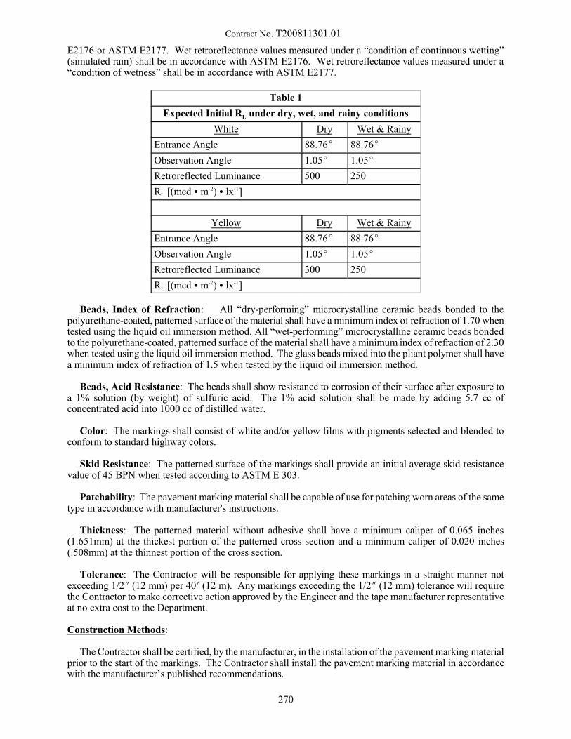
Contract No. T200811301.01
E2176 or ASTM E2177. Wet retroreflectance values measured under a “condition of continuous wetting”(simulated rain) shall be in accordance with ASTM E2176. Wet retroreflectance values measured under a“condition of wetness” shall be in accordance with ASTM E2177.
Table 1
Expected Initial RL under dry, wet, and rainy conditions
White Dry Wet & Rainy
Entrance Angle 88.76E 88.76E
Observation Angle 1.05E 1.05E
Retroreflected Luminance 500 250
RL [(mcd C m-2) C lx-1]
Yellow Dry Wet & Rainy
Entrance Angle 88.76E 88.76E
Observation Angle 1.05E 1.05E
Retroreflected Luminance 300 250
RL [(mcd C m-2) C lx-1]
Beads, Index of Refraction: All “dry-performing” microcrystalline ceramic beads bonded to thepolyurethane-coated, patterned surface of the material shall have a minimum index of refraction of 1.70 whentested using the liquid oil immersion method. All “wet-performing” microcrystalline ceramic beads bondedto the polyurethane-coated, patterned surface of the material shall have a minimum index of refraction of 2.30when tested using the liquid oil immersion method. The glass beads mixed into the pliant polymer shall havea minimum index of refraction of 1.5 when tested by the liquid oil immersion method.
Beads, Acid Resistance: The beads shall show resistance to corrosion of their surface after exposure toa 1% solution (by weight) of sulfuric acid. The 1% acid solution shall be made by adding 5.7 cc ofconcentrated acid into 1000 cc of distilled water.
Color: The markings shall consist of white and/or yellow films with pigments selected and blended toconform to standard highway colors.
Skid Resistance: The patterned surface of the markings shall provide an initial average skid resistancevalue of 45 BPN when tested according to ASTM E 303.
Patchability: The pavement marking material shall be capable of use for patching worn areas of the sametype in accordance with manufacturer's instructions.
Thickness: The patterned material without adhesive shall have a minimum caliper of 0.065 inches(1.651mm) at the thickest portion of the patterned cross section and a minimum caliper of 0.020 inches(.508mm) at the thinnest portion of the cross section.
Tolerance: The Contractor will be responsible for applying these markings in a straight manner notexceeding 1/2O (12 mm) per 40N (12 m). Any markings exceeding the 1/2O (12 mm) tolerance will requirethe Contractor to make corrective action approved by the Engineer and the tape manufacturer representativeat no extra cost to the Department.
Construction Methods:
The Contractor shall be certified, by the manufacturer, in the installation of the pavement marking materialprior to the start of the markings. The Contractor shall install the pavement marking material in accordancewith the manufacturer’s published recommendations.
270
Contract No. T200811301.01
The manufacturer shall provide technical assistance as required to ensure successful installation of themarkings. This shall include a representative on site for the start of the markings, training, productinformation, problem solving, etc.
Installation of the pavement markings shall be performed in a neat and workmanlike manner. TheContractor shall premark the pavement to ensure correct location of markings and such layout work shall beincidental to the price bid for the pavement marking items. The method for premarking should be asrecommended by the manufacturer. A thin layer of paint as a premarking is not recommended. Particularcare shall be taken to ensure that the leading edges of the markings are secured to the pavement.
General application rules:
C The Air and surface temperature shall be a minimum of 40E F.
C The pavement must be clean and dry. 24 hours of dry weather where no rain is expected. C When not placed by inlaid method a surface preparation adhesive shall be used.
C Do not overlap tape - use butt splice.
C Do not apply tape on longitudinal seams or joints or cracks.
C Do not apply tape on deteriorating pavement surfaces.
C Existing markings must be 80% removed.
After application, the markings shall be immediately ready for use by traffic.
Inlay into Fresh Bituminous Concrete:
When markings are specified in the contract for newly paved asphalt concrete surfaces, they shall beapplied before public traffic is allowed on the freshly paved surface - the pavement markings shall be inlaidin the fresh surface during final rolling of the mat, in accordance with the manufacturer's recommendationsunless otherwise directed by Engineer.
The Contractor shall show how the pavement mats will be placed to avoid applying the tape onlongitudinal seams or joints or cracks and maintain correct marking location.
The Contractor shall employ a sufficient number of workers to premark the pavement and install themarkings such that all markings are inlaid into the hot pavement prior to the finish rolling. No paving shallbe permitted unless the striping crew and materials are on the project site.
* General procedure for inlay application on fresh asphalt surfaces:
* Tape is applied after the compaction roller and before the finish roller using minimum water, slowspeed and no vibration.
* Tape shall be applied using equipment recommended by manufacturer
* Tamping shall be done by the finish roller and in the same direction the tape was applied. A separate
roller of a size approved by the tape manufacturer may be required to meet the manufacturer'srequirements.
* Roller shall use minimum speed to prevent wrinkling the tape.
* Asphalt temperatures shall be between 180EF (66EC) and 120EF (49EC) when tape is applied.
271

Contract No. T200811301.01
NOTE: Even though the tape will stand these high temperatures the contractor is to use caution to assurethe asphalt is firm enough to walk on above 140EF (60EC).
Placement on new P.C. Concrete Pavement:
When markings are specified in the contract for new P.C. concrete pavement surfaces they shall be appliedafter the concrete has adequately cured as determined by the Engineer and prior to opening to traffic.
1. When a membrane curing compound has been applied to the concrete surface, it shall be removed bysandblasting prior to applying the markings. Cost for such sandblasting shall be incidental to the pricebid for the pavement marking item. The road shall be cleaned by sweeping and with high pressure air.
2. The manufacturer shall specify a primer/solvent for the pavement surface.
3. The tape shall be applied with an approved applicator.
4. The tape shall be tamped with a roller tamper cart with a minimum 200 lb (90 kg) load or by slowly(2-3 mph [3-5 km/hr]) driving over the tape with a vehicle tire. Do not twist or turn on the tape. Aminimum of three passes back and forth over the tape will be required. All edges of the tape shall bethoroughly tamped.
Placement on Existing Pavement:
When markings are specified in the contract for existing pavement, the pavement surface shall be free ofany existing markings.
1. The road shall be cleaned by sweeping and with high pressure air.
Steps 2 through 4 are the same as for new P.C. C. pavement.
Method of Measurement:
This work will be measured for payment by the number of linear feet (meters) of line or square foot(meter) of symbol/legend of Retroreflective Preformed Patterned Markings installed on the pavement andaccepted in accordance with the plans.
Basis of Payment:
This work will be paid for at the contract unit price bid per linear foot (meter) of line or square meter ofsymbol/legend as measured for item "Retroreflective Preformed Patterned Markings" of the type specified. This price shall include cleaning and preparing the pavement surface, furnishing and placing all materials,for all labor, tools, equipment, maintenance bond and incidentals necessary to complete the work.
WARRANTY
The Contractor shall warrant to the Department that the installed retroreflective preformed patternedpavement markings are free of defects, as hereafter defined, for one calendar year beginning at the initialacceptance of the marking installation by the Department. The initial acceptance of the marking installationwill occur upon the satisfactory correction of all deficiencies noted in the marking installation during the FinalInspection of the project. The markings shall show no fading, lifting, shrinking, tearing, rollback, distortionor chipping due to vehicular traffic or normal maintenance activities including snow plowing. Although somewear is expected, the markings shall remain intact and serviceable (as defined below) for no less than 95%of the total item quantities in the first year of installation.
The Contractor shall repair all defective areas identified by the Department after initial installation orduring the Warranty Period. All repairs shall begin immediately following the notice to the Contractor unlessweather limitations prevent the corrective work. Should the contractor not commence work within seventy-
272

Contract No. T200811301.01
two hours, weather permitting, and pending severity, the Department reserves the right to remedy thecondition and charge the contractor for the work. Any corrective work shall be as recommended by themanufacturer of the marking material and approved by the Department. The Department shall be givennotification before the Contractor begins corrective work to allow for inspection of the operation. All costsassociated with the repair work shall be the responsible of the contractor. These costs shall include, but arenot limited to, removal, material, maintenance of traffic, etc.
Maintenance Bond:
Upon completion of the work, the Contractor shall submit to the Department a Maintenance Bond to insurethe State of Delaware during the above Warranty periods. The Maintenance Bond shall meet the followingrequirements:
a) A sum equal to 100% of the value of all Retroreflective Preformed Patterned Markings Items paid tothe Contractor;
b) All signatures are original signatures, in ink, and not mechanical reproductions or facsimiles of anykind;
c) The Contractor is the named principle;
d) The term of the bond is for one full year;
e) The term of the Maintenance Bond will be for a period of one year beyond completion ofRetroreflective Preformed Patterned Markings; and
f) Written by a Surety or insurance company that is in good standing and currently licensed to write suretybonds in the State of Delaware by the Delaware Department of Insurance.
MANUFACTURER’S RESPONSIBILITY:
The following information is for use by DelDOT only. The Contractor will not be held responsible forthe time frames listed in the chart below.
After satisfactory completion of the one-year warranty period, the contractor will be relieved of hisresponsibility and the Department shall work directly with the Manufacturer to guarantee the remainder ofthe warranty as specified below.
In addition, the pavement markings shall warrant the material to retain a minimum reflective value of 150millicandelas per square foot (meter) per lux for the first year after initial acceptance.
1. All reflectance measurements shall be made on a clean, dry surface at a minimum temperature of 40EF(4EC).
2. All reflectance measurements shall be made using a "LTL 2000” retroreflectometer.3. One year from initial installation acceptance all pavement marking material shall meet the minimum
retained coefficient of dry retroreflection value of 125 millicandelas per foot squared per foot-candle(in accordance with ASTM E1710), and meet the minimum retained coefficient of wet retroreflectionvalue of 75 millicandelas per foot squared per foot-candle (in accordance with ASTM E2177) for thefollowing Warranty Periods.
Warranty Periods
ApplicationDry RetroreflectivityWarranty Period
Wet RetroreflectivityWarranty Period
Longitudinal Markings 4 years 2 years
Symbols and Legends 2 years 1 year
03/04/2011
273
Contract No. T200811301.01
748525 - TEMPORARY MARKINGS, TAPE, 4"748526 - TEMPORARY MARKINGS, TAPE, 6"
748527 - TEMPORARY MARKINGS, TAPE, WORDS/SYMBOLS748570 - TEMPORARY MARKINGS, TAPE, 5"
Description:
This work shall consist of furnishing, installing, removing or obliterating pavement markings in workzones in accordance with this provision and in reasonably close conformity with the dimensions and linesshown on the plans or established by the Engineer.
Materials:
The markings shall consist of white or yellow retro reflective pavement marking on a conformablebacking.
The quality of the pavement marking shall be such that the performance requirements for the marking shallbe met.
The markings shall be precoated with a pressure sensitive adhesive and shall be capable of being adheredto Asphalt concrete or Portland cement concrete at temperatures as low as 50EF (10EC) in accordance withthe manufacturer's recommendations. A surface preparation adhesive recommended by the manufacturershall be used for all applications to improve initial and long term adhesion.
When stored in a cool dry area indoors, the materials shall be suitable for use for one year after the dateof purchase.
Classification:
The removable retro reflective pavement marking tape must be designed and constructed in such a mannerthat it can be readily removed when the markings are no longer applicable. The tape shall be capable ofperforming for the duration of a normal construction season and shall then be capable of being removed intactor in large pieces. The tape shall be wet and dry reflective throughout its useful life. (A normal constructionseason is defined as the time after the last snowplowing in the spring and before the first snowplowing in thefall/winter. In non-snow removal locations, a normal construction season is limited to the calendar year atthe time of installation.)
Requirements:
Composition
The removable, retro reflective pavement markings shall consist of a highly reflective white or yellowenclosed lens pavement marking with a thin, flexible, conformable backing which is precoated with apressure sensitive adhesive.
Retro reflectance
The enclosed lens white and yellow pavement markings shall have the initial minimum retroreflectancevalues as shown in Table 1 under dry, wet, and rainy conditions at 1.05E observation angle and 88.76Eentrance angle. These angles represent a simulated driver viewing geometry at 30 meters distance. Thephotometric quantity to be measured shall be the coefficient of retroreflected luminance (RL), and shallbe expressed as millicandelas per square meter per lux [(mcd C m-2) C lx-1]. The English equivalent shallbe expressed as millicandelas per square foot per foot candle [(mcd C ft-2) C fc-1]
274
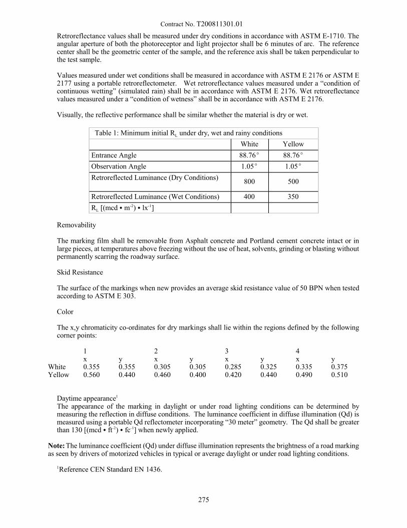
Contract No. T200811301.01
Retroreflectance values shall be measured under dry conditions in accordance with ASTM E-1710. Theangular aperture of both the photoreceptor and light projector shall be 6 minutes of arc. The referencecenter shall be the geometric center of the sample, and the reference axis shall be taken perpendicular tothe test sample.
Values measured under wet conditions shall be measured in accordance with ASTM E 2176 or ASTM E2177 using a portable retroreflectometer. Wet retroreflectance values measured under a “condition ofcontinuous wetting” (simulated rain) shall be in accordance with ASTM E 2176. Wet retroreflectancevalues measured under a “condition of wetness” shall be in accordance with ASTM E 2176.
Visually, the reflective performance shall be similar whether the material is dry or wet.
Table 1: Minimum initial RL under dry, wet and rainy conditions
White Yellow
Entrance Angle 88.76E 88.76E
Observation Angle 1.05E 1.05E
Retroreflected Luminance (Dry Conditions)800 500
Retroreflected Luminance (Wet Conditions) 400 350
RL [(mcd C m-2) C lx-1]
Removability
The marking film shall be removable from Asphalt concrete and Portland cement concrete intact or inlarge pieces, at temperatures above freezing without the use of heat, solvents, grinding or blasting withoutpermanently scarring the roadway surface.
Skid Resistance
The surface of the markings when new provides an average skid resistance value of 50 BPN when testedaccording to ASTM E 303.
Color
The x,y chromaticity co-ordinates for dry markings shall lie within the regions defined by the followingcorner points:
1x y
2x y
3x y
4x y
White 0.355 0.355 0.305 0.305 0.285 0.325 0.335 0.375Yellow 0.560 0.440 0.460 0.400 0.420 0.440 0.490 0.510
Daytime appearance1
The appearance of the marking in daylight or under road lighting conditions can be determined bymeasuring the reflection in diffuse conditions. The luminance coefficient in diffuse illumination (Qd) ismeasured using a portable Qd reflectometer incorporating “30 meter” geometry. The Qd shall be greaterthan 130 [(mcd C ft-2) C fc-1] when newly applied.
Note: The luminance coefficient (Qd) under diffuse illumination represents the brightness of a road markingas seen by drivers of motorized vehicles in typical or average daylight or under road lighting conditions.
1Reference CEN Standard EN 1436.
275

Contract No. T200811301.01
Construction Methods:
Pavement markings in work zones shall be placed in accordance with the following provisions:
At the end of each day's work, pavement markings shall be in place on each paving lift that is open tonormal traffic flow. Materials requiring removal shall be specified above, and marking configurations shallbe in accordance with the Manual on Uniform Traffic Control Devices.
The pavement markings shall be maintained and replaced by the Contractor without additionalcompensation until they have served their purpose, at which time the contractor will be required to removethem.
Pavement markings shall be applied to clean dry surfaces in accordance with the manufacturer'sinstallation instructions or a method approved by the Engineer.
Method of Measurement:
Linear pavement markings will be measured in linear feet complete-in-place for the width specified.
Removal or obliteration of pavement markings in construction work zones will not be measured forpayment, but shall be considered incidental to the work.
Basis of Payment:
Retro reflective pavement markings will be paid for at the contract unit price, which price shall be fullcompensation for cleaning and preparing the pavement surface, for furnishing and placing all materials, andfor all materials, labor, tools, equipment and incidentals necessary to complete the work.
Payment will be made under:
Pay Item Pay Unit
Temporary Marking, Tape, linear Linear FootTemporary Marking, Tape, words/symbol Square foot
2/17/14
276
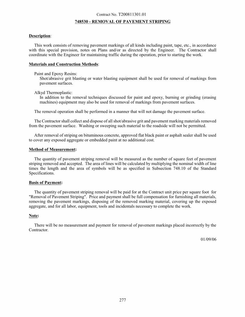
Contract No. T200811301.01
748530 - REMOVAL OF PAVEMENT STRIPING
Description:
This work consists of removing pavement markings of all kinds including paint, tape, etc., in accordancewith this special provision, notes on Plans and/or as directed by the Engineer. The Contractor shallcoordinate with the Engineer for maintaining traffic during the operation, prior to starting the work.
Materials and Construction Methods:
Paint and Epoxy Resins:Shot/abrasive grit blasting or water blasting equipment shall be used for removal of markings frompavement surfaces.
Alkyd Thermoplastic:In addition to the removal techniques discussed for paint and epoxy, burning or grinding (erasingmachines) equipment may also be used for removal of markings from pavement surfaces.
The removal operation shall be performed in a manner that will not damage the pavement surface.
The Contractor shall collect and dispose of all shot/abrasive grit and pavement marking materials removedfrom the pavement surface. Washing or sweeping such material to the roadside will not be permitted.
After removal of striping on bituminous concrete, approved flat black paint or asphalt sealer shall be usedto cover any exposed aggregate or embedded paint at no additional cost.
Method of Measurement:
The quantity of pavement striping removal will be measured as the number of square feet of pavementstriping removed and accepted. The area of lines will be calculated by multiplying the nominal width of linetimes the length and the area of symbols will be as specified in Subsection 748.10 of the StandardSpecifications.
Basis of Payment:
The quantity of pavement striping removal will be paid for at the Contract unit price per square foot for"Removal of Pavement Striping". Price and payment shall be full compensation for furnishing all materials,removing the pavement markings, disposing of the removed marking material, covering up the exposedaggregate, and for all labor, equipment, tools and incidentals necessary to complete the work.
Note:
There will be no measurement and payment for removal of pavement markings placed incorrectly by theContractor.
01/09/06
277

Contract No. T200811301.01
748541 - PREFORMED RETROREFLECTIVE THERMOPLASTIC PAVEMENT MARKINGS,
4”748542 - PREFORMED RETROREFLECTIVE THERMOPLASTIC PAVEMENT MARKINGS,
6"748543 - PREFORMED RETROREFLECTIVE THERMOPLASTIC PAVEMENT MARKINGS,
8"748544 - PREFORMED RETROREFLECTIVE THERMOPLASTIC PAVEMENT MARKINGS,
12”748545 - PREFORMED RETROREFLECTIVE THERMOPLASTIC PAVEMENT MARKINGS,
16"748546 - PREFORMED RETROREFLECTIVE THERMOPLASTIC PAVEMENT MARKINGS,
SYMBOL/LEGEND748553 - PREFORMED RETROREFLECTIVE THERMOPLASTIC PAVEMENT MARKINGS,
BIKE SYMBOL748554 - PREFORMED RETROREFLECTIVE THERMOPLASTIC PAVEMENT MARKINGS,
PEDESTRIAN SYMBOL748555 - PREFORMED RETROREFLECTIVE THERMOPLASTIC PAVEMENT MARKINGS,
HANDICAP SYMBOL
Description:
This work consists of furnishing and installing preformed retroreflective thermoplastic pavement markingwith a preapplied Federal Specification Type IV glass bead coating throughout its entire cross section onbituminous asphalt pavement at the locations and in accordance with the patterns on the Plans, or as directedby the Engineer.
The preformed retroreflective markings shall conform to the size and dimensions as shown in the Federal“Standard Highway Signs” book found at: http://mutcd.fhwa.dot.gov/SHSe/pavement.pdf as referred to inthe Delaware Manual on Uniform Traffic Control Devices, Part 3, Markings.
Materials:
General: Only materials listed on the Department’s Approved Pavement Markings Material List will beused for this item. The preformed retroreflective markings shall be fusible to bituminous asphalt pavementby means of the normal heat of a propane type of torch. Adhesives, primers or sealers are not necessary priorto the preformed retroreflective markings application on bituminous asphalt pavement.
The preformed retroreflective markings shall conform to pavement contours, breaks and faults throughthe action of traffic at normal pavement temperatures. The markings shall have resealing characteristics andbe capable of fusing to itself and previously applied worn hydrocarbon and/or alkyd thermoplastic pavementmarkings.
The preformed retroreflective markings shall be capable of application on bituminous asphalt pavementwearing courses during the paving operation in accordance with the manufacturer's instructions. Afterapplication the markings shall be immediately ready for traffic. The preformed retroreflective markings shallbe suitable for use for one year after the date of receipt when stored in accordance with the manufacturer'srecommendations.
The preformed retroreflective thermoplastic markings shall not be brittle and must be sufficiently cohesiveand flexible at temperatures exceeding 50oF (10oC) for one person to carry without the danger of fracturingthe material prior to application.
Composition: The retroreflective pliant rosin ester thermoplastic pavement markings shall consist of ahomogeneous mixture of high quality polymeric thermoplastic binders, pigments, fillers and glass beads. The
278
Contract No. T200811301.01
thermoplastic material must conform to AASHTO M249-79(86) with the exception of the relevant differencesdue to the material being preformed, and identified herein.
Intermix Glass Beads: The preformed retroreflective material shall contain a minimum of 30% glassspheres which shall conform to AASHTO M247-81 Type 1. Glass spheres shall have a minimum of 80% truespheres overall.
Top Beads: To provide the required retroreflectivity, the preapplied factory top coating of glass beads shallbe a combination of both Federal Spec. Type IV and AASHTO M247-81 Type I beads. Federal Spec. TypeIV beads shall be evenly disbursed across the entire surface of the product at a minimum rate of 4 lb. per 100ft2 and the AASHTO at 3 lb. per 100 ft2 . In combination, the total glass bead coverage shall be 7-8 lb. per100 ft2 . The AASHTO M247-81 Type I beads shall have a minimum of 80% true spheres overall and theFederal Spec. Type IV beads shall be 80% true spheres on the 12 and 14 sieves and shall be no less than 75%true spheres on the remaining sieves.
Retroreflectivity: After satisfactory completion of all striping work and written notification from thecontractor, the Department shall test the striping to ensure it has the minimum reflectivity. The testing willbe completed within 30 calendar days from notification. Testing will be done using a Delta LTL 2000Retrometer. The required minimum initial reflectivity reading in millicandellas shall be:
White 300Yellow 200Blue 200
Skid Resistance: The surface of the preformed retroreflective thermoplastic markings shall provide a pre-appled minimum skid resistance value of 45-51 BPN and a post-applied minimum skid resistance value of45-55 BPN when tested according to ASTM E303-74.
Thickness: The thickness of the supplied material shall have a minimum average thickness of .090" forall Longitudinal lines and a thickness of .125" for all transverse lines and symbols/legends.
Tensile Strength and Elongation: The preformed retroreflective thermoplastic material shall have aminimum tensile strength of 150 lb. per square inch of cross section, at .002" thickness, when testedaccording to ASTM D638-76 except that a sample 6" by 1" shall be tested at a temperature between 70oF and80oF using a jaw speed of 10" to 12" per minute. The sample shall have a maximum elongation of 20% atbreak when tested by this method.
Flexibility: The preformed retroreflective thermoplastic marking material shall have flexibility at 50oFsuch that when a 1" by 6" sample is bent through an arc of 90 degrees at a uniform rate in 10 seconds (9degrees per second) over a 1" mandrel, no cracking occurs in the test sample. The sample must be conditionedprior to testing at 50oF±2 degrees for a minimum of four hours. At least two specimens tested must meet theflexibility requirements at 50oF for a passing result.
Environmental Resistance: The applied markings shall be resistance to deterioration due to exposureto sunlight, water, oil, diesel fuels, gasoline, pavement oil content, salt and adverse weather conditions.
Effective Performance Life: When properly applied, in accordance with manufacturer's instructions, thepreformed retroreflective pavement markings shall be neat and durable. The markings shall remain skidresistant and show no lifting, shrinkage, tearing, roll back or other signs of poor adhesion for a period of onewinter season.
Oil/grease Resistant Test: The preformed retroreflective thermoplastic material shall not dissolve orsmear after rubbing a small amount of motor oil on a small piece of the thermoplastic material for twominutes.
Bond Strength: The material shall exhibit a bond strength to Portland Cement Concrete (PCC) equal orexceed 180 psi when tested at room temperature (73.4±3oF) in accordance to ASTM Standard Test Method
279
Contract No. T200811301.01
for Bond Strength of thermoplastic marking Material D4796-88. Place a coarse brick in a 400oF oven for 5minutes. Prepare a 4 square inch test specimen. Place the test specimen on the brick and further heat in the400oF oven for 15 minutes. The test specimen is then allowed to cool to room temperature and prepared fortesting.
Low Temperature Cracking (Stress) Resistance for Extended Period: The material shall be testedaccording to AASHTO T250 Section 7 with Section 7.2.3 modified for and extended cold temperature 15degrees ±3oF exposure period 72 hours. Any cracking shall constitute failure of the material for PCC roadsurfaces.
Impact Resistance (Gardner Falling Weight): A 2" by 7.5" specimen shall be applied on a courseconcrete brick. Using a Gardner Impact Tester, a 2 lb weight is dropped from a height of 80". The specimenwhen tested at room temperature 73.4o±3oF should show no sign of cracking. (Test procedure is in accordancewith ASTM D5420-93).
Packaging: The flexible preformed retroreflective thermoplastic marking materials, for use as transverseor longitudinal markings as well as legends, arrows and symbols shall be available in flat form material orin rolls. Flat material shall be supplied in maximum of 4' lengths up to 2' in width. The material shall bepacked in suitable cartons clearly labeled for ease of identifying the contents.
Construction Methods:
The markings shall be applied in strict accordance with the manufacturer's recommendations on clean anddry surfaces. Marking configurations shall be in accordance with the "Delaware Manual on Uniform TrafficControl Devices, Part 3, Markings."
The preformed retroreflective thermoplastic material shall be fusible to the pavement by means of apropane torch recommended by the manufacturer. Preheating the surface to remove any latent moisture willbe done just prior to the placement and installation of the Symbol/ Legend.
No markings shall be placed when the ambient temperature is below 40oF. The material shall be kept ina location above 55oF until just before application.
The supplier shall provide technical services as may be required.
Method of Measurement:
The quantity of pavement striping (748541-748545) will be measured by the number of linear feet of 4”,6”, 8”, 12”, or 16” pavement striping line placed and accepted. The quantity of symbol/ legend (748546) willbe measured by the number of square feet of symbol/legend placed and accepted. The quantity of bikesymbol, pedestrian symbol, and handicap symbol (748551-748553) will be measured as each placed andaccepted. The dimensions for the symbol/legends are as follows:
Bike Rider with Helmet shall be 3’ X 5’.Pedestrian shall be 4’ X 8’.Handicap Symbol shall be 40” X 40”.
Basis of Payment:
The quantity of pavement striping payment will be paid for at the Contract unit price per linear foot for4”, 6”, 8”, 12” and 16” line. The quantity of symbol/legend will be paid for at the Contract unit price persquare foot. The quantity of bike symbol, pedestrian symbol, and handicap symbol will be paid for at theContract unit price per each. Price and payment shall include cleaning and preparing the pavement surface,and placing all materials, for all labor, tools, equipment and incidentals necessary to complete the work.
280
Contract No. T200811301.01
Warranty:
The Contractor shall warrant to the Department that the installed retroreflective preformed thermoplasticpavement markings are free of defects, as hereafter defined, for a period of one winter season beginning atthe initial acceptance of the marking installation by the Department. The initial acceptance of the markinginstallation will occur upon the satisfactory correction of all deficiencies noted in the marking installationduring the Final Inspection of the project. The markings shall be warranted against failure due to blistering,excessive cracking, bleeding, staining, discoloration, oil content of the pavement materials, smearing andspreading under heat, deterioration due to contact with grease deposits, oil, diesel fuel, or gasoline drippings,chipping, spalling, poor adhesion to the pavement materials, vehicular damage, and wear from normalmaintenance activities including snow plowing.
The Contractor shall repair all defective areas identified by the Department after initial installation orduring the Warranty Period. All repairs shall begin immediately following the notice to the Contractor bythe Department unless weather limitations prevent the corrective work. Should the contractor not commencework within the period stated in the notice, weather permitting, and pending severity, the Department reservesthe right to remedy the condition and charge the contractor for the work. Any corrective work shall be asrecommended by the manufacturer of the marking material and approved by the Department. The Departmentshall be given notification before the Contractor begins corrective work to allow for inspection of theoperation. All costs associated with the repair work shall be the responsibility of the contractor. These costsshall include, but are not limited to, removal, material, maintenance of traffic, etc.
2/28/09
281

Contract No. T200811301.01
748560 - 5" PERMANENT PREFORMED PATTERNED REFLECTIVE PAVEMENT
MARKINGS, MARYLAND
Description:
This work consists of furnishing and applying permanent preformed patterned reflective pavement(PPPRP) markings in accordance with the details and as shown on the Plans and as directed by the Engineer,for locations in Maryland.
Materials:
Permanent Preformed Patterned Reflective Pavement Marking Materials
The material shall be capable of adhering to hot mix asphalt and portland cement concrete surfaces, andto any existing pavement markings in accordance with manufacturer's recommendations by a pre-coatedpressure sensitive adhesive. A primer shall be used to precondition the surface if recommended by themanufacturer. The markings shall be capable of being inlaid in new hot mix asphalt surfaces during thepaving operation.
The material shall be highly durable and retroreflective and shall be fabricated of a polymeric materialdesigned for longitudinal and legend/symbol markings subjected to high traffic volumes and severe wearconditions, such as shear action from crossover or encroachment on typical longitudinal configurations, andwhere high levels of reflectivity are required to ensure the safety of the motoring public.
The material shall be of good appearance and free from cracks. Edges shall be true, straight and unbroken. Line marking material shall be in rolls having no more than three splices per 150 ft of length. All markingmaterials shall be packaged in conformance with accepted commercial standards and shall have a minimumshelf life of one year.
The material shall remain in place on the pavement surface without being displaced by traffic, and shallnot be affected by weather conditions.
Composition. The material shall consist of a mixture of polymeric materials, pigments and reflective spheresdistributed throughout the base cross-sectional area and reflective spheres bonded to the topcoat surface toprovide immediate and continuing retroreflection.
Restrictions. The combined total of lead, cadmium, mercury and hexavalent chromium shall not exceed100 ppm. Diarylide based pigments and non-leachable lead pigmentation are not acceptable. The presenceof these compounds shall be tested for compliance to the specification by X-ray diffraction, ICP, or anothercomparable method, capable of this level of detection.
Construction:
General. PPPRP markings shall be applied in conformance with the manufacturer's recommendations or asdirected by the Engineer.
On new hot mix asphalt projects, the PPPRP markings shall be inlaid into the hot surface of the top courseof pavement. No top course paving shall be permitted unless the stripping crew and marking materials areat the project site.
When the Contract Documents specifies the use of PPPRP markings on concrete pavements or existingasphalt pavements, the Contractor shall use heat, solvent, or other type of adhesive primer in conformancewith the manufacturer's recommendations.
PPPRP markings shall conform to pavement contours and be resistant to deformation by traffic anddamage from snow removal equipment. Surface preparation, use of solvents and primers and equipment used
282
Contract No. T200811301.01
in the application of PPPRP markings shall conform with the manufacturer's recommendations and beapproved by the Engineer. After PPPRP markings are applied, they shall be immediately ready for traffic.
Quality Assurance/Quality Control. At least 30 days prior to the prestriping meeting, submit in writinga proposed Quality Control Plan (QCP).
Address procedures for random sampling as specified in MSMT 729, and show how the equipment andmaterial will be controlled to ensure conformance with the Specifications. Include the material manufacturer’sapplication recommendations, personnel certifications, inspection and record keeping procedures, andminimum frequencies of sampling and testing as specified in MSMT 729. Detail when and how correctiveaction will be taken for unsatisfactory construction practices and deviations from the Specifications. Anydeviation from the QCP shall be cause for immediate suspension of the marking operation. Operations shallnot resume without approval.
a. Placement. Do not begin placement operations until the QCP is approved and a walkthrough has beenperformed to approve the layout with the Engineer, Contractor, and pavement marking foreman.
Widths. The traveled way lane widths and width of longitudinal lines shall be as specified. Lanewidths shall be measured from center to center of the lane lines once a control line is established forthe lane configuration of the roadway. When measurements are taken from existing longitudinal lines,the point of reference shall be the center of the single line or the center of the space between dual lines.The traveled way lane widths are in compliance when they have an acceptable appearance and arewithin 2 in. from the proposed lane width.
Alignment. Place markings in a straight and uniform manner. Lane lines are in compliance when theyhave an acceptable appearance and are visually in alignment, with no more than a 3/8 in. variation inany 40 ft section of traveled way. Maintain longitudinal alignment through all intersections and breaks,even though the lines themselves may discontinue. Do not apply pavement line markings overlongitudinal joints; Offset the markings 2 in.
Layout Markings. Remove layout markings that detract from the overall appearance or function ofthe final markings as determined by the Engineer at no additional cost to the Administration.
b. Certified Technicians. Provide Administration certified technicians to perform quality control testingand sampling. The technicians shall demonstrate that they have a thorough knowledge of sampling andtesting procedures as specified in MSMT 729. Perform quality control during the marking operationsin conformance with the approved QCP. Identify the location of quality control tests. Should a certifiedtechnician be delinquent in any of their duties (i.e., fail to have all the proper test equipment on the site,fail to perform tests, fail to submit documents to the Engineer at the end of the day, report informationthat varies substantially from the Administration’s results, etc.), then the technician’s certification shallbecome invalid and a recertification shall be required. All pavement marking operations shall besuspended until the Contractor provides a certified replacement technician.
c. Records. Maintain complete records of quality control inspection results, including actions taken tocorrect problems. Submit a copy of the QC results, signed by the certified technician, daily. Identifythe location of the following quality control tests:
(1) Ambient temperature.(2) Pavement surface temperature.(3) Material temperature.(4) Material thickness.(5) Retroreflectivity.(6) Alignment.(7) Color.
283
Contract No. T200811301.01
d. Quality Assurance. The Administration will provide quality assurance by:
(1) Conducting independent sampling and testing.(2) Periodically observing testing performed by the Contractor.(3) Directing the Contractor to take additional samples and perform additional tests at any time and atany location.(4) Monitoring Contractor conformance with the Quality Control Plan.(5) Evaluation of quality control results and testing performed by the Administration will provide thebasis for final acceptance. The Administration will perform independent assurance audits to confirmand assure that both the quality control personnel's test methods and quality control test equipment arein reasonable conformity with Administration specifications.
Cleaning Pavement Surfaces. Pavement surfaces shall be dry and free of oil, dirt, grease, and othercontaminants prior to application of pavement markings. Clean nonconforming surfaces to a width 4 to 6 in.wider than the markings.
Application. Refer to the following:
(a) Manufacturer's Recommendations. The Contractor shall provide a copy of the manufacturer'srecommendations to the Engineer, and shall follow them for the installation of the line markings.
(b)Adherence. Adherence of PPPRP markings shall be randomly checked by using a paint scraper oranother approved tool, which shall be held nearly parallel with the highway surface, so there is nodislodging of the tape.
(c) Thickness. The finished thickness of the PPPRP markings shall have a minimum caliper of 0.060 in.at the thickest portion of the patterned cross section, and a minimum caliper of 0.020 in. at the thinnestportion of the cross section. Measurements shall be made from the top of finished pavement surface.
(d)Color. The color of the markings shall match Federal Standard 595 (33538 - yellow, 37886 - white,or 37038 - black). The Contractor shall supply the specified color chips for the Engineer's use tovisually determine that the PPPRP markings match the specified color.
(e) Retroreflectance. Refer to MSMT 729 and the following:
MINIMUM RETROREFLECTANCE
COLOR RETROREFLECTIVITY CORRECTIVE ACTIONWhite 350 or higher NoneYellow 250 or higher NoneWhite less than 350 Necessary corrective actions, removal, replacementYellow less than 250 Necessary corrective actions, removal, replacement
(f) Width. Refer to Quality Assurance/Quality Control Section (a) above.
(g)Alignment. Refer to Quality Assurance/Quality Control Section (a) above.
(h)Layout Markings. Refer to Quality Assurance/Quality Control Section (a) above.
(i) Frictional Resistance. The surface of the retroreflective pliant polymer shall provide a minimum initialaverage skid resistance value of 45 BPN when tested according to ASTM E 303.
Quality Control Test Strip. As specified, or as directed, place a 200 to 300 ft cumulative quality controltest strip of pavement marking material that conforms to the Contract Documents at a location determinedby the Engineer. Place additional control strips as directed. Authorization to proceed will be given when thequality control test strip conforms to the Contract Documents.
284

Contract No. T200811301.01
Observation Period. The Contractor shall be responsible for any defects in materials and workmanship ofthe PPPRP markings for a period of 180 days from the date the markings are applied and under traffic.
The Engineer will not assess time charges during the observation period provided all other work on theContract is complete. At the end of the observation period, the Engineer will inspect the pavement markingfor durability, color, reflectivity, and inform the Contractor of all pavement markings that have failed andrequire replacement. The pavement marking will be considered failed for any of the following conditions:
(a) More than five percent of the substrate is exposed in any 2000 ft section of longitudinal pavementmarking line.
(b)Retroreflectance values have dropped below 300 mcd/L/m2 for white or 220 mcd/L/m2 for yellow.
(c) Marking is discolored on a visual comparison with the color chips.
The Contractor shall remove and replace all failed PPPRP markings within 30 days of receiving writtennotification from the Engineer at no additional cost to the Administration. Work shall be in conformance withthe manufacturer's recommendation and as approved by the Engineer before the project is accepted. Thereplacement markings shall conform to the same requirements as the original markings. If the work is notcompleted in this period, the Engineer will resume time charges until this work is completed.
At the end of the observation period, the Engineer will accept the work and terminate the Contractor'sresponsibilities upon satisfactory inspection of the PPPRP markings.
Method of Measurement:
Permanent Preformed Patterned Reflective Pavement Markings, Maryland will be measured per linear footinstalled on the pavement and accepted in accordance with the Plans for the color and width specified.
The reflectometer will become the property of the Contractor at the completion of the project.
Basis of Payment:
The quantity of Permanent Preformed Patterned Reflective Pavement Markings, Maryland will be paidfor at the Contract unit price per linear foot and will constitute full compensation for all pavementpreparation, furnishing and placing of markings, testing, and for all material, labor, equipment, tools, andincidentals necessary to complete the work.
11/29/11
285
Contract No. T200811301.01
748563 – SNOWPLOWABLE RAISED PAVEMENT MARKERS, MARYLAND
Description:
This work consists of furnishing and installing new Snowplowable Raised Pavement Markers (SPRPM)and replacement components as specified in the Contract Documents or as directed by the Engineer, forlocations in Maryland.
Materials:
Pavement Marker Reflector Lenses. Pavement marker reflector lenses shall conform to the requirementsof D 4383 and shall be comprised of materials with adequate chemical, water and UV resistance for theintended use. The reflector lens shall contain one or two prismatic reflective faces to reflect incident lightfrom opposite directions. The reflector lens shall be in the shape of a shallow frustum of a pyramid. Thebottom of the reflector lens shall be equipped with an elastomeric pad to permit its attachment to the surfaceof the casting using the manufacturer’s recommended adhesive. The lens faces shall provide extremely hardand durable abrasion resistant surfaces.
Pavement marker reflector lenses shall be 4.00 x 2.00 x 0.46 in. The slope of the reflecting surface shallbe 30 degrees and the area of each reflecting surface shall be 1.7in.2. The outer surface of the shell shall besmooth except in identification areas.
The pavement marker reflector lens shall be imprinted with the model number and the manufacturer’sname.
The following models have been tested and approved by the Administration and shall be used or anapproved equal:
1. 3M Corporation - 3M Series 190 Marker RPM (05-OH)-022. Ennis Paint, Inc. - Ennis/Stimsonite Model C40 (v) RPM (04-OH)-033. Ennis Paint, Inc. - Ennis/Stimsonite Model C40 (d) RPM (04-OH)-024. Ennis Paint, Inc. - Ennis Model 944 5. Hallen Product, Ltd. - Ray O Lite Division, PAC Tec, Inc. RPM (05OH)-04 Model #2004
SPRPM Casting. Both ends of the casting shall be shaped to deflect a snow plow blade. The bottom ofthe casting shall incorporate two parallel keels and an accurately shaped web designed to fit into a groovedsurface. Casting dimensions shall be a minimum of 9.25 x 5.86 x 1.69 in. and shall not exceed10.5 x 7.25 x 1.69 in. The installed height shall not exceed 0.25 in. above the road surface.
The casting shall be nodular iron conforming to A 536, Grade 80-55-06, hardened to 51 to 55 RC. Recyclediron castings are prohibited. The surface of the keel and web shall be free of scale, dirt, oil, grease or anyother contaminant, which may reduce its bond to the epoxy adhesive.
The casting shall be imprinted with the model number and the manufacturer’s name.
The following models have been tested and approved by the Administration and shall be used or anapproved equal:
1. Ennis Paint, Inc.- Stimsonite Model 96 RPMM (05-OH)-032. Ennis Paint, Inc. - Stimsonite Model 101 LP RPM (04-OH)-033. Ennis Paint, Inc. - Stimsonite Model 101 LPS4. Ray-O-Lite - Ironstar 664 Housing5. Hallen Products, Ltd. - Model H 1010 RPM (04-OH)-04
286
Contract No. T200811301.01
Recessed Pavement Marker Adhesive. The adhesive used to fasten the pavement marker lens to thepavement surface shall conform to D 4383-05 Table X1.4.2.3 M 237 Type II. Rapid Set Type adhesives shallnot be used.
Casting Adhesive. The epoxy adhesive used to fasten the castings to the pavement surface shall conformto D 4383-05 Table X1.1.
Reflector Lens Adhesive in Casting. The adhesive used to fasten the reflector lens to the casting shallconform to the manufacturers’ recommendations.
Construction:
Snowplowable Raised Pavement Markers shall be installed and located as specified in the ContractDocuments and in conformance with the Maryland Manual of Uniform Traffic Control Devices(MdMUTCD).
General Installation Requirements. The Contractor shall install the SRPM no later than two weeks afterthe completion of the final surface or as directed by the Engineer.
At the time of installation, the road surface and ambient temperature shall be as specified in themanufacturers’ recommendations. Installing markers on wet pavement surfaces as determined in MSMT 729is prohibited.
At the time of installation, the Contractor shall have on the jobsite all the materials necessary to completethe installation.
The quality control test strip containing a minimum of 10 groove cuts spaced as specified in the ContractDocument shall be constructed to verify the accuracy and ability of the equipment and personnel. Thecontractor shall replace at no additional cost to the Department any incorrect groove cuts and any incorrectcasting placements within the test strip.
At the time of installation, SRPM castings delivered with Pavement Marker Reflector Lens affixed shouldbe free of dirt, dust, oil, grease, rust, moisture, or any foreign matter that will impair adhesion to thepavement. Any residual material that inhibits retroreflectivity of the reflector lens shall be removed withoutdamage to the lens surface. It shall be the contractor’s responsibility to clean each contaminated casting bysand blasting, wire brushing or other procedure approved by the Engineer to remove all foreign matter priorto installation. The use of chemicals to remove rust from the castings is prohibited.
The Contractor shall replace at no additional cost to the Department any incorrect groove cut and anyincorrect casting placement. An additional test strip may be required by the Engineer in the event of incorrectinstallations. Incorrect installations, as determined by the Engineer, shall be corrected and repaired by thecontractor at no additional cost to the Department.
Pavement Marker Reflector Lens. Reflector lenses for pavement markers shall be the same color as theadjacent pavement marking except the back side shall be as follows;
One-Way Applications: The backside for One-Way Markers shall be red or blank as specified in theContract Documents or as directed by the Engineer.
Two-Way Applications: The backside for Two-Way Markers shall be the same color as the adjacentpavement marking.
The pavement marker reflector lens shall be imprinted with the model/batch number and themanufacturer’s name.
New Installation. The SRPM shall be installed in accordance with manufacturer’s recommendations andD 4383. The installed height shall not exceed 0.25 in. above the road surface. The surface of the keel and web
287

Contract No. T200811301.01
shall be free of scale, dirt, oil, grease or any other contaminant which may reduce its bond to the epoxyadhesive. All requirements of the manufacturer’s installation instructions shall be met.
The groove cut for the casting shall be the appropriate dimensions to allow 0.125 in. movement side toside of the casting. All leveling lugs on the casting must contact the pavement. The leading and trailingedges of the casting must lie below the pavement surface and the casting properly seated. All otherrequirements of the manufacturer’s installation instructions shall be met.
Lenses used shall be of a type specifically manufactured and approved for use as SRPM reflector lenses.Lenses that are manufactured exclusively for recessed pavement markers are not permitted as substitutes forSRPM reflector lenses.
Observation Period. The Contractor shall replace at no additional cost to the Department, any SRPM orPavement Marker Reflector Lenses found to be damaged, non-retroreflective, or missing due to improperinstallation or manufacturing defects within 180 days after opening to traffic.
Material Shipment. The components shall be shipped in containers sealed by the manufacturer. The labelon each container shall include the following information:
a. Manufacturer’s Name.b. Place of Manufacture.c. Color of Material and Component Type.d. Date of Manufacture (month-year).e. Batch and Lot Identification Number.f. Size/quantity of lot represented.
Method of Measurement:
Snowplowable Raised Pavement Markers, Maryland, will be measured as the number of snowplowableraised pavement markers furnished, installed and accepted in Maryland.
Basis of Payment:
The quantity of Snowplowable Raised Pavement Markers, Maryland, will be paid for at the Contract unitprice for each Snowplowable Raised Pavement Markers, Maryland. Price and payment will constitute fullcompensation for all pavement preparation, furnishing and placement of SPRPM’s including casting,reflector, adhesive and grooving, testing, removal, groove cutting, repair and all materials, labor, equipment,tools and all incidentals necessary to complete the work.
11/29/11
288
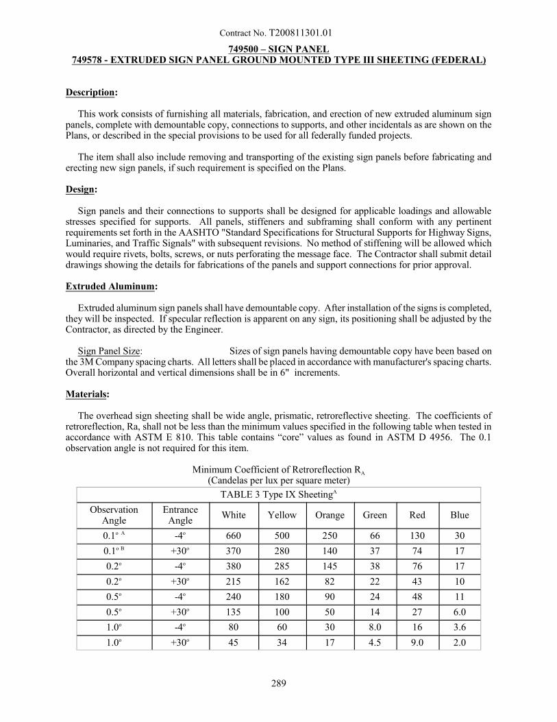
Contract No. T200811301.01
749500 – SIGN PANEL749578 - EXTRUDED SIGN PANEL GROUND MOUNTED TYPE III SHEETING (FEDERAL)
Description:
This work consists of furnishing all materials, fabrication, and erection of new extruded aluminum signpanels, complete with demountable copy, connections to supports, and other incidentals as are shown on thePlans, or described in the special provisions to be used for all federally funded projects.
The item shall also include removing and transporting of the existing sign panels before fabricating anderecting new sign panels, if such requirement is specified on the Plans.
Design:
Sign panels and their connections to supports shall be designed for applicable loadings and allowablestresses specified for supports. All panels, stiffeners and subframing shall conform with any pertinentrequirements set forth in the AASHTO "Standard Specifications for Structural Supports for Highway Signs,Luminaries, and Traffic Signals" with subsequent revisions. No method of stiffening will be allowed whichwould require rivets, bolts, screws, or nuts perforating the message face. The Contractor shall submit detaildrawings showing the details for fabrications of the panels and support connections for prior approval.
Extruded Aluminum:
Extruded aluminum sign panels shall have demountable copy. After installation of the signs is completed,they will be inspected. If specular reflection is apparent on any sign, its positioning shall be adjusted by theContractor, as directed by the Engineer.
Sign Panel Size: Sizes of sign panels having demountable copy have been based onthe 3M Company spacing charts. All letters shall be placed in accordance with manufacturer's spacing charts.Overall horizontal and vertical dimensions shall be in 6" increments.
Materials:
The overhead sign sheeting shall be wide angle, prismatic, retroreflective sheeting. The coefficients ofretroreflection, Ra, shall not be less than the minimum values specified in the following table when tested inaccordance with ASTM E 810. This table contains “core” values as found in ASTM D 4956. The 0.1observation angle is not required for this item.
Minimum Coefficient of Retroreflection RA
(Candelas per lux per square meter)
TABLE 3 Type IX SheetingA
ObservationAngle
EntranceAngle
White Yellow Orange Green Red Blue
0.1o A -4o 660 500 250 66 130 30
0.1o B +30o 370 280 140 37 74 17
0.2o -4o 380 285 145 38 76 17
0.2o +30o 215 162 82 22 43 10
0.5o -4o 240 180 90 24 48 11
0.5o +30o 135 100 50 14 27 6.0
1.0o -4o 80 60 30 8.0 16 3.6
1.0o +30o 45 34 17 4.5 9.0 2.0
289
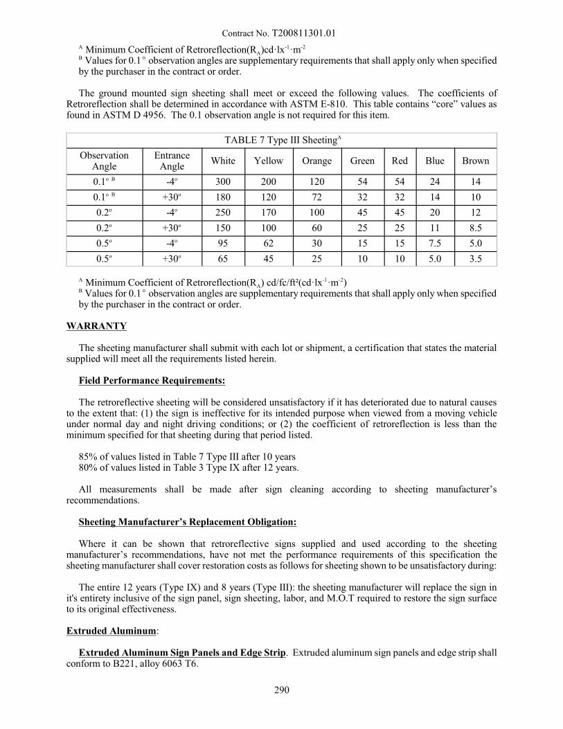
Contract No. T200811301.01 A Minimum Coefficient of Retroreflection(RA)cd·lx-1·m-2
B Values for 0.1E observation angles are supplementary requirements that shall apply only when specifiedby the purchaser in the contract or order.
The ground mounted sign sheeting shall meet or exceed the following values. The coefficients ofRetroreflection shall be determined in accordance with ASTM E-810. This table contains “core” values asfound in ASTM D 4956. The 0.1 observation angle is not required for this item.
TABLE 7 Type III SheetingA
ObservationAngle
EntranceAngle
White Yellow Orange Green Red Blue Brown
0.1o B -4o 300 200 120 54 54 24 14
0.1o B +30o 180 120 72 32 32 14 10
0.2o -4o 250 170 100 45 45 20 12
0.2o +30o 150 100 60 25 25 11 8.5
0.5o -4o 95 62 30 15 15 7.5 5.0
0.5o +30o 65 45 25 10 10 5.0 3.5
A Minimum Coefficient of Retroreflection(RA) cd/fc/ft²(cd·lx-1·m-2)B Values for 0.1E observation angles are supplementary requirements that shall apply only when specifiedby the purchaser in the contract or order.
WARRANTY
The sheeting manufacturer shall submit with each lot or shipment, a certification that states the materialsupplied will meet all the requirements listed herein.
Field Performance Requirements:
The retroreflective sheeting will be considered unsatisfactory if it has deteriorated due to natural causesto the extent that: (1) the sign is ineffective for its intended purpose when viewed from a moving vehicleunder normal day and night driving conditions; or (2) the coefficient of retroreflection is less than theminimum specified for that sheeting during that period listed.
85% of values listed in Table 7 Type III after 10 years 80% of values listed in Table 3 Type IX after 12 years.
All measurements shall be made after sign cleaning according to sheeting manufacturer’srecommendations.
Sheeting Manufacturer’s Replacement Obligation:
Where it can be shown that retroreflective signs supplied and used according to the sheetingmanufacturer’s recommendations, have not met the performance requirements of this specification thesheeting manufacturer shall cover restoration costs as follows for sheeting shown to be unsatisfactory during:
The entire 12 years (Type IX) and 8 years (Type III): the sheeting manufacturer will replace the sign init's entirety inclusive of the sign panel, sign sheeting, labor, and M.O.T required to restore the sign surfaceto its original effectiveness.
Extruded Aluminum:
Extruded Aluminum Sign Panels and Edge Strip. Extruded aluminum sign panels and edge strip shallconform to B221, alloy 6063 T6.
290
Contract No. T200811301.01
Hardware: hardware shall be clear anodized, conforming to one of the following: B209, alloy 2024 T4;B211, alloy 2024 T4, 6262 T9, 6061 T6, 7075 T6 or 2017 T4.
Extruded Aluminum:
The front faces of the sign panels shall be degreased by one of the following methods:
1. Vapor degreasing by total immersion in a saturated vapor of trichlorethylene or perchloroethylene. Trademark printing shall be removed with lacquer thinner or by a controlled alkaline cleaning system.
2. Alkaline degreasing by total immersion in a tank containing alkaline solutions controlled and titratedto the solution manufacturer's specification. Rinse thoroughly with clean running water.
Immersion time shall depend upon the amount of grease or dirt present and the gage of the metal, and shallbe sufficient to effect complete removal of all corrosion, white rust, and dirt.
Following degreasing, the front faces shall be etched by one of the following methods:
1. Acid etching in a 6 to 8 percent phosphoric acid solution at 100 oF, or proprietary acid etching solution. Rinse thoroughly with cold, then hot running water.
2. Alkaline etching in an approved alkaline etching material that is controlled by titration. The etchingtime, temperature, and concentration shall be as specified by the solution manufacturer. Smut shall beremoved with an acidic chromium compound type solution as specified by the solution manufacturer,and shall be rinsed thoroughly with clean running water.
The surface etch shall provide a clean mat, or non-glare finish, suitable for the application of theretroreflective sheeting. This finish shall also be suitable for the uncovered reverse sides of the signs. Anyprotective film or coating applied to resulting from chemical action on the aluminum surface shall be light,tight, and free from all powdery residue.
As an alternate to the above etching systems, any one of the following metal preparation systems,employing a chemical conversions coating, may be used providing it complies fully with therecommendations and specifications furnished by the respective preparation manufacturer:
1. "Alodine" 1200 or 1200S, by Amchem Products, Inc.
2. "Bonderite" 723 with Process Specification No. 249, by Parker Rust Proof Company.
3. "Chromicoat", by Oakite Products, Inc.
4. Other approved system(s), producing a conversion coat meeting the requirements of MilitarySpecification MIL-C-5541.
Alternate coats shall be light, tight, and free from any powdery residue.
After degreasing and etching, the panels shall be dried by the use of forced, hot air.
Panels shall not be handled except by device or clean canvas gloves, from the time degreasing is startedto the time of application of retroreflective sheeting, nor shall contaminants be permitted to come into contactwith the panels during that period.
Construction Methods:
Sign Face Finishing: All retroreflective sheeting, backgrounds, letters, numerals, symbols, and bordersshall be clean-cut and sharp, and the messages on all signs shall be as indicated on the plans. Application ofretroreflective sheeting to aluminum panels shall be in accordance with sheeting manufacturer's
291
Contract No. T200811301.01
recommendations. Retroreflective sheeting shall be color matched and marked. The height of characters andthe alphabet series to be employed for the signs shall conform to the Plans and their references. The alphabetseries used on the sign panels shall be those of the publication titled "Standard Alphabets for HighwaysSigns" of the Federal Highway Administration.
The working drawings prepared by the Contractor shall clearly indicate the proposed spacing of the lettersand the locations and arrangements of symbols and borders.
After the panel has been degreased and etched, the retroreflective sheeting shall be applied by a methoddescribed elsewhere in these Special Provisions.
No sheeting shall be applied when the temperature is less than 50 oF.
Whenever it is necessary to construct the background of a sign face with two or more pieces ofretroreflective sheeting, they must be carefully matched for color prior to application and sign fabrication,to provide uniform appearance and brilliance, day and night. Each full width section of retroreflectivesheeting mounted adjacent to another full width section taken consecutively from the same roll shall berotated and mounted 180 degrees with respect to that adjacent section. This rule shall also be observed asa guide when partial width sheets of retroreflective sheeting are used.
Non-conformance may result in non-uniform shading and an undesirable contrast between adjacent widthsof applied sheeting which will render signs unacceptable. The entire background of each sign shall beuniform in color, brilliance, texture, and general appearance as seen in the daytime and under typicalautomobile illumination at night. No more sections of retroreflective sheeting shall be used for backgroundsthan is necessary; remnants, scraps, and odd sized pieces of sheeting shall not be used in the fabrication ofany signs manufactured for this contract. Joints between retroreflective sheeting sections shall either butt oroverlap no more than 3/8". Horizontal joints between retroreflective sheeting sections shall not be allowed.
Sign Panel Erection: Signs shall be slip-sheeted, packed, and shipped in such manner as to ensure arrivalat their respective places of erection in an undamaged condition. All signs arriving at the erection site(s) ina condition which in the opinion of the Engineer, renders them unsuitable for use, shall be removed andreplaced by the Contractor at his sole expense. Sign Panels shall not be shipped for erection in such a mannerthat results in horizontal joints of the retroreflective sheeting.
Signing requiring more than one sign panel conveying a singular message when mounted on a structureshall be positioned so that no vertical gap between panels is present in the final configuration. Costs for anyrequired adjustments in this regard are incidental to Item 749500, Sign Panel.
It is not anticipated that there will be any sign panels which are required to be mounted whose messageswill be inappropriate to the guiding of traffic at the time of sign erection. However, in the event that theEngineer determines that certain sign messages are inappropriate, the panels of such signs shall be coveredby an opaque material, until such time as the sign messages become appropriate. The covering material andthe manner of securing the material to the sign panel(s), shall meet with the approval of the Engineer. TheEngineer will indicate to the Contractor which signs, if any, must be covered, and when to remove the covers.
Sign Covers: Sign covers shall be 10 ounce cotton duck conforming to ASTM D-320, Army Duck, anddyed to a dark green approximating the green for sign backgrounds.
Identification Tags: The Contractor shall furnish and place identification tags or decals which state theContract number, month and year of erection on the lower reverse side of the panel, near the point closest tothe roadway shoulder.
Method of Measurement:
The quantity of sign panels will be measured as the actual number of square feet of front sign face surfacearea of all sign panels constructed, installed and accepted. The area will be computed from the maximumwidth and height dimensions of each sign panel, as shown on the Plans, or on the approved sign panel shop
292
Contract No. T200811301.01
drawings, (verified by field measurements). All sign panels will be considered either square or rectangularin shape, as the case may be, and no area deductions will be made for rounding of corners.
Basis of Payment:
The quantity of sign panel will be paid for at the Contract unit price per square foot. Price and paymentwill constitute full compensation for furnishing, fabricating, and erecting sign panels complete in place andaccepted, with retroreflective materials, copy, symbols, borders, connections to supports, degreasing, etching,covering and uncovering sign messages where necessary, and for all labor, materials, tools, equipment, andincidentals required to complete the item.
Unless otherwise indicated on the Plans, the cost of removing and transporting to the nearest highwaymaintenance yard the existing sign panels and accessories shall also be included under this item if suchrequirement is indicated on the Plans.
7/20/15
293
Contract No. T200811301.01
749516 – REINFORCED CONCRETE SIGN FOUNDATION, W-6749517 – REINFORCED CONCRETE SIGN FOUNDATION, W-8
749518 – REINFORCED CONCRETE SIGN FOUNDATION, W-10749519 – REINFORCED CONCRETE SIGN FOUNDATION, W-12749520 – REINFORCED CONCRETE SIGN FOUNDATION, W-14749581 - REINFORCED CONCRETE SIGN FOUNDATION, W-18
Description:
This work consists of furnishing all material and installing sign foundations.
Materials:
Bar Reinforcement shall conform to the requirements of Subsection 603.02 of the Standard Specifications.
Portland Cement Concrete shall be Class B and shall conform to the requirements of Section 812 of theStandard Specifications.
Anchors shall be fabricated from 304 Stainless Steel for the threaded ferrule portion, and 1058 steel rodand coil for cage portion of anchor.
Nuts, Bolts and Cap Screws shall meet AASHTO M 164 (m 164M). All nuts, bolts and cap screws shallbe within a hardness range of Rockwell C23 to C31 prior to hot dip galvanizing per AASHTO M232/M232M.
Construction Methods:
The bases shall conform to the dimensions and details as indicated on the Plans.
Excavation for the foundation may not exceed the dimension of the foundation by more than 1 foot (300mm) in any one direction. If a form is used in the excavation more than 18 inches (460 mm) below theground surface, it is necessary that the excavation be filled and tamped on all sides inlayers not to exceed 6inches (150 mm).
The excavated material shall be disposed of and the area shall be properly graded. After grading, the areashall be returned to its original condition around the supports with mulching, seeding or other landscapingas necessary or as directed by the Engineer.
Anchor bolts shall be set to template for alignment and elevation and shall be secured in position toprevent displacement while concrete is being placed. The steel reinforcement and conduit elbows shall havebeen placed and secured before the placing of concrete.
Method of Measurement:
The quantity of sign foundations will be measured as the number of foundations for the specified size ofbeam constructed in accordance with these specifications, complete in place, and accepted.
Basis of Payment:
The quantity of sign foundations will be paid for at the contract unit price per each foundation of the typespecified. Price and payment will constitute full compensation all materials and sign foundation installationcomplete in place and for all labor, equipment, tools, and incidentals required to complete the work. Paymentwill also include returning the area around the sign post to its original conditions by mulch, seeding or otherlandscaping necessary.
10/27/2009
294
Contract No. T200811301.01
749521 - SUPPLY OF BREAKAWAY I-BEAM SIGN POSTS, W-6749522 - SUPPLY OF BREAKAWAY I-BEAM SIGN POSTS, W-8
749523 - SUPPLY OF BREAKAWAY I-BEAM SIGN POSTS, W-10749524 - SUPPLY OF BREAKAWAY I-BEAM SIGN POSTS, W-12749525 - SUPPLY OF BREAKAWAY I-BEAM SIGN POSTS, W-14749563 - SUPPLY OF BREAKAWAY I-BEAM SIGN POSTS, W-4
749582 - SUPPLY OF BREAKAWAY I-BEAM SIGN POSTS, W-18
Description:
This work consists of furnishing all materials for ground mount breakaway type sign posts and breakawayassemblies to the job order site in conformance with the details and notes shown on the Plans, and as directedby the Engineer.
Materials:
Structural Steel shall meet the applicable requirements of Subsection 605.02 of the Standard Specificationsand AASHTO M 270/M 270M, GR36 (GR250), GR50 (GR345), or GR50W (GR 345W) as detailed on theplans. Steel posts shall be galvanized in accordance with the requirements of AASHTO M 111/M 11M.
Breakaway Couplings shall be made from alloy steel which conforms to AISI 4340, 4130 or an equivalentmaterial, and shall have a minimum tensile yield stress of 175,000 psi (1200 MPa). The Rockwell C hardnessshall be 26 minimum. The couplings shall have tensile breaking strength ranges as noted below; and shallbe of the type as shown on the Plans:
Type A 17,000 – 21,000 lb (75 – 93 kN)Type B 47,000 – 57,000 lb (209 – 253 kN)
This steel shall conform to the requirements of the current ASTM designation A-370.
The couplings shall be clean, dry and free from any foreign material and shall be primed and coated witha suitable paint which shall be baked or fused with a polyurethane additive. The color of the coating shallbe as follows:
Type A YellowType B Red
Chipped areas on the coating surface shall be repaired. All threaded surfaces, after coating, shall becleaned to all them to function properly.
Brackets shall be made from aluminum alloy 6061 T-6 or an equivalent material. Upper brackets shallincorporate the load concentrating member or bass which shall be made from the following material:
Type A Aluminum alloy 6061 T-6 or equivalent as part of bracketsType B Stainless steel 416 or equivalent ASTM A582-Rockwell C35-C45
The type of bass shall be as shown on the Plans.
Location holes for the breakaway coupling shall be accurately positioned relative to the load concentratingmember in accordance with the Engineer’s requirements. All Brackets shall be permanently labeled withbracket number to reflect the hole positioning.
295
Contract No. T200811301.01
Hinge Plates shall be made from alloy steel which conforms to AISI 4340, 4130 or an equivalent materialand shall have a minimum tensile yield stress of 90,000 psi (620 MPa). The hinge plates shall have tensilebreaking strength ranges as follows:
HI-10 11,450 – 13,900 lb (50.9 – 61.8 kN)HI-1 16,400 – 19,700 lb (72.9 – 87.6 kN)HI-2 6,700 – 8,100 lb (29.8 – 36.0 kN)
Nuts, Bolts and Cap Screws shall meet AASHTO M 164 (m 164M). All nuts, bolts and cap screws shallbe within a hardness range of Rockwell C23 to C31 prior to hot dip galvanizing per AASHTO M232/M232M.
Construction Methods:
Working Drawings. Working drawings shall be submitted in accordance with subsection 105.04 of theStandard Specifications. Minor variations in details may be permitted; however, any major departure fromthe design will not be accepted.
Fabrications. Loading, transporting, unloading and erection of structural materials shall be done so thatthe metal will be kept clean and free from injury in handling.
Structural materials shall be stored above the ground upon platforms, skid or other supports and shall bekept free from accumulation of dirt, oil, acids or other foreign matter.
Structural material which has been deformed shall be straightened before being laid out, punched, drilledor otherwise worked upon in the shop. Sharp kinks or bends will be cause for rejection.
When sign support structures are subcontracted, the subcontract shall be in accordance with Subsection108.01 of the Standard Specifications except that the value of the subcontract will be based on the value ofthe work for fabrication.
Repair Galvanizing. Galvanized areas damaged during shipping or erection shall be repaired by any ofthe three methods specified under ASTM A780. In all cases, the repair shall achieve the minimum coatingthickness specified.
Erection. Material shall not be dropped, thrown or dragged over the ground. The Contractor shall supplydetailed, written instructions and drawings for the erection of all sign structure components.
Method of Measurement:
The quantity of supplying ground mount breakaway type sign posts and breakaway assemblies will bemeasured as linear feet for the length and size of ground mount breakaway sign post furnished as specifiedand accepted.
Basis of Payment:
The quantity of supplying ground mount breakaway type sign posts and breakaway assemblies will be paidfor at the Contract unit price per linear feet for the length and size of ground mount breakaway sign postspecified. Price and payment will constitute full compensation for furnishing hinge plates, breakawaycouplings, nuts, bolts and cap screws and all other materials for the sign posts and breakaway assemblies inaccordance with the details and notes shown on the Plans, and as directed by the Engineer; and for all labor,equipment, tools and incidentals necessary to complete the work.
3/6/08
296
Contract No. T200811301.01
749532 – SUPPLY OF FLAT SHEET ALUMINUM SIGN PANEL TYPE IX
RETROREFLECTIVE SHEETING749534 – SUPPLY OF EXTRUDED ALUMINUM SIGN PANEL TYPE IX RETROREFLECTIVE
SHEETING749579 - SUPPLY OF FLAT SHEET ALUMINUM SIGN PANEL,TYPE XI
RETROREFLECTIVE SHEETING749580 - SUPPLY OF EXTRUDED ALUMINUM SIGN PANEL, TYPE XI
RETROREFLECTIVE SHEETING
Description:
This work shall include fabrication and furnishing new sign panels constructed of either flat sheetaluminum panels OR extruded aluminum sign panels as specified in the job order. Supply of sign overlayswill be part of flat sheet aluminum panels. The sign panels shall have a reflective sheeting background, andall complete with demountable copy or direct applied or silk screened copy. Included with the sign panel willbe connections to supports, and other incidentals shown on the Plans or as described in the special provisions.Installation of flat sheet aluminum panels and extruded aluminum panels are paid for under other items in thiscontract.
The removing and transporting of the existing sign panels before fabricating and erecting new sign panels,if such requirement is specified shall be paid for under other items in this contract.
Design:
Sign panels and their connections to supports shall be designed for applicable loadings and allowablestresses specified for supports. All panels, stiffeners and subframing shall conform with any pertinentrequirements set forth in the 1985 AASHTO “Standard Specifications for Structural Supports for HighwaySigns, Luminaries, and Traffic Signals” with subsequent revisions. No method of stiffening will be allowedwhich would require rivets, bolts, screws, or nuts perforating the message face. The Contractor shall submitworking drawings showing the details for fabrications of the panels and support connections for priorapproval.
Sign panel sections shall be fabricated of standard width, readily available, aluminum sheets not less than3’-0” wide and not more than 5’-6” wide, except that not more than one sheet of 2’-0” minimum width willbe permitted.
Sections 12 feet and under: Sign panel sections including those twelve (12) feet in height shall run fromthe top edge to the bottom edge of the sign face without horizontal joints in the aluminum sheets.
Sections 12 feet and Over: Sign panel sections over twelve (12) feet in height shall be fabricated of twoor more sheets with horizontal joints which butt and fasten securely together and may be disassembled forsimplified handling and erection in the field. Each horizontal joint in sign panel sheets shall be located atpoint of contraflexure in the sign face.
Fasteners and Backing Strips: Sign panel sections shall be provided with suitable fastenings, as shownon the Plans, to permit easy attachment to the supporting frames and these fastenings shall be so designed asto carry the full design load with a factor of safety of 1.6 against the minimum yield stress of the materials.
Sign panel sections shall be provided with backing strips at the joints, held firmly in place to keep theabutting panel sections in proper alignment. All sign panel fastenings and backing strips, accepting thefastening of letters, symbols and border to the sign face, shall be applied without causing visible projectionsor indentations of the sign face. Each sign panel section shall be designed to engage and hang from two ormore horizontal structural members of the supporting frame. The method of fastening to obtain secure closebutt joints between panels may vary as recommended by the fabricator. Shop drawings will be requiredshowing proposed method of attachment for approval of the Engineer.
297
Contract No. T200811301.01
Supporting Frame: The supporting sign frame shall consist of horizontal and vertical stringers as shownon the plans. The horizontal members of the supporting sign frame shall be fabricated of new material in onepiece. Where large signs necessitate splicing the stringers, such splices shall be located at points ofcontraflexure and shall be held to a minimum, but splice must develop full section of member.
Sign Panel Size: Sizes of sign panels having demountable copy shall be based on the manufacturer’sspacing charts. All letters shall be placed in accordance with manufacturer’s spacing charts. Overallhorizontal and vertical dimensions shall be in six-inch increments.
Materials:
Aluminum Flat Sheet Panels: Sign panels shall be of aluminum sheet type conforming to ASTMDesignation B209 (alloy 6061-T6 or 5052-H38). The minimum panel sheet thickness shall be 0.125 inches. Stringers or horizontal structural sign supporting members and vertical connections shall be fabricated of6061-T6 or 6062-T6 ASTM B221 aluminum alloy. All sign panels shall be fully reflectorized unlessotherwise indicated on the Plans.
All sign hardware shall be stainless steel or galvanized steel or 2024-T4 aluminum alloy ASTM B211 orASTM B221. Hardware for attachment to overhead members shall be Type 304 passivated stainless steel,except that stainless steel lock washers shall be Type 302 stainless steel alloy. Connections to the signsupport structure shall be of steel conforming to the requirements of ASTM Designation A36 and galvanizedto the requirements of ASTM Designation A123.
Extruded Aluminum Sign Panels: Extruded aluminum sign panels and edge strips shall conform to B221, alloy 6063 T6. (See Extruded Aluminum Detail Sheets)
Hardware: Hardware shall be clear anodized, conforming to one of the following: ASTM B 209, alloy2024 T4; B 211, alloy 2024 T4, 6262 T9, 6061 T6, 7075 T6 or 2017 T4.
Sheeting: The sheeting shall consist of prismatic lens elements with a distinctive interlocking patternvisible from the face of a smooth surface, unless otherwise specified on the plans. The sheeting shall havea precoated adhesive protected by an easily removable liner.
Retroreflective properties will be measured in:
Minimum Coefficient of Retroreflection Ra(cd/lux/m2)
- All measurements shall be made after sign cleaning according to sheeting manufacturer’srecommendations.
- The coefficients of retroreflection observation angles shall be 0.2°, 0.5°, 1.0°. - The coefficients of retroreflection entrance angles shall be -4° and 30°.
Letter of Certification
The contractor shall send a letter of certification stating that the sign sheeting materials meet the requiredMinimum Coefficient of Retroreflection described in the charts below. The letter shall be sent to:
Delaware Department of TransportationSigns and Markings Section
Attn: Traffic Operations ManagerP.O. Box 778
Dover, Delaware 19901
298
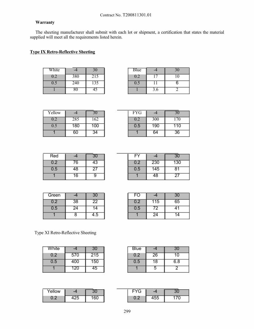
Contract No. T200811301.01
Warranty
The sheeting manufacturer shall submit with each lot or shipment, a certification that states the materialsupplied will meet all the requirements listed herein.
Type IX Retro-Reflective Sheeting
White -4 30 Blue -4 30
0.2 380 215 0.2 17 10
0.5 240 135 0.5 11 6
1 80 45 1 3.6 2
Yellow -4 30 FYG -4 30
0.2 285 162 0.2 300 170
0.5 180 100 0.5 190 110
1 60 34 1 64 36
Red -4 30 FY -4 30
0.2 76 43 0.2 230 130
0.5 48 27 0.5 145 81
1 16 9 1 48 27
Green -4 30 FO -4 30
0.2 38 22 0.2 115 65
0.5 24 14 0.5 72 41
1 8 4.5 1 24 14
Type XI Retro-Reflective Sheeting
White -4 30 Blue -4 30
0.2 570 215 0.2 26 10
0.5 400 150 0.5 18 6.8
1 120 45 1 5 2
Yellow -4 30 FYG -4 30
0.2 425 160 0.2 455 170
299
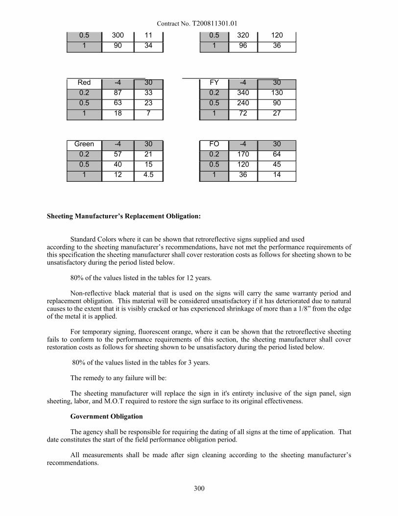
Contract No. T200811301.01
0.5 300 11 0.5 320 120
1 90 34 1 96 36
Red -4 30 FY -4 30
0.2 87 33 0.2 340 130
0.5 63 23 0.5 240 90
1 18 7 1 72 27
Green -4 30 FO -4 30
0.2 57 21 0.2 170 64
0.5 40 15 0.5 120 45
1 12 4.5 1 36 14
Sheeting Manufacturer’s Replacement Obligation:
Standard Colors where it can be shown that retroreflective signs supplied and used according to the sheeting manufacturer’s recommendations, have not met the performance requirements ofthis specification the sheeting manufacturer shall cover restoration costs as follows for sheeting shown to beunsatisfactory during the period listed below.
80% of the values listed in the tables for 12 years.
Non-reflective black material that is used on the signs will carry the same warranty period andreplacement obligation. This material will be considered unsatisfactory if it has deteriorated due to naturalcauses to the extent that it is visibly cracked or has experienced shrinkage of more than a 1/8” from the edgeof the metal it is applied.
For temporary signing, fluorescent orange, where it can be shown that the retroreflective sheetingfails to conform to the performance requirements of this section, the sheeting manufacturer shall coverrestoration costs as follows for sheeting shown to be unsatisfactory during the period listed below.
80% of the values listed in the tables for 3 years.
The remedy to any failure will be:
The sheeting manufacturer will replace the sign in it's entirety inclusive of the sign panel, signsheeting, labor, and M.O.T required to restore the sign surface to its original effectiveness.
Government Obligation
The agency shall be responsible for requiring the dating of all signs at the time of application. Thatdate constitutes the start of the field performance obligation period.
All measurements shall be made after sign cleaning according to the sheeting manufacturer’srecommendations.
300
Contract No. T200811301.01
Natural causes include effects of exposure to weather. Natural causes exclude (without limitation)damage from exposure to chemicals, abrasion and other mechanical damage (such as from fasteners used tomount the sign, collisions or mishandling), vandalism, or malicious mischief.
Applicable Documents
The following documents, of the issues in effect on the date of invitation for bids or request for proposal,form a part of this specification to the extent specified herein.
ASTM Standards
D 4956 Standard Specification for Retroreflective Sheeting for Traffic Control
E 810 Standard Test Method for Coefficient of Retroreflection of Retroflective Sheeting
AASHTO Standard Specifications for Structural Supports for Highway Signs, Luminaries, andTraffic Signals
Construction Methods:
Sign Face Finishing: All reflective sheeting, backgrounds, letters, numerals, symbols, and bordersshall be clean-cut and sharp, and the messages on all signs shall be as indicated on the plans. Application ofreflective sheeting to aluminum panels shall be in accordance with sheeting manufacturer’s recommendations. Reflective sheeting shall be color matched and marked. The height of characters and the alphabet series tobe employed for the signs shall conform to the Plans and their references. The alphabet series used on thesign panels shall conform to the Plans and the “Standard Alphabets for Highways Signs” of the FederalHighway Administration.
The working drawings prepared by the Contractor shall clearly indicate the proposed spacing of theletters and the locations and arrangements of symbols and borders.
Sheeting applications shall meet ambient temperature requirements as specified by the manufacturer.
Whenever it is necessary to construct the background of a sign face with two or more pieces ofreflective sheeting, they must be carefully matched for color prior to application and sign fabrication, toprovide uniform appearance and brilliance, day and night. Each full width section of reflective sheetingmounted adjacent to another full width section taken consecutively from the same roll shall be rotated andmounted 180 degrees with respect to that adjacent section. This rule shall also be observed as a guide whenpartial width sheets of reflective sheeting are used.
Non-conformance may result in non-uniform shading and an undesirable contrast between adjacentwidths of applied sheeting which will render signs unacceptable. The entire background of each sign shallbe uniform in color, brilliance, texture, and general appearance as seen in the daytime and under typicalautomobile illumination at night. No more sections of reflective sheeting shall be used for backgrounds thanis necessary; remnants, scraps, and odd sized pieces of sheeting shall not be used in the fabrication of anysigns manufactured for this contract. Joints between reflective sheeting sections shall either butt or overlapno more than 3/8 of an inch.
Transporting Sign Panel: Signs shall be slip-sheeted, packed, and shipped in such manner as toensure arrival at their respective places of erection in an undamaged condition. All signs arriving at theerection site(s) in a condition which in the opinion of the Engineer, renders them unsuitable for use, shall beremoved and replaced by the Contractor at his sole expense.
Identification Tags: The Contractor shall furnish and place identification tags or decals which statethe contract number, month and year of erection on the lower reverse side of the panel, near the point closestto the roadway shoulder.
301
Contract No. T200811301.01
Method of Measurement:
The quantity of sign panels is to be measured as the square footage of front sign face installed for thetype and sheeting grade specified under this item complete and accepted. The area will be computed fromthe maximum width and height dimensions of each sign panel, as shown on the Plans, or on the approved signpanel working drawings, (verified by field measurements). All sign panels will be considered either squareor rectangular in shape, as the case may be, and no area deductions will be made for rounding corners.
Basis of Payment:
The quantity of sign panels will be paid for at the unit price per square foot for the type and sheetinggrade specified. Price and payment shall constitute full compensation for furnishing, fabricating, anddelivering sign panels complete in place and accepted, with reflective materials, copy, symbols, borders,connections to supports, degreasing, etching, and for all labor, materials, tools, equipment, and incidentalsrequired to complete the item.
12/12/2012
302
Contract No. T200811301.01
749550 - INSTALLATION OF BREAKAWAY I-BEAM SIGN POSTS749551 -REMOVAL OF BREAKAWAY I-BEAM SIGN POSTS
Description:
This work consists of installing or removing breakaway I-beam sign posts and breakaway assemblieson sign bases previously installed or installed under other items in this contract.
Materials:
Steel I-beams and all mounting hardware to be used will be paid for under other items of this contractor may be furnished by the Department. The supply of the material will be designated in the job order. AllI-beams will be cut to the correct length and marked for the area they are to be installed.
Construction Methods:
The I-beams are to be installed in a manner as not to damage the base that the I-beam is to be installedon and care taken to not interfere with overhead utility lines.
When re-installing an existing sign post and breakaway assemblies, removal of broken couplings andbolts in existing I-beams and removal of broken anchor bolts in existing bases shall be considered part of thisitem.
Where an existing sign has been knocked down, this item will pay for the repair of breakawaycouplings and standing up the existing sign. No additional compensation will be made for removal orinstallation of sign unless a new sign is required.
In the removal of the I-beams, all hardware is to be returned to the Department at the Dover SignShop.
Method of Measurement:
The quantity of installation or removal of breakaway posts and breakaway assemblies will bemeasured as the number of breakaway posts and breakaway assemblies installed as specified, complete andin place, or removed and returned to the Department at the Dover Sign Shop.
Basis of Payment:
The quantity of installation or removal of breakaway posts and breakaway assemblies will be paidfor at the contract unit price per each. Price and payment will constitute full compensations for all labor,equipment, tools, and incidentals required to complete the work.
10/26/05
303

Contract No. T200811301.01
749687 - INSTALLATION OR REMOVAL OF TRAFFIC SIGN ON SINGLE SIGN POST
Description:
This work consists of installing or removing traffic sign(s) on a single post or other type of pole atthe locations indicated on the Plans or as directed by the Engineer. This specification also includesinstallation of posts in boring holes constructed under other items.
A single sign totaling more than 9 square feet, or with any dimension, length or width, greater thanor equal to 48 inches shall be installed on multiple sign posts under Item 749690 - Installation or Removalof Traffic Sign on Multiple Sign Posts.
Materials:
The Department will provide all sign materials to be used on this project. The Contractor shall contactthe DelDOT Sign Shop Supervisor with project plans and quantity sheets at 302-760-2581. Sign fabricationorders require a minimum of four (4) weeks for completion. Orders placed with less than 4 weeks lead-timewill result in a delay. Any delay caused by inadequate lead-time due to a late order will be the soleresponsibility of the Contractor. The Contractor shall pick-up the sign materials from the DelDOT Sign Shopand deliver them to the job site without any damage to the sign materials.
Construction Methods:
The Contractor shall pick-up necessary signs, sign posts, hardware, and extensions from theDepartment and install the signs in the locations indicated on the Plans in accordance with the DelawareMUTCD or as directed by the Engineer. The Contractor shall be responsible for obtaining all necessaryutility clearances before the signs may be installed. Signs and plaques shall be mounted no lower than theminimum mounting height specified in the Delaware MUTCD. Signs and plaques shall be mounted no higherthan one foot above the minimum mounting height specified in the Delaware MUTCD. Any excess sign postprotruding above the top of the top sign shall be cut off and removed. For sign removals, the sign posts shallhave all nuts, bolts, and other connectors removed. The disturbed ground shall be graded and backfilledaccordingly. The Contractor is responsible for disposal of all signing material removed from the project
Method of Measurement:
The number of single sign installations or removals will be measured as the actual number of signs installed or removed and accepted.
Basis of Payment:
The quantity of single sign post installations or removals will be paid for at the Contract unit priceper each. Price and payment will constitute full compensation for installing or removing signs and signmaterials, pick-up and delivery of sign materials, grading disturbed areas, and for all labor, equipment, tools,and incidentals required to complete the work. Signs that are not installed in accordance with the DelawareMUTCD or signs installed in the incorrect location shall be moved at no additional cost to the Department.
5/28/2013
304

Contract No. T200811301.01
749688 - INSTALLATION OF 4” DIAMETER HOLE, LESS THAN OR EQUAL TO 6” IN
DEPTH749689 - INSTALLATION OF 4” DIAMETER HOLE, GREATER THAN 6” IN DEPTH
Description:
This work consists of boring a hole 4” in diameter averaging 6” in depth into bituminous concreteor P.C.C. surfaces for installing single or multiple sign posts at the locations indicated on the Plans or asdirected by an Engineer.
Materials:
The Contractor shall provide the equipment necessary to bore a 4” hole into paved surfaces, whilemaintaining the stability of the surrounding paved or P.C.C. surfaces. The depth of the bored hole shall beto the top of the subbase material.
Construction Methods:
The holes shall be bored into pavement or P.C.C. islands, medians, or sidewalk using a mechanicalhole borer for such work or other methods approved by the Engineer. The hole shall be 4” in diameter. Holesbigger or smaller than 4” shall be corrected at the Contractor’s expense.
Method of Measurement:
The number of 4” holes in diameter bored will be measured as the actual number of holes bored andaccepted.
Basis of Payment:
The quantity of holes bored as required above will be paid for at the Contract unit price per each. Price and payment will constitute full compensation for boring holes at the required depth, and for all labor,equipment, tools, and incidentals required to complete the work.
Note:
The cost for installing holes and PVC sleeves for sign posts in newly constructed P.C.C. islands,medians, or sidewalks shall be incidental to the P.C.C. item.
3/23/09
305
Contract No. T200811301.01
749690 - INSTALLATION OR REMOVAL OF TRAFFIC SIGN ON MULTIPLE SIGN POSTS
Description:
This work consists of installing or removing traffic sign(s) on multiple sign posts at the locationsindicated on the Plans or as directed by the Engineer. This specification also includes installation of posts inholes installed under other items.
A single sign totaling more than 9 square feet, or with any dimension, length or width, greater than48 inches shall be mounted on two (2) posts. Signs with a length greater than or equal to 78 inches shall bemounted on three (3) sign posts.
Materials:
The Department will provide all sign materials to be used on this project. The Contractor shallcontact the DelDOT Sign Shop Supervisor with project plans and quantity sheets at 302-760-2581. Signfabrication orders require a minimum of four (4) weeks for completion. Orders placed with less than 4 weekslead-time will result in a delay. Any delay caused by inadequate lead-time due to a late order will be the soleresponsibility of the Contractor. The Contractor shall pick-up the sign materials from the DelDOT Sign Shopand deliver them to the job site without any damage to the sign materials.
Construction Methods:
The Contractor shall pick-up necessary signs, sign posts, hardware, and extensions from theDepartment and install the signs in the locations indicated on the Plans in accordance with the DelawareMUTCD or as directed by the Engineer. The Contractor shall be responsible for obtaining all necessaryutility clearances before the signs may be installed. Signs and plaques shall be mounted no lower than theminimum mounting height specified in the Delaware MUTCD. Signs and plaques shall be mounted no higherthan one foot above the minimum mounting height specified in the Delaware MUTCD. Any excess sign postprotruding above the top of the top sign shall be cut off and removed. For sign removals, the sign posts shallhave all nuts, bolts, and other connectors removed For sign removals, the sign posts shall have all nuts, bolts,and other connectors removed. The disturbed ground shall be graded and backfilled accordingly. The Contractoris responsible for disposal of all signing material removed from the project..
Method of Measurement:
The number of sign installations or removals will be measured as the total square foot of the sign(s)installed or removed and accepted.
Basis of Payment:
The quantity of sign installations or removals will be paid for at the Contract unit price per square foot.Price and Payment will constitute full compensation for installing or removing signs and sign materials, pick-upand delivery of sign materials, grading disturbed areas, and for all labor, equipment, tools, and incidentalsrequired to complete the work. Signs that are not installed accordance with the Delaware MUTCD or signsinstalled in the incorrect location shall be moved at no additional cost to the Department.
5/28/2013
306
Contract No. T200811301.01
753501 - INSTALLING SANITARY SEWER, PVC 8"753502 - INSTALLING SANITARY SEWER, PVC 10"753503 - INSTALLING SANITARY SEWER, PVC 12"753504 - INSTALLING SANITARY SEWER, PVC 15"753505 - INSTALLING SANITARY SEWER, PVC 18"753506 - INSTALLING SANITARY SEWER, PVC 21"753507 - INSTALLING SANITARY SEWER, DIP 30"753508 - INSTALLING SANITARY SEWER, DIP 42"
753509 - INSTALLING SANITARY SEWER (FORCE MAIN), PVC 4"753510 - INSTALLING SANITARY SEWER (FORCE MAIN), PVC 8"
753511 - INSTALLING SANITARY SEWER, DIP 4"753512 - INSTALLING SANITARY SEWER, RCP 24"753513 - INSTALLING SANITARY SEWER, DIP 12"
753514 - INSTALLING SANITARY SEWER (FORCE MAIN), PVC 6"753515 - INSTALLING SANITARY SEWER (FORCE MAIN), PVC 2"
753517 - INSTALLING SANITARY SEWER, PVC 6"753518 - INSTALLING SANITARY SEWER, DIP 6"753520 - INSTALLING SANITARY SEWER, DIP 8"
753522 - INSTALLING SANITARY SEWER, PVC 24"753524 - INSTALLING SANITARY SEWER, DIP 10"
753525 - INSTALLING SANITARY SEWER (FORCE MAIN), DIP 10"753526 - INSTALLING SANITARY SEWER (FORCE MAIN), PVC 3"
753527 - INSTALLING SANITARY SEWER, DIP 24"753528 - INSTALLING SANITARY SEWER, DIP 24"753529 - INSTALLING SANITARY SEWER, DIP 8"
753530 - INSTALLING SANITARY SEWER, DIP 16"753531 - INSTALLING SANITARY SEWER, RCP 30"753532 - INSTALLING SANITARY SEWER, PVC 4"
753533 - INSTALLING SANITARY SEWER (FORCE MAIN), PVC 1 1/2"753534 - INSTALLING SANITARY SEWER (FORCE MAIN), PVC 2 1/2"
753539 - INSTALLING SANITARY SEWER (FORCE MAIN), DIP, 4"753540 - INSTALLING SANITARY SEWER (FORCE MAIN), DIP, 24"753541 - INSTALLING SANITARY SEWER (FORCE MAIN), DIP, 8"
753542 - INSTALLING SANITARY SEWER , DIP, 18"753543 - INSTALLING SANITARY SEWER (FORCE MAIN), DIP, 6O
754544 - INSTALLING SANITARY SEWER (FORCE MAIN), HDPE, 8O
Description:
This work consists of furnishing all materials including pipes with all required fittings with bends Wyes,clean-outs, etc., and installing sanitary sewer in accordance with these Special Provisions, Delaware StandardSpecifications, and requirements of the Standard Specifications of the Owner of the sewer line. In case of anyconflict between the notes and details on the Plans; Special Provisions; Standards and Specifications of theOwner of the Utility; the Standards and Specifications of the Owner of the Utility shall prevail. The Contractorshall obtain the Standards and Specifications of the Owner of the utility and study for materials cost beforesubmitting the bids. The Owner could be a city, municipality or a county, and from hereafter shall be addressedas the Owner.
General Requirements: All work shall be subject to inspection and subsequent approval/disapproval of theEngineer and the representative of the Owner of the utility; and the Contractor shall be required to correct thediscrepancies at his/her expense.
Included in this work are the connections of all existing commercial, industrial, and residential sanitarysewer services to the new sanitary sewer system. All modifications to such services, as required by the presentStandards and Specifications of the Owner, and all relocations of such services necessary to avoid conflicts with
307
Contract No. T200811301.01
utilities and highway drainage facilities are included in the work. Since the exact locations of the conflictscannot be determined prior to trench excavation operations, the Contractor must coordinate and schedule anyrequired relocation efforts of each sanitary sewer connection on an individual basis with the utility Owner andthe property owner.
It is of prime importance that the Contractor, in the performance of his/her work, does not disrupt theoperation of the existing sanitary sewer facilities in any manner or at any time, without the expressed priorapproval of the Owner. The Contractor shall construct, maintain and remove, following construction, suchtemporary bypasses as may be required during construction to maintain sanitary sewer facilities in service.
Any and all emergency repairs required during the period of this Contract shall be the responsibility ofthe Contractor. In the event the Owner is unable to contact the Contractor for the immediate emergency repairitems of work, or in the event the Contractor does not take action when contacted within a reasonable length oftime, the Owner of the utility reserves the right to attend to any and all emergency repair work items and toresubmit the costs directly to the Contractor for complete payment.
Materials:
The requirements for the materials as applicable to the Contract are as noted below, unless otherwisestated on the Plans and/or required by the Owner of the sewer system. The Contractor shall verify thecompatibility of these materials specifications with the Owner before placing order for the Contract.
The Polyvinyl Chloride Pipe (PVC pipe) suitable for non-pressure drainage of sewage and fittings shallconform to the applicable requirements of ASTM D3033 Type PSP, and/or ASTM D3034 Type PSM, and pipeshall be of SDR-35 or SDR-41 or SDR-42 of the nominal size required by the Plans and/or as required by theOwner.
PVC pipe and fittings for Force Main shall conform to the requirements of ASTM D-2241 and AWWAC 900 (SDR-14) utilizing the bell and spigot concept with a single sealing synthetic rubber gasket provided bythe same manufacturer in conformance with ASTM D1859. Pressure rating of PVC pipe for force mains shallbe 1034 kPa minimum.
Ductile Iron Pipe shall be centrifugally cast, and all pipe and fittings shall conform to the applicablespecifications of AWWA C-151 and ANSI and shall be Class 52 for gravity and force mains unless otherwisespecified on the Plans.
Reinforced Concrete Pipe shall meet the applicable requirements of Section 612 of the DelawareStandard Specifications.
All the pipe and fittings shall be free from defects, and the defective materials as determined by theEngineer or the Owner, shall be rejected and replaced.
Warning tape for sanitary sewer or force main shall be printed polyethylene plastic tape with a metalliccore, manufactured specifically for warning and identification of buried utility lines. The tape shall be of a rolltype, 2" (50 mm) minimum width, and color coded for sewer (green), with warning and identification imprintedin bold black letters continuously and repeatedly over entire length of tape. The code and letter color shall bepermanent and unaffected by moisture and other substances contained in trench backfill materials. Imprintedon the tape shall be "Caution, Buried Sewer Line Below", or a similar message as approved by the Engineer.
Concrete for the thrust blocks and clear-outs shall meet the requirements of Section 812, Class B ofStandard Specifications. Thrust blocks and clean-outs shall be constructed in accordance with the StandardDetail Drawings of the Owner or as directed.
Borrow Type C and sand for backfilling when required by the Contract and specified on the Plans shallconform to the respective requirements of Sections 210 and 804 of the Standard Specifications. Concreterequired for the work shall be Class B, and shall conform to the requirements of Section 812.
308
Contract No. T200811301.01
Unless shown otherwise on the Plans or required by the owner, all commercial, industrial, andresidential connections shall be constructed of the same class of material as the sewer mains to which they areconnected. Minimum grade and size of the lateral pipes shall be as required by the Owner's Standards andSpecifications.
Construction Methods:
All pipes shall be thoroughly cleaned before they are laid and shall be kept clean until the completedwork is accepted.
The excavation and backfill for the pipe shall be performed in accordance with the applicablerequirements including backfill requirements of Section 612 of the Delaware Standard Specifications, unlessotherwise modified on the Plans, or in conflict with the requirements of the Owner. If there is a conflict betweenthe Delaware Standard Specifications (including these Special Provisions) and the Specifications of the Ownerof the utility, the latter will prevail. The Contractor is advised to obtain and be fully acquainted with theapplicable specifications of the Owner. The pipe shall be installed at the locations and to the lines, grades, anddimensions shown on the Plans or as directed by the Engineer.
During backfill of the sewer or force main the Contractor shall install the specified warning tape at adepth of 8" (200 mm) to 12" (300 mm) below finished grade or as directed and approved by theEngineer/Owner.
No pipe shall be laid upon a foundation into which frost has penetrated nor at any time when theEngineer shall deem that there is danger of the formation of ice or the penetration of frost at the bottom of theexcavation, unless the minimum length of open trench and promptness of refilling are observed.
The Contractor shall build all future service connections to the existing houses, businesses, and others,complete to the property line, right-of-way lines or other designated points. The ends of all such serviceconnections shall be closed with stoppers as directed and approved by the Engineer/Owner.
Acceptance Testing:
Prior to the request for inspection by the Engineer, it shall be the Contractor's responsibility to examineall completed pipe lines to insure that they are laid to the proper alignment and grade and free from foreignmaterial. After this has been done to the satisfaction of the Engineer, he/she will order tests to be made on allportions of the sewers built under the Contract.
The Contractor shall cooperate and furnish all assistance necessary to perform the tests as specifiedherein and as further required and directed by the Engineer and the representative of the Owner.
Sanitary sewer lines shall be tested for the maximum amount of allowable leakage as specified by theOwner in the presence of the Engineer and the representative of the Owner. If a maximum leakage rate is notspecified by the Owner, the allowable leakage rate will be 25 gallons per inch of diameter per mile (59 liters per25 mm of diamter per kilometer) per day.
A. All sewers above the ground water line with a diameter of 39" (990 mm) or less will be testedby the low air pressure method. Sewers greater than 39" (990 mm) in diameter will be testedby the exfiltration method. This test will be made by plugging the lower manhole and fillingthe pipe section between manholes with water until the upper manhole is filled to the top or toa level designated by the Engineer. The quantity of water leakage will be measured by thedrop in the level of the water in the upper manhole.
B. All sewers below the ground water line will be tested by the infiltration method. This test willbe made by measuring the amount of water infiltration at the lower end of the pipe section atthe end of the manhole stretch by means of a weir installed in the pipe or other means, asapproved by the Engineer.
309
Contract No. T200811301.01
C. All sewers shall be tested in individual sections or an accumulation of series of sections inlengths approved by the Engineer. If the series method is used, each section between manholesshall meet the infiltration and exfiltration requirements specified herein.
All sewers before they are tested shall be carefully plugged and backfilled to a depth not less than 2 feet(0.6 meters) above the top of the pipe. Water shall be furnished by the Contractor and maintained at such levelsas directed by the Engineer for a period of at least twenty hours immediately prior to the time of the test andduring the test. The Contractor shall replace or repair all defects on sections of sewers failing to meet therequirements of these tests.
For conducting low pressure test, all branch fittings and ends of lateral stubs shall be securely pluggedto withstand the internal test pressures. The section of line being tested shall also be securely plugged at eachmanhole. All stoppers shall be adequately braced when required.
Air shall be slowly supplied to the plugged pipe line until the internal air pressure reaches 4 psi (28 kPa)greater than the average back pressure of any ground water that may submerge the pipe. At least two minutesshall be allowed for temperature stabilization before proceeding further. The rate of air loss shall then bedetermined by measuring the time interval required for the internal pressure to decrease from 3.5 to 2.5 psi (24to 17 kPa). When the Owner of the utility is satisfied that the sewer main is functional, then the sewer main willbe accepted.
The Contractor shall furnish all equipment and personnel to conduct the tests specified herein and/orany proposed by the Owner of the utility.
The Contractor shall not make connections to existing sanitary sewers until after the final inspectionand tests have been approved. All material and labor required for tests shall be furnished by the Contractor andthe cost thereof included in the prices bid for installing sanitary pipe. Water for leakage test shall be furnishedby the Contractor.
Method of Measurement and Basis of Payment:
Payment for the item Installing Sanitary Sewer of respective diameter(s) as required by the Contractmeasured along the centerline from end-to-end shall be paid for at the Contract unit price per linear foot (linearmeter) for "Installing Sanitary Sewer", of the size(s) and type(s) required by the Contract, which price andpayment will constitute full compensation for furnishing and installing sanitary sewer pipes; bends, Wyes,clean-outs including valves and related fittings including concrete thrust blocks in the sewer line which are notcovered by a separate Contract item(s); for furnishing and installing warning tape; for excavation, backfillBorrow Type C, and backfilling for pipe sizes under 24" (600 mm); for all labor, tools, equipment, andincidentals to complete the work and make the sewer system functional.
Sanitary sewer installed for services will be measured and paid for at the Contract unit price per linearfoot (linear meter) for "Installing Sanitary Sewer" of the size(s) and type(s) required for the service, which priceand payment will constitute full compensation for furnishing and installing sanitary sewer pipes, bends, Wyes,clean-outs including valves and related fittings; for furnishing and installing warning tape; for excavation,backfill Borrow Type C, and backfilling for pipe under 24" (600 mm) for all labor, tools, equipment, andincidentals to complete the work and make the sewer service functional.
Payment for the use of Del. No. 57 stone shall be incidental to the respective sizes of sanitary sewerinstalled, unless otherwise Del. No. 57 stone is a separate bid item of this Contract.
For pipe of internal diameter 24" (600 mm) and over, payment for excavation, backfill and backfillingshall be in accordance with Section 208.
7/24/02
310
Contract No. T200811301.01
759506 - FIELD OFFICE, TYPE II.22 SPECIAL COMPLEX
Description:
This Field Office, Type II.22 Special Complex item provides a field office complex which consists oferecting, furnishing, equipping, maintaining, and removing two (2) double wide modular office units, theirentrances, and their adjacent parking areas. Equivalent rented space may be substituted for the modular officesand their parking areas as approved by the Engineer. Rented space may be no more than one and a half milesfrom the project limits. The Contractor shall submit a specific location layout drawing and construction detailsfor each office unit, its entrance, and its adjacent parking area for approval by the Engineer. Each office unitand its adjacent parking area shall be for the exclusive use of Department Officials, Engineers, Consultants, andInspectors.
Each office unit shall be free of asbestos and/or other hazardous materials. Each office unit, itsentrance, and its adjacent parking area shall be constructed and installed in accordance with all applicable city,county, state, and federal codes. The Contractor shall be responsible for obtaining all required licenses andpermits for installation and placement of each office unit, its entrance, and its adjacent parking area. The costsof obtaining such licenses and permits are to be incidental to the "Field Office, Type II.22 Special Complex"Item. Each office unit shall be available for use by the Department continuously throughout the duration of theproject.
Construction of and Equipment for the Office Units:
Each office unit shall be new and have a minimum floor space of 1,200 square feet with minimumexterior dimensions of 50'-0" length by 24'-0" width. The floor to ceiling height of each office unit shall benominal 8'-0". The exterior walls, ceiling, and floor of each office unit shall be insulated. Each office unit shallbe of weather-proof construction, tightly floored and roofed, constructed with an air space above the ceiling forventilation, supported above the ground, safely secured to its support if the support is an inground anchoredfoundation or otherwise by tie-downs to the ground, and fully skirted with rigid watertight covering overlappingthe bottom of the exterior siding to the existing ground.
The Contractor shall provide entries to each office unit by constructing a stair and deck platform withcanopy at each exterior door. Each entry shall have an exterior light. These entries shall be fabricated usingtreated dimension lumber, be constructed with hand and safety railing, be designed to last the life of theContract, and conform to the requirements of the Architectural Accessibility Board and other federal, state andlocal boards, bodies and/or courts having jurisdiction in the Contract limits.
The Contractor shall construct and maintain an all-weather parking area adjacent to each office unit ofat least 6000 square feet having a minimum of 16 functional parking spaces striped for full size cars. Lightingof the parking areas shall be provided. An entrance shall be constructed to each office unit from its point ofaccess to its parking area as determined by its approved location layout drawing and construction details, thecost to be incidental to the "Field Office, Type II.22 Special Complex" Item. All weather pathways from theparking area to the entrances of each office unit shall also be constructed and maintained. This parking area andentrance pathways shall have a minimum of 2" type "C" hot mix on top of minimum 6" graded aggregatesubbase. Snow and/or ice shall be removed from the entrance, the parking area, and the entrance pathways ofeach office unit within 12 hours after each occurrence. Costs for furnishing, placing, and maintaining theaggregate base and hot mix, and for snow and/or ice removal, to be incidental to the "Field Office, Type II.22Special Complex" Item.
The ground area 30'-0" from around the perimeter of each office unit shall be landscaped andmaintained. If the earthen grounds do not have a stand of weed free grass, the surface of this area shall beloosened to a depth of 4" and a satisfactory seedbed shall be prepared free of debris and extraneous matter. Thearea shall be seeded to a healthy stand of grass or sodded, after which the area shall be watered, mowed, andtrimmed a minimum of three times a month during the growing seasons. Cost for this landscaping andmaintenance is incidental to the "Field Office, Type II.22 Special Complex" Item.
311

Contract No. T200811301.01
Each office unit shall have full carpeting, kitchenette facilities, interior paneling, lighting, and plumbingfixtures. Each office unit shall have a minimum of two (2) exterior doors, each door having a passage and adeadbolt lock. These door locks shall be keyed alike and at least 2 complete sets of keys shall be supplied tothe Engineer's representatives. The exterior doors of each office unit shall be insulated or have storm doors. Each office unit shall have a minimum of six (6) windows, each window having a minimum glass area of 1,150square inches and a horizontal mini-blind covering the full glass area. The windows of each office unit shallbe insulated or have storm windows, shall be equipped with a locking device, and shall have screens installedand repaired when damaged.
At least two (2) outside water service connections shall be provided at each office unit. Each waterconnection shall have a 3/4" frost proof hose bib with vacuum breaker and shall include 100 linear feet of 5/8"minimum diameter reinforced, industrial or commercial grade, and soft rubber hose with spray nozzle perconnection.
Each office unit shall be provided with sufficient natural and artificial light and shall be adequatelyheated and cooled to provide comfortable working conditions.
Each office unit shall have satisfactory lighting, electrical outlets, heating equipment, exhaust fan, andair-conditioning connected to an operational power source. Plan and drawing areas shall have individualfluorescent lights situated over their worktables. Replacement fluorescent lights shall be furnished as required. Electrical current, water, and any fuel for heating equipment shall be furnished and the cost of such shall beborne by the Contractor. Maintenance of the heating, exhaust fan, and air-conditioning equipment for eachoffice unit shall be provided for by validated service contracts for the length of the Contract. These servicecontracts shall allow a Department authorized project person to deal directly with the service organization torequest repair.
The Contractor shall furnish and maintain two fire extinguishers and provide one lighted "Exit" signfor each exterior passage door of the office units. Fire extinguisher(s) may be chemical or dry powder and shallbe UL Classification 10-B:C(min.) and shall be suitable for Types A:B:C fires. A commercial or industrial typefirst aid and safety kit suitable for project conditions and hazards (including snakebite) shall be provided andmaintained to full capacity on a monthly basis in each office unit.
The Contractor shall provide an alarm system in each office unit for security with electronic, directconnection to a security service provider. The security systems shall have interior motion, window, and entrancedetectors and built in manual fire alarms. All windows of each office unit shall be covered with steel bar gridsas a deterrent to forced entry. The Contractor shall provide validated monitoring and service contracts for thelength of the Contract for each office unit. These contracts shall allow a Department authorized project personto deal directly with the security service provider to request service and/or repair.
The Contractor shall furnish and maintain in each office unit a hot and cold water dispenser withcontinuous adequate supply of 5-gallon bottled water, running potable water, a minimum 23 cubic foot newrefrigerator, and a minimum 900-watt new microwave oven. Maintenance of the hot and cold water dispenser,running potable water supply, refrigerator, and microwave shall be provided for by validated service contractsfor the length of the Contract. These service contracts shall allow a Department authorized project person todeal directly with the service organization to request repair.
Suitable indoor toilet facilities, conforming to the requirements of the State and Local Boards of Healthor of other bodies or courts having jurisdiction in the area, shall be provided for each office unit.. Signsindicating the toilet facilities as being for Men, Women, or Unisex shall be placed on the doorway and anadequate positive locking system shall be provided on the inside of the doorway to insure privacy. Thefacility(s) shall be maintained by the Contractor to be clean and in good working condition and shall be stockedby the Contractor with adequate lavatory and sanitary supplies at all times during the period of the Contract.
For each office unit the Contractor shall be responsible for performing or for making arrangements forall necessary telephone connections and/or for their maintenance; for providing a new telephone equipmentsystem, for payment of all connections and the new telephone system equipment and its installation; and for finaldisconnection of the telephones.
312
Contract No. T200811301.01
The telephone system for the field office complex shall have a total of 6 lines consisting of 5 directsingle lines with call forward busy feature and 1 dedicated facsimile line and have 13 key sets consisting of 1master key set having privacy feature, and 12 six-button key sets having privacy feature (1 set which may befor wall mounting) and 2 TLS or T1 circuit line for data transmission, all for the official and exclusive use ofthe Engineer and other representatives of the Department. Location of telephone lines and key sets shall be asdirected by the Engineer. Arrangement shall be made to allow a Department authorized project person to dealdirectly with the telephone company to report outages and/or request repair. The Contractor shall arrange forthe installation and initial setup of the specified telephone system including phone company provision of atermination point with smart-jack. Initial installation and setup costs shall be the responsibility of the Contractoras well. All subsequent monthly billings, after initial installation and setup, for the field office complextelephone system and the TLS or T1 circuit lines shall be received and paid by the Contractor. A copy of eachof these subsequent bills shall be forwarded to the Project Resident for reimbursement on the contract payestimate and the reimbursement will be for the amount of the bill only and shall not include any additional mark-up or profit. An intercom system shall be provided for use in and between office units; the intercom system maybe integrated with the telephone system.
For all other utilities, the Contractor shall be responsible for performing or for making arrangementsfor all necessary utility connections and for their maintenance; for payment of all utility connections,installations, service fees and bills; and for final disconnection of utilities.
The Contractor shall provide new and maintain the following office furnishings, all which are to beapproved by the Engineer prior to installation in the field office complex. Placement of these furnishings in theoffice units shall be as directed by the Engineer. These furnishings consist of 4 drafting tables with sufficientdrawers for standard size plans, either attached to the tables or in cabinet form, each drafting table to have anergonomic design spring back stool with five leg base having wheel casters, 12 full size office desks each withfiling drawer and fully adjustable ergonomic design swivel chair with armrests and five leg base having wheelcasters, 2 computer stations with acoustical panels having minimum 60 NRC rating for privacy screen and fullyadjustable ergonomic design swivel chair with armrests and five leg base having wheel casters, 1 largeconference table for a minimum of 12 people with surrounding chairs with armrests, 4 folding tables minimum6'-0" by 3'-0" each with ergonomic design straight back chair with armrests, 2 work tables, 2 supply cabinets,2 or more clothes closets of ample size to meet inspection manpower requirements, 4 rough plan racks, 4 legalsize filing cabinets with 4 drawers, 2 legal size fire-resistant filing cabinets with lock and key with 4 drawersand meeting fire underwriters' approval for not less than one hour test, 2 stackable steel flat file cabinets for 43"by 32" size plan sheets each cabinet having 5 drawers with full suspension, rear hood, and hinged frontdepressor, 2 book shelves minimum 3'- 6" by 4'- 6" each, 4 vertical surface legal size three compartmentpockets, 2 dry erase boards minimum 4' by 3' each with markers and erasers, and 2 cork bulletin boardsminimum 3' by 2'. These office furnishings will remain the property of the Contractor at the conclusion of theproject.
The Contractor shall also furnish new and maintain the following office equipment for the field officecomplex, all which are to be approved by the Engineer prior to installation. Location of the office equipmentshall by as directed by the Engineer. The required equipment will enable the Department to synchronize projectrecord keeping and office functions. The equipment shall be delivered in working and useable condition:
8 heavy-duty calculators having extra large 12-digit fluorescent display, full size keyboard withcontoured keys, two-color ribbon printer, and AC powered;
1 Printer, multifunction having print, scan, copy, and e-media interface capability having printresolution up to 2400x1200 optimized dpi from 1200x1200 input dpi and optimization from photopaper selected, margins roll 0.2x0.2x0.2x0.2 in, ink cartridges cyan, gray, magenta, matte black, photoblack and yellow, minimum line width 0.02 mm (GL/2 addressable and guaranteed line width 0.06 mm(ISO/IEC 13660:2001; Scan resolution up to 600 dpi, maximum scan size 36x93.6 in and maximumscan thickness 0.03 in; Copy reduction/enlargement 25 to 400%, copier setting – quality, color, roll,content type, original paper type, background removal, contrast and de-skew; Media handling - printer:sheet feed, 2 automatic roll feeds, automatic roll-switching and automatic cutter - scanner: straight-through scan paper path for sheet and cardboard originals, media types – printer bond and coated paper,technical paper, film, photographic paper, backlit and self adhesive – scanner: non-abrasive paper,
313

Contract No. T200811301.01
vellum, translucent, Mylar, recycled, blueprints and cardboard; Memory, 32GB (virtual) and 160GBhard disk; and Connectivity – interfaces (standard): Gigabit Ethernet (1000Base-T), Hi-Speed USB 2.0certified, EIO Jetdirect accessory slot – printing languages (standard) ... eMFP: TIFF, JPEG, HP-GL/2,HP-RTL, CALS G4 and HP PCL 3 GUI ... PostScript eMFP: Adobe PostScript 3, Adobe PDF 1.7,TIFF, JPEG, HP-GL/2 HP-RTL, CALS G4, and HP PCL 3 GUI, including drivers supporting theprinting languages;
1 Konica Minolta bizhub C280 full color printer/copier/scanner/fax unit or approved equal all-in-onecopier which includes scanner, printer, and fax unit. Unit to have high speed wireless and networkcapability. Unit shall have all necessary software and cables for proper operation and shall beconnected to high speed wireless and connected for use to share on the field office complex localnetwork. Unit to have zoom and preset reduction and enlargement features, automatic two (2) sidedcopying, automatic document feeder with minimum 30 sheet capacity with automatic stapling capacity;
1 compact plain paper copying machine and cabinet with stationary platen, bypass feeding, and dualloading cassette system with cassettes for letter, legal, and ledger size paper. Copy machine to havezoom and preset reduction and enlargement features, automatic two (2) sided copying, automaticdocument feeder with minimum 30 sheet capacity, and 20 bin collator with automatic stapling capacity;
1 micro cassette recorder, having fast playback, voice-activated system, three-digit tape counter, silentauto-stop and pause, two tape speeds, one-touch and follow-up, built-in condenser microphone, cue andreview, and rechargeable with combination battery charger/AC adapter;
1 telephone answering machine having all-digital recording, 14 minute message capacity, selectablemessage time, voice prompt assistance, day/time stamp, call screening, two-digit LED messageindicator, toll saver, power failure memory back-up, and message interrupt from any station;
6 compact digital cameras with 10 megapixels or greater, maximum dimensions of 3” x 5” x 3, builtin flash, autofocus, video mode LCD for review of images, LCD viewfinder acceptable, removablememory compatible with compact flash, or secure digital (SD) or secure digital high capacity (SDHC),ISO compatible with 100, 200, 400 standard of quality of better, and memory cards supported bycamera of 8 GB or better;
1 Canon Vixia HF M300, Panasonic HDC SD60, Samsung HMX-R10 or approved equal digital videocamera, 1080p, CMOS optical sensor, digital format H.264, digital photo mode, camcorder sensorresolution 3.2 mega-pixels or greater, SD memory expansion card for still images, connection type,HDMI, USB, component video/audio output;
1 video projector, DLP projector, resolution of 1280x720 or greater, 16.7 million colors, contrast ratiosof minimum 2000:1 or greater, video inputs to include SVGA, HDMI, S-Video and RGB, component,video modes minimum 720p or greater;
1 heavy duty 3-hole punch with minimum 40 sheet capacity;
2 extra heavy duty staplers with anti-jam feature having capacity up to 200 sheets; and
1 comb binding machine with manual punching capacity of 10 sheets having a minimum bindingcapacity of 150 sheets.
Consumables as required to manage the business of the project for the field office complex shall beprovided for all office equipment for the length of the Contract. These consumables shall be furnishedon request and shall include but not be limited to paper, tapes, ribbons, various size plastic combs, rolls,toner, cleaning kits, microcassette tapes and batteries, answering machine cassettes, camera batteriesand memory cards/sticks, DVD and CD R/RW media, printer paper rolls for full and half size plans,ink cartridges, etc.
314
Contract No. T200811301.01
Maintenance of all office equipment in the field office complex shall be provided for by a validatedservice contract for the length of the Contract. This service contract shall allow a Departmentauthorized project person to deal directly with the service organization to request repair.
Computer Requirements for the Field Office Complex:
The field office complex shall have twelve (12) IBM compatible Microcomputer Systems to befurnished and maintained by the Contractor for use by the Engineer, the cost to be incidental to the "FieldOffice, Type II.22 Special Complex" Item. The specified computer systems will synchronize the constructionmanagement functions of the Department to monitor, report, and perform the accounting of the project work. The computer systems and all their related equipment specified below shall be furnished new and remain theproperty of the Contractor at the conclusion of the Contract. A detailed listing of the proposed computersystems and all their related equipment to be provided by the Contractor shall be submitted for approval by theEngineer prior to furnishing the Microcomputer Systems. The Microcomputer Systems shall be LaptopComputer Systems each with docking station, unless otherwise determined by the Engineer. Each of the twelve(12) Microcomputer Systems shall consist of:
Central Processing Unit (CPU) – Lap Top
Intel Core i7 series processor and wireless networking capability included,
Minimum 6.0 GB RAM with expansion capability to at least 10.0 GB, and
Microsoft "Windows® 7 Professional with 64 bit support operating system with latest updates;
Memory (Storage)
DVD+RW or Blue Ray BD-RE (rewritable) drive with support for DVD RW support capability, and120GB hard drive minimum, integrated Ethernet 10/100. Included software shall support system and databackups with the DVD/Blue Ray device using double/dual layer DVD discs;
Monitor (LCD)
Monitor for docking station and docking station. 21" minimum diagonal visual area flat panel capableof multiple frequency color graphics, 1440x900(wide) or 1280x1024 or better resolution, 16.7 million displaycolors, 5 ms response time, D-Sub and DVI video input ports;
Laptop - shall have 15.4” diagonal display minimum and anti-glare screen feature;
Color Graphics Card
PCIe video card or integrated video;
Keyboard
Keyboard shall be ergonomic, enhanced layout minimum with keyboard interface cable;
Software
The latest version programs for application management (operating system), word processing,spreadsheet, and anti-virus shall be provided with all user manuals. Upgrades, maintenance, and full technicalsupport by the manufacturer shall be provided for the length of the Contract. The required software will enablethe Department to synchronize accounting and record keeping functions between the project, District, andDepartment offices. A list of programs to be provided shall be submitted to the Engineer for approval. Software, other than for application management and anti-virus, is to be delivered unopened to the Department'sadministrative office. All software is to be compatible with and for use to run on "Windows® 7 Professional"
315
Contract No. T200811301.01
or "Windows® XP Professional". The required applications software follows and is to be latest version unlessnoted:
collection - "Office 2013 Business Professional", or latest edition, with Word, Excel,antivirus - "Norton™,schedule - Primavera Project Planner® version 7.0 or latest,replication - Adobe Acrobat X Suite Software w/Adobe Photoshop® CS5 suite, andsoftware - supporting creation of DVD +/- R/RW disks (supporting double layer media writing) andDVDR and DVDRW disks using DVDRW drive, for example: Ahead Nero, Roxio DVD/CD Creator,or some equivalent product. Note: software commonly included as part of the standard CDRWupgrade/standalone package is acceptable if included with the unit,An electrical outlet with dedicated circuit for the main computer unit,
A wireless optical mouse with proper driving software having complete Microsoft emulation,
Necessary cables for proper operation,
24 bit Sound Blaster compatible PCI soundcard with quality desktop speakers,
A combination surge, spike, and noise protection device with receptacles for all peripherals (may be incombination with the UPS power supply),
A wrist rest suitable for use with the furnished keyboard, and
All cards, hardware, and operating, anti-virus, and equipment software to be fully installed andoperational;
Related Equipment for Field Office Complex
Wireless networking hub/router, 802.11g or better with all associated hardware (adapters, cables, etc)and software to enable wireless networking for resource/equipment sharing among all office computersand printers, the cost of wireless and network connections and service to be incidental to the "FieldOffice, Type II.22 Special Complex" Item,
2 laser printers, color, capable of printing 8-1/2"x11", 11"x17" and envelope, having wireless and hardline network connectivity, printers shall have all necessary software and cables for proper operation andshall be connected to high speed wireless and connected for use to share on a local network, and
An uninterruptible power supply (UPS) unit for protection from power loss or fluctuation, minimumof 6 outlets, adequate to provide a minimum of 30 minutes backup power for an orderly shutdown ofthe field office complex computer system with software and connections for automatic field officecomplex system shutdown;
Maintenance and Service
Maintenance of all specified equipment and components shall be provided for by a validated serviceagreement for the length of the Contract. Maintenance (upgrades, replacement, full technical support) for eachsoftware application shall be provided for by validated maintenance agreement for the length of the Contract. These agreements shall allow an authorized project person to deal directly with the service organization torequest repair or the maintenance organization to request assistance; and
Supplies
Consumables as required to manage the business of the project shall be provided for the MicrocomputerSystems in the field office complex for the length of the Contract. These consumables shall be furnished onrequest and include but not be limited to memory cards/sticks compatible with provided digital cameras having8 GB or greater capacity and compatible with provided computers, DVDR and DVDRW media compatible
316
Contract No. T200811301.01
supporting operational minimum to maximum speed of the DVD/RW drive unit, cut sheet paper and labelscompatible with the printers, hardware and screen cleaners, printer ink cartridges, and toner cartridges.
Maintenance Requirements for the Field Office Complex:
Maintenance of each office unit, its entrance, and its adjacent parking area, for the time required, shallconsist of maintenance and/or replacement of all provided items, security system, furniture and equipment,computer systems, providing lavatory supplies, providing trash containers and waste baskets, providing entrancemats at each door, providing replacement items for lighting fixtures, maintaining all utilities, providing verminand pest control by professional exterminator(s), providing satisfactory and sanitary janitorial and waste disposalservices twice a week, providing cleanup of trash and debris on the parking area and landscaped area once aweek, and shall be included in the monthly unit cost.
The Contractor shall provide a current copy of all validated office equipment and computermaintenance, service, assistance and/or monitoring agreements and/or contracts for the field office complex asmentioned hereinabove to the Department's administrative office on or before the first day each office unit isready for use.
Method of Measurement:
This item will not be measured but will be paid for on a monthly basis. Partial months will be paid atthe rate of 0.033 months per day.
Basis of Payment:
The field office complex will be paid for on a unit price bid per month, which price shall be fullcompensation for performing the work specified, obtaining all licenses and permits, and furnishing of allmaterials, labor, tools, equipment and incidentals necessary to construct and maintain each office unit, itsentrance, and its adjacent parking area and restore each office unit area, its entrance, and its adjacent parkingarea to match their original site condition. No separate payment will be made for costs involved for removinghazardous material or underground tanks to install these office units, their entrances, and their parking areas. One (1) unit of payment will constitute erecting, furnishing, equipping, maintaining, and removing two (2)double wide modular office units, their entrances, and their adjacent parking areas.
Payment will be made only for the actual number of months that the field office complex is acceptablyprovided by the Contractor.
Per Standard Specification subsection 108.02, the Engineer shall issue a Notice to Proceed and stipulatethe date on or before which the Contractor is expected to begin work. The office units, their entrances, and theiradjacent parking areas and all materials and equipment shall be ready for use at least seven (7) calendar daysprior to the date which the Contractor is expected to begin work as stipulated in the Notice to Proceed and beforeany construction operations begin. Contract time charges shall begin on the day work actually starts or on thedate stipulated in the notice to proceed, whichever is earlier. There will be no delays in beginning the contracttime charges due to delays in preparing the field office complex.
7/20/15
317
Contract No. T200811301.01
760507 - PROFILE MILLING, HOT-MIX
760508 - PROFILE MILLING, CONCRETE
Description:
This work consists of furnishing a pavement-milling machine or cold planer and planing the existingbituminous concrete pavement or P.C.C. Pavement at the locations and to the nominal depths shown on thePlans and/or as directed by the Engineer to obtain a smooth profile on the existing roadway surface. Unlessotherwise noted on the Plans or specifications the Contractor shall reuse, salvage and/or dispose of the milledmaterial.
Equipment:
The milling equipment shall be a commercially designed and manufactured milling machine capableof performing the work in a manner satisfactory to the Engineer. The machine shall be power-operated and self-propelled, shall have sufficient power, traction and stability to remove a thickness of material to a specifieddepth. In addition, the machine must accurately and automatically establish profile grades by referencing theexisting pavement surface. This shall be accomplished by means of 1.) a ski of 30N minimum length with anaccuracy of ±1/8O in 30Nor 2.) a minimum of three (3) ultra sonic, non-ground contacting sensors with anaccuracy of ±0.100" in 25N. If noted on the Plans, a profile grade shall be established independent of the existingpavement surface. In such case the machine shall be capable of following the independent grade line (e.g. stringline). The machine shall have an automatic system for controlling grade elevation and cross slope. The machineshall also be equipped with a means to effectively control dust generated by the cutting operation.
Construction Methods:
The surface resulting from the planing operation shall be in accordance with notes and details on thePlans and shall be characterized by uniform, discontinuous longitudinal striations and shall not be gouged ortorn. Imperfections exceeding 5/16" at any point along the surface as a result of missing teeth or faultyoperation shall be removed by approved methods.
Before opening the milled surface to traffic, all loose material shall be removed from the surface witha power vacuum sweeper.
Whenever the milling operation causes water to pond or lay within the wheelpaths of the roadway theContractor shall alleviate this problem by cutting bleeders into the shoulder or median to provide positivedrainage. Cost for such work will be incidental to this item.
If the road is to remain open to traffic, longitudinal vertical drop-offs in excess of 2" at lane lines or atthe centerline shall not be left overnight.
Transverse faces at the beginning and end of the milling operation existing at the end of a work periodshall be tapered 20:1 or flatter in a manner approved by the Engineer to avoid a hazard for traffic.
Surface material that cannot be removed by cold planing equipment because of physical or geometricalrestraints shall be removed by other methods acceptable to the Engineer.
If independent grade reference is required, it shall be designated in the Plans and/or Contract documentsand elevations shall be provided by the Plans or at the direction of the Engineer.
If a severe bump exist in the pavement surface extra effort shall be taken at these locations to improvethe profile. Manual changes to the cutter head may be needed at these locations to achieve this. It is the intentto remove bumps and irregularities in the pavement and produce a smooth milled surface for hot-mixresurfacing.
318

Contract No. T200811301.01
If the existing bituminous surface is over concrete the intent is to remove all of the existing bituminousmaterial to the top of the concrete surface unless otherwise directed by the Plans or the Engineer.
If milling to remove open graded hot mix, the milling operation must remove all of the open graded hotmix from the roadway surface.
Method of Measurement:
The quantity of pavement milling will be measured as the number of square yards per inch of depth asshown on the Plans or established by the Engineer. The nominal depth shown on the Plans and initially set onthe milling machine, even though it will vary automatically during profiling, will be the depth measured andpaid.
Basis of Payment:
The quantity of pavement milling will be paid for at the Contract unit price per square yard per inch of depth. Price and payment will constitute full compensation for furnishing an accepted pavement-millingmachine and operator, for removal and disposal of the milled material or delivery to a designated site, fortransporting equipment, for all labor, tools equipment and incidentals necessary to complete the item.
5/02/02
319
Contract No. T200811301.01
763501 - CONSTRUCTION ENGINEERING
1) Description:
This work consists of construction lay out including; stakes, lines and grades as specified below.Subsection 105.10 Construction Stakes, Lines and Grades of the Standard Specifications is voided.
Based on contract plans and information provided by the Engineer, the Contractor shall stake out right-of-wayand easements lines, limits of construction and wetlands, slopes, profile grades, drainage system, centerline oroffset lines, benchmarks, structure working points and any additional points to complete the project.
The Engineer will only establish the following:
(a) Original and final cross-sections for borrow pits.(b) Final cross-sections: Top and bottom pay limit elevations for all excavation bid items that are
not field measured by Construction inspection personnel. The Contractor shall notify theEngineer when these pay limit elevations are ready and allow for a minimum of two calendardays for the Engineer to obtain the information.
(c) Line and grade for extra work added on to the project plans.
2) Equipment. The Contractor shall use adequate equipment/instruments in a good working order. He/she shallprovide written certification that the equipment/instrument has been calibrated and is within manufacturer'stolerance. The certification shall be dated a maximum of 9 months before the start of construction. TheContractor shall renew the certification a minimum of every 9 months. The equipment/instrument shall have aminimum measuring accuracy of [3mm+2ppmxD] and an angle accuracy of up to 2.0 arc seconds or 0.6milligons. If the Contractor chooses to use GPS technology in construction stakeout, the Contractor shall providethe Engineer with a GPS rover and Automatic Level for the duration of the contract. The GPS rover shall be ingood working condition and of similar make and model used by the Contractor. The Contractor shall provideup to 8 hours of formal training on the Contractor's GPS system to a maximum of four Engineer's appointees(DELDOT Construction Inspectors). At the end of the contract, the Engineer will return the GPS rover to theContractor. If any of the equipment/instruments are found to be out of adjustment or inadequate to perform itsfunction, such instrument or equipment shall be immediately replaced by the Contractor to the satisfaction ofthe Engineer. Choosing to use GPS technology does not give the contractor authority to use machine control.-Construction Engineering (GPS) Machine Control Grading shall only be used if noted in the General Notes inthe plan set outlining the available files that will be provided to the Contractor and "the Release for delivery ofdocuments in electronic form to a contractor" are signed by all parties prior to delivery of any electronic files. Only files designated in the General Notes shall be provided to the contractor. If machine control grading isallowed on the project see the "machine control" section of this specification. GPS technology and machinecontrol technology shall not be used in the construction of bridges.
3) Engineering/Survey Staff. The Contractor shall provide and have available for the project an adequateengineering staff that is competent and experienced to set lines and grades needed to construct the project. Theengineering personnel required to perform the work outlined herein shall have experience and ability compatiblewith the magnitude and scope of the project. Additionally, the Contractor shall employ an engineer or surveyorlicensed in the State of Delaware to be responsible for the quality and accuracy of the work done by theengineering staff. When individuals or firms other than the Contractor perform any professional services underthis item, that work shall not be subject to the subcontracting requirements of Subsection 108.01 of the StandardSpecifications. The Contractor shall assume full responsibility for any errors and/or omissions in the work ofthe engineering staff described herein. If construction errors are caused due to erroneous work done underConstruction Engineering the Contractor accepts full responsibility, no matter when the error is discovered.Consideration will not be given for any extension of contract time or additional compensation due to delays,corrective work, or additional work that may result from faulty and erroneous construction stakeout, surveying,and engineering required by this specification.
320
Contract No. T200811301.01
Construction Methods:
4) Performance Requirements:
(a) Construction Engineering shall include establishing the survey points and survey centerlines; finding,referencing, offsetting the project control points; running a horizontal and vertical circuit to verify theprecision of given control points. Establishing plan coordinates and elevation marks for culverts, slopes,subbase, subsurface drains, paving, subgrade, retaining walls, and any other stakes required for controllines and grades; and setting vertical control elevations, such as footings, caps, bridge seats and deckscreed. The Contractor shall be responsible for the preservation of the Department's project controlpoints and benchmarks. The Contractor shall establish and preserve any temporary control points(traverse points or benchmarks) needed for construction. Any project control points (traverse points)or benchmarks conflicting with construction of the project shall be relocated by the Contractor. TheContractor as directed by the Engineer must replace any or all stakes that are destroyed at any timeduring the life of the contract. The Contractor shall re-establish centerline points and stationing priorto final cross-sections by the Engineer. The Vertical Control error of closure shall not exceed 0.035 fttimes [Square root of number of miles in the level run] (0.01 m times. The Horizontal Control precisionratio shall have a minimum precision of 1:20,000 feet of distance traversed prior to adjustment.
(b) The Contractor shall perform construction centerline layout of all roadways, ramps and connections,etc. from project control points set by the Engineer. The Contractor using the profiles and typicalsections provided in the plans shall calculate proposed grades at the edge of pavement or verifyinformation shown on Grades and Geometric sheets.
(c) The Contractor shall advise the Engineer of any horizontal or vertical alignment revisions needed toestablish smooth transitions to existing facilities. The Contractor must immediately bring to theattention of the Engineer any potential drainage problem within the project limits. The Engineer mustapprove any proposed variation in profile, width or cross slope.
(d) The Contractor shall establish the working points, centerlines of bearings on bridge abutments and onpiers, mark the location of anchor bolts to be installed, check the elevation of bearing surfaces beforeand after they are ground and set anchor bolts at their exact elevation and alignment as per ContractPlans. Before completion of the fabrication of beams for bridge superstructures, the Contractor shallverify by accurate field measurements the locations both vertically and horizontally of all bearings andshall assume full responsibility for fabricated beams fitting and bearing as constructed. After beamerection and concurrently with the Department project surveyors or their designated representative, theContractor shall survey top of beam elevations at a maximum of 10-ft stations and compute screedgrades. These shall be submitted to the Engineer for review and approval before the stay in place formsare set. Construction stakes and other reference control marks shall be set at sufficiently frequentintervals to assure that all components of the structure are constructed in accordance with the lines andgrades shown on the plans. The Contractor will be responsible for all structure alignment control, gradecontrol and all necessary calculations to establish and set these controls.
(e) The Contractor, using contract plans, shall investigate proposed construction for possible conflicts withexisting and proposed utilities. The Contractor shall then report such conflicts to the Engineer forresolution. All stakes for utility relocations, which will be performed by others, after the Notice toProceed has been given to the Contractor, shall be paid for under item 763597 - Utility ConstructionEngineering.
(f) The Contractor shall be responsible for the staking of all sidewalk and curb ramp grades in accordancewith the plans and the Departments Standard Construction Details. The Contractor shall review thestakeout with the Engineer prior to construction. The Engineer must approve any deviation from plans,Department Standard Construction Details and Specifications in writing. The Contractor shall beresponsible for any corrective actions resulting from problems created by adjustments if they fail toobtain such approval.
(g) If wetland areas are involved and specifically defined on the Plans the following shall apply:
321
Contract No. T200811301.01
i. It is the intent of these provisions to alert the Contractor, that he/she shall not damage ordestroy wetland areas, which exist beyond the construction limits. These provisions will bestrictly enforced and the Contractor shall advise his/her personnel and those of anySubcontractor of the importance of these provisions.
ii. All clearing operations and delineation of wetlands areas shall be performed in accordance withthese Special Provisions. Before any clearing operation commences the Contractor shalldemarcate wetlands at the Limits of Construction throughout the entire project as shown on thePlans labeled as Limits of Construction or Wetland Delineation to the satisfaction of theEngineer.
iii. The material to be used for flagging the limits of construction shall be orange vinyl materialwith the wording "Wetland Boundary" printed thereon. In wooded areas, the flagging shall betied on the trees, at approximate 20-foot intervals through wetland areas. In open field andyard areas that have been identified as wetlands, 3 foot wooden grade stakes shall be driveninto the ground at approximate 20 foot intervals and tied with the flagging.
iv. If the flagging has been destroyed and the Engineer determines that its use is still required, theContractor shall reflag the area at no cost to the Department. If the Contractor, afternotification by the Engineer that replacement flagging is needed, does not replace the destroyedflagging within 48 hours, the Engineer may proceed to have the area reflagged. The cost ofthe reflagging by the Engineer will be charged to the Contractor and deducted from any moniesdue under the Contract.
v. At the completion of construction, the Contractor shall remove all stakes and flagging. vi. The Contractor shall be responsible for any damages to wetlands located beyond the
construction limits, which occurs from his/her operations during the life of the Contract. TheContractor shall restore all temporarily disturbed wetland areas to their preconstructionconditions. This includes restoring bank elevations, streambed and wetland surface contoursand wetlands vegetation disturbed or destroyed. The expense for this restoration shall be bornesolely by the Contractor.
(h) Whenever the Engineer will be recording data for establishment of pay limits, the Contractor will beinvited to obtain the data jointly with the Engineer’s Survey Crew(s) in order to agree with theinformation. If the Contractor’s representative is not able to obtain the same data, then the informationobtained by the Engineer shall be considered the information to be used in computing the quantities inquestion.
5) Submittals. All computations necessary to establish the exact position of all work from the control pointsshall be made and preserved by the Contractor. All computations, survey notes, electronic files, and otherrecords necessary to accomplish the work shall be made available to the Department in a neat and organizedmanner at any time as directed by the Engineer. The Engineer may check all or any portion of the stakeoutsurvey work or notes made by the Contractor and any necessary correction to the work shall be made as soonas possible. The Contractor shall furnish the Engineer with such assistance as may be required for checking alllines, grades, and measurements established by the Contractor and necessary for the execution of the work. Suchchecking by the Engineer shall not relieve the Contractor of his/her responsibility for the accuracy orcompleteness of the work. Copies of all notes must be furnished to the engineer at the completion of the project.
The Contractor shall submit any of the following at the Engineer's request:
(a) Proposed method of recording information in field books to ensure clarity and adequacy.(b) A printout of horizontal control verification, as well as coordinates, differences and error of
closure for all reestablished or temporary Control Points.(c) A printout of vertical control verification, with benchmark location elevation and differences
from plan elevation.(d) Sketch of location of newly referenced horizontal control, with text printout of coordinates,
method of reference and field notes associated with referencing control - traverse closurereport.
(e) Description of newly established benchmarks with location, elevation and closed loop surveyfield notes - bench closure report
(f) All updated electronic and manuscript survey records.
322
Contract No. T200811301.01
(g) Stakeout plan for each structure and culvert.(h) Computations for buildups over beams, screed grades and overhang form elevations.(i) A report showing differences between supplied baseline coordinates and field obtained
coordinates, including a list of preliminary input data.(j) Any proposed plan alteration to rectify a construction stakeout error, including design
calculations, narrative and sealed drawings.(k) Baseline for each borrows pit location.(l) Detailed sketch of proposed overhead ground mounted signs or signals showing obstructions
that may interfere with their installation.(m) Copies of cut sheets.
Machine Control Grading
This Section of the specification shall only be used if machine control is authorized for use on theproject.
Description:
This specification contains the requirements for grading operations utilizing Global Positioning Systems (GPS).
Use of this procedure and equipment is intended for grading the subgrade surface; it is not intended for the usein constructing final surface grades.
The Contractor may use any manufacturer's GPS machine control equipment and system that results inachieving the grading requirements outlined in section 202 of the standard specifications. The Contractor shallconvert the electronic data provided by the Department into the format required by their system. TheDepartment will only provide the information outlined in this document and no additional electronic data willbe provided.
The Contractor shall perform at least one 500 foot test section with the selected GPS system to demonstrate thatthe Contractor has the capabilities, knowledge, equipment, and experience to properly operate the system andmeet acceptable tolerances. The engineer will evaluate and make the determination as to whether additional 500foot test sections are required. If the Contractor fails to demonstrate this ability to the satisfaction of theDepartment, the Contractor shall construct the project using conventional surveying and staking methods.
Materials:
All equipment required to perform GPS machine control grading, including equipment needed by DelDOT toverify the work, shall be provided by the Contractor and shall be able to generate end results that are inaccordance with the requirements of Division 200 - EARTHWORK of the Standard Specifications.
Construction:
a. DelDOT Responsibilities:
1. The Department will set initial vertical and horizontal control points in the field for the projectas indicated in the contract documents, (plans set). If the Contractor needs to establish newcontrol points they shall be traversed from existing control points and verified to be accurateby conventional surveying techniques.
2. The Department will provide the project specific localized coordinate system.
323
Contract No. T200811301.01
3. The Department will provide data in an electronic format to the Contractor as indicated in theGeneral Notes.
a. The information provided shall not be considered a representation of actual conditionsto be encountered during construction. Furnishing this information does not relieve theContractor from the responsibility of making an investigation of conditions to beencountered including, but not limited to site visits, and basing the bid on informationobtained from these investigations, and the professional interpretations and judgmentsof the Contractor. The Contractor shall assume the risk of error if the information isused for any purpose for which the information is not intended.
b. Any assumption the Contractor makes from this electronic information shall be at theirrisk. If the Contractor chooses to develop their own digital terrain model theContractor shall be fully responsible for all cost, liability, accuracy and delays.
c. The Department will develop and provide electronic data to the Contractor for theiruse as part of the contract documents in a format as indicated in the General Notes.The Contractor shall independently ensure that the electronic data will function in theirmachine control grading system.
4. The Files that are provided were originally created with the computer software applicationsMicroStation (CADD software) and INROADS (civil engineering software). The data fileswill be provided in the native formats and other software formats described below. Thecontractor shall perform necessary conversion of the files for their selected grade controlequipment. The Department will furnish the Contractor with the following electronic files:
a. CAD files i. Inroads -Existing digital terrain model (.DTM) ii. Inroads -Proposed digital terrain model (.DTM)iii. Microstation -Proposed surface elements - triangles
b. Alignment Data Files:i. ASCII Format
5. The Engineer shall perform spot checks of the Contractor's machine control grading results,surveying calculations, records, field procedures, and actual staking. If the Engineer determinesthat the work is not being performed in a manner that will assure accurate results, the Engineermay order the Contractor to redo such work to the requirements of the contract documents, andin addition, may require the Contractor to use conventional surveying and staking, both at noadditional cost to the Department.
B. Contractor's Responsibilities
1. The Contractor shall provide the Engineer with a GPS rover and Automatic Level, for use during theduration of the contract. At the end of the contract, the GPS rover and Automatic Level will be returnedto the Contractor. The Contractor shall provide a total of 8 hours of formal training on the Contractor'sGPS machine control system to the Engineer and up to three additional Department appointees perrover.
2. The Contractor shall review and apply the data provided by the Department to perform GPS machinecontrol grading.
3. The Contractor shall bear all costs, including but not limited to the cost of actual reconstruction of work,that may be incurred due to application of GPS machine control grading techniques. Grade elevationerrors and associated corrections including quantity adjustments resulting from the contractor's use ofGPS machine control shall be at no cost to the Department.
324
Contract No. T200811301.01
4. The Contractor shall convert the electronic data provided by the Department into a format compatiblewith their system.
5. The Contractor's manipulation of the electronic data provided by the Department shall be performedat their own risk.
6. The Contractor shall check and if necessary, recalibrate their GPS machine control system at thebeginning of each workday in accordance with the manufacturer's recommendations, or more frequentlyas needed to meet the requirements of the project.
7. The Contractor shall meet the accuracy requirements as detailed in the Standard Specifications.
8. The Contractor shall establish secondary control points at appropriate intervals and at locations alongthe length of the project. These points shall be outside the project limits and/or where work isperformed. These points shall be at intervals not to exceed 1000 feet. The horizontal position of thesepoints shall be determined by conventional survey traverse and adjustments from the original baselinecontrol points. The conventional traverse shall meet or exceed the Department's Standards. Theelevation of these control points shall be established using differential leveling from the projectbenchmarks, forming a closed loop. A copy of all new control point information including closurereport shall be provided and approved by the Engineer prior to construction activities. The Contractorshall be responsible for all errors resulting from their efforts and shall correct deficiencies to thesatisfaction of the Engineer and at no additional cost to the Department.
9. The Contractor shall provide stakes at all alignment control points, at every 500 foot stationing, andwhere required for coordination activities involving environmental agencies and utility companies atthe Contractor's expense. Work that is done solely for utility companies and that is beyond the workperformed under item 763501 - Construction shall follow and be paid for under item 763597 -UtilityConstruction Engineering.
10. The Contractor shall at a minimum set hubs at the top of finished grade at all hinge points on the crosssection at 500 foot intervals on the main line and at least 4 cross sections on side roads and ramps asdirected by the engineer or as shown on the plans. Placement of a minimum of 4 control points outsidethe limits of disturbance for the excavation of borrow pits, Stormwater Management Ponds, wetlandmitigation sites etc. These control points shall be established using conventional survey methods foruse by the Engineer to check the accuracy of the construction.
11. The Contractor shall preserve all reference points and monuments that are identified and establishedby the Engineer for the project. If the Contractor fails to preserve these items the Contractor shallreestablish them at no additional cost to the Department.
12. The Contractor shall provide control points and conventional grades stakes at critical points such as,but not limited to, PC's, PT's, superelevation points, and other critical points required for theconstruction of drainage and roadway structures.
13. No less than 2 weeks before the scheduled preconstruction meeting, the Contractor shall submit to theEngineer for review a written machine control grading work plan which shall include the equipmenttype, control software manufacturer and version, and proposed location of the local GPS base stationused for broadcasting differential correction data to rover units.
14. The Contractor shall follow the guidelines set forth in the "Geometric Geodetic Accuracy Standards andSpecifications for Using GPS Relative Positioning Techniques" and follow a minimum of Second OrderClass 1, (2-I) classification standards.
Automated equipment operations have a high reliance on accurate control networks from which to takemeasurements, establish positions, and verify locations and features. Therefore, a strong contract control
325
Contract No. T200811301.01
network in the field which is the same or is strongly integrated with the project control used during the designof the contract is essential to the successful use of this technology with the proposed Digital Terrain Model(DTM). Consistent and well designed site calibration for all machine control operations (as described belowunder Contract Control Plan) are required to ensure the quality of the contract deliverables. The ContractControl Plan is intended to document which horizontal and vertical control will be held for these operations.Continued incorporation of the Base Station(s) as identified in the Contract Control Plan is essential tomaintaining the integrity of positional locations and elevations of features. The Contract Control Plan shall besubmitted to the Department for review and approval by the Departments Survey Section 3 weeks prior to thestart of any machine control work. The Contractor shall operate and maintain all elements of the MachineGrade Control continuously once the operations begin until otherwise approved by the Engineer.
Contract Control Plan:
The Contractor shall develop and submit a Contract Control Plan for all contracts which use Machine ControlGrading. Contract control includes all primary and secondary horizontal and vertical control which will be usedfor the construction contract. Upon the Contractor's completion of the initial survey reconnaissance and controlverification, but prior to beginning primary field operations, the Contractor shall submit a Contract Control Plandocument (signed and sealed by the Delaware licensed Land Surveyor or Delaware Professional Engineer whooversees its preparation) for acceptance by the Engineer, which shall include the following:
1. A control network diagram of all existing horizontal and vertical control recovered in the field ascontract control.
2. Include a summary of the calculated closures of the existing control network, and which control hasbeen determined to have been disturbed or out of tolerance from its original positioning.
3. An explanation of which horizontal and vertical control points will be held for construction purposes.If necessary include all adjustments which may have been made to achieve required closures.
4. An explanation of what horizontal and vertical control (including base stations) was set to accomplishthe required stakeout or automated machine operation. Include how the position of these new controlpoints was determined.
5. Describe the proposed method and technique (technology and quality control) for utilizing the controlto establish the existing and/or proposed feature location and to verify the completed feature locationand/or measured quantity.
6. A listing of the horizontal and vertical datums to be used and the combined factor to be used to accountfor ellipsoidal reduction factor and grid scale factor.
7. If the Contractor chooses to use machine control as a method of measuring and controlling excavation,fill, material placement or grading operations as a method of measuring and controlling excavation, fill,material placement or grading operations, the Contractor Control Plan shall include the method bywhich the automated machine guidance system will initially be site calibrated to both the horizontal andvertical contract control, and shall describe the method and frequency of the calibration to ensureconsistent positional results.
8. Issues with equipment including inconsistent satellite reception of signals to operate the GPS machinecontrol system will not result in adjustment to the "Basis of Payment" for any construction items or bejustification for granting contract time extension.
Method of Measurement:
The quantity of Construction Engineering will not be measured.
326

Contract No. T200811301.01
Basis of Payment:
Payment will be made at the Lump Sum price bid for the item "Construction Engineering". The pricebid shall include the cost of furnishing all labor, equipment, instruments, stakes and other material necessaryto satisfactorily complete the work as herein described under this item for all roads and structures that are a partof the contract. Adjustment in payment will be made for the deletion or addition of work not shown in thecontract documents.
Monthly payment will be made under this item in proportion to the amount of work done as determinedby the Engineer.
3/27/15
327
Contract No. T200811301.01
763503 - TRAINEE
Description:
The item shall consist of providing training in the construction crafts in accordance with therequirements stated in the General Notices of this proposal under the Standard Federal Equal EmploymentOpportunity Construction Contract Specifications (Executive Order 11246).
Basis of Payment:
The payment for the item shall be made at a fixed rate of $.80 per hour toward the hourly rate of thetrainee.
5/2/02
328
Contract No. T200811301.01
763508 - PROJECT CONTROL SYSTEM DEVELOPMENT PLAN
763509 - CPM SCHEDULE UPDATES AND/OR REVISED UPDATES
Description:
The Contractor Shall plan, schedule and construct the Project by using a Critical Path Method ProjectSchedule (CPM) meeting the requirements of these specifications. Use the CPM for coordinating andmonitoring the Work specified in the Contract Documents including all activities of Subcontractors, vendors,suppliers, utilities, railroads, the Department, and all other parties associated with the construction of theContract. Include all Work in the CPM; including but not limited to submittals, major procurement, delivery,and construction activities. Include all activities, including bid items, quantified in the Contract Documents. Base the CPM upon the entirety of the Contract Documents. Utilize CPM software that generates filescompatible with Primavera P6 Project Management Release: 7.0.0.
Scheduling Representative:
Designate a scheduling representative prior to submission of the Original Critical Path Method ProjectSchedule (OCPM). The scheduling representative is the person primarily responsible for development andmaintenance of the CPM schedule; the Contractor’s representative in all matters regarding the schedule; and theContractor’s designated attendee for all schedule related meetings. The scheduling representative shall also beknowledgeable of the status of all parts of the Work throughout the duration of the Project. Replacement of thescheduling representative will require written approval from the Engineer.
Submit the qualifications of the scheduling representative to the Engineer for approval. This approvalis required before the OCPM will be accepted. The scheduling representative shall have at least three years ofverifiable experience for preparing and maintaining CPM project schedules on Contracts of similar size andcomplexity.
Critical Path, Project Completion Date, and Float:
The critical path is defined as the series of activities in a CPM that has the longest path in time. Thesubmitted activity sequence and durations must generate a CPM with only one critical path. Divide Project wideactivities such as Maintenance of Traffic, Construction Engineering, or Temporary Erosion Control that, by theirnature, generate long durations and complement other activities into “establish” and “conclude” activities toprevent this type of Work from occupying a significant portion of the critical path.
The project start date, or initial data date, of the original CPM shall be the first chargeable day of Work. Nonproductive Work and administrative activities may begin and/or end prior to the project start date. TheOriginal CPM must use all of the Contract Time and contain a critical path containing exactly zero float. Earlycompletion schedules are not permitted. The schedule ending date of the Original CPM that uses all of theProject Time is the contract completion date.
Total Float is the difference between the schedule’s finish date and the contract completion date. Freefloat is the difference in time between an activity’s early finish and late finish. Free float is a shared commodityfor the use of the Department and the Contractor and is not for the exclusive use or benefit of either party. Bothparties have the full use of free float until depleted.
Submittal of the OCPM; the Start of Work and the Schedule of Record:
Complete and submit the proposed original CPM schedule (OCPM) database and the written narrative(WN) within 30 calendar days after Contract is Awarded. The WN is a description of any elements of theSchedule that deviate from the proposed construction sequence shown in the Contract Documents. Submit theOCPM in CPM format fully compatible with Primavera P6 Project Management Release: 7.0.0 by email or CDROM as a single compressed database in CPM format.
329
Contract No. T200811301.01
The Engineer will complete the review of the OCPM within 30 calendar days after submittal. Ifrequired, a Joint Review Conference will be convened at which time the Engineer and Contractor may makecorrections and adjustments to the proposed OCPM. If a revision is necessary due to the Engineer’s review orthe Joint Review Conference, submit the proposed revision within seven calendar days after receiving theEngineer’s review comments or within seven calendar days after the date of the Joint Review Conference,whichever is the latest. Make revisions in accordance with the requirements for the OCPM. The Engineer willrespond to the revised OCPM within seven calendar days after receipt. Clearly identify each submittal andresubmittal for clarity by labeling “2nd Draft”, “3rd Draft”, etc.
Do not start any Work until the OCPM is accepted. If the Engineer is ready to issue a Notice to Proceedbut the OCPM is not yet accepted, the Engineer may issue the NTP and start Contract Time, but forbid Workto begin until the OCPM is accepted. The Engineer may partially accept a OCPM and allow Work to begin ifthe required corrections to the OCPM are minor, but the Engineer will not accept submittals that do not showthe complete schedule. The Engineer will not pay any estimates until the OCPM is partially accepted. Oncethe OCPM is partially accepted, the Engineer will pay the first estimate. If the Contractor fails to make a goodfaith effort to address the Engineer’s comments before the second estimate is due for payment, the Engineer willnot pay the second estimate until a good faith effort is made by the Contractor to comply. The Engineer maynot withhold an estimate payment if, within the estimate period in question, the Engineer has failed to providetimely review comments in response to the Contractor’s submittal. The Engineer may, however, withhold thepayment of subsequent estimates if the Contractor fails to make a good faith effort to address the Engineer’scomments. Upon issuance of the Notice to Proceed, the start date utilized in the OCPM will be adjusted tocomply with the first chargeable day of Work. Any delay in starting Work caused by the acceptance of theOCPM by the Engineer will not be considered as a basis for any adjustment in the Contract amount or time. For Contracts that have fast-tracked starts, the Engineer and the Contractor may agree to alter the response timesand approval dates listed above. Upon notification that the OCPM has been accepted, the corrected copy will become the CPM of record. TheCPM of record shall be the Contractor’s work plan for completing the entire Contract as specified in theContract Documents.
Requirements for the OCPM:
The format of the OCPM database shall be the precedence diagram method with days as the planningunit and shall be based on Calendar Days. Use the Department’s partially predetermined coding structure (CS)that is furnished by the Engineer.
Activity Sequencing. Activity sequence must be logical and representative of the Contractor’s order ofthe Work. Successors and predecessors determine the schedule logic or activity sequence. A given activitycannot start until all of the given activity’s predecessors have been completed. Use only finish to startdependency relationships (links); do not use lag times without approval from the Engineer. The Engineer mayrequest that the Contractor resequence the activities to reflect realistic job logic. When scheduling usingmultiple resources, each resource unit shall have a corresponding activity. Durations of activities include all thetime necessary to complete the activity including, but not limited to, Contractor’s non-work periods (other thanthose shown on the calendars), reasonably foreseeable inclement weather, weekends and holidays. Baseschedule calculations on retained logic, contiguous durations, and total float as finish float.
Activity Resources. Sequence activities to reflect resource apportionment. Logically connect and codeeach activity to reflect the crew (resource) performing the operation. Submit a summary list of crews, their crewcodes, and their operation(s) with each schedule submission, unless unchanged. Identify responsibility for eachactivity. Identify Subcontractors, DBE’s, utilities and Work performed by others that affects the Schedule.
Breakdown and Durations of Activities. An individual activity is required for each construction elementor each activity not under the control of the Contractor that affects the sequence or progress of the Work. TheEngineer reserves the right to require additional breakdown of the Work activities at any time. Each activitymust be identified by a name, symbol and coding, and shall have a duration, sequence, responsibility andresource(s). Choose activity names that are descriptive and identify single construction elements. Activitysymbols, or ID’s, shall be unique and systematic.
330
Contract No. T200811301.01
Activity types must be either “task”, “start milestone”, or “finish milestone”. Do not use “hammock”type activities. Date constraints, float and duration constraints, and/or flags for activities are not permitted.
Assign a reasonable duration to each activity representative of its scope. Durations may not exceed 14calendar days unless approved by the Engineer. Determine the duration of each activity by using productivityrates based on Calendar Days.
Include the preparation and approval of Working Drawings as activities. Include phasing (staging)milestones as activities. Correlate phasing milestones with the sequence of construction provided in the ContractDocuments. Use a separate start and finish milestone activity to delineate each phase (stage).
Utility Work. Include all Work performed by utilities on the Project as activities in the OCPM. Includeeach utility item of Work shown in the Contract’s Utility Statement as an activity. Durations for utility activitiesshall be the same as the durations shown in the Utility statement for each activity unless otherwise approved bythe Engineer.
Calendars. Assign a calendar to each activity in the schedule. Use a minimum of 6 calendars, whenapplicable: (1) Full Schedule; (2) Permit Requirements; (3) Winter Condition; (4) Concrete Work; (5) AsphaltPaving Work; and (6) Nighttime Asphalt Paving Work. Use additional calendars if needed. Calendar non-workperiods shall reflect the average Delaware weather history for the jobsite and the restrictions identified in theContract Documents. The Contractor may choose perform Work during an activity’s calendar non-work periodat no additional cost to the Department if weather conditions are favorable for such Work and the Work doesnot violate a set forth in the Contract Documents. The maximum allowable non-work period for each calendaris set forth below. The Contractor may choose to shorten non-work periods at his/her discretion.
CALENDAR MAXIMUM NON-WORK PERIOD
Full Schedule NoneWinter Condition December 1 through March 15Concrete Work December 1 through March 15Asphalt Paving November 15 through March 15Nighttime Asphalt Paving October 15 through April 30
Written Narrative (WN). Provide a written narrative (WN) as part of the OCPM explaining thefollowing:
(a) Relationships between activities not obviously identified(b) Equipment usage and limitations.(c) Manpower usage and limitations.(d) Use of additional shifts and overtime.(e) Activity codes, abbreviations, and activity identification system.(f) All calendars utilized in the CPM and the basis of determining each non-work period(g) All abbreviations.(h) Use of calendars.(i) Any other conditions that affect the schedule and are not readily discernible in the database.
CPM Updates:
Provide monthly updates to the CPM of record. Meet with the Engineer once a month prior tosubmitting the update to review the status of the schedule’s activities. Prepare an updated list of activitiesshowing all of the actual start and actual finish for each of the schedule’s activities so that both parties can agreeon the dates. Use the dates that were agreed upon in the meeting to status the CPM of record and submit theupdated schedule to the Engineer for approval. Assign a unique file name to each update (Number/version). The data date of the update shall be the next day after the end of the update period. As part of the monthlyupdate, submit a written description that identifies any delays or disruptions to the schedule experienced duringthe period of an update, any change in manpower or equipment, and any potential delays to the completion dateof the schedule.
331
Contract No. T200811301.01
Do not include any revisions to the CPM without prior approval. Failure to submit complete updatesin a timely manner may result in the withholding of estimates by the Engineer. The Engineer agrees to refrainfrom withholding estimates unless the Contractor is habitually late in providing updates, is more than four weekslate in submitting an update or has failed to submit an update that is part of a resolution to a serious problem thatmust be addressed immediately.
Revisions to the Schedule of Record:
Revisions are defined as any changes to the database other than status updates, log entries and movingthe data date. Discuss any proposed revisions to the CPM verbally with the Engineer. If the revision is minorin nature, the Engineer may allow the revision to be included on the next Update of the CPM. If the Engineerdetermines that the revision is not minor in nature, submit the proposed revision for review and approval priorto deviating from the approved CPM. When a revision to the CPM is required due to changes in the Contractinitiated by the Engineer, immediately contact the Engineer to discuss the changes. The Engineer may allowa deviation from the approved CPM for specific mitigating activities.
The Engineer may direct the Contractor to revise the schedule of record at the Contractor’s expense if: the critical path has less than minus ten (-10) Calendar Days of total float due to the Contractor’s failure toperform the Work in accordance with the schedule; the Contractor requests to re-sequence the Work; and/or theContractor has performed a significant amount of Work out of sequence. The Engineer may direct theContractor to revise the schedule for any other reason; and such a revision will be paid at the unit cost for a CPMRevision. The Engineer will review and respond to the proposed revision within 7 Calendar Days after receipt. Resubmit,if required, within seven calendar days after receipt of the Engineer’s review comments. The Engineer reservesthe right to reject any proposed revision that adversely impacts the Department, utilities, or other concernedparties.
Extensions of Contract Time and/or Incentive/Disincentive Dates.
Make requests for extension of Contract time in writing and subject to the notice and timeliness ofsubmission provisions as provided for elsewhere in the Contract. Requests for an extension of Contract timeor change in an incentive/disincentive date will be evaluated by the Engineer’s analysis of the CPM of recordand any proposed revision submitted. Include in the request a written narrative of the events that impacted theschedule and a detailed explanation of why the Contractor cannot meet the requirements of the schedule ofrecord. Only delays to activities that affect the Contract completion date or will be considered for an extensionof Contract time. Only delays to activities that affect the completion duration of an incentive/disincentive periodwill be considered for an extension of an incentive/disincentive completion date. The extension of the specifiedContract completion date or incentive/disincentive date will be based upon the number of Calendar Days theContract completion date or incentive/disincentive date is impacted as determined by the Engineer’s analysis. The Engineer and Contractor may agree to defer the analysis of a potential impact to the schedule until thecompletion of the activities that are affected. Such a deferment does not relieve the Contractor of his/her dutyto identify potential impacts to the schedule in the applicable schedule updates.
All requests for extensions of Contract Time must be supported by the most recent CPM Update. If,within a reasonable period of time, the Contractor fails to make a good faith effort to produce an acceptableCPM update and uses an unacceptable CPM update to support a request for a time extension, the Contractorloses the right to receive that time extension; and/or the right to receive compensation for that delay caused inwhole or in part by the Engineer.
Final As Built Schedule.
Submit a final CPM Schedule database within 14 Calendar Days of Substantial Completion. Failureto submit a final CPM Schedule may result in the withholding of estimates by the Engineer.
332

Contract No. T200811301.01
Method of Measurement:
The Project Control System will be measured in two items. The item, “Project Control SystemDevelopment Plan” will be lump sum. The item “CPM Schedule Updates and/or Revised Updates” will bemeasured one each per update that is submitted and accepted.
Basis of Payment:
The item, “763508 - Project Control System Development Plan” will be paid at the Contract’s lump sumbid price on the next monthly estimate after completion of the requirements of the Project Control SystemDevelopment Plan, which includes the approval of the Original CPM Schedule. Price and payment willconstitute full compensation for preparing the CPM database, acquiring the necessary software, attending allscheduling meetings with the Department, submitting and resubmitting all documents and for all labor, tools,equipment and incidentals necessary to complete the Work.
The item, “763509 - CPM Schedule Updates and/or Revised Updates” will be paid at the Contract unitprice per each approved CPM schedule update as described above. Price and payment will constitute fullcompensation for preparing, submitting and resubmitting all CPM updates, for attendance at all schedulingmeetings with the Department, for preparing and reviewing a list of actual start and actual finish dates with theEngineer, and for all labor, tools, Equipment and incidentals necessary to complete the Work.
2/11/2015
333
Contract No. T200811301.01
763573 - SIGN, MARYLAND
Description:
This work consists of furnishing the post and materials necessary to install the Blue Star MemorialMarker and post as specified on the Plans, and as directed. The marker will be furnished by SHA. The singlepost historical markers are manufactured to sit down on top of an octagonal extruded aluminum post. Themarker is secured to the post by eight (8) set screws that will be provided with the marker.
Materials:
Post and Foundation: Materials used in the construction of the post and foundation shall meet the minimummaterials as shown on the project plans and contract documents.
Marker: Sign with set screws to be furnished and delivered to the project site by SHA, Contractor to contact:
Mark HowardLandscape Operations DivisionSHA Cambridge ShopCambridge, MD 21613
Construction Methods:
Construction methods shall conform to the project plans, and as directed. Upon acceptance by theEngineer, the marker should be made theft proof by drilling the flats off the set screws after the marker issecured to the post.
Method of Measurement:
The quantity of Sign, Maryland will be measured as the actual number of markers installed inaccordance with these special provisions, complete in place and accepted.
Basis of Payment:
The quantity of Sign, Maryland will be paid for at the Contract unit price for each. Price and paymentshall constitute full compensation for furnishing and placing all materials, the marker will be furnished by SHA;for all excavation and backfilling around the pole, for the disposal of surplus materials; and for all labor,equipment, tools, and incidentals necessary to complete the item.
11/3/15
334
Contract No. T200811301.01
763597 - UTILITY CONSTRUCTION ENGINEERING
Description:
Utility Construction Engineering consists of providing construction and right-of-way/easementinformation to utility companies performing work (as defined in the Utility Statement) within the project limits. This may include but not necessarily be limited to staking right-of-way/easement lines, tops of cuts, bottomsof slopes, clear zones, drainage facilities, fill and cut grades, and other features that will enable utility companiesto coordinate their work and correctly locate/relocate their facilities. Engineering/surveying required for utilitywork bid as part of the Contract is included in item 763501.
It is the intent of this item to cover engineering/surveying work that is done solely for utility companiesand that is beyond the work performed under item 763501 - Construction Engineering. Work covered underUtility Construction Engineering will generally fall into two categories:
1. Engineering/surveying work that is not necessary for construction of the project, i.e. stakingthe clear zone line, providing cut/fill grades at proposed utility pole locations, staking back ofdrainage structures, and staking right-of-way lines where construction of the project (exclusiveof utilities) is obviously well within the right-of-way.
2. Engineering/surveying work that is necessary for construction, but has to be provided for utilitycompanies well in advance of the Contractor's need and will likely need to be redone later. This can essentially be any of the Construction Engineering work that when done early cannotbe reasonably expected to remain undisturbed until needed for construction of the project (non-utility).
The Engineer must approve all requests for Utility Construction Engineering before the work begins. To this end, the Contractor should instruct utility companies to submit their requests to the Engineer. TheEngineer will decide if the requested work meets the criteria for Utility Construction Engineering or is normalConstruction Engineering and pass the requests along with his/her decisions to the Contractor. When theEngineer determines that the requested work qualifies as Utility Construction Engineering, the Department willreimburse the Contractor on a per hourly basis for each and every hour the Contractor's survey crew is in thefield actively engaged in performing the Utility Construction Engineering work. The survey crew size shall beadequate to efficiently perform the work required and shall meet the approval of the Engineer. Office workassociated with Utility Construction Engineering will be considered as incidental to the item.
The personnel engaged in and the equipment used for Utility Construction Engineering shall meet therequirements as described in item 763501 - Construction Engineering.
Method of Measurement:
The quantity of Utility Construction Engineering will be measured as the actual number of hours theContractor's survey crew is in the field actively engaged in utility construction engineering work.
Basis of Payment:
The quantity of Utility Construction Engineering will be paid for at the Contract unit price per hour. Price and payment will constitute full compensation for furnishing all labor, equipment, instruments, stakes andother materials necessary to complete the work.
02/28/09
335
Contract No. T200811301.01
763619 – WEIGH IN MOTION SYSTEM (WIM)
Description:
This work consists of furnishing materials and performing all necessary modifications to the existingWeigh in Motion System (WIM) as indicated in the Contract Documents.
Materials and Construction Methods:
All materials and construction shall conform to the requirements of the contract documents and thetechnical specifications in Appendix A.
Method of Measurement:
Payment for this item will be made on a lump sum basis wherein no measurement will be made.
Basis of Payment:
Payment will be made at the Lump Sum price bid for this item. The price bid shall include the cost forperforming the work specified and furnishing all labor, materials, tools, equipment, and incidentals necessaryto provide a complete, working and usable WIM system acceptable to the Engineer.
7/25/12
336
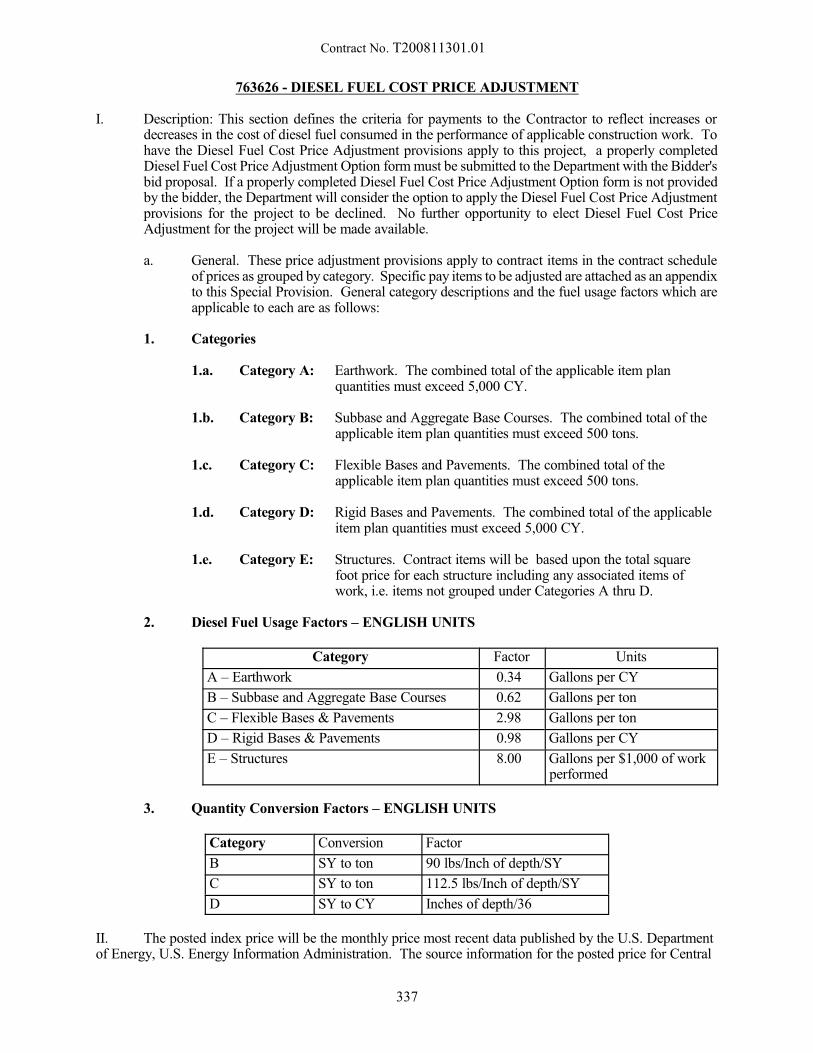
Contract No. T200811301.01
763626 - DIESEL FUEL COST PRICE ADJUSTMENT
I. Description: This section defines the criteria for payments to the Contractor to reflect increases ordecreases in the cost of diesel fuel consumed in the performance of applicable construction work. Tohave the Diesel Fuel Cost Price Adjustment provisions apply to this project, a properly completedDiesel Fuel Cost Price Adjustment Option form must be submitted to the Department with the Bidder'sbid proposal. If a properly completed Diesel Fuel Cost Price Adjustment Option form is not providedby the bidder, the Department will consider the option to apply the Diesel Fuel Cost Price Adjustmentprovisions for the project to be declined. No further opportunity to elect Diesel Fuel Cost PriceAdjustment for the project will be made available.
a. General. These price adjustment provisions apply to contract items in the contract scheduleof prices as grouped by category. Specific pay items to be adjusted are attached as an appendixto this Special Provision. General category descriptions and the fuel usage factors which areapplicable to each are as follows:
1. Categories
1.a. Category A: Earthwork. The combined total of the applicable item planquantities must exceed 5,000 CY.
1.b. Category B: Subbase and Aggregate Base Courses. The combined total of theapplicable item plan quantities must exceed 500 tons.
1.c. Category C: Flexible Bases and Pavements. The combined total of theapplicable item plan quantities must exceed 500 tons.
1.d. Category D: Rigid Bases and Pavements. The combined total of the applicableitem plan quantities must exceed 5,000 CY.
1.e. Category E: Structures. Contract items will be based upon the total squarefoot price for each structure including any associated items ofwork, i.e. items not grouped under Categories A thru D.
2. Diesel Fuel Usage Factors – ENGLISH UNITS
Category Factor Units
A – Earthwork 0.34 Gallons per CY
B – Subbase and Aggregate Base Courses 0.62 Gallons per ton
C – Flexible Bases & Pavements 2.98 Gallons per ton
D – Rigid Bases & Pavements 0.98 Gallons per CY
E – Structures 8.00 Gallons per $1,000 of workperformed
3. Quantity Conversion Factors – ENGLISH UNITS
Category Conversion Factor
B SY to ton 90 lbs/Inch of depth/SY
C SY to ton 112.5 lbs/Inch of depth/SY
D SY to CY Inches of depth/36
II. The posted index price will be the monthly price most recent data published by the U.S. Departmentof Energy, U.S. Energy Information Administration. The source information for the posted price for Central
337
Contract No. T200811301.01
Atlantic (PADD 1B) No 2 Diesel Ultra Low Sulfur (0-15 ppm) Retail Prices (Dollars per Gallon) may beviewed at the following website:
http://www.eia.gov/dnav/pet/hist/LeafHandler.ashx?n=PET&s=EMD_EPD2DXL0_PTE_R1Y_DPG&f=M
The release date for the U.S. Department of Energy, U.S. Energy Information Administration average price dataoccurs the first Monday of the following month, i.e. October prices are released the first Monday of Novemberand used as the November Price Index.
The price index, FB, is the index price posted by the Department, determined as specified above, on theproject advertisement date.
PRICE INDEX (FB) FOR DIESEL FUEL
PER GALLON = $
The price index, FP, will be the index price posted by the Department, determined as specified above,for the month during which the Notice to Proceed (NTP) is issued, and every 90 calendar daysthereafter.
III. Price Adjustment Criteria and Conditions. The following criteria and conditions will be considered indetermining a price adjustment for diesel fuel cost fluctuations.
a. Price Adjustment Calculation. When the ratio FP/FB is calculated to be less than 0.95 orcalculated to be greater than 1.05, the Department will adjust unit bid price prices inaccordance with the following formula:
AUP = (FP-FB)(F)+(UBP)where:
AUP = Adjusted Unit PriceFP = Fuel Price Index for the month in which prices are adjusted for applicable
construction work.FB = Fuel Price Index in the Bid ProposalF = Diesel Fuel Usage FactorUBP = Unit Bid Price specified in the Contractor’s Bid Proposal
b. Payment of Adjusted Unit Prices. The unit bid prices of work items affected by the fuelescalation will be adjusted by work order, either up or down, at Notice to Proceed and every90 Calendar Days thereafter.
c. Expiration of Contract Time. If the Contractor exceeds the authorized allotted completiontime, the adjusted item prices on the last authorized allotted work day shall be the prices usedduring the time liquidated damages are assessed. However, if the posted price for diesel fuelgoes down, the item prices shall be adjusted downward accordingly
d. Final Quantities. Upon completion of the work and determination of final pay quantities, anadjusting work order will be prepared to reconcile any difference between estimated quantitiespreviously paid and the final quantities. In this situation, the value for FP used in the priceadjustment formula will be the average of all FP’s previously used for computing priceadjustments.
e. Inspection of Records. The Department reserves the right to inspect the records of the primecontractor and its subcontractors and material suppliers to ascertain actual pricing and costinformation for the diesel fuel used in the performance of applicable items of work.
338
Contract No. T200811301.01
f. Extra Work. When applicable items of work, as specified herein, are added to the contract asExtra Work in accordance with the provisions of Section 110.03, no price adjustment will bemade for fluctuations in the cost of diesel fuel consumed in the performance of the extra work,unless otherwise approved by the Engineer. The current price for diesel fuel is to be used whenpreparing required backup data for extra work to be performed at a negotiated price. For extrawork performed on force account basis, reimbursement for material and equipment along withspecified overhead and profit markups will be considered to include full compensation for thecurrent cost of diesel fuel.
g. Subcontractors. Any Price Increases or Price Rebates that are calculated based on items ofwork performed by subcontractors will be added to or deducted from payments due to theContractor in the appropriate pay period. The Contractor shall then accurately record on theappropriate CN-91 or CN-103 form the additions or deductions into adjusted contract value. The Contractor shall make payment to the subcontractor(s) who actually performed the workin accordance with DelCode Title 17, Chapter 8.
11/10/11
339

Appendix---Item 763626 Diesel Fuel Cost Adjustment
Contract: T200811301.01 US 301, Maryland State Line to Levels Road
Item No./sCategory A: Earthwork
Excavation & Embankment, Borrow(total qty must exceed 5000 CY)
Category B: Subbase and Agg.GABC, PTB, Soil Cement Base(total qty must exceed 500 T)
Category C: Flexible Bases and Pavements 401801, 401810, 401819, 401825, 401827 Warm Mix Asphalts(total qty must exceed 500 T)
Category D: Rigid Bases and Pavements 501006Concrete, P.C.C. Patching(total qty must exceed 5000 CY)
Category E: Structures
Bridges, Large P.C.C. Structures
602006, 602007, 602013, 602014, 602015, 602017, 604000, 618050, 618051, 618062, 618065, 619042, 619045, 619055, 619056, 623003
202000, 203000, 207000, 208000, 209002
302007, 608000
340

Contract No. T200811301.01
763656 – AS-BUILT CERTIFICATION, MARYLAND
Description:
This work shall consist of inspecting stormwater management (SWM) facilities located in Marylandduring various stages of construction and providing documentation to the Administration that certifies that theSWM facilities have been constructed as specified in the Contract Documents, including certification that theconstructed SWM facilities meet the functionality as designed.
As-Built (AB) Inspector. The AB Inspector shall be a licensed Professional Engineer or LandSurveyor in the State of Maryland with experience in stormwater management design and construction.
Inspections of planting installations and survival and final turf establishment shall be performed byeither a licensed Landscape Architect in the State of Maryland or an Administration approved EnvironmentalSpecialist. The inspector shall have experience in stormwater management planting design and construction.
As-Built Certification Package. The as-built certification package shall consist of photographs,completed as-built checklists for each SWM facility, completed as-built certification forms for each SWMfacility, material testing reports for any soil, a copy of green-line revision plans for SWM facilities that includeas-built survey information, a copy of completed planting checklists, and turf inspection data for SWM facilitiesand drainage conveyances areas (such as ditches and swales). The as-built survey information shall besuperimposed on the final design (including addendums or redlines) contours and a separate plan shall beprepared depicting the as-built information alone.
Information about the person(s) that perform the plant and turf inspections shall be part of the as-builtcertification package and shall include, but not be limited to name of the person(s), employer name, briefdescription of related work history, contact information, and anticipated dates for plant and turf establishmentinspections.
The Contractor shall provide to the Engineer two hard-copies and one digital copy in PDF format ofthe as-built certification package.
Plant and Turf Establishment Certification Package. The plant and turf establishment certificationpackage shall consist of field photos, completed turf inspection checklists, completed planting checklists, andthe contract planting plans and details with green-line revisions. If survivability percentages are not achieved,notation shall be made on the plans and report designating the plants or areas that are dead or exhibit patchygrowth. A description of efforts taken to bring the plantings or turf up to the required survivability shall beincluded in the report. A schedule for implementing the remediation efforts and documentation of completionof the remediation efforts shall also be included.
The plant and turf establishment certification process must be completed and approved prior to theAdministration accepting the establishment phase for maintenance (see Section 710.03.06).
Materials:
Not applicable.
Construction Methods:
Stages for As-Built Inspections. The AB Inspector shall perform minimum inspections for SWMfacilities as follows:
(a) Ponds.
(1) Upon completion of excavation to sub-foundation and when required, installation ofstructural supports or reinforcement for structures, including, but not limited to:
341
Contract No. T200811301.01
(i) Core trenches for structural embankments.
(ii) Inlet and outlet structures, anti-seep collars or diaphragms, and watertightconnections on pipes.
(iii) Trenches for enclosed storm drainage facilities.
(2) During placement of structural fill, concrete, and installation of piping andcatchbasins.
(3) During backfill of foundations and trenches.
(4) During embankment construction.
(5) Upon completion of final grading and establishment of permanent stabilization.
(b) Wetlands. Refer to stages specified for pond construction. Additional inspections include:
(1) During and after wetland area planting.
(2) During the second growing season to verify a vegetation survival rate of no less thanfifty percent (50%).
(c) Infiltration Trenches.
(1) During excavation to subgrade.
(2) During placement and backfill of underdrain systems and observations wells.
(3) During placement of geotextiles and all filter media.
(4) During construction of appurtenant conveyance systems such as diversion structures,pre-filters and filters, inlets, outlets, and flow distribution structures.
(5) Upon completion of final grading and establishment of permanent stabilization.
(d) Infiltration Basins. Refer to stages specified for pond construction and add:
(1) During placement and backfill of underdrain systems.
(e) Filtering Systems. Filtering systems include bioretention, sand filters, organic filters, bio-filters,and dry swales.
(1) During excavation to subgrade.
(2) During placement and backfill of underdrain systems.
(3) During placement of geotextiles and all filter media.
(4) During construction of appurtenant conveyance systems such as flow diversionstructures, pre-filters and filters, inlets, outlets, orifices, and flow distributionstructures.
(5) Upon completion of final grading and establishment of permanent stabilization.
(f) Open Channel Systems. Open channel systems include wet swales and grass channels.
342
Contract No. T200811301.01
(1) During excavation to subgrade.
(2) During installation of diaphragms, check dams, or weirs.
(3) Upon completion of final grading and establishment of permanent stabilization.
(g) Non-Structural Practices. Upon completion of final grading and after the establishment ofpermanent stabilization.
The checklist for each SWM facility shall be completed in its entirety at the appropriate stages ofconstruction as specified in the Contract Documents. The as-built certification shall be signed and dated by theAB Inspector upon completion of all SWM facility checklists.
Stages for Plant and Turf Establishment Inspections. At the plant establishment phase (710.03.06)inspection, the plant and turf establishment inspection shall also be conducted and documented. Turfestablishment inspection shall be conducted according to the Administration’s turf inspection standards. Plantsshall be inspected for species, size, quantity, health and location. Plants that measure smaller than the installedsize are considered to be dead. Dead plants shall be replaced according to the design specifications. Plant andturf establishment inspections shall be conducted from June 15 to November 15.
The following planting and turf shall be inspected and documented:
(a) Ponds and Wetlands
(1) SWM embankment (including roadway embankment if applicable) and clear zone 15feet beyond toe of embankment cleared of woody vegetation and established with turfor native meadow.
(2) During second growing (plant establishment phase inspection) season to verify avegetation survival rate at submerged benches and wetlands of 50 percent.
(b) Infiltration Trenches
Turf establishment with 95% coverage inspected in conveyances, filter strips and other featuresdraining to the trench that are within the Administration right-of-way and within the projectsite. Off-site areas shall be visually observed and the location of off-site eroded or bare areasincluded in the report and photographed.
(c) Infiltration Basins
(1) Woody plant clear zones listed for Ponds above.
(2) Plant, turf or native meadow establishment inspected at basin bottom and side slopes.
(3) Establishment of turf with 95% coverage on all conveyances draining to the facilitythat are within the MdSHA right-of-way and within the project site. Off-site areasshall be visually observed and the location of off-site eroded or bare areas included inthe report and photographed.
(d) Filtering Systems
(1) Establishment of turf on weir, bottom and sides of facility, and all conveyancesdraining to the facility.
(2) At Bioretention Facilities, to verify a plant survival rate of at least 90 percent. Themulch bed shall be inspected and replenished to constructed depth and condition.
343
Contract No. T200811301.01
(e) Open Channel Systems.
(1) For Dry Swales, inspect establishment of turf on weir, bottom, side slopes andconveyances draining to the facility.
(2) For Wet Swales, inspect establishment of turf on weirs, sides and all conveyancesdraining to the facility. Inspect planting at bottom of facility for 50 percent survivalrate.
As-Built Survey, Computations and Green-Line Drawings. Upon completion of the final grade andstabilization at each SWM facility, the Contractor shall survey each SWM facility, including contours, inflowand outflow ditches, limits of riprap, emergency spillway(s), outfall structure(s) (including elevations anddimensions at top, all orifices, weirs and openings), and all other pertinent features in and around the facility.
The constructed elevations shall be within 3 in of design elevations. Elevation variance greater than3 in shall be corrected by the Contractor to meet the acceptable tolerance limits or the Contractor shall providecomputations for the volumes, discharges, stage-storages and detention times that demonstrate that the SWMfacility meets the designed parameters. The Contractor shall resurvey any corrected areas.
The Engineer will provide to the Contractor a copy of the final approved design StormwaterManagement Report and copies of the plan CADD files that shall be used in producing the green-line revisionplans. The AB Inspector shall follow SHA CADD standards in producing the green-line documents.
Submission to and Approval by the Administration. The Contractor shall submit the completed as-built certification package to:
Maryland State Highway AdministrationHighway Hydraulics Division Chief707 North Calvert Street, Mailstop C-201Baltimore, MD 21202
Method of Measurement:
Stormwater Management Facility As-Built Certification will not be measured but will be paid for at theContract lump sum price. The payment will be full compensation for the completion and submission of the as-built certification package, and for all material, labor, equipment, tools, and incidentals necessary to completethe work. Re-inspection of corrections to stormwater management facilities and re-certification of anydeficiencies to be corrected by the Contractor shall be at no additional cost to the Department.Engineering and analysis for Contractor-modified SWM facilities shall be at no additional cost to theDepartment.
Deficiencies to the as-built certification package shall be corrected by the Contractor at no additionalcost to the Department. Additional construction, planting and stabilization necessary to meet the certificationstandards shall be completed at no additional cost to the Department.
Basis of Payment:
Payment will conform to the following:
No greater than thirty-five percent (35%) of the total payment will be paid upon completion andsubmission of the As-Built Certification Package.
No greater than thirty-five percent (35%) of the total payment will be paid upon approval from theAdministration for the As-Built Certification Package. Final payment will be paid upon approval from theDepartment for the Plant and Turf Inspection Certification Package.
11/23/11
344
Contract No. T200811301.01
763686 – TRAFFIC OFFICER, MARYLAND
Description:
This item shall consist of providing off duty police officers for law enforcement presence in the workzone, enforcing traffic laws within the work zone, providing emergency assistance within the work zone, orcontrolling traffic at any locations as designated by the Engineer.
Officers will be expected to assist with stopping, controlling and/or maintaining the flow of trafficoutside of their vehicle when necessary. Officers are expected to use authority to control the traffic to assurenot just the safety of the construction personnel but the safety of the traveling public as well. If necessary theEngineer may authorize additional officers to be used for speed enforcement. The use of Traffic Officers in ahighway work zone shall be in accordance with the latest version of MdMUTCD, Part 6.
Such officers shall wear police officer uniforms. They shall have a marked police vehicle with fullemergency lights. The vehicle shall be equipped with a radar unit or any other speed-measuring device that willbe detectable as radar to assist with slowing traffic. Officers must at all times have radio communicationavailable to inform 911 and DelDOT's Transportation Management Center (TMC) of traffic backups or otheremergencies. The traffic officers shall be Maryland State Police in accordance with the location of the project. Traffic officers outside of their vehicle are required to wear high-visibility safety apparel as required in theMdMUTCD.
The Contractor will discuss with the Engineer in advance for approval of the schedule of hours andnumber of traffic officers anticipated for each site or operation. It will be the responsibility of the Contractorto explain to the officer the project activities pertaining to where the officer's services are needed.
Traffic officers shall not be used to close lanes without additional temporary traffic control except forrolling road blocks or emergencies. Rolling road blocks require advance approval from the Engineer throughDelDOT’s Traffic Section.
The Contractor shall be responsible for paying the Maryland State Police for their work performed inconjunction with this project, completing MSP 198A Contract for Extraordinary Law Enforcement Services andpresenting it to the Maryland State Police Barrack that has jurisdiction in the area. For Cecil County: BarrackF - North East; 2433 West Pulaski Highway, North East, Maryland 21901; 410-996-7800; contact 1st/SGTHamm or the duty officer. The Contractor shall be responsible for contacting and coordinating with theMaryland State Police to schedule the traffic officers.
Method of Measurement and Basis of Payment:
For bidding purposes, the unit price shall be fixed at $98.16 per hour. Actual payment shall be basedon the submitted invoice from the police department plus ten (10) percent. Payment shall constitute fullcompensation for the police officer's wages, vehicle and equipment, the Contractor's allowable administrativecost and any necessary incidentals.
11/01/12
345
Contract No. T200811301.01
763689 - STRUCTURAL WORK, GANTRY
Description:
The Contractor shall furnish and install all materials necessary for and incidental to the completeconstruction of gantry foundations in accordance with the Plans or as directed by the Engineer.
Materials and Construction Methods:
Division 100 General Provisions of the Delaware Department of Transportation "StandardSpecifications", dated August 2001 and the Delaware Department of Transportation "Standard ConstructionDetails", dated 2001, including all revisions up to the date of advertisement, apply to this section.
Working drawings including materials shall be submitted to the Engineer for approval.
Method of Measurement:
Measurement of this item, "Structural Work, Gantry" will not be made.
Basis of Payment:
Payment will be made at the lump sum price bid for this item. The price bid shall include the cost forall cast-in-place concrete, including formwork, reinforcement, concrete materials, mixture design, placementprocedures, finishes, conduits and incidentals shall be in accordance with Delaware Department ofTransportation "Standard Specifications", dated August 2001 and the Delaware Department of Transportation"Standard Construction Details", dated 2001, including all revisions up to the date of advertisement necessaryto provide a complete, working and usable facility acceptable to the Engineer.
09/29/15
346

Contract No. T200811301.01
763691 - FLAGGER, MARYLAND, STATE
763692 - FLAGGER, MARYLAND, STATE, OVERTIME
Description:
This item shall consist of providing flaggers when specified or directed when the flagger is positionedoutside of the State of Delaware and within the State of Maryland due to construction being performed undera DelDOT contract.
Flaggers positioned in Maryland shall have completed a MDSHA approved flagger training coursewithin the last four years. The Contractor shall provide appropriate training documentation for each flaggerthroughout the duration of the contract. Flaggers are required to have their approved training documentationand a photo identification card on their person at all times while flagging. The Engineer will require thereplacement of any flagger that immediately fails to produce approved training documentation and photoidentification when requested. The Contractor shall have available a person with approved trainingdocumentation, photo identification and equipment that can relieve the flagger for any necessary breaks.
Working flaggers shall be equipped with two-way radios or other approved communication devices.Cellular telephones with or without push-to-talk features, MP3 players or other similar electronic devices arenot approved communication devices. Use of a cellular telephone or other unapproved electroniccommunication device while performing flagging operations is justification for immediate removal of a flagger.
Working flaggers shall be equipped with an audible warning device to alert workers of an errant vehicle.
Any flagger not performing duties in accordance with the specifications is justification for suspensionof work as specified in DelDOT’s Standard Specification Section 104.07, Suspension of Work. Once theoffending flagger is replaced and all flaggers are in compliance with the requirements of this specification, thework may resume.
Flagging shall conform to the requirements of the MdMUTCD. All outfits and equipment will besubject to approval. Use STOP/SLOW paddles unless otherwise permitted.
Method of Measurement and Basis of Payment:
The quantity of Flaggers will be measured as the actual number of hours an approved flagger is in placeon the roadway and protecting active construction operations. Payment will only be made for those flaggers inplace on the roadway and protecting active construction operations that have the required training documentationand photo identification available and that have the required equipment in use. No payment will be made forflaggers that are on-site and available but not in use. Price and payment constitutes full compensation for alllabor, benefits, tools, equipment and necessary incidentals to complete the work. Overtime payment will onlybe made when approved by the Engineer and in accordance with applicable labor laws.
The unit price for Item 763691 - FLAGGER, MARYLAND, STATE shall be at the per hour rate basedon the prevailing wage rates as determined by the Department of Labor for the State of Maryland.
The unit price for Item 763692 - FLAGGER, MARYLAND, STATE, OVERTIME shall be at the perhour rate based on the prevailing wage rates as determined by the Department of Labor for the State ofMaryland.
1. Flaggers must be bid at a minimum equal to the Laborer wage rate and may be bid up to, butnot to exceed, 3 times the Laborer wage rate in accordance with Cecil County, where the workis being performed.
347

Contract No. T200811301.01
2. Flagger overtime must be bid at minimum of 1.45 times, and may be bid up to 4.35 timesmaximum, the Laborer wage rate in accordance with Cecil County, where the work is beingperformed.
3. When a contract for a project contains both Federal Davis-Bacon and State of Marylandprevailing wage standards, the employer’s minimum wage obligations are determined bywhichever standards are higher.
4. If the Contractor’s bid price is not within the limits set forth in 1 and 2, the Department willadjust the bid to the minimum for prices bid below the minimum acceptable bid and to themaximum for prices bid above the maximum allowable bid prior to award.
11/4/15
348
Contract No. T200811301.01
900500 - ENVIRONMENTAL PERFORMANCE INCENTIVE (DISINCENTIVE)
Description:
This work consists of maintaining the project’s erosion and sediment control items and provides anincentive payment for that Work.
Materials:
There are no materials included in this specification.
Construction Methods:
Continuously maintain all erosion and sediment control items per the approved plan throughout theduration of the Project. Repair, replace, and/or maintain any erosion and sediment control measures as notedon the ES2M Inspection Rating Reports
http://www.deldot.gov/information/business/drc/pd_files/plan_development/es2m_inspection_rating_form.pdf?050415
and as directed by the Engineer. Maintain access to all sediment control devices until construction phasingand stabilization allow the removal of those controls that are no longer required.
The incentive payment is based on performance. Performance is determined by the score obtainedonly on the weekly ES2M Inspection Rating Reports.
Compliance procedures for failure to perform will be implemented per Section 901.06.
Method of Measurement:
There is no method of measurement in this specification.
Basis of Payment:
The total incentive awarded for this Contract will not exceed $ 488,000.00. This amount applies toall erosion and sediment control work shown on the Plans or required by the Engineer to complete the Workand any erosion and sediment control work that is required to perform work that is added to the Contract.
Divide the total incentive by the number of Calendar Days originally assigned to the Contract toobtain the daily incentive amount. At the end of each estimate period, the Engineer will multiply the numberof Calendar Days consumed during the estimate period times the daily incentive amount times the incentivefactor taken from the table below. This amount will be paid on the next estimate
Payments will be made per each Calendar Day charged until either (1) Substantial Completion or (2)the total incentive amount reaches $488,000.00 or (3) the expiration of Contract time (including approvedtime extensions), whichever occurs first.
349
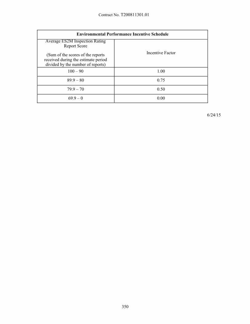
Contract No. T200811301.01
Environmental Performance Incentive Schedule
Average ES2M Inspection RatingReport Score
(Sum of the scores of the reportsreceived during the estimate perioddivided by the number of reports)
Incentive Factor
100 – 90 1.00
89.9 – 80 0.75
79.9 – 70 0.50
69.9 – 0 0.00
6/24/15
350
Contract No. T200811301.01
905500 - SUPER SILT FENCE
Description:
This work consists of furnishing, installing, constructing, maintaining, and ultimately removing supersilt filter fences as a temporary measure to control sedimentation within the limits of construction. Super siltfence shall be constructed as shown on the details in the Plans, at the locations shown on the Plans, and asdirected by the Engineer.
Materials:
General. All materials shall be approved prior to use by the Department's Materials and ResearchSection.
Chain Link Fence. The construction requirements for the placement of the chain link fence shallbe as specified in SECTION 727 FENCES AND GATES with the following exceptions:
(a) Concrete footings (727.07), Top Rail, Tension Wire, Horizontal Braces shall not be used.
Fasteners. Aluminized steel tie wires long enough to securely attach the fabric to the posts.
Seed. Seed shall conform to the requirements of Section 908.
Mulch. Mulch shall conform to the requirements of Section 908.
Geotextile. Geotextile shall conform to the requirements of Section 827. It shall be a minimum of36" (900 mm) wide.
Construction Methods:
Construction of Super Silt Fence.
The Contractor shall excavate the trench along the upstream side of the post line as shown onStandard Construction Detail, Super Silt Fence. Posts shall be installed on the Downstream edge of the trench,along the established fence line. The geotextile shall be fastened to the upstream side of the chain link. Thegeotextile and chain link must extend a minimum of 33” above the ground. The chain link fabric andgeotextile shall be embedded 8 inches into the excavated trench. The trench shall be backfilled and compactedover the chain link and geotextile to prevent water from flowing under the chain link and geotextile.
The super silt fence shall not be constructed across a ditch, or swale, or area of concentrated flow.On slopes, the terminal ends of super silt fence shall be turned upslope a sufficient distance to eliminate flowaround the ends of the super silt fence. All geotextile damaged prior to installation, during installation, orduring the life of the Contract shall be repaired or replacedto the satisfaction of the Engineer.
Maintenance of Super Silt Fence.
Throughout the Project construction period, the super silt fence shall be maintained by removingtrapped sediment. The Contractor shall clean the geotextile of trapped sediment by tapping the geotextilewhen dry. No trash shall be allowed to accumulate to the height of the fence. Any geotextile that does notfunction due to clogging or deterioration shall be replaced.
351
Contract No. T200811301.01
Sediment Removal.
After every heavy rainfall, the Contractor shall check for excessive buildups of sediment which mustbe removed so that the super silt fence can continue to function as intended. Remove accumulated sedimentwhen it reaches 50% of the height of the super silt fence.
Removal of Super Silt Fence.
The super silt fence shall be removed when the Engineer determines that it is no longer required. Thesuper silt fence and all materials incidental to the super silt fence construction shall be removed. All areasaffected by the construction of the super silt fence shall be restored to the original or plan contours andstabilized with seed and mulch.
Method of Measurement:
The quantity of super silt fence will be measured as the actual number of linear feet (linear meters)of super silt fence placed and accepted.
Basis of Payment:
The quantity of super silt fence will be paid for at the Contract unit price per linear foot (linearmeter) for each type of fence. Price and payment will constitute full compensation for furnishing allmaterials; for excavating and backfilling associated with the construction of the super silt fence; formaintaining the super silt fence during the Project construction period; sediment removal, for removing thesuper silt fence with all related hardware after completion of the Project; for restoring the site; for seedingand mulching; and for all labor, equipment, tools and incidentals required to complete the work. No paymentwill be made for any replacement of or repairs to the super silt fence damaged prior to installation, duringinstallation, or during the life of the Contract. No payment will be made for the replacement of the super siltfence.
11/18/2014
352
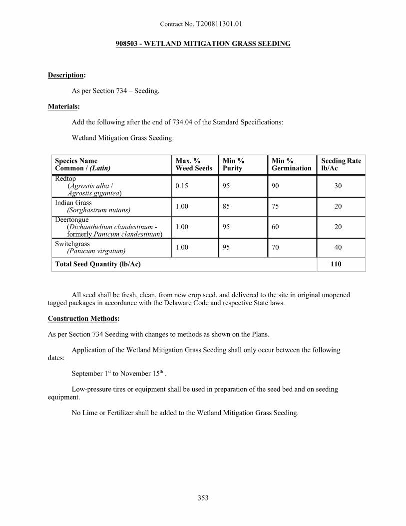
Contract No. T200811301.01
Species NameCommon / (Latin)
Max. %Weed Seeds
Min %Purity
Min %Germination
Seeding Ratelb/Ac
Redtop (Agrostis alba / Agrostis gigantea)
0.15 95 90 30
Indian Grass(Sorghastrum nutans)
1.00 85 75 20
Deertongue (Dichanthelium clandestinum -formerly Panicum clandestinum)
1.00 95 60 20
Switchgrass (Panicum virgatum)
1.00 95 70 40
Total Seed Quantity (lb/Ac) 110
908503 - WETLAND MITIGATION GRASS SEEDING
Description:
As per Section 734 – Seeding.
Materials:
Add the following after the end of 734.04 of the Standard Specifications:
Wetland Mitigation Grass Seeding:
All seed shall be fresh, clean, from new crop seed, and delivered to the site in original unopenedtagged packages in accordance with the Delaware Code and respective State laws.
Construction Methods:
As per Section 734 Seeding with changes to methods as shown on the Plans.
Application of the Wetland Mitigation Grass Seeding shall only occur between the followingdates:
September 1st to November 15th .
Low-pressure tires or equipment shall be used in preparation of the seed bed and on seedingequipment.
No Lime or Fertilizer shall be added to the Wetland Mitigation Grass Seeding.
353
Contract No. T200811301.01
Add the following at the end of Section 734.06:
Acceptance of 734553 – Wetland Mitigation Grass Seeding shall be made at time of placement,provided the seed is mixed and placed as specified and as directed on the Plans.
Add the following at the end of Section 734.07:
No Maintenance Bond is required for this work.
All other aspects and conditions of Section 734 – Seeding shall apply.
Method of Measurement:
As per Section 734 – Seeding.
Basis of Payment:
As per Section 734 – Seeding.
10/26/15
354
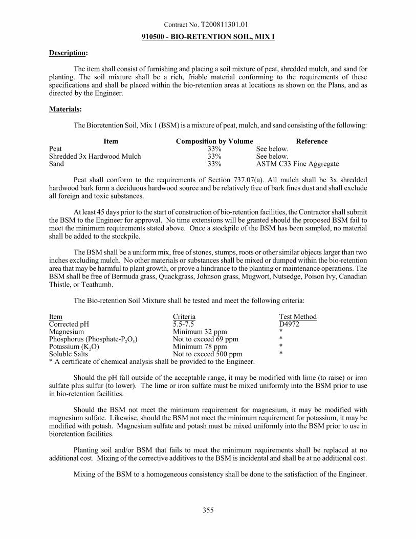
Contract No. T200811301.01
910500 - BIO-RETENTION SOIL, MIX I
Description:
The item shall consist of furnishing and placing a soil mixture of peat, shredded mulch, and sand forplanting. The soil mixture shall be a rich, friable material conforming to the requirements of thesespecifications and shall be placed within the bio-retention areas at locations as shown on the Plans, and asdirected by the Engineer.
Materials:
The Bioretention Soil, Mix 1 (BSM) is a mixture of peat, mulch, and sand consisting of the following:
Item Composition by Volume ReferencePeat 33% See below.Shredded 3x Hardwood Mulch 33% See below.Sand 33% ASTM C33 Fine Aggregate
Peat shall conform to the requirements of Section 737.07(a). All mulch shall be 3x shreddedhardwood bark form a deciduous hardwood source and be relatively free of bark fines dust and shall excludeall foreign and toxic substances.
At least 45 days prior to the start of construction of bio-retention facilities, the Contractor shall submitthe BSM to the Engineer for approval. No time extensions will be granted should the proposed BSM fail tomeet the minimum requirements stated above. Once a stockpile of the BSM has been sampled, no materialshall be added to the stockpile.
The BSM shall be a uniform mix, free of stones, stumps, roots or other similar objects larger than twoinches excluding mulch. No other materials or substances shall be mixed or dumped within the bio-retentionarea that may be harmful to plant growth, or prove a hindrance to the planting or maintenance operations. TheBSM shall be free of Bermuda grass, Quackgrass, Johnson grass, Mugwort, Nutsedge, Poison Ivy, CanadianThistle, or Teathumb.
The Bio-retention Soil Mixture shall be tested and meet the following criteria:
Item Criteria Test MethodCorrected pH 5.5-7.5 D4972Magnesium Minimum 32 ppm *Phosphorus (Phosphate-P2O5) Not to exceed 69 ppm *Potassium (K2O) Minimum 78 ppm *Soluble Salts Not to exceed 500 ppm ** A certificate of chemical analysis shall be provided to the Engineer.
Should the pH fall outside of the acceptable range, it may be modified with lime (to raise) or ironsulfate plus sulfur (to lower). The lime or iron sulfate must be mixed uniformly into the BSM prior to usein bio-retention facilities.
Should the BSM not meet the minimum requirement for magnesium, it may be modified withmagnesium sulfate. Likewise, should the BSM not meet the minimum requirement for potassium, it may bemodified with potash. Magnesium sulfate and potash must be mixed uniformly into the BSM prior to use inbioretention facilities.
Planting soil and/or BSM that fails to meet the minimum requirements shall be replaced at noadditional cost. Mixing of the corrective additives to the BSM is incidental and shall be at no additional cost.
Mixing of the BSM to a homogeneous consistency shall be done to the satisfaction of the Engineer.
355
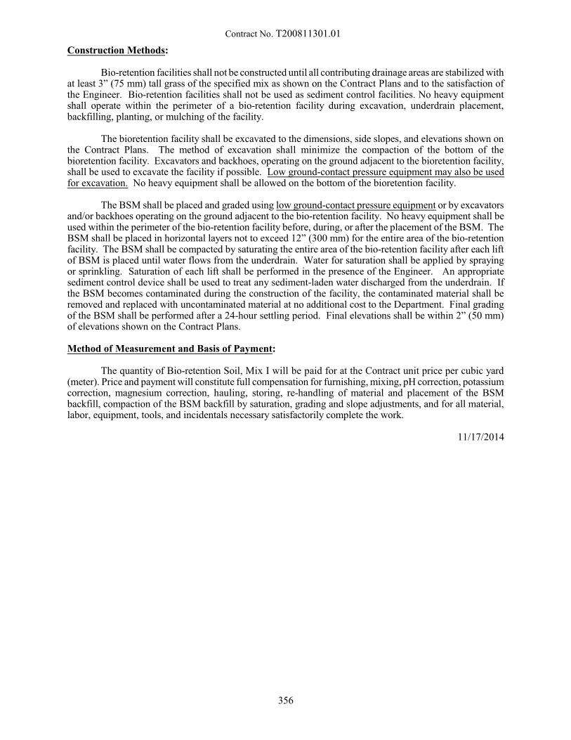
Contract No. T200811301.01
Construction Methods:
Bio-retention facilities shall not be constructed until all contributing drainage areas are stabilized withat least 3” (75 mm) tall grass of the specified mix as shown on the Contract Plans and to the satisfaction ofthe Engineer. Bio-retention facilities shall not be used as sediment control facilities. No heavy equipmentshall operate within the perimeter of a bio-retention facility during excavation, underdrain placement,backfilling, planting, or mulching of the facility.
The bioretention facility shall be excavated to the dimensions, side slopes, and elevations shown onthe Contract Plans. The method of excavation shall minimize the compaction of the bottom of thebioretention facility. Excavators and backhoes, operating on the ground adjacent to the bioretention facility,shall be used to excavate the facility if possible. Low ground-contact pressure equipment may also be usedfor excavation. No heavy equipment shall be allowed on the bottom of the bioretention facility.
The BSM shall be placed and graded using low ground-contact pressure equipment or by excavatorsand/or backhoes operating on the ground adjacent to the bio-retention facility. No heavy equipment shall beused within the perimeter of the bio-retention facility before, during, or after the placement of the BSM. TheBSM shall be placed in horizontal layers not to exceed 12” (300 mm) for the entire area of the bio-retentionfacility. The BSM shall be compacted by saturating the entire area of the bio-retention facility after each liftof BSM is placed until water flows from the underdrain. Water for saturation shall be applied by sprayingor sprinkling. Saturation of each lift shall be performed in the presence of the Engineer. An appropriatesediment control device shall be used to treat any sediment-laden water discharged from the underdrain. Ifthe BSM becomes contaminated during the construction of the facility, the contaminated material shall beremoved and replaced with uncontaminated material at no additional cost to the Department. Final gradingof the BSM shall be performed after a 24-hour settling period. Final elevations shall be within 2” (50 mm)of elevations shown on the Contract Plans.
Method of Measurement and Basis of Payment:
The quantity of Bio-retention Soil, Mix I will be paid for at the Contract unit price per cubic yard(meter). Price and payment will constitute full compensation for furnishing, mixing, pH correction, potassiumcorrection, magnesium correction, hauling, storing, re-handling of material and placement of the BSMbackfill, compaction of the BSM backfill by saturation, grading and slope adjustments, and for all material,labor, equipment, tools, and incidentals necessary satisfactorily complete the work.
11/17/2014
356
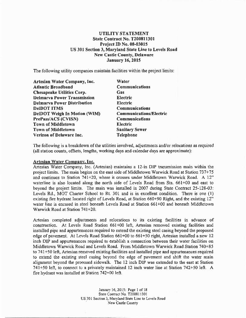
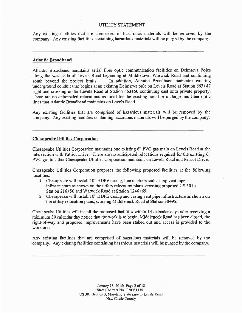
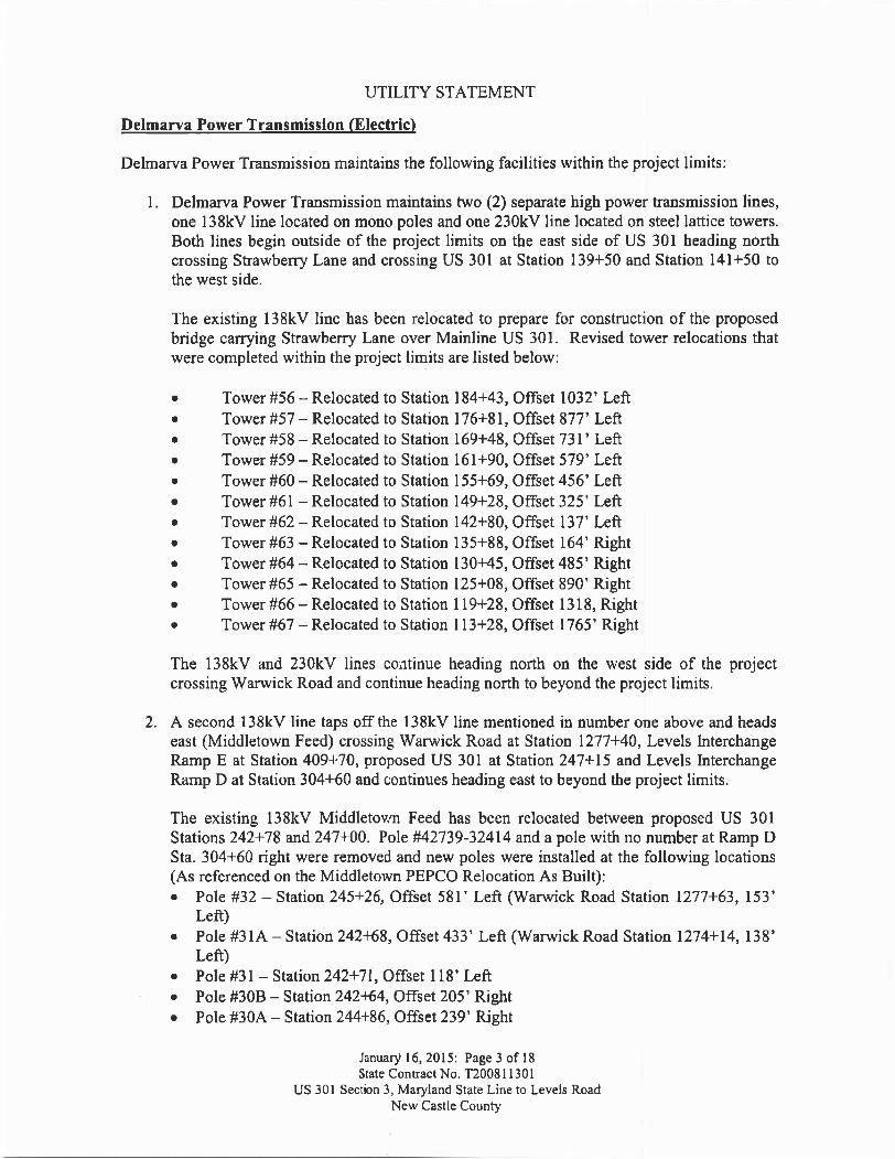
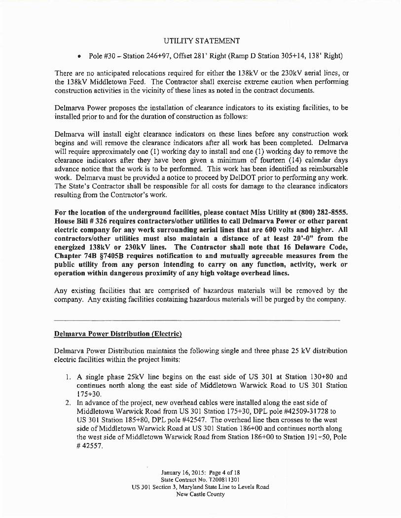
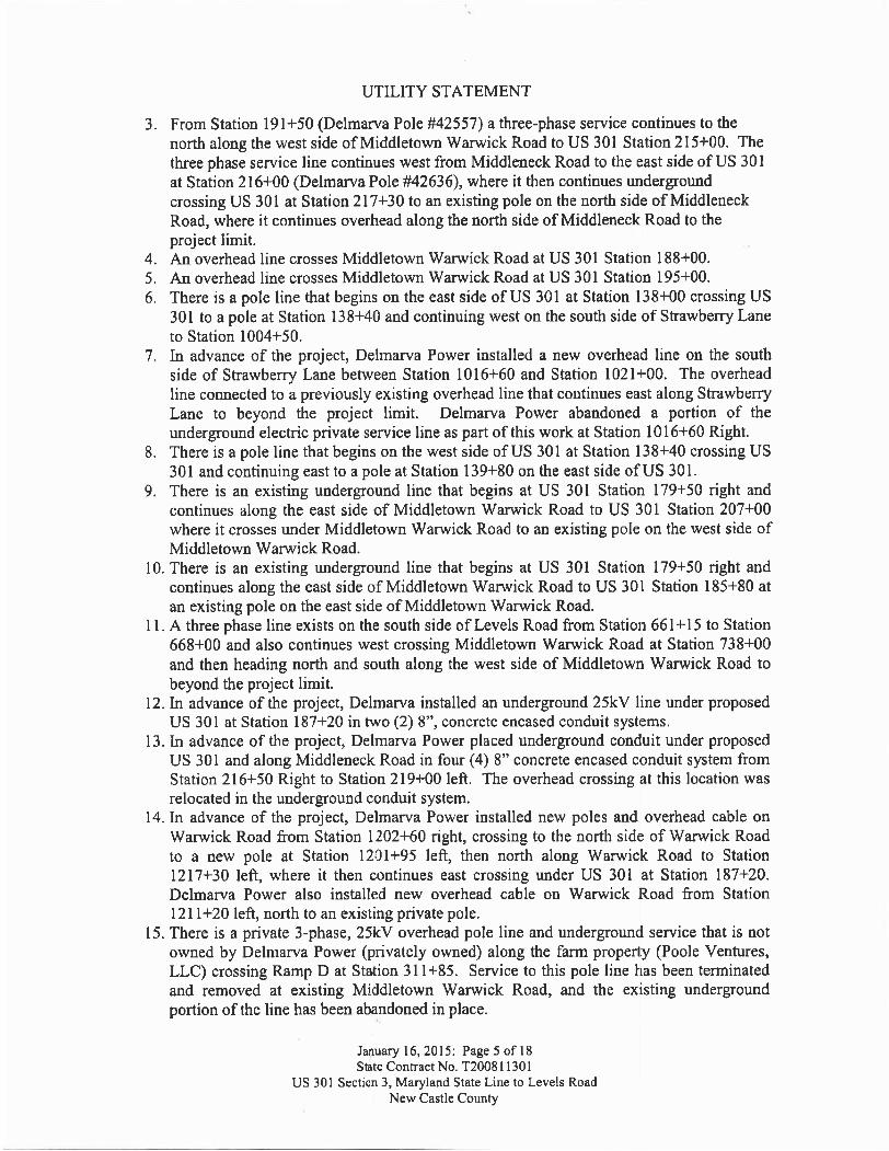
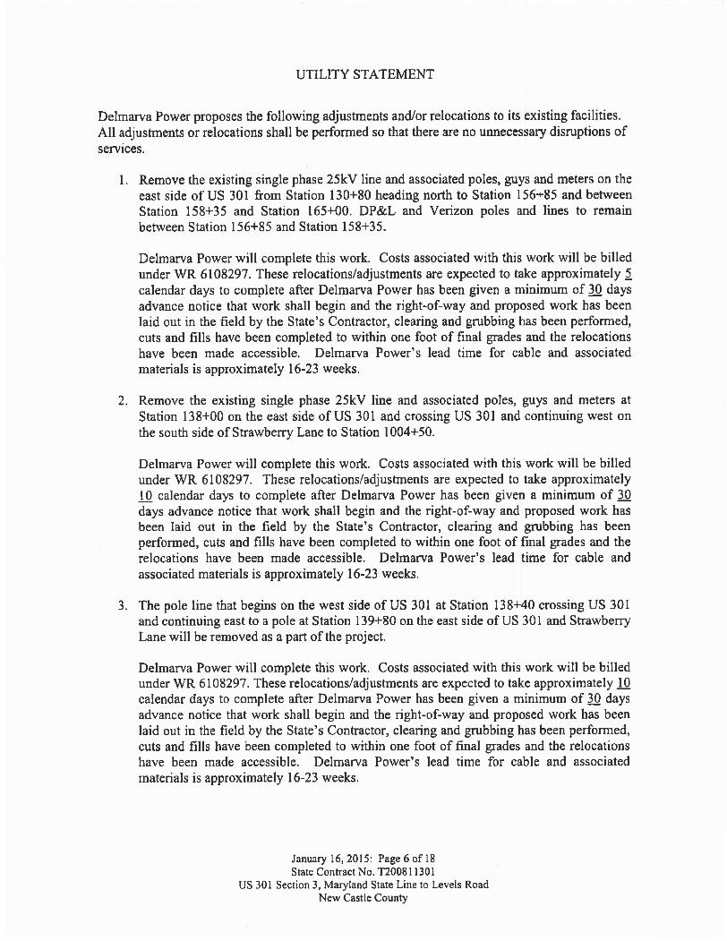

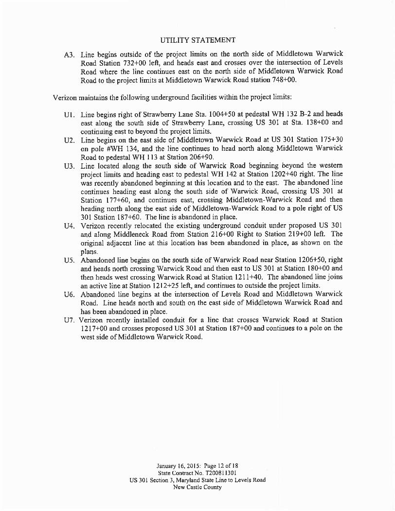
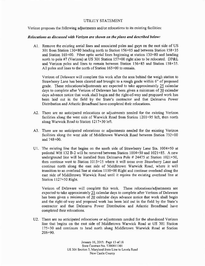
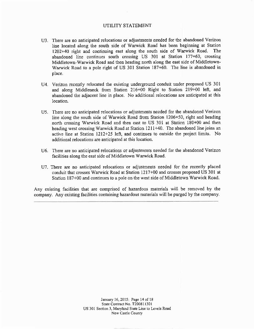
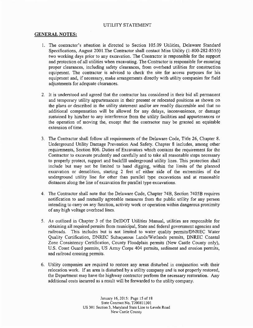
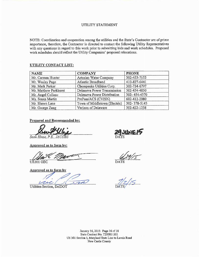
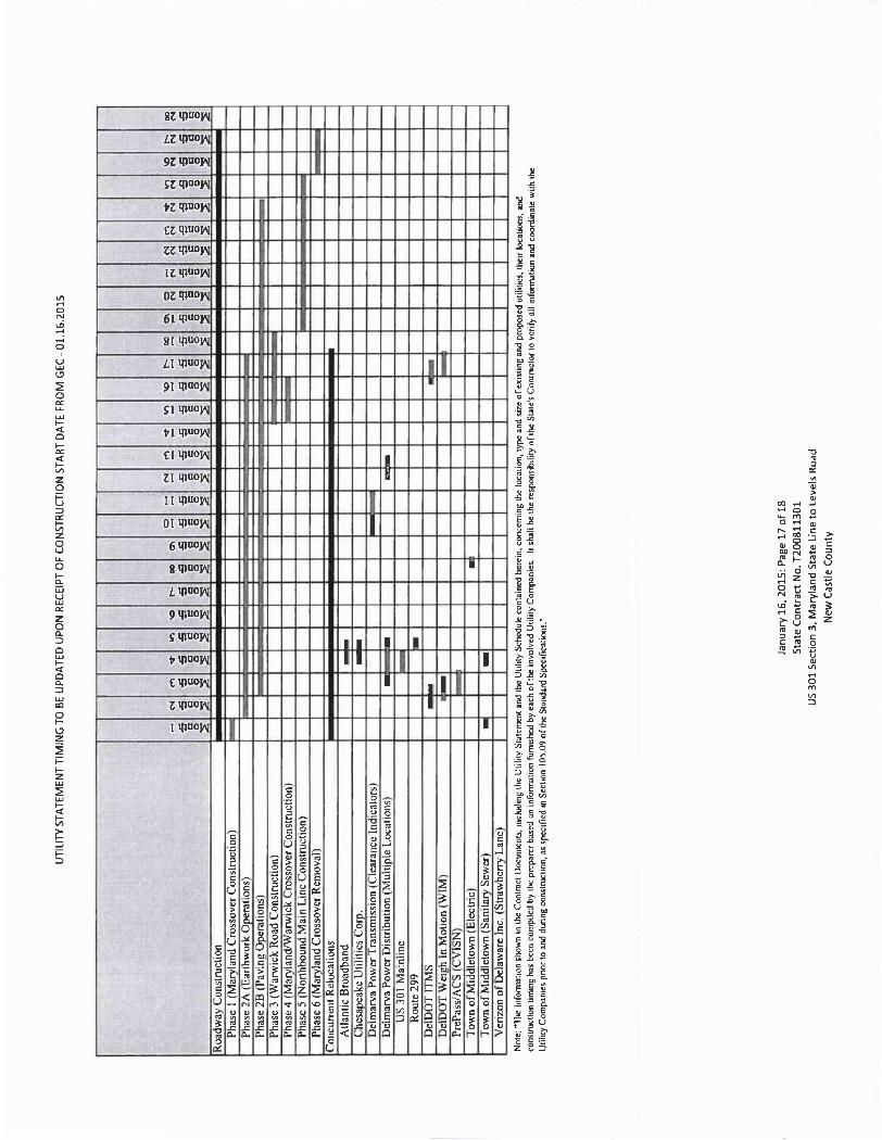
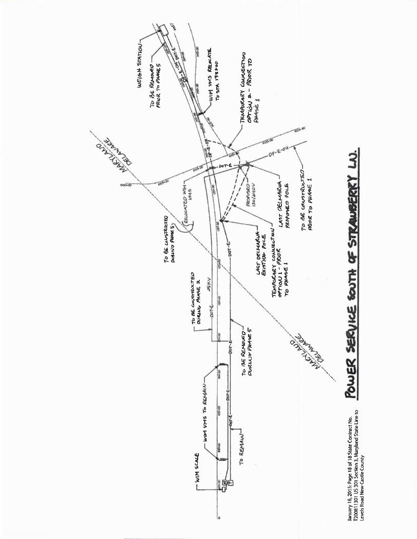
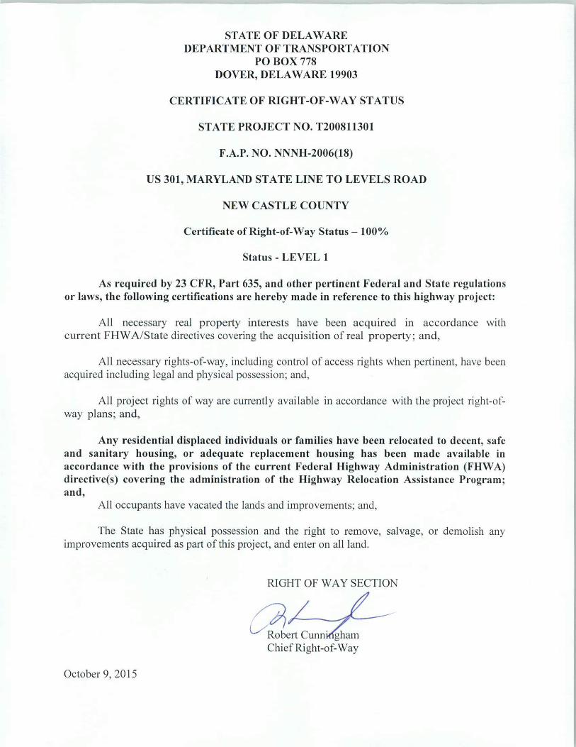
June 18, 2015
STIPULATED
ENVIRONMENTAL REQUIREMENTS
for
U.S. 301, Maryland State Line to Levels Road (Contract #3) State Contract No.: T200811301
Federal Aid Project Number: NH-2015(20)
In accordance with the procedural provisions for implementing the National Environmental Policy Act of 1969, as amended, the referenced project has been processed through the Department’s Environmental Review Procedures and has been classified as a Level A/ Class I Action.
PERMIT REQUIREMENTS:
The proposed construction work for this portion of U.S. 301, requires permit approval from those agencies listed below. It is the responsibility of the contracting agency, the Delaware Department of Transportation, Division of Transportation Solutions to obtain the necessary permits to ensure that the contractor complies with the requirements and conditions established by the regulatory agencies. REQUIRED PERMITS AND APPROVAL STATUS:
• U.S. Army Corps of Engineers (USACE) – Individual Permit – Approved 01-07-2013, CENAP-OP-R-2006-6071-1, Expiration 12-31-2023
• Delaware Department of Natural Resources and Environmental Control (DNREC) Subaqueous Lands Permit – Approved 01-30-2012, SP-233/11, Expiration 01-30-2017
• DNREC – 401 Water Quality Certification – Approved 01-30-2012, WQ-276/11, Expiration 01-30-2017
2
• DNREC – Coastal Zone Consistency – Approved 09-14-2007, modification of
condition 3 – 04-04-2011 – No expiration • New Castle County Floodplain Permit – Approved 01-31-2012, SLD# 20110732
– No expiration • Maryland Department of the Environment (MDE) Water Management
Administration Nontidal Wetlands and Waterways Permit- Approved 12-13-2011 modification on 12-13-2014, 10-NT-0112/2010603687, Expiration 12-13-2017
• Maryland Department of the Environment (MDE) Stormwater Management and
Sediment & Erosion Control – Pending • Maryland Department of the Environment (MDE) NPDES Discharge Permit –
Pending
SPECIFIC REQUIREMENTS:
Compliance with all requirements of the permits is the responsibility of the contractor. The contractor will follow all special conditions or requirements as stated within those permits or as indicated below. The contractor will be subject to penalties, fines, and the risk of shut down as mandated by law if conditions of the permits or other additional requirements are violated or ignored.
Additional requirements by DelDOT not specified within the permits, but listed below, or on
the Environmental Compliance Sheets are also the responsibility of the contractor and are subject to risk of shut down at the contractor’s expense.
1. The contractor shall employ measures during construction to prevent spills of fuels, or lubricants, if a spill should occur, efforts shall be undertaken to prevent its entry into wetlands, aquatic, or drainage areas. Any spills entering wetlands, aquatic, or drainage areas shall be removed immediately. The Division of Water Resources (DNREC), Wetlands & Aquatic Protection Branch, 302-739-4691, shall be notified of any spill(s) within six (6) hours of their occurrence. That office will determine the effectiveness of spill and contamination removal and specify remediation efforts as necessary.
2. All construction debris, excavated material, brush, rocks, and refuse incidental to such
work shall be placed either on shore above the influence of flood waters or on some suitable disposal site approved by the department.
3. The disposal of trees, brush, and other debris in any stream corridor, wetland surface
water or any drainage ditch is prohibited.
4. There shall be no stockpiling of construction materials or temporary fills in wetlands or subaqueous lands unless otherwise specified on project plans and approved by permitting
3
agencies that govern them. It is the contractor’s responsibility to coordinate and secure those additional permits/amendments in deviating from the plan.
5. The effort shall be made to keep construction debris from entering adjacent waterways,
wetlands, ground cover, or drainage areas. Any debris that enters these areas shall be removed immediately. Netting, mats, or establishing confined work areas in stages may be necessary to address these issues.
6. If routine maintenance of worker equipment and heavy machinery is necessary during the
construction period, refuse material is prohibited from being disposed or deposited onto or into the ground. All used oils and filters must be recycled or disposed of properly.
7. Harmful chemical wash water applied to clean equipment or machinery shall be
discouraged. If undertaken, the residue water and/or material must be collected or contained such that it will be disposed of properly. By no means, shall it be deposited or disposed of in waterways, streams, wetlands, or drainage areas.
8. The contractor shall follow all requirements as indicated in the Environmental
Compliance Sheet. It will be the contractor’s responsibility, expense, & effort to ensure that workers also follow these requirements. As part of the restrictions, please note the timetables reflected in the contract for the in-stream/water work for endangered species protection.
9. Environmental Monitor:
DelDOT has designated an environmental monitoring team to help and ensure compliance with the Project’s environmental commitments contained in NEPA documentation, Permits, and shown on the Environmental Compliance Sheets. The environmental monitoring team will attend relevant pre-construction and construction meetings and monitor construction activities adjacent to protected resources. The environmental monitoring team will track compliance with Project commitments and report regularly to DelDOT Environmental Studies. The environmental monitor will work closely with the Engineer to resolve any environmental issues, or concerns in a timely but environmentally suitable fashion.
10. Resource Protection Fence:
Resource protection fence is being used to prevent impacts to sensitive resources near the Project. Resource protection fence is shown in the Project’s Environmental Compliance Sheets and shall be installed immediately after stakeout of the LOC. The Contractor shall ensure that all employees understand and comply with the purpose of the resource protection fence.
CULTURAL RESOURCE REQUIREMENTS:

4
1. The contractor will submit to the District, the location(s) of permanent disposal sites to be used for the disposition of clean wasted materials resulting from the construction contract. The contractor will submit at the Preconstruction meeting, a location map and a plot plan (sketch or diagram) of where on the property clean wasted material is to be placed. The limits of the site(s) will be physically staked or surveyed on the property. The District will submit the contractor’s disposal site location(s) to the State Historic Preservation Office for approval.
The SHPO will determine if a cultural resource survey is required before the site can be approved. If additional survey work is required, it will be the contractor’s responsibility to hire a qualified professional to assess the site(s) for the presence or absence of cultural resources (i.e. historic or prehistoric archeological sites). The contractor’s consultant will be responsible for producing documentation of the survey results for submission to the SHPO. If the contractor proposes the use of disposal sites outside the State of Delaware, the contractor must provide written approval from the State Historic Preservation Office of each respective state. A project’s disposal operation will not commence until the SHPO has notified the DelDOT District office that the site location(s) is approved for use. The use of the disposal site will not result in discharge of materials into the Corps of Engineer or DNREC jurisdictional wetlands or waters. It is the responsibility of the contractor to provide any site surveys or wetland delineations needed to preclude wetland encroachment. The contractor will be responsible for all sediment and erosion control measures and subsequent approvals required for the disposal site(s) operations. It is the contractor’s responsibility to obtain all other appropriate Federal, State, or local approvals required by law for use of the disposal site(s).
NATURAL RESOURCES SPECIFIC REQUIREMENTS :
The contractor shall pay special attention to specific construction requirements listed below [MDE conditions unless noted]:
The following requirements apply to activities taking place in Maryland.
1. Disposal of Excess: Unless otherwise shown on the Approved Plan, all excess fill, spoil material, debris, and construction material shall be disposed of outside of nontidal wetlands, nontidal wetlands buffers, and the 100-year floodplain, and in a location and manner which does not adversely impact surface or subsurface water flow into or out of nontidal wetlands.

5
2. Temporary Staging Areas: Temporary construction trailers or structures, staging areas
and stockpiles shall not be located within nontidal wetlands, nontidal wetlands buffers, or the 100-year floodplain unless specifically included on the Approved Plan.
3. Instream Construction Prohibition: To protect important aquatic species, motor driven construction equipment shall not be allowed within stream channels unless on authorized ford crossings. Activities within stream channels are prohibited as determined by the classification of the stream (COMAR 26.08.02.08): Sassafras River is a Use 1 waterway; in-stream work may not be conducted from March 1 through June 15 inclusive, of any year.
4. Minimum Disturbance: Any disturbance of stream banks, channel bottom, wetlands, and wetlands buffer authorized by Permit or Approved Plan shall be the minimum necessary to conduct permitted activities. All disturbed areas shall be stabilized vegetatively no later than seven (7) days after construction is completed or in accordance with the approved grading or sediment and erosion control plan.
The contractor shall pay special attention to specific construction requirements listed
below [USACE conditions unless noted]:
1. Any deviation in construction methodology or project design of the regulated activities from that shown on the construction plan sheets must be approved by Corps of Engineers Philadelphia Office, in writing, prior to performance of the work. All modifications to the construction plans shall be approved, in writing by the Corps of Engineers. No work shall be performed prior to written approval of the Corps of Engineers.
2. Prior to the placement of temporary fill in any Waters of the United States including wetlands, a removal and restoration plan of the fill must be submitted to and approved by the Corps of Engineers. This plan should include but shall not be limited to: reason for temporary fill; location, quantity and type of temporary fill; methods of installation and removal; restoration procedures; and Corps of Engineers final inspection provisions. This condition does not apply to temporary fills associated with erosion and sediment controls. The following shall be considered when utilizing temporary fills:
a. Earthen materials shall not be used in the deployment of temporary stream diversions, crossings, or cofferdams, due to the potential for washout during storm events, unless those materials are properly contained and stabilized as shown on approved plans.
6
b. Any temporary stream crossings will be completely removed when no longer needed and the stream banks restored by planting native woody vegetation.
c. Any pre-existing riparian vegetation that is disturbed will be replanted after the removal of temporary disturbance.
d. Temporary stream crossings shall be located within the approved limits of
disturbance.
3. The permittee will continue to coordinate project plan development for work in regulated wetlands and waters of the United States to assure that the identified impacts remain the same, and that if possible, further reductions in impacts to the aquatic environment may be identified.
4. The permittee is responsible for ensuring that the contractor and/or workers executing the activity(s) authorized by this permit have knowledge of the terms and conditions of the authorization and that a copy of the permit document is at the project site throughout the period the work is underway.
5. All fill materials shall be clean and free from fines, oils, grease, debris, wood, asphalt and other contaminants. [DNREC]
6. Waterways temporarily diverted in association with construction activities authorized herein shall be re-diverted to their original channels within 72 hours of completion of the culvert installation. [DNREC]
7. Culverts conveying the stream base flow, and capable of passing aquatic life, will be depressed so that a natural substrate will accumulate in the culvert. The Permittee shall design culverts to address the specific geomorphic characteristics of the stream to avoid downstream scour and channel degradation, and to maintain ecological functions such as aquatic habitat, flood attenuation, sediment transport, and stream channel stability.
8. In order to maintain stream channel connectivity at U.S. 301 Station 126+00, the following additional culvert designs shall be implemented at this station: a) The culvert invert shall be installed at a depth of at least 12 inches below the existing streambed in alignment with the thalweg of the stream, b) The riprap at the inlet and/or ourlet of the culverts shall be placed in the stream so that the top of the riprap is at the same elevation as the invert of the culvert, c) The riprap placed at the inlet and/or outlet of the culvert shall then be choked with clean materials to fill voids, and d) The stream shall be backfilled with natural streambed materials to match the pre disturbance elevations of the steam. [DNREC]
7
9. If riprap is needed in a stream channel for energy dissipation at either end of a stream
culvert, or to protect a buried utility, riprap and stream substrate material shall be placed together, to establish a stream invert that will not impede fish passage during low flows.
10. The permittee is responsible to ensure that, after construction, the stream shall not be “lost” or infiltrate beneath the channel or culvert. If flow is lost from the stream, the permittee shall take corrective action to restore flow to the stream. [DNREC]
11. No stockpiling or storage of equipment, materials, or structural steel; no staging areas; and no installation of ancillary facilities such as concrete or asphalt plants or construction trailers shall be permitted within any wetland or stream areas outside of identified storage areas as approved by the Corps of Engineers. No construction materials, aggregates, or earth shall be stockpiled or stored in a manner that would affect wetlands or streams, and such stockpiles shall have erosion and sediment controls approved by DelDOT.
12. Where utility lines are being relocated by DelDOT and pass through or along the boundaries of wetland areas, measures must be taken to prevent the porous bedding and backfill material from acting as a French drain that would drain the wetland. Examples of acceptable measures would be clay collars or trench plugs installed, at a minimum, every 100 feet, with a collar located at the entrance point and exit point of the utility lines into and out of the wetland area.
13. As a part of the earthen grading activities associated with surface water management and runoff, and/or the restoration of temporary drainage and diversion activities associated with project construction, the permittee shall assure that any wetlands or waters of the United States outside of the approved limit of construction (LOC) and not shown as impacted on the plans identified in special condition 1 are not adversely affected by the project. These adverse effects would include, but are not limited to, the removal of wetland hydrology (surface or subsurface), and the increased scour and erosion of stream channels within the project area. In the event that any adverse effects are identified, the permittee will immediately contact this office and coordinate with this office to develop and implement corrective or remedial measures.
14. All excess excavated material not used in highway or compensatory mitigation site construction shall be disposed of at upland, non-wetland disposal site(s). The excavated material shall be properly contained and stabilized to prevent its entry into any adjacent wetlands or waterways. No disposal/wasting operation shall commence until the permittee obtains written approval of any disposal site(s) from the Corps of Engineers to ensure that there are no unauthorized discharges of fill into waters of the United States, including jurisdictional wetlands.

8
Any changes to or deviations from these plans requested by the contractor must be reviewed and approved by the Engineer and Environmental Monitor prior to conducting any work. Approval may take a significant amount of time to complete and all changes may not be approved. The contractor shall have no claim against the department for costs or delays associated with the approval or rejection of requested changes or deviations from these plans
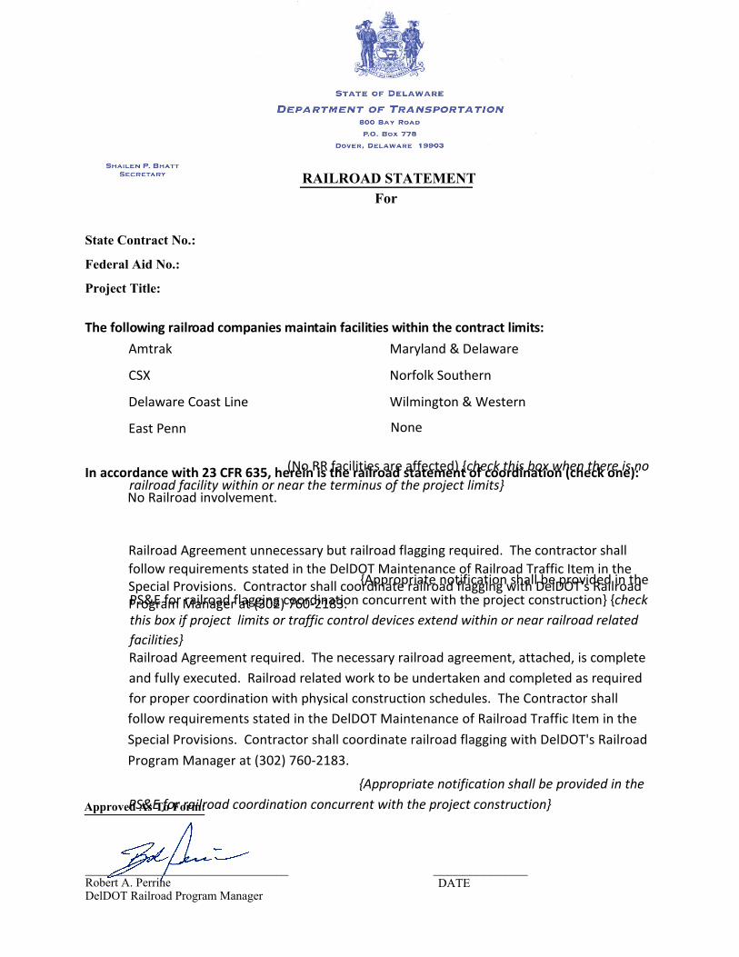
(No RR facilities are affected) {check this box when there is norailroad facility within or near the terminus of the project limits}
{Appropriate notification shall be provided in thePS&E for railroad flagging coordination concurrent with the project construction} {checkthis box if project limits or traffic control devices extend within or near railroad relatedfacilities}
{Appropriate notification shall be provided in thePS&E for railroad coordination concurrent with the project construction}
RAILROAD STATEMENT For
State Contract No.: Federal Aid No.:
Project Title:
The following railroad companies maintain facilities within the contract limits: Amtrak Maryland & Delaware
CSX Norfolk Southern
Delaware Coast Line Wilmington & Western
East Penn
In accordance with 23 CFR 635, herein is the railroad statement of coordination (check one):
No Railroad involvement.
Railroad Agreement unnecessary but railroad flagging required. The contractor shallfollow requirements stated in the DelDOT Maintenance of Railroad Traffic Item in theSpecial Provisions. Contractor shall coordinate railroad flagging with DelDOT's RailroadProgram Manager at (302) 760-2183.
Railroad Agreement required. The necessary railroad agreement, attached, is complete and fully executed. Railroad related work to be undertaken and completed as required for proper coordination with physical construction schedules. The Contractor shallfollow requirements stated in the DelDOT Maintenance of Railroad Traffic Item in theSpecial Provisions. Contractor shall coordinate railroad flagging with DelDOT's RailroadProgram Manager at (302) 760-2183.
Approved As To Form:
____________________________ _____________Robert A. PerrineDelDOT Railroad Program Manager
DATE
None

BID PROPOSAL FORMS
CONTRACT T200811301.01
FEDERAL AID PROJECT NH-2015 (20)
385

DELAWARE DEPARTMENT OF TRANSPORTATION PAGE: 1 SCHEDULE OF ITEMS DATE:
CONTRACT ID: T200811301.01 PROJECT(S): NH-2015 (20)
All figures must be typewritten. CONTRACTOR :________________________________________________________________ ------------------------------------------------------------------------------- LINE| ITEM | APPROX. | UNIT PRICE | BID AMOUNT NO | DESCRIPTION | QUANTITY |----------------|-------------- | | AND UNITS | DOLLARS | CTS | DOLLARS |CTS -------------------------------------------------------------------------------
SECTION 0001 ROADWAY DE ONLY
------------------------------------------------------------------------------- |201000 CLEARING AND | | | 0010|GRUBBING |LUMP |LUMP | | | | | ------------------------------------------------------------------------------- |202000 EXCAVATION AND | | | 0020|EMBANKMENT | 1049186.000| | | |CY | | ------------------------------------------------------------------------------- |202515 COMPACTING INSITU | | | 0030|MATERIAL | 720.000| | | |SY | | ------------------------------------------------------------------------------- |202572 BORROW AREA | | | 0040|EROSION & SEDIMENT |LUMP |LUMP | |CONTROL & DEWATERING | | | ------------------------------------------------------------------------------- |203000 CHANNEL | | | 0050|EXCAVATION | 110.000| | | |CY | | ------------------------------------------------------------------------------- |207000 EXCAVATION AND | | | 0060|BACKFILL FOR STRUCTURES | 22.000| | | |CY | | ------------------------------------------------------------------------------- |208000 EXCAVATION AND | | | 0070|BACKFILLING FOR PIPE | 10228.000| | |TRENCHES |CY | | ------------------------------------------------------------------------------- |208001 FLOWABLE FILL | | | 0080| | 17.000| | | |CY | | ------------------------------------------------------------------------------- |209002 BORROW, TYPE B | | | 0090| | 80814.000| | | |CY | | -------------------------------------------------------------------------------
CANNOT BE USED FOR BIDDING

DELAWARE DEPARTMENT OF TRANSPORTATION PAGE: 2 SCHEDULE OF ITEMS DATE:
CONTRACT ID: T200811301.01 PROJECT(S): NH-2015 (20)
All figures must be typewritten. CONTRACTOR :________________________________________________________________ ------------------------------------------------------------------------------- LINE| ITEM | APPROX. | UNIT PRICE | BID AMOUNT NO | DESCRIPTION | QUANTITY |----------------|-------------- | | AND UNITS | DOLLARS | CTS | DOLLARS |CTS ------------------------------------------------------------------------------- |211000 REMOVAL OF | | | 0100|STRUCTURES AND |LUMP |LUMP | |OBSTRUCTIONS | | | ------------------------------------------------------------------------------- |211521 ABANDONMENT OF | | | 0110|WELLS | 6.000| | | |EACH | | ------------------------------------------------------------------------------- |212000 UNDERCUT | | | 0120|EXCAVATION | 1892.000| | | |CY | | ------------------------------------------------------------------------------- |302007 GRADED AGGREGATE | | | 0130|BASE COURSE, TYPE B | 22803.000| | | |CY | | ------------------------------------------------------------------------------- |302011 DELAWARE NO. 3 | | | 0140|STONE | 1380.000| | | |TON | | ------------------------------------------------------------------------------- |304501 PERMEABLE TREATED | | | 0150|BASE, 4" | 129994.000| | | |SY | | ------------------------------------------------------------------------------- |304502 SOIL CEMENT BASE | | | 0160|COURSE, 6" | 126083.000| | | |SY | | ------------------------------------------------------------------------------- |304506 PORTLAND CEMENT | | | 0170| | 2741.000| | | |TON | | ------------------------------------------------------------------------------- |401801 BITUMINOUS | | | 0180|CONCRETE, SUPERPAVE, | 4257.000| | |TYPE C, 160 GYRATIONS PG |TON | | |64-22 (CARBONATE STONE) | | | | | | | ------------------------------------------------------------------------------- |401810 BITUMINOUS | | | 0190|CONCRETE, SUPERPAVE, | 15969.000| | |TYPE B, 160 GYRATIONS, |TON | | |PG 64-22 | | | -------------------------------------------------------------------------------
CANNOT BE USED FOR BIDDING

DELAWARE DEPARTMENT OF TRANSPORTATION PAGE: 3 SCHEDULE OF ITEMS DATE:
CONTRACT ID: T200811301.01 PROJECT(S): NH-2015 (20)
All figures must be typewritten. CONTRACTOR :________________________________________________________________ ------------------------------------------------------------------------------- LINE| ITEM | APPROX. | UNIT PRICE | BID AMOUNT NO | DESCRIPTION | QUANTITY |----------------|-------------- | | AND UNITS | DOLLARS | CTS | DOLLARS |CTS ------------------------------------------------------------------------------- |401819 BITUMINOUS | | | 0200|CONCRETE, SUPERPAVE, | 19086.000| | |BITUMINOUS CONCRETE BASE |TON | | |COURSE, 160 GYRATIONS, | | | |PG 64-22 | | | ------------------------------------------------------------------------------- |401825 BITUMINOUS | | | 0210|CONCRETE, SUPERPAVE, | 3.000| | |TYPE B, 160 GYRATIONS, |TON | | |PG 64-22, WEDGE | | | ------------------------------------------------------------------------------- |401827 BITUMINOUS | | | 0220|CONCRETE, SUPERPAVE, | 7916.000| | |TYPE C, 160 GYRATIONS, |TON | | |PG 64-22 (NON-CARBONATE | | | |STONE) | | | ------------------------------------------------------------------------------- |501006 PORTLAND CEMENT | | | 0230|CONCRETE PAVEMENT, 12" | 129978.000| | | |SY | | ------------------------------------------------------------------------------- |605755 OVERHEAD SIGN | | | 0240|SUPPORTS AND FOUNDATIONS |LUMP |LUMP | | | | | ------------------------------------------------------------------------------- |612020 REINFORCED | | | 0250|CONCRETE PIPE, 12", | 696.000| | |CLASS IV |LF | | ------------------------------------------------------------------------------- |612022 REINFORCED | | | 0260|CONCRETE PIPE, 18", | 5973.000| | |CLASS IV |LF | | ------------------------------------------------------------------------------- |612023 REINFORCED | | | 0270|CONCRETE PIPE, 24", | 2800.000| | |CLASS IV |LF | | ------------------------------------------------------------------------------- |612025 REINFORCED | | | 0280|CONCRETE PIPE, 30", | 2426.000| | |CLASS IV |LF | | -------------------------------------------------------------------------------
CANNOT BE USED FOR BIDDING

DELAWARE DEPARTMENT OF TRANSPORTATION PAGE: 4 SCHEDULE OF ITEMS DATE:
CONTRACT ID: T200811301.01 PROJECT(S): NH-2015 (20)
All figures must be typewritten. CONTRACTOR :________________________________________________________________ ------------------------------------------------------------------------------- LINE| ITEM | APPROX. | UNIT PRICE | BID AMOUNT NO | DESCRIPTION | QUANTITY |----------------|-------------- | | AND UNITS | DOLLARS | CTS | DOLLARS |CTS ------------------------------------------------------------------------------- |612026 REINFORCED | | | 0290|CONCRETE PIPE, 30", | 176.000| | |CLASS V |LF | | ------------------------------------------------------------------------------- |612027 REINFORCED | | | 0300|CONCRETE PIPE, 42", | 945.000| | |CLASS IV |LF | | ------------------------------------------------------------------------------- |612028 REINFORCED | | | 0310|CONCRETE PIPE, 48", | 206.000| | |CLASS IV |LF | | ------------------------------------------------------------------------------- |612030 REINFORCED | | | 0320|CONCRETE PIPE, 18", | 304.000| | |CLASS V |LF | | ------------------------------------------------------------------------------- |612031 REINFORCED | | | 0330|CONCRETE PIPE, 24", | 528.000| | |CLASS V |LF | | ------------------------------------------------------------------------------- |612034 REINFORCED | | | 0340|CONCRETE PIPE, 36", | 777.000| | |CLASS IV |LF | | ------------------------------------------------------------------------------- |612038 REINFORCED | | | 0350|CONCRETE PIPE, 60", | 1065.000| | |CLASS IV |LF | | ------------------------------------------------------------------------------- |612049 REINFORCED | | | 0360|CONCRETE PIPE, 12", | 140.000| | |CLASS V |LF | | ------------------------------------------------------------------------------- |612205 REINFORCED | | | 0370|CONCRETE ELLIPTICAL PIPE,| 679.000| | |19"X30", CLASS IV |LF | | ------------------------------------------------------------------------------- |612216 REINFORCED | | | 0380|CONCRETE ELLIPTICAL PIPE,| 816.000| | |14"X23", CLASS IV |LF | | -------------------------------------------------------------------------------
CANNOT BE USED FOR BIDDING

DELAWARE DEPARTMENT OF TRANSPORTATION PAGE: 5 SCHEDULE OF ITEMS DATE:
CONTRACT ID: T200811301.01 PROJECT(S): NH-2015 (20)
All figures must be typewritten. CONTRACTOR :________________________________________________________________ ------------------------------------------------------------------------------- LINE| ITEM | APPROX. | UNIT PRICE | BID AMOUNT NO | DESCRIPTION | QUANTITY |----------------|-------------- | | AND UNITS | DOLLARS | CTS | DOLLARS |CTS ------------------------------------------------------------------------------- |612219 REINFORCED | | | 0390|CONCRETE ELLIPTICAL PIPE,| 394.000| | |24"X38", CLASS IV |LF | | ------------------------------------------------------------------------------- |612535 CLEANING DRAINAGE | | | 0400|PIPE, 15"-24" DIA | 858.000| | | |LF | | ------------------------------------------------------------------------------- |612536 CLEANING DRAINAGE | | | 0410|PIPE, GREATER THAN 24" | 296.000| | |DIA |LF | | ------------------------------------------------------------------------------- |617001 REINFORCED | | | 0420|CONCRETE FLARED END | 15.000| | |SECTION, 12" |EACH | | ------------------------------------------------------------------------------- |617003 REINFORCED | | | 0430|CONCRETE FLARED END | 51.000| | |SECTION, 18" |EACH | | ------------------------------------------------------------------------------- |617005 REINFORCED | | | 0440|CONCRETE FLARED END | 19.000| | |SECTION, 24" |EACH | | ------------------------------------------------------------------------------- |617007 REINFORCED | | | 0450|CONCRETE FLARED END | 12.000| | |SECTION, 30" |EACH | | ------------------------------------------------------------------------------- |617164 REINFORCED | | | 0460|CONCRETE FLARED END | 4.000| | |SECTION, 19" X 30" |EACH | | ------------------------------------------------------------------------------- |617165 REINFORCED | | | 0470|CONCRETE FLARED END | 4.000| | |SECTION, 14" X 23" |EACH | | ------------------------------------------------------------------------------- |617174 REINFORCED | | | 0480|CONCRETE FLARED END | 2.000| | |SECTION, 24" X 38" |EACH | | -------------------------------------------------------------------------------
CANNOT BE USED FOR BIDDING

DELAWARE DEPARTMENT OF TRANSPORTATION PAGE: 6 SCHEDULE OF ITEMS DATE:
CONTRACT ID: T200811301.01 PROJECT(S): NH-2015 (20)
All figures must be typewritten. CONTRACTOR :________________________________________________________________ ------------------------------------------------------------------------------- LINE| ITEM | APPROX. | UNIT PRICE | BID AMOUNT NO | DESCRIPTION | QUANTITY |----------------|-------------- | | AND UNITS | DOLLARS | CTS | DOLLARS |CTS ------------------------------------------------------------------------------- |617518 DRAINAGE | | | 0490|HEADWALLS, MODIFIED |LUMP |LUMP | | | | | ------------------------------------------------------------------------------- |701011 PORTLAND CEMENT | | | 0500|CONCRETE CURB, TYPE 2 | 6204.000| | | |LF | | ------------------------------------------------------------------------------- |701012 PORTLAND CEMENT | | | 0510|CONCRETE CURB, TYPE 1-4 | 1877.000| | | |LF | | ------------------------------------------------------------------------------- |701016 INTEGRAL PORTLAND | | | 0520|CEMENT CONCRETE CURB & | 1408.000| | |GUTTER, TYPE 1-4 |LF | | ------------------------------------------------------------------------------- |701022 INTEGRAL PORTLAND | | | 0530|CEMENT CONCRETE CURB & | 3084.000| | |GUTTER, TYPE 3-8 |LF | | ------------------------------------------------------------------------------- |705001 P.C.C. SIDEWALK, | | | 0540|4" | 6738.000| | | |SF | | ------------------------------------------------------------------------------- |705002 P.C.C. SIDEWALK, | | | 0550|6" | 29291.000| | | |SF | | ------------------------------------------------------------------------------- |705007 SIDEWALK SURFACE | | | 0560|DETECTABLE WARNING | 100.000| | |SYSTEM |SF | | ------------------------------------------------------------------------------- |707005 UNDERDRAIN OUTLET | | | 0570| | 134.000| | | |EACH | | ------------------------------------------------------------------------------- |708050 DRAINAGE INLET, | | | 0580|34" X 18" | 17.000| | | |EACH | | -------------------------------------------------------------------------------
CANNOT BE USED FOR BIDDING

DELAWARE DEPARTMENT OF TRANSPORTATION PAGE: 7 SCHEDULE OF ITEMS DATE:
CONTRACT ID: T200811301.01 PROJECT(S): NH-2015 (20)
All figures must be typewritten. CONTRACTOR :________________________________________________________________ ------------------------------------------------------------------------------- LINE| ITEM | APPROX. | UNIT PRICE | BID AMOUNT NO | DESCRIPTION | QUANTITY |----------------|-------------- | | AND UNITS | DOLLARS | CTS | DOLLARS |CTS ------------------------------------------------------------------------------- |708051 DRAINAGE INLET, | | | 0590|34" X 24" | 14.000| | | |EACH | | ------------------------------------------------------------------------------- |708052 DRAINAGE INLET, | | | 0600|48" X 30" | 14.000| | | |EACH | | ------------------------------------------------------------------------------- |708053 DRAINAGE INLET, | | | 0610|48" X 48" | 12.000| | | |EACH | | ------------------------------------------------------------------------------- |708055 DRAINAGE INLET, | | | 0620|66" X 48" | 3.000| | | |EACH | | ------------------------------------------------------------------------------- |708057 DRAINAGE INLET, | | | 0630|72" X 24" | 4.000| | | |EACH | | ------------------------------------------------------------------------------- |708058 DRAINAGE INLET, | | | 0640|72" X 48" | 3.000| | | |EACH | | ------------------------------------------------------------------------------- |708105 MANHOLE | | | 0650|(SANITARY) | 4.000| | | |EACH | | ------------------------------------------------------------------------------- |708111 MANHOLE, 48" X | | | 0660|30" | 18.000| | | |EACH | | ------------------------------------------------------------------------------- |708112 MANHOLE, 48" X | | | 0670|48" | 1.000| | | |EACH | | ------------------------------------------------------------------------------- |708114 MANHOLE, 66" X | | | 0680|48" | 3.000| | | |EACH | | -------------------------------------------------------------------------------
CANNOT BE USED FOR BIDDING

DELAWARE DEPARTMENT OF TRANSPORTATION PAGE: 8 SCHEDULE OF ITEMS DATE:
CONTRACT ID: T200811301.01 PROJECT(S): NH-2015 (20)
All figures must be typewritten. CONTRACTOR :________________________________________________________________ ------------------------------------------------------------------------------- LINE| ITEM | APPROX. | UNIT PRICE | BID AMOUNT NO | DESCRIPTION | QUANTITY |----------------|-------------- | | AND UNITS | DOLLARS | CTS | DOLLARS |CTS ------------------------------------------------------------------------------- |708583 PERSONNEL GRATE | | | 0690|FOR PIPE INLET | 6.000| | | |EACH | | ------------------------------------------------------------------------------- |708585 JUNCTION BOX, 48" | | | 0700|X 30" | 1.000| | | |EACH | | ------------------------------------------------------------------------------- |708658 DRAINAGE INLETS, | | | 0710|MODIFIED |LUMP |LUMP | | | | | ------------------------------------------------------------------------------- |708659 DRAINAGE MANHOLES,| | | 0720|MODIFIED |LUMP |LUMP | | | | | ------------------------------------------------------------------------------- |712005 RIPRAP, R-4 | | | 0730| | 2154.000| | | |SY | | ------------------------------------------------------------------------------- |712006 RIPRAP, R-5 | | | 0740| | 373.000| | | |SY | | ------------------------------------------------------------------------------- |712007 RIPRAP, R-6 | | | 0750| | 31.000| | | |SY | | ------------------------------------------------------------------------------- |712531 CHANNEL BED FILL | | | 0760| | 15.000| | | |CY | | ------------------------------------------------------------------------------- |713002 GEOTEXTILES, | | | 0770|SEPARATION | 7306.000| | | |SY | | ------------------------------------------------------------------------------- |713003 GEOTEXTILES, | | | 0780|RIPRAP | 3776.000| | | |SY | | -------------------------------------------------------------------------------
CANNOT BE USED FOR BIDDING

DELAWARE DEPARTMENT OF TRANSPORTATION PAGE: 9 SCHEDULE OF ITEMS DATE:
CONTRACT ID: T200811301.01 PROJECT(S): NH-2015 (20)
All figures must be typewritten. CONTRACTOR :________________________________________________________________ ------------------------------------------------------------------------------- LINE| ITEM | APPROX. | UNIT PRICE | BID AMOUNT NO | DESCRIPTION | QUANTITY |----------------|-------------- | | AND UNITS | DOLLARS | CTS | DOLLARS |CTS ------------------------------------------------------------------------------- |715001 PERFORATED PIPE | | | 0790|UNDERDRAINS, 6" | 59887.000| | | |LF | | ------------------------------------------------------------------------------- |715500 UNDERDRAIN OUTLET | | | 0800|PIPE, 6" | 3642.000| | | |LF | | ------------------------------------------------------------------------------- |716000 CONVERTING | | | 0810|EXISTING DRAINAGE INLET | 1.000| | |TO JUNCTION BOX |EACH | | ------------------------------------------------------------------------------- |720050 GALVANIZED STEEL | | | 0820|BEAM GUARDRAIL, TYPE | 6563.000| | |1-31 |LF | | ------------------------------------------------------------------------------- |720052 GALVANIZED STEEL | | | 0830|BEAM GUARDRAIL, TYPE | 2275.000| | |3-31 |LF | | ------------------------------------------------------------------------------- |720055 CURVED GUARDRAIL | | | 0840|SECTION | 282.000| | | |LF | | ------------------------------------------------------------------------------- |720585 GUARDRAIL END | | | 0850|TREATMENT ATTENUATOR, | 5.000| | |TYPE 1-31 |EACH | | ------------------------------------------------------------------------------- |720586 GUARDRAIL END | | | 0860|TREATMENT ATTENUATOR, | 11.000| | |TYPE 2-31 |EACH | | ------------------------------------------------------------------------------- |720588 GUARDRAIL END | | | 0870|TREATMENT ATTENUATOR, | 10.000| | |TYPE 3-31 |EACH | | ------------------------------------------------------------------------------- |720611 FLEXIBLE | | | 0880|DELINEATOR, PERMANENT | 183.000| | | |EACH | | -------------------------------------------------------------------------------
CANNOT BE USED FOR BIDDING

DELAWARE DEPARTMENT OF TRANSPORTATION PAGE: 10 SCHEDULE OF ITEMS DATE:
CONTRACT ID: T200811301.01 PROJECT(S): NH-2015 (20)
All figures must be typewritten. CONTRACTOR :________________________________________________________________ ------------------------------------------------------------------------------- LINE| ITEM | APPROX. | UNIT PRICE | BID AMOUNT NO | DESCRIPTION | QUANTITY |----------------|-------------- | | AND UNITS | DOLLARS | CTS | DOLLARS |CTS ------------------------------------------------------------------------------- |720626 CONCRETE SINGLE | | | 0890|FACE BARRIER, TYPE I | 630.000| | | |LF | | ------------------------------------------------------------------------------- |725001 GUARDRAIL TO | | | 0900|BARRIER CONNECTION (EXIT | 5.000| | |TYPE 31) |EACH | | ------------------------------------------------------------------------------- |725002 GUARDRAIL TO | | | 0910|BARRIER CONNECTION, | 7.000| | |APPROACH TYPE 1-31 |EACH | | ------------------------------------------------------------------------------- |726001 END ANCHORAGE 31 | | | 0920| | 21.000| | | |EACH | | ------------------------------------------------------------------------------- |727000 RIGHT-OF-WAY | | | 0930|FENCE | 27099.000| | | |LF | | ------------------------------------------------------------------------------- |727001 RIGHT-OF-WAY | | | 0940|FENCE GATE | 3.000| | | |EACH | | ------------------------------------------------------------------------------- |727014 CONSTRUCTION | | | 0950|SAFETY FENCE | 621.000| | | |LF | | ------------------------------------------------------------------------------- |727552 RESOURCE | | | 0960|PROTECTION FENCE | 5636.000| | | |LF | | ------------------------------------------------------------------------------- |735501 HERBICIDE | | | 0970|APPLICATION, NOXIOUS | 50.000| | |WEEDS |ACRE | | ------------------------------------------------------------------------------- |737523 PLANTINGS | | | 0980| |LUMP |LUMP | | | | | -------------------------------------------------------------------------------
CANNOT BE USED FOR BIDDING

DELAWARE DEPARTMENT OF TRANSPORTATION PAGE: 11 SCHEDULE OF ITEMS DATE:
CONTRACT ID: T200811301.01 PROJECT(S): NH-2015 (20)
All figures must be typewritten. CONTRACTOR :________________________________________________________________ ------------------------------------------------------------------------------- LINE| ITEM | APPROX. | UNIT PRICE | BID AMOUNT NO | DESCRIPTION | QUANTITY |----------------|-------------- | | AND UNITS | DOLLARS | CTS | DOLLARS |CTS ------------------------------------------------------------------------------- |743000 MAINTENANCE OF | | | 0990|TRAFFIC |LUMP |LUMP | | | | | ------------------------------------------------------------------------------- |743003 ARROWPANELS, TYPE | | | 1000|C | 189.000| | | |EADY | | ------------------------------------------------------------------------------- |743004 FURNISH AND | | | 1010|MAINTAIN PORTABLE | 317.000| | |CHANGEABLE MESSAGE SIGN |EADY | | | | | | ------------------------------------------------------------------------------- |743005 FURNISH AND | | | 1020|MAINTAIN PORTABLE LIGHT | 91.000| | |ASSEMBLY |EADY | | ------------------------------------------------------------------------------- |743006 PLASTIC DRUMS | | | 1030| | 290542.000| | | |EADY | | ------------------------------------------------------------------------------- |743007 TRAFFIC OFFICERS | | | 1040| | 924.000| 75.00000| 69300.00 | |HOUR | | ------------------------------------------------------------------------------- |743010 FURNISH AND | | | 1050|MAINTAIN TRUCK MOUNTED | 534.000| | |ATTENUATOR, TYPE II |EADY | | ------------------------------------------------------------------------------- |743015 FURNISH AND | | | 1060|MAINTAIN PORTABLE PCC | 1745.000| | |SAFETY BARRIER |LF | | ------------------------------------------------------------------------------- |743016 RELOCATION | | | 1070|PORATBLE SAFETY BARRIER | 1960.000| | | |LF | | ------------------------------------------------------------------------------- |743023 TEMPORARY | | | 1080|BARRICADES, TYPE III | 271614.000| | | |LFDY | | -------------------------------------------------------------------------------
CANNOT BE USED FOR BIDDING

DELAWARE DEPARTMENT OF TRANSPORTATION PAGE: 12 SCHEDULE OF ITEMS DATE:
CONTRACT ID: T200811301.01 PROJECT(S): NH-2015 (20)
All figures must be typewritten. CONTRACTOR :________________________________________________________________ ------------------------------------------------------------------------------- LINE| ITEM | APPROX. | UNIT PRICE | BID AMOUNT NO | DESCRIPTION | QUANTITY |----------------|-------------- | | AND UNITS | DOLLARS | CTS | DOLLARS |CTS ------------------------------------------------------------------------------- |743024 TEMPORARY WARNING | | | 1090|SIGNS AND PLAQUES | 65228.000| | | |EADY | | ------------------------------------------------------------------------------- |743025 INSTALL TEMPORARY | | | 1100|IMPACT ATTENUATOR | 11.000| | | |EACH | | ------------------------------------------------------------------------------- |743029 FURNISH TEMPORARY | | | 1110|IMPACT ATTENUATOR - | 9.000| | |NON-GATING, REDIRECTIVE, |EACH | | |TEST LEVEL 3 | | | ------------------------------------------------------------------------------- |743030 RELOCATE | | | 1120|TEMPORARY IMPACT | 3.000| | |ATTENUATOR |EACH | | ------------------------------------------------------------------------------- |743031 ATSSA CERTIFIED | | | 1130|TRAFFIC CONTROL | 1574.000| | |SUPERVISOR |HOUR | | ------------------------------------------------------------------------------- |743056 FLAGGER, NEW | | | 1140|CASTLE COUNTY, FEDERAL | 5730.000| | | |HOUR | | ------------------------------------------------------------------------------- |743065 FLAGGER, NEW | | | 1150|CASTLE COUNTY, FEDERAL, | 1146.000| | |OVERTIME |HOUR | | ------------------------------------------------------------------------------- |744506 CONDUIT JUNCTION | | | 1160|WELL, TYPE 7, PRECAST | 17.000| | |POLYMER CONCRETE |EACH | | ------------------------------------------------------------------------------- |744519 RELOCATION OF | | | 1170|EXISTING JUNCTION WELL | 8.000| | | |EACH | | ------------------------------------------------------------------------------- |744520 CONDUIT JUNCTION | | | 1180|WELL, TYPE 1, PRECAST | 4.000| | |CONCRETE |EACH | | -------------------------------------------------------------------------------
CANNOT BE USED FOR BIDDING

DELAWARE DEPARTMENT OF TRANSPORTATION PAGE: 13 SCHEDULE OF ITEMS DATE:
CONTRACT ID: T200811301.01 PROJECT(S): NH-2015 (20)
All figures must be typewritten. CONTRACTOR :________________________________________________________________ ------------------------------------------------------------------------------- LINE| ITEM | APPROX. | UNIT PRICE | BID AMOUNT NO | DESCRIPTION | QUANTITY |----------------|-------------- | | AND UNITS | DOLLARS | CTS | DOLLARS |CTS ------------------------------------------------------------------------------- |744523 CONDUIT JUNCTION | | | 1190|WELL, TYPE 4, PRECAST | 1.000| | |CONCRETE |EACH | | ------------------------------------------------------------------------------- |744530 CONDUIT JUNCTION | | | 1200|WELL, TYPE 11, PRECAST | 125.000| | |CONCRETE/ POLYMER |EACH | | |LID-FRAME | | | ------------------------------------------------------------------------------- |744531 CONDUIT JUNCTION | | | 1210|WELL, TYPE 14, PRECAST | 56.000| | |CONCRETE/ POLYMER |EACH | | |LID-FRAME | | | ------------------------------------------------------------------------------- |744541 FURNISH & INSTALL | | | 1220|FRAME AND LID FOR | 3.000| | |JUNCTION WELL, TYPE 11 |EACH | | ------------------------------------------------------------------------------- |744542 FURNISH & INSTALL | | | 1230|FRAME AND LID FOR | 1.000| | |JUNCTION WELL, TYPE 14 |EACH | | ------------------------------------------------------------------------------- |744544 ADJUST OR REPAIR | | | 1240|EXISTING CONDUIT | 6.000| | |JUNCTION WELL |EACH | | ------------------------------------------------------------------------------- |745602 FURNISH & INSTALL | | | 1250|UP TO 4" SCHEDULE 80 | 651.000| | |HDPE CONDUIT (BORE) |LF | | ------------------------------------------------------------------------------- |745604 FURNISH & INSTALL | | | 1260|UP TO 4" SCHEDULE 80 PVC | 45263.000| | |CONDUIT (TRENCH) |LF | | ------------------------------------------------------------------------------- |745606 FURNISH & INSTALL | | | 1270|UP TO 4" GALVANIZED | 2087.000| | |STEEL CONDUIT (TRENCH) |LF | | -------------------------------------------------------------------------------
CANNOT BE USED FOR BIDDING

DELAWARE DEPARTMENT OF TRANSPORTATION PAGE: 14 SCHEDULE OF ITEMS DATE:
CONTRACT ID: T200811301.01 PROJECT(S): NH-2015 (20)
All figures must be typewritten. CONTRACTOR :________________________________________________________________ ------------------------------------------------------------------------------- LINE| ITEM | APPROX. | UNIT PRICE | BID AMOUNT NO | DESCRIPTION | QUANTITY |----------------|-------------- | | AND UNITS | DOLLARS | CTS | DOLLARS |CTS ------------------------------------------------------------------------------- |745609 FURNISH & INSTALL | | | 1280|UP TO 4" GALVANIZED | 20.000| | |STEEL CONDUIT (ON |LF | | |STRUCTURE) | | | ------------------------------------------------------------------------------- |746509 RELOCATING LIGHT | | | 1290|POLE | 13.000| | | |EACH | | ------------------------------------------------------------------------------- |746511 CABLES, 1/#4 AWG | | | 1300| | 3986.000| | | |LF | | ------------------------------------------------------------------------------- |746512 CABLES, 1/#6 AWG | | | 1310| | 33809.000| | | |LF | | ------------------------------------------------------------------------------- |746513 CABLES, 1/#8 AWG | | | 1320| | 318.000| | | |LF | | ------------------------------------------------------------------------------- |746515 INSULATED GROUND | | | 1330|CABLES, 1/#6 | 9603.000| | | |LF | | ------------------------------------------------------------------------------- |746517 ALUMINUM LIGHTING | | | 1340|STANDARD WITH SINGLE | 19.000| | |DAVIT ARM, 30' POLE |EACH | | ------------------------------------------------------------------------------- |746519 ALUMINUM LIGHTING | | | 1350|STANDARD WITH SINGLE | 16.000| | |DAVIT ARM, 40' POLE |EACH | | ------------------------------------------------------------------------------- |746527 CABLES, 1/#2 AWG | | | 1360| | 12711.000| | | |LF | | ------------------------------------------------------------------------------- |746541 INSTALLATION OF | | | 1370|ELECTRICAL WIRE OR CABLE | 93945.000| | |IN EMPTY CONDUITS |LF | | -------------------------------------------------------------------------------
CANNOT BE USED FOR BIDDING

DELAWARE DEPARTMENT OF TRANSPORTATION PAGE: 15 SCHEDULE OF ITEMS DATE:
CONTRACT ID: T200811301.01 PROJECT(S): NH-2015 (20)
All figures must be typewritten. CONTRACTOR :________________________________________________________________ ------------------------------------------------------------------------------- LINE| ITEM | APPROX. | UNIT PRICE | BID AMOUNT NO | DESCRIPTION | QUANTITY |----------------|-------------- | | AND UNITS | DOLLARS | CTS | DOLLARS |CTS ------------------------------------------------------------------------------- |746564 INSULATED GROUND | | | 1380|CABLES, 1/#4 | 625.000| | | |LF | | ------------------------------------------------------------------------------- |746577 INSULATED GROUND | | | 1390|CABLE, 1/#8 | 165.000| | | |LF | | ------------------------------------------------------------------------------- |746586 RELOCATE SIGN | | | 1400| | 140.000| | | |SF | | ------------------------------------------------------------------------------- |746590 FURNISH & INSTALL | | | 1410|GROUND ROD | 8.000| | | |EACH | | ------------------------------------------------------------------------------- |746594 LUMINAIRE (HPS), | | | 1420|250 WATT | 45.000| | | |EACH | | ------------------------------------------------------------------------------- |746595 ALUMINUM LIGHTING | | | 1430|STANDARD, 40' POLE | 48.000| | | |EACH | | ------------------------------------------------------------------------------- |746598 INSULATED GROUND | | | 1440|CABLE , 1/#2 | 3234.000| | | |LF | | ------------------------------------------------------------------------------- |746615 PVC SCHEDULE 40 | | | 1450|DUCT, 6" | 80.000| | | |LF | | ------------------------------------------------------------------------------- |746622 CABLES, 1/#4/0 | | | 1460|AWG | 6868.000| | | |LF | | ------------------------------------------------------------------------------- |746653 ELECTRICAL | | | 1470|TESTING |LUMP |LUMP | | | | | -------------------------------------------------------------------------------
CANNOT BE USED FOR BIDDING

DELAWARE DEPARTMENT OF TRANSPORTATION PAGE: 16 SCHEDULE OF ITEMS DATE:
CONTRACT ID: T200811301.01 PROJECT(S): NH-2015 (20)
All figures must be typewritten. CONTRACTOR :________________________________________________________________ ------------------------------------------------------------------------------- LINE| ITEM | APPROX. | UNIT PRICE | BID AMOUNT NO | DESCRIPTION | QUANTITY |----------------|-------------- | | AND UNITS | DOLLARS | CTS | DOLLARS |CTS ------------------------------------------------------------------------------- |746669 LUMINAIRE (HPS), | | | 1480|150 WATTS | 19.000| | | |EACH | | ------------------------------------------------------------------------------- |746717 ELECTRIC SERVICE | | | 1490|ON RACK WITH SERVICE | 3.000| | |RISER |EACH | | ------------------------------------------------------------------------------- |746817 CABLES, 1/#2/0 | | | 1500|AWG | 9953.000| | | |LF | | ------------------------------------------------------------------------------- |746847 POLE BASE, TYPE 3 | | | 1510| | 4.000| | | |EACH | | ------------------------------------------------------------------------------- |746850 POLE BASE, TYPE | | | 1520|4A | 4.000| | | |EACH | | ------------------------------------------------------------------------------- |746852 POLE BASE, TYPE 6 | | | 1530| | 82.000| | | |EACH | | ------------------------------------------------------------------------------- |746861 INSULATED GROUND | | | 1540|CABLES, 1/350 KCMIL | 6621.000| | | |LF | | ------------------------------------------------------------------------------- |746872 LIGHTING CONTROL | | | 1550|AND DISTRIBUTION | 2.000| | |ENCLOSURE |EACH | | ------------------------------------------------------------------------------- |746903 INSULATED GROUND | | | 1560|CABLES, 1/#2/0 | 4033.000| | | |LF | | ------------------------------------------------------------------------------- |746904 INSULATED GROUND | | | 1570|CABLES, 1/#4/0 | 1871.000| | | |LF | | -------------------------------------------------------------------------------
CANNOT BE USED FOR BIDDING

DELAWARE DEPARTMENT OF TRANSPORTATION PAGE: 17 SCHEDULE OF ITEMS DATE:
CONTRACT ID: T200811301.01 PROJECT(S): NH-2015 (20)
All figures must be typewritten. CONTRACTOR :________________________________________________________________ ------------------------------------------------------------------------------- LINE| ITEM | APPROX. | UNIT PRICE | BID AMOUNT NO | DESCRIPTION | QUANTITY |----------------|-------------- | | AND UNITS | DOLLARS | CTS | DOLLARS |CTS ------------------------------------------------------------------------------- |746924 FURNISH & INSTALL | | | 1580|LOOP WIRE 1-CONDUCTOR | 3504.000| | |#14 AWG ENCASED IN 1/4" |LF | | |FLEXIBLE TUBING IN A | | | |LOOP SAWCUT | | | ------------------------------------------------------------------------------- |746951 RELOCATING POLE & | | | 1590|MAST ARM | 1.000| | | |EACH | | ------------------------------------------------------------------------------- |747515 CABINET BASE, | | | 1600|TYPE M | 4.000| | | |EACH | | ------------------------------------------------------------------------------- |747516 CABINET BASE, | | | 1610|TYPE P | 3.000| | | |EACH | | ------------------------------------------------------------------------------- |748015 PERMANENT | | | 1620|PAVEMENT STRIPING, | 4301.000| | |SYMBOL/LEGEND |SF | | |ALKYD-THERMOPLAST IC | | | ------------------------------------------------------------------------------- |748019 TEMPORARY | | | 1630|MARKINGS, PAINT, 4" | 9351.000| | | |LF | | ------------------------------------------------------------------------------- |748026 TEMPORARY | | | 1640|MARKINGS, PAINT | 276.000| | |SYMBOL/LEGEND |SF | | ------------------------------------------------------------------------------- |748032 TEMPORARY | | | 1650|MARKINGS, PAINT, 5" | 258.000| | | |LF | | ------------------------------------------------------------------------------- |748033 PERMANENT | | | 1660|PAVEMENT STRIPING, | 62.000| | |ALKYD-THERMOPLASTIC, 5" |LF | | | | | | -------------------------------------------------------------------------------
CANNOT BE USED FOR BIDDING

DELAWARE DEPARTMENT OF TRANSPORTATION PAGE: 18 SCHEDULE OF ITEMS DATE:
CONTRACT ID: T200811301.01 PROJECT(S): NH-2015 (20)
All figures must be typewritten. CONTRACTOR :________________________________________________________________ ------------------------------------------------------------------------------- LINE| ITEM | APPROX. | UNIT PRICE | BID AMOUNT NO | DESCRIPTION | QUANTITY |----------------|-------------- | | AND UNITS | DOLLARS | CTS | DOLLARS |CTS ------------------------------------------------------------------------------- |748502 RAISED/RECESSED | | | 1670|PAVEMENT MARKER | 533.000| | | |EACH | | ------------------------------------------------------------------------------- |748525 TEMPORARY | | | 1680|MARKINGS, TAPE, 4" | 37313.000| | | |LF | | ------------------------------------------------------------------------------- |748527 TEMPORARY | | | 1690|MARKINGS, TAPE, | 520.000| | |WORDS/SYMBOLS |SF | | ------------------------------------------------------------------------------- |748530 REMOVAL OF | | | 1700|PAVEMENT STRIPING | 10624.000| | | |SF | | ------------------------------------------------------------------------------- |748548 PERMANENT | | | 1710|PAVEMENT STRIPING, EPOXY | 146717.000| | |RESIN PAINT, |LF | | |WHITE/YELLOW, 5" | | | ------------------------------------------------------------------------------- |748549 PERMANENT | | | 1720|PAVEMENT STRIPING, EPOXY | 3812.000| | |RESIN PAINT, |LF | | |WHITE/YELLOW, 10" | | | ------------------------------------------------------------------------------- |748553 PREFORMED | | | 1730|RETROREFLECTIVE | 49.000| | |THERMOPLASTIC PAVEMENT |EACH | | |MARKINGS, BIKE SYMBOL | | | ------------------------------------------------------------------------------- |748557 PERMANENT | | | 1740|PAVEMENT STRIPING, EPOXY | 23558.000| | |RESIN PAINT, BLACK, 3" |LF | | ------------------------------------------------------------------------------- |748566 RETROREFLECTIVE | | | 1750|PREFORMED PATTERNED | 5475.000| | |MARKINGS, 8" |LF | | -------------------------------------------------------------------------------
CANNOT BE USED FOR BIDDING

DELAWARE DEPARTMENT OF TRANSPORTATION PAGE: 19 SCHEDULE OF ITEMS DATE:
CONTRACT ID: T200811301.01 PROJECT(S): NH-2015 (20)
All figures must be typewritten. CONTRACTOR :________________________________________________________________ ------------------------------------------------------------------------------- LINE| ITEM | APPROX. | UNIT PRICE | BID AMOUNT NO | DESCRIPTION | QUANTITY |----------------|-------------- | | AND UNITS | DOLLARS | CTS | DOLLARS |CTS ------------------------------------------------------------------------------- |748567 RETROREFLECTIVE | | | 1760|PREFORMED PATTERNED | 395.000| | |MARKINGS, 13" |LF | | ------------------------------------------------------------------------------- |749500 SIGN PANEL | | | 1770| | 2553.000| | | |SF | | ------------------------------------------------------------------------------- |749516 REINFORCED | | | 1780|CONCRETE SIGN FOUNDATION,| 12.000| | |W-6 |EACH | | ------------------------------------------------------------------------------- |749517 REINFORCED | | | 1790|CONCRETE SIGN FOUNDATION,| 2.000| | |W-8 |EACH | | ------------------------------------------------------------------------------- |749518 REINFORCED | | | 1800|CONCRETE SIGN FOUNDATION,| 4.000| | |W-10 |EACH | | ------------------------------------------------------------------------------- |749521 SUPPLY OF | | | 1810|BREAKAWAY I-BEAM SIGN | 190.000| | |POSTS, W-6 |LF | | ------------------------------------------------------------------------------- |749522 SUPPLY OF | | | 1820|BREAKAWAY I-BEAM SIGN | 40.000| | |POSTS, W-8 |LF | | ------------------------------------------------------------------------------- |749523 SUPPLY OF | | | 1830|BREAKAWAY I-BEAM SIGN | 95.000| | |POSTS, W-10 |LF | | ------------------------------------------------------------------------------- |749532 SUPPLY OF FLAT | | | 1840|SHEET ALUMINUM SIGN | 20.000| | |PANEL, TYPE IX |SF | | |RETROREFLECTIVE SHEETING | | | | | | | ------------------------------------------------------------------------------- |749550 INSTALLATION OF | | | 1850|BREAKAWAY I-BEAM SIGN | 28.000| | |POSTS |EACH | | -------------------------------------------------------------------------------
CANNOT BE USED FOR BIDDING

DELAWARE DEPARTMENT OF TRANSPORTATION PAGE: 20 SCHEDULE OF ITEMS DATE:
CONTRACT ID: T200811301.01 PROJECT(S): NH-2015 (20)
All figures must be typewritten. CONTRACTOR :________________________________________________________________ ------------------------------------------------------------------------------- LINE| ITEM | APPROX. | UNIT PRICE | BID AMOUNT NO | DESCRIPTION | QUANTITY |----------------|-------------- | | AND UNITS | DOLLARS | CTS | DOLLARS |CTS ------------------------------------------------------------------------------- |749581 REINFORCED | | | 1860|CONCRETE SIGN FOUNDATION,| 10.000| | |W-18 |EACH | | ------------------------------------------------------------------------------- |749582 SUPPLY OF | | | 1870|BREAKAWAY I-BEAM SIGN | 258.000| | |POSTS, W-18 |LF | | ------------------------------------------------------------------------------- |749687 INSTALLATION OR | | | 1880|REMOVAL OF TRAFFIC | 196.000| | |SIGN(S) ON SINGLE SIGN |EACH | | |POST | | | ------------------------------------------------------------------------------- |749688 INSTALLATION OF | | | 1890|4" DIAMETER HOLE, LESS | 10.000| | |THAN OR EQUAL TO 6" |EACH | | |DEPTH | | | ------------------------------------------------------------------------------- |749689 INSTALLATION OF | | | 1900|4" DIAMETER HOLE, | 4.000| | |GREATER THAN 6" DEPTH |EACH | | ------------------------------------------------------------------------------- |749690 INSTALLATION OR | | | 1910|REMOVAL OF TRAFFIC SIGNS | 1069.000| | |ON MULTIPLE SIGN POSTS |SF | | ------------------------------------------------------------------------------- |753503 INSTALLING | | | 1920|SANITARY SEWER, PVC, 12" | 262.000| | | |LF | | ------------------------------------------------------------------------------- |758000 REMOVAL OF | | | 1930|EXISTING PORTLAND | 19253.000| | |CEMENTCONCRETE PAVEMENT, |SY | | |CURB, SIDEWALK, ETC. | | | ------------------------------------------------------------------------------- |759506 FIELD OFFICE, | | | 1940|TYPE II.22 SPECIAL | 30.000| | |COMPLEX |EAMO | | ------------------------------------------------------------------------------- |760012 RUMBLE STRIPS, | | | 1950|BIKE-FRIENDLY, HOT-MIX | 22362.000| | | |LF | | -------------------------------------------------------------------------------
CANNOT BE USED FOR BIDDING

DELAWARE DEPARTMENT OF TRANSPORTATION PAGE: 21 SCHEDULE OF ITEMS DATE:
CONTRACT ID: T200811301.01 PROJECT(S): NH-2015 (20)
All figures must be typewritten. CONTRACTOR :________________________________________________________________ ------------------------------------------------------------------------------- LINE| ITEM | APPROX. | UNIT PRICE | BID AMOUNT NO | DESCRIPTION | QUANTITY |----------------|-------------- | | AND UNITS | DOLLARS | CTS | DOLLARS |CTS ------------------------------------------------------------------------------- |760017 RUMBLE STRIPS, | | | 1960|CONCRETE | 59567.000| | | |LF | | ------------------------------------------------------------------------------- |760507 PROFILE MILLING, | | | 1970|BITUMINOUS CONCRETE | 6786.000| | | |SYIN | | ------------------------------------------------------------------------------- |762001 SAW CUTTING, | | | 1980|BITUMINOUS CONCRETE | 4764.000| | | |LF | | ------------------------------------------------------------------------------- |762002 SAW CUTTING, | | | 1990|CONCRETE, FULL DEPTH | 697.000| | | |LF | | ------------------------------------------------------------------------------- |763000 INITIAL EXPENSE | | | 2000| |LUMP |LUMP | | | | | ------------------------------------------------------------------------------- |763501 CONSTRUCTION | | | 2010|ENGINEERING |LUMP |LUMP | | | | | ------------------------------------------------------------------------------- |763503 TRAINEE | | | 2020| | 2000.000| 0.80000| 1600.00 | |HOUR | | ------------------------------------------------------------------------------- |763508 PROJECT CONTROL | | | 2030|SYSTEM DEVELOPMENT PLAN |LUMP |LUMP | | | | | ------------------------------------------------------------------------------- |763509 CPM SCHEDULE | | | 2040|UPDATES AND/OR REVISED | 30.000| | |UPDATES |EAMO | | ------------------------------------------------------------------------------- |763597 UTILITY | | | 2050|CONSTRUCTION ENGINEERING | 100.000| | | |HOUR | | -------------------------------------------------------------------------------
CANNOT BE USED FOR BIDDING

DELAWARE DEPARTMENT OF TRANSPORTATION PAGE: 22 SCHEDULE OF ITEMS DATE:
CONTRACT ID: T200811301.01 PROJECT(S): NH-2015 (20)
All figures must be typewritten. CONTRACTOR :________________________________________________________________ ------------------------------------------------------------------------------- LINE| ITEM | APPROX. | UNIT PRICE | BID AMOUNT NO | DESCRIPTION | QUANTITY |----------------|-------------- | | AND UNITS | DOLLARS | CTS | DOLLARS |CTS ------------------------------------------------------------------------------- |763619 WEIGH IN MOTION | | | 2060|SYSTEM (WIM) |LUMP |LUMP | | | | | ------------------------------------------------------------------------------- |763689 STRUCTURAL WORK, | | | 2070|GANTRY |LUMP |LUMP | | | | | ------------------------------------------------------------------------------- |900500 ENVIRONMENTAL | | | 2080|PERFORMANCE INCENTIVE |LUMP |LUMP | 488000.00 |(DISINCENTIVE) | | | ------------------------------------------------------------------------------- |905001 SILT FENCE | | | 2090| | 12571.000| | | |LF | | ------------------------------------------------------------------------------- |905002 REINFORCED SILT | | | 2100|FENCE | 45734.000| | | |LF | | ------------------------------------------------------------------------------- |905003 SEDIMENT TRAP | | | 2110| | 1303.000| | | |CY | | ------------------------------------------------------------------------------- |905004 INLET SEDIMENT | | | 2120|CONTROL, DRAINAGE INLET | 16.000| | | |EACH | | ------------------------------------------------------------------------------- |905005 INLET SEDIMENT | | | 2130|CONTROL, CURB INLET | 11.000| | | |EACH | | ------------------------------------------------------------------------------- |906001 PORTABLE SEDIMENT | | | 2140|TANK | 1.000| | | |EACH | | ------------------------------------------------------------------------------- |906002 DEWATERING BAG | | | 2150| | 9.000| | | |EACH | | ------------------------------------------------------------------------------- |906003 SUMP PIT | | | 2160| | 1.000| | | |EACH | | -------------------------------------------------------------------------------
CANNOT BE USED FOR BIDDING

DELAWARE DEPARTMENT OF TRANSPORTATION PAGE: 23 SCHEDULE OF ITEMS DATE:
CONTRACT ID: T200811301.01 PROJECT(S): NH-2015 (20)
All figures must be typewritten. CONTRACTOR :________________________________________________________________ ------------------------------------------------------------------------------- LINE| ITEM | APPROX. | UNIT PRICE | BID AMOUNT NO | DESCRIPTION | QUANTITY |----------------|-------------- | | AND UNITS | DOLLARS | CTS | DOLLARS |CTS ------------------------------------------------------------------------------- |906004 SKIMMER | | | 2170|DEWATERING DEVICE | 11.000| | | |EACH | | ------------------------------------------------------------------------------- |907011 STONE CHECK DAM | | | 2180| | 47.000| | | |TON | | ------------------------------------------------------------------------------- |908010 TOPSOILING, 6" | | | 2190|DEPTH | 500754.000| | | |SY | | ------------------------------------------------------------------------------- |908014 PERMANENT GRASS | | | 2200|SEEDING, DRY GROUND | 519169.000| | | |SY | | ------------------------------------------------------------------------------- |908015 PERMANENT GRASS | | | 2210|SEEDING, WET GROUND | 450305.000| | | |SY | | ------------------------------------------------------------------------------- |908017 TEMPORARY GRASS | | | 2220|SEEDING | 468154.000| | | |SY | | ------------------------------------------------------------------------------- |908019 STREAMBANK SEED | | | 2230|MIX, SEEDING | 50.000| | | |SY | | ------------------------------------------------------------------------------- |908020 EROSION CONTROL | | | 2240|BLANKET MULCH | 123047.000| | | |SY | | ------------------------------------------------------------------------------- |908021 TURF | | | 2250|REINFORCEMENT MATTING, | 1824.000| | |TYPE 1 |SY | | ------------------------------------------------------------------------------- |908023 STABILIZED | | | 2260|CONSTRUCTION ENTRANCE | 1259.000| | | |TON | | -------------------------------------------------------------------------------
CANNOT BE USED FOR BIDDING

DELAWARE DEPARTMENT OF TRANSPORTATION PAGE: 24 SCHEDULE OF ITEMS DATE:
CONTRACT ID: T200811301.01 PROJECT(S): NH-2015 (20)
All figures must be typewritten. CONTRACTOR :________________________________________________________________ ------------------------------------------------------------------------------- LINE| ITEM | APPROX. | UNIT PRICE | BID AMOUNT NO | DESCRIPTION | QUANTITY |----------------|-------------- | | AND UNITS | DOLLARS | CTS | DOLLARS |CTS ------------------------------------------------------------------------------- |908503 WETLAND | | | 2270|MITIGATION GRASS SEEDING | 25854.000| | | |SY | | ------------------------------------------------------------------------------- |909002 SANDBAG DIVERSION | | | 2280| | 54.000| | | |CF | | ------------------------------------------------------------------------------- |909005 STREAM DIVERSION | | | 2290| |LUMP |LUMP | | | | | ------------------------------------------------------------------------------- |910004 CLAY BORROW, | | | 2300|CUT-OFF TRENCH | 2981.000| | | |CY | | ------------------------------------------------------------------------------- |910007 OUTLET STRUCTURE | | | 2310| |LUMP |LUMP | | | | | ------------------------------------------------------------------------------- |910009 INFILTRATION | | | 2320|TRENCH | 200.000| | | |LF | | ------------------------------------------------------------------------------- | | | SECTION 0001 TOTAL |-------------------------------------------------------------------------------
SECTION 0002 BRIDGE 1-486 STANDARD ITEMS
------------------------------------------------------------------------------- |202505 SETTLEMENT | | | 2330|PLATFORM | 4.000| | | |EACH | | ------------------------------------------------------------------------------- |207000 EXCAVATION AND | | | 2340|BACKFILL FOR STRUCTURES | 216.000| | | |CY | | -------------------------------------------------------------------------------
CANNOT BE USED FOR BIDDING

DELAWARE DEPARTMENT OF TRANSPORTATION PAGE: 25 SCHEDULE OF ITEMS DATE:
CONTRACT ID: T200811301.01 PROJECT(S): NH-2015 (20)
All figures must be typewritten. CONTRACTOR :________________________________________________________________ ------------------------------------------------------------------------------- LINE| ITEM | APPROX. | UNIT PRICE | BID AMOUNT NO | DESCRIPTION | QUANTITY |----------------|-------------- | | AND UNITS | DOLLARS | CTS | DOLLARS |CTS ------------------------------------------------------------------------------- |602006 PORTLAND CEMENT | | | 2350|CONCRETE MASONRY, PIER | 94.000| | |FOOTING, CLASS B |CY | | ------------------------------------------------------------------------------- |602007 PORTLAND CEMENT | | | 2360|CONCRETE MASONRY, PIER | 70.000| | |ABOVE FOOTING, CLASS A |CY | | ------------------------------------------------------------------------------- |602013 PORTLAND CEMENT | | | 2370|CONCRETE MASONRY, | 195.000| | |SUPERSTRUCTURE, CLASS D |CY | | | | | | ------------------------------------------------------------------------------- |602014 PORTLAND CEMENT | | | 2380|CONCRETE MASONRY, | 110.000| | |APPROACH SLAB, CLASS D |CY | | | | | | ------------------------------------------------------------------------------- |602015 PORTLAND CEMENT | | | 2390|CONCRETE MASONRY, | 70.000| | |ABUTMENT ABOVE FOOTING, |CY | | |CLASS A | | | ------------------------------------------------------------------------------- |602017 PORTLAND CEMENT | | | 2400|CONCRETE MASONRY, | 50.000| | |PARAPET, CLASS A |CY | | ------------------------------------------------------------------------------- |602772 MECHANICALLY | | | 2410|STABILIZED EARTH WALLS |LUMP |LUMP | | | | | ------------------------------------------------------------------------------- |604000 BAR REINFORCEMENT,| | | 2420|EPOXY COATED | 135000.000| | | |LB | | ------------------------------------------------------------------------------- |608000 COARSE AGGREGATE | | | 2430|FOR FOUNDATION | 20.000| | |STABILIZATION AND |TON | | |SUBFOUNDATION BACKFILL | | | -------------------------------------------------------------------------------
CANNOT BE USED FOR BIDDING

DELAWARE DEPARTMENT OF TRANSPORTATION PAGE: 26 SCHEDULE OF ITEMS DATE:
CONTRACT ID: T200811301.01 PROJECT(S): NH-2015 (20)
All figures must be typewritten. CONTRACTOR :________________________________________________________________ ------------------------------------------------------------------------------- LINE| ITEM | APPROX. | UNIT PRICE | BID AMOUNT NO | DESCRIPTION | QUANTITY |----------------|-------------- | | AND UNITS | DOLLARS | CTS | DOLLARS |CTS ------------------------------------------------------------------------------- |623003 PRESTRESSED | | | 2440|REINFORCED CONCRETE |LUMP |LUMP | |MEMBERS, BULB T BEAM | | | ------------------------------------------------------------------------------- |727507 BRIDGE SAFETY | | | 2450|FENCE | 290.000| | | |LF | | ------------------------------------------------------------------------------- | | | SECTION 0002 TOTAL |-------------------------------------------------------------------------------
SECTION 0003 BRIDGE 1-486 PILE ALTERNATE 1
------------------------------------------------------------------------------- |618062 STEEL H PILES, HP | | | 2460|14 X 73 | 854.000| | | |LF | | ------------------------------------------------------------------------------- |618065 STEEL H TEST | | | 2470|PILES, HP 14 X 73 | 142.000| | | |LF | | ------------------------------------------------------------------------------- |619042 INSTALL STEEL H | | | 2480|PILES, HP 14 X 73 | 854.000| | | |LF | | ------------------------------------------------------------------------------- |619045 INSTALL STEEL H | | | 2490|TEST PILES, HP 14 X 73 | 142.000| | | |LF | | ------------------------------------------------------------------------------- |619501 PRODUCTION PILE | | | 2500|RESTRIKE | 1.000| 500.00000| 500.00 | |EACH | | ------------------------------------------------------------------------------- |619502 TEST PILE | | | 2510|RESTRIKE | 1.000| 1000.00000| 1000.00 | |EADY | | ------------------------------------------------------------------------------- |619519 DYNAMIC PILE | | | 2520|TESTING BY CONTRACTOR | 4.000| | | |EACH | | -------------------------------------------------------------------------------
CANNOT BE USED FOR BIDDING

DELAWARE DEPARTMENT OF TRANSPORTATION PAGE: 27 SCHEDULE OF ITEMS DATE:
CONTRACT ID: T200811301.01 PROJECT(S): NH-2015 (20)
All figures must be typewritten. CONTRACTOR :________________________________________________________________ ------------------------------------------------------------------------------- LINE| ITEM | APPROX. | UNIT PRICE | BID AMOUNT NO | DESCRIPTION | QUANTITY |----------------|-------------- | | AND UNITS | DOLLARS | CTS | DOLLARS |CTS ------------------------------------------------------------------------------- |619539 SIGNAL MATCHING | | | 2530|ANALYSIS BY CONTRACTOR | 4.000| | | |EACH | | ------------------------------------------------------------------------------- | | | SECTION 0003 TOTAL |-------------------------------------------------------------------------------
SECTION 0004 BRIDGE 1-486 PILE ALTERNATE 2
------------------------------------------------------------------------------- |618552 FURNISH PIPE PILE,| | | 2540|SCHEDULE 40, OPEN END, | 924.000| | |14" |LF | | ------------------------------------------------------------------------------- |618557 FURNISH TEST PIPE | | | 2550|PILE, SCHEDULE 40, OPEN | 152.000| | |END, 14" |LF | | ------------------------------------------------------------------------------- |619501 PRODUCTION PILE | | | 2560|RESTRIKE | 1.000| 500.00000| 500.00 | |EACH | | ------------------------------------------------------------------------------- |619502 TEST PILE | | | 2570|RESTRIKE | 1.000| 1000.00000| 1000.00 | |EADY | | ------------------------------------------------------------------------------- |619519 DYNAMIC PILE | | | 2580|TESTING BY CONTRACTOR | 4.000| | | |EACH | | ------------------------------------------------------------------------------- |619539 SIGNAL MATCHING | | | 2590|ANALYSIS BY CONTRACTOR | 4.000| | | |EACH | | ------------------------------------------------------------------------------- |619540 INSTALL PIPE PILE,| | | 2600|SCHEDULE 40, OPEN END, | 924.000| | |14" |LF | | -------------------------------------------------------------------------------
CANNOT BE USED FOR BIDDING

DELAWARE DEPARTMENT OF TRANSPORTATION PAGE: 28 SCHEDULE OF ITEMS DATE:
CONTRACT ID: T200811301.01 PROJECT(S): NH-2015 (20)
All figures must be typewritten. CONTRACTOR :________________________________________________________________ ------------------------------------------------------------------------------- LINE| ITEM | APPROX. | UNIT PRICE | BID AMOUNT NO | DESCRIPTION | QUANTITY |----------------|-------------- | | AND UNITS | DOLLARS | CTS | DOLLARS |CTS ------------------------------------------------------------------------------- |619558 INSTALL TEST PIPE | | | 2610|PILE, SCHEDULE 40, OPEN | 152.000| | |END, 14" |LF | | ------------------------------------------------------------------------------- | | | SECTION 0004 TOTAL |-------------------------------------------------------------------------------
SECTION 0005 BRIDGE 1-482 STANDARD ITEMS
------------------------------------------------------------------------------- |202505 SETTLEMENT | | | 2620|PLATFORM | 4.000| | | |EACH | | ------------------------------------------------------------------------------- |207000 EXCAVATION AND | | | 2630|BACKFILL FOR STRUCTURES | 313.000| | | |CY | | ------------------------------------------------------------------------------- |602006 PORTLAND CEMENT | | | 2640|CONCRETE MASONRY, PIER | 178.000| | |FOOTING, CLASS B |CY | | ------------------------------------------------------------------------------- |602007 PORTLAND CEMENT | | | 2650|CONCRETE MASONRY, PIER | 111.000| | |ABOVE FOOTING, CLASS A |CY | | ------------------------------------------------------------------------------- |602013 PORTLAND CEMENT | | | 2660|CONCRETE MASONRY, | 443.000| | |SUPERSTRUCTURE, CLASS D |CY | | | | | | ------------------------------------------------------------------------------- |602014 PORTLAND CEMENT | | | 2670|CONCRETE MASONRY, | 237.000| | |APPROACH SLAB, CLASS D |CY | | | | | | ------------------------------------------------------------------------------- |602015 PORTLAND CEMENT | | | 2680|CONCRETE MASONRY, | 120.000| | |ABUTMENT ABOVE FOOTING, |CY | | |CLASS A | | | -------------------------------------------------------------------------------
CANNOT BE USED FOR BIDDING

DELAWARE DEPARTMENT OF TRANSPORTATION PAGE: 29 SCHEDULE OF ITEMS DATE:
CONTRACT ID: T200811301.01 PROJECT(S): NH-2015 (20)
All figures must be typewritten. CONTRACTOR :________________________________________________________________ ------------------------------------------------------------------------------- LINE| ITEM | APPROX. | UNIT PRICE | BID AMOUNT NO | DESCRIPTION | QUANTITY |----------------|-------------- | | AND UNITS | DOLLARS | CTS | DOLLARS |CTS ------------------------------------------------------------------------------- |602017 PORTLAND CEMENT | | | 2690|CONCRETE MASONRY, | 51.000| | |PARAPET, CLASS A |CY | | ------------------------------------------------------------------------------- |602772 MECHANICALLY | | | 2700|STABILIZED EARTH WALLS |LUMP |LUMP | | | | | ------------------------------------------------------------------------------- |604000 BAR REINFORCEMENT,| | | 2710|EPOXY COATED | 258953.000| | | |LB | | ------------------------------------------------------------------------------- |608000 COARSE AGGREGATE | | | 2720|FOR FOUNDATION | 18.000| | |STABILIZATION AND |TON | | |SUBFOUNDATION BACKFILL | | | ------------------------------------------------------------------------------- |623003 PRESTRESSED | | | 2730|REINFORCED CONCRETE |LUMP |LUMP | |MEMBERS, BULB T BEAM | | | ------------------------------------------------------------------------------- |727507 BRIDGE SAFETY | | | 2740|FENCE | 354.000| | | |LF | | ------------------------------------------------------------------------------- | | | SECTION 0005 TOTAL |-------------------------------------------------------------------------------
SECTION 0006 BRIDGE 1-482 PILE ALTERNATE 1
------------------------------------------------------------------------------- |618062 STEEL H PILES, HP | | | 2750|14 X 73 | 1836.000| | | |LF | | ------------------------------------------------------------------------------- |618065 STEEL H TEST | | | 2760|PILES, HP 14 X 73 | 135.000| | | |LF | | -------------------------------------------------------------------------------
CANNOT BE USED FOR BIDDING

DELAWARE DEPARTMENT OF TRANSPORTATION PAGE: 30 SCHEDULE OF ITEMS DATE:
CONTRACT ID: T200811301.01 PROJECT(S): NH-2015 (20)
All figures must be typewritten. CONTRACTOR :________________________________________________________________ ------------------------------------------------------------------------------- LINE| ITEM | APPROX. | UNIT PRICE | BID AMOUNT NO | DESCRIPTION | QUANTITY |----------------|-------------- | | AND UNITS | DOLLARS | CTS | DOLLARS |CTS ------------------------------------------------------------------------------- |619042 INSTALL STEEL H | | | 2770|PILES, HP 14 X 73 | 1836.000| | | |LF | | ------------------------------------------------------------------------------- |619045 INSTALL STEEL H | | | 2780|TEST PILES, HP 14 X 73 | 135.000| | | |LF | | ------------------------------------------------------------------------------- |619501 PRODUCTION PILE | | | 2790|RESTRIKE | 1.000| 500.00000| 500.00 | |EACH | | ------------------------------------------------------------------------------- |619502 TEST PILE | | | 2800|RESTRIKE | 1.000| 1000.00000| 1000.00 | |EADY | | ------------------------------------------------------------------------------- |619519 DYNAMIC PILE | | | 2810|TESTING BY CONTRACTOR | 4.000| | | |EACH | | ------------------------------------------------------------------------------- |619539 SIGNAL MATCHING | | | 2820|ANALYSIS BY CONTRACTOR | 4.000| | | |EACH | | ------------------------------------------------------------------------------- | | | SECTION 0006 TOTAL |-------------------------------------------------------------------------------
SECTION 0007 BRIDGE 1-482 PILE ALTERNATE 2
------------------------------------------------------------------------------- |618552 FURNISH PIPE PILE,| | | 2830|SCHEDULE 40, OPEN END, | 2156.000| | |14" |LF | | ------------------------------------------------------------------------------- |618557 FURNISH TEST PIPE | | | 2840|PILE, SCHEDULE 40, OPEN | 155.000| | |END, 14" |LF | | ------------------------------------------------------------------------------- |619501 PRODUCTION PILE | | | 2850|RESTRIKE | 1.000| 500.00000| 500.00 | |EACH | | -------------------------------------------------------------------------------
CANNOT BE USED FOR BIDDING

DELAWARE DEPARTMENT OF TRANSPORTATION PAGE: 31 SCHEDULE OF ITEMS DATE:
CONTRACT ID: T200811301.01 PROJECT(S): NH-2015 (20)
All figures must be typewritten. CONTRACTOR :________________________________________________________________ ------------------------------------------------------------------------------- LINE| ITEM | APPROX. | UNIT PRICE | BID AMOUNT NO | DESCRIPTION | QUANTITY |----------------|-------------- | | AND UNITS | DOLLARS | CTS | DOLLARS |CTS ------------------------------------------------------------------------------- |619502 TEST PILE | | | 2860|RESTRIKE | 1.000| 1000.00000| 1000.00 | |EADY | | ------------------------------------------------------------------------------- |619519 DYNAMIC PILE | | | 2870|TESTING BY CONTRACTOR | 4.000| | | |EACH | | ------------------------------------------------------------------------------- |619539 SIGNAL MATCHING | | | 2880|ANALYSIS BY CONTRACTOR | 4.000| | | |EACH | | ------------------------------------------------------------------------------- |619540 INSTALL PIPE PILE,| | | 2890|SCHEDULE 40, OPEN END, | 2156.000| | |14" |LF | | ------------------------------------------------------------------------------- |619558 INSTALL TEST PIPE | | | 2900|PILE, SCHEDULE 40, OPEN | 155.000| | |END, 14" |LF | | ------------------------------------------------------------------------------- | | | SECTION 0007 TOTAL |-------------------------------------------------------------------------------
SECTION 0008 BRIDGE 1-482 PILE ALTERNATE 3
------------------------------------------------------------------------------- |618050 FURNISH STEEL | | | 2910|SHELL PILES, 14" | 1612.000| | | |LF | | ------------------------------------------------------------------------------- |618051 FURNISH TEST | | | 2920|STEEL SHELL PILES, 14" | 121.000| | | |LF | | ------------------------------------------------------------------------------- |619055 INSTALL STEEL | | | 2930|SHELL PILES, 14" | 1612.000| | | |LF | | ------------------------------------------------------------------------------- |619056 INSTALL TEST | | | 2940|STEEL SHELL PILES, 14" | 121.000| | | |LF | | -------------------------------------------------------------------------------
CANNOT BE USED FOR BIDDING

DELAWARE DEPARTMENT OF TRANSPORTATION PAGE: 32 SCHEDULE OF ITEMS DATE:
CONTRACT ID: T200811301.01 PROJECT(S): NH-2015 (20)
All figures must be typewritten. CONTRACTOR :________________________________________________________________ ------------------------------------------------------------------------------- LINE| ITEM | APPROX. | UNIT PRICE | BID AMOUNT NO | DESCRIPTION | QUANTITY |----------------|-------------- | | AND UNITS | DOLLARS | CTS | DOLLARS |CTS ------------------------------------------------------------------------------- |619501 PRODUCTION PILE | | | 2950|RESTRIKE | 1.000| 500.00000| 500.00 | |EACH | | ------------------------------------------------------------------------------- |619502 TEST PILE | | | 2960|RESTRIKE | 1.000| 1000.00000| 1000.00 | |EADY | | ------------------------------------------------------------------------------- |619519 DYNAMIC PILE | | | 2970|TESTING BY CONTRACTOR | 4.000| | | |EACH | | ------------------------------------------------------------------------------- |619539 SIGNAL MATCHING | | | 2980|ANALYSIS BY CONTRACTOR | 4.000| | | |EACH | | ------------------------------------------------------------------------------- | | | SECTION 0008 TOTAL |-------------------------------------------------------------------------------
SECTION 0009 MARYLAND QUANTITIES
------------------------------------------------------------------------------- |202000 EXCAVATION AND | | | 2990|EMBANKMENT | 56440.000| | | |CY | | ------------------------------------------------------------------------------- |202569 POND ACCESS ROAD, | | | 3000|MARYLAND | 2602.000| | | |SY | | ------------------------------------------------------------------------------- |208000 EXCAVATION AND | | | 3010|BACKFILLING FOR PIPE | 333.000| | |TRENCHES |CY | | ------------------------------------------------------------------------------- |208001 FLOWABLE FILL | | | 3020| | 6.000| | | |CY | | ------------------------------------------------------------------------------- |209002 BORROW, TYPE B | | | 3030| | 2837.000| | | |CY | | -------------------------------------------------------------------------------
CANNOT BE USED FOR BIDDING

DELAWARE DEPARTMENT OF TRANSPORTATION PAGE: 33 SCHEDULE OF ITEMS DATE:
CONTRACT ID: T200811301.01 PROJECT(S): NH-2015 (20)
All figures must be typewritten. CONTRACTOR :________________________________________________________________ ------------------------------------------------------------------------------- LINE| ITEM | APPROX. | UNIT PRICE | BID AMOUNT NO | DESCRIPTION | QUANTITY |----------------|-------------- | | AND UNITS | DOLLARS | CTS | DOLLARS |CTS ------------------------------------------------------------------------------- |211002 REMOVAL OF | | | 3040|STRUCTURES AND | 63.000| | |OBSTRUCTIONS (GUARDRAIL) |LF | | | | | | ------------------------------------------------------------------------------- |255502 GABION OUTLET | | | 3050|STRUCTURE, MARYLAND | 3.000| | | |TON | | ------------------------------------------------------------------------------- |272511 POND OUTLET | | | 3060|STRUCTURE, CONCRETE, |LUMP |LUMP | |MARYLAND | | | ------------------------------------------------------------------------------- |302007 GRADED AGGREGATE | | | 3070|BASE COURSE, TYPE B | 966.000| | | |CY | | ------------------------------------------------------------------------------- |302012 DELAWARE NO. 57 | | | 3080|STONE | 2923.000| | | |TON | | ------------------------------------------------------------------------------- |304501 PERMEABLE TREATED | | | 3090|BASE, 4" | 14264.000| | | |SY | | ------------------------------------------------------------------------------- |304502 SOIL CEMENT BASE | | | 3100|COURSE, 6" | 13852.000| | | |SY | | ------------------------------------------------------------------------------- |304506 PORTLAND CEMENT | | | 3110| | 247.000| | | |TON | | ------------------------------------------------------------------------------- |401801 BITUMINOUS | | | 3120|CONCRETE, SUPERPAVE, | 547.000| | |TYPE C, 160 GYRATIONS PG |TON | | |64-22 (CARBONATE STONE) | | | | | | | -------------------------------------------------------------------------------
CANNOT BE USED FOR BIDDING

DELAWARE DEPARTMENT OF TRANSPORTATION PAGE: 34 SCHEDULE OF ITEMS DATE:
CONTRACT ID: T200811301.01 PROJECT(S): NH-2015 (20)
All figures must be typewritten. CONTRACTOR :________________________________________________________________ ------------------------------------------------------------------------------- LINE| ITEM | APPROX. | UNIT PRICE | BID AMOUNT NO | DESCRIPTION | QUANTITY |----------------|-------------- | | AND UNITS | DOLLARS | CTS | DOLLARS |CTS ------------------------------------------------------------------------------- |401810 BITUMINOUS | | | 3130|CONCRETE, SUPERPAVE, | 63.000| | |TYPE B, 160 GYRATIONS, |TON | | |PG 64-22 | | | ------------------------------------------------------------------------------- |401819 BITUMINOUS | | | 3140|CONCRETE, SUPERPAVE, | 2232.000| | |BITUMINOUS CONCRETE BASE |TON | | |COURSE, 160 GYRATIONS, | | | |PG 64-22 | | | ------------------------------------------------------------------------------- |401825 BITUMINOUS | | | 3150|CONCRETE, SUPERPAVE, | 33.000| | |TYPE B, 160 GYRATIONS, |TON | | |PG 64-22, WEDGE | | | ------------------------------------------------------------------------------- |401827 BITUMINOUS | | | 3160|CONCRETE, SUPERPAVE, | 2772.000| | |TYPE C, 160 GYRATIONS, |TON | | |PG 64-22 (NON-CARBONATE | | | |STONE) | | | ------------------------------------------------------------------------------- |501006 PORTLAND CEMENT | | | 3170|CONCRETE PAVEMENT, 12" | 14264.000| | | |SY | | ------------------------------------------------------------------------------- |612022 REINFORCED | | | 3180|CONCRETE PIPE, 18", | 70.000| | |CLASS IV |LF | | ------------------------------------------------------------------------------- |612023 REINFORCED | | | 3190|CONCRETE PIPE, 24", | 362.000| | |CLASS IV |LF | | ------------------------------------------------------------------------------- |612205 REINFORCED | | | 3200|CONCRETE ELLIPTICAL PIPE,| 88.000| | |19"X30", CLASS IV |LF | | ------------------------------------------------------------------------------- |612210 REINFORCED | | | 3210|CONCRETE ELLIPTICAL PIPE,| 66.000| | |22"X34", CLASS IV |LF | | -------------------------------------------------------------------------------
CANNOT BE USED FOR BIDDING

DELAWARE DEPARTMENT OF TRANSPORTATION PAGE: 35 SCHEDULE OF ITEMS DATE:
CONTRACT ID: T200811301.01 PROJECT(S): NH-2015 (20)
All figures must be typewritten. CONTRACTOR :________________________________________________________________ ------------------------------------------------------------------------------- LINE| ITEM | APPROX. | UNIT PRICE | BID AMOUNT NO | DESCRIPTION | QUANTITY |----------------|-------------- | | AND UNITS | DOLLARS | CTS | DOLLARS |CTS ------------------------------------------------------------------------------- |612505 PVC PIPE, 12" | | | 3220| | 291.000| | | |LF | | ------------------------------------------------------------------------------- |612526 CORRUGATED | | | 3230|POLYETHYLENE PIPE, TYPE | 100.000| | |S, 36" |LF | | ------------------------------------------------------------------------------- |612535 CLEANING DRAINAGE | | | 3240|PIPE, 15"-24" DIA | 70.000| | | |LF | | ------------------------------------------------------------------------------- |612536 CLEANING DRAINAGE | | | 3250|PIPE, GREATER THAN 24" | 255.000| | |DIA |LF | | ------------------------------------------------------------------------------- |617519 CONCRETE END | | | 3260|SECTION, 24", MARYLAND | 4.000| | | |EACH | | ------------------------------------------------------------------------------- |617520 CONCRETE END | | | 3270|SECTION, 19"X 30", | 1.000| | |MARYLAND |EACH | | ------------------------------------------------------------------------------- |617521 CONCRETE END | | | 3280|SECTION, 22"X34", | 1.000| | |MARYLAND |EACH | | ------------------------------------------------------------------------------- |708660 DRAINAGE INLET, | | | 3290|TYPE K, SINGLE, MARYLAND | 6.000| | | |EACH | | ------------------------------------------------------------------------------- |712005 RIPRAP, R-4 | | | 3300| | 783.000| | | |SY | | ------------------------------------------------------------------------------- |712552 RIPRAP SLOPE | | | 3310|PROTECTION, MARYLAND | 476.000| | | |SY | | -------------------------------------------------------------------------------
CANNOT BE USED FOR BIDDING

DELAWARE DEPARTMENT OF TRANSPORTATION PAGE: 36 SCHEDULE OF ITEMS DATE:
CONTRACT ID: T200811301.01 PROJECT(S): NH-2015 (20)
All figures must be typewritten. CONTRACTOR :________________________________________________________________ ------------------------------------------------------------------------------- LINE| ITEM | APPROX. | UNIT PRICE | BID AMOUNT NO | DESCRIPTION | QUANTITY |----------------|-------------- | | AND UNITS | DOLLARS | CTS | DOLLARS |CTS ------------------------------------------------------------------------------- |713003 GEOTEXTILES, | | | 3320|RIPRAP | 3713.000| | | |SY | | ------------------------------------------------------------------------------- |715001 PERFORATED PIPE | | | 3330|UNDERDRAINS, 6" | 3238.000| | | |LF | | ------------------------------------------------------------------------------- |715004 PERFORATED PIPE | | | 3340|UNDERDRAINS, 12" | 520.000| | | |LF | | ------------------------------------------------------------------------------- |715500 UNDERDRAIN OUTLET | | | 3350|PIPE, 6" | 273.000| | | |LF | | ------------------------------------------------------------------------------- |720043 GALVANIZED STEEL | | | 3360|BEAM GUARDRAIL, TYPE | 653.000| | |1-27 |LF | | ------------------------------------------------------------------------------- |720044 GALVANIZED STEEL | | | 3370|BEAM GUARDRAIL, TYPE | 63.000| | |2-27 |LF | | ------------------------------------------------------------------------------- |720050 GALVANIZED STEEL | | | 3380|BEAM GUARDRAIL, TYPE | 300.000| | |1-31 |LF | | ------------------------------------------------------------------------------- |720051 GALVANIZED STEEL | | | 3390|BEAM GUARDRAIL, TYPE | 50.000| | |2-31 |LF | | ------------------------------------------------------------------------------- |720585 GUARDRAIL END | | | 3400|TREATMENT ATTENUATOR, | 1.000| | |TYPE 1-31 |EACH | | ------------------------------------------------------------------------------- |720611 FLEXIBLE | | | 3410|DELINEATOR, PERMANENT | 17.000| | | |EACH | | -------------------------------------------------------------------------------
CANNOT BE USED FOR BIDDING

DELAWARE DEPARTMENT OF TRANSPORTATION PAGE: 37 SCHEDULE OF ITEMS DATE:
CONTRACT ID: T200811301.01 PROJECT(S): NH-2015 (20)
All figures must be typewritten. CONTRACTOR :________________________________________________________________ ------------------------------------------------------------------------------- LINE| ITEM | APPROX. | UNIT PRICE | BID AMOUNT NO | DESCRIPTION | QUANTITY |----------------|-------------- | | AND UNITS | DOLLARS | CTS | DOLLARS |CTS ------------------------------------------------------------------------------- |727552 RESOURCE | | | 3420|PROTECTION FENCE | 1785.000| | | |LF | | ------------------------------------------------------------------------------- |727553 DIVERSION FENCE, | | | 3430|MARYLAND | 335.000| | | |LF | | ------------------------------------------------------------------------------- |734555 TEMPORARY | | | 3440|VEGETATVIE STABILIZATION,| 91022.000| | |MARYLAND |SY | | ------------------------------------------------------------------------------- |734556 PERMANENT | | | 3450|VEGETATIVE STABILIZATION,| 82149.000| | |MARYLAND |SY | | ------------------------------------------------------------------------------- |737531 PLANTINGS, | | | 3460|MARYLAND |LUMP |LUMP | | | | | ------------------------------------------------------------------------------- |743003 ARROWPANELS, TYPE | | | 3470|C | 4.000| | | |EADY | | ------------------------------------------------------------------------------- |743004 FURNISH AND | | | 3480|MAINTAIN PORTABLE | 72.000| | |CHANGEABLE MESSAGE SIGN |EADY | | | | | | ------------------------------------------------------------------------------- |743006 PLASTIC DRUMS | | | 3490| | 57020.000| | | |EADY | | ------------------------------------------------------------------------------- |743010 FURNISH AND | | | 3500|MAINTAIN TRUCK MOUNTED | 223.000| | |ATTENUATOR, TYPE II |EADY | | ------------------------------------------------------------------------------- |743015 FURNISH AND | | | 3510|MAINTAIN PORTABLE PCC | 2205.000| | |SAFETY BARRIER |LF | | -------------------------------------------------------------------------------
CANNOT BE USED FOR BIDDING

DELAWARE DEPARTMENT OF TRANSPORTATION PAGE: 38 SCHEDULE OF ITEMS DATE:
CONTRACT ID: T200811301.01 PROJECT(S): NH-2015 (20)
All figures must be typewritten. CONTRACTOR :________________________________________________________________ ------------------------------------------------------------------------------- LINE| ITEM | APPROX. | UNIT PRICE | BID AMOUNT NO | DESCRIPTION | QUANTITY |----------------|-------------- | | AND UNITS | DOLLARS | CTS | DOLLARS |CTS ------------------------------------------------------------------------------- |743016 RELOCATION | | | 3520|PORATBLE SAFETY BARRIER | 1190.000| | | |LF | | ------------------------------------------------------------------------------- |743023 TEMPORARY | | | 3530|BARRICADES, TYPE III | 10650.000| | | |LFDY | | ------------------------------------------------------------------------------- |743024 TEMPORARY WARNING | | | 3540|SIGNS AND PLAQUES | 32564.000| | | |EADY | | ------------------------------------------------------------------------------- |743025 INSTALL TEMPORARY | | | 3550|IMPACT ATTENUATOR | 5.000| | | |EACH | | ------------------------------------------------------------------------------- |743029 FURNISH TEMPORARY | | | 3560|IMPACT ATTENUATOR - | 2.000| | |NON-GATING, REDIRECTIVE, |EACH | | |TEST LEVEL 3 | | | ------------------------------------------------------------------------------- |743030 RELOCATE | | | 3570|TEMPORARY IMPACT | 2.000| | |ATTENUATOR |EACH | | ------------------------------------------------------------------------------- |744506 CONDUIT JUNCTION | | | 3580|WELL, TYPE 7, PRECAST | 2.000| | |POLYMER CONCRETE |EACH | | ------------------------------------------------------------------------------- |744530 CONDUIT JUNCTION | | | 3590|WELL, TYPE 11, PRECAST | 9.000| | |CONCRETE/ POLYMER |EACH | | |LID-FRAME | | | ------------------------------------------------------------------------------- |744531 CONDUIT JUNCTION | | | 3600|WELL, TYPE 14, PRECAST | 4.000| | |CONCRETE/ POLYMER |EACH | | |LID-FRAME | | | -------------------------------------------------------------------------------
CANNOT BE USED FOR BIDDING

DELAWARE DEPARTMENT OF TRANSPORTATION PAGE: 39 SCHEDULE OF ITEMS DATE:
CONTRACT ID: T200811301.01 PROJECT(S): NH-2015 (20)
All figures must be typewritten. CONTRACTOR :________________________________________________________________ ------------------------------------------------------------------------------- LINE| ITEM | APPROX. | UNIT PRICE | BID AMOUNT NO | DESCRIPTION | QUANTITY |----------------|-------------- | | AND UNITS | DOLLARS | CTS | DOLLARS |CTS ------------------------------------------------------------------------------- |745602 FURNISH & INSTALL | | | 3610|UP TO 4" SCHEDULE 80 | 295.000| | |HDPE CONDUIT (BORE) |LF | | ------------------------------------------------------------------------------- |745604 FURNISH & INSTALL | | | 3620|UP TO 4" SCHEDULE 80 PVC | 2880.000| | |CONDUIT (TRENCH) |LF | | ------------------------------------------------------------------------------- |745606 FURNISH & INSTALL | | | 3630|UP TO 4" GALVANIZED | 5.000| | |STEEL CONDUIT (TRENCH) |LF | | ------------------------------------------------------------------------------- |746586 RELOCATE SIGN | | | 3640| | 52.000| | | |SF | | ------------------------------------------------------------------------------- |746852 POLE BASE, TYPE 6 | | | 3650| | 2.000| | | |EACH | | ------------------------------------------------------------------------------- |748032 TEMPORARY | | | 3660|MARKINGS, PAINT, 5" | 9079.000| | | |LF | | ------------------------------------------------------------------------------- |748034 TEMPORARY | | | 3670|MARKINGS, PAINT, 10" | 810.000| | | |LF | | ------------------------------------------------------------------------------- |748525 TEMPORARY | | | 3680|MARKINGS, TAPE, 4" | 10915.000| | | |LF | | ------------------------------------------------------------------------------- |748527 TEMPORARY | | | 3690|MARKINGS, TAPE, | 120.000| | |WORDS/SYMBOLS |SF | | ------------------------------------------------------------------------------- |748530 REMOVAL OF | | | 3700|PAVEMENT STRIPING | 3551.000| | | |SF | | -------------------------------------------------------------------------------
CANNOT BE USED FOR BIDDING

DELAWARE DEPARTMENT OF TRANSPORTATION PAGE: 40 SCHEDULE OF ITEMS DATE:
CONTRACT ID: T200811301.01 PROJECT(S): NH-2015 (20)
All figures must be typewritten. CONTRACTOR :________________________________________________________________ ------------------------------------------------------------------------------- LINE| ITEM | APPROX. | UNIT PRICE | BID AMOUNT NO | DESCRIPTION | QUANTITY |----------------|-------------- | | AND UNITS | DOLLARS | CTS | DOLLARS |CTS ------------------------------------------------------------------------------- |748560 5" WHITE | | | 3710|PERMANENT PATTERNED | 20532.000| | |REFLECTIVE PAVEMENT |LF | | |MARKING TAPE, MARYLAND | | | ------------------------------------------------------------------------------- |748563 SNOWPLOWABLE | | | 3720|RAISED PAVEMENT MARKERS, | 115.000| | |MARYLAND |EACH | | ------------------------------------------------------------------------------- |749500 SIGN PANEL | | | 3730| | 320.000| | | |SF | | ------------------------------------------------------------------------------- |749516 REINFORCED | | | 3740|CONCRETE SIGN FOUNDATION,| 4.000| | |W-6 |EACH | | ------------------------------------------------------------------------------- |749521 SUPPLY OF | | | 3750|BREAKAWAY I-BEAM SIGN | 67.000| | |POSTS, W-6 |LF | | ------------------------------------------------------------------------------- |749550 INSTALLATION OF | | | 3760|BREAKAWAY I-BEAM SIGN | 6.000| | |POSTS |EACH | | ------------------------------------------------------------------------------- |749581 REINFORCED | | | 3770|CONCRETE SIGN FOUNDATION,| 2.000| | |W-18 |EACH | | ------------------------------------------------------------------------------- |749582 SUPPLY OF | | | 3780|BREAKAWAY I-BEAM SIGN | 52.000| | |POSTS, W-18 |LF | | ------------------------------------------------------------------------------- |749687 INSTALLATION OR | | | 3790|REMOVAL OF TRAFFIC | 26.000| | |SIGN(S) ON SINGLE SIGN |EACH | | |POST | | | ------------------------------------------------------------------------------- |749690 INSTALLATION OR | | | 3800|REMOVAL OF TRAFFIC SIGNS | 477.000| | |ON MULTIPLE SIGN POSTS |SF | | -------------------------------------------------------------------------------
CANNOT BE USED FOR BIDDING

DELAWARE DEPARTMENT OF TRANSPORTATION PAGE: 41 SCHEDULE OF ITEMS DATE:
CONTRACT ID: T200811301.01 PROJECT(S): NH-2015 (20)
All figures must be typewritten. CONTRACTOR :________________________________________________________________ ------------------------------------------------------------------------------- LINE| ITEM | APPROX. | UNIT PRICE | BID AMOUNT NO | DESCRIPTION | QUANTITY |----------------|-------------- | | AND UNITS | DOLLARS | CTS | DOLLARS |CTS ------------------------------------------------------------------------------- |756000 SAND | | | 3810| | 143.000| | | |TON | | ------------------------------------------------------------------------------- |760006 PAVEMENT - | | | 3820|MILLING, HOT-MIX, 2" | 21343.000| | |DEPTH |SY | | ------------------------------------------------------------------------------- |760016 RUMBLE STRIPS, | | | 3830|HOT-MIX | 11700.000| | | |LF | | ------------------------------------------------------------------------------- |760017 RUMBLE STRIPS, | | | 3840|CONCRETE | 5800.000| | | |LF | | ------------------------------------------------------------------------------- |760507 PROFILE MILLING, | | | 3850|BITUMINOUS CONCRETE | 2887.000| | | |SYIN | | ------------------------------------------------------------------------------- |762001 SAW CUTTING, | | | 3860|BITUMINOUS CONCRETE | 2763.000| | | |LF | | ------------------------------------------------------------------------------- |763573 SIGN, MARYLAND | | | 3870| | 1.000| | | |EACH | | ------------------------------------------------------------------------------- |763656 ASBUILT | | | 3880|CERTIFICATION, MARYLAND |LUMP |LUMP | | | | | ------------------------------------------------------------------------------- |763686 TRAFFIC OFFICER, | | | 3890|MARYLAND | 432.000| 98.16000| 42405.12 | |HOUR | | ------------------------------------------------------------------------------- |763691 FLAGGER, MARYLAND,| | | 3900|STATE | 500.000| | | |HOUR | | -------------------------------------------------------------------------------
CANNOT BE USED FOR BIDDING

DELAWARE DEPARTMENT OF TRANSPORTATION PAGE: 42 SCHEDULE OF ITEMS DATE:
CONTRACT ID: T200811301.01 PROJECT(S): NH-2015 (20)
All figures must be typewritten. CONTRACTOR :________________________________________________________________ ------------------------------------------------------------------------------- LINE| ITEM | APPROX. | UNIT PRICE | BID AMOUNT NO | DESCRIPTION | QUANTITY |----------------|-------------- | | AND UNITS | DOLLARS | CTS | DOLLARS |CTS ------------------------------------------------------------------------------- |763692 FLAGGER, MARYLAND,| | | 3910|STATE, OVERTIME | 100.000| | | |HOUR | | ------------------------------------------------------------------------------- |905001 SILT FENCE | | | 3920| | 216.000| | | |LF | | ------------------------------------------------------------------------------- |905003 SEDIMENT TRAP | | | 3930| | 2818.000| | | |CY | | ------------------------------------------------------------------------------- |905004 INLET SEDIMENT | | | 3940|CONTROL, DRAINAGE INLET | 7.000| | | |EACH | | ------------------------------------------------------------------------------- |905500 SUPER SILT FENCE | | | 3950| | 5311.000| | | |LF | | ------------------------------------------------------------------------------- |906002 DEWATERING BAG | | | 3960| | 1.000| | | |EACH | | ------------------------------------------------------------------------------- |907011 STONE CHECK DAM | | | 3970| | 9.000| | | |TON | | ------------------------------------------------------------------------------- |908010 TOPSOILING, 6" | | | 3980|DEPTH | 53274.000| | | |SY | | ------------------------------------------------------------------------------- |908020 EROSION CONTROL | | | 3990|BLANKET MULCH | 7828.000| | | |SY | | ------------------------------------------------------------------------------- |908023 STABILIZED | | | 4000|CONSTRUCTION ENTRANCE | 529.000| | | |TON | | -------------------------------------------------------------------------------
CANNOT BE USED FOR BIDDING

DELAWARE DEPARTMENT OF TRANSPORTATION PAGE: 43 SCHEDULE OF ITEMS DATE:
CONTRACT ID: T200811301.01 PROJECT(S): NH-2015 (20)
All figures must be typewritten. CONTRACTOR :________________________________________________________________ ------------------------------------------------------------------------------- LINE| ITEM | APPROX. | UNIT PRICE | BID AMOUNT NO | DESCRIPTION | QUANTITY |----------------|-------------- | | AND UNITS | DOLLARS | CTS | DOLLARS |CTS ------------------------------------------------------------------------------- |910002 INFILTRATION | | | 4010|STONE, NO. 8 | 844.000| | | |TON | | ------------------------------------------------------------------------------- |910004 CLAY BORROW, | | | 4020|CUT-OFF TRENCH | 4926.000| | | |CY | | ------------------------------------------------------------------------------- |910500 BIORETENTION SOIL | | | 4030|MIX | 290.000| | | |CY | | ------------------------------------------------------------------------------- | | | SECTION 0009 TOTAL |------------------------------------------------------------------------------- | | | TOTAL BID | -------------------------------------------------------------------------------
CANNOT BE USED FOR BIDDING

Contract No. T200811301.01 Diesel Fuel Cost Price Adjustment Option
The Bidder is required to submit this form with his/her Bid Proposal at the time of bid opening. Whenthis form is not provided by the Bidder at the time of Bid, the Option-OUT will be automatically selectedand no further option is available to the Contractor and no Diesel Fuel Cost Adjustments will be made.
OPTION-IN
9 Checking here selects the option to participate in the 763626 - Diesel Fuel Cost Price Adjustment.
OPTION-OUT
9 Checking here declines the option to participate in the 763626 - Diesel Fuel Cost Price Adjustment.
The undersigned hereby certifies that he/she is authorized to make this Option on behalf of the bidder incompliance with the special provision 763626 - Diesel Fuel Cost Price Adjustment.
Sealed and dated this day of in the year of our Lord two thousand and( 20 ).
Name of Bidder (Organization)
CorporateSeal
By:Authorized Signature
Attest Title
SWORN TO AND SUBSCRIBED BEFORE ME this day of , 20 .
NotarySeal
Notary
CANNOT BE USED FOR BIDDING

BREAKOUT SHEETINSTRUCTIONS
BREAKOUT SHEET(S) MUST BE SUBMITTED EITHER WITH YOUR BID DOCUMENTS;
OR WITHIN SEVEN (7) CALENDAR DAYS FOLLOWING THE BID DUE DATE BY THE
LOWEST APPARENT BIDDER.
BREAKOUT SHEETS ARE TO BE SUBMITTED TO DELDOT'S CONTRACT ADMINISTRATION
AS SHOWN BELOW. BREAKOUT SHEETS CANNOT BE CHANGED AFTER AWARD. THE
DEPARTMENT WILL REVIEW THE FIGURES SUBMITTED ON THE BREAKOUT SHEET(S) TO
ENSURE THEY MATCH THE RESPECTIVE LUMP SUM BID AMOUNT(S). MATHEMATICALLY
INCORRECT BREAKOUT SHEETS WILL BE RETURNED FOR IMMEDIATE CORRECTION.
BREAKOUT SHEETS MAY BE SUBMITTED;
VIA E-MAIL TO: [email protected] SUBJECT: T200811301.01 Breakout Sheet
OR MAILED TO: DELDOTCONTRACT ADMINISTRATIONPO BOX 778, DOVER, DE 19903
'BREAKOUT SHEET' AND THE PROJECT NUMBER MUST APPEAR ON THE ENVELOPE.
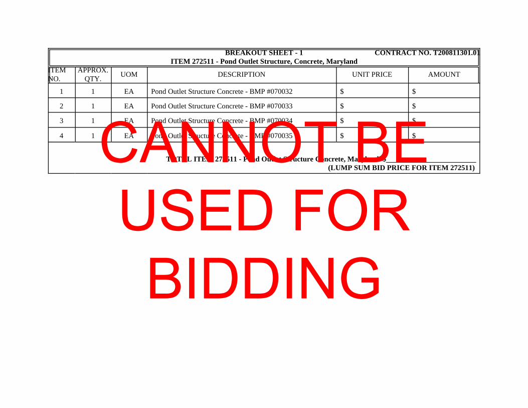
BREAKOUT SHEET - 1 CONTRACT NO. T200811301.01ITEM 272511 - Pond Outlet Structure, Concrete, Maryland
ITEMNO.
APPROX.QTY. UOM DESCRIPTION UNIT PRICE AMOUNT
1 1 EA Pond Outlet Structure Concrete - BMP #070032 $ $
2 1 EA Pond Outlet Structure Concrete - BMP #070033 $ $
3 1 EA Pond Outlet Structure Concrete - BMP #070034 $ $
4 1 EA Pond Outlet Structure Concrete - BMP #070035 $ $
TOTAL ITEM 272511 - Pond Outlet Structure Concrete, Maryland $ (LUMP SUM BID PRICE FOR ITEM 272511)
CANNOT BE USED FOR BIDDING

BREAKOUT SHEET - 2 CONTRACT NO. T200811301.01602772 - Mechanically Stabilized Earth Walls
ITEMNO.
APPROX.QTY. UOM DESCRIPTION UNIT PRICE AMOUNT
1 1 LS Bridge 1-482 MSE Walls at Abutment 1 (Abutment andWingwalls)
$ $
2 1 LS Bridge 1-482 MSE Walls at Abutment 2 (Abutment andWingwalls)
$ $
TOTAL ITEM 602772 - Mechanically Stabilized Earth Walls $ (LUMP SUM BID PRICE FOR ITEM 602772)CANNOT BE
USED FOR BIDDING
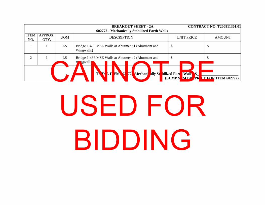
BREAKOUT SHEET - 2A CONTRACT NO. T200811301.01602772 - Mechanically Stabilized Earth Walls
ITEMNO.
APPROX.QTY. UOM DESCRIPTION UNIT PRICE AMOUNT
1 1 LS Bridge 1-486 MSE Walls at Abutment 1 (Abutment andWingwalls)
$ $
2 1 LS Bridge 1-486 MSE Walls at Abutment 2 (Abutment andWingwalls)
$ $
TOTAL ITEM 602772 - Mechanically Stabilized Earth Walls $ (LUMP SUM BID PRICE FOR ITEM 602772)CANNOT BE
USED FOR BIDDING
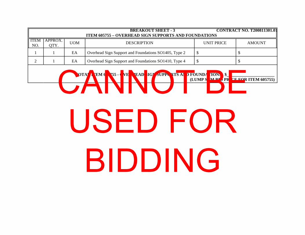
BREAKOUT SHEET - 3 CONTRACT NO. T200811301.01ITEM 605755 – OVERHEAD SIGN SUPPORTS AND FOUNDATIONS
ITEMNO.
APPROX.QTY. UOM DESCRIPTION UNIT PRICE AMOUNT
1 1 EA Overhead Sign Support and Foundations SO1405, Type 2 $ $
2 1 EA Overhead Sign Support and Foundations SO1410, Type 4 $ $
TOTAL ITEM 605755 - OVERHEAD SIGN SUPPORTS AND FOUNDATIONS $ (LUMP SUM BID PRICE FOR ITEM 605755)CANNOT BE
USED FOR BIDDING
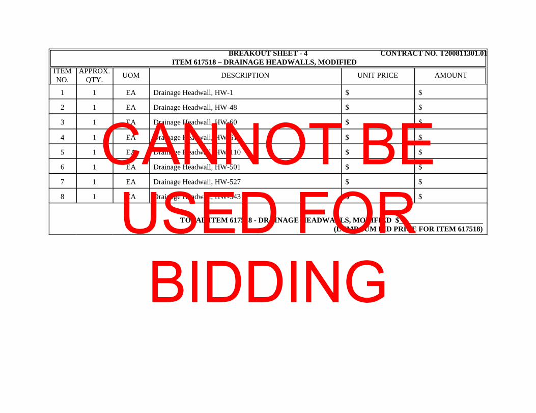
BREAKOUT SHEET - 4 CONTRACT NO. T200811301.01ITEM 617518 – DRAINAGE HEADWALLS, MODIFIED
ITEMNO.
APPROX.QTY. UOM DESCRIPTION UNIT PRICE AMOUNT
1 1 EA Drainage Headwall, HW-1 $ $
2 1 EA Drainage Headwall, HW-48 $ $
3 1 EA Drainage Headwall, HW-60 $ $
4 1 EA Drainage Headwall, HW-61 $ $
5 1 EA Drainage Headwall, HW-110 $ $
6 1 EA Drainage Headwall, HW-501 $ $
7 1 EA Drainage Headwall, HW-527 $ $
8 1 EA Drainage Headwall, HW-543 $ $
TOTAL ITEM 617518 - DRAINAGE HEADWALLS, MODIFIED $ (LUMP SUM BID PRICE FOR ITEM 617518)
CANNOT BE USED FOR BIDDING
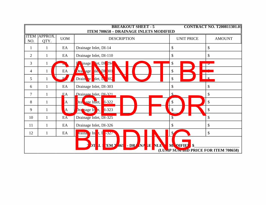
BREAKOUT SHEET - 5 CONTRACT NO. T200811301.01ITEM 708658 – DRAINAGE INLETS MODIFIED
ITEMNO.
APPROX.QTY. UOM DESCRIPTION UNIT PRICE AMOUNT
1 1 EA Drainage Inlet, DI-14 $ $
2 1 EA Drainage Inlet, DI-110 $ $
3 1 EA Drainage Inlet, DI-294 $ $
4 1 EA Drainage Inlet, DI-301 $ $
5 1 EA Drainage Inlet, DI-302 $ $
6 1 EA Drainage Inlet, DI-303 $ $
7 1 EA Drainage Inlet, DI-321 $ $
8 1 EA Drainage Inlet, DI-322 $ $
9 1 EA Drainage Inlet, DI-323 $ $
10 1 EA Drainage Inlet, DI-325 $ $
11 1 EA Drainage Inlet, DI-326 $ $
12 1 EA Drainage Inlet, DI-327 $ $
TOTAL ITEM 708658 - DRAINAGE INLETS, MODIFIED $ (LUMP SUM BID PRICE FOR ITEM 708658)
CANNOT BE USED FOR BIDDING
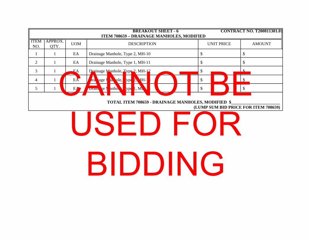
BREAKOUT SHEET - 6 CONTRACT NO. T200811301.01ITEM 708659 – DRAINAGE MANHOLES, MODIFIED
ITEMNO.
APPROX.QTY. UOM DESCRIPTION UNIT PRICE AMOUNT
1 1 EA Drainage Manhole, Type 2, MH-10 $ $
2 1 EA Drainage Manhole, Type 1, MH-11 $ $
3 1 EA Drainage Manhole, Type 2, MH-12 $ $
4 1 EA Drainage Manhole, Type 2, MH-13 $ $
5 1 EA Drainage Manhole, Type 1, MH-14 $ $
TOTAL ITEM 708659 - DRAINAGE MANHOLES, MODIFIED $ (LUMP SUM BID PRICE FOR ITEM 708659)
CANNOT BE USED FOR BIDDING
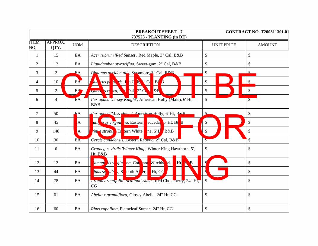
BREAKOUT SHEET - 7 CONTRACT NO. T200811301.01737523 - PLANTING (in DE)
ITEMNO.
APPROX.QTY. UOM DESCRIPTION UNIT PRICE AMOUNT
1 15 EA Acer rubrum 'Red Sunset', Red Maple, 3" Cal, B&B $ $
2 13 EA Liquidambar styraciflua, Sweet-gum, 2" Cal, B&B $ $
3 2 EA Platanus occidentalis, Sycamore, 3" Cal, B&B $ $
4 10 EA Quercus palustris, Pin Oak, 3" Cal, B&B $ $
5 2 EA Quercus rubra, Red Oak, 2" Cal, B&B $ $
6 4 EA Ilex opaca 'Jersey Knight', American Holly (Male), 6' Ht,B&B
$ $
7 50 EA Ilex opaca 'Miss Helen', American Holly, 6' Ht, B&B $ $
8 45 EA Juniperus virginiana, Eastern Redcedar, 6' Ht, B&B $ $
9 148 EA Pinus strobus, Eastern White Pine, 6' Ht, B&B $ $
10 30 EA Cercis canadensis, Eastern Redbud, 2" Cal, B&B $ $
11 6 EA Crataegus virdis 'Winter King', Winter King Hawthorn, 5',Ht, B&B
$ $
12 12 EA Hamamelis virginiana, Common Witchhazel, 5' Ht, B&B $ $
13 44 EA Alnus serrulata, Smooth Alder, 3' Ht, CG $ $
14 78 EA Aronia arbutifolia 'Brilliantissima', Red Chokeberry, 24" Ht,CG
$ $
15 61 EA Abelia x grandiflora, Glossy Abelia, 24" Ht, CG $ $
16 60 EA Rhus copallina, Flameleaf Sumac, 24" Ht, CG $ $
CANNOT BE USED FOR BIDDING
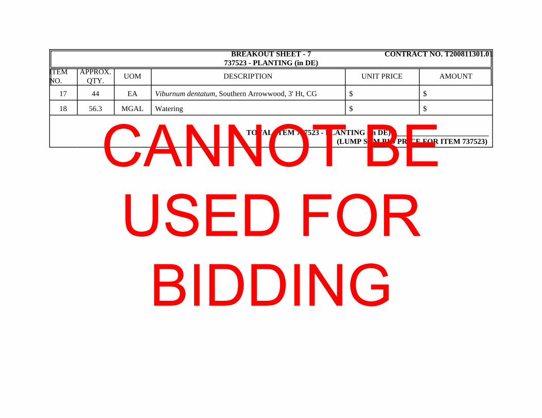
BREAKOUT SHEET - 7 CONTRACT NO. T200811301.01737523 - PLANTING (in DE)
ITEMNO.
APPROX.QTY. UOM DESCRIPTION UNIT PRICE AMOUNT
17 44 EA Viburnum dentatum, Southern Arrowwood, 3' Ht, CG $ $
18 56.3 MGAL Watering $ $
TOTAL ITEM 737523 - PLANTING (in DE) $ (LUMP SUM BID PRICE FOR ITEM 737523)CANNOT BE
USED FOR BIDDING
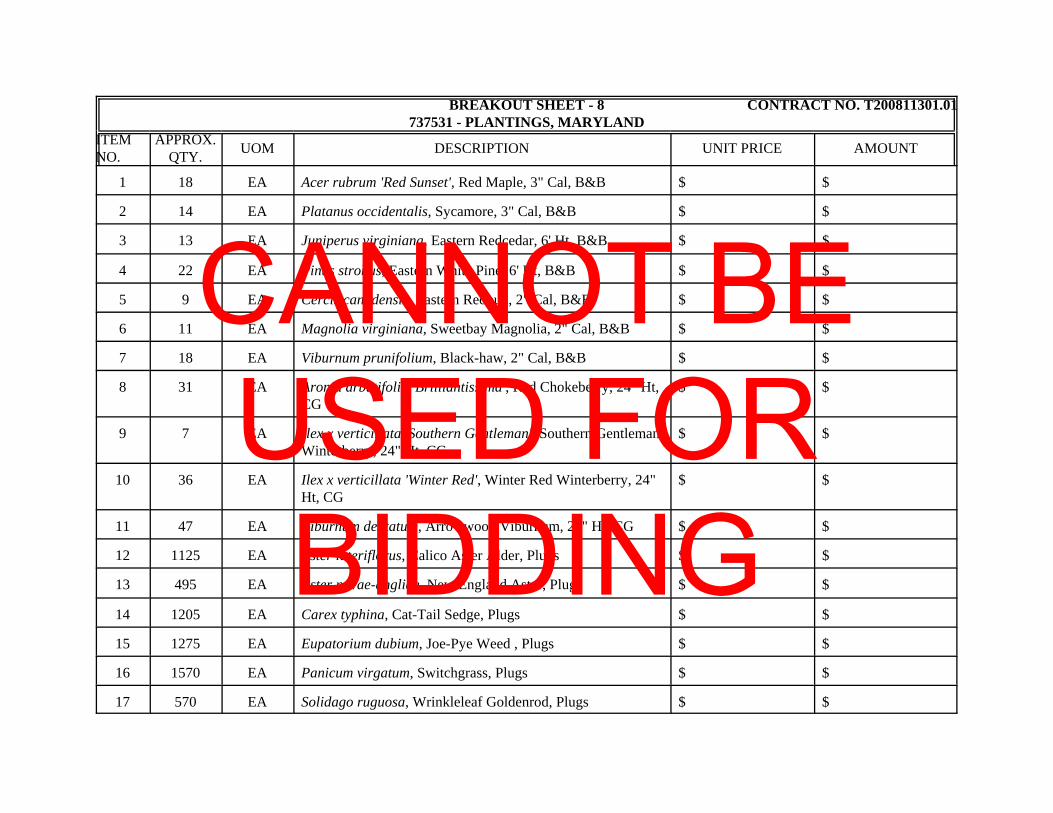
BREAKOUT SHEET - 8 CONTRACT NO. T200811301.01737531 - PLANTINGS, MARYLAND
ITEMNO.
APPROX.QTY. UOM DESCRIPTION UNIT PRICE AMOUNT
1 18 EA Acer rubrum 'Red Sunset', Red Maple, 3" Cal, B&B $ $
2 14 EA Platanus occidentalis, Sycamore, 3" Cal, B&B $ $
3 13 EA Juniperus virginiana, Eastern Redcedar, 6' Ht, B&B $ $
4 22 EA Pinus strobus, Eastern White Pine, 6' Ht, B&B $ $
5 9 EA Cercis canadensis, Eastern Redbud, 2" Cal, B&B $ $
6 11 EA Magnolia virginiana, Sweetbay Magnolia, 2" Cal, B&B $ $
7 18 EA Viburnum prunifolium, Black-haw, 2" Cal, B&B $ $
8 31 EA Aronia arbutifolia 'Brilliantissima', Red Chokeberry, 24" Ht,CG
$ $
9 7 EA Ilex x verticillata 'Southern Gentleman', Southern GentlemanWinterberry, 24" Ht, CG
$ $
10 36 EA Ilex x verticillata 'Winter Red', Winter Red Winterberry, 24"Ht, CG
$ $
11 47 EA Viburnum dentatum, Arrowwood Viburnum, 24" Ht, CG $ $
12 1125 EA Aster lateriflorus, Calico Aster Alder, Plugs $ $
13 495 EA Aster novae-angliae, New England Aster, Plugs $ $
14 1205 EA Carex typhina, Cat-Tail Sedge, Plugs $ $
15 1275 EA Eupatorium dubium, Joe-Pye Weed , Plugs $ $
16 1570 EA Panicum virgatum, Switchgrass, Plugs $ $
17 570 EA Solidago ruguosa, Wrinkleleaf Goldenrod, Plugs $ $
CANNOT BE USED FOR BIDDING
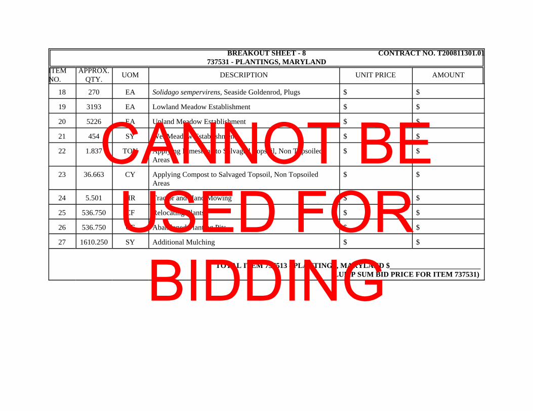
BREAKOUT SHEET - 8 CONTRACT NO. T200811301.01737531 - PLANTINGS, MARYLAND
ITEMNO.
APPROX.QTY. UOM DESCRIPTION UNIT PRICE AMOUNT
18 270 EA Solidago sempervirens, Seaside Goldenrod, Plugs $ $
19 3193 EA Lowland Meadow Establishment $ $
20 5226 EA Upland Meadow Establishment $ $
21 454 SY Wet Meadow Establishment $ $
22 1.837 TON Applying Limestone to Salvaged Topsoil, Non TopsoiledAreas
$ $
23 36.663 CY Applying Compost to Salvaged Topsoil, Non TopsoiledAreas
$ $
24 5.501 HR Tractor and Hand Mowing $ $
25 536.750 CF Relocating Plants $ $
26 536.750 CF Abandoned Planting Pits $ $
27 1610.250 SY Additional Mulching $ $
TOTAL ITEM 737513 - PLANTINGS, MARYLAND $ (LUMP SUM BID PRICE FOR ITEM 737531)
CANNOT BE USED FOR BIDDING
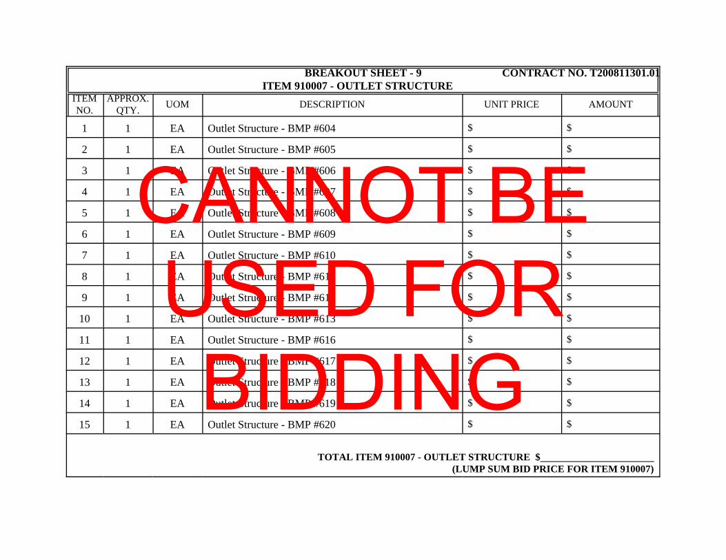
BREAKOUT SHEET - 9 CONTRACT NO. T200811301.01ITEM 910007 - OUTLET STRUCTURE
ITEMNO.
APPROX.QTY. UOM DESCRIPTION UNIT PRICE AMOUNT
1 1 EA Outlet Structure - BMP #604 $ $
2 1 EA Outlet Structure - BMP #605 $ $
3 1 EA Outlet Structure - BMP #606 $ $
4 1 EA Outlet Structure - BMP #607 $ $
5 1 EA Outlet Structure - BMP #608 $ $
6 1 EA Outlet Structure - BMP #609 $ $
7 1 EA Outlet Structure - BMP #610 $ $
8 1 EA Outlet Structure - BMP #611 $ $
9 1 EA Outlet Structure - BMP #612 $ $
10 1 EA Outlet Structure - BMP #613 $ $
11 1 EA Outlet Structure - BMP #616 $ $
12 1 EA Outlet Structure - BMP #617 $ $
13 1 EA Outlet Structure - BMP #618 $ $
14 1 EA Outlet Structure - BMP #619 $ $
15 1 EA Outlet Structure - BMP #620 $ $
TOTAL ITEM 910007 - OUTLET STRUCTURE $ (LUMP SUM BID PRICE FOR ITEM 910007)
CANNOT BE USED FOR BIDDING

"ATTENTION"
TO BIDDERS
BREAKOUT SHEET(S) MUST BE SUBMITTED EITHER WITH YOUR BID DOCUMENTS;
OR WITHIN SEVEN (7) CALENDAR DAYS FOLLOWING THE BID DUE DATE BY THE
LOWEST APPARENT BIDDER.
BREAKOUT SHEETS ARE TO BE SUBMITTED TO DELDOT'S CONTRACT ADMINISTRATION
AS SHOWN BELOW. BREAKOUT SHEETS CANNOT BE CHANGED AFTER AWARD. THE
DEPARTMENT WILL REVIEW THE FIGURES SUBMITTED ON THE BREAKOUT SHEET(S) TO
ENSURE THEY MATCH THE RESPECTIVE LUMP SUM BID AMOUNT(S). MATHEMATICALLY
INCORRECT BREAKOUT SHEETS WILL BE RETURNED FOR IMMEDIATE CORRECTION.
BREAKOUT SHEETS MAY BE SUBMITTED;
VIA E-MAIL TO: [email protected] SUBJECT: T200811301.01 Breakout Sheet
OR MAILED TO: DELDOTCONTRACT ADMINISTRATIONPO BOX 778, DOVER, DE 19903
'BREAKOUT SHEET' AND THE PROJECT NUMBER MUST APPEAR ON THE ENVELOPE.

Prequalification for US 301 Contracts
I certify that __________________________________________ , Contractor/Subcontractor Company
Check One:
Either independently or through agreement with other organizations, is
providing craft training for journeyman and apprentice levels through a
bona fide program approved by and registered with the State of Delaware
and/or United States Department of Labor, to comply with 29 Del C.
6962(c)(11). Enclosed is a copy of the certification of this program.
Does not have a Craft Training Program because we do not have any
apprenticeable trades, as defined in the Rules and Regulations Relating to
Delaware Apprenticeship and Training Law Sections 5 and 6. Enclosed is
documentation from the State of Delaware and/or United States
Department of Labor confirming this determination.
Name:_________________________
Title: ____________________________
Date:_____________________________
The completed Form and supporting documentation must be submitted no later
than 10 a.m. local time on the day of the bid opening for Prequalification.
CANNOT BE USED FOR BIDDING

CERTIFICATION
Contract No. T200811301.01 Federal Aid Project No. NH-2015 (20)
The undersigned bidder,
whose address is
and telephone number is hereby certifies the following:
I/We have carefully examined the location of the proposed work, the proposed plans andspecifications, and will be bound, upon award of this contract by the Department of Transportation, toexecute in accordance with such award, a contract with necessary surety bond, of which contract thisproposal and said plans and specifications shall be a part, to provide all necessary machinery, tools, laborand other means of construction, and to do all the work and to furnish all the materials necessary toperform and complete the said contract within the time and as required in accordance with therequirements of the Department of Transportation, and at the unit prices for the various items as listed onthe preceding pages.
Bidder's Certification Statement [US DOT Suspension and Debarment Regulation (49 CFR 29)]:
NOTICE: All contractors who hold prime contracts (Federal Aid) with DelDOT are advised that theprime contractor and subcontractors are required to submit to DelDOT a signed and notary attestedcopy of the Bidder Certification Statement for each and every subcontract that will be utilized by theprime contractor. This Certification must be filed with DelDOT prior to written approval beinggranted for each and every subcontractor. Copies of the Certification Form are available from theappropriate District Construction Office.
Under penalty of perjury under the laws of the United States, that I/We, or any person associatedtherewith in the capacity of (owner, partner, director, officer, principal, investigator, project director,manager, auditor, or any position involving the administration federal funds):a. am/are not currently under suspension, debarment, voluntary exclusion, or determination of
ineligibility by any federal agency;b. have not been suspended, debarred, voluntarily excluded or determined ineligible by any federal
agency within the past 3 years;c. do not have a proposed debarment pending; and,d. have not been indicted, convicted, or had a civil judgement rendered against (it) by a court of
competent jurisdiction in any matter involving fraud or official misconduct within the past 3 years.
Exceptions will not necessarily result in denial of award, but will be considered in determining bidderresponsibility. For any exception noted, indicate below to whom it applies, initiating agency, and dates ofaction. Providing false information may result in criminal prosection or administrative sanctions.
(Insert Exceptions)DBE Program Assurance:
NOTICE: In accordance with 49 CFR Part 26 the undersigned, a legally authorized representative ofthe bidder listed below, must complete this assurance. By its signature affixed hereto, assures theDepartment that it will attain DBE participation as indicated:
Disadvantaged Business Enterprise percent (blank to be filled in by bidder)
CANNOT BE USED FOR BIDDING

The foregoing quantities are considered to be approximate only and are given as the basis forcomparison of bids. The Department of Transportation may increase or decrease the amount of any itemor portion of the work as may be deemed necessary or expedient. Any such increase or decrease in thequantity for any item will not be regarded as a sufficient ground for an increase or decrease in the unitprices, nor in the time allowed for the completion of the work, except as provided in the contract.
Accompanying this proposal is a surety bond or a security of the bidder assigned to the Department ofTransportation, for at least ten (10) percentum of total amount of the proposal, which deposit is to beforfeited as liquidated damages in case this proposal is accepted, and the undersigned shall fail to executea contract with necessary bond, when required, for the performance of said contract with the Departmentof Transportation, under the conditions of this proposal, within twenty (20) days after date of officialnotice of the award of the contract as provided in the requirement and specifications hereto attached;otherwise said deposit is to be returned to the undersigned.
I/We are licensed, or have initiated the license application as required by Section 2502, Chapter 25,Title 30, of the Delaware Code.
By submission of this proposal, each person signing on behalf of the bidder, certifies as to its ownorganization, under penalty of perjury, that to the best of each signer’s knowledge and belief:
1. The prices in this proposal have been arrived at independently without collusion, consultation,communication, or Agreement with any other bidder or with any competitor for the purpose ofrestricting competition.
2. Unless required by law, the prices which have been quoted in this proposal have not beenknowingly disclosed and will not knowingly be disclosed by the bidder, directly or indirectly, toany other bidder or competitor prior to the opening of proposals.
3. No attempt has been made or will be made by the bidder to induce any other person, partnership,or corporation to submit or not to submit a proposal for the purpose of restricting competition.
===========================================================================I/We acknowledge receipt and incorporation of addenda to this proposal as follows:
No. Date No. Date No. Date No. Date No. Date
BIDDERS MUST ACKNOWLEDGE RECEIPT OF ALL ADDENDA
MUST INSERT DATE OF FINAL QUESTIONS AND ANSWERS ON WEBSITE: _____________ ³===========================================================================
Sealed and dated this day of in the year of our Lord two thousand ( 20 ).
Name of Bidder (Organization)
CorporateSeal
By:Authorized Signature
Attest Title
SWORN TO AND SUBSCRIBED BEFORE ME this day of , 20 .Notary
Seal
Notary
CANNOT BE USED FOR BIDDING

BID BOND
TO ACCOMPANY PROPOSAL(Not necessary if security is used)
KNOW ALL MEN BY THESE PRESENTS That:
of in the County of and State of as
Principal, and of in the County of
and State of as Surety, legally authorized to do business in the State of
Delaware ("State"), are held and firmly unto the State in the sum of
Dollars ($ ), or percent not to exceed
Dollars ($ ) of amount of bid onContract No. T200811301.01 , to be paid to the State for the use and benefit of its Department ofTransportation ("DelDOT") for which payment well and truly to be made, we do bind ourselves, our andeach of our heirs, executors, administrators, and successors, jointly and severally for and in the wholefirmly by these presents.
NOW THE CONDITION OF THIS OBLIGATION IS SUCH That if the above bounden Principalwho has submitted to the DelDOT a certain proposal to enter into this contract for the furnishing ofcertain materiel and/or services within the State, shall be awarded this Contract, and if said Principalshall well and truly enter into and execute this Contract as may be required by the terms of this Contractand approved by the DelDOT, this Contract to be entered into within twenty days after the date of officialnotice of the award thereof in accordance with the terms of said proposal, then this obligation shall bevoid or else to be and remain in full force and virtue.
Sealed with seal and dated this day of in the year of our Lord
two thousand and ( 20 ).
SEALED, AND DELIVERED IN THEpresence of
Name of Bidder (Organization)
CorporateSeal
By:Authorized Signature
Attest Title
Name of Surety
Witness: By:
Title
CANNOT BE USED FOR BIDDING