Embed Size (px)
Citation preview
Ci
Ma
b
a
ARRAA
KTOEC
1
iabembmaiimwtoctT
(
0d
Electrochimica Acta 56 (2010) 193–202
Contents lists available at ScienceDirect
Electrochimica Acta
journa l homepage: www.e lsev ier .com/ locate /e lec tac ta
omparing performance of nanoarchitectures fabricated by Ti6Al7Nb anodizingn two kinds of electrolytes
ihaela Mîndroiua, Cristian Pirvua,1, Raluca Ionb, Ioana Demetrescua,∗,1
University Polytechnic of Bucharest, Faculty of Applied Chemistry and Materials Science, 1-7 Polizu, 011061 Bucharest, RomaniaUniversity of Bucharest, Research Center for Biochemistry and Molecular Biology, 91-95 Independentei, 76201 Bucharest, Romania
r t i c l e i n f o
rticle history:eceived 14 July 2010eceived in revised form 30 August 2010ccepted 30 August 2010vailable online 17 September 2010
eywords:
a b s t r a c t
The present paper is focused on comparative behaviour of various nanotubes growth on Ti6Al7Nb alloyusing electrochemical procedure. The anodizing method under controlled conditions was performed intwo kinds of electrolytes as following: a mixture of fluoride salts as inorganic solution (NH4)2SO4 + NH4F0.5 wt%), and a hybrid inorganic + organic components as glycerol + 4% H2O + NH4F 0.36 wt%. The obtainedsurface nanostructures were investigated with an Environmental Scanning Electron Microscope and withan Atomic Force Microscope. The evaluation of hydrophilic character completed the surface character-
i6Al7Nb alloyxide nanotube layerlectrochemical behaviourell response
ization. The performance of nanotubes layers on Ti6Al7Nb alloy was evaluated from electrochemicalmethods (open circuit potential, cyclic voltammetry, Electrochemical Impedance Spectroscopy and fromcellular response at the interface Ti6Al7Nb/oxide/bioelectrolyte). The behaviour of studied systems wasdiscussed taking into account the effect of ˛ + ˇ phases of the bioalloy and fabrication conditions ofnanotubes. The improvement in cellular response was ascribed to nanotubes structure as results of fab-rication route. As a conclusion the nanoarchitectures obtained in hybrid inorganic + organic components
4F 0.3
as glycerol + 4% H2O + NH. Introduction
The performance of a material with potential applicationsn implantology should be evaluated depending on materialnd approach [1]. Our approach in understanding performanceehaviour of metallic biomaterials is related both to real surfacevaluation in electrochemistry according to in situ and ex situethods [2], and to biocompatibility [3], and such aspects have
een discussed in the last years, as a part of materials bioperfor-ance [4]. In the context of osseointegration of metal implants such
s titanium, well known for its very good stability [4,5] and mechan-cal properties [6] were subject to various processing proceduresn order to change the inert behaviour in physiological environ-
ents [7,8] to an active one [9,10]. In implant history, anotheray of reaching a better biocompatibility was related to fabrica-
ion of biomimetic coating on titanium implants as hydroxyapatite
r other phosphate coating [11–13] able to enhance system bio-ompatibility due to a structure close to natural bone [14]. Despitehe very good electrochemical behaviour and biocompatibility ofi, the mechanical properties were not good enough in various∗ Corresponding author. Tel.: +40 214023930.E-mail addresses: i [email protected], IOANA [email protected]
I. Demetrescu).1 ISE member.
013-4686/$ – see front matter © 2010 Elsevier Ltd. All rights reserved.oi:10.1016/j.electacta.2010.08.100
6 wt% leads to more performances.© 2010 Elsevier Ltd. All rights reserved.
situations, and alloying was the route to solve this problem andto obtain improvement [15,16]. The first ternary alloy proposedwas TiAlV [17], which is still in use; due to the suspicion of cyto-toxicity, however, several other ternary Ti alloys were introducedand homologated as implant materials. One of them is TiAlNb alloy[18], being a typical ˛ + ˇ alloy, with Al as stabilizing element for˛ phase and Nb as an element of stabilizing ˇ phase. In the lastyears, several surface modifications were investigated, in order toget a friendly response from implant host [19–21]. The propertiesof Ti and Ti alloys enhancement is related more recently to a nanos-tructure in the entire bulk [22,23] or at surface level [24,25]. Thesekind of procedures have the potential to enhance the biomechan-ical interlocking, and the literature data [26,27] pointed out nonsophisticated methods as anodizing under controlled conditionsable to fabricate self-organized nanotubular porous oxide layers.The TiAlNb two phases alloy was anodized in (NH4)2SO4 + NH4F0.5 wt% solution and an almost ideal coverage of both phases wasreported [28]. The objective of the research described here is acomparative behaviour of nanotubes growth on Ti6Al7Nb alloyusing anodizing in two kinds of electrolytes: mixture of fluoridesalts for inorganic solution (similar mixture to the above), and a
hybrid inorganic + organic components as glycerol + 4% H2O + NH4F0.36 wt%. These two kinds of electrolytes are representative foranodic growth of self-organized TiO2 nanotubes in water-basedelectrolytes and in viscous electrolytes [29–34]. Our study is relatedto the anodized Ti6Al7Nb alloy for nanotubes performance and the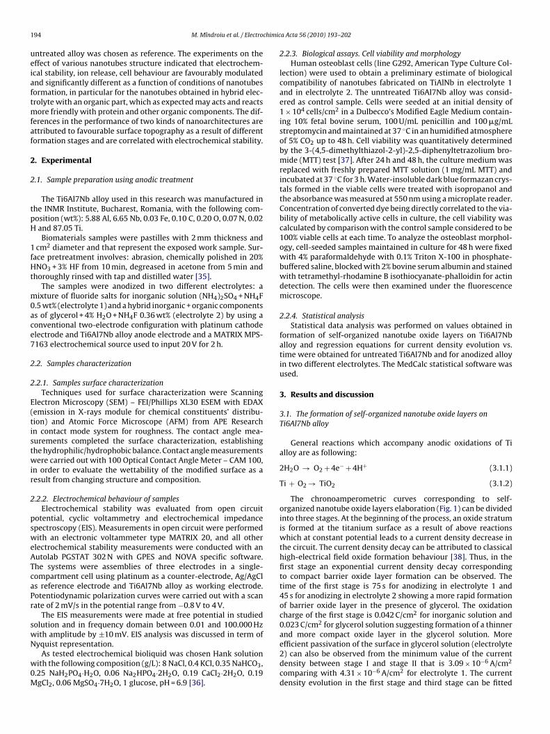
1 chimic
ueiaftmfaf
2
2
tpH
1fHt
m0ace7
2
2
E(tistwir
2
psweATcaPr
swN
w0M
94 M. Mîndroiu et al. / Electro
ntreated alloy was chosen as reference. The experiments on theffect of various nanotubes structure indicated that electrochem-cal stability, ion release, cell behaviour are favourably modulatednd significantly different as a function of conditions of nanotubesormation, in particular for the nanotubes obtained in hybrid elec-rolyte with an organic part, which as expected may acts and reacts
ore friendly with protein and other organic components. The dif-erences in the performance of two kinds of nanoarchitectures arettributed to favourable surface topography as a result of differentormation stages and are correlated with electrochemical stability.
. Experimental
.1. Sample preparation using anodic treatment
The Ti6Al7Nb alloy used in this research was manufactured inhe INMR Institute, Bucharest, Romania, with the following com-osition (wt%): 5.88 Al, 6.65 Nb, 0.03 Fe, 0.10 C, 0.20 O, 0.07 N, 0.02and 87.05 Ti.Biomaterials samples were pastilles with 2 mm thickness and
cm2 diameter and that represent the exposed work sample. Sur-ace pretreatment involves: abrasion, chemically polished in 20%NO3 + 3% HF from 10 min, degreased in acetone from 5 min and
horoughly rinsed with tap and distilled water [35].The samples were anodized in two different electrolytes: a
ixture of fluoride salts for inorganic solution (NH4)2SO4 + NH4F.5 wt% (electrolyte 1) and a hybrid inorganic + organic componentss of glycerol + 4% H2O + NH4F 0.36 wt% (electrolyte 2) by using aonventional two-electrode configuration with platinum cathodelectrode and Ti6Al7Nb alloy anode electrode and a MATRIX MPS-163 electrochemical source used to input 20 V for 2 h.
.2. Samples characterization
.2.1. Samples surface characterizationTechniques used for surface characterization were Scanning
lectron Microscopy (SEM) – FEI/Phillips XL30 ESEM with EDAXemission in X-rays module for chemical constituents’ distribu-ion) and Atomic Force Microscope (AFM) from APE Researchn contact mode system for roughness. The contact angle mea-urements completed the surface characterization, establishinghe hydrophilic/hydrophobic balance. Contact angle measurementsere carried out with 100 Optical Contact Angle Meter – CAM 100,
n order to evaluate the wettability of the modified surface as aesult from changing structure and composition.
.2.2. Electrochemical behaviour of samplesElectrochemical stability was evaluated from open circuit
otential, cyclic voltammetry and electrochemical impedancepectroscopy (EIS). Measurements in open circuit were performedith an electronic voltammeter type MATRIX 20, and all other
lectrochemical stability measurements were conducted with anutolab PGSTAT 302 N with GPES and NOVA specific software.he systems were assemblies of three electrodes in a single-ompartment cell using platinum as a counter-electrode, Ag/AgCls reference electrode and Ti6Al7Nb alloy as working electrode.otentiodynamic polarization curves were carried out with a scanate of 2 mV/s in the potential range from −0.8 V to 4 V.
The EIS measurements were made at free potential in studiedolution and in frequency domain between 0.01 and 100.000 Hzith amplitude by ±10 mV. EIS analysis was discussed in term of
yquist representation.As tested electrochemical bioliquid was chosen Hank solutionith the following composition (g/L): 8 NaCl, 0.4 KCl, 0.35 NaHCO3,
.25 NaH2PO4·H2O, 0.06 Na2HPO4·2H2O, 0.19 CaCl2·2H2O, 0.19gCl2, 0.06 MgSO4·7H2O, 1 glucose, pH = 6.9 [36].
a Acta 56 (2010) 193–202
2.2.3. Biological assays. Cell viability and morphologyHuman osteoblast cells (line G292, American Type Culture Col-
lection) were used to obtain a preliminary estimate of biologicalcompatibility of nanotubes fabricated on TiAlNb in electrolyte 1and in electrolyte 2. The unntreated Ti6Al7Nb alloy was consid-ered as control sample. Cells were seeded at an initial density of1 × 104 cells/cm2 in a Dulbecco’s Modified Eagle Medium contain-ing 10% fetal bovine serum, 100 U/mL penicillin and 100 �g/mLstreptomycin and maintained at 37 ◦C in an humidified atmosphereof 5% CO2 up to 48 h. Cell viability was quantitatively determinedby the 3-(4,5-dimethylthiazol-2-yl)-2,5-diphenyltetrazolium bro-mide (MTT) test [37]. After 24 h and 48 h, the culture medium wasreplaced with freshly prepared MTT solution (1 mg/mL MTT) andincubated at 37 ◦C for 3 h. Water-insoluble dark blue formazan crys-tals formed in the viable cells were treated with isopropanol andthe absorbance was measured at 550 nm using a microplate reader.Concentration of converted dye being directly correlated to the via-bility of metabolically active cells in culture, the cell viability wascalculated by comparison with the control sample considered to be100% viable cells at each time. To analyze the osteoblast morphol-ogy, cell-seeded samples maintained in culture for 48 h were fixedwith 4% paraformaldehyde with 0.1% Triton X-100 in phosphate-buffered saline, blocked with 2% bovine serum albumin and stainedwith tetramethyl-rhodamine B isothiocyanate-phalloidin for actindetection. The cells were then examined under the fluorescencemicroscope.
2.2.4. Statistical analysisStatistical data analysis was performed on values obtained in
formation of self-organized nanotube oxide layers on Ti6Al7Nballoy and regression equations for current density evolution vs.time were obtained for untreated Ti6Al7Nb and for anodized alloyin two different electrolytes. The MedCalc statistical software wasused.
3. Results and discussion
3.1. The formation of self-organized nanotube oxide layers onTi6Al7Nb alloy
General reactions which accompany anodic oxidations of Tialloy are as following:
2H2O → O2 + 4e− + 4H+ (3.1.1)
Ti + O2 → TiO2 (3.1.2)
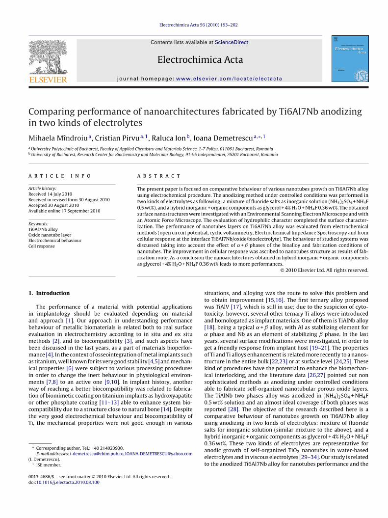
The chronoamperometric curves corresponding to self-organized nanotube oxide layers elaboration (Fig. 1) can be dividedinto three stages. At the beginning of the process, an oxide stratumis formed at the titanium surface as a result of above reactionswhich at constant potential leads to a current density decrease inthe circuit. The current density decay can be attributed to classicalhigh-electrical field oxide formation behaviour [38]. Thus, in thefirst stage an exponential current density decay correspondingto compact barrier oxide layer formation can be observed. Thetime of the first stage is 75 s for anodizing in electrolyte 1 and45 s for anodizing in electrolyte 2 showing a more rapid formationof barrier oxide layer in the presence of glycerol. The oxidationcharge of the first stage is 0.042 C/cm2 for inorganic solution and0.023 C/cm2 for glycerol solution suggesting formation of a thinnerand more compact oxide layer in the glycerol solution. More
efficient passivation of the surface in glycerol solution (electrolyte2) can also be observed from the minimum value of the currentdensity between stage I and stage II that is 3.09 × 10⁻⁶ A/cm2comparing with 4.31 × 10⁻⁶ A/cm2 for electrolyte 1. The currentdensity evolution in the first stage and third stage can be fitted
M. Mîndroiu et al. / Electrochimic
Fe
wcf
p
T
tore
igti
assts
mica
ig. 1. The current density evolution of Ti6Al7Nb alloy in 2 h anodizing time in: (a)lectrolyte 1 and (b) electrolyte 2, at 20 V.
ith an exponential equation, j = k × t−n. The obtained equation isompared with the Cottrell equation [39], but n has still deviaterom the value of 0.5.
Due to the fluoride ions presence, the oxide stratum suffers aartial dissolution with pits formation:
iO2 + 6F− + 4H+ → TiF62− + 2H2O (3.1.3)
These pits act as the pore forming centres; as was described inhe literature [34] this model of dissolution is a key factor of wellrganized structure of titanium nanotubes. This way, an action foreducing of barrier oxide stratum is taking place, keeping an activelectrochemical corrosion.
As a consequence, the current density starts to increase againn the next stage. The surface is locally activated and pores start torow randomly (II). Due to pore growth, both the active area andhe current density increase. After some time, the pores have beennitiated and a tree-like growth takes place [40].
The individual pores start interfering, and compete for the avail-ble current density. Under optimized conditions this leads to aituation where the pores equally share the available current, andelf-ordering under steady state conditions is established. Thus inhe stage III the current density decreases and reaches a quasi-teady state of about 100 �A/cm2 for both electrolytes.
In the presence of glycerol, the competition between the for-ation of the Ti–glycerol complex and the restriction of fluoride
on diffusion is taking place, but the formation of the Ti–glycerolomplex accelerates the dissolution of the oxide layer facilitatingppearance ordered TiO2 nanotubes. Such highly viscous elec-
a Acta 56 (2010) 193–202 195
trolytes can suppress one dissolution process through decreasingthe diffusion constant of the F−, and such behaviour reveals theimportance of the amount of water in electrolyte, as was suggestedin some studies [29,41].
The influence of electrolyte viscosity can also be observed bythe deviation of n coefficient form Cottrell equation from 0.5 toalmost 0.15 for fitted equation of the stage III (j = 11597 × t−0.615
for electrolyte 1 and j = 562 × t−0.146 for electrolyte 2).To further understand the formation of the nanotube like struc-
tures during anodizing of alloy there is a need to have a look tothe anodizing of aluminium. According to literature data porousstructures are formed through two processes during aluminiumanodizing [42], both of them being field enhanced. The first processis oxidation of aluminium which occurs at the metal/oxide inter-face near the pore bottom and the second the oxide dissolution,consisting first in the migration of metal ions (Al+3) from metal tothe solution/oxide interface followed up by a dissolution into thesolution. At higher intensity aluminium will be consumed at a highrate near the bottom of the pore, permitting the growth of the poredepth, in contrast, with thickness of porous oxide of titanium whichdoes not increase with the anodizing time. As a result a continuouspore structures is achieved during aluminium anodizing, and a dis-continuous nanoporous titanium oxide film is formed in the caseof titanium. It is known that Nb just like Al, has a tendency to formporous oxide in the anodizing conditions when Ti tends to formnanotubes [41]. At higher water content the morphology changesto tubular structure. From such structures transitions to nanotubeswith different diameters are taking place, sustaining the fabricationof such valve metal alloy oxide nanotubes array [43].
3.2. Surface characterization
Surface features were investigated using scanning elec-tronic microscopy, atomic force microscopy and balancehydrophilic/hydrophobic character evaluation.
3.2.1. Scanning electronic microscopy (SEM)The SEM characterization of untreated Ti6Al7Nb alloy has
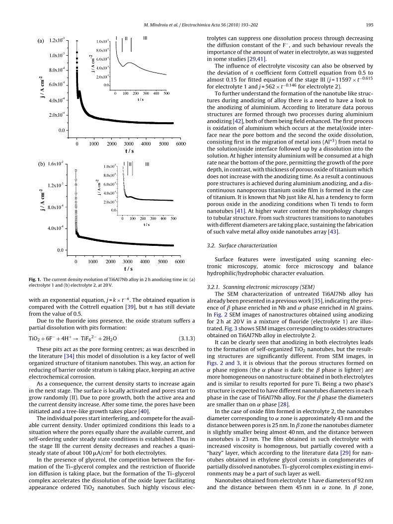
already been presented in a previous work [35], indicating the pres-ence of ˇ phase enriched in Nb and ˛ phase enriched in Al grains.In Fig. 2 SEM images of nanostructures obtained using anodizingfor 2 h at 20 V in a mixture of fluoride (electrolyte 1) are illus-trated. Fig. 3 shows SEM images corresponding to oxides structuresobtained on Ti6Al7Nb alloy in electrolyte 2.
It can be clearly seen that anodizing in both electrolytes leadsto the formation of self-organized TiO2 nanotubes, but the result-ing structures are significantly different. From SEM images, inFigs. 2 and 3, it is obvious that the porous structures formed on˛ phase regions (the ˛ phase is dark; the ˇ phase is lighter) aremore homogeneous on nanostructure obtained in both electrolytesand is similar to results reported for pure Ti. Being a two phase’sstructure is expected to have different nanotubes diameters in eachphase in the case of Ti6Al7Nb alloy. For the ˇ phase the diametersare smaller than on ˛ phase [28].
In the case of oxide film formed in electrolyte 2, the nanotubesdiameter corresponding to ˛ zone is approximately 43 nm and thedistance between pores is 25 nm. In ˇ zone the nanotubes diameteris slightly smaller being almost 40 nm, and the distance betweennanotubes is 23 nm. The film obtained in such electrolyte withincreased viscosity is homogenous, but partially covered with a“hazy” layer, which according to the literature data [29] for nan-
otubes obtained in ethylene glycol consists in conglomerates ofpartially dissolved nanotubes. Ti–glycerol complex existing in envi-ronments may be a part of such layer as well.Nanotubes obtained from electrolyte 1 have diameters of 92 nmand the distance between them 45 nm in ˛ zone. In ˇ zone,
196 M. Mîndroiu et al. / Electrochimic
F1t
nbraoodttospoAwdt
TC
Ra is average roughness and Rms is root mean square rough-ness. The higher roughness for treated surfaces was registeredfor Ti6Al7Nb/nanotubular oxide electrodeposited from electrolyte1. The surface characterization clearly revealed the role of the
ig. 2. Top view of SEM images for TiO2 nanostructures obtained from electrolyteonTi6Al7Nb alloy: (a) at scale 2 �m and (b) at a scale 500 nm (the ˛ phase is dark;
he ˇ phase is bright).
anotubes diameters are approximately 53 nm with a distanceetween them of about 32 nm. Nanotubes on Ti6Al7Nb alloyeported in the literature [28] and obtained in the same electrolytesre more homogenous. Such data reveals that the nanotubes layern Ti6Al7Nb alloy consists mainly of TiO2 and that the amountf Nb and Al species are smaller as can be seen from the EDAXata presented in Table 1. In fact, such data confirm that, in a mix-ure of nanoarchitecture fabricated in anodizing conditions, Ti ishe prototype of tubular structure and Al and Nb are prototypesf nanopores. Our data are thus consistent with recent paper [41]upporting the concept that the tube formation originates fromorous structure via “wall splitting mechanism” and the amountf water decides whether pores or tubular structure are favourites.
t smaller amount of F− related to higher solubility of fluoride inater (the case of aqueous electrolytes) a tendency to chemicalissolution is taking place followed by transition from pores to aubular structure.able 1ompositional data of nanotube layer as a function of elaboration conditions.
Element (wt%) Nanotube layerfrom electrolyte 1
Nanotube layerfrom electrolyte 2
C 5.87 4.57O 19.84 23.74F 1.36 2.11Al 3.54 3.15Nb 6.20 5.64Ti 63.19 60.35
a Acta 56 (2010) 193–202
Table 1 reveals in both surface an amount of Al less thanexpected according to its presence in alloy, but a migration of ionsinto solution are taking place in the anodizing [42].
Regarding the EDAX composition, the literature especially refer-ence [28] reported nonstoichiometric ratio for TiO2. In our cases thestoichiometry of the layer seems further away from the stoichio-metric ratio foreseen for TiO2. This is most likely due to the fact thatonly a part of Ti in the surface participates in TiO2 nanoarchitec-ture formation. Fluoride ion detected with EDAX analysis (Table 1),seems to be in the nanotubes, in both elaboration procedures andhave an important influence in localized dissolution of oxide [29].
3.2.2. Atomic force microscopy (AFM)Using contact mode procedure of AFM analysis, the roughness
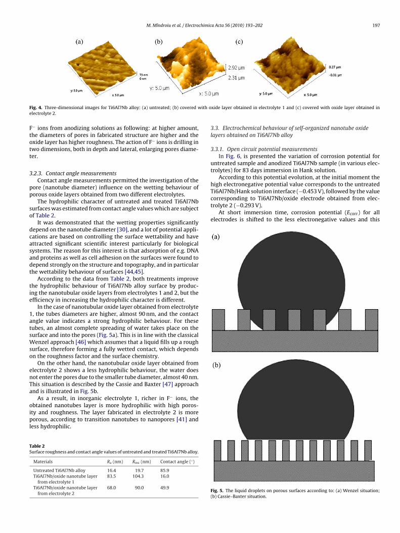
was evaluated and its parameters were computed with Gwyddionsoftware. In the following figure (Fig. 4) three-dimensional imagesfor untreated Ti6Al7Nb alloy and with nanotubes layer on afteranodizing in the two discussed electrolytes, are presented.
Images from Fig. 4 reveal a nanotubular auto-organizedstructure for oxide layer obtained electrochemically from bothelectrolytes. Pore density for oxide layer obtained from electrolyte2 is higher compared to pore density for nanotubes fabricatedin electrolyte 1. Roughness values are given in Table 2 where
Fig. 3. Top view of SEM images for TiO2 nanostructures obtained in electrolyte 2 onTi6Al7Nb alloy: (a) at scale 2 �m and (b) at scale 500 nm (the ˛ phase is dark; the ˇphase is bright).
M. Mîndroiu et al. / Electrochimica Acta 56 (2010) 193–202 197
F ith oe
Ftott
3
pp
so
dcasadt
tie
1atsWso
enTa
oipl
TS
Ti6Al7Nb/Hank solution interface (−0.453 V), followed by the valuecorresponding to Ti6Al7Nb/oxide electrode obtained from elec-trolyte 2 (−0.293 V).
At short immersion time, corrosion potential (Ecorr) for allelectrodes is shifted to the less electronegative values and this
ig. 4. Three-dimensional images for Ti6Al7Nb alloy: (a) untreated; (b) covered wlectrolyte 2.
− ions from anodizing solutions as following: at higher amount,he diameters of pores in fabricated structure are higher and thexide layer has higher roughness. The action of F− ions is drilling inwo dimensions, both in depth and lateral, enlarging pores diame-er.
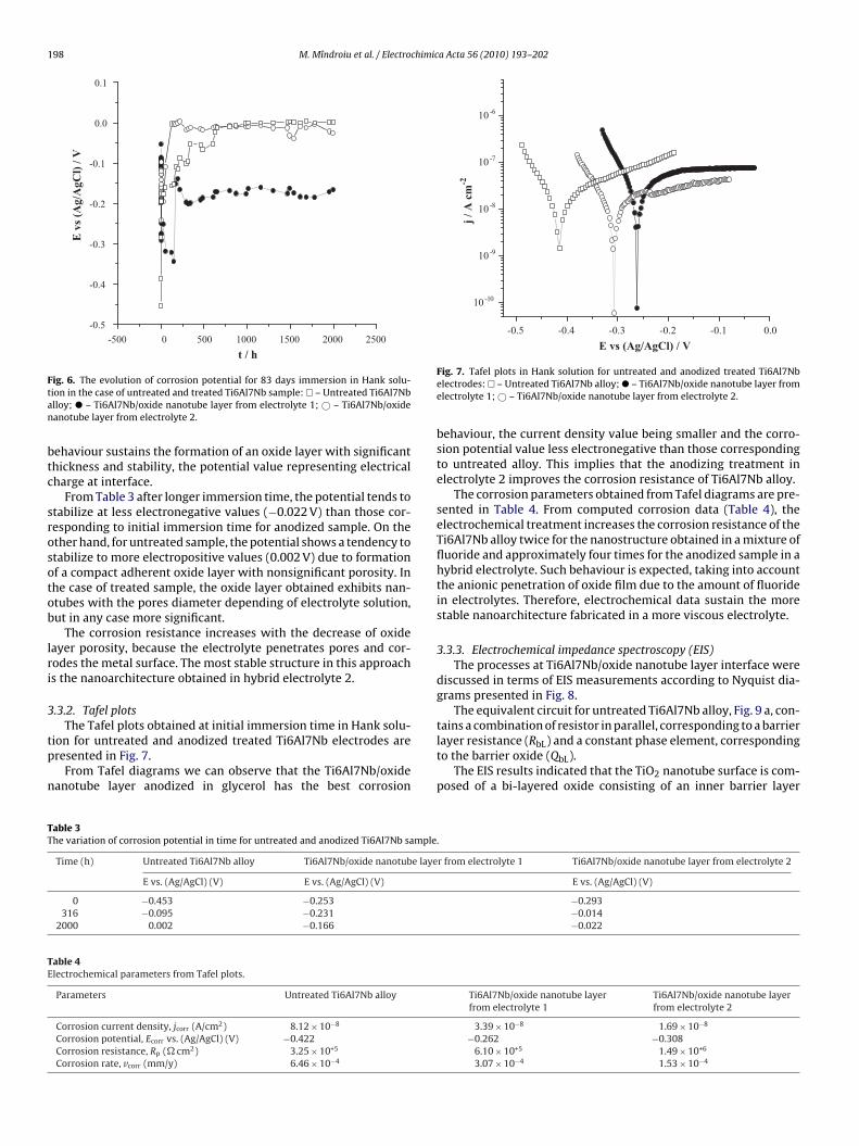
.2.3. Contact angle measurementsContact angle measurements permitted the investigation of the
ore (nanotube diameter) influence on the wetting behaviour oforous oxide layers obtained from two different electrolytes.
The hydrophilic character of untreated and treated Ti6Al7Nburfaces was estimated from contact angle values which are subjectf Table 2.
It was demonstrated that the wetting properties significantlyepend on the nanotube diameter [30], and a lot of potential appli-ations are based on controlling the surface wettability and havettracted significant scientific interest particularly for biologicalystems. The reason for this interest is that adsorption of e.g. DNAnd proteins as well as cell adhesion on the surfaces were found toepend strongly on the structure and topography, and in particularhe wettability behaviour of surfaces [44,45].
According to the data from Table 2, both treatments improvehe hydrophilic behaviour of Ti6Al7Nb alloy surface by produc-ng the nanotubular oxide layers from electrolytes 1 and 2, but thefficiency in increasing the hydrophilic character is different.
In the case of nanotubular oxide layer obtained from electrolyte, the tubes diameters are higher, almost 90 nm, and the contactngle value indicates a strong hydrophilic behaviour. For theseubes, an almost complete spreading of water takes place on theurface and into the pores (Fig. 5a). This is in line with the classical
enzel approach [46] which assumes that a liquid fills up a roughurface, therefore forming a fully wetted contact, which dependsn the roughness factor and the surface chemistry.
On the other hand, the nanotubular oxide layer obtained fromlectrolyte 2 shows a less hydrophilic behaviour, the water doesot enter the pores due to the smaller tube diameter, almost 40 nm.his situation is described by the Cassie and Baxter [47] approachnd is illustrated in Fig. 5b.
As a result, in inorganic electrolyte 1, richer in F− ions, the
btained nanotubes layer is more hydrophilic with high poros-ty and roughness. The layer fabricated in electrolyte 2 is moreorous, according to transition nanotubes to nanopores [41] andess hydrophilic.
able 2urface roughness and contact angle values of untreated and treated Ti6Al7Nb alloy.
Materials Ra (nm) Rms (nm) Contact angle (◦)
Untreated Ti6Al7Nb alloy 16.4 19.7 85.9Ti6Al7Nb/oxide nanotube layer
from electrolyte 183.5 104.3 16.0
Ti6Al7Nb/oxide nanotube layerfrom electrolyte 2
68.0 90.0 49.9
xide layer obtained in electrolyte 1 and (c) covered with oxide layer obtained in
3.3. Electrochemical behaviour of self-organized nanotube oxidelayers obtained on Ti6Al7Nb alloy
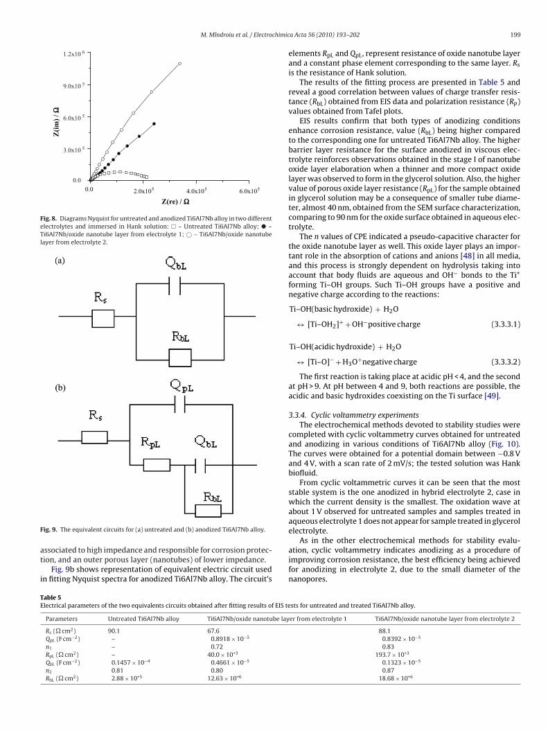
3.3.1. Open circuit potential measurementsIn Fig. 6, is presented the variation of corrosion potential for
untreated sample and anodized Ti6Al7Nb sample (in various elec-trolytes) for 83 days immersion in Hank solution.
According to this potential evolution, at the initial moment thehigh electronegative potential value corresponds to the untreated
Fig. 5. The liquid droplets on porous surfaces according to: (a) Wenzel situation;(b) Cassie–Baxter situation.
198 M. Mîndroiu et al. / Electrochimica Acta 56 (2010) 193–202
25002000150010005000-500
-0.5
-0.4
-0.3
-0.2
-0.1
0.0
0.1
t / h
E v
s (A
g/A
gCl)
/ V
Ftan
btc
srosotob
lri
3
tp
n
0.0-0.1-0.2-0.3-0.4-0.5
10-10
10 -9
10 -8
10 -7
10 -6
j / A
cm
-2
E vs (Ag/AgCl) / V
TT
TE
ig. 6. The evolution of corrosion potential for 83 days immersion in Hank solu-ion in the case of untreated and treated Ti6Al7Nb sample: � – Untreated Ti6Al7Nblloy; � – Ti6Al7Nb/oxide nanotube layer from electrolyte 1; © – Ti6Al7Nb/oxideanotube layer from electrolyte 2.
ehaviour sustains the formation of an oxide layer with significanthickness and stability, the potential value representing electricalharge at interface.
From Table 3 after longer immersion time, the potential tends totabilize at less electronegative values (−0.022 V) than those cor-esponding to initial immersion time for anodized sample. On thether hand, for untreated sample, the potential shows a tendency totabilize to more electropositive values (0.002 V) due to formationf a compact adherent oxide layer with nonsignificant porosity. Inhe case of treated sample, the oxide layer obtained exhibits nan-tubes with the pores diameter depending of electrolyte solution,ut in any case more significant.
The corrosion resistance increases with the decrease of oxideayer porosity, because the electrolyte penetrates pores and cor-odes the metal surface. The most stable structure in this approachs the nanoarchitecture obtained in hybrid electrolyte 2.
.3.2. Tafel plots
The Tafel plots obtained at initial immersion time in Hank solu-ion for untreated and anodized treated Ti6Al7Nb electrodes areresented in Fig. 7.
From Tafel diagrams we can observe that the Ti6Al7Nb/oxideanotube layer anodized in glycerol has the best corrosion
able 3he variation of corrosion potential in time for untreated and anodized Ti6Al7Nb sample
Time (h) Untreated Ti6Al7Nb alloy Ti6Al7Nb/oxide nanotube laye
E vs. (Ag/AgCl) (V) E vs. (Ag/AgCl) (V)
0 −0.453 −0.253316 −0.095 −0.231
2000 0.002 −0.166
able 4lectrochemical parameters from Tafel plots.
Parameters Untreated Ti6Al7Nb alloy
Corrosion current density, jcorr (A/cm2) 8.12 × 10⁻⁸
Corrosion potential, Ecorr vs. (Ag/AgCl) (V) −0.422Corrosion resistance, Rp (� cm2) 3.25 × 10+5
Corrosion rate, vcorr (mm/y) 6.46 × 10⁻⁴
Fig. 7. Tafel plots in Hank solution for untreated and anodized treated Ti6Al7Nbelectrodes: � – Untreated Ti6Al7Nb alloy; � – Ti6Al7Nb/oxide nanotube layer fromelectrolyte 1; © – Ti6Al7Nb/oxide nanotube layer from electrolyte 2.
behaviour, the current density value being smaller and the corro-sion potential value less electronegative than those correspondingto untreated alloy. This implies that the anodizing treatment inelectrolyte 2 improves the corrosion resistance of Ti6Al7Nb alloy.
The corrosion parameters obtained from Tafel diagrams are pre-sented in Table 4. From computed corrosion data (Table 4), theelectrochemical treatment increases the corrosion resistance of theTi6Al7Nb alloy twice for the nanostructure obtained in a mixture offluoride and approximately four times for the anodized sample in ahybrid electrolyte. Such behaviour is expected, taking into accountthe anionic penetration of oxide film due to the amount of fluoridein electrolytes. Therefore, electrochemical data sustain the morestable nanoarchitecture fabricated in a more viscous electrolyte.
3.3.3. Electrochemical impedance spectroscopy (EIS)The processes at Ti6Al7Nb/oxide nanotube layer interface were
discussed in terms of EIS measurements according to Nyquist dia-grams presented in Fig. 8.
The equivalent circuit for untreated Ti6Al7Nb alloy, Fig. 9 a, con-
tains a combination of resistor in parallel, corresponding to a barrierlayer resistance (RbL) and a constant phase element, correspondingto the barrier oxide (QbL).The EIS results indicated that the TiO2 nanotube surface is com-posed of a bi-layered oxide consisting of an inner barrier layer
.
r from electrolyte 1 Ti6Al7Nb/oxide nanotube layer from electrolyte 2
E vs. (Ag/AgCl) (V)
−0.293−0.014−0.022
Ti6Al7Nb/oxide nanotube layerfrom electrolyte 1
Ti6Al7Nb/oxide nanotube layerfrom electrolyte 2
3.39 × 10⁻⁸ 1.69 × 10⁻⁸
−0.262 −0.3086.10 × 10+5 1.49 × 10+6
3.07 × 10⁻⁴ 1.53 × 10⁻⁴
M. Mîndroiu et al. / Electrochimic
0.0 2.0x10⁵ 4.0x10⁵ 6.0x1050.0
3.0x10 5
6.0x10 5
9.0x10 5
1.2x10 6Z
(im
) / Ω
Z(re) / Ω
Fig. 8. Diagrams Nyquist for untreated and anodized Ti6Al7Nb alloy in two differentelectrolytes and immersed in Hank solution: � – Untreated Ti6Al7Nb alloy; � –Ti6Al7Nb/oxide nanotube layer from electrolyte 1; © – Ti6Al7Nb/oxide nanotubelayer from electrolyte 2.
F
at
i
As in the other electrochemical methods for stability evalu-
TE
ig. 9. The equivalent circuits for (a) untreated and (b) anodized Ti6Al7Nb alloy.
ssociated to high impedance and responsible for corrosion protec-ion, and an outer porous layer (nanotubes) of lower impedance.
Fig. 9b shows representation of equivalent electric circuit usedn fitting Nyquist spectra for anodized Ti6Al7Nb alloy. The circuit’s
able 5lectrical parameters of the two equivalents circuits obtained after fitting results of EIS te
Parameters Untreated Ti6Al7Nb alloy Ti6Al7Nb/oxide nanotube lay
Rs (� cm2) 90.1 67.6QpL (F cm−2) – 0.8918 × 10⁻⁵
n1 – 0.72RpL (� cm2) – 40.0 × 10+3
QbL (F cm−2) 0.1457 × 10⁻⁴ 0.4661 × 10⁻⁵
n2 0.81 0.80RbL (� cm2) 2.88 × 10+5 12.63 × 10+6
a Acta 56 (2010) 193–202 199
elements RpL and QpL, represent resistance of oxide nanotube layerand a constant phase element corresponding to the same layer. Rs
is the resistance of Hank solution.The results of the fitting process are presented in Table 5 and
reveal a good correlation between values of charge transfer resis-tance (RbL) obtained from EIS data and polarization resistance (Rp)values obtained from Tafel plots.
EIS results confirm that both types of anodizing conditionsenhance corrosion resistance, value (RbL) being higher comparedto the corresponding one for untreated Ti6Al7Nb alloy. The higherbarrier layer resistance for the surface anodized in viscous elec-trolyte reinforces observations obtained in the stage I of nanotubeoxide layer elaboration when a thinner and more compact oxidelayer was observed to form in the glycerol solution. Also, the highervalue of porous oxide layer resistance (RpL) for the sample obtainedin glycerol solution may be a consequence of smaller tube diame-ter, almost 40 nm, obtained from the SEM surface characterization,comparing to 90 nm for the oxide surface obtained in aqueous elec-trolyte.
The n values of CPE indicated a pseudo-capacitive character forthe oxide nanotube layer as well. This oxide layer plays an impor-tant role in the absorption of cations and anions [48] in all media,and this process is strongly dependent on hydrolysis taking intoaccount that body fluids are aqueous and OH− bonds to the Ti+
forming Ti–OH groups. Such Ti–OH groups have a positive andnegative charge according to the reactions:
Ti–OH(basic hydroxide) + H2O
↔ [Ti–OH2]+ + OH−positive charge (3.3.3.1)
Ti–OH(acidic hydroxide) + H2O
↔ [Ti–O]− + H3O+negative charge (3.3.3.2)
The first reaction is taking place at acidic pH < 4, and the secondat pH > 9. At pH between 4 and 9, both reactions are possible, theacidic and basic hydroxides coexisting on the Ti surface [49].
3.3.4. Cyclic voltammetry experimentsThe electrochemical methods devoted to stability studies were
completed with cyclic voltammetry curves obtained for untreatedand anodizing in various conditions of Ti6Al7Nb alloy (Fig. 10).The curves were obtained for a potential domain between −0.8 Vand 4 V, with a scan rate of 2 mV/s; the tested solution was Hankbiofluid.
From cyclic voltammetric curves it can be seen that the moststable system is the one anodized in hybrid electrolyte 2, case inwhich the current density is the smallest. The oxidation wave atabout 1 V observed for untreated samples and samples treated inaqueous electrolyte 1 does not appear for sample treated in glycerolelectrolyte.
ation, cyclic voltammetry indicates anodizing as a procedure ofimproving corrosion resistance, the best efficiency being achievedfor anodizing in electrolyte 2, due to the small diameter of thenanopores.
sts for untreated and treated Ti6Al7Nb alloy.
er from electrolyte 1 Ti6Al7Nb/oxide nanotube layer from electrolyte 2
88.10.8392 × 10−5
0.83193.7 × 10+3
0.1323 × 10⁻⁵
0.8718.68 × 10+6
200 M. Mîndroiu et al. / Electrochimic
43210-1
-4.0x10⁻⁵
-2.0x10⁻⁵
0.0
2.0x10⁻⁵j
/ A c
m-2
E vs (Ag/AgCl) / V
FTTl
3M
pt
t7Frdbmo
tr4
TT
ig. 10. Cyclic voltametric curves in Hank solution for untreated and anodizedi6Al7Nb alloy in two different electrolytes: � – Untreated Ti6Al7Nb alloy; � –i6Al7Nb/oxide nanotube layer from electrolyte 1; © – Ti6Al7Nb/oxide nanotubeayer from electrolyte 2.
.4. Ions release evaluation with Inductively Coupled Plasmaass Spectrometry (ICP-MS)
After a couple of days of immersion in Hank solution, all samplesresent a fast increase in concentration of ions release, but a trendo a constant value is observed after 14 days.
The increase is more significant for untreated alloy suggestinghat the protection is better for anodized samples. After almost
days a decrease is noticed followed by a trend to steady state.or both anodized samples the decrease is very small. Also suchesults confirm the electrochemical data discussed above. The ten-ency to steady state in open circuit potential is a characteristic foroth untreated and treated samples and the more stable with theost electropositive values for potential is the nanoarchitecture
btained in hybrid electrolyte.In Table 6, the corrosion rate (vcorr) in the case of untreated and
reated Ti6Al7Nb alloy was estimated using the amounts of ionselease in Hank solution determined from ICP-MS data from 2 h to6 days.
able 6he corrosion rate estimated from ICP-MS data.
Time (days) Untreated Ti6Al7Nb alloy Ti6Al7Nb/oxide nanotube lay
vcorr (mm/y) vcorr (mm/y)
0.083 4.24 × 10⁻³ 5.18 × 10⁻³
6 6.48 × 10⁻⁴ 2.28 × 10⁻⁴
8 9.68 × 10⁻⁴ 2.30 × 10⁻⁴
14 3.70 × 10⁻⁴ 1.50 × 10⁻⁴
46 1.10 × 10⁻⁴ 4.98 × 10⁻⁵
Fig. 11. Cell viability MTT assay showing the effects of Ti6Al7Nb
a Acta 56 (2010) 193–202
The corrosion rate (vcorr) in mm/year was determined using thenext equation:
vcorr = ions release × 365 × 10S × t × d
(3.4.1)
where vcorr = corrosion rate (mm/y); ions release = the metallicions release (Ti, Al, Nb) determined from ICP-MS data (�g/L);S = surface of Ti6Al7Nb alloy immersed in Hank solution (1 cm2);t = time (days); d = density (4.5 g/cm3).
The values of corrosion rates calculated from ICP-MS data areconsistent with those obtained from Tafel plots (Table 4). Regard-ing the ions release in short, medium and longer exposure time,the corrosion rate reveals higher values at shorter time when thecorrosion potential is more electronegative, and smaller values formedium and long term when corrosion potential tends to steadystate.
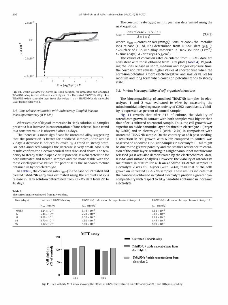
3.5. In vitro biocompatibility of self-organized structures
The biocompatibility of anodized Ti6Al7Nb samples in elec-trolytes 1 and 2 was evaluated in vitro by measuring themitochondrial dehydrogenase activity of G292 osteoblasts. Viabil-ity is expressed as percent of control sample.
Fig. 11 reveals that after 24 h of culture, the viability ofosteoblasts grown in contact with both samples was higher thanthat of cells cultured on control sample. Thus, the cell growth wassuperior on oxide nanotube layer obtained in electrolyte 1 (largerby 6.86%) and in electrolyte 2 (with 12.7%) in comparison withuntreated Ti6Al7Nb sample. On the contrary, at 48 h post-seeding,a reduction in cell growth with 6.25% compared to control wasobserved on anodized Ti6Al7Nb samples in electrolyte 1. This mightbe due to the greater porosity and the smaller resistance to corro-sion of the oxide layer, resulting in a higher amount of metallic ionsreleased (as it was also demonstrated by the electrochemical data,ICP-MS and surface analysis). However, the viability of osteoblastsmaintained in culture for 48 h on anodized Ti6Al7Nb samples in
electrolyte 2 was still higher (with 6.66%) than that of the cellsgrown on untreated Ti6Al7Nb samples. These results indicate thatthe nanotubes obtained in hybrid electrolyte provide a greater bio-compatibility with respect to TiO2 nanotubes obtained in inorganicelectrolyte.er from electrolyte 1 Ti6Al7Nb/oxide nanotube layer from electrolyte 2
vcorr (mm/y)
1.94 × 10⁻²
3.81 × 10⁻⁴
2.63 × 10⁻⁴
1.45 × 10⁻⁵
5.99 × 10⁻⁶
treatment on cell viability at 24 h and 48 h post-seeding.
M. Mîndroiu et al. / Electrochimica Acta 56 (2010) 193–202 201
F Ti6Al71
ic
osgcTtafpir
4
ktsr˛gccT
m
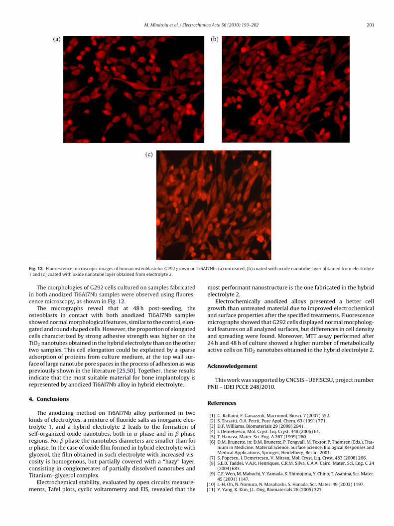
ig. 12. Fluorescence microscopic images of human osteoblastelor G292 grown onand (c) coated with oxide nanotube layer obtained from electrolyte 2.
The morphologies of G292 cells cultured on samples fabricatedn both anodized Ti6Al7Nb samples were observed using fluores-ence microscopy, as shown in Fig. 12.
The micrographs reveal that at 48 h post-seeding, thesteoblasts in contact with both anodized Ti6Al7Nb sampleshowed normal morphological features, similar to the control, elon-ated and round shaped cells. However, the proportion of elongatedells characterized by strong adhesive strength was higher on theiO2 nanotubes obtained in the hybrid electrolyte than on the otherwo samples. This cell elongation could be explained by a sparsedsorption of proteins from culture medium, at the top wall sur-ace of large nanotube pore spaces in the process of adhesion as wasreviously shown in the literature [25,50]. Together, these results
ndicate that the most suitable material for bone implantology isepresented by anodized Ti6Al7Nb alloy in hybrid electrolyte.
. Conclusions
The anodizing method on Ti6Al7Nb alloy performed in twoinds of electrolytes, a mixture of fluoride salts as inorganic elec-rolyte 1, and a hybrid electrolyte 2 leads to the formation ofelf-organized oxide nanotubes, both in ˛ phase and in ˇ phaseegions. For ˇ phase the nanotubes diameters are smaller than forphase. In the case of oxide film formed in hybrid electrolyte with
lycerol, the film obtained in such electrolyte with increased vis-
osity is homogenous, but partially covered with a “hazy” layer,onsisting in conglomerates of partially dissolved nanotubes anditanium–glycerol complex.Electrochemical stability, evaluated by open circuits measure-ents, Tafel plots, cyclic voltammetry and EIS, revealed that the
[[
Nb: (a) untreated, (b) coated with oxide nanotube layer obtained from electrolyte
most performant nanostructure is the one fabricated in the hybridelectrolyte 2.
Electrochemically anodized alloys presented a better cellgrowth than untreated material due to improved electrochemicaland surface properties after the specified treatments. Fluorescencemicrographs showed that G292 cells displayed normal morpholog-ical features on all analyzed surfaces, but differences in cell densityand spreading were found. Moreover, MTT assay performed after24 h and 48 h of culture showed a higher number of metabolicallyactive cells on TiO2 nanotubes obtained in the hybrid electrolyte 2.
Acknowledgement
This work was supported by CNCSIS –UEFISCSU, project numberPNII – IDEI PCCE 248/2010.
References
[1] G. Raffaini, F. Ganazzoli, Macromol. Biosci. 7 (2007) 552.[2] S. Trasatti, O.A. Petrii, Pure Appl. Chem. 63 (1991) 771.[3] D.F. Williams, Biomaterials 29 (2008) 2941.[4] I. Demetrescu, Mol. Cryst. Liq. Cryst. 448 (2006) 61.[5] T. Hanava, Mater. Sci. Eng. A 267 (1999) 260.[6] D.M. Brunette, in: D.M. Brunette, P. Tengvall, M. Textor, P. Thomsen (Eds.), Tita-
nium in Medicine: Material Science, Surface Science, Biological Responses andMedical Applications, Springer, Heidelberg, Berlin, 2001.
[7] S. Popescu, I. Demetrescu, V. Mitran, Mol. Cryst. Liq. Cryst. 483 (2008) 266.
[8] S.E.B. Taddei, V.A.R. Henriques, C.R.M. Silva, C.A.A. Cairo, Mater. Sci. Eng. C 24(2004) 683.[9] C.E. Wen, M. Mabuchi, Y. Yamada, K. Shimojima, Y. Chino, T. Asahina, Scr. Mater.
45 (2001) 1147.10] I.-H. Oh, N. Nomura, N. Masahashi, S. Hanada, Scr. Mater. 49 (2003) 1197.11] Y. Yang, K. Kim, J.L. Ong, Biomaterials 26 (2005) 327.
2 chimic
[
[[[
[
[
[
[[
[
[
[
[
[[[
[
[[[
[
[
[
[[[[
[
[
[
[
[[[[[
02 M. Mîndroiu et al. / Electro
12] Y. Yang, K. Bessho, J.L. Ong, in: M.J. Yaszemski, D.J. Trantolo, K.U. Lewandrowski,V. Hasirci, D.E. Altobelli, D.L. Wise (Eds.), Biomaterials in Orthopedics, MarcelDekker, Inc., New York, 2004.
13] X. Zhu, J.L. Ong, S. Kim, K. Kim, J. Biomed. Mater. Res. 60 (2002) 333.14] J.W. Vehof, P.H. Spauwen, J.A. Jansen, Biomaterials 21 (2000) 2003.15] M.V. Popa, I. Demetrescu, E. Vasilescu, P. Drob, S. Lopez, J.M. Rosca, D. Ionita, C.
Vasilescu, Electrochim. Acta 49 (2004) 2113.16] S. Popescu, I. Demetrescu, C. Sarantopoulos, A. Gleizes, D. Iordachescu, J. Mater.
Sci. Mater. Med. 18 (2007) 2075.17] Standard Specification for Wrought Ti6Al4V Eli Alloy for surgical implants
ASTM designation 136-82, 1994, p. 19, Philadelphia, PA.18] Standard Specification for Wrought Ti6Al7Nb Alloy for surgical implants ASTM
designation F 1295-92, 1994, p. 687, Philadelphia, PA.19] I.V. Brânzoi, M. Iordoc, F. Brânzoiu, U.P.B. Sci. Bull. 71 (2009) 31.20] M.V. Popa, D. Iordachescu, A. Câmpean, E. Vasilescu, P. Drob, C. Vasilescu, Mater.
Corros. 58 (2007) 667.21] M. Sovar, E. Aldea, V. Mitran, F. Miculescu, I. Demetrescu, Key Eng. Mater.
361–363 (2008) 1131.22] T.J. Webster, C. Ergun, R.H. Doremus, R.W. Siegel, R. Bizios, J. Biomed. Mater.
Res. B 51 (2000) 475.23] P.K.C. Venkatsurya, W.W. Thein-Han, R.D.K. Misra, M.C. Somani, L.P. Kar-
jalainen, Mater. Sci. Eng. C 30 (2010) 1050.24] V. Taveira, J.M. Macak, H. Tsuchiya, L.F.P. Dick, P. Schmuki, J. Electrochem. Soc.
152 (2005) B405.25] I. Demetrescu, C. Pîrvu, V. Mitran, Bioelectrochemistry 79 (2010) 122.26] J.M. Macak, H. Tsuchiya, P. Schmuki, Angew. Chem. Int. Ed. Engl. 44 (2005) 2100.27] K.D. Yun, Y. Yang, H.P. Lim, G.J. Oh, J.T. Koh, I.H. Bae, J. Kim, K.M. Lee, S.W. Park,
Mater. Sci. Eng. C 30 (2010) 27.28] J.M. Macak, H. Tsuchiya, L. Taveira, A. Ghicov, P. Schmuki, J. Biomed. Mater. Res.
75 (2005) 928.29] J.M. Macak, P. Schmuki, Electrochim. Acta 52 (2006) 1258.30] E. Balaur, J.M. Macak, H. Tsuchiya, P. Schmuki, J. Mater. Chem. 15 (2005) 4488.31] C.C. Manole, C. Pîrvu, I. Demetrescu, Key Eng. Mater. 415 (2009) 5.
[
[
[
a Acta 56 (2010) 193–202
32] S.P. Albu, A. Ghicov, J.M. Macak, R. Hahn, P. Schmuki, Nano Lett. 7 (2007)1286.
33] M. Paulose, H.E. Prakasam, O.K. Varghese, L. Peng, K.C. Popat, G.K. Mor, T.A.Desai, C.A. Grimes, J. Phys. Chem. C 111 (2007) 14992.
34] Y. Lai, H. Zhuanga, L. Suna, Z. Chenb, L. Changjian, Electrochim. Acta 54 (2009)6536.
35] V.M. Mîndroiu, E. Cicek, R. Ciubar, Mol. Cryst. Liq. Cryst. 486 (2008), 120/[1168].36] A. Rahmel, P.J. Spencer, Oxid. Met. 35 (1991) 53.37] M.V. Berridge, A.S. Tan, K.D. McCoy, R. Wang, Biochemica 4 (1996) 14.38] R.B. Wehrspohn, K. Nielsch, A. Birner, J. Schilling, F. Müller, A.P. Li, U. Gösele, Pits
and Pore II: Formation and Properties and Significance for Advanced Materials.PV 2000-25, in: P. Schmuki, D.J. Lockwood, Y.H. Ogata, H.S. Isaacs (Eds.), TheElectrochemical Society Proceedings Series, Pennington, NJ, 2000.
39] J.O’M. Bockris, A.K.N. Reddy, M. Gamboa-Aldeco, Modern Electrochemistry Fun-damental of Electrodics, 2nd ed., Kluwer Academic/Plenum Publisher, NewYork, 2000.
40] J.M. Macak, H. Tsuchiya, A. Ghicov, K. Yasuda, R. Hahn, S. Bauer, P. Schmuki,Curr. Opin. Solid State Mater. Sci. 11 (2007) 3.
41] W. Wei, S. Berger, C. Hauser, K. Meyer, M. Yang, P. Schmuki, Electrochem.Commun. 12 (2010) 1184.
42] D. Gong, C.A. Grimesa, O.K. Varghese, W. Hu, R.S. Singh, Z. Chen, E.C. Dickey, J.Mater. Res. 16 (2001) 3331.
43] K. Yasuda, P. Schmuki, Electrochim. Acta 52 (2007) 4053.44] E.A. Vogler, Adv.Colloid Interface Sci. 74 (1998) 69.45] B.W. Ninham, K. Kurihara, O.I. Vinogradova, Colloids Surf. A 123 (1997) 7.46] R.N. Wenzel, Ind. Eng. Chem. 28 (1936) 988.47] A.B.D. Cassie, S. Baxter, Trans. Faraday Soc. 40 (1944) 546.
48] R. Rohanizadeh, M. Al-Sadeq, R.Z. LeGeros, J. Biomed. Mater. Res. Part A 71(2004) 343.49] H.H. Park, S. Park, K.S. Kim, W.Y. Jeon, B.K. Park, H.S. Kim, T.S. Bae, M.H. Lee,
Electrochim. Acta 55 (2010) 6109.50] K.S. Brammer, O. Seunghan, C.J. Cobb, L.M. Bjursten, H. van der Heyde, S. Jin,
Acta Biomater. 5 (2009) 3215.


![(2016) Two kinds of 'and' [26/2/2016]](https://img.dokumen.tips/doc/110x75/6353f0329ef77da538047641/2016-two-kinds-of-and-2622016.jpg)


