Embed Size (px)
Citation preview

This article was originally published in a journal published byElsevier, and the attached copy is provided by Elsevier for the
author’s benefit and for the benefit of the author’s institution, fornon-commercial research and educational use including without
limitation use in instruction at your institution, sending it to specificcolleagues that you know, and providing a copy to your institution’s
administrator.
All other uses, reproduction and distribution, including withoutlimitation commercial reprints, selling or licensing copies or access,
or posting on open internet sites, your personal or institution’swebsite or repository, are prohibited. For exceptions, permission
may be sought for such use through Elsevier’s permissions site at:
http://www.elsevier.com/locate/permissionusematerial
Autho
r's
pers
onal
co
py
Sensors and Actuators A 135 (2007) 748–757
Characterization of dielectric elastomer actuators basedon a hyperelastic film model
Lochmatter Patrick a,b,∗, Kovacs Gabor a, Michel Silvain a
a Laboratory for Materials and Engineering, Swiss Federal Laboratories for Materials Testing and Research (Empa),8600 Duebendorf, Switzerland
b Center of Structures and Technologies, Swiss Federal Institute of Technology Zurich (ETH), 8092 Zurich, Switzerland
Received 9 December 2005; received in revised form 19 July 2006; accepted 11 August 2006Available online 15 September 2006
Abstract
The focus of this paper is on the energy characterization of dielectric elastomer (DE) actuators under quasi-static activation cycles. To this end, asimple model covering the basic mechanical effects of hyperelastic dielectric elastomer films was introduced and fitted to the experimental behaviorof the widely used dielectric film VHB 4910 in a uniaxial tensile test. The film model was then applied to planar DE actuators by introducing theelectromechanical coupling of the electrodes to the film. The evaluation of this system permitted the characterization of the inner force equilibriumstates of planar DE actuators under activation with either constant charge or constant voltage. In a second step, a quasi-static activation cycle ofan idealized DE strip actuator with uniaxial prestrain was simulated. The configuration was evaluated regarding the characteristics of the specificwork output per cycle as well as the overall electromechanical efficiency for various activation voltage levels and different prestrain levels.© 2006 Elsevier B.V. All rights reserved.
Keywords: Actuator; Electroactive polymers (EAP); Dielectric elastomers (DE); Hyperelastic film model; Specific energy density; Electromechanical efficiency
1. Introduction
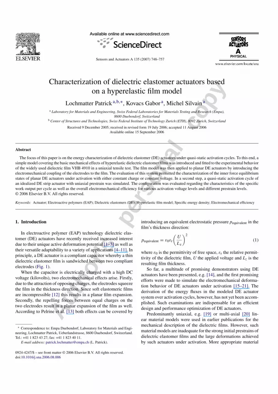
In electroactive polymer (EAP) technology dielectric elas-tomer (DE) actuators have recently received increased interestdue to their unique active deformation potential [1–3] as well astheir versatile adaptability to a variety of applications [4–11]. Inprinciple, a DE actuator is a compliant capacitor whereby a thindielectric elastomer film is sandwiched between two compliantelectrodes (Fig. 1).
When the capacitor is electrically charged with a high DCvoltage (kilovolts), two electromechanical effects arise. Firstly,due to the attraction of opposing charges, the electrodes squeezethe film in the thickness direction. Since soft elastomeric filmsare incompressible [12] this results in a planar film expansion.Secondly, the repelling forces between equal charges on thetwo electrodes result in a planar expansion of the film as well.According to Pelrine et al. [13] both effects can be covered by
∗ Correspondence to: Empa Duebendorf, Laboratory for Materials and Engi-neering, Lochmatter Patrick, Ueberlandstrasse, 8600 Duebendorf, Switzerland.Tel.: +41 1 823 43 27; fax: +41 1 823 40 11.
E-mail address: [email protected] (L. Patrick).
introducing an equivalent electrostatic pressure pequivalent in thefilm’s thickness direction:
pequivalent = ε0εr
(U
Lz
)2
(1)
where ε0 is the permittivity of free space, εr the relative permit-tivity of the dielectric film, U the applied voltage and Lz is theresulting film thickness.
So far, a multitude of promising demonstrators using DEactuators have been presented, e.g. [14], and the first promisingefforts were made to simulate the electromechanical deforma-tion behavior of DE actuators under activation [15–21]. Thederivation of the energy fluxes in the modeled DE actuatorsystem over activation cycles, however, has not yet been accom-plished. Such examinations are indispensable for an efficientdesign and performance optimization of DE actuators.
Predominantly uniaxial, e.g. [19] or multi-axial [20] lin-ear material models were used in earlier publications for themechanical description of the dielectric films. However, suchmaterial models are inadequate for the strong initial prestrains ofdielectric elastomer films and the large deformations achievedby such actuators under activation. More appropriate material
0924-4247/$ – see front matter © 2006 Elsevier B.V. All rights reserved.doi:10.1016/j.sna.2006.08.006
Autho
r's
pers
onal
co
py
L. Patrick et al. / Sensors and Actuators A 135 (2007) 748–757 749
Fig. 1. DE actuator in the de-activated (left) and activated state (right).
models to describe the hyperelastic behavior of the dielectricelastomer films are given by Mooney-Rivlin [22], Ogden [23]and Yeoh [24,25].
The aim of this study was to investigate the performanceof planar DE actuators under given boundary conditions forquasi-static activation cycles. This was achieved by introduc-ing a hyperelastic film model corresponding to the Ogdenform.
2. Introduction to the hyperelastic film model
The proposed model covers the mechanical behavior of elas-tomeric films and serves as a tool to investigate the basic mech-anisms in planar DE actuators under electrical activation.
From experimental observations of dielectric elastomer filmsthe following two main mechanical requirements arise for themodel:
(i) Hyperelastic material characteristics in all three-spacedirections.
(ii) Mechanical coupling of the spatial deformations based onthe incompressibility condition for soft elastomers [12].
Due to viscous losses, the viscosity of the widely used VHB4910 acrylic film (3M) reduces the overall electromechanicalefficiency of DE actuators. Thus future dielectrics are aimed at
being made purely elastic (e.g. silicone). In order to estimate theupper performance limits for the DE actuator technology, themodel newly introduced for the dielectric film is taken to coverthe hyperelastic material behavior.
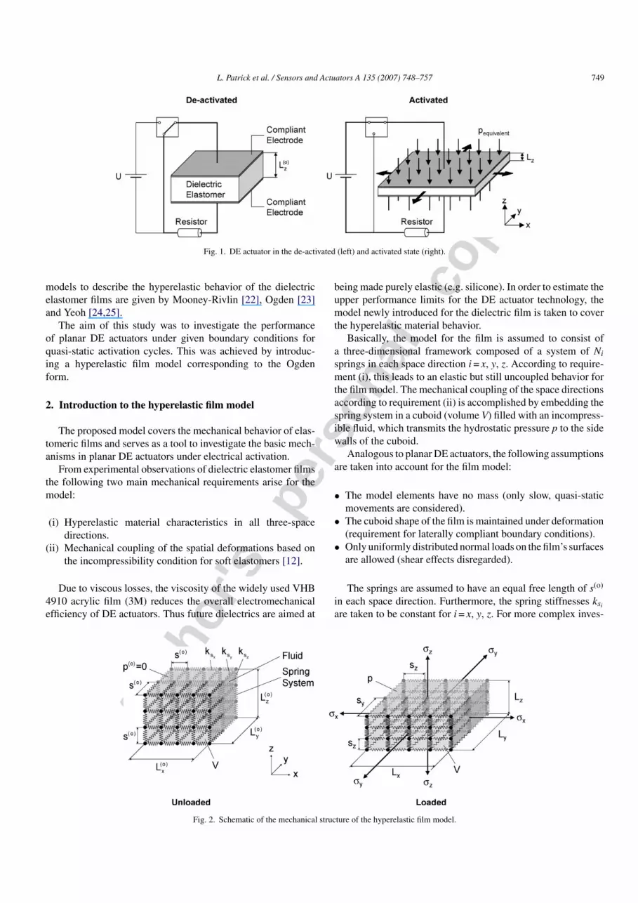
Basically, the model for the film is assumed to consist ofa three-dimensional framework composed of a system of Ni
springs in each space direction i = x, y, z. According to require-ment (i), this leads to an elastic but still uncoupled behavior forthe film model. The mechanical coupling of the space directionsaccording to requirement (ii) is accomplished by embedding thespring system in a cuboid (volume V) filled with an incompress-ible fluid, which transmits the hydrostatic pressure p to the sidewalls of the cuboid.
Analogous to planar DE actuators, the following assumptionsare taken into account for the film model:
• The model elements have no mass (only slow, quasi-staticmovements are considered).
• The cuboid shape of the film is maintained under deformation(requirement for laterally compliant boundary conditions).
• Only uniformly distributed normal loads on the film’s surfacesare allowed (shear effects disregarded).
The springs are assumed to have an equal free length of s(o)
in each space direction. Furthermore, the spring stiffnesses ksi
are taken to be constant for i = x, y, z. For more complex inves-
Fig. 2. Schematic of the mechanical structure of the hyperelastic film model.
Autho
r's
pers
onal
co
py
750 L. Patrick et al. / Sensors and Actuators A 135 (2007) 748–757
tigations, however, the spring stiffnesses could be changed, e.g.as a function of the film’s deformation.
The modeled dielectric film with unloaded (σi = 0) cuboiddimensions L
(o)i o is deformed under the external normal stresses
σi to geometry Li in i = x, y, z (Fig. 2). Note that under deforma-tion the hydrostatic pressure p diverges from the initial value ofzero (p(o) = 0). The force equilibria across the side walls of thecuboid are:
σi = σspringsi − p, i = x, y, z (2)
where σspringsi corresponds to the normal loads of the spring sys-tem, which, under the assumption of a large number of springs(Ni � 1), e.g. in the x-direction, can be expressed by:
σspringsx =(
kx
s(o)
)(λx − 1
λyλz
)= Kx
(λx − 1
λyλz
)(3)
where the deformation of the film is given by the stretch ratiosλi = (Li/L
(o)i ). The stiffness of the film model is defined by
Ki = (ki/s(o)). When the loads of the spring system of Eq. (3) aresubstituted into Eq. (2), three force equilibrium relationshipsresult. When the volume conservation condition (V = const.) isadded, a set of four equations is obtained for the description ofthe mechanical stress versus stretch ratio behavior of hyperelas-tic films:
σi = Kiλi(λi − 1) − p, i = x, y, z
1 = λxλyλz
(4)
The strain energy potential e of the spring-fluid system is givenby:
e = 12 (Kx(λx − 1)2 + Ky(λy − 1)2 + Kz(λz − 1)2) (5)
For an isotropic (Ki =: K) film the strain energy potential (5)becomes:
e = −K(λx + λy + λz − 3) + K
2(λ2
x + λ2y + λ2
z − 3) (6)
where I1 = λ2x + λ2
y + λ2z is the first invariant of the so-called
left Cauchy–Green deformation tensor. It is obvious that thestrain energy potential of our hyperelastic film model approach(6) corresponds to the Ogden form, given as a function of theprincipal stretch ratios [23] by:
e =M∑
m=1
μm
αm
(λαmx + λαm
y + λαmz − 3), (7)
when applying the first two terms (M = 2) with the materialparameters α1 = 1, α2 = 2, μ1 = −K and μ2 = K. The advantageof our (isotropic) film model is that only one material parameterK is sufficient for the description of a model with two terms ofthe Ogden series.
For example, according to [23], the Cauchy normal stresses σi
can be determined for an incompressible material by the deriva-tion of the strain energy potential, e, with respect to the stretchratio λi:
σi = λi
∂e
∂λi
− p, i = x, y, z (8)
where p is the hydrostatic pressure. When the strain energypotential of our film model (5) is substituted into Eq.(8), the Cauchy normal stresses according to Eq. (4) areobtained.
3. Fitting of the hyperelastic film model to the acrylicfilm VHB 4910
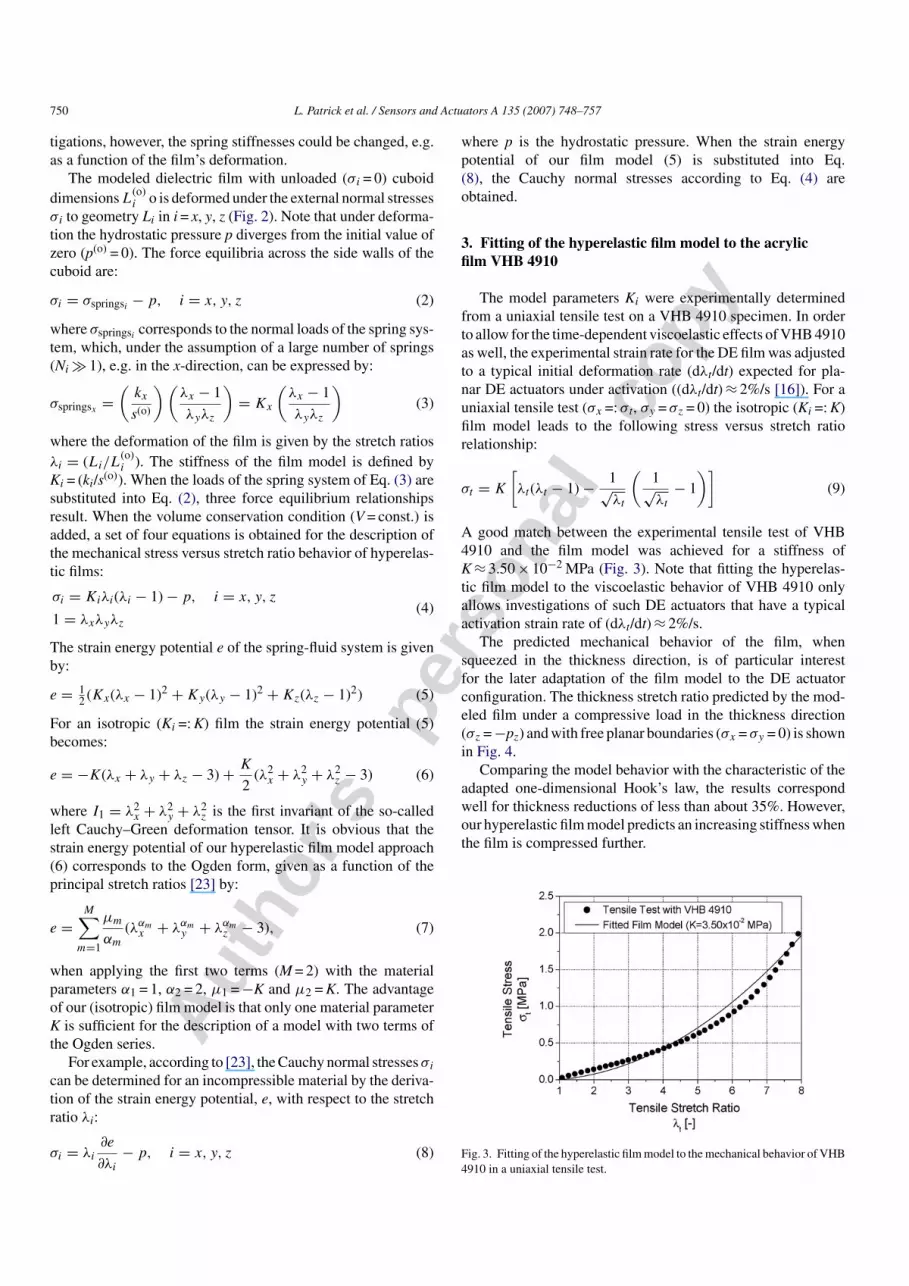
The model parameters Ki were experimentally determinedfrom a uniaxial tensile test on a VHB 4910 specimen. In orderto allow for the time-dependent viscoelastic effects of VHB 4910as well, the experimental strain rate for the DE film was adjustedto a typical initial deformation rate (dλt/dt) expected for pla-nar DE actuators under activation ((dλt/dt) ≈ 2%/s [16]). For auniaxial tensile test (σx =: σt, σy = σz = 0) the isotropic (Ki =: K)film model leads to the following stress versus stretch ratiorelationship:
σt = K
[λt(λt − 1) − 1√
λt
(1√λt
− 1
)](9)
A good match between the experimental tensile test of VHB4910 and the film model was achieved for a stiffness ofK ≈ 3.50 × 10⁻² MPa (Fig. 3). Note that fitting the hyperelas-tic film model to the viscoelastic behavior of VHB 4910 onlyallows investigations of such DE actuators that have a typicalactivation strain rate of (dλt/dt) ≈ 2%/s.
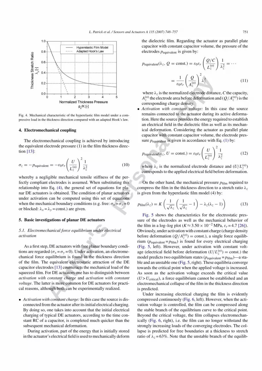
The predicted mechanical behavior of the film, whensqueezed in the thickness direction, is of particular interestfor the later adaptation of the film model to the DE actuatorconfiguration. The thickness stretch ratio predicted by the mod-eled film under a compressive load in the thickness direction(σz = −pz) and with free planar boundaries (σx = σy = 0) is shownin Fig. 4.
Comparing the model behavior with the characteristic of theadapted one-dimensional Hook’s law, the results correspondwell for thickness reductions of less than about 35%. However,our hyperelastic film model predicts an increasing stiffness whenthe film is compressed further.
Fig. 3. Fitting of the hyperelastic film model to the mechanical behavior of VHB4910 in a uniaxial tensile test.
Autho
r's
pers
onal
co
py
L. Patrick et al. / Sensors and Actuators A 135 (2007) 748–757 751
Fig. 4. Mechanical characteristic of the hyperelastic film model under a com-pressive load in the thickness direction compared with an adapted Hook’s law.
4. Electromechanical coupling
The electromechanical coupling is achieved by introducingthe equivalent electrode pressure (1) in the film thickness direc-tion [13]:
σz = −pequivalent = −ε0εr
(U
L(o)z
)21
λ2z
(10)
whereby a negligible mechanical tensile stiffness of the per-fectly compliant electrodes is assumed. When substituting thisrelationship into Eq. (4), the general set of equations for pla-nar DE actuators is obtained. The condition of planar actuatorsunder activation can be computed using this set of equationswhen the mechanical boundary conditions (e.g. free: σx = σy = 0or blocked: λx = λy = const.) are given.
5. Basic investigations of planar DE actuators
5.1. Electromechanical force equilibrium under electricalactivation
As a first step, DE actuators with free planar boundary condi-tions are regarded (σx = σy = 0). Under activation, an electrome-chanical force equilibrium is found in the thickness directionof the film. The equivalent electrostatic attraction of the DEcapacitor electrodes [13] counteracts the mechanical load of thesqueezed film. For DE actuators one has to distinguish betweenactivation with constant charge and activation with constantvoltage. The latter is more common for DE actuators for practi-cal reasons, although both can be experimentally realized.
• Activation with constant charge: In this case the source is dis-connected from the actuator after its initial electrical charging.By doing so, one takes into account that the initial electricalcharging of typical DE actuators, according to the time con-stant RC of a capacitor, is completed much quicker than thesubsequent mechanical deformation.
During activation, part of the energy that is initially storedin the actuator’s electrical field is used to mechanically deform
the dielectric film. Regarding the actuator as parallel platecapacitor with constant capacitor volume, the pressure of theelectrodes pequivalent is given by:
pequivalent(λz, Q = const.) = ε0εr
(Q/C
L(o)z
)1
λ2z
= · · ·
= 1
ε0εr
(Q
A(o)z
)2
λ2z (11)
where λz is the normalized electrode distance, C the capacity,A(o)
z the electrode area before deformation and (Q/A(o)z ) is the
corresponding charge density.• Activation with constant voltage: In this case the source
remains connected to the actuator during its active deforma-tion. Here the source provides the energy required to establishan electrical field in the dielectric film as well as its mechan-ical deformation. Considering the actuator as parallel platecapacitor with constant capacitor volume, the electrode pres-sure pequivalent is given in accordance with Eq. (1) by:
pequivalent(λz, U = const.) = ε0εr
(U
L(o)z
)21
λ2z
(12)
where λz is the normalized electrode distance and (U/L(o)z )
corresponds to the applied electrical field before deformation.
On the other hand, the mechanical pressure pfilm required tocompress the film in the thickness direction to a stretch ratio λz
is given from the hyperelastic film model (4) by:
pfilm(λz) = K
(1√λz
(1√λz
− 1
)− λz(λz − 1)
)(13)
Fig. 5 shows the characteristics for the electrostatic pres-sure of the electrodes as well as the mechanical behavior ofthe film in a log–log plot (K ≈ 3.50 × 10⁻² MPa, εr = 4.7 [26]).Obviously, under activation with constant charge (charge densitybefore deformation (Q/A(o)
z ) = const.), a single force equilib-rium (pequivalent = pfilm) is found for every electrical charging(Fig. 5, left). However, under activation with constant volt-age (electrical field before deformation (U/L(o)
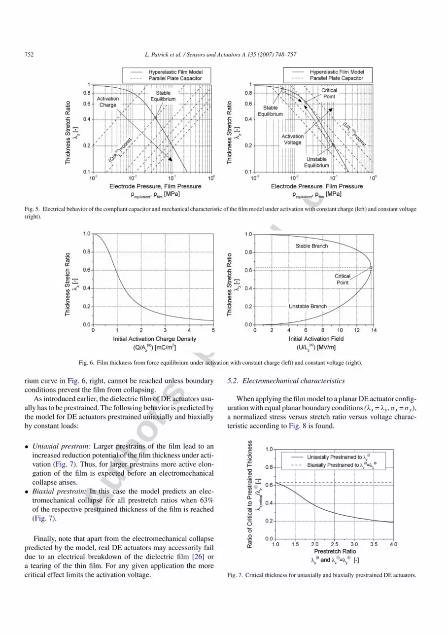
z ) = const.) themodel predicts two equilibrium states (pequivalent = pfilm)—a sta-ble and an unstable one (Fig. 5, right). These equilibria convergetowards the critical point when the applied voltage is increased.As soon as the activation voltage exceeds the critical value(U > Ucritical), a force equilibrium cannot be established and anelectromechanical collapse of the film in the thickness directionis predicted.
Under increasing electrical charging the film is evidentlycompressed continuously (Fig. 6, left). However, when the acti-vation voltage is controlled, the film can be compressed alongthe stable branch of the equilibrium curve to the critical point.Beyond the critical voltage, the film collapses electromechan-ically (Fig. 6, right), i.e. the film can no longer withstand thestrongly increasing loads of the converging electrodes. The col-lapse is predicted for free boundaries at a thickness to stretchratio of λz = 63%. Note that the unstable branch of the equilib-
Autho
r's
pers
onal
co
py
752 L. Patrick et al. / Sensors and Actuators A 135 (2007) 748–757
Fig. 5. Electrical behavior of the compliant capacitor and mechanical characteristic of the film model under activation with constant charge (left) and constant voltage(right).
Fig. 6. Film thickness from force equilibrium under activation with constant charge (left) and constant voltage (right).
rium curve in Fig. 6, right, cannot be reached unless boundaryconditions prevent the film from collapsing.
As introduced earlier, the dielectric film of DE actuators usu-ally has to be prestrained. The following behavior is predicted bythe model for DE actuators prestrained uniaxially and biaxiallyby constant loads:
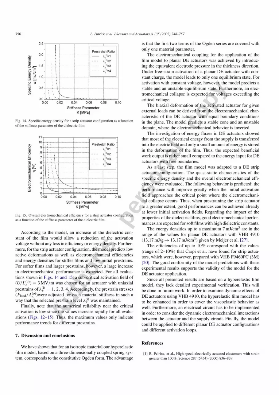
• Uniaxial prestrain: Larger prestrains of the film lead to anincreased reduction potential of the film thickness under acti-vation (Fig. 7). Thus, for larger prestrains more active elon-gation of the film is expected before an electromechanicalcollapse arises.
• Biaxial prestrain: In this case the model predicts an elec-tromechanical collapse for all prestretch ratios when 63%of the respective prestrained thickness of the film is reached(Fig. 7).
Finally, note that apart from the electromechanical collapsepredicted by the model, real DE actuators may accessorily faildue to an electrical breakdown of the dielectric film [26] ora tearing of the thin film. For any given application the morecritical effect limits the activation voltage.
5.2. Electromechanical characteristics
When applying the film model to a planar DE actuator config-uration with equal planar boundary conditions (λx = λy, σx = σy),a normalized stress versus stretch ratio versus voltage charac-teristic according to Fig. 8 is found.
Fig. 7. Critical thickness for uniaxially and biaxially prestrained DE actuators.

Autho
r's
pers
onal
co
py
L. Patrick et al. / Sensors and Actuators A 135 (2007) 748–757 753
Fig. 8. Normalized stress vs. stretch ratio vs. voltage characteristic of a planarDE actuator.
The drawn curves correspond to biaxial tensile tests of pla-nar DE actuators in the de-activated state (U = 0) and underactivation (U > 0), respectively. All actuator states are situatedon the surface spanned by these curves. An activation cycleof a DE actuator would correspond to a closed track on thecharacteristic’s surface (e.g. (o)–(i) biaxial prestrain, (i)–(ii) iso-tonic activation, (ii)–(iii) isometric de-activation, (iii)–(i) passiverelaxation). Apart from the stable domain, where the actuatorshows the expected stress-strain behavior under activation, themodel predicts an unstable domain with inverse behavior beyondthe critical line. In this sector, the mechanical tension required toprestrain the actuator under constant activation voltage reduceswhen the film is expanded.
Note that since single-layered actuators exhibit no inherentbending stiffness they cannot counteract external pressure loads.Thus, only actuator states in the domain σx = σy > 0 are feasible.In most single-layered DE actuators this condition is accom-plished by a strong planar prestrain of the film. However, thisdomain could be accessible for multi-layer actuators with inher-ent bending stiffness.
5.3. Energy considerations under electrical activation
DE actuators use electrical energy from the high voltagesource Wsource to perform mechanical work Wexternal againstan external load. The electromechanical efficiency defined asη = (Wexternal/Wsource) is influenced by the DE actuator config-uration and the type of activation cycle. The quasi-static cycleconsidered here corresponds to the case with vanishing resis-tance of the electrical supply circuit. Thus, energy losses in thecircuit are not taken into account.
Under activation of the DE actuator, the electrical sourceenergy Wsource is transformed into electric field energyWfield = CU2/2 and deformation energy of the film Wdeformation(Fig. 9).
Since only the deformation energy stored in the film can beemployed to perform mechanical work, the aim is to increasethe share of this beneficial deformation energy compared to theelectrical field energy. For DE actuators with free planar bound-aries (σx = σy = 0), the model gives an analytical expression forthe ratio of electrical field energy to mechanical deformation
Fig. 9. Schematic energy consideration of a DE actuator.
Fig. 10. Predicted ratio of mechanical deformation energy to electrical fieldenergy in the film of an activated DE actuator.
energy under activation:
Wdeformation
Wfield= (2((1/
√λz) − 1)2 + (λz − 1)2)
((1/√
λz)((1/√
λz) − 1) − λz(λz − 1))(14)
According to the model, the energy ratio is independent ofthe film’s stiffness. Furthermore, the ratio improves for greaterthickness compression under activation of the DE actuator(Fig. 10). However, the compression level is limited by the elec-tromechanical collapse (at λz ≈ 63%) as well as the electricalbreakdown of the film. Thus, according to the model, rather lowmechanical energies compared to the field energies are achiev-able for actuators with free boundaries (Wdeformation/Wfield < 0.5).
6. Consideration of DE strip actuators underquasi-static activation cycles
A strip actuator configuration was simulated using the hyper-elastic film model whereby the energy fluxes for quasi-staticactivation cycles were evaluated.
Basically, a strip actuator is a planar DE actuator, which isfixed on one side and uniaxially prestrained at the other side[21]. The primary reason for prestraining DE actuators made ofVHB 4910 is to reduce the film thickness (original thicknessL(o)
z = 1 mm). This enables a lowering of the activation voltagewithout a reduction of the electrical field in the actuator. Here, a

Autho
r's
pers
onal
co
py
754 L. Patrick et al. / Sensors and Actuators A 135 (2007) 748–757
Table 1Prestraining and quasi-static activation cycle of the strip actuator configuration
State/phase Explanation Energy consideration
(o) Initial state DE strip actuator is attached at the top. –(o)–(i) Prestraining Controlled vertical prestraining of the film with a constant
load.Prestrain energy is stored as deformation energy in the film.
(i) Passive equilibrium Force equilibrium between the passive film and the load. –(i)–(ii) Activation Controlled electrical activation of the strip actuator induces
a vertical elongation of the DE strip and lowering of theload.
Electrical source energy minus potential change of thelowered load used for establishing an electrical field andfurther deformation of the film.
(ii) Activated equilibrium Force equilibrium between the activated film and the load. –(ii)–(iii) Fixing and de-activation Lower fixing of the DE strip and controlled short-circuiting
of the electrodes.Dissipation of the electrical field energy and part of themechanical deformation energy (due to changed mechanicalboundaries at the film) in the circuit’s resistor.
(iii) Fixed equilibrium Maintenance of the strip’s length by an external fixture. –(iii)–(i) Working phase Replacement of the fixture by an equivalent external force.
Successive reduction of the external force results in acontrolled contraction of the film. Thus, the external forceand the prestrain load are lifted.
Remaining mechanical deformation energy in the film isconverted to work against an external force and used tochange the prestrain load potential.
vertical strip actuator made of VHB 4910 is considered which isprestrained at the bottom with a constant load. Under electricalactivation the strip actuator elongates and the load is lowered.When de-activated, the actuator contracts and can thus performwork against an external force in vertical direction (e.g. lift anadditional load).
6.1. Quasi-static activation cycle
The detailed steps for the prestraining under considerationand the quasi-static activation cycle of the strip actuator config-uration are presented in Table 1 and in Fig. 11.
In the chosen activation cycle the activation phase (i)–(ii)and the working phase (iii)–(i) are staggered. This means thatthe DE strip actuator works contractively after de-activation.Note also that the prestrain load has no energy gain over a fullactivation cycle – it is just lowered and lifted in the earth’s gravityfield.
6.2. Simulation of the strip actuator
The following additional assumptions were made for thesimulation of the strip actuator behavior by adapting the filmmodel:
Fig. 11. Prestraining and quasi-static activation cycle of the strip actuator configuration.

Autho
r's
pers
onal
co
py
L. Patrick et al. / Sensors and Actuators A 135 (2007) 748–757 755
• Laterally compliant upper fixing of the film.• Activation cycle regarded as quasi-static process.• No energy dissipation during activation considered (negligi-
ble resistance in the electrical circuit).
The equations of the film model (4) were adapted to thegeneral state of a strip actuator configuration by introducing auniaxial force Fload from the prestrain load and an external forceFexternal acting in the vertical direction at the bottom of the DEstrip (σx = (Fload + Fexternal)/Ax, σy = 0, σz = −pequivalent). Thus,one obtains in the x direction:
λx
(Fload
A(o)x
)+(
Fexternal
Ax
)= λx(λx − 1)K − p (15)
where (Fload/A(o)x ) is the initial prestrain stress, which is constant
for a given prestrain load, and (Fexternal/Ax) is the actual externalstress in the x direction.
6.3. Evaluation of the strip actuator configuration
The evaluation of the modeled strip actuator configurationwas done with regard to:
• Volume specific work per activation cycle (w = (Wexternal/V),denoted as specific energy density.
• Overall electromechanical efficiency of the actuator(η = (Wexternal/Wsource)).
The relationships for the electrical source energy and themechanical work of the external force are given by:
Wsource =
⎛⎜⎝E
(ii)field −
=0︷ ︸︸ ︷E
(i)field
⎞⎟⎠
︸ ︷︷ ︸=Wfield
+ (E(ii)springs − E
(i)springs)
− (E(ii)load − E
(i)load) (16)
Wexternal = (E(iii)springs − E
(i)springs) − (E(iii)
load − E(i)load) (17)
where Esprings is the deformation energy of the film model, Eloadis the potential of the prestrain load and Efield is the field energyof the strip actuator.
The numerical evaluation of the adapted equation system (4)for the states (i) to (iii) was executed with Mathematica. Theinitial prestrain stresses (Fload/A
(o)x ) = 0, 3.86 × 10⁻², 7.28 ×
10−2, 1.07 × 10⁻¹ MPa were selected to cover a wide range ofresulting uniaxial prestrains λ(i)
x = 1, 2, 3, 4 of the DE stripactuator.
6.4. Results for the strip actuator
The results for the energy densities achieved for varyingactivation fields are given in Fig. 12. It is obvious that theexpected specific energy densities are very small for low ini-tial activation fields. However, when the critical activation field
Fig. 12. Specific energy density for a strip actuator configuration as a functionof the activation field.
Fig. 13. Overall electromechanical efficiency for a strip actuator configurationas a function of the activation field.
is approached, a large increase in specific energy densities ispredicted. For larger prestrain loads the critical initial field isreduced since larger vertical prestrains lead to thinner initialfilm thicknesses. Thus, the increase in energy densities appearsearlier for larger prestrain loads. The highest energy densi-ties are reached for large prestrains (up to about 7 mJ/cm3 forλ(i)
x = 4, (Fload/A(o)x ) = 1.07 × 10⁻¹ MPa).
When considering the overall electromechanical efficiency(Fig. 13), the simulation of the strip actuator predicts a simi-lar behavior to the above. The low efficiencies at low activa-tion fields increase strongly when the critical activation field isapproached. Again, for larger prestrain the critical initial field islower and thus the efficiency increase occurs at lower activationvoltages. The maximum efficiencies predicted for the strip actu-ator are in the range of 10%. As shown, the maximum efficiencytends to decrease for stronger prestrain.
To improve the energy density and efficiency of DE actuatorsone could change the actuator configuration, the activation cycle(including recovery of the electrical field energy) or developDE films with improved electromechanical properties. In par-ticular, the development of novel films is of central interest,although the performance of the active material in general can-not be considered independently from the actuator configurationand activation cycle.
Autho
r's
pers
onal
co
py
756 L. Patrick et al. / Sensors and Actuators A 135 (2007) 748–757
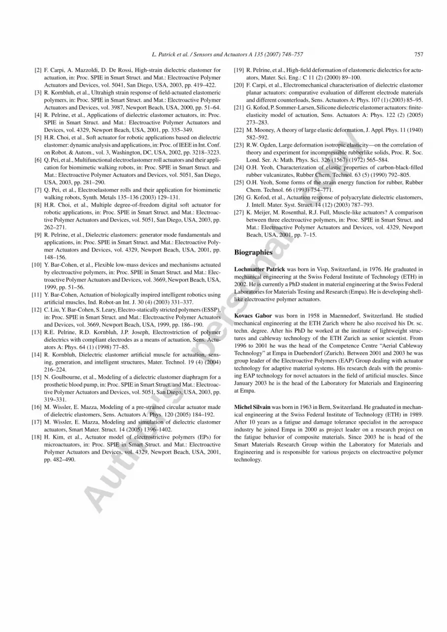
Fig. 14. Specific energy density for a strip actuator configuration as a functionof the stiffness parameter of the dielectric film.
Fig. 15. Overall electromechanical efficiency for a strip actuator configurationas a function of the stiffness parameter of the dielectric film.
According to the model, an increase of the dielectric con-stant of the film would allow a reduction of the activationvoltage without any loss in efficiency or energy density. Further-more, for the strip actuator configuration, the model predicts lowactive deformations as well as electromechanical efficienciesand energy densities for stiffer films and low initial prestrains.For softer films and larger prestrains, however, a large increasein electromechanical performance is expected. For all evalua-tions shown in Figs. 14 and 15, a sub-critical activation field of(U/L(o)
z ) = 3 MV/m was chosen for an actuator with uniaxialprestrains of λ(i)
x = 1, 2, 3, 4. Accordingly, the prestrain stresses(Fload/A
(o)x )were adjusted for each material stiffness in such a
way that the selected prestrain level λ(i)x was maintained.
Finally, note that the numerical reliability near the criticalactivation is low since the values increase rapidly for all evalu-ations (Figs. 12–15). Thus, the maximum values only indicateperformance trends for different prestrains.
7. Discussion and conclusions
We have shown that for an isotropic material our hyperelasticfilm model, based on a three-dimensionally coupled spring sys-tem, corresponds to the constitutive Ogden form. The advantage
is that the first two terms of the Ogden series are covered withonly one material parameter.
The electromechanical coupling for the application of thefilm model to planar DE actuators was achieved by introduc-ing the equivalent electrode pressure in the thickness direction.Under free-strain activation of a planar DE actuator with con-stant charge, the model leads to only one equilibrium state. Foractivation with constant voltage, however, the model predicts astable and an unstable equilibrium state. Furthermore, an elec-tromechanical collapse is expected for voltages exceeding thecritical voltage.
The biaxial deformation of the activated actuator for givenexternal loads can be derived from the electromechanical char-acteristic of the DE actuator with equal boundary conditionsin the plane. The model predicts a stable zone and an unstabledomain, where the electromechanical behavior is inverted.
The investigation of energy fluxes in DE actuators showedthat most of the electrical energy from the supply is transferredinto the electric field and only a small amount of energy is storedin the deformation of the film. Thus, the expected beneficialwork output is rather small compared to the energy input for DEactuators with free boundaries.
As a last step, the film model was adapted to a DE stripactuator configuration. The quasi-static characteristics of thespecific energy density and the overall electromechanical effi-ciency were evaluated. The following behavior is predicted: theperformance will improve greatly when the initial activationfield approaches the critical point where the electromechani-cal collapse occurs. Thus, when prestraining the strip actuatorto a greater extent, good performances can be achieved alreadyat lower initial activation fields. Regarding the impact of theproperties of the dielectric films, good electromechanical perfor-mances are expected for soft films with high dielectric constants.
The energy densities up to a maximum 7 mJ/cm3 are in therange of the values for planar DE actuators with VHB 4910(13.17 mJ/g → 13.17 mJ/cm3) given by Meijer et al. [27].
The efficiencies of up to 10% correspond with the values(range of 2–10%) that Carpi et al. have found for strip actua-tors, which were, however, prepared with VHB F9460PC (3M)[20]. The good conformity of the model predictions with theseexperimental results supports the validity of the model for theDE actuator application.
Since all presented results are based on a hyperelastic filmmodel, they lack detailed experimental verification. This willbe done in future work. In order to examine dynamic effects ofDE actuators using VHB 4910, the hyperelastic film model hasto be enhanced in order to cover the viscoelastic behavior aswell. Furthermore, an electrical circuit has to be implementedin order to consider the dynamic electromechanical interactionsbetween the actuator and the supply circuit. Finally, the modelcould be applied to different planar DE actuator configurationsand different activation loops.
References
[1] R. Pelrine, et al., High-speed electrically actuated elastomers with straingreater than 100%, Science 287 (5454) (2000) 836–839.
Autho
r's
pers
onal
co
py
L. Patrick et al. / Sensors and Actuators A 135 (2007) 748–757 757
[2] F. Carpi, A. Mazzoldi, D. De Rossi, High-strain dielectric elastomer foractuation, in: Proc. SPIE in Smart Struct. and Mat.: Electroactive PolymerActuators and Devices, vol. 5041, San Diego, USA, 2003, pp. 419–422.
[3] R. Kornbluh, et al., Ultrahigh strain response of field-actuated elastomericpolymers, in: Proc. SPIE in Smart Struct. and Mat.: Electroactive PolymerActuators and Devices, vol. 3987, Newport Beach, USA, 2000, pp. 51–64.
[4] R. Pelrine, et al., Applications of dielectric elastomer actuators, in: Proc.SPIE in Smart Struct. and Mat.: Electroactive Polymer Actuators andDevices, vol. 4329, Newport Beach, USA, 2001, pp. 335–349.
[5] H.R. Choi, et al., Soft actuator for robotic applications based on dielectricelastomer: dynamic analysis and applications, in: Proc. of IEEE in Int. Conf.on Robot. & Autom., vol. 3, Washington, DC, USA, 2002, pp. 3218–3223.
[6] Q. Pei, et al., Multifunctional electroelastomer roll actuators and their appli-cation for biomimetic walking robots, in: Proc. SPIE in Smart Struct. andMat.: Electroactive Polymer Actuators and Devices, vol. 5051, San Diego,USA, 2003, pp. 281–290.
[7] Q. Pei, et al., Electroelastomer rolls and their application for biomimeticwalking robots, Synth. Metals 135–136 (2003) 129–131.
[8] H.R. Choi, et al., Multiple degree-of-freedom digital soft actuator forrobotic applications, in: Proc. SPIE in Smart Struct. and Mat.: Electroac-tive Polymer Actuators and Devices, vol. 5051, San Diego, USA, 2003, pp.262–271.
[9] R. Pelrine, et al., Dielectric elastomers: generator mode fundamentals andapplications, in: Proc. SPIE in Smart Struct. and Mat.: Electroactive Poly-mer Actuators and Devices, vol. 4329, Newport Beach, USA, 2001, pp.148–156.
[10] Y. Bar-Cohen, et al., Flexible low-mass devices and mechanisms actuatedby electroactive polymers, in: Proc. SPIE in Smart Struct. and Mat.: Elec-troactive Polymer Actuators and Devices, vol. 3669, Newport Beach, USA,1999, pp. 51–56.
[11] Y. Bar-Cohen, Actuation of biologically inspired intelligent robotics usingartificial muscles, Ind. Robot-an Int. J. 30 (4) (2003) 331–337.
[12] C. Liu, Y. Bar-Cohen, S. Leary, Electro-statically stricted polymers (ESSP),in: Proc. SPIE in Smart Struct. and Mat.: Electroactive Polymer Actuatorsand Devices, vol. 3669, Newport Beach, USA, 1999, pp. 186–190.
[13] R.E. Pelrine, R.D. Kornbluh, J.P. Joseph, Electrostriction of polymerdielectrics with compliant electrodes as a means of actuation, Sens. Actu-ators A: Phys. 64 (1) (1998) 77–85.
[14] R. Kornbluh, Dielectric elastomer artificial muscle for actuation, sens-ing, generation, and intelligent structures, Mater. Technol. 19 (4) (2004)216–224.
[15] N. Goulbourne, et al., Modeling of a dielectric elastomer diaphragm for aprosthetic blood pump, in: Proc. SPIE in Smart Struct. and Mat.: Electroac-tive Polymer Actuators and Devices, vol. 5051, San Diego, USA, 2003, pp.319–331.
[16] M. Wissler, E. Mazza, Modeling of a pre-strained circular actuator madeof dielectric elastomers, Sens. Actuators A: Phys. 120 (2005) 184–192.
[17] M. Wissler, E. Mazza, Modeling and simulation of dielectric elastomeractuators, Smart Mater. Struct. 14 (2005) 1396–1402.
[18] H. Kim, et al., Actuator model of electrostrictive polymers (EPs) formicroactuators, in: Proc. SPIE in Smart Struct. and Mat.: ElectroactivePolymer Actuators and Devices, vol. 4329, Newport Beach, USA, 2001,pp. 482–490.
[19] R. Pelrine, et al., High-field deformation of elastomeric dielectrics for actu-ators, Mater. Sci. Eng.: C 11 (2) (2000) 89–100.
[20] F. Carpi, et al., Electromechanical characterisation of dielectric elastomerplanar actuators: comparative evaluation of different electrode materialsand different counterloads, Sens. Actuators A: Phys. 107 (1) (2003) 85–95.
[21] G. Kofod, P. Sommer-Larsen, Silicone dielectric elastomer actuators: finite-elasticity model of actuation, Sens. Actuators A: Phys. 122 (2) (2005)273–283.
[22] M. Mooney, A theory of large elastic deformation, J. Appl. Phys. 11 (1940)582–592.
[23] R.W. Ogden, Large deformation isotropic elasticity—on the correlation oftheory and experiment for incompressible rubberlike solids, Proc. R. Soc.Lond. Ser. A: Math. Phys. Sci. 326 (1567) (1972) 565–584.
[24] O.H. Yeoh, Characterization of elastic properties of carbon-black-filledrubber vulcanizates, Rubber Chem. Technol. 63 (5) (1990) 792–805.
[25] O.H. Yeoh, Some forms of the strain energy function for rubber, RubberChem. Technol. 66 (1993) 754–771.
[26] G. Kofod, et al., Actuation response of polyacrylate dielectric elastomers,J. Intell. Mater. Syst. Struct. 14 (12) (2003) 787–793.
[27] K. Meijer, M. Rosenthal, R.J. Full, Muscle-like actuators? A comparisonbetween three electroactive polymers, in: Proc. SPIE in Smart Struct. andMat.: Electroactive Polymer Actuators and Devices, vol. 4329, NewportBeach, USA, 2001, pp. 7–15.
Biographies
Lochmatter Patrick was born in Visp, Switzerland, in 1976. He graduated inmechanical engineering at the Swiss Federal Institute of Technology (ETH) in2002. He is currently a PhD student in material engineering at the Swiss FederalLaboratories for Materials Testing and Research (Empa). He is developing shell-like electroactive polymer actuators.
Kovacs Gabor was born in 1958 in Maennedorf, Switzerland. He studiedmechanical engineering at the ETH Zurich where he also received his Dr. sc.techn. degree. After his PhD he worked at the institute of lightweight struc-tures and cableway technology of the ETH Zurich as senior scientist. From1996 to 2001 he was the head of the Competence Centre “Aerial CablewayTechnology” at Empa in Duebendorf (Zurich). Between 2001 and 2003 he wasgroup leader of the Electroactive Polymers (EAP) Group dealing with actuatortechnology for adaptive material systems. His research deals with the promis-ing EAP technology for novel actuators in the field of artificial muscles. SinceJanuary 2003 he is the head of the Laboratory for Materials and Engineeringat Empa.
Michel Silvain was born in 1963 in Bern, Switzerland. He graduated in mechan-ical engineering at the Swiss Federal Institute of Technology (ETH) in 1989.After 10 years as a fatigue and damage tolerance specialist in the aerospaceindustry he joined Empa in 2000 as project leader on a research project onthe fatigue behavior of composite materials. Since 2003 he is head of theSmart Materials Research Group within the Laboratory for Materials andEngineering and is responsible for various projects on electroactive polymertechnology.


