Embed Size (px)
Citation preview
© 2014 Cisco and/or its affiliates. All rights reserved. This document is Cisco Public. Page 1 of 12
CCNPv7 ROUTE
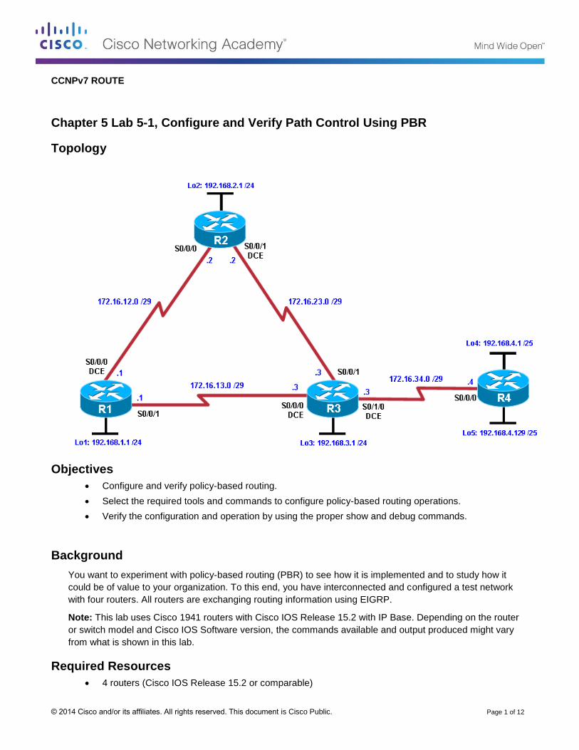
Chapter 5 Lab 5-1, Configure and Verify Path Control Using PBR
Topology
Objectives
Configure and verify policy-based routing.
Select the required tools and commands to configure policy-based routing operations.
Verify the configuration and operation by using the proper show and debug commands.
Background
You want to experiment with policy-based routing (PBR) to see how it is implemented and to study how it
could be of value to your organization. To this end, you have interconnected and configured a test network
with four routers. All routers are exchanging routing information using EIGRP.
Note: This lab uses Cisco 1941 routers with Cisco IOS Release 15.2 with IP Base. Depending on the router
or switch model and Cisco IOS Software version, the commands available and output produced might vary
from what is shown in this lab.
Required Resources
4 routers (Cisco IOS Release 15.2 or comparable)
CCNPv7 ROUTE Lab 5-1, Configure and Verify Path Control Using PBR
© 2014 Cisco and/or its affiliates. All rights reserved. This document is Cisco Public. Page 2 of 12
Serial and Ethernet cables
Step 1: Configure loopbacks and assign addresses.
a. Cable the network as shown in the topology diagram. Erase the startup configuration, and reload each
router to clear previous configurations.
b. Using the addressing scheme in the diagram, create the loopback interfaces and apply IP addresses to
these and the serial interfaces on R1, R2, R3, and R4. On the serial interfaces connecting R1 to R3 and
R3 to R4, specify the bandwidth as 64 Kb/s and set a clock rate on the DCE using the clock rate 64000
command. On the serial interfaces connecting R1 to R2 and R2 to R3, specify the bandwidth as 128 Kb/s
and set a clock rate on the DCE using the clock rate 128000 command.
You can copy and paste the following configurations into your routers to begin.
Note: Depending on the router model, interfaces might be numbered differently than those listed. You
might need to alter them accordingly.
Router R1
hostname R1
!
interface Lo1
description R1 LAN
ip address 192.168.1.1 255.255.255.0
!
interface Serial0/0/0
description R1 --> R2
ip address 172.16.12.1 255.255.255.248
clock rate 128000
bandwidth 128
no shutdown
!
interface Serial0/0/1
description R1 --> R3
ip address 172.16.13.1 255.255.255.248
bandwidth 64
no shutdown
!
end
Router R2
hostname R2
!
interface Lo2
description R2 LAN
ip address 192.168.2.1 255.255.255.0
!
interface Serial0/0/0
description R2 --> R1
ip address 172.16.12.2 255.255.255.248
bandwidth 128
no shutdown
interface Serial0/0/1
description R2 --> R3
ip address 172.16.23.2 255.255.255.248
clock rate 128000
CCNPv7 ROUTE Lab 5-1, Configure and Verify Path Control Using PBR
© 2014 Cisco and/or its affiliates. All rights reserved. This document is Cisco Public. Page 3 of 12
bandwidth 128
no shutdown
!
end
Router R3
hostname R3
!
interface Lo3
description R3 LAN
ip address 192.168.3.1 255.255.255.0
!
interface Serial0/0/0
description R3 --> R1
ip address 172.16.13.3 255.255.255.248
clock rate 64000
bandwidth 64
no shutdown
!
interface Serial0/0/1
description R3 --> R2
ip address 172.16.23.3 255.255.255.248
bandwidth 128
no shutdown
!
interface Serial0/1/0
description R3 --> R4
ip address 172.16.34.3 255.255.255.248
clock rate 64000
bandwidth 64
no shutdown
!
end
Router R4
hostname R4
!
interface Lo4
description R4 LAN A
ip address 192.168.4.1 255.255.255.128
!
interface Lo5
description R4 LAN B
ip address 192.168.4.129 255.255.255.128
!
interface Serial0/0/0
description R4 --> R3
ip address 172.16.34.4 255.255.255.248
bandwidth 64
no shutdown
!
end
c. Verify the configuration with the show ip interface brief, show protocols, and show interfaces
description commands. The output from router R3 is shown here as an example.
R3# show ip interface brief | include up
CCNPv7 ROUTE Lab 5-1, Configure and Verify Path Control Using PBR
© 2014 Cisco and/or its affiliates. All rights reserved. This document is Cisco Public. Page 4 of 12
Serial0/0/0 172.16.13.3 YES manual up up
Serial0/0/1 172.16.23.3 YES manual up up
Serial0/1/0 172.16.34.3 YES manual up up
Loopback3 192.168.3.1 YES manual up up
R3#
R3# show protocols
Global values:
Internet Protocol routing is enabled
Embedded-Service-Engine0/0 is administratively down, line protocol is down
GigabitEthernet0/0 is administratively down, line protocol is down
GigabitEthernet0/1 is administratively down, line protocol is down
Serial0/0/0 is up, line protocol is up
Internet address is 172.16.13.3/29
Serial0/0/1 is up, line protocol is up
Internet address is 172.16.23.3/29
Serial0/1/0 is up, line protocol is up
Internet address is 172.16.34.3/29
Serial0/1/1 is administratively down, line protocol is down
Loopback3 is up, line protocol is up
Internet address is 192.168.3.1/24
R3#
R3# show interfaces description | include up
Se0/0/0 up up R3 --> R1
Se0/0/1 up up R3 --> R2
Se0/1/0 up up R3 --> R4
Lo3 up up R3 LAN
R3#
Step 3: Configure basic EIGRP.
a. Implement EIGRP AS 1 over the serial and loopback interfaces as you have configured it for the other
EIGRP labs.
b. Advertise networks 172.16.12.0/29, 172.16.13.0/29, 172.16.23.0/29, 172.16.34.0/29, 192.168.1.0/24,
192.168.2.0/24, 192.168.3.0/24, and 192.168.4.0/24 from their respective routers.
You can copy and paste the following configurations into your routers.
Router R1
router eigrp 1
network 192.168.1.0
network 172.16.12.0 0.0.0.7
network 172.16.13.0 0.0.0.7
no auto-summary
Router R2
router eigrp 1
network 192.168.2.0
network 172.16.12.0 0.0.0.7
network 172.16.23.0 0.0.0.7
no auto-summary
Router R3
router eigrp 1
network 192.168.3.0
network 172.16.13.0 0.0.0.7
network 172.16.23.0 0.0.0.7
network 172.16.34.0 0.0.0.7
CCNPv7 ROUTE Lab 5-1, Configure and Verify Path Control Using PBR
© 2014 Cisco and/or its affiliates. All rights reserved. This document is Cisco Public. Page 5 of 12
no auto-summary
Router R4
router eigrp 1
network 192.168.4.0
network 172.16.34.0 0.0.0.7
no auto-summary
You should see EIGRP neighbor relationship messages being generated.
Step 4: Verify EIGRP connectivity.
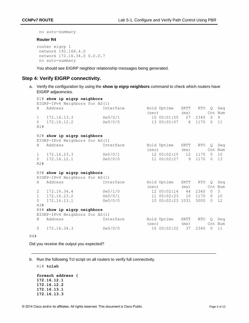
a. Verify the configuration by using the show ip eigrp neighbors command to check which routers have
EIGRP adjacencies.
R1# show ip eigrp neighbors
EIGRP-IPv4 Neighbors for AS(1)
H Address Interface Hold Uptime SRTT RTO Q Seq
(sec) (ms) Cnt Num
1 172.16.13.3 Se0/0/1 10 00:01:55 27 2340 0 9
0 172.16.12.2 Se0/0/0 13 00:02:07 8 1170 0 11
R1#
R2# show ip eigrp neighbors
EIGRP-IPv4 Neighbors for AS(1)
H Address Interface Hold Uptime SRTT RTO Q Seq
(sec) (ms) Cnt Num
1 172.16.23.3 Se0/0/1 12 00:02:15 12 1170 0 10
0 172.16.12.1 Se0/0/0 11 00:02:27 9 1170 0 13
R2#
R3# show ip eigrp neighbors
EIGRP-IPv4 Neighbors for AS(1)
H Address Interface Hold Uptime SRTT RTO Q Seq
(sec) (ms) Cnt Num
2 172.16.34.4 Se0/1/0 12 00:02:14 44 2340 0 3
1 172.16.23.2 Se0/0/1 11 00:02:23 10 1170 0 10
0 172.16.13.1 Se0/0/0 10 00:02:23 1031 5000 0 12
R3#
R4# show ip eigrp neighbors
EIGRP-IPv4 Neighbors for AS(1)
H Address Interface Hold Uptime SRTT RTO Q Seq
(sec) (ms) Cnt Num
0 172.16.34.3 Se0/0/0 10 00:02:22 37 2340 0 11
R4#
Did you receive the output you expected?
__________________________________________________________________________________
b. Run the following Tcl script on all routers to verify full connectivity.
R1# tclsh
foreach address {
172.16.12.1
172.16.12.2
172.16.13.1
172.16.13.3
CCNPv7 ROUTE Lab 5-1, Configure and Verify Path Control Using PBR
© 2014 Cisco and/or its affiliates. All rights reserved. This document is Cisco Public. Page 6 of 12
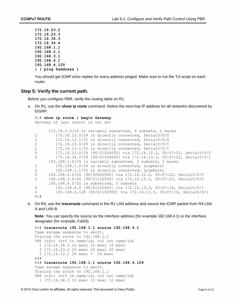
172.16.23.2
172.16.23.3
172.16.34.3
172.16.34.4
192.168.1.1
192.168.2.1
192.168.3.1
192.168.4.1
192.168.4.129
} { ping $address }
You should get ICMP echo replies for every address pinged. Make sure to run the Tcl script on each
router.
Step 5: Verify the current path.
Before you configure PBR, verify the routing table on R1.
a. On R1, use the show ip route command. Notice the next-hop IP address for all networks discovered by
EIGRP.
R1# show ip route | begin Gateway
Gateway of last resort is not set
172.16.0.0/16 is variably subnetted, 6 subnets, 2 masks
C 172.16.12.0/29 is directly connected, Serial0/0/0
L 172.16.12.1/32 is directly connected, Serial0/0/0
C 172.16.13.0/29 is directly connected, Serial0/0/1
L 172.16.13.1/32 is directly connected, Serial0/0/1
D 172.16.23.0/29 [90/21024000] via 172.16.12.2, 00:07:22, Serial0/0/0
D 172.16.34.0/29 [90/41024000] via 172.16.13.3, 00:07:22, Serial0/0/1
192.168.1.0/24 is variably subnetted, 2 subnets, 2 masks
C 192.168.1.0/24 is directly connected, Loopback1
L 192.168.1.1/32 is directly connected, Loopback1
D 192.168.2.0/24 [90/20640000] via 172.16.12.2, 00:07:22, Serial0/0/0
D 192.168.3.0/24 [90/21152000] via 172.16.12.2, 00:07:22, Serial0/0/0
192.168.4.0/25 is subnetted, 2 subnets
D 192.168.4.0 [90/41152000] via 172.16.13.3, 00:07:14, Serial0/0/1
D 192.168.4.128 [90/41152000] via 172.16.13.3, 00:07:14, Serial0/0/1
R1#
b. On R4, use the traceroute command to the R1 LAN address and source the ICMP packet from R4 LAN
A and LAN B.
Note: You can specify the source as the interface address (for example 192.168.4.1) or the interface
designator (for example, Fa0/0).
R4# traceroute 192.168.1.1 source 192.168.4.1
Type escape sequence to abort.
Tracing the route to 192.168.1.1
VRF info: (vrf in name/id, vrf out name/id)
1 172.16.34.3 12 msec 12 msec 16 msec
2 172.16.23.2 20 msec 20 msec 20 msec
3 172.16.12.1 24 msec * 24 msec
R4#
R4# traceroute 192.168.1.1 source 192.168.4.129
Type escape sequence to abort.
Tracing the route to 192.168.1.1
VRF info: (vrf in name/id, vrf out name/id)
1 172.16.34.3 12 msec 16 msec 12 msec
CCNPv7 ROUTE Lab 5-1, Configure and Verify Path Control Using PBR
© 2014 Cisco and/or its affiliates. All rights reserved. This document is Cisco Public. Page 7 of 12
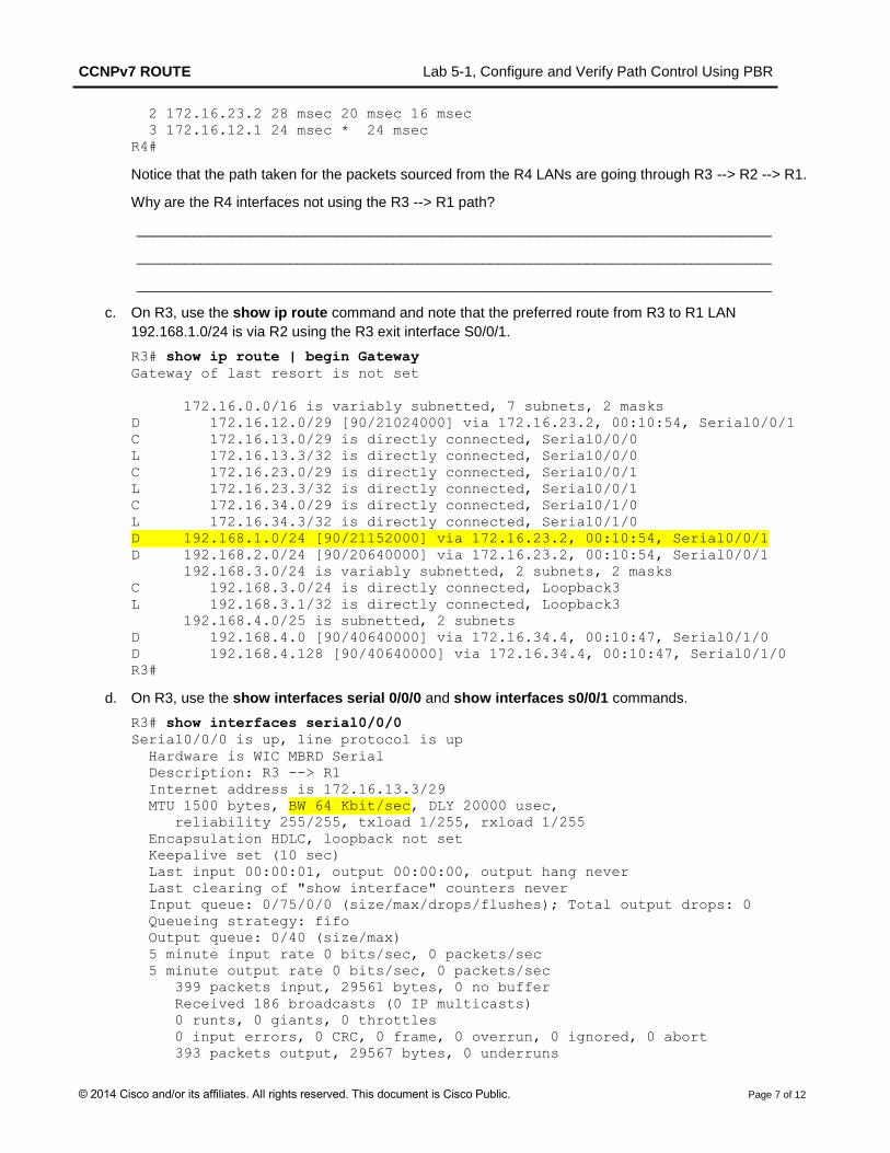
2 172.16.23.2 28 msec 20 msec 16 msec
3 172.16.12.1 24 msec * 24 msec
R4#
Notice that the path taken for the packets sourced from the R4 LANs are going through R3 --> R2 --> R1.
Why are the R4 interfaces not using the R3 --> R1 path?
_______________________________________________________________________________
_______________________________________________________________________________
_______________________________________________________________________________
c. On R3, use the show ip route command and note that the preferred route from R3 to R1 LAN
192.168.1.0/24 is via R2 using the R3 exit interface S0/0/1.
R3# show ip route | begin Gateway
Gateway of last resort is not set
172.16.0.0/16 is variably subnetted, 7 subnets, 2 masks
D 172.16.12.0/29 [90/21024000] via 172.16.23.2, 00:10:54, Serial0/0/1
C 172.16.13.0/29 is directly connected, Serial0/0/0
L 172.16.13.3/32 is directly connected, Serial0/0/0
C 172.16.23.0/29 is directly connected, Serial0/0/1
L 172.16.23.3/32 is directly connected, Serial0/0/1
C 172.16.34.0/29 is directly connected, Serial0/1/0
L 172.16.34.3/32 is directly connected, Serial0/1/0
D 192.168.1.0/24 [90/21152000] via 172.16.23.2, 00:10:54, Serial0/0/1
D 192.168.2.0/24 [90/20640000] via 172.16.23.2, 00:10:54, Serial0/0/1
192.168.3.0/24 is variably subnetted, 2 subnets, 2 masks
C 192.168.3.0/24 is directly connected, Loopback3
L 192.168.3.1/32 is directly connected, Loopback3
192.168.4.0/25 is subnetted, 2 subnets
D 192.168.4.0 [90/40640000] via 172.16.34.4, 00:10:47, Serial0/1/0
D 192.168.4.128 [90/40640000] via 172.16.34.4, 00:10:47, Serial0/1/0
R3#
d. On R3, use the show interfaces serial 0/0/0 and show interfaces s0/0/1 commands.
R3# show interfaces serial0/0/0
Serial0/0/0 is up, line protocol is up
Hardware is WIC MBRD Serial
Description: R3 --> R1
Internet address is 172.16.13.3/29
MTU 1500 bytes, BW 64 Kbit/sec, DLY 20000 usec,
reliability 255/255, txload 1/255, rxload 1/255
Encapsulation HDLC, loopback not set
Keepalive set (10 sec)
Last input 00:00:01, output 00:00:00, output hang never
Last clearing of "show interface" counters never
Input queue: 0/75/0/0 (size/max/drops/flushes); Total output drops: 0
Queueing strategy: fifo
Output queue: 0/40 (size/max)
5 minute input rate 0 bits/sec, 0 packets/sec
5 minute output rate 0 bits/sec, 0 packets/sec
399 packets input, 29561 bytes, 0 no buffer
Received 186 broadcasts (0 IP multicasts)
0 runts, 0 giants, 0 throttles
0 input errors, 0 CRC, 0 frame, 0 overrun, 0 ignored, 0 abort
393 packets output, 29567 bytes, 0 underruns
CCNPv7 ROUTE Lab 5-1, Configure and Verify Path Control Using PBR
© 2014 Cisco and/or its affiliates. All rights reserved. This document is Cisco Public. Page 8 of 12
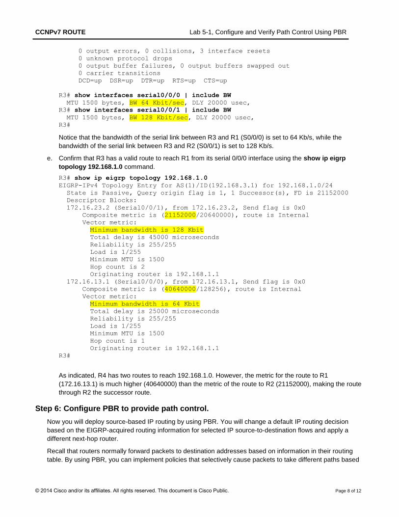
0 output errors, 0 collisions, 3 interface resets
0 unknown protocol drops
0 output buffer failures, 0 output buffers swapped out
0 carrier transitions
DCD=up DSR=up DTR=up RTS=up CTS=up
R3# show interfaces serial0/0/0 | include BW
MTU 1500 bytes, BW 64 Kbit/sec, DLY 20000 usec,
R3# show interfaces serial0/0/1 | include BW
MTU 1500 bytes, BW 128 Kbit/sec, DLY 20000 usec,
R3#
Notice that the bandwidth of the serial link between R3 and R1 (S0/0/0) is set to 64 Kb/s, while the
bandwidth of the serial link between R3 and R2 (S0/0/1) is set to 128 Kb/s.
e. Confirm that R3 has a valid route to reach R1 from its serial 0/0/0 interface using the show ip eigrp
topology 192.168.1.0 command.
R3# show ip eigrp topology 192.168.1.0
EIGRP-IPv4 Topology Entry for AS(1)/ID(192.168.3.1) for 192.168.1.0/24
State is Passive, Query origin flag is 1, 1 Successor(s), FD is 21152000
Descriptor Blocks:
172.16.23.2 (Serial0/0/1), from 172.16.23.2, Send flag is 0x0
Composite metric is (21152000/20640000), route is Internal
Vector metric:
Minimum bandwidth is 128 Kbit
Total delay is 45000 microseconds
Reliability is 255/255
Load is 1/255
Minimum MTU is 1500
Hop count is 2
Originating router is 192.168.1.1
172.16.13.1 (Serial0/0/0), from 172.16.13.1, Send flag is 0x0
Composite metric is (40640000/128256), route is Internal
Vector metric:
Minimum bandwidth is 64 Kbit
Total delay is 25000 microseconds
Reliability is 255/255
Load is 1/255
Minimum MTU is 1500
Hop count is 1
Originating router is 192.168.1.1
R3#
As indicated, R4 has two routes to reach 192.168.1.0. However, the metric for the route to R1
(172.16.13.1) is much higher (40640000) than the metric of the route to R2 (21152000), making the route
through R2 the successor route.
Step 6: Configure PBR to provide path control.
Now you will deploy source-based IP routing by using PBR. You will change a default IP routing decision
based on the EIGRP-acquired routing information for selected IP source-to-destination flows and apply a
different next-hop router.
Recall that routers normally forward packets to destination addresses based on information in their routing
table. By using PBR, you can implement policies that selectively cause packets to take different paths based
CCNPv7 ROUTE Lab 5-1, Configure and Verify Path Control Using PBR
© 2014 Cisco and/or its affiliates. All rights reserved. This document is Cisco Public. Page 9 of 12
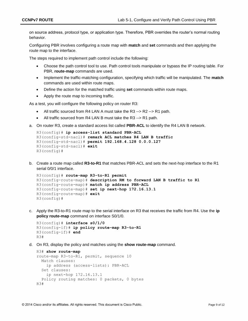
on source address, protocol type, or application type. Therefore, PBR overrides the router’s normal routing
behavior.
Configuring PBR involves configuring a route map with match and set commands and then applying the
route map to the interface.
The steps required to implement path control include the following:
Choose the path control tool to use. Path control tools manipulate or bypass the IP routing table. For
PBR, route-map commands are used.
Implement the traffic-matching configuration, specifying which traffic will be manipulated. The match
commands are used within route maps.
Define the action for the matched traffic using set commands within route maps.
Apply the route map to incoming traffic.
As a test, you will configure the following policy on router R3:
All traffic sourced from R4 LAN A must take the R3 --> R2 --> R1 path.
All traffic sourced from R4 LAN B must take the R3 --> R1 path.
a. On router R3, create a standard access list called PBR-ACL to identify the R4 LAN B network.
R3(config)# ip access-list standard PBR-ACL
R3(config-std-nacl)# remark ACL matches R4 LAN B traffic
R3(config-std-nacl)# permit 192.168.4.128 0.0.0.127
R3(config-std-nacl)# exit
R3(config)#
b. Create a route map called R3-to-R1 that matches PBR-ACL and sets the next-hop interface to the R1
serial 0/0/1 interface.
R3(config)# route-map R3-to-R1 permit
R3(config-route-map)# description RM to forward LAN B traffic to R1
R3(config-route-map)# match ip address PBR-ACL
R3(config-route-map)# set ip next-hop 172.16.13.1
R3(config-route-map)# exit
R3(config)#
c. Apply the R3-to-R1 route map to the serial interface on R3 that receives the traffic from R4. Use the ip
policy route-map command on interface S0/1/0.
R3(config)# interface s0/1/0
R3(config-if)# ip policy route-map R3-to-R1
R3(config-if)# end
R3#
d. On R3, display the policy and matches using the show route-map command.
R3# show route-map
route-map R3-to-R1, permit, sequence 10
Match clauses:
ip address (access-lists): PBR-ACL
Set clauses:
ip next-hop 172.16.13.1
Policy routing matches: 0 packets, 0 bytes
R3#
CCNPv7 ROUTE Lab 5-1, Configure and Verify Path Control Using PBR
© 2014 Cisco and/or its affiliates. All rights reserved. This document is Cisco Public. Page 10 of 12
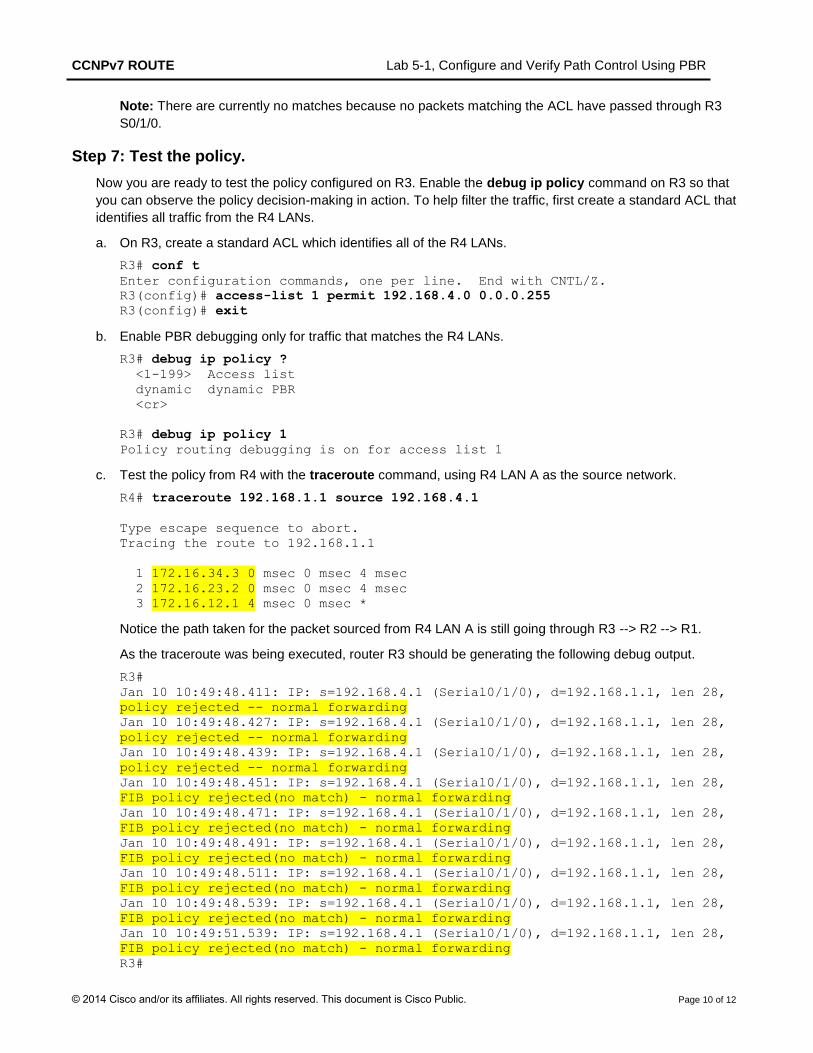
Note: There are currently no matches because no packets matching the ACL have passed through R3
S0/1/0.
Step 7: Test the policy.
Now you are ready to test the policy configured on R3. Enable the debug ip policy command on R3 so that
you can observe the policy decision-making in action. To help filter the traffic, first create a standard ACL that
identifies all traffic from the R4 LANs.
a. On R3, create a standard ACL which identifies all of the R4 LANs.
R3# conf t
Enter configuration commands, one per line. End with CNTL/Z.
R3(config)# access-list 1 permit 192.168.4.0 0.0.0.255
R3(config)# exit
b. Enable PBR debugging only for traffic that matches the R4 LANs.
R3# debug ip policy ?
<1-199> Access list
dynamic dynamic PBR
<cr>
R3# debug ip policy 1
Policy routing debugging is on for access list 1
c. Test the policy from R4 with the traceroute command, using R4 LAN A as the source network.
R4# traceroute 192.168.1.1 source 192.168.4.1
Type escape sequence to abort.
Tracing the route to 192.168.1.1
1 172.16.34.3 0 msec 0 msec 4 msec
2 172.16.23.2 0 msec 0 msec 4 msec
3 172.16.12.1 4 msec 0 msec *
Notice the path taken for the packet sourced from R4 LAN A is still going through R3 --> R2 --> R1.
As the traceroute was being executed, router R3 should be generating the following debug output.
R3#
Jan 10 10:49:48.411: IP: s=192.168.4.1 (Serial0/1/0), d=192.168.1.1, len 28,
policy rejected -- normal forwarding
Jan 10 10:49:48.427: IP: s=192.168.4.1 (Serial0/1/0), d=192.168.1.1, len 28,
policy rejected -- normal forwarding
Jan 10 10:49:48.439: IP: s=192.168.4.1 (Serial0/1/0), d=192.168.1.1, len 28,
policy rejected -- normal forwarding
Jan 10 10:49:48.451: IP: s=192.168.4.1 (Serial0/1/0), d=192.168.1.1, len 28,
FIB policy rejected(no match) - normal forwarding
Jan 10 10:49:48.471: IP: s=192.168.4.1 (Serial0/1/0), d=192.168.1.1, len 28,
FIB policy rejected(no match) - normal forwarding
Jan 10 10:49:48.491: IP: s=192.168.4.1 (Serial0/1/0), d=192.168.1.1, len 28,
FIB policy rejected(no match) - normal forwarding
Jan 10 10:49:48.511: IP: s=192.168.4.1 (Serial0/1/0), d=192.168.1.1, len 28,
FIB policy rejected(no match) - normal forwarding
Jan 10 10:49:48.539: IP: s=192.168.4.1 (Serial0/1/0), d=192.168.1.1, len 28,
FIB policy rejected(no match) - normal forwarding
Jan 10 10:49:51.539: IP: s=192.168.4.1 (Serial0/1/0), d=192.168.1.1, len 28,
FIB policy rejected(no match) - normal forwarding
R3#
CCNPv7 ROUTE Lab 5-1, Configure and Verify Path Control Using PBR
© 2014 Cisco and/or its affiliates. All rights reserved. This document is Cisco Public. Page 11 of 12
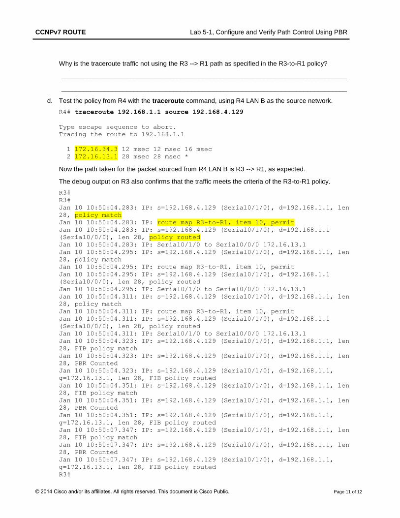
Why is the traceroute traffic not using the R3 --> R1 path as specified in the R3-to-R1 policy?
_______________________________________________________________________________
_______________________________________________________________________________
d. Test the policy from R4 with the traceroute command, using R4 LAN B as the source network.
R4# traceroute 192.168.1.1 source 192.168.4.129
Type escape sequence to abort.
Tracing the route to 192.168.1.1
1 172.16.34.3 12 msec 12 msec 16 msec
2 172.16.13.1 28 msec 28 msec *
Now the path taken for the packet sourced from R4 LAN B is R3 --> R1, as expected.
The debug output on R3 also confirms that the traffic meets the criteria of the R3-to-R1 policy.
R3#
R3#
Jan 10 10:50:04.283: IP: s=192.168.4.129 (Serial0/1/0), d=192.168.1.1, len
28, policy match
Jan 10 10:50:04.283: IP: route map R3-to-R1, item 10, permit
Jan 10 10:50:04.283: IP: s=192.168.4.129 (Serial0/1/0), d=192.168.1.1
(Serial0/0/0), len 28, policy routed
Jan 10 10:50:04.283: IP: Serial0/1/0 to Serial0/0/0 172.16.13.1
Jan 10 10:50:04.295: IP: s=192.168.4.129 (Serial0/1/0), d=192.168.1.1, len
28, policy match
Jan 10 10:50:04.295: IP: route map R3-to-R1, item 10, permit
Jan 10 10:50:04.295: IP: s=192.168.4.129 (Serial0/1/0), d=192.168.1.1
(Serial0/0/0), len 28, policy routed
Jan 10 10:50:04.295: IP: Serial0/1/0 to Serial0/0/0 172.16.13.1
Jan 10 10:50:04.311: IP: s=192.168.4.129 (Serial0/1/0), d=192.168.1.1, len
28, policy match
Jan 10 10:50:04.311: IP: route map R3-to-R1, item 10, permit
Jan 10 10:50:04.311: IP: s=192.168.4.129 (Serial0/1/0), d=192.168.1.1
(Serial0/0/0), len 28, policy routed
Jan 10 10:50:04.311: IP: Serial0/1/0 to Serial0/0/0 172.16.13.1
Jan 10 10:50:04.323: IP: s=192.168.4.129 (Serial0/1/0), d=192.168.1.1, len
28, FIB policy match
Jan 10 10:50:04.323: IP: s=192.168.4.129 (Serial0/1/0), d=192.168.1.1, len
28, PBR Counted
Jan 10 10:50:04.323: IP: s=192.168.4.129 (Serial0/1/0), d=192.168.1.1,
g=172.16.13.1, len 28, FIB policy routed
Jan 10 10:50:04.351: IP: s=192.168.4.129 (Serial0/1/0), d=192.168.1.1, len
28, FIB policy match
Jan 10 10:50:04.351: IP: s=192.168.4.129 (Serial0/1/0), d=192.168.1.1, len
28, PBR Counted
Jan 10 10:50:04.351: IP: s=192.168.4.129 (Serial0/1/0), d=192.168.1.1,
g=172.16.13.1, len 28, FIB policy routed
Jan 10 10:50:07.347: IP: s=192.168.4.129 (Serial0/1/0), d=192.168.1.1, len
28, FIB policy match
Jan 10 10:50:07.347: IP: s=192.168.4.129 (Serial0/1/0), d=192.168.1.1, len
28, PBR Counted
Jan 10 10:50:07.347: IP: s=192.168.4.129 (Serial0/1/0), d=192.168.1.1,
g=172.16.13.1, len 28, FIB policy routed
R3#
CCNPv7 ROUTE Lab 5-1, Configure and Verify Path Control Using PBR
© 2014 Cisco and/or its affiliates. All rights reserved. This document is Cisco Public. Page 12 of 12
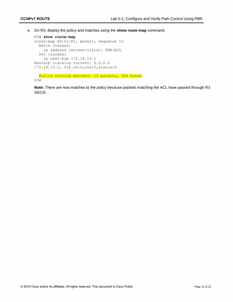
e. On R3, display the policy and matches using the show route-map command.
R3# show route-map
route-map R3-to-R1, permit, sequence 10
Match clauses:
ip address (access-lists): PBR-ACL
Set clauses:
ip next-hop 172.16.13.1
Nexthop tracking current: 0.0.0.0
172.16.13.1, fib_nh:0,oce:0,status:0
Policy routing matches: 12 packets, 384 bytes
R3#
Note: There are now matches to the policy because packets matching the ACL have passed through R3
S0/1/0.


