Embed Size (px)
Citation preview
www.jespublication.com
CFD ANALYSIS OF CATALYTIC CONVERTER 1BUDAMAKAYALA RAMESWARA REDDY,
2P.HUSSAIN,
3A.GOUSE PEERA,
4Dr.P.MALLIKARJUNA REDDY
1M.Tech Student,
2Associate Professor,
3Assistant Professor,
4Professor
DEPARTMENT OF MECHANICAL ENGINEERING
SVR Engineering College, Nandyal
ABSTRACT:
Diesel engines have high efficiency,
durability, and reliability together with their low-
operating cost. These important features make them
the most preferred engines especially for heavy-duty
vehicles. The interest in diesel engines has risen
substantially day by day. In addition to the
widespread use of these engines with many
advantages, they play an important role in
environmental pollution problems worldwide. Diesel
engines are considered as one of the largest
contributors to environmental pollution caused by
exhaust emissions, and they are responsible for
several health problems as well. The four main
pollutant emissions from diesel engines (carbon
monoxide-CO, hydrocarbons-HC, particulate matter-
PM and nitrogen oxides-NOx) and control systems
for these emissions (diesel oxidation catalyst, diesel
particulate filter and selective catalytic reduction) are
discussed. Each type of emissions and control
systems is comprehensively examined. The present
project deals with the fabrication of filter type
emission controller suitable for clamping to diesel
engine for optimizing the control of emissions before
and after usage.
Keywords: Diesel engine, Emission control system
I. INTRODUCTION
Diesel exhaust soot is the visible cloud of
black carbon-containing smoke that appears on
engine start-up and during normal diesel engine
operation. Black carbon is hazardous to health and
presents a range of other issues, including visible
product contamination and soiling. It is also believed
that black carbon is a contributory factor in climate
change. This technical paper aims to clarify the issues
surrounding exhaust soot and presents information
designed to assist in the decision-making process of
how best to reduce black carbon emissions from
diesel exhausts.
1.1 PARTICULATE MATTER (PM):
In a theoretically perfect combustion,
carbon dioxide, water and nitrogen are the end
products. In reality, the incomplete combustion of
diesel fuel results in emissions that include oxides of
nitrogen (NOx), carbon monoxide (CO), carbon
dioxide (CO2), water (H2O) and unburned
hydrocarbons (HC). There are also unborn carbon
particles, as well as engine oils, debris, soot and ash
particulates, which are known as particulate matter
(PM). This diesel particulate matter (DPM) is the
visible cloud of black smoke that appears from
engine start-up and continues to appear when the
engine is running. DPMs can be categorized into two
groups
PM10 - Particles of 2.5 microns to 10 microns, and
PM2.5 - Particles of less than 2.5 microns in size.
Although most Diesel Particulates are very small,
more than 99% are in the sub-micrometer range.
1.2 THE CONCERNS ASSOCIATED WITH
DPM:
Climate change is something that directly affects
us all and is just one of the concerns associated with
diesel exhaust emissions. The main issues
surrounding black carbon soot being:
Health DPM has been identified by health experts
as contributing to a variety of lung related illnesses.
Exposure to DPM has been linked to acute short-term
symptoms such as headaches, nausea, and irritation
of the eyes, nose and throat. Long-term exposure can
lead to chronic and more serious health problems
such as cardiovascular disease and lung cancer.
Inhalation The smallest particles have the worst
health implications because of their ability to
penetrate deep into lung tissue. They easily bind with
other toxins in the environment, thereby increasing
the hazards of particle inhalation.
www.jespublication.com
Confined Spaces Machinery operating in confined
or enclosed spaces – for example in tunnels, mines,
and quarries, or in factories and warehouses where
ventilation is limited – pose a greater health risk to
operatives and anyone in the vicinity of that
equipment.
Air Quality In addition to the health concerns
mentioned above, the pollution emitted by diesel
engines contributes greatly to air quality problems
such as haze and smog, both of which restrict
visibility and can cause irritation of the eyes, nose
and throat. Furthermore, diesel exhaust fumes
contribute to ozone formation, acid rain, and climate
change.
Contamination DPM can also contaminate products
and packaging in factories and warehouses where
DPMs are present in the atmosphere. In the wider
environment DPM contaminates foliage and soils
buildings, an all too common sight in urban areas.
1.3 HOW CAN THE BLACK SMOKE BE
REDUCED:
The industry has been developing innovative
ideas to reduce exhaust emissions for many years. A
number of solutions are available and these range
from Exhaust Gas Recirculation (EGR) to Dual Fuel
conversions. The most effective solutions are
designed specifically to deal with particulates and can
reduce the DPM emissions in the exhaust by up to
99%, from startup. These systems are known as
Diesel Particulate Filters or Soot Filters.
1.4 WHAT IS A DIESEL PARTICULATE
FILTER (DPF):
A Diesel Particulate Filter is a device that
traps the exhaust stream particulate matter by means
of physical filtration. This process is an established,
efficient and effective way of removing DPM from
the exhaust stream. Once captured, the accumulated
DPM must then be dealt with in a safe and secure
manner. All types of filters have a finite capacity.
DPFs are no different and must be cleared of the
accumulated DPM, either at regular intervals, or
during operation. Failure to do so will eventually
cause the filter to block. This can damage or destroy
the filter and may also damage the engine due to
increased backpressure. There are two solutions to
this problem. One is to remove and replace the filter
with a fresh one; the second method is to regenerate
the filter so it can be reused
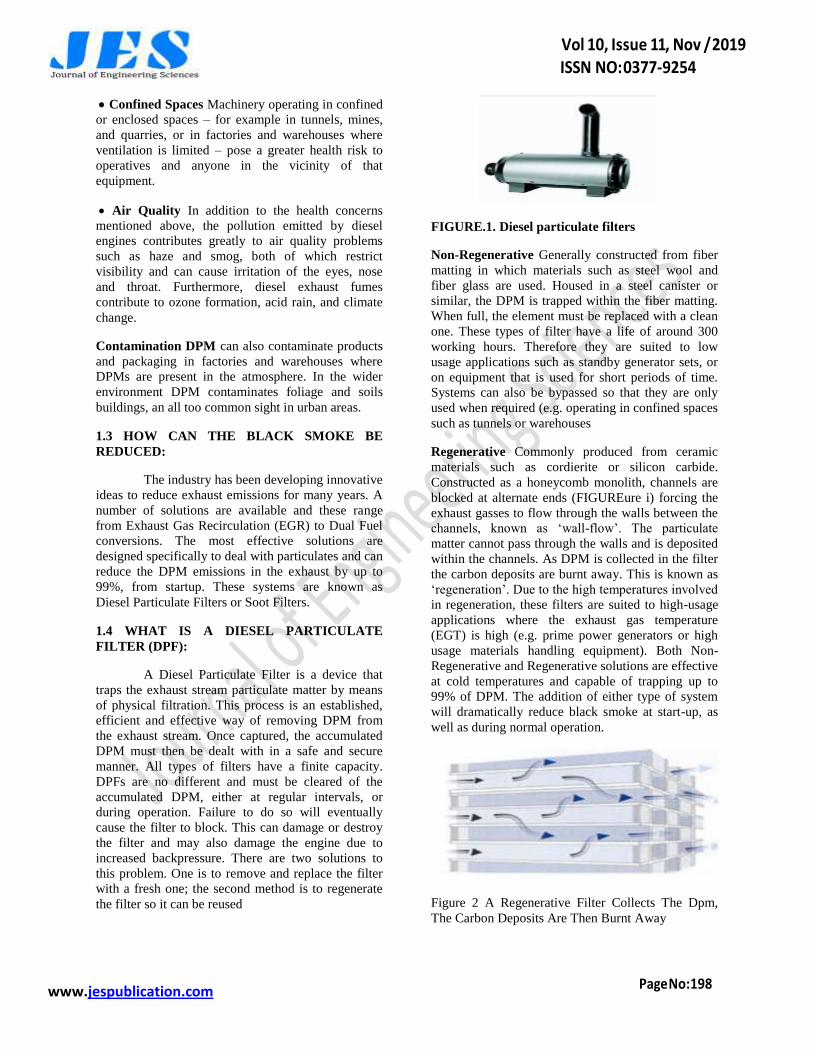
FIGURE.1. Diesel particulate filters
Non-Regenerative Generally constructed from fiber
matting in which materials such as steel wool and
fiber glass are used. Housed in a steel canister or
similar, the DPM is trapped within the fiber matting.
When full, the element must be replaced with a clean
one. These types of filter have a life of around 300
working hours. Therefore they are suited to low
usage applications such as standby generator sets, or
on equipment that is used for short periods of time.
Systems can also be bypassed so that they are only
used when required (e.g. operating in confined spaces
such as tunnels or warehouses
Regenerative Commonly produced from ceramic
materials such as cordierite or silicon carbide.
Constructed as a honeycomb monolith, channels are
blocked at alternate ends (FIGUREure i) forcing the
exhaust gasses to flow through the walls between the
channels, known as „wall-flow‟. The particulate
matter cannot pass through the walls and is deposited
within the channels. As DPM is collected in the filter
the carbon deposits are burnt away. This is known as
„regeneration‟. Due to the high temperatures involved
in regeneration, these filters are suited to high-usage
applications where the exhaust gas temperature
(EGT) is high (e.g. prime power generators or high
usage materials handling equipment). Both Non-
Regenerative and Regenerative solutions are effective
at cold temperatures and capable of trapping up to
99% of DPM. The addition of either type of system
will dramatically reduce black smoke at start-up, as
well as during normal operation.
Figure 2 A Regenerative Filter Collects The Dpm,
The Carbon Deposits Are Then Burnt Away
www.jespublication.com
1.5 PASSIVE AND ACTIVE REGENERATIVE
SYSTEMS:
The DPM collected in a regenerative
system burns at approximately 600°C, which is a
temperature rarely reached in a diesel exhaust
system. There are two main solutions to this problem,
namely 'active' or „passive‟ regeneration. A passive
system requires no additional energy inputs and
works by lowering the temperature at which the DPM
will combust. An example of this is a fuel-borne
catalyst, which reduces the combustion temperature
to around 280˚C. An active system uses electric
heating or a fuel burning system to increase the
temperature in the filter when required and allows
regeneration of the filter to occur.
DPF Applications Diesel Particulate Filters can be
fitted to almost any piece of machinery or vehicle, for
on or off-road use, that uses a diesel engine, such as
Materials handling equipment Forklift trucks, side
loaders and telescopic handlers.
Power generation equipment Standby or prime
power generators.
Construction equipment & non-road mobile
machinery (NRMM) Excavators, dumpers and earth
moving equipment
On-road vehicles On-road vehicles such as buses,
coaches and HGVs.
The table below indicates which types of filters are
recommended, based on engine usage and the type of
emissions reduction required
STANDBY/LO
W USAGE
PRIME/HIGH
USAGE
PM Non-regenerative Regenerative
CO Catalytic
converter
Catalytic converter
HC Catalytic
converter
Catalytic converter
PM,CO+
HC
Non-
regenartive+catal
ytic converter
Regenerative+catal
ytic converter
As each application is unique, the above table is for
guidance only. GenCat engineers are happy to assist
in the selection of appropriate Diesel Particulate
Filters or Catalytic Convertors tailored to your
specific requirements.
1.6 CATALYTIC CONVERTERS:
Catalytic converters are separate systems that reduce
carbon monoxide (CO), unburned hydrocarbons (HC)
and aldehydes. These exhaust emissions are generally
associated with contributing significantly to
atmospheric pollution problems and are responsible
for irritation to the eyes and respiratory system. They
can also cause nausea, headaches and tiredness.
These effects are further compounded in enclosed
spaces such as warehouses, tunnels and mines.
Health and Safety Guidance 187 HS (G)187 This
guide, provides practical advice to employers on how
to control exposure to diesel engine exhaust
emissions (DEEE's) in the workplace, and so protects
the health of employees and others who may be
exposed. The guidance also details the use of diesel
exhaust gas after treatment systems such as catalytic
converters and diesel soot particulate traps to remove
particulate matter. The Health and Safety Executive
(HSE) The Diesel Engine Exhaust Emissions
guidelines have recommendations for health
protection against exposure to diesel fumes.
Low Emissions Zone (LEZ) To reduce the pollution
into London‟s air from vehicle exhausts, vehicles
such as HGVs, vans, coaches and buses will have to
be adapted to meet tightening standards or pay to
drive through the capital Best Practice Guide (BPG)
Outlines guidance for the control of dust and
emissions from construction sites, paying particular
attention to off-road machinery and plant. The guide
also suggests fitting particulate filters to non-road
mobile machinery (NRMM) to reduce particulate
emissions for Transport The Emission Standards for
Non-Road Mobile Machinery is dedicated to
reducing emissions from NRMM is part of the EU‟s
strategy to reduce air pollution. These legislations
tighten emissions from diesel engines
1.7 VEHICLES – LOW EMISSION ZONES:
A Low Emission Zone (LEZ) is an area where only
vehicles that meet certain emission standards are
allowed to enter. Common features of LEZs are:
• They can apply to all vehicles or only certain
vehicle types (e.g. large vehicles)
• They set a minimum Euro standard that a vehicle
must meet for one or all pollutants covered by the
standard
• The standards become increasingly strict over time
www.jespublication.com
• Enforcement is carried via number plate recognition
cameras or issuing window stickers to be checked by
on-street traffic wardens
• Large fines are given to non-compliant vehicles
caught in the LEZ
Low Emission Strategies use planning conditions to
help mitigate the air quality and greenhouse gas
impacts of new developments. Air quality assessment
in the planning system is frequently „adversarial‟,
with developers and the planning authority arguing
whether the impacts of a development are acceptable.
Low Emission Strategies take a different approach by
looking at mitigation actions that can be taken to
allow a development to proceed. Low Emission
Strategies were pioneered by the London Borough of
Greenwich and are now used by many local
authorities all around the UK. Mitigation measures
secured in Greenwich include:
• A temporary Low Emission Zone for the
development and construction of the Warren
development
• Emission based parking policies in the Greenwich
Millennium Village
• Requirements for a new superstore to have 50% of
delivery vehicles and 50% of home delivery vehicles
associated with the store meeting the Euro 5 emission
standard. The superstore was also required to report
to the Council on the implementation of pollution
measures and targets five and ten years after opening
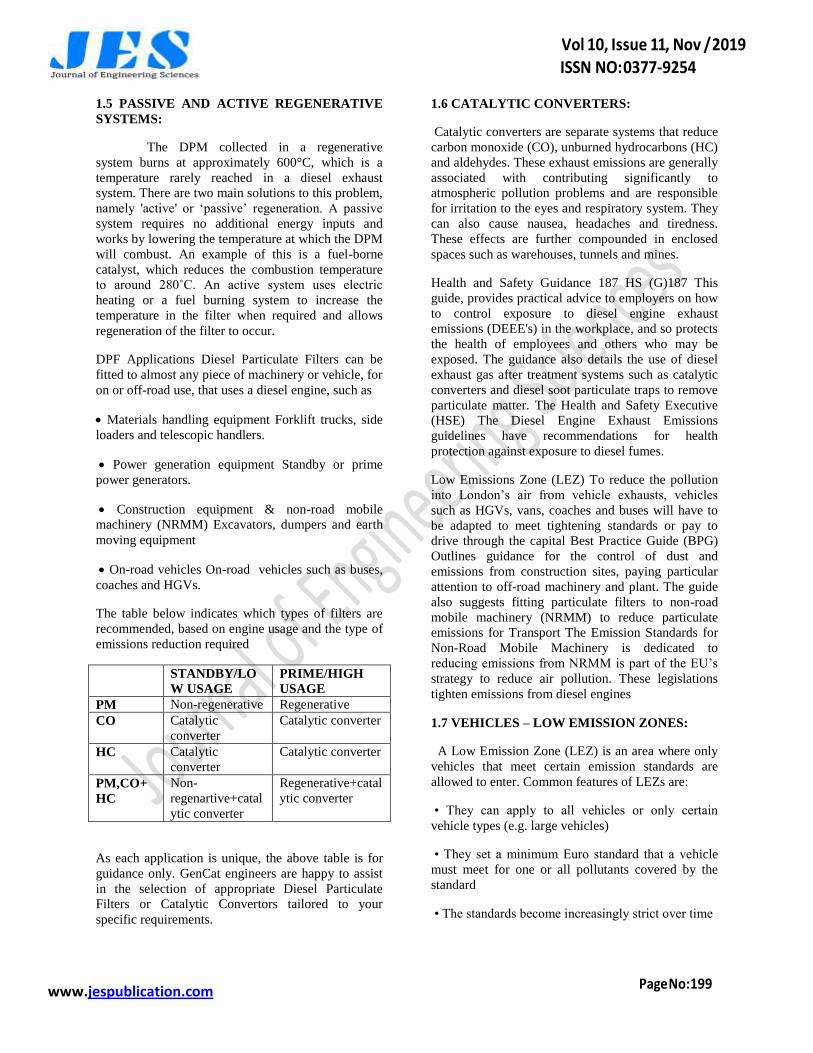
1.8THE CLIMATE IMPACTS OF
PARTICULATE MATTER EMISSIONS:
The world is already warming due to the impact of
greenhouse gases (such as carbon dioxide and
methane) released by human activities. Action to
reduce black carbon emissions could reduce this rate
of warming: a 2011 report by the United Nations
Environment Programmed set out how measures to
reduce black carbon (and other air pollutants with a
warming impact such as ground level ozone) could
radically reduce the amount of warming the globe
will experience over the next 40 years. The Arctic
would especially benefit from cuts in black carbon
emissions, with the report calculating that the
warming projected for the next 30 years would be cut
by two thirds. Measures to reduce black carbon
emissions can complement those taken to reduce
emissions of carbon dioxide (CO2), the main gas
involved in the process of global warming. CO2 has a
long life in the atmosphere and there is therefore a
long „lag time‟ before measures taken to reduce
emissions have an appreciable impact on the
concentration of CO2 in the atmosphere. By contrast
black carbon is removed from the atmosphere in a
matter of days. Measures taken to reduce black
carbon emissions quickly cut the amount in the
atmosphere and reduce the warming it produces.
Figure 3. Climate Impacts Of Particulate Matter
Emissions
II.LITARATURE REVIEW
Several techniques have been researched
and developed to abate hazardous emission
constituents from diesel engines at the source level.
Some of such extensively investigated techniques
are:
• Variations of Injection Pressure and Nozzle
Geometry
• Pre-Mixed Combustion
• Water Injection or combinations of two or more of
above.
• Retarded and split fuel injection
• Exhaust Gas Recirculation (EGR)
Climate change is being counted as a global
environmental threat caused by people. It is seen as
the second most serious issue that the world faces and
has brought about results that affect life adversely
(European Commission 2011). The major ones of
these effects are average 0.8 _C global warming
above pre-industrial levels, 0.09 _C warming and
acidifying of ocean since 1950s, 3.2 cm sea levels
rising per decade, an exceptional number of extreme
heat waves in last decade, and drought affecting food
crop growing areas (Levitus et al. 2012; Meyssignac
and Cozenage 2012; McKenzie and Wolf 2010; Li et
al. 2009;
[1] Heyder et al. 2011; Dai
Unless the current mitigation, commitments,
and pledges are fully implemented, the negative
effects of climate change will go on. It is expected
www.jespublication.com
that a warming of 4 _C and sea-level rise of 0.5–1 m
can occur as early as 2060s (Huddleston 2012). The
greenhouse effect is a natural process that plays a
major role in shaping the earth‟s climate. Human
activities, especially burning fossil fuels, have
contributed to the enhancement of the natural
greenhouse effect. This enhanced greenhouse effect
stems from an increase in the atmospheric
concentrations called greenhouse gases (Jain 1993;
Saxena 2009). Greenhouse gases in the atmosphere
lead to climate change. The major greenhouse gases
emitted into the atmosphere through human activities
are carbon dioxide, methane, nitrous oxide, and
fluorinated gases (hydro fluorocarbons, per
fluorocarbons, and sulfur hexafluoride)
(Venkataraman et al. 2012;
[2] Wei et al. 2008;
Carbon dioxide (CO2) has the largest rate
among the green house gases, and it is the main
reason of global warming. The global emission of
carbon dioxide has reached 34 billion tons with an
increase of 3 % in 2011 (Olivier et al. 2012).
Throughout the world, CO2 emissions are currently
about 35,000 million metric tons per year. Unless the
urgent policies are put in action, CO2 emissions will
be projected to rise up 41,000 million metric tons per
year in 2020s. In addition to warming in climate
systems, the rising of CO2 concentration in the
atmosphere leads ocean acidification as a result of
dissolutions (The Potsdam Institute for Climate
Impact Research and Climate 2012).
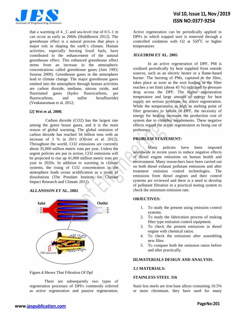
ALLANSSON ET AL. 2002
Figure.4.Shows That Filtration Of Dpf
There are subsequently two types of
regeneration processes of DPFs commonly referred
as active regeneration and passive regeneration.
Active regeneration can be periodically applied to
DPFs in which trapped soot is removed through a
controlled oxidation with O2 at 5500C or higher
temperatures
JEGUIRIM ET AL. 2005
In an active regeneration of DPF, PM is
oxidized periodically by heat supplied from outside
sources, such as an electric heater or a flame-based
burner. The burning of PMs, captured in the filter,
takes place as soon as the soot loading in the filter
reaches a set limit (about 45 %) indicated by pressure
drop across the DPF. The higher regeneration
temperature and large amount of energy for heat
supply are serious problems for active regeneration.
While the temperatures as high as melting point of
filter generates to failure of DPF, the necessity of
energy for heating increases the production cost of
system due to complex supplements. These negative
effects regard the active regeneration as being out of
preference.
PROBLEM STATEMENT:
Many policies have been imposed
worldwide in recent years to reduce negative effects
of diesel engine emissions on human health and
environment. Many researchers have been carried out
on both diesel exhaust pollutant emissions and after
treatment emission control technologies. The
emissions from diesel engines and their control
systems are reviewed and there is a need to develop
of pollutant filtration in a practical testing system to
check the minimum emission rate.
OBJECTIVES:
1. To study the present using emission control
systems.
2. To study the fabrication process of making
filter type emission control equipment.
3. To check the present emissions in diesel
engine with chemical ratios.
4. To check the emissions after assembling
new filter.
5. To compare both the emission ratios before
and after practically.
III.MATERIALS DESIGN AND ANALYSIS.
3.1 MATERIALS:
STAINLESS STEEL 316
Stain less steels are iron base alloys containing 10.5%
or more chromium. they have used for many
www.jespublication.com
industrial architectural chemical and consumer
applications for over a half century Currently there
are being marketed a number of stain less steels
originally recognized by the American iron and steel
intuits (AISI) as standard alloys .also commercially
available are property stain less steels with special
characteristics A stainless steel in the singular sense
as if it were one material .actually there are over fifty
stain less steel alloys there are classification are used
to identify stain less steels
There are:
1. Metallurgical structure
2. The AISI numbering system (Namely
„‟200,300,400. Series numbers)
3. The unified numbering system
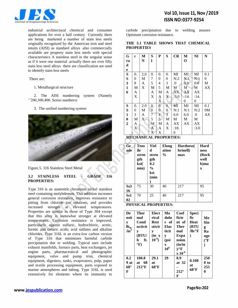
Figure.5. 316 Stainless Steel Metal
3.2 STAINLESS STEEL - GRADE 316
PROPERTIES:
Type 316 is an austenitic chromium nickel stainless
steel containing molybdenum. This addition increases
general corrosion resistance, improves resistance to
pitting from chloride ion solutions, and provides
increased strength at elevated temperatures.
Properties are similar to those of Type 304 except
that this alloy is somewhat stronger at elevated
temperatures. Corrosion resistance is improved,
particularly against sulfuric, hydrochloric, acetic,
formic and tartaric acids; acid sulfates and alkaline
chlorides. Type 316L is an extra-low carbon version
of Type 316 that minimizes harmful carbide
precipitation due to welding. Typical uses include
exhaust manifolds, furnace parts, heat exchangers, jet
engine parts, pharmaceutical and photographic
equipment, valve and pump trim, chemical
equipment, digesters, tanks, evaporators, pulp, paper
and textile processing equipment, parts exposed to
marine atmospheres and tubing. Type 316L is used
extensively for elements where its immunity to
carbide precipitation due to welding assures
Optimum corrosion resistance.
THE 3.1 TABLE SHOWS THAT CHEMICAL
PROPERTIES
G
ra
d
e
c M
N
S
I
P S CR M
O
NI N
S
S
3
1
6
0.
0
8
M
A
X
2.0
M
A
X
0.
7
5
M
A
X
0.
0
4
5
M
A
X
0.
0
3
M
A
X
MI
N:2
.0
M
AX
:3.0
MI
N:1
0.0
M
AX
:14.
0
MI
N:1
0.0
M
AX
:14.
0
0.1
0
M
AX
S
S
1
0
2
0.
0
3
M
A
X
2.0
M
A
X
0.
0
7
5
M
A
X
0.
0
4
5
M
A
X
0.
0
3
M
A
X
MI
N:1
6.0
M
AX
:18.
0
MI
N:1
6.0
M
AX
MI
N:2
.0
M
AX
:3.0
0.1
0M
AX
MECHANICAL PROPERTIES:
Gr
ade
Tens
ile
stren
gth
ksi(
min)
Yiel
d
stren
gth
0.2
%
ksi
(min
)
Elong
ation
%
Hardness(
brinell)
max
Hard
ness
(Rock
well
b)ma
x
Ss3
16
75 30 40 217 95
Ss1
02
70 25 40 217 95
PHYSICAL PROPERTIES:
De
nsit
y
lbm
/in3
Ther
mal
Cond
uctivit
y
(BTU/
h ft.
°F)
Elect
rical
Resi
stivit
y
(in x
10-6
)
Mo
dulu
s of
Elas
ticit
y
(psi
x
106
Coef
ficie
nt of
Ther
mal
Expa
nsion
(in/in
)/°F
x 10-6
Speci
fic
Heat
(BTU
/lb/°F
)
Me
ltin
g
Ra
nge
(°F
)
0.2
9 at
68°
F
100.8
at 68
212°F
29.1
at
68°F
29 8.9
at 32
–
212°
F
0.108
at
68°F
250
0 to
255
0
www.jespublication.com
3.3 DESIGN OF SMOKE FILTER:
INTRODUCTION TO CAD
CAD data exchange is a modality of data
exchange used to translate data between
different Computer-aided design (CAD) authoring
systems or between CAD and other
downstream CAD systems.
Many companies use different CAD systems
internally and exchange CAD data with suppliers,
customers and subcontractors.[1]
Transfer of data is
necessary so that, for example, one organization can
be developing a CAD model, while another performs
analysis work on the same model; at the same time a
third organization is responsible for manufacturing
the product.[2]
The CAD systems currently available
in the market differ not only in their application aims,
user interfaces and performance levels, but also in
data structures and data formats[3]
therefore accuracy
in the data exchange process is of paramount
importance and robust exchange mechanisms are
needed.[2]
The exchange process targets primarily the geometric
information of the CAD data but it can also target
other aspects such as metadata, knowledge,
manufacturing information, tolerances and assembly
structure.
There are three options available for CAD data
exchange: direct model translation, neutral file
exchange and third-party translators
THIRD-PARTY TRANSLATORS:
Several companies specialize in CAD data
translation software that can read from one CAD
system and write the information in another CAD
system format. There are a handful of companies,
including Datakit, Spatial Corp, and Tech Soft 3D,
that provide low-level software toolkits to directly
read and write the major CAD file formats. Most
CAD developers license these toolkits, to add import
and export capabilities to their products. There are
also a significant number of companies that use the
low-level translation toolkits as the basis for building
standalone end-user translation and validation
applications. Among these companies
are International Technic Group Incorporated
(ITI), Trans Magic, and Core Technologies. These
systems have their own proprietary intermediate
format some of which will allow reviewing the data
during translation. Some of these translators work
stand-alone while others require one or both of the
CAD packages installed on the translation machine as
they use code (APIs) from these systems to
read/write the data.
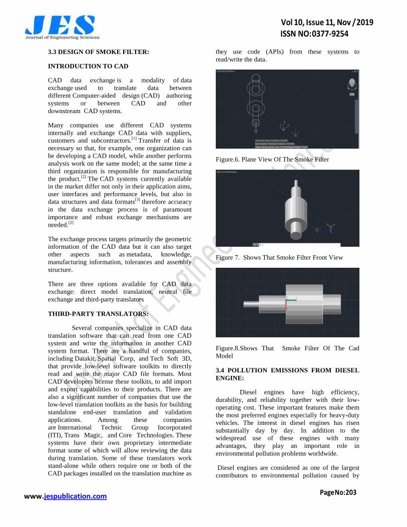
Figure.6. Plane View Of The Smoke Filter
Figure 7. Shows That Smoke Filter Front View
Figure.8.Shows That Smoke Filter Of The Cad
Model
3.4 POLLUTION EMISSIONS FROM DIESEL
ENGINE:
Diesel engines have high efficiency,
durability, and reliability together with their low-
operating cost. These important features make them
the most preferred engines especially for heavy-duty
vehicles. The interest in diesel engines has risen
substantially day by day. In addition to the
widespread use of these engines with many
advantages, they play an important role in
environmental pollution problems worldwide.
Diesel engines are considered as one of the largest
contributors to environmental pollution caused by
www.jespublication.com
exhaust emissions, and they are responsible for
several health problems as well. Many policies have
been imposed worldwide in recent years to reduce
negative effects of diesel engine emissions on human
health and environment. Many researches have been
carried out on both diesel exhaust pollutant emissions
and aftertreatment emission control technologies. In
this paper, the emissions from diesel engines and
their control systems are reviewed. The four main
pollutant emissions from diesel engines (carbon
monoxide-CO, hydrocarbons-HC, particulate matter-
PM and nitrogen oxides-NOx) and control systems
for these emissions (diesel oxidation catalyst, diesel
particulate filter and selective catalytic reduction) are
discussed. Each type of emissions and control
systems is comprehensively examined
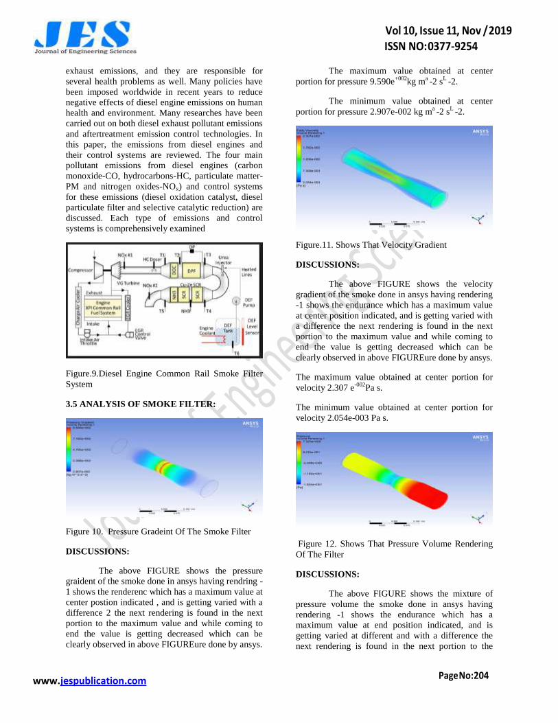
Figure.9.Diesel Engine Common Rail Smoke Filter
System
3.5 ANALYSIS OF SMOKE FILTER:
Figure 10. Pressure Gradeint Of The Smoke Filter
DISCUSSIONS:
The above FIGURE shows the pressure
graident of the smoke done in ansys having rendring -
1 shows the renderenc which has a maximum value at
center postion indicated , and is getting varied with a
difference 2 the next rendering is found in the next
portion to the maximum value and while coming to
end the value is getting decreased which can be
clearly observed in above FIGUREure done by ansys.
The maximum value obtained at center
portion for pressure 9.590e+002
kg ma -2 s
L -2.
The minimum value obtained at center
portion for pressure 2.907e-002 kg ma -2 s
L -2.
Figure.11. Shows That Velocity Gradient
DISCUSSIONS:
The above FIGURE shows the velocity
gradient of the smoke done in ansys having rendering
-1 shows the endurance which has a maximum value
at center position indicated, and is getting varied with
a difference the next rendering is found in the next
portion to the maximum value and while coming to
end the value is getting decreased which can be
clearly observed in above FIGUREure done by ansys.
The maximum value obtained at center portion for
velocity 2.307 e-002
Pa s.
The minimum value obtained at center portion for
velocity 2.054e-003 Pa s.
Figure 12. Shows That Pressure Volume Rendering
Of The Filter
DISCUSSIONS:
The above FIGURE shows the mixture of
pressure volume the smoke done in ansys having
rendering -1 shows the endurance which has a
maximum value at end position indicated, and is
getting varied at different and with a difference the
next rendering is found in the next portion to the
www.jespublication.com
maximum value and while coming to end the value is
getting decreased which can be clearly observed in
above FIGUREure done by Ansys.
The maximum value obtained at end portion for
pressure emission is 7.323e+000
Pa
The minimum value obtained at end portion for
volume emission is 1.834e+001
Pa.
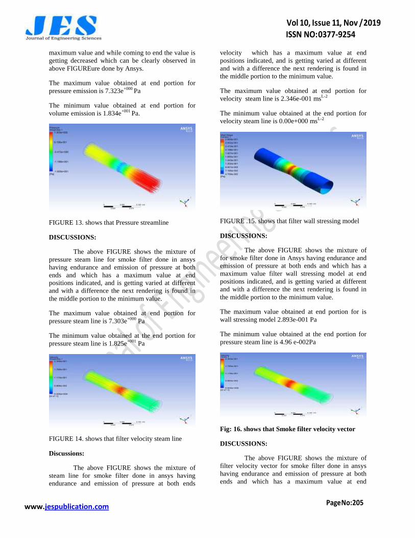
FIGURE 13. shows that Pressure streamline
DISCUSSIONS:
The above FIGURE shows the mixture of
pressure steam line for smoke filter done in ansys
having endurance and emission of pressure at both
ends and which has a maximum value at end
positions indicated, and is getting varied at different
and with a difference the next rendering is found in
the middle portion to the minimum value.
The maximum value obtained at end portion for
pressure steam line is 7.303e+000
Pa
The minimum value obtained at the end portion for
pressure steam line is 1.825e+001
Pa
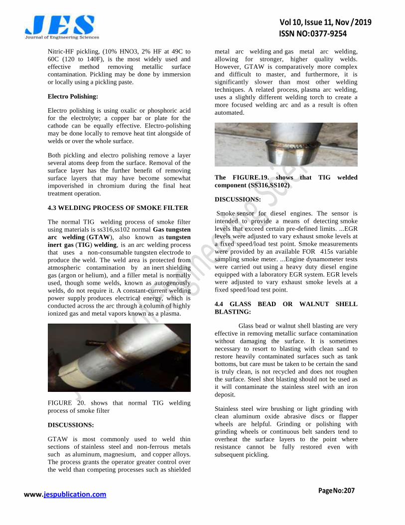
FIGURE 14. shows that filter velocity steam line
Discussions:
The above FIGURE shows the mixture of
steam line for smoke filter done in ansys having
endurance and emission of pressure at both ends
velocity which has a maximum value at end
positions indicated, and is getting varied at different
and with a difference the next rendering is found in
the middle portion to the minimum value.
The maximum value obtained at end portion for
velocity steam line is 2.346e-001 msL-2
The minimum value obtained at the end portion for
velocity steam line is 0.00e+000 msL-2
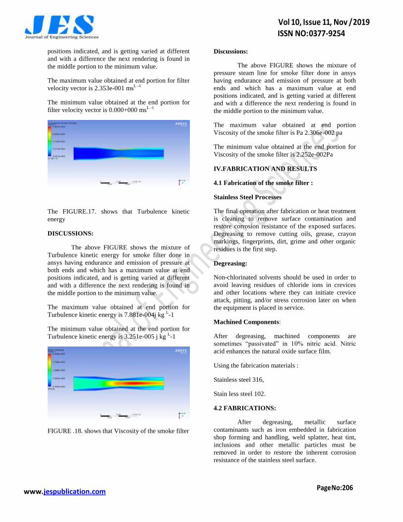
FIGURE .15. shows that filter wall stressing model
DISCUSSIONS:
The above FIGURE shows the mixture of
for smoke filter done in Ansys having endurance and
emission of pressure at both ends and which has a
maximum value filter wall stressing model at end
positions indicated, and is getting varied at different
and with a difference the next rendering is found in
the middle portion to the minimum value.
The maximum value obtained at end portion for is
wall stressing model 2.893e-001 Pa
The minimum value obtained at the end portion for
pressure steam line is 4.96 e-002Pa
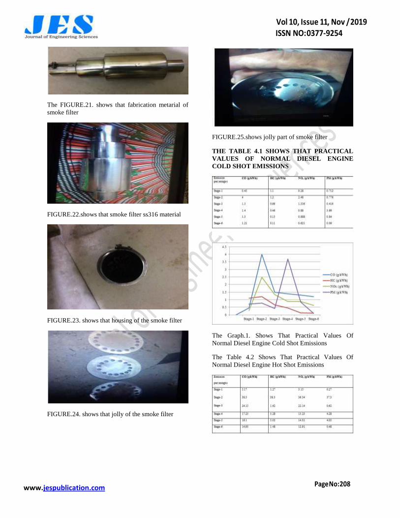
Fig: 16. shows that Smoke filter velocity vector
DISCUSSIONS:
The above FIGURE shows the mixture of
filter velocity vector for smoke filter done in ansys
having endurance and emission of pressure at both
ends and which has a maximum value at end
www.jespublication.com
positions indicated, and is getting varied at different
and with a difference the next rendering is found in
the middle portion to the minimum value.
The maximum value obtained at end portion for filter
velocity vector is 2.353e-001 msL -1
The minimum value obtained at the end portion for
filter velocity vector is 0.000+000 msL -1
The FIGURE.17. shows that Turbulence kinetic
energy
DISCUSSIONS:
The above FIGURE shows the mixture of
Turbulence kinetic energy for smoke filter done in
ansys having endurance and emission of pressure at
both ends and which has a maximum value at end
positions indicated, and is getting varied at different
and with a difference the next rendering is found in
the middle portion to the minimum value.
The maximum value obtained at end portion for
Turbulence kinetic energy is 7.881e-004j kg L-1
The minimum value obtained at the end portion for
Turbulence kinetic energy is 3.251e-005 j kg L-1
FIGURE .18. shows that Viscosity of the smoke filter
Discussions:
The above FIGURE shows the mixture of
pressure steam line for smoke filter done in ansys
having endurance and emission of pressure at both
ends and which has a maximum value at end
positions indicated, and is getting varied at different
and with a difference the next rendering is found in
the middle portion to the minimum value.
The maximum value obtained at end portion
Viscosity of the smoke filter is Pa 2.306e-002 pa
The minimum value obtained at the end portion for
Viscosity of the smoke filter is 2.252e-002Pa
IV.FABRICATION AND RESULTS
4.1 Fabrication of the smoke filter :
Stainless Steel Processes
The final operation after fabrication or heat treatment
is cleaning to remove surface contamination and
restore corrosion resistance of the exposed surfaces.
Degreasing to remove cutting oils, grease, crayon
markings, fingerprints, dirt, grime and other organic
residues is the first step.
Degreasing:
Non-chlorinated solvents should be used in order to
avoid leaving residues of chloride ions in crevices
and other locations where they can initiate crevice
attack, pitting, and/or stress corrosion later on when
the equipment is placed in service.
Machined Components:
After degreasing, machined components are
sometimes “passivated” in 10% nitric acid. Nitric
acid enhances the natural oxide surface film.
Using the fabrication materials :
Stainless steel 316,
Stain less steel 102.
4.2 FABRICATIONS:
After degreasing, metallic surface
contaminants such as iron embedded in fabrication
shop forming and handling, weld splatter, heat tint,
inclusions and other metallic particles must be
removed in order to restore the inherent corrosion
resistance of the stainless steel surface.
www.jespublication.com
Nitric-HF pickling, (10% HNO3, 2% HF at 49C to
60C (120 to 140F), is the most widely used and
effective method removing metallic surface
contamination. Pickling may be done by immersion
or locally using a pickling paste.
Electro Polishing:
Electro polishing is using oxalic or phosphoric acid
for the electrolyte; a copper bar or plate for the
cathode can be equally effective. Electro-polishing
may be done locally to remove heat tint alongside of
welds or over the whole surface.
Both pickling and electro polishing remove a layer
several atoms deep from the surface. Removal of the
surface layer has the further benefit of removing
surface layers that may have become somewhat
impoverished in chromium during the final heat
treatment operation.
4.3 WELDING PROCESS OF SMOKE FILTER
The normal TIG welding process of smoke filter
using materials is ss316,ss102 normal Gas tungsten
arc welding (GTAW), also known as tungsten
inert gas (TIG) welding, is an arc welding process
that uses a non-consumable tungsten electrode to
produce the weld. The weld area is protected from
atmospheric contamination by an inert shielding
gas (argon or helium), and a filler metal is normally
used, though some welds, known as autogenously
welds, do not require it. A constant-current welding
power supply produces electrical energy, which is
conducted across the arc through a column of highly
ionized gas and metal vapors known as a plasma.
FIGURE 20. shows that normal TIG welding
process of smoke filter
DISCUSSIONS:
GTAW is most commonly used to weld thin
sections of stainless steel and non-ferrous metals
such as aluminum, magnesium, and copper alloys.
The process grants the operator greater control over
the weld than competing processes such as shielded
metal arc welding and gas metal arc welding,
allowing for stronger, higher quality welds.
However, GTAW is comparatively more complex
and difficult to master, and furthermore, it is
significantly slower than most other welding
techniques. A related process, plasma arc welding,
uses a slightly different welding torch to create a
more focused welding arc and as a result is often
automated.
The FIGURE.19. shows that TIG welded
component (SS316,SS102)
DISCUSSIONS:
Smoke sensor for diesel engines. The sensor is
intended to provide a means of detecting smoke
levels that exceed certain pre-defined limits. ...EGR
levels were adjusted to vary exhaust smoke levels at
a fixed speed/load test point. Smoke measurements
were provided by an available FOR 415s variable
sampling smoke meter. ...Engine dynamometer tests
were carried out using a heavy duty diesel engine
equipped with a laboratory EGR system. EGR levels
were adjusted to vary exhaust smoke levels at a
fixed speed/load test point.
4.4 GLASS BEAD OR WALNUT SHELL
BLASTING:
Glass bead or walnut shell blasting are very
effective in removing metallic surface contamination
without damaging the surface. It is sometimes
necessary to resort to blasting with clean sand to
restore heavily contaminated surfaces such as tank
bottoms, but care must be taken to be certain the sand
is truly clean, is not recycled and does not roughen
the surface. Steel shot blasting should not be used as
it will contaminate the stainless steel with an iron
deposit.
Stainless steel wire brushing or light grinding with
clean aluminum oxide abrasive discs or flapper
wheels are helpful. Grinding or polishing with
grinding wheels or continuous belt sanders tend to
overheat the surface layers to the point where
resistance cannot be fully restored even with
subsequent pickling.
www.jespublication.com
The FIGURE.21. shows that fabrication metarial of
smoke filter
FIGURE.22.shows that smoke filter ss316 material
FIGURE.23. shows that housing of the smoke filter
FIGURE.24. shows that jolly of the smoke filter
FIGURE.25.shows jolly part of smoke filter
THE TABLE 4.1 SHOWS THAT PRACTICAL
VALUES OF NORMAL DIESEL ENGINE
COLD SHOT EMISSIONS
The Graph.1. Shows That Practical Values Of
Normal Diesel Engine Cold Shot Emissions
The Table 4.2 Shows That Practical Values Of
Normal Diesel Engine Hot Shot Emissions

www.jespublication.com
The Graph 2 Shows That Practical Values Of Normal
Diesel Engine Hot Shot Emissions
Table 4.3 Shows That Normal Diesel Engine Cold
Shot Emission
The Graph 3 Shows That Normal Diesel Engine Cold
Shot Emission
Table 4.4 Shows That Normal Diesel Engine Hot
Shot Emission
The Graph 4. Shows That Normal Diesel Engine Hot
Shot Emission
V.CONCLUSION
The smoke filter characteristics of main pollutant
emissions (CO, HC, PM, and NOx) from diesel
engines and control technologies of these pollutant
emissions with standards and regulations. Among
these pollutant emission, CO and HC are emitted
because of incomplete combustion and unburned fuel
while NOx emissions are caused because of high
combustion temperatures above 1,600 °C. As for PM
emissions, the reasons of PM emissions are
agglomeration of very small particles of partly
burned fuel, partly burned lube oil, ash content of
fuel oil and cylinder lube oil or sulfates and water.
These pollutant emissions have harmful effects
on environment and human health. Even though
many applications have been implemented on diesel
engines to prevent harmful effects of these pollutant
emissions and to meet stringent emission regulations,
only after treatment emission control systems are of
the potential to eliminate the pollutant emissions
from diesel exhaust gas.
To control these pollutant emissions as desired is
only possible with after treatment systems. Diesel
exhaust after treatment systems include DOC, DPF,
and SCR. These systems are the most requested
components especially for heavy-duty diesel engines
and usually a combination of DOC, DPF, and SCR
has been respectively used for the simultaneous
removal of main pollutant emissions from diesel
engine exhaust.
The temperature of diesel exhaust gas has an
important effect on reducing pollutant emissions.
Besides catalyst type, space velocity of exhaust gas,
and emission form are the other parameters affecting
the efficiency. With the after treatment emission
control systems, it is possible to reduce the damage
of the pollutant emissions on air pollution, to meet
emission standards and requirements, and to prevent
the harmful effects of pollutant emissions on
environment and human health. Due to these
missions, emission control systems are utmost
importance worldwide. For the complete destruction
www.jespublication.com
of polluting emissions from diesel engines, further
studies and researches on the after treatment emission
control systems should be intensified and continued.
REFERENCES
[1] heyder et al. 2011; dai issn: 0022-1767 page 1-2
[2] wei et al. 2008; pages 240-247 issn: 1045-2257
[3] (prasad and bella 2010). issn: 1936-6612 page 3-
7
[4] allansson et al. 2002). issn: 0267- ... 20, pages
22-40
[5] chen m, schirmer k (2003) issn: 2053-230 pages
61-68
[6] golunski se (2010) issn 1754-5692 pages 677–
856 (2010)
[7] rc-Zone.com (2009). "Tungsten Selection" (PDF).
Carlsbad, California: Arc-Zone.com. Retrieved 15
June 2015.
[8] Cary, Howard B.; Helzer, Scott C.
(2005). Modern welding technology. Upper Saddle
River, New Jersey: Pearson Education. ISSN 0-13-
113029-3.
[9] Jeffus, Larry F. (1997). Welding: Principles and
applications (Fourth ed.). Thomson
Delmar. ISBN 978-0-8273-8240-4.
[10] Jeffus, Larry (2002). Welding: Principles and
applications (Fifth ed.). Thomson Delmar. ISSN 1-
4018-1046-2.
[11] Lincoln Electric (1994). The procedure
handbook of arc welding. Cleveland: Lincoln
Electric. ISSN 99949-25-82-2.
[12] Miller Electric Mfg Co (2013). Guidelines For
Gas Tungsten Arc Welding