Embed Size (px)
Citation preview
Narda-MITEQ 1
F R E Q U E N C Y C O N V E R T E R
This series of outdoor block upconverters and downconverters is designed for antenna mounting.
A strong set of monitor and control functions support powerful remote control. A contact closure summary alarm is provided for fault monitoring. A continuously updated log of time-stamped records of activity is also provided.
Vertical Mount OptionStandard Configuration
FEATURES
• Antenna mount, weatherproof to IP-65
• Automatic 5/10 MHz internal/external reference selection
• RS-485/RS-422 and 10/100 Base-T Ethernet remote control
• Superior phase noise below IESS-308/IESS-309 and MIL-STD-188-164B specification
• 30 dB gain control
• 32 memory locations
• High frequency stability
• Summary alarm
• AC power supply (CE mark)
OPTIONS
• Custom and multi-band models
• Higher frequency stability
• Lower phase noise
• Fiber-optic L-Band interface
• Fiber-optic RF-Band interface
• LO level monitor
• Lower gain
• DC power
• Eternal reference on IF connector
• Amplitude slope control
H I G H - P E R F O R M A N C E O U T D O O R B L O C K U P A N D D O W N C O N V E RT E R S
Narda-MITEQ
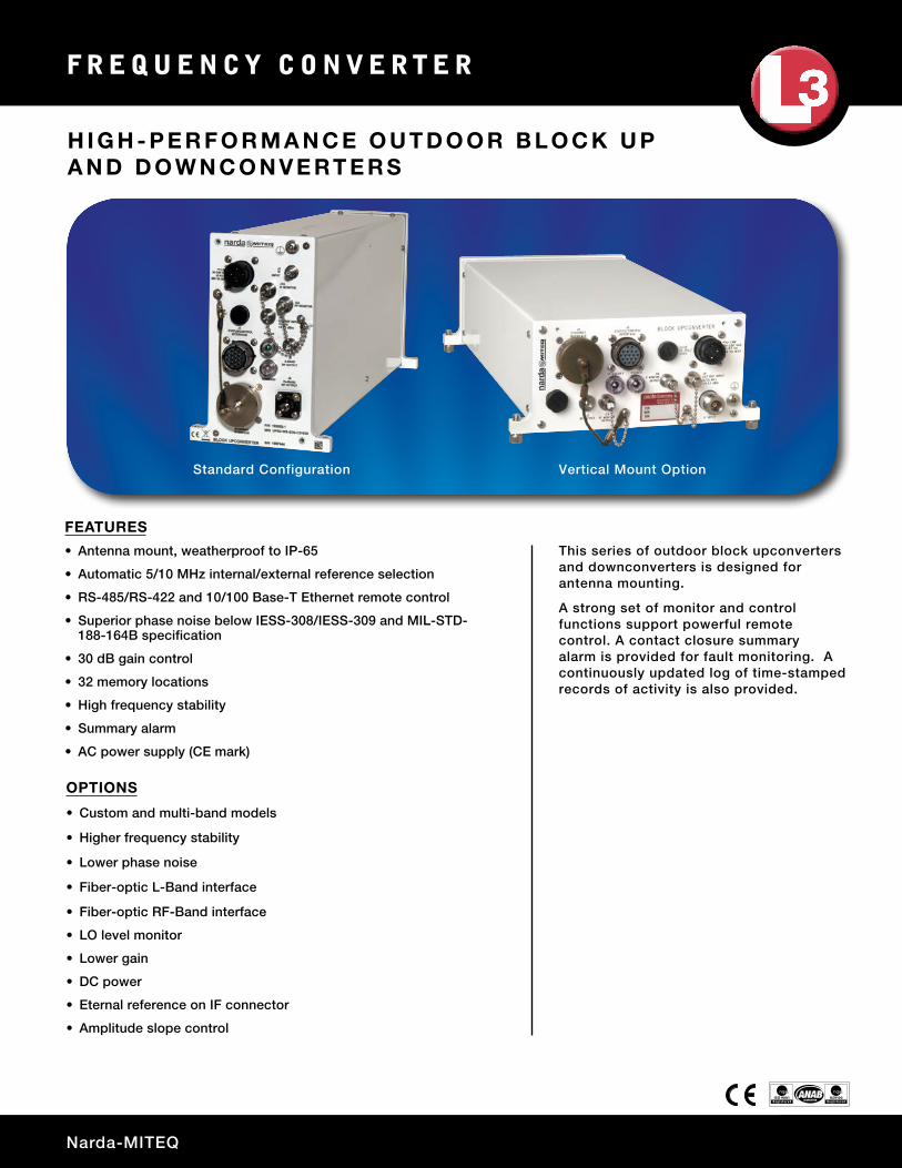
BLOCK UPCONVERTERSRF FREQUENCY (GHz) IF FREQUENCY (MHz) LO FREQUENCY (GHz) MODEL NUMBER5.85 to 6.425 950 to 1525 7.375 UPB-WS-6.1-IN*
5.85 to 6.65 950 to 1750 4.9 UPB-WS-6.25
6.7 to 7.1 950 to 1350 5.75 UPB-WS-6.9
7.9 to 8.4 950 to 1450 6.95 UPB-WS-8.15
11.7 to 12.75 950 to 2000 10.75 UPB-WS-12.225**
12.75 to 13.25 950 to 1450 11.8 UPB-WS-13
13.75 to 14.5 950 to 1700 12.8 UPB-WS-14.125
14 to 14.5 950 to 1450 13.05 UPB-WS-14.25
17.3 to 18.4 950 to 2050 16.35 UPB-WS-17.85**
18.1 to 18.4 950 to 1250 17.15 UPB-WS-18.25
* Model includes frequency inversion.
** Wide IF: 1 to 1.5 GHz IF bandwidths.
Ka-BANDRF FREQUENCY (GHz) IF FREQUENCY (MHz) LO FREQUENCY (GHz) MODEL NUMBER19.2 to 20.2 950 to 1950 18.25 UPB-WS-19.7**
20.2 to 21.2 1000 to 2000 19.2 UPB-WS-20.7-1**
25.5 to 27.0 950 to 2450 24.55 UPB-WS-26.25-1.5**
27.5 to 28.0 950 to 1450 26.55 UPB-WS-27.75
27 to 27.55 950 to 1500 26.05 UPB-WS-29.275
28.0 to 28.5 950 to 1450 27.05 UPB-WS-28.25
28.1 to 28.6 950 to 1450 27.15 UPB-WS-28.35
28.35 to 28.6 950 to 1200 27.4 UPB-WS-28.475
28.5 to 29.0 950 to 450 27.55 UPB-WS-28.75
28.6 to 29.1 950 to 1450 27.65 UPB-WS-28.85
28.75 to 29.35 950 to 1550 27.8 UPB-WS-29.05
28.8 to 30.0 950 to 2150 27.85 UPB-WS-29.4**
29.0 to 29.5 950 to 1450 28.05 UPB-WS-29.25
29 to 30 1000 to 2000 28 UPB-WS-29.5-1**
29.5 to 30.0 950 to 1450 28 UPB-WS-29.75
30 to 31 950 to 1950 29.05 UPB-WS-30.5**
30 to 31 1000 to 2000 29 UPB-WS-30.5-1**
** Wide IF: 1 to 1.5 GHz IF bandwidths.
F R E Q U E N C Y C O N V E R T E R
3
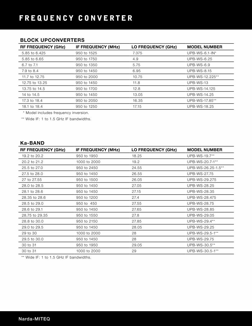
BLOCK DOWNCONVERTERSRF FREQUENCY (GHz) IF FREQUENCY (MHz) LO FREQUENCY (GHz) MODEL NUMBER3.4 to 4.2 950 to 1750 5.15 DNB-WS-3.8-IN*
3.4 to 4.2 950 to 1750 8.85/11.3 DNB-WS-3.8B
3.7 to 4.2 950 to 1450 8.55/11.3 DNB-WS-3.95D
7.25 to 7.75 950 to 1450 6.3 DNB-WS-7.5
10.7 to 11.7 950 to 1950 9.75 DNB-WS-11.2**
10.95 to 11.7 950 to 1700 10 DNB-WS-11.325
11.2 to 12 950 to 1750 10.25 DNB-WS-11.6
11.45 to 12.25 950 to 1750 10.5 DNB-WS-11.85
11.7 to 12.5 950 to 1750 10.75 DNB-WS-12.1
11.7 to 12.75 950 to 2000 10.75 DNB-WS-12.225**
12.2 to 12.75 950 to 1500 11.25 DNB-WS-12.475
12.25 to 12.75 950 to 1450 11.3 DNB-WS-12.5
17.3 to 18.4 950 to 2050 16.35 DNB-WS-17.85
* Model includes frequency inversion.
** Wide IF: 1 to 1.5 GHz IF bandwidths.
Ka-BANDRF FREQUENCY (GHz) IF FREQUENCY (MHz) LO FREQUENCY (GHz) MODEL NUMBER17.7 to 18.2 950 to 1450 16.75 DNB-WS-17.95
18.3 to 18.8 950 to 1450 17.35 DNB-WS-18.55
18.8 to 19.3 950 to 1450 17.85 DNB-WS-19.05
19.7 to 20.2 950 to 1450 18.75 DNB-WS-19.95
20.2 to 21.2 950 to 1950 19.25 DNB-WS-20.7**
20.2 to 21.2 1000 to 2000 19.2 DNB-WS-20.7-1**
25.5 to 27.0 950 to 2450 24.55 DNB-WS-26.25-1.5**
27.5 to 28.0 950 to 1450 26.55 DNB-WS-27.75
27.6 to 29.1 950 to 2450 26.65 DNB-WS-28.35-1.5**
28.0 to 28.5 950 to 1450 27.05 DNB-WS-28.25
28.1 to 28.6 950 to 1450 27.15 DNB-WS-28.35
28.35 to 28.6 950 to 1200 27.4 DNB-WS-28.475
28.5 to 29.0 950 to 1450 27.55 DNB-WS-28.75
28.6 to 29.1 950 to 1450 27.65 DNB-WS-28.85
28.8 to 30.0 950 to 2150 27.85 DNB-WS-29.4**
29.0 to 29.5 950 to 1450 28.05 DNB-WS-29.25
29 to 30 1000 to 2000 28 DNB-WS-29.5-1**
29.5 to 30.0 950 to 1450 28.55 DNB-WS-29.75
30 to 31 950 to 1950 29.05 DNB-WS-30.5**
30 to 31 1000 to 2000 29 DNB-WS-30.5-1**
** Wide IF: 1 to 1.5 GHz IF bandwidths.
Narda-MITEQ
F R E Q U E N C Y C O N V E R T E R
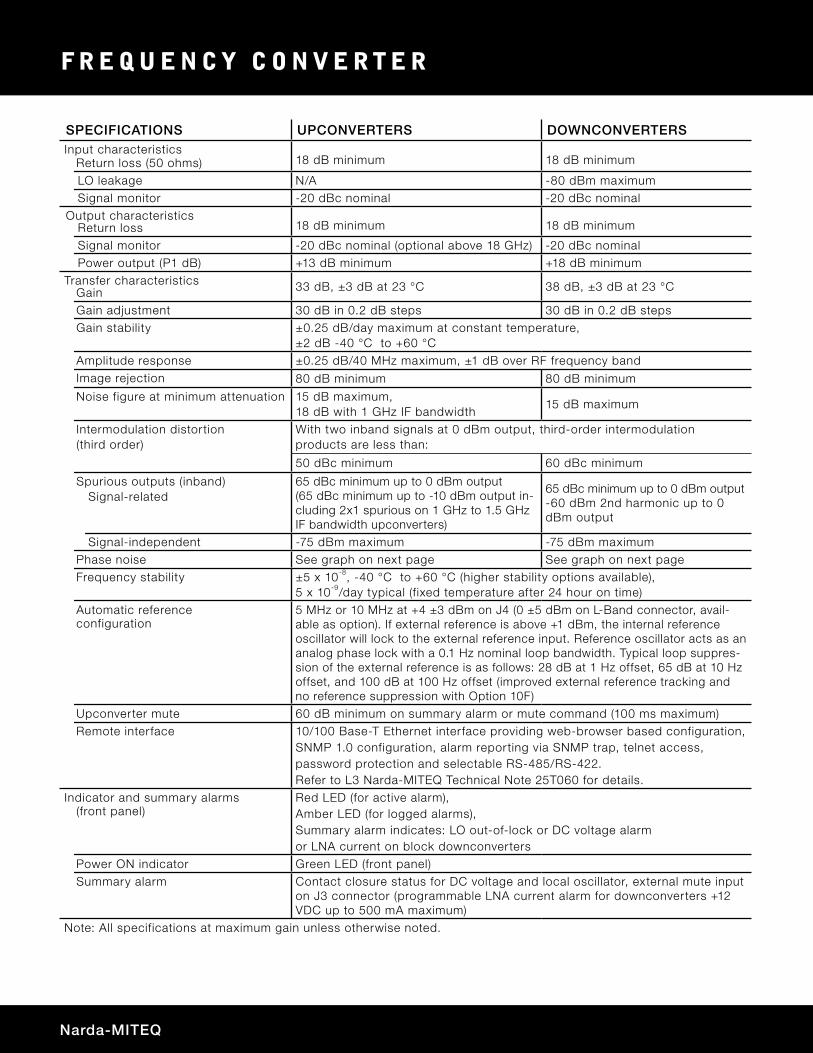
SPECIFICATIONS UPCONVERTERS DOWNCONVERTERSInput characteristics
Return loss (50 ohms) 18 dB minimum 18 dB minimum
LO leakage N/A -80 dBm maximumSignal monitor -20 dBc nominal -20 dBc nominal
Output characteristicsReturn loss 18 dB minimum 18 dB minimum
Signal monitor -20 dBc nominal (optional above 18 GHz) -20 dBc nominal Power output (P1 dB) +13 dB minimum +18 dB minimum
Transfer characteristicsGain 33 dB, ±3 dB at 23 °C 38 dB, ±3 dB at 23 °C
Gain adjustment 30 dB in 0.2 dB steps 30 dB in 0.2 dB stepsGain stability ±0.25 dB/day maximum at constant temperature,
±2 dB -40 °C to +60 °CAmplitude response ±0.25 dB/40 MHz maximum, ±1 dB over RF frequency bandImage rejection 80 dB minimum 80 dB minimum
Noise figure at minimum attenuation 15 dB maximum, 18 dB with 1 GHz IF bandwidth
15 dB maximum
Intermodulation distortion(third order)
With two inband signals at 0 dBm output, third-order intermodulationproducts are less than:
50 dBc minimum 60 dBc minimum
Spurious outputs (inband)Signal-related
65 dBc minimum up to 0 dBm output (65 dBc minimum up to -10 dBm output in-cluding 2x1 spurious on 1 GHz to 1.5 GHz IF bandwidth upconverters)
65 dBc minimum up to 0 dBm output -60 dBm 2nd harmonic up to 0 dBm output
Signal-independent -75 dBm maximum -75 dBm maximumPhase noise See graph on next page See graph on next pageFrequency stability ±5 x 10⁻⁸, -40 °C to +60 °C (higher stability options available),
5 x 10⁻⁹/day typical (f ixed temperature after 24 hour on time)Automatic referenceconfiguration
5 MHz or 10 MHz at +4 ±3 dBm on J4 (0 ±5 dBm on L-Band connector, avail-able as option). If external reference is above +1 dBm, the internal reference oscillator will lock to the external reference input. Reference oscillator acts as an analog phase lock with a 0.1 Hz nominal loop bandwidth. Typical loop suppres-sion of the external reference is as follows: 28 dB at 1 Hz offset, 65 dB at 10 Hz offset, and 100 dB at 100 Hz offset (improved external reference tracking and no reference suppression with Option 10F)
Upconverter mute 60 dB minimum on summary alarm or mute command (100 ms maximum)Remote interface 10/100 Base-T Ethernet interface providing web-browser based configuration,
SNMP 1.0 configuration, alarm reporting via SNMP trap, telnet access, password protection and selectable RS-485/RS-422. Refer to L3 Narda-MITEQ Technical Note 25T060 for details.
Indicator and summary alarms(front panel)
Red LED (for active alarm),Amber LED (for logged alarms),Summary alarm indicates: LO out-of-lock or DC voltage alarm or LNA current on block downconverters
Power ON indicator Green LED (front panel)Summary alarm Contact closure status for DC voltage and local oscillator, external mute input
on J3 connector (programmable LNA current alarm for downconverters +12 VDC up to 500 mA maximum)
Note: All specifications at maximum gain unless otherwise noted.
5
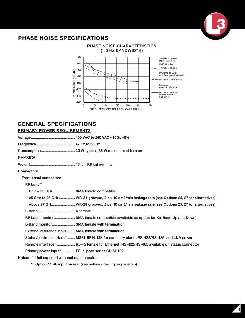
PHASE NOISE SPECIFICATIONS
GENERAL SPECIFICATIONS
PHASE NOISE CHARACTERISTICS(1.0 Hz BANDWIDTH)
10 100 1K 100KFREQUENCY OFFSET FROM CARRIER (Hz)
10K 1M 10M
TYPICAL PHASE NOISE CHARACTERISTICS(1.0 Hz BANDWIDTH)
-20
-40
-60
-80
-100
-120
-140
-160
PHAS
E N
OIS
E (d
Bc/H
z)9 GHz to 16 GHzand Dual converion units
Maximum performance
Maximum external reference with Options 10
Maximum external reference
INTELSAT IESS-308/IESS-309
16 GHz to 20 GHz
25 GHz to 30 GHz
PRIMARY POWER REQUIREMENTS
Voltage ............................................ 100 VAC to 240 VAC (-10%, +6%)
Frequency ....................................... 47 Hz to 63 Hz
Consumption .................................. 30 W typical, 38 W maximum at turn on
PHYSICAL
Weight ............................................. 15 lb. [6.8 kg] nominal
Connectors
Front panel connectors
RF band**
Below 22 GHz ...................... SMA female compatible
25 GHz to 27 GHz ................ WR-34 grooved, 2 psi 10 cm3/min leakage rate (see Options 25, 27 for alternatives)
Above 27 GHz ...................... WR-28 grooved, 2 psi 10 cm3/min leakage rate (see Options 25, 27 for alternatives)
L-Band ..................................... N female
RF band monitor ..................... SMA female compatible (available as option for Ka-Band Up and Down)
L-Band monitor ....................... SMA female with termination
External reference input ......... SMA female with termination
Status/control interface* ........ MS3116F14-18S for summary alarm, RS-422/RS-485, and LNA power
Remote interface* .................. RJ-45 female for Ethernet, RS-422/RS-485 available on status connector
Primary power input* .............. FCI clipper series CL1M1102
Notes: * Unit supplied with mating connector.
** Option 14 RF input on rear (see outline drawing on page ten).
Narda-MITEQ
F R E Q U E N C Y C O N V E R T E R
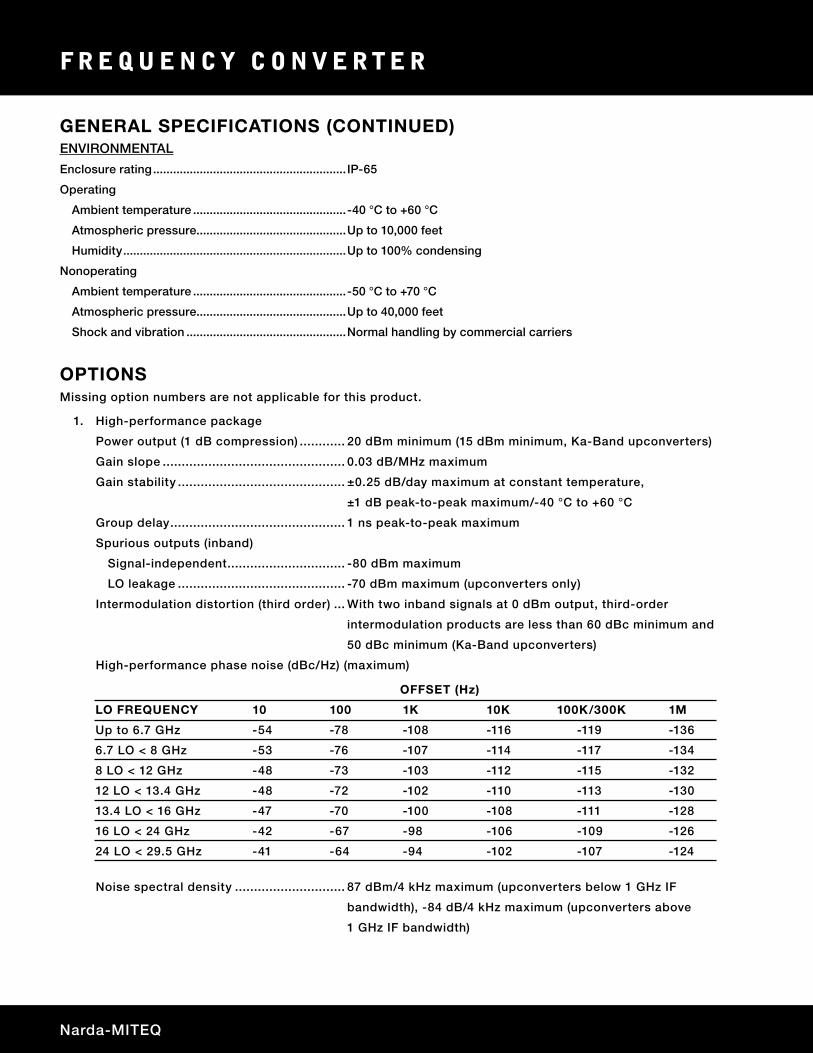
Missing option numbers are not applicable for this product.
1. High-performance package
Power output (1 dB compression) ............ 20 dBm minimum (15 dBm minimum, Ka-Band upconverters)
Gain slope ................................................ 0.03 dB/MHz maximum
Gain stability ............................................ ±0.25 dB/day maximum at constant temperature,
±1 dB peak-to-peak maximum/-40 °C to +60 °C
Group delay .............................................. 1 ns peak-to-peak maximum
Spurious outputs (inband)
Signal-independent ............................... -80 dBm maximum
LO leakage ............................................ -70 dBm maximum (upconverters only)
Intermodulation distortion (third order) ... With two inband signals at 0 dBm output, third-order
intermodulation products are less than 60 dBc minimum and
50 dBc minimum (Ka-Band upconverters)
High-performance phase noise (dBc/Hz) (maximum)
Noise spectral density ............................. 87 dBm/4 kHz maximum (upconverters below 1 GHz IF
bandwidth), -84 dB/4 kHz maximum (upconverters above
1 GHz IF bandwidth)
OFFSET (Hz)
LO FREQUENCY 10 100 1K 10K 100K/300K 1M
Up to 6.7 GHz -54 -78 -108 -116 -119 -136
6.7 LO < 8 GHz -53 -76 -107 -114 -117 -134
8 LO < 12 GHz -48 -73 -103 -112 -115 -132
12 LO < 13.4 GHz -48 -72 -102 -110 -113 -130
13.4 LO < 16 GHz -47 -70 -100 -108 -111 -128
16 LO < 24 GHz -42 -67 -98 -106 -109 -126
24 LO < 29.5 GHz -41 -64 -94 -102 -107 -124
OPTIONS
ENVIRONMENTAL
Enclosure rating .......................................................... IP-65
Operating
Ambient temperature ..............................................-40 °C to +60 °C
Atmospheric pressure.............................................Up to 10,000 feet
Humidity ...................................................................Up to 100% condensing
Nonoperating
Ambient temperature ..............................................-50 °C to +70 °C
Atmospheric pressure.............................................Up to 40,000 feet
Shock and vibration ................................................Normal handling by commercial carriers
GENERAL SPECIFICATIONS (CONTINUED)
7
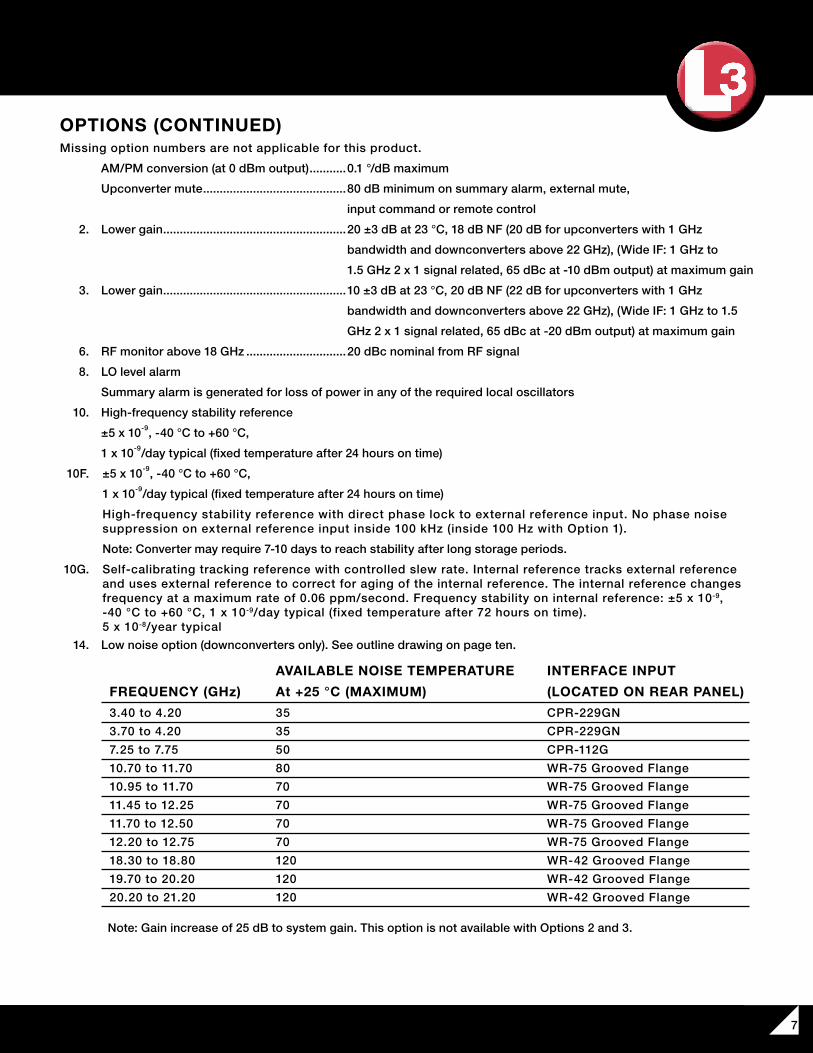
Missing option numbers are not applicable for this product.
AM/PM conversion (at 0 dBm output) ...........0.1 °/dB maximum
Upconverter mute ...........................................80 dB minimum on summary alarm, external mute,
input command or remote control
2. Lower gain .......................................................20 ±3 dB at 23 °C, 18 dB NF (20 dB for upconverters with 1 GHz
bandwidth and downconverters above 22 GHz), (Wide IF: 1 GHz to
1.5 GHz 2 x 1 signal related, 65 dBc at -10 dBm output) at maximum gain
3. Lower gain .......................................................10 ±3 dB at 23 °C, 20 dB NF (22 dB for upconverters with 1 GHz
bandwidth and downconverters above 22 GHz), (Wide IF: 1 GHz to 1.5
GHz 2 x 1 signal related, 65 dBc at -20 dBm output) at maximum gain
6. RF monitor above 18 GHz ..............................20 dBc nominal from RF signal
8. LO level alarm
Summary alarm is generated for loss of power in any of the required local oscillators
10. High-frequency stability reference
±5 x 10⁻⁹, -40 °C to +60 °C,
1 x 10⁻⁹/day typical (fixed temperature after 24 hours on time)
10F. ±5 x 10⁻⁹, -40 °C to +60 °C,
1 x 10⁻⁹/day typical (fixed temperature after 24 hours on time)
High-frequency stability reference with direct phase lock to external reference input. No phase noise suppression on external reference input inside 100 kHz (inside 100 Hz with Option 1).
Note: Converter may require 7-10 days to reach stability after long storage periods.
10G. Self-calibrating tracking reference with controlled slew rate. Internal reference tracks external reference and uses external reference to correct for aging of the internal reference. The internal reference changes frequency at a maximum rate of 0.06 ppm/second. Frequency stability on internal reference: ±5 x 10⁻⁹, -40 °C to +60 °C, 1 x 10⁻⁹/day typical (fixed temperature after 72 hours on time). 5 x 10⁻⁸/year typical
14. Low noise option (downconverters only). See outline drawing on page ten.
Note: Gain increase of 25 dB to system gain. This option is not available with Options 2 and 3.
AVAILABLE NOISE TEMPERATURE INTERFACE INPUT
FREQUENCY (GHz) At +25 °C (MAXIMUM) (LOCATED ON REAR PANEL)
3.40 to 4.20 35 CPR-229GN
3.70 to 4.20 35 CPR-229GN
7.25 to 7.75 50 CPR-112G
10.70 to 11.70 80 WR-75 Grooved Flange
10.95 to 11.70 70 WR-75 Grooved Flange
11.45 to 12.25 70 WR-75 Grooved Flange
11.70 to 12.50 70 WR-75 Grooved Flange
12.20 to 12.75 70 WR-75 Grooved Flange
18.30 to 18.80 120 WR-42 Grooved Flange
19.70 to 20.20 120 WR-42 Grooved Flange
20.20 to 21.20 120 WR-42 Grooved Flange
OPTIONS (CONTINUED)
Narda-MITEQ
F R E Q U E N C Y C O N V E R T E R
Missing option numbers are not applicable for this product.
19. DC power input
A. +24 to +32 VDC input
*21-1. Amplitude slope control ............ Remote control of amplitude slope. Control range: 0 dB to
1 dB minimum 500 MHz IF BW, 0 dB to 1.5 dB minimum 800 MHz IF BW,
0 dB to 2 dB minimum 1000 MHz IF BW, 0 dB to 3 dB minimum 1500 MHz
IF BW. Control step size: 0.2 dB
*21-2. Amplitude slope control ............ Remote control of amplitude slope. Control range: 0 dB to
2 dB minimum 500 MHz IF BW, 0 dB to 3 dB minimum 800 MHz IF BW, 0 dB to
4 dB minimum 1000 MHz IF BW, 0 dB to 6 dB minimum 1500 MHz IF BW.
Control step size: 0.2 dB
Notes: Amplitude response specifications are measure with linear components of slope equalization removed. Units are calibrated outside minimum range, however, minimum slope range provided as listed above. For Option 21-1 and 21-2, amplitude slope may be flat for 0 dB slope value. * Available with Option 17 only. 25. Front panel connector option
1. WR-42 per low noise Ka-Band outline
2. WR-34 input per Ka-Band up outline
3. 2.92 mm female per standard outline
4. 3.5 mm female per standard outline
27. Rear panel RF waveguide connector option. RF output on rear panel as per outlines on pages nine and ten
1. WR-34 input per low noise outline
2. WR-42 input per Ka-Band up outline
3. 2.92 mm female per standard outline
4. 3.5 mm female per standard outline
28. L-Band fiber-optic interface (available 0.95 GHz to 2.15 GHz)
A. Downconverter output transmitter
Fiber: 9/125 (single-mode fiber), Wavelength: 1540 nm to 1560 nm, Optical power in fiber: 4 mW typical,
Connector: FC/APC
B. Upconverter input receiver
Fiber: 9/125 (single-mode fiber), Wavelength: 1300 nm to 1560 nm, Connector: FC/APC
29. RF-Band fiber-optic interface (available 0.95 GHz to 18 GHz)
A. Upconverter output transmitter
Fiber: 9/125 (single-mode fiber), Wavelength: 1540 nm to 1560 nm, Optical power in fiber: 4 mW typical,
Connector: FC/APC
B. Downconverter input receiver
Fiber: 9/125 (single-mode fiber), Wavelength: 1300 nm to 1560 nm, Connector: FC/APC
34. External reference input on IF connector
VM. Vertical Mount (see outline on page ten)
OPTIONS (CONTINUED)
9
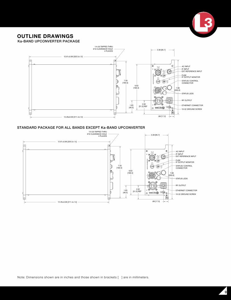
OUTLINE DRAWINGSKa-BAND UPCONVERTER PACKAGE
STANDARD PACKAGE FOR ALL BANDS EXCEPT Ka-BAND UPCONVERTER
STATUS LEDS
RF OUTPUT
10-32 GROUND SCREW
ETHERNET CONNECTOR
IF INPUTAC INPUT
BREATHER VALVE
STATUS/ CONTROL CONNECTOR
EXT REFERENCE INPUT
IF OUTPUT MONITORFUSE
1/4-20 TAPPED THRU#10 CLEARANCE HOLE
4 PLACES
STATUS LEDS
STATUS/ CONTROL CONNECTOR
ETHERNET CONNECTOR
AC INPUT
EXT REFERENCE INPUTIF
FUSEIF MONITOR
RF MONITOR
10-32 GROUND SCREW
1/4-20 TAPPED THRU#10 CLEARANCE HOLE
4 PLACES
7.50 [190.5]
6.63 [168.3]
1.83 [46.5]
2.02 [51.3] REF
7.88 [200.0]
3.38 [85.7]
.68 [17.3]
7.50 [190.5]
7.88 [200.0]
6.63 [168.3]
3.38 [85.7]
12.61±0.06 [320.3±1.5]
12.26±0.06 [311.4±1.5]
12.26±0.06 [311.4±1.5]
12.61±0.06 [320.3±1.5]
12.26±0.06 [311.4±1.5]
12.61 [320.3]
MOUNTING HOLES(CAPTIVE HARDWARE PROVIDED)
10-32 CAPTIVE SCREW
4.25 [108.0]
.19 [4.8]
6.67 [169.3]
4.63 [117.5]
3.29 [83.7]
.00 [0.0]
RF OUTPUT
BREATHER VALVE
10-32 GROUND LUGWITH SCREW AND WASHER
IF INPUT
EXT. REFERENCE INPUT
IF MONITOR
STATUS LEDS
RF MONITOR
1.43 [36.3]
FUSE
ETHERNET
STATUS CONTROLCONNECTOR
.00 [0.0]
AC INPUT
EXT
REF
INPU
T5/
10 M
Hz
+4±3
dBm
J4
90-2
50 V
AC
250
VA M
AX
LIN
E
47-6
3 H
z
J5
T1.2
5A/
FUSE
250V
IF M
ON
ITO
RO
UTP
UT
IF IN
PUT
J1
J1A
SUM
MA
RYPO
WER
STAT
US/
CON
TRO
LIN
TERF
ACE
J3BL
OCK
UPC
ON
VERT
ERET
HER
NET
INTE
RFAC
E
J6
RF O
UTP
UT
J2
HAUPPAUGE, NY
J2A
IF M
ON
ITO
RO
UTP
UT
HAUPPAUGE, NY
J5 90-2
50 V
AC
250
VA M
AX
LIN
E
47-6
3 H
z
J1IF
INPU
T
5/10
MH
z+4
±3 d
Bm
EXT
REF
INPU
TJ4
FUSE
T1.2
5A/
250V
BLOC
K UPC
ONVE
RTER
J3
INTE
RFAC
EST
ATUS
/CON
TROL PO
WER
SUM
MA
RY
ETH
ERN
ETIN
TERF
ACE
J6 RF O
UTP
UT
J2RF
MO
NIT
OR
J2A
OU
TPU
T
J1AIF MONITOROUTPUT
FUSET1.25A/
250V
BLOCK UPCONVERTER
J6ETHERNETINTERFACE
J3STATUS/CONTROL
INTERFACE
J2RF OUTPUT
SUMMARY
POWER
J8RFOUTPUT
J5 LINE
90-250 VAC47-63 Hz
250 VA MAX
J4EXT REF INPUT10 MHz+4±3 dBm
J2ARF MONITOR
J1IF INPUT
STATUS LEDS
RF OUTPUT
10-32 GROUND SCREW
ETHERNET CONNECTOR
IF INPUTAC INPUT
BREATHER VALVE
STATUS/ CONTROL CONNECTOR
EXT REFERENCE INPUT
IF OUTPUT MONITORFUSE
1/4-20 TAPPED THRU#10 CLEARANCE HOLE
4 PLACES
STATUS LEDS
STATUS/ CONTROL CONNECTOR
ETHERNET CONNECTOR
AC INPUT
EXT REFERENCE INPUTIF
FUSEIF MONITOR
RF MONITOR
10-32 GROUND SCREW
1/4-20 TAPPED THRU#10 CLEARANCE HOLE
4 PLACES
7.50 [190.5]
6.63 [168.3]
1.83 [46.5]
2.02 [51.3] REF
7.88 [200.0]
3.38 [85.7]
.68 [17.3]
7.50 [190.5]
7.88 [200.0]
6.63 [168.3]
3.38 [85.7]
12.61±0.06 [320.3±1.5]
12.26±0.06 [311.4±1.5]
12.26±0.06 [311.4±1.5]
12.61±0.06 [320.3±1.5]
12.26±0.06 [311.4±1.5]
12.61 [320.3]
MOUNTING HOLES(CAPTIVE HARDWARE PROVIDED)
10-32 CAPTIVE SCREW
4.25 [108.0]
.19 [4.8]
6.67 [169.3]
4.63 [117.5]
3.29 [83.7]
.00 [0.0]
RF OUTPUT
BREATHER VALVE
10-32 GROUND LUGWITH SCREW AND WASHER
IF INPUT
EXT. REFERENCE INPUT
IF MONITOR
STATUS LEDS
RF MONITOR
1.43 [36.3]
FUSE
ETHERNET
STATUS CONTROLCONNECTOR
.00 [0.0]
AC INPUT
EXT
REF
INPU
T5/
10 M
Hz
+4±3
dBm
J4
90-2
50 V
AC
250
VA M
AX
LIN
E
47-6
3 H
z
J5
T1.2
5A/
FUSE
250V
IF M
ON
ITO
RO
UTP
UT
IF IN
PUT
J1
J1A
SUM
MA
RYPO
WER
STAT
US/
CON
TRO
LIN
TERF
ACE
J3BL
OCK
UPC
ON
VERT
ERET
HER
NET
INTE
RFAC
E
J6
RF O
UTP
UT
J2
HAUPPAUGE, NY
J2A
IF M
ON
ITO
RO
UTP
UT
HAUPPAUGE, NY
J5 90-2
50 V
AC
250
VA M
AX
LIN
E
47-6
3 H
z
J1IF
INPU
T
5/10
MH
z+4
±3 d
Bm
EXT
REF
INPU
TJ4
FUSE
T1.2
5A/
250V
BLOC
K UPC
ONVE
RTER
J3
INTE
RFAC
EST
ATUS
/CON
TROL PO
WER
SUM
MA
RY
ETH
ERN
ETIN
TERF
ACE
J6 RF O
UTP
UT
J2RF
MO
NIT
OR
J2A
OU
TPU
T
J1AIF MONITOROUTPUT
FUSET1.25A/
250V
BLOCK UPCONVERTER
J6ETHERNETINTERFACE
J3STATUS/CONTROL
INTERFACE
J2RF OUTPUT
SUMMARY
POWER
J8RFOUTPUT
J5 LINE
90-250 VAC47-63 Hz
250 VA MAX
J4EXT REF INPUT10 MHz+4±3 dBm
J2ARF MONITOR
J1IF INPUT
Note: Dimensions shown are in inches and those shown in brackets [ ] are in millimeters.
F R E Q U E N C Y C O N V E R T E R
435 Moreland Road
Hauppauge, NY 11788
Tel : 631-231-1700
Fax: 631-231-1711
Email : [email protected]
www.nardamiteq.com
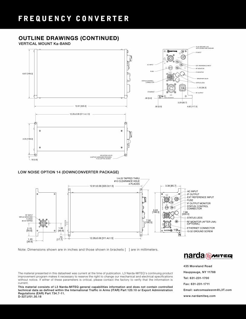
OUTLINE DRAWINGS (CONTINUED)
LOW NOISE OPTION 14 (DOWNCONVERTER PACKAGE)
HAUPPAUGE, NY
BLO
CK
UP
CO
NV
ER
TE
R
IF M
ON
ITO
R
INT
ER
FAC
ES
TAT
US
/CO
NT
RO
L
SU
MM
AR
Y
J6
INT
ER
FAC
EE
TH
ER
NE
TJ3
PO
WE
R
J2A
47-6
3 H
z25
0 V
A M
AX
90-2
50 V
AC
FU
SE
J5
250V
T
1.25
A/
J4 +4±
3 dB
m5/
10 M
Hz
EX
T R
EF
INP
UT
LIN
E
OU
TP
UT
J2IF
OU
TP
UT
RF
INP
UT
J1
RF INPUTWR-42 GROOVED
FLANGE#4-40 TAPPED 7.50
[190.5]
12.26±0.06 [311.4±1.5]
12.61±0.06 [320.3±1.5]
1/4-20 TAPPED THRU#10 CLEARANCE HOLE
4 PLACES
7.88 [200.0]
6.63 [168.3]
3.38 [85.7]
.70[17.7]1.20
[30.6]
2.15 [54.6]
1.96 [49.9]
ETHERNET CONNECTOR10-32 GROUND SCREW
IF OUTPUT MONITOR
EXT REFERENCE INPUT
STATUS/ CONTROL CONNECTOR
RF MONITOR (AFTER LNA)(OPTIONAL)
STATUS LEDS
FUSE
IF OUTPUTAC INPUT
STATUS LEDS
RF OUTPUT
10-32 GROUND SCREW
ETHERNET CONNECTOR
IF INPUTAC INPUT
BREATHER VALVE
STATUS/ CONTROL CONNECTOR
EXT REFERENCE INPUT
IF OUTPUT MONITORFUSE
1/4-20 TAPPED THRU#10 CLEARANCE HOLE
4 PLACES
STATUS LEDS
STATUS/ CONTROL CONNECTOR
ETHERNET CONNECTOR
AC INPUT
EXT REFERENCE INPUTIF
FUSEIF MONITOR
RF MONITOR
10-32 GROUND SCREW
1/4-20 TAPPED THRU#10 CLEARANCE HOLE
4 PLACES
7.50 [190.5]
6.63 [168.3]
1.83 [46.5]
2.02 [51.3] REF
7.88 [200.0]
3.38 [85.7]
.68 [17.3]
7.50 [190.5]
7.88 [200.0]
6.63 [168.3]
3.38 [85.7]
12.61±0.06 [320.3±1.5]
12.26±0.06 [311.4±1.5]
12.26±0.06 [311.4±1.5]
12.61±0.06 [320.3±1.5]
12.26±0.06 [311.4±1.5]
12.61 [320.3]
MOUNTING HOLES(CAPTIVE HARDWARE PROVIDED)
10-32 CAPTIVE SCREW
4.25 [108.0]
.19 [4.8]
6.67 [169.3]
4.63 [117.5]
3.29 [83.7]
.00 [0.0]
RF OUTPUT
BREATHER VALVE
10-32 GROUND LUGWITH SCREW AND WASHER
IF INPUT
EXT. REFERENCE INPUT
IF MONITOR
STATUS LEDS
RF MONITOR
1.43 [36.3]
FUSE
ETHERNET
STATUS CONTROLCONNECTOR
.00 [0.0]
AC INPUT
EXT
REF
INPU
T5/
10 M
Hz
+4±3
dBm
J4
90-2
50 V
AC
250
VA M
AX
LIN
E
47-6
3 H
z
J5
T1.2
5A/
FUSE
250V
IF M
ON
ITO
RO
UTP
UT
IF IN
PUT
J1
J1A
SUM
MA
RYPO
WER
STAT
US/
CON
TRO
LIN
TERF
ACE
J3BL
OCK
UPC
ON
VERT
ERET
HER
NET
INTE
RFAC
E
J6
RF O
UTP
UT
J2
HAUPPAUGE, NY
J2A
IF M
ON
ITO
RO
UTP
UT
HAUPPAUGE, NY
J5 90-2
50 V
AC
250
VA M
AX
LIN
E
47-6
3 H
z
J1IF
INPU
T
5/10
MH
z+4
±3 d
Bm
EXT
REF
INPU
TJ4
FUSE
T1.2
5A/
250V
BLOC
K UPC
ONVE
RTER
J3
INTE
RFAC
EST
ATUS
/CON
TROL PO
WER
SUM
MA
RY
ETH
ERN
ETIN
TERF
ACE
J6 RF O
UTP
UT
J2RF
MO
NIT
OR
J2A
OU
TPU
T
J1AIF MONITOROUTPUT
FUSET1.25A/
250V
BLOCK UPCONVERTER
J6ETHERNETINTERFACE
J3STATUS/CONTROL
INTERFACE
J2RF OUTPUT
SUMMARY
POWER
J8RFOUTPUT
J5 LINE
90-250 VAC47-63 Hz
250 VA MAX
J4EXT REF INPUT10 MHz+4±3 dBm
J2ARF MONITOR
J1IF INPUT
Note: Dimensions shown are in inches and those shown in brackets [ ] are in millimeters.
This material consists of L3 Narda-MITEQ general capabilities information and does not contain controlled technical data as defined within the International Traffic in Arms (ITAR) Part 120.10 or Export Administration Regulations (EAR) Part 734.7-11. D-327J/01.30.18
VERTICAL MOUNT Ka-BAND
The material presented in this datasheet was current at the time of publication. L3 Narda-MITEQ’s continuing product improvement program makes it necessary to reserve the right to change our mechanical and electrical specifications without notice. If either of these parameters is critical, please contact the factory to verify that the information is current.