Embed Size (px)
Citation preview
Getting Started
Distributed converterControl Units CU240D-2 and CU250D-2 with encoder evaluation
SINAMICS G120D
04/2018Edition
SINAMICS
www.siemens.com/drives
Margin Margin
Bufferzone
blue dark 100 % Stone gray 100%
Siemens Sans, Roman, 36/30/26 pt, whiteAbsatzformat: 01 System
Siemens Sans, Roman, 13/12/11 pt, whiteAbsatzformat: 03 Titel
Siemens Sans, Bold, 11/12/13 pt, whiteAbsatzformat: 04 Dokuklasse
Wird mehr Text verwendetVerlaufsfeld nach oben erweitern. Abstände vonRand zu Text einhalten!
Siemens Sans, Bold, 9 pt, blackAbsatzformat: 06 URL
2 x
Siemens Sans, Bold18/16/14 pt, whiteAbsatzformat: 02 Produkt
Siemens Sans, Bold11/9/7,5 pt, whiteAbsatzformat: 05 Ausgabe
1/10x
1/10x
1/10x
1/14x
1/10x
1/5x
1/5x
1/28x
1/20x
1/20x
1/5x
1/28x
1/20x
1/20x
1/20x
1 x
wenn möglich in gleicher Schriftgruppe bleiben!
groß361813139
11
mittel3016121299
klein261411119
7,5
SystemProduktgruppeTitel DokuklasseURL Ausgabe
Titelseite OHNE Beschnitt in RGBAlle Schriften sind als Absatzformat hinterlegt!!!

___________________
___________________
___________________
___________________
___________________
___________________
SINAMICS
SINAMICS G120D SINAMICS G120D converter
Getting Started
Edition 04/2018, firmware V4.7 SP10
04/2018, FW V4.7 SP10 A5E38556189B AC
About this manual 1
Fundamental safety instructions
2
Introduction 3
Installation 4
Commissioning 5
Troubleshooting and further information
6
Siemens AG Division Digital Factory Postfach 48 48 90026 NÜRNBERG GERMANY
A5E38556189B AC Ⓟ 04/2018 Subject to change
Copyright © Siemens AG 2018. All rights reserved
Legal information Warning notice system
This manual contains notices you have to observe in order to ensure your personal safety, as well as to prevent damage to property. The notices referring to your personal safety are highlighted in the manual by a safety alert symbol, notices referring only to property damage have no safety alert symbol. These notices shown below are graded according to the degree of danger.
DANGER indicates that death or severe personal injury will result if proper precautions are not taken.
WARNING indicates that death or severe personal injury may result if proper precautions are not taken.
CAUTION indicates that minor personal injury can result if proper precautions are not taken.
NOTICE indicates that property damage can result if proper precautions are not taken.
If more than one degree of danger is present, the warning notice representing the highest degree of danger will be used. A notice warning of injury to persons with a safety alert symbol may also include a warning relating to property damage.
Qualified Personnel The product/system described in this documentation may be operated only by personnel qualified for the specific task in accordance with the relevant documentation, in particular its warning notices and safety instructions. Qualified personnel are those who, based on their training and experience, are capable of identifying risks and avoiding potential hazards when working with these products/systems.
Proper use of Siemens products Note the following:
WARNING Siemens products may only be used for the applications described in the catalog and in the relevant technical documentation. If products and components from other manufacturers are used, these must be recommended or approved by Siemens. Proper transport, storage, installation, assembly, commissioning, operation and maintenance are required to ensure that the products operate safely and without any problems. The permissible ambient conditions must be complied with. The information in the relevant documentation must be observed.
Trademarks All names identified by ® are registered trademarks of Siemens AG. The remaining trademarks in this publication may be trademarks whose use by third parties for their own purposes could violate the rights of the owner.
Disclaimer of Liability We have reviewed the contents of this publication to ensure consistency with the hardware and software described. Since variance cannot be precluded entirely, we cannot guarantee full consistency. However, the information in this publication is reviewed regularly and any necessary corrections are included in subsequent editions.
SINAMICS G120D converter Getting Started, 04/2018, FW V4.7 SP10, A5E38556189B AC 3
Table of contents
1 About this manual ................................................................................................................................... 5
2 Fundamental safety instructions .............................................................................................................. 7
2.1 General safety instructions ....................................................................................................... 7
2.2 Equipment damage due to electric fields or electrostatic discharge ...................................... 13
2.3 Warranty and liability for application examples ...................................................................... 13
2.4 Industrial security .................................................................................................................... 14
2.5 Residual risks of power drive systems .................................................................................... 16
3 Introduction ........................................................................................................................................... 19
3.1 SINAMICS G120D converter .................................................................................................. 19
3.2 Commissioning tools ............................................................................................................... 21
4 Installation ............................................................................................................................................ 23
4.1 Fitting the CU to the PM.......................................................................................................... 23
4.2 Drill pattern SINAMICS G120D ............................................................................................... 24
4.3 Overview of the interfaces ...................................................................................................... 26
4.4 Protective conductor ............................................................................................................... 27
4.5 Grounding converter and motor .............................................................................................. 29
4.6 Basic EMC Rules .................................................................................................................... 30
4.7 Connections and interference suppression ............................................................................ 31
4.8 Equipotential bonding ............................................................................................................. 32
4.9 Branch circuit protection of individual inverters ...................................................................... 34
4.10 Branch circuit protection of multiple inverters ......................................................................... 37
4.11 Connections and cables ......................................................................................................... 39
4.12 Default settings of inputs and outputs (CU240D-2) ................................................................ 53
4.13 Settings PROFIBUS DP address with DIP switches .............................................................. 62
4.14 Connecting the PROFINET interface ...................................................................................... 63
5 Commissioning ..................................................................................................................................... 65
5.1 Default settings for the SINAMICS G120D ............................................................................. 65
5.2 Commissioning with the IOP-2 ............................................................................................... 65 5.2.1 Commissioning a decentralized drive with the IOP-2 ............................................................. 66
5.3 Commissioning the application ............................................................................................... 70
5.4 Reset Parameters to Factory Settings .................................................................................... 71
Table of contents
SINAMICS G120D converter 4 Getting Started, 04/2018, FW V4.7 SP10, A5E38556189B AC
6 Troubleshooting and further information ................................................................................................ 73
6.1 Operating states indicated on LEDs ...................................................................................... 73
6.2 LED DI/DO ............................................................................................................................. 75
6.3 LED ACT/LNK ........................................................................................................................ 75
6.4 List of alarms and faults ......................................................................................................... 76
6.5 Manuals for the converter ...................................................................................................... 89
6.6 Technical support ................................................................................................................... 89
SINAMICS G120D converter Getting Started, 04/2018, FW V4.7 SP10, A5E38556189B AC 5
About this manual 1
This manual describes how you install the CU230P-2 Control Unit of the SINAMICS G120P inverter and commission it.
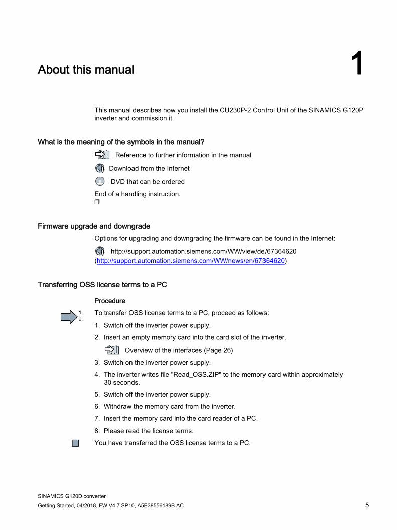
What is the meaning of the symbols in the manual?
Reference to further information in the manual
Download from the Internet
DVD that can be ordered
End of a handling instruction. ❒
Firmware upgrade and downgrade Options for upgrading and downgrading the firmware can be found in the Internet:
http://support.automation.siemens.com/WW/view/de/67364620 (http://support.automation.siemens.com/WW/news/en/67364620)
Transferring OSS license terms to a PC
Procedure
To transfer OSS license terms to a PC, proceed as follows:
1. Switch off the inverter power supply.
2. Insert an empty memory card into the card slot of the inverter.
Overview of the interfaces (Page 26)
3. Switch on the inverter power supply.
4. The inverter writes file "Read_OSS.ZIP" to the memory card within approximately 30 seconds.
5. Switch off the inverter power supply.
6. Withdraw the memory card from the inverter.
7. Insert the memory card into the card reader of a PC.
8. Please read the license terms.
You have transferred the OSS license terms to a PC.

About this manual
SINAMICS G120D converter 6 Getting Started, 04/2018, FW V4.7 SP10, A5E38556189B AC
SINAMICS G120D converter Getting Started, 04/2018, FW V4.7 SP10, A5E38556189B AC 7
Fundamental safety instructions 2 2.1 General safety instructions
WARNING
Electric shock and danger to life due to other energy sources
Touching live components can result in death or severe injury. • Only work on electrical devices when you are qualified for this job. • Always observe the country-specific safety rules.
Generally, the following six steps apply when establishing safety: 1. Prepare for disconnection. Notify all those who will be affected by the procedure. 2. Isolate the drive system from the power supply and take measures to prevent it being
switched back on again. 3. Wait until the discharge time specified on the warning labels has elapsed. 4. Check that there is no voltage between any of the power connections, and between any
of the power connections and the protective conductor connection. 5. Check whether the existing auxiliary supply circuits are de-energized. 6. Ensure that the motors cannot move. 7. Identify all other dangerous energy sources, e.g. compressed air, hydraulic systems, or
water. Switch the energy sources to a safe state. 8. Check that the correct drive system is completely locked.
After you have completed the work, restore the operational readiness in the inverse sequence.
WARNING
Risk of electric shock and fire from supply networks with an excessively high impedance
Excessively low short-circuit currents can lead to the protective devices not tripping or tripping too late, and thus causing electric shock or a fire. • In the case of a conductor-conductor or conductor-ground short-circuit, ensure that the
short-circuit current at the point where the inverter is connected to the line supply at least meets the minimum requirements for the response of the protective device used.
• You must use an additional residual-current device (RCD) if a conductor-ground short circuit does not reach the short-circuit current required for the protective device to respond. The required short-circuit current can be too low, especially for TT supply systems.
Fundamental safety instructions 2.1 General safety instructions
SINAMICS G120D converter 8 Getting Started, 04/2018, FW V4.7 SP10, A5E38556189B AC
WARNING
Risk of electric shock and fire from supply networks with an excessively low impedance
Excessively high short-circuit currents can lead to the protective devices not being able to interrupt these short-circuit currents and being destroyed, and thus causing electric shock or a fire. • Ensure that the prospective short-circuit current at the line terminal of the inverter does
not exceed the breaking capacity (SCCR or Icc) of the protective device used.
WARNING
Electric shock if there is no ground connection
For missing or incorrectly implemented protective conductor connection for devices with protection class I, high voltages can be present at open, exposed parts, which when touched, can result in death or severe injury. • Ground the device in compliance with the applicable regulations.
WARNING
Electric shock due to connection to an unsuitable power supply
When equipment is connected to an unsuitable power supply, exposed components may carry a hazardous voltage that might result in serious injury or death. • Only use power supplies that provide SELV (Safety Extra Low Voltage) or PELV-
(Protective Extra Low Voltage) output voltages for all connections and terminals of the electronics modules.
WARNING
Electric shock due to equipment damage
Improper handling may cause damage to equipment. For damaged devices, hazardous voltages can be present at the enclosure or at exposed components; if touched, this can result in death or severe injury. • Ensure compliance with the limit values specified in the technical data during transport,
storage and operation. • Do not use any damaged devices.
Fundamental safety instructions 2.1 General safety instructions
SINAMICS G120D converter Getting Started, 04/2018, FW V4.7 SP10, A5E38556189B AC 9
WARNING
Electric shock due to unconnected cable shield
Hazardous touch voltages can occur through capacitive cross-coupling due to unconnected cable shields. • As a minimum, connect cable shields and the conductors of power cables that are not
used (e.g. brake cores) at one end at the grounded housing potential.
WARNING
Arcing when a plug connection is opened during operation
Opening a plug connection when a system is operation can result in arcing that may cause serious injury or death. • Only open plug connections when the equipment is in a voltage-free state, unless it has
been explicitly stated that they can be opened in operation.
WARNING
Electric shock due to residual charges in power components
Because of the capacitors, a hazardous voltage is present for up to 5 minutes after the power supply has been switched off. Contact with live parts can result in death or serious injury. • Wait for 5 minutes before you check that the unit really is in a no-voltage condition and
start work.
NOTICE
Property damage due to loose power connections
Insufficient tightening torques or vibration can result in loose power connections. This can result in damage due to fire, device defects or malfunctions. • Tighten all power connections to the prescribed torque. • Check all power connections at regular intervals, particularly after equipment has been
transported.
Fundamental safety instructions 2.1 General safety instructions
SINAMICS G120D converter 10 Getting Started, 04/2018, FW V4.7 SP10, A5E38556189B AC
WARNING
Spread of fire from built-in devices
In the event of fire outbreak, the enclosures of built-in devices cannot prevent the escape of fire and smoke. This can result in serious personal injury or property damage. • Install built-in units in a suitable metal cabinet in such a way that personnel are
protected against fire and smoke, or take other appropriate measures to protect personnel.
• Ensure that smoke can only escape via controlled and monitored paths.
WARNING
Active implant malfunctions due to electromagnetic fields
Inverters generate electromagnetic fields (EMF) in operation. People with active implants in the immediate vicinity of this equipment are at particular risk. • As the operator of an EMF-emitting installation, assess the individual risks of persons
with active implants. The following clearances are usually adequate: – No clearance to closed control cabinets and shielded MOTION-CONNECT supply
cables – Forearm length (approx. 35 cm clearance) to distributed drive systems and open
control cabinets
WARNING
Unexpected movement of machines caused by radio devices or mobile phones
When radio devices or mobile phones with a transmission power > 1 W are used in the immediate vicinity of components, they may cause the equipment to malfunction. Malfunctions may impair the functional safety of machines and can therefore put people in danger or lead to property damage. • If you come closer than around 2 m to such components, switch off any radios or mobile
phones. • Use the "SIEMENS Industry Online Support app" only on equipment that has already
been switched off.
Fundamental safety instructions 2.1 General safety instructions
SINAMICS G120D converter Getting Started, 04/2018, FW V4.7 SP10, A5E38556189B AC 11
NOTICE
Damage to motor insulation due to excessive voltages
When operated on systems with grounded line conductor or in the event of a ground fault in the IT system, the motor insulation can be damaged by the higher voltage to ground. If you use motors that have insulation that is not designed for operation with grounded line conductors, you must perform the following measures: • IT system: Use a ground fault monitor and eliminate the fault as quickly as possible. • TN or TT systems with grounded line conductor: Use an isolating transformer on the line
side.
WARNING
Fire due to inadequate ventilation clearances
Inadequate ventilation clearances can cause overheating of components with subsequent fire and smoke. This can cause severe injury or even death. This can also result in increased downtime and reduced service lives for devices/systems. • Ensure compliance with the specified minimum clearance as ventilation clearance for
the respective component.
WARNING
Unrecognized dangers due to missing or illegible warning labels
Dangers might not be recognized if warning labels are missing or illegible. Unrecognized dangers may cause accidents resulting in serious injury or death. • Check that the warning labels are complete based on the documentation. • Attach any missing warning labels to the components, where necessary in the national
language. • Replace illegible warning labels.
NOTICE
Device damage caused by incorrect voltage/insulation tests
Incorrect voltage/insulation tests can damage the device. • Before carrying out a voltage/insulation check of the system/machine, disconnect the
devices as all converters and motors have been subject to a high voltage test by the manufacturer, and therefore it is not necessary to perform an additional test within the system/machine.
Fundamental safety instructions 2.1 General safety instructions
SINAMICS G120D converter 12 Getting Started, 04/2018, FW V4.7 SP10, A5E38556189B AC
WARNING
Unexpected movement of machines caused by inactive safety functions
Inactive or non-adapted safety functions can trigger unexpected machine movements that may result in serious injury or death. • Observe the information in the appropriate product documentation before
commissioning. • Carry out a safety inspection for functions relevant to safety on the entire system,
including all safety-related components. • Ensure that the safety functions used in your drives and automation tasks are adjusted
and activated through appropriate parameterizing. • Perform a function test. • Only put your plant into live operation once you have guaranteed that the functions
relevant to safety are running correctly.
Note Important safety notices for Safety Integrated functions
If you want to use Safety Integrated functions, you must observe the safety notices in the Safety Integrated manuals.
WARNING
Malfunctions of the machine as a result of incorrect or changed parameter settings
As a result of incorrect or changed parameterization, machines can malfunction, which in turn can lead to injuries or death. • Protect the parameterization (parameter assignments) against unauthorized access. • Handle possible malfunctions by taking suitable measures, e.g. emergency stop or
emergency off.
Fundamental safety instructions 2.2 Equipment damage due to electric fields or electrostatic discharge
SINAMICS G120D converter Getting Started, 04/2018, FW V4.7 SP10, A5E38556189B AC 13
2.2 Equipment damage due to electric fields or electrostatic discharge Electrostatic sensitive devices (ESD) are individual components, integrated circuits, modules or devices that may be damaged by either electric fields or electrostatic discharge.
NOTICE
Equipment damage due to electric fields or electrostatic discharge
Electric fields or electrostatic discharge can cause malfunctions through damaged individual components, integrated circuits, modules or devices. • Only pack, store, transport and send electronic components, modules or devices in their
original packaging or in other suitable materials, e.g conductive foam rubber of aluminum foil.
• Only touch components, modules and devices when you are grounded by one of the following methods: – Wearing an ESD wrist strap – Wearing ESD shoes or ESD grounding straps in ESD areas with conductive flooring
• Only place electronic components, modules or devices on conductive surfaces (table with ESD surface, conductive ESD foam, ESD packaging, ESD transport container).
2.3 Warranty and liability for application examples Application examples are not binding and do not claim to be complete regarding configuration, equipment or any eventuality which may arise. Application examples do not represent specific customer solutions, but are only intended to provide support for typical tasks.
As the user you yourself are responsible for ensuring that the products described are operated correctly. Application examples do not relieve you of your responsibility for safe handling when using, installing, operating and maintaining the equipment.
Fundamental safety instructions 2.4 Industrial security
SINAMICS G120D converter 14 Getting Started, 04/2018, FW V4.7 SP10, A5E38556189B AC
2.4 Industrial security
Note Industrial security
Siemens provides products and solutions with industrial security functions that support the secure operation of plants, systems, machines and networks.
In order to protect plants, systems, machines and networks against cyber threats, it is necessary to implement – and continuously maintain – a holistic, state-of-the-art industrial security concept. Siemens’ products and solutions constitute one element of such a concept.
Customers are responsible for preventing unauthorized access to their plants, systems, machines and networks. Such systems, machines and components should only be connected to an enterprise network or the Internet if and to the extent such a connection is necessary and only when appropriate security measures (e.g. firewalls and/or network segmentation) are in place.
For additional information on industrial security measures that may be implemented, please visit:
Industrial security (http://www.siemens.com/industrialsecurity)
Siemens’ products and solutions undergo continuous development to make them more secure. Siemens strongly recommends that product updates are applied as soon as they are available and that the latest product versions are used. Use of product versions that are no longer supported, and failure to apply the latest updates may increase customer’s exposure to cyber threats.
To stay informed about product updates, subscribe to the Siemens Industrial Security RSS Feed at:
Industrial security (http://www.siemens.com/industrialsecurity)
Further information is provided on the Internet:
Industrial Security Configuration Manual (https://support.industry.siemens.com/cs/ww/en/view/108862708)
Fundamental safety instructions 2.4 Industrial security
SINAMICS G120D converter Getting Started, 04/2018, FW V4.7 SP10, A5E38556189B AC 15
WARNING
Unsafe operating states resulting from software manipulation
Software manipulations (e.g. viruses, trojans, malware or worms) can cause unsafe operating states in your system that may lead to death, serious injury, and property damage. • Keep the software up to date. • Incorporate the automation and drive components into a holistic, state-of-the-art
industrial security concept for the installation or machine. • Make sure that you include all installed products into the holistic industrial security
concept. • Protect files stored on exchangeable storage media from malicious software by with
suitable protection measures, e.g. virus scanners. • Protect the drive against unauthorized changes by activating the "know-how protection"
drive function.
Fundamental safety instructions 2.5 Residual risks of power drive systems
SINAMICS G120D converter 16 Getting Started, 04/2018, FW V4.7 SP10, A5E38556189B AC
2.5 Residual risks of power drive systems When assessing the machine- or system-related risk in accordance with the respective local regulations (e.g., EC Machinery Directive), the machine manufacturer or system installer must take into account the following residual risks emanating from the control and drive components of a drive system:
1. Unintentional movements of driven machine or system components during commissioning, operation, maintenance, and repairs caused by, for example,
– Hardware and/or software errors in the sensors, control system, actuators, and cables and connections
– Response times of the control system and of the drive
– Operation and/or environmental conditions outside the specification
– Condensation/conductive contamination
– Parameterization, programming, cabling, and installation errors
– Use of wireless devices/mobile phones in the immediate vicinity of electronic components
– External influences/damage
– X-ray, ionizing radiation and cosmic radiation
2. Unusually high temperatures, including open flames, as well as emissions of light, noise, particles, gases, etc., can occur inside and outside the components under fault conditions caused by, for example:
– Component failure
– Software errors
– Operation and/or environmental conditions outside the specification
– External influences/damage
3. Hazardous shock voltages caused by, for example:
– Component failure
– Influence during electrostatic charging
– Induction of voltages in moving motors
– Operation and/or environmental conditions outside the specification
– Condensation/conductive contamination
– External influences/damage
4. Electrical, magnetic and electromagnetic fields generated in operation that can pose a risk to people with a pacemaker, implants or metal replacement joints, etc., if they are too close
5. Release of environmental pollutants or emissions as a result of improper operation of the system and/or failure to dispose of components safely and correctly
6. Influence of network-connected communication systems, e.g. ripple-control transmitters or data communication via the network

Fundamental safety instructions 2.5 Residual risks of power drive systems
SINAMICS G120D converter Getting Started, 04/2018, FW V4.7 SP10, A5E38556189B AC 17
For more information about the residual risks of the drive system components, see the relevant sections in the technical user documentation.

Fundamental safety instructions 2.5 Residual risks of power drive systems
SINAMICS G120D converter 18 Getting Started, 04/2018, FW V4.7 SP10, A5E38556189B AC
SINAMICS G120D converter Getting Started, 04/2018, FW V4.7 SP10, A5E38556189B AC 19
Introduction 3 3.1 SINAMICS G120D converter
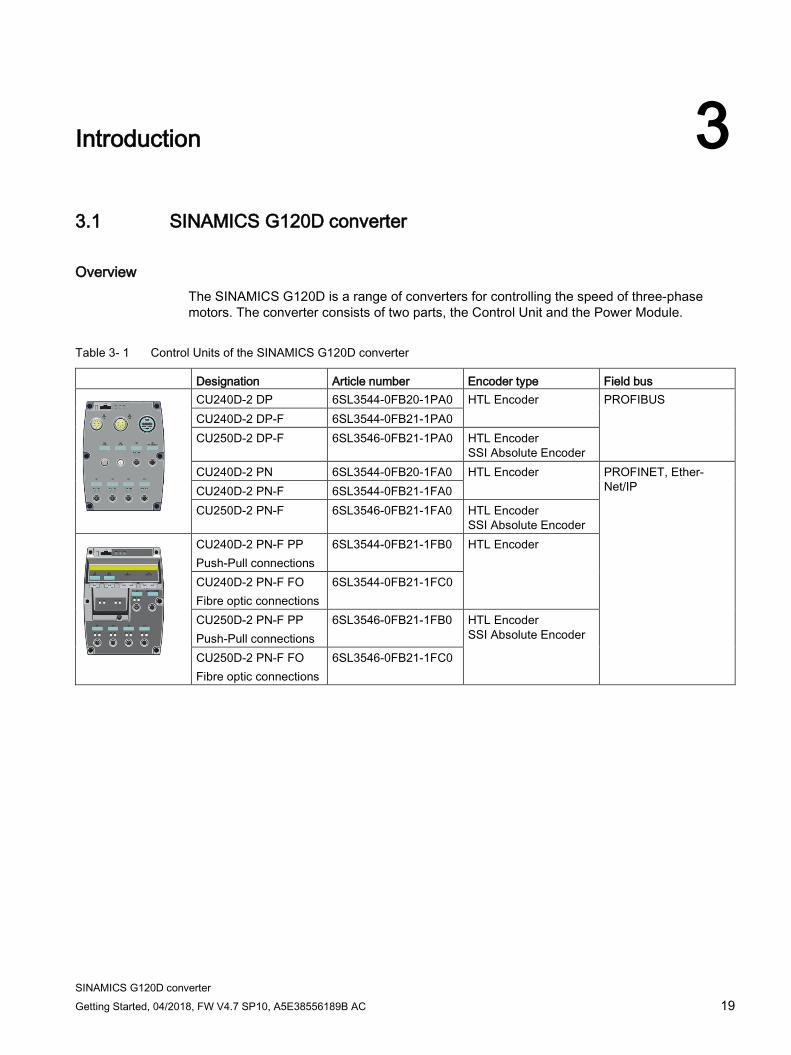
Overview The SINAMICS G120D is a range of converters for controlling the speed of three-phase motors. The converter consists of two parts, the Control Unit and the Power Module.
Table 3- 1 Control Units of the SINAMICS G120D converter
Designation Article number Encoder type Field bus
CU240D-2 DP 6SL3544-0FB20-1PA0 HTL Encoder PROFIBUS CU240D-2 DP-F 6SL3544-0FB21-1PA0 CU250D-2 DP-F 6SL3546-0FB21-1PA0 HTL Encoder
SSI Absolute Encoder CU240D-2 PN 6SL3544-0FB20-1FA0 HTL Encoder PROFINET, Ether-
Net/IP CU240D-2 PN-F 6SL3544-0FB21-1FA0 CU250D-2 PN-F 6SL3546-0FB21-1FA0 HTL Encoder
SSI Absolute Encoder
CU240D-2 PN-F PP Push-Pull connections
6SL3544-0FB21-1FB0 HTL Encoder
CU240D-2 PN-F FO Fibre optic connections
6SL3544-0FB21-1FC0
CU250D-2 PN-F PP Push-Pull connections
6SL3546-0FB21-1FB0 HTL Encoder SSI Absolute Encoder
CU250D-2 PN-F FO Fibre optic connections
6SL3546-0FB21-1FC0
Introduction 3.1 SINAMICS G120D converter
SINAMICS G120D converter 20 Getting Started, 04/2018, FW V4.7 SP10, A5E38556189B AC
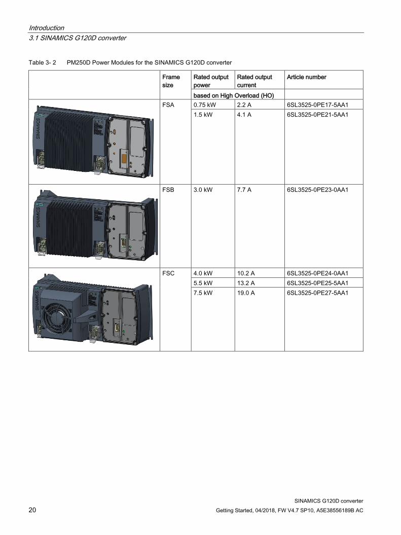
Table 3- 2 PM250D Power Modules for the SINAMICS G120D converter
Frame size
Rated output power
Rated output current
Article number
based on High Overload (HO)
FSA 0.75 kW 2.2 A 6SL3525-0PE17-5AA1 1.5 kW 4.1 A 6SL3525-0PE21-5AA1
FSB 3.0 kW 7.7 A 6SL3525-0PE23-0AA1
FSC 4.0 kW 10.2 A 6SL3525-0PE24-0AA1 5.5 kW 13.2 A 6SL3525-0PE25-5AA1 7.5 kW 19.0 A 6SL3525-0PE27-5AA1
Introduction 3.2 Commissioning tools
SINAMICS G120D converter Getting Started, 04/2018, FW V4.7 SP10, A5E38556189B AC 21
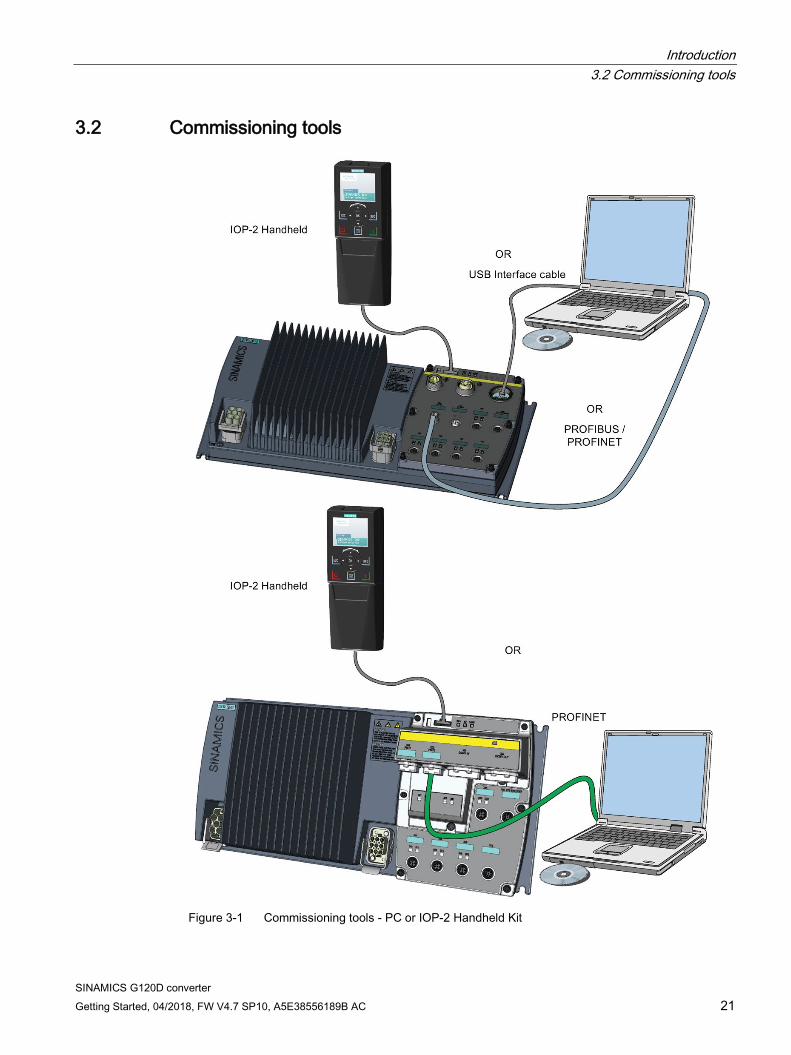
3.2 Commissioning tools
Figure 3-1 Commissioning tools - PC or IOP-2 Handheld Kit
Introduction 3.2 Commissioning tools
SINAMICS G120D converter 22 Getting Started, 04/2018, FW V4.7 SP10, A5E38556189B AC
IOP-2 Handheld: Article number 6SL3255-0AA00-4HA1
Connection cable (3 m) between PC and converter: Article number 6SL3255-0AA00-2CA0
You obtain STARTER and Startdrive on a DVD:
● STARTER: Article number 6SL3072-0AA00-0AG0
● Startdrive: Article number 6SL3072-4CA02-1XG0
STARTER and Startdrive download:
● STARTER Download (http://support.automation.siemens.com/WW/view/en/26233208)
● Startdrive (http://support.automation.siemens.com/WW/view/en/68034568)
Help regarding operation:
● STARTER videos (http://www.automation.siemens.com/mcms/mc-drives/en/low-voltage-inverter/sinamics-g120/videos/Pages/videos.aspx)
● Startdrive tutorial (http://support.automation.siemens.com/WW/view/en/73598459)

SINAMICS G120D converter Getting Started, 04/2018, FW V4.7 SP10, A5E38556189B AC 23
Installation 4 4.1 Fitting the CU to the PM
Fitting the Control Unit to the Power Module The inverter is delivered as two separate components - the Power Module (PM) and the Control Unit (CU). The CU must be fitted to the PM prior to any further commissioning taking place.
NOTICE
Damage due to incorrectly fitted seal
If the seal is not fitted correctly, the drive will not reach IP65 rating. In this case the converter is not protected against water or dust. This may damage the converter. • Fit the seal correctly when assembling the Power Module and the Control Unit.
Figure 4-1 Fitting the Control Unit to the Power Module
Installation 4.2 Drill pattern SINAMICS G120D
SINAMICS G120D converter 24 Getting Started, 04/2018, FW V4.7 SP10, A5E38556189B AC
4.2 Drill pattern SINAMICS G120D
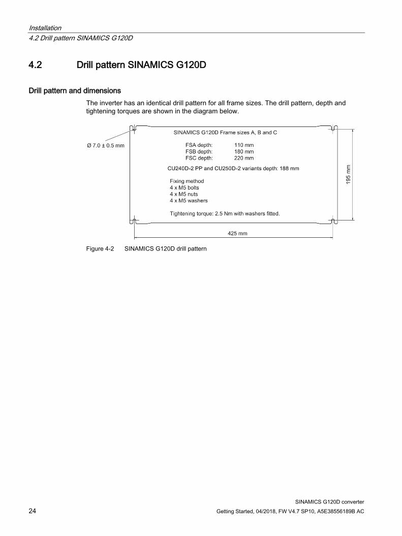
Drill pattern and dimensions The inverter has an identical drill pattern for all frame sizes. The drill pattern, depth and tightening torques are shown in the diagram below.
Figure 4-2 SINAMICS G120D drill pattern

Installation 4.2 Drill pattern SINAMICS G120D
SINAMICS G120D converter Getting Started, 04/2018, FW V4.7 SP10, A5E38556189B AC 25
Mounting orientation Mount the converter on a table or on a wall. The minimum clearance distances are as follows:
● Side-by-side - no clearance distance is required
● Above and below the inverter 150 mm (5.9 inches).
Figure 4-3 Mounting orientation: correct (✓), impermissible (X), permissible with restrictions (!)
Restrictions due to vertical mounting If the converter is mounted in the vertical position, the maximum ambient temperature is 40°C.
Additionally you have to reduce the converter output current to 80 % of rated converter current.
If the output current derating adversely affects the application, you have to use an converter of the next highest power rating.
Installation 4.3 Overview of the interfaces
SINAMICS G120D converter 26 Getting Started, 04/2018, FW V4.7 SP10, A5E38556189B AC
4.3 Overview of the interfaces
Interfaces of the converter
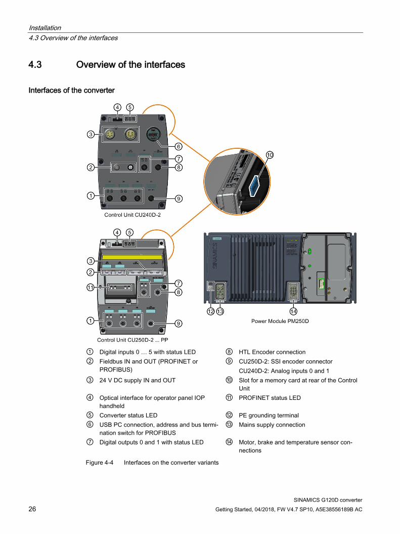
① Digital inputs 0 … 5 with status LED ⑧ HTL Encoder connection ② Fieldbus IN and OUT (PROFINET or
PROFIBUS) ⑨ CU250D-2: SSI encoder connector
CU240D-2: Analog inputs 0 and 1 ③ 24 V DC supply IN and OUT ⑩ Slot for a memory card at rear of the Control
Unit ④ Optical interface for operator panel IOP
handheld ⑪ PROFINET status LED
⑤ Converter status LED ⑫ PE grounding terminal ⑥ USB PC connection, address and bus termi-
nation switch for PROFIBUS ⑬ Mains supply connection
⑦ Digital outputs 0 and 1 with status LED ⑭ Motor, brake and temperature sensor con-nections
Figure 4-4 Interfaces on the converter variants

Installation 4.4 Protective conductor
SINAMICS G120D converter Getting Started, 04/2018, FW V4.7 SP10, A5E38556189B AC 27
4.4 Protective conductor
WARNING
Electric shock due to interrupted protective conductor
The drive components conduct a high leakage current via the protective conductor. Touching conductive parts when the protective conductor is interrupted can result in death or serious injury. • Dimension the protective conductor as stipulated in the appropriate regulations.
Dimensioning the protective conductor Observe the local regulations for protective conductors subject to an increased leakage current at the installation site.
① Protective conductor for line feeder cables ② Protective conductor for inverter line feeder cables ③ Protective conductor between PE and the electrical cabinet ④ Protective conductor for motor feeder cables
Installation 4.4 Protective conductor
SINAMICS G120D converter 28 Getting Started, 04/2018, FW V4.7 SP10, A5E38556189B AC
The minimum cross-section of the protective conductor ① … ④ depends on the cross-section of the line or motor feeder cable:
● Line or motor feeder cable ≤ 16 mm2
⇒ Minimum cross-section of the protective conductor = cross-section of the line or motor feeder cable
● Line feeder cable = 16 mm² … 35 mm2
⇒ Minimum cross-section of the protective conductor = 16 mm2
● Line feeder cable> 35 mm2
⇒ Minimum cross-section of the protective conductor = ½ cross-section of the line or motor feeder cable
Additional requirements placed on the protective conductor ①:
● For permanent connection, the protective conductor must fulfill at least one of the following conditions:
– The protective conductor is routed so that it is protected against damage along its complete length. Cables routed inside electrical cabinets or enclosed machine housings are considered to be adequately protected against mechanical damage.
– As a conductor of a multi-conductor cable, the protective conductor has a cross-section ≥ 2.5 mm² Cu.
– For an individual conductor, the protective conductor has a cross-section ≥ 10 mm² Cu.
– The protective conductor consists of two conductors with the same cross-section.
● When connecting a multi-conductor cable using an industrial plug connector according to EN 60309, the protective conductor must have a cross-section of ≥ 2.5 mm² Cu.
Installation 4.5 Grounding converter and motor
SINAMICS G120D converter Getting Started, 04/2018, FW V4.7 SP10, A5E38556189B AC 29
4.5 Grounding converter and motor
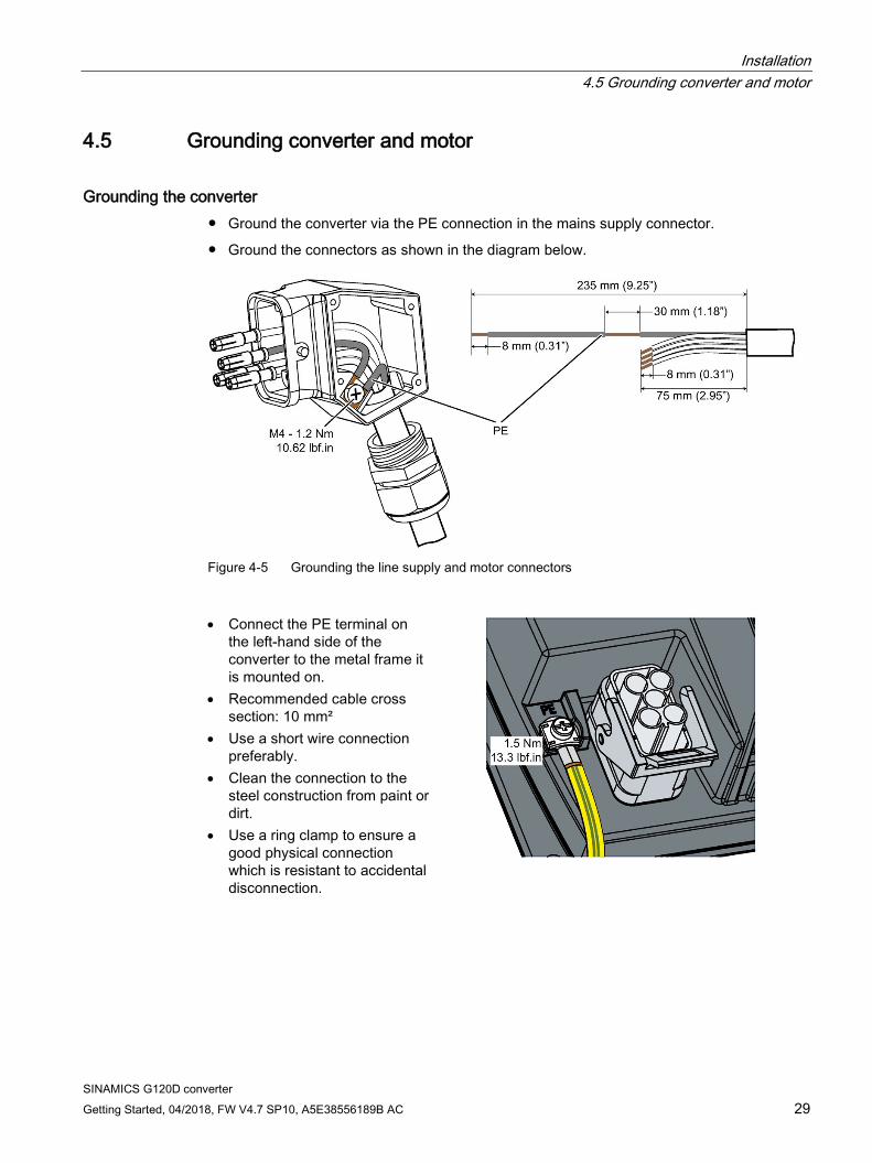
Grounding the converter ● Ground the converter via the PE connection in the mains supply connector.
● Ground the connectors as shown in the diagram below.
Figure 4-5 Grounding the line supply and motor connectors
• Connect the PE terminal on
the left-hand side of the converter to the metal frame it is mounted on.
• Recommended cable cross section: 10 mm²
• Use a short wire connection preferably.
• Clean the connection to the steel construction from paint or dirt.
• Use a ring clamp to ensure a good physical connection which is resistant to accidental disconnection.
Installation 4.6 Basic EMC Rules
SINAMICS G120D converter 30 Getting Started, 04/2018, FW V4.7 SP10, A5E38556189B AC
Grounding the motor ● Ground the motor via the PE connection in the motor connector.
● Ground the connector as shown in the diagram above (grounding the converter). Although the line and motor connectors are of a different type, the principle of grounding them is the same.
● If possible, ground the motor housing.
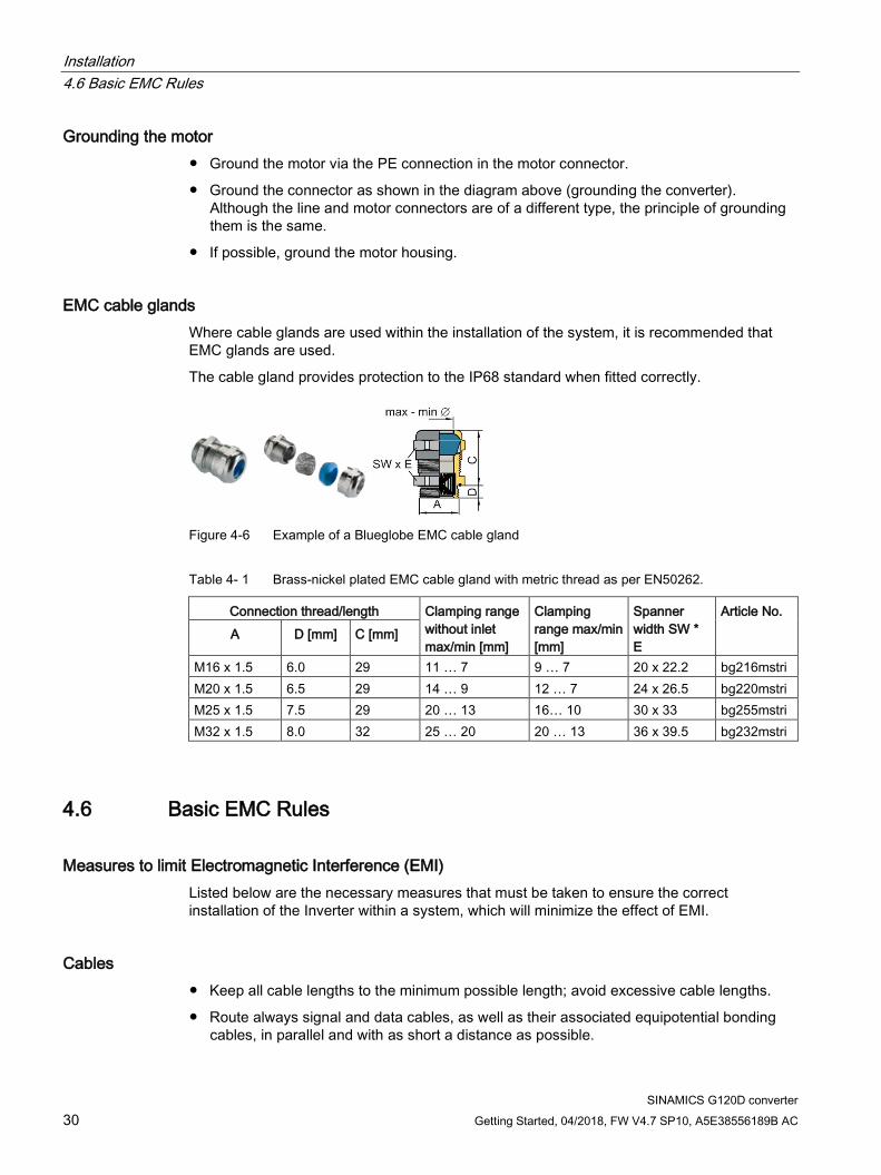
EMC cable glands Where cable glands are used within the installation of the system, it is recommended that EMC glands are used.
The cable gland provides protection to the IP68 standard when fitted correctly.
Figure 4-6 Example of a Blueglobe EMC cable gland
Table 4- 1 Brass-nickel plated EMC cable gland with metric thread as per EN50262.
Connection thread/length Clamping range without inlet max/min [mm]
Clamping range max/min [mm]
Spanner width SW * E
Article No. A D [mm] C [mm]
M16 x 1.5 6.0 29 11 … 7 9 … 7 20 x 22.2 bg216mstri M20 x 1.5 6.5 29 14 … 9 12 … 7 24 x 26.5 bg220mstri M25 x 1.5 7.5 29 20 … 13 16… 10 30 x 33 bg255mstri M32 x 1.5 8.0 32 25 … 20 20 … 13 36 x 39.5 bg232mstri
4.6 Basic EMC Rules
Measures to limit Electromagnetic Interference (EMI) Listed below are the necessary measures that must be taken to ensure the correct installation of the Inverter within a system, which will minimize the effect of EMI.
Cables ● Keep all cable lengths to the minimum possible length; avoid excessive cable lengths.
● Route always signal and data cables, as well as their associated equipotential bonding cables, in parallel and with as short a distance as possible.
Installation 4.7 Connections and interference suppression
SINAMICS G120D converter Getting Started, 04/2018, FW V4.7 SP10, A5E38556189B AC 31
● Don't route signal and data cables and line supply cables in parallel to motor cables.
● Signal and data cables and line supply cables should not cross motor cables; if crossing is necessary, they should cross at an angle of 90 °.
● Shield signal and data cables.
● Route particularly sensitive signal cables, such as setpoint and actual value cables, with optimum shield bonding at both ends and without any interruptions of the shield.
● Ground spare wires for signal and data cables at both ends.
● Route all power cables (line supply cables, as well as motor cables) separately from signal and data cables. The minimum distance should be approximately 25 cm. Exception: hybrid motor cables with integrated shielded temperature sensor and brake control wires are allowed.
● Shield the power cable between inverter and motor. We recommend shielded cables with symmetrical three-phase conductors (L1, L2, and L3) and an integrated, 3-wire, and symmetrically arranged PE conductor.
Cable shields ● Use shielded cables with finely stranded braided shields. Foil shields are not suitable
since they are much less effective.
● Connect shields to the grounded housings at both ends with excellent electrical conductivity and a large contact area.
● Bond the cable shields to the plug connectors of the inverter.
● Don't interrupt cable shields by intermediate terminals.
● In the case of both, the power cables and the signal and data cables, the cable shields should be connected by means of suitable EMC shield clips or via electrically conductive PG glands. These must connect the shields to the shield bonding options for cables and the unit housing respectively with excellent electrical conductivity and a large contact area.
● Use only metallic or metallized connector housings for shielded data cables (e. g. PROFIBUS cables).
4.7 Connections and interference suppression All connections should be made so that they are permanent. Screwed connections on painted or anodized metal components must be made either by means of special contact washers, which penetrate the isolating surface and establish a metallically conductive contact, or by removing the isolating surface on the contact points.
Contactor coils, relays and the solenoid valves must have interference suppressors to reduce high-frequency radiation when the contacts are opened (RC elements or varistors for AC currentoperated coils, and freewheeling diodes for DC current-operated coils). The interference suppressors must be connected directly on each coil.
No external suppression device is required for the motor holding brake.
Installation 4.8 Equipotential bonding
SINAMICS G120D converter 32 Getting Started, 04/2018, FW V4.7 SP10, A5E38556189B AC
4.8 Equipotential bonding
Grounding and high-frequency equipotential bonding measures All electrical and mechanical drive components (transformer, motor and driven machine) must be connected to the grounding system. These connections are established by means of standard heavy-power PE cables, which do not need to have any special high-frequency properties.
In addition to these connections, the inverter (as the source of the high-frequency interference) and the motor must be interconnected with respect to the high-frequency point of view:
● Use a shielded motor cable.
● Connect the cable shield both to the motor connector on the inverter and to the motor terminal box.
● Use a short grounding connection from the PE terminal on the inverter to the metal frame.
The following figure illustrates all grounding and high-frequency equipotential bonding measures using an example.
Installation 4.8 Equipotential bonding
SINAMICS G120D converter Getting Started, 04/2018, FW V4.7 SP10, A5E38556189B AC 33
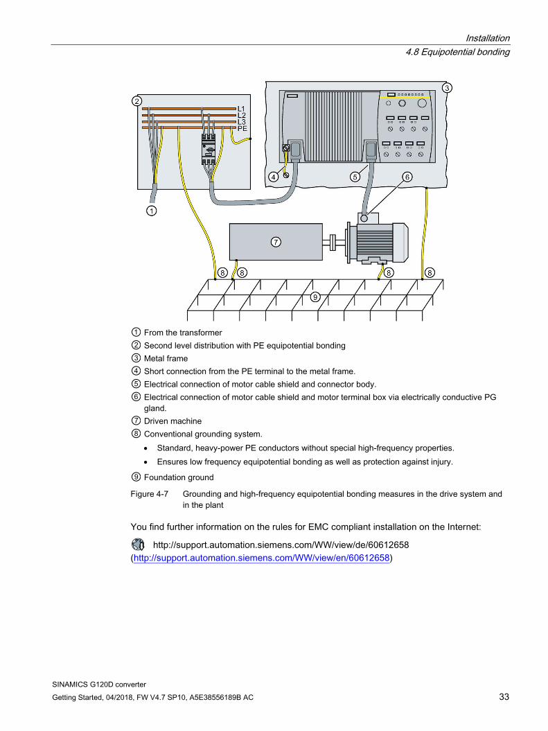
① From the transformer ② Second level distribution with PE equipotential bonding ③ Metal frame ④ Short connection from the PE terminal to the metal frame. ⑤ Electrical connection of motor cable shield and connector body. ⑥ Electrical connection of motor cable shield and motor terminal box via electrically conductive PG
gland. ⑦ Driven machine ⑧ Conventional grounding system.
• Standard, heavy-power PE conductors without special high-frequency properties. • Ensures low frequency equipotential bonding as well as protection against injury.
⑨ Foundation ground
Figure 4-7 Grounding and high-frequency equipotential bonding measures in the drive system and in the plant
You find further information on the rules for EMC compliant installation on the Internet:
http://support.automation.siemens.com/WW/view/de/60612658 (http://support.automation.siemens.com/WW/view/en/60612658)
Installation 4.9 Branch circuit protection of individual inverters
SINAMICS G120D converter 34 Getting Started, 04/2018, FW V4.7 SP10, A5E38556189B AC
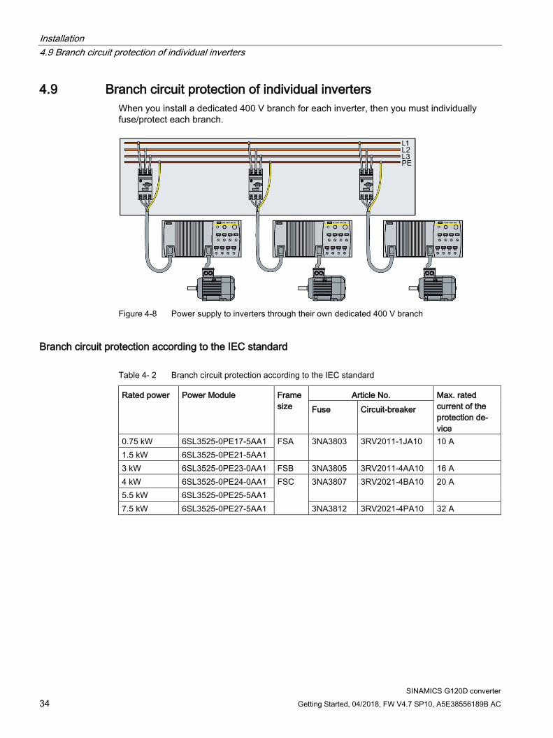
4.9 Branch circuit protection of individual inverters When you install a dedicated 400 V branch for each inverter, then you must individually fuse/protect each branch.
Figure 4-8 Power supply to inverters through their own dedicated 400 V branch
Branch circuit protection according to the IEC standard
Table 4- 2 Branch circuit protection according to the IEC standard
Rated power Power Module Frame size
Article No. Max. rated current of the protection de-vice
Fuse Circuit-breaker
0.75 kW 6SL3525-0PE17-5AA1 FSA 3NA3803 3RV2011-1JA10 10 A 1.5 kW 6SL3525-0PE21-5AA1 3 kW 6SL3525-0PE23-0AA1 FSB 3NA3805 3RV2011-4AA10 16 A 4 kW 6SL3525-0PE24-0AA1 FSC 3NA3807 3RV2021-4BA10 20 A 5.5 kW 6SL3525-0PE25-5AA1 7.5 kW 6SL3525-0PE27-5AA1 3NA3812 3RV2021-4PA10 32 A

Installation 4.9 Branch circuit protection of individual inverters
SINAMICS G120D converter Getting Started, 04/2018, FW V4.7 SP10, A5E38556189B AC 35
Branch circuit protection according to the UL standard Use in the American market requires protection devices that meet UL standards as detailed in the following tables.
Table 4- 3 Overview of the approved protection devices/fuses according to UL standards
Protection device UL category Fuses of any manufacturer with faster tripping characteristic than class RK5, e.g. class J, T, CC, G, or CF
JDDZ
SIEMENS circuit breaker DIVQ Type E combination motor controller (designation according to the UL standard - is available as SIEMENS circuit breaker)
NKJH
Table 4- 4 Branch circuit protection with non-semiconductor fuses of Classes J, T, CC, G or CF (UL Category JDDZ)
Rated power Power Module Frame size
Max. rated current of the fuse
Short circuit current rating SCCR
0.75 kW 6SL3525-0PE17-5AA1 FSA 10 A 100 kA, 480 V 3 AC 1.5 kW 6SL3525-0PE21-5AA1 15 A 100 kA, 480 V 3 AC 3 kW 6SL3525-0PE23-0AA1 FSB 25 A 100 kA, 480 V 3 AC 4 kW 6SL3525-0PE24-0AA1 FSC 35 A 100 kA, 480 V 3 AC 5.5 kW 6SL3525-0PE25-5AA1 45 A 100 kA, 480 V 3 AC 7.5 kW 6SL3525-0PE27-5AA1 60 A 100 kA, 480 V 3 AC
Table 4- 5 Branch circuit protection according to UL Categories DIVQ and NKJH
Rated power
Power Module Frame size
Article No. UL cat. Max. rated current of the circuit breaker
Short circuit current rating SCCR
0.75 kW 6SL3525-0PE17-5AA1 FSA 3RV2711… DIVQ 15 A 65 kA, 480Y/277 V AC
3RV1742…, LGG… or CED6…
DIVQ 15 A 65 kA, 480 V 3 AC
3RV2021-1JA… NKJH 10 A 65 kA, 480Y/277 V AC
1.5 kW 6SL3525-0PE21-5AA1 FSA 3RV2711… DIVQ 15 A 65 kA, 480Y/277 V AC
3RV1742…, LGG… or CED6…
DIVQ 15 A 65 kA, 480 V 3 AC
3RV2021-1JA… NKJH 10 A 65 kA, 480Y/277 V AC
3 kW 6SL3525-0PE23-0AA1 FSB 3RV1742…, LGG…, or CED6…
DIVQ 25 A 65 kA, 480 V 3 AC
3RV2721… DIVQ 22 A 50 kA, 480Y/277 V AC
Installation 4.9 Branch circuit protection of individual inverters
SINAMICS G120D converter 36 Getting Started, 04/2018, FW V4.7 SP10, A5E38556189B AC
Rated power
Power Module Frame size
Article No. UL cat. Max. rated current of the circuit breaker
Short circuit current rating SCCR
3RV2021-4AA… NKJH 16 A 65 kA, 480Y/277 V AC
3RV1031-4AA… or 3RV2031-4AA…
NKJH 16 A 65 kA, 480Y/277 V AC
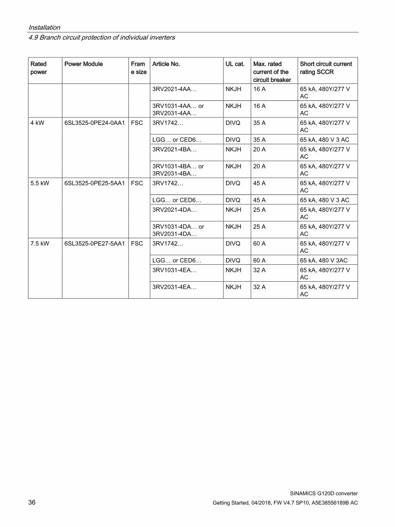
4 kW 6SL3525-0PE24-0AA1 FSC 3RV1742… DIVQ 35 A 65 kA, 480Y/277 V AC
LGG… or CED6… DIVQ 35 A 65 kA, 480 V 3 AC 3RV2021-4BA… NKJH 20 A 65 kA, 480Y/277 V
AC 3RV1031-4BA… or 3RV2031-4BA…
NKJH 20 A 65 kA, 480Y/277 V AC
5.5 kW 6SL3525-0PE25-5AA1 FSC 3RV1742… DIVQ 45 A 65 kA, 480Y/277 V AC
LGG… or CED6… DIVQ 45 A 65 kA, 480 V 3 AC 3RV2021-4DA… NKJH 25 A 65 kA, 480Y/277 V
AC 3RV1031-4DA… or 3RV2031-4DA…
NKJH 25 A 65 kA, 480Y/277 V AC
7.5 kW 6SL3525-0PE27-5AA1 FSC 3RV1742… DIVQ 60 A 65 kA, 480Y/277 V AC
LGG… or CED6… DIVQ 60 A 65 kA, 480 V 3AC 3RV1031-4EA… NKJH 32 A 65 kA, 480Y/277 V
AC 3RV2031-4EA… NKJH 32 A 65 kA, 480Y/277 V
AC
Installation 4.10 Branch circuit protection of multiple inverters
SINAMICS G120D converter Getting Started, 04/2018, FW V4.7 SP10, A5E38556189B AC 37
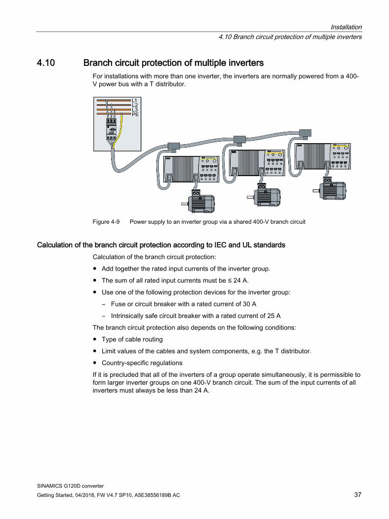
4.10 Branch circuit protection of multiple inverters For installations with more than one inverter, the inverters are normally powered from a 400-V power bus with a T distributor.
Figure 4-9 Power supply to an inverter group via a shared 400-V branch circuit
Calculation of the branch circuit protection according to IEC and UL standards Calculation of the branch circuit protection:
● Add together the rated input currents of the inverter group.
● The sum of all rated input currents must be ≤ 24 A.
● Use one of the following protection devices for the inverter group:
– Fuse or circuit breaker with a rated current of 30 A
– Intrinsically safe circuit breaker with a rated current of 25 A
The branch circuit protection also depends on the following conditions:
● Type of cable routing
● Limit values of the cables and system components, e.g. the T distributor.
● Country-specific regulations
If it is precluded that all of the inverters of a group operate simultaneously, it is permissible to form larger inverter groups on one 400-V branch circuit. The sum of the input currents of all inverters must always be less than 24 A.
Installation 4.10 Branch circuit protection of multiple inverters
SINAMICS G120D converter 38 Getting Started, 04/2018, FW V4.7 SP10, A5E38556189B AC
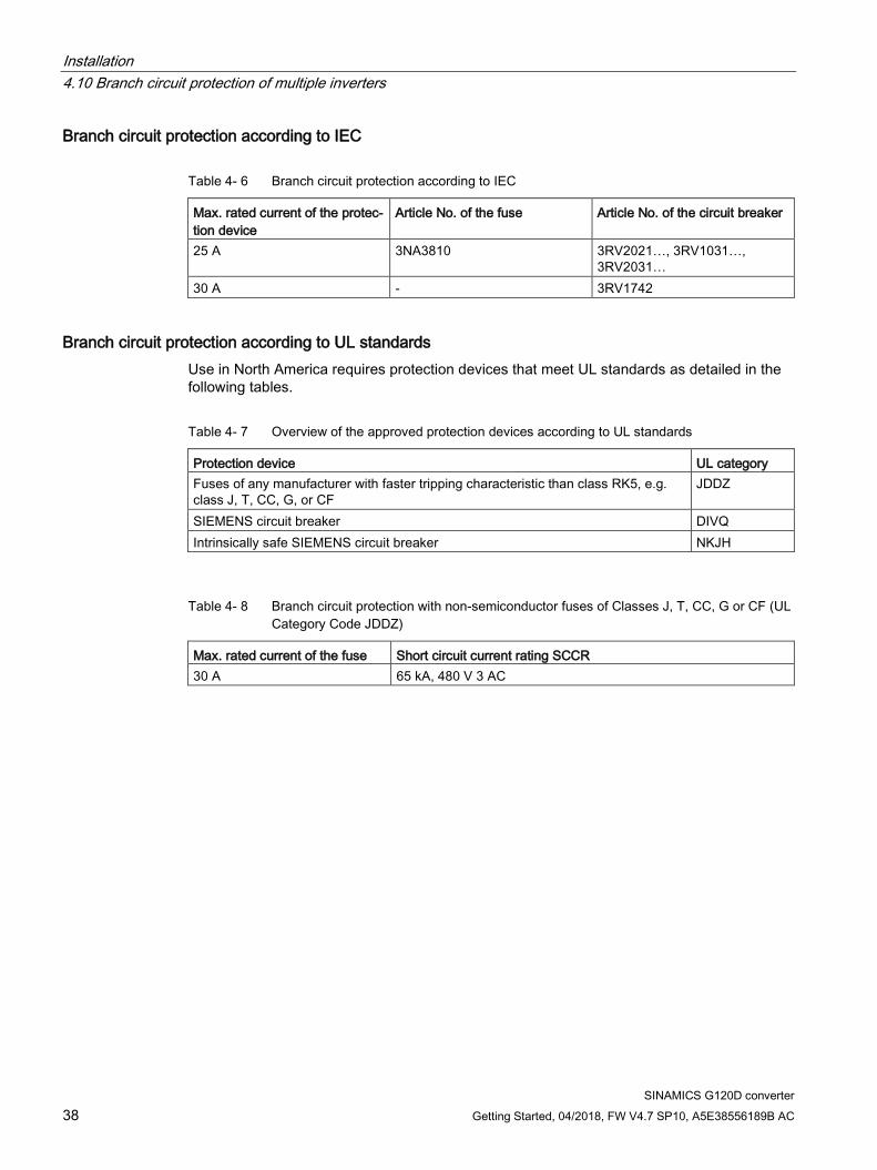
Branch circuit protection according to IEC
Table 4- 6 Branch circuit protection according to IEC
Max. rated current of the protec-tion device
Article No. of the fuse Article No. of the circuit breaker
25 A 3NA3810 3RV2021…, 3RV1031…, 3RV2031…
30 A - 3RV1742
Branch circuit protection according to UL standards Use in North America requires protection devices that meet UL standards as detailed in the following tables.
Table 4- 7 Overview of the approved protection devices according to UL standards
Protection device UL category Fuses of any manufacturer with faster tripping characteristic than class RK5, e.g. class J, T, CC, G, or CF
JDDZ
SIEMENS circuit breaker DIVQ Intrinsically safe SIEMENS circuit breaker NKJH
Table 4- 8 Branch circuit protection with non-semiconductor fuses of Classes J, T, CC, G or CF (UL Category Code JDDZ)
Max. rated current of the fuse Short circuit current rating SCCR 30 A 65 kA, 480 V 3 AC

Installation 4.11 Connections and cables
SINAMICS G120D converter Getting Started, 04/2018, FW V4.7 SP10, A5E38556189B AC 39
Table 4- 9 Branch circuit protection with circuit breaker, UL categories DIVQ and NKJH
Max. rated current of the circuit breaker
Article No. UL cat. Short circuit cur-rent rating SCCR
30 A 3RV2711… DIVQ 65 kA, 480Y/277 V AC
3RV1742…, LGG… or CED6… DIVQ 65 kA, 480 V 3 AC
25 A 3RV2021-4DA… NKJH 65 kA, 480Y/277 V AC
3RV1031-4DA… or 3RV2031-4DA… NKJH 65 kA, 480Y/277 V AC
22 A 3RV2721… DIVQ 50 kA, 480Y/277 V AC
NOTICE
Material damage from inappropriate supply system Vt > 1%
Operating the converter on an inappropriate supply system can cause damage to the converter and other loads. • Only operate the converter on supply systems with Vt ≤ 1%.
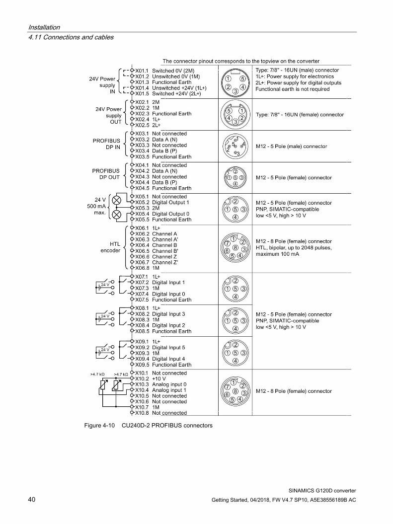
4.11 Connections and cables
Connectors
"Switched" and "unswitched" 24 V power supply
The unswitched 24 V power supply (1L+) is required for the device to function.
● Use a power supply with PELV (Protective Extra Low Voltage).
● For applications in USA and Canada: Use a power supply NEC Class 2.
● The 0 V of the power supply must be connected with low resistance to the PE of the system.
The switched 24 V (2L+) supplies the two digital outputs. Switching brings all of the actuators connected to the digital outputs into the no-voltage state.
If you don't need the switching of 2L+ power supply, then both the switched as well as the non-switched 24 V may come from the same supply.
Installation 4.11 Connections and cables
SINAMICS G120D converter 40 Getting Started, 04/2018, FW V4.7 SP10, A5E38556189B AC
Figure 4-10 CU240D-2 PROFIBUS connectors
Installation 4.11 Connections and cables
SINAMICS G120D converter Getting Started, 04/2018, FW V4.7 SP10, A5E38556189B AC 41
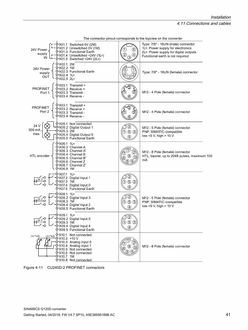
Figure 4-11 CU240D-2 PROFINET connectors
Installation 4.11 Connections and cables
SINAMICS G120D converter 42 Getting Started, 04/2018, FW V4.7 SP10, A5E38556189B AC
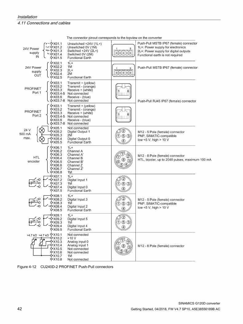
Figure 4-12 CU240D-2 PROFINET Push-Pull connectors
Installation 4.11 Connections and cables
SINAMICS G120D converter Getting Started, 04/2018, FW V4.7 SP10, A5E38556189B AC 43
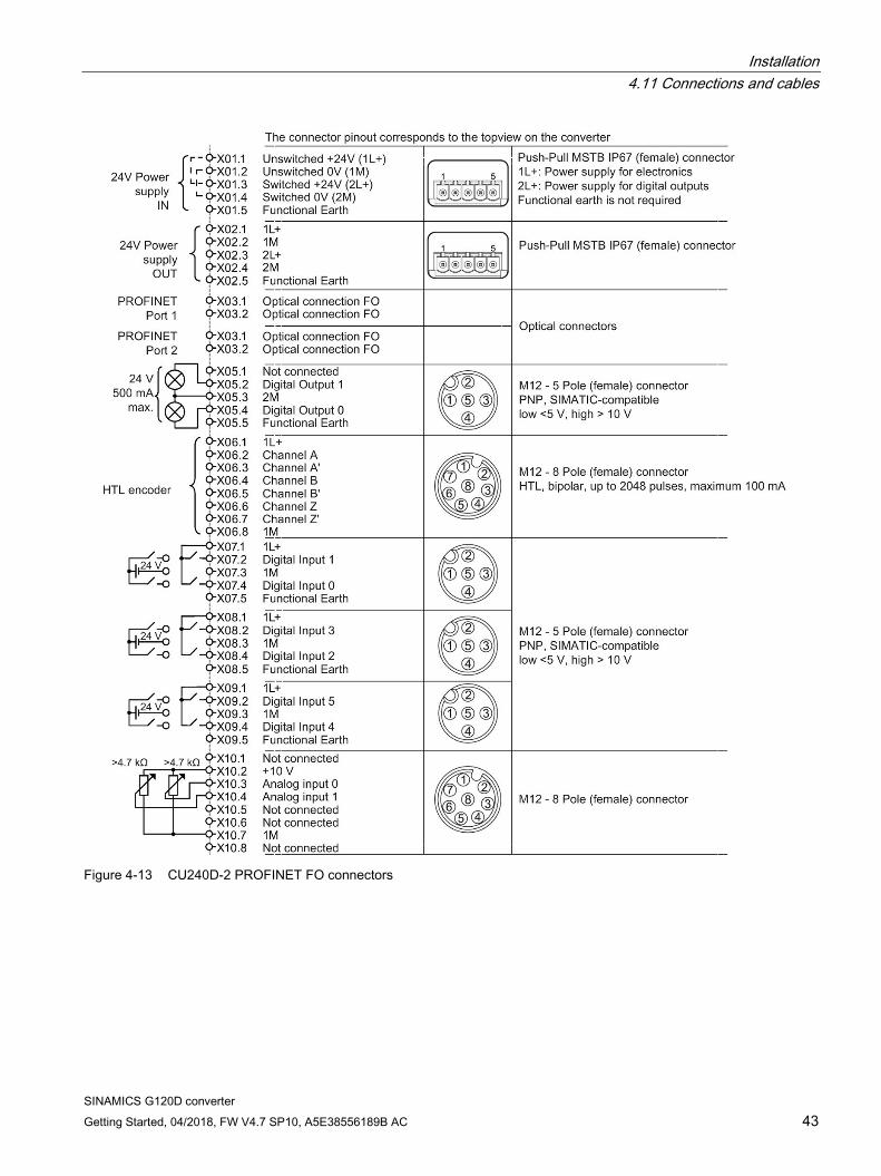
Figure 4-13 CU240D-2 PROFINET FO connectors
Installation 4.11 Connections and cables
SINAMICS G120D converter 44 Getting Started, 04/2018, FW V4.7 SP10, A5E38556189B AC
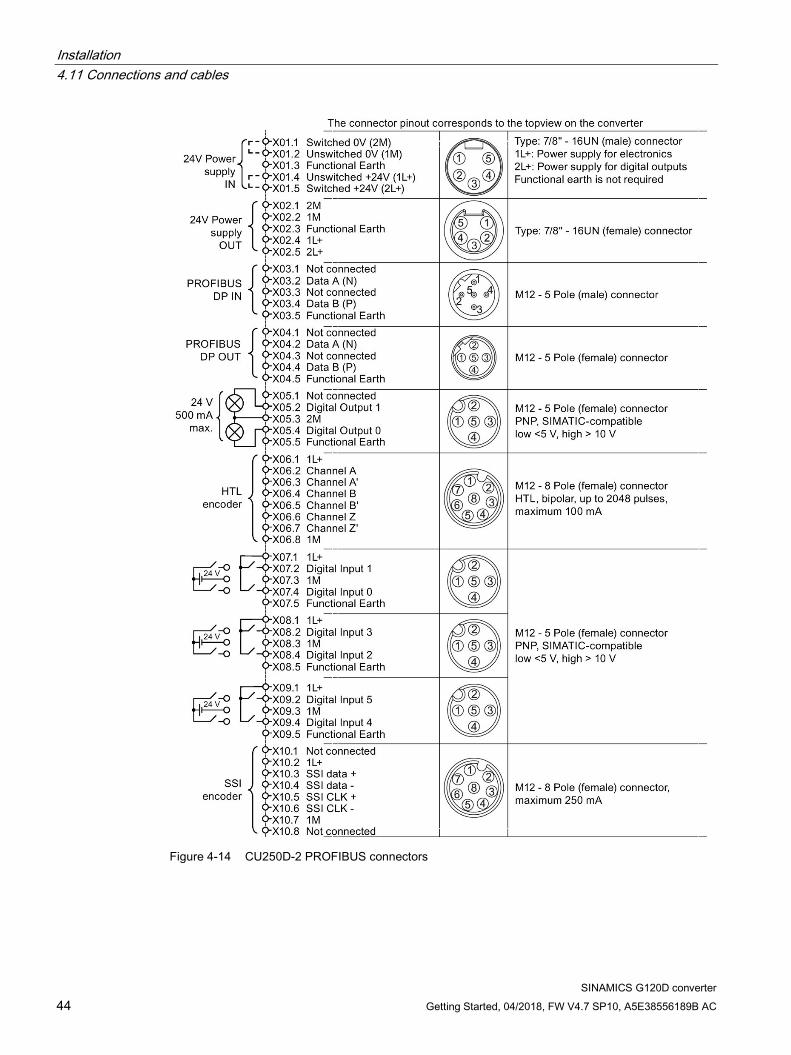
Figure 4-14 CU250D-2 PROFIBUS connectors
Installation 4.11 Connections and cables
SINAMICS G120D converter Getting Started, 04/2018, FW V4.7 SP10, A5E38556189B AC 45
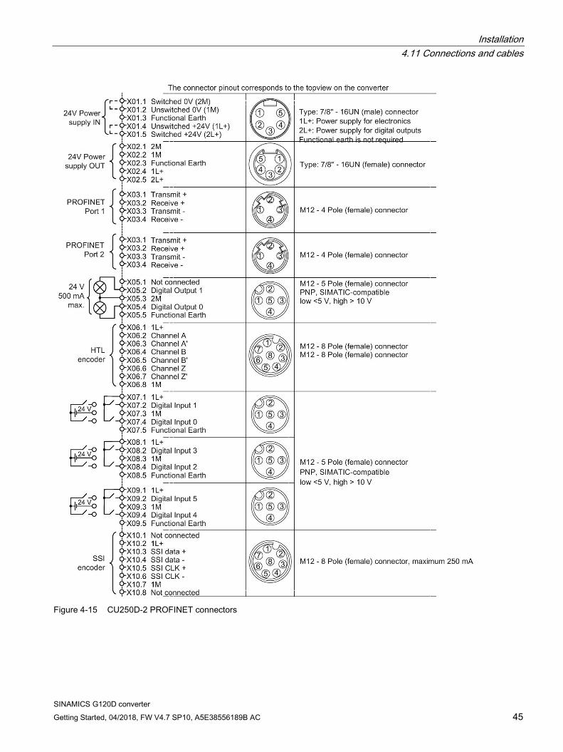
Figure 4-15 CU250D-2 PROFINET connectors

Installation 4.11 Connections and cables
SINAMICS G120D converter 46 Getting Started, 04/2018, FW V4.7 SP10, A5E38556189B AC
Figure 4-16 CU250D-2 PROFINET Push-Pull connectors
Installation 4.11 Connections and cables
SINAMICS G120D converter Getting Started, 04/2018, FW V4.7 SP10, A5E38556189B AC 47
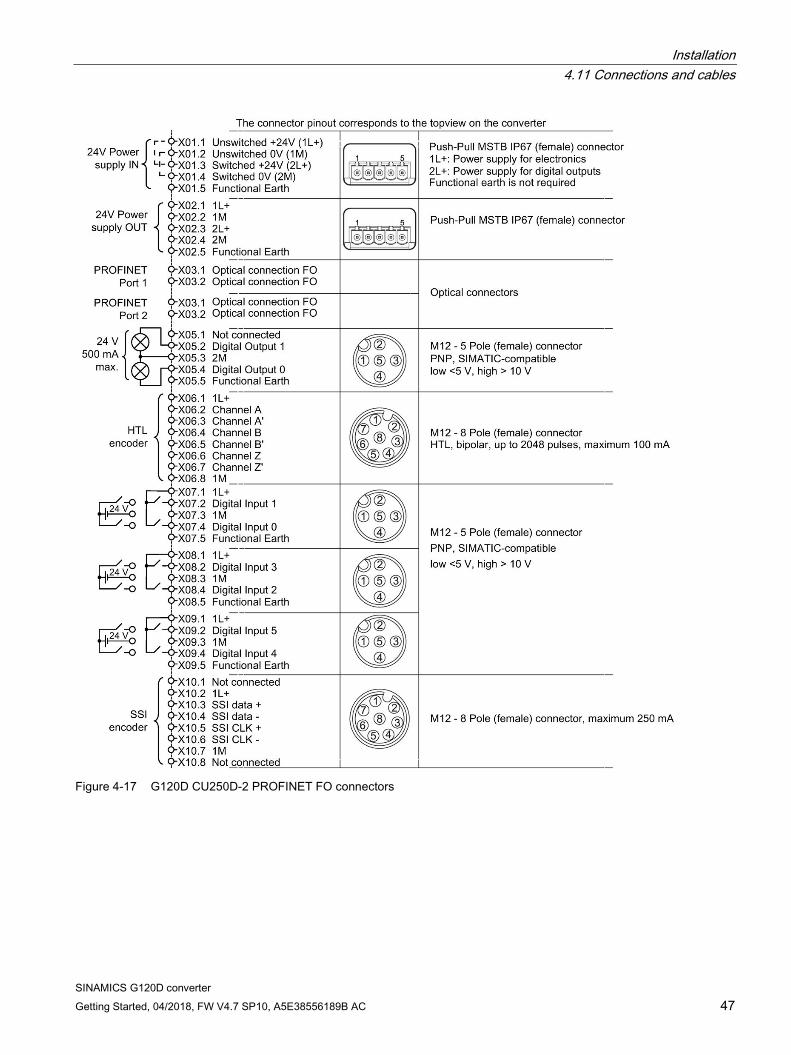
Figure 4-17 G120D CU250D-2 PROFINET FO connectors
Installation 4.11 Connections and cables
SINAMICS G120D converter 48 Getting Started, 04/2018, FW V4.7 SP10, A5E38556189B AC
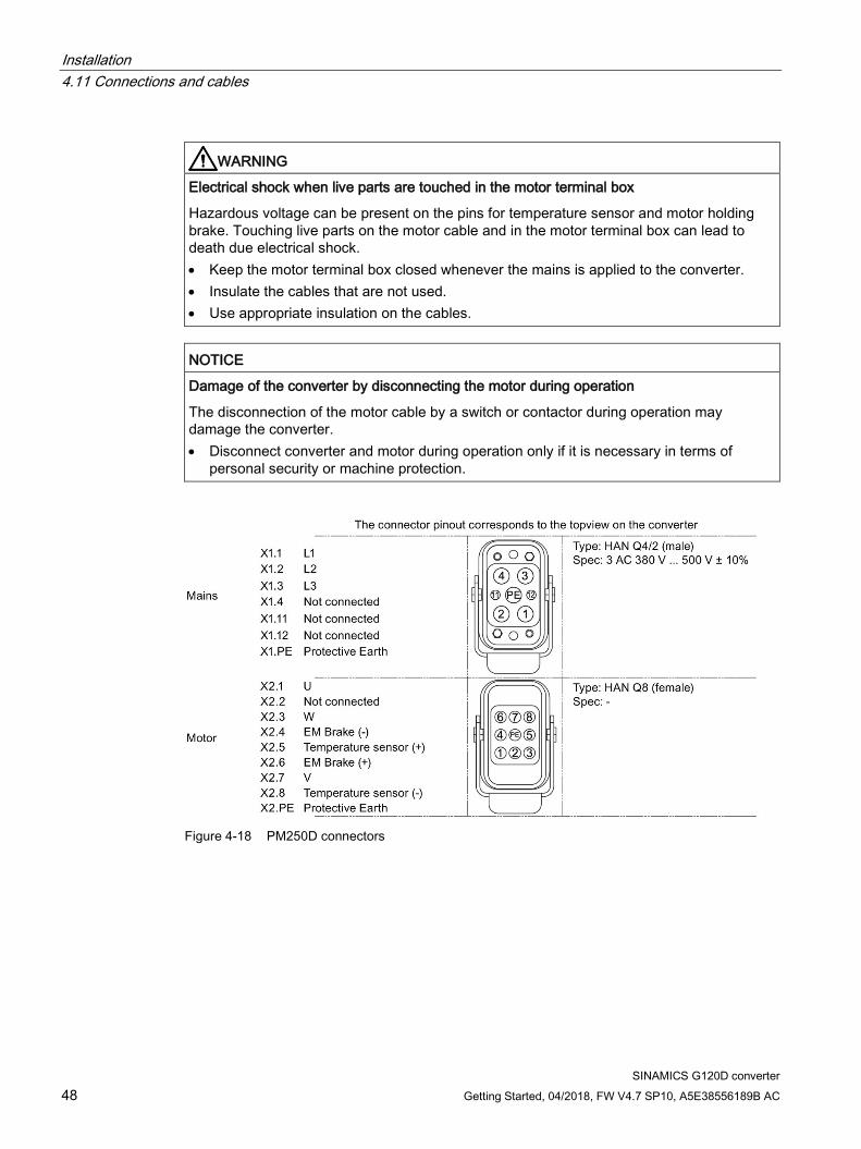
WARNING
Electrical shock when live parts are touched in the motor terminal box
Hazardous voltage can be present on the pins for temperature sensor and motor holding brake. Touching live parts on the motor cable and in the motor terminal box can lead to death due electrical shock. • Keep the motor terminal box closed whenever the mains is applied to the converter. • Insulate the cables that are not used. • Use appropriate insulation on the cables.
NOTICE
Damage of the converter by disconnecting the motor during operation
The disconnection of the motor cable by a switch or contactor during operation may damage the converter. • Disconnect converter and motor during operation only if it is necessary in terms of
personal security or machine protection.
Figure 4-18 PM250D connectors
Installation 4.11 Connections and cables
SINAMICS G120D converter Getting Started, 04/2018, FW V4.7 SP10, A5E38556189B AC 49
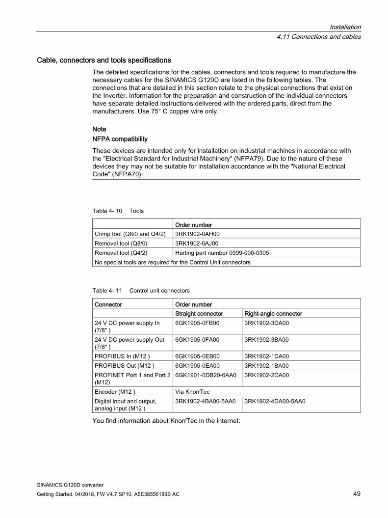
Cable, connectors and tools specifications The detailed specifications for the cables, connectors and tools required to manufacture the necessary cables for the SINAMICS G120D are listed in the following tables. The connections that are detailed in this section relate to the physical connections that exist on the Inverter. Information for the preparation and construction of the individual connectors have separate detailed instructions delivered with the ordered parts, direct from the manufacturers. Use 75° C copper wire only.
Note NFPA compatibility
These devices are intended only for installation on industrial machines in accordance with the "Electrical Standard for Industrial Machinery" (NFPA79). Due to the nature of these devices they may not be suitable for installation accordance with the "National Electrical Code" (NFPA70).
Table 4- 10 Tools
Order number Crimp tool (Q8/0 and Q4/2) 3RK1902-0AH00 Removal tool (Q8/0) 3RK1902-0AJ00 Removal tool (Q4/2) Harting part number 0999-000-0305 No special tools are required for the Control Unit connectors
Table 4- 11 Control unit connectors
Connector Order number Straight connector Right-angle connector 24 V DC power supply In (7/8" )
6GK1905-0FB00 3RK1902-3DA00
24 V DC power supply Out (7/8" )
6GK1905-0FA00 3RK1902-3BA00
PROFIBUS In (M12 ) 6GK1905-0EB00 3RK1902-1DA00 PROFIBUS Out (M12 ) 6GK1905-0EA00 3RK1902-1BA00 PROFINET Port 1 and Port 2 (M12)
6GK1901-0DB20-6AA0 3RK1902-2DA00
Encoder (M12 ) Via KnorrTec Digital input and output, analog input (M12 )
3RK1902-4BA00-5AA0 3RK1902-4DA00-5AA0
You find information about KnorrTec in the internet:
Installation 4.11 Connections and cables
SINAMICS G120D converter 50 Getting Started, 04/2018, FW V4.7 SP10, A5E38556189B AC
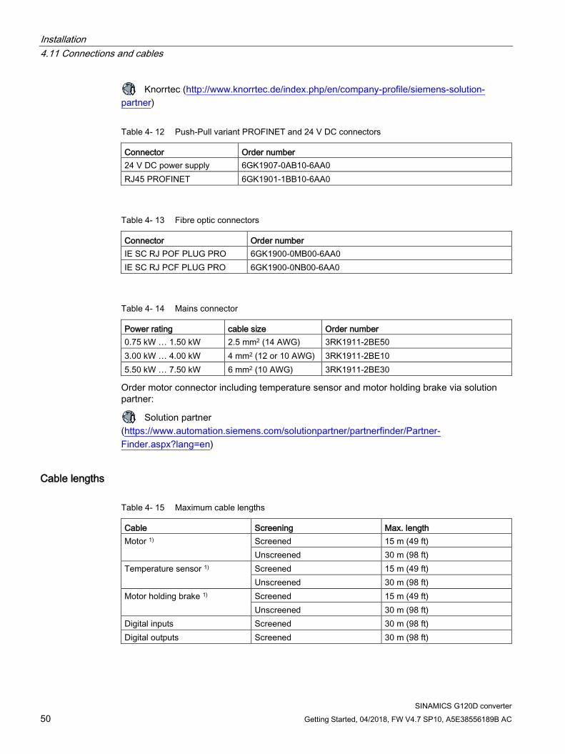
Knorrtec (http://www.knorrtec.de/index.php/en/company-profile/siemens-solution-partner)
Table 4- 12 Push-Pull variant PROFINET and 24 V DC connectors
Connector Order number 24 V DC power supply 6GK1907-0AB10-6AA0 RJ45 PROFINET 6GK1901-1BB10-6AA0
Table 4- 13 Fibre optic connectors
Connector Order number IE SC RJ POF PLUG PRO 6GK1900-0MB00-6AA0 IE SC RJ PCF PLUG PRO 6GK1900-0NB00-6AA0
Table 4- 14 Mains connector
Power rating cable size Order number 0.75 kW … 1.50 kW 2.5 mm2 (14 AWG) 3RK1911-2BE50 3.00 kW … 4.00 kW 4 mm2 (12 or 10 AWG) 3RK1911-2BE10 5.50 kW … 7.50 kW 6 mm2 (10 AWG) 3RK1911-2BE30
Order motor connector including temperature sensor and motor holding brake via solution partner:
Solution partner (https://www.automation.siemens.com/solutionpartner/partnerfinder/Partner-Finder.aspx?lang=en)
Cable lengths
Table 4- 15 Maximum cable lengths
Cable Screening Max. length Motor 1) Screened 15 m (49 ft)
Unscreened 30 m (98 ft) Temperature sensor 1) Screened 15 m (49 ft)
Unscreened 30 m (98 ft) Motor holding brake 1) Screened 15 m (49 ft)
Unscreened 30 m (98 ft) Digital inputs Screened 30 m (98 ft) Digital outputs Screened 30 m (98 ft)
Installation 4.11 Connections and cables
SINAMICS G120D converter Getting Started, 04/2018, FW V4.7 SP10, A5E38556189B AC 51
Cable Screening Max. length Analog input Screened 30 m (98 ft) Encoder Screened 30 m (98 ft) 1) The motor, temperature sensor and motor holding brake are connected through a hybrid cable to
the inverter using a Harting connector.
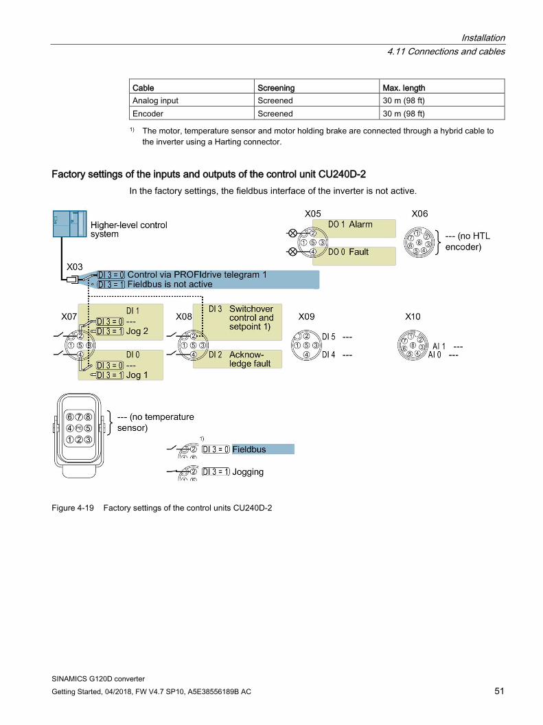
Factory settings of the inputs and outputs of the control unit CU240D-2 In the factory settings, the fieldbus interface of the inverter is not active.
Figure 4-19 Factory settings of the control units CU240D-2
Installation 4.11 Connections and cables
SINAMICS G120D converter 52 Getting Started, 04/2018, FW V4.7 SP10, A5E38556189B AC
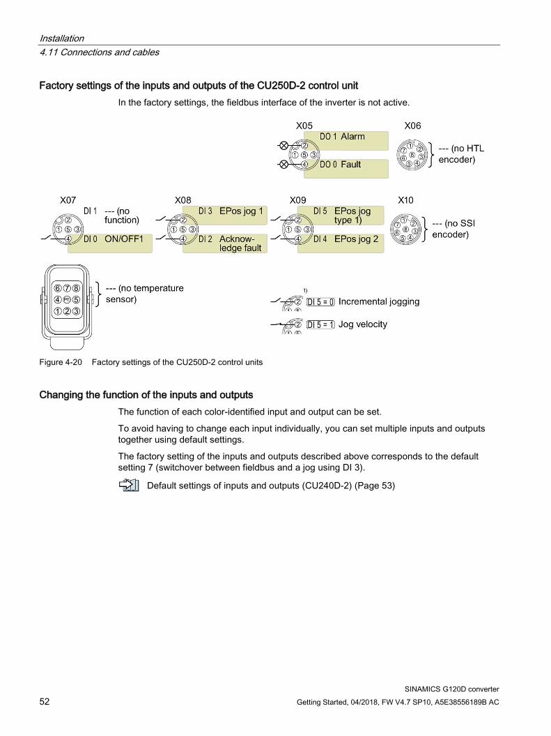
Factory settings of the inputs and outputs of the CU250D-2 control unit In the factory settings, the fieldbus interface of the inverter is not active.
Figure 4-20 Factory settings of the CU250D-2 control units
Changing the function of the inputs and outputs The function of each color-identified input and output can be set.
To avoid having to change each input individually, you can set multiple inputs and outputs together using default settings.
The factory setting of the inputs and outputs described above corresponds to the default setting 7 (switchover between fieldbus and a jog using DI 3).
Default settings of inputs and outputs (CU240D-2) (Page 53)
Installation 4.12 Default settings of inputs and outputs (CU240D-2)
SINAMICS G120D converter Getting Started, 04/2018, FW V4.7 SP10, A5E38556189B AC 53
4.12 Default settings of inputs and outputs (CU240D-2)
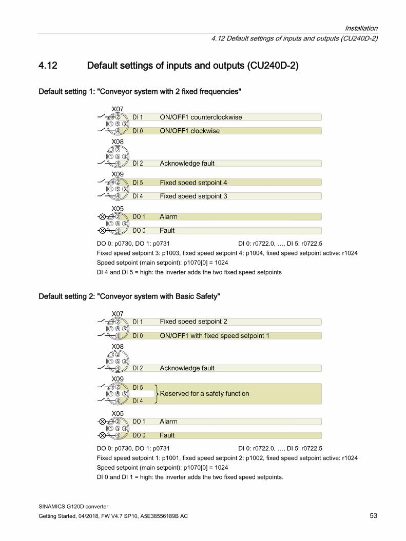
Default setting 1: "Conveyor system with 2 fixed frequencies"
DO 0: p0730, DO 1: p0731 DI 0: r0722.0, …, DI 5: r0722.5 Fixed speed setpoint 3: p1003, fixed speed setpoint 4: p1004, fixed speed setpoint active: r1024 Speed setpoint (main setpoint): p1070[0] = 1024 DI 4 and DI 5 = high: the inverter adds the two fixed speed setpoints
Default setting 2: "Conveyor system with Basic Safety"
DO 0: p0730, DO 1: p0731 DI 0: r0722.0, …, DI 5: r0722.5 Fixed speed setpoint 1: p1001, fixed speed setpoint 2: p1002, fixed speed setpoint active: r1024 Speed setpoint (main setpoint): p1070[0] = 1024 DI 0 and DI 1 = high: the inverter adds the two fixed speed setpoints.
Installation 4.12 Default settings of inputs and outputs (CU240D-2)
SINAMICS G120D converter 54 Getting Started, 04/2018, FW V4.7 SP10, A5E38556189B AC
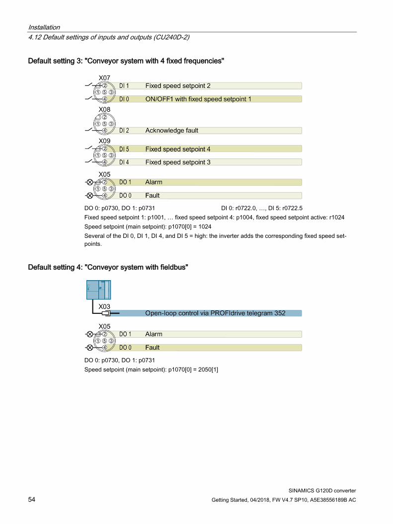
Default setting 3: "Conveyor system with 4 fixed frequencies"
DO 0: p0730, DO 1: p0731 DI 0: r0722.0, …, DI 5: r0722.5 Fixed speed setpoint 1: p1001, … fixed speed setpoint 4: p1004, fixed speed setpoint active: r1024 Speed setpoint (main setpoint): p1070[0] = 1024 Several of the DI 0, DI 1, DI 4, and DI 5 = high: the inverter adds the corresponding fixed speed set-points.
Default setting 4: "Conveyor system with fieldbus"
DO 0: p0730, DO 1: p0731 Speed setpoint (main setpoint): p1070[0] = 2050[1]
Installation 4.12 Default settings of inputs and outputs (CU240D-2)
SINAMICS G120D converter Getting Started, 04/2018, FW V4.7 SP10, A5E38556189B AC 55
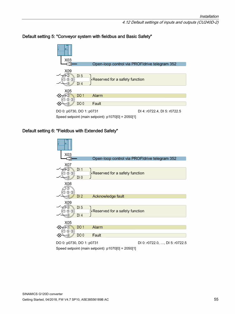
Default setting 5: "Conveyor system with fieldbus and Basic Safety"
DO 0: p0730, DO 1: p0731 DI 4: r0722.4, DI 5: r0722.5 Speed setpoint (main setpoint): p1070[0] = 2050[1]
Default setting 6: "Fieldbus with Extended Safety"
DO 0: p0730, DO 1: p0731 DI 0: r0722.0, …, DI 5: r0722.5 Speed setpoint (main setpoint): p1070[0] = 2050[1]
Installation 4.12 Default settings of inputs and outputs (CU240D-2)
SINAMICS G120D converter 56 Getting Started, 04/2018, FW V4.7 SP10, A5E38556189B AC
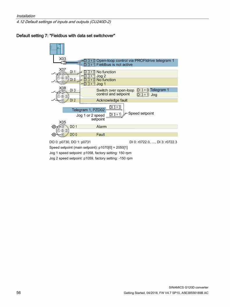
Default setting 7: "Fieldbus with data set switchover"
DO 0: p0730, DO 1: p0731 DI 0: r0722.0, …, DI 3: r0722.3 Speed setpoint (main setpoint): p1070[0] = 2050[1] Jog 1 speed setpoint: p1058, factory setting: 150 rpm Jog 2 speed setpoint: p1059, factory setting: -150 rpm
Installation 4.12 Default settings of inputs and outputs (CU240D-2)
SINAMICS G120D converter Getting Started, 04/2018, FW V4.7 SP10, A5E38556189B AC 57
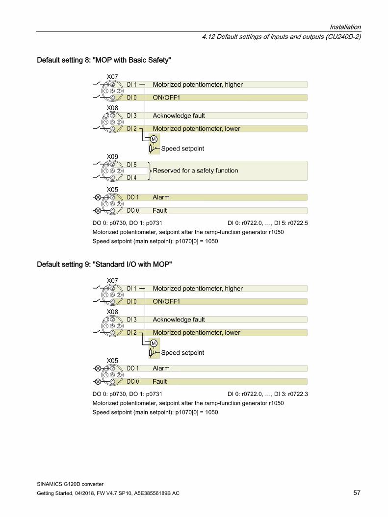
Default setting 8: "MOP with Basic Safety"
DO 0: p0730, DO 1: p0731 DI 0: r0722.0, …, DI 5: r0722.5 Motorized potentiometer, setpoint after the ramp-function generator r1050 Speed setpoint (main setpoint): p1070[0] = 1050
Default setting 9: "Standard I/O with MOP"
DO 0: p0730, DO 1: p0731 DI 0: r0722.0, …, DI 3: r0722.3 Motorized potentiometer, setpoint after the ramp-function generator r1050 Speed setpoint (main setpoint): p1070[0] = 1050
Installation 4.12 Default settings of inputs and outputs (CU240D-2)
SINAMICS G120D converter 58 Getting Started, 04/2018, FW V4.7 SP10, A5E38556189B AC
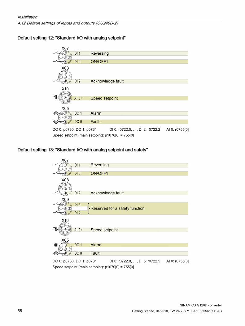
Default setting 12: "Standard I/O with analog setpoint"
DO 0: p0730, DO 1: p0731 DI 0: r0722.0, …, DI 2: r0722.2 AI 0: r0755[0] Speed setpoint (main setpoint): p1070[0] = 755[0]
Default setting 13: "Standard I/O with analog setpoint and safety"
DO 0: p0730, DO 1: p0731 DI 0: r0722.0, …, DI 5: r0722.5 AI 0: r0755[0] Speed setpoint (main setpoint): p1070[0] = 755[0]
Installation 4.12 Default settings of inputs and outputs (CU240D-2)
SINAMICS G120D converter Getting Started, 04/2018, FW V4.7 SP10, A5E38556189B AC 59
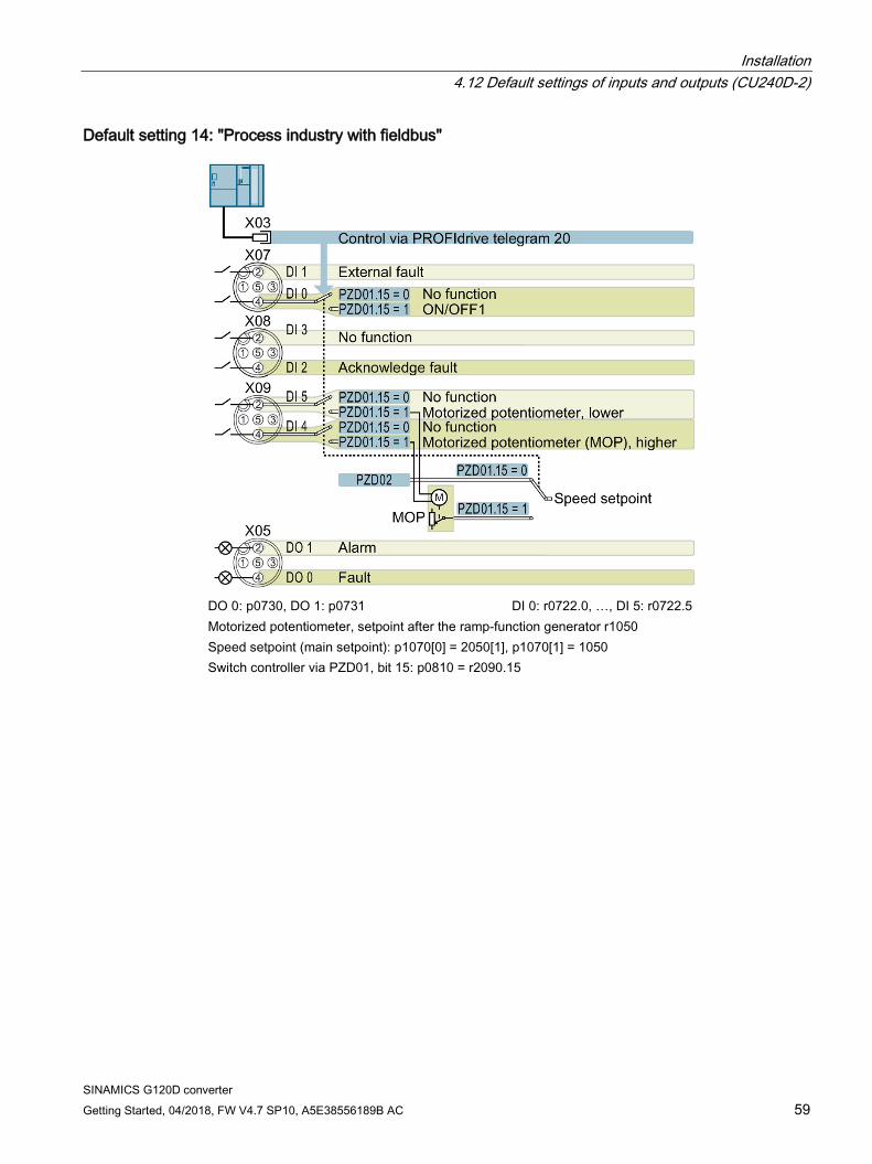
Default setting 14: "Process industry with fieldbus"
DO 0: p0730, DO 1: p0731 DI 0: r0722.0, …, DI 5: r0722.5 Motorized potentiometer, setpoint after the ramp-function generator r1050 Speed setpoint (main setpoint): p1070[0] = 2050[1], p1070[1] = 1050 Switch controller via PZD01, bit 15: p0810 = r2090.15
Installation 4.12 Default settings of inputs and outputs (CU240D-2)
SINAMICS G120D converter 60 Getting Started, 04/2018, FW V4.7 SP10, A5E38556189B AC
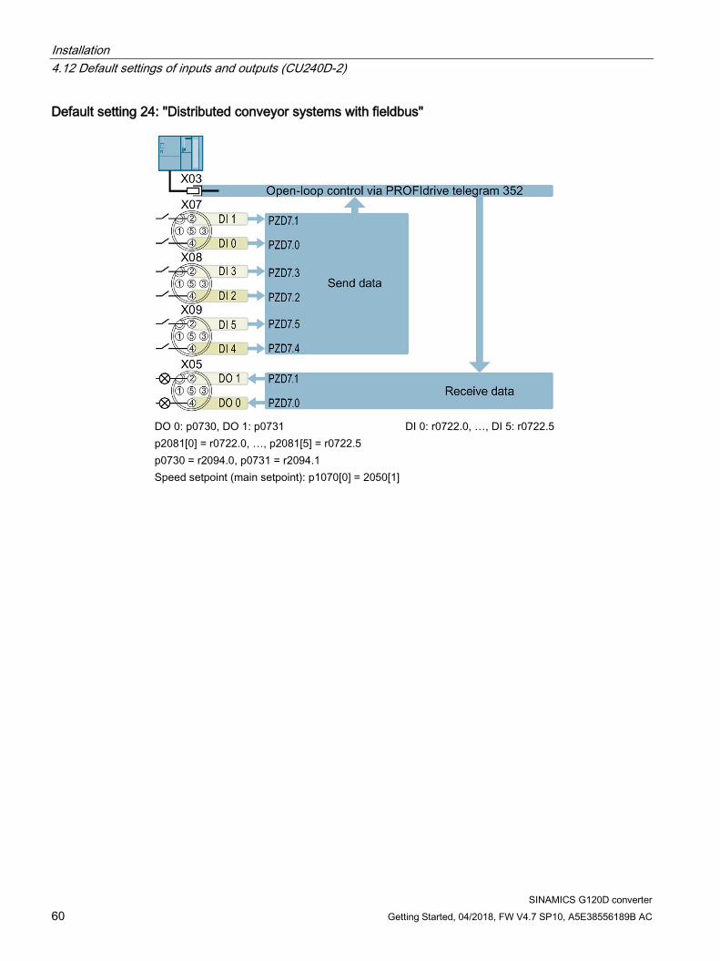
Default setting 24: "Distributed conveyor systems with fieldbus"
DO 0: p0730, DO 1: p0731 DI 0: r0722.0, …, DI 5: r0722.5 p2081[0] = r0722.0, …, p2081[5] = r0722.5 p0730 = r2094.0, p0731 = r2094.1 Speed setpoint (main setpoint): p1070[0] = 2050[1]
Installation 4.12 Default settings of inputs and outputs (CU240D-2)
SINAMICS G120D converter Getting Started, 04/2018, FW V4.7 SP10, A5E38556189B AC 61
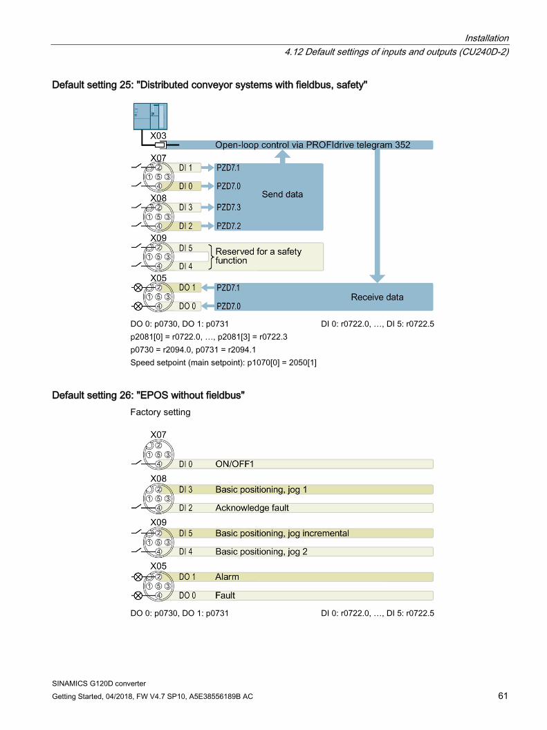
Default setting 25: "Distributed conveyor systems with fieldbus, safety"
DO 0: p0730, DO 1: p0731 DI 0: r0722.0, …, DI 5: r0722.5 p2081[0] = r0722.0, …, p2081[3] = r0722.3 p0730 = r2094.0, p0731 = r2094.1 Speed setpoint (main setpoint): p1070[0] = 2050[1]
Default setting 26: "EPOS without fieldbus" Factory setting
DO 0: p0730, DO 1: p0731 DI 0: r0722.0, …, DI 5: r0722.5
Installation 4.13 Settings PROFIBUS DP address with DIP switches
SINAMICS G120D converter 62 Getting Started, 04/2018, FW V4.7 SP10, A5E38556189B AC
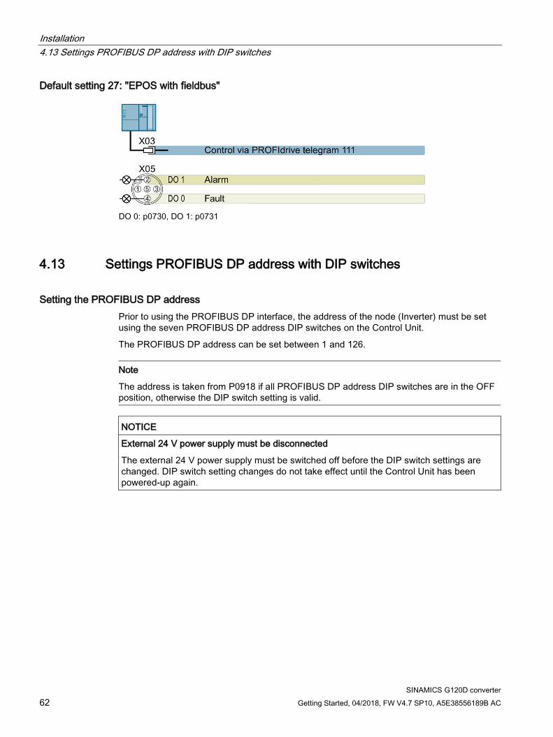
Default setting 27: "EPOS with fieldbus"
DO 0: p0730, DO 1: p0731
4.13 Settings PROFIBUS DP address with DIP switches
Setting the PROFIBUS DP address Prior to using the PROFIBUS DP interface, the address of the node (Inverter) must be set using the seven PROFIBUS DP address DIP switches on the Control Unit.
The PROFIBUS DP address can be set between 1 and 126.
Note
The address is taken from P0918 if all PROFIBUS DP address DIP switches are in the OFF position, otherwise the DIP switch setting is valid.
NOTICE
External 24 V power supply must be disconnected
The external 24 V power supply must be switched off before the DIP switch settings are changed. DIP switch setting changes do not take effect until the Control Unit has been powered-up again.
Installation 4.14 Connecting the PROFINET interface
SINAMICS G120D converter Getting Started, 04/2018, FW V4.7 SP10, A5E38556189B AC 63
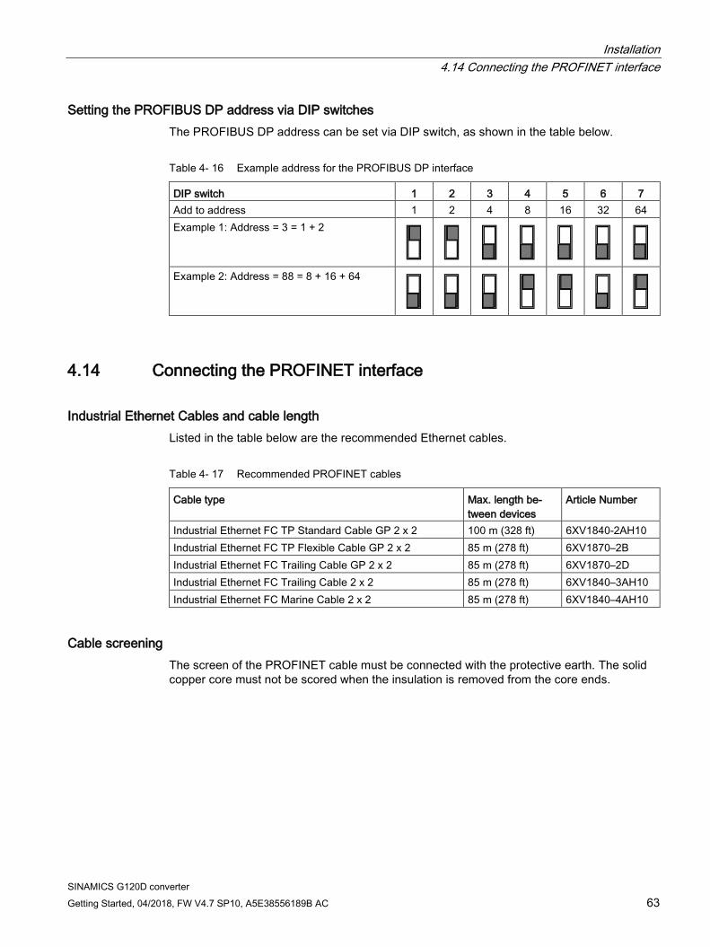
Setting the PROFIBUS DP address via DIP switches The PROFIBUS DP address can be set via DIP switch, as shown in the table below.
Table 4- 16 Example address for the PROFIBUS DP interface
DIP switch 1 2 3 4 5 6 7 Add to address 1 2 4 8 16 32 64 Example 1: Address = 3 = 1 + 2
Example 2: Address = 88 = 8 + 16 + 64
4.14 Connecting the PROFINET interface
Industrial Ethernet Cables and cable length Listed in the table below are the recommended Ethernet cables.
Table 4- 17 Recommended PROFINET cables
Cable type Max. length be-tween devices
Article Number
Industrial Ethernet FC TP Standard Cable GP 2 x 2 100 m (328 ft) 6XV1840-2AH10 Industrial Ethernet FC TP Flexible Cable GP 2 x 2 85 m (278 ft) 6XV1870–2B Industrial Ethernet FC Trailing Cable GP 2 x 2 85 m (278 ft) 6XV1870–2D Industrial Ethernet FC Trailing Cable 2 x 2 85 m (278 ft) 6XV1840–3AH10 Industrial Ethernet FC Marine Cable 2 x 2 85 m (278 ft) 6XV1840–4AH10
Cable screening The screen of the PROFINET cable must be connected with the protective earth. The solid copper core must not be scored when the insulation is removed from the core ends.

Installation 4.14 Connecting the PROFINET interface
SINAMICS G120D converter 64 Getting Started, 04/2018, FW V4.7 SP10, A5E38556189B AC
SINAMICS G120D converter Getting Started, 04/2018, FW V4.7 SP10, A5E38556189B AC 65
Commissioning 5 5.1 Default settings for the SINAMICS G120D
Factory default settings The inverter system is shipped from the factory as a Control Unit and a Power Module. Without any parameterization or after a factory reset, the inverter can be operated without additional parameterization if the inverter default settings (which depend on the inverter type and size) match the following data of a 4-pole motor: Default line supply frequency 50 Hz Rated motor voltage P0304 Rated motor current P0305 Rated motor power P0307 Rated motor frequency P0310 Rated motor speed P0311 (A Siemens standard motor is recommended.) Further, the following conditions must be fulfilled: Control (ON/OFF command) using digital inputs See pre-assigned inputs below. Asyncronous motor P0300 = 1 Self-cooled motor P0335 = 0 Motor overload factor P0640 = 150 % Min. frequency P1080 = 0 Hz Max. frequency P1082 = 50 Hz Ramp-up time P1120 = 10 s Ramp-down time P1121 = 10 s Linear V/f characteristic P1300 = 0
The Control Unit is intended to be control and operate the inverter utilizing the PROFIBUS or PROFINET interface. The PROFIBUS or PROFINET interface may be used to further configure and control the inverter as required.
5.2 Commissioning with the IOP-2
Commission the Inverter The Intelligent Operator Panel 2 (IOP-2) has been designed to enhance the interface and communications capabilities of the SINAMICS Inverters.
Commissioning 5.2 Commissioning with the IOP-2
SINAMICS G120D converter 66 Getting Started, 04/2018, FW V4.7 SP10, A5E38556189B AC
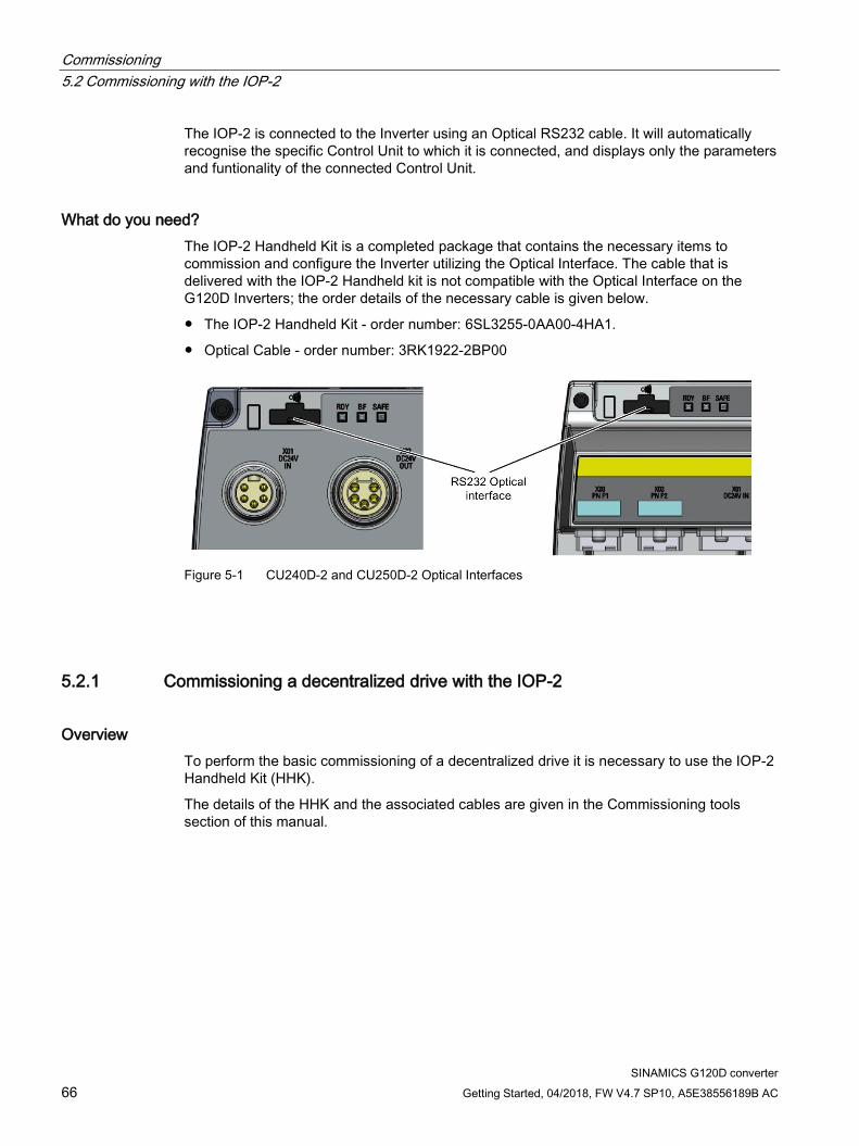
The IOP-2 is connected to the Inverter using an Optical RS232 cable. It will automatically recognise the specific Control Unit to which it is connected, and displays only the parameters and funtionality of the connected Control Unit.
What do you need? The IOP-2 Handheld Kit is a completed package that contains the necessary items to commission and configure the Inverter utilizing the Optical Interface. The cable that is delivered with the IOP-2 Handheld kit is not compatible with the Optical Interface on the G120D Inverters; the order details of the necessary cable is given below.
● The IOP-2 Handheld Kit - order number: 6SL3255-0AA00-4HA1.
● Optical Cable - order number: 3RK1922-2BP00
Figure 5-1 CU240D-2 and CU250D-2 Optical Interfaces
5.2.1 Commissioning a decentralized drive with the IOP-2
Overview To perform the basic commissioning of a decentralized drive it is necessary to use the IOP-2 Handheld Kit (HHK).
The details of the HHK and the associated cables are given in the Commissioning tools section of this manual.
Commissioning 5.2 Commissioning with the IOP-2
SINAMICS G120D converter Getting Started, 04/2018, FW V4.7 SP10, A5E38556189B AC 67
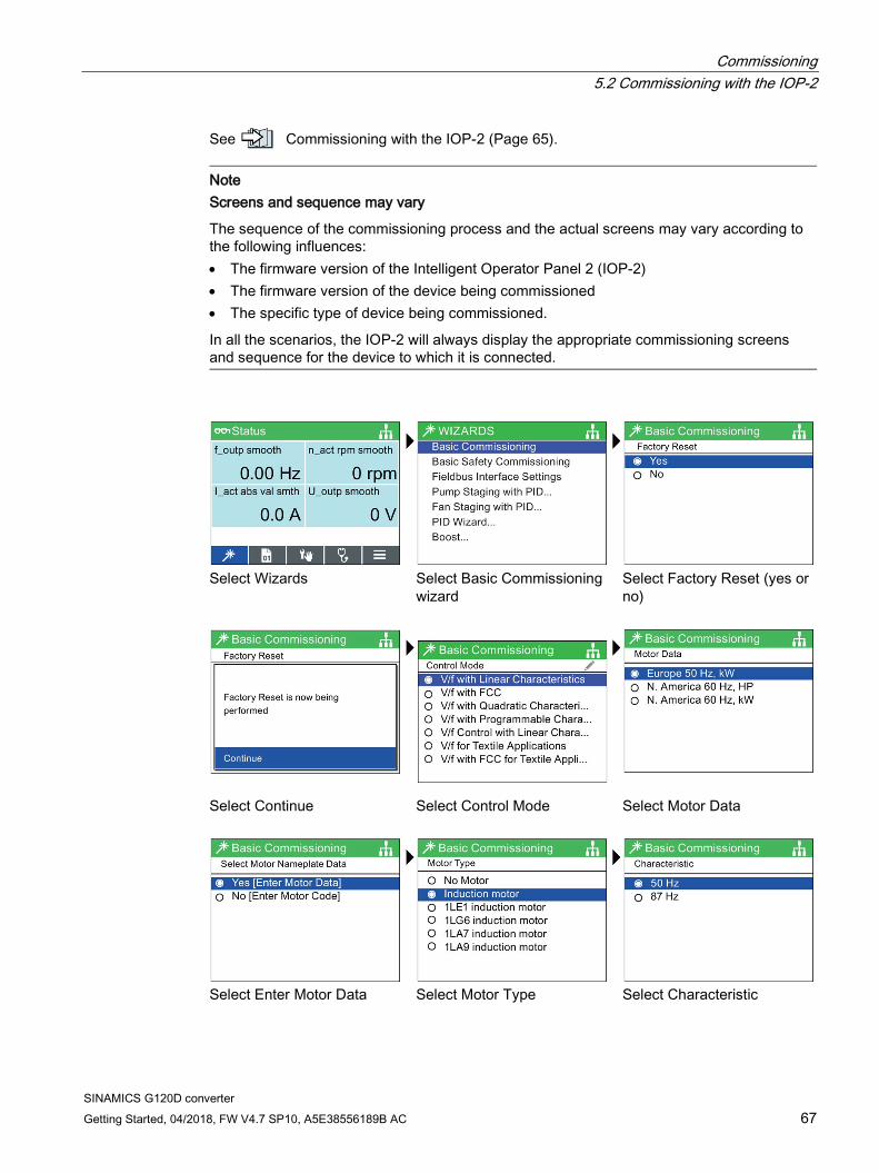
See Commissioning with the IOP-2 (Page 65).
Note Screens and sequence may vary
The sequence of the commissioning process and the actual screens may vary according to the following influences: • The firmware version of the Intelligent Operator Panel 2 (IOP-2) • The firmware version of the device being commissioned • The specific type of device being commissioned.
In all the scenarios, the IOP-2 will always display the appropriate commissioning screens and sequence for the device to which it is connected.
Select Wizards Select Basic Commissioning
wizard Select Factory Reset (yes or
no)
Select Continue Select Control Mode Select Motor Data
Select Enter Motor Data Select Motor Type Select Characteristic
Commissioning 5.2 Commissioning with the IOP-2
SINAMICS G120D converter 68 Getting Started, 04/2018, FW V4.7 SP10, A5E38556189B AC
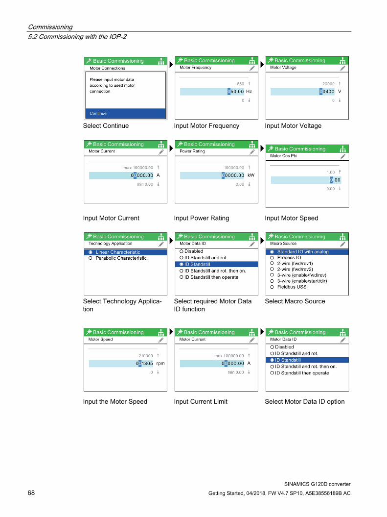
Select Continue Input Motor Frequency Input Motor Voltage
Input Motor Current Input Power Rating Input Motor Speed
Select Technology Applica-tion
Select required Motor Data ID function
Select Macro Source
Input the Motor Speed Input Current Limit Select Motor Data ID option
Commissioning 5.2 Commissioning with the IOP-2
SINAMICS G120D converter Getting Started, 04/2018, FW V4.7 SP10, A5E38556189B AC 69
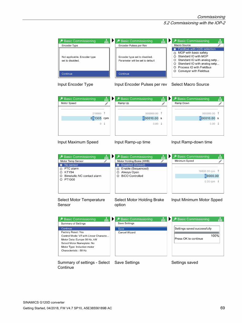
Input Encoder Type Input Encoder Pulses per rev Select Macro Source
Input Maximum Speed Input Ramp-up time Input Ramp-down time
Select Motor Temperature Sensor
Select Motor Holding Brake option
Input Minimum Motor Spped
Summary of settings - Select Continue
Save Settings Settings saved
Commissioning 5.3 Commissioning the application
SINAMICS G120D converter 70 Getting Started, 04/2018, FW V4.7 SP10, A5E38556189B AC
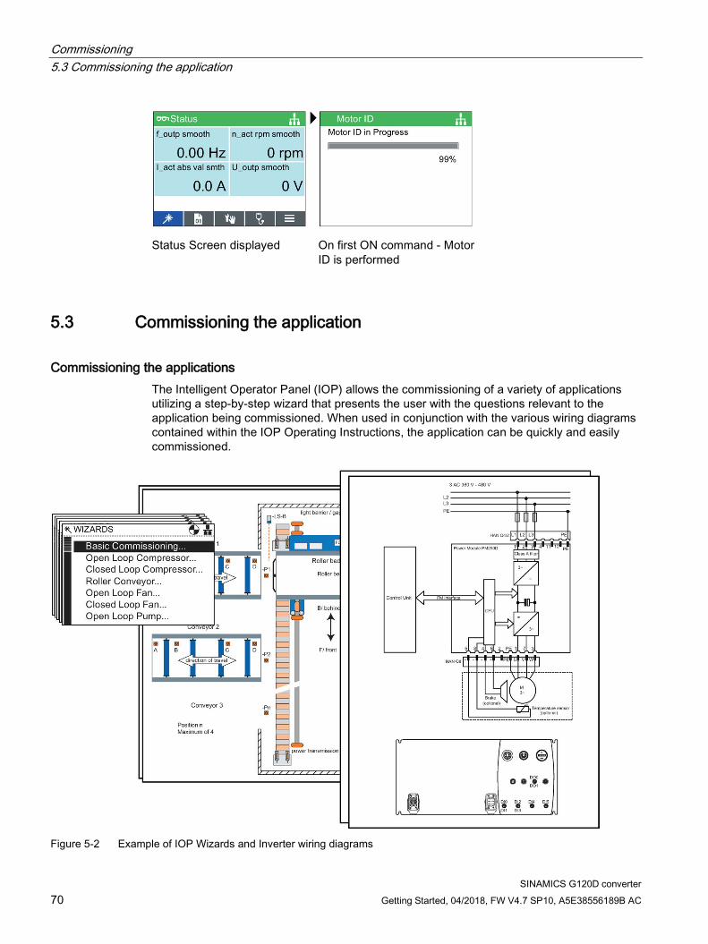
Status Screen displayed On first ON command - Motor ID is performed
5.3 Commissioning the application
Commissioning the applications The Intelligent Operator Panel (IOP) allows the commissioning of a variety of applications utilizing a step-by-step wizard that presents the user with the questions relevant to the application being commissioned. When used in conjunction with the various wiring diagrams contained within the IOP Operating Instructions, the application can be quickly and easily commissioned.
Figure 5-2 Example of IOP Wizards and Inverter wiring diagrams
Commissioning 5.4 Reset Parameters to Factory Settings
SINAMICS G120D converter Getting Started, 04/2018, FW V4.7 SP10, A5E38556189B AC 71
5.4 Reset Parameters to Factory Settings
Overview With a factory reset via P0970 the initial state of the all the inverter parameters can be re-established.
The factory setting values are designated as "Factory setting" in the Parameter Manual.
For further information, refer to the section "Factory Settings of the Control Unit" in this manual.
Note
When resetting the parameters to the factory setting, the communications memory is re-initialized. This means that communications are interrupted for the time it takes to perform the reset.
WARNING
Parameter reset in case of CUs with fail-safe functions
Parameters that don't relate to fail-safe functions are reset with P0970 = 1.
To reset parameters that relate to fail-safe functions an additional parameter reset with P0970 = 5 must be performed. This parameter reset is password protected.
In case of a parameter reset with P0970 = 5 an acceptance test necessary.

Commissioning 5.4 Reset Parameters to Factory Settings
SINAMICS G120D converter 72 Getting Started, 04/2018, FW V4.7 SP10, A5E38556189B AC
SINAMICS G120D converter Getting Started, 04/2018, FW V4.7 SP10, A5E38556189B AC 73
Troubleshooting and further information 6 6.1 Operating states indicated on LEDs
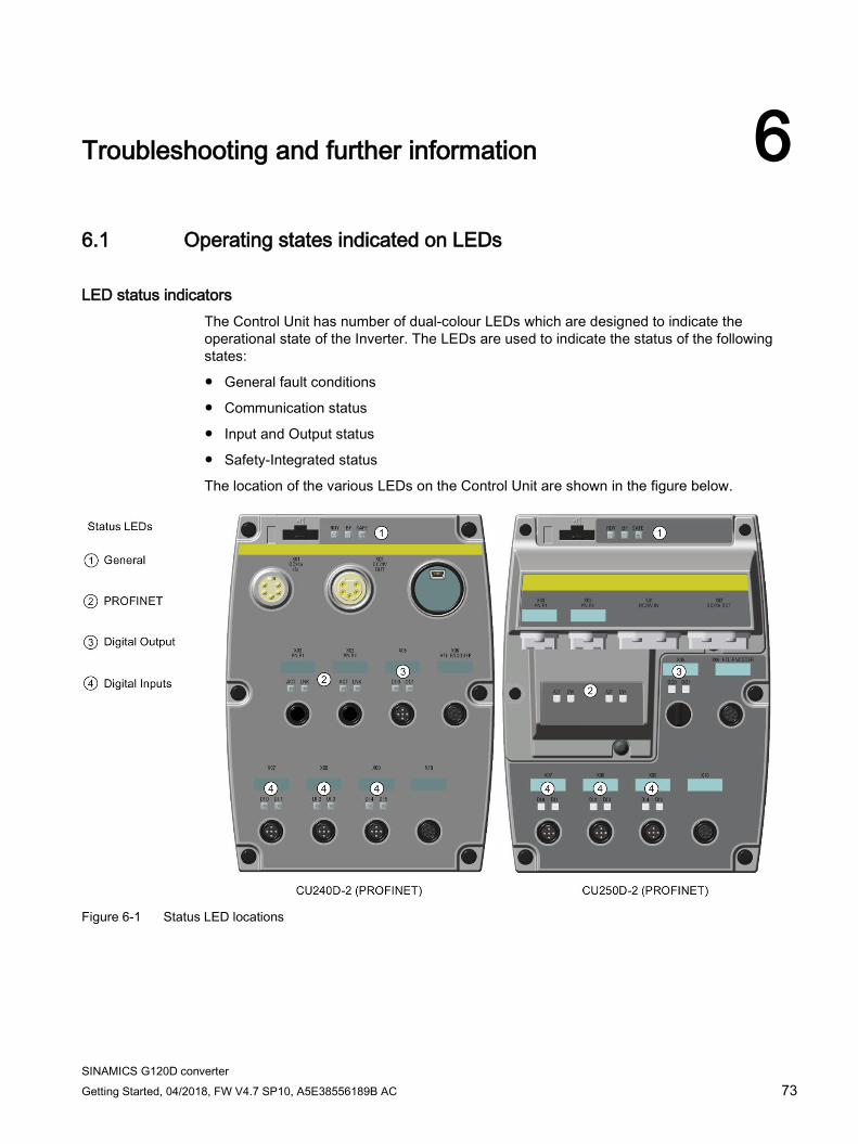
LED status indicators The Control Unit has number of dual-colour LEDs which are designed to indicate the operational state of the Inverter. The LEDs are used to indicate the status of the following states:
● General fault conditions
● Communication status
● Input and Output status
● Safety-Integrated status
The location of the various LEDs on the Control Unit are shown in the figure below.
Figure 6-1 Status LED locations
Troubleshooting and further information 6.1 Operating states indicated on LEDs
SINAMICS G120D converter 74 Getting Started, 04/2018, FW V4.7 SP10, A5E38556189B AC
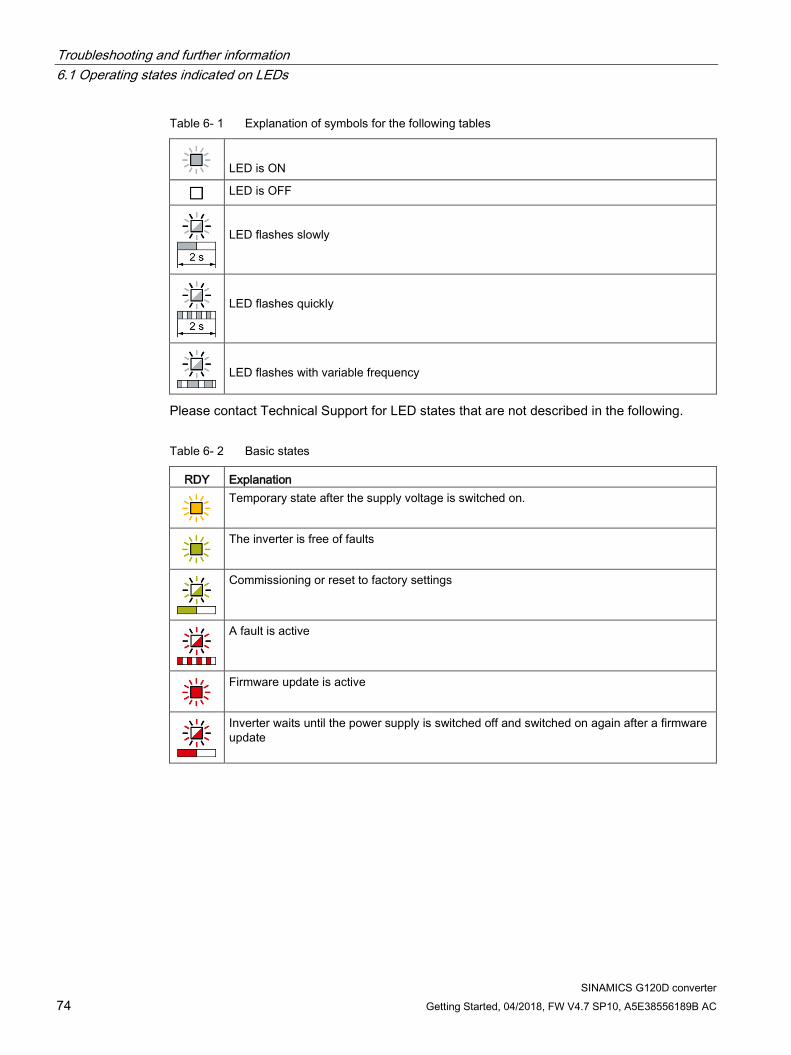
Table 6- 1 Explanation of symbols for the following tables
LED is ON
LED is OFF
LED flashes slowly
LED flashes quickly
LED flashes with variable frequency
Please contact Technical Support for LED states that are not described in the following.
Table 6- 2 Basic states
RDY Explanation
Temporary state after the supply voltage is switched on.
The inverter is free of faults
Commissioning or reset to factory settings
A fault is active
Firmware update is active
Inverter waits until the power supply is switched off and switched on again after a firmware update
Troubleshooting and further information 6.2 LED DI/DO
SINAMICS G120D converter Getting Started, 04/2018, FW V4.7 SP10, A5E38556189B AC 75
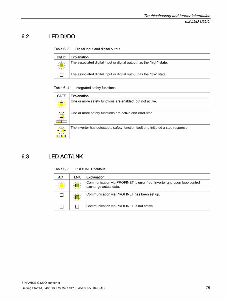
6.2 LED DI/DO
Table 6- 3 Digital input and digital output
DI/DO Explanation
The associated digital input or digital output has the "high" state.
The associated digital input or digital output has the "low" state.
Table 6- 4 Integrated safety functions
SAFE Explanation
One or more safety functions are enabled, but not active.
One or more safety functions are active and error-free.
The inverter has detected a safety function fault and initiated a stop response.
6.3 LED ACT/LNK
Table 6- 5 PROFINET fieldbus
ACT LNK Explanation
Communication via PROFINET is error-free. Inverter and open-loop control exchange actual data.
Communication via PROFINET has been set up.
Communication via PROFINET is not active.
Troubleshooting and further information 6.4 List of alarms and faults
SINAMICS G120D converter 76 Getting Started, 04/2018, FW V4.7 SP10, A5E38556189B AC
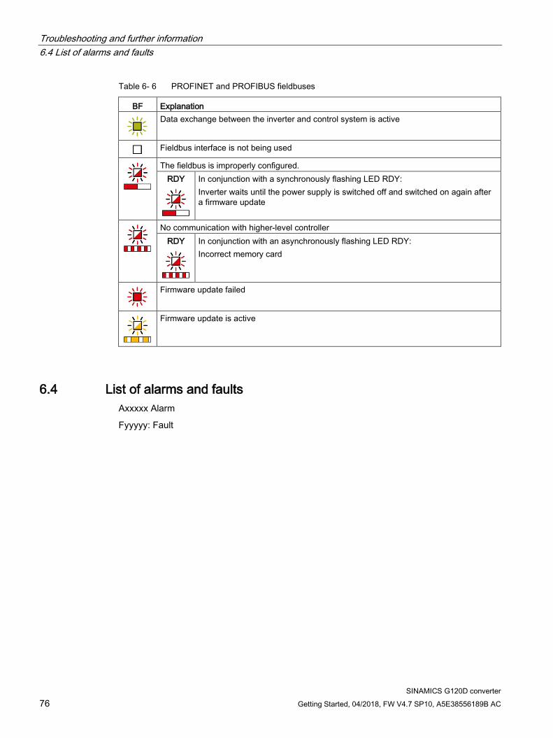
Table 6- 6 PROFINET and PROFIBUS fieldbuses
BF Explanation
Data exchange between the inverter and control system is active
Fieldbus interface is not being used
The fieldbus is improperly configured. RDY
In conjunction with a synchronously flashing LED RDY: Inverter waits until the power supply is switched off and switched on again after a firmware update
No communication with higher-level controller RDY
In conjunction with an asynchronously flashing LED RDY: Incorrect memory card
Firmware update failed
Firmware update is active
6.4 List of alarms and faults Axxxxx Alarm
Fyyyyy: Fault
Troubleshooting and further information 6.4 List of alarms and faults
SINAMICS G120D converter Getting Started, 04/2018, FW V4.7 SP10, A5E38556189B AC 77
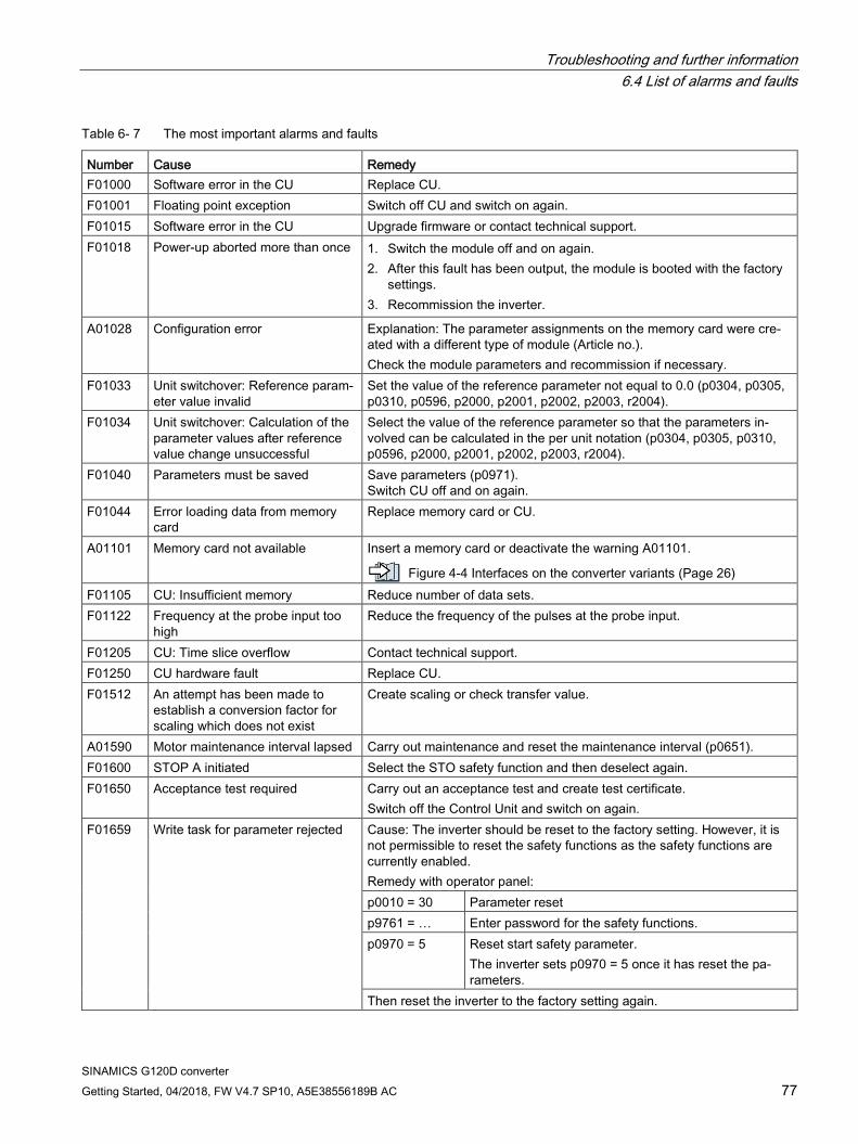
Table 6- 7 The most important alarms and faults
Number Cause Remedy F01000 Software error in the CU Replace CU. F01001 Floating point exception Switch off CU and switch on again. F01015 Software error in the CU Upgrade firmware or contact technical support. F01018 Power-up aborted more than once 1. Switch the module off and on again.
2. After this fault has been output, the module is booted with the factory settings.
3. Recommission the inverter.
A01028 Configuration error Explanation: The parameter assignments on the memory card were cre-ated with a different type of module (Article no.). Check the module parameters and recommission if necessary.
F01033 Unit switchover: Reference param-eter value invalid
Set the value of the reference parameter not equal to 0.0 (p0304, p0305, p0310, p0596, p2000, p2001, p2002, p2003, r2004).
F01034 Unit switchover: Calculation of the parameter values after reference value change unsuccessful
Select the value of the reference parameter so that the parameters in-volved can be calculated in the per unit notation (p0304, p0305, p0310, p0596, p2000, p2001, p2002, p2003, r2004).
F01040 Parameters must be saved Save parameters (p0971). Switch CU off and on again.
F01044 Error loading data from memory card
Replace memory card or CU.
A01101 Memory card not available Insert a memory card or deactivate the warning A01101.
Figure 4-4 Interfaces on the converter variants (Page 26) F01105 CU: Insufficient memory Reduce number of data sets. F01122 Frequency at the probe input too
high Reduce the frequency of the pulses at the probe input.
F01205 CU: Time slice overflow Contact technical support. F01250 CU hardware fault Replace CU. F01512 An attempt has been made to
establish a conversion factor for scaling which does not exist
Create scaling or check transfer value.
A01590 Motor maintenance interval lapsed Carry out maintenance and reset the maintenance interval (p0651). F01600 STOP A initiated Select the STO safety function and then deselect again. F01650 Acceptance test required Carry out an acceptance test and create test certificate.
Switch off the Control Unit and switch on again. F01659 Write task for parameter rejected Cause: The inverter should be reset to the factory setting. However, it is
not permissible to reset the safety functions as the safety functions are currently enabled. Remedy with operator panel: p0010 = 30 Parameter reset p9761 = … Enter password for the safety functions. p0970 = 5 Reset start safety parameter.
The inverter sets p0970 = 5 once it has reset the pa-rameters.
Then reset the inverter to the factory setting again.
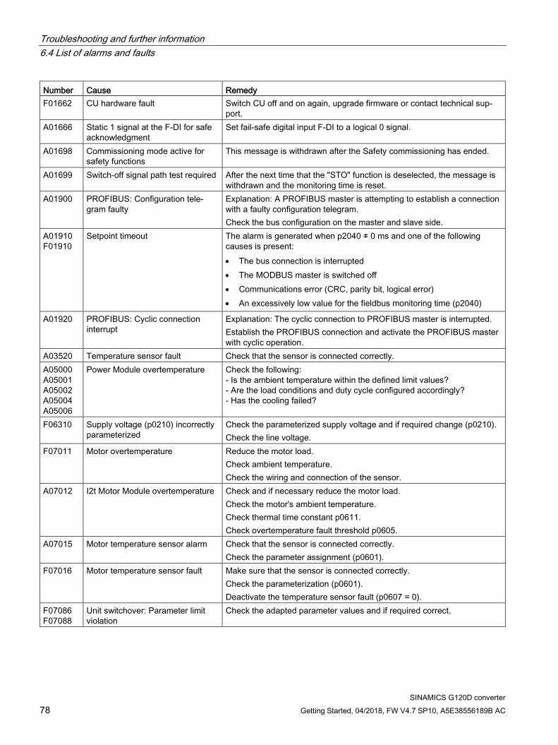
Troubleshooting and further information 6.4 List of alarms and faults
SINAMICS G120D converter 78 Getting Started, 04/2018, FW V4.7 SP10, A5E38556189B AC
Number Cause Remedy F01662 CU hardware fault Switch CU off and on again, upgrade firmware or contact technical sup-
port. A01666 Static 1 signal at the F-DI for safe
acknowledgment Set fail-safe digital input F-DI to a logical 0 signal.
A01698 Commissioning mode active for safety functions
This message is withdrawn after the Safety commissioning has ended.
A01699 Switch-off signal path test required After the next time that the "STO" function is deselected, the message is withdrawn and the monitoring time is reset.
A01900 PROFIBUS: Configuration tele-gram faulty
Explanation: A PROFIBUS master is attempting to establish a connection with a faulty configuration telegram. Check the bus configuration on the master and slave side.
A01910 F01910
Setpoint timeout The alarm is generated when p2040 ≠ 0 ms and one of the following causes is present: • The bus connection is interrupted • The MODBUS master is switched off • Communications error (CRC, parity bit, logical error) • An excessively low value for the fieldbus monitoring time (p2040)
A01920 PROFIBUS: Cyclic connection interrupt
Explanation: The cyclic connection to PROFIBUS master is interrupted. Establish the PROFIBUS connection and activate the PROFIBUS master with cyclic operation.
A03520 Temperature sensor fault Check that the sensor is connected correctly. A05000 A05001 A05002 A05004 A05006
Power Module overtemperature Check the following: - Is the ambient temperature within the defined limit values? - Are the load conditions and duty cycle configured accordingly? - Has the cooling failed?
F06310 Supply voltage (p0210) incorrectly parameterized
Check the parameterized supply voltage and if required change (p0210). Check the line voltage.
F07011 Motor overtemperature Reduce the motor load. Check ambient temperature. Check the wiring and connection of the sensor.
A07012 I2t Motor Module overtemperature Check and if necessary reduce the motor load. Check the motor's ambient temperature. Check thermal time constant p0611. Check overtemperature fault threshold p0605.
A07015 Motor temperature sensor alarm Check that the sensor is connected correctly. Check the parameter assignment (p0601).
F07016 Motor temperature sensor fault Make sure that the sensor is connected correctly. Check the parameterization (p0601). Deactivate the temperature sensor fault (p0607 = 0).
F07086 F07088
Unit switchover: Parameter limit violation
Check the adapted parameter values and if required correct.
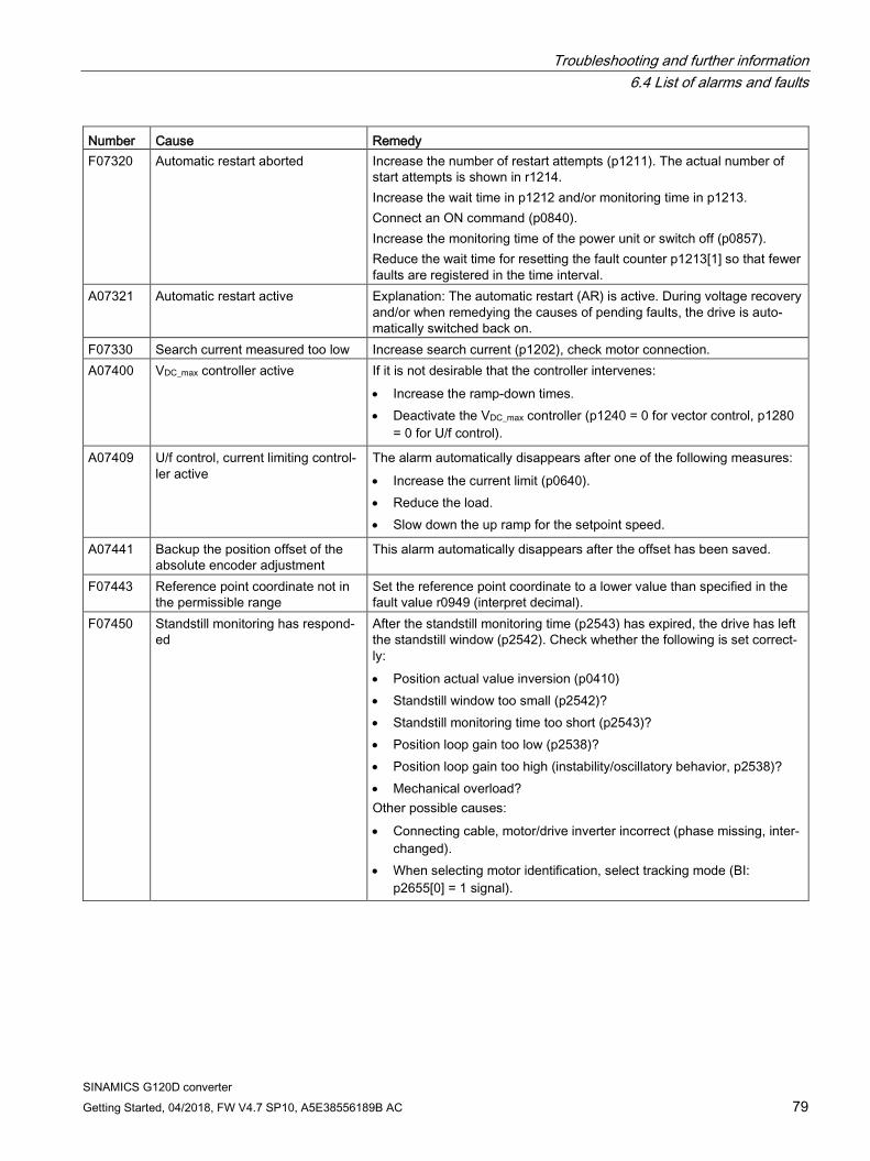
Troubleshooting and further information 6.4 List of alarms and faults
SINAMICS G120D converter Getting Started, 04/2018, FW V4.7 SP10, A5E38556189B AC 79
Number Cause Remedy F07320 Automatic restart aborted Increase the number of restart attempts (p1211). The actual number of
start attempts is shown in r1214. Increase the wait time in p1212 and/or monitoring time in p1213. Connect an ON command (p0840). Increase the monitoring time of the power unit or switch off (p0857). Reduce the wait time for resetting the fault counter p1213[1] so that fewer faults are registered in the time interval.
A07321 Automatic restart active Explanation: The automatic restart (AR) is active. During voltage recovery and/or when remedying the causes of pending faults, the drive is auto-matically switched back on.
F07330 Search current measured too low Increase search current (p1202), check motor connection. A07400 VDC_max controller active If it is not desirable that the controller intervenes:
• Increase the ramp-down times. • Deactivate the VDC_max controller (p1240 = 0 for vector control, p1280
= 0 for U/f control).
A07409 U/f control, current limiting control-ler active
The alarm automatically disappears after one of the following measures: • Increase the current limit (p0640). • Reduce the load. • Slow down the up ramp for the setpoint speed.
A07441 Backup the position offset of the absolute encoder adjustment
This alarm automatically disappears after the offset has been saved.
F07443 Reference point coordinate not in the permissible range
Set the reference point coordinate to a lower value than specified in the fault value r0949 (interpret decimal).
F07450 Standstill monitoring has respond-ed
After the standstill monitoring time (p2543) has expired, the drive has left the standstill window (p2542). Check whether the following is set correct-ly: • Position actual value inversion (p0410) • Standstill window too small (p2542)? • Standstill monitoring time too short (p2543)? • Position loop gain too low (p2538)? • Position loop gain too high (instability/oscillatory behavior, p2538)? • Mechanical overload? Other possible causes: • Connecting cable, motor/drive inverter incorrect (phase missing, inter-
changed). • When selecting motor identification, select tracking mode (BI:
p2655[0] = 1 signal).
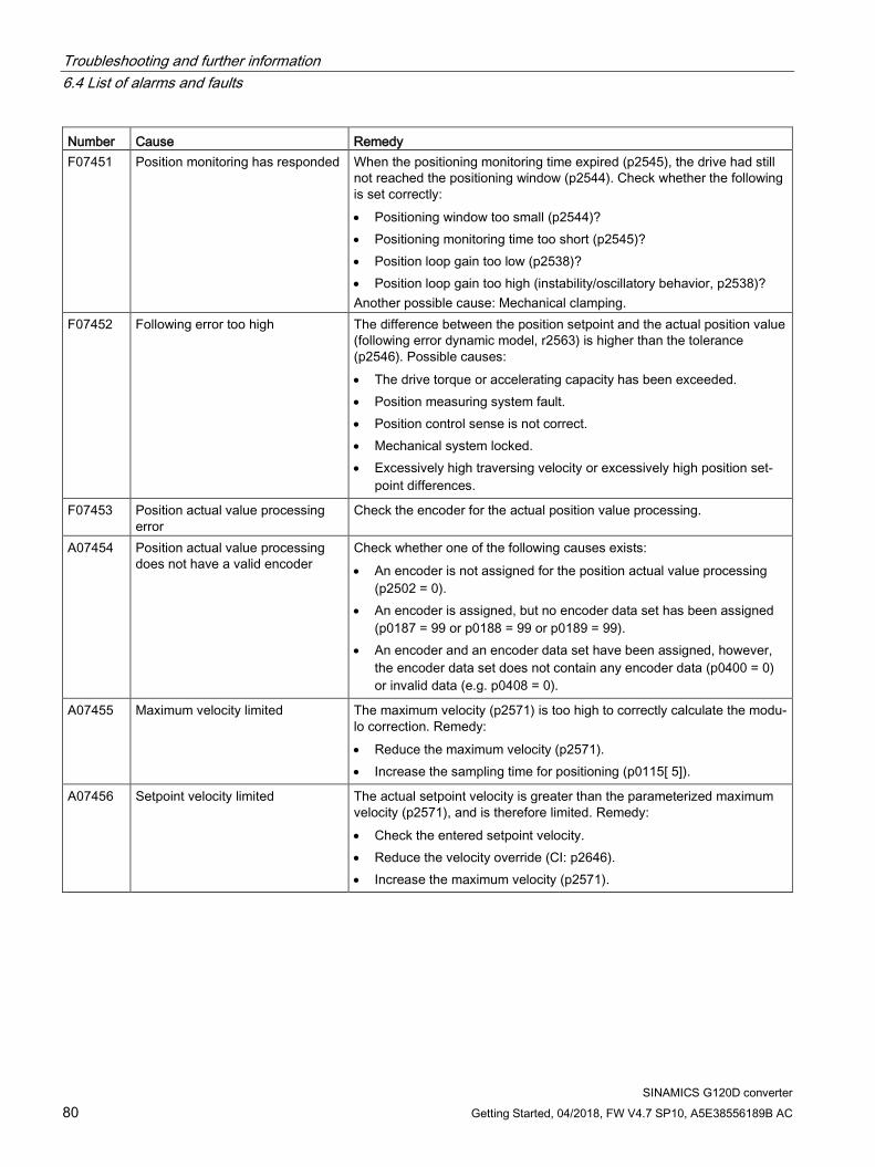
Troubleshooting and further information 6.4 List of alarms and faults
SINAMICS G120D converter 80 Getting Started, 04/2018, FW V4.7 SP10, A5E38556189B AC
Number Cause Remedy F07451 Position monitoring has responded When the positioning monitoring time expired (p2545), the drive had still
not reached the positioning window (p2544). Check whether the following is set correctly: • Positioning window too small (p2544)? • Positioning monitoring time too short (p2545)? • Position loop gain too low (p2538)? • Position loop gain too high (instability/oscillatory behavior, p2538)? Another possible cause: Mechanical clamping.
F07452 Following error too high The difference between the position setpoint and the actual position value (following error dynamic model, r2563) is higher than the tolerance (p2546). Possible causes: • The drive torque or accelerating capacity has been exceeded. • Position measuring system fault. • Position control sense is not correct. • Mechanical system locked. • Excessively high traversing velocity or excessively high position set-
point differences.
F07453 Position actual value processing error
Check the encoder for the actual position value processing.
A07454 Position actual value processing does not have a valid encoder
Check whether one of the following causes exists: • An encoder is not assigned for the position actual value processing
(p2502 = 0). • An encoder is assigned, but no encoder data set has been assigned
(p0187 = 99 or p0188 = 99 or p0189 = 99). • An encoder and an encoder data set have been assigned, however,
the encoder data set does not contain any encoder data (p0400 = 0) or invalid data (e.g. p0408 = 0).
A07455 Maximum velocity limited The maximum velocity (p2571) is too high to correctly calculate the modu-lo correction. Remedy: • Reduce the maximum velocity (p2571). • Increase the sampling time for positioning (p0115[ 5]).
A07456 Setpoint velocity limited The actual setpoint velocity is greater than the parameterized maximum velocity (p2571), and is therefore limited. Remedy: • Check the entered setpoint velocity. • Reduce the velocity override (CI: p2646). • Increase the maximum velocity (p2571).
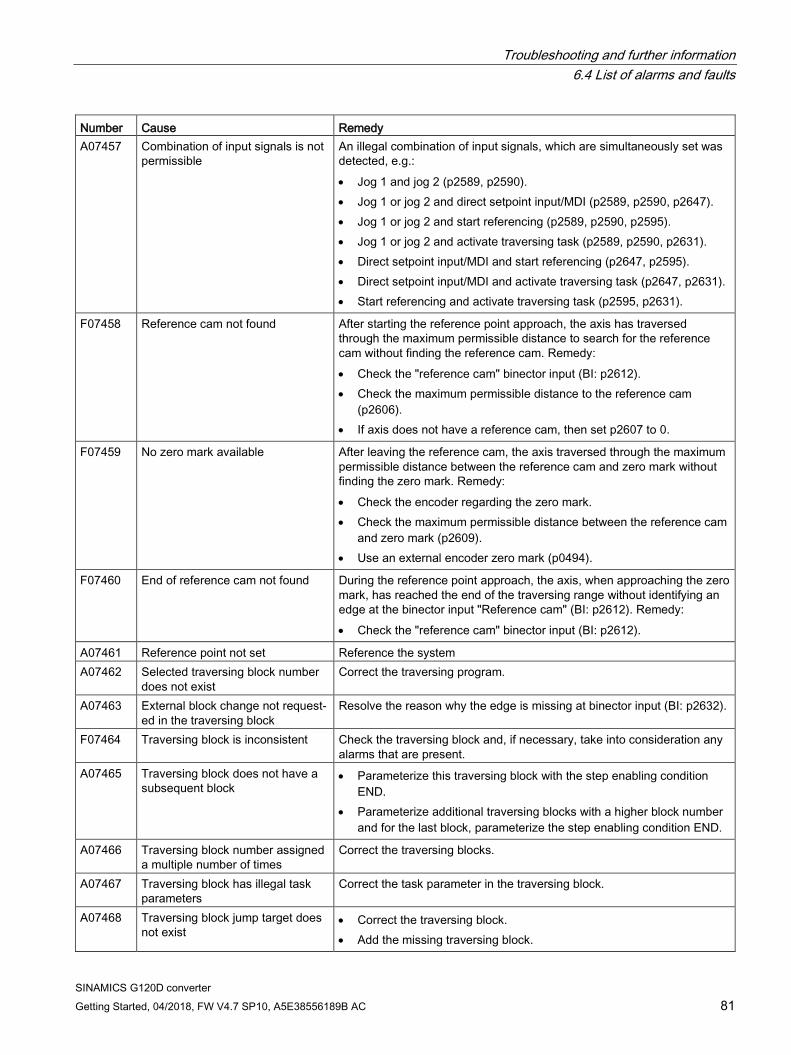
Troubleshooting and further information 6.4 List of alarms and faults
SINAMICS G120D converter Getting Started, 04/2018, FW V4.7 SP10, A5E38556189B AC 81
Number Cause Remedy A07457 Combination of input signals is not
permissible An illegal combination of input signals, which are simultaneously set was detected, e.g.: • Jog 1 and jog 2 (p2589, p2590). • Jog 1 or jog 2 and direct setpoint input/MDI (p2589, p2590, p2647). • Jog 1 or jog 2 and start referencing (p2589, p2590, p2595). • Jog 1 or jog 2 and activate traversing task (p2589, p2590, p2631). • Direct setpoint input/MDI and start referencing (p2647, p2595). • Direct setpoint input/MDI and activate traversing task (p2647, p2631). • Start referencing and activate traversing task (p2595, p2631).
F07458 Reference cam not found After starting the reference point approach, the axis has traversed through the maximum permissible distance to search for the reference cam without finding the reference cam. Remedy: • Check the "reference cam" binector input (BI: p2612). • Check the maximum permissible distance to the reference cam
(p2606). • If axis does not have a reference cam, then set p2607 to 0.
F07459 No zero mark available After leaving the reference cam, the axis traversed through the maximum permissible distance between the reference cam and zero mark without finding the zero mark. Remedy: • Check the encoder regarding the zero mark. • Check the maximum permissible distance between the reference cam
and zero mark (p2609). • Use an external encoder zero mark (p0494).
F07460 End of reference cam not found During the reference point approach, the axis, when approaching the zero mark, has reached the end of the traversing range without identifying an edge at the binector input "Reference cam" (BI: p2612). Remedy: • Check the "reference cam" binector input (BI: p2612).
A07461 Reference point not set Reference the system A07462 Selected traversing block number
does not exist Correct the traversing program.
A07463 External block change not request-ed in the traversing block
Resolve the reason why the edge is missing at binector input (BI: p2632).
F07464 Traversing block is inconsistent Check the traversing block and, if necessary, take into consideration any alarms that are present.
A07465 Traversing block does not have a subsequent block
• Parameterize this traversing block with the step enabling condition END.
• Parameterize additional traversing blocks with a higher block number and for the last block, parameterize the step enabling condition END.
A07466 Traversing block number assigned a multiple number of times
Correct the traversing blocks.
A07467 Traversing block has illegal task parameters
Correct the task parameter in the traversing block.
A07468 Traversing block jump target does not exist
• Correct the traversing block. • Add the missing traversing block.
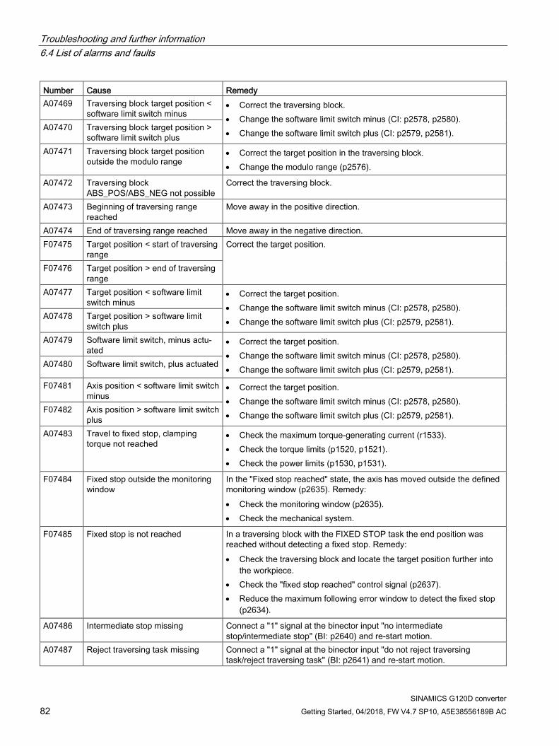
Troubleshooting and further information 6.4 List of alarms and faults
SINAMICS G120D converter 82 Getting Started, 04/2018, FW V4.7 SP10, A5E38556189B AC
Number Cause Remedy A07469 Traversing block target position <
software limit switch minus • Correct the traversing block. • Change the software limit switch minus (CI: p2578, p2580). • Change the software limit switch plus (CI: p2579, p2581). A07470 Traversing block target position >
software limit switch plus A07471 Traversing block target position
outside the modulo range • Correct the target position in the traversing block. • Change the modulo range (p2576).
A07472 Traversing block ABS_POS/ABS_NEG not possible
Correct the traversing block.
A07473 Beginning of traversing range reached
Move away in the positive direction.
A07474 End of traversing range reached Move away in the negative direction. F07475 Target position < start of traversing
range Correct the target position.
F07476 Target position > end of traversing range
A07477 Target position < software limit switch minus
• Correct the target position. • Change the software limit switch minus (CI: p2578, p2580). • Change the software limit switch plus (CI: p2579, p2581). A07478 Target position > software limit
switch plus A07479 Software limit switch, minus actu-
ated • Correct the target position. • Change the software limit switch minus (CI: p2578, p2580). • Change the software limit switch plus (CI: p2579, p2581). A07480 Software limit switch, plus actuated
F07481 Axis position < software limit switch minus
• Correct the target position. • Change the software limit switch minus (CI: p2578, p2580). • Change the software limit switch plus (CI: p2579, p2581). F07482 Axis position > software limit switch
plus A07483 Travel to fixed stop, clamping
torque not reached • Check the maximum torque-generating current (r1533). • Check the torque limits (p1520, p1521). • Check the power limits (p1530, p1531).
F07484 Fixed stop outside the monitoring window
In the "Fixed stop reached" state, the axis has moved outside the defined monitoring window (p2635). Remedy: • Check the monitoring window (p2635). • Check the mechanical system.
F07485 Fixed stop is not reached In a traversing block with the FIXED STOP task the end position was reached without detecting a fixed stop. Remedy: • Check the traversing block and locate the target position further into
the workpiece. • Check the "fixed stop reached" control signal (p2637). • Reduce the maximum following error window to detect the fixed stop
(p2634).
A07486 Intermediate stop missing Connect a "1" signal at the binector input "no intermediate stop/intermediate stop" (BI: p2640) and re-start motion.
A07487 Reject traversing task missing Connect a "1" signal at the binector input "do not reject traversing task/reject traversing task" (BI: p2641) and re-start motion.
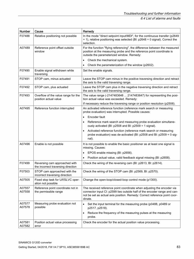
Troubleshooting and further information 6.4 List of alarms and faults
SINAMICS G120D converter Getting Started, 04/2018, FW V4.7 SP10, A5E38556189B AC 83
Number Cause Remedy F07488 Relative positioning not possible In the mode "direct setpoint input/MDI", for the continuous transfer (p2649
= 1), relative positioning was selected (BI: p2648 = 0 signal). Correct the selection.
A07489 Reference point offset outside window
For the function "flying referencing", the difference between the measured position at the measuring probe and the reference point coordinate is outside the parameterized window. Remedy: • Check the mechanical system. • Check the parameterization of the window (p2602).
F07490 Enable signal withdrawn while traversing
Set the enable signals.
F07491 STOP cam, minus actuated Leave the STOP cam minus in the positive traversing direction and retract the axis to the valid traversing range.
F07492 STOP cam, plus actuated Leave the STOP cam plus in the negative traversing direction and retract the axis to the valid traversing range.
F07493 Overflow of the value range for the position actual value
The value range (-2147483648 ... 2147483647) for representing the posi-tion actual value was exceeded. Remedy: If necessary reduce the traversing range or position resolution (p2506).
A07495 Reference function interrupted An activated reference function (reference mark search or measuring probe evaluation) was interrupted. Possible causes: • Encoder fault • Reference mark search and measuring probe evaluation simultane-
ously activated (BI: p2508 and BI: p2509 = 1 signal). • Activated reference function (reference mark search or measuring
probe evaluation) was de-activated (BI: p2508 and BI: p2509 = 0 sig-nal).
A07496 Enable is not possible It is not possible to enable the basic positioner as at least one signal is missing. Causes: • EPOS enable missing (BI: p2656). • Position actual value, valid feedback signal missing (BI: p2658).
F07499 Reversing cam approached with the incorrect traversing direction
Check the wiring of the reversing cam (BI: p2613, BI: p2614).
F07503 STOP cam approached with the incorrect traversing direction
Check the wiring of the STOP cam (BI: p2569, BI: p2570).
A07505 Fixed stop task for U/f/SLVC oper-ation not possible
Change the open-loop/closed-loop control mode (p1300).
A07557 A07558
Reference point coordinate not in the permissible range
The received reference point coordinate when adjusting the encoder via connector input CI: p2599 lies outside half of the encoder range and can-not be set as actual axis position. Remedy: Correct reference point coor-dinate.
A07577 A07578
Measuring probe evaluation not possible
• Set the input terminal for the measuring probe (p0488, p0489 or p2517, p2518).
• Reduce the frequency of the measuring pulses at the measuring probe.
A07581 A07582
Position actual value processing error
Check the encoder for the actual position value processing.
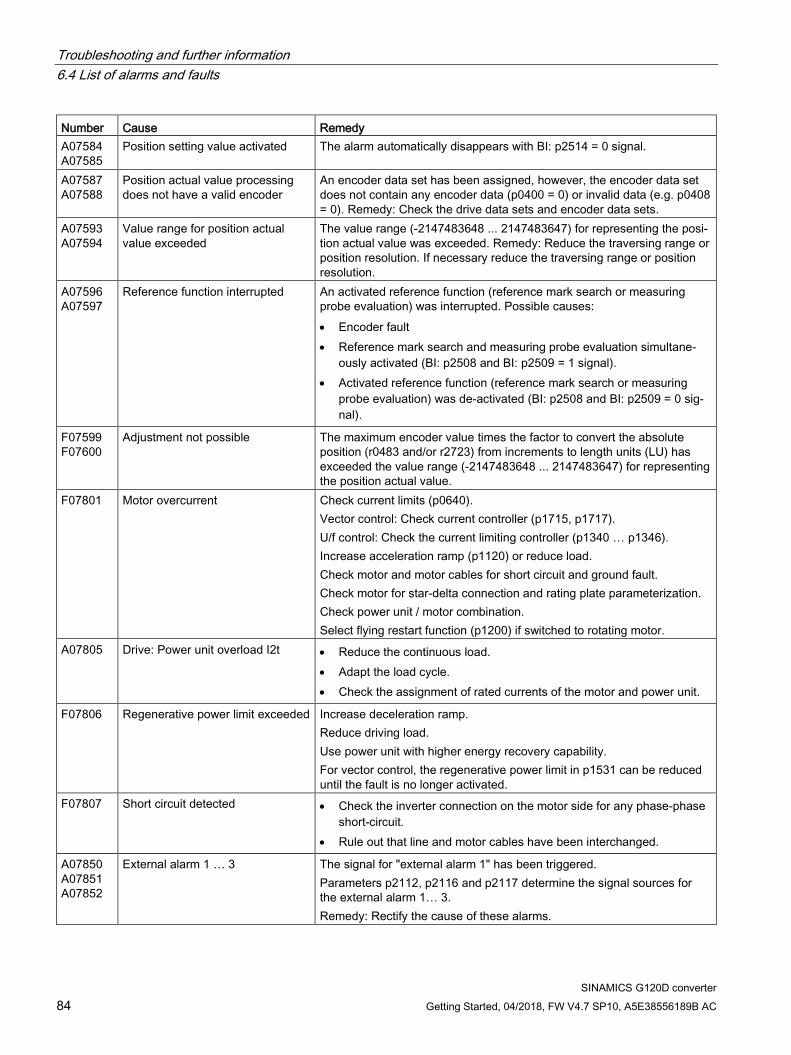
Troubleshooting and further information 6.4 List of alarms and faults
SINAMICS G120D converter 84 Getting Started, 04/2018, FW V4.7 SP10, A5E38556189B AC
Number Cause Remedy A07584 A07585
Position setting value activated The alarm automatically disappears with BI: p2514 = 0 signal.
A07587 A07588
Position actual value processing does not have a valid encoder
An encoder data set has been assigned, however, the encoder data set does not contain any encoder data (p0400 = 0) or invalid data (e.g. p0408 = 0). Remedy: Check the drive data sets and encoder data sets.
A07593 A07594
Value range for position actual value exceeded
The value range (-2147483648 ... 2147483647) for representing the posi-tion actual value was exceeded. Remedy: Reduce the traversing range or position resolution. If necessary reduce the traversing range or position resolution.
A07596 A07597
Reference function interrupted An activated reference function (reference mark search or measuring probe evaluation) was interrupted. Possible causes: • Encoder fault • Reference mark search and measuring probe evaluation simultane-
ously activated (BI: p2508 and BI: p2509 = 1 signal). • Activated reference function (reference mark search or measuring
probe evaluation) was de-activated (BI: p2508 and BI: p2509 = 0 sig-nal).
F07599 F07600
Adjustment not possible The maximum encoder value times the factor to convert the absolute position (r0483 and/or r2723) from increments to length units (LU) has exceeded the value range (-2147483648 ... 2147483647) for representing the position actual value.
F07801 Motor overcurrent Check current limits (p0640). Vector control: Check current controller (p1715, p1717). U/f control: Check the current limiting controller (p1340 … p1346). Increase acceleration ramp (p1120) or reduce load. Check motor and motor cables for short circuit and ground fault. Check motor for star-delta connection and rating plate parameterization. Check power unit / motor combination. Select flying restart function (p1200) if switched to rotating motor.
A07805 Drive: Power unit overload I2t • Reduce the continuous load. • Adapt the load cycle. • Check the assignment of rated currents of the motor and power unit.
F07806 Regenerative power limit exceeded Increase deceleration ramp. Reduce driving load. Use power unit with higher energy recovery capability. For vector control, the regenerative power limit in p1531 can be reduced until the fault is no longer activated.
F07807 Short circuit detected • Check the inverter connection on the motor side for any phase-phase short-circuit.
• Rule out that line and motor cables have been interchanged.
A07850 A07851 A07852
External alarm 1 … 3 The signal for "external alarm 1" has been triggered. Parameters p2112, p2116 and p2117 determine the signal sources for the external alarm 1… 3. Remedy: Rectify the cause of these alarms.

Troubleshooting and further information 6.4 List of alarms and faults
SINAMICS G120D converter Getting Started, 04/2018, FW V4.7 SP10, A5E38556189B AC 85
Number Cause Remedy F07860 F07861 F07862
External fault 1 … 3 Remove the external causes for these faults.
F07900 Motor blocked Check that the motor can run freely. Check the torque limits (r1538 and r1539). Check the parameters of the "Motor blocked" message (p2175, p2177).
F07901 Motor overspeed Activate precontrol of the speed limiting controller (p1401 bit 7 = 1). Increase hysteresis for overspeed signal p2162.
F07902 Motor stalled Check whether the motor data has been parameterized correctly and perform motor identification. Check the current limits (p0640, r0067, r0289). If the current limits are too low, the drive cannot be magnetized. Check whether motor cables are disconnected during operation.
A07903 Motor speed deviation Increase p2163 and/or p2166. Increase the torque, current and power limits.
A07910 Motor overtemperature Check the motor load. Check the motor's ambient temperature. Check the KTY84 or PT1000 sensor. Check the overtemperatures of the thermal model (p0626 ... p0628).
A07920 Torque/speed too low The torque deviates from the torque/speed envelope curve. • Check the connection between the motor and the load. • Adapt the parameterization corresponding to the load.
A07921 Torque/speed too high A07922 Torque/speed out of tolerance
F07923 Torque/speed too low • Check the connection between the motor and the load. • Adapt the parameterization corresponding to the load. F07924 Torque/speed too high
A07927 DC braking active Not required A07975 Traverse to the zero mark - set-
point input expected The alarm disappears when the zero mark is detected.
A07980 Rotary measurement activated Not required A07981 No enabling for rotary measure-
ment Acknowledge pending faults. Establish missing enables (see r00002, r0046).
A07991 Motor data identification activated Switch on the motor and identify the motor data. F08501 Setpoint timeout • Check the PROFINET connection.
• Set the controller to RUN mode. • If the error occurs repeatedly, check the monitoring time set (p2044).
F08502 Monitoring time, sign-of-life expired • Check the PROFINET connection.
F08510 Send configuration data not valid • Check the PROFINET configuration A08511 Receive configuration data not
valid A08526 No cyclic connection • Activate the controller with cyclic operation.
• Check the parameters "Name of Station" and "IP of Station" (r61000, r61001).
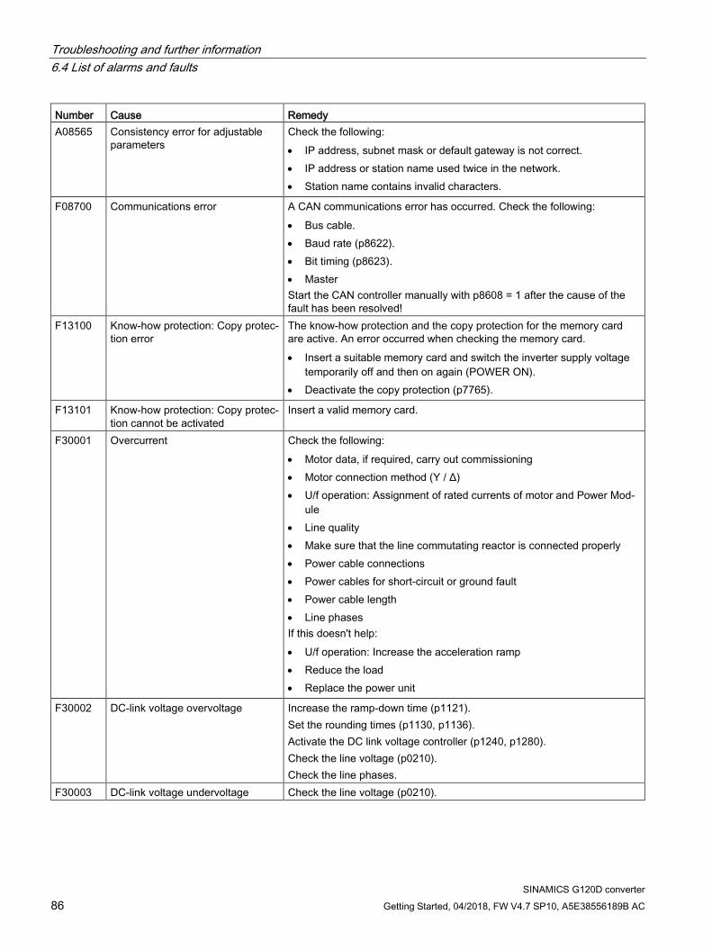
Troubleshooting and further information 6.4 List of alarms and faults
SINAMICS G120D converter 86 Getting Started, 04/2018, FW V4.7 SP10, A5E38556189B AC
Number Cause Remedy A08565 Consistency error for adjustable
parameters Check the following: • IP address, subnet mask or default gateway is not correct. • IP address or station name used twice in the network. • Station name contains invalid characters.
F08700 Communications error A CAN communications error has occurred. Check the following: • Bus cable. • Baud rate (p8622). • Bit timing (p8623). • Master Start the CAN controller manually with p8608 = 1 after the cause of the fault has been resolved!
F13100 Know-how protection: Copy protec-tion error
The know-how protection and the copy protection for the memory card are active. An error occurred when checking the memory card. • Insert a suitable memory card and switch the inverter supply voltage
temporarily off and then on again (POWER ON). • Deactivate the copy protection (p7765).
F13101 Know-how protection: Copy protec-tion cannot be activated
Insert a valid memory card.
F30001 Overcurrent Check the following: • Motor data, if required, carry out commissioning • Motor connection method (Υ / Δ) • U/f operation: Assignment of rated currents of motor and Power Mod-
ule • Line quality • Make sure that the line commutating reactor is connected properly • Power cable connections • Power cables for short-circuit or ground fault • Power cable length • Line phases If this doesn't help: • U/f operation: Increase the acceleration ramp • Reduce the load • Replace the power unit
F30002 DC-link voltage overvoltage Increase the ramp-down time (p1121). Set the rounding times (p1130, p1136). Activate the DC link voltage controller (p1240, p1280). Check the line voltage (p0210). Check the line phases.
F30003 DC-link voltage undervoltage Check the line voltage (p0210).
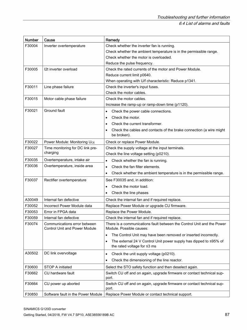
Troubleshooting and further information 6.4 List of alarms and faults
SINAMICS G120D converter Getting Started, 04/2018, FW V4.7 SP10, A5E38556189B AC 87
Number Cause Remedy F30004 Inverter overtemperature Check whether the inverter fan is running.
Check whether the ambient temperature is in the permissible range. Check whether the motor is overloaded. Reduce the pulse frequency.
F30005 I2t inverter overload Check the rated currents of the motor and Power Module. Reduce current limit p0640. When operating with U/f characteristic: Reduce p1341.
F30011 Line phase failure Check the inverter's input fuses. Check the motor cables.
F30015 Motor cable phase failure Check the motor cables. Increase the ramp-up or ramp-down time (p1120).
F30021 Ground fault • Check the power cable connections. • Check the motor. • Check the current transformer. • Check the cables and contacts of the brake connection (a wire might
be broken).
F30022 Power Module: Monitoring UCE Check or replace Power Module. F30027 Time monitoring for DC link pre-
charging Check the supply voltage at the input terminals. Check the line voltage setting (p0210).
F30035 Overtemperature, intake air • Check whether the fan is running. • Check the fan filter elements. • Check whether the ambient temperature is in the permissible range.
F30036 Overtemperature, inside area
F30037 Rectifier overtemperature See F30035 and, in addition: • Check the motor load. • Check the line phases
A30049 Internal fan defective Check the internal fan and if required replace. F30052 Incorrect Power Module data Replace Power Module or upgrade CU firmware. F30053 Error in FPGA data Replace the Power Module. F30059 Internal fan defective Check the internal fan and if required replace. F30074 Communications error between
Control Unit and Power Module There is a communications fault between the Control Unit and the Power Module. Possible causes: • The Control Unit may have been removed or inserted incorrectly. • The external 24 V Control Unit power supply has dipped to ≤95% of
the rated voltage for ≤3 ms
A30502 DC link overvoltage • Check the unit supply voltage (p0210). • Check the dimensioning of the line reactor.
F30600 STOP A initiated Select the STO safety function and then deselect again. F30662 CU hardware fault Switch CU off and on again, upgrade firmware or contact technical sup-
port. F30664 CU power up aborted Switch CU off and on again, upgrade firmware or contact technical sup-
port. F30850 Software fault in the Power Module Replace Power Module or contact technical support.
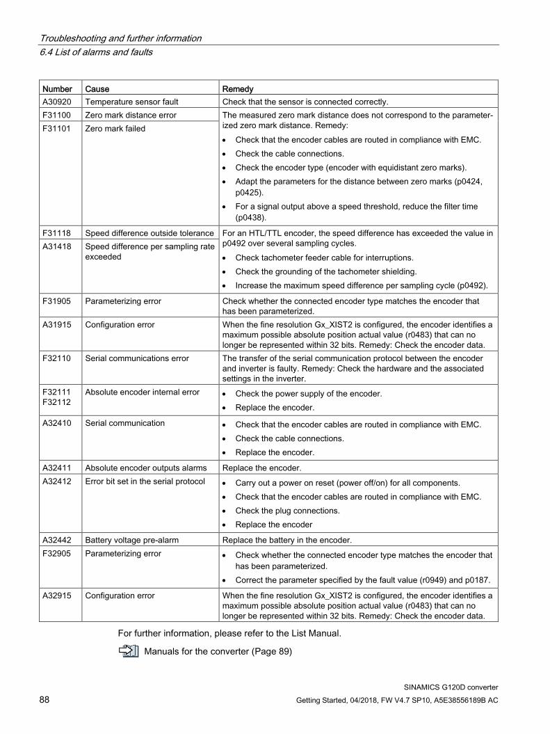
Troubleshooting and further information 6.4 List of alarms and faults
SINAMICS G120D converter 88 Getting Started, 04/2018, FW V4.7 SP10, A5E38556189B AC
Number Cause Remedy A30920 Temperature sensor fault Check that the sensor is connected correctly. F31100 Zero mark distance error The measured zero mark distance does not correspond to the parameter-
ized zero mark distance. Remedy: • Check that the encoder cables are routed in compliance with EMC. • Check the cable connections. • Check the encoder type (encoder with equidistant zero marks). • Adapt the parameters for the distance between zero marks (p0424,
p0425). • For a signal output above a speed threshold, reduce the filter time
(p0438).
F31101 Zero mark failed
F31118 Speed difference outside tolerance For an HTL/TTL encoder, the speed difference has exceeded the value in p0492 over several sampling cycles. • Check tachometer feeder cable for interruptions. • Check the grounding of the tachometer shielding. • Increase the maximum speed difference per sampling cycle (p0492).
A31418 Speed difference per sampling rate exceeded
F31905 Parameterizing error Check whether the connected encoder type matches the encoder that has been parameterized.
A31915 Configuration error When the fine resolution Gx_XIST2 is configured, the encoder identifies a maximum possible absolute position actual value (r0483) that can no longer be represented within 32 bits. Remedy: Check the encoder data.
F32110 Serial communications error The transfer of the serial communication protocol between the encoder and inverter is faulty. Remedy: Check the hardware and the associated settings in the inverter.
F32111 F32112
Absolute encoder internal error • Check the power supply of the encoder. • Replace the encoder.
A32410 Serial communication • Check that the encoder cables are routed in compliance with EMC. • Check the cable connections. • Replace the encoder.
A32411 Absolute encoder outputs alarms Replace the encoder. A32412 Error bit set in the serial protocol • Carry out a power on reset (power off/on) for all components.
• Check that the encoder cables are routed in compliance with EMC. • Check the plug connections. • Replace the encoder
A32442 Battery voltage pre-alarm Replace the battery in the encoder. F32905 Parameterizing error • Check whether the connected encoder type matches the encoder that
has been parameterized. • Correct the parameter specified by the fault value (r0949) and p0187.
A32915 Configuration error When the fine resolution Gx_XIST2 is configured, the encoder identifies a maximum possible absolute position actual value (r0483) that can no longer be represented within 32 bits. Remedy: Check the encoder data.
For further information, please refer to the List Manual.
Manuals for the converter (Page 89)

Troubleshooting and further information 6.5 Manuals for the converter
SINAMICS G120D converter Getting Started, 04/2018, FW V4.7 SP10, A5E38556189B AC 89
6.5 Manuals for the converter
Handbücher mit weiterführender Information zum Download:
● Getting Started SINAMICS G120D (https://support.industry.siemens.com/cs/ww/en/view/109477364) Installing and commissioning the inverter.
● Operating instructions SINAMICS G120D with CU240D-2 (https://support.industry.siemens.com/cs/ww/en/view/109477366) Installing, commissioning and operating the inverter. Advanced commissioning. Technical data.
● Operating instructions SINAMICS G120D with CU250D-2 (https://support.industry.siemens.com/cs/ww/en/view/109477365) Installing, commissioning and operating the inverter. Advanced commissioning. Technical data.
● List manual SINAMICS G120D (https://support.industry.siemens.com/cs/ww/en/view/109477255)
List of parameters, alarms and faults. Graphic function block diagrams.
● Operating instructions IOP (https://support.industry.siemens.com/cs/ww/en/view/109478559)
Description of operator panel
6.6 Technical support +49 (0)911 895 7222
+44 161 446 5545
+39 (02) 24362000
+34 902 237 238
+33 (0) 821 801 122
You can find additional telephone numbers for Technical Support in the Internet:
Product support (https://support.industry.siemens.com/cs/ww/en/)

Troubleshooting and further information 6.6 Technical support
SINAMICS G120D converter 90 Getting Started, 04/2018, FW V4.7 SP10, A5E38556189B AC