Embed Size (px)
Citation preview
Journal of Mechanical Engineering and Automation 2013, 3(2): 38-45 DOI: 10.5923/j.jmea.20130302.03
Assistive Caster Unit of Wheelchair for Step Climbing
Sho Yokota1,*, Daisuke Chugo2, Hiroshi Hashimoto3, Kuniaki Kawabata4
1Faculty of Science and Engineering, Setsunan University, Neyagawa, 572-8508, Osaka, Japan 2School of Science and Engineering, Kwansei Gakuin University, Sanda, Hyogo, Japan
3Master Program of Innovation for Design and Engineering, Advanced Institute of Industrial Technology, Shinagawa, Tokyo, Japan 4RIKEN-XJTU Joint Research Unit, RIKEN, Wako, Saitama, Japan
Abstract Th is paper proposes the wheelchair caster unit which assists manual wheelchair users in a step climbing. Th is caster unit has 2 functions. First one is the assistive plate which en larges radius of a front wheel equivalently in the limited space between main frame and foot rest. When the caster meets the step, the assistive plates are rotated as same manner as a general big wheel. Thus, the user driving force is reduced compared with conventional small caster wheel. Second one is the lock mechanism. Th is mechanism enables to make fu ll use of user's driv ing force in case of oblique climbing by holding yaw axis rotation of the caster. In addition, the caster unit can be easily converted from a conventional caster without any modifications on the main frame. In order to verify the efficiency of proposed caster unit, this paper conducted two experiments: I) Dynamics simulation before constructing a prototype. II) Evaluation experiment using a prototype. In the I) simulation stage, we verified two functions by measuring the driving torque of main wheel in a dynamics simulation. In the II) real experiment, we measured the strain between hand rim and main wheel by using the load cell. In both verifications, the efficiency was verified. Thus it turned out that proposed caster unit can reduce user's driving force, namely it can assist manual wheelchair user in a step climbing.
Keywords Assistive Mechanism, Solenoid, Rack & Pinion Gear, Step Climbing, Wheelchair
1. Introduction This paper proposes the assistive caster unit for manual
wheelchair users in case of a step climbing. The assistive caster is a simple mechanism and realizes easy attachment to a conventional standard wheelchair. This system assists users in not only frontal step climbing but also oblique climbing to the step by reducing user's driving force.
A wheelchair is a typical assistive apparatus, and has not only complement mobility functions but also means of assisting the human activit ies and social participation by expanding a field of act ivities. For a wheelchair, one of the big obstacles is an uneven road such as stair and a step. On uneven road, a user is required to generate much driving force compared with the flat road. Reducing driv ing force on uneven road is able to reduce user's physical load for moving. This may contribute to improve the quality of life of manual wheelchair user.
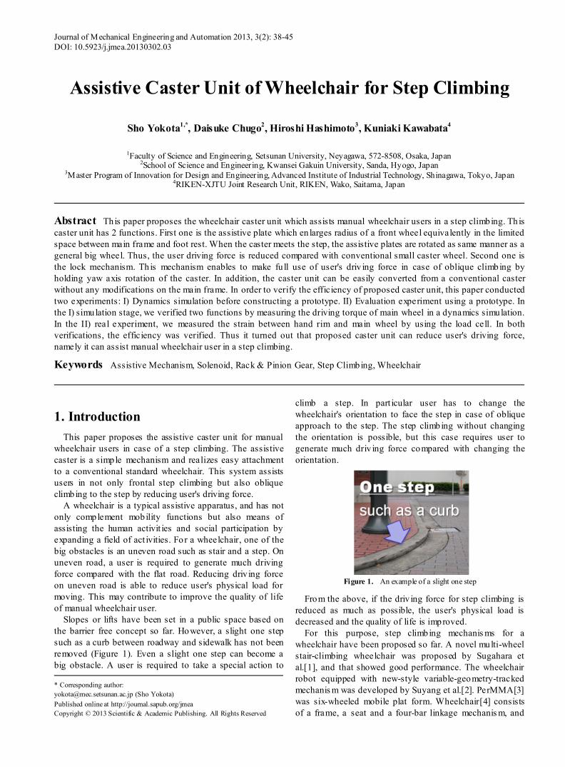
Slopes or lifts have been set in a public space based on the barrier free concept so far. However, a slight one step such as a curb between roadway and sidewalk has not been removed (Figure 1). Even a slight one step can become a big obstacle. A user is required to take a special action to
* Corresponding author: [email protected] (Sho Yokota) Published online at http://journal.sapub.org/jmea Copyright © 2013 Scientific & Academic Publishing. All Rights Reserved
climb a step. In part icular user has to change the wheelchair's orientation to face the step in case of oblique approach to the step. The step climbing without changing the orientation is possible, but this case requires user to generate much driv ing force compared with changing the orientation.
Figure 1. An example of a slight one step
From the above, if the driv ing force for step climbing is reduced as much as possible, the user's physical load is decreased and the quality of life is improved.
For this purpose, step climbing mechanis ms for a wheelchair have been proposed so far. A novel multi-wheel stair-climbing wheelchair was proposed by Sugahara et al.[1], and that showed good performance. The wheelchair robot equipped with new-style variable-geometry-tracked mechanis m was developed by Suyang et al.[2]. PerMMA[3] was six-wheeled mobile plat form. Wheelchair[4] consists of a frame, a seat and a four-bar linkage mechanis m, and
Journal of Mechanical Engineering and Automation 2013, 3(2): 38-45 39
performed stair climbing. However these systems have complex link mechanism or many wheels, which brings about increasing the size and weight. Therefore these are not practical. Moreover these systems was designed for electric wheelchair, therefore it is difficult to apply them to manual wheelchair.
On the other hand, there are specialized systems for a manual wheelchair. The auxiliary step - climbing mechanism[5] was proposed which is composed by the omni directional wheel and auxiliary device. The other system is Hinged Caster mechanism[6]. These systems showed good results and improved step climbing performance. However, there are remained problems, from the v iewpoint of the practical use, because the mechanism[5] uses omni directional wheel and the hinged caster[6] needs some modifications to the main frame of a wheelchair. Moreover the oblique climbing has not been considered in order to reduce driving force.
Thus this paper proposes a wheelchair caster unit to assist manual wheelchair users in a step climbing. This caster unit provides an easy step-climbing including oblique approach, and can be easily convert from conventional caster without any modifications on the main frame.
The paper is organized as follows: The required functions and specification are discussed in section II. In section III, the design concept which fulfils the required functions is presented. In addition, the efficiency of required functions is verified by simulation. In section V, the prototype and its configuration are presented. And evaluation experiment is performed by measuring the user's driving force using load cell. In the last, the paper is concluded.
2. Problems and Requirements The problems of step climbing are summarized as fo llow.
2.1. Wheel Diameter VS. Limited Attachment S pace
In general, maximum climbable step height is less than 1/3 of the d iameter. Thus, the big wheel is preferable for reducing the driving force.
Figure 2. Model of Caster wheel in case of step climbing
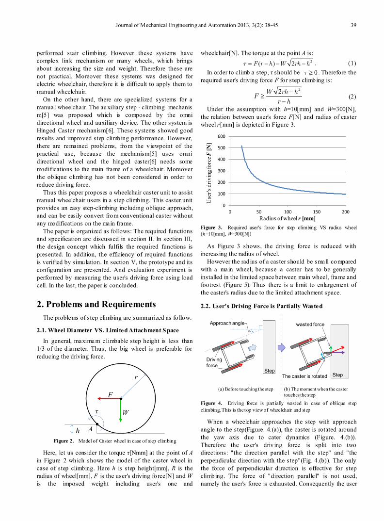
Here, let us consider the torque τ[Nmm] at the point of A in Figure 2 which shows the model of the caster wheel in case of step climbing. Here h is step height[mm], R is the radius of wheel[mm], F is the user's driving fo rce[N] and W is the imposed weight including user's one and
wheelchair[N]. The torque at the point A is: 2( ) 2F r h W rh h = − − − . (1)
In order to climb a step, τ should be 0 ≥ . Therefore the required user's driving force F fo r step climbing is:
22W rh hF
r h−
≥−
(2)
Under the assumption with h=10[mm] and W=300[N], the relation between user's force F[N] and radius of caster wheel r[mm] is depicted in Figure 3.
Figure 3. Required user's force for step climbing VS radius wheel (h=10[mm], W=300[N])
As Figure 3 shows, the driving force is reduced with increasing the radius of wheel.
However the rad ius of a caster should be small compared with a main wheel, because a caster has to be generally installed in the limited space between main wheel, frame and footrest (Figure 5). Thus there is a limit to enlargement of the caster's radius due to the limited attachment space.
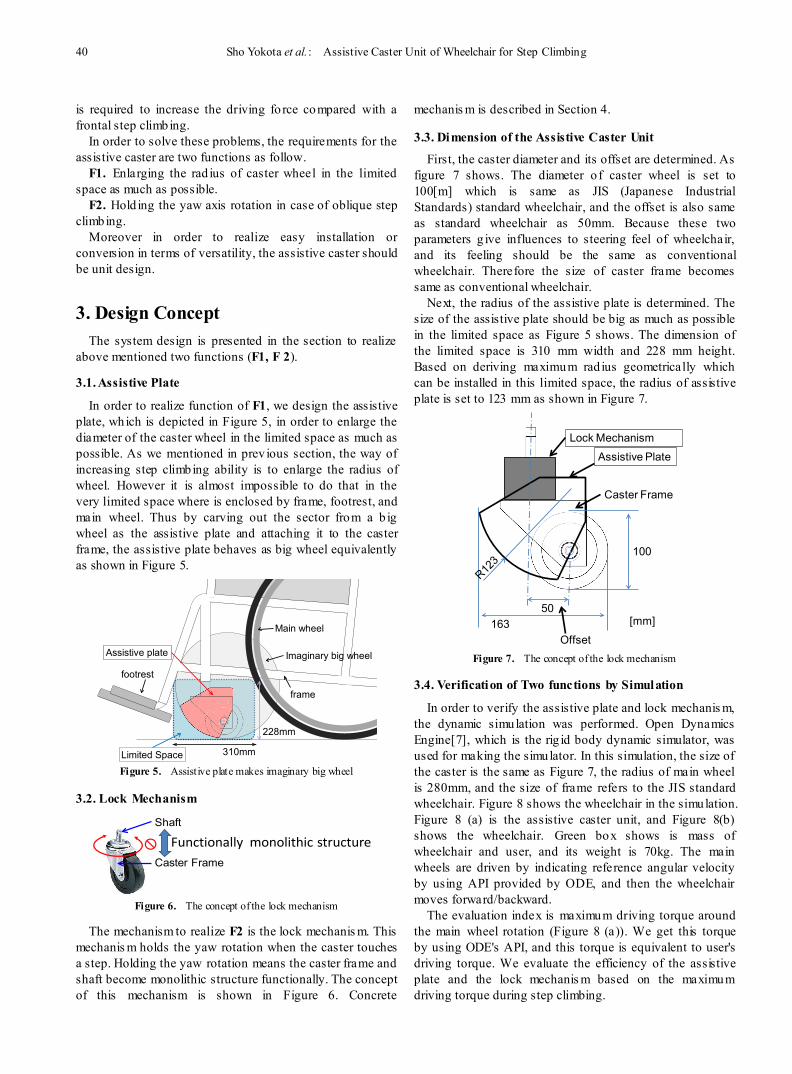
2.2. User's Driving Force is Partially Wasted
Figure 4. Driving force is partially wasted in case of oblique step climbing. This is the top view of wheelchair and step
When a wheelchair approaches the step with approach angle to the step(Figure. 4.(a)), the caster is rotated around the yaw axis due to cater dynamics (Figure. 4.(b)). Therefore the user's driv ing force is split into two directions: "the direction parallel with the step" and "the perpendicular direction with the step"(Fig. 4.(b)). The only the force of perpendicular d irection is effective for step climbing. The force of "direction parallel" is not used, namely the user's force is exhausted. Consequently the user
A
F
W
h
r
τ
0
100
200
300
400
500
600
0 50 100 150 200U
ser's
driv
ing f
orce
F[N
]
Radius of wheel r [mm]
StepStep
Approach angle
Drivingforce
wasted force
The caster is rotated.
(a) Before touching the step (b) The moment when the caster touches the step
40 Sho Yokota et al.: Assistive Caster Unit of Wheelchair for Step Climbing
is required to increase the driving fo rce compared with a frontal step climbing.
In order to solve these problems, the requirements for the assistive caster are two functions as follow.
F1. Enlarging the rad ius of caster wheel in the limited space as much as possible.
F2. Hold ing the yaw axis rotation in case of oblique step climbing.
Moreover in order to realize easy installation or conversion in terms of versatility, the assistive caster should be unit design.
3. Design Concept The system design is presented in the section to realize
above mentioned two functions (F1, F 2).
3.1. Assistive Plate
In order to realize function of F1, we design the assistive plate, which is depicted in Figure 5, in order to enlarge the diameter of the caster wheel in the limited space as much as possible. As we mentioned in prev ious section, the way of increasing step climbing ability is to enlarge the radius of wheel. However it is almost impossible to do that in the very limited space where is enclosed by frame, footrest, and main wheel. Thus by carving out the sector from a b ig wheel as the assistive plate and attaching it to the caster frame, the assistive plate behaves as big wheel equivalently as shown in Figure 5.
Figure 5. Assistive plate makes imaginary big wheel
3.2. Lock Mechanism
Figure 6. The concept of the lock mechanism
The mechanism to realize F2 is the lock mechanis m. This mechanis m holds the yaw rotation when the caster touches a step. Holding the yaw rotation means the caster frame and shaft become monolithic structure functionally. The concept of this mechanism is shown in Figure 6. Concrete
mechanis m is described in Section 4.
3.3. Dimension of the Assistive Caster Unit
First, the caster diameter and its offset are determined. As figure 7 shows. The diameter o f caster wheel is set to 100[m] which is same as JIS (Japanese Industrial Standards) standard wheelchair, and the offset is also same as standard wheelchair as 50mm. Because these two parameters g ive influences to steering feel of wheelchair, and its feeling should be the same as conventional wheelchair. Therefore the size of caster frame becomes same as conventional wheelchair.
Next, the radius of the assistive plate is determined. The size of the assistive plate should be big as much as possible in the limited space as Figure 5 shows. The dimension of the limited space is 310 mm width and 228 mm height. Based on deriving maximum rad ius geometrically which can be installed in this limited space, the radius of assistive plate is set to 123 mm as shown in Figure 7.
Figure 7. The concept of the lock mechanism
3.4. Verification of Two functions by Simulation
In order to verify the assistive plate and lock mechanis m, the dynamic simulation was performed. Open Dynamics Engine[7], which is the rig id body dynamic simulator, was used for making the simulator. In this simulation, the size of the caster is the same as Figure 7, the radius of main wheel is 280mm, and the size of frame refers to the JIS standard wheelchair. Figure 8 shows the wheelchair in the simulation. Figure 8 (a) is the assistive caster unit, and Figure 8(b) shows the wheelchair. Green box shows is mass of wheelchair and user, and its weight is 70kg. The main wheels are driven by indicating reference angular velocity by using API provided by ODE, and then the wheelchair moves forward/backward.
The evaluation index is maximum driving torque around the main wheel rotation (Figure 8 (a)). We get this torque by using ODE's API, and this torque is equivalent to user's driving torque. We evaluate the efficiency of the assistive plate and the lock mechanis m based on the maximum driving torque during step climbing.
frame
footrest
Main wheel
Assistive plate Imaginary big wheel
310mm
228mm
Limited Space
Shaft
Caster Frame
Functionally monolithic structure
100
50163
Assistive Plate
Lock Mechanism
[mm]
Caster Frame
Offset
Journal of Mechanical Engineering and Automation 2013, 3(2): 38-45 41
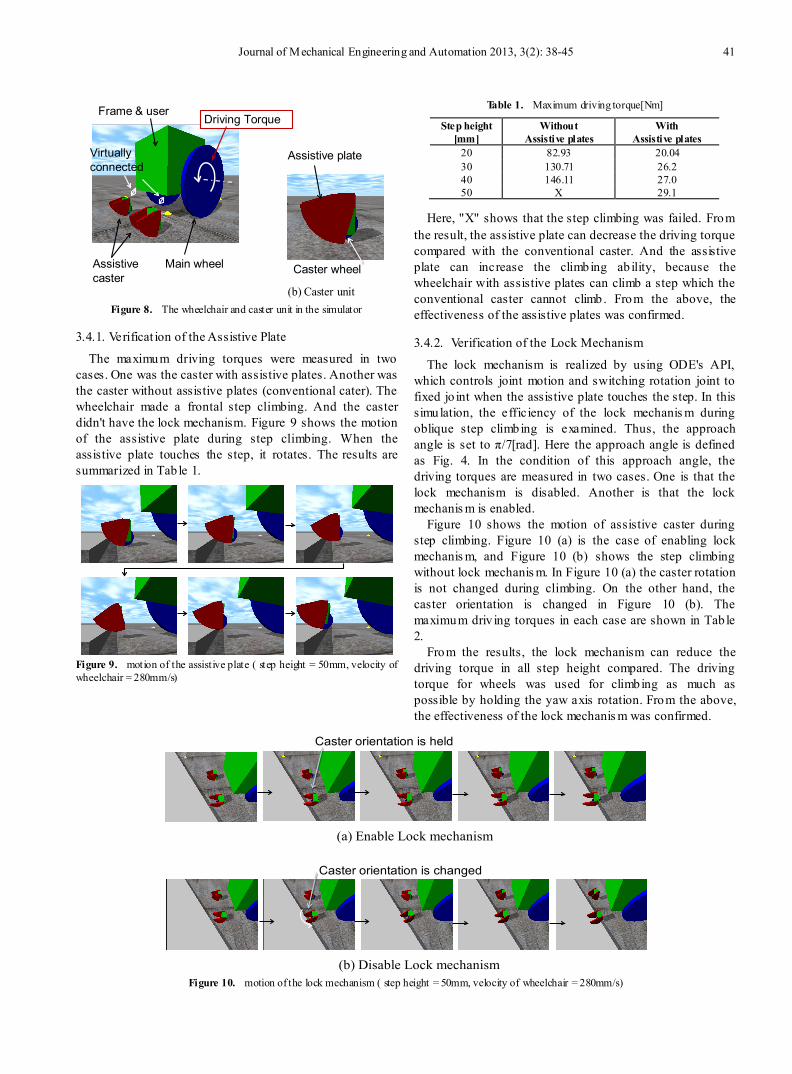
Figure 8. The wheelchair and caster unit in the simulator
3.4.1. Verificat ion of the Assistive Plate
The maximum driving torques were measured in two cases. One was the caster with assistive plates. Another was the caster without assistive plates (conventional cater). The wheelchair made a frontal step climbing. And the caster didn't have the lock mechanism. Figure 9 shows the motion of the assistive plate during step climbing. When the assistive plate touches the step, it rotates. The results are summarized in Tab le 1.
Figure 9. motion of the assistive plate ( step height = 50mm, velocity of wheelchair = 280mm/s)
Table 1. Maximum driving torque[Nm]
Step height [mm]
Without Assistive plates
With Assistive plates
20 82.93 20.04 30 130.71 26.2 40 146.11 27.0 50 X 29.1
Here, "X" shows that the step climbing was failed. From the result, the assistive plate can decrease the driving torque compared with the conventional caster. And the assistive plate can increase the climbing ab ility, because the wheelchair with assistive plates can climb a step which the conventional caster cannot climb. From the above, the effectiveness of the assistive plates was confirmed.
3.4.2. Verification of the Lock Mechanism
The lock mechanism is realized by using ODE's API, which controls joint motion and switching rotation joint to fixed jo int when the assistive plate touches the step. In this simulation, the efficiency of the lock mechanis m during oblique step climbing is examined. Thus, the approach angle is set to π/7[rad]. Here the approach angle is defined as Fig. 4. In the condition of this approach angle, the driving torques are measured in two cases. One is that the lock mechanism is disabled. Another is that the lock mechanis m is enabled.
Figure 10 shows the motion of assistive caster during step climbing. Figure 10 (a) is the case of enabling lock mechanis m, and Figure 10 (b) shows the step climbing without lock mechanis m. In Figure 10 (a) the caster rotation is not changed during climbing. On the other hand, the caster orientation is changed in Figure 10 (b). The maximum driv ing torques in each case are shown in Tab le 2.
From the results, the lock mechanism can reduce the driving torque in all step height compared. The driving torque for wheels was used for climbing as much as possible by holding the yaw axis rotation. From the above, the effectiveness of the lock mechanis m was confirmed.
Figure 10. motion of the lock mechanism ( step height = 50mm, velocity of wheelchair = 280mm/s)
Frame & user
Main wheelAssistivecaster
Virtually connected
Assistive plate
Caster wheel
(b) Caster unit
Driving Torque
(b) Disable Lock mechanism
Caster orientation is changed
(a) Enable Lock mechanism
Caster orientation is held
42 Sho Yokota et al.: Assistive Caster Unit of Wheelchair for Step Climbing
Table 2. Maximum driving torque[Nm] (approach angle = π/7[rad])
Step height [mm]
Without Lock mechanism
With Lock mechanism
20 31.72 24.82 30 47.84 31.01 40 58.03 40.01 50 63.48 51.15
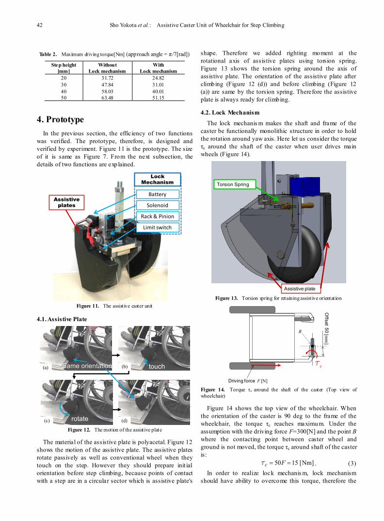
4. Prototype In the previous section, the efficiency of two functions
was verified. The prototype, therefore, is designed and verified by experiment. Figure 11 is the prototype. The size of it is same as Figure 7. From the next subsection, the details of two functions are exp lained.
Figure 11. The assistive caster unit
4.1. Assistive Plate
Figure 12. The motion of the assistive plate
The material of the assistive plate is polyacetal. Figure 12 shows the motion of the assistive plate. The assistive plates rotate passively as well as conventional wheel when they touch on the step. However they should prepare init ial orientation before step climbing, because points of contact with a step are in a circular sector which is assistive plate's
shape. Therefore we added righting moment at the rotational axis of assistive plates using torsion spring. Figure 13 shows the torsion spring around the axis of assistive plate. The orientation of the assistive plate after climbing (Figure 12 (d)) and before climbing (Figure 12 (a)) are same by the torsion spring. Therefore the assistive plate is always ready for climbing.
4.2. Lock Mechanism
The lock mechanis m makes the shaft and frame of the caster be functionally monolithic structure in order to hold the rotation around yaw axis. Here let us consider the torque τc around the shaft of the caster when user drives main wheels (Figure 14).
Figure 13. Torsion spring for retaining assistive orientation
Figure 14. Torque τc around the shaft of the caster (Top view of wheelchair)
Figure 14 shows the top view of the wheelchair. When the orientation of the caster is 90 deg to the frame of the wheelchair, the torque τc reaches maximum. Under the assumption with the driving force F=300[N] and the point B where the contacting point between caster wheel and ground is not moved, the torque τc around shaft of the caster is:
50 15 [Nm]= =c F . (3) In order to realize lock mechanis m, lock mechanism
should have ability to overcome this torque, therefore the
Battery
Solenoid
Rack & Pinion
Limit switch
Assistive plates
Lock Mechanism
(a) (b)
(c) (d)rotate
touchSame orientation
Assistive plate
Torsion Spring
Driving force F [N]
Offset 50 [m
m]
c
B
Journal of Mechanical Engineering and Automation 2013, 3(2): 38-45 43
big holding torque is needed. For instance, if electromagnetic brake or motor is adopted, the weight of the caster becomes large, and big battery at least 24V DC is required.
Thus, lock mechanism should use mechanical or structural constraint, namely all of holding torque should not rely on actuator's output. In other words, the actuator should be used for just engaging or releasing the mechanical structural constraint. By this concept, we can get big holding torque by using small output actuator.
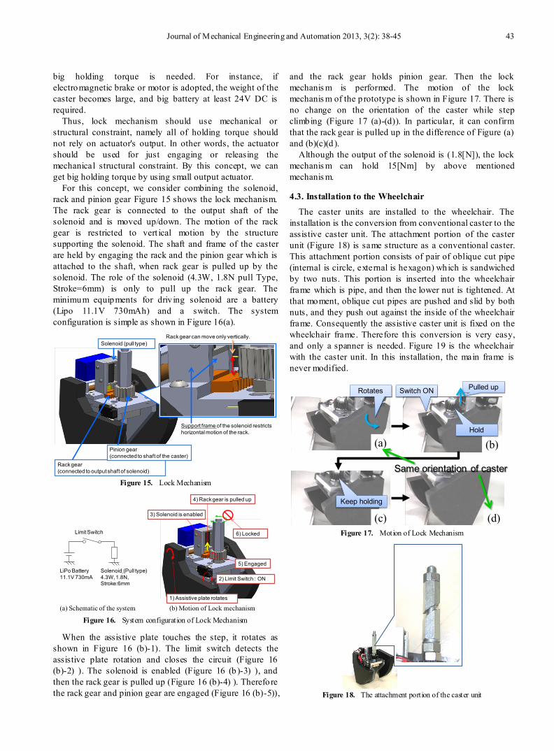
For this concept, we consider combining the solenoid, rack and pinion gear Figure 15 shows the lock mechanism. The rack gear is connected to the output shaft of the solenoid and is moved up/down. The motion of the rack gear is restricted to vert ical motion by the structure supporting the solenoid. The shaft and frame of the caster are held by engaging the rack and the pinion gear which is attached to the shaft, when rack gear is pulled up by the solenoid. The role of the solenoid (4.3W, 1.8N pull Type, Stroke=6mm) is only to pull up the rack gear. The minimum equipments for driv ing solenoid are a battery (Lipo 11.1V 730mAh) and a switch. The system configuration is simple as shown in Figure 16(a).
Figure 15. Lock Mechanism
Figure 16. System configuration of Lock Mechanism
When the assistive plate touches the step, it rotates as shown in Figure 16 (b)-1). The limit switch detects the assistive plate rotation and closes the circuit (Figure 16 (b)-2) ). The solenoid is enabled (Figure 16 (b )-3) ), and then the rack gear is pulled up (Figure 16 (b)-4) ). Therefore the rack gear and pinion gear are engaged (Figure 16 (b)-5)),
and the rack gear holds pinion gear. Then the lock mechanis m is performed. The motion of the lock mechanis m of the p rototype is shown in Figure 17. There is no change on the orientation of the caster while step climbing (Figure 17 (a)-(d)). In particular, it can confirm that the rack gear is pulled up in the difference of Figure (a) and (b)(c)(d ).
Although the output of the solenoid is (1.8[N]), the lock mechanis m can hold 15[Nm] by above mentioned mechanis m.
4.3. Installation to the Wheelchair
The caster units are installed to the wheelchair. The installation is the conversion from conventional caster to the assistive caster unit. The attachment portion of the caster unit (Figure 18) is same structure as a conventional caster. This attachment portion consists of pair of oblique cut pipe (internal is circle, external is hexagon) which is sandwiched by two nuts. This portion is inserted into the wheelchair frame which is pipe, and then the lower nut is tightened. At that moment, oblique cut pipes are pushed and slid by both nuts, and they push out against the inside of the wheelchair frame. Consequently the assistive caster unit is fixed on the wheelchair frame. Therefore th is conversion is very easy, and only a spanner is needed. Figure 19 is the wheelchair with the caster unit. In this installation, the main frame is never modified.
Figure 17. Motion of Lock Mechanism
Figure 18. The attachment portion of the caster unit
Solenoid (pull type)
Rack gear(connected to output shaft of solenoid)
Pinion gear(connected to shaft of the caster)
Rack gear can move only vertically.
Support frame of the solenoid restrictshorizontal motion of the rack.
LiPo Battery 11.1V 730mA
Solenoid (Pull type)4.3W, 1.8N, Stroke:6mm
Limit Switch
(a) Schematic of the system (b) Motion of Lock mechanism
2) Limit Switch : ON
1) Assistive plate rotates
3) Solenoid is enabled
4) Rack gear is pulled up
5) Engaged
6) Locked
(a) (b)
(c) (d)
Switch ONRotates Pulled up
Hold
Keep holding
Same orientation of caster
44 Sho Yokota et al.: Assistive Caster Unit of Wheelchair for Step Climbing
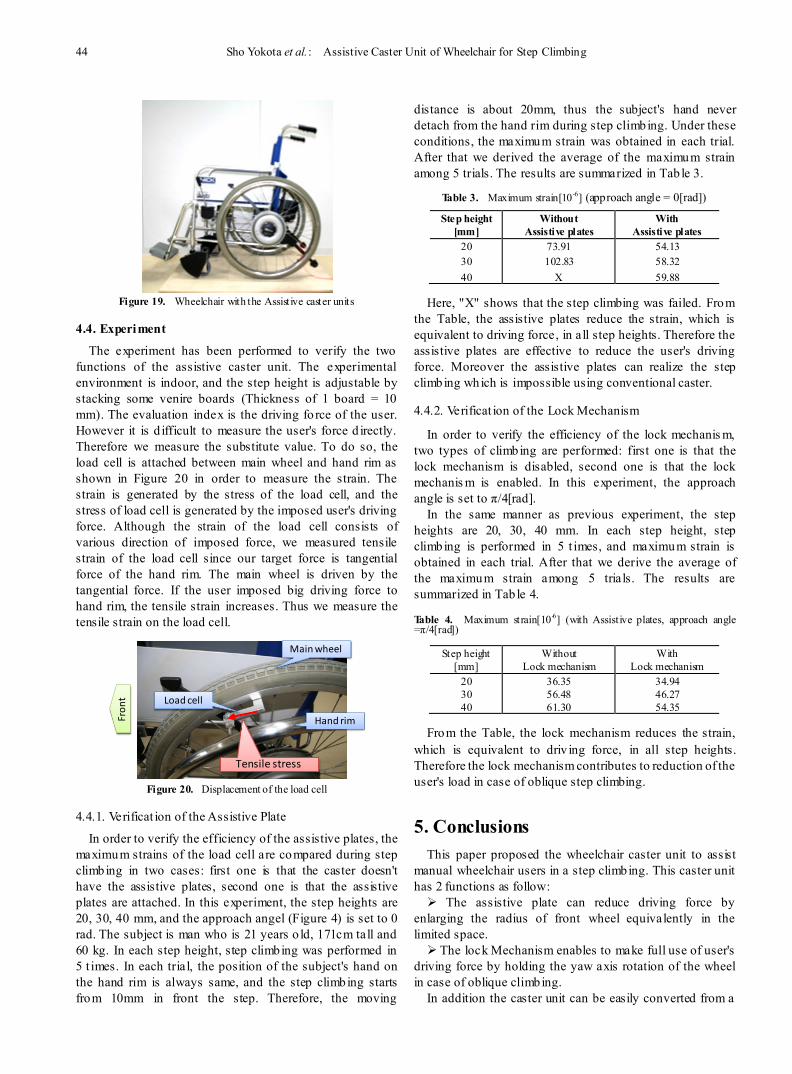
Figure 19. Wheelchair with the Assistive caster units
4.4. Experiment
The experiment has been performed to verify the two functions of the assistive caster unit. The experimental environment is indoor, and the step height is adjustable by stacking some venire boards (Thickness of 1 board = 10 mm). The evaluation index is the driving fo rce of the user. However it is d ifficult to measure the user's force d irectly. Therefore we measure the substitute value. To do so, the load cell is attached between main wheel and hand rim as shown in Figure 20 in order to measure the strain. The strain is generated by the stress of the load cell, and the stress of load cell is generated by the imposed user's driving force. Although the strain of the load cell consists of various direction of imposed force, we measured tensile strain of the load cell since our target force is tangential force of the hand rim. The main wheel is driven by the tangential force. If the user imposed big driving force to hand rim, the tensile strain increases. Thus we measure the tensile strain on the load cell.
Figure 20. Displacement of the load cell
4.4.1. Verificat ion of the Assistive Plate
In order to verify the efficiency of the assistive plates, the maximum strains of the load cell are compared during step climbing in two cases: first one is that the caster doesn't have the assistive plates, second one is that the assistive plates are attached. In this experiment, the step heights are 20, 30, 40 mm, and the approach angel (Figure 4) is set to 0 rad. The subject is man who is 21 years o ld, 171cm tall and 60 kg. In each step height, step climbing was performed in 5 t imes. In each trial, the position of the subject's hand on the hand rim is always same, and the step climbing starts from 10mm in front the step. Therefore, the moving
distance is about 20mm, thus the subject's hand never detach from the hand rim during step climbing. Under these conditions, the maximum strain was obtained in each trial. After that we derived the average of the maximum strain among 5 trials. The results are summarized in Tab le 3.
Table 3. Maximum strain[10-6] (approach angle = 0[rad])
Step height [mm]
Without Assistive plates
With Assistive plates
20 73.91 54.13 30 102.83 58.32 40 X 59.88
Here, "X" shows that the step climbing was failed. From the Table, the assistive plates reduce the strain, which is equivalent to driving force, in all step heights. Therefore the assistive plates are effective to reduce the user's driving force. Moreover the assistive plates can realize the step climbing which is impossible using conventional caster.
4.4.2. Verificat ion of the Lock Mechanism
In order to verify the efficiency of the lock mechanis m, two types of climbing are performed: first one is that the lock mechanism is disabled, second one is that the lock mechanis m is enabled. In this experiment, the approach angle is set to π/4[rad].
In the same manner as previous experiment, the step heights are 20, 30, 40 mm. In each step height, step climbing is performed in 5 t imes, and maximum strain is obtained in each trial. After that we derive the average of the maximum strain among 5 trials. The results are summarized in Tab le 4.
Table 4. Maximum strain[10-6] (with Assistive plates, approach angle =π/4[rad])
Step height [mm]
Without Lock mechanism
With Lock mechanism
20 36.35 34.94 30 56.48 46.27 40 61.30 54.35
From the Table, the lock mechanism reduces the strain, which is equivalent to driv ing force, in all step heights. Therefore the lock mechanism contributes to reduction of the user's load in case of oblique step climbing.
5. Conclusions This paper proposed the wheelchair caster unit to assist
manual wheelchair users in a step climbing. This caster unit has 2 functions as follow: The assistive plate can reduce driving force by
enlarging the radius of front wheel equivalently in the limited space. The lock Mechanism enables to make full use of user's
driving force by holding the yaw axis rotation of the wheel in case of oblique climbing.
In addition the caster unit can be easily converted from a
Hand rim
Main wheel
Load cell
Fron
t
Tensile stress
Journal of Mechanical Engineering and Automation 2013, 3(2): 38-45 45
conventional caster without any modificat ions on the main frame. In order to verify the efficiency of proposed caster unit, this paper adopted two methods:
I) Dynamics simulat ion before constructing a prototype. II) Evaluation experiment using a prototype. In the I) simulat ion stage, we verified two functions by
measuring the driving torque of main wheel in a dynamics simulation. In the II) real experiment, we measured the strain between hand rim and main wheel by the load cell.
In both verifications, the efficiency was verified. Therefore proposed caster unit can reduce user's driving force, namely it can assist manual wheelchair user in a step climbing.
REFERENCES [1] Sugahara, Y., Yonezawa, N. and Kosuge, K. (2010),"A Novel
Stair-Climbing Wheelchair with Transformable Wheeled Four-Bar Linkages", The 2010 IEEE/RSJ International Conference on Intelligent Robots and Systems, 2010, pp. 3333-3339.
[2] Suyang Yu, Ting Wang, Xiaofan Li, Chen Yao, Zhong Wang and Di Zhi, (2010), "Configuration and Tip-Over Stability Analysis for Stair-Climbing of a New-Style Wheelchair
Robot" Proceedings of the 2010 IEEE International Conference on Mechatronics and Automation, pp. 1388 - 1392.
[3] Hongwu Wang, Garrett G Grindle, Jorge Candiotti, Chengshiu Chung, Motoki Shino, Elaine Houston, and Rory A Cooper, (2012), "The Personal Mobility and Manipulation Appliance (PerMMA): a Robotic Wheelchair with Advanced Mobility and Manipulation", 34th Annual International Conference of the IEEE EMBS, San Diego, California USA, 28 August - 1 September, 2012, pp. 3324-3327.
[4] Giuseppe Quaglia, Walter Franco, Riccardo Oderio, (2011), "Wheelchair.q, a motorized wheelchair with stair climbing ability", Mechanism and Machine Theory, Elsevier, Vo. 46 (2011), pp. 1601-1609.
[5] Takuro Hayashi, Satoshi Kawakami, Hideaki Matsuo, Mitsunori Yuinamochi, (2003), "A Study on a Multi-function Wheelchair with Auxiliary Step-climbing Mechanism", JSME Proceedings of the Welfare Engineering Symposium 2003, Vol. 2003,No. 3,pp. 29-32, (in Japanese).
[6] Takuto OHMURA, Taro IWAMOTO, Koji SHIBUYA, (2006), "Step Traveling of Wheel Chair with Hinged Caster Mount", Proceedings of the 2006 JSME conference on Robotics and Mechatronics, Vol. 2006, pp. 1P1-A17, (in Japanese).
[7] Open Dynamics Engine, http://www.ode.org/ode.html http:// www.sapub.org/journal/journalintroduction.aspx?journalid=1040