Embed Size (px)
Citation preview

02002183 Revision A©GF Health Products, Inc.
January 2006
METRO® POWER III
POWER WHEELCHAIR
OWnER’s MAnuAL
IMPORTAnT: Read this manual before operating your Metro Power III Power Wheelchair

02002183 Revision A, January 2006 Metro Power III Owner’s Manual2
COntents
I IntROduCtIOn .........................................................................................................3
II sAfety PReCAutIOns ...........................................................................................4
III HAndlIng tIPs .......................................................................................................9
IV gettIng stARted ................................................................................................12
V OPeRAtIng InstRuCtIOns .................................................................................17
VI AdJustMents ......................................................................................................18
VII BAtteRIes ............................................................................................................23
VIII MAIntenAnCe ....................................................................................................29
IX tROuBlesHOOtIng .............................................................................................34
X tRAnsPORtIng tHe MetRO POweR III ............................................................39
XI lIMIted wARRAnty .............................................................................................40
XII IndeX .....................................................................................................................42
gRAHAM-fIeld HeAltH PROduCts, InC. Is nOt ResPOnsIBle fOR tyPOgRAPHICAl eRRORs.
PACkAgIng, wARRAntIes And PROduCts ARe suBJeCt tO CHAnge wItHOut nOtICe.
Metro Power III Owner’s Manual 02002183 Revision A, January 2006 3
I IntROduCtIOn
Important safety, operating, and maintenance instructions that warrant your attention are included in this owner’s manual. Read the entire manual carefully before operating your new wheelchair, and refer to it as often as necessary to help maintain good performance standards.
Consult your healthcare professional and qualified Everest & Jennings dealer for assistance in devel-oping and learning safe and effective techniques to perform your daily activities according to your in-dividual physical abilities and needs, and to make certain that your wheelchair is properly prescribed and adjusted for your use.
The safety precautions in this manual are general warnings intended to be used only as basic guide-lines. You may find it necessary to develop your own methods for safely solving frequently encoun-tered challenges. Again, consult your professional medical advisors for their recommendations about safety methods, and never hesitate to ask for their assistance.
Your wheelchair should receive frequent, regularly scheduled maintenance, including an inspection of the mechanical parts, to ensure proper operation. Some suggested inspection procedures, trouble-shooting procedures, and adjustment procedures are included in this manual. When it comes to service and repair, remember that your Everest & Jennings dealer knows your wheelchair best.
All information and specifications in this manual are current at the time of printing. However, because it is Everest & Jennings policy to continually improve the quality and reliability of all our products, we reserve the right to make changes at any time without notice.
Thank you for choosing an Everest & Jennings product. We at Everest & Jennings wish to as-sure you of our continuing commitment to provide innovation and quality in our product. The Metro Power III is a light duty power wheelchair with programmability features that adjust driving control parameters to best suit the client’s current driving requirements and adapt to their evolving needs over time. It is suitable for frequent users who require a power wheelchair fitted to their spe-cific anatomy and best suited for use indoors and limited outdoor use. Its ease of disassembly allows for easy transportation. The Metro Power III’s maximum weight capacity is 250 pounds (113 kg.).
The person performing adjustments on the Metro Power III has the responsibility of making certain that the user can safely operate the wheelchair with the adjustments selected. This person must evalu-ate the user’s ability, weight, physical condition, the environment in which the wheelchair will be used, and the terrain over which the wheelchair will travel. Everest & Jennings recommends the use of anti-tippers at all times.
Please note the following special statements, used throughout this manual, and their significance:
Note: Specialinformationsetofffromthetext.
s Caution: Damagetoequipmentispossible
Warning: Personal injury could occur.
02002183 Revision A, January 2006 Metro Power III Owner’s Manual4
II sAfety PReCAutIOns
IMPORTAnT: BEFORE usInG YOuR Metro Power III, PLEAsE READ AnD unDERsTAnD THE FOLLOWInG sAFETY PRECAuTIOns.
MAIntenAnCe
Protect your Metro Power III by having it serviced regularly. Whenever any part of your wheelchair is not functioning properly, a hazardous situation could result. Only excellent condition is acceptable where safety is concerned.
Periodic inspection, adjustment, and replacement of worn parts will provide many years of superb performance. Many phases of maintenance are best performed by a qualified Everest & Jennings dealer. We recommend the use of only Everest & Jennings replacement parts.
wARnIngs
Warning: The wheelchair user must be capable of driving a power wheelchair safely.
Warning: Do not operate this wheelchair on streets or roadways.
Warning: Do not operate this wheelchair on hilly or rough terrain, sand, wet or icy surfaces, or surfaces with impaired traction.
Warning: Do not attempt inclines without anti-tippers installed. Do not attempt any incline or decline greater than six degrees (10% grade, or one foot of rise or fall per ten feet of ramp length). Wet or icy surfaces, or surfaces with impaired traction, may cause loss of control.
Warning: During descent, the lowest part of the footrests should be no closer to the ground than 2-1/2 inches to permit proper clearance at the bottom of the incline.
Warning: Do not turn wheelchair while going downhill.
Warning: This wheelchair does not offer seating or occupant restraint equivalent to the seat provided in a motor vehicle! To increase your safety while traveling in a mo-tor vehicle, always transfer to the vehicle seat and use the restraint provided by the vehicle manufacturer.
Warning: Do not tie down or attach anything to the wheels. This could cause tipping and possibly result in injury or damage to the wheelchair.
Warning: When using a wheelchair lift, engage the rear wheel levers and turn the wheelchair power switch OFF.
Metro Power III Owner’s Manual 02002183 Revision A, January 2006 �
Warning: Do not enter or exit the wheelchair without first turning the wheelchair power switch OFF, and ensuring that the drive engagement levers are engaged, to prevent wheelchair movement.
Warning: Operate only with anti-tippers in place.
Warning: Disengaging the rear wheel levers will also disengage the electromechani-cal park brakes and allow the wheelchair to roll.
Warning: Do not lean over the top of the wheelchair back. This could cause the wheelchair to tip.
Warning: Before leaning or reaching forward: To reduce the risk of tipping, sit back in the seat and rotate casters fully toward front of wheelchair.
Warning: Do not stand or step on the footplates while transferring to or from your wheelchair. This could cause the wheelchair to tip.
Warning: Ensure that no water, moisture, or other liquid enters the integral control-ler.
Warning: The integral controller programs should be adjusted only by a qualified therapist or technician. This person must evaluate the user’s ability, weight, and physical condition, the environment in which the wheelchair will be used, and the terrain over which the wheelchair will travel. A wide range of adjustment and ver-satility is provided so that the requirements of many different abilities may be met, and the person setting the driving characteristics has the responsibility of making certain that the user can safely operate the wheelchair at the speed and rates se-lected.
Warning: When adjusting with the programmer, start with a slow (low number) stan-dard program or factory setting. Increase only if the user has the ability to control the wheelchair safely.
Warning: When adjusting with the programmer, use caution when changing the indi-vidual parameters to a setting different than that provided by the factory setting.
Warning: When adjusting with the programmer, do not set reverse speed faster than forward speed.
Warning: Ensure that wheelchair power is off before connecting or disconnecting the programmer.
02002183 Revision A, January 2006 Metro Power III Owner’s Manual6
Warning: Do not switch programmer into PROGRAM mode while wheelchair is mov-ing.
Warning: Do not disconnect the wheelchair batteries while the programmer is con-nected to the integral controller.
Warning: Do not use any adaptive control devices other than those provided or rec-ommended by Everest & Jennings.
Warning: Do not connect accessories to the batteries; it will decrease driving range and shorten battery life. Do not connect AnYTHInG to only one battery; this will cause premature battery failure.
Warning: never connect a respirator or other life-support device to the wheelchair batteries, since it will shorten the battery operating time. This could cause an unan-ticipated failure of both the wheelchair and the life-support equipment.
Warning: unauthorized modification could create a hazardous condition, which could result in serious injury.
Warning: The use of non-Everest & Jennings replacement parts could create a haz-ardous condition, which could result in serious injury.
Warning: standard weight capacity for the Metro Power III wheelchair is 250 pounds (113 kg).
Warning: Do not tow any loads or “piggyback” passengers or heavy packages.
Warning: Keep all cables away from the moving parts of the wheelchair.
Warning: As a safety feature, this wheelchair is equipped with fail-safe electrome-chanical park brakes. Any interruption in the power supply will cause these brakes to immediately engage and stop the wheelchair. If the occupant is not properly positioned, an unanticipated stop could pitch the occupant forward and out of the wheelchair. Review the owner’s manual and consult with your dealer regarding proper positioning and use of this wheelchair.
Warning: Everest & Jennings specifically disclaims responsibility for any bodily injury or property damage which may occur during any use which does not comply with federal, state or local laws or ordinances.

Metro Power III Owner’s Manual 02002183 Revision A, January 2006 7
eleCtROMAgnetIC InteRfeRenCe (eMI) fROM RAdIO wAVe sOuRCes
It is very important that you read this information regarding the possible effects of electromagnetic interference on your Everest & Jennings Metro Power III power wheelchair.
Powered wheelchairs may be susceptible to electromagnetic interference (EMI), which is interfering electromagnetic (EM) energy emitted from sources such as radio stations, TV stations, amateur radio (HAM) transmitters, two-way radios, and cellular telephones. The interference (from radio wave sources) can cause the powered wheelchair to release its brakes, move by itself, or move in unintend-ed directions. It can also permanently damage the powered wheelchair’s control system. The intensity of the interfering EM energy can be measured in volts per meter (V/m). Each powered wheelchair can resist EMI up to a certain intensity. This is called its “immunity level”. The higher the immunity level, the greater the protection. At this time, current technology is capable of achieving at least a 20 V/m immunity level, which would provide useful protection from the more common sources of radi-ated EMI.
This powered wheelchair model has an immunity level of 20 V/m when tested with Integral Control-ler Part Number 90762330.Be aware that using different components, adding accessories, or modifying the powered wheelchair may change the immunity level.
There are a number of sources of relatively intense electromagnetic fields in the everyday environ-ment. Some of these sources are obvious and easy to avoid. Others are not apparent and exposure is unavoidable. However, we believe that by following the warnings that follow, your risk to EMI exposure will be minimized.
The sources of radiated EMI can be broadly classified into three types:
1) Hand-held portable transceivers (transmitters-receivers) with the antenna mounted directly on the transmitting unit. Examples include: citizens band (CB) radios, “walkie talkies”, security, fire, and police transceivers, cellular telephones, and other personal communication devices.
Note: Somecellulartelephonesandsimilardevicestransmitsignalswhiletheyareon,evenwhennotbeingused;
2) Medium-range mobile transceivers, such as those used in police cars, fire trucks, ambulances, and taxis. These usually have the antenna mounted on the outside of the vehicle; and
3) Long-range transmitters and transceivers, such as commercial broadcast transmitters (radio and TV broadcast antenna towers) and amateur (HAM) radios.
Note: Othertypesofhand-helddevices,suchascordlesstelephones,laptopcomputers,AM/FMradios,TVsets,CDplayers,andcassetteplayers,andsmallappliances,suchaselectricshaversandhairdryers,sofarasweknow,arenotlikelytocauseEMIproblemswithyourpoweredwheel-chair.
02002183 Revision A, January 2006 Metro Power III Owner’s Manual8
POweRed wHeelCHAIR eleCtROMAgnetIC InteRfeRenCe (eMI)
Because EM energy rapidly becomes more intense as one moves closer to the transmitting antenna (source), the EM fields from hand-held radio wave sources (transceivers) are of special concern. It is possible to unintentionally bring high levels of EM energy very close to the powered wheelchair’s control system while using these devices. This can affect powered wheelchair movement and brak-ing. Therefore, the warnings that follow are recommended to prevent possible interference with the control system of the powered wheelchair.
eMI wARnIngs
Electromagnetic interference (EMI) from sources such as radio and TV stations, amateur radio (HAM) transmitters, two-way radios, and cellular telephones can affect powered wheelchairs. Fol-lowing the warnings listed below should reduce the chance of unintended brake release or powered wheelchair movement which could result in serious injury.
Warning: Do not operate hand-held transceivers (transmitters-receivers), such as citizens band (CB) radios, or turn on personal communication devices, such as cel-lular telephones, while the powered wheelchair is turned on.
Warning: Be aware of nearby transmitters, such as radio or TV stations, and try to avoid coming close to them.
Warning: If unintended movement or brake release occurs, turn the powered wheel-chair off as soon as it is safe.
Warning: Be aware that adding accessories or components, or modifying the pow-ered wheelchair, may make it more susceptible to EMI (note: There is no easy way to evaluate their effect on the overall immunity of the powered wheelcchair).
Warning: Report all incidence of unintended movement or brake release to Everest & Jennings, and note whether there is a source of EMI nearby.
IMPORtAnt InfORMAtIOn
1) 20 volts per meter (V/m) is a generally achievable and useful immunity level against EMI (as of May 1994) (the higher the level, the greater the protection);
2) The immunity level of this powered wheelchair model is listed on page 7.
Be aware that using different components, adding accessories, or modifying the powered wheelchair may change the immunity level.
Metro Power III Owner’s Manual 02002183 Revision A, January 2006 9
III HAndlIng tIPs
The Everest & Jennings Metro Power III been designed and engineered to perform as a stable and well balanced unit when used for its intended purpose. However, it is possible to tip the Metro Power III over if it is used improperly. We urge you to learn the characteristics of your wheel-chair. It is most important to learn safe methods to perform the daily activities basic to your life-style. Consult your medical professionals for assistance in developing the skills and proper techniques to perform all activities safely.
BAlAnCe
Proper balance is the key to maintaining the stability of your wheelchair. Reaching, bending, and transferring to or from a wheelchair will change the weight distribution and center of gravity of you and your wheelchair. When performing such activities, do so as instructed in the following para-graphs to avoid tipping the wheelchair.
tRAnsfeR ACtIVItIes
Warning: Always ensure that wheelchair is on a stable, level surface, engage the drive engagement levers, and turn the wheelchair power switch OFF before transfer.
Warning: Check pneumatic tire pressure at least once a week to ensure correct air pressure. Failure to maintain proper air pressure could result in the malfunction of the wheel locks, if so equipped, which could result in personal injury.
Warning: Do not step on the footplates; this could cause the wheelchair to tip. Fold them up, and either detach them, or swing them aside. There is a critical moment when there is little or no seat platform beneath you. Take every precaution to re-duce this unsupported distance before you attempt transfer.
Transferring to or from a wheelchair is a very difficult maneuver. Exercise extreme care when trans-ferring without the aid of either an attendant or a patient lift. Consult your physician, nurse, or physical therapist for assistance in developing your individual technique. Make sure that the wheel-chair is stabilized, and will not move or slide during the transfer. Take extra precaution to prevent tipping. Use good body mechanics to prevent personal injury.
ReACHIng / BendIng
Warning: Always turn the casters frontward to provide stability while reaching. If in doubt, ask for assistance or use a device that will extend your reach without requir-ing you to shift your weight.
Although it is not recommended, you may find it occasionally necessary to lean or reach from your wheelchair. Consult with your healthcare professional for assistance in developing your personal safe reaching or moving techniques suited to your ability and restrictions.
02002183 Revision A, January 2006 Metro Power III Owner’s Manual10
forward or sideward
Warning: Do not attempt to reach objects if you are required to move forward in the seat. Do not attempt to retrieve objects from the floor if you must reach down between your knees. Do not shift your weight in the direction that you are reaching and/or bending; this could cause the wheelchair to tip.
1. Maneuver the wheelchair as close as possible to the object you wish to reach.
2. Rotate both casters fully forward. If otherwise, go forward and then back the wheelchair toward the object to swing the casters fully forward.
3. Ensure that the casters are rotated fully forward before reaching. If not, repeat step 1.
Backward
Warning: Do not lean over the back upholstery; this could cause the wheelchair to tip.
1. Maneuver the wheelchair as close as possible to the object. The rear wheels will limit how close you can get.
2. Rotate both casters fully forward. If otherwise, go forward and then back the wheelchair toward the object to swing the casters fully forward.
3. Reach only as far as your arm will extend without changing your sitting position. If in doubt, reposition the wheelchair or ask for assistance.
RAMPs And InClInes
Warning: During descent, the lowest part of the footrests should be no closer to the ground than 2-1/2 inches, to permit proper clearance.
Warning: Do not attempt inclines without anti-tippers installed. Do not attempt any incline or decline of more than 6 degrees (10% grade, or one foot of rise or fall per ten feet of ramp length).
Warning: If equipped with wheel locks—do not use the locks to slow your descent. Attempting to use wheel locks is likely to result in accidental locking that could cause the wheelchair to stop abruptly, suddenly pitch forward, or tip sideways.
Warning: Avoid changing direction while descending a ramp or incline, as this could cause instability.
Most people are capable of negotiating short inclines without assistance, depending upon upper body strength, endurance, and the degree of incline. Know your own capabilities and limitations in terms of strength and endurance before attempting to negotiate an incline or decline. Practice with an attendant or healthcare professional first before attempting any inclines, declines curbs or ramps.
Metro Power III Owner’s Manual 02002183 Revision A, January 2006 11
Always inspect the ramp for hazards such as holes, slippery or uneven surfaces, etc. before starting up or down. If you can not see the entire ramp, ask someone to inspect it for you.
AscentLean the upper part of your body slightly forward as you ascend the incline. If it becomes necessary to stop on the incline, avoid any sudden forward movement as you resume climbing; this could cause tipping.
descentAlways face forward when going down a ramp, but DO NOT lean forward; this could cause the wheelchair to tip. If possible, lean slightly backward to increase stability.
It is critical to keep the wheelchair under control at all times. Descent should be made slowly and steadily, allowing the wheelchair’s control system to maintain a safe speed. Upon stopping, electro-mechanical park brakes will engage to prevent the wheelchair from rolling.
CuRBs And stePs
Curbs, steps and stairways are dangerous obstacles that confront the wheelchair user. When you encounter curbs, try to find a way around, or use the ramps now available in most locations. If you encounter steps and there is no ramp available, try to avoid the steps by utilizing the disabled desig-nated elevators now required in most locations.
Warning: never attempt to negotiate curbs, steps, stairs or escalators in your Metro Power III.

02002183 Revision A, January 2006 Metro Power III Owner’s Manual12
IV gettIng stARted
The Metro Power III is designed to provide the highest degree of independence and mobility. The tested range of the Metro Power III is approximately 16 miles on a hard level surface (tested with a 250 pound user and fully charged U1 size batteries). Actual range will vary according to your weight, the amount of start/stop driving, ambient temperature, and the terrain on which you travel with your wheelchair. As you become more acquainted with your wheelchair, its range and performance capabilities will become more apparent.
The Metro Power III is illustrated below. Main featres are identified.
Footplate
Front rigging(footrest)
Seat Upholstery
Seat Cushion
Leg Strap
RearWheel
Motor
Battery Box &Battery Tray
Crossbrace(Serial NumberLabel)
WheelLock
Joystick
Integral Controller
Caster
Arm
Push handle/handgrip
Back Upholstery
Metro Power III Owner’s Manual 02002183 Revision A, January 2006 13
POweR dRIVe systeM
The standard Metro Power III power drive system consists of two independent rear drive wheels, an integral controller, independent, direct drive right and left motors, and two twelve volt batteries (not supplied by Everest & Jennings) that provide power.
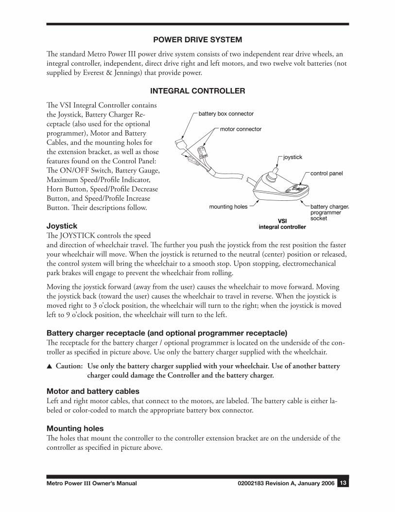
IntegRAl COntROlleR
The VSI Integral Controller contains the Joystick, Battery Charger Re-ceptacle (also used for the optional programmer), Motor and Battery Cables, and the mounting holes for the extension bracket, as well as those features found on the Control Panel: The ON/OFF Switch, Battery Gauge, Maximum Speed/Profile Indicator, Horn Button, Speed/Profile Decrease Button, and Speed/Profile Increase Button. Their descriptions follow.
JoystickThe JOYSTICK controls the speed and direction of wheelchair travel. The further you push the joystick from the rest position the faster your wheelchair will move. When the joystick is returned to the neutral (center) position or released, the control system will bring the wheelchair to a smooth stop. Upon stopping, electromechanical park brakes will engage to prevent the wheelchair from rolling.
Moving the joystick forward (away from the user) causes the wheelchair to move forward. Moving the joystick back (toward the user) causes the wheelchair to travel in reverse. When the joystick is moved right to 3 o’clock position, the wheelchair will turn to the right; when the joystick is moved left to 9 o’clock position, the wheelchair will turn to the left.
Battery charger receptacle (and optional programmer receptacle)The receptacle for the battery charger / optional programmer is located on the underside of the con-troller as specified in picture above. Use only the battery charger supplied with the wheelchair.
s Caution: Useonlythebatterychargersuppliedwithyourwheelchair.UseofanotherbatterychargercoulddamagetheControllerandthebatterycharger.
Motor and battery cablesLeft and right motor cables, that connect to the motors, are labeled. The battery cable is either la-beled or color-coded to match the appropriate battery box connector.
Mounting holesThe holes that mount the controller to the controller extension bracket are on the underside of the controller as specified in picture above.
POWER
battery box connector
battery charger/programmer socket
control panel
motor connector
joystick
mounting holes
VSIintegral controller
02002183 Revision A, January 2006 Metro Power III Owner’s Manual14
COntROl PAnel feAtuRes, VsI IntegRAl COntROlleR
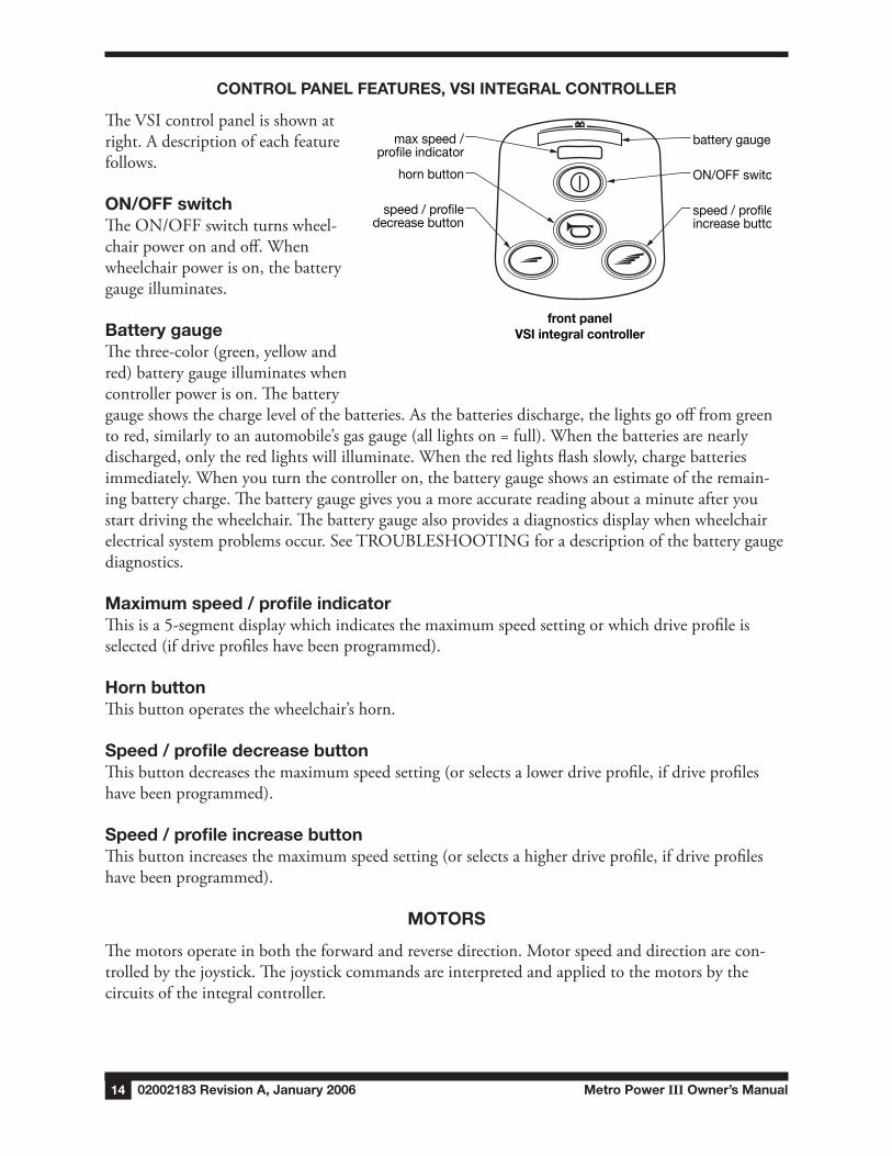
The VSI control panel is shown at right. A description of each feature follows.
On/Off switchThe ON/OFF switch turns wheel-chair power on and off. When wheelchair power is on, the battery gauge illuminates.
Battery gaugeThe three-color (green, yellow and red) battery gauge illuminates when controller power is on. The battery gauge shows the charge level of the batteries. As the batteries discharge, the lights go off from green to red, similarly to an automobile’s gas gauge (all lights on = full). When the batteries are nearly discharged, only the red lights will illuminate. When the red lights flash slowly, charge batteries immediately. When you turn the controller on, the battery gauge shows an estimate of the remain-ing battery charge. The battery gauge gives you a more accurate reading about a minute after you start driving the wheelchair. The battery gauge also provides a diagnostics display when wheelchair electrical system problems occur. See TROUBLESHOOTING for a description of the battery gauge diagnostics.
Maximum speed / profile indicatorThis is a 5-segment display which indicates the maximum speed setting or which drive profile is selected (if drive profiles have been programmed).
Horn buttonThis button operates the wheelchair’s horn.
Speed / profile decrease buttonThis button decreases the maximum speed setting (or selects a lower drive profile, if drive profiles have been programmed).
Speed / profile increase buttonThis button increases the maximum speed setting (or selects a higher drive profile, if drive profiles have been programmed).
MOtORs
The motors operate in both the forward and reverse direction. Motor speed and direction are con-trolled by the joystick. The joystick commands are interpreted and applied to the motors by the circuits of the integral controller.
speed / profiledecrease button
speed / profileincrease button
horn button
battery gauge
ON/OFF switch
max speed /profile indicator
front panelVSI integral controller

Metro Power III Owner’s Manual 02002183 Revision A, January 2006 1�
BAtteRy CHARgeR
BAtteRy CHARgeR feAtuRes
FUSE
115
The 4 amp switch-mode battery charger has the following features:
• Compatible with gel cell lead acid, sealed lead acid, and unsealed lead acid batteries.
• Can be left connected indefinitely after charging without harming the batteries.
• Compatible with 50/60 cycles. 115 or 220 VAC operation is adjustable by switch to either: 115 volts AC (range 90-130 VAC) or 230 volts AC (range 180-260 VAC).
• Charges deeply discharged batteries, starting voltage as low as 1/2 volt.
• UL and CSA approved.
• Conveniently small and light weight.
BAtteRy CHARgeR InteRfACe
BAtteRy CHARgeR BACk PAnel
115
ON/OFF switch
AC voltage switch
AC fuse compartment
line connector
AC connector
backpanel
02002183 Revision A, January 2006 Metro Power III Owner’s Manual16
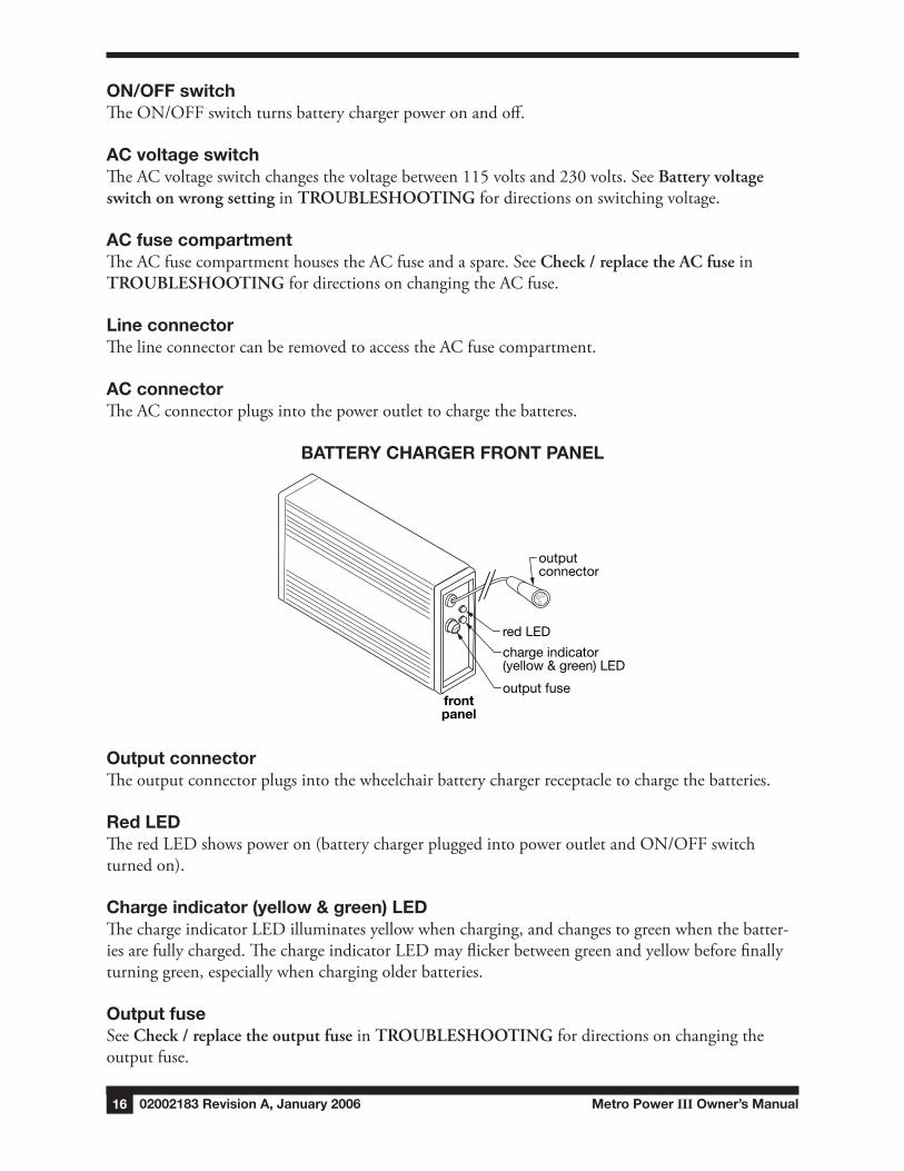
On/Off switchThe ON/OFF switch turns battery charger power on and off.
AC voltage switchThe AC voltage switch changes the voltage between 115 volts and 230 volts. See Batteryvoltageswitchonwrongsettingin TROUBLESHOOTINGfor directions on switching voltage.
AC fuse compartmentThe AC fuse compartment houses the AC fuse and a spare. See Check/replacetheACfusein TROUBLESHOOTING for directions on changing the AC fuse.
line connectorThe line connector can be removed to access the AC fuse compartment.
AC connectorThe AC connector plugs into the power outlet to charge the batteres.
BAtteRy CHARgeR fROnt PAnel
FUSE
outputconnector
red LED
charge indicator(yellow & green) LED
output fusefrontpanel
Output connectorThe output connector plugs into the wheelchair battery charger receptacle to charge the batteries.
Red ledThe red LED shows power on (battery charger plugged into power outlet and ON/OFF switch turned on).
Charge indicator (yellow & green) ledThe charge indicator LED illuminates yellow when charging, and changes to green when the batter-ies are fully charged. The charge indicator LED may flicker between green and yellow before finally turning green, especially when charging older batteries.
Output fuseSee Check/replacetheoutputfusein TROUBLESHOOTING for directions on changing the output fuse.
Metro Power III Owner’s Manual 02002183 Revision A, January 2006 17
V OPeRAtIng InstRuCtIOns
Read and understand all safety Precautions before operating your wheelchair.
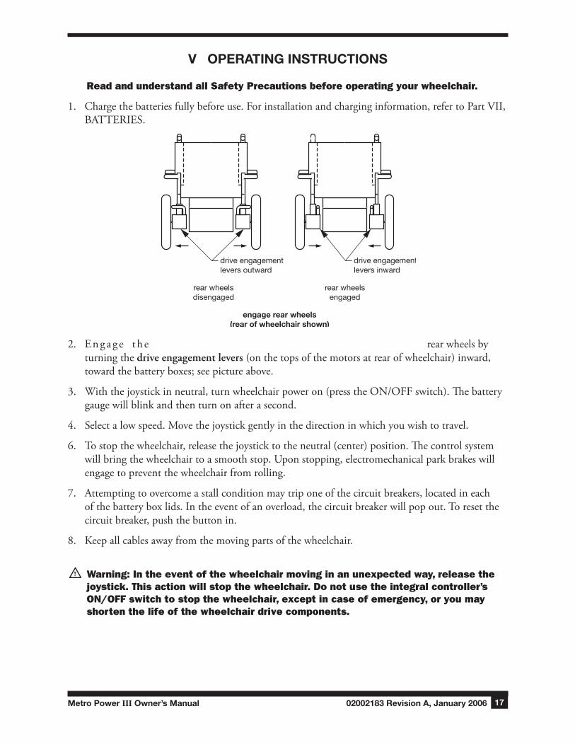
1. Charge the batteries fully before use. For installation and charging information, refer to Part VII, BATTERIES.
drive engagementlevers outward
rear wheelsdisengaged
rear wheelsengaged
drive engagementlevers inward
engage rear wheels(rear of wheelchair shown)
2. En g a g e t h e rear wheels by turning the driveengagementlevers (on the tops of the motors at rear of wheelchair) inward, toward the battery boxes; see picture above.
3. With the joystick in neutral, turn wheelchair power on (press the ON/OFF switch). The battery gauge will blink and then turn on after a second.
4. Select a low speed. Move the joystick gently in the direction in which you wish to travel.
6. To stop the wheelchair, release the joystick to the neutral (center) position. The control system will bring the wheelchair to a smooth stop. Upon stopping, electromechanical park brakes will engage to prevent the wheelchair from rolling.
7. Attempting to overcome a stall condition may trip one of the circuit breakers, located in each of the battery box lids. In the event of an overload, the circuit breaker will pop out. To reset the circuit breaker, push the button in.
8. Keep all cables away from the moving parts of the wheelchair.
Warning: In the event of the wheelchair moving in an unexpected way, release the joystick. This action will stop the wheelchair. Do not use the integral controller’s On/OFF switch to stop the wheelchair, except in case of emergency, or you may shorten the life of the wheelchair drive components.
02002183 Revision A, January 2006 Metro Power III Owner’s Manual18
adjust extension position
clamprelease
extension
clampbracket
arm
integralcontroller
VI AdJustMents
The Metro Power III offers several adjustments to enhance driving ease and comfort. Adjustments should be performed with wheelchair power off and the wheelchair unoccupied. Ensure that all components are in excellent condition before adjusting (Part VIII, MAINTENANCE, offers sugges-tions for maintaining your wheelchair in excellent condition). These adjustments are recommended methods; after performing a few, you may develop your own.
Specific tools needed to perform each adjustment are identified in adjustment sections. A complete list of tools needed to perform all adjustments in Part VI follows:
7/32” hex key 3/16” hex key
ARMs
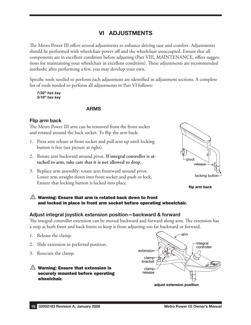
flip arm backThe Metro Power III arm can be removed from the front socket and rotated around the back socket. To flip the arm back:
1. Press arm release at front socket and pull arm up until locking button is free (see picture at right).
2. Rotate arm backward around pivot. Ifintegralcontrollerisat-tachedtoarm,takecarethatitisnotallowedtodrop.
3. Replace arm assembly: rotate arm frontward around pivot. Lower arm straight down into front socket and push to lock. Ensure that locking button is locked into place.
Warning: Ensure that arm is rotated back down to front and locked in place in front arm socket before operating wheelchair.
Adjust integral joystick extension position—backward & forwardThe integral controller extension can be moved backward and forward along arm. The extension has a stop at both front and back limits to keep it from adjusting too far backward or forward.
1. Release the clamp.
2. Slide extension to preferred position.
3. Resecure the clamp.
Warning: Ensure that extension is securely mounted before operating wheelchair.
flip arm back
releasepivot
locking button
Metro Power III Owner’s Manual 02002183 Revision A, January 2006 19
adjust footplateextension length
(left shown)
clampfootplateextensiontube
footresthangertube
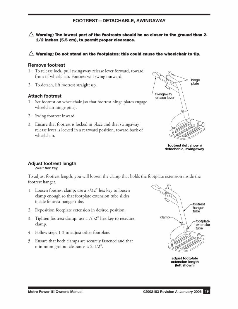
fOOtRest—detACHABle, swIngAwAy
Warning: The lowest part of the footrests should be no closer to the ground than 2-1/2 inches (5.5 cm), to permit proper clearance.
Warning: Do not stand on the footplates; this could cause the wheelchair to tip.
Remove footrest1. To release lock, pull swingaway release lever forward, toward
front of wheelchair. Footrest will swing outward.
2. To detach, lift footrest straight up.
Attach footrest1. Set footrest on wheelchair (so that footrest hinge plates engage
wheelchair hinge pins).
2. Swing footrest inward.
3. Ensure that footrest is locked in place and that swingaway release lever is locked in a rearward position, toward back of wheelchair.
Adjust footrest length7/32” hex key
To adjust footrest length, you will loosen the clamp that holds the footplate extension inside the footrest hanger.
1. Loosen footrest clamp: use a 7/32” hex key to loosen clamp enough so that footplate extension tube slides inside footrest hanger tube.
2. Reposition footplate extension in desired position.
3. Tighten footrest clamp: use a 7/32” hex key to resecure clamp.
4. Follow steps 1-3 to adjust other footplate.
5. Ensure that both clamps are securely fastened and that minimum ground clearance is 2-1/2”.
hingeplate
swingawayrelease lever
footrest (left shown)detachable, swingaway
02002183 Revision A, January 2006 Metro Power III Owner’s Manual20
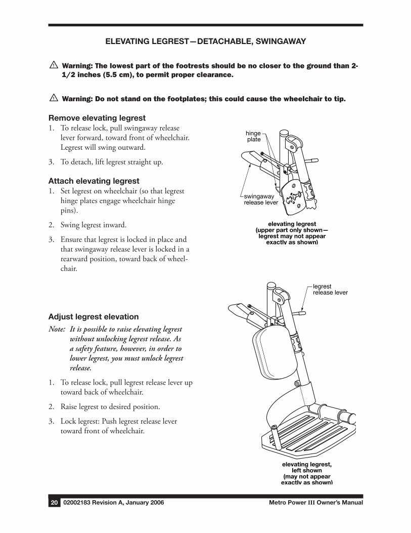
hingeplate
swingawayrelease lever
elevating legrest(upper part only shown—legrest may not appear
exactly as shown)
elevating legrest,left shown
(may not appearexactly as shown)
legrestrelease lever
eleVAtIng legRest—detACHABle, swIngAwAy
Warning: The lowest part of the footrests should be no closer to the ground than 2-1/2 inches (5.5 cm), to permit proper clearance.
Warning: Do not stand on the footplates; this could cause the wheelchair to tip.
Remove elevating legrest1. To release lock, pull swingaway release
lever forward, toward front of wheelchair. Legrest will swing outward.
3. To detach, lift legrest straight up.
Attach elevating legrest1. Set legrest on wheelchair (so that legrest
hinge plates engage wheelchair hinge pins).
2. Swing legrest inward.
3. Ensure that legrest is locked in place and that swingaway release lever is locked in a rearward position, toward back of wheel-chair.
Adjust legrest elevation
Note: Itispossibletoraiseelevatinglegrestwithoutunlockinglegrestrelease.Asasafetyfeature,however,inordertolowerlegrest,youmustunlocklegrestrelease.
1. To release lock, pull legrest release lever up toward back of wheelchair.
2. Raise legrest to desired position.
3. Lock legrest: Push legrest release lever toward front of wheelchair.
Metro Power III Owner’s Manual 02002183 Revision A, January 2006 21
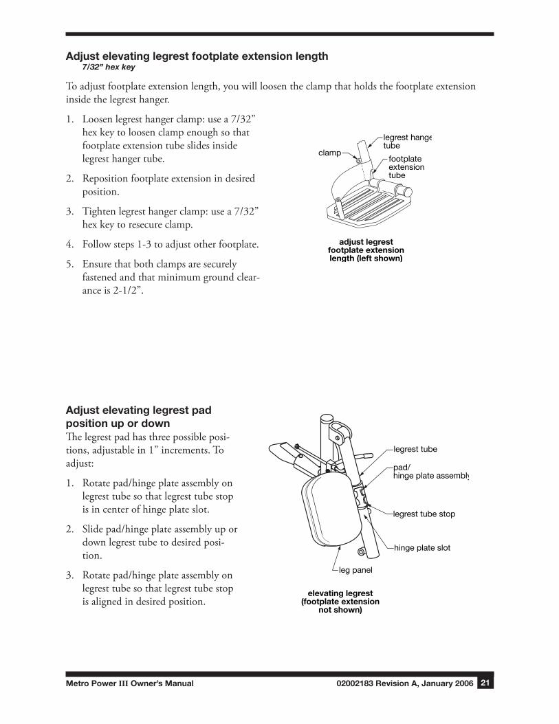
Adjust elevating legrest footplate extension length7/32” hex key
To adjust footplate extension length, you will loosen the clamp that holds the footplate extension inside the legrest hanger.
1. Loosen legrest hanger clamp: use a 7/32” hex key to loosen clamp enough so that footplate extension tube slides inside legrest hanger tube.
2. Reposition footplate extension in desired position.
3. Tighten legrest hanger clamp: use a 7/32” hex key to resecure clamp.
4. Follow steps 1-3 to adjust other footplate.
5. Ensure that both clamps are securely fastened and that minimum ground clear-ance is 2-1/2”.
Adjust elevating legrest pad position up or downThe legrest pad has three possible posi-tions, adjustable in 1” increments. To adjust:
1. Rotate pad/hinge plate assembly on legrest tube so that legrest tube stop is in center of hinge plate slot.
2. Slide pad/hinge plate assembly up or down legrest tube to desired posi-tion.
3. Rotate pad/hinge plate assembly on legrest tube so that legrest tube stop is aligned in desired position.
elevating legrest(footplate extension
not shown)
leg panel
hinge plate slot
legrest tube stop
legrest tube
pad/hinge plate assembly
adjust legrestfootplate extensionlength (left shown)
clampfootplateextensiontube
legrest hangertube
02002183 Revision A, January 2006 Metro Power III Owner’s Manual22
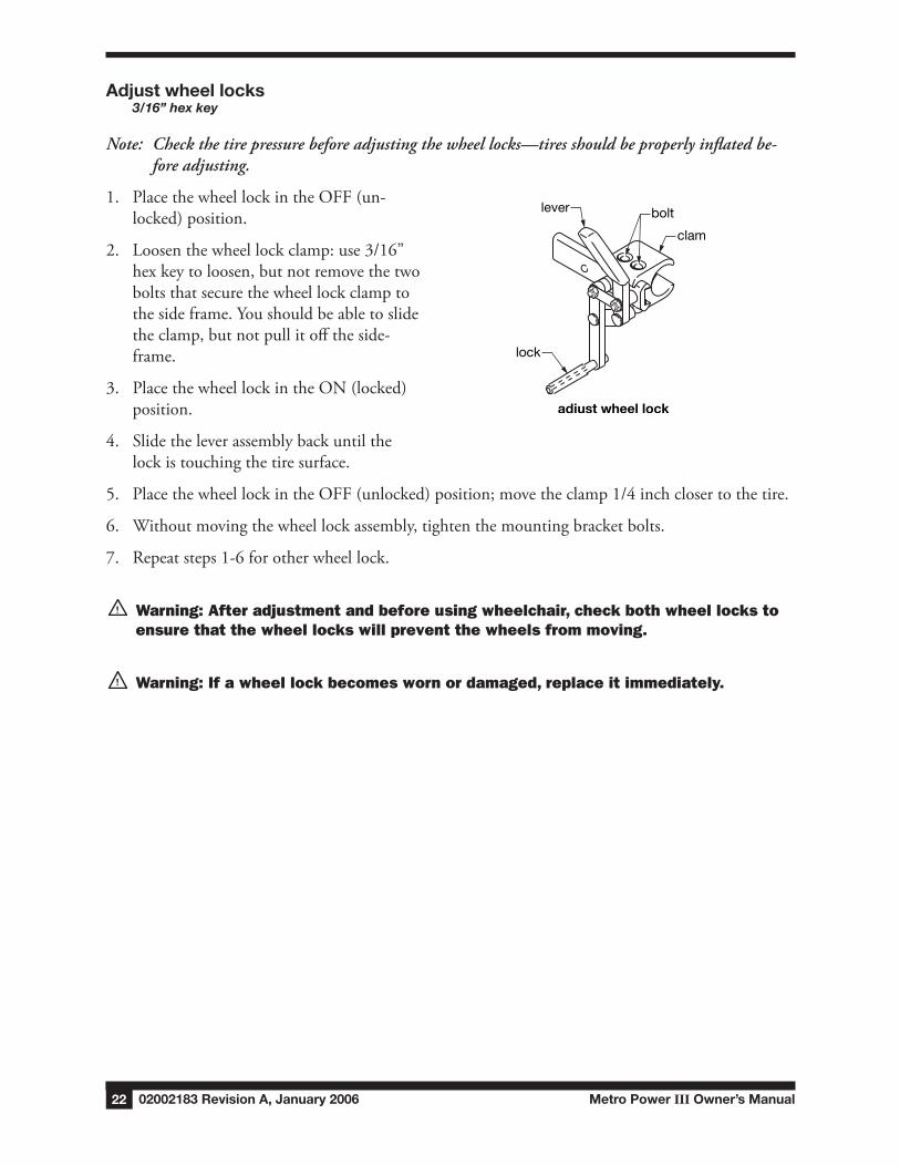
Adjust wheel locks3/16” hex key
Note: Checkthetirepressurebeforeadjustingthewheellocks—tiresshouldbeproperlyinflatedbe-foreadjusting.
1. Place the wheel lock in the OFF (un-locked) position.
2. Loosen the wheel lock clamp: use 3/16” hex key to loosen, but not remove the two bolts that secure the wheel lock clamp to the side frame. You should be able to slide the clamp, but not pull it off the side-frame.
3. Place the wheel lock in the ON (locked) position.
4. Slide the lever assembly back until the lock is touching the tire surface.
5. Place the wheel lock in the OFF (unlocked) position; move the clamp 1/4 inch closer to the tire.
6. Without moving the wheel lock assembly, tighten the mounting bracket bolts.
7. Repeat steps 1-6 for other wheel lock.
Warning: After adjustment and before using wheelchair, check both wheel locks to ensure that the wheel locks will prevent the wheels from moving.
Warning: If a wheel lock becomes worn or damaged, replace it immediately.
adjust wheel lock
lock
lever bolt
clamp
Metro Power III Owner’s Manual 02002183 Revision A, January 2006 23
VII BAtteRIes
Batteries are of critical importance, require attention and maintenance, and will require periodic replacement. As batteries age, their ability to hold a charge decreases. Old batteries discharge much more quickly than new batteries under the same driving conditions. This results in a decrease in the distance the wheelchair can travel before batteries need to be charged. This decrease is often misin-terpreted as a problem with the wheelchair system, when in fact the batteries have simply reached the end of their useful lives and should be replaced. Properly maintained batteries can be expected to last approximately 9 to 18 months. The purpose of proper maintenance is to extend that life as much as possible, and to minimize the incidence of unsatisfactory wheelchair performance.
Batteries are not supplied with your Metro Power III wheelchair. The Metro Power III uses two 12 volt deep cycle batteries, group size U1. For best performance, batteries with the highest possible amp/hour rating should be used.
s Caution:Useonlydeepcyclebatteriesonyourwheelchair.Donotuseautomotivebatteries.
Warning: Batteries generate sulfuric acid, which can burn eyes, skin, clothes, etc. use caution! Always wear safety glasses when working with batteries. If contact oc-curs, flush immediately with water and get medical attention.
guIdelInes tO eXtendIng BAtteRy lIfe
• Give the batteries a full charge before using them for the first time.
• Limit use of new batteries for the first ten charge/discharge cycles—avoid deeply discharging the batteries. New batteries are not capable of their rated output until they have been discharged a number of times.
• Recharge batteries after every discharge. Discharging batteries deeply before recharging them will shorten battery life. Leaving partially discharged batteries idle for several days is not recommend-ed; charge them as soon as possible after discharging.
• Charge batteries fully each time before using. Allow the charger to finish its charge cycle once started. This will help prevent deeply discharging the batteries. Unlike some rechargeable bat-teries, the batteries used on wheelchairs do not exhibit a significant “memory effect”—they will recharge to their full capacity, even if only partially discharged before each charge.
• If you must store your wheelchair for a long period of time, charge the batteries weekly.
• Perform regular maintenance on the batteries. See maintenance schedule in Section VIII, MAINTENANCE, for recommended regularity.

02002183 Revision A, January 2006 Metro Power III Owner’s Manual24
BAtteRy CHARgeR sAfety
Warning: Do not use a household extension cord if the charger plug does not reach the power outlet. use of an improper extension cord could result in fire and electric shock. If an extension cord must be used, use a three conductor no. 16 AWG (or heavier) cord with ground, properly wired, in good electrical condition, and keep it as short as possible.
Warning: Do not use cords that are damaged or defective. use of a damaged or de-fective cord could result in fire or electric shock.
Warning: Locate all battery charger cords so that they will not be stepped on, tripped over, or otherwise subjected to damage or stress.
Warning: To prevent electrical shock, do not touch uninsulated parts of the battery charger output connector, battery connectors, or battery terminals. Ensure that all electrical connectors are in good working condition. Do not use connectors that are cracked, corroded, or do not make adequate electrical contact. use of a damaged or defective connnector could result in fire or electric shock.
Warning: Ensure that area around battery charger and batteries is well ventilated while batteries are being charged. Do not allow clothing, blankets, or other material to cover battery charger. Do not place under a bed.
Warning: Keep sparks, flame, and smoking materials away from batteries at all times. no smoking!
Warning: Battery chargers can ignite flammable materials and vapors. Do not use near fuels, grain dust, solvents, thinners, or other flammables.
Warning: Batteries generate gases which can be explosive. To prevent arcing or burning near batteries, do not disconnect battery charger output connector from wheelchair battery charger receptacle when battery charger is operating. If charge cycle must be interrupted, move the battery charger On/OFF switch to OFF and disconnect the battery charger AC connector from power outlet, then disconnect battery charger output connecotor from wheelchair battery charger receptacle.
Warning: To avoid damage to any of the battery charger connectors and their cords, disconnect by grasping the plug body and pulling it straight out of the outlet or receptacle. DO nOT pull on the cord. DO nOT twist, rock or pull the connector side-ways.

Metro Power III Owner’s Manual 02002183 Revision A, January 2006 2�
Warning: Do not use battery chargers not supplied by Graham-Field Health Products. Battery chargers not supplied by Graham-Field Health Products could damage the controller and the battery charger. Electrical arcing could result, which could cause severe personal injury, explosion, and fire.
CHARgIng tHe BAtteRIes
Note: Beforechargingthebatteries,readtherestofthismanual,especiallytheBatteryChargersec-tions.
Note: Asasafetyfeature,thewheelchairisinoperableduringcharging.
1. Ensure that power to both wheelchair and battery charger is OFF.
2. Connect the battery charger output connector to the wheelchair battery charger receptacle.
3. North America: Plug the battery charger AC connector into a properly grounded, 115 volt, 60 cycle single phase power outlet. If you are not in North America, check that the battery charger AC voltage switch is set on the appropriate voltage for your location.
4. Place the battery charger power switch in ON position. The battery charger’s power indicator LED will illuminate red, the charge indicator LED will illuminate yellow, and the fan will begin to run.
5. The charge indicator LED may appear to flicker or alternate between green and yellow when the batteries are nearly finished charging, and the fan may go on and off. The charge-indicator LED will change to non-flashing green when the batteries are fully charged.
Allow adequate time to bring the batteries up to a full charge—the actual time required to recharge the batteries will depend on discharge condition. The charger supplied with the wheel-chair is automatic, and will not damage the batteries if left connected after batteries are fully charged.
6. When batteries are fully charged, place battery charger power switch in the OFF position.
7. Remove battery charger cable connector from receptacle.
Note: Ifyouhaveanyproblemschargingthebatteries,seeTroubleshooting,batterychargerintheTROUBLESHOOTINGsection.Identifythesymptomandfollowthestepsinorder.Ifyouareunabletoresolvetheproblem,contactyourEverest&Jenningsdealer.
02002183 Revision A, January 2006 Metro Power III Owner’s Manual26
ReMOVe And InstAll BAtteRIes
Note: Ifyouarereplacingbatteries,youwillneedaPhillipsscrewdriverand3/8”wrench.
Warning: Batteries can supply a large amount of current. Take care not to connect the terminals accidentally with anything metal; severe burns could result.
Warning: Always wear safety glasses and gloves while working on batteries.
Warning: Do not wear jewelry or watches while working on batteries.
Remove BatteriesTools needed: Phillips screwdriver, 3/8” wrench
1. Switch wheelchair power OFF.
2. Remove strap that secures battery boxes to battery tray: loosen battery strap at back of rear bat-tery box; pull up and forward.
3. Disconnect black connectors connecting integral controller and battery box.
4. Disconnect red connectors connecting the two battery boxes.
5. Remove battery boxes—from rear, lift up and over battery tray.
6. Loosen and remove battery box straps.
7. Carefully remove battery box lids.
8. Use a Phillips screwdriver and 3/8” wrench to remove nuts and screws that secure wire terminals to battery terminals. Set aside for reassembly. Repeat for other battery.
9. Remove batteries from battery boxes.
Velcro is a registered trademark of Velcro Industries B.V.
Metro Power III Owner’s Manual 02002183 Revision A, January 2006 27
Install BatteriesTools needed: Phillips screwdriver, 3/8” wrench
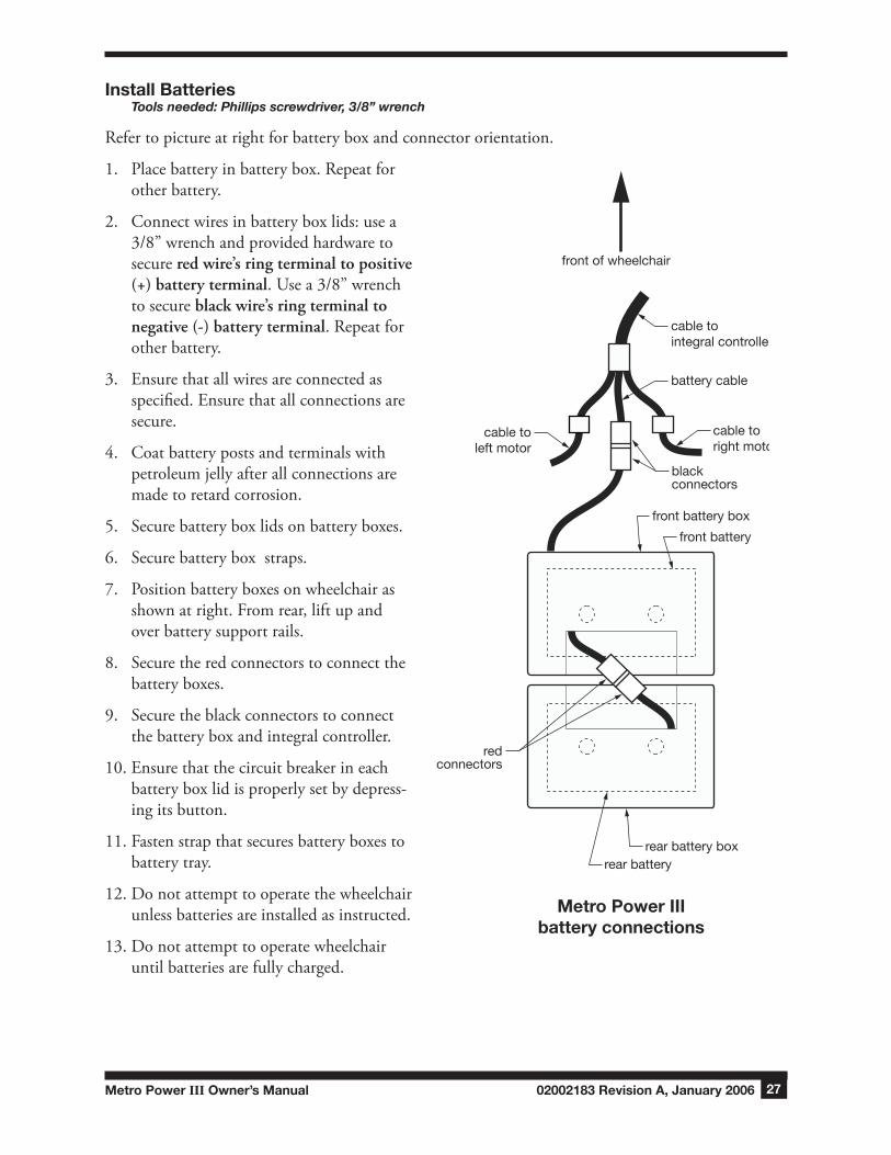
Refer to picture at right for battery box and connector orientation.
1. Place battery in battery box. Repeat for other battery.
2. Connect wires in battery box lids: use a 3/8” wrench and provided hardware to secure redwire’sringterminaltopositive(+)batteryterminal. Use a 3/8” wrench to secure blackwire’sringterminaltonegative(-)batteryterminal. Repeat for other battery.
3. Ensure that all wires are connected as specified. Ensure that all connections are secure.
4. Coat battery posts and terminals with petroleum jelly after all connections are made to retard corrosion.
5. Secure battery box lids on battery boxes.
6. Secure battery box straps.
7. Position battery boxes on wheelchair as shown at right. From rear, lift up and over battery support rails.
8. Secure the red connectors to connect the battery boxes.
9. Secure the black connectors to connect the battery box and integral controller.
10. Ensure that the circuit breaker in each battery box lid is properly set by depress-ing its button.
11. Fasten strap that secures battery boxes to battery tray.
12. Do not attempt to operate the wheelchair unless batteries are installed as instructed.
13. Do not attempt to operate wheelchair until batteries are fully charged.
blackconnectors
redconnectors
rear batteryrear battery box
front battery box
front battery
battery cable
cable tointegral controller
cable toright motor
cable toleft motor
front of wheelchair
Metro Power IIIbattery connections

02002183 Revision A, January 2006 Metro Power III Owner’s Manual28
BAtteRy MAIntenAnCe
Warning: Batteries can supply a large amount of current. Do not wear jewelry or watches when working on batteries. Take care not to connect the terminals acciden-tally with anything metal; severe burns could result.
Warning: Batteries contain sulfuric acid, which can burn eyes, skin, clothes, etc. use caution! Always wear gloves when working with batteries. If contact occurs, flush immediately with water and get medical attention.
s Caution: Whencleaningbatteries,donotletanybakingsodasolutionenterthebatteries;itwilldamagetheelectrolyte.
s Caution: Alwayskeepunsealedbatteriesuprightsothattheelectrolytedoesn’tleak.
Clean batteries1. You will first need to remove the batteries; see RemoveBatteries in previous REMOVEAND
INSTALLBATTERIES section—follow steps 1-9.
2. Clean outside of batteries, and inside and outside of battery boxes, with a solution of one table-spoon baking soda to ten ounces water.
3. Rinse with clear water. Allow to dry.
4. Ensure that batteries and connectors are clean and dry. Reinstall batteries; see InstallBatteries in previous REMOVEANDINSTALLBATTERIES section—follow steps 1-13.
Clean battery terminals1. You will first need to remove the batteries; see RemoveBatteries in previous REMOVEAND
INSTALLBATTERIES section—follow steps 1-8.
2. Clean all battery terminals and clamps with a wire brush (brushes for this purpose can be pur-chased at most automotive parts stores).
3. Reinstall batteries; see InstallBatteries in previous REMOVEANDINSTALLBATTERIES section—follow steps 2-13.

Metro Power III Owner’s Manual 02002183 Revision A, January 2006 29
VIII MAIntenAnCe
We urge you to protect your power drive wheelchair investment by keeping your Metro Power III in top condition. Periodic inspection, adjustment, and replacement of worn parts will provide years of superb performance. When a component or part does not function properly, a potentially hazardous condition can result. Only excellent condition is acceptable where safety is concerned.
Note: WerecommendthatyouhaveaqualifiedEverest&Jenningsdealerperformthe6monthmaintenancechecks,becausesomespecialtoolsarerequired.Becausethedealerhasyearsofex-perienceandtrainingwithpowerwheelchairs,thedealermayfindandcorrectaproblemthatmightotherwisegoundetectedandeventuallycausemoreseriousproblems.
dO-It-yOuRself MAIntenAnCe
You can do many of the scheduled maintenance tasks yourself, if you have mechanical ability and a few basic tools. Refer to the maintenance schedule below for the recommended regularity of each procedure. If any maintenance procedure is not clear to you, ask your Everest & Jennings dealer for assistance.
MAINTENANCE SCHEDULE
Procedure Perform at least every
day week month 3 months 6 months
Charge batteries 4
Check joystick 4
Check cables & connections 4
Check tire pressure & wear 4
Check integral controller & park brakes 4
Check wheel lock engagement 4
Clean/check upholstery 4
Clean batteries 4
Clean wheelchair 4
Check caster forks 4
Clean battery terminals 4
Inspect motor brushes 4
Check bearings 4
Warning: Improper maintenance can cause operating problems and may affect your warranty coverage.
Warning: The use of non-Everest & Jennings replacement parts could create a haz-ardous condition, which could result in serious injury.
02002183 Revision A, January 2006 Metro Power III Owner’s Manual30
list of toolsThe tools and cleaning supplies listed will assist in the procedures outlined in Part VIII.
Adjustable wrench Phillips screwdriver Blade screwdriver Battery terminal cleaning tool
Mild soap or cleaning agent Auto wax or equivalent Cleaning rags
Charge batteriesCharge the batteries daily. See Part VII, BATTERIES, CHARGING THE BATTERIES.
COntROlleR MAIntenAnCe
Warning: The Integral Controller contains no serviceable parts. Do not open the cover. see TROuBLEsHOOTInG if you have a problem with the Controller, and con-tact your dealer if you have a problem you are unable to resolve.
geneRAl
Avoid knocking your Integral Controller, especially the joystick. When transporting your wheelchair, ensure that the Controller is well protected, especially the cables. To prolong the Controller’s life, keep exposure to extreme conditions to a minimum. Do not expose the Controller to damp condi-tions for prolonged periods. Always clean your Controller if it becomes contaminated with food or drink. Use a damp cloth and dish soap mixed with water. Be careful when cleaning the joystick. Do not use abrasive or solvent based cleaning agents.
Perform the following daily and weekly control system checks as directed. If the control system fails any of these checks, do not use the wheelchair; contact your Everest & Jennings dealer.
COntROl systeM dAIly CHeCk
JoystickTurn Controller ON/OFF switch off. Check that the joystick is not bent or damaged, and that it returns to center when you push and release it. If there is a problem, do not continue with the safety checks; contact your dealer.
COntROl systeM weekly CHeCk
Park brakesThis test should be carried out on a level floor with at least one meter (40 inches) of clear space around the wheelchair.
1. Turn Controller ON/OFF switch on.
2. Check that the battery gauge remains on, or flashes slowly, after one second.
Metro Power III Owner’s Manual 02002183 Revision A, January 2006 31
3. Push the joystick slowly forward until you hear the park brakes operate. The wheelchair may start to move.
4. Immediately release the joystick. You must be able to hear each park brake operate within a few seconds.
5. Repeat the test a further three times, pushing the joystick slowly backward, left and right.
ConnectorsCheck that all Controller connectors are secure, properly mated and free from damage.
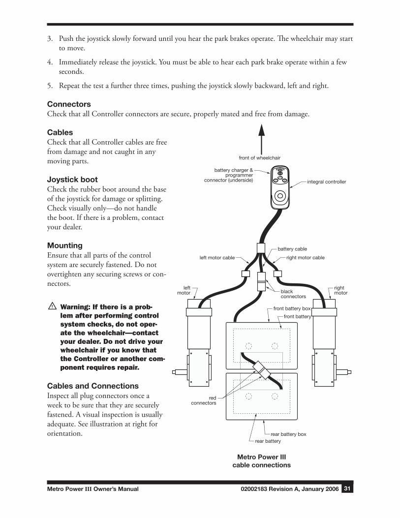
CablesCheck that all Controller cables are free from damage and not caught in any moving parts.
Joystick bootCheck the rubber boot around the base of the joystick for damage or splitting. Check visually only—do not handle the boot. If there is a problem, contact your dealer.
MountingEnsure that all parts of the control system are securely fastened. Do not overtighten any securing screws or con-nectors.
Warning: If there is a prob-lem after performing control system checks, do not oper-ate the wheelchair—contact your dealer. Do not drive your wheelchair if you know that the Controller or another com-ponent requires repair.
Cables and ConnectionsInspect all plug connectors once a week to be sure that they are securely fastened. A visual inspection is usually adequate. See illustration at right for orientation.
integral controller
leftmotor
rightmotorblack
connectors
redconnectors
rear batteryrear battery box
front battery box
front battery
battery cable
right motor cableleft motor cable
battery charger &programmer
connector (underside)
front of wheelchair
Metro Power IIIcable connections
02002183 Revision A, January 2006 Metro Power III Owner’s Manual32
Check tiresExamine the tires periodically for wear, and replace as required.
Check wheel lock engagementCheck wheel lock engagement weekly. See Part VI, Adjustwheellocks, to adjust wheel locks.
Warning: If a wheel lock becomes worn or damaged, replace it immediately.
Clean & check upholsteryClean the upholstery with a mild soap and water solution monthly. Ensure that all upholstery secur-ing hardware is tight. If upholstery mounting screws are loose, use a Phillips screwdriver to tighten them. Inspect upholstery mounting grommets to ensure that they are all properly aligned and se-cured. Inspect for rips, tears and worn spots.
Warning: Replace worn or torn upholstery immediately. It may not support body weight.
Clean BatteriesPerform this at least every three months. See Part VII, BATTERIES,BATTERYMAINTENANCE, Cleanbatteries,for this procedure.
Clean wheelchairClean and wax all chrome or painted parts at least every three months. Clean the metal parts with a wax that contains a cleaner (auto wax). Do not use abrasive cleaners such as chrome cleaner or scouring cleaners; these will scratch the finish. Never use steam or high pressure cleaners to clean the wheelchair; they will remove protective coatings and lubricating oils.
Check caster forksCheck the caster stems/forks for proper rotation at least every three months. The caster fork must swivel freely to facilitate steering and handling. Adjusting the stem nut varies the amount of force required to turn the caster. If the nut is too loose, the caster will flutter or shimmy; if the nut is too tight, the wheelchair will be difficult to steer. If the caster stem requires adjustment, or the caster stem bearing requires replacement, visit a qualified Everest & Jennings dealer. Ensure that stems are firmly attached to forks, and that forks and stems are not bent. Evaluate all threads, locking nuts and bearings.
Clean battery terminalsPerform this at least every six months. See Part VII, BATTERIES,BATTERYMAINTENANCE, Cleanbatteryterminals, or contact your Everest & Jennings dealer.
Metro Power III Owner’s Manual 02002183 Revision A, January 2006 33
Inspect motor brushesThe motor brushes should be inspected for wear every six months and replaced as needed. This should be performed by an Everest & Jennings dealer.
s Caution: Badlywornbrushescanresultindamagetothemotorsorintegralcontroller.
s Caution: Afterreplacingthebrushes,runthewheelchairgentlyforthefirstfewmilestoallowthebrushestoseatproperly.
Check bearingsThe Metro Power III has bearings only in the caster wheels, not in the rear wheels. Always be alert for unusual noises in the bearings or excessive caster wobble. These signs indicate that the bearings are becoming worn and may require replacement. The caster bearings should be inspected every six months and replaced as needed. This should be performed by an Everest & Jennings dealer.

02002183 Revision A, January 2006 Metro Power III Owner’s Manual34
IX tROuBlesHOOtIng
tROuBlesHOOtIng, POweR dRIVe
Most power drive problems are battery related. As batteries age, their ability to hold a charge decreas-es. Old batteries discharge much more quickly than new batteries under the same driving conditions. This results in a decrease in the distance the wheelchair can travel before batteries need to be charged. This decrease is often misinterpreted as a problem with the wheelchair system, when in fact the bat-teries have simply reached the end of their useful life and should be replaced. Sometimes expensive components are unnecessarily replaced when the batteries are the real problem. If an electrical prob-lem exists, check the following:
BatteriesMake sure the batteries are fully charged. Test unsealed lead acid batteries with a calibrated hydrom-eter, as directed in wheelchair owner’s manual. Keep battery posts and terminals clean and tight.
Circuit breakerYour wheelchair is equipped with circuit breakers, to protect the electrical circuits from overload, in each of the battery box lids. In the event of an overload, the circuit breaker button will pop out. To reset the circuit breaker, push the button in.
tROuBlesHOOtIng, IntegRAl COntROlleR
A general diagnostic guide is first, followed by the battery gauge diagnostic guide. Use the general di-agnostic guide first; if you are unable to solve your problem, use the battery gauge diagnostic guide.
Warning: If problems or fault indicators persist, do not attempt to operate the wheelchair. see a qualified Everest & Jennings dealer. Operation of the wheelchair could be unsafe.
general diagnostic guideSYMPTOM BATTERY POSSIBLECAUSE CORRECTIVEACTION GAUGE LIGHTS
Wheelchair Off Systemoff TurnON/OFFswitchonwon’tdrive Batteriesnot Connectbatteries connected
Batteriesnot CorrectConnections connectedproperly,or polarityreversed
Circuitbreakeropen Resetcircuitbreaker Batteriesseverely Recharge/replacebatteries discharged

Metro Power III Owner’s Manual 02002183 Revision A, January 2006 3�
SYMPTOM BATTERY POSSIBLECAUSE CORRECTIVEACTION GAUGE LIGHTS
Wheelchair Offwon’tdrive Flashfast Controlsystemfault TheControllersafetycircuitshaveoperatedandtheControllerhas (evenwith beenpreventedfrommovingthewheelchair.Thisindicatesthatthere joystick isafault.Pleasefollowthisprocedure: released) 1. TurntheController’sON/OFFswitchoff. 2. EnsurethatallControllerandwheelchairconnectorsaresecurelymated. 3.Checkbatterycondition. 4. Ifyoucan’tfindtheproblem,tryusingthefollowingBatterygaugediagnosticguide. 5. TurntheControlleronagainandtrytodrivethewheelchair.Ifthefaultlightsflashagain, donottrytousethewheelchair;seeyourdealer.
Wheelchair On,steady Alliswell Nonedrives
Flash Lowbatteries Controllerisfunctioningcorrectlybutyoushouldchargethebatteries slowly assoonaspossible.
Wheelchair On Speedcontrolor Ifthewheelchairdoesnottravelatfullspeedordoesnotresponddrives,but nonhazardousfault quicklyenough,andbatteryconditionisgood,checkspeedcontrolmovementis setting.Ifadjustingthespeedcontroldoesnotremedytheproblem,sluggish theremaybeanonhazardousfault.Callyourdealer.
Speedandresponse Reprogramtodesired havebeen performance programmedslow
Battery gauge diagnostic guideIn addition to the battery gauge function, the battery gauge provides a diagnostic display. When a system fault occurs, a set (from one to ten) of light bars will flash. Use the illustration below to di-agnose the fault (the number represents the number of light bars flashing), then find the problem in the Battery gauge diagnostic guide table that follows.
Battery gauge diagnostic guide tableBATTERYINDICATOR SYSTEMLIGHTS FAULT CHECK/ACTION
Red,yellow,& None Batterycharged;ControllerandelectricalsystemOK.greenbarslit
Red&yellow None Chargebatteryifpossible;ControllerandelectricalsystemOK. barslit
Redbarsonly None Lowbatteries;ControllerandelectricalsystemOK.litorslowflash Chargebatteries.
Red,yellow, Possible Joystickoutofneutral—leavejoystickinneutralwhileturningwheelchairpoweron.Operate&greenbars, joystickfault joysticktomakesureitreturnstoneutral.TurnON/OFFswitchoffandONtoreset. rippleup& down
02002183 Revision A, January 2006 Metro Power III Owner’s Manual36
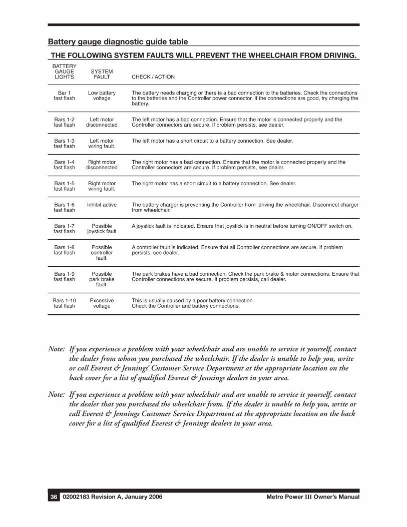
Battery gauge diagnostic guide table
tHe fOllOwIng systeM fAults wIll PReVent tHe wHeelCHAIR fROM dRIVIng. BATTERY GAUGE SYSTEM LIGHTS FAULT CHECK/ACTION
Bar1 Lowbattery Thebatteryneedschargingorthereisabadconnectiontothebatteries.Checktheconnections fastflash voltage tothebatteriesandtheControllerpowerconnector.Iftheconnectionsaregood,trychargingthe battery.
Bars1-2 Leftmotor Theleftmotorhasabadconnection.Ensurethatthemotorisconnectedproperlyandthe fastflash disconnected Controllerconnectorsaresecure.Ifproblempersists,seedealer.
Bars1-3 Leftmotor Theleftmotorhasashortcircuittoabatteryconnection.Seedealer. fastflash wiringfault.
Bars1-4 Rightmotor Therightmotorhasabadconnection.Ensurethatthemotorisconnectedproperlyandthe fastflash disconnected Controllerconnectorsaresecure.Ifproblempersists,seedealer.
Bars1-5 Rightmotor Therightmotorhasashortcircuittoabatteryconnection.Seedealer. fastflash wiringfault.
Bars1-6 Inhibitactive ThebatterychargerispreventingtheControllerfromdrivingthewheelchair.Disconnectcharger fastflash fromwheelchair.
Bars1-7 Possible Ajoystickfaultisindicated.EnsurethatjoystickisinneutralbeforeturningON/OFFswitchon. fastflash joystickfault
Bars1-8 Possible Acontrollerfaultisindicated.EnsurethatallControllerconnectionsaresecure.Ifproblem fastflash controller persists,seedealer. fault.
Bars1-9 Possible Theparkbrakeshaveabadconnection.Checktheparkbrake&motorconnections.Ensurethat fastflash parkbrake Controllerconnectionsaresecure.Ifproblempersists,calldealer. fault.
Bars1-10 Excessive Thisisusuallycausedbyapoorbatteryconnection. fastflash voltage ChecktheControllerandbatteryconnections.
Note: Ifyouexperienceaproblemwithyourwheelchairandareunabletoserviceityourself,contactthedealerfromwhomyoupurchasedthewheelchair.Ifthedealerisunabletohelpyou,writeorcallEverest&Jennings’CustomerServiceDepartmentattheappropriatelocationonthebackcoverforalistofqualifiedEverest&Jenningsdealersinyourarea.
Note: Ifyouexperienceaproblemwithyourwheelchairandareunabletoserviceityourself,contactthedealerthatyoupurchasedthewheelchairfrom.Ifthedealerisunabletohelpyou,writeorcallEverest&JenningsCustomerServiceDepartmentattheappropriatelocationonthebackcoverforalistofqualifiedEverest&Jenningsdealersinyourarea.
Metro Power III Owner’s Manual 02002183 Revision A, January 2006 37
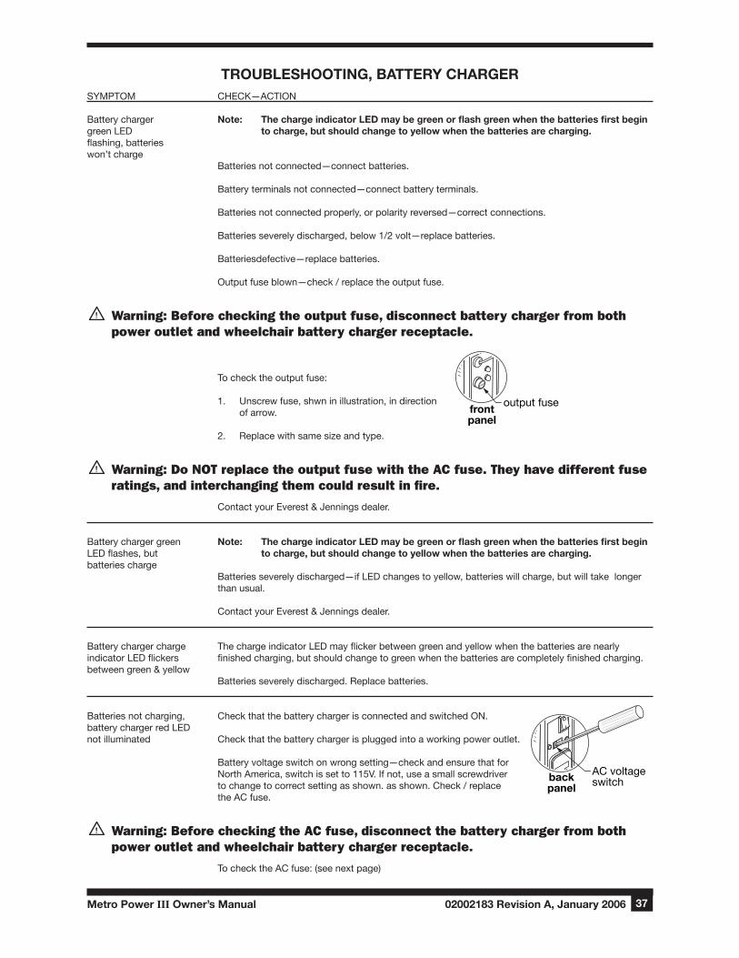
tROuBlesHOOtIng, BAtteRy CHARgeRSYMPTOM CHECK—ACTION
Battery charger Note: The charge indicator LED may be green or flash green when the batteries first begin green LED to charge, but should change to yellow when the batteries are charging. flashing, batteries won’t charge Batteries not connected—connect batteries.
Battery terminals not connected—connect battery terminals.
Batteries not connected properly, or polarity reversed—correct connections.
Batteries severely discharged, below 1/2 volt—replace batteries.
Batteriesdefective—replace batteries.
Output fuse blown—check / replace the output fuse.
Warning: Before checking the output fuse, disconnect battery charger from both power outlet and wheelchair battery charger receptacle.
To check the output fuse:
1. Unscrew fuse, shwn in illustration, in direction of arrow.
2. Replace with same size and type.
Warning: Do nOT replace the output fuse with the AC fuse. They have different fuse ratings, and interchanging them could result in fire.
Contact your Everest & Jennings dealer.
Battery charger green Note: The charge indicator LED may be green or flash green when the batteries first begin LED flashes, but to charge, but should change to yellow when the batteries are charging.batteries charge Batteries severely discharged—if LED changes to yellow, batteries will charge, but will take longer than usual. Contact your Everest & Jennings dealer.
Battery charger charge The charge indicator LED may flicker between green and yellow when the batteries are nearly indicator LED flickers finished charging, but should change to green when the batteries are completely finished charging.between green & yellow Batteries severely discharged. Replace batteries.
Batteries not charging, Check that the battery charger is connected and switched ON.battery charger red LEDnot illuminated Check that the battery charger is plugged into a working power outlet. Battery voltage switch on wrong setting—check and ensure that for North America, switch is set to 115V. If not, use a small screwdriver to change to correct setting as shown. as shown. Check / replace the AC fuse.
Warning: Before checking the AC fuse, disconnect the battery charger from both power outlet and wheelchair battery charger receptacle.
To check the AC fuse: (see next page)
FUSE
output fusefrontpanel
115
backpanel
AC voltageswitch
02002183 Revision A, January 2006 Metro Power III Owner’s Manual38
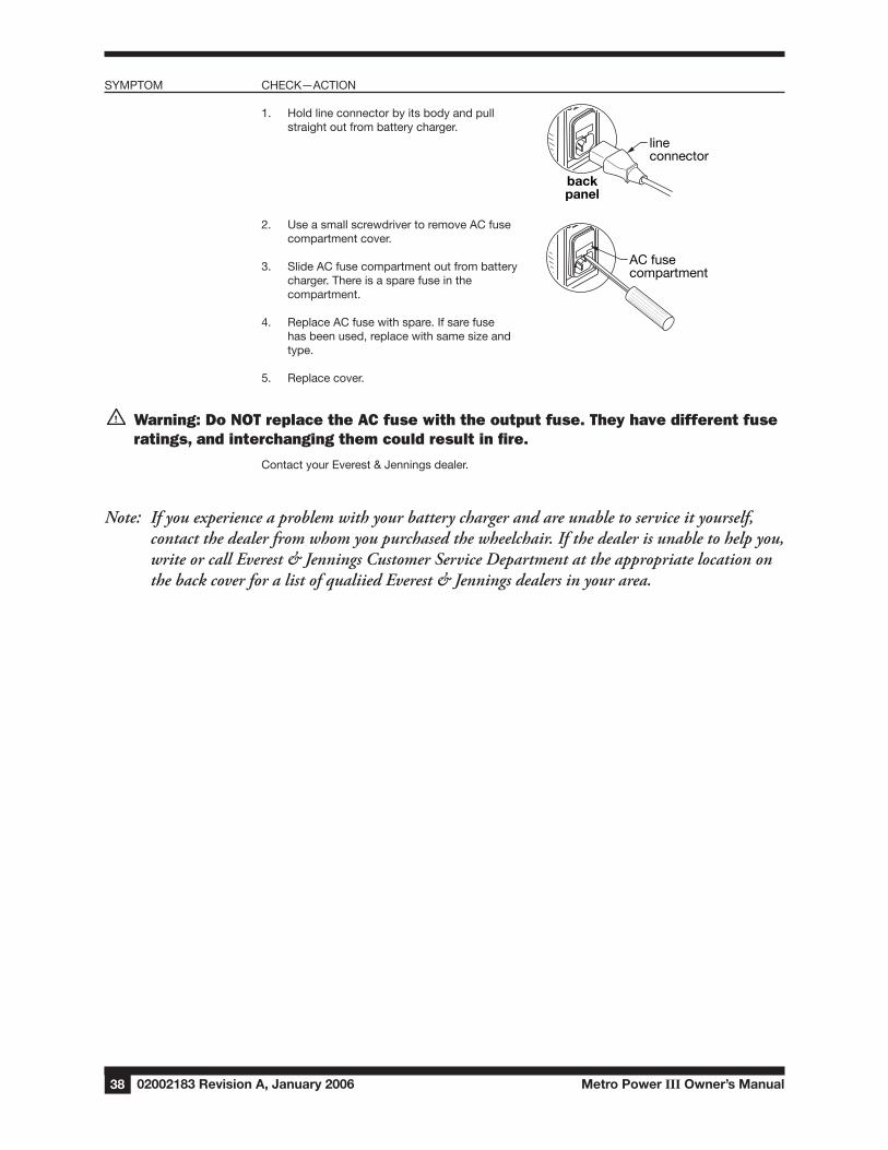
SYMPTOM CHECK—ACTION
1. Hold line connector by its body and pull straight out from battery charger.
2. Use a small screwdriver to remove AC fuse compartment cover.
3. Slide AC fuse compartment out from battery charger. There is a spare fuse in the compartment.
4. Replace AC fuse with spare. If sare fuse has been used, replace with same size and type. 5. Replace cover.
Warning: Do nOT replace the AC fuse with the output fuse. They have different fuse ratings, and interchanging them could result in fire.
Contact your Everest & Jennings dealer.
Note: Ifyouexperienceaproblemwithyourbatterychargerandareunabletoserviceityourself,contactthedealerfromwhomyoupurchasedthewheelchair.Ifthedealerisunabletohelpyou,writeorcallEverest&JenningsCustomerServiceDepartmentattheappropriatelocationonthebackcoverforalistofqualiiedEverest&Jenningsdealersinyourarea.
115
backpanel
lineconnector
115
AC fusecompartment

Metro Power III Owner’s Manual 02002183 Revision A, January 2006 39
X tRAnsPORtIng tHe MetRO POweR III
Warning: This wheelchair does not offer seating or occupant restraint equivalent to the seat provided in a motor vehicle! To increase your safety while traveling in a mo-tor vehicle, always transfer to the vehicle seat and use the restraint provided by the vehicle manufacturer.
The unoccupied Metro Power III can be dismantled somewhat to ease transport.
1. Place the wheelchair power switch in the OFF position.
2. Remove strap that secures battery boxes to battery tray.
3. Disconnect black connectors connecting integral controller and battery box.
4. Disconnect red connectors connecting the two battery boxes.
5. Remove battery boxes—from rear, lift up and over battery tray.
s Caution: Alwayskeepunsealedbatteriesuprightsothattheelectrolytedoesn’tleak.
6. Unlock and pull up on battery tray center rod to fold wheelchair.
7. Remove front rigging from wheelchair.
8. Fold the wheelchair: tip the wheelchair toward you, taking weight off the opposite wheel so that the tire won’t drag. Lift the opposite side up and toward you.
Reassembly1. Tip the wheelchair toward you, taking weight off the opposit wheel so that the tire won’t drag.
Open the wheelchair by pulling the sides apart.
Warning: To avoid injury while opening the wheelchair, do not place your hand be-tween the seat tubes and the side panels, and do not place your fingers beneath the seat tubes.
2. Push down with even pressure on seat tubes on both sides of wheelchair.
3. Push down on battery tray center rod and lock into place.
4. Replace battery boxes as previously positioned on wheelchair—from rear, lift up and over battery support rails.
5. Secure the red connectors to connect the battery boxes.
6. Secure the black connectors to connect the battery box and integral controller.
7. Fasten strap that secures battery boxes to battery tray.
8. Attach front rigging to wheelchair.
Warning: Ensure that both seat tubes are locked in place on seat rail cradles. If not, wheelchair is unsafe to occupy, and crossbrace could break.

02002183 Revision A, January 2006 Metro Power III Owner’s Manual40
XI lIMIted wARRAnty
This warranty has been drafted to comply with the U.S. Federal Law applicable to products manufac-tured after July 4, 1975. This warranty is extended only to the original purchaser/consumer or dealer/
non-consumer and to no other purchaser or transferee. Graham-Field warrants the Metro ower III against manufacturing defects in materials and workmanship as listed below:
The Warranty period for the consumer commences on the first date a product is delivered to con-sumer by seller/dealer. If the product is rented or leased, the warranty period commences on the invoice date from Graham-Field. A copy of the invoice showing date of purchase must be provided when submitting a warranty claim. Without proof of purchase date, warranty coverage shall com-mence upon Graham-Field’s invoice date to the dealer/purchaser.
If within the warranty period, the product or component part is proven to Graham-Field’s satisfac-tion to be defective, Graham-Field shall provide, at its option, one of the following: (1) repair or replacement of any defective or nonconforming part or product or (2) a credit and/or refund of the original selling price made to Graham-Field’s initial customer on a prorated or depreciated basis. GRAHAM-FIELD’S SOLE OBLIGATION AND YOUR EXCLUSIVE REMEDY UNDER THIS WARRANTY SHALL BE LIMITED TO SUCH REPAIR, REPLACEMENT, CREDIT AND/OR REFUND. This warranty does not include any labor charges incurred in replacement part(s) installa-tion or any associated freight or shipping charges to the manufacturer.
6 mo. 1 yr.METRO POWER III POWER WHEELCHAIR
a) Sideframes, crossbraces, wheelhubs.-----------------------------------------------------------------------------------------------------4b) Motors, integral controller, cables.---------------------------------------------------------------------------------------4c) Upholstered components, plastic parts, painted surfaces, rubber parts, bearings, ---------------4 front rigging, forks and any other parts not specifically identified above (all models).
a) Sideframe, mainframe, crossbraces, cross struts.----------------------------------------------------------------------------------4b) New—motors, actuators, control module, hand control.-----------------------------------------------------------------------4c) Remanufactured—motors, actuators, control module, hand control.----------------------------------4d) All other components.------------------------------------------------------------------------------------------4
* �e warranty period is as designated above. If a part is replaced under warranty, the original warranty period will not be affected. All other replacement parts will be subjected to the warranty period specified.
BATTERY CHARGERS------------------------------------------------------------------------------------------------------4
REPLACEMENT PARTS*
WARRANTY PERIODS
3 yrs.
3 mo. 6 mo.

Metro Power III Owner’s Manual 02002183 Revision A, January 2006 41
LIMITATIONSANDEXCLUSIONS:Theforegoingwarrantyshallnotapplytoserialnumberedproductsiftheserialnumberhasbeenremovedordefaced.Productssubjectedtonegligence,abuse,misuse,improperoperation,impropermaintenance,impropercleaning,improperstorage,ordamagesbeyondGraham-Field’scontrolarenotcoveredbythiswarranty,andthatevaluationshallbesolelydeterminedbyGraham-Field.Thiswarrantyshallnotapplytoproblemsarisingfromnormalwearandtearorfailuretofollowinstructions.ThewarrantyshallalsonotapplytoproductsmodifiedwithoutGraham-Field’sexpresswrittenconsent;norshallitapplyifpartsnotmanufacturedbyGraham-Field,orifpartsnotcomplyingwithoriginalequipmentspecificationsareaddedtoaGraham-fieldproduct,oriftheproductorpartisservicedbyanentitynotautho-rizedbyGraham-Field.
THE FOREGOING WARRANTY IS EXCLUSIVE AND IN LIEU OF ALL OTHER EXPRESS WARRANTIES AND IMPLIED WARRANTIES, INCLUDING BUT NOT LIMITED TO THE IMPLIED WARRANTIES OF MERCHANTABILITY AND FITNESS FOR A PARTICULAR PURPOSE, AND SHALL NOT EXTEND BEYOND THE DURATION OF THE EXPRESS WARRANTY PROVIDED HEREIN, AND THE REMEDY FOR VIOLATIONS OF ANY IMPLIED WARRANTY SHALL BE LIMITED TO THE REPAIR , REPLACEMENT, CREDIT AND/OR REFUND OF THE DEFECTIVE PRODUCT OR PART PURSUANT TO THE TERMS CONTAINED HEREIN. GRAHAM-FIELD SHALL NOT BE LIABLE FOR ANY CONSEQUENTIAL OR INCIDENTAL DAMAGES WHATSOEVER.
This warranty gives you specific legal rights and you may also have other legal rights which vary from state to state (province to province). Some states (provinces) do not allow the exclusion or limitation of incidental or consequential damages, or limitation on how long an implied warranty lasts, so the above exclusions and limitations may not apply to you.
For warranty service, please contact the authorized dealer from whom you acquired your Graham-Field product. In the event you do not receive satisfactory warranty service, please contact Graham-Field at the address on the back cover. Do not return products to our factory without prior authorization. This warranty contains the entire agreement between the parties and supersedes any prior, contrary or additional representations or understandings, whether oral or written, concerning our warranty policy.

02002183 Revision A, January 2006 Metro Power III Owner’s Manual42
XII IndeX
AAdjustments 18
Ascent 11
BBackward, leaning & bending 10
Balance 9
Batteries 23
Batteries, clean 28
Batteries, install 27
Batteries, remove 26
Batteries, troubleshooting 34
Battery charger AC connector 16
Battery charger AC fuse compartment 16
Battery charger AC voltage switch 16
Battery charger back panel 15
Battery charger charge indicator (yellow &
green) 16
Battery charger features 15
Battery charger front panel 16
Battery charger interface 15
Battery charger output connector 16
Battery charger output fuse 16
Battery charger output fuse, check 37
Battery compatibility 15
Battery maintenance 28
Battery terminals, clean 28
Bearings, check 33
CCables and connections, check 31
Caster stems, check 32
Caution, significance 3,23
Charging the batteries 25
Circuit breakers, troubleshooting 34
Clean wheelchair 32
Controller battery gauge 14
Controller diagnostic guide, general 34
Controller diagnostic guide table, battery gauge
35
Controller extension position, adjust 18
Controller maintenance 30
Control system daily check 30
Control system weekly check 30
Curbs and steps 11
dDescent 11
Do-it-yourself maintenance 29
eElectromagnetic interference, radio waves ... 7
Elevating legrest, adjust 20
EMI warnings 8
fFootrest, adjust 19
Forward or sideward, leaning & bending 10
gGetting started 12
HHandling tips 9
IIntegral controller 13
Introduction 3
JJoystick 13
lLimited warranty 40
Line connector, battery charger 16
MMaintenance 29
Metro Power III, illustration 12
Modification, unauthorized 6
Motor brushes, inspect 33
Motors 14
OOperating instructions 17
PPower drive system 13
Metro Power III Owner’s Manual 02002183 Revision A, January 2006 43
RRamps and inclines 10
Reaching / bending 9
Red LED, battery charger 16
Regular battery maintenance 28
Replacement parts, non-Everest & Jennings 6
sSafety precautions 4
Standard weight capacity 6
tTires, check 32
Tools, adjustment, list 18
Tools and cleaning supplies, maintenance, list
30
Transporting the Metro Power III 39
Troubleshooting, battery charger 37
Troubleshooting, integral controller 34
uUpholstery, clean & check 32
wWarranty, Limited 40
Wheel locks, adjust 22

U.S.A., Corporate Headquarters:
Graham-Field Health Products 2935 Northeast Parkway Atlanta, Georgia 30360
telephone: 800-347-5678, 770-447-1609 fax: 800-726-0601, 678-291-3232
www.grahamfield.com


