Embed Size (px)
Citation preview
Edition 08/2007
CB 240Climbing Scaffold
Assembly Instructions for Standard Application

Dokument 1 28.04.2005 12:48 Uhr Seite 1
Page
Overview 1-2Intended use 3Standards and regulations 3Safety Information 4Load models 5Standard work flow 6-7
Part A Pre-Assembly
A1 Required resources
A1.1 Tools 8A1.2 Resources 8A1.3 Flat assembly surface 8
A2 Assembly of the CB 240 Platform
A2.1 Positioning of the brackets 9A2.2 Girder assembly 10-11A2.3 Carriage assembly 12-13A2.4 Guardrail post assembly 14A2.5 Platform planking assembly 15-16A2.6 Guardrail assembly 16-17
A3 Other assembly work
A3.1 Lateral guardrails 18A3.2 Sliding hatch cover assembly 19A3.3 Finishing platform assembly 20-21A3.4 Concluding work 21
Part B Assembly and Use
B1 Work on the construction site
B1.1 Leading anchor assembly 22-25B1.2 Important aspects when stripping 26B1.3 Scaffold mounting ring assembly 27B1.4 Mounting platform to first section 28-29B1.5 Mounting of finishing platform 30-32B1.6 Tension anchor assembly 33-34B1.7 Removal of climbing cones 35B1.8 Dismantling of climbing scaffold 35B1.9 Ladder assembly 36-37
B2 Mounting of VARIO Elements
B2.1 Mounting of units with strongback 38-39B2.2 Exchange of formwork 40-41
B3 Mounting of TRIO Elements
B3.1 Mounting of units with strongback 42-43B3.2 Exchange of formwork 44-45
B4 Formwork Utilisation
B4.1 Carriage operations 46B4.2 Formwork alignment 47B4.3 Plumbing 48B4.4 Horizontal adjustment 48
B5 Moving
B5.1 Preparations 49-50B5.2 Moving process 50-51B5.3 Securing 51
Contents
Page
Part C Planning and Work Preparation
C1 Platforms
C1.1 Permissible width of influence 52C1.2 Reaction forces for standard designs 53-54C1.3 Anchoring 55C1.4 Platform decking 56-58C1.5 Handrails and guardrails 59C1.6 Individual components and weights 60-61C1.7 Connecting VARIO formwork 62-63C1.8 Connecting TRIO formwork 64-65C1.9 Mounting of compression timber 66
C2 Accessories
C2.1 Ladder access 67C2.2 Wind bracing 67C2.3 End handrail posts, guardrails 68
C3 Construction Site Data
C3.1 Form for calculating platformweights 69
C3.1 Sample form 70C3.2 Drawings 71
C4 Special Cases
C4.1 Round buildings 72C4.2 Corner platforms 73C4.3 Working and safety scaffold 74
Part D General Information
D1 Cleaning and maintenance 75D2 Transport 75D3 Storage 75
Part E Programme Overview
E1 CB 240 and accessories 76-85E2 Anchoring 86-87E3 Other accessories 88-89
Legend
Important Hints Visual Check Site Tipssafety instructions
1
Overview
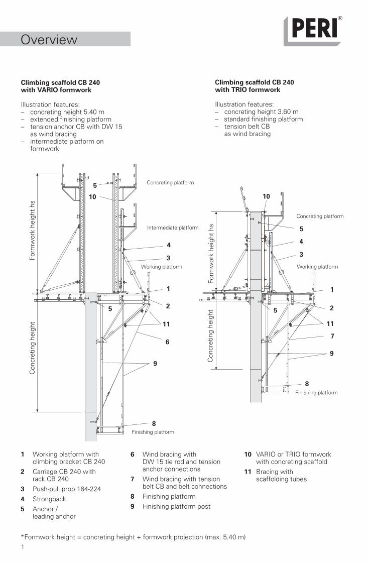
Climbing scaffold CB 240with VARIO formwork
Illustration features:– concreting height 5.40 m– extended finishing platform– tension anchor CB with DW 15
as wind bracing– intermediate platform on
formwork
Climbing scaffold CB 240with TRIO formwork
Illustration features:– concreting height 3.60 m– standard finishing platform– tension belt CB
as wind bracing
1 Working platform with climbing bracket CB 240
2 Carriage CB 240 withrack CB 240
3 Push-pull prop 164-2244 Strongback5 Anchor /
leading anchor
6 Wind bracing withDW 15 tie rod and tension
anchor connections7 Wind bracing with tension
belt CB and belt connections8 Finishing platform9 Finishing platform post
*Formwork height = concreting height + formwork projection (max. 5.40 m)
7
8
1010
4
2
3
Working platform
9
5
5
1
4
3
2
1
Concreting platform
Intermediate platform
Finishing platform
Concreting platform
Working platform
Finishing platform
9
5
5
6
Con
cret
ing
heig
htFo
rmw
ork
heig
ht h
s
Con
cret
ing
heig
htFo
rmw
ork
heig
ht h
s
11
8
11
10 VARIO or TRIO formworkwith concreting scaffold
11 Bracing with scaffolding tubes
2
5.15.2
5.35.4 5.5
5.6 5.7
5.8
5.75.6
15,5
10
h
8
LD
Ls
Overview
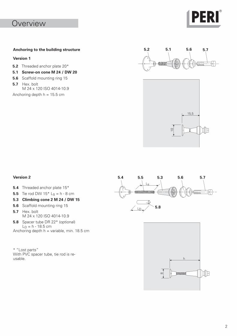
Anchoring to the building structure
Version 1
Version 2
5.4 Threaded anchor plate 15*5.5 Tie rod DW 15* Ls = h - 8 cm5.3 Climbing cone 2 M 24 / DW 15
5.6 Scaffold mounting ring 155.7 Hex. bolt
M 24 x 120 ISO 4014-10.95.8 Spacer tube DR 22* (optional)
LD = h - 18.5 cmAnchoring depth h = variable, min. 18.5 cm
5.2 Threaded anchor plate 20*5.1 Screw-on cone M 24 / DW 20
5.6 Scaffold mounting ring 155.7 Hex. bolt
M 24 x 120 ISO 4014-10.9Anchoring depth h = 15.5 cm
* “Lost parts”With PVC spacer tube, tie rod is re-usable.

Dokument 1 28.04.2005 12:48 Uhr Seite 1
3
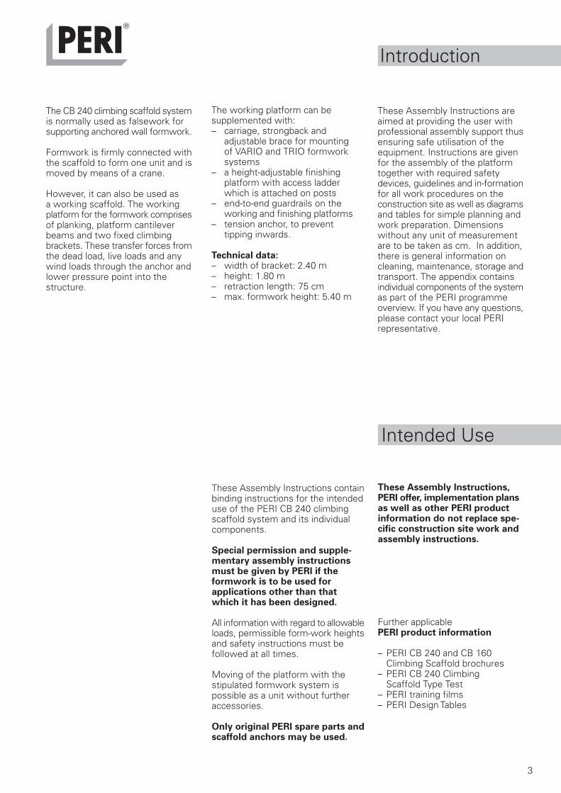
The CB 240 climbing scaffold systemis normally used as falsework forsupporting anchored wall formwork.
Formwork is firmly connected withthe scaffold to form one unit and ismoved by means of a crane.
However, it can also be used asa working scaffold. The workingplatform for the formwork comprisesof planking, platform cantileverbeams and two fixed climbingbrackets. These transfer forces fromthe dead load, live loads and anywind loads through the anchor andlower pressure point into thestructure.
Introduction
The working platform can besupplemented with:– carriage, strongback and
adjustable brace for mountingof VARIO and TRIO formworksystems
– a height-adjustable finishingplatform with access ladderwhich is attached on posts
– end-to-end guardrails on theworking and finishing platforms
– tension anchor, to preventtipping inwards.
Technical data:– width of bracket: 2.40 m– height: 1.80 m– retraction length: 75 cm– max. formwork height: 5.40 m
These Assembly Instructions areaimed at providing the user withprofessional assembly support thusensuring safe utilisation of theequipment. Instructions are givenfor the assembly of the platformtogether with required safetydevices, guidelines and in-formationfor all work procedures on theconstruction site as well as diagramsand tables for simple planning andwork preparation. Dimensionswithout any unit of measurementare to be taken as cm. In addition,there is general information oncleaning, maintenance, storage andtransport. The appendix containsindividual components of the systemas part of the PERI programmeoverview. If you have any questions,please contact your local PERIrepresentative.
These Assembly Instructions containbinding instructions for the intendeduse of the PERI CB 240 climbingscaffold system and its individualcomponents.
Special permission and supple-mentary assembly instructionsmust be given by PERI if theformwork is to be used forapplications other than thatwhich it has been designed.
All information with regard to allowableloads, permissible form-work heightsand safety instructions must befollowed at all times.
Moving of the platform with thestipulated formwork system ispossible as a unit without furtheraccessories.
Only original PERI spare parts andscaffold anchors may be used.
These Assembly Instructions,PERI offer, implementation plansas well as other PERI productinformation do not replace spe-cific construction site work andassembly instructions.
Further applicablePERI product information
– PERI CB 240 and CB 160 Climbing Scaffold brochures
– PERI CB 240 ClimbingScaffold Type Test
– PERI training films– PERI Design Tables
Intended Use
4
Safety Instructions
These Assembly Instructions aredirected at site personnel who workwith the PERI CB 240 ClimbingScaffold. Non-observance of assemblyguidelines and safety information canlead to accidents and damage tomaterials.
Safety Warnings:
1. The contractor is to ensure that theAssembly Instructions supplied byPERI are available on site.
2. All persons who work with the productmust be conversant with the contentsof these instructions and the safetywarnings contained therein.
3. Persons who cannot, or have difficultyin reading and understanding theseinstructions, must be informed andinstructed by the contractor.
4. The contractor must ensure that theassembly and dismantling of theproduct as well as its proper use isoverseen and lead by suitableprofessionals who are authorised togive instructions.
5. The contractor must put in placethe necessary conditions for theadherence to all valid safetyregulations.
12. Formwork parts may only bemoved with lifting equipment andload-carrying equipment whensuitable lifting means are available.
13. The weight of the componentsmust not exceed the permissibleload of the lifting equipment.
14. Remove loose parts or secure sothat they do not fall.
15. Load should not be released fromthe crane until the formwork unitsare secured in position.
16. Due to wind influences it is notpermitted to add additionalstructures (e.g. working platformsor enclosures) that are not featuredin the PERI design. If in doubt,contact PERI.
17. It is the responsibility of thecontractor to inspect all anchorsand associated components.
18. All lifting operations must be fullyplanned and supervised.
19. Store and transport componentsso that they are secured fromfalling and sliding.
20. No site personnel, constructionmaterials or tools can betransported on the units!
General Safety Information:
1. Check the CB 240 ClimbingScaffold components for conditionbefore every use.
2. The CB 240 Climbing Scaffold mustbe assembled in such a way thatall applied loads are safely trans-ferred.
3. Ensure stability during all buildingstates.
4. Establish safe working locationsfor assembly, alteration anddismantling as well as for moving.
5. Working areas must be providedwith safe access routes.
6. When working at height, adequatefall prevention measures must betaken in accordance with the healthand safety regulations.
7. Hatch cover is to be closed afterevery use!
8. Extreme caution must be exercisedduring unfavourable weatherconditions.
9. Only strip the components whenthe concrete has sufficiently setand the person responsible hasauthorised it.
10.Carry out stripping or moving withsuitable tools. Do not strikeformwork elements with a crane!
11.Do not endanger the stability of thebuilding scaffold and formworkparts during striking.
5
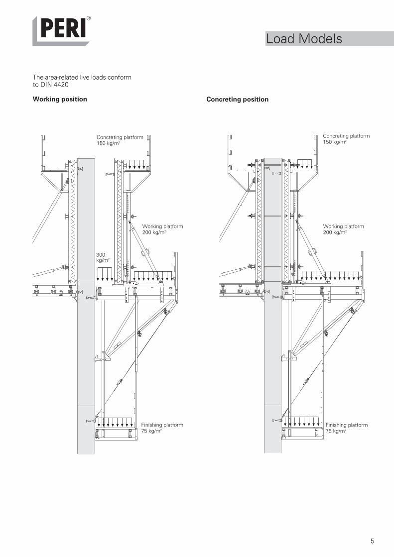
Concreting position
The area-related live loads conformto DIN 4420
Working position
300kg/m2
Concreting platform150 kg/m2
Working platform200 kg/m2
Finishing platform75 kg/m2
Concreting platform150 kg/m2
Working platform200 kg/m2
Finishing platform75 kg/m2
Load Models
6
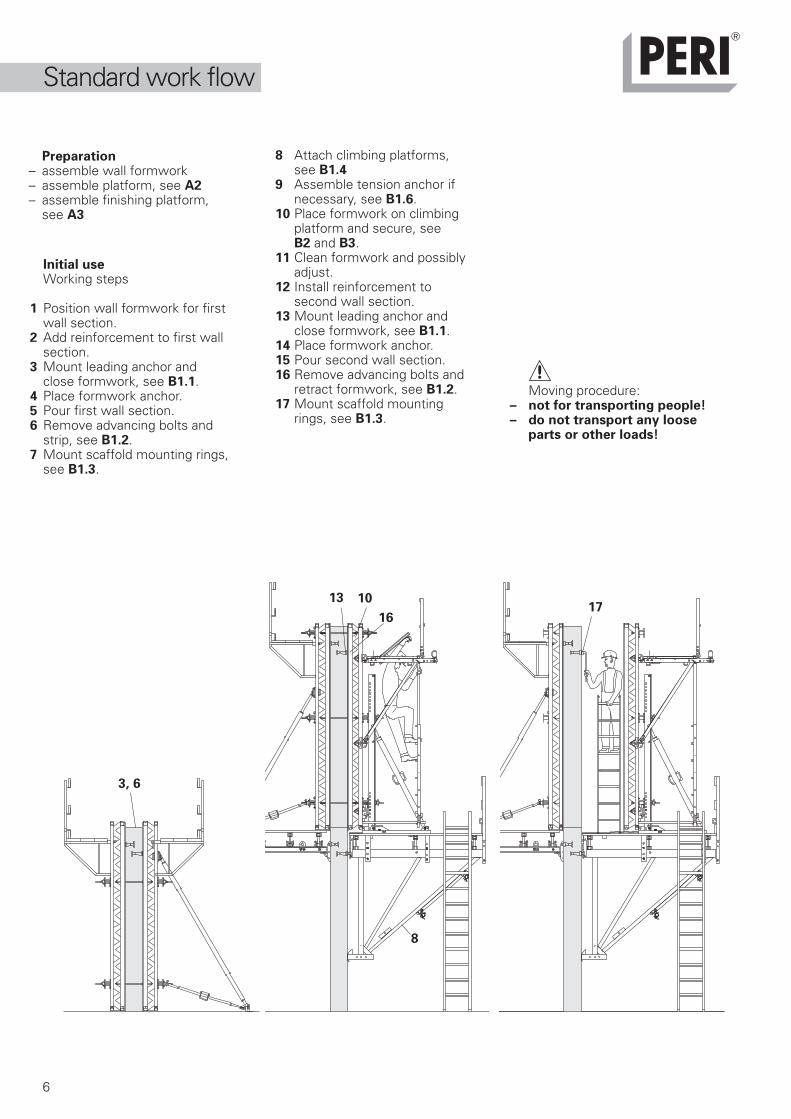
Initial useWorking steps
1 Position wall formwork for first wall section.
2 Add reinforcement to first wall section.
3 Mount leading anchor and close formwork, see B1.1.
4 Place formwork anchor.5 Pour first wall section.6 Remove advancing bolts and
strip, see B1.2.7 Mount scaffold mounting rings,
see B1.3.
8 Attach climbing platforms,see B1.4
9 Assemble tension anchor if necessary, see B1.6.
10 Place formwork on climbing platform and secure, see B2 and B3.
11 Clean formwork and possibly adjust.
12 Install reinforcement to second wall section.
13 Mount leading anchor and close formwork, see B1.1.
14 Place formwork anchor.15 Pour second wall section.16 Remove advancing bolts and
retract formwork, see B1.2.17 Mount scaffold mounting
rings, see B1.3.
Moving procedure:– not for transporting people!– do not transport any loose
parts or other loads!
Preparation– assemble wall formwork– assemble platform, see A2– assemble finishing platform,
see A3
8
1017
13
16
3, 6
Standard work flow
7
22
19
25 28
20
18
21
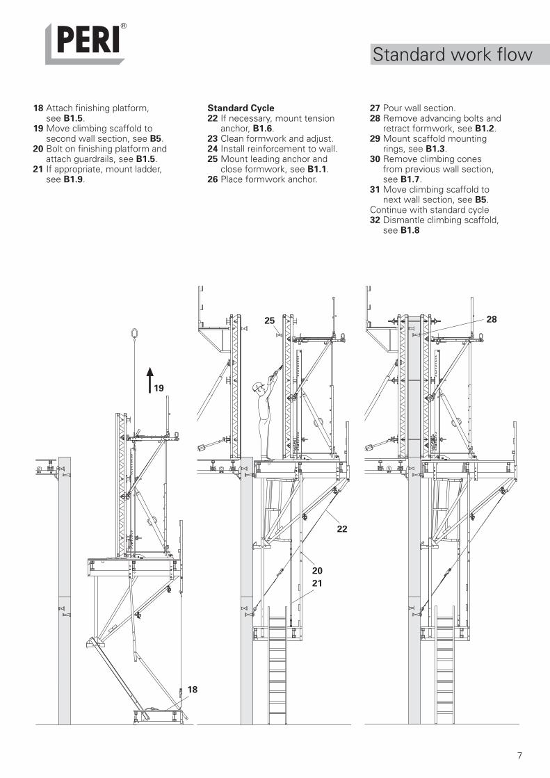
18 Attach finishing platform,see B1.5.
19 Move climbing scaffold to second wall section, see B5.
20 Bolt on finishing platform and attach guardrails, see B1.5.
21 If appropriate, mount ladder, see B1.9.
Standard Cycle22 If necessary, mount tension
anchor, B1.6.23 Clean formwork and adjust.24 Install reinforcement to wall.25 Mount leading anchor and
close formwork, see B1.1.26 Place formwork anchor.
27 Pour wall section.28 Remove advancing bolts and
retract formwork, see B1.2.29 Mount scaffold mounting
rings, see B1.3.30 Remove climbing cones
from previous wall section, see B1.7.
31 Move climbing scaffold tonext wall section, see B5.
Continue with standard cycle32 Dismantle climbing scaffold,
see B1.8
Standard work flow
8
82 mm
62 mm62 mm C
82 mm
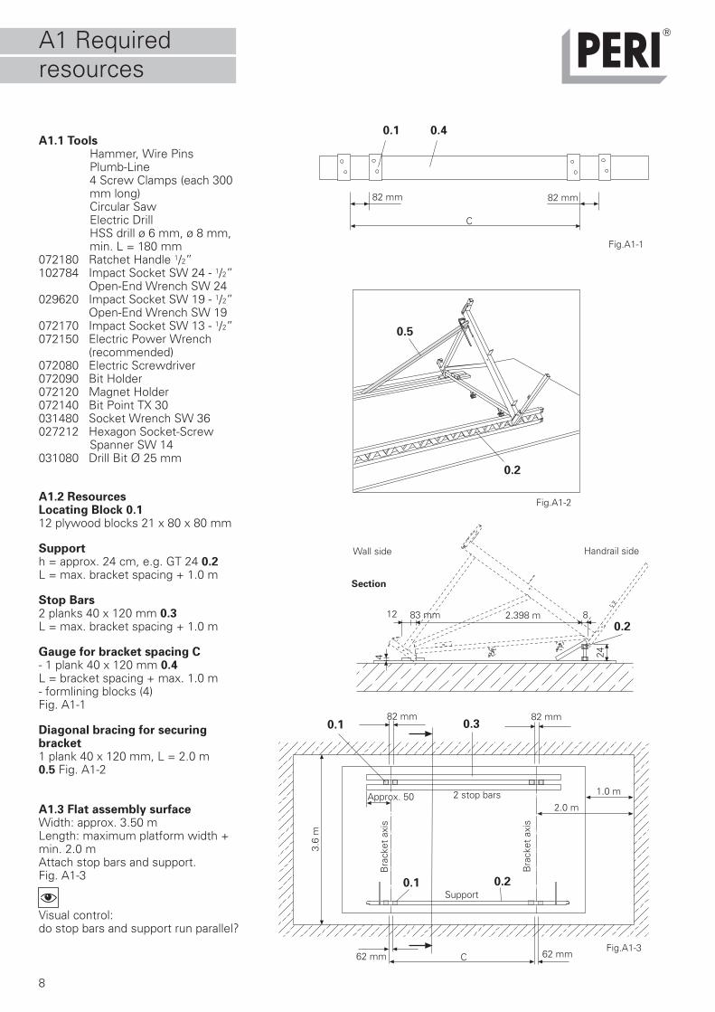
A1.1 ToolsHammer, Wire PinsPlumb-Line4 Screw Clamps (each 300mm long)Circular SawElectric DrillHSS drill ø 6 mm, ø 8 mm,min. L = 180 mm
072180 Ratchet Handle 1/2”102784 Impact Socket SW 24 - 1/2” Open-End Wrench SW 24029620 Impact Socket SW 19 - 1/2” Open-End Wrench SW 19072170 Impact Socket SW 13 - 1/2”072150 Electric Power Wrench (recommended)072080 Electric Screwdriver072090 Bit Holder072120 Magnet Holder072140 Bit Point TX 30031480 Socket Wrench SW 36027212 Hexagon Socket-Screw
Spanner SW 14031080 Drill Bit Ø 25 mm
A1.2 ResourcesLocating Block 0.112 plywood blocks 21 x 80 x 80 mm
Supporth = approx. 24 cm, e.g. GT 24 0.2L = max. bracket spacing + 1.0 m
Stop Bars2 planks 40 x 120 mm 0.3L = max. bracket spacing + 1.0 m
Gauge for bracket spacing C- 1 plank 40 x 120 mm 0.4L = bracket spacing + max. 1.0 m- formlining blocks (4)Fig. A1-1
Diagonal bracing for securingbracket1 plank 40 x 120 mm, L = 2.0 m0.5 Fig. A1-2
A1.3 Flat assembly surfaceWidth: approx. 3.50 mLength: maximum platform width +min. 2.0 mAttach stop bars and support.Fig. A1-3
Visual control:do stop bars and support run parallel?
Fig.A1-1
Section
C
82 mm 82 mm
Fig.A1-2
Fig.A1-3
Bra
cket
axi
s
Bra
cket
axi
s
Support
2 stop barsApprox. 50
0.1 0.4
0.5
0.2
0.1 0.3
0.20.1
0.2
1.0 m
2.0 m
3.6
m
8
24
2.398 m12 83 mm
4
Handrail sideWall side
A1 Requiredresources
9
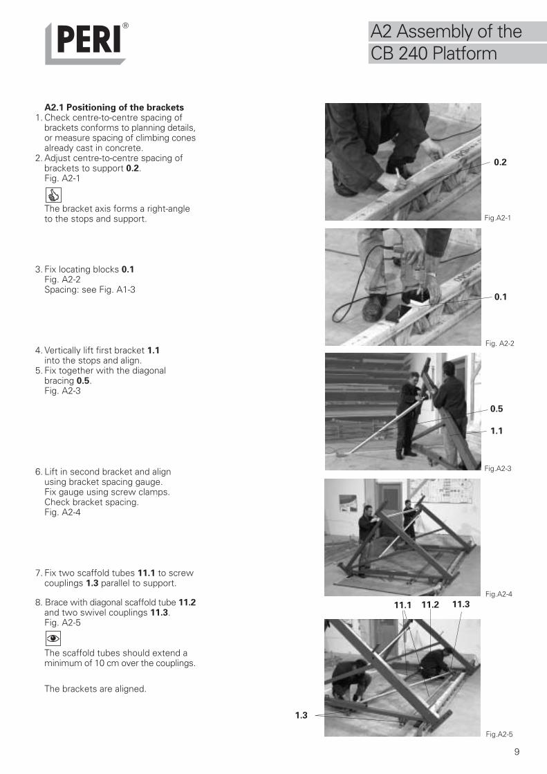
A2.1 Positioning of the brackets1. Check centre-to-centre spacing of
brackets conforms to planning details,or measure spacing of climbing conesalready cast in concrete.
2. Adjust centre-to-centre spacing ofbrackets to support 0.2.Fig. A2-1
The bracket axis forms a right-angleto the stops and support.
3. Fix locating blocks 0.1Fig. A2-2Spacing: see Fig. A1-3
4. Vertically lift first bracket 1.1 into the stops and align.
5. Fix together with the diagonal bracing 0.5.Fig. A2-3
6. Lift in second bracket and alignusing bracket spacing gauge.Fix gauge using screw clamps.Check bracket spacing.Fig. A2-4
7. Fix two scaffold tubes 11.1 to screwcouplings 1.3 parallel to support.
8. Brace with diagonal scaffold tube 11.2and two swivel couplings 11.3.Fig. A2-5
The scaffold tubes should extend aminimum of 10 cm over the couplings.
The brackets are aligned.
Fig.A2-3
Fig. A2-2
Fig.A2-1
Fig.A2-4
Fig.A2-5
A2 Assembly of theCB 240 Platform
0.2
0.1
0.5
1.1
11.1
1.3
11.2 11.3
10
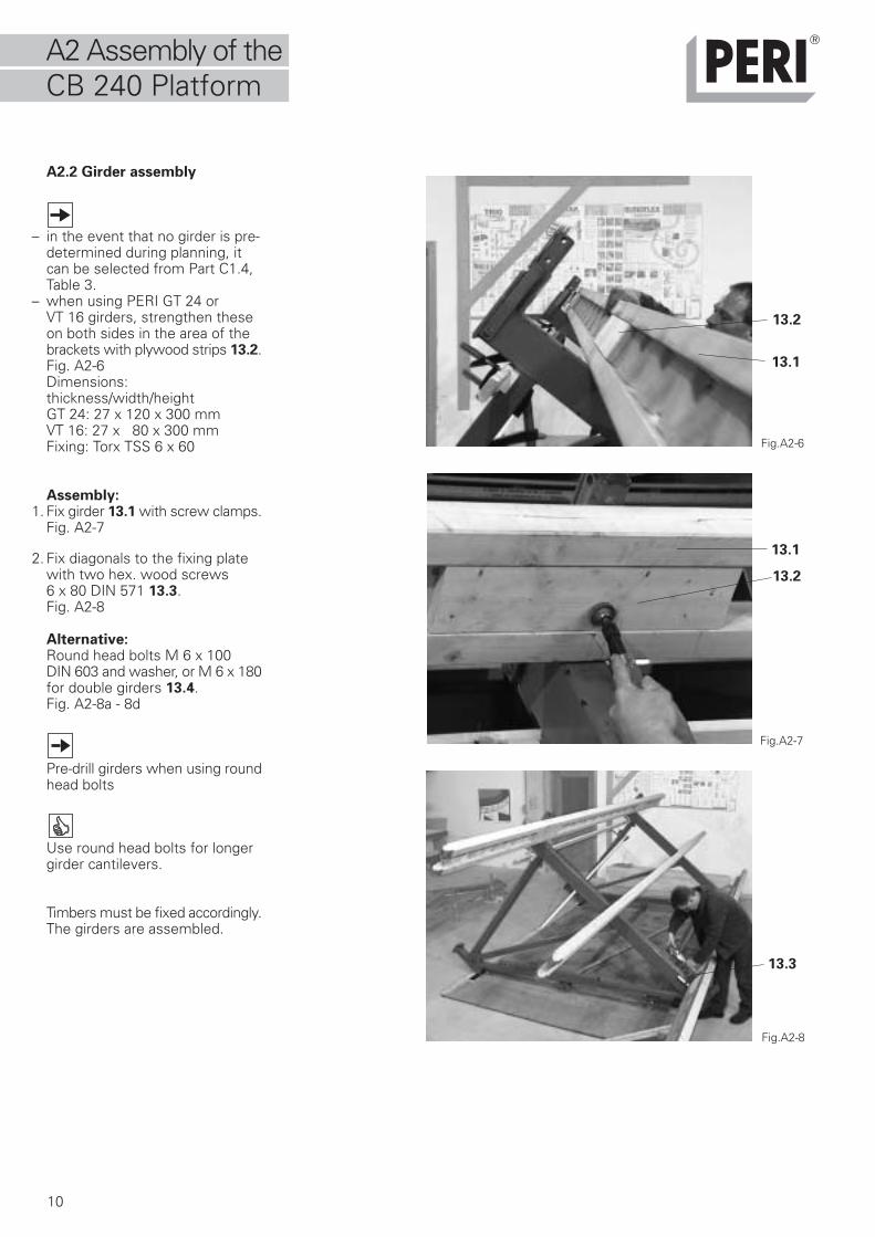
A2.2 Girder assembly
– in the event that no girder is pre-determined during planning, itcan be selected from Part C1.4,Table 3.
– when using PERI GT 24 orVT 16 girders, strengthen theseon both sides in the area of thebrackets with plywood strips 13.2.Fig. A2-6Dimensions:thickness/width/heightGT 24: 27 x 120 x 300 mmVT 16: 27 x 80 x 300 mmFixing: Torx TSS 6 x 60
Assembly:1. Fix girder 13.1 with screw clamps.
Fig. A2-7
2. Fix diagonals to the fixing platewith two hex. wood screws6 x 80 DIN 571 13.3.Fig. A2-8
Alternative:Round head bolts M 6 x 100DIN 603 and washer, or M 6 x 180for double girders 13.4.Fig. A2-8a - 8d
Pre-drill girders when using roundhead bolts
Use round head bolts for longergirder cantilevers.
Timbers must be fixed accordingly.The girders are assembled.
Fig.A2-7
Fig.A2-6
Fig.A2-8
13.2
13.1
13.3
13.2
13.1
A2 Assembly of theCB 240 Platform
11
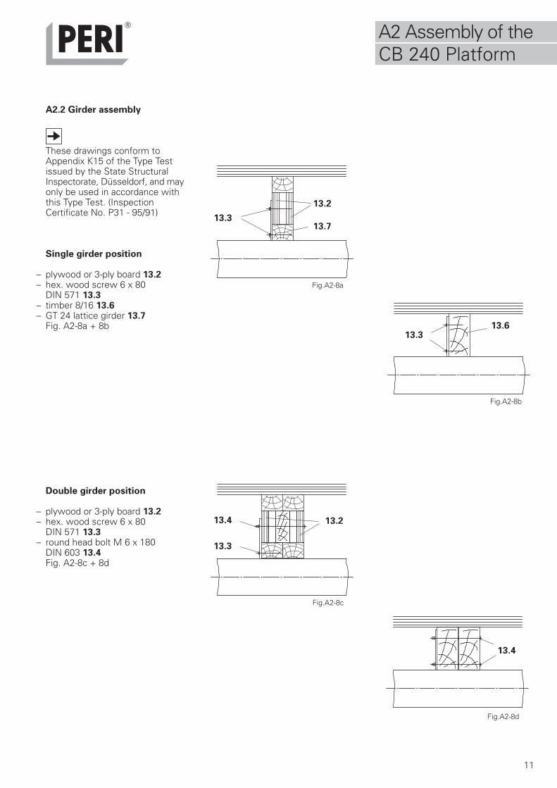
A2.2 Girder assembly
These drawings conform toAppendix K15 of the Type Testissued by the State StructuralInspectorate, Düsseldorf, and mayonly be used in accordance withthis Type Test. (InspectionCertificate No. P31 - 95/91)
Single girder position
– plywood or 3-ply board 13.2– hex. wood screw 6 x 80
DIN 571 13.3– timber 8/16 13.6– GT 24 lattice girder 13.7
Fig. A2-8a + 8b
Double girder position
– plywood or 3-ply board 13.2– hex. wood screw 6 x 80
DIN 571 13.3– round head bolt M 6 x 180
DIN 603 13.4Fig. A2-8c + 8d
Fig.A2-8c
13.3
13.4
Fig.A2-8d
Fig.A2-8b
Fig.A2-8a
13.2
13.4
13.3
13.2
13.613.3
13.7
A2 Assembly of theCB 240 Platform
12
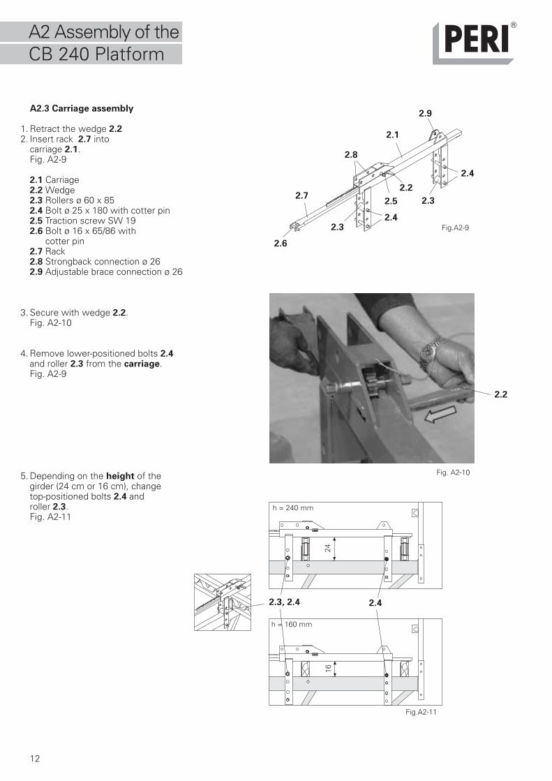
A2.3 Carriage assembly
1. Retract the wedge 2.22. Insert rack 2.7 into
carriage 2.1.Fig. A2-9
2.1 Carriage2.2 Wedge2.3 Rollers ø 60 x 852.4 Bolt ø 25 x 180 with cotter pin2.5 Traction screw SW 192.6 Bolt ø 16 x 65/86 with cotter pin2.7 Rack2.8 Strongback connection ø 262.9 Adjustable brace connection ø 26
3. Secure with wedge 2.2.Fig. A2-10
4. Remove lower-positioned bolts 2.4and roller 2.3 from the carriage.Fig. A2-9
5. Depending on the height of thegirder (24 cm or 16 cm), changetop-positioned bolts 2.4 androller 2.3.Fig. A2-11
Fig. A2-10
Fig.A2-9
2.2
Fig.A2-11
2.3, 2.4
2416
h = 240 mm
h = 160 mm
2.4
2.2
2.1
2.3
2.3
2.4
2.4
2.5
2.6
2.7
2.8
2.9
A2 Assembly of theCB 240 Platform
13
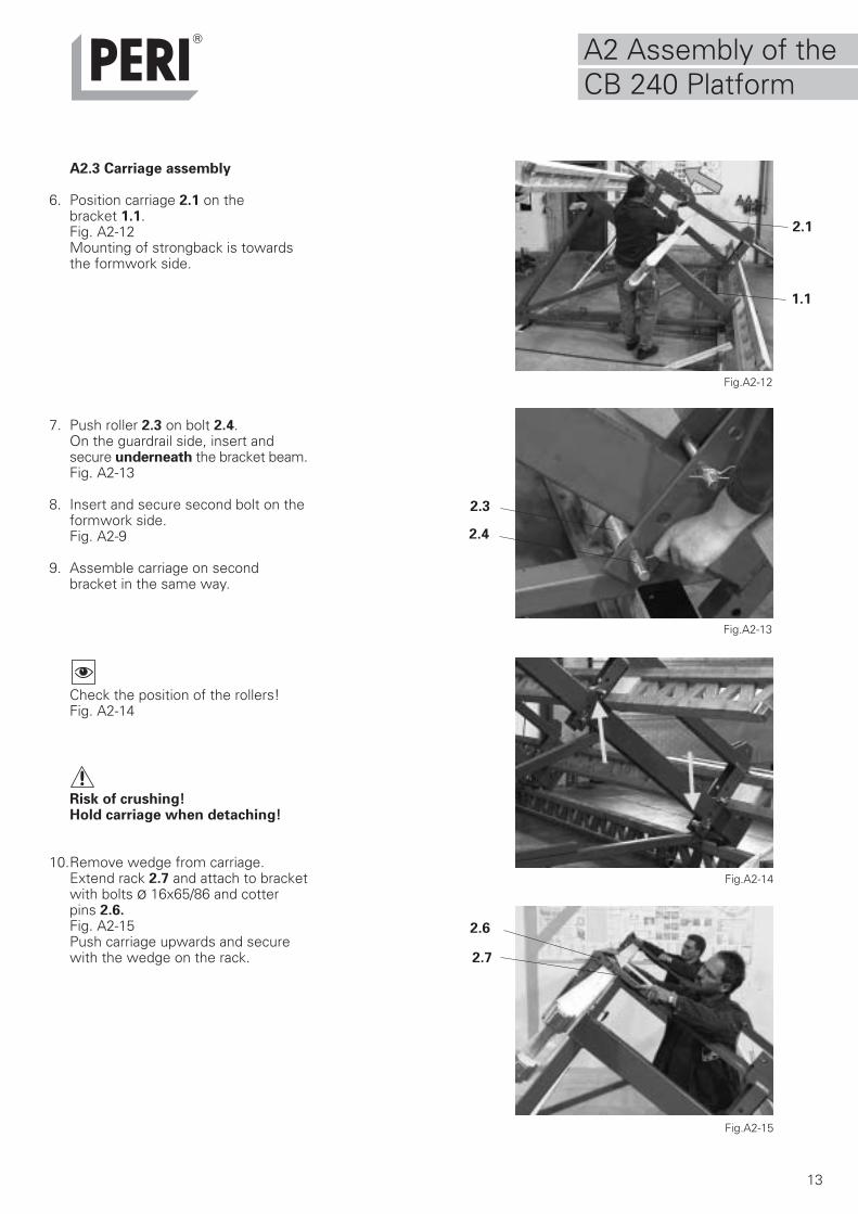
A2.3 Carriage assembly
6. Position carriage 2.1 on thebracket 1.1.Fig. A2-12Mounting of strongback is towardsthe formwork side.
7. Push roller 2.3 on bolt 2.4.On the guardrail side, insert andsecure underneath the bracket beam.Fig. A2-13
8. Insert and secure second bolt on theformwork side.Fig. A2-9
9. Assemble carriage on secondbracket in the same way.
Check the position of the rollers!Fig. A2-14
Risk of crushing!Hold carriage when detaching!
10.Remove wedge from carriage.Extend rack 2.7 and attach to bracketwith bolts ø 16x65/86 and cotterpins 2.6.Fig. A2-15Push carriage upwards and securewith the wedge on the rack.
Fig.A2-12
Fig.A2-13
Fig.A2-15
Fig.A2-14
A2 Assembly of theCB 240 Platform
2.7
2.6
2.3
2.4
2.1
1.1
14
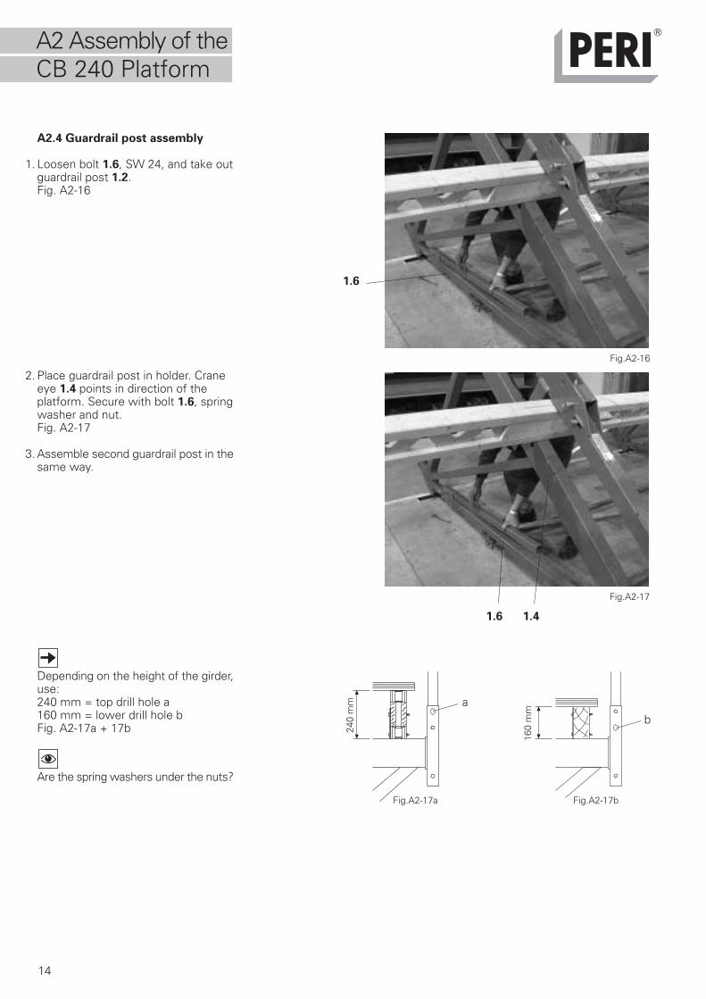
A2.4 Guardrail post assembly
1. Loosen bolt 1.6, SW 24, and take outguardrail post 1.2.Fig. A2-16
2. Place guardrail post in holder. Craneeye 1.4 points in direction of theplatform. Secure with bolt 1.6, springwasher and nut.Fig. A2-17
3. Assemble second guardrail post in thesame way.
Depending on the height of the girder,use:240 mm = top drill hole a160 mm = lower drill hole bFig. A2-17a + 17b
Are the spring washers under the nuts?
Fig.A2-16
Fig.A2-17a
ba
Fig.A2-17
1.6
1.6 1.4
240
mm
Fig.A2-17b
160
mm
A2 Assembly of theCB 240 Platform
15
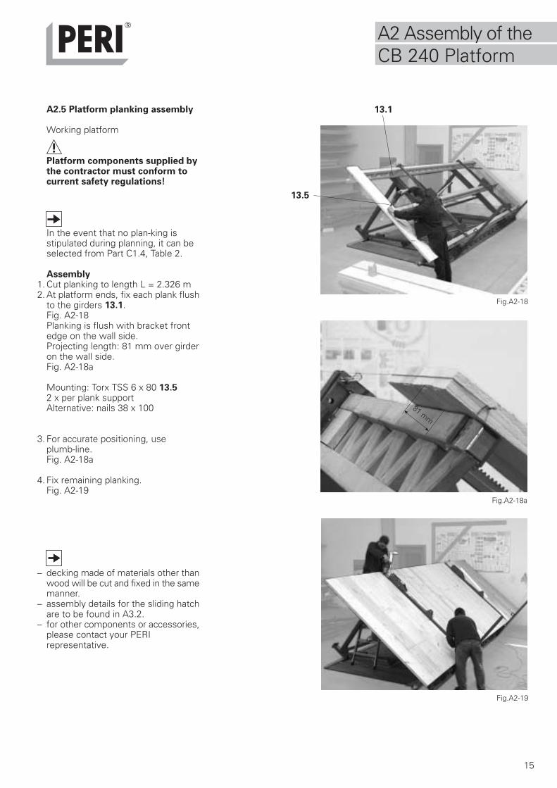
A2.5 Platform planking assembly
Working platform
Platform components supplied bythe contractor must conform tocurrent safety regulations!
In the event that no plan-king isstipulated during planning, it can beselected from Part C1.4, Table 2.
Assembly1. Cut planking to length L = 2.326 m2. At platform ends, fix each plank flush
to the girders 13.1.Fig. A2-18Planking is flush with bracket frontedge on the wall side.Projecting length: 81 mm over girderon the wall side.Fig. A2-18a
Mounting: Torx TSS 6 x 80 13.52 x per plank supportAlternative: nails 38 x 100
3. For accurate positioning, use plumb-line.Fig. A2-18a
4. Fix remaining planking.Fig. A2-19
– decking made of materials other thanwood will be cut and fixed in the samemanner.
– assembly details for the sliding hatchare to be found in A3.2.
– for other components or accessories,please contact your PERIrepresentative.
81 mm
Fig.A2-18
Fig.A2-18a
Fig.A2-19
13.1
13.5
A2 Assembly of theCB 240 Platform
16
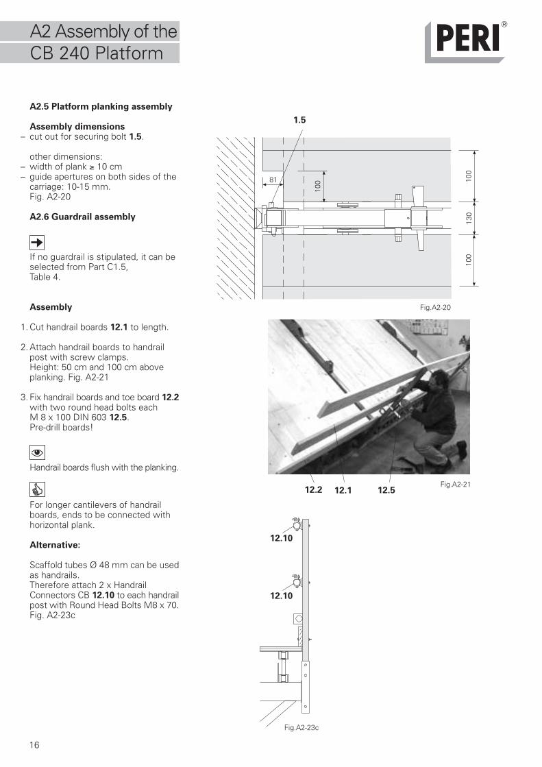
A2.5 Platform planking assembly
Assembly dimensions– cut out for securing bolt 1.5.
other dimensions:– width of plank ≥ 10 cm– guide apertures on both sides of the
carriage: 10-15 mm.Fig. A2-20
A2.6 Guardrail assembly
If no guardrail is stipulated, it can beselected from Part C1.5, Table 4.
Assembly
1. Cut handrail boards 12.1 to length.
2. Attach handrail boards to handrailpost with screw clamps.Height: 50 cm and 100 cm aboveplanking. Fig. A2-21
3. Fix handrail boards and toe board 12.2with two round head bolts eachM 8 x 100 DIN 603 12.5.Pre-drill boards!
Handrail boards flush with the planking.
For longer cantilevers of handrailboards, ends to be connected withhorizontal plank.
Alternative:
Scaffold tubes Ø 48 mm can be usedas handrails.Therefore attach 2 x HandrailConnectors CB 12.10 to each handrailpost with Round Head Bolts M8 x 70.Fig. A2-23c
Fig.A2-21
Fig.A2-20
1.5
100
100
130
10081
Fig.A2-23c
12.10
12.10
12.112.2 12.5
A2 Assembly of theCB 240 Platform
17
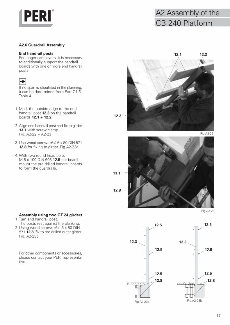
A2.6 Guardrail Assembly
End handrail postsFor longer cantilevers, it is necessaryto additionally support the handrailboards with one or more end handrailposts.
If no span is stipulated in the planning,it can be determined from Part C1.5,Table 4.
1. Mark the outside edge of the endhandrail post 12.3 on the handrailboards 12.1 + 12.2.
2. Align end handrail post and fix to girder13.1 with screw clamp.Fig. A2-22 + A2-23
3. Use wood screws (6x) 6 x 80 DIN 57112.8 for fixing to girder. Fig.A2-23a
4. With two round head boltsM 8 x 100 DIN 603 12.5 per board,mount the pre-drilled handrail boardsto form the guardrails.
Assembly using two GT 24 girders1. Turn end handrail post.
The posts rest against the planking.2. Using wood screws (6x) 6 x 80 DIN
571 12.8, fix to pre-drilled outer girder.Fig. A2-23b
For other components or accessories,please contact your PERI representa-tive.
Fig.A2-23a
12.8 12.8
Fig.A2-23b
Fig.A2-22
Fig.A2-23
12.3
12.5
12.1
12.8
13.1
12.2
12.3 12.3
12.5
12.5
12.5
12.5
12.5
A2 Assembly of theCB 240 Platform
18
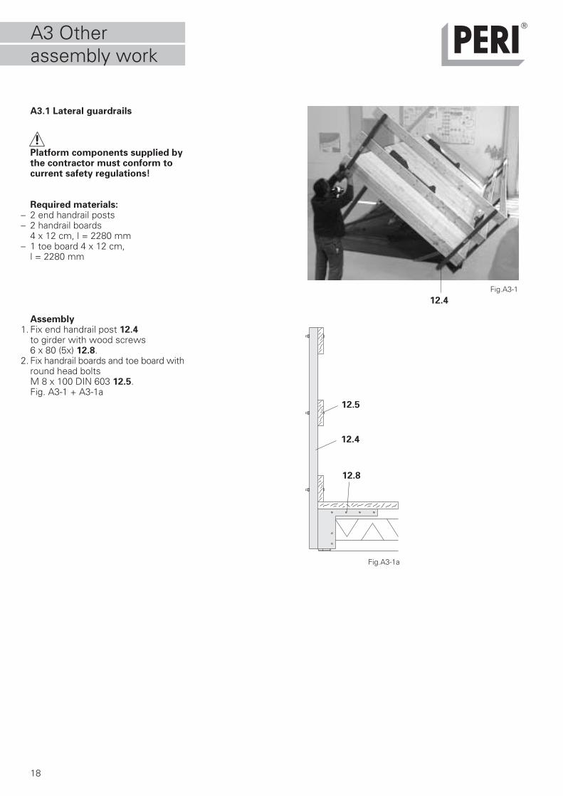
A3.1 Lateral guardrails
Platform components supplied bythe contractor must conform tocurrent safety regulations!
Required materials:– 2 end handrail posts– 2 handrail boards
4 x 12 cm, l = 2280 mm– 1 toe board 4 x 12 cm,
l = 2280 mm
Assembly1. Fix end handrail post 12.4
to girder with wood screws6 x 80 (5x) 12.8.
2. Fix handrail boards and toe board withround head boltsM 8 x 100 DIN 603 12.5.Fig. A3-1 + A3-1a
Fig.A3-1a
12.4
12.8
12.5
Fig.A3-1
12.4
A3 Otherassembly work
19
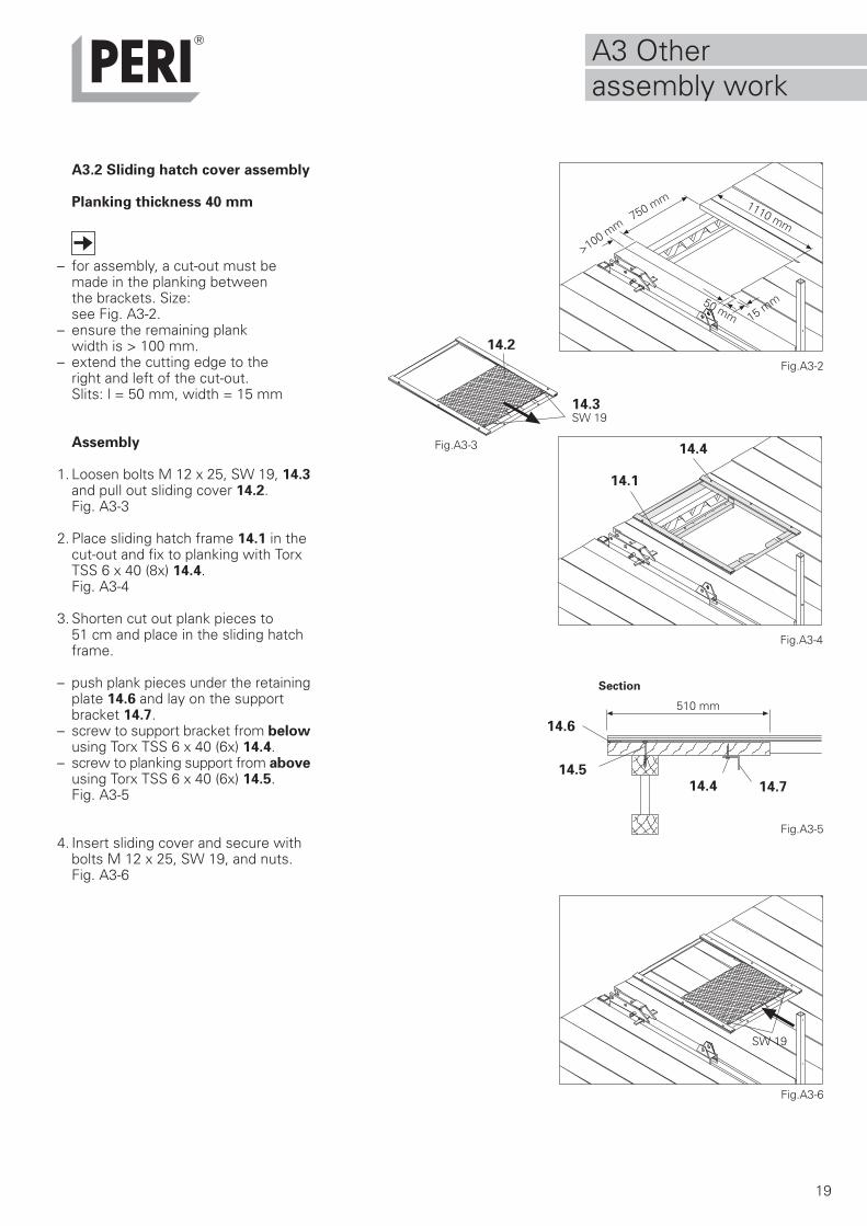
A3.2 Sliding hatch cover assembly
Planking thickness 40 mm
– for assembly, a cut-out must be made in the planking between the brackets. Size:see Fig. A3-2.
– ensure the remaining plank width is > 100 mm.
– extend the cutting edge to the right and left of the cut-out.Slits: l = 50 mm, width = 15 mm
Assembly
1. Loosen bolts M 12 x 25, SW 19, 14.3and pull out sliding cover 14.2.Fig. A3-3
2. Place sliding hatch frame 14.1 in thecut-out and fix to planking with TorxTSS 6 x 40 (8x) 14.4.Fig. A3-4
3. Shorten cut out plank pieces to51 cm and place in the sliding hatchframe.
– push plank pieces under the retainingplate 14.6 and lay on the supportbracket 14.7.
– screw to support bracket from belowusing Torx TSS 6 x 40 (6x) 14.4.
– screw to planking support from aboveusing Torx TSS 6 x 40 (6x) 14.5.Fig. A3-5
4. Insert sliding cover and secure withbolts M 12 x 25, SW 19, and nuts.Fig. A3-6
Fig.A3-5
Fig.A3-4
Fig.A3-2
Fig.A3-6
Fig.A3-3
SW 19
14.4
SW 19
14.3
14.2
750 mm
>100 mm
15 mm
1110 mm
14.1
14.6
14.714.414.5
50 mm
510 mm
Section
A3 Otherassembly work
20
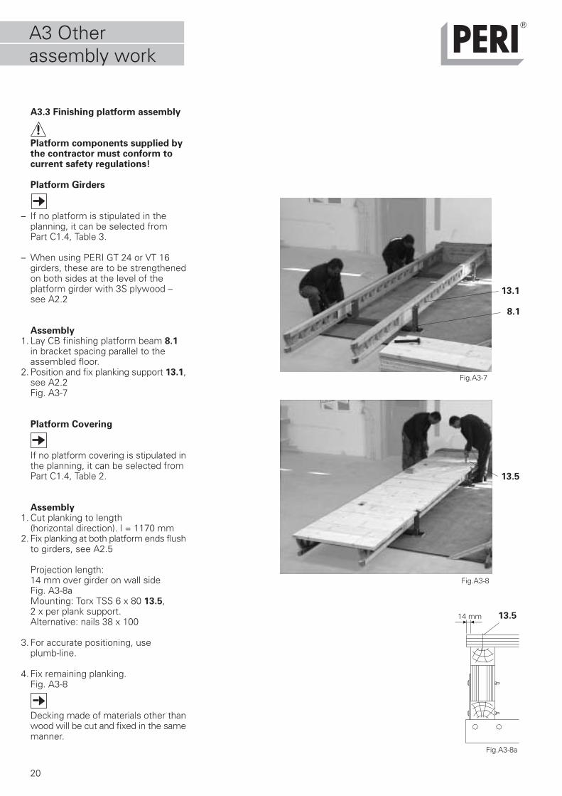
A3.3 Finishing platform assembly
Platform components supplied bythe contractor must conform tocurrent safety regulations!
Platform Girders
– If no platform is stipulated in theplanning, it can be selected fromPart C1.4, Table 3.
– When using PERI GT 24 or VT 16girders, these are to be strengthenedon both sides at the level of theplatform girder with 3S plywood –see A2.2
Assembly1. Lay CB finishing platform beam 8.1
in bracket spacing parallel to theassembled floor.
2. Position and fix planking support 13.1,see A2.2Fig. A3-7
Platform Covering
If no platform covering is stipulated inthe planning, it can be selected fromPart C1.4, Table 2.
Assembly1. Cut planking to length
(horizontal direction). l = 1170 mm2. Fix planking at both platform ends flush
to girders, see A2.5
Projection length:14 mm over girder on wall sideFig. A3-8aMounting: Torx TSS 6 x 80 13.5,2 x per plank support.Alternative: nails 38 x 100
3. For accurate positioning, use plumb-line.
4. Fix remaining planking.Fig. A3-8
Decking made of materials other thanwood will be cut and fixed in the samemanner.
Fig.A3-8
Fig.A3-7
8.1
13.1
13.5
14 mm
Fig.A3-8a
13.5
A3 Otherassembly work
21
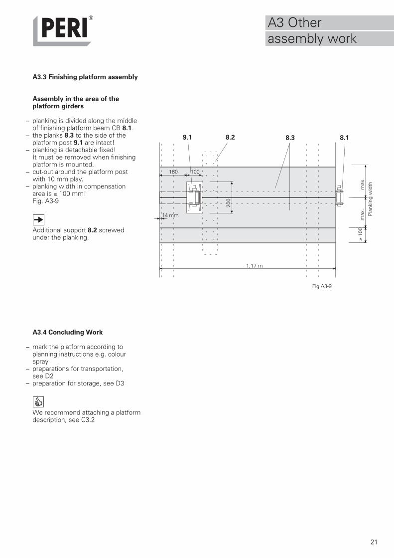
A3.3 Finishing platform assembly
Assembly in the area of theplatform girders
– planking is divided along the middleof finishing platform beam CB 8.1.
– the planks 8.3 to the side of the platform post 9.1 are intact!
– planking is detachable fixed!It must be removed when finishingplatform is mounted.
– cut-out around the platform postwith 10 mm play.
– planking width in compensationarea is ≥ 100 mm!Fig. A3-9
Additional support 8.2 screwedunder the planking.
A3.4 Concluding Work
– mark the platform according to planning instructions e.g. colour spray
– preparations for transportation, see D2
– preparation for storage, see D3
We recommend attaching a platformdescription, see C3.2
Fig.A3-9
max
.
max
.P
lank
ing
wid
th
≥ 10
0
1,17 m
200
100180
14 mm
8.38.2 8.19.1
A3 Otherassembly work
8
22
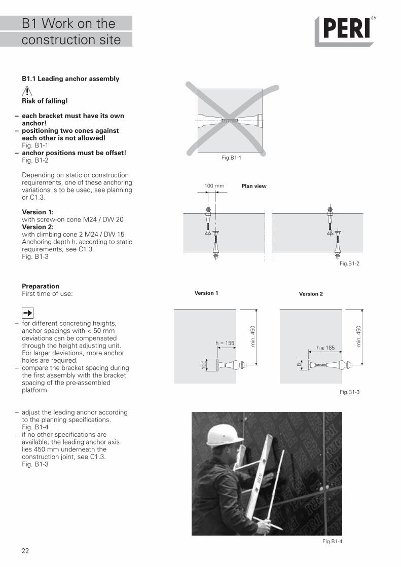
B1.1 Leading anchor assembly
Risk of falling!
– each bracket must have its ownanchor!
– positioning two cones againsteach other is not allowed!Fig. B1-1
– anchor positions must be offset!Fig. B1-2
Depending on static or constructionrequirements, one of these anchoringvariations is to be used, see planningor C1.3.
Version 1:with screw-on cone M24 / DW 20Version 2:with climbing cone 2 M24 / DW 15Anchoring depth h: according to staticrequirements, see C1.3.Fig. B1-3
PreparationFirst time of use:
– for different concreting heights,anchor spacings with < 50 mmdeviations can be compensatedthrough the height adjusting unit.For larger deviations, more anchorholes are required.
– compare the bracket spacing duringthe first assembly with the bracketspacing of the pre-assembledplatform.
– adjust the leading anchor accordingto the planning specifications.Fig. B1-4
– if no other specifications areavailable, the leading anchor axislies 450 mm underneath theconstruction joint, see C1.3.Fig. B1-3
Fig.B1-2
Fig.B1-3
Version 1 Version 2
Fig.B1-1
100 mm
Fig.B1-4
Plan view
h ≥ 185h = 155
100
min
. 450
min
. 450
B1 Work on theconstruction site
23
L = h - 80 mm
h - 185 mm
B1.1 Leading anchor assembly
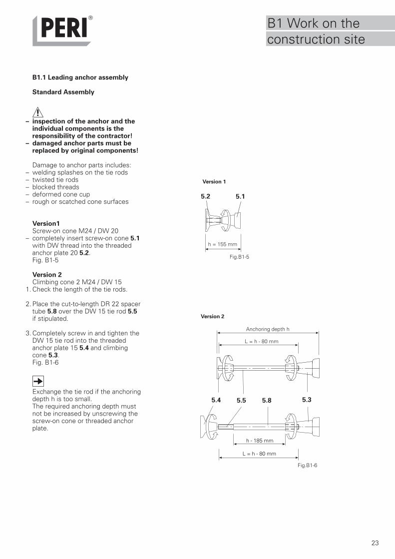
Standard Assembly
– inspection of the anchor and theindividual components is theresponsibility of the contractor!
– damaged anchor parts must bereplaced by original components!
Damage to anchor parts includes:– welding splashes on the tie rods– twisted tie rods– blocked threads– deformed cone cup– rough or scatched cone surfaces
Version1Screw-on cone M24 / DW 20
– completely insert screw-on cone 5.1with DW thread into the threadedanchor plate 20 5.2.Fig. B1-5
Version 2Climbing cone 2 M24 / DW 15
1. Check the length of the tie rods.
2. Place the cut-to-length DR 22 spacertube 5.8 over the DW 15 tie rod 5.5if stipulated.
3. Completely screw in and tighten theDW 15 tie rod into the threadedanchor plate 15 5.4 and climbingcone 5.3.Fig. B1-6
Exchange the tie rod if the anchoringdepth h is too small.The required anchoring depth mustnot be increased by unscrewing thescrew-on cone or threaded anchorplate.
Fig.B1-5
5.15.2
h = 155 mm
5.35.55.4 5.8
Fig.B1-6
Version 1
Version 2
Anchoring depth h
L = h - 80 mm
B1 Work on theconstruction site
24
B1.1 Leading anchor assembly
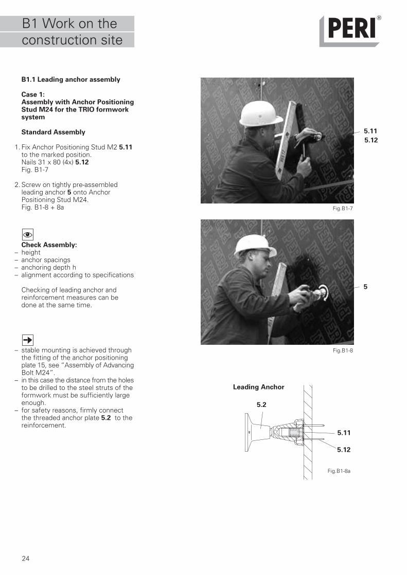
Case 1:Assembly with Anchor PositioningStud M24 for the TRIO formworksystem
Standard Assembly
1. Fix Anchor Positioning Stud M2 5.11to the marked position.Nails 31 x 80 (4x) 5.12Fig. B1-7
2. Screw on tightly pre-assembledleading anchor 5 onto AnchorPositioning Stud M24.Fig. B1-8 + 8a
Check Assembly:– height– anchor spacings– anchoring depth h– alignment according to specifications
Checking of leading anchor andreinforcement measures can bedone at the same time.
– stable mounting is achieved throughthe fitting of the anchor positioningplate 15, see “Assembly of AdvancingBolt M24”.
– in this case the distance from the holesto be drilled to the steel struts of theformwork must be sufficiently largeenough.
– for safety reasons, firmly connectthe threaded anchor plate 5.2 to thereinforcement.
Fig.B1-7
Fig.B1-8
5.11
5
5.12
Fig.B1-8a
5.11
5.12
5.2
Leading Anchor
B1 Work on theconstruction site
25
B1.1 Leading anchor assembly
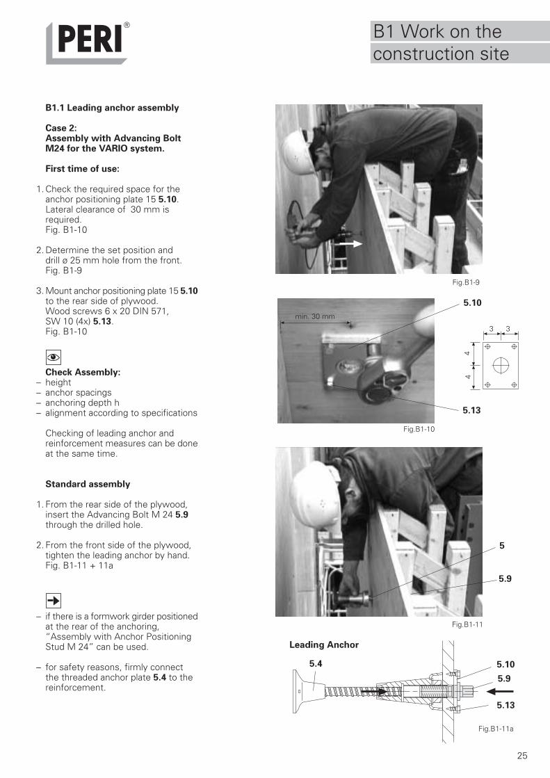
Case 2:Assembly with Advancing BoltM24 for the VARIO system.
First time of use:
1. Check the required space for theanchor positioning plate 15 5.10.Lateral clearance of 30 mm isrequired.Fig. B1-10
2. Determine the set position anddrill ø 25 mm hole from the front.Fig. B1-9
3. Mount anchor positioning plate 15 5.10to the rear side of plywood.Wood screws 6 x 20 DIN 571,SW 10 (4x) 5.13.Fig. B1-10
Check Assembly:– height– anchor spacings– anchoring depth h– alignment according to specifications
Checking of leading anchor andreinforcement measures can be doneat the same time.
Standard assembly
1. From the rear side of the plywood,insert the Advancing Bolt M 24 5.9through the drilled hole.
2. From the front side of the plywood,tighten the leading anchor by hand.Fig. B1-11 + 11a
– if there is a formwork girder positionedat the rear of the anchoring,“Assembly with Anchor PositioningStud M 24” can be used.
– for safety reasons, firmly connectthe threaded anchor plate 5.4 to thereinforcement.
Fig.B1-10
Fig.B1-9
Fig.B1-11
5.10
5
5.13
5.9
min. 30 mm
3 3
44
5.10
5.13
5.9
Fig.B1-11a
5.4
Leading Anchor
B1 Work on theconstruction site
26
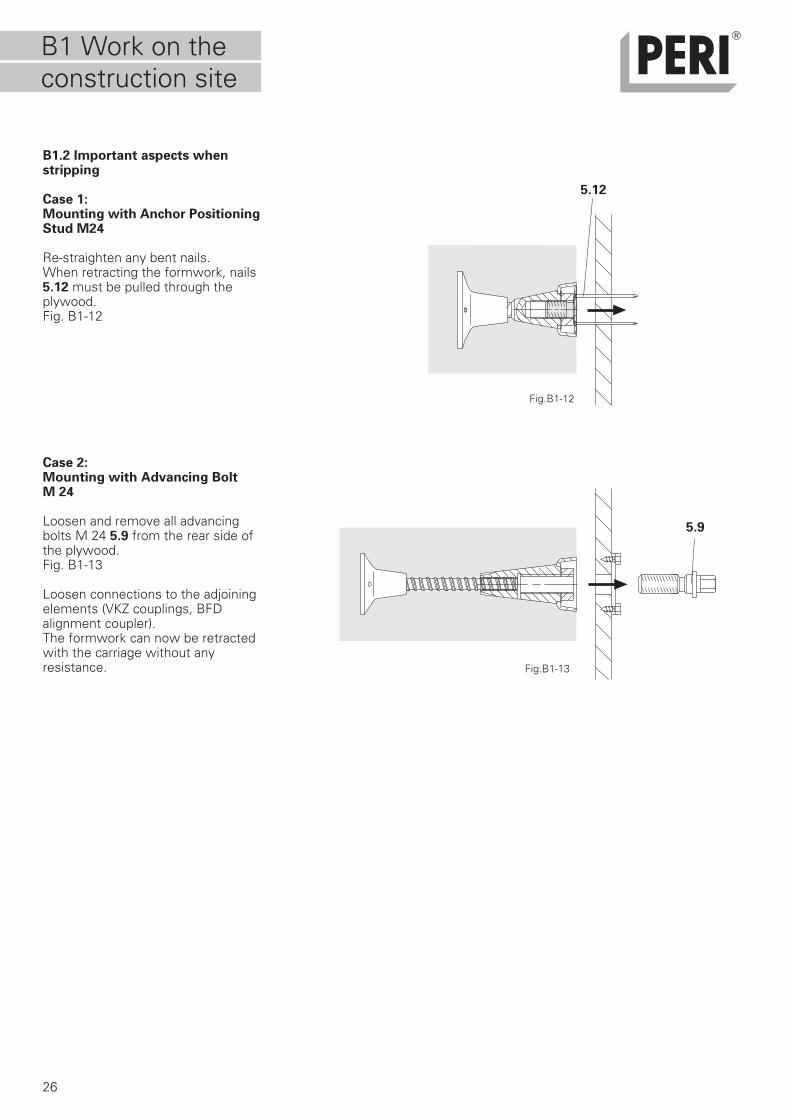
B1.2 Important aspects whenstripping
Case 1:Mounting with Anchor PositioningStud M24
Re-straighten any bent nails.When retracting the formwork, nails5.12 must be pulled through theplywood.Fig. B1-12
Case 2:Mounting with Advancing BoltM 24
Loosen and remove all advancingbolts M 24 5.9 from the rear side ofthe plywood.Fig. B1-13
Loosen connections to the adjoiningelements (VKZ couplings, BFDalignment coupler).The formwork can now be retractedwith the carriage without anyresistance.
Fig.B1-12
Fig.B1-13
5.9
5.12
B1 Work on theconstruction site
27
Fig.B1-14
Fig.B1-15
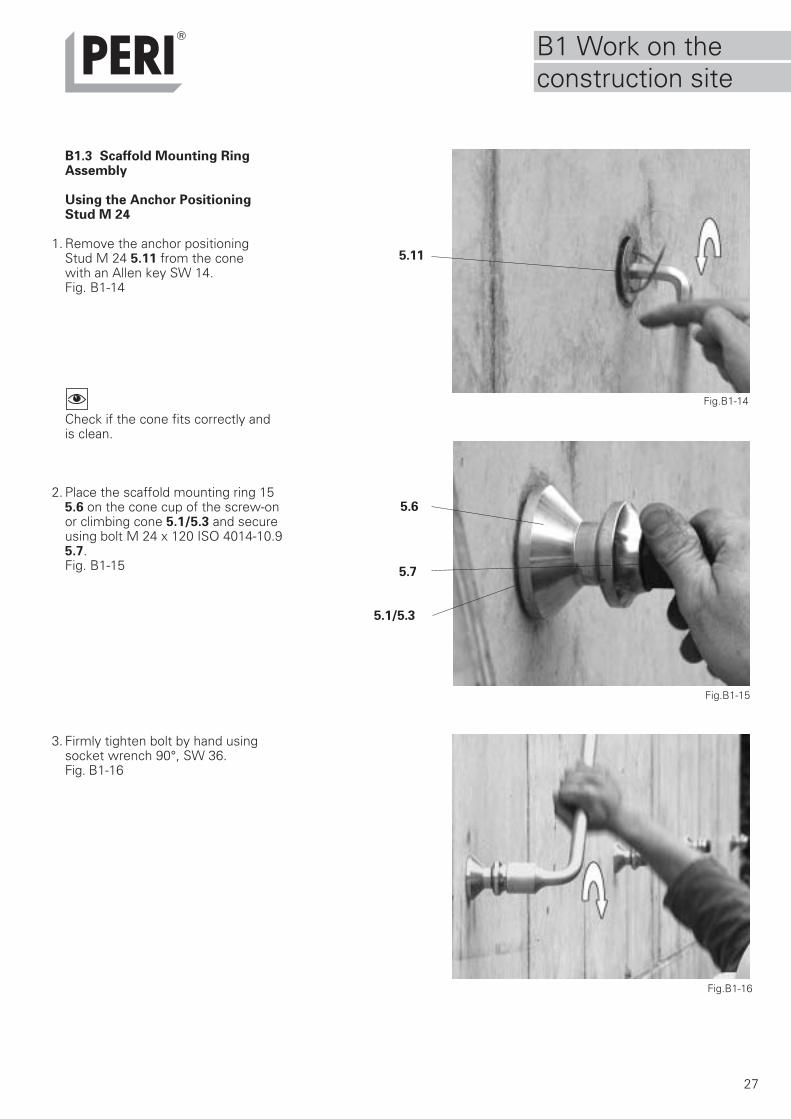
B1.3 Scaffold Mounting RingAssembly
Using the Anchor PositioningStud M 24
1. Remove the anchor positioning Stud M 24 5.11 from the cone with an Allen key SW 14.Fig. B1-14
Check if the cone fits correctly andis clean.
2. Place the scaffold mounting ring 155.6 on the cone cup of the screw-onor climbing cone 5.1/5.3 and secureusing bolt M 24 x 120 ISO 4014-10.95.7.Fig. B1-15
3. Firmly tighten bolt by hand usingsocket wrench 90°, SW 36.Fig. B1-16
Fig.B1-16
5.11
5.6
5.7
5.1/5.3
B1 Work on theconstruction site
28
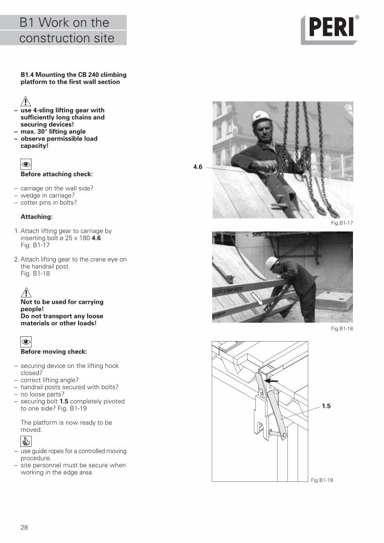
B1.4 Mounting the CB 240 climbingplatform to the first wall section
– use 4-sling lifting gear with sufficiently long chains and securing devices!
– max. 30° lifting angle– observe permissible load
capacity!
Before attaching check:
– carriage on the wall side?– wedge in carriage?– cotter pins in bolts?
Attaching:
1. Attach lifting gear to carriage byinserting bolt ø 25 x 180 4.6.Fig. B1-17
2. Attach lifting gear to the crane eye onthe handrail post.Fig. B1-18
Not to be used for carryingpeople!Do not transport any loosematerials or other loads!
Before moving check:
– securing device on the lifting hookclosed?
– correct lifting angle?– handrail posts secured with bolts?– no loose parts?– securing bolt 1.5 completely pivoted
to one side? Fig. B1-19
The platform is now ready to bemoved.
– use guide ropes for a controlled movingprocedure.
– site personnel must be secure whenworking in the edge area.
Fig.B1-17
Fig.B1-18
Fig.B1-19
1.5
4.6
B1 Work on theconstruction site
29
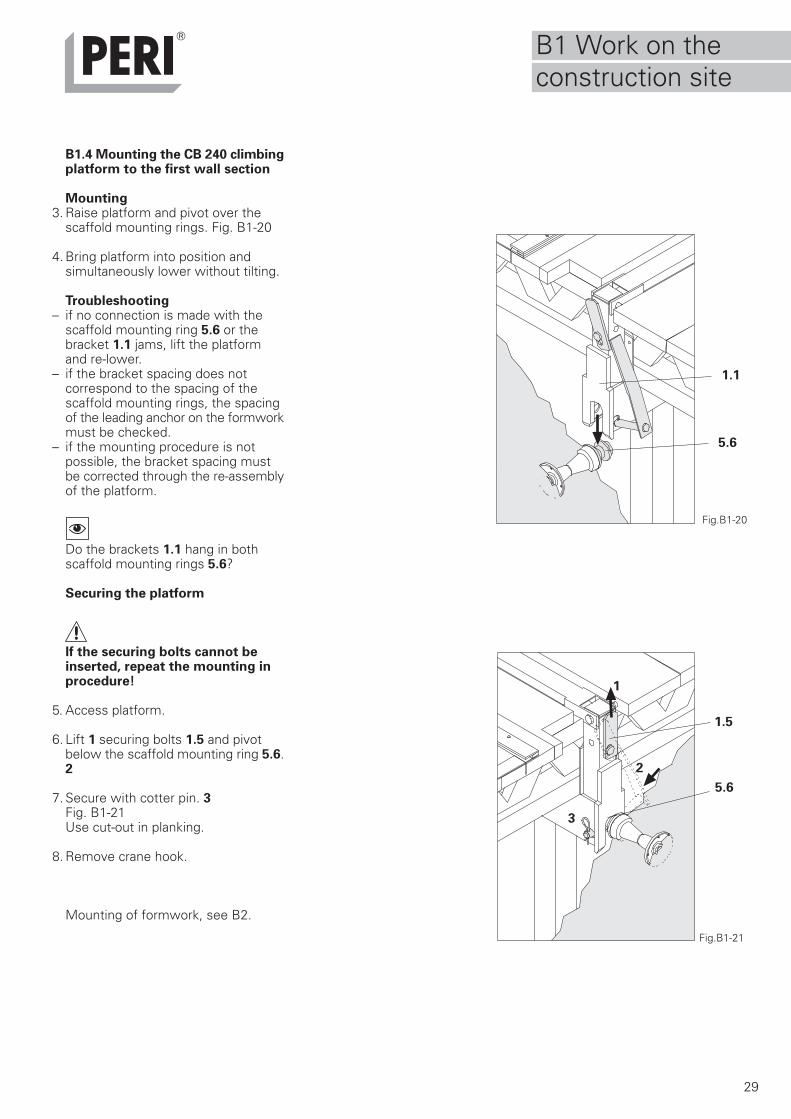
B1.4 Mounting the CB 240 climbingplatform to the first wall section
Mounting3. Raise platform and pivot over the
scaffold mounting rings. Fig. B1-20
4. Bring platform into position andsimultaneously lower without tilting.
Troubleshooting– if no connection is made with the
scaffold mounting ring 5.6 or thebracket 1.1 jams, lift the platformand re-lower.
– if the bracket spacing does notcorrespond to the spacing of thescaffold mounting rings, the spacingof the leading anchor on the formworkmust be checked.
– if the mounting procedure is notpossible, the bracket spacing mustbe corrected through the re-assemblyof the platform.
Do the brackets 1.1 hang in bothscaffold mounting rings 5.6?
Securing the platform
If the securing bolts cannot beinserted, repeat the mounting inprocedure!
5. Access platform.
6. Lift 1 securing bolts 1.5 and pivotbelow the scaffold mounting ring 5.6.2
7. Secure with cotter pin. 3Fig. B1-21Use cut-out in planking.
8. Remove crane hook.
Mounting of formwork, see B2.
Fig.B1-21
1.5
Fig.B1-20
5.6
5.6
1.1
1
2
3
B1 Work on theconstruction site
30
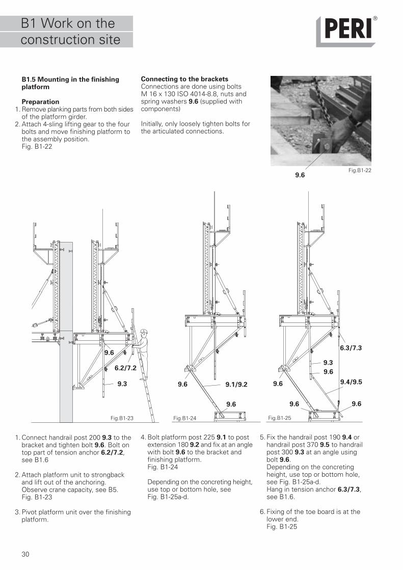
B1.5 Mounting in the finishingplatform
Preparation1. Remove planking parts from both sides
of the platform girder.2. Attach 4-sling lifting gear to the four
bolts and move finishing platform tothe assembly position.Fig. B1-22
Fig.B1-24 Fig.B1-25
1. Connect handrail post 200 9.3 to thebracket and tighten bolt 9.6. Bolt ontop part of tension anchor 6.2/7.2,see B1.6
2. Attach platform unit to strongbackand lift out of the anchoring.Observe crane capacity, see B5.Fig. B1-23
3. Pivot platform unit over the finishingplatform.
4. Bolt platform post 225 9.1 to postextension 180 9.2 and fix at an anglewith bolt 9.6 to the bracket andfinishing platform.Fig. B1-24
Depending on the concreting height,use top or bottom hole, seeFig. B1-25a-d.
5. Fix the handrail post 190 9.4 orhandrail post 370 9.5 to handrailpost 300 9.3 at an angle using bolt 9.6.Depending on the concretingheight, use top or bottom hole,see Fig. B1-25a-d.Hang in tension anchor 6.3/7.3,see B1.6.
6. Fixing of the toe board is at thelower end.Fig. B1-25
Fig.B1-23
Fig.B1-22
9.3 9.1/9.2 9.4/9.5
9.3
9.6
9.6
9.6
9.6
9.6
9.6
9.6
9.6
6.2/7.2
6.3/7.3
Connecting to the bracketsConnections are done using boltsM 16 x 130 ISO 4014-8.8, nuts andspring washers 9.6 (supplied withcomponents)
Initially, only loosely tighten bolts forthe articulated connections.
B1 Work on theconstruction site
31
B1.5 Mounting in the finishingplatform
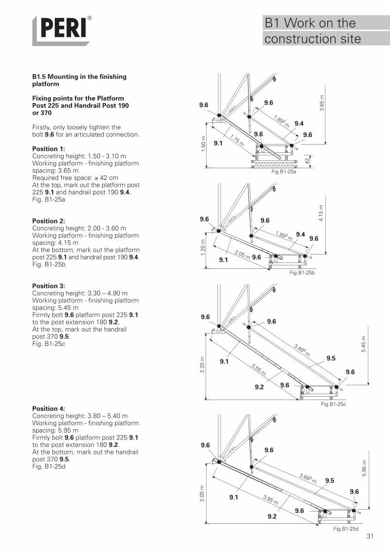
Fixing points for the PlatformPost 225 and Handrail Post 190or 370
Firstly, only loosely tighten thebolt 9.6 for an articulated connection.
Position 1:Concreting height: 1.50 - 3.10 mWorking platform - finishing platformspacing: 3.65 mRequired free space: ≥ 42 cmAt the top, mark out the platform post225 9.1 and handrail post 190 9.4.Fig. B1-25a
Position 2:Concreting height: 2.00 - 3.60 mWorking platform - finishing platformspacing: 4.15 mAt the bottom, mark out the platformpost 225 9.1 and handrail post 190 9.4.Fig. B1-25b
Position 3:Concreting height: 3.30 – 4.90 mWorking platform - finishing platformspacing: 5.45 mFirmly bolt 9.6 platform post 225 9.1to the post extension 180 9.2.At the top, mark out the handrailpost 370 9.5.Fig. B1-25c
Position 4:Concreting height: 3.80 – 5.40 mWorking platform - finishing platformspacing: 5.95 mFirmly bolt 9.6 platform post 225 9.1to the post extension 180 9.2.At the bottom, mark out the handrailpost 370 9.5.Fig. B1-25d
9.4
9.1
9.1
9.4
9.2
9.5
9.5
1.50
m1.
20 m
2.20
m2.
00 m
1.69 5 m
1.89 5 m
3.49 5 m
3.69 5 m
3.85 m
3.55 m
2.05 m
1.75 m
42
9.2
9.6 9.6
9.69.6
9.6 9.6
9.6
9.6
9.69.6
9.6
9.6
9.6
9.6
9.6
9.69.1
Fig.B1-25a
Fig.B1-25d
Fig.B1-25c
Fig.B1-25b
9.15.
95 m
5.45
m
4.15
m3.
65 m
B1 Work on theconstruction site
32
B1.5 Mounting in the finishingplatform
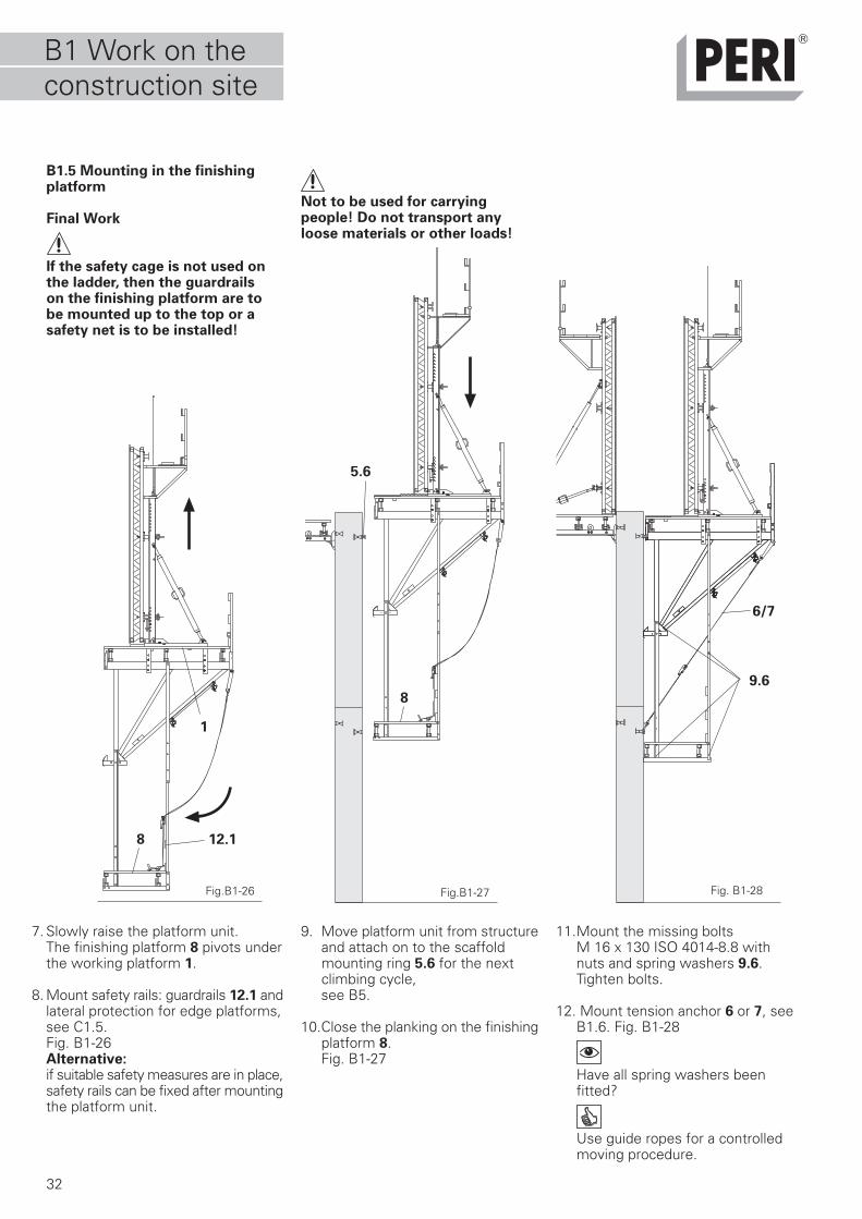
Final Work
If the safety cage is not used onthe ladder, then the guardrailson the finishing platform are tobe mounted up to the top or asafety net is to be installed!
Fig.B1-27 Fig. B1-28
7. Slowly raise the platform unit.The finishing platform 8 pivots underthe working platform 1.
8. Mount safety rails: guardrails 12.1 andlateral protection for edge platforms,see C1.5.Fig. B1-26Alternative:if suitable safety measures are in place,safety rails can be fixed after mountingthe platform unit.
9. Move platform unit from structureand attach on to the scaffoldmounting ring 5.6 for the nextclimbing cycle,see B5.
10.Close the planking on the finishingplatform 8.Fig. B1-27
11.Mount the missing boltsM 16 x 130 ISO 4014-8.8 withnuts and spring washers 9.6.Tighten bolts.
12. Mount tension anchor 6 or 7, seeB1.6. Fig. B1-28
Have all spring washers beenfitted?
Use guide ropes for a controlledmoving procedure.
Fig.B1-26
6/7
9.6
12.1
5.6
8
8
1
Not to be used for carryingpeople! Do not transport anyloose materials or other loads!
B1 Work on theconstruction site
33
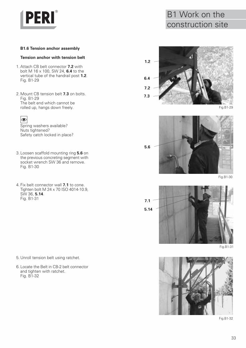
B1.6 Tension anchor assembly
Tension anchor with tension belt
1. Attach CB belt connector 7.2 withbolt M 16 x 100, SW 24, 6.4 to thevertical tube of the handrail post 1.2.Fig. B1-29
2. Mount CB tension belt 7.3 on bolts.Fig. B1-29The belt end which cannot berolled up, hangs down freely.
Spring washers available?Nuts tightened?Safety catch locked in place?
3. Loosen scaffold mounting ring 5.6 onthe previous concreting segment withsocket wrench SW 36 and remove.Fig. B1-30
4. Fix belt connector wall 7.1 to cone.Tighten bolt M 24 x 70 ISO 4014-10.9,SW 36, 5.14.Fig. B1-31
5. Unroll tension belt using ratchet.
6. Locate the Belt in CB-2 belt connectorand tighten with ratchet.Fig. B1-32
Fig.B1-30
5.6
Fig.B1-29
Fig.B1-31
7.3
7.2
7.1
1.2
5.14
Fig.B1-32
6.4
B1 Work on theconstruction site
34
Fig.B1-33c
Fig.B1-33d
Fig.B1-33a
Fig.B1-33b
Fig.B1-33f
6.5
6.1
6.2 6.2
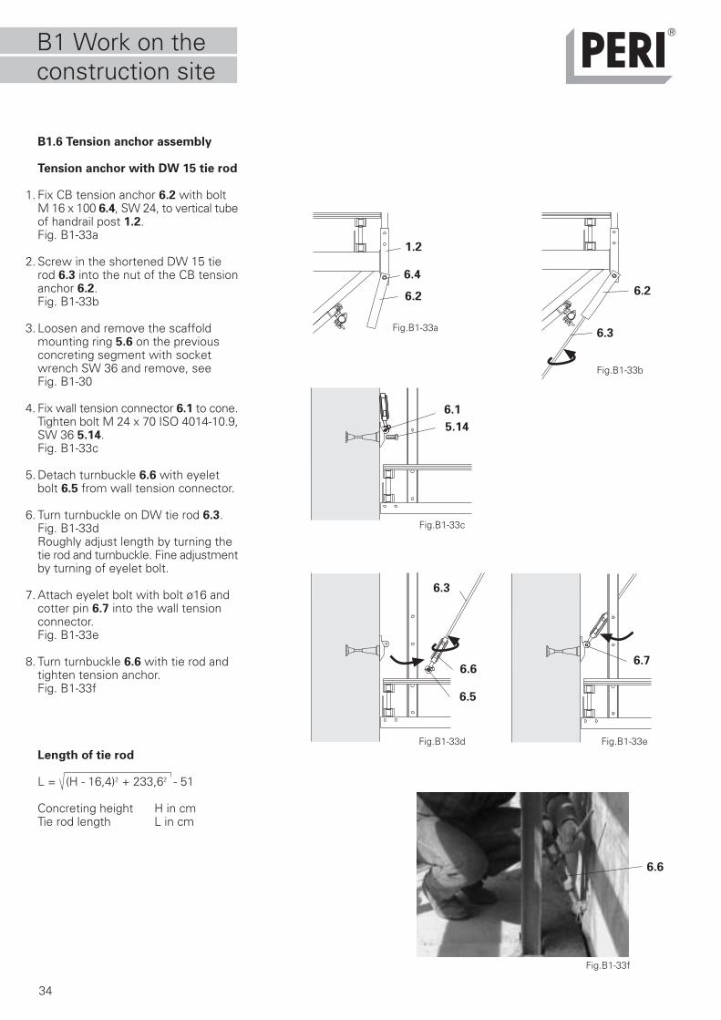
B1.6 Tension anchor assembly
Tension anchor with DW 15 tie rod
1. Fix CB tension anchor 6.2 with boltM 16 x 100 6.4, SW 24, to vertical tubeof handrail post 1.2.Fig. B1-33a
2. Screw in the shortened DW 15 tierod 6.3 into the nut of the CB tensionanchor 6.2.Fig. B1-33b
3. Loosen and remove the scaffoldmounting ring 5.6 on the previousconcreting segment with socketwrench SW 36 and remove, seeFig. B1-30
4. Fix wall tension connector 6.1 to cone.Tighten bolt M 24 x 70 ISO 4014-10.9,SW 36 5.14.Fig. B1-33c
5. Detach turnbuckle 6.6 with eyeletbolt 6.5 from wall tension connector.
6. Turn turnbuckle on DW tie rod 6.3.Fig. B1-33dRoughly adjust length by turning thetie rod and turnbuckle. Fine adjustmentby turning of eyelet bolt.
7. Attach eyelet bolt with bolt ø16 andcotter pin 6.7 into the wall tensionconnector.Fig. B1-33e
8. Turn turnbuckle 6.6 with tie rod andtighten tension anchor.Fig. B1-33f
Length of tie rod
L = (H - 16,4)2 + 233,62 - 51
Concreting height H in cmTie rod length L in cm
6.3
6.6
5.14
6.4
1.2
Fig.B1-33e
6.76.6
6.3
B1 Work on theconstruction site
35
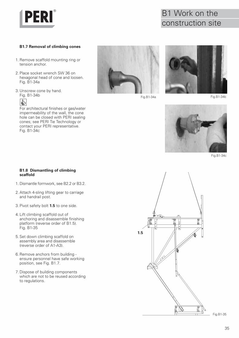
B1.7 Removal of climbing cones
1. Remove scaffold mounting ring ortension anchor.
2. Place socket wrench SW 36 onhexagonal head of cone and loosen.Fig. B1-34a
3. Unscrew cone by hand.Fig. B1-34b
For architectural finishes or gas/waterimpermeability of the wall, the conehole can be closed with PERI sealingcones; see PERI Tie Technology orcontact your PERI representative.Fig. B1-34c
B1.8 Dismantling of climbingscaffold
1. Dismantle formwork, see B2.2 or B3.2.
2. Attach 4-sling lifting gear to carriageand handrail post.
3. Pivot safety bolt 1.5 to one side.
4. Lift climbing scaffold out ofanchoring and disassemble finishingplatform (reverse order of B1.5).Fig. B1-35
5. Set down climbing scaffold onassembly area and disassemble(reverse order of A1-A3).
6. Remove anchors from building -ensure personnel have safe workingposition, see Fig. B1.7.
7. Dispose of building componentswhich are not to be reused accordingto regulations.
Fig.B1-34a Fig.B1-34b
Fig.B1-34c
Fig.B1-35
1.5
B1 Work on theconstruction site
36
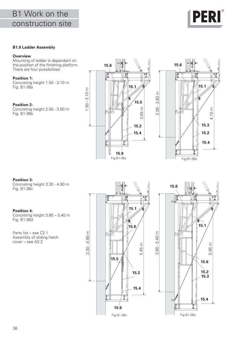
B1.9 Ladder Assembly
OverviewMounting of ladder is dependant onthe position of the finishing platform.There are four possibilities:
Position 1:Concreting height 1.50 - 3.10 mFig. B1-36a
Position 2:Concreting height 2.00 - 3.60 mFig. B1-36b
Position 3:Concreting height 3.30 - 4.90 mFig. B1-36c
Position 4:Concreting height 3.80 – 5.40 mFig. B1-36d
Parts list – see C2.1Assembly of sliding hatchcover – see A3.2
15.6
Fig.B1-36a
15.1
15.2
15.4
15.9
Fig.B1-36b
Fig.B1-36c Fig.B1-36d
15.9
15.2 15.2
15.1
15.1
15.4
15.4
15.6
15.1
15.2
15.4
15.6
15.5
15.5
15.3
15.3
15.6
15.6
1.50
- 3.
10 m
3.65
m
2.00
- 3.
60 m
4.15
m
3.30
- 4.
90 m
3.80
- 5.
40 m
5.95
m
5.45
m
B1 Work on theconstruction site
37
B1.9 Ladder Assembly
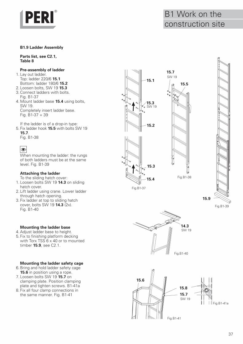
Parts list, see C2.1,Table 8
Pre-assembly of ladder1. Lay out ladder.
Top: ladder 220/6 15.1Bottom: ladder 180/6 15.2
2. Loosen bolts, SW 19 15.33. Connect ladders with bolts.
Fig. B1-374. Mount ladder base 15.4 using bolts,
SW 19.Completely insert ladder base.Fig. B1-37 + 39
If the ladder is of a drop-in type:5. Fix ladder hook 15.5 with bolts SW 19
15.7.Fig. B1-38
When mounting the ladder: the rungsof both ladders must be at the samelevel. Fig. B1-39
Attaching the ladderTo the sliding hatch cover:
1. Loosen bolts SW 19 14.3 on slidinghatch cover.
2. Lift ladder using crane. Lower ladderthrough hatch opening.
3. Fix ladder at top to sliding hatchcover, bolts SW 19 14.3 (2x).Fig. B1-40
Mounting the ladder base4. Adjust ladder base to height.5. Fix to finishing platform decking
with Torx TSS 6 x 40 or to mountedtimber 15.9, see C2.1.
Mounting the ladder safety cage6. Bring and hold ladder safety cage
15.6 in position using a rope.7. Loosen bolts SW 19 15.7 on
clamping plate. Position clampingplate and tighten screws. B1-41a
8. Fix all four clamp connections inthe same manner. Fig. B1-41
Fig.B1-38
15.1
15.8
14.3
15.2
15.3
15.9
15.7
Fig.B1-40
Fig.B1-41
15.6
Fig.B1-37
15.3
15.5
Fig.B1-39
Fig.B1-41a
SW 19
SW 19
SW 19
SW 19
15.4
15.7
B1 Work on theconstruction site
38
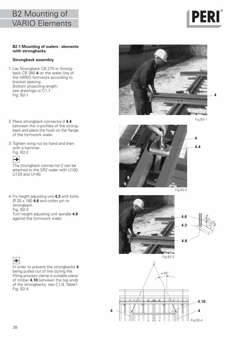
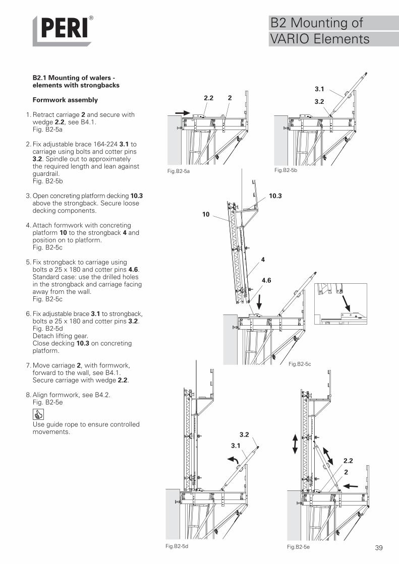
B2.1 Mounting of walers - elementswith strongbacks
Strongback assembly
1. Lay Strongback CB 270 or Strong-back CB 380 4 on the waler line ofthe VARIO formwork according tobracket spacing.Bottom projecting length:see drawings or C1.7Fig. B2-1
2. Place strongback connector-2 4.4between the U-profiles of the strong-back and place the hook on the flangeof the formwork waler.
3. Tighten wing nut by hand and thenwith a hammer.Fig. B2-2
The strongback connec-tor-2 can beattached to the SRZ waler with U100,U120 and U140.
4. Fix height adjusting unit 4.3 with boltsØ 25 x 180 4.6 and cotter pin tostrongback.Fig. B2-3Turn height adjusting unit spindle 4.8against the formwork waler.
In order to prevent the strongbacks 4being pulled out of line during thelifting process clamp a suitable pieceof timber 4.10 between the top endsof the strongbacks, see C1.9, Table7.Fig. B2-4
Fig.B2-1
Fig.B2-2
Fig.B2-3
Fig.B2-4
4.4
4
4.6
4.10
≤ 45°
4
4.3
44
4.8
B2 Mounting ofVARIO Elements
39
B2.1 Mounting of walers -elements with strongbacks
Formwork assembly
1. Retract carriage 2 and secure withwedge 2.2, see B4.1.Fig. B2-5a
2. Fix adjustable brace 164-224 3.1 tocarriage using bolts and cotter pins3.2. Spindle out to approximatelythe required length and lean againstguardrail.Fig. B2-5b
3. Open concreting platform decking 10.3above the strongback. Secure loosedecking components.
4. Attach formwork with concretingplatform 10 to the strongback 4 andposition on to platform.Fig. B2-5c
5. Fix strongback to carriage usingbolts ø 25 x 180 and cotter pins 4.6.Standard case: use the drilled holesin the strongback and carriage facingaway from the wall.Fig. B2-5c
6. Fix adjustable brace 3.1 to strongback,bolts ø 25 x 180 and cotter pins 3.2.Fig. B2-5dDetach lifting gear.Close decking 10.3 on concretingplatform.
7. Move carriage 2, with formwork,forward to the wall, see B4.1.Secure carriage with wedge 2.2.
8. Align formwork, see B4.2.Fig. B2-5e
Use guide rope to ensure controlledmovements.
23.2
3.1
3.1
Fig.B2-5bFig.B2-5a
Fig.B2-5c
Fig.B2-5d Fig.B2-5e
2.2
2
3.2
4.6
4
10.3
10
2.2
B2 Mounting ofVARIO Elements
40
Kranlasche 24Art.-Nr. 070760
Betriebsanleitung
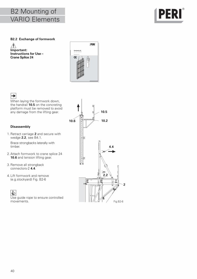
B2.2 Exchange of formwork
Important:Instructions for Use –Crane Splice 24
When laying the formwork down,the handrail 10.5 on the concretingplatform must be removed to avoidany damage from the lifting gear.
Disassembly
1. Retract carriage 2 and secure withwedge 2.2, see B4.1.
Brace strongbacks laterally withtimber.
2. Attach formwork to crane splice 2410.6 and tension lifting gear.
3. Remove all strongbackconnectors-2 4.4.
4. Lift formwork and remove(e.g.stockyard) Fig. B2-6
Use guide rope to ensure controlledmovements. Fig.B2-6
4.4
10.6
2
10.5
2.2
10.2
B2 Mounting ofVARIO Elements
41
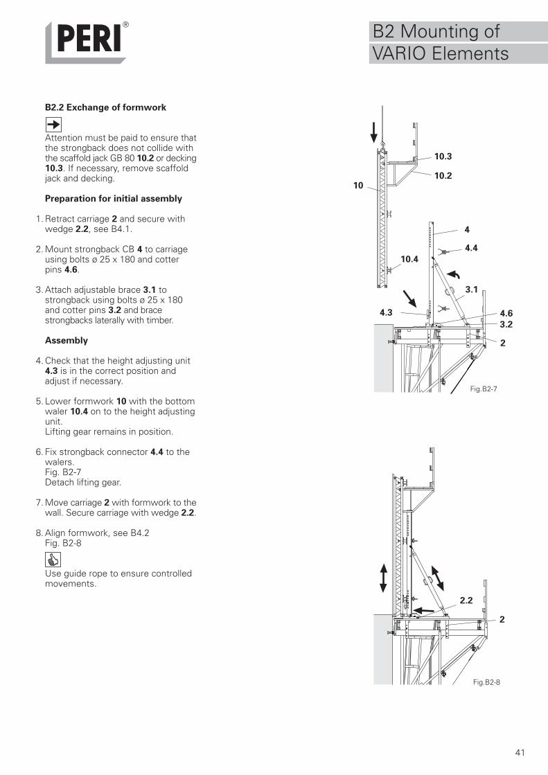
B2.2 Exchange of formwork
Attention must be paid to ensure thatthe strongback does not collide withthe scaffold jack GB 80 10.2 or decking10.3. If necessary, remove scaffoldjack and decking.
Preparation for initial assembly
1. Retract carriage 2 and secure withwedge 2.2, see B4.1.
2. Mount strongback CB 4 to carriageusing bolts ø 25 x 180 and cotterpins 4.6.
3. Attach adjustable brace 3.1 tostrongback using bolts ø 25 x 180and cotter pins 3.2 and bracestrongbacks laterally with timber.
Assembly
4. Check that the height adjusting unit4.3 is in the correct position andadjust if necessary.
5. Lower formwork 10 with the bottomwaler 10.4 on to the height adjustingunit.Lifting gear remains in position.
6. Fix strongback connector 4.4 to thewalers.Fig. B2-7Detach lifting gear.
7. Move carriage 2 with formwork to thewall. Secure carriage with wedge 2.2.
8. Align formwork, see B4.2Fig. B2-8
Use guide rope to ensure controlledmovements.
Fig.B2-7
Fig.B2-8
4.4
2
4.6
3.2
2.2
10.3
10.210
4
3.1
4.3
10.4
2
B2 Mounting ofVARIO Elements
42
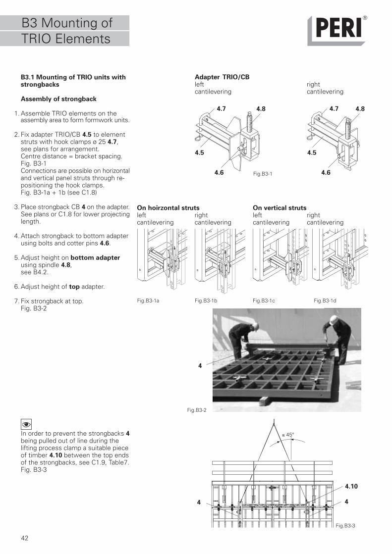
B3.1 Mounting of TRIO units withstrongbacks
Assembly of strongback
1. Assemble TRIO elements on theassembly area to form formwork units.
2. Fix adapter TRIO/CB 4.5 to elementstruts with hook clamps ø 25 4.7,see plans for arrangement.Centre distance = bracket spacing.Fig. B3-1Connections are possible on horizontaland vertical panel struts through re-positioning the hook clamps.Fig. B3-1a + 1b (see C1.8)
3. Place strongback CB 4 on the adapter.See plans or C1.8 for lower projectinglength.
4. Attach strongback to bottom adapterusing bolts and cotter pins 4.6.
5. Adjust height on bottom adapterusing spindle 4.8,see B4.2.
6. Adjust height of top adapter.
7. Fix strongback at top.Fig. B3-2
In order to prevent the strongbacks 4being pulled out of line during thelifting process clamp a suitable pieceof timber 4.10 between the top endsof the strongbacks, see C1.9, Table7.Fig. B3-3
Fig.B3-1
Fig.B3-3
4.10
4.5
4
Fig.B3-2
≤ 45°
4 4
4.7
4.6
4.8
B3 Mounting ofTRIO Elements
4.8
4.5
4.7
4.6
Fig.B3-1a Fig.B3-1b Fig.B3-1c Fig.B3-1d
On hoirzontal strutsleft rightcantilevering cantilevering
On vertical strutsleft rightcantilevering cantilevering
Adapter TRIO/CBleft cantilevering
rightcantilevering
43
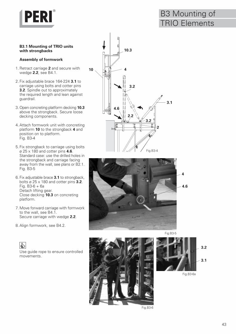
B3.1 Mounting of TRIO unitswith strongbacks
Assembly of formwork
1. Retract carriage 2 and secure withwedge 2.2, see B4.1.
2. Fix adjustable brace 164-224 3.1 tocarriage using bolts and cotter pins3.2. Spindle out to approximatelythe required length and lean againstguardrail.
3. Open concreting platform decking 10.3above the strongback. Secure loosedecking components.
4. Attach formwork unit with concretingplatform 10 to the strongback 4 andposition on to platform.Fig. B3-4
5. Fix strongback to carriage using boltsø 25 x 180 and cotter pins 4.6.Standard case: use the drilled holes inthe strongback and carriage facingaway from the wall, see plans or B2.1.Fig. B3-5
6. Fix adjustable brace 3.1 to strongback,bolts ø 25 x 180 and cotter pins 3.2.Fig. B3-6 + 6aDetach lifting gear.Close decking 10.3 on concretingplatform.
7. Move forward carriage with formworkto the wall, see B4.1.Secure carriage with wedge 2.2.
8. Align formwork, see B4.2.
Use guide rope to ensure controlledmovements.
Fig.B3-5
Fig.B3-4
Fig.B3-6
3.1
4.6
3.2
2
4.6
3.1
3.2
Fig.B3-6a
4
2.2
3.2
4
10.3
10
B3 Mounting ofTRIO Elements
TRIO Versetzhaken 1,5tArt.-Nr. 023690
Bedienungsanleitung
44
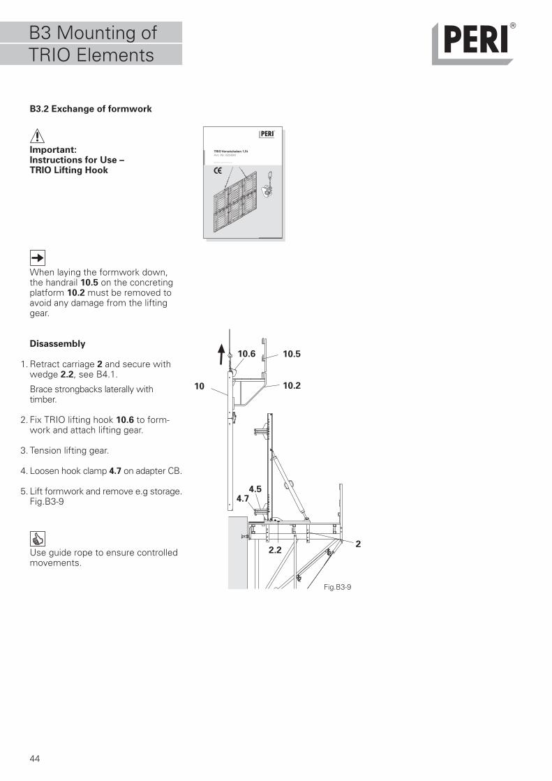
B3.2 Exchange of formwork
Important:Instructions for Use –TRIO Lifting Hook
When laying the formwork down,the handrail 10.5 on the concretingplatform 10.2 must be removed toavoid any damage from the liftinggear.
Disassembly
1. Retract carriage 2 and secure withwedge 2.2, see B4.1.
Brace strongbacks laterally withtimber.
2. Fix TRIO lifting hook 10.6 to form-work and attach lifting gear.
3. Tension lifting gear.
4. Loosen hook clamp 4.7 on adapter CB.
5. Lift formwork and remove e.g storage.Fig.B3-9
Use guide rope to ensure controlledmovements.
Fig.B3-9
2
4.5
10.6
10.2
10.5
10
2.2
4.7
B3 Mounting ofTRIO Elements
45
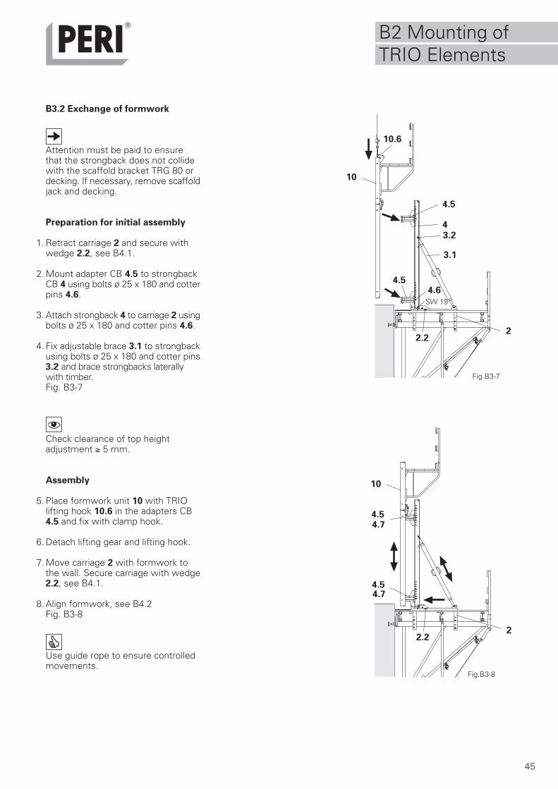
B3.2 Exchange of formwork
Attention must be paid to ensurethat the strongback does not collidewith the scaffold bracket TRG 80 ordecking. If necessary, remove scaffoldjack and decking.
Preparation for initial assembly
1. Retract carriage 2 and secure withwedge 2.2, see B4.1.
2. Mount adapter CB 4.5 to strongbackCB 4 using bolts ø 25 x 180 and cotterpins 4.6.
3. Attach strongback 4 to carriage 2 usingbolts ø 25 x 180 and cotter pins 4.6.
4. Fix adjustable brace 3.1 to strongbackusing bolts ø 25 x 180 and cotter pins3.2 and brace strongbacks laterallywith timber.Fig. B3-7
Check clearance of top heightadjustment ≥ 5 mm.
Assembly
5. Place formwork unit 10 with TRIOlifting hook 10.6 in the adapters CB4.5 and fix with clamp hook.
6. Detach lifting gear and lifting hook.
7. Move carriage 2 with formwork tothe wall. Secure carriage with wedge2.2, see B4.1.
8. Align formwork, see B4.2Fig. B3-8
Use guide rope to ensure controlledmovements.
Fig.B3-7
Fig.B3-8
4
2
4.5
SW 19
3.1
3.2
2.2
4.6
4.7
4.7
4.5
10
10.6
10
4.5
4.5
22.2
B2 Mounting ofTRIO Elements
46
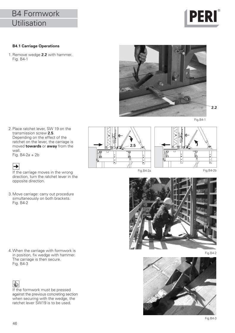
B4.1 Carriage Operations
1. Remove wedge 2.2 with hammer.Fig. B4-1
2. Place ratchet lever, SW 19 on thetransmission screw 2.5.Depending on the effect of theratchet on the lever, the carriage ismoved towards or away from thewall.Fig. B4-2a + 2b
If the carriage moves in the wrongdirection, turn the ratchet lever in theopposite direction.
3. Move carriage: carry out proceduresimultaneously on both brackets.Fig. B4-2
4. When the carriage with formwork isin position, fix wedge with hammer.The carriage is then secure.Fig. B4-3
If the formwork must be pressedagainst the previous concreting sectionwhen securing with the wedge, theratchet lever SW19 is to be used.
Fig.B4-1
Fig.B4-2
Fig.B4-2a Fig.B4-2b
Fig.B4-3
2.2
2.5
B4 FormworkUtilisation
47
10
4.3
4.3
4.84.6
4.8
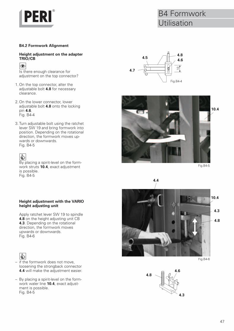
B4.2 Formwork Alignment
Height adjustment on the adapterTRIO/CB
Is there enough clearance foradjustment on the top connector?
1. On the top connector, alter theadjustable bolt 4.8 for necessaryclearance.
2. On the lower connector, loweradjustable bolt 4.8 onto the lockingpin 4.6.Fig. B4-4
3. Turn adjustable bolt using the ratchetlever SW 19 and bring formwork intoposition. Depending on the rotationaldirection, the formwork moves up-wards or downwards.Fig. B4-5
By placing a spirit-level on the form-work struts 10.4, exact adjustmentis possible.Fig. B4-5
Height adjustment with the VARIOheight adjusting unit
Apply ratchet lever SW 19 to spindle4.8 on the height adjusting unit CB4.3. Depending on the rotationaldirection, the formwork movesupwards or downwards.Fig. B4-6
– if the formwork does not move,loosening the strongback connector4.4 will make the adjustment easier.
– By placing a spirit-level on the form-work waler line 10.4, exact adjust-ment is possible.Fig. B4-5
Fig.B4-5
Fig.B4-6
10.4
Fig.B4-4
4.8
4.7
4.64.5
10.4
4.4
B4 FormworkUtilisation
48
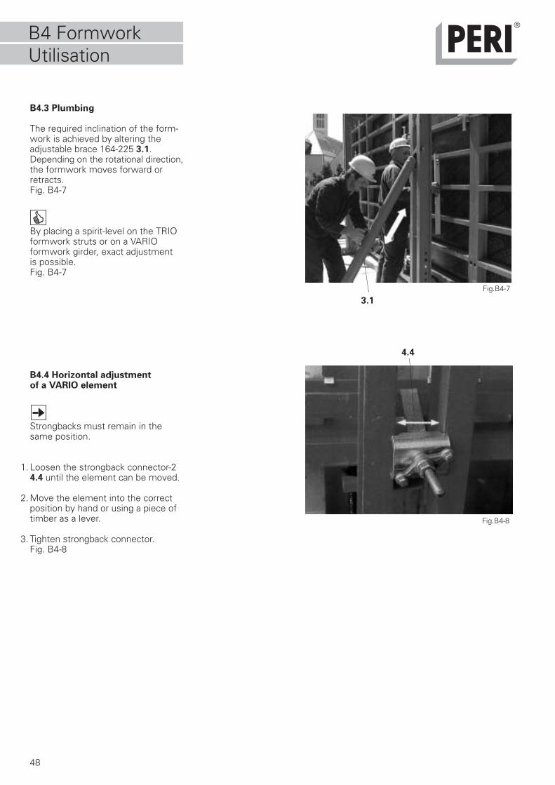
B4.3 Plumbing
The required inclination of the form-work is achieved by altering theadjustable brace 164-225 3.1.Depending on the rotational direction,the formwork moves forward orretracts.Fig. B4-7
By placing a spirit-level on the TRIOformwork struts or on a VARIOformwork girder, exact adjustmentis possible.Fig. B4-7
B4.4 Horizontal adjustmentof a VARIO element
Strongbacks must remain in thesame position.
1. Loosen the strongback connector-24.4 until the element can be moved.
2. Move the element into the correctposition by hand or using a piece oftimber as a lever.
3. Tighten strongback connector.Fig. B4-8
Fig.B4-7
Fig.B4-8
3.1
4.4
B4 FormworkUtilisation
49
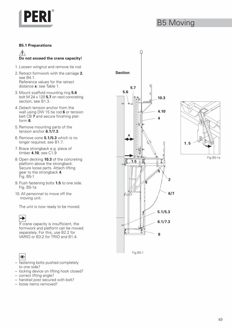
B5.1 Preparations
Do not exceed the crane capacity!
1. Loosen wingnut and remove tie rod.
2. Retract formwork with the carriage 2,see B4.1.Reference values for the retractdistance x: see Table 1.
3. Mount scaffold mounting ring 5.6bolt M 24 x 120 5.7 on next concretingsection, see B1.3.
4. Detach tension anchor from thewall using DW 15 tie rod 6 or tensionbelt CB 7 and secure finishing plat-form 8.
5. Remove mounting parts of thetension anchor 6.1/7.3.
6. Remove cone 5.1/5.3 which is nolonger required, see B1.7.
7. Brace strongback e.g. piece oftimber 4.10, see C1.9
8. Open decking 10.3 of the concretingplatform above the strongback.Secure loose parts. Attach liftinggear to the strongback 4.Fig. B5-1
9. Push fastening bolts 1.5 to one side.Fig. B5-1a
10. All personnel to move off the moving unit.
The unit is now ready to be moved.
If crane capacity is insufficient, theformwork and platform can be movedseparately. For this, use B2.2 forVARIO or B3.2 for TRIO and B1.4.
– fastening bolts pushed completelyto one side?
– locking device on lifting hook closed?– correct lifting angle?– handrail post secured with bolt?– loose items removed?
Fig.B5-1
2
5.6
1.5
6/7
Fig.B5-1a
5.7
4
8
5.1/5.3
6.1/7.3
x
1 . 5
Section
10.3
4.10
B5 Moving
50
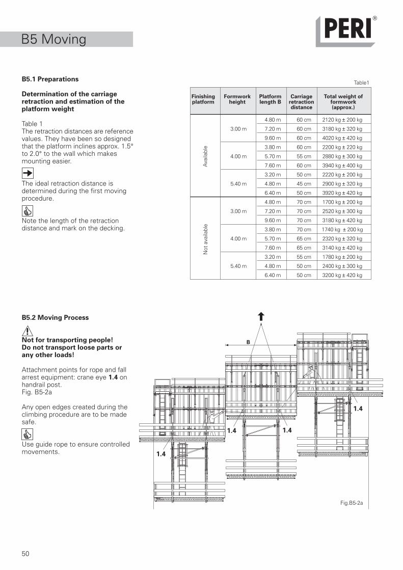
B5.1 Preparations
Determination of the carriageretraction and estimation of theplatform weight
Table 1The retraction distances are referencevalues. They have been so designedthat the platform inclines approx. 1.5°to 2.0° to the wall which makesmounting easier.
The ideal retraction distance isdetermined during the first movingprocedure.
Note the length of the retractiondistance and mark on the decking.
B5.2 Moving Process
Not for transporting people!Do not transport loose parts orany other loads!
Attachment points for rope and fallarrest equipment: crane eye 1.4 onhandrail post.Fig. B5-2a
Any open edges created during theclimbing procedure are to be madesafe.
Use guide rope to ensure controlledmovements.
4.80 m 60 cm 2120 kg ± 200 kg
3.00 m 7.20 m 60 cm 3180 kg ± 320 kg
9.60 m 60 cm 4020 kg ± 420 kg
3.80 m 60 cm 2200 kg ± 220 kg
4.00 m 5.70 m 55 cm 2880 kg ± 300 kg
7.60 m 60 cm 3940 kg ± 400 kg
3.20 m 50 cm 2220 kg ± 200 kg
5.40 m 4.80 m 45 cm 2900 kg ± 320 kg
6.40 m 50 cm 3920 kg ± 420 kg
4.80 m 70 cm 1700 kg ± 200 kg
3.00 m 7.20 m 70 cm 2520 kg ± 300 kg
9.60 m 70 cm 3180 kg ± 420 kg
3.80 m 70 cm 1740 kg ± 200 kg
4.00 m 5.70 m 65 cm 2320 kg ± 320 kg
7.60 m 65 cm 3140 kg ± 420 kg
3.20 m 55 cm 1780 kg ± 200 kg
5.40 m 4.80 m 50 cm 2400 kg ± 300 kg
6.40 m 50 cm 3200 kg ± 420 kg
Ava
ilabl
eN
ot a
vaila
ble
Finishing Formwork Platform Carriage Total weight ofplatform height length B retraction formwork
distance (approx.)
Table1
1.41.4
1.4
1.4
Fig.B5-2a
B
B5 Moving
51
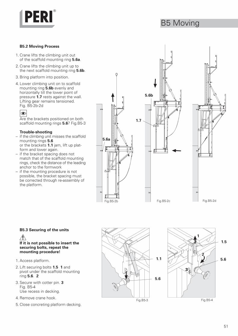
B5.2 Moving Process
1. Crane lifts the climbing unit outof the scaffold mounting ring 5.6a.
2. Crane lifts the climbing unit up tothe next scaffold mounting ring 5.6b.
3. Bring platform into position.
4. Lower climbing unit on to scaffoldmounting ring 5.6b evenly andhorizontally till the lower point ofpressure 1.7 rests against the wall.Lifting gear remains tensioned.Fig. B5-2b-2d
Are the brackets positioned on bothscaffold mounting rings 5.6? Fig.B5-3
Trouble-shooting– if the climbing unit misses the scaffold
mounting rings 5.6or the brackets 1.1 jam, lift up plat-form and lower again.
– if the bracket spacing does notmatch that of the scaffold mountingrings, check the distance of the leadinganchor to the formwork
– if the mounting procedure is notpossible, the bracket spacing mustbe corrected through re-assembly ofthe platform.
B5.3 Securing of the units
If it is not possible to insert thesecuring bolts, repeat themounting procedure!
1. Access platform.
2. Lift securing bolts 1.5 1 andpivot under the scaffold mountingring 5.6. 2
3. Secure with cotter pin. 3Fig. B5-4Use recess in decking.
4. Remove crane hook.
5. Close concreting platform decking.Fig.B5-4
1.5
Fig.B5-3
5.6
5.6
1.1
1
2
3
Fig.B5-2b Fig.B5-2dFig.B5-2c
5.6b
5.6a
1.7
B5 Moving
52
Wind from backWind from front
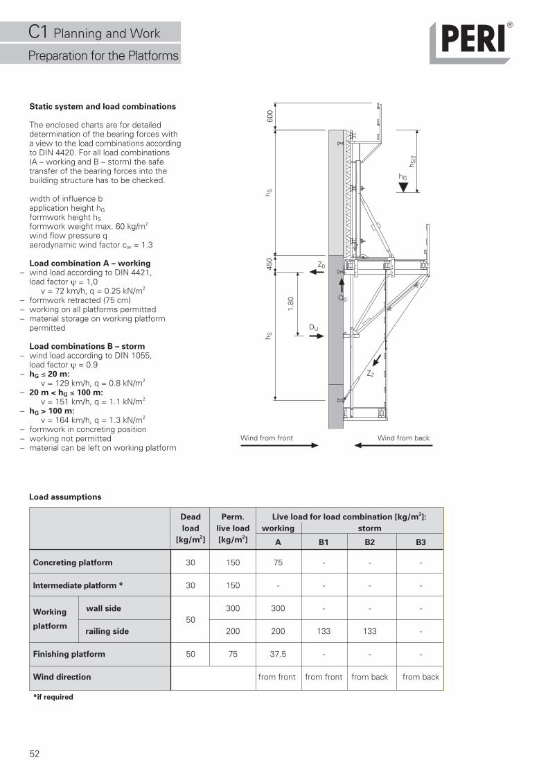
Load assumptions
Dead Perm. Live load for load combination [kg/m2]:
load live load working storm
[kg/m2] [kg/m
2] A B1 B2 B3
Concreting platform 30 150 75 - - -
Intermediate platform * 30 150 - - - -
wall side 300 300 - - -Working50
platform railing side 200 200 133 133 -
Finishing platform 50 75 37.5 - - -
Wind direction from front from front from back from back
*if required
Static system and load combinations
The enclosed charts are for detaileddetermination of the bearing forces witha view to the load combinations accordingto DIN 4420. For all load combinations(A – working and B – storm) the safetransfer of the bearing forces into thebuilding structure has to be checked.
width of influence b application height hGformwork height hS formwork weight max. 60 kg/m2
wind flow pressure q aerodynamic wind factor cw = 1.3
Load combination A – working– wind load according to DIN 4421,
load factor ψ = 1,0 v = 72 km/h, q = 0.25 kN/m2
– formwork retracted (75 cm)– working on all platforms permitted– material storage on working platform
permitted
Load combinations B – storm– wind load according to DIN 1055,
load factor ψ = 0.9– hG ≤ 20 m:
v = 129 km/h, q = 0.8 kN/m2
– 20 m < hG ≤ 100 m: v = 151 km/h, q = 1.1 kN/m2
– hG > 100 m: v = 164 km/h, q = 1.3 kN/m2
– formwork in concreting position– working not permitted– material can be left on working platform
h S/2
600
h S
hG
450
h S
DU
1.80
Z0
Q0
ZZ
C1 Planning and Work
Preparation for the Platforms
53
2.00 2.50 3.00 3.50 4.00 4.503.00
3.50
4.00
4.50
5.00
5.40
width of influenceperm. b [m]
formwork height hs [m]
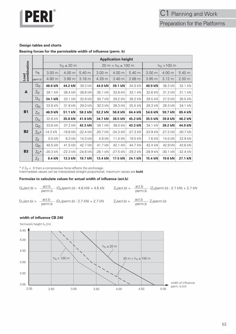
Design tables and charts
hG ≤ 20 m
Application height
A
B1
B2
B3
Lo
ad
co
mb
inati
on
hs
perm.b
Qo
Zo
Du
Qo
Zo
Du
Qo
Zo*
Zz
Qo
Zo*
Zz
hG ≤ 20 m 20 m < hG ≤ 100 m hG >100 m
3.00 m 4.00 m 5.40 m 3.00 m 4.00 m 5.40 m 3.00 m 4.00 m 5.40 m
4.80 m 3.90 m 3.16 m 4.28 m 3.40 m 2.68 m 3.95 m 3.12 m 2.50 m
48.8 kN 44.2 kN 39.3 kN 44.0 kN 39.1 kN 34.0 kN 40.9 kN 36.3 kN 32.1 kN
39.1 kN 38.4 kN 38.6 kN 35.1 kN 33.8 kN 33.1 kN 32.6 kN 31.2 kN 31.1 kN
34.1 kN 33.1 kN 32.8 kN 30.7 kN 29.2 kN 28.2 kN 28.5 kN 27.0 kN 26.5 kN
33.6 kN 31.8 kN 29.3 kN 30.3 kN 28.3 kN 25.5 kN 28.3 kN 26.3 kN 24.1 kN
46.9 kN 51.1 kN 58.3 kN 52.2 kN 56.8 kN 64.4 kN 54.6 kN 59.7 kN 69.4 kN
32.6 kN 35.8 kN 41.8 kN 34.7 kN 38.5 kN 45.2 kN 35.5 kN 39.8 kN 48.2 kN
33.6 kN 37.2 kN 42.3 kN 34.1 kN 38.0 kN 43.3 kN 34.1 kN 38.2 kN 44.9 kN
-14.3 kN -18.6 kN -22.4 kN -20.7 kN -24.3 kN -27.3 kN -23.9 kN -27.2 kN -30.7 kN
0.0 kN 6.3 kN 14.3 kN 4.9 kN 11.4 kN 19.5 kN 7.6 kN 14.0 kN 22.9 kN
40.5 kN 41.5 kN 42.7 kN 41.7 kN 42.1 kN 44.7 kN 42.4 kN 42.9 kN 43.6 kN
-20.3 kN -22.3 kN -24.6 kN -26.1 kN -27.5 kN -29.2 kN -28.9 kN -30.1 kN -32.4 kN
9.4 kN 13.3 kN 19.7 kN 13.4 kN 17.5 kN 24.1 kN 15.4 kN 19.6 kN 27.1 kN
* if Zo < 0 then a compressive force affects the anchorage.Intermediate values can be interpolated straight proportional, maximum values are bold.
Qo(act.b) = act.b · (Qo(perm.b) - 4.6 kN) + 4.6 kN Zo(act.b) = act.b · (Zo(perm.b) - 2.7 kN) + 2.7 kN perm.b perm.b
DU(act.b) = act.b · (DU(perm.b) - 2.7 kN) + 2.7 kN ZZ(act.b) = act.b · ZZ(perm.b) perm.b perm.b
width of influence CB 240
Formulas to calculate values for actual width of influence (act.b)
Bearing forces for the permissible width of influence (perm. b)
5.00
20 m < hG ≤ 100 mhG > 100 m
C1 Planning and Work
Preparation for the Platforms
54
QO
ZO
450
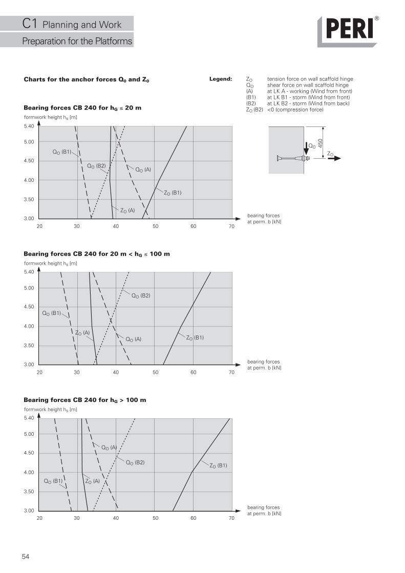
Legend: ZO tension force on wall scaffold hingeQO shear force on wall scaffold hinge(A) at LK A - working (Wind from front)(B1) at LK B1 - storm (Wind from front)(B2) at LK B2 - storm (Wind from back)ZO (B2) <0 (compression force)
3.00
3.50
4.00
4.50
5.00
5.40
bearing forcesat perm. b [kN]
formwork height hs [m]
Bearing forces CB 240 for hG ≤ 20 m
ZO (B1)
QO (A)QO (B2)
ZO (A)
QO (B1)
3.00
3.50
4.00
4.50
5.00
5.40
formwork height hs [m]
Bearing forces CB 240 for 20 m < hG ≤ 100 m
ZO (B1)QO (A)
QO (B2)
ZO (A)
QO (B1)
3.00
3.50
4.00
4.50
5.00
5.40
formwork height hs [m]
Bearing forces CB 240 for hG > 100 m
ZO (B1)
QO (A)
QO (B2)
ZO (A)QO (B1)
Charts for the anchor forces Q0 and Z0
20 30 40 50 60 70
bearing forcesat perm. b [kN]
20 30 40 50 60 70
bearing forcesat perm. b [kN]
20 30 40 50 60 70
C1 Planning and Work
Preparation for the Platforms
55
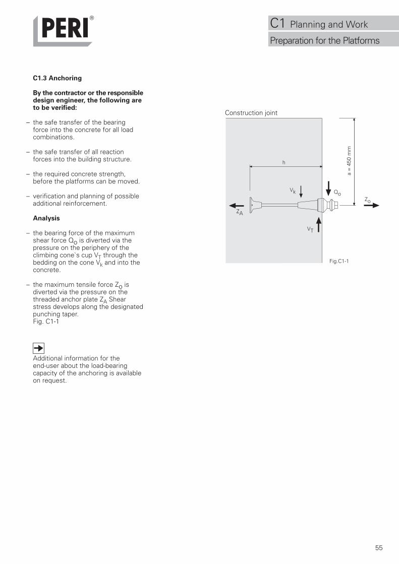
C1.3 Anchoring
By the contractor or the responsibledesign engineer, the following areto be verified:
– the safe transfer of the bearingforce into the concrete for all loadcombinations.
– the safe transfer of all reactionforces into the building structure.
– the required concrete strength,before the platforms can be moved.
– verification and planning of possibleadditional reinforcement.
Analysis
– the bearing force of the maximumshear force Qo is diverted via thepressure on the periphery of theclimbing cone`s cup VT through thebedding on the cone Vk and into theconcrete.
– the maximum tensile force Zo isdiverted via the pressure on thethreaded anchor plate ZA Shearstress develops along the designatedpunching taper.Fig. C1-1
Additional information for theend-user about the load-bearingcapacity of the anchoring is availableon request.
Fig.C1-1
h
Vk
VT
ZA
Zo
Qo
a =
450
mm
Construction joint
C1 Planning and Work
Preparation for the Platforms
56
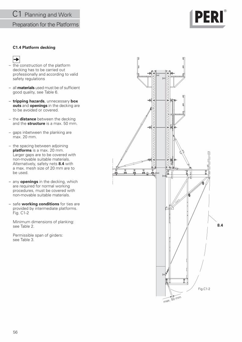
C1.4 Platform decking
– the construction of the platformdecking has to be carried outprofessionally and according to validsafety regulations
– all materials used must be of sufficientgood quality, see Table 6.
– tripping hazards, unnecessary boxouts and openings in the decking areto be avoided or covered.
– the distance between the deckingand the structure is a max. 50 mm.
– gaps inbetween the planking aremax. 20 mm.
– the spacing between adjoiningplatforms is a max. 20 mm.Larger gaps are to be covered withnon-movable suitable materials.Alternatively, safety nets 8.4 witha max. mesh size of 20 mm are tobe used.
– any openings in the decking, whichare required for normal workingprocedures, must be covered withnon-movable suitable materials.
– safe working conditions for ties areprovided by intermediate platforms.Fig. C1-2
Minimum dimensions of planking:see Table 2.
Permissible span of girders:see Table 3.
max. 50 mm
Fig.C1-2
8.4
C1 Planning and Work
Preparation for the Platforms
57
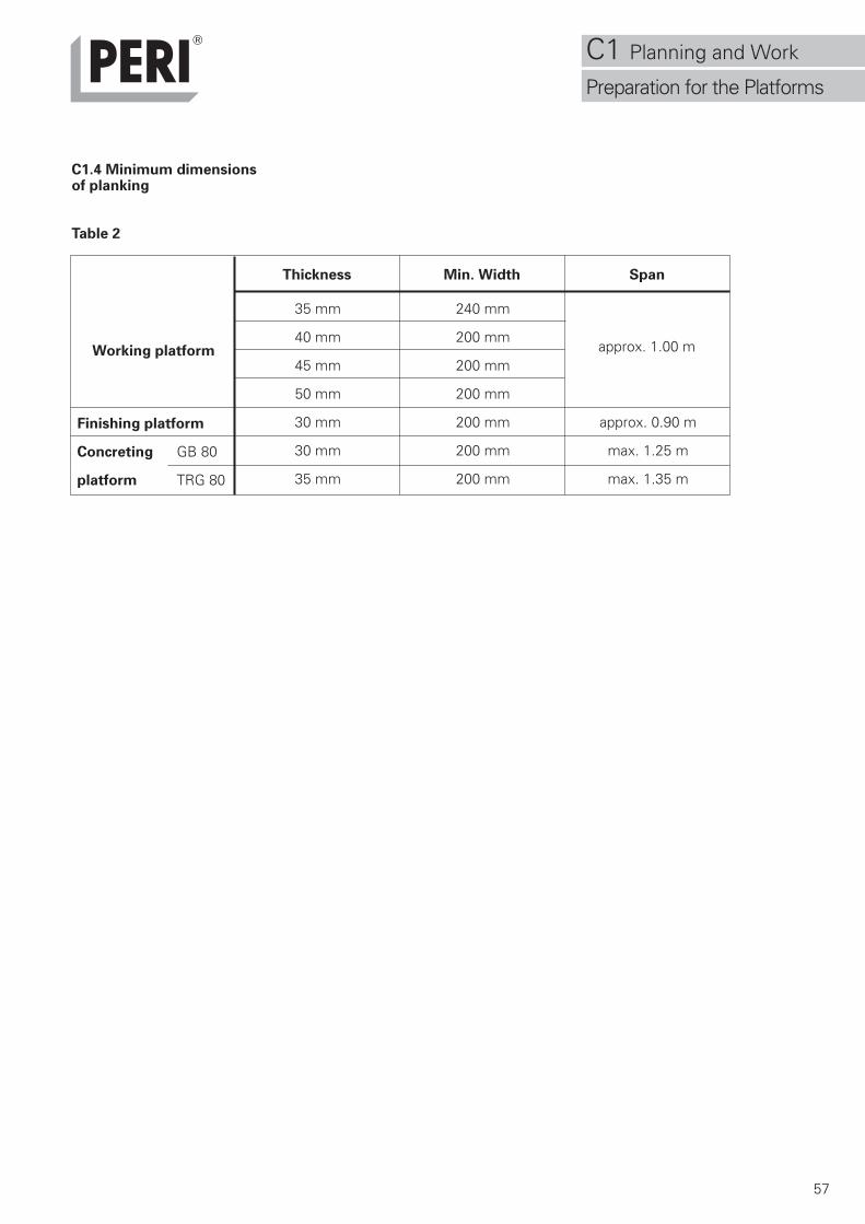
C1.4 Minimum dimensionsof planking
Table 2
35 mm 240 mm
40 mm 200 mm
45 mm 200 mm
50 mm 200 mm
30 mm 200 mm approx. 0.90 m
30 mm 200 mm max. 1.25 m
35 mm 200 mm max. 1.35 m
approx. 1.00 mWorking platform
Finishing platform
Concreting GB 80
platform TRG 80
Thickness Min. Width Span
C1 Planning and Work
Preparation for the Platforms
58
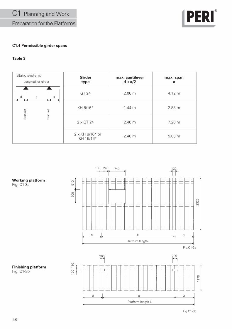
C1.4 Permissible girder spans
Table 3
Girder max. cantilever max. spantype d ≤ c/2 c
GT 24 2.06 m 4.12 m
KH 8/16* 1.44 m 2.88 m
2 x GT 24 2.40 m 7.20 m
2.40 m 5.03 m
Static system:
d c d
Bra
cket
Bra
cket
Longitudinal girder
2 x KH 8/16* orKH 16/16*
Working platformFig. C1-3a
Finishing platformFig. C1-3b
Fig.C1-3a
Fig.C1-3b
130130 740240
cd d
Platform length L
200 200
cd d
Platform length L
100
180
1170
600
510
2326
C1 Planning and Work
Preparation for the Platforms
59
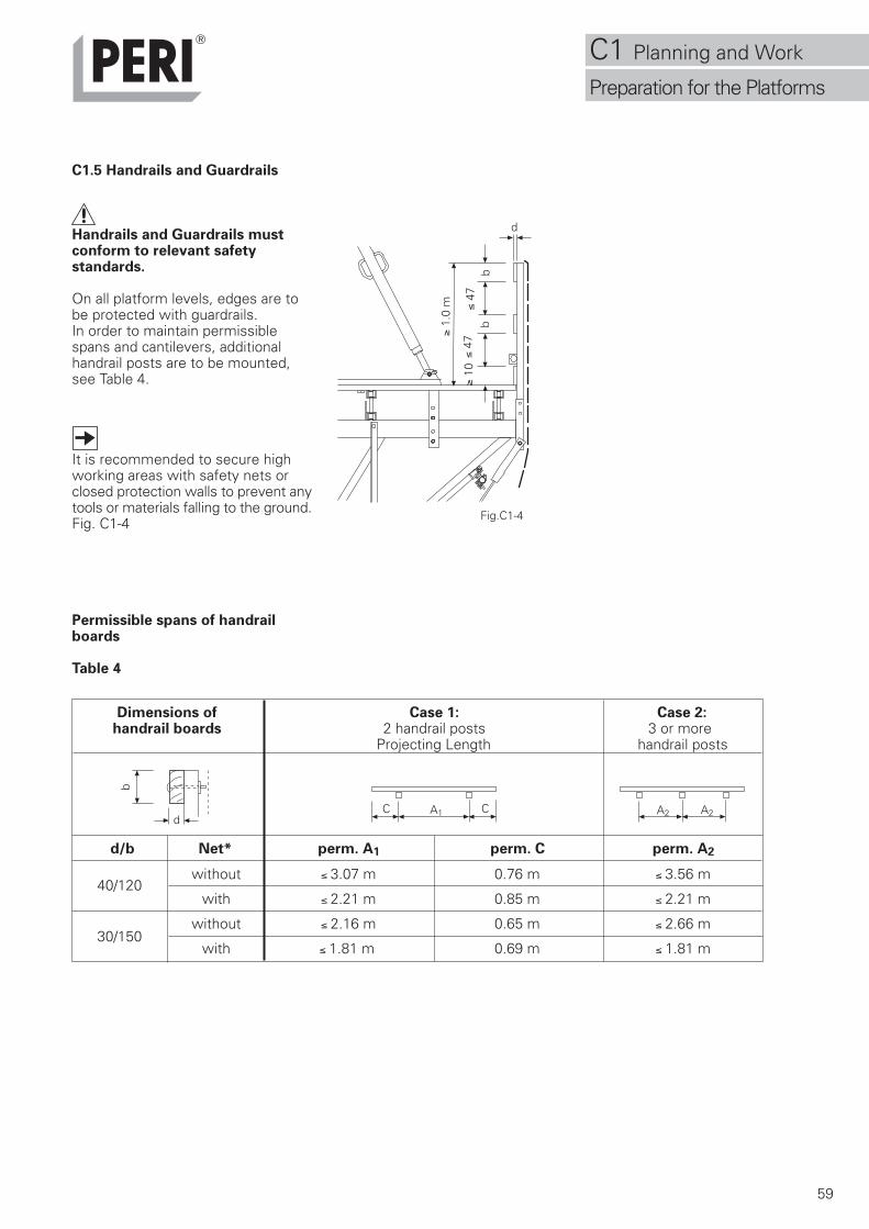
C1.5 Handrails and Guardrails
Handrails and Guardrails mustconform to relevant safetystandards.
On all platform levels, edges are tobe protected with guardrails.In order to maintain permissiblespans and cantilevers, additionalhandrail posts are to be mounted,see Table 4.
It is recommended to secure highworking areas with safety nets orclosed protection walls to prevent anytools or materials falling to the ground.Fig. C1-4
Permissible spans of handrailboards
Table 4
Fig.C1-4
d
≤ 47
b
≥ 1.
0 m
b≥
10≤
47
Dimensions of Case 1: Case 2:handrail boards 2 handrail posts 3 or more
Projecting Length handrail posts
40/120
30/150
d/b Net* perm. A1 perm. C perm. A2
without ≤ 3.07 m 0.76 m ≤ 3.56 m
with ≤ 2.21 m 0.85 m ≤ 2.21 m
without ≤ 2.16 m 0.65 m ≤ 2.66 m
with ≤ 1.81 m 0.69 m ≤ 1.81 m
A1 A2 A2C Cd
b
C1 Planning and Work
Preparation for the Platforms
60
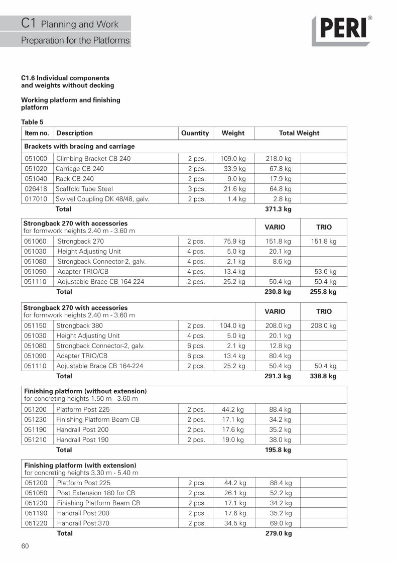
C1.6 Individual componentsand weights without decking
Working platform and finishingplatform
Table 5
051000 Climbing Bracket CB 240 2 pcs. 109.0 kg 218.0 kg
051020 Carriage CB 240 2 pcs. 33.9 kg 67.8 kg
051040 Rack CB 240 2 pcs. 9.0 kg 17.9 kg
026418 Scaffold Tube Steel 3 pcs. 21.6 kg 64.8 kg
017010 Swivel Coupling DK 48/48, galv. 2 pcs. 1.4 kg 2.8 kg
Total 371.3 kg
051200 Platform Post 225 2 pcs. 44.2 kg 88.4 kg
051230 Finishing Platform Beam CB 2 pcs. 17.1 kg 34.2 kg
051190 Handrail Post 200 2 pcs. 17.6 kg 35.2 kg
051210 Handrail Post 190 2 pcs. 19.0 kg 38.0 kg
Total 195.8 kg
051200 Platform Post 225 2 pcs. 44.2 kg 88.4 kg
051050 Post Extension 180 for CB 2 pcs. 26.1 kg 52.2 kg
051230 Finishing Platform Beam CB 2 pcs. 17.1 kg 34.2 kg
051190 Handrail Post 200 2 pcs. 17.6 kg 35.2 kg
051220 Handrail Post 370 2 pcs. 34.5 kg 69.0 kg
Total 279.0 kg
Item no. Description Quantity Weight Total Weight
Brackets with bracing and carriage
Strongback 270 with accessoriesVARIO TRIOfor formwork heights 2.40 m - 3.60 m
051060 Strongback 270 2 pcs. 75.9 kg 151.8 kg 151.8 kg
051030 Height Adjusting Unit 4 pcs. 5.0 kg 20.1 kg
051080 Strongback Connector-2, galv. 4 pcs. 2.1 kg 8.6 kg
051090 Adapter TRIO/CB 4 pcs. 13.4 kg 53.6 kg
051110 Adjustable Brace CB 164-224 2 pcs. 25.2 kg 50.4 kg 50.4 kg
Total 230.8 kg 255.8 kg
051150 Strongback 380 2 pcs. 104.0 kg 208.0 kg 208.0 kg
051030 Height Adjusting Unit 4 pcs. 5.0 kg 20.1 kg
051080 Strongback Connector-2, galv. 6 pcs. 2.1 kg 12.8 kg
051090 Adapter TRIO/CB 6 pcs. 13.4 kg 80.4 kg
051110 Adjustable Brace CB 164-224 2 pcs. 25.2 kg 50.4 kg 50.4 kg
Total 291.3 kg 338.8 kg
Strongback 270 with accessories VARIO TRIOfor formwork heights 2.40 m - 3.60 m
Finishing platform (without extension)for concreting heights 1.50 m - 3.60 m
Finishing platform (with extension)for concreting heights 3.30 m - 5.40 m
C1 Planning and Work
Preparation for the Platforms
61
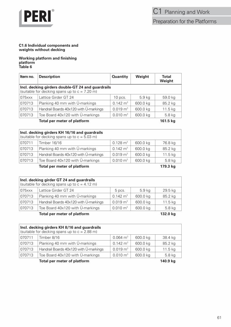
C1.6 Individual components andweights without decking
Working platform and finishingplatformTable 6
Incl. decking girders KH 8/16 and guardrails(suitable for decking spans up to c = 2.88 m)070711 Timber 8/16 0.064 m3 600.0 kg 38.4 kg
070713 Planking 40 mm with Ü-markings 0.142 m3 600.0 kg 85.2 kg
070713 Handrail Boards 40x120 with Ü-markings 0.019 m3 600.0 kg 11.5 kg
070713 Toe Board 40x120 with Ü-markings 0.010 m3 600.0 kg 5.8 kg
Total per meter of platform 140.9 kg
075xxx Lattice Girder GT 24 5 pcs. 5.9 kg 29.5 kg
070713 Planking 40 mm with Ü-markings 0.142 m3 600.0 kg 85.2 kg
070713 Handrail Boards 40x120 with Ü-markings 0.019 m3 600.0 kg 11.5 kg
070713 Toe Board 40x120 with Ü-markings 0.010 m3 600.0 kg 5.8 kg
Total per meter of platform 132.0 kg
Incl. decking girder GT 24 and guardrails(suitable for decking spans up to c = 4.12 m)
070711 Timber 16/16 0.128 m3 600.0 kg 76.8 kg
070713 Planking 40 mm with Ü-markings 0.142 m3 600.0 kg 85.2 kg
070713 Handrail Boards 40x120 with Ü-markings 0.019 m3 600.0 kg 11.5 kg
070713 Toe Board 40x120 with Ü-markings 0.010 m3 600.0 kg 5.8 kg
Total per meter of platform 179.3 kg
Incl. decking girders KH 16/16 and guardrails(suitable for decking spans up to c = 5.03 m)
075xxx Lattice Girder GT 24 10 pcs. 5.9 kg 59.0 kg
070713 Planking 40 mm with Ü-markings 0.142 m3 600.0 kg 85.2 kg
070713 Handrail Boards 40x120 with Ü-markings 0.019 m3 600.0 kg 11.5 kg
070713 Toe Board 40x120 with Ü-markings 0.010 m3 600.0 kg 5.8 kg
Total per meter of platform 161.5 kg
Item no. Description Quantity Weight TotalWeight
Incl. decking girders double-GT 24 and guardrails(suitable for decking spans up to c = 7.20 m)
C1 Planning and Work
Preparation for the Platforms
62
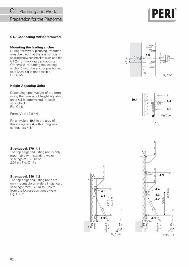
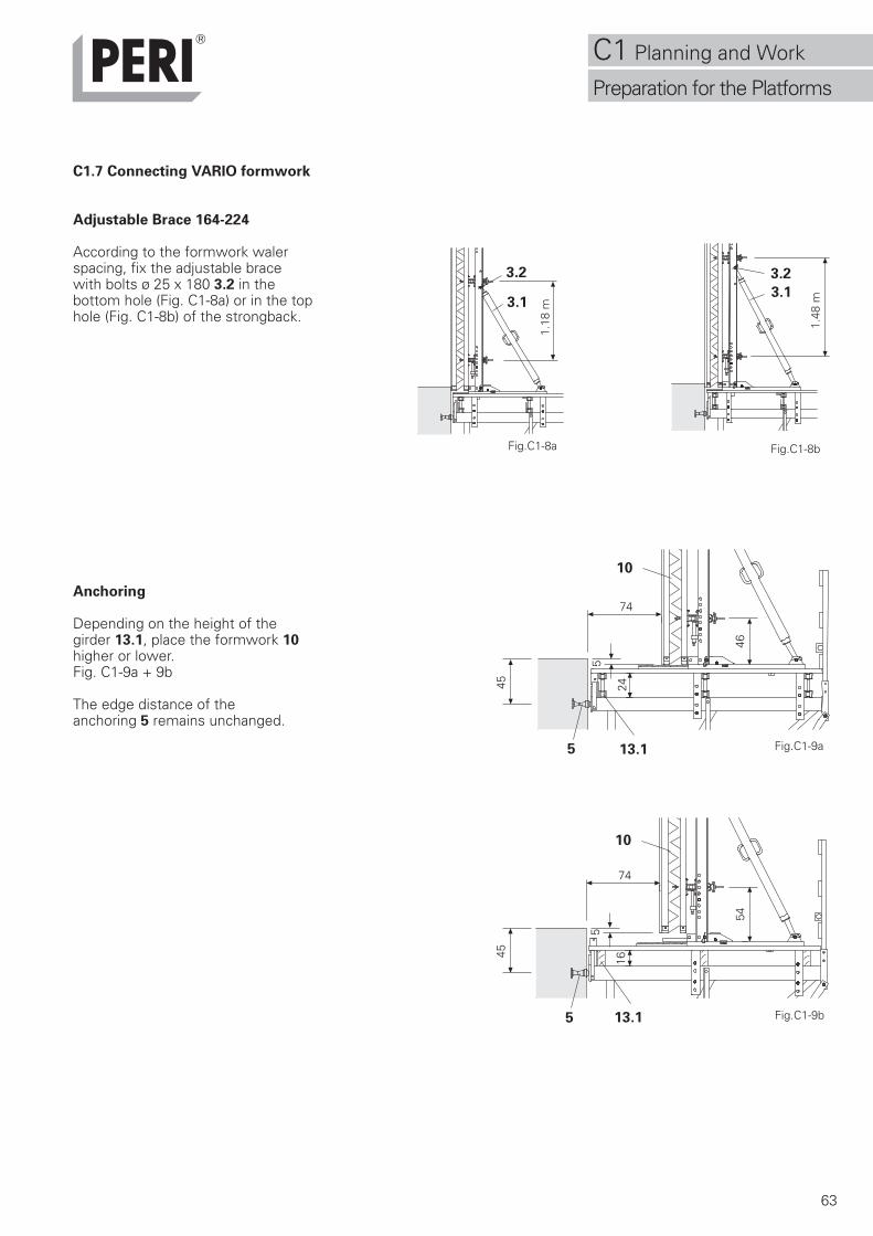
C1.7 Connecting VARIO formwork
Mounting the leading anchorDuring formwork planning, attentionmust be paid that there is sufficientspacing between bracket axes and theGT 24 formwork girder opposite.Otherwise, mounting the leadinganchor 5 with the anchor positioningstud M24 5.9 is not possible.Fig. C1-5
Height Adjusting Units
Depending upon weight of the form-work, the number of height adjustingunits 4.3 is determined for eachstrongback.Fig. C1-6
Perm. V1 = 12.8 kN
Fix all walers 10.4 in the area ofthe strongback 4 with strongbackconnectors 4.4.
Strongback 270 4.1The top height adjusting unit is onlymountable with standard walerspacings of 1.78 m or2.07 m. Fig. C1-7a
Strongback 380 4.2The top height adjusting units areonly mountable on walers in standardspacings from 1.78 m to 3.26 mfrom the lowest-positioned waler.Fig. C1-7b
Fig.C1-5
> 3
cm
5
5.9
Fig.C1-6
4.3
V1
10.4 4.4
4
Fig.C1-7a Fig.C1-7b
4.3
4.4
4.1
1.77
6 m
2.07
2 m
1.77
6 m
3.25
6 m
4.2
4.3
4.3
4.3
4.3
C1 Planning and Work
Preparation for the Platforms
63
5
46
C1.7 Connecting VARIO formwork
Adjustable Brace 164-224
According to the formwork walerspacing, fix the adjustable bracewith bolts ø 25 x 180 3.2 in thebottom hole (Fig. C1-8a) or in the tophole (Fig. C1-8b) of the strongback.
Anchoring
Depending on the height of thegirder 13.1, place the formwork 10higher or lower.Fig. C1-9a + 9b
The edge distance of theanchoring 5 remains unchanged.
Fig.C1-8a
3.1
3.2
Fig.C1-8b
3.1
1.48
m
3.2
Fig.C1-9b
Fig.C1-9a
1.18
m
45
7424
45
5
74
16
545
5 13.1
10
13.1
10
C1 Planning and Work
Preparation for the Platforms
64
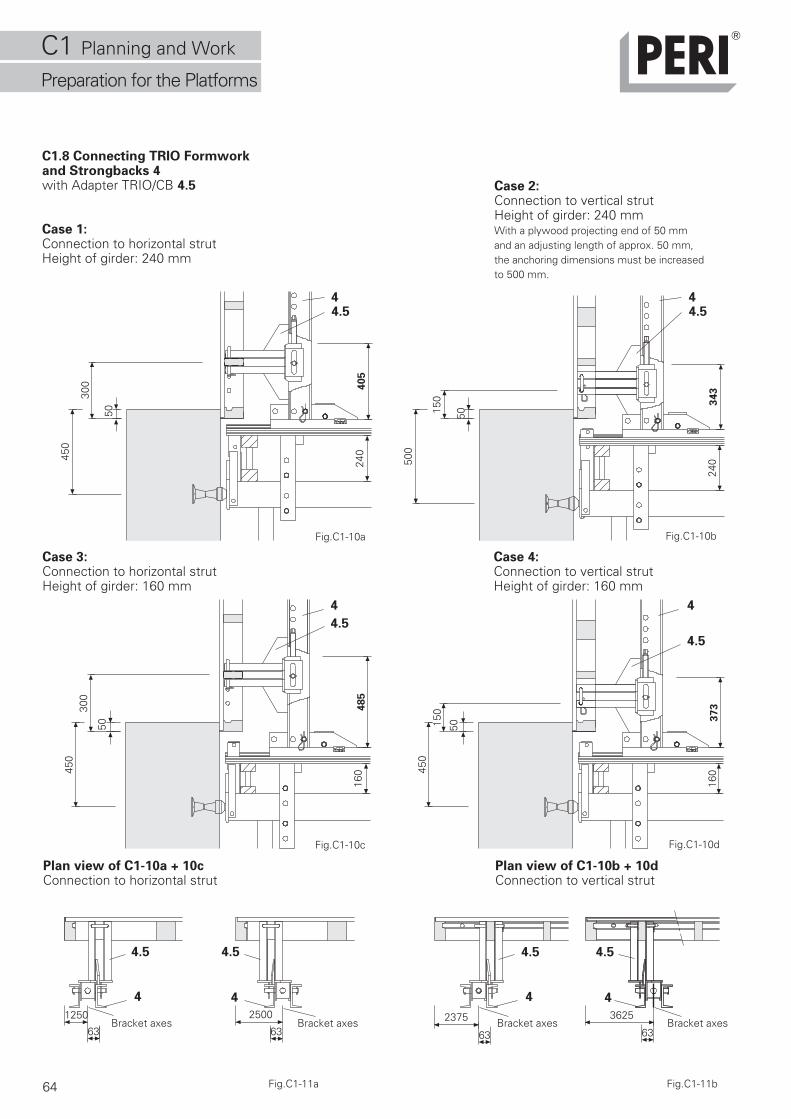
C1.8 Connecting TRIO Formworkand Strongbacks 4with Adapter TRIO/CB 4.5
Case 1:Connection to horizontal strutHeight of girder: 240 mm
Case 2:Connection to vertical strutHeight of girder: 240 mmWith a plywood projecting end of 50 mmand an adjusting length of approx. 50 mm,the anchoring dimensions must be increasedto 500 mm.
450
50
300 405
240
Case 3:Connection to horizontal strutHeight of girder: 160 mm
Plan view of C1-10a + 10cConnection to horizontal strut
Case 4:Connection to vertical strutHeight of girder: 160 mm
Plan view of C1-10b + 10dConnection to vertical strut
63
1250
63
2500 2375
63 63
3625
Fig.C1-10a Fig.C1-10b
Fig.C1-10c Fig.C1-10d
Fig.C1-11a Fig.C1-11b
4.5
4.5
4.54
4
4
4.5 4.5
4 4
485
16045
0
50
300
4.5
4
373
16045
0
50150
343
24050
0
50150
4.54
C1 Planning and Work
Preparation for the Platforms
4.5
4
Bracket axesBracket axesBracket axesBracket axes
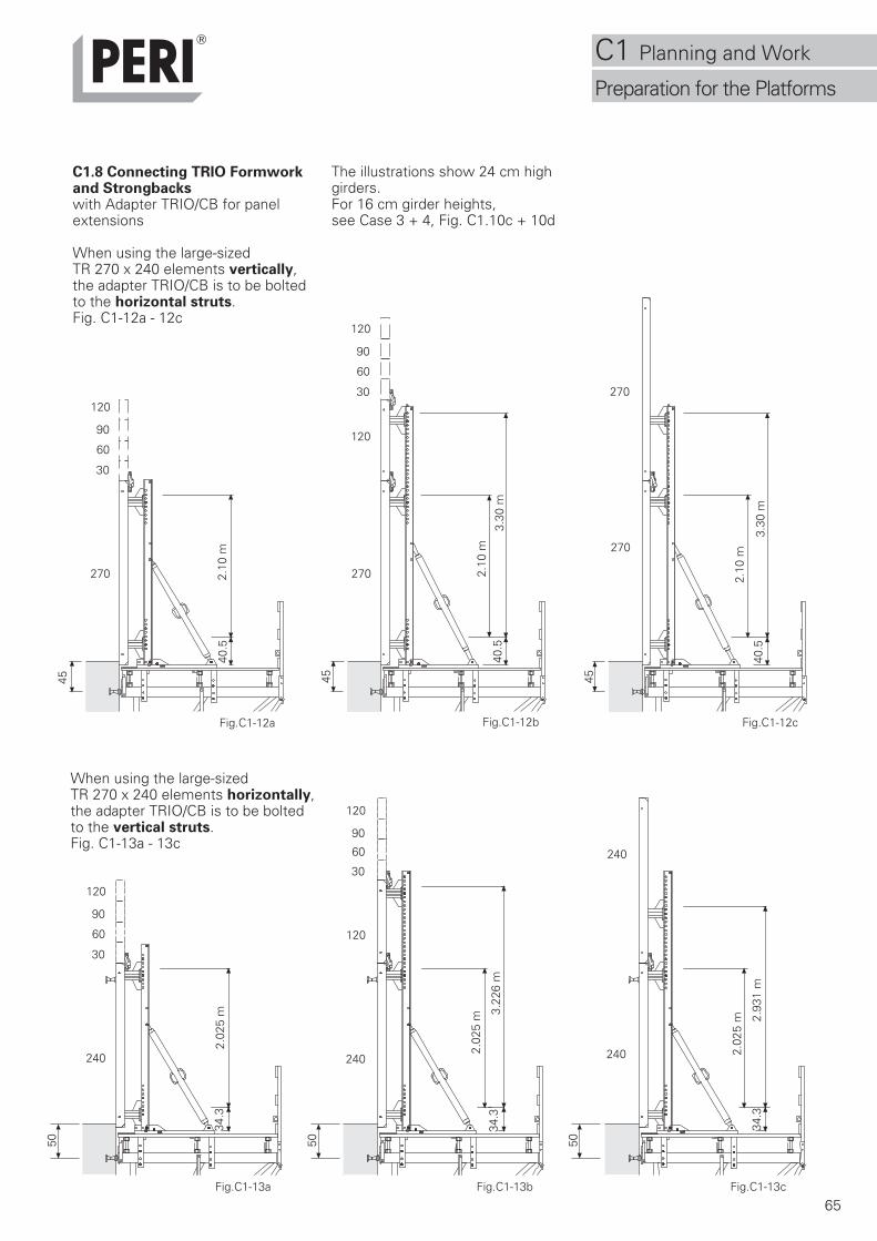
65
C1.8 Connecting TRIO Formworkand Strongbackswith Adapter TRIO/CB for panelextensions
When using the large-sizedTR 270 x 240 elements vertically,the adapter TRIO/CB is to be boltedto the horizontal struts.Fig. C1-12a - 12c
Fig.C1-12c
270
30
60
90
120
2.10
m
45
40.5
270
30
60
90
120
120
2.10
m40
.53.
30 m
45 45
270
270
2.10
m
3.30
m40
.5
Fig.C1-12bFig.C1-12a
When using the large-sizedTR 270 x 240 elements horizontally,the adapter TRIO/CB is to be boltedto the vertical struts.Fig. C1-13a - 13c
The illustrations show 24 cm highgirders.For 16 cm girder heights,see Case 3 + 4, Fig. C1.10c + 10d
240
30
60
90
120
50
2.02
5 m
34.3
240
30
60
90
120
120
2.02
5 m 3.
226
m
240
240
2.02
5 m
34.3
34.3
2.93
1 m
Fig.C1-13cFig.C1-13bFig.C1-13a
50 50
C1 Planning and Work
Preparation for the Platforms
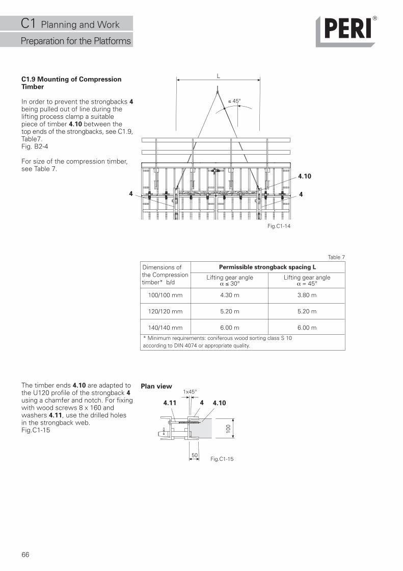
66
C1.9 Mounting of CompressionTimber
In order to prevent the strongbacks 4being pulled out of line during thelifting process clamp a suitablepiece of timber 4.10 between thetop ends of the strongbacks, see C1.9,Table7.Fig. B2-4
For size of the compression timber,see Table 7.
The timber ends 4.10 are adapted tothe U120 profile of the strongback 4using a chamfer and notch. For fixingwith wood screws 8 x 160 andwashers 4.11, use the drilled holesin the strongback web.Fig.C1-15
Dimensions ofthe Compressiontimber* b/d
* Minimum requirements: coniferous wood sorting class S 10according to DIN 4074 or appropriate quality.
Lifting gear angleα ≤ 30°
4.30 m
5.20 m
6.00 m
Lifting gear angleα = 45°
3.80 m
5.20 m
6.00 m
Permissible strongback spacing L
Table 7
Fig.C1-15
Fig.C1-14
L
1x45°
50
100
100/100 mm
120/120 mm
140/140 mm
Plan view
4.11 4 4.10
4.10
≤ 45°
4 4
C1 Planning and Work
Preparation for the Platforms
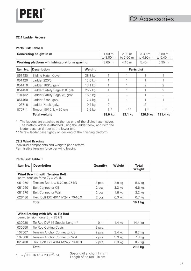
67
C2.1 Ladder Access
Parts List: Table 8
C2.2 Wind BracingIndividual components and weights per platformPermissible tension force per wind bracing
Parts List: Table 9
Item No. Description Weight Parts List
051430 Sliding Hatch Cover 38.8 kg 1 1 1 1
051420 Ladder 220/6 13.6 kg 1 1 1 1
051410 Ladder 180/6, galv. 13.1 kg 1 1 2 2
051450 Ladder Safety Cage 150, galv. 25.2 kg 1 1 1 2
104132 Ladder Safety Cage 75, galv. 15.5 kg – – 1 –
051460 Ladder Base, galv. 2.4 kg 1 1 1 1
103718 Ladder Hook, galv. 0.7 kg 2 - 2 -
070711 Timber 10/10, L = 60 cm 3.6 kg 1 * - ** 1 * - **
Total weight 98.0 kg 93.1 kg 126.6 kg 131.4 kg
Concreting height in m 1.50 m 2.00 m 3.30 m 3.80 mto 3.00 m to 3.60 m to 4.90 m to 5.40 m
Working platform – finishing platform spacing 3.65 m 4.15 m 5.45 m 5.95 m
* The ladders are attached to the top end of the sliding hatch cover.The bottom ladder is attached using the ladder hook, and with theladder base on timber at the lower end.
** Screw ladder base tightly on decking of the finishing platform.
051250 Tension Belt L = 5,70 m, 25 kN 2 pcs. 2.8 kg 5.6 kg
051260 Belt Connector CB 2 pcs. 3.3 kg 6.6 kg
051270 Belt Connector Wall 2 pcs. 1.6 kg 3.2 kg
026430 Hex. Bolt ISO 4014 M24 x 70-10.9 2 pcs. 0.3 kg 0.7 kg
Total 16.1 kg
Item No. Description Quantity Weight TotalWeight
Wind Bracing with Tension Beltperm. tension force Zz = 25 kN
030030 Tie Rod DW 15 Special Length* 10 m 1.4 kg 14.4 kg
030050 Tie Rod Cutting Costs 2 pcs.
107007 Tension Anchor Connector CB 2 pcs. 3.4 kg 6.7 kg
107008 Tension Anchor Connector Wall 2 pcs. 3.9 kg 7.8 kg
026430 Hex. Bolt ISO 4014 M24 x 70-10.9 2 pcs. 0.3 kg 0.7 kg
Total 29.6 kg
Wind Bracing with DW 15 Tie Rodperm. tension force Zz = 35 kN
* L = (H - 16.4)2 + 233.62 - 51 Spacing of anchor H in cmLength of tie rod L in cm
C2 Accessories
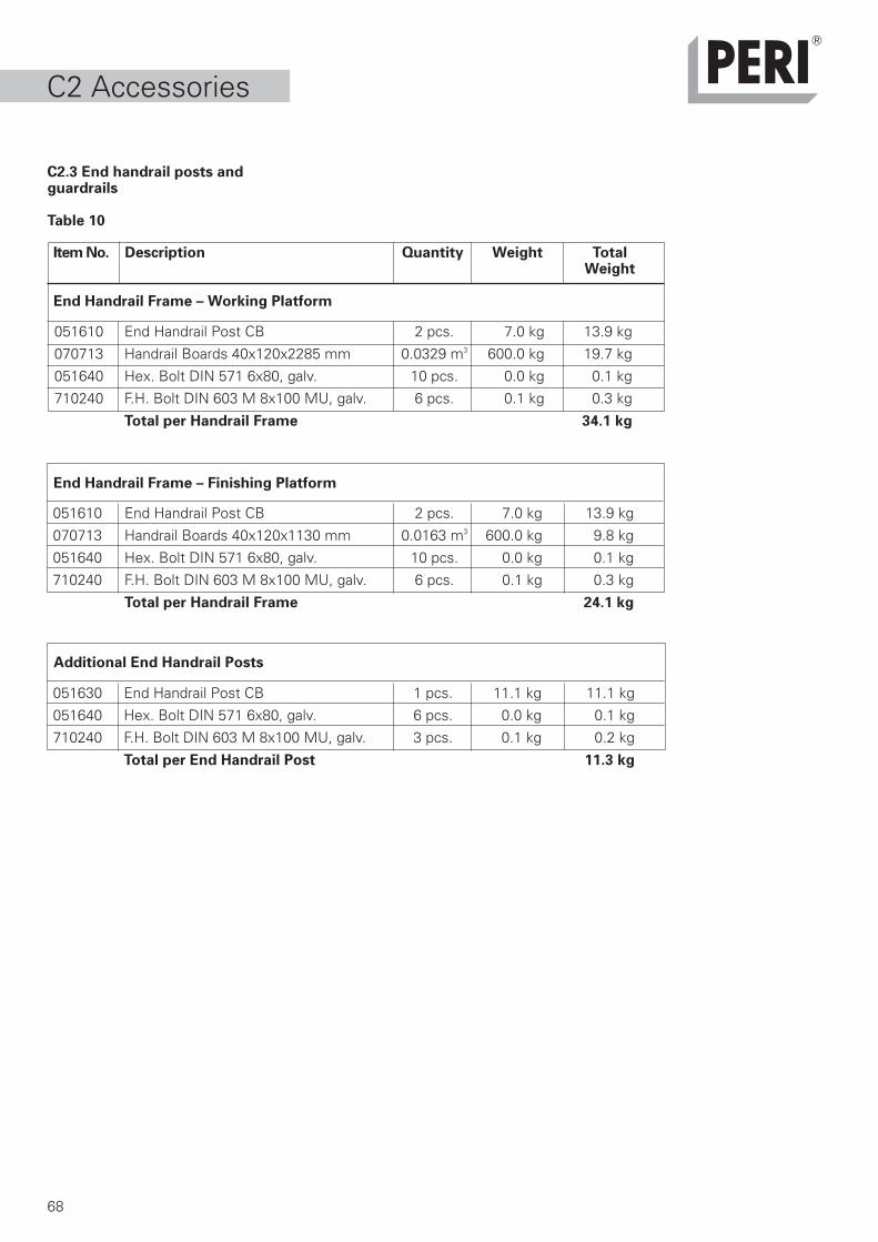
68
C2.3 End handrail posts andguardrails
Table 10
Item No. Description Quantity Weight TotalWeight
End Handrail Frame – Working Platform
051610 End Handrail Post CB 2 pcs. 7.0 kg 13.9 kg
070713 Handrail Boards 40x120x2285 mm 0.0329 m3 600.0 kg 19.7 kg
051640 Hex. Bolt DIN 571 6x80, galv. 10 pcs. 0.0 kg 0.1 kg
710240 F.H. Bolt DIN 603 M 8x100 MU, galv. 6 pcs. 0.1 kg 0.3 kg
Total per Handrail Frame 34.1 kg
End Handrail Frame – Finishing Platform
Additional End Handrail Posts
051610 End Handrail Post CB 2 pcs. 7.0 kg 13.9 kg
070713 Handrail Boards 40x120x1130 mm 0.0163 m3 600.0 kg 9.8 kg
051640 Hex. Bolt DIN 571 6x80, galv. 10 pcs. 0.0 kg 0.1 kg
710240 F.H. Bolt DIN 603 M 8x100 MU, galv. 6 pcs. 0.1 kg 0.3 kg
Total per Handrail Frame 24.1 kg
051630 End Handrail Post CB 1 pcs. 11.1 kg 11.1 kg
051640 Hex. Bolt DIN 571 6x80, galv. 6 pcs. 0.0 kg 0.1 kg
710240 F.H. Bolt DIN 603 M 8x100 MU, galv. 3 pcs. 0.1 kg 0.2 kg
Total per End Handrail Post 11.3 kg
C2 Accessories
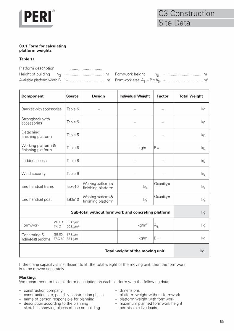
69
Component Source Design Individual Weight Factor Total Weight
Bracket with accessories Table 5 – – – kg
accessories Table 5 – – kg
Table 5 – – kg
Table 6 kg/m B= kg
Ladder access Table 8 – – kg
Wind security Table 9 – – kg
End handrail frame Table10 kgQuantity=
kg
End handrail post Table10 kgQuantity=
kg
Sub-total without formwork and concreting platform kg
Formwork kg/m2 As kg
kg/m B= kg
Total weight of the moving unit kg
C3.1 Form for calculatingplatform weights
Table 11
Platform description ................................Height of building hG = ................................ m Formwork height hs = ................................ mAvailable platform width B = ................................. m Formwork area As = B x hs = ................................ m2
If the crane capacity is insufficient to lift the total weight of the moving unit, then the formworkis to be moved separately.
Marking:We recommend to fix a platform description on each platform with the following data:
– construction company – dimensions– construction site, possibly construction phase – platform weight without formwork– name of person responsible for planning – platform weight with formwork– description according to the planning – maximum planned formwork height– sketches showing places of use on building – permissible live loads
Detachingfinishing platform
Working platform &finishing platform
Working platform &finishing platform
Working platform &finishing platform
Concreting &intermediate platforms
GB 80 37 kg/mTRG 80 38 kg/m
VARIO 55 kg/m2
TRIO 50 kg/m2
Strongback with
C3 ConstructionSite Data
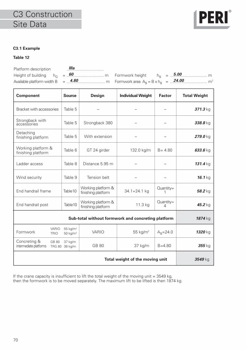
70
Component Source Design Individual Weight Factor Total Weight
Bracket with accessories Table 5 – – – 371.3 kg
accessories Table 5 Strongback 380 – – 338.8 kg
Table 5 With extension – – 279.0 kg
Table 6 GT 24 girder 132.0 kg/m B= 4.80 633.6 kg
Ladder access Table 8 Distance 5.95 m – – 131.4 kg
Wind security Table 9 Tension belt – – 16.1 kg
End handrail frame Table10 34.1+24.1 kg 58.2 kg
End handrail post Table10 11.3 kg 45.2 kg
Sub-total without formwork and concreting platform 1874 kg
Formwork VARIO 55 kg/m2 As=24.0 1320 kg
GB 80 37 kg/m B=4.80 355 kg
Total weight of the moving unit 3549 kg
Platform description ................................Height of building hG = ................................ m Formwork height hs = ................................ mAvailable platform width B = ................................. m Formwork area As = B x hs = ................................ m2
C3.1 Example
Table 12
Detachingfinishing platform
Working platform &finishing platform
Working platform &finishing platform
Working platform &finishing platform
Concreting &intermediate platforms
GB 80 37 kg/mTRG 80 38 kg/m
VARIO 55 kg/m2
TRIO 50 kg/m2
If the crane capacity is insufficient to lift the total weight of the moving unit = 3549 kg,then the formwork is to be moved separately. The maximum lift to be lifted is then 1874 kg.
IIIa
60 5.00
4.80 24.00
Quantity= 4
Strongback with
C3 ConstructionSite Data
Quantity= 1
71
C3.2 Drawings
For the assembly team and theconstruction site suitable and easilyreadable drawings have to be provided,sufficient in number and size.The drawings must be createdprofessionally and clearly in thelanguage of the country where theconstruction site is located.
At least, the following pointsshould be featured in theplatform assembly drawings:
– bracket spacing and bracing– dimensions of the working and
finishing platforms– dimensions, arrangement and number
of concreting and intermediateplatforms
– erection of girders and guardrails– layout of end handrail posts– layout of lateral guardrails– position of access ladders– material requirements (parts list)
We recommend including a planview and a top view of the platform.
At least, the following pointsshould be featured in theutilisation drawings:
– position of the climbing anchor in theplan view and sectional view
– which scaffolding platform is usedon which part of the building
– associated formwork and finishingplatform
– installation of wind bracing– distance of finishing platform to the
working platform– formwork and strongback connection
points– timber brace position between the
strongbacks– reference values for retraction
process during moving(see Table 1)
– possible special measures in case ofirregular concreting heights
– details of modifications– material requirements (parts list)
We recommend including a plan viewand sectional view of the scaffold aswell as an overview plan for positioningpurposes.
C3 ConstructionSite Data
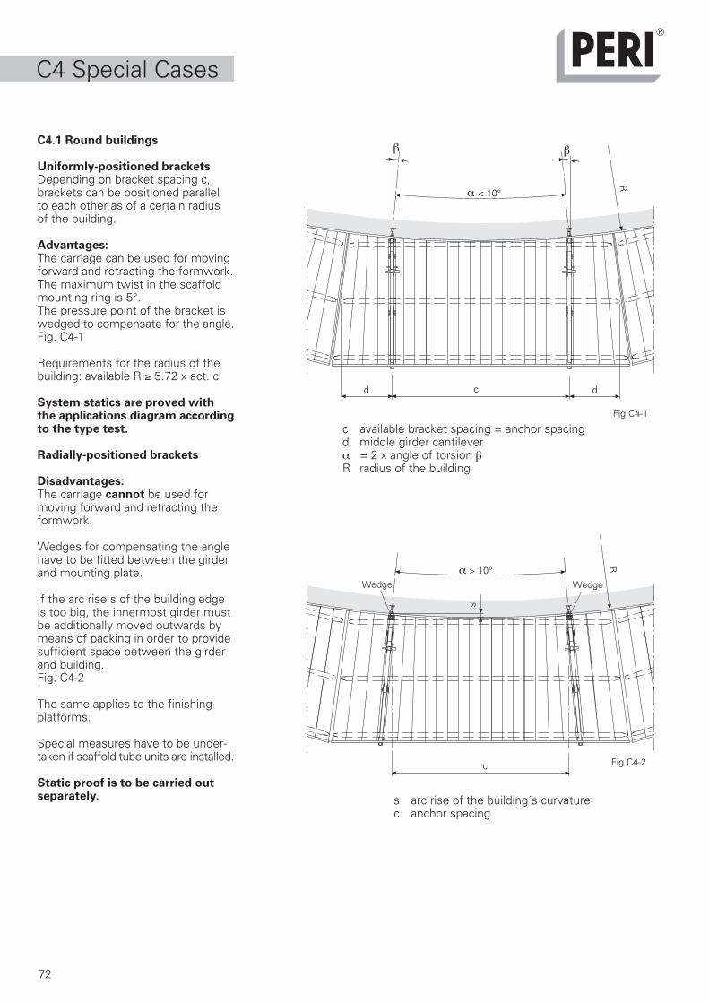
72
C4.1 Round buildings
Uniformly-positioned bracketsDepending on bracket spacing c,brackets can be positioned parallelto each other as of a certain radiusof the building.
Advantages:The carriage can be used for movingforward and retracting the formwork.The maximum twist in the scaffoldmounting ring is 5°.The pressure point of the bracket iswedged to compensate for the angle.Fig. C4-1
Requirements for the radius of thebuilding: available R ≥ 5.72 x act. c
System statics are proved withthe applications diagram accordingto the type test.
Radially-positioned brackets
Disadvantages:The carriage cannot be used formoving forward and retracting theformwork.
Wedges for compensating the anglehave to be fitted between the girderand mounting plate.
If the arc rise s of the building edgeis too big, the innermost girder mustbe additionally moved outwards bymeans of packing in order to providesufficient space between the girderand building.Fig. C4-2
The same applies to the finishingplatforms.
Special measures have to be under-taken if scaffold tube units are installed.
Static proof is to be carried outseparately.
Fig.C4-1
Fig.C4-2
dd c
R
α < 10°
α > 10°
R
s
Wedge Wedge
ββ
c available bracket spacing = anchor spacingd middle girder cantileverα = 2 x angle of torsion βR radius of the building
s arc rise of the building´s curvaturec anchor spacing
c
C4 Special Cases
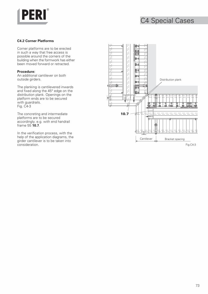
73
C4.2 Corner Platforms
Corner platforms are to be erectedin such a way that free access ispossible around the corners of thebuilding when the formwork has eitherbeen moved forward or retracted.
Procedure:An additional cantilever on bothoutside girders.
The planking is cantilevered inwardsand fixed along the 45° edge on thedistribution plank. Openings on theplatform ends are to be securedwith guardrails.Fig. C4-3
The concreting and intermediateplatforms are to be securedaccordingly. e.g. with end handrailframe 55 10.7.
In the verification process, with thehelp of the application diagrams, thegirder cantilever is to be taken intoconsideration.
10.7
Cantilever Bracket spacing
Distribution plank
Fig.C4-3
C4 Special Cases
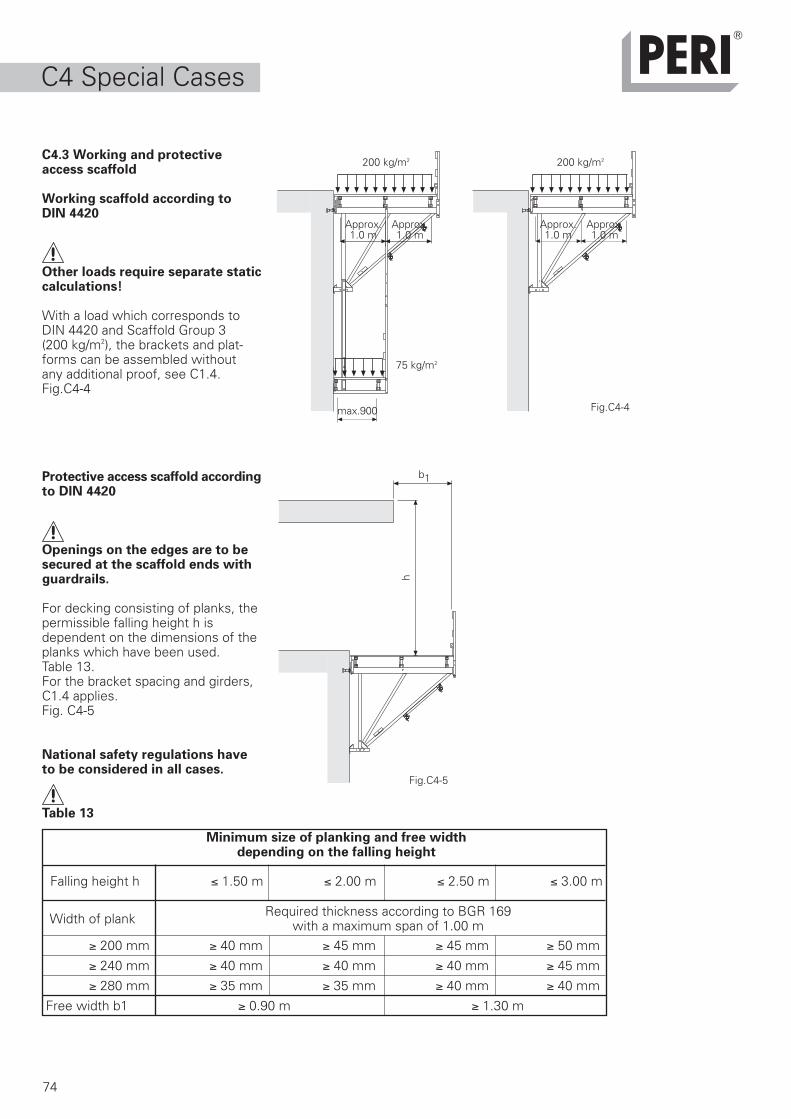
h
b1
74
C4.3 Working and protectiveaccess scaffold
Working scaffold according toDIN 4420
Other loads require separate staticcalculations!
With a load which corresponds toDIN 4420 and Scaffold Group 3(200 kg/m2), the brackets and plat-forms can be assembled withoutany additional proof, see C1.4.Fig.C4-4
Protective access scaffold accordingto DIN 4420
Openings on the edges are to besecured at the scaffold ends withguardrails.
For decking consisting of planks, thepermissible falling height h isdependent on the dimensions of theplanks which have been used.Table 13.For the bracket spacing and girders,C1.4 applies.Fig. C4-5
National safety regulations haveto be considered in all cases.
Table 13
Fig.C4-5
≥ 200 mm ≥ 40 mm ≥ 45 mm ≥ 45 mm ≥ 50 mm
≥ 240 mm ≥ 40 mm ≥ 40 mm ≥ 40 mm ≥ 45 mm
≥ 280 mm ≥ 35 mm ≥ 35 mm ≥ 40 mm ≥ 40 mm
Free width b1 ≥ 0.90 m ≥ 1.30 m
Width of plank Required thickness according to BGR 169with a maximum span of 1.00 m
Minimum size of planking and free widthdepending on the falling height
Falling height h ≤ 1.50 m ≤ 2.00 m ≤ 2.50 m ≤ 3.00 m
Approx.1.0 m
Fig.C4-4
75 kg/m2
max.900
200 kg/m2200 kg/m2
Approx.1.0 m
Approx.1.0 m
Approx.1.0 m
C4 Special Cases
75
What should be done
Care tips
1. Spray new formwork all over with releaseagent, e.g. PERI Clean before use.
2. Spray formwork with PERI Clean each time,after striking, then clean.
3. For long storage periods, e.g. bad weather,store formwork after cleaning and spraying.
4. Spray moving parts regularly with releaseagent and/or grease as required.
5. Transport elements with suitable and secure transportequipment and lifting gear.
6. Dismantle platforms, form storage units,and combine into transportation units.
7. Place pieces of timber between the elements.Secure transportation units e.g. steel bands
8. Ensure proper storage of elements and accessories.
9. Do not throw or drop accessories.
10.Do not use unnecessary force during assembly or dismantling.
11.Store all parts in bundles. Use closed containers.
12.Avoid direct contact with the ground water.Storage in an inclined position if possible.
Tips for cleaning
During cleaning, store the element securely!It is not permitted to clean elements that arehanging from a crane! Remove excess concrete!
1. Spray the reverse side of the formwork withwater immediately after concreting.
2. After striking, spray the formwork all overwith PERI Clean.
3. Before mechanical cleaning, remove nails,batons, etc from the formlining.
4. Use a suitable tool, e.g. scraper, to cleanelement mechanically.
5. Brush elements after mechanical cleaning. Removedust and concrete residue.
6. If necessary, spray elements again after shuttering.
Why?
Provides fundamental protection against adhesionand corrosion – before first soiling cover completelywith release agent.
Helps to remove concrete and eases cleaning. Useof force and scraping is unnecessary. Formliner /paint stay intact.
The frame is thus protected against corrosion &Formlining against weathering.
Removes rust, prevents corrosion and maintainsease of movement of parts.
Prevents damage by incorrect transport.
Small parts are not lost, assembly groups remaintogether.
Securing parts will be protected; dents, shifting ofelements or falling on top of each other is avoided.
Prevents damage to the element frames andaccessories.
The parts remain functional.
The parts remain functional.
Parts can be found and used faster. Damageable andsmaller components as well as tools are protected.
Components are protected from dirt, dampness andcorrosion . Storage bundles supported on timberpieces.
Concrete not yet hardened and can be easily removed,thus reducing the cleaning effort.
Mixes and removes concrete residue, makes latermechanical cleaning easier.
Prevents unnecessary enlargement of nail holes anddamage to formlining. Also prevents damage tocleaning tools.
The formlining surface is clean for the next use.
D1 Care andcleaning
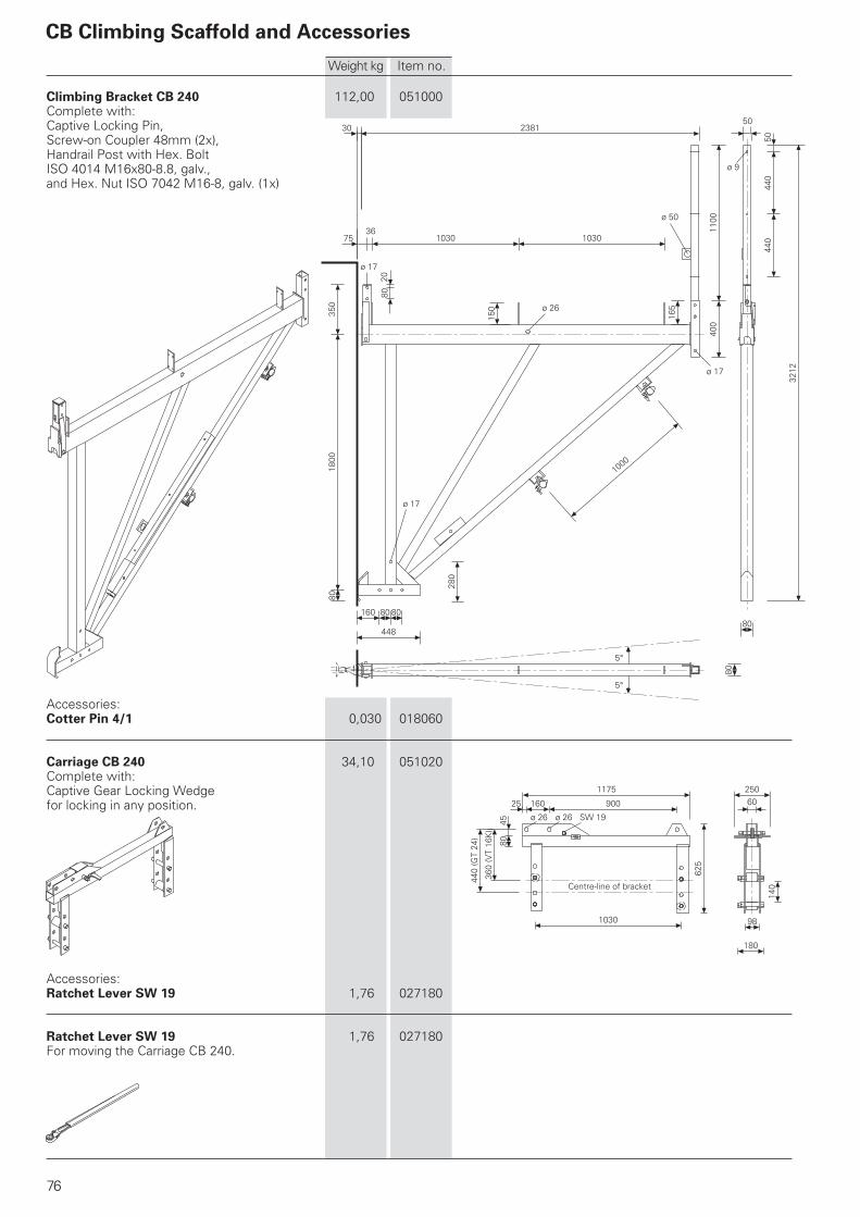
30 2381
7536
1030 1030
50
1100
400
165
ø 17
ø 26
150
8020
ø 17
350
1800
80
448
160 80 80
280
ø 17
1000
3212
440
440
50
ø 9
80
80
5°
5°
ø 26ø 26
1175
90016025
8045
360
(VT
16K
)
440
(GT
24)
1030
625
180
98
140
25060
ø 50
76
Climbing Bracket CB 240 112,00 051000Complete with:Captive Locking Pin,Screw-on Coupler 48mm (2x),Handrail Post with Hex. BoltISO 4014 M16x80-8.8, galv.,and Hex. Nut ISO 7042 M16-8, galv. (1x)
Accessories:Cotter Pin 4/1 0,030 018060
Carriage CB 240 34,10 051020Complete with:Captive Gear Locking Wedgefor locking in any position.
Accessories:Ratchet Lever SW 19 1,76 027180
Ratchet Lever SW 19 1,76 027180For moving the Carriage CB 240.
CB Climbing Scaffold and Accessories
Weight kg Item no.
Centre-line of bracket
SW 19

1620
50
x
64
ø 20
FS 4/162
ø 16x65/86
93 140
1672
1490
150
985
140 450
30 15
1100
1800
1870
100 90 ø 17
7020
0
6025
0
50
50
63014
017
0
705
(102
5)
50
8050
8044
044
0
2815
(313
5)
80
4050
50
ø 21 ø 21
30
80
ø 26
ø 21
ø 17
M16x80
230
120
35
150
200
260
83
52
80
237
ø 26
2240
430 900
35 3010
ø 9
77
Rack CB 240 8,97 051040Complete with:Pin ø 16x65/86 andCotter Pin 4/1 (1x).
Lifting Eye CB 240, galv. 0,93 051010Complete with:Pin ø 16x65/86 and Cotter Pin 4/1 (1x).
Load-bearing pointPermiss. Load: 700kg
Climbing Bracket CB 160 79,50 051100Complete with:Captive Locking Pin,Screw-on Coupler 48mm (2x),Handrail Post with Hex. BoltISO 4014 M16x80-8.8, galv.,and Hex. Nut ISO 7042 M16-8, galv. (1x)
Adjusting Unit CB 160 12,90 051130Complete with:Hex. Bolt ISO 4014 M20x150-8.8, galv.,and Hex. Nut ISO 7042 M20-8, galv. (2x).
Weight kg Item no.
ø 16x65/86FS 4/1
Detail x
Centre-lineof bracket
M20x150
SW 19
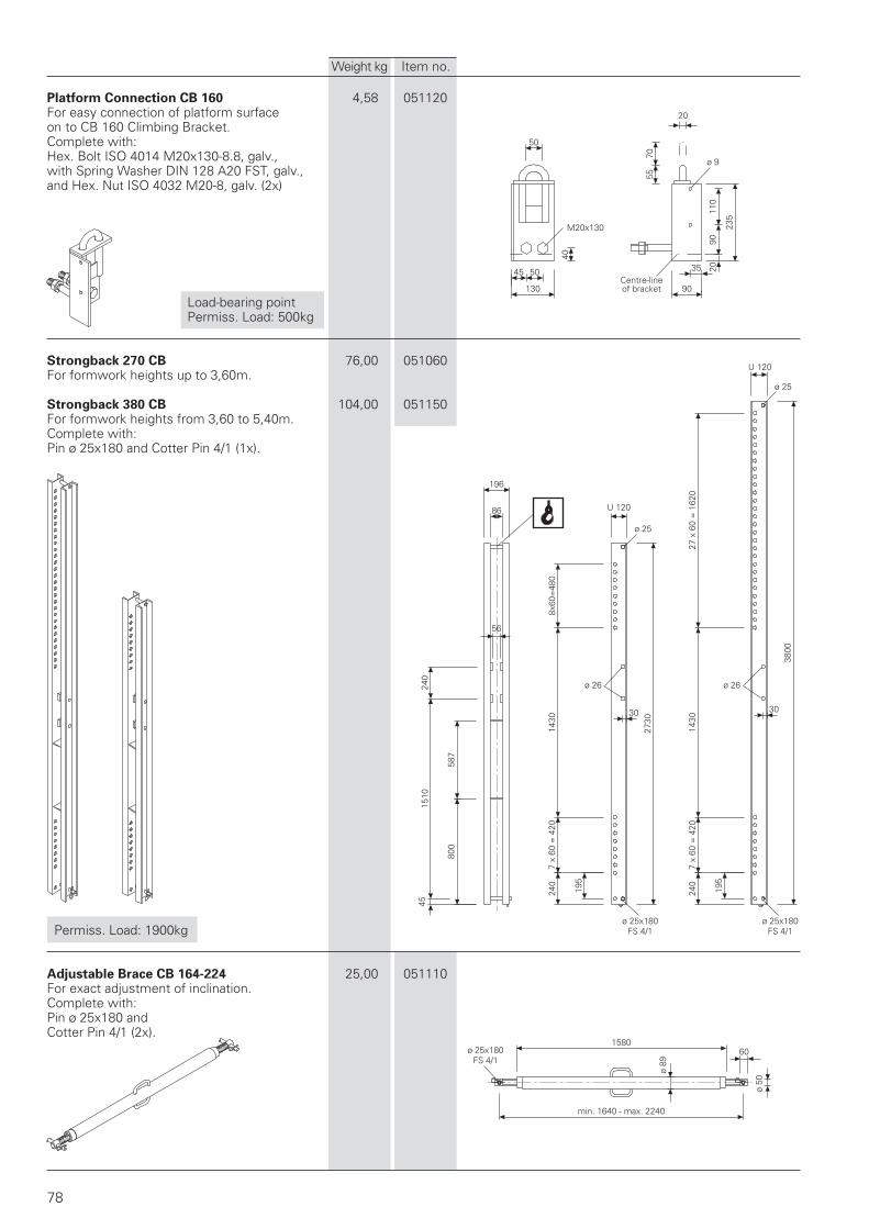
50
40
45 50
130
35
90
2090
110
235
ø 9
5570
20
U 120
ø 25
3800
30
ø 26
195
240
7 x
60 =
420
1430
27 x
60
= 1
620
U 120
7 x
60 =
420
1430
30
ø 26
195
240
ø 25
196
86
56
240
587
800
4515
10
ø 89
158060
ø 50
8x60
=48
0
2730
78
Platform Connection CB 160 4,58 051120For easy connection of platform surfaceon to CB 160 Climbing Bracket.Complete with:Hex. Bolt ISO 4014 M20x130-8.8, galv.,with Spring Washer DIN 128 A20 FST, galv.,and Hex. Nut ISO 4032 M20-8, galv. (2x)
Load-bearing pointPermiss. Load: 500kg
Strongback 270 CB 76,00 051060For formwork heights up to 3,60m.
Strongback 380 CB 104,00 051150For formwork heights from 3,60 to 5,40m.Complete with:Pin ø 25x180 and Cotter Pin 4/1 (1x).
Permiss. Load: 1900kg
Adjustable Brace CB 164-224 25,00 051110For exact adjustment of inclination.Complete with:Pin ø 25x180 andCotter Pin 4/1 (2x).
Weight kg Item no.
min. 1640 - max. 2240
ø 25x180FS 4/1
ø 25x180FS 4/1
ø 25x180FS 4/1
Centre-lineof bracket
M20x130
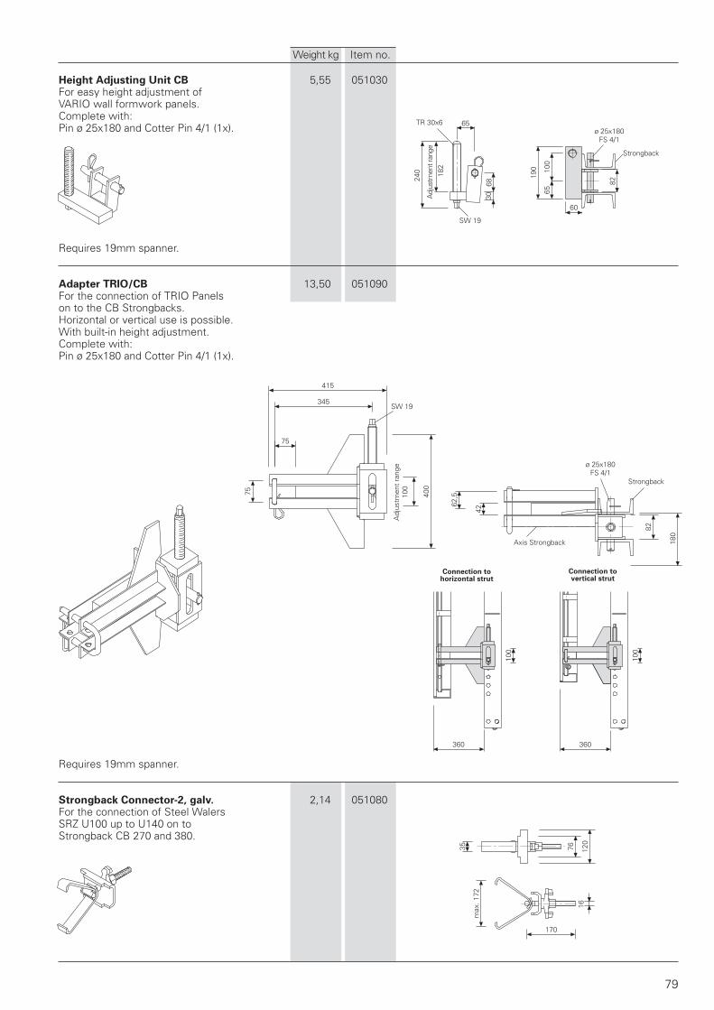
65
240
3068
100
65
190
60
82
75
35
170
1676 12
0
400
345
415
7562
,5
42
82
180
100
100
360360
79
Height Adjusting Unit CB 5,55 051030For easy height adjustment ofVARIO wall formwork panels.Complete with:Pin ø 25x180 and Cotter Pin 4/1 (1x).
Requires 19mm spanner.
Adapter TRIO/CB 13,50 051090For the connection of TRIO Panelson to the CB Strongbacks.Horizontal or vertical use is possible.With built-in height adjustment.Complete with:Pin ø 25x180 and Cotter Pin 4/1 (1x).
Requires 19mm spanner.
Strongback Connector-2, galv. 2,14 051080For the connection of Steel WalersSRZ U100 up to U140 on toStrongback CB 270 and 380.
Weight kg Item no.
TR 30x6
Adj
ustm
ent r
ange
182
SW 19
Strongback
ø 25x180FS 4/1
Adj
ustm
ent
rang
e10
0SW 19
Axis Strongback
Strongback
ø 25x180FS 4/1
Connection tovertical strut
Connection tohorizontal strut
max
. 172
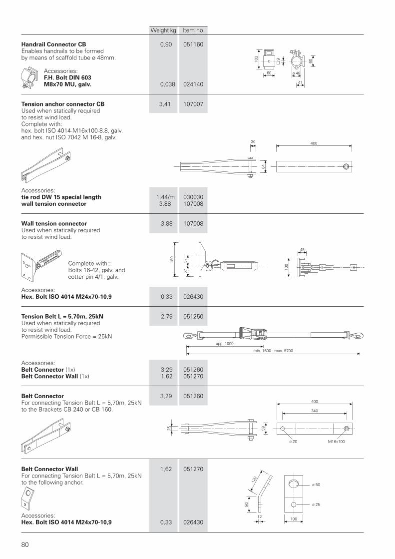
103
60
9
60
ø 48
41
340
400
ø 20
120
12
80
100
ø 50
ø 25
5925
40030
64
100
45
180
5757
80
Handrail Connector CB 0,90 051160Enables handrails to be formedby means of scaffold tube ø 48mm.
Accessories:F.H. Bolt DIN 603M8x70 MU, galv. 0,038 024140
Tension anchor connector CB 3,41 107007Used when statically requiredto resist wind load.Complete with:hex. bolt ISO 4014-M16x100-8.8, galv.and hex. nut ISO 7042 M 16-8, galv.
Accessories:tie rod DW 15 special length 1,44/m 030030wall tension connector 3,88 107008
Wall tension connector 3,88 107008Used when statically requiredto resist wind load.
Complete with::Bolts 16-42, galv. andcotter pin 4/1, galv.
Accessories:Hex. Bolt ISO 4014 M24x70-10,9 0,33 026430
Tension Belt L = 5,70m, 25kN 2,79 051250Used when statically requiredto resist wind load.Permissible Tension Force = 25kN
Accessories:Belt Connector (1x) 3,29 051260Belt Connector Wall (1x) 1,62 051270
Belt Connector 3,29 051260For connecting Tension Belt L = 5,70m, 25kNto the Brackets CB 240 or CB 160.
Belt Connector Wall 1,62 051270For connecting Tension Belt L = 5,70m, 25kNto the following anchor.
Accessories:Hex. Bolt ISO 4014 M24x70-10,9 0,33 026430
Weight kg Item no.
min. 1600 - max. 5700
app. 1000
M16x100
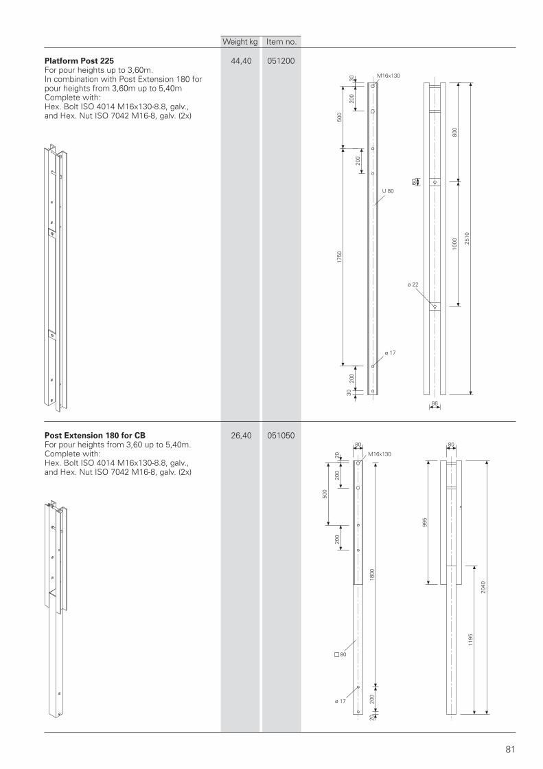
3020
0
500
200
U 80
60
ø 22
3020
0
1750
1000
800
86
2510
80 80
2020
020
0
500
80
ø 17
2020
018
00
995
1195
2040
81
ø 17
Platform Post 225 44,40 051200For pour heights up to 3,60m.In combination with Post Extension 180 forpour heights from 3,60m up to 5,40mComplete with:Hex. Bolt ISO 4014 M16x130-8.8, galv.,and Hex. Nut ISO 7042 M16-8, galv. (2x)
Post Extension 180 for CB 26,40 051050For pour heights from 3,60 up to 5,40m.Complete with:Hex. Bolt ISO 4014 M16x130-8.8, galv.,and Hex. Nut ISO 7042 M16-8, galv. (2x)
Weight kg Item no.
M16x130
M16x130
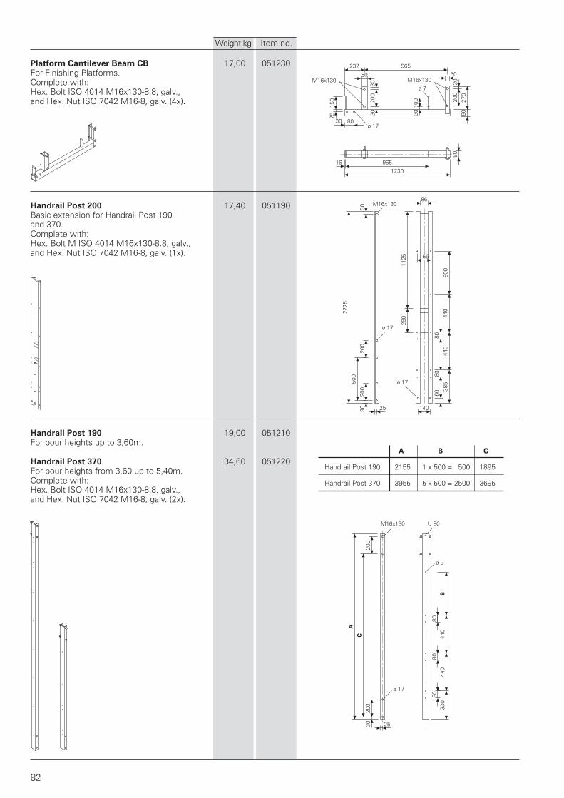
B
30
86
156
280
1125
500
440
440
80
385
8060
140
ø 17
ø 17
200
25
200
500
2225
30
U 80
ø 9
A
C
200
200
30 25
ø 17
330
8044
080
440
80
232 96550
3020
0
270
80
100
30
200
3030
ø 178030
150
25
80
ø 7
80
16 9651230
82
Platform Cantilever Beam CB 17,00 051230For Finishing Platforms.Complete with:Hex. Bolt ISO 4014 M16x130-8.8, galv.,and Hex. Nut ISO 7042 M16-8, galv. (4x).
Handrail Post 200 17,40 051190Basic extension for Handrail Post 190and 370.Complete with:Hex. Bolt M ISO 4014 M16x130-8.8, galv.,and Hex. Nut ISO 7042 M16-8, galv. (1x).
Handrail Post 190 19,00 051210For pour heights up to 3,60m.
Handrail Post 370 34,60 051220For pour heights from 3,60 up to 5,40m.Complete with:Hex. Bolt ISO 4014 M16x130-8.8, galv.,and Hex. Nut ISO 7042 M16-8, galv. (2x).
Weight kg Item no.
M16x130M16x130
M16x130
A B C
Handrail Post 190 2155 1 x 500 = 500 1895
Handrail Post 370 3955 5 x 500 = 2500 3695
M16x130
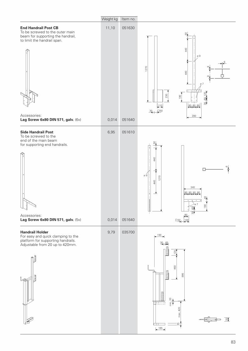
5044
0
ø 9
440
88
6
80 80 80
280
190
3060
120
ø 7
230
110
5030
1270
6
340
80 80 80 80
4019
0
603080
10050
1270
440
440
ø 9
50
ø 7
190
30 65
120
460
995
35
185
70
83
End Handrail Post CB 11,10 051630To be screwed to the outer mainbeam for supporting the handrail,to limit the handrail span.
Accessories:Lag Screw 6x80 DIN 571, galv. (6x) 0,014 051640
Side Handrail Post 6,95 051610To be screwed to theend of the main beamfor supporting end handrails.
Accessories:Lag Screw 6x80 DIN 571, galv. (5x) 0,014 051640
Handrail Holder 9,79 035700For easy and quick clamping to theplatform for supporting handrails.Adjustable from 20 up to 420mm.
Weight kg Item no.
max
. 420
min
. 20
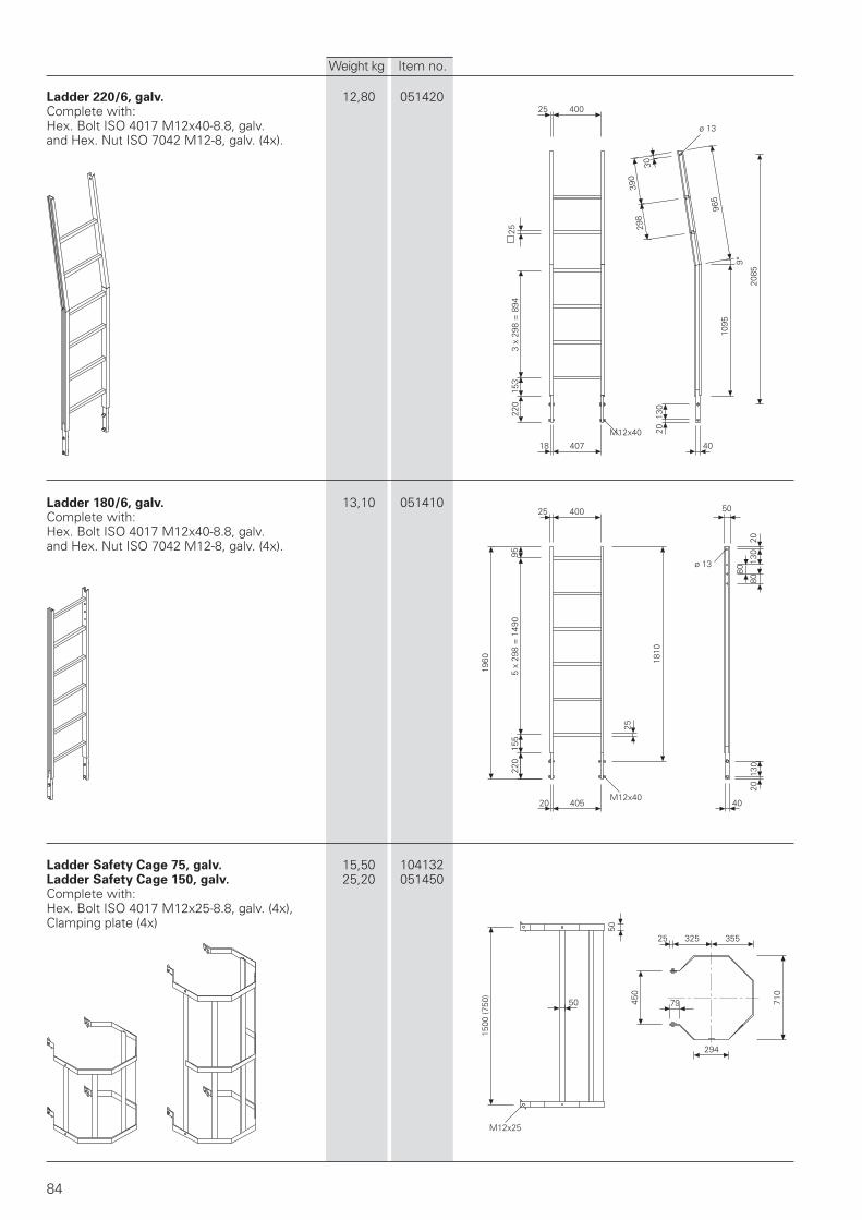
20 405 40
2013
0
50
80
8013
020
ø 13
1810
25
220
155
1960
5 x
298
= 1
490
9540025
294
79450
710
35532525
50
50
1500
(750
)
84
25 400
253
x 29
8 =
894
153
220
2085
18 407 40
2013
0
1095
298
390
30
ø 13
965
9°
Ladder 220/6, galv. 12,80 051420Complete with:Hex. Bolt ISO 4017 M12x40-8.8, galv.and Hex. Nut ISO 7042 M12-8, galv. (4x).
Ladder 180/6, galv. 13,10 051410Complete with:Hex. Bolt ISO 4017 M12x40-8.8, galv.and Hex. Nut ISO 7042 M12-8, galv. (4x).
Ladder Safety Cage 75, galv. 15,50 104132Ladder Safety Cage 150, galv. 25,20 051450Complete with:Hex. Bolt ISO 4017 M12x25-8.8, galv. (4x),Clamping plate (4x)
Weight kg Item no.
M12x25
M12x40
M12x40
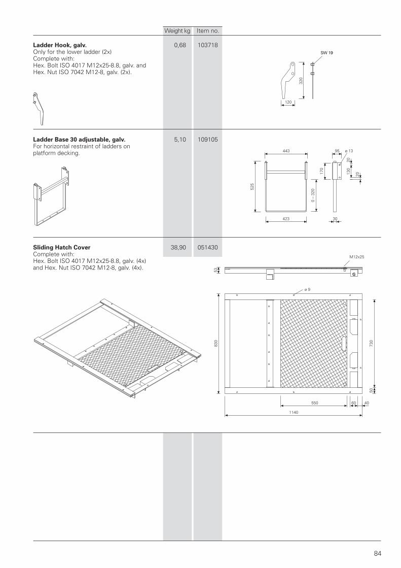
5383
0
1140
550 60 40
5073
0
ø 9
120
320
SW 19
84
ø 1395443
525
0 –
320
423
170
30
130
20
20
SW 19
Ladder Hook, galv. 0,68 103718Only for the lower ladder (2x)Complete with:Hex. Bolt ISO 4017 M12x25-8.8, galv. andHex. Nut ISO 7042 M12-8, galv. (2x).
Ladder Base 30 adjustable, galv. 5,10 109105For horizontal restraint of ladders onplatform decking.
Sliding Hatch Cover 38,90 051430Complete with:Hex. Bolt ISO 4017 M12x25-8.8, galv. (4x)and Hex. Nut ISO 7042 M12-8, galv. (4x).
Weight kg Item no.
M12x25
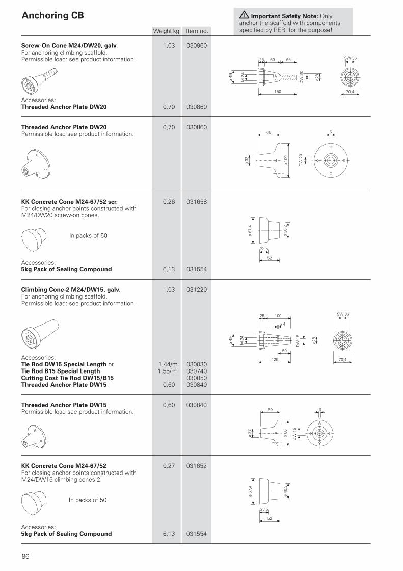
!
ø 49
M 2
4
150
60 6525
ø28
SW 36
70,4
70,4
ø28
ø 4
10025
50
125
ø 49
M 2
4
6
ø 80
60
ø 27
65
ø 32
ø 10
0
6
23,5
ø 36
,2
52
ø 67
,4
23,5
ø 40
,3
52
ø 67
,4
86
DW
20
SW 36
DW
15
DW
20
DW
15
Anchoring CB
Screw-On Cone M24/DW20, galv. 1,03 030960For anchoring climbing scaffold.Permissible load: see product information.
Accessories:Threaded Anchor Plate DW20 0,70 030860
Threaded Anchor Plate DW20 0,70 030860Permissible load see product information.
KK Concrete Cone M24-67/52 scr. 0,26 031658For closing anchor points constructed withM24/DW20 screw-on cones.
In packs of 50
Accessories:5kg Pack of Sealing Compound 6,13 031554
Climbing Cone-2 M24/DW15, galv. 1,03 031220For anchoring climbing scaffold.Permissible load: see product information.
Accessories:Tie Rod DW15 Special Length or 1,44/m 030030Tie Rod B15 Special Length 1,55/m 030740Cutting Cost Tie Rod DW15/B15 030050Threaded Anchor Plate DW15 0,60 030840
Threaded Anchor Plate DW15 0,60 030840Permissible load see product information.
KK Concrete Cone M24-67/52 0,27 031652For closing anchor points constructed withM24/DW15 climbing cones 2.
In packs of 50
Accessories:5kg Pack of Sealing Compound 6,13 031554
Important Safety Note: Onlyanchor the scaffold with componentsspecified by PERI for the purpose!Weight kg Item no.
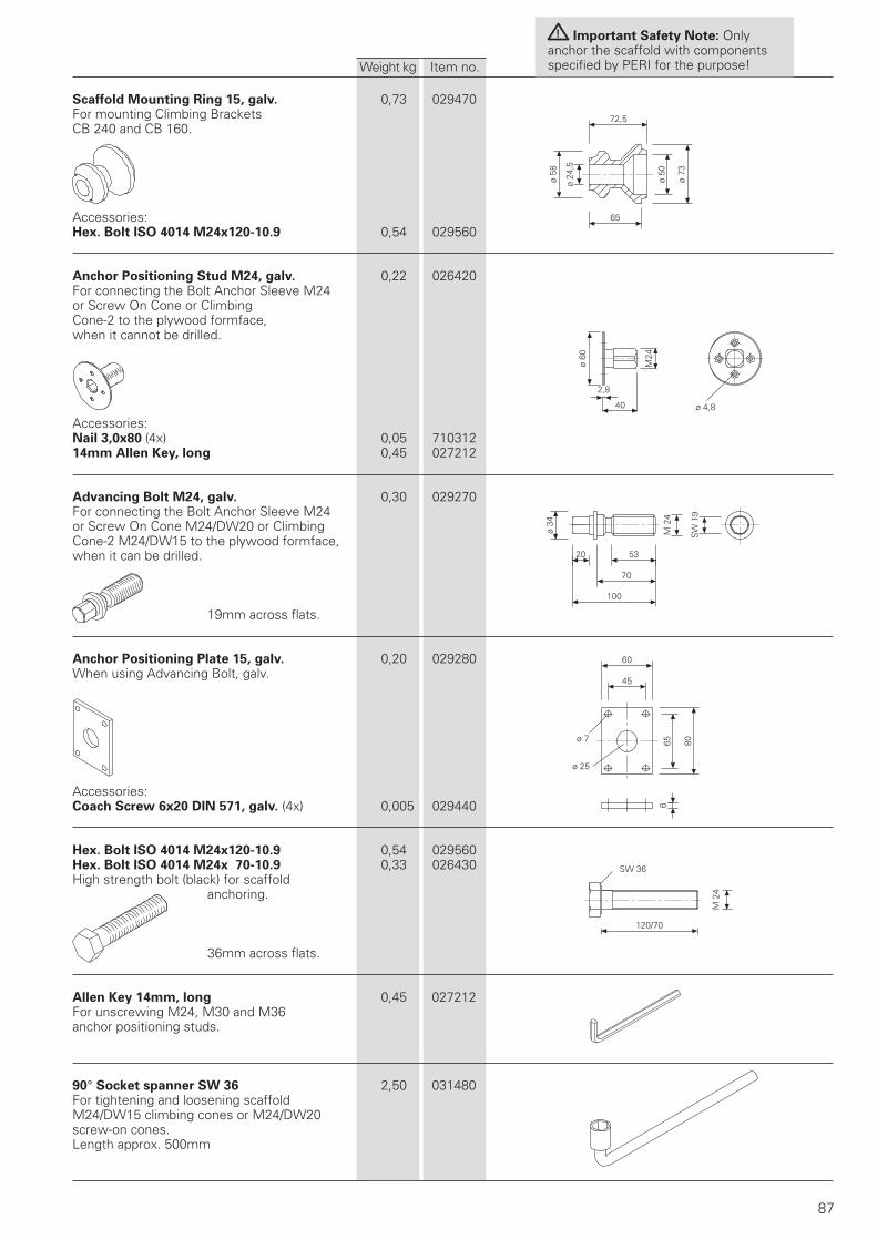
!
ø 60
40 ø 4,8
M24
20ø
3453
70
100
45
6065 80ø 7
ø 25
6
120/70
2,8
87
65
72,5
ø 24
,5
ø 58
ø 50
ø 73
SW 36
M 2
4
M 2
4
SW
19
Scaffold Mounting Ring 15, galv. 0,73 029470For mounting Climbing BracketsCB 240 and CB 160.
Accessories:Hex. Bolt ISO 4014 M24x120-10.9 0,54 029560
Anchor Positioning Stud M24, galv. 0,22 026420For connecting the Bolt Anchor Sleeve M24or Screw On Cone or ClimbingCone-2 to the plywood formface,when it cannot be drilled.
Accessories:Nail 3,0x80 (4x) 0,05 71031214mm Allen Key, long 0,45 027212
Advancing Bolt M24, galv. 0,30 029270For connecting the Bolt Anchor Sleeve M24or Screw On Cone M24/DW20 or ClimbingCone-2 M24/DW15 to the plywood formface,when it can be drilled.
19mm across flats.
Anchor Positioning Plate 15, galv. 0,20 029280When using Advancing Bolt, galv.
Accessories:Coach Screw 6x20 DIN 571, galv. (4x) 0,005 029440
Hex. Bolt ISO 4014 M24x120-10.9 0,54 029560Hex. Bolt ISO 4014 M24x 70-10.9 0,33 026430High strength bolt (black) for scaffold
anchoring.
36mm across flats.
Allen Key 14mm, long 0,45 027212For unscrewing M24, M30 and M36anchor positioning studs.
90° Socket spanner SW 36 2,50 031480For tightening and loosening scaffoldM24/DW15 climbing cones or M24/DW20screw-on cones.Length approx. 500mm
Important Safety Note: Onlyanchor the scaffold with componentsspecified by PERI for the purpose!Weight kg Item no.
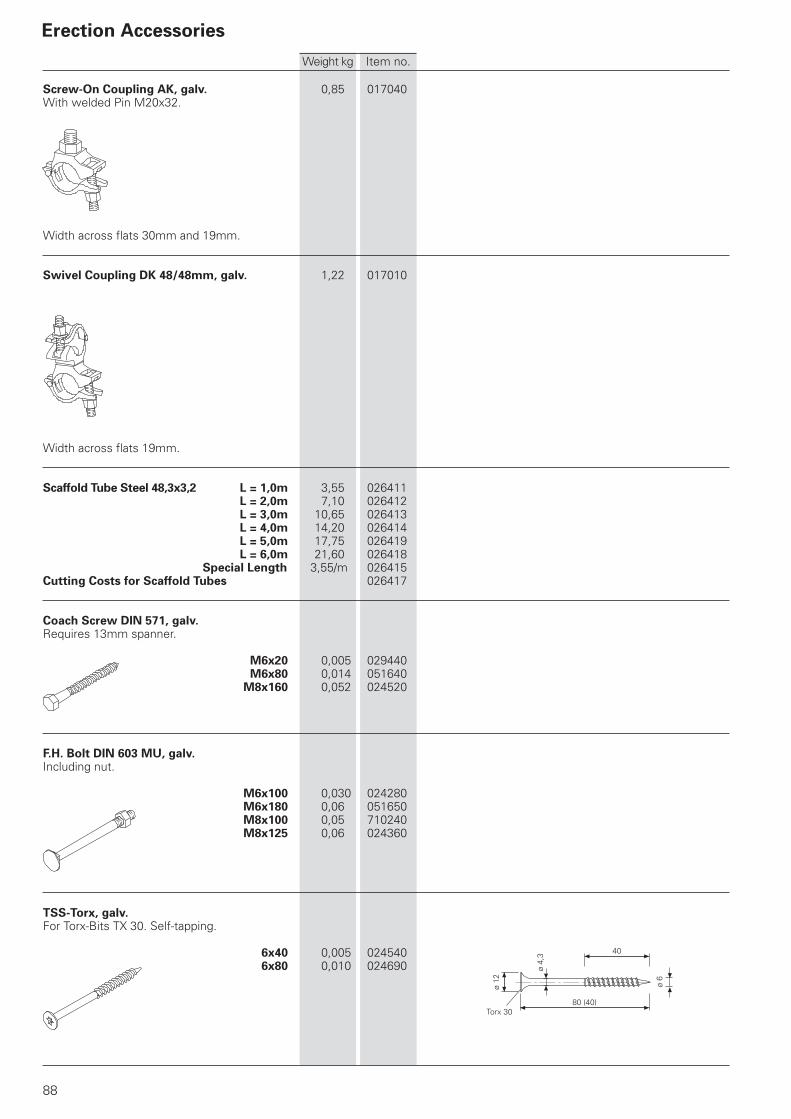
88
80 (40)
ø 12
ø 4,
3 40
ø 6
Torx 30
Screw-On Coupling AK, galv. 0,85 017040With welded Pin M20x32.
Width across flats 30mm and 19mm.
Swivel Coupling DK 48/48mm, galv. 1,22 017010
Width across flats 19mm.
Scaffold Tube Steel 48,3x3,2 L = 1,0m 3,55 026411L = 2,0m 7,10 026412L = 3,0m 10,65 026413L = 4,0m 14,20 026414L = 5,0m 17,75 026419
L = 6,0m 21,60 026418 Special Length 3,55/m 026415Cutting Costs for Scaffold Tubes 026417
Coach Screw DIN 571, galv.Requires 13mm spanner.
M6x20 0,005 029440M6x80 0,014 051640
M8x160 0,052 024520
F.H. Bolt DIN 603 MU, galv.Including nut.
M6x100 0,030 024280M6x180 0,06 051650M8x100 0,05 710240M8x125 0,06 024360
TSS-Torx, galv.For Torx-Bits TX 30. Self-tapping.
6x40 0,005 0245406x80 0,010 024690
Erection Accessories
Weight kg Item no.
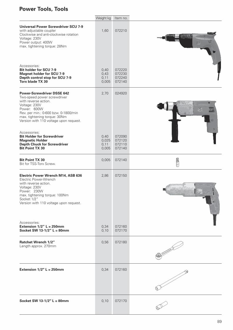
89
Power Tools, Tools
Universal Power Screwdriver SCU 7-9with adjustable coupler 1,60 072210Clockwise and anti-clockwise rotationVoltage: 230VPower output: 400Wmax. tightening torque: 28Nm
Accessories:Bit holder for SCU 7-9 0,40 072220Magnet holder for SCU 7-9 0,43 072230Depth control stop for SCU 7-9 0,11 072240Torx blade TX 30 0,005 072140
Power-Screwdriver DSSE 642 2,70 024920Two-speed power screwdriverwith reverse action.Voltage: 230VPower: 600WRev. per min.: 0-600 bzw. 0-1800/minmax. tightening torque: 30NmVersion with 110 voltage upon request.
Accessories:Bit Holder for Screwdriver 0,40 072090Magnetic Holder 0,025 072120Depth Chuck for Screwdriver 0,11 072110Bit Point TX 30 0,005 072140
Bit Point TX 30 0,005 072140Bit for TSS-Torx Screw.
Electric Power Wrench M14, ASB 636 2,86 072150Electric Power-Wrenchwith reverse action.Voltage: 230VPower: 230Wmax. tightening torque: 100NmSocket 1/2”Version with 110 voltage upon request.
Accessories:Extension 1/2” L = 250mm 0,34 072160Socket SW 13-1/2” L = 80mm 0,10 072170
Ratchet Wrench 1/2” 0,56 072180Length approx. 270mm
Extension 1/2" L = 250mm 0,34 072160
Socket SW 13-1/2" L = 80mm 0,10 072170
Weight kg Item no.

90
02 PERI S.A.S. Zone Industrielle Nord 34-36 rue des Frères Lumière 77109 Meaux Cedex [email protected] www.peri.fr
03 PERI AG Aspstraße 17 8472 Ohringen [email protected] www.peri.ch
04 PERI S.A. Sociedad Unipersonal Ctra. Paracuellos - Fuente el Saz km. 18,9 Camino de Malatones, km. 0,5 28110 Algete/Madrid [email protected] www.peri.es
05 N.V. PERI S.A. Industriepark Nijverheidsstraat 6 PB 54 1840 Londerzeel [email protected] www.peri.be
06 PERI B.V. v. Leeuwenhoekweg 23 Postbus 304 5480 AH-Schijndel [email protected] www.peri.nl
07 PERI Formwork Systems, Inc. 7135 Dorsey Run Road Elkridge, MD 21075 [email protected] www.peri-usa.com
08 PT Beton Perkasa Wijaksana P.O. Box 3737 Jakarta 10210 [email protected] www.peri.de
09 PERI S.p.A. Via G. Pascoli, 4 20060 Basiano (MI) [email protected] www.peri.it
10 PERI Japan K.K. 7F Hakozaki 314 Building, 31-4 Hakozaki-cho, Nihonbashi Chuo-ku Tokyo 103-0015 [email protected] www.perijapan.jp
11 PERI Ltd. Market Harborough Road Clifton upon Dunsmore Rugby, CV23 0AN [email protected] www.peri.ltd.uk
12 PERI Kalıp ve İskeleleri San. ve Tic. Ltd. Sti. Çakmaklı Mahallesi Akçaburgaz Cad. 72. Sokak No: 23 Kıraç - Büyükçekmece/ Istanbul 34500 [email protected] www.peri.com.tr
13 PERI Kft. Zádor u. 4. 1181 Budapest [email protected] www.peri.hu
14 PERI Formwork Malaysia Sdn. Bhd. Unit 19-07-4, Level 7 PNB Damansara 19 Lorong Dungun Damansara Heights 50490 Kuala Lumpur [email protected] www.perimalaysia.com
15 PERI-HORY ASIA Formwork Pte. Ltd. No. 1 Sims Lane # 06-10 Singapore 387355 [email protected] www.periasia.com
16 PERI Ges.mbH Traisenstraße 3 3134 Nußdorf ob der Traisen offi [email protected] www.peri.at
17 PERI spol. s r.o. Průmyslová 392 252 42 Jesenice [email protected] www.peri.cz
18 PERI Danmark A/S forskalling og stillads Greve Main 26 2670 Greve [email protected] www.peri.dk
19 PERI Suomi Ltd. Oy Hakakalliontie 5 05460 Hyvinkää [email protected] www.perisuomi.fi
20 PERI NORGE AS Kobbervikdalen 156 3036 Drammen [email protected] www.peri.no
21 PERI Polska Sp. z o.o. ul. Stołeczna 62 05-860 Płochocin [email protected] www.peri.pl.pl
22 PERIform SVERIGE AB Montörgatan 4-6 Box 9073 30013 Halmstad [email protected] www.periform.se
23 PERI (Korea) Ltd. 8-9th Fl., Yuseong Bldg. 830-67, Yeoksam-dong, Kangnam-ku, Seoul 135-080 [email protected] www.perikorea.com
24 PERIcofragens Lda. Cofragens e Andaimes Rua Cesário Verde, nº 5 - 3º Esq. Linda-a-Pastora 2790-326 Queijas [email protected] www.peri.pt
25 PERI S.A. Ruta Nacional N°. 9, km 47,5 (Panamericana Ramal Escobar) (1625) Escobar/Prov. Bs. As. [email protected] www.peri.com.ar
26 PERI Formas e Escoramentos Ltda. Rodovia Raposo Tavares, km 41 Colinas Bandeirante CEP 06730-000 Vargem Grande Paulista São Paulo [email protected] www.peribrasil.com.br
27 PERI Chile Ltda. C/José de San Martin N° 104 Parque Industrial Los Libertadores Colina, Santiago de Chile [email protected] www.peri.cl
28 PERI România SRL Calea Bucureşti nr. 2B 077015 Baloteşti - ILFOV [email protected] www.peri.ro
29 PERI SLOWENIEN Goran Opalic Obrežna 137 2000 Maribor [email protected] www.peri.de
30 PERI spol. s r.o. Šamorínska 18 903 01 Senec [email protected] www.peri.sk
31 PERI Australia Pty. Ltd. 116 Glendenning Road Glendenning NSW 2761 [email protected] www.periaus.com.au
32 PERI AS Valdmäe 8 Tänassilma Tehnopark 76401 Saku vald Harjumaa [email protected] www.peri.ee
2
1
3
4
5
6
9
11
12
1316
17
18
19
20
22
21
24
2829
30
32
33
34
38
41
42
46
48
52
53
01 PERI GmbH Rudolf-Diesel-Strasse 89264 Weissenhorn [email protected] www.peri.de
France
Switzerland
Spain
Belgium/Luxembourg
Netherlands
USA
Indonesia
Italy
Japan
United Kingdom/Ireland
Turkey
Hungary
Malaysia
Singapore
Austria
Czech Republic
Denmark
Finland
Norway
Poland
Sweden
Korea
Portugal
Argentina
Brazil
Chile
Romania
Slovania
Slovakia
Australia
Estonia
PERI International

91
33 PERI Hellas Ltd. Sokratous Str. 5th kil. Koropi-Varis Ave. P. O. Box 407 194 00 Koropi [email protected] www.perihellas.gr
34 PERI SIA Granita 26 1057 Riga [email protected] www.peri-latvija.lv
35 PERI (L.L.C.) Brashy Building, Offi ce No. 212 Shk. Zayed Road P.O. Box 27933 Dubai [email protected] www.perime.com
36 PERI Formwork Systems, Inc. 45 Nixon Road Bolton, Ontario L7E 1K1 [email protected] www.peri.ca
37 PERI GmbH Lebanon Representative Offi ce AYA Commercial Center, 7th fl oor, Dora Highway, Beirut P.O. Box 90 416 Jdeidet [email protected] www.peri.de
38 PERI UAB Titnago st. 19 02300 Vilnius [email protected] www.peri.lt
39 PERI S.A. Route de Rabat, km. 5 Piste de Beni Touzine Tanger [email protected] www.peri.de
40 PERI Formwork Engineering Ltd 16 Moshe Dayan st., P.O. Box 10202 Petach Tikva, 49002 Israel [email protected] www.peri.co.il
41 PERI BULGARIA EOOD Kv. Vragdebna m. Nova Machala Nr. 46 1839 – Sofi a [email protected] www.peri.bg
42 MEST ltd., Fornubudum 5 220 Hafnarfjordur [email protected] www.mest.is
43 PERI Kazakhstan Rubenstein Street 10 (corner Dostyk Str.) 050010 Almaty [email protected] www.peri.kz
44 OOO PERI 8 Etage, OOO PERI Buro Krasnaya Presnya Str. 24 123022 Moskau [email protected] www.peri.ru
45 PERI Wiehahn (Pty.) Ltd. P.O. Box 2668 Bellville 7535 [email protected] www.periwiehahn.co.za
46 TOW PERI Ukraina 23, M. Raskowa Str., B. 822 02002 Kiew [email protected] www.peri.ua
47 PERI GmbH Egypt Branch Offi ce 24 A, Obour Gardens, 4th Floor, apt. # 1 Salah Salem Street 11361 Heliopolis Cairo [email protected] www.peri.com.eg
48 PERI Oplate d.o.o. Jurija Gagarina 81 11070 Novi Beograd offi [email protected] www.peri.co.yu
49 PERI Cimbras y Andamios, S.A. de C.V. Parque de las Américas KM 3.5 de la Carretera Jorobas - Tula Huehuetoca Estado de México, C.P. 54680 [email protected] www.peri.com.mx
50 PERI BAKU Baku Branch Offi ce 28 May Küç. Ev 72 Menzil 27 Baku [email protected] www.peri.de
51 PERI Kalıp ve İskeleleri Aşgabat Branch Offi ce Göroglu Sokak No. 130, Kat 2 744035 Aşgabat [email protected] www.peri.com.tr
52 PERI Belarus Pr. Nesawisimosti 11 Kopus-2 Zimmer: 526,528 220030 Minsk [email protected] www.peri.com.tr
53 PERI oplate i skele d.o.o. Dolenica 20 10 250 Donji Stupnik/ Zagreb [email protected] www.peri.com.hr
54 PERI GmbH Iran Branch Offi ce Flat 27, Blvd. KAVE, Building No. 246 P.O. Box 9 3979 3669 Tehran [email protected] www.peri.ir
55 PERI (India) Pvt Ltd 717 Palm Springs Palm Court Malad Link Road Malad (West) Mumbai – 400064 [email protected] www.peri.in
56 PERI Jordan Saad 5 Center, 4th Floor Offi ce No. 404 Al Madineh Al Munawara Street P.O. Box 367 11947 Amman [email protected] www.peri.de
57 PERI Kuwait Arraya Center, 29th Floor Al-Shuhada Street, Sharq P.O. Box 1060 Safat 13011 Kuwait [email protected] www.peri.de
58 PERI Saudi Arabia 33 AL-Batraa Street AL -Shurbatiy Building AL - Bughdadiah AL - Gharbiah Distrect 6th Floor, Flat # 61 P.O. Box 11641 Jeddah [email protected] www.peri.de
59 PERI Qatar LLC P.O. Box 24133 Doha [email protected] www.peri.de
60 Société PERI S.A.S. Bureau de liaison d‘Alger 50 bis, Route de Gué de Constantine Hai El Badr (ex Apreval) Immeuble FADLI Kouba - Alger [email protected] www.peri.fr
7
8
10
1415
23
25
26
27 31
35
36
3739 40
43
44
45
4749
50 51
54
595558
5760 56
Greece
Latvia
United Arab Emirates
Canada
Libanon
Lithuania
Marocco
Israel
Bulgaria
Iceland
Kazakhstan
Russian Federation
South Africa
Ukraine
Egypt
Serbia
Mexico
Azerbaijan
Turkmenistan
Belorussia
Croatia
Iran
India
Jordan
Kuwait
Saudi Arabia
Qatar
Algeria

PERI GmbHFormwork ScaffoldingEngineeringP.O.Box 126489259 WeissenhornGermanyTelefon +49 (0)73 09.9 50- 0Telefax +49 (0)73 09.9 51- [email protected] D
e 0
8/20
07 3
ma
Art
. Nr.:
791
778
© C
opyr
ight
by
PE
RI G
mbH


