Embed Size (px)
Citation preview

CBci & CB MAXw/Control Box Thermostat
TK 40738-1-MM (Rev. 1, 1/99)
Copyright© 1993 Thermo King Corp., Minneapolis, MN, U.S.A.Printed in U.S.A.
This manual is published for informational purposes only and the information so provided should not beconsidered as all-inclusive or covering all contingencies. If further information is required, Thermo KingCorporation should be consulted.
Sale of product shown in this manual is subject to Thermo King’s terms and conditions including, but notlimited to, the THERMO KING EXPRESS WARRANTY. Such terms and conditions are available uponrequest.
Thermo King’s warranty will not apply to any equipment which has been “so repaired or altered outside themanufacturer’s plants as, in the manufacturer's judgment, to effect its stability.”
No warranties, express or implied, including warranties of fitness for a particular purpose ormerchantability, or warranties arising from course of dealing or usage of trade, are made regardingthe information, recommendations, and descriptions contained herein. Manufacturer is notresponsible and will not be held liable in contract or in tort (including negligence) for any special,indirect or consequential damages, including injury or damage caused to vehicles, contents orpersons, by reason of the installation of any Thermo King product or its mechanical failure.
The maintenance information in this manual covers unit models:
CBci 10 12V (914725) CB MAX 10 12V (915091)CBci 10 24V (914724) CB MAX 10 24V (915090)CBci 20 12V (914729) CB MAX 20 12V (915097)CBci 20 24V (914728) CB MAX 20 24V (915094)
For further information, refer to…
CBci and CB Parts Manual TK 40097
CBci Operating Manual TK 40170
Diagnosing Thermo King Refrigeration System TK 5984
Tool Catalog TK 5955
The information in this manual is provided to assist owners, operators and service people in the properupkeep and maintenance of Thermo King units.
Recover RefrigerantAt Thermo King, we recognize the need to preserve the environ-ment and limit the potential harm to the ozone layer that canresult from allowing refrigerant to escape into the atmosphere.
We strictly adhere to a policy that promotes the recovery andlimits the loss of refrigerant into the atmosphere.
In addition, service personnel must be aware of Federal regula-tions concerning the use of refrigerants and the certification oftechnicians. For additional information on regulations and tech-nician certification programs, contact your local THERMO KINGdealer.
R-404A and R-134aCAUTION: Use ONLY Polyol Ester based refrigeration compressor oil (TK P/N203-413) in R-404A and R-134a units.
DO NOT use Polyol Ester based oil in standard Thermo King units.
DO NOT mix Polyol Ester and standard synthetic compressor oils.
Keep Polyol Ester compressor oil in tightly sealed containers. If Polyol Ester oilbecomes contaminated with moisture or standard oils, dispose of properly—DO NOTUSE!
CAUTION: When servicing Thermo King R-404A and R-134a units, use only thoseservice tools certified for and dedicated to R-404A and R-134a refrigerant and
Polyol Ester compressor oils. Residual non-HFC refrigerants and non-HFC refrigerantsor oils will contaminate R-404A and R-134a systems.


Table of Contents
Safety Precautions . . . . . . . . . . . . . . . . . . . . . . . . . . . . . . . . . . . . . . . . . . . . . . . . . . . . . . . . . . . . . . . . . . . . . . . . . i
Specifications . . . . . . . . . . . . . . . . . . . . . . . . . . . . . . . . . . . . . . . . . . . . . . . . . . . . . . . . . . . . . . . . . . . . . . . . . . . . .1
Maintenance Inspection Schedule . . . . . . . . . . . . . . . . . . . . . . . . . . . . . . . . . . . . . . . . . . . . . . . . . . . . . . . . . . . . .5
Unit Description . . . . . . . . . . . . . . . . . . . . . . . . . . . . . . . . . . . . . . . . . . . . . . . . . . . . . . . . . . . . . . . . . . . . . . . . . . . .7Liquid Injection System . . . . . . . . . . . . . . . . . . . . . . . . . . . . . . . . . . . . . . . . . . . . . . . . . . . . . . . . . . . . . . . . . . . . .7Oil Separator . . . . . . . . . . . . . . . . . . . . . . . . . . . . . . . . . . . . . . . . . . . . . . . . . . . . . . . . . . . . . . . . . . . . . . . . . . . . .8CBci MAX Features. . . . . . . . . . . . . . . . . . . . . . . . . . . . . . . . . . . . . . . . . . . . . . . . . . . . . . . . . . . . . . . . . . . . . . . .8Unit Operation . . . . . . . . . . . . . . . . . . . . . . . . . . . . . . . . . . . . . . . . . . . . . . . . . . . . . . . . . . . . . . . . . . . . . . . . . . . .8Operating Modes. . . . . . . . . . . . . . . . . . . . . . . . . . . . . . . . . . . . . . . . . . . . . . . . . . . . . . . . . . . . . . . . . . . . . . . . . .9Unit Features. . . . . . . . . . . . . . . . . . . . . . . . . . . . . . . . . . . . . . . . . . . . . . . . . . . . . . . . . . . . . . . . . . . . . . . . . . . .10Protection Features . . . . . . . . . . . . . . . . . . . . . . . . . . . . . . . . . . . . . . . . . . . . . . . . . . . . . . . . . . . . . . . . . . . . . . .10Optional Features . . . . . . . . . . . . . . . . . . . . . . . . . . . . . . . . . . . . . . . . . . . . . . . . . . . . . . . . . . . . . . . . . . . . . . . .10Serial Number Locations . . . . . . . . . . . . . . . . . . . . . . . . . . . . . . . . . . . . . . . . . . . . . . . . . . . . . . . . . . . . . . . . . . .10
Operating Instructions . . . . . . . . . . . . . . . . . . . . . . . . . . . . . . . . . . . . . . . . . . . . . . . . . . . . . . . . . . . . . . . . . . . . .23Unit Controls . . . . . . . . . . . . . . . . . . . . . . . . . . . . . . . . . . . . . . . . . . . . . . . . . . . . . . . . . . . . . . . . . . . . . . . . . . . .23Unit Protection Devices . . . . . . . . . . . . . . . . . . . . . . . . . . . . . . . . . . . . . . . . . . . . . . . . . . . . . . . . . . . . . . . . . . . .24Unit Operation . . . . . . . . . . . . . . . . . . . . . . . . . . . . . . . . . . . . . . . . . . . . . . . . . . . . . . . . . . . . . . . . . . . . . . . . . . .25Starting the Unit. . . . . . . . . . . . . . . . . . . . . . . . . . . . . . . . . . . . . . . . . . . . . . . . . . . . . . . . . . . . . . . . . . . . . . . . . .25Adjusting the Thermostat . . . . . . . . . . . . . . . . . . . . . . . . . . . . . . . . . . . . . . . . . . . . . . . . . . . . . . . . . . . . . . . . . .26After Start Inspection. . . . . . . . . . . . . . . . . . . . . . . . . . . . . . . . . . . . . . . . . . . . . . . . . . . . . . . . . . . . . . . . . . . . . .26Loading Procedure . . . . . . . . . . . . . . . . . . . . . . . . . . . . . . . . . . . . . . . . . . . . . . . . . . . . . . . . . . . . . . . . . . . . . . .27Post Loading Procedure . . . . . . . . . . . . . . . . . . . . . . . . . . . . . . . . . . . . . . . . . . . . . . . . . . . . . . . . . . . . . . . . . . .27Weekly Post Trip Checks . . . . . . . . . . . . . . . . . . . . . . . . . . . . . . . . . . . . . . . . . . . . . . . . . . . . . . . . . . . . . . . . . .27
Electrical Maintenance . . . . . . . . . . . . . . . . . . . . . . . . . . . . . . . . . . . . . . . . . . . . . . . . . . . . . . . . . . . . . . . . . . . . .29Unit Wiring. . . . . . . . . . . . . . . . . . . . . . . . . . . . . . . . . . . . . . . . . . . . . . . . . . . . . . . . . . . . . . . . . . . . . . . . . . . . . .29Remote Control Box Components. . . . . . . . . . . . . . . . . . . . . . . . . . . . . . . . . . . . . . . . . . . . . . . . . . . . . . . . . . . .29Testing the Thermometer . . . . . . . . . . . . . . . . . . . . . . . . . . . . . . . . . . . . . . . . . . . . . . . . . . . . . . . . . . . . . . . . . .29Testing the Thermostat . . . . . . . . . . . . . . . . . . . . . . . . . . . . . . . . . . . . . . . . . . . . . . . . . . . . . . . . . . . . . . . . . . . .30Cab Control Box Components (Optional) . . . . . . . . . . . . . . . . . . . . . . . . . . . . . . . . . . . . . . . . . . . . . . . . . . . . . .33Temperature Control Module (TCM) . . . . . . . . . . . . . . . . . . . . . . . . . . . . . . . . . . . . . . . . . . . . . . . . . . . . . . . . . .33Defrost System . . . . . . . . . . . . . . . . . . . . . . . . . . . . . . . . . . . . . . . . . . . . . . . . . . . . . . . . . . . . . . . . . . . . . . . . . .36Engine Operation . . . . . . . . . . . . . . . . . . . . . . . . . . . . . . . . . . . . . . . . . . . . . . . . . . . . . . . . . . . . . . . . . . . . . . . .36Electric Standby Operation (Model 20 Only) . . . . . . . . . . . . . . . . . . . . . . . . . . . . . . . . . . . . . . . . . . . . . . . . . . . .37Defrost Components . . . . . . . . . . . . . . . . . . . . . . . . . . . . . . . . . . . . . . . . . . . . . . . . . . . . . . . . . . . . . . . . . . . . . .37Testing the Defrost System . . . . . . . . . . . . . . . . . . . . . . . . . . . . . . . . . . . . . . . . . . . . . . . . . . . . . . . . . . . . . . . . .38Defrost Timer. . . . . . . . . . . . . . . . . . . . . . . . . . . . . . . . . . . . . . . . . . . . . . . . . . . . . . . . . . . . . . . . . . . . . . . . . . . .40Circuit Breakers. . . . . . . . . . . . . . . . . . . . . . . . . . . . . . . . . . . . . . . . . . . . . . . . . . . . . . . . . . . . . . . . . . . . . . . . . .42Condenser Fan Pressure Switch (CFPS) . . . . . . . . . . . . . . . . . . . . . . . . . . . . . . . . . . . . . . . . . . . . . . . . . . . . . .42Electric Standby Circuits (Model 20 Only) . . . . . . . . . . . . . . . . . . . . . . . . . . . . . . . . . . . . . . . . . . . . . . . . . . . . . .43

Table of Contents
Refrigeration Maintenance . . . . . . . . . . . . . . . . . . . . . . . . . . . . . . . . . . . . . . . . . . . . . . . . . . . . . . . . . . . . . . . . . 45Refrigerant Charge . . . . . . . . . . . . . . . . . . . . . . . . . . . . . . . . . . . . . . . . . . . . . . . . . . . . . . . . . . . . . . . . . . . . . . 45Charging the Refrigeration System . . . . . . . . . . . . . . . . . . . . . . . . . . . . . . . . . . . . . . . . . . . . . . . . . . . . . . . . . . 45Checking Compressor Oil Charge . . . . . . . . . . . . . . . . . . . . . . . . . . . . . . . . . . . . . . . . . . . . . . . . . . . . . . . . . . . 47High Pressure Cutout Switch (HPCO) . . . . . . . . . . . . . . . . . . . . . . . . . . . . . . . . . . . . . . . . . . . . . . . . . . . . . . . . 47System Cleanup. . . . . . . . . . . . . . . . . . . . . . . . . . . . . . . . . . . . . . . . . . . . . . . . . . . . . . . . . . . . . . . . . . . . . . . . . 48Refrigerant Hose Routing . . . . . . . . . . . . . . . . . . . . . . . . . . . . . . . . . . . . . . . . . . . . . . . . . . . . . . . . . . . . . . . . . 49Three-way Valve Condenser Pressure Bypass Check Valve . . . . . . . . . . . . . . . . . . . . . . . . . . . . . . . . . . . . . . 50
Refrigeration Service Operations . . . . . . . . . . . . . . . . . . . . . . . . . . . . . . . . . . . . . . . . . . . . . . . . . . . . . . . . . . . . 51compressor . . . . . . . . . . . . . . . . . . . . . . . . . . . . . . . . . . . . . . . . . . . . . . . . . . . . . . . . . . . . . . . . . . . . . . . . . . . . 51Condenser Coil . . . . . . . . . . . . . . . . . . . . . . . . . . . . . . . . . . . . . . . . . . . . . . . . . . . . . . . . . . . . . . . . . . . . . . . . . 51Filter Drier . . . . . . . . . . . . . . . . . . . . . . . . . . . . . . . . . . . . . . . . . . . . . . . . . . . . . . . . . . . . . . . . . . . . . . . . . . . . . 51Evaporator Coil . . . . . . . . . . . . . . . . . . . . . . . . . . . . . . . . . . . . . . . . . . . . . . . . . . . . . . . . . . . . . . . . . . . . . . . . . 52Expansion Valve Assembly . . . . . . . . . . . . . . . . . . . . . . . . . . . . . . . . . . . . . . . . . . . . . . . . . . . . . . . . . . . . . . . . 52Receiver Tank . . . . . . . . . . . . . . . . . . . . . . . . . . . . . . . . . . . . . . . . . . . . . . . . . . . . . . . . . . . . . . . . . . . . . . . . . . 53Oil Separator . . . . . . . . . . . . . . . . . . . . . . . . . . . . . . . . . . . . . . . . . . . . . . . . . . . . . . . . . . . . . . . . . . . . . . . . . . . 53Replacing Refrigerant Hoses . . . . . . . . . . . . . . . . . . . . . . . . . . . . . . . . . . . . . . . . . . . . . . . . . . . . . . . . . . . . . . . 55Liquid Injection Solenoid Valve . . . . . . . . . . . . . . . . . . . . . . . . . . . . . . . . . . . . . . . . . . . . . . . . . . . . . . . . . . . . . 56Liquid Injection Metering Orifice. . . . . . . . . . . . . . . . . . . . . . . . . . . . . . . . . . . . . . . . . . . . . . . . . . . . . . . . . . . . . 56Testing the Liquid Injection Solenoid Valve and Metering Orifice . . . . . . . . . . . . . . . . . . . . . . . . . . . . . . . . . . . 57High Pressure Cutout And Condenser Fan Switches . . . . . . . . . . . . . . . . . . . . . . . . . . . . . . . . . . . . . . . . . . . . 57Low Pressure Cutout Switch . . . . . . . . . . . . . . . . . . . . . . . . . . . . . . . . . . . . . . . . . . . . . . . . . . . . . . . . . . . . . . . 57Suction Pressure Regulator Valve . . . . . . . . . . . . . . . . . . . . . . . . . . . . . . . . . . . . . . . . . . . . . . . . . . . . . . . . . . . 57Discharge Check Valve Repair (Model 20 Only) . . . . . . . . . . . . . . . . . . . . . . . . . . . . . . . . . . . . . . . . . . . . . . . . 58Accumulator . . . . . . . . . . . . . . . . . . . . . . . . . . . . . . . . . . . . . . . . . . . . . . . . . . . . . . . . . . . . . . . . . . . . . . . . . . . . 60Three-way Valve Repair . . . . . . . . . . . . . . . . . . . . . . . . . . . . . . . . . . . . . . . . . . . . . . . . . . . . . . . . . . . . . . . . . . 61Three-way Valve Condenser Pressure Bypass Check Valve Repair. . . . . . . . . . . . . . . . . . . . . . . . . . . . . . . . . 62Pilot Solenoid . . . . . . . . . . . . . . . . . . . . . . . . . . . . . . . . . . . . . . . . . . . . . . . . . . . . . . . . . . . . . . . . . . . . . . . . . . . 63In-line Condenser Check Valve . . . . . . . . . . . . . . . . . . . . . . . . . . . . . . . . . . . . . . . . . . . . . . . . . . . . . . . . . . . . . 63In-line Condenser Check Valve Replacement . . . . . . . . . . . . . . . . . . . . . . . . . . . . . . . . . . . . . . . . . . . . . . . . . . 64O-Ring Seal (ORS) Connections . . . . . . . . . . . . . . . . . . . . . . . . . . . . . . . . . . . . . . . . . . . . . . . . . . . . . . . . . . . . 64
Structural Maintenance . . . . . . . . . . . . . . . . . . . . . . . . . . . . . . . . . . . . . . . . . . . . . . . . . . . . . . . . . . . . . . . . . . . . 65Unit Inspection . . . . . . . . . . . . . . . . . . . . . . . . . . . . . . . . . . . . . . . . . . . . . . . . . . . . . . . . . . . . . . . . . . . . . . . . . . 65Evaporator Coil . . . . . . . . . . . . . . . . . . . . . . . . . . . . . . . . . . . . . . . . . . . . . . . . . . . . . . . . . . . . . . . . . . . . . . . . . 65Fan Location . . . . . . . . . . . . . . . . . . . . . . . . . . . . . . . . . . . . . . . . . . . . . . . . . . . . . . . . . . . . . . . . . . . . . . . . . . . 65Condenser Coil . . . . . . . . . . . . . . . . . . . . . . . . . . . . . . . . . . . . . . . . . . . . . . . . . . . . . . . . . . . . . . . . . . . . . . . . . 66Unit Mounting Bolts . . . . . . . . . . . . . . . . . . . . . . . . . . . . . . . . . . . . . . . . . . . . . . . . . . . . . . . . . . . . . . . . . . . . . . 66
Table of Contents (Continued)
Compressor and Clutch Maintenance . . . . . . . . . . . . . . . . . . . . . . . . . . . . . . . . . . . . . . . . . . . . . . . . . . . . . . . . .67Clutch Removal . . . . . . . . . . . . . . . . . . . . . . . . . . . . . . . . . . . . . . . . . . . . . . . . . . . . . . . . . . . . . . . . . . . . . . . . . .67Clutch Installation . . . . . . . . . . . . . . . . . . . . . . . . . . . . . . . . . . . . . . . . . . . . . . . . . . . . . . . . . . . . . . . . . . . . . . . .69Shaft Seal Cover and Shaft Seal: Removal and Installation . . . . . . . . . . . . . . . . . . . . . . . . . . . . . . . . . . . . . . . .71Special Tools. . . . . . . . . . . . . . . . . . . . . . . . . . . . . . . . . . . . . . . . . . . . . . . . . . . . . . . . . . . . . . . . . . . . . . . . . . . .74System Compressor and Oil . . . . . . . . . . . . . . . . . . . . . . . . . . . . . . . . . . . . . . . . . . . . . . . . . . . . . . . . . . . . . . . .76Checking the Oil Level . . . . . . . . . . . . . . . . . . . . . . . . . . . . . . . . . . . . . . . . . . . . . . . . . . . . . . . . . . . . . . . . . . . .77Electrical Connection. . . . . . . . . . . . . . . . . . . . . . . . . . . . . . . . . . . . . . . . . . . . . . . . . . . . . . . . . . . . . . . . . . . . . .77Clutch Test . . . . . . . . . . . . . . . . . . . . . . . . . . . . . . . . . . . . . . . . . . . . . . . . . . . . . . . . . . . . . . . . . . . . . . . . . . . . .78Belt Tensions. . . . . . . . . . . . . . . . . . . . . . . . . . . . . . . . . . . . . . . . . . . . . . . . . . . . . . . . . . . . . . . . . . . . . . . . . . . .78Engine/Compressor Belt and Pulleys . . . . . . . . . . . . . . . . . . . . . . . . . . . . . . . . . . . . . . . . . . . . . . . . . . . . . . . . .78
Over-the-Road Mechanical Diagnosis . . . . . . . . . . . . . . . . . . . . . . . . . . . . . . . . . . . . . . . . . . . . . . . . . . . . . . . . .79
Electric Standby Mechanical Diagnosis . . . . . . . . . . . . . . . . . . . . . . . . . . . . . . . . . . . . . . . . . . . . . . . . . . . . . . .81
Refrigeration Diagnosis . . . . . . . . . . . . . . . . . . . . . . . . . . . . . . . . . . . . . . . . . . . . . . . . . . . . . . . . . . . . . . . . . . . .85
Wiring and Schematic Diagrams Index . . . . . . . . . . . . . . . . . . . . . . . . . . . . . . . . . . . . . . . . . . . . . . . . . . . . . . . .87


i
Safety Precautions
GENERAL PRACTICES
1. ALWAYS WEAR GOGGLES OR SAFETY
GLASSES. Refrigerant liquid, refrigeration oil, and
battery acid can permanently damage the eyes (see First
Aid under Refrigeration Oil).
2. Never operate the unit with the compressor discharge
valve closed.
3. Keep your hands, clothing and tools clear of the fans
and belts when the unit is running. This should also be
considered when opening and closing the compressor
service valves.
4. Make sure gauge manifold hoses are in good condition.
Never let them come in contact with a belt, fan motor
pulley, or any hot surface.
5. Never apply heat to a sealed refrigeration system or
container.
6. Fluorocarbon refrigerants, in the presence of an open
flame or electrical short, produce toxic gases that are
severe respiratory irritants capable of causing death.
7. Make sure all mounting bolts are tight and are of cor-
rect length for their particular application.
8. Use extreme caution when drilling holes in the unit.
The holes may weaken structural components, and
holes drilled into electrical wiring can cause fire or
explosion.
9. Use caution when working around exposed coil fins.
The fins can cause painful lacerations.
10. Use caution when working with a refrigerant or refrig-
eration system in any closed or confined area with a
limited air supply (for example, a truck box or garage).
Refrigerant tends to displace air and can cause oxygen
depletion resulting in suffocation and possible death.
11. In the USA, EPA Section 608 Certification is needed to
work on refrigeration systems.
REFRIGERANT
Although fluorocarbon refrigerants are classified as safe
refrigerants, certain precautions must be observed when
handling them or servicing a unit in which they are used.
When exposed to the atmosphere from the liquid state, fluo-
rocarbon refrigerants evaporator rapidly, freezing anything
they contact.
First Aid
In the event of frost bite, the objectives of First Aid are to
protect the frozen area from further injury, to warm the
affected area rapidly and to maintain respiration.
• EYES: For contact with liquid, immediately flush eyes
with large amounts of water and get prompt medical
attention.
• SKIN: Flush area with large amounts of lukewarm
water. Do not apply heat. Remove contaminated cloth-
ing and shoes. Wrap burns with dry, sterile, bulky
dressing to protect from infection/injury. Get medical
attention. Wash contaminated clothing before reuse.
• INHALATION: Move victim to fresh air and use CPR
if necessary. Stay with victim until arrival of emer-
gency medical personnel.
REFRIGERATION OIL
Avoid refrigeration oil contact with the eyes. Avoid pro-
longed or repeated contact of refrigeration oil with skin or
clothing. Wash thoroughly after handling refrigeration oil to
prevent irritation.
First Aid
In case of eye contact, immediately flush with plenty of
water for at least 15 minutes. Wash skin with soap and
water. CALL A PHYSICIAN.

Safety Precautions (Rev. 1/99)
ii
ELECTRICAL HAZARDS
High Voltage
When servicing or repairing a refrigeration unit, the possi-
bility of serious or even fatal injury from electrical shock
exists. Extreme care must be used when working with an
operating refrigeration unit. Lethal voltage potentials can
exist on connections in the high voltage tray of the control
box.
Precautions
1. When working on high voltage circuits on the refrigera-
tion unit, do not make any rapid moves. If a tool drops,
do not grab for it. People do not contact high voltage
wires on purpose. It occurs from an unplanned move-
ment.
2. Use tools with insulated handles that are in good condi-
tion. Never hold metal tools in your hand if exposed,
energized conductors are within reach.
3. Treat all wires and connections as high voltage until a
meter and wiring diagram show otherwise.
4. Never work alone on high voltage circuits on the refrig-
eration unit, another person should always be standing
by in the event of an accident to shut off the refrigera-
tion unit and to aid a victim.
5. Have electrically insulated gloves, cable cutters and
safety glasses available in the immediate vicinity in the
event of an accident.
First Aid
IMMEDIATE action must be initiated after a person has
received an electrical shock. Obtain immediate medical
assistance if available.
The source of shock must be immediately removed by
either shutting down the power or removing the victim from
the source. If it is not possible to shut off the power, the wire
should be cut with either an insulated instrument (e.g., a
wooden handled axe or cable cutters with heavy insulated
handles) or by a rescuer wearing electrically insulated
gloves and safety glasses. Whichever method is used do not
look at the wire while it is being cut. The ensuing flash can
cause burns and blindness.
If the victim has to be removed from a live circuit, pull the
victim off with a non-conductive material. Use the victim’s
coat, a rope, wood, or loop your belt around the victim’s leg
or arm and pull the victim off. DO NOT TOUCH the victim.
You can receive a shock from current flowing through the
victim’s body. After separating the victim from power
source, check immediately for the presence of a pulse and
respiration. If a pulse is not present, start CPR (Cardio Pul-
monary Resuscitation) and call for emergency medical
assistance. If a pulse is present, respiration may be restored
by using mouth-to-mouth resuscitation, but call for emer-
gency medical assistance.
Low Voltage
Control circuits used in the refrigeration unit are low volt-
age (12 volts dc). This voltage potential is not considered
dangerous, but the large amount of current available (over
30 amperes) can cause severe burns if shorted or ground.
Do not wear jewelry, watch or rings. These items can short
out electrical circuits and cause severe burns to the wearer.
1
Specifications
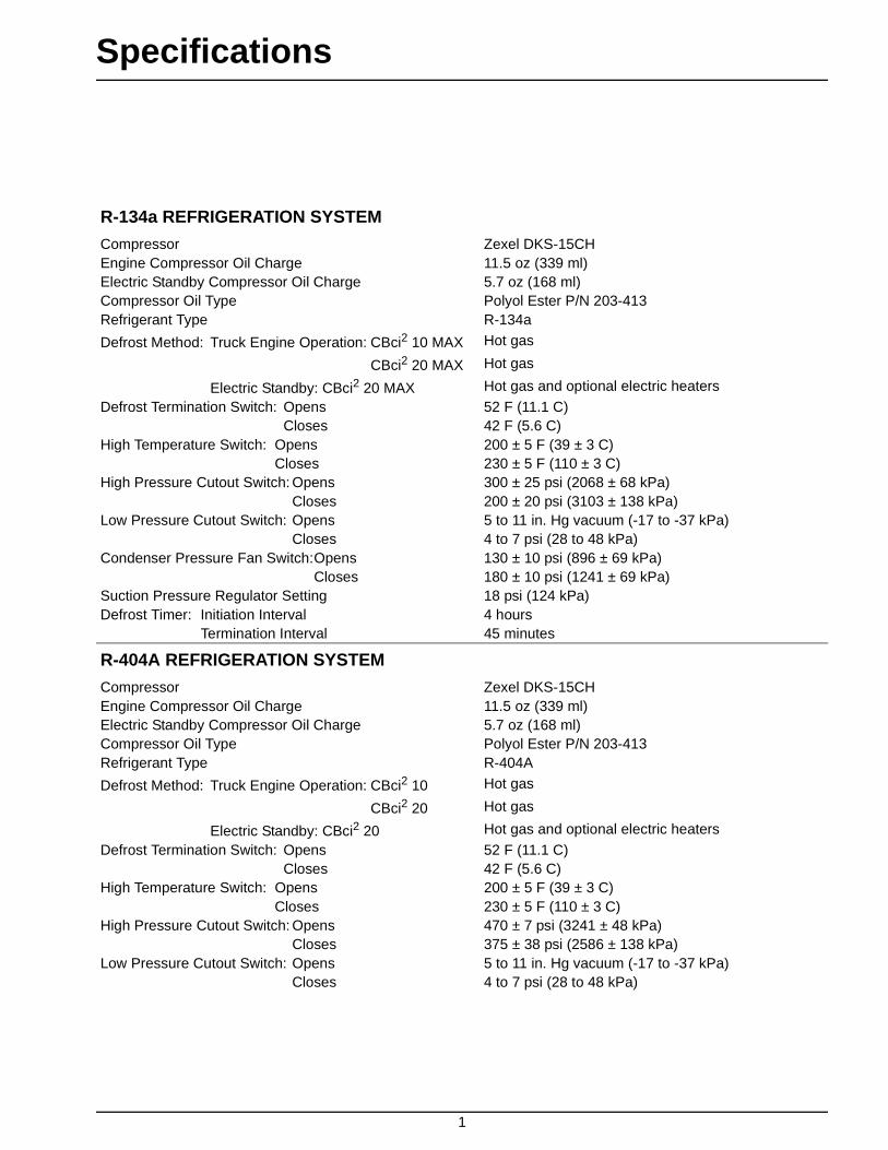
R-134a REFRIGERATION SYSTEM
Compressor Zexel DKS-15CHEngine Compressor Oil Charge 11.5 oz (339 ml)Electric Standby Compressor Oil Charge 5.7 oz (168 ml)Compressor Oil Type Polyol Ester P/N 203-413Refrigerant Type R-134a
Defrost Method: Truck Engine Operation: CBci2 10 MAX Hot gas
CBci2 20 MAX Hot gas
Electric Standby: CBci2 20 MAX Hot gas and optional electric heaters
Defrost Termination Switch: Opens 52 F (11.1 C)Closes 42 F (5.6 C)
High Temperature Switch: Opens 200 ± 5 F (39 ± 3 C)Closes 230 ± 5 F (110 ± 3 C)
High Pressure Cutout Switch: Opens 300 ± 25 psi (2068 ± 68 kPa)Closes 200 ± 20 psi (3103 ± 138 kPa)
Low Pressure Cutout Switch: Opens 5 to 11 in. Hg vacuum (-17 to -37 kPa)Closes 4 to 7 psi (28 to 48 kPa)
Condenser Pressure Fan Switch:Opens 130 ± 10 psi (896 ± 69 kPa)Closes 180 ± 10 psi (1241 ± 69 kPa)
Suction Pressure Regulator Setting 18 psi (124 kPa)Defrost Timer: Initiation Interval 4 hours
Termination Interval 45 minutes
R-404A REFRIGERATION SYSTEM
Compressor Zexel DKS-15CHEngine Compressor Oil Charge 11.5 oz (339 ml)Electric Standby Compressor Oil Charge 5.7 oz (168 ml)Compressor Oil Type Polyol Ester P/N 203-413Refrigerant Type R-404A
Defrost Method: Truck Engine Operation: CBci2 10 Hot gas
CBci2 20 Hot gas
Electric Standby: CBci2 20 Hot gas and optional electric heaters
Defrost Termination Switch: Opens 52 F (11.1 C)Closes 42 F (5.6 C)
High Temperature Switch: Opens 200 ± 5 F (39 ± 3 C)Closes 230 ± 5 F (110 ± 3 C)
High Pressure Cutout Switch: Opens 470 ± 7 psi (3241 ± 48 kPa)Closes 375 ± 38 psi (2586 ± 138 kPa)
Low Pressure Cutout Switch: Opens 5 to 11 in. Hg vacuum (-17 to -37 kPa)Closes 4 to 7 psi (28 to 48 kPa)

Specifications (Rev. 1/99)
2
R-404A REFRIGERATION SYSTEM (continued)
Condenser Pressure Fan Switch:Opens 130 ± 10 psi (896 ± 69 kPa)Closes 180 ± 10 psi (1241 ± 69 kPa)
Suction Pressure Regulator Setting 18 psi (124 kPa)Defrost Timer: Intuition Interval 4 hours
Termination Interval 45 minutes
ELECTRICAL SYSTEM
Circuit Breaker Ratings12 Vdc 40 amp manual reset24 Vdc 25 amp manual reset
Condenser and Evaporator Fan Motors
Voltage HorsepowerPower Rating in
Kilowatts rpm Full Load Current
12 Vdc 0.17 0.12 1850 to 2250 8.0 to 14.5 amps
24 Vdc 0.1 0.12 1850 to 2250 4.2 to 7.8 amps
Pilot Solenoid and Liquid Injection Solenoid Coils
Voltage Current Resistance
12 Vdc 0.6 to 0.8 amps 15 to 19 ohms
24 Vdc 0.3 to 0.4 amps 62 to 72 ohms
Electric Standby Compressor Motors
Voltage Phase Frequency HorsepowerPower Rating in Kilowatts
Full Loadrpm
Full LoadCurrent
230 Vac 1 60 Hz 3 2.2 1755 12.4 amps
220 Vac 1 50 Hz 2.5 1.9 1470 11.0 amps
230 Vac* 3 60 Hz 3 2.2 1750 9.8 amps
460 Vac* 3 60 Hz 3 2.2 1750 4.9 amps
380 Vac* 3 50 Hz 2.5 1.9 1420 5.0 amps
380 Vac 3 50 Hz 3 2.2 1420 5.2 amps
415 Vac 3 50 Hz 3 2.2 1420 4.7 amps
*Motor can be wired for all three voltages.

Specifications (Rev. 1/99)
3
Optional Electric Heaters
VoltagePower Rating
Watts Current Resistance
230 Vac 800 3.48 amps 66.1 ohms
380 Vac 800 2.1 amps 180.5 ohms
BELT TENSION (Using Tool P/N 204-427)
Field ResetEngine/Compressor 35Electric Motor/Compressor 58

4
5
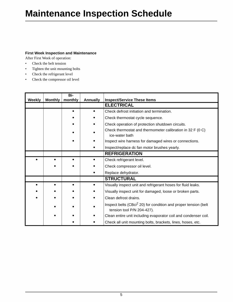
Maintenance Inspection Schedule
First Week Inspection and MaintenanceAfter First Week of operation:
• Check the belt tension
• Tighten the unit mounting bolts
• Check the refrigerant level
• Check the compressor oil level
Weekly MonthlyBi-
monthly Annually Inspect/Service These ItemsELECTRICAL
• • Check defrost initiation and termination.
• • Check thermostat cycle sequence.
• • Check operation of protection shutdown circuits.
• • Check thermostat and thermometer calibration in 32 F (0 C) ice-water bath
• • Inspect wire harness for damaged wires or connections.
• Inspect/replace dc fan motor brushes yearly.
REFRIGERATION• • • • Check refrigerant level.
• • • Check compressor oil level.
• Replace dehydrator.
STRUCTURAL• • • • Visually inspect unit and refrigerant hoses for fluid leaks.
• • • • Visually inspect unit for damaged, loose or broken parts.
• • • • Clean defrost drains.
• • • Inspect belts (CBci2 20) for condition and proper tension (belt tension tool P/N 204-427).
• • • Clean entire unit including evaporator coil and condenser coil.
• • Check all unit mounting bolts, brackets, lines, hoses, etc.

6

7
Unit Description
The Thermo King CBci truck refrigeration system is a
three-piece system consisting of a condenser, an evaporator,
and a compressor. The assemblies are separate, and the con-
denser section can be installed either in a nosemount or an
undermount position. The evaporator mounts on the inside
of the front wall of the truck body close to the ceiling. The
compressor is mounted on and driven by the truck engine.
Refrigeration hoses or lines are used to connect the con-
denser, the evaporator and the compressor. Model 20 units
have another compressor and an electric motor mounted in
the condenser section for electric standby operation.
The units are designed for low and medium temperature
applications on medium-sized trucks. There are two basic
models:
• Model 10: Cool and defrost on engine-driven compres-
sor operation.
• Model 20: Cool and defrost on both truck engine-
driven and electric standby compressor operation.
The control circuits operate on 12 or 24 Vdc supplied by the
truck batteries for over-the-road operation. On standby
operation, the power is rectified from an AC transformer.
The refrigeration system is protected by a high pressure cut-
out switch and a low pressure cutout switch.
The remote control box is normally mounted on the truck
body. It contains the On-Off switch, manual defrost switch,
thermometer, thermostat, and indicator lights. The remote
control box cover must be opened to access the thermostat.
An optional cab control box is available. It is mounted in the
truck cab and replaces the remote control box. The cab con-
trol box contains the On-Off switch, Manual Defrost switch,
thermometer, thermostat, and indicator lights. The Model 20
cab control box also has a warning light that illuminates if
the driver starts the truck engine while the electric standby
cord is still plugged into the power receptacle.
The electric standby compressor is connected in parallel
with the engine-driven compressor on the Model 20 units.
The engine compressor is driven by a belt from the engine.
The standby compressor is mounted in the condenser sec-
tion and is belt driven by an electric motor. Both compres-
sors use the same refrigeration system circuit. Check valves
isolate one compressor from the other during operation.
Compressor operation is controlled by the thermostat, start-
ing the motor on electric standby or energizing the clutch
during engine operation.
Selection of engine operation or standby operation is auto-
matic on Model 20 units. When the Model 20 unit is
plugged into standby power, engine operation is automati-
cally locked out. If the driver turns the truck on while the
power cord is still plugged into a power receptacle, the
power cord warning light (Model 20 only) comes on to
remind the driver to unplug the cord. The engine driven
compressor cannot be started until the power cord is
unplugged from the unit.
A three-way valve refrigeration system provides defrost in
the unit. An electronic defrost timer can initiate defrost
automatically. Defrost is normally terminated by the defrost
termination switch mounted on the evaporator coil, but the
defrost timer can also terminate defrost.
Liquid Injection System
If the discharge gas leaving the engine driven compressor
reaches a temperature of 230 ± 5 F (110 ± 3 C), the high
temperature switch closes, providing voltage to the liquid
injection solenoid. The solenoid opens a valve, allowing liq-
uid refrigerant to flow from the liquid line near the receiver
outlet valve to the metering orifice attached to the suction
fitting at the compressor. As the refrigerant passes through
the metering orifice it expands and evaporates, cooling the
suction gas entering the compressor. This cooling effect is
transferred to the discharge gas leaving the compressor from

Unit Description (Rev. 1/99)
8
the adjacent cavity in the compressor head. When the dis-
charge gas is cooled to 200 ± 5 F (93 ± 3 C), the high tem-
perature switch opens, the liquid injection solenoid valve
closes and refrigerant no longer flows through the liquid
injection system.
Oil Separator
An oil separator is a standard feature. It separates compres-
sor oil from refrigerant vapor and returns the oil to the com-
pressor through the oil fill hole by using a special adapter.
The oil separator helps provide positive oil return at high
compressor speeds and low operating temperatures. This
feature enhances compressor lubrication and extends com-
pressor life.
CBci MAX Features
The CBci MAX is functionally the same as CBci units, but
it uses R-404A refrigerant. This unit has a redesigned evap-
orator in order to operate more efficiently with R-404A
refrigerant. All other operating features are the same as
CBci units.
UNIT OPERATION
These units shift between cool, null, and heat (optional) to
maintain the box temperature at the thermostat setpoint. The
operating modes are: cool, null, heat (optional), and defrost.
The thermostat controls the operation of the unit by energiz-
ing and de-energizing the cool relay and the heat relay.
When the cool relay is energized, it closes contacts that
energize the fan relay and the compressor clutch (or the
compressor motor contactor on Model 20 units during elec-
tric standby operation).
When the heat relay is energized, it closes contacts that
energize the fan relay.
When the fan relay is energized, it closes contacts that ener-
gize the condenser and evaporator fans. The condenser fan
is also controlled by the condenser fan pressure switch. This
normally open switch monitors the compressor discharge
pressure. When the discharge pressure rises to 180 ± 10 psi
(1241 ± 69 kPa), the switch closes and energizes the con-
denser fan. When the discharge pressure drops to 130 ± 10
psi (896 ± 69 kPa), the switch opens and de-energizes the
condenser fan.
Cool
The thermostat energizes the cool relay at box temperatures
above setpoint when the temperature is dropping. The ther-
mostat energizes the cool relay at box temperatures more
than 2 ± 1 F (1 ± 0.5 C) above setpoint when the tempera-
ture is rising. The cool relay energizes the fan relay and the
compressor clutch (or motor contactor). The fans and the
compressor run and the unit cools.
Null
The thermostat de-energizes the cool relay and the heat
relay at box temperatures between setpoint and 2 ± 1 F (1 ±
0.5 C) below setpoint when the temperature is dropping.
The thermostat de-energizes the cool relay and the heat
relay at box temperatures between setpoint and 2 ± 1 F (1 ±
0.5 C) above setpoint when the temperature is rising. When
the cool relay and the heat relay are both de-energized, the
unit does not operate unless it is in defrost.
Heat (Optional)
NOTE: Heat lockout occurs at setpoints of 15 F (-9.5 C)and lower. Heat lockout disables Heat and replaces Heatwith Null.
The thermostat energizes the heat relay at box temperatures
more than 2 ± 1 F (1 ± 0.5 C) below setpoint when the tem-
perature is dropping. The thermostat energizes the heat
relay at box temperatures below setpoint when the tempera-
ture is rising. The heat relay energizes the fan relay, but the
compressor clutch (or motor contactor) is not energized.
Therefore, the evaporator fans run but the condenser fan

Unit Description (Rev. 1/99)
9
does not. The heat relay also energizes the optional water
pump and hot water valve, or the optional heater contactor.
Defrost
The defrost cycle can be initiated any time the evaporator
coil temperature is below 42 F (5.6 C). Defrost is initiated
automatically by the defrost timer, or manually by pressing
the Manual Defrost switch.
The defrost relay energizes the compressor clutch (or motor
contactor) and the 26 circuit to route hot refrigerant gas to
the evaporator. The defrost relay also interrupts power to the
fan relay to stop the evaporator and condenser fans during
defrost. The defrost cycle will continue until the evaporator
coil temperature rises to 52 F (11.1 C), causing the defrost
termination switch to open, which terminates the defrost
cycle. If the defrost termination switch does not open in less
than 45 minutes, the defrost timer will terminate the defrost
cycle 45 minutes after is was started.
OPERATING MODES
• Cool—Above setpoint when the temperature is drop-
ping. More than 2 ± 1 F (1 ± 0.5 C) above setpoint
when the temperature is rising.
• Null—Between setpoint and 2 ± 1 F (1 ± 0.5 C) below
setpoint when the temperature is dropping. Between
setpoint and 2 ± 1 F (1 ± 0.5 C) above setpoint when
the temperature is rising.
• Heat—More than 2 ± 1 F (1 ± 0.5 C) below setpoint
when the temperature is dropping. Below setpoint when
the temperature is rising (optional).
• Defrost—Initiated manually or automatically at evapo-
rator temperatures below 42 F (5.6 C). Terminated
when the evaporator temperature rises to 52 F (11.1 C),
or 45 minutes after initiated.
0. Setpoint1. Cool2. Null3. Heat* (Optional)*Heat lockout occurs at setpoints of
15 F (-9.5 C) or lower.
Thermostat Algorithm
AG
A301

Unit Description (Rev. 1/99)
10
UNIT FEATURES
• Digital Thermometer
• Electronic Thermostat
• Defrost Timer
• Hot Gas Defrost
• Defrost Termination Switch
• Liquid Injection System
• Manual Defrost Switch
• Receiver Tank with Outlet Service Valve
• Suction Pressure Regulator
• Oil Separator
• Compressor Powered by Truck Engine
• Three-way Valve Refrigeration System
• Accumulator Tank
• Standby Compressor (Model 20 only)
• Refrigerant Flow Controlled by Discharge Check Valve
(Model 20 only)
PROTECTION FEATURES
• Control Circuit Breaker(s):
40 amp auto reset in 12 Vdc system
• Refrigerant High Pressure Cutout
• Refrigerant Low Pressure Cutout
• Refrigerant High Pressure Relief Valve
• Power Cord Warning Light (in Optional Cab Control
Box for Model 20 only)
• Overload Relay Protection for Electric Standby Motor
(Model 20 only)
• Transformer Fuses (Model 20 only)
OPTIONAL FEATURES
• Cab Control Box
• Refrigerant R-134a
• Electric Motors (Model 20 only)
230 Volt/1 Phase/60 Hz
220 Volt/1 Phase/50 Hz
230 Volt/3 Phase/60 Hz
460 Volt/3 Phase/60 Hz
380 Volt/3 Phase/50Hz
415 Volt/3 Phase/50 Hz
• Heat, Truck Engine (Model 10)
• Heat, Truck Engine and Electric Standby Heater Strips
(Model 20)
• Paint, Special Color
SERIAL NUMBER LOCATIONS
Condenser: Roadside, top corner.
Evaporator: Roadside panel.
Compressor: Nameplate on compressor body.
Standby Motor: Nameplate on motor.
Unit Description (Rev. 1/99)
11
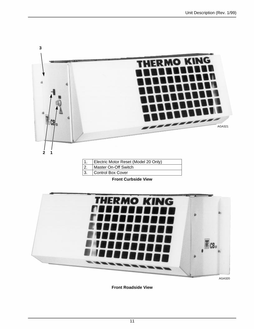
Front Roadside View
1. Electric Motor Reset (Model 20 Only)2. Master On-Off Switch3. Control Box Cover
Front Curbside View
12
3
AGA321
AGA320

Unit Description (Rev. 1/99)
12
1. Receiver Outlet Valve 5. Sight Glass2. Accumulator 6. Condenser Check Valve3. Drier 7. High Pressure Valve4. Liquid Injection Solenoid
Roadside Components
56
47
1 2
3
AGA414

Unit Description (Rev. 1/99)
13
1. Defrost Timer 6. Fan Relay2. Defrost Relay 7. Cool Relay3. Circuit Breakers 8. Heat Relay4. Terminal Board 9. Power Disconnect Relay5. Defrost Jumper (Emergency Use Only)
Model 10 Control Box Components
AGA290
1 2 3
4
5
6789

Unit Description (Rev. 1/99)
14
1. Defrost Timer 5. Terminal Board2. Defrost Relay 6. Motor Contactor3. Circuit Breakers 7. Overload Relay4. Fan Relay 8. 3-Phase Transformer
Model 20 3-Phase Control Box Components
AGA336
8
654321
7
Unit Description (Rev. 1/99)
15
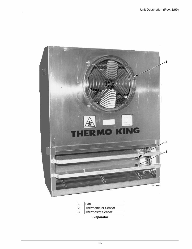
1. Fan2. Thermometer Sensor3. Thermostat Sensor
Evaporator
1
2
3
AGA358

Unit Description (Rev. 1/99)
16
1. ORS Fittings 5. Thermostat Sensor2. Heat Exchanger 6. Thermometer Sensor3. Expansion Valve 7. Evaporator Coil4. Defrost Termination Switch 8. Pan Heater
Evaporator Components
8 7 6
5
4
AGA359
3
21
1
Unit Description (Rev. 1/99)
17
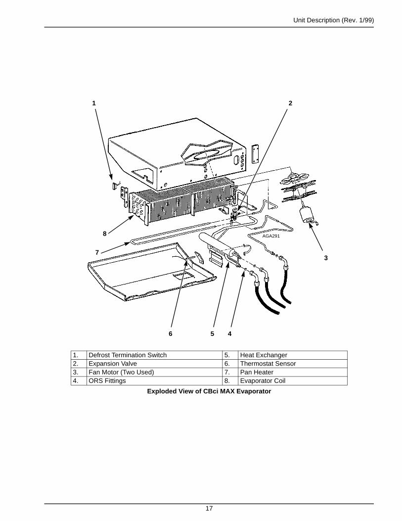
1. Defrost Termination Switch 5. Heat Exchanger2. Expansion Valve 6. Thermostat Sensor3. Fan Motor (Two Used) 7. Pan Heater4. ORS Fittings 8. Evaporator Coil
Exploded View of CBci MAX Evaporator
6 5 4
3
AGA291
21
8
7

Unit Description (Rev. 1/99)
18
1. On Light 4. Manual Defrost Switch2. On-Off Switch 5. Defrost Light3. Wing Screw 6. Thermometer
Remote Control Box
1
2
3
6
5
4
AGA416

Unit Description (Rev. 1/99)
19
1. Cool Light 5. Inner Dial2. Heat LED 6. Thermostat Module3. Thermostat Dial 7. On LED4. Outer Bezel
Inside Remote Control Box
AGA292
1
2
3
45
6
7

Unit Description (Rev. 1/99)
20
1. Defrost Timer 7. Motor Overload Relay2. Defrost Relay 8. Chokes3. Circuit Breakers 9. Clutch Relay4. Fan Relay 10. Fuse5. Terminal Board 11. Standby Relay6. Motor Contractor 12. Single Phase Transformer
Model 20 Single Phase Control Box Components
AGA327
12
11 10 9
8
7
654321

Unit Description (Rev. 1/99)
21
1. LED Display 6. Manual Defrost Switch2. Setpoint LED 7. On-Off Switch3. Power Cord LED (Model 20 Only) 8. Setpoint Switch4. On LED 9. Thermostat Dial5. Defrost LED
Cab Control BoxStandard on New Units
AGA293
1 2 3 4 5
6789

22

23
Operating Instructions
UNIT CONTROLS
Remote Control Box
1. ON-OFF SWITCH. The master On-Off switch must be
in the ON position to enable this switch. Placing this
switch in the ON position energizes the On light, the
thermometer, and the thermostat. The unit will operate
under the control of the thermostat and the defrost con-
trols. Placing this switch in the OFF position de-ener-
gizes the On light, the thermometer, and the thermostat;
the unit will not operate. If the master On-Off switch is
in the OFF position, this switch is disabled.
2. MANUAL DEFROST SWITCH. Pushing this switch
causes the unit to shift to defrost if the defrost termina-
tion switch is closed (the evaporator coil temperature is
below 42 F [5.6 C]).
3. ON LIGHT. This light comes on when both On-Off
switches are turned ON and the unit is operating.
4. DEFROST LIGHT. This light comes on when the unit
is in defrost.
5. THERMOMETER. The digital thermometer displays
the temperature of the air that is returning to the evapo-
rator from the box.
6. THERMOSTAT DIAL. The thermostat dial is located
inside the remote control box. Loosen the wing screw
to open the remote control box and access the thermo-
stat dial. The outer bezel must be held down to turn the
inner dial. The line on the inner dial indicates the ther-
mostat setpoint.
Optional Cab Control Box
1. THERMOSTAT DIAL. Turn this locking dial to change
the thermostat setpoint. Push the outer bezel down to
turn the inner knob. The setpoint switch must be
pushed to display the thermostat setpoint.
2. SETPOINT SWITCH. Pushing this switch displays the
thermostat setpoint on the LED display and causes the
setpoint LED to light up.
3. ON-OFF SWITCH. The master On-Off switch must be
in the ON position to enable this switch. Placing this
switch in the ON position energizes the On LED and
the thermostat. The unit will operate under the control
of the thermostat and the defrost controls. Placing this
switch in the OFF position de-energizes the On LED
and the thermostat. The unit will not operate. If the
master On-Off switch is OFF, this switch is disabled.
4. MANUAL DEFROST SWITCH. Pushing this switch
causes the unit to go into defrost if the defrost termina-
tion switch is closed (the evaporator coil temperature is
below 42 F [5.6 C]).
5. LED DISPLAY. The thermometer reading (sensor tem-
perature) normally appears on this display. Pushing the
Setpoint switch causes the thermostat setpoint to appear
on this display.
6. SETPOINT LED. This LED lights up when the Set-
point switch is being pushed and the setpoint appears
on the LED display.
7. POWER CORD LED (Model 20 only). This LED
lights up if the truck is turned on while a power cord for
electric standby power is connected to the unit.
8. ON LED. This LED lights up when both On-Off
switches are turned ON and the unit is operating.
9. DEFROST LED. This LED lights up when the unit is
in defrost.
Control Box
1. MASTER ON-OFF SWITCH. Placing this switch in
ON position energizes the 8 circuit that provides power
to the unit’s electrical system. Placing this switch in the
OFF position de-energizes the 8 circuit and disables the
unit’s electrical system.

Operating Instructions (Rev. 1/99)
24
2. DEFROST TIMER. This timer automatically places the
unit in defrost every 4 hours. The defrost timer also ter-
minates defrost 45 minutes after it starts if the defrost
termination switch does not open.
3. POWER RELAY. This relay supplies power to the mas-
ter On-Off switch when the truck is turned on. In Model
20 units the electric standby relay disables the power
relay when the unit is connected to electric standby
power.
4. ELECTRIC MOTOR RESET (Model 20 only). Push-
ing this button resets the electric motor overload relay
if the overload relay has opened.
5. ELECTRIC STANDBY RELAY (Model 20 only). This
relay is energized when the unit is connected to electric
standby power. When energized, this relay disables
engine-driven compressor operation and energizes the
compressor motor contactor.
6. COMPRESSOR MOTOR CONTACTOR (Model 20
only). This contactor is energized by the cool relay dur-
ing electric standby operation. When energized, this
contactor energizes the electric standby compressor
motor.
Other Controls
1. DEFROST TERMINATION SWITCH. This tempera-
ture sensitive switch is mounted on the evaporator coil
and is used to control defrost. The switch closes when
the evaporator temperature drops to 42 F (5.6 C). This
enables defrost. The switch opens when the evaporator
temperature rises to 52 F (11.1 C). This terminates
defrost if the unit is in defrost. It disables defrost if the
unit is not in defrost.
2. SUCTION PRESSURE REGULATOR VALVE. This
valve is located in the suction line and limits the suction
pressure at the compressor. The normal pressure setting
for this valve is 18 psi (124 kPa).
UNIT PROTECTION DEVICES
1. CONTROL SYSTEM CIRCUIT BREAKERS. The
control system circuit breaker is located in the unit con-
trol box. It trips if the control circuit is overloaded.
Model 20 units have a second control system circuit
breaker that protects the control circuit during electric
standby operation. 40 amp circuit breakers are installed
in 12 Vdc control systems, and 25 amp circuit breakers
are installed in 24 Vdc control systems.
2. HIGH PRESSURE CUTOUT SWITCH. The high
pressure cutout switch is a pressure sensitive switch
located in the discharge line. If the discharge pressure
rises above 300 psi (206 kPa), the switch opens the cir-
cuit to the compressor clutch and standby compressor
motor contactor to stop unit operation.
3. CONDENSER FAN PRESSURE SWITCH. The con-
denser fan pressure switch is a pressure sensitive switch
located in the discharge line. When the condenser head
pressure rises above 180 psi (1241 kPa), the condenser
fan pressure switch closes, starting the condenser fan.
When the condenser head pressure falls below 130 psi
(896 kPa), the condenser fan pressure switch opens,
stopping the condenser fan.
4. LOW PRESSURE CUTOUT SWITCH. The low pres-
sure cutout switch is a pressure sensitive switch located
in the suction line. If the suction pressure falls below 5
to 11 psi (-17 to -37 kPa), the switch opens the circuit to
the compressor clutch or the standby compressor motor
contactor to stop unit operation.
5. HIGH PRESSURE RELIEF VALVE. The high pres-
sure relief valve is designed to relieve excess pressure
within the refrigeration system. The valve is a spring-
loaded piston that lifts off its seat when refrigerant
pressure exceeds 500 psi (3447 kPa). The valve will
reset when the pressure drops to 400 psi (2758 kPa).
The valve could possibly leak refrigerant after it has
relieved excess pressure. Tapping the valve lightly may

Operating Instructions (Rev. 1/99)
25
help the valve reseat and SEAL PROPERLY. The valve
is non-repairable and requires no adjustment. If the
valve fails to reseat properly, remove the refrigerant
charge and replace the valve.
The high pressure relief valve is located on a high pres-
sure line near the condenser. Its location is such that
when the pressure is expelled from the valve, it would
be directed away from anyone servicing the unit.
6. LIQUID INJECTION TEMPERATURE SWITCH.
The liquid injection temperature switch is mounted on
the compressor discharge fitting. It activates the liquid
injection system to cool the compressor. The switch
closes at 230 F (110 C) and opens at 200 F (93 C).
7. OVERLOAD RELAY (Model 20 only). A manual reset
overload relay protects the compressor motor. The
overload relay opens the circuit from the compressor
motor contactor to the electric motor if the motor over-
loads for any reason (e.g., low line voltage or improper
power supply) while the unit is on electric standby
operation.
8. TRANSFORMER FUSES (Model 20 only). The trans-
former fuses are located in the unit control box. They
protect the transformer and rectifier from excessive
current loads.
UNIT OPERATION
Weekly Pretrip Checks
The following weekly pretrip inspection should be com-
pleted before loading the truck. While the weekly inspection
is not a substitute for regularly scheduled maintenance
inspections, it is an important part of the preventive mainte-
nance program designed to head off operating problems
before they happen.
1. LEAKS. Inspect for refrigerant leaks and worn refriger-
ant lines.
2. BELTS. Inspect for cracks, wear and proper tensions.
3. ELECTRICAL INSPECTION. The electrical connec-
tions should be securely fastened. Wires and terminals
should be free of corrosion, cracks or moisture.
4. DEFROST DRAINS. Check the defrost drain hoses
and fittings to make sure that they are open so conden-
sate can run out during defrost. Check the bottom end
of each drain hose to make sure that it is not plugged or
crushed.
5. STRUCTURAL INSPECTION. Visually check for
physical damage.
6. REFRIGERANT CHARGE. Check the receiver tank
sight glass for the proper charge level.
Starting the Unit
Model 10 Units
1. Adjust the thermostat setting.
2. Start the truck engine.
3. Make sure the master On-Off switch is in the ON
position.
4. Place the On-Off switch in the remote or cab control
box in the ON position.
Model 20 Units
Engine Operation
1. Adjust the thermostat setting.
2. Start the truck engine.
3. Make sure the master On-Off switch is in the ON
position.
4. Place the On-Off switch in the remote or cab control
box in the ON position.
NOTE: The cab control box power cord light will lightup if the power cord is plugged in and the truck’sengine is started.
Operating Instructions (Rev. 1/99)
26
Electric Standby Operation
1. Connect the external power supply to the power recep-
tacle. Make sure that the power supply voltage and
phasing is correct for the unit as required by the electri-
cal information plate located on the standby motor.
2. Adjust the thermostat setting.
3. Make sure the master On-Off switch is in the ON
position.
4. Place the On-Off switch in the remote or cab control
box in the ON position.
NOTE: The cab control box power cord light will lightup if the power cord is plugged in and the truck’sengine is started.
Adjusting the Thermostat
Remote Control Box
To check or change the thermostat setting in the remote con-
trol box:
1. Open the remote control box by loosening the wing
screw and lifting the cover. The thermostat dial (poten-
tiometer) and the thermostat module will be visible.
2. The pointer on the thermostat dial indicates the thermo-
stat setpoint.
3. The thermostat dial has a locking feature. To change the
setpoint:
a. Push the outer bezel in and hold it in with one
hand.
b. Turn the inner part of the dial to the desired set-
point with the other hand.
c. Release the outer bezel to lock the dial in position.
4. Close the remote control box cover and tighten the
wing screw.
Optional Cab Control Box
The thermometer reading (sensor temperature) normally
appears on the LED display while the unit is turned on.
Pressing the setpoint switch lights the setpoint LED and
causes the thermostat setpoint to appear on the LED display.
To check or change the thermostat setting in the cab control
box:
1. Press the setpoint switch to display the setpoint.
2. The thermostat dial has a locking feature. To change the
setpoint:
a. Push the outer bezel in and hold it in.
b. Turn the inner part of the dial until the display
shows the desired setpoint.
c. Release the outer bezel to lock the dial in position.
NOTE: It is difficult to press the setpoint switch, holdthe outer bezel in, and turn the thermostat dial all atthe same time. It may be easier to obtain the correctsetpoint by repeatedly releasing the Setpoint switch,changing the position of the thermostat dial, andpressing the Setpoint switch to recheck the setpoint.
After Start Inspection
1. THERMOSTAT. Adjust the thermostat setting above
and below the box temperature to check the thermostat
operation (see Operating Modes).
2. PRECOOLING. With the thermostat set at the correct
temperature, allow the unit to run for one-half to one
hour (longer if possible) before loading the truck. Pre-
cooling will remove residual body heat and moisture
from the box interior and provide a good test of the
refrigeration system.
3. DEFROST. When the unit has finished pre-cooling the
truck interior (the evaporator temperature has dropped
below 42 F [5.6 C]), initiate a defrost cycle with the
Manual Defrost switch. The defrost cycle should end
automatically.

Operating Instructions (Rev. 1/99)
27
Loading Procedure
1. Make sure that the unit is Off before opening the doors
to minimize frost accumulation on the evaporator coil
and heat gain in the trailer. (The unit may be running
when the truck is being loaded from a warehouse with
door seals.)
2. Spot check and record the load temperature while load-
ing. Especially note any off-temperature product.
3. Load the product so there is adequate space for air cir-
culation completely around the load. DO NOT block
the evaporator inlet or outlet.
4. Products should be precooled before loading. Thermo
King units are designed to maintain loads at the
temperature at which they are loaded. Transport
refrigeration units are not designed to pull hot loads
down to temperature.
Post Loading Procedure
1. Make sure that all the doors are closed and locked.
2. Adjust the thermostat to the desired temperature set-
point.
3. Start the unit.
4. One-half hour after loading, defrost the unit by momen-
tarily pressing the Manual Defrost switch. If the coil
temperature has dropped below 42 F (5.6 C), the unit
will defrost. The defrost cycle should stop automati-
cally.
Weekly Post Trip Checks
1. Wash the unit.
2. Check for leaks.
3. Check for loose or missing hardware.
4. Check for physical damage to the unit.

28

29
Electrical Maintenance
UNIT WIRING
Periodically inspect the unit wiring and the wire harnesses
for loose, chafed or broken wires to protect against unit mal-
functions due to open or short circuits.
REMOTE CONTROL BOX COMPONENTS
NOTE: Use a Fluke 77 or an equivalent meter for all tests.
Testing the Thermometer
Check the Thermometer Display
1. Turn the unit ON (both On-Off switches must be ON).
Note what appears on the thermometer display and
refer to the diagnosis chart to see what to check next.
a. Normal display (-40 to 199 F [-40 to 93 C])
b. Blank Display
c. Erratic Display
d.
e. 1, -00, or -55
Check Power
1. Make sure the master On-Off switch is ON.
2. Open the remote control box cover.
3. Turn the remote control box On-Off switch ON.
4. Check the voltage between the 8X circuit (+ terminal)
and the CH circuit (- terminal) on the back of the ther-
mometer. Battery voltage (12 or 24 volts) should be
present.
5. If battery voltage is not present, check:
a. The wiring, connectors, and components in the
power circuit (8X, 8, 2B, and 2A) to the battery.
b. The wiring, connectors, and ground connections in
the ground circuit (CH) to the battery.
6. If there are no faults in the power circuit or the ground
circuit, check the sensor and the sensor circuits.
7. If there are no faults in the sensor or the sensor circuits,
recheck the thermometer display. If the thermometer
display has not changed, the thermometer is defective
and must be replaced.
Thermometer Display Diagnosis Chart
TemperatureDisplay
Normal Display No Problem
Blank Display1. Check Power2. Check Sensor and Sensor Circuits3. Check for Reversed Red and Black Wires
Erratic Display1. Check Power2. Check Sensor and Sensor Circuits
⊥ Check Sensor and Sensor Circuits
1, -00, or -55 Check Sensor and Sensor Circuits
⊥

Electrical Maintenance (Rev. 1/99)
30
Check Sensor and Sensor Circuits
1. Turn the unit ON (both On-Off switches must be turned
ON).
2. Check the power to the thermometer (see Check
Power).
3. Disconnect the thermometer sensor harness from the
thermometer sensor wires (3 pin connector).
4. Check the voltage between the positive SN3 circuit (red
wire - pin C) and the negative SN1 circuit (black wire -
pin A) in the 3 pin connector on the thermometer sensor
wires. The voltage should be 5.0 ± 0.5 volts.
5. If the voltage is not correct, the thermometer is defec-
tive and must be replaced.
6. If the voltage is correct, check the wiring and connec-
tors in the SN1, SN2, and SN3 circuits to the sensor.
If there are no faults in the SN1, SN2, and SN3 circuits,
reconnect all sensor circuit connectors and recheck the
thermometer display. The black, white and red wires in
the thermometer lead must match the black, white, and
red wires in the sensor lead.
If the thermometer display has not changed, attach a
new sensor and check the thermometer display.
a. If the thermometer display is now normal the old
sensor is defective.
b. If the thermometer display is not normal, the ther-
mometer is defective and must be replaced.
Faulty Thermometer
Before replacing the thermometer, make sure that another
problem, such as a loose wire connection or a bad ground, is
not causing the thermometer to malfunction.
Thermometer Calibration Test
1. Place the sensor in an ice-water bath for a few minutes
and allow the sensor temperature to stabilize. Stir the
ice-water bath occasionally to keep the temperature sta-
ble.
2. Check the thermometer reading. It should be 32 ± 1.8 F
(0 ± 1 C).
3. If the thermometer reading is out of calibration, replace
the sensor and repeat the test.
4. If the thermometer reading is still out of calibration, the
thermometer is defective.
Testing the Thermostat
Check Power
1. Make sure the master On-Off switch is ON.
2. Open the remote control box cover.
3. Turn the remote control box On-Off switch ON. The
thermostat’s On LED should light up.
4. Check the voltage between the 8X circuit (T12 termi-
nal) and the CH circuit (T13 terminal) on the front of
the thermostat. Battery voltage (12 or 24 volts) should
be present.
5. If battery voltage is not present, check:
a. The wiring, connectors, and components in the
power circuit (8X, 8, 2B, 2A, and 2) to the battery).
b. The wiring, connectors, and ground connections in
the ground circuit (CH) to the battery.
6. If battery voltage is present and the thermostat’s On
LED is not lit, the thermostat is defective.
Check the Sensor Output
1. Turn the unit ON (both On-Off switches must be turned
ON).
Electrical Maintenance (Rev. 1/99)
31
2. Check the power to the thermostat (see Check Power).
3. Turn the On-Off switch OFF and disconnect the sensor
wires from the thermostat (wires SN4, SN5, and SN6
from thermostat terminals T11, T10, and T9, respec-
tively).
4. Check the voltage between the positive SN6 circuit
(terminal T9) and the negative SN4 circuit (terminal
T11) on the thermostat. The voltage should be 5.0 ±
0.5 volts.
If the voltage is not in this range, the thermostat is
defective.
Check the Thermostat Sensor
1. Turn the unit ON (both On-Off switches must be turned
ON).
2. Check the thermometer display. Make sure that the
thermometer is operating properly and note the reading.
3. Disconnect the thermometer sensor and the thermostat
sensor from the evaporator harness (three pin connector
in the evaporator). Connect the thermostat sensor to the
thermometer section of the evaporator harness (wires
SN1, SN2, and SN3).
4. Check the thermometer display now that the thermostat
sensor is attached to the thermometer section of the
evaporator harness. The thermometer should display a
reading approximately equal to the reading observed in
step 2. If not, the thermostat sensor is defective.
Check the Thermostat Sensor Harness and Sensor Assembly
1. Turn the unit ON (both On-Off switches must be turned
ON).
2. Check the thermometer display. Make sure that the
thermometer is operating properly and note the reading.
3. Disconnect the thermometer sensor harness from the
thermometer sensor wires (3 pin connector).
4. Disconnect the thermostat sensor harness from the ther-
mostat (wires SN4, SN5, and SN6 from terminals T11,
T10, and T9, respectively).
5. Connect the thermostat sensor harness wires to the ther-
mometer sensor wires. Connect wire SN4 to SN1 (red),
connect SN5 to SN2 (white), and connect SN6 to SN3
(black).
6. Check the thermometer display now that the thermostat
sensor harness is attached to the thermometer wires.
The thermometer should display a reading approxi-
mately equal to the reading observed in step 2. If not,
the thermostat sensor harness or the thermostat sensor
is defective.
Check the Potentiometer Circuit
1. Turn the unit ON (both On-Off switches must be turned
ON).
2. Check the power to the thermostat (see Check Power).
3. Check the voltage between the positive T1 circuit
(black wire - T1 terminal) and the negative T3 circuit
(red wire - T3 terminal) on the thermostat. The voltage
should be 0.80 ± 0.10 volts. If the voltage is not in this
range, the thermostat is defective.
4. Check the voltage between the positive T1 circuit
(black wire - T1 terminal) and the setpoint input T2 cir-
cuit (white wire - T2 terminal) while turning the ther-
mostat dial (potentiometer) back and forth. The voltage
should increase to 0.80 volts and decrease to 0 volts as
the dial is turned back and forth. If not, the potentiome-
ter is defective.
5. Check the voltage between the negative T3 circuit (red
wire - T3 terminal) and the setpoint input T2 circuit
(white wire - T2 terminal) while turning the thermostat
dial (potentiometer) back and forth. The voltage should
increase to 0.80 volts and decrease to 0 volts as the dial
is turned back and forth. If not, the potentiometer is
defective.

Electrical Maintenance (Rev. 1/99)
32
Thermostat Switch Sequence Test
The switch sequence test should be performed during
scheduled preventive maintenance operations.
NOTE: The following temperature tolerances are for tem-peratures at or near 32 F (0 C) and may be greater nearthe extremes of the setpoint range.
1. Start the unit and set the thermostat setpoint 8 to 10 F
(4.4 to 5.6 C) below the thermometer reading. The Cool
LED should be lit, the cool relay should be energized,
the Heat LED should not be lit, the heat relay should be
de-energized, and the unit should operate in cool.
2. Slowly turn the thermostat dial up to raise the thermo-
stat setpoint about 2 F (1.1 C) every 5 seconds. When
the thermostat setpoint reaches the thermometer read-
ing ± 1 F (0.6 C), the unit should shift to null. The Cool
LED should go out and the Heat LED should not be lit.
The cool relay and the heat relay should both be de-
energized.
3. Continue to slowly turn the thermostat dial up and raise
the thermostat setpoint about 2 F (1.1 C) every 5 sec-
onds. When the thermostat setpoint reaches 2 ± 1 F
(1.1 ± 0.6 C) above the thermometer reading, the unit
should shift to Heat (optional). The Heat LED should
light up and the Cool LED should not be lit. The heat
relay should be energized and the cool relay should be
de-energized.
4. Slowly turn the thermostat dial down to lower the ther-
mostat setpoint about 2 F (1.1 C) every 5 seconds.
When the thermostat setpoint reaches the thermometer
reading ± 1 F (0.6 C), the unit should shift to null. The
Heat LED should go out and the Cool LED should not
be lit. The cool relay and the heat relay should both be
de-energized.
5. Continue to slowly turn the thermostat dial down and
lower the thermostat setpoint about 2 F (1.1 C) every
5 seconds. When the thermostat setpoint reaches 2 ±
1 F (1.1 ± 0.6 C) below the thermometer reading, the
unit should shift to cool. The Cool LED should light up
and the Heat LED should not be lit. The cool relay
should be energized and the heat relay should be de-
energized.
If the unit does not shift operating modes properly, make
sure that the cool relay, the heat relay, the associated wiring,
and the wire connections are not defective before assuming
that the thermostat is faulty. Specifically:
1. Battery voltage must be present on wire 8X (T12 termi-
nal), and wire CH (T13 terminal) must be grounded at
the thermostat when the unit is turned on.
2. Terminals T5, T7, and T13 must have continuity to
each other and to the CH circuit (chassis ground).
3. The thermostat energizes the cool relay, which shifts
the unit to Cool, by sending a 12 or 24 volt signal from
the CR circuit (T8 terminal) to pin 85 of the cool relay
coil.
4. The thermostat energizes the heat relay, which shifts
the unit to heat (optional), by sending a 12 or 24 volt
signal from the HR circuit (T6 terminal) to pin 85 of the
heat relay coil.
Therefore, the thermostat is not defective if it sends a
voltage signal (12 or 24 volts) to the CR and HR circuits
properly.
Thermostat Calibration Procedure
1. Set the thermostat at 32 F (0 C).
2. Start the unit and let it run until it shifts from cool to
null.

Electrical Maintenance (Rev. 1/99)
33
CAB CONTROL BOX COMPONENTS (OPTIONAL)
Temperature Control Module (TCM)
The TCM is located in the cab control box. The TCM con-
tains the thermometer and the thermostat. The thermometer
and the thermostat share the same digital LED display and
use the same sensor.
1. Thermometer2. Potentiometer3. Thermostat4. Locking Thermostat Dial
Remote Control Box Components
1
3
4
2
AGA295
3. Use a known good thermometer (or a 32 F [0 C] ice-
water bath) to check the switch points. The unit should
shift from cool to null at 32 F (0 C).
4. If the unit shifts modes properly and is out of calibra-
tion by less than 5 F (2.7 C), recalibrate the thermostat
by loosening the set screw and repositioning the ther-
mostat dial.
If the thermostat shifts modes erratically or is out of
calibration by more than 5 F (2.7 C), at least one of the
thermostat components is faulty. Test the thermostat
components and make the needed repairs before cali-
brating the thermostat.

Electrical Maintenance (Rev. 1/99)
34
Digital Thermometer
The range for the thermometer is -40 to 199 F (-40 to 93 C).
Normally the thermometer reading appears on the LED dis-
play. Pressing the Setpoint switch causes the thermostat set-
point to appear on the LED display.
Thermostat
The setpoint range for the thermostat is 0 to 80 F (-18 to
30 C). The thermostat setpoint appears on the LED display
when the Setpoint switch is pressed. Turning the dial under
the LED display changes the setpoint. The thermostat con-
trols the operation of the unit by controlling the cool and
heat relays
Initial TCM Display Test
1. Turn the unit ON (both On-Off switches must be ON).
Note what appears on the LED display. This is the tem-
perature display.
a. Normal display (-40 to 199 F [-40 to 93 C])
TCM Display Diagnosis Chart
Setpoint Display
Normal Display Blank Display Erratic Display No Change
TemperatureDisplay
Normal Display No Problem Faulty TCM Faulty TCM Faulty TCM
Blank DisplayCheck Sensor & Sensor Circuits
Check Power Check Power Check Power
Erratic DisplayCheck Sensor & Sensor Circuits
Check Power Check Power Check Power
⊥ Check Sensor & Sensor Circuits
Faulty TCM Faulty TCM Faulty TCM
1, -00, or -55 Check Sensor & Sensor Circuits
Faulty TCM Faulty TCM Faulty TCM
b. Blank Display
c. Erratic Display
d.
e. 1, -00, or -55
2. Press the Setpoint switch and note what appears on the
LED display. This is the setpoint display.
a. Normal Display (0 to 80 F[-18 to 30 C])
b. Blank Display
c. Erratic Display
d. No Change
3. Refer to the TCM Display Diagnosis Chart to see what
to check next.⊥

Electrical Maintenance (Rev. 1/99)
35
Check Power
1. Make sure the master On-Off switch is ON.
2. Disconnect the 14 pin connector (cab control box
extension harness) from the back of the cab control
box.
3. Check the voltage between the 8 circuit (pin 8) and the
CH circuit (pin 13) in the 14 pin connector on the cab
control box extension harness. Battery voltage (12 or
24 volts) should be present.
4. If battery voltage is not present, check:
a. The wiring, connectors and components in the
power circuit (8, 2B, and 2A) to the battery.
b. The wiring, connectors, and ground connections in
the ground circuit (CH) to the battery.
5. If there are no faults in the power circuit or the ground
circuit, repeat the Initial TCM Display Test. If the
results of the test have not changed, the TCM is defec-
tive and must be replaced.
Check Sensor and Sensor Circuits
1. Turn the unit ON (both On-Off switches must be turned
ON).
2. Disconnect the sensor from the evaporator wire harness
(three pin connector).
3. Check the voltage between the positive SN3 circuit (pin
C) and the negative SN1 circuit (pin A) in the three pin
connector on the evaporator harness. The voltage
should be 5.0 ± 0.5 volts.
4. If the voltage is not correct, check the wiring and con-
nectors in the SN1, SN2, and SN3 circuits back to the
cab control box.
If there are no faults in the SN1, SN2, and SN3 circuits,
repeat the Initial TCM Display Test. If the results of the
test have not changed, the TCM is defective and must
be replaced.
5. If the voltage is correct, attach a new sensor and check
the thermometer display.
a. If the thermometer display is now normal, the old
sensor is defective.
b. If the thermometer display is not normal, check the
wiring and connectors in the SN2 circuit.
If there are no faults in the SN2 circuit, repeat the
Initial TCM Display Test. If the results of the test
have not changed, the TCM is defective and must
be replaced.
Faulty TCM
Before replacing the TCM make sure that another problem,
such as a loose wire connection or a bad ground, is not caus-
ing the TCM to malfunction.
Thermometer Calibration Test
1. Place the sensor in an ice-water bath for a few minutes
and allow the sensor temperature to stabilize.
2. Check the thermometer reading. It should be 32 ± 1.8 F
(0 ± 1 C).
3. If the thermometer reading is out of calibration, replace
the sensor and repeat the test.
4. If the thermometer reading is still out of calibration, the
TCM is defective.
Thermostat Switch Sequence Test
This test should be performed during scheduled preventive
maintenance operations. Make sure that the thermometer is
calibrated before performing this test.

Electrical Maintenance (Rev. 1/99)
36
NOTE: Press the Setpoint switch to display the thermostatsetpoint.
1. Start the unit and set the thermostat setpoint 8 to 10 F
(4.4 to 5.6 C) below the thermometer reading. The cool
relay should be energized, the heat relay should be de-
energized, and the unit should operate in cool.
2. Slowly turn the thermostat dial up to raise the thermo-
stat setpoint about 2 F (1.1 C) every 5 seconds. When
the thermostat setpoint reaches the thermometer read-
ing ± 1 F (± 0.6 C), the unit should shift to null. The
cool relay and the heat relay should both be de-ener-
gized.
3. Continue to slowly turn the thermostat dial up and raise
the thermostat setpoint about 20 F (1.1 C) every 5
seconds. When the thermostat setpoint reaches 2 ± 1 F
(1.1 ± 0.6 C) above the thermometer reading, the unit
should shift to heat (optional). The heat relay should be
energized and the cool relay should be de-energized.
4. Slowly turn the thermostat dial down to lower the ther-
mostat setpoint about 20 F (1.1 C) every 5 seconds.
When the thermostat setpoint reaches the thermometer
reading ± 1.0 F (± 0.6 C), the unit should shift to null.
The cool relay and the heat relay should both be
de-energized.
5. Continue to slowly turn the thermostat dial down and
lower the thermostat setpoint about 2 F (1.1 C) every
5 seconds. When the thermostat setpoint reaches 2 ±
1 F (1.1 ± 0.6 C) below the thermometer reading, the
unit should shift to cool. The cool relay should be
energized and the heat relay should be de-energized.
If the unit does not shift operating modes properly, make
sure that the cool relay, the heat relay, the associated wiring,
and the wire connections are not defective before assuming
that the TCM is faulty. Specifically:
1. Battery voltage must be present on wire CR1 (pin 5)
and wire HR1 (pin 7) in the 14 pin connector on the cab
control box wire harness when the unit is turned on.
2. The thermostat energizes the cool relay, which shifts
the unit to cool, by closing internal contacts that con-
nect the CR1 circuit to the CR circuit.
3. The thermostat energizes the heat relay, which shifts
the unit to heat (optional), by closing internal contacts
that connect the HR1 circuit to the 11R circuit.
Therefore, the TCM is not defective if it energizes the CR
and HR circuits properly.
Thermostat Calibration Procedure
1. Set the thermostat at 32 F (0 C).
2. Start the unit and let it run until it shifts from cool to
null.
3. Use a known good thermometer (or a 32 F [0 C] ice-
water bath) to check the switch points. The unit should
shift from cool to null at 32 F (0 C).
4. If the units shifts modes properly and is out of calibra-
tion by less than 5 F (2.7 C), recalibrate the thermostat
by loosening the set screw and repositioning the ther-
mostat dial.
If the thermostat shifts modes erratically or is out of calibra-
tion by more than 5 F (2.7 C), at least one of the thermostat
components is faulty. Test the thermostat components and
make the needed repairs before calibrating the thermostat.
DEFROST SYSTEM
Engine Operation
A defrost cycle can be initiated by pressing the manual
defrost switch or by the defrost timer when the defrost ter-
mination switch is closed. Starting a defrost cycle energizes
the defrost relay and the 26 circuit, and de-energizes the fan
relay, which stops the evaporator and condenser fans.
Energizing the 26 circuit diverts hot gas into the evaporator
coil, melting the ice. The defrost termination switch de-
energizes the defrost relay when the evaporator temperature
rises above 52 F (11.1 C).
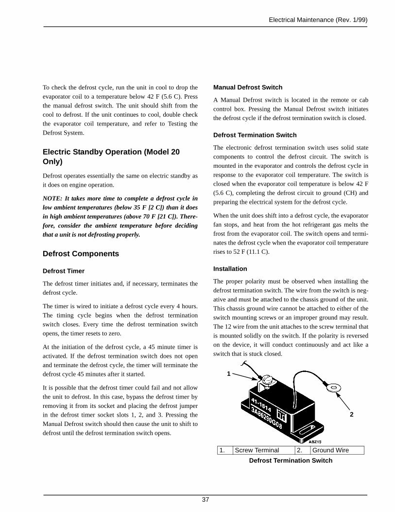
Electrical Maintenance (Rev. 1/99)
37
To check the defrost cycle, run the unit in cool to drop the
evaporator coil to a temperature below 42 F (5.6 C). Press
the manual defrost switch. The unit should shift from the
cool to defrost. If the unit continues to cool, double check
the evaporator coil temperature, and refer to Testing the
Defrost System.
Electric Standby Operation (Model 20 Only)
Defrost operates essentially the same on electric standby as
it does on engine operation.
NOTE: It takes more time to complete a defrost cycle inlow ambient temperatures (below 35 F [2 C]) than it doesin high ambient temperatures (above 70 F [21 C]). There-fore, consider the ambient temperature before decidingthat a unit is not defrosting properly.
Defrost Components
Defrost Timer
The defrost timer initiates and, if necessary, terminates the
defrost cycle.
The timer is wired to initiate a defrost cycle every 4 hours.
The timing cycle begins when the defrost termination
switch closes. Every time the defrost termination switch
opens, the timer resets to zero.
At the initiation of the defrost cycle, a 45 minute timer is
activated. If the defrost termination switch does not open
and terminate the defrost cycle, the timer will terminate the
defrost cycle 45 minutes after it started.
It is possible that the defrost timer could fail and not allow
the unit to defrost. In this case, bypass the defrost timer by
removing it from its socket and placing the defrost jumper
in the defrost timer socket slots 1, 2, and 3. Pressing the
Manual Defrost switch should then cause the unit to shift to
defrost until the defrost termination switch opens.
Manual Defrost Switch
A Manual Defrost switch is located in the remote or cab
control box. Pressing the Manual Defrost switch initiates
the defrost cycle if the defrost termination switch is closed.
Defrost Termination Switch
The electronic defrost termination switch uses solid state
components to control the defrost circuit. The switch is
mounted in the evaporator and controls the defrost cycle in
response to the evaporator coil temperature. The switch is
closed when the evaporator coil temperature is below 42 F
(5.6 C), completing the defrost circuit to ground (CH) and
preparing the electrical system for the defrost cycle.
When the unit does shift into a defrost cycle, the evaporator
fan stops, and heat from the hot refrigerant gas melts the
frost from the evaporator coil. The switch opens and termi-
nates the defrost cycle when the evaporator coil temperature
rises to 52 F (11.1 C).
Installation
The proper polarity must be observed when installing the
defrost termination switch. The wire from the switch is neg-
ative and must be attached to the chassis ground of the unit.
This chassis ground wire cannot be attached to either of the
switch mounting screws or an improper ground may result.
The 12 wire from the unit attaches to the screw terminal that
is mounted solidly on the switch. If the polarity is reversed
on the device, it will conduct continuously and act like a
switch that is stuck closed.
1. Screw Terminal 2. Ground Wire
Defrost Termination Switch
2
1

Electrical Maintenance (Rev. 1/99)
38
Defrost Termination Switch Bench Test
1. Connect a test light between the screw terminal on the
switch and the positive battery terminal.
NOTE: Attempting to test the electronic defrost termi-nation switch with an ohmmeter is generally not satis-factory because of the low voltage available at themeter leads.
2. Connect the ground wire of the switch to the negative
battery terminal.
3. Raise the temperature of the defrost termination switch
above 52 F (11.1 C). The light should be off, indicating
an open switch.
4. Cool the defrost termination switch below 42 F (5.6 C).
The light should come on, indicating the switch has
closed.
NOTE: Allow adequate time for the temperaturechange to saturate the defrost termination switchbefore performing the test.
Defrost Relay
The defrost relay controls the operation of the defrost cycle.
When the defrost timer or the Manual Defrost switch com-
pletes the circuit through the defrost termination switch to
ground, the defrost relay is energized. This energizes the 26
circuit and de-energizes the fan relay. The defrost relay
stays energized until the defrost cycle is terminated by the
defrost termination switch or the automatic defrost timer.
Pilot Solenoid
The pilot solenoid is an electrical valve that controls the
operation of the three-way valve in the refrigeration system.
The pilot solenoid is energized by the 26 circuit. When the
pilot solenoid coil is energized, it lifts the pilot solenoid
valve piston and allows refrigerant pressure to shift the
three-way valve. This routes hot refrigerant gas to the evap-
orator.
Testing the Defrost System
To test the defrost system, run the unit on Cool until the
evaporator coil temperature is below 42 F (5.6 C) and press
the Manual Defrost switch.
If the unit shifts to defrost momentarily but shifts out of
defrost when the switch is released, check the defrost timer.
If the unit will not shift to defrost, or if the defrost cycle will
not terminate, see the following defrost checkout procedure.
CAUTION: Do not forget to remove the jumperwires from the unit after checking or testing unit
components.
Unit Does Not Defrost
1. Check the evaporator temperature:
Make sure that the evaporator temperature is actually
below 42 F (5.6 C) if the unit will not defrost. Use a test
thermometer to check the evaporator temperature.
2. Check the defrost termination switch:
If the unit fails to defrost, place a jumper wire between
the 12 wire at the screw terminal on the defrost termi-
nation switch and a good ground. Press the Manual
Defrost switch.
If the unit shifts to defrost, the defrost termination
switch is defective.
If the unit does not shift to defrost, check for an open
circuit in the 12 circuit that goes back to the Manual
Defrost switch. If the 12 circuit is not open, go to
step 3.
3. Check the Manual Defrost switch:
Place a jumper wire between a good ground (CH) and
the 11 wire in the four pin connector that connects the
control relay harness to the main wire harness. This
connector is located inside the unit control box.

Electrical Maintenance (Rev. 1/99)
39
If the unit shifts to defrost immediately, check for an
open circuit in the 11 circuit that goes back to the
Manual Defrost switch. If the 11 circuit is not open, the
Manual Defrost switch is defective.
If the unit does not shift to defrost, go to step 4.
4. Check the defrost timer:
Remove the defrost timer from its socket and insert the
defrost jumper into socket slots 1, 2, and 3. Press the
Manual Defrost switch.
If the unit shifts to defrost, the defrost timer is
defective.
If the unit does not shift to defrost, go to step 5.
5. Place a jumper wire between a good ground and the
11A wire at the defrost relay socket (B terminal).
If the unit shifts to defrost, check for an open circuit in
the 11A circuit between the defrost timer socket and the
four pin connector that connects the control relay har-
ness to the main wire harness.
If the unit does not shift to defrost, check for battery
voltage on the 8 wire at the defrost relay socket (A ter-
minal).
If battery voltage is present on the 8 wire, the defrost
relay is defective.
If battery voltage is not present, check for an open cir-
cuit in the 8 circuit between the defrost relay socket and
the terminal board.
Unit Will Not Terminate Defrost
NOTE: The defrost timer should automatically terminatethe defrost cycle 45 minutes after it is initiated.
Unit Sticks in Defrost Indefinitely
1. Check the defrost timer:
If the unit has been stuck in defrost for more than 45
minutes, remove the defrost timer from its socket.
If the unit shifts out of defrost, the defrost timer is
defective.
If the unit remains in defrost, go to step 2.
2. Remove the defrost relay from its socket and check the
11A wire (slot B in the defrost relay socket) for conti-
nuity to ground.
If the 11A wire is not grounded, the defrost relay is
defective.
If the 11A wire is grounded, find and repair the short to
ground.
Unit Continually Fails to Terminate Defrost (In Less than 45 Minutes)
If the unit continually fails to complete the defrost cycle in
less than 45 minutes and cycles between cool and defrost,
check the evaporator coil temperature, three-way valve seal,
refrigerant charge, defrost termination switch, and the 11
and 12 wires.
1. Check the Evaporator Temperature:
Be sure the evaporator temperature is actually above 52
F (11.1 C) if the unit will not terminate defrost. Use a
test thermometer to check the temperature. If the evap-
orator temperature does not rise enough to bring the
unit out of defrost, the unit may be low on refrigerant,
or the condenser seal in the three-way valve may be
leaking.
To check the three-way valve or the condenser check
valve, refer to the procedures described in TK 5984,
Diagnosing the Thermo King Refrigeration System.
To check the refrigerant charge, refer to Refrigerant
Charge in the Refrigeration Maintenance chapter.

Electrical Maintenance (Rev. 1/99)
40
2. Check the operation of the defrost termination switch.
If the unit will not come out of defrost, disconnect the
12 wire from the defrost termination switch. If the unit
shifts back to cool, the defrost termination switch is not
opening and should be replaced. If the unit remains in
defrost, move to step 3.
3. Check the 11 and 12 wires for a ground:
If the unit remains in defrost, use an ohmmeter to check
the 11 and 12 wires for a ground. If the 11 or 12 wire is
grounded, find the grounded portion and repair it.
Defrost Timer
The defrost timer both initiates and terminates the defrost
cycle.
First, the timer will initiate a defrost cycle at 4, 8, or 12 hour
intervals. The jumper between the 7 terminal and the 5, 8 or
9 terminal of the timer socket determines the time interval.
The timing cycle begins when the defrost termination
switch closes. If the defrost termination switch opens during
the timing cycle, the timer will reset at zero when the
defrost termination switch closes.
Second, the defrost timer will terminate the defrost cycle
after 45 minutes if the defrost termination switch has not
opened.
1. Test Terminal
Defrost Timer
1
AEA502
Temporary Defrost Timer Bypass Procedure
If the timer fails and a replacement is not available, bypass-
ing the timer will allow the manual defrost switch to pro-
vide defrost control.
Bypass Procedure
1. Remove the defrost timer from its socket.
2. Remove the defrost jumper from the bottom of the ter-
minal board. Insert the defrost jumper into slots 1, 2,
and 3 in the defrost timer socket.
3. To install a new timer, remove the defrost jumper from
the defrost timer socket and insert the new defrost
timer. Place the defrost jumper back on the bottom of
the terminal board.
Defrost Timer Test
1. With the defrost termination switch open, press the
Manual Defrost switch. The unit should not go into
defrost.
2. Connect the screw terminal on the defrost termination
thermostat (12 circuit) to CH. Press the Manual Defrost
switch. The unit should go into defrost. Disconnect the
CH circuit from the 12 circuit. The defrost relay should
open.
3. Connect the jumper from the timer test terminal to
ground. Reconnect the CH circuit to the 12 circuit, and
then press the manual defrost switch. The unit should
go into defrost for about 10 seconds, and then terminate
defrost even though the 12 circuit is still connected to
CH.
Cycle Interval Test Duration
4 hours 1 minute
8 hours 2 minutes
12 hours 3 minutes

Electrical Maintenance (Rev. 1/99)
41
2. Attach a test lead to the B terminal and to the negative
terminal of the power source.
3. Attach a test lead to the 6 terminal and to the negative
terminal of the power source.
4. Connect a test light between the A terminal and the #1
terminal.
5. Attach a test lead to the 7 terminal and to the 5, 8, or 9
terminal. The terminal selected will determine the off
time of the test.
a. 5—4-hour selection Approx. 1 minute
b. 8—8-hour selection Approx. 2 minutes
c. 9—12-hour selection Approx. 3 minutes
4. Approximately 1 to 3 minutes after the timer termi-
nated defrost, the defrost cycle should reinitiate for
another brief period of time. This On-Off cycle should
repeat until the 12 circuit opens.
5. If the defrost timer fails to function properly, replace
the defrost timer.
Defrost Timer Bench Test
The defrost timer may be removed from the unit and bench
tested. Use the drawing to identify the terminals used to per-
form the bench test. Obtain a 12 volt battery or a 12 Vdc
power supply, some test leads, and a test light.
1. Attach a test lead to the test terminal and to the negative
terminal of the power source.
1. Test Light From Note 4 Above 6. Test Lead From Note 5 Above2. Test Lead From Note 3 Above 7. Test Lead From Note 1 Above3. Test Lead From Note 2 Above 8. Battery Positive Terminal4. Battery Negative Terminal 9. Test Lead From Note 7 Above5. Timer Test Terminal
Defrost Timer Bench Test
AGA311
1
2
34
5678
9
Electrical Maintenance (Rev. 1/99)
42
6. Attach a test lead to the A terminal and to the positive
terminal of the power source.
7. Attach a test lead to the 4 terminal and to the positive
terminal of the power source.
8. The test light should come on for approximately 10 sec-
onds. This is the speed-up mode of the 45 minute maxi-
mum defrost interval.
9. The test light should then turn off for approximately 1
to 3 minutes depending on which terminal 7 is con-
nected to. This is the speed-up mode of the interval
between defrost cycles.
10. A good timer will alternate between 10 second “on”
time and the 1 to 3 minute “off” time until the 6 termi-
nal is disconnected from the negative terminal of the
power source. Replace the timer if it fails to function
properly.
CIRCUIT BREAKERS
Units with 12 volt systems use 40 amp circuit breakers.
Units with 24 volt systems use 25 amp circuit breakers.
CB2
This auto reset circuit breaker is located in the unit control
box. Electrically it is located between the 2 circuit and the
2A circuit. It protects the unit control circuits during truck
engine operation.
If CB2 opens, check the unit for a grounded wire, a defec-
tive solenoid, a defective relay, or a defective fan motor.
CB1 (Model 20 Only)
This auto reset circuit breaker is located in the unit control
box. Electrically it is located between the 2R circuit and the
2B circuit. It protects the unit control circuits during electric
standby operation.
If CBI opens, check the unit for a grounded wire, a defec-
tive solenoid, a defective relay, or a defective fan motor.
CONDENSER FAN PRESSURE SWITCH (CFPS)
The CFPS is located in the discharge line. Electrically it is
located between the J circuit and the CH circuit. It closes to
energize the condenser fan when the head pressure rises to
180 ± 10 psi (1241 ± 69 kPa). It opens to de-energize the
condenser fan when the head pressure drops to 130 ± 10 psi
(896 ± 69 kPa). To check the CFPS:
1. Install a manifold gauge set.
2. Connect a voltmeter between the J circuit and the CH
circuit where the CFPS wires are connected to the main
wire harness.
3. Run the unit on cool, check the voltmeter reading, and
watch the condenser fan.
a. When the head pressure is below 180 ± 10 psi
(1241 ± 69 kPa), the CFPS should be open, the
voltmeter should indicate battery voltage, and the
condenser fan should not be running.
If the voltage is low and the condenser fan is run-
ning, the CFPS is defective.
If the voltage is low and the condenser fan is not
running, check the power circuit (J, CF, and 8)
back through the condenser fan motor and the fan
relay to the battery. Also check the ground circuit
(CH) back to the battery.
b. When the head pressure rises above 180 ± 10 psi
(1241 ± 69 kPa), the CFPS should close, the volt-
meter should indicate a very low voltage, and the
condenser fan should be running.
c. When the head pressure drops below 130 ± 10 psi
(896 ± 69 kPa), the CFPS should open, the voltme-
ter should indicate battery voltage, and the con-
denser fan should not be running.
If the CFPS does not open or close at the proper pres-
sures, it is defective and must be replaced.
Electrical Maintenance (Rev. 1/99)
43
ELECTRIC STANDBY CIRCUITS (Model 20 Only)
Make sure the unit is connected to the proper power source.
The current draw through the compressor motor should not
exceed the full load current listed in the Specifications.
The DC current draw through the 2B wire should not
exceed 35 amps in 12 volt systems and 22 amps in 24 volt
systems.
If the DC current is excessive, check the current draw
through each fan motor. The current draw through an indi-
vidual fan motor should not exceed the full load current
listed in the Specifications.
If the fan motor currents are satisfactory, check the control
relays and switches for shorts.
When the unit is inoperative, follow a systematic checking
sequence. This will save time and eliminate guesswork.
Check the power cable receptacle for power. If power is
present, check for power at the unit terminal board.
Check for control circuit power at the circuit breaker.
If the contactor is pulled down but the compressor motor
fails to start, the trouble is probably in the compressor motor
assembly.
12 Volt System, Three Phase Electric Standby
The DC voltage should be 12 to 15 volts and the current
through the 2B wire should be less than 35 amps. If the cur-
rent is less than 35 amps and the voltage is less than 12
volts:
1. Check the AC line voltage and the transformer fuses.
The line voltage must be at least 90% of the voltage
specified for the unit. If the AC line voltage is accept-
able and the transformer fuses are intact, go to step 2.
2. Measure the transformer output voltage (AC) at the ter-
minal board. Measure the voltage between wires A and
B, between wires B and C, and between wires A and C.
The voltage reading at each pair of wires should be
equal to (within 10%) the voltage readings at the other
pairs of wires. If not the transformer is defective. If the
transformer output voltage is acceptable, go to step 3.
3. Check the rectifier output voltage (DC) on the 2R wires
at CB1. If this voltage is less than 12 Vdc and the load
is not excessive (less than 35 amps) the rectifier is
defective.
24 Volt System, Three Phase Electric Standby
The DC voltage should be 24 to 30 volts and the current
through the 2B wire should be less than 22 amps. If the cur-
rent is less than 22 amps and the voltage is less than 24
volts:
1. Check the AC line voltage and the transformer fuses.
The line voltage must be at least 90% of the voltage
specified for the unit. If the AC line voltage is accept-
able and the transformer fuses are intact, go to step 2.
2. Measure the transformer output voltage (AC) at the ter-
minal board. Measure the voltage between wires A and
B, between wires B and C, and between wires A and C.
The voltage reading at each pair of wires should be
equal to (within 10%) the voltage readings at the other
pairs of wires. If not, the transformer is defective. If the
transformer output voltage is acceptable, go to step 3.
3. Check the rectifier output voltage (DC) on the 2R wires
at CB1. If this voltage is less than 24 Vdc and the load
is not excessive (less than 22 amps), the rectifier is
defective.

Electrical Maintenance (Rev. 1/99)
44
12 Volt System, Single Phase Electric Standby
The DC voltage should be 12 to 15 volts and the current
through the 2B wire should be less than 35 amps. If the cur-
rent is less than 35 amps and the voltage is less than 12
volts:
1. Check the AC line voltage and the transformer fuses.
The line voltage must be at least 90% of the voltage
specified for the unit. If the AC line voltage is accept-
able and the transformer fuses are intact, go to step 2.
2. Measure the transformer output voltage (AC) at the ter-
minal board. Measure the voltage between wires A and
B. If the transformer output voltage is less than 16 volts
AC, the transformer is defective. If the transformer out-
put voltage is acceptable, go to step 3.
3. Check the rectifier output voltage (DC) on the 2R wires
at CB1.
If the rectifier output voltage is less than 14 Vdc and
the load is not excessive (less than 35 amps), check the
choke coil jumper to make sure that it is installed cor-
rectly.
If the rectifier output voltage is more than 14 Vdc, the
load is not excessive (less than 35 amps), and the choke
coil jumper is installed correctly, the rectifier is defec-
tive.
If the rectifier output voltage is more than 14 Vdc, the
choke is defective.
24 Volt System, Single Phase Electric Standby
The DC voltage should be 24 to 30 volts and the current
through the 2B wire should be less than 22 amp. If the cur-
rent is less than 22 amps and the voltage is less than 24
volts:
1. Check the AC line voltage and the transformer fuses.
The line voltage must be at least 90% of the voltage
specified for the unit. If the AC line voltage is accept-
able and the transformer fuses are intact, go to step 2.
2. Measure the transformer output voltage (AC) at the ter-
minal board. Measure the voltage between wires A and
B. If the transformer output voltage is less than 32 Vac,
the transformer is defective. If the transformer output
voltage is acceptable, go to step 3.
3. Check the rectifier output voltage (DC) on the 2R wires
at CB1.
If the rectifier output voltage is less than 28 Vdc and
the load is not excessive (less than 22 amps), check the
choke coil jumper to make sure that it is installed
correctly.
If the rectifier output voltage is less than 28 Vdc, the
load is not excessive (less than 22 amps), and the choke
coil jumper is installed correctly, the rectifier is
defective.
If the rectifier output voltage is more than 28 Vdc, the
choke is defective.
45
Refrigeration Maintenance
NOTE: The following procedures involve servicing the refrigeration system. Some of these service procedures are regu-lated by Federal, and in some cases, by State and Local laws.
All regulated refrigeration service procedures must be performed by an EPA certified technician, using approved equip-ment and complying with all Federal, State and Local laws.
REFRIGERANT CHARGE
Charging the Refrigeration System
The receiver tank sight glass allows the operator to deter-
mine the amount of charge under established operating con-
ditions. These units can be damaged by an overcharge of
refrigerant. The amount of refrigerant the system can hold
depends on circuit volume which is affected by hose length.
The most satisfactory method of charging the engine-driven
compressor circuit and the electric standby driven compres-
sor circuit is:
1. Connect a gauge manifold to the engine-driven com-
pressor and receiver tank.
2. Connect the center hose of the gauge manifold to the
manifold of an evacuation station.
3. Connect the hose form a drum of refrigerant to the
manifold of the evacuation station. Make sure the valve
on the refrigerant drum is closed.
4. Open the valves on the gauge manifold and the valves
on the evacuation station.
5. Start the vacuum pump and evacuate the system to 500
microns. After the system reaches 500 microns, evacu-
ate the system for an additional hour.
NOTE: If the system will not come down to 500microns, there is probably a leak in the system or inthe evacuation and charging equipment hoses. Findand repair the leak.
6. After the additional hour of evacuation, close the valve
at the evacuation pump, stop the vacuum pump, and
observe the reading on the vacuum gauge for 5 min-
utes. The pressure should not exceed 2000 microns.
NOTE: If it does, repeat steps 4 and 5. This time if thepressure exceeds 2000 microns within 5 minutes, lookfor a leak in the system or in the evacuation andcharging equipment hoses. Find and repair the leak.
7. Open the vacuum valve at the vacuum pump, start the
vacuum pump and evacuate the system to 500 microns.
8. When the system reaches 500 microns, close the
vacuum valve at the evacuation station manifold. The
system is now ready to charge.
9. Close the low side valve on the gauge manifold, leave
the high side valve on the gauge manifold open, and
open the valve on the refrigerant drum to delivery
liquid.
10. Allow 5 lb (2.3 kg) of refrigerant to enter the system.
Then close the valve on the refrigerant drum and the
high side valve on the gauge manifold.
11. Start the unit on engine operation, set the thermostat at
0 F (-20 C), and run the unit in cool until the box tem-
perature approaches 0 F (-20 C).
12. Make sure that the unit is running in cool, the compres-
sor is running at approximately 1000 rpm, the suction
pressure is 2 to 8 psig (14 to 55 kPa), and the head pres-
sure is at least 180 psig (1241 kPa) for R-134a systems
and 275 psig (1896 kPa) for R-404A. If necessary, raise
the head pressure by covering the condenser.
13. With these conditions established, open the low side
valve on the gauge manifold and open the valve on the
refrigerant drum to deliver liquid.
14. Observe the receiver tank sight glass. When the ball in
the receiver tank sight glass reaches the top of the sight
glass, close the valve on the refrigerant drum.

Refrigeration Maintenance (Rev. 1/99)
46
15. Close the low side valve on the gauge manifold and
operate the unit for 15 minutes.
16. Model 20 only.
a. Turn the unit OFF and shut off the truck engine.
b. Connect the electric power receptacle to an appro-
priate electric power supply. Start and run the unit
in cool on electric operation for a minimum of 15
minutes.
c. Turn the unit OFF and disconnect the electric
power supply. Start the truck and run the unit in
cool on engine operation for a minimum of 15
minutes.
17. Check the receiver tank sight glass with the unit run-
ning in cool, the box temperature at 0 F (-20 C), and a
head pressure of at least 180 psig (1241 kPa) for
R-134a systems and 275 psig (1896 kPa) for R-404A
systems. The ball should be at the top of the sight glass.
If not, open the valve on the refrigerant drum to deliv-
ery liquid and open the low side valve on the gauge
manifold. Add refrigerant liquid until the ball in the
receiver tank sight glass reaches the top of the sight
glass, then close the valve on the refrigerant drum and
close the low side valve on the gauge manifold.
18. Stop the unit, shut OFF the truck engine and remove the
gauge manifold set.
19. The above conditions MUST be established each time
the refrigerant level is checked or if refrigerant needs to
be added for any reason.
NOTE: To prevent oil migration from one compressor toanother, and for proper oil return when a compressor isoperating, operate the compressor for a minimum of 15minutes. Do not operate the compressor for shorter inter-vals.
Checking the Refrigerant Charge
If the unit has an insufficient charge of refrigerant, the evap-
orator will be “starved” and the box temperature will rise
even though the unit is operating. Also, an insufficient
charge does not circulate enough oil to properly lubricate
the compressor. The charge may be determined by inspec-
tion of the refrigerant through the receiver tank sight glass
with the following conditions established:
Testing the Refrigerant Charge with an Empty Box
1. Place a test box over the evaporator.
2. Install a gauge manifold set.
3. Run the unit in cool on engine-driven compressor oper-
ation until the thermometer reads 0 F (-18 C). By
allowing the box to leak a small amount, you will be
able to maintain 0 F (-18 C).
4. The discharge or head pressure gauge should read
175 psi (1206 kPa) on the gauge manifold. If the pres-
sure is below this, it can be raised by covering a portion
of the condenser grille with a piece of cardboard.
5. Under these conditions the ball should be at the top of
the sight glass to indicate a full charge.
Testing the Refrigerant Charge with a Loaded Box
1. Install a gauge manifold.
2. Run the unit in cool cycle on engine-driven compressor
operation.
3. Cover the condenser to drive any excess refrigerant
from the condenser into the receiver tank.
4. As the head pressure rises, check the receiver tank sight
glass. If there is no indication of refrigerant in the
receiver tank sight glass, indicated by the float ball
being down in the bottom sight glass, the unit contains
less than a full charge and more refrigerant MUST be
added. Refer to Charging the Refrigeration System to
add refrigerant.
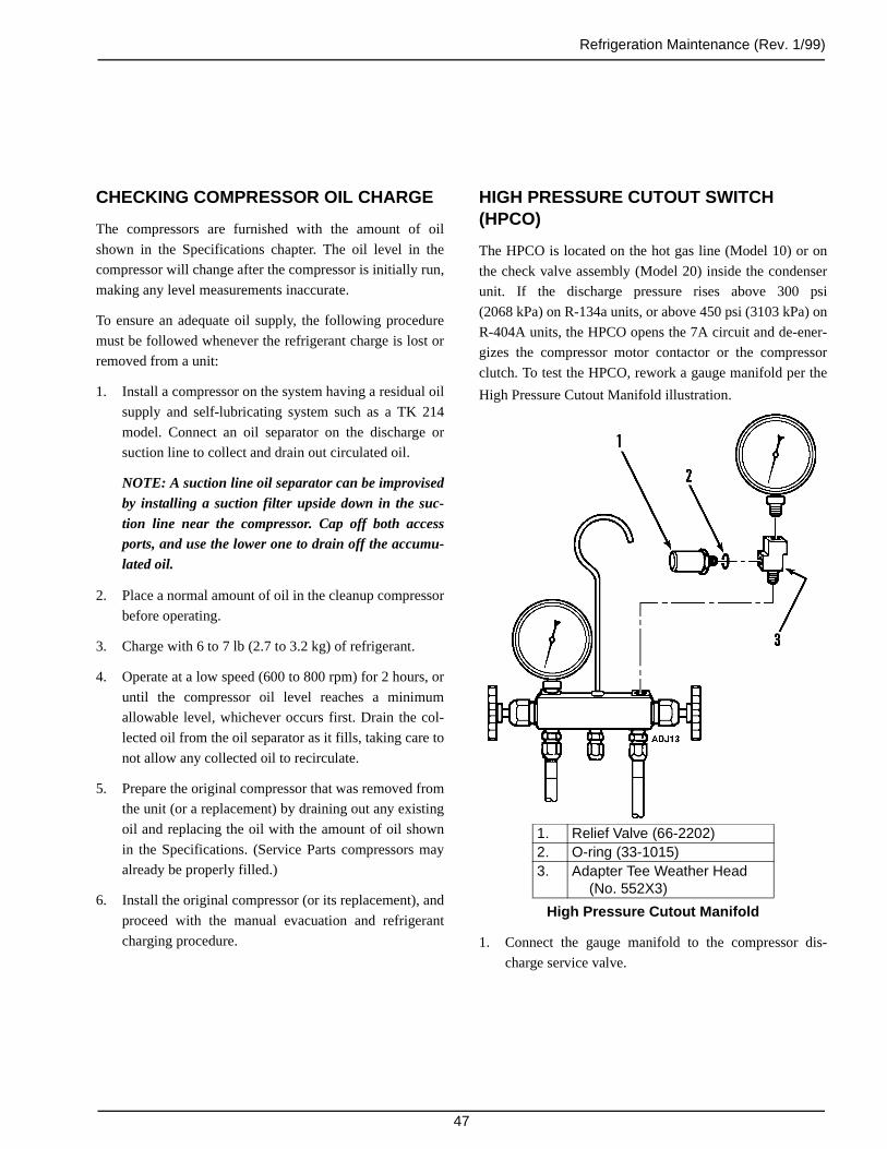
Refrigeration Maintenance (Rev. 1/99)
47
CHECKING COMPRESSOR OIL CHARGE
The compressors are furnished with the amount of oil
shown in the Specifications chapter. The oil level in the
compressor will change after the compressor is initially run,
making any level measurements inaccurate.
To ensure an adequate oil supply, the following procedure
must be followed whenever the refrigerant charge is lost or
removed from a unit:
1. Install a compressor on the system having a residual oil
supply and self-lubricating system such as a TK 214
model. Connect an oil separator on the discharge or
suction line to collect and drain out circulated oil.
NOTE: A suction line oil separator can be improvisedby installing a suction filter upside down in the suc-tion line near the compressor. Cap off both accessports, and use the lower one to drain off the accumu-lated oil.
2. Place a normal amount of oil in the cleanup compressor
before operating.
3. Charge with 6 to 7 lb (2.7 to 3.2 kg) of refrigerant.
4. Operate at a low speed (600 to 800 rpm) for 2 hours, or
until the compressor oil level reaches a minimum
allowable level, whichever occurs first. Drain the col-
lected oil from the oil separator as it fills, taking care to
not allow any collected oil to recirculate.
5. Prepare the original compressor that was removed from
the unit (or a replacement) by draining out any existing
oil and replacing the oil with the amount of oil shown
in the Specifications. (Service Parts compressors may
already be properly filled.)
6. Install the original compressor (or its replacement), and
proceed with the manual evacuation and refrigerant
charging procedure.
HIGH PRESSURE CUTOUT SWITCH (HPCO)
The HPCO is located on the hot gas line (Model 10) or on
the check valve assembly (Model 20) inside the condenser
unit. If the discharge pressure rises above 300 psi
(2068 kPa) on R-134a units, or above 450 psi (3103 kPa) on
R-404A units, the HPCO opens the 7A circuit and de-ener-
gizes the compressor motor contactor or the compressor
clutch. To test the HPCO, rework a gauge manifold per the
High Pressure Cutout Manifold illustration.
1. Connect the gauge manifold to the compressor dis-
charge service valve.
1. Relief Valve (66-2202)2. O-ring (33-1015)3. Adapter Tee Weather Head
(No. 552X3)
High Pressure Cutout Manifold

Refrigeration Maintenance (Rev. 1/99)
48
NOTE: Service manifold hoses must have Schradervalve (tire valve) depressors.
2. Set the thermostat well below the box temperature so
that the unit will be in cool.
3. Raise the discharge pressure of the compressor first by
blocking the condenser coil air flow.
NOTE: The discharge pressure should never beallowed to exceed a pressure of 400 psi (2758 kPa) onR-134a units, or 450 psi (3103 kPa) on R-404A units.
4. Failure of the high pressure cutout system to stop com-
pressor operation should be investigated first by check-
ing the control circuit operation and second by
replacing the HPCO.
SYSTEM CLEANUP
If the system ever becomes contaminated, cleanup the sys-
tem as follows:
1. Install a compressor on the system having a residual oil
supply and self-lubricating system such as a TK 214
model. Connect an oil separator on the discharge or
suction line to collect and drain out circulated oil.
NOTE: A suction line oil separator can be improvisedby installing a suction filter upside down in the suc-tion line near the compressor. Cap off both accessports, and use the lower one to drain off accumulatedoil.
2. Place a normal amount of oil in the cleanup compressor
before operating.
3. Charge with 6 to 7 lb (2.7 to 3.2 kg) of refrigerant.
4. Operate at low speed (600 to 800 rpm) for 2 hours, or
until the compressor oil level reaches a minimum
allowable level, whichever occurs first. Drain the col-
lected oil from the oil separator as it fills, taking care to
not allow any collected oil to recirculate.
5. Test the compressor oil with an acid test kit No.
203-346. Repeat Step 4 if the test shows acid in the
compressor oil.
6. Remove the cleanup compressor and suction filter.
Replace with a standard compressor, containing the
proper amount of oil.
7. Leak test, evacuate and charge the system.
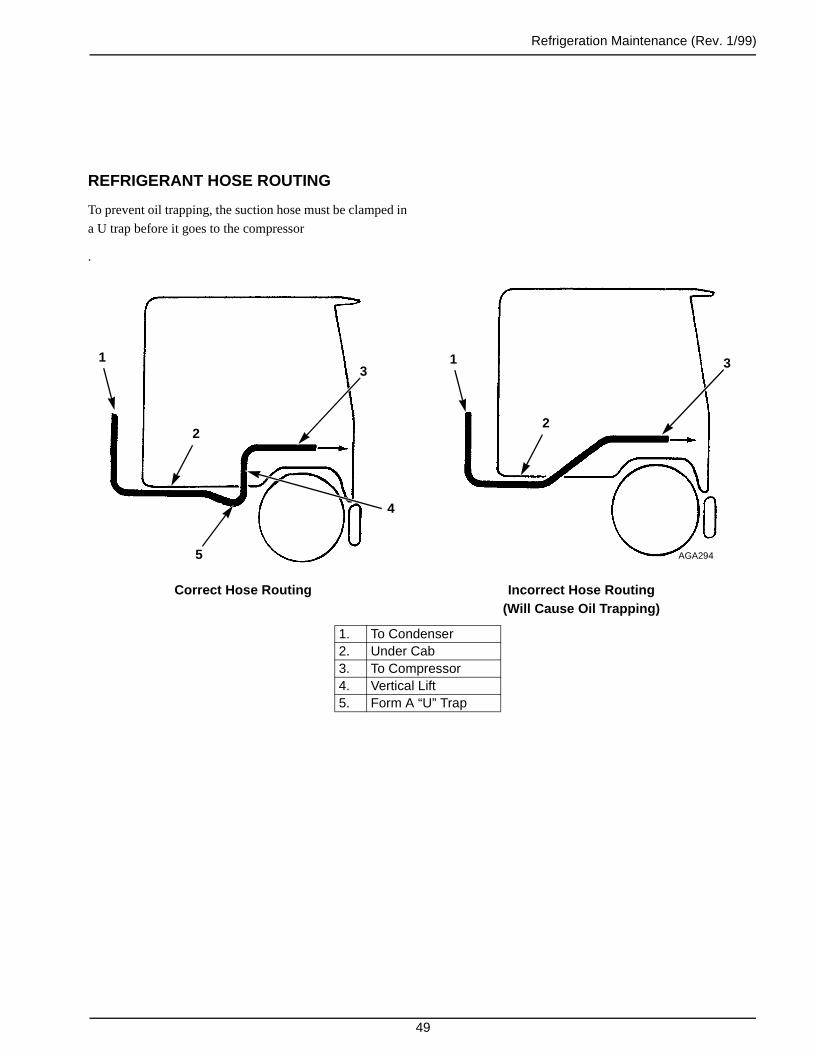
Refrigeration Maintenance (Rev. 1/99)
49
REFRIGERANT HOSE ROUTING
To prevent oil trapping, the suction hose must be clamped in
a U trap before it goes to the compressor
.
Correct Hose Routing Incorrect Hose Routing(Will Cause Oil Trapping)
1. To Condenser2. Under Cab3. To Compressor4. Vertical Lift5. Form A “U” Trap
1
2
3
AGA294
1
2
3
4
5

Refrigeration Maintenance (Rev. 1/99)
50
THREE-WAY VALVE CONDENSER PRESSURE BYPASS CHECK VALVE
A three-way valve condenser pressure bypass check valve is
used in this unit. This check valve controls the bypass flow
of refrigerant gas between the condenser inlet line and the
compressor discharge line.
The check valve is closed when the unit is running on cool,
or whenever the discharge pressure is higher than the con-
denser pressure.
When the unit is running in defrost, if the condenser pres-
sure is higher than the discharge pressure, the check valve
opens and the condenser pressure is bled off until it drops to
the level of the discharge pressure. The purpose of the check
valve is to improve the heating/defrosting ability and the
three-way valve response.
To check the operation of the check valve:
1. Remove the condenser pressure bypass check valve cap
from the three-way valve.
2. Using a screwdriver, gently turn the check valve stem
in until the valve is front seated.
3. Install a gauge manifold set on the compressor.
4. Close (front seat) the receiver tank outlet valve.
5. Operate the unit in cool and pump down the low side to
20 in. Hg of vacuum (-68 kPa).
6. Stop the unit. The condenser and suction pressures
should remain stable, indicating no leaks.
7. Shift the three-way valve to the defrost position. The
low side gauge will rise slightly and the high side gauge
will drop to approximately zero as the gauges will
equalize.
8. The gauges will remain in this position (approximately
zero) if the three-way seals properly toward the con-
denser and the condenser pressure bypass check valve
seals properly.
9. Back seat the condenser pressure bypass check valve
stem against the snap ring. Both gauges should rise
indicating that the condenser pressure bypass check
valve is properly releasing condenser pressure into the
discharge tube and evaporator.
10. Replace the cap on the condenser pressure bypass
check valve.
NOTE: The check valve stem MUST be back seatedduring normal unit operation.
11. Open the receiver tank return outlet valve, remove the
gauges, and return the unit to operation.
1. Check Valve2. Cool Position3. Defrost Position
Three-way Valve Condenser PressureBypass Check Valve
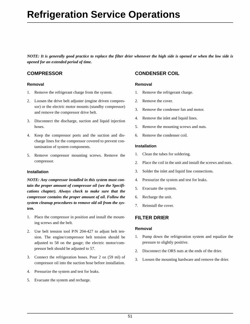
51
Refrigeration Service Operations
NOTE: It is generally good practice to replace the filter drier whenever the high side is opened or when the low side isopened for an extended period of time.
COMPRESSOR
Removal
1. Remove the refrigerant charge from the system.
2. Loosen the drive belt adjuster (engine driven compres-
sor) or the electric motor mounts (standby compressor)
and remove the compressor drive belt.
3. Disconnect the discharge, suction and liquid injection
hoses.
4. Keep the compressor ports and the suction and dis-
charge lines for the compressor covered to prevent con-
tamination of system components.
5. Remove compressor mounting screws. Remove the
compressor.
Installation
NOTE: Any compressor installed in this system must con-tain the proper amount of compressor oil (see the Specifi-cations chapter). Always check to make sure that thecompressor contains the proper amount of oil. Follow thesystem cleanup procedures to remove old oil from the sys-tem.
1. Place the compressor in position and install the mount-
ing screws and the belt.
2. Use belt tension tool P/N 204-427 to adjust belt ten-
sion. The engine/compressor belt tension should be
adjusted to 58 on the gauge; the electric motor/com-
pressor belt should be adjusted to 57.
3. Connect the refrigeration hoses. Pour 2 oz (59 ml) of
compressor oil into the suction hose before installation.
4. Pressurize the system and test for leaks.
5. Evacuate the system and recharge.
CONDENSER COIL
Removal
1. Remove the refrigerant charge.
2. Remove the cover.
3. Remove the condenser fan and motor.
4. Remove the inlet and liquid lines.
5. Remove the mounting screws and nuts.
6. Remove the condenser coil.
Installation
1. Clean the tubes for soldering.
2. Place the coil in the unit and install the screws and nuts.
3. Solder the inlet and liquid line connections.
4. Pressurize the system and test for leaks.
5. Evacuate the system.
6. Recharge the unit.
7. Reinstall the cover.
FILTER DRIER
Removal
1. Pump down the refrigeration system and equalize the
pressure to slightly positive.
2. Disconnect the ORS nuts at the ends of the drier.
3. Loosen the mounting hardware and remove the drier.

Refrigeration Service Operations (Rev. 1/99)
52
Installation
1. Place new O-rings in the ORS fittings on the ends of
the drier.
2. Install the new drier and tighten the mounting screws
and nuts.
3. Install and tighten the inlet ORS nut. Hold the drier
with a back-up wrench on the hex behind the ORS
fitting.
4. Release a small amount of refrigerant to purge the air
through the drier, and then tighten the outlet ORS nut.
5. Pressurize the system and inspect for leaks. If no leaks
are found, open the refrigeration valves and place the
unit in operation.
EVAPORATOR COIL
Removal
1. Pump down the low side and equalize the pressure to
slightly positive.
2. Remove the evaporator panel. Disconnect the evapora-
tor fan motor wires. Unbolt the expansion valve from
the mounting bracket.
3. Disconnect the expansion valve from the distributor.
4. Disconnect the hot gas line from the distributor.
5. Remove the defrost termination switch wire.
6. Unsolder the suction line from the evaporator coil.
7. Remove the mounting bolts and slide the coil from the
unit.
Installation
1. Place the coil in the housing.
2. Install the mounting bolts and tighten them.
3. Clean the tubes for soldering.
4. Solder the suction line to the evaporator coil.
5. Connect the hot gas line to the distributor.
6. Connect the expansion valve to the distributor.
7. Connect the defrost termination switch wire.
8. Install the expansion valve on the mounting bracket.
9. Pressurize the system and test for leaks. If no leaks are
found, evacuate the system.
10. Connect the evaporator fan motor wires. Install the
evaporator panel.
11. Open the refrigeration valves and place the unit in oper-
ation. Check the refrigerant charge and the compressor
oil and add as required.
EXPANSION VALVE ASSEMBLY
Removal
1. Pump down the low side and equalize the pressure to
slightly positive.
2. Remove the feeler bulb from the suction line clamps.
Note the position of the feeler bulb on the suction line.
3. Disconnect the equalizer line from the expansion valve.
4. Disconnect the liquid line and the distributor from the
expansion valve.
5. Remove the expansion valve mounting bolt, and then
remove the expansion valve from the unit.
Installation
1. Install and bolt the expansion valve assembly in the
unit.
2. Connect the liquid line and the distributor to the expan-
sion valve.
3. Connect the equalizer line to the expansion valve.

Refrigeration Service Operations (Rev. 1/99)
53
4. Clean the suction line to a bright, polished condition.
Install the feeler bulb clamps and the feeler bulb on the
side of the suction line in its former position. The feeler
bulb must make good contact with the suction line or
operation will be faulty. Wrap the bulb with insulating
tape.
5. Pressurize the low side and test for leaks. If no leaks are
found, evacuate the low side.
Completely Wrap Bulb with TapeLocation of Expansion Valve Bulb
RECEIVER TANK
Removal
1. Remove the refrigerant charge.
2. Unsolder the refrigerant lines from the receiver tank.
3. Remove the nut from the top and bottom of the receiver
tank.
4. Remove the receiver tank.
Installation
1. Position the receiver tank in the unit and install the
mounting nuts.
2. Solder the refrigerant lines to the receiver tank.
3. Pressurize the refrigeration system and check for leaks.
4. If no leaks are found, evacuate the system.
5. Recharge the unit.
OIL SEPARATOR
Once installed, the oil separator unit requires no mainte-
nance. However, all connections to the separator and
throughout the refrigeration system should be checked on a
regular basis for leaks.
Oil Separator Kit Installation
For units which do not have oil separators, a kit is available
using flare connections for installing the oil separator. The
kit (PN 20-126) contains an oil separator, a mounting
clamp, clamp screws, an oil return hose with fittings, an
adapter, and two fittings for the discharge hose.
Installation Recommendations
1. Connect the oil separator in series with the compressor
discharge line. (Inlet end of oil separator is labeled IN.)
2. Mount the oil separator as close as possible to the
compressor.
3. The oil separator can be mounted horizontally or verti-
cally, but the oil outlet MUST be at the lowest point on
the oil separator.
4. Remove and discard the oil fill plug on the compressor
housing. Install the special adapter with a gasket in the
oil fill opening of the compressor housing. Connect the
oil return hose of the oil separator to the special adapter
on the compressor.

Refrigeration Service Operations (Rev. 1/99)
54
Oil Separator Installation
NOTE: Newer models have oil separator in condenser unit.
5. Use a hose cutter to cut the oil return hose to the proper
length, and to cut the discharge hose for the installation
of the inlet and outlet fitting. Make sure there is no for-
eign matter in any of the hoses.
See the following illustration as an example of the installa-
tion.
NOTES:
1. When using flare fittings, lubricate the matingsurfaces as well as the flare fitting threads prior toconnecting.
2. Use tubing wrenches to tighten all connections toavoid collapsing or warping fittings. DO NOT over-tighten. Tighten to the proper torque specifications.
NOTE: The oil outlet MUST be at lowest point on the oilseparator.
1. Self-tapping Screw (4)2. Clamp3. Pad4. Oil Separator5. Fitting Hose (2)6. Discharge Hose7. Copper Washer8. O-ring9. Adapter10. Copper Washer11. Oil Return Hose
1
23
4
56
7
11
109
8
AGA296
No No
Yes Yes

Refrigeration Service Operations (Rev. 1/99)
55
REPLACING REFRIGERANT HOSES
Disassembly
1. Remove the refrigerant charge or pump down the low
side.
2. Use two wrenches to loosen the flare fittings.
3. Remove the hose and remove the fittings from the hose.
Assembly
1. Measure the hose, and using a sharp knife or suitable
plastic tube and hose cutter tool, cut to length. Make
sure the cut is clean and square. Wipe the inside of the
hose clean.
NOTE: DO NOT use a saw to cut the hose.
2. Assemble the hose and fittings.
a. Place the fitting socket in a vise and screw in the
hose counterclockwise until the hose bottoms.
Then back out the hose 1/4 turn.
AGA341
AGA342
b. Lubricate nipple threads and inside of hose with
refrigerant oil.
Refrigerant Hose Installation
1. Apply clean compressor oil to the flares to facilitate the
connection and use two wrenches to tighten the fittings.
2. Pour 2 oz. (59 ml) of compressor oil into the suction
hose before connecting on new installations and when-
ever replacing a compressor.
3. Leak check the system.
Torque Values for Refrigeration Flare Fittings
Refrigerant connections made with flare fittings must be
properly torqued to be leak free.
NOTE: Refrigerant oil must be used on flare seats to pre-vent damage.
1. Tighten the nut finger tight until it bottoms the seat.
2. Mark a line lengthwise on the nut and extend it onto the
adapter.
1. Mark a line on nut and adapterbefore torquing
2. Misalignment of mark shows amount that nut was tightened
AGA343
1
AGA297
2

Refrigeration Service Operations (Rev. 1/99)
56
3. Using a wrench, rotate the unit to tighten. Turn the nut
the amount shown in the following chart.
NOTE: Misalignment of the marks will show how muchthe nut was tightened, and best of all that it has been tight-ened.
LIQUID INJECTION SOLENOID VALVE
Removal
1. Disconnect the coil wires on the liquid injection sole-
noid valve.
2. Pump down the low side and shut down the unit.
NOTE: Take caution to avoid the danger of liquidrefrigerant escaping when the lines are disconnected.
3. Disconnect the refrigerant lines on both sides of the
solenoid valve.
4. Unbolt the solenoid valve from its mounting bracket,
and remove it.
Line Size Rotate No. of Hex Flats
14 2-1/2
5 2-1/2
6 2
8 2
10 1-1/2 to 2
12 1
16 3/4 to 1
20 3/4 to 1
24 1/2 to 3/4
Installation
1. Fasten the solenoid valve to the mounting bracket.
2. Connect refrigerant lines to both sides of the solenoid
valve. (The line from the liquid line is connected to the
port marked IN.)
3. Connect the coil wires to the solenoid valve.
4. Open the refrigeration valves.
NOTE: The screen inside the solenoid valve is thesame as that used in the pilot solenoid and mayrequire cleaning.
LIQUID INJECTION METERING ORIFICE
Removal
1. Disconnect the coil wires on the liquid injection sole-
noid valve.
2. Pump down the low side and stop the unit.
3. Disconnect the flexible hose from the metering orifice
and remove the metering orifice from the suction hose
fitting.
NOTE: Take caution to avoid the danger of liquidrefrigerant escaping when the line is disconnected.
NOTE: This orifice may become plugged with dirtunless the flexible hose and solenoid valve are keptclean.
Installation
1. Install the metering orifice on the suction hose fitting.
2. Connect the flexible hose to the metering orifice fitting.
3. Open the refrigeration valves.

Refrigeration Service Operations (Rev. 1/99)
57
Testing the Liquid Injection Solenoid Valve and Metering Orifice
1. Disconnect the LIS wire from the liquid injection sole-
noid.
2. Install a gauge manifold set on the engine-driven com-
pressor.
3. Set the thermostat on the lowest setting.
4. Start the truck and run the unit on the engine-driven
compressor until the suction pressure stabilizes.
5. Place a jumper wire between CH and the LIS terminal
on the liquid injection solenoid.
6. With the jumper wire in place the suction pressure
should rise.
7. With the jumper wire removed the suction pressure
should return to the stabilized pressure in step 4.
8. If the suction pressure does not change, check the CLU
wire for voltage, the liquid injection solenoid valve, or
the metering orifice.
9. Shut off the unit and the truck, remove the gauge mani-
fold set and replace the LIS wire.
HIGH PRESSURE CUTOUT AND CONDENSER FAN SWITCHES
Removal
1. Remove the refrigerant charge.
2. Disconnect the wires and remove the switch.
Installation
1. Apply a refrigerant locktite to the threads of the switch.
2. Install and tighten the switch and reconnect the wires.
3. Pressurize the refrigeration system and test for leaks.
4. If no leaks are found, charge the system.
LOW PRESSURE CUTOUT SWITCH
Removal
1. Pump down the low side and stop the unit.
2. Disconnect the wires and remove the switch.
Installation
1. Apply a refrigerant locktite to the threads of the switch.
2. Install and tighten the switch and reconnect the wires.
3. Pressurize the refrigeration system and test for leaks.
4. If no leaks are found, evacuate the low side.
5. Open the receiver tank outlet valve, start the unit and
check the refrigerant charge.
SUCTION PRESSURE REGULATOR VALVE
Removal
1. Pump down the low side and equalize the pressure to
slightly positive.
2. Release the remaining pressure and unsolder the suc-
tion pressure regulator valve from the suction tubes.
Installation
1. Clean the tubes for soldering.
2. Place the valve in position and solder the connections.
3. Pressurize the low side and check for leaks.
4. If no leaks are found, evacuate the low side.
5. Open the refrigeration valves, and place the unit in
operation. Check refrigerant charge and add refrigerant
as required.

Refrigeration Service Operations (Rev. 1/99)
58
DISCHARGE CHECK VALVE REPAIR (Model 20 Only)
Testing the Discharge Check Valve
The discharge check valve is a very important part of the
Model 20 system. The check valve isolates the engine-
driven compressor from the electric standby compressor,
ensuring the compressor oil and refrigerant do not migrate
between compressors. The check valve should be tested
when the system is initially charged and operating and any-
time the system has been opened for service or repair. Test-
ing the check valve requires two gauge manifold sets.
1. Disconnect the liquid injection solenoid valve wires.
2. With the unit off, install a gauge manifold set on each
compressor.
3. Observe the gauge manifold readings of the electric
standby compressor. If the high side and low side read-
ings are not the same, open the gauge manifold valves
and equalize the pressures. Close the gauge manifold
valves.
4. Adjust the thermostat so the unit will run in cool. Start
the truck and run the unit with the engine-driven com-
pressor.
5. Observe the gauge manifold readings of the engine-
driven compressor. The head pressure should increase
and the suction pressure should decrease.
6. Observe the gauge manifold readings of the electric
standby compressor. The high side pressure should
remain the same as the pressure in step 3 after the high
and low sides were equalized. If the high side pressure
is increasing or has increased noticeably, the discharge
check valve is leaking internally.
7. Turn the unit off and shut off the truck engine. Connect
the remote control box to an appropriate electric power
source.
8. Observe the gauge manifold reading of the engine-
driven compressor. If the high side and low side read-
ings are not the same, open the gauge manifold valves
and equalize the pressures. Close the gauge manifold
valves.
9. Adjust the thermostat so the unit will run in cool. Start
the unit and run on electric standby.
10. Observe the gauge manifold readings of the electric
standby compressor. The head pressure should increase
and the suction pressure should decrease.
11. Observe the gauge manifold readings of the engine-
driven compressor. The high side pressure should
remain the same as the pressure in step 8 after the high
and low sides were equalized. If the high side pressure
is increasing or has increased noticeably, the discharge
check valve is leaking internally. Stop the unit.
12. Remove the gauge manifold sets and the electric
standby power source. Connect the wires to the liquid
injection solenoid valve. If the check valve is leaking
internally, refer to the repair procedures.
Discharge Check Valve Repair
Disassembly
1. Remove the refrigerant charge.
2. Loosen and remove the end cap nuts.
3. Carefully remove the end caps from the valve body.
Avoid damaging the refrigeration lines, pistons or
spring.
4. Remove the pistons, spring and copper sealing washers.
5. Check the spring. The free length should be 1.75 in.
(44.5 mm). Replace the spring if the free length is less
than 1.57 in. (37.9 mm).
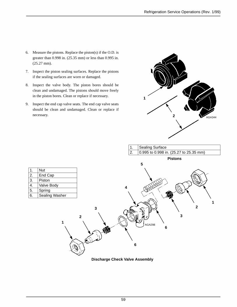
Refrigeration Service Operations (Rev. 1/99)
59
1. Sealing Surface2. 0.995 to 0.998 in. (25.27 to 25.35 mm)
Pistons
1
AGA3442
6. Measure the pistons. Replace the piston(s) if the O.D. is
greater than 0.998 in. (25.35 mm) or less than 0.995 in.
(25.27 mm).
7. Inspect the piston sealing surfaces. Replace the pistons
if the sealing surfaces are worn or damaged.
8. Inspect the valve body. The piston bores should be
clean and undamaged. The pistons should move freely
in the piston bores. Clean or replace if necessary.
9. Inspect the end cap valve seats. The end cap valve seats
should be clean and undamaged. Clean or replace if
necessary.
Discharge Check Valve Assembly
AGA2981
2
3
4
5
12
3
6
6
1. Nut2. End Cap3. Piston4. Valve Body5. Spring6. Sealing Washer
Refrigeration Service Operations (Rev. 1/99)
60
Assembly
NOTE: Coat all parts with compressor oil before assembly.
1. Place the spring in the valve body.
2. Place a piston in the valve body piston bore with the
piston sealing surface facing out toward the end cap
seat. Holding the spring at the other end of the valve
body, push the piston in and let the spring return the
piston several times to check that the piston moves
freely.
3. Place a new copper sealing washer in the valve body
near the piston. The sharp edge of the copper sealing
washer should face the valve body and the smooth side
should face the end cap.
4. Carefully place the end cap in the valve body to avoid
damaging the piston, copper sealing washer or the
refrigeration lines. Tighten the end cap nut finger tight.
5. Place the other piston in the other valve body piston
bore with the piston sealing surface facing out toward
the end cap seat. Push the piston in and let the spring
return the piston several times to check that the piston
moves freely.
6. Place a new copper sealing washer in the valve body
near the piston. The sharp edge of the copper sealing
washer should face the valve body and the smooth side
should face the end cap.
7. Carefully place the end cap in the valve body to avoid
damaging the piston, copper sealing washer or the
refrigeration lines. Tighten the end cap nut finger tight.
8. Using a 1-3/4 in. (44.5 mm) crows foot or similar tool,
torque the end cap nuts to 80 ft-lb (59 N•m).
NOTE: A crows foot of this size increases the torqueread on the torque wrench by approximately 6%.Therefore, the reading on the torque wrench shouldbe 75 ft-lb (55 N•m).
9. Leak check, evacuate and recharge the system. Test the
check valve operation.
Discharge Check Valve Replacement
Removal
1. Remove the refrigerant charge.
2. Disassemble the check valve.
3. Unsolder the lines and remove the check valve.
Installation
1. Clean the tubes for soldering.
2. Place the disassembled check valve in position.
3. Solder the connections. After the valve cools,
reassemble the valve.
4. Pressurize the refrigeration system and test for leaks.
5. If no leaks are found, evacuate the system.
6. Recharge the unit with refrigerant and check
compressor oil.
ACCUMULATOR
Removal
1. Pump down the low side and equalize the pressure to
slightly positive.
2. Unsolder the inlet and outlet refrigerant suction lines
from the accumulator.
3. Unbolt and remove the accumulator from the unit.

Refrigeration Service Operations (Rev. 1/99)
61
Installation
1. Place the accumulator in the unit and tighten the
mounting bolts.
2. Solder the inlet and outlet suction lines to the accumu-
lator.
3. Pressurize the low side and test for refrigerant leaks. If
no leaks are found, evacuate the low side.
4. Open the refrigeration valves and place the unit in oper-
ation. Check the refrigerant charge and compressor oil
and add as required.
THREE-WAY VALVE REPAIR
In most cases, the three-way valve can be repaired in the
unit.
Disassembly
1. Remove the refrigerant charge.
2. Clean the exterior surface of the valve.
3. Remove the 1/4 in. (6 mm) copper line from the three-
way valve to the pilot solenoid.
4. Loosen the four Allen head screws (DO NOT
REMOVE); use Tool P/N 204-424 to break the gasket
at each side of the center section.
CAUTION: Do not force the tool into the brassor against the bolts.
5. Remove the four bolts from the valve.
6. Remove the top cap and spring.
7. Remove the spring clip. Observe the slot in the piston
and slide the piston off the stem.
8. Remove the seat and stem assembly.
9. Inspect the following parts for wear or damage:
a. Bottom cap, sealing and support area.
b. Seat, sealing surface.
c. Top cap, sealing and support area.
Remove the screen. If any particles drop from the
screen into the discharge line, the discharge line must
be removed at the compressor.
NOTE: The valve body cannot be reconditioned. Seatpositions change and improper sealing will result.
Assembly
After cleaning and inspecting all parts, reassemble the
valve.
1. Place the screen in the bottom cap.
2. Place a new stem in the bottom cap.
3. Install new gaskets on both sides of the seat. Dip the
gaskets in compressor oil before installing.
4. Install the piston on the stem and attach with a spring
clip.
5. Install a new O-ring on the piston, then place the Teflon
seal over the O-ring.
NOTE: The Teflon seal will stretch when it isinstalled. To prevent this stretch from becoming per-manent (and possibly causing a malfunction), the topcap must be installed immediately.
6. Install the spring and top cap.
7. Line up the passageways in the top cap and the seat.
Failure to line up the holes will result in improper oper-
ation of the three-way valve.
8. Install the bolts and tighten them in a rotating sequence.
9. Install the pilot solenoid line and pressurize the system
with refrigerant to check for leaks.
10. If there are no leaks, evacuate the system and recharge
with refrigeration.
11. Run the unit to check for proper three-way valve
operation.

Refrigeration Service Operations (Rev. 1/99)
62
1. Cap 7. Clip2. Top Cap 8. Seat3. Check Valve 9. Gaskets4. Spring 10. Stem Assembly5. Piston 11. Screen6. Seal 12. Bottom Cap
Three-way Valve
AEA714
THREE-WAY VALVE CONDENSER PRESSURE BYPASS CHECK VALVE REPAIR
Removal
1. Remove the refrigerant charge.
2. Unscrew the condenser pressure bypass check valve
cap from the three-way valve.
3. Remove the snap ring.
4. Unscrew the check valve stem by using a screwdriver
in the slot provided.
NOTE: The spring and the check valve are held in bythe stem. While removing the stem, use care to makesure that the spring and the check valve are not lost.
5. Remove the spring and the check valve.
6. Inspect the check valve seat in the three-way valve.
7. If replacement parts are needed, a kit P/N 60-163 must
be used which includes the check valve, spring, O-ring,
valve stem and snap ring.
1. Check Valve 4 Valve Stem2 Snap Ring 5 O-ring3 Cap 6 Spring
Check Valve Assembly
AEA715
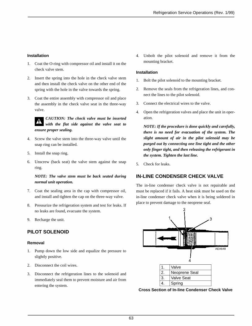
Refrigeration Service Operations (Rev. 1/99)
63
Installation
1. Coat the O-ring with compressor oil and install it on the
check valve stem.
2. Insert the spring into the hole in the check valve stem
and then install the check valve on the other end of the
spring with the hole in the valve towards the spring.
3. Coat the entire assembly with compressor oil and place
the assembly in the check valve seat in the three-way
valve.
CAUTION: The check valve must be insertedwith the flat side against the valve seat to
ensure proper sealing.
4. Screw the valve stem into the three-way valve until the
snap ring can be installed.
5. Install the snap ring.
6. Unscrew (back seat) the valve stem against the snap
ring.
NOTE: The valve stem must be back seated duringnormal unit operation.
7. Coat the sealing area in the cap with compressor oil,
and install and tighten the cap on the three-way valve.
8. Pressurize the refrigeration system and test for leaks. If
no leaks are found, evacuate the system.
9. Recharge the unit.
PILOT SOLENOID
Removal
1. Pump down the low side and equalize the pressure to
slightly positive.
2. Disconnect the coil wires.
3. Disconnect the refrigeration lines to the solenoid and
immediately seal them to prevent moisture and air from
entering the system.
4. Unbolt the pilot solenoid and remove it from the
mounting bracket.
Installation
1. Bolt the pilot solenoid to the mounting bracket.
2. Remove the seals from the refrigeration lines, and con-
nect the lines to the pilot solenoid.
3. Connect the electrical wires to the valve.
4. Open the refrigeration valves and place the unit in oper-
ation.
NOTE: If the procedure is done quickly and carefully,there is no need for evacuation of the system. Theslight amount of air in the pilot solenoid may bepurged out by connecting one line tight and the otheronly finger tight, and then releasing the refrigerant inthe system. Tighten the last line.
5. Check for leaks.
IN-LINE CONDENSER CHECK VALVE
The in-line condenser check valve is not repairable and
must be replaced if it fails. A heat sink must be used on the
in-line condenser check valve when it is being soldered in
place to prevent damage to the neoprene seal.
1. Valve2. Neoprene Seal3. Valve Seat4. Spring
Cross Section of In-line Condenser Check Valve
AEA648

Refrigeration Service Operations (Rev. 1/99)
64
IN-LINE CONDENSER CHECK VALVE REPLACEMENT
Removal
1. Remove the refrigerant charge.
2. Place a heat sink on the check valve.
3. Unsolder the lines and remove the check valve.
Installation
Note: A heat sink must be used on the in-line check valvewhen it is being soldered in place to prevent damage to theneoprene seal.
1. Clean the tubes for soldering.
2. Place the check valve in position. The arrow on the
valve body indicates direction of refrigerant flow
through the valve.
3. Place a heat sink on the check valve.
4. Solder the inlet and outlet connections.
5. Pressurize the refrigeration system and test for leaks.
6. If no leaks are found, evacuate the system.
7. Recharge the unit with the proper refrigerant and check
the compressor oil.
O-Ring Seal (ORS) Connections
Replacement
1. Close the receiver outlet valve, pump down the low
side, and equalize the pressure to slightly positive.
2. To break the threaded line connections use two
wrenches. A rubber O-ring is used at line connections
to assure a positive seal. Install a new O-ring whenever
a line connection has been broken.
3. Before the line is connected, apply clean compressor oil
to the O-ring. Hand tighten the connector nut on the
line against the line fitting. Support the line fitting with
a wrench and tighten the connector nut with another
wrench until the fitting bottoms out. The connection
bottoms out when tight, reducing the chance of over
and under torque.
NOTE: ORS O-rings are made of a material with acertain hardness. Do not substitute other O-rings. Useonly O-rings from Thermo King service parts.
1. Valve Fitting2. O-ring3. Connecting Nut
O-ring Seal (ORS)
1
AGA300
2 3

65
Structural Maintenance
UNIT INSPECTION
Inspect the unit during the pre-trip inspection and during
scheduled maintenance inspections for loose or broken
wires or hardware, compressor oil leaks, or other physical
damage which might affect the unit performance and
require the repair or replacement of parts.
EVAPORATOR COIL
Clean the evaporator coil during scheduled maintenance
inspection by blowing compressed air down through the
coil out into the box (direction opposite the normal air
flow). Inspect the coil and fins for damage and repair if nec-
essary (requires removing the evaporator fan and front
cover).
CAUTION: Air pressure should not be high enoughto damage the coil fins.
FAN LOCATION
When mounting the fan and hub assembly on the fan shaft,
position the assembly in the orifice with 30 to 35 percent of
the blade width to the air discharge side for proper fan per-
formance.
.
1. Orifice2. Airflow3. 30 to 35 Percent of Blade Depth
to Discharge Side
Fan Blade Position in Orifice
AEA654

Structural Maintenance (Rev. 1/99)
66
CONDENSER COIL
Clean the condenser coil during scheduled maintenance
inspections by blowing compressed air from the back side
of the coil out toward the front of the unit (the direction
opposite normal air flow). Inspect the coil and fins for dam-
age and repair if necessary.
UNIT MOUNTING BOLTS
Periodically check and torque the unit mounting bolts to 60
ft-lb (81 N•m).
Unit Mounting Bolts
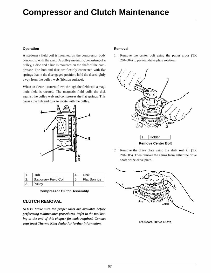
67
Compressor and Clutch Maintenance
Operation
A stationary field coil is mounted on the compressor body
concentric with the shaft. A pulley assembly, consisting of a
pulley, a disc and a hub is mounted on the shaft of the com-
pressor. The hub and disc are flexibly connected with flat
springs that in the disengaged position, hold the disc slightly
away from the pulley web (friction surface).
When an electric current flows through the field coil, a mag-
netic field is created. The magnetic field pulls the disk
against the pulley web and compresses the flat springs. This
causes the hub and disk to rotate with the pulley.
Compressor Clutch Assembly
CLUTCH REMOVAL
NOTE: Make sure the proper tools are available beforeperforming maintenance procedures. Refer to the tool list-ing at the end of this chapter for tools required. Contactyour local Thermo King dealer for further information.
Removal
1. Remove the center bolt using the puller arbor (TK
204-804) to prevent drive plate rotation.
Remove Center Bolt
2. Remove the drive plate using the shaft seal kit (TK
204-805). Then remove the shims from either the drive
shaft or the drive plate.
Remove Drive Plate
1. Hub 4. Disk2. Stationary Field Coil 5. Flat Springs3. Pulley
1. Holder

Compressor and Clutch Maintenance (Rev. 1/99)
68
3. Remove the snap ring using external snap ring pliers
(TK 204-808).
4. Remove the cover.
Remove Snap Ring and Cover
5. Remove the pulley assembly using the clutch remover
(TK No. 204-806) and the spacer positioned on the
cylinder head hub.
1. Snap Ring2. Cover
NOTE: To avoid damaging the pulley groove, thepulley claws should be hooked into (NOT UNDER)the pulley groove.
Remove Pulley
6. Remove the coil’s lead wire from the holder on the top
of the compressor.
7. Remove the three screws that attach the coil to the com-
pressor and remove the coil.

Compressor and Clutch Maintenance (Rev. 1/99)
69
NOTE: DO NOT hold the coil by the lead wire.
Remove Coil
Inspection
1. Drive Plate
If the contact surface is scorched, the drive plate and
pulley should be replaced.
2. Pulley Assembly
Inspect the appearance of the pulley assembly. If the
pulley’s contact surface is excessively grooved due to
slippage, both the pulley and drive plate must be
replaced. There should also be no foreign matter, such
as oil or grit, lodged between the clutch plate and
pulley. Thoroughly clean these contact surfaces and the
drive plate.
3. Coil
Inspect the coil for a loose connector or cracked insula-
tion. If the insulation is cracked, replace the coil.
Repair or replace the wire or the connector if either is
loose or damaged.
Clutch Installation
NOTE: Before installation refer to the “Inspection”procedures previously described.
1. Confirm that the felt is installed on the front of the
cylinder head.
2. Install the coil on the compressor (with the lead wire on
top). At this time, confirm that the coil’s concave por-
tion is aligned with the felt and then tighten the mount-
ing screws to the specified torque.
NOTE: Specified torque: 2.9 to 4.3 ft-lbs (0.4 to0.6 kgm).
3. Install the lead wire in the wire holder on the
compressor.
1. Drive Plate2. Pulley Assembly3. Coil
Inspect Components

Compressor and Clutch Maintenance (Rev. 1/99)
70
Install Coil
4. Install the pulley assembly using the compressor holder
(TK No. 204-807) and a hand press.
Install Pulley
1. Felt
5. Install the cover and the snap ring using external ring
pliers.
NOTE: When installing the snap ring, the chamferredinner edge of the snap ring should face upward.
Install Cover and Snap Ring
6. Install the driver plate on the drive shaft, together with
the original shim(s). Press the drive plate down by
hand.
7. Tighten the bolt to the specified torque using the puller
arbor (TK No. 204-804) to prevent drive-plate rotation.
NOTE: Specified torque: 8.7 to 10.1 ft-lbs (1.2 to1.4 kgm).
1. Snap Ring2. Cover

Compressor and Clutch Maintenance (Rev. 1/99)
71
After tightening the bolt, ensure that the pulley rotates
smoothly.
Install Shims and Drive Plate
8. Ensure that the clutch clearance is as specified. If nec-
essary, adjust the clearance using shims.
Adjusting shims are available in the following thick-
nesses:
Shim TK P/N Thickness in. (mm)
TK 11-8031 0.0039 in. (0.1 mm)TK 11-8032 0.0118 in. (0.3 mm)TK 11-8033 0.0197 in. (0.5 mm)
1. Shims
NOTE: Specified clearance: 0.01 to 0.02 in. (0.3 to0.6 mm).
Check Clearance
Electrical Connection
1. Connect the lead wire to the electrical circuit.
NOTE: The stationary field is grounded at the fac-tory; therefore, it is necessary only to connect the hot(lead) wire.
2. Engage and disengage the clutch several times to check
the clutch engagement. The disc should snap firmly
against the pulley.
SHAFT SEAL COVER AND SHAFT SEAL: REMOVAL AND INSTALLATION
Removal
1. Remove the magnetic clutch assembly, as outlined in
“Magnetic Clutch Removal” section of this manual.
2. Remove the felt pad.
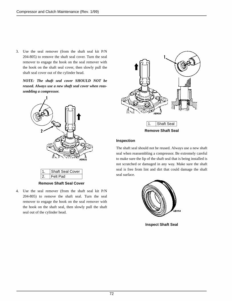
Compressor and Clutch Maintenance (Rev. 1/99)
72
3. Use the seal remover (from the shaft seal kit P/N
204-805) to remove the shaft seal cover. Turn the seal
remover to engage the hook on the seal remover with
the hook on the shaft seal cover, then slowly pull the
shaft seal cover out of the cylinder head.
NOTE: The shaft seal cover SHOULD NOT bereused. Always use a new shaft seal cover when reas-sembling a compressor.
Remove Shaft Seal Cover
4. Use the seal remover (from the shaft seal kit P/N
204-805) to remove the shaft seal. Turn the seal
remover to engage the hook on the seal remover with
the hook on the shaft seal, then slowly pull the shaft
seal out of the cylinder head.
1. Shaft Seal Cover2. Felt Pad
Remove Shaft Seal
Inspection
The shaft seal should not be reused. Always use a new shaft
seal when reassembling a compressor. Be extremely careful
to make sure the lip of the shaft seal that is being installed is
not scratched or damaged in any way. Make sure the shaft
seal is free from lint and dirt that could damage the shaft
seal surface.
Inspect Shaft Seal
1. Shaft Seal

Compressor and Clutch Maintenance (Rev. 1/99)
73
Shaft Seal Installation
Before installing a shaft seal inspect it carefully (see Inspec-
tion).
1. Clean the section of the front cylinder head that holds
shaft seal.
2. Apply clean compressor oil to the new shaft seal and to
the front cylinder head. If the slip surfaces are dirty,
clean them with thinners, dry the clean surfaces and
apply clean compressor oil.
3. Place the seal guide (from the shaft seal kit P/N
204-805) on the end of the shaft.
Place Guide on Shaft
1. Seal Guide
4. Place the shaft seal on the seal guide and slide the
seal into the cylinder head.
Place Shaft Seal on Guide
5. Use the seal installer (from the shaft seal kit P/N
204-805) to press the shaft seal into the cylinder
head as far as possible.
6. Remove the seal guide from the shaft.
Press Seal Into Cylinder Head
7. Place the seal guide (from the shaft seal kit P/N
204-805) on the end of the shaft.
1. Seal Guide2. Shaft Seal

Compressor and Clutch Maintenance (Rev. 1/99)
74
8. Place the shaft seal cover on the seal guide and slide
the shaft seal cover into the cylinder head.
Install Shaft Seal Cover
9. Use the seal installer (from the shaft seal kit P/N
204-805) to press the shaft seal cover into the
cylinder.
10. Remove the seal guide from the shaft.
NOTE: Position the shaft seal cover as shown in the illus-tration. The felt pad should also be replaced with a newone when the shaft seal is replaced.
1. Top 3. Felt Pad2. Shaft Seal Cover 4. Bottom
Proper Shaft Seal Cover Position
Special Tools
Clutch Remover P/N 204-806
Compressor Holder P/N 204-807
8932a
8932b
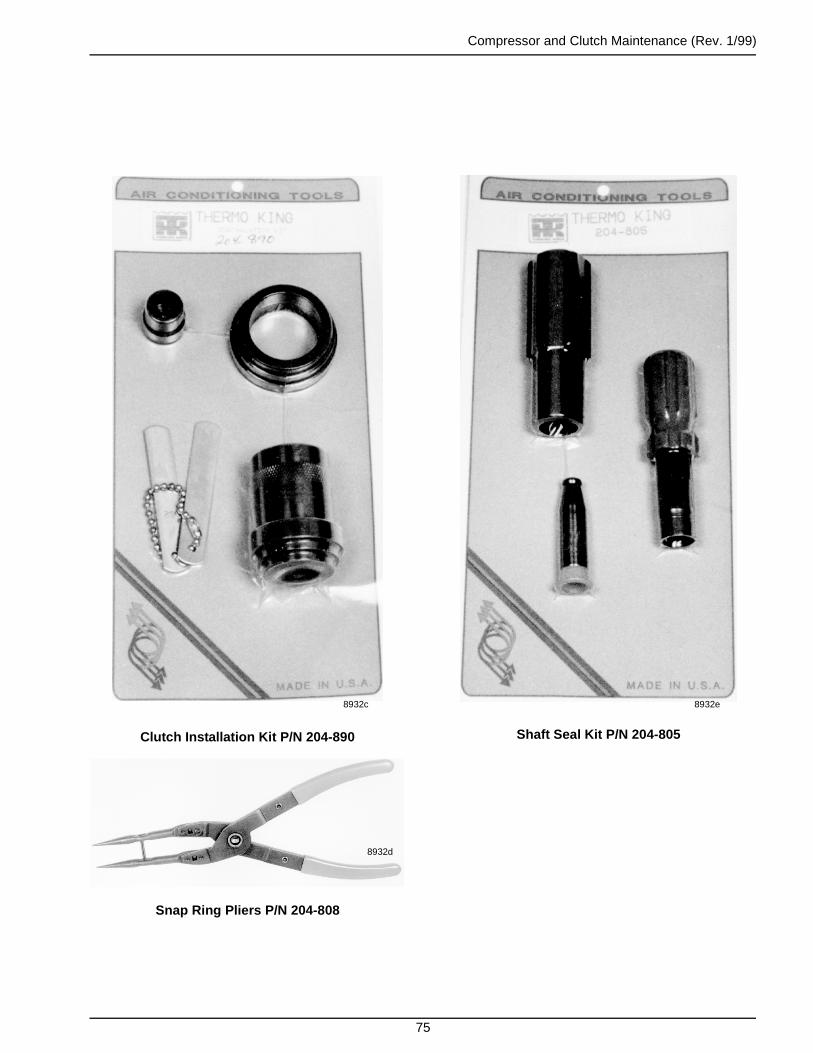
Compressor and Clutch Maintenance (Rev. 1/99)
75
Clutch Installation Kit P/N 204-890
Snap Ring Pliers P/N 204-808
8932c
8932d
Shaft Seal Kit P/N 204-805
8932e
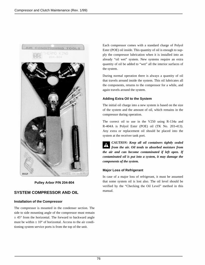
Compressor and Clutch Maintenance (Rev. 1/99)
76
Pulley Arbor P/N 204-804
SYSTEM COMPRESSOR AND OIL
Installation of the Compressor
The compressor is mounted in the condenser section. The
side to side mounting angle of the compressor must remain
± 45° from the horizontal. The forward to backward angle
must be within ± 10° of horizontal. Access to the air condi-
tioning system service ports is from the top of the unit.
8932f
Each compressor comes with a standard charge of Polyol
Ester (POE) oil inside. This quantity of oil is enough to sup-
ply the compressor lubrication when it is installed into an
already “oil wet” system. New systems require an extra
quantity of oil be added to “wet” all the interior surfaces of
the system.
During normal operation there is always a quantity of oil
that travels around inside the system. This oil lubricates all
the components, returns to the compressor for a while, and
again travels around the system.
Adding Extra Oil to the System
The initial oil charge into a new system is based on the size
of the system and the amount of oil, which remains in the
compressor during operation.
The correct oil to use in the V250 using R-134a and
R-404A is Polyol Ester (POE) oil (TK No. 203-413).
Any extra or replacement oil should be placed into the
system at the receiver tank port.
CAUTION: Keep all oil containers tightly sealedfrom the air. Oil tends to absorbed moisture from
the air and can become contaminated if left open. Ifcontaminated oil is put into a system, it may damage thecomponents of the system.
Major Loss of Refrigerant
In case of a major loss of refrigerant, it must be assumed
that some system oil is lost also. The oil level should be
verified by the “Checking the Oil Level” method in this
manual.

Compressor and Clutch Maintenance (Rev. 1/99)
77
Checking the Oil Level
Drain the Oil
Draining the Oil
Remove the compressor from the unit and drain the oil from
the compressor drain plug and all other ports. Turn the
clutch (rotating the internal compressor parts) by hand and
drain oil again. Repeat until all oil is removed from the
compressor. Measure the oil in liquid ounces. Also, inspect
the oil for signs of contamination.
Oil contamination.
1. Dirt in the oil.
2. Color changed to a varnish color.
3. Presence of foreign substances, metal shavings, etc. in
the oil.
NOTE: Always replace oil with new fresh oil taken from asealed container only.
NOTE: Always replace the system filter-drier anytime thesystem has been opened for service.
When a System Becomes Contaminated
A severely contaminated system may be indicated by black
oil in the compressor. If severe contamination occurs, it will
be necessary to flush the complete system. If flushing is
required, use industry approved materials.
In all cases when this occurs you must determine the extent
of contamination. Do this by removing the filter-drier and
determine if the darker colored oil is present at that point of
the system too. If it is, flushing the system is recommended.
If the oil appears clean at the filter-drier, install a new filter-
drier and replace the compressor with clean new oil. Refer
to checking and draining the compressor oil section for
details.
CAUTION: Any extra or replacement oil should beplaced into the system at the receiver tank port.
Electrical Connection
1. Connect the lead wire to the electrical circuit.
NOTE: The stationary field is grounded at the fac-tory; therefore, it is necessary only to connect the hot(lead) wire.
2. Engage and disengage the clutch several times to check
the clutch engagement. The disc should snap firmly
against the pulley.

Compressor and Clutch Maintenance (Rev. 1/99)
78
Clutch Test
1. If the field coil lead wire is broken, replace the field
coil.
2. Check the amperage and voltage. The amperage range
should be 3.6 to 4.2 amps at 12 volts or 1.8 to 2.1 amps
at 24 volts. Note the following symptoms and
conditions.
a. A very high amperage reading—a short within the
field coil.
b. No amperage reading—an open circuit in the
winding.
c. An intermittent or poor system ground results in
lower voltage at the clutch. Check for tight fit of
the coil retaining snap ring or coil retaining screws
for good ground.
d. Replace field coil if it has an open or short circuit.
3. Air Gap—An incorrect air gap could cause erratic
engagement or disengagement and/or clutch rattle.
Check the air gap with a feeler gauge (0.01 to 0.02 in.
[0.3 to 0.6 mm]). Adjust per the Clutch Installation sec-
tion.
BELT TENSIONS
Engine/Compressor Belt and Pulleys
Correct pulley alignment and proper belt tension are very
important factors in compressor installation. The compres-
sor clutch must be perfectly aligned with the engine pulley
and any auxiliary idler or belt adjustment pulley compo-
nents. When installing the clutch, be sure the shaft drive key
is in place and the shaft bolt is properly tightened. Check the
pulley alignment by holding a 24 to 35 in. (60 to 90 cm)
long rod, 0.5 in. (13 mm) in diameter firmly into the
V-groove of the clutch pulley and make sure the rod aligns
squarely with the engine drive pulley groove. Double check
by making sure the belt goes from pulley to pulley in perfect
alignment with no indication of a sideward bend.
Adjust the belt tension to 58 to 60 on TK Gauge P/N
204-427. Check the belt tension again after 36 to 48 hours
of initial operation of the unit because the belt may stretch
slightly during the first hours of use. Remember, good
alignment and proper belt tension ensure long belt life.
NOTE: Do not overtighten the belts. Proper belt tensionshould allow the belt to be deflected 0.5 in. (13 mm) at thecenter of the span with no motor movement. A belt that istoo tight causes severe overload on the compressor andmotor bearings. Use only approved Thermo King ServiceParts replacement belts. They are specially designed forthese units.

79
Over-the-Road Mechanical Diagnosis
If the desired box temperature cannot be obtained, any of
the following may be indicated:
1. EXCESSIVE HEAT LOAD. An excessive heat load on
the system will be caused by too many, or excessively
long, stops with the doors open. Excessive heat loads
will also be caused by loose doors, loose body panels,
warm loads and poor insulation.
2. DIRT ON COILS. Dirt on the condenser or evaporator
coils acts as an insulator reducing the capacity of the
unit.
3. INCORRECT BELT TENSION. If the drive belt is not
correctly tensioned, the compressor will not be driven
at the proper speed, and unit efficiency will be reduced.
By contrast, too much tension will place an additional
load on the bearings causing rapid wear.
4. SHORTAGE OF REFRIGERANT. Shortage of refrig-
erant reduces the capacity of the unit. Find and remedy
the cause of the shortage and recharge the system. DO
NOT operate the unit if there is an indication of low
charge. DO NOT operate below 30 F (-1 C) box tem-
perature if the refrigerant level is below the sight glass
on the receiver tank.
5. FAULTY EXPANSION VALVE ADJUSTMENT. High
superheat settings will starve the evaporator causing
low suction pressure. Low superheat settings will flood
the coil causing high suction pressure. The superheat
setting should be adjusted ONLY by a trained refrigera-
tion service technician.
The superheat setting is 8 F (4.4 C) at 0 F (-18 C) box
temperature.
6. EXCESSIVE OIL. Too much compressor oil in the sys-
tem may result in lower than normal suction pressure as
well as lowered capacity.
7. MOISTURE IN THE SYSTEM. Symptom: Expansion
valve freeze-up—will not refrigerate. Usually this can
be checked by warming the expansion valve with either
a hand or hot towels to see if the valve opens. Evacuate
the system in the same manner used during installation.
Install a new drier.
8. EXPANSION VALVE LOSES ITS CHARGE. If the
expansion valve loses its charge, the valve will close
causing the system to go into vacuum. Replace the
valve.
9. AIR IN THE SYSTEM. Air is not condensable. Its
presence in the system increases head pressure. When
the compressor is stopped, air will gather at the high
point of the high side. Purge the system high side of air
and recheck the charge and head pressure.
10. TEMPERATURE OF THE LIQUID LINE. During nor-
mal operation, the liquid line will be slightly warmer
than the surrounding air. An extremely hot line indi-
cates either a shortage of refrigerant or a lack of a liquid
seal at the receiver outlet. A cold line indicates a
restriction, and some flashing takes place in the liquid
line sight glass.
11. DIRTY OR WET DRIER. If the outlet line of the drier
is colder than the inlet line, the drier is either saturated
with moisture or is dirty and must be replaced.
12. DIRT IN THE EXPANSION VALVE SCREEN.
Release the refrigerant charge, remove the screen and
clean. Moisture in the refrigeration system will collect
at the expansion valve and freeze. This is indicated by
abnormally low suction pressure. Replace the drier, dry
the system and recharge.
13. ICE ON THE EVAPORATOR COIL. Run the unit
through a defrost cycle to remove the ice.
14. COMRPESSOR LIFE. Operating without sufficient oil
in the system, or at low temperatures over-the-road at
high compressor speeds, can cause short compressor
life.
Avoid extended high speed operation at low box tem-
peratures.
15. AIR FLOW. Do not load product directly in front of the
air return or discharge. Ensure that the fan is correctly
positioned in the orifice to achieve maximum air flow.
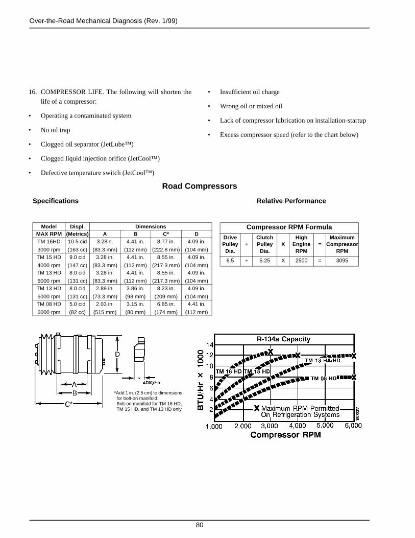
Over-the-Road Mechanical Diagnosis (Rev. 1/99)
80
16. COMPRESSOR LIFE. The following will shorten the
life of a compressor:
• Operating a contaminated system
• No oil trap
• Clogged oil separator (JetLube™)
• Clogged liquid injection orifice (JetCool™)
• Defective temperature switch (JetCool™)
Road Compressors
Specifications Relative Performance
Model Displ. DimensionsMAX RPM (Metrics) A B C* DTM 16HD
3000 rpm
10.5 cid
(163 cc)
3.28in.
(83.3 mm)
4.41 in.
(112 mm)
8.77 in.
(222.8 mm)
4.09 in.
(104 mm)TM 15 HD
4000 rpm
9.0 cid
(147 cc)
3.28 in.
(83.3 mm)
4.41 in.
(112 mm)
8.55 in.
(217.3 mm)
4.09 in.
(104 mm)TM 13 HD
6000 rpm
8.0 cid
(131 cc)
3.28 in.
(83.3 mm)
4.41 in.
(112 mm)
8.55 in.
(217.3 mm)
4.09 in.
(104 mm)TM 13 HD
6000 rpm
8.0 cid
(131 cc)
2.89 in.
(73.3 mm)
3.86 in.
(98 mm)
8.23 in.
(209 mm)
4.09 in.
(104 mm)TM 08 HD
6000 rpm
5.0 cid
(82 cc)
2.03 in.
(515 mm)
3.15 in.
(80 mm)
6.85 in.
(174 mm)
4.41 in.
(112 mm)
Compressor RPM FormulaDrivePulley
Dia.÷
ClutchPulley
Dia.X
HighEngine
RPM=
MaximumCompressor
RPM
6.5 ÷ 5.25 X 2500 = 3095
*Add 1 in. (2.5 cm) to dimensions for bolt-on manifold.Bolt-on manifold for TM 16 HD, TM 15 HD, and TM 13 HD only.
• Insufficient oil charge
• Wrong oil or mixed oil
• Lack of compressor lubrication on installation-startup
• Excess compressor speed (refer to the chart below)

81
Electric Standby Mechanical Diagnosis
CONDITION POSSIBLE CAUSE REMEDY
Compressor does not run Improperly wired Check wiring against diagram
Low line voltage Check line voltage—determine location of voltage drop
Relay contacts not closing Check and replace relay if defective
Power relay open Check relay, replace if defective
Motor wiring defective—open circuit Close power supply start or disconnect switch
Tripped circuit breaker Reset
Open circuit in motor winding Check stator leads. If leads OK, replace stator
High pressure cutout switch open Eliminate cause of excessive pressure
Thermostat faulty Repair or replace
Compressor piston stuck Replace compressor
Frozen compressor or motor bearings
Repair or replace
Shortage of refrigerant Recharge
Low pressure cutout switch open Recharge
Overload relay open Reset
Unit short cycles Evaporator fan rotating in wrong direction
Correction rotation
Shortage of refrigerant (low pressurecutout)
Repair leak and recharge
Restricted expansion valve (low pressure cutout)
Replace expansion valve
Refrigerant overcharge (high pressure cutout)
Remove excess charge
Cycling on high pressure cutout Check air flow and fan
Clogged condenser coil Clean coil
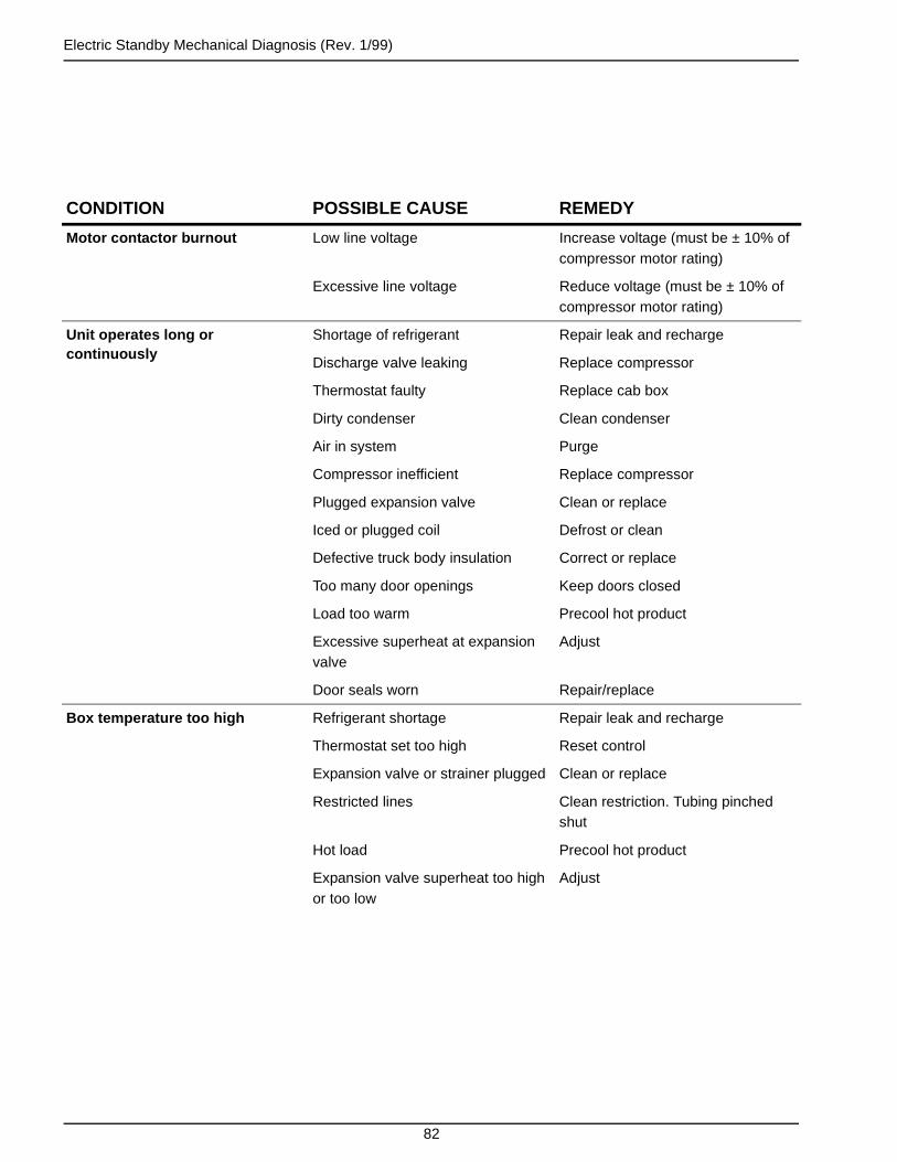
Electric Standby Mechanical Diagnosis (Rev. 1/99)
82
Motor contactor burnout Low line voltage Increase voltage (must be ± 10% of compressor motor rating)
Excessive line voltage Reduce voltage (must be ± 10% of compressor motor rating)
Unit operates long or continuously
Shortage of refrigerant Repair leak and recharge
Discharge valve leaking Replace compressor
Thermostat faulty Replace cab box
Dirty condenser Clean condenser
Air in system Purge
Compressor inefficient Replace compressor
Plugged expansion valve Clean or replace
Iced or plugged coil Defrost or clean
Defective truck body insulation Correct or replace
Too many door openings Keep doors closed
Load too warm Precool hot product
Excessive superheat at expansion valve
Adjust
Door seals worn Repair/replace
Box temperature too high Refrigerant shortage Repair leak and recharge
Thermostat set too high Reset control
Expansion valve or strainer plugged Clean or replace
Restricted lines Clean restriction. Tubing pinched shut
Hot load Precool hot product
Expansion valve superheat too high or too low
Adjust
CONDITION POSSIBLE CAUSE REMEDY

Electric Standby Mechanical Diagnosis (Rev. 1/99)
83
Head pressure too high Refrigerant overcharge Remove excess
Air in system Evacuate system
Dirty condenser Clean
Restricted condenser Clean condenser
Condenser fan not running Check fan motor
Condenser fan rotating backwards Check direction
Head pressure too low Refrigerant shortage Repair leak and recharge
Compressor suction or discharge valve inefficient
Replace compressor
Noisy unit Insufficient compressor oil Add oil to proper level
Mounting bolts loose Tighten
Oil slugging or refrigerant flooding back
Adjust oil level or refrigerant charge. Check expansion valve for proper superheat
Compressor loses oil Shortage of refrigerant Repair leak and recharge
Plugged expansion valve or strainer Clean or replace
Wrong oil viscosity Use proper oil
Short cycling Refer to Unit Short Cycles
Superheat too high Adjust expansion valve
Frosted or sweating suction line Expansion valve set too low, admitting excess refrigerant
Adjust expansion valve
Heat exchanger internal leak Replace
Hot liquid line Shortage of refrigerant Repair leak and recharge
Frosted liquid line Restricted dehydrator or strainer Replace restricted part
Condenser coils cool when unit is in cool
Refrigerant undercharge Repair leak and recharge
Compressor inefficient Replace compressor
CONDITION POSSIBLE CAUSE REMEDY

Electric Standby Mechanical Diagnosis (Rev. 1/99)
84
Unit in vacuum. Frost on expansion valve only
Ice plugging expansion valve orifice Apply hot wet cloth to expansion valve. Moisture indicated by increase in suction pressure. Replace drier
Plugged expansion valve strainer Clean strainer or replace expansion valve
Sensor bulb lost charge Replace expansion valve
ELECTRIC STANDBY SERVICE CHECKS
1. Motor does not run 1. Check for power at source2. Check for power at plug3. Check for power at compressor contactor4. Check for power at overload terminals (contactor
closed)5. Check for power at motor terminals
2. Power at motor terminals but motor does not run 1. Replace motor
3. Motor hums but does not run 1. Check for locked rotor2. Check for worn bearings. Replace if necessary3. Check for locked compressor and repair4. Power source for single phasing5. Check capacitors (on single phase units)
4. Check transformer 1. Check for power output 16 Vac, 12 volt system
5. Check rectifier 1. Check for rectifier output 14 Vdc, 12 volt system
CONDITION POSSIBLE CAUSE REMEDY
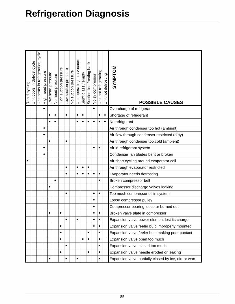
85
Refrigeration DiagnosisR
apid
cyc
ling
Uni
t coo
ls in
def
rost
cyc
le
Uni
t hea
ts in
ref
riger
atio
n cy
cle
Hig
h he
ad p
ress
ure
Low
hea
d pr
essu
re
No
head
pre
ssur
e
Hig
h su
ctio
n pr
essu
re
Low
suc
tion
pres
sure
No
suct
ion
pres
sure
Uni
t ope
ratin
g in
a v
acuu
m
Sig
ht g
lass
/ em
pty
Suc
tion
line
fros
ting
back
Noi
sy c
ompr
esso
r
Uni
t not
ref
riger
atin
g
Uni
t not
def
rost
ing
SY
MP
TO
M
POSSIBLE CAUSES• • Overcharge of refrigerant
• • • • • • • Shortage of refrigerant
• • • • • • • • No refrigerant
• Air through condenser too hot (ambient)
• Air flow through condenser restricted (dirty)
• • Air through condenser too cold (ambient)
• • • Air in refrigerant system
• Condenser fan blades bent or broken
• Air short cycling around evaporator coil
• • • • Air through evaporator restricted
• • • • • • Evaporator needs defrosting
• • Broken compressor belt
• Compressor discharge valves leaking
• • • Too much compressor oil in system
• Loose compressor pulley
• Compressor bearing loose or burned out
• • • • Broken valve plate in compressor
• • • • Expansion valve power element lost its charge
• • • Expansion valve feeler bulb improperly mounted
• • • Expansion valve feeler bulb making poor contact
• • • • Expansion valve open too much
• • Expansion valve closed too much
• • • Expansion valve needle eroded or leaking
• • • • Expansion valve partially closed by ice, dirt or wax

Refrigeration Diagnosis (Rev. 1/99)
86
• • • • Liquid refrigerant entering compressor
• • • Restricted line on the low side
• • Restricted line on the high side
• • • Restricted dehydrator
• • Reversed fan rotation
• • • Leak in heat exchanger
• • • • • Faulty pilot solenoid
• • Loose or broken electrical connections
• • • • Gauge out of calibration
• • Leaky bypass check valve
• • Leaky condenser check valve
• Condenser fan motor not operating
• • • • • Evaporator fan motor not operating
• Belts are loose
Rap
id c
yclin
g
Uni
t coo
ls in
def
rost
cyc
le
Uni
t hea
ts in
ref
riger
atio
n cy
cle
Hig
h he
ad p
ress
ure
Low
hea
d pr
essu
re
No
head
pre
ssur
e
Hig
h su
ctio
n pr
essu
re
Low
suc
tion
pres
sure
No
suct
ion
pres
sure
Uni
t ope
ratin
g in
a v
acuu
m
Sig
ht g
lass
/ em
pty
Suc
tion
line
fros
ting
back
Noi
sy c
ompr
esso
r
Uni
t not
ref
riger
atin
g
Uni
t not
def
rost
ing
SY
MP
TO
MPOSSIBLE CAUSES

87
Wiring and Schematic Diagrams Index
Refrigeration Mode Schematic Page
CBci 10 in Cool 89
CBci 10 in Defrost 90
CBci 20 in Cool 91
CBci 20 in Defrost 92
CBci 10 in Cool (Reference Only for Older Units) 93
CBci 10 in Defrost (Reference Only for Older Units) 94
CBci 20 in Cool (Reference Only for Older Units) 95
CBci 20 in Defrost (Reference Only for Older Units) 96
Dwg No. Drawing Title Rev. Page
5D37084 Model 10 and 20 Schematic Diagram H 97
5D37245 Model 10 Wiring Diagram G 98
5D37311 Model 20 Wiring Diagram C 99
5D45773 Model 20 Single Phase with Heat Option Schematic Diagram A 100
5D39290 Model 20 Single Phase Wiring Diagram A 101

88
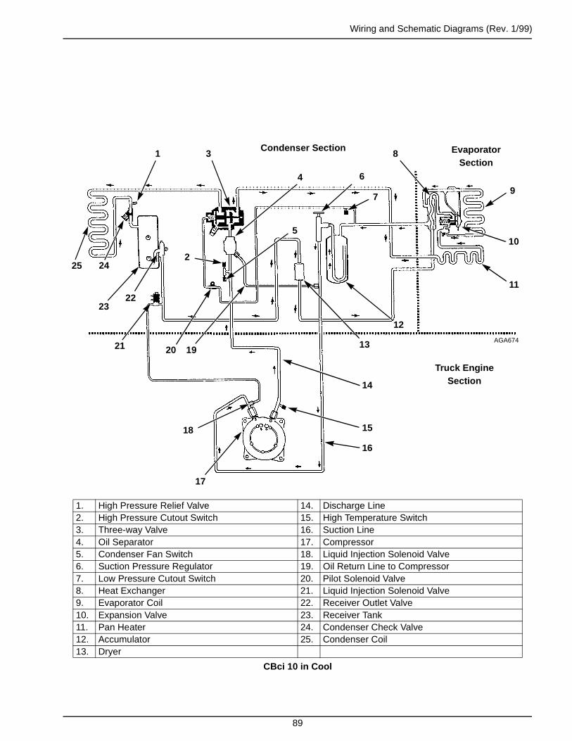
Wiring and Schematic Diagrams (Rev. 1/99)
89
1. High Pressure Relief Valve 14. Discharge Line2. High Pressure Cutout Switch 15. High Temperature Switch3. Three-way Valve 16. Suction Line4. Oil Separator 17. Compressor5. Condenser Fan Switch 18. Liquid Injection Solenoid Valve6. Suction Pressure Regulator 19. Oil Return Line to Compressor7. Low Pressure Cutout Switch 20. Pilot Solenoid Valve8. Heat Exchanger 21. Liquid Injection Solenoid Valve9. Evaporator Coil 22. Receiver Outlet Valve10. Expansion Valve 23. Receiver Tank11. Pan Heater 24. Condenser Check Valve12. Accumulator 25. Condenser Coil13. Dryer
CBci 10 in Cool
1 3
2
20
4
25 24
2322
21
7
6
8
9
12
10
11
14
15
16
17
18
19AGA674
Condenser Section Evaporator Section
Truck Engine Section
5
13
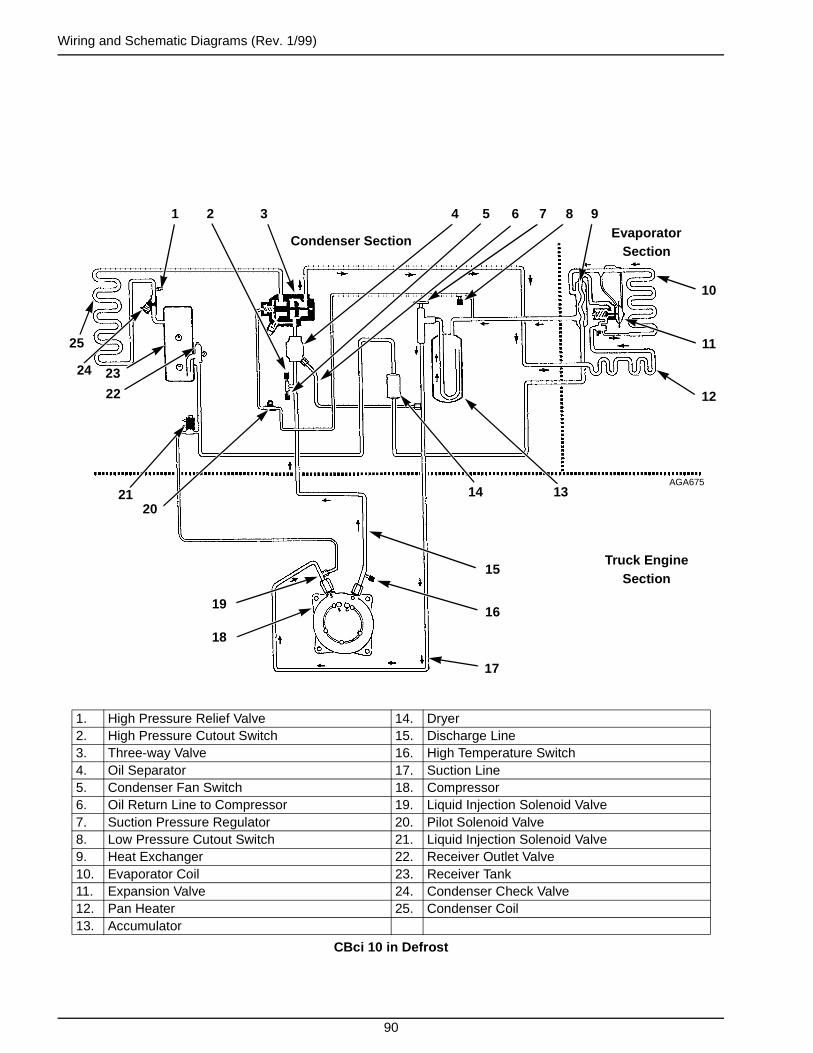
Wiring and Schematic Diagrams (Rev. 1/99)
90
1. High Pressure Relief Valve 14. Dryer2. High Pressure Cutout Switch 15. Discharge Line3. Three-way Valve 16. High Temperature Switch4. Oil Separator 17. Suction Line5. Condenser Fan Switch 18. Compressor6. Oil Return Line to Compressor 19. Liquid Injection Solenoid Valve7. Suction Pressure Regulator 20. Pilot Solenoid Valve8. Low Pressure Cutout Switch 21. Liquid Injection Solenoid Valve9. Heat Exchanger 22. Receiver Outlet Valve10. Evaporator Coil 23. Receiver Tank11. Expansion Valve 24. Condenser Check Valve12. Pan Heater 25. Condenser Coil13. Accumulator
CBci 10 in Defrost
1 32
20
4
25
23
22
21
5
14
6 7 8
11
9
10
13
15
16
17
18
19
AGA675
Condenser SectionEvaporator
Section
Truck Engine Section
12
24

Wiring and Schematic Diagrams (Rev. 1/99)
91
1. Condenser Check Valve 15. Accumulator2. high Pressure Relief Valve 16. Standby Compressor3. Pilot Solenoid Valve 17. Suction Line4. Three-way Valve 18. Discharge Check Valve5. High Pressure Cutout Switch 19. Discharge Line6. Condenser Fan Switch 20. High Temperature Switch7. Oil Separator 21. Compressor8. Oil Return Line to Compressor 22. Liquid Injection Line Orifice9. Low Pressure Cutout Switch 23. Liquid Injection Solenoid Valve10. Suction Pressure Regulator 24. Drier11. Heat Exchanger 25. Receiver Tank12. Evaporator Coil 26. Receiver Outlet Valve13. Expansion Valve 27. Condenser Coil14. Pan Heater
CBci 20 in Cool
1
Condenser Section Evaporator Section
Truck Engine Section
AGA676
2 3
4
5
6
7 8 9 10 11 12
1314
1516
17
18
19
20
2122
23
24
25
26
27
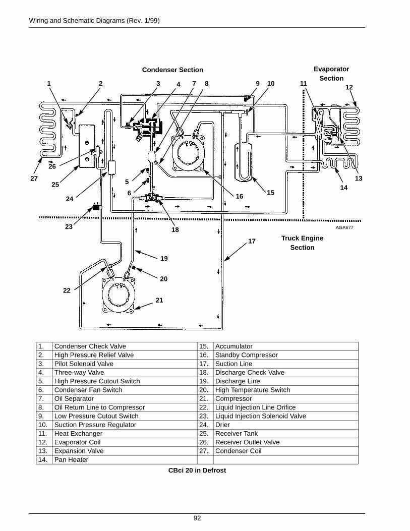
Wiring and Schematic Diagrams (Rev. 1/99)
92
1. Condenser Check Valve 15. Accumulator2. High Pressure Relief Valve 16. Standby Compressor3. Pilot Solenoid Valve 17. Suction Line4. Three-way Valve 18. Discharge Check Valve5. High Pressure Cutout Switch 19. Discharge Line6. Condenser Fan Switch 20. High Temperature Switch7. Oil Separator 21. Compressor8. Oil Return Line to Compressor 22. Liquid Injection Line Orifice9. Low Pressure Cutout Switch 23. Liquid Injection Solenoid Valve10. Suction Pressure Regulator 24. Drier11. Heat Exchanger 25. Receiver Tank12. Evaporator Coil 26. Receiver Outlet Valve13. Expansion Valve 27. Condenser Coil14. Pan Heater
CBci 20 in Defrost
AGA677
1
Condenser Section Evaporator Section
Truck Engine Section
2 3 4
5
6
7 8 9 10 11 12
1314
1516
17
18
19
20
2122
23
24
25
26
27

Wiring and Schematic Diagrams (Rev. 1/99)
93
1. High Pressure Relief Valve 14. Discharge Line2. High Pressure Cutout Switch 15. High Temperature Switch3. Three-way Valve 16. Suction Line4. Condenser Fan Switch 17. Compressor5. Suction Pressure Regulator 18. Liquid Injection Solenoid Valve6. Low Pressure Cutout Switch 19. Oil Return Line to Compressor7. Heat Exchanger 20. Pilot Solenoid Valve8. Evaporator Coil 21. Liquid Injection Solenoid Valve9. Expansion Valve 22. Receiver Outlet Valve10. Pan Heater 23. Receiver Tank11. Accumulator 24. Condenser Check Valve12. Drier 25. Condenser Coil13. Oil Separator
CBci 10 in Cool(Reference Only for Older Units)
1 3
2
20
4
2524
23 22
21
6
5
7
8
11
9
10
13
15
16
17
18
19
AGA302
Condenser Section Evaporator Section
Truck Engine Section
12
14

Wiring and Schematic Diagrams (Rev. 1/99)
94
1. High Pressure Relief Valve 14. Discharge Line2. High Pressure Cutout Switch 15. High Temperature Switch3. Three-way Valve 16. Suction Line4. Condenser Fan Switch 17. Compressor5. Suction Pressure Regulator 18. Liquid Injection Solenoid Valve6. Low Pressure Cutout Switch 19. Oil Return Line to Compressor7. Heat Exchanger 20. Pilot Solenoid Valve8. Evaporator Coil 21. Liquid Injection Solenoid Valve9. Expansion Valve 22. Receiver Outlet Valve10. Pan Heater 23. Receiver Tank11. Accumulator 24. Condenser Check Valve12. Drier 25. Condenser Coil13. Oil Separator
CBci 10 in Defrost(Reference Only for Older Units)
AGA303
1
2
3
4
5 6
7
8
9
10
11
12
1314
15
16
17
18
19
20
21
2223
2425
Condenser Section Evaporator Section
Truck Engine Section

Wiring and Schematic Diagrams (Rev. 1/99)
95
1. Condenser Check Valve 15. Discharge Check Valve2. High Pressure Relief Valve 16. Oil Separator3. Pilot Solenoid Valve 17. Discharge Line4. Three-way Valve 18. Suction Line5. High Pressure Cutout Switch 19. High Temperature Switch6. Condenser Fan Switch 20. Compressor7. Low Pressure Cutout Switch 21. Liquid Injection Line Orifice8. Suction Pressure Regulator 22. Oil Return Line to Compressor9. Heat Exchanger 23. Liquid Injection Solenoid Valve10. Evaporator Coil 24. Drier11. Expansion Valve 25. Receiver Outlet Valve12. Pan Heater 26. Receiver Tank13. Accumulator 27. Condenser Coil14. Standby Compressor
CBci 20 in Cool(Reference Only for Older Units)
AGA304
12
3
45
6
7 89
1011
12
13
1415
16
17
18
20
1921
22
23
24
25
2627
Condenser Section Evaporator Section
Truck Engine Section

Wiring and Schematic Diagrams (Rev. 1/99)
96
1. Condenser Check Valve 15. Discharge Check Valve2. High Pressure Relief Valve 16. Oil Separator3. Pilot Solenoid Valve 17. Discharge Line4. Three-way Valve 18. Suction Line5. High Pressure Cutout Switch 19. High Temperature Switch6. Condenser Fan Switch 20. Compressor7. Low Pressure Cutout Switch 21. Liquid Injection Line Orifice8. Suction Pressure Regulator 22. Oil Return Line to Compressor9. Heat Exchanger 23. Liquid Injection Solenoid Valve10. Evaporator Coil 24. Drier11. Expansion Valve 25. Receiver Outlet Valve12. Pan Heater 26. Receiver Tank13. Accumulator 27. Condenser Coil14. Standby Compressor
CBci 20 in Defrost(Reference Only for Older Units)
AGA305
12
3
45
6
7 89
1011
12
13
1415
16
17
18
20
1921
22
23
24
25
2627
Truck Engine Section
Condenser Section Evaporator Section

97
Mo
del
10
and
20
Sch
emat
ic D
iag
ram

98
Mo
del
10
Wir
ing
Dia
gra
m

99
Mo
del
20
Wir
ing
Dia
gra
m
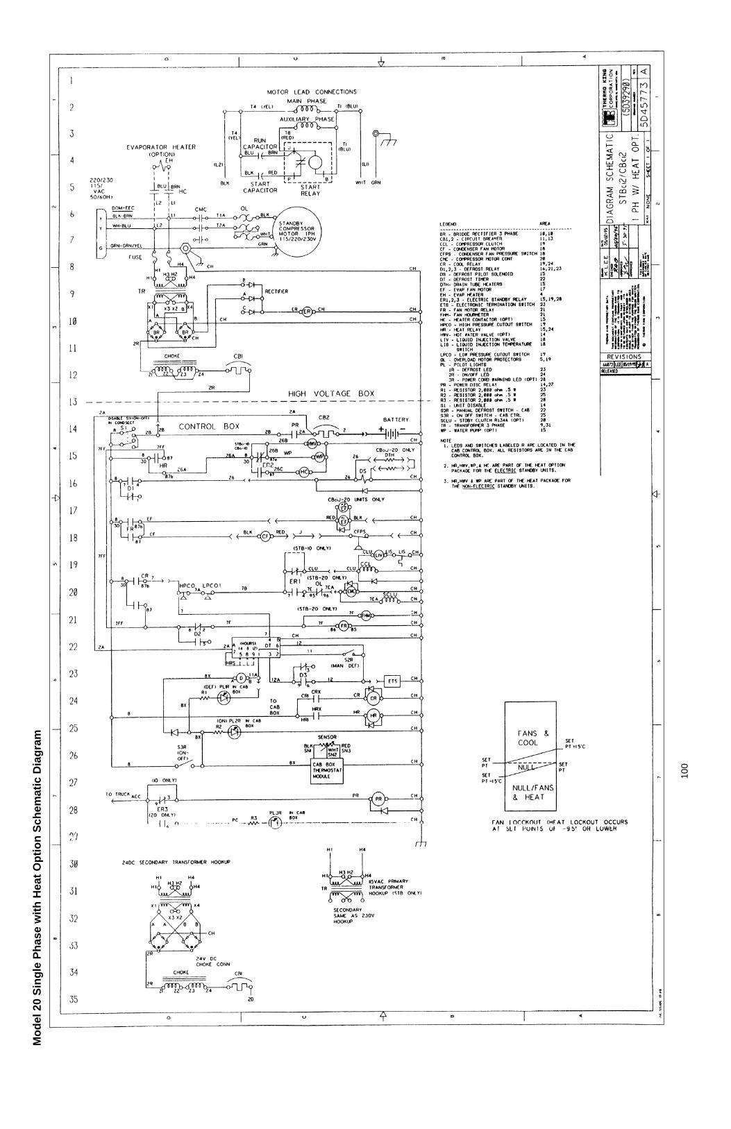
100
Mo
del
20
Sin
gle
Ph
ase
wit
h H
eat
Op
tio
n S
chem
atic
Dia
gra
m

101
Mo
del
20
Sin
gle
Ph
ase
Wir
ing
Dia
gra
m