Embed Size (px)
Citation preview

Assembly InstructionsConference Room Mac
rooms

Tools Required For InstallTape measure, drill & drill bits, stud finder, socket set, screwdrivers (regular & philips), utility knife, drywall saw, pencil, blue painter tape, small shop vac, level
Tape Measure
Socket Set
Drywall Saw
Shop Vac
Painters Tape
Level
Screw Drivers
Drill and Bits
Pencil
Utility Knife
Stud Finder

Parts List Huddle Room Dell
Aver Cam340 Heckler Design Meeting Room Console
Lindy HDMI NON-CEC Adapter
50ft CAT6 cable
Cable Tie Mount pads
6ft CAT6 cable
TechFlex Cable Cover Split Loom
Tryten Wall Mount
Kramer 6’ Flexible High-Speed HDMI
cable
Star Tech USB to Lightning 3M
Grainger #6 zinc wood screws
Logitech Wireless Keyboard w/
touchpad
Heckler Design Camera Mount
Pulse Eight USB to HDMI CEC control
adapter
IOGear USB Extender
7.5” Cable ties
APC AC Power strip w/7 Outlet
3M 1”x 3” Re-closable fasteners clear
3/8 Toggle BoltsX4
Chief FCAV1UAccesory Arms
Chief LTM1UWall Mount
55 Inch Display Brush Plate x 2
9.7 Inch iPad MXL AC404 Microphones X2
Mac Mini
1A 6A
11
16
21
2
7
12
17
22
3
8
13
18
23
4
9
14
19
24
5
10
15
20
25 26

WARNING:
IMPROPER INSTALLATION CAN LEAD TO MOUNT FALLING CAUSING SEVERE PERSONAL INJURY OR
DAMAGE TO EQUIPMENT!It is the installers responsibility to make certain the structure to which the accessory is being attached is capable of supporting five times the combined weight of accessory and mount, not to exceed weight capacities listed in Table 1
Table 1:
Use this accessory only for its intended use as described in these instructions. Do not use attachments not recommended by the manufacturer. WARNING: Never operate this accessory if it is damaged. Return the accessory to a service center for examination and repair. WARNING: Do not use this product outdoors.
IMPORTANT ! : The FCAV1U accessory is designed to be mounted to:a bare 8” concrete or 8”x8”x16” concrete block wall, ora 2” x 4” wood studs wall covered by drywall with maximum thickness of 5/8”:MSM1U/MTM1U/MTMP1U: Wood studs must be 16” on center;LSM1U/LTM1U: Wood studs may be 16” or 24” on center;XSM1U/XTM1U: Wood studs may be 24” or 32” on center.
NOTE: Accessory is intended to be used with the following Chief mounting systems (not included):
Before You BeginVerify you meet all the system requirements for a Zoom Rooms for Huddle Rooms (2-7 people) as outlined on the Zoom website - https://support.zoom.us/hc/en-us/articles/115005412443-Zoom-Rooms-for-Huddle-Room
You will need some information gathered ahead of time as you prepare your computer and iPad for use with Zoom and Zoom Rooms.
Room Name__________Computer Login Name_________Computer Login PW_________Apple ID Login Name__________Apple ID PW__________Zoom Room Admin Login__________Zoom Room Login PW__________Zoom Room App Lock Code__________iPad Access Code__________Guided Access Passcode__________WiFi SSID__________WiFi PW__________
You may choose to have your IT staff provision your PC and iPad for use on your network rather than following the instructions later in this document. You can have your IT staff unbox and prepare the units for use in your installation. You will need the computer and iPad back in a few hours. You will still also need most, if not all, of the information listed above.
Ensure that your room meets the “Conduit / Backing / General Contractor details” diagram on the webpage listed above (shown below) as it relates to AC power receptacle, data wall plate, AV junction box and conduit (note – the AV junction box and conduit can be omitted and the provided brush plate assemblies can be used if the wall interior access and local code allows pulling of cable within the wall cavity). (See Figure 1)
Figure 1
(image courtesy of Zoom’s webpage as of 03-13-18)
Verify that you have all the necessary tools as outlined on page 2.
Verify that you have all the parts in the kit as outlined on page 3.

Locate and Mark the Mounting SiteDetermine if the display will be centered on the wall or centered on the meeting room table.
If the display will be centered on the wall: Measure the width of the wall where the display will be mounted.
Determine the centerline of the room and mark the centerline with a short strip (6” to 8”) of the blue tape at a location approximately 60” to 66”.
If the display will be centered on the meeting table:Determine the centerline of the meeting table and mark the centerline of the meeting table on the wall with a short strip (6” to 8”) of the blue tape at a location approximately 60” to 66”.
Measure 61.5” above the finished floor and mark the spot on the centerline’s blue tape. This will be the center point of the display.
Make a template of where the display will be installed by marking the outer edges of where the intended display location by creating a rectangular perimeter with the blue tape. The outside edge of the tape should represent the outside edge of the display. You can easily do this by measuring out 24” from the centerline and placing a strip of tape representing the two sides of the display to the left and to the right of the centerline. Then measure 48” up from the floor and place a horizontal strip of tape to represent the bottom edge of the display. Place a strip of tape to represent the top of the display at 75” above the finished floor. After creating the rectangle make sure the top and bottom tape lines are parallel to the floor and the side lines are perpendicular to the floor. You can measure from opposite corners to ensure that you have proper rectangle. The measurement from upper left to lower right corner should equal the measurement from the upper right to the lower left corner. (See Figure 2)
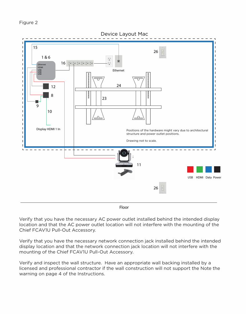
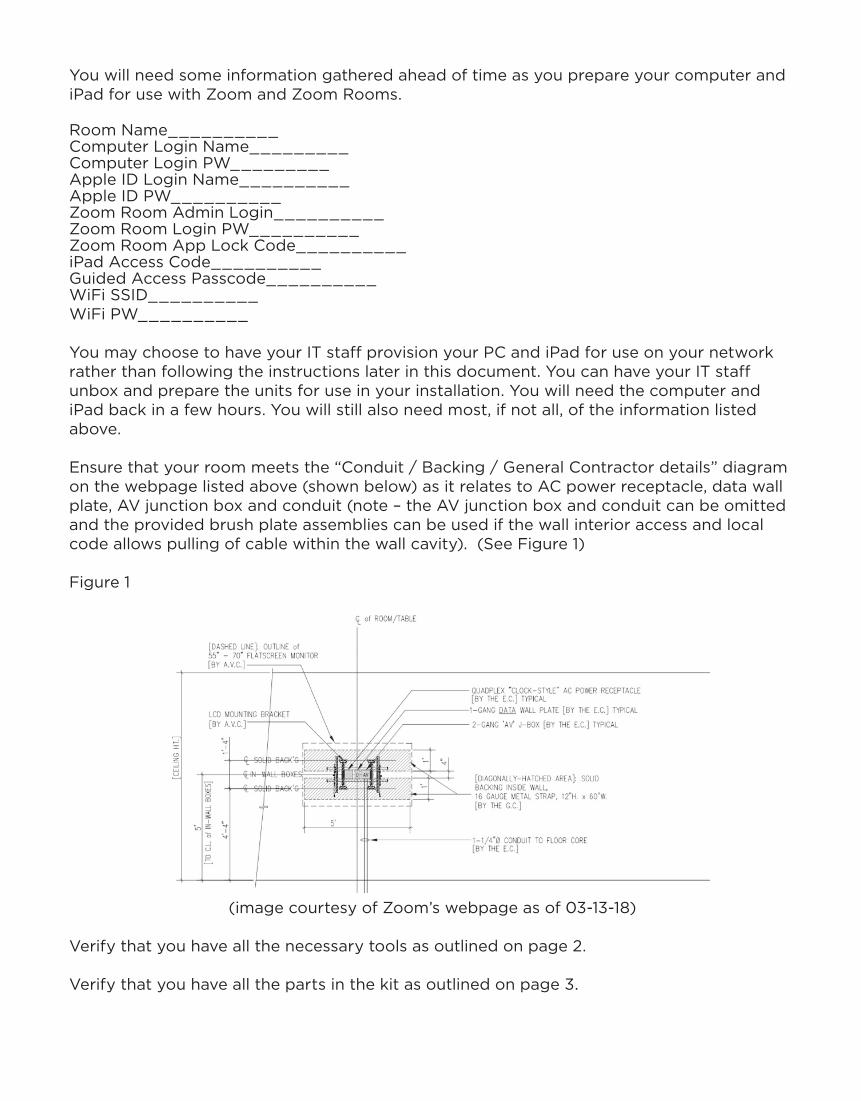
Figure 2
Verify that you have the necessary AC power outlet installed behind the intended display location and that the AC power outlet location will not interfere with the mounting of the Chief FCAV1U Pull-Out Accessory.
Verify that you have the necessary network connection jack installed behind the intended display location and that the network connection jack location will not interfere with the mounting of the Chief FCAV1U Pull-Out Accessory.
Verify and inspect the wall structure. Have an appropriate wall backing installed by a licensed and professional contractor if the wall construction will not support the Note the warning on page 4 of the Instructions.
Device Layout Mac
Positions of the hardware might vary due to architecturalstructure and power outlet positions.
Drawing not to scale.
12
8
161 & 6
15
Display HDMI 1 In
Ethernet
11
Floor
23
24
26
26
3
USBHDMIEthernet
USBUSB
910
USB HDMI Data Power
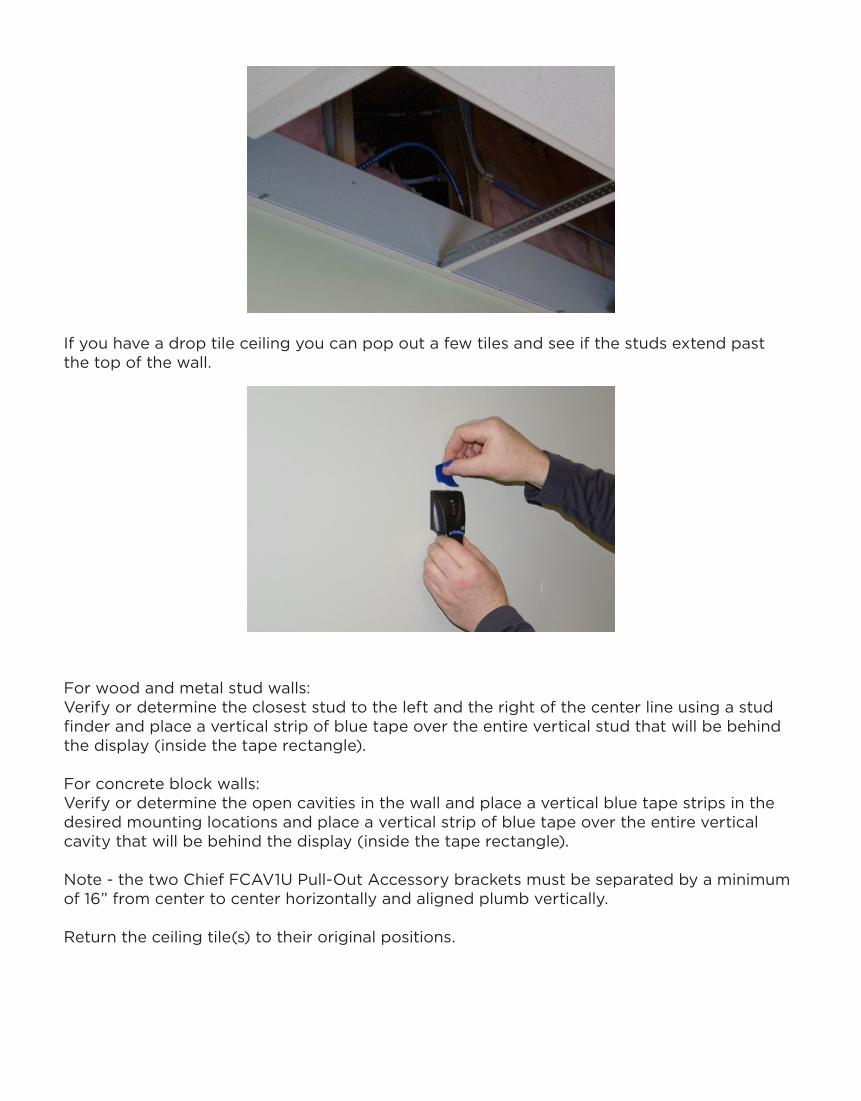
If you have a drop tile ceiling you can pop out a few tiles and see if the studs extend past the top of the wall.
For wood and metal stud walls:Verify or determine the closest stud to the left and the right of the center line using a stud finder and place a vertical strip of blue tape over the entire vertical stud that will be behind the display (inside the tape rectangle).
For concrete block walls:Verify or determine the open cavities in the wall and place a vertical blue tape strips in the desired mounting locations and place a vertical strip of blue tape over the entire vertical cavity that will be behind the display (inside the tape rectangle).
Note - the two Chief FCAV1U Pull-Out Accessory brackets must be separated by a minimum of 16” from center to center horizontally and aligned plumb vertically.
Return the ceiling tile(s) to their original positions.

Installing the Chief FCAV1U Pull-Out Accessory to a Wood Stud Wall
Skip to the next section if mounting to a metal studSkip two sections if mounting to a concrete block wall
Locate and open the Chief FCAV1U Pull-Out Accessory box – Item 23. Keep the included hardware nearby for use in mounting the Pull-Out Accessory. Read and follow the included instructions from Chief. Also refer to Figure 3.
Figure 3
(image courtesy of Chief instructions as of 03-13-18)
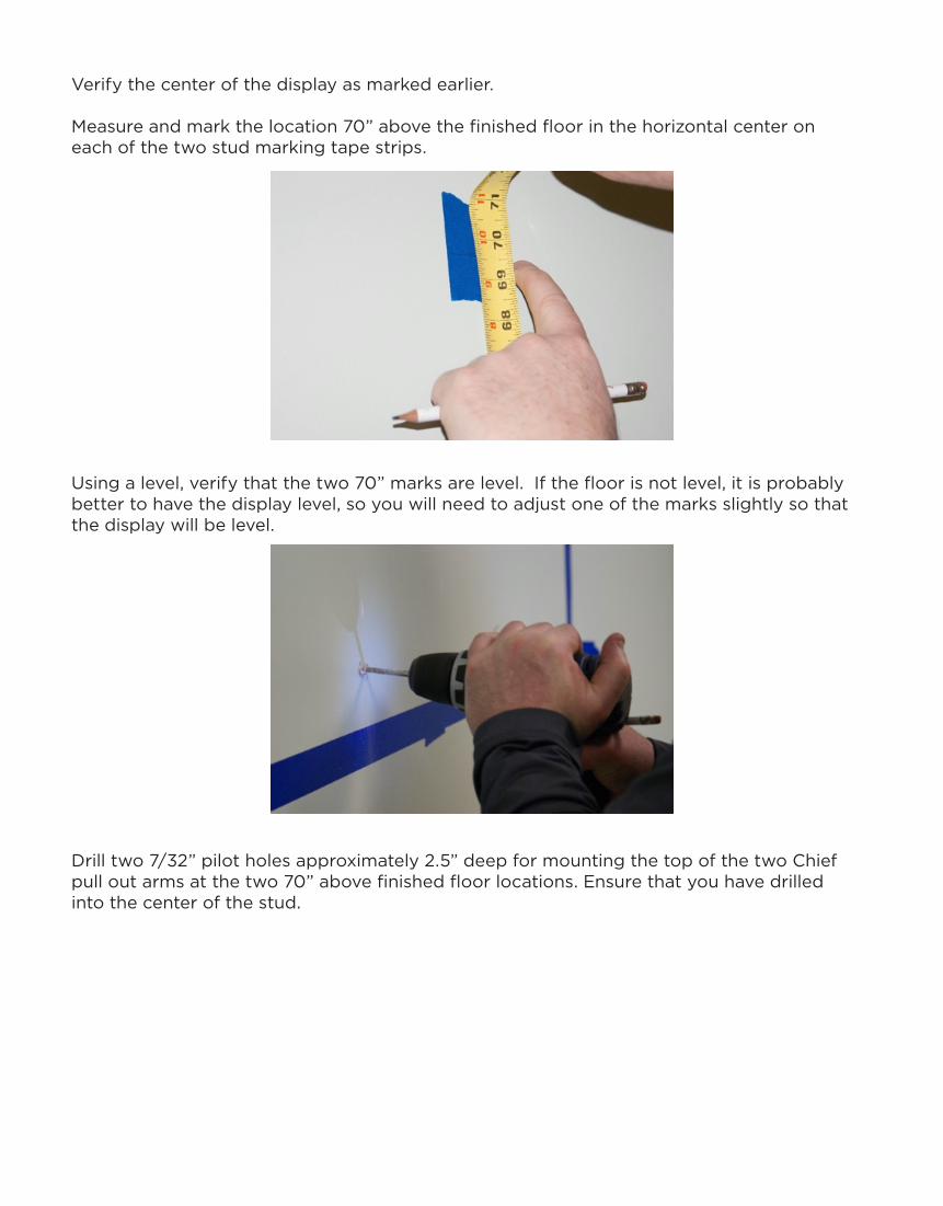
Verify the center of the display as marked earlier.
Measure and mark the location 70” above the finished floor in the horizontal center on each of the two stud marking tape strips.
Using a level, verify that the two 70” marks are level. If the floor is not level, it is probably better to have the display level, so you will need to adjust one of the marks slightly so that the display will be level.
Drill two 7/32” pilot holes approximately 2.5” deep for mounting the top of the two Chief pull out arms at the two 70” above finished floor locations. Ensure that you have drilled into the center of the stud.

Using a 1/2” socket and socket wrench, partially install two of the flanged bolts provided by Chief in the two holes leaving about ¼” not fully tightened.
Using a level or a plumb line, mark the location on the stud marking tape 17.5” directly below center of the two upper flanged bolts for the attachment points for the two lower mounting holes.
Drill two 7/32” pilot holes approximately 2.5” deep for mounting the bottom of the two Chief pull-out arms at the two 52.5” above finished floor (70” – 17.5” = 52.5”) locations. Ensure that you have drilled into the center of the stud.
Proceed to the “Hang the Chief FCAV1U on the wall” section

Installing the Chief FCAV1U Pull-Out Accessory to a Metal Stud Wall
Locate and open the Chief FCAV1U Pull-Out Accessory box – Item 23. Keep the included hardware nearby for use in mounting the Pull-Out Accessory. Read and follow the included instructions from Chief. Also refer to Figure 4.
Figure 4
(image courtesy of Chief instructions as of 03-13-18)
Verify the center of the display as marked earlier.
Measure and mark the location 70” above the finished floor in the horizontal center on each of the two stud marking tape strips.
Using a level, verify that the two 70” marks are level. If the floor is not level, it is probably better to have the display level, so you will need to adjust one of the marks slightly so that the display will be level.
Figure 5
(image courtesy of Hilti instructions as of 03-13-18)

Drill two 3/4” holes approximately 2.5” deep for mounting the top of the two Chief pull out arms at the two 70” above finished floor locations. Locate and install two of the 3/8” channel toggle bolt anchors – Item 22. (See Figure 5)
Position the metal channel of the toggle bolt anchor parallel with the plastic legs.
Insert the metal channel through the two drilled holes into the wall cavity.
Pull the metal channel firmly against the inner wall cavity by tugging the plastic pull ring.
Slide the plastic cap forward along the legs until it is seated flush to the work surface.
Snap the plastic legs off flush at the plastic cap by pushing outward.
Using a 1/2” socket and socket wrench, partially install two of the flanged bolts provided by Chief in the two holes leaving about ¼” not fully tightened.
Using a level or a plumb line, mark the location on the stud marking tape 17.5” directly below center of the two upper flanged bolts for the attachment points for the two lower mounting holes.
Drill two 3/4” holes approximately 2.5” deep for mounting the bottom of the two Chief pull out arms at the two 52.5” above finished floor (70” – 17.5” = 52.5”) locations. Locate and install two of the 3/8” channel toggle bolt anchors – Item 22 as described above in these two lower holes.
Proceed to the “Hang the Chief FCAV1U on the wall” section

Installing the Chief FCAV1U Pull-Out Accessory to a Concrete Block Wall
Locate and open the Chief FCAV1U Pull-Out Accessory box – Item 23. Keep the included hardware nearby for use in mounting the Pull-Out Accessory. Read and follow the included instructions from Chief. Also refer to Figure 6.
Figure 6
(image courtesy of Chief instructions as of 03-13-18)
Verify the center of the display as marked earlier.
Measure and mark the location 70” above the finished floor in the horizontal center on each of the two stud marking tape strips.
Using a level, verify that the two 70” marks are level. If the floor is not level, it is probably better to have the display level, so you will need to adjust one of the marks slightly so that the display will be level.
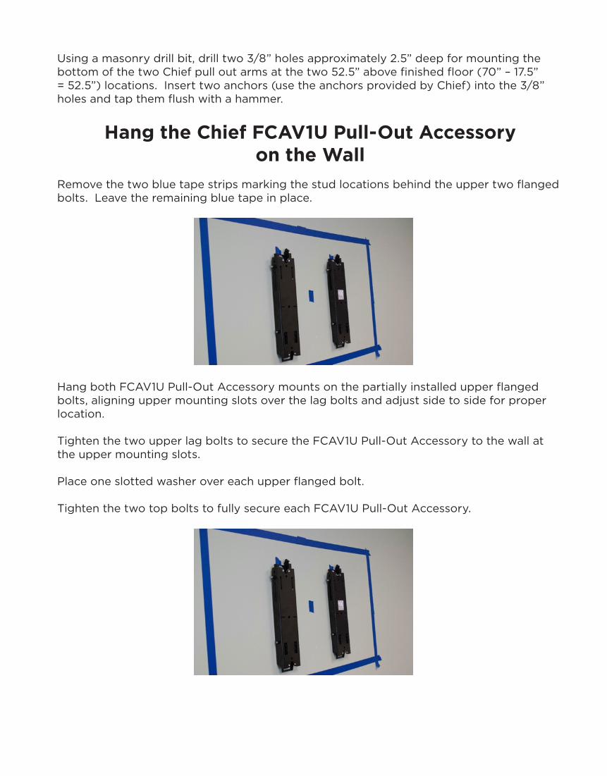
Using a masonry drill bit, drill two 3/8” holes approximately 3.5” deep for the top of the two Chief pull out arms at the two 70” above finished floor locations. Insert two anchors (use the anchors provided by Chief) into the 3/8” holes and tap them flush with a hammer.
Using a 1/2” socket and socket wrench, partially install two of the flanged bolts provided by Chief in the two holes leaving about ¼” not fully tightened.
Using a level or a plumb line, mark the location on the stud marking tape 17.5” directly below center of the two upper flanged bolts for the attachment points for the two lower mounting holes.
Using a masonry drill bit, drill two 3/8” holes approximately 2.5” deep for mounting the bottom of the two Chief pull out arms at the two 52.5” above finished floor (70” – 17.5” = 52.5”) locations. Insert two anchors (use the anchors provided by Chief) into the 3/8” holes and tap them flush with a hammer.
Hang the Chief FCAV1U Pull-Out Accessoryon the Wall
Remove the two blue tape strips marking the stud locations behind the upper two flanged bolts. Leave the remaining blue tape in place.
Hang both FCAV1U Pull-Out Accessory mounts on the partially installed upper flanged bolts, aligning upper mounting slots over the lag bolts and adjust side to side for proper location.
Tighten the two upper lag bolts to secure the FCAV1U Pull-Out Accessory to the wall at the upper mounting slots.
Place one slotted washer over each upper flanged bolt.
Tighten the two top bolts to fully secure each FCAV1U Pull-Out Accessory.

Install the lower two flanged bolts and slotted washers to both pullout mounts but do not fully tighten.
Using a 1/2” socket and socket wrench, partially install two of the flanged bolts with two slotted washers (one on each bolt) provided by Chief in the two holes leaving about ¼” not fully tightened.
Check to ensure the two mounts are vertical and tighten the lower two flanged bolts using the socket and socket wrench. Note - the Chief FCAV1U and LTM1U have adjustments to allow for plumb mounting if the mount isn’t perfectly vertical – but it needs to be close. See page 8 of Chief’s FCAV1U instructions to optionally lock the display close to the wall or to make adjustments to the plumb of the bracket.
Locate and open the Chief Flat Panel Mount LTM1U – Item 24. Read and follow the included instructions from Chief.
Organize the included Chief LTM1U Flat Panel Mount hardware for use in this section.
Attach the LTM1U Flat Panel Mount to the FCAV1U Pull-Out Accessory using the hardware included with the LTM1U.
Attach the top of the LTM1U Flat Panel Mount – Item 24 to the top of the FCAV1U Pull-Out Accessory – Item 23 using two 5/16”-18 x ½” button head cap screw (G) and two 5/16” washers (J) in each top mounting slot (see figure #?).

Attach the bottom of the LTM1U Flat Panel Mount to the bottom of the FCAV1U Pull-Out Accessory using two ¼”-20 x ½” socket head cap screw (F) and two ¼” washers (H) in each bottom mounting slot. (See Figure 7)
Figure 7
(image courtesy of Chief instructions as of 03-13-18)
Slide the rails to the approximate center of the display location.
Locking Rails (Optional)
Lock the rails into place using two 1/4”-20 x ¾” set screws (T) on mount upright (CC) and the 1/8” hex key (R). (See Figure 8)
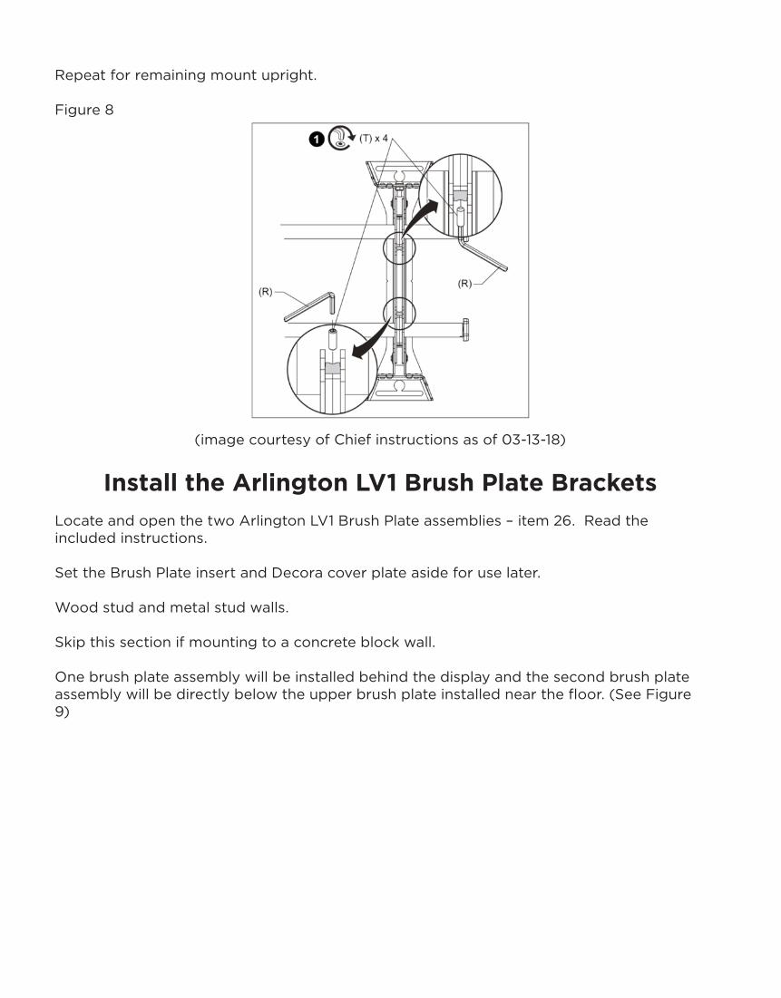
Repeat for remaining mount upright.
Figure 8
(image courtesy of Chief instructions as of 03-13-18)
Install the Arlington LV1 Brush Plate BracketsLocate and open the two Arlington LV1 Brush Plate assemblies – item 26. Read the included instructions.
Set the Brush Plate insert and Decora cover plate aside for use later.
Wood stud and metal stud walls.
Skip this section if mounting to a concrete block wall.
One brush plate assembly will be installed behind the display and the second brush plate assembly will be directly below the upper brush plate installed near the floor. (See Figure 9)
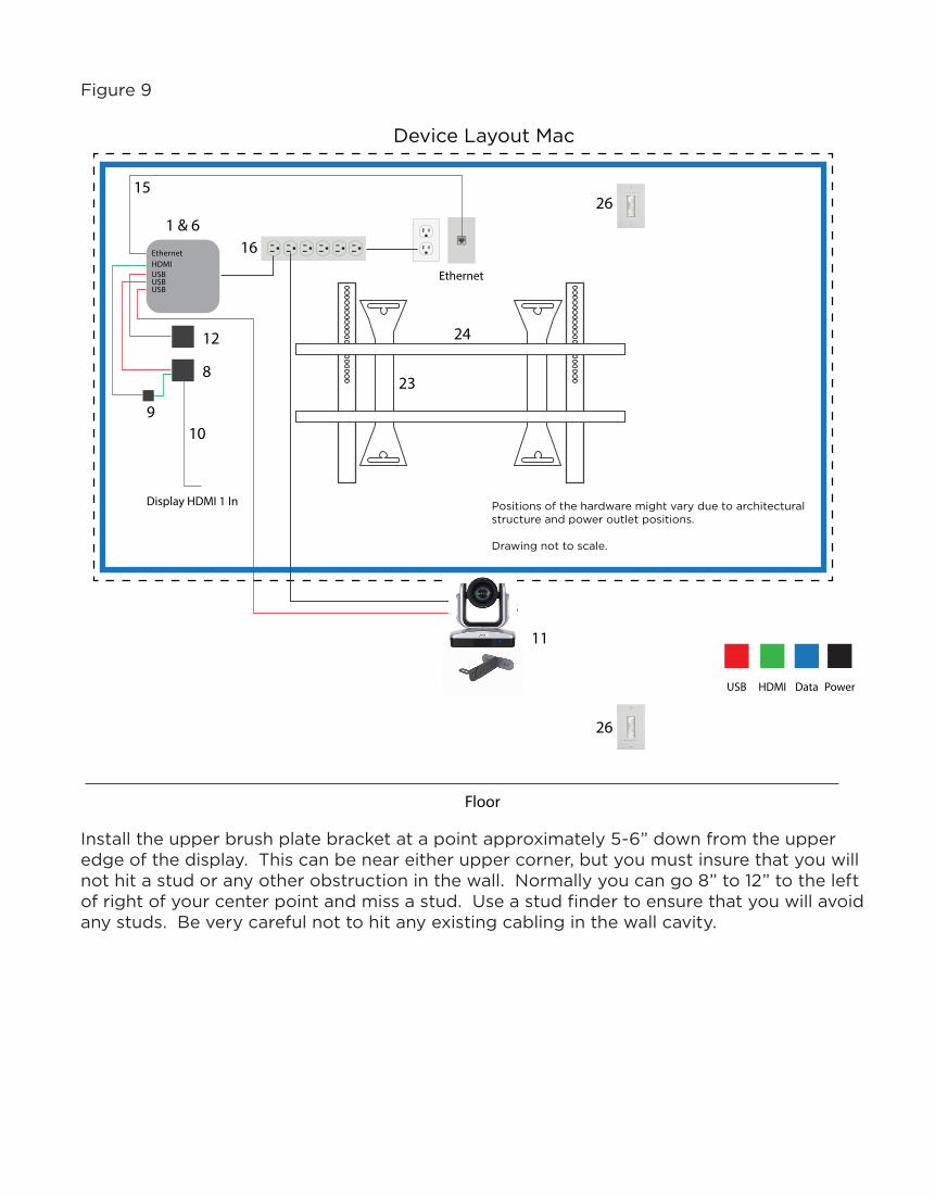
Figure 9
Install the upper brush plate bracket at a point approximately 5-6” down from the upper edge of the display. This can be near either upper corner, but you must insure that you will not hit a stud or any other obstruction in the wall. Normally you can go 8” to 12” to the left of right of your center point and miss a stud. Use a stud finder to ensure that you will avoid any studs. Be very careful not to hit any existing cabling in the wall cavity.
Device Layout Mac
Positions of the hardware might vary due to architecturalstructure and power outlet positions.
Drawing not to scale.
12
8
161 & 6
15
Display HDMI 1 In
Ethernet
11
Floor
23
24
26
26
3
USBHDMIEthernet
USBUSB
910
USB HDMI Data Power

Trace along the inside edge of the upper Arlington LV1 bracket with a pencil on the wall surface. (See Figure 10)
Figure 10
image courtesy of Arlington instructions as of 03-13-18)
Verify the LV1 bracket will be level. (See Figure 10)
Verify the LV1 bracket with its cover plate on will not interfere with any other equipment behind the display.
Cut to the outside of the traced line with the wallboard saw. (See Figure 10)
Install the upper LV1 bracket by inserting the bracket in the hole and then tightening the two screws in the bracket. The screw wings should rotate out and secure the bracket to the drywall.
Install the lower brush plate Arlington LV1 bracket directly below the upper bracket so that the top is approximately 16” above finished floor or align it with existing fixtures in the wall. Again, you must insure that you will not hit a stud or any other obstruction in the wall. Normally you can go 8” to 12” to the left of right of your center point and miss a stud. Use a stud finder to ensure that you will avoid any studs. Be very careful not to hit any existing cabling in the wall cavity.
Trace along the inside edge of the lower Arlington LV1 bracket with a pencil on the wall surface. (See Figure 10)

Verify the LV1 bracket will be level. (See Figure 10)
Cut to the outside of the traced line with the wallboard saw. (See Figure 10)

Install the lower LV1 bracket by inserting the bracket in the hole and then tightening the two screws in the bracket. The screw wings should rotate out and secure the bracket to the drywall.
Mount the Dell OptiPlex Wall Mount – Item 6A and Computer – Item 1A
Locate and open the Dell Optiplex Wall Mount – Item 6A. Read and follow the included instruction steps 1 through 3b from Dell.
Set aside the VESA Monitor Hardware packet for use later.
Determine the location in the area behind the display away from the door in the room. Be sure to consider cable routing and length. Mount the bracket at least 4” down from the top edge of the display and at least 2” inside the side edge of the display. While the computer can be placed on either side of the center line, the area away from the door will be the most inconspicuous.
Mark the four hole positions on the wall by holding the base in position and marking the
hole positions with a pencil. Verify the holes are level using your level.
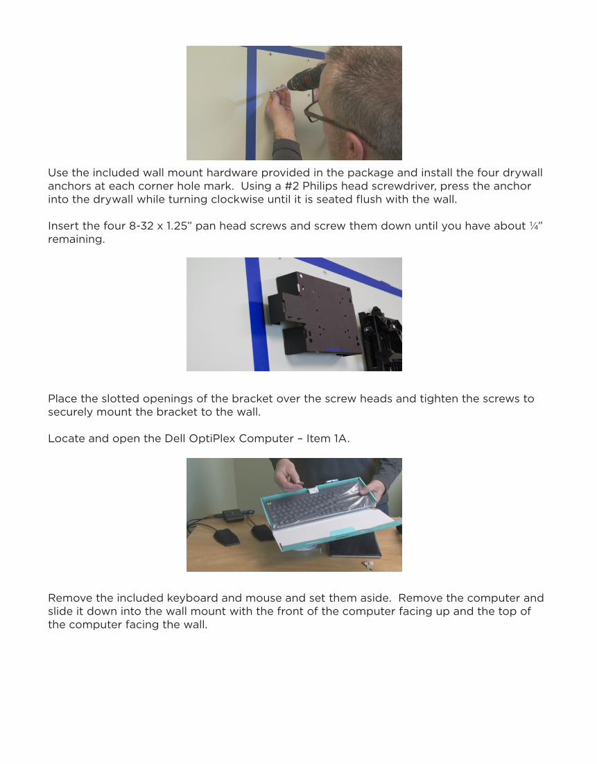
Use the included wall mount hardware provided in the package and install the four drywall anchors at each corner hole mark. Using a #2 Philips head screwdriver, press the anchor into the drywall while turning clockwise until it is seated flush with the wall.
Insert the four 8-32 x 1.25” pan head screws and screw them down until you have about ¼” remaining.
Place the slotted openings of the bracket over the screw heads and tighten the screws to securely mount the bracket to the wall.
Locate and open the Dell OptiPlex Computer – Item 1A.
Remove the included keyboard and mouse and set them aside. Remove the computer and slide it down into the wall mount with the front of the computer facing up and the top of the computer facing the wall.

Place the computer’s power supply in the mounting bracket with the detachable AC side facing up and the fixed DC side facing down.
Attach the computer’s wi-fi antenna on the bottom of the computer.

Plug the power supply into the computer.
Mount the APC Surge ProtectorLocate and open the APC Surge Protector – Item 16. Read and follow the included instructions from APC.
Remove the APC Surge Protector from its packaging.
Using a piece of scrap paper (possibly one of the foreign language instruction pages for the APC Surge Protector), make a template for the mounting holes on the back of the surge protector.
Mark the top two holes on your template while the Surge Protector is positioned horizontally.

Then hold the template horizontally at least 3” below the top edge of the display area. Before marking the wall, ensure the Surge Protector will not interfere with the adjustment screw on the Flat Panel Mount.
Locate and open the ThinkFastTrack Hardware packet and remove two drywall anchors – Item 27
Install the drywall anchors at two hole marks for the Surge Protector. Using a #2 Philips head screwdriver, press the anchor into the drywall while turning clockwise until it is seated flush with the wall.
Locate and open the VESA Monitor Hardware package that came with Dell OptiPlex Mount – Item 6A. Remove two of the five shortest screws. Insert the 8-32 x 0.5” pan head machine screws and screw them into the two drywall anchors your just installed until you have about 1/8” remaining.
Place the slotted openings of the surge protector over the screw heads to mount the surge protector to the wall.
Plug the computer into the surge protector
Install the Lindy 41232 HDMI Non-CEC AdapterLocate and install the Lindy 41232 HDMI Non-CEC Adapter - Item 9 in the HDMI port of the computer.

Install the Pulse Eight USB to HDMI CEC Control Adapter
Locate and open the Pulse Eight USB to HDMI CEC Control Adapter - Item 8. You will have three pieces – the Pulse Eight unit, a 4” HDMI to HDMI jumper cable and a 6” USB data cable.
Plug the 4” HDMI jumper cable in the HDMI port of the Lindy that you just installed in the computer.
Connect the other of the 6” HDMI jumper cable to the PC port on the Pulse Eight unit.
Plug the 6” USB data cable into one of the four open USB ports on the back of the computer.
Connect the other of the 6” USB data cable to the data port on the Pulse Eight unit.
Locate and open the Kramer 6’ High-Speed HDMI cable – Item 10.
Connect one end of the Kramer HDMI cable to the TV port on the Pulse Eight unit.
Loosely install a cable tie through one of the unused holes on the back of the Dell OptiPlex Mounting Bracket – Item 6A. Loosely loop the excess HDMI cable through this cable tie so that it functions as a strain relief and temporary restraint for the HDMI cable that will be plugged into the display when it is mounted.
Skip the next step if you have a wood or metal stud wall.

For installations with concrete block walls you will have to install surface mounted conduit (not included) with two single gang wall boxes, one behind the display and one near the floor. The locations of the single gang wall boxes should mimick the location instructions described previously for the Arlington LV1 brush plate brackets in wood or metal stud walls. (See Figure 9 previously or Figure 11 below)
Figure 11
Device Layout Mac
Positions of the hardware might vary due to architecturalstructure and power outlet positions.
Drawing not to scale.
12
8
161 & 6
15
Display HDMI 1 In
Ethernet
11
Floor
23
24
26
26
3
USBHDMIEthernet
USBUSB
910
USB HDMI Data Power

Pull in the Cat6 Network Data CableInsert your fish tape in the upper Arlington LV1 brush plate bracket or single gang wall box and run it to the lower Arlington LV1 brush plate bracket or single gange wall box so that you can pull in the necessary cabling.
Locate and open the 6’ Cat6 data cable - Item 15 and locate and open the 25’ Cat6 data cable – Item 13
Attach one end of each of the two Cat6 data cables to the lower end of the fish tape using your electrical tape and pull the fish tape carefully and slowly from the bottom to the top bracket. Be sure to label or mark the two cables if they are the same color.
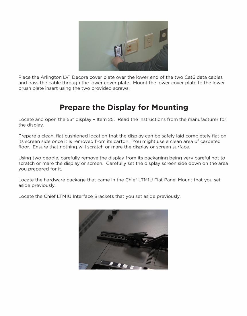
Place the Arlington LV1 Brush insert over the upper end of the Cat6 data cables and pass the cables through the brushes. Mount the upper LV1 brush plate insert to the upper brush plate bracket using the two provided screws.
Place the Arlington LV1 Decora cover plate over the upper end of the Cat6 data cables and pass the cable through the upper cover plate. Mount the upper cover plate to the upper brush plate insert using the two provided screws.

Connect the upper end of the 6’ Cat6 data cable to the network port of the Dell OptiPlex computer. This network port is on the bottom of the computer.
Install the IOGear USB ExtenderLocate and open the IOGear USB Extender – Item 12. Read the included instructions from IOGear. Locate the 3M Dual Lock Fastners – Item 21 in the ThinkFastTrack Hardware packet.
Set aside the IOGear USB Extender Remote unit for use later.
Mount the IOGear USB Extender Local unit below the computer behind the display at least 8” inside display edges using the 3M dual lock fasteners – Item 21. To mount the 3M dual lock fastener to the IOGear Local unit, peel back and remove the sticky tape cover from one flat side of the fastener and press the adhesive side onto the IOGear Local unit. Make sure the surface of the Local Unit is clean and dry first.
Finally, mount the IOGear USB Extender Local unit to the wall by peeling back the sticky tape on the remaining flat side of the 3M dual lock fastener and press the adhesive side to the wall. Make sure the wall surface is clean and dry first.
Connect the upper end of the 25’ Cat6 data cable to the data port on the IOGear Local unit.
Connect the IOGear USB Extender Local unit to the Dell OptiPlex computer using the USB cable provided with the IOGear Local unit.
Using the provided cable ties and cable tie mounting tabs in the ThinkFastTrack Hardware packet, neatly dress the cabling as needed to make a neat and professional appearance. This includes HDMI, USB, data and power cables.
To mount the cable tie mounting tabs – Item 18 to the wall, peel back the sticky tape cover and press the adhesive side to the wall. Then secure the cable tie mount with a single drywall screw – Item 28 through the tab and into the wall using your screwdriver.
Place the Arlington LV1 Brush insert over the lower end of the two Cat6 data cables and pass the cable through the brushes. Mount the lower brush plate insert to the lower brush plate bracket using the two provided screws.
Place the Arlington LV1 Decora cover plate over the lower end of the two Cat6 data cables and pass the cable through the lower cover plate. Mount the lower cover plate to the lower brush plate insert using the two provided screws.
Prepare the Display for MountingLocate and open the 55” display – Item 25. Read the instructions from the manufacturer for the display.
Prepare a clean, flat cushioned location that the display can be safely laid completely flat on its screen side once it is removed from its carton. You might use a clean area of carpeted floor. Ensure that nothing will scratch or mare the display or screen surface.
Using two people, carefully remove the display from its packaging being very careful not to scratch or mare the display or screen. Carefully set the display screen side down on the area you prepared for it.
Locate the hardware package that came in the Chief LTM1U Flat Panel Mount that you set aside previously.
Locate the Chief LTM1U Interface Brackets that you set aside previously.
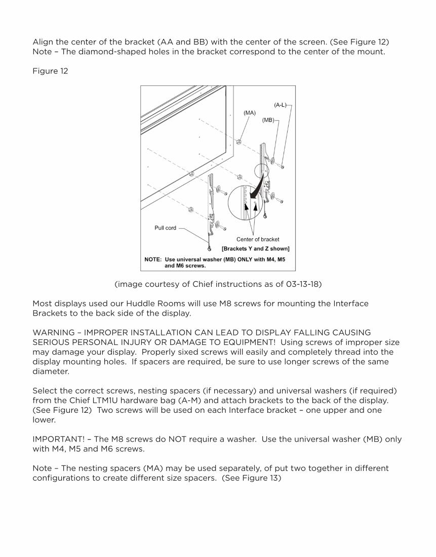
Align the center of the bracket (AA and BB) with the center of the screen. (See Figure 12) Note – The diamond-shaped holes in the bracket correspond to the center of the mount.
Figure 12
(image courtesy of Chief instructions as of 03-13-18)
Most displays used our Huddle Rooms will use M8 screws for mounting the Interface Brackets to the back side of the display.
WARNING – IMPROPER INSTALLATION CAN LEAD TO DISPLAY FALLING CAUSING SERIOUS PERSONAL INJURY OR DAMAGE TO EQUIPMENT! Using screws of improper size may damage your display. Properly sixed screws will easily and completely thread into the display mounting holes. If spacers are required, be sure to use longer screws of the same diameter.
Select the correct screws, nesting spacers (if necessary) and universal washers (if required) from the Chief LTM1U hardware bag (A-M) and attach brackets to the back of the display. (See Figure 12) Two screws will be used on each Interface bracket – one upper and one lower.
IMPORTANT! – The M8 screws do NOT require a washer. Use the universal washer (MB) only with M4, M5 and M6 screws.
Note – The nesting spacers (MA) may be used separately, of put two together in different configurations to create different size spacers. (See Figure 13)

Figure 13
(image courtesy of Chief instructions as of 03-13-18)
Attaching the Display with Flat Panel Mount Bracket to the Wall Mount
Remove the blue tape from the wall.
Attach the four-plastic wall cover plates (X) to the Flat Panel Mount. (See Figure 14)
Figure 14
(image courtesy of Chief instructions as of 03-13-18)
Verify the crossbars are level using your level. Each of the two sides of the Flat Panel Mount has an adjustment point to raise or lower the individual side to level the unit. Refer to the instructions on page 12 of the Chief LTM1U manual make adjustments to the Flat Panel Mount.

Using two people, carefully lift the display and place the Chief LTM1U Interface Brackets on the Chief LTM1U Flat Panel Mount already mounted securely to the wall. Hook the two top hooks Interface Bracket over the upper horizontal rail.
CAUTION: PINCH POINTS! Keep fingers, hands, clothing and cables out of the pinch point areas.
Then pull downward on the pull cords on the two Interface Brackets and swing inward toward the wall and let the lower hooks attach to the lower horizontal rail.
Attach the magnet end of the pull cords to the mount so it does not extend beyond the bottom of the screen.
Insert the provided batteries in the display’s remote control and set aside for use later.
Extend the display away from the wall by gently pulling on the LTM1U bracket to extend the FCAV1U Pull-Out Accessory and gain easy service access to the area behind the display.
Plug the included power cord into the power strip and the display.
Push the display back against the wall.
Install the Camera Mount and Camera on the wall Locate and open the Heckler Design Camera Mount – Item 11. Read the instructions from Heckler.
Locate and open the AVER CAM340 – Item 3. Read the instructions from AVER.
Remove the Heckler bracket from its packaging.
Remove the AVER CAM340 from its packaging.
Open the mounting hardware package from Heckler.
Remove the ¼-20 Allen bolt from the Heckler mounting hardware package.

Attach the CAM340 to the Heckler mounting bracket using the ¼-20 Allen bolt.
Hold the mounted CAM340 and bracket under the display as close to the display as possible without touching the display. Mark the two mounting holes at this location with your pencil.
Verify the bracket will be level using your level.
Verify the camera and mounting bracket will not interfere with opening and closing the Chief FCAV1U Pull-Out Accessory while accessing the area behind the display.
Remove the two drywall anchors from the Heckler mounting hardware package.
Install the two drywall anchors at the two hole marks for the camera bracket. Using a #2 Philips head screwdriver, press the anchor into the drywall while turning clockwise until it is seated flush with the wall.
Remove the two 2” screws in the Heckler mounting hardware package.
Attach the camera and camera bracket to the wall using the two screws.

Pull the display out so that you can access behind the display. Be careful that your display does not hit the camera.
Remove the USB cable and the power supply from the AVER CAM340 box.
Plug the AC power supply into the power strip behind the display and the DC connector into the camera.
Plug the smaller USB C connector into the camera and the larger USB A connector into one of the open USB ports on the back of the computer.
Using the provided cable ties and cable tie mounting tabs in the ThinkFastTrack Hardware packet, neatly dress the cabling as needed to make a neat and professional appearance behind the display. This includes the camera’s USB and power cables.
Mount the IOGear USB Extender Remote Unit Under the Meeting Table
Locate the IOGear USB Extender Remote Unit and included power supply – part of Item 12 that was installed earlier.
Remove one set of the 3M dual lock fastener from the ThinkFastTrack Hardware packet.
Determine the location under the table or desk where you are going to mount the IOGear USB Extender Remote unit. Make sure the microphone(s) USB cabling can reach from the microphone locations to the IOGear USB Extender Remote unit. Also, make sure the IOGear USB Extender power supply can reach an electrical outlet.
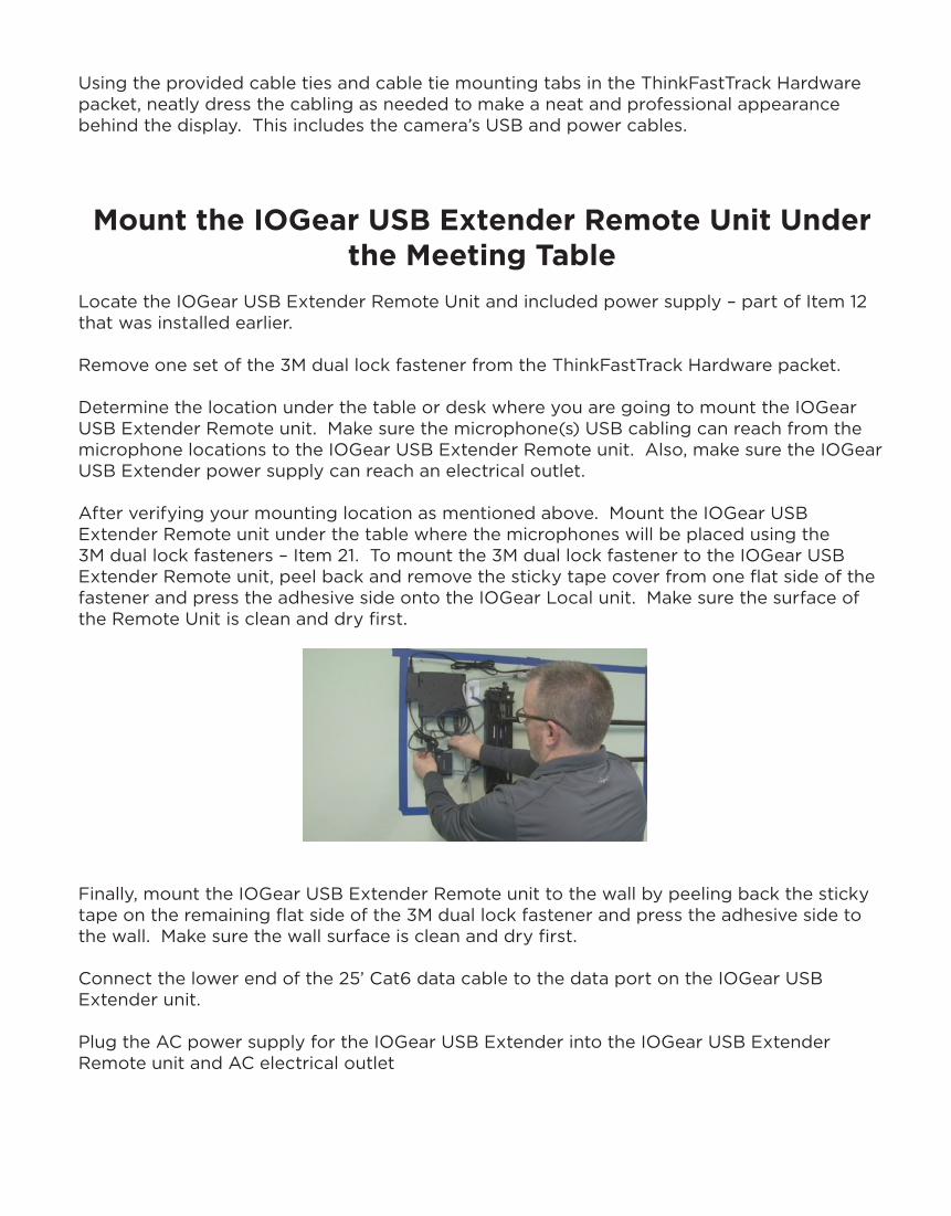
After verifying your mounting location as mentioned above. Mount the IOGear USB Extender Remote unit under the table where the microphones will be placed using the 3M dual lock fasteners – Item 21. To mount the 3M dual lock fastener to the IOGear USB Extender Remote unit, peel back and remove the sticky tape cover from one flat side of the fastener and press the adhesive side onto the IOGear Local unit. Make sure the surface of the Remote Unit is clean and dry first.
Finally, mount the IOGear USB Extender Remote unit to the wall by peeling back the sticky tape on the remaining flat side of the 3M dual lock fastener and press the adhesive side to the wall. Make sure the wall surface is clean and dry first.
Connect the lower end of the 25’ Cat6 data cable to the data port on the IOGear USB Extender unit.
Plug the AC power supply for the IOGear USB Extender into the IOGear USB Extender Remote unit and AC electrical outlet

Position and Connect the USB MicrophonesLocate the two MXL AC404 USB microphones – Item 4.
Remove the two MXL AC404 USB microphone and cables from its packaging
Extend the included microphone USB cabling, plug the smaller USB Mini plug into the microphones and the larger USB A plug into the IOGear USB Extender Remote unit. (See Figure 15)
Figure 15
(image courtesy of Zoom’s webpage as of 03-13-18)
Locate the Logitech K400 Wireless Keyboard with touchpad – Item 7. Read the instructions from Logitech.
Remove the Logitech K400 Wireless Keyboard and the included USB dongle from the packaging.
Plug the Logitech dongle into one of the open USB ports on the back of the computer behind the display.
Plug the display’s power cord into the APC Surge Protector and into the display.Plug the HDMI cable that is loosely wrapped behind the display and plug it into HDMI port 1 of the display.
Using the provided cable ties and cable tie mounting tabs in the ThinkFastTrack Hardware packet, neatly dress the cabling as needed to make a neat and professional appearance behind the display. This includes the display’s HDMI and power cables.
Plug the APC Surge Protector – Item 16 into the AC outlet behind the display.
Turn on the APC Surge Protector – then red light in the switch should illuminate.
Turn on the Dell OptiPlex computer by pushing the button on the front of the computer (top left as it is mounted on the wall).
Install the iPad in the Heckler Room ConsoleLocate the Apple iPad – Item 2.
Remove the Apple iPad, power supply and lightning cabling from its packaging.
Locate the Star Tech USB to Lightning 10’ cable – Item 14
Remove the Star Tech USB to Lightning 10’ cable from its packaging.
Locate the Heckler Design Meeting Room Console for iPad – Item 5. Read the instructions from Heckler Designs. Also refer to Figure 16.
Remove the Heckler Design Meeting Room Console for iPad and accessories from its packaging.
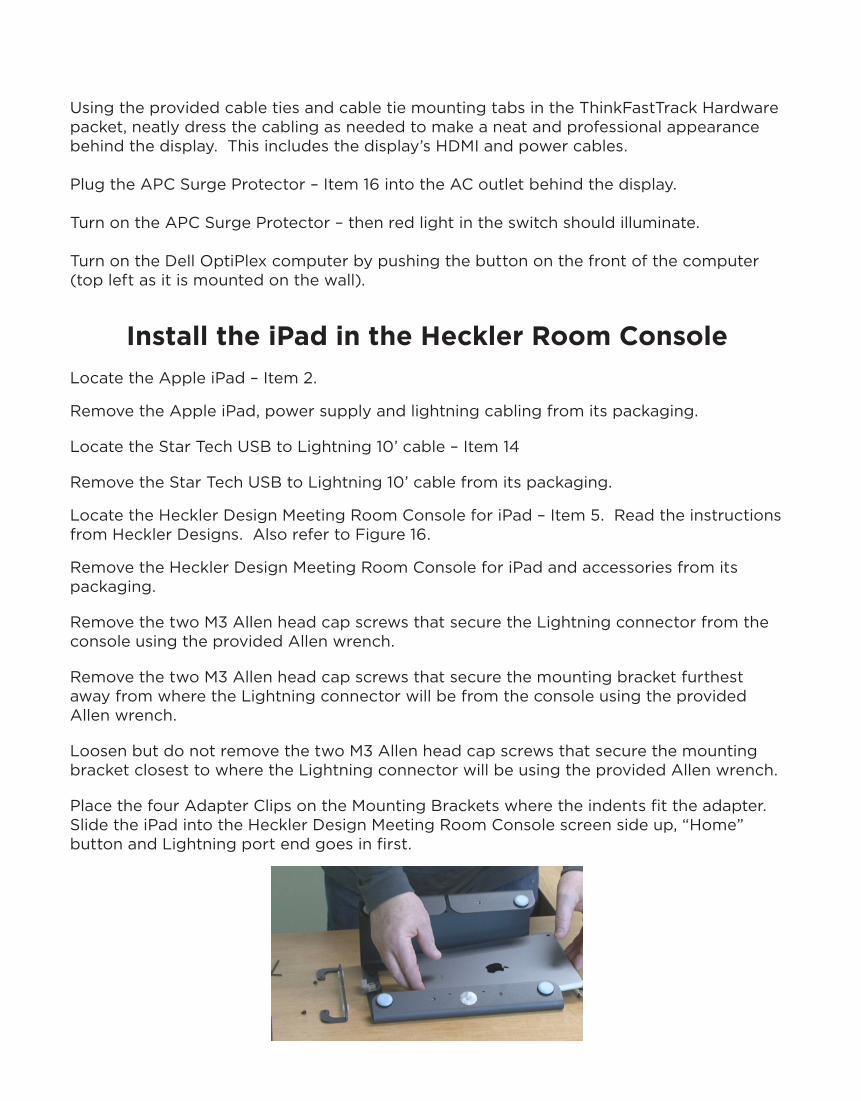
Remove the two M3 Allen head cap screws that secure the Lightning connector from the console using the provided Allen wrench.
Remove the two M3 Allen head cap screws that secure the mounting bracket furthest away from where the Lightning connector will be from the console using the provided Allen wrench.
Loosen but do not remove the two M3 Allen head cap screws that secure the mounting bracket closest to where the Lightning connector will be using the provided Allen wrench.
Place the four Adapter Clips on the Mounting Brackets where the indents fit the adapter.Slide the iPad into the Heckler Design Meeting Room Console screen side up, “Home” button and Lightning port end goes in first.
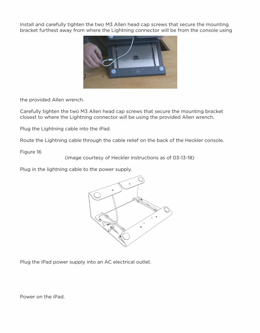
Install and carefully tighten the two M3 Allen head cap screws that secure the mounting bracket furthest away from where the Lightning connector will be from the console using
the provided Allen wrench.
Carefully tighten the two M3 Allen head cap screws that secure the mounting bracket closest to where the Lightning connector will be using the provided Allen wrench.
Plug the Lightning cable into the iPad.
Route the Lightning cable through the cable relief on the back of the Heckler console.
Figure 16(image courtesy of Heckler instructions as of 03-13-18)
Plug in the lightning cable to the power supply.
Plug the iPad power supply into an AC electrical outlet.
Power on the iPad.
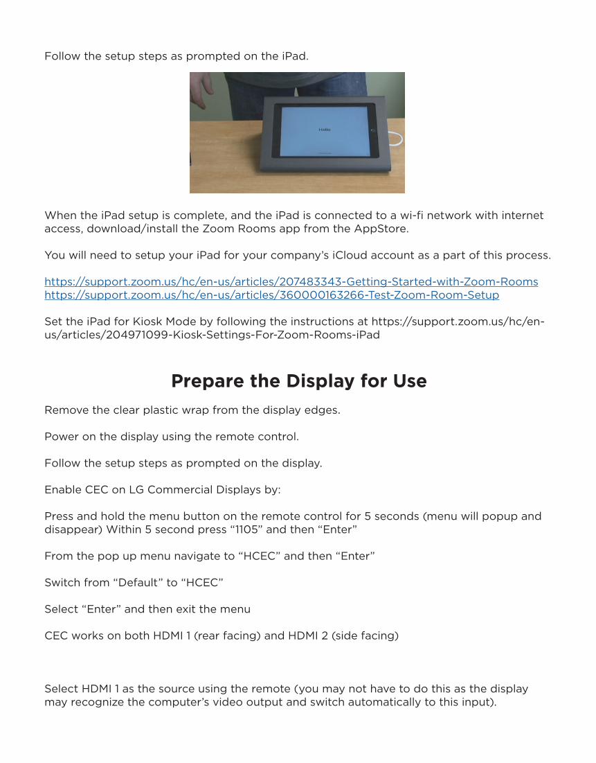
Follow the setup steps as prompted on the iPad.
When the iPad setup is complete, and the iPad is connected to a wi-fi network with internet access, download/install the Zoom Rooms app from the AppStore.
You will need to setup your iPad for your company’s iCloud account as a part of this process.
https://support.zoom.us/hc/en-us/articles/207483343-Getting-Started-with-Zoom-Roomshttps://support.zoom.us/hc/en-us/articles/360000163266-Test-Zoom-Room-Setup
Set the iPad for Kiosk Mode by following the instructions at https://support.zoom.us/hc/en-us/articles/204971099-Kiosk-Settings-For-Zoom-Rooms-iPad
Prepare the Display for UseRemove the clear plastic wrap from the display edges.
Power on the display using the remote control.
Follow the setup steps as prompted on the display.
Enable CEC on LG Commercial Displays by:
Press and hold the menu button on the remote control for 5 seconds (menu will popup and disappear) Within 5 second press “1105” and then “Enter”
From the pop up menu navigate to “HCEC” and then “Enter”
Switch from “Default” to “HCEC”
Select “Enter” and then exit the menu
CEC works on both HDMI 1 (rear facing) and HDMI 2 (side facing)
Select HDMI 1 as the source using the remote (you may not have to do this as the display may recognize the computer’s video output and switch automatically to this input).

Follow the onscreen setup steps as prompted for the Dell OptiPlex computer using the Logitech K400 keyboard and trackpad.
When the Dell OptiPlex computer is updated and setup is complete, and the Dell OptiPlex is connected to the wired network with internet access, download/install the “Zoom Client for Meetings” application from https://zoom.us/meetings (you will find a link to this download in the section titled Online Meetings).
Download/install the “Zooms Rooms App” for Windows from the link near the top of the webpage.
Set your PC to operate in “Kiosk Mode” by following the instructions at https://support.zoom.us/hc/en-us/articles/203689369-Kiosk-Settings-for-Zoom-Rooms
Set your PC’s Screen Saver mode by following the instructions at https://support.zoom.us/hc/en-us/articles/201379359-Screen-Saver-and-Energy-Saver-With-Zoom-Rooms. DO NOT allow the computer to go into “sleep mode”.
Launch the Zoom Client for Meetings application on the Dell OptiPlex and sign into your Zoom account.
Launch the Zoom Room App for Windows on the Dell OptiPlex and sign into your Zoom
Rooms account. Optionally, you can use a free 30-day trial of the Zoom Rooms software.

Software, Operational and Licensing Support“Support Ticket” means a notification by a customer advising Zoom of a perceived issue, or question concerning the service.
Report support tickets to Zoom by:Online submission via https://support.zoom.us/hc/en-us/requests/newChat live with our support teamPhone dial-inUS: +1.888.799.9666 ext 2 or +1.650.397.6096 ext 2AU: +61.1800.768.027 ext 2UK: +44.800.368.7314 ext 2 or +44.20.3890.5445 ext 2
Hardware Support

Notes