Embed Size (px)
Citation preview
T
ATS
ATS
TSD
SD
CR
CR
CR
CC
ELT
D
VFCVFC
F
IMIM
IMC
MC
MC
MC
M
F
TS FS
IM IM
CRCR
CR
SD SD
SD
SD
F
F
CR
CR
CR
A
7
6
A
7
6
ELECTRICAL159
RP-1A
LP-OSBAA
UH
159A
MSB
T-DPRP
DP-RP
ATS-OSB
ATS-EM
DP-OSB
LP-EM1AA
FIRE PUMP
RP-OSBA
T-RPOSBA
UH
159B
1A
-3
1A-3
GENERATOR EPO
EMERG. ELECTR.162
CONTACTOR & TIMECLOCK FOR GYMNASIUM LIGHTING
CONTACTOR & TIMECLOCK FOR EXTERIOR LIGHTING
ELTD FOR EXTERIOR EGRESS LIGHTING
LP-2AA-1
FOR ELECTRICAL METER
M N P Q
7
M.9M N Q
7
M.9
121
BCU
UH
110
2
B
3
B
1
B
CP
B1
CP
B2
CP
B3CP
4
CP
3
P
1
P
21
FP
MECHANICAL / JANITORROOM
109
FIRE PUMP110
STAIRS 03119
CP
7+48"
+48"
+48"
+48"
+48"
WP
1C-1
1C-3
1C-5
+48"
+48"
IRRIGATION CONTROLLER
DP-MECH2
DP-MECH2
DP-MECH2
DP-MECH2
1C-35
CP-4DP-MECH1
CP-3DP-MECH1
CLASSROOM 03108
CORRIDOR 01120 CORRIDOR 02
121
CP
8
1C-37
+48"
MFP-21C-33
MFP-11C-33
+48"
+48"
1
JP
+48"
1
CP
5
1C-35
GLYCOL FEED PUMP 1C-31
CP
61C-37
OSBAA-31,33,35
FIRE PUMP SERVICE DISCONNECT
1C-31
1C-41
1C-31 1C-31
1B-3
LP1AA-41
1C-33
1C-33
1C-31
1C-33
1C-311C-14
1
DWH2
DWH
1C-39 1C-41
BMS
3
EF
1C-46
1C-42UH
109
1C-44
2
EF
3
3
3
P
7
6
7
6
STORAGE 03212
DATA213
CORRIDOR 04214
MECHANICAL215
JANITOR'S CLOSET219
213
ACU
15cd
OSBA-2
OSBA-4
OSBA-6
OSBA-8
OSBA-10
2C-1
2C-1
2C-1
2C-1
FOR EF-1, SERVE FROM DP-MECH2
DP-MECH1
DP-MECH2
LDP-1
THE FOLLOWING DIMENSION EQUALSONE INCH WHEN PRINTED TO SCALE.
1"
5145 Livernois, Suite 100Troy, Michigan 48098-3276
Tel: 248-879-5666Fax: 248-879-0007
www.PeterBassoAssociates.com
Peter Basso Associates Inc
CONSULTING ENGINEERS
Scale:
Preliminary
Construction
Record
Do not scaleUse figured dimensions onlyCopyright 2018
1500 WoodwardSuite 300Detroit, MI 48226phone 248 352 8310fax 248 352 [email protected]
Date
Drawn
Checked
Approved
Bidpak Number
Job Number
Title
Sheet
Revisions
2016.0394
PROJECT NAME
PROJECT ADDRESS
WAYNE COUNTY COMMUNITY COLLEGE
DISTRICT
801 West Fort StreetDetroit, Michigan 48226
Buildings & Safety Eng. Dept.PAGE OF PAGES
Date . NOTE: Final approval shall not be construed
as authority to violate, cancel or set aside any of the provisions of the applicable
codes, except as specifically stipulated by modification or legally granted variance in
accordance with established procedures.
02
1/4" = 1'-0"
E601
2016043
TGC
TGC
DMB
01/15/18
ELECTRICALENLARGED PLANS
971 West Fort StreetDetroit, MI 48226
WCCCD Health and WellnessEducation Center
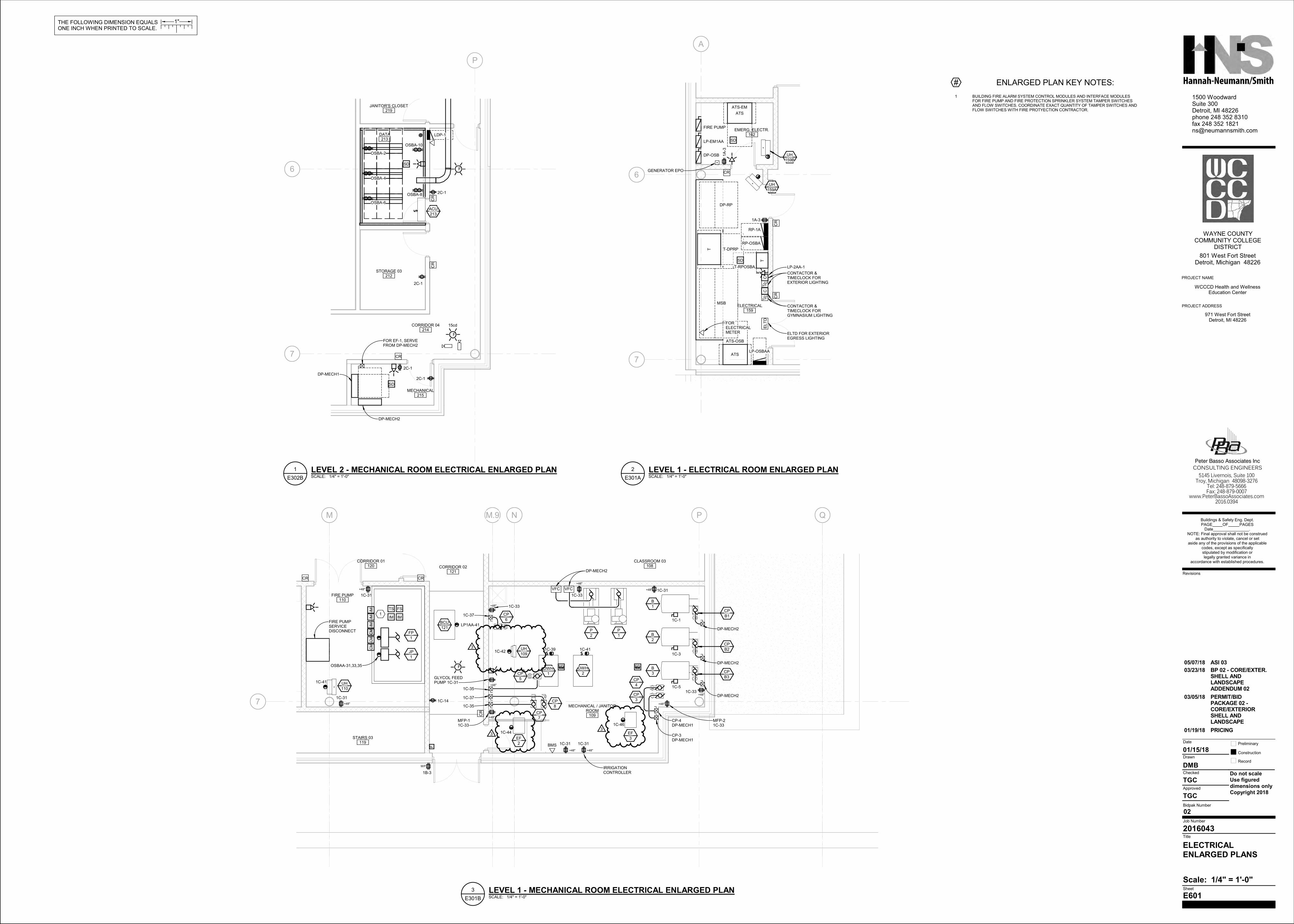
# ENLARGED PLAN KEY NOTES:
1 BUILDING FIRE ALARM SYSTEM CONTROL MODULES AND INTERFACE MODULESFOR FIRE PUMP AND FIRE PROTECTION SPRINKLER SYSTEM TAMPER SWITCHESAND FLOW SWITCHES. COORDINATE EXACT QUANTITY OF TAMPER SWITCHES ANDFLOW SWITCHES WITH FIRE PROTYECTION CONTRACTOR.
SCALE: 1/4" = 1'-0"E301A
LEVEL 1 - ELECTRICAL ROOM ENLARGED PLAN2
SCALE: 1/4" = 1'-0"E301B
LEVEL 1 - MECHANICAL ROOM ELECTRICAL ENLARGED PLAN3
SCALE: 1/4" = 1'-0"E302B
LEVEL 2 - MECHANICAL ROOM ELECTRICAL ENLARGED PLAN1
01/19/18 PRICING
03/05/18 PERMIT/BIDPACKAGE 02 -CORE/EXTERIORSHELL ANDLANDSCAPE
03/23/18 BP 02 - CORE/EXTER.SHELL ANDLANDSCAPEADDENDUM 02
05/07/18 ASI 03
Revisions
JMC
JMC
Suite 3001500 WOODWARD
phone 313.782.4822DETROIT, Michigan 48226
Date Preliminary
Record
Use figured
Drawn
Checked
Approved
Bidpak Number
Title
Sheet
Job Number
dimensions only
Do not scale
Copyright © 2010
Construction
Revisions
2016043
PROJECT NAME
WAYNE COUNTYCOMMUNITY COLLEGE
DISTRICT801 West Fort Street
Detroit, Michigan 48226
WCCCD Health and WellnessEducation Center
PROJECT ADDRESS971 West Fort Street
Detroit, MI 48226
Buildings & Safety Eng. Dept.PAGE OF PAGES
Date .NOTE: Final approval shall not be construed
as authority to violate, cancel or setaside any of the provisions of the applicable
codes, except as specificallystipulated by modification orlegally granted variance in
accordance with established procedures.
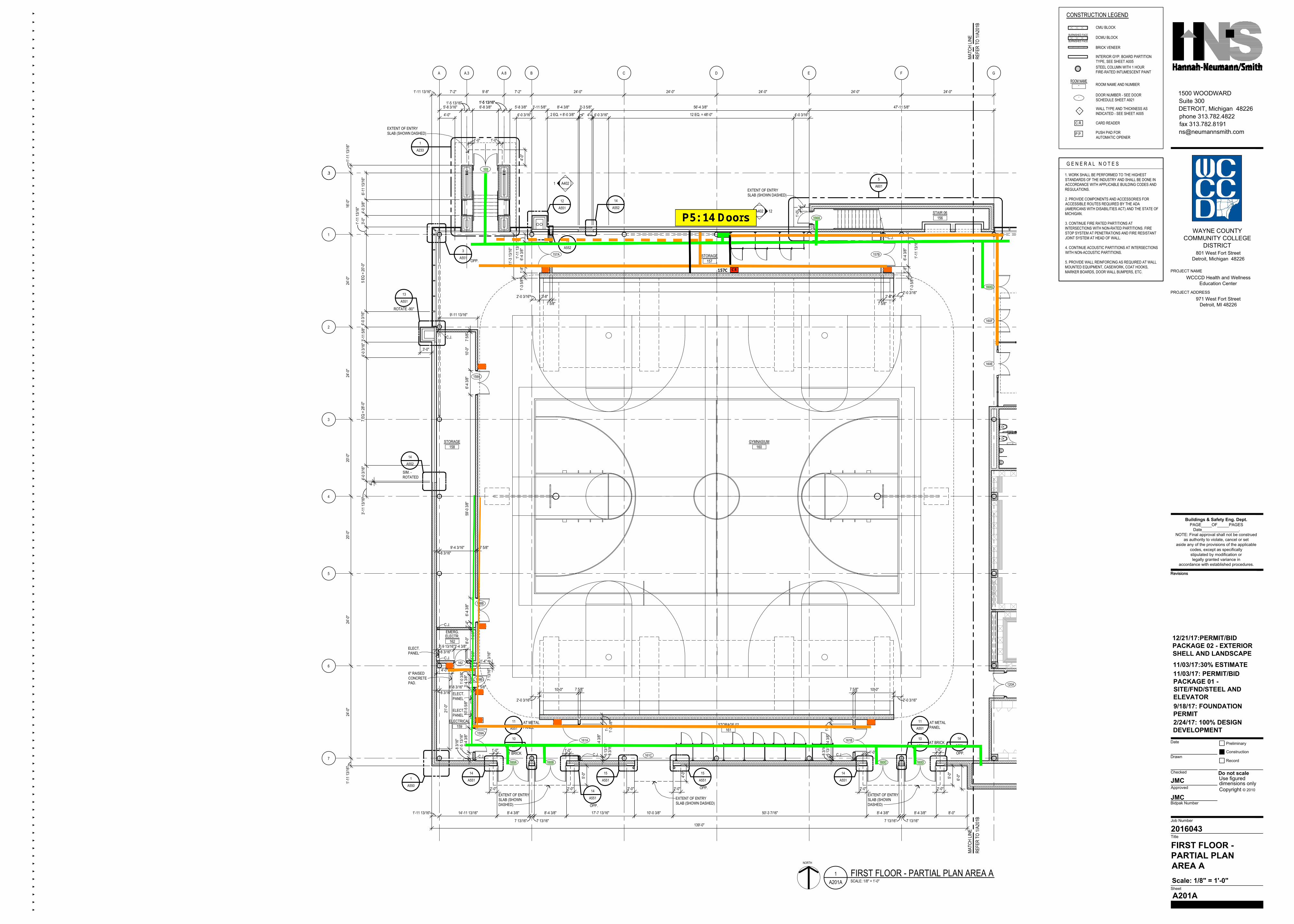
FIRST FLOOR -PARTIAL PLANAREA A
A201A
Scale: 1/8" = 1'-0"
2/24/17: 100% DESIGNDEVELOPMENT
MATC
H LIN
ERE
FER
TO 1/
A201
BMA
TCH
LINE
REFE
R TO
1/A2
01B
NORTH
1A201A SCALE: 1/8" = 1'-0"
FIRST FLOOR - PARTIAL PLAN AREA A
161STORAGE 02
160GYMNASIUM
- DOOR NUMBER - SEE DOORSCHEDULE SHEET A921
-ROOM NAME
ROOM NAME AND NUMBER
WALL TYPE AND THICKNESS ASINDICATED - SEE SHEET A005
CMU BLOCK
BRICK VENEER
INTERIOR GYP. BOARD PARTITIONTYPE, SEE SHEET A005
CARD READERC.R.
PUSH PAD FORAUTOMATIC OPENER
P.P.
1. WORK SHALL BE PERFORMED TO THE HIGHESTSTANDARDS OF THE INDUSTRY AND SHALL BE DONE INACCORDANCE WITH APPLICABLE BUILDING CODES ANDREGULATIONS.
2. PROVIDE COMPONENTS AND ACCESSORIES FORACCESSIBLE ROUTES REQUIRED BY THE ADA(AMERICANS WITH DISABILITIES ACT) AND THE STATE OFMICHIGAN.
3. CONTINUE FIRE RATED PARTITIONS ATINTERSECTIONS WITH NON-RATED PARTITIONS. FIRESTOP SYSTEM AT PENETRATIONS AND FIRE RESISTANTJOINT SYSTEM AT HEAD OF WALL.
4. CONTINUE ACOUSTIC PARTITIONS AT INTERSECTIONSWITH NON-ACOUSTIC PARTITIONS.
5. PROVIDE WALL REINFORCING AS REQUIRED AT WALLMOUNTED EQUIPMENT, CASEWORK, COAT HOOKS,MARKER BOARDS, DOOR WALL BUMPERS, ETC.
G E N E R A L N O T E S
CONSTRUCTION LEGEND
DCMU BLOCKBURNISHED FACE
BURNISHED FACE
STEEL COLUMN WITH 1 HOURFIRE-RATED INTUMESCENT PAINTA A.3 A.8 B C D E F G
.3.3
1
2
3
4
5
6
7
16'-0
"24
'-0"
24'-0
"20
'-0"
20'-0
"24
'-0"
24'-0
"1'-
11 13
/16"
12
A551
13
A551
1
A550
103
160A 160B 160C 160D
7'-2" 9'-8" 7'-2" 24'-0" 24'-0" 24'-0" 24'-0" 24'-0"1'-11 13/16"
1'-11
13/16
"
3
A551
6'-11
13/16
"4'-
0 3/8"
3'-0"
14'-11 13/16" 8'-4 3/8"
7 13/16"
8'-4 3/8" 8'-4 3/8" 8'-4 3/8" 8'-0"
6'-0"
1'-11
13/16
"
7 13/16"
1'-11 13/16"
5 EQ
= 20
'-0"
8'-4 3/8"
7 13/16" 7 13/16"
1
A233
6'-8 3/8"1'-5 13/16" 1'-5 13/16"1'-5 13/16"
120A
161A 161B
160G
160F
160E
9/18/17: FOUNDATIONPERMIT
5'-8 3/8" 3'-11 5/8" 3'-3 5/8" 47'-11 5/8"
4'-0 3
/16"
3'-11
5/8"
7 EQ
= 28
'-0"
4"
5'-8 3/16"
4"
3'-11
13/16
"
2 EQ. = 8'-0 3/8" 4"
14
A552
4'-0 3
/16"
156STAIR 06
157STORAGE
158STORAGE
159ELECTRICAL
159A
158B
158A
157B157A
156A
5
A601
14
A552
11/03/17: PERMIT/BIDPACKAGE 01 -SITE/FND/STEEL ANDELEVATOR
17'-7 13/16" 10'-0 3/8" 50'-3 7/16"
139'-0"
11/03/17:30% ESTIMATE
1 A402
56'-4 3/8"
4'-0 3/16" 12 EQ. = 48'-0" 4'-0 3/16"4'-0 3/16"4'-0"
12A402
159B
162
2'-0" 2'-0" 2'-0" 2'-0" 2'-0" 2'-0"
161C
10
A551
11
A551
AT BRICK
AT METALPANEL
10
A551
11
A551AT METALPANEL
AT BRICK
OPP.
ROTATE -90°
14
A551
15
A551
14
A551
14
A551
OPP.
15
A551
OPP.
14
A551
OPP.
SIM. -ROTATED4'-
0 3/16
"
1'-0" 1'-0"
4'-0"
EXTENT OF ENTRYSLAB (SHOWN DASHED)
1'-0"
EXTENT OF ENTRYSLAB (SHOWN DASHED)
1'-0" 1'-0"
5'-0"
EXTENT OF ENTRYSLAB (SHOWNDASHED)
1'-0"1'-0"
5'-0"
EXTENT OF ENTRYSLAB (SHOWNDASHED)
4'-0"
EXTENT OF ENTRYSLAB (SHOWN DASHED)
C.J.C.J.C.J.
C.J.
C.J.
C.J.
162ELECTR.EMERG.
C.J.
3'-0"
15
A552
1'-11
13/16
"6'-
4 3/8"
1'-8"
1'-3 5
/8"
1'-11
13/16
"
6'-4 3
/8"1'-
8"1'-
3 5/8"
2'-0 3/16"2'-0 3/16"
2'-0 3/16"
2'-8" 2'-8"7 5/8" 7 5/8"
10'-0" 7 5/8"
2'-0 3/16"
10'-0"7 5/8"
1'-2"
8'-4 3
/8"5 1
3/16"
8 3/16
"
1'-2"
8'-4 3
/8"5 1
3/16"
8 3/16
"
1'-3 5
/8"
8 3/16
"1'-
5 13/1
6"6'-
4 3/8"
10'-5
5/8"
3'-4 3
/8"1'-
0 3/8"
7 5/8"
8'-0" 7 5
/8"1'-
4"6'-
4 3/8"
59'-0
3/8"
6'-4 3
/8"10
'-0"
7 5/8"
3'-4 3/8"3'-9 13/16"8 3/16"
9'-4 3/16"8 3/16"
7 5/8"
8'-8 3/16"8 3/16"
7 5/8"
8 3/16
"
9'-11 13/16"
11'-3
13/16
"
12/21/17:PERMIT/BIDPACKAGE 02 - EXTERIORSHELL AND LANDSCAPE
ELECT.PANEL
ELECT.PANEL
6" RAISEDCONCRETEPAD.
4'-0"
21'-0
"
ELECT.PANEL
7 13/1
6"
1'-4"
8"
C.R.C.R.C.R.
C.R.
C.R.
C.R.
C.R.
C.R. C.R.
.�%#4
%
.�
.�
.�
.�
IQX
Revisions
JMC
JMC
Suite 3001500 WOODWARD
phone 313.782.4822DETROIT, Michigan 48226
Date Preliminary
Record
Use figured
Drawn
Checked
Approved
Bidpak Number
Title
Sheet
Job Number
dimensions only
Do not scale
Copyright © 2010
Construction
Revisions
2016043
PROJECT NAME
WAYNE COUNTYCOMMUNITY COLLEGE
DISTRICT801 West Fort Street
Detroit, Michigan 48226
WCCCD Health and WellnessEducation Center
PROJECT ADDRESS971 West Fort Street
Detroit, MI 48226
Buildings & Safety Eng. Dept.PAGE OF PAGES
Date .NOTE: Final approval shall not be construed
as authority to violate, cancel or setaside any of the provisions of the applicable
codes, except as specificallystipulated by modification orlegally granted variance in
accordance with established procedures.
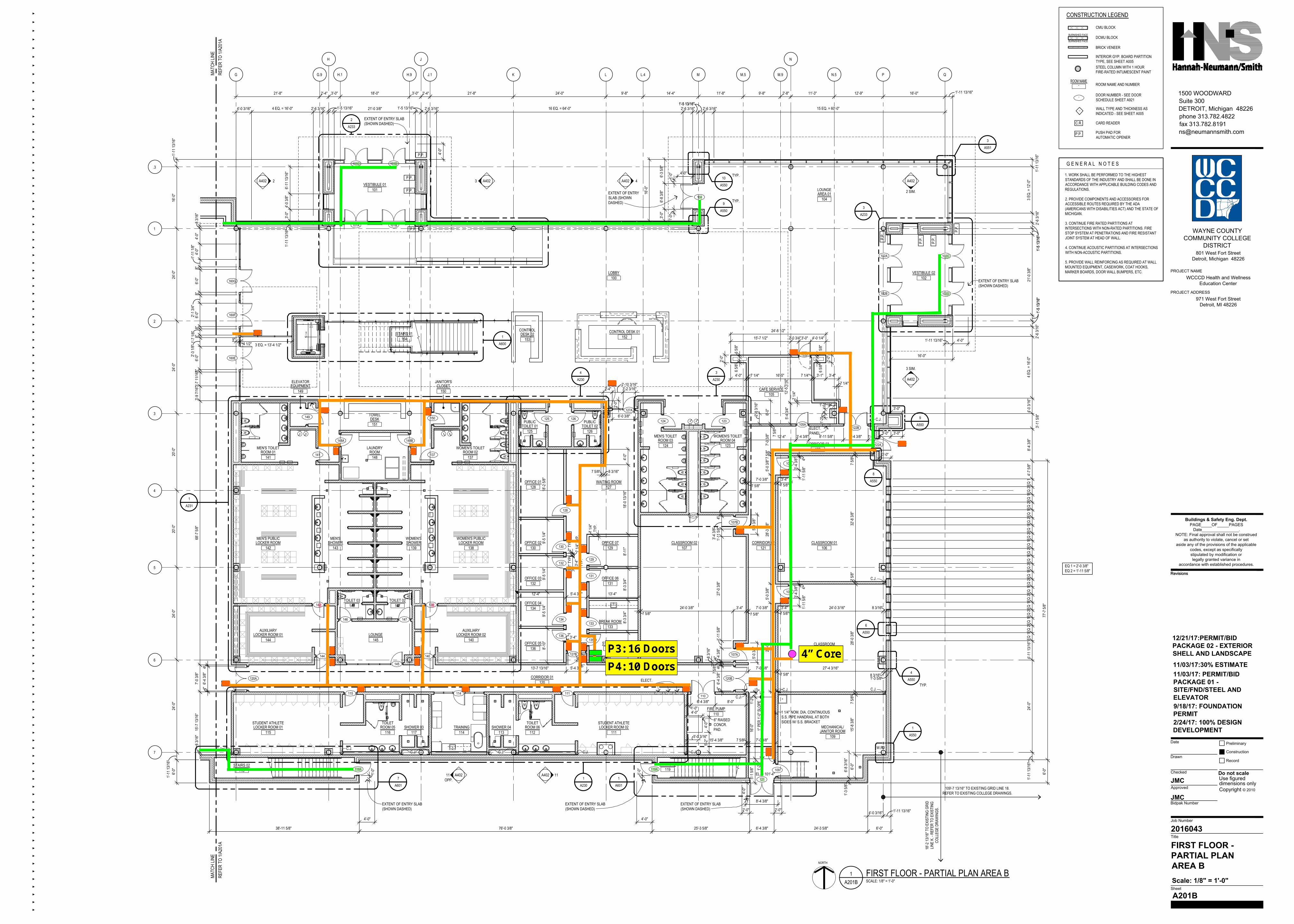
FIRST FLOOR -PARTIAL PLANAREA B
A201B
Scale: 1/8" = 1'-0"
2/24/17: 100% DESIGNDEVELOPMENT
NORTH
MATC
H LIN
ERE
FER
TO 1/
A201
AMA
TCH
LINE
REFE
R TO
1/A2
01A
101VESTIBULE 01
154STAIRS 01
149EQUIPMENTELEVATOR
151DESK
TOWEL
141ROOM 01
MEN'S TOILET
142LOCKER ROOMMEN'S PUBLIC
143SHOWER
MEN'S
139SHOWERWOMEN'S
138LOCKER ROOM
WOMEN'S PUBLIC
148ROOM
LAUNDRY
137ROOM 02
WOMEN'S TOILET
144LOCKER ROOM 01
AUXILIARY
140LOCKER ROOM 02
AUXILIARY
145LOUNGE
146TOILET 03
147TOILET 02
118STAIRS 02
115LOCKER ROOM 01
STUDENT ATHLETE
112ROOM 06TOILET
116ROOM 05TOILET
117SHOWER 03
113SHOWER 04
111LOCKER ROOM 02
STUDENT ATHLETE
120CORRIDOR 01
136OFFICE 05
134OFFICE 04
132OFFICE 03
130OFFICE 02
128OFFICE 01
135STORAGE
133BREAK ROOM
131OFFICE 06
129OFFICE 07
127WAITING ROOM
107CLASSROOM 02
125TOILET 01
PUBLIC
126TOILET 02
PUBLIC
124ROOM 03
MEN'S TOILET
123ROOM 04
WOMEN'S TOILET
110FIRE PUMP
119STAIRS 03
109JANITOR ROOMMECHANICAL/
108CLASSROOM
106CLASSROOM 01
121CORRIDOR 02
122CORRIDOR 03
105CAFE SERVICE150
CLOSETJANITOR'S
104AREA 01LOUNGE
102VESTIBULE 02
100LOBBY
1A201B SCALE: 1/8" = 1'-0"
FIRST FLOOR - PARTIAL PLAN AREA B
K LJ.1
J
H.9H.1
H
G.9G L.4 M M.5 M.9
N
N.5 P Q
- DOOR NUMBER - SEE DOORSCHEDULE SHEET A921
-ROOM NAME
ROOM NAME AND NUMBER
WALL TYPE AND THICKNESS ASINDICATED - SEE SHEET A005
CMU BLOCK
BRICK VENEER
INTERIOR GYP. BOARD PARTITIONTYPE, SEE SHEET A005
CARD READERC.R.
PUSH PAD FORAUTOMATIC OPENER
P.P.
1. WORK SHALL BE PERFORMED TO THE HIGHESTSTANDARDS OF THE INDUSTRY AND SHALL BE DONE INACCORDANCE WITH APPLICABLE BUILDING CODES ANDREGULATIONS.
2. PROVIDE COMPONENTS AND ACCESSORIES FORACCESSIBLE ROUTES REQUIRED BY THE ADA(AMERICANS WITH DISABILITIES ACT) AND THE STATE OFMICHIGAN.
3. CONTINUE FIRE RATED PARTITIONS ATINTERSECTIONS WITH NON-RATED PARTITIONS. FIRESTOP SYSTEM AT PENETRATIONS AND FIRE RESISTANTJOINT SYSTEM AT HEAD OF WALL.
4. CONTINUE ACOUSTIC PARTITIONS AT INTERSECTIONSWITH NON-ACOUSTIC PARTITIONS.
5. PROVIDE WALL REINFORCING AS REQUIRED AT WALLMOUNTED EQUIPMENT, CASEWORK, COAT HOOKS,MARKER BOARDS, DOOR WALL BUMPERS, ETC.
G E N E R A L N O T E S
CONSTRUCTION LEGEND
DCMU BLOCKBURNISHED FACE
BURNISHED FACE
STEEL COLUMN WITH 1 HOURFIRE-RATED INTUMESCENT PAINT
.3
1
2
3
4
5
6
7
21'-8" 2'-4" 3'-0" 18'-0" 3'-0" 2'-4" 21'-8" 24'-0" 9'-8" 14'-4" 11'-8" 9'-8" 2'-8" 11'-3" 12'-9" 16'-0" 1'-11 13/16"
3
A233
16'-0
"24
'-0"
24'-0
"20
'-0"
24'-0
"24
'-0"
1'-11
13/16
"1'-
11 13
/16"
7
A601
1
A601
6'-11
13/16
"4'-
0 3/8"
3'-0"
2'-6 3/16"16 EQ. = 64'-0"1'-5 13/16"
3'-0"
6'-8 3
/8"6'-
3 5/8"
16'-0
"
1'-5 13/16"2'-6 3/16" 15 EQ. = 60'-0"
1'-11
13/16
"
3 EQ.
= 12
'-0"
2'-6 3
/16"
1'-5 1
3/16"
1'-5 1
3/16"
21'-0
3/8"
1'-5 1
3/16"
1'-5 1
3/16"
2'-6 3
/16"
4 EQ.
= 16
'-0"
3'-11
5/8"
8'-4 3
/8"
77'-7
5/8"
20'-0
"
6'-0"
EQ 1
6'-0"
EQ 2
1'-11 13/16"4'-0 3/16"
6'-0"24'-3 5/8"6'-4 3/8"25'-3 5/8"76'-0 3/8"38'-11 5/8"
3'-0"3'-0"
3'-0"
3'-0"
16'-0"
1'-11 13/16"
1'-11
13/16
"24
'-0"
4'-11
13/16
"
121
109
110
4
A230
3
A230
1
A550
EQ 1
EQ 2
EQ 1
EQ 2
EQ 1
EQ 2
EQ 1
EQ 2
EQ 1
EQ 2
EQ 1
EQ 2
EQ 1
EQ 2
EQ 1
EQ 2
EQ 1
EQ 2
EQ 1
9
A550
1
A230
1
A231
1
A600
9
A550
TYP.
10
A550
TYP.
EQ 1 = 2'-0 3/8"EQ 2 = 1'-11 5/8"
101C 101D
101A 101B
102C
102D
102A
102B
122B
122A
106
127A
126125
128
130
132
134
136
127B
135
133
131
129
111115
118A 119A
144
145
140
138
147146
142
150
137
148B148A
141
149
120A
124 123105A
105B
104
152CONTROL DESK 01
153DESK 02
CONTROL
9/18/17: FOUNDATIONPERMIT
160E
160F
160G
1'-5 13/16"
1'-11
13/16
"
2
A233
107A
107B
120B
108
2'-6 3/16"2'-6 3/16"4 EQ. = 16'-0" 1'-5 13/16"21'-0 3/8"
114
114TRAINING
11/03/17: PERMIT/BIDPACKAGE 01 -SITE/FND/STEEL ANDELEVATOR
W.P.
11/03/17:30% ESTIMATE
4'-0 3/16"
4'-0 3
/16"
4'-7 5
/8"
18'-2
13/16
" TO
EXIS
TING
GRI
DLIN
E K.
- RE
FER
TO E
XIST
ING
COLL
EGE
DRAW
INGS
.
109'-7 13/16" TO EXISTING GRID LINE 18.REFER TO EXISTING COLLEGE DRAWINGS.
2A402 3 A402 4A402
2 SIM.
A402
3 SIM.
A402
11A40211 A402OPP.
2'-0" 2'-0"
4
A550
6
A550
8
A550
3
A551
EXTENT OF ENTRYSLAB (SHOWNDASHED)
4'-0"
1'-0"
1'-0"
EXTENT OF ENTRY SLAB(SHOWN DASHED)
4'-0"
1'-0"
4'-0"
1'-0"
EXTENT OF ENTRY SLAB(SHOWN DASHED)
EXTENT OF ENTRY SLAB(SHOWN DASHED)
4'-0"
4'-0"
EXTENT OF ENTRY SLAB(SHOWN DASHED)
C.J. C.J.C.J. C.J. C.J. C.J.
C.J.
C.J.
C.J.
C.J.
TYP.
8 3/16
"4'-
0"4'-
0"1'-
11 1/
8"8"
6'-0"
8"6'-
0"2'-1 3
/4"8"
1'-7 1
/8"8"
2'-3 1
/8"6'-
0"8"
3'-7 1
1/16"
3'-9 7
/16"
68'-7
5/8"
7'-0 3
/8"15
'-7 13
/16"
8 3/16
"
13'-7 13/16" 5'-4 3/8" 41'-11 5/8" 7'-0 3/8"7 5/8"
27'-4 3/16"
8 3/16"1'-3 5/8"
7'-0 3/8"7 5/8"15'-4 3/8"3'-0 3/16"
C.J.
C.J.
1'-0"6'-4 3/8" 8'-0" 1'-
2"16
'-0"
1'-2"
5'-1 5
/8"
UP
1 1/4" NOM. DIA. CONTINUOUSS.S. PIPE HANDRAIL AT BOTHSIDES W/ S.S. BRACKET
2"1"
PER
1'-0
" SLO
PE
EL. = 101'-4"
4"6'-
4 3/8"
4"4"
7 5/8"
8 3/16
"
3'-4 3
/8"1'-
11 5/
8"27
'-0 3/
8"1'-
11 5/
8"3'-
4 3/8"
4"
5'-0 3
/8"5'-
0 3/8"
7'-0 3
/8" 7 5/8"
6'-0"
2'-8 3
/16"
7 5/8"
5'-0 3
/8"28
'-3 5/
8"5'-
0 3/8"
23'-0
"
3'-4"24'-0 3/8"7 5/8" 7 5/8"
7'-0 3/8"7 5/8"3'-4" 24'-0 3/16" 8 3/16"
6'-0"
6'-8 3
/16"
1'-3 5
/8"15
'-8 3/
8"7 5
/8"28
'-0 3/
8"7 5
/8"32
'-8 3/
8"7 5
/8"4"
3'-4 3
/8"
1'-11
5/8"
4"
3'-4 3
/8"
1'-11
5/8"
7 5/8"7'-0 3/8"
7 5/8"3'-4"
12'-4" 3'-4 3/8" 8'-11 5/8" 6'-4 3/8" 1'-8"
13'-4"5'-4 3/8"12'-4"
3'-0"
2"3'-4"
8'-10
"9'-
5 1/4"
9'-5 1
/4"9'-
5 1/4"
18'-2
5/8"
7'-9 1
/16"
8'-3 3
/4"8'-
3 3/4"
8'-11
"18
'-0 13
/16"
4'-0"
8 3/16"7 5/8"
7 1/4"
TYP.
2" T
YP.
7 1/4"
TYP
.
2" T
YP.
3'-4"
TYP.
C.R.
P.P.
9"4 1/2" 3 EQ. = 13'-4 1/2"
P.P.
P.P.
P.P.
P.P.
P.P.P.
P.
P.P.
12/21/17:PERMIT/BIDPACKAGE 02 - EXTERIORSHELL AND LANDSCAPE
ELECT.PANEL
6" RAISEDCONCR.PAD.
4'-0"
4'-0"
5'-2"
2'-0"
24'-8 1/2"
6 5/8"
6 5/8"
15'-7 1/2" 2'-0 3/4"3'-0" 4'-0 1/4"
4'-0" 7 1/4" 16'-5" 7 1/4" 3'-1" 3'-4"
2'-0"
6 5/8"
6 5/8"
5'-4 3
/4"12
'-5 7/
16"
1'-2"
1'-2"
7 1/4"
7 1/4"
6'-4 3
/8"4"
4"
EXTENT OF ENTRY SLAB(SHOWN DASHED)
4'-0"
8'-4 3/8"
2'-4"
6'-0 3/8"
2'-10 3/16"3'-2 3/16"
2'-0"
C.R.
C.R.
C.R.
C.R.
C.R.
C.R.
C.R.C.R.
C.R.
C.R.
C.R.
C.R.
C.R.
C.R.
C.R.
C.R.
C.R.
C.R.
C.R.
C.R.
C.R.
C.R.
C.R.
C.R.
C.R.
C.R.
C.R.
C.R.
C.R. C.R. C.R.
C.R.
ELECT.PANEL
107C
C.R.
Revisions
JMC
JMC
Suite 3001500 WOODWARD
phone 313.782.4822DETROIT, Michigan 48226
Date Preliminary
Record
Use figured
Drawn
Checked
Approved
Bidpak Number
Title
Sheet
Job Number
dimensions only
Do not scale
Copyright © 2010
Construction
Revisions
2016043
PROJECT NAME
WAYNE COUNTYCOMMUNITY COLLEGE
DISTRICT801 West Fort Street
Detroit, Michigan 48226
WCCCD Health and WellnessEducation Center
PROJECT ADDRESS971 West Fort Street
Detroit, MI 48226
Buildings & Safety Eng. Dept.PAGE OF PAGES
Date .NOTE: Final approval shall not be construed
as authority to violate, cancel or setaside any of the provisions of the applicable
codes, except as specificallystipulated by modification orlegally granted variance in
accordance with established procedures.
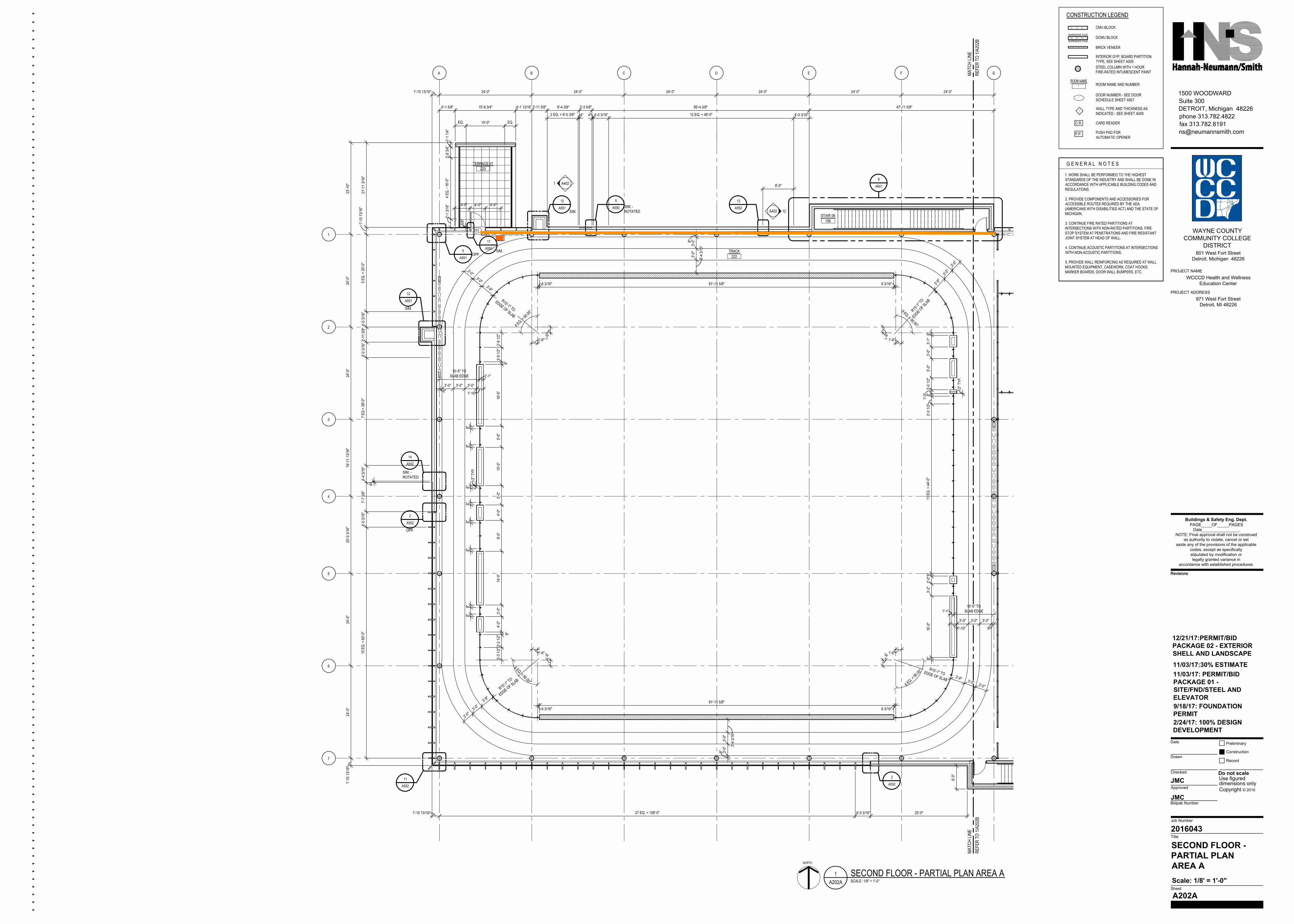
SECOND FLOOR -PARTIAL PLANAREA A
A202A
Scale: 1/8' = 1'-0"
2/24/17: 100% DESIGNDEVELOPMENT
NORTH
1A202A SCALE: 1/8" = 1'-0"
SECOND FLOOR - PARTIAL PLAN AREA A
222TRACK
MATC
H LIN
ERE
FER
TO 1/
A202
BMA
TCH
LINE
REFE
R TO
1/A2
02B
- DOOR NUMBER - SEE DOORSCHEDULE SHEET A921
-ROOM NAME
ROOM NAME AND NUMBER
WALL TYPE AND THICKNESS ASINDICATED - SEE SHEET A005
CMU BLOCK
BRICK VENEER
INTERIOR GYP. BOARD PARTITIONTYPE, SEE SHEET A005
CARD READERC.R.
PUSH PAD FORAUTOMATIC OPENER
P.P.
1. WORK SHALL BE PERFORMED TO THE HIGHESTSTANDARDS OF THE INDUSTRY AND SHALL BE DONE INACCORDANCE WITH APPLICABLE BUILDING CODES ANDREGULATIONS.
2. PROVIDE COMPONENTS AND ACCESSORIES FORACCESSIBLE ROUTES REQUIRED BY THE ADA(AMERICANS WITH DISABILITIES ACT) AND THE STATE OFMICHIGAN.
3. CONTINUE FIRE RATED PARTITIONS ATINTERSECTIONS WITH NON-RATED PARTITIONS. FIRESTOP SYSTEM AT PENETRATIONS AND FIRE RESISTANTJOINT SYSTEM AT HEAD OF WALL.
4. CONTINUE ACOUSTIC PARTITIONS AT INTERSECTIONSWITH NON-ACOUSTIC PARTITIONS.
5. PROVIDE WALL REINFORCING AS REQUIRED AT WALLMOUNTED EQUIPMENT, CASEWORK, COAT HOOKS,MARKER BOARDS, DOOR WALL BUMPERS, ETC.
G E N E R A L N O T E S
CONSTRUCTION LEGEND
DCMU BLOCKBURNISHED FACE
BURNISHED FACE
STEEL COLUMN WITH 1 HOURFIRE-RATED INTUMESCENT PAINTA B C D E F G
1
2
3
4
5
6
7
24'-0
"24
'-0"
19'-1
1 13/1
6"20
'-0 3/
16"
24'-0
"24
'-0"
1'-10
13/16
"
24'-0" 24'-0" 24'-0" 24'-0" 24'-0" 24'-0"1'-10 13/16"
27 EQ. = 108'-0"
6'-0"
1'-10
13/16
"
56'-4 3/8"
1'-10 13/16"
5 EQ.
= 20
'-0"
8'-4 3/8"
7'-7 5
/8"15
EQ.
= 60
'-0"
3'-3 5/8"
25'-0"
23'-1
0"
9/18/17: FOUNDATIONPERMIT
4"
4'-1 5/8" 15'-8 3/4" 4'-1 13/16" 3'-11 5/8"
4"
4'-0 3
/16"
2 EQ. = 8'-0 3/8" 4" 4'-0 3/16" 12 EQ. = 48'-0"
7 EQ
= 28
'-0"
47'-11 5/8"
3'-11
5/8"
156STAIR 06
223TERRACE 01
223
6
A601
11/03/17: PERMIT/BIDPACKAGE 01 -SITE/FND/STEEL ANDELEVATOR
4'-0 3/16"
11/03/17:30% ESTIMATE
4'-0 3
/16"
4'-0 3
/16"
4'-4 3
/16"
4'-0 3/16"
1 A402
12A4024'-0" 4'-0" 4'-0"
12
A551
5
A551OPP.
12
A551
SIM.
14
A552
5
A550 SIM. -ROTATED
SIM. -ROTATED
2
A55211
A552
2
A552
OPP.
8'-0"
13
A552
EQ. 10'-0" EQ.
5/8"
SIM.
6 3/16"
1'-6"
1'-6"
6 EQ. =
90.00°
3'-9 1
/2"3'-
9 1/2"
8"
R15'-1" TO
EDGE OF SLAB
10'-5" TOSLAB EDGE
16'-0
"
1'-1"
1'-10"
3'-0"3'-0"3'-0"8"
5'-6"
10'-0
"5'-
0"4'-
0"8'-
0"14
'-0"
3'-0"
4'-0"
8"8"
8"8"
8"8"
8"8"
6 3/16"
1'-6"1'-6"
6 EQ. = 90.00°
R15'-1" TO
EDGE OF SLAB
3'-3 1
/2"3'-
3 1/2"
8"
6 3/16"
1'-6" 1'-6"
6 EQ. =
90.00°
R15'-1" TOEDGE OF SLAB
8"16
'-0"
3'-2"
2'-0"
8"11
EQ.
= 44
'-0"
8"1'-
0"3'-
0 1/2"
5'-0"
3'-0"
3'-1"
8"
6 3/16"
1'-6"
1'-6"
6 EQ. = 90.00°R15'
-1" TO
EDGE OF SLA
B
91'-11 5/8"
91'-11 5/8"
8" 3'-0"
3'-0"
3'-4 3
/16"
8"3'-
0"3'-
0"
3'-4 3
/16"
3'-9"
3'-0"
3'-0"
3'-9"
3'-0"
3'-0"
3'-9" 3'-0" 3'-0"
3'-9"
3'-0"
3'-0"
10'-5" TOSLAB EDGE1'-1"
1'-10"
3'-0" 3'-0" 3'-0"
8"
2'-0 1
/2"
1/2" T
YP.
1/2" T
YP.
17
A552 SIM.
1'-1 1
/4"2'-
8 3/4"
21'-1
1 3/16
"
4 EQ.
- 16
'-0"
2'-1 3
/16"
12/21/17:PERMIT/BIDPACKAGE 02 - EXTERIORSHELL AND LANDSCAPE
C.R.
.�%#4
%
.�
.�
.�
.�
IQX
VITREOUS CHINALAVATORYPENNINGTONK-2196-8K-942-4STILLNESSFAUCETBRASS
VITREOUS CHINALAVATORYPENNINGTONK-2196-8K-942-4STILLNESSFAUCETBRASS
VITREOUS CHINALAVATORYPENNINGTONK-2196-8K-942-4STILLNESSFAUCETBRASS
VITREOUS CHINALAVATORYPENNINGTONK-2196-8K-942-4STILLNESSFAUCETBRASS
VITREOUS CHINALAVATORYPENNINGTONK-2196-8K-942-4STILLNESSFAUCETBRASS
VITREOUS CHINALAVATORYPENNINGTONK-2196-8
K-942-4STILLNESSFAUCETBRASS
VITREOUS CHINALAVATORYPENNINGTONK-2196-8K-942-4STILLNESSFAUCETBRASS
VITREOUS CHINALAVATORYPENNINGTONK-2196-8K-942-4STILLNESSFAUCETBRASS
Revisions
JMC
JMC
Suite 3001500 WOODWARD
phone 313.782.4822DETROIT, Michigan 48226
Date Preliminary
Record
Use figured
Drawn
Checked
Approved
Bidpak Number
Title
Sheet
Job Number
dimensions only
Do not scale
Copyright © 2010
Construction
Revisions
2016043
PROJECT NAME
WAYNE COUNTYCOMMUNITY COLLEGE
DISTRICT801 West Fort Street
Detroit, Michigan 48226
WCCCD Health and WellnessEducation Center
PROJECT ADDRESS971 West Fort Street
Detroit, MI 48226
Buildings & Safety Eng. Dept.PAGE OF PAGES
Date .NOTE: Final approval shall not be construed
as authority to violate, cancel or setaside any of the provisions of the applicable
codes, except as specificallystipulated by modification orlegally granted variance in
accordance with established procedures.
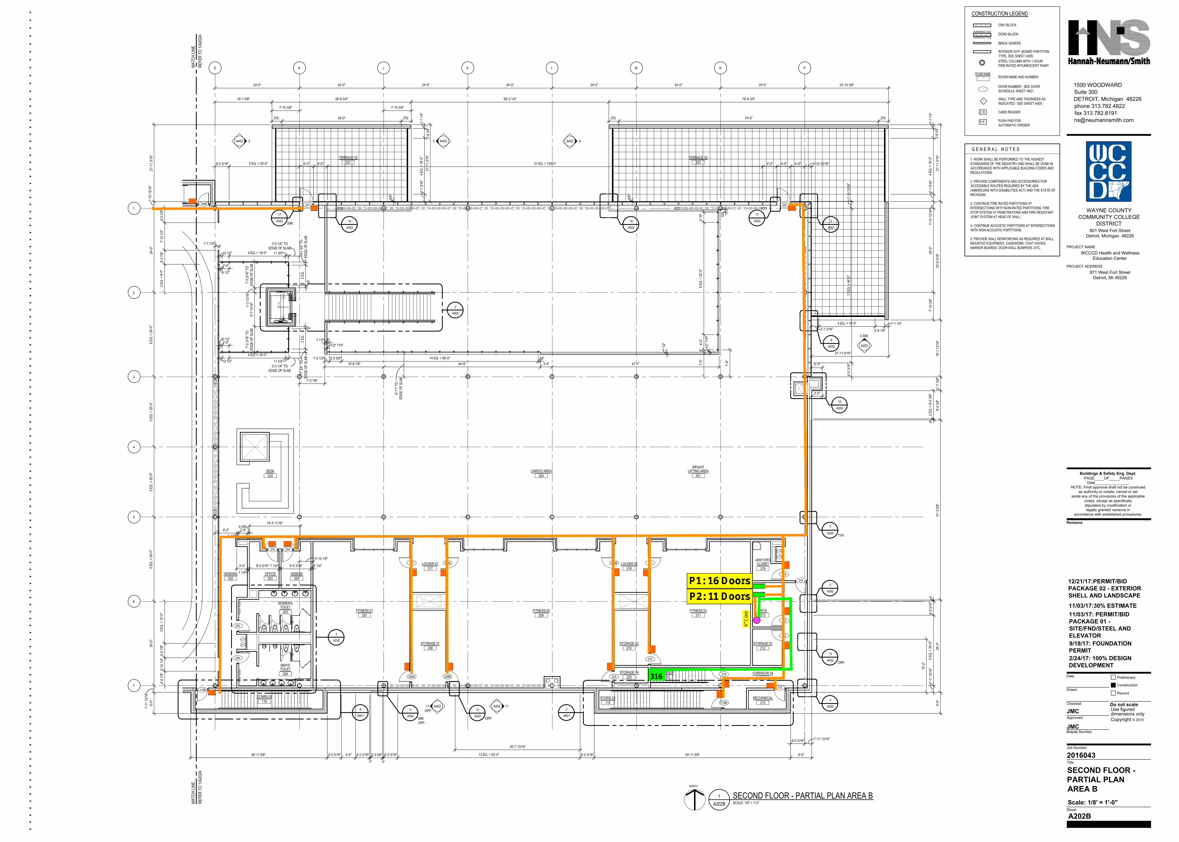
SECOND FLOOR -PARTIAL PLANAREA B
A202B
Scale: 1/8' = 1'-0"
2/24/17: 100% DESIGNDEVELOPMENT
NORTH
1A202B SCALE: 1/8" = 1'-0"
SECOND FLOOR - PARTIAL PLAN AREA B
MATC
H LIN
ERE
FER
TO 1/
A202
AMA
TCH
LINE
REFE
R TO
1/A2
02A
203OFFICE
204ASSESS
202VENDING
205TOILET
WOMEN'S
206TOILETMEN'S
118STAIRS 02
207FITNESS 01
209FITNESS 02
208STORAGE 01
217LOCKER 01
210STORAGE 02
218LOCKER 02
211FITNESS 03
200CARDIO AREA
201LIFTING AREA
WEIGHT
213DATA
212STORAGE 03
219CLOSET
JANITOR'S
214CORRIDOR 04
215MECHANICAL
119STAIRS 03
220TERRACE 03
221TERRACE 02
K LJHG M N P
1
2
3
4
5
6
7
24'-0" 24'-0" 24'-0" 24'-0" 24'-0" 24'-0" 24'-0" 23'-10 3/8"
24'-0
"6 E
Q. =
24'-0
"5 E
Q. =
20'-0
"6 E
Q. =
24'-0
"24
'-0"
1'-11
13/16
"21
'-11 3
/16"
1'-10
13/16
"
33'-9
3/16
"
5 EQ.
= 20
'-0"
6'-0"
51'-3
5/8"
6'-0"
1'-11 13/16"4'-0 3/16"
6'-0"55'-11 5/8"38'-11 5/8"
3'-0"
3'-1"
8
A601
2
A601
21'-1
1 3/16
"
3
A550
5
A550
10
A550
5
A551
2
A600
221
118B
206
205
220
203 204
208A 208B
207 209A
225
209B 211
210
219
213
212
214
215
216
119B
216STAIRS 04
9/18/17: FOUNDATIONPERMIT
5 EQ. = 20'-0" 4'-0"
39'-8 3/4" 56'-3 1/4"
31 EQ. = 124'-0"
79'-8 3/4"
4'-0" 4'-0"
1'-10
13/16
"24
'-0"
7'-10
3/8"
16'-1
13/16
"3'-
11 5/
8"
2 EQ.
= 8'
-0 3/
8"4"
26'-4
"
4"5 E
Q. =
20'-0
"1'-
11 13
/16"
1'-10 13/16"
1'-10
13/16
"11
EQ.
= 44
'-0"
4'-0 3
/16"
8'-4 3
/8"
13 EQ. = 52'-0" 4'-0 3/16"
4"
3'-3 5/8"4'-0 3/16"
- DOOR NUMBER - SEE DOORSCHEDULE SHEET A921
-ROOM NAME
ROOM NAME AND NUMBER
WALL TYPE AND THICKNESS ASINDICATED - SEE SHEET A005
CMU BLOCK
BRICK VENEER
INTERIOR GYP. BOARD PARTITIONTYPE, SEE SHEET A005
CARD READERC.R.
PUSH PAD FORAUTOMATIC OPENER
P.P.
1. WORK SHALL BE PERFORMED TO THE HIGHESTSTANDARDS OF THE INDUSTRY AND SHALL BE DONE INACCORDANCE WITH APPLICABLE BUILDING CODES ANDREGULATIONS.
2. PROVIDE COMPONENTS AND ACCESSORIES FORACCESSIBLE ROUTES REQUIRED BY THE ADA(AMERICANS WITH DISABILITIES ACT) AND THE STATE OFMICHIGAN.
3. CONTINUE FIRE RATED PARTITIONS ATINTERSECTIONS WITH NON-RATED PARTITIONS. FIRESTOP SYSTEM AT PENETRATIONS AND FIRE RESISTANTJOINT SYSTEM AT HEAD OF WALL.
4. CONTINUE ACOUSTIC PARTITIONS AT INTERSECTIONSWITH NON-ACOUSTIC PARTITIONS.
5. PROVIDE WALL REINFORCING AS REQUIRED AT WALLMOUNTED EQUIPMENT, CASEWORK, COAT HOOKS,MARKER BOARDS, DOOR WALL BUMPERS, ETC.
G E N E R A L N O T E S
CONSTRUCTION LEGEND
DCMU BLOCKBURNISHED FACE
BURNISHED FACE
STEEL COLUMN WITH 1 HOURFIRE-RATED INTUMESCENT PAINT
16'-1 5/8"
7'-10 3/8"
4'-0"
224DESK
4"
11/03/17: PERMIT/BIDPACKAGE 01 -SITE/FND/STEEL ANDELEVATOR
4'-0 3
/16"
11/03/17:30% ESTIMATE
5
A550
4'-0 3/16" 4'-0"
4'-0 3/16"4'-0" 4'-0 3/16"
4'-0 7
/8"7'-
10 1/
4"4'-
0 7/8"
2 EQ.
= 8'
-0"
4'-0 7
/8"3'-
10 1/
4"4'-
0 7/8"
3 EQ.
= 12
'-0"
2A402 3 A402 4A402
4 SIM.
A402
11A40211 A402OPP.
7
A550 TYP.
6
A552
SIM.OPP.
225STORAGE 04
15'-2
"
35'-7 13/16"
13
A552 OPP.
13
A552 OPP.
7'-10 3/8"
EQ. EQ.34'-0"
5/8"
5/8"
EQ. EQ.74'-0"
1'-1 1/2"
10 1/2"
8 1/2"
2'-0"
4 EQ. = 16'-0"
10 1/2"
8 1/2"2'-0"
4 EQ. = 16'-0"
1'-3 1
3/16"
9'-7 1
3/16"
7'-5 3
/16" T
OED
GE O
F SL
AB7'-
5 3/16
" TO
EDGE
OF
SLAB
11 3/4" 11 3/
4" T
OED
GE O
F SL
AB
3'-0 1/4" TOEDGE OF SLAB
2 EQ.
8"
11 3/4"
11 3/
4" T
OED
GE O
F SL
AB
3'-0 1/4" TOEDGE OF SLAB
2 EQ.
8"
16'-9 1/8"
6'-11
" TO
EDGE
OF
SLAB
44'-8" 3'-4"1'-3 1/2" 14 EQ. = 56'-0"3'-5 5/8"
8"1/2" TYP.
47'-7" 7'-8"
8"
7'-2 7/8"
7'-0"
8 EQ.
= 32
'-0"
2'-10
"
10"
1/2" T
YP.
7 1/2"
8"
4'-4"
7 1/2"
18
A552
17
A552
17
A552 SIM. 19
A552
1'-1 1/4"
21'-11 9/16"
21'-1
1 3/16
"1'-
1 1/4"
2'-8 3
/4"
4 EQ.
= 16
'-0"
2'-1 3
/16"
1'-1 1
/4"
2'-8 3
/4"
4 EQ.
= 16
'-0"
2'-1 3
/16"
2'-9 1/8"
4 EQ. = 16'-0"2'-1 3/16"
12/21/17:PERMIT/BIDPACKAGE 02 - EXTERIORSHELL AND LANDSCAPE
2
A230
3'-10 1/8"
7 1/4"8'-5 3/16"7 1/4"8'-5 3/16"
7 1/4"
3'-0"
6 5/8"2'-6"
6 5/8"14'-5 11/16"
6'-2"
C.R. C.R.
C.R.
C.R.
C.R.
C.R.
C.R.
C.R.
C.R.
C.R.
C.R.
C.R.
C.R.
C.R.
C.R.
C.R.
C.R. C.R.
156B
C.R.
C.R.
L C
AR
C
L1
L3
L2
L4
gov
VITREOUS CHINA LAVATORY PENNINGTONK-2196-8
K-942-4STILLNESSFAUCETBRASS
VITREOUS CHINALAVATORYPENNINGTONK-2196-8K-942-4STILLNESSFAUCETBRASS
VITREOUS CHINALAVATORYPENNINGTONK-2196-8K-942-4STILLNESSFAUCETBRASS
VITREOUS CHINALAVATORYPENNINGTONK-2196-8K-942-4STILLNESSFAUCETBRASS
VITREOUS CHINALAVATORYPENNINGTONK-2196-8K-942-4STILLNESSFAUCETBRASS
VITREOUS CHINALAVATORYPENNINGTONK-2196-8K-942-4STILLNESSFAUCETBRASS
VITREOUS CHINALAVATORYPENNINGTONK-2196-8K-942-4STILLNESSFAUCETBRASS
VITREOUS CHINALAVATORYPENNINGTONK-2196-8K-942-4STILLNESSFAUCETBRASS
-0"-3/8"
-0"-3/8"
Revisions
JMC
JMC
Suite 3001500 WOODWARD
phone 313.782.4822DETROIT, Michigan 48226
Date Preliminary
Record
Use figured
Drawn
Checked
Approved
Bidpak Number
Title
Sheet
Job Number
dimensions only
Do not scale
Copyright © 2010
Construction
Revisions
2016043
PROJECT NAME
WAYNE COUNTYCOMMUNITY COLLEGE
DISTRICT801 West Fort Street
Detroit, Michigan 48226
WCCCD Health and WellnessEducation Center
PROJECT ADDRESS971 West Fort Street
Detroit, MI 48226
Buildings & Safety Eng. Dept.PAGE OF PAGES
Date .NOTE: Final approval shall not be construed
as authority to violate, cancel or setaside any of the provisions of the applicable
codes, except as specificallystipulated by modification orlegally granted variance in
accordance with established procedures.
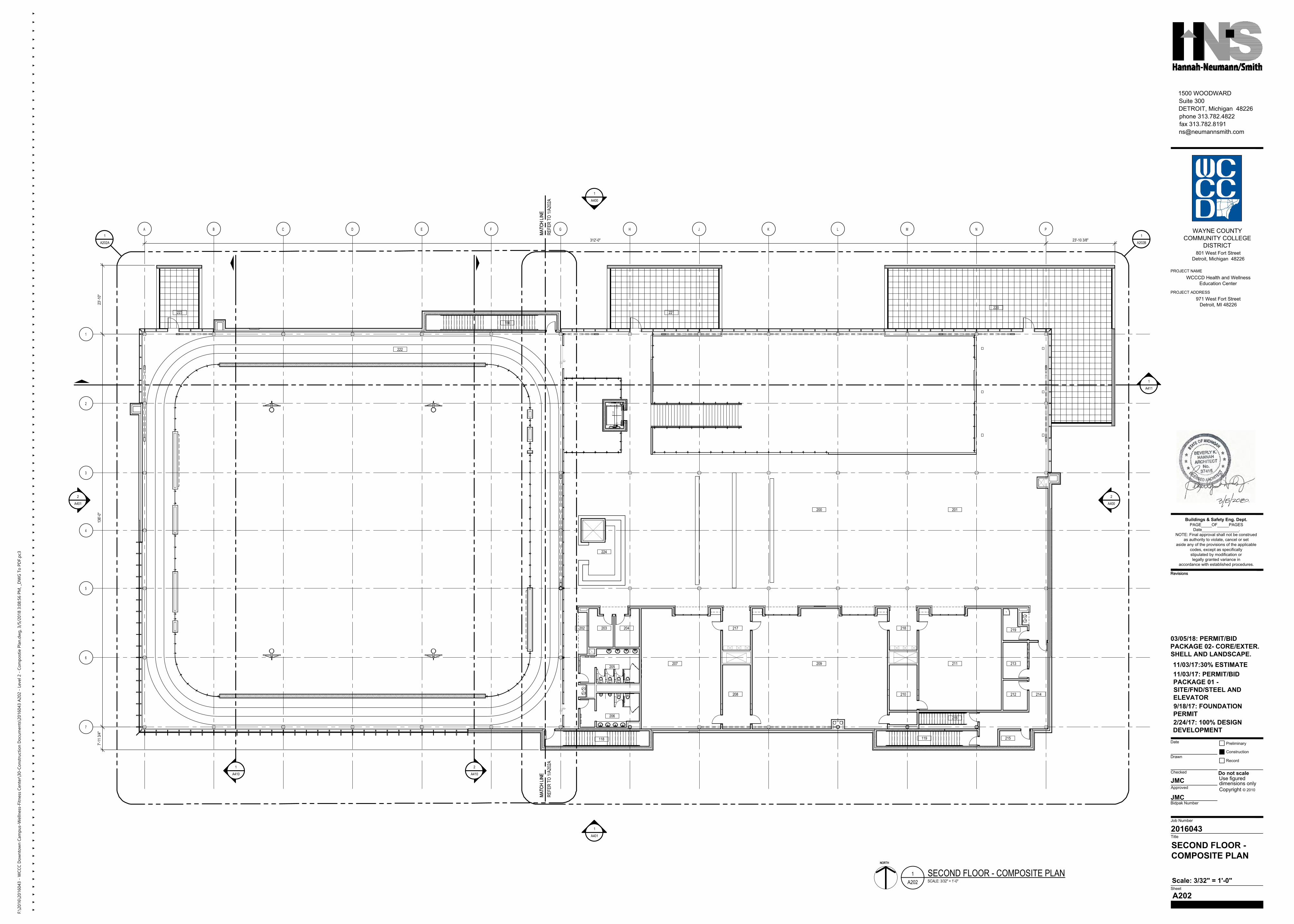
SECOND FLOOR -COMPOSITE PLAN
A202
Scale: 3/32" = 1'-0"
2/24/17: 100% DESIGNDEVELOPMENT
NORTH
1A202 SCALE: 3/32" = 1'-0"
SECOND FLOOR - COMPOSITE PLAN
MATC
H LIN
ERE
FER
TO 1/
A202
AMA
TCH
LINE
REFE
R TO
1/A2
02A
212
219218
209
217
206
207
202
211
216
221
118 119
222
220
203 204
136'-
0"
312'-0"
1
A410
2
A410
1
A202A
1
A202B
213
210
215
214
205
200 201
208
NORTH
MATC
H LIN
EMA
TCH
LINE
PNMLKJHGFEDCBA
1
2
3
4
5
6
7
9/18/17: FOUNDATIONPERMIT
156
223
224
7'-11
3/4"
23'-1
0"
23'-10 3/8"
11/03/17: PERMIT/BIDPACKAGE 01 -SITE/FND/STEEL ANDELEVATOR
11/03/17:30% ESTIMATE
2
A401
1
A401
1
A400
2
A400
1
A411
03/05/18: PERMIT/BIDPACKAGE 02- CORE/EXTER.SHELL AND LANDSCAPE.
F:\2
016\
2016
043
- WCC
C D
ownt
own
Cam
pus-
Wel
lnes
s-Fi
tnes
s Cen
ter\
30-C
onst
ruct
ion
Doc
umen
ts\2
0160
43 A
202
- Lev
el 2
- Co
mpo
stie
Pla
n.dw
g, 3
/5/2
018
3:08
:56
PM, _
DW
G To
PD
F.pc
3
Revisions
JMC
JMC
Suite 3001500 WOODWARD
phone 313.782.4822DETROIT, Michigan 48226
Date Preliminary
Record
Use figured
Drawn
Checked
Approved
Bidpak Number
Title
Sheet
Job Number
dimensions only
Do not scale
Copyright © 2010
Construction
Revisions
2016043
PROJECT NAME
WAYNE COUNTYCOMMUNITY COLLEGE
DISTRICT801 West Fort Street
Detroit, Michigan 48226
WCCCD Health and WellnessEducation Center
PROJECT ADDRESS971 West Fort Street
Detroit, MI 48226
Buildings & Safety Eng. Dept.PAGE OF PAGES
Date .NOTE: Final approval shall not be construed
as authority to violate, cancel or setaside any of the provisions of the applicable
codes, except as specificallystipulated by modification orlegally granted variance in
accordance with established procedures.
-
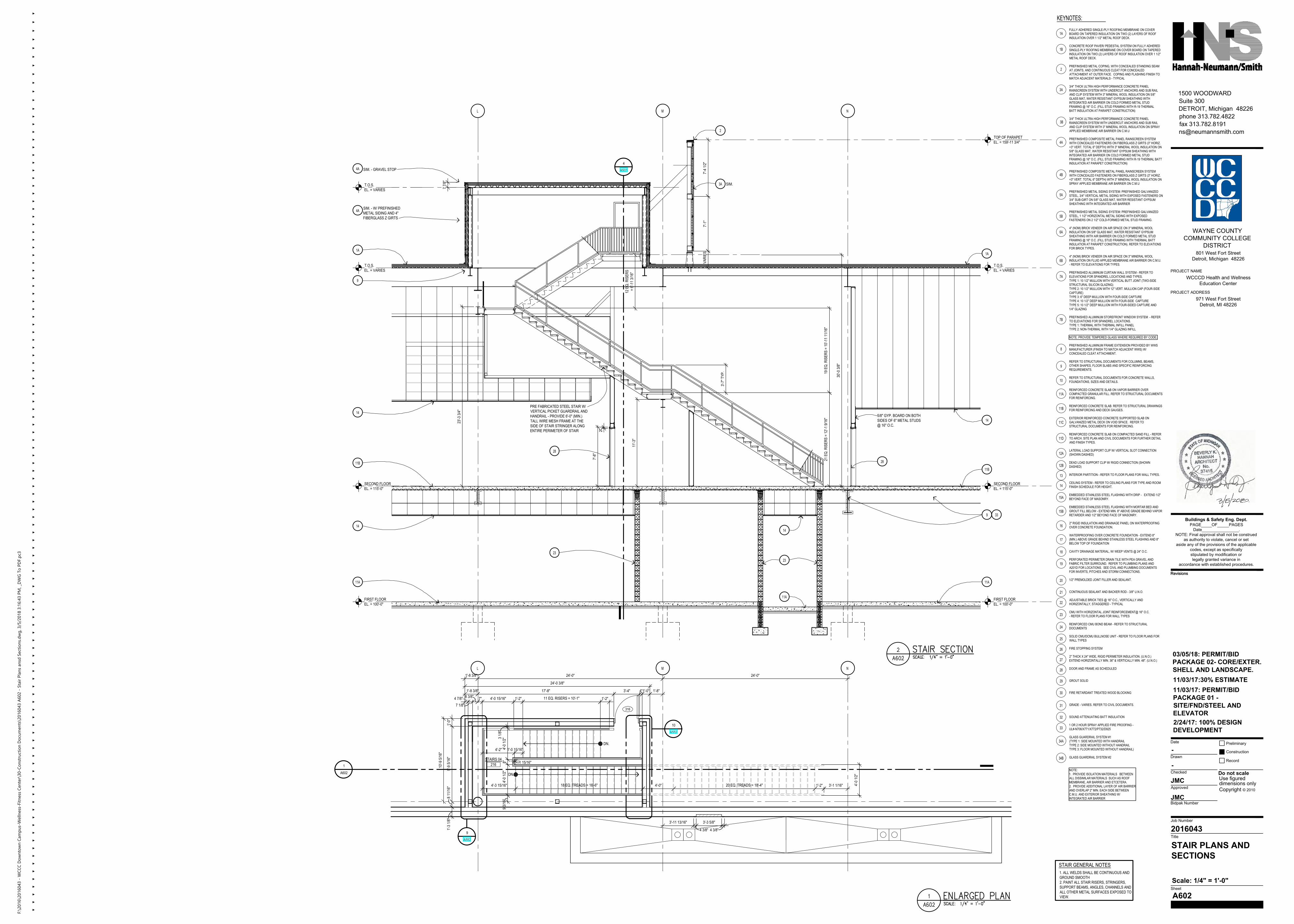
STAIR PLANS ANDSECTIONS
A602
Scale: 1/4" = 1'-0"
-
KEYNOTES: FULLY ADHERED SINGLE-PLY ROOFING MEMBRANE ON COVERBOARD ON TAPERED INSULATION ON TWO (2) LAYERS OF ROOFINSULATION OVER 1 1/2" METAL ROOF DECK.
CONCRETE ROOF PAVER/ PEDESTAL SYSTEM ON FULLY ADHEREDSINGLE-PLY ROOFING MEMBRANE ON COVER BOARD ON TAPEREDINSULATION ON TWO (2) LAYERS OF ROOF INSULATION OVER 1 1/2"METAL ROOF DECK.
PREFINISHED METAL COPING, WITH CONCEALED STANDING SEAMAT JOINTS, AND CONTINUOUS CLEAT FOR CONCEALEDATTACHMENT AT OUTER FACE. COPING AND FLASHING FINISH TOMATCH ADJACENT MATERIALS - TYPICAL
3/4" THICK ULTRA HIGH PERFORMANCE CONCRETE PANELRAINSCREEN SYSTEM WITH UNDERCUT ANCHORS AND SUB RAILAND CLIP SYSTEM WITH 3" MINERAL WOOL INSULATION ON 5/8"GLASS MAT, WATER RESISTANT GYPSUM SHEATHING WITHINTEGRATED AIR BARRIER ON COLD FORMED METAL STUDFRAMING @ 16" O.C. (FILL STUD FRAMING WITH R-19 THERMALBATT INSULATION AT PARAPET CONSTRUCTION)
3/4" THICK ULTRA HIGH PERFORMANCE CONCRETE PANELRAINSCREEN SYSTEM WITH UNDERCUT ANCHORS AND SUB RAILAND CLIP SYSTEM WITH 3" MINERAL WOOL INSULATION ON SPRAYAPPLIED MEMBRANE AIR BARRIER ON C.M.U
PREFINISHED COMPOSITE METAL PANEL RAINSCREEN SYSTEMWITH CONCEALED FASTENERS ON FIBERGLASS Z GIRTS (3" HORIZ.+3" VERT. TOTAL 6" DEPTH) WITH 3" MINERAL WOOL INSULATION ON5/8" GLASS MAT, WATER RESISTANT GYPSUM SHEATHING WITHINTEGRATED AIR BARRIER ON COLD FORMED METAL STUDFRAMING @ 16" O.C. (FILL STUD FRAMING WITH R-19 THERMAL BATTINSULATION AT PARAPET CONSTRUCTION)
PREFINISHED COMPOSITE METAL PANEL RAINSCREEN SYSTEMWITH CONCEALED FASTENERS ON FIBERGLASS Z GIRTS (3" HORIZ.+3" VERT. TOTAL 6" DEPTH) WITH 3" MINERAL WOOL INSULATION ONSPRAY APPLIED MEMBRANE AIR BARRIER ON C.M.U
PREFINISHED METAL SIDING SYSTEM: PREFINISHED GALVANIZEDSTEEL, 3/4" VERTICAL METAL SIDING WITH EXPOSED FASTENERS ON3/4" SUB-GIRT ON 5/8" GLASS MAT, WATER RESISTANT GYPSUMSHEATHING WITH INTEGRATED AIR BARRIER
PREFINISHED METAL SIDING SYSTEM: PREFINISHED GALVANIZEDSTEEL, 1 1/2" HORIZONTAL METAL SIDING WITH EXPOSEDFASTENERS ON 2 1/2" COLD-FORMED METAL STUD FRAMING.
4" (NOM) BRICK VENEER ON AIR SPACE ON 3" MINERAL WOOLINSULATION ON 5/8" GLASS MAT, WATER RESISTANT GYPSUMSHEATHING WITH AIR BARRIER ON COLD FORMED METAL STUDFRAMING @ 16" O.C. (FILL STUD FRAMING WITH THERMAL BATTINSULATION AT PARAPET CONSTRUCTION). REFER TO ELEVATIONSFOR BRICK TYPES.
4" (NOM) BRICK VENEER ON AIR SPACE ON 3" MINERAL WOOLINSULATION ON FLUID APPLIED MEMBRANE AIR BARRIER ON C.M.U.- REFER TO ELEVATIONS FOR TYPES.
PREFINISHED ALUMINUM CURTAIN WALL SYSTEM - REFER TOELEVATIONS FOR SPANDREL LOCATIONS AND TYPES.TYPE 1: 10 1/2" MULLION WITH VERTICAL BUTT JOINT (TWO-SIDESTRUCTURAL SILICON GLAZING)TYPE 2: 10 1/2" MULLION WITH 12" VERT. MULLION CAP (FOUR-SIDECAPTURE)TYPE 3: 6" DEEP MULLION WITH FOUR-SIDE CAPTURETYPE 4: 10 1/2" DEEP MULLION WITH FOUR-SIDE CAPTURETYPE 5: 10 1/2" DEEP MULLION WITH FOUR-SIDED CAPTURE AND1/4" GLAZING
PREFINISHED ALUMINUM STOREFRONT WINDOW SYSTEM - REFERTO ELEVATIONS FOR SPANDREL LOCATIONS.TYPE 1: THERMAL WITH THERMAL INFILL PANELTYPE 2: NON-THERMAL WITH 1/4" GLAZING INFILL
NOTE: PROVIDE TEMPERED GLASS WHERE REQUIRED BY CODE.
PREFINISHED ALUMINUM FRAME EXTENSION PROVIDED BY WWSMANUFACTURER (FINISH TO MATCH ADJACENT WWS) W/CONCEALED CLEAT ATTACHMENT.
REFER TO STRUCTURAL DOCUMENTS FOR COLUMNS, BEAMS,OTHER SHAPES, FLOOR SLABS AND SPECIFIC REINFORCINGREQUIREMENTS.
REFER TO STRUCTURAL DOCUMENTS FOR CONCRETE WALLS,FOUNDATIONS, SIZES AND DETAILS.
REINFORCED CONCRETE SLAB ON VAPOR BARRIER OVERCOMPACTED GRANULAR FILL. REFER TO STRUCTURAL DOCUMENTSFOR REINFORCING.
REINFORCED CONCRETE SLAB. REFER TO STRUCTURAL DRAWINGSFOR REINFORCING AND DECK GAUGES.
EXTERIOR REINFORCED CONCRETE SUPPORTED SLAB ONGALVANIZED METAL DECK ON VOID SPACE. REFER TOSTRUCTURAL DOCUMENTS FOR REINFORCING.
REINFORCED CONCRETE SLAB ON COMPACTED SAND FILL - REFERTO ARCH. SITE PLAN AND CIVIL DOCUMENTS FOR FURTHER DETAILAND FINISH TYPES.
LATERAL LOAD SUPPORT CLIP W/ VERTICAL SLOT CONNECTION(SHOWN DASHED)
DEAD LOAD SUPPORT CLIP W/ RIGID CONNECTION (SHOWNDASHED)
INTERIOR PARTITION - REFER TO FLOOR PLANS FOR WALL TYPES.
CEILING SYSTEM - REFER TO CEILING PLANS FOR TYPE AND ROOMFINISH SCHEDULE FOR HEIGHT.
EMBEDDED STAINLESS STEEL FLASHING WITH DRIP - EXTEND 1/2"BEYOND FACE OF MASONRY.
EMBEDDED STAINLESS STEEL FLASHING WITH MORTAR BED ANDGROUT FILL BELOW - EXTEND MIN. 8" ABOVE GRADE BEHIND VAPORRETARDER AND 1/2" BEYOND FACE OF MASONRY.
2" RIGID INSULATION AND DRAINAGE PANEL ON WATERPROOFINGOVER CONCRETE FOUNDATION.
WATERPROOFING OVER CONCRETE FOUNDATION - EXTEND 8"(MIN.) ABOVE GRADE BEHIND STAINLESS STEEL FLASHING AND 8"BELOW TOP OF FOUNDATION
CAVITY DRAINAGE MATERIAL, W/ WEEP VENTS @ 24" O.C.
PERFORATED PERIMETER DRAIN TILE WITH PEA GRAVEL ANDFABRIC FILTER SURROUND. REFER TO PLUMBING PLANS ANDA201D FOR LOCATIONS. SEE CIVIL AND PLUMBING DOCUMENTSFOR INVERTS, PITCHES AND STORM CONNECTIONS.
1/2" PREMOLDED JOINT FILLER AND SEALANT.
CONTINUOUS SEALANT AND BACKER ROD - 3/8" U.N.O.
ADJUSTABLE BRICK TIES @ 16" O.C., VERTICALLY ANDHORIZONTALLY, STAGGERED - TYPICAL
CMU WITH HORIZONTAL JOINT REINFORCEMENT@ 16" O.C.- REFER TO FLOOR PLANS FOR WALL TYPES
REINFORCED CMU BOND BEAM - REFER TO STRUCTURALDOCUMENTS
SOLID CMU/DCMU BULLNOSE UNIT - REFER TO FLOOR PLANS FORWALL TYPES
FIRE STOPPING SYSTEM
2" THICK X 24" WIDE, RIGID PERIMETER INSULATION. (U.N.O.)EXTEND HORIZONTALLY MIN. 36" & VERTICALLY MIN. 48". (U.N.O.)
DOOR AND FRAME AS SCHEDULED
GROUT SOLID
FIRE RETARDANT TREATED WOOD BLOCKING
GRADE - VARIES. REFER TO CIVIL DOCUMENTS.
SOUND ATTENUATING BATT INSULATION
1 OR 2 HOUR SPRAY APPLIED FIRE PROOFING -UL#-N706/X771/X772/P732/D925
GLASS GUARDRAIL SYSTEM #1(TYPE 1: SIDE MOUNTED WITH HANDRAILTYPE 2: SIDE MOUNTED WITHOUT HANDRAILTYPE 3: FLOOR MOUNTED WITHOUT HANDRAIL)
GLASS GUARDRAIL SYSTEM #2
1A
2
3A
3B
4A
4B
5A
5B
6B
7A
8
9
10
11A
11B
11C
11D
12A
12B
13
14
15A
15B
16
17
18
19
20
21
22
23
24
25
26
27
28
29
30
31
32
33
1B
34A
7B
34B
NOTE:1. PROVIDE ISOLATION MATERIALS BETWEENALL DISSIMILAR MATERIALS SUCH AS ROOFMEMBRANE, AIR BARRIER AND ETCETERA.2. PROVIDE ADDITIONAL LAYER OF AIR BARRIERAND OVERLAP 2" MIN. EACH SIDE BETWEENC.M.U. AND EXTERIOR SHEATHING W/INTEGRATED AIR BARRIER
6A
2/24/17: 100% DESIGNDEVELOPMENT
1
A602
M NL
1'-8 3/8" 17'-8" 3'-4" 4"1'-0" 1'-8"
3'-11 13/16"
4 3/8"
3'-3 5/8"
4 3/8"
8 11/1
6"1'-
3 1/8"
9'-9 5
/16"
1'-0"
10'-9
5/16
"
8"4'-
0 1/2"
4'-0 1
/2"3 1
/8"9 3
/16"
24'-0 3/8"
24'-0" 24'-0"
7" 4'-0 15/16" 1'-2" 1'-2"11 EQ. RISERS = 10'-1"
DN.
DN.
1'-0 15/16"4'-2"
1 15/16"
4'-3 15/16" 18 EQ. TREADS = 16'-6" 4'-0" 20 EQ. TREADS = 18'-4" 3'-1 1/16" 4'-0 1
/2"
1'-2"
14
T.O.S.EL. = VARIES
FIRST FLOOREL. = 100'-0"
SECOND FLOOREL. = 115'-0"
9
11A
M NL
TOP OF PARAPETEL. = 159'-11 3/4"
14
T.O.S.EL. = VARIES
FIRST FLOOREL. = 100'-0"
SECOND FLOOREL. = 115'-0"
14
11A
T.O.S.EL. = VARIES
11B
9
1A
4A
PRE FABRICATED STEEL STAIR W/VERTICAL PICKET GUARDRAIL ANDHANDRAIL - PROVIDE 6'-0" (MIN.)TALL WIRE MESH FRAME AT THESIDE OF STAIR STRINGER ALONGENTIRE PERIMETER OF STAIR
28
SIM. - W/ PREFINISHEDMETAL SIDING AND 4"FIBERGLASS Z GIRTS
2
7 7/8"
23'-3
3/4"
21 E
Q. R
ISER
S =
12'-1
9/16
"19
EQ.
RIS
ERS
= 10
'-11 1
1/16"
12 E
Q. R
ISER
S=
6'-11
3/16
"
30'-0
3/8"
3'-7"
TYP
.
11'-3
"
23
11A
23
14
33
11B
5/8" GYP. BOARD ON BOTHSIDES OF 6" METAL STUDS@ 16" O.C.
28
1A
7'-4 1
/2"7'-
1"VA
RIES
3A SIM.
4A SIM. - GRAVEL STOP
11/03/17: PERMIT/BIDPACKAGE 01 -SITE/FND/STEEL ANDELEVATOR
11/03/17:30% ESTIMATE
316
216STAIRS 04
9
A552
10
A552
STAIR GENERAL NOTES1. ALL WELDS SHALL BE CONTINUOUS ANDGROUND SMOOTH2. PAINT ALL STAIR RISERS, STRINGERS,SUPPORT BEAMS, ANGLES, CHANNELS ANDALL OTHER METAL SURFACES EXPOSED TOVIEW.
4
A503
7'-8"
2"
1'-8 3/8"
8 3/8"
7 1/8"4 7/8"
03/05/18: PERMIT/BIDPACKAGE 02- CORE/EXTER.SHELL AND LANDSCAPE.
F:\2
016\
2016
043
- WCC
C D
ownt
own
Cam
pus-
Wel
lnes
s-Fi
tnes
s Cen
ter\
30-C
onst
ruct
ion
Doc
umen
ts\2
0160
43 A
602
- Sta
ir Pl
ans a
nsd
Sect
ions
.dw
g, 3
/5/2
018
3:16
:43
PM, _
DW
G To
PD
F.pc
3
F
F
F F
FB
FB
FB
FB
FB
FB
CR
CR
CR
CR CR
CR
CR
CR
SH
EE
T E
301B
SH
EE
T E
301B
RP-1A
2
2 2
WP
WP WP
WP
STORAGE157
STORAGE 02161
VESTIBULE 03103
GYMNASIUM160
A B C D E F G
7
4
3
2
6
5
.3
A.3 A.8
ELECTRICAL159
STORAGE158
STAIR 06156
1
WP
MOTORIZED CURTAIN
BACKBOARD MOTORS
CUH
103B
CUH
103A
UH
158A
UH
158B
UH
161A
UH
161B
UH
157A
UH
157B
E601
2RP-OSBA
LP-OSBAA160A
BCU
160B
BCU
160C
BCU
75cd
2
4 4 4
4 4 4
5
5
6 6
6 6
1A-30
1A-6 1A-32,34,36 1A-6 1A-38,40,42 1A-8
1A-8
1A-6
1A-81A-4
1A-21A-2
1A-30
1A-30
LP2AA-41
1A-30
1A-3
1A-6
1A-8
1A-6
1A-8
1A-6
1A-3
1A-10
1A-12
1A-12
1A-10
1A-12
1A-121A-37,39,411A-31,33,351A-10
1A-12
1A-10
1A-10
1A-3
1A-2
1A-2
1A-30
1A-41A-4
1A-2
1A-4
1A-4
1A-2
1A-3
1A-30
1A-5 1A-9
1A-13 1A-17
1A-21
1A-23
1
SF 1
RF
MSB
IDF
1A-3
1A-6
EMERG. ELECTR.162
OSBA-5 OSBA-7
1A-30
1A-29
1A-29
LP2AA-37LP2AA-39
1A-7 1A-11
1A-15 1A-19
(TYP)
34
(TYP)
34
WAP
WAP
WAP
WAP
WAP
37
37
37
37
37
373737
37
1B-361
BPMSB
AT FD CONNECTION
WP
CUH
156
3
THE FOLLOWING DIMENSION EQUALSONE INCH WHEN PRINTED TO SCALE.
1"
5145 Livernois, Suite 100Troy, Michigan 48098-3276
Tel: 248-879-5666Fax: 248-879-0007
www.PeterBassoAssociates.com
Peter Basso Associates Inc
CONSULTING ENGINEERS
Scale:
Preliminary
Construction
Record
Do not scaleUse figured dimensions onlyCopyright 2018
1500 WoodwardSuite 300Detroit, MI 48226phone 248 352 8310fax 248 352 [email protected]
Date
Drawn
Checked
Approved
Bidpak Number
Job Number
Title
Sheet
Revisions
2016.0394
PROJECT NAME
PROJECT ADDRESS
WAYNE COUNTY COMMUNITY COLLEGE
DISTRICT
801 West Fort StreetDetroit, Michigan 48226
Buildings & Safety Eng. Dept.PAGE OF PAGES
Date . NOTE: Final approval shall not be construed
as authority to violate, cancel or set aside any of the provisions of the applicable
codes, except as specifically stipulated by modification or legally granted variance in
accordance with established procedures.
02
1/8" = 1'-0"
E301A
2016043
TGC
TGC
DMB
01/23/17
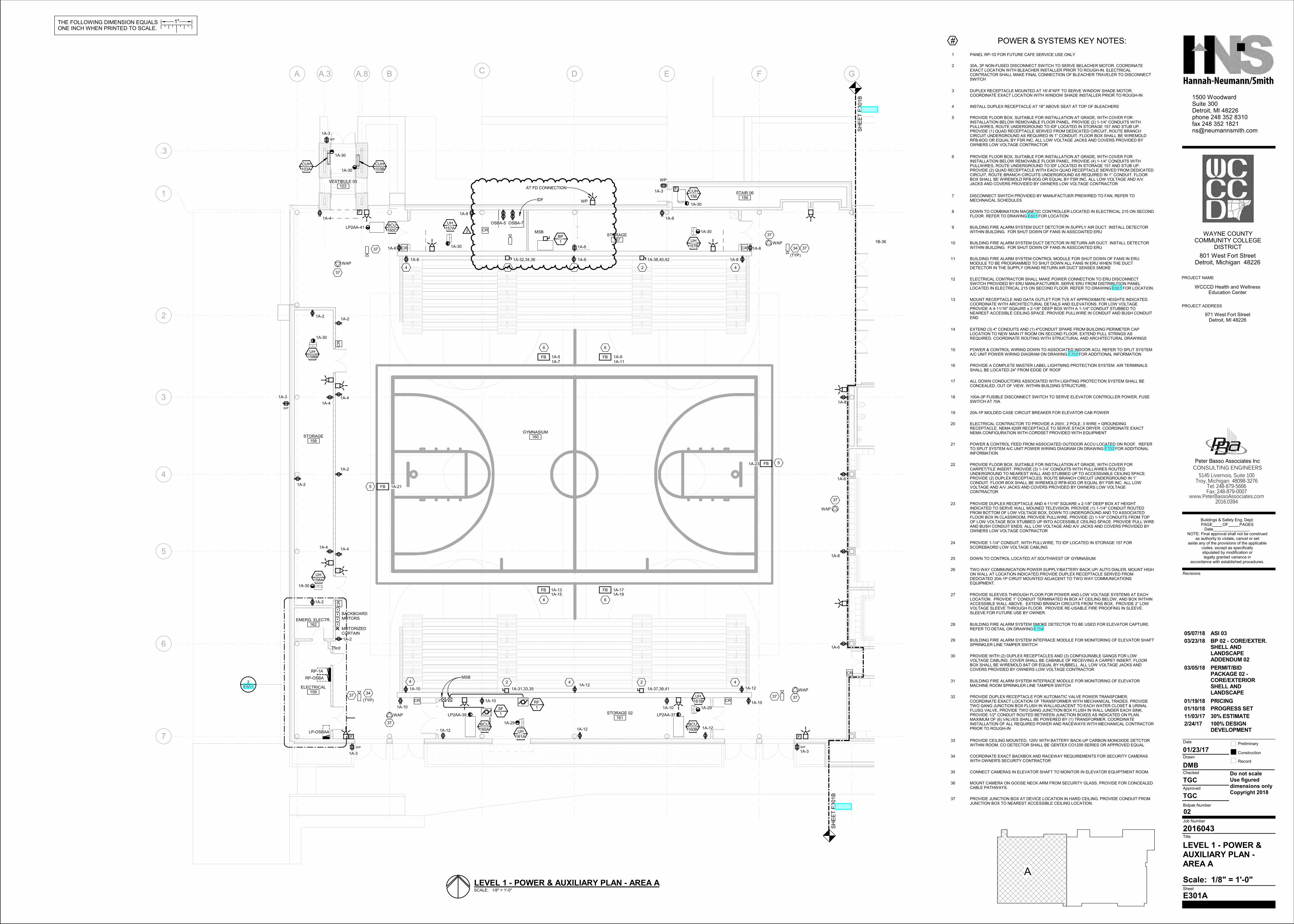
LEVEL 1 - POWER &AUXILIARY PLAN -AREA A
971 West Fort StreetDetroit, MI 48226
WCCCD Health and WellnessEducation Center
SCALE: 1/8" = 1'-0"
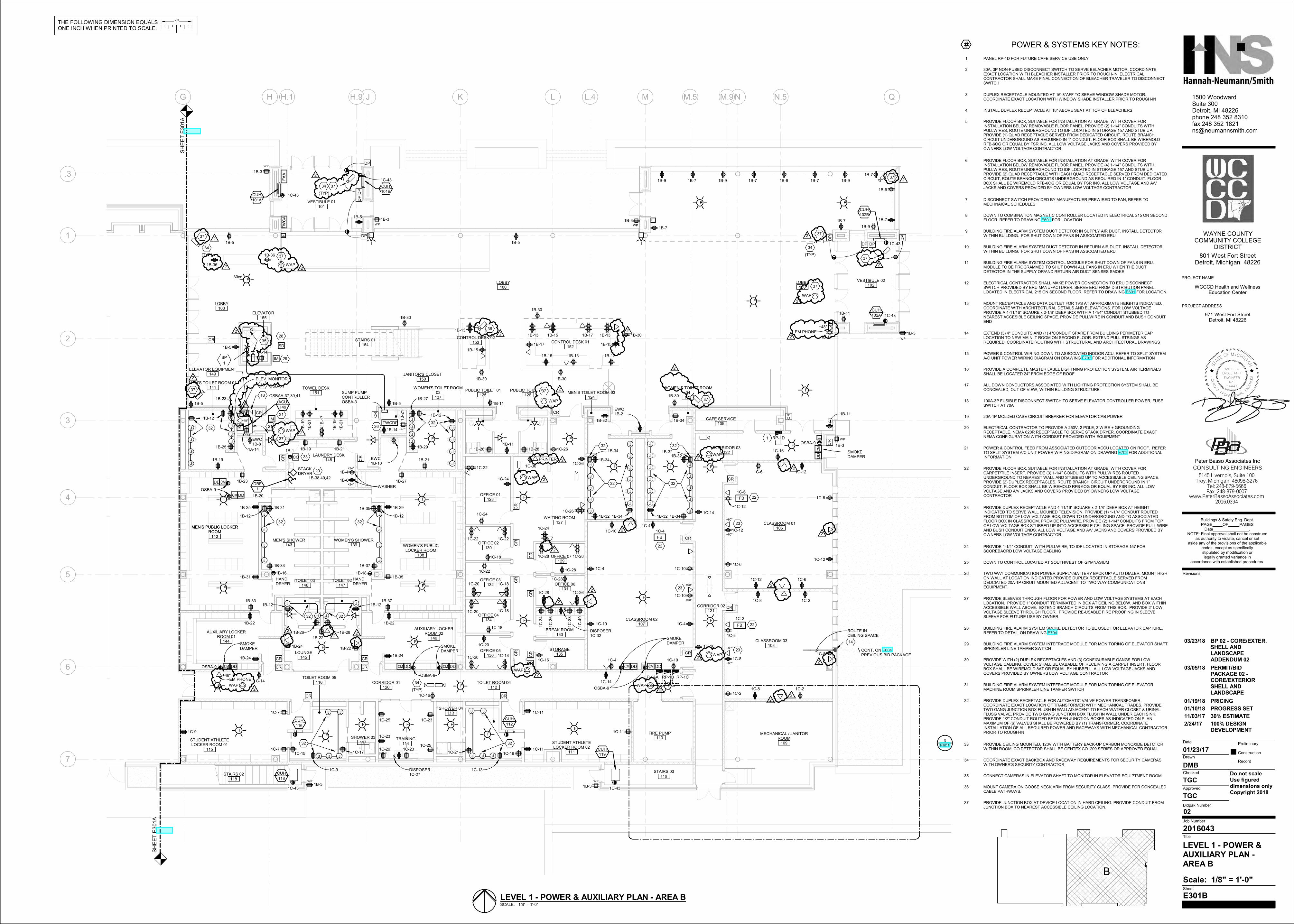
LEVEL 1 - POWER & AUXILIARY PLAN - AREA A
A
# POWER & SYSTEMS KEY NOTES:
1 PANEL RP-1D FOR FUTURE CAFE SERVICE USE ONLY
2 30A, 3P NON-FUSED DISCONNECT SWITCH TO SERVE BELACHER MOTOR. COORDINATEEXACT LOCATION WITH BLEACHER INSTALLER PRIOR TO ROUGH-IN. ELECTRICALCONTRACTOR SHALL MAKE FINAL CONNECTION OF BLEACHER TRAVELER TO DISCONNECTSWITCH
3 DUPLEX RECEPTACLE MOUNTED AT 16'-8"AFF TO SERVE WINDOW SHADE MOTOR.COORDINATE EXACT LOCATION WITH WINDOW SHADE INSTALLER PRIOR TO ROUGH-IN
4 INSTALL DUPLEX RECEPTACLE AT 18" ABOVE SEAT AT TOP OF BLEACHERS
5 PROVIDE FLOOR BOX, SUITABLE FOR INSTALLATION AT GRADE, WITH COVER FORINSTALLATION BELOW REMOVABLE FLOOR PANEL. PROVIDE (2) 1-1/4” CONDUITS WITHPULLWIRES, ROUTE UNDERGROUND TO IDF LOCATED IN STORAGE 157 AND STUB UP.PROVIDE (1) QUAD RECEPTACLE SERVED FROM DEDICATED CIRCUIT, ROUTE BRANCHCIRCUIT UNDERGROUND AS REQUIRED IN 1” CONDUIT. FLOOR BOX SHALL BE WIREMOLDRFB-6OG OR EQUAL BY FSR INC. ALL LOW VOLTAGE JACKS AND COVERS PROVIDED BYOWNERS LOW VOLTAGE CONTRACTOR
6 PROVIDE FLOOR BOX, SUITABLE FOR INSTALLATION AT GRADE, WITH COVER FORINSTALLATION BELOW REMOVABLE FLOOR PANEL. PROVIDE (4) 1-1/4” CONDUITS WITHPULLWIRES, ROUTE UNDERGROUND TO IDF LOCATED IN STORAGE 157 AND STUB UP.PROVIDE (2) QUAD RECEPTACLE WITH EACH QUAD RECEPTACLE SERVED FROM DEDICATEDCIRCUIT, ROUTE BRANCH CIRCUITS UNDERGROUND AS REQUIRED IN 1” CONDUIT. FLOORBOX SHALL BE WIREMOLD RFB-6OG OR EQUAL BY FSR INC. ALL LOW VOLTAGE AND A/VJACKS AND COVERS PROVIDED BY OWNERS LOW VOLTAGE CONTRACTOR
7 DISCONNECT SWITCH PROVIDED BY MANUFACTUER PREWIRED TO FAN, REFER TOMECHNAICAL SCHEDULES
8 DOWN TO COMBINATION MAGNETIC CONTROLLER LOCATED IN ELECTRICAL 215 ON SECONDFLOOR. REFER TO DRAWING E601 FOR LOCATION
9 BUILDING FIRE ALARM SYSTEM DUCT DETCTOR IN SUPPLY AIR DUCT. INSTALL DETECTORWITHIN BUILDING. FOR SHUT DOWN OF FANS IN ASSCOAITED ERU
10 BUILDING FIRE ALARM SYSTEM DUCT DETCTOR IN RETURN AIR DUCT. INSTALL DETECTORWITHIN BUILDING. FOR SHUT DOWN OF FANS IN ASSCOAITED ERU
11 BUILDING FIRE ALARM SYSTEM CONTROL MODULE FOR SHUT DOWN OF FANS IN ERU.MODULE TO BE PROGRAMMED TO SHUT DOWN ALL FANS IN ERU WHEN THE DUCTDETECTOR IN THE SUPPLY OR/AND RETURN AIR DUCT SENSES SMOKE
12 ELECTRICAL CONTRACTOR SHALL MAKE POWER CONNECTION TO ERU DISCONNECTSWITCH PROVIDED BY ERU MANUFACTURER. SERVE ERU FROM DISTRIBUTION PANELLOCATED IN ELECTRICAL 215 ON SECOND FLOOR. REFER TO DRAWING E601 FOR LOCATION.
13 MOUNT RECEPTACLE AND DATA OUTLET FOR TVS AT APPROXIMATE HEIGHTS INDICATED.COORDINATE WITH ARCHITECTURAL DETAILS AND ELEVATIONS. FOR LOW VOLTAGEPROVIDE A 4-11/16" SQAURE x 2-1/8" DEEP BOX WITH A 1-1/4" CONDUIT STUBBED TONEAREST ACCESIBLE CEILING SPACE. PROVIDE PULLWIRE IN CONDUIT AND BUSH CONDUITEND
14 EXTEND (3) 4" CONDUITS AND (1) 4"CONDUIT SPARE FROM BUILDING PERIMETER CAPLOCATION TO NEW MAIN IT ROOM ON SECOND FLOOR. EXTEND PULL STRINGS ASREQUIRED. COORDINATE ROUTING WITH STRUCTURAL AND ARCHITECTURAL DRAWINGS
15 POWER & CONTROL WIRING DOWN TO ASSOCIATED INDOOR ACU, REFER TO SPLIT SYSTEMA/C UNIT POWER WIRING DIAGRAM ON DRAWING E702 FOR ADDITIONAL INFORMATION
16 PROVIDE A COMPLETE MASTER LABEL LIGHTNING PROTECTION SYSTEM. AIR TERMINALSSHALL BE LOCATED 24" FROM EDGE OF ROOF
17 ALL DOWN CONDUCTORS ASSOCIATED WITH LIGHTING PROTECTION SYSTEM SHALL BECONCEALED, OUT OF VIEW, WITHIN BUILDING STRUCTURE.
18 100A-3P FUSIBLE DISCONNECT SWITCH TO SERVE ELEVATOR CONTROLLER POWER, FUSESWITCH AT 70A
19 20A-1P MOLDED CASE CIRCUIT BREAKER FOR ELEVATOR CAB POWER
20 ELECTRICAL CONTRACTOR TO PROVIDE A 250V, 2 POLE, 3 WIRE + GROUNDINGRECEPTACLE, NEMA 620R RECEPTACLE TO SERVE STACK DRYER. COORDINATE EXACTNEMA CONFIGURATION WITH CORDSET PROVIDED WITH EQUIPMENT
21 POWER & CONTROL FEED FROM ASSOCIATED OUTDOOR ACCU LOCATED ON ROOF. REFERTO SPLIT SYSTEM A/C UNIT POWER WIRING DIAGRAM ON DRAWING E702 FOR ADDITIONALINFORMATION
22 PROVIDE FLOOR BOX, SUITABLE FOR INSTALLATION AT GRADE, WITH COVER FORCARPET/TILE INSERT. PROVIDE (3) 1-1/4” CONDUITS WITH PULLWIRES ROUTEDUNDERGROUND TO NEAREST WALL AND STUBBED UP TO ACCESSIABLE CEILING SPACE.PROVIDE (2) DUPLEX RECEPTACLES. ROUTE BRANCH CIRCUIT UNDERGROUND IN 1”CONDUIT. FLOOR BOX SHALL BE WIREMOLD RFB-6OG OR EQUAL BY FSR INC. ALL LOWVOLTAGE AND A/V JACKS AND COVERS PROVIDED BY OWNERS LOW VOLTAGECONTRACTOR
23 PROVIDE DUPLEX RECEPTACLE AND 4-11/16" SQUARE x 2-1/8" DEEP BOX AT HEIGHTINDICATED TO SERVE WALL MOUNED TELEVISION. PROVIDE (1) 1-1/4" CONDUIT ROUTEDFROM BOTTOM OF LOW VOLTAGE BOX, DOWN TO UNDERGROUND AND TO ASSOCIATEDFLOOR BOX IN CLASSROOM, PROVIDE PULLWIRE. PROVIDE (2) 1-1/4" CONDUITS FROM TOPOF LOW VOLTAGE BOX STUBBED UP INTO ACCESSIBLE CEILING SPACE. PROVIDE PULL WIREAND BUSH CONDUIT ENDS. ALL LOW VOLTAGE AND A/V JACKS AND COVERS PROVIDED BYOWNERS LOW VOLTAGE CONTRACTOR
24 PROVIDE 1-1/4" CONDUIT, WITH PULLWIRE, TO IDF LOCATED IN STORAGE 157 FORSCOREBAORD LOW VOLTAGE CABLING
25 DOWN TO CONTROL LOCATED AT SOUTHWEST OF GYMNASIUM
26 TWO WAY COMMUNICATION POWER SUPPLY/BATTERY BACK UP/ AUTO DIALER, MOUNT HIGHON WALL AT LOCATION INDICATED.PROVIDE DUPLEX RECEPTACLE SERVED FROMDEDCIATED 20A-1P CIRUIT MOUNTED ADJACENT TO TWO WAY COMMUNICATIONSEQUIPMENT.
27 PROVIDE SLEEVES THROUGH FLOOR FOR POWER AND LOW VOLTAGE SYSTEMS AT EACHLOCATION. PROVIDE 1” CONDUIT TERMINATED IN BOX AT CEILING BELOW, AND BOX WITHINACCESSIBLE WALL ABOVE. EXTEND BRANCH CIRCUITS FROM THIS BOX. PROVIDE 2” LOWVOLTAGE SLEEVE THROUGH FLOOR. PROVIDE RE-USABLE FIRE PROOFING IN SLEEVE.SLEEVE FOR FUTURE USE BY OWNER.
28 BUILDING FIRE ALARM SYSTEM SMOKE DETECTOR TO BE USED FOR ELEVATOR CAPTURE.REFER TO DETAIL ON DRAWING E704
29 BUILDING FIRE ALARM SYSTEM INTEFRACE MODULE FOR MONITORING OF ELEVATOR SHAFTSPRINKLER LINE TAMPER SWITCH
30 PROVIDE WITH (2) DUPLEX RECEPTACLES AND (3) CONFIGURABLE GANGS FOR LOWVOLTAGE CABLING. COVER SHALL BE CABABLE OF RECEIVING A CARPET INSERT. FLOORBOX SHALL BE WIREMOLD 8AT OR EQUAL BY HUBBELL. ALL LOW VOLTAGE JACKS ANDCOVERS PROVIDED BY OWNERS LOW VOLTAGE CONTRACTOR
31 BUILDING FIRE ALARM SYSTEM INTEFRACE MODULE FOR MONITORING OF ELEVATORMACHINE ROOM SPRINKLER LINE TAMPER SWITCH
32 PROVIDE DUPLEX RECEPTACLE FOR AUTOMATIC VALVE POWER TRANSFOMER,COORDINATE EXACT LOCATION OF TRANSFORMER WITH MECHANICAL TRADES. PROVIDETWO GANG JUNCTION BOX FLUSH IN WALLADJACENT TO EACH WATER CLOSET & URINALFLUSG VALVE, PROVIDE TWO GANG JUNCTION BOX FLUSH IN WALL UNDER EACH SINK.PROVIDE 1/2" CONDUIT ROUTED BETWEEN JUNCTION BOXES AS INDICATED ON PLAN.MAXIMUM OF (6) VALVES SHALL BE POWERED BY (1) TRANSFORMER. COORDINATEINSTALLATION OF ALL REQUIRED POWER AND RACEWAYS WITH MECHANICAL CONTRACTORPRIOR TO ROUGH-IN
33 PROVIDE CEILING MOUNTED, 120V WITH BATTERY BACK-UP CARBON MONOXIDE DETCTORWITHIN ROOM. CO DETECTOR SHALL BE GENTEX CO1209 SERIES OR APPROVED EQUAL
34 COORDINATE EXACT BACKBOX AND RACEWAY REQUIREMENTS FOR SECURITY CAMERASWITH OWNER'S SECURITY CONTRACTOR
35 CONNECT CAMERAS IN ELEVATOR SHAFT TO MONITOR IN ELEVATOR EQUIPTMENT ROOM.
36 MOUNT CAMERA ON GOOSE NECK ARM FROM SECURITY GLASS. PROVIDE FOR CONCEALEDCABLE PATHWAYS.
37 PROVIDE JUNCTION BOX AT DEVICE LOCATION IN HARD CEILING. PROVIDE CONDUIT FROMJUNCTION BOX TO NEAREST ACCESSIBLE CEILING LOCATION.
2/24/17 100% DESIGNDEVELOPMENT
11/03/17 30% ESTIMATE
01/10/18 PROGRESS SET
01/19/18 PRICING
03/05/18 PERMIT/BIDPACKAGE 02 -CORE/EXTERIORSHELL ANDLANDSCAPE
03/23/18 BP 02 - CORE/EXTER.SHELL ANDLANDSCAPEADDENDUM 02
05/07/18 ASI 03
REF.
DP
DP
DP
DP
FB
FB
FB
F
F
F
F
F
F F
F
FF
F
F
F
F F
F
F
F F
F
F F F
F
F F
F
F
FF
AA
SD
IM
CMCMCM
CM
CMDD DDDD DDDDCM
DD
F
F
F
F
F
F
TW
CA
DP
DP
DP DP
CR
CR
CR
CR
CR
CR
CR
CR
CR
CR
CR
CRCR
CR
CR
CR
CR
CR
CR
CR
CR
CR
CR
CR
CR
CR
CB
TWCDP
IM
IM
J
J
J
J
J
J
J
J
J J
J J J J J J
J J
J
J
J
J
J
J
J
J
J
J
J J
J
J
J
J
J
J
J
J
J
J
J
JJ
J
J
J
J
J
J
J
J
J
J
J
J
J
J
J
J
J
CO
DD CM
CM DD
SH
EE
T E
301A
SH
EE
T E
301A
RP-1D
LP-1AA RP-1B RP-1C
WP
WP WP
WP
WP WP
WP
LOBBY100
AUXILIARY LOCKERROOM 01
144
MEN'S PUBLIC LOCKERROOM
142
STAIRS 02118
VESTIBULE 01101
CLASSROOM 01106
CLASSROOM 03108
MECHANICAL / JANITORROOM
109
VESTIBULE 02102
WOMEN'S TOILET ROOM04
123MEN'S TOILET ROOM 03
124
CLASSROOM 02107
FIRE PUMP110
STUDENT ATHLETELOCKER ROOM 02
111
CORRIDOR 02121
LAUNDRY DESK148
WOMEN'S PUBLICLOCKER ROOM
138
AUXILIARY LOCKERROOM 02
140
TOILET 02147
LOUNGE145
TOILET 03146
PUBLIC TOILET 01125
PUBLIC TOILET 02126
WAITING ROOM127
OFFICE 07129
OFFICE 06131
BREAK ROOM133
STORAGE135
OFFICE 05136
OFFICE 04134
OFFICE 03132
OFFICE 02130
OFFICE 01128
STAIRS 03119
SHOWER 03117
TOILET ROOM 05116
TRAINING114
CORRIDOR 03122
WOMEN'S TOILET ROOM02
137
WOMEN'S SHOWER139
MEN'S SHOWER143
ELEVATOR EQUIPMENT149 JANITOR'S CLOSET
150
ELEVATOR155
STAIRS 01154
G H J K L M N Q
7
4
3
2
6
5
.3
H.1 H.9 L.4 M.5 N.5M.9
STUDENT ATHLETELOCKER ROOM 01
115
CORRIDOR 01120
MEN'S PUBLIC LOCKERROOM
142
CONTROL DESK 02153 CONTROL DESK 01
152
TOWEL DESK151
SHOWER 04113
TOILET ROOM 06112
1
CUH
102B
CUH
102A
CUH
101A
CUH
101B
CUH
119
CUH
118
CUH
116
CUH
112
MEN'S TOILET ROOM 01141
LOBBY100
LOBBY100
E601
3
+48"
+48"
SMOKE DAMPER
SMOKE DAMPER
SMOKE DAMPER
SMOKE DAMPER
1
+60"
+60"
+60"
+60"
+60"
+60"
DISPOSER1C-32
HAND DRYER
HAND DRYER
149
ACU
1
DBF
30cd
SP
1
CAFE SERVICE105
ROUTE IN CEILING SPACE
14
CONT. ON E004PREVIOUS BID PACKAGE
+24"
+24"
STACK DRYER
WASHER
SUMP PUMP CONTROLLEROSBA-3
19
18
OSBA-1
OSBAA-37,39,41
EWC1B-8
EWC1B-10
20
21
22
22
22
26
28
29
EWC1B-231
32
32
3232
32 32
32 32
32
32
32
321A-14
1A-14
1B-5
1B-3
1B-3 1B-3
1B-3
1B-3
1B-31B-3
1B-5
1B-5
1B-5 1B-5 1B-11
1B-7
1B-7 1B-7 1B-7
1B-7
1B-71B-7
1B-9 1B-9 1B-9 1B-9
1B-9
1B-9
1B-11
1B-11
1B-11
1B-5
1B-13
1B-13
1B-13 1B-13
1B-15
1B-15
1B-15
1B-151B-17
1B-17
1B-17
1B-4
1B-61B-38,40,42
1B-121B-12
1B-141B
-19
1B
-19
1B
-21
1B
-21
1B
-17
1B-19 1B-21
1B-19 1B-21
1B-12 1B-12
1B-25
1B-23
1B-29
1B-27
1B-23
1B-25
1B-27
1B-291B-31
1B-31
1B-33
1B-33
1B-37
1B-37
1B-35
1B-351B-16 1B-18
1B
-21
1B-20
1B-22 1B-22
1B-241B-24
1B-241B-22
1B-12 1B-12
1B-26 1B-28
1B-26 1B-28
1B-11
1C-7
1C-7
1C-9
1C-9
1C-11
1C-11
1C-11
1C-13
1C-15 1C-17 1C-191C-211C-231C-29
DISPOSER1C-27
1C-23
1C-23
1B-30
1B-30
1B-30 1B-30
1B-30
1B-30
1B-32
1B-32
1B-32 1B-34
1B-34
1B-34
1B-34 1B-32
1B-321B-34
1C-2
1C-4
1C-6
1C-21C-2
1C-2
1C-6
1C-6
1C-6
1C-6
1C-4
1C-4
1C-4
1C-4
1C-8
1C-8
1C-8
1C-8
1C-8
1C-10
1C-10
1C-10
1C-10
1C-10 1C-12
1C-12
1C-12
1C-12
1C-12
1C-16
1C-14
1C-16
1C-14
1C-16
1C-14
1C-161C-18
1C-18
1C-18
1C-18
1C-20
1C-20
1C-20
1C-20
1C-22 1C-22
1C-22
1C-22
1C-24
1C-24
1C-24
1C-28
1C-26
1C-26
1C-28
1C-26
1C-28
1C-28
1C-28
1C-26
1C-18
1C-30
1C
-34
1C
-36
1C
-38
1C
-40
1B-1
33
23
23
23
(TYP)
34
(TYP)
34
(TYP)
34
OSBA-9
OSBA-9
OSBA-9
OSBA-9
1C-43 1C-43
1C-25
1C-25
1C-43
1C-43
1C-43
1C-43
OSBA-9
+48"EM PHONE
+48"
EM PHONE
WAP
WAP
WAP
WAP
WAP
WAP
WAP
WAP
WAP
WAP
+48"
ELEV. MONITOR
35
PRINTER
362
2
2
2
2
22
2
2
2
2
2
2
2
2
22
2
2
2
2
2
2
2
2
2
2
2
2
2
2
1B-22
372
37
37
37
37
37
372
37
2
37
37
(TYP)
34
37
2
1B-36
1B-36
2
2
L
STA
TEOF M ICH
IG
AN
ICENSED
PROFESSION
ALE
NGIN
EE
R
DANIEL J.
ENGLEHART
ENGINEER
No.
34447
THE FOLLOWING DIMENSION EQUALSONE INCH WHEN PRINTED TO SCALE.
1"
5145 Livernois, Suite 100Troy, Michigan 48098-3276
Tel: 248-879-5666Fax: 248-879-0007
www.PeterBassoAssociates.com
Peter Basso Associates Inc
CONSULTING ENGINEERS
Scale:
Preliminary
Construction
Record
Do not scaleUse figured dimensions onlyCopyright 2018
1500 WoodwardSuite 300Detroit, MI 48226phone 248 352 8310fax 248 352 [email protected]
Date
Drawn
Checked
Approved
Bidpak Number
Job Number
Title
Sheet
Revisions
2016.0394
PROJECT NAME
PROJECT ADDRESS
WAYNE COUNTY COMMUNITY COLLEGE
DISTRICT
801 West Fort StreetDetroit, Michigan 48226
Buildings & Safety Eng. Dept.PAGE OF PAGES
Date . NOTE: Final approval shall not be construed
as authority to violate, cancel or set aside any of the provisions of the applicable
codes, except as specifically stipulated by modification or legally granted variance in
accordance with established procedures.
02
1/8" = 1'-0"
E301B
2016043
TGC
TGC
DMB
01/23/17
LEVEL 1 - POWER &AUXILIARY PLAN -AREA B
971 West Fort StreetDetroit, MI 48226
WCCCD Health and WellnessEducation Center
SCALE: 1/8" = 1'-0"
LEVEL 1 - POWER & AUXILIARY PLAN - AREA B
B
# POWER & SYSTEMS KEY NOTES:
1 PANEL RP-1D FOR FUTURE CAFE SERVICE USE ONLY
2 30A, 3P NON-FUSED DISCONNECT SWITCH TO SERVE BELACHER MOTOR. COORDINATEEXACT LOCATION WITH BLEACHER INSTALLER PRIOR TO ROUGH-IN. ELECTRICALCONTRACTOR SHALL MAKE FINAL CONNECTION OF BLEACHER TRAVELER TO DISCONNECTSWITCH
3 DUPLEX RECEPTACLE MOUNTED AT 16'-8"AFF TO SERVE WINDOW SHADE MOTOR.COORDINATE EXACT LOCATION WITH WINDOW SHADE INSTALLER PRIOR TO ROUGH-IN
4 INSTALL DUPLEX RECEPTACLE AT 18" ABOVE SEAT AT TOP OF BLEACHERS
5 PROVIDE FLOOR BOX, SUITABLE FOR INSTALLATION AT GRADE, WITH COVER FORINSTALLATION BELOW REMOVABLE FLOOR PANEL. PROVIDE (2) 1-1/4” CONDUITS WITHPULLWIRES, ROUTE UNDERGROUND TO IDF LOCATED IN STORAGE 157 AND STUB UP.PROVIDE (1) QUAD RECEPTACLE SERVED FROM DEDICATED CIRCUIT, ROUTE BRANCHCIRCUIT UNDERGROUND AS REQUIRED IN 1” CONDUIT. FLOOR BOX SHALL BE WIREMOLDRFB-6OG OR EQUAL BY FSR INC. ALL LOW VOLTAGE JACKS AND COVERS PROVIDED BYOWNERS LOW VOLTAGE CONTRACTOR
6 PROVIDE FLOOR BOX, SUITABLE FOR INSTALLATION AT GRADE, WITH COVER FORINSTALLATION BELOW REMOVABLE FLOOR PANEL. PROVIDE (4) 1-1/4” CONDUITS WITHPULLWIRES, ROUTE UNDERGROUND TO IDF LOCATED IN STORAGE 157 AND STUB UP.PROVIDE (2) QUAD RECEPTACLE WITH EACH QUAD RECEPTACLE SERVED FROM DEDICATEDCIRCUIT, ROUTE BRANCH CIRCUITS UNDERGROUND AS REQUIRED IN 1” CONDUIT. FLOORBOX SHALL BE WIREMOLD RFB-6OG OR EQUAL BY FSR INC. ALL LOW VOLTAGE AND A/VJACKS AND COVERS PROVIDED BY OWNERS LOW VOLTAGE CONTRACTOR
7 DISCONNECT SWITCH PROVIDED BY MANUFACTUER PREWIRED TO FAN, REFER TOMECHNAICAL SCHEDULES
8 DOWN TO COMBINATION MAGNETIC CONTROLLER LOCATED IN ELECTRICAL 215 ON SECONDFLOOR. REFER TO DRAWING E601 FOR LOCATION
9 BUILDING FIRE ALARM SYSTEM DUCT DETCTOR IN SUPPLY AIR DUCT. INSTALL DETECTORWITHIN BUILDING. FOR SHUT DOWN OF FANS IN ASSCOAITED ERU
10 BUILDING FIRE ALARM SYSTEM DUCT DETCTOR IN RETURN AIR DUCT. INSTALL DETECTORWITHIN BUILDING. FOR SHUT DOWN OF FANS IN ASSCOAITED ERU
11 BUILDING FIRE ALARM SYSTEM CONTROL MODULE FOR SHUT DOWN OF FANS IN ERU.MODULE TO BE PROGRAMMED TO SHUT DOWN ALL FANS IN ERU WHEN THE DUCTDETECTOR IN THE SUPPLY OR/AND RETURN AIR DUCT SENSES SMOKE
12 ELECTRICAL CONTRACTOR SHALL MAKE POWER CONNECTION TO ERU DISCONNECTSWITCH PROVIDED BY ERU MANUFACTURER. SERVE ERU FROM DISTRIBUTION PANELLOCATED IN ELECTRICAL 215 ON SECOND FLOOR. REFER TO DRAWING E601 FOR LOCATION.
13 MOUNT RECEPTACLE AND DATA OUTLET FOR TVS AT APPROXIMATE HEIGHTS INDICATED.COORDINATE WITH ARCHITECTURAL DETAILS AND ELEVATIONS. FOR LOW VOLTAGEPROVIDE A 4-11/16" SQAURE x 2-1/8" DEEP BOX WITH A 1-1/4" CONDUIT STUBBED TONEAREST ACCESIBLE CEILING SPACE. PROVIDE PULLWIRE IN CONDUIT AND BUSH CONDUITEND
14 EXTEND (3) 4" CONDUITS AND (1) 4"CONDUIT SPARE FROM BUILDING PERIMETER CAPLOCATION TO NEW MAIN IT ROOM ON SECOND FLOOR. EXTEND PULL STRINGS ASREQUIRED. COORDINATE ROUTING WITH STRUCTURAL AND ARCHITECTURAL DRAWINGS
15 POWER & CONTROL WIRING DOWN TO ASSOCIATED INDOOR ACU, REFER TO SPLIT SYSTEMA/C UNIT POWER WIRING DIAGRAM ON DRAWING E702 FOR ADDITIONAL INFORMATION
16 PROVIDE A COMPLETE MASTER LABEL LIGHTNING PROTECTION SYSTEM. AIR TERMINALSSHALL BE LOCATED 24" FROM EDGE OF ROOF
17 ALL DOWN CONDUCTORS ASSOCIATED WITH LIGHTING PROTECTION SYSTEM SHALL BECONCEALED, OUT OF VIEW, WITHIN BUILDING STRUCTURE.
18 100A-3P FUSIBLE DISCONNECT SWITCH TO SERVE ELEVATOR CONTROLLER POWER, FUSESWITCH AT 70A
19 20A-1P MOLDED CASE CIRCUIT BREAKER FOR ELEVATOR CAB POWER
20 ELECTRICAL CONTRACTOR TO PROVIDE A 250V, 2 POLE, 3 WIRE + GROUNDINGRECEPTACLE, NEMA 620R RECEPTACLE TO SERVE STACK DRYER. COORDINATE EXACTNEMA CONFIGURATION WITH CORDSET PROVIDED WITH EQUIPMENT
21 POWER & CONTROL FEED FROM ASSOCIATED OUTDOOR ACCU LOCATED ON ROOF. REFERTO SPLIT SYSTEM A/C UNIT POWER WIRING DIAGRAM ON DRAWING E702 FOR ADDITIONALINFORMATION
22 PROVIDE FLOOR BOX, SUITABLE FOR INSTALLATION AT GRADE, WITH COVER FORCARPET/TILE INSERT. PROVIDE (3) 1-1/4” CONDUITS WITH PULLWIRES ROUTEDUNDERGROUND TO NEAREST WALL AND STUBBED UP TO ACCESSIABLE CEILING SPACE.PROVIDE (2) DUPLEX RECEPTACLES. ROUTE BRANCH CIRCUIT UNDERGROUND IN 1”CONDUIT. FLOOR BOX SHALL BE WIREMOLD RFB-6OG OR EQUAL BY FSR INC. ALL LOWVOLTAGE AND A/V JACKS AND COVERS PROVIDED BY OWNERS LOW VOLTAGECONTRACTOR
23 PROVIDE DUPLEX RECEPTACLE AND 4-11/16" SQUARE x 2-1/8" DEEP BOX AT HEIGHTINDICATED TO SERVE WALL MOUNED TELEVISION. PROVIDE (1) 1-1/4" CONDUIT ROUTEDFROM BOTTOM OF LOW VOLTAGE BOX, DOWN TO UNDERGROUND AND TO ASSOCIATEDFLOOR BOX IN CLASSROOM, PROVIDE PULLWIRE. PROVIDE (2) 1-1/4" CONDUITS FROM TOPOF LOW VOLTAGE BOX STUBBED UP INTO ACCESSIBLE CEILING SPACE. PROVIDE PULL WIREAND BUSH CONDUIT ENDS. ALL LOW VOLTAGE AND A/V JACKS AND COVERS PROVIDED BYOWNERS LOW VOLTAGE CONTRACTOR
24 PROVIDE 1-1/4" CONDUIT, WITH PULLWIRE, TO IDF LOCATED IN STORAGE 157 FORSCOREBAORD LOW VOLTAGE CABLING
25 DOWN TO CONTROL LOCATED AT SOUTHWEST OF GYMNASIUM
26 TWO WAY COMMUNICATION POWER SUPPLY/BATTERY BACK UP/ AUTO DIALER, MOUNT HIGHON WALL AT LOCATION INDICATED.PROVIDE DUPLEX RECEPTACLE SERVED FROMDEDCIATED 20A-1P CIRUIT MOUNTED ADJACENT TO TWO WAY COMMUNICATIONSEQUIPMENT.
27 PROVIDE SLEEVES THROUGH FLOOR FOR POWER AND LOW VOLTAGE SYSTEMS AT EACHLOCATION. PROVIDE 1” CONDUIT TERMINATED IN BOX AT CEILING BELOW, AND BOX WITHINACCESSIBLE WALL ABOVE. EXTEND BRANCH CIRCUITS FROM THIS BOX. PROVIDE 2” LOWVOLTAGE SLEEVE THROUGH FLOOR. PROVIDE RE-USABLE FIRE PROOFING IN SLEEVE.SLEEVE FOR FUTURE USE BY OWNER.
28 BUILDING FIRE ALARM SYSTEM SMOKE DETECTOR TO BE USED FOR ELEVATOR CAPTURE.REFER TO DETAIL ON DRAWING E704
29 BUILDING FIRE ALARM SYSTEM INTEFRACE MODULE FOR MONITORING OF ELEVATOR SHAFTSPRINKLER LINE TAMPER SWITCH
30 PROVIDE WITH (2) DUPLEX RECEPTACLES AND (3) CONFIGURABLE GANGS FOR LOWVOLTAGE CABLING. COVER SHALL BE CABABLE OF RECEIVING A CARPET INSERT. FLOORBOX SHALL BE WIREMOLD 8AT OR EQUAL BY HUBBELL. ALL LOW VOLTAGE JACKS ANDCOVERS PROVIDED BY OWNERS LOW VOLTAGE CONTRACTOR
31 BUILDING FIRE ALARM SYSTEM INTEFRACE MODULE FOR MONITORING OF ELEVATORMACHINE ROOM SPRINKLER LINE TAMPER SWITCH
32 PROVIDE DUPLEX RECEPTACLE FOR AUTOMATIC VALVE POWER TRANSFOMER,COORDINATE EXACT LOCATION OF TRANSFORMER WITH MECHANICAL TRADES. PROVIDETWO GANG JUNCTION BOX FLUSH IN WALLADJACENT TO EACH WATER CLOSET & URINALFLUSG VALVE, PROVIDE TWO GANG JUNCTION BOX FLUSH IN WALL UNDER EACH SINK.PROVIDE 1/2" CONDUIT ROUTED BETWEEN JUNCTION BOXES AS INDICATED ON PLAN.MAXIMUM OF (6) VALVES SHALL BE POWERED BY (1) TRANSFORMER. COORDINATEINSTALLATION OF ALL REQUIRED POWER AND RACEWAYS WITH MECHANICAL CONTRACTORPRIOR TO ROUGH-IN
33 PROVIDE CEILING MOUNTED, 120V WITH BATTERY BACK-UP CARBON MONOXIDE DETCTORWITHIN ROOM. CO DETECTOR SHALL BE GENTEX CO1209 SERIES OR APPROVED EQUAL
34 COORDINATE EXACT BACKBOX AND RACEWAY REQUIREMENTS FOR SECURITY CAMERASWITH OWNER'S SECURITY CONTRACTOR
35 CONNECT CAMERAS IN ELEVATOR SHAFT TO MONITOR IN ELEVATOR EQUIPTMENT ROOM.
36 MOUNT CAMERA ON GOOSE NECK ARM FROM SECURITY GLASS. PROVIDE FOR CONCEALEDCABLE PATHWAYS.
37 PROVIDE JUNCTION BOX AT DEVICE LOCATION IN HARD CEILING. PROVIDE CONDUIT FROMJUNCTION BOX TO NEAREST ACCESSIBLE CEILING LOCATION.
2/24/17 100% DESIGNDEVELOPMENT
11/03/17 30% ESTIMATE
01/10/18 PROGRESS SET
01/19/18 PRICING
03/05/18 PERMIT/BIDPACKAGE 02 -CORE/EXTERIORSHELL ANDLANDSCAPE
03/23/18 BP 02 - CORE/EXTER.SHELL ANDLANDSCAPEADDENDUM 02
F
F
FF F F F
F
F
F
F
F
F
F
FFFF
CR
CR
SH
EE
T E
302B
SH
EE
T E
302B
SCOREBOARD
SCOREBOARD
SCOREBOARD
TERRACE 01223
A B C D E F G
7
4
3
2
6
5
.3
A.3 A.8
Room224
Room224
1
MOTORIZED DIVIDER CURTAIN
MOTORIZED DIVIDER CURTAIN
BACKBOARD MOTOR
BACKBOARD MOTOR
BACKBOARD MOTOR
BACKBOARD MOTOR
+6" +6"
+6" +6"
3
3
3
3
3
3
24
24
24
25
25
25
25 25
WP
2A-2
2A-2
2A-6
2A-2
2A-2 2A-22A-4
2A-4
2A-4 2A-4
2A-6
2A-8
2A-8
2A-10
2A-10
2A-4
(TYP)
34
(TYP)
34
2A-122A-14
2A-162A-18
2A-20
2A-28
2A-28
2A-28
L
STA
TEOF M ICH
IG
AN
ICENSED
PROFESSION
ALE
NGIN
EE
R
DANIEL J.
ENGLEHART
ENGINEER
No.
34447
THE FOLLOWING DIMENSION EQUALSONE INCH WHEN PRINTED TO SCALE.
1"
5145 Livernois, Suite 100Troy, Michigan 48098-3276
Tel: 248-879-5666Fax: 248-879-0007
www.PeterBassoAssociates.com
Peter Basso Associates Inc
CONSULTING ENGINEERS
Scale:
Preliminary
Construction
Record
Do not scaleUse figured dimensions onlyCopyright 2018
1500 WoodwardSuite 300Detroit, MI 48226phone 248 352 8310fax 248 352 [email protected]
Date
Drawn
Checked
Approved
Bidpak Number
Job Number
Title
Sheet
Revisions
2016.0394
PROJECT NAME
PROJECT ADDRESS
WAYNE COUNTY COMMUNITY COLLEGE
DISTRICT
801 West Fort StreetDetroit, Michigan 48226
Buildings & Safety Eng. Dept.PAGE OF PAGES
Date . NOTE: Final approval shall not be construed
as authority to violate, cancel or set aside any of the provisions of the applicable
codes, except as specifically stipulated by modification or legally granted variance in
accordance with established procedures.
02
1/8" = 1'-0"
E302A
2016043
TGC
TGC
DMB
01/23/17
LEVEL 2 - POWER &AUXILIARY PLAN -AREA A
971 West Fort StreetDetroit, MI 48226
WCCCD Health and WellnessEducation Center
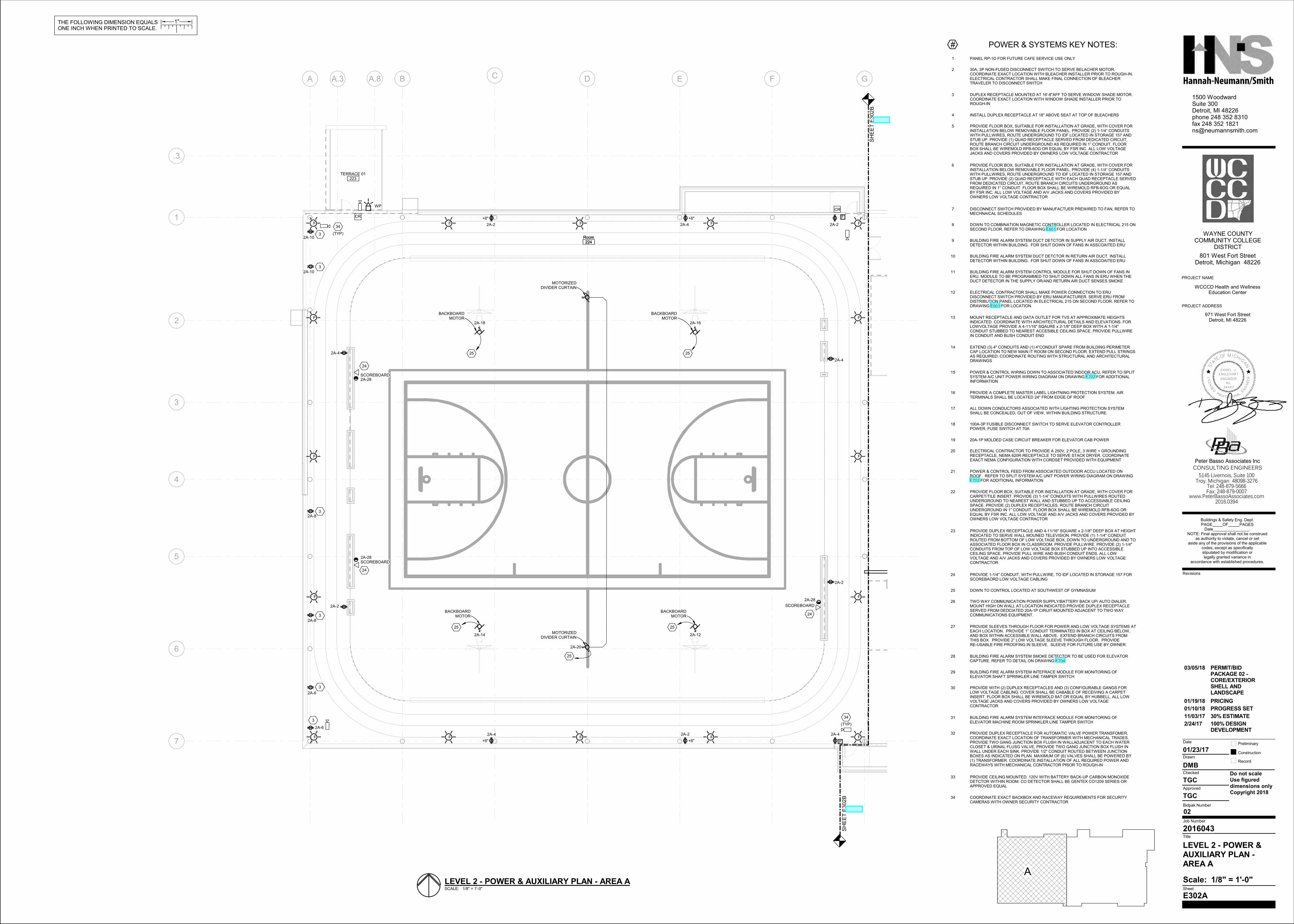
SCALE: 1/8" = 1'-0"
LEVEL 2 - POWER & AUXILIARY PLAN - AREA AA
# POWER & SYSTEMS KEY NOTES:
1 PANEL RP-1D FOR FUTURE CAFE SERVICE USE ONLY
2 30A, 3P NON-FUSED DISCONNECT SWITCH TO SERVE BELACHER MOTOR.COORDINATE EXACT LOCATION WITH BLEACHER INSTALLER PRIOR TO ROUGH-IN.ELECTRICAL CONTRACTOR SHALL MAKE FINAL CONNECTION OF BLEACHERTRAVELER TO DISCONNECT SWITCH
3 DUPLEX RECEPTACLE MOUNTED AT 16'-8"AFF TO SERVE WINDOW SHADE MOTOR.COORDINATE EXACT LOCATION WITH WINDOW SHADE INSTALLER PRIOR TOROUGH-IN
4 INSTALL DUPLEX RECEPTACLE AT 18" ABOVE SEAT AT TOP OF BLEACHERS
5 PROVIDE FLOOR BOX, SUITABLE FOR INSTALLATION AT GRADE, WITH COVER FORINSTALLATION BELOW REMOVABLE FLOOR PANEL. PROVIDE (2) 1-1/4” CONDUITSWITH PULLWIRES, ROUTE UNDERGROUND TO IDF LOCATED IN STORAGE 157 ANDSTUB UP. PROVIDE (1) QUAD RECEPTACLE SERVED FROM DEDICATED CIRCUIT,ROUTE BRANCH CIRCUIT UNDERGROUND AS REQUIRED IN 1” CONDUIT. FLOORBOX SHALL BE WIREMOLD RFB-6OG OR EQUAL BY FSR INC. ALL LOW VOLTAGEJACKS AND COVERS PROVIDED BY OWNERS LOW VOLTAGE CONTRACTOR
6 PROVIDE FLOOR BOX, SUITABLE FOR INSTALLATION AT GRADE, WITH COVER FORINSTALLATION BELOW REMOVABLE FLOOR PANEL. PROVIDE (4) 1-1/4” CONDUITSWITH PULLWIRES, ROUTE UNDERGROUND TO IDF LOCATED IN STORAGE 157 ANDSTUB UP. PROVIDE (2) QUAD RECEPTACLE WITH EACH QUAD RECEPTACLE SERVEDFROM DEDICATED CIRCUIT, ROUTE BRANCH CIRCUITS UNDERGROUND ASREQUIRED IN 1” CONDUIT. FLOOR BOX SHALL BE WIREMOLD RFB-6OG OR EQUALBY FSR INC. ALL LOW VOLTAGE AND A/V JACKS AND COVERS PROVIDED BYOWNERS LOW VOLTAGE CONTRACTOR
7 DISCONNECT SWITCH PROVIDED BY MANUFACTUER PREWIRED TO FAN, REFER TOMECHNAICAL SCHEDULES
8 DOWN TO COMBINATION MAGNETIC CONTROLLER LOCATED IN ELECTRICAL 215 ONSECOND FLOOR. REFER TO DRAWING E601 FOR LOCATION
9 BUILDING FIRE ALARM SYSTEM DUCT DETCTOR IN SUPPLY AIR DUCT. INSTALLDETECTOR WITHIN BUILDING. FOR SHUT DOWN OF FANS IN ASSCOAITED ERU
10 BUILDING FIRE ALARM SYSTEM DUCT DETCTOR IN RETURN AIR DUCT. INSTALLDETECTOR WITHIN BUILDING. FOR SHUT DOWN OF FANS IN ASSCOAITED ERU
11 BUILDING FIRE ALARM SYSTEM CONTROL MODULE FOR SHUT DOWN OF FANS INERU. MODULE TO BE PROGRAMMED TO SHUT DOWN ALL FANS IN ERU WHEN THEDUCT DETECTOR IN THE SUPPLY OR/AND RETURN AIR DUCT SENSES SMOKE
12 ELECTRICAL CONTRACTOR SHALL MAKE POWER CONNECTION TO ERUDISCONNECT SWITCH PROVIDED BY ERU MANUFACTURER. SERVE ERU FROMDISTRIBUTION PANEL LOCATED IN ELECTRICAL 215 ON SECOND FLOOR. REFER TODRAWING E601 FOR LOCATION.
13 MOUNT RECEPTACLE AND DATA OUTLET FOR TVS AT APPROXIMATE HEIGHTSINDICATED. COORDINATE WITH ARCHITECTURAL DETAILS AND ELEVATIONS. FORLOWVOLTAGE PROVIDE A 4-11/16" SQAURE x 2-1/8" DEEP BOX WITH A 1-1/4"CONDUIT STUBBED TO NEAREST ACCESIBLE CEILING SPACE. PROVIDE PULLWIREIN CONDUIT AND BUSH CONDUIT END
14 EXTEND (3) 4" CONDUITS AND (1) 4"CONDUIT SPARE FROM BUILDING PERIMETERCAP LOCATION TO NEW MAIN IT ROOM ON SECOND FLOOR. EXTEND PULL STRINGSAS REQUIRED. COORDINATE ROUTING WITH STRUCTURAL AND ARCHITECTURALDRAWINGS
15 POWER & CONTROL WIRING DOWN TO ASSOCIATED INDOOR ACU, REFER TO SPLITSYSTEM A/C UNIT POWER WIRING DIAGRAM ON DRAWING E702 FOR ADDITIONALINFORMATION
16 PROVIDE A COMPLETE MASTER LABEL LIGHTNING PROTECTION SYSTEM. AIRTERMINALS SHALL BE LOCATED 24" FROM EDGE OF ROOF
17 ALL DOWN CONDUCTORS ASSOCIATED WITH LIGHTING PROTECTION SYSTEMSHALL BE CONCEALED, OUT OF VIEW, WITHIN BUILDING STRUCTURE.
18 100A-3P FUSIBLE DISCONNECT SWITCH TO SERVE ELEVATOR CONTROLLERPOWER, FUSE SWITCH AT 70A
19 20A-1P MOLDED CASE CIRCUIT BREAKER FOR ELEVATOR CAB POWER
20 ELECTRICAL CONTRACTOR TO PROVIDE A 250V, 2 POLE, 3 WIRE + GROUNDINGRECEPTACLE, NEMA 620R RECEPTACLE TO SERVE STACK DRYER. COORDINATEEXACT NEMA CONFIGURATION WITH CORDSET PROVIDED WITH EQUIPMENT
21 POWER & CONTROL FEED FROM ASSOCIATED OUTDOOR ACCU LOCATED ONROOF. REFER TO SPLIT SYSTEM A/C UNIT POWER WIRING DIAGRAM ON DRAWINGE702 FOR ADDITIONAL INFORMATION
22 PROVIDE FLOOR BOX, SUITABLE FOR INSTALLATION AT GRADE, WITH COVER FORCARPET/TILE INSERT. PROVIDE (3) 1-1/4” CONDUITS WITH PULLWIRES ROUTEDUNDERGROUND TO NEAREST WALL AND STUBBED UP TO ACCESSIABLE CEILINGSPACE. PROVIDE (2) DUPLEX RECEPTACLES. ROUTE BRANCH CIRCUITUNDERGROUND IN 1” CONDUIT. FLOOR BOX SHALL BE WIREMOLD RFB-6OG OREQUAL BY FSR INC. ALL LOW VOLTAGE AND A/V JACKS AND COVERS PROVIDED BYOWNERS LOW VOLTAGE CONTRACTOR
23 PROVIDE DUPLEX RECEPTACLE AND 4-11/16" SQUARE x 2-1/8" DEEP BOX AT HEIGHTINDICATED TO SERVE WALL MOUNED TELEVISION. PROVIDE (1) 1-1/4" CONDUITROUTED FROM BOTTOM OF LOW VOLTAGE BOX, DOWN TO UNDERGROUND AND TOASSOCIATED FLOOR BOX IN CLASSROOM, PROVIDE PULLWIRE. PROVIDE (2) 1-1/4"CONDUITS FROM TOP OF LOW VOLTAGE BOX STUBBED UP INTO ACCESSIBLECEILING SPACE. PROVIDE PULL WIRE AND BUSH CONDUIT ENDS. ALL LOWVOLTAGE AND A/V JACKS AND COVERS PROVIDED BY OWNERS LOW VOLTAGECONTRACTOR
24 PROVIDE 1-1/4" CONDUIT, WITH PULLWIRE, TO IDF LOCATED IN STORAGE 157 FORSCOREBAORD LOW VOLTAGE CABLING
25 DOWN TO CONTROL LOCATED AT SOUTHWEST OF GYMNASIUM
26 TWO WAY COMMUNICATION POWER SUPPLY/BATTERY BACK UP/ AUTO DIALER,MOUNT HIGH ON WALL AT LOCATION INDICATED.PROVIDE DUPLEX RECEPTACLESERVED FROM DEDCIATED 20A-1P CIRUIT MOUNTED ADJACENT TO TWO WAYCOMMUNICATIONS EQUIPMENT.
27 PROVIDE SLEEVES THROUGH FLOOR FOR POWER AND LOW VOLTAGE SYSTEMS ATEACH LOCATION. PROVIDE 1” CONDUIT TERMINATED IN BOX AT CEILING BELOW,AND BOX WITHIN ACCESSIBLE WALL ABOVE. EXTEND BRANCH CIRCUITS FROMTHIS BOX. PROVIDE 2” LOW VOLTAGE SLEEVE THROUGH FLOOR. PROVIDERE-USABLE FIRE PROOFING IN SLEEVE. SLEEVE FOR FUTURE USE BY OWNER.
28 BUILDING FIRE ALARM SYSTEM SMOKE DETECTOR TO BE USED FOR ELEVATORCAPTURE. REFER TO DETAIL ON DRAWING E704
29 BUILDING FIRE ALARM SYSTEM INTEFRACE MODULE FOR MONITORING OFELEVATOR SHAFT SPRINKLER LINE TAMPER SWITCH
30 PROVIDE WITH (2) DUPLEX RECEPTACLES AND (3) CONFIGURABLE GANGS FORLOW VOLTAGE CABLING. COVER SHALL BE CABABLE OF RECEIVING A CARPETINSERT. FLOOR BOX SHALL BE WIREMOLD 8AT OR EQUAL BY HUBBELL. ALL LOWVOLTAGE JACKS AND COVERS PROVIDED BY OWNERS LOW VOLTAGECONTRACTOR
31 BUILDING FIRE ALARM SYSTEM INTEFRACE MODULE FOR MONITORING OFELEVATOR MACHINE ROOM SPRINKLER LINE TAMPER SWITCH
32 PROVIDE DUPLEX RECEPTACLE FOR AUTOMATIC VALVE POWER TRANSFOMER,COORDINATE EXACT LOCATION OF TRANSFORMER WITH MECHANICAL TRADES.PROVIDE TWO GANG JUNCTION BOX FLUSH IN WALLADJACENT TO EACH WATERCLOSET & URINAL FLUSG VALVE, PROVIDE TWO GANG JUNCTION BOX FLUSH INWALL UNDER EACH SINK. PROVIDE 1/2" CONDUIT ROUTED BETWEEN JUNCTIONBOXES AS INDICATED ON PLAN. MAXIMUM OF (6) VALVES SHALL BE POWERED BY(1) TRANSFORMER. COORDINATE INSTALLATION OF ALL REQUIRED POWER ANDRACEWAYS WITH MECHANICAL CONTRACTOR PRIOR TO ROUGH-IN
33 PROVIDE CEILING MOUNTED, 120V WITH BATTERY BACK-UP CARBON MONOXIDEDETCTOR WITHIN ROOM. CO DETECTOR SHALL BE GENTEX CO1209 SERIES ORAPPROVED EQUAL
34 COORDINATE EXACT BACKBOX AND RACEWAY REQUIREMENTS FOR SECURITYCAMERAS WITH OWNER SECURITY CONTRACTOR
2/24/17 100% DESIGNDEVELOPMENT
11/03/17 30% ESTIMATE
01/10/18 PROGRESS SET
01/19/18 PRICING
03/05/18 PERMIT/BIDPACKAGE 02 -CORE/EXTERIORSHELL ANDLANDSCAPE
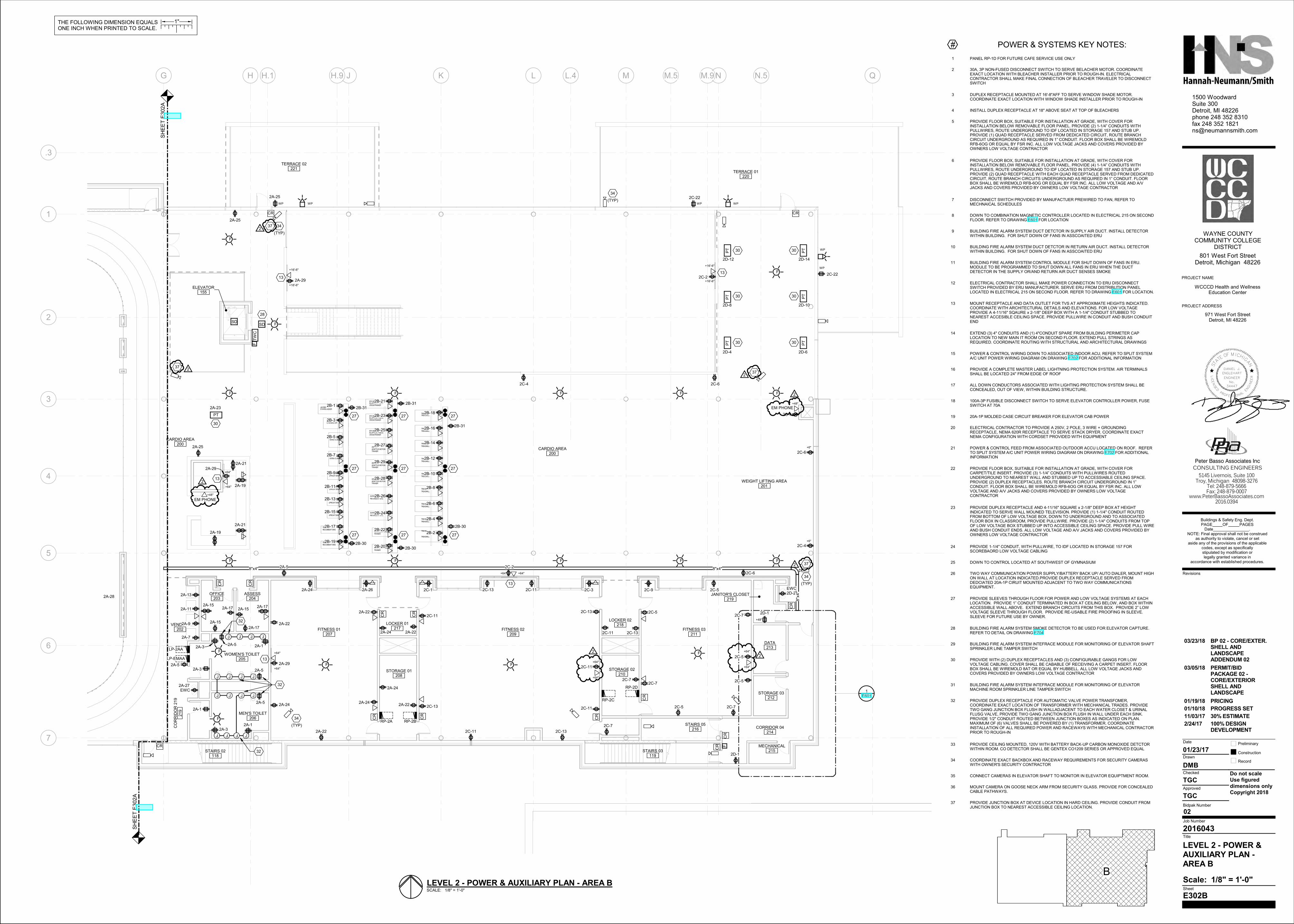
PT
PT
PT
PT
PT
PT
PT
F
F
F
F
F
FT
WC
F
F
F
F
F
F
F
F
F
F
F
F
F
FSD
TREADMILL
TREADMILL
TREADMILL
TREADMILL
TREADMILL
TREADMILL
TREADMILL
TREADMILL
TREADMILL
ELLIPTICAL FINESSCROSSTRAINER
ADAPTIVE MOTIONTRAINER
ADAPTIVE MOTIONTRAINER
ADAPTIVE MOTIONTRAINER
ELLIPTICAL FINESSCROSSTRAINER
ELLIPTICAL FINESSCROSSTRAINER
STAIRMASTER
UPRIGHT BIKE
UPRIGHT BIKE
UPRIGHT BIKE
UPRIGHT BIKE
RECUMBENT BIKE
RECUMBENT BIKE
RECUMBENT CROSSTRAINER
RECUMBENT CROSSTRAINER
RECUMBENT BIKE
RECUMBENT BIKE
STAIRS/LADDER
VERSA CLIMBER
VERSA CLIMBER
AMT 885
EFX 885
TRM 885
TRM 885
TRM 885
TRM 885
TRM 885
TRM 885
TRM 885
TRM 885
TRM 885
AMT 885
AMT 885
EFX 885
EFX 885
9-5250-8G
EXPRESSO GO
EXPRESSO GO
UBK 885
UBK 885
UBK 885
UBK 885
NUSTEOP
NUSTEOP
EXPRESSO GO
EXPRESSO GO
JACOBS
CR CR
CR
CR
CR
CR
CR
CR
CR
CR
CR
CR
CR
CR
SD
J J J J
JJJJ
J J J J
JJJJ
SH
EE
T E
302A
SH
EE
T E
302A
RP-2D
RP-2B
LP-2AA
RP-2A
RP-2C
STAIRS 02118
CARDIO AREA200
VENDING202
CO
RR
IDO
R 2
19
219
STAIRS 03119
ELEVATOR155
WEIGHT LIFTING AREA201
OFFICE203
ASSESS204
WOMEN'S TOILET205
MEN'S TOILET206
FITNESS 01207
STORAGE 01208
FITNESS 02209
STORAGE 02210
FITNESS 03211
STORAGE 03212
DATA213
CORRIDOR 04214
MECHANICAL215
LOCKER 01217
LOCKER 02218
STAIRS 05216
TERRACE 01220
TERRACE 02221
JANITOR'S CLOSET219
G H J K L M N Q
7
4
3
2
6
5
.3
H.1 H.9 L.4 M.5 N.5M.9
1
WP
WP
WP
+6"
+6"
+48"
E601
1
EWC2D-2
EWC
13
13
13
13
13
+64"
8"x4"
8"x
4"
8"x4"
+64"
+64" +64"
+16'-6"
+16'-6"
+64"
+64"
+16'-6"
+16'-6"
27 27 27
272727
27 27 27
28
30
30
30
30
30
30
32
32
32
WP
WP
WP
2D-1
2C-5
2C-5
2C-5
2C-5
2C-7
2C-7
2C-7
2C-9
2C-7
2D-1
2C-4
2C-4
2C-62C-4
2C-6
2C-6
2D-4 2D-6
2D-8 2D-10
2D-12 2D-14
2A-1
2A-1
2A-5
2A-5
2A-3
2A-5
2A-3
2A-3 2A-1
2A-5
2A-7
2A-9
2A-11
2A-13
2A-15
2A-15
2A-152A-17
2A-17
2A-17
LP-EMAA
2A-19
2A-19
2A-21
2A-21
30
2A-23
2A-25
2A-25
2A-25
2A-27
2A-29
2A-29
2A-29
(TYP)
34
(TYP)
34
(TYP)
34
(TYP)
34
2A-22
2A-22
2A-22
2A-24
2A-242A-24
2A-24
2A-22
2A-26
2A-24 2A-22
2A-5
2B-1
2B-3
2B-5
2B-7
2B-9
2B-11
2B-13
2B-15
2B-17
2B-19
2B-21
2B-23
2B-25
2B-27
2B-29
2B-312B-31
2B-31
2B-2
2B-4
2B-6
2B-8
2B-10
2B-12
2B-14
2B-16
2B-18
2B-20
2B-22
2B-24
2B-26
2B-28
2B-302B-30
2B-30
2C-2
2C-2
2C-22
2C-22
2C-11
2C-11
2C-11
2C-11 2C-13
2C-13
2C-13
2C-13
2C-132C-11
2C-32C-1
2A-28
2C-7
CARDIO AREA200
+48"
EM PHONE
+64"
+64"
+64"
+64"
2C-5
2C-11
+48"
EM PHONE
22
2
2
372
372
372
372
L
STA
TEOF M ICH
IG
AN
ICENSED
PROFESSION
ALE
NGIN
EE
R
DANIEL J.
ENGLEHART
ENGINEER
No.
34447
THE FOLLOWING DIMENSION EQUALSONE INCH WHEN PRINTED TO SCALE.
1"
5145 Livernois, Suite 100Troy, Michigan 48098-3276
Tel: 248-879-5666Fax: 248-879-0007
www.PeterBassoAssociates.com
Peter Basso Associates Inc
CONSULTING ENGINEERS
Scale:
Preliminary
Construction
Record
Do not scaleUse figured dimensions onlyCopyright 2018
1500 WoodwardSuite 300Detroit, MI 48226phone 248 352 8310fax 248 352 [email protected]
Date
Drawn
Checked
Approved
Bidpak Number
Job Number
Title
Sheet
Revisions
2016.0394
PROJECT NAME
PROJECT ADDRESS
WAYNE COUNTY COMMUNITY COLLEGE
DISTRICT
801 West Fort StreetDetroit, Michigan 48226
Buildings & Safety Eng. Dept.PAGE OF PAGES
Date . NOTE: Final approval shall not be construed
as authority to violate, cancel or set aside any of the provisions of the applicable
codes, except as specifically stipulated by modification or legally granted variance in
accordance with established procedures.
02
1/8" = 1'-0"
E302B
2016043
TGC
TGC
DMB
01/23/17
LEVEL 2 - POWER &AUXILIARY PLAN -AREA B
971 West Fort StreetDetroit, MI 48226
WCCCD Health and WellnessEducation Center
SCALE: 1/8" = 1'-0"
LEVEL 2 - POWER & AUXILIARY PLAN - AREA B
BB
# POWER & SYSTEMS KEY NOTES:
1 PANEL RP-1D FOR FUTURE CAFE SERVICE USE ONLY
2 30A, 3P NON-FUSED DISCONNECT SWITCH TO SERVE BELACHER MOTOR. COORDINATEEXACT LOCATION WITH BLEACHER INSTALLER PRIOR TO ROUGH-IN. ELECTRICALCONTRACTOR SHALL MAKE FINAL CONNECTION OF BLEACHER TRAVELER TO DISCONNECTSWITCH
3 DUPLEX RECEPTACLE MOUNTED AT 16'-8"AFF TO SERVE WINDOW SHADE MOTOR.COORDINATE EXACT LOCATION WITH WINDOW SHADE INSTALLER PRIOR TO ROUGH-IN
4 INSTALL DUPLEX RECEPTACLE AT 18" ABOVE SEAT AT TOP OF BLEACHERS
5 PROVIDE FLOOR BOX, SUITABLE FOR INSTALLATION AT GRADE, WITH COVER FORINSTALLATION BELOW REMOVABLE FLOOR PANEL. PROVIDE (2) 1-1/4” CONDUITS WITHPULLWIRES, ROUTE UNDERGROUND TO IDF LOCATED IN STORAGE 157 AND STUB UP.PROVIDE (1) QUAD RECEPTACLE SERVED FROM DEDICATED CIRCUIT, ROUTE BRANCHCIRCUIT UNDERGROUND AS REQUIRED IN 1” CONDUIT. FLOOR BOX SHALL BE WIREMOLDRFB-6OG OR EQUAL BY FSR INC. ALL LOW VOLTAGE JACKS AND COVERS PROVIDED BYOWNERS LOW VOLTAGE CONTRACTOR
6 PROVIDE FLOOR BOX, SUITABLE FOR INSTALLATION AT GRADE, WITH COVER FORINSTALLATION BELOW REMOVABLE FLOOR PANEL. PROVIDE (4) 1-1/4” CONDUITS WITHPULLWIRES, ROUTE UNDERGROUND TO IDF LOCATED IN STORAGE 157 AND STUB UP.PROVIDE (2) QUAD RECEPTACLE WITH EACH QUAD RECEPTACLE SERVED FROM DEDICATEDCIRCUIT, ROUTE BRANCH CIRCUITS UNDERGROUND AS REQUIRED IN 1” CONDUIT. FLOORBOX SHALL BE WIREMOLD RFB-6OG OR EQUAL BY FSR INC. ALL LOW VOLTAGE AND A/VJACKS AND COVERS PROVIDED BY OWNERS LOW VOLTAGE CONTRACTOR
7 DISCONNECT SWITCH PROVIDED BY MANUFACTUER PREWIRED TO FAN, REFER TOMECHNAICAL SCHEDULES
8 DOWN TO COMBINATION MAGNETIC CONTROLLER LOCATED IN ELECTRICAL 215 ON SECONDFLOOR. REFER TO DRAWING E601 FOR LOCATION
9 BUILDING FIRE ALARM SYSTEM DUCT DETCTOR IN SUPPLY AIR DUCT. INSTALL DETECTORWITHIN BUILDING. FOR SHUT DOWN OF FANS IN ASSCOAITED ERU
10 BUILDING FIRE ALARM SYSTEM DUCT DETCTOR IN RETURN AIR DUCT. INSTALL DETECTORWITHIN BUILDING. FOR SHUT DOWN OF FANS IN ASSCOAITED ERU
11 BUILDING FIRE ALARM SYSTEM CONTROL MODULE FOR SHUT DOWN OF FANS IN ERU.MODULE TO BE PROGRAMMED TO SHUT DOWN ALL FANS IN ERU WHEN THE DUCTDETECTOR IN THE SUPPLY OR/AND RETURN AIR DUCT SENSES SMOKE
12 ELECTRICAL CONTRACTOR SHALL MAKE POWER CONNECTION TO ERU DISCONNECTSWITCH PROVIDED BY ERU MANUFACTURER. SERVE ERU FROM DISTRIBUTION PANELLOCATED IN ELECTRICAL 215 ON SECOND FLOOR. REFER TO DRAWING E601 FOR LOCATION.
13 MOUNT RECEPTACLE AND DATA OUTLET FOR TVS AT APPROXIMATE HEIGHTS INDICATED.COORDINATE WITH ARCHITECTURAL DETAILS AND ELEVATIONS. FOR LOW VOLTAGEPROVIDE A 4-11/16" SQAURE x 2-1/8" DEEP BOX WITH A 1-1/4" CONDUIT STUBBED TONEAREST ACCESIBLE CEILING SPACE. PROVIDE PULLWIRE IN CONDUIT AND BUSH CONDUITEND
14 EXTEND (3) 4" CONDUITS AND (1) 4"CONDUIT SPARE FROM BUILDING PERIMETER CAPLOCATION TO NEW MAIN IT ROOM ON SECOND FLOOR. EXTEND PULL STRINGS ASREQUIRED. COORDINATE ROUTING WITH STRUCTURAL AND ARCHITECTURAL DRAWINGS
15 POWER & CONTROL WIRING DOWN TO ASSOCIATED INDOOR ACU, REFER TO SPLIT SYSTEMA/C UNIT POWER WIRING DIAGRAM ON DRAWING E702 FOR ADDITIONAL INFORMATION
16 PROVIDE A COMPLETE MASTER LABEL LIGHTNING PROTECTION SYSTEM. AIR TERMINALSSHALL BE LOCATED 24" FROM EDGE OF ROOF
17 ALL DOWN CONDUCTORS ASSOCIATED WITH LIGHTING PROTECTION SYSTEM SHALL BECONCEALED, OUT OF VIEW, WITHIN BUILDING STRUCTURE.
18 100A-3P FUSIBLE DISCONNECT SWITCH TO SERVE ELEVATOR CONTROLLER POWER, FUSESWITCH AT 70A
19 20A-1P MOLDED CASE CIRCUIT BREAKER FOR ELEVATOR CAB POWER
20 ELECTRICAL CONTRACTOR TO PROVIDE A 250V, 2 POLE, 3 WIRE + GROUNDINGRECEPTACLE, NEMA 620R RECEPTACLE TO SERVE STACK DRYER. COORDINATE EXACTNEMA CONFIGURATION WITH CORDSET PROVIDED WITH EQUIPMENT
21 POWER & CONTROL FEED FROM ASSOCIATED OUTDOOR ACCU LOCATED ON ROOF. REFERTO SPLIT SYSTEM A/C UNIT POWER WIRING DIAGRAM ON DRAWING E702 FOR ADDITIONALINFORMATION
22 PROVIDE FLOOR BOX, SUITABLE FOR INSTALLATION AT GRADE, WITH COVER FORCARPET/TILE INSERT. PROVIDE (3) 1-1/4” CONDUITS WITH PULLWIRES ROUTEDUNDERGROUND TO NEAREST WALL AND STUBBED UP TO ACCESSIABLE CEILING SPACE.PROVIDE (2) DUPLEX RECEPTACLES. ROUTE BRANCH CIRCUIT UNDERGROUND IN 1”CONDUIT. FLOOR BOX SHALL BE WIREMOLD RFB-6OG OR EQUAL BY FSR INC. ALL LOWVOLTAGE AND A/V JACKS AND COVERS PROVIDED BY OWNERS LOW VOLTAGECONTRACTOR
23 PROVIDE DUPLEX RECEPTACLE AND 4-11/16" SQUARE x 2-1/8" DEEP BOX AT HEIGHTINDICATED TO SERVE WALL MOUNED TELEVISION. PROVIDE (1) 1-1/4" CONDUIT ROUTEDFROM BOTTOM OF LOW VOLTAGE BOX, DOWN TO UNDERGROUND AND TO ASSOCIATEDFLOOR BOX IN CLASSROOM, PROVIDE PULLWIRE. PROVIDE (2) 1-1/4" CONDUITS FROM TOPOF LOW VOLTAGE BOX STUBBED UP INTO ACCESSIBLE CEILING SPACE. PROVIDE PULL WIREAND BUSH CONDUIT ENDS. ALL LOW VOLTAGE AND A/V JACKS AND COVERS PROVIDED BYOWNERS LOW VOLTAGE CONTRACTOR
24 PROVIDE 1-1/4" CONDUIT, WITH PULLWIRE, TO IDF LOCATED IN STORAGE 157 FORSCOREBAORD LOW VOLTAGE CABLING
25 DOWN TO CONTROL LOCATED AT SOUTHWEST OF GYMNASIUM
26 TWO WAY COMMUNICATION POWER SUPPLY/BATTERY BACK UP/ AUTO DIALER, MOUNT HIGHON WALL AT LOCATION INDICATED.PROVIDE DUPLEX RECEPTACLE SERVED FROMDEDCIATED 20A-1P CIRUIT MOUNTED ADJACENT TO TWO WAY COMMUNICATIONSEQUIPMENT.
27 PROVIDE SLEEVES THROUGH FLOOR FOR POWER AND LOW VOLTAGE SYSTEMS AT EACHLOCATION. PROVIDE 1” CONDUIT TERMINATED IN BOX AT CEILING BELOW, AND BOX WITHINACCESSIBLE WALL ABOVE. EXTEND BRANCH CIRCUITS FROM THIS BOX. PROVIDE 2” LOWVOLTAGE SLEEVE THROUGH FLOOR. PROVIDE RE-USABLE FIRE PROOFING IN SLEEVE.SLEEVE FOR FUTURE USE BY OWNER.
28 BUILDING FIRE ALARM SYSTEM SMOKE DETECTOR TO BE USED FOR ELEVATOR CAPTURE.REFER TO DETAIL ON DRAWING E704
29 BUILDING FIRE ALARM SYSTEM INTEFRACE MODULE FOR MONITORING OF ELEVATOR SHAFTSPRINKLER LINE TAMPER SWITCH
30 PROVIDE WITH (2) DUPLEX RECEPTACLES AND (3) CONFIGURABLE GANGS FOR LOWVOLTAGE CABLING. COVER SHALL BE CABABLE OF RECEIVING A CARPET INSERT. FLOORBOX SHALL BE WIREMOLD 8AT OR EQUAL BY HUBBELL. ALL LOW VOLTAGE JACKS ANDCOVERS PROVIDED BY OWNERS LOW VOLTAGE CONTRACTOR
31 BUILDING FIRE ALARM SYSTEM INTEFRACE MODULE FOR MONITORING OF ELEVATORMACHINE ROOM SPRINKLER LINE TAMPER SWITCH
32 PROVIDE DUPLEX RECEPTACLE FOR AUTOMATIC VALVE POWER TRANSFOMER,COORDINATE EXACT LOCATION OF TRANSFORMER WITH MECHANICAL TRADES. PROVIDETWO GANG JUNCTION BOX FLUSH IN WALLADJACENT TO EACH WATER CLOSET & URINALFLUSG VALVE, PROVIDE TWO GANG JUNCTION BOX FLUSH IN WALL UNDER EACH SINK.PROVIDE 1/2" CONDUIT ROUTED BETWEEN JUNCTION BOXES AS INDICATED ON PLAN.MAXIMUM OF (6) VALVES SHALL BE POWERED BY (1) TRANSFORMER. COORDINATEINSTALLATION OF ALL REQUIRED POWER AND RACEWAYS WITH MECHANICAL CONTRACTORPRIOR TO ROUGH-IN
33 PROVIDE CEILING MOUNTED, 120V WITH BATTERY BACK-UP CARBON MONOXIDE DETCTORWITHIN ROOM. CO DETECTOR SHALL BE GENTEX CO1209 SERIES OR APPROVED EQUAL
34 COORDINATE EXACT BACKBOX AND RACEWAY REQUIREMENTS FOR SECURITY CAMERASWITH OWNER'S SECURITY CONTRACTOR
35 CONNECT CAMERAS IN ELEVATOR SHAFT TO MONITOR IN ELEVATOR EQUIPTMENT ROOM.
36 MOUNT CAMERA ON GOOSE NECK ARM FROM SECURITY GLASS. PROVIDE FOR CONCEALEDCABLE PATHWAYS.
37 PROVIDE JUNCTION BOX AT DEVICE LOCATION IN HARD CEILING. PROVIDE CONDUIT FROMJUNCTION BOX TO NEAREST ACCESSIBLE CEILING LOCATION.
2/24/17 100% DESIGNDEVELOPMENT
11/03/17 30% ESTIMATE
01/10/18 PROGRESS SET
01/19/18 PRICING
03/05/18 PERMIT/BIDPACKAGE 02 -CORE/EXTERIORSHELL ANDLANDSCAPE
03/23/18 BP 02 - CORE/EXTER.SHELL ANDLANDSCAPEADDENDUM 02
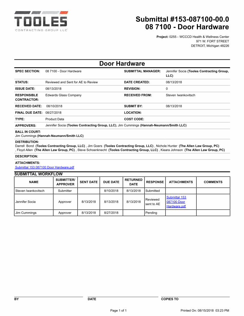
Project: 0255 - WCCCD Health & Wellness Center971 W. FORT STREET
DETROIT, Michigan 48226
Door HardwareSPEC SECTION: 08 7100 - Door Hardware SUBMITTAL MANAGER: Jennifer Socia (Tooles Contracting Group,
LLC)
STATUS: Reviewed and Sent for AE to Review DATE CREATED: 08/13/2018 ISSUE DATE: 08/13/2018 REVISION: 0
RESPONSIBLECONTRACTOR:
Edwards Glass Company RECEIVED FROM: Steven Iwankovitsch
RECEIVED DATE: 08/10/2018 SUBMIT BY: 08/13/2018 FINAL DUE DATE: 08/27/2018 LOCATION: TYPE: Product Data COST CODE: APPROVERS: Jennifer Socia (Tooles Contracting Group, LLC), Jim Cummings (Hannah-Neumann/Smith LLC)
BALL IN COURT:Jim Cummings (Hannah-Neumann/Smith LLC) DISTRIBUTION:Darrell Bond (Tooles Contracting Group, LLC) , Jim Goers (Tooles Contracting Group, LLC) , Nichole Hunter (The Allen Law Group, PC), Floyd Allen (The Allen Law Group, PC) , Steve Schoenknecht (Tooles Contracting Group, LLC) , Kieara Johnson (The Allen Law Group, PC)
DESCRIPTION:
ATTACHMENTS:Submittal 153 087100 Door Hardware.pdf
SUBMITTAL WORKFLOW
NAME SUBMITTER/APPROVER SENT DATE DUE DATE RETURNED
DATE RESPONSE ATTACHMENTS COMMENTS
Steven Iwankovitsch Submitter 8/10/2018 8/13/2018 Submitted
Jennifer Socia Approver 8/13/2018 8/13/2018 8/13/2018Reviewedsent to AE
Submittal 153087100 DoorHardware.pdf
Jim Cummings Approver 8/13/2018 8/27/2018 Pending
BY DATE COPIES TO
Page 1 of 1 Printed On: 08/15/2018 03:23 PM
Submittal #153-087100-00.008 7100 - Door Hardware
EDWARDS GLASS COMPANY
32000 Plymouth Road, Livonia, MI. 48150
(734) 422-7540 (734) 422-0858 FAX
TO: Tooles Contracting Group
535 Griswold Street, Suite 2550
Detroit, MI 48226
Attn: Jennifer Socia
LETTER OF TRANSMITTAL
Date: 8/10/2018
Job No: 18MG0018
Re: WCCCD Health & Wellness Center
From: Steven Iwankovitsch
Copy To: Job File
We are sending you attached the following items:
COPIES DATE NO. DESCRIPTION
1 8/10/2018 18 pgs. 087100-Hardware Schedule 8-7-18 WCCCD Health and Wellness
1 8/10/2018 49 pgs. 087100-Product Data_Catalog Cuts 8-7-18 WCCCD Health and Wellness
1 8/10/2018 2 pgs. 087100-Samples_TIGER_-_RAL VOL10
1 8/10/2018 2 pgs. 087100-Samples_TIGER_Drylac Series_38_Vol_4_Web
THESE ARE TRANSMITTED AS: For Approval,
REMARKS:
Note: AE, please use the attached color charts for finish selection of components annotated in the hardware schedule requiring a color. Once a color has been selected we will request paint samples of the requested colors. Please contact Matt Greca at 734-838-9157 or [email protected] if you have any questions or concerns.
Thank you,
Steve Iwankovitsch Project Engineer
Phone (734) 422-7540 | Direct (734) 838-9161 Fax (734) 422-0858 [email protected] | www.edwardsglass.com
Submittal 153-087100-00
Page 1
HARDWARE SCHEDULEFOR
FAX: (734) 422-0858
PREPARED BY: LINDA HEIMER
DATE: AUGUST 7, 2018
WCCCD
ARCHITECT: HANNAH - NEUMAN/SMITH ARCH.
CONTRACTOR: EDWARDS GLASS COMPANY
PHONE: (734) 422-7540
HEALTH & WELLNESS EDUCATION CENTER
Submittal 153-087100-00
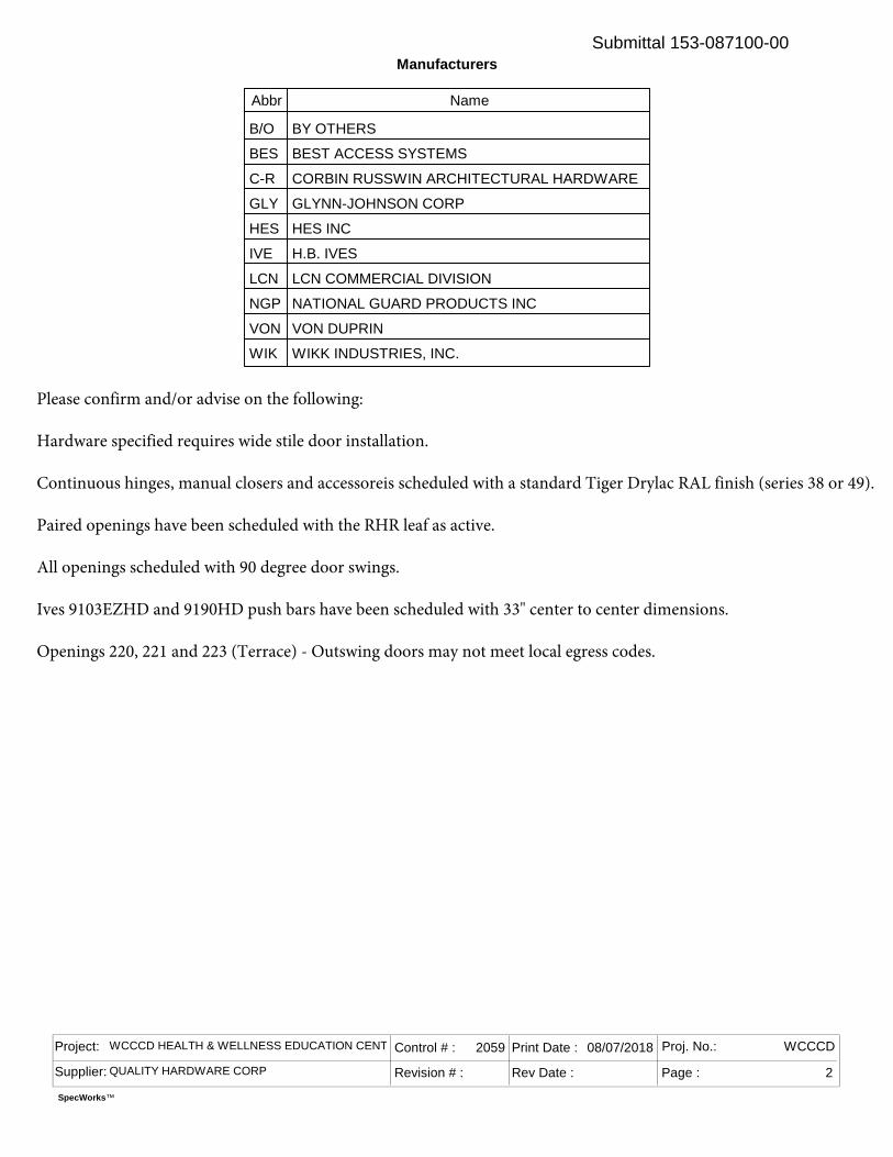
Abbr Name
B/O BY OTHERS
BES BEST ACCESS SYSTEMS
C-R CORBIN RUSSWIN ARCHITECTURAL HARDWARE
GLY GLYNN-JOHNSON CORP
HES HES INC
IVE H.B. IVES
LCN LCN COMMERCIAL DIVISION
NGP NATIONAL GUARD PRODUCTS INC
VON VON DUPRIN
WIK WIKK INDUSTRIES, INC.
SpecWorks™
Project: WCCCD HEALTH & WELLNESS EDUCATION CENTER
Supplier: QUALITY HARDWARE CORP
Control # : 2059
Revision # :
Print Date : 08/07/2018
Rev Date : Page : 2
Proj. No.: WCCCD
Manufacturers
Please confirm and/or advise on the following:
Hardware specified requires wide stile door installation.
Continuous hinges, manual closers and accessoreis scheduled with a standard Tiger Drylac RAL finish (series 38 or 49).
Paired openings have been scheduled with the RHR leaf as active.
All openings scheduled with 90 degree door swings.
Ives 9103EZHD and 9190HD push bars have been scheduled with 33" center to center dimensions.
Openings 220, 221 and 223 (Terrace) - Outswing doors may not meet local egress codes.
Submittal 153-087100-00
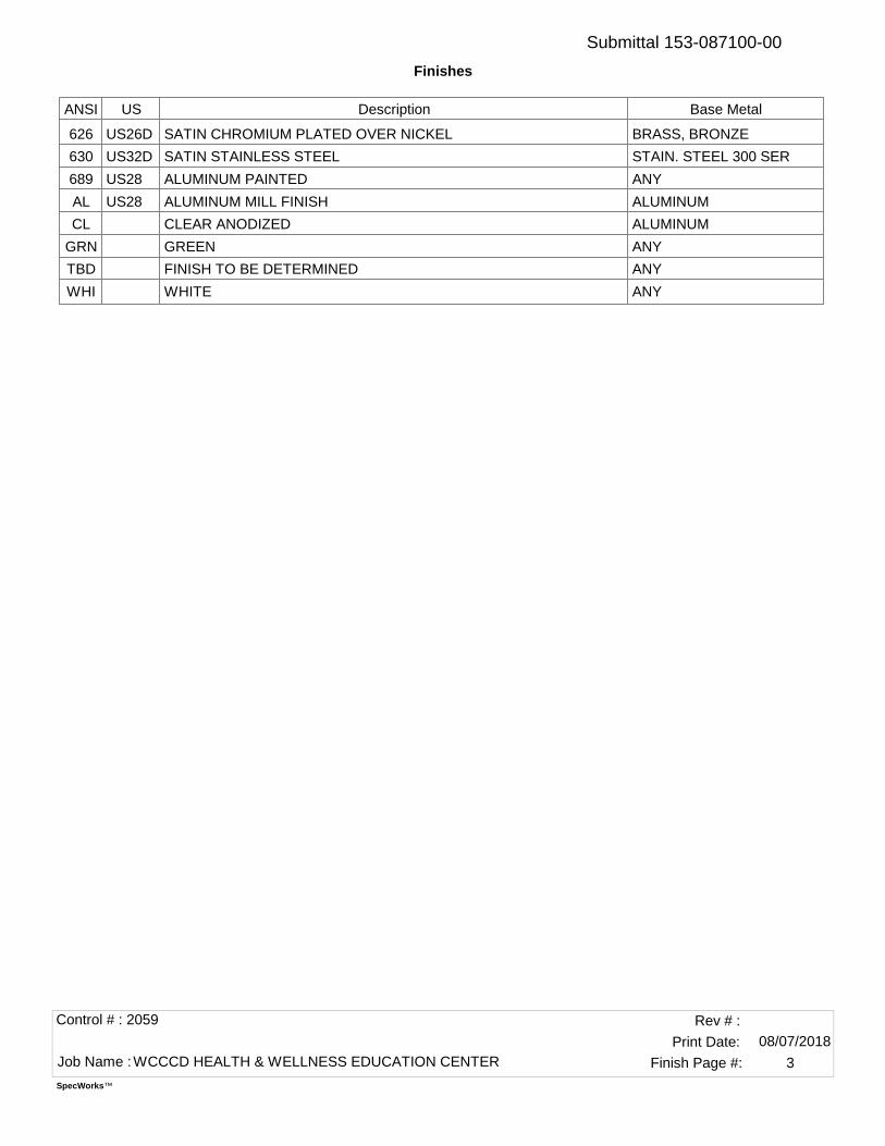
ANSI US Description Base Metal
626 US26D SATIN CHROMIUM PLATED OVER NICKEL BRASS, BRONZE
630 US32D SATIN STAINLESS STEEL STAIN. STEEL 300 SER
689 US28 ALUMINUM PAINTED ANY
AL US28 ALUMINUM MILL FINISH ALUMINUM
CL CLEAR ANODIZED ALUMINUM
GRN GREEN ANY
TBD FINISH TO BE DETERMINED ANY
WHI WHITE ANY
Control # : 2059
Job Name : WCCCD HEALTH & WELLNESS EDUCATION CENTER08/07/2018Print Date:
Rev # :
Finish Page #: 3
SpecWorks™
Finishes
Submittal 153-087100-00
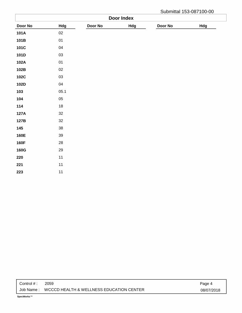
101A 02
101B 01
101C 04
101D 03
102A 01
102B 02
102C 03
102D 04
103 05.1
104 05
114 18
127A 32
127B 32
145 38
160E 39
160F 28
160G 29
220 11
221 11
223 11
Page 4
08/07/2018
Control # : 2059
Job Name : WCCCD HEALTH & WELLNESS EDUCATION CENTER
SpecWorks™
Door No Hdg Door No Hdg Door No Hdg
Door IndexSubmittal 153-087100-00
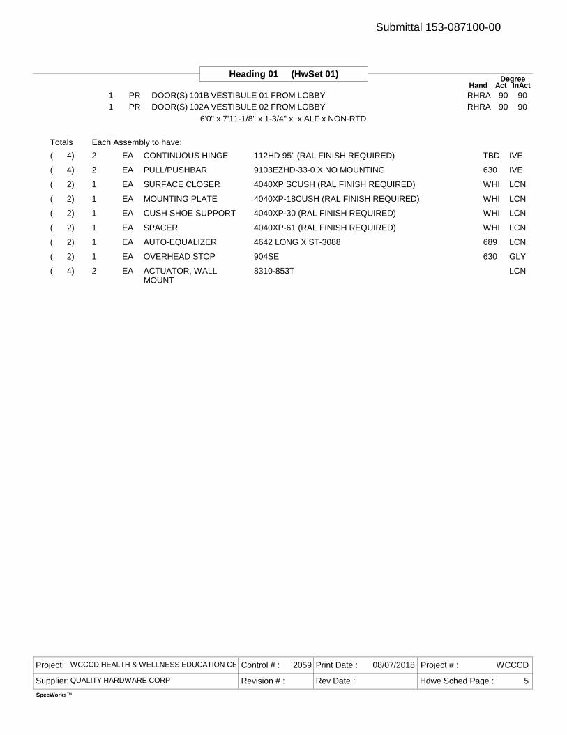
Heading 01 (HwSet 01) DegreeAct InActHand
1 PR DOOR(S) 101B VESTIBULE 01 FROM LOBBY RHRA 90 901 PR DOOR(S) 102A VESTIBULE 02 FROM LOBBY RHRA 90 90
6'0" x 7'11-1/8" x 1-3/4" x x ALF x NON-RTD
2 112HD 95" (RAL FINISH REQUIRED) TBDCONTINUOUS HINGE IVEEA( 4)
2 9103EZHD-33-0 X NO MOUNTING 630PULL/PUSHBAR IVEEA( 4)
1 4040XP SCUSH (RAL FINISH REQUIRED) WHISURFACE CLOSER LCNEA( 2)
1 4040XP-18CUSH (RAL FINISH REQUIRED) WHIMOUNTING PLATE LCNEA( 2)
1 4040XP-30 (RAL FINISH REQUIRED) WHICUSH SHOE SUPPORT LCNEA( 2)
1 4040XP-61 (RAL FINISH REQUIRED) WHISPACER LCNEA( 2)
1 4642 LONG X ST-3088 689AUTO-EQUALIZER LCNEA( 2)
1 904SE 630OVERHEAD STOP GLYEA( 2)
2 8310-853TACTUATOR, WALLMOUNT
LCNEA( 4)
Totals Each Assembly to have:
Project: WCCCD HEALTH & WELLNESS EDUCATION CENTER
Supplier: QUALITY HARDWARE CORP Revision # :
Control # : 2059 Print Date : 08/07/2018
Rev Date :
Project # : WCCCD
Hdwe Sched Page : 5
SpecWorks™
Submittal 153-087100-00

Heading 02 (HwSet 02) DegreeAct InActHand
1 PR DOOR(S) 101A VESTIBULE 01 FROM LOBBY RHRA 90 901 PR DOOR(S) 102B VESTIBULE 02 FROM LOBBY RHRA 90 90
6'0" x 7'11-1/8" x 1-3/4" x x ALF x NON-RTD
2 112HD 95" (RAL FINISH REQUIRED) TBDCONTINUOUS HINGE IVEEA( 4)
2 9190HD-33-2 X NO MOUNTING 630PULL/PUSHBAR IVEEA( 4)
2 4040XP SCUSH (RAL FINISH REQUIRED) WHISURFACE CLOSER LCNEA( 4)
2 4040XP-18CUSH (RAL FINISH REQUIRED) WHIMOUNTING PLATE LCNEA( 4)
2 4040XP-30 (RAL FINISH REQUIRED) WHICUSH SHOE SUPPORT LCNEA( 4)
2 4040XP-61 (RAL FINISH REQUIRED) WHISPACER LCNEA( 4)
Totals Each Assembly to have:
Project: WCCCD HEALTH & WELLNESS EDUCATION CENTER
Supplier: QUALITY HARDWARE CORP Revision # :
Control # : 2059 Print Date : 08/07/2018
Rev Date :
Project # : WCCCD
Hdwe Sched Page : 6
SpecWorks™
Submittal 153-087100-00

Heading 03 (HwSet 03) DegreeAct InActHand
1 PR DOOR(S) 101D EXTERIOR FROM VESTIBULE 01 RHRA 90 901 PR DOOR(S) 102C EXTERIOR FROM VESTIBULE 02 RHRA 90 90
6'0" x 7'11-1/8" x 1-3/4" x x ALF x NON-RTD
2 112HD 95" (RAL FINISH REQUIRED) TBDCONTINUOUS HINGE IVEEA( 4)
1 (BY SPECIAL-LITE)REMOVABLE MULLION B/OEA( 2)
1 154 689MULLION STABILIZER VONEA( 2)
1 98EO 3' 626PANIC HARDWARE VONEA( 2)
1 98NL-OP 3' 626PANIC HARDWARE VONEA( 2)
1 12E72 (LESS CORE) 626RIM CYLINDER BESEA( 2)
1 1E76 C181 (LESS CORE) MULLION 626MORTISE CYLINDER BESEA( 2)
2 GRNCONSTRUCTION CORE BESEA( 4)
2 (BY OTHERS)FINAL CORE B/OEA( 4)
2 8190HD-2 X O MOUNTING 630OFFSET DOOR PULL IVEEA( 4)
1 4040XP SCUSH (RAL FINISH REQUIRED) WHISURFACE CLOSER LCNEA( 2)
1 4040XP-18CUSH (RAL FINISH REQUIRED) WHIMOUNTING PLATE LCNEA( 2)
1 4040XP-30 (RAL FINISH REQUIRED) WHICUSH SHOE SUPPORT LCNEA( 2)
1 4040XP-61 (RAL FINISH REQUIRED) WHISPACER LCNEA( 2)
1 4642 LONG X ST-3088 689AUTO-EQUALIZER LCNEA( 2)
1 904SE 630OVERHEAD STOP GLYEA( 2)
1 BY FRAME SUPPLIERWEATHER SEAL B/OSET( 2)
2 C627A X 36" CLDOOR SWEEP NGPEA( 4)
1 425 X 76" SSMS/LA ALTHRESHOLD NGPEA( 2)
2 8310-853TACTUATOR, WALLMOUNT
LCNEA( 4)
1 BPS-SM-TUBE 630BOLLARD POST WIKEA( 2)
2 BY SECURITY CONTRACTORDOOR POSITION SWITCH B/OEA( 4)
1 BY SECURITY CONTRACTORREX MOTION SENSOR B/OEA( 2)
Totals Each Assembly to have:
Project: WCCCD HEALTH & WELLNESS EDUCATION CENTER
Supplier: QUALITY HARDWARE CORP Revision # :
Control # : 2059 Print Date : 08/07/2018
Rev Date :
Project # : WCCCD
Hdwe Sched Page : 7
SpecWorks™
Submittal 153-087100-00
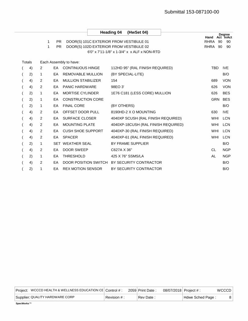
Heading 04 (HwSet 04) DegreeAct InActHand
1 PR DOOR(S) 101C EXTERIOR FROM VESTIBULE 01 RHRA 90 901 PR DOOR(S) 102D EXTERIOR FROM VESTIBULE 02 RHRA 90 90
6'0" x 7'11-1/8" x 1-3/4" x x ALF x NON-RTD
2 112HD 95" (RAL FINISH REQUIRED) TBDCONTINUOUS HINGE IVEEA( 4)
1 (BY SPECIAL-LITE)REMOVABLE MULLION B/OEA( 2)
2 154 689MULLION STABILIZER VONEA( 4)
2 98EO 3' 626PANIC HARDWARE VONEA( 4)
1 1E76 C181 (LESS CORE) MULLION 626MORTISE CYLINDER BESEA( 2)
1 GRNCONSTRUCTION CORE BESEA( 2)
1 (BY OTHERS)FINAL CORE B/OEA( 2)
2 8190HD-2 X O MOUNTING 630OFFSET DOOR PULL IVEEA( 4)
2 4040XP SCUSH (RAL FINISH REQUIRED) WHISURFACE CLOSER LCNEA( 4)
2 4040XP-18CUSH (RAL FINISH REQUIRED) WHIMOUNTING PLATE LCNEA( 4)
2 4040XP-30 (RAL FINISH REQUIRED) WHICUSH SHOE SUPPORT LCNEA( 4)
2 4040XP-61 (RAL FINISH REQUIRED) WHISPACER LCNEA( 4)
1 BY FRAME SUPPLIERWEATHER SEAL B/OSET( 2)
2 C627A X 36" CLDOOR SWEEP NGPEA( 4)
1 425 X 76" SSMS/LA ALTHRESHOLD NGPEA( 2)
2 BY SECURITY CONTRACTORDOOR POSITION SWITCH B/OEA( 4)
1 BY SECURITY CONTRACTORREX MOTION SENSOR B/OEA( 2)
Totals Each Assembly to have:
Project: WCCCD HEALTH & WELLNESS EDUCATION CENTER
Supplier: QUALITY HARDWARE CORP Revision # :
Control # : 2059 Print Date : 08/07/2018
Rev Date :
Project # : WCCCD
Hdwe Sched Page : 8
SpecWorks™
Submittal 153-087100-00
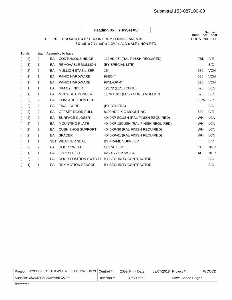
Heading 05 (HwSet 05) DegreeAct InActHand
1 PR DOOR(S) 104 EXTERIOR FROM LOUNGE AREA 01 RHRA 90 906'0-1/8" x 7'11-1/8" x 1-3/4" x ALD x ALF x NON-RTD
2 112HD 95" (RAL FINISH REQUIRED) TBDCONTINUOUS HINGE IVEEA( 2)
1 (BY SPECIAL-LITE)REMOVABLE MULLION B/OEA( 1)
2 154 689MULLION STABILIZER VONEA( 2)
1 98EO 4' 626PANIC HARDWARE VONEA( 1)
1 98NL-OP 4' 626PANIC HARDWARE VONEA( 1)
1 12E72 (LESS CORE) 626RIM CYLINDER BESEA( 1)
1 1E76 C181 (LESS CORE) MULLION 626MORTISE CYLINDER BESEA( 1)
2 GRNCONSTRUCTION CORE BESEA( 2)
2 (BY OTHERS)FINAL CORE B/OEA( 2)
2 8190HD-2 X O MOUNTING 630OFFSET DOOR PULL IVEEA( 2)
2 4040XP SCUSH (RAL FINISH REQUIRED) WHISURFACE CLOSER LCNEA( 2)
2 4040XP-18CUSH (RAL FINISH REQUIRED) WHIMOUNTING PLATE LCNEA( 2)
2 4040XP-30 (RAL FINISH REQUIRED) WHICUSH SHOE SUPPORT LCNEA( 2)
2 4040XP-61 (RAL FINISH REQUIRED) WHISPACER LCNEA( 2)
1 BY FRAME SUPPLIERWEATHER SEAL B/OSET( 1)
2 C627A X 37" CLDOOR SWEEP NGPEA( 2)
1 425 X 77" SSMS/LA ALTHRESHOLD NGPEA( 1)
2 BY SECURITY CONTRACTORDOOR POSITION SWITCH B/OEA( 2)
1 BY SECURITY CONTRACTORREX MOTION SENSOR B/OEA( 1)
Totals Each Assembly to have:
Project: WCCCD HEALTH & WELLNESS EDUCATION CENTER
Supplier: QUALITY HARDWARE CORP Revision # :
Control # : 2059 Print Date : 08/07/2018
Rev Date :
Project # : WCCCD
Hdwe Sched Page : 9
SpecWorks™
Submittal 153-087100-00
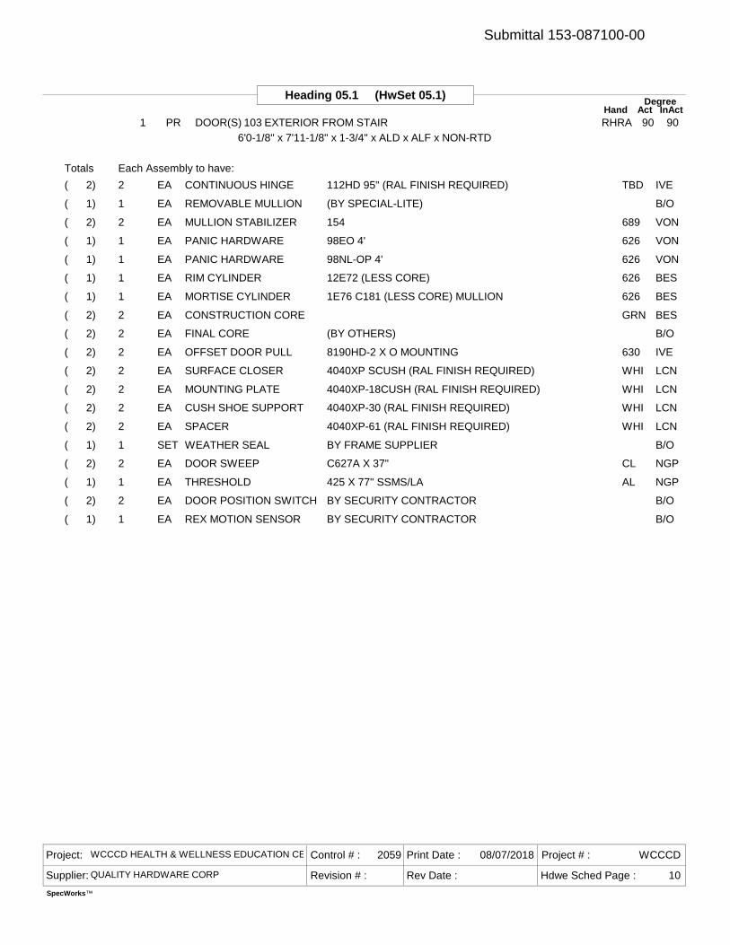
Heading 05.1 (HwSet 05.1) DegreeAct InActHand
1 PR DOOR(S) 103 EXTERIOR FROM STAIR RHRA 90 906'0-1/8" x 7'11-1/8" x 1-3/4" x ALD x ALF x NON-RTD
2 112HD 95" (RAL FINISH REQUIRED) TBDCONTINUOUS HINGE IVEEA( 2)
1 (BY SPECIAL-LITE)REMOVABLE MULLION B/OEA( 1)
2 154 689MULLION STABILIZER VONEA( 2)
1 98EO 4' 626PANIC HARDWARE VONEA( 1)
1 98NL-OP 4' 626PANIC HARDWARE VONEA( 1)
1 12E72 (LESS CORE) 626RIM CYLINDER BESEA( 1)
1 1E76 C181 (LESS CORE) MULLION 626MORTISE CYLINDER BESEA( 1)
2 GRNCONSTRUCTION CORE BESEA( 2)
2 (BY OTHERS)FINAL CORE B/OEA( 2)
2 8190HD-2 X O MOUNTING 630OFFSET DOOR PULL IVEEA( 2)
2 4040XP SCUSH (RAL FINISH REQUIRED) WHISURFACE CLOSER LCNEA( 2)
2 4040XP-18CUSH (RAL FINISH REQUIRED) WHIMOUNTING PLATE LCNEA( 2)
2 4040XP-30 (RAL FINISH REQUIRED) WHICUSH SHOE SUPPORT LCNEA( 2)
2 4040XP-61 (RAL FINISH REQUIRED) WHISPACER LCNEA( 2)
1 BY FRAME SUPPLIERWEATHER SEAL B/OSET( 1)
2 C627A X 37" CLDOOR SWEEP NGPEA( 2)
1 425 X 77" SSMS/LA ALTHRESHOLD NGPEA( 1)
2 BY SECURITY CONTRACTORDOOR POSITION SWITCH B/OEA( 2)
1 BY SECURITY CONTRACTORREX MOTION SENSOR B/OEA( 1)
Totals Each Assembly to have:
Project: WCCCD HEALTH & WELLNESS EDUCATION CENTER
Supplier: QUALITY HARDWARE CORP Revision # :
Control # : 2059 Print Date : 08/07/2018
Rev Date :
Project # : WCCCD
Hdwe Sched Page : 10
SpecWorks™
Submittal 153-087100-00

Heading 11 (HwSet 11) DegreeAct InActHand
1 SGL DOOR(S) 220 TERRACE 03 FROM RHR 901 SGL DOOR(S) 221 TERRACE 02 FROM RHR 901 SGL DOOR(S) 223 TERRACE 01 FROM TRACK RHR 90
3'9-1/2" x 7'6" x 1-3/4" x ALD x ALF x NON-RTD
1 112HD 95" (RAL FINISH REQUIRED) TBDCONTINUOUS HINGE IVEEA( 3)
1 ML2057 CT7SD NSA 626STOREROOM LOCK C-REA( 3)
1 GRNCONSTRUCTION CORE BESEA( 3)
1 (BY OTHERS)FINAL CORE B/OEA( 3)
1 4500C 630ELECTRIC STRIKE HESEA( 3)
1 4040XP SCUSH (RAL FINISH REQUIRED) WHISURFACE CLOSER LCNEA( 3)
1 4040XP-18CUSH (RAL FINISH REQUIRED) WHIMOUNTING PLATE LCNEA( 3)
1 4040XP-30 (RAL FINISH REQUIRED) WHICUSH SHOE SUPPORT LCNEA( 3)
1 4040XP-61 (RAL FINISH REQUIRED) WHISPACER LCNEA( 3)
1 BY FRAME SUPPLIERWEATHER SEAL B/OSET( 3)
1 C627A X 46" CLDOOR SWEEP NGPEA( 3)
1 425 X 50" SSMS/LA ALTHRESHOLD NGPEA( 3)
1 BY SECURITY CONTRACTORCARD READER B/OEA( 3)
1 BY SECURITY CONTRACTORDOOR POSITION SWITCH B/OEA( 3)
1 BY SECURITY CONTRACTORPOWER SUPPLY B/OEA( 3)
1 BY SECURITY CONTRACTORREX MOTION SENSOR B/OEA( 3)
Totals Each Assembly to have:
Project: WCCCD HEALTH & WELLNESS EDUCATION CENTER
Supplier: QUALITY HARDWARE CORP Revision # :
Control # : 2059 Print Date : 08/07/2018
Rev Date :
Project # : WCCCD
Hdwe Sched Page : 11
SpecWorks™
Submittal 153-087100-00
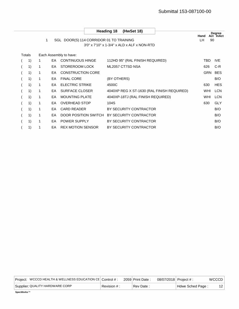
Heading 18 (HwSet 18) DegreeAct InActHand
1 SGL DOOR(S) 114 CORRIDOR 01 TO TRAINING LH 903'0" x 7'10" x 1-3/4" x ALD x ALF x NON-RTD
1 112HD 95" (RAL FINISH REQUIRED) TBDCONTINUOUS HINGE IVEEA( 1)
1 ML2057 CT7SD NSA 626STOREROOM LOCK C-REA( 1)
1 GRNCONSTRUCTION CORE BESEA( 1)
1 (BY OTHERS)FINAL CORE B/OEA( 1)
1 4500C 630ELECTRIC STRIKE HESEA( 1)
1 4040XP REG X ST-1630 (RAL FINISH REQUIRED) WHISURFACE CLOSER LCNEA( 1)
1 4040XP-18TJ (RAL FINISH REQUIRED) WHIMOUNTING PLATE LCNEA( 1)
1 104S 630OVERHEAD STOP GLYEA( 1)
1 BY SECURITY CONTRACTORCARD READER B/OEA( 1)
1 BY SECURITY CONTRACTORDOOR POSITION SWITCH B/OEA( 1)
1 BY SECURITY CONTRACTORPOWER SUPPLY B/OEA( 1)
1 BY SECURITY CONTRACTORREX MOTION SENSOR B/OEA( 1)
Totals Each Assembly to have:
Project: WCCCD HEALTH & WELLNESS EDUCATION CENTER
Supplier: QUALITY HARDWARE CORP Revision # :
Control # : 2059 Print Date : 08/07/2018
Rev Date :
Project # : WCCCD
Hdwe Sched Page : 12
SpecWorks™
Submittal 153-087100-00
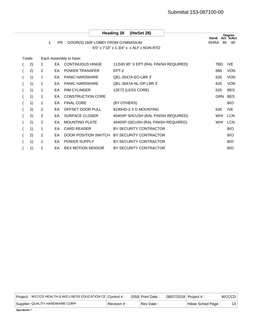
Heading 28 (HwSet 28) DegreeAct InActHand
1 PR DOOR(S) 160F LOBBY FROM GYMNASIUM RHRA 90 906'0" x 7'10" x 1-3/4" x x ALF x NON-RTD
2 112HD 95" X EPT (RAL FINISH REQUIRED) TBDCONTINUOUS HINGE IVEEA( 2)
2 EPT-2 689POWER TRANSFER VONEA( 2)
1 QEL-3547A-EO-LBR 3' 626PANIC HARDWARE VONEA( 1)
1 QEL-3547A-NL-OP-LBR 3' 626PANIC HARDWARE VONEA( 1)
1 12E72 (LESS CORE) 626RIM CYLINDER BESEA( 1)
1 GRNCONSTRUCTION CORE BESEA( 1)
1 (BY OTHERS)FINAL CORE B/OEA( 1)
2 8190HD-2 X O MOUNTING 630OFFSET DOOR PULL IVEEA( 2)
2 4040XP SHCUSH (RAL FINISH REQUIRED) WHISURFACE CLOSER LCNEA( 2)
2 4040XP-18CUSH (RAL FINISH REQUIRED) WHIMOUNTING PLATE LCNEA( 2)
1 BY SECURITY CONTRACTORCARD READER B/OEA( 1)
2 BY SECURITY CONTRACTORDOOR POSITION SWITCH B/OEA( 2)
1 BY SECURITY CONTRACTORPOWER SUPPLY B/OEA( 1)
1 BY SECURITY CONTRACTORREX MOTION SENSOR B/OEA( 1)
Totals Each Assembly to have:
Project: WCCCD HEALTH & WELLNESS EDUCATION CENTER
Supplier: QUALITY HARDWARE CORP Revision # :
Control # : 2059 Print Date : 08/07/2018
Rev Date :
Project # : WCCCD
Hdwe Sched Page : 13
SpecWorks™
Submittal 153-087100-00
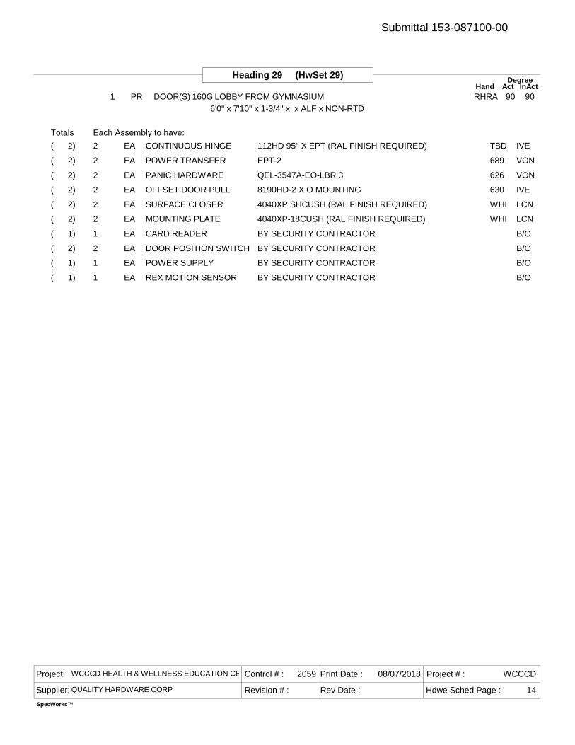
Heading 29 (HwSet 29) DegreeAct InActHand
1 PR DOOR(S) 160G LOBBY FROM GYMNASIUM RHRA 90 906'0" x 7'10" x 1-3/4" x x ALF x NON-RTD
2 112HD 95" X EPT (RAL FINISH REQUIRED) TBDCONTINUOUS HINGE IVEEA( 2)
2 EPT-2 689POWER TRANSFER VONEA( 2)
2 QEL-3547A-EO-LBR 3' 626PANIC HARDWARE VONEA( 2)
2 8190HD-2 X O MOUNTING 630OFFSET DOOR PULL IVEEA( 2)
2 4040XP SHCUSH (RAL FINISH REQUIRED) WHISURFACE CLOSER LCNEA( 2)
2 4040XP-18CUSH (RAL FINISH REQUIRED) WHIMOUNTING PLATE LCNEA( 2)
1 BY SECURITY CONTRACTORCARD READER B/OEA( 1)
2 BY SECURITY CONTRACTORDOOR POSITION SWITCH B/OEA( 2)
1 BY SECURITY CONTRACTORPOWER SUPPLY B/OEA( 1)
1 BY SECURITY CONTRACTORREX MOTION SENSOR B/OEA( 1)
Totals Each Assembly to have:
Project: WCCCD HEALTH & WELLNESS EDUCATION CENTER
Supplier: QUALITY HARDWARE CORP Revision # :
Control # : 2059 Print Date : 08/07/2018
Rev Date :
Project # : WCCCD
Hdwe Sched Page : 14
SpecWorks™
Submittal 153-087100-00

Heading 32 (HwSet 32) DegreeAct InActHand
1 SGL DOOR(S) 127A LOBBY FROM WAITING ROOM LHR 901 SGL DOOR(S) 127B CORRIDOR 01 FROM WAITING ROOM LHR 90
3'0" x 7'10" x 1-3/4" x ALD x HMF x NON-RTD
1 112HD 95" (RAL FINISH REQUIRED) TBDCONTINUOUS HINGE IVEEA( 2)
1 ML2057 CT7SD NSA 626STOREROOM LOCK C-REA( 2)
1 1E74 C4 626MORTISE CYLINDER BESEA( 2)
1 4500C 630ELECTRIC STRIKE HESEA( 2)
1 4040XP EDA (RAL FINISH REQUIRED) WHISURFACE CLOSER LCNEA( 2)
1 4040XP-18PA (RAL FINISH REQUIRED) WHIMOUNTING PLATE LCNEA( 2)
1 8400 10" X 34" 630KICK PLATE IVEEA( 2)
1 WS33 626WALL STOP IVEEA( 2)
1 BY SECURITY CONTRACTORCARD READER B/OEA( 2)
1 BY SECURITY CONTRACTORDOOR POSITION SWITCH B/OEA( 2)
1 BY SECURITY CONTRACTORPOWER SUPPLY B/OEA( 2)
1 BY SECURITY CONTRACTORREX MOTION SENSOR B/OEA( 2)
Totals Each Assembly to have:
Project: WCCCD HEALTH & WELLNESS EDUCATION CENTER
Supplier: QUALITY HARDWARE CORP Revision # :
Control # : 2059 Print Date : 08/07/2018
Rev Date :
Project # : WCCCD
Hdwe Sched Page : 15
SpecWorks™
Submittal 153-087100-00
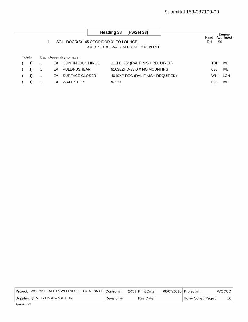
Heading 38 (HwSet 38) DegreeAct InActHand
1 SGL DOOR(S) 145 COORIDOR 01 TO LOUNGE RH 903'0" x 7'10" x 1-3/4" x ALD x ALF x NON-RTD
1 112HD 95" (RAL FINISH REQUIRED) TBDCONTINUOUS HINGE IVEEA( 1)
1 9103EZHD-33-0 X NO MOUNTING 630PULL/PUSHBAR IVEEA( 1)
1 4040XP REG (RAL FINISH REQUIRED) WHISURFACE CLOSER LCNEA( 1)
1 WS33 626WALL STOP IVEEA( 1)
Totals Each Assembly to have:
Project: WCCCD HEALTH & WELLNESS EDUCATION CENTER
Supplier: QUALITY HARDWARE CORP Revision # :
Control # : 2059 Print Date : 08/07/2018
Rev Date :
Project # : WCCCD
Hdwe Sched Page : 16
SpecWorks™
Submittal 153-087100-00
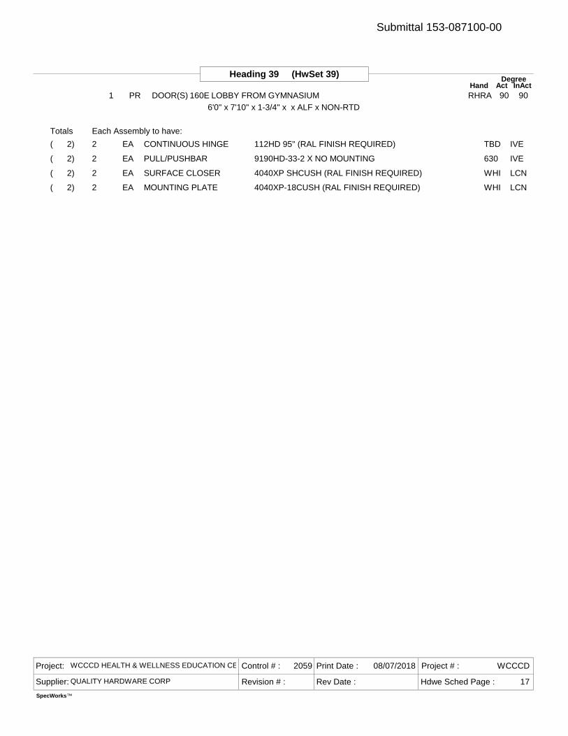
Heading 39 (HwSet 39) DegreeAct InActHand
1 PR DOOR(S) 160E LOBBY FROM GYMNASIUM RHRA 90 906'0" x 7'10" x 1-3/4" x x ALF x NON-RTD
2 112HD 95" (RAL FINISH REQUIRED) TBDCONTINUOUS HINGE IVEEA( 2)
2 9190HD-33-2 X NO MOUNTING 630PULL/PUSHBAR IVEEA( 2)
2 4040XP SHCUSH (RAL FINISH REQUIRED) WHISURFACE CLOSER LCNEA( 2)
2 4040XP-18CUSH (RAL FINISH REQUIRED) WHIMOUNTING PLATE LCNEA( 2)
Totals Each Assembly to have:
Project: WCCCD HEALTH & WELLNESS EDUCATION CENTER
Supplier: QUALITY HARDWARE CORP Revision # :
Control # : 2059 Print Date : 08/07/2018
Rev Date :
Project # : WCCCD
Hdwe Sched Page : 17
SpecWorks™
Submittal 153-087100-00
End of Schedule
Project: WCCCD HEALTH & WELLNESS EDUCATION CENTER
Supplier: QUALITY HARDWARE CORP Revision # :
Control # : 2059 Print Date : 08/07/2018
Rev Date :
Project # : WCCCD
Hdwe Sched Page : 18
SpecWorks™
Submittal 153-087100-00
Catalog Cutsfor
WCCCD HEALTH & WELLNESS EDUCATION CENTER
Sorted by Manufacturer
Prepared ByLINDA HEIMER
QUALITY HARDWARE CORP3411 E. 10 MILE RD.
WARREN MI 48091Phone (586) 880-0158 Fax (586) 880-0166
Created 08/07/2018
2059
PDF created by Specworks® Page 1
Submittal 153-087100-00
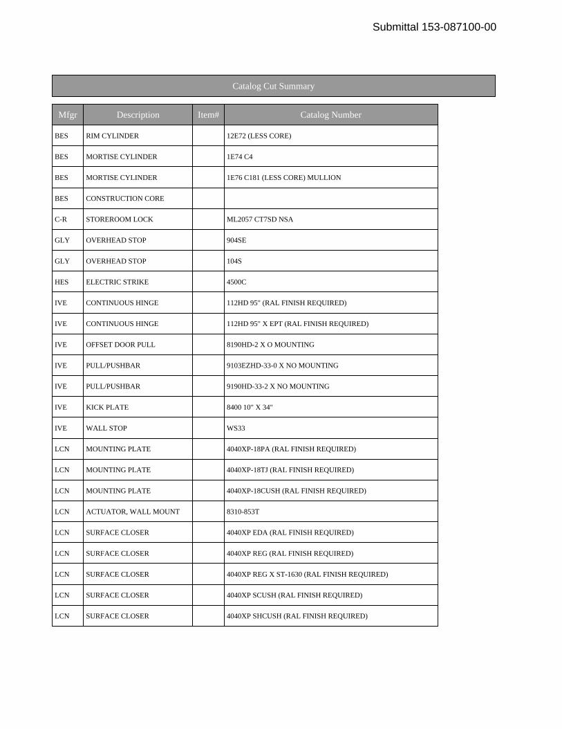
Catalog Cut Summary
Mfgr Description Item# Catalog Number
BES RIM CYLINDER 12E72 (LESS CORE)
BES MORTISE CYLINDER 1E74 C4
BES MORTISE CYLINDER 1E76 C181 (LESS CORE) MULLION
BES CONSTRUCTION CORE
C-R STOREROOM LOCK ML2057 CT7SD NSA
GLY OVERHEAD STOP 904SE
GLY OVERHEAD STOP 104S
HES ELECTRIC STRIKE 4500C
IVE CONTINUOUS HINGE 112HD 95" (RAL FINISH REQUIRED)
IVE CONTINUOUS HINGE 112HD 95" X EPT (RAL FINISH REQUIRED)
IVE OFFSET DOOR PULL 8190HD-2 X O MOUNTING
IVE PULL/PUSHBAR 9103EZHD-33-0 X NO MOUNTING
IVE PULL/PUSHBAR 9190HD-33-2 X NO MOUNTING
IVE KICK PLATE 8400 10" X 34"
IVE WALL STOP WS33
LCN MOUNTING PLATE 4040XP-18PA (RAL FINISH REQUIRED)
LCN MOUNTING PLATE 4040XP-18TJ (RAL FINISH REQUIRED)
LCN MOUNTING PLATE 4040XP-18CUSH (RAL FINISH REQUIRED)
LCN ACTUATOR, WALL MOUNT 8310-853T
LCN SURFACE CLOSER 4040XP EDA (RAL FINISH REQUIRED)
LCN SURFACE CLOSER 4040XP REG (RAL FINISH REQUIRED)
LCN SURFACE CLOSER 4040XP REG X ST-1630 (RAL FINISH REQUIRED)
LCN SURFACE CLOSER 4040XP SCUSH (RAL FINISH REQUIRED)
LCN SURFACE CLOSER 4040XP SHCUSH (RAL FINISH REQUIRED)
Submittal 153-087100-00
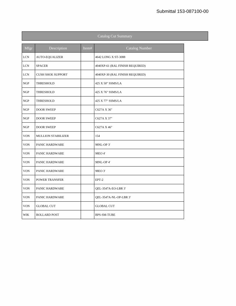
Catalog Cut Summary
Mfgr Description Item# Catalog Number
LCN AUTO-EQUALIZER 4642 LONG X ST-3088
LCN SPACER 4040XP-61 (RAL FINISH REQUIRED)
LCN CUSH SHOE SUPPORT 4040XP-30 (RAL FINISH REQUIRED)
NGP THRESHOLD 425 X 50" SSMS/LA
NGP THRESHOLD 425 X 76" SSMS/LA
NGP THRESHOLD 425 X 77" SSMS/LA
NGP DOOR SWEEP C627A X 36"
NGP DOOR SWEEP C627A X 37"
NGP DOOR SWEEP C627A X 46"
VON MULLION STABILIZER 154
VON PANIC HARDWARE 98NL-OP 3'
VON PANIC HARDWARE 98EO 4'
VON PANIC HARDWARE 98NL-OP 4'
VON PANIC HARDWARE 98EO 3'
VON POWER TRANSFER EPT-2
VON PANIC HARDWARE QEL-3547A-EO-LBR 3'
VON PANIC HARDWARE QEL-3547A-NL-OP-LBR 3'
VON GLOBAL CUT GLOBAL CUT
WIK BOLLARD POST BPS-SM-TUBE
Submittal 153-087100-00
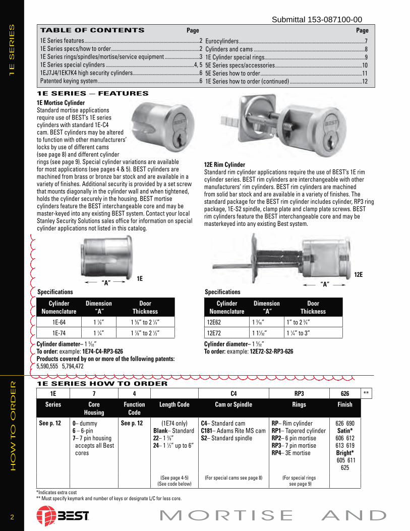
2 M O R T I S E A N D
12E Rim CylinderStandard rim cylinder ap pli ca tions re quire the use of BEST’s 1E rim cyl in der series. BEST rim cylinders are interchangeable with other manufacturers’ rim cyl in ders. BEST rim cyl in ders are ma chined from solid bar stock and are avail able in a variety of fin ish es. The standard pack age for the BEST rim cylinder includes cylinder, RP3 ring package, 1E-S2 spin dle, clamp plate and clamp plate screws. BEST rim cyl in ders feature the BEST in ter change able core and may be master keyed into any existing Best system.
1E Mortise Cylinder Standard mortise applications require use of BEST’s 1E series cylinders with standard 1E-C4 cam. BEST cylinders may be al tered to func tion with oth er man u fac tur ers’ locks by use of dif fer ent cams (see page 8) and dif fer ent cyl inder rings (see page 9). Special cyl in der vari a tions are available for most ap pli ca tions (see pag es 4 & 5). BEST cylinders are ma chined from brass or bronze bar stock and are avail able in a variety of fin ish es. Ad di tion al se cu ri ty is pro vid ed by a set screw that mounts di ag o nal ly in the cyl inder wall and when tightened, holds the cylinder se cure ly in the housing. BEST mortise cylinders feature the BEST in ter change able core and may be mas ter- keyed into any existing BEST system. Contact your local Stanley Security Solutions sales office for in for ma tion on special cyl in der ap pli ca tions not listed in this catalog.
“A”
TABLE OF CONTENTS
1E Series features ......................................................................................21E Series specs/how to order ..................................................................21E Series rings/spindles/mortise/service equipment ..........................31E Series special cylinders ..................................................................4, 51EJ7J4/1EK7K4 high security cylinders..................................................6Patented keying system ............................................................................6
1E SERIES – FEATURES
1E SERIES HOW TO ORDER
1E S
ER
IES
“A”Specifications Specifications
Page Page
Eurocylinders ..............................................................................................7Cylinders and cams ...................................................................................81E Cylinder special rings...........................................................................95E Series specs/accessories .................................................................105E Series how to order ............................................................................111E Series how to order (continued) ......................................................12
Cylinder diameter– 1 5⁄32”To order: example: 1E74-C4-RP3-626Products covered by on or more of the following patents:5,590,555 5,794,472
Cylinder diameter– 1 5⁄32”To order: example: 12E72-S2-RP3-626
CylinderNomenclature
Dimension “A”
DoorThick ness
1E-64 1 1⁄8” 1 5⁄8” to 2 1⁄4”
1E-74 1 1⁄4” 1 7⁄8” to 2 1⁄2”
CylinderNomenclature
Dimension “A”
DoorThick ness
12E62 1 3⁄16” 1” to 2 3⁄4”
12E72 1 11⁄32” 1 1⁄4” to 3”
1E 12E
1E 7 4 C4 RP3 626 **
Series CoreHousing
Function Code
Length Code Cam or Spindle Rings Finish
See p. 12 0– dummy6 – 6-pin7– 7 pin housing accepts all Best cores
See p. 12 (1E74 only)Blank– Standard22– 1 3⁄8”24– 1 1⁄2” up to 6”
C4– Standard camC181– Adams Rite MS camS2– Standard spindle
RP– Rim cylinderRP1– Tapered cylinderRP2– 6 pin mortiseRP3– 7 pin mortiseRP4– 3E mortise
626 690Satin*
606 612613 619Bright* 605 611
625(See page 4-5)
(See code below)(For special cams see page 8) (For special rings
see page 9)
*Indicates extra cost** Must specify keymark and number of keys or designate L/C for less core.
HO
W T
O O
RD
ER
Submittal 153-087100-00
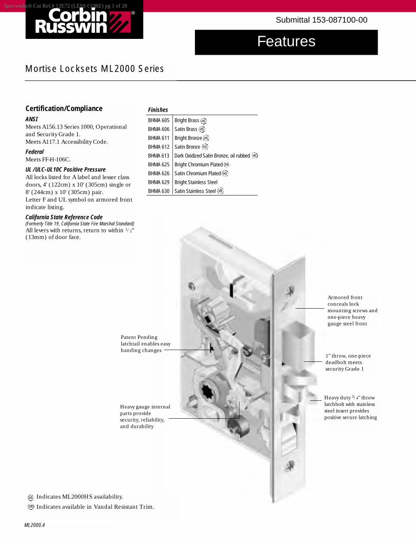
Features
ML2000.4
Mortise Locksets ML2000 Series
Certification/ComplianceANSIMeets A156.13 Series 1000, Operationaland Security Grade 1.Meets A117.1 Accessibility Code.
Federal Meets FF-H-106C.
UL /ULC-UL10C Positive PressureAll locks listed for A label and lesser classdoors, 4' (122cm) x 10' (305cm) single or8' (244cm) x 10' (305cm) pair. Letter F and UL symbol on armored frontindicate listing.
California State Reference Code(Formerly Title 19, California State Fire Marshal Standard)All levers with returns, return to within 1/2"(13mm) of door face.
Patent Pendinglatchtail enables easyhanding changes
Heavy gauge internalparts providesecurity, reliability,and durability
Armored frontconceals lockmounting screws andone-piece heavygauge steel front
Heavy duty 3/4" throwlatchbolt with stainlesssteel insert providespositive secure latching
1" throw, one-piecedeadbolt meetssecurity Grade 1
Finishes
BHMA 605 Bright Brass
BHMA 606 Satin Brass
BHMA 611 Bright Bronze
BHMA 612 Satin Bronze
BHMA 613 Dark Oxidized Satin Bronze, oil rubbed
BHMA 625 Bright Chromium Plated
BHMA 626 Satin Chromium Plated
BHMA 629 Bright Stainless Steel
BHMA 630 Satin Stainless Steel
Indicates ML2000HS availability.
Indicates available in Vandal Resistant Trim.
HS
HS
HS
HS
HS
HS
HS
VR
HS
VR
Specworks® Cut Ref.# 12E72 (LESS CORE) pg 1 of 28
Submittal 153-087100-00
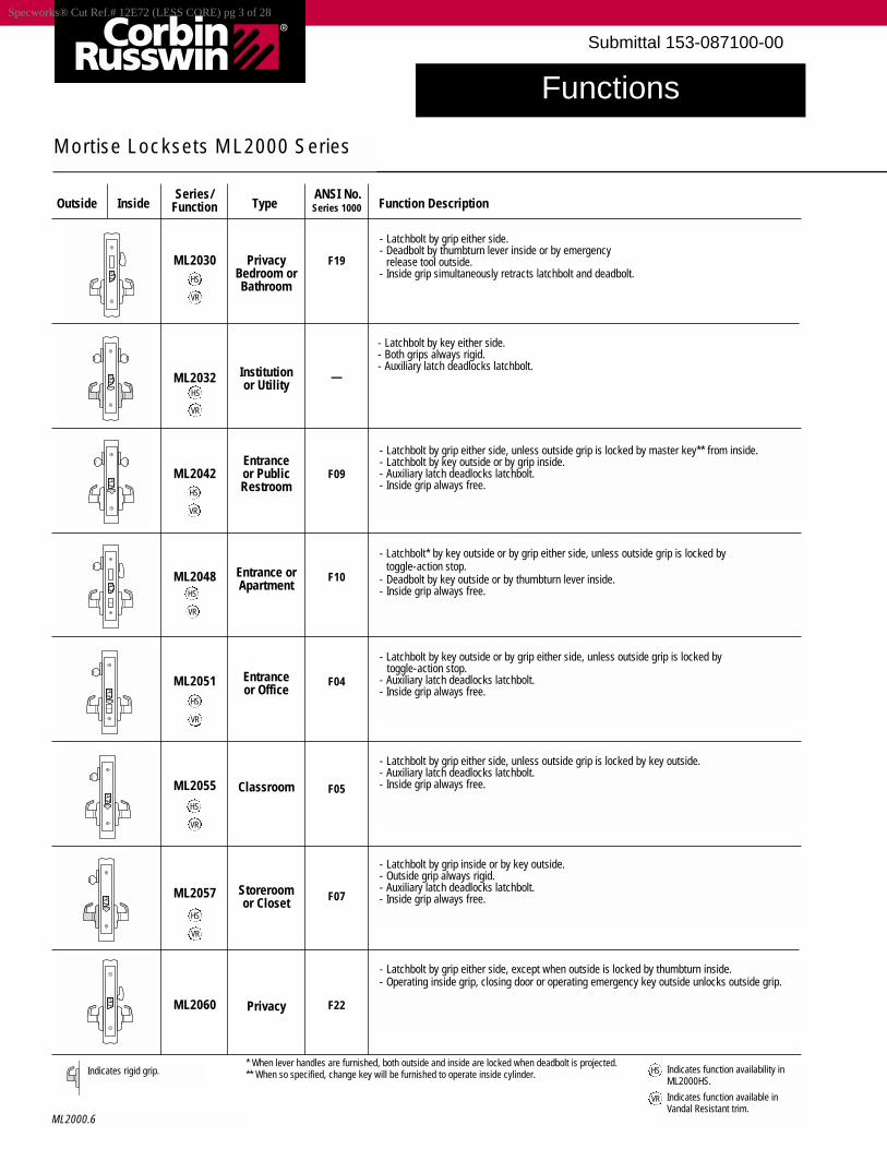
Functions
ML2000.6
Mortise Locksets ML2000 Series
PrivacyBedroom orBathroom
Institutionor Utility
Entranceor PublicRestroom
Entrance orApartment
Entranceor Office
Classroom
Storeroomor Closet
Privacy
* When lever handles are furnished, both outside and inside are locked when deadbolt is projected.** When so specified, change key will be furnished to operate inside cylinder.
Series/ ANSI No.Outside Inside Function Type Series 1000 Function Description
F19
—
F09
F10
F04
F05
F07
F22
ML2030
ML2032
ML2042
ML2048
ML2051
ML2055
ML2057
ML2060
- Latchbolt by grip either side, unless outside grip is locked by master key** from inside.- Latchbolt by key outside or by grip inside.- Auxiliary latch deadlocks latchbolt.- Inside grip always free.
- Latchbolt* by key outside or by grip either side, unless outside grip is locked by toggle-action stop.
- Deadbolt by key outside or by thumbturn lever inside.- Inside grip always free.
- Latchbolt by key outside or by grip either side, unless outside grip is locked bytoggle-action stop.
- Auxiliary latch deadlocks latchbolt.- Inside grip always free.
- Latchbolt by grip either side, unless outside grip is locked by key outside.- Auxiliary latch deadlocks latchbolt.- Inside grip always free.
- Latchbolt by grip inside or by key outside.- Outside grip always rigid.- Auxiliary latch deadlocks latchbolt.- Inside grip always free.
- Latchbolt by grip either side, except when outside is locked by thumbturn inside.- Operating inside grip, closing door or operating emergency key outside unlocks outside grip.
- Latchbolt by grip either side.- Deadbolt by thumbturn lever inside or by emergency
release tool outside.- Inside grip simultaneously retracts latchbolt and deadbolt.
- Latchbolt by key either side.- Both grips always rigid.- Auxiliary latch deadlocks latchbolt.
Indicates rigid grip. Indicates function availability inML2000HS.
Indicates function available inVandal Resistant trim.
HS
VR
HS
HS
VR
HS
VR
HS
VR
HS
VR
HS
VR
VR
VR
HS
Specworks® Cut Ref.# 12E72 (LESS CORE) pg 3 of 28
Submittal 153-087100-00
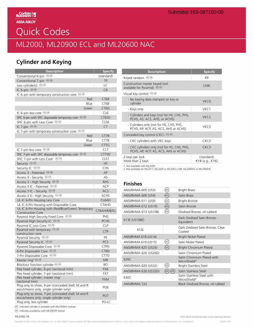
OverviewML2000
ML2000.76
Copyright © 2001-2016 Corbin Russwin, Inc., an ASSA ABLOY Group company. All rights reserved. Reproduction in whole or in part without the express written permission of Corbin Russwin, Inc. is prohibited. 45300-4/16
Quick CodesML2000, ML20900 ECL and ML20600 NAC
Cylinder and Keying
Indicates cylinder is available with ML2000HS lockset
Indicates availability with ML200VR lockset
Description Specify
Construction master keyed (not
Visual key control
- No keying data stamped on key or cylinder
2 keys per lockMore than 2 keys
(standard)
1. Not available with ML2029.2. Not available for ML2017, ML2029 or ML2032 x MR, ML2000HS or ML2000VR.
Description Specify
Conventional 6-pin (standard)Conventional 7-pin Less cylinder(s) LCIC 6-pin C6IC 6-pin with temporary construction core
Red CT6RBlue CT6B
Green CT6GIC 6-pin less core CL6SFIC 6-pin with SFIC disposable temporary core CT6SDSFIC 6-pin with Less Core1 CLS6IC 7-pin C7IC 7-pin with temporary construction core
Red CT7RBlue CT7B
Green CT7GIC 7-pin less core CL7SFIC 7-pin with SFIC disposable temporary core CT7SDSFIC 7-pin with Less Core1 CLS7Security HSSecurity IC CHS
Access 3 - Security ASAccess 3 - High Security AHS
Access 3 IC - Security ACSAccess 3 IC- High Security ACHS
CL6AH CTAHD
Construction Core CT6AH(R/B/G)
construction core
CT6DCT7D
Master ring2 MRBlockout function cylinder BOFlex head cylinder, 6-pin (sectional trim) FX6Flex head cylinder, 7-pin (sectional trim) FX7Flex head cylinder, master ring2 (sectional trim)
FXM
escutcheons only, single cylinder only)
escutcheons only, single cylinder only)
FinishesANSI/BHMA 605 (US3) Bright Brass
ANSI/BHMA 606 (US4) Satin Brass
ANSI/BHMA 611 (US9) Bright Bronze
ANSI/BHMA 612 (US10) Satin Bronze
ANSI/BHMA 613 (US10B) Oxidized Bronze, oil rubbed
613E (US10BE)Dark Oxidized Satin Bronze - Equivalent
613LDark Oxidized Satin Bronze, Clear Coated
ANSI/BHMA 618 (US14)
ANSI/BHMA 619 (US15)
ANSI/BHMA 625 (US26)
ANSI/BHMA 626 (US26D)
626CMicroShield®
ANSI/BHMA 629 (US32) Bright Stainless Steel
ANSI/BHMA 630 (US32D) Satin Stainless Steel
630CSatin Stainless Steel with MicroShield®
ANSI/BHMA 722 Black Oxidized Bronze, oil rubbed
HS
HS
HS
HS
HS
HS
HS
HS
HS VR
Submittal 153-087100-00
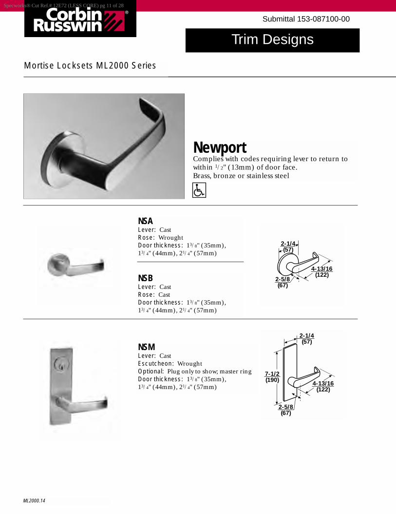
Trim Designs
ML2000.14
Mortise Locksets ML2000 Series
NewportComplies with codes requiring lever to return towithin 1/2" (13mm) of door face.Brass, bronze or stainless steel
NSALever: CastRose: WroughtDoor thickness: 13/8" (35mm), 13/4" (44mm), 21/4" (57mm)
NSBLever: CastRose: CastDoor thickness: 13/8" (35mm), 13/4" (44mm), 21/4" (57mm)
NSMLever: CastEscutcheon: WroughtOptional: Plug only to show; master ringDoor thickness: 13/8" (35mm), 13/4" (44mm), 21/4" (57mm)
2-1/4(57)
4-13/16(122)
2-5/8(67)
4-13/16(122)
2-5/8(67)
2-1/4(57)
7-1/2(190)
Specworks® Cut Ref.# 12E72 (LESS CORE) pg 11 of 28
Submittal 153-087100-00
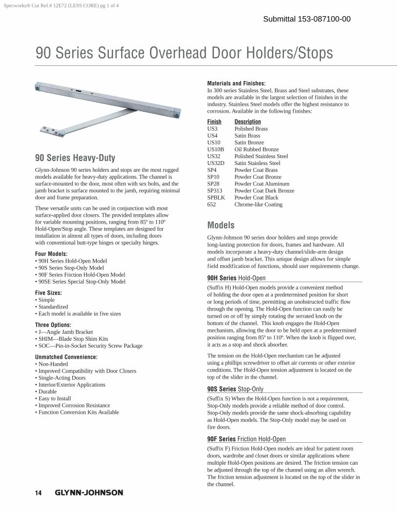
14
90 Series Surface Overhead Door Holders/Stops
90 Series Heavy-DutyGlynn-Johnson 90 series holders and stops are the most ruggedmodels available for heavy-duty applications. The channel is surface-mounted to the door, most often with sex bolts, and thejamb bracket is surface mounted to the jamb, requiring minimaldoor and frame preparation.
These versatile units can be used in conjunction with most surface-applied door closers. The provided templates allow for variable mounting positions, ranging from 85º to 110º Hold-Open/Stop angle. These templates are designed for installation in almost all types of doors, including doors with conventional butt-type hinges or specialty hinges.
Four Models:• 90H Series Hold-Open Model• 90S Series Stop-Only Model• 90F Series Friction Hold-Open Model• 90SE Series Special Stop-Only Model
Five Sizes:• Simple• Standardized• Each model is available in five sizes
Three Options:• J—Angle Jamb Bracket• SHIM—Blade Stop Shim Kits• SOC—Pin-in-Socket Security Screw Package
Unmatched Convenience:• Non-Handed• Improved Compatibility with Door Closers• Single-Acting Doors• Interior/Exterior Applications• Durable• Easy to Install• Improved Corrosion Resistance• Function Conversion Kits Available
Materials and Finishes:In 300 series Stainless Steel, Brass and Steel substrates, these models are available in the largest selection of finishes in the industry. Stainless Steel models offer the highest resistance to corrosion. Available in the following finishes:
Finish DescriptionUS3 Polished BrassUS4 Satin BrassUS10 Satin BronzeUS10B Oil Rubbed BronzeUS32 Polished Stainless SteelUS32D Satin Stainless SteelSP4 Powder Coat BrassSP10 Powder Coat BronzeSP28 Powder Coat AluminumSP313 Powder Coat Dark BronzeSPBLK Powder Coat Black652 Chrome-like Coating
ModelsGlynn-Johnson 90 series door holders and stops provide long-lasting protection for doors, frames and hardware. All models incorporate a heavy-duty channel/slide-arm design and offset jamb bracket. This unique design allows for simplefield modification of functions, should user requirements change.
90H Series Hold-Open (Suffix H) Hold-Open models provide a convenient method of holding the door open at a predetermined position for short or long periods of time, permitting an unobstructed traffic flowthrough the opening. The Hold-Open function can easily be turned on or off by simply rotating the serrated knob on the bottom of the channel. This knob engages the Hold-Open mechanism, allowing the door to be held open at a predeterminedposition ranging from 85º to 110º. When the knob is flipped over, it acts as a stop and shock absorber.
The tension on the Hold-Open mechanism can be adjusted using a phillips screwdriver to offset air currents or other exteriorconditions. The Hold-Open tension adjustment is located on the top of the slider in the channel.
90S Series Stop-Only (Suffix S) When the Hold-Open function is not a requirement,Stop-Only models provide a reliable method of door control. Stop-Only models provide the same shock-absorbing capability as Hold-Open models. The Stop-Only model may be used on fire doors.
90F Series Friction Hold-Open (Suffix F) Friction Hold-Open models are ideal for patient roomdoors, wardrobe and closet doors or similar applications where multiple Hold-Open positions are desired. The friction tension canbe adjusted through the top of the channel using an allen wrench.The friction tension adjustment is located on the top of the slider inthe channel.
Specworks® Cut Ref.# 12E72 (LESS CORE) pg 1 of 4
Submittal 153-087100-00
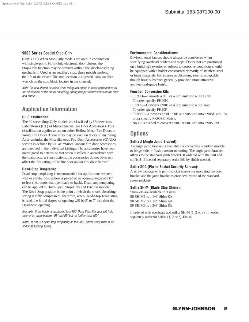
15
90SE Series Special Stop-Only (Suffix SE) When Stop-Only models are used in conjunction with single-point, Hold-Only electronic door closers, the Stop-Only function may be ordered without the shock-absorbing mechanism. Used as an auxiliary stop, these models prolong the life of the closer. The stop location is adjusted using an allenwrench on the stop block located in the channel.
Note: Caution should be taken when using this option in other applications, asthe elimination of the shock-absorbing spring can put added stress on the doorand frame.
Application InformationUL ClassificationThe 90 series Stop-Only models are classified by UnderwritersLaboratories (UL) as Miscellaneous Fire Door Accessories. Thisclassification applies to use on either Hollow Metal Fire Doors orWood Fire Doors. These units may be used on doors of any rating.As a reminder, the Miscellaneous Fire Door Accessories (GVUX)section is defined by UL as: “Miscellaneous fire door accessoriesare intended in the individual Listings. The accessories have beeninvestigated to determine that when installed in accordance with the manufacturer’s instructions, the accessories do not adverselyaffect the fire rating of the fire door and/or fire door frames.”
Dead-Stop Templating:Dead-stop templating is recommended for applications where awall or similar obstruction is placed at an opening angle of 110º or less (i.e., doors that open back-to-back). Dead-stop templatingcan be applied to Hold-Open, Stop-Only and Friction models. The Dead-Stop position is the point at which the shock-absorbing spring is fully compressed. Therefore, when Dead-Stop Templatingis used, the initial degree of opening will be 5º to 7º less than theDead-Stop opening.
Example: If the holder is templated to a 100º Dead Stop, the door will holdopen at an angle between 93º and 95º but no further than 100º
Note: Do not use dead-stop templating on the 90SE Series since there is noshock-absorbing spring.
Environmental Considerations:Environmental factors should always be considered when specifying overhead holders and stops. Doors that are positioned on a building’s exterior or subject to corrosive conditions should be equipped with a holder constructed primarily of stainless steel or brass materials. For interior applications, steel is acceptable,though brass substrates generally provide a more attractive architectural-grade finish.
Function Conversion Kits• FK90H—Converts a 90F or a 90S unit into a 90H unit.
To order specify FK90H.• FK90F—Converts a 90H or a 90S unit into a 90F unit.
To order specify FK90F.• FK90SE—Converts a 90H, 90F or a 90S unit into a 90SE unit. To
order specify FK90SE–Finish.• No kit is needed to convert a 90H or 90F unit into a 90S unit.
OptionsSuffix J (Angle Jamb Bracket):An angle jamb bracket is available for converting standard modelsto hinge-side or flush transom mounting. The angle jamb bracketaffixes to the standard jamb bracket. If ordered with the unit addsuffix J. If needed separately order 90J by finish needed.
Suffix SOC (Pin-in-Socket Security Screws):A screw package with pin-in-socket screws for mounting the doorbracket and the jamb bracket is provided instead of the standardscrew package.
Suffix SHIM (Blade Stop Shims):Shim kits are available in 3 sizes90 SHIM1 is a 1/4" Shim Kit90 SHIM2 is a 1/2" Shim Kit90 SHIM3 is a 3/4" Shim Kit
If ordered with overhead, add suffix SHIM (1, 2 or 3). If needed separately order 90 SHIM (1, 2 or 3)–Finish.
Specworks® Cut Ref.# 12E72 (LESS CORE) pg 2 of 4
Submittal 153-087100-00
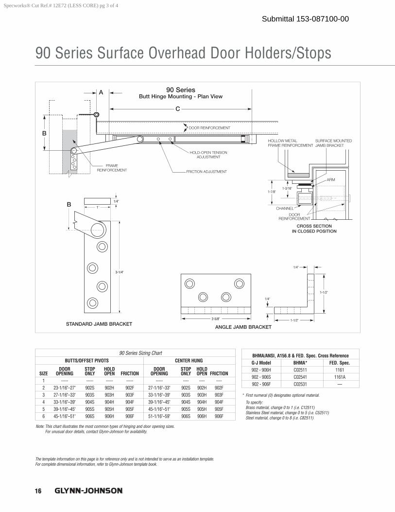
16
90 Series Surface Overhead Door Holders/Stops
The template information on this page is for reference only and is not intended to serve as an installation template. For complete dimensional information, refer to Glynn-Johnson template book.
1'
1/4"
3-1/4"
2-5/8"
1/4"
1-1/2"
1-1/2"
1/4"
1-7/8"1-3/16"
BUTTS/OFFSET PIVOTS CENTER HUNG
DOOR STOP HOLD DOOR STOP HOLDSIZE OPENING ONLY OPEN FRICTION OPENING ONLY OPEN FRICTION
1 ----- ----- ----- ----- ----- ---- ---- ----2 23-1/16"–27" 902S 902H 902F 27-1/16"–33" 902S 902H 902F3 27-1/16"–33" 903S 903H 903F 33-1/16"–39" 903S 903H 903F 4 33-1/16"–39" 904S 904H 904F 39-1/16"–45" 904S 904H 904F5 39-1/16"–45" 905S 905H 905F 45-1/16"–51" 905S 905H 905F6 45-1/16"–51" 906S 906H 906F 51-1/16"–59" 906S 906H 906F
90 Series Sizing Chart
* First numeral (0) designates optional material.
To specify: Brass material, change 0 to 1 (i.e. C12511)Stainless Steel material, change 0 to 5 (i.e. C52511)Steel material, change 0 to 8 (i.e. C82511)
Note: This chart illustrates the most common types of hinging and door opening sizes. For unusual door details, contact Glynn-Johnson for availability.
BHMA/ANSI, A156.8 & FED. Spec. Cross ReferenceG-J Model BHMA* FED. Spec.902 - 906H C02511 1161902 - 906S C02541 1161A902 - 906F C02531 —
Specworks® Cut Ref.# 12E72 (LESS CORE) pg 3 of 4
Submittal 153-087100-00
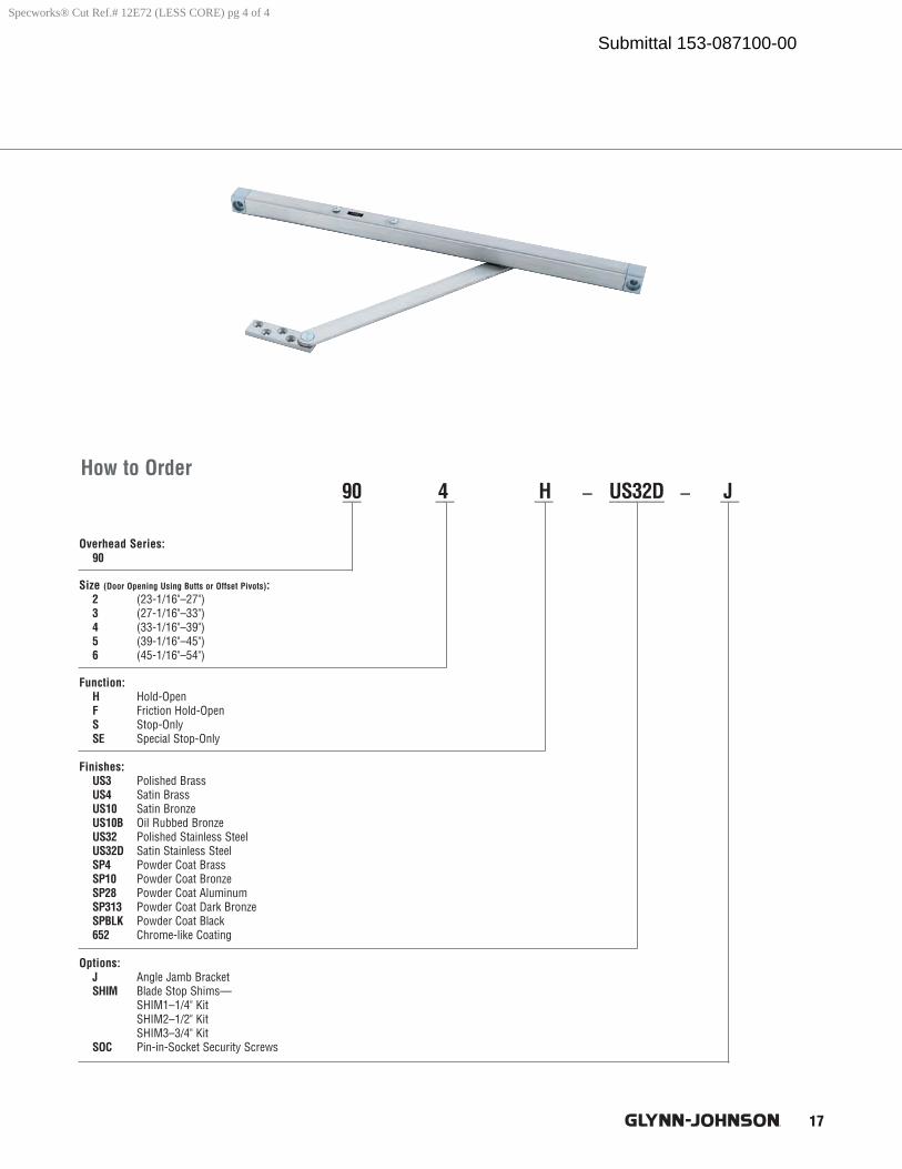
17
How to Order
Overhead Series:90
Size (Door Opening Using Butts or Offset Pivots):2 (23-1/16"–27")3 (27-1/16"–33")4 (33-1/16"–39")5 (39-1/16"–45")6 (45-1/16"–54")
Function:H Hold-OpenF Friction Hold-OpenS Stop-OnlySE Special Stop-Only
Finishes:US3 Polished BrassUS4 Satin BrassUS10 Satin BronzeUS10B Oil Rubbed BronzeUS32 Polished Stainless SteelUS32D Satin Stainless SteelSP4 Powder Coat BrassSP10 Powder Coat BronzeSP28 Powder Coat AluminumSP313 Powder Coat Dark BronzeSPBLK Powder Coat Black652 Chrome-like Coating
Options:J Angle Jamb BracketSHIM Blade Stop Shims—
SHIM1–1/4" KitSHIM2–1/2" KitSHIM3–3/4" Kit
SOC Pin-in-Socket Security Screws
__ __ __ – ______ – __90 4 H US32D J
Specworks® Cut Ref.# 12E72 (LESS CORE) pg 4 of 4
Submittal 153-087100-00
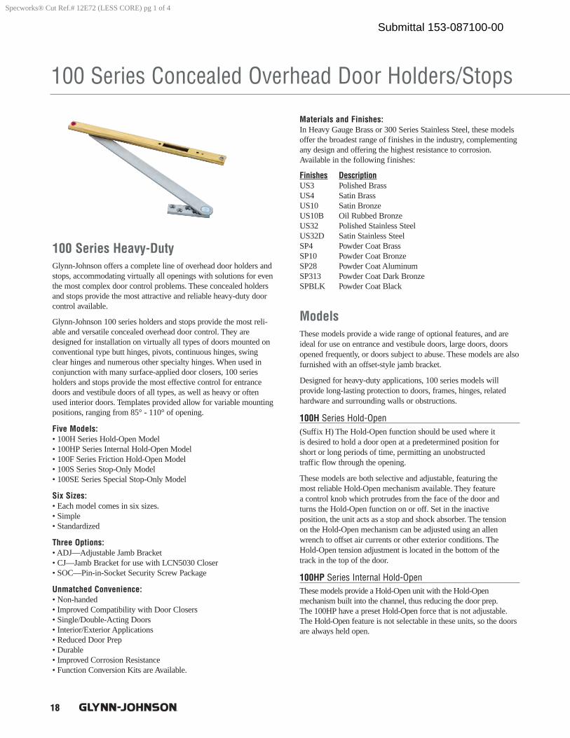
18
100 Series Concealed Overhead Door Holders/Stops
100 Series Heavy-DutyGlynn-Johnson offers a complete line of overhead door holders andstops, accommodating virtually all openings with solutions for eventhe most complex door control problems. These concealed holdersand stops provide the most attractive and reliable heavy-duty doorcontrol available.
Glynn-Johnson 100 series holders and stops provide the most reli-able and versatile concealed overhead door control. They aredesigned for installation on virtually all types of doors mounted onconventional type butt hinges, pivots, continuous hinges, swingclear hinges and numerous other specialty hinges. When used inconjunction with many surface-applied door closers, 100 seriesholders and stops provide the most effective control for entrancedoors and vestibule doors of all types, as well as heavy or oftenused interior doors. Templates provided allow for variable mountingpositions, ranging from 85° - 110° of opening.
Five Models: • 100H Series Hold-Open Model• 100HP Series Internal Hold-Open Model• 100F Series Friction Hold-Open Model• 100S Series Stop-Only Model• 100SE Series Special Stop-Only Model
Six Sizes:• Each model comes in six sizes.• Simple• Standardized
Three Options:• ADJ—Adjustable Jamb Bracket• CJ—Jamb Bracket for use with LCN5030 Closer• SOC—Pin-in-Socket Security Screw Package
Unmatched Convenience:• Non-handed• Improved Compatibility with Door Closers• Single/Double-Acting Doors• Interior/Exterior Applications• Reduced Door Prep• Durable• Improved Corrosion Resistance• Function Conversion Kits are Available.
Materials and Finishes:In Heavy Gauge Brass or 300 Series Stainless Steel, these modelsoffer the broadest range of finishes in the industry, complementingany design and offering the highest resistance to corrosion.Available in the following finishes:
Finishes DescriptionUS3 Polished BrassUS4 Satin BrassUS10 Satin BronzeUS10B Oil Rubbed BronzeUS32 Polished Stainless SteelUS32D Satin Stainless SteelSP4 Powder Coat BrassSP10 Powder Coat BronzeSP28 Powder Coat AluminumSP313 Powder Coat Dark BronzeSPBLK Powder Coat Black
ModelsThese models provide a wide range of optional features, and areideal for use on entrance and vestibule doors, large doors, doorsopened frequently, or doors subject to abuse. These models are alsofurnished with an offset-style jamb bracket.
Designed for heavy-duty applications, 100 series models will provide long-lasting protection to doors, frames, hinges, relatedhardware and surrounding walls or obstructions.
100H Series Hold-Open(Suffix H) The Hold-Open function should be used where it is desired to hold a door open at a predetermined position for short or long periods of time, permitting an unobstructed traffic flow through the opening.
These models are both selective and adjustable, featuring the most reliable Hold-Open mechanism available. They feature a control knob which protrudes from the face of the door and turns the Hold-Open function on or off. Set in the inactive position, the unit acts as a stop and shock absorber. The tension on the Hold-Open mechanism can be adjusted using an allenwrench to offset air currents or other exterior conditions. TheHold-Open tension adjustment is located in the bottom of the track in the top of the door.
100HP Series Internal Hold-OpenThese models provide a Hold-Open unit with the Hold-Open mechanism built into the channel, thus reducing the door prep. The 100HP have a preset Hold-Open force that is not adjustable. The Hold-Open feature is not selectable in these units, so the doorsare always held open.
Specworks® Cut Ref.# 12E72 (LESS CORE) pg 1 of 4
Submittal 153-087100-00
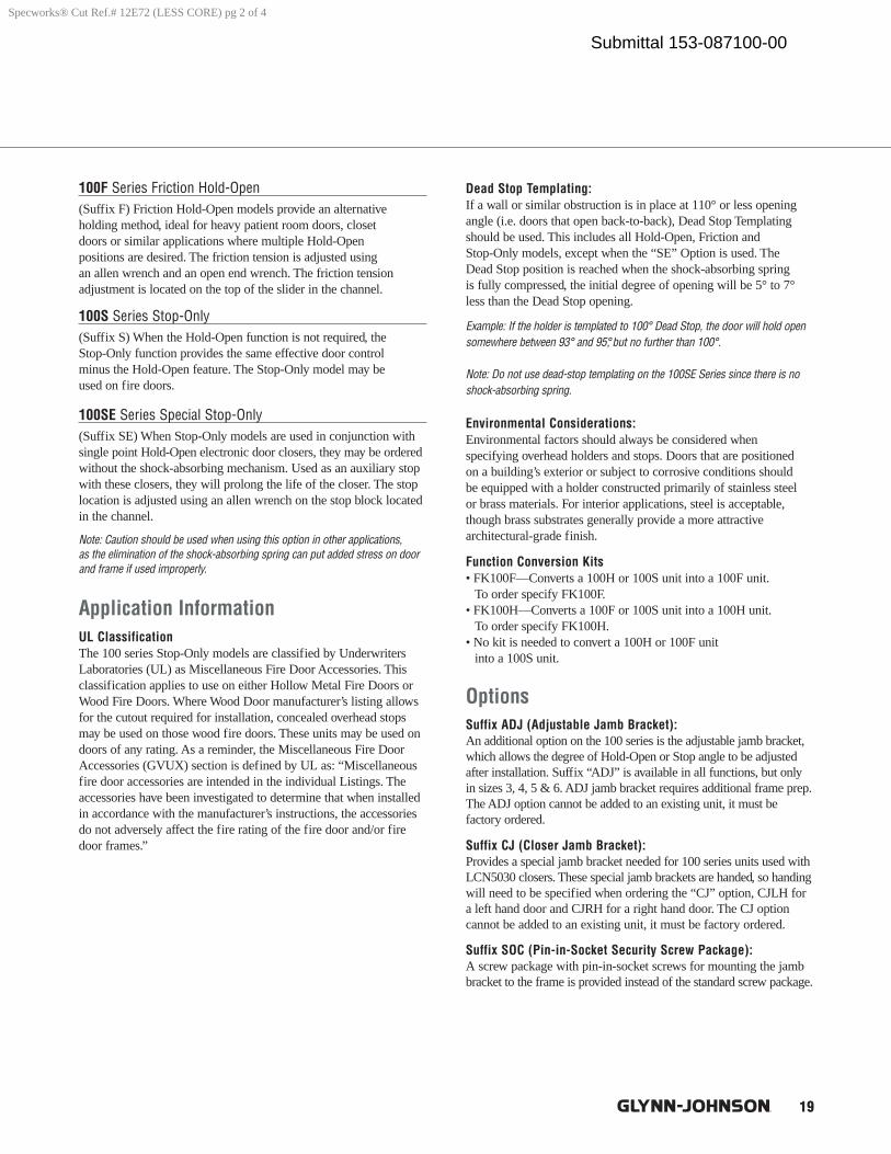
19
100F Series Friction Hold-Open (Suffix F) Friction Hold-Open models provide an alternative holding method, ideal for heavy patient room doors, closet doors or similar applications where multiple Hold-Open positions are desired. The friction tension is adjusted using an allen wrench and an open end wrench. The friction tension adjustment is located on the top of the slider in the channel.
100S Series Stop-Only(Suffix S) When the Hold-Open function is not required, the Stop-Only function provides the same effective door control minus the Hold-Open feature. The Stop-Only model may be used on fire doors.
100SE Series Special Stop-Only(Suffix SE) When Stop-Only models are used in conjunction withsingle point Hold-Open electronic door closers, they may be orderedwithout the shock-absorbing mechanism. Used as an auxiliary stopwith these closers, they will prolong the life of the closer. The stoplocation is adjusted using an allen wrench on the stop block locatedin the channel.
Note: Caution should be used when using this option in other applications, as the elimination of the shock-absorbing spring can put added stress on doorand frame if used improperly.
Application InformationUL ClassificationThe 100 series Stop-Only models are classified by UnderwritersLaboratories (UL) as Miscellaneous Fire Door Accessories. Thisclassification applies to use on either Hollow Metal Fire Doors orWood Fire Doors. Where Wood Door manufacturer’s listing allowsfor the cutout required for installation, concealed overhead stopsmay be used on those wood fire doors. These units may be used ondoors of any rating. As a reminder, the Miscellaneous Fire DoorAccessories (GVUX) section is defined by UL as: “Miscellaneousfire door accessories are intended in the individual Listings. Theaccessories have been investigated to determine that when installedin accordance with the manufacturer’s instructions, the accessoriesdo not adversely affect the fire rating of the fire door and/or firedoor frames.”
Dead Stop Templating: If a wall or similar obstruction is in place at 110° or less openingangle (i.e. doors that open back-to-back), Dead Stop Templatingshould be used. This includes all Hold-Open, Friction and Stop-Only models, except when the “SE” Option is used. The Dead Stop position is reached when the shock-absorbing spring is fully compressed, the initial degree of opening will be 5° to 7°less than the Dead Stop opening.
Example: If the holder is templated to 100° Dead Stop, the door will hold opensomewhere between 93° and 95°, but no further than 100°.
Note: Do not use dead-stop templating on the 100SE Series since there is noshock-absorbing spring.
Environmental Considerations:Environmental factors should always be considered when specifying overhead holders and stops. Doors that are positioned on a building’s exterior or subject to corrosive conditions should be equipped with a holder constructed primarily of stainless steel or brass materials. For interior applications, steel is acceptable,though brass substrates generally provide a more attractive architectural-grade finish.
Function Conversion Kits• FK100F—Converts a 100H or 100S unit into a 100F unit.
To order specify FK100F.• FK100H—Converts a 100F or 100S unit into a 100H unit.
To order specify FK100H.• No kit is needed to convert a 100H or 100F unit
into a 100S unit.
OptionsSuffix ADJ (Adjustable Jamb Bracket):An additional option on the 100 series is the adjustable jamb bracket,which allows the degree of Hold-Open or Stop angle to be adjustedafter installation. Suffix “ADJ” is available in all functions, but onlyin sizes 3, 4, 5 & 6. ADJ jamb bracket requires additional frame prep.The ADJ option cannot be added to an existing unit, it must be factory ordered.
Suffix CJ (Closer Jamb Bracket):Provides a special jamb bracket needed for 100 series units used withLCN5030 closers. These special jamb brackets are handed, so handingwill need to be specified when ordering the “CJ” option, CJLH fora left hand door and CJRH for a right hand door. The CJ optioncannot be added to an existing unit, it must be factory ordered.
Suffix SOC (Pin-in-Socket Security Screw Package):A screw package with pin-in-socket screws for mounting the jambbracket to the frame is provided instead of the standard screw package.
Specworks® Cut Ref.# 12E72 (LESS CORE) pg 2 of 4
Submittal 153-087100-00
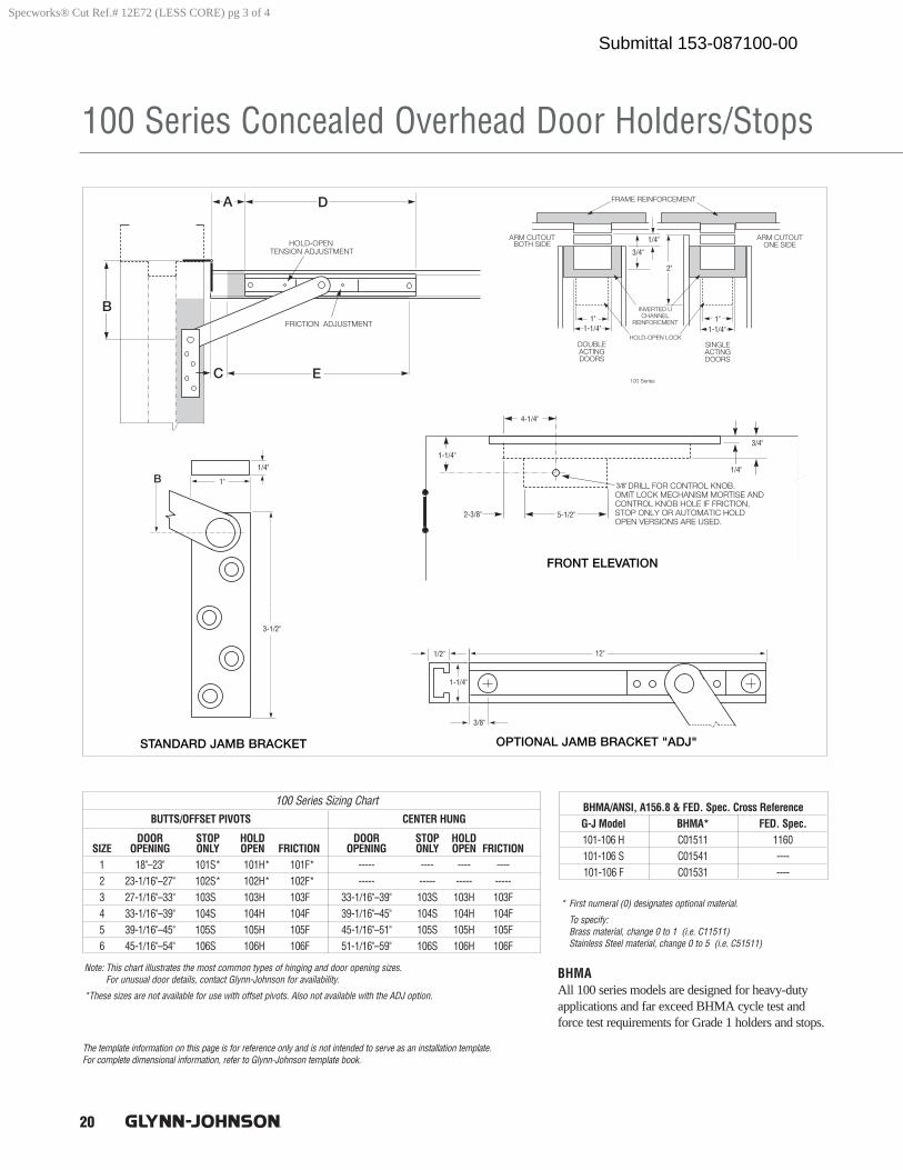
20
100 Series Concealed Overhead Door Holders/Stops
The template information on this page is for reference only and is not intended to serve as an installation template. For complete dimensional information, refer to Glynn-Johnson template book.
1-1/4"1"
1/4"
1-1/4"1"
2"
3/4"
3/8"
4-1/4"
1-1/4"
2-3/8" 5-1/2"
1/4"
3/4"
1"
1/4"
3-1/2"
1-1/4"
1/2"
3/8"
12"
BUTTS/OFFSET PIVOTS CENTER HUNG
DOOR STOP HOLD DOOR STOP HOLDSIZE OPENING ONLY OPEN FRICTION OPENING ONLY OPEN FRICTION
1 18"–23" 101S* 101H* 101F* ----- ---- ---- ----2 23-1/16"–27" 102S* 102H* 102F* ----- ----- ----- -----3 27-1/16"–33" 103S 103H 103F 33-1/16"–39" 103S 103H 103F 4 33-1/16"–39" 104S 104H 104F 39-1/16"–45" 104S 104H 104F5 39-1/16"–45" 105S 105H 105F 45-1/16"–51" 105S 105H 105F6 45-1/16"–54" 106S 106H 106F 51-1/16"–59" 106S 106H 106F
100 Series Sizing Chart
* First numeral (0) designates optional material.
To specify: Brass material, change 0 to 1 (i.e. C11511)Stainless Steel material, change 0 to 5 (i.e. C51511)
Note: This chart illustrates the most common types of hinging and door opening sizes. For unusual door details, contact Glynn-Johnson for availability.
*These sizes are not available for use with offset pivots. Also not available with the ADJ option.
BHMAAll 100 series models are designed for heavy-dutyapplications and far exceed BHMA cycle test andforce test requirements for Grade 1 holders and stops.
BHMA/ANSI, A156.8 & FED. Spec. Cross ReferenceG-J Model BHMA* FED. Spec.101-106 H C01511 1160101-106 S C01541 ----101-106 F C01531 ----
Specworks® Cut Ref.# 12E72 (LESS CORE) pg 3 of 4
Submittal 153-087100-00
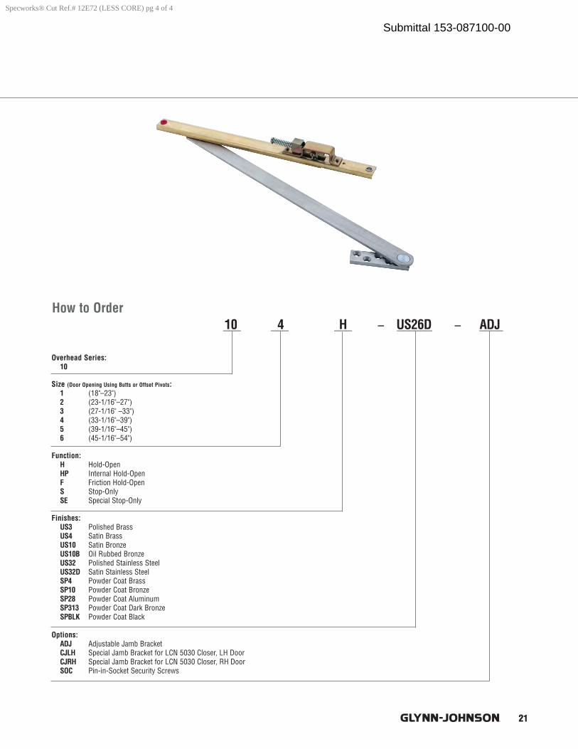
21
How to Order
Overhead Series:10
Size (Door Opening Using Butts or Offset Pivots:1 (18"–23")2 (23-1/16"–27")3 (27-1/16" –33")4 (33-1/16"–39")5 (39-1/16"–45")6 (45-1/16"–54")
Function:H Hold-OpenHP Internal Hold-OpenF Friction Hold-OpenS Stop-OnlySE Special Stop-Only
Finishes:US3 Polished BrassUS4 Satin BrassUS10 Satin BronzeUS10B Oil Rubbed BronzeUS32 Polished Stainless SteelUS32D Satin Stainless SteelSP4 Powder Coat BrassSP10 Powder Coat BronzeSP28 Powder Coat AluminumSP313 Powder Coat Dark BronzeSPBLK Powder Coat Black
Options:ADJ Adjustable Jamb BracketCJLH Special Jamb Bracket for LCN 5030 Closer, LH DoorCJRH Special Jamb Bracket for LCN 5030 Closer, RH DoorSOC Pin-in-Socket Security Screws
___ ___ ___ – ______ – ____10 4 H US26D ADJ
Specworks® Cut Ref.# 12E72 (LESS CORE) pg 4 of 4
Submittal 153-087100-00
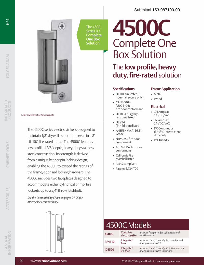
The 4500C series electric strike is designed to
maintain 1/2" drywall penetration even in a 2"
UL 10C fire-rated frame. The 4500C features a
low profile 1-3/8" depth, heavy-duty stainless
steel construction. Its strength is derived
from a unique keeper pin locking design,
enabling the 4500C to exceed the ratings of
the frame, door and locking hardware. The
4500C includes two faceplates designed to
accommodate either cylindrical or mortise
locksets up to a 3/4" throw latchbolt.
See the Compatibility Chart on pages 94-95 for mortise lock compatibility.
Shown with mortise lock faceplate
Specifications• UL 10C fire-rated, 3
hour (fail secure only)• CAN4-S104
(ULC-S104) fire door conformant
• UL 1034 burglary-resistant listed
• UL 294 (6th Edition) listed
• ANSI/BHMA A156.31, Grade 1
• NFPA-252 fire door conformant
• ASTM-E152 fire door conformant
• California Fire Marshall listed
• RoHS compliant• Patent: 5,934,720
Frame Application• Metal • Wood
Electrical• .24 Amps at
12 VDC/VAC• .12 Amps at
24 VDC/VAC• DC Continuous
duty/AC intermittent duty only
• PoE friendly
4500C Complete One Box SolutionThe low profile, heavy duty, fire-rated solution
The 4500 Series is a Complete One Box Solution
4500C Complete electric strike
Includes faceplates for cylindrical and mortise locks
RF4510 Integrated Prox
Includes the strike body, Prox reader and door position switch
IC4520 Integrated iCLASS®
Includes the strike body, iCLASS reader and door position switch in the box
4500C Models
20 www.hesinnovations.com ASSA ABLOY, the global leader in door opening solutions
INTE
GRA
TED
PR
OD
UCT
SCA
BIN
ET L
OCK
SAC
CESS
ORI
ESG
ENER
AL
INFO
RMAT
ION
FOLG
ER A
DA
MH
ESG
ENER
AL
INFO
RMAT
ION
ACCE
SSO
RIES
CABI
NET
LO
CKS
INTE
GRA
TED
PR
OD
UCT
SFO
LGER
AD
AM
HES
Submittal 153-087100-00
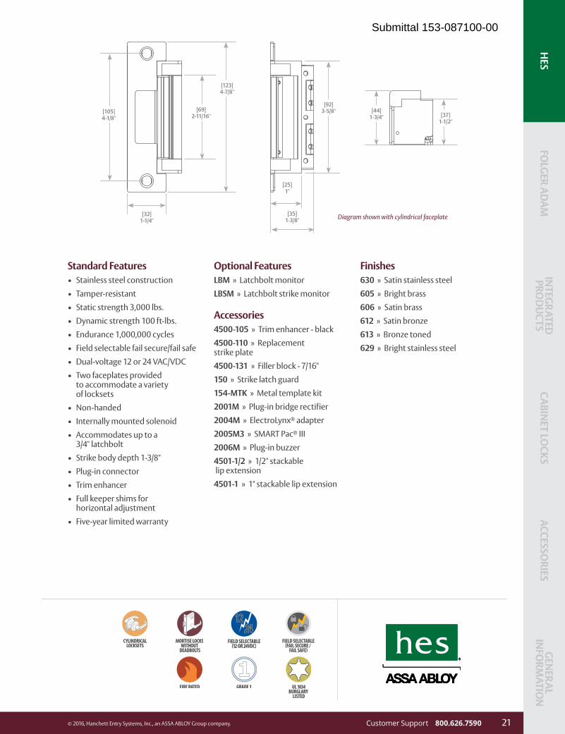
INTEG
RATED
PROD
UCTS
CABINET LO
CKSACCESSO
RIESG
ENERAL
INFO
RMATIO
NFO
LGER AD
AM
HES
Standard Features• Stainless steel construction• Tamper-resistant• Static strength 3,000 lbs.• Dynamic strength 100 ft-lbs.• Endurance 1,000,000 cycles• Field selectable fail secure/fail safe• Dual-voltage 12 or 24 VAC/VDC• Two faceplates provided
to accommodate a variety of locksets
• Non-handed• Internally mounted solenoid• Accommodates up to a
3/4" latchbolt• Strike body depth 1-3/8"• Plug-in connector• Trim enhancer• Full keeper shims for
horizontal adjustment• Five-year limited warranty
Optional FeaturesLBM » Latchbolt monitorLBSM » Latchbolt strike monitor
Accessories4500-105 » Trim enhancer - black4500-110 » Replacement strike plate4500-131 » Filler block - 7/16"150 » Strike latch guard154-MTK » Metal template kit2001M » Plug-in bridge rectifier2004M » ElectroLynx® adapter2005M3 » SMART Pac® III2006M » Plug-in buzzer4501-1/2 » 1/2" stackable lip extension4501-1 » 1" stackable lip extension
Finishes630 » Satin stainless steel605 » Bright brass606 » Satin brass612 » Satin bronze613 » Bronze toned629 » Bright stainless steel
Diagram shown with cylindrical faceplate[32]1-1/4"
[123]4-7/8"
[69]2-11/16"
[105]4-1/8"
[25]1"
[92]3-5/8"
[35]1-3/8"
[44]1-3/4" [37]
1-1/2"
Customer Support 800.626.7590 21© 2016, Hanchett Entry Systems, Inc., an ASSA ABLOY Group company.
FOLG
ER ADA
MIN
TEGRATED
PRO
DU
CTSCABIN
ET LOCKS
ACCESSORIES
GEN
ERAL IN
FORM
ATION
HES
Submittal 153-087100-00

Ives Architectural XY Series hinges16
Aluminum Geared Hinges
Options: Optional Mounting Hardware:HT Hospital Tip SEC/HM Security Screws - Hollow
Metal Door and FrameEPT Electric Power Transfer SEC/WD/HM Security Screws - 1/2
Wood, 1/2 Hollow Metal TWP CON* Through Wire Panel with
Allegion ConnectTF Thread Forming Screws
TWP* Electrical Through Wire Panel TEK/WD 1/2 Self Drill, Self Tap 1/2 Wood
TW8 Electrical Through Wire WD Wood Door and Frame
*TWP only available on lengths <= 95"
112HD Full Mortise - Narrow Frame and Door Leaf
UL10C certified Meets ANSI 156 .26 for 150lbs
• For 1 3/4" Doors• Spread bearing design• Non Handed for custom cut lengths• Flush Mounted, No inset• 48" Maximum Door Width• Beveled or Square Edge Doors• For doors weighing up to 450 pounds without reinforcing, 600 pounds
with reinforcing
Standard lengths 83", 85", 95", 120"
Standard Mounting Hardware12-24 x 3/4" Steel Self Drilling / Self Tapping Phillips Head Screw
FinishesClear Anodized (US28), Dark Bronze Anodized (313AN)Custom Anodizing and Painting are available, consult factory
1 9/16"
2 9/32"
Bevel Edge
5/16" Clearance for Square Edge Door11/32" Clearance for Beveled Edge Door
For Single Door ApplicationsFor pairs of doors see chart and general informationHospital tip recommended for retrofit only
Specworks® Cut Ref.# 12E72 (LESS CORE) pg 1 of 1
Submittal 153-087100-00
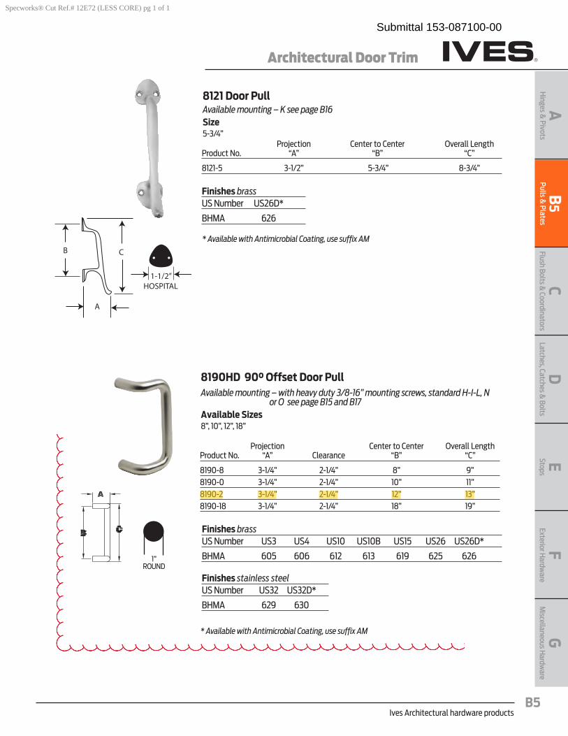
Ives Architectural hardware productsB5
Architectural Door Trim
B5
Pulls & Plates
AH
inges & Pivots
CFlush Bolts &
CoordinatorsD
Latches, Catches & Bolts
EStopsF
Exterior Hardw
areG
Miscellaneous H
ardware
8121 Door PullAvailable mounting – K see page B16 Size5-3/4” Projection Center to Center Overall Length Product No . “A” “B” “C”
8121-5 3-1/2” 5-3/4” 8-3/4”
C
A
1-1/2”HOSPITAL
B
8190HD 90° Offset Door PullAvailable mounting – with heavy duty 3/8-16” mounting screws, standard H-I-L, N
or O see page B15 and B17Available Sizes8”, 10”, 12”, 18”
Projection Center to Center Overall Length Product No . “A” Clearance “B” “C”
8190-8 3-1/4” 2-1/4” 8” 9”8190-0 3-1/4” 2-1/4” 10” 11”8190-2 3-1/4” 2-1/4” 12” 13”8190-18 3-1/4” 2-1/4” 18” 19”
Finishes brassUS Number US3 US4 US10 US10B US15 US26 US26D*
BHMA 605 606 612 613 619 625 626
Finishes stainless steelUS Number US32 US32D*
BHMA 629 630
Finishes brassUS Number US26D*
BHMA 626
* Available with Antimicrobial Coating, use suffix AM
* Available with Antimicrobial Coating, use suffix AM
1”ROUND
Specworks® Cut Ref.# 12E72 (LESS CORE) pg 1 of 1
Submittal 153-087100-00

Ives Architectural hardware productsB17
Architectural Door Trim
B17
Pulls & Plates
AH
inges & Pivots
CFlush Bolts &
CoordinatorsD
Latches, Catches & Bolts
EStopsF
Exterior Hardw
areG
Miscellaneous H
ardware
Type NS-Standard Push/Pull Mounting Type N & Standard
Pushbar to Pull - (1) 3/8 - 16 X 3”steel countersunk trim head machine screws
with (2) set screws.- (1) steel screw sleeve, zinc plated.
Free End Pushbar & Pull - (2) 3/8 - 16 X 2-1/4” brass, oval head mach screws;
plated to match.- (2) No. 14 countersunk washers; plated to match.
Type NO Push/Pull Mounting Type N & Type O
Pushbar to Pull - (1) 3/8 -16 X 3”steel countersunk trim head machine screws
with (2) set screws.- (1) steel screw sleeve, zinc plated.
Free End Pushbar & Pull - (2) 3/8 - 16 X 2-1/4” blind thru-bolts; plated to match.
Mounting for 8103EZ, 8190, 9100, 9103EZ, 9190 and 9264, 9265, 9266 and 9267 long door pulls.
Type J/N Mount Type O Mount
Type P Mount
(push) (pull)
Back to Back “Two-Anchor” Wood or Metal Door
Available only for 8103EZHD, 8190HD, 9100HD push/pull combinations and 9264, 9265, 9266 and 9267 long door pulls.
with (4) set screws for maximum anchoring force.
Decorative Blind Thru - Bolt Wood or Metal Door
Available only for 8103EZHD, 8190HD and 9100HD Series Push/Pull Combinations.
1/2” Glass DoorAvailable only for 8103EZHD, 8190HD, 9100HD, 9265 and 9266 long door pulls.
with (4) set screws for maximum anchoring force.
Submittal 153-087100-00

Ives Architectural hardware productsB9
Architectural Door Trim
B9
Pulls & Plates
AH
inges & Pivots
CFlush Bolts &
CoordinatorsD
Latches, Catches & Bolts
EStopsF
Exterior Hardw
areG
Miscellaneous H
ardware
Finishes brassUS Number US3 US4 US10 US10B US15 US26 US26D*
BHMA 605 606 612 613 619 625 626
Finishes stainless steelUS Number US32 US32D*
BHMA 629 630
9103EzHD Straight Pull/Pushbar Combo (8103EZHD Pull + 9100HD Push)Available mounting – NO or NS see page B17 with heavy duty 3/8-16” mounting
Projection Product No . CTC Push CTC Pull Push & Pull
9103EZ 28”, 33” 8” 2-1/2” & 3-1/2”9103EZ 28”, 33” 10” 2-1/2” & 3-1/2”9103EZ 28”, 33” 12” 2-1/2” & 3-1/2”
9190HD Offset Pull/Pushbar Combo (8190HD pull + 9100HD push)Available mounting – NO or NS see page B17with heavy duty 3/8-16” mounting
Projection Product No . CTC Push CTC Pull Push & Pull
9190 28”, 33” 8” 2-1/2” & 3-1/4”9190 28”, 33” 10” 2-1/2” & 3-1/4”9190 28”, 33” 12” 2-1/2” & 3-1/4”9190 28”, 33” 18” 2-1/2” & 3-1/4”
Finishes brassUS Number US3 US4 US10 US10B US15 US26 US26D*
BHMA 605 606 612 613 619 625 626
Finishes stainless steelUS Number US32 US32D*
BHMA 629 630
* Available with Antimicrobial Coating, use suffix AM
Special lengths available, consult factory
* Available with Antimicrobial Coating, use suffix AM
Special lengths available, consult factory
1”ROUND
1”ROUND
Specworks® Cut Ref.# 12E72 (LESS CORE) pg 1 of 1
Submittal 153-087100-00

Ives Architectural hardware productsB14
Protection Plates
B14
Pulls
& P
late
sA
Hin
ges
& P
ivot
sC
Flus
h Bo
lts &
Coo
rdin
ator
sD
Latc
hes,
Cat
ches
& B
olts
E Stop
sF
Exte
rior H
ardw
are
GM
isce
llane
ous H
ardw
are
8400 Series Protection Plates • Doorprotectionplatesareavailablein.050”thickbrass,stainless
steel or aluminum; and 1/8” thick high impact polyethylene in clear or black .
• Beveledgeoptions;specifyB4Eforallfouredges. • Mountingscrewpackfurnishedstandard,16screwsperpack.
Optional screw packs are available for TEK or TORK screw heads . Refer to the following chart for ordering .
• SpecifyNMHfornomountingholes.(Notavailableon8402) • SpecifyNMH-Afornomountingholeswithadhesive.(Notavailableon8402) • SpecifyCSforcountersunkmountingholes. • SpecifyERSpreppedwithextrarowofscrews. Kickplate Gasket Tape Tape is recommended when using a
brass plate on a metal door to reduce tarnishing from electrolytic oxidation . One tape pack will cover an the perimeters of a 8” x 34” kickplate . Order 8401 Gasket Tape .
8400 Protection Plate8402 (UL)* Protection Plate*UL mark appears in upper right corner. Factory supplied screws must be used.Number of screw packs required by plate size (specify TEK Screws or TORK screws) .
22”-25” 26”-33” 34”-41” 42”-48”4”-8” 1 1 1 19”-16” 1 1 1 117”-24” 1 1 1 225”-32” 1 1 2 233”-40” 1 2 2 241”-48” 2 2 2 2
Finishes brass 24” x 48” max. sizeUS Number US3 US4 US10 US10B US15 US26 US26D
BHMA 605 606 612 613 619 625 626
Finishes stainless steelUS Number US32 US32D
BHMA 629 630
Finishes aluminumUS Number US28
BHMA 628
Finishes plasticClear and Black
Residential Grade Kickplates available Carded only, finishes PA28, PA3, PA619, PA716, B3, B505, B619, B716
Specworks® Cut Ref.# 12E72 (LESS CORE) pg 1 of 1
Submittal 153-087100-00
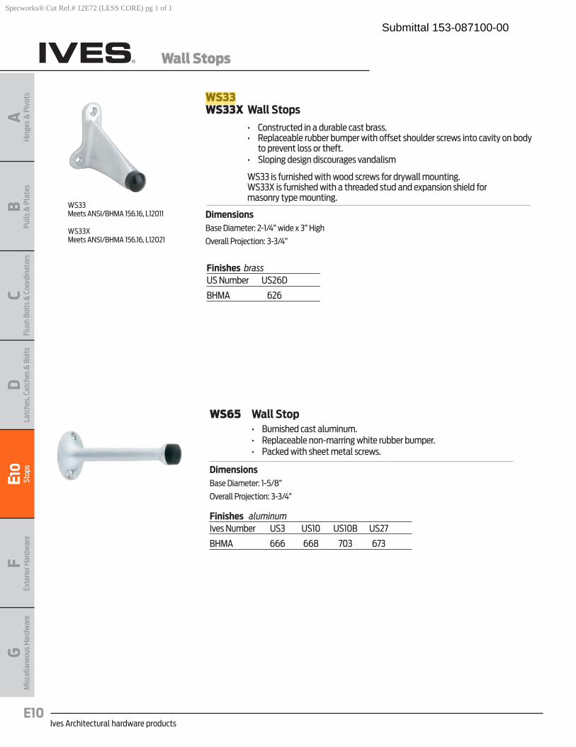
Ives Architectural hardware productsE10
Wall Stops
BPu
lls &
Pla
tes
AH
inge
s &
Piv
ots
CFl
ush
Bolt
s & C
oord
inat
ors
DLa
tche
s, C
atch
es &
Bol
tsE1
0St
ops
FEx
terio
r Har
dwar
eG
Mis
cella
neou
s Har
dwar
e
WS33WS33X Wall Stops
• Constructedinadurablecastbrass. • Replaceablerubberbumperwithoffsetshoulderscrewsintocavityonbody
to prevent loss or theft . • Slopingdesigndiscouragesvandalism
WS33 is furnished with wood screws for drywall mounting . WS33X is furnished with a threaded stud and expansion shield for
masonry type mounting .
DimensionsBase Diameter: 2-1/4” wide x 3” High
Overall Projection: 3-3/4”
Finishes brassUS Number US26D
BHMA 626
WS33Meets ANSI/BHMA 156 .16, L12011
WS33X Meets ANSI/BHMA 156 .16, L12021
WS65 Wall Stop • Burnishedcastaluminum. • Replaceablenon-marringwhiterubberbumper. • Packedwithsheetmetalscrews.
DimensionsBase Diameter: 1-5/8”
Overall Projection: 3-3/4”
Finishes aluminumIves Number US3 US10 US10B US27
BHMA 666 668 703 673
Specworks® Cut Ref.# 12E72 (LESS CORE) pg 1 of 1
Submittal 153-087100-00
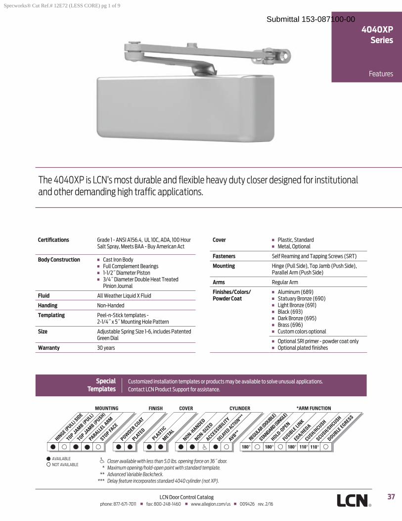
37LCN Door Control Catalogphone: 877-671-7011 fax: 800-248-1460 www.allegion.com/us 009426 rev. 2/16
AVAILABLE NOT AVAILABLE
Features
4040XPSeries
The 4040XP is LCN’s most durable and flexible heavy duty closer designed for institutional and other demanding high traffic applications.
Certifications Grade 1 - ANSI A156.4, UL 10C, ADA, 100 Hour Salt Spray, Meets BAA - Buy American Act
Body Construction Cast Iron Body Full Complement Bearings
Fluid
Handing Non-Handed
Templating
SizeGreen Dial
Warranty 30 years
Cover Metal, Optional
Fasteners
Mounting
Arms Regular Arm
Finishes/Colors/ Powder Coat
Custom colors optional
Optional plated finishes
Special Templates
PLASTIC
METAL
HINGE (P
ULL) SIDE
TOP JAMB (PULL
)
TOP JAMB (PUSH)
PARALLEL A
RM
STOP FACE
MOUNTING COVER
180° 180° 180° 110°110°STA
NDARD (SINGLE)
REGULA
R (DOUBLE)
HOLD-O
PEN
FUSIB
LE LI
NK
EDA/HEDA
CUSH/HCUSH
SCUSH/SHCUSH
DOUBLE EGRESS
*ARM FUNCTIONFINISH CYLINDER
NON-HANDED
NON-SIZED
ACCESSIBILI
TY
DELAYED ACTION***
AVB**POW
DER COAT
PLATED
Specworks® Cut Ref.# 12E72 (LESS CORE) pg 1 of 9
Submittal 153-087100-00
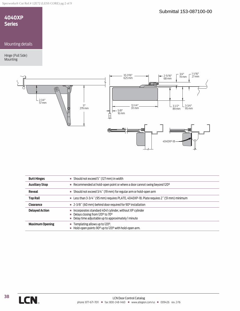
38 LCN Door Control Catalogphone: 877-671-7011 fax: 800-248-1460 www.allegion.com/us 009426 rev. 2/16
2-1/4"57 mm
11"279 mm
1-1/16"27 mm
3/4"19 mm2-11/16"
68 mm10-7/16"625 mm
5/8"16 mm
12-1/4"311 mm
3-1/2"89 mm
3-3/4"95 mm
4040XP-18
Hinge (Pull Side) Mounting
Mounting details
4040XPSeries
Butt Hinges
Auxiliary Stop
Reveal
Top Rail
Clearance
Delayed Action
Maximum Opening
Specworks® Cut Ref.# 12E72 (LESS CORE) pg 2 of 9
Submittal 153-087100-00
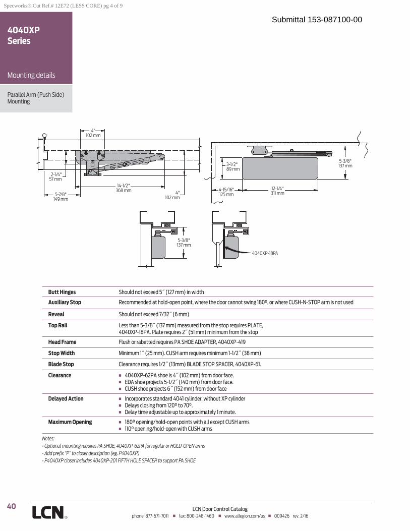
40 LCN Door Control Catalogphone: 877-671-7011 fax: 800-248-1460 www.allegion.com/us 009426 rev. 2/16
2-1/4"57 mm
4"102 mm
4"102 mm
5-7/8"149 mm
5-3/8"137 mm
12-1/4"311 mm
3-1/2"89 mm
4-15/16"125 mm
5-3/8"137 mm
4040XP-18PA
14-1/2"368 mm
Parallel Arm (Push Side)Mounting
Mounting details
4040XPSeries
Butt Hinges
Auxiliary Stop
Reveal
Top Rail
Head Frame
Stop Width
Blade Stop
Clearance
Delayed Action
Maximum Opening
Notes:
Specworks® Cut Ref.# 12E72 (LESS CORE) pg 4 of 9
Submittal 153-087100-00

41LCN Door Control Catalogphone: 877-671-7011 fax: 800-248-1460 www.allegion.com/us 009426 rev. 2/16
Mounting details
4040XPSeries
EDA and CUSH Mounting
Clearance
Head Frame
CUSH ARM
Delayed Action
Maximum Opening
Notes:
CUSH mount
EDA mount
AB
4"102 mm
14-1/16"357 mm
3-1/2"89 mm
12-1/4"311 mm
4040XP-18PA
2-1/4"57 mm
5-1/4"133 mm
5-1/4"133 mm
AB
4"102 mm
5-1/2"140 mm
14-1/16"357 mm
3-1/2"89 mm
12-1/4"311 mm
4040XP-18PA
2-1/4"57 mm
6"152 mm
5-1/4"133 mm
Specworks® Cut Ref.# 12E72 (LESS CORE) pg 5 of 9
Submittal 153-087100-00
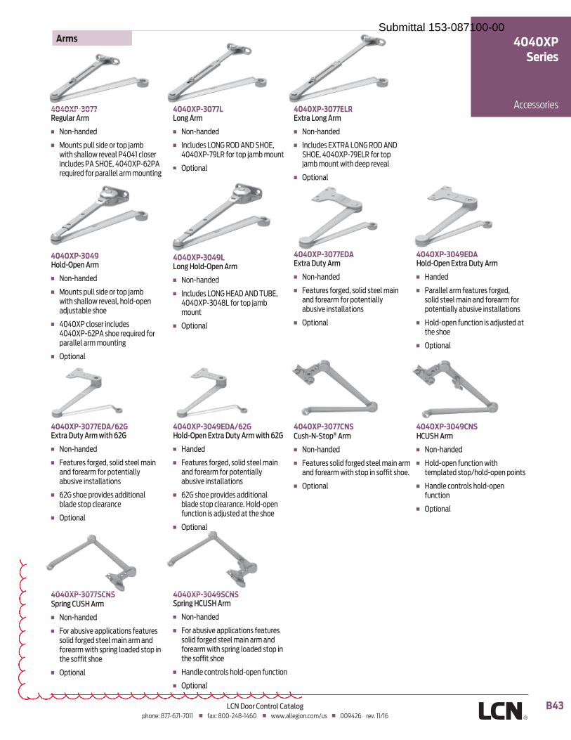
B43LCN Door Control Catalogphone: 877-671-7011 fax: 800-248-1460 www.allegion.com/us 009426 rev. 11/16
4040XP-3077Regular Arm
Non-handed
4040XP-3077ELRExtra Long Arm
Non-handed
Optional
4040XP-3049Hold-Open Arm
Non-handed
parallel arm mounting
Optional
4040XP-3077L Long Arm
Non-handed
Optional
4040XP-3049EDA/62GHold-Open Extra Duty Arm with 62G
Handed
Features forged, solid steel main and forearm for potentially
function is adjusted at the shoe
Optional
4040XP-3049SCNSSpring HCUSH Arm
Non-handed
solid forged steel main arm and
the soffit shoe
Handle controls hold-open function
Optional
4040XP-3077CNSCush-N-Stop® Arm
Non-handed
Features solid forged steel main arm
Optional
4040XP-3049CNSHCUSH Arm
Non-handed
templated stop/hold-open points
Handle controls hold-open function
Optional
4040XP-3049LLong Hold-Open Arm
Non-handed
mount
Optional
4040XP-3077EDAExtra Duty Arm
Non-handed
Features forged, solid steel main and forearm for potentially
Optional
4040XP-3049EDAHold-Open Extra Duty Arm
Handed
solid steel main and forearm for
Hold-open function is adjusted at the shoe
Optional
4040XP-3077EDA/62GExtra Duty Arm with 62G
Non-handed
Features forged, solid steel main and forearm for potentially
Optional
4040XP-3077SCNSSpring CUSH Arm
Non-handed
solid forged steel main arm and
the soffit shoe
Optional
Arms
Accessories
4040XP Series
4040XP-3077 4040XP-3077L 4040XP-3077ELR
Optional
4040XP 3077SCNS 4040XP 3049SCNS
4040XP 3077EDA 4040XP 3049EDA
Submittal 153-087100-00

42 LCN Door Control Catalogphone: 877-671-7011 fax: 800-248-1460 www.allegion.com/us 009426 rev. 2/16
4040XP-3071 Cast Iron Cylinder Assembly
Non-handed
4041-3071 DELCast Iron Cylinder Assembly
Used for delayed action closing
Non-handed
4040XP-72Plastic Cover
Non-handed
Standard
4040XP-72MCMetal Cover
Handed
Optional
4040XP-18Plate
4040XP-18GPlate
frame face in flush ceiling condition
minimum head frame
4040XP-18TJPlate
minimum head frame
4040XP-18PAPlate
measured from the stop
top rail
Cylinders
Installation Accessories
Covers
Accessories
4040XPSeries
4040XP-62PAPA Shoe
mounting
4040XP-18PAPlate
4040XP 72
Specworks® Cut Ref.# 12E72 (LESS CORE) pg 6 of 9
Submittal 153-087100-00

44 LCN Door Control Catalogphone: 877-671-7011 fax: 800-248-1460 www.allegion.com/us 009426 rev. 2/16
4040XP-30CUSH Shoe Support
Optional
4040XP-54Snap-On Cover Clip
4040XP-61Blade Stop Spacer
Optional
4040XP-419PA Flush Panel Adapter
surface for parallel arm shoe on
Optional
4040XP-62AAuxiliary Shoe
parallel arm mounting of
holder/stop
Optional
Installation Accessories cont.
Accessories
4040XPSeries
4040XP 61
Specworks® Cut Ref.# 12E72 (LESS CORE) pg 8 of 9
Submittal 153-087100-00
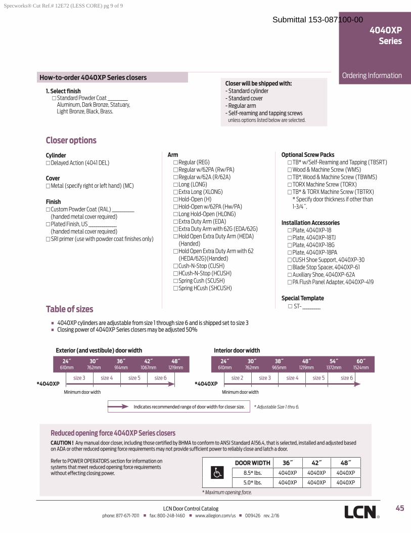
45LCN Door Control Catalogphone: 877-671-7011 fax: 800-248-1460 www.allegion.com/us 009426 rev. 2/16
Table of sizes
Ordering Information
4040XP Series
Closer will be shipped with: - Standard cylinder
- Regular arm
unless options listed below are selected.
1. Select finish Standard Powder Coat __________
Aluminum, Dark Bronze, Statuary, Light Bronze, Black, Brass.
Reduced opening force 4040XP Series closersCAUTION !
How-to-order 4040XP Series closers
* Maximum opening force.
*4040XP *4040XP
Exterior (and vestibule) door width
610mm
Interior door width
610mm 1524mm
Closer options
Cylinder Delayed Action (4041 DEL)
Cover Metal (specify right or left hand) (MC)
Finish Custom Powder Coat (RAL) ___________
(handed metal cover required) Plated Finish, US ______________
(handed metal cover required) SRI primer (use with powder coat finishes only)
Arm Regular (REG) Regular w/62PA (Rw/PA) Regular w/62A (R/62A) Long (LONG) Extra Long (XLONG) Hold-Open (H) Hold-Open w/62PA (Hw/PA) Long Hold-Open (HLONG) Extra Duty Arm (EDA) Extra Duty Arm with 62G (EDA/62G) Hold Open Extra Duty Arm (HEDA)
(Handed) Hold Open Extra Duty Arm with 62
(HEDA/62G)(Handed) Cush-N-Stop (CUSH) HCush-N-Stop (HCUSH) Spring Cush (SCUSH) Spring HCush (SHCUSH)
Optional Screw Packs TB* w/Self-Reaming and Tapping (TBSRT) Wood & Machine Screw (WMS) TB*, Wood & Machine Screw (TBWMS) TORX Machine Screw (TORX) TB* & TORX Machine Screw (TBTRX)
* Specify door thickness if other than
Installation Accessories Plate, 4040XP-18 Plate, 4040XP-18TJ Plate, 4040XP-18G Plate, 4040XP-18PA CUSH Shoe Support, 4040XP-30 Blade Stop Spacer, 4040XP-61 Auxiliary Shoe, 4040XP-62A PA Flush Panel Adapter, 4040XP-419
Special Template ST- _________
DOOR WIDTH
Specworks® Cut Ref.# 12E72 (LESS CORE) pg 9 of 9
Submittal 153-087100-00
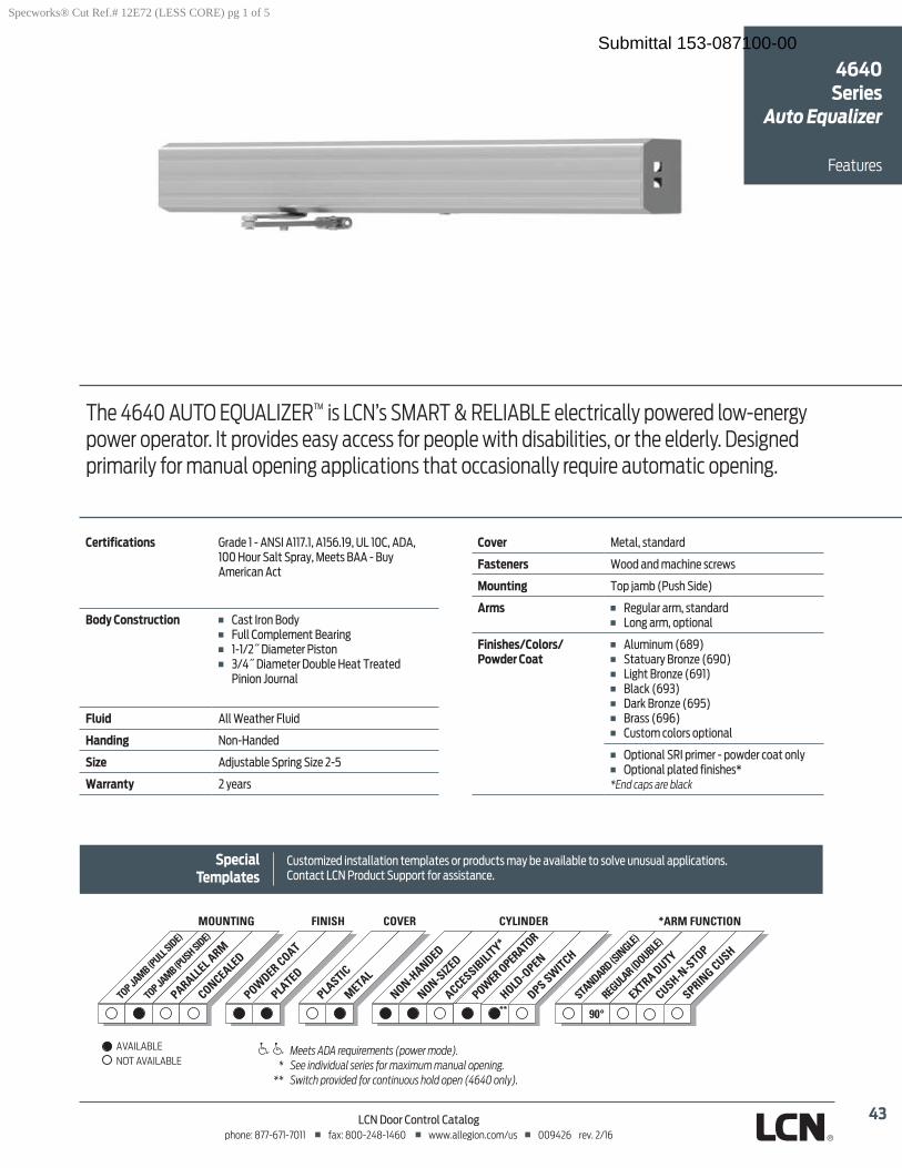
43LCN Door Control Catalogphone: 877-671-7011 fax: 800-248-1460 www.allegion.com/us 009426 rev. 2/16
The 4640 AUTO EQUALIZER™ is LCN’s SMART & RELIABLE electrically powered low-energy power operator. It provides easy access for people with disabilities, or the elderly. Designed primarily for manual opening applications that occasionally require automatic opening.
Certifications
American Act
Body Construction Cast Iron Body
Pinion Journal
Fluid
Handing
Size
Warranty 2 years
Cover
Fasteners Wood and machine screws
Mounting
Arms
Finishes/Colors/ Powder Coat
Custom colors optional
Optional plated finishes**End caps are black
Customized installation templates or products may be available to solve unusual applications.
Features
Special Templates
TOP JA
MB (PULL
SIDE)
TOP JA
MB (PUSH SIDE)
MOUNTING
PARALLEL A
RM
POWDER COAT
PLATED
PLASTIC
METAL
NON-HANDED
NON-SIZED
ACCESSIBILI
TY*
COVER CYLINDERFINISH
POWER OPER
ATOR
CONCEALED
HOLD-O
PEN
DPS SWITCH
STANDARD (S
INGLE)
REGULA
R (DOUBLE)
EXTRA DUTY
*ARM FUNCTION
CUSH-N-S
TOP
SPRING CUSH
Meets ADA requirements (power mode). * See individual series for maximum manual opening. ** Switch provided for continuous hold open (4640 only).
AVAILABLE NOT AVAILABLE
4640 Series
Auto Equalizer
Specworks® Cut Ref.# 12E72 (LESS CORE) pg 1 of 5
Submittal 153-087100-00
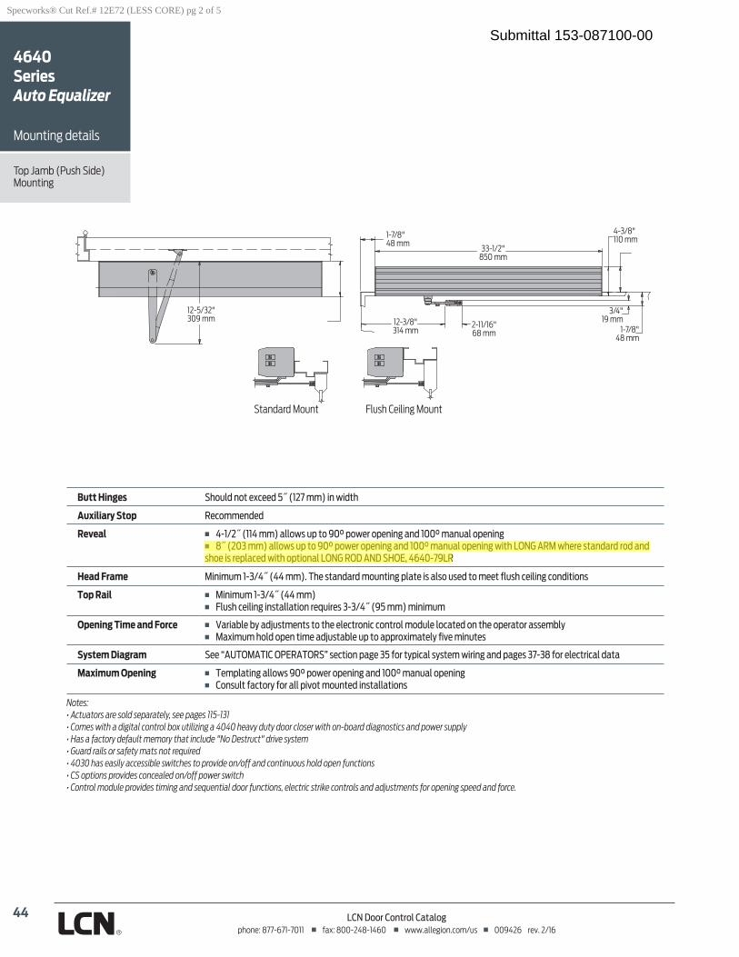
44 LCN Door Control Catalogphone: 877-671-7011 fax: 800-248-1460 www.allegion.com/us 009426 rev. 2/16
Mounting
Mounting details
1-7/8"48 mm
33-1/2"850 mm
4-3/8"110 mm
3/4"19 mm
1-7/8"48 mm
2-11/16"68 mm
12-3/8"314 mm
12-5/32"309 mm
Butt Hinges
Auxiliary Stop
Reveal
Head Frame
Top Rail
Opening Time and Force
System Diagram
Maximum Opening Templating allows 90° power opening and 100° manual opening Consult factory for all pivot mounted installations
Notes:
Flush Ceiling MountStandard Mount
4640 SeriesAuto Equalizer
Specworks® Cut Ref.# 12E72 (LESS CORE) pg 2 of 5
Submittal 153-087100-00
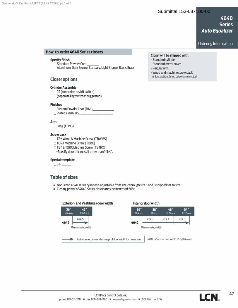
47LCN Door Control Catalogphone: 877-671-7011 fax: 800-248-1460 www.allegion.com/us 009426 rev. 2/16
Ordering Information
Closer will be shipped with:
unless options listed below are selected
Closer options
Cylinder Assembly
Finishes
Arm
Screw pack
Special template
Specify finish Standard Powder Coat __________
How-to-order 4640 Series closers
4642 4642
Exterior (and Vestibule) door width
914mm
Interior door width
914mm 1219mm
Indicates recommended range of door width for closer size.
Table of sizes
4640 Series
Auto Equalizer
Specworks® Cut Ref.# 12E72 (LESS CORE) pg 5 of 5
Submittal 153-087100-00
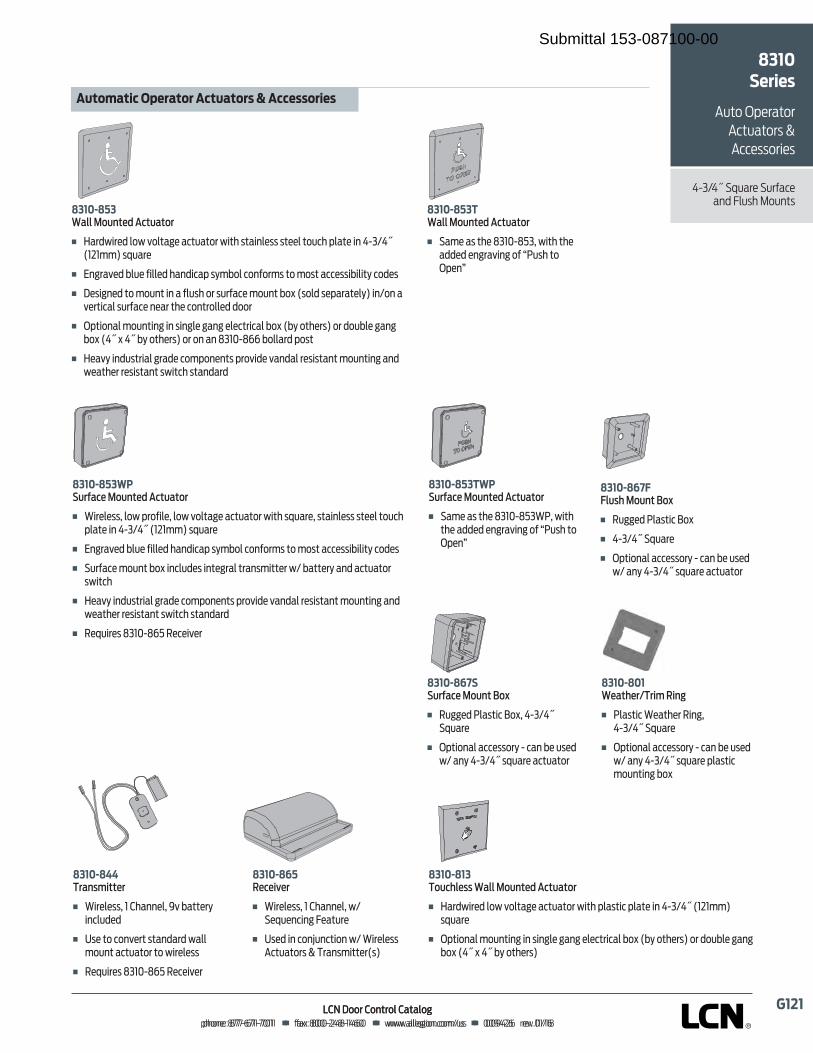
������������� ����� ��������������������������������������� !���!������������"""#�$$�%&��#'�()*+�����������,! �����-�.#���)������/01�2334�0356437�0868739:;<=>?�@AABCADBAEDD�����F����GHI?�@EEBJK@BDKCE�����F����LLLMHNN>OP<=MQ<RSTU����F����EEVKJC����W>XMDDSDC������
YZ�[\Y]Z^_̀̀�abcdefg�hiec_ebj�F��klmnopmqn�rso�tsrulvq�lwuxlusm�opuy�zulp{rqzz�zuqqr�usxwy�|rluq�p{�}~��}����������z�xlmqF���{vmltqn��rxq��prrqn�yl{npwl|�z���sr�ws{�sm�z�us��szu�lwwqzzp�prpu��wsnqzF���qzpv{qn�us��sx{u�p{�l��rxzy�sm�zxm�lwq��sx{u��s���zsrn�zq|lmluqr���p{�s{�l�tqmupwlr�zxm�lwq�{qlm�uyq�ws{umsrrqn�nssmF���|ups{lr��sx{up{v�p{�zp{vrq�vl{v�qrqwumpwlr��s������suyqmz��sm�nsx�rq�vl{v��s���}����}�����suyqmz��sm�s{�l{�����~�����srrlmn�|szuF��kqlt��p{nxzumplr�vmlnq�ws�|s{q{uz�|mstpnq�tl{nlr�mqzpzul{u��sx{up{v�l{n�oqluyqm�mqzpzul{u�zopuwy�zul{nlmnYZ�[\Y]Z�^_̀̀�abcdefg�hiec_ebjF���l�q�lz�uyq�����~�����opuy�uyq�lnnqn�q{vmltp{v�s����xzy�us��|q{�
YZ�[\Y����cj�_if�abcde��b�F�� xvvqn��rlzupw�¡s���}~��}����xlmqF���|ups{lr�lwwqzzsm��~�wl{��q�xzqn�o��l{��}~��}��z�xlmq�lwuxlusmYZ�[\Y]Z�¢£�cj�_if�abcdefg�hiec_ebjF���l�q�lz�uyq�����~���¤���opuy�uyq�lnnqn�q{vmltp{v�s����xzy�us��|q{�
YZ�[\Y¥¥¦j_d§̈©eefjF��¤pmqrqzz����ªyl{{qr��«t��luuqm��¬57®̄°̄F��±zq�us�ws{tqmu�zul{nlmn�olrr��sx{u�lwuxlusm�us�opmqrqzzF� q�xpmqz�����~���� qwqptqm YZ�[\Y�]²fif©³fjF��¤pmqrqzz����ªyl{{qr��o���q�xq{wp{v�́qluxmqF��±zqn�p{�ws{µx{wups{�o��¤pmqrqzz�¶wuxlusmz�·�̧ml{z�puuqm�z� YZ�[\Y�Z¦bci¹̀f§§�̂_̀̀�abcdefg�hiec_ebjF��klmnopmqn�rso�tsrulvq�lwuxlusm�opuy�|rlzupw�|rluq�p{�}~��}����������z�xlmqF���|ups{lr��sx{up{v�p{�zp{vrq�vl{v�qrqwumpwlr��s������suyqmz��sm�nsx�rq�vl{v��s���}����}�����suyqmz�
YZ�[\Y]Z¢£�cj�_if�abcdefg�hiec_ebjF��¤pmqrqzz��rso�|ms�prq��rso�tsrulvq�lwuxlusm�opuy�z�xlmq��zulp{rqzz�zuqqr�usxwy�|rluq�p{�}~��}����������z�xlmqF���{vmltqn��rxq��prrqn�yl{npwl|�z���sr�ws{�sm�z�us��szu�lwwqzzp�prpu��wsnqzF���xm�lwq��sx{u��s��p{wrxnqz�p{uqvmlr�uml{z�puuqm�o���luuqm��l{n�lwuxlusm�zopuwyF��kqlt��p{nxzumplr�vmlnq�ws�|s{q{uz�|mstpnq�tl{nlr�mqzpzul{u��sx{up{v�l{n�oqluyqm�mqzpzul{u�zopuwy�zul{nlmnF� q�xpmqz�����~���� qwqptqm YZ�[\Y[�^f_e¹fjº¦j©̈�²©d»F���rlzupw�¤qluyqm� p{v���}~��}����xlmqF���|ups{lr�lwwqzzsm��~�wl{��q�xzqn�o��l{��}~��}��z�xlmq�|rlzupw��sx{up{v��s�
YZ�[\Y��¼½̀c§¹�abcde��b�F� xvvqn��rlzupw�¡s�F�}~��}����xlmqF���|ups{lr�lwwqzzsm��~�wl{��q�xzqn�o��l{��}~��}��z�xlmq�lwuxlusm
¾¿ÀÁÂÃÀÄÅ�ÆÇÈÉÃÀÁÉ�¾ÅÀ¿ÃÀÁÉÊ�Ë�¾ÅÅÈÊÊÁÉÄÈÊ ÌÍÎÏÌÐ�ÑÒÓÔÕÖ�ÑÓÕ×ÔØÖ�H=Ù�ÚNTU;�Û<T=ÜUYZ�[��ÈÉÄÈÊÝTÜ<�Þ:>WHÜ<W�ÝQÜTHÜ<WU�ß�ÝQQ>UU<WP>USubmittal 153-087100-00
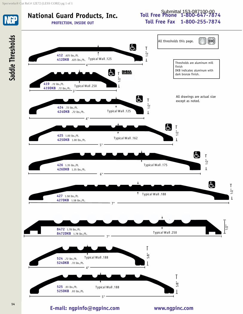
Toll Free Phone 1-800-647-7874Toll Free Fax 1-800-255-7874
E-mail: [email protected] www.ngpinc.com
Sadd
le Th
resh
olds
14
National Guard Products, Inc.PROTECTION, INSIDE OUT
Typical Wall .125
4"
1/2"
Typical Wall .250
3"
1/2
"
Typical Wall .125
4"
1/2"
5"
1/2"
Typical Wall .162
Typical Wall .175
6"
1/2"
Typical Wall .188
7"
1/2"
Thresholds are aluminum millfinishDKB indicates aluminum withdark bronze finish.
412 .625 lbs./ft.
412DKB .625 lbs./ft.
419 .72 lbs./ft.
419DKB .72 lbs./ft.
424 .72 lbs./ft.
424DKB .72 lbs./ft.
425 1.00 lbs./ft.
425DKB 1.00 lbs./ft.
426 1.35 lbs./ft.
426DKB 1.35 lbs./ft.
427 1.58 lbs./ft.
427DKB 1.58 lbs./ft.
Typical Wall .188
5"
5/8"
525 .93 lbs./ft.
525DKB .93 lbs./ft.
Typical Wall .188
4"
5/8"
524 .72 lbs./ft.
524DKB .72 lbs./ft.
All drawings are actual sizeexcept as noted.
All thresholds this page. 10C
1/2"
7"Typical Wall .250
8472 1.78 lbs./ft.
8472DKB 1.78 lbs./ft.
Specworks® Cut Ref.# 12E72 (LESS CORE) pg 1 of 1
Submittal 153-087100-00
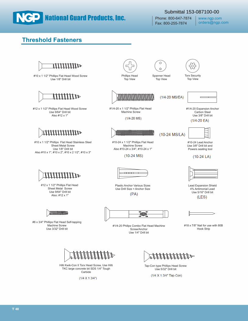
T 48
#12 x 1 1/2" Phillips Flat Head Wood ScrewUse 9/64" Drill bit
Also #12 x 1"
#10 x 1 1/2" Phillips Flat Head Stainless SteelSheet Metal Screw
Use 1/8" Drill bitAlso #10 x 1", #10 x 2", #10 x 2 1/2", #10 x 3"
#12 x 1 1/2" Phillips Flat Head Sheet Metal ScrewUse 9/64" Drill bit
Also: #12 x 1"
#6 x 3/4" Phillips Flat Head Self-tapping Machine Screw
Use 3/32" Drill bit
Hilti Kwik-Con II Torx Head Screw, Use Hilti TKC large concrete bit SDS 1/4" Tough
Carbide
Tap-Con type Phillips Head ScrewUse 5/32" Drill bit
#1/4-20 Phillps Combo Flat Head Machine Screw/Anchor
Use 1/4" Drill bit
#10 x 1 1/2" Phillips Flat Head Wood ScrewUse 1/8" Drill bit
Lead Expansion Shield4% Antimonial Lead
Use 5/16" Drill bit
Plastic Anchor Various SizesUse Drill Size = Anchor Size
#10-24 Lead AnchorUse 3/8" Drill bit and Powers seating tool
#10-24 x 1 1/2" Phillips Flat HeadMachine Screw
Also #10-24 x 3/4", #10-24 x 1"
#1/4-20 Expansion AnchorCarbon Steel
Use 3/8" Drill bit
#1/4-20 x 1 1/2" Phillips Flat Head Machine Screw
Phillips HeadTop View
Spanner HeadTop View
Torx SecurityTop View
#18 x 7/8" Nail for use with 80B Hook Strip
Threshold Fasteners
Submittal 153-087100-00
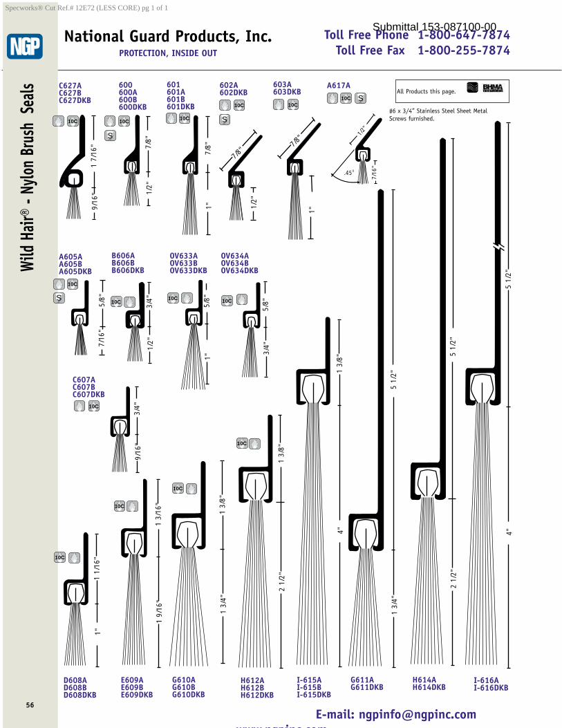
Toll Free Phone 1-800-647-7874Toll Free Fax 1-800-255-7874
E-mail: [email protected] ngpinc com
56
National Guard Products, Inc.PROTECTION, INSIDE OUT
1 7/
16"
9/16
"C627AC627BC627DKB
7/8"
1/2"
600600A600B600DKB
7/8"
1"
601601A601B601DKB
5/8"
7/16
"
A605AA605BA605DKB
3/4"
1/2"
B606AB606BB606DKB
3/4"
9/16
"
C607AC607BC607DKB
1 1/
16"
1"
D608AD608BD608DKB
1 3/
16"
1 9/
16"
E609AE609BE609DKB
1 3/
8"1
3/4"
G610AG610BG610DKB
5 1/
2"1
3/4"
G611AG611DKB
2 1/
2"1
3/8"
H612AH612BH612DKB
2 1/
2"5
1/2"
H614AH614DKB
1 3/
8"4"
I-615AI-615BI-615DKB
5 1/
2"4"
I-616AI-616DKB
5/8"
1"
OV633AOV633BOV633DKB
5/8"
3/4"
OV634AOV634BOV634DKB
1/2"
7/8"
602A602DKB
1"
7/8"
603A603DKB
7/16
"
1/2"
.45O
A617A
10C 10C 10C
10C10C S
10C
S10C
10C
10C 10C
#6 x 3/4” Stainless Steel Sheet MetalScrews furnished.
S
10C
10C
S
10C
10C
10C
All Products this page.
Wild
Hair®
- Ny
lon B
rush
Sea
lsSpecworks® Cut Ref.# 12E72 (LESS CORE) pg 1 of 1
Submittal 153-087100-00
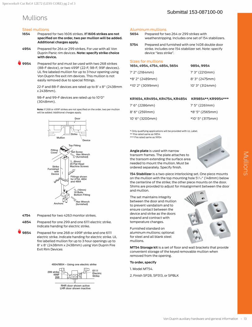
Mullions
Mullio
ns
Steel mullions1654 Prepared for two 1606 strikes. If 1606 strikes are not
specified on the order, two per mullion will be added. Additional charges apply.
4954 Prepared for 264 or 299 strikes. For use with all Von Duprin Panic rim devices. Note: specify strike choice with device.
9954 Prepared for and must be used with two 268 strikes (88-F device), or two 499F (22-F, 98-F, 99F devices). UL fire labeled mullion for up to 3 hour opening using Von Duprin fire exit rim devices. This mullion is not easily removed due to special fittings.
22-F and 88-F devices are rated up to 8' x 8" (2438mm x 2438mm).
98-F and 99-F devices are rated up to 10'0" (3048mm).
Note: If 268 or 499F strikes are not specified on the order, two per mullion will be added. Additional charges apply.
4754 Prepared for two 4263 monitor strikes.
4854 Prepared for one 299 and one 6111 electric strike. Indicate handing for electric strike.
9854 Prepared for one 268 or 499F strike and one 6111 electric strike. Indicate handing for electric strike. UL fire labelled mullion for up to 3 hour openings up to 8' x 8' (2438mm x 2438mm) using Von Duprin Fire Exit Rim Devices
Aluminum mullions5654 Prepared for two 264 or 299 strikes with
weatherstripping. Includes one set of 154 stabilizers.
5754 Prepared and furnished with one 1408 double door strike. Includes one 154 stabilizer set. Note: specify device “less strike”.
Sizes for mullions1654, 4954, 4754, 4854, 5654 9854, 9954
7' 2" (2184mm) 7' 3" (2210mm)
*8' 2" (2489mm) 8' 3" (2475mm)
*10' 2" (3099mm) 10' 3" (3124mm)
KR1654, KR4954, KR4754, KR4854 KR9854**, KR9954***
7' 6" (2286mm) 7' 5" (2261mm)
8' 6" (2591mm) *8' 5" (2565mm)
10' 6" (3200mm) *10' 5" (3175mm)
* Only qualifying applications will be provided with UL Label.** Fire rated same as 9854*** Fire rated same as 9954
Angle plate is used with narrow transom frames. The plate attaches to the transom extending the surface area needed to mount the mullion. Must be ordered separately. Specify finish.
154 Stabilizer is a two-piece interlocking set. One piece mounts on the mullion with the top mounting hole 53/16" (148mm) below the centerline of the strike; the other piece mounts on the door. Shims are provided to adjust for misalignment between the door and mullion.
The set maintains integrity between the door and mullion to prevent vandalism and to ensure contact between the device and strike as the doors expand and contract with temperature changes.
Furnished standard on aluminum mullions; optional for steel and all blank steel mullions.
MT54 Storage kit is a set of floor and wall brackets that provide convenient storage of the keyed removable mullion when removed from the opening.
To order, specify
1. Model MT54.
2. Finish SP28, SP313, or SPBLK
VonDuprinauxiliaryhardwareandgeneralinformation•13
Specworks® Cut Ref.# 12E72 (LESS CORE) pg 2 of 3
Submittal 153-087100-00
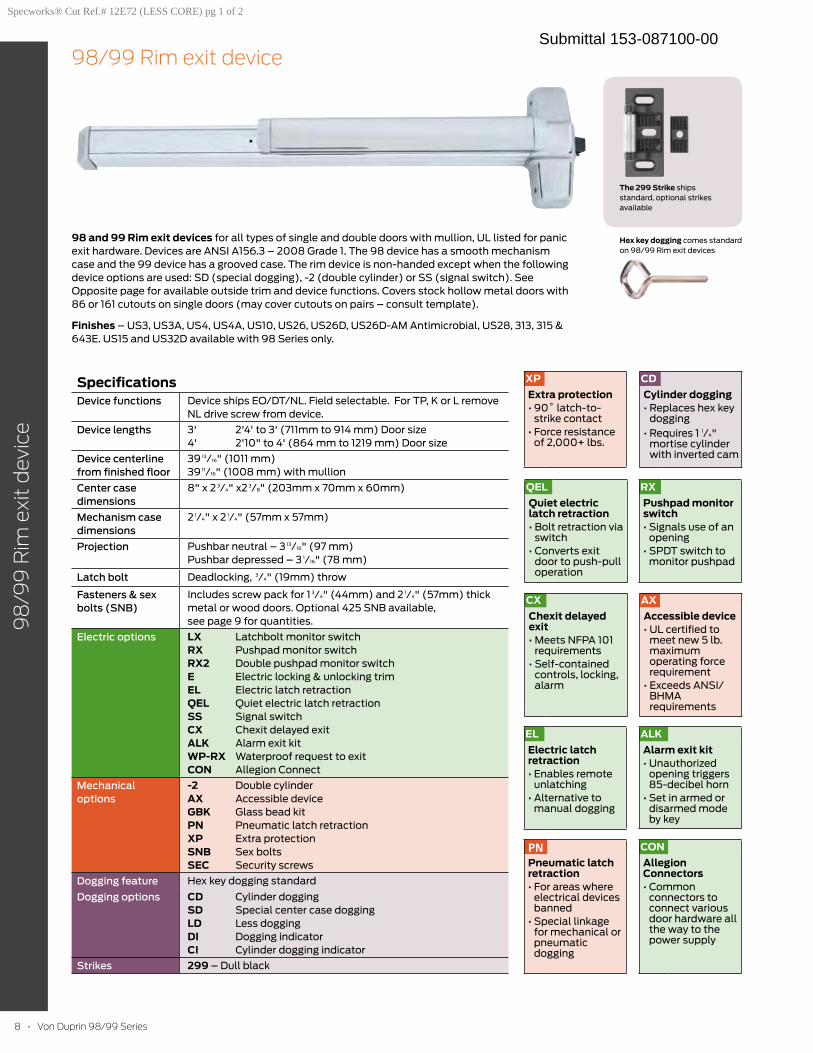
8 • Von Duprin 98/99 Series
98
/99
Rim
exi
t d
evic
e
98/99 Rim exit device
98 and 99 Rim exit devices for all types of single and double doors with mullion, UL listed for panic exit hardware. Devices are ANSI A156.3 – 2008 Grade 1. The 98 device has a smooth mechanism case and the 99 device has a grooved case. The rim device is non-handed except when the following device options are used: SD (special dogging), -2 (double cylinder) or SS (signal switch). See Opposite page for available outside trim and device functions. Covers stock hollow metal doors with 86 or 161 cutouts on single doors (may cover cutouts on pairs – consult template).
Finishes – US3, US3A, US4, US4A, US10, US26, US26D, US26D-AM Antimicrobial, US28, 313, 315 & 643E. US15 and US32D available with 98 Series only.
Hex key dogging comes standard on 98/99 Rim exit devices
The 299 Strike ships standard, optional strikes available
SpecificationsDevice functions Device ships EO/DT/NL. Field selectable. For TP, K or L remove
NL drive screw from device.Device lengths 3' 2'4' to 3' (711mm to 914 mm) Door size
4' 2'10" to 4' (864 mm to 1219 mm) Door sizeDevice centerline from finished floor
39 13/16" (1011 mm)39 11/16" (1008 mm) with mullion
Center case dimensions
8" x 2 3/4" x2 3/8" (203mm x 70mm x 60mm)
Mechanism case dimensions
2 1/4" x 2 1/4" (57mm x 57mm)
Projection Pushbar neutral – 3 13/16" (97 mm)Pushbar depressed – 3 1/16" (78 mm)
Latch bolt Deadlocking, 3/4" (19mm) throw
Fasteners & sex bolts (SNB)
Includes screw pack for 1 3/4" (44mm) and 2 1/4" (57mm) thick metal or wood doors. Optional 425 SNB available, see page 9 for quantities.
Electric options LX Latchbolt monitor switch RX Pushpad monitor switchRX2 Double pushpad monitor switchE Electric locking & unlocking trim EL Electric latch retractionQEL Quiet electric latch retractionSS Signal switchCX Chexit delayed exitALK Alarm exit kitWP-RX Waterproof request to exit CON Allegion Connect
Mechanical options
-2 Double cylinderAX Accessible device GBK Glass bead kitPN Pneumatic latch retractionXP Extra protectionSNB Sex boltsSEC Security screws
Dogging feature Hex key dogging standardDogging options CD Cylinder dogging
SD Special center case doggingLD Less doggingDI Dogging indicatorCI Cylinder dogging indicator
Strikes 299 – Dull black
QELQuiet electric latch retraction • Bolt retraction via
switch• Converts exit
door to push-pull operation
CXChexit delayed exit• Meets NFPA 101
requirements• Self-contained
controls, locking, alarm
ALKAlarm exit kit• Unauthorized
opening triggers 85-decibel horn
• Set in armed or disarmed mode by key
CONAllegion Connectors• Common
connectors to connect various door hardware all the way to the power supply
RXPushpad monitor switch• Signals use of an
opening • SPDT switch to
monitor pushpad
XPExtra protection• 90˚ latch-to-
strike contact • Force resistance
of 2,000+ lbs.
AXAccessible device• UL certified to
meet new 5 lb. maximum operating force requirement
• Exceeds ANSI/BHMA requirements
CDCylinder dogging• Replaces hex key
dogging • Requires 1 1/4"
mortise cylinder with inverted cam
ELElectric latch retraction• Enables remote
unlatching • Alternative to
manual dogging
PNPneumatic latch retraction • For areas where
electrical devices banned
• Special linkage for mechanical or pneumatic dogging
Specworks® Cut Ref.# 12E72 (LESS CORE) pg 1 of 2
Submittal 153-087100-00
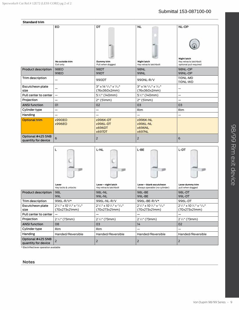
Von Duprin 98/99 Series • 9
Notes
98
/99
Rim
exit device
Standard trim
No outside trim Exit only
Dummy trim Pull when dogged
Night latch Key retracts latchbolt
Night latch Key retracts latchbolt optional pull required
Product description 98EO99EO
98DT99DT
98NL99NL
98NL-OP99NL-OP
Trim description— 990DT 990NL-R/V
110NL-MD110NL-WD
Escutcheon plate size
—3" x 14 13/16" x 3/32"(76x360x2mm)
3" x 14 13/16" x 3/32"(76x360x2mm)
—
Pull center to center — 5 1/2" (140mm) 5 1/2" (140mm) —Projection — 2" (51mm) 2" (51mm) —
ANSI function 01 02 03 03Cylinder type — — Rim Rim
Handing — — — —
Optional trim x990EOx996EO
x996K-DTx996L-DTx696DTx697DT
x996K-NLx996L-NLx696NLx697NL
Optional #425 SNB quantity for device
6 2 2 6
Lever Key locks & unlocks
Lever – night latch Key retracts latchbolt
Lever – blank escutcheon Always operable (no cylinder)
Lever dummy trim pull when dogged
Product description 98L99L
98L-NL99L-NL
98L-BE99L-BE
98L-DT99L-DT
Trim description 996L-R/V* 996L-NL-R/V 996L-BE-R/V* 996L-DTEscutcheon plate size
2 3/4" x 10 3/4" x 27/32"(70x273x21mm)
2 3/4" x 10 3/4" x 27/32"(70x273x21mm)
2 3/4" x 10 3/4" x 27/32"(70x273x21mm)
2 3/4" x 10 3/4" x 27/32"(70x273x21mm)
Pull center to center — — — —Projection 2 7/8" (73mm) 2 7/8" (73mm) 2 7/8" (73mm) 2 7/8" (73mm)
ANSI function 08 03 14 02Cylinder type Rim Rim — —
Handing Handed/Reversible Handed/Reversible Handed/Reversible Handed/Reversible
Optional #425 SNB quantity for device
2 2 2 2
* Electrified lever operation available
EO
L L-NL L-BE L-DT
DT NL NL-OP
Specworks® Cut Ref.# 12E72 (LESS CORE) pg 2 of 2
Submittal 153-087100-00
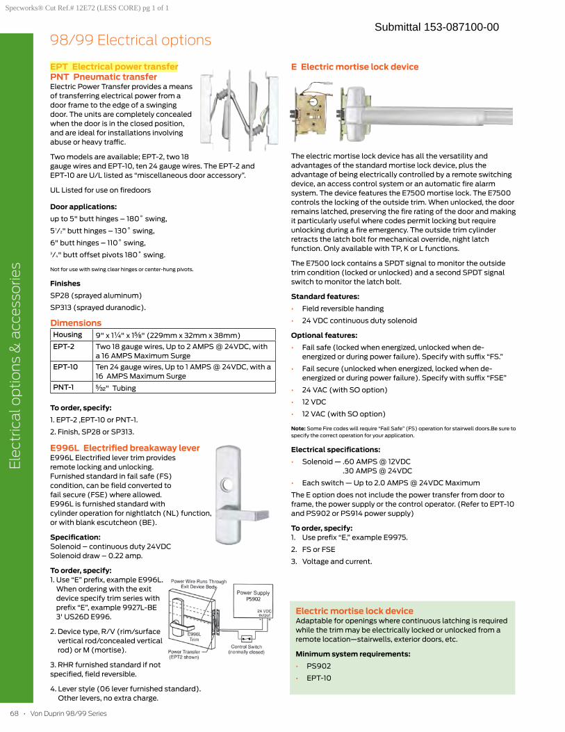
6868 • Von Duprin 98/99 Series
Elec
tric
al o
ptio
ns &
acc
esso
ries
98/99 Electrical options
EPT Electrical power transfer PNT Pneumatic transferElectric Power Transfer provides a means of transferring electrical power from a door frame to the edge of a swinging door. The units are completely concealed when the door is in the closed position, and are ideal for installations involving abuse or heavy traffic.
Two models are available; EPT-2, two 18 gauge wires and EPT-10, ten 24 gauge wires. The EPT-2 and EPT-10 are U/L listed as “miscellaneous door accessory”.
UL Listed for use on firedoors
Door applications:up to 5" butt hinges – 180˚ swing,
5 1/2" butt hinges – 130˚ swing,
6" butt hinges – 110˚ swing,3/4" butt offset pivots 180˚ swing.
Not for use with swing clear hinges or center-hung pivots.
FinishesSP28 (sprayed aluminum)
SP313 (sprayed duranodic).
DimensionsHousing 9" x 1¹|₄" x 1⁵|₈" (229mm x 32mm x 38mm)EPT-2 Two 18 gauge wires, Up to 2 AMPS @ 24VDC, with
a 16 AMPS Maximum SurgeEPT-10 Ten 24 gauge wires, Up to 1 AMPS @ 24VDC, with a
16 AMPS Maximum SurgePNT-1 ⁵|₃₂" Tubing
To order, specify:1. EPT-2 ,EPT-10 or PNT-1.
2. Finish, SP28 or SP313.
E996L Electrified breakaway leverE996L Electrified lever trim provides remote locking and unlocking. Furnished standard in fail safe (FS) condition, can be field converted to fail secure (FSE) where allowed. E996L is furnished standard with cylinder operation for nightlatch (NL) function, or with blank escutcheon (BE).
Specification: Solenoid – continuous duty 24VDC Solenoid draw – 0.22 amp.
To order, specify: 1. Use “E” prefix, example E996L.
When ordering with the exit device specify trim series with prefix “E”, example 9927L-BE 3' US26D E996.
2. Device type, R/V (rim/surface vertical rod/concealed vertical rod) or M (mortise).
3. RHR furnished standard if not specified, field reversible.
4. Lever style (06 lever furnished standard). Other levers, no extra charge.
E Electric mortise lock device
The electric mortise lock device has all the versatility and advantages of the standard mortise lock device, plus the advantage of being electrically controlled by a remote switching device, an access control system or an automatic fire alarm system. The device features the E7500 mortise lock. The E7500 controls the locking of the outside trim. When unlocked, the door remains latched, preserving the fire rating of the door and making it particularly useful where codes permit locking but require unlocking during a fire emergency. The outside trim cylinder retracts the latch bolt for mechanical override, night latch function. Only available with TP, K or L functions.
The E7500 lock contains a SPDT signal to monitor the outside trim condition (locked or unlocked) and a second SPDT signal switch to monitor the latch bolt.
Standard features:• Field reversible handing
• 24 VDC continuous duty solenoid
Optional features:• Fail safe (locked when energized, unlocked when de-
energized or during power failure). Specify with suffix “FS.”
• Fail secure (unlocked when energized, locked when de-energized or during power failure). Specify with suffix “FSE”
• 24 VAC (with SO option)
• 12 VDC
• 12 VAC (with SO option)
Note: Some Fire codes will require “Fail Safe” (FS) operation for stairwell doors.Be sure to specify the correct operation for your application.
Electrical specifications:• Solenoid — .60 AMPS @ 12VDC
.30 AMPS @ 24VDC
• Each switch — Up to 2.0 AMPS @ 24VDC Maximum
The E option does not include the power transfer from door to frame, the power supply or the control operator. (Refer to EPT-10 and PS902 or PS914 power supply)
To order, specify: 1. Use prefix “E,” example E9975.
2. FS or FSE
3. Voltage and current.
Electric mortise lock deviceAdaptable for openings where continuous latching is required while the trim may be electrically locked or unlocked from a remote location—stairwells, exterior doors, etc.
Minimum system requirements:• PS902
• EPT-10
Specworks® Cut Ref.# 12E72 (LESS CORE) pg 1 of 1
Submittal 153-087100-00
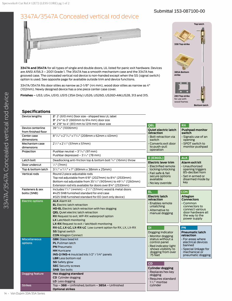
14 • Von Duprin 33A/35A Series
33
47A
/35
47A
Co
nce
ale
d v
erti
cal r
od
dev
ice
3347A/3547A Concealed vertical rod device
3347A and 3547A for all types of single and double doors, UL listed for panic exit hardware. Devices are ANSI A156.3 – 2001 Grade 1. The 3547A has a smooth mechanism case and the 3347A has grooved case. The concealed vertical rod device is non-handed except when the SS (signal switch) option is used. See opposite page for available outside trim and device functions.
3347A/3547A fits door stiles as narrow as 2-1/8" (44 mm), wood door stiles as narrow as 4" (102mm). Newly designed device has a one piece center case cover.
Finishes – US3, US4, US10, US15 (35A Only) US26, US26D, US26D-AM,US28, 313 and 315.
CD
Cylinder dogging• Replaces hex key
dogging • Requires standard
1 1/4" mortise cylinder
E (E360L)
Electric lever trim • Electrified remote
locking/unlocking• Fail safe & fail
secure options available
• No key override
PN
Pneumatic latch retraction • For areas where
electrical devices banned
• Special linkage for mechanical or pneumatic dogging
EL
Electric latch retraction• Enables remote
unlatching • Alternative to
manual dogging
QEL
Quiet electric latch retraction • Bolt retraction via
switch• Converts exit door
to push-pull operation
RX
Pushpad monitor switch• Signals use of an
opening • SPDT switch to
monitor pushpad
ALK
Alarm exit kit• Unauthorized
opening triggers 85-decibel horn
• Set in armed or disarmed mode by key
SpecificationsDevice lengths 2' 2' (610 mm) Door size - shipped less UL label
3' 2'4" to 3' (660mm to 914 mm) door size4' 2'8" to 4' (813 mm to 1219 mm) door size
Device centerline from finished floor
39 13/16" (1006mm)
Center case dimensions
8 13/16" x 2 13/32" x 1 9/16" (208mm x 62mm x 40mm)
Mechanism case dimensions
2 1/4" x 2 1/4" (57mm x 57mm)
Projection Pushbar neutral – 3 13/16" (97 mm)Pushbar depressed – 3 1/16" (78 mm)
Latch bolt Deadlocking anti-friction top & bottom bolt 5/8" (16mm) throw
Door undercut 1/4" (7mm)
Top & bottom latch 3 3/4" x 1 1/2" x 1" (89mm x 38mm x 25mm)
Vertical rods Round 2 piece adjustable rodsTop rod adjustable from 6'8" (2027mm) to 8'4" (2533mm)Bottom rod adjustable from 35 5/8" (905mm) to 49 5/8" (1260mm)Extension rod kits available for doors over 8'4" (2533mm)
Fasteners & sex bolts (SNB)
Includes 1 3/4" (44mm) – 2 1/4" (57mm) wood & metal doors #425 SNB furnished standard for end case#325 SNB furnished standard for EO (exit only device)
Electric options ALK Alarm kitEL Electric latch retractionHD-EL Electric latch retraction with hex doggingQEL Quiet electric latch retractionRX Request to exit, WP-RX waterproof optionLX Latchbolt monitoringLX-RX Request to exit / latchbolt monitoringRX-LC, LX-LC, LX-RX-LC Low current option for RX, LX, LX-RXSS Signal switch CON Allegion Connect
Miscellaneous options
GBK Glass bead kitPL Pullman latchPN PneumaticHH HurricaneINS-2/INS-4 Insulclad kits 1/2" / 1/4" panelsLBR Less bottom rodSG Safety glowSEC Security screwsSNB Sex bolts
Dogging feature Hex dogging standardCD Cylinder doggingLD Less dogging
Strikes Top – 388 – Unfinished, bottom – 385A – UnfinishedOptional strikes
DI
Dogging Indicator • Monitor dogging
status without a control panel
• Red indicator light shows visibility to dogging from over 75 feet
338 Top strike
385A Bottom strike
283 Top strike for use with wood frames
Bottom latch
Top latch
CON
Allegion Connectors• Common
connectors to connect various door hardware all the way to the power supply
Specworks® Cut Ref.# 12E72 (LESS CORE) pg 1 of 2
Submittal 153-087100-00
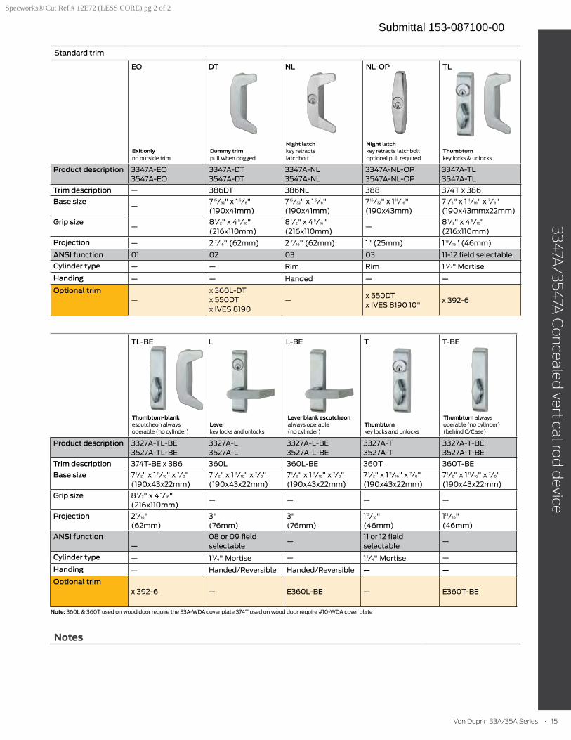
Von Duprin 33A/35A Series • 15
33
47A
/354
7A C
on
ceale
d vertica
l rod
device
Notes
Thumbturn-blank escutcheon always operable (no cylinder)
Lever key locks and unlocks
Lever blank escutcheon always operable (no cylinder)
Thumbturn key locks and unlocks
Thumbturn always operable (no cylinder)(behind C/Case)
Product description 3327A-TL-BE 3527A-TL-BE
3327A-L 3527A-L
3327A-L-BE3527A-L-BE
3327A-T3527A-T
3327A-T-BE 3527A-T-BE
Trim description 374T-BE x 386 360L 360L-BE 360T 360T-BE
Base size 7 1/2" x 1 11/16" x 7/8"(190x43x22mm)
7 1/2" x 1 11/16" x 7/8"(190x43x22mm)
7 1/2" x 1 11/16" x 7/8"(190x43x22mm)
7 1/2" x 1 11/16" x 7/8"(190x43x22mm)
7 1/2" x 1 11/16" x 7/8"(190x43x22mm)
Grip size 8 1/2" x 4 5/16"(216x110mm)
— — — —
Projection 27/16"(62mm)
3" (76mm)
3" (76mm)
113/16"(46mm)
113/16"(46mm)
ANSI function—
08 or 09 field selectable
—11 or 12 field selectable
—
Cylinder type — 1 1/4" Mortise — 1 1/4" Mortise —
Handing — Handed/Reversible Handed/Reversible — —
Optional trim x 392-6 — E360L-BE — E360T-BE
Note: 360L & 360T used on wood door require the 33A-WDA cover plate 374T used on wood door require #10-WDA cover plate
Standard trim
Exit only no outside trim
Dummy trim pull when dogged
Night latch key retracts latchbolt
Night latch key retracts latchbolt optional pull required
Thumbturn key locks & unlocks
Product description 3347A-EO 3547A-EO
3347A-DT3547A-DT
3347A-NL3547A-NL
3347A-NL-OP 3547A-NL-OP
3347A-TL 3547A-TL
Trim description — 386DT 386NL 388 374T x 386
Base size—
7 15/32" x 1 5/8" (190x41mm)
7 15/32" x 1 5/8" (190x41mm)
7 15/32" x 1 11/16" (190x43mm)
7 1/2" x 1 11/16" x 7/8" (190x43mmx22mm)
Grip size—
8 1/2" x 4 5/16" (216x110mm)
8 1/2" x 4 5/16" (216x110mm)
—8 1/2" x 4 5/16" (216x110mm)
Projection — 2 7/16" (62mm) 2 7/16" (62mm) 1" (25mm) 1 13/16" (46mm)
ANSI function 01 02 03 03 11-12 field selectable
Cylinder type — — Rim Rim 1 1/4" Mortise
Handing — — Handed — —
Optional trim —
x 360L-DT x 550DT x IVES 8190
—x 550DT x IVES 8190 10"
x 392-6
EO
TL-BE L L-BE T T-BE
DT NL NL-OP TL
Specworks® Cut Ref.# 12E72 (LESS CORE) pg 2 of 2
Submittal 153-087100-00
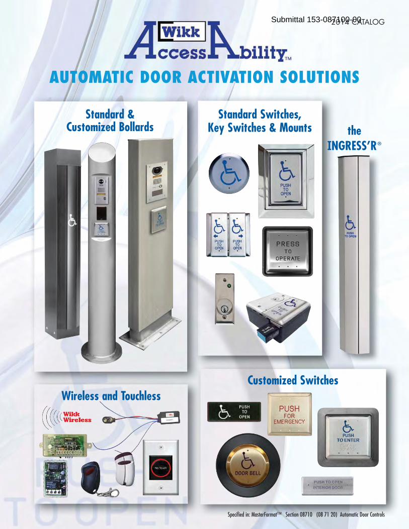
2014 CATALOG
Standard &Customized Bollards
Customized SwitchesWireless and Touchless
Standard Switches,Key Switches & Mounts the
INGRESS’R®
Specified in: MasterFormat™ Section 08710 (08 71 20) Automatic Door Controls
AUTOMATIC DOOR ACTIVATION SOLUTIONS
Submittal 153-087100-00
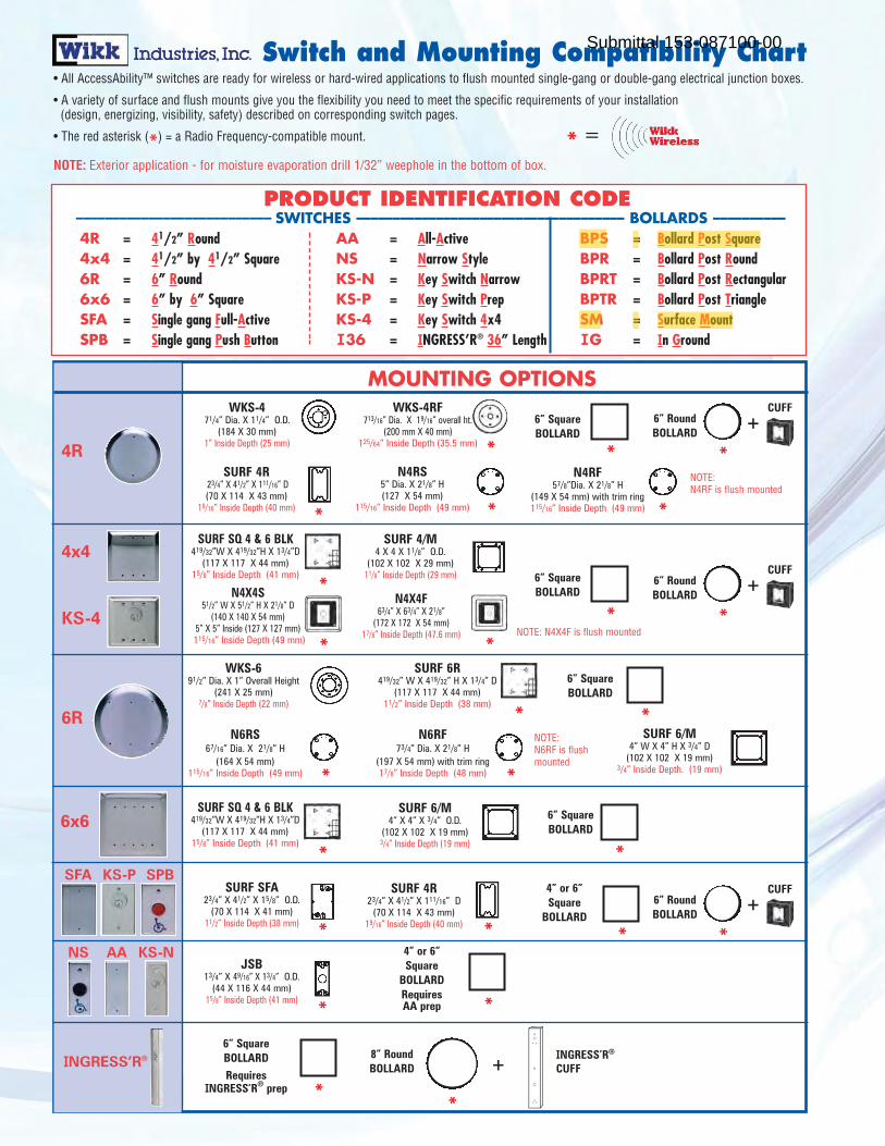
SWITCHES MOUNTING OPTIONS
• All AccessAbility™ switches are ready for wireless or hard-wired applications to flush mounted single-gang or double-gang electrical junction boxes.
• A variety of surface and flush mounts give you the flexibility you need to meet the specific requirements of your installation (design, energizing, visibility, safety) described on corresponding switch pages.
• The red asterisk (*) = a Radio Frequency-compatible mount.
NOTE: Exterior application - for moisture evaporation drill 1/32” weephole in the bottom of box.
WKS-471/4” Dia. X 11/4” O.D.
(184 X 30 mm)1” Inside Depth (25 mm)
WKS-4RF713/16” Dia. X 19/16” overall ht.
(200 mm X 40 mm)125/64” Inside Depth (35.5 mm)
SURF 4/M4 X 4 X 11/8” O.D.
(102 X 102 X 29 mm)11/8” Inside Depth (29 mm)
SURF 6/M4” W X 4” H X 3/4” D
(102 X 102 X 19 mm)3/4” Inside Depth. (19 mm)
SURF 4R23/4” X 41/2” X 111/16” D(70 X 114 X 43 mm)
19/16” Inside Depth (40 mm)
6R
SPBSFA KS-P
NS AA KS-N
4R
4x4
KS-4
*
*
SURF SFA23/4” X 41/2” X 15/8” O.D.
(70 X 114 X 41 mm)11/2” Inside Depth (38 mm)
SURF 6/M4” X 4” X 3/4” O.D.
(102 X 102 X 19 mm)3/4” Inside Depth (19 mm)
6x6
WKS-691/2” Dia. X 1” Overall Height
(241 X 25 mm)7/8” Inside Depth (22 mm)
SURF SQ 4 & 6 BLK419/32”W X 419/32”H X 13/4”D
(117 X 117 X 44 mm)15/8” Inside Depth (41 mm)
JSB13/4” X 49/16” X 13/4” O.D.
(44 X 116 X 44 mm)15/8” Inside Depth (41 mm)
SURF 4R23/4” X 41/2” X 111/16” D
(70 X 114 X 43 mm)19/16” Inside Depth (40 mm)
*
*
*
N6RS67/16” Dia. X 21/8” H
(164 X 54 mm)115/16” Inside Depth (49 mm)
N4RS5” Dia. X 21/8” H (127 X 54 mm)
115/16” Inside Depth (49 mm) *
N4RF57/8”Dia. X 21/8” H
(149 X 54 mm) with trim ring115/16” Inside Depth (49 mm)
6” Square BOLLARD
6” Square BOLLARD
4” or 6”Square
BOLLARD*
Switch and Mounting Compatibility Chart
*
*
*
N6RF73/4” Dia. X 21/8” H
(197 X 54 mm) with trim ring 17/8” Inside Depth (48 mm) *
*4” or 6”Square
BOLLARDRequiresAA prep *
*
*
6” RoundBOLLARD
*
6” Square BOLLARD
*
*
N4X4F63/4” X 63/4” X 21/8”
(172 X 172 X 54 mm)17/8” Inside Depth (47.6 mm)
*
N4X4S51/2” W X 51/2” H X 21/8” D
(140 X 140 X 54 mm) 5” X 5” Inside (127 X 127 mm)115/16” Inside Depth (49 mm) *
SURF 6R419/32” W X 419/32” H X 13/4” D
(117 X 117 X 44 mm)11/2” Inside Depth (38 mm)
+CUFF
6” Square BOLLARD
*
6” RoundBOLLARD
*
+CUFF
6” RoundBOLLARD
*
+CUFF
6” SquareBOLLARDRequires
INGRESS’R® prep *
8” RoundBOLLARD
*
+INGRESS’R®
CUFF
PRODUCT IDENTIFICATION CODE––––––––––––––––––––––––––– SWITCHES ––––––––––––––––––––––––––––––––––––– BOLLARDS ––––––––––4R = 41/2” Round AA = All-Active BPS = Bollard Post Square4x4 = 41/2” by 41/2” Square NS = Narrow Style BPR = Bollard Post Round 6R = 6” Round KS-N = Key Switch Narrow BPRT = Bollard Post Rectangular6x6 = 6” by 6” Square KS-P = Key Switch Prep BPTR = Bollard Post TriangleSFA = Single gang Full-Active KS-4 = Key Switch 4x4 SM = Surface MountSPB = Single gang Push Button I36 = INGRESS’R® 36” Length IG = In Ground
NOTE: N4RF is flush mounted
NOTE: N6RF is flushmounted
NOTE: N4X4F is flush mounted
* =
SURF SQ 4 & 6 BLK419/32”W X 419/32”H X 13/4”D
(117 X 117 X 44 mm)15/8” Inside Depth (41 mm)
INGRESS’R®
Submittal 153-087100-00
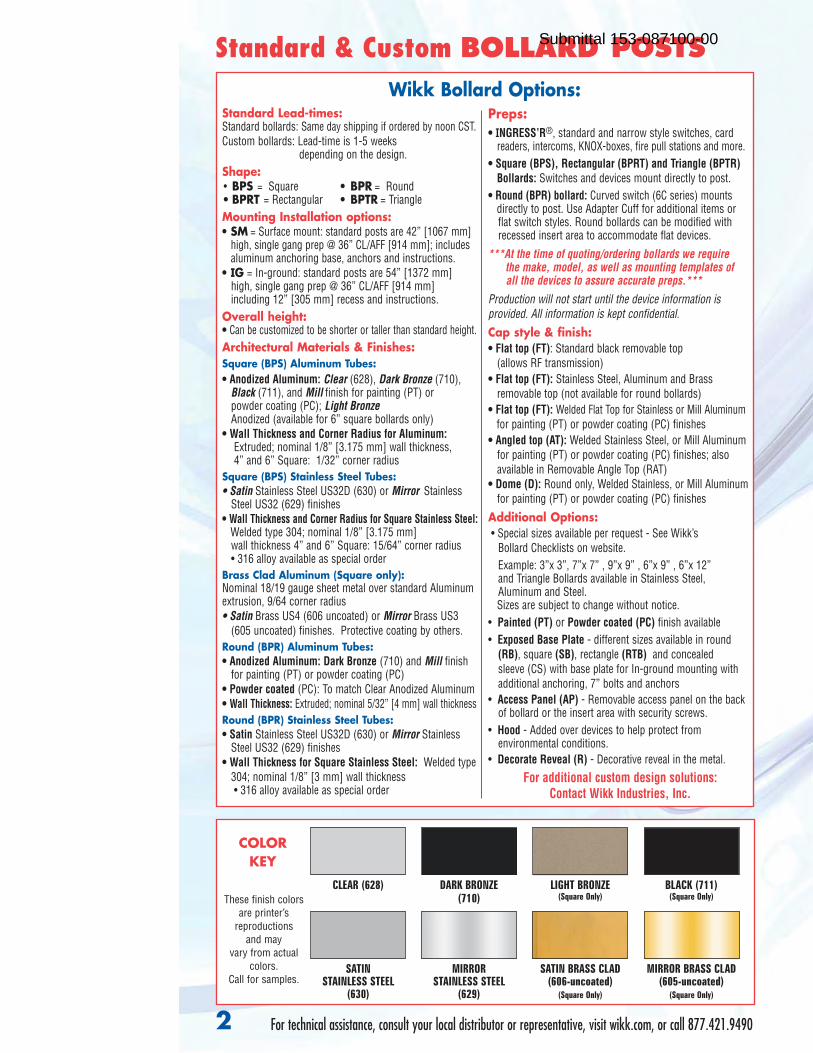
Wikk Bollard Options:
For technical assistance, consult your local distributor or representative, visit wikk.com, or call 877.421.9490
Standard & Custom BOLLARD POSTS
Standard Lead-times:Standard bollards: Same day shipping if ordered by noon CST.Custom bollards: Lead-time is 1-5 weeks
depending on the design. Shape:• BPS = Square • BPR = Round• BPRT = Rectangular • BPTR = TriangleMounting Installation options:• SM = Surface mount: standard posts are 42” [1067 mm]
high, single gang prep @ 36” CL/AFF [914 mm]; includesaluminum anchoring base, anchors and instructions.
• IG = In-ground: standard posts are 54” [1372 mm]high, single gang prep @ 36” CL/AFF [914 mm] including 12” [305 mm] recess and instructions.
Overall height: • Can be customized to be shorter or taller than standard height.Architectural Materials & Finishes:Square (BPS) Aluminum Tubes:• Anodized Aluminum: Clear (628), Dark Bronze (710),
Black (711), and Mill finish for painting (PT) or powder coating (PC); Light BronzeAnodized (available for 6” square bollards only)
• Wall Thickness and Corner Radius for Aluminum: Extruded; nominal 1/8” [3.175 mm] wall thickness, 4” and 6” Square: 1/32” corner radius
Square (BPS) Stainless Steel Tubes:• Satin Stainless Steel US32D (630) or Mirror Stainless
Steel US32 (629) finishes • Wall Thickness and Corner Radius for Square Stainless Steel:
Welded type 304; nominal 1/8” [3.175 mm] wall thickness 4” and 6” Square: 15/64” corner radius • 316 alloy available as special order
Brass Clad Aluminum (Square only):Nominal 18/19 gauge sheet metal over standard Aluminumextrusion, 9/64 corner radius• Satin Brass US4 (606 uncoated) or Mirror Brass US3
(605 uncoated) finishes. Protective coating by others.Round (BPR) Aluminum Tubes:• Anodized Aluminum: Dark Bronze (710) and Mill finish
for painting (PT) or powder coating (PC)• Powder coated (PC): To match Clear Anodized Aluminum • Wall Thickness: Extruded; nominal 5/32” [4 mm] wall thicknessRound (BPR) Stainless Steel Tubes:• Satin Stainless Steel US32D (630) or Mirror Stainless
Steel US32 (629) finishes • Wall Thickness for Square Stainless Steel: Welded type
304; nominal 1/8” [3 mm] wall thickness • 316 alloy available as special order
2
Preps:• INGRESS’R®, standard and narrow style switches, card
readers, intercoms, KNOX-boxes, fire pull stations and more.• Square (BPS), Rectangular (BPRT) and Triangle (BPTR)
Bollards: Switches and devices mount directly to post.• Round (BPR) bollard: Curved switch (6C series) mounts
directly to post. Use Adapter Cuff for additional items orflat switch styles. Round bollards can be modified withrecessed insert area to accommodate flat devices.
***At the time of quoting/ordering bollards we require the make, model, as well as mounting templates ofall the devices to assure accurate preps.***
Production will not start until the device information is provided. All information is kept confidential.Cap style & finish:• Flat top (FT): Standard black removable top
(allows RF transmission)• Flat top (FT): Stainless Steel, Aluminum and Brass
removable top (not available for round bollards)• Flat top (FT): Welded Flat Top for Stainless or Mill Aluminum
for painting (PT) or powder coating (PC) finishes• Angled top (AT): Welded Stainless Steel, or Mill Aluminum
for painting (PT) or powder coating (PC) finishes; alsoavailable in Removable Angle Top (RAT)
• Dome (D): Round only, Welded Stainless, or Mill Aluminumfor painting (PT) or powder coating (PC) finishes
Additional Options:• Special sizes available per request - See Wikk’s
Bollard Checklists on website.Example: 3”x 3”, 7”x 7” , 9”x 9” , 6”x 9” , 6”x 12” and Triangle Bollards available in Stainless Steel,Aluminum and Steel. Sizes are subject to change without notice.
• Painted (PT) or Powder coated (PC) finish available • Exposed Base Plate - different sizes available in round
(RB), square (SB), rectangle (RTB) and concealed sleeve (CS) with base plate for In-ground mounting withadditional anchoring, 7” bolts and anchors
• Access Panel (AP) - Removable access panel on the backof bollard or the insert area with security screws.
• Hood - Added over devices to help protect from environmental conditions.
• Decorate Reveal (R) - Decorative reveal in the metal.
For additional custom design solutions: Contact Wikk Industries, Inc.
SATINSTAINLESS STEEL
(630)
MIRRORSTAINLESS STEEL
(629)
SATIN BRASS CLAD(606-uncoated)
(Square Only)
MIRROR BRASS CLAD(605-uncoated)
(Square Only)
CLEAR (628) DARK BRONZE (710)
LIGHT BRONZE(Square Only)
BLACK (711)(Square Only)These finish colors
are printer’s reproductions
and may vary from actual
colors. Call for samples.
COLORKEY
Submittal 153-087100-00
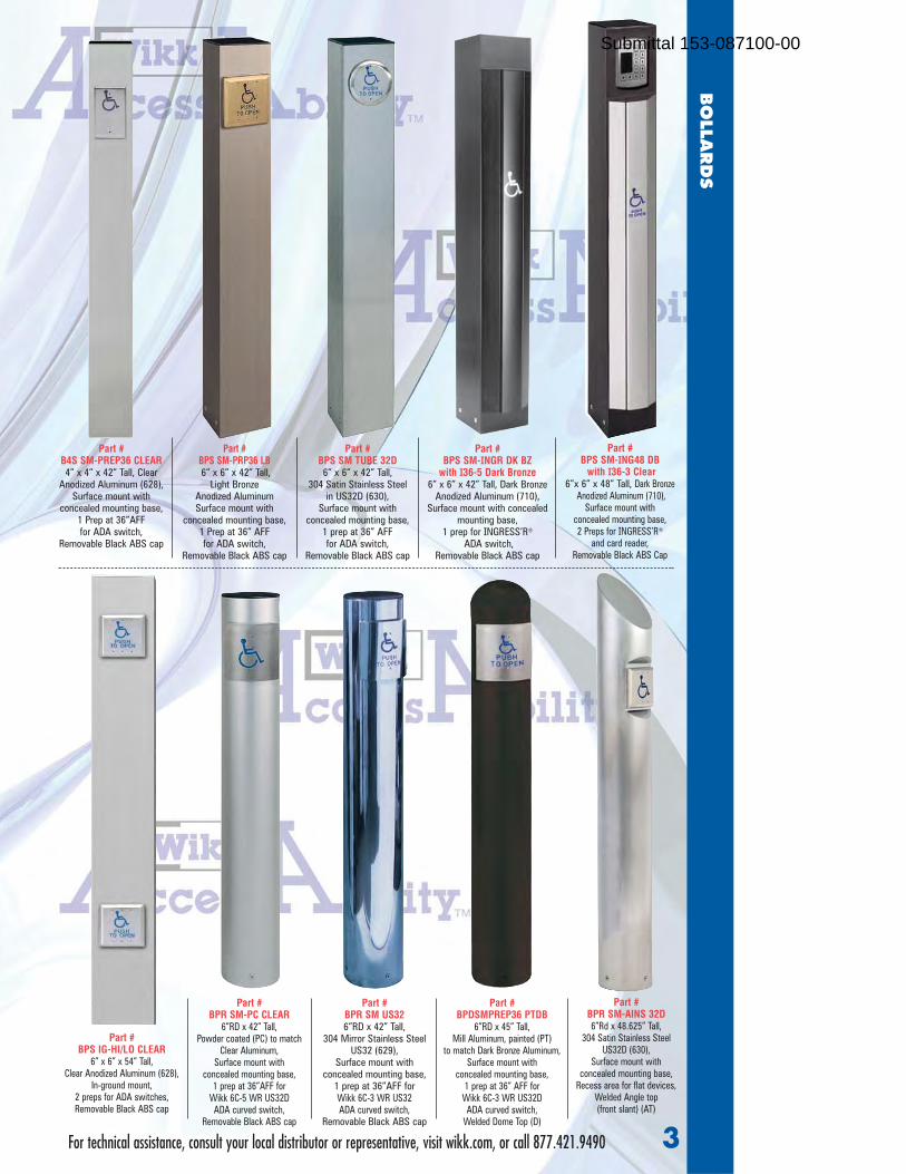
For technical assistance, consult your local distributor or representative, visit wikk.com, or call 877.421.9490
Part # BPS SM-PRP36 LB6” x 6” x 42” Tall,
Light Bronze Anodized AluminumSurface mount with
concealed mounting base, 1 Prep at 36” AFF for ADA switch,
Removable Black ABS cap
Part # BPR SM-AINS 32D6”Rd x 48.625” Tall,
304 Satin Stainless SteelUS32D (630),
Surface mount with concealed mounting base,
Recess area for flat devices,Welded Angle top (front slant) (AT)
Part # BPR SM-PC CLEAR
6”RD x 42” Tall,Powder coated (PC) to match
Clear Aluminum,Surface mount with
concealed mounting base,1 prep at 36”AFF for
Wikk 6C-5 WR US32DADA curved switch,
Removable Black ABS cap
Part # BPDSMPREP36 PTDB
6”RD x 45” Tall, Mill Aluminum, painted (PT)
to match Dark Bronze Aluminum,Surface mount with
concealed mounting base,1 prep at 36” AFF for
Wikk 6C-3 WR US32DADA curved switch,
Welded Dome Top (D)
3
Part # BPS SM TUBE 32D6” x 6” x 42” Tall,
304 Satin Stainless Steel in US32D (630),
Surface mount with concealed mounting base,
1 prep at 36” AFF for ADA switch,
Removable Black ABS cap
Part # BPS SM-ING48 DB
with I36-3 Clear 6”x 6” x 48” Tall, Dark Bronze
Anodized Aluminum (710), Surface mount with
concealed mounting base,2 Preps for INGRESS’R®
and card reader, Removable Black ABS Cap
Part # BPR SM US326”RD x 42” Tall,
304 Mirror Stainless SteelUS32 (629),
Surface mount with concealed mounting base,
1 prep at 36”AFF for Wikk 6C-3 WR US32 ADA curved switch,
Removable Black ABS cap
Part #BPS IG-HI/LO CLEAR
6” x 6” x 54” Tall, Clear Anodized Aluminum (628),
In-ground mount,2 preps for ADA switches,Removable Black ABS cap
Part #B4S SM-PREP36 CLEAR4” x 4” x 42” Tall, Clear
Anodized Aluminum (628),Surface mount with
concealed mounting base, 1 Prep at 36”AFF for ADA switch,
Removable Black ABS cap
BO
LLARDS
Part #BPS SM-INGR DK BZ
with I36-5 Dark Bronze6” x 6” x 42” Tall, Dark Bronze
Anodized Aluminum (710),Surface mount with concealed
mounting base,1 prep for INGRESS’R®
ADA switch,Removable Black ABS cap
Submittal 153-087100-00

RAL colorsInterior and exterior applications | volume 10
A GREENER FI NISH. FOR A BETTER WORLD.
green coating
T H E A M E R I C A S
TIGER WORLDWIDE NETWORK
tiger-coatings.comcontact details available at
T H E A M E R I C A SCANADAMEXICOU.S.A.
E U R O P EAUSTRIABELARUSBENELUXBOSNIA & HERZEGOVINABULGARIACROATIACZECH REPUBLICESTONIAFRANCEGERMANYGREAT BRITAINHUNGARYITALYLATVIAPOLANDROMANIA SERBIA & MONTENEGROSLOVAKIASLOVENIASPAINSWEDENTURKEYUKRAINE
A F R I C AEGYPTSOUTH AFRICA
A S I ACHINAINDIAJAPANMALAYSIATAIWANVIETNAM
A GREENER FINISH. FOR A BETTER WORLD.
green coating
a finish by TIGER Drylac Powder Coatings
need to con�rm which green coating logo should be used going forward. New Austrian version doesn’t show caption below or TIGER logo.
A GREENER FI NISH. FOR A BETTER WORLD.
green coating
CCT-
GEN
-104
2-EN
-101
6
Submittal 153-087100-00

RAL 1012 49/22530 RAL 1013 49/11280 RAL 1014 49/1517038/15014
RAL 1015 49/15320 RAL 1016 49/22520 RAL 1017 49/22510 RAL 1018 49/21830 RAL 1019 49/13660 RAL 1020 49/2250038/10013 38/15015 38/20016 38/15019 38/20020
38/20024RAL 1021 49/22280 RAL 1023 49/22490 RAL 1024 49/22480 RAL 1027 49/22470 RAL 1028 49/22460 RAL 1032 49/22450 RAL 1033 49/22240 RAL 1034 49/23910 RAL 1037 49/20096
RAL 2000 49/24570 RAL 2001 49/24560 RAL 2002 49/24550 RAL 2003 49/24540 RAL 2004 49/24530 RAL 2008 49/24340 RAL 2009 49/24360 RAL 2010 49/24520 RAL 2011 49/24580
RAL 2012 49/24690 RAL 3000 49/33120 RAL 3001 49/31120 RAL 3002 49/31110 RAL 3003 49/31100 RAL 3004 49/33900 RAL 3005 49/31900 RAL 3007 49/31910 RAL 3009 49/31920
RAL 3011 49/31090 RAL 3012 49/31940 RAL 3013 49/31950 RAL 3014 49/31080 RAL 3015 49/33670 RAL 3016 49/31980 RAL 3017 49/31060 RAL 3018 49/31050 RAL 3020 49/3104038/30012
RAL 3022 49/33700 RAL 3027 49/33660 RAL 3031 49/34730 RAL 4001 49/43160 RAL 4002 49/31030 RAL 4003 49/32270 RAL 4004 49/31020 RAL 4005 49/42780 RAL 4006 49/32090
RAL 4007 49/32540 RAL 4008 49/32280 RAL 4009 49/34740 RAL 4010 49/40490 RAL 5000 49/42200 RAL 5001 49/42210 RAL 5002 49/42220 RAL 5003 49/42230 RAL 5004 49/4224038/40004
RAL 5005 49/43190 RAL 5007 RAL 5008 49/42260 RAL 5009 49/42270 RAL 5010 49/42280 RAL 5011 49/43180 RAL 5012 49/43170 RAL 5013 49/42310 RAL 5014 49/4232049/4225038/40007 38/40008 38/40011 38/40013
RAL 5015 49/42330 RAL 5017 RAL 5018 49/41140 RAL 5019 49/42360 RAL 5020 49/44270 RAL 5021 49/41190 RAL 5022 49/42390 RAL 5023 49/44650 RAL 5024 49/4466049/4076038/40017 38/40020 38/4002138/40019 38/40018
RAL 6000 49/53160 RAL 6001 RAL 6002 49/52890 RAL 6003 49/52880 RAL 6004 49/50980 RAL 6005 49/50670 RAL 6006 49/52870 RAL 6007 49/52860 RAL 6008 49/5324049/5290038/50005 38/5000238/50003 38/5000438/50000 38/50006 38/50007 38/50008
RAL 6009 49/52840 RAL 6010 RAL 6011 49/52820 RAL 6012 49/51540 RAL 6013 49/52810 RAL 6014 49/52800 RAL 6015 49/52790 RAL 6016 49/51020 RAL 6017 49/5278049/5283038/50031 38/50012 38/5001338/50009 38/50016 38/5001738/50011
RAL 6018 49/52720 RAL 6019 RAL 6020 49/52710 RAL 6021 49/52700 RAL 6022 49/52690 RAL 6024 49/52680 RAL 6025 49/52670 RAL 6026 49/52660 RAL 6027 49/5099049/5100038/50019 38/50021 38/5002238/50018 38/50026 38/5002738/50020
RAL 6028 49/52650 RAL 6029 RAL 6032 49/52630 RAL 6033 49/55010 RAL 6034 49/55020 RAL 7000 49/72700 RAL 7001 49/72710 RAL 7002 49/72720 RAL 7003 49/7260049/5264038/50029 38/50033 38/5003438/50028 38/7000738/50032 38/70000
RAL 7004 49/73300 RAL 7005 RAL 7006 49/72580 RAL 7008 49/72570 RAL 7009 49/72770 RAL 7010 49/72560 RAL 7011 49/72790 RAL 7012 49/71180 RAL 7013 49/7255049/7259038/70005 38/7000938/70004 38/7001238/70006 38/70014 38/70011 38/70013
RAL 7015 49/72820 RAL 7016 RAL 7021 49/72540 RAL 7022 49/72850 RAL 7023 49/72530 RAL 7024 49/72870 RAL 7026 49/72880 RAL 7030 49/72890 RAL 7031 49/7252049/7283038/70016 38/7002338/70015 38/7002738/70021 38/70024 38/70026 38/7003138/70022
RAL 7032 49/72910 RAL 7033 RAL 7034 49/72500 RAL 7035 49/73510 RAL 7036 49/72950 RAL 7037 49/72480 RAL 7038 49/72470 RAL 7039 49/71020 RAL 7040 49/7547049/7251038/70033 38/7003638/70001 38/7003938/70037 38/70038 38/7004638/70035
RAL 7042 49/73250 RAL 7043 RAL 7044 49/75480 RAL 7045 49/77890 RAL 7046 49/72010 RAL 7047 49/72020 RAL 8000 49/66170 RAL 8001 49/66160 RAL 8002 49/6615049/7246038/70043 38/7000238/70042 38/6000538/70047 38/6000238/7004538/70044
RAL 8003 49/66140 RAL 8004 RAL 8007 49/66120 RAL 8008 49/66110 RAL 8011 49/66100 RAL 8012 49/66090 RAL 8014 49/65230 RAL 8015 49/63040 RAL 8016 49/6608049/6613038/60004 38/6001138/60003 38/60012 38/6001638/6000838/60007 38/60010
RAL 8017 49/65220 RAL 8019 RAL 8022 49/63080 RAL 8023 49/66070 RAL 8024 49/66060 RAL 8025 49/66050 RAL 8028 49/66500 RAL 9001 49/10016 RAL 9002 49/7052049/6549038/60019 38/6002438/60017 38/60025 38/1000238/6002338/60022 38/60028 38/10001
RAL 9003 49/11400 RAL 9004 RAL 9005 49/82830 RAL 9010 49/11500 RAL 9011 49/80540 RAL 9016 49/11340 RAL 9017 49/8055049/8195038/8000438/10003 38/1001038/1000438/80010 38/80017
49/7249038/10018
RAL 9018
RAL 1000 49/15200 RAL 1001 49/15190 RAL 1002 49/2259038/20002
RAL 1003 49/22580 RAL 1004 49/22570 RAL 1005 49/22560 RAL 1006 49/22550 RAL 1007 49/22540 RAL 1011 49/1518038/15001
Disclaimer
RAL color swatches featured in this color chart have been matched to color standards at a 60-degree visual angle under a D65 Daylight primary source. The swatches are to be considered as an indication only. In practice, discrepancy between the color swatch and the actual powder coating may arise. This is due to paper and ink limitations, the influence of light and heat during the color chart production, as well as gloss level, substrate, surface variations, binder systems and pigments, coating thickness and cure oven conditions used during application. For an accurate color and finish assessment, it is recommended to obtain a powder coated sample panel from TIGER Drylac®.
Submittal 153-087100-00

Series 38AAMA 2604 super durable powder coatings | Volume 4
A GREENER FI NISH. FOR A BETTER WORLD.
green coating
T H E A M E R I C A S
TIGER WORLDWIDE NETWORK
tiger-coatings.comcontact details available at
T H E A M E R I C A SCANADAMEXICOU.S.A.
E U R O P EAUSTRIABELARUSBENELUXBOSNIA & HERZEGOVINABULGARIACROATIACZECH REPUBLICESTONIAFRANCEGERMANYGREAT BRITAINHUNGARYITALYLATVIAPOLANDROMANIA SERBIA & MONTENEGROSLOVAKIASLOVENIASPAINSWEDENTURKEYUKRAINE
A F R I C AEGYPTSOUTH AFRICA
A S I ACHINAINDIAJAPANMALAYSIATAIWANVIETNAM
A GREENER FINISH. FOR A BETTER WORLD.
green coating
a finish by TIGER Drylac Powder Coatings
need to con�rm which green coating logo should be used going forward. New Austrian version doesn’t show caption below or TIGER logo.
A GREENER FI N ISH. FOR A BETTER WORLD.
green coating
CCT-
ARC-
1040
-EN
-101
6
series 38
Disclaimer
Color swatches featured in this color chart have been matched to color standards at a 60-degree visual angle under a D65 Daylight primary source. RAL numbers are matched as approximate as possible to the RAL Standards. Gloss level on metallic and fine textured swatches cannot be accurately measured.
The swatches are to be considered as an indication only. In practice, discrepancy between the color swatch and the actual powder coating may arise. This is due to paper and ink limitations, the influence of light and heat during the color chart production, as well as gloss level, substrate, surface variations, binder systems and pigments, coating thickness and cure oven conditions used during application.
For an accurate color and finish assessment, it is recommended to obtain a powder coated sample panel from TIGER Drylac®.
Super durable powder coatingsfor exterior and interior architectural applications
This color chart features a wide selection of TIGER Drylac® Series 38 high performance powder coatings intended for architectural applications such as metal façades, steel constructions, stadium seating, railings and residential window and door frames.
TIGER Drylac® Series 38 is also suitable for industrial applications where a high performance weather resistance is required such as agricultural equipment, external ship components, military equipment, communication towers, playground equipment, patio furniture and garden equipment.
AAMA 2604 compliance
TIGER Drylac® Series 38 complies with the American Architectural Manufacturing Association’s specificationAAMA 2604*. It imparts excellent weather and UV resistance. Based on 5-year Florida exposure, TIGER Drylac® Series 38 exhibits 5.0 (Hunter) color change and > 30% gloss retention.
* AAMA 2604 compliance is dependent upon the color and or effect.
TIGER Shield system
To achieve excellent corrosion resistance in marine environments and coastal regions where objects coated are directly exposed to salt and fog conditions, it is recommended to use TIGER Shield system.
TIGER Shield is a two-coat system consisting of a corrosion protective primer as base coat and an opaque weather resistant TIGER Drylac® powder coating as top coat.
Dryprotector, TIGER Drylac® 69/70000, Zinc-Rich Primer, TIGER Drylac® 69/90500 (69/90701 Canada only) and zinc-free OGF Primer, TIGER Drylac® 09/73841 are recommended primers to achieve an optimum non-porous film. For additional information on the application of TIGER Shield system, it is recommended to refer to the latest edition of the Product Data Sheets of these primers.
Standard BLM colors
The Bureau of Land Management Standard Environmental Colors (BLM) were developed by the American government to minimize adverse visual contrast with the background landscape and ensure proper color selection for a facility.
BLM colors in TIGER Drylac® Series 38 are weather and UV resistant and can withstand long exposure to harsh environments.
≤∆ε
Submittal 153-087100-00
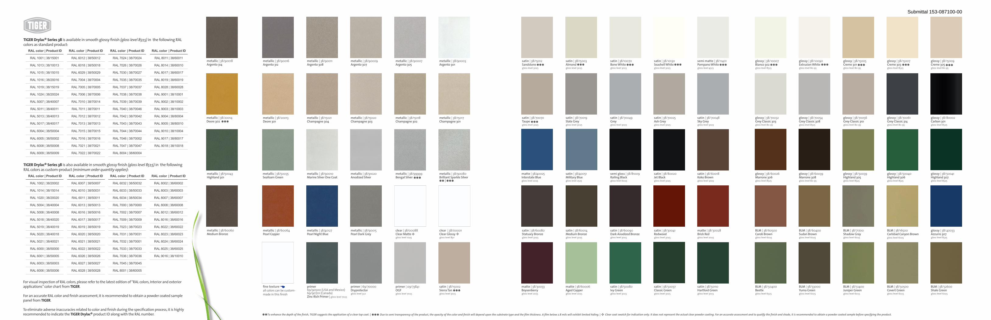
Clear coat swatch for indication only. It does not represent the actual clear powder coating. For an accurate assessment and to qualify the finish and shade, it is recommended to obtain a powder coated sample before specifying the product.To enhance the depth of the finish, TIGER suggests the application of a clear top coat. | ** Due to semi transparency of the product, the opacity of the color and finish will depend upon the substrate type and the film thickness. A film below 2.8 mils will exhibit limited hiding. |***
metallic | 38/90018Argento 314
metallic | 38/20014Deore 302
metallic | 38/50043Highland 301
metallic | 38/60060Medium Bronze
metallic | 38/90016Argento 312
metallic | 38/20013Deore 301
metallic | 38/50035Seafoam Green
metallic | 38/60064Pearl Copper
fine textureall colors can be custom-made in this finish
metallic | 38/90011Argento 308
metallic | 38/15021Champagne 304
metallic | 38/90010Marine Silver One Coat
metallic | 38/40127Pearl Night Blue
metallic | 38/90009Argento 307
metallic | 38/15020Champagne 303
metallic | 38/91020Anodized Silver
metallic | 38/90015Pearl Dark Grey
metallic | 38/90007Argento 305
metallic | 38/15018Champagne 302
metallic | 38/99999Bengal Silver
clear | 38/00088Clear Matte gloss level 10±5
primer | 69/70000Dryprotector gloss level 3±2
primer | 09/73841OGF gloss level 70±5
metallic | 38/90003Argento 301
metallic | 38/15017Champagne 301
metallic | 38/90080Brilliant Sparkle Silver
clear | 38/00001Clear Glossygloss level 85+
satin | 38/15002Sierra Tan gloss level 30±5
satin | 38/15012Sandstone gloss level 30±5
satin | 38/70070Taupe gloss level 30±5
matte | 38/40025Interstate Blue gloss level 20±5
satin | 38/60080Statuary Bronze gloss level 30±5
matte | 38/30033Boysenberry gloss level 20±5
satin | 38/15003Almond gloss level 30±5
satin | 38/70019Slate Grey gloss level 30±5
satin | 38/40051Military Blue gloss level 25±5
satin | 38/60014Medium Bronze gloss level 30±5
matte | 38/60006Aged Copper gloss level 20±5
satin | 38/10070Bone White gloss level 30±5
satin | 38/70049Grey gloss level 30±5
semi gloss | 38/81009Railing Black gloss level 60±5
satin | 38/60090 Dark Anodized Bronzegloss level 30±5
satin | 38/50080Ivy Green gloss level 30±5
satin | 38/10130Seashell White gloss level 30±5
satin | 38/70025Ash Grey gloss level 30±5
satin | 38/80020Jet Black gloss level 30±5
satin | 38/30041Redwood gloss level 30±5
satin | 38/50037Classic Green gloss level 30±5
semi matte | 38/11401Pompano White gloss level 45±5
satin | 38/70048Sky Grey gloss level 30±5
satin | 38/60018Koko Brown gloss level 30±5
matte | 38/30028Brick Red gloss level 20±5
satin | 38/50110Hartford Green gloss level 30±5
glossy | 38/10007Bianco 302 gloss level 85±5
glossy | 38/70032Grey Classic 303 gloss level 80-95
glossy | 38/60026Marrone 306 gloss level 85±5
BLM | 38/60500Carob Brown gloss level 60±5
BLM | 38/50400Beetle gloss level 65±5
glossy | 38/10090Extrusion White gloss level 80-95
glossy | 38/70054Grey Classic 308 gloss level 85±5
glossy | 38/60039Marrone 308 gloss level 80-95
BLM | 38/60400Sudan Brown gloss level 60±5
BLM | 38/53000Yuma Green gloss level 60±5
glossy | 38/15005Creme 301 gloss level 80-95
glossy | 38/70056Grey Classic 310 gloss level 80-95
glossy | 38/50039Highland 305 gloss level 85±5
BLM | 38/71700Shadow Gray gloss level 60±5
BLM | 38/51400Juniper Green gloss level 60±5
glossy | 38/15007Creme 303 gloss level 85±5
glossy | 38/70061Grey Classic 314 gloss level 80-95
glossy | 38/50040Highland 306 gloss level 85±5
BLM | 38/16500 Carlsbad Canyon Browngloss level 60±5
BLM | 38/50500Covert Green gloss level 60±5
glossy | 38/15009Creme 305 gloss level 80-95
glossy | 38/80002Carbon 301 gloss level 85±5
glossy | 38/50041Highland 307 gloss level 85±5
glossy | 38/40033Azzurro 307 gloss level 85±5
BLM | 38/52600Shale Green gloss level 60±5
***
*** ** | ***
primer 69/90500 (USA and Mexico)69/90701 (Canada)Zinc-Rich Primer | gloss level 70±5
***
*** *** *** *** ***
***
*** *** *** *** ***
TIGER Drylac® Series 38 is available in smooth glossy finish (gloss level 85±5) in the following RAL colors as standard product:
For visual inspection of RAL colors, please refer to the latest edition of “RAL colors, Interior and exterior applications” color chart from TIGER.
For an accurate RAL color and finish assessment, it is recommended to obtain a powder coated sample panel from TIGER.
To eliminate adverse inaccuracies related to color and finish during the specification process, it is highly recommended to indicate the TIGER Drylac® product ID along with the RAL number.
RAL color | Product ID RAL color | Product ID RAL color | Product ID RAL color | Product ID
RAL 1001 | 38/15001 RAL 6012 | 38/50012 RAL 7024 | 38/70024 RAL 8011 | 38/60011
RAL 1013 | 38/10013 RAL 6018 | 38/50018 RAL 7026 | 38/70026 RAL 8014 | 38/60010
RAL 1015 | 38/15015 RAL 6029 | 38/50029 RAL 7030 | 38/70027 RAL 8017 | 38/60017
RAL 1016 | 38/20016 RAL 7004 | 38/70004 RAL 7035 | 38/70035 RAL 8019 | 38/60019
RAL 1019 | 38/15019 RAL 7005 | 38/70005 RAL 7037 | 38/70037 RAL 8028 | 38/60028
RAL 1024 | 38/20024 RAL 7006 | 38/70006 RAL 7038 | 38/70038 RAL 9001 | 38/10001
RAL 5007 | 38/40007 RAL 7010 | 38/70014 RAL 7039 | 38/70039 RAL 9002 | 38/10002
RAL 5011 | 38/40011 RAL 7011 | 38/70011 RAL 7040 | 38/70046 RAL 9003 | 38/10003
RAL 5013 | 38/40013 RAL 7012 | 38/70012 RAL 7042 | 38/70042 RAL 9004 | 38/80004
RAL 5017 | 38/40017 RAL 7013 | 38/70013 RAL 7043 | 38/70043 RAL 9005 | 38/80010
RAL 6004 | 38/50004 RAL 7015 | 38/70015 RAL 7044 | 38/70044 RAL 9010 | 38/10004
RAL 6005 | 38/50002 RAL 7016 | 38/70016 RAL 7046 | 38/70002 RAL 9017 | 38/80017
RAL 6008 | 38/50008 RAL 7021 | 38/70021 RAL 7047 | 38/70047 RAL 9018 | 38/10018
RAL 6009 | 38/50009 RAL 7022 | 38/70022 RAL 8004 | 38/60004
RAL color | Product ID RAL color | Product ID RAL color | Product ID RAL color | Product ID
RAL 1002 | 38/20002 RAL 6007 | 38/50007 RAL 6032 | 38/50032 RAL 8002 | 38/60002
RAL 1014 | 38/15014 RAL 6010 | 38/50031 RAL 6033 | 38/50033 RAL 8003 | 38/60003
RAL 1020 | 38/20020 RAL 6011 | 38/50011 RAL 6034 | 38/50034 RAL 8007 | 38/60007
RAL 5004 | 38/40004 RAL 6013 | 38/50013 RAL 7000 | 38/70000 RAL 8008 | 38/60008
RAL 5008 | 38/40008 RAL 6016 | 38/50016 RAL 7002 | 38/70007 RAL 8012 | 38/60012
RAL 5018 | 38/40020 RAL 6017 | 38/50017 RAL 7009 | 38/70009 RAL 8016 | 38/60016
RAL 5019 | 38/40019 RAL 6019 | 38/50019 RAL 7023 | 38/70023 RAL 8022 | 38/60022
RAL 5020 | 38/40018 RAL 6020 | 38/50020 RAL 7031 | 38/70031 RAL 8023 | 38/60023
RAL 5021 | 38/40021 RAL 6021 | 38/50021 RAL 7032 | 38/70001 RAL 8024 | 38/60024
RAL 6000 | 38/50000 RAL 6022 | 38/50022 RAL 7033 | 38/70033 RAL 8025 | 38/60025
RAL 6001 | 38/50005 RAL 6026 | 38/50026 RAL 7036 | 38/70036 RAL 9016 | 38/10010
RAL 6003 | 38/50003 RAL 6027 | 38/50027 RAL 7045 | 38/70045
RAL 6006 | 38/50006 RAL 6028 | 38/50028 RAL 8001 | 38/60005
TIGER Drylac® Series 38 is also available in smooth glossy finish (gloss level 85±5) in the following RAL colors as custom-product (minimum order quantity applies):
Submittal 153-087100-00
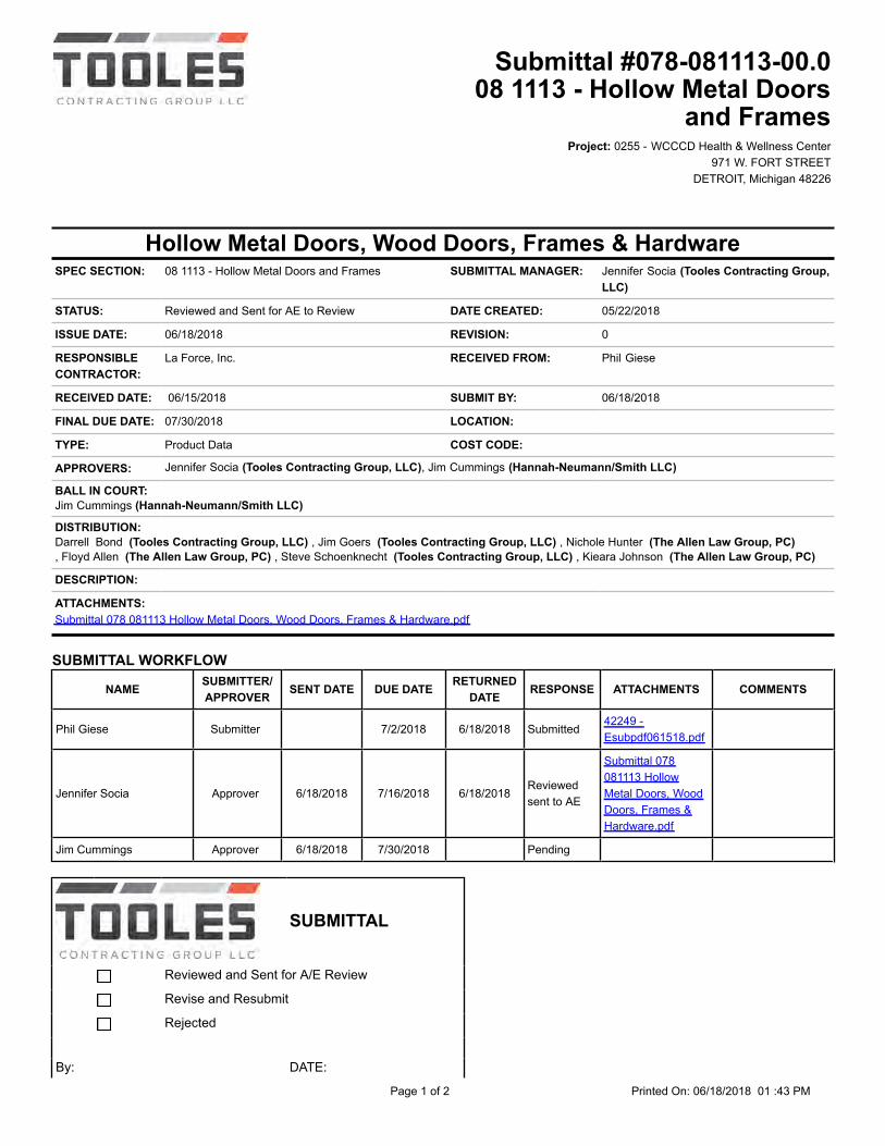
Project: 0255 - WCCCD Health & Wellness Center971 W. FORT STREET
DETROIT, Michigan 48226
Hollow Metal Doors, Wood Doors, Frames & HardwareSPEC SECTION: 08 1113 - Hollow Metal Doors and Frames SUBMITTAL MANAGER: Jennifer Socia (Tooles Contracting Group,
LLC)
STATUS: Reviewed and Sent for AE to Review DATE CREATED: 05/22/2018 ISSUE DATE: 06/18/2018 REVISION: 0
RESPONSIBLECONTRACTOR:
La Force, Inc. RECEIVED FROM: Phil Giese
RECEIVED DATE: 06/15/2018 SUBMIT BY: 06/18/2018 FINAL DUE DATE: 07/30/2018 LOCATION: TYPE: Product Data COST CODE: APPROVERS: Jennifer Socia (Tooles Contracting Group, LLC), Jim Cummings (Hannah-Neumann/Smith LLC)
BALL IN COURT:Jim Cummings (Hannah-Neumann/Smith LLC) DISTRIBUTION:Darrell Bond (Tooles Contracting Group, LLC) , Jim Goers (Tooles Contracting Group, LLC) , Nichole Hunter (The Allen Law Group, PC), Floyd Allen (The Allen Law Group, PC) , Steve Schoenknecht (Tooles Contracting Group, LLC) , Kieara Johnson (The Allen Law Group, PC)
DESCRIPTION:
ATTACHMENTS:Submittal 078 081113 Hollow Metal Doors, Wood Doors, Frames & Hardware.pdf
SUBMITTAL WORKFLOW
NAME SUBMITTER/APPROVER SENT DATE DUE DATE RETURNED
DATE RESPONSE ATTACHMENTS COMMENTS
Phil Giese Submitter 7/2/2018 6/18/2018 Submitted42249 -Esubpdf061518.pdf
Jennifer Socia Approver 6/18/2018 7/16/2018 6/18/2018Reviewedsent to AE
Submittal 078081113 HollowMetal Doors, WoodDoors, Frames &Hardware.pdf
Jim Cummings Approver 6/18/2018 7/30/2018 Pending
SUBMITTAL
Reviewed and Sent for A/E Review
Revise and Resubmit
Rejected
By: DATE:
Page 1 of 2 Printed On: 06/18/2018 01 :43 PM
Submittal #078-081113-00.008 1113 - Hollow Metal Doors
and Frames

SUBMITTAL ID: 078-081113-00 SPEC: 08 1113 TOOLES JOB # 0255 AE JOB # This submittal has been reviewed by the contractor for generalconformance with the requirements of the contract documents. Thissubmittal meets the requirements of the work outlined in the contractdocuments.
BY DATE COPIES TO
Page 2 of 2 Printed On: 06/18/2018 01:43 PM
Submittal #078-081113-00.008 1113 - Hollow Metal Doors
and Frames
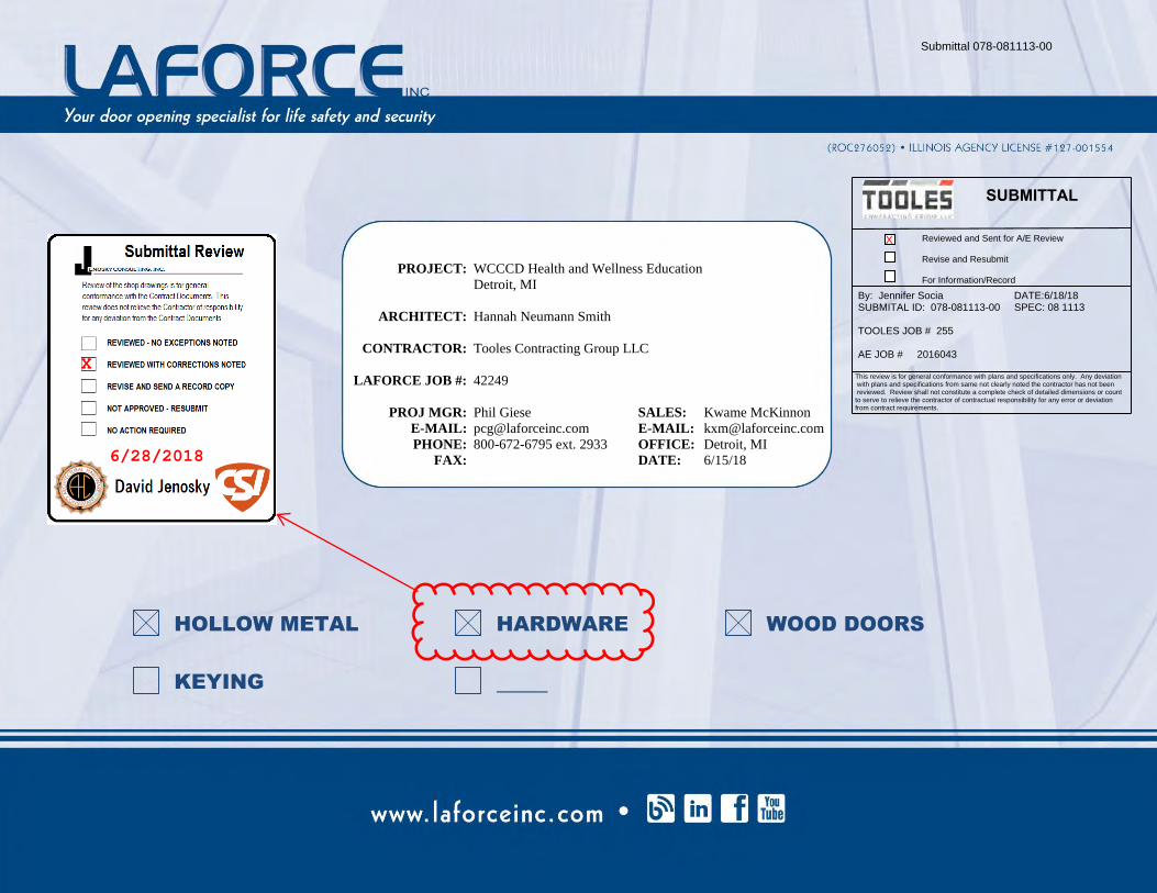
PROJECT: WCCCD Health and Wellness Education Detroit, MI ARCHITECT: Hannah Neumann Smith CONTRACTOR: Tooles Contracting Group LLC LAFORCE JOB #: 42249 PROJ MGR: Phil Giese SALES: Kwame McKinnon E-MAIL: [email protected] E-MAIL: [email protected] PHONE: 800-672-6795 ext. 2933 OFFICE: Detroit, MI FAX: DATE: 6/15/18
HOLLOW METAL HARDWARE WOOD DOORS KEYING
Submittal 078-081113-00
SUBMITTAL
Reviewed and Sent for A/E Review
Revise and Resubmit
For Information/Record
By: Jennifer Socia DATE:6/18/18SUBMITAL ID: 078-081113-00 SPEC: 08 1113
TOOLES JOB # 255
AE JOB # 2016043
This review is for general conformance with plans and specifications only. Any deviation with plans and specifications from same not clearly noted the contractor has not been reviewed. Review shall not constitute a complete check of detailed dimensions or count to serve to relieve the contractor of contractual responsibility for any error or deviation from contract requirements.
X
X
6/28/2018
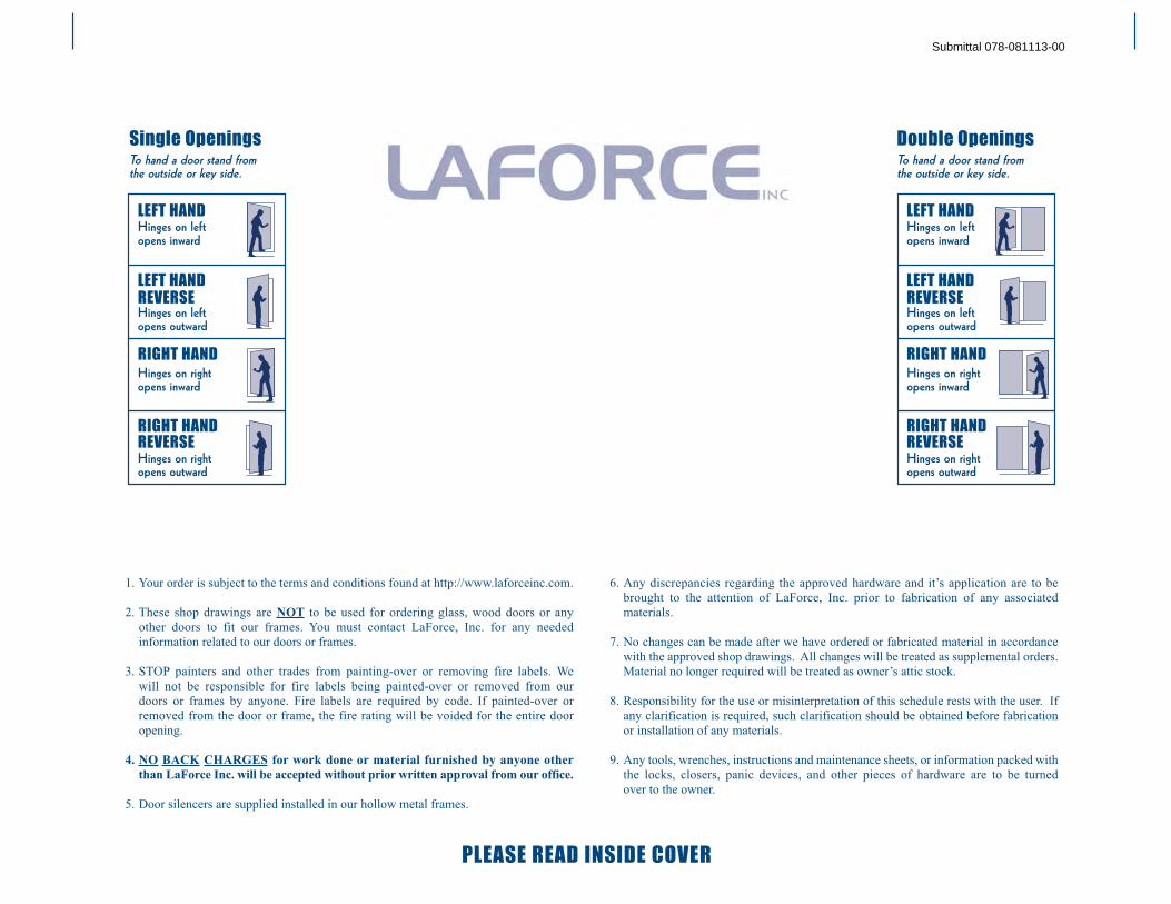
1. Your order is subject to the terms and conditions found at http://www.laforceinc.com.
2. These shop drawings are NOT to be used for ordering glass, wood doors or any
other doors to fit our frames. You must contact LaForce, Inc. for any needed
information related to our doors or frames.
3. STOP painters and other trades from painting-over or removing fire labels. We
will not be responsible for fire labels being painted-over or removed from our
doors or frames by anyone. Fire labels are required by code. If painted-over or
removed from the door or frame, the fire rating will be voided for the entire door
opening.
4. NO BACK CHARGES for work done or material furnished by anyone other
than LaForce Inc. will be accepted without prior written approval from our office.
5. Door silencers are supplied installed in our hollow metal frames.
6. Any discrepancies regarding the approved hardware and it’s application are to be
brought to the attention of LaForce, Inc. prior to fabrication of any associated
materials.
7. No changes can be made after we have ordered or fabricated material in accordance
with the approved shop drawings. All changes will be treated as supplemental orders.
Material no longer required will be treated as owner’s attic stock.
8. Responsibility for the use or misinterpretation of this schedule rests with the user. If
any clarification is required, such clarification should be obtained before fabrication
or installation of any materials.
9. Any tools, wrenches, instructions and maintenance sheets, or information packed with
the locks, closers, panic devices, and other pieces of hardware are to be turned
over to the owner.
LEFT HANDHinges on left
opens inward
LEFT HANDREVERSEHinges on left
opens outward
RIGHT HANDHinges on right
opens inward
RIGHT HANDREVERSEHinges on right
opens outward
Single OpeningsTo hand a door stand from
the outside or key side.
LEFT HANDHinges on left
opens inward
LEFT HANDREVERSEHinges on left
opens outward
RIGHT HANDHinges on right
opens inward
RIGHT HANDREVERSEHinges on right
opens outward
Double OpeningsTo hand a door stand from
the outside or key side.
PLEASE READ INSIDE COVER
Submittal 078-081113-00
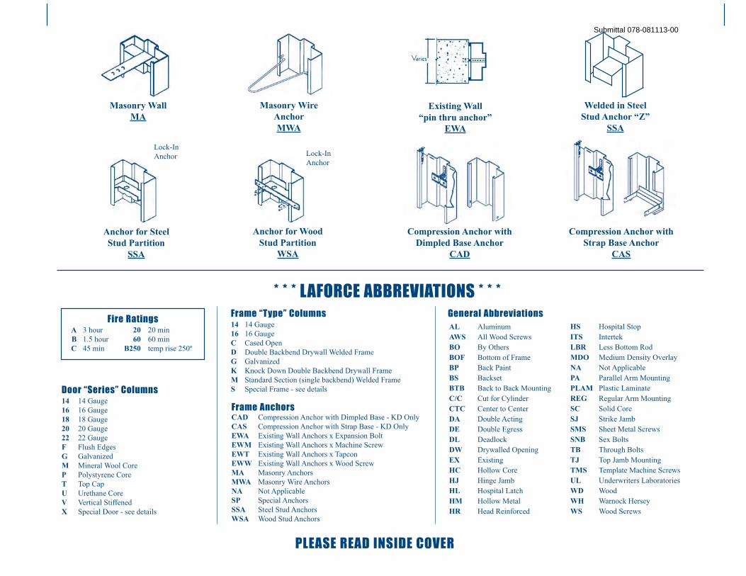
* * * LAFORCE ABBREVIATIONS * * *
Masonry Wall
MA
Welded in Steel
Stud Anchor “Z”
SSA
Existing Wall
“pin thru anchor”
EWA
Anchor for Wood
Stud Partition
WSA
Anchor for Steel
Stud Partition
SSA
Lock-In
AnchorLock-In
Anchor
Varies
Frame “Type” Columns14 14 Gauge
16 16 Gauge
C Cased Open
D Double Backbend Drywall Welded Frame
G Galvanized
K Knock Down Double Backbend Drywall Frame
M Standard Section (single backbend) Welded Frame
S Special Frame - see detailsDoor “Series” Columns14 14 Gauge
16 16 Gauge
18 18 Gauge
20 20 Gauge
22 22 Gauge
F Flush Edges
G Galvanized
M Mineral Wool Core
P Polystyrene Core
T Top Cap
U Urethane Core
V Vertical Stiffened
X Special Door - see details
Frame AnchorsCAD Compression Anchor with Dimpled Base - KD Only
CAS Compression Anchor with Strap Base - KD Only
EWA Existing Wall Anchors x Expansion Bolt
EWM Existing Wall Anchors x Machine Screw
EWT Existing Wall Anchors x Tapcon
EWW Existing Wall Anchors x Wood Screw
MA Masonry Anchors
MWA Masonry Wire Anchors
NA Not Applicable
SP Special Anchors
SSA Steel Stud Anchors
WSA Wood Stud Anchors
AL Aluminum
AWS All Wood Screws
BO By Others
BOF Bottom of Frame
BP Back Paint
BS Backset
BTB Back to Back Mounting
C/C Cut for Cylinder
CTC Center to Center
DA Double Acting
DE Double Egress
DL Deadlock
DW Drywalled Opening
EX Existing
HC Hollow Core
HJ Hinge Jamb
HL Hospital Latch
HM Hollow Metal
HR Head Reinforced
HS Hospital Stop
ITS Intertek
LBR Less Bottom Rod
MDO Medium Density Overlay
NA Not Applicable
PA Parallel Arm Mounting
PLAM Plastic Laminate
REG Regular Arm Mounting
SC Solid Core
SJ Strike Jamb
SMS Sheet Metal Screws
SNB Sex Bolts
TB Through Bolts
TJ Top Jamb Mounting
TMS Template Machine Screws
UL Underwriters Laboratories
WD Wood
WH Warnock Hersey
WS Wood Screws
General AbbreviationsFire Ratings
A 3 hour 20 20 min
B 1.5 hour 60 60 min
C 45 min B250 temp rise 250º
Masonry Wire
Anchor
MWA
Compression Anchor with
Dimpled Base Anchor
CAD
Compression Anchor with
Strap Base Anchor
CAS
PLEASE READ INSIDE COVER
Submittal 078-081113-00
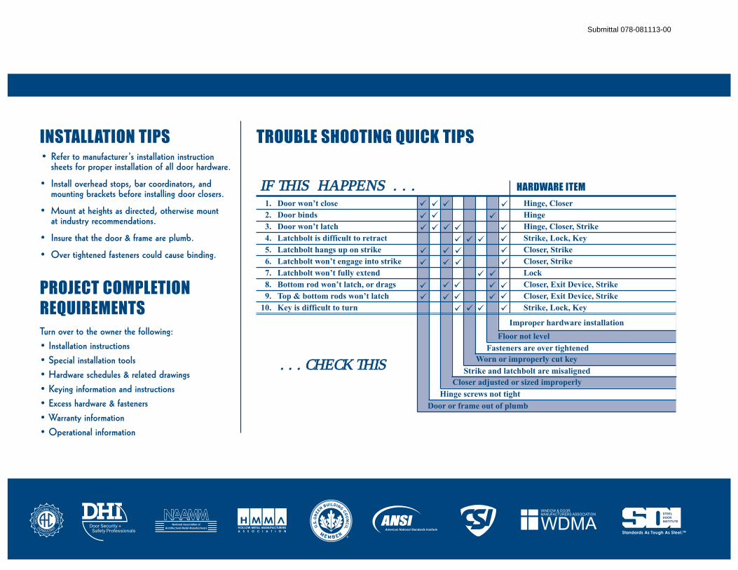
TROUBLE SHOOTING QUICK TIPSINSTALLATION TIPS• Refer to manufacturer ’s installation instruction
sheets for proper installation of all door hardware.
• Install overhead stops, bar coordinators, and
mounting brackets before installing door closers.
• Mount at heights as directed, otherwise mount
at industry recommendations.
• Insure that the door & frame are plumb.
• Over tightened fasteners could cause binding.
PROJECT COMPLETIONREQUIREMENTSTurn over to the owner the following:
• Installation instructions
• Special installation tools
• Hardware schedules & related drawings
• Keying information and instructions
• Excess hardware & fasteners
• Warranty information
• Operational information
IIF THIS HAPPENS . . . HARDWARE ITEM
. . . CHECK THIS
�
�
�
�
�
�
�
��� �
��
� �
�
�
�
�
�
�
��
�
�
�
�
�
�
�
�
�
�
�
�
�
� �
�
�
American National Standards Institute
1. Door won’t close Hinge, Closer
2. Door binds Hinge
3. Door won’t latch Hinge, Closer, Strike
4. Latchbolt is difficult to retract Strike, Lock, Key
5. Latchbolt hangs up on strike Closer, Strike
6. Latchbolt won’t engage into strike Closer, Strike
7. Latchbolt won’t fully extend Lock
8. Bottom rod won’t latch, or drags Closer, Exit Device, Strike
9. Top & bottom rods won’t latch Closer, Exit Device, Strike
10. Key is difficult to turn Strike, Lock, Key
Improper hardware installation
Floor not level
Fasteners are over tightened
Worn or improperly cut key
Strike and latchbolt are misaligned
Closer adjusted or sized improperly
Hinge screws not tight
Door or frame out of plumb
Submittal 078-081113-00
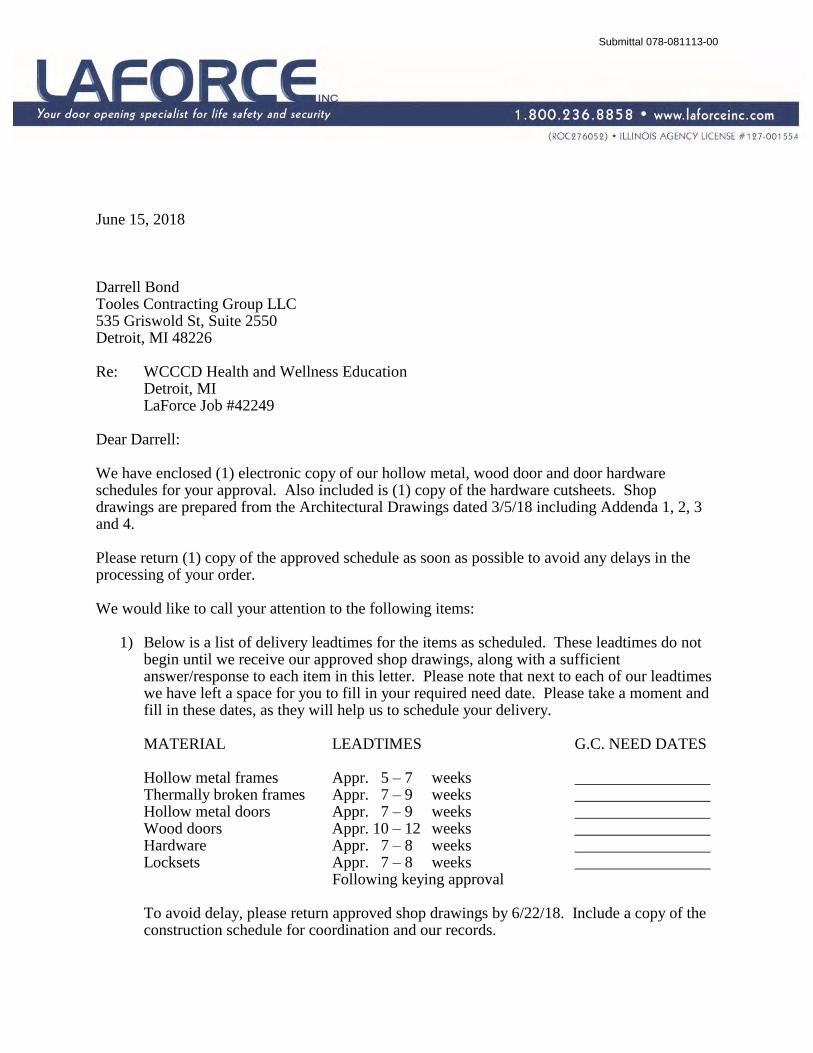
June 15, 2018 Darrell Bond Tooles Contracting Group LLC 535 Griswold St, Suite 2550 Detroit, MI 48226 Re: WCCCD Health and Wellness Education Detroit, MI LaForce Job #42249 Dear Darrell: We have enclosed (1) electronic copy of our hollow metal, wood door and door hardware schedules for your approval. Also included is (1) copy of the hardware cutsheets. Shop drawings are prepared from the Architectural Drawings dated 3/5/18 including Addenda 1, 2, 3 and 4. Please return (1) copy of the approved schedule as soon as possible to avoid any delays in the processing of your order. We would like to call your attention to the following items:
1) Below is a list of delivery leadtimes for the items as scheduled. These leadtimes do not begin until we receive our approved shop drawings, along with a sufficient answer/response to each item in this letter. Please note that next to each of our leadtimes we have left a space for you to fill in your required need date. Please take a moment and fill in these dates, as they will help us to schedule your delivery.
MATERIAL LEADTIMES G.C. NEED DATES Hollow metal frames Appr. 5 – 7 weeks _________________ Thermally broken frames Appr. 7 – 9 weeks _________________ Hollow metal doors Appr. 7 – 9 weeks _________________ Wood doors Appr. 10 – 12 weeks _________________ Hardware Appr. 7 – 8 weeks _________________ Locksets Appr. 7 – 8 weeks _________________ Following keying approval To avoid delay, please return approved shop drawings by 6/22/18. Include a copy of the construction schedule for coordination and our records.
Submittal 078-081113-00
Page 2 RE: WCCCD Health and Wellness Education June 15, 2018
2) We have scheduled industry standard undercuts of ⅝” at all wood doors and ¾” at all hollow metal doors (unless noted otherwise). Please verify that this is correct or advise if a different undercut is needed to accommodate thicker flooring conditions.
3) Please provide approval of the pre-finished wood door samples which were sent under separate cover dated 6/1/18. This approval is required before we can release wood doors for production.
4) Please provide us with the glass thickness, being provided by others, at our door elevations NL and FG. We require this information before we can release this material.
5) We have scheduled opening 301A as indicated only on the hardware schedule as we could not find this opening on the plans. Please provide us with a detail showing where this opening is for us to determine the jamb depth, anchor type, degree of opening, and handing of this opening.
6) We have scheduled frames 219, 119B with a 8 ¼” jamb depth (which has a 7 ½” throat opening) and steel stud anchors. Please verify that this is appropriate for each of these openings as we could not determine the wall types.
7) We have scheduled frames 105, 106, 107A, 107B, 107C, 108, 109, 110, 111, 115, 120A, 120B, 122B, 123, 124, 125, 126, 137, 138, 140, 141, 142, 144, 146, 147, 148A, 148B, 149, 150, 157A, 157B, 158A, 158B, 159A, 159B, 161A, 161B, 162, 118B, 156B with a 5 ¾” jamb depth, to abut the wall, and masonry anchors. Please verify that this is appropriate for each of these openings as we could not determine the wall types.
8) As indicated in our bid and confirmation letter, hollow metal frames cannot be both fire rated and thermally broken. Where indicated to be both, we have scheduled frames with the fire ratings indicated but without a thermal break. Please verify what we have scheduled is correct.
9) Please provide us with the exact manufacturer and model number of the door position switches being provided by other. We require this information to prep the frame accordingly.
10) Please advise us of the lock manufacturer, model number and finish of the lock being provided (by others) for each of the aluminum doors. We require this information in order to determine the proper cylinder.
Submittal 078-081113-00
Coordinate with the Security Integrator.
Coordinate with the the Glazing Contractor
DOOR 301A HAS BEEN DELETED.
Page 3 RE: WCCCD Health and Wellness Education June 15, 2018
11) Keying schedule to be coordinated between the owner and Steve with ESS. Please reach out to Steve at ESS to determine the keying requirements for each keyed opening, his number is 586-756-8400.
Respectfully,
Phil Giese LaForce, Inc. P: 800-672-6795, ext. 2933 PCG/eak Enclosures cc: Kwame McKinnon - LaForce Inc.
Submittal 078-081113-00
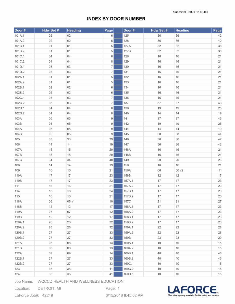
Door # Hdw Set # Heading Page Door # Hdw Set # Heading Page101A.1 02 02 6 125 36 36 42101A.2 02 02 6 126 36 36 42101B.1 01 01 5 127A 32 32 38101B.2 01 01 5 127B 32 32 38101C.1 04 04 8 128 16 16 21101C.2 04 04 8 129 16 16 21101D.1 03 03 7 130 16 16 21101D.2 03 03 7 131 16 16 21102A.1 01 01 5 132 16 16 21102A.2 01 01 5 133 16 16 21102B.1 02 02 6 134 16 16 21102B.2 02 02 6 135 16 16 21102C.1 03 03 7 136 16 16 21102C.2 03 03 7 137 37 37 43102D.1 04 04 8 138 19 19 25102D.2 04 04 8 140 14 14 19103A 05 05 9 141 37 37 43103B 05 05 9 142 19 19 25104A 05 05 9 144 14 14 19104B 05 05 9 145 38 38 44105 33 33 39 146 36 36 42106 14 14 19 147 36 36 42107A 15 15 20 148A 16 16 21107B 15 15 20 148B 16 16 21107C 34 34 40 149 20 20 26108 14 14 19 150 16 16 21109 16 16 21 156A 06 06 v2 11110A 17 17 23 156B 12 12 17110B 17 17 23 157A.1 17 17 23111 16 16 21 157A.2 17 17 23114 18 18 24 157B.1 17 17 23115 16 16 21 157B.2 17 17 23118A 06 06 v1 10 157C 21 21 27118B 12 12 17 158A.1 17 17 23119A 07 07 12 158A.2 17 17 23119B 12 12 17 158B.1 17 17 23120A.1 26 26 32 158B.2 17 17 23120A.2 26 26 32 159A.1 22 22 28120B.1 27 27 33 159A.2 22 22 28120B.2 27 27 33 159B 23 23 29121A 08 08 13 160A.1 10 10 15121B 08 08 13 160A.2 10 10 15122A 09 09 14 160B.1 40 40 46122B.1 27 27 33 160B.2 40 40 46122B.2 27 27 33 160C.1 10 10 15123 35 35 41 160C.2 10 10 15124 35 35 41 160D.1 10 10 15
WCCCD HEALTH AND WELLNESS EDUCATIONJob Name:
Location: DETROIT, MI
LaForce Job#: 42249
Page: 1
6/15/2018 8:45:02 AM
INDEX BY DOOR NUMBERSubmittal 078-081113-00
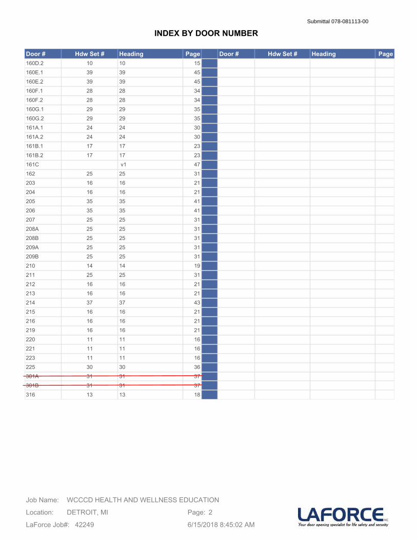
Door # Hdw Set # Heading Page Door # Hdw Set # Heading Page160D.2 10 10 15160E.1 39 39 45160E.2 39 39 45160F.1 28 28 34160F.2 28 28 34160G.1 29 29 35160G.2 29 29 35161A.1 24 24 30161A.2 24 24 30161B.1 17 17 23161B.2 17 17 23161C v1 47162 25 25 31203 16 16 21204 16 16 21205 35 35 41206 35 35 41207 25 25 31208A 25 25 31208B 25 25 31209A 25 25 31209B 25 25 31210 14 14 19211 25 25 31212 16 16 21213 16 16 21214 37 37 43215 16 16 21216 16 16 21219 16 16 21220 11 11 16221 11 11 16223 11 11 16225 30 30 36301A 31 31 37301B 31 31 37316 13 13 18
WCCCD HEALTH AND WELLNESS EDUCATIONJob Name:
Location: DETROIT, MI
LaForce Job#: 42249
Page: 2
6/15/2018 8:45:02 AM
INDEX BY DOOR NUMBERSubmittal 078-081113-00
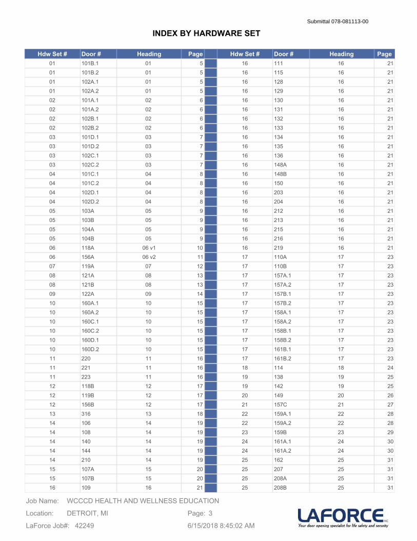
Hdw Set # Door # Heading Page Hdw Set # Door # Heading Page01 101B.1 01 5 16 111 16 2101 101B.2 01 5 16 115 16 2101 102A.1 01 5 16 128 16 2101 102A.2 01 5 16 129 16 2102 101A.1 02 6 16 130 16 2102 101A.2 02 6 16 131 16 2102 102B.1 02 6 16 132 16 2102 102B.2 02 6 16 133 16 2103 101D.1 03 7 16 134 16 2103 101D.2 03 7 16 135 16 2103 102C.1 03 7 16 136 16 2103 102C.2 03 7 16 148A 16 2104 101C.1 04 8 16 148B 16 2104 101C.2 04 8 16 150 16 2104 102D.1 04 8 16 203 16 2104 102D.2 04 8 16 204 16 2105 103A 05 9 16 212 16 2105 103B 05 9 16 213 16 2105 104A 05 9 16 215 16 2105 104B 05 9 16 216 16 2106 118A 06 v1 10 16 219 16 2106 156A 06 v2 11 17 110A 17 2307 119A 07 12 17 110B 17 2308 121A 08 13 17 157A.1 17 2308 121B 08 13 17 157A.2 17 2309 122A 09 14 17 157B.1 17 2310 160A.1 10 15 17 157B.2 17 2310 160A.2 10 15 17 158A.1 17 2310 160C.1 10 15 17 158A.2 17 2310 160C.2 10 15 17 158B.1 17 2310 160D.1 10 15 17 158B.2 17 2310 160D.2 10 15 17 161B.1 17 2311 220 11 16 17 161B.2 17 2311 221 11 16 18 114 18 2411 223 11 16 19 138 19 2512 118B 12 17 19 142 19 2512 119B 12 17 20 149 20 2612 156B 12 17 21 157C 21 2713 316 13 18 22 159A.1 22 2814 106 14 19 22 159A.2 22 2814 108 14 19 23 159B 23 2914 140 14 19 24 161A.1 24 3014 144 14 19 24 161A.2 24 3014 210 14 19 25 162 25 3115 107A 15 20 25 207 25 3115 107B 15 20 25 208A 25 3116 109 16 21 25 208B 25 31
WCCCD HEALTH AND WELLNESS EDUCATIONJob Name:
Location: DETROIT, MI
LaForce Job#: 42249
Page: 3
6/15/2018 8:45:02 AM
INDEX BY HARDWARE SETSubmittal 078-081113-00
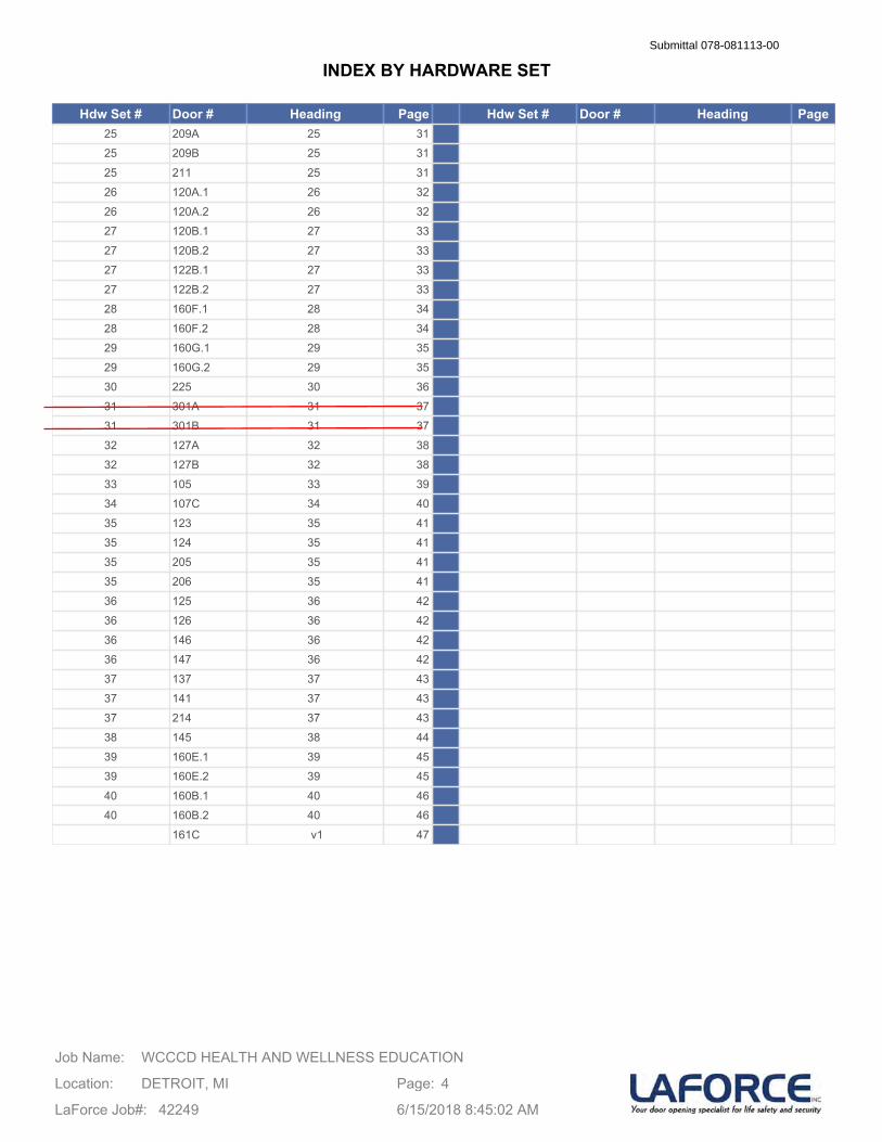
Hdw Set # Door # Heading Page Hdw Set # Door # Heading Page25 209A 25 3125 209B 25 3125 211 25 3126 120A.1 26 3226 120A.2 26 3227 120B.1 27 3327 120B.2 27 3327 122B.1 27 3327 122B.2 27 3328 160F.1 28 3428 160F.2 28 3429 160G.1 29 3529 160G.2 29 3530 225 30 3631 301A 31 3731 301B 31 3732 127A 32 3832 127B 32 3833 105 33 3934 107C 34 4035 123 35 4135 124 35 4135 205 35 4135 206 35 4136 125 36 4236 126 36 4236 146 36 4236 147 36 4237 137 37 4337 141 37 4337 214 37 4338 145 38 4439 160E.1 39 4539 160E.2 39 4540 160B.1 40 4640 160B.2 40 46
161C v1 47
WCCCD HEALTH AND WELLNESS EDUCATIONJob Name:
Location: DETROIT, MI
LaForce Job#: 42249
Page: 4
6/15/2018 8:45:02 AM
INDEX BY HARDWARE SETSubmittal 078-081113-00
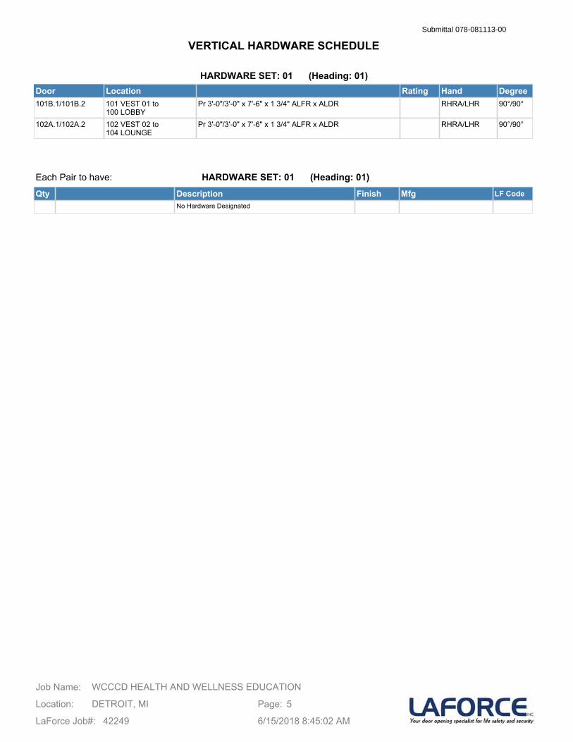
HARDWARE SET: 01 (Heading: 01)Door Location Rating Hand Degree101B.1/101B.2 101 VEST 01 to
100 LOBBYPr 3'-0"/3'-0" x 7'-6" x 1 3/4" ALFR x ALDR RHRA/LHR 90°/90°
102A.1/102A.2 102 VEST 02 to 104 LOUNGE
Pr 3'-0"/3'-0" x 7'-6" x 1 3/4" ALFR x ALDR RHRA/LHR 90°/90°
Each Pair to have:
Qty Description Finish Mfg LF CodeNo Hardware Designated
HARDWARE SET: 01 (Heading: 01)
WCCCD HEALTH AND WELLNESS EDUCATIONJob Name:
Location: DETROIT, MI
LaForce Job#: 42249
Page: 5
6/15/2018 8:45:02 AM
VERTICAL HARDWARE SCHEDULESubmittal 078-081113-00

HARDWARE SET: 02 (Heading: 02)Door Location Rating Hand Degree101A.1/101A.2 101 VEST 01 to
100 LOBBYPr 3'-0"/3'-0" x 7'-6" x 1 3/4" ALFR x ALDR RHRA/LHR 90°/90°
102B.1/102B.2 102 VEST 02 to 104 LOUNGE
Pr 3'-0"/3'-0" x 7'-6" x 1 3/4" ALFR x ALDR RHRA/LHR 90°/90°
Each Pair to have:
Qty Description Finish Mfg LF CodeNo Hardware Designated
HARDWARE SET: 02 (Heading: 02)
WCCCD HEALTH AND WELLNESS EDUCATIONJob Name:
Location: DETROIT, MI
LaForce Job#: 42249
Page: 6
6/15/2018 8:45:02 AM
VERTICAL HARDWARE SCHEDULESubmittal 078-081113-00
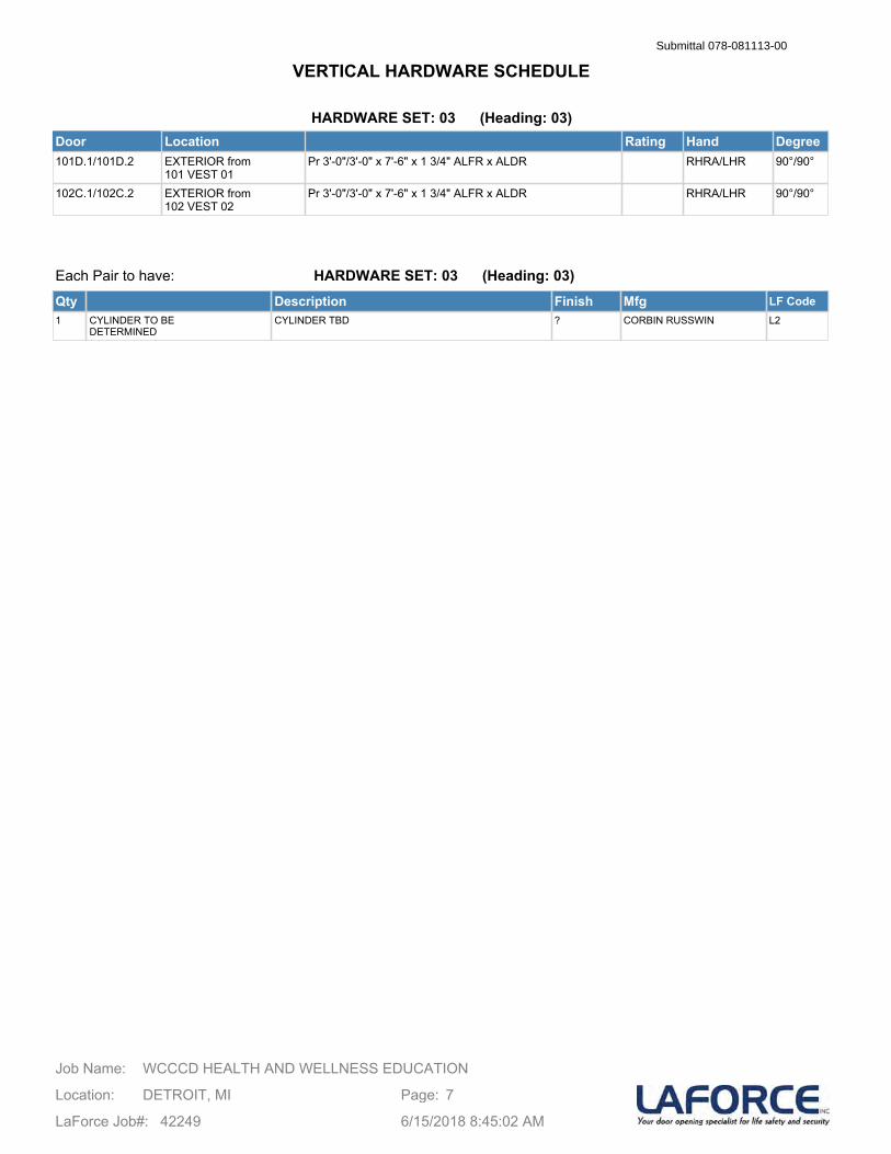
HARDWARE SET: 03 (Heading: 03)Door Location Rating Hand Degree101D.1/101D.2 EXTERIOR from
101 VEST 01Pr 3'-0"/3'-0" x 7'-6" x 1 3/4" ALFR x ALDR RHRA/LHR 90°/90°
102C.1/102C.2 EXTERIOR from 102 VEST 02
Pr 3'-0"/3'-0" x 7'-6" x 1 3/4" ALFR x ALDR RHRA/LHR 90°/90°
Each Pair to have:
Qty Description Finish Mfg LF Code1 CYLINDER TO BE
DETERMINEDCYLINDER TBD ? CORBIN RUSSWIN L2
HARDWARE SET: 03 (Heading: 03)
WCCCD HEALTH AND WELLNESS EDUCATIONJob Name:
Location: DETROIT, MI
LaForce Job#: 42249
Page: 7
6/15/2018 8:45:02 AM
VERTICAL HARDWARE SCHEDULESubmittal 078-081113-00

HARDWARE SET: 04 (Heading: 04)Door Location Rating Hand Degree101C.1/101C.2 EXTERIOR from
101 VEST 01Pr 3'-0"/3'-0" x 7'-6" x 1 3/4" ALFR x ALDR RHRA/LHR 90°/90°
102D.1/102D.2 EXTERIOR from 102 VEST 02
Pr 3'-0"/3'-0" x 7'-6" x 1 3/4" ALFR x ALDR RHRA/LHR 90°/90°
Each Pair to have:
Qty Description Finish Mfg LF Code1 CYLINDER TO BE
DETERMINEDCYLINDER TBD ? CORBIN RUSSWIN L2
HARDWARE SET: 04 (Heading: 04)
WCCCD HEALTH AND WELLNESS EDUCATIONJob Name:
Location: DETROIT, MI
LaForce Job#: 42249
Page: 8
6/15/2018 8:45:02 AM
VERTICAL HARDWARE SCHEDULESubmittal 078-081113-00
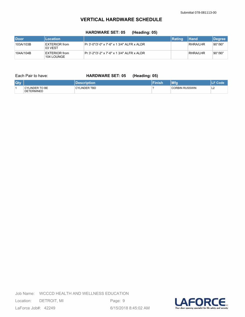
HARDWARE SET: 05 (Heading: 05)Door Location Rating Hand Degree103A/103B EXTERIOR from
03 VESTPr 3'-0"/3'-0" x 7'-6" x 1 3/4" ALFR x ALDR RHRA/LHR 90°/90°
104A/104B EXTERIOR from 104 LOUNGE
Pr 3'-2"/3'-2" x 7'-6" x 1 3/4" ALFR x ALDR RHRA/LHR 90°/90°
Each Pair to have:
Qty Description Finish Mfg LF Code1 CYLINDER TO BE
DETERMINEDCYLINDER TBD ? CORBIN RUSSWIN L2
HARDWARE SET: 05 (Heading: 05)
WCCCD HEALTH AND WELLNESS EDUCATIONJob Name:
Location: DETROIT, MI
LaForce Job#: 42249
Page: 9
6/15/2018 8:45:02 AM
VERTICAL HARDWARE SCHEDULESubmittal 078-081113-00
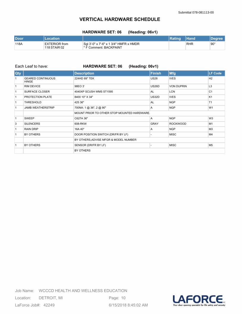
HARDWARE SET: 06 (Heading: 06v1)Door Location Rating Hand Degree118A EXTERIOR from
118 STAIR 02Sgl 3'-0" x 7'-6" x 1 3/4" HMFR x HMDR* F Comment: BACKPAINT
RHR 90°
Each Leaf to have:
Qty Description Finish Mfg LF Code1 GEARED CONTINUOUS
HINGE224HD 89" TEK US28 IVES H2
1 RIM DEVICE 98EO 3' US26D VON DUPRIN L3
1 SURFACE CLOSER 4040XP SCUSH WMS ST1595 AL LCN C1
1 PROTECTION PLATE 8400 10" X 34" US32D IVES K1
1 THRESHOLD 425 36" AL NGP T1
1 JAMB WEATHERSTRIP 700NA: 1 @ 36", 2 @ 90" A NGP W1
MOUNT PRIOR TO OTHER STOP MOUNTED HARDWARE.
1 SWEEP C627A 36" A NGP W3
3 SILENCERS 608-RKW GRAY ROCKWOOD M1
1 RAIN DRIP 16A 40" A NGP M3
1 BY OTHERS DOOR POSITION SWITCH (DR/FR BY LF) - MISC M4
BY OTHERS,ADVISE MFGR & MODEL NUMBER
1 BY OTHERS SENSOR (DR/FR BY LF) - MISC M5
BY OTHERS
HARDWARE SET: 06 (Heading: 06v1)
WCCCD HEALTH AND WELLNESS EDUCATIONJob Name:
Location: DETROIT, MI
LaForce Job#: 42249
Page: 10
6/15/2018 8:45:02 AM
VERTICAL HARDWARE SCHEDULESubmittal 078-081113-00
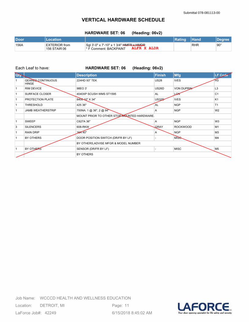
HARDWARE SET: 06 (Heading: 06v2)Door Location Rating Hand Degree156A EXTERIOR from
156 STAIR 06Sgl 3'-0" x 7'-10" x 1 3/4" HMFR x HMDR* F Comment: BACKPAINT
RHR 90°
Each Leaf to have:
Qty Description Finish Mfg LF Code1 GEARED CONTINUOUS
HINGE224HD 93" TEK US28 IVES H3
1 RIM DEVICE 98EO 3' US26D VON DUPRIN L3
1 SURFACE CLOSER 4040XP SCUSH WMS ST1595 AL LCN C1
1 PROTECTION PLATE 8400 10" X 34" US32D IVES K1
1 THRESHOLD 425 36" AL NGP T1
1 JAMB WEATHERSTRIP 700NA: 1 @ 36", 2 @ 94" A NGP W2
MOUNT PRIOR TO OTHER STOP MOUNTED HARDWARE.
1 SWEEP C627A 36" A NGP W3
3 SILENCERS 608-RKW GRAY ROCKWOOD M1
1 RAIN DRIP 16A 40" A NGP M3
1 BY OTHERS DOOR POSITION SWITCH (DR/FR BY LF) - MISC M4
BY OTHERS,ADVISE MFGR & MODEL NUMBER
1 BY OTHERS SENSOR (DR/FR BY LF) - MISC M5
BY OTHERS
HARDWARE SET: 06 (Heading: 06v2)
WCCCD HEALTH AND WELLNESS EDUCATIONJob Name:
Location: DETROIT, MI
LaForce Job#: 42249
Page: 11
6/15/2018 8:45:02 AM
VERTICAL HARDWARE SCHEDULESubmittal 078-081113-00
ALFR X ALDR

HARDWARE SET: 07 (Heading: 07)Door Location Rating Hand Degree119A EXTERIOR from
119 STAIR 03Sgl 3'-0" x 7'-6" x 1 3/4" HMFR x HMDR* F Comment: BACKPAINT
60 LHR 90°
Each Leaf to have:
Qty Description Finish Mfg LF Code1 GEARED CONTINUOUS
HINGE224HD 89" TEK US28 IVES H2
1 RIM DEVICE 98EO-F 3' MD US26D VON DUPRIN L1
1 SURFACE CLOSER 4040XP SCUSH WMS ST1595 AL LCN C1
1 PROTECTION PLATE 8400 10" X 34" US32D IVES K1
1 THRESHOLD 425 36" AL NGP T1
1 JAMB WEATHERSTRIP 700NA: 1 @ 36", 2 @ 90" A NGP W1
MOUNT PRIOR TO OTHER STOP MOUNTED HARDWARE.
1 SWEEP C627A 36" A NGP W3
3 SILENCERS 608-RKW GRAY ROCKWOOD M1
1 RAIN DRIP 16A 40" A NGP M3
1 BY OTHERS DOOR POSITION SWITCH (DR/FR BY LF) - MISC M4
BY OTHERS,ADVISE MFGR & MODEL NUMBER
1 BY OTHERS SENSOR (DR/FR BY LF) - MISC M5
BY OTHERS
HARDWARE SET: 07 (Heading: 07)
WCCCD HEALTH AND WELLNESS EDUCATIONJob Name:
Location: DETROIT, MI
LaForce Job#: 42249
Page: 12
6/15/2018 8:45:02 AM
VERTICAL HARDWARE SCHEDULESubmittal 078-081113-00

HARDWARE SET: 08 (Heading: 08)Door Location Rating Hand Degree121A/121B EXTERIOR from
121 CORR 02Pr 3'-0"/3'-0" x 7'-10" x 1 3/4" HMFR x HMDR* F Comment: HEAD REINFORCING* F Comment: BACKPAINT
60 RHRA/LHR 90°/90°
Each Pair to have:
Qty Description Finish Mfg LF Code2 GEARED CONTINUOUS
HINGE224HD 93" TEK US28 IVES H3
1 RIM DEVICE 98DT-F 990DT 3' MD US26D VON DUPRIN L4
1 RIM DEVICE 98NL-F 990NL 3' MD US26D VON DUPRIN L5
1 SECURITY RIMCYLINDER
3010 200 626 CORBIN RUSSWIN L6
1 SECURITY MORTISECYLINDER
1010 114 A02 626 CORBIN RUSSWIN L7
FOR KEYED MULLIONS
2 SURFACE CLOSER 4040XP SCUSH WMS ST1595 AL LCN C1
2 PROTECTION PLATE 8400 10" X 34" US32D IVES K1
1 THRESHOLD 425 72" AL NGP T2
2 SWEEP C627A 36" A NGP W3
1 JAMB WEATHERSTRIP 700NA: 1 @ 72", 2 @ 94" A NGP W4
MOUNT PRIOR TO OTHER STOP MOUNTED HARDWARE.
2 SILENCERS 608-RKW GRAY ROCKWOOD M2
2 BY OTHERS DOOR POSITION SWITCH (DR/FR BY LF) - MISC M4
BY OTHERS,ADVISE MFGR & MODEL NUMBER
1 BY OTHERS SENSOR (DR/FR BY LF) - MISC M5
BY OTHERS
1 STEEL MULLION KR9954 8'5" SP28 VON DUPRIN M6
1 RAIN DRIP 16A 76" A NGP M7
HARDWARE SET: 08 (Heading: 08)
WCCCD HEALTH AND WELLNESS EDUCATIONJob Name:
Location: DETROIT, MI
LaForce Job#: 42249
Page: 13
6/15/2018 8:45:02 AM
VERTICAL HARDWARE SCHEDULESubmittal 078-081113-00
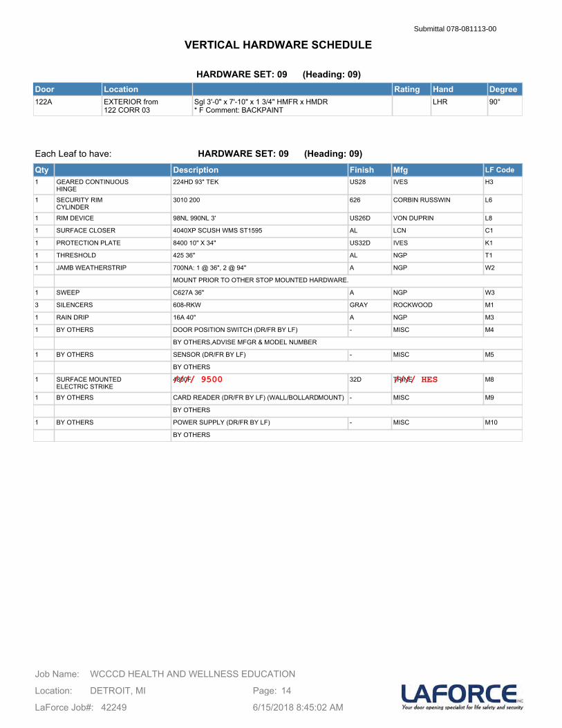
HARDWARE SET: 09 (Heading: 09)Door Location Rating Hand Degree122A EXTERIOR from
122 CORR 03Sgl 3'-0" x 7'-10" x 1 3/4" HMFR x HMDR* F Comment: BACKPAINT
LHR 90°
Each Leaf to have:
Qty Description Finish Mfg LF Code1 GEARED CONTINUOUS
HINGE224HD 93" TEK US28 IVES H3
1 SECURITY RIMCYLINDER
3010 200 626 CORBIN RUSSWIN L6
1 RIM DEVICE 98NL 990NL 3' US26D VON DUPRIN L8
1 SURFACE CLOSER 4040XP SCUSH WMS ST1595 AL LCN C1
1 PROTECTION PLATE 8400 10" X 34" US32D IVES K1
1 THRESHOLD 425 36" AL NGP T1
1 JAMB WEATHERSTRIP 700NA: 1 @ 36", 2 @ 94" A NGP W2
MOUNT PRIOR TO OTHER STOP MOUNTED HARDWARE.
1 SWEEP C627A 36" A NGP W3
3 SILENCERS 608-RKW GRAY ROCKWOOD M1
1 RAIN DRIP 16A 40" A NGP M3
1 BY OTHERS DOOR POSITION SWITCH (DR/FR BY LF) - MISC M4
BY OTHERS,ADVISE MFGR & MODEL NUMBER
1 BY OTHERS SENSOR (DR/FR BY LF) - MISC M5
BY OTHERS
1 SURFACE MOUNTEDELECTRIC STRIKE
4800F 32D TRINE M8
1 BY OTHERS CARD READER (DR/FR BY LF) (WALL/BOLLARDMOUNT) - MISC M9
BY OTHERS
1 BY OTHERS POWER SUPPLY (DR/FR BY LF) - MISC M10
BY OTHERS
HARDWARE SET: 09 (Heading: 09)
WCCCD HEALTH AND WELLNESS EDUCATIONJob Name:
Location: DETROIT, MI
LaForce Job#: 42249
Page: 14
6/15/2018 8:45:02 AM
VERTICAL HARDWARE SCHEDULESubmittal 078-081113-00
//// 9500 //// HES
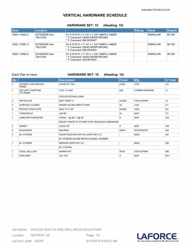
HARDWARE SET: 10 (Heading: 10)Door Location Rating Hand Degree160A.1/160A.2 EXTERIOR from
160 GYMPr 4'-0"/4'-0" x 7'-10" x 1 3/4" HMFR x HMDR* F Comment: HEAD REINFORCING* F Comment: BACKPAINT
RHRA/LHR 90°/90°
160C.1/160C.2 EXTERIOR from 160 GYM
Pr 4'-0"/4'-0" x 7'-10" x 1 3/4" HMFR x HMDR* F Comment: HEAD REINFORCING* F Comment: BACKPAINT
RHRA/LHR 90°/90°
160D.1/160D.2 EXTERIOR from 160 GYM
Pr 4'-0"/4'-0" x 7'-10" x 1 3/4" HMFR x HMDR* F Comment: HEAD REINFORCING* F Comment: BACKPAINT
RHRA/LHR 90°/90°
Each Pair to have:
Qty Description Finish Mfg LF Code2 GEARED CONTINUOUS
HINGE224HD 93" TEK US28 IVES H3
1 SECURITY MORTISECYLINDER
1010 114 A02 626 CORBIN RUSSWIN L7
FOR KEYED MULLIONS
2 RIM DEVICE 98DT 990DT 4' US26D VON DUPRIN L9
2 SURFACE CLOSER 4040XP SCUSH WMS ST1595 AL LCN C1
2 PROTECTION PLATE 8400 10" X 46" US32D IVES K2
1 THRESHOLD 425 96" AL NGP T3
1 JAMB WEATHERSTRIP 700NA: 1 @ 96", 2 @ 94" A NGP W5
MOUNT PRIOR TO OTHER STOP MOUNTED HARDWARE.
2 SWEEP C627A 48" A NGP W6
2 SILENCERS 608-RKW GRAY ROCKWOOD M2
2 BY OTHERS DOOR POSITION SWITCH (DR/FR BY LF) - MISC M4
BY OTHERS,ADVISE MFGR & MODEL NUMBER
1 BY OTHERS SENSOR (DR/FR BY LF) - MISC M5
BY OTHERS
1 STEEL MULLION KR9954 8'5" SP28 VON DUPRIN M6
1 RAIN DRIP 16A 100" A NGP M11
HARDWARE SET: 10 (Heading: 10)
WCCCD HEALTH AND WELLNESS EDUCATIONJob Name:
Location: DETROIT, MI
LaForce Job#: 42249
Page: 15
6/15/2018 8:45:02 AM
VERTICAL HARDWARE SCHEDULESubmittal 078-081113-00
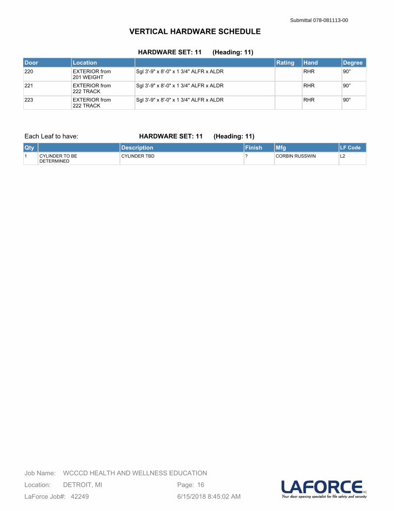
HARDWARE SET: 11 (Heading: 11)Door Location Rating Hand Degree220 EXTERIOR from
201 WEIGHTSgl 3'-9" x 8'-0" x 1 3/4" ALFR x ALDR RHR 90°
221 EXTERIOR from 222 TRACK
Sgl 3'-9" x 8'-0" x 1 3/4" ALFR x ALDR RHR 90°
223 EXTERIOR from 222 TRACK
Sgl 3'-9" x 8'-0" x 1 3/4" ALFR x ALDR RHR 90°
Each Leaf to have:
Qty Description Finish Mfg LF Code1 CYLINDER TO BE
DETERMINEDCYLINDER TBD ? CORBIN RUSSWIN L2
HARDWARE SET: 11 (Heading: 11)
WCCCD HEALTH AND WELLNESS EDUCATIONJob Name:
Location: DETROIT, MI
LaForce Job#: 42249
Page: 16
6/15/2018 8:45:02 AM
VERTICAL HARDWARE SCHEDULESubmittal 078-081113-00
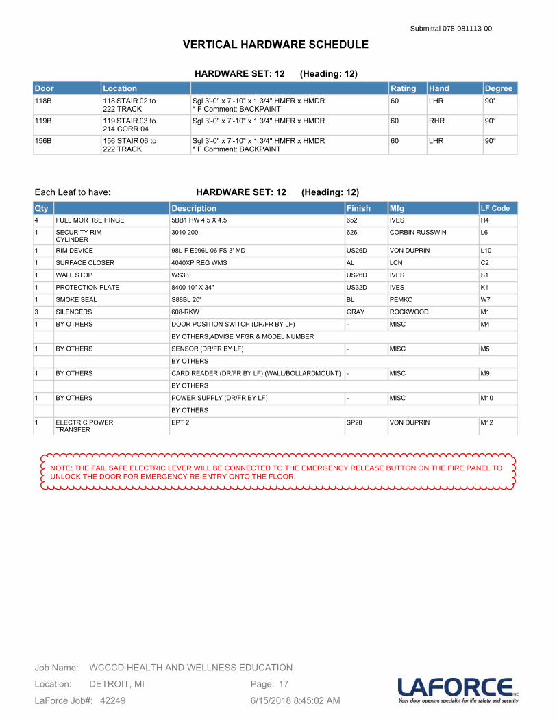
HARDWARE SET: 12 (Heading: 12)Door Location Rating Hand Degree118B 118 STAIR 02 to
222 TRACKSgl 3'-0" x 7'-10" x 1 3/4" HMFR x HMDR* F Comment: BACKPAINT
60 LHR 90°
119B 119 STAIR 03 to 214 CORR 04
Sgl 3'-0" x 7'-10" x 1 3/4" HMFR x HMDR 60 RHR 90°
156B 156 STAIR 06 to 222 TRACK
Sgl 3'-0" x 7'-10" x 1 3/4" HMFR x HMDR* F Comment: BACKPAINT
60 LHR 90°
Each Leaf to have:
Qty Description Finish Mfg LF Code4 FULL MORTISE HINGE 5BB1 HW 4.5 X 4.5 652 IVES H4
1 SECURITY RIMCYLINDER
3010 200 626 CORBIN RUSSWIN L6
1 RIM DEVICE 98L-F E996L 06 FS 3' MD US26D VON DUPRIN L10
1 SURFACE CLOSER 4040XP REG WMS AL LCN C2
1 WALL STOP WS33 US26D IVES S1
1 PROTECTION PLATE 8400 10" X 34" US32D IVES K1
1 SMOKE SEAL S88BL 20' BL PEMKO W7
3 SILENCERS 608-RKW GRAY ROCKWOOD M1
1 BY OTHERS DOOR POSITION SWITCH (DR/FR BY LF) - MISC M4
BY OTHERS,ADVISE MFGR & MODEL NUMBER
1 BY OTHERS SENSOR (DR/FR BY LF) - MISC M5
BY OTHERS
1 BY OTHERS CARD READER (DR/FR BY LF) (WALL/BOLLARDMOUNT) - MISC M9
BY OTHERS
1 BY OTHERS POWER SUPPLY (DR/FR BY LF) - MISC M10
BY OTHERS
1 ELECTRIC POWERTRANSFER
EPT 2 SP28 VON DUPRIN M12
HARDWARE SET: 12 (Heading: 12)
WCCCD HEALTH AND WELLNESS EDUCATIONJob Name:
Location: DETROIT, MI
LaForce Job#: 42249
Page: 17
6/15/2018 8:45:02 AM
VERTICAL HARDWARE SCHEDULESubmittal 078-081113-00
NOTE: THE FAIL SAFE ELECTRIC LEVER WILL BE CONNECTED TO THE EMERGENCY RELEASE BUTTON ON THE FIRE PANEL TOUNLOCK THE DOOR FOR EMERGENCY RE-ENTRY ONTO THE FLOOR.
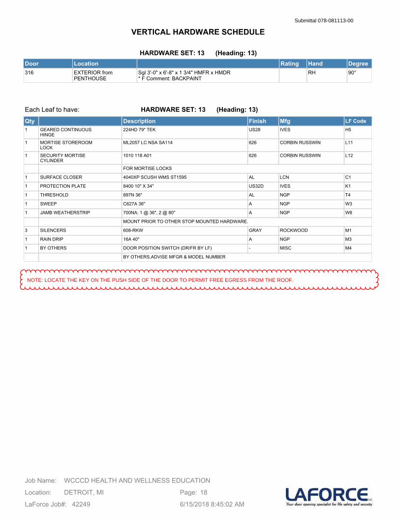
HARDWARE SET: 13 (Heading: 13)Door Location Rating Hand Degree316 EXTERIOR from
PENTHOUSESgl 3'-0" x 6'-8" x 1 3/4" HMFR x HMDR* F Comment: BACKPAINT
RH 90°
Each Leaf to have:
Qty Description Finish Mfg LF Code1 GEARED CONTINUOUS
HINGE224HD 79" TEK US28 IVES H5
1 MORTISE STOREROOMLOCK
ML2057 LC NSA SA114 626 CORBIN RUSSWIN L11
1 SECURITY MORTISECYLINDER
1010 118 A01 626 CORBIN RUSSWIN L12
FOR MORTISE LOCKS
1 SURFACE CLOSER 4040XP SCUSH WMS ST1595 AL LCN C1
1 PROTECTION PLATE 8400 10" X 34" US32D IVES K1
1 THRESHOLD 897N 36" AL NGP T4
1 SWEEP C627A 36" A NGP W3
1 JAMB WEATHERSTRIP 700NA: 1 @ 36", 2 @ 80" A NGP W8
MOUNT PRIOR TO OTHER STOP MOUNTED HARDWARE.
3 SILENCERS 608-RKW GRAY ROCKWOOD M1
1 RAIN DRIP 16A 40" A NGP M3
1 BY OTHERS DOOR POSITION SWITCH (DR/FR BY LF) - MISC M4
BY OTHERS,ADVISE MFGR & MODEL NUMBER
HARDWARE SET: 13 (Heading: 13)
WCCCD HEALTH AND WELLNESS EDUCATIONJob Name:
Location: DETROIT, MI
LaForce Job#: 42249
Page: 18
6/15/2018 8:45:02 AM
VERTICAL HARDWARE SCHEDULESubmittal 078-081113-00
NOTE: LOCATE THE KEY ON THE PUSH SIDE OF THE DOOR TO PERMIT FREE EGRESS FROM THE ROOF.
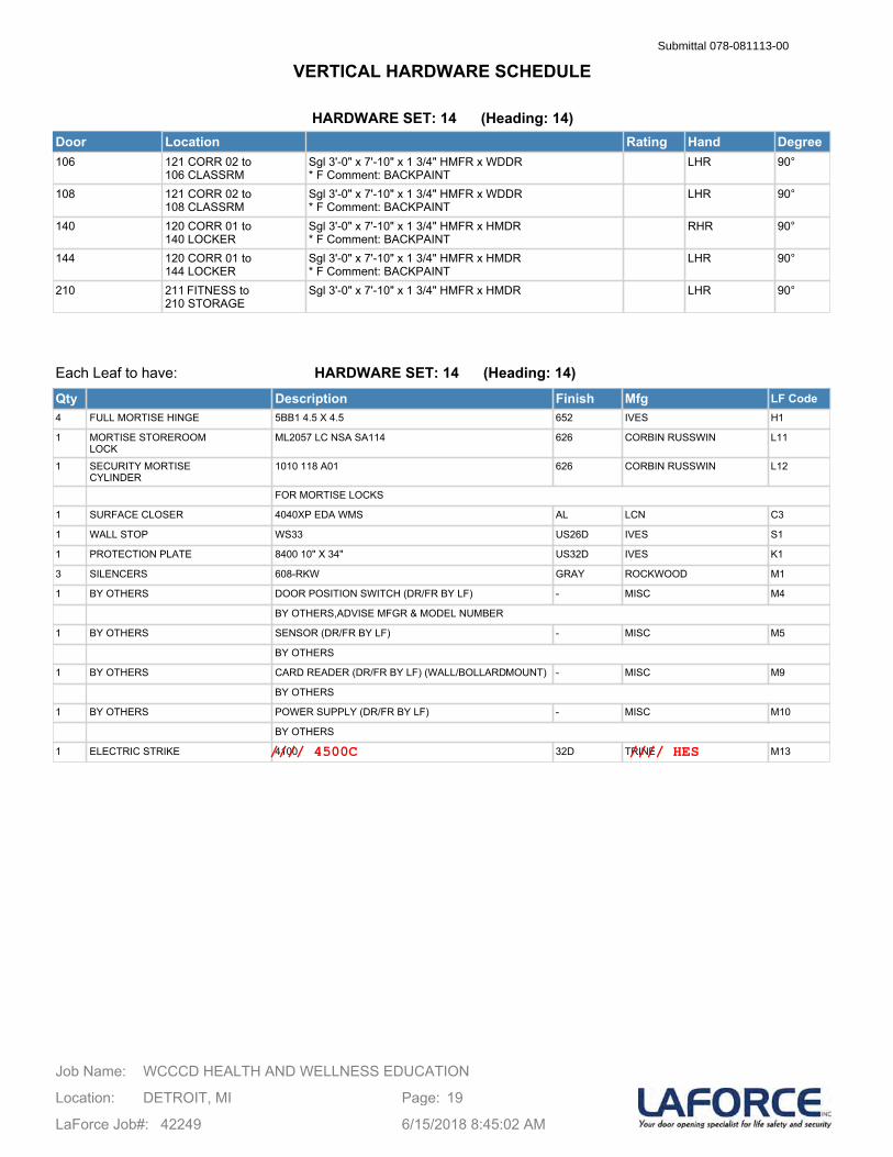
HARDWARE SET: 14 (Heading: 14)Door Location Rating Hand Degree106 121 CORR 02 to
106 CLASSRMSgl 3'-0" x 7'-10" x 1 3/4" HMFR x WDDR* F Comment: BACKPAINT
LHR 90°
108 121 CORR 02 to 108 CLASSRM
Sgl 3'-0" x 7'-10" x 1 3/4" HMFR x WDDR* F Comment: BACKPAINT
LHR 90°
140 120 CORR 01 to 140 LOCKER
Sgl 3'-0" x 7'-10" x 1 3/4" HMFR x HMDR* F Comment: BACKPAINT
RHR 90°
144 120 CORR 01 to 144 LOCKER
Sgl 3'-0" x 7'-10" x 1 3/4" HMFR x HMDR* F Comment: BACKPAINT
LHR 90°
210 211 FITNESS to 210 STORAGE
Sgl 3'-0" x 7'-10" x 1 3/4" HMFR x HMDR LHR 90°
Each Leaf to have:
Qty Description Finish Mfg LF Code4 FULL MORTISE HINGE 5BB1 4.5 X 4.5 652 IVES H1
1 MORTISE STOREROOMLOCK
ML2057 LC NSA SA114 626 CORBIN RUSSWIN L11
1 SECURITY MORTISECYLINDER
1010 118 A01 626 CORBIN RUSSWIN L12
FOR MORTISE LOCKS
1 SURFACE CLOSER 4040XP EDA WMS AL LCN C3
1 WALL STOP WS33 US26D IVES S1
1 PROTECTION PLATE 8400 10" X 34" US32D IVES K1
3 SILENCERS 608-RKW GRAY ROCKWOOD M1
1 BY OTHERS DOOR POSITION SWITCH (DR/FR BY LF) - MISC M4
BY OTHERS,ADVISE MFGR & MODEL NUMBER
1 BY OTHERS SENSOR (DR/FR BY LF) - MISC M5
BY OTHERS
1 BY OTHERS CARD READER (DR/FR BY LF) (WALL/BOLLARDMOUNT) - MISC M9
BY OTHERS
1 BY OTHERS POWER SUPPLY (DR/FR BY LF) - MISC M10
BY OTHERS
1 ELECTRIC STRIKE 4100 32D TRINE M13
HARDWARE SET: 14 (Heading: 14)
WCCCD HEALTH AND WELLNESS EDUCATIONJob Name:
Location: DETROIT, MI
LaForce Job#: 42249
Page: 19
6/15/2018 8:45:02 AM
VERTICAL HARDWARE SCHEDULESubmittal 078-081113-00
//// 4500C //// HES
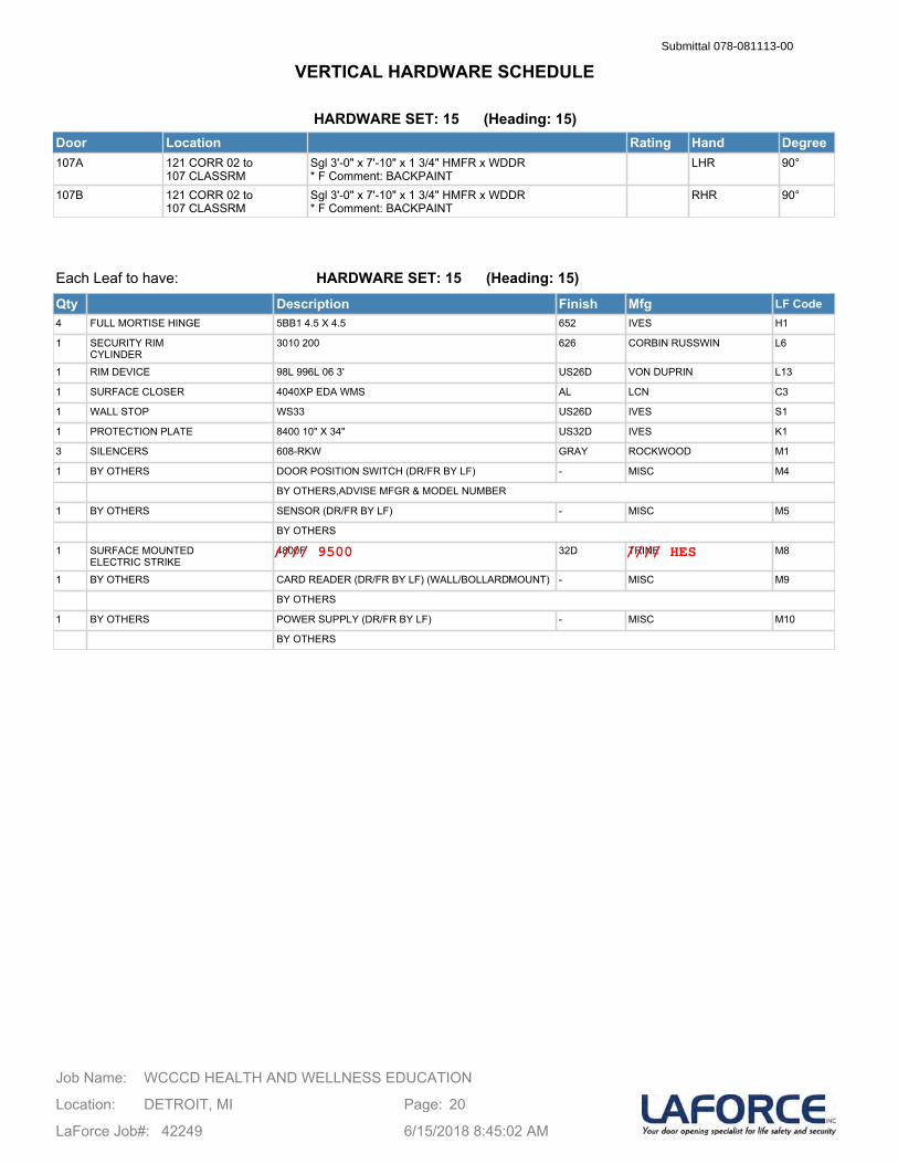
HARDWARE SET: 15 (Heading: 15)Door Location Rating Hand Degree107A 121 CORR 02 to
107 CLASSRMSgl 3'-0" x 7'-10" x 1 3/4" HMFR x WDDR* F Comment: BACKPAINT
LHR 90°
107B 121 CORR 02 to 107 CLASSRM
Sgl 3'-0" x 7'-10" x 1 3/4" HMFR x WDDR* F Comment: BACKPAINT
RHR 90°
Each Leaf to have:
Qty Description Finish Mfg LF Code4 FULL MORTISE HINGE 5BB1 4.5 X 4.5 652 IVES H1
1 SECURITY RIMCYLINDER
3010 200 626 CORBIN RUSSWIN L6
1 RIM DEVICE 98L 996L 06 3' US26D VON DUPRIN L13
1 SURFACE CLOSER 4040XP EDA WMS AL LCN C3
1 WALL STOP WS33 US26D IVES S1
1 PROTECTION PLATE 8400 10" X 34" US32D IVES K1
3 SILENCERS 608-RKW GRAY ROCKWOOD M1
1 BY OTHERS DOOR POSITION SWITCH (DR/FR BY LF) - MISC M4
BY OTHERS,ADVISE MFGR & MODEL NUMBER
1 BY OTHERS SENSOR (DR/FR BY LF) - MISC M5
BY OTHERS
1 SURFACE MOUNTEDELECTRIC STRIKE
4800F 32D TRINE M8
1 BY OTHERS CARD READER (DR/FR BY LF) (WALL/BOLLARDMOUNT) - MISC M9
BY OTHERS
1 BY OTHERS POWER SUPPLY (DR/FR BY LF) - MISC M10
BY OTHERS
HARDWARE SET: 15 (Heading: 15)
WCCCD HEALTH AND WELLNESS EDUCATIONJob Name:
Location: DETROIT, MI
LaForce Job#: 42249
Page: 20
6/15/2018 8:45:02 AM
VERTICAL HARDWARE SCHEDULESubmittal 078-081113-00
//// 9500 //// HES

HARDWARE SET: 16 (Heading: 16)Door Location Rating Hand Degree109 121 CORR 02 to
109 MECHSgl 3'-0" x 7'-10" x 1 3/4" HMFR x WDDR* F Comment: BACKPAINT
RH 90°
111 120 CORR 01 to 111 LOCKER
Sgl 3'-0" x 7'-10" x 1 3/4" HMFR x HMDR* F Comment: BACKPAINT
LH 90°
115 120 CORR 01 to 115 LOCKER
Sgl 3'-0" x 7'-10" x 1 3/4" HMFR x HMDR* F Comment: BACKPAINT
RH 90°
128 127 WAITING to 128 OFFICE
Sgl 3'-0" x 7'-10" x 1 3/4" HMFR x WDDR LH 90°
129 127 WAITING to 129 OFFICE
Sgl 3'-0" x 7'-10" x 1 3/4" HMFR x WDDR RH 90°
130 127 WAITING to 130 OFFICE
Sgl 3'-0" x 7'-10" x 1 3/4" HMFR x WDDR LH 90°
131 127 WAITING to 131 OFFICE
Sgl 3'-0" x 7'-10" x 1 3/4" HMFR x WDDR LH 90°
132 127 WAITING to 132 OFFICE
Sgl 3'-0" x 7'-10" x 1 3/4" HMFR x WDDR RH 90°
133 127 WAITING to 133 BREAK RM
Sgl 3'-0" x 7'-10" x 1 3/4" HMFR x WDDR RH 90°
134 127 WAITING to 134 OFFICE
Sgl 3'-0" x 7'-10" x 1 3/4" HMFR x WDDR LH 90°
135 127 WAITING to 135 STORAGE
Sgl 3'-0" x 7'-10" x 1 3/4" HMFR x WDDR LH 90°
136 127 WAITING to 136 OFFICE
Sgl 3'-0" x 7'-10" x 1 3/4" HMFR x WDDR RH 90°
148A 151 TWL DESK to 148 LAUNDRY
Sgl 3'-0" x 7'-10" x 1 3/4" HMFR x HMDR* F Comment: BACKPAINT
LH 90°
148B 151 TWL DESK to 148 LAUNDRY
Sgl 3'-0" x 7'-10" x 1 3/4" HMFR x HMDR* F Comment: BACKPAINT
RH 90°
150 151 TWL DESK to 150 JANITOR
Sgl 3'-0" x 7'-10" x 1 3/4" HMFR x HMDR* F Comment: BACKPAINT
RH 90°
203 224 DESK to 203 OFFICE
Sgl 3'-0" x 7'-10" x 1 3/4" HMFR x HMDR LH 90°
204 224 DESK to 204 ASSESS
Sgl 3'-0" x 7'-10" x 1 3/4" HMFR x HMDR RH 90°
212 214 CORR 04 to 212 STORAGE
Sgl 3'-0" x 7'-10" x 1 3/4" HMFR x HMDR RH 90°
213 214 CORR 04 to 213 DATA
Sgl 3'-0" x 7'-10" x 1 3/4" HMFR x HMDR LH 90°
215 214 CORR 04 to 215 ELEC
Sgl 3'-0" x 7'-10" x 1 3/4" HMFR x HMDR LH 90°
216 216 STAIR 04 to 214 CORR 04
Sgl 3'-0" x 7'-10" x 1 3/4" HMFR x HMDR LHR 90°
219 214 CORR 04 to 219 JANITOR
Sgl 3'-0" x 7'-10" x 1 3/4" HMFR x HMDR LH 90°
WCCCD HEALTH AND WELLNESS EDUCATIONJob Name:
Location: DETROIT, MI
LaForce Job#: 42249
Page: 21
6/15/2018 8:45:02 AM
VERTICAL HARDWARE SCHEDULESubmittal 078-081113-00
60
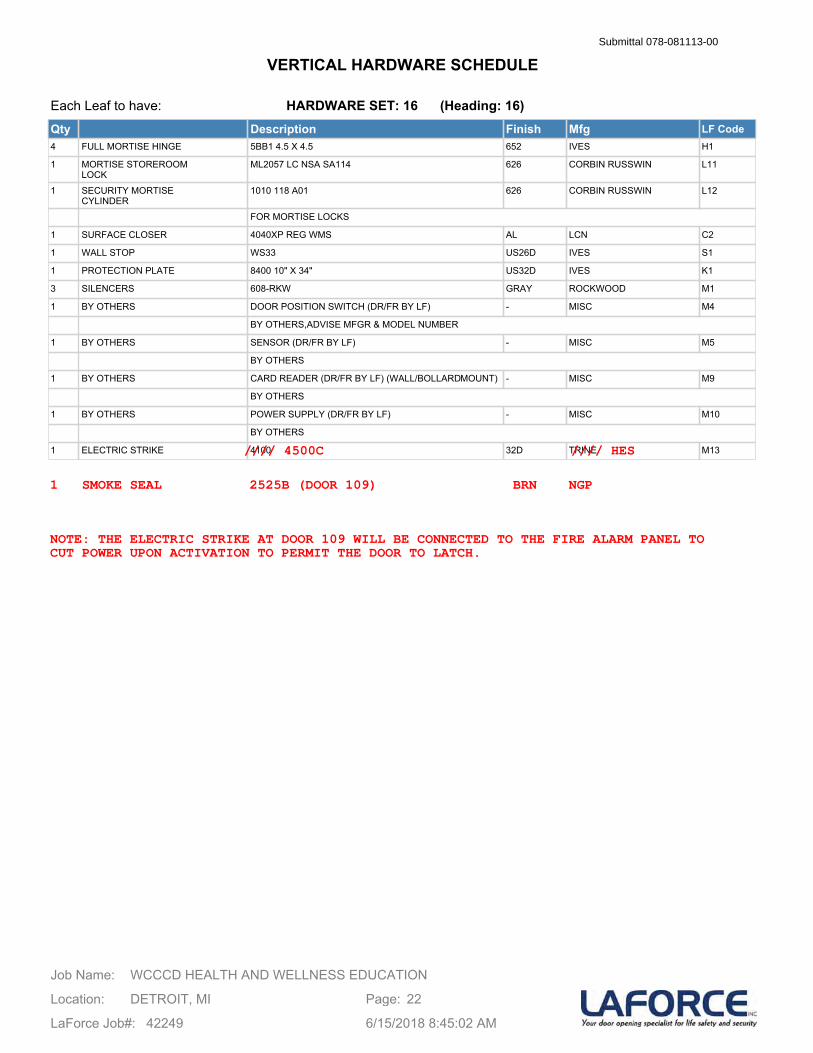
Each Leaf to have:
Qty Description Finish Mfg LF Code4 FULL MORTISE HINGE 5BB1 4.5 X 4.5 652 IVES H1
1 MORTISE STOREROOMLOCK
ML2057 LC NSA SA114 626 CORBIN RUSSWIN L11
1 SECURITY MORTISECYLINDER
1010 118 A01 626 CORBIN RUSSWIN L12
FOR MORTISE LOCKS
1 SURFACE CLOSER 4040XP REG WMS AL LCN C2
1 WALL STOP WS33 US26D IVES S1
1 PROTECTION PLATE 8400 10" X 34" US32D IVES K1
3 SILENCERS 608-RKW GRAY ROCKWOOD M1
1 BY OTHERS DOOR POSITION SWITCH (DR/FR BY LF) - MISC M4
BY OTHERS,ADVISE MFGR & MODEL NUMBER
1 BY OTHERS SENSOR (DR/FR BY LF) - MISC M5
BY OTHERS
1 BY OTHERS CARD READER (DR/FR BY LF) (WALL/BOLLARDMOUNT) - MISC M9
BY OTHERS
1 BY OTHERS POWER SUPPLY (DR/FR BY LF) - MISC M10
BY OTHERS
1 ELECTRIC STRIKE 4100 32D TRINE M13
HARDWARE SET: 16 (Heading: 16)
WCCCD HEALTH AND WELLNESS EDUCATIONJob Name:
Location: DETROIT, MI
LaForce Job#: 42249
Page: 22
6/15/2018 8:45:02 AM
VERTICAL HARDWARE SCHEDULESubmittal 078-081113-00
//// 4500C //// HES
1 SMOKE SEAL 2525B (DOOR 109) BRN NGP
NOTE: THE ELECTRIC STRIKE AT DOOR 109 WILL BE CONNECTED TO THE FIRE ALARM PANEL TOCUT POWER UPON ACTIVATION TO PERMIT THE DOOR TO LATCH.
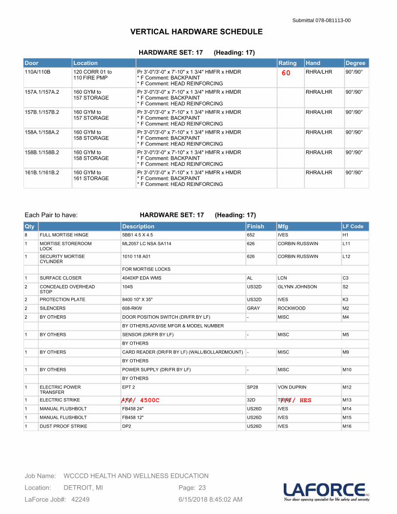
HARDWARE SET: 17 (Heading: 17)Door Location Rating Hand Degree110A/110B 120 CORR 01 to
110 FIRE PMPPr 3'-0"/3'-0" x 7'-10" x 1 3/4" HMFR x HMDR* F Comment: BACKPAINT* F Comment: HEAD REINFORCING
RHRA/LHR 90°/90°
157A.1/157A.2 160 GYM to 157 STORAGE
Pr 3'-0"/3'-0" x 7'-10" x 1 3/4" HMFR x HMDR* F Comment: BACKPAINT* F Comment: HEAD REINFORCING
RHRA/LHR 90°/90°
157B.1/157B.2 160 GYM to 157 STORAGE
Pr 3'-0"/3'-0" x 7'-10" x 1 3/4" HMFR x HMDR* F Comment: BACKPAINT* F Comment: HEAD REINFORCING
RHRA/LHR 90°/90°
158A.1/158A.2 160 GYM to 158 STORAGE
Pr 3'-0"/3'-0" x 7'-10" x 1 3/4" HMFR x HMDR* F Comment: BACKPAINT* F Comment: HEAD REINFORCING
RHRA/LHR 90°/90°
158B.1/158B.2 160 GYM to 158 STORAGE
Pr 3'-0"/3'-0" x 7'-10" x 1 3/4" HMFR x HMDR* F Comment: BACKPAINT* F Comment: HEAD REINFORCING
RHRA/LHR 90°/90°
161B.1/161B.2 160 GYM to 161 STORAGE
Pr 3'-0"/3'-0" x 7'-10" x 1 3/4" HMFR x HMDR* F Comment: BACKPAINT* F Comment: HEAD REINFORCING
RHRA/LHR 90°/90°
Each Pair to have:
Qty Description Finish Mfg LF Code8 FULL MORTISE HINGE 5BB1 4.5 X 4.5 652 IVES H1
1 MORTISE STOREROOMLOCK
ML2057 LC NSA SA114 626 CORBIN RUSSWIN L11
1 SECURITY MORTISECYLINDER
1010 118 A01 626 CORBIN RUSSWIN L12
FOR MORTISE LOCKS
1 SURFACE CLOSER 4040XP EDA WMS AL LCN C3
2 CONCEALED OVERHEADSTOP
104S US32D GLYNN JOHNSON S2
2 PROTECTION PLATE 8400 10" X 35" US32D IVES K3
2 SILENCERS 608-RKW GRAY ROCKWOOD M2
2 BY OTHERS DOOR POSITION SWITCH (DR/FR BY LF) - MISC M4
BY OTHERS,ADVISE MFGR & MODEL NUMBER
1 BY OTHERS SENSOR (DR/FR BY LF) - MISC M5
BY OTHERS
1 BY OTHERS CARD READER (DR/FR BY LF) (WALL/BOLLARDMOUNT) - MISC M9
BY OTHERS
1 BY OTHERS POWER SUPPLY (DR/FR BY LF) - MISC M10
BY OTHERS
1 ELECTRIC POWERTRANSFER
EPT 2 SP28 VON DUPRIN M12
1 ELECTRIC STRIKE 4100 32D TRINE M13
1 MANUAL FLUSHBOLT FB458 24" US26D IVES M14
1 MANUAL FLUSHBOLT FB458 12" US26D IVES M15
1 DUST PROOF STRIKE DP2 US26D IVES M16
HARDWARE SET: 17 (Heading: 17)
WCCCD HEALTH AND WELLNESS EDUCATIONJob Name:
Location: DETROIT, MI
LaForce Job#: 42249
Page: 23
6/15/2018 8:45:02 AM
VERTICAL HARDWARE SCHEDULESubmittal 078-081113-00
60
//// 4500C //// HES
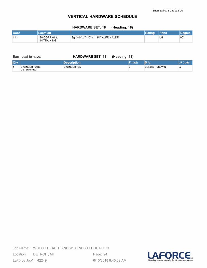
HARDWARE SET: 18 (Heading: 18)Door Location Rating Hand Degree114 120 CORR 01 to
114 TRAININGSgl 3'-0" x 7'-10" x 1 3/4" ALFR x ALDR LH 90°
Each Leaf to have:
Qty Description Finish Mfg LF Code1 CYLINDER TO BE
DETERMINEDCYLINDER TBD ? CORBIN RUSSWIN L2
HARDWARE SET: 18 (Heading: 18)
WCCCD HEALTH AND WELLNESS EDUCATIONJob Name:
Location: DETROIT, MI
LaForce Job#: 42249
Page: 24
6/15/2018 8:45:02 AM
VERTICAL HARDWARE SCHEDULESubmittal 078-081113-00
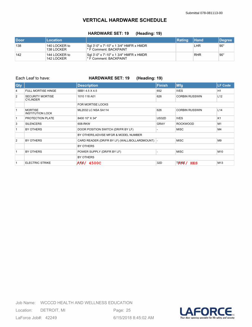
HARDWARE SET: 19 (Heading: 19)Door Location Rating Hand Degree138 140 LOCKER to
138 LOCKERSgl 3'-0" x 7'-10" x 1 3/4" HMFR x HMDR* F Comment: BACKPAINT
LHR 90°
142 144 LOCKER to 142 LOCKER
Sgl 3'-0" x 7'-10" x 1 3/4" HMFR x HMDR* F Comment: BACKPAINT
RHR 90°
Each Leaf to have:
Qty Description Finish Mfg LF Code4 FULL MORTISE HINGE 5BB1 4.5 X 4.5 652 IVES H1
2 SECURITY MORTISECYLINDER
1010 118 A01 626 CORBIN RUSSWIN L12
FOR MORTISE LOCKS
1 MORTISEINSTITUTION LOCK
ML2032 LC NSA SA114 626 CORBIN RUSSWIN L14
1 PROTECTION PLATE 8400 10" X 34" US32D IVES K1
3 SILENCERS 608-RKW GRAY ROCKWOOD M1
1 BY OTHERS DOOR POSITION SWITCH (DR/FR BY LF) - MISC M4
BY OTHERS,ADVISE MFGR & MODEL NUMBER
2 BY OTHERS CARD READER (DR/FR BY LF) (WALL/BOLLARDMOUNT) - MISC M9
BY OTHERS
1 BY OTHERS POWER SUPPLY (DR/FR BY LF) - MISC M10
BY OTHERS
1 ELECTRIC STRIKE 4100 32D TRINE M13
HARDWARE SET: 19 (Heading: 19)
WCCCD HEALTH AND WELLNESS EDUCATIONJob Name:
Location: DETROIT, MI
LaForce Job#: 42249
Page: 25
6/15/2018 8:45:02 AM
VERTICAL HARDWARE SCHEDULESubmittal 078-081113-00
//// 4500C //// HES

HARDWARE SET: 20 (Heading: 20)Door Location Rating Hand Degree149 151 TWL DESK to
149 ELEV EQPSgl 3'-6" x 7'-10" x 1 3/4" HMFR x HMDR* F Comment: BACKPAINT
LHR 90°
Each Leaf to have:
Qty Description Finish Mfg LF Code1 GEARED CONTINUOUS
HINGE224HD 93" TEK US28 IVES H3
1 MORTISE STOREROOMLOCK
ML2057 LC NSA SA114 626 CORBIN RUSSWIN L11
1 SECURITY MORTISECYLINDER
1010 118 A01 626 CORBIN RUSSWIN L12
FOR MORTISE LOCKS
1 SURFACE CLOSER 4040XP SCUSH WMS AL LCN C4
1 PROTECTION PLATE 8400 10" X 40" US32D IVES K4
3 SILENCERS 608-RKW GRAY ROCKWOOD M1
1 BY OTHERS DOOR POSITION SWITCH (DR/FR BY LF) - MISC M4
BY OTHERS,ADVISE MFGR & MODEL NUMBER
1 BY OTHERS SENSOR (DR/FR BY LF) - MISC M5
BY OTHERS
1 BY OTHERS CARD READER (DR/FR BY LF) (WALL/BOLLARDMOUNT) - MISC M9
BY OTHERS
1 BY OTHERS POWER SUPPLY (DR/FR BY LF) - MISC M10
BY OTHERS
1 ELECTRIC STRIKE 4100 32D TRINE M13
HARDWARE SET: 20 (Heading: 20)
WCCCD HEALTH AND WELLNESS EDUCATIONJob Name:
Location: DETROIT, MI
LaForce Job#: 42249
Page: 26
6/15/2018 8:45:02 AM
VERTICAL HARDWARE SCHEDULESubmittal 078-081113-00
//// 4500C //// HES
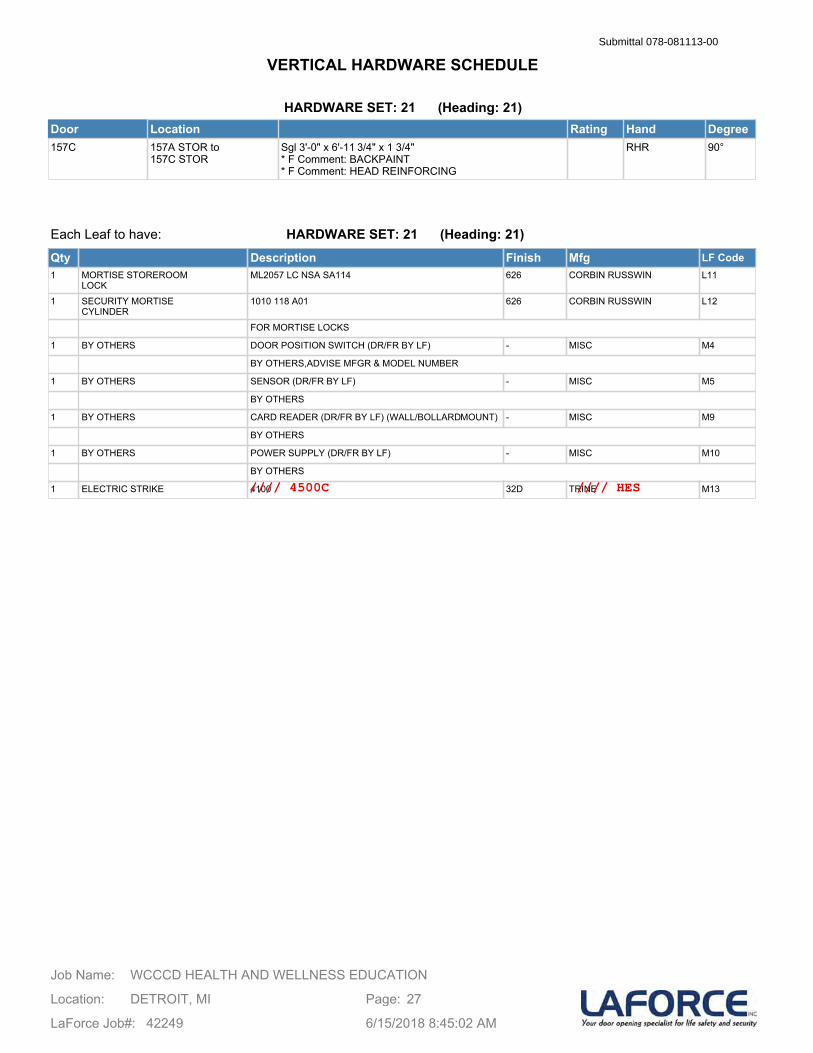
HARDWARE SET: 21 (Heading: 21)Door Location Rating Hand Degree157C 157A STOR to
157C STORSgl 3'-0" x 6'-11 3/4" x 1 3/4"* F Comment: BACKPAINT* F Comment: HEAD REINFORCING
RHR 90°
Each Leaf to have:
Qty Description Finish Mfg LF Code1 MORTISE STOREROOM
LOCKML2057 LC NSA SA114 626 CORBIN RUSSWIN L11
1 SECURITY MORTISECYLINDER
1010 118 A01 626 CORBIN RUSSWIN L12
FOR MORTISE LOCKS
1 BY OTHERS DOOR POSITION SWITCH (DR/FR BY LF) - MISC M4
BY OTHERS,ADVISE MFGR & MODEL NUMBER
1 BY OTHERS SENSOR (DR/FR BY LF) - MISC M5
BY OTHERS
1 BY OTHERS CARD READER (DR/FR BY LF) (WALL/BOLLARDMOUNT) - MISC M9
BY OTHERS
1 BY OTHERS POWER SUPPLY (DR/FR BY LF) - MISC M10
BY OTHERS
1 ELECTRIC STRIKE 4100 32D TRINE M13
HARDWARE SET: 21 (Heading: 21)
WCCCD HEALTH AND WELLNESS EDUCATIONJob Name:
Location: DETROIT, MI
LaForce Job#: 42249
Page: 27
6/15/2018 8:45:02 AM
VERTICAL HARDWARE SCHEDULESubmittal 078-081113-00
//// 4500C //// HES
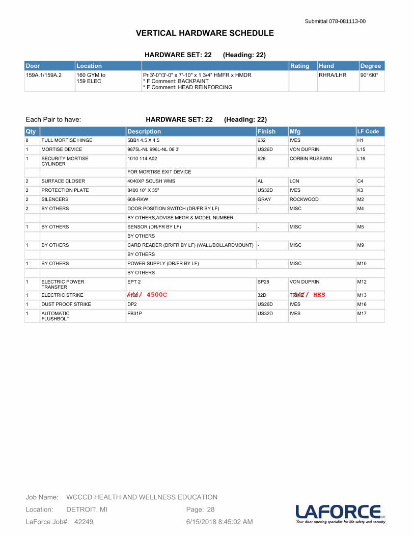
HARDWARE SET: 22 (Heading: 22)Door Location Rating Hand Degree159A.1/159A.2 160 GYM to
159 ELECPr 3'-0"/3'-0" x 7'-10" x 1 3/4" HMFR x HMDR* F Comment: BACKPAINT* F Comment: HEAD REINFORCING
RHRA/LHR 90°/90°
Each Pair to have:
Qty Description Finish Mfg LF Code8 FULL MORTISE HINGE 5BB1 4.5 X 4.5 652 IVES H1
1 MORTISE DEVICE 9875L-NL 996L-NL 06 3' US26D VON DUPRIN L15
1 SECURITY MORTISECYLINDER
1010 114 A02 626 CORBIN RUSSWIN L16
FOR MORTISE EXIT DEVICE
2 SURFACE CLOSER 4040XP SCUSH WMS AL LCN C4
2 PROTECTION PLATE 8400 10" X 35" US32D IVES K3
2 SILENCERS 608-RKW GRAY ROCKWOOD M2
2 BY OTHERS DOOR POSITION SWITCH (DR/FR BY LF) - MISC M4
BY OTHERS,ADVISE MFGR & MODEL NUMBER
1 BY OTHERS SENSOR (DR/FR BY LF) - MISC M5
BY OTHERS
1 BY OTHERS CARD READER (DR/FR BY LF) (WALL/BOLLARDMOUNT) - MISC M9
BY OTHERS
1 BY OTHERS POWER SUPPLY (DR/FR BY LF) - MISC M10
BY OTHERS
1 ELECTRIC POWERTRANSFER
EPT 2 SP28 VON DUPRIN M12
1 ELECTRIC STRIKE 4100 32D TRINE M13
1 DUST PROOF STRIKE DP2 US26D IVES M16
1 AUTOMATICFLUSHBOLT
FB31P US32D IVES M17
HARDWARE SET: 22 (Heading: 22)
WCCCD HEALTH AND WELLNESS EDUCATIONJob Name:
Location: DETROIT, MI
LaForce Job#: 42249
Page: 28
6/15/2018 8:45:02 AM
VERTICAL HARDWARE SCHEDULESubmittal 078-081113-00
//// 4500C //// HES
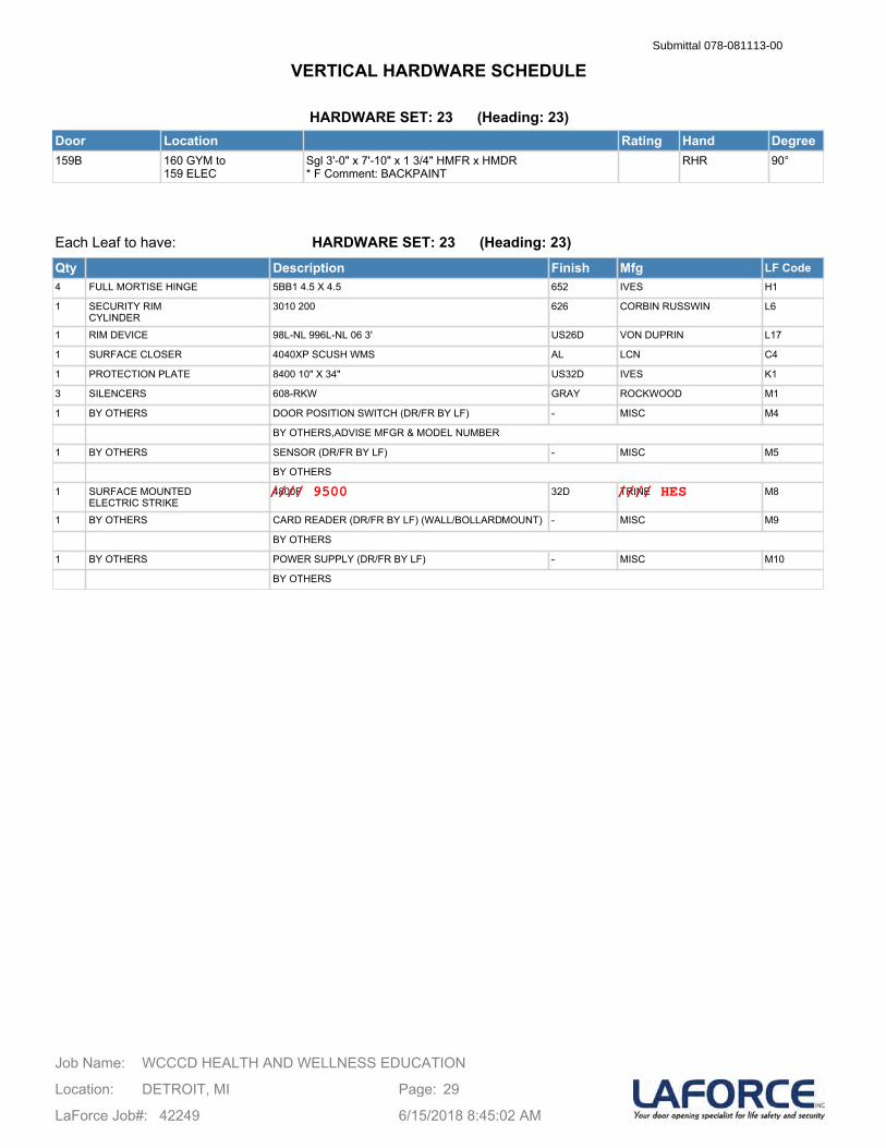
HARDWARE SET: 23 (Heading: 23)Door Location Rating Hand Degree159B 160 GYM to
159 ELECSgl 3'-0" x 7'-10" x 1 3/4" HMFR x HMDR* F Comment: BACKPAINT
RHR 90°
Each Leaf to have:
Qty Description Finish Mfg LF Code4 FULL MORTISE HINGE 5BB1 4.5 X 4.5 652 IVES H1
1 SECURITY RIMCYLINDER
3010 200 626 CORBIN RUSSWIN L6
1 RIM DEVICE 98L-NL 996L-NL 06 3' US26D VON DUPRIN L17
1 SURFACE CLOSER 4040XP SCUSH WMS AL LCN C4
1 PROTECTION PLATE 8400 10" X 34" US32D IVES K1
3 SILENCERS 608-RKW GRAY ROCKWOOD M1
1 BY OTHERS DOOR POSITION SWITCH (DR/FR BY LF) - MISC M4
BY OTHERS,ADVISE MFGR & MODEL NUMBER
1 BY OTHERS SENSOR (DR/FR BY LF) - MISC M5
BY OTHERS
1 SURFACE MOUNTEDELECTRIC STRIKE
4800F 32D TRINE M8
1 BY OTHERS CARD READER (DR/FR BY LF) (WALL/BOLLARDMOUNT) - MISC M9
BY OTHERS
1 BY OTHERS POWER SUPPLY (DR/FR BY LF) - MISC M10
BY OTHERS
HARDWARE SET: 23 (Heading: 23)
WCCCD HEALTH AND WELLNESS EDUCATIONJob Name:
Location: DETROIT, MI
LaForce Job#: 42249
Page: 29
6/15/2018 8:45:02 AM
VERTICAL HARDWARE SCHEDULESubmittal 078-081113-00
//// 9500 //// HES
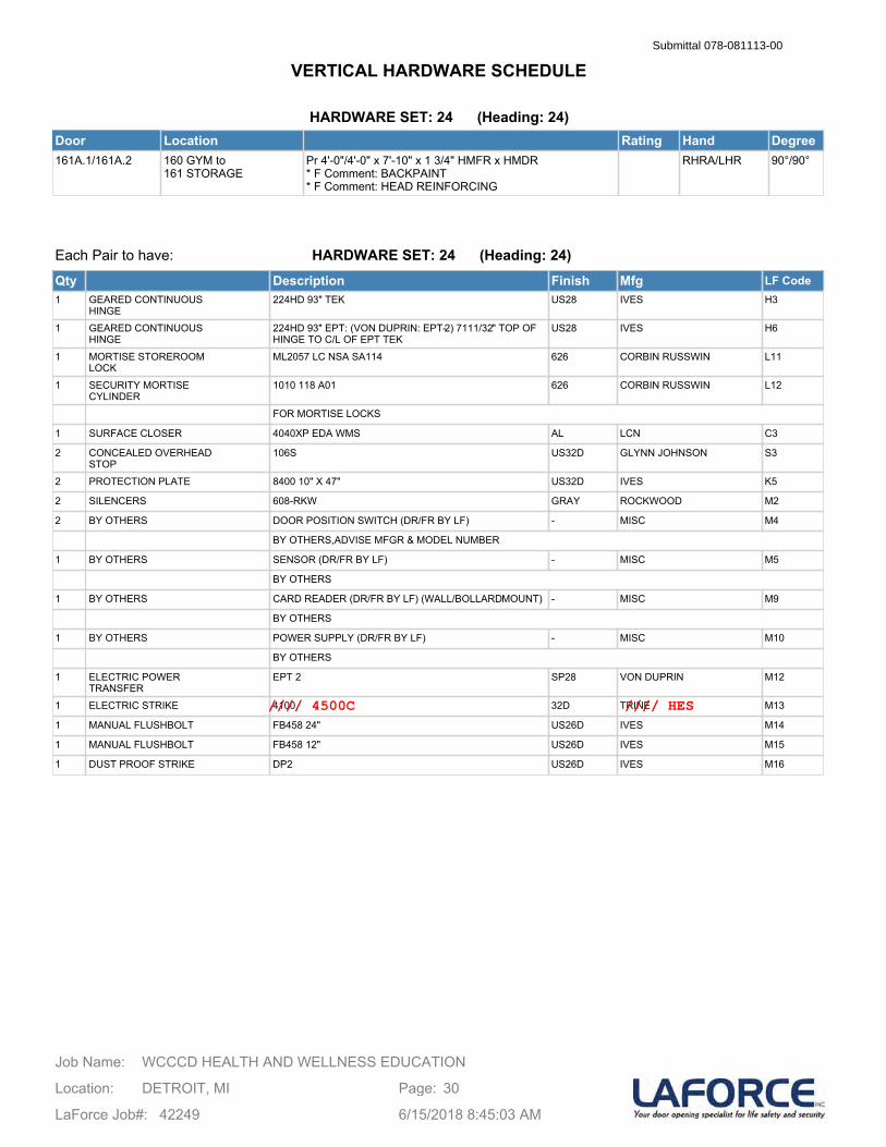
HARDWARE SET: 24 (Heading: 24)Door Location Rating Hand Degree161A.1/161A.2 160 GYM to
161 STORAGEPr 4'-0"/4'-0" x 7'-10" x 1 3/4" HMFR x HMDR* F Comment: BACKPAINT* F Comment: HEAD REINFORCING
RHRA/LHR 90°/90°
Each Pair to have:
Qty Description Finish Mfg LF Code1 GEARED CONTINUOUS
HINGE224HD 93" TEK US28 IVES H3
1 GEARED CONTINUOUSHINGE
224HD 93" EPT: (VON DUPRIN: EPT-2) 7111/32" TOP OF HINGE TO C/L OF EPT TEK
US28 IVES H6
1 MORTISE STOREROOMLOCK
ML2057 LC NSA SA114 626 CORBIN RUSSWIN L11
1 SECURITY MORTISECYLINDER
1010 118 A01 626 CORBIN RUSSWIN L12
FOR MORTISE LOCKS
1 SURFACE CLOSER 4040XP EDA WMS AL LCN C3
2 CONCEALED OVERHEADSTOP
106S US32D GLYNN JOHNSON S3
2 PROTECTION PLATE 8400 10" X 47" US32D IVES K5
2 SILENCERS 608-RKW GRAY ROCKWOOD M2
2 BY OTHERS DOOR POSITION SWITCH (DR/FR BY LF) - MISC M4
BY OTHERS,ADVISE MFGR & MODEL NUMBER
1 BY OTHERS SENSOR (DR/FR BY LF) - MISC M5
BY OTHERS
1 BY OTHERS CARD READER (DR/FR BY LF) (WALL/BOLLARDMOUNT) - MISC M9
BY OTHERS
1 BY OTHERS POWER SUPPLY (DR/FR BY LF) - MISC M10
BY OTHERS
1 ELECTRIC POWERTRANSFER
EPT 2 SP28 VON DUPRIN M12
1 ELECTRIC STRIKE 4100 32D TRINE M13
1 MANUAL FLUSHBOLT FB458 24" US26D IVES M14
1 MANUAL FLUSHBOLT FB458 12" US26D IVES M15
1 DUST PROOF STRIKE DP2 US26D IVES M16
HARDWARE SET: 24 (Heading: 24)
WCCCD HEALTH AND WELLNESS EDUCATIONJob Name:
Location: DETROIT, MI
LaForce Job#: 42249
Page: 30
6/15/2018 8:45:03 AM
VERTICAL HARDWARE SCHEDULESubmittal 078-081113-00
//// 4500C //// HES
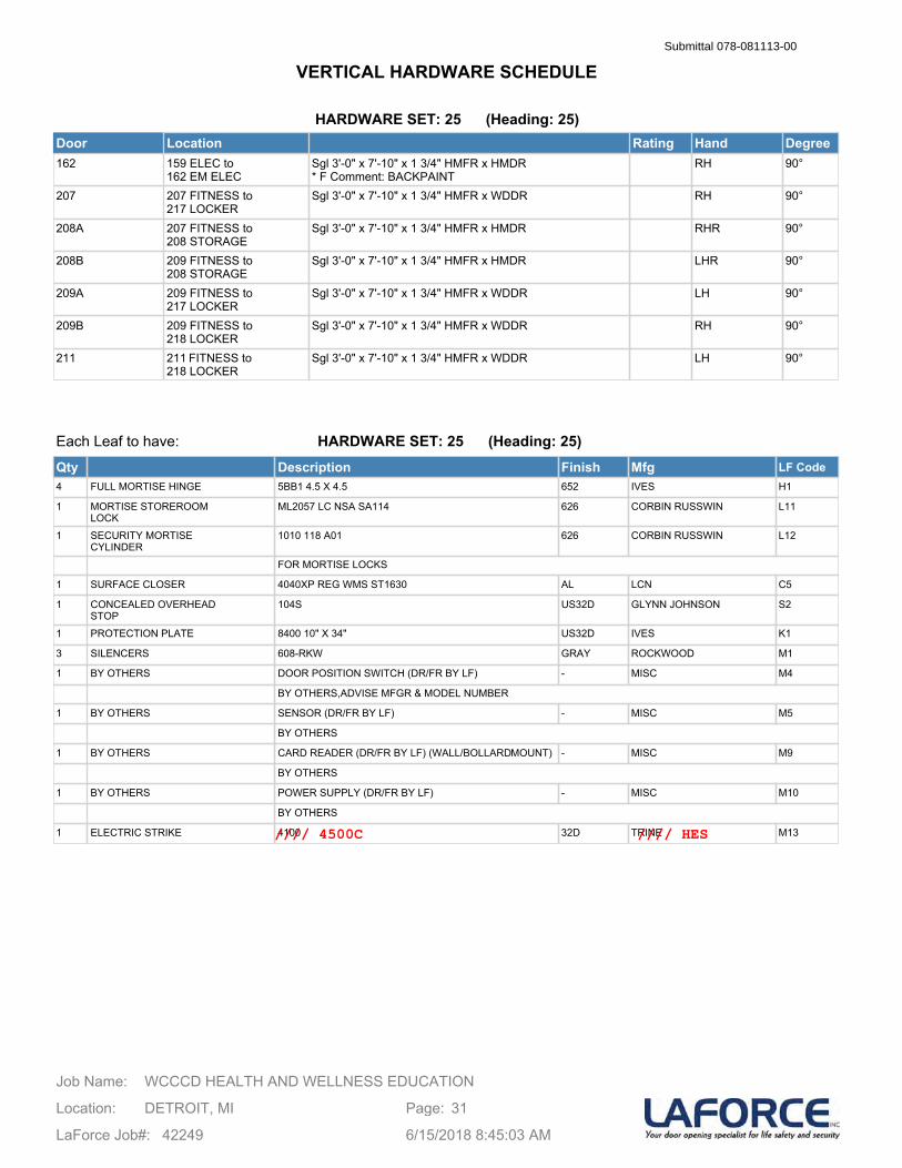
HARDWARE SET: 25 (Heading: 25)Door Location Rating Hand Degree162 159 ELEC to
162 EM ELECSgl 3'-0" x 7'-10" x 1 3/4" HMFR x HMDR* F Comment: BACKPAINT
RH 90°
207 207 FITNESS to 217 LOCKER
Sgl 3'-0" x 7'-10" x 1 3/4" HMFR x WDDR RH 90°
208A 207 FITNESS to 208 STORAGE
Sgl 3'-0" x 7'-10" x 1 3/4" HMFR x HMDR RHR 90°
208B 209 FITNESS to 208 STORAGE
Sgl 3'-0" x 7'-10" x 1 3/4" HMFR x HMDR LHR 90°
209A 209 FITNESS to 217 LOCKER
Sgl 3'-0" x 7'-10" x 1 3/4" HMFR x WDDR LH 90°
209B 209 FITNESS to 218 LOCKER
Sgl 3'-0" x 7'-10" x 1 3/4" HMFR x WDDR RH 90°
211 211 FITNESS to 218 LOCKER
Sgl 3'-0" x 7'-10" x 1 3/4" HMFR x WDDR LH 90°
Each Leaf to have:
Qty Description Finish Mfg LF Code4 FULL MORTISE HINGE 5BB1 4.5 X 4.5 652 IVES H1
1 MORTISE STOREROOMLOCK
ML2057 LC NSA SA114 626 CORBIN RUSSWIN L11
1 SECURITY MORTISECYLINDER
1010 118 A01 626 CORBIN RUSSWIN L12
FOR MORTISE LOCKS
1 SURFACE CLOSER 4040XP REG WMS ST1630 AL LCN C5
1 CONCEALED OVERHEADSTOP
104S US32D GLYNN JOHNSON S2
1 PROTECTION PLATE 8400 10" X 34" US32D IVES K1
3 SILENCERS 608-RKW GRAY ROCKWOOD M1
1 BY OTHERS DOOR POSITION SWITCH (DR/FR BY LF) - MISC M4
BY OTHERS,ADVISE MFGR & MODEL NUMBER
1 BY OTHERS SENSOR (DR/FR BY LF) - MISC M5
BY OTHERS
1 BY OTHERS CARD READER (DR/FR BY LF) (WALL/BOLLARDMOUNT) - MISC M9
BY OTHERS
1 BY OTHERS POWER SUPPLY (DR/FR BY LF) - MISC M10
BY OTHERS
1 ELECTRIC STRIKE 4100 32D TRINE M13
HARDWARE SET: 25 (Heading: 25)
WCCCD HEALTH AND WELLNESS EDUCATIONJob Name:
Location: DETROIT, MI
LaForce Job#: 42249
Page: 31
6/15/2018 8:45:03 AM
VERTICAL HARDWARE SCHEDULESubmittal 078-081113-00
//// 4500C //// HES
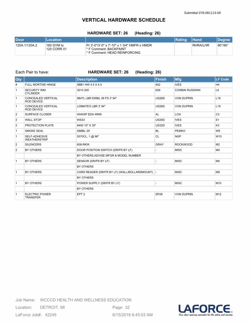
HARDWARE SET: 26 (Heading: 26)Door Location Rating Hand Degree120A.1/120A.2 160 GYM to
120 CORR 01Pr 3'-0"/3'-0" x 7'-10" x 1 3/4" HMFR x HMDR* F Comment: BACKPAINT* F Comment: HEAD REINFORCING
RHRA/LHR 90°/90°
Each Pair to have:
Qty Description Finish Mfg LF Code8 FULL MORTISE HINGE 5BB1 HW 4.5 X 4.5 652 IVES H4
1 SECURITY RIMCYLINDER
3010 200 626 CORBIN RUSSWIN L6
1 CONCEALED VERTICALROD DEVICE
9847L LBR E996L 06 FS 3' 94" US26D VON DUPRIN L18
1 CONCEALED VERTICALROD DEVICE
LD9847EO LBR 3' 94" US26D VON DUPRIN L19
2 SURFACE CLOSER 4040XP EDA WMS AL LCN C3
2 WALL STOP WS33 US26D IVES S1
2 PROTECTION PLATE 8400 10" X 35" US32D IVES K3
1 SMOKE SEAL S88BL 25' BL PEMKO W9
1 SELF-ADHESIVEWEATHERSTRIP
5070CL, 1 @ 96" CL NGP W10
2 SILENCERS 608-RKW GRAY ROCKWOOD M2
2 BY OTHERS DOOR POSITION SWITCH (DR/FR BY LF) - MISC M4
BY OTHERS,ADVISE MFGR & MODEL NUMBER
1 BY OTHERS SENSOR (DR/FR BY LF) - MISC M5
BY OTHERS
1 BY OTHERS CARD READER (DR/FR BY LF) (WALL/BOLLARDMOUNT) - MISC M9
BY OTHERS
1 BY OTHERS POWER SUPPLY (DR/FR BY LF) - MISC M10
BY OTHERS
1 ELECTRIC POWERTRANSFER
EPT 2 SP28 VON DUPRIN M12
HARDWARE SET: 26 (Heading: 26)
WCCCD HEALTH AND WELLNESS EDUCATIONJob Name:
Location: DETROIT, MI
LaForce Job#: 42249
Page: 32
6/15/2018 8:45:03 AM
VERTICAL HARDWARE SCHEDULESubmittal 078-081113-00
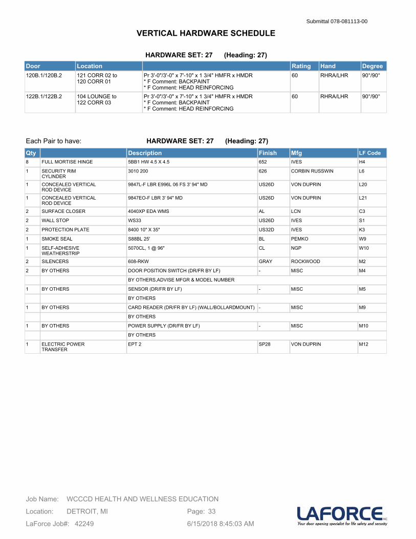
HARDWARE SET: 27 (Heading: 27)Door Location Rating Hand Degree120B.1/120B.2 121 CORR 02 to
120 CORR 01Pr 3'-0"/3'-0" x 7'-10" x 1 3/4" HMFR x HMDR* F Comment: BACKPAINT* F Comment: HEAD REINFORCING
60 RHRA/LHR 90°/90°
122B.1/122B.2 104 LOUNGE to 122 CORR 03
Pr 3'-0"/3'-0" x 7'-10" x 1 3/4" HMFR x HMDR* F Comment: BACKPAINT* F Comment: HEAD REINFORCING
60 RHRA/LHR 90°/90°
Each Pair to have:
Qty Description Finish Mfg LF Code8 FULL MORTISE HINGE 5BB1 HW 4.5 X 4.5 652 IVES H4
1 SECURITY RIMCYLINDER
3010 200 626 CORBIN RUSSWIN L6
1 CONCEALED VERTICALROD DEVICE
9847L-F LBR E996L 06 FS 3' 94" MD US26D VON DUPRIN L20
1 CONCEALED VERTICALROD DEVICE
9847EO-F LBR 3' 94" MD US26D VON DUPRIN L21
2 SURFACE CLOSER 4040XP EDA WMS AL LCN C3
2 WALL STOP WS33 US26D IVES S1
2 PROTECTION PLATE 8400 10" X 35" US32D IVES K3
1 SMOKE SEAL S88BL 25' BL PEMKO W9
1 SELF-ADHESIVEWEATHERSTRIP
5070CL, 1 @ 96" CL NGP W10
2 SILENCERS 608-RKW GRAY ROCKWOOD M2
2 BY OTHERS DOOR POSITION SWITCH (DR/FR BY LF) - MISC M4
BY OTHERS,ADVISE MFGR & MODEL NUMBER
1 BY OTHERS SENSOR (DR/FR BY LF) - MISC M5
BY OTHERS
1 BY OTHERS CARD READER (DR/FR BY LF) (WALL/BOLLARDMOUNT) - MISC M9
BY OTHERS
1 BY OTHERS POWER SUPPLY (DR/FR BY LF) - MISC M10
BY OTHERS
1 ELECTRIC POWERTRANSFER
EPT 2 SP28 VON DUPRIN M12
HARDWARE SET: 27 (Heading: 27)
WCCCD HEALTH AND WELLNESS EDUCATIONJob Name:
Location: DETROIT, MI
LaForce Job#: 42249
Page: 33
6/15/2018 8:45:03 AM
VERTICAL HARDWARE SCHEDULESubmittal 078-081113-00
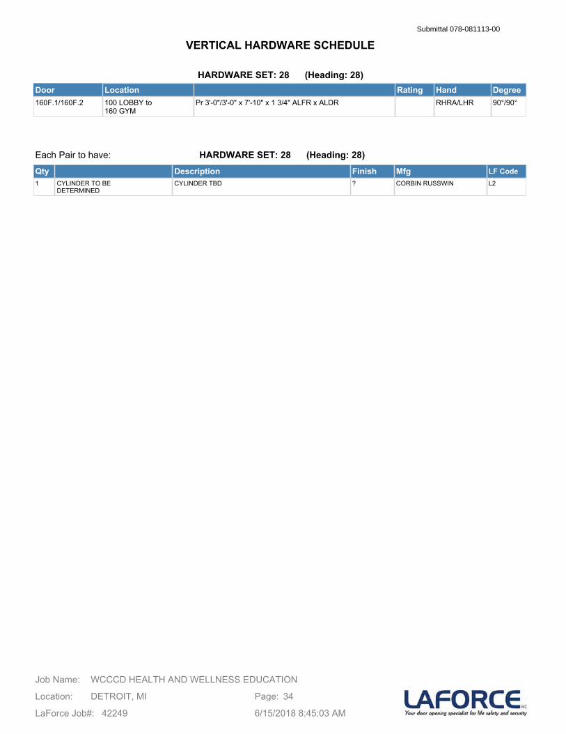
HARDWARE SET: 28 (Heading: 28)Door Location Rating Hand Degree160F.1/160F.2 100 LOBBY to
160 GYMPr 3'-0"/3'-0" x 7'-10" x 1 3/4" ALFR x ALDR RHRA/LHR 90°/90°
Each Pair to have:
Qty Description Finish Mfg LF Code1 CYLINDER TO BE
DETERMINEDCYLINDER TBD ? CORBIN RUSSWIN L2
HARDWARE SET: 28 (Heading: 28)
WCCCD HEALTH AND WELLNESS EDUCATIONJob Name:
Location: DETROIT, MI
LaForce Job#: 42249
Page: 34
6/15/2018 8:45:03 AM
VERTICAL HARDWARE SCHEDULESubmittal 078-081113-00
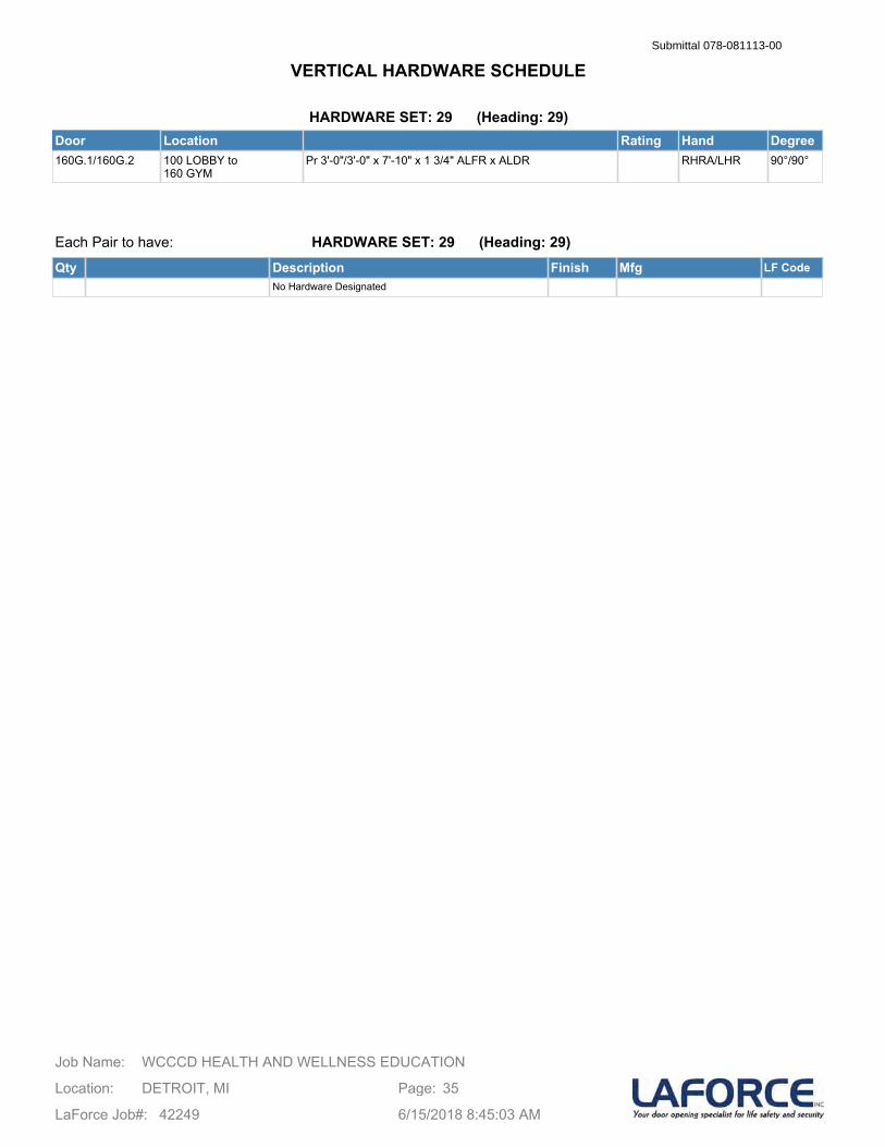
HARDWARE SET: 29 (Heading: 29)Door Location Rating Hand Degree160G.1/160G.2 100 LOBBY to
160 GYMPr 3'-0"/3'-0" x 7'-10" x 1 3/4" ALFR x ALDR RHRA/LHR 90°/90°
Each Pair to have:
Qty Description Finish Mfg LF CodeNo Hardware Designated
HARDWARE SET: 29 (Heading: 29)
WCCCD HEALTH AND WELLNESS EDUCATIONJob Name:
Location: DETROIT, MI
LaForce Job#: 42249
Page: 35
6/15/2018 8:45:03 AM
VERTICAL HARDWARE SCHEDULESubmittal 078-081113-00
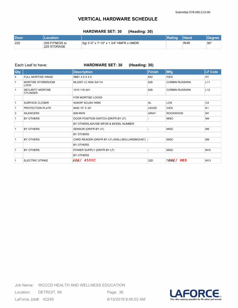
HARDWARE SET: 30 (Heading: 30)Door Location Rating Hand Degree225 209 FITNESS to
225 STORAGESgl 3'-0" x 7'-10" x 1 3/4" HMFR x HMDR RHR 90°
Each Leaf to have:
Qty Description Finish Mfg LF Code4 FULL MORTISE HINGE 5BB1 4.5 X 4.5 652 IVES H1
1 MORTISE STOREROOMLOCK
ML2057 LC NSA SA114 626 CORBIN RUSSWIN L11
1 SECURITY MORTISECYLINDER
1010 118 A01 626 CORBIN RUSSWIN L12
FOR MORTISE LOCKS
1 SURFACE CLOSER 4040XP SCUSH WMS AL LCN C4
1 PROTECTION PLATE 8400 10" X 34" US32D IVES K1
3 SILENCERS 608-RKW GRAY ROCKWOOD M1
1 BY OTHERS DOOR POSITION SWITCH (DR/FR BY LF) - MISC M4
BY OTHERS,ADVISE MFGR & MODEL NUMBER
1 BY OTHERS SENSOR (DR/FR BY LF) - MISC M5
BY OTHERS
1 BY OTHERS CARD READER (DR/FR BY LF) (WALL/BOLLARDMOUNT) - MISC M9
BY OTHERS
1 BY OTHERS POWER SUPPLY (DR/FR BY LF) - MISC M10
BY OTHERS
1 ELECTRIC STRIKE 4100 32D TRINE M13
HARDWARE SET: 30 (Heading: 30)
WCCCD HEALTH AND WELLNESS EDUCATIONJob Name:
Location: DETROIT, MI
LaForce Job#: 42249
Page: 36
6/15/2018 8:45:03 AM
VERTICAL HARDWARE SCHEDULESubmittal 078-081113-00
//// 4500C //// HES
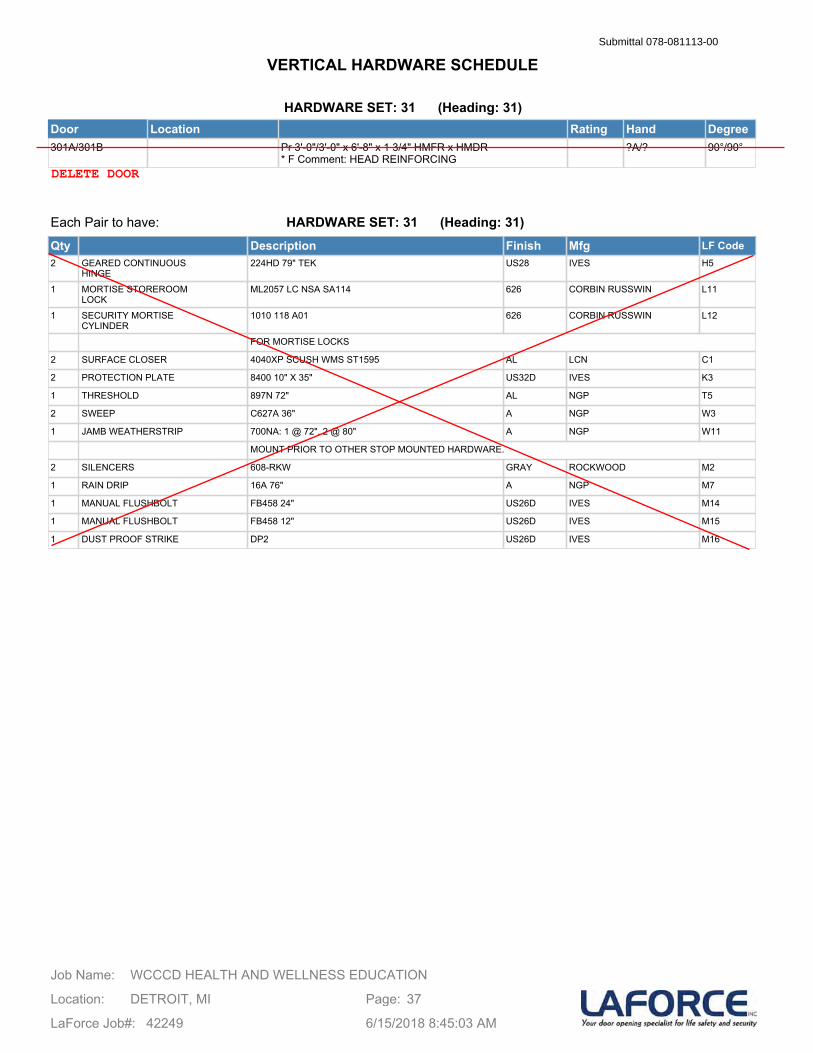
HARDWARE SET: 31 (Heading: 31)Door Location Rating Hand Degree301A/301B Pr 3'-0"/3'-0" x 6'-8" x 1 3/4" HMFR x HMDR
* F Comment: HEAD REINFORCING?A/? 90°/90°
Each Pair to have:
Qty Description Finish Mfg LF Code2 GEARED CONTINUOUS
HINGE224HD 79" TEK US28 IVES H5
1 MORTISE STOREROOMLOCK
ML2057 LC NSA SA114 626 CORBIN RUSSWIN L11
1 SECURITY MORTISECYLINDER
1010 118 A01 626 CORBIN RUSSWIN L12
FOR MORTISE LOCKS
2 SURFACE CLOSER 4040XP SCUSH WMS ST1595 AL LCN C1
2 PROTECTION PLATE 8400 10" X 35" US32D IVES K3
1 THRESHOLD 897N 72" AL NGP T5
2 SWEEP C627A 36" A NGP W3
1 JAMB WEATHERSTRIP 700NA: 1 @ 72", 2 @ 80" A NGP W11
MOUNT PRIOR TO OTHER STOP MOUNTED HARDWARE.
2 SILENCERS 608-RKW GRAY ROCKWOOD M2
1 RAIN DRIP 16A 76" A NGP M7
1 MANUAL FLUSHBOLT FB458 24" US26D IVES M14
1 MANUAL FLUSHBOLT FB458 12" US26D IVES M15
1 DUST PROOF STRIKE DP2 US26D IVES M16
HARDWARE SET: 31 (Heading: 31)
WCCCD HEALTH AND WELLNESS EDUCATIONJob Name:
Location: DETROIT, MI
LaForce Job#: 42249
Page: 37
6/15/2018 8:45:03 AM
VERTICAL HARDWARE SCHEDULESubmittal 078-081113-00
DELETE DOOR

HARDWARE SET: 32 (Heading: 32)Door Location Rating Hand Degree127A 152 CTRL DSK to
127 WAITINGSgl 3'-0" x 7'-10" x 1 3/4" ALFR x ALDR LHR 90°
127B 120 CORR 01 to 127 WAITING
Sgl 3'-0" x 7'-10" x 1 3/4" ALFR x ALDR LHR 90°
Each Leaf to have:
Qty Description Finish Mfg LF Code1 CYLINDER TO BE
DETERMINEDCYLINDER TBD ? CORBIN RUSSWIN L2
HARDWARE SET: 32 (Heading: 32)
WCCCD HEALTH AND WELLNESS EDUCATIONJob Name:
Location: DETROIT, MI
LaForce Job#: 42249
Page: 38
6/15/2018 8:45:03 AM
VERTICAL HARDWARE SCHEDULESubmittal 078-081113-00
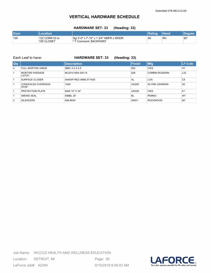
HARDWARE SET: 33 (Heading: 33)Door Location Rating Hand Degree105 122 CORR 03 to
105 CLOSETSgl 3'-0" x 7'-10" x 1 3/4" HMFR x WDDR* F Comment: BACKPAINT
60 RH 90°
Each Leaf to have:
Qty Description Finish Mfg LF Code4 FULL MORTISE HINGE 5BB1 4.5 X 4.5 652 IVES H1
1 MORTISE PASSAGELATCH
ML2010 NSA SA114 626 CORBIN RUSSWIN L22
1 SURFACE CLOSER 4040XP REG WMS ST1630 AL LCN C5
1 CONCEALED OVERHEADSTOP
104S US32D GLYNN JOHNSON S2
1 PROTECTION PLATE 8400 10" X 34" US32D IVES K1
1 SMOKE SEAL S88BL 20' BL PEMKO W7
3 SILENCERS 608-RKW GRAY ROCKWOOD M1
HARDWARE SET: 33 (Heading: 33)
WCCCD HEALTH AND WELLNESS EDUCATIONJob Name:
Location: DETROIT, MI
LaForce Job#: 42249
Page: 39
6/15/2018 8:45:03 AM
VERTICAL HARDWARE SCHEDULESubmittal 078-081113-00
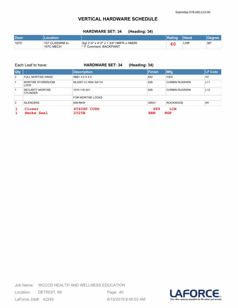
HARDWARE SET: 34 (Heading: 34)Door Location Rating Hand Degree107C 107 CLASSRM to
107C MECHSgl 2'-0" x 4'-0" x 1 3/4" HMFR x HMDR* F Comment: BACKPAINT
LHR 90°
Each Leaf to have:
Qty Description Finish Mfg LF Code3 FULL MORTISE HINGE 5BB1 4.5 X 4.5 652 IVES H7
1 MORTISE STOREROOMLOCK
ML2057 LC NSA SA114 626 CORBIN RUSSWIN L11
1 SECURITY MORTISECYLINDER
1010 118 A01 626 CORBIN RUSSWIN L12
FOR MORTISE LOCKS
3 SILENCERS 608-RKW GRAY ROCKWOOD M1
HARDWARE SET: 34 (Heading: 34)
WCCCD HEALTH AND WELLNESS EDUCATIONJob Name:
Location: DETROIT, MI
LaForce Job#: 42249
Page: 40
6/15/2018 8:45:03 AM
VERTICAL HARDWARE SCHEDULESubmittal 078-081113-00
60
1 Closer 4040XP CUSH 689 LCN1 Smoke Seal 2525B BRN NGP
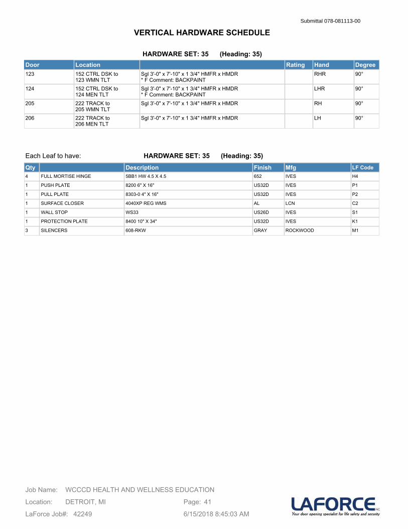
HARDWARE SET: 35 (Heading: 35)Door Location Rating Hand Degree123 152 CTRL DSK to
123 WMN TLTSgl 3'-0" x 7'-10" x 1 3/4" HMFR x HMDR* F Comment: BACKPAINT
RHR 90°
124 152 CTRL DSK to 124 MEN TLT
Sgl 3'-0" x 7'-10" x 1 3/4" HMFR x HMDR* F Comment: BACKPAINT
LHR 90°
205 222 TRACK to 205 WMN TLT
Sgl 3'-0" x 7'-10" x 1 3/4" HMFR x HMDR RH 90°
206 222 TRACK to 206 MEN TLT
Sgl 3'-0" x 7'-10" x 1 3/4" HMFR x HMDR LH 90°
Each Leaf to have:
Qty Description Finish Mfg LF Code4 FULL MORTISE HINGE 5BB1 HW 4.5 X 4.5 652 IVES H4
1 PUSH PLATE 8200 6" X 16" US32D IVES P1
1 PULL PLATE 8303-0 4" X 16" US32D IVES P2
1 SURFACE CLOSER 4040XP REG WMS AL LCN C2
1 WALL STOP WS33 US26D IVES S1
1 PROTECTION PLATE 8400 10" X 34" US32D IVES K1
3 SILENCERS 608-RKW GRAY ROCKWOOD M1
HARDWARE SET: 35 (Heading: 35)
WCCCD HEALTH AND WELLNESS EDUCATIONJob Name:
Location: DETROIT, MI
LaForce Job#: 42249
Page: 41
6/15/2018 8:45:03 AM
VERTICAL HARDWARE SCHEDULESubmittal 078-081113-00
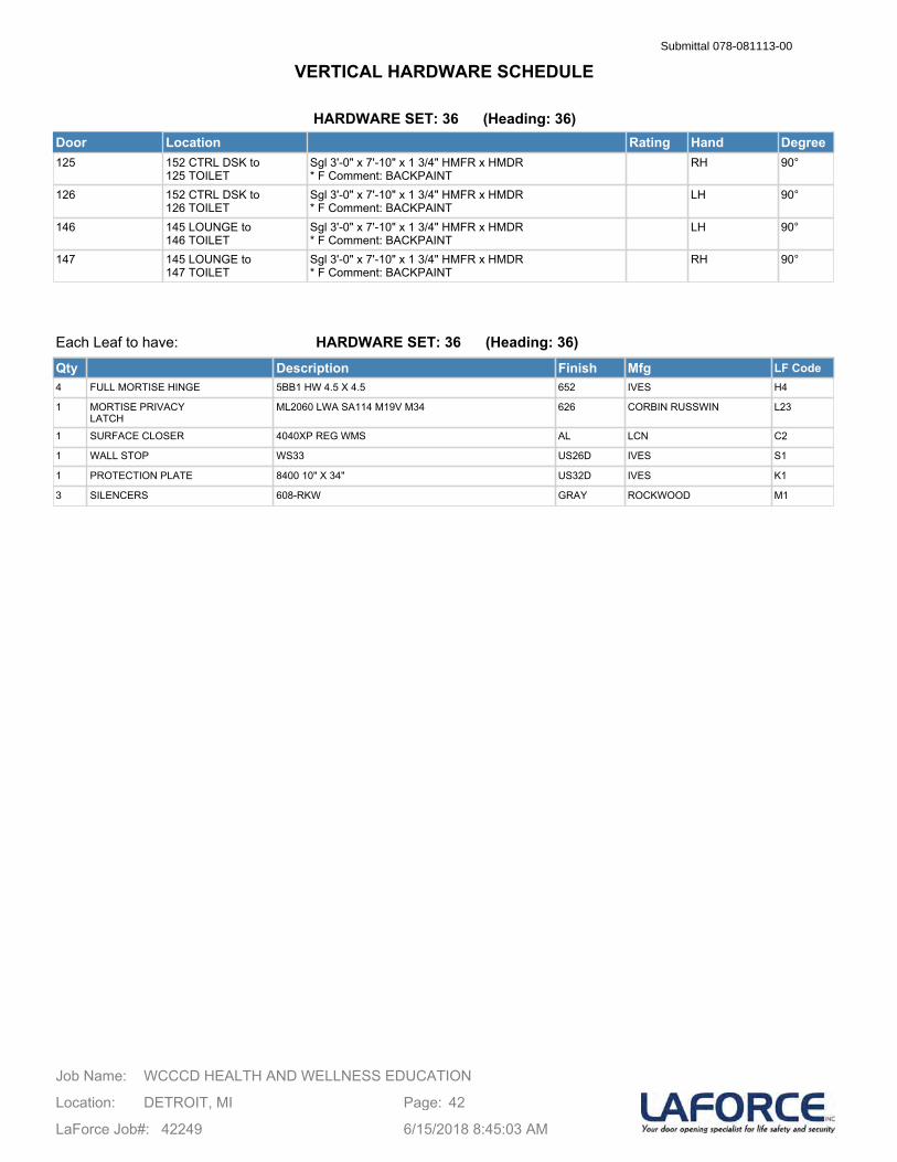
HARDWARE SET: 36 (Heading: 36)Door Location Rating Hand Degree125 152 CTRL DSK to
125 TOILETSgl 3'-0" x 7'-10" x 1 3/4" HMFR x HMDR* F Comment: BACKPAINT
RH 90°
126 152 CTRL DSK to 126 TOILET
Sgl 3'-0" x 7'-10" x 1 3/4" HMFR x HMDR* F Comment: BACKPAINT
LH 90°
146 145 LOUNGE to 146 TOILET
Sgl 3'-0" x 7'-10" x 1 3/4" HMFR x HMDR* F Comment: BACKPAINT
LH 90°
147 145 LOUNGE to 147 TOILET
Sgl 3'-0" x 7'-10" x 1 3/4" HMFR x HMDR* F Comment: BACKPAINT
RH 90°
Each Leaf to have:
Qty Description Finish Mfg LF Code4 FULL MORTISE HINGE 5BB1 HW 4.5 X 4.5 652 IVES H4
1 MORTISE PRIVACYLATCH
ML2060 LWA SA114 M19V M34 626 CORBIN RUSSWIN L23
1 SURFACE CLOSER 4040XP REG WMS AL LCN C2
1 WALL STOP WS33 US26D IVES S1
1 PROTECTION PLATE 8400 10" X 34" US32D IVES K1
3 SILENCERS 608-RKW GRAY ROCKWOOD M1
HARDWARE SET: 36 (Heading: 36)
WCCCD HEALTH AND WELLNESS EDUCATIONJob Name:
Location: DETROIT, MI
LaForce Job#: 42249
Page: 42
6/15/2018 8:45:03 AM
VERTICAL HARDWARE SCHEDULESubmittal 078-081113-00

HARDWARE SET: 37 (Heading: 37)Door Location Rating Hand Degree137 151 TWL DESK to
137 WMN TLTSgl 3'-0" x 7'-10" x 1 3/4" HMFR x HMDR* F Comment: BACKPAINT
RHR 90°
141 151 TWL DESK to 141 MEN TLT
Sgl 3'-0" x 7'-10" x 1 3/4" HMFR x HMDR* F Comment: BACKPAINT
LHR 90°
214 201 WEIGHT to 214 CORR 04
Sgl 3'-0" x 7'-10" x 1 3/4" HMFR x HMDR RHR 90°
Each Leaf to have:
Qty Description Finish Mfg LF Code4 FULL MORTISE HINGE 5BB1 HW 4.5 X 4.5 652 IVES H4
1 PUSH PLATE 8200 6" X 16" US32D IVES P1
1 PULL PLATE 8303-0 4" X 16" US32D IVES P2
1 SURFACE CLOSER 4040XP EDA WMS AL LCN C3
1 WALL STOP WS33 US26D IVES S1
1 PROTECTION PLATE 8400 10" X 34" US32D IVES K1
3 SILENCERS 608-RKW GRAY ROCKWOOD M1
HARDWARE SET: 37 (Heading: 37)
WCCCD HEALTH AND WELLNESS EDUCATIONJob Name:
Location: DETROIT, MI
LaForce Job#: 42249
Page: 43
6/15/2018 8:45:03 AM
VERTICAL HARDWARE SCHEDULESubmittal 078-081113-00
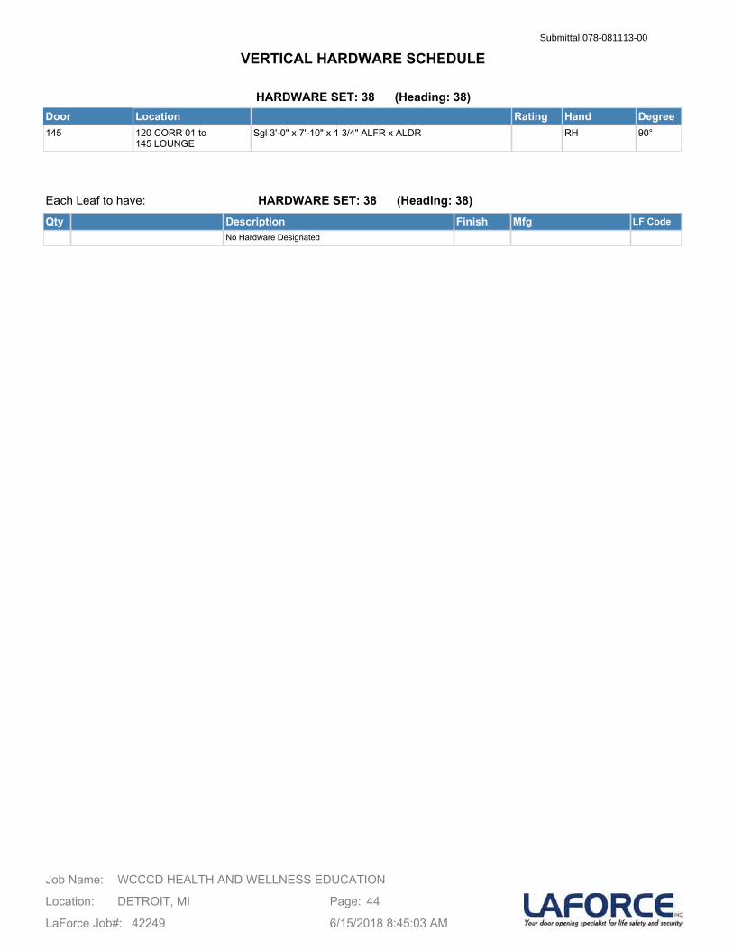
HARDWARE SET: 38 (Heading: 38)Door Location Rating Hand Degree145 120 CORR 01 to
145 LOUNGESgl 3'-0" x 7'-10" x 1 3/4" ALFR x ALDR RH 90°
Each Leaf to have:
Qty Description Finish Mfg LF CodeNo Hardware Designated
HARDWARE SET: 38 (Heading: 38)
WCCCD HEALTH AND WELLNESS EDUCATIONJob Name:
Location: DETROIT, MI
LaForce Job#: 42249
Page: 44
6/15/2018 8:45:03 AM
VERTICAL HARDWARE SCHEDULESubmittal 078-081113-00

HARDWARE SET: 39 (Heading: 39)Door Location Rating Hand Degree160E.1/160E.2 100 LOBBY to
160 GYMPr 3'-0"/3'-0" x 7'-10" x 1 3/4" ALFR x ALDR RHRA/LHR 90°/90°
Each Pair to have:
Qty Description Finish Mfg LF CodeNo Hardware Designated
HARDWARE SET: 39 (Heading: 39)
WCCCD HEALTH AND WELLNESS EDUCATIONJob Name:
Location: DETROIT, MI
LaForce Job#: 42249
Page: 45
6/15/2018 8:45:03 AM
VERTICAL HARDWARE SCHEDULESubmittal 078-081113-00
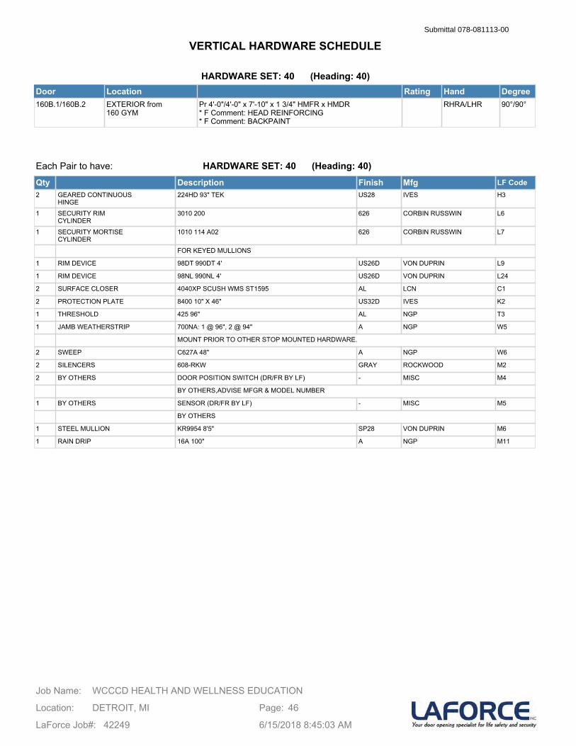
HARDWARE SET: 40 (Heading: 40)Door Location Rating Hand Degree160B.1/160B.2 EXTERIOR from
160 GYMPr 4'-0"/4'-0" x 7'-10" x 1 3/4" HMFR x HMDR* F Comment: HEAD REINFORCING* F Comment: BACKPAINT
RHRA/LHR 90°/90°
Each Pair to have:
Qty Description Finish Mfg LF Code2 GEARED CONTINUOUS
HINGE224HD 93" TEK US28 IVES H3
1 SECURITY RIMCYLINDER
3010 200 626 CORBIN RUSSWIN L6
1 SECURITY MORTISECYLINDER
1010 114 A02 626 CORBIN RUSSWIN L7
FOR KEYED MULLIONS
1 RIM DEVICE 98DT 990DT 4' US26D VON DUPRIN L9
1 RIM DEVICE 98NL 990NL 4' US26D VON DUPRIN L24
2 SURFACE CLOSER 4040XP SCUSH WMS ST1595 AL LCN C1
2 PROTECTION PLATE 8400 10" X 46" US32D IVES K2
1 THRESHOLD 425 96" AL NGP T3
1 JAMB WEATHERSTRIP 700NA: 1 @ 96", 2 @ 94" A NGP W5
MOUNT PRIOR TO OTHER STOP MOUNTED HARDWARE.
2 SWEEP C627A 48" A NGP W6
2 SILENCERS 608-RKW GRAY ROCKWOOD M2
2 BY OTHERS DOOR POSITION SWITCH (DR/FR BY LF) - MISC M4
BY OTHERS,ADVISE MFGR & MODEL NUMBER
1 BY OTHERS SENSOR (DR/FR BY LF) - MISC M5
BY OTHERS
1 STEEL MULLION KR9954 8'5" SP28 VON DUPRIN M6
1 RAIN DRIP 16A 100" A NGP M11
HARDWARE SET: 40 (Heading: 40)
WCCCD HEALTH AND WELLNESS EDUCATIONJob Name:
Location: DETROIT, MI
LaForce Job#: 42249
Page: 46
6/15/2018 8:45:03 AM
VERTICAL HARDWARE SCHEDULESubmittal 078-081113-00
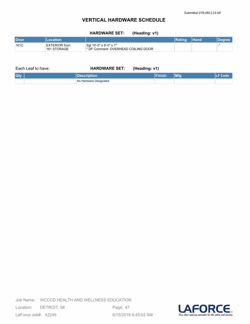
HARDWARE SET: (Heading: v1)Door Location Rating Hand Degree161C EXTERIOR from
161 STORAGESgl 10'-0" x 8'-0" x ?" * DF Comment: OVERHEAD COILING DOOR
-°
Each Leaf to have:
Qty Description Finish Mfg LF CodeNo Hardware Designated
HARDWARE SET: (Heading: v1)
WCCCD HEALTH AND WELLNESS EDUCATIONJob Name:
Location: DETROIT, MI
LaForce Job#: 42249
Page: 47
6/15/2018 8:45:03 AM
VERTICAL HARDWARE SCHEDULESubmittal 078-081113-00
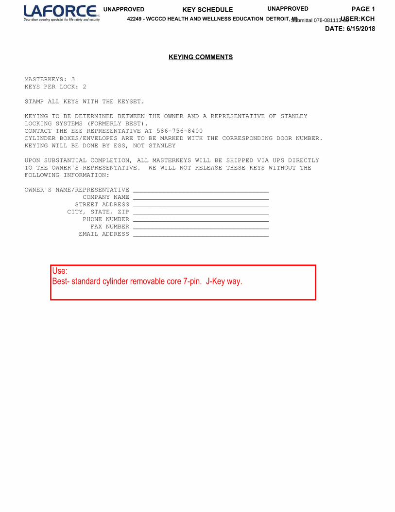
MASTERKEYS: 3KEYS PER LOCK: 2
STAMP ALL KEYS WITH THE KEYSET.
KEYING TO BE DETERMINED BETWEEN THE OWNER AND A REPRESENTATIVE OF STANLEYLOCKING SYSTEMS (FORMERLY BEST).CONTACT THE ESS REPRESENTATIVE AT 586-756-8400CYLINDER BOXES/ENVELOPES ARE TO BE MARKED WITH THE CORRESPONDING DOOR NUMBER.KEYING WILL BE DONE BY ESS, NOT STANLEY
UPON SUBSTANTIAL COMPLETION, ALL MASTERKEYS WILL BE SHIPPED VIA UPS DIRECTLYTO THE OWNER'S REPRESENTATIVE. WE WILL NOT RELEASE THESE KEYS WITHOUT THE FOLLOWING INFORMATION:
OWNER'S NAME/REPRESENTATIVE ___________________________________ COMPANY NAME ___________________________________ STREET ADDRESS ___________________________________ CITY, STATE, ZIP ___________________________________ PHONE NUMBER ___________________________________ FAX NUMBER ___________________________________ EMAIL ADDRESS ___________________________________
KEYING COMMENTS
DATE: 6/15/2018USER:KCH
PAGE 1KEY SCHEDULE42249 - WCCCD HEALTH AND WELLNESS EDUCATION DETROIT, MI
UNAPPROVED UNAPPROVED
Submittal 078-081113-00
Use:Best- standard cylinder removable core 7-pin. J-Key way.
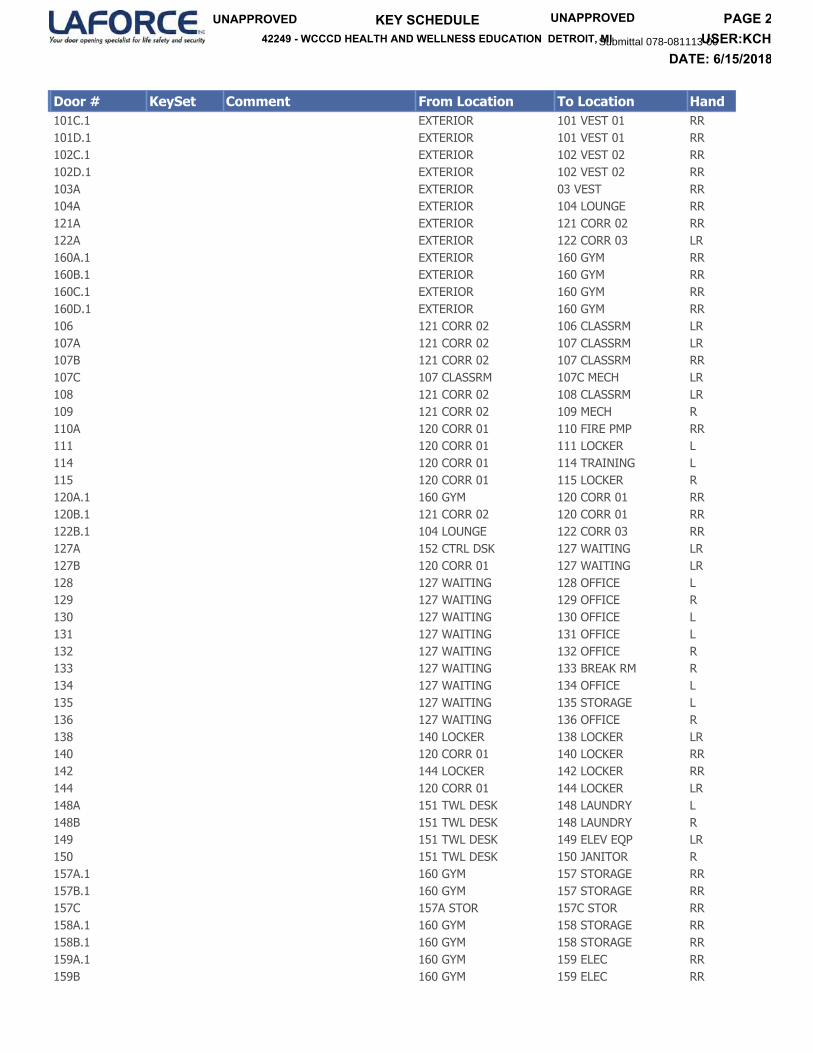
Door # KeySet Comment From Location To Location Hand
101C.1 EXTERIOR 101 VEST 01 RR101D.1 EXTERIOR 101 VEST 01 RR102C.1 EXTERIOR 102 VEST 02 RR102D.1 EXTERIOR 102 VEST 02 RR103A EXTERIOR 03 VEST RR104A EXTERIOR 104 LOUNGE RR121A EXTERIOR 121 CORR 02 RR122A EXTERIOR 122 CORR 03 LR160A.1 EXTERIOR 160 GYM RR160B.1 EXTERIOR 160 GYM RR160C.1 EXTERIOR 160 GYM RR160D.1 EXTERIOR 160 GYM RR106 121 CORR 02 106 CLASSRM LR107A 121 CORR 02 107 CLASSRM LR107B 121 CORR 02 107 CLASSRM RR107C 107 CLASSRM 107C MECH LR108 121 CORR 02 108 CLASSRM LR109 121 CORR 02 109 MECH R110A 120 CORR 01 110 FIRE PMP RR111 120 CORR 01 111 LOCKER L114 120 CORR 01 114 TRAINING L115 120 CORR 01 115 LOCKER R120A.1 160 GYM 120 CORR 01 RR120B.1 121 CORR 02 120 CORR 01 RR122B.1 104 LOUNGE 122 CORR 03 RR127A 152 CTRL DSK 127 WAITING LR127B 120 CORR 01 127 WAITING LR128 127 WAITING 128 OFFICE L129 127 WAITING 129 OFFICE R130 127 WAITING 130 OFFICE L131 127 WAITING 131 OFFICE L132 127 WAITING 132 OFFICE R133 127 WAITING 133 BREAK RM R134 127 WAITING 134 OFFICE L135 127 WAITING 135 STORAGE L136 127 WAITING 136 OFFICE R138 140 LOCKER 138 LOCKER LR140 120 CORR 01 140 LOCKER RR142 144 LOCKER 142 LOCKER RR144 120 CORR 01 144 LOCKER LR148A 151 TWL DESK 148 LAUNDRY L148B 151 TWL DESK 148 LAUNDRY R149 151 TWL DESK 149 ELEV EQP LR150 151 TWL DESK 150 JANITOR R157A.1 160 GYM 157 STORAGE RR157B.1 160 GYM 157 STORAGE RR157C 157A STOR 157C STOR RR158A.1 160 GYM 158 STORAGE RR158B.1 160 GYM 158 STORAGE RR159A.1 160 GYM 159 ELEC RR159B 160 GYM 159 ELEC RR
DATE: 6/15/2018USER:KCH
PAGE 2KEY SCHEDULE42249 - WCCCD HEALTH AND WELLNESS EDUCATION DETROIT, MI
UNAPPROVED UNAPPROVED
Submittal 078-081113-00
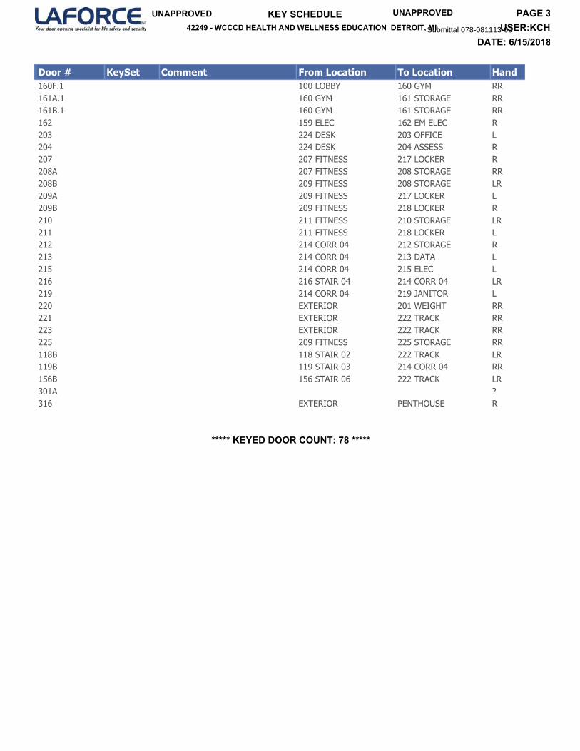
Door # KeySet Comment From Location To Location Hand
160F.1 100 LOBBY 160 GYM RR161A.1 160 GYM 161 STORAGE RR161B.1 160 GYM 161 STORAGE RR162 159 ELEC 162 EM ELEC R203 224 DESK 203 OFFICE L204 224 DESK 204 ASSESS R207 207 FITNESS 217 LOCKER R208A 207 FITNESS 208 STORAGE RR208B 209 FITNESS 208 STORAGE LR209A 209 FITNESS 217 LOCKER L209B 209 FITNESS 218 LOCKER R210 211 FITNESS 210 STORAGE LR211 211 FITNESS 218 LOCKER L212 214 CORR 04 212 STORAGE R213 214 CORR 04 213 DATA L215 214 CORR 04 215 ELEC L216 216 STAIR 04 214 CORR 04 LR219 214 CORR 04 219 JANITOR L220 EXTERIOR 201 WEIGHT RR221 EXTERIOR 222 TRACK RR223 EXTERIOR 222 TRACK RR225 209 FITNESS 225 STORAGE RR118B 118 STAIR 02 222 TRACK LR119B 119 STAIR 03 214 CORR 04 RR156B 156 STAIR 06 222 TRACK LR301A ?316 EXTERIOR PENTHOUSE R
***** KEYED DOOR COUNT: 78 *****
DATE: 6/15/2018USER:KCH
PAGE 3KEY SCHEDULE42249 - WCCCD HEALTH AND WELLNESS EDUCATION DETROIT, MI
UNAPPROVED UNAPPROVED
Submittal 078-081113-00

/----FRAME DATA---\ OPENING /--------DOOR DATA---------\ /--------------HARDWARE-------------\
DOOR NO./ ARCH NO.
PR/BK LOCATION
G SA EU RG IE E S
DEPTH
SECT
ELEV
ANCHOR
WIDTH
HEIGHT
MTRL
THICK
ELEV
UN CD UE TR
DEGREE
HAND
LABEL
QTY
SET#
HINGE
LOCK
CLOSER
T WH SR TS RH P
STOP
P PU US LH L
KICK
MISC
MISC
EXTERIOR DOORS
101A.1
P1 101 VEST 01100 LOBBY
AL BO NA 3 - 0 7 - 6 AL 1 3/4 BO 90 RR 02
101A.2
P2 NA 3 - 0 7 - 6 AL 1 3/4 BO 90 LR 02
101B.1
P1 101 VEST 01100 LOBBY
AL BO NA 3 - 0 7 - 6 AL 1 3/4 BO 90 RR 01
101B.2
P2 NA 3 - 0 7 - 6 AL 1 3/4 BO 90 LR 01
101C.1
P1 EXTERIOR101 VEST 01
AL BO NA 3 - 0 7 - 6 AL 1 3/4 BO 90 RR 04 L2
101C.2
P2 NA 3 - 0 7 - 6 AL 1 3/4 BO 90 LR 04
101D.1
P1 EXTERIOR101 VEST 01
AL BO NA 3 - 0 7 - 6 AL 1 3/4 BO 90 RR 03 L2
101D.2
P2 NA 3 - 0 7 - 6 AL 1 3/4 BO 90 LR 03
102A.1
P1 102 VEST 02104 LOUNGE
AL BO NA 3 - 0 7 - 6 AL 1 3/4 BO 90 RR 01
102A.2
P2 NA 3 - 0 7 - 6 AL 1 3/4 BO 90 LR 01
102B.1
P1 102 VEST 02104 LOUNGE
AL BO NA 3 - 0 7 - 6 AL 1 3/4 BO 90 RR 02
Page 1 of 23
RUN DATE 6/15/2018 8:44:34 AM* UNAPPROVED * * UNAPPROVED *
MOST RECENT LF CHANGE ORDER INCLUDED :
DOORS, FRAMES, & HARDWARE SCHEDULE42249 - WCCCD HEALTH AND WELLNESS EDUCATION DETROIT, MI RUN BY KCH
Subm
ittal 078-081113-00
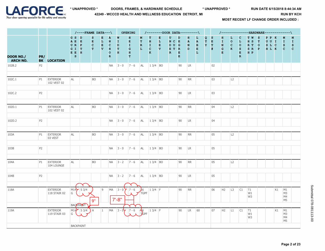
/----FRAME DATA---\ OPENING /--------DOOR DATA---------\ /--------------HARDWARE-------------\
DOOR NO./ ARCH NO.
PR/BK LOCATION
G SA EU RG IE E S
DEPTH
SECT
ELEV
ANCHOR
WIDTH
HEIGHT
MTRL
THICK
ELEV
UN CD UE TR
DEGREE
HAND
LABEL
QTY
SET#
HINGE
LOCK
CLOSER
T WH SR TS RH P
STOP
P PU US LH L
KICK
MISC
MISC
102B.2
P2 NA 3 - 0 7 - 6 AL 1 3/4 BO 90 LR 02
102C.1
P1 EXTERIOR102 VEST 02
AL BO NA 3 - 0 7 - 6 AL 1 3/4 BO 90 RR 03 L2
102C.2
P2 NA 3 - 0 7 - 6 AL 1 3/4 BO 90 LR 03
102D.1
P1 EXTERIOR102 VEST 02
AL BO NA 3 - 0 7 - 6 AL 1 3/4 BO 90 RR 04 L2
102D.2
P2 NA 3 - 0 7 - 6 AL 1 3/4 BO 90 LR 04
103A
P1 EXTERIOR03 VEST
AL BO NA 3 - 0 7 - 6 AL 1 3/4 BO 90 RR 05 L2
103B
P2 NA 3 - 0 7 - 6 AL 1 3/4 BO 90 LR 05
104A
P1 EXTERIOR104 LOUNGE
AL BO NA 3 - 2 7 - 6 AL 1 3/4 BO 90 RR 05 L2
104B
P2 NA 3 - 2 7 - 6 AL 1 3/4 BO 90 LR 05
118A
EXTERIOR118 STAIR 02
M14G
5 3/4 9 MA 3 - 0 7 - 6 16TGPF
1 3/4 F 90 RR 06 H2 L3 C1 T1W1W3
K1 M1M3M4M5
BACKPAINT
119A
EXTERIOR119 STAIR 03
M14G
5 3/4 A 1 MA 3 - 0 7 - 6 16TGPF
1 3/4 F 90 LR 60 07 H2 L1 C1 T1W1W3
K1 M1M3M4M5
BACKPAINT
Page 2 of 23
RUN DATE 6/15/2018 8:44:34 AM* UNAPPROVED * * UNAPPROVED *
MOST RECENT LF CHANGE ORDER INCLUDED :
DOORS, FRAMES, & HARDWARE SCHEDULE42249 - WCCCD HEALTH AND WELLNESS EDUCATION DETROIT, MI RUN BY KCH
Subm
ittal 078-081113-00
9" 7'-8"
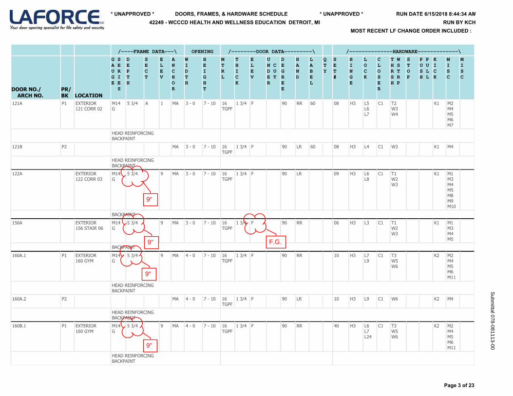
/----FRAME DATA---\ OPENING /--------DOOR DATA---------\ /--------------HARDWARE-------------\
DOOR NO./ ARCH NO.
PR/BK LOCATION
G SA EU RG IE E S
DEPTH
SECT
ELEV
ANCHOR
WIDTH
HEIGHT
MTRL
THICK
ELEV
UN CD UE TR
DEGREE
HAND
LABEL
QTY
SET#
HINGE
LOCK
CLOSER
T WH SR TS RH P
STOP
P PU US LH L
KICK
MISC
MISC
121A
P1 EXTERIOR121 CORR 02
M14G
5 3/4 A 1 MA 3 - 0 7 - 10 16TGPF
1 3/4 F 90 RR 60 08 H3 L5L6L7
C1 T2W3W4
K1 M2M4M5M6M7
HEAD REINFORCINGBACKPAINT
121B
P2 MA 3 - 0 7 - 10 16TGPF
1 3/4 F 90 LR 60 08 H3 L4 C1 W3 K1 M4
HEAD REINFORCINGBACKPAINT
122A
EXTERIOR122 CORR 03
M14G
5 3/4 9 MA 3 - 0 7 - 10 16TGPF
1 3/4 F 90 LR 09 H3 L6L8
C1 T1W2W3
K1 M1M3M4M5M8M9M10
BACKPAINT
156A
EXTERIOR156 STAIR 06
M14G
5 3/4 9 MA 3 - 0 7 - 10 16TGPF
1 3/4 F 90 RR 06 H3 L3 C1 T1W2W3
K1 M1M3M4M5
BACKPAINT
160A.1
P1 EXTERIOR160 GYM
M14G
5 3/4 9 MA 4 - 0 7 - 10 16TGPF
1 3/4 F 90 RR 10 H3 L7L9
C1 T3W5W6
K2 M2M4M5M6M11
HEAD REINFORCINGBACKPAINT
160A.2
P2 MA 4 - 0 7 - 10 16TGPF
1 3/4 F 90 LR 10 H3 L9 C1 W6 K2 M4
HEAD REINFORCINGBACKPAINT
160B.1
P1 EXTERIOR160 GYM
M14G
5 3/4 9 MA 4 - 0 7 - 10 16TGPF
1 3/4 F 90 RR 40 H3 L6L7L24
C1 T3W5W6
K2 M2M4M5M6M11
HEAD REINFORCINGBACKPAINT
Page 3 of 23
RUN DATE 6/15/2018 8:44:34 AM* UNAPPROVED * * UNAPPROVED *
MOST RECENT LF CHANGE ORDER INCLUDED :
DOORS, FRAMES, & HARDWARE SCHEDULE42249 - WCCCD HEALTH AND WELLNESS EDUCATION DETROIT, MI RUN BY KCH
Subm
ittal 078-081113-00
9"
9"
9"
9"
F.G.
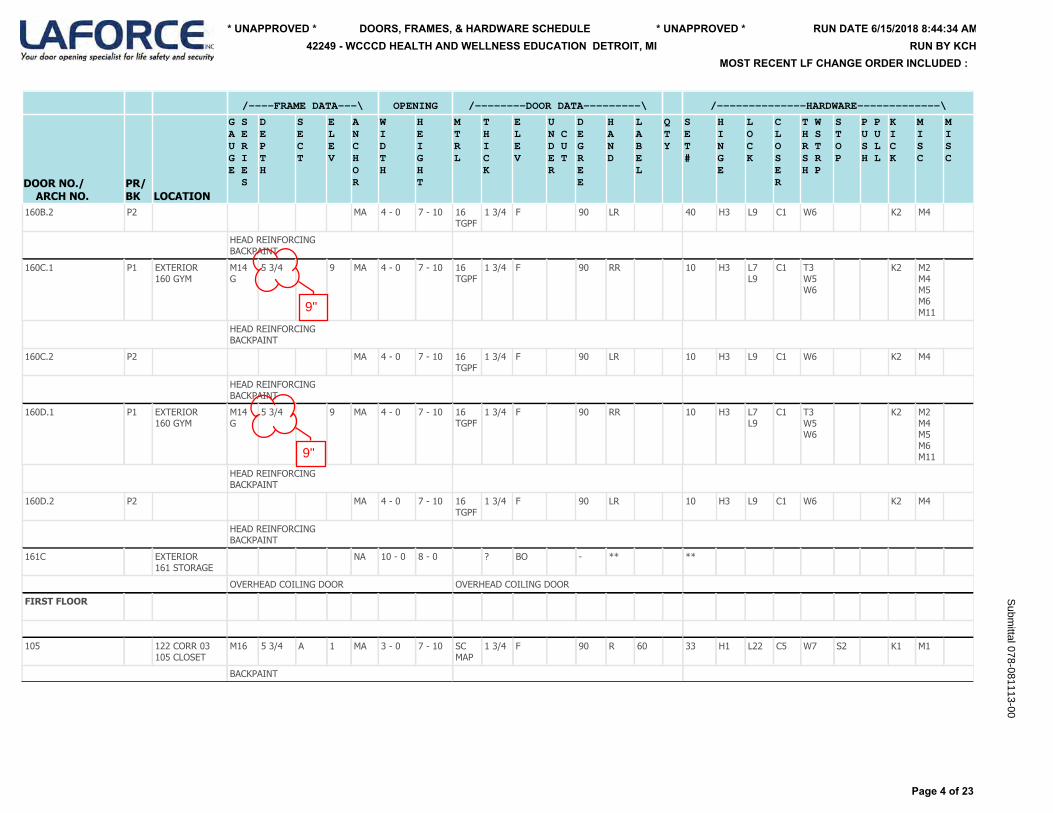
/----FRAME DATA---\ OPENING /--------DOOR DATA---------\ /--------------HARDWARE-------------\
DOOR NO./ ARCH NO.
PR/BK LOCATION
G SA EU RG IE E S
DEPTH
SECT
ELEV
ANCHOR
WIDTH
HEIGHT
MTRL
THICK
ELEV
UN CD UE TR
DEGREE
HAND
LABEL
QTY
SET#
HINGE
LOCK
CLOSER
T WH SR TS RH P
STOP
P PU US LH L
KICK
MISC
MISC
160B.2
P2 MA 4 - 0 7 - 10 16TGPF
1 3/4 F 90 LR 40 H3 L9 C1 W6 K2 M4
HEAD REINFORCINGBACKPAINT
160C.1
P1 EXTERIOR160 GYM
M14G
5 3/4 9 MA 4 - 0 7 - 10 16TGPF
1 3/4 F 90 RR 10 H3 L7L9
C1 T3W5W6
K2 M2M4M5M6M11
HEAD REINFORCINGBACKPAINT
160C.2
P2 MA 4 - 0 7 - 10 16TGPF
1 3/4 F 90 LR 10 H3 L9 C1 W6 K2 M4
HEAD REINFORCINGBACKPAINT
160D.1
P1 EXTERIOR160 GYM
M14G
5 3/4 9 MA 4 - 0 7 - 10 16TGPF
1 3/4 F 90 RR 10 H3 L7L9
C1 T3W5W6
K2 M2M4M5M6M11
HEAD REINFORCINGBACKPAINT
160D.2
P2 MA 4 - 0 7 - 10 16TGPF
1 3/4 F 90 LR 10 H3 L9 C1 W6 K2 M4
HEAD REINFORCINGBACKPAINT
161C
EXTERIOR161 STORAGE
NA 10 - 0 8 - 0 ? BO - ** **
OVERHEAD COILING DOOR OVERHEAD COILING DOOR
FIRST FLOOR
105
122 CORR 03105 CLOSET
M16 5 3/4 A 1 MA 3 - 0 7 - 10 SCMAP
1 3/4 F 90 R 60 33 H1 L22 C5 W7 S2 K1 M1
BACKPAINT
Page 4 of 23
RUN DATE 6/15/2018 8:44:34 AM* UNAPPROVED * * UNAPPROVED *
MOST RECENT LF CHANGE ORDER INCLUDED :
DOORS, FRAMES, & HARDWARE SCHEDULE42249 - WCCCD HEALTH AND WELLNESS EDUCATION DETROIT, MI RUN BY KCH
Subm
ittal 078-081113-00
9"
9"
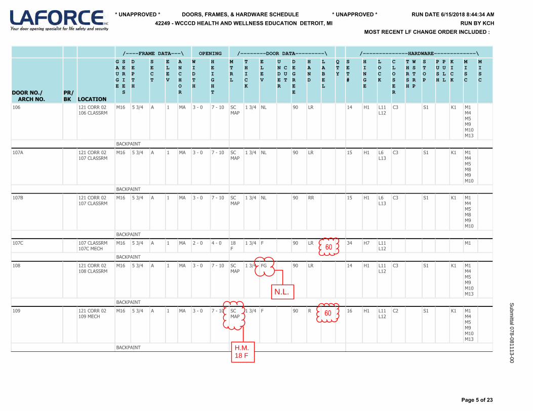
/----FRAME DATA---\ OPENING /--------DOOR DATA---------\ /--------------HARDWARE-------------\
DOOR NO./ ARCH NO.
PR/BK LOCATION
G SA EU RG IE E S
DEPTH
SECT
ELEV
ANCHOR
WIDTH
HEIGHT
MTRL
THICK
ELEV
UN CD UE TR
DEGREE
HAND
LABEL
QTY
SET#
HINGE
LOCK
CLOSER
T WH SR TS RH P
STOP
P PU US LH L
KICK
MISC
MISC
106
121 CORR 02106 CLASSRM
M16 5 3/4 A 1 MA 3 - 0 7 - 10 SCMAP
1 3/4 NL 90 LR 14 H1 L11L12
C3 S1 K1 M1M4M5M9M10M13
BACKPAINT
107A
121 CORR 02107 CLASSRM
M16 5 3/4 A 1 MA 3 - 0 7 - 10 SCMAP
1 3/4 NL 90 LR 15 H1 L6L13
C3 S1 K1 M1M4M5M8M9M10
BACKPAINT
107B
121 CORR 02107 CLASSRM
M16 5 3/4 A 1 MA 3 - 0 7 - 10 SCMAP
1 3/4 NL 90 RR 15 H1 L6L13
C3 S1 K1 M1M4M5M8M9M10
BACKPAINT
107C
107 CLASSRM107C MECH
M16 5 3/4 A 1 MA 2 - 0 4 - 0 18F
1 3/4 F 90 LR 34 H7 L11L12
M1
BACKPAINT
108
121 CORR 02108 CLASSRM
M16 5 3/4 A 1 MA 3 - 0 7 - 10 SCMAP
1 3/4 FG 90 LR 14 H1 L11L12
C3 S1 K1 M1M4M5M9M10M13
BACKPAINT
109
121 CORR 02109 MECH
M16 5 3/4 A 1 MA 3 - 0 7 - 10 SCMAP
1 3/4 F 90 R 16 H1 L11L12
C2 S1 K1 M1M4M5M9M10M13
BACKPAINT
Page 5 of 23
RUN DATE 6/15/2018 8:44:34 AM* UNAPPROVED * * UNAPPROVED *
MOST RECENT LF CHANGE ORDER INCLUDED :
DOORS, FRAMES, & HARDWARE SCHEDULE42249 - WCCCD HEALTH AND WELLNESS EDUCATION DETROIT, MI RUN BY KCH
Subm
ittal 078-081113-00
60
60
N.L.
H.M.18 F
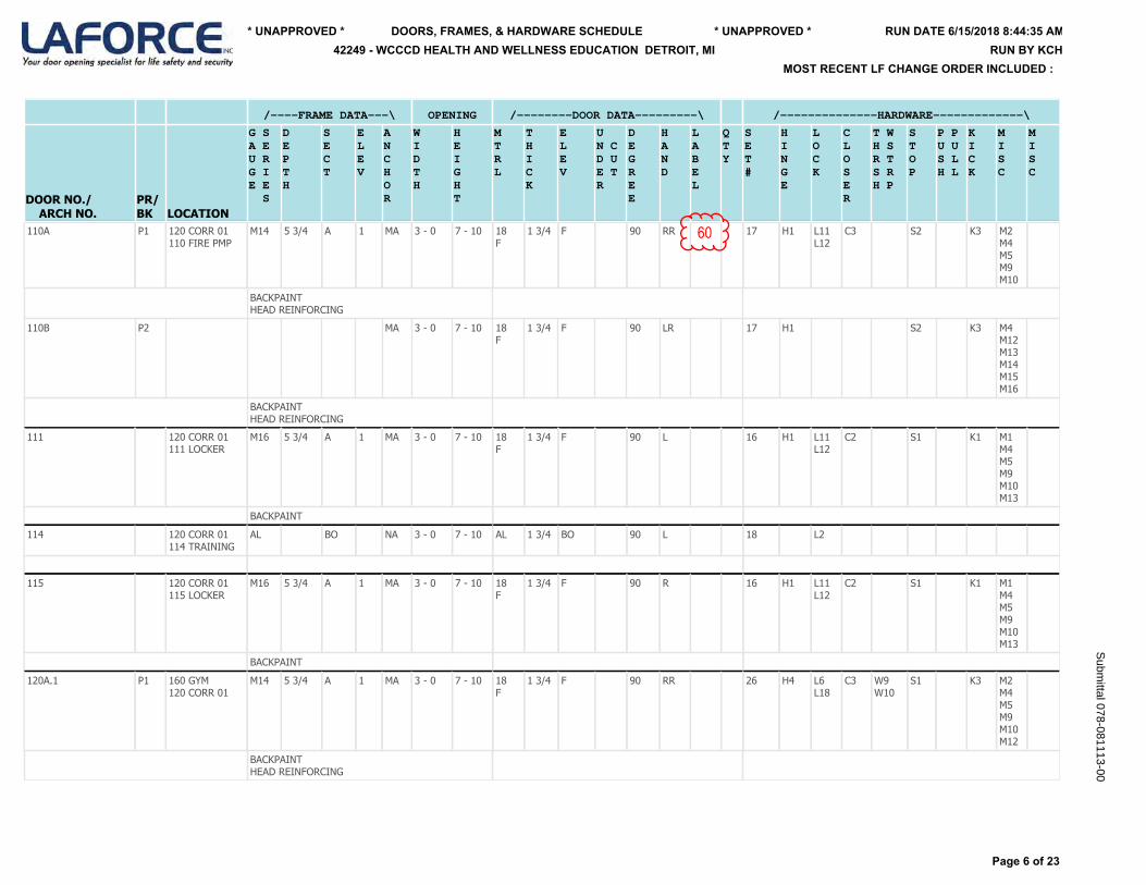
/----FRAME DATA---\ OPENING /--------DOOR DATA---------\ /--------------HARDWARE-------------\
DOOR NO./ ARCH NO.
PR/BK LOCATION
G SA EU RG IE E S
DEPTH
SECT
ELEV
ANCHOR
WIDTH
HEIGHT
MTRL
THICK
ELEV
UN CD UE TR
DEGREE
HAND
LABEL
QTY
SET#
HINGE
LOCK
CLOSER
T WH SR TS RH P
STOP
P PU US LH L
KICK
MISC
MISC
110A
P1 120 CORR 01110 FIRE PMP
M14 5 3/4 A 1 MA 3 - 0 7 - 10 18F
1 3/4 F 90 RR 17 H1 L11L12
C3 S2 K3 M2M4M5M9M10
BACKPAINTHEAD REINFORCING
110B
P2 MA 3 - 0 7 - 10 18F
1 3/4 F 90 LR 17 H1 S2 K3 M4M12M13M14M15M16
BACKPAINTHEAD REINFORCING
111
120 CORR 01111 LOCKER
M16 5 3/4 A 1 MA 3 - 0 7 - 10 18F
1 3/4 F 90 L 16 H1 L11L12
C2 S1 K1 M1M4M5M9M10M13
BACKPAINT
114
120 CORR 01114 TRAINING
AL BO NA 3 - 0 7 - 10 AL 1 3/4 BO 90 L 18 L2
115
120 CORR 01115 LOCKER
M16 5 3/4 A 1 MA 3 - 0 7 - 10 18F
1 3/4 F 90 R 16 H1 L11L12
C2 S1 K1 M1M4M5M9M10M13
BACKPAINT
120A.1
P1 160 GYM120 CORR 01
M14 5 3/4 A 1 MA 3 - 0 7 - 10 18F
1 3/4 F 90 RR 26 H4 L6L18
C3 W9W10
S1 K3 M2M4M5M9M10M12
BACKPAINTHEAD REINFORCING
Page 6 of 23
RUN DATE 6/15/2018 8:44:35 AM* UNAPPROVED * * UNAPPROVED *
MOST RECENT LF CHANGE ORDER INCLUDED :
DOORS, FRAMES, & HARDWARE SCHEDULE42249 - WCCCD HEALTH AND WELLNESS EDUCATION DETROIT, MI RUN BY KCH
Subm
ittal 078-081113-00
60
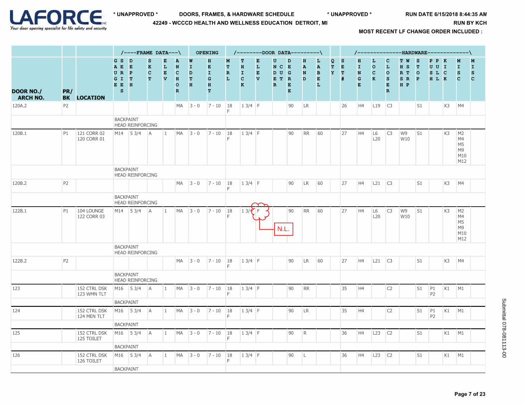
/----FRAME DATA---\ OPENING /--------DOOR DATA---------\ /--------------HARDWARE-------------\
DOOR NO./ ARCH NO.
PR/BK LOCATION
G SA EU RG IE E S
DEPTH
SECT
ELEV
ANCHOR
WIDTH
HEIGHT
MTRL
THICK
ELEV
UN CD UE TR
DEGREE
HAND
LABEL
QTY
SET#
HINGE
LOCK
CLOSER
T WH SR TS RH P
STOP
P PU US LH L
KICK
MISC
MISC
120A.2
P2 MA 3 - 0 7 - 10 18F
1 3/4 F 90 LR 26 H4 L19 C3 S1 K3 M4
BACKPAINTHEAD REINFORCING
120B.1
P1 121 CORR 02120 CORR 01
M14 5 3/4 A 1 MA 3 - 0 7 - 10 18F
1 3/4 F 90 RR 60 27 H4 L6L20
C3 W9W10
S1 K3 M2M4M5M9M10M12
BACKPAINTHEAD REINFORCING
120B.2
P2 MA 3 - 0 7 - 10 18F
1 3/4 F 90 LR 60 27 H4 L21 C3 S1 K3 M4
BACKPAINTHEAD REINFORCING
122B.1
P1 104 LOUNGE122 CORR 03
M14 5 3/4 A 1 MA 3 - 0 7 - 10 18F
1 3/4 F 90 RR 60 27 H4 L6L20
C3 W9W10
S1 K3 M2M4M5M9M10M12
BACKPAINTHEAD REINFORCING
122B.2
P2 MA 3 - 0 7 - 10 18F
1 3/4 F 90 LR 60 27 H4 L21 C3 S1 K3 M4
BACKPAINTHEAD REINFORCING
123
152 CTRL DSK123 WMN TLT
M16 5 3/4 A 1 MA 3 - 0 7 - 10 18F
1 3/4 F 90 RR 35 H4 C2 S1 P1P2
K1 M1
BACKPAINT
124
152 CTRL DSK124 MEN TLT
M16 5 3/4 A 1 MA 3 - 0 7 - 10 18F
1 3/4 F 90 LR 35 H4 C2 S1 P1P2
K1 M1
BACKPAINT
125
152 CTRL DSK125 TOILET
M16 5 3/4 A 1 MA 3 - 0 7 - 10 18F
1 3/4 F 90 R 36 H4 L23 C2 S1 K1 M1
BACKPAINT
126
152 CTRL DSK126 TOILET
M16 5 3/4 A 1 MA 3 - 0 7 - 10 18F
1 3/4 F 90 L 36 H4 L23 C2 S1 K1 M1
BACKPAINT
Page 7 of 23
RUN DATE 6/15/2018 8:44:35 AM* UNAPPROVED * * UNAPPROVED *
MOST RECENT LF CHANGE ORDER INCLUDED :
DOORS, FRAMES, & HARDWARE SCHEDULE42249 - WCCCD HEALTH AND WELLNESS EDUCATION DETROIT, MI RUN BY KCH
Subm
ittal 078-081113-00
N.L.
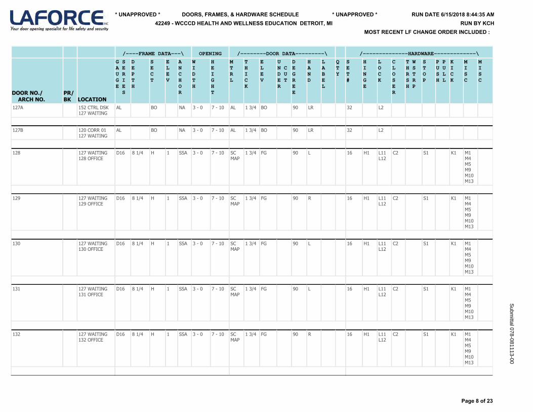
/----FRAME DATA---\ OPENING /--------DOOR DATA---------\ /--------------HARDWARE-------------\
DOOR NO./ ARCH NO.
PR/BK LOCATION
G SA EU RG IE E S
DEPTH
SECT
ELEV
ANCHOR
WIDTH
HEIGHT
MTRL
THICK
ELEV
UN CD UE TR
DEGREE
HAND
LABEL
QTY
SET#
HINGE
LOCK
CLOSER
T WH SR TS RH P
STOP
P PU US LH L
KICK
MISC
MISC
127A
152 CTRL DSK127 WAITING
AL BO NA 3 - 0 7 - 10 AL 1 3/4 BO 90 LR 32 L2
127B
120 CORR 01127 WAITING
AL BO NA 3 - 0 7 - 10 AL 1 3/4 BO 90 LR 32 L2
128
127 WAITING128 OFFICE
D16 8 1/4 H 1 SSA 3 - 0 7 - 10 SCMAP
1 3/4 FG 90 L 16 H1 L11L12
C2 S1 K1 M1M4M5M9M10M13
129
127 WAITING129 OFFICE
D16 8 1/4 H 1 SSA 3 - 0 7 - 10 SCMAP
1 3/4 FG 90 R 16 H1 L11L12
C2 S1 K1 M1M4M5M9M10M13
130
127 WAITING130 OFFICE
D16 8 1/4 H 1 SSA 3 - 0 7 - 10 SCMAP
1 3/4 FG 90 L 16 H1 L11L12
C2 S1 K1 M1M4M5M9M10M13
131
127 WAITING131 OFFICE
D16 8 1/4 H 1 SSA 3 - 0 7 - 10 SCMAP
1 3/4 FG 90 L 16 H1 L11L12
C2 S1 K1 M1M4M5M9M10M13
132
127 WAITING132 OFFICE
D16 8 1/4 H 1 SSA 3 - 0 7 - 10 SCMAP
1 3/4 FG 90 R 16 H1 L11L12
C2 S1 K1 M1M4M5M9M10M13
Page 8 of 23
RUN DATE 6/15/2018 8:44:35 AM* UNAPPROVED * * UNAPPROVED *
MOST RECENT LF CHANGE ORDER INCLUDED :
DOORS, FRAMES, & HARDWARE SCHEDULE42249 - WCCCD HEALTH AND WELLNESS EDUCATION DETROIT, MI RUN BY KCH
Subm
ittal 078-081113-00
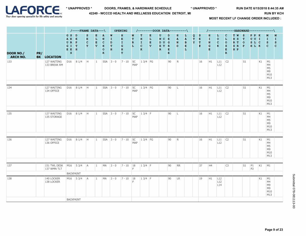
/----FRAME DATA---\ OPENING /--------DOOR DATA---------\ /--------------HARDWARE-------------\
DOOR NO./ ARCH NO.
PR/BK LOCATION
G SA EU RG IE E S
DEPTH
SECT
ELEV
ANCHOR
WIDTH
HEIGHT
MTRL
THICK
ELEV
UN CD UE TR
DEGREE
HAND
LABEL
QTY
SET#
HINGE
LOCK
CLOSER
T WH SR TS RH P
STOP
P PU US LH L
KICK
MISC
MISC
133
127 WAITING133 BREAK RM
D16 8 1/4 H 1 SSA 3 - 0 7 - 10 SCMAP
1 3/4 FG 90 R 16 H1 L11L12
C2 S1 K1 M1M4M5M9M10M13
134
127 WAITING134 OFFICE
D16 8 1/4 H 1 SSA 3 - 0 7 - 10 SCMAP
1 3/4 FG 90 L 16 H1 L11L12
C2 S1 K1 M1M4M5M9M10M13
135
127 WAITING135 STORAGE
D16 8 1/4 H 1 SSA 3 - 0 7 - 10 SCMAP
1 3/4 F 90 L 16 H1 L11L12
C2 S1 K1 M1M4M5M9M10M13
136
127 WAITING136 OFFICE
D16 8 1/4 H 1 SSA 3 - 0 7 - 10 SCMAP
1 3/4 FG 90 R 16 H1 L11L12
C2 S1 K1 M1M4M5M9M10M13
137
151 TWL DESK137 WMN TLT
M16 5 3/4 A 1 MA 3 - 0 7 - 10 18F
1 3/4 F 90 RR 37 H4 C3 S1 P1P2
K1 M1
BACKPAINT
138
140 LOCKER138 LOCKER
M16 5 3/4 A 1 MA 3 - 0 7 - 10 18F
1 3/4 F 90 LR 19 H1 L12L12L14
K1 M1M4M9M9M10M13
BACKPAINT
Page 9 of 23
RUN DATE 6/15/2018 8:44:35 AM* UNAPPROVED * * UNAPPROVED *
MOST RECENT LF CHANGE ORDER INCLUDED :
DOORS, FRAMES, & HARDWARE SCHEDULE42249 - WCCCD HEALTH AND WELLNESS EDUCATION DETROIT, MI RUN BY KCH
Subm
ittal 078-081113-00

/----FRAME DATA---\ OPENING /--------DOOR DATA---------\ /--------------HARDWARE-------------\
DOOR NO./ ARCH NO.
PR/BK LOCATION
G SA EU RG IE E S
DEPTH
SECT
ELEV
ANCHOR
WIDTH
HEIGHT
MTRL
THICK
ELEV
UN CD UE TR
DEGREE
HAND
LABEL
QTY
SET#
HINGE
LOCK
CLOSER
T WH SR TS RH P
STOP
P PU US LH L
KICK
MISC
MISC
140
120 CORR 01140 LOCKER
M16 5 3/4 A 1 MA 3 - 0 7 - 10 18F
1 3/4 F 90 RR 14 H1 L11L12
C3 S1 K1 M1M4M5M9M10M13
BACKPAINT
141
151 TWL DESK141 MEN TLT
M16 5 3/4 A 1 MA 3 - 0 7 - 10 18F
1 3/4 F 90 LR 37 H4 C3 S1 P1P2
K1 M1
BACKPAINT
142
144 LOCKER142 LOCKER
M16 5 3/4 A 1 MA 3 - 0 7 - 10 18F
1 3/4 F 90 RR 19 H1 L12L12L14
K1 M1M4M9M9M10M13
BACKPAINT
144
120 CORR 01144 LOCKER
M16 5 3/4 A 1 MA 3 - 0 7 - 10 18F
1 3/4 F 90 LR 14 H1 L11L12
C3 S1 K1 M1M4M5M9M10M13
BACKPAINT
145
120 CORR 01145 LOUNGE
AL BO NA 3 - 0 7 - 10 AL 1 3/4 BO 90 R 38
146
145 LOUNGE146 TOILET
M16 5 3/4 A 1 MA 3 - 0 7 - 10 18F
1 3/4 F 90 L 36 H4 L23 C2 S1 K1 M1
BACKPAINT
147
145 LOUNGE147 TOILET
M16 5 3/4 A 1 MA 3 - 0 7 - 10 18F
1 3/4 F 90 R 36 H4 L23 C2 S1 K1 M1
BACKPAINT
148A
151 TWL DESK148 LAUNDRY
M16 5 3/4 A 1 MA 3 - 0 7 - 10 18F
1 3/4 F 90 L 16 H1 L11L12
C2 S1 K1 M1M4M5M9M10M13
BACKPAINT
Page 10 of 23
RUN DATE 6/15/2018 8:44:35 AM* UNAPPROVED * * UNAPPROVED *
MOST RECENT LF CHANGE ORDER INCLUDED :
DOORS, FRAMES, & HARDWARE SCHEDULE42249 - WCCCD HEALTH AND WELLNESS EDUCATION DETROIT, MI RUN BY KCH
Subm
ittal 078-081113-00N.L.
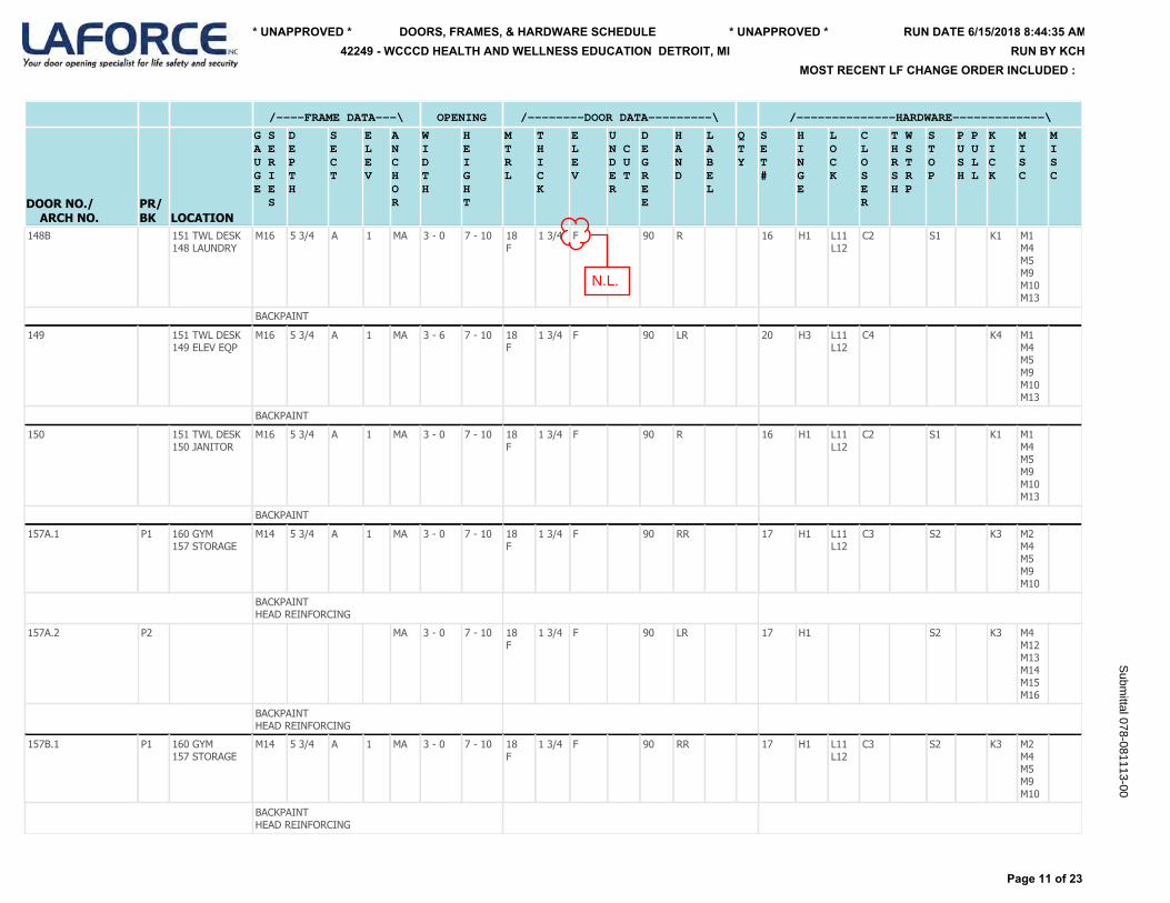
/----FRAME DATA---\ OPENING /--------DOOR DATA---------\ /--------------HARDWARE-------------\
DOOR NO./ ARCH NO.
PR/BK LOCATION
G SA EU RG IE E S
DEPTH
SECT
ELEV
ANCHOR
WIDTH
HEIGHT
MTRL
THICK
ELEV
UN CD UE TR
DEGREE
HAND
LABEL
QTY
SET#
HINGE
LOCK
CLOSER
T WH SR TS RH P
STOP
P PU US LH L
KICK
MISC
MISC
148B
151 TWL DESK148 LAUNDRY
M16 5 3/4 A 1 MA 3 - 0 7 - 10 18F
1 3/4 F 90 R 16 H1 L11L12
C2 S1 K1 M1M4M5M9M10M13
BACKPAINT
149
151 TWL DESK149 ELEV EQP
M16 5 3/4 A 1 MA 3 - 6 7 - 10 18F
1 3/4 F 90 LR 20 H3 L11L12
C4 K4 M1M4M5M9M10M13
BACKPAINT
150
151 TWL DESK150 JANITOR
M16 5 3/4 A 1 MA 3 - 0 7 - 10 18F
1 3/4 F 90 R 16 H1 L11L12
C2 S1 K1 M1M4M5M9M10M13
BACKPAINT
157A.1
P1 160 GYM157 STORAGE
M14 5 3/4 A 1 MA 3 - 0 7 - 10 18F
1 3/4 F 90 RR 17 H1 L11L12
C3 S2 K3 M2M4M5M9M10
BACKPAINTHEAD REINFORCING
157A.2
P2 MA 3 - 0 7 - 10 18F
1 3/4 F 90 LR 17 H1 S2 K3 M4M12M13M14M15M16
BACKPAINTHEAD REINFORCING
157B.1
P1 160 GYM157 STORAGE
M14 5 3/4 A 1 MA 3 - 0 7 - 10 18F
1 3/4 F 90 RR 17 H1 L11L12
C3 S2 K3 M2M4M5M9M10
BACKPAINTHEAD REINFORCING
Page 11 of 23
RUN DATE 6/15/2018 8:44:35 AM* UNAPPROVED * * UNAPPROVED *
MOST RECENT LF CHANGE ORDER INCLUDED :
DOORS, FRAMES, & HARDWARE SCHEDULE42249 - WCCCD HEALTH AND WELLNESS EDUCATION DETROIT, MI RUN BY KCH
Subm
ittal 078-081113-00
N.L.
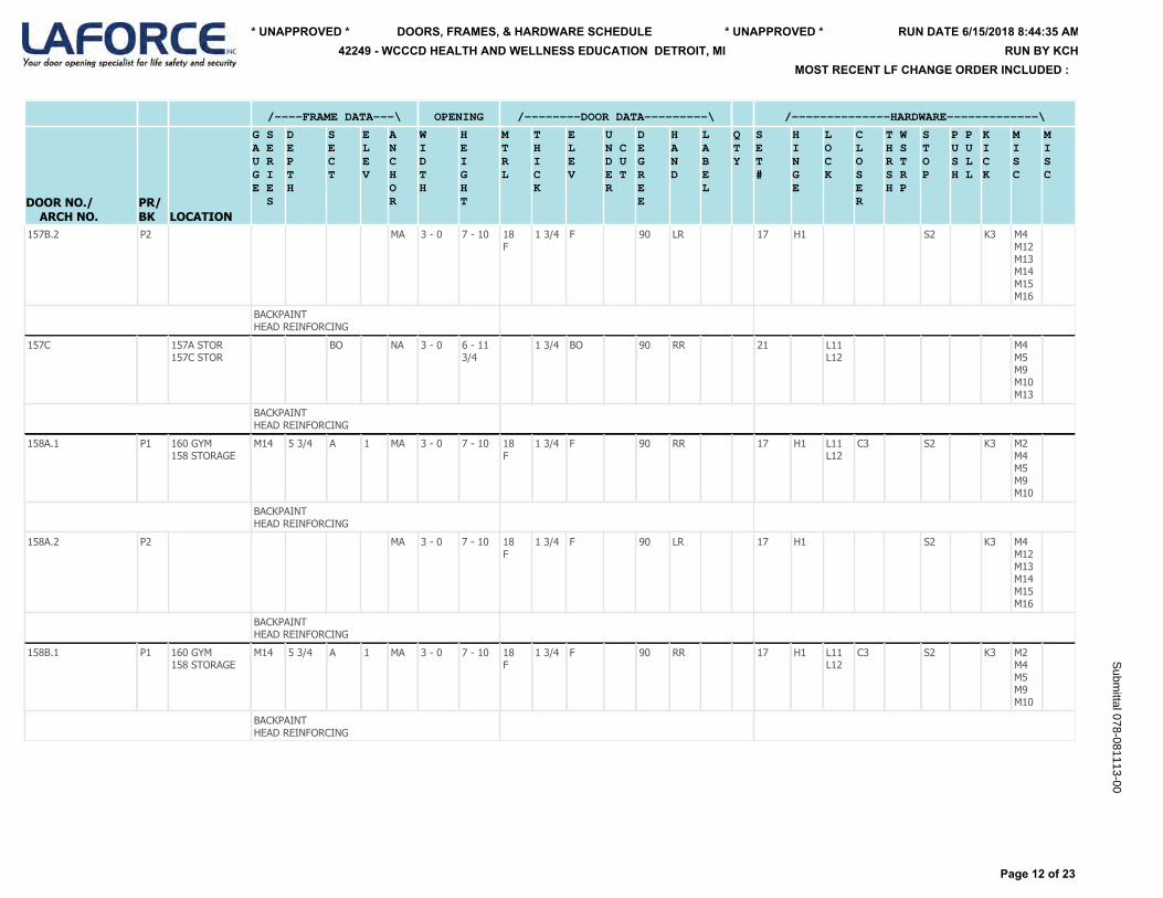
/----FRAME DATA---\ OPENING /--------DOOR DATA---------\ /--------------HARDWARE-------------\
DOOR NO./ ARCH NO.
PR/BK LOCATION
G SA EU RG IE E S
DEPTH
SECT
ELEV
ANCHOR
WIDTH
HEIGHT
MTRL
THICK
ELEV
UN CD UE TR
DEGREE
HAND
LABEL
QTY
SET#
HINGE
LOCK
CLOSER
T WH SR TS RH P
STOP
P PU US LH L
KICK
MISC
MISC
157B.2
P2 MA 3 - 0 7 - 10 18F
1 3/4 F 90 LR 17 H1 S2 K3 M4M12M13M14M15M16
BACKPAINTHEAD REINFORCING
157C
157A STOR157C STOR
BO NA 3 - 0 6 - 11 3/4
1 3/4 BO 90 RR 21 L11L12
M4M5M9M10M13
BACKPAINTHEAD REINFORCING
158A.1
P1 160 GYM158 STORAGE
M14 5 3/4 A 1 MA 3 - 0 7 - 10 18F
1 3/4 F 90 RR 17 H1 L11L12
C3 S2 K3 M2M4M5M9M10
BACKPAINTHEAD REINFORCING
158A.2
P2 MA 3 - 0 7 - 10 18F
1 3/4 F 90 LR 17 H1 S2 K3 M4M12M13M14M15M16
BACKPAINTHEAD REINFORCING
158B.1
P1 160 GYM158 STORAGE
M14 5 3/4 A 1 MA 3 - 0 7 - 10 18F
1 3/4 F 90 RR 17 H1 L11L12
C3 S2 K3 M2M4M5M9M10
BACKPAINTHEAD REINFORCING
Page 12 of 23
RUN DATE 6/15/2018 8:44:35 AM* UNAPPROVED * * UNAPPROVED *
MOST RECENT LF CHANGE ORDER INCLUDED :
DOORS, FRAMES, & HARDWARE SCHEDULE42249 - WCCCD HEALTH AND WELLNESS EDUCATION DETROIT, MI RUN BY KCH
Subm
ittal 078-081113-00
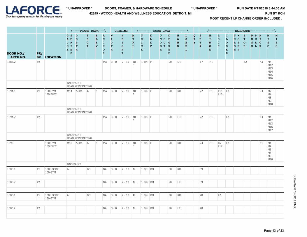
/----FRAME DATA---\ OPENING /--------DOOR DATA---------\ /--------------HARDWARE-------------\
DOOR NO./ ARCH NO.
PR/BK LOCATION
G SA EU RG IE E S
DEPTH
SECT
ELEV
ANCHOR
WIDTH
HEIGHT
MTRL
THICK
ELEV
UN CD UE TR
DEGREE
HAND
LABEL
QTY
SET#
HINGE
LOCK
CLOSER
T WH SR TS RH P
STOP
P PU US LH L
KICK
MISC
MISC
158B.2
P2 MA 3 - 0 7 - 10 18F
1 3/4 F 90 LR 17 H1 S2 K3 M4M12M13M14M15M16
BACKPAINTHEAD REINFORCING
159A.1
P1 160 GYM159 ELEC
M14 5 3/4 A 1 MA 3 - 0 7 - 10 18F
1 3/4 F 90 RR 22 H1 L15L16
C4 K3 M2M4M5M9M10
BACKPAINTHEAD REINFORCING
159A.2
P2 MA 3 - 0 7 - 10 18F
1 3/4 F 90 LR 22 H1 C4 K3 M4M12M13M16M17
BACKPAINTHEAD REINFORCING
159B
160 GYM159 ELEC
M16 5 3/4 A 1 MA 3 - 0 7 - 10 18F
1 3/4 F 90 RR 23 H1 L6L17
C4 K1 M1M4M5M8M9M10
BACKPAINT
160E.1
P1 100 LOBBY160 GYM
AL BO NA 3 - 0 7 - 10 AL 1 3/4 BO 90 RR 39
160E.2
P2 NA 3 - 0 7 - 10 AL 1 3/4 BO 90 LR 39
160F.1
P1 100 LOBBY160 GYM
AL BO NA 3 - 0 7 - 10 AL 1 3/4 BO 90 RR 28 L2
160F.2
P2 NA 3 - 0 7 - 10 AL 1 3/4 BO 90 LR 28
Page 13 of 23
RUN DATE 6/15/2018 8:44:35 AM* UNAPPROVED * * UNAPPROVED *
MOST RECENT LF CHANGE ORDER INCLUDED :
DOORS, FRAMES, & HARDWARE SCHEDULE42249 - WCCCD HEALTH AND WELLNESS EDUCATION DETROIT, MI RUN BY KCH
Subm
ittal 078-081113-00
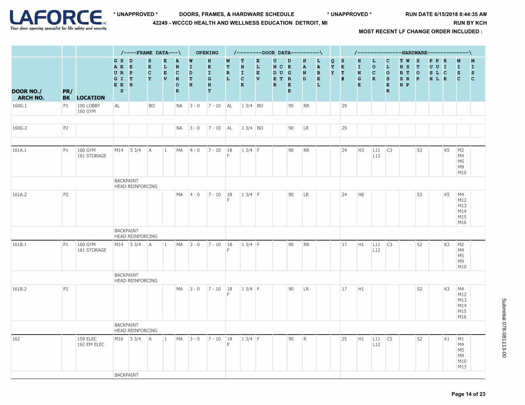
/----FRAME DATA---\ OPENING /--------DOOR DATA---------\ /--------------HARDWARE-------------\
DOOR NO./ ARCH NO.
PR/BK LOCATION
G SA EU RG IE E S
DEPTH
SECT
ELEV
ANCHOR
WIDTH
HEIGHT
MTRL
THICK
ELEV
UN CD UE TR
DEGREE
HAND
LABEL
QTY
SET#
HINGE
LOCK
CLOSER
T WH SR TS RH P
STOP
P PU US LH L
KICK
MISC
MISC
160G.1
P1 100 LOBBY160 GYM
AL BO NA 3 - 0 7 - 10 AL 1 3/4 BO 90 RR 29
160G.2
P2 NA 3 - 0 7 - 10 AL 1 3/4 BO 90 LR 29
161A.1
P1 160 GYM161 STORAGE
M14 5 3/4 A 1 MA 4 - 0 7 - 10 18F
1 3/4 F 90 RR 24 H3 L11L12
C3 S3 K5 M2M4M5M9M10
BACKPAINTHEAD REINFORCING
161A.2
P2 MA 4 - 0 7 - 10 18F
1 3/4 F 90 LR 24 H6 S3 K5 M4M12M13M14M15M16
BACKPAINTHEAD REINFORCING
161B.1
P1 160 GYM161 STORAGE
M14 5 3/4 A 1 MA 3 - 0 7 - 10 18F
1 3/4 F 90 RR 17 H1 L11L12
C3 S2 K3 M2M4M5M9M10
BACKPAINTHEAD REINFORCING
161B.2
P2 MA 3 - 0 7 - 10 18F
1 3/4 F 90 LR 17 H1 S2 K3 M4M12M13M14M15M16
BACKPAINTHEAD REINFORCING
162
159 ELEC162 EM ELEC
M16 5 3/4 A 1 MA 3 - 0 7 - 10 18F
1 3/4 F 90 R 25 H1 L11L12
C5 S2 K1 M1M4M5M9M10M13
BACKPAINT
Page 14 of 23
RUN DATE 6/15/2018 8:44:35 AM* UNAPPROVED * * UNAPPROVED *
MOST RECENT LF CHANGE ORDER INCLUDED :
DOORS, FRAMES, & HARDWARE SCHEDULE42249 - WCCCD HEALTH AND WELLNESS EDUCATION DETROIT, MI RUN BY KCH
Subm
ittal 078-081113-00
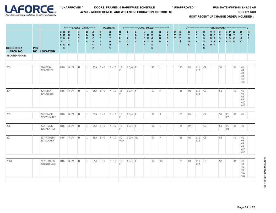
/----FRAME DATA---\ OPENING /--------DOOR DATA---------\ /--------------HARDWARE-------------\
DOOR NO./ ARCH NO.
PR/BK LOCATION
G SA EU RG IE E S
DEPTH
SECT
ELEV
ANCHOR
WIDTH
HEIGHT
MTRL
THICK
ELEV
UN CD UE TR
DEGREE
HAND
LABEL
QTY
SET#
HINGE
LOCK
CLOSER
T WH SR TS RH P
STOP
P PU US LH L
KICK
MISC
MISC
SECOND FLOOR
203
224 DESK203 OFFICE
D16 8 1/4 H 1 SSA 3 - 0 7 - 10 18F
1 3/4 F 90 L 16 H1 L11L12
C2 S1 K1 M1M4M5M9M10M13
204
224 DESK204 ASSESS
D16 8 1/4 H 1 SSA 3 - 0 7 - 10 18F
1 3/4 F 90 R 16 H1 L11L12
C2 S1 K1 M1M4M5M9M10M13
205
222 TRACK205 WMN TLT
D16 8 1/4 H 1 SSA 3 - 0 7 - 10 18F
1 3/4 F 90 R 35 H4 C2 S1 P1P2
K1 M1
206
222 TRACK206 MEN TLT
D16 8 1/4 H 1 SSA 3 - 0 7 - 10 18F
1 3/4 F 90 L 35 H4 C2 S1 P1P2
K1 M1
207
207 FITNESS217 LOCKER
D16 8 1/4 H 1 SSA 3 - 0 7 - 10 SCMAP
1 3/4 NL 90 R 25 H1 L11L12
C5 S2 K1 M1M4M5M9M10M13
208A
207 FITNESS208 STORAGE
D16 8 1/4 H 1 SSA 3 - 0 7 - 10 18F
1 3/4 F 90 RR 25 H1 L11L12
C5 S2 K1 M1M4M5M9M10M13
Page 15 of 23
RUN DATE 6/15/2018 8:44:35 AM* UNAPPROVED * * UNAPPROVED *
MOST RECENT LF CHANGE ORDER INCLUDED :
DOORS, FRAMES, & HARDWARE SCHEDULE42249 - WCCCD HEALTH AND WELLNESS EDUCATION DETROIT, MI RUN BY KCH
Subm
ittal 078-081113-00

/----FRAME DATA---\ OPENING /--------DOOR DATA---------\ /--------------HARDWARE-------------\
DOOR NO./ ARCH NO.
PR/BK LOCATION
G SA EU RG IE E S
DEPTH
SECT
ELEV
ANCHOR
WIDTH
HEIGHT
MTRL
THICK
ELEV
UN CD UE TR
DEGREE
HAND
LABEL
QTY
SET#
HINGE
LOCK
CLOSER
T WH SR TS RH P
STOP
P PU US LH L
KICK
MISC
MISC
208B
209 FITNESS208 STORAGE
D16 8 1/4 H 1 SSA 3 - 0 7 - 10 18F
1 3/4 F 90 LR 25 H1 L11L12
C5 S2 K1 M1M4M5M9M10M13
209A
209 FITNESS217 LOCKER
D16 8 1/4 H 1 SSA 3 - 0 7 - 10 SCMAP
1 3/4 NL 90 L 25 H1 L11L12
C5 S2 K1 M1M4M5M9M10M13
209B
209 FITNESS218 LOCKER
D16 8 1/4 H 1 SSA 3 - 0 7 - 10 SCMAP
1 3/4 NL 90 R 25 H1 L11L12
C5 S2 K1 M1M4M5M9M10M13
210
211 FITNESS210 STORAGE
D16 8 1/4 H 1 SSA 3 - 0 7 - 10 18F
1 3/4 F 90 LR 14 H1 L11L12
C3 S1 K1 M1M4M5M9M10M13
211
211 FITNESS218 LOCKER
D16 8 1/4 H 1 SSA 3 - 0 7 - 10 SCMAP
1 3/4 NL 90 L 25 H1 L11L12
C5 S2 K1 M1M4M5M9M10M13
212
214 CORR 04212 STORAGE
D16 8 1/4 H 1 SSA 3 - 0 7 - 10 18F
1 3/4 F 90 R 16 H1 L11L12
C2 S1 K1 M1M4M5M9M10M13
Page 16 of 23
RUN DATE 6/15/2018 8:44:35 AM* UNAPPROVED * * UNAPPROVED *
MOST RECENT LF CHANGE ORDER INCLUDED :
DOORS, FRAMES, & HARDWARE SCHEDULE42249 - WCCCD HEALTH AND WELLNESS EDUCATION DETROIT, MI RUN BY KCH
Subm
ittal 078-081113-00
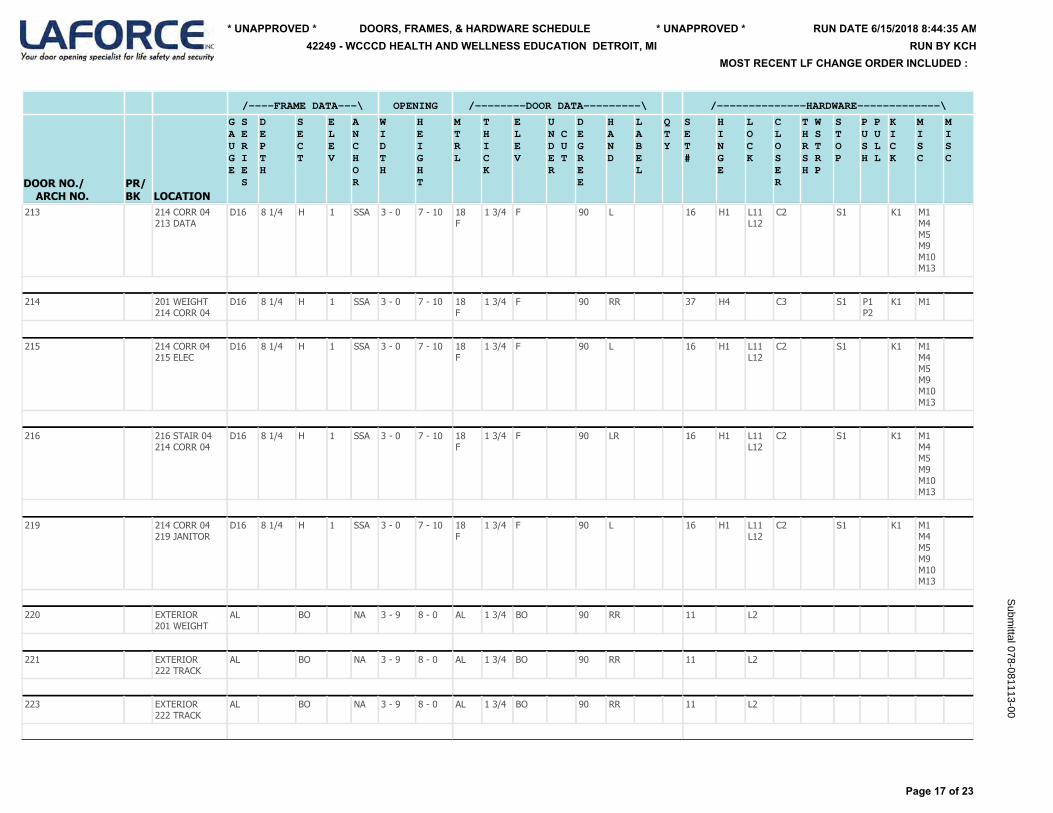
/----FRAME DATA---\ OPENING /--------DOOR DATA---------\ /--------------HARDWARE-------------\
DOOR NO./ ARCH NO.
PR/BK LOCATION
G SA EU RG IE E S
DEPTH
SECT
ELEV
ANCHOR
WIDTH
HEIGHT
MTRL
THICK
ELEV
UN CD UE TR
DEGREE
HAND
LABEL
QTY
SET#
HINGE
LOCK
CLOSER
T WH SR TS RH P
STOP
P PU US LH L
KICK
MISC
MISC
213
214 CORR 04213 DATA
D16 8 1/4 H 1 SSA 3 - 0 7 - 10 18F
1 3/4 F 90 L 16 H1 L11L12
C2 S1 K1 M1M4M5M9M10M13
214
201 WEIGHT214 CORR 04
D16 8 1/4 H 1 SSA 3 - 0 7 - 10 18F
1 3/4 F 90 RR 37 H4 C3 S1 P1P2
K1 M1
215
214 CORR 04215 ELEC
D16 8 1/4 H 1 SSA 3 - 0 7 - 10 18F
1 3/4 F 90 L 16 H1 L11L12
C2 S1 K1 M1M4M5M9M10M13
216
216 STAIR 04214 CORR 04
D16 8 1/4 H 1 SSA 3 - 0 7 - 10 18F
1 3/4 F 90 LR 16 H1 L11L12
C2 S1 K1 M1M4M5M9M10M13
219
214 CORR 04219 JANITOR
D16 8 1/4 H 1 SSA 3 - 0 7 - 10 18F
1 3/4 F 90 L 16 H1 L11L12
C2 S1 K1 M1M4M5M9M10M13
220
EXTERIOR201 WEIGHT
AL BO NA 3 - 9 8 - 0 AL 1 3/4 BO 90 RR 11 L2
221
EXTERIOR222 TRACK
AL BO NA 3 - 9 8 - 0 AL 1 3/4 BO 90 RR 11 L2
223
EXTERIOR222 TRACK
AL BO NA 3 - 9 8 - 0 AL 1 3/4 BO 90 RR 11 L2
Page 17 of 23
RUN DATE 6/15/2018 8:44:35 AM* UNAPPROVED * * UNAPPROVED *
MOST RECENT LF CHANGE ORDER INCLUDED :
DOORS, FRAMES, & HARDWARE SCHEDULE42249 - WCCCD HEALTH AND WELLNESS EDUCATION DETROIT, MI RUN BY KCH
Subm
ittal 078-081113-00
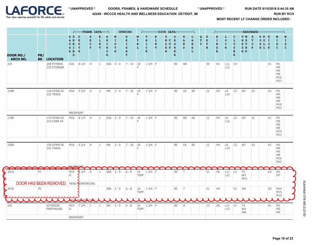
/----FRAME DATA---\ OPENING /--------DOOR DATA---------\ /--------------HARDWARE-------------\
DOOR NO./ ARCH NO.
PR/BK LOCATION
G SA EU RG IE E S
DEPTH
SECT
ELEV
ANCHOR
WIDTH
HEIGHT
MTRL
THICK
ELEV
UN CD UE TR
DEGREE
HAND
LABEL
QTY
SET#
HINGE
LOCK
CLOSER
T WH SR TS RH P
STOP
P PU US LH L
KICK
MISC
MISC
225
209 FITNESS225 STORAGE
D16 8 1/4 H 1 SSA 3 - 0 7 - 10 18F
1 3/4 F 90 RR 30 H1 L11L12
C4 K1 M1M4M5M9M10M13
118B
118 STAIR 02222 TRACK
M16 5 3/4 A 1 MA 3 - 0 7 - 10 18F
1 3/4 F 90 LR 60 12 H4 L6L10
C2 W7 S1 K1 M1M4M5M9M10M12
BACKPAINT
119B
119 STAIR 03214 CORR 04
M16 8 1/4 H 1 SSA 3 - 0 7 - 10 18F
1 3/4 F 90 RR 60 12 H4 L6L10
C2 W7 S1 K1 M1M4M5M9M10M12
156B
156 STAIR 06222 TRACK
M16 5 3/4 A 1 MA 3 - 0 7 - 10 18F
1 3/4 F 90 LR 60 12 H4 L6L10
C2 W7 S1 K1 M1M4M5M9M10M12
BACKPAINT
301A
P1 M14G
5 3/4 A 1 SSA 3 - 0 6 - 8 16TGPF
1 3/4 F 90 ? 31 H5 L11L12
C1 T5W3W11
K3 M2M7
HEAD REINFORCING
301B
P2 SSA 3 - 0 6 - 8 16TGPF
1 3/4 F 90 ? 31 H5 C1 W3 K3 M14M15M16
HEAD REINFORCING
316
EXTERIORPENTHOUSE
M14G
7 3/4 J 1 MA 3 - 0 6 - 8 16TGPF
1 3/4 F 90 R 13 H5 L11L12
C1 T4W3W8
K1 M1M3M4
BACKPAINT
Page 18 of 23
RUN DATE 6/15/2018 8:44:35 AM* UNAPPROVED * * UNAPPROVED *
MOST RECENT LF CHANGE ORDER INCLUDED :
DOORS, FRAMES, & HARDWARE SCHEDULE42249 - WCCCD HEALTH AND WELLNESS EDUCATION DETROIT, MI RUN BY KCH
Subm
ittal 078-081113-00
DOOR HAS BEEN REMOVED.

DESCRIPTION OF PRODUCT
H-Code Qty Manufacturer's Number Finish Description/Remark Quantity Vendor Name
H1 4 EA 5BB1 4.5 X 4.5 652 FULL MORTISE HINGE 220 IVES
H2 1 EA 224HD 89" TEK US28 GEARED CONTINUOUS HINGE 2 IVES
H3 1 EA 224HD 93" TEK US28 GEARED CONTINUOUS HINGE 14 IVES
H4 4 EA 5BB1 HW 4.5 X 4.5 652 FULL MORTISE HINGE 80 IVES
H5 1 EA 224HD 79" TEK US28 GEARED CONTINUOUS HINGE 3 IVES
H6 1 EA 224HD 93" EPT: (VON DUPRIN: EPT-2) 71 11/32" TOP OF HINGE TO C/L OF EPT TEK US28 GEARED CONTINUOUS HINGE 1 IVES
H7 3 EA 5BB1 4.5 X 4.5 652 FULL MORTISE HINGE 3 IVES
*** Total Qty 323 ***
L1 1 EA 98EO-F 3' MD US26D RIM DEVICE 1 VON DUPRIN
L2 1 EA CYLINDER TBD ? CYLINDER TO BE DETERMINED 13 CORBIN RUSSWIN
L3 1 EA 98EO 3' US26D RIM DEVICE 2 VON DUPRIN
L4 1 EA 98DT-F 990DT 3' MD US26D RIM DEVICE 1 VON DUPRIN
L5 1 EA 98NL-F 990NL 3' MD US26D RIM DEVICE 1 VON DUPRIN
L6 1 EA 3010 200 626 SECURITY RIM CYLINDER 12 CORBIN RUSSWIN
L7 1 EA 1010 114 A02 626 SECURITY MORTISE CYLINDER 5 CORBIN RUSSWIN
FOR KEYED MULLIONS
L8 1 EA 98NL 990NL 3' US26D RIM DEVICE 1 VON DUPRIN
L9 1 EA 98DT 990DT 4' US26D RIM DEVICE 7 VON DUPRIN
L10 1 EA 98L-F E996L 06 FS 3' MD US26D RIM DEVICE 3 VON DUPRIN
L11 1 EA ML2057 LC NSA SA114 626 MORTISE STOREROOM LOCK 47 CORBIN RUSSWIN
L12 1 EA 1010 118 A01 626 SECURITY MORTISE CYLINDER 51 CORBIN RUSSWIN
FOR MORTISE LOCKS
L13 1 EA 98L 996L 06 3' US26D RIM DEVICE 2 VON DUPRIN
Page 19 of 23
RUN DATE 6/15/2018 8:44:35 AM* UNAPPROVED * * UNAPPROVED *
MOST RECENT LF CHANGE ORDER INCLUDED :
DOORS, FRAMES, & HARDWARE SCHEDULE42249 - WCCCD HEALTH AND WELLNESS EDUCATION DETROIT, MI RUN BY KCH
Subm
ittal 078-081113-00
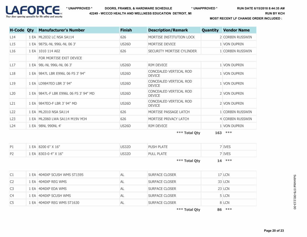
H-Code Qty Manufacturer's Number Finish Description/Remark Quantity Vendor Name
L14 1 EA ML2032 LC NSA SA114 626 MORTISE INSTITUTION LOCK 2 CORBIN RUSSWIN
L15 1 EA 9875L-NL 996L-NL 06 3' US26D MORTISE DEVICE 1 VON DUPRIN
L16 1 EA 1010 114 A02 626 SECURITY MORTISE CYLINDER 1 CORBIN RUSSWIN
FOR MORTISE EXIT DEVICE
L17 1 EA 98L-NL 996L-NL 06 3' US26D RIM DEVICE 1 VON DUPRIN
L18 1 EA 9847L LBR E996L 06 FS 3' 94" US26D CONCEALED VERTICAL ROD DEVICE 1 VON DUPRIN
L19 1 EA LD9847EO LBR 3' 94" US26D CONCEALED VERTICAL ROD DEVICE 1 VON DUPRIN
L20 1 EA 9847L-F LBR E996L 06 FS 3' 94" MD US26D CONCEALED VERTICAL ROD DEVICE 2 VON DUPRIN
L21 1 EA 9847EO-F LBR 3' 94" MD US26D CONCEALED VERTICAL ROD DEVICE 2 VON DUPRIN
L22 1 EA ML2010 NSA SA114 626 MORTISE PASSAGE LATCH 1 CORBIN RUSSWIN
L23 1 EA ML2060 LWA SA114 M19V M34 626 MORTISE PRIVACY LATCH 4 CORBIN RUSSWIN
L24 1 EA 98NL 990NL 4' US26D RIM DEVICE 1 VON DUPRIN
*** Total Qty 163 ***
P1 1 EA 8200 6" X 16" US32D PUSH PLATE 7 IVES
P2 1 EA 8303-0 4" X 16" US32D PULL PLATE 7 IVES
*** Total Qty 14 ***
C1 1 EA 4040XP SCUSH WMS ST1595 AL SURFACE CLOSER 17 LCN
C2 1 EA 4040XP REG WMS AL SURFACE CLOSER 33 LCN
C3 1 EA 4040XP EDA WMS AL SURFACE CLOSER 23 LCN
C4 1 EA 4040XP SCUSH WMS AL SURFACE CLOSER 5 LCN
C5 1 EA 4040XP REG WMS ST1630 AL SURFACE CLOSER 8 LCN
*** Total Qty 86 ***
Page 20 of 23
RUN DATE 6/15/2018 8:44:35 AM* UNAPPROVED * * UNAPPROVED *
MOST RECENT LF CHANGE ORDER INCLUDED :
DOORS, FRAMES, & HARDWARE SCHEDULE42249 - WCCCD HEALTH AND WELLNESS EDUCATION DETROIT, MI RUN BY KCH
Subm
ittal 078-081113-00
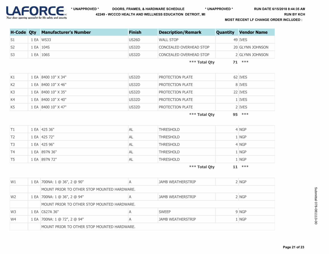
H-Code Qty Manufacturer's Number Finish Description/Remark Quantity Vendor Name
S1 1 EA WS33 US26D WALL STOP 49 IVES
S2 1 EA 104S US32D CONCEALED OVERHEAD STOP 20 GLYNN JOHNSON
S3 1 EA 106S US32D CONCEALED OVERHEAD STOP 2 GLYNN JOHNSON
*** Total Qty 71 ***
K1 1 EA 8400 10" X 34" US32D PROTECTION PLATE 62 IVES
K2 1 EA 8400 10" X 46" US32D PROTECTION PLATE 8 IVES
K3 1 EA 8400 10" X 35" US32D PROTECTION PLATE 22 IVES
K4 1 EA 8400 10" X 40" US32D PROTECTION PLATE 1 IVES
K5 1 EA 8400 10" X 47" US32D PROTECTION PLATE 2 IVES
*** Total Qty 95 ***
T1 1 EA 425 36" AL THRESHOLD 4 NGP
T2 1 EA 425 72" AL THRESHOLD 1 NGP
T3 1 EA 425 96" AL THRESHOLD 4 NGP
T4 1 EA 897N 36" AL THRESHOLD 1 NGP
T5 1 EA 897N 72" AL THRESHOLD 1 NGP
*** Total Qty 11 ***
W1 1 EA 700NA: 1 @ 36", 2 @ 90" A JAMB WEATHERSTRIP 2 NGP
MOUNT PRIOR TO OTHER STOP MOUNTED HARDWARE.
W2 1 EA 700NA: 1 @ 36", 2 @ 94" A JAMB WEATHERSTRIP 2 NGP
MOUNT PRIOR TO OTHER STOP MOUNTED HARDWARE.
W3 1 EA C627A 36" A SWEEP 9 NGP
W4 1 EA 700NA: 1 @ 72", 2 @ 94" A JAMB WEATHERSTRIP 1 NGP
MOUNT PRIOR TO OTHER STOP MOUNTED HARDWARE.
Page 21 of 23
RUN DATE 6/15/2018 8:44:35 AM* UNAPPROVED * * UNAPPROVED *
MOST RECENT LF CHANGE ORDER INCLUDED :
DOORS, FRAMES, & HARDWARE SCHEDULE42249 - WCCCD HEALTH AND WELLNESS EDUCATION DETROIT, MI RUN BY KCH
Subm
ittal 078-081113-00
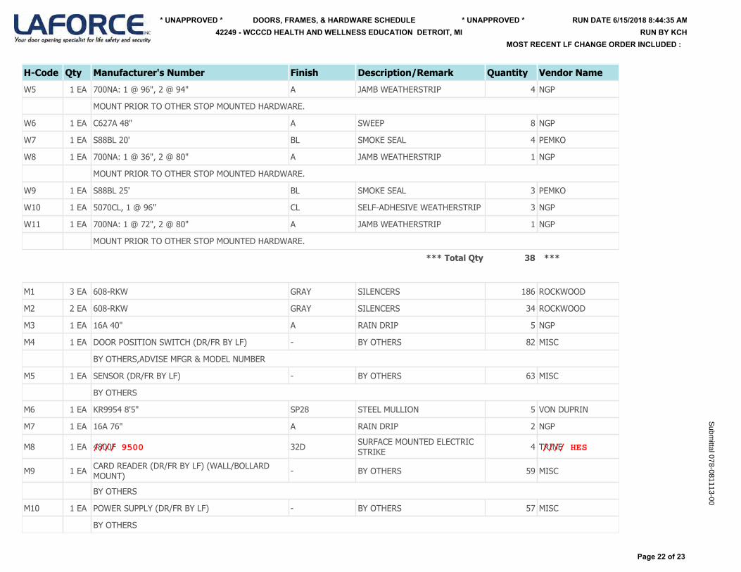
H-Code Qty Manufacturer's Number Finish Description/Remark Quantity Vendor Name
W5 1 EA 700NA: 1 @ 96", 2 @ 94" A JAMB WEATHERSTRIP 4 NGP
MOUNT PRIOR TO OTHER STOP MOUNTED HARDWARE.
W6 1 EA C627A 48" A SWEEP 8 NGP
W7 1 EA S88BL 20' BL SMOKE SEAL 4 PEMKO
W8 1 EA 700NA: 1 @ 36", 2 @ 80" A JAMB WEATHERSTRIP 1 NGP
MOUNT PRIOR TO OTHER STOP MOUNTED HARDWARE.
W9 1 EA S88BL 25' BL SMOKE SEAL 3 PEMKO
W10 1 EA 5070CL, 1 @ 96" CL SELF-ADHESIVE WEATHERSTRIP 3 NGP
W11 1 EA 700NA: 1 @ 72", 2 @ 80" A JAMB WEATHERSTRIP 1 NGP
MOUNT PRIOR TO OTHER STOP MOUNTED HARDWARE.
*** Total Qty 38 ***
M1 3 EA 608-RKW GRAY SILENCERS 186 ROCKWOOD
M2 2 EA 608-RKW GRAY SILENCERS 34 ROCKWOOD
M3 1 EA 16A 40" A RAIN DRIP 5 NGP
M4 1 EA DOOR POSITION SWITCH (DR/FR BY LF) - BY OTHERS 82 MISC
BY OTHERS,ADVISE MFGR & MODEL NUMBER
M5 1 EA SENSOR (DR/FR BY LF) - BY OTHERS 63 MISC
BY OTHERS
M6 1 EA KR9954 8'5" SP28 STEEL MULLION 5 VON DUPRIN
M7 1 EA 16A 76" A RAIN DRIP 2 NGP
M8 1 EA 4800F 32D SURFACE MOUNTED ELECTRIC STRIKE 4 TRINE
M9 1 EA CARD READER (DR/FR BY LF) (WALL/BOLLARD MOUNT) - BY OTHERS 59 MISC
BY OTHERS
M10 1 EA POWER SUPPLY (DR/FR BY LF) - BY OTHERS 57 MISC
BY OTHERS
Page 22 of 23
RUN DATE 6/15/2018 8:44:35 AM* UNAPPROVED * * UNAPPROVED *
MOST RECENT LF CHANGE ORDER INCLUDED :
DOORS, FRAMES, & HARDWARE SCHEDULE42249 - WCCCD HEALTH AND WELLNESS EDUCATION DETROIT, MI RUN BY KCH
Subm
ittal 078-081113-00
//// 9500 //// HES
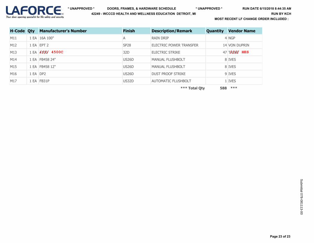
H-Code Qty Manufacturer's Number Finish Description/Remark Quantity Vendor Name
M11 1 EA 16A 100" A RAIN DRIP 4 NGP
M12 1 EA EPT 2 SP28 ELECTRIC POWER TRANSFER 14 VON DUPRIN
M13 1 EA 4100 32D ELECTRIC STRIKE 47 TRINE
M14 1 EA FB458 24" US26D MANUAL FLUSHBOLT 8 IVES
M15 1 EA FB458 12" US26D MANUAL FLUSHBOLT 8 IVES
M16 1 EA DP2 US26D DUST PROOF STRIKE 9 IVES
M17 1 EA FB31P US32D AUTOMATIC FLUSHBOLT 1 IVES
*** Total Qty 588 ***
Page 23 of 23
RUN DATE 6/15/2018 8:44:35 AM* UNAPPROVED * * UNAPPROVED *
MOST RECENT LF CHANGE ORDER INCLUDED :
DOORS, FRAMES, & HARDWARE SCHEDULE42249 - WCCCD HEALTH AND WELLNESS EDUCATION DETROIT, MI RUN BY KCH
Subm
ittal 078-081113-00
//// 4500C //// HES
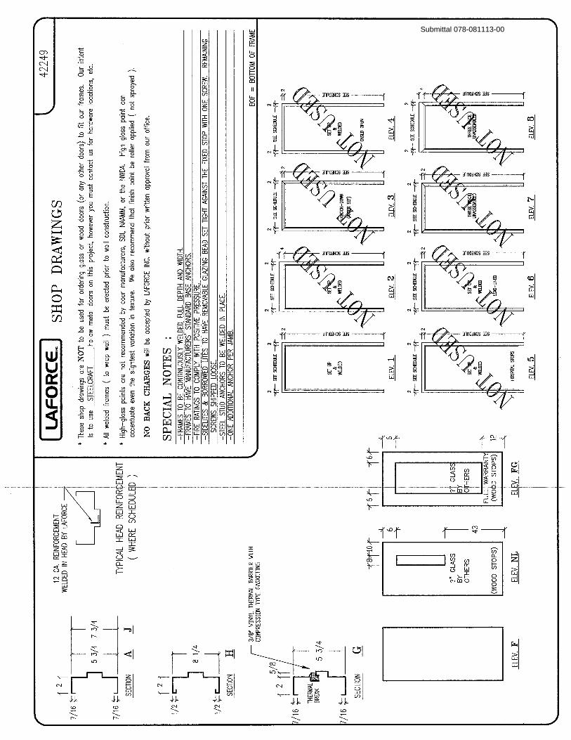
Submittal 078-081113-00

Submittal 078-081113-00

Submittal 078-081113-00
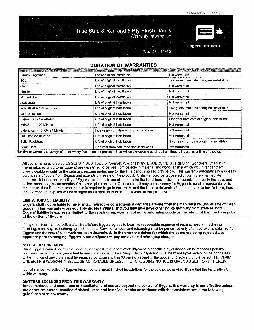
Submittal 078-081113-00
Submittal 078-081113-00
Submittal 078-081113-00
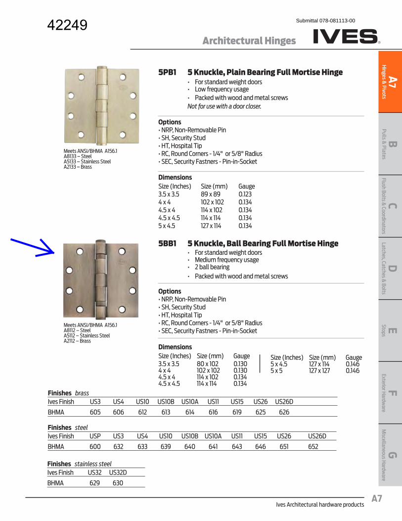
Ives Architectural hardware products
Architectural Hinges
BPulls &
PlatesA
7H
inges & Pivots
CFlush Bolts &
CoordinatorsD
Latches, Catches & Bolts
EStopsF
Exterior Hardw
areG
Miscellaneous H
ardware
A7
Meets ANSI/BHMA A156.1A8112 – SteelA5112 – Stainless SteelA2112 – Brass
5BB1 5 Knuckle, Ball Bearing Full Mortise Hinge� � �� ����������� ����������� � �� � ������� �� ������ � � �� ������� ��� �� ��� ��������������� ������ �� Options���������!� ��"�� �����#$��# �������#�����$%��$��&����%�&���'�������'�� ���!�()*+�����,)-+��������#0'��# ���������� ���!���!�!#��� �
DimensionsSize (Inches) Size (mm) Gauge3.5 x 3.5 80 x 102 0.1304 x 4 102 x 102 0.1304.5 x 4 114 x 102 0.1344.5 x 4.5 114 x 114 0.134
Size (Inches) Size (mm) Gauge5 x 4.5 127 x 114 0.1465 x 5 127 x 127 0.146
Meets ANSI/BHMA A156.1A8133 – SteelA5133 – Stainless SteelA2133 – Brass
5PB1 5 Knuckle, Plain Bearing Full Mortise Hinge� � �� ����������� ����������� � �� <����� �� ������ �� ��� ��������������� ������ �� Not for use with a door closer.
Options���������!� ��"�� �����#$��# �������#�����$%��$��&����%�&���'�������'�� ���!�()*+�����,)-+��������#0'��# ���������� ���!���!�!#��� �
DimensionsSize (Inches) Size (mm) Gauge3.5 x 3.5 89 x 89 0.1234 x 4 102 x 102 0.1344.5 x 4 114 x 102 0.1344.5 x 4.5 114 x 114 0.1345 x 4.5 127 x 114 0.134
Finishes brassIves Finish US3 US4 US10 US10B US10A US11 US15 US26 US26D
BHMA 605 606 612 613 614 616 619 625 626
Finishes steelIves Finish USP US3 US4 US10 US10B US10A US11 US15 US26 US26D
BHMA 600 632 633 639 640 641 643 646 651 652
Finishes stainless steelIves Finish US32 US32D
BHMA 629 630
42249 Submittal 078-081113-00

Ives Architectural hardware products
Continuous Hinges
BPulls &
PlatesA
23H
inges & Pivots
CFlush Bolts &
CoordinatorsD
Latches, Catches & Bolts
EStopsF
Exterior Hardw
areG
Miscellaneous H
ardware
A23
Electrical Cutouts
Ives Aluminum Geared Continuous Hinges are available with factory modified cutouts to accommodate most electrical frame to door requirements. Special templates are required.
When ordering indicate the following:1. Opening size.2. Handing. LH, RH, RHR or LHR.3. Manufacturer and model number of the electrical product being used. Example; Von Duprin EPT2
Because clearances may vary between door and frame manufacturer, and locations can be influenced by the door hardware it is always recommend contacting Ives Customer Technical for specific template information.
For your general information below are standard locations for Von Duprin EPT2 or EPT10, and monitor switch.
224HD Full Mortise Aluminum Geared Continuous Hinge� � �� Handing required when modified� � �� J����0�� ����� ����� � �� *-+��K�����J����Q����� � �� ()(X+�J����Y� �� � �� Beveled or Square Edge Doors
For Doors Weighing up to 450 pounds without reinforcing, 600 pounds with reinforcing
Standard lengths 83", 85", 95", 120"Standard Mounting Hardware12-24 X 3/4" Steel Self Drilling, Self Tapping ScrewsOptional WD - Wood Screws or SEC - Security Fasteners Available
Finishes Clear (CL), Dark Bronze (DB)Custom Anodizing and Painting areavailable, consult factory.
EPT112HD
“C EPT”L
Top of hinge/door
Top of hinge/door
“C TW”L
EPT224HD
“C EPT”L
Top of hinge/door
TW112HD
224HD
5/16" Clearance for Square Edge Door1/32" Clearance For Beveled Edge Door
From Top Edge of Door to Center Line of Cut-Out
Standard 112HD 224HD 112HD/224HDLength EPT EPT TW83" 30" 30" 41-1/2"85" 32" 32" 42-1/2"95" 42" 42" 57-3/4"120" 67" 67" 81-25/32"
TWP option centered in hinge.Note: See ordering guide in price book for proper placement.
Submittal 078-081113-00
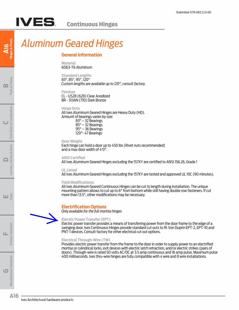
Ives Architectural hardware productsA16
Continuous Hinges
BPu
lls &
Pla
tes
A16
Hin
ges
& P
ivot
sC
Flus
h Bo
lts &
Coo
rdin
ator
sD
Latc
hes,
Cat
ches
& B
olts
E Stop
sF
Exte
rior H
ardw
are
GM
isce
llane
ous H
ardw
are
General Information
Material6063-T6 Aluminum
Standard Lengths83", 85", 95", 120"Custom lengths are available up to 120", consult factory.
FinishesCL - US28 (628) Clear AnodizedBR - 313AN (710) Dark Bronze
Hinge DutyAll Ives Aluminum Geared Hinges are Heavy Duty (HD). Amount of bearings varies by size: 83" – 32 Bearings 85" – 32 Bearings 95" – 36 Bearings 120"- 47 Bearings
Door WeightEach hinge can hold a door up to 450 lbs (Rivet nuts recommended) and a max door width of 4'0".
ANSI CertifiedAll Ives Aluminum Geared Hinges excluding the 157XY are certified to ANSI 156.26, Grade 1
UL ListedAll Ives Aluminum Geared Hinges excluding the 157XY are tested and approved UL 10C (90 minutes).
Field Modifications:All Ives Aluminum Geared Continuous Hinges can be cut to length during installation. The unique mounting pattern allows to cut up to 6" from bottom while still having double row fasteners. If cut more than 13.5", other modifications may be necessary.
Electrification OptionsOnly available for the full mortise hinges
Electric Power Transfer (EPT) Electric power transfer provides a means of transferring power from the door frame to the edge of a swinging door. Ives Continuous Hinges provide standard cut outs to fit Von Duprin EPT-2, EPT-10 and PNT-1 devices. Consult factory for other electrical cut out options.
Electrical Through-Wire (TW) Provides electric power transfer from the frame to the door in order to supply power to an electrified mortise or cylindrical locks, exit devices with electric latch retraction, and/or electric strikes (pairs of doors). Through-wire is rated 50 volts AC/DC at 3.5 amp continuous and 16 amp pulse. Maximum pulse 400 milliseconds. Ives thru-wire hinges are fully compatible with 4 wire and 8 wire installations.
Aluminum Geared Hinges
Submittal 078-081113-00
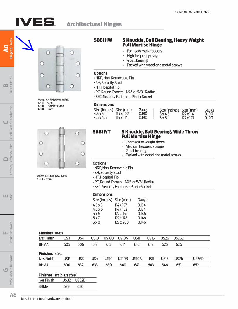
Ives Architectural hardware productsA8
Architectural Hinges
BPu
lls &
Pla
tes
A8
Hin
ges
& P
ivot
sC
Flus
h Bo
lts &
Coo
rdin
ator
sD
Latc
hes,
Cat
ches
& B
olts
E Stop
sF
Exte
rior H
ardw
are
GM
isce
llane
ous H
ardw
are
Meets ANSI/BHMA A156.1A8111 – Steel
5BB1WT 5 Knuckle, Ball Bearing, Wide Throw Full Mortise Hinge� � �� ����� ������ ����������� � �� � ������� �� ������ � � �� ������� ��� �� ��� ��������������� ������ �� Options���������!� ��"�� �����#$��# �������#�����$%��$��&����%�&���'�������'�� ���!�()*+�����,)-+��������#0'��# ���������� ���!���!�!#��� �
DimensionsSize (Inches) Size (mm) Gauge4.5 x 5 114 x 127 0.1344.5 x 6 114 x 152 0.1345 x 6 127 x 152 0.1465 x 7 127 x 178 0.1465 x 8 127 x 203 0.146
Meets ANSI/BHMA A156.1A8111 – SteelA5111 – Stainless SteelA2111 – Brass
5BB1HW 5 Knuckle, Ball Bearing, Heavy Weight Full Mortise Hinge� � �� ����� "��� ����������� � �� $������ �� ������ � � �� *������ ��� �� ��� ��������������� ������ �� Options���������!� ��"�� �����#$��# �������#�����$%��$��&����%�&���'�������'�� ���!�()*+�����,)-+��������#0'��# ���������� ���!���!�!#��� �
DimensionsSize (Inches) Size (mm) Gauge4.5 x 4 114 x 102 0.1804.5 x 4.5 114 x 114 0.180
Size (Inches) Size (mm) Gauge5 x 4.5 127 x 114 0.1905 x 5 127 x 127 0.190
Finishes brassIves Finish US3 US4 US10 US10B US10A US11 US15 US26 US26D
BHMA 605 606 612 613 614 616 619 625 626
Finishes steelIves Finish USP US3 US4 US10 US10B US10A US11 US15 US26 US26D
BHMA 600 632 633 639 640 641 643 646 651 652
Finishes stainless steelIves Finish US32 US32D
BHMA 629 630
Submittal 078-081113-00

98 and 99 Rim exit devices for all types of single and double doors with mullion, UL listed for panic
exit hardware. Devices are ANSI A156.3 – 2008 Grade 1. The 98 device has a smooth mechanism
case and the 99 device has a grooved case. The rim device is non-handed except when the following
device options are used: SD (special dogging), -2 (double cylinder) or SS (signal switch). See
Opposite page for available outside trim and device functions. Covers stock hollow metal doors with
86 or 161 cutouts on single doors (may cover cutouts on pairs – consult template).
Finishes – US3, US3A, US4, US4A, US10, US26, US26D, US26D-AM Antimicrobial, US28, 313, 315 &
643E. US15 and US32D available with 98 Series only.
Hex key dogging comes standard
on 98/99 Rim exit devices
The 299 Strike ships
standard, optional strikes
available
SpecificationsDevice functions Device ships EO/DT/NL. Field selectable. For TP, K or L remove
NL drive screw from device.
Device lengths 3' 2'4' to 3' (711mm to 914 mm) Door size
4' 2'10" to 4' (864 mm to 1219 mm) Door size
Device centerline
from finished floor
39 13/16" (1011 mm)
39 11/16" (1008 mm) with mullion
Center case
dimensions
8" x 2 3/4" x2 3/8" (203mm x 70mm x 60mm)
Mechanism case
dimensions
2 1/4" x 2 1/4" (57mm x 57mm)
Projection Pushbar neutral – 3 13/16" (97 mm)
Pushbar depressed – 3 1/16" (78 mm)
Latch bolt Deadlocking, 3/4" (19mm) throw
Fasteners & sex
bolts (SNB)
Includes screw pack for 1 3/4" (44mm) and 2 1/4" (57mm) thick
metal or wood doors. Optional 425 SNB available,
see page 9 for quantities.
Electric options LX Latchbolt monitor switch
RX Pushpad monitor switch
RX2 Double pushpad monitor switch
E Electric locking & unlocking trim
EL Electric latch retraction
QEL Quiet electric latch retraction
SS Signal switch
CX Chexit delayed exit
ALK Alarm exit kit
WP-RX Waterproof request to exit
CON Allegion Connect
Mechanical
options
-2 Double cylinder
AX Accessible device GBK Glass bead kit
PN Pneumatic latch retraction
XP Extra protection
SNB Sex bolts
SEC Security screws
Dogging feature Hex key dogging standard
Dogging options CD Cylinder dogging
SD Special center case dogging
LD Less dogging
DI Dogging indicator
CI Cylinder dogging indicator
Strikes 299 – Dull black
QELQuiet electric latch retraction
switch
door to push-pull operation
CXChexit delayed exit
requirements
controls, locking, alarm
ALKAlarm exit kit
opening triggers 85-decibel horn
disarmed mode by key
CONAllegion Connectors
connectors to connect various door hardware all the way to the power supply
RXPushpad monitor switch
opening
monitor pushpad
XPExtra protection
strike contact
of 2,000+ lbs.
AXAccessible device
meet new 5 lb. maximum operating force requirement
BHMA requirements
CDCylinder dogging
dogging 1/4"
mortise cylinder with inverted cam
ELElectric latch retraction
unlatching
manual dogging
PNPneumatic latch retraction
electrical devices banned
for mechanical or pneumatic dogging
Submittal 078-081113-00
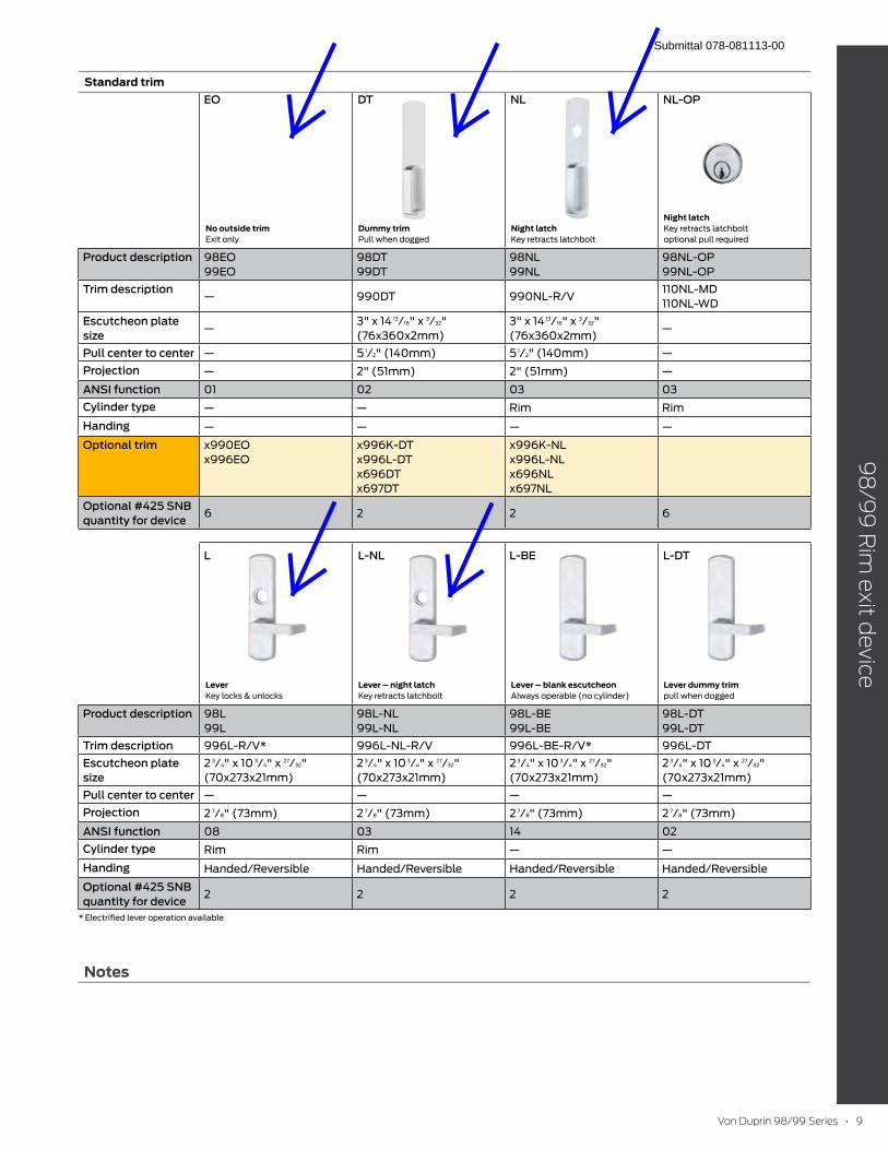
Notes
Standard trim
No outside trim Exit only
Dummy trim Pull when dogged
Night latch Key retracts latchbolt
Night latch Key retracts latchbolt
optional pull required
Product description 98EO
99EO
98DT
99DT
98NL
99NL
98NL-OP
99NL-OP
Trim description— 990DT 990NL-R/V
110NL-MD
110NL-WD
Escutcheon plate
size—
3" x 14 13/16" x 3/32"
(76x360x2mm)
3" x 14 13/16" x 3/32"
(76x360x2mm)—
Pull center to center — 5 1/2" (140mm) 5 1/2" (140mm) —
Projection — 2" (51mm) 2" (51mm) —
ANSI function 01 02 03 03
Cylinder type — — Rim Rim
Handing — — — —
Optional trim x990EO
x996EO
x996K-DT
x996L-DT
x696DT
x697DT
x996K-NL
x996L-NL
x696NL
x697NL
Optional #425 SNB
quantity for device6 2 2 6
Lever Key locks & unlocks
Lever – night latch Key retracts latchbolt
Lever – blank escutcheon Always operable (no cylinder)
Lever dummy trim pull when dogged
Product description 98L
99L
98L-NL
99L-NL
98L-BE
99L-BE
98L-DT
99L-DT
Trim description 996L-R/V* 996L-NL-R/V 996L-BE-R/V* 996L-DT
Escutcheon plate
size
2 3/4" x 10 3/4" x 27/32"
(70x273x21mm)
2 3/4" x 10 3/4" x 27/32"
(70x273x21mm)
2 3/4" x 10 3/4" x 27/32"
(70x273x21mm)
2 3/4" x 10 3/4" x 27/32"
(70x273x21mm)
Pull center to center — — — —
Projection 2 7/8" (73mm) 2 7/8" (73mm) 2 7/8" (73mm) 2 7/8" (73mm)
ANSI function 08 03 14 02
Cylinder type Rim Rim — —
Handing Handed/Reversible Handed/Reversible Handed/Reversible Handed/Reversible
Optional #425 SNB
quantity for device2 2 2 2
* Electrified lever operation available
EO
L L-NL L-BE L-DT
DT NL NL-OP
Submittal 078-081113-00
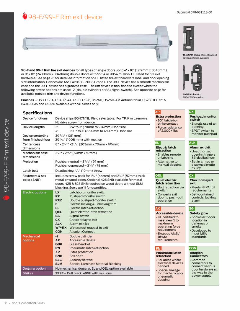
98-F and 99-F Rim fire exit devices for all types of single doors up to 4' x 10' (1219mm x 3048mm)
or 8' x 10' (2438mm x 3048mm) double doors with 9954 or 9854 mullion, UL listed for fire exit
hardware. See page 76 for detailed information on UL listed fire exit hardware label and door opening
size information. Devices are ANSI A156.3 – 2008 Grade 1. The 98-F device has a smooth mechanism
case and the 99-F device has a grooved case. The rim device is non-handed except when the
following device options are used: -2 (double cylinder) or SS (signal switch). See opposite page for
available outside trim and device functions.
Finishes – US3, US3A, US4, US4A, US10, US26, US26D, US26D-AM Antimicrobial, US28, 313, 315 &
643E. US15 and US32D available with 98 Series only.
SpecificationsDevice functions Device ships EO/DT/NL. Field selectable. For TP, K or L remove
NL drive screw from device.
Device lengths 3' 2'4' to 3' (711mm to 914 mm) Door size
4' 2'10" to 4' (864 mm to 1219 mm) Door size
Device centerline
from finished floor
39 13/16" (1011 mm)
39 11/16" (1008 mm) with mullion
Center case
dimensions
8" x 2 3/4" x2 3/8" (203mm x 70mm x 60mm)
Mechanism case
dimensions
2 1/4" x 2 1/4" (57mm x 57mm)
Projection Pushbar neutral – 3 13/16" (97 mm)
Pushbar depressed – 3 1/16" (78 mm)
Latch bolt Deadlocking, 3/4" (19mm) throw
Fasteners & sex
bolts (SNB)
Includes screw pack for 1 3/4" (44mm) and 2 1/4" (57mm) thick
metal or wood doors. Optional 425 SNB available for metal
doors. 425 & 825 SNB required on wood doors without SLM
blocking. See page 11 for quantities.
Electric options LX Latchbolt monitor switch
RX Pushpad monitor switch
RX2 Double pushpad monitor switch
E Electric locking & unlocking trim
EL Electric latch retraction
QEL Quiet electric latch retraction
SS Signal switch
CX Chexit delayed exit
ALK Alarm exit kit
WP-RX Waterproof request to exit
CON Allegion Connect
Mechanical
options
-2 Double cylinder
AX Accessible device GBK Glass bead kit
PN Pneumatic latch retraction
XP Extra protection
SNB Sex bolts
SEC Security screws
SLM Special Laminate Material Blocking
Dogging option No mechanical dogging. EL and QEL option available
Strikes 299F – Dull black, 499F with mullions
CXChexit delayed exit
requirements
controls, locking, alarm
SGSafety glow
location in darkness or smoke
meet MEA standards
ALKAlarm exit kit
opening triggers 85-decibel horn
disarmed mode by key
RXPushpad monitor switch
opening
monitor pushpad
XPExtra protection
strike contact
of 2,000+ lbs.
ELElectric latch retraction
unlatching
manual dogging
PNPneumatic latch retraction
electrical devices banned
for mechanical or pneumatic dogging
The 299F Strike ships standard,
optional strikes available
499F Strike with
9854/9954 mullion
QELQuiet electric latch retraction
switch
door to push-pull operation
AXAccessible device
meet new 5 lb. maximum operating force requirement
BHMA requirements
CONAllegion Connectors
connectors to connect various door hardware all the way to the power supply
Submittal 078-081113-00

Standard trim
No outside trim Exit only
Dummy trim Pull when dogged
(not recommended for fire device)
Night latch Key retracts latchbolt
Night latch Key retracts latchbolt
optional pull required
Product description 98EO-F
99EO-F
98DT-F
99DT-F
98NL-F
99NL-F
98NL-OP-F
99NL-OP-F
Trim description— 990DT 990NL-R/V
110NL-MD
110NL-WD
Escutcheon plate
size—
3" x 14 13/16" x 3/32"
(76x360x2mm)
3" x 14 13/16" x 3/32"
(76x360x2mm)—
Pull center to center — 5 1/2" (140mm) 5 1/2" (140mm) —
Projection — 2" (51mm) 2" (51mm) —
ANSI function 01 02 03 03
Cylinder type — — Rim Rim
Handing — — — —
Optional trim x990EO
x996EO
x996K-DT
x996L-DT
x696DT
x697DT
x996K-NL
x996L-NL
x696NL
x697NL
#425 SNB optional
- HMD req. WD w/o
SLM pkg.
6 2 2 2
#825 SNB req. WD
w/o SLM pkg.2 (if using trim) 2 2 2
#425 SNB req.
w/ 499F2 2 2 2
Lever Key locks & unlocks
Lever – night latch Key retracts latchbolt
Lever – blank escutcheon Always operable (no cylinder)
Lever dummy trim pull when dogged
(not recommended for fire device)
Product description 98L-F
99L-F
98L-NL-F
99L-NL-F
98L-BE-F
99L-BE-F
98L-DT-F
99L-DT-F
Trim description 996L-R/V* 996L-NL-R/V 996L-BE-R/V* 996L-DT
Escutcheon plate
size
2 3/4" x 10 3/4" x 27/32"
(70x273x21mm)
2 3/4" x 10 3/4" x 27/32"
(70x273x21mm)
2 3/4" x 10 3/4" x 27/32"
(70x273x21mm)
2 3/4" x 10 3/4" x 27/32"
(70x273x21mm)
Pull center to center — — — —
Projection 2 7/8" (73mm) 2 7/8" (73mm) 2 7/8" (73mm) 2 7/8" (73mm)
ANSI function 08 03 14 02
Cylinder type Rim Rim — —
Handing Handed/Reversible Handed/Reversible Handed/Reversible Handed/Reversible
#425 SNB optional
- HMD req. WD w/o
SLM pkg.
2 2 2 2
#825 SNB req. WD
w/o SLM pkg.2 (if using trim) 2 2 2
#425 SNB req.
w/ 499F2 2 2 2
* Electrified lever operation available
EO
L L-NL L-BE L-DT
DT NL NL-OP
Submittal 078-081113-00

9847/9947 Concealed vertical rod device for use on single or double metal doors, UL listed for
panic exit hardware. Devices are ANSI A156.3 – 2008 Grade 1. The 9847 device has a smooth
mechanism case and the 9947 device has a grooved case. The concealed vertical rod device is
non-handed except when the following device options are used: SD (special dogging), or SS (signal
switch). See opposite page for available outside trim and device functions.
Finishes – US3, US3A, US4, US4A, US10, US26, US26D, US26D-AM Antimicrobial, US28, 313, 315 &
643E. US15 and US32D available with 98 Series only.
SpecificationsDevice functions Device ships EO/DT/NL. Field selectable. For TP, K or L remove
NL drive screw from device.
Device lengths 2' 2' (610 mm) Door size
3' 2'4' to 3' (711mm to 914 mm) Door size
4' 2'10" to 4' (864 mm to 1219 mm) Door size
Device centerline
from finished floor
395/8" (1006 mm) Standard
Adjustable from 355/8" (905mm) to 495/8" (1260mm)
Center case
dimensions
8" x 2 3/4" x2 3/8" (203mm x 70mm x 60mm)
Mechanism case
dimensions
2 1/4" x 2 1/4" (57mm x 57mm)
Projection Pushbar neutral – 3 13/16" (97 mm)
Pushbar depressed – 3 1/16" (78 mm)
Latch bolt Deadlocking top & bottom bolt, 5/8" (16mm) throw
Door undercut 1/4" (7mm) recommended
Top & bottom
Latch case
4 1/2" x 2 1/8" x 1 1/2" (114mm x 54mm x 38mm)
Vertical rods Round 2-piece adjustable rods – Top rod adjustable from 6'8"
(2027mm) to 8'4"(2533mm). Bottom rod adjustable 35 5/8"
(905 mm) to 49 5/8" (1260 mm). Extension rod kits available for
doors over 8'4" (2533mm).
Fasteners & sex
bolts (SNB)
Includes screw pack for 1 3/4" (44mm) to 2 1/4" (57mm) thick
metal doors. Optional 425 SNB available.
Electric options LX Latchbolt monitor switch
RX Pushpad monitor switch
RX2 Double pushpad monitor switch
E Electric unlocking and locking trim
EL Electric latch retraction
QEL Quiet electric latch retraction
SS Signal switch
CX Chexit delayed exit
ALK Alarm exit kit
WP-RX Waterproof request to exit
CON Allegion Connect
Mechanical
options
GBK Glass bead kit
PN Pneumatic latch retraction
LBR Less bottom rod
PL Pullman latch
SNB Sex bolts
SEC Security screws
Dogging feature Hex key dogging standard
Dogging option CD Cylinder dogging
SD Special center case dogging
LD Less dogging
DI Dogging indicator
CI Cylinder dogging indicator
Strikes Top – 338 - Unfinished, Bottom – 385A - Unfinished
DIDogging indicator
status without a control panel
light shows visibility to dogging from over 75 feet
ALKAlarm exit kit
opening triggers 85-decibel horn
disarmed mode by key
RXPushpad monitor switch
opening
monitor pushpad
ELElectric latch retraction
unlatching
manual dogging
PNPneumatic latch retraction
electrical devices banned
for mechanical or pneumatic dogging
Hex key dogging comes
standard on 9847/9947
Concealed vertical rod
devices
E (E996L)Electrified breakaway lever
locking/unlocking
safe condition
LXLatchbolt monitor switch
opening
monitor latch bolt
QELQuiet electric latch retraction
switch
door to push-pull operation
338 Top Strike
385A Bottom Strike
Top Latch
Bottom Latch
CXChexit delayed exit
requirements
controls, locking, alarm
CONAllegion Connectors
connectors to connect various door hardware all the way to the power supply
Submittal 078-081113-00
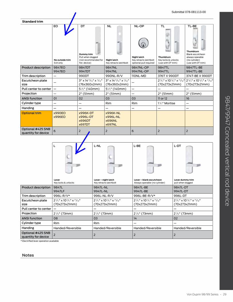
Notes
Standard trim
No outside trim Exit only
Dummy trim Pull when dogged
(not recommended for
fire device)
Night latch Key retracts latchbolt
Night latch Key retracts latchbolt
optional pull required
Thumbturn
Key locks & unlocks
(use with DT trim)
Thumbturn Blank escutcheon
always operable
(no cylinder)
(use with DT trim)
Product description 9847EO
9947EO
9847DT
9947DT
9847NL
9947NL
9847NL-OP
9947NL-OP
9847TL
9947TL
9847TL-BE
9947TL-BE
Trim description — 990DT 990NL-R/V 110NL-MD 376T X 990DT 374T-BE X 990DT
Escutcheon plate
size—
3" x 14 13/16" x 3/32"
(76x360x2mm)
3" x 14 13/16" x 3/32"
(76x360x2mm)—
2 3/4" x 10 3/4" x 27/32"
(70x273x21mm)
2 3/4" x 10 3/4" x 27/32"
(70x273x21mm)
Pull center to center — 5 1/2" (140mm) 5 1/2" (140mm) — — —
Projection — 2" (51mm) 2" (51mm) — 2" (51mm) 2" (51mm)
ANSI function 01 02 03 03 11 or 12 16
Cylinder type — — Rim Rim 1 1/4" Mortise —
Handing — — — — — —
Optional trim x990EO
x996EO
x996K-DT
x996L-DT
x696DT
x697DT
x996K-NL
x996L-NL
x696NL
x697NL
Optional #425 SNB
quantity for device6 2 2 6 2 2
Lever Key locks & unlocks
Lever – night latch Key retracts latchbolt
Lever – blank escutcheon Always operable (no cylinder)
Lever dummy trim pull when dogged
Product description 9847L
9947LF
9847L-NL
9947L-NL
9847L-BE
9947L-BE
9847L-DT
9947L-DT
Trim description 996L-R/V* 996L-NL-R/V 996L-BE-R/V* 996L-DT
Escutcheon plate
size
2 3/4" x 10 3/4" x 27/32"
(70x273x21mm)
2 3/4" x 10 3/4" x 27/32"
(70x273x21mm)
2 3/4" x 10 3/4" x 27/32"
(70x273x21mm)
2 3/4" x 10 3/4" x 27/32"
(70x273x21mm)
Pull center to center — — — —
Projection 2 7/8" (73mm) 2 7/8" (73mm) 2 7/8" (73mm) 2 7/8" (73mm)
ANSI function 08 03 14 02
Cylinder type Rim Rim — —
Handing Handed/Reversible Handed/Reversible Handed/Reversible Handed/Reversible
Optional #425 SNB
quantity for device2 2 2 2
* Electrified lever operation available
EO
L L-NL L-BE L-DT
DT NL NL-OP TL TL-BE
Submittal 078-081113-00
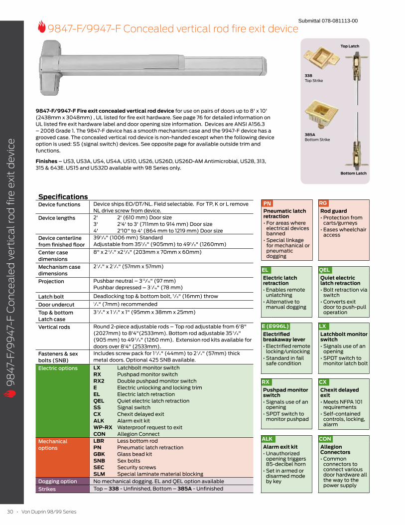
9847-F/9947-F Fire exit concealed vertical rod device for use on pairs of doors up to 8' x 10'
(2438mm x 3048mm) , UL listed for fire exit hardware. See page 76 for detailed information on
UL listed fire exit hardware label and door opening size information. Devices are ANSI A156.3
– 2008 Grade 1. The 9847-F device has a smooth mechanism case and the 9947-F device has a
grooved case. The concealed vertical rod device is non-handed except when the following device
option is used: SS (signal switch) devices. See opposite page for available outside trim and
functions.
Finishes – US3, US3A, US4, US4A, US10, US26, US26D, US26D-AM Antimicrobial, US28, 313,
315 & 643E. US15 and US32D available with 98 Series only.
SpecificationsDevice functions Device ships EO/DT/NL. Field selectable. For TP, K or L remove
NL drive screw from device.
Device lengths 2' 2' (610 mm) Door size
3' 2'4' to 3' (711mm to 914 mm) Door size
4' 2'10" to 4' (864 mm to 1219 mm) Door size
Device centerline
from finished floor
395/8" (1006 mm) Standard
Adjustable from 355/8" (905mm) to 495/8" (1260mm)
Center case
dimensions
8" x 2 3/4" x2 3/8" (203mm x 70mm x 60mm)
Mechanism case
dimensions
2 1/4" x 2 1/4" (57mm x 57mm)
Projection Pushbar neutral – 3 13/16" (97 mm)
Pushbar depressed – 3 1/16" (78 mm)
Latch bolt Deadlocking top & bottom bolt, 5/8" (16mm) throw
Door undercut1/4" (7mm) recommended
Top & bottom
Latch case
3 3/4" x 1 1/2" x 1" (95mm x 38mm x 25mm)
Vertical rods Round 2-piece adjustable rods – Top rod adjustable from 6'8"
(2027mm) to 8'4"(2533mm). Bottom rod adjustable 35 5/8"
(905 mm) to 49 5/8" (1260 mm). Extension rod kits available for
doors over 8'4" (2533mm).
Fasteners & sex
bolts (SNB)
Includes screw pack for 1 3/4" (44mm) to 2 1/4" (57mm) thick
metal doors. Optional 425 SNB available.
Electric options LX Latchbolt monitor switch
RX Pushpad monitor switch
RX2 Double pushpad monitor switch
E Electric unlocking and locking trim
EL Electric latch retraction
QEL Quiet electric latch retraction
SS Signal switch
CX Chexit delayed exit
ALK Alarm exit kit
WP-RX Waterproof request to exit
CON Allegion Connect
Mechanical
options
LBR Less bottom rod
PN Pneumatic latch retraction
GBK Glass bead kit
SNB Sex bolts
SEC Security screws
SLM Special laminate material blocking
Dogging option No mechanical dogging. EL and QEL option available
Strikes Top – 338 - Unfinished, Bottom – 385A - Unfinished
ALKAlarm exit kit
opening triggers 85-decibel horn
disarmed mode by key
RXPushpad monitor switch
opening
monitor pushpad
ELElectric latch retraction
unlatching
manual dogging
PNPneumatic latch retraction
electrical devices banned
for mechanical or pneumatic dogging
RGRod guard
carts/gurneys
access
E (E996L)Electrified breakaway lever
locking/unlocking
safe condition
LXLatchbolt monitor switch
opening
monitor latch bolt
QELQuiet electric latch retraction
switch
door to push-pull operation
CXChexit delayed exit
requirements
controls, locking, alarm
338 Top Strike
385A Bottom Strike
Top Latch
Bottom Latch
CONAllegion Connectors
connectors to connect various door hardware all the way to the power supply
Submittal 078-081113-00
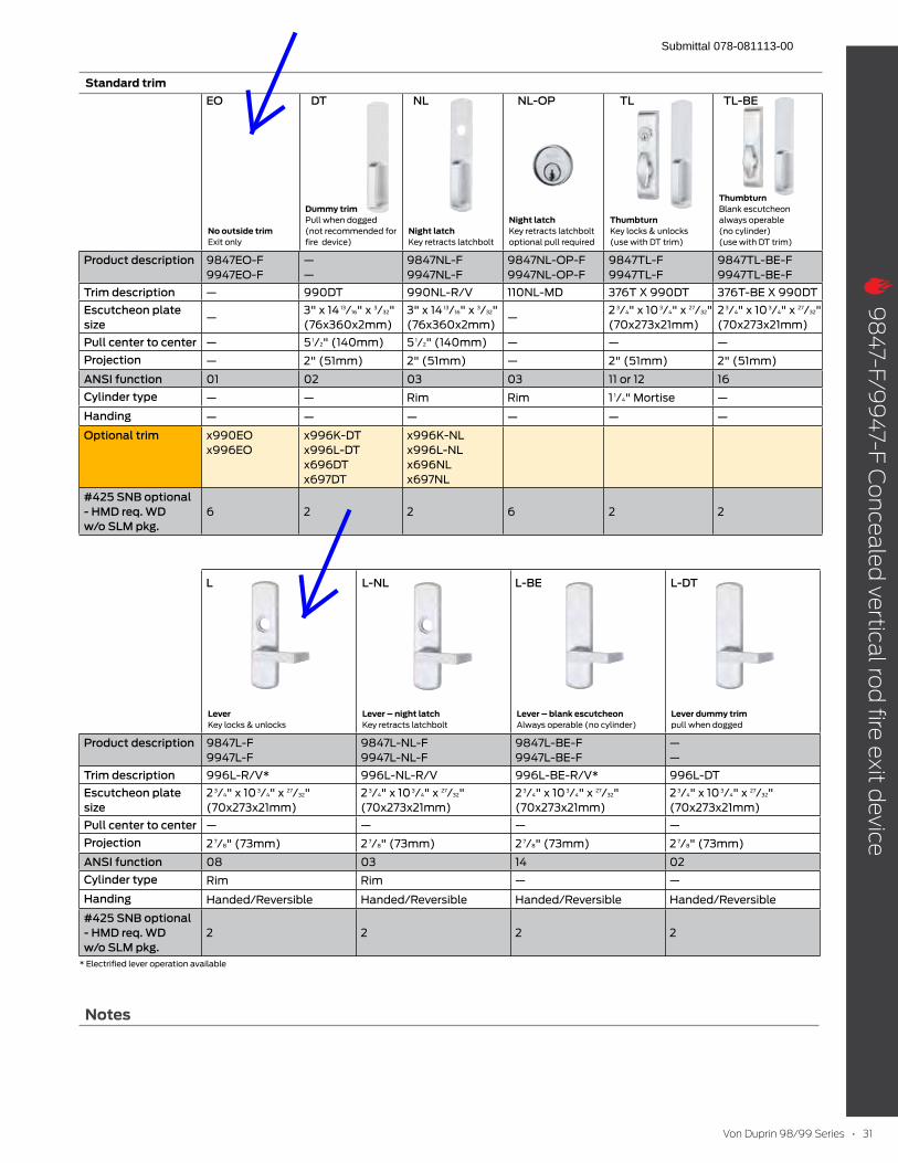
Standard trim
No outside trim Exit only
Dummy trim Pull when dogged
(not recommended for
fire device)
Night latch Key retracts latchbolt
Night latch Key retracts latchbolt
optional pull required
Thumbturn
Key locks & unlocks
(use with DT trim)
Thumbturn Blank escutcheon
always operable
(no cylinder)
(use with DT trim)
Product description 9847EO-F
9947EO-F
—
—
9847NL-F
9947NL-F
9847NL-OP-F
9947NL-OP-F
9847TL-F
9947TL-F
9847TL-BE-F
9947TL-BE-F
Trim description — 990DT 990NL-R/V 110NL-MD 376T X 990DT 376T-BE X 990DT
Escutcheon plate
size—
3" x 14 13/16" x 3/32"
(76x360x2mm)
3" x 14 13/16" x 3/32"
(76x360x2mm)—
2 3/4" x 10 3/4" x 27/32"
(70x273x21mm)
2 3/4" x 10 3/4" x 27/32"
(70x273x21mm)
Pull center to center — 5 1/2" (140mm) 5 1/2" (140mm) — — —
Projection — 2" (51mm) 2" (51mm) — 2" (51mm) 2" (51mm)
ANSI function 01 02 03 03 11 or 12 16
Cylinder type — — Rim Rim 1 1/4" Mortise —
Handing — — — — — —
Optional trim x990EO
x996EO
x996K-DT
x996L-DT
x696DT
x697DT
x996K-NL
x996L-NL
x696NL
x697NL
#425 SNB optional
- HMD req. WD
w/o SLM pkg.
6 2 2 6 2 2
Lever Key locks & unlocks
Lever – night latch Key retracts latchbolt
Lever – blank escutcheon Always operable (no cylinder)
Lever dummy trim pull when dogged
Product description 9847L-F
9947L-F
9847L-NL-F
9947L-NL-F
9847L-BE-F
9947L-BE-F
—
—
Trim description 996L-R/V* 996L-NL-R/V 996L-BE-R/V* 996L-DT
Escutcheon plate
size
2 3/4" x 10 3/4" x 27/32"
(70x273x21mm)
2 3/4" x 10 3/4" x 27/32"
(70x273x21mm)
2 3/4" x 10 3/4" x 27/32"
(70x273x21mm)
2 3/4" x 10 3/4" x 27/32"
(70x273x21mm)
Pull center to center — — — —
Projection 2 7/8" (73mm) 2 7/8" (73mm) 2 7/8" (73mm) 2 7/8" (73mm)
ANSI function 08 03 14 02
Cylinder type Rim Rim — —
Handing Handed/Reversible Handed/Reversible Handed/Reversible Handed/Reversible
#425 SNB optional
- HMD req. WD
w/o SLM pkg.
2 2 2 2
* Electrified lever operation available
EO
L L-NL L-BE L-DT
DT NL NL-OP TL TL-BE
Notes
Submittal 078-081113-00
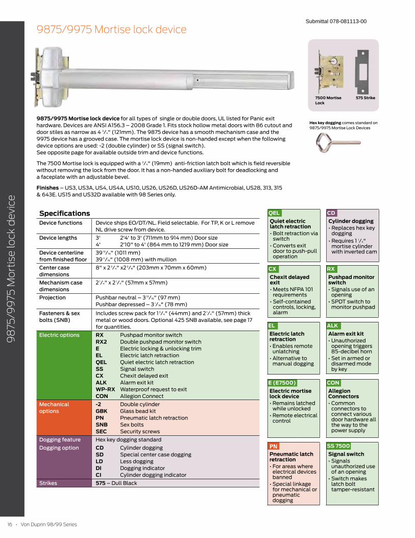
9875/9975 Mortise lock device for all types of single or double doors, UL listed for Panic exit
hardware. Devices are ANSI A156.3 – 2008 Grade 1. Fits stock hollow metal doors with 86 cutout and
door stiles as narrow as 4 3/4" (121mm). The 9875 device has a smooth mechanism case and the
9975 device has a grooved case. The mortise lock device is non-handed except when the following
device options are used: -2 (double cylinder) or SS (signal switch).
See opposite page for available outside trim and device functions.
The 7500 Mortise lock is equipped with a 3/4" (19mm) anti-friction latch bolt which is field reversible
without removing the lock from the door. It has a non-handed auxiliary bolt for deadlocking and
a faceplate with an adjustable bevel.
Finishes – US3, US3A, US4, US4A, US10, US26, US26D, US26D-AM Antimicrobial, US28, 313, 315
& 643E. US15 and US32D available with 98 Series only.
SpecificationsDevice functions Device ships EO/DT/NL. Field selectable. For TP, K or L remove
NL drive screw from device.
Device lengths 3' 2'4' to 3' (711mm to 914 mm) Door size
4' 2'10" to 4' (864 mm to 1219 mm) Door size
Device centerline
from finished floor
39 13/16" (1011 mm)
39 11/16" (1008 mm) with mullion
Center case
dimensions
8" x 2 3/4" x2 3/8" (203mm x 70mm x 60mm)
Mechanism case
dimensions
2 1/4" x 2 1/4" (57mm x 57mm)
Projection Pushbar neutral – 3 13/16" (97 mm)
Pushbar depressed – 3 1/16" (78 mm)
Fasteners & sex
bolts (SNB)
Includes screw pack for 1 3/4" (44mm) and 2 1/4" (57mm) thick
metal or wood doors. Optional 425 SNB available, see page 17
for quantities.
Electric options RX Pushpad monitor switch
RX2 Double pushpad monitor switch
E Electric locking & unlocking trim
EL Electric latch retraction
QEL Quiet electric latch retraction
SS Signal switch
CX Chexit delayed exit
ALK Alarm exit kit
WP-RX Waterproof request to exit
CON Allegion Connect
Mechanical
options
-2 Double cylinder
GBK Glass bead kit
PN Pneumatic latch retraction
SNB Sex bolts
SEC Security screws
Dogging feature Hex key dogging standard
Dogging option CD Cylinder dogging
SD Special center case dogging
LD Less dogging
DI Dogging indicator
CI Cylinder dogging indicator
Strikes 575 – Dull Black
CXChexit delayed exit
requirements
controls, locking, alarm
SS 7500Signal switch
unauthorized use of an opening
latch bolt tamper-resistant
ALKAlarm exit kit
opening triggers 85-decibel horn
disarmed mode by key
RXPushpad monitor switch
opening
monitor pushpad
ELElectric latch retraction
unlatching
manual dogging
PNPneumatic latch retraction
electrical devices banned
for mechanical or pneumatic dogging
7500 Mortise Lock
575 Strike
Hex key dogging comes standard on
9875/9975 Mortise Lock Devices
QELQuiet electric latch retraction
switch
door to push-pull operation
CDCylinder dogging
dogging 1/4"
mortise cylinder with inverted cam
E (E7500)Electric mortise lock device
while unlocked
control
CONAllegion Connectors
connectors to connect various door hardware all the way to the power supply
Submittal 078-081113-00
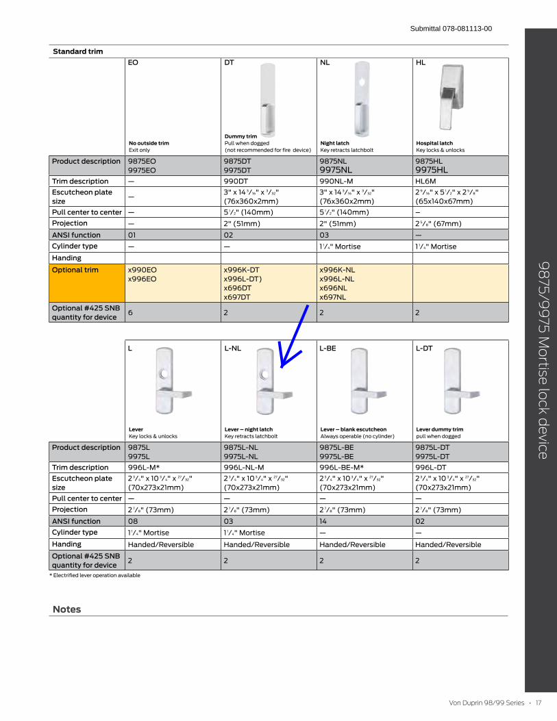
Notes
Standard trim
No outside trim Exit only
Dummy trim Pull when dogged
(not recommended for fire device)
Night latch Key retracts latchbolt
Hospital latch Key locks & unlocks
Product description 9875EO
9975EO
9875DT
9975DT
9875NL
9975NL9875HL
9975HL
Trim description — 990DT 990NL-M HL6M
Escutcheon plate
size—
3" x 14 3/16" x 3/32"
(76x360x2mm)
3" x 14 3/16" x 3/32"
(76x360x2mm)
2 9/16" x 5 1/2" x 2 5/8"
(65x140x67mm)
Pull center to center — 5 1/2" (140mm) 5 1/2" (140mm) –
Projection — 2" (51mm) 2" (51mm) 2 5/8" (67mm)
ANSI function 01 02 03 —
Cylinder type — — 1 1/4" Mortise 1 1/4" Mortise
Handing
Optional trim x990EO
x996EO
x996K-DT
x996L-DT)
x696DT
x697DT
x996K-NL
x996L-NL
x696NL
x697NL
Optional #425 SNB
quantity for device6 2 2 2
Lever Key locks & unlocks
Lever – night latch Key retracts latchbolt
Lever – blank escutcheon Always operable (no cylinder)
Lever dummy trim pull when dogged
Product description 9875L
9975L
9875L-NL
9975L-NL
9875L-BE
9975L-BE
9875L-DT
9975L-DT
Trim description 996L-M* 996L-NL-M 996L-BE-M* 996L-DT
Escutcheon plate
size
2 3/4" x 10 3/4" x 27/32"
(70x273x21mm)
2 3/4" x 10 3/4" x 27/32"
(70x273x21mm)
2 3/4" x 10 3/4" x 27/32"
(70x273x21mm)
2 3/4" x 10 3/4" x 27/32"
(70x273x21mm)
Pull center to center — — — —
Projection 2 7/8" (73mm) 2 7/8" (73mm) 2 7/8" (73mm) 2 7/8" (73mm)
ANSI function 08 03 14 02
Cylinder type 1 1/4" Mortise 1 1/4" Mortise — —
Handing Handed/Reversible Handed/Reversible Handed/Reversible Handed/Reversible
Optional #425 SNB
quantity for device2 2 2 2
* Electrified lever operation available
EO
L L-NL L-BE L-DT
DT NL HL
Submittal 078-081113-00
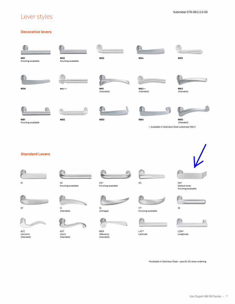
Decorative levers
M51 Knurling available
M52
Knurling available
M53 M54 M55
M56 M61 (Handed)
(Handed)
M63 (Handed)
M81 Knurling available
M82 M83 M84 M85 (Handed)
01 02
Knurling available
03*
Knurling available
05 06*
Default lever
Knurling available
07 12
(Handed)
16
(Omega)
17*
Knurling available
18
ACC
(Accent)
(Handed)
AST
(Asti)
(Handed)
MER
(Merano)
(Handed)
LAT*
Latitude
LON*
Longitude
Standard Levers
*Available in Stainless Steel - specify SS when ordering
Submittal 078-081113-00
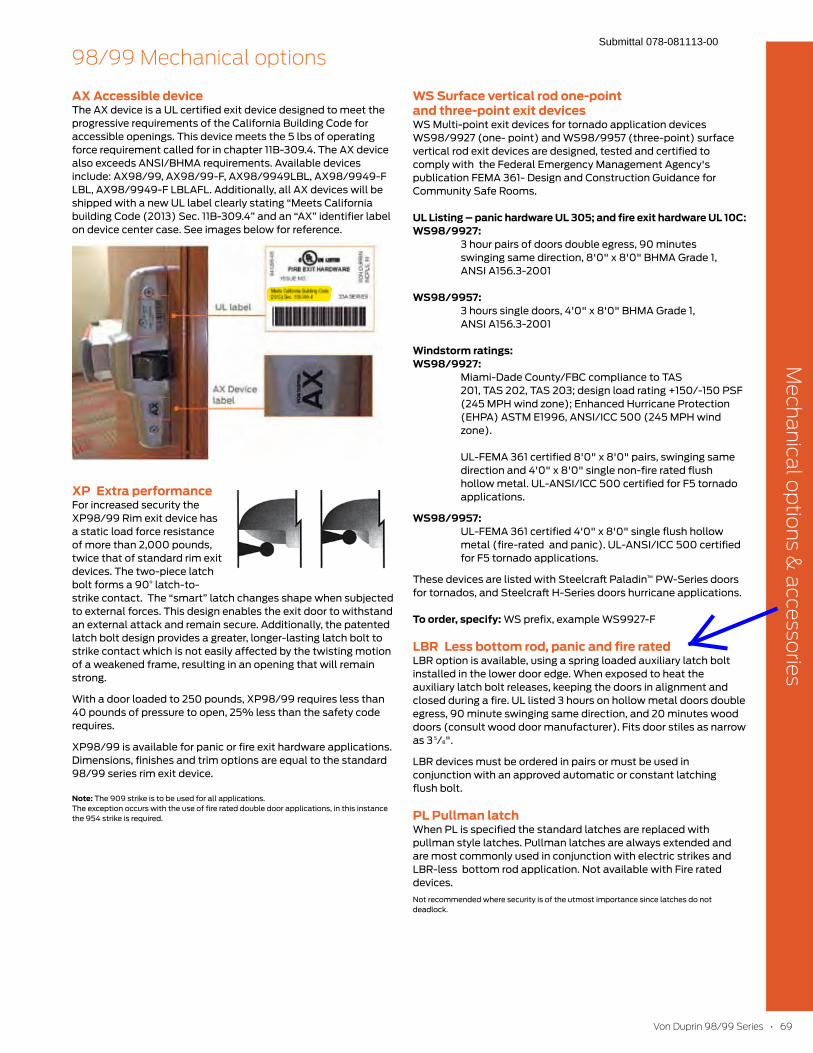
69
AX Accessible deviceThe AX device is a UL certified exit device designed to meet the
progressive requirements of the California Building Code for
accessible openings. This device meets the 5 lbs of operating
force requirement called for in chapter 11B-309.4. The AX device
also exceeds ANSI/BHMA requirements. Available devices
include: AX98/99, AX98/99-F, AX98/9949LBL, AX98/9949-F
LBL, AX98/9949-F LBLAFL. Additionally, all AX devices will be
shipped with a new UL label clearly stating “Meets California
building Code (2013) Sec. 11B-309.4” and an “AX” identifier label
on device center case. See images below for reference.
XP Extra performanceFor increased security the
XP98/99 Rim exit device has
a static load force resistance
of more than 2,000 pounds,
twice that of standard rim exit
devices. The two-piece latch
bolt forms a 90° latch-to-
strike contact. The “smart” latch changes shape when subjected
to external forces. This design enables the exit door to withstand
an external attack and remain secure. Additionally, the patented
latch bolt design provides a greater, longer-lasting latch bolt to
strike contact which is not easily affected by the twisting motion
of a weakened frame, resulting in an opening that will remain
strong.
With a door loaded to 250 pounds, XP98/99 requires less than
40 pounds of pressure to open, 25% less than the safety code
requires.
XP98/99 is available for panic or fire exit hardware applications.
Dimensions, finishes and trim options are equal to the standard
98/99 series rim exit device.
Note: The 909 strike is to be used for all applications.
The exception occurs with the use of fire rated double door applications, in this instance
the 954 strike is required.
WS Surface vertical rod one-point and three-point exit devicesWS Multi-point exit devices for tornado application devices
WS98/9927 (one- point) and WS98/9957 (three-point) surface
vertical rod exit devices are designed, tested and certified to
comply with the Federal Emergency Management Agency's
publication FEMA 361- Design and Construction Guidance for
Community Safe Rooms.
UL Listing – panic hardware UL 305; and fire exit hardware UL 10C: WS98/9927: 3 hour pairs of doors double egress, 90 minutes
swinging same direction, 8'0" x 8'0" BHMA Grade 1,
ANSI A156.3-2001
WS98/9957: 3 hours single doors, 4'0" x 8'0" BHMA Grade 1,
ANSI A156.3-2001
Windstorm ratings: WS98/9927: Miami-Dade County/FBC compliance to TAS
201, TAS 202, TAS 203; design load rating +150/-150 PSF
(245 MPH wind zone); Enhanced Hurricane Protection
(EHPA) ASTM E1996, ANSI/ICC 500 (245 MPH wind
zone).
UL-FEMA 361 certified 8'0" x 8'0" pairs, swinging same
direction and 4'0" x 8'0" single non-fire rated flush
hollow metal. UL-ANSI/ICC 500 certified for F5 tornado
applications.
WS98/9957: UL-FEMA 361 certified 4'0" x 8'0" single flush hollow
metal (fire-rated and panic). UL-ANSI/ICC 500 certified
for F5 tornado applications.
These devices are listed with Steelcraft Paladin™ PW-Series doors
for tornados, and Steelcraft H-Series doors hurricane applications.
To order, specify: WS prefix, example WS9927-F
LBR Less bottom rod, panic and fire ratedLBR option is available, using a spring loaded auxiliary latch bolt
installed in the lower door edge. When exposed to heat the
auxiliary latch bolt releases, keeping the doors in alignment and
closed during a fire. UL listed 3 hours on hollow metal doors double
egress, 90 minute swinging same direction, and 20 minutes wood
doors (consult wood door manufacturer). Fits door stiles as narrow
as 3 5/8".
LBR devices must be ordered in pairs or must be used in
conjunction with an approved automatic or constant latching
flush bolt.
PL Pullman latchWhen PL is specified the standard latches are replaced with
pullman style latches. Pullman latches are always extended and
are most commonly used in conjunction with electric strikes and
LBR-less bottom rod application. Not available with Fire rated
devices.
Not recommended where security is of the utmost importance since latches do not
deadlock.
Submittal 078-081113-00

60
CDSI/HDSI dogging indicators
Indicator provides an at-a-glance
verification of the status of the door
from inside of the room. Visible
“LOCKED” and “UNLOCKED”
indicators show whether the device
is undogged or dogged. This feature
can be used with Hex key (HDSI) or
Cylinder dogging (CDSI) options
on various device types – rim, mortise and vertical systems.
Modular conversion kits allow you to quickly and easily
upgrade your existing devices
Available for 98/99 & 33A/35A Series panic devices
To order, specify:
Use prefix, CDSI or HDSI, example CDSI99L
CD Cylinder dogging
Cylinder dogging is available on all 98/99™ Panic exit devices
to replace the standard hex key dogging. Unit requires a standard
1 1/4" (32mm) mortise cylinder with an inverted straight cam
(Schlage Cam B502-191 reference).
To order, specify: Use prefix, CD, example CD99L
CDK Cylinder dogging kit*
For field conversion, a cylinder dogging conversion kit
is available.
To order, specify: 99CDK or 98CDK, specify finish.
*Cannot be added to fire exit hardware.
HDK Hex key dogging kit*
For field conversion, a hex key dogging conversion kit is available.
To order, specify: 99HDK or 98HDK, specify finish.
*Cannot be added to fire exit hardware.
LD Less doggingLess dogging is available in all 98/99™ Panic exit devices to
remove the dogging option.
To order, specify: Use prefix LD, example LD99L
-2SI Double cylinder with security indicatorThe Von Duprin Classroom Security Indicator
provides an at-a-glance verification of the
locked/unlocked status of the door from inside
of the room. This option can be ordered as a
new product or as a retrofit conversion kit to an
existing 98/99 device. Indicator in Unlocked
state presents a 1/2" x 1/2" metal flag (white
background with black icon) at top of device
head. Indicator in Locked state has no flag
present.
To order, specify:1. Suffix-2SI with device/trim number, example 99L-2SI.
2. Handing required, LHR or RHR.
3. *Specify keyed rim cylinder ot thumbturn rim cylinder.
* Rim cylinder (3216) sold seperately. Rim cylinder with
thumbturn available from Schlage (part #XB11-979).
SD Special center case dogging
Special cylinder dogging in the center case is available for Chexit,
EL, QEL, ALK panic devices to allow for mechanical push/pull
operation. With this option, the latchbolt is held retracted and
pushbar is still operable. Specify handing—RHR or LHR.
SD requires 1 1/4" (32mm) mortise cylinder with an inverted
straight cam. (Schlage cam reference 20-001-XQ11-949.)
Note: Available on Rim and Vertical Rod Panic Exit Devices only.
To order, specify: Use prefix SD, example SD99L and Handing
Not for 98/9975 Devices
Double cylinder
Double cylinder features an inside key cylinder which locks
or unlocks the outside trim and an outside key cylinder which
retracts the latch bolt only (Night latch function). Available
on rim or mortise lock device.
Rim requires two rim type cylinders. Mortise device requires 1 rim
cylinder and 1 mortise cylinder 11/4" with a straight cam. (Schlage
cam reference B502-191.)
Available functions are thumbpiece, knob or lever.
To order, specify:1. Suffix-2 with device/trim number, example 99TP-2.
2. Handing required, LHR or RHR.
Dog keys Dog key (old style) Dog key (standard)
2 3/16" (56mm)
7/32" (6mm) hex
2 3/4" (70mm)
5/32" (4mm) hex
Submittal 078-081113-00
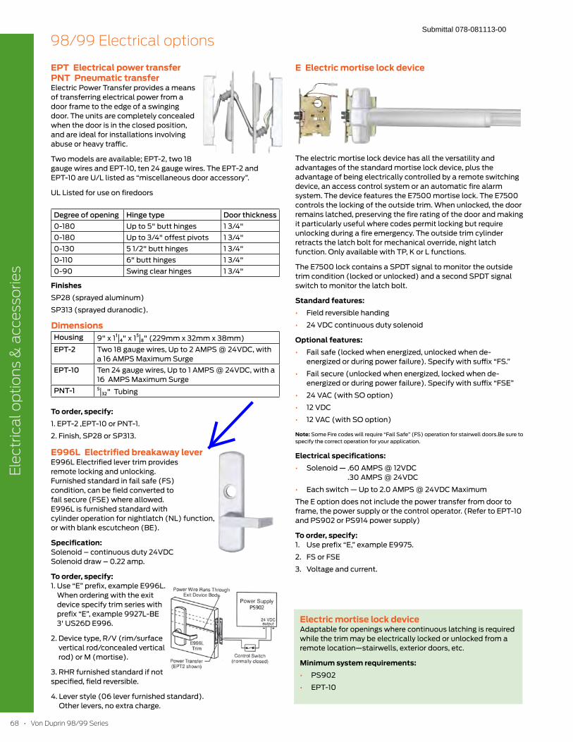
68
EPT Electrical power transfer PNT Pneumatic transferElectric Power Transfer provides a means
of transferring electrical power from a
door frame to the edge of a swinging
door. The units are completely concealed
when the door is in the closed position,
and are ideal for installations involving
abuse or heavy traffic.
Two models are available; EPT-2, two 18
gauge wires and EPT-10, ten 24 gauge wires. The EPT-2 and
EPT-10 are U/L listed as “miscellaneous door accessory”.
UL Listed for use on firedoors
Degree of opening Hinge type Door thickness
0-180 Up to 5" butt hinges 1 3/4"
0-180 Up to 3/4" offest pivots 1 3/4"
0-130 5 1/2" butt hinges 1 3/4"
0-110 6" butt hinges 1 3/4"
0-90 Swing clear hinges 1 3/4"
FinishesSP28 (sprayed aluminum)
SP313 (sprayed duranodic).
DimensionsHousing 9" x 1¹|4" x 15|8" (229mm x 32mm x 38mm)
EPT-2 Two 18 gauge wires, Up to 2 AMPS @ 24VDC, with
a 16 AMPS Maximum Surge
EPT-10 Ten 24 gauge wires, Up to 1 AMPS @ 24VDC, with a
16 AMPS Maximum Surge
PNT-1 5|32" Tubing
To order, specify:1. EPT-2 ,EPT-10 or PNT-1.
2. Finish, SP28 or SP313.
E996L Electrified breakaway leverE996L Electrified lever trim provides
remote locking and unlocking.
Furnished standard in fail safe (FS)
condition, can be field converted to
fail secure (FSE) where allowed.
E996L is furnished standard with
cylinder operation for nightlatch (NL) function,
or with blank escutcheon (BE).
Specification: Solenoid – continuous duty 24VDC
Solenoid draw – 0.22 amp.
To order, specify: 1. Use “E” prefix, example E996L.
When ordering with the exit
device specify trim series with
prefix “E”, example 9927L-BE
3' US26D E996.
2. Device type, R/V (rim/surface
vertical rod/concealed vertical
rod) or M (mortise).
3. RHR furnished standard if not
specified, field reversible.
4. Lever style (06 lever furnished standard).
Other levers, no extra charge.
E Electric mortise lock device
The electric mortise lock device has all the versatility and
advantages of the standard mortise lock device, plus the
advantage of being electrically controlled by a remote switching
device, an access control system or an automatic fire alarm
system. The device features the E7500 mortise lock. The E7500
controls the locking of the outside trim. When unlocked, the door
remains latched, preserving the fire rating of the door and making
it particularly useful where codes permit locking but require
unlocking during a fire emergency. The outside trim cylinder
retracts the latch bolt for mechanical override, night latch
function. Only available with TP, K or L functions.
The E7500 lock contains a SPDT signal to monitor the outside
trim condition (locked or unlocked) and a second SPDT signal
switch to monitor the latch bolt.
Standard features: Field reversible handing
24 VDC continuous duty solenoid
Optional features: Fail safe (locked when energized, unlocked when de-
energized or during power failure). Specify with suffix “FS.”
Fail secure (unlocked when energized, locked when de-
energized or during power failure). Specify with suffix “FSE”
24 VAC (with SO option)
12 VDC
12 VAC (with SO option)
Note: Some Fire codes will require “Fail Safe” (FS) operation for stairwell doors.Be sure to
specify the correct operation for your application.
Electrical specifications: Solenoid — .60 AMPS @ 12VDC
.30 AMPS @ 24VDC
Each switch — Up to 2.0 AMPS @ 24VDC Maximum
The E option does not include the power transfer from door to
frame, the power supply or the control operator. (Refer to EPT-10
and PS902 or PS914 power supply)
To order, specify: 1. Use prefix “E,” example E9975.
2. FS or FSE
3. Voltage and current.
Electric mortise lock deviceAdaptable for openings where continuous latching is required
while the trim may be electrically locked or unlocked from a
remote location—stairwells, exterior doors, etc.
Minimum system requirements: PS902
EPT-10
Submittal 078-081113-00
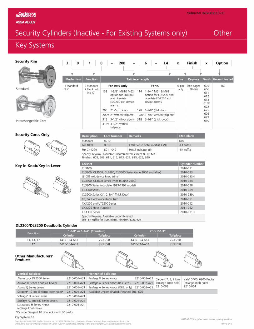
Key Systems.18
45078 5/18Copyright © 2001-2018, Corbin Russwin, Inc., an ASSA ABLOY Group company. All rights reserved. Reproduction in whole or in part without the express written permission of Corbin Russwin is prohibited. Patent pending and/or patent www.assaabloydss.com/patents.
Key Systems
Other
Description Core Number Remarks EMK Blank
Standard 8010 N/A
For 1091 8010 EMK Set to hotel mortise EMK -E1 suffix
For CK4229 8011-042 Hotel indicator pin -E4 suffix
Specify Keyway. Available uncombinated, except 8010EMK. Finishes: 605, 606, 611, 612, 613, 622, 625, 626, 690
Lockset Cylinder Number
CL3100 2010-031000 and after) 2010-033
G1055 exit device knob trims 2010-033H
2010-034
ete 1993-1997 model) 2010-038
CL3900 Series 2010-039
CL3900 Series 2010-039L
B2, G2 Exit Device Knob Trim 2010-051
CK4200 and UT5200 Series 2010-052
CK4229 Hotel Function 2011-052
CK4300 Series 2010-031H
Specify Keyway. Available uncombinated. Use -E4 suffix for EMK blank. Finishes: 606, 626
Vertical Tailpiece Horizontal Tailpiece
Alarm Lock DL2500 Series 2210-001-A21 Schlage D Series Knobs 2210-002-A21 Sargent 7, 8, 9 Line knob hole)
2210-008
Yale® 5400, 6200 Knobs knob hole)
2210-054Arrow® H 2210-001-A21 Schlage A S 2210-002-A22
Arrow Q Series Levers 2210-001-A21 Schlage 2210-002-A23
Sargent® 2210-001-A21 Available Uncombinated. Finishes: 606, 626
Schlage® D Series Levers 2210-001-A21
Schlage AL and ND Series Levers 2210-001-A22Lockwood H Series Knobs 2210-003-A24
*Or order Sargent 10 Line locks with 30 prefix.
Security Cores Only
Key-in-Knob/Key-in-Lever
Other Manufacturers’ Products
Security Rim
Interchangeable Core
Standard
Mechanism Function Tailpiece Length Pins Keyway Finish Uncombinated
1 Standard9 IC
0 Standard2 Blockout
For 3010 Only For IC 6-pinonly 28-36)
605606611612613613E622625626629630
UC
option for ED8200 and obsolete ED9200 exit device alarms
option for ED8200 and obsolete ED9200 exit device alarms
200V 2" vertical tailpiece 178V 1-7/8" vertical tailpiece
312V 3-1/2" vertical tailpiece
3 0 1 0 – 200 – 6 – L4 x Finish x Option
DL2200/DL3200 Deadbolts Cylinder
Function1-3/8" or 1-3/4" (Standard) 2" or 2-1/4"
Cylinder Tailpiece Cylinder Tailpiece
11, 13, 17 4410-134-A51 753F768 4410-134-A51 753F768
12 4410-134-A52 753F778 4410-214-A52 753F788
Submittal 078-081113-00
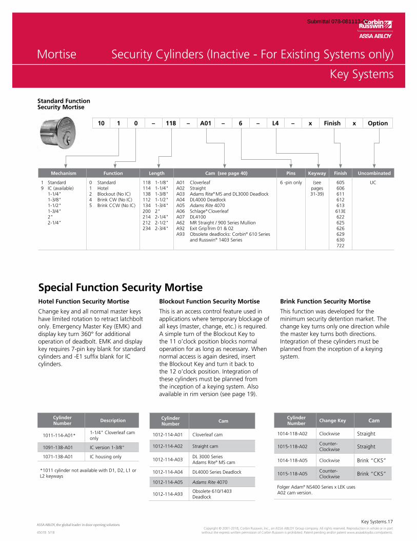
Key Systems.17
45078 5/18Copyright © 2001-2018, Corbin Russwin, Inc., an ASSA ABLOY Group company. All rights reserved. Reproduction in whole or in part
without the express written permission of Corbin Russwin is prohibited. Patent pending and/or patent www.assaabloydss.com/patents.
Key Systems
Mortise
Cylinder Number
Cam
1012-114-A01 Cloverleaf cam
1012-114-A02 Straight cam
1012-114-A03DL 3000 Series Adams Rite® MS cam
1012-114-A04 DL4000 Series Deadlock
1012-114-A05 Adams Rite 4070
1012-114-A93Obsolete 610/1403 Deadlock
Cylinder Number
Change Key Cam
1014-118-A02 Clockwise Straight
1015-118-A02Counter-Clockwise Straight
1014-118-A05 Clockwise Brink “CKS”
1015-118-A05Counter- Clockwise Brink “CKS”
Folger Adam® NS400 Series x LEK uses A02 cam version.
Special Function Security Mortise
Standard Function Security Mortise
Hotel Function Security Mortise
Change key and all normal master keys have limited rotation to retract latchbolt
operation of deadbolt. EMK and display key requires 7-pin key blank for standard cylinders and -E1 suffix blank for IC cylinders.
Blockout Function Security Mortise
This is an access control feature used in applications where temporary blockage of
A simple turn of the Blockout Key to
operation for as long as necessary. When normal access is again desired, insert the Blockout Key and turn it back to
these cylinders must be planned from the inception of a keying system. Also
Brink Function Security Mortise
This function was developed for the minimum security detention market. The change key turns only one direction while the master key turns both directions. Integration of these cylinders must be planned from the inception of a keying system.
Cylinder Number
Description
1011-114-A01*1-1/4" Cloverleaf cam only
1091-138-A01 IC version 1-3/8"
1071-138-A01 IC housing only
*1011 cylinder not available with D1, D2, L1 or L2 keyways
Mechanism Function Length Cam (see page 40) Pins Keyway Finish Uncombinated
1 Standard
1-1/4" 1-3/8" 1-1/2" 1-3/4" 2" 2-1/4"
0 Standard1 Hotel
118 1-1/8"114 1-1/4"138 1-3/8"112 1-1/2"134 1-3/4"200 2"214 2-1/4"212 2-1/2"234 2-3/4"
A01 CloverleafA02 StraightA03 Adams Rite® MS and DL3000 DeadlockA04 DL4000 DeadlockA05 Adams Rite 4070A06 Schlage® CloverleafA07 DL4100A62 MR Straight / 900 Series Mullion
A93 Obsolete deadlocks: Corbin® 610 Series and Russwin® 1403 Series
6 -pin onlypages 31-39)
605606611612613613E622625626629630722
UC
10 1 0 – 118 – A01 – 6 – L4 – x Finish x Option
Submittal 078-081113-00
OverviewML2000 Series
ML2000.2
45300 12/17Copyright © 2001-2017, Corbin Russwin, Inc., an ASSA ABLOY Group company. All rights reserved. Reproduction in whole or in part without the express written permission of Corbin Russwin is prohibited. Patent pending and/or patent www.assaabloydss.com/patents.
OverviewML2000 Series
QualityThe ML2000 Series is a Grade 1 mortise lock designed to meet the rigors of high-traffic commercial, institutional, industrial and government applications. Constructed of heavy-gauge steel, the lockbody features our patented Quick Reversible latchbolt, and a 1" stainless steel deadbolt. A wide variety of trim designs and functions and a 10-year warranty lend to the ML2000’s versatility and reliability, making it the ideal choice for use in offices, schools, hospitals, hotels and other high-use applications.
SecurityFurther discourage intrusion and abuse with the ML2000VR (Vandal Resistant) series mortise lock. This lock features vandal-resistant stainless steel escutcheons with tapered edges and Torx® pin tamper resistant screws. When matched with Corbin Russwin patented high-security cylinders, any door can become a formidable barrier to intruders.
FlexibleThe ML2000 Series has a multi-function capability, allowing 12 functions to be configured from one lockbody. The ML2054 entrance function (ANSI F04) uses a universal lockbody with the ability to reconfigure into other functions without dissembling the lock case.
AestheticsComplement any application with the full range of trim designs and finishes offered with ML2000 Series. From stainless steel security trims to bright brass Vineyard™ levers, design continuum can be achieved without forfeiting aesthetics. For additional information regarding designer trim, see the Corbin Russwin Vineyard™ Collection and Muséo® Collection catalogs.
Key Advantages
enables reversal of hands without disassembling the lock case (Patent # 6,349,982)
barrier
Corbin Russwin key systems. Also accepts cylinders of most other manufacturers.
single door prep, saving the additional cost of a deadlock
alignment and increased security
Table of Contents
ML2000 Series Overview.........2
ML2000 Series Features .......3-4
ML2000 Series Functions .....5-9
Multi-Function Configuration ..................10-11
ML20900 ECL Applications ...12
ML20900 ECL Features .........14
ML20900 ECL Functions .......15
ML20600 NAC Series Electrified Mortise Lock with High Security Monitoring ......16
NAC Functions .................17-18
NAC How to Order ...............19
Trim Designs ....................20-39
Muséo® Trim .........................40
Muséo® Inspire™ Roseless Trim ........................41
Muséo® Levers .................42-54
Vineyard™ Collection Trim .................................55-57
Vandal Resistant Trim (VR) ......56
Behavioral HealthTrim (BHSS)............................59
Behavioral Health Lever
Trim (BLSS) ............................60
Push/Pull Trim (HPSK) ............. 61
Anti-Harm Trim (HSS) ............. 62
Options and Accessories ....63-71
How to Order ..................72-74
Quick Codes ....................75-77
How to Specify ................78-80
Reversing Handing ................81
www.corbinrusswin.com
Submittal 078-081113-00
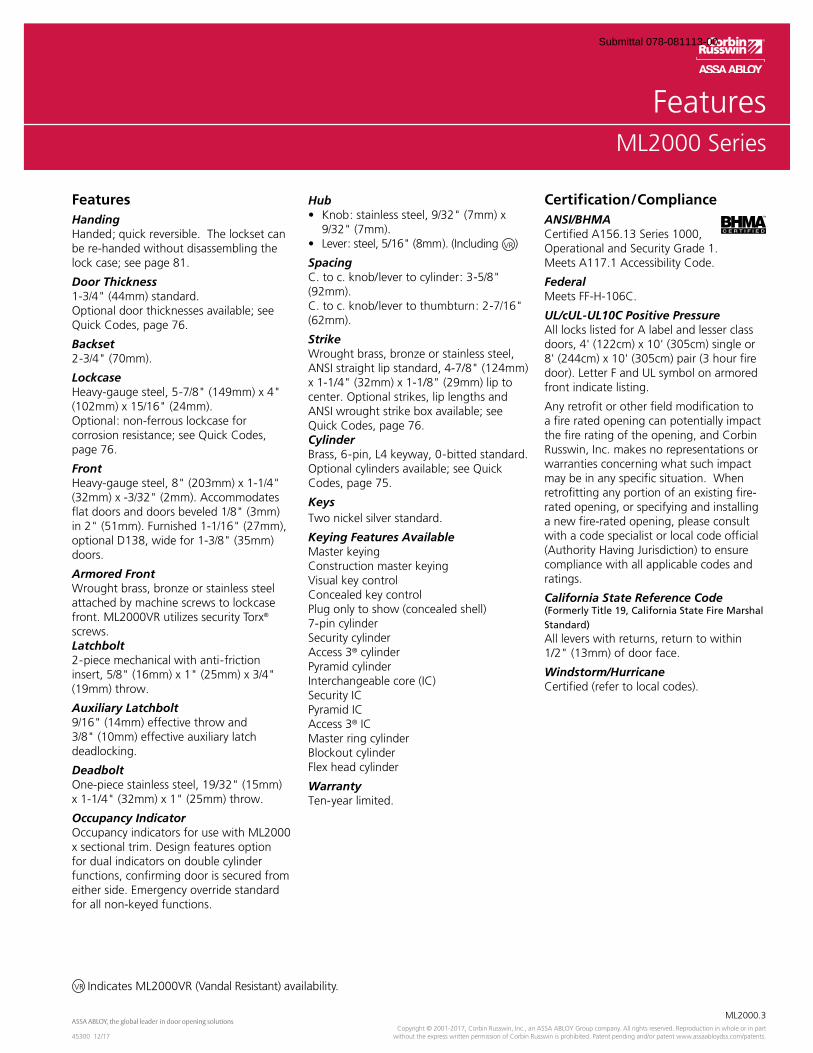
OverviewML2000 Series
ML2000.3
45300 12/17Copyright © 2001-2017, Corbin Russwin, Inc., an ASSA ABLOY Group company. All rights reserved. Reproduction in whole or in part
without the express written permission of Corbin Russwin is prohibited. Patent pending and/or patent www.assaabloydss.com/patents.
FeaturesML2000 Series
FeaturesHandingHanded; quick reversible. The lockset can be re-handed without disassembling the lock case; see page 81.
Door Thickness1-3/4" (44mm) standard.Optional door thicknesses available; see Quick Codes, page 76.
Backset2-3/4" (70mm).
LockcaseHeavy-gauge steel, 5-7/8" (149mm) x 4" (102mm) x 15/16" (24mm). Optional: non-ferrous lockcase for corrosion resistance; see Quick Codes, page 76.
FrontHeavy-gauge steel, 8" (203mm) x 1-1/4" (32mm) x -3/32" (2mm). Accommodates flat doors and doors beveled 1/8" (3mm) in 2" (51mm). Furnished 1-1/16" (27mm), optional D138, wide for 1-3/8" (35mm) doors.
Armored FrontWrought brass, bronze or stainless steel attached by machine screws to lockcase front. ML2000VR utilizes security Torx® screws.Latchbolt2-piece mechanical with anti-friction insert, 5/8" (16mm) x 1" (25mm) x 3/4" (19mm) throw.
Auxiliary Latchbolt9/16" (14mm) effective throw and 3/8" (10mm) effective auxiliary latch deadlocking.
DeadboltOne-piece stainless steel, 19/32" (15mm) x 1-1/4" (32mm) x 1" (25mm) throw.
Occupancy IndicatorOccupancy indicators for use with ML2000 x sectional trim. Design features option for dual indicators on double cylinder functions, confirming door is secured from either side. Emergency override standard for all non-keyed functions.
Hub/32" (7mm) x
9/32" (7mm).
SpacingC. to c. knob/lever to cylinder: 3-5/8" (92mm).C. to c. knob/lever to thumbturn: 2-7/16" (62mm).
StrikeWrought brass, bronze or stainless steel, ANSI straight lip standard, 4-7/8" (124mm) x 1-1/4" (32mm) x 1-1/8" (29mm) lip to center. Optional strikes, lip lengths and ANSI wrought strike box available; see Quick Codes, page 76.Cylinder Brass, 6-pin, L4 keyway, 0-bitted standard. Optional cylinders available; see Quick Codes, page 75.
Keys Two nickel silver standard.
Keying Features AvailableMaster keyingConstruction master keyingVisual key controlConcealed key controlPlug only to show (concealed shell)7-pin cylinderSecurity cylinderAccess 3® cylinder Pyramid cylinderInterchangeable core (IC) Security IC Pyramid ICAccess 3® IC Master ring cylinderBlockout cylinderFlex head cylinder
Warranty Ten-year limited.
Certification/ComplianceANSI/BHMACertified A156.13 Series 1000, Operational and Security Grade 1.Meets A117.1 Accessibility Code.
Federal Meets FF-H-106C.
UL/cUL-UL10C Positive PressureAll locks listed for A label and lesser class doors, 4' (122cm) x 10' (305cm) single or 8' (244cm) x 10' (305cm) pair (3 hour fire door). Letter F and UL symbol on armored front indicate listing.
Any retrofit or other field modification to a fire rated opening can potentially impact the fire rating of the opening, and Corbin Russwin, Inc. makes no representations or warranties concerning what such impact may be in any specific situation. When retrofitting any portion of an existing fire- rated opening, or specifying and installing a new fire-rated opening, please consult with a code specialist or local code official (Authority Having Jurisdiction) to ensure compliance with all applicable codes and ratings.
California State Reference Code(Formerly Title 19, California State Fire Marshal Standard)All levers with returns, return to within 1/2" (13mm) of door face.
Windstorm/HurricaneCertified (refer to local codes).
Indicates ML2000VR (Vandal Resistant) availability.VR
VR
Submittal 078-081113-00
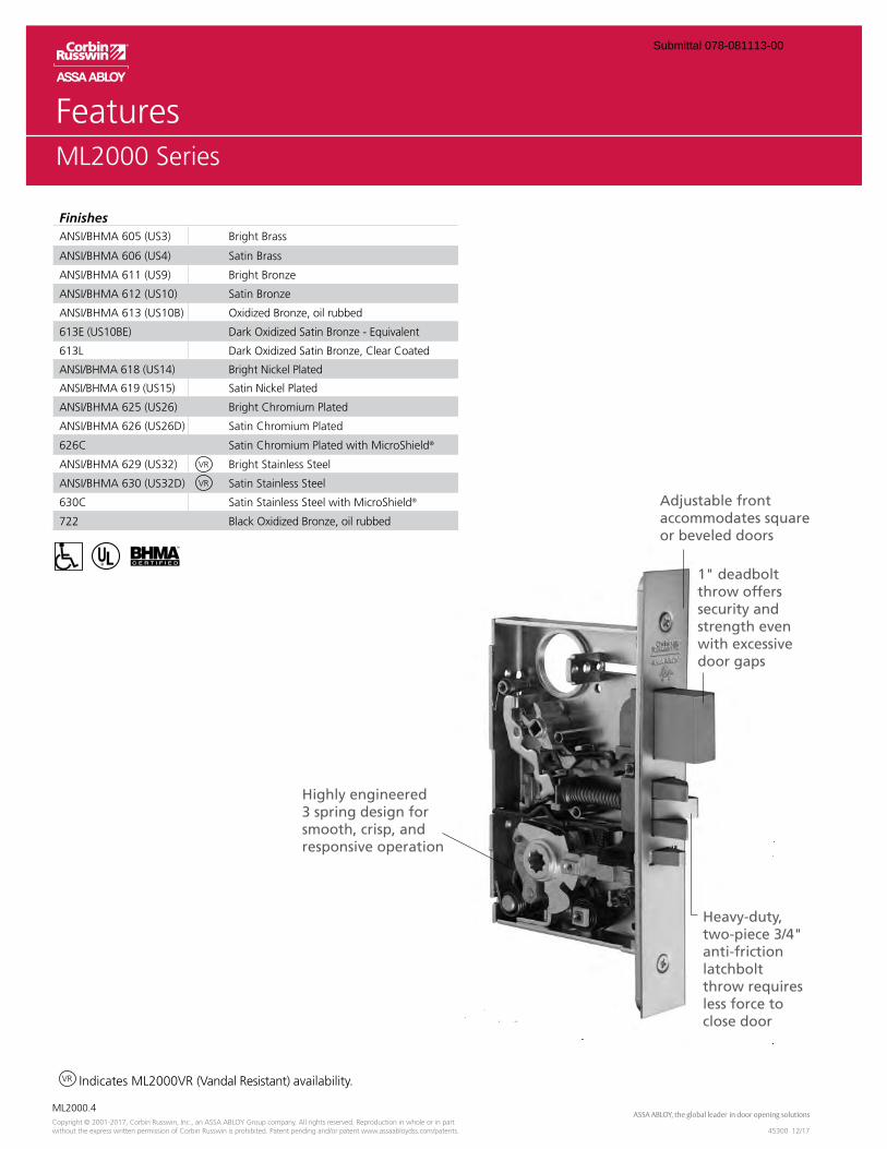
OverviewML2000 Series
ML2000.4
45300 12/17Copyright © 2001-2017, Corbin Russwin, Inc., an ASSA ABLOY Group company. All rights reserved. Reproduction in whole or in part without the express written permission of Corbin Russwin is prohibited. Patent pending and/or patent www.assaabloydss.com/patents.
FinishesANSI/BHMA 605 (US3) Bright Brass
ANSI/BHMA 606 (US4) Satin Brass
ANSI/BHMA 611 (US9) Bright Bronze
ANSI/BHMA 612 (US10) Satin Bronze
ANSI/BHMA 613 (US10B) Oxidized Bronze, oil rubbed
613E (US10BE) Dark Oxidized Satin Bronze - Equivalent
613L Dark Oxidized Satin Bronze, Clear Coated
ANSI/BHMA 618 (US14) Bright Nickel Plated
ANSI/BHMA 619 (US15) Satin Nickel Plated
ANSI/BHMA 625 (US26) Bright Chromium Plated
ANSI/BHMA 626 (US26D) Satin Chromium Plated
626C Satin Chromium Plated with MicroShield®
ANSI/BHMA 629 (US32) Bright Stainless Steel
ANSI/BHMA 630 (US32D) Satin Stainless Steel
630C Satin Stainless Steel with MicroShield®
722 Black Oxidized Bronze, oil rubbed
Indicates ML2000VR (Vandal Resistant) availability.VR
FeaturesML2000 Series
VR
VR
Adjustable front accommodates square or beveled doors
Heavy-duty, two-piece 3/4" anti-friction latchbolt throw requires less force to close door
1" deadbolt throw offers security and strength even with excessive door gaps
Highly engineered 3 spring design for smooth, crisp, and responsive operation
Submittal 078-081113-00
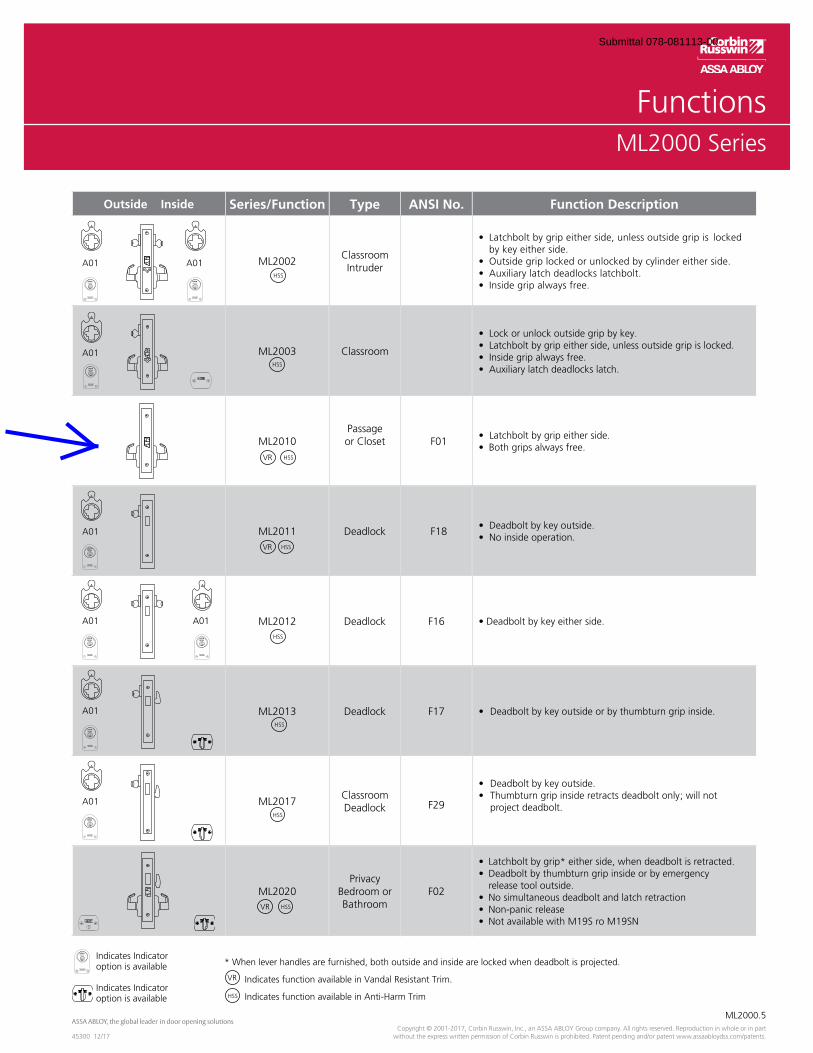
OverviewML2000 Series
ML2000.5
45300 12/17Copyright © 2001-2017, Corbin Russwin, Inc., an ASSA ABLOY Group company. All rights reserved. Reproduction in whole or in part
without the express written permission of Corbin Russwin is prohibited. Patent pending and/or patent www.assaabloydss.com/patents.
FunctionsML2000 Series
Indicates Indicator option is available
Indicates Indicatoroption is available
* When lever handles are furnished, both outside and inside are locked when deadbolt is projected.
Indicates function available in Vandal Resistant Trim.
Indicates function available in Anti-Harm Trim
Outside Inside Series/Function Type ANSI No. Function Description
ML2002ClassroomIntruder
by key either side.
ML2003 Classroom
Auxiliary latch deadlocks latch.
ML2010Passageor Closet F01
ML2011 Deadlock F18
ML2012 Deadlock F16
ML2013 Deadlock F17
ML2017ClassroomDeadlock F29 project deadbolt.
ML2020Privacy
Bedroom or Bathroom
F02 release tool outside.
VR
A01 A01
A01
VR
A01
A01 A01
A01
A01
VR
VR
HSS
HSS
HSS
HSS
HSS
HSS
HSS
HSS
HSS
Submittal 078-081113-00

OverviewML2000 Series
ML2000.6
45300 12/17Copyright © 2001-2017, Corbin Russwin, Inc., an ASSA ABLOY Group company. All rights reserved. Reproduction in whole or in part without the express written permission of Corbin Russwin is prohibited. Patent pending and/or patent www.assaabloydss.com/patents.
FunctionsML2000 Series
Indicates Indicator option is available
Indicates Indicatoroption is available
* When lever handles are furnished, both outside and inside are locked when deadbolt is projected.
Indicates function available in Vandal Resistant Trim.
Indicates function available in Anti-Harm Trim.
Indicates rigid grip.
VR
HSS
Outside Inside Series/Function Type ANSI No. Function Description
A01 A01ML2022VR HSS
Store Door F14
A01ML2024VR HSS
Entrance or Storeroom
F21
A01(Hotel Cylinder) ML2029
VRHotel orMotel
F15
outside.
outside.
Note: Indicator shows deadbolt position only
ML2030VR
Privacy Bedroom or Bathroom
F19
thumbturn
release tool outside.
and unlocks outside grip.
A01 A01
ML2032VR HSS
Institution or Utility
F30 Note: This function does not allow free egress and can pose a life safety hazard in event of an emergency. Installation should be in accordance with approved codes only.
A01 A02
ML2042VR HSS
Entranceor Public Restroom
F09by key from inside.
A01 ML2048VR
Entranceor
Apartment
F08F10
outside grip is locked by toggle-action stop.
Note: Indicator shows deadbolt position only
ML2050
HalfDummy
Trim—
Submittal 078-081113-00
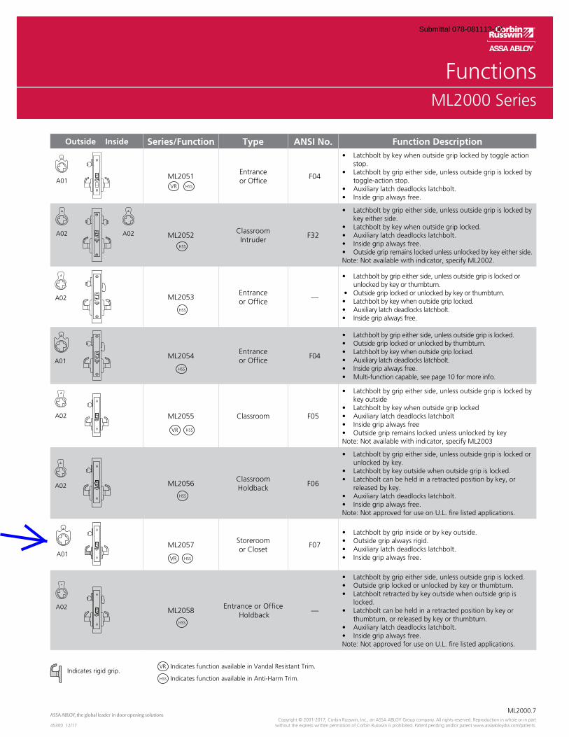
OverviewML2000 Series
ML2000.7
45300 12/17Copyright © 2001-2017, Corbin Russwin, Inc., an ASSA ABLOY Group company. All rights reserved. Reproduction in whole or in part
without the express written permission of Corbin Russwin is prohibited. Patent pending and/or patent www.assaabloydss.com/patents.
Outside Inside Series/Function Type ANSI No. Function Description
ML2051Entranceor Office
F04
stop.
toggle-action stop.
ML2052Classroom Intruder
F32
key either side.
Outside grip remains locked unless unlocked by key either side.Note: Not available with indicator, specify ML2002.
ML2053Entrance or Office
—
unlocked by key or thumbturn.
ML2054Entrance or Office
F04
ML2055 Classroom F05
key outside
Note: Not available with indicator, specify ML2003
ML2056Classroom Holdback
F06
unlocked by key.
released by key.
Note: Not approved for use on U.L. fire listed applications.
ML2057Storeroomor Closet
F07
ML2058Entrance or Office
Holdback—
locked.
thumbturn, or released by key or thumbturn.
Note: Not approved for use on U.L. fire listed applications.
VR
VR
VR
A02
A01
A02
A02
Indicates rigid grip. Indicates function available in Vandal Resistant Trim.
Indicates function available in Anti-Harm Trim.
VR
A01
A02 A02
A02
A01
FunctionsML2000 Series
HSS
HSS
HSS
HSS
HSS
HSS
HSS
HSS
HSS
Submittal 078-081113-00
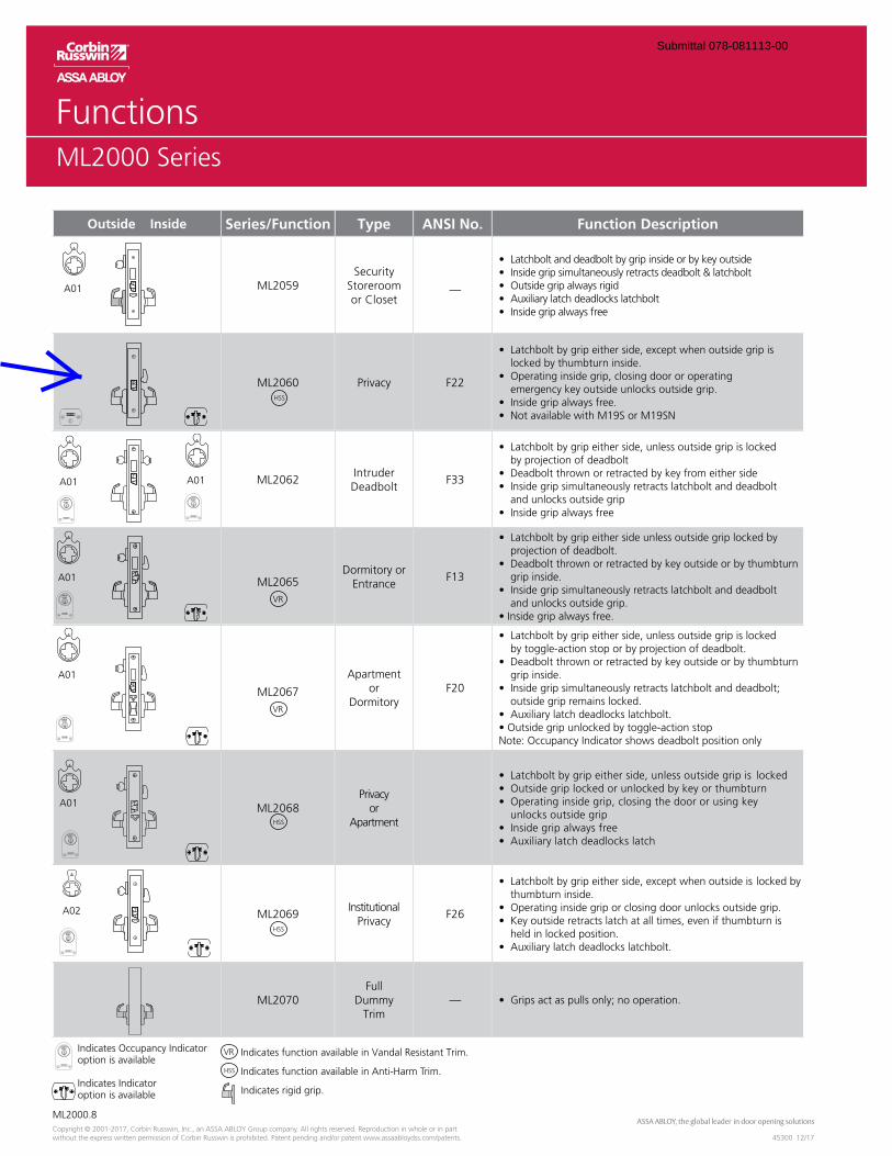
OverviewML2000 Series
ML2000.8
45300 12/17Copyright © 2001-2017, Corbin Russwin, Inc., an ASSA ABLOY Group company. All rights reserved. Reproduction in whole or in part without the express written permission of Corbin Russwin is prohibited. Patent pending and/or patent www.assaabloydss.com/patents.
Outside Inside Series/Function Type ANSI No. Function Description
ML2059Security
Storeroomor Closet
—
ML2060 Privacy F22
locked by thumbturn inside.
emergency key outside unlocks outside grip.
ML2062Intruder Deadbolt
F33
by projection of deadbolt
and unlocks outside grip
ML2065Dormitory or
EntranceF13
projection of deadbolt.
grip inside.
and unlocks outside grip.
ML2067
Apartmentor
DormitoryF20
by toggle-action stop or by projection of deadbolt.
grip inside.
outside grip remains locked.
Note: Occupancy Indicator shows deadbolt position only
ML2068Privacy
orApartment
unlocks outside grip
ML2069Institutional
PrivacyF26
thumbturn inside.
held in locked position.
ML2070Full
DummyTrim
—
A01
VR
VR
A01 A01
A01
A01
Indicates Occupancy Indicator option is available
Indicates Indicatoroption is available
Indicates function available in Vandal Resistant Trim.
Indicates function available in Anti-Harm Trim.
Indicates rigid grip.
VR
A01
FunctionsML2000 Series
HSS
HSS
HSS
HSS
A02
Submittal 078-081113-00
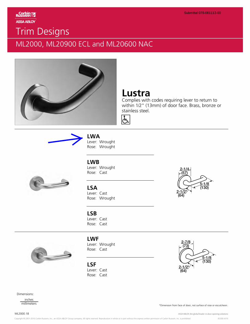
OverviewML2000
ML2000.18
Copyright © 2001-2016 Corbin Russwin, Inc., an ASSA ABLOY Group company. All rights reserved. Reproduction in whole or in part without the express written permission of Corbin Russwin, Inc. is prohibited. 45300-4/16
Trim DesignsML2000, ML20900 ECL and ML20600 NAC
*Dimension from face of door, not surface of rose or escutcheon.
LWALever: WroughtRose: Wrought
LWBLever: WroughtRose: Cast
LSALever: CastRose: Wrought
LustraComplies with codes requiring lever to return to within 1/2" (13mm) of door face. Brass, bronze or stainless steel.
LSBLever: CastRose: Cast
LWFLever: WroughtRose: Cast
LSFLever: CastRose: Cast
2-1/4(57)
5-1/8(130)
2-1/2*(64)
2-7/8(73)
5-1/8(130)
2-1/2*(64)
Dimensions:
inchesmillimeters
Submittal 078-081113-00
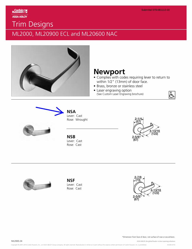
OverviewML2000
ML2000.24
Copyright © 2001-2016 Corbin Russwin, Inc., an ASSA ABLOY Group company. All rights reserved. Reproduction in whole or in part without the express written permission of Corbin Russwin, Inc. is prohibited. 45300-4/16
*Dimension from face of door, not surface of rose or escutcheon.
Trim DesignsML2000, ML20900 ECL and ML20600 NAC
Newportwithin 1/2" (13mm) of door face.
(See Custom Laser Engraving brochure)
NSALever: CastRose: Wrought
NSBLever: CastRose: Cast
2-1/4(57)
4-13/16(122)
2-5/8*(67)
NSFLever: CastRose: Cast
2-7/8(73)
4-13/16(122)
2-5/8*(67)
Submittal 078-081113-00
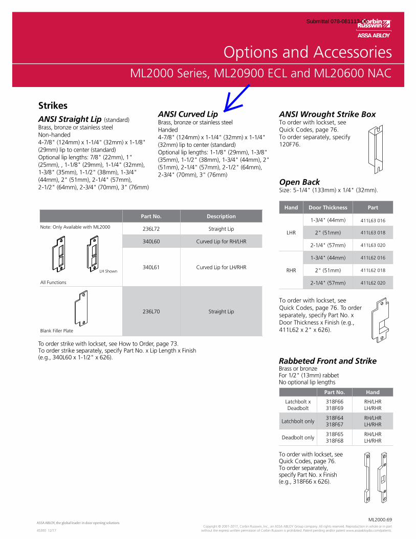
OverviewML2000 Series
ML2000.69
45300 12/17Copyright © 2001-2017, Corbin Russwin, Inc., an ASSA ABLOY Group company. All rights reserved. Reproduction in whole or in part
without the express written permission of Corbin Russwin is prohibited. Patent pending and/or patent www.assaabloydss.com/patents.
Options and AccessoriesML2000 Series, ML20900 ECL and ML20600 NAC
ANSI Wrought Strike BoxTo order with lockset, see Quick Codes, page 76.To order separately, specify 120F76.
Open Back Size: 5-1/4" (133mm) x 1/4" (32mm).
To order with lockset, see Quick Codes, page 76. To order separately, specify Part No. x Door Thickness x Finish (e.g., 411L62 x 2" x 626).
Rabbeted Front and StrikeBrass or bronzeFor 1/2" (13mm) rabbet No optional lip lengths
To order with lockset, see Quick Codes, page 76. To order separately, specify Part No. x Finish (e.g., 318F66 x 626).
StrikesANSI Straight Lip (standard)Brass, bronze or stainless steel Non-handed4-7/8" (124mm) x 1-1/4" (32mm) x 1-1/8" (29mm) lip to center (standard)Optional lip lengths: 7/8" (22mm), 1" (25mm), , 1-1/8" (29mm), 1-1/4" (32mm), 1-3/8" (35mm), 1-1/2" (38mm), 1-3/4" (44mm), 2" (51mm), 2-1/4" (57mm), 2-1/2" (64mm), 2-3/4" (70mm), 3" (76mm)
ANSI Curved LipBrass, bronze or stainless steelHanded4-7/8" (124mm) x 1-1/4" (32mm) x 1-1/4" (32mm) lip to center (standard)Optional lip lengths: 1-1/8" (29mm), 1-3/8" (35mm), 1-1/2" (38mm), 1-3/4" (44mm), 2" (51mm), 2-1/4" (57mm), 2-1/2" (64mm), 2-3/4" (70mm), 3" (76mm)
To order strike with lockset, see How to Order, page 73.To order strike separately, specify Part No. x Lip Length x Finish (e.g., 340L60 x 1-1/2" x 626).
Hand Door Thickness Part
LHR
1-3/4" (44mm) 411L63 016
2" (51mm) 411L63 018
2-1/4" (57mm) 411L63 020
RHR
1-3/4" (44mm) 411L62 016
2" (51mm) 411L62 018
2-1/4" (57mm) 411L62 020
Part No. Hand
Latchbolt x Deadbolt
318F66318F69
RH/LHRLH/RHR
Latchbolt only318F64318F67
RH/LHRLH/RHR
Deadbolt only318F65318F68
RH/LHRLH/RHR
Part No. Description
Note: Only Available with ML2000
LH Shown
All Functions
236L72 Straight Lip
340L60 Curved Lip for RH/LHR
340L61 Curved Lip for LH/RHR
Blank Filler Plate
236L70 Straight Lip
Submittal 078-081113-00
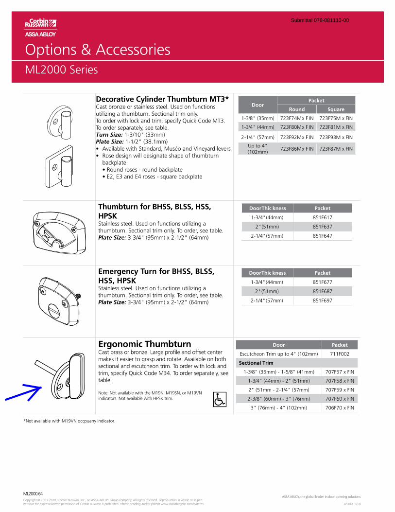
OverviewML2000 Series
ML2000.64
45300 5/18Copyright © 2001-2018, Corbin Russwin, Inc., an ASSA ABLOY Group company. All rights reserved. Reproduction in whole or in part without the express written permission of Corbin Russwin is prohibited. Patent pending and/or patent www.assaabloydss.com/patents.
ML2000 Series
Decorative Cylinder Thumbturn MT3*Cast bronze or stainless steel. Used on functions utilizing a thumbturn. Sectional trim only. To order with lock and trim, specify Quick Code MT3. To order separately, see table.Turn Size: 1-3/10" (33mm)Plate Size: 1-1/2" (38.1mm)
backplate
DoorPacket
Round Square
1-3/8" (35mm) 723F74M x F IN 723F75M x FIN
1-3/4" (44mm) 723F80M x F IN 723F81M x FIN
2-1/4" (57mm) 723F92M x F IN 723F93M x FIN
Up to 4" (102mm)
723F86M x F IN 723F87M x FIN
Thumbturn for BHSS, BLSS, HSS, HPSKStainless steel. Used on functions utilizing athumbturn. Sectional trim only. To order, see table.Plate Size: 3-3/4" (95mm) x 2-1/2" (64mm)
Door Thic kness Packet
1-3/4" (44mm) 851F617
2" (51mm) 851F637
2-1/4" (57mm) 851F647
Emergency Turn for BHSS, BLSS, HSS, HPSKStainless steel. Used on functions utilizing athumbturn. Sectional trim only. To order, see table.Plate Size: 3-3/4" (95mm) x 2-1/2" (64mm)
Door Thic kness Packet
1-3/4" (44mm) 851F677
2" (51mm) 851F687
2-1/4" (57mm) 851F697
Ergonomic ThumbturnCast brass or bronze. Large profile and offset center makes it easier to grasp and rotate. Available on both sectional and escutcheon trim. To order with lock and trim, specify Quick Code M34. To order separately, see table.
Note: Not available with the M19N, M19SN, or M19VN indicators. Not available with HPSK trim.
Door Packet
Escutcheon Trim up to 4" (102mm) 711F002
Sectional Trim
1-3/8" (35mm) - 1-5/8" (41mm) 707F57 x FIN
1-3/4" (44mm) - 2" (51mm) 707F58 x FIN
2" (51mm - 2-1/4" (57mm) 707F59 x FIN
2-3/8" (60mm) - 3" (76mm) 707F60 x FIN
3" (76mm) - 4" (102mm) 706F70 x FIN
*Not available with M19VN occpuany indicator.
Submittal 078-081113-00
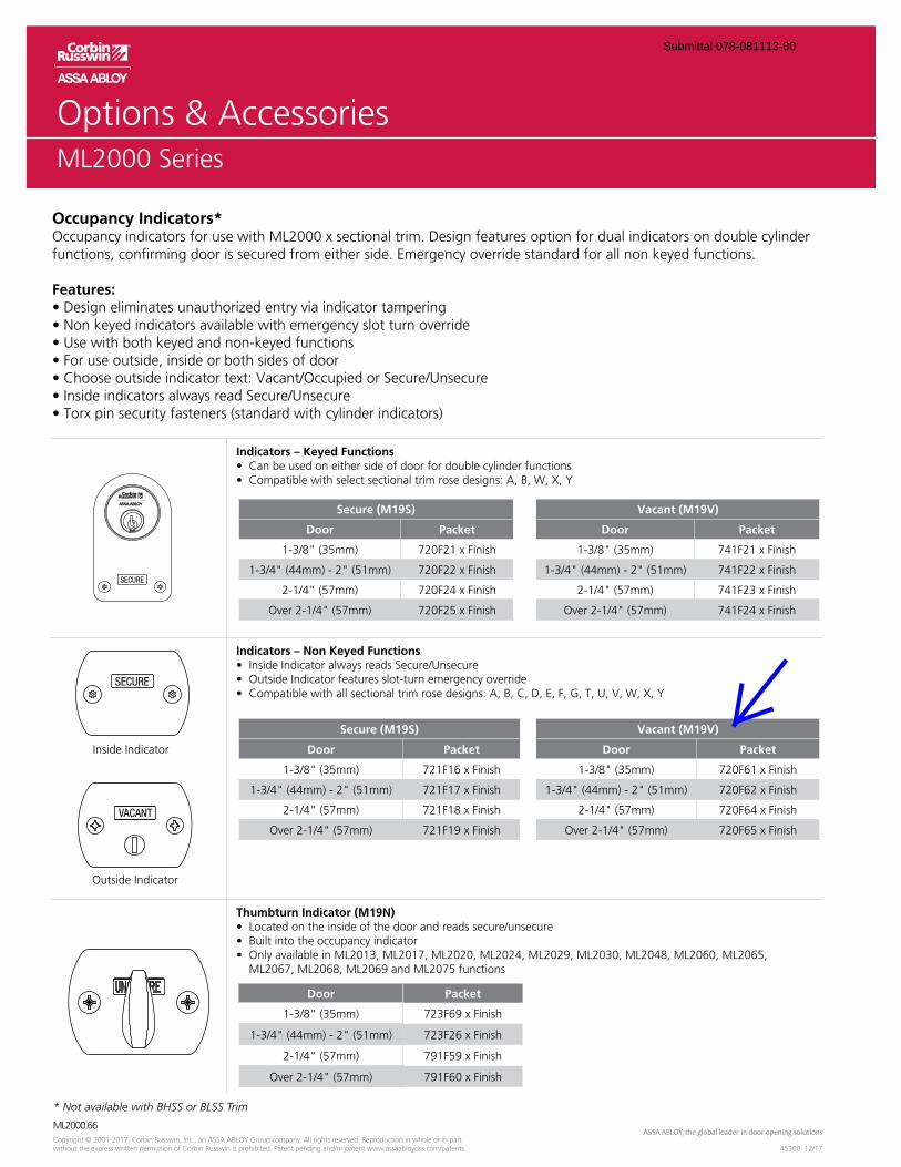
OverviewML2000 Series
ML2000.66
45300 12/17Copyright © 2001-2017, Corbin Russwin, Inc., an ASSA ABLOY Group company. All rights reserved. Reproduction in whole or in part without the express written permission of Corbin Russwin is prohibited. Patent pending and/or patent www.assaabloydss.com/patents.
ML2000 Series
Indicators – Keyed Functions
Indicators – Non Keyed Functions
Thumbturn Indicator (M19N)
ML2067, ML2068, ML2069 and ML2075 functions
Occupancy Indicators*Occupancy indicators for use with ML2000 x sectional trim. Design features option for dual indicators on double cylinder functions, confirming door is secured from either side. Emergency override standard for all non keyed functions.
Features:
Inside Indicator
Outside Indicator
Secure (M19S)
Door Packet
1-3/8" (35mm) 720F21 x Finish
1-3/4" (44mm) - 2" (51mm) 720F22 x Finish
2-1/4" (57mm) 720F24 x Finish
Over 2-1/4" (57mm) 720F25 x Finish
Vacant (M19V)
Door Packet
1-3/8" (35mm) 741F21 x Finish
1-3/4" (44mm) - 2" (51mm) 741F22 x Finish
2-1/4" (57mm) 741F23 x Finish
Over 2-1/4" (57mm) 741F24 x Finish
Secure (M19S)
Door Packet
1-3/8" (35mm) 721F16 x Finish
1-3/4" (44mm) - 2" (51mm) 721F17 x Finish
2-1/4" (57mm) 721F18 x Finish
Over 2-1/4" (57mm) 721F19 x Finish
Vacant (M19V)
Door Packet
1-3/8" (35mm) 720F61 x Finish
1-3/4" (44mm) - 2" (51mm) 720F62 x Finish
2-1/4" (57mm) 720F64 x Finish
Over 2-1/4" (57mm) 720F65 x Finish
Door Packet
1-3/8" (35mm) 723F69 x Finish
1-3/4" (44mm) - 2" (51mm) 723F26 x Finish
2-1/4" (57mm) 791F59 x Finish
Over 2-1/4" (57mm) 791F60 x Finish
* Not available with BHSS or BLSS Trim
Submittal 078-081113-00
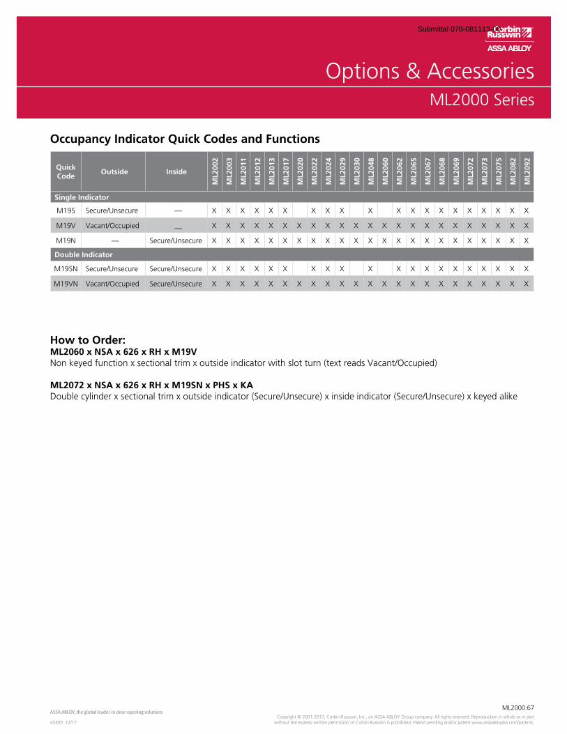
OverviewML2000 Series
ML2000.67
45300 12/17Copyright © 2001-2017, Corbin Russwin, Inc., an ASSA ABLOY Group company. All rights reserved. Reproduction in whole or in part
without the express written permission of Corbin Russwin is prohibited. Patent pending and/or patent www.assaabloydss.com/patents.
ML2000 Series
Occupancy Indicator Quick Codes and Functions
Quick Code
Outside Inside
ML2
002
ML2
003
ML2
011
ML2
012
ML2
013
ML2
017
ML2
020
ML2
022
ML2
024
ML2
029
ML2
030
ML2
048
ML2
060
ML2
062
ML2
065
ML2
067
ML2
068
ML2
069
ML2
072
ML2
073
ML2
075
ML2
082
ML2
092
Single Indicator
M19S Secure/Unsecure — X X X X X X X X X X X X X X X X X X X X
M19V Vacant/Occupied — X X X X X X X X X X X X X X X X X X X X X X X
M19N — Secure/Unsecure X X X X X X X X X X X X X X X X X X X X X X X
Double Indicator
M19SN Secure/Unsecure Secure/Unsecure X X X X X X X X X X X X X X X X X X X X
M19VN Vacant/Occupied Secure/Unsecure X X X X X X X X X X X X X X X X X X X X X X X
How to Order:ML2060 x NSA x 626 x RH x M19VNon keyed function x sectional trim x outside indicator with slot turn (text reads Vacant/Occupied)
ML2072 x NSA x 626 x RH x M19SN x PHS x KADouble cylinder x sectional trim x outside indicator (Secure/Unsecure) x inside indicator (Secure/Unsecure) x keyed alike
Submittal 078-081113-00
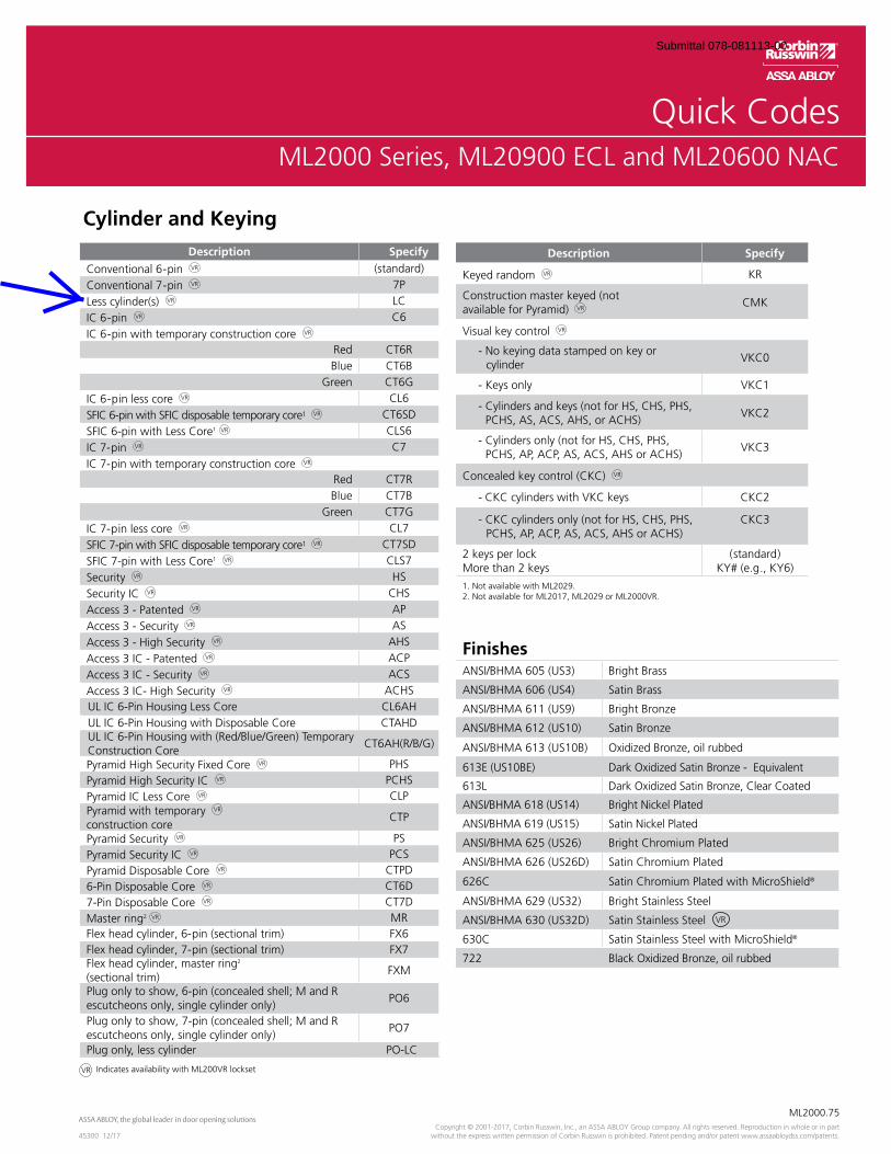
OverviewML2000 Series
ML2000.75
45300 12/17Copyright © 2001-2017, Corbin Russwin, Inc., an ASSA ABLOY Group company. All rights reserved. Reproduction in whole or in part
without the express written permission of Corbin Russwin is prohibited. Patent pending and/or patent www.assaabloydss.com/patents.
Quick CodesML2000 Series, ML20900 ECL and ML20600 NAC
Cylinder and Keying
Indicates availability with ML200VR lockset
Description Specify
Keyed random KR
Construction master keyed (notavailable for Pyramid)
CMK
Visual key control
- No keying data stamped on key or cylinder
VKC0
- Keys only VKC1
- Cylinders and keys (not for HS, CHS, PHS, PCHS, AS, ACS, AHS, or ACHS)
VKC2
- Cylinders only (not for HS, CHS, PHS, PCHS, AP, ACP, AS, ACS, AHS or ACHS)
VKC3
Concealed key control (CKC)
- CKC cylinders with VKC keys CKC2
- CKC cylinders only (not for HS, CHS, PHS, PCHS, AP, ACP, AS, ACS, AHS or ACHS)
CKC3
2 keys per lockMore than 2 keys
(standard)KY# (e.g., KY6)
1. Not available with ML2029.2. Not available for ML2017, ML2029 or ML2000VR.
Description Specify
Conventional 6-pin (standard)Conventional 7-pin 7PLess cylinder(s) LCIC 6-pin C6IC 6-pin with temporary construction core
Red CT6RBlue CT6B
Green CT6GIC 6-pin less core CL6SFIC 6-pin with SFIC disposable temporary core1 CT6SDSFIC 6-pin with Less Core1 CLS6IC 7-pin C7IC 7-pin with temporary construction core
Red CT7RBlue CT7B
Green CT7GIC 7-pin less core CL7SFIC 7-pin with SFIC disposable temporary core1 CT7SDSFIC 7-pin with Less Core1 CLS7Security HSSecurity IC CHSAccess 3 - Patented APAccess 3 - Security ASAccess 3 - High Security AHSAccess 3 IC - Patented ACPAccess 3 IC - Security ACSAccess 3 IC- High Security ACHSUL IC 6-Pin Housing Less Core CL6AH UL IC 6-Pin Housing with Disposable Core CTAHD UL IC 6-Pin Housing with (Red/Blue/Green) Temporary Construction Core
CT6AH(R/B/G)
Pyramid High Security Fixed Core PHSPyramid High Security IC PCHSPyramid IC Less Core CLPPyramid with temporary construction core
CTP
Pyramid Security PSPyramid Security IC PCSPyramid Disposable Core CTPD6-Pin Disposable Core CT6D7-Pin Disposable Core CT7DMaster ring2 MRFlex head cylinder, 6-pin (sectional trim) FX6Flex head cylinder, 7-pin (sectional trim) FX7Flex head cylinder, master ring2 (sectional trim)
FXM
Plug only to show, 6-pin (concealed shell; M and R escutcheons only, single cylinder only)
PO6
Plug only to show, 7-pin (concealed shell; M and R escutcheons only, single cylinder only)
PO7
Plug only, less cylinder PO-LC
FinishesANSI/BHMA 605 (US3) Bright Brass
ANSI/BHMA 606 (US4) Satin Brass
ANSI/BHMA 611 (US9) Bright Bronze
ANSI/BHMA 612 (US10) Satin Bronze
ANSI/BHMA 613 (US10B) Oxidized Bronze, oil rubbed
613E (US10BE) Dark Oxidized Satin Bronze - Equivalent
613L Dark Oxidized Satin Bronze, Clear Coated
ANSI/BHMA 618 (US14) Bright Nickel Plated
ANSI/BHMA 619 (US15) Satin Nickel Plated
ANSI/BHMA 625 (US26) Bright Chromium Plated
ANSI/BHMA 626 (US26D) Satin Chromium Plated
626C Satin Chromium Plated with MicroShield®
ANSI/BHMA 629 (US32) Bright Stainless Steel
ANSI/BHMA 630 (US32D) Satin Stainless Steel
630C Satin Stainless Steel with MicroShield®
722 Black Oxidized Bronze, oil rubbed
VR
Submittal 078-081113-00
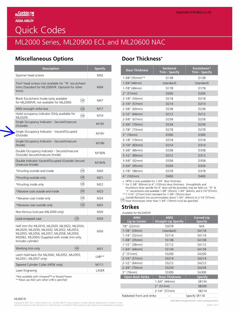
OverviewML2000 Series
ML2000.76
45300 12/17Copyright © 2001-2017, Corbin Russwin, Inc., an ASSA ABLOY Group company. All rights reserved. Reproduction in whole or in part without the express written permission of Corbin Russwin is prohibited. Patent pending and/or patent www.assaabloydss.com/patents.
Quick CodesML2000 Series, ML20900 ECL and ML20600 NAC
Miscellaneous Options Door Thickness+
Description Specify
Spanner head screws M02
Torx® head screws (not available for “N” escutcheon trims (Standard for ML2000VR. Optional for other trims)
M04
Blank Escutcheon Inside (only available for ML2000VR, not available for ML2000)
M07
ANSI wrought strike box M17
Hotel occupancy indicator (Only available for ML2029)
M19
Single Occupancy Indicator - Secure/Unsecure (Outside)
M19S
Single Occupancy Indicator - Vacant/Occupied (Outside)
M19V
Single Occupancy Indicator - Secure/Unsecure (Inside)
M19N
Double Occupancy Indicator - Secure/Unsecure (Outside) Secure/Unsecure (Inside)
M19SN
Double Indicator Vacant/Occupied (Outside) Secure/Unsecure (Inside)
M19VN
*Knurling outside and inside M20
*Knurling outside only M21
*Knurling inside only M22
*Abrasive coat outside and inside M23
*Abrasive coat inside only M24
*Abrasive coat outside only M25
Non-ferrous lockcase (ML2000 only) M26
Lead-wrapped case M29
Half trim (for ML2010, ML2020, ML2022, ML2024, ML2029, ML2030, ML2032, ML2052, ML2053, ML2055, ML2056, ML2057, ML2058, ML2059, Ml2062, ML2065) (Supplied with inside trim only. Includes cylinder)
M30
Working trim only M31
Latch hold back (for ML2042, ML2052, ML2055, ML2051, ML2057 only)
LHB**
Tapered Cylinder Collar (HPSK only) M111
Laser Engraving LASER
*Not available with Vineyard™ or Muséo® levers.** Must use A02 cam when LHB is specified
Door ThicknessSectional
Trim - SpecifyEscutcheon*
Trim - Specify
1-3/8"(35mm)** D138 D138
1-3/4"(44mm) (standard) (standard)
1-7/8"(48mm) D178 D178
2" (51mm) D200 D200
2-1/8" (54mm) D218 D218
2-1/4" (57mm) D214 D214
2-3/8" (60mm) D238 D238
2-1/2" (64mm) D212 D212
2-5/8" (67mm) D258 D258
2-3/4" (70mm) D234 D234
2-7/8" (73mm) D278 D278
3" (76mm) D300 D300
3-1/8" (79mm) D318 D318
3-1/4" (83mm) D314 D314
3-3/8" (86mm) D338 D338
3-1/2" (89mm) D312 D312
3-5/8" (92mm) D358 D358
3-3/4" (95mm) D334 D334
3-7/8" (98mm) D378 D378
4" (102mm) D400 D400
+ HPSK is only available for 1-3/4" door thickness* For 2-3/8" (60mm) to 4" (102mm) door thickness: throughbolts and
“L” escutcheons only available 1-3/8" (35mm), 1-3/4" (44mm), and 2-1/4"(57mm). ** 1-1/16" (27mm) front standard for 1-3/8" (35mm) door Vandal Resistant trim accommodates doors 1-3/4" (44mm) to 2-1/4"(57mm). Door thicknesses other than 1-3/4" (19mm) must be specified.
StrikesAvailable for ML2000VR
ANSILip to Center
ANSIStraight Lip Specify
Curved LipSpecify
7/8" (22mm) SS078 N/A
1-1/8" (29mm) (standard) SA118
1-1/4" (32mm) SS114 SA114
1-3/8" (35mm) SS138 SA138
1-1/2" (38mm) SS112 SA112
1-3/4" (44mm) SS134 SA134
2" (51mm) SS200 SA200
2-1/4" (57mm) SS214 SA214
2-1/2" (64mm) SS212 SA212
2-3/4" (70mm) SS234 SA234
3" (76mm) SS300 SA300
Open Back Strike Door Thickness Specify1-3/4" (44mm) SB134
2" (51mm) SB200
2-1/4" (57mm) SB214
Rabbeted front and strike – Specify SR118
Submittal 078-081113-00
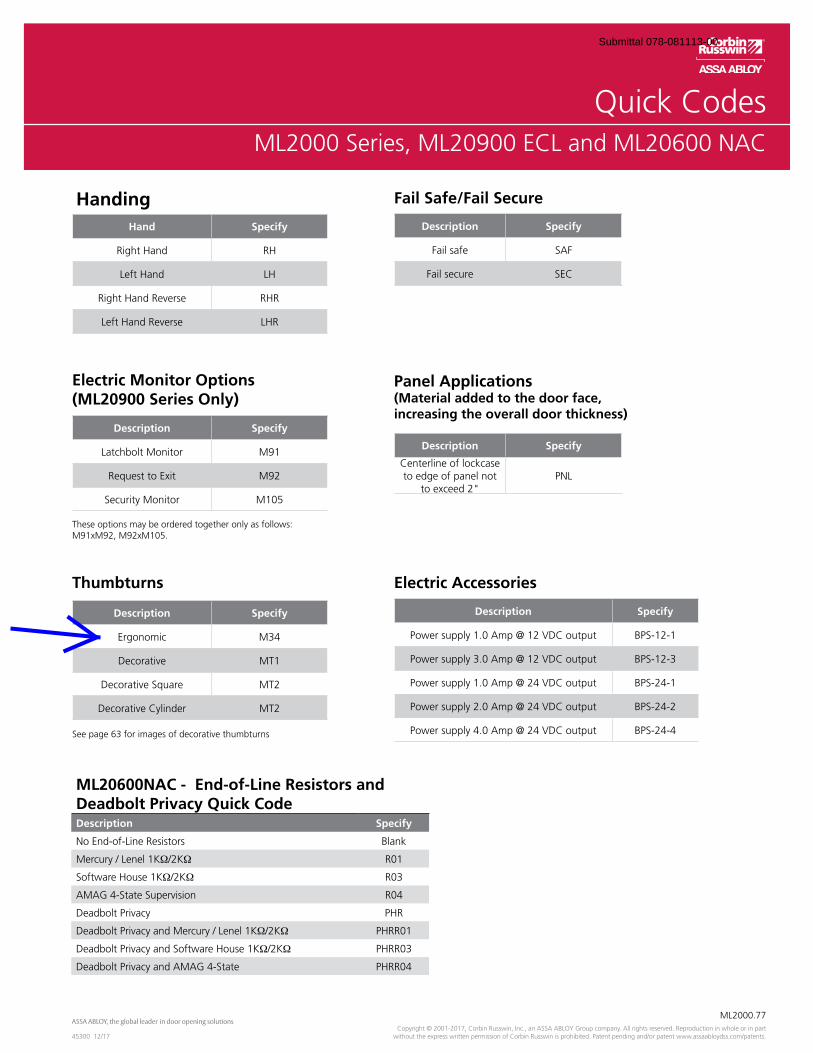
OverviewML2000 Series
ML2000.77
45300 12/17Copyright © 2001-2017, Corbin Russwin, Inc., an ASSA ABLOY Group company. All rights reserved. Reproduction in whole or in part
without the express written permission of Corbin Russwin is prohibited. Patent pending and/or patent www.assaabloydss.com/patents.
Quick CodesML2000 Series, ML20900 ECL and ML20600 NAC
HandingHand Specify
Right Hand RH
Left Hand LH
Right Hand Reverse RHR
Left Hand Reverse LHR
These options may be ordered together only as follows: M91xM92, M92xM105.
Electric Monitor Options(ML20900 Series Only)
Description Specify
Latchbolt Monitor M91
Request to Exit M92
Security Monitor M105
Description Specify
Fail safe SAF
Fail secure SEC
Fail Safe/Fail Secure
Thumbturns
Description Specify
Ergonomic M34
Decorative MT1
Decorative Square MT2
Decorative Cylinder MT2
See page 63 for images of decorative thumbturns
Description Specify
Centerline of lockcase to edge of panel not
to exceed 2"PNL
Panel Applications(Material added to the door face, increasing the overall door thickness)
ML20600NAC - End-of-Line Resistors and Deadbolt Privacy Quick CodeDescription Specify
No End-of-Line Resistors Blank
Mercury / Lenel 1K�/2K� R01
Software House 1K�/2K� R03
AMAG 4-State Supervision R04
Deadbolt Privacy PHR
Deadbolt Privacy and Mercury / Lenel 1K�/2K� PHRR01
Deadbolt Privacy and Software House 1K�/2K� PHRR03
Deadbolt Privacy and AMAG 4-State PHRR04
Electric Accessories
Description Specify
Power supply 1.0 Amp @ 12 VDC output BPS-12-1
Power supply 3.0 Amp @ 12 VDC output BPS-12-3
Power supply 1.0 Amp @ 24 VDC output BPS-24-1
Power supply 2.0 Amp @ 24 VDC output BPS-24-2
Power supply 4.0 Amp @ 24 VDC output BPS-24-4
Submittal 078-081113-00

Ives Architectural hardware productsB6
Architectural Door Trim
B6
Pulls
& P
late
sA
Hin
ges
& P
ivot
sC
Flus
h Bo
lts &
Coo
rdin
ator
sD
Latc
hes,
Cat
ches
& B
olts
E Stop
sF
Exte
rior H
ardw
are
GM
isce
llane
ous H
ardw
are
Plates Cut for Cylinder or ThumbturnsPlates are available with cutout for cylinder or thumbturn; standard cutout is 2” fromtop and centered on plates up to 4” wide. For plates wider than 4” cutout is located2” from outer edge, specify LH or RH. When pull location interferes with standardcutout location a detail drawing should be furnished with the order.
Standard cutout is 1-1/4” for cylinder and 3/8” for thumbturn.
Specify CFC for cutout for cylinder or CFT for cutout for thumbturn.
8200 Push Plate8300 Pull Plate, Prep for Pull (less pull)
Available Sizes3” x 12”3.5” x 15”4” x 16”6” x 16”8” x 16”Special sizes are available. Consult factory.
2”
2”
2”
CFC
2”
CFT
CFC
2”
2”
CFT
Finishes brassUS Number US3 US4 US10 US10B US15 US26 US26D*
BHMA 605 606 612 613 619 625 626
Finishes stainless steelUS Number US32D*
BHMA 630
Finishes aluminumUS Number US28
BHMA 628
* Available with Antimicrobial Coating, use suffix AM
Submittal 078-081113-00
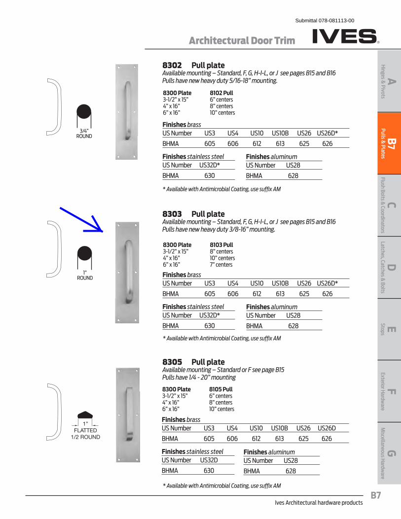
Ives Architectural hardware productsB7
Architectural Door Trim
B7
Pulls & Plates
AH
inges & Pivots
CFlush Bolts &
CoordinatorsD
Latches, Catches & Bolts
EStopsF
Exterior Hardw
areG
Miscellaneous H
ardware
8302 Pull plateAvailable mounting – Standard, F, G, H-I-L, or J see pages B15 and B16Pulls have new heavy duty 5/16-18” mounting.
8300 Plate 8102 Pull 3-1/2” x 15” 6” centers 4” x 16” 8” centers 6” x 16” 10” centers
8303 Pull plateAvailable mounting – Standard, F, G, H-I-L, or J see pages B15 and B16Pulls have new heavy duty 3/8-16” mounting.
8300 Plate 8103 Pull 3-1/2” x 15” 8” centers 4” x 16” 10” centers 6” x 16” 7” centers
8305 Pull plateAvailable mounting – Standard or F see page B15 Pulls have 1/4 - 20” mounting
8300 Plate 8105 Pull 3-1/2” x 15” 6” centers 4” x 16” 8” centers 6” x 16” 10” centers
Finishes brassUS Number US3 US4 US10 US10B US26 US26D*
BHMA 605 606 612 613 625 626
Finishes stainless steelUS Number US32D*
BHMA 630
Finishes aluminumUS Number US28
BHMA 628
Finishes brassUS Number US3 US4 US10 US10B US26 US26D*
BHMA 605 606 612 613 625 626
Finishes stainless steelUS Number US32D*
BHMA 630
Finishes aluminumUS Number US28
BHMA 628
Finishes brassUS Number US3 US4 US10 US10B US26 US26D
BHMA 605 606 612 613 625 626
Finishes stainless steelUS Number US32D
BHMA 630
Finishes aluminumUS Number US28
BHMA 628
* Available with Antimicrobial Coating, use suffix AM
* Available with Antimicrobial Coating, use suffix AM
* Available with Antimicrobial Coating, use suffix AM
3/4”ROUND
1”ROUND
1”FLATTED
1/2 ROUND
Submittal 078-081113-00

2 LCN Door Control Catalogphone: 877-671-7011 � fax: 800-248-1460 � www.allegion.com/us � 009426 rev. 2/16
APPLICATIONS� �� For aluminum, hollow metal, or wood swinging doors and frames.� �� Can be used with hinge or pivot mounted door. � �� �Adapter plates and other installation accessories available for
unusual conditions.
FEATURES COMMON TO 4000 SERIES� �� �Each closer (except 4050, 4040XP, 4040XPT, 4030, 4030T) is
designed for a specific mounting; hinge side, top jamb, or parallel arm. 4040XP closer with regular or hold-open arm mounts hinge side or top jamb. 4030, 4040XP and 4050 regular parallel arm closers include 62PA SHOE required to parallel arm mount either regular or hold-open arm.
� �� �Handed for right or left swinging doors, except for 4000T, 4030, 4030T, 4040XP, 4050 and 4040XPT.
� �� �Closers to meet ADA reduced opening force requirements except 4000T.
� �� Adjustable hydraulic backcheck cushions opening swing prior to 90°. � �� Separate regulation of general closing speed and latching speed. � �� Joints in regular arm and shoe adapt to uneven trim. � �� Reversible shoe to boost latching power on double lever arms.� �� �Available in a wide range of standard or optional custom powder
coat finishes to blend with door and frame.� �� Plated finishes available to accent door and frame. � �� Not designed for exterior mounting or exposed to elements.
DESIGN ASSISTANCELCN has been providing reliable solutions to unique door control problems since 1925. Design and specification assistance are only a phone call away.
Contact LCN for assistance or technical information at 877-671-7011 or FAX 800-248-1460 (Order Entry), Fax 815-879-1495 for Product Support.
WARRANTY 30 year limited warranty; 25 year limited warranty (4050). See General Information Section for complete warranty details.
SPECIFICATIONS Refer to “SPECIFICATIONS” section for suggested architectural specifications.
MATERIALS� �� High strength cast iron or cast aluminum (4050) cylinder.� �� Forged steel main arms.� �� One piece forged steel piston.� �� Double heat treated pinion.� �� �LCN’s all weather “Liquid X” fluid performs to temperature
ranges from 120°F (49°C) to -30°F (-35°C) without any seasonal adjustment.
� �� �LCN's standard all weather fluid performs to temperature ranges from 120°F (49°C) to -30°F (-35°C). .
� �� High efficiency, full complement, low friction bearings. � �� Tamper resistant regulating screws.� �� Full rack and pinion hydraulic action.� �� �Quiet, low friction track and roller combination for all single lever arm
(track style) closers.
FINISHES � �� �Available in six standard or optional custom powder
coat finishes to blend with door and frame.� �� �LCN’s powder coat finishes surpass 100 hours of salt spray which
is over four times the ANSI standard for corrosion resistance.� �� �For installations where a higher level of corrosive resistance is
required, LCN offers an optional special rust inhibiting (SRI) pre-treatment. Closers that combine the exclusive LCN powder coat finish and the SRI pre-treatment exceed the ANSI standard for corrosion resistance even further.
� �� �Plated finishes are available as an option to accent door and frame. (SRI not available with plated finishes).
LISTINGS & APPROVALSUL listed for self-closing doors without hold-open under “SWINGING DOOR CLOSERS”(GVEV) file R1943.
Tested and certified under ANSI Standard A156.4 Grade One. Consult factory for details.
Consult factory for other listings such as; cUL, California State Fire Marshal, Bureau of Standards and Appeals.
POSITIVE PRESSURE LCN closers have been certified for three hours by UL to be in compliance with UL 10C. Contact LCN for specific details on door closer fire ratings.
FASTENERS4010, 4010T, 4020, 4020T, 4040XP, 4040XPT, 4050, 4110, 4110T Series closers are shipped with: A standard SELF-REAMING and TAPPING SCREW (SRT) pack that contains Philips head SRT screws to install the closer. 4000T series closers are shipped with: A standard WOOD and MACHINE SCREW (WMS) pack that contains Philips head wood and machine screws to install the closer. 4030, 4030T series closers are shipped with: A standard WOOD and SELF-TAPPING MACHINE SCREW (WMS) pack that contains Phillips head wood and self-tapping machine screws to install the ��������� �� ��������������������������������� ���������������!!��thick doors with 1/4-20 machine screws. Optional thru bolt (TB) sizes are �"��������#�����$�%������!!���������%����$�!!�� �������&����*��������must be specified when ordering.
Notes:�������������� ���������������� ������������ ��� ������������� !�
�������� ���������#�� ������ �������$%$�&���'������������ � ���� ����������(�������)����*�����������������������+,-����� ����� ��������(��������(����)����*�������� ������./0�����(��������
����(���������������� �����
MAINTENANCE Closers mounted according to LCN installation instructions require no periodic maintenance or adjustments.
Drill 25/64˝ forsteel doorsorDrill 3/8˝for wood doors
4000 Series mounted closers
Submittal 078-081113-00

37LCN Door Control Catalogphone: 877-671-7011 � fax: 800-248-1460 � www.allegion.com/us � 009426 rev. 2/16
� ,�������)����*���(� ������ ���1�2��*���������#�����������3�������� 4� /�5� �������#�������������� �(� �� ������� � ��� ��� 44� 6�)������7����*������������� 444� 8�������� ������������ ���� ��������2�2������������� �%'!������
AVAILABLE NOT AVAILABLE
Features
4040XPSeries
The 4040XP is LCN’s most durable and flexible heavy duty closer designed for institutional and other demanding high traffic applications.
Certifications Grade 1 - ANSI A156.4, UL 10C, ADA, 100 Hour Salt Spray, Meets BAA - Buy American Act
Body Construction � Cast Iron Body� Full Complement Bearings�� (!()�`�J�� � ��������� �j)*`�J�� � ��J���� �$ ��%� � ��
�����{����
Fluid |���Q �� ��<������}������
Handing Non-Handed
Templating � �!!#������ �&�� ��!��!()*`�K�,`��������$�� ���� �
Size |�~����� �#&����#�� �(!X������� ���� � ��Green Dial
Warranty 30 years
Cover �� ��������#����� Metal, Optional
Fasteners # ���� ������%&&���#�� ����#�%��
Mounting $�� �������#�� ���%�&�{���������#�� ������� ��|���������#�� �
Arms Regular Arm
Finishes/Colors/ Powder Coat
�� |��������X-���� #���������� ��X����� <��������� ��X�(��� ������X�j��� J������� ��X�,��� ������X�X�� Custom colors optional
�� ��&�����#�Y�&��� ��!�&��� ���������� Optional plated finishes
'������� ������������ �&�� �����&������������ �"���� �������" �������&&��������� '�����<'����������#�&&�������������� �
Special Templates
PLASTIC
METAL
HINGE (P
ULL) SIDE
TOP JAMB (PULL
)
TOP JAMB (PUSH)
PARALLEL A
RM
STOP FACE
MOUNTING COVER
180° 180° 180° 110°110°STA
NDARD (SINGLE)
REGULA
R (DOUBLE)
HOLD-O
PEN
FUSIB
LE LI
NK
EDA/HEDA
CUSH/HCUSH
SCUSH/SHCUSH
DOUBLE EGRESS
*ARM FUNCTIONFINISH CYLINDER
NON-HANDED
NON-SIZED
ACCESSIBILI
TY
DELAYED ACTION***
AVB**POW
DER COAT
PLATED
Submittal 078-081113-00

38 LCN Door Control Catalogphone: 877-671-7011 � fax: 800-248-1460 � www.allegion.com/us � 009426 rev. 2/16
2-1/4"57 mm
11"279 mm
1-1/16"27 mm
3/4"19 mm2-11/16"
68 mm10-7/16"625 mm
5/8"16 mm
12-1/4"311 mm
3-1/2"89 mm
3-3/4"95 mm
4040XP-18
Hinge (Pull Side) Mounting
Mounting details
4040XPSeries
Butt Hinges �� #��������� K� ��,`��(��������������
Auxiliary Stop �� � ���� � ��������!�& �&��������� � ����������������� ����(���
Reveal �� #��������� K� ��j)*`��(����������� ���������������!�& ����
Top Rail �� < ������j!j)*`���,������ ���� ���<|%0��*�*�}�!(-����� �� ���� ���`��,(�����������
Clearance �� �!j)-`��X������� ���������� ���� ������������������
Delayed Action �� Y���&��� ��������*�*(������ �����������}������� ��� J ����������������(������������ �J ������ ��~����� ��&����&&��K��� ���(�����
Maximum Opening �� % �&������������&����(���� �� $���!�& �&����������&����(�������������!�& ����
Submittal 078-081113-00

40 LCN Door Control Catalogphone: 877-671-7011 � fax: 800-248-1460 � www.allegion.com/us � 009426 rev. 2/16
2-1/4"57 mm
4"102 mm
4"102 mm
5-7/8"149 mm
5-3/8"137 mm
12-1/4"311 mm
3-1/2"89 mm
4-15/16"125 mm
5-3/8"137 mm
4040XP-18PA
14-1/2"368 mm
Parallel Arm (Push Side)Mounting
Mounting details
4040XPSeries
Butt Hinges #��������� K� ��,`��(��������������
Auxiliary Stop � ���� � ��������!�& �&������� � ��� ���������������(-��������� � �'�#$!�!#%�������������� �
Reveal #��������� K� ���)j�`��X�����
Top Rail < ������,!j)-`��(j������� ��� ��������� ����&�� ���� ���<|%0�� *�*�}�!(-�|����� �� ���� ���`��,(������������������� ����&
Head Frame ����������� �� ��� ���� ���|�#$�0�|J|�%0���*�*�}�!*(�
Stop Width �������(`���,������'�#$����� ���� ���������(!()�`��j-����
Blade Stop '� �� �� ���� ��()�`��(j�����<|J0�#%���#�|'0���*�*�}�!X(�
Clearance �� *�*�}�!X��|���� ����*`��(������������������� � �� 0J|���� �&��~ ����,!()�`��(*������������������ � �� '�#$���� �&��~ ����X`��(,������������������
Delayed Action �� Y���&��� ��������*�*(������ �����������}������� ��� J ����������������(�������������� J ������ ��~����� ��&����&&��K��� ���(����� �
Maximum Opening �� (-����& ��)����!�& �&������������� K� &��'�#$������ �((����& ��)����!�& ������'�#$����
Notes:9�;� ������ �� ��#���<�����'6�0=;>���2�2%'�3&'6�������#�������=;+8�;'>-��� �9�6��������5�?'@� ���������������� ������#��'�2�2%'!9�'�2�2%'�����������������2�2%'�&2���A��=�=;+>�0'6,>B� ������� �'6�0=;>
Submittal 078-081113-00
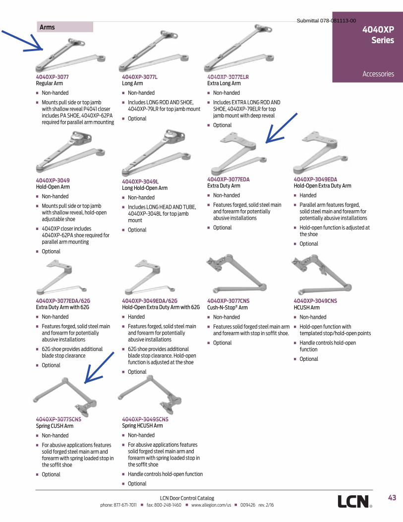
43LCN Door Control Catalogphone: 877-671-7011 � fax: 800-248-1460 � www.allegion.com/us � 009426 rev. 2/16
4040XP-3077Regular Arm
� Non-handed
�� �������&������� ������&�~���������������� " ���*�*(����� ������� ���|�#$�0��*�*�}�!X��|�� ���� ������&��� �����������
4040XP-3077ELRExtra Long Arm
� Non-handed
�� �Y���� ��0}%�|�<������J�|�J�#$�0��*�*�}�!��0<��������&�~�������������� &�� " ��
� Optional
4040XP-3049Hold-Open Arm
� Non-handed
�� �������&������� ������&�~���������������� " �������!�& ��~����� ����
�� �*�*�}������ ������� ���*�*�}�!X��|���� �� ���� ������parallel arm mounting
� Optional
4040XP-3077L Long Arm
� Non-handed
�� �Y���� ��<������J�|�J�#$�0��*�*�}�!��<��������&�~�������
� Optional
4040XP-3049EDA/62GHold-Open Extra Duty Arm with 62G
� Handed
� Features forged, solid steel main and forearm for potentially ����" ����������
�� �X������ �&��"�� ������������� ����&��� �� ��$���!�& �function is adjusted at the shoe
� Optional
4040XP-3049SCNSSpring HCUSH Arm
� Non-handed
�� ���������" �&&��������� ��� ��solid forged steel main arm and ��� ���������&������� �����&���the soffit shoe
� Handle controls hold-open function
� Optional
4040XP-3077CNSCush-N-Stop® Arm
� Non-handed
� Features solid forged steel main arm ����� �����������&������������� �
� Optional
4040XP-3049CNSHCUSH Arm
� Non-handed
�� �$���!�& �������������templated stop/hold-open points
� Handle controls hold-open function
� Optional
4040XP-3049LLong Hold-Open Arm
� Non-handed
�� �Y���� ��<����$0|J�|�J�%��0��*�*�}�!j�*-<�������&�~���mount
� Optional
4040XP-3077EDAExtra Duty Arm
� Non-handed
� Features forged, solid steel main and forearm for potentially ����" ����������
� Optional
4040XP-3049EDAHold-Open Extra Duty Arm
� Handed
�� ����� ������ ��� ������ ���solid steel main and forearm for &�� ����������" ����������
� Hold-open function is adjusted at the shoe
� Optional
4040XP-3077EDA/62GExtra Duty Arm with 62G
� Non-handed
� Features forged, solid steel main and forearm for potentially ����" ����������
�� �X������ �&��"�� ������������� ����&��� ��
� Optional
4040XP-3077SCNSSpring CUSH Arm
� Non-handed
�� ���������" �&&��������� ��� ��solid forged steel main arm and ��� ���������&������� �����&���the soffit shoe
� Optional
Arms
Accessories
4040XPSeries
4040XP-3077 4040XP-3077L 4040XP-3077ELR
� Optional
4040XP 3077SCNS 4040XP 3049SCNS
4040XP 3077EDA 4040XP 3049EDA
Submittal 078-081113-00
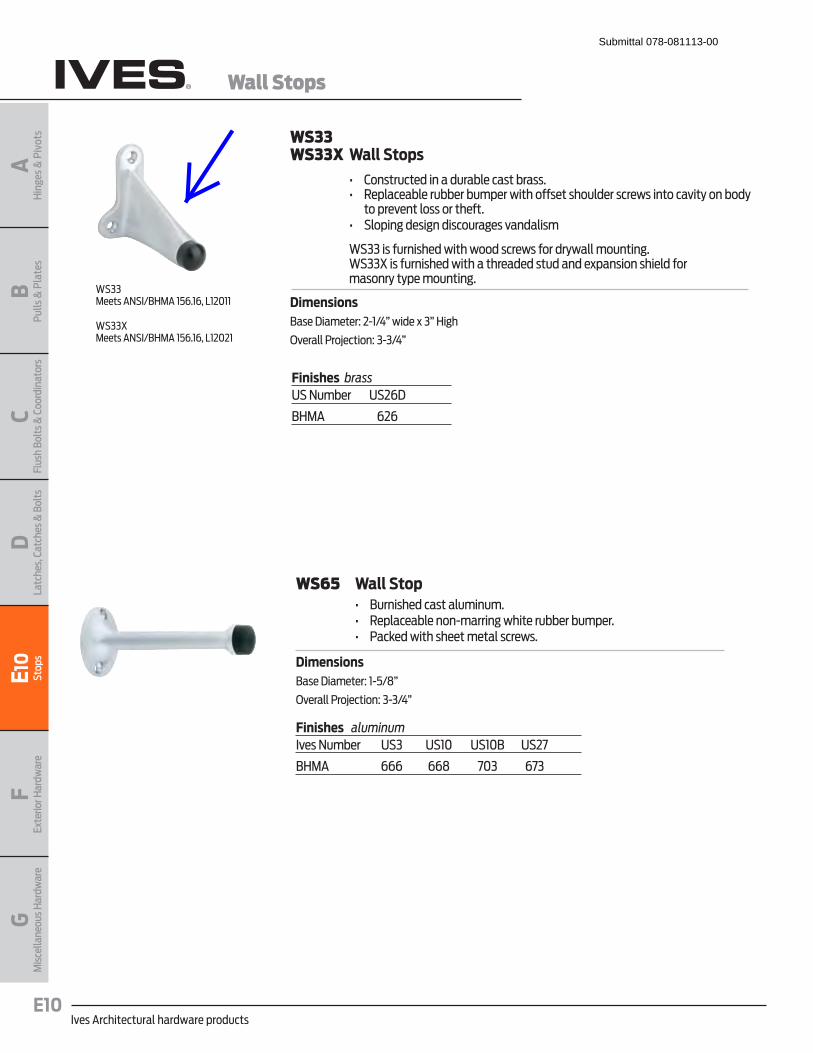
Ives Architectural hardware productsE10
Wall Stops
BPu
lls &
Pla
tes
AH
inge
s &
Piv
ots
CFl
ush
Bolt
s & C
oord
inat
ors
DLa
tche
s, C
atch
es &
Bol
tsE1
0St
ops
FEx
terio
r Har
dwar
eG
Mis
cella
neou
s Har
dwar
e
WS33WS33X Wall Stops
� � �� '������� ���������� ����������� � ��� � &�� �� ����� �����& ����������� �������� ����� ��������"�����������
to prevent loss or theft.� � ��� #��&���� ������������ ��"�����
WS33 is furnished with wood screws for drywall mounting. WS33X is furnished with a threaded stud and expansion shield for
masonry type mounting.
DimensionsBase Diameter: 2-1/4” wide x 3” High
Overall Projection: 3-3/4”
Finishes brassUS Number US26D
BHMA 626
WS33Meets ANSI/BHMA 156.16, L12011
WS33X Meets ANSI/BHMA 156.16, L12021
WS65 Wall Stop� � �� ������ �������������� � ��� � &�� �� ��!���������� ����� �����& ��� � ��� ��� ��������� ��� ������ ���
DimensionsBase Diameter: 1-5/8”
Overall Projection: 3-3/4”
Finishes aluminumIves Number US3 US10 US10B US27
BHMA 666 668 703 673
Submittal 078-081113-00

Glynn-Johnson offers a complete line of overhead door holders
and stops, accommodating virtually all openings with solutions
for even the most complex door control problems. These
concealed holders and stops provide the most attractive and
reliable heavy-duty door control available.
Glynn-Johnson 100 Series holders and stops provide the most
reliable and versatile concealed overhead door control. They
are designed for installation on virtually all types of doors
mounted on conventional type butt hinges, pivots, continuous
hinges, swing clear hinges and numerous other specialty
hinges. When used in conjunction with many surface-applied
door closers, 100 Series holders and stops provide the most
effective control for entrance doors and vestibule doors of all
types, as well as heavy or often used interior doors. Templates
provided allow for variable mounting positions, ranging from
85° - 110° of opening.
Five models:
� 100H Series hold-open model
� 100HP Series internal hold-open model
� 100F Series friction hold-open model
� 100S Series stop-only model
� 100SE Series special stop-only model
Six sizes:
� Each model comes in six sizes.
� Simple
� Standardized
Three options:
� ADJ—Adjustable jamb bracket
� CJ—Jamb Bracket for use with LCN 5030 closer
� SOC—Pin-in-socket security screw package
Unmatched convenience:
� Non-handed
� Improved compatibility with door closers
� Single/double-acting doors
� Interior/exterior applications
� Reduced door prep
� Durable
� Improved corrosion resistance
� Function conversion kits are available
Materials and finishes
In heavy gauge brass or 300 Series stainless steel, these
models offer the broadest range of finishes in the industry,
complementing any design and offering the highest
resistance to corrosion. Available in the following finishes:
Finishes DescriptionUS3 Polished brass
US4 Satin brass
US10 Satin bronze
US10B Oil rubbed bronze
US32 Polished stainless steel
US32D Satin stainless steel
SP4 Powder coat brass
SP10 Powder coat bronze
SP28 Powder coat aluminum
SP313 Powder coat dark bronze
SPBLK Powder coat black
ModelsThese models provide a wide range of optional features,
and are ideal for use on entrance and vestibule doors,
large doors, doors opened frequently, or doors subject to
abuse. These models are also furnished with an offset-
style jamb bracket.
Designed for heavy-duty applications, 100 Series models
will provide long-lasting protection to doors, frames,
hinges, related hardware and surrounding walls or
obstructions.
100H Series hold-open
(Suffix H) The hold-open function should be used where it
is desired to hold a door open at a predetermined position
for short or long periods of time, permitting an
unobstructed traffic flow through the opening.
These models are both selective and adjustable, featuring
the most reliable hold-open mechanism available. They
feature a control knob which protrudes from the face of
the door and turns the hold-open function on or off. Set in
the inactive position, the unit acts as a stop and shock
absorber. The tension on the hold-open mechanism can be
adjusted using an allen wrench to offset air currents or
other exterior conditions. The hold-open tension
adjustment is located in the bottom of the track in the top
of the door.
100 Series concealed overhead door holders/stopsSubmittal 078-081113-00
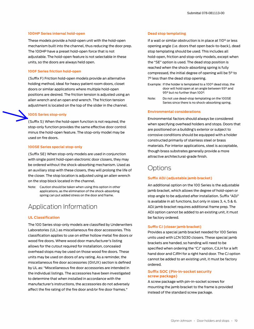
100HP Series internal hold-open
These models provide a hold-open unit with the hold-open
mechanism built into the channel, thus reducing the door prep.
The 100HP have a preset hold-open force that is not
adjustable. The hold-open feature is not selectable in these
units, so the doors are always held open.
100F Series friction hold-open
(Suffix F) Friction hold-open models provide an alternative
holding method, ideal for heavy patient room doors, closet
doors or similar applications where multiple hold-open
positions are desired. The friction tension is adjusted using an
allen wrench and an open end wrench. The friction tension
adjustment is located on the top of the slider in the channel.
100S Series stop-only
(Suffix S) When the hold-open function is not required, the
stop-only function provides the same effective door control
minus the hold-open feature. The stop-only model may be
used on fire doors.
100SE Series special stop-only
(Suffix SE) When stop-only models are used in conjunction
with single point hold-open electronic door closers, they may
be ordered without the shock-absorbing mechanism. Used as
an auxiliary stop with these closers, they will prolong the life of
the closer. The stop location is adjusted using an allen wrench
on the stop block located in the channel.
Note: Caution should be taken when using this option in other
applications, as the elimination of the shock-absorbing
spring can put added stress on the door and frame.
UL Classification
The 100 Series stop-only models are classified by Underwriters
Laboratories (UL) as miscellaneous fire door accessories. This
classification applies to use on either hollow metal fire doors or
wood fire doors. Where wood door manufacturer’s listing
allows for the cutout required for installation, concealed
overhead stops may be used on those wood fire doors. These
units may be used on doors of any rating. As a reminder, the
miscellaneous fire door accessories (GVUX) section is defined
by UL as: “Miscellaneous fire door accessories are intended in
the individual listings. The accessories have been investigated
to determine that when installed in accordance with the
manufacturer’s instructions, the accessories do not adversely
affect the fire rating of the fire door and/or fire door frames."
Dead stop templating
If a wall or similar obstruction is in place at 110° or less
opening angle (i.e. doors that open back-to-back), dead
stop templating should be used. This includes all
hold-open, friction and stop-only models, except when
the “SE” option is used. The dead stop position is
reached when the shock-absorbing spring is fully
compressed, the initial degree of opening will be 5° to
7° less than the dead stop opening.
Example: If the holder is templated to a 100° dead stop, the
door will hold open at an angle between 93° and
95° but no further than 100°.
Note: Do not use dead-stop templating on the 100SE
Series since there is no shock-absorbing spring.
Environmental considerations
Environmental factors should always be considered
when specifying overhead holders and stops. Doors that
are positioned on a building’s exterior or subject to
corrosive conditions should be equipped with a holder
constructed primarily of stainless steel or brass
materials. For interior applications, steel is acceptable,
though brass substrates generally provide a more
attractive architectural-grade finish.
Options
Suffix ADJ (adjustable jamb bracket)
An additional option on the 100 Series is the adjustable
jamb bracket, which allows the degree of hold-open or
stop angle to be adjusted after installation. Suffix “ADJ”
is available in all functions, but only in sizes 3, 4, 5 & 6.
ADJ jamb bracket requires additional frame prep. The
ADJ option cannot be added to an existing unit, it must
be factory ordered.
Suffix CJ (closer jamb bracket)Provides a special jamb bracket needed for 100 Series
units used with LCN 5030 closers. These special jamb
brackets are handed, so handing will need to be
specified when ordering the “CJ” option, CJLH for a left
hand door and CJRH for a right hand door. The CJ option
cannot be added to an existing unit, it must be factory
ordered.
Suffix SOC (Pin-in-socket security screw package)A screw package with pin-in-socket screws for
mounting the jamb bracket to the frame is provided
instead of the standard screw package.
Submittal 078-081113-00
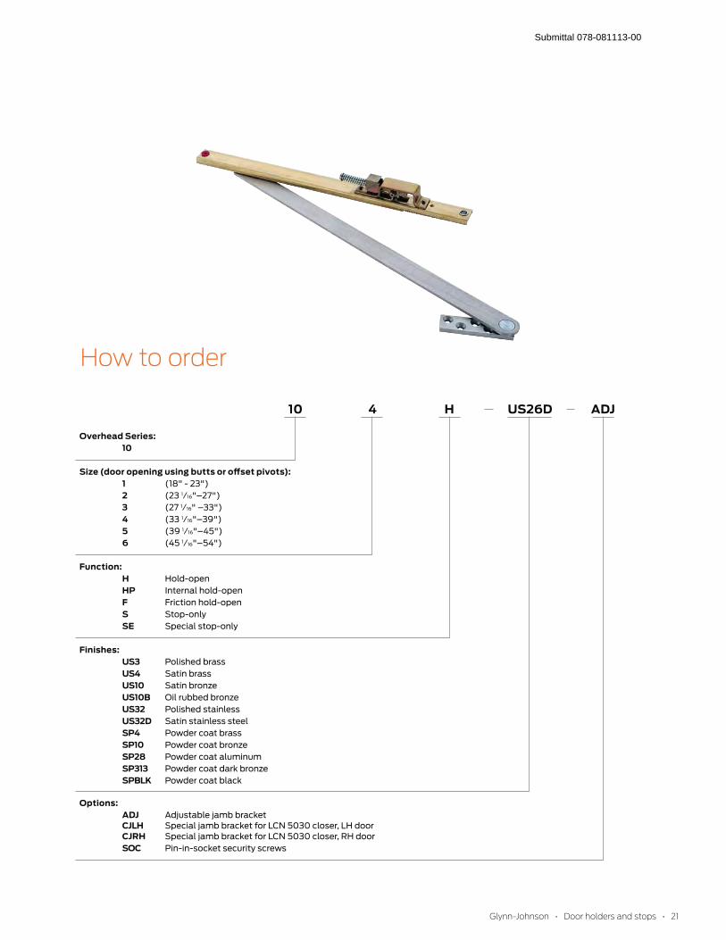
How to order
Overhead Series: 10
Size (door opening using butts or offset pivots): 1 (18" - 23")
2 (23 1⁄16"–27")
3 (27 1⁄16" –33")
4 (33 1⁄16"–39")
5 (39 1⁄16"–45")
6 (45 1⁄16"–54")
Function: H Hold-open
HP Internal hold-open
F Friction hold-open
S Stop-only
SE Special stop-only
Finishes: US3 Polished brass
US4 Satin brass US10 Satin bronze
US10B Oil rubbed bronze
US32 Polished stainless
US32D Satin stainless steel
SP4 Powder coat brass
SP10 Powder coat bronze
SP28 Powder coat aluminum
SP313 Powder coat dark bronze
SPBLK Powder coat black
Options: ADJ Adjustable jamb bracket
CJLH Special jamb bracket for LCN 5030 closer, LH door
CJRH Special jamb bracket for LCN 5030 closer, RH door
SOC Pin-in-socket security screws
10 4 H US26D ADJ
Submittal 078-081113-00

Ives Architectural hardware productsB14
Protection Plates
B14
Pulls
& P
late
sA
Hin
ges
& P
ivot
sC
Flus
h Bo
lts &
Coo
rdin
ator
sD
Latc
hes,
Cat
ches
& B
olts
E Stop
sF
Exte
rior H
ardw
are
GM
isce
llane
ous H
ardw
are
8400 Series Protection Plates � � �� J����&��� �����&�� ��� �"���� �����,������������������� ����
steel or aluminum; and 1/8” thick high impact polyethylene in clear or black.
� � �� � " �� �� ��&�������& ������*0������������� �� ��� � �� ���������� ��&��������� ���������(X���� ���& ��&����
Optional screw packs are available for TEK or TORK screw heads. Refer to the following chart for ordering.
� � �� #& �������$����������������� ��������"���� ���-*���� � �� #& �������$!|����������������� ��������� ��" �������"���� ���-*���� � �� #& �����'#��������� ���������������� ��� � �� #& �����0�#�&� && ������� K������������� ��� Kickplate Gasket Tape Tape is recommended when using a
brass plate on a metal door to reduce tarnishing from electrolytic oxidation. One tape pack will cover an the perimeters of a 8” x 34” kickplate. Order 8401 Gasket Tape.
8400 Protection Plate8402 (UL)* Protection Plate*UL mark appears in upper right corner. Factory supplied screws must be used.Number of screw packs required by plate size (specify TEK Screws or TORK screws).
22”-25” 26”-33” 34”-41” 42”-48”4”-8” 1 1 1 19”-16” 1 1 1 117”-24” 1 1 1 225”-32” 1 1 2 233”-40” 1 2 2 241”-48” 2 2 2 2
Finishes brass 24” x 48” max. sizeUS Number US3 US4 US10 US10B US15 US26 US26D
BHMA 605 606 612 613 619 625 626
Finishes stainless steelUS Number US32 US32D
BHMA 629 630
Finishes aluminumUS Number US28
BHMA 628
Finishes plasticClear and Black
Residential Grade Kickplates available Carded only, finishes PA28, PA3, PA619, PA716, B3, B505, B619, B716
Submittal 078-081113-00

Ives Architectural hardware productsB18
Protection Plates
B18
Pulls
& P
late
sA
Hin
ges
& P
ivot
sC
Flus
h Bo
lts &
Coo
rdin
ator
sD
Latc
hes,
Cat
ches
& B
olts
E Stop
sF
Exte
rior H
ardw
are
GM
isce
llane
ous H
ardw
are
Mop Plates � � �� ���� ����� ������������� �&������� ������������~ �������� ���
and mopping procedures. � � �� #�� ��� ��*�����X���������������*-�����
Kick Plates � � �� ���� ����� ������������� �&������� �������������~ ������
scuffing from foot traffic. � � ����� ���� � ������������������~ ������������� �
(especially doors using a closer). � � ��� #�� ��� ���-������*���������������*-�����
Stretcher Plates � � �� ���� ������������& ������� ���� � ������� �����������
made by stretchers, service carts or other equipment.� � �� �������&&�� �����&������� ������������ � �� #& �������*0���&��������� " � �� �� ��� � ��� #�� ��� ���X�����-���������������*-�����
Armor Plates � � �� ���� ������ ����������������������� ��������������
trucks and rough usage. � � ��� �������&&�� �����&������� �������� ����������������� ��
of double acting doors. � � ��� #�� ��� ����X�����*-���������������*-�����
Submittal 078-081113-00
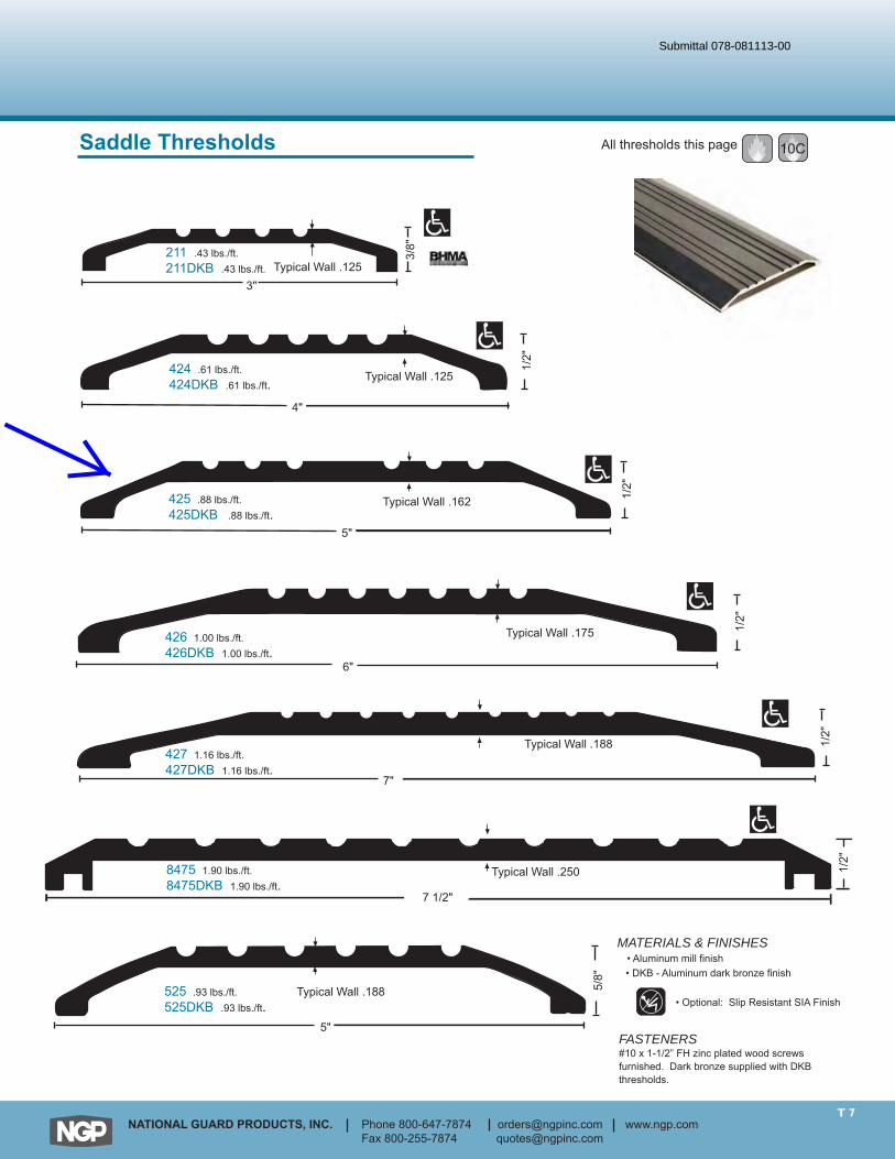
T 7NATIONAL GUARD PRODUCTS, INC. Phone 800-647-7874 [email protected] www.ngp.com
Fax 800-255-7874 [email protected]
Typical Wall .1253"
3/8"211 .43 lbs./ft.
211DKB .43 lbs./ft.
All thresholds this page 10C
4"
1/2"
Typical Wall .125
5"
1/2"
Typical Wall .162
Typical Wall .175
6"
1/2"
7"
1/2"
Typical Wall .188
424 .61 lbs./ft.424DKB .61 lbs./ft.
425 .88 lbs./ft.425DKB .88 lbs./ft.
426 1.00 lbs./ft.426DKB 1.00 lbs./ft.
427 1.16 lbs./ft.427DKB 1.16 lbs./ft.
Typical Wall .188
5"
5/8"
525 .93 lbs./ft.525DKB .93 lbs./ft.
1/2"
7 1/2"
Typical Wall .2508475 1.90 lbs./ft.8475DKB 1.90 lbs./ft.
FASTENERS#10 x 1-1/2” FH zinc plated wood screwsfurnished. Dark bronze supplied with DKBthresholds.
MATERIALS & FINISHES• Aluminum mill finish • DKB - Aluminum dark bronze finish
• Optional: Slip Resistant SIA Finish
Saddle Thresholds
Submittal 078-081113-00
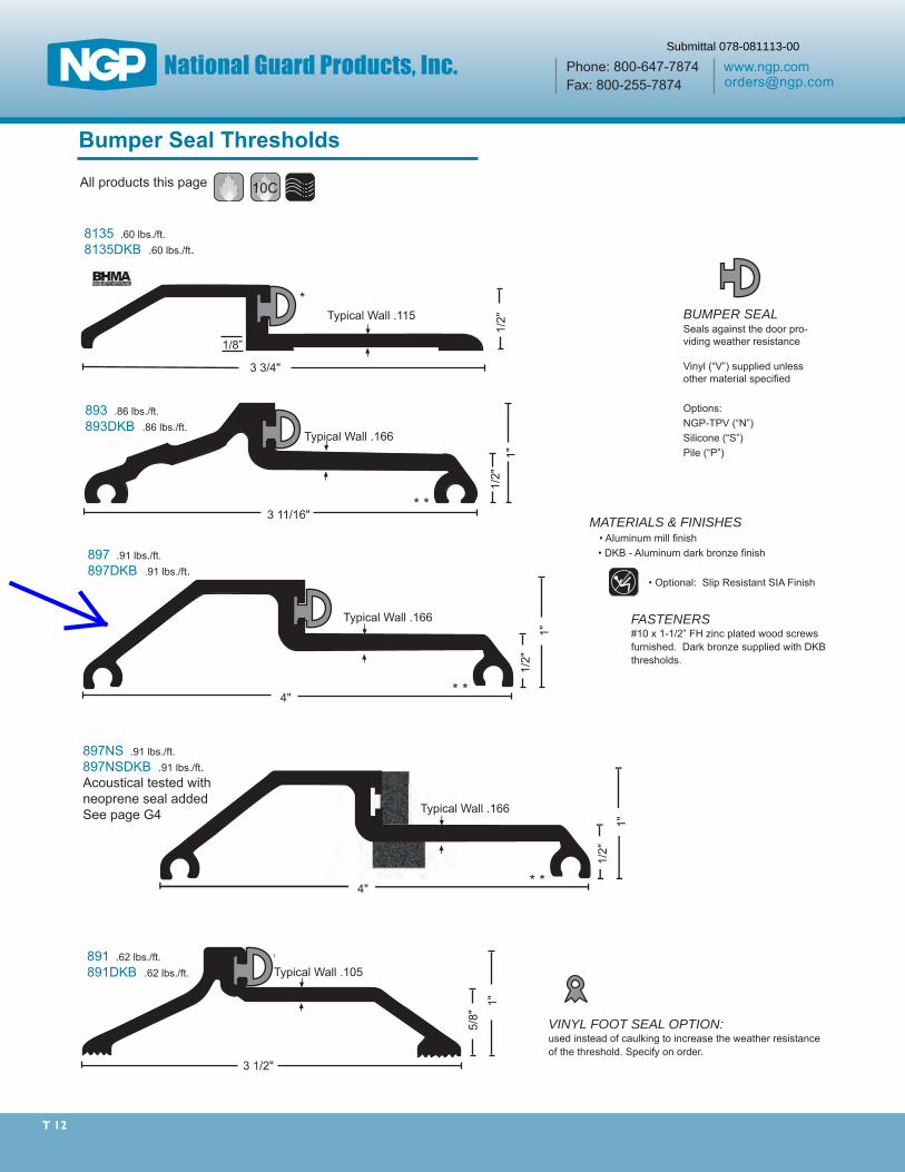
T 12
3 1/2"
5/8"
Typical Wall .105
1"
*
3 11/16"1/
2"1"
Typical Wall .166
* *
*
1"
4"
1/2"
Typical Wall .166
* *
*
8135 .60 lbs./ft.8135DKB .60 lbs./ft.
891 .62 lbs./ft.891DKB .62 lbs./ft.
893 .86 lbs./ft.893DKB .86 lbs./ft.
897 .91 lbs./ft.897DKB .91 lbs./ft.
10CAll products this page
Bumper Seal Thresholds
1"
4"
1/2"
Typical Wall .166
* *
*
897NS .91 lbs./ft.897NSDKB .91 lbs./ft.Acoustical tested with neoprene seal added See page G4
FASTENERS#10 x 1-1/2” FH zinc plated wood screwsfurnished. Dark bronze supplied with DKBthresholds.
VINYL FOOT SEAL OPTION:
used instead of caulking to increase the weather resistanceof the threshold. Specify on order.
MATERIALS & FINISHES• Aluminum mill finish • DKB - Aluminum dark bronze finish
• Optional: Slip Resistant SIA Finish
BUMPER SEALSeals against the door pro-viding weather resistance
Vinyl (“V”) supplied unlessother material specified
Options: NGP-TPV (“N”)Silicone (“S”)Pile (“P”)
3 3/4"
1/2"Typical Wall .115
*
1/8”
Submittal 078-081113-00
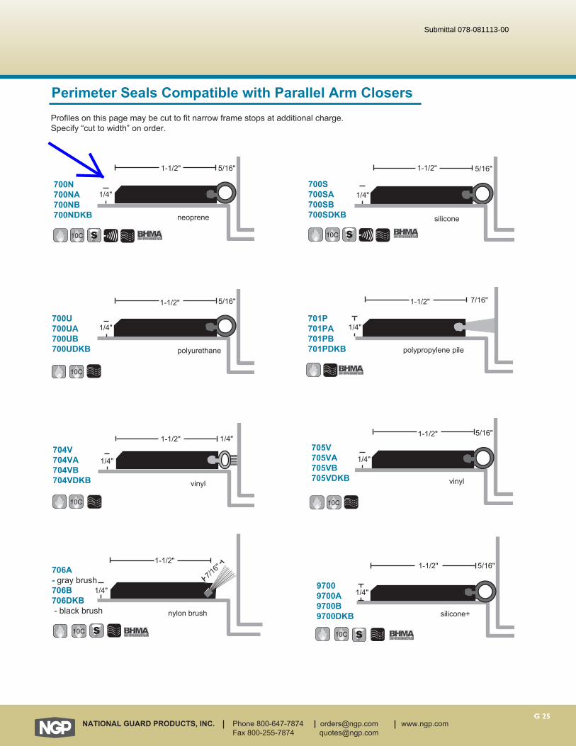
nylon brush
1-1/2"
7/16"
1/4"
G 25NATIONAL GUARD PRODUCTS, INC. Phone 800-647-7874 [email protected] www.ngp.com Fax 800-255-7874 [email protected]
neoprene
1-1/2" 5/16"
1/4"
polypropylene pile
1-1/2" 7/16"
1/4"
700N700NA700NB 700NDKB silicone
1-1/2" 5/16"
1/4"
polyurethane
1-1/2" 5/16"
1/4"701P701PA701PB 701PDKB
700S700SA700SB 700SDKB
700U700UA700UB 700UDKB
vinyl
1-1/2" 1/4"
1/4"
vinyl
1-1/2"
1/4"
5/16"
704V704VA704VB 704VDKB
705V705VA705VB 705VDKB
10C 10C
10C
10C 10C
97009700A9700B9700DKB
10C
Profiles on this page may be cut to fit narrow frame stops at additional charge. Specify “cut to width” on order.
706A- gray brush706B706DKB - black brush
10C
Perimeter Seals Compatible with Parallel Arm Closers
1/4"
1-1/2" 5/16"
silicone+
Submittal 078-081113-00
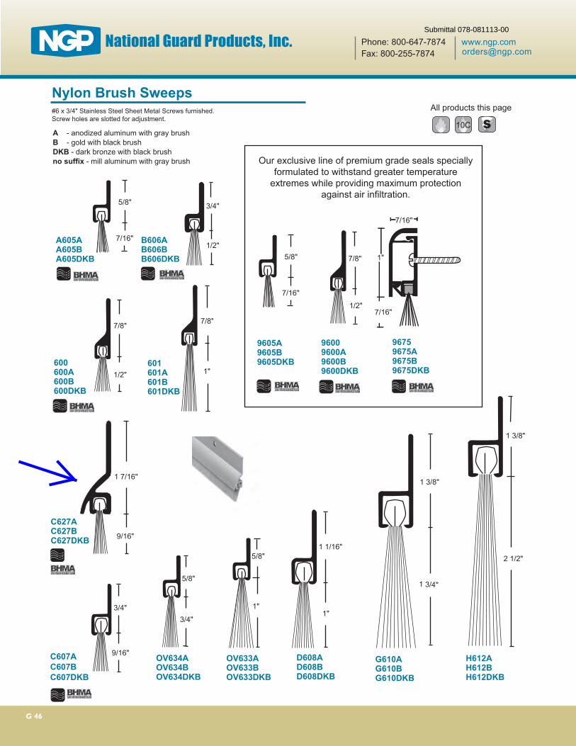
G 46
7/8"
1/2"600600A600B600DKB
3/4"
9/16"C607AC607BC607DKB
9/16"
1 7/16"
C627AC627BC627DKB
3/4"
1/2"B606AB606BB606DKB
1 1/16"
1"
D608AD608BD608DKB
1 3/8"
1 3/4"
G610AG610BG610DKB
2 1/2"
1 3/8"
H612AH612BH612DKB
Our exclusive line of premium grade seals specially formulated to withstand greater temperature
extremes while providing maximum protection against air infiltration.
5/8"
7/16"
7/8"
1/2"
All products this page
10C
96009600A9600B9600DKB
9605A9605B9605DKB
7/8"
1"601601A601B601DKB
5/8"
1"
OV633AOV633BOV633DKB
OV634AOV634BOV634DKB
#6 x 3/4" Stainless Steel Sheet Metal Screws furnished. Screw holes are slotted for adjustment.
A - anodized aluminum with gray brush B - gold with black brushDKB - dark bronze with black brushno suffix - mill aluminum with gray brush
Nylon Brush Sweeps
5/8"
7/16"A605AA605BA605DKB 1"
7/16"
7/16"
96759675A9675B9675DKB
5/8"
3/4"
Submittal 078-081113-00
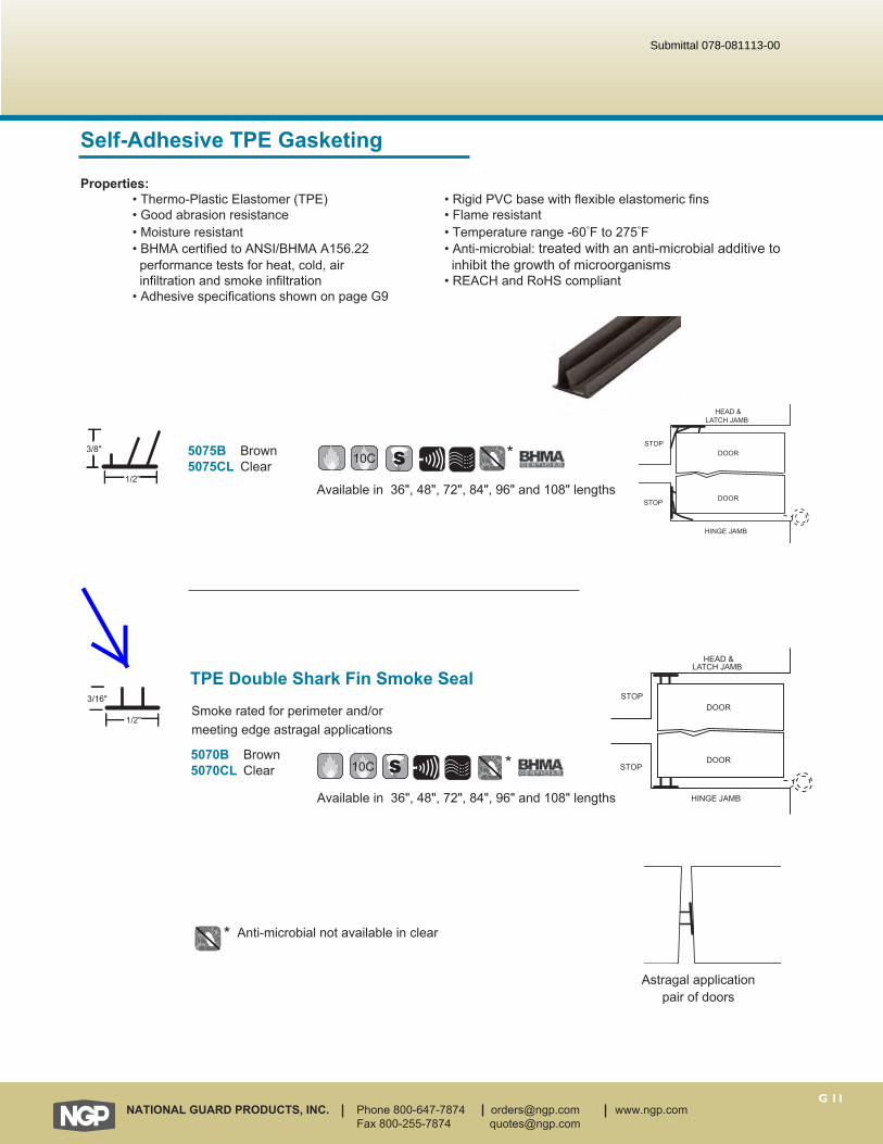
G 11NATIONAL GUARD PRODUCTS, INC. Phone 800-647-7874 [email protected] www.ngp.com Fax 800-255-7874 [email protected]
5070B Brown5070CL Clear
1/2"
3/16"
Available in 36", 48", 72", 84", 96" and 108" lengths
10C
HEAD &LATCH JAMB
STOP
STOP
HINGE JAMB
DOOR
DOOR
TPE Double Shark Fin Smoke SealSmoke rated for perimeter and/or meeting edge astragal applications
M
RSA
*
Self-Adhesive TPE Gasketing
Properties: • Thermo-Plastic Elastomer (TPE) • Rigid PVC base with flexible elastomeric fins • Good abrasion resistance • Flame resistant • Moisture resistant • Temperature range -60°F to 275°F • BHMA certified to ANSI/BHMA A156.22 • Anti-microbial: treated with an anti-microbial additive to performance tests for heat, cold, air inhibit the growth of microorganisms infiltration and smoke infiltration • REACH and RoHS compliant • Adhesive specifications shown on page G9
5075B Brown5075CL Clear
1/2"
3/8"
Available in 36", 48", 72", 84", 96" and 108" lengths
10C
HEAD &LATCH JAMB
STOP
STOP
HINGE JAMB
DOOR
DOOR
M
RSA
* Anti-microbial not available in clear
M
RSA
*
Astragal applicationpair of doors
Submittal 078-081113-00

Pem
ko A
dhes
ive
Gas
keti
ng
800-824-3018 | www.pemko.com Check the web site for the up-to-date catalog
Copyright © 2015-2017, Pemko Manufacturing Co., an ASSA ABLOY Group company. All rights reserved. Reproduction in whole or in part without the express written permission of Pemko Manufacturing Co. is prohibited.
SiliconSeal Adhesive-Backed Fire/Smoke Gasketing
S44_AVAILABLE FINISHES: BL, C, D, GR, WAVAILABLE LENGTHS: 17', 18' 20', 21', 25', 30', 204', 510'ANSI: R0E154, R0E155• Designed for tighter frames • Demonstrates extremely low closing force• Seal begins compressing at 5/16"; compresses
to seal up to a 1/16" gap
S77_AVAILABLE FINISHES: BL, C, D, WAVAILABLE LENGTHS: 17', 18', 20', 21', 25', 30', 204', 500'ANSI: R0E154, R0E155• Designed for hollow metal and wood
meeting stile applications• Seal begins compressing at 5/16";
compresses to seal up to a 1/16" gap
AVAILABLE FINISHES FOR PRODUCTS SHOWN ON THIS PAGE (see General Information section for finish chart)BL (Black) C (Clear) D (Dark Brown) GR (Light Gray) TAN (Tan) W (White)
S88_AVAILABLE FINISHES: BL, C, D, GR, TAN, WAVAILABLE LENGTHS: 17', 18', 20', 21', 25', 30', 204', 510'ANSI: R0E154, R0E155• Seal begins compressing at 1/4";
compresses to seal up to a 1/16" gap
Application is acceptable anywhere along jamb face**S44 shown, but application detail applies to PK33, PK55, S442, S77, S88, S773, and S776 also.
Strike JambHeaderHinge Jamb• SiliconSeal is extruded from high-temperature
silicone; effective between -58°F and 450°F• Self-extinguishing and non-toxic; unaffected by
sunlight, ozone, and ultraviolet rays • Impervious to fungus and mildew; will not deteriorate
under normal exposure• Meets FAR 25.853 Airworthiness Standards for
Compartment Interiors
S773_AVAILABLE FINISHES: BL, D, GR, WAVAILABLE LENGTHS: 17’, 18’, 20’, 21’, 25’, 30', 250', 500'ANSI: R0E154, R0E155• Triple-fin design effectively blocks light
and sound from infiltrating a room• Seal begins compressing at 3/8"; compresses
to seal up to a 1/16" gap
S776_AVAILABLE FINISHES: BLAVAILABLE LENGTHS: 17', 18', 20', 21', 25', 30'ANSI: R0E154, R0E155• Designed for hollow metal and
wood meeting stile applications• Seal begins compressing at 3/8";
compresses to seal up to a 1/16" gap
S442_ AVAILABLE FINISHES: BL, D, GR, WAVAILABLE LENGTHS: 17', 18', 20', 21', 25', 30', 510'ANSI: R0E154, R0E155• Fits flush into corner • Seal begins compressing at 5/16";
compresses to seal up to a 1/16" gap in either direction
Submittal 078-081113-00
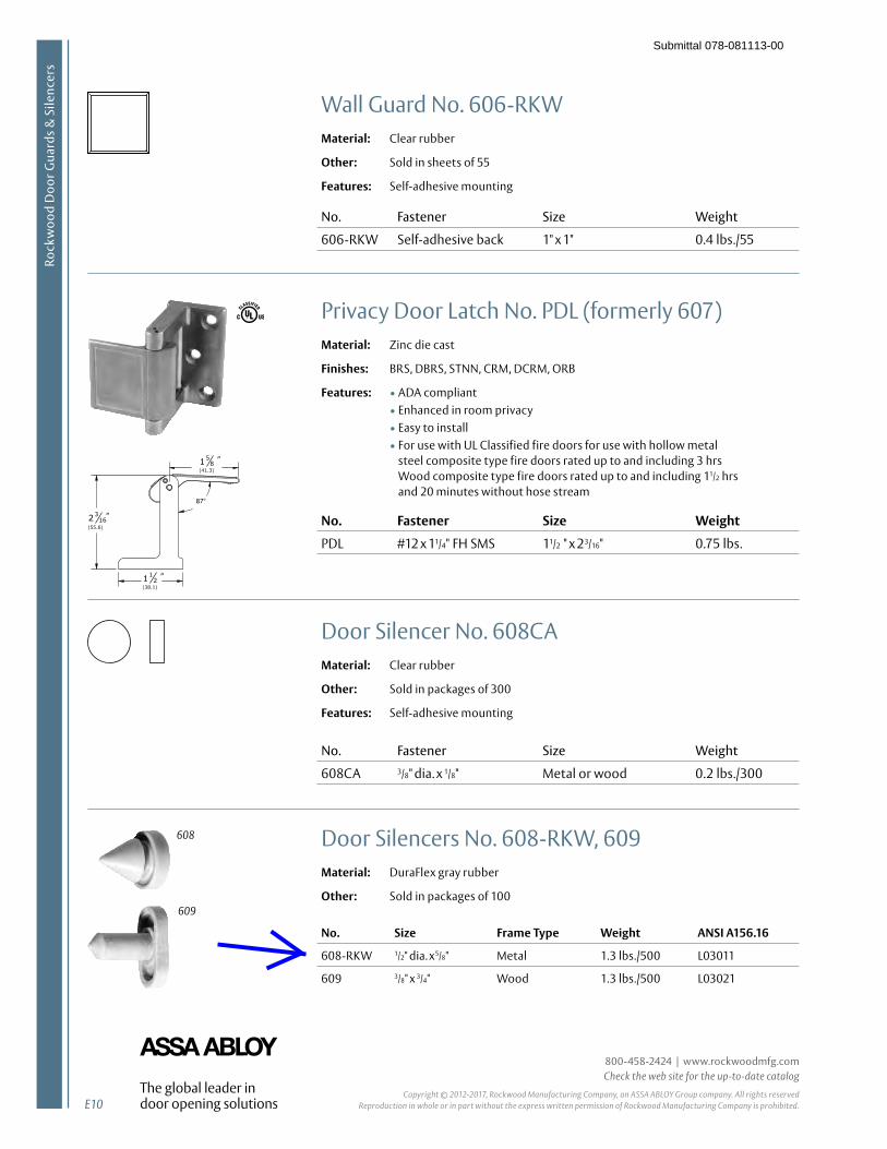
E10
800-458-2424 | www.rockwoodmfg.com Check the web site for the up-to-date catalog
Copyright © 2012-2017, Rockwood Manufacturing Company, an ASSA ABLOY Group company. All rights reserved Reproduction in whole or in part without the express written permission of Rockwood Manufacturing Company is prohibited.
Rock
woo
d D
oor G
uard
s & S
ilenc
ers
Door Silencers No. 608-RKW, 609Material: DuraFlex gray rubber
Other: Sold in packages of 100
No. Size Frame Type Weight ANSI A156.16
608-RKW 1/2" dia. x5/8" Metal 1.3 lbs./500 L03011
609 3/8" x 3/4" Wood 1.3 lbs./500 L03021
Door Silencer No. 608CAMaterial: Clear rubber
Other: Sold in packages of 300
Features: Self-adhesive mounting
No. Fastener Size Weight
608CA 3/8" dia. x 1/8" Metal or wood 0.2 lbs./300
Wall Guard No. 606-RKWMaterial: Clear rubber
Other: Sold in sheets of 55
Features: Self-adhesive mounting
No. Fastener Size Weight
606-RKW Self-adhesive back 1" x 1" 0.4 lbs./55
Privacy Door Latch No. PDL (formerly 607)Material: Zinc die cast
Finishes: BRS, DBRS, STNN, CRM, DCRM, ORB
Features: • ADA compliant• Enhanced in room privacy• Easy to install• For use with UL Classified fire doors for use with hollow metal
steel composite type fire doors rated up to and including 3 hrs Wood composite type fire doors rated up to and including 11/2 hrs and 20 minutes without hose stream
No. Fastener Size Weight
PDL #12 x 11/4" FH SMS 11/2 " x 23/16" 0.75 lbs.
608
609
Submittal 078-081113-00

G 55NATIONAL GUARD PRODUCTS, INC. Phone 800-647-7874 [email protected] www.ngp.com Fax 800-255-7874 [email protected]
Rain Drip Guards
2-1/2"
1-1/2"
5/8"
3/4"
1-1/2"
16A16B16DKB
1717B17DKB
#6 x 3/4" Stainless Steel SMS furnished
#6 x 3/4" Stainless Steel SMS furnished.Screw holes slotted for adjustment.Maximum length 144"
Magnetic Seals
Cushion Bronze Weatherstrip
159MA159MB159MDKB
METALDOOR
5/8"
Frame Stop
Head and Lock Jamb
43CB9/16"
1-1/8"
Cushion material will not coil. Specify lengths required (36", 48", 72" 86", and 96".) Nails not included. Normal installation requires 3/4 lb. of nails per 100 ft. of weatherstrip; install 2" o.c. Zinc plated bronze finish nails available in 1 lb. bags. Wafer head pilot point drive nails make excellent applications for metal jambs, normal installation re-quires 6 per foot. Install using #41 drill bit. Available with Fast Attach Tape - Specify x “FATT”.
10C
157MA157MDKB 10C
magnet encased in gray vinyl
magnet encased in brown vinyl
A - anodized aluminumB - gold DKB - dark bronzeNo Suffix - mll aluminum
DOOR
HINGEJAMB
#18Nail
DOOR
1-1/4"
5/8"
Frame Stop
Hinge Side
1/2"
Head and Lock Jamb
METALDOOR
DOOR
7/8"
1/2"
Frame Stop
Hinge Side
Submittal 078-081113-00
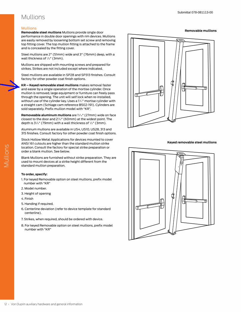
Mullions
Mu
llio
ns
12 • Von Duprin auxiliary hardware and general information
MullionsRemovable steel mullions Mullions provide single door
performance in double door openings with rim devices. Mullions
are easily removed by loosening bottom set screw and removing
top fitting cover. The top mullion fitting is attached to the frame
and is concealed by the fitting cover.
Steel mullions are 2" (51mm) wide and 3" (76mm) deep, with a
wall thickness of 1/8" (3mm).
Mullions are shipped with mounting screws and prepared for
strikes. Strikes are not included except where indicated.
Steel mullions are available in SP28 and SP313 finishes. Consult
factory for other powder coat finish options.
KR – Keyed removable steel mullions makes removal faster
and easier by a single operation of the mortise cylinder. Once
mullion is removed, large equipment or furniture can freely pass
through the opening. The unit will self lock when re-installed,
without use of the cylinder key. Uses a 11/4" mortise cylinder with
a straight cam (Schlage cam reference B502-191). Cylinders are
sold separately. Prefix mullion model with “KR”.
Removeable aluminum mullions are 11/16" (27mm) wide on face
closest to the door and 23/8" (60mm) at the widest point. The
depth is 31/8" (79mm) with a wall thickness of 1/8" (3mm).
Aluminum mullions are available in US4, US10, US28, 313 and
315 finishes. Consult factory for other powder coat finish options.
Stock Hollow Metal Applications for devices mounted to cover
ANSI 161 cutouts are higher than the standard mullion strike
location. Consult the factory for special strike preparation or
order a blank mullion. See below.
Blank Mullions are furnished without strike preparation. They are
used to mount devices at a strike height different from the
standard mullion preparation.
To order, specify:1. For keyed Removable option on steel mullions, prefix model
number with “KR”
2. Model number.
3. Height of opening
4. Finish
5. Handing if required.
6. Centerline deviation (refer to device template for standard
centerline).
7. Strikes, when required, should be ordered with device.
8. For keyed Removable option on steel mullions, prefix model
number with “KR”
Removable mullions
Keyed removable steel mullions
Submittal 078-081113-00
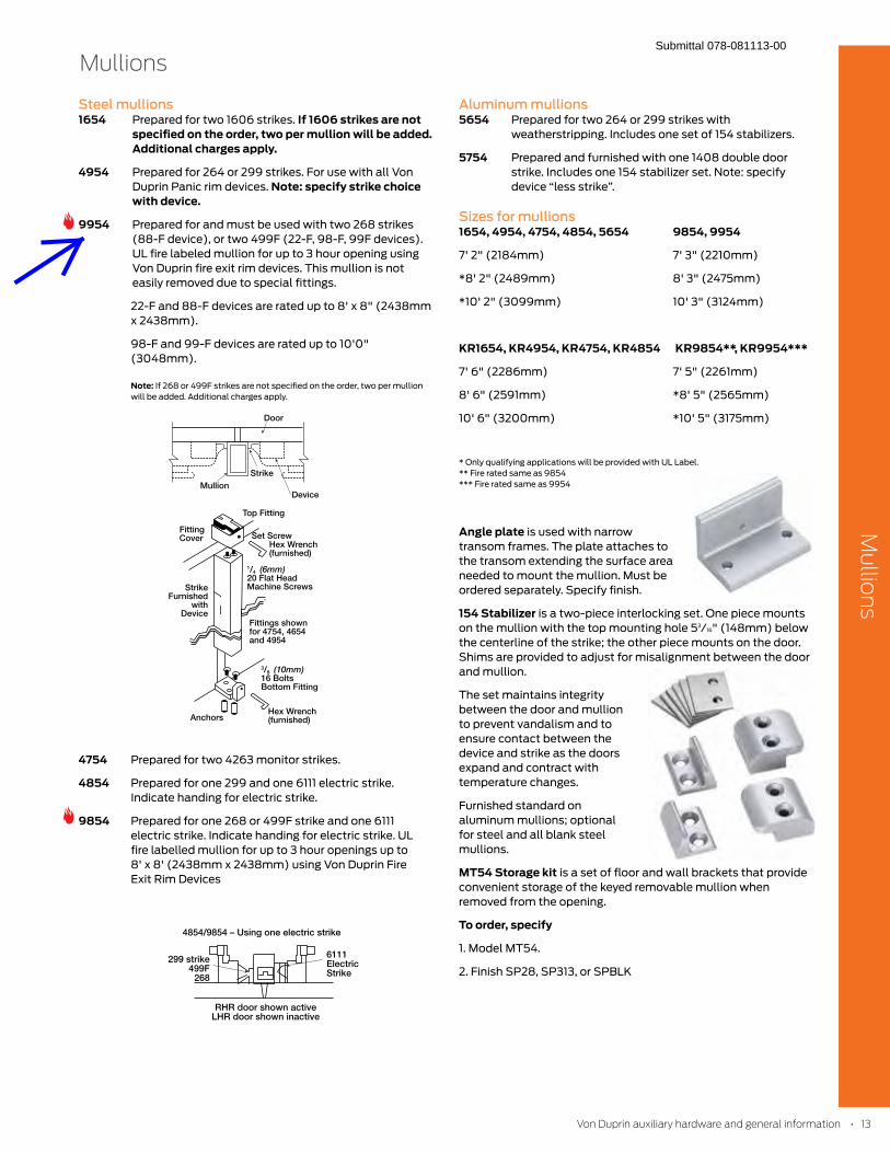
Mullions
Mu
llion
s
Steel mullions1654 Prepared for two 1606 strikes. If 1606 strikes are not
specified on the order, two per mullion will be added. Additional charges apply.
4954 Prepared for 264 or 299 strikes. For use with all Von
Duprin Panic rim devices. Note: specify strike choice with device.
9954 Prepared for and must be used with two 268 strikes
(88-F device), or two 499F (22-F, 98-F, 99F devices).
UL fire labeled mullion for up to 3 hour opening using
Von Duprin fire exit rim devices. This mullion is not
easily removed due to special fittings.
22-F and 88-F devices are rated up to 8' x 8" (2438mm
x 2438mm).
98-F and 99-F devices are rated up to 10'0"
(3048mm).
Note: If 268 or 499F strikes are not specified on the order, two per mullion
will be added. Additional charges apply.
4754 Prepared for two 4263 monitor strikes.
4854 Prepared for one 299 and one 6111 electric strike.
Indicate handing for electric strike.
9854 Prepared for one 268 or 499F strike and one 6111
electric strike. Indicate handing for electric strike. UL
fire labelled mullion for up to 3 hour openings up to
8' x 8' (2438mm x 2438mm) using Von Duprin Fire
Exit Rim Devices
Aluminum mullions5654 Prepared for two 264 or 299 strikes with
weatherstripping. Includes one set of 154 stabilizers.
5754 Prepared and furnished with one 1408 double door
strike. Includes one 154 stabilizer set. Note: specify
device “less strike”.
Sizes for mullions1654, 4954, 4754, 4854, 5654 9854, 9954
7' 2" (2184mm) 7' 3" (2210mm)
*8' 2" (2489mm) 8' 3" (2475mm)
*10' 2" (3099mm) 10' 3" (3124mm)
KR1654, KR4954, KR4754, KR4854 KR9854**, KR9954***
7' 6" (2286mm) 7' 5" (2261mm)
8' 6" (2591mm) *8' 5" (2565mm)
10' 6" (3200mm) *10' 5" (3175mm)
* Only qualifying applications will be provided with UL Label.
** Fire rated same as 9854
*** Fire rated same as 9954
Angle plate is used with narrow
transom frames. The plate attaches to
the transom extending the surface area
needed to mount the mullion. Must be
ordered separately. Specify finish.
154 Stabilizer is a two-piece interlocking set. One piece mounts
on the mullion with the top mounting hole 53/16" (148mm) below
the centerline of the strike; the other piece mounts on the door.
Shims are provided to adjust for misalignment between the door
and mullion.
The set maintains integrity
between the door and mullion
to prevent vandalism and to
ensure contact between the
device and strike as the doors
expand and contract with
temperature changes.
Furnished standard on
aluminum mullions; optional
for steel and all blank steel
mullions.
MT54 Storage kit is a set of floor and wall brackets that provide
convenient storage of the keyed removable mullion when
removed from the opening.
To order, specify
1. Model MT54.
2. Finish SP28, SP313, or SPBLK
Von Duprin auxiliary hardware and general information • 13
Submittal 078-081113-00
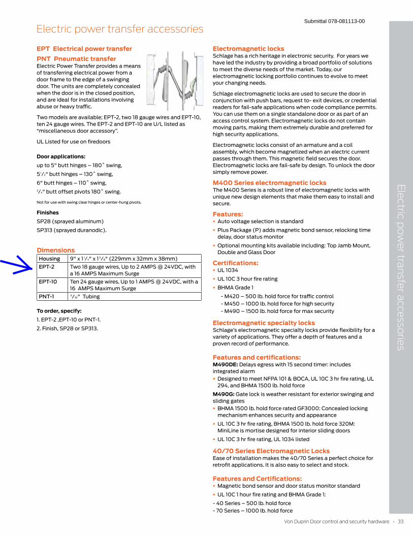
Von Duprin Door control and security hardware • 33
Ele
ctric po
wer tra
nsfer a
ccesso
ries
Electric power transfer accessories
Electromagnetic locksSchlage has a rich heritage in electronic security. For years we
have led the industry by providing a broad portfolio of solutions
to meet the diverse needs of the market. Today, our
electromagnetic locking portfolio continues to evolve to meet
your changing needs.
Schlage electromagnetic locks are used to secure the door in
conjunction with push bars, request to- exit devices, or credential
readers for fail-safe applications when code compliance permits.
You can use them on a single standalone door or as part of an
access control system. Electromagnetic locks do not contain
moving parts, making them extremely durable and preferred for
high security applications.
Electromagnetic locks consist of an armature and a coil
assembly, which become magnetized when an electric current
passes through them. This magnetic field secures the door.
Electromagnetic locks are fail-safe by design. To unlock the door
simply remove power.
M400 Series electromagnetic locksThe M400 Series is a robust line of electromagnetic locks with
unique new design elements that make them easy to install and
secure.
Features: � Auto voltage selection is standard
� Plus Package (P) adds magnetic bond sensor, relocking time
delay, door status monitor
� Optional mounting kits available including: Top Jamb Mount,
Double and Glass Door
Certifications: � UL 1034
� UL 10C 3 hour fire rating
� BHMA Grade 1
- M420 – 500 lb. hold force for traffic control
- M450 – 1000 lb. hold force for high security
- M490 – 1500 lb. hold force for max security
Electromagnetic specialty locksSchlage’s electromagnetic specialty locks provide flexibility for a
variety of applications. They offer a depth of features and a
proven record of performance.
Features and certifications:M490DE: Delays egress with 15 second timer: includes
integrated alarm
� Designed to meet NFPA 101 & BOCA, UL 10C 3 hr fire rating, UL
294, and BHMA 1500 lb. hold force
M490G: Gate lock is weather resistant for exterior swinging and
sliding gates
� BHMA 1500 lb. hold force rated GF3000: Concealed locking
mechanism enhances security and appearance
� UL 10C 3 hr fire rating, BHMA 1500 lb. hold force 320M:
MiniLine is mortise designed for interior sliding doors
� UL 10C 3 hr fire rating, UL 1034 listed
40/70 Series Electromagnetic LocksEase of installation makes the 40/70 Series a perfect choice for
retrofit applications. It is also easy to select and stock.
Features and Certifications: � Magnetic bond sensor and door status monitor standard
� UL 10C 1 hour fire rating and BHMA Grade 1:
- 40 Series – 500 lb. hold force
- 70 Series – 1000 lb. hold force
EPT Electrical power transferPNT Pneumatic transferElectric Power Transfer provides a means
of transferring electrical power from a
door frame to the edge of a swinging
door. The units are completely concealed
when the door is in the closed position,
and are ideal for installations involving
abuse or heavy traffic.
Two models are available; EPT-2, two 18 gauge wires and EPT-10,
ten 24 gauge wires. The EPT-2 and EPT-10 are U/L listed as
“miscellaneous door accessory”.
UL Listed for use on firedoors
Door applications:up to 5" butt hinges – 180˚ swing,
5 1/2" butt hinges – 130˚ swing,
6" butt hinges – 110˚ swing,
3/4" butt offset pivots 180˚ swing.
Not for use with swing clear hinges or center-hung pivots.
FinishesSP28 (sprayed aluminum)
SP313 (sprayed duranodic).
DimensionsHousing 9" x 1 1/4" x 1 5/8" (229mm x 32mm x 38mm)
EPT-2 Two 18 gauge wires, Up to 2 AMPS @ 24VDC, with
a 16 AMPS Maximum Surge
EPT-10 Ten 24 gauge wires, Up to 1 AMPS @ 24VDC, with a
16 AMPS Maximum Surge
PNT-1 5/32" Tubing
To order, specify:1. EPT-2 ,EPT-10 or PNT-1.
2. Finish, SP28 or SP313.
Submittal 078-081113-00

Submittal 078-081113-00
USE HES SERIES 4500 PER SPECIFICATIONS
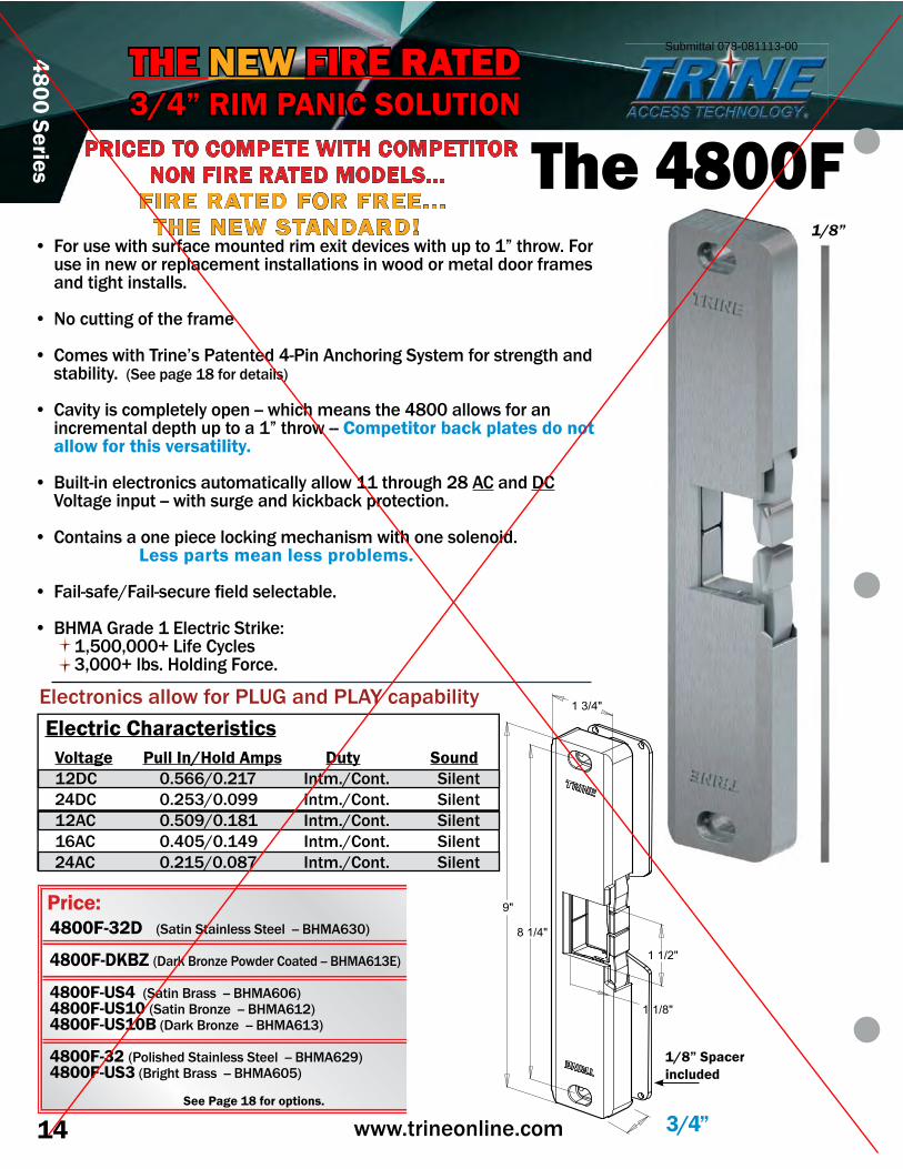
14 www.trineonline.com
4800 Series
• For use with surface mounted rim exit devices with up to 1” throw. For use in new or replacement installations in wood or metal door frames and tight installs.
• No cutting of the frame
• Comes with Trine’s Patented 4-Pin Anchoring System for strength and stability. �������������� ���������
• Cavity is completely open -- which means the 4800 allows for an incremental depth up to a 1” throw -- Competitor back plates do not allow for this versatility.
• Built-in electronics automatically allow 11 through 28 AC and DC ������������������������ ����������������� ���������
• ��������������������������������������������������������� Less parts mean less problems.
• !��������"!�������� ��#���������������
• $%&'�( �����)���� ����� ���* 1,500,000+ Life Cycles 3,000+ lbs. Holding Force.
3/4”
9"
8 1/4"
1 3/4"
1 1/2"
1 1/8"
1/8”
1/8” Spacerincluded
Electronics allow for PLUG and PLAY capability
THE NEW FIRE RATED3/4” RIM PANIC SOLUTION
The 4800F
Electric CharacteristicsVoltage Pull In/Hold Amps Duty Sound12DC 0.566/0.217 Intm./Cont. Silent24DC 0.253/0.099 Intm./Cont. Silent12AC 0.509/0.181 Intm./Cont. Silent16AC 0.405/0.149 Intm./Cont. Silent24AC 0.215/0.087 Intm./Cont. Silent
1/8”
See Page 18 for options.
4800F-32D ���������������������������$%&':;<�
4800F-DKBZ �=� ��$ ��>��?���� �����������$%&':;)�
4800F-US4 �������$ ��������$%&':<:�4800F-US10 �������$ ��>������$%&':@�4800F-US10B��=� ��$ ��>������$%&':;�
4800F-32 �?����������������������������$%&':@J��4800F-US3��$ �����$ ��������$%&':<K�
PRICED TO COMPETE WITH COMPETITOR NON FIRE RATED MODELS...
FIRE RATED FOR FREE...THE NEW STANDARD!
Price:$484.00
$499.00
$550.00
$569.00
Submittal 078-081113-00
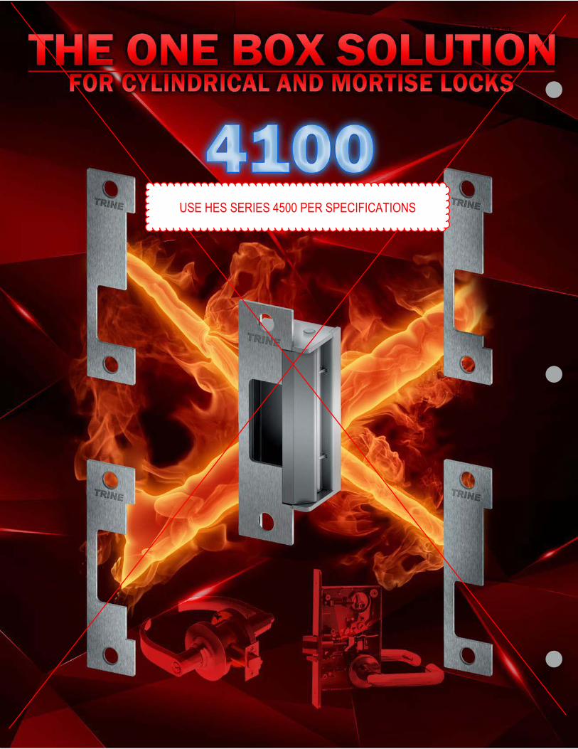
Submittal 078-081113-00
USE HES SERIES 4500 PER SPECIFICATIONS
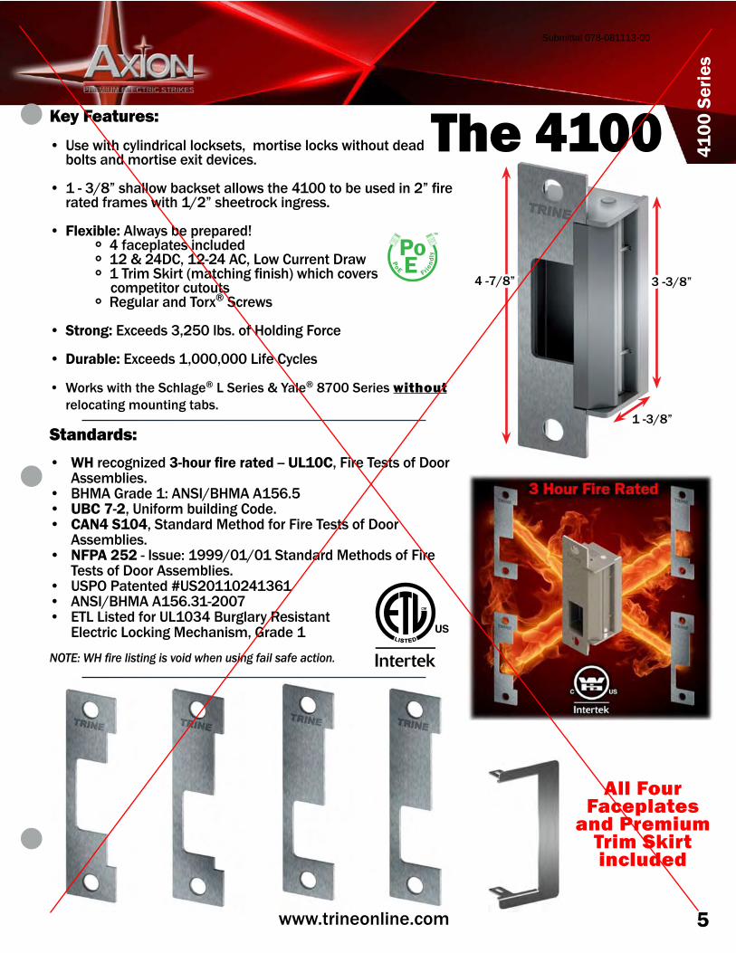
5www.trineonline.com
4100
Ser
ies
lit i
Key Features:
• M���������O���� �������������Q���� ������������������������bolts and mortise exit devices.
• ���;"R����������������������������V<<���������������@R�# �� ������ ����������"@R������ ������� ����
• Flexible: Always be prepared! ° 4 faceplates included ° 12 & 24DC, 12-24 AC, Low Current Draw ° �Z ������ ������������#��������������[� ��� competitor cutouts ° Regular and Torx® Screws
• Strong: Exceeds 3,250 lbs. of Holding Force
• Durable: Exceeds 1,000,000 Life Cycles
• ]� �������������������® L Series & Yale® 8700 Series without relocating mounting tabs.
Standards:
• WH recognized ������������ -- UL10C, Fire Tests of Door Assemblies.
• BHMA Grade 1: ANSI/BHMA A156.5• UBC 7-2, Uniform building Code.• CAN4 S104, Standard Method for Fire Tests of Door
Assemblies.• NFPA 252 - Issue: 1999/01/01 Standard Methods of Fire
Tests of Door Assemblies.• USPO Patented #US20110241361• ANSI/BHMA A156.31-2007• ETL Listed for UL1034 Burglary Resistant
)���� ���k�������&��������Q�( ����
����������� ����������������������������� �������������
All Four Faceplates
and Premium Trim Skirt included
The 4100
3 -3/8”4 -7/8”
1 -3/8”
Submittal 078-081113-00
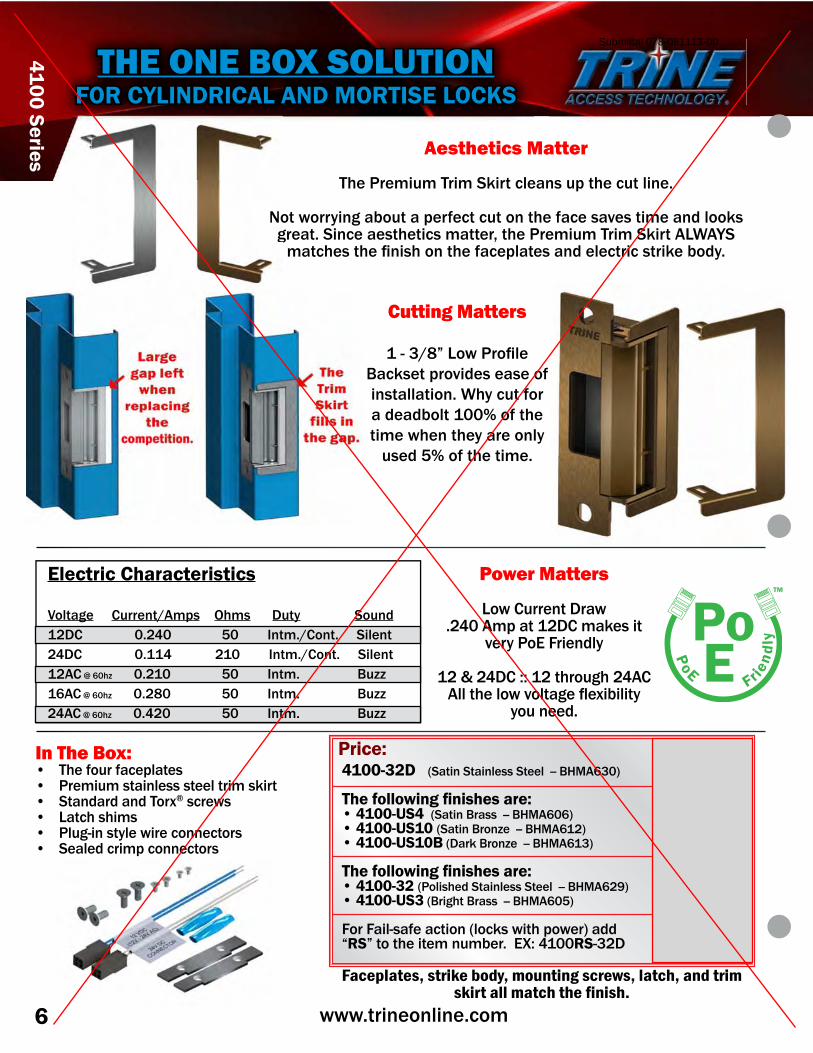
6 www.trineonline.com
4100 Series
Power Matters
Low Current Draw�@V<�'������@=�����������
very PoE Friendly
12 & 24DC :: 12 through 24AC'�����������[�������q�{������O�
you need.
Cutting Matters
���;"R�k���? �#���$�������� �[�������������installation. Why cut for a deadbolt 100% of the time when they are only
used 5% of the time.
Aesthetics Matter
Z���? ������Z ������ �������������������������
~����� O�������������� �����������������������[������������������� ��������������������������� Q�����? ������Z ������ ��'k]'���
������������#�������������������������������� ����� �������O�
Faceplates, strike body, mounting screws, latch, and trim ��������������� �������
4100-32D ���������������������������$%&':;<�
����������������������• 4100-US4 �������$ ��������$%&':<:�• 4100-US10 �������$ ��>������$%&':@�• 4100-US10B��=� ��$ ��>������$%&':;��
����������������������• 4100-32 �?����������������������������$%&':@J�• 4100-US3��$ �����$ ��������$%&':<K�
!� �!�������������������������������� ������“RS” to the item number. EX: 4100RS-32D
In The Box:• The four faceplates• ? ����������������������� ������ �• Standard and Torx® screws• Latch shims• Plug-in style wire connectors• Sealed crimp connectors
Electric Characteristics
Voltage Current/Amps Ohms Duty Sound12DC 0.240 50 Intm./Cont. Silent24DC 0.114 210 Intm./Cont. Silent12AC @ 60hz 0.210 50 Intm. Buzz16AC @ 60hz 0.280 50 Intm. Buzz24AC @ 60hz 0.420 50 Intm. Buzz
THE ONE BOX SOLUTIONFOR CYLINDRICAL AND MORTISE LOCKS
~��
Price:
$492.00
$572.00
$639.00
RS price same as above.
Submittal 078-081113-00
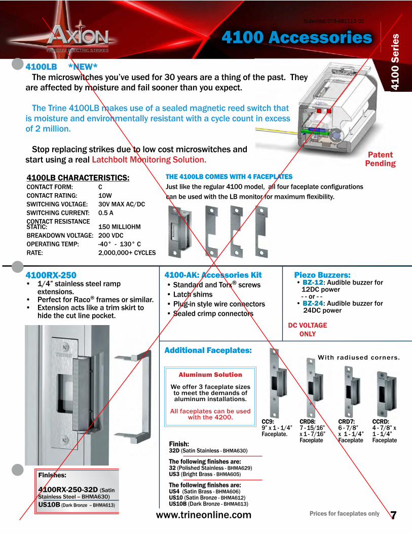
7www.trineonline.com
4100
Ser
ies
4100RX-250• 1/4” stainless steel ramp
extensions.• Perfect for Raco® frames or similar.• ){��������������������� ������ �����
�������������������������
THE 4100LB COMES WITH 4 FACEPLATES�������������� ����� �V<<������Q��������� ��������������#�� ����������������������������k$������� ��� ���{�����q�{������O�
PatentPending
DC VOLTAGE ONLY
Finish:32D����������������� - BHMA630�
����������������������32 �?����������������� - BHMA629�US3��$ �����$ ������$%&':<K�
����������������������US4 �������$ ��� - BHMA606�US10 �������$ ��>� - BHMA612�US10B��=� ��$ ��>� - BHMA613�
CC9:9” x 1 - 1/4” Faceplate.
Prices for faceplates only
CRD8:7 - 15/16” x 1 - 7/16” Faceplate
With radiused corners.
CRD7:6 - 7/8” x 1 - 1/4” Faceplate
CCRD:4 - 7/8” x 1 - 1/4” Faceplate
4100 Accessories
Additional Faceplates:
Piezo Buzzers: • BZ-12: Audible buzzer for 12DC power - - or - - • BZ-24: Audible buzzer for 24DC power
4100-AK: Accessories Kit • Standard and Torx® screws • Latch shims • Plug-in style wire connectors • Sealed crimp connectors
Aluminum Solution
We offer 3 faceplate sizes to meet the demands of aluminum installations.
All faceplates can be used with the 4200.
Finishes: 4100RX-250-32D ��������������������������$%&':;<�US10B �=� ��$ ��>������$%&':;�
4100LB *NEW* The microswitches you’ve used for 30 years are a thing of the past. They are affected by moisture and fail sooner than you expect.
���Z���Z ����V<<k$�������������������������������� ����������������is moisture and environmentally resistant with a cycle count in excess of 2 million.
�������� ����������� ������������������������ ��������������start using a real Latchbolt Monitoring Solution.
4100LB CHARACTERISTICS: @@CONTACT FORM: CCONTACT RATING: 10WSWITCHING VOLTAGE: 30V MAX AC/DCSWITCHING CURRENT: 0.5 ACONTACT RESISTANCESTATIC: 150 MILLIOHMBREAKDOWN VOLTAGE: 200 VDCOPERATING TEMP: -40° - 130° CRATE: 2,000,000+ CYCLES
$40.00
$70.00
$60.00
$30.00
$60.00
$50.00
$30.00
$60.00
$50.00
$25.00
$55.00
$45.00
Price: $26.00 Price: $13.00
Price:
add $75.00 to the list price.
Price:
$47.00
$72.00
Submittal 078-081113-00
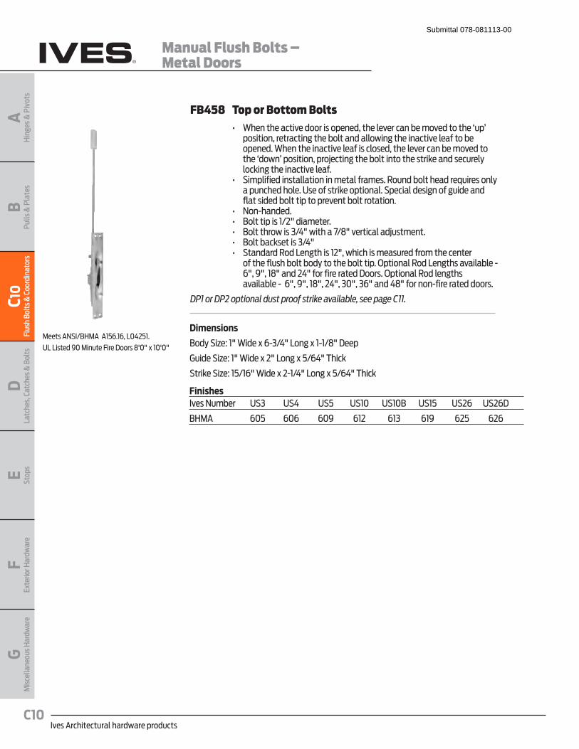
Ives Architectural hardware productsC10
Manual Flush Bolts – Metal Doors
BPu
lls &
Pla
tes
AH
inge
s &
Piv
ots
C10
Flus
h Bo
lts &
Coo
rdin
ator
sD
Latc
hes,
Cat
ches
& B
olts
E Stop
sF
Exte
rior H
ardw
are
GM
isce
llane
ous H
ardw
are
FB458 Top or Bottom Bolts � �� Q� ��� ����" ����������& ����� �� " ����� ���" ������� ���&��� position, retracting the bolt and allowing the inactive leaf to be opened. When the inactive leaf is closed, the lever can be moved to the ‘down’ position, projecting the bolt into the strike and securely locking the inactive leaf.� � �� #��&���� �������������� ������ �������������� ��� ���� ������
a punched hole. Use of strike optional. Special design of guide and flat sided bolt tip to prevent bolt rotation.
� � �� ��!�� ��� � �� �������&����()�+���� � ��� � �� ��������������j)*+��������)-+�" �������~���� ��� � �� ��������� �����j)*+� � �� #���������< �������(�+������������ ��� ��������� �� � ��
of the flush bolt body to the bolt tip. Optional Rod Lengths available - 6", 9", 18" and 24" for fire rated Doors. Optional Rod lengths available - 6", 9", 18", 24", 30", 36" and 48" for non-fire rated doors.
DP1 or DP2 optional dust proof strike available, see page C11.
Dimensions
Body Size: 1" Wide x 6-3/4" Long x 1-1/8" Deep
Guide Size: 1" Wide x 2" Long x 5/64" Thick
Strike Size: 15/16" Wide x 2-1/4" Long x 5/64" Thick
Meets ANSI/BHMA A156.16, L04251.
UL Listed 90 Minute Fire Doors 8'0" x 10'0"
FinishesIves Number US3 US4 US5 US10 US10B US15 US26 US26D
BHMA 605 606 609 612 613 619 625 626
Submittal 078-081113-00

Ives Architectural hardware productsC11
Dust Proof Strikes
BPulls &
PlatesA
Hinges &
PivotsC
11Flush Bolts &
CoordinatorsD
Latches, Catches & Bolts
EStopsF
Exterior Hardw
areG
Miscellaneous H
ardware
DP1DP2 Dust Proof Strikes� �� J ��� �������� �������� ����������������������������������������� �� #&���!��� ��&��� ��� �������������������� ������� " ������ � flush bolt is retracted, eliminating need to clean standard floor strikes.� �� #���� ���� ����j)*+�J�� � ����(!()-+�J &
DimensionsDP1 Face Plate: 1-7/16" Diameter DP2 Face Plate: 1-5/8" W x 3-1/2" L x 1/8" Thick Body: 1-3/16" Diameter x 1-7/8" Deep
DP1
DP2
Meets Meets ANSI/BHMA 156.16, L14011.
FinishesIves Number US3 US4 US10 US10B US26 US26D
BHMA 605 606 612 613 625 626
Submittal 078-081113-00
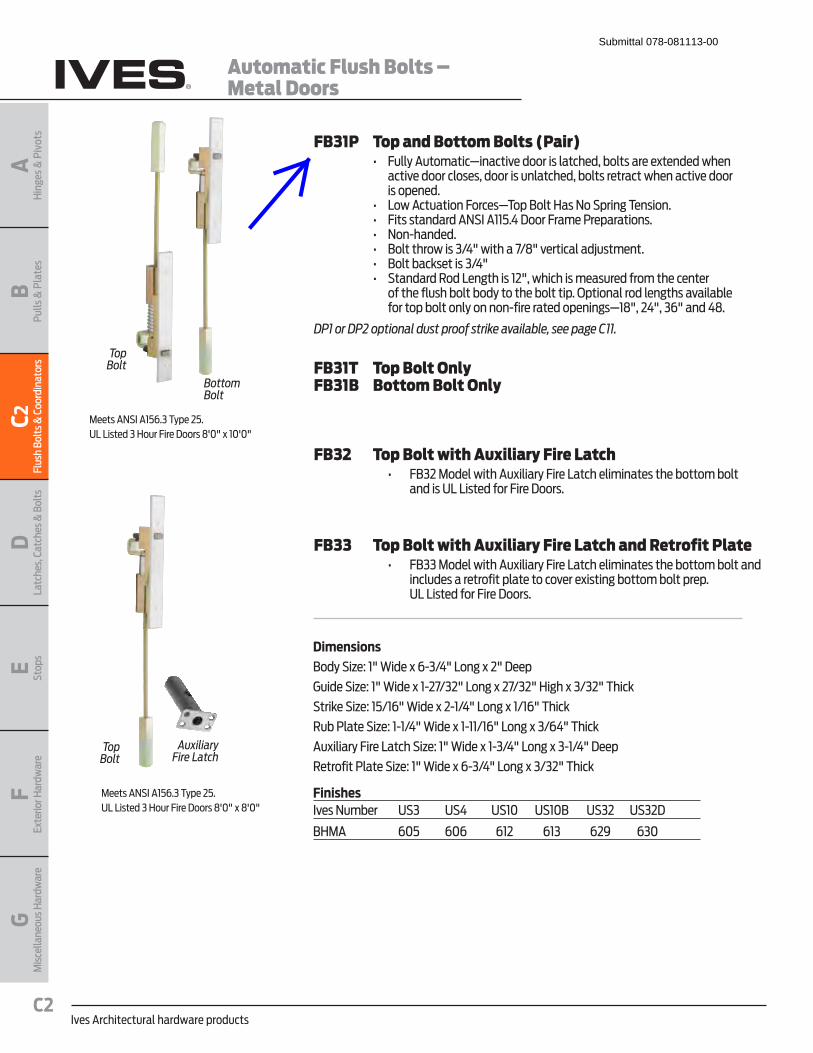
Ives Architectural hardware productsC2
Automatic Flush Bolts – Metal Doors
BPu
lls &
Pla
tes
AH
inge
s &
Piv
ots
C2Fl
ush
Bolt
s & C
oord
inat
ors
DLa
tche
s, C
atch
es &
Bol
tsE Stop
sF
Exte
rior H
ardw
are
GM
isce
llane
ous H
ardw
are
FB31P Top and Bottom Bolts (Pair)� � �� ������|������������" ������������� ���������� � K� � ���� ��
active door closes, door is unlatched, bolts retract when active door is opened.
� � �� <���|����������� ��%�&������$�����#&����% ����� � �� �����������|�#Y�|((,�*�J������� ��� &������� � �� ��!�� ��� � �� ��������������j)*+��������)-+�" �������~���� ��� � �� ��������� �����j)*+�� � �� #���������< �������(�+������������ ��� ��������� �� � ��
of the flush bolt body to the bolt tip. Optional rod lengths available � � ������&�������������!��� ��� ���& ����(-+���*+��jX+���*-�
DP1 or DP2 optional dust proof strike available, see page C11.
FB31T Top Bolt OnlyFB31B Bottom Bolt Only
FB32 Top Bolt with Auxiliary Fire Latch� � � �� ��j����� �������|�K��������� �<���� ����� ���� �������������
and is UL Listed for Fire Doors.
FB33 Top Bolt with Auxiliary Fire Latch and Retrofit Plate� � � �� ��jj���� �������|�K��������� �<���� ����� ���� ���������������
includes a retrofit plate to cover existing bottom bolt prep. UL Listed for Fire Doors.
DimensionsBody Size: 1" Wide x 6-3/4" Long x 2" Deep
Guide Size: 1" Wide x 1-27/32" Long x 27/32" High x 3/32" Thick
Strike Size: 15/16" Wide x 2-1/4" Long x 1/16" Thick
Rub Plate Size: 1-1/4" Wide x 1-11/16" Long x 3/64" Thick
Auxiliary Fire Latch Size: 1" Wide x 1-3/4" Long x 3-1/4" Deep
Retrofit Plate Size: 1" Wide x 6-3/4" Long x 3/32" Thick
Meets ANSI A156.3 Type 25.UL Listed 3 Hour Fire Doors 8'0" x 10'0"
Meets ANSI A156.3 Type 25.UL Listed 3 Hour Fire Doors 8'0" x 8'0"
FinishesIves Number US3 US4 US10 US10B US32 US32D
BHMA 605 606 612 613 629 630
Top Bolt
Top Bolt
AuxiliaryFire Latch
BottomBolt
Submittal 078-081113-00


