Embed Size (px)
Citation preview
Invited Paper
Continuous manufacturing of thin cover sheet optical media
w. Dennis Slafer, Milford Kime, Marinus Monen, Wffliam Horton,William Robinson, and Leonard Wan
Polaroid Corporation2 Osborn St.- 1E
Cambridge, MA 02139
ABSTRACT
A general method for making optical media by a continuous roll process has been developed. Theprocess can accommodate a variety of optical structures, although it has been optimized for those withsmaller form factors and thin cover sheets. A test disk was used to demonstrate process capabilities andevaluate media made by this method.
1. INTRODUCTION
Continuous roll manufacturing techniques have dominated the production of magnetic media, miniand micro floppies, and tape and stripe cards due to the extremely high volumes and low production coststhey can achieve. The application of these same techniques to the fabrication of optical media similarlyoffers a number of cost and production advantages when compared to present batch and/or semi-continuousprocesses. Using a single basic method, a roll process has the potential to produce optical media having arange of form factors, format structures, and recording schemes, in high volumes and at very low cost.
Continuous roll production of optical media also presents some unique problems. The intrinsic anddistinctive features of optical media, precise preformatting and cover sheet protection, are not as easilyachievable. We have developed two proprietary technologies to solve these problems: hemically nhancedmicro mbossing (CEME) on thin carrier films, and continuous lamination of thin cover sheets. Thesedevelopments have led to a general process to produce optical media; the features of such media aresummarized in table 1.
2. BACKGROUND
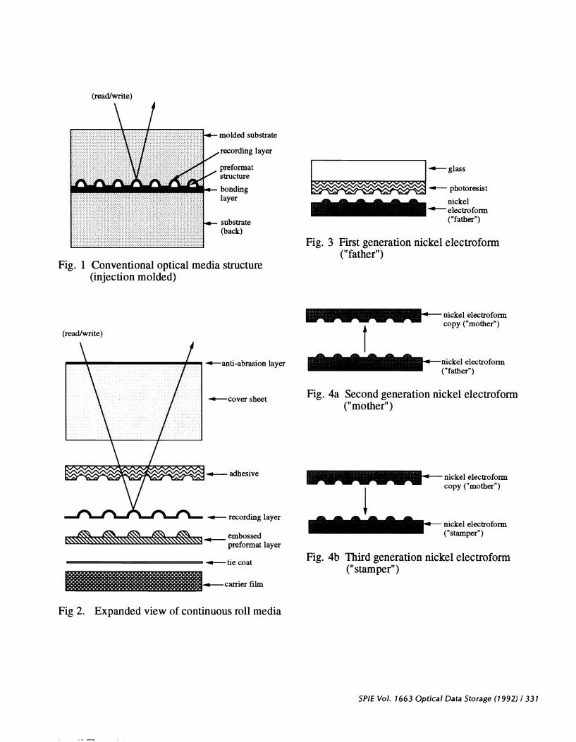
Beginning with the development in the early 1970ts of optical videodisc systems and followed byaudio compact disc, write-once (WORM) and erasable optical disks, the process of choice for producingsubstrates has been batch-oriented, such as injection molding or photopolymerization'. The generalstructure of optical disks is well known and has been discussed in detail 1 ,2,3 and for reference across-sectional diagram of a generalized optical disk is given in fig. 1.
During this same time period new roll processes were being developed in the photographic industryto produce precision optical structures in high volumes for novel photographic films4; further developmentshave allowed the precise microreplication of submicron periodic structures in continuous films58.
3. CONTINUOUS MEDIA STRUCTURE & PROCESS STEPS
Our continuous optical media process comprises five steps: (i) fabrication of master preformattingtool, (ii) preformat replication, (iii) vacuum deposition of recording layer, (iv) lamination of cover sheet,and (v) die punching of inside and outside dimensions. A summary of the process flow is given in table 2and an expanded view of an optical disk produced by this method is given in fig. 2.
324 / SPIE Vol. 1663 Optical Data Storage (1992) 0-8194-081 7-4/921$4.00
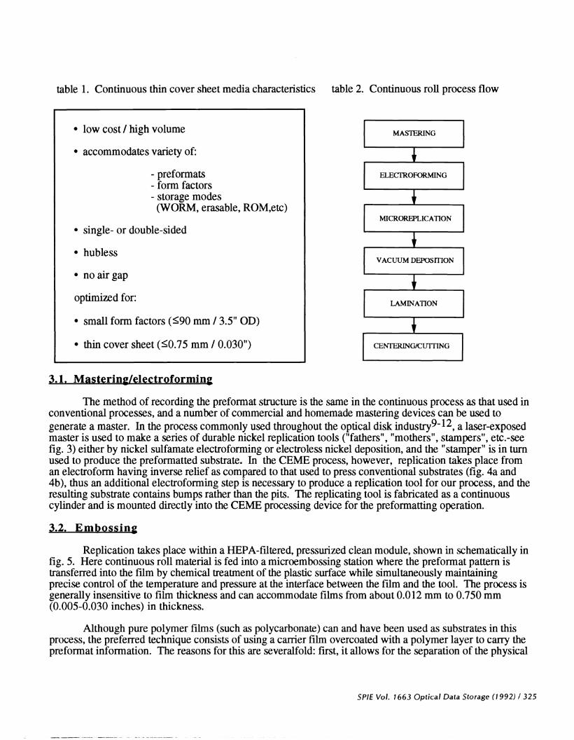
table 1 . Continuous thin cover sheet media characteristics table 2. Continuous roll process flow
. low cost I high volume[
MASTERING
. accommodates variety of:
- preformats ELECFROFORMING- form factors __________________- storage modes
(WORM, erasable, ROM,etc)MICROREPLICATION. single- or double-sided
. hublessVACUUM DEPOSiTION
. noairgap
optimized for: LAMINATION
. small form factors (�90 mm I 3.5" OD)
. thin cover sheet (�O.75 mm I 0.030")[
CENTERING/CWTING
3. 1. Mastering/electroforming
The method of recording the preformat structure is the same in the continuous process as that used inconventional processes, and a number of commercial and homemade mastering devices can be used togenerate a master. In the process commonly used throughout the optical disk industry92, a laser-exposedmaster is used to make a series of durable nickel replication tools ("fathers", "mothers", stampers", etc.-seefig. 3) either by nickel sulfamate electroforming or electroless nickel deposition, and the "stamper" is in turnused to produce the preformatted substrate. In the CEME process, however, replication takes place froman electroform having inverse relief as compared to that used to press conventional substrates (fig. 4a and4b), thus an additional electroforming step is necessary to produce a replication tool for our process, and theresulting substrate contains bumps rather than the pits. The replicating tool is fabricated as a continuouscylinder and is mounted directly into the CEME processing device for the preformatting operation.
3.2. Embossing
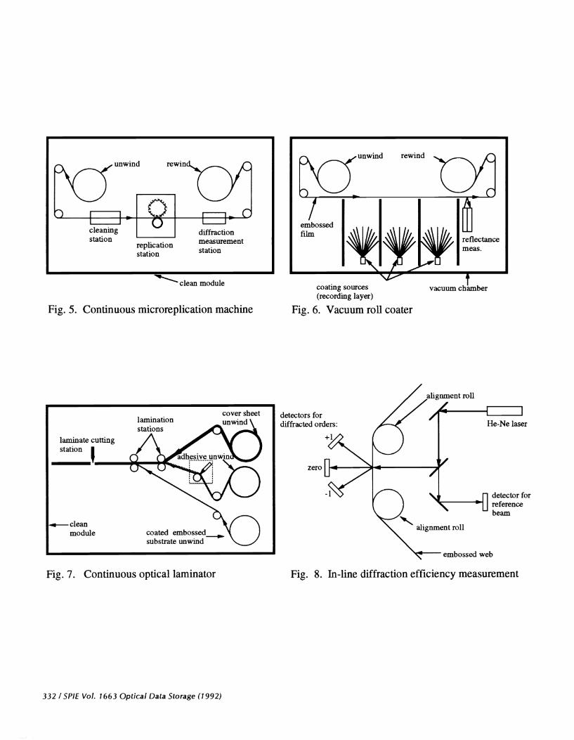
Replication takes place within a HEPA-filtered, pressurized clean module, shown in schematically infig. 5. Here continuous roll material is fed into a microembossing station where the preformat pattern istransferred into the film by chemical treatment of the plastic surface while simultaneously maintainingprecise control of the temperature and pressure at the interface between the film and the tool. The process isgenerally insensitive to film thickness and can accommodate films from about 0.012 mm to 0.750 mm(0.005-0.030 inches) in thickness.
Although pure polymer films (such as polycarbonate) can and have been used as substrates in thisprocess, the preferred technique consists of using a carrier film overcoated with a polymer layer to cany thepreformat information. The reasons for this are severalfold: first, it allows for the separation of the physical
SPIE Vol. 1663 Optical Data Storage (1992) / 325

and chemical properties of the support and information carrying layers, thus the support film can beoptimized for physical strength, stability and chemical inertness while the overcoat can provide the propertiesrequired for high speed, high resolution microreplication. This is particularly useful in related applications,such as optical tape, where very thin substrates (e.g. 0.012-0.050 mm) with high tensile strength arerequired. Support films such as polyester and polyimide, while not generally capable of accommodate highresolution replication by themselves, can nonetheless be used to provide the required dimensional strengthand toughness. A second advantage of coated films is that the proper coating procedures can often improvethe surface quality of the carrier ifim. The leveling action of the solution-coated overcoat layer, whenapplied using precision solution coating techniques, can provide a very high quality surface suitable forcarrying the optical preformat information. A third advantage is provided by the "microcalendering effectof the replication process, which imparts the high surface quality characteristic of the original master to thereplicated surface.
3.3. Vacuum Deposition
The continuous process is compatible with a number of recording schemes, and based on ourevaluation of various technologies we concluded that a vacuum deposited recording layer would meet thequality and throughput requirements of the roll process. A general multi-station vacuum coating machinewas built having sufficient flexibility to accommodate deposition by electron beam, thermal evaporation, andsputtering.
Following the preformatting operation the roll material is transferred to the vacuum roll coaterwhere the recording and protective layers are sequentially deposited (fig. 6). The most critical issues in thisoperation are compositional and topographical uniformity (transverse and longitudinal) and defects such asthose induced by the film transport system. Compositional uniformity is significant for multicomponentalloys and care must be taken to minimize both variations in the output flux of the source(s) andcompositional breakdown of the alloy during deposition, either of which would result in non-uniformities.Lateral material distribution is related to the source emission characteristics and is controlled by severalfactors, including the distance of the source to the film plane, the source design and the use of precisionaperture plates to modify the intrinsic deposition of the source material at the film plane. Longitudinalvariations are not generally caused by the same factors causing lateral variations, since the film movementeffectively time-averages lateral variations, but rather are a function of variations in deposition rate andmachine speed. These are both related to the precision of the vacuum coater control system (discussedbelow). The last issue, induced film defects, is handled by the mechanical design of the film transport inwhich contact between the face (preformatted) side of the film and any mechanical components is totallyeliminated.
3.4. Cover Sheet and Bonding
The cover sheet is a critical component in the continuous process; the intrinsic physicalcharacteristics, such as birefringence, optical transmission, clarity, refractive index, surface quality, etc.,must be carefully controlled. Polycarbonate is presently the material of choice for the cover sheet, but thediscussion generally applies to other materials as well.
As the thickness of the cover sheet increases, a phenomenon known as roll set becomes significantRoll set refers to the ability of certain polymer films to retain a degree of curvature characteristic of the filmin its rolled state, and this tendency increases as film thickness increases. Unless precautions are taken, adisk made with such a cover sheet will not be flat Techniques such as heat annealing and reverse windingcan be used to minimize roll set, but this becomes more difficult as the gauge thickness increases. We havedeveloped our roll process with thinner cover sheets in order to more effectively control this effect.
The use of thinner cover sheets can also result in greater sensitivity to dust and scratches on the outersurface of the media. It has been necessary to develop an anti-scratch/anti-static coating for the outer surface
326 ISPIE Vol. 1663 Optical Data Storage (1992)

of the cover sheet to reduce this problem. The coated polycarbonate offers significant performanceimprovements over uncoated plastic substrates; coated media can be vigorously handled and solventcleaned, since the coating is resistant to virtually all common solvents. In addition, incorporation of suchcoatings on continuous roll film is very efficient and cost effective.
Birefringence of the cover sheet is of considerable importance, since the intensity of the polarizedread/write laser beam will be effected by any net optical retardation in the media, and the characteristics ofthe extrusion process by which the cover sheet is made influence its optical retardation. The linear nature ofthe extrusion process produces stresses that tend to run in the longitudinal film direction, in contrast to theessentially radial stresses characteristic of the injection molding process. Measurement of the opticalretardation in the cover sheet film to maintain consistent quality is as important as in the injection moldingcase, and these measurement techniques are discussed subsequently. It should be noted that thebirefringence of the carrier film and embossed layer is irrelevant, as the recording layer is not exposedthrough these layers.
Bonding of the cover sheet and the preformat film takes place in a HEPA-filtered clean laminator,shown schematically in fig. 7. The cover sheet is bonded to the vacuum-coated surface of the substrate usinga purified, ultra-smooth optical adhesive. Several materials and techniques have been developed toaccomplish this, and they fall into two general categories: pressure sensitive and pure liquid bonding. In theformer case, a pressure sensitive adhesive in a carrier fluid is coated onto the surface of the cover sheet andthe carrier fluid removed. The vacuum-coated preformatted layer is then pressure bonded to the adhesive-coated surface. With the pure liquid adhesive system, the adhesive is injected between the cover sheet andthe vacuum-coated surface at the lamination interface, at which point the curing process is initiated.
An important advantage of locating the adhesive between the vacuum-coated embossed surface andthe cover sheet is that, with the proper choice of refractive index, the adhesive can act as a refractive indexmatching layer to minimize the effects of scratches and other such defects in the inner surface of the coversheet.
Once the lamination process is complete, the structure is sealed and no longer susceptible to internalcontamination.
3.5. Centering/punching
In order to avoid stresses within the laminated structure (such as caused by rewinding the laminatedcomposite film) the material is cut into sheets immediately after exiting the lamination station. The panels arefed into a die punching machine where the center is located using an optical edge-detection scheme, which inturn controls the positioning of a micro-stepper in a step-and-repeat punching operation. The inner and outerdimensions can either be punched simultaneously or the inner diameter cut first and used to locate and cut theouter dimension. The punches are readily changed to accommodate various diameters and form factors.The precision of the punching operation was found to meet the centering requirements without the need forhubs in the finished media.
4. PROCESS CONTROL AND DIAGNOSTICS
Continuous microreplication of a moving thin film under tension requires precise control of machineconditions and replication efficiency. This is accomplished by using a film handling system undermicroprocessor control and computer data acquisition and analysis to monitor the machine's operationalparameters in run time. Film handling is controlled by a programmable logic controller, which maintainsmachine speed, multiple zone tensions, acceleration and deceleration rates, etc. The data logging operationrecords a number of parameters such as film speed, tensions, chemical flows and concentrations, pneumaticpressures at the replication station, temperatures, relative humidity, air flow, etc. These values are logged at
SPIE Vol. 1663 Optical Data Storage (1992)1327
a rate of one complete data set per disk. In addition, an inkjet labeller prints the individual diskidentification code on the edge of the film so that full process information is available for any disk in aparticular run. Data-logging is accomplished by a commercial software package running on a 386-basedcomputer.
The critical parameter of preformat replication fidelity is related to the diffraction efficiency of thepreformat pattern, which in turn is related to the dimensions of the periodic preformat structures'3. It istherefore possible to use diffraction efficiency to monitor and control the replication process. The diffractionis measured at several points downstream from the replication station by directing the output of a small (0.5mw) He-Ne laser through the preformatted film, shown schematically in fig. 8. The transmitted diffractionspots for each of the orders fall onto a large area silicon detector, and an arc-shaped aperture mask is usedto minimize stray light and accommodate any slight rotation of the diffracted spots about the zero orderwhich would accompany transverse film motion. A beam splitter is used to obtain an incident beamreference and normalize the diffracted orders to eliminate the effects of laser output variation, and a dedicatedcomputer acquires approximately 1000 diffraction data points per disk pattern by direct memory accessinterface, analyzes the information and plots the diffraction efficiency as a function of position within asingle disk pattern in run time. The integrated intensity for each disk is displayed and recorded as anefficiency factor which is used to control the machine parameters in order to maintain peak diffractionefficiency. This control system is presently operated in open-loop mode but can ultimately be run closed-loop.
The vacuum deposition operation also features a computer-controlled closed-loop film transportsystem. In order to minimize the longitudinal deposition variations referred to previously, the multiplesources (both thermal and electron beam) are controlled by crystal deposition rate monitors. In addition, anarray of infrared diode reflectometers within the vacuum chamber provides reflectance data to the datalogging computer. These in-line reflectance monitors can ultimately be used to directly control the sourceflux and provide improved reflectance control. With the present control system and using aperture plates tocontrol the lateral material distribution, the reflectance variations across the preformatted area of a disk areless than 1%.
Measurement of the optical retardation of the cover sheet film before and after incorporation into themedia was accomplished using two instruments. A laser-based device14 was used to measure samples inboth the reflection and transmission modes, and a Babinet compensator13 combined with a computer-basedimage capture and analysis system was used to measure cover sheet optical retardation over large sampleareas.
5. EVALUATION OF PROCESS AND TEST DISK
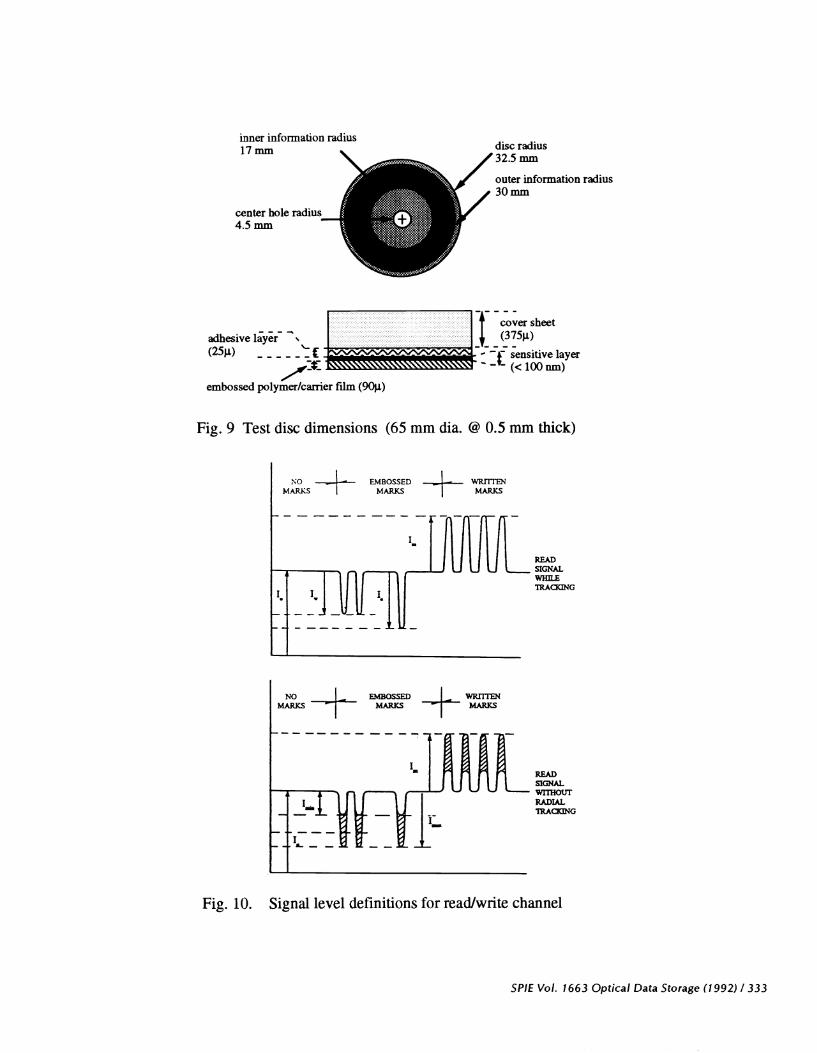
In order to effectively demonstrate and evaluate the continuous process, it was necessary to developa set of specifications for a test disk and drive. A 65 mm diameter/O.5 mm thick phase-change-basedWORM system with sampled servo format structure was chosen as the test vehicle to evaluate the process.The small diameter and thin cover sheet was chosen based on our expectation that a smaller diameter diskmade from continuous roll material would suffer least from possible residual cover sheet curvature discussedpreviously. A write-bright phase-change WORM recording scheme was chosen for the test disk because ofits insensitivity to overcoat thickness, its ability to be vacuum deposited at high rates, its archivabiity, andits ability to be reformulated as an erasable system. Detailed specifications for the evaluation disk are givenin fig. 9, and the property defmitions for the read (preformat servo) and write (WORM layer) channels aregiven in fig. 10.
328 / SPIE Vol. 1663 Optical Data Storage (1992)
The drives used to test this structure were a modified version of a commercially available WORMdrive and the required modifications were as follows:
. addition of optical compensation to correct for thinner cover sheet. design of new clamping mechanism to accommodate hubless media. incorporationof new motor to allow access to smaller inner radii. design of caddy cartridge for 65 mm disk. modification of circuitry to accommodate write-bright recording. use of 1 8-sector sampled servo format
6. RESULTS
Using the equipment described previously, a number of disks were produced for evaluation. Ademonstration system was set up in which a high-resolution CCD camera was used to capture images whichwere stored in a frame buffer and written to a test disk in the modified drive connected to a 386-based hostcomputer. The image files were read from the test disk and displayed on a black and white video monitorand were used as a method of providing user-level evaluation of the disk performance at various stages ofprocess development. A number of basic tests were also performed using the dynamic test equipment.
In addition to dynamic testing, a number of other techniques were used to examine the disk atdifferent stages of fabrication. One of the most useful tools in examining the actual preformat structure forreplication fidelity was photon tunneling microscopy (PTM)15'16, in which an optical microscope is usedto measure the tunneling of photons incident on a total internal reflection surface. The tunneling of theoptical field produces a vertical gray scale which can be accurately converted to a perpendicular distancescale and quantitatively displayed in real time as a 3-D picture. Samples can be analyzed quickly since theyare run at ambient pressure and temperature and PTM does not require sample coating. PTM images ofsampled servo sector header and servo byte areas of an embossed (uncoated) disk are shown in fig. 1 1.PTM images comparing a conventional molded substrate and our continuous embossed surface are shown infig. 12. Note the apparent gray-scale inversion of this pair; the molded substrate contains pits while theembossed surface contains bumps and in PTM a decrease in brightness indicates greater distance from thesurface. Conventional scanning electron and optical microscopy were also used to evaluate the preformatstructure. Optical micrographs comparing the surface of a nickel master and an embossed surface madefrom its copy are shown in fig. 13. It can be seen from this group of micrographs that even though thepreformat structures have inverse symmetry compared to conventional media, the resulting structures arefunctionally equivalent.
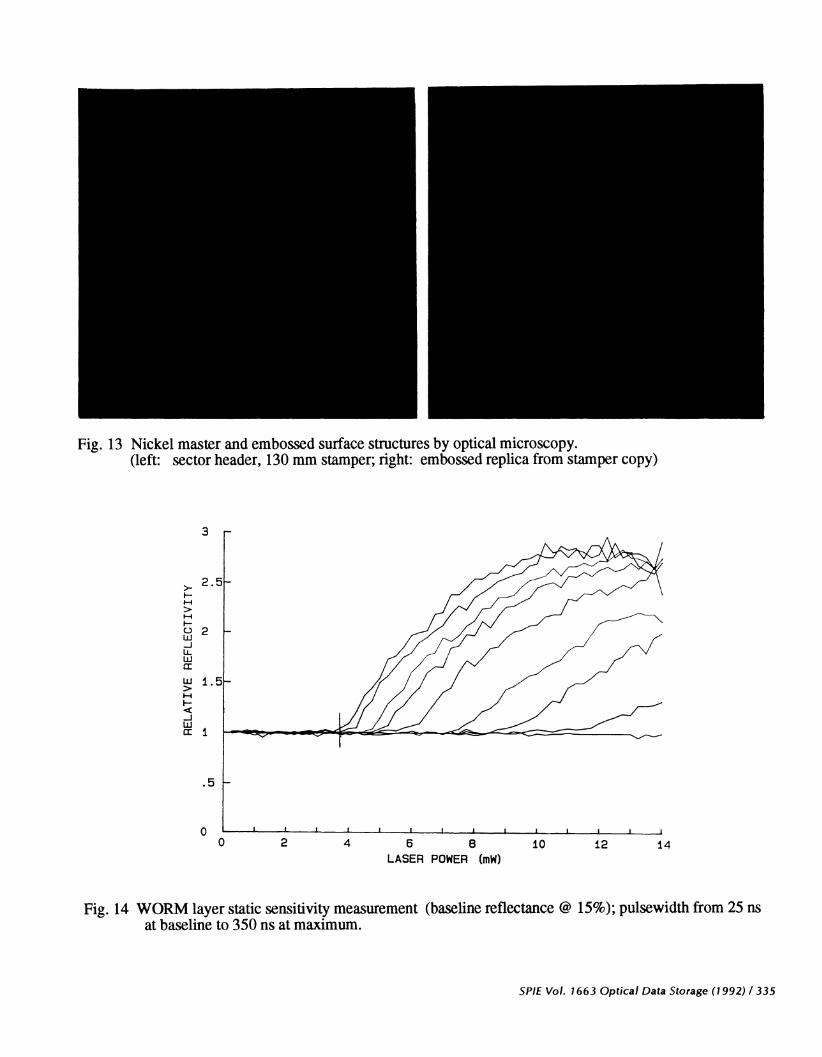
The optically sensitive component is a Te-based write-bright/write-once system and comprises oftwo layers, including a underlying reflective metallic layer, and an overlying phase-change Te alloy layer1720 The two layers are coated sequentially in a singlepass, and the resulting material is amorphous and ofrelatively low reflectance. Upon exposure to the laser write beam, this layer irreversibly crystallizes with aconcomitant increase in reflectance. The initial and fmal reflectance and sensitivity are controlled by therelative layer thicknesses and alloy composition, and depending on these values the reflectances can rangefrom approximately lO%-35% for the amorphous state and approx. 20%-60% for the crystallized state.Additional protective layers can be incorporated to enhance stability. Static testing, which measures therelative change in reflectance versus delivered laser power for a number of pulse durations, was also used toevaluate the sensitivity of the layer and a typical test curve is given in fig. 14.
Dynamic tests on full structure media were carried out and the evaluation of read/write channelproperties on test media showed consistent compliance with target properties (indicated in fig. 10). Acomplete error analysis has not yet been completed for the test structure; however, qualitative results fromboth dynamic drives show acceptable error rates. The quantitative results depend upon the exact details ofthe media and will depend on final optimization of a media structure.
SPIE Vol. 1663 Optical Data Storage (1992)! 329
Preliminary tests have been carried out to assess the environmental stability of disks made by thecontinuous process. Disks with both pictorial information and blocks of written data were cycled between-20C and 55C at up to 95% RH for a number of weeks, and the disks were sampled at regular intervals,with the same blocks being re-tested in the drives. No noticeable changes resulted during these initial tests.
7. SUMMARY
We have shown the continuous roll process to be a viable technique for producing optical media.We have also demonstrated initial performance and stability characteristics of this media in a test diskdeveloped for process evaluation. The process is found to be optimally suited for smaller form factors andthinner cover sheet media and within these constraints can be readily adapted to a range of servo formats,form factors, and optical recording schemes.
8. REFERENCES
(1) J. Isailovic, Videodisc and Optical Memory Systems. Prentice-Hall, Inc., Englewood Cliffs, NJ,1985.(2) G. Bouwhuis et al, Principles of Optical Disc Systems, pp. 204ff, Adam Hilger Ltd, Boston, 1985.(3) W.D. Slafer and M. Kime, U.S. Patent #4,831,244, "Optical Record Cards", May 16, 1989.(4) E.H. Land, "An Introduction to Polavision", Photogr. Sci. Eng. 21: 225 (1977).(5) E. H. Land, U.S. Pat. 4,366,235, Dec. 28, 1982, "Photosensitive Element and Method of Preparing
Same.(6) J.J. Cowan and W. D. Slafer, "The Recording and Replication of Holographic Micropattems for the
Ordering of Photographic Emulsion Grains in Film Systems", J. Imaging Sci. 31: 100 (1987).(7) W. D. Slafer et al., "Investigations of Arrayed Silver Halide Grains" J. Imaging Sci. 31: 1 17 (1987).(8) W.D. Slafer, V. Walworth, U.S. Patent #4,663,274, "Method for Forming a Photosensitive Silver
Halide Element", May 5, 1987.(9) W. Blum and G. B. Hogaboom, Principles of Electroplating and Electroforming, McGraw-Hill Co.,
NY, 1958.(10) Carl M. Rodia, "Precision Electroforming for Optical Disk Manufacturing", 73rd Annual Tech.
Conference, Am.Electroplaters and Surface Finishers Society, Philadelphia, D-3, 1986.(1 1) "AES International Symposium on ElectroforminglDeposition Forming," American Electroplaters
Society, Inc., Winter Park, FL, sec. 1-3, 1983.(12) "AESF Electroforming Symposium", American Electroplaters and Surface Finishers Society, Orlando,
FL, I-D, IV-B, 1989.(13) S. 0. Lipson and H. Lipson, Optical Physics, Cambridge Univ. Press, NY, 1981.(14) G. R. Lange, "Automated Retardation Measurement", Proc. of SPIE, 899, pg. 134, 1988.(15) J.M. Guerra, "Photon Tunneling Microscopy," Proc. of SPIE, 1009, pg. 254 (1988).(16) J.M. Guerra, "Photon Tunneling Microscopy," Appl. Optics, 29, pg. 3741 (1990).(17) D. Adler and J. Feinleib, "Optics of Solid State Phase Transitions", The Physics of Opto-Elect.ronic
Materials, ed by W. A. Albers, Jr., Plenum Publishing, pg. 233, 1971.(18) 5. Ovshinsky' "Amorphous Materials as Optical Information Media", J. Appl. Photogr. Engr., 3,
pg. 35 (1977).(19) D. Strand, "Data Storage Device...", U. S. Pat. #4,660,175, April 21, 1987.(20) J. P. deNeufville and D. Strand, "Method of Forming Data Storage Medium...", U. S. Pat.
#4,6621032, April 21, 1987.
330/SPIE Vol. 1663 Optical Data Storage (1992)
— molded substrate
,,,,recording layerpreformatstructure
I— bondinglayer
— substrate(back)
Fig. 1 Conventional optical media structure(injection molded)
Fig. 3 First generation nickel electroform("father")
embossedpreformat layer
-nickel electroform("father")
Fig. 4a Second generation nickel electroform("mother")
- nicei electroformW Wcopy ("mother")
- • nickel electroform("stamper")
Fig. 4b Third generation nickel electroform("stamper")
Fig 2. Expanded view of continuous roll media
SPIE Vol. 1663 Optical Data Storage (1992) / 331
•— photoresist— nickelelectroform("father")
w w w w w • nickel electroformcopy ("mother")
(read/write)
—anti-abrasion layer
—cover sheet
I adhesive
— recording layer
•— tie coat
ø—caITer film
clean module
Fig. 5. Continuous microreplication machine
Fig. 7. Continuous optical laminator
Fig. 6. Vacuum roil coater
Fig. 8. In-line diffraction efficiency measurement
332 ISPIE Vol. 1663 Optical Data Storage (1992)
nwind rewi
cleaning _________ diffractionStatlofl measurement
replication stationstation
coating sources(recording layer)
cover sheet detectors fordiffracted orders:
+1
— cleanmodule
He-Ne laser
coated embossed,substrate unwind
detector forreferencebeam
embossed web
inner information radius17mm
center hole radius....j4.5mm
disc radius325 mm
outer information radius30mm
cover sheet
adhesive layer _______________________(25) ___________________________________________ sensitive layer_________________ - (<lOOnm)
embossed polymer/carrier fihn (9Oi)
Fig. 9 Test disc dimensions (65 mm dia. @ 0.5 mm thick)
READSIGNALWKUTRAK1NG
READSIGNALwrmouRADIALIRAThG
Fig. 10. Signal level definitions for read/write channel
SPIE Vol. 1663 Optical Data Storage (1992) / 333
NO ..4- EMBOSSED .4—MARKS I MARKS MARKS
I
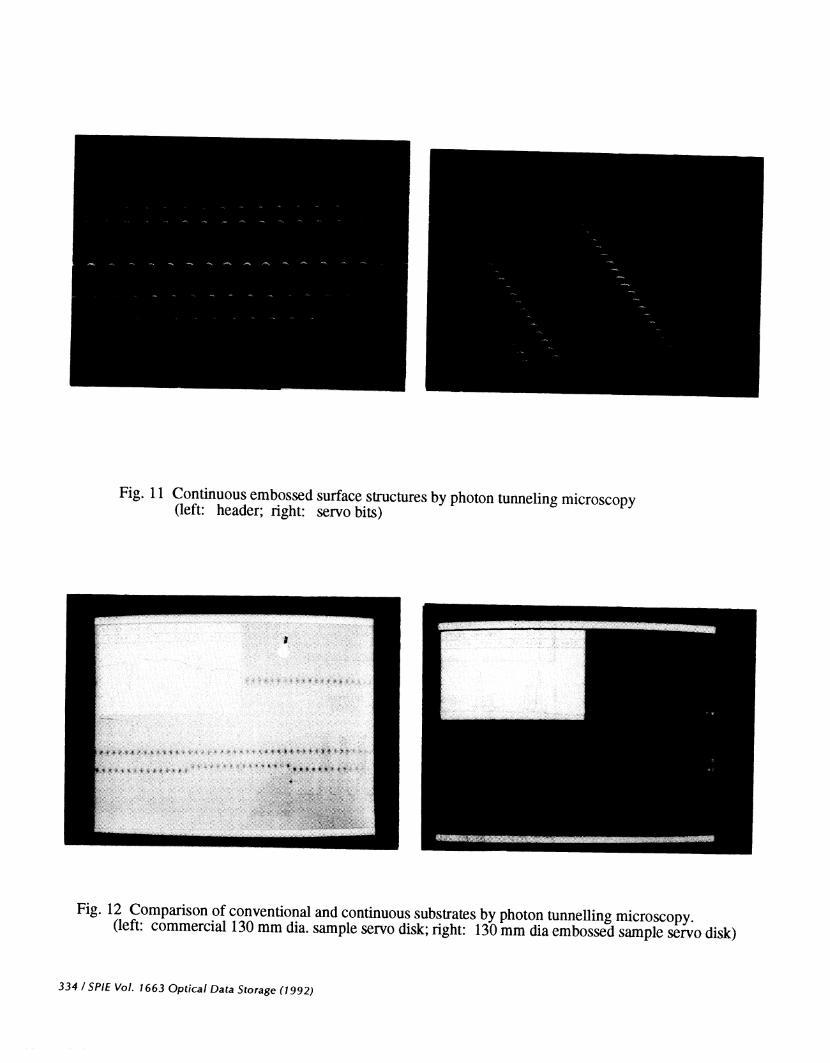
Fig. 11 Continuous embossed surface structures by photon tunnelingmicroscopy(left: header; right: servo bits)
Fig. 12 Comparison of conventional and continuous substrates by photontunnelling microscopy.(left: commercial 130 mm dia. sample servo disk; right: 130 mm dia embossed sample servo disk)
334 ISPIE Vol. 1663 Optical Data Storage (1992)
>.I->I-0uJ-JLL.LiiLIw>1-4I—
-Jwcc
Fig. 14 WORM layer static sensitivity measurement (baseline reflectanceat baseline to 350 ns at maximum.
@ 15%); pulsewidth from 25 ns
SPIE Vol. 1663 Optical Data Storage (1992)1335
Fig. 13 Nickel master and embossed surface structures by optical microscopy.(left: sector header, 130 mm stamper; right: embossed replica from stamper copy)
3
2.
2
1.
I
.5
00 2 4 6 8 10 12
LASER POWER (mW)14


