Embed Size (px)
Citation preview
*** RMIS View/Print Document Cover Sheet ***
This document was retrieved from the Documentation and RecordsManagement (DRM) ISEARCH System. It is intended for Informationonly and may not be the most recent or updated version. Contact aDocument Service Center fsee Hanford Info for locations) if you needadditional retrieval information.
Accession #: D296004558
Document*: SD-W379-ES-003
Title/Desc:CSB TRADE STUDY FINAL REPORT
Pages: 333

JAN U 4 1996ENGINEERING DATA TRANSMITTAL Pag* 1 of
1.EDT N° 6147522. To: (Receiving Organization)
Distribution5. Proi./Prog./Dept./Div.;
Project W-379, SNF, CSB8. Or
Theul SiBCSRtranscan1 1 . R
3. From: (Originating Organization)
Spent Nuclear Fuels6. cog. Engr.:
C.E. Swensongin*tor Remarks:
attached reports were previously reproduced andr ibuted, but were not released and processed throughDocument Control Services. These reports are hereby
smitted v ia EDT for release/data entry, and electronicning/indexing fo r record and re t r ieva l purposes.sceiver Remarks:
1 5 . DATA TRANSMITTED(A)
KemNo.
1.
2.
(B) Document/Drawing No.
WHC-SD-W&79-CDR-001 ^A*WHC-SD-W*379-ES-002 JK*&
WHC-SD-W4379-ES-003
(C)SheetNo.
1-191
ID)Rav.No.
0
0
0
(El Title or Description of DataTransmitted
SNF CSB ConceptualDesign ReportSSF Feas ib i l i t y StudyFinal ReportCSB Trade Study FinalReport
4. Related EDT No.:
N/A7. Purchase Order No.:
P.O. TVW-SVV-3702529. Equip./Component No.:
N/A
10, System/Bldg./Facility:
CSB, Bui ld ing 212H
12. Major Assm. Dug. Mo.:
N/A13. Permit/Permit Application No.:
N/A14. Required Response Date:
N/A(F )
ApprovalDeaig-nator
N/A
N/A
N/A
(G)Reaaon
forTrana-mittal
2
2
2
(H)Origi-natorDiapo-artion
1
1
1
CDReceiv-
erDitpo-aition
1
1
1
16. KEY
Approval Deaiflnator IF)
E. S, Q, 0 or N/A\t99 WHC-CM-3-6,Sec. 12.7)
(Gl
flea-ton
1.1.
&.
(H,
Oiap.
1.1.
Raaaon for Tranemittal (G)
1. Approval 4. Reviaw2. Releaea S. Port-Review3. Information 6. Diet. (Receipt Acknow. Required)
Difpotition |H} & (1)
1. Approved 4. Ra via wad no/commant2. Approved w/conunant S. Reviewed w/comment3. Diaapproved w/comment ' 6. Receipt acknowledged
17. SIGNATURE/DISTRIBUTION(Sea Approval Designator for required algnaturaa)
(J) Nam* IK) Signature (L) Date (M) MS IN
Cog.Eng. C.E. Swenson fafittfajHfort'W'ffA
Cog. Mgr. M.K. *^**f*Yc^£'%faJ*j£l2/q/fCQA " '
Safety
Env. /-^-?>
CHAR BUSLSZ CPD&***~ &g~O&
18.
Signature of EDT D'atafOriginator
19.
Authorized Rapreaantative Datafor Receiving Organization
(J) Name (K) Signature |L) Date (M) MS IN
20.
Cognizant Manager/ ' Data
IQ)
Raa-aon
2 1 . DOE APPROVAL ( i f requiredC t r l . Ho. N/A
[] Approved[] Approved u/commentsI ] Disapproved w/comments
(HI
Dlap.
)
BD-7400-17M

WHC-SD-W379-ES-003, Rev. 0
Canister Storage BuildingTrade StudyFinal Report
C.E.SwensonWestinghouse Hanford Company, Richland, WA 99352U.S. Department of Energy Contract DE-AC06-87RL10930
EOT/ECN:Org Code:B&R Code:
Key Words:Report.
EDT-6147528KA20EW3135040
UC: 510Charge Code: LG003Total Pages: 332
Project W379, SNF, CSB, Trade Study, Engineering Study.
Abstract: This study was performed to evaluate the impact of severaltechnical issues related to the usage of the Canister Storage Building(CSB) to safely stage and store N-Reactor spent fuel currently locatedat K-Basin 100KW and 100KE. Each technical issue formed the basis foran individual trade study used to develop the ROM cost ans scheduleestimates. The study used concept 2D from the Fluor prepared "Stagingand Storage Facility (SSF) Feasibility Report" as the basis fordevelopment of the individual trade studies.
Fluent is a registered trademark of Fluent, Inc. Hanover, NH
Flotran is a registered trademark of SAS Acquisition Corp, Houston, PA.
TRADEMARK DISCLAIMER. Reference herein to any specific commercial product, process, or service bytrade name, trademark, manufacturer, or otherwise, does not necessarily constitute or imply itsendorsement, recommendation, or favoring by the United States Government or any agency thereof orits contractors or subcontractors.
Printed in the United States of America. To obtain copies of this document, contact: UHC/BCSDocument Control Services, P.O. Box 1970, Mailstop H6-0B, Rich Iand WA 99352, Phone (509) 372-2420;Fax (509> 376-4989.
hb -9bRelease Approval Date
Approved for Public Release
A-6400-073 (10/95) GEF321

CANISTER STORAGE BUILDINGTRADE STUDYFinal Report
Prepared for
Westinghouse Hanford Company
Prepared By
Fluor Daniel, Inc.Government Services Operating Company
May 1995
UHC-SD-U379-ES-003 Rev, 0

Westingfcouse Kanford Company Government ServicesWKC P.O. TVW-SW-370252 ConCract 04436306
NOTICE
This report was prepared as an account of work sponsored hy theUnited States Government and not for the purpose of reliance by anythird party. Neither the United States nor the Department ofEnergy, nor any or their employees, nor any of their contractors,subcontractors, or their employees, makes any warranty, express orimplied, or assumes any legal liability or responsibility for theaccuracy, completeness, or usefulness of any information,apparatus, product or process disclosed or represents that its usewould not infringe privately-owned rights. Reference herein to anyspecific commercial product, process, or service by trade name,mark, manufacturer, or otherwise, does not necessarily constituteor imply its endorsement, recommendation, or favoring by the UnitedStates Government or any agency thereof nor any contractor,subcontractor or their employees. The views and opinions ofauthors expressed herein do not necessarily state or reflect thoseof the United States Government or any agency thereof, nor anycontractor, subcontractor or their employees. Use of any part ofthis report shall be at the user's sole risk and shall constitutea release and an agreement to defend and indemnify the UnitedStates, the Department of Energy and/or any of their employees,contractors, subcontractors and/or their employees, against any andall liability in connection therewith, regardless of fault ornegligence.
WHC-SD-W379-ES-003 Rev. 0

•-JS3 Trade Study F?.uor Daniel, Inc .We:=t:.ngt:.ouse Hanford Company Government ServicesWKC P.O. TVW-3W-370252 Contract 04436306
TABLE OF CONTENTS
Page
LIST OF DRAWINGS AND FIGURES iv
LIST OF TABLES vi
LIST OF ACRONYMS viii
EXECUTIVE SUMMARY 1
1.0 INTRODUCTION 1-11.1 BACKGROUND 1-11.2 STUDY OBJECTIVES 1-21.3 SCOPE OF WORK ' 1-31.4 DESIGN BASIS 1-4
2.0 CONCEPT 2D TECHNICAL DESCRIPTION 2-12.1 FACILITY DESCRIPTION 2-12.1.1 Plot Plans 2-12.1.2 Rail Tunnel/Cask Unloading Area 2-12.1.3 MCO Servicing 2-62.1.4 Cask Unloading Pool Water Treatment
System 2-82.1.5 MCO Cooling and HVAC 2-152.1.6 Structural 2-202.1.7 Material Flow 2-212.2 FEASIBILITY ISSUES 2-332.2.1 Structural 2-332.2.2 Thermal/HVAC 2-342.2.3 Contamination Control 2-392.2.4 Criticality 2-412.2.5 Shielding 2-512.2.6 Conversion 2-552.2.7 Health Physics 2-552.3 SAFETY ANALYSIS 2-572.3.1 APPLICABLE REQUIREMENTS 2-572.3.1.1 DOE Orders 2-532.3.1.2 DOE Standards 2-592.3.1.3 NRC Regulations 2-602.3.1.4 Other Federal Regulations 2-602.3.1.5 Washington State Regulations 2-612.3.1.6 WHC Requirements 2-612.3.1.7 ANSI/ANS Standards 2-612.3.2 DESIGN BASIS ACCIDENTS
SAFETY CLASSIFICATIONS 2-612.3.2.1 DBA Methodology 2-622.3.2.2 Assumptions 2-662.3.2.3 Results 2-69
UHC-SD-U379-ES-003 Rev. 0

CSB Trade Study Fluor Daniel, Inc.Westinghouse Hanford Company Government; ServicesWHC P.O. TVW-SW-370252 Contract 04436306
TABLE OF CONTENTS
Page
2.4 COST ESTIMATES 2-702.4.1 ESTIMATE BASIS 2-702.4.1.1 Assumptions 2-742.4.1.2 Estimate Inclusions 2-752.4.1.3 Estimate Exclusions 2-752.4.1.4 Work Breakdown Structure (WBS) 2-762.4.1.5 Quantities 2-782.4.1.6 References 2-782.4.1.7 Escalation 2-782.4.1.8 Contingency .- 2-792.4.2 CONCEPT 2D CAPITAL COST 2-792.4.2.1 Concept 2D Cost Estimate 2-792.4.3 SIGNIFICANT OPERATING COST
DIFFERENCES 2-792.4.3.1 Operating Labor During Staging 2-792.4.3.2 Fuel Cooling During Staging 2-802.4.3.3 Heating, Ventilation, and Lighting 2-802.4.3.4 Crane Usage 2-802.4.3.5 Pool Water Sterilization 2-852.4.3.6 Chemical Consumption 2-852.5 SCHEDULES 2-852.5.1 SCHEDULE ASSUMPTIONS 2-852.5.1.1 General 2-852.5.2 CONCEPT 2D SCHEDULE 2-872.6 CONCLUSIONS AND RECOMMENDATIONS 2-872.6.1 FEASIBILITY OF CSB ADAPTATION 2-872.6.2 OTHER TECHNICAL CONCERNS 2-872.7 REFERENCES 2-902.8 DESIGN BASIS 2-94
3.0 TRADE STUDY REPORTS 3-13.1 TABLE OF CONTENTS 3-1
Task Description TabA Facility Confinement Investigation AB MCO Receipt and Staging Function and Area B
RemovalC Cask Decontamination Function and Area C
RemovalD One Track Rail Service DE Storage Tube Material Investigation EF MCO Shipment Reduction FG Damp-Dried MCO GH RCRA Functions: Prevention and Detection H
of MCO Leaks
3.2 INTRODUCTION 3-1APPENDIX CALCULATIONS
iii
UHC-SD-W379-ES-003 Rev. 0
CSB Trade Study Fluor Danie l , Inc .Westinghouse Hanford Company Government Serv icesWHC P.O. TVW-SW-370252 Contract 04436306
LIST OF DRAWINGS AND FIGURES
Page
FIGURE 2-1, MASTER SITE PLAN CONCEPT 2D 2-2
FIGURE 2-2, PLOT PLAN CONCEPT 2D 2-3
FIGURE 2-3, FLOOR PLAN CONCEPT 2D 2-4
FIGURE 2-4, MCO SERVICE STATION FOR CONCEPT 2D 2-9
FIGURE 2-5, PROCESS BLOCK FLOW DIAGRAM, POOL WATER TREATMENT .... 2-13
FIGURE 2-6, SSF FEASIBILITY STUOY CONCEPT 2D VAULT -
HVAC SYSTEM 2-16
FIGURE 2-7, CONCEPT 20 OPERATING AREA HVAC SYSTEM 2-17
FIGURE 2-8, CONCEPT 20 POOL WATER TREATMENT BUILDING HVACSYSTEM 2-18
FIGURE 2-9, CONCEPT 2D OPERATING AREA HVAC EMERGENCY VENTSYSTEM 2-19
FIGURE 2-10, CONCEPT 2D STAGING MATERIAL FLOW DIAGRAM,IN RAIL TUNNEL/CASK UNLOADING AREA 2-23
FIGURE 2-11, CONCEPT 2D STAGING MATERIAL TIME STUDY IN CASKUNLOADING AND STORAGE AREA 2-24
FIGURE 2-12, CONCEPT 2D STAGING MATERIAL FLOW DIAGRAM, IN STORAGETUBES AREA 2-25
FIGURE 2-13, CONCEPT 2D STAGING MATERIAL TIME STUDY IN STORAGETUBES AREA 2-26
FIGURE 2-14, CONCEPT 2D STORAGE MATERIAL FLOW DIAGRAM TO ANDFROM FUTURE STABILIZATION FACILITY 2-27
FIGURE 2-15, CONCEPT 2D STORAGE MATERIAL TIME STUDY OUT &
INTO STORAGE TUBES 2-28
FIGURE 2-16, OVERHEAD CASK/CRANE PICKUP AND DELIVERY 2-32
FIGURE 2-17, PASSIVE COOLING VAULT TEMPERATURE PROFILECONCEPT 2D 2-37
FIGURE 2-18, PASSIVE COOLING VELOCITY PROFILE, CONCEPT 20 2-38
IV
UHC-SD-W379-ES-003 Rev. 0

CSB Trade StudyWesCinghouse Hanford CompanyWHC P.O. TVW-SW-370252
Fluor Daniel, Inc.Government Services
Contract 04436306
FIGURE 2-19,
FIGURE 2-20,
FIGURE 2 - 2 1 ,
FIGURE 2-22,
FIGURE 2-23,
FIGURE 2-24,
LIST OF DRAWINGS AND FIGURES
Page
SENSITIVITY TO SPACING, 31 FUEL ELEMENTS
(IN A TRIANGULAR ARRAY) PER LAYER, 12 LAYERS, 7 COLUMNS . 2-47
FUEL ELEMENTS IN A SINGLE LAYER OF AN MCO MODEL 2-48
CSB VAULT MODEL SHOWING TUBES IN TRIANGULAR ARRAY .... 2-49
CROSS SET OF STORAGE TUBES SHOWING MCO AND
CANISTER WALLS 2-50
CONCEPT 2D WBS AREAS 2-77
STAGING & STORAGE FACILITY CONCEPT 2D CSB ADAPTATION . . 2-88
WHC-SD-W379-ES-003 Rev. 0

CSB Trade Study Fluor Daniel, Inc.wescinghouse Hanford Company Government ServicesWHC P.O. TWJ-SW-370252 Contract 04436306
CSB TRADE STUDY
List of Tables
Page
TABLE 1, COST ESTIMATE SUMMARY 3
TABLE 2-1, EQUIPMENT LIST STAGING AND STORAGEFACILITY SSF (CONCEPT 20) 2-10
TABLE 2-2, EQUIPMENT LIST STAGING AND STORAGE
FACILITY SSF (CONCEPT 2D) 2-14
TABLE 2-3, 10 CANISTER MCO TRANSFER SYSTEMS 2-30
TABLE 2-4, 10 CANISTER MCO TRANSFER SYSTEMS 2-31
TABLE 2-5, CONCEPT 20 THERMAL ANALYSIS - SUMMARY 2-36
TABLE 2-6, DENSITIES OF SOME MATERIALS 2-44
TABLE 2-7, COMPOSITION OF MATERIALS USED IN
RADIATION SHIELDING CALCULATIONS 2-45
TABLE 2-8, SAFETY ANALYSIS RESULTS SUMMARY 2-71
TABLE 2-9, DOE/WHC SAFETY CLASS STRUCTURES,SYSTEMS, AND COMPONENTS ("STAGING PHASE11) 2-72
TABLE 2-10, OOE/WHC SAFETY CLASS STRUCTURES,
SYSTEMS, AND COMPONENTS "STORAGE PHASE" 2-73
TABLE 2-11, CONCEPT 2D PROJECT COST SUMMARY 2-81
TABLE 2-12, CONCEPT 2D $ EXPENDITURE 2-82
TABLE 2-13, CONCEPT 2D WORK BREAKDOWN STRUCTURE SUMMARY 2-83
TABLE 2-14, CONCEPT 2D ESTIMATE SUMMARY BY WBS 2-84
TABLE 3-1, COST ESTIMATE SUMMARY 3-2
UHC-SD-W379-ES-003 Rev. 0

CSB Trade StudyWestinghouse Hanford CompanyWHC P.O. TVW-SW-370252
Fluor Daniel, Inc.Government Services
Contract 04436306
LIST OF ACRONYMS
B&0CEDECFDCRCSBCTEDEDBADBEDBWEHWEPAESAABES&HF&RsFHAHPHWVPICEISFSIsK-DLANLLATAMARMCOMICMO INFPANPHPCPGAPHAPSARPSERAZRCRARFROMRRRWPSASARSCSCTSNFSOPSS
Business and Occupation TaxCommitted Effective Dose EquivalentComputational Fluid DynamicChange RequestCanister Storage BuildingCumulative Total Effective Dose EquivalentDesign Basis AccidentDesign Basis EarthquakeDesign Basis WindExtremely Hazardous WasteEnvironmental Protection AgencyEnergy System Acquisition Advisory BoardEnvironmental, Safety and HealthFunctions and RequirementsFire Hazards AnalysisHealth PhysicsHanford Waste Vitrification PlantIndependent Cost EstimateIndependent Spent Fuel Storage InstallationsKey DecisionLos Alamos National LaboratoryLos Alamos Tech AssociatesMaterial At RiskMulti-Canister OverpackMicrobiologically Influenced CorrosionMaximum Offsite IndividualNational Fire Protection AssociationNatural Phenomena HazardsPerformance CategoryPeak Ground AccelerationPreliminary Hazards AnalysisPreliminary Safety Analysis ReportPreliminary Safety EvaluationRadiation Access ZoneResource Conservation and Recovery ActRelease FractionRough Order of MagnitudeRespiration RateRadiation Work PermitSpecific ActivitySafety Analysis ReportSafety ClassShielded Canister TransporterSpent Nuclear FuelStep-Off-PadsStainless Steel
vn
WHC-SD-U379-ES-003 Rev. 0

CSB Trade Study Fluor Daniel, Inc.WesCinghouse Hanford Company Government ServicesWHC P.O. TVW-SW-370252 Contract 04436306
LIST OF ACRONYMS
SSCs Structures, Systems and ComponentsSSF Staging and Storage FacilitySWP Special Work PermitTSD Treatment, Storage and DisposalTSR Technical Safety RequirementsTWRS Tank Waste Remediation SystemWAC Washington Administrative CodeWBS Work Breakdown StructureWHC Westinghouse Hanford Company
vm
UHC-SD-W379-ES-003 Rev. 0

C33 Trad.e StudyWestinghouse Hanford CompanyWHC P.O. TVW-SW-370252
Fluor Daniel, Inc.Government Services
Contract 04436306
EXECUTIVE SUMMARY
This study was performed to evaluate the impact of severaltechnical issues related to the usage of the Canister StorageBuilding(CSB) of the Hanford Waste Vitrification Plant<HWVP)Project to safely stage and store N-Reactor spent fuel currentlylocated at K-Basin 100KW and 100KE. Each technical issue formedthe basis for an individual Trade Study that was used to developRough Order Magnitude(ROM) cost and schedule estimates. The studyused Concept 2D from the Fluor Daniel prepared "Staging and StorageFacility (SSF) Feasibility Report", dated February 1995, as thebasis for development of the individual trade studies.
Concept 2D was a variation of Concepts 2A and 2C presented in thefeasibility study. Concept 2D had storage tubes installed in onlytwo of the three vaults, resulting in a total of 440 storage tubes.The storage tubes were fabricated of Corten material. The vaultscontaining tubes were cooled with 35° F refrigerated air during thestaging phase and convective cooling once all the fuel had beenstabilized. The MCO characteristics included 880 MCOs with 8 fuelcanisters stacked four high per MCO and a temperature of 100° F.Heat generation per MCO was 176 W(Nominal) and 328 W(Limit) , basedon an 80% Nominal, 5% Limit and 15% below Nominal distribution.The fuel centerline temperature after stabilization was limited to400° F.
To perform the trade studies WHC requested further modification toConcept 2D, including revising MCO characteristics. Concept 2D wasto be adjusted to accommodate 750 MCOs with 10 fuel canistersstacked five high per MCO with a maximum temperature of 100° F.Heat generation per MCO was increased to 221 W(Nominal) and 482W(Limit), based on an 80% Nominal and 20% Limit distribution.Fluor Daniel was further instructed not to reconfigure the buildingfor 750 MCOs, but to continue on a with 220 storage tube per vaultarrangement. To ensure that worst case loads were used for ourheat load calculations it was assumed that all 220 tubes per vaultwere filled with two MCOs each. The fuel centerline temperatureremained at 400° F after stabilization.
A re-evaluation of Concept 2D with the modifications indicated ispresented in Section 2.0. The results of the re-evaluation foundthat it is not feasible to adapt the current design of the CSB andcomply with the functions and requirements of the SSF. The highheat load per MCO and 80/20 MCO distribution would require 35° Frefrigerated air operating in excess of 500,000 CFM to achieve a105° F MCO temperature, not 100° F as required.
The re-evaluation also highlighted several other technicalchallenges that would need to be overcome to meet operating and
UHC-SD-W379-ES-003 Rev. 0

CSB Trade Study Fluor Daniel, Inc.Wescinghouse Hanford Company Government ServicesWHC P.O. TVW-SW-370252 Contract 04436306
safety concerns. By increasing the allowable MCO temperaturerequirement to 100° F , hydrogen gas production due to water in theMCOs will be increased requiring the tubes to be vented and purgedmore often. The volume of hydrogen gas would be high enough towarrant the purging of nearly 100 tubes per day or roughly 25% ofall tubes would require purging daily during the staging phaseprior to stabilization. The 100° F MCO temperature would furtherexacerbate Microbiological Influenced Corrosion (MIC) reducing thefuel storage time and life of the MCO. The radionuclideconcentrations are also much higher for the revised MCO requiringsignificantly thicker shielding, especially for the facility(handling) cask within the CSB, to ensure worker safety. Theheavier cask will also increase the crane capacities required tohandle the material flow. During conceptual design aninvestigation into remote handling of the MCOs without a cask mightbe given consideration. The dose rates and exposure concerns wouldfurther complicate use of the empty vault in the future. Toprotect personnel in the future it may be required to isolate theempty vault with sufficient shielding at the air intake and exhaustplenum,as well as increase the common wall thickness.
The study also included an evaluation of the technical, cost andschedule impacts to Concept 2D due to eight independent TradeStudies. The estimate for Concept 2D was updated to reflectstructural and mechanical changes. An allowance was left in theestimate for HVAC equipment with the understanding that a changemay occur as a result of the technical feasibility evaluation. Inaddition, the cost of transport and facility casks and the railroaddonkey engine were excluded from the Concept 2D estimate update tomore accurately reflect only facility cost. A summary of the costestimates for each of the Trade Studies in relation to Concept 2Dis provided in Table 1. In terms of the construction schedule, itappears that only Task "H" of the Trade Studies, i.e. RCRAFunctions: Prevention and Detection of MCO leaks, would have animpact on the proposed construction schedule end date indicated inSection 2.5. It is estimated that RCRA compliance would extend thefacility completion date by a minimum of two months. Someintermediate activities may be enhanced by certain other TradeStudies .
WHC-SO-U379-ES-003 Rev. 0
CSB Trade SCudy Fluor Daniel, Inc.Westinghouse Hanford Company Governmenc ServicesWHC P.O. TVW-SW-370252 Contract 04436306
1.0 INTRODUCTION
1.1 Background
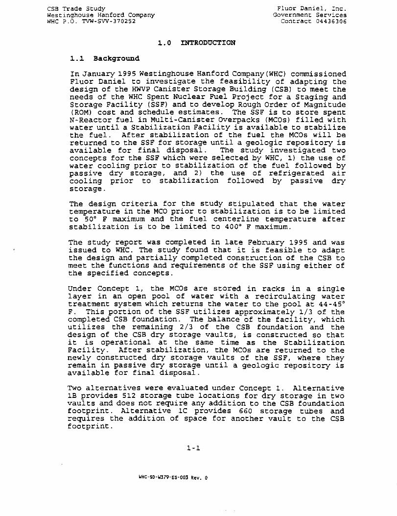
In January 1995 Westinghouse Hanford Company (WHO commissionedFluor Daniel to investigate the feasibility of adapting thedesign of the HWVP Canister Storage Building (CSB) to meet theneeds of the WHC Spent Nuclear Fuel Project for a Staging andStorage Facility (SSF) and to develop Rough Order of Magnitude(ROM) cost and schedule estimates. The SSF is to store spentN-Reactor fuel in Multi-Canister Overpacks (MCOs) filled withwater until a Stabilization Facility is available to stabilizethe fuel. After stabilization of the fuel the MCOs will bereturned to the SSF for storage until a geologic repository isavailable for final disposal. The study investigated twoconcepts for the SSF which were selected by WHC, 1) the use ofwater cooling prior to stabilization of the fuel followed bypassive dry storage, and 2) the use of refrigerated aircooling prior to stabilization followed by passive drystorage.
The design criteria for the study stipulated that the watertemperature in the MCO prior to stabilization is to be limitedto 50° F maximum and the fuel centerline temperature afterstabilization is to be limited to 400° F maximum.
The study report was completed in late February 1995 and wasissued to WHC. The study found that it is feasible to adaptthe design and partially completed construction of the CSB tomeet the functions and requirements of the SSF using either ofthe specified concepts.
Under Concept 1, the MCOs are stored in racks in a singlelayer in an open pool of water with a recirculating watertreatment system which returns the water to the pool at 44-45°F. This portion of the SSF utilizes approximately 1/3 of thecompleted CSB foundation. The balance of the facility, whichutilizes the remaining 2/3 of the CSB foundation and thedesign of the CSB dry storage vaults, is constructed so thatit is operational at the same time as the StabilizationFacility. After stabilization, the MCOs are returned to thenewly constructed dry storage vaults of the SSF, where theyremain in passive dry storage until a geologic repository isavailable for final disposal.
Two alternatives were evaluated under Concept 1. AlternativeIB provides 512 storage tube locations for dry storage in twovaults and does not require any addition to the CSB foundationfootprint. Alternative 1C provides 660 storage tubes andrequires the addition of space for another vault to the CSBfootprint.
1-1
HHC-SD-W379-ES-003 Rev. 0
CSS Trade Study • Fluor Daniel, Inc.Westinghouse Hanford Company Government ServicesWHC P.O. TVW-SW-370252 Contract 04436306
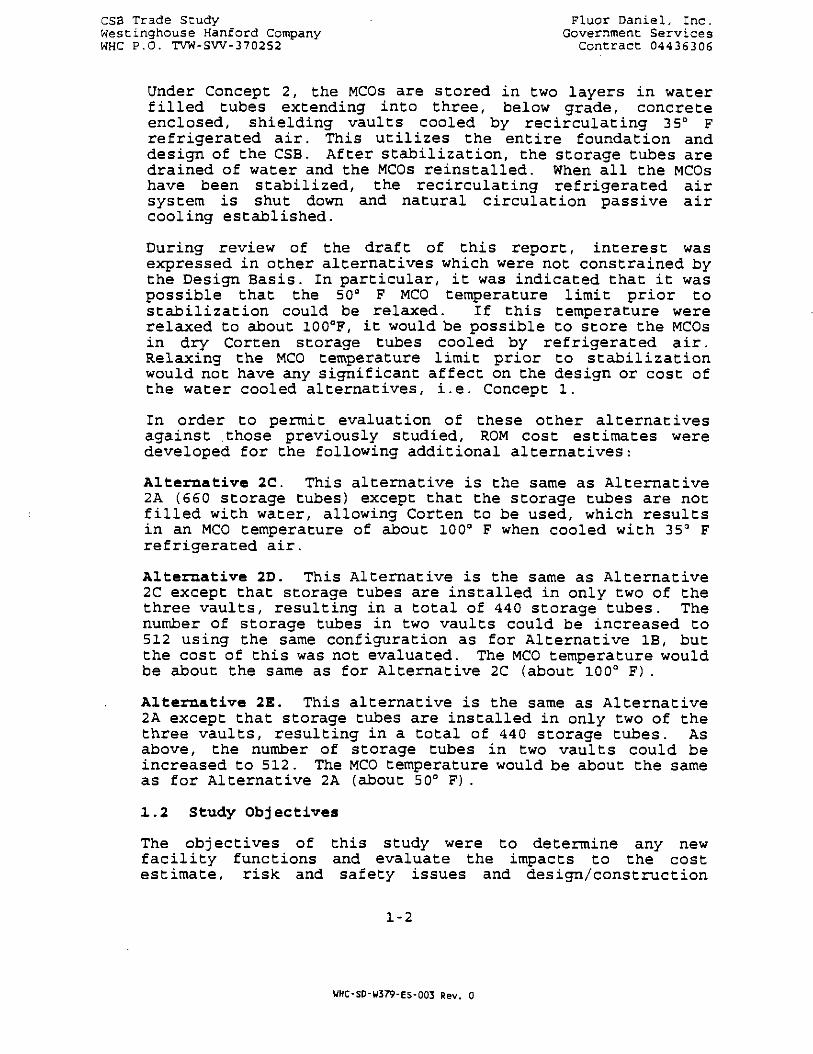
Under Concept 2, the MCOs are stored in two layers in waterfilled tubes extending into three, below grade, concreteenclosed, shielding vaults cooled by recirculating 35° Frefrigerated air. This utilizes the entire foundation anddesign of the CSB. After stabilization, the storage tubes aredrained of water and the MCOs reinstalled. When all the MCOshave been stabilized, the recirculating refrigerated airsystem is shut down and natural circulation passive aircooling established.
During review of the draft of this report, interest wasexpressed in other alternatives which were not constrained bythe Design Basis. In particular, it was indicated that it waspossible that the 50° F MCO temperature limit prior tostabilization could be relaxed. If this temperature wererelaxed to about 100°F, it would be possible to store the MCOsin dry Corten storage tubes cooled by refrigerated air.Relaxing the MCO temperature limit prior to stabilizationwould not have any significant affect on the design or cost ofthe water cooled alternatives, i.e. Concept 1.
In order to permit evaluation of these other alternativesagainst those previously studied, ROM cost estimates weredeveloped for the following additional alternatives:
Alternative 2C. This alternative is the same as Alternative2A (660 storage tubes) except that the storage tubes are notfilled with water, allowing Corten to be used, which resultsin an MCO temperature of about 100° F when cooled with 35° Frefrigerated air.
Alternative 2D. This Alternative is the same as Alternative2C except that storage tubes are installed in only two of thethree vaults, resulting in a total of 440 storage tubes. Thenumber of storage tubes in two vaults could be increased to512 using the same configuration as for Alternative IB, butthe cost of this was not evaluated. The MCO temperature wouldbe about the same as for Alternative 2C (about 100° F) .
Alternative 2E. This alternative is the same as Alternative2A except that storage tubes are installed in only two of thethree vaults, resulting in a total of 440 storage tubes. Asabove, the number of storage tubes in two vaults could beincreased to 512. The MCO temperature would be about the sameas for Alternative 2A (about 50° F) .
1.2 Study Objectives
The objectives of this study were to determine any newfacility functions and evaluate the impacts to the costestimate, risk and safety issues and design/construction
1-2
WHC-SD-W379-ES-003 Rev. 0
C5B Trade Scudy Fluor Daniel, Inc.Westinghouse Hanford Company Government ServicesWHC P.O. TVW-SW-370252 Concract 04436306
schedule for Che Concept 2D, i.e. Alternate 2D for the SSFFeasibility Study. This study will be performed concurrentlywith the Spent Nuclear Fuels(SNF) CSB conceptual design effortand be used as basis for development of a conceptual design.
1.3 Scope of Work
Using Fluor Daniel Concept 2D (dry stage/dry store/1000 FMCO/3 vaults one without tubes/Corten tubes) from the FluorDaniel SSF Feasibility Study, dated February 1995, performtrade studies and prepare individual reports documenting theresults of each investigation in accordance with Statement ofWork, Revision 5, dated April 21, 1995, in Attachment 1 of WHCWork Order TVW-SW-370252, Modification No. 90. Use the samecriteria as the SSF Feasibility Study, unless directedotherwise. The trade studies are as follows:
Concept 2D. Adjust for 750 MCOs with 10 canisters stacked 5-high per MCO. Use MCO characteristics defined in Section3.2.2.1.2.2 of WHC-SNF-FRD-014, "Draft PerformanceSpecification for the Spent Nuclear Fuel Canister StorageBuilding", Rev. A, dated May 1995. Do not reconfigure the HWVPCSB storage vaults to support only 750 MCOs. Storage tubequantity should remain at 220 tubes per vault for a total tubecount of 440 tubes (two vaults) . Revise cost and schedule datafrom the SSF Feasibility Study as appropriate.
Task A Further investigate the requirements for SafetyClass 1 confinement of the operating spaces abovethe storage tubes. A negative air pressurerelative to atmospheric pressure is required.Considerations include, but are not limited to,sealing the building, providing airlocks, andadequate capacity exhaust fans to maintain anegative relative air pressure. Refer to the draftPreliminary Safety Evaluation <PSE).
Task B Remove the new MCO receipt and staging, i.e.cask/MCO unloading and storage, function and area.
Task C Remove the cask decontamination, i.e. wash area,function and area.
Task D Simplify rail service to one track with passingtrack outside facility.
Task E Determine the technical feasibility of non-stainless steel water-filled tubes. Recommendmaterial to resist wet corrosion for only 7 yearsversus 40 years.
1-3
WHC-SD-W379-ES-003 Rev. 0

CSB Trade StudyWescinghouse Hanford CompanyWHC P.O. TVW-SW-370252
Fluor Daniel, Inc.Government Services
Contract 04436306
Task F Reduce from 4 to 2 shipments per day. Handlingequipment demands should be reduced.
Task G Evaluate handling and staging MCOs shipped drained,damp dried from K-Basin assuming 10 SNF canistersper MCO. Determine cooling requirements andinvestigate natural circulation cooling duringstaging.
Task H Functions to comply with Resource Conservation andRecovery Act (RCRA) for prevention and detection ofMCO and tube leaks.
1.4 Design Basis
The criteria for the trade studies is the same as the SSFFeasibility Study unless noted otherwise. MCO characteristicsare defined in Section 3.2.2.1.2.2 of WHC-SNF-FRD-014, "DraftPerformance Specification for the Spent Nuclear Fuel CanisterStorage Building", Rev. A, dated May 1995. Design Basisrequirements are defined in Section 2.8.
1-4
WHC-SD-W379-ES-003 Rev. 0

CSB Trade StudyWestmghouse Hanford. Company Government ServicesWHC P.O. TVW-SW-370252 Contract 04436306
2 . 0 CONCEPT 2D TECHNICAL DESCRIPTION"
2 . 1 FACILITY DESCRIPTION
2.1.1 Plot Plans
Figure 2-1 shows the outline of the Concept 2D SSF and an assumedadjacent Stabilization Facility superimposed on a modified MasterSite Plan for what was previously the HWVP site within the 200 EastArea, The SSF is shown on the location of the existing CSBfoundation. Other existing buildings, roads, rail lines andunderground utilities in the area are shown" in their currentlocations. New facilities which have been proposed forconstruction in the area as shown in the Master Site Plan preparedby Fluor Daniel for the Tank Waste Remediation System (TWRS) SiteIntegration Task Force have been rearranged to be compatible withthe Concept 2D layout and location. The Figure shows that locationof the SSF on the existing CSB foundation is feasible and providesgood access to all required utilities, roads and rail lines. Italso shows that location of the SSF in this area is compatible withplans for other facilities which have been proposed forconstruction in the area.
A more detailed plot plan for Alternative 2D is shown in Figure 2-2. The Stabilization Facility outline shown in Figure 2-2 showsone possible location for the Stabilization Facility relative tothe SSF based on a 100'x 100' foot print and is not intended toportray an accurate representation of its size or geometry.
2.1.2 Rail Tunnel/Cask Unloading Area
2.1.2.1 General Description
The Rail Tunnel/Cask Unloading area is a new addition ofapproximately 10,000 square feet to the original CSB design. It islocated in the north west corner of the CSB and interfaces with theMCO Storage Tube Area via a covered water canal as shown in Figure2-3.
The main functions of this area are to safely receive, handle andprepare the incoming packaged MCO for placement in the storagetubes prior to stabilization. The packaged MCOs are deliveredinside a transport cask, via rail car or truck, one at a time.Before being returned to the K-Basins, the transport casks areprepared for handling and loaded with an empty MCO.
In addition to the underwater transfer canal to transfer MCOs to areceiving station within the operating area of the storage facilitywhere they can be retrieved by the bottom loading MCO shield caskfor transfer to their storage tubes, the Rail Tunnel/Cask Unloading
2-1
WHC-SD-W379-ES-003 Rev. 0

CSd iraae ituayWestinqhouse Hanford ComDanyWHC P.O. TVW-SW-370252
Government ServicesContract 04436306
too
GRAPMtC SOU.E100'
SSF FEASIBILITY STUDYCONCEPT 2 0
WASTER SITE PLAN
FIGURE 2 - 1
CAOFHX- flG2-i C* 5-J0-95

We.; t:.nchouse Kanford CompanyWHC P.O. TVW-SW-370252
.r ..uor jar.ie.., r.nc.Government: Services
Contract 04436.306
H 42200
ROAD ACCESS RAMP
WASH AREAWATER TREATMENTfe MSTR AWCOMPR AREA
CASK/UCOUHS3NXHQ ANOSTOAACC AREA
RCFRIQ.MRUECH.AREA
D
PARXWWAREA
EOUPWCNT/OFnCEBUILDMG AREA
VAULT 1
VAULT 2
DVAULT 3
FUTURE STABtUZATION
MANFOTO PIAHT GRD100 EAST AREA OATUU
0 2S 50 73 TOO 125 150 175 2001 1 1 1 u i i t i i i i
CRAPHIC SCALE IN
SSF FEASIBILITY STUDYCONCEPT 2D
PLOT
FIGURE 2 - 2CADFILE: F1G2-2 CA 5-30-95
2-3
WHC-SD-W379-ES-003 Rev. 0

CASK^-UNLOADING PQDL
gog
OO OO OOOQoooo ooooooooooo
oRoRoxoxo
EQUIPMENT/OFF ICE BUILDING
^
bgOo8g8ggog|g|g§""8gggB§8gg|g§-gogogogogogogogogogogogoR0R0R0R0R0R0
o oo^o^o^owo^owo^o°c£L-
gogogogogoRoRo
xononogogoggogogogogo
ogog/-vVJ A U
gogo
ooogS
j--\O -\O r\O /-\O r\O /-\Oxoxoxogogogogogogo°^0^°^0oRoRoRoRoxoO l f O O O /^O O
«stLi o^ooooooooo/ ^ vJ /-\ vj r\ ^J r*\ w
n o Ro y o xo Ro Ro xo xoO°0oO<^OoO°i_ _
HANfORD PLANT GRID£00 EAST AftCA DAIUH
rui
FUTURE STABILIZATION AREA
SSF
CADflLE'
FEASIBILITYCONCEPT 2DFLDDR PLAN
FIGURE 2~3£DBASE
STUDY
CA 5-30-95
O
n°
O 'D ~rtx IA r
CL
I OCOT
P
UHC-SD-U379 -E S_0 0 3 R e v . 0
CSB Trade Study Fluor Daniel, Inc.Westinghouse Hanford Company Government ServicesWHC P.O. TVW-SW-370252 Contract 04436306
Area contains the following:
(2) rail cars outside the facility{2) rail cars in the facility(4) transport casks: (2) clean, ready for use, (l)
contaminated, waiting for decontamination and (l)in the decontamination pit
(28) empty new MCOs(1) empty new MCO overpack
The Rail Tunnel /Cask Unloading Area includes the Wash Area, theCask Unloading and Storage Area, the Cask Preparation Pit, the CaskUnloading Pool, MCO Transfer Canal, MCO Transfer* Canal Cart and theCask Loading Pit.
A remotely operated hot cell type facility was considered as analternative to the Cask Preparation Pit/Cask Unloading Pool/MCOTransfer Canal/Cask Loading Pit, but was expected to be more costlyand was therefore not considered further.
2.1.2.2 Wash Area
The Wash Area is a air lock confinement area where the incomingrailroad cars and delivery truck/trailer are washed prior enteringthe Cask Unloading and Storage Area. Two railroad cars, and thedonkey engine, and a truck trailer parked in parallel can beaccommodated inside. A permanent ceiling installed liquid sprayarrangement allows wash/decon of the shipping cask upper section.Hand held wash/decon lances are available for the lower areas.Wash water can be pumped out of one or more sumps into a hold tankfor monitoring, before being sent through the non-radioactive drainline to the 200 area.
2.1.2.3 Cask Unloading and Storage Area
The Cask Unloading and Storage Area is designed for unloading andloading transport casks and for handling and storage of empty MCOs.Two railroad cars, one truck trailer, twenty eight MCOs, one MCOoverpack and two clean ready to use shipping casks can beaccommodated in this area. A cask unloading overhead crane, withan auxiliary hoist, running in the west/east direction servicesthis area. A fifteen foot tall wall partially isolates this areafrom the Cask Preparation Pit, the Cask Unloading Pool, MCOTransfer Canal and the Cask Loading Pit, but allows the passage ofthe overhead crane above it.
2.1.2.4 Cask Preparation Pit
The Cask Preparation Pit is dedicated to the preparation ofshipping casks for unloading, which consists primarily of unboltingthe cask cover. A sleeve, anchored to the bottom of the pit,
2-5
WHC-SD-U379-ES-003 Rev. 0
CSB Trade Study . Fluor .Daniel, Inc.Westinghouse Hanford Company Government ServicesWHC P.O. TVW-SW-370252 Contract 04436306
receives and restrains the cask. Access working platforms areaffixed to the upper interior walls of the pit. The overhead craneis used to handle the cask. The* Cask Preparation Pic could also beused for additional cask decontamination or other pre-unloadingservices if necessary.
2.1.2.5 Cask Unloading Pool/MCO Transfer Canal
The Cask Unloading Pool, adjacent to the Cask Preparation Pit westend, is dedicated to unloading MCOs from their casks, MCO servicingand placing defective MCOs in an overpack. Underwater fixtures areprovided to support the cask cover and two MCOs during servicing.Required MCO servicing is performed underwater* at this location,using specially designed tools as described in Section 2.1.3. Anopening, i.e. MCO Transfer Canal, through the common wall separatingthe Unloading Pool with the MCO Storage Area Transfer Canal Poolallows underwater transfer of MCO's from one pool to the other. Tominimize cross contamination to the MCO Storage Area Transfer CanalPool, the pool water return flow is directed toward the UnloadingPool. In case contamination is detected in the Unloading Pool aportable gate can be placed in the wall opening to isolate the twopools. When retrieving an empty cask from the pool, the water inthe cask is drained above the Unloading Pool using special tools.The overhead crane is used to handle the cask and the portablegate. The auxiliary hoist is used to handle the cask cover, MCOand overpack.
The underwater transfer of the MCO from the Unloading Pool to theStorage Area Transfer Canal Pool is accomplished using the MCOTransfer Canal Cart.
2.1:2.6 Cask Loading Pit
The Cask Loading Pit, similar in construction to the CaskPreparation Pit, is located west of the Cask Unloading Pool and isdedicated to cask preparation for return to the K-basins. With thecover removed, the cask is decontaminated, and an empty MCO isloaded inside the cask. The gap between cask cavity and MCO isfilled with deionized water. Finally the cask cover is bolted onand decontaminated if necessary. The now ready to use cask istransferred to a storage position or to an empty railroad carlocated in the Cask Loading and Storage area.
2.1.3 MCO Servicing
2.1.3.1 Functional Description
After each MCO is received into the SSF for staging, the MCO willbe purged with nitrogen, then deionized water will be added ifneeded to reach the desired level in the MCO. The servicing willbe done with the MCO submerged in the Cask Unloading Pool. A pool
2-6
UHC-SD-W379-ES-003 Rev. 0

C3E Trade Stuc.y Fluor Daniel, m e ,West:.ngr.ouse Kanford Company Government: ServicesWHC! P.O. TVW-SW-370252 Contract 04436306
water treatment system will maintain pool temperature, clarity, andradioactive contamination at acceptable levels.
2.1.3.2 System Design Requirements
Once all MCOs have been received, only water-filled MCOs will needto be serviced. Based on the water reaction rate with, uranium andthe evaporation rate at 100 °F, the worst MCO must be serviced atleast every 300 days. Since there is no means of determining thewater level within an MCO, a conservative schedule must beestablished to ensure that the top canister in the most active MCOdoes not become dry. This requires servicing at least 3 MCOs perday, starting within 300 days after placement.- For water-filledMCOs, it was assumed that the hydrogen inside each MCO does notconstitute a hazard, assuming the MCOs are designed so they willnot release gas in the event of a Design Basis Accident (if thisassumption is incorrect, then more than 500 MCOs per day must bepurged in order to keep hydrogen concentrations below the hazardouslevel of 6%. The pool water will provide sufficient shielding foroperators above the pool to assist in making the necessary pipingor hose connections to the MCO using specially designed tools.Water will flow into the servicing area from the MCO Storage AreaTransfer Canal Pool, then back to the pool treatment system. Thecontainment and confinement requirements for this area are asdefined in ANSI/ANS Standard 57-7. Because of the greater chancefor contamination of the pool when MCO valves are opened, the waterturnover time in the service area is 36 hr, half that of the ANSIStandard requirement.
2.1.3.3 Design Assumptions
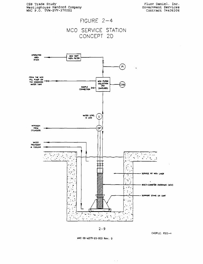
The- MCO will be designed so that a grapple can be attached fortransporting it underwater without the cask. The MCO will have atleast three valved connections that can be remotely connected topiping or hoses, with each valve capable of remote operation (seeFigure 2-4) . One of the connections will have an interior dip tubewhich extends a known length below the desired water level (butabove any sludge) , and another connection will terminate at the topof the MCO, so that a differential pressure sensor in the servicearea can determine the MCO water level. One of the differentialpressure legs will also be used for nitrogen purging, describedbelow. The third valved connection will allow the MCO to be filledwhile the water level is monitored.
2.1.3.4 Mechanical Design and Operation
The servicing of 4 MCOs per day requires two service stations inthe servicing area. Each station is equipped with a gas collectionpot, filter, piping, and instruments that must be connected to theMCO for servicing. The station is attached by flexible hoses tofixed piping for nitrogen, water, and vent gas. The basic
2-7
WHC-SD-W379-ES-003 Rev. 0

CSS Trace Stuc.y "..uor -•ar.:.e-, 7. .c.WA.st:.nghouse E-:anford Company Government ServicesWHC P.O. TVW-.EW-370252 Contract 0443(5306
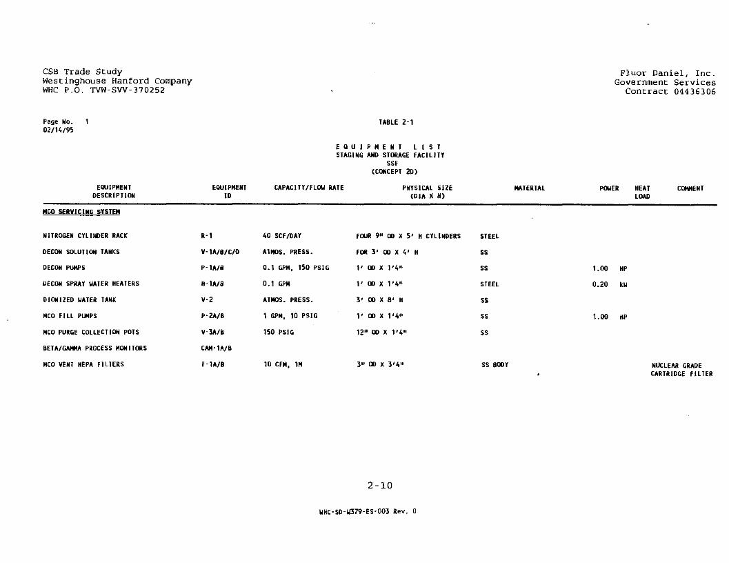
components of a station are shown on Figure 2-4. The systemequipment list (Table 2-1) indicates the major items needed for thetwo stations as well as auxiliary equipment that supports thefunction of the stations.
The cask unloading crane brings the shielding cask with MCO intothe Cask Unloading Pool. The cask provides operator shieldinguntil the cask is covered by at least 8 ft of water. After thecrane removes the cask lid and places the MCO on an underwaterstand for servicing, the operator manually positions the servicingpiping assembly onto the MCO, remotely couples the piping to theMCO connections and prepares to operate the MCO valves. The ventgas pressure and contamination level are monitored before the gasis released through a HEPA filter to the operating area buildingstack. Upstream of the HEPA filter is a shielded gas collectionpot which will serve as a radiation monitor source, catch anyentrained liquid in the vent gas, and provide capability for gassampling. After the pressure in the MCO is released, sufficientnitrogen is purged through the MCO to reduce the hydrogenconcentration to 1% by volume or less. After purging, thenitrogen flow is reduced in order to measure the level of water inthe MCO. Nitrogen is stored in cylinders delivered by truck to arack outside the building. If needed, deionized water is added bya metering pump through the collection pot in order to flush anycontamination back into the MCO. The valves on the MCO are closedafter servicing, the service station is disconnected, and the MCOis transported underwater by the MCO Transfer Canal Cart into theMCO Storage Area Transfer Canal Pool.
2.1.4 Cask Unloading Pool Water Treatment System
2.1-.4.1 Functional Description
After each MCO is received and passed through the Cask PreparationPit, the MCO will be placed in the Cask Unloading Pool. The poolwater provides shielding and cooling for the worst case. The poolwater treatment system will maintain pool temperature, clarity, andradioactive contamination at acceptable levels. Although noleakage is expected from MCOs or system components, the pool andits water treatment system are designed to minimize radiationexposure in the event of leakage due to a credible accident.
2.1.4.2 System Design Requirements
The nominal value of heat generation per MCO is 221 W and themaximum value is 482 W. At 100 °F the maximum MCO produces near 40L/day of hydrogen gas contaminated with 4.62 mCi/L of Kr-85. Thenominal values apply to 80% of the MCOs, the upper limits apply to20%. There are no particulates or condensible vapors generatedduring non-accident conditions. The total system cooling duty isbased on the maximum MCO.
2-3
WHC-SD-W379-ES-003 Rev. 0
CSB Trade StudyWestinghouse Hanford CompanyWHC P.O. TVW-SW-370252
Fluor Daniel, Inc.Government Services
Concract 04436306
FIGURE 2 - 4
MCO SERVICE STATIONCONCEPT 2D
OPERATING
AREASTACK
FROM THE UCOFILL PUMP ON
THE DOONIZEOWATER TANK
UCO VEHTHEPA FILTER
—CKl-
WATER LEVELIN UCO
NITTOCENFROM
CYUNOEKS
WATERTREATUENT* COOUNC
SERVICE PTT WITH UNER
MULTI-CANSTEH OVERPACK (UCO)
SUPPORT STANO OR CART
2 - 9CADFILE: FIG2-A-
WHC-SD-U379-ES-003 Rev. 0
CSB Trade StudyWesCinghouse Hanford CompanyWHC P.O. TVW-SW-370252
Fluor Daniel, Inc.Government Services
Contract 04436306
Page No. 10 2 / U / 9 5
EQUIPMENTDESCRIPTION
EQUIPMENTID
TABLE 2-1
E Q U I P M E N T L I S TSTAGING AND STORAGE FACILITY
SSF(CONCEPT 2D)
CAPACITY/FLOW RATE PHYSICAL SIZE(D1A X H)
MATERIAL POWER HEATLOAD
COMMENT
MCO SERVICING SYSTEM
NITROGEN CYLINDER RACK
DECON SOLUTION TANKS
DECON PUMPS
DECON SPRAY WATER HEATERS
DIONIZED WATER TANK
MCO FILL PUMPS
MCO PURGE COLLECTION POTS
BETA/GAMMA PROCESS MONITORS
MCO VENT HEPA FILTERS
R-1
V-1A/B/C/D
P-1A/B
H 1A/B
V-2
P-2A/B
V-3A/B
CAM-1A/B
F-1A/B
40 SCF/DAY
ATMOS. PRESS.
0.1 GPH, 150 PSIG
0.1 GPM
ATMOS. PRESS.
1 GPH, 10 PSIG
150 PSIG
10 CFH, 1H
FOUR 9" OD X 5' H CYLINDERS
FOR 3' OD X 4' H
1' OD X 1'4"
1' OD X 1'4"
3' OD X 8' H
1' OD X 1'4"
12" OD X 1'4«
3" OD X 3'4"
STEEL
SS
SS
STEEL
SS
SS
SS
SS B(
1.00 HP
0.20 kU
1.00 HP
NUCLEAR GRADECARTRIDGE FILTER
2-10
WHC-SD-W379-ES-003 Rev. 0

CSB Trade Study Fluor Daniel, Inc.Westinghouse Hanford Company Government ServicesWHC P.O. TVW-SW-370252 Contract 04436306
The pool is lined with stainless steel to ensure water purity, toprevent water migration through the concrete pool structure, and toallow decontamination at the end of the facility life. Asrecommended by DOE Order 6430.1A, Section 1320, the liner has aleak detection system with a collection sump in the concretestructure.
The water treatment system returns water which has been purifiedand cooled to 95 °F. This will maintain the MCO at 100 °F or lessunder normal conditions. The system has sufficient redundancy (orelse contingency back-up capability within the available responsetime) so that a single failure of any active component {such as apump, filter, or control) will not cause loss of system function.The following requirements of ANSI/ANS 57.7 and NRC Reg Guide 3.49are met: Clarity will be sufficient to clearly see to the bottomof the pool. Contamination will be maintained at an annual averagegross activity level of 5 x 10"* mCi/L or less during normaloperation. The recirculation rate is sufficient to turnover thepool volume in 36 hours and the deionization units will not beregenerated. The piping is designed so that water will not siphonout of the pool in the event of a piping leak. Because of thesmall size of the units, the resin beds are replaced when theybecome saturated.
The system will maintain a safe condition after loss of normalpower, loss of cooling, and Design Basis Accidents such asearthquake,- in these cases, credit will be taken for portableequipment that can be moved in during the period of time beforetemperatures, hydrogen concentration, or contamination levelsexceed safe levels. The clean-up system will have the capacity forthe worst-credible release of contamination into the pool.
2.1.4.3 Design Assumptions
The MCO will be designed so that a grapple can be attached fortransporting it underwater without the cask. The laboratoryrequired for periodic analysis of pool water samples is not part ofthis facility. Fresh make-up to the deionizer will come from thesite sanitary water, containing 95.1 ppm dissolved solids, lessthan 10 ppm suspended solids, pH 7.80, and CaCOa hardness of 73.46ppm.
2.1.4.4 Mechanical Design and Operation
Figure 2-3 shows the arrangement of the Cask Unloading Pool andassociated areas. MCOs are transported to and from the caskunloading pool by the MCO Transfer Cart. The depth of water abovethe MCO Transfer Cart allows the MCO being transported to becovered by 8 ft of water at all times.
2-11
WHC-SD-W379-ES-003 Rev. 0
CSB Trade Study • Fluor Daniel, Inc.westinghouse Hanford Company Government ServicesWHC P.O. TVW-SW-3702S2 Contract 04436306
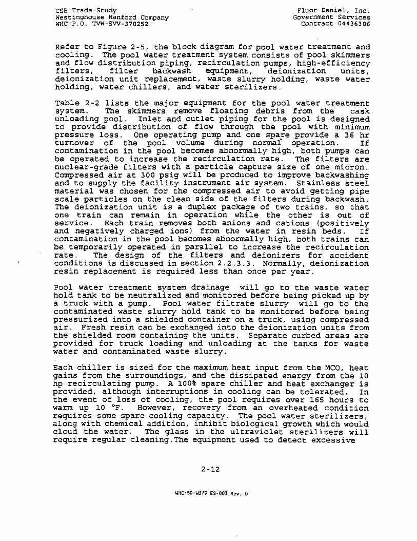
Refer to Figure 2-5, the block diagram for pool water treatment andcooling. The pool water treatment system consists of pool skimmersand flow distribution piping, recirculation pumps, high-efficiencyfilters, filter backwash equipment, deionization units,deionization unit replacement, waste slurry holding, waste waterholding, water chillers, and water sterilizers.
Table 2-2 lists the major equipment for the pool water treatmentsystem. The skimmers remove floating debris from the caskunloading pool. Inlet and outlet piping for the pool is designedto provide distribution of flow through the pool with minimumpressure loss. One operating pump and one spare provide a 36 hrturnover of the pool volume during normal* operation. Ifcontamination in the pool becomes abnormally high, both pumps canbe operated to increase the recirculation rate. The filters arenuclear-grade filters with a particle capture size of one micron.Compressed air at 300 psig will be produced to improve backwashingand to supply the facility instrument air system. Stainless steelmaterial was chosen for the compressed air to avoid getting pipescale particles on the clean side of the filters during backwash.The deionization unit is a duplex package of two trains, so thatone train can remain in operation while the other is out ofservice. Each train removes both anions and cations (positivelyand negat ively charged ions) from the water in res in beds. I fcontamination in the pool becomes abnormally high, both trains canbe temporarily operated in parallel to increase the recirculationrate. The design of the filters and deionizers for accidentconditions is discussed in section 2.2.3.3. Normally, deionizationresin replacement is required less than once per year.
Pool water treatment system drainage will go to the waste waterhold tank to be neutralized and monitored before being picked up bya truck with a pump. Pool water filtrate slurry will go to thecontaminated waste slurry hold tank to be monitored before beingpressurized into a shielded container on a truck, using compressedair. Fresh resin can be exchanged into the deionization units fromthe shielded room containing the units. Separate curbed areas areprovided for truck loading and unloading at the tanks for wastewater and contaminated waste slurry.
Each chiller is sized for the maximum heat input from the MCO, heatgains from the surroundings, and the dissipated energy from the 10hp recirculating pump. A 100% spare chiller and heat exchanger isprovided, although interruptions in cooling can be tolerated. Inthe event of loss of cooling, the pool requires over 165 hours towarm up 10 °F. However, recovery from an overheated conditionrequires some spare cooling capacity. The pool water sterilizers,along with chemical addition, inhibit biological growth which wouldcloud the water. The glass in the ultraviolet sterilizers willrequire regular cleaning.The equipment used to detect excessive
2-12
WHC-SD-W379-ES-003 Rev. 0

CSB Trade StudyWestinghouse Hanford CompanyWHC P.O. TVW-SW-370252
Fluor Daniel, Inc.Government Services
Contract 04436306
POOLWATER
COMPRESSEDAIR
SKIMMERSAND FLOW
DISTRIBUTIONRECIRCULAT1ON
PUMPS
FILTERBACKWASH
TRUCKS ORONSITE TREATMENT
RESINREPLACEMENT
HIGH-BFFICIENCYFILTRATION
DEIONIZAHON
CONTAMINATEDWASTE SLURRY
HOLDING
CONTAMINATEDWASTE WATER
HOLDING
TRUCKS
COOUNGAND
STERILIZATIONPOOL
WATER
TRUCKS ORONSITE TREATMENT
FIGURE 2-5
PROCESS BLOCK FLOW DIAGRAMCASK UNLOADING POOL
WATER TREATMENT
2-13WHC-S0-W379-ES-003 Rev. 0

CSB Trade StudyWestinghouse Hanford CompanyWHC P.O. TVW-SW-370252
Page No. 102/14/95
EQUIPMENTDESCRIPTION
EQUIPMENTID
TABLE 2 - 2
E Q U I P M E N T L I S TSTAGING AND STORAGE FACILITY
SSF(CONCEPT 2D>
CAPACITY/FLOW RATE PHYSICAL SIZE(D1A X H)
MATERIAL
Fluor Daniel, Inc.Government Services
Contract 04436306
POWER HEATLOAD
COMMENT
POOL UATEB TREATMENT SYSTEM
RECIRCULATION PUMPS
PRIMARY POOL FILTERS
DE1ONIZAT1ON UNIT
WASTE SLURRY HOLD TANK
WASTE WATER HOLD TANK
POOL UAIER CHILLERS
POOL UAIER EXCHANGERS
POOL WATER STERILIZERS
P-3A/B
F-2A/B
R-1A/B
v-«
V-5
CH-1A/B
E-1A/B
UV-1A/B
30 GPM, 300 PSIG
30 GPM, 50 PSIG
30 GPM, NET
25 PSIG
15 PSIG
2,200 BTU/HR (0.18)TONS) NET
600 BTU/HR
30 GPM
2" SUCTION
FOUR TANKS
3' OD X 6'
3' 00 X 6'
IS' OD X 6' H
H
H
SS
SS
SS
SS
SS
STEEL
STEEL & SS
GLASS & SS
10.00 HP ONE SPARE
60.00 HP ONE SPARE
INSTRUMENT AIR SYSTEM
AIR COMPRESSOR
INSTRUMENT AIR ORYER
INSTRUMENT AIR RECEIVER
C-1A/B
DY-1
V-1
100 SCFM, 300 PSIG
100 SCFM, NET
300 PSIG 8' OD X 8' H
STEEL
STEEL
ONE SPARE
DUPLEX
2-14
WHC-SD-W379-ES-003 Rev. 0

JSr> ."/rao? o-ucy ~.\uor Dan:.e.\, Inc.We;:C:.ncrb:iuse Kanford Company Government ServicesWHC P.O. TVW-SW-370252 Contract 04436306
contamination in the pool and locate a leaking MCO is discussed inSection 2.2.3.3.
2.1.5 MCO Cooling and HVAC
2.1.5.1 HVAC Systems for Normal Operation
Vault Refrigerated Air System. The block flow diagram for the HVACsystem serving the SSF Vaults during staging is shown on Figure 2-6. The HVAC system is a recirculating refrigerated air systemconsisting of five 50,000 CFM Air Handling Units (4-operating andl-standby) which supply chilled air at 35 °F to the vault. Thissupply air temperature to the vault will maintain the MCOs at111 °F. The 111 °F does not comply with current MCO temperature{100 DF) requirements, but is used as the basis for the ROM costestimate. Since the MCO's are stored in dry air filled Cortentubes which serve as a secondary confinement barrier, the airinside the vault will not be contaminated.
Vault Passive Ventilation System. The passive ventilation systemfor the vault during dry storage will be identical to the CSBdesign. This concept has two vaults, each with 220 tubes. Thereare provisions for 11 overpacks and the tube spacing for thisconcept will be identical to the CSB design. A third vault isprovided as in the original CSB design, however, no tubes will beinstalled.
Operating Area HVAC System. The Operating Area HVAC System for theCSB design will be modified to accommodate the ventilation systemfor the MCO service area and the MCO/Cask unloading and storagearea. The system is capable of diluting the hydrogen and krypton-85 'to acceptable levels by introducing sufficient amounts ofoutside air. The block flow diagram for this system is depicted inFigure 2-7) .
Pool Water Treatment Building. This building consists of cleanareas and potentially contaminated areas. A single HVAC systemwill be used to serve these areas.
The block flow diagram for the HVAC system serving these areas isshown on Figure 2-8. Redundant 2,000 CFM Air Handling Units (AHU-1and AHU-2) with evaporative cooler and heating coil supply air tothese areas and the air is exhausted through redundant HEPA filterplenums (PF-1 and PF-2) and exhaust fans (EF-1 and EF-2).
2.1.5.2 HVAC Systems for Abnormal Operation
Vault Refrigerated Air System. It has been estimated that onfailure of the vault refrigerated air system used during staging,the MCO temperature will increase by 30 °F in approximately 20hours. Concept 2D is currently not a safety class system.
2-15
WHC-SD-U379-ES-003 Rev. 0

CSB Trade StudyWestinghouse Hanford CompanyWHC P.O. TVW-SW-370252
IX1MMM. IKJ-t
u--i juLdoa cru]
Fluor Daniel, Inc.Government Set vices
Contract 04436306
SSF - VAULT
F I G U R E : 2 - 6
SSF FEASIBILITY STUDY
CONCEPT 2D
VAULT - HVAC SYSTEM
2-16UHC-SD-W379-ES-003 Rev. 0

CSB Trade StudyWestinghouse Hanford CompanyWHC P.O. TVW-SW-370252
Fluor Daniel, Inc.Government Services
Contract 04436306
TO ATM
OSA
OSA
TO ATM
RETURN/EXHAUST FAN
PH HC EC
AIR KANDtlMr, UNIT
PH HC EC
AIR HANDLING UNIT
OPERATINGAREA AND CASKUNLOADING AREA
RETURN/FXHAU5T FAN
F I G U R E : 2 - 7
SSF FEASIBILITY STUDY
CONCEPT 2 0
OPERATING AREA
HVAC SYSTEM
2-17
UHC-SD-W379-ES-003 Rev. 0

CSB Trade StudyWestinghouse Hanford CompanyWHC P.O. TVW-SW-370252
Fluor Daniel, inc.Government Services
Contract 04436306
TO AIM
OSA
OSA
PH HC EC
AIR HAMfXJNG UNITAHU-1 f2OOO CFM)
PH HC EC
AIR HAMMING UNITAHU~2 f2QOQ(STANDBT)
POOL WATER TREATMENTBUILDING
WORKSPACE
EFFLUENTMONITOR
HE.PA FILTER QNffPF-t f2OQn
u: WORKSPACE
FXHAUST FAN
EXHAUST STACK
FXHA1JST fAH
(STAN06Y)
FILTERP F - 2 ^2000 CFMl(STANDBY)
F I G U R E : 2 - 8
SSf FEASIBILITY STUDYCONCEPT 20
POOt WATER TREATMENT BUILDINGHVAC SYSTEM
I1[IW«: K1-*
2-18
WHC-SD-U379-ES-003 Rev. 0

CSB Trade StudyWestinghouse Hanford CompanyWHC P.O. TVW-SW-370252
Fluor Daniel, Inc.Government Services
Contract 04436306
TO ATM
OPERATINGAREA AND CASKUNLOADING AREA
WORKSPACE
HEPAPF-1 f6QQQ
WORKSPACE
HEPA U.NtTPF-2 (6OO0 CFM)
EFFLUENTMONITOR
EXHAUST
EXHAUST FANTRAIN - - f l "
EXHAUST STACK
F I G U R E : 2 - 9
S5F FEASIBILITY STUDY
CONCEPT 2D
OPERATING AREA
HVAC EMERGENCY VENTILATION SYSTEM
2-19
UHC-SO-U379-ES-003 Rev. 0

CSB Trade Study Fluor Daniel, Inc.Westinghouse Hanford Company Government ServicesWHC P.O. TVW-SW-370252 , Contract 04436306
Adequate time would mostly likely not be available in the event ofa sustained loss of refrigerated air cooling to bring in mobileemergency cooling capability before MCO temperatures becameexcessive.
Vault Passive Ventilation System. The vault passive ventilationsystem used during dry storage is designed to operate following allDBA's. No other HVAC systems are required for operation of thevaults during abnormal operation.
Operating Area. The block flow diagram for the HVAC system foremergency ventilation of the Operating Area is shown on Figure 2-9) . This system is designed to be activated following an accident(potential drop of an MCO and release of contamination to theoperating area) and is interlocked to stop the normally operatingHVAC system. The HVAC system consists of two trains with HEPAfilter plenums (PF-l and PF-2) and exhaust fans (EF-1 and EF-2).
2.1.6 Structural
The CSB below grade concrete vaults and the operating floor willessentially remain the same as originally designed. Vaults 1 and 2will be used for the staging and storage of the MCOs containingSNF, and vault 3 will remain empty for future storage of undefinedmaterial. The existing 3 feet east-west wall between vaults 2 & 3must be increased to 42" to provide adequate shielding protectionto persons entering the vault 3 for activation at a later date.Preliminary HVAC calculations indicate that the concrete surfacetemperature inside the vaults during staging and support phaseswill not exceed 150°F. Therefore, the insulating concrete may bedeleted from the original design. Also the 1 inch metallic traffictopping over the concrete operating floor will be replaced with aless expensive concrete sealer / hardener since the MCOs are to behandled by crane and not by shielded transporters. The structuralconsequence of dropping the facility cask containing MCO from a 3foot height on the operating floor will require further evaluationincluding a crane with features to prevent a drop. The storagetubes will be of Corten material similar to those designed for theCSB.
The existing design of the steel shelter over the operating floorwill be modified to include crane rails and girders for theoverhead crane for the cask/MCO handling system. This buildingheight will be increased by approximately 12 feet and the currentlydesigned steel columns and portion of roof trusses members will bereplaced with stronger sections. The north wall of the operatingbuilding may require relocation north by approximately 8'-0" toaccommodate crane operation. The Cask/MCO Unloading and StorageArea Building is approximately 170 feet long, 61 feet wide, and 33ft high. This building will have an overhead crane for unloading
2-20
UHC-SD-W379-ES-003 Rev. 0
We. t:.nct-.ouse ;-:anford Company Governmen: Serv icesWK< • P.O. TVW-EW-370252 Contract 04436306
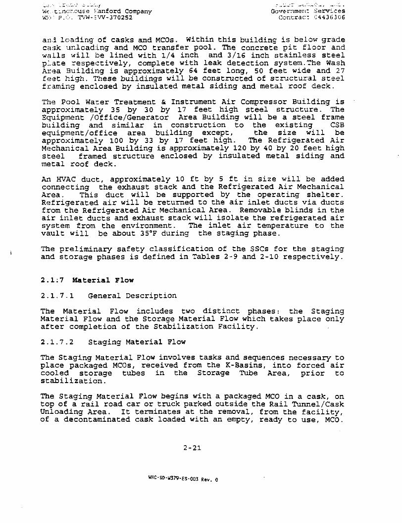
an-i loading of casks and MCOs. Within this building is below gradecask unloading and MCO transfer pool. The concrete pit floor andwalls will be lined with 1/4 inch and 3/16 inch stainless steelplate respectively, complete with leak detection system.The WashArea Building is approximately 64 feet long, 50 feet wide and 27feet high. These buildings will be constructed of structural steelframing enclosed by insulated metal siding and metal roof deck.
The Pool Water Treatment & Instrument Air Compressor Building isapproximately 35 by 30 by 17 feet high steel structure. TheEquipment /Office/Generator Area Building will be a steel framebuilding and similar in construction to the existing CSBequipment/of f ice area building except, the size will beapproximately 100 by 33 by 17 feet high. The Refrigerated AirMechanical Area Building is approximately 120 by 40 by 20 feet highsteel framed structure enclosed by insulated metal siding andmetal roof deck.
An HVAC duct, approximately 10 ft by 5 ft in size will be addedconnecting the exhaust stack and the Refrigerated Air MechanicalArea. This duct will be supported by the operating shelter.Refrigerated air will be returned to the air inlet ducts via ductsfrom the Refrigerated Air Mechanical Area. Removable blinds in theair inlet ducts and exhaust stack will isolate the refrigerated airsystem from the environment. The inlet air temperature to thevault will be about 35°F during the staging phase.
The preliminary safety classification of the SSCs for the stagingand storage phases is defined in Tables 2-9 and 2-10 respectively.
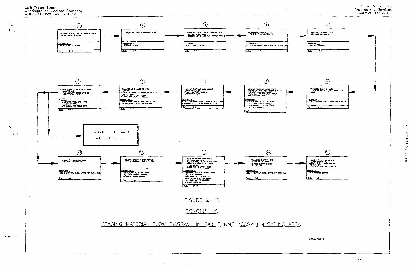
2.1:7 Material Flow
2.1.7.1 General Description
The Material Flow includes two distinct phases: the StagingMaterial Flow and the Storage Material Flow which takes place onlyafter completion of the Stabilization Facility.
2.1.7.2 Staging Material Flow
The Staging Material Flow involves tasks and sequences necessary toplace packaged MCOs, received from the K-Basins, into forced aircooled storage tubes in the Storage Tube Area, prior tostabilization.
The Staging Material Flow begins with a packaged MCO in a cask, ontop of a rail road car or truck parked outside the Rail Tunnel/CaskUnloading Area. It terminates at the removal, from the facility,of a decontaminated cask loaded with an empty, ready to use, MCO.
2-21
WHC-SD-W379-ES-003 Rev. 0
CSB Trade Scudy Fluor Daniel , I nc .Westinghouse Hanford Company Government Serv icesWHC P.O. TVW-SW-370252 Contract 04436306
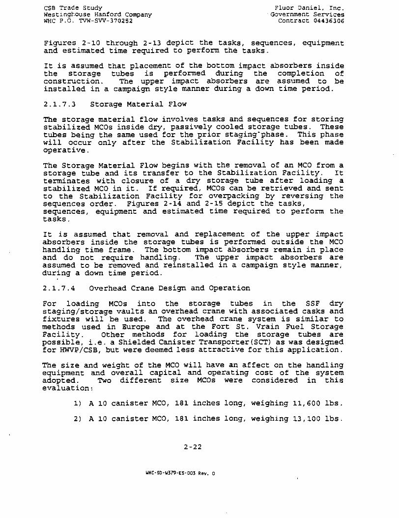
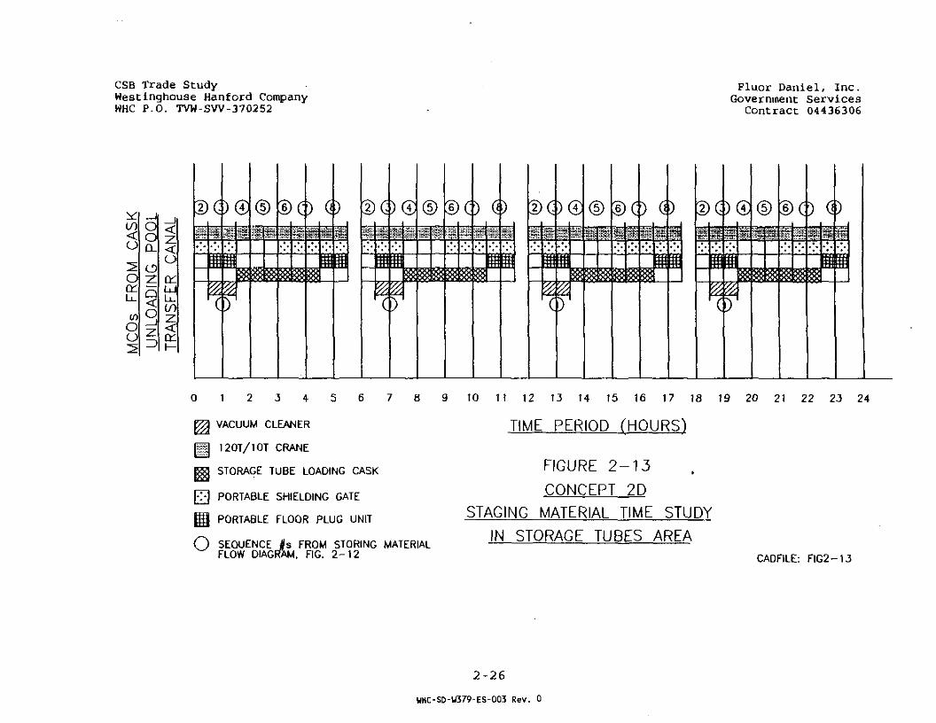
Figures 2-10 through 2-13 depict the tasks, sequences, equipmentand estimated time required to perform the tasks.
It is assumed that placement of the bottom impact absorbers insidethe storage tubes is performed during the completion ofconstruction. The upper impact absorbers are assumed to beinstalled in a campaign style manner during a down time period.
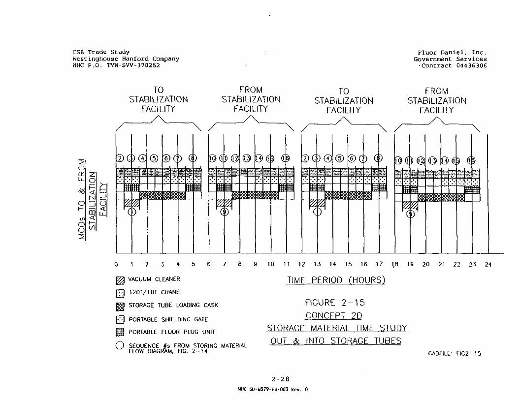
2.1.7.3 Storage Material Flow
The storage material flow involves tasks and sequences for storingstabilized MCOs inside dry, passively cooled storage tubes. Thesetubes being the same used for the prior staging'phase. This phasewill occur only after the Stabilization Facility has been madeoperative.
The Storage Material Flow begins with the removal of an MCO from astorage tube and its transfer to the Stabilization Facility. Itterminates with closure of a dry storage tube after loading astabilized MCO in it. If required, MCOs can be retrieved and sentto the Stabilization Facility for overpacking by reversing thesequences order. Figures 2-14 and 2-15 depict the tasks,sequences / equipment and estimated time required to perform thetasks.
It is assumed that removal and replacement of the upper impactabsorbers inside the storage tubes is performed outside the MCOhandling time frame. The bottom impact absorbers remain in placeand do not require handling. The upper impact absorbers areassumed to be removed and reinstalled in a campaign style manner,during a down time period.
2.1.7.4 Overhead Crane Design and Operation
For loading MCOs into the storage tubes in the SSF drystaging/storage vaults an overhead crane with associated casks andfixtures will be used. The overhead crane system is similar tomethods used in Europe and at the Fort St. Vrain Fuel StorageFacility. Other methods for loading the storage tubes arepossible, i.e. a Shielded Canister Transporter(SCT) as was designedfor HWVP/CSB, but were deemed less attractive for this application.
The size and weight of the MCO will have an affect on the handlingequipment and overall capital and operating cost of the systemadopted. Two different size MCOs were considered in thisevaluation:
1) A 10 canister MCO, 181 inches long, weighing 11,600 lbs.
2) A 10 canister MCO, 181 inches long, weighing 13,100 lbs.
2-22
UHC-SD-U379-ES-003 Rev. 0
CSB Trade StudyWestinqhouse Hanford CompanyWHC P.O. TVW-SW-370252
•Fluor Daniel, Inc.Governmen t Services
Contract 04436306
O-TRANSFER RJL C M * S H * > P I N G CASKmsoE WASH
-S.R. DONKEY ENGINE
-WASH R J t
FlKBPuFNT --OECON SYS1
TlUC: >.d
CAR
FEM
•i
* SMPPMC CASK
-I.OAO SERVCEO UCO INTO CANALTRANSFER CART
-SEND «CO\IRANSFEH CART TOSTORAGE TUBE AREA
-iJNLOAQlNG POOL. J18 CRANEW / UCO CRAPPU
- U C 0 O N M . TRANSFER CART
TtUf;
-CONNECT VENT HOSE K) UCO.V£NT UCO
-CONNECT OEWtZEQ WATER NOSE TO WCO.rILL UP UCO
-PURGE UCO * VENT HOSE
FQU1P>iFNT- U C O UAINTDWtCE HANDLING TOOLS-MAINTENANCE * UTUIY STATKM
STORAGE TU8E AREA
SEE FIGURE 2 - 1 2
-TRANSFER SHPPINCCASKTO CASK LOADING PIT
ZSU1BA-no r
nut-
S W P P W C C A S K C R A N E * / CASK BAJL
-BEUOVE SHIPRMG CASK COVER-0CCON SHPPING CASK A COVER
-UNLOAOHC POOL JIB« / CASK COVER GRAPPLE
-STATION DECON SYSTEM
HUE:
©- I R W S F M S A C W * EWPPWC C*SX
TO UNLOADING AREA-OOCQNNECT X £»T s_R. OONKET
OONKET CHCME
-UFT UP SHIPP1NC CASK ABOVE
b w N S H & P W C CUM.0AONC POOt
EOHIPMFWT- 1 1 0 ~ r SHIPPING CASK CRANE W / CASK Q«L-SHIPPING CASK ORAIH HWOUNG TOOL
-LOAD AN EMPTY MCO MSJOC
ffil^r^S^ THE CASKINTERIOR CAVITT * UCO WITHCt£AN WATER
-CLOSE THE SHPPWC CASK
FnillPUFNT-SHtPPINO CASK AUSUART CRAKE
W / MCO GRAPPLE-OEKWIZCD WATER STATION-«iNL0AONC POOL J 8 CRANEw / CASK COVCfl CRAPPU
-IMPACT WRENCH
2.0 H
-HO f SWPWG CASK CftV*£ w/ CASK
-PREPARE SHIPPING CASKFQtt MCQ ODING
TIME: 1.0 H
0-REMOVE SWPPWG CASK COVER
-REPLACE SHiPPwC CASK COVEHON SHIPPING CASK
- UNLOADING POOL JIB CRANEW / CASK COVER. CRAPPLE
- UNLOADING POOL JIB CRANE
w/ uca ownsTlKlf; 2.0 H
-TRANSFER SMPP1NC CASKTO UNLOACUNG POOL/UCO TRANSFERCANAL ^
CASK CRANC W / CASK a*4t
TIME:
-TRANSFER SHIPPING CASKTO UNLOADING AREA
-SECURE SHAPING CASKtO « A CAR
- 1 1 0 T SMPPNG CASK CRANE W / CASK SNL
TIMF: 3.0 M
-=ra»« fl.fl. aoNKCr ENGINE
-AfTACH l & L O O f K f ENGINETO R.FL CAR
-car RJI . CAR FROM FACUTY
-«-R. 0ONKEY EHGME
TJMfc 1.5 M
FIGURE 2 - 1 0
CONCEPT 2D
STAGING MATERIAL FLOW DIAGRAM. IN RAIL TUNNEL/CASK UNLOADING AREA
2-23

CSB Trade StudyWestinghouse Hanford CompanyWHC P.O. TVW-SW-370252
Fluor Daniel, Inc.Government Services
Contract 04436306
o
if)
o
nr m
WMWM,
«"idU™
0 1 2 3 4 5 6 7 8 9 10 11 12 13 14 15 16 17 18 19 20 21 22 23 24*
m DONKEY ENGINE TIME PERIOD (HOURS)g 110T/10T CRANE
B53 UNLOADING POOL JIB CRANE
[T] LOADING PIT JIB CRANE
O SEQUENCE J s FROM STAGING MATERIALFLOW DIAGRAM, FIG. 2 - 1 0
FIGURE 2 - 1 1
CONCEPT 2D
STAGING MATERIAL TIME STUDY
IN CASK UNLOADING & STORAGE AREA
CADFILE; F IG2-11
2-24
WHC-SO-W379-ES-003 Rev. 0

^ WHC P.O. TVW-SW-370252"' ' '
©-PREPARE SELECTED STORAGE TU9E
FOR UNLOADING
rni-SPECIAL PORTABLE VACUUM CLEANER
- P U C E PORTABLE SHtCLONC GATEON TOP OF SELECTED STORAGE TUBE
-PORTABLE SHIELDING CATC- 1 2 0 T STORAGE TUBE LOADING CRANE
TIME: 0.5 H
FROM RAIL TUNNEL/UNLOADING AREACASK UNLOADING POOLCANAL TRANSFER CART
SEE FIGURE 2 - 1 0
-PLACE PORTABLE FLOOR PLUG UNIT ONTOP OF PORTABLE SHIELDING GATE
-REMOVE H.OOR PLUG INSIDEPORTABLE FLOOR PLUG UNIT
-REMOVE PORTABLE fLOOR PLUG UNIT
-PORTABLE SHOOING GATE-PORTABLE FLOOR PLUG UNTT- 1 2 0 T STORAGE TUBE LOADING CRANE
TIME:
1A
-PLACE PORTABLE FLOOR PLUG UNIT OMTOP OF PORTABLE SHIELDING GATE
-REMOVE FLOOR PLUC INSIOEPORTABLE FLOOR PLUG UNIT
-REUOVC PORTABLE FLOOR PLUG UNIT-TRANSFER PORTABLE SHIELDING GATE
TO SELECTED STORAGE TUBE
-PORTABLE SHCLDKG GATE-FLOOR PLUG HANDLING UNIT- 1 2 0 T STORAGE TU8£ LOAONG CRANE
HUE;
-PLACE STORAGE TU(ON rop OF FIXED :UCO TRANSFER CAN
-FIXEO SHlELOWG C-STORAGE TUBE LQ- 1 3 0 T STORAGE Tl
TIME:
CZ-UNLOA0 UCO INTO S-TRAMSFER STORAGE
TO nxEQ SHIELDING
-PORTABLE SMEUWC G-STORAGC ruac LOAOINI- 1 2 0 T STORAGE TUBE
TIME;
FIGURE 2 - 1 2
CONCEPT 2D
STAGING MATERIAL FLOW DIAGRAM. IN STORA
CSB Trade StudyWestinghouse Hanford CompanyWHC P.O. TVW-SW-370252
Fluor Daniel, Inc.Government Services
Contract 04436306
CO<£O
oQ:
LL.
COoo
ooQ_
Oz:
.OA
DI
— J
CJ
orLUL L00
<fcr
2) I) D
0 1 2 3 4 5 6 7 8
^ VACUUM CLEANER
H I 120T/10T CRANE
|53 STORAGE TUBE LOADING CASK
0 PORTABLE SHIELDING GATE
Q PORTABLE FLOOR PLUG UNIT
O SEQUENCERS FROM STORING MATERIALFLOW DIAGRAM. FIG. 2 - 1 2
10 1! 12 13 14 15 16 17 18 19 20 21 22 23 24
TIME PERIOD (HOURS)
FIGURE 2 - 1 3
CONCEPT 2D
STAGING MATERIAL TIME STUDY
\N STORAGE TUBES AREACADFILE: FIG2-13
2 -26
WHC-SD-U379-ES-003 Rev. 0

CSB Trade StudyWestinghouse Hanford CompanyWHC P.O. TVW-SW-370252
Fluor Daniel, Inc.Government Services
Contract 04436306
©-PREPARE SELECTED staves ruse
FOR UHLOAOWC
-SPECIAL PORTABLE VACUUM CLEANER
TiMf;
-PLACE PORTABLE SHIELDING GATEON TOP Of SELECTED STORAGE TUBE
-PORTABLE SHCLOINC CATC- 1 2 0 T STORAGE TUBE LOAOJNG CRANE
T1UF;
-PREPARE SELECTED STORAGE TUBEFOR LOADING
EQUIPMENT --SPECW. PORTABLE VACUUM CLEANER
Tnig; 1.0 H GAT
-PLACE PORTABLE SHIELDING SATEON rap or SELECTED STORAGE TUBE
EQUIPMENT ---"ORrABLE SHIELDING GATE- 1 2 0 r STORACE RISE LOADING CRANE
TIIJF- o.a H
©-PLACE PORTABLE FLOOR PLUG UNjr ON
TOP OF PORTABLE SWELDWC CAtE-REMOVE FLOOR PLUG IMSOE
PORTABLE FLOOR PLUC UNIT-REMOVE PORTABLE FLOOR PLUG UMT
-PORTABLE SHCLOING GATE-PORTABLE FLOOR PLUG UMT- 1 2 0 T STORACE O B E LOADIttG CAANE
-PLACE PORTABLE FLOOR PUXI UMT ONTOP OF PORTABLE SrtELOWG CAlE
-REMOVE FLOOR PLUG 1NS0EPORTABLE FLOOR PLUG UNtf
-AEuovE PORTABLE: FLOOR PLUG UNIT-TRANSFER PORTABLE SHIELDING QATE
TO SELECTED STORAGE TUBE
cmnPUrtJT •-PORTABLE SHtLONG CATC-FLOOR PLUG HANDLING UNIT- 1 3 0 T STORAGE TUBE LOADING CRANE
JJilL i.O H
-PLACE STORAGE TUBE LOAOWC CASKON I 0 P OF PORTABLE SWELONC CATE
-POflTABLE SHIdOINC GATE-STORAGE TUBE LOADNC CASK- 1 3 0 T STORAGE TUBE LOAQNG CRANE
-LOAD UCO INSOE THESTORAGE TUBE kCjanG CASK
-STORAGE TUBE LOADING CASK- 1 2 0 T STORAGE TUBE L0AO1NG CRANE
TlUf;
T
-UNLOAD UCO INTO STAauZATIONfAOUrr ntANSFER CART
-TRANSFER STORAGE RtBE LOAOINC CASKTO PORTABLE SMELOINC OTE
-STABIUZArON BUJLOtNG UCO TRANSFER CAR1-STORAGE TUBE LOAOIHC CASK- 1 2 0 T STORAGE TUBE LOAOWG CRWE-STABKJZATWN auUXftG TRANSFER
SHIEUXNC GATE
HUE: 1.0 H
-TRAMSfEH STORAGE TUBE LOADING CASKTO TOP OF STAauZATION 9UUHNGTRANSFER TUNNEL SHIELDING CAIt
-STORAGE TUBE LOADING CASK- 1 2 0 I STORAGE TUBE LOADING CRANE
STABRJZAnON 9UHJXNG TRANSFER TUNNELSHCLDtNC » T E
FUTURE
STABILIZATION FACLITY
-PLACE PORTABLE FLOOR PLUG UMT ONTOP OF PORTABU SHELQWG CATE
-REWOVC aOQR PLUG WS0EP0HTA8U FLOOR PLUG UMT
-REMOVE PORTABLE FLOOR PLUS UMT
FQlnPMFNT •-PORTABLE SHIELDINC GATE-PORTABLE FLOOR PLUC UNIT- 1 2 0 T STORAGE TUBE LO*0KC CflAHC
T1UF- 1.0 H
-PLACE PORTABLE FLOOR PLUG UMT ONTOP OF PORTABLE SHELOttt GATE
-REMOVE FLOOR PLUC IM90EPORTABLE FLOOR PLUG UNF
-REMOVE PORTABLE FLOOR PLUC UMT-TRANSFER PORTABU SMCLDMG CATE
TO SELECTED S T O R A C E TUBE
FntllPUFNT •-PORTABLE SHCLONC GATE- a O 0 R PLUG HANDUHG UMT- 1 2 0 T STORACE TUBE LOMMW CRANE
T)UE: 1.0 M
- P U C E STORACE TUBE LOADING CASKON r&P OF STAS»JZAnON 8L0GTRANSFER TUNNCL SHIELDING GATE
-STORAGE TUBE LOADING CASK- 1 3 0 T STORACE RISE LOADING CRANE-STASHJZAHON 9ULQ1NG TRANSFER TUNNEL
SHELONG CATE
TIMC:
-LOAD STABHJZEO UCO INSCE THESTORAGE TUBE LOAQftG CASK
-STORACE TUBE LOAONC CASK- 1 2 0 f STORAGE TUBE LOAONG CRAME-STA8UZAD0N 3UIXING TRANSFCR TUNNEL
SHCLOfNG SATE
TIUF- 1.0
-UNLOAD UCO INTO STORACE TUBE
-TRANSFER STORACE TUBC L O O N C CASKTO TOP Of STASUZATJON 9LDGTRANSFER TUNNEL SH£LDMG CATE
-PORTABLE SMELOtNC GATE-STORACE TUBE LOADING CASK- 1 2 0 T STORACE TUBE lOAONG CRANE
-TRANSFER STORAGE TUBE LOAOINC CASKTO PORTABLE SHCLOtNG GATE
-PORTABLE SHCLDWG SATE-STORACE TUBE LCAOHC CASK- 1 7 0 T STORACE TUBE LOAOINC CRANE
ML.
STORING MATERIAL FLOW
FIGURE 2 - 1 4
CONCEPT 2D
DIAGRAM; TO AiND FROM FUTURE STABiLlZATiQN FACILITYCA0F»X: "G2- I *
2-27
CSB Trade StudyWestinghouse Hanford CompanyWHC P.O. TVW-SW-370252
Fluor Daniel, Inc.Government Services-Contract 04436306
ooru_<%
o
oo
o<M_ l
mi—if)
o
TOSTABILIZATION
FACILITY
FROMSTABILIZATION
FACILITY
TOSTABILIZATION
FACILITY
FROMSTABILIZATION
FACILITY
0 1 2 3 4 5 6 7 8 9 10 11 12 13 14 15 16 17 1,8 19 20 21 22 23 24
^ VACUUM CLEANER
[ £ ] 120T/10T CRANE
^ STORAGE TUBE LOADING CASK
[ T ] PORTABLE SHIELDING GATE
g | PORTABLE FLOOR PLUG UNIT
O SEQUENCE #s PROM STORING MATERIALFLOW DIAGRAM, FIG. 2 - 1 4
TIME PERIOD (HOURS)
FIGURE 2 - 1 5
CONCEPT 2D
STORAGE MATERIAL TIME STUDY
OUT & INTO STORAGE TUBES
CADFILE: F1G2-15
2-28WHC-SD-U379-ES-003 Rev. 0

CSB Trade Study Fluor Daniel, inc.Westinghouse Hanford Company Government ServicesWHC P.O. TVW-SW-370252 Contract 04436306
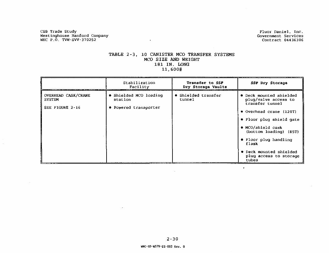
The equipment required for the transfer systems associated witheach of the above MCOs is described in Tables 2-3 and 2-4. Figure2-16 describes the possible operation of this equipment. Caskweights were based on the requirements defined in Section 2.8,Design Basis, Section 3.2.2.1.2.2 of WHC-SNF-FWD-014, "DraftPerformance Specification for the Spent Nuclear Fuel CanisterStorage Building", Rev. A, dated May 1995. Crane capacities wereestimated based on the heaviest loads to be lifted including theweight of the cask based on shielding requirements defined inSection 2.2.5.7, and the safety margins required for critical liftsat Hanford. The SSF crane capacity was based on a safety margin of125% of the heaviest lift anticipated.
The MCO shield cask is a bottom loading cask that incorporates anMCO grapple and hoist assembly. It would be positioned above ashield gate located above a selected SSF storage tube. The storagetube shield plug is handled (removed and installed) using ahandling flask. This system is similar to that employed at theFort St. Vrain fuel storage facility and at several locations inEurope. The MCO Transfer Canal will be the point of entry for theMCO for the overhead crane/cask method. This station would requirea floor plug shield gate.
The overhead cask/crane method will require a means to transportthe MCO to the Stabilization Plant. If the Stabilization Plant isclose coupled to the dry storage facility an unshielded transfercart operating in a below grade tunnel can be used to make thetransfer similar to in Figure 2-16. If the Stabilization Plant isat a distant location, a top-loading shipping cask can be used.
The overhead cask/crane will require four basic components to loadthe' canisters into the SSF storage tubes,
1) The bottom loading MCO shield cask2) The floor plug shield gate3) The portable shielded floor plug handling flask4) The 120T overhead bridge crane with 10T auxiliary hoist
The bottom loading MCO shield cask will contain an integral hoistand grapple system to handle the MCO. It will incorporate a shieldgate at the bottom and a ventilation system to control theatmosphere within the storage tube during MCO transfer.
The floor plug shield gate is used to seal and shield the storagetube when the tube's shield plug is removed. The gate is locatedover the desired storage tube using the overhead bridge crane. Theportable shielded floor plug handling flask is then mated with thetop of the shield gate. A grapple within the flask is used to liftthe plug thru the open shield gate. The gate is then closed andthe flask containing the plug removed. The storage tube is nowready for installation of the MCO.
2-29
UHC-SD-U379-ES-003 Rev. 0
CSB Trade StudyWestinghouse Hanford CompanyWHC P.O. TVW-SW-370252
Fluor Daniel , Inc .Government Services
Contract 04436306
TABLE 2 - 3 , 10 CANISTER MCO TRANSFER SYSTEMSMCO SIZE AND WEIGHT
1 8 1 IN. LONGl l , 6 0 0 #
OVERHEAD CASK/CRANESYSTEM
SEE FIGURE 2-16
StabilizationFacility
• Shielded MCO loadingstation
• Powered transporter
Transfer to SSPDry Storage Vaults
• Shielded transfertunnel
SSF Dry Storage
• Deck mounted shieldedplug/valve access totransfer tunnel
• Overhead crane (120T)
• Floor plug shield gate
• MCO/shield cask(bottom loading) (85T)
• Floor plug handlingflask
• Deck mounted shieldedplug access to storagetubes
2-30
WHC-SD-W379-ES-003 Rev. 0

CSB Trade StudyWestinghouse Hanford CompanyWHC P.O. TVW-SW-370252
Fluor Daniel, Inc.Government Services
Contract 04436306
TABLE 2 - 4 , 10 CANISTER MCO TRANSFER SYSTEMSMCO SIZE AND WEIGHT
181 IN. LONG13,100ft
OVERHEAD CASK/CRANESYSTEM
SEE FIGURE 2-16
StabilizationFacility
• Shielded MCO loadingstation
• Powered transporter
Transfer to SSFDry Storage Vaults
• Shielded transfertunnel
SSP Dry Storage
• Deck mounted shieldedplug/ valve access totransfer tunnel
• Overhead crane (120T)
• Floor plug shield gate
• MCO/shield cask(bottom loading) (93T)
• Floor plug handlingflask
• Deck mounted shieldedplug access to storagetubes
2-31
UHC-SO-W379-ES-003 Rev. 0
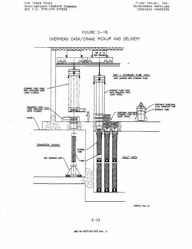
CSB Trade StudyWest:.ngl\ouse Hanford CompanyWHC P.O. TVW-SW-370252
?.'.uor 2an:.eJ., Inc.Government Services
Contract 04436306
FIGURE 2 - 1 6
OVERHEAD CASK/CRANE PICKUP AND DELIVERY
STORAGE TUBE CASKWITH SHIELDING GATE(GATE CLOSED)
TRANSFER PORTFIXED SHIELDING GATE(GATE CLOSED)
WATER-
SSF - STORAGE TUBE ARFAUCO LOADING INTO STORAGE TUBE
STORAGE TUBE CASKWFTH SHIELDING GATE(GATE OPEN)
PORTABLE SHIELDING!STORAGE TUBE GATE!(GATE OPEN)
dUJn
VAULT AREA
CAOFILE: F1G2-18
• PORTABLE SHIELDINGPLUG HANDLING UNft
-STORAGE TUBE
2-32
WHC-S0-W379-ES-003 Rev. 0

CSB Trace Study . Fluor Daniel, Inc.West:.nchouse Hanford Company Government ServicesWHC P.O. TVW-SW-370252 Contract 04436306
The MCO contained within the MCO storage tube loading cask is nextpositioned on top of the shield gate using the overhead bridgecrane. The floor gate and the MCO cask bottom gate are next openedand the MCO lowered into the storage tube, upon reaching bottom,the MCO cask grapple is disengaged and raised back into the MCOcask. The gates are closed and the MCO cask removed from thestorage tube. Finally, the storage tube floor plug is re-installed, and the floor gate removed and installed over the nextstorage tube to be loaded.
2.2 FEASIBILITY ISSUES
2.2.1 Structural
The SSF Feasibility Study final report dated February 1995(Reference FDI transmittal No. FRT-2604) had enumerated on twostructural issues: (a) seismic criteria change; (b) existing CSBconfiguration/design adaption. With respect to the seismic criteriaWHC has confirmed that the basis for design will be Hanford PlantStandard SDC 4.1, Revision 12 as specified in the Draft PerformanceSpecification document WHC-SNF-FRD-014. The design and evaluationof the SSCs will be based on UCRL 15910 as Hanford site has notimplemented the replacement document DOE-STD- 1020-94. The CSB hadbeen designed to 0.35g PGA and there should be little impact tothe concrete vault design for adaption to SNF SSF. The operatingfloor shelter will have to be redesigned for the 12 feet increasein height and addition of bridge crane lead.
Further, the document " Implementation Strategies for U.S. DOEOrder 5480.28 Natural Phenomena Hazards Mitigation" by Tom Conradsof WHC, has correlated WHC safety class 1 (high hazard) as equal toperformance category (PC) 3 of DOE Order 5480.28. For PC-3 theearthquake return period is 2000 years in DOE-STD-1020, whereas inUCRL 15910 the return period is 5000 years for high hazard {WHCSC-1) usage. From Figure 5-lb of Geomatrix Consultants report"Probabilistic Seismic Hazard Analysis" (Project No. 2169, May1993), the PGA for 2000 year return is 0.19g and for 5000 yearreturn is 0.28g. These values when multiplied by 1.25 scale factor,as given in DOE-STD-1020, will give design PGA of 0.24g for PC-3and 0.35g for UCRL high hazard usage facility. Therefore, DOE-STD-1020 PC-3 level earthquake forces are much less than UCRL 15910high hazard class provided the correlation of PC-3 with WHC SC-lasstated my Mr. Conrads is correct.
The MCO/Cask drop over the operating floor during crane handlingwill require further evaluation including a crane with features toprevent a drop. Also as-built drawings of the partiallyconstructed CSB need to be developed prior to start of detaileddesign. Field inspection of the existing construction by anexperienced structural engineer is recommended to evaluate any sign
2-33
UHC-SD-U379-ES-003 Rev. 0

'_.:>3 . . race .:-~'j.c.y ,:..•_•. or .-e.n;.e.., . .r.c.West:.nct.ouse Hanford Company Governmen: Serv icesWHC P.O. TVW-SW-370252 Contirae: :443(i306
of rebar corrosion that may have initiated since the stop of workin 1.992. An optional Gantry crane handling of the MCO/GasJc overthe vault area should be investigated during conceptual design.
The performance specification WHC-SNF-FRD-014 requires the SC-1structures design life as 2 00 years. This new requirement willrequire further investigation of the concrete degradation due tovarious factors such as temperature, wet-dry exposure, reactivechemicals in aggregates, sulfates in soil, etc.
2.2.2 Thermal /HVAC
This section documents the results of a series of thermal analysesthat were performed to assess the feasibility of meeting the Multi-Canister Overpack (MCO) temperature requirements during wet and drystorage with the Concept 2D Staging and Storage Facility (SSF).These analyses were performed for forced refrigerated air andpassive ventilation systems.
The thermal feasibility analyses is based on storage of MCO's indry air filled tubes in vaults 1 and 2 with a forced refrigerationair cooling of the tubes during staging. MCO's are removed andreturned to the tubes after stabilization. After all fuel isstabilized, the passive air ventilation system is made operational.Vault 3 will contain no storage tubes.
2.2.2.1 Design Basis Assumptions
The following design basis assumptions were used for the thermalanalyses:
• The heat generation rate was based on a total 880 MCO's.Twenty (20) percent are assumed to be at the upper limit(maximum) (482 W) and the remaining 80% are assumed to be atthe nominal (average) value (221 W) . Due to the preliminarynature of the heat transfer calculations a ten percent safetyfactor was used for the heat generation rate. Additional heatloads were added for building heat gains and fan heat.
• The heat generation for the limiting case (482 W) per MCO wasused for the calculating the MCO's temperature assuming thatit is located at the end of the vault.
• The design basis required storage conditions are as follows:
Staging: The MCO temperature at 100 °F.Storage: Maximum fuel centerline temperature at 400 °F.
• During the staging operation the MCO provides primaryconfinement and the dry air filled storage tubes provide the
2-34
WHC-SD-W379-ES-003 Rev. 0
_c ;i ..re.c.e o'zv.c.y .7..uor .-ar...e.., ..ac .We.3C:.nct.ouse Kanford Company Governmeri- ServicesWHO P.O. TVW-SW-3702S2 Contract 04436306
secondary-confinement. It is assumed that the interior ot thestorage tubes are isolated from the vault, which would preventthe vault from getting contaminated.
• The total flow is assumed to be evenly and uniformlydistributed around each of the containment tubes. This is acritical assumption that must be assured by design andverified by additional analyses using Computational FluidDynamic (CFD) techniques.
• The heat transfer coefficients for air were calculated at thepoint of maximum vault air temperature.
• One dimensional (radial) heat transfer only. Two-dimensional(radial and axial) heat transfer was not modeled.
• Heat transfer by radiation between the tubes was notconsidered.
2.2.2.2 Summary of Results:
The results of the thermal analyses during staging are shown inTable 2-5 and involve various combinations of MCO's surrounded byair in tubes for different ventilation flow rates. The analyseswere performed for 35 °F and 50 °F supply air.
The results indicate that it is not feasible to maintain the MCOtemperature at 100 °F with a refrigerated forced air ventilationsystem. This system would require 200,000 to 500,000 CFM at asupply air temperature of 35 °F based on the above heat generationrate to maintain the MCO temperature between 105 °F and 111 °F. Thetemperature of 35 °F was selected to prevent freezing of MCO'shaving very low heat generation. The MCO temperature is calculatedon the basis that the MCO is located at the end of the vault withthe limiting heat load.
The results of the thermal analyses during storage operation withthe existing CSB design concept, assuming the same intakestructure, vault size and exhaust stack (height and diameter)indicate that an MCO fuel centerline temperature of 270 °F can bemaintained by a passive ventilation system. This is based on aninlet air temperature of 115 °F (same design basis as CSB) and aventilation flow rate of 53,000 CFM. The vault air temperaturedistribution and velocity profile for a fully loaded vault duringpassive ventilation are shown in Figures 2-17 and 2-18.
The above results demonstrate that it is not feasible to use therefrigerated air system to maintain the MCO temperature below100 °F during the staging operation. However, the passive
2-35
UHC-SD-U379-ES-003 Rev. 0
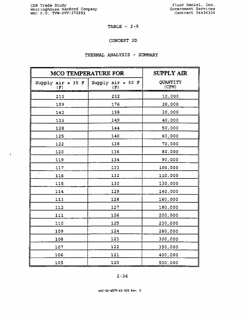
CSB Trade StudyWesCinghouse Hanford CompanyWHC P.O. TVW-SW-370252
Fluor Daniel , I nc .Government Se rv ices
Contract 04436306
TABLE - 2 - 5
CONCEPT 2D
THERMAL ANALYSIS - SUMMARY
MCO TEMPERATURE FOR
Supply a i r * 35 F(F)
213
159
142
133
128
125
122
120
119
117
U S
115
114
113
112
1 1 1
110
109
108
107
106
105
Supply air = 50 F(F)
232
176
158
149
144
140
138
136
134
133
132
130
129
128
127
126
125
124
123
122
121
120
SUPPLY AIRQUANTITY
(CFM)
10,000
20,000
30,000
40,000
50,000
60,000
70,000
80,000
90,000
100,000
110,000
130,000
140,000
160,000
180,000
200,000
230,000
260,000
300,000
350,000
400,000
500,000
2-36
UHC-SD-W379-ES-003 Rev. 0

CSB Trade StudyWest:.nghouse Eanford CompanyWKC P.O. TVW-SW-370252
Fluor Daniel, Inc.Governmenc Services
Contract 04436306
Viewpoint:Up vector:
Command?
1.08 0.000 -B.Z54E-05Q.Z54E-Q5 0.127E-85 1.00
Z UAULTS, 2D CASE, Z78 KU, 115 INLET PHOENICS
FIGURE 2-17
PASSIVE COOLING VAULT TEMPERATUREPROFILE CONCEPT 2D
2-37
WHC-SD-W379-ES-003 Rev. 0
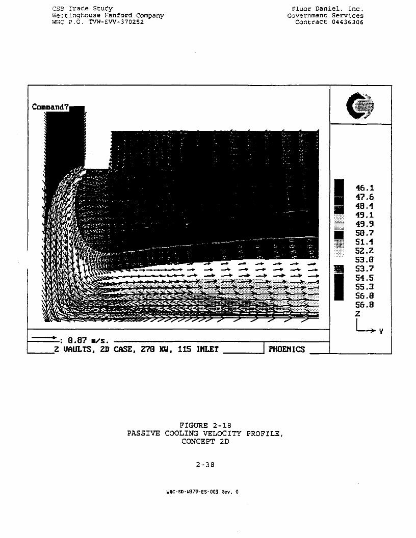
CS3 TraC.e StudyWestinghouse Kanford CompanyWHC P.O. TVW-SW-370252
Fluor Daniel, Inc.Governmenc Services
Contract 04436306
Command?
0.87 M/S.Z UAULTS, 2D CASE, 278 XU, 115 INLET PHOEMICS
46.147.64849495051.452.253.053.754.555.356. Q56.8Zu
FIGURE 2-18PASSIVE COOLING VELOCITY PROFILE,
CONCEPT 2D
2-38
WHC-SD-W379-ES-003 Rev. 0

^.;. ..race ,= uc.y r"_.ucr ?ar?.:.e.., 7.nc.We stz-nc-house Hianford Company ' Government ServicesWHC P.O. TVW-SW-370252 Contract 04436306
ventilation systems can maintain the MCO temperature below the 400°F limit during the storage operation.
It must be emphasized that these are rough conservative feasibility-analyses using limited design information and do not cover alllimiting or upset conditions. More detailed analyses are requiredusing CFD techniques to cover all limiting and upset conditions andto verify some basic assumptions. Also no analysis was performedfor MCO's stored in an overpack.
2.2.3 Contamination Control
2.2.3.1 Introduction
The potential hazards are from gas normally generated by the MCOsbefore stabilization and from the unlikely failure of an MCO tocontain the spent fuel. The feasibility concern is whether theMCOs can be cooled and vented while maintaining acceptableconfinement/containment.
The unstabilized MCOs normally generate decay heat and hydrogengas. The gas is contaminated and the rate of gas generationroughly doubles for every 1O°C (18 °F). The gas must be releasedfrom the MCOs without creating a fire or explosion hazard andwithout exceeding acceptable levels of contamination in occupiedareas. The MCOs must be cooled to reduce the rate of gasgeneration and to prevent the MCOs from drying out. If the watercontained in the unstabilized MCOs evaporates and uranium metal oruranium hydride from the fuel is exposed to air, there is a hazardof pyrophoric reaction. This intense reaction could melt the MCOshell, causing the release of fine particles of oxidized fuelcontaining radionuclides.
The remainder of this section discusses confinement and containmentissues during normal MCO venting or accident conditions duringstaging and storage.
2.2.3.2 Normal Operation
MCO Servicing. The MCOs require servicing after receipt from theK-Basins prior to staging: After each MCO is received into theSSF, the MCO is purged with nitrogen and deionized water is addedif needed to reach the desired level in the MCO. The services canbe done with the MCO submerged in the Cask Unloading Pool. Thepool temperature, clarity, and radioactive contamination must bemaintained at acceptable levels; also, the level of contaminationabove the pool must be acceptable for controlled occupancy. Theissues concerning gas and liquid releases from the MCO whilesubmerged are discussed in Section 2.2.3.1. The design includesthe normal building ventilation system for dilution of hydrogen and
2-39
UHC-SD-W379-ES-003 Rev. 0

CSB Trade Study Fluor Daniel, Inc.Westinghouse Hanford Company Government ServicesWHC P.O. TVW-SW-370252 Contract 04436306
krypton-85, and an MCO servicing system that vents MCO gas to astack and prevents overfilling of MCOs.
Closed Tube Staging. During abnormal operation, i.e. when thefloor plug is removed, gas vented from the MCOs rises through thestorage tube to reach the operating area, which is normally-ventilated with enough fresh air (over 10,000 cfm) to dilute thehydrogen and krypton-85 to acceptable levels. However, since thestorage tube is normally an enclosed space in which hydrogen couldaccumulate, provisions must be made to ensure that explosiveconcentrations do not develop. The following paragraph describesone concept for achieving this objective.
Each storage tube has a sealed floor plug with an embedded ventline and two test lines. The test lines have normally-closedvalves and the vent line contains a HEPA filter. The tubes asoriginally designed can contain a pressure of almost 5 psig beforethe plug lifts from its sealed seat; the tube wall and bellows weredesigned for higher pressures. It would be simple to add a reliefdevice to each vent line so that the vent would only be used if thepressure in the tube were to rise to about 4 psig. With a localpressure indicator added to each tube plug, pressures could bemonitored and a portable cart used to sample and purge each tubewith nitrogen. The cart would consist of a nitrogen cylinder onwheels, a regulator, a vent HEPA filter (similar to the one in thetube plug) , and half-inch hoses to connect to the test lines on theplug. As long as each tube is vented and purged with nitrogenbefore the pressure rises above 0.8 psig, the hydrogenconcentration will not exceed 6% by volume. A 6% mixture ofhydrogen in nitrogen is non-flammable when mixed with anyproportion of air. At the nominal design hydrogen generation rate,a tube with one MCO takes 4.8 days to reach 0.8 psig after ventingand purging. With 750 MCOs staged in 375 tubes, an average of 78tubes per day would have to be vented and purged to maintain non-hazardous mixtures of hydrogen in the tubes.
Passive Air-Cooled Storage. After stabilization, the MCOs do notnormally vent gas. There are no contamination issues during normaloperation.
2.2.3.3 Abnormal Operation
MCO Servicing. The Cask Unloading Pool could become contaminatedin the event of the failure of an MCO during unloading orservicing. Until the accident is quantified, it is assumed thatthe unmitigated consequences are severe enough to require safetyclass 1 or 2 systems, as defined in WHC document MRP 5.46 and DOEOrder 6430.1A. To prevent this potential contamination fromreaching the soil, the pit must be lined with stainless steel andmonitored for leakage. Any place where pit water is contained,there must be a way to inspect or test for leaks; this includes anypiping that penetrates through walls or the ground. The glycol
2-40
WHC-SD-U379-ES-003 Rev. 0

_S3 Oracle Study Fluor Daniel, Inc.WesC:.ngt\ause Hanford Company Government ServicesWKC P.O. TVW-SW-370252 Contract 04436306
coolant in the chillers must have monitors or test connections todetect any leaks across the glycol/pit water heat exchangers.
The operating area above the pit could become contaminated in theevent of a crane accident during cask or MCO handling. Should anyabnormal contamination be detected above the pool, alarms warn theoperators to leave the area and the Emergency Ventilation System isactivated. This system ensures that there is no unfiltered releasefrom the building and that the hydrogen concentration remainsorders of magnitude below the flammable limit.
The dropping of an MCO in the pool is not the worst MCO accident(compared, for example, to an accident during MCO handling abovethe storage tube operating floor) , but this accident is a basis fordesigning the pool water treatment system. The pool water filtersand deionizers are sized to contain the upper limit corrosionproducts from an MCO. The soluble corrosion products (cesiumhydroxide) do not pose a criticality threat in the deionizer. Thecritically-safe geometry for the filters has not been determined inthis study, due to time limitations.
Closed Tube Staging. If there is a failure of an MCO duringstaging, the HEPA filter in the sealed tube plug will preventairborne contamination from spreading out of the tube. The tubeplugs have test fittings which allow for periodic water sampling todetect MCO failure. The contamination is localized, but there isno built-in design feature for clean-up.
Passive Air-Cooled Storage. If there is a failure of a stabilizedMCO during storage in a tube, only one tube becomes contaminated.The floor plugs have HEPA filters and test fittings which allow forperiodic gas sampling to detect MCO failure. The contamination islocalized, but there is no built-in design feature for clean-up.
2.2.4 Criticality
2.2.4.1 Introduction
One of the issues identified at the start of the SSF FeasibilityStudy was the minimum allowable spacing between MCO's, from acriticality standpoint, and the identification of a feasiblestorage configuration based on criticality considerations. Some ofthe conclusions reached as part of other concepts within the SSFFeasibility Study are applicable to Concept 2D and are addressedherein. Since criticality safety was identified as a potentialdesign driver, an analysis effort was undertaken to identify andquantify restrictions on N-Reactor fuel storage configurationsbased on criticality. Although the Design Basis contained inSection 2.8 indicates that there are no restrictions on MCO spacing
2-41
UHC-SD-W379-ES-003 Rev. 0

CS?> Trace Stzuc.y Fluor Oan:.e:., .T.nc .West:.nghouse Kanford Company Government ServicesWHi:: P.O. TVW-SW-370252 Contract 0443C306
and stacking based on criticality, it was decided to continue theanalyses to verify the Design Basis.
2.2.4.2 Summary of Results
Preliminary criticality calculations were performed with simplifiedgeometries, talcing no credit for structural material, such ascanister and MCO walls, and all simplifying assumptions made wereconservative. These calculations confirmed that the MCO's could bestacked, even when loaded with five layers of canisters, and can beplaced side-by-side without additional space between MCO's. Theworst-case k.fC calculated was less than 0.90, well within the 0.95limit imposed by the Nuclear Criticality Safety Manual, Section2.0, Paragraph 5.1.3, Allowed Maximum Calculated K-effective.
2.2.4.3 Criteria and Assumptions
The criteria and standards on which these criticality calculationsare based, as well as the assumption used in formulating thecomputations, are given the following paragraphs.
Applicable Orders and Standards. The criticality calculationsperformed in support of this feasibility study conform with thefollowing criteria and standards:
DOE Order 5480.24, "Nuclear Criticality Safety"
DOE-STD-3007-93, "Guidelines for Preparing Criticality SafetyEvaluations at Department of Energy Non-reactor NuclearFacilities"
WHC-CM-4-29, "Nuclear Criticality Safety Manual," issuedSeptember 15, 1988.
Choice of Computer Models. The principal tool selected forcriticality calculations is the PC version of MCNP, Version 4A,developed and supported by the Los Alamos National Laboratory(LAND, Reference 2. This code was selected because of its greatflexibility, high fidelity modeling (e.g., ENDF/B-V continuouscross sections) , and the ability to perform both shielding andcriticality calculations.
Another code available for criticality calculations is KENO,Version V.A (contained in the SCALE-PC, Version 4.1; Reference 3) .This code was not used to perform criticality calculations directlyfor this study, but was used to compare results during thevalidation and verification process.
Code Verification & Validation. All codes used in shielding andcriticality calculations at Fluor Daniel have been verified byrunning the test problems supplied with the code packages. The
2-42
UHC-SD-U379-ES-003 Rev. 0
CSB Trade Study Fluor Daniel, inc.Westinghouse Hanford Company Government ServicesWHC P.O. TVW-SW-370252 ConCracC 04436306
test problem results are shown to be in agreement either with thepublished documentation supplied as part of the code package, orwith the sample problem output, if supplied. This information isdocumented, dated, and retained on file at Fluor Daniel. Anychanges, such as upgrades, corrections, modifications, etc., areincorporated into the documentation following rerunning of theverification problems.
MCNP, Version 4A is the latest version, Reference 2, of a widely-used and well accepted radiation transport code employed for a widevariety of radiation analyses including neutron, photon andelectron transport, and criticality. LANL has performed extensivecalculations with MCNP,. duplicating a wide ranije of experimentalresults, to validate the models contained in this code. Theresults of these benchmark cases are documented in References 4 and5. The version of MCNP4A used at Fluor Daniel was tested byexercising the twenty-five sample problems supplied by LANL, andthe results were found to be in agreement within reasonablestatistical limits. These sample problems are designed to exercisea broad range of the code's computational capabilities, includingcriticality calculations, which is addressed by five of the twenty-five sample problems.
Material Properties. The densities and composition of materialsused in the criticality calculations are given in Tables 2-6 and2-7.
Preliminary Calculations. Preliminary criticality calculations wereperformed to define the worst case spacing of fuel elements insidea canister, and/or each layer of a CSB storage tube. To this end,a computational model of seven storage tubes was formulated; with12 vertical layers, each layer consisting of 31 fuel elements in atriangular pitch array. The material composition of this arrayconsisted of fuel elements only: concentric cylinders of 1.25%enriched uranium, with zirconium cladding. All voids and spaceswithin the fuel elements and storage tubes were filled with water,and water was medium surrounding these storage tubes on all sides.The k.cf of the configuration was calculated, varying the pitch ofthe triangular array. The results are shown in Figure 2-19. Theimportant result of these calculations is that the worst casespacing between fuel elements is 3.2 inches.
The spacing between storage tubes, was 55 inches. These tubes wereagain arranged in a hexagonal pattern, in cross section, whichapproximated the storage tube configuration within the CSB vaults.Because of this spacing between tubes, and because the tubes wereimmersed in water, there was no appreciable interaction between thetubes, and the results show no sensitivity to variations in thisspacing (except when the tubes were placed very close together, asdiscussed below).
2-43
WHC-SD-U379-ES-003 Rev. 0

CSB Trace StudyWestinghouse Hanford CompanyWHC P.O. TVW-SW-3702S2
"•.ucr -,'a.n:.e;., r.nc .Government: Services
Contract 0443(5306
TABLE 2 - 6DENSITIES OF SOME MATERIALS
Material
AirAluminumIron (Steel)
Densitv fa/cc)
0.001222.707.83
Material
UraniumWaterZirconium
Densitv
18.71.06.4
fcr/cc)
The fractional densities for compound- materials used inthis study are l is ted in Table 2-7.
2-44
UHC-SD-U379-ES-003 Rev. 0
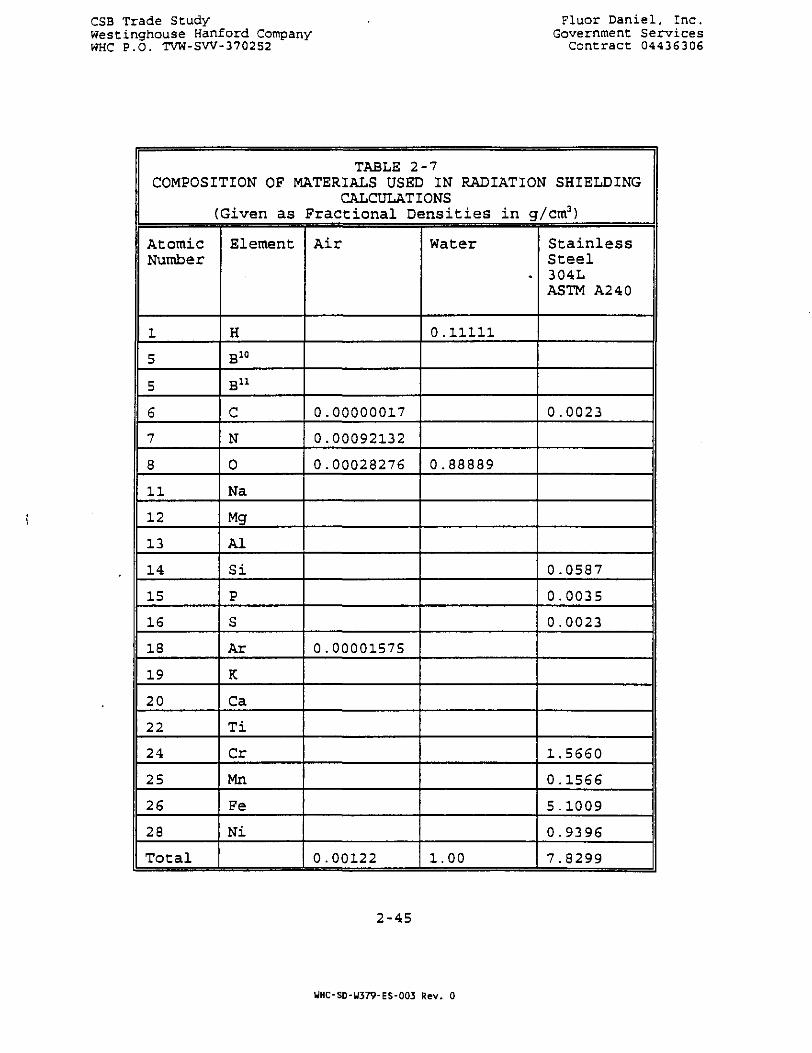
CSB Trade StudyWestinghouse Hanford CompanyWHC P.O. TVW-SW-370252
Fluor Daniel, Inc.Government Services
Contract 04436306
TABLE 2-7COMPOSITION OF MATERIALS USED IN RADIATION SHIELDING
CALCULATIONS(Given as Fractional Densities in g/cm3)
AtomicNumber
1
5
5
6
7
8
11
12
13
14
15
15
18
19
20
22
24
25
26
28
Total
Element
H
B10
B u
C
N
0
Na
Mg
Al
Si
P
S
Ar
K
Ca
Ti
Cr
Mn
Fe
Ni
Air
0.00000017
0.00092132
0.00028276
0.00001575
0.00122
Water
0.11111
0.88889
1.00
StainlessSteel304LASTM A240
0.0023
0.0587
0.0035
0.0023
1.5660
0.1566
5.1009
0.9396
7.8299
2-45
WHC-SD-W379-ES-003 Rev. 0
CSB Trade Study Fluor Daniel, Inc.Westinghouse Hanford Company Government ServicesWHC P.O. TVW-SW-370252 Contract 04436306
2.2.4.4 Results Of Calculations
A computational model was formulated which could address key-factors with respect to criticality safety for Concept 2D. Alluncertainties were compensated for with conservative assumptions.In the event these assumptions led to an unacceptable risk of acriticality event, it was planned to perform sensitivity studies toidentify safe limits.
In this computational model, fuel elements were arranged incolumns, each containing 280 fuel elements. Each column containedfuel arranged in patterns representative of two MCO's, stacked oneon top of the other. Each MCO was modeled with five verticallayers of canisters, two canisters of 28 fuel elements, per layer.The 28 fuel elements in each layer were arranged in a patternsimilar to that found in the canisters, Figure 2-20, but thecenter-to-center separation between fuel elements was taken to be3.2 inches, the worst-case spacing from Figure 2-19.
In a nominal CSB vault, 220 such columns would have been arrangedin a hexagonal pattern. This pattern was modeled as a triangularpitch array, with a 55 inch center-to-center separation betweencolumns, Figure 2-21. (Since interaction between columns isnegligible, this will be shown in what follows, changing the sizeof this array was not required.) The closest spacing betweencolumns, which could be achieved in a flooded pool, was assumed tobe 26 inches, center-to-center. This assumes a bare MCO, no tube,and a minimal amount of structural material for keeping the 24 inchOb MCO in place. For this calculation, no credit was taken foreither the MCO or the canister walls. In fact, the only materialsincluded in this model are the fuel, cladding, and the surroundingwater. The results for this configuration gave a k.ff of 0.81289with a standard deviation of 0.00091 (calculation ID: NF032).Replacing the water outside the MCO boundaries with air, gave a k.£fof 0.87063, +/- 0.00073 (NF033). This increase is probably due tothe increased interaction between columns for this close a spacing.
To evaluate the impact of some of the structural material, assumedto be stainless steel (SS 304) , the case with air outside the MCOwas repeated, but this time the canister walls were included in themodel. This calculation gave a k,ff of 0.77375, with a standarddeviation of 0.00065 (NF034) . Including the MCO wall material,further reduced the k,£f to 0.74524 +/-0.00069 (NF035) . (Toaccommodate the 3.2 inch spacing between fuel elements, thecanister outside diameter was taken to be 9.2 inches and itsthickness 0.25 inches, Figure 2-22. This should be compared to astandard schedule 20, 8 inch pipe which has an outside diameter of8.625 inches and the same thickness.)
Increasing the spacing between columns to 55 inches and includingthe tube material, reduced the k.ff to 0.7234 +/-0.00061 (NF036) .
2-46
WHC-SD-U379-ES-003 Rev. 0
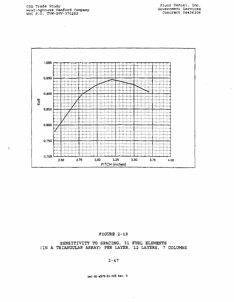
CSB Trade StudyWestinghouse Hanford CompanyWHC P.O. TW-SW-370252
Fluor Daniel, Inc.Government Services
Contract 04436306
1.000
0.950
0.900
0.850
0.800
0.750
0.700 •—l
...
...
...
7...
...
...
f/
^ — •
: : : :
• - • > " •
i . . ;
• • < - • • ; - - • ! • • - ! • - •
!::i::::::m..i.p^i..
rtrZL
; ; ; • ; i I , i , ;
S s < i : :
...........;...!...
; . ; i
• • • > • • • : • • • - > • - •
; i i
. . .
• -
. . .
. . .
. . . .
-
—
. . .
. . .
2.50 2.75 3.00 3.25 3.50 3.75 4.00
PITCH (inches)
FIGURE 2 - 1 9
SENSITIVITY TO SPACING, 31 FUEL ELEMENTS(IN A TRIANGULAR ARRAY) PER LAYER, 12 LAYERS, 7 COLUMNS
2-47
UHC-S0-W379-ES-003 Rev. 0

CSB Trade StudyWestinghouse Hanford CompanyWHC P.O. TVW-SW-370252
Fluor Daniel, Inc.Government Services
Contract 01436306
I 01X19/93 131)4149
NTOIOT, N f«* l . ! •
*l«ntiiti/UM*r. 110 M l m i 4T
C l.OOOQQO* Q.OOOOQQ* OaOOOOOOl
< a.oooooo, i.ooooaa. a.ooaooo>
< a.oa, o.oo, i«i.«o>•»*••«« • t 3O.OO. 3O,Oa>
FIGURE 2-20FUEL ELEMENTS IN A SINGLE LAYER OF AN MCO MODEL
2-48
UHC-SD-W379-ES-003 Rev. 0

CSB Trade StudyWestinghouse Hanford CompanyWHC P.O. TVW-SW-370252
Fluor Daniel, Inc.Government Services
Concract 04436306
wni,titSOt>T
. full !>«*•• *«nt
( L.OOOOOO* OiQOOOOOt 0<0000OO>< O.OOOOOO, l . O O 0 0 0 0 t O.OOOOOO) •< O.OO. 0.00* 0,OO»fHtaat a I 1T0O.0O, 1700.00)
«*akt«—««tt«r * « t l 1* **— mwmrm*a r n M * M r l * * « «atM«lA«<tt t i lth
*lw * ! • ! rtMi.
© 0 ® © 0 © © © 0 0
0 0 0 © 0 0 0 0 0 ©
© © © 0 © 0 ©1© © 0
FIGURE 2-21CSB VAULT MODEL SHOWING STORAGE TUBES IN A TRIANGULAR ARRAY
2-49
UHC-SD-W379-ES-003 Rev. 0

CSB Trade StudyWestinghouse Hanford CompanyWHC P.O. TVW-SW-370252
Fluor Daniel, Inc.Government ServicesContract 04436306
I Ot/DSSfS IStittOSHTO3*. N ftMl, HCV.aM««lta. IIQ H I « M « SS«p««ln*, •!•> In MMtlt
m b ! 4 • t «^0«/«kultl( l .OOOOOO, O.OOOOOOt a>OOOOOOt( o.oooooo. i.oooooa. o.oooooa)•rlain It O.OO. O.OO, 14X.OO>•M««Mt a < 50 .00 , SO.OO>
FIGURE 2-22CROSS SECTION OF STORAGE TUBE SHOWING MCO AND CANISTER WALLS
2-50
WHC-SD-W379-ES-003 Rev. 0
CSS Trace Stuc.y _ ?;.uor Daniel, Inc.We3C:.nghouse Kanford Company Government ServicesWKC P.O. TVW-=W-370252 Contract 04436306
The relatively small decrease between this case and case NF035,indicates that the interaction between columns has already beensignificantly reduced by the addition of the MCO wall material.
Case NF03S is representative of Concept 2D storage of MCO's in airfilled tubes with forced refrigerated air cooling of the tubes.Eliminating water from the calculation will result in an under-moderated situation with an effective decrease in k#ff. Filling thevault with water would have only a minor effect on the vault k#fC,since there is only negligible interaction between tubes at thisspacing and when taking credit for tube and MCO wall thicknesses.(The case of a water filled vault is a credible accident scenarioand would have to be considered in a criticalitysafety evaluation.Partial filling of the vault with water may actually be a worstcase situation, as was illustrated by comparing results for casesNF032 and NF033.)
2.2.5 Shielding
Shielding calculations during the feasibility study evaluationswere performed with MicroShield 4 which is adequate for the bulkshielding studies performed. The adequacy of this method wascalculated using the MCNP, Version 4A, code. Penetrations, ducts,and cracks were not evaluated but are noted where additional workwill be needed in the future. Some allowances were taken with thebulk shielding thicknesses in anticipation of the more complicatedgeometries.
Shielding issues associated with Concept 2D which were notaddressed in either the Feasibility Study or the Trade Study, butwhich may contribute to design changes, include the following:
• Tube Closure Design, Tube Spacing
Tube spacing in the vault may depend, in part, on the design ofthe tube closure at the operating floor level. Exposure levelsabove tube closures will depend on operating floor thickness andradiation streaming through gaps around the closures. Anypenetrations through these closures, for gas/liquid sampling, mayalso contribute to these exposure levels. The MCO's internalstructure may favor propagation in the axial directions,enhancing the radiation environment at the top and bottom of thetubes. (This will be particularly significant afterstabilization.)
• Unfinished Vault Capable of Future Outfitting
An unfinished vault presents several closure and shieldingproblems. Openings to both the intake and exhaust plenums willhave to be closed off both to reduce radiation in this vault andto restrict refrigerated air flow through the unused vault.
2-51
UHC-SD-W379-ES-003 Rev. 0
Ci3 Trace Stuc.y Fluor Dan:.e.\, Inc.We =c:.nghouse Kanford Company Government S«rv:.cesWKC P.O. TVW-SW-370252 Contract 0443(1306
Provisions must be made Co remove these barriers, under a highradiation environment, when this vault is eventually activated.
• Temporary Refrigerated Air System
The means of delivering refrigerated air to the vaults may-require additional ducting and wall penetrations. These ducts,and wall penetrations will have to be designed to preserve therequired low radiation exposure levels outside the building. Anyclosures to existing air intakes and exhausts will have to beremoved, under enhanced radiation conditions, when the switch ismade to passive cooling for stabilized fuel.
2.2.5.1 Introduction
The shielding issues for Concept 2D involve health protection ofthe occupants of the SSF throughout its life. During the SSFFeasibility Study selection of an appropriate source term wasexamined by looking at the defined "limit" (maximum) source andanother "shield" (average) source, as well as a combination of thetwo sources. There are several water conditions that must be metat all times to provide a maximum dose rate of 0.2 mrem/hr. Theseinclude the minimum pool water depth over the filled MCO racks andthe minimum water level over an individual MCO. The interior andexterior wall thicknesses are important to provide healthprotection during possible construction activities. The operatingfloor thickness must protect workers during maintenance activities.The thickness of the transporter or shielded cask must provideadequate shielding during transport, insertion and removal of theshield plugs and MCO's.
2.2-. 5.2 Source Selection
Three possible sources were examined to determine the mostappropriate for the shielding studies. The "maximum" source isthat found in Section 2.8, Basis For Design, "Draft MCO Table" byR. G. Cowan, March 17, 1995. The "shield" source is that found inTable 3.6 - Safety Basis Radionuclides - referenced as the shieldsource in paragraph 3.6 - Shielding Design Basis of the "DraftDesign Basis Feed Development", A. L. Pajunen, December 22, 1994.Direction from Westinghouse indicated that the "maximum" sourceidentified with 10 canisters should be used. Previous experienceand the increased number of radionuclides in the "shield" sourceprompted examination of the two sources. The "shield" source isbased on the most radioactive fuel elements currently in the K-Basins. Apparently, there is only 0.6 metric tons of thismaterial, which is considerably less than one filled MCO. However,three cases were examined: 1) filled MCO with the "maximum"source; 2} filled MCO with the "average" source; and 3) combinedMCO with 0.6 metric tons of the "average" source and the balance ofthe fuel elements of the "maximum" source. A simple geometry of an
2-52
UHC-SD-W379-ES-003 Rev. 0
CSB Trade Study Fluor Daniel, Inc.Westinghouse Hanford Company Government ServicesWHC P.O. TVW-SW-370252 Contract 04436306
MCO immersed in water with a 2 foot concrete wall was used toevaluate the three sources. All other things being equal, exceptfor the radionuclide composition, the resulting dose rates were:"maximum" - 0.0112 mrem/hr; "average" - 0.0122 mrem/hr; and"combined" - 0.0114 mrem/hr. The limit source was selected sinceall sources were very close to being equal.
The impact on shielding requirements, of changing the MCOconfiguration to include five layers of canisters, instead of four,and changing the isotope mix to that specified as the "Maximum" MCO(Appendix 1) , was evaluated. This was done by generating a morerepresentative model of the MCO geometry for use in MCNP MonteCarlo simulations. Sample calculations were performed with thismodel, using a gamma source based on the "Maximum" MCO isotope mix.The results of these calculations confirmed that the conservativeapproach used to define shielding requirements based on the MCOsource model discussed above were adequate to accommodate theincreased source of the new MCO model. The changes in shieldingrequirements, recommended as part of this Trade Study, are based onthe lowered exposure level requirement for occupied areas (i.e.,lowered from 0.5 mrem/h to 0.2 mrem/h).
2.2.5.3 Minimum Water Depth Over a Single MCO
The MCO is brought into the SSF in a shielded cask. The cask isimmersed in water before withdrawing the MCO. Radiation shieldingof the MCO is provided by the water surrounding the cask and theMCO. Whenever the MCO is not in the cask, it must be surroundedand covered by water. Personnel do not generally have access tothe sides or bottom of the pool so only the top of the MCO must beshielded. This shielding is provided by establishing a minimumwater depth above the MCO which must be maintained. This minimumwater depth is 8 feet.
2.2.5.4 Minimum Concrete Thickness of Interior and Exterior Walls
There are several construction sequence possibilities for the SSF.The thickness of the interior walls is not important from a healthprotection standpoint if all construction is performed initially.However, if one vault is constructed first and filled and the otherstorage vaults are built at a later time, the construction workerswill need to be shielded against radiation penetrating the interiorwall between the filled vault and the adj acent vault. Anadditional need for personnel access to a vault could be forcleanup before conversion to natural convection cooling. If thiscleanup is required, all MCO's in the vault to be cleaned will needto be removed. Radiation levels from adjacent filled vaults willneed to be less than 0.2 mrem/hr to avoid partial emptying of theadjacent vaults. The minimum wall thickness required is 42 inchesof full density standard concrete. Since the interior walls arecurrently 36 inches of full density concrete, the wall thickness is
2-53
WHC-SD-W379-ES-003 Rev. 0

Westingrouse Kanford Company Government ServicesWHC P.O. TVW-SW-370252 Contract 04436306
leas than adequate for maintenance activities near the wall. Atone time, there was an additional layer of thermal concrete (lowdensity) applied to the interior surfaces of the vaults. If thisadditional thermal layer is included in the SSF design, theshielding may be adequate. Also, since entry into the vault willonly occur if cleanup is required, localized shielding might be abetter solution than increasing the wall thickness.
An unfinished vault presents several shielding problems, inaddition to the inside wall thickness requirements. Openings toboth the intake and exhaust plenums will have to be closed off withshielding materials to reduce radiation exposure levels in thisvault during any future reconfiguration. Provisions must be madeto remove these shields, under a high radiation environment, whenthis vault is eventually activated.
The second construction sequence involves the construction of theStabilization Facility adjacent to the exhaust plenum. Excavationcould remove all of the soil surrounding the exterior wall. Again,the minimum wall thickness is 42 inches, so that the 54 inchexterior wall is more than adequate.
2.2.5.5 Minimum Thickness of Operating Floor
Radiation protection of personnel from stabilized MCO's in drystorage is provided by the concrete operating floor. This floor,along with the individual shield plugs which provide access intoeach storage tube, must provide shielding sufficient to maintain atarget dose rate of 0.2 mrem/hr. The minimum floor thickness mustbe 48 inches. This floor thickness allows for a solid floor. Whenthe floor is cast with plug holes and the holes are fitted withplugs which do not completely fill the space, radiation streamingis possible. Plugs and holes with steps solve this problem. It isestimated that the current design thickness of the floor is 60inches which will provide adequate shielding. The geometry withthe holes and plugs will need to be examined thoroughly at a laterdate.
2.2.5.6 Minimum Transporter/Cask Thickness of Steel and Tungsten
There are two options for transporting the MCO's filled withstabilized fuel tubes. The first would involve a stand alonetransporter which would be driven around on the operating floor.The second would involve a special remote controlled cask whichwould be moved with an overhead crane. In either case, personnelhealth protection and shielding weight are important. The targetcontact dose rate is 0.2 mrem/hr. The thickness of iron to achievethis dose rate is 14 inches. The thickness of tungsten to achievethis dose rate is 4.7 inches. The tungsten shield is moreexpensive, but considerably lighter which reduces the cost of thetransporter or overhead crane. These thicknesses provide gamma
2-54
WHC-SD-W379-ES-003 Rev. 0

CS3 Trace otuc.y Fluor uaniex, m e ,West-ngrouse Fanford Company Government ServicesWHO P.O. TVW-SW-370252 Contract 04436306
shielding only. These shielding requirements will need to bereviewed for neutron shielding adequacy (Section 2.2.5.8)
2.2.5.. 7 Special Shielding Issues (Neutrons, Betas)
A neutron source was not provided and neutrons have been ignoredduring this study. However, in future design efforts, neutron doserates will need to be evaluated. The areas of particular concernare the incoming and outgoing casks and the transporter/cask.These shielding structures are designed to provide adequate gammashielding. Additional neutron shielding may be needed. Theneutron source will result from some a,n reactions and spontaneousfission of the transuranics.
The beta source does not appear to be a significant shieldingsource in the MCO. The shielding concern is not to provide betashielding which is provided by the shell of the MCO, but to provideadequate shielding of the Bremsstrahlung radiation resulting fromthe beta absorption in the gamma shield.
The secondary photon source, resulting from the "Maximum"MCO (Section 2.8) mix of beta emitting isotopes, was evaluated usingMCNP. This source of photons was found to contribute less than 3%of the exposure rate contributed by the gammas.
2.2.6 Conversion
Conversion of Concept 2D from refrigerated air cooling ofunstabilized fuel to passive dry storage will be accomplished afterstabilization of all the MCOs is complete. As MCOs are removed forstabilization, MCOs containing dry stabilized fuel will beinstalled in dry storage tubes upon return from the StabilizationFacility. When all of the fuel has been stabilized and higher fueland vault temperatures can be tolerated, blinds in the air intakeplenums and stack would be removed, air refrigeration equipmentwould be shut down and isolated if necessary, allowing naturalcirculation cooling to be established.
There do not appear to be any additional feasibility issuesassociated with the conversion from refrigerated air cooling topassive dry storage for this concept other than shielding andradiation safety, already addressed.
2.2.7 Health Physics
2.2.7.1 Objective
Perform a Health Physics (HP) analytical review of the use of theCanister Storage Building (CSB) as a staging and storage facility(SSF) for the N-reactor fuel.
2-55
UHC-SD-W379-ES-003 Rev. 0

_.; ;. ..re.c.e c-',v-.y n u o r uaniei, inc.We;=t:.iict'.cuse hanford Company Government ServicesWFC P.O. TVW-3W-370252 Contract 04436306
2.2.7 . 2 Summary
Whereas? the facility as designed for the Hanford WasteVitrification Plant (HWVP) project is ideally suited for thestorage of spent fuel, there are some features of concept 2D thatwill need to be altered in order to meet the latest DOErequirements such as DOE/EH-0256T, Radiological Control Manual,Rev. 1, April 1994. For example, the facility will require changerooms, step-off-pads (SOP) , and a personnel decontaminationfacility. In addition, the concept of allowing the third vault toremain empty will not work from an HP or an HVAC stand pointwithout major changes to the building. The building modificationswill more than likely off-set any potential savings attributable todeferring the third vault work at this time. Although dataconcerning the potential neutron source associated with the max Amulti-canister overpack (MCO) shielding source is not available atthis time, it is inevitable that there will be more neutronsassociated with this source than there were with the HWVP sourcebecause this source contains far more fissile material. Further,since a neutron shield was required on the HWVP transporter, beadvised that it will be required as an integral part of theshipping cask and as part of the floor plug shield valve. Finally,it is beyond the scope of this study and left to later designstages to verify that workers will be able to remain on theoperating floor during insertion of the MCO into the storage tubes.
2.2.7.3 Facility Description And Evaluation
It should be noted that although the CSB was designed when theyearly exposure for radiation workers was 1,000 rnrem cumulativetotal effective dose equivalent (CTEDE), the Westinghouse HanfordCorporation (WHO and the Fluor Daniel Inc. (FDD, Health Physicsdepartments mutually agreed that this dose should be divided into400 mrem/yr, whole body dose, and 600 mrem/yr for internal doseexposure. The DOE regulation cited above, limits the yearly CTEDEto radiation workers to 500 mrem. This means that the CSB isdesigned in compliance with Che latest contemporary DOEregulations. The design of the operating floor meets the latestWHC requirements for a radiation access zone (RAZ) 1 which permits40 hours per week occupation.The Radiological Control Manual (Rad Con) manual requires the HPfacilities noted above in the summary. In addition, the SOPs mustbe contiguous with the radiological areas that require radiationwork permit (RWP) /special work permit (SWP) such as the caskhandling, storage, preparation and operating areas.
If the third vault remains empty, without any flow restrictions,then the preponderance of natural convection air, afterstabilization, will flow through Che empty vault and not throughthe MCO filled vaults. Flow restrictors will be difficult, if notimpossible, to remove if WHC finds a use for the vault at a later
2-56
WHC-SD-W379-ES-003 Rev. 0

CSB Trade Study • Fluor Daniel, Inc.Westinghouse Hanford Company Government ServicesWHC P.O. TVW-SW-3702S2 Contract 04436306
date because it is currently inconceivable that anyone can enterthe area after the first and second vaults are filled with MCOs.Please be advised that even if the wall thickness between thesecond and third vault is increased, the scattering around theexhaust and inlet plenums will most likely produce a RAZ 5, whichdoes not allow access.
The shipping cask and the floor plug stiield valve will have toprovide shielding against gammas, beta originated bremsstrahlungradiation (X-rays) and neutrons. The preliminary estimates withoutbremsstrahlung or neutrons, indicate that the maximum MCO willproduce a dose rate of approximately 200 R/h at three feet from themidsection of the overpack. It should be noted* that the shieldingrequirement to allow this source to become contact maintained in aRAZ 1 would be approximately 14 inches of steel. This shield mayexceed the weight restrictions for the CSB floor and crane. Thisis one of the reasons why it may not be possible to allow workersto remain on the operating floor during insertion of the MCO intothe storage tubes.
2.3.0 SAFETY ANALYSIS
2.3.1 APPLICABLE REQUIREMENTS
The environmental, safety and health (ES&H) requirements applicableto the SSF are very similar to the requirements applied to the HWVPCSB, especially for the storage phase- Other than updatedrequirements for protection against natural phenomena (recentlyissued DOE-STD-1020) , all such requirements applicable to the CSBwill apply to the SSF.
The CSB design (the starting point for the SSF design) wascompleted using these ES&H requirements as part of the designbasis. This CSB design has been reviewed and approved by the DOE,WHC and the State of Washington as meeting all these requirements.This successful track record should ease the regulatory process forthe SSF.
On the other hand, the fact that spent nuclear fuel (SNF) is beingstored instead of glass, and the necessity for wet storage ofunstabilized fuel in the staging phase, will make several newadditional requirements applicable to the SSF. For example, inaddition to meeting the requirements applicable to the CSB, WHC hasindicated that the SSF will be required to meet the intent ofNuclear Regulatory Commission requirements for SNF storagefacilities.
2-57
UHC-SD-U379-ES-003 Rev. 0

CSB Trade Study Fluor Daniel, Inc.Westinghouse Hanford Company Government ServicesWHC P.O. TVW-SW-370252 Contract_04436306
2 . 3 . 1 . 1 DOE Orders
The following safety related DOE Orders are applicable to the SSF.The technical descriptions provided in this report are intended tomeet these regulations. They are the core of the safety designbasis for the facility:
2.3.1.1.1 DOE Order 6430.1A, General Design Criteria
This is the primary design requirements document which the SSF mustmeet. Key safety related sections influencing the SSF designinclude:
1. Section 0200-1.3Radiological Siting GuidelinesSection 1300-1.4Guidelines on Limiting Exposure of the Public
Establish offsite exposure limits for normal operations, and thebasic 25 rem offsite dose limit for Design Basis Accidents (DBAs) .
2. Section 1300Special Facilities {in general)Section 1300-3Safety Class Criteria (in particular)
Identify the requirements for DOE Safety Class (SO structures,systems and components (SSCs), including the Single FailureCriterion.
3. Section 1320Irradiated Fissile Material Storage Facilities
Identifies special design requirements applicable to dry-type spentnuclear fuel (SNF) storage facilities such as the SSF. It alsorequires the designer to consider the applicability of NRC SNFstorage requirements, such as 10CFR72 and Regulatory Guide 3.60 tothe design of DOE SNF facilities. It requires primary andsecondary confinement systems.
2.3.1.1.2 DOE Order 5480.5, Safety of Nuclear Facilities
Identifies general safety requirements applicable to the SSF,including effluent release limits for normal operation.
2.3.1.1.3 DOE Order 5480.22, Technical Safety Requirements
This Order defines the requirements for the Technical SafetyRequirements (TSR) document. The TSRs are an agreement between afacility's operating management and the DOE regarding the safeoperation of the facility. They define the safe operating limits,surveillance requirements, and management controls under which thefacility must operate to maintain its safety design basis.The TSRs are based on the facility Safety Analysis Report (SAR).They are closely related to the assumptions made in the DesignBasis Accident (DBA) analyses regarding the initial condition of
2-58
UHC-SD-W379-ES-003 Rev. 0
CSB Trade Study Fluor Daniel, inc.Westinghouse Hanford Company Government ServicesWHC P.O. TVW-SW-370252 Contract 04436306
the facility (e.g., operability of Safety Class systems) when eachaccident is initiated.
2.3.1.1.4 DOE Order 5480.23, Nuclear Safety Analysis Reports
This Order defines the requirements for the preparation, review,and approval of DOE Safety Analysis Reports (SARs) . It alsodescribes acceptable SAR format, content, and level of detail. WHChas applied for an exemption from this Order and has indicated thatthe SSF SAR will meet the intent of the format and contentrequirements in NRC Regulatory Guide 3.48.
2.3.1.1.5 DOE Order 5480.28, Natural Phenomena Hazards (NPH)Mitigation
This Order identifies the seismic and other NPH protectionrequirements applicable to the SSF. To a large degree, this Orderand its implementing Standards define the design of SSF structures.
2.3.1.2 DOE Standards
The following safety related DOE Standards are applicable to theSSF. These standards generally provide guidance to the designerfor meeting the intent of the above DOE Orders:
2.3.1.2.1 DOE Standard 1020, Natural Phenomena Hazards Design andEvaluation Criteria for DOE Facilities
This standard defines the detailed NPH design criteria applicableto each DOE site for structures to meet the intent of DOE Order5480.28.
2.3.1.2.2 DOE Standard 1021, Natural Phenomena Hazards PerformanceCategorization Guidelines for Structures, Systems and Components
This standard defines DOE structural Performance Categoriesapplicable the safety related structures in a facility as afunction of the facility's Hazard Category. It also defines thestructural requirements for each Performance Category to meet theintent of DOE Order 5480.28.
2.3.1.2.3 DOE Standard 1027, Hazard Categorization and AccidentAnalysis Techniques for Compliance with DOE Order 5480.23
This Standard provides standard techniques for determining thehazard level of a facility, and for performing a PreliminaryHazards Analysis.
2-59
WHC-SD-U379-ES-003 Rev. 0
CSB Trade Study Fluor Daniel, Inc.Wescinghouse Hanford Company Government ServicesWHC P.O. TVW-SW-370252 Contract 04436306
2.3.1.3 NRC Regulations
2.3.1.3.1 10CFR72, Licensing Requirements for the IndependentStorage of Spent Nuclear Fuel and High-Level Radioactive Waste
Part 72 prescribes high level design and other licensingrequirements for the independent storage of SNF. Its requirementsin the design and safety analysis area are specified in more detailin Regulatory Guide 3.54.
2.3.1.3.2 Regulatory Guides
WHC has indicated that the SSF must meet Che intent of thefollowing NRC Regulatory Guides:
1. Regulatory Guide 1.25, Assumptions Used for Evaluating thePotential Radiological Consequences of a Fuel Handling Accident inthe Fuel Handling and Storage Facility for Boiling Water andPressurized Water Reactors
This Regulatory Guide identifies the assumptions required to beused in performing accident analysis for SNF storage facilities.
2. Regulatory Guide 3.48, Standard Format and Content for theSafety Analysis Report for an Independent Spent Fuel StorageInstallation or Monitored Retrievable Storage Installation (DryStorage)
WHC has indicated that the SSF SAR will meet the intent of theformat and content requirements of these Regulatory Guides, ratherthan the requirements of DOE 5480.23, from which it has requestedexemption.
3. Regulatory Guide 3.60, Design of an Independent Spent FuelStorage Installation (Dry Type).
Generally, this Regulatory Guide merely finds acceptable the use ofANSI/ANS 57.9-1992 in the design of dry type Independent Spent FuelStorage Installations (ISFSIs).
2.3.1.4 Other Federal Regulations
2.3.1.4.1 National Environmental Policy Act
NEPA will require the preparation, review and approval of anEnvironmental Impact Statement for the SSF design.
2-60
WHC-SD-W379-ES-003 Rev. 0

CSB Trade Study Fluor Danie l , I nc .Westinghouse Hanford Company Government Serv icesWHC P.O. TVW-SW-370252 Contract 04436306
2.3.1.4.2 Resource Conservation and Recovery Act (RCRA)
Enforcement of RCRA requirements generally is delegated to theindividual States. For the State of Washington, RCRA requirementsare implemented primarily through WAC 173-303.
2.3.1.5 Washington State Regulations
Washington Administrative Code (WAC) 173-303
This (and several other statutes) implement the requirements of theFederal Resource Conservation and Recovery Act (RCRA) for the Stateof Washington. The primary objective of the 173-303 is to preventthe release of dangerous wastes into the ground water.
If the facility would contain dangerous wastes, it must apply tothe Washington State Department of Ecology for a Dangerous WastePermit. Key requirements of the RCRA that affect the designinclude a requirement for double containment of dangerous liquidsand detection within 24 hours and collection of any leakage.
2.3.1.6 WHC Requirements
WHC-CM-4-46, Nonreactor Facility Safety Analysis
Provides requirements for the preparation, review and approval ofsafety analyses for facilities at the Hanford site. In particular,Section 9.0 (Draft Revision OB) of this manual defines a gradedsystem for safety classification of systems, components, andstructures (SSCs). It specifies design requirements applicable tothe four WHC safety categories: Safety Class 1 (DOE SafetyClass-offsite hazard), Safety Class 2 (onsite hazard only), SafetyClass 3 (facility hazard only), and Non-Safety.
Section 9.0 (in Table 2 of Attachment 1) of WHC-CM-4-46 alsospecifies frequency-dependent Radiological Dose Limits for DBAs.These limits are discussed below in Section 6.2.
2.3.1.7 ANSI/ANS Standards
Standard 57.9, Design Criteria for an Independent Spent FuelStorage Installation (Dry Type)
Provides detailed design criteria for dry type ISFSIs such as theSSF. This standard requires a minimum of two barriers between theSNF and the outside environment.
2.3.2 DESIGN BASIS ACCIDENTS/SAFETY CLASSIFICATIONS
This section documents the results of a first-cut Design BasisAccident (DBA) analysis for the SSF. It describes the
2-61
UHC-SD-U379-ES-003 Rev. 0

CSB Trade Study Fluor Daniel, Inc.Westinghouse Hanford Company Government ServicesWHC P.O. TVW-SW-370252 Contract 04436306
pre-conceptual safety design basis of SSF Feasibility DesignConcept 2D, including the basis for determination of requiredSafety Class (SO SSCs.
A spectrum of candidate accident scenarios is postulated. Includedare scenarios required to be addressed by programmatic requirementsand additional scenarios identified by the WHC Draft PreliminaryHazards Analysis (PHA). All postulated scenarios are addressed.
The radiological consequences for each DBA are calculated for SSFFeasibility Design Concept 2D. The SSF is located on the site ofthe HWVP CSB (20,000 meter site boundary distance).
These consequences are compared with the onsite and offsiteradiological dose limits of WHC-CM-4-46, Section 9.0 (Revision OB) .Where unmitigated consequences exceed the dose limits, mitigatingSSCs are designated as SC-2 or SC-1 as appropriate. Credit istaken for the operability of these SSCs to mitigate theconsequences of the DBA to within the dose limit.
These frequency-dependent dose limits include the following:
A. Offsite:
1. Accident frequency of >lE-2 to alE-l/year: 0.5 rem
2. Accident frequency of >lE-4 to slE-2/year: 5 rem
3. Accident frequency of >lE-6 to slE-4/year:25 rem
B. Onsite:
1. Accident frequency of >lE-2 to alE-l/year: 5 rem
2. Accident frequency of >lE-4 to slE-2/year: 25 rem
3. Accident frequency of >lE-6 to slE-4/year:100 rem
2.3.2.1 DBA Methodology
2.3.2.1.1 Event Consequences
The methodology described in DOE-STD-1027-92 is used for thisanalysis. The following equation, from page A-6 ofDOE-STD-1027-92, describes the basic method used to calculate theoffsite dose for each DBA:
MOI Dose= (MAR) (RF) (X/Q) (RR) (SA) (CEDE)(1)
or:(Source Activity) (CEDE) (RF) (X/Q) (RR)(la)
2-62
UHC-SD-W379-ES-Q03 Rev. 0

CSB Trade Study Fluor Daniel, Inc.Westinghouse Hanford Company Government ServicesWHC P.O. TVW-SW-370252 Contract 04436306
where:
MOI Dose - Maximum Off sice Individual Dose[rem]
MAR - Material at Risk [grams] ; RF - Release Fraction [Unitless]
RR - Respiration Rate [m3/sec]; SA - Specific Activity Cci/g]
X/Q - Atmospheric dispersion factor for the [sec/m3]site boundary distance
CEDE - Committed Effective Dose Equivalent [rem/ci]per curie inhaled
Source Activity ~ (MAR) (SA) [ci]
2.3.2.1.2 Initiating Event Frequencies
Formal quantitative calculation of event frequencies is notincluded in this assessment. The estimated frequencies listed inResults Table A are based on the frequency categories shown in theWHC Draft PHA.
As stated in the assumptions below, the frequencies of severalscenarios are assumed to be below the threshold of credibility,based on the assumed outcomes of future, more detailed safetyanalyses. These assumptions should be verified or changed in laterphases of the design of the SSF, based on the results of theseanalyses.
2.3.2.1.3 Scenario Development/Screening
The first step in the DBA analysis process is a screening processto justify eliminating from consideration all scenarios that arenot DBAs. Remaining as DBAs are those scenarios that meet both ofthe following criteria:
A. The scenario is "credible:" The frequency of occurrence of theinitiating event is equal to or greater than lE-6/year. Accidentswith frequencies less than this threshold are considered to be"beyond the design basis," or "not credible." This credibilitythreshold is defined in Section 1300-1.4.2 (and the Glossary) ofDOE Order 6430.LA. The basic credibility threshold of lE-6/year ismodified by DOE-STD-1021 for natural phenomena hazards (NPH) tolE-5/year. Accidents beyond the design basis, or "residual risk,"will be analyzed in later phases of the design as required by DOEOrder 5480.23.
B. The scenario is the limiting, or highest consequence, accidentin its type: For example, the (credible) spill with the mostsevere consequence is the "design basis spill." If the plant is
2-63
WHC-S0-W379-ES-003 Rev. 0
CSB Trade Study Fluor Daniel , I nc .Westinghouse Hanford Company Government ServicesWHC P.O. TVW-SW-370252 Contract 04436306
designed to mitigate the risk of the design basis spill to withinthe dose limits, then it also can mitigate adequately all spills oflesser consequence.
2.3.2.1.4 Material At Risk Estimates
All spent fuel received at the SSF will be contained in SafetyClass Multi-Canister Overpacks (MCOs). For the purposes of thisassessment, Material At Risk (MAR) is assumed to be the "maximum"inventory of radionuclides in each MCO, taken from the "MCODescription" contained in Section 2.8, times the number of MCOs atrisk in each accident scenario. The one exception to this is the"uncontrolled gas discharge" DBA, where the MAR is assumed to bethe Kr-85 inventory of one MCO.
Failure of a MCO containing the "maximum" radionuclide inventorywould cause a release and a resultant dose that can be calculated.The theoretical inhalation dose that would result from uptake ofthe entire contents of a MCO (immersion dose for Kr-85) iscalculated. This doses is the "peak inhalation Committed EffectiveDose Equivalent (CEDE) at the source." The method of calculationof this dose source term is described below.
2.3.2.1.5 Source Terms
Equation (la) shown in the Methodology section above can berestated as follows:
MOI Dose = [ (Source Activity [in curies]) (CEDE)] [ (RF) (X/Q)
(RR)]
or • =[Inhalation CEDE at the source] [K]
where:[Inhalation CEDE = (Source Activity) (CEDE) (2)at the Source]
and K« (RF) (X/Q) (RR)
The "K" part the dose calculation is independent of the nuclearcharacteristics of the source MAR. Inhalation CEDE At the Source,on the other hand, is completely characteristic of the each nuclidemaking up the source term.
In fact, the RF (1E-3 for all isotopes except Kr-85) and RR (3.5E-4m3/sec) and meteorology all are assumed to be fixed for the SSF byDOE-STD-1027-92. The CSB site boundary distance (20,000 meters)fixes X/Q for the SSF as well, as described below.
2-64
WHC-SD-W379-ES-003 Rev. 0

CSB Trade Study Fluor Daniel, Inc.Westinghouse Hanford Company Government ServicesWHC P.O. TVW-SW-370252 Contract 04436306
Equation 1 is intended to be used to calculate the dose caused by-one source radionuclide at a time. The inventory of a MCOcomprises several isotopes as listed given in the Appendix l "MCODescription".
The dose that would result from a failed MCO containing thismixture of isotopes actually would comprise the sum of theindividual doses contributed by each isotope present in the mixtureat the time of release:
(Inhalation CEDE=£ (Source Activity)L (CEDE)iof the mixture) L
The (Source Activity) L values used in this analysis are taken fromthe Section 2.8 "MCO Proposed Description". The CEDEj. values aretaken from DOE/EH--0070 and DOE/EH--0071.
2.3.2.1.6 Release Modeling
As stated above, the release model used for this analysis is takenfrom DOE-STD-1027-92. The Release Fraction (RF) used for eachscenario is 1E-3(except for noble gases such as Kr-85, which havean RF of 1). Respiration rate (RR) of the receptor used for eachscenario is 3.5E-4 m3/sec. Both are bounding values taken fromDOE-STD-1027-92, page A-7.
The offsite receptor distance for the HWVP CSB is 20,000 meters.The onsite receptor distance is 300 meters per DOE-STD-1027-92,page A-7.
Atmospheric dispersion factors (X/Q values) are derived for theoffsite and onsite receptor distances using the meteorologicalassumptions recommended for Preliminary Hazard Analyses inAppendix A (p. A-7) of DOE-STD-1027-92:
D-stability weather classification
4.5 meters/second wind speed
These parameters are used with the appropriate distances as inputsto the GENII algorithm, documented in PNL-6584, to calculate thefollowing X/Qs:
A. Maximum Offsite Individual(MOD (20,000 meter Offsite Boundary) :3 .206E-7
B. Onsite receptor (300 meters):2.200E-4
These values are significantly less conservative than the X/Qs usedfor the HWVP CSB accident analyses. At the high end of the rangefor X/Q is the conservative X/Q used for the HWVP CSB PSAR
2-65
UHC-SD-W379-ES-003 Rev. 0

CS3 Trade Study Fluor Daniel, Inc.westinghouse Hanford Company Government ServicesWHC P.O. TVW-SW-370252 Contract 04436306
Addendum, the "0-8 hour release" site boundary X/Q, 8.67E-6. Thisis greater than the DOE-STD-1027 off site X/Q by a factor ofapproximately twenty seven. This wide range of X/Qs that arepotentially applicable to the SSF is used to calculate the "range"of doses reported in Results Table 2-8 below.
2.3.2.2 Assumptions
2.3.2.2.1 Initiating Event Frequency/Credibility
A. Except for the "MCO failure" DBA, fire anywhere within the SSFis not a credible initiating event. Similarly, fire as a dependentevent (e.g., caused by a DBE) is not a credible event. The basisfor these assumptions is qualitative at this early phase of thedesign. The Fire Hazards Analysis (FHA) has not been performed.For several reasons, however, there is a level of confidence thatthe FHA will result in a detailed facility configuration thatpositively will prevent the introduction of significantcombustibles into the facility and support this assumption.
Historically, SNF storage facilities such as the SSF have posed asubstantially lower fire risk than other types of facilities suchas reactors and radiochemical processing plants. Normalcombustible loadings are at insignificant levels throughout most ofthe SSF. Review of chemical usage in the facility generally showsminimal use of combustible chemicals.
Process engineering has reviewed the rates and amounts of hydrogenreleases from MCOs during normal operation. At the rate ofonce-through ventilation planned for the operating deck, hydrogenconcentrations will stay several orders of magnitude belowflammable limits. Even after an extended loss of ventilation {notconsidered credible) it would take several days for concentrationsto reach flammable levels. This could be prevented merely byopening exterior doors to the wind.
For Concept 2D, periodic purging of the tube annulus during normaloperation will prevent the buildup of hydrogen to dangerous levels.Even if hydrogen levels did reach flammable levels in the annulus,there is no ignition source in the tube.
There are, however, a few issues identified to date that could bearon the validity of this assumption and should be addressed indetail by the FHA:
i. The capability should be provided for an adequate, timelyresponse to a possible fire resulting from the failure of a MCO,resulting from a handling drop or other leakage of water from a MCOand ignition of the uncovered fuel rods.
2-66
WHC-SD-U379-ES-003 Rev. 0

CSB Trade Study Fluor Daniel, Inc.Westinghouse Hanford Company Government ServicesWHC P.O. TVW-SW-370252 Contract 04436306
ii. If diesel generators and/or batteries are used for backupelectrical power, then the fire risk associated with this equipmentshould be addressed.
iii. Although it is a relatively smaller risk, the fire riskassociated with the use of ion exchange resins, filter media andregenerant chemicals should be addressed.
iv. The FHA should consider the fire risks associated with anyuse of liquid nitrogen inside the SSF, such as the condensation andreevaporation of oxygen from the surrounding atmosphere.
This assumption is key to this assessment. If it were invalid (ifa substantial release due to a fire (not related to a MCO failure)were credible inside the SSF, then SC mitigation may be required tomeet the dose limits. Substantial additional SC SSCs could berequired. This change could affect the estimated capital cost ofthe facility significantly.
B. Explosion anywhere within the vicinity of the SSF structure(including the stacks) is not a credible initiating event.Similarly, explosion as a dependent event (e.g., caused by a DBE)is not a credible event. The basis for these assumptions also isqualitative at this early phase of the design, because the FireHazards Analysis (FHA) has not been performed. For reasons similarto those listed above for fire, however, there is a level ofconfidence that the FHA will result in a detailed plantconfiguration that positively will prevent the creation of acredible explosive hazard in the vicinity of the SSF and supportthis assumption.
There are, however, a few issues identified to date that could bearon the validity of this assumption and should be addressed indetail by the FHA:
i. If hydrogen gas or other explosive gases or liquids would beused in the facility, the source containers preferably should belocated outside the SSF, far enough away so that leakage andexplosion involving all the stored gas would not be a crediblethreat to the SSF structures.
ii. If any such gases are brought into the facility viapermanently installed tubing, then the tubing from the storagebottle should be provided with Safety Class isolation valves.These valves must close automatically on high seismic acceleration.
iii. If a bottles of such gases are transported into (thevicinity of) SSF structures, then the frequency and consequences ofthe resultant hazard should be limited:
2-67
WHC-SD-U379-ES-003 Rev. 0
CSB Trade Study Fluor Daniel, Inc.Westinghouse Hanford Company Government ServicesWHC P.O. TVW-SW-370252 Contract 04436306
a) The capacity of the bottles should t>e minimized, and
b) The amount of time the bottle is in the facility should beminimized.
The FHA should show that an explosion capable of failing SafetyClass SSF structures is not a credible event.
This assumption also is key to this assessment. If it were invalid(if an explosion capable of threatening failure of SSF structureswere credible) , then SC mitigation and/or structural upgrades couldbe required to meet the dose limits. Substantial additional orupgraded SC SSCs could be required. This change could also affectthe estimated capital cost significantly.
C. Analysis of aircraft crash, both credibility (frequency) andconsequences, is not included in this assessment (i.e., forpurposes of this assessment, aircraft crash is assumed notcredible). The extensive analysis already done for the HWVP PSARproves that this is the case.
D. This analysis assumes that a MCO will fail (release itsradioactive contents) if dropped from a significant height, both inand out of water, whether or not it is inside a MCO handling cask.In contrast, it is assumed that the transport cask (and the MCOinside it) will not fail if dropped from any height attainable inthe facility, unless the lid is unbolted- If the lid is unboltedwhen the cask is dropped, then it is assumed that the impact ejectsthe MCO from the transport cask and causes the MCO to fail.
Similarly, it is assumed that an uncontrolled discharge of gas froman MCO (due to a relief valve sticking open or a hydrogen burninside the MCO) results in the release of the entire maximuminventory of Kr-85 from the MCO, This is considered to be a veryconservative assumption that is a candidate for relaxation ifnecessary, by more detailed analysis in later phases of the design.
2.3.2.2.2 Event Consequences
A. Loss of ventilation due to equipment failure or power failureis not considered to be a DBA initiating event because it causes norelease by itself, and requires no mitigation by permanentlyinstalled SSCs. In later stages of the design, the effects ofthese and other equipment failures will be considered in the designof SC SSCs, when taken as single failures in addition to DBAinitiating events, as required to meet the single failure criterionof DOE Order 6430.1A, WHC-CM-4-46(MRP 5-46) and IEEE 379.
B. It is assumed that SSF SC SSCs will be designed to withstandthe effects of the site-specific Design Basis Earthquake (DBE),Design Basis Wind (DBW), and Design Basis Ashfall and other natural
2-68
UHC-SD-U379-ES-003 Rev. 0
CSB Trade Study . Fluor Daniel, Inc.wescinghouse Hanford Company Government ServicesWHC P.O. TVW-SW-370252 Contract 04436306
phenomena hazards without causing an offsite dose exceeding thelimit, as required by DOE-STD-1021-92, Reference L. Thisassumption is reflected in the capital cost estimates herein.
C. It is assumed that only one MCO or cask will be moved at a timeduring any loading, unloading, servicing or inspection activity.
D. HVAC calculations show that approximately 20 hours after forcedair cooling is lost, the temperature in the tubes has risen only30 °F. Concept 2D is currently not a safety class system.Adequate time would most likely not be available after a loss ofcooling or loss of power event to bring in mobile emergency coolingcapability well before temperatures reach unacceptable levels.Based on this assumption, no permanently installed emergencycooling or makeup system is included in the SSF Feasibility Design,in accordance with Section 1320-4 of DOE Order 6430.1A.
2.3.2.3 Results
2.3.2.3.1 Scenario Screening Results
Table 2-8 shows the results of the scenario screening process usedto determine which scenarios are considered DBAs applicable to eachphase of SSF Concept 2D.
2.3.2.3.2 Material At Risk/Source Terms
Table 2-8 also shows the MAR quantities/source terms for each DBA.
2.3.2.3.3 Unmitigated Doses/Facility Hazard Category
Table 2-8 also shows the unmitigated offsite and onsite doseconsequences for each DBA. Dose consequences are compared with theonsite and offsite dose limits of Section 2.3.2 above.
As Table 2-3 clearly shows, the total quantity of MAR present inthe SSF makes the facility a candidate for DOE Hazard Category 1(High Hazard) , the same category as the K-Basins (and the HWVPCSB) .
2'. 3.2.3.4 Safety Classifications
Where unmitigated offsite consequences exceed the applicable doselimit, credit must be taken for the operability of DOE Safety Class(WHC SC-1) SSCs to prevent or mitigate the consequences of the DBAto within the limit. When credit is taken for the SC-1 SCCs shownin Table 2-8, offsite consequences are less than the dose limitsfor all eight DBAs analyzed, given the Assumptions on which theanalysis is based.
Similarly, onsite consequences are less than the onsite limits for
2-69
WHC-SD-U379-ES-003 Rev. 0
wo.? ..race snuc.y Fluor uaniei, inc.We:Et;.nct.ouse Kanford Company Governmenc ServicesWHC P.O. TVW-SW-370252 Contract 04436306
most DBAs analyzed, again given the assumptions on which theanalysis is based. The exceptions are DBA Nos. 2, 3 and 4, MCOfailure scenarios. For these accidents, the particulate releasescan be filtered by the emergency ventilation exhaust system to asmall fraction of the threshold. Along with the particulate,however, the maximum MCO inventory of Kr-85, an unfilterable noblegas, is released.
Calculations show that release of the Kr-85 inventory only from asingle MCO may exceed the onsite limits, depending on the X/Q used.If the X/Qs used for the HWVP PSAR are used (resulting in up to 720rem) , the limit would be exceeded. This issue probably can beresolved by more detailed analysis in later pha'ses of the design-Tables 2-8, 2-9 and 2-10 show the SC-2 and SC-1 SSCs required forthe SSF design to meet the onsite and offsite dose limits.
Structures/Performance Categories. Because the SSF is a candidatefor DOE Hazard Category 1, and because some of the structureslisted in Table 2-9 and 2-10 provide DOE Safety Class (WHC SC-1)protection against natural phenomena hazards, these structures arecandidates for designation as Performance Category 3 as defined inDOE Order 5480.28, and DOE-STD-1021.
Other structures listed in Tables 2-9 and 2-10 provide WHC SC-2protection against natural phenomena hazards. These structures arePerformance Category 2 as defined in DOE Order 5480.28, andDOE-STD-1021.
Systems. As Tables 2-9 and 2-10 show, there are nonon-structure-related DOE Safety Class (WHC SC-1) systems requiredfor'the SSF (except the MCO pressure boundary itself, which is notpart of the SSF scope) . These tables also show the WHC SC-2systems required for each SSF phase.
2.4 COST ESTIMATES
2.4.1 ESTIMATE BASIS
The capital cost estimates of the Concept 2D SSF configuration wasprepared as a Rough Order of Magnitude (ROM) estimate, utilizing acombination of estimating methodologies. The excavation estimatefor the vault/plenum area is shown at zero cost. The excavationwas performed by the C200-01 construction package contractor, HWVPProject. The estimate for the existing slab constructed by DavidMowat Company, (C350-01 construction package contractor) , is shownat zero cost. Unit rates for the construction of the below gradeportion of the SSF Facility, including the fabrication andinstallation of the storage tubes, were obtained from the HWVP CSBC350-01 package fair cost estimate. Unit rates for the above grade
2-70
UHC-SD-U379-ES-003 Rev. 0

CSB Trade StudyWesCinghouse Hanford CompanyWHC P.O. TVW-SW-370252
Fluor Daniel, Inc.Government Services
Contract 04436306
TABLE 2 - 8SAFETY ANALYSIS RESULTS SUMMARY
Applicable to Phases
Staging Only
Staging &• Storage
Staging Only
Staging & Storage
Staging Only
Staging & Storage
Staging & Storage
Staging & Storage
DBANo.
1
2
3
4
5
6
7
8
Initiating Event Scenario
Uncontrolled gaseous dischargefrom one MCO (relief sticks open,H2 burn inside MCO) [stagingphase only]
One MCO fails (Drop, damage,loss of MCO water inventory)
2 MCOs fail (Drop)
3 MCOs fail (Stacking too manyMCOs in tube)
Excessive cooling: Freezing &failure of multiple MCOs) (stagingphase only]
Design Basis Earthquake
Design Basis Wind
Design Basis Ashfall
SourceTerm
1 MCOKr-85Inventory
1 MCOInventory
2 MCOsInventory
3 MCOsInventory
750 MCOs
750 MCOs
750 MCOs
750 MCOs
UnmitigatedOffsite Dose/
Limit[rem]
.039- 1.070.5- 5
.21 - 5.55
41 - 11.15
.62 - 16.625
154 - 4,15625
154-4,15625
154 - 4.15625
154-4,15625
UnmitigatedOiisite Dose/
Limit[rem]
2 7 - 1,0245-25
141 - 5,32425
282 - 10,64825
423 - 15,972100
1.1E5-4.0E6100
1.1E5-4.0E6100
1.1E5-4.0E6100
1 1B5-4.0E6100
Bstim.Freq.lYr1]
lE-lto1E-3
1E-3
1E-3
1E-4
1E-4
1E-5
1E-5
1E-5
S.C. SSCsRequired*
MCO pressureboundary. Cask
EmergencyVentilation ExhaustFiltration System(Minimum FiltrationEfficiency ofApprox. 99.9percent).Tube VentCapability
HVAC temperaturecontrols, alarms
Structures only
Structures only
Structures, ashhandling equipmenton air intakes
*WHC Safety Class 2 if the Ousile Limit applicable to the event frequency is exceeded, WHC Safely Class 1 (DOE Safety Class) if the Offsite Limit applicable to the eventfrequency is exceeded.
2-7X
WHC-SD-W379-ES-003 Rev. 0

CSB Trade StudyWestinghouse Hanford CompanyWHC P.O. TVW-SW-370252
Fluor Daniel, Inc.Government Services
Contract 04436306
TABLE 2-9
DOE/WHC SAFETY CLASS STRUCTURES, SYSTEMS,AND COMPONENTS ("STAGING PHASE")
SSC Type
Sliucluie
System
Description1
Vault, including operating deck floor & tubes, if present
Cask handling crane (Uiuctun only) St. supports
MCO handling crane (itntctmc only), overhead or deck-niouaUd, A. supports
Above grade wall* and loof
Structures aubjecl la compromise by'runaway rail transport'
UVAC room*
Emergency generator A f witchgear rooms
Emergency HVAC Bxbaua (Fan*, fillen, ducting, aeiuingSL actuation) + supports + electrical power (AC/DC)
MCO (ind. relief valve, fmingi and other pfeatureboundary coaiponenU) (NOT FART OF 1HE SSP SCOPE)
Trauport cask [NOT PART OP THE SSP SCOPE]
MitigatesThese DBAs
Natural phenomena hazard*, includingDesign Bail*;
Earthquake/Wind/Ashfall
+ Caak A MCO Drops
Runaway rail Uawport
Cask & MCO Drops
Cask II MCO Diopi
Cask &. MCO Drops
DBE, Uncontrolled gaieoui diicfaaigefrom MCO
Cask drops, coUUion*
DOE S.C.7(WHC s.c.yPert Cat.'*
Yes <l)/PC-3
Yes (l*)/PC-3
No (2)/PC-2
No (2)/PC-2
No <2)/PC-2
Yes (l>/PC-3
No (2VPC-2
S.F. ProofDesisnReq'd?
No
No
No
Ye.
Yet'
No
Q.L.
1
1
1
1
OperabilityRequirement
Whenever MCOsaxe present
WheneverMCOs/Caski
are moved
During cask AMCO handling
Fuel present
MCO Present
l.'llie SSI- is designated DOE Hazard Category 2 per DOE-STD-1027. All DOE Safety Class (WilC SC-1, SCI*) structures are Performance Category 3 and must withstand Natural Phenomena
Hazards per DOfi Order 5480.28 and DOE-STD-1021.2. All DOE "Safety Significant" (WHC SC-2) structures arc Performance Category 2 and must withstand Natural Phenomena Hazards per DOE Order 5480.28 and DOE-STD-1021.
2-72
WHC-SD-W379-ES-003 Rev. 0
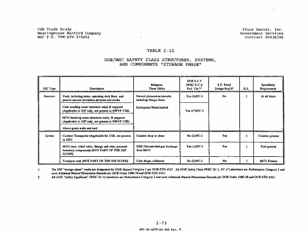
CSB Trade StudyWestinghouse Hanford CompanyWHC P.O. TVW-SW-370252
Fluor Daniel, Inc.Government Services
Contract 04436306
TABLE 2-10
DOE/WHC SAFETY CLASS STRUCTURES, SYSTEMS,AND COMPONENTS "STORAGE PHASE"
SSC Type
Structure
System
Description
Vault, including lubes, operating deck floor, andpassive natural circulation plenums and stacks
Cask handling crane (structure only) & supports(Applicable to SSF only, not present in HWVP CSB)
MCO handling crane (structure only), & supports(Applicable to SSF only, not present in HWVP CSB)
Above-grade walls and roof
Canister Transporter (Applicable for CSB, not presentin SSF)
MCO (incl. relief valve, fillings and other pressureboundary components) [NOT PART OF THE SSFSCOPE)
Transport cask (NOT PART OF THE SSF SCOPE)
MitigatesThese DBAs
Natural phenomena hazards,including Design Basis:
Earthquake/Wind/ Ashfail
Canister drop or shear
DDE, Uncontrolled gas dischargefrom MCO
Cask drops, collisions
DOES.C?(WHC s.c.yPcrf. Cat.1-1
Yes (l)/PC-3
Yes (l*)/PC-3
No (2)/PC-2
Yes (l)/PC-3
No (2)/PC-2
S F . ProofDesign Req'd?
No
Yes
Yes
No
Q.L.
1
1
1
1
OperabilityRequirement
At all times
Canister present
Fuel present
MCO Present
1 The SSP "storage phase" vaults are designated for DOE Hazard Category 2 per DOE-STD-1027. All DOE Safety Class (WHC SC 1, SC-1*) structures are Performance Category 3 andmust withsund Natural Phenomena Hazards per DOE Order 5480.28 and DOE-STD-1021.
2 All DOE "Safety Significant' (WHC SC-2) structures are Performance Category 2 and musl withstand Natural Phenomena Hazards per DOE Order 5480.28 and DOE-STD-1021.
2-73
UHC-S0-W379-ES-003 Rev. 0
CSS Trace Slucy .": ..ucr _e.r.:.e.., ..c.c .We = c:.nghouse Kanford Company Governmeni; ServicesWKC P.O. TVW-SW-370252 Contract 04436 3 06
portion of the facility were obtained from the Independent CostEstimate (ICE) prepared by the architect engineer in October, 1992,as part of the HWVP review of Key Decision (K-D) 3B. Quantities ofstructural steel were developed by Engineering. The Mechanical andProcess equipment requirements were obtained from the EquipmentList. Equipment installation and associated bulk material costswere factored from the equipment, which was priced in-house.
Miscellaneous site support costs were derived from quantity take-off estimates. Estimates for engineering construction, and projectmanagement, are expressed as percentages of direct construction andGFE procurement costs.
2.4.1.1 Assumptions
• All direct costs are expressed in present day (1995) dollars.
• The estimate was based on a standard 40 hour work week.
• Sufficient skilled labor is available on site during theperiod of construction.
• No project mission changes or major rework will occur duringthe engineering and construction of the facility.
• No radioactive or otherwise contaminated soil, or undergroundobstructions,will be encountered during excavation for thefacility.
• An est imated average craf t wage rate of $31.50/hour wasapplied to the estimated direct construction manhours. The
• average rate is based on the current Hanford Sitestabilization agreement, and current Hanford Site prevailingwages. The estimated rate covers the craft's base wage, plusbenefits and state legislated burdens.
• Engineering Costs:
25% of the direct construction cost estimates of the MCOLoading/Storage, Pool Water Treatment and InfrastructureAreas, including the Refrigeration HVAC Bldg. was added to12.5% of the Direct Construction Cost Estimate of the vaultsand office areas to provide an estimate of the Conceptual /Advanced Conceptual and Detail Design costs. Conceptual /Advanced Conceptual Design was assumed to be 20% of theengineering cost estimate, and detail design was assumed to be80%.
• The Title III engineering estimate was calculated at 4.0% ofthe direct construction cost estimate.
2-74
UHC-SD-U379-ES-003 Rev. 0

CS3 Trace Study F:.uor Daniel, Inc.West:.nghouse Kanford Company Government ServicesWHC P.O. TVW-SW-370252 Contract 04436306
• The Title III inspection estimate was calculated at 4.0% ofthe Direct Construction Cost Estimate.
• Construction management costs were calculated at 8.0% ofdirect construction costs.
• Proj ect management costs were calculated at 8.0% of directconstruction costs.
• Field construction is fixed price. An allowance of 53% wasapplied to direct field labor dollars to provide forassociated indirect field labor, temporary facilities,personnel protection, weather protection," area maintenance,small tools and consumables, field and home office staff.QA/AC staff, construction equipment usage, bond and insurance,and the Washington state business and occupation (B&O) tax.
• 5% was applied to direct field materials and equipment toprovide for overhead and profit.
• 10% was applied to direct subcontract costs to provide foroverhead and profit.
• Construction acceptance testing was calculated at 3% of directfield manhours.
• Mobilization and demobilization costs were calculated at 5% ofdirect field manhours.
2.4.1.2 Estimate Inclusions
The capital cost estimate includes all conceptual, detailed, fieldengineering and inspection costs, direct and indirect fieldconstruction labor, material, equipment, and subcontract costs,construction management, and project management costs, expended inthe execution of the SSF project. The estimate was prepared inpresent day (1995) dollars and is escalated to the appropriateactivity centroid dates dictated by the schedule (Section 2*1 5) .
2.4.1.3 Estimate Exclusions
The following costs were excluded from the scope of the capitalcost estimate:
• All capital, start-up and operating spare parts.
• Canister tube impact limiters.
• Cask transportation equipment (includes casks (transport &facility) &. donkey engine) .
• Expense funded costs
2-75
UHC-SD-U379-ES-003 Rev. 0

JS3 Tre.ce c--/->We,= t:.ncrt-.ouse Kanford CompanyWK'"1 P 6. TVW-SVV-3702S2
.'F.-uor •Jan;.e.'./ Inc.Government Services
Contract 04436306
• Operating costs
• Special work procedure (SWP) construction
• Transfer tunnels and carts to and from the StabilizationFacility
2.4.1.4 Work Breakdown Structure (WBS)
The estimate was accrued to the following WBS:
WBS
100
200
300
400
500
600
• 700
ESTIMATECODE(1)
210/310
220/320
230/330
240/340
250/350
260/360
370
100
400
500
DESCRIPTION
Rail Tunnel/CaskUnloading/Area
Staging Pool
Vaults & InletExhaust Plenums
Pool WaterTreatment/Inst AirCompressor
HVAC/Office/Generator Equipment
Refrigerated AirMechanical Area
Site Support
Engineering
ConstructionManagement
Project Management
REMARKS
All Alts
N/A
All Alts
All Alts
All Alts
Alt 2D Only
All Alts
All Alts
All Alts
All Alts
(1) Note the prefix code 2 indicates Procurement Costs, the prefixcode 3, Construction Costs. WBS areas are reflected in Figure 2-23In addition, the estimate was encoded by DOE code as described in,and required by DOE Order RL5700.3.
The estimate was further accrued by CSI Code of Accounts.
2-76
WHC-SD-U379-ES-003 Rev. 0
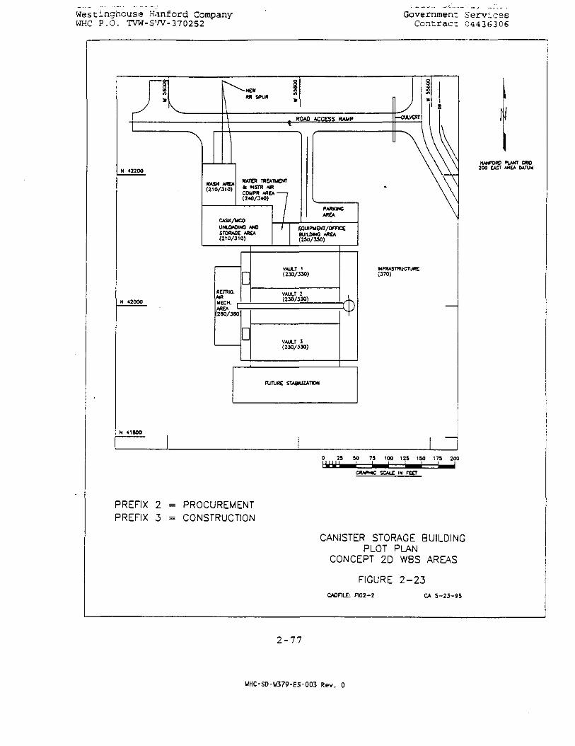
Westinghouse Hanford CompanyWHC P.O. TVW-SW-370252
Government ServicesContract G4436306
ROAD ACCESS RAMP
WASH M E *(210/310)
WATER TREATMENTfc MSTR AMCOHPR AREA 7(240/340) /
CASX/UCOUNLOADING AM)STORAGE AREA(2T0/310)
REFRIG.AIRMECH.AREA
D
PARKINGAREA
EQUIRUENT/OFFICCaurLWNG *RCA(150/350)
VAULT 1(230/330)
VAULT 2(2J0/330)
D VAULT 3(230 /J30 )
FUTURE STABILIZATION
INFRASTRUCTURE(370)
HANFORD PIAKT CRD200 CAST AREA DATUM
GRAPHIC SCALE IN FEET
PREFIX 2PREFIX 3
PROCUREMENTCONSTRUCTION
CANISTER STORAGE BUILDINGPLOT PU\N
CONCEPT 2D WBS AREAS
FIGURE 2 - 2 3
CA0F1LE: F1G2-2 CA 5-23-95
2-77
UHC-SD-U379-ES-003 Rev. 0

Westinghouse Hanford Company Government Serv icesWHC P.O. TVW-SW-370252 Contract 04436306
2.4.1.5 Quantities
The following quantity abbreviations were used throughout theestimate for all capital cost estimate line items:
Description Unit Abbreviations
Excavation and Backfill Yd3 - Cubic yardsConcrete Yd3
Structural Steel TonsLiner Plate, Finishes/Coatings Sg Ft = Square FeetMachinery & Equipment EA = EachMisc. Individual Items EAAllowances and Composites LotManhours MH
2.4.1.6 References
The following documents were used as reference documents in thepreparation of the capital cost estimate.
• Hanford Waste vitrification Plant (HWVP) Baselined Preliminary-Design Estimate, Rev. "F", dated July 1991.
• K-D 3B ICE estimate of Package 350 [(HWVP) Canister StorageBuilding <CSB)] dated October, 1992.
• Fair cost estimate of Package 350-01 (below grade portion ofthe HWVP CSB) dated February, 1993.
• Drawings and Equipments Lists prepared in support of the SSF• Report.
2.4.1.7 Escalation
The direct costs are expressed in current (1995 dollars). Theestimate was evaluated in terms of the study schedule. Thefollowing direct costs were escalated to the centroid dates oftheir respective activities:
• Conceptual and Detailed Engineering - Design through initialconstruction
• Title III - Engineering and Inspection
• Procurement
• Construction
• Construction Management
2-78
UHC-S0-W379-ES-003 Rev. 0
Wesc:.nghouse Hanford Company Government. ServicesWHC P.O. TVW-SW-370252 Contract 04436306
• Project Management
The escalation table used in the estimate preparation was providedby WHC through ICF Kaiser Hanford, Richland, WA.
2.4.1.8 Contingency
The estimated contingency was developed from an evaluation of thecompleteness of design information available to estimating, and thereliability of unit cost data obtained from prior estimates. Thefollowing contingencies were applied to the direct procurement,construction, and indirect cost centers of the estimate:
Load In/Load Out & Pool Water Treatment - 30%Infrastructure - 15%Vaults - 15%Engineering - 15%Construction Management - 15%Project Management - 15%
The resulting composite contingency is 17%.
2.4.2 CONCEPT 2D CAPITAL COST
The following capital cost alternative is included in support ofConcept 2D, 3 vaults, one empty, processed material stored in 440(2 vaults) dry Corten tubes.
2.4.2.1 Concept 2D Cost Estimate
Tables 2-11 and 2-12 contain the estimated capital cost and cashflow requirements for Alternative 2D, respectively. Supportingdetail is contained in Tables 2-13 and 2-14.
2.4.3 SIGNIFICANT OPERATING COST DIFFERENCES
Review of the operating costs indicated that Concept 2D may havehigher operating costs than other concepts i.e. a staging pool.The following operating cost factors were considered in reachingthis conclusion:
2.4.3.1 Operating Labor During Staging
The loading of MCOs into tubes is more labor-intensive than otherloading methods such as a pool rack. The distances that a poolcrane would have to travel are shorter than for tube storage.Placing MCOs in tubes requires many more operating steps, becausethe floor plug, floor plug handling flask, bottom-loading cask, andimpact absorbers have to be handled in addition to the MCO. A taskanalysis of tube loading shows that 4 operators would be requiredduring the loading, while 2 operators would be required for loading
2-79
UHC-SD-U379-ES-003 Rev. 0

WesCinghouse Hanford Company Government ServicesWHC P.O. TVW-SW-370252 ConCraci 0443(5306
pool racks. At the design rate of 4 MCOs per day, the loading willrequire 300 days. Unloading at the end of staging will requireanother 300 days. At the current estimated wage plus burdens andoverheads rate of $34.50 per hour, plus 15% average shiftdifferential, the Concept 2D labor cost is estimated at $1,140,000more (in present dollars) for loading and unloading.
In Concept 2D during staging, the tubes must be vented and purgedat the rate of at least 78 per day to prevent hydrogen frombuilding up in the tubes. If 375 tubes were filled and if 440tubes were used, 92 tubes per day would require purging (seeSection 2.2.3.2); if one were to use Los Alamos Tech Associates(LATA) data, 130 per day would require purging* for 375 tubes and150 per day for 440 tubes; pool concepts would not require thisactivity. From an estimate of 2 operators working regular days,the Concept 2D labor cost is $144,000 more per year of staging.Based on 7 years of staging, the Concept 2D labor cost is$1,000,000 more {in present dollars) for venting and purging, withthe cost increasing for each year of staging.
Combining the above labor costs without escalation, the Concept 2Dlabor cost differential (above a pool concept) will be $2,150,000plus $144,000 per year for each year that staging extends beyondthe assumed staging period of 7 years.
2.4.3.2 Fuel Cooling During Staging
Regardless of the concept used, heat load from the MCOs is thesame. However, a pool cooling concept would be more efficient thanair cooling, and the heat gain from surroundings would be less forthe pool. As a result, the horsepower ratings for the chillers andpool recirculation pumps in a pool concept would be about 500 kWless than for the chillers and air handling fans in Concept 2D. Atthe Bonneville Power wholesale rate of 30 mills per kW-hr, Concept2D costs about $13,000 per year more for power.
2.4.3.3 Heating, Ventilation, and Lighting
Because the buildings have about the same size and requirementsregardless of concept, there is no significant difference.
2.4.3.4 Crane Usage
In a pool concept the crane would be smaller than the storage cranein Concept 2D. In addition, the storage crane has to travelfarther with each MCO and perform more operations. The differencein power consumption averages about 50 kW, and is balanced by thedifference below due to water sterilization. This difference isnot significant.
2-80
UHC-SD-W379-ES-003 Rev. 0

CSB Trade StudyWestinghouse Hanford CompanyWHC P.O. TVW-SW-370252
Fluor Daniel, Inc.Government Services
Contract 04436306
FLUOR DANIEL INC.UEST1NGH0USE HANFORD COMPANYJOB HO. 436306
TABLE 2-11
** 1ESI - INTERACTIVE ESTIMATING •*STAGING AND STORAGE FACILITY
CONCEPT 20, REVISEDDOE ROt - PROJECT COST SUHHARY
PAGE 01 OF 01DATE 05/31/95 12:00:018Y AAF/JFD
COSTCODE
000
460
501
600
700
XXX
YYY
DESCRIPTION
ENGINEERING
IMPROVEMENTS TO LAND
BUILDINGS
UT ILHIES
SPECIAL EQUIP/PROCESS SYSTEMS
CONSTRUCTION HANAGEMENT
PROJECT MANAGEMENT
(ADJUSTED TO MEET DOE 5100.4)
PROJECT TOTAL
1995 $DIRECT COST
10,600,000
1 , 160,000
31,630,000
860,000
12,230,000
3,700,000
3,700,000
ESCALATEDTOTAL COST
11,030,000
1,230,000
33,650,000
910,000
13,030,000
3,930,000
3,890,000
CONTINGENCYX
: s = =
IS
15
17
15
20
15
15
TOTAL
1,650,000
160,000
5,620,000
140,000
2,580,000
590,000
560,000
TOTALESTIHATEO
COST
12,680,000
1 ,410,000
39,270,000
1,050,000
15,610.000
4,520,000
4,470,000
63,880,000 67,670,000 17 11,340,000 79,010,000
TYPE OFESTIMATE ROUGH ORDER OF MAGNITUDE ( R O M )
ARCH IIECTENGINEER FLUOR DANIEL
OPERAT INGCONTRACTOR UESTINGHOUSE HANFORD COMPANY
REMARKS:
CONCEPT 20 (RE V I S E D ) :
INITIAL CONSTRUCTION OF THREE STORAGE VAULTS, MCO STORAGEIH 440 STANDARD, AND 12 OVERPACK CORTEN STORAGE TUBES, NODEFERRED CONSTRUCTION.
THIS ESTIMATE REVISION REFLECTS THE DELETION OF THE SSFCASK LOADER, STORAGE GATE/PLUG FLASK UNIT ANO THE DONKEYENGINE FROM THE CAPITAL COST ESTIMATE. THE ESTIMATE FURTHERREFLECTS MECHANICAL CHANGES TO ACCOMMODATE HEAVIER CASKS.
( R O U N D E D / A D J U S T E D T O T H E N E A R E S T 1 0 , 0 0 0 / 1 0 0 , 0 0 0 " - P E R C E N T A G E S N O T R E C A L C U L A T E D T O R E F L E C T R O U N D I N G )
2-81
UHC-SD-U379-ES-003 Rev. 0
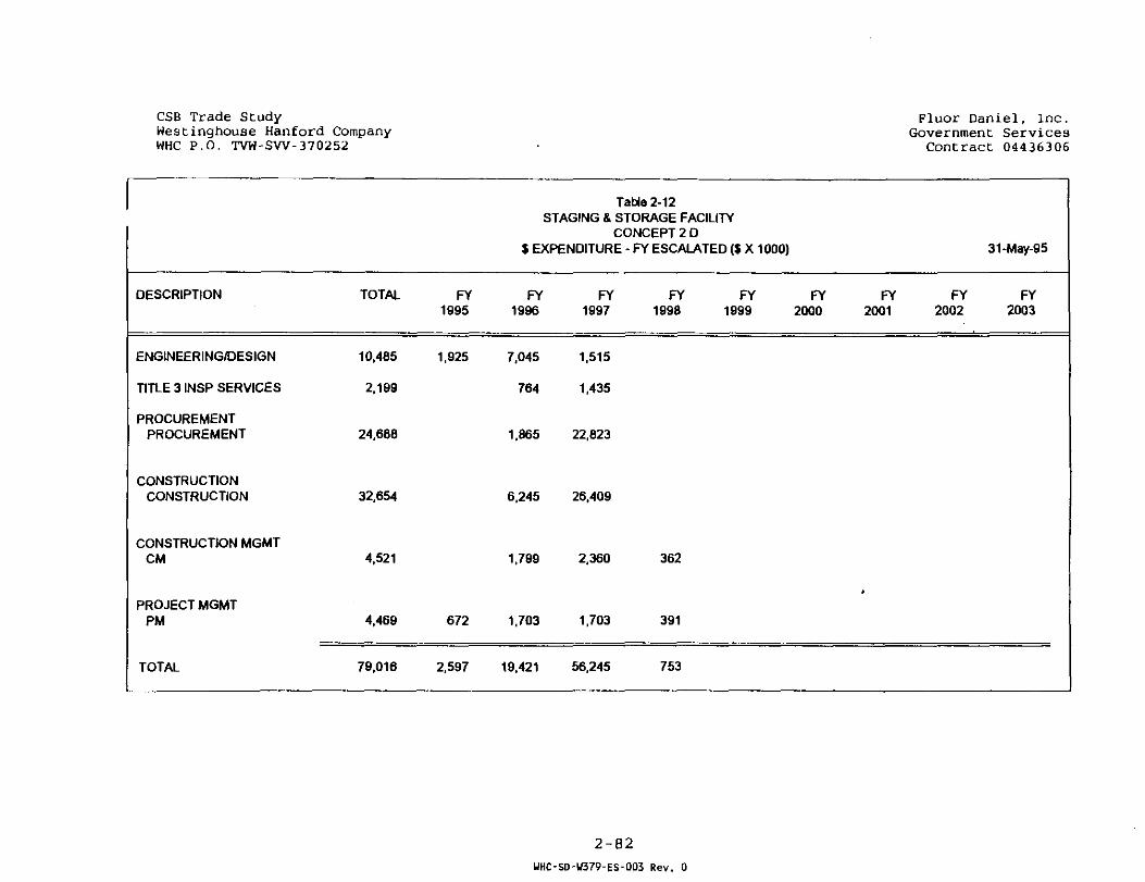
CSB Trade StudyWestinghouse Hanford CompanyWHC P.O. TVW-SW-370252
Fluor Daniel, Inc.Government Services
Contract 04436306
DESCRIPTION
ENGINEERING/DESIGN
TITLE 3 INSP SERVICES
PROCUREMENTPROCUREMENT
CONSTRUCTIONCONSTRUCTION
CONSTRUCTION MGMTCM
PROJECT MGMTPM
TOTAL
TOTAL
10,485
2.199
24,688
32,654
4,521
4,469
79,016
FY1995
1,925
672
2.597
Table 2-12STAGING & STORAGE FACILITY
CONCEPT 2 D$ EXPENDITURE - FY ESCALATED ($ X 1000)
FY1996
7,045
764
1,865
6,245
1.799
1.703
19.421
FY1997
1,515
1,435
22,623
26,409
2,360
1,703
56,245
FY FY FY1998 1999 2000
362
391
753
FY2001
>
31-May-95
FY FY2002 2003
2-82WHC-SD-U379-ES-003 Rev. 0
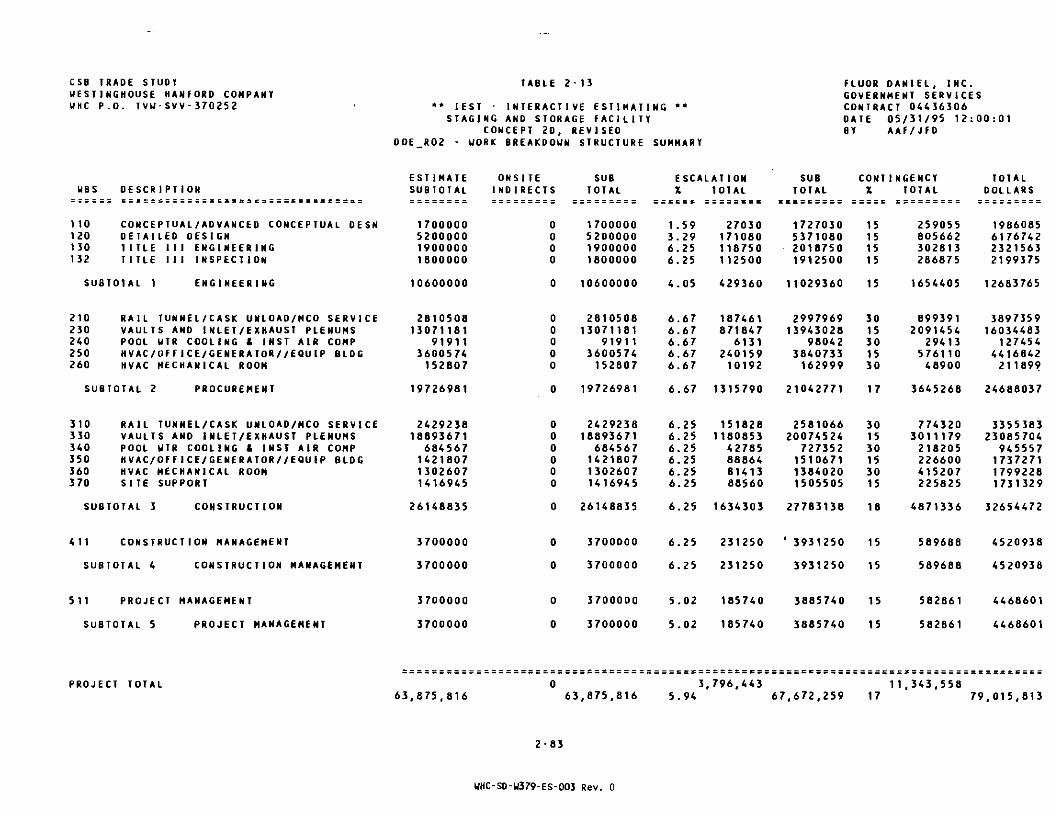
CSB TRADE STUDYW E S T J N G H O U S E H A N F O R D C O M P A N YUHC P.O. T V U - S V V - 3 7 0 2 5 2
DOE
TABLE 2-13
*• IEST - I N T E R A C T I V E E S T I M A T I N G •*S T A G I N G AND S T O R A G E F A C I L I T Y
C O N C E P T 2D, R E V I S E DR 0 2 - UO R K B R E A K D O W N S T R U C T U R E SUMMARY
FLUOR D A N I E L , I N C .G O V E R N M E N T S E R V I C E SC O N T R A C T 0 4 4 3 6 3 0 6D A T E 0 5 / 3 1 / 9 5 1 2 : 0 0 : 0 1BY A A F / J F D
UBS
1 10120no132
DESCR1PTION
CONCEPTUAL/ADVANCED CONCEPTUAL DESNDETA1LEO DESIGNTITLE 111 ENGINEERINGTlTLE I I I INSPECTION
SUBTOTAL 1 ENGINEERING
210 RAIL TUNNEL/CASK UNLOA0/HCO SERVICE230 VAULTS AND INLET/EXHAUST PLENUMS240 POOL UTR COOLING 1 INST AIR COMP250 HVAC/OFFICE/GENERATOR//EQUIP BLDG260 HVAC MECHANICAL ROOH
SUBTOTAL 2 PROCUREMENT
310 RAIL TUNNEL/CASK UNLOAD/HCO SERVICE330 VAULTS AND INLET/EXHAUST PLENUMS340 POOL UTR COOLING & INST AIR COMP350 HVAC/OFFICE/GENERATOR//EQUIP BLDG360 HVAC MECHANICAL ROOM370 SITE SUPPORT
SUBTOTAL 3 CONSTRUCTION
411 CONSTRUCTION MANAGEMENT
SUBTOTAL 4 CONSTRUCTION MANAGEMENT
511 PROJECT MANAGEMENT
SUBTOTAL 5 PROJECT MANAGEMENT
ESTIMATESUBTOTAL
1700000520000019000001800000
10600000
281050813071161
919113600574152807
19726981
242923818893671
684567142180713026071416945
26148835
3700000
3700000
3700000
3700000
ONSITE1N0IRECTS
0000
0
00000
0
000000
0
0
0
0
0
SUBTOTAL
1700000520000019000001800000
10600000
281050813071181
919113600574152807
19726981
242923818893671
684567142180713026071416945
26148835
3700000
3700000
3700000
3700000
ESCALATIONX TOTAL
1.593.296.256.25
4.05
6.676.676.676.676.67
6.67
6.256.256.256.256.256.25
6.25
6.25
6.25
5.02
5.02
27030171080118750112500
429360
187461871847
613124015910192
1315790
1518281180853
427858S8648141388560
1634303
231250
231250
185740
185740
SUBTOTAL
1727030537108020187501912500
11029360
299796913943028
980423840733162999
21042771
258106620074524
727352151067113840201505505
27783138
' 3931250
3931250
3885740
3885740
CONTX
15151515
15
3015301530
17
301530153015
18
15
15
15
15
1NGENCYTOTAL
259055805662302813286875
1654405
8993912091454
2941357611048900
3645268
7743203011179218205226600415207225625
4871336
589668
589688
562661
582861
TOTALDOLLARS
1986065617674223215632199375
12683765
389735916034463
1274544416642211899
24688037
335538323085704
945557173727117992281731329
32654472
4520938
4520938
4468601
4468601
PROJECT TOTAL63,875,816
0 3,796,443 11,343,55863,875.816 5.94 67,672,259 17 79,015,813
2-83
WHC-SD-U379-ES-003 Rev. 0

CSB TRADE STUDYU E S W N G H O U S E HANFORD COMPANYUHC P . O . T V U - S V V - 3 7 O 2 5 2
TABLE 2-14
' IEST - INTERACTIVE ESTIMATINGSTAGING AND STORAGE FACILITY
CONCEPT 20, REVISEDSI - ESTIMATE SUMMARY BY UBS
FLUOR DANIEL INC.GOVERNMENT SERVICESCONTRACT 04436306DATE 05/31/95 12:00:01BY AAF/JFD
UBS
1 10120130132
OESCR]PTION
CONCEPTUAL/ADVANCED CONCEPTUAL DESNDETAILED DESIGNTITLE I 11 ENGINEERINGTITLE I 1 1 INSPECTION
SUBTOTAL 1 ENGINEERING
210230240250260
RAIL TUNNEL/CASK UNLOAD/HCO SERVICEVAULTS AND INLET/EXHAUST PLENUMSPOOL HTR COOLING 1 INST AIR COMPHVAC/OFF ICE/GENE RAT OR//EQUIP BLDGHVAC MECHANICAL ROOM
SUBTOTAL 2 PROCUREMENT
310330340350360370
RAIL TUNNEL/CASK UNLOAD/MCO SERVICEVAULTS AMD INLET/EXHAUST PLENUMSPOOL UTR COOLING & INST AIR C0HPHVAC/OFFICE/GENERATOR//EQU1P BLDGHVAC MECHANICAL ROOMSITE SUPPORT
SUBTOTAL 3 CONSTRUCTION
411 CONSTRUCTION MANAGEMENT
SUBTOTAL 4 CONSTRUCTION MANAGEMENT
511 PROJECT MANAGEMENT
SUBTOTAL 5 PROJECT MANAGEMENT
MANHOURS
0000
0
00000
0
333302784501070020600176105615
366305
0
0
0
0
LABOR
0000
0
00000
0
1049895877117633705064S900554715176874
1 1538610
0
0
0
0
EQUIPUSAGE
0000
0
00000
0
000000
0
0
0
0
0
MATERIAL
0000
0
00000
0
7341185213112160838408562432278166399
71 15307
0
0
0
0
SUB-CONTRACT
1700000520000019000001800000
10600000
00000
0
473400000
883280
930620
3700000
3700000
3700000
3700000
EQUIPMENT
0000
0
267667412448744
875343429118145530
18787600
000000
0
0
0
0
0
OVERHEAD& PROF IT
0000
0
6224374377
1714567277
939381
5978854909383186679364345315614190392
656429S
0
0
0
0
TOTALDOLLARS
1700000520000019000001800000
10600000
? H 1 fs s n a130711B1
9191 136005741W81J/
19726981
242923818893671684i6/14210U/13026071416945
2614BB35
3700000
* 7 [i i) 0 n cj
S7finnoo
3700000
PROJECT TOTAL 366,3 0511,538,610
0 18,930,620 7,503,6 797,115,307 18,787,600 63,875,816
UHC-SD-W379-ES-O03 Rev. 0

CSB Trade Study Fluor Danie l , I n c .westinghouse Hanford Company Government Serv icesWHC P.O., TVW-SW-370252 Contract 04436306
2.4.3.5 Pool Water Sterilization
In a pool concept, the ultraviolet lamps for the sterilizers willconsume less than 50 kW of power, which is not significant, and isbalanced by the difference above due to cranes.
2.4.3.6 Chemical Consumption
The nitrogen consumption for MCO servicing and the decontaminationchemical consumption are the same regardless of concept. Becausepool water deionizers would not require regeneration as watertreatment chemical usage is not significant.
2.5 SCHEDULES
2.5.1 SCHEDULE ASSUMPTIONS
2.5.1.1 General
These schedules are based on the use of the Canister StorageBuilding (CSB) design and partially completed construction from theHanford Waste Vitrification Plant (HWVP) Project. Utility tie-insare available from the completed construction of the HWVP project.
WHC provided the date for start of the engineering studies, the KeyDecision 0 date of 10 March 1995, and the date of May 9, 1995 forapproval by DOE of the Functions and Requirements (F&Rs) for theproject. April 24, 1995 is assumed to be the start of ConceptualDesign and Capital funds are assumed to be available in October1995. The Stabilization Facility is assumed to be operational inDecember 2002.
This schedule assumes that there will be no annual fundingconstraints for the duration of the project.
The cost estimates prepared for each alternative provide a basisfor each schedule.
An important objective of these schedules was to have the SSFoperational and ready to receive MCO's from the K-Basins as rapidlyas possible. Aggressive, but achievable schedules were thereforedeveloped.
2.5.1.1.1 Engineering and Design
Maximum use of the existing engineering and design of the CSB andthe results of this feasibility study allows the approximatelythree month duration for conceptual design. New requirements andadditional facilities will have minimal impact to the existingfacility design and drawings.
2-85
UHC-SD-U379-ES-003 Rev. 0

We:3t;.nc'h.ouse Hanford Company Government ServicesWHO P.O. TVW-SW-370252 Contract 04436306
Client, review changes will have no impact at the end of conceptualengineering and definitive design. Continuous reviews andalignments are required to minimize change.
2.5.1.1.2 Procurement and Construction:
The October 1992 statused Mowat schedule for the CSB was used as abasis for deriving activity durations for completion of the walls,the operating floor and storage tube installation.
The construction of the facility will be performed with specialtysubcontractors.
There is no shortage of local craft labor or specialty contractorsin the area.
Construction is based on a standard forty hour work week.Scheduled overtime is excluded from this schedule.
The concrete slab and walls that are currently in place will beused with minimal changes required to complete the concrete vaultwalls and operating floor.
The walls for all vaults will be formed and poured simultaneously.
Rebar for the walls and for the operating floors will be pre-assembled and set in place with cranes.
Structural steel buildings will be prefabricated in shops, andassembled in the field.
Thete is no shortage of material locally, including concrete batchplant requirements.
Long lead equipment items will be identified very early so as tonot delay construction.
There are no shortages of construction equipment in the area.
Reviews by WHC will be concurrent with the design during all phaseswith a twenty day review continuing after the end of conceptualdes ign.
DOE reviews will be for twenty days after the WHC review period.
Independent cost verifications will be for twenty days after theWHC review and concurrent with the DOE reviews.
ESAAB reviews will take place for twenty-five days subsequent tothe DOE reviews and prior to Key decisions one through four.
2-86
UHC-SD-W379-ES-003 Rev. 0
wS3 Trcit^.e S-J.c.y fr'iuor uaniel, Inc.We,3t:.ngh.Guse Eanford Company Governmenc ServicesWHC P.O. TVW-SW-370252 Contract 04436306
Safety analysis reports will be generated on a one step SAR basis.Final review and approval extends for a nine month period andapproval is required prior to start-up. Construction will beallowed to commence based on approval of a preliminary safetyevaluation.
2.5.1.4 Concept 2D
Construction of the operating decks will be concurrent in all threevaults.
Storage tube installation will be concurrent in two vaults.
2.5.2 CONCEPT 2D SCHEDULE
Figure 2-24 contains the schedule for Concept 2D. It shows that,subject to the above assumptions, it is possible to achieveoperation of the SSF in December 1997. The entire facility isconstructed initially under this concept so there is no secondphase of procurement and construction.
2.6 CONCLUSIONS AND RECOMMENDATIONS
2.6.1 FEASIBILITY OF CSB ADAPTATION
The results of this study demonstrate that it is currently notfeasible to adapt the design of the CSB to meet the F&Rs of the SSFdue to the 100 °F MCO temperature requirement. If a relaxation ofthe temperature requirement was to occur then construction of theSSF on the CSB site will enable the. already completed CSB siteclearing and grubbing, site preparation, excavation, base mat andwalls to be utilized for the SSF, saving both time and money. Useof the CSB site for the SSF is also consistent with master planscurrently being developed for the Hanford Site and the objective ofmoving the N-Reactor fuel away from the Columbia River.
2.6.2 OTHER TECHNICAL CONCERNS
Relaxation of the 100 °F maximum MCO temperature requirement priorto stabilization would allow further cost reduction alternatives tobe considered.
In addition to a relaxation of the MCO Temperature requirementseveral other technical issues would require further investigationto ensure cost, schedule and safety requirements are achievedincluding:
• Shielding requirements regarding the empty vault and itsfuture use.
2-87
WHC-SD-U379-ES-003 Rev. 0

CSB Trade StudyWestinghouse Hanford CompanyWHC P.O. TVW-SW-370252
Fluor Daniel, Inc.Government ServicesContract 04436306
EartyStart
EartyFintah
OrioDuf TTFIHIAIH- I AlftlQIHTTT J IF IM IA IH: J I F IM I A I M I JIFIMIAIMUTJ
KEY DECISIONS10MAR9501NOV9528FEB9631JUL9624OEC97
V K E Y DECISION #OV K E Y DECISION »1 & *2
V K E Y DECISION «3AV K E Y DECISION not
\J KEY DECISION #4
KEY MILESTONES09MAY95
04OCT9501JUN9S*
V D O E APPROVAL OF F ft R*»VDESIGN ONLY VALIDATION
CAPITAL DOLLARS AVAILABLE
STUDIES[06JAN9S |24FEB95j 36 CUTIENGINEERING STUDIES
-tI
PTUAL DESIGN jREVIEW/A PPROVE CDR
MOV AN) ED CONCEPTUAL DESIGNWDEPENDE *T COST VERIFICATION
DESIGN REVIEW]=SAAB*
CONCEPT DESIGN10MAYSS 01AUG96 000SJUL9S02AUG9S3QAUG9530AUG95
29AUG9530OCT9526SEP9526SEP9S
27SEP95 31OCT95
40
2Q2025 ziiSSF DESIGN
01NOV95 28MAY96 15001NOV9501NOV9527DEC9S27DEC9S24JAN9629MAY9629MAY9626JUN96 30JUL96
02JAN9626DEC9S23JAN9C23JAN9C27FEB9625JUN962SJUN96
45jSSF DEFINITIVE DESIGN
40202025202025
IPREPARE FINAL DESIGN SPECIFICATIONSEP VAULT DESIGN DWGS'
i ^INDEPENDENT COST VERIFICATION^ZJDOE DESIGN REVIEW (*3A)
ESAABIWAJ
HMCEREVEWU p O E 'DESIGN REVIEW (<J3B)
SAABK3B
PROCUREMENT27DECS5 1SMAR96 6003JAN9631JUL96
O8APR9722OCTB6
23OCT96 20MAY97
33060
150
BID & AWARD VAULT CONSTRUCT 10 i
IIP & AVJfARD TUBE FABRICATIONDSSF CONSTRUCTION PROCUREM :NT
)FAB ft DELIVER TUBE ASSEt BLIES
CONSTRUCTION2SFEB9628FEB9628FEB9620MAR9620MAR9629MAY96
27FEB9627FEB9627FEB9630SEP9728MAY9606AUG96
400'
IStTE CLEAR ft GRUB (COMPLETE)1 ROADS (COMPLETEJBLDGEXCAV ft CONCR SLAB (COMPLETE)
5050
ftP VAULTS (3A)ILL EXTERK)R WALLS (3A)
JENGRftlN PECTION SERVICES-TITLE III
FIGURE 2-24 (Sheet 1 of 2)STAGING & STORAGE FACIUTY
CONCEPT 2 D - CSB ADAPTATION
2-88WHC-SD-U379-ES-003 Rev. 0
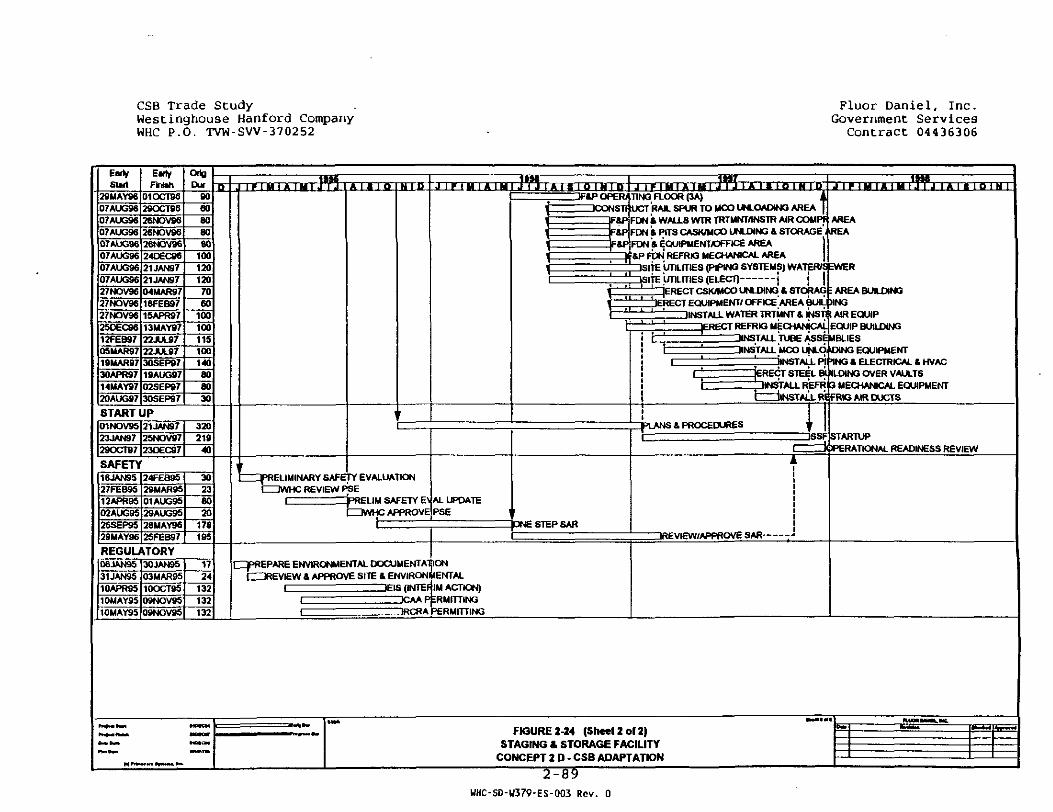
CSB Trade StudyWestinghouse Hanford CompanyWHC P.O. TVW-SW-370252
Fluor Daniel, Inc.Government ServicesContract 04436306
SlutEarlyFkfeh
OrigDo, T T I M I A I H ,AI8IOIM7P|J Tx-rainim
2SUAY96 01OCTB6 8007AUG96 29OCT9607AUG96 26NOV96Q7AUG96 26NOV9607AUG96 26NOV9607AUG96 24DEC86O7AUG96 21JAN9707AUG96 21JAN9727NOV96 O4MAR9727NOV96 18FEB9727NOV96 15APR9725DEC96 13MAY9712FEB97 22JUL970SMAR97 22JUL8719MAR97 3OSEP9730APR97 19AUG9714MAY97 O2SEP9720AUG97 3OSEP97
60808060
1001201207060
10010011510Q140808030
UFfcP OPER> TING FLOOR (3A)4STf UCT RAIL SPUR TO MCO UNLOADING AREAF&PiFDN * WALLS WTR TRTMHTANSTR AIR COMPf AREAFftP FDN ft PITS CASK/MCO UNLDING & STORAGE >REAF8P FDN ft EQUIPMENT/OFFICE AREA
f 4P FDN REFRK3 MECHANICAL AREA1SITE UTILITIES (PIPING SYSTEMS) WATER/SEWER]|SIT£ UTILITIES (ELECT)
I AREA BUILDINGjERECT CSKWCO UNLDING & STORAGERECT EQUIPMENT/ OFFICE | ARE A BUILpING
1INSTALL WATER TRTMNT & INSTft AIR EQUIP3ERECT REFRK3 UECHANtCALjEQUIP BUILDING
_MNSTALL TUBE ASSEMBLIESINSTALL MOO UNLO DING EQUIPMENT
'• "JIMSTAJI pi TNG I. ELECTRICAL IHVAC^ERECT STEEL BUILDING OVER VAULTSZIHNSTALL REFR 3 MECHANICAL EQUIPMENTi iTALL REFRtG AIR DUCTS
START UP01NOV95 21JAN9723JAN97 25NOV9729OCT87 23DEC87
320219
40
IJPLANS & PROCEDURESSSF STARTUP
dHZJOPERATIONAL READINESS REVIEW
SAFETY16JAN9S 24FEB9527FEB9512APR9502AUG9S26SEP9S
2SMAR9501AUG9529AUG9S26MAY96
29MAY96 25FEB97
30238020
176195
^^PRELIMINARY SAFETY EVALUATIONCZ3WHC REVIEW PSE
^>RELIM SAFETY E AL UPDATECDWHC APPROVE PSE
•ME STEP SABDREVIEW/APPROVE 5AR -
REGULATORY06JAN9531JAN9510APR9510MAY9510MAY95
30JAN9S03MAR9510OCT9509NOV9509NOV95
1724
132132132
CqpREPARE ENVIRONMENTAL DOCUMENTATIONC3REVIEW & APPROVE SITE & ENVIRONMENTAL
t 1EIS (INTERIM ACTION)I " " ' TCAA PERMITTING\ "~TRCRA PERMITTING
FIGURE 2-24 (Sheet 2 of 2)STAGING & STORAGE FACILITY
CONCEPT 2 D - CSB ADAPTATION
2-89WHC-SD-U379-ES-Q03 Rev. 0

CSB Trade Study Fluor Daniel, Inc.Westinghouse Hanford Company Government ServicesWHC P.O. TVW-SW-370252 Contract 04436306
• Contact maintenance and servicing of the transport andfacility casks due to the high source dose rates.
• RCRA requirements to detect liquid in the annular spacebetween the MCO and staging tubes.
• Microbiological Influenced Corrosion (MIC) affects on theStainless Steel (SS) MCO due to high MCO temperatures.
• Venting and purging of staging tubes due to hydrogenbuild-up in the MCOs due to high MCO^temperature.
• MCO/Cask drop evaluation over the operating floor.
• Emergency response capability in the event of a sustainedloss of cooling, e.g. due to DBE or loss of power, toprevent unacceptable high MCO temperatures.
2.7. REFERENCES
American National Standards Institute/American Nuclear Society,March 1989, Design Criteria for an Independent Spent FuelStorage Installation (Water-Pool Type),ANSI/ANS Standard 57.7-1998
American National Standards Institute/American Nuclear Society,May 1992, Design Criteria for an Independent Spent FuelStorage Installation (Dry Type) ANSI/ANS Standard 57.9-1992
American Nuclear Society, 1988, "Design Criteria for anIndependent Spent Fuel Storage Installation (Water Pool Type),"ANSI/ANS-57.7-1988
Anderson, H.L. Ed., 1981, "AIP 50TH Anniversity Physics VadeMecum, " American Institute of Physics, NY
ASHRAE Handbook of Fundamentals
Borenstein, S. W. and Licina, G. C , 1990, "Avoid MIC-RelatedProblems in Nuclear Cooling Systems", Power, June 1990
Briesmeister, J. F., Editor, November 1993, "MCNP - A GeneralMonte Carlo N-Particle Transport Code, Version 4A," LA-12625-M
DOE Order 6430.1A (1989), General Design Criteria
DOE Order 6430.1A, April 1989, "General Design Criteria"
Fair cost estimate of Package 350-01 (below grade portion of theHWVP CSB), February, 1993
2-90
WHC-SD-W379-ES-003 Rev. 0

ZS3 Tracf.f; S-ucy Fluor Daniel, Inc.We.= t:.nghouse Fanford Company Government ServicesWHC P.O. TVW-SW-370252 Contract 04436306
Fulton, John C., 1994, "Hanford Spent Nuclear Fuel ProjectRecommended Path Forward", WHC-EP-0830 Rev 0, October 1994
Hanford Waste Vitrification Plant (HWVP) Baselined Preliminary-Design Estimate, July 1991, Rev. "F"
The Health Physics and Radiological Health Handbook
Institute of Electrical and Electronic Engineers, IEEE 379
K-D 3B Ice Estimate of Package 350 [(HWVP) Canister StorageBuilding (CSB)]# October, 1992
Nuclear News, June 1994, p. 33, "Energy First in U.S. to UseFuel 'Sipping'"
Oak Ridge National Laboratory, RSIC CCC-619, July 1993, "SCALE-PC, Modular Code System for Performing Criticality SafetyAnalyses for Licensing Evaluation, Version 4.111
Pacific Northwest Laboratories, December 1988, "The HanfordEnvironmental Radiation Dosimetry Software System,"PNL-6584, Volume 1
Perry, Robert H. (ed.), 1984, "Perry's Chemical Engineers'Handbook," 6th ed.
"Radiological Control Manual," June 1992, DOE/EH-02561, Rev. 1
Solutions Engineering & Facilitating, Inc., 1995, "ValueEngineering/Study Analysis Session, Spent Nuclear FuelProject, Staging & Storage Facility, Project W-379, January1995
State of Washington Department of Ecology, March 1991, DangerousWaste Regulations, Washington Administrative Code 173-303,
US Department of Energy, April 1989, General Design Criteria, DOEOrder 6430.1A
US Department of Energy, October 1984, Safety of NuclearFacilities, DOE Order 5480.5
US Department of Energy, August 1992, Technical SafetyRequirements, DOE Order 5480.22
US Department of Energy, April 1992, Nuclear Safety AnalysisReports, DOE Order 5480.23
US Department of Energy, January 1993, Natural Phenomena HazardsMitigation, DOE Order 5480.28
2-91
WHC-SD-U379-ES-003 Rev. 0

CSB Trade Study Fluor Daniel, Inc.Westinghouse Hanford Company Government ServicesWHC P.O. TVW-SW-370252 Contract 04436306
US Department of Energy, April 1994, Natural Phenomena HazardsDesign and Evaluation Criteria for Department of EnergyFacilities, DOE Standard 1020-94
US Department of Energy, July 1993, Natural Phenomena HazardsPerformance Categorization Criteria for Structures, Systems,and Components, DOE Standard 1021-93
US Department of Energy, December 1992, "Hazard Categorizationand Accident Analysis Techniques for Compliance with DOEOrder 5480.23," DOE Standard 1027-92
US Department of Energy, July 1988, "External D"ose-RateConversion Factors for Calculation of Dose to the Public,"DOE/EH--0070
US Department of Energy, July 1988, "Internal Dose ConversionFactors for Calculation of Dose to the Public," DOE/EH--0071
US Environmental Protection Agency, National Environmental PolicyAct
US Environmental Protection Agency, Resource Conservation andRecovery Act
US Nuclear Regulatory Commission, Licensing Requirements for theIndependent Storage of Spent Nuclear Fuel and High-LevelRadioactive Waste, 10CFR72
US Nuclear Regulatory Commission, Assumptions Used for Evaluatingthe Potential Radiological Consequences of a Fuel HandlingAccident in the Fuel Handling and Storage Facility forBoiling Water and Pressurized Water Reactors, RegulatoryGuide 1.25
US Nuclear Regulatory Commission, Standard Format and Content forthe Safety Analysis Report for an Independent Spent FuelStorage Installation (Water Basin Type), Regulatory Guide3.44
US Nuclear Regulatory Commission, Standard Format and Content forthe Safety Analysis Report for an independent Spent FuelStorage Installation or Monitored Retrievable StorageInstallation (Dry Storage), Regulatory Guide 3.48
US Nuclear Regulatory Commission, December 1981, Design of anIndependent Spent Fuel Storage Installation (Water BasinType), Regulatory Guide 3.49
2-92
WHC-SD-W379-ES-003 Rev. 0
-.- -i ..race irZUC.y " ..uui j a t u e . , ..nc.We:=t:.ncT.ouse Hanford Company Government ServicesWHi: P.O. TVW-SW-370252 Contract 04436306
US Nuclear Regulatory Commission, March 1987, Design of anIndependent Spent Fuel Storage Installation (Dry Type),Regulatory Guide 3.60
Westinghouse Hanford Company, 1988, "Nonreactor Facility SafetyAnalysis," WHC-CM-4-46
Westinghouse Hanford Company, August 1991, "Safety Classificationof Systems, Components, and Structures," WHC-CM-1-3, MRP5.46
Westinghouse Hanford Company, October 1992, "HWVP CanisterStorage Building Preliminary Safety Analys'is ReportAddendum," WHC-SD-HWV-PSE-001, Revision 0A
Whalen, D.J., D.E. Hollowell, J.S. Hendricks, September 1991,"MCNP: Photon Benchmark Problems," Los Alamos NationalLaboratory, Report No. LA-12196,
Whalen, D.J., D.A. Cardon, J.L. Uhle, J.S. Hendricks, November1991, "MCNP: Neutron Benchmark Problems," Los AlamosNational Laboratory, Report No. LA-12212,
WHC-CM-1-3, Section MRP 5.46, Rev. 4, "Safety Classification ofSystems, Components, and Structures"
WHC-SNF-FRD-014, May 1995, Section 3.2.2.1.2.2, Rev. A, "DraftPerformance Specification for the Spent Nuclear FuelCanister Storage Building"
WHC, Implementation Strategies for US Department of Energy Order5480-28 Natural Phenomena Hazzards Mitigation, T. Conrads,undated
2-93
UHC-S0-W379-ES-QQ3 Rev. Q
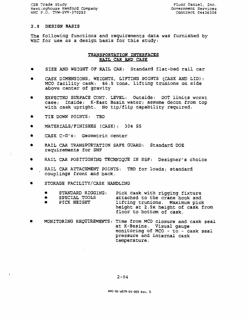
CSB Trade Study Fluor Daniel , I nc .Westmghouse Hanford Company Government Serv icesWHC P.O. TVW-SW-370252 Contract 04436306
2 . 8 DESIGN BASIS
The following functions and requirements data was furnished byWHC for use as a design basis for this study:
TRANSPORTATION INTERFACESRAIL CAR AND CASK
• SIZE AND WEIGHT OP RAIL CAR: S t a n d a r d f l a t - b e d r a i l c a r
• CASK DIMENSIONS, WEIGHTS, LIFTING POINTS (CASK AND LID) :MCO f a c i l i t y c a s k : 86-5 t o n s , l i f t i n g t r u n i o n s on s i d eabove center of gravity
• EXPECTED SURFACE CONT. LEVEL: Outside: DOT limits worstcase; Inside: K-East Basin water; assume decon from topwith cask upright. No t ip / f l ip capability required.
• TIE DOWN POINTS: TBD
• MATERIALS/FINISHES (CASK): 304 SS
• CASK C-G's: Geometric center
• RAIL CAR TRANSPORTATION SAFE GUARD: Standard DOErequirements for SNF
• RAIL CAR POSITIONING TECHNIQUE IN SSF: Designer's choice
• RAIL CAR ATTACHMENT POINTS: TBD for loads,- standardcouplings front and back.
• STORAGE FACILITY/CASK HANDLING
• STANDARD RIGGING: Pick cask with rigging fixture• SPECIAL TOOLS attached to the crane hook and• PICK HEIGHT lifting trunions. Maximum pick
height at 2.5x height of cask fromfloor to bottom of cask.
• MONITORING REQUIREMENTS: Time from MCO closure and cask sealat K-Basins. Visual gaugemonitoring of MCO - to - cask sealpressure and internal casktemperature.
2-94
WHC-SD-W379-ES-003 Rev. 0

CSB Trade Scudy ' Fluor Daniel , I nc .Westinghouse Hanford Company Government Serv icesWHC P.O. TVW-SW-370252 Contract 04436306
SERVICE REQUIREMENTS
• AIR• WATER TBD, no special requirements• POWERS ident i f ied• IMPACT RECORDING
NUMBER OF RAIL CARS: 2 cars in the facility at once forcask unload/load cycle and MCOload/unload cycle
LAG STORAGE REQUIREMENTS
• RAIL CARS: 2 cars on rail siding outside• CASKS: 4 casks; 2 clean, ready for use; 1
contaminated, waiting fordecontamination; 1 in thedecontamination station.
• MCO's: 1 week supply at facility: 4/dayconsumed.
• RAIL CAR WEIGHT - FULL CASK LOAD: Standard flatbedrail car plus 86.5 tons cask
• IDENTIFICATION OF ANY OTHER TRANSPORTER CONCEPTS: TBD,assume rail
• SECURITY NEEDS (LIMITS, ETC.): DOE standards for SNF
• TRANSPORTER CONVEYANCE
• LOCOMOTIVES Designer choice inside facility.• TRACKMASTER: Locomotive delivery to facility and• TUGGERS pick-up from facility.
• RAIL CAR MATERIALS AND SURFACE FINISH: Assume easilydecontamination design to facilitate standard wash-downtechnologies.
• CAR IDENTIFICATION AND TRACKING: Visual
• BRAKE STATUS: Visual indication
MCO INTERFACES
SIZE: See attached table
SHAPE: See attached table
WEIGHT/CG'S: EMPTY/LOADED: See attached table
2-95
WHC-SD-W379-ES-003 Rev. 0

CSB Trade Study Fluor Daniel, Inc.Westinghouse Hanford Company Government ServicesWHC P.O. TVW-SW'37O252 Contract 04436306
MATERIAL AND FINISH CONDITION: 304 SS
LIFTING POINTS/GEOMETRY: Top of MCO; specifics TBD.Lifting fixtures compatible with normal crane hook.
ATTACHMENTS FOR MONITORING: MCO lid
ATTACHMENTS FOR SERVICES: MCO lid
DEFINITIONS OF SERVICE REQUIREMENTS:
• Vent and inert-gas purge MCO upon receipt;• Cycle for water addition at 2 MC0s/we"ek after
completion of MCO delivery to the SSF
MONITORING REQUIREMENTS: Temperature of cooling media (mustlimit MCO temperatures as listedbelow)
REQUIRED STORAGE Staging: MCO at 100° F.
CONDITIONS: Storage: Fuel centerlinetemperature at 400 C.
IDENTIFICATION Visual identification of MCO, orper
REQUIREMENTS: DOE standard materialaccountability requirements for SNF
TRACKING REQUIREMENTS: DOE standard materialaccountability requirements for SNF
MINIMUM, MAXIMUM, AVERAGE RADIATION LEVELS: TBD, beingcalculated
EXPECTED SURFACE Nominal conditions: cleanCONDITIONS: Upset conditions: K-Basin water
contamination
CRITICALLY CONTROL MCO stacking acceptable, MCOSPACING: placement side-by-side with no gap
acceptable.
INSPECTION REQUIREMENTS: Receipt inspection: MCO - to -cask seal verification - visualgauge observation. MCO sealverification - visual gaugeobservation. Surface contaminationof MCO and cask. MCO weight. MCOH2 levels during venting.
2-96
WHC-S0-U379-ES-Q03 Rev. 0

CSB Trade Study Fluor Danie l , I nc .Westinghouse Hanford Company Government Serv icesWHC P.O. TVW-SW-370252 Contract 04436306
• ORIENTATION REQUIREMENTS: VERTICAL +- 10 d e g r e e s
• SEALING SURFACES LOCATION/CONFIGURATION/MATERIALS/ e t c . :Top of MCO l i d
• ACCELERATION LIMITS: Normal crane ope ra t ing l i m i t s ; o r2-g vertical lift, l-g verticallowering, l-g horizontal, impactlimiters for long verticalplacements.
• SOURCE TERMS• RADIOLOGICAL ' See attached Cowan list.• CHEMICAL List must be updated to describe• HAZARDOUS minimum MCO source term, % of MCOs• LIQUID at minimum levels, sludge source• GAS term and # of sludge MCOs. Assume• THERMAL sludge MCOS contain RCRA
waste. Assume 100 m3 of sludge.SSF must meet RCRA waste storagerequirements for sludge MCOs.
• STANDARD RIGGING Deployed from crane hook.HARDWARE: Designer's choice.
• SPECIAL TOOLS: Deployed from crane hook. Designer'schoice.
• MAXIMUM ALLOWABLE OPERATION PRESSURE: 125 psig prior toventing. Gas volume 50 liters. Gas venting throughbreather filter (air cooling) or water trap (water poolcooling).
• RESPONSIBILITY FOR MCO OVERPACK DESIGN: SSF designer
• ALLOWABLE PICK ELEVATIONS: 2.5 x MCO height from floor tobottom of MCO.
2-97
UHC-SD-U379-ES-003 Rev. 0

CSB Trade StudyWestinghouse Hanford CompanyWHC P.O. TVW-SW-3702S2
Fluor Daniel , Inc .Government Serv ices
Contract 04436306
MCO Proposed DescriptionDraft Rev. A R.G. Cowan Mav 17, 1995
MCO Radio nuclide Inventory
Radio nuclide
U
ZrPuSnAl
C
All Other
Total Mass For One MCO
Co-60
Kr-85
Sr-90
Y-90
Cs-137
Ba-137m
Pm-U7
Sm-151
Eu-154
Pu-238
Pu-239
Pu-240
Pu-241
Am-241
All Other
Total Activity For One MCO
unit
kgkg
kg
k*
kg
kgkg
kgCi
Ci
Ci
Ci
Ci
Ci
Ci
Ci
Ci
Ci
Ci
Ci
Ci
Ci
CiCi
Average
2,800
197
5
3
2
2
4
3,013
197937
14,000
14,000
18,000
17,067
1,440
229171
167
300
173
7.S40
420
379
77,320
Maximum
3,287
230
100
3
3
2
53,630
786
2,440
27,941
27,941
37,929
35,906
8,180
344
804
496
499
37835,021
742
3,283
182,692
MCO General Attributes
Parameter
Heat10
Water Weight
Stainless/Al
lotal MCO Weight
Fuel Volume
MCO Volume
MCO Fuel Fraction
MCO Length
MCO Diameter
MCO Wall Thickness
MCO Top Shield
Canisters/MCO
Cask (20 cm iron) Weight°»
Loaded Cask & MCO
Cask; <fc MCO
Fuel Surface
MCO & Canisters
Total Inside Surface
Unit
Watt
kg
kg
kg
LL%cmcmcmcm
kgkg
tons
sq. m
sq. m
sq. m
Average
221
963
1,274
5,251
202
1,203
17
460
61.00
1.00
20
10
20,375
25,626
28.25
37.77
29.1766.94
Maximum
482
984
1,314
i.927
243
1,265
19
460
62.50
1.00
20
10
20,76326,690
29.42
44.34
29.40
73.74
Notes: See Page 2-99
2-98
WHC-SD-W379-ES-003 Rev. 0

CSB Trade StudyWestinghouse Hanford CompanyWHC P.O. TVW-SW-3702S2
Fluor Daniel, Inc.Government Services
Contract 04436306
MCO Heat Capacity
Parameter
Uranium
ZirconiumStainless steel
Water
Cask
Total<3 10 'C
Uranium CorrosionGas Generation
Reaction HeatHeat LossTemperature Rise
® 2 5 XUranium Corrosion
Gu generationReaction HeatHeat Loss
Temperature Rise
a so cUranium CorrosionGas generation
Reaction HeatHeat Low
Temperature Rise® 7 5 X
Uranium CorrosionGu generationReaction HeatHeat Loss
Temperature Rise
@ 85 C
Uranium Corrosion
Gas generation
Reaction Ueat
Meat Lou
Temperature Rise
@95 C
Uranium CorrosionG u generation
Reaction HeatHeat Lou
Temperature Rise
Unit
Kw-hi/X
fcw-hr/X
Icw-hr/'Ciw-hr/X
tw-hr/'Cfcw-hr/X
g/d
L/d
Watt
Watt
C/hr
g/d
L/dWatt
Watt
C/nc
g/d
L/d
Watt
Watt
C/hr
g/d
Ud
Watt
Watt
•C/hr
g/d
L/d
Watt
Watt
•C/hr
g/d
L/dWitt
Watt
C/hr
Average
O.iO
0.02
0.11
1.11
2.53
3.95
1.74
0.33* 0.05
36.86
0.05
6.12
1.150.17
136.31
Q.02
49.63
9.34
1.35
302.06
-0.02
402.68
79.8
10.92
467.81
-0.06
930.37
175.13
25.23
534.11
•O.07
2,149.59
404.63
58.29
600.41
-0.08
Maximum
0.11
0.03
0.18
1.14
2.58
4,05
20.44
3.85
0.55
36.86
0.11
71.80
13.521.95
136.31
0.09
582.60
109.67
15.80
302.06
0.05
4,727.41
889.87
128.20
467.81
0.04
10,922.54
2,056.01
296.20
>34.11
0.06
25,236.18
4,750.34
684.35600.41
0.14
(1) Heat generation design feed basis is calculated at 30% of the attributes shown under
"Average" and 20% of those shown under "Maximum"
(2) Cask weight not consistent with requirements to meet shielding.
2-99
WHC-SD-U379-ES-003 Rev. 0

X
\
WHC-S0-W379-ES-003 Rev. 0

_^ =. ...race czuc.y ?luor Daniel, Inc.Westmcfcuse Hanford Company Government ServicesWHC P.O. TVW-SW-370252 Contract 04436306
3.0 TRADE STUDY REPORTS
3.1 TABLE OF CONTENTS
Description TabFacility Confinement Investigation AMCO Receipt and Staging Function and Area BRemoval
C Cask Decontamination Function and Area CRemoval
D One Track Rail Service DE Storage Tube Material Investigation EF MCO Shipment Reduction FG Damp-Dried MCO GH RCRA Functions: Prevention and Detection H
of MCO Leaks
3.2 INTRODUCTION
In accordance with the Statement of Work, Revision 5, dated April21, 1995 in Work Order TVW-SW-37052, Modification No. 90,individual Trade Study Reports have been prepared and are includedin this section. Each report is independent of the others ,•however, each study is based on requirements defined in the BaseCase Concept 2D description, Section 2.0. A cost summary ispresented in Table 3-1. The cost and schedule basis for the TradeStudies is identical to that defined in Sections 2-4 and 2-5, ofthe Base Case Concept 2D.
In terms of the Construction schedule, it appears only Task "H",RCRA Functions: Prevention and Detection of MCO leaks, would havean impact on the proposed construction schedule and date. It isestimated that RCRA compliance would extend the facility completiondate by a minimum of two months.
No cost data has been provided for Task "G", Damp-Dried MCO, as theanalysis demonstrated that it was not feasible to adapt the CSB tocomply with the functions and requirements for the SNF CSB.
3-1
WHC-SD-U379-ES-003 Rev. 0
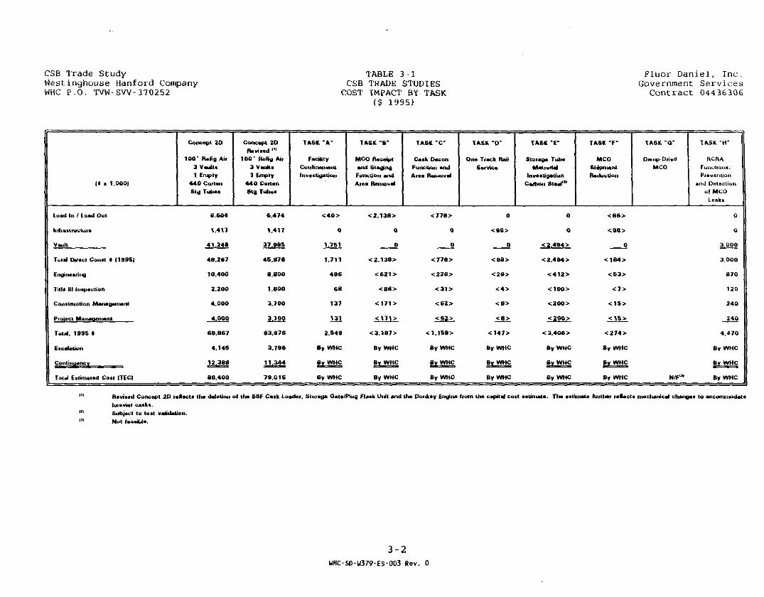
CSB Trade StudyWestinghouse Hanford CompanyWHC P.O. TVW-SVV-370252
TABLE 3-1CSB TRADE STUDIESCOST IMPACT BY TASK
($ 1995)
Fluor Daniel, Inc.Government Services
Contract 04436306
it • 1,000)
Luatl In / Load Out
InllaalnivtiMe
Vault
Total Direct Conat • (19951
Engineering
Till a lit luapection
Construction Management
Pi Of eel Menaaen lent
Total. 1995 •
Escalation
Contingency
Total Estimated Cott (TEC)
Concept 2 0
100' Rrtfig Air3 Vault.1 Empty
440 CoileiiStg Tutlea
6.604
1.417
41.246
48,267
10.400
2.20O
4.000
4.000
69.867
4.145
12,388
86,400
Concept 2 0fUviaad '"
100' Rt.Htf Ail3 Vaulla1 Empty
440 CortanBig Tubea
6.474
1,417
37,985
46,876
8.800
1.800
3.700
3,700
63.876
3,796
11,344
79.016
TASK -A-
FacilityConfinementInvestigation
< 4 0 >
0
1.751
1,711
4 9 6
68
137
1 3 7
2.549
By WHC
Bg WHC
By WHC
TASK -B*
MCO Receiptand StagingFunction andAfea Removal
<2,138>
0
0
<2.138>
<621>
<86>
<171>
<171>
<3.187>
By WHC
Bv WHC
By WHC
TASK *C*
Cask peconFunction andArea Removal
<778>
0
0
<778>
<226>
<31>
<62>
<62>
<1.159>
By WHC
By WHC
By WHC
TASK -D-
Ona Tiach HtiiService
0
<98>
0
<98>
<29>
< 4 >
< 8 >
< 8 >
<147>
By WHC
Bv WHC
By WHC
TASK 'E"
Stoiaga TubeMatrerial
In vatti galionCwbwi Stael"1
0
0
< 2.494 >
< 2.494 >
<412>
<100>
<200>
<200>
< 3,406 >
By WHC
By WHC
By WHC
TASK *F"
MCOStapnMntRaduction
<B6>
<=98>
0
<1B4>
<53>
< 7 >
<15>
<15>
<274>
By WHC
By WHC
By WHC
TASK - 0 '
Damp-DriedMCO
TASK "H"
RCBAFunctloni.Prevention
and Dutecliunol MCO
0
0
3.000
3.000
8 7 0
120
2 4 0
2 4 0
4,470
By WHC
By WHC
N/F1* By WHC
Revi*«d Cone apt 20 teHecta t l» deletion of tlta SSF Caak Loader. Sloiaoa QeU/Piuo FUak Unit and the Donkey EngiiM tfoni KM capital cott oaliniala. Tlta aitiinMa furflMr raflecta nieclMUHcal chaitgea lo accomiiKMlataheavier calkt.Subiett to last validation.Nut le«»iUa.
3 -2UHC-SD-U379-ES-003 Rev. 0
CANISTER STORAGE BUILDINGTRADE STUDY REPORT
TASK "A"
FACILITY CONFINEMENT INVESTIGATION
PREPARED FOR WESTINGHOUSE HANFORD COMPANYRICHLAND, WASHINGTON
PREPARED BY FLUOR DANIEL, INC.
MAY 31, 1995
UHC-SD-W379-ES-003 Rev. 0
West:.ngiiouse r-Ianford Company Government Serv- r«sP.O. TVW-,:W--370252 Contract 04436.306
TABLE OF CONTENTS
PAGE
LIST OF FIGURES ii
1 . 0 OBJECTIVE A - 1
2 . 0 SUMMARY A - 1
3 . 0 FACILITY DESCRIPTION AND EVALUATION A-1
4 . 0 SCHEDULE • A-3
5 . 0 COST ESTIMATES A-3
6.0 REFERENCES A-3
UHC-SD-W379-ES-003 Rev. 0

Westi.nghouse Hanford Company Government ServicesWKC P.O. TVW-SW-370252 Contract C443fi306
LIST OF FIGURESPAGE
Figure 3-1 CSB Trade Study, Task "A" A-5Operating Area, HVAC System
Figure 3-2 CSB Trade Study, Task "A" A-6Floor Plan
11
WHC-SD-W379-ES-003 Rev. 0

•-.r.ri ..race :-:Vj.c.y : ..v.c.r .-e.r.;.e.., ...r.c.We ;c;.ngh.ouse K a n f o r d C o m p a n y Government ServicesWHC P.O. TVW-SW- 370252 Contract 0443ft 306
1 0 OBJECTIVE
The objective of Trade Study Task "A" is to investigate therequirements for a Safety Class 1 (SC-1) confinement of theoperating area above the storage vault.
2.0 SUMMARY
A SC-1 HVAC system is provided for the Operating Area which iscapable of maintaining negative pressure during normal andDesign Basis Accident (DBA) conditions. The Operating Areastructure will be upgraded for SC-1. Emergency power isprovided to the HVAC system and the associated equipment by aclass IE emergency generator system. A minimum of two trainsare required to meet the single point failure criterionassociated with safety class systems. It is estimated that$1.7 million in direct cost and $840,000 in Engr/PM/CM costwill be added to the construction cost to provide SC-1operating requirements. Should the safety analyses determinethe site helicopter crash and design basis fire are credibly,then the cost of the SC-1 structures would increase.
3 . 0 FACILITY DESCRIPTION AND EVALUATION
3.1 Structural
The facility structural system and materials of constructionfor Task A requirements will be essentially the same as thatof Concept 2D. The SC-1 confinement of the operating floorarea above the storage vaults requires the structure to be
• classified as SC-1 also. The existing shelter is classifiedas SC-3 structure but designed for SC-1 Design BasisEarthquake (DBE) anchored at 0.35g Peak Ground Acceleration(PGA) to prevent collapse over the concrete vault. Inaddition to DBE, the building will have to be evaluated forother DBAs such as design basis wind, ashfall, fire, and windgenerated missile. The operating shelter building structuralsteel, siding and roof deck cost would increase byapproximately 10 percent. Current safety analysis has assumedfire as being not credible within the operating area. Shouldfuture fire hazard analysis be shown as credible, the buildingsteel framing system will have to be fireproofed to provide 2hour resistance rating.
The existing wall system, consisting of corrugated 22 gagesteel exterior panel and 22 gage flat liner interior panelwith insulation between them, would be specified to provide anadequately sealed enclosure for maintaining negative airpressure within the building. If for SC-1 the site securityhelicopter crash is considered credible, as it was for the
A-l
WHC-SD-U379-ES-003 Rev. 0

We3t:.nghouse v.anford Company Government Serv icesWKC P.O. TVW-3W-370252 Contract C4436306
HWVP proj ect, the steel building will not meet thisrequirement. A concrete structure of 24 to 36 inch thickwalls and roof would be required for helicopter crash. If thehelicopter crash becomes a requirement it would add asignificantly to the facility cost, and add 2 to 3 months tothe design/construction schedule.
Section 1320-5.4 of DOE 6430.1A states that irradiatedfissile material storage facilities need not be protected frommissiles, but shall be designed from massive collapse of thebuilding structure or the dropping of heavy objects on to thestored SNF as a result of building structural failures. Thisrequirement could be met by designing to SC-1 DBAs.
The mechanical room containing the SC-1 HVAC equipment and theemergency generator room will be designed to withstand the NPHforces appropriate for SC-1 requirements.
3.1.1 Structural Issues
The structural issues described for concept 2D, Section 2.2.1,are also applicable to this task. In addition the two DBA's,fire and helicopter crash, if determined credible would impactsignificantly the building cost since a concrete structurewould be necessary for conforming to these DBAs. Therequirements for other DBAs can be met with some modificationto the existing operating steel shelter.
3.2 HVAC System
The block flow diagram for the HVAC System for the Operating• Area is shown on Figure 3-1. This HVAC system is designed toprovide confinement in the operating areas during normal andDBA conditions. The HVAC supply system consists of two 18,000CFM air handling units (AHU-1 and 2) and the exhaust systemconsists of exhaust fans (EF-1 and 2) and two stage HEPAfilter plenums (PF-1,2,3 and 4) . The capacity of each filterplenum is 9,000 CFM. The system is capable of diluting thehydrogen and Kr-85 to acceptable levels by introducingsufficient amounts of outside air. The air from the OperatingArea is exhausted to the atmosphere through a SC-1 exhauststack. Following a DBA only one train of the exhaust systemwhich is SC-1 is required to operate. The building layoutshown on Figure 3-2 has been modified to accommodate theadditional space required to handle the SC-1 HVAC system.
3.3 Electrical System
Based on the requirements of the SC-1 HVAC system and theassociated equipment required to maintain confinementfollowing a DBA, the size of the emergency SC-1 generators is
A-2
UHC-SD-W379-ES-003 Rev. 0

,.;..-• ...-. ...•- .-• / r . . . . ' . : : . - c \ . : . . . . e . . ( . . n c .
West:.ncl-.ouse Kanford Company Government ServicesWHC P.O. TVW-.SW-370252 Contrac* 044363 06
estimated at 80 KW. This is based on the assumption that noheating is required after a DBA event. The additional spacerequired to accommodate the generators and associatedelectrical and control equipment is indicated on Figure 3-2.
3.4 Plot Plans
A plot plan for the Concept 2D is shown on Figure 3-2. Thisoverall plan includes the additional requirements for a SC-1HVAC confinement system, emergency generators and theassociated equipment.
4.0 SCHEDULE
Provided a site helicopter crash is determined not to be acredible accident, no impact is anticipated to the facilitycompletion date indicated in the Concept 2D base case.
5.0 COST ESTIMATE
The structural steel costs for the operating shelter willincrease by approximately 10 percent, for the Operating HVACMechanical Area by 20 percent, and for the Emergency GeneratorArea by 20 percent due to SC-1 design requirements. Noallowance for fireproofing and helicopter crash is included atthis time.
The assumptions, exclusions, and basis for the estimate remainthe same as for the Concept 2D Feasibility Study. Thedifference in the direct cost from the baseline Concept 2Destimate is:
Structures, add $ 131,000HVAC, add $ 517,000Elect, add $ 101,000I&C, add S 962.000
Subtotal $ 1,711,000Engr/PM/CM, add S 838,000Total direct cost addition $ 2,549,000
6.0 REFERENCES
"Staging and Storage Facility Feasibility Study Final Report",Fluor Daniel, Inc., February 1995.
Statement of Work, "Trade Studies for the Evaluation of HWVPCanister Storage Building for Spent Nuclear Fuels", Rev. 5,April 21, 1995.
A-3
UHC-SD-W379-ES-003 Rev. 0
Z3B Trade study • Fluor Daniel , Inc .Westi.nghouse Kanford Company Government ServicesWHC P.O. TVW-SW-370252 Contract 04436306
WHC-SNF-FRD-014, May 1995, Section 3 .2 . 2 . 1 . 2 .2, Rev. A, '"DraftPerformance Specification for the Spent Nuclear Fuel CanisterStorage Building" (Contains tabular data from R. G. Cowan ofWHC on proposed MCO description).
A - 4
WHC-SD-W379-ES-003 Rev. 0
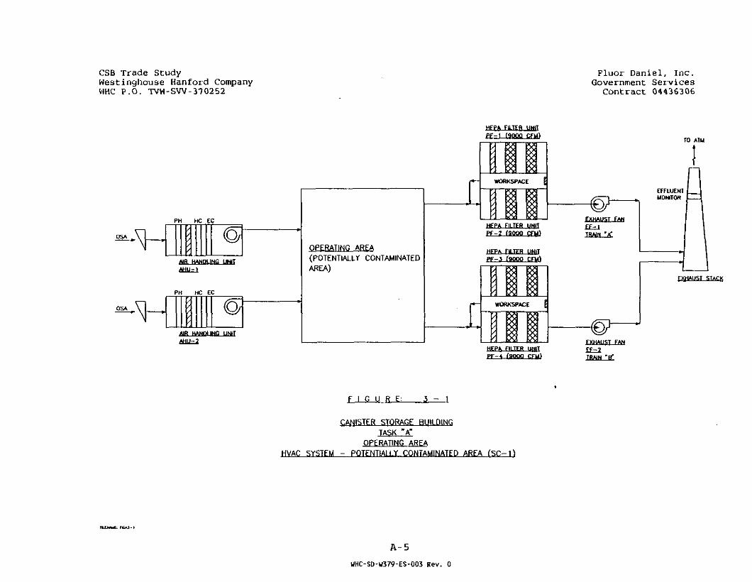
CSB Trade StudyWestinghouse Hanford CompanyWHC P.O. TVW-SW-370252
Fluor Daniel, Inc.Government Services
Contract 04436306
OSA
PH HC EC
AIR HANDLING UNITAHU-1
PH HC EC
AIR HANGING UNIT,AHU-2
OPERATING AREA(POTENTIALLY CONTAMINATEDAREA)
HFPA FlLTFfl UNITPF-1 fSOOO CFU)
£ WORKSPACE
HFPA F1ITFR fUf
PF-2 faooo cru>
HEPA FILTER UNITP F - 5 fSOOO CFU)
WORKSPACE [
FILTER ljN|T
TO ATM
EFFLUENTMONITOR
TXHAUST STACK
PF-4 f9QQQ CFU)
FXHAUfif FAN
TRAIN V
F I G U R E : 3 - 1
CANISTER STORAGE BUILDINGTASK "A"
OPERATING AREAHVAC SYSTEM - POTFNTIAI I.Y CONTAMINATED AREA (SC-1)
A-5
UHC-SD-U379-ES-003 Rev. 0

CSB Trade StudyVest;nqhause Han ford ConpanyVHC P.O. TVV-SVV-370252
Fluor Daniel, Inc.Government Services
Contract 04436306
r
'V.
a !
pooo -ooo gppop 5
ooooo00000OPOOO
POO*
OOOOPOOOOOiaaaoooooooOOOOOOOOOOlOOOQOOOOOO,ooopooooodo a o ooo:
CO\00Q>
oooOOOOooooOOOOOOOOOOOOOOOOOOOO
ooocboooooojiOOOOOOOOOOiOOOOOOOOOO'OOOOQOPOOO1OOOOOOOOOO
;oooooooooo-LGOQOOOOOOO
POOQOOOOOOOOOOOOOOOO
OOOOOOOOOOOOOOOOOOOO
OOOOOOQOOO-r-eeeeoooooo
ooooobooooi OOOOOOOOOOOQQQQQQQQQ' OOOOOOOOOO
looooi^oooo
0 0 0t _ _ _ „., OOOO
°coo°o0
OOOO . , .ocoooooooopoooooooooCOOOOOOOOOpoooooooooCOOOOOOOOOQPPQCPocoooo., OQOOOOOOOOOOOOOOiCOOOOOOOQOICOOOOOOOOOiOpOOOQOOOOI OOOOOOOOOOi O O O O O O
ipoooooqpooir00000OO0OOoooooooooo-i0000000000,OOOOOOOOOObooooooooo0000000000OOOOOQOOOOOOOOOOOOOOpoooooooooOOOOOOOOOOpoooosoooo
2 ocee-s ooooI OCOO-OOOOs OOOOoooa
,0000OOOO"000 3pooo >OOOOlOOPppooooooooooipQOQQOOOOOirooooooooooooo QOO
4 I
" T "I
T
OJ
UJcm3
L_
10 20 30 40I I
GRAPHIC
A-6

CANISTER STORAGE BUILDINGTRADE STUDY REPORT
TASK "B"
MCO RECEIPT AND STAGING FUNCTION AND AREA REMOVAL
PREPARED FOR WESTINGHOUSE HANFORD COMPANYRICHLAND, WASHINGTON
PREPARED BY FLUOR DANIEL, INC.
MAY 31, 1995
01WHC-SD-W379-ES-003 Rev. 0

CSB Trade Study Fluor Daniel, Inc.Westinghouse Hanford Company Government ServicesWHC P.O. TW-SW-370252 Contract 04436306
TABLE OF CONTENTS
LIST OF FIGURES i i
1.0 OBJECTIVE B - l
2 . 0 SUMMARY B - l
3 . 0 FACILITY DESCRIPTION AND EVALUATION B - l
4 . 0 SCHEDULE * B-3
5 .0 COST ESTIMATES B-3
6.0 REFERENCES B_3
WHC-SD-W379-ES-0Q3 Rev. 0
CSB Trade Study Fluor Danie l , I nc .Westinghouse Hanford Company Government ServicesWHC P.O. TVW-3W-370252 Contract 04436306
LIST OF FIGURES
Figure 3-1 CSB Trade Study, Task "B", Floor Plan
11
UHC-SD-U379-ES-003 Rev. 0

CSB Trade Study . Fluor Daniel , Inc .Wescinghouse Hanford Company Government ServicesWHC P.O. TVW-SW-370252 Contract 04436306
1.0 OBJECTIVE
The objective of Trade Study Task "B" is to determine theeffects of changing the Base Case Concept 2D by removing theMCO Receipt and Staging Function and Area.
2.0 SUMMARY
The results of this study show that the receipt and stagingfunction and area can be removed from the SSF provided the MCOis shipped in a bottom loading cask and that the MCO isserviced (purged and water level checked) before shipping.The size of the receipt and staging area would be smaller. Itis estimated that approximately $3.2 million may be saved bynot constructing this area; however, no reduction in thecompletion schedule is anticipated.
3.0 FACILITY DESCRIPTION AND EVALUATION
3.1 Plot Plans
Figure 3-1 shows the floor plan of Concept 2D SSF with TradeStudy Task B. This is the same as the original feasibilitystudy base case Concept 2D except for the Rail Tunnel/CaskUnloading Area.
3.2 Rail Tunnel/Cask Unloading Area
3.2.1 General Description
The Rail Tunnel/Cask Unloading Area is a facility of about• 4,000 square feet attached to the CSB at the northwest corner.This facility interfaces with the MCO Storage Tube Area via atransfer cart. The main functions of this area are to safelyreceive and handle incoming MCOs for placement in the storagetubes prior to stabilization. The packaged MCOs are deliveredinside a bottom loading transport/facility cask via rail caror truck one at a time.
The bottom loading transport/facility cask will be similar tothe bottom loading MCO shield cask as described in the basecase except that it must also be designed as a shipping cask.
The Rail Tunnel/Cask Unloading Area will be used as a washarea cask unloading/loading for rail cars and loading on tothe transfer cart.
Two railroad cars and a truck trailer parked in parallel canbe accommodated inside. A permanent ceiling installed liquidspray arrangement allows wash/decon of the shipping cask upper
B-l
UHC-SD-U379-ES-003 Rev. 0

CSB Trade Study Fluor Daniel, Inc.Westinghouse Hanford Company Government: ServicesWHC P.O. TVW-SW-370252 Contract 04436306
section. Hand held wash/decon lances are available for thelower areas.
The casks will be unloaded from the railroad cars or truck andloaded on to a transfer cart. A 120 ton overhead crane, witha 10 ton auxiliary hoist running in the east/west directionservices this area. The transfer cart runs on rails at floorlevel and transfers the bottom loading transport/facility caskbetween the rail tunnel/cask unloading area and the canisterstorage operating area.
3.3 Findings
3.3.1 Impacts
The size of the Rail Tunnel/Cask Unloading Area is reducedfrom the base case Concept 2D of approximately 10,000 to 4,000square feet for Task B.
The bridge crane in the Rail Tunnel/Cask Unloading Area musthave a larger capacity to handle the heavier cask. For TaskB the crane would have a capacity of 120 tons vs 110 for thebase case.
For the base case only one bottom loading handling cask isrequired but for Task B approximately 6 are required.
3.3.2 Advantages/Disadvantages
The advantages of removing the MCO receipt and stagingfunction and area are:
• Smaller and less costly building.
• No water pools and associated water treatment system.
• No below grade pits in the Rail Tunnel/Cask UnloadingArea.
• No MCO servicing area.
The disadvantages of removing the MCO receipt and stagingfunction and area are:
• Capacity of the bridge crane increases.
• The design of the bottom loading transport cask will bemore complicated than a bottom loading facility cask.
• Increase the number of casks.
B-2
UHC-SD-W379-ES-003 Rev. 0

CSB Trade SCudy Fluor Daniel, Inc.Westinghouse Hanford Company Government ServicesWHC P.O. TVW-SW-370252 Contract 04436306
3.3.3 Concerns/Uncertainties
The concern of removing the MCO receipt and staging area is:
• With no MCO servicing stations the MCO cannot be purgedor water level checked and adjusted at the SSF.
There are no uncertainties with removing the MCO receipt andstaging area at this time.
4.0 SCHEDULE
With the size and complexity reduction of the Rail Tunnel/CaskUnloading and with the removal of the MCO Receipt and StagingArea no impact is anticipated to the facility completion dateas indicated in the Concept 2D base case.
5.0 COST ESTIMATE
Assumptions, exclusions, and basis for the estimate remain thesame as for the Concept 2D Feasibility Study. The differencein the direct cost from the baseline Concept 2D estimate is:
Structures, deduct <$ 570,000>Mechanical, deduct <$ 1,568,000>Engr/PM/CM, deduct <$ 1.049,000>Total direct cost reduction <$ 3,187,000>
6.0 REFERENCES
"Staging and Storage Facility Feasibility Study Final Report",• Fluor Daniel, Inc., February 1995.
Statement of Work, "Trade Studies for the Evaluation of HWVPCanister Storage Building for Spent Nuclear Fuels", Rev. 5,April 21, 1995.
WHC-SNF-FRD-014, May 1995, Section 3 . 2 .2.1.2 .2, Rev. A, "DraftPerformance Specification for the Spent Nuclear Fuel CanisterStorage Building" (Contains tabular data from R. G. Cowan ofWHC on proposed MCO description).
B-3
WHC-SD-U379-ES-003 Rev. 0

CS3 Trade StudyVestinqhouse Han ford CompanyVHC P.D. TVV-SVV-370252
Ftuor Daniet, Inc.Governnent Services
Contract 04436306
-e—
-+FEH-1 - 0 - -
ooocboooooojioocooooood--eeoeooooooiooooooocoo\OQOQOQQQQQ! ooooooocoo; oooooooooo.L aoaooooooopooooooooooooooooocoooooooooooooooooooooi OOOOOOOOOO^e^eoooooopooo:OOO 5POPQJ
0000000000QOOOQ
oooooooooopnnnnnnnnniOOOOOOOOOOI O O O Q O O O O O O Jiooopooooodi o a o o o o iI J
IOOOOOOOOOO,iOOOOOOOOOOooooooooooioooogooooo;oo0o0o0|o0o0o°opooo 3§g oooooo ifooopooo i oooooooooooooopooooooooooooooooooopooooooooooooooooooopoo^ooooooOO 51 000000
00O5I000000ooooooooooiOOOOOOOOOOIooooooooooI O O O O O O O O O OIOOOOQOOOOOi OOOIOOOJ L 1
ipooooodoooI 'OOOOOOCDOOOooooooooooIOOOOOOOOOOpooooooooo1OOOOOOOOOOpooooooooooooooooooopooooooooooooooooooopooooooooooooooooooopoooosoooo0000 2 OOOOOOOO"£0000OOO 5 s 0000
pooo5-ooooOOCO 3 0000
J
ooooooooooipoooooqpooiroooooocbooo(oooao oI
T"
a
LJ " CL
h- _J
LJ
a;a
mu
BQ 3Q 40 50 60 70I ^ I '
GRAPHIC SCALE: ;N FZEJ
3 -4

CANISTER STORAGE BUILDINGTRADE STUDY REPORT
TASK "C"
CASK DECONTAMINATION FUNCTION AND AREA REMOVAL
PREPARED FOR WESTINGHOUSE HANFORD COMPANYRICHLAND, WASHINGTON
PREPARED BY FLUOR DANIEL, INC.
MAY 31, 1995
WHC-SD-U379-ES-003 Rev. 0

CSB Trade Study Fluor Danie l , Inc .Westingtvouse Kanford Company Government Serv icesWHC P.O. TVW-SW-370252 Contract 04436306
TABLE OF CONTENTS
PAGE
LIST OF FIGURES ii
1.0 OBJECTIVE C-l
2.0 SUMMARY C-l
3.0 FACILITY DESCRIPTION AND EVALUATION C-l
4.0 SCHEDULE " C-2
5.0 COST ESTIMATES C-2
6.0 REFERENCES C-2
HHC-SD-W379-ES-003 Rev. 0

CSB Trade Study • Fluor Daniel , Inc .Westinghouse Hanford Company Government Serv icesWHC P.O. TVW-SW-370252 Contract 04436306
LIST OP FIGURES
Figure 3-1 CSB Trade Study, Task "C" Floor Plan C-3
WHC-SD-W379-ES-003 Rev. 0
CSB Trade Study Fluor Daniel, Inc.Westinghouse Hanford Company Government ServicesWHC P.O. TVW-SW-370252 Contract 04436306
1.0 OBJECTIVE
The objective of Trade Study Task "C" is to determine theeffects of changing the original feasibility study Base CaseConcept 2D by removing the cask decontamination function andarea (wash area).
2.0 SUMMARY
The results of removing the cask decontamination function andarea will reduce the size of the receipt area and amount ofequipment. It is estimated that approximately $1.2 millionmay be saved by not constructing this "area; however, noreduction in the completion schedule is anticipated.
3.0 FACILITY DESCRIPTION AND EVALUATION
3.1 Plot Plans
Figure 3-1 shows the floor plan of the Concept 2D SSF withTrade Study Task "C". This is the same as base case Concept2D except for the removal of the wash area from the RailTunnel/Cask Unloading Area.
3.2 Rail Tunnel/Cask Unloading Area
3.2.1 General Description
The Rail Tunnel/Cask Unloading Area is a facility of about6,600 square feet attached to the CSB at the northwest corner.This facility interfaces with the MCO Storage Tube Area via a
• covered water canal as shown in Figure 3-1. This task is thesame as the base case except for the following changes:
• Removal of the wash area and its associated pumps, tanks,and holding tanks.
3.3 Findings
3.3.1 Impacts
The size of the Rail Tunnel/Cask Unloading Area is reducedfrom the base case of approximately 10,000 to 6,600 squarefeet.
The cycle time for the MCO/Transport Cask within the RailTunnel/Cask Unloading Area would be reduced by about 2 hoursby removing the wash area.
C-l
UHC-SD-U379-ES-003 Rev. 0

CSB Trade Study Fluor Daniel , Inc .Westinghouse Hanford Company Government ServicesWHC P.O. TVW-SW-370252 Contract 04436306
3.3.2 Advantages/Disadvantages
The advantages of removing the wash area are:
• Smaller building.
• Less equipment required to service incoming shipments.
No disadvantages have been determined at this time.
3.3.3 Concerns/Uncertainties
There are no concerns or uncertainties at -this time.
4.0 SCHEDULE
With the size and complexity reduction of the Rail Tunnel/CaskUnloading Area and with the removal of the decontaminationarea no impact is anticipated to the facility completion dateas indicated in the Concept 2D base case.
5.0 COST ESTIMATE
Assumptions, exclusions, and basis for the estimate remain thesame as for the Concept 2D Feasibility Study. The differencein the direct cost from the baseline Concept 2D estimate is:
Structures, deductMechanical, deductEngr/PM/CM, deductTotal direct cost reduction <$ 1,159,000>
6.0 REFERENCES
"Staging and Storage Facility Feasibility Study Final Report",Fluor Daniel, Inc., February 1995.
Statement of Work, "Trade Studies for the Evaluation of HWVPCanister Storage Building for Spent Nuclear Fuels", Rev. 5,April 21, 1995.
WHC-SNF-FRD-014, May 1995, Section 3 .2.2.1.2.2, Rev. A, "DraftPerformance Specification for the Spent Nuclear Fuel CanisterStorage Building" (Contains tabular data from R. G. Cowan ofWHC on proposed MCO description).
<$<$<$
635,143,381.
000>000>000>
C-2
UHC-S0-W379-ES-003 Rev. 0
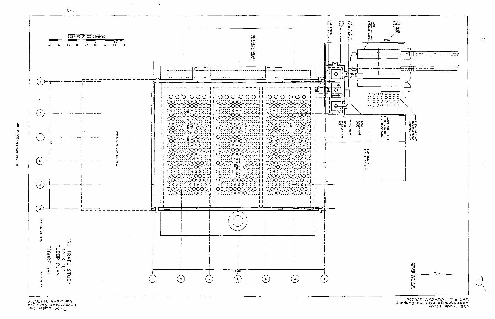
L133 NI DJHdtffcD
D8 01 09 Dt- 0E 05ri n n
D! D
CA}
mCO
oCO
-o * m
-r> * C-0
-<
. . J l
•) r
OOD OOOin OOOQQO6QQQQQQJooooooooodQOOOQpQOOO!OQOOsOOOO0QQQO s 0.0.0.0
i r
OOO i
OOOO g £ QpQOOOOsQOQQ g OQQO;OOOOEOOOOOooooooooooOOOOOOQQOOOOQQQQQOQQOOOQOOOOOOQOQQQQQQOQoooooooooqOOOQQOOQQQiOOOOOOOOOOiQOOOQQQQQQioooooooooaOOOOOOOOOOHooc5poooooqi
QQOQOppQQQI OOOOQOOOOOi]oooodboooo'OOOOOOOOOO!QQQQQPQQQQOOOOOOOO.QQQ.QOOOOOQoooooo
: oo•000OOOPQOPOOQ
ooooqpooooOQQQQOQQOQooooooooooOOQOOOOQOQOOOOi OOOO
iOOQQ^g 000ooo m oooooooo000
000 iOOOOi
OQOOOQQOOQ.OOOOOOOOOOiooooopooooiOOOOOOOOOOi
riooo op opooooooboolOOOOOOOOOO1
oooooooopp•OOOOOOOOOcJOOOOOOOOOQooooc5|£ oooo
OOOOO £ OOOOOOOO-OOOOOOOOOOOQO^oooooooooooooooooooooooooooooooooooooooooooooooooo;QOOOQODUOOooooooooooOOOOOOOOOOiOOOOOOOOOOiOOOOOOOOOQooooooGoopOOOOOOpOQI
fOOOOOOCpOOQ
r\O O O O O O O
J=:ooo oooo
*n-d
CANISTER STORAGE BUILDINGTRADE STUDY REPORT
TASK "D"
ONE TRACK RAIL SERVICE '
PREPARED FOR WESTINGHOUSE HANFORD COMPANYRICHLAND, WASHINGTON
PREPARED BY FLUOR DANIEL, INC.
MAY 31, 1995
DoWHC-SD-lU/9-ES-UO.S Rev. u

CSB Trade Study Fluor Daniel , I nc .Westinghouse Hanford Company Governmenc ServicesWHC P.O. TVW-SW-370252 Contract 04436306
TABLE OF CONTENTS
PAGE
LIST OF FIGURES ii
1.0 OBJECTIVE D-l
2.0 SUMMARY D-l
3.0 FACILITY DESCRIPTION AND EVALUATION D-l
4.0 SCHEDULE * D-2
5.0 COST ESTIMATES D-2
6.0 REFERENCES D-2
UHC-SD-U379-ES-003 Rev. 0

CSB Trade Study . Fluor Danie l , I nc .Westmghouse Hanford Company Government ServicesWHC P.O. TVW-SW-370252 Contract 04436306
LIST OF FIGURESPAGE
Figure 3-1 CSB Trade Study, Task »D" D-3
Master Site Plan
Figure 3-2 CSB Trade Study, Task "D" Floor Plan, D-4
Figure 3-3 Task "D" Staging Material Flow Diagram, D-5In Rail Tunnel/Cask Unloading Area
Figure 3-4 Task "D" Staging and Material Time D-SStudy In Cask Unloading and Storage Area
i i
Rev. U

CSB Trade Study Fluor Daniel , Inc .Westinghouse Hanford Company Government Serv icesWHC P.O. TVW-SW-370252 Contract 04436306
1.0 OBJECTIVE
The purpose of Trade Study Task "D" was to determine changesto facility functions, technical requirements/ identify riskand safety issues, and evaluate the impacts to the costestimate, and design/construction schedule due tosimplification of the rail service to one track with a passingtrack outside the facility, versus two tracks used in theoriginal feasibility base case Concept 2D.
The work was performed under Task "D" of the Statement ofWork, Revision 5, dated April 21,1995 in Attachment 1 to WHCWork Order TVW-SW-370252, Modification 09-0.
2.0 SUMMARY
Except for the smaller size of the railcar Wash Area and theCask/MCO Unloading and Storage Area due to the elimination ofone track within the facility, there are no significantchanges to facility functions and technical requirements. Therisks, technical and safety issues as enumerated in theConcept 2D Feasibility Study Report remain unchanged. There isno impact to the design and construction schedule as given forthe base case.
The Cask/MCO transportation on one track into the facilitywill be able to handle 3.4 shipments per day as opposed to 4in Concept 2D. The reduction in the estimated direct cost ofthe facility from the Concept 2D case will be approximately$98,000.00 and the cost of Engr/PM/CM is approximately$49,000.
3.0 FACILITY DESCRIPTION AND EVALUATION
3.1 Plot Plan
Figure 3-1 shows the master site plan for Task "D" for the onerail spur entering the CSB. The overall plot showing variousbuildings floor plans is shown in Figure 3-2 with the reducedfootprint of the Wash Area and the Cask/MCO Unloading AreaBuildings. A Change Room area has been added.
3.2 System Descriptions
The facility system descriptions are similar to those given inthe Concept 2D Feasibility Study Report. The elimination ofone rail track will reduce the track length by about 250 feet; reduce the Cask Wash Area by approximately 1040 square feet;and reduce the Cask/MCO Unloading and Storage Area by about640 square feet. A 1550 square feet area has been added for
D-l
WHC-SD-W379-ES-003 Rev. 0

_. . ...---.-.:• .:•:,/:.. .:..'jor Oarue."., 7.nc.West;.nc-house -:.inford Company Government ServicesWHO P.O. TVW-iW-370252 Contract 04433306
the Change Rooms between the Cask/MCO Unloading and theEquipment/Office Buildings.
There will be some change in the material flow in the CaskWash and Unloading Areas when using one rail track. It ispossible to receive and handle 1 Cask/MCO every 7 hours (3.4per 24 hour workday). Figures 3-4 and 3-5 depict the tasks,sequences, equipment, and estimated time required to performthe tasks.
3.3 Facility Issues
The facility issues and concerns described*tor the Concept 2DFeasibility Study are also applicable to this Task "D" study.A single rail system in the facility is able to handle 3.4Casks/MCOs per 24 hour workday.
4.0 SCHEDULE
The design/ construction schedule for the Concept 2DFeasibility Study is also applicable to this Task study and nonew impacts are identified.
5.0 COST ESTIMATES
Assumptions/ exclusions, and basis for the estimate remain thesame as for the Concept 2D Feasibility Study. The differencein the direct cost from the baseline Concept 2D estimate is:
Structures, add $ 4,000Railroad, deduct <$ 102,000>Engr/PM/CM, deduct <$ 49,000>Total direct cost reduction <$ 147,000>
6 . 0 REFERENCES
"Staging and Storage Facility Feasibility Study Final Report",Fluor Daniel, Inc., February 1995.
D-2
WHC-SD-W379-ES-003 Rev. 0
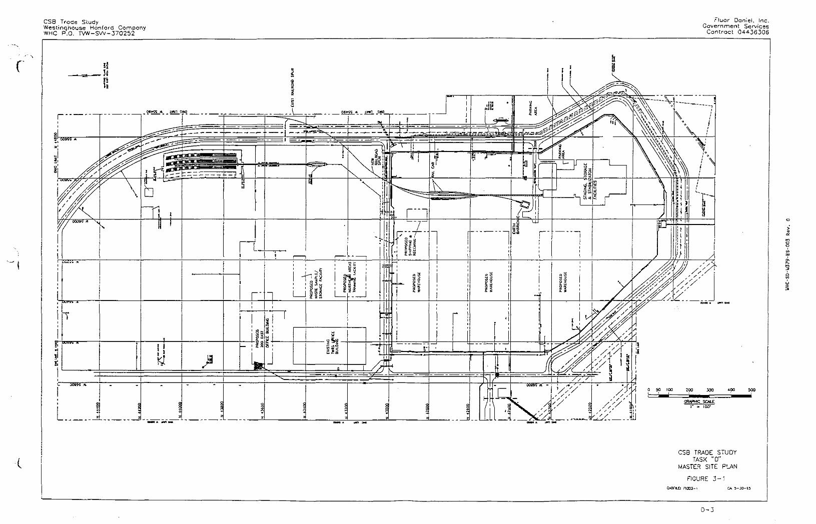
CS3 Trade StudyWestinqhouse Han ford CompanyWHC P.O. TVW-SW-370252
Fluor Daniei, Inc.Government Services
Contract 04436306
r
91M M am 9M
GRAPHrC SOLE
r - too'
400 500
CS8 TRADE STUDYTASK "D"
MASTER SITE PWN
FIGURE 3 - 1
f !C03-l CA 5-JO-9S
0 - 3
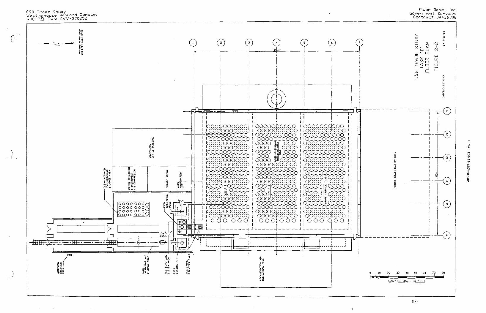
CS3 Trade StudyWestinchcuse Hanford CompanyWHC P.O. TVV-SVV-370252
Fluor Daniel, Inc.Government Services
Contract 04436306
risin.
d t ^
9 a
OOO OOOQooo oooooo oooooo OOQ
HhH "
© ©
' ! 1ooocpoooooojiOOOOOOOOOO
• oooooooooopooooooooooooooooooopooooooooo_LQOQQOOOGOOpooooooooooooooooooopoooooooqooooooooooopooooooooo-reoeeoooooopooo:ooooo000 5 OOOOOpooo slpoooooooooooooo
t pnnnnnnnoc)IOOOOOOOOOOOOOQOOOOOO,iooopooooodi o a o o o ol
OOOOObOOQOiOOOOOOOOOOoooooooooo•ooooooooooooooooo 000
oooo
L J
pooo dS ooo000 3f OOOOpooo i^oooooooooooooooooooooooooooooooooopooooooooooooooooooo
I'ibooooooloooi'OOOOOOOOOOooooooooooIOOOOOOOOOOpooooooooo!OOOOOOOOOOpooooooooooooooooooopooooooooooooooooooopooooooooooooooooooopoooosooooOOOO 5 OOOO
POO;00 Lboos
000000oooooo
lOooo°o0
oooooo^ i poop >ooooooooooioooooooooo!ooooooooooooooopooooioooodoooooi OOOiOOO
OOOO
1 ^"OOOO£ OOOO
00000 sOOOO!OOOOOOOOOOooooooqpoo1 OOOOOOcDOOOi OOO OOOJ L 4 J L
1CO
LJ
<.
i—
LJ
*
<
-z.<_ IQ_
•
OJ1
CO
LJ
—1
L_
TIT" T"
0 !0 20 30 40 301 M I I j • I I '
60 70 90
GRAPHtC SCALE IN FEET
D-4

CSB Trade StudyWestinqhouse Hanford CompanyWHC P.O. TVW-SW-370252
Fluor Daniel, Inc.Government Services
Contract 04436306
©-TRANSFER lf.IL CAR *
INSOE WAS* STATION
-RA OONKEY ENGINE
TIME; 1.0 H
- 1 0 * 0 SERVICEO MCO INTO CANALTRANSFER CART
-SEND UCOVfRANSFER CART TOSTORAGE TUBE M C A
-UNLOADING POOL JO CRANEW / UCO GRAPPLE
-MCO CANAL TRANSFER CART
-TRANSFER SHtPP-NG CASKTO CASK LOWING PfT
FoqpMI- n a r
IMC
SH*>PINC CASK CSAME
0.5 H
W / CASK SML
-WASH H A CAR A SHIPPING CASK
TIME: 1-0 H
-TRANSFER H A CAR FT SHIPPING CASKTO UNLOADING ARIA
-DISCONNECT * EXIT RJL DONKEY ENOWE
©-CONNECT VENT HOSE TO UCO,
VCNT UCO-CONNECT OEWMZa) WATER HOSE TO k»CO.
FILL UP MCO-PURGE UCO * »tNT HOSE
FQUIPWNf-UCO UAIMIHANCC HANOUNG TOOLS-MAINTENANCE * unUTY STATWN
UP SHIPPING CASK ABOVE
UNLOADING POOL
- 1 1 0 r SHIPPING CASK CRANE * / CASK 9AA-SHIPPING CASK ORMH HANDLING TOOL
TIME:
-REMOVE SHIPPING CASK COVER-OECON SHIPPMG CASK ft COVER
EOUPWEltf '-UNLOAQING POOL JIB CRANEW / CASK COVER GRAPPLE
-STATION OECON SYSTEM
-LQAO A EUPTY MCO «SOE
-FILL THE VO& BETWEEN THE CASK
CLEAN WATER-CLOSE THE SUPPING CASK
EOUIPMOir ;-SHIPPING CASK W S U W r CRANE
<«/ UCO GRAPPLE-OEIOMZEO WATER STATION-UNLOMXHG POOL J f l CRANE
* / CASK COVER GRAPPLE-IMPACT WRENCH
TIMf- 1.0 H
©-TRANSFER SHIPPING CASK
TO CASK PREPARATION PIT
EQUIP- H O
TIME:
S H I P P I N G CASK
I .O »
CRANE w/ CASK BAIL
-PREPARE SWPWNC CASKFOR UCO UNLOADING
-IMPACT WRENCH
TIME: :.O H
©-REMOVE SHUfWG CASK COVER-TRANSFER <<C0 FROU SHIPPING CASK
TO UCG SESVONC SACK-REPLACE SHIPPING CASK COVER
ON SHIPPING GASK
- 0NLQA&NC POOL JI9 CRANECASK COVER GRAPPLE
- UNLOADING POOL JIB CRANEW / UCO CRAPPU
TIME; 2.0 H
- 1 1 0 T SHIPPING CASK CRANE W / CASK 3ML
JIUf: 1.0 .4
-TRANSFER SHIPPING CASKTO UNLOAOHG AREA
-SECURE SHAPING CASKTO R A CAR
FnnPtrfMT •
- 1 1 0 I SHPPWG CASK CRANC W/ CASK SML
HME: 2.0 H
-8»MG R.R. OONKEY EMGWE
- A r T A O t a K M N ^ ' ENQNE
ro R A CAR- £ X H H-R- CAR FROM fACHJIY
-H.R. OONKEY ENGWE
Tjua 1.5 H
FIGURE 3-3
TASK "D"
STAGING MATERIAL FLOW DIAGRAM. IN RAIL TUNNEL/CASK UNLOADING AREA
0 - 5

CSB Trade StudyWesCinghouse Hanford CompanyWHC P.O. TVW-SW-370252
Fluor Daniel, Inc.Government Services
Contract 04436306
O loo
LT>\
o
Bfl
0 1 2 3 4 5 6 7 8 9 10 11 12 13 14 15 16 17 18 19 20 21 22 23 24
K3 DONKEY ENGINE
r n 11OT/1OT CRANE
| g | UNLOADING POOL JIB CRANE
[2 ] LOADING PIT JIB CRANE
O SEQUENCE #3 FROM STAGING MATERIALFLOW DIAGRAM, FIG. 3 - 3
TIME PERIOD (HOURS)
EIGURE 3 - 4
TASK " D "
STAGING MATERIAL TIME STUDY
IN CASK UNLOADING....* STORAGE AREA
CADFILE: FIGD3-4
D-6
UHC-SD-W379-ES-003 Rev. 0

CANISTER STORAGE BUILDINGTRADE STUDY REPORT
TASK "E"
STORAGE TUBE MATERIAL INVESTIGATION
PREPARED FOR WESTINGHOUSE HANFORD COMPANYRICHLAND, WASHINGTON
PREPARED BY FLUOR DANIEL, INC.
MAY 31, 1995
ECWHC-SD-W379-ES-003 Rev. 0

CSB Trade Study ?..uor Dan:.e.., ;:nc.Westinghouse Hanford Company Government S«rv:.cesWHC P.O. TVW-SW-370252 Contract CK436306
TABLE OF CONTENTS
LIST OF FIGURES ii
1.0 OBJECTIVE E - l
2 .0 SUMMARY E - l
3 .0 FACILITY DESCRIPTION AND EVALUATION E-3
4 . 0 SCHEDULE * E-6
5 .0 COST ESTIMATES E-6
6 .0 REFERENCES E-6
WHC-SO-W379-ES-003 Rev. 0

CSB Trade Study ' - ; c : *e.r.:.e.., ...r._.Westinghouse Hanford Company Governmen: Serv icesWHC P.O. TVW-SW-370252 Contract 04436306
LIST OF FIGURESPAGE
Figure 3-1 Task "E" Storage Tube Containing MCOs E-4
WHC-SD-U379-ES-003 Rev. 0
CSB Trade Study ~_Vj.or Oan;.e."., ;.nc.Westinghouse Hanford Company Government ServicesWHC P.O. TVW-SW-370252 Contract 04436306
1.0 OBJECTIVE
1.1 Background
The Canister Storage Building as originally designed in 1992for the Hanford Waste Vitrification Project contained storagetubes made of ASTM A242 weathering steel (e.g., Corten brandby U.S. Steel). During the Staging and Storage FacilityFeasibility Study, stainless steel tube material was proposedfor the options involving water-filled tubes. Stainless steelwas chosen based on 50 °F deionized water in the tubes and a40-year design life. The Feasibility Study Final Report notedthe unresolved technical issue of corrosion of the stainlesssteel in stagnant (oxygen-depleted) water.
The objective of the trade studies is to resolve technicalissues related to the usage of the Canister Storage Buildingto safely stage and store N-Reactor spent fuel now located atK-Basin 100KW and 100KE. The Trade Study Task "E11 Statementof Work is to determine the technical feasibility of non-stainless steel water-filled storage tubes and recommendmaterial to resist wet corrosion for only 7 years versus 40years.
1.2 Purpose and Need
Although the building will be used for 40 years {or more) , thestaging phase when the tubes could be filled with water willnot exceed 7 years. Each of the three vaults in the originaldesign contains 220 tubes. The present fabricated cost ofeach stainless steel tube was estimated to be $43,300,
• compared to $17,100 for weathering steel. Carbon steel wouldcost 30% less than weathering steel. The installed cost ofstainless tubes would be a major portion of the total buildingcost. As noted in the Feasibility Study Final Report,corrosion of stainless steel is possible in stagnant water.
2.0 SUMMARY
A review of literature on corrosion due to stagnant waterrevealed a threat to not only the storage tubes, but also theinside and outside of the MCOs. Pitting corrosion ofstainless steel in oxygen-depleted water is well-known, as isthe fact that this form of corrosion is accelerated bybacterial action. The iron-oxidizing bacteria whichaccelerate the corrosion are found in spent fuel storagepools. The rate of local corrosion is unpredictable, rangingfrom slight pitting to complete penetration within a fewyears.
E-l
UHC-SD-W379-ES-003 Rev. 0

CSB Trade Study Fluor Daniel, Inc.Westinghouse Hanford Company Government ServicesWHC P.O. TVW-SW-370252 Contract 04436306
Although the options for tube design are discussed below, noneof these options solves the more important problem ofcorrosion of the MCO from the inside by stagnant water.
Any option with water-filled tubes requires the addition of asystem for detecting that a tube leak has occurred and findingthe leaky tube. Even a single undetected tube failure mighthave severe consequences if this could also cause MCO failuredue to high temperature, which might result in contaminationof the concrete vault around the tubes. The tube-leakdetection system is yet to be defined, subject to many safetyand feasibility issues. The building must contain featuresnecessary for recovery and clean-up in the event of leakage.
If the water in each of the tubes is treated and regularlymonitored to maintain the pH above 10.5 with an acceptableconcentration of biocide, then it is likely that there will beno unacceptable corrosion due to stagnant water when the tubesare constructed of bare carbon steel or weathering steel.Weathering steel (such as Corten) probably would be suitablefor staging and storage. Weathering steel was determined tobe preferable to carbon steel for HWVP storage. The impactabsorbers in the tubes would have to be redesigned so thatwhen water treatment chemicals are added, the chemicals willmix evenly between the top and bottom of the tube. Because ofthe uncertainty intrinsic to corrosion prediction in thesecircumstances, and the severe consequences associated withtube failures, further investigation is recommended.Corrosion literature should be searched for reports ofcorrosion of stainless steel and weathering steel (or carbonsteel) in stagnant treated water. Testing is recommended to
• verify the material choice and to determine the requiredinterval for monitoring and replenishing the treated water.
If further investigation shows that it is not practical totreat and monitor the water in the individual tubes, then theonly design using well-developed technology {known to FluorDaniel) which assures the integrity of all tubes and MCOs overa period of 7 years requires an interconnecting watercirculation system and stainless steel tubes. Other possibledesigns are more expensive, require development/testing and/orinvolve a significant chance of at least one tube failurecaused by undetected damage during MCO insertion. Epoxycoating is an option which appears acceptable, subj ect toverification that there is no problem with dry MCO damageduring MCO placement.
Although it may be feasible to connect the tubes and circulatetreated water through them, this design is more expensive thanthe base case, and therefore is a step in the wrong direction.A system of connected tubes is functionally similar to an
E-2
UHC-SD-W37V-ES-0Q3 Rev. 0

CSB Trade Study ?-'-'or -an:.e... ;.nc.Westinghouse Hanford Company Governmenc ServicesWHC P.O. TVW-SW-370252 Cantracc 04436306
expensive version of the open pool Alternative 1 of theFeasibility Study. Rather than estimate the cost of anundesirable option, it should suffice to say that the costwould exceed that of Alternative 2A in the Feasibility Study.
3.0 FACILITY DESCRIPTION AND EVALUATION
3.1 System Description
The N-Reactor fuel consisted of uranium metal with zirconiumcladding. The spent fuel has been stored underwater in theeast and west K-Basin pools in order to cool the fuel andprevent contact with air. Uranium metal can react with air inan uncontrolled, highly-exothermic (pyrophoric) manner. Thispyrophoric reaction could destroy the fuel containers andrelease the spent fuel in the form of smoke. During thestaging phase of operation, metallic fuel contained instainless steel Multi-Canister Overpacks (MCOs) will bemaintained at 100 °F or less in the tubes using refrigeratedforced-air cooling on the outside of the tubes. Although itis not essential to have water in the tubes, water is by farthe cheapest and most effective heat transfer fluid. The useof other fluids in the tubes (such as air, nitrogen, helium,or fluorocarbons) will result in greater cooling flowrequirements or higher MCO temperatures. Later, the fuel willbe removed and stabilized in an adjacent facility. In thestabilization process, fuel surfaces are oxidized to preventfurther reaction and to allow higher-temperature storage.Then, in the storage phase, the returned stabilized fuel inMCOs will be stored in dry tubes and maintained at 400 °F orless by natural convection of outside air.
An MCO is inserted into a tube by an overhead crane equippedwith a grapple which grips the top of the MCO. The MCOdimensions are 24" OD and 15'-1" long. The maximum MCO weightis 13,100 lb. The maximum heat generation rate is 482 W perMCO.
Figure 3-1 shows a typical tube with two MCOs. The top of thetube is covered with a concrete shielding plug. The plug ismoved aside when an MCO is inserted. The plug seals the tube,but contains two valved tubing connections. One connectioncould allow the gas space above the MCOs to be monitored andpurged during operation. The other connection has a HEPAfilter and would be attached to a relief valve to vent thetube before gas pressure could lift the plug. Below the plugis an embedded funnel which aligns the MCO into the tubeduring insertion.
Two MCOs will fit in each storage tube, which is 34'-3" fromthe base to the funnel. The bottom 23'-4" of the tube is 27"
E-3
WHC-SD-U379-ES-003 Rev. 0
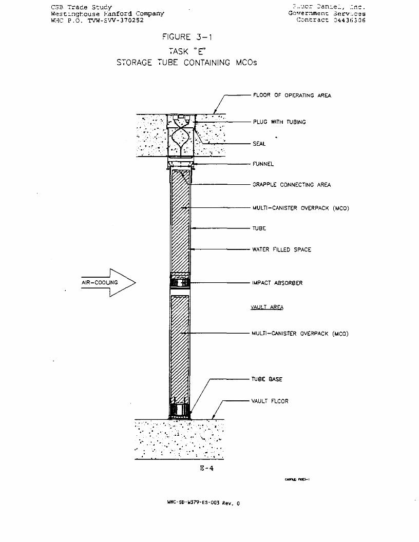
CSB Trade StudyWest-nghouse Kanford CompanyWHC P.O. TVW-SW-370252
:- ..ucr Jan;.e.\, :nc.Government 3«rv:.ces
Contract 0443(53 06
FIGURE 3 - 1
TASK "E"
STORAGE TUBE CONTAINING MCOs
FLOOR OF OPERATING AREA
PLUG WITH TUBING
SEAL
FUNNEL
GRAPPLE CONNECTING AREA
MULTI-CANISTER OVERPACK (MCO)
TUBE
WATER FILLED SPACE
IMPACT ABSOR8ER
VAULT ARFA
MULTI-CANISTER OVERPACK (MCO)
TUBE BASE
VAULT FLOOR
E-4
HHC-SD-W379-ES-003 Rev. 0
CSB Trade Study Fluor Daniel, Inc.Westinghouse Hanford Company Government ServicesWHC P.O. TVW-SW-370252 Contract 04436306
ID and 28" OD. The top of the tube is 29" ID and 30" OD.Stainless steel impact absorbers about 18" high are installedunder each MCO in case an MCO is dropped. Stagnant, deionizedwater at approximately 100 °F would cover the MCOs. With twoMCOs in place, the water volume is 24.8 cubic feet or 185gallons.
3.2 Evaluation
Concern for the design of water-filled tubes is not thegeneral corrosion of the carbon steel tubes but theMirobiolgically Influenced Corrosion (MIC) of the carbon steelor weathering steel tubes and the stainless steel MCOs due tostagnant water.
MIC is a well-known corrosion phenomenon and is recognized asa serious problem affecting industrial facilities, includingnuclear sites. MIC was a major concern of WestinghouseHanford Company on the HWVP project, based on experiencereported by the Tennessee valley Authority with stainlesssteel piping (Guthrie and Kuzniak); With the wet design, thecarbon steel tubes and the stainless steel canisters (insideand outside) are at risk of MIC. The corrosion could rangefrom minor pitting to complete through-wall penetrations.
Methods of preventing MIC are having constant flow above 5ft/sec to prevent microbes and nutrients from accumulating onthe materials surface, treating the water with a biocide tocontrol microbial population, raising the pH to 10.5 orgreater, or applying cathodic protection. An effectivemonitoring program is essential in controlling microbial
' population.
Provided MIC is prevented, one option for the material ofconstruction for stagnant water-filled storage tubes is carbonsteel. Weathering steel, ASTM grade A242, is also acceptablebut more expensive. General corrosion of carbon steel tubesis not a major concern due to the fact that the extent ofcorrosion is dependent on the amount of water and surface areaexposed to the water. Carbon steel will only corrode untilthe dissolved oxygen is consumed. The extent of penetrationof corrosion is 0.0006 inch per sq. in. of surface per gallonof water. With the large amount of surface area and therather small amount of water (approximately 185 gallons) thecarbon steel would perform satisfactorily in this application.If MIC is prevented and the corrosion products derived fromgeneral corrosion are not a problem, then carbon steel is anacceptable material for the tubes.
Alternative material to eliminate or reduce the corrosionproducts and possibly avoid MIC of the tubes could be epoxy-
E-5
UHC-SD-U379-ES-003 Rev. 0

CSB Trade Study ?:.uor .Oan:.e."., :.nc.Westinghouse Hanford Company Government ServicesWHC P.O. TVW-SW-370252 • Contract 0443f>306
coated carbon steel or bare carbon steel with cathodicprotection. If epoxy-coated carbon steel is considered thedesign must incorporate the standard preparation techniquessuch as rounded corners, contoured welds and clean base metalsurface. Any pinhole flaw in the coating would result inrapid corrosion of the steel behind the flaw. Coating flawsduring fabrication can be detected by holiday testing(electric discharge testing). Damaging of the coating duringcanister placement seems likely with the current placementmechanism shown in the feasibility study. However, a softprotective bumper around the bottom edge of the MCO could beadded to protect the coating during placement. Thefeasibility of cathodic protection for" this applicationrequires further consideration of maintainability. Mostimportantly, protection of the tubes does not solve the moreserious problem of corrosion of the MCO.
From a corrosion viewpoint, it would be best to eliminatewater as a cooling media for the MCO. If a change is notpossible because of heat transfer limitations, methods ofpreventing MIC should be implemented. Prevention of MIC wouldrequire a method of circulating biocide-treated water betweentubes or monitoring the water quality in each tube. Treatingor monitoring the water inside the MCO would be required,which might be a difficult or costly task. If MIC cannot beprevented, materials with an assured resistance to MIC must beinvestigated and tested. The referenced report by Guthrie andKuzniak suggests that titanium may be a suitable material.
4.0 SCHEDULE
• The choice of storage tube material does not affect the designor construction schedule of the revised Canister StorageBuilding.
5.0 COST ESTIMATES
If unacceptable corrosion of the MCO and tube cannot beprevented by treatment and monitoring the water in each tube,the cost of circulating treated water through the tubes toavoid stagnant conditions will exceed that of Alternative 2Ain the Feasibility Study. Although this water-circulationoption will prevent unacceptable corrosion of the storagetubes, it does not address internal corrosion of the MCO bystagnant water.
If the water in the tubes can be treated and monitored toprevent unacceptable corrosion by stagnant water, thenweathering steel (such as Corten) is suitable for the tubes.This design has been estimated as Concept 2D.
E-6
WHC-SD-W379-ES-003 Rev. 0

CSB Trade StudyWestingl-.ouse Hanford CompanyWHC" P .O. TVW-SW-370252
.7..vor Jarue.'., ."Inc.Government Services
Contract 04436306
The assumptions, exclusions, and basis for the estimate remainthe same as for the Concept 2D Feasibility Study. Thedifference in the direct cost from the baseline Concept 2Destimate is:
OPTIONTitaniumEpoxy CoatingCarbon Stee l
6 . 0 REFERENCES
DIRECT COST$ 40 ,736 ,000$ 1,400,000
<$ 2 ,494,000>
ENGR/PM/CM$ 15 ,797 ,000$ 543,000
<$ 912,000>
TOTALCOST
$ 5 6 , 5 3 3 , 0 0 0S 1 ,943 ,000
<S 3 ,406 ,000>
P.V. Guthrie and W.C. Kuzniak, "Are O U E Pipes Safe FromMicrobiologically Influenced Corrosion?"
Hanford Waste Vitrification Project, memo from Kishor Shah toN.H. Williams, "Project Wide Concern, MIC Impact," 7/8/92.
Hanford Waste Vitrification Project, mechanical drawings forthe Canister Storage Building: H-2-120142, -120394, -120395,and -120397, Rev. 0 (Approved for Construction), 8/28/92.
"Staging and Storage Facility Feasibility Study Final Report",Fluor Daniel, Inc., Feb. 1995.
Statement of Work, "Trade Studies for the Evaluation of theHWVP Canister Storage Building for Spent Nuclear Fuels," Rev.5, 4/21/95.
WHC-SNF-FRD-014, May 1995, Section 3.2.2.1.2.2, Rev. A, "DraftPerformance Specification for the Spent Nuclear Fuel CanisterStorage Building" (Contains tabular data from R. G. Cowan ofWHC on proposed MCO description).
E-7
WHC-SD-W379-ES-Q03 Rev. 0

CANISTER STORAGE BUILDINGTRADE STUDY REPORT
TASK "F"
MCO SHIPMENT REDUCTION-
PREPARED FOR WESTINGHOUSE HANFORD COMPANYRICHLAND, WASHINGTON
PREPARED BY FLUOR DANIEL, INC.
MAY 31, 1995
f oWHC-SD-W379-ES-003 Rev. 0
CSB Trade Scudy Fluor Daniel, Inc.Westinghouse Hanford Company Governmenc ServicesWHC P.O. TVW-SW-370252 Contract 04436306
TABLE OF CONTENTS
LIST OF FIGURES i i
1.0 OBJECTIVE F - l
2 . 0 SUMMARY F - l
3 . 0 FACILITY DESCRIPTION AND EVALUATION F - l
4 . 0 SCHEDULE • F-2
5 . 0 COST ESTIMATES F-2
6 . 0 REFERENCES F-2
UHC-SD-W379-ES-003 Rev. 0

CSB Trade Study Fluor Danie l , IncWestinghouse Hanford Company Government Serv icesWHC P.O. TVW-SW-370252 Contract 04436306
LIST OF FIGURES
Figure 3-1 CSB Trade Study, Task "F" Floor Plan
WHC-SD-U379-ES-003 Rev. 0

CSB Trade Study Fluor Daniel, Inc.Westinghouse Hanford Company Government ServicesWHC P.O. TVW-SW-370252 Contract 04436306
1.0 OBJECTIVE
The objective of Trade Study Task "F" is to determine theeffects of changing the original Feasibility Study Base CaseConcept 2D by reducing MCO shipments from 4 to 2 per day.
2.0 SUMMARY
The results of reducing the MCO shipments from 4 to 2 reducesthe size of the receipt area by removing one of the tworailroad tracks coming into the building and reduces thequantity handling equipment. It is estimated thatapproximately $274,000 may be saved by not constructing thisarea; however, no reduction in the completion schedule isanticipated.
3.0 FACILITY DESCRIPTION AND EVALUATION
3.1 Plot Plans
Figure 3-1 shows the outline of Concept 2D SSF with TradeStudy Task "F". This is similar to the base case Concept 2Dexcept for the Rail Car Wash Area and Rail Tunnel/CaskUnloading Area.
3.2 Rail Tunnel/Cask Unloading Area
3.2.1 General Description
The Rail Tunnel/Cask Unloading Area is a facility of about8,000 square feet attached to the CSB at the northwest corner.
• This facility interfaces with the MCO Storage Tube Area via acovered water canal as shown in Figure 3-1.
This task is the same as the base case except for thefollowing changes:
• Only one MCO servicing station is required.
• The size of the clean MCO/MCO Overpack/Cask Storage Rackcan be reduced to 1/2 of the base case rack.
• The Unloading Pool Jib Crane and the Cask Loading Pit JibCrane are not required. The operations performed by thejib cranes can be done by the 10 ton hoist on the bridgecrane because of the reduced use of this crane.
• Only one rail track is required to service the 2shipments per day.
F-l
WHC-SD-W379-ES-003 Rev. 0

C3B Trace Study • Fluor Daniel, Inc.West;.ngfc.ouse Fanford Company Government ServicesWKC P.O. TVW-SW-370252 Contract 04436306
The operations for Task "F" within the Rail Tunnel/CaskUnloading Area will be the same as the base case.
3.3 Findings
3.3.1 Impacts
The size of the Rail Tunnel/Cask Unloading Area including thewash area, is reduced from the base case Concept 2D ofapproximately 10,000 to 8,100 square feet.
Only one rail track is required.
3.3.2 Advant age s/D i s advant age s
The advantages of two MCO shipments per day are:
• Smaller building.
• Less handling and servicing equipment for the MCOs.
The disadvantage of two MCO shipments per day is:
• It will take longer to remove the spent nuclear fuel fromK-Basins.
3.3.3 Concerns/Uncertainties
There are no additional concerns or uncertainties from thebase case.
4.0' SCHEDULE
With the reduction in the size and complexity of the RailTunnel/Cask Unloading Area no impact on the schedule isanticipated from Concept 2D.
5.0 COST ESTIMATE
Assumptions, exclusions, and basis for the estimate remain thesame as for the Concept 2D Feasibility Study. The differencein the direct cost from the baseline Concept 2D estimate is:
Structures, deduct <$ 98,000>Mechanical, deduct <$ 86,000>Engr/PM/CM, deduct <S 90,000>Total direct cost reduction <$ 274,000>
F-2
WHC-SD-U379-ES-003 Rev. 0

CSB Trade Study Fluor Danie l , I nc .Westinghouse Hanford Company Government Serv icesWHC P.O. TVW-SW-370252 Contract 04436306
6 . 0 REFERENCES
"Staging and Storage Facility Feasibility Study Final Report",Fluor Daniel, Inc., February 1995.
Statement of Work, "Trade Studies for the Evaluation of HWVPCanister Storage Building for Spent Nuclear Fuels", Rev. 5,April 21, 1995.
WHC-SNF-FRD-014, May 1995, Section 3 .2 .2 .1.2 .2, Rev. A, "DraftPerformance Specification for the Spent Nuclear Fuel CanisterStorage Building" (Contains tabular data from R. G. Cowan ofWHC on proposed MCO description).
F - 3
WHC-SD-W379-ES-003 Rev. 0

P - J
JL33J NI 3*lfcOS
OB Oi 09 Of DCM I N I
DI 0
otd
CDC70
mCOi
i n> *
a
I JO
Jon>U
it n
r- n w :a > •< i> M H I
: iTig
y;
rOOO OOO i0000)000000 iOOOOOOOOOO'ooooopoooo!OOOOsOOOOO1oooo $ o.o.oo0000-OOOO IOOOOR
ooooS OOO-ooooOOOO s OOOO
oooo^oooooOOOOOOOOOOOOOOOOOOOOOQOOOOOOOOOOOOOOOOOOOOOOOOOOOOOOOOOOOOOOOOQOOOOOOOiOOOOOOOOOOiOQOOOOOOOOiOOOOOOOOOOiOOOOOOOOOOjooopoooooqi
rr "1
OOO OOO iooooobooooiOOOOOOOOOO"oooooooooo iooooooooodOPQOP.OOO.OQ000000oooooo000000
ood0000
i O O O O p O iiboooooqboo'I ^OOOOOOOOOOiIQOOQOOPOOP!1 OOOOOOOOOO1
qoppppopopi oooooooooo;00 OOOOO
.000 QOOOO£ 000- ooooOOOOOOOOOOOOOOOOOOOOOOOQOOOOOOOOOOOOOOOOOOOOOOOOOOOOOOgg OOOOOOOOJI 000 IOOO B" OOOO!ooooli oooi000 E| OOOOiOOOOOOQOOOiOOOOOOOOOOiOQC^OQQOPO Ioooooooooa
000000090^4OOOOOOOOOOOOOQOOOQOOOOOOOOOOOOOOOOQOOOOQooooooooodOOOOOOOOOUiOOOOOOOOOOOQOOQQOOOO iOOOOOOOOOOiOQQQOOQOOQiOOOOOOOOOO}
poooQoqpoo ffoooooocpoooi
I I
0
I"1-e-
rnrt
zH-^Hr ^Ff fH-
V
Q O O O O
Oooo o\
Tun-r JD >~* n is>•o x.
»_>o "> —o - »
Sis10 Z >
J
5g|
2S20ZC-AAS-AA1 'D'd 3HAt>H asnoMDuiqsaA

CANISTER STORAGE BUILDINGTRADE STUDY REPORT
TASK "G"
DAMP-DRIED MCO
PREPARED FOR WESTINGHOUSE HANFORD COMPANYRICHLAND, WASHINGTON
PREPARED BY FLUOR DANIEL, INC.
MAY 31, 1995
G 6UHC-SD-W379-ES-003 Rev. 0

'_ir.3 Trace Stuc.y F.'.ucr Oan:.e:., Inc.We'3t~nchousa hanford Company Government S e r v i c e sWHO P.O. TVW-SW-3 70252 Contract 04436306
TABLE OF CONTENTS
PAGE
LIST OF TABLES ii
1.0 OBJECTIVE G-l
2.0 SUMMARY G-l
3.0 FACILITY DESCRIPTION AND EVALUATION G-l
4.0 SCHEDULE - G-3
5.0 COST ESTIMATES G-3
6.0 REFERENCES G-4
APPENDIX 1 CALCULATIONS Al-1
Gr1
WHC-SO-W379-ES-003 Rev. 0

CSB Trade Study -..uor .:an:.e.., .:nc.Westinghouse Kanford Company Government S«rv:.cesWHC P.O. TVW-SW-370252 Contract 04436306
LIST OF TABLESPAGE
Table 3-1 Thermal Analysis - Summary G-4
UHC-SD-W379-ES-003 Rev. 0
CSB Trade Study Fluor Daniel , Inc .Westinghouse Hanford Company Government ServicesWHC P.O. TVW-SW-370252 Contract 04436306
1.0 OBJECTIVE
The objective of Trade Study Task "G" is to evaluate handlingand staging requirements for MCOs shipped drained, damp-driedfrom K-Basin. Determine cooling requirements for arefrigerated air system during staging operations andinvestigate natural circulation cooling system during storageoperations.
2.0 SUMMARY
The results of the thermal analyses for MCOs shipped drained,damp-dried from K-Basin for staging in 2-vaults indicates thatit is not feasible to maintain MCO temperatures at 100 °F witha refrigerated forced air system. However, during the storageoperation the MCO temperature can be maintained at 270 °F bya passive ventilation system, this is below the limitingcriteria of 400 °F for storage operations.
3 . 0 EVALUATION OF MCO HANDLING/STAGING AND COOLING REQUIREMENTS
3.1 Evaluation of MCO Handling and Staging
There will be no significant impact in the conceptualizedparameters for handling and staging of MCO's in the Concept2D.
The immediate affect on handling a dry MCO will be anapproximate 1 ton reduction in weight of a loadedtransportation cask due to the weight of water. Thisreduction is not considered large enough to re-size the cask
• handling cranes for this trade study.
3.2 Evaluation of MCO Cooling Requirements
This section documents the results of a series of thermalanalyses that were performed to assess the feasibility ofmeeting the Multi-Canister Overpack {MCO} temperaturerequirements during dry staging with the Concept 2D Stagingand Storage Facility (SSF). These analyses were performed forforced refrigerated air and passive ventilation systems.
The thermal feasibility analysis is based on staging ofdrained, damp-dried MCOs in air filled tubes in vaults 1 and2 {third vault contains no tubes) with a forced refrigerationair cooling of the tubes during staging. MCOs are removed andreturned to the tubes after stabilization. After all fuel isstabilized, the passive air ventilation system is madeoperational.
G-l
WHC-SD-U379-ES-003 Rev. 0
C'JT. Trace Study .7J.v.or .:an.:.e,", r.nc.West:.nghouse Kanford Company Government ServicesWHC P.O. TVW-SW-370252 Contract 04436306
3 2.1 Design Basis Assumptions
The following design basis assumptions were used for thethermal analyses:
• The heat generation rate was based on a total 880 MCOs.Twenty percent are assumed to be at the upper limit("maximum") (482 W) and the remaining eighty percent areassumed to be at the nominal value ("average") (221 W) .Due to the preliminary nature of the heat transfercalculations a ten percent safety factor was used for theheat generation rate. Additional heat loads were addedfor building heat gains.
• The heat generation for the "maximum" case (482 W) perMCO was used for calculating the MCO temperature assumingthat it is located at the end of the vault. Each MCOconsists of five canisters, each storage tube containstwo MCOs, and each vault contains 220 tubes.
• The design basis required staging/storage conditions areas follows:
Staging: Maximum MCO temperature at 100 °F.Storage: Maximum fuel centerline temperature at 400 °F.
• During the staging operation the MCO provides primaryconfinement and the air filled storage tubes provide thesecondary confinement. It is assumed that the interiorof the storage tubes are isolated from the vault, whichwould prevent the vault from getting contaminated.
• The total flow is assumed to be evenly and uniformlydistributed around each of the containment tubes. Thisis a critical assumption that must be assured by designand verified by additional analyses using ComputationalFluid Dynamic (CFD) techniques.
• The heat transfer coefficients for air were calculated atthe point of maximum vault air temperature.
• One dimensional (radial) heat transfer only. Two-dimensional (radial and axial) heat transfer was notmodeled.
• Heat transfer by radiation between the tubes was notconsidered.
G-2
UHC-SD-W379-ES-003 Rev. 0
CS3 Trade Study Fluor Daniel, Inc.Weatinghouse l-:anford Company Government ServicesWHC P.O. TVW-EW-370252 Contract 04436306
3.2.2 Summary of Results
The results of the thermal analyses during staging are shownin Table 3-1 and involve various combinations of drained,damp-dried MCOs surrounded by air in tubes for differentventilation flow rates.
The results indicate that it is not feasible to maintain theMCO temperature at 100 °F with a refrigerated forced airventilation system with a supply air temperature of 35°F.With 200,000 CFM system and a supply air temperature of 35 °F(Concept 2A of the SSF Feasibility Study) the MCO temperaturecan only be maintained at 173 °F based "on the above heatgeneration rate. The temperature of 35 °F was selected tomaintain the same basis as the previous feasibility studyalternatives. The MCO temperature is calculated on the basisthat the MCO is located at the end of the vault with thelimiting heat load. (The MCO temperature could be maintainedat 100 ° F with 200,000 CFM supply air at minus 37 °F, this isnot feasible).
The results of the thermal analyses during storage operationwith the existing CSB design concept, assuming the same intakestructure, vault size (2-vaults) and exhaust stack (height anddiameter) indicates that an MCO temperature of 270 °F can bemaintained by a passive ventilation system. This is based onan inlet air temperature of 115 °F (same design basis as CSB)and a ventilation flow rate of 53,000 CFM.
The above results indicate that it is not feasible to use therefrigerated air system to maintain the MCO temperature below100 °F during the staging operation. However; the passiveventilation system can maintain the MCO temperature below the400 °F limit during the storage operation.
It must be emphasized that these are rough conservativefeasibility analyses using limited design information and donot cover all limiting or upset conditions. More detailedanalyses are required using CFD techniques to cover alllimiting and upset conditions and to verify some basicassumptions. Also no analysis was performed for MCOs storedin an overpack.
4.0 SCHEDULE
As the Trade Study requirements were determined not feasiblethe current construction schedule is not impacted.
G-3
WHC-SD-W379-ES-003 Rev. 0

CSB Trade StudyWestinghouse Kanford CompanyWHC P.O. TVW-SW-370252
Fluor Daniel, Inc.Government; Services
Contract 04436306
TABLE - 3-1
THERMAL ANALYSIS - SUMMARY(Drained, Damp-Dried MCOs)
MCOTEMPERATURE
(°F>
180
176
173
170
163
167
SUPPLY AIRQUANTITY(CFM)
100,000
150,000
200,000
300,000
400,000
500,000
SUPPLY AIRTEMPERATURETO VAULT (°F)
35
* 35
35
35
35
35
5.0 COST ESTIMATE
As the Trade Study requirements were determined not feasiblethe current estimate for Concept 2D is not impacted.
6.0 REFERENCES
"Staging and Storage Facility Feasibility Study Final Report",Fluor Daniel, Inc., February 1995.
Statement of Work, "Trade Studies for the Evaluation of HWVPCanister Storage Building for Spent Nuclear Fuels", Rev. 5,April 21, 1995.
WHC-SNF-FRD-014, May 1995, Section 3 .2 . 2.1.2.2, Rev. A, "DraftPerformance Specification for the Spent Nuclear Fuel CanisterStorage Building" (Contains tabular data from R. G. Cowan ofWHC on proposed MCO description).
G-4
WHC-SD-W379-ES-003 Rev. 0
CSB Trade Study F?.uor Daniel, Inc.Westmghouse Hanford Company Government ServicesWHC P.O. TVW-SW-370252 Contract 04436306
Appendix 1
Calculations specific to TASK "G"
G-5
UHC-SD-W379-ES-003 Rev. 0
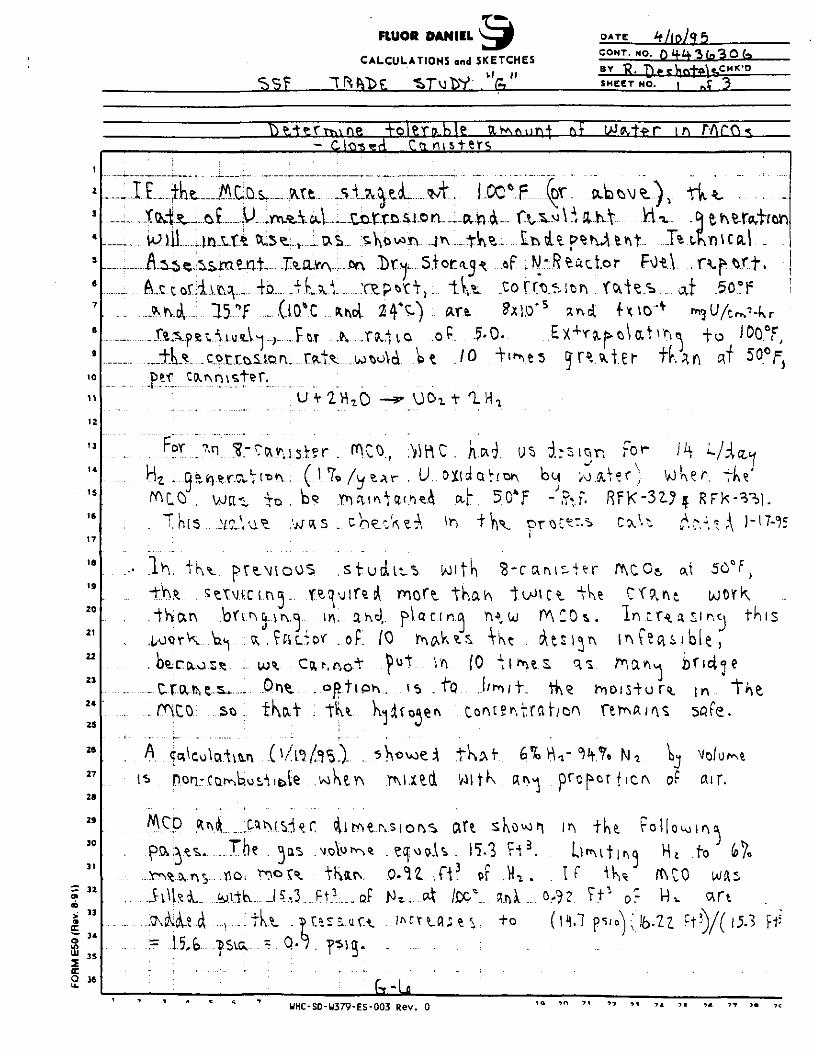
FlUOR DANIEL
CALCULATIONS and SKETCHES
OATE
CONT. NO. o i+u.-\(o3Ota_BY
SHEET HO.
1
2
3
4
5
6
7
B
9
10
11
12
13
14
IS
16
17
IS
19
20
21
22
23
24
25
26
27
28
29
30
31
~ 32at
3 4
3 5
trO 36
IE A t M; ^ . j
tail) ,tnx-—--- A.ii.ft..isw
. ~H}* COt
^L.0 . we- .. . This _vr
-CiW,t^' . HtQ st
^ P.On-CQrr
p&; i** . . . . .
..Yr^fc.n$---fl
: **&£;
^f ....(.10*u.«-V^._.j—Ft
\ \ u ^ :•//
. &.... ? ci L :
1 (1? ...^Q5>
i k f? 3
cJ tctfrD&ion a
IT _ A. . .T(^4 l ^ ° • "
a .Studlt-t> Wl|!r^a«j i red rnoft The
in- a-h<i pi a c r n.aor . oF. (0 tr\Q>k^$.
. o p t I P h . ^ . +"Q
<„_
_ n i
504f
0 "" C fl.
Ht . c0 l i ^ t
or . H i .
•Rtac
prcF
. !V(11.7
tor F\)l\. roiie.s... c
r. To*" i
RFK-3IJ
* i ' 1 .L \ X -
| l\ [ W fl S
7. N, \3o r f i c ^ o?
? Fk-
safe.
air.
.to d
-
t h i s
s
5-3 W
UHC-SD-W379-ES-003 Rev. 0
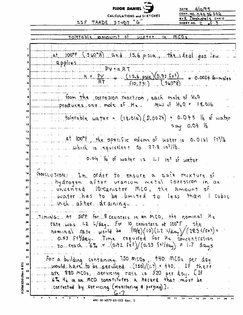
SSF
FLUOR DANIEL
CALCULATIONS end SKETCHES
6
DATEC°"T- g* ft H ftavR,SHEET HO.
CMK-O
or fACOs.
2
,
4
5
6
7
B
9
10
t l
' 2
13
14
15
16
17
18
19
20
21
22
23
24
25
26
27
26
29
30
31
~ 32aat> "|otn
2 "J. 3 S
: I ; : ' : ,
•ftovn t ^
LoVti.^K
... wale* ..In a
.....Ji.miiNifiL.At 56"{=r^.H UJ^S- ... l-2.
RT
COT re 3
ordUt
10--Catc
s Uf AT a
for ; 3 c
i
Iv of
*• 0
of ujo
to.UTftr
L* -1
• 3
pfttstei
j5-t..,PSlA.... ." " J I
C/0.730 I
t , o i ^ (D,oo2V
t t o . ^7.% I
.V^r n I . /
' fACO *tkl v ^ \ " V ? . & . - t o
s. Ih. «h fACO,
FT3V(0,5.3 ?t-?
!^ou.lcL-k!Uv.-ia; v$\ ^30 Z^COs,
O *O ' 1 1 In vy.ii .'
.Co.tvtc.Tea o^ .51 MnHI'
r-^-7
_..{15OV(I..7V =-oc^t u 520_ o ufl _ 0 r j
• , -
j r J 4/
) = 0 - C
j
J(xV.?r, \s
n 3 / J b .
ivi1 of i
a o r T f
l e ss
mco4
pit iat
1
-tat -485- 'j2tJ -
0 00*4 k - * I
f VkS
) T lb or wowT^r
0,04 It
0.0 IH FtVfc
V ' ' J
ptr ..AttHIF tU re,. [If^ .
UHC-SD-U379-ES-003 Rev. 0 " " "

FlUOR DANIEL
CALCULATIONS and SKETCHES
TftAftC SToTVf "G>"
DATE
CONT.B YR«
NO. 3 0 fcCHK'D
SMggT NO.
*- 32«^ 33
*. 2 7.05
_olxft.
• it.Z
U).
• . or. U M T I ^ j 52J5".
v:. == "37. .5 f t 3
/ A C O = . 3 7 . 5 - 2 2 . 1 -• 15.* f t :
UHC-SD-U379-ES-003 Rev. 0 M 22 23 24 25 26 27 28 29
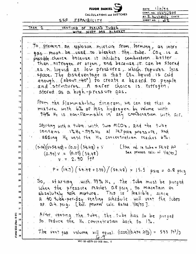
FLUOR DANIEL ^ - J OATECONT. NO.
CALCULATIONS and SKETCHESBY R. TY»
S H E g T NO.
5^^L^^bfefts
- 32
o 34
S i "2 »
To r_ ptey^vy^.... (
. I K cuv _..yv i.tTc
. . s»pac*.. The
and ..Mrvt_ stored . as
&d^U*\n .1-
p= (1
to r ti'JC .
b. u s.4.-..-.*to -kt b^c,ft.ov^. vt
cv Vwgk,-p r^^
Y\ O A ~i V iCt JT1. Ct .01
- 2. 0 ft3
-p-tfriau ^^\lin
,fer cKovct.
TUPO ^
V
ke^ 0.This
0 SCI\
s uU.
WHC-SD-U379-ES-003 Rev. 0
j
IS f
m Lack.
(uoo)Co
Wo 5."
canLr. 1DM <
[5
to.
willVK/?
e.. Cc
- 'Otf i
r& to
V) T o t ft. ~
io be1 /o »
*%) -
« ;
s c
of 1/
a r
be
si nc-i
t)U|f
;
hK a i r .
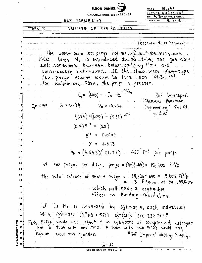
FlUOR DANIEL
CALCULATIONS and SKETCHES
DATE
. NO.
SHEET NO. flE *2-
VENTW& SEALED TUftES
2
3
4
9
6
7
8
9
10
11
12
13
14
IS
16
17
18
19
20
21
22
2 3
2 4
2 5
26
27
2 8
29
30
31
- 32a»
<boK
s 3*
_.. ; .
7 foCO. WKerun il .some<-
. . . f KR. - P MT-W
hivrU r v^fl^ tooot-d
f^t (X "Vub .•
_ . . . . _ .
•Mjc^d • FICMJ >
C = (Ub}F
(o.^^) "U.oc
p-it -
X -
t U a ^ of vev\J
^ ^
with on^_ mco
- " • * / - " " • • - • • - - -
T $A V olu in ^ ^^/ & "yop^ • \|41 TK o h t
A bfitter^up -PIUQ-.flow . .cucl .cj.. .IE. tKt--.^Loto. wtr^. pli/p-'tuptj
.0.01)
o.olo(b
(101.3 V) r 4-60 ft3 per purj^
; t purflt .= - l? ; !}^^ feOQ " 1. .0^ . ft5/])
5 Ft] c ft+airj-s 200-230 Ft3 ?
i w o t ende r s .of torr.^reisedi K\+(&<?W
' 75?^ i>np?rm) W*;tJ(^y ^obbL.%J J%
WHC-SD-W379-ES-003 Rev. 0

cur,
T*fto\ ft-
sFUYfWHLITYLIMITS WITH
WATERCAftBO* DIOXIDEfllTXOGEfl
20 10 GO 8 0
HYDItOGEfl CONCDTTIATIOfl, VOL X
100'HYDROCEH
Figure A5. - Effect of nitrogen, helium, carbon dioxide, andwater vapor on flammability of hydrogen in air. Example: atpoint A, in flammable range, concentrations are hydrogen,35 vol %; air, 45 vol %; and inert, 20 vol %.
— ~ ClrFj
CHjBf
FLNftUIUTYUMTS WITH
. CBfClF-,
UHC-SD-U379-ES-003 Rev. 0

FLUOR DANIEL V J DATE
CALCULATIONS and SKETCHES av R.SSF F&V*/BILH1 SHEET NO,
GA*>
2
3
4
3
S
7
S
9
10
11
12
13
14
15
16
17
16
19
20
21
22
23
24
25
26
27
28
23
30
31
— 32
i "ft
n
EC
£ 36
: : ^
lAmcV\_... - «-mn
Mfc Ly
3,07
The
. . . on
• • Jn +ta I
J
"to
(l
• o f
k> ft i v s k o ^ s
- ! i m \ "t. G a^
^ittepA^Wl^ con1
OE R*dUo\© avertj f - =
V =
2OO)(7'(5>) ~ -%W
or V W K " a i r
t5w"Kr .
wJl....ft
2.5 fc
t. T
2- ? /U C i
2 -?^>I7
1
r
= 7.5
ft or K at
^ r « .Akg
G
fl\jam_. witK. ..tH^...fv
\ « 1 1 1 / J .
R^.. F** fr»W
(l.Sfc K C - , / L V U
/Kr * 2.13 /«c.
on in a Lo^
tta -V fc-'.-cr
/(JO1 cc
>\ TI ' :+ '
c»e Kr 'ev«-l in T
1
iI
?p*cifjed £V . Kr0^Sfc\ , RtV. t , Aft. Wi-
L ^ 3 / AA A n
*T /w i'N p-er |MCO
i / r v s f r ft v **\ f i r' J i * l 1 J V\_ l v **+ \ j
air for C^£
T^f'v, t o t i oie K
WHC-S0-W379-ES-003 Rev. 0

FiUOR DANIEL *<j} OATE
CONT. NO.CALCULATIONS ond SKETCHES =
5 S F FE.F\S1 &1LUT SHEET NO. I o f \A TASK-2.
Of
Hi. But <3K
~ 32
«
<£to
IE
9 36
c\ l a .cct
cts Rf f IH.7
* D.00
A-t 5(TF.onVu.3.5
31
so
- the i o i e , . " b u t i.s . pTobcib l^ ^ 1 ^ - ^ ^ t o . *tA»
WHC-SD-W379-ES-003 Rev. 0

CANISTER STORAGE BUILDINGTRADE STUDY REPORT
TASK "H"
RCRA FUNCTIONS:PREVENTION AND DETECTION OF MCO LEAKS
PREPARED FOR WESTINGHOUSE HANFORD COMPANYRICHLAND, WASHINGTON
PREPARED BY FLUOR DANIEL, INC.
MAY 31, 1995
'0WHC-SD-W379-ES-003 Rev. 0

C3B Trade Study Fluor Daniel , Inc .We.scinghouse Hanford Company Government ServicesWHC P.O. TVW-SW-370252 Contract 04436306
TABLE OF CONTENTS
PAGE
1.0 OBJECTIVE H-l
2.0 SUMMARY H-l
3.0 FACILITY DESCRIPTION AND EVALUATION H-l
4.0 SCHEDULE H-ll
5.0 COST ESTIMATES H-12
6.0 REFERENCES H-13
WHC-SD-W379-ES-003 Rev. 0

CSB Trade Study Fluor Daniel, Inc.Wescinghouse Hanford Company Government ServicesWHC P.O. TVW-SW-370252 . Contract 04436306
1.0 OBJECTIVE
Part of the mission of the SNF CSB is to provideenvironmentally sound staging and storage of K Basin SNF.This mission may require compliance with the Federal ResourceConservation and Recovery Act (RCRA). The purpose of TradeStudy "H" is to identify the impacts on the SNF CSB Projectassuming compliance with RCRA, and specifically to identifythe design functions required to prevent and detect MCO leaks.
2.0 SUMMARY
Several SNF CSB functions would be required to comply withRCRA. Some already are a requirement in the base case (e.g.,MCO retrievability) and would not cause a cost/schedule impactfor the purpose of this trade study. Others are not in BaseCase 2D and would be required only to comply with RCRA {e.g.,thirty inch minimum separation between rows of MCOs, arequirement which probably would be waived because directvisual inspection of the MCOs would not be feasible).
Only one RCRA-required funct ion would cause s igni f icantcost/schedule impact, detection of MCO leakage within twenty-four hours. To achieve this function would appear difficultand expensive, regardless of the approach considered, andwould pose significant feasibly issues. Continuouslyoperating MCO leak detection would add approximately $4.5million to the facility cost and extend the scheduled facilitycompletion date by a minimum of two months. Given the BaseCase 2D design, featuring an MCO filled with water (theprimary heat sink) in a dry tube, potential safety andlicensing risk could be incurred by not including thisfunction, even if RCRA compliance is not a projectrequirement.
3 . 0 FACILITY DESCRIPTION AND EVALUATION
3.1 Applicability
The Federal Resource Conservation and Recovery Act (RCRA) gaveguidance to the Environmental Protection Agency (EPA) for the"cradle to grave" regulation of hazardous wastes. In general,RCRA regulates the generation, transportation, treatment,storage and disposal of hazardous wastes, and theseregulations are found in 40 CFR 260 to 270.
The State of Washington has obtained authorization from theEPA to administer the basic RCRA program. The WashingtonHazardous Waste Management Act (the Washington Act) parallelsthe federal RCRA requirements, and gives authorization to theDepartment of Ecology (Ecology) to regulate permitting for the
H-l
WHC-SD-U379-ES-003 Rev. 0

CSB Trade SCudy Fluor Daniel, Inc.Westinghouse Hanford Company Government ServicesWHC P.O. TVW-SW-370252 Contract: 04436306
generation, transportation, treatment, storage and disposal ofhazardous wastes. The Washington regulations are contained inWAC (Washington Administration Code) 173-303, Dangerous WasteRegulations.
The applicability of WAC 173-303 to the SNF CSB is containedin 173-303-020, Applicability, which reads in part, "Thischapter 173-303 WAC shall apply to all persons who handledangerous wastes including, but not limited to owners andoperators of dangerous waste recycling, transfer, storage,treatment, and disposal facilities."
Since spent fuel elements potentially meet the requirements asa Washington State extremely hazardous waste (EHW), seesections 173-303-070 to 173-303-103, the SNF-CSB could requirea RCRA type permit from the Department of Ecology, seesections 173-303-800 to 173-303-840. This permit would be fora TSD (Treatment, Storage and Disposal) facility for thestorage of dangerous wastes.
3.2 The Regulation of MCOs (as either containers or tanks)
The regulatory requirements in WAC 173-303 are different forstorage of dangerous wastes in containers versus storage intanks. Section 173-303-040 defines a container as, "Containermeans any portable device in which a material is stored,transported, treated, disposed of, or otherwise handled," anda tank as, "Tank means a stationary device designed to containan accumulation of dangerous waste, and which is constructedprimarily of nonearthen materials to provide structuralsupport."
The main difference of the two definitions appears to bebetween a portable device and a stationary device. Since anMCO is a portable device, it appears to meet the definition ofa container. However, the storage of an MCO in a tube isessentially stationary, and as a result, the regulators(Ecology) may classify the MCOs as a tank.
Since the classification of the MCOs may be that of either acontainer or a tank, the regulatory requirements for bothclassifications are presented in this analysis.
3.3 Containers
WAC 173-303-630 regulates the use and management of containersused to store dangerous wastes.
3.3.1 173-303-630(2) Condition of Containers
3.3.1.1 Regulatory Requirements
H-2
WHC-SD-U379-ES-003 Rev. 0
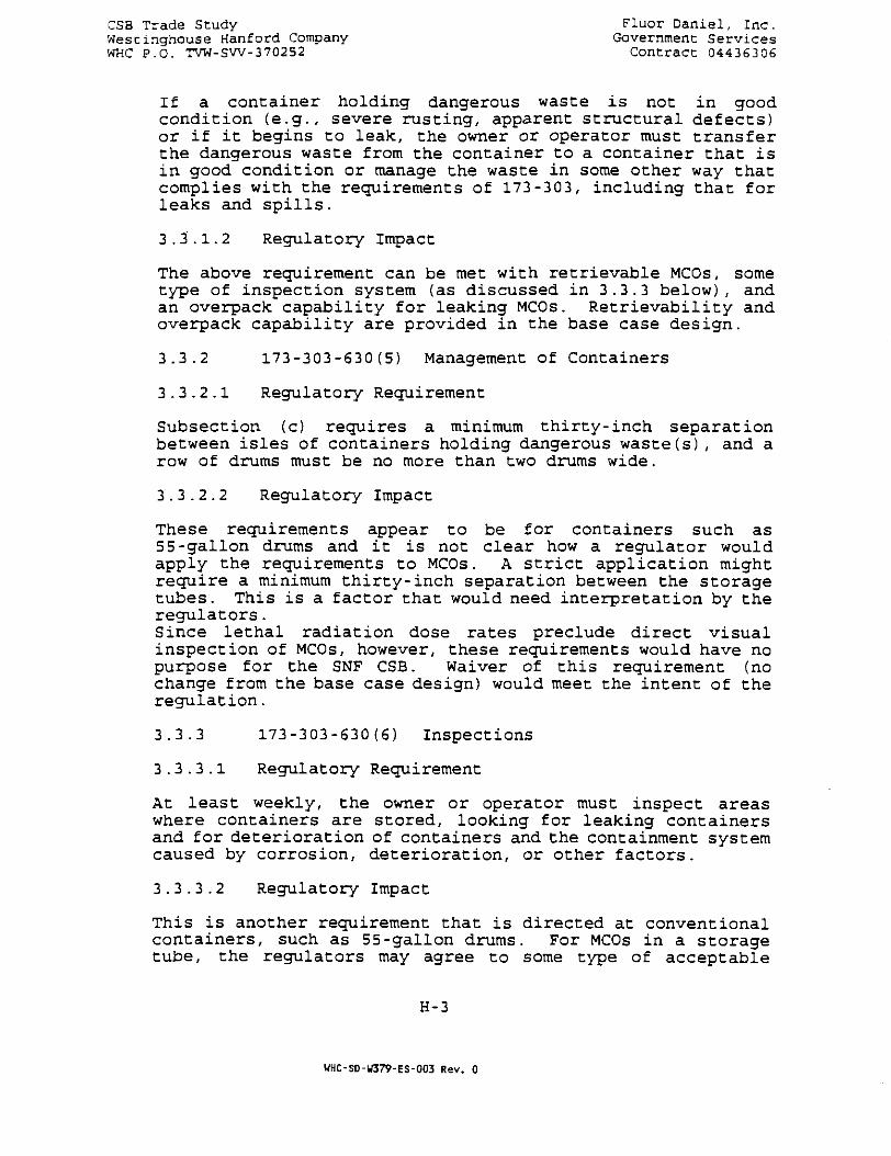
CSB Trade Study Fluor Daniel, Inc.Wescinghouse Hanford Company Government ServicesWHC P.O. TVW-SW-370252 Contract 04436306
If a container holding dangerous waste is not in goodcondition (e.g., severe rusting, apparent structural defects)or if it begins to leak, the owner or operator must transferthe dangerous waste from the container to a container that isin good condition or manage the waste in some other way thatcomplies with the requirements of 173-303, including that forleaks and spills.
3.3.1.2 Regulatory Impact
The above requirement can be met with retrievable MCOs, sometype of inspection system (as discussed in 3.3.3 below), andan overpack capability for leaking MCOs. Retrievability andoverpack capability are provided in the base case design.
3.3.2 173-303-630(5) Management of Containers
3.3.2.1 Regulatory Requirement
Subsection (c) requires a minimum thirty-inch separationbetween isles of containers holding dangerous waste(s), and arow of drums must be no more than two drums wide.
3.3.2.2 Regulatory Impact
These requirements appear to be for containers such as55-gallon drums and it is not clear how a regulator wouldapply the requirements to MCOs. A strict application mightrequire a minimum thirty-inch separation between the storagetubes. This is a factor that would need interpretation by theregulators.Since lethal radiation dose rates preclude direct visualinspection of MCOs, however, these requirements would have nopurpose for the SNF CSB. Waiver of this requirement (nochange from the base case design) would meet the intent of theregulation.
3 .3 .3 173-303-630(6) Inspections
3.3.3.1 Regulatory Requirement
At least weekly, the owner or operator must inspect areaswhere containers are stored, looking for leaking containersand for deterioration of containers and the containment systemcaused by corrosion, deterioration, or other factors.
3.3.3.2 Regulatory Impact
This is another requirement that is directed at conventionalcontainers, such as 55-gallon drums. For MCOs in a storagetube, the regulators may agree to some type of acceptable
H-3
WHC-SD-W379-ES-003 Rev. 0

CSB Trade Study ' Fluor Daniel, Inc.Westinghouse Hanford Company Government ServicesWHC P.O. TVW-SW-370252 Contract 04436306
weekly leak inspection system. This is another factor thatneeds interpretation by the regulators.
Compliance with the letter of this requirement clearly is notfeasible because of the extremely high MCO dose rate. Weeklydirect observation of each MCO, even by remote means such asa fiber optics, clearly is not feasible. CCTV would not fitinto a tube. A contxnuously operating leak detector in eachtube should, however, meet the intent of this requirement.
3.3.4 173-303-630(7) Containment
3.3.4.1 Regulatory Requirements
Container storage areas must have a containment system that iscapable of collecting, holding and removing spills and leaks.Spilled or leaked waste must be removed from the containmentsystem in an timely manner as is necessary to preventoverflow.
3.3.4.2 Regulatory Impact
The storage tubes will meet the containment system requirementto collect and hold spills and leaks, if the tubes aredesigned to be watertight. (Note: The HWVP CSB design doesnot require the tube to be watertight [leaktight]. Groutedanchor bolts penetrate the bottom plate of each tube.)
Tube/facility design also would have to provide for somemanner of removing liquid that has leaked from an MCO.Because of the radiation field, removal of liquid would haveto be accomplished remotely, after both MCOs have been removedand the leaking MCO has been placed in a MCO overpack.
3.3.5 173-303-630(8) Special Requirements for IgnitableWaste
3.3.5.1 Regulatory Requirement
The owner or operator shall design, operate and maintainignitable waste container storage in a manner equivalent withthe Uniform Fire Code.
3.3.5.2 Regulatory Impact
Section 173-303-630 (8) is applicable if the generation ofhydrogen in the MCOs is considered possible. However, as longas a sufficient amount of HVAC air exists to dilute hydrogento levels below the lower explosive limit, which is expected,the requirements of 173-303-630(8) might be waived. If not,the spacial requirements required by the Uniform Fire Code may
H-4
UHC-SD-W379-ES-003 Rev. 0

CSB Trade Study Fluor Daniel, Inc.Westinghouse Hanford Company Government ServicesWHC P.O. TVW-SW-370252 Contract 04436306
be necessary (this is another area where the regulators wouldneed to be consulted).
3.3.6 Summary of Regulatory Impacts
A summary of the regulatory impacts for Base Case Concept 2Dand the classification of the MCOs as containers follows:
• The MCOs would have to be retrievable (already anintrinsic characteristic of the MCO conceptual design)
• Some type of continuously operating leak detection systemwould have to be provided in lieu of inspection, whichprobably is not feasible
• An MCO overpack capability would have to be provided(already provided in the Base Case)
• Depending upon interpretation, a minimum thirty-inchseparation (or other spacing arrangement) between storagetubes may be required, but would have no known purpose
• The design would have to include watertight storage tubesand provide for prompt (and probably remote) removal ofmaterial that has leaked from an MCO
• Since the entire SNF CSB facility has the potential to beradiologically contaminated, all drainage sumps alsoshould be provided with continuously operating leakdetection systems and provisions for removal ofaccumulated liquids
3.4 Tank Systems
WAC 173-303-640, Tank Systems, applies to owners and operatorsof facilities that use tank systems to treat or storedangerous wastes. Under the WAC regulations, the MCOs inConcept 2D would be considered the primary containment vessel(or tank) and the storage tubes would be considered thesecondary containment vessel.
3.4.1 173-303-640(4) Containment and Detection ofReleases:
3.4.1.1 Regulatory Requirements
In order to prevent the release of dangerous waste ordangerous constituents to the environment, secondarycontainment must be provided that meets the followingrequirements: secondary confinement systems must be designed(and installed and operated) to prevent any migration ofwastes or accumulated liquid out of the system to the soil,
H-5
WHC-SD-U379-ES-003 Rev. 0
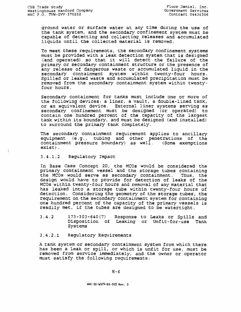
CSB Trade Study Fluor Daniel, Inc.Westinghouse Hanford Company Government ServicesWHC P.O. TVW-SW-370252 Contract 04436306
ground water or surface water at any time during the use ofthe tank system, and the secondary confinement system must becapable of detecting and collecting releases and accumulatedliquids until the collected material is removed.
To meet these requirements, the secondary confinement systemsmust be provided with a leak detection system that is designed(and operated) so that it will detect the failure of theprimary or secondary containment structure or the presence ofany release of dangerous waste or accumulated liquid in thesecondary containment system within twenty-four hours.Spilled or leaked waste and accumulated precipitation must beremoved from the secondary containment system within twenty-four hours.
Secondary containment for tanks must include one or more ofthe following devices: a liner, a vault, a double-lined tank,or an equivalent device. External liner systems serving assecondary confinement must be designed (or operated) tocontain one hundred percent of the capacity of the largesttank within its boundary, and must be designed (and installed)to surround the primary tank completely.
The secondary containment requirement applies to ancillaryequipment (e.g., tubing and other penetrations of thecontainment pressure boundary) as well. (Some exemptionsexist).
3.4.1.2 Regulatory Impact
In Base Case Concept 2D, the MCOs would be considered theprimary containment vessel and the storage tubes containingthe MCOs would serve as secondary containment. Thus, thedesign would have to provide for detection of leaks of theMCOs within twenty-four hours and removal of any material thathas leaked into a storage tube within twenty-four hours ofdetection. Considering the geometry of the storage tubes, therequirement on the secondary containment system for containingone hundred percent of the capacity of the primary vessels isreadily met, if the tubes are designed to be watertight.
3.4.2 173-303-640(7) Response to Leaks or Spills andDisposition of Leaking or Unfit-for-use TankSystems
3.4.2.1 Regulatory Requirements
A tank system or secondary containment system from which therehas been a leak or spill, or which is unfit for use, must beremoved from service immediately, and the owner or operatormust satisfy the following requirements:
H-6
WHC-SD-U379-ES-003 Rev. 0

CSB Trade Study Fluor Daniel, Inc.Wescinghouse Hanford Company Government ServicesWHC P.O. TVW-SW-370252 Contract 04436306
• Cessation of use; prevent flow or addition of wastes.The owner must immediately stop the flow of dangerouswaste into the tank system or secondary confinementsystem and inspect the system to determine the cause ofthe release.
• If the release was from the tank system, theowner/operator must, within twenty-four hours afterdetection of the leak or, if the owner/operatordemonstrates that it is not possible, at the earliestpracticable time, remove as much of the waste as isnecessary to prevent further release of dangerous wasteto the environment and allow inspection and repair of thetank system to be performed.
If the leak was to the secondary confinement system, allreleased materials must be removed within twenty-fourhours or in a timely a manner as is possible to preventharm to human health and the environment.
• The owner/operator must immediately conduct a visualinspection of the release and prevent any furthermigration of the leak or spill.
3.4.2.2 Regulatory Impact
These requirements are satisfied by having retrievable MCOs,watertight tubes, and the ability to detect and remove(probably remotely) any MCO leakage from inside the storagetubes. A leaking MCO probably could be retrieved and placedin an MCO overpack within twenty four hours. It probablycould be shown, however, that (remote) removal of MCO leakagefrom a storage tube within twenty four hours of detection isnot practicable.
3.4.3 173-303-640(9) Special Requirements for Ignitable(or Reactive) Wastes
3.4.3.1 Regulatory Requirement
Ignitable wastes must not be placed in tank systems unless:
• the waste is treated, rendered or mixed before orimmediately after placement in the tank system so thatthe resulting waste, mixture, or dissolution of materialno longer meets the definition of ignitable waste and (a)the storage does not generate extreme heat or pressure,fire or explosion or violent reaction (b) produceuncontrolled toxic gases in sufficient quantities tothreaten human health, (c) produce uncontrolled flammablefumes or gases in sufficient quantities to pose a risk of
H-7
WHC-SD-U379-ES-003 Rev. 0
CSB Trade SCudy Fluor Daniel, Inc.Westinghouse Hanford Company Government: ServicesWHC P.O. TVW-SW-370252 Contract 04436306
fire or explosions, (d) damage Che structural integrityof the facility or device containing the waste, and (e)through other means, threaten human health or theenvironment, or
• the waste is stored or treated in such a way that it isprotected from any material or conditions which may causethe waste to ignite or react.
The owner or operator of a facility which treats or storesignitable waste in covered tanks must locate the tanks in amanner equivalent to the National Fire ProtectionAssociation's (NFPA) buffer zone requirements for tanks.
Along with 173-303-640(9), WAC 173-303-395(1) regulatesprecautions to be taken with ignitable wastes.
3.4.3.2 Regulatory Impact
As noted earlier, section 173-303-640(9) would be applicableif the generation of hydrogen in the MCOs is consideredpossible. However, as long as a sufficient amount of HVAC airexists to dilute hydrogen to levels below the lower explosivelimit, which is expected, the requirements of 173-303-640(9)would be satisfied using the provision in part (2) above, i.e.Section 3 .3-1.
If section 173-303-640(9) is applicable, a NFPA buffer zonerequirement might exist.
3.4.4 Summary of Regulatory Impacts
A summary of the regulatory impacts for the designs associatedwith Base Case Concept 2D and with the classification of theMCOs as tanks follows:
• Some type of system for detecting leaks in the MCOswithin twenty-four would have to be provided
• The design would have to provide for the removal of anyleaked material (from the MCOs) into the storage tubeswithin twenty-four hours after detection
• The MCOs would have to be retrievable (already acharacteristic of the Base Case MCO)
• Some type of system would have to be provided forinspecting storage tubes (after a leak from an MCO)
H-8
UHC-SD-W379-ES-003 Rev. 0

CSB Trade Study Fluor Daniel, Inc.Westinghouse Hanford Company Government ServicesWHC P.O. TVW-SW-370252 Contract 04436306
• The spent fuel would have to be stored in such a way thatit is protected from any material or conditions which maycause the (hydrogen produced by the) waste to ignite
3.5 Other Requirements
There are other regulations in WAC 173-303 that apply to thedesign of the SNF CSB facility, but these are very generic innature (e.g., siting criteria) and have not been includedhere.
3.6 Summary of Functions To Comply with RCRA Requirements
Several SNF CSB functions would be required to comply withRCRA, if the stored SNF were classified as "dangerous waste."These functions can be categorized as:
• Already a requirement in the original Feasibility StudyBase Case Concept 2D,
• Currently not a requirement in the Base Case, but shouldbe a requirement, whether or not RCRA compliance would berequired, and
• Currently not a requirement in the Base Case, but wouldbe required only for compliance with RCRA
Only the last category of functions, listed in Section 3.8below, would have cost/schedule impacts for the purpose ofthis trade study.
3.6.1 Functions already a requirement in the Base Case:
• MCOs would have to be retrievable.
• MCO overpack capability would have to be provided.
• SNF would have to be stored in such a way that it isprotected from any material or conditions which may causeit Cor the hydrogen produced by it) to ignite.Protective functions would include:
Adequate MCO coolingStorage tube ventilating/purging/inertingcapability"Explosion-proof" components (e.g., hoist/motor,limit switches) inside the handling cask/floorshield gates, and storage tube, andAn operating deck HVAC system capable of removingvented hydrogen before it reaches explosiveconcentrations.
H-9
WHC-SD-U379-ES-003 Rev. 0
CSB Trade Study ' Fluor Daniel, Inc.westinghouse Hanford Company Government ServicesWHC P.O. TVW-SW-370252 Contract 04436306
3.6.2 Functions currently not a requirement in the BaseCase, but should be a requirement, whether or notRCRA compliance would be required:
• The design would have to include watertight storage tubes[HWVP CSB design does not require the tube to bewatertight].
• The design would have to provide for prompt (and probablyremote) removal of material that has leaked from an MCO.
• Because the entire operating area of the facility has thepotential to be radiologically contaminated, all drainagesumps should be provided with continuously operating leakdetectors and provisions for removal of accumulatedliquids.
3.6.3 Functions currently not a requirement in the BaseCase, that would be required only for compliancewith RCRA:
• Continuously operating MCO leak detection (capable ofdetecting leakage within twenty four hours) would have tobe provided in lieu of inspection, which probably is notfeasible.
• Capability to inspect storage tubes, probably remotely,after a MCO leak.
• Depending upon interpretation by the regulator, a minimumthirty-inch separation (or other spacing arrangement)between storage tubes may be required. This would haveno known purpose, however, given that inspection bydirect observation is not feasible. A waiver of thisrequirement would be anticipated.
3.7 Detailed Schedule Impacts
• MCO leak detection:
If installation of detectors requires modification ofeach tube (e.g., watertight penetrations), then theduration of both tube procurement and tube installationcould be extended. If installation of detectors requiresmodification of the operating deck floor (e.g., embeddedcable conduits), then the construction duration for theoperating deck floor could be extended.
Because of the lead time required, procurement of the MCOleak detection system and other RCRA leak detection
H-10
WHC-SD-W379-ES-003 Rev. 0

CSB Trade Study Fluor Daniel, Inc.Wescinghouse Hanford Company Government ServicesWHC P.O. TVW-SW-370252 Contract 04436306
systems should be initiated as soon as possible after adecision is made to provide these functions.
• Post-leakage inspection of storage tubes:
No anticipated effects on schedule.
• Minimum thirty inch separation between tubes
No anticipated effects on schedule, if waived.
3.8 Equipment Required to Implement RCRA Functions
The design functions to comply with RCRA would require thefollowing equipment:
• MCO leak detection (per tube, plus one central displaypanel):
In-tube sensorSignal path from sensor to display, via water-tightpenetration through tube or conduit to and throughoperating deck, plus cabling to display panellocation
The direct cost is estimated to be $3.0 million and the costof Engr/PM/CM approximately $1.6 million
• Post-leakage inspection of storage tubes:
No additional equipment would be anticipated above theinspection capability that would have to be built in toprovide the leakage removal capability referred to inSection 3.7 above.
• Minimum thirty inch separation between tubes
No additional equipment would be anticipated, if waived.
4.0 SCHEDULE
The procurement and installation of an MCO leak detectionsystem extend the facility completion date a minimum of twomonths.
H-ll
WHC-SD-U379-ES-003 Rev. 0

CSB Trade Study Fluor Daniel, Inc.Westinghouse Hanford Company Government ServicesWHC P.O. TVW-SW-370252 Contract: 04436306
5.0 COST ESTIMATES
The assumptions, exclusions, and basis for the estimate remainthe same as for the Concept 2D Feasibility Study. Thedifference in the direct cost from the baseline Concept 2Destimate is:
Direct cost, add $ 3,000,000Mech/I&C/ElecEngr/PM/CM, add $ 1.470,000
Subtotal $ 4,470,000
6.0 REFERENCES
"Staging and Storage Facility Feasibility Study Final Report",Fluor Daniel, Inc., February 1995.
WHC-SNF-FRD-014, May 1995, Section 3.2.2.1.2 .2, Rev. A, "DraftPerformance Specification for the Spent Nuclear Fuel CanisterStorage Building" (Contains tabular data from R. G. Cowan ofWHC on proposed MCO description).
H-12
WHC-SD-W379-ES-003 Rev. 0
PROCESS CALCULATIONS
CONCEPT 2D
LOL- IUHC-SD-U379-ES-003 Rev. 0
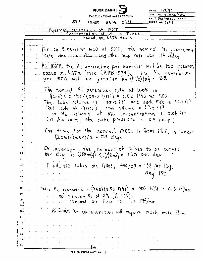
FUIOR DANIEL
CALCULATIONS and SKETCHES
DATE
COMT.
BYR,
5NO.
ithOf «-
5
CHK'D
c n pit )QO*
m
1
2
3
4
5
S
7
S
»
10
11
12
13
14
15
16
17
18
19
20
21
22
23
24
25
26
27
28
2»
10
31
- 32
3
i "5 3 *
; 35
L
- - Foi...: ; t ^
......
. (RetTH
. (od
^ T
' I c
Y
......
am. V C A J
W K i _
us^ (1.2,t-obv .V
• .Cafe.
^ \ ^ ^
hiLA«.rl ft
v\i Kr 7AC0
•TA - \*\?o
L/. ) /(.Z?,.3
»f. l / t? /° fO
^ j . 1m it
^ J/-
tubts art
" • • " •
rs LftTA 4t.sis
at . 5OaF ; tJ»e.
M -tU max r«
t j V o r OTN r •»• n
D r^ ' ^ o 1 M I C Os1-°! dtu
J
; r n ^ r >0^ fob
^ ( o ^ 3 Ft4/*) =
2 % OA L E L ) ,
/0(»^ =
IS 0'?
ts to 1
« 152 ^
J
!•*- R therV'r^r>1-2-5.
^.CO is 4 5 - f f t f t 3
Is 3.00 ft^
tLAy
J
150
WHC-SD-W379-ES-003 Rev. 0
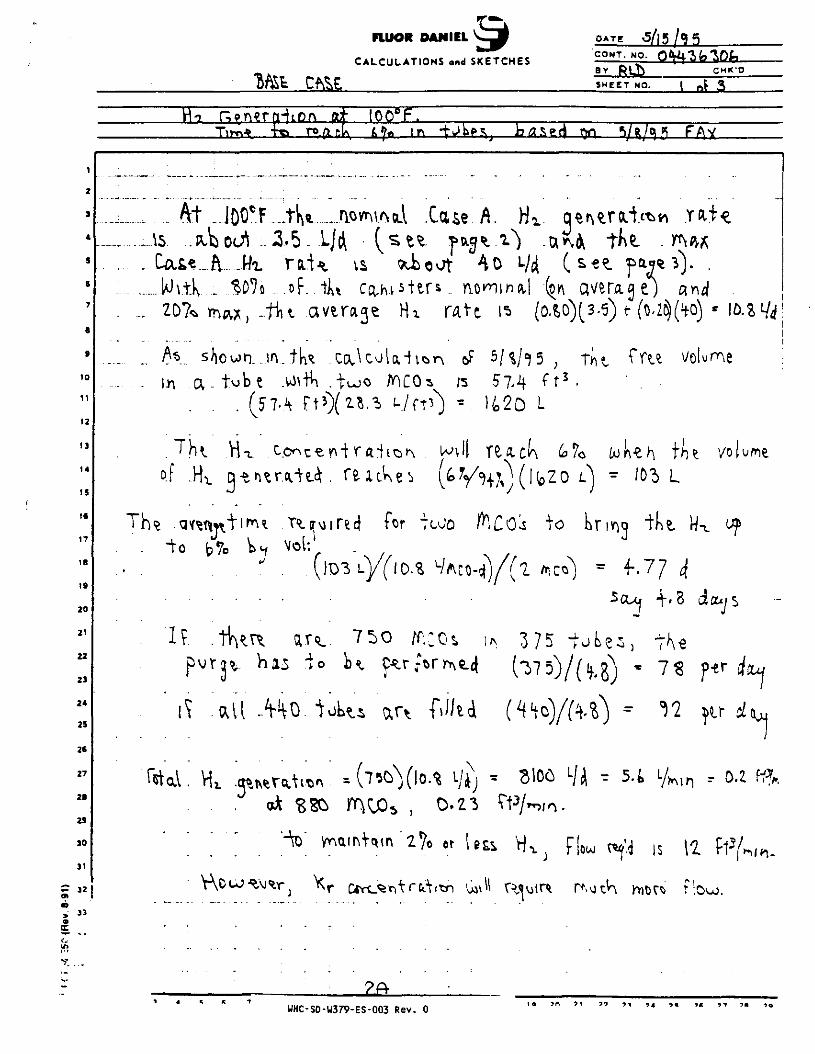
i
2
J
4
S
6
7
•
9
10
11
12
13
14
15
16
1?
IB
19
20
21
22
23
24
25
26
27
2B
29
30
31
- 32en
33
FlUOR DANIEL
CALCULATIONS and SKETCHES
DATE
CONT.NO.
BY
At3,5
Wvtk ~.
a - tob t .two S l , i \ f t 3 .1420 L
"I"hi H-L co*^c€v^+rftilo^L
for i to
w
i"kt
f.77
'1 ? ar?.. 7 s o /r..;os, ^ 3 75
"to K 7S
all .
H,. « (7^(10.^ L/ij « S106, 0.Z3
CHK-0
T\m* fe» ro ft r.• 100° F.
SHEET NO. | ,
AI
r 5 . t L/Min , D.Z Wfc
i s
Pj* <otr* flow.
UHC-SD-W379-ES-003 Rev. 0
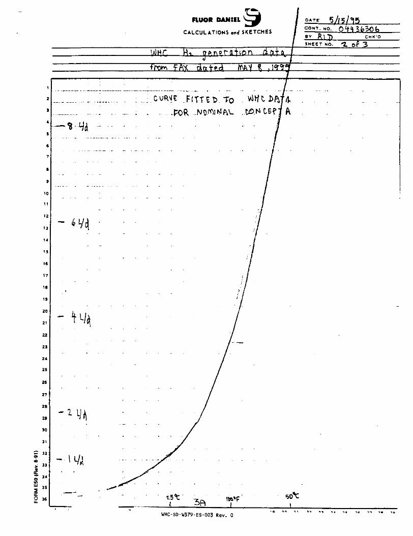
FLUOR DANIELCALCULATIONS and SKETCHES
WHC-SD-W379-ES-003 Rev. 0

FUJOR DANIEL
CALCULATIONS and SKETCHES
DATE
CONT. NO.
BY k\J\ CHK'D
SHEET NO. £WiHC Mn 4
Ffott FAX
i
2
1
4
9
S
7
a
9
10
11
12
13
14
19
IS
17
18
19
ZO
21
22
23
24
29
26
27
28
29
30
31
*- 32
33
34
36
TO
CONCEPT
WHC-SD-W379-ES-003 Rev. 0
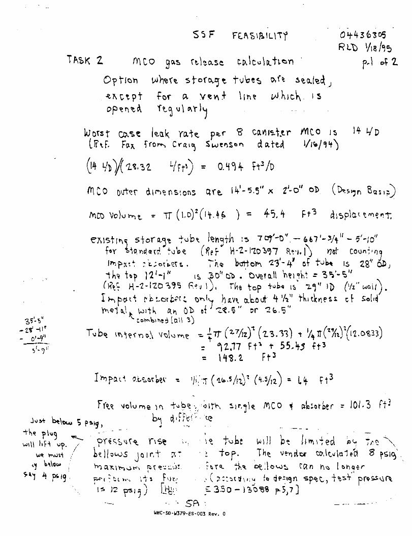
for ak
kak rat?. p*r S ca^MjtdcittJl
-/ft's ) =
- TT
p.l of Z
14 i/p
n BttS,s)
<H u?.
f«r ^o.ftd.ad tote
Ik* Up ]2H" is 301J,
'Detailtop
is 2$' o
&i cf So-2b.
Ft* tF t 3
f t '
r J O / - 3
t^be bt limbed8
R )
UHC-SD-U379-ES-003 Rev. 0

p. 2.
on*. S.-c^nvs-ttr AlCO present,
Y\ _
on*
I f U?<"«. DK +uoo 10 carus^er *K0'2> J* ar-
.23S
to r pV ( /0-io\>% toilK +<-<Jo /0-ca»\i3^€r A W s c^ ma^ j ^ ^ raff
If % t4 t totes' to t t
for -YV.*is taiect Ow the
ro b^ v^Meti is was )2N\ - fo ^ tes
WHC-SD-W379-ES-003 Rev. 0

FLUOR DANIEL
CONT. NO.CALCULATIONS and SKETCHES , - ^
SHEET NO,
ftM LOTA TTTST¥
- 320»
The,... nominal TViYt fif. H2 . Qtr\tuh.or\ is 0.53
379-45 5CF-- t5
6
7
of "VW Nth^r N ^ s ^ 9700
(o,53 SCF. H^.(0.00*7) -..O..
9
10
t3 J
15
17 - J
16
19
20
21
22
23
24
25
26
27
2fl
29
30
31
- 0.625
H«
3 1 "§» u
( a v W;
- ". M
UHC-SD-U379-ES-003 Rev. 0

THERMAL ANALYSIS
CONCEPT 2D AND TASK "G"
•"TA- nUHC-SD-W379-ES-003 Rev. 0

TABLE OF CONTENTS
THERMAL ANALYSIS 1
TRANSIENT ANALYSIS 8
CFD MODELING 12
WHC-SD-U379-ES-003 Rev. 0

C:\SJD0\ftEP0m\4
THERMAL ANALYSIS FOR STORING K-BASIN FUELIN THE HWVP CANISTER STORAGE BUILDING
Following is the rough calculation of heat transfer in the storage vaults. The assumptionsas well as calculation results can be used only as a first guess. Detailed calculation usingthe Computational Fluid Dynamics (CFD) technique is proposed on the next stage of thisproject.
K-Basin fuel elements are stored in 2 vaults of the canister storage.
Unit Vault Sleeve MCO AMembly Canister Cylinder Element
Storage 2 loaded 440 880 4400 8800 17600 104846'
Vsuit 220 440 2200 4400 8800 S24231
Sleeve 10 20 40 280
MCO 10 20 140
Afsembly 28
Canittar 14
Cyfindar
Table 1. Number of Units in the Storage
There is a mixed heat transfer media: air or water inside the MCOs, air between MCOsand sleeves, and air as a cooling media in the vault.
There is 20% of the maximum heat decay fuel elements and 80% of the nominal heatdecay fuel elements. A single maximum heat decay element is releasing 3.44 W of heat.A single nominal heat decay element is releasing 1.56 W of heat.
It is assumed for conservative reason that 280 elements of maximum heat decay (3.44 W)can be loaded into a sleeve and located in the last row of the vault. This elements will beexpressed to the highest vault air temperature. For comparison a number of calculationsare made for the high loaded sleeve located at the beginning of the vault in the first rowand expressed to the intet airflow.
At the first stage, codirg air is supplied by the forced ventilation system with 100% of
Based on 750 MCOs
Bs.se on 375 MCOs
WHC-SD-W379-ES-003 Rev. 0

r/?- 2return air. Proposed air inlet temperature is 35°F. For comparison, inlet temperature of50°F is analysed as well. Maximum allowable temperature of the surface of a fuelelement is 100°F. Calculation is made for the maximum vault load of 320 kW at forforced ventilation system and maximum vault load of 270 kW for natural convection. Thedifference of these loads is due to additional heat load from structures at low supply airtemperature.
The purpose of this calculation is to find the maximum temperature of the surface of a fuelelement.
The highest temperature is expected at the fuel elements closed to the center of the MCO.Each fuel element is assumed as a solid uranium cylinders surrounded by water or air(Figure 2).
The diameter of the hollow outer element ring is assumed the same as the diameter of theouter zirconium cladding {identified as #17).
D17 « 6,1 cm « 2.4 in
The diameter of the inner cylinder of the outer element (identified as ft 14) is
DM = 4.4 cm = 1.7 in
Relative diameters for the inner hollow cylinder (Identified as #13 and #10) are:
D13 = 3.2 cm = 1.25 inD10 = 1.15 cm = 0.45 in
Relatively the thicknesses of uranium are
K«~ = 2 .4-1 .7 = 0.7 inA i fW = 1.25-0.45 = 0.3 in
The uranium cross-section is
S = : t / 4 ( ( D 1 72 - D ' > -D t 0
2 ) ) * * /4{(2.41 72 - 1.714
2)+ (1.2513
2 -0 .45 1 02 ) )= 3.32sq.in
The diameter of the equivalent by cross-section solid uranium cylinder is
D - ( 4 S / 0.5 = (4 * 3.32 / re ,0.5 = 2.06 in
The volume of a single element r;.
V - 7t / 4 •.'• « n I 4 (2.06/1 2) * 2 « 0.0463 ft3
Since the maximum heat dec5. 44 W which is 11.74 Btu/h, the rate of heat flow is
UHC-SD-U379-ES-003 Rev. 0

qx = Q / V a 11.74/ 0.0463 * 253.6 btu/h-ft3
The heat networking model is assumed with a number of zones of heat transfer.Considering a symmetrical heat transfer network the one-dimensional scheme is utilized inthe following Figure 1.
'—fit]—*«—js]—**—[AIR
Figure 1. Heat Transfer Network.
Gap x: between the inner and the outer rings of a fuel elementGap x-1: between the center element and six peripheral fuel elementsGap 1-C: between the peripheral fuef elements and the canister.Gap C-M: between the canister and the MCO,Gap M-S: between the MCO and the sleeve.Gap S-AIR: resistance between the sleeve and surrounding air.
Networking resistance factors:
Zone x; 1 element :Zone x-1; 6 elements:Other zones in series:
f x = 1f, = 1+1/6 = 1.17f = 1
Heat transfer between two adjacent zones i and i + 1. Zones are assumed as flat
q, = q,, + k ( 1/f, ) A, (T , -T i + 1 )a,
where,
k"
A:
- heat transfer from previous zone, Btu/h= thermal conductivity coefficient between two zones, btu/h-ft-F= networking resistance factor, dimensionless• heat conduction area for i-zone, sq.ft= (i)-surface temperature, F= (i + 1 J-surface temperature, F= number of elements in (i)-zone
It is assumed for simplification reasons that thr» thermal conductivity coefficients are notchanging with temperatures.
Following calculations, made for heat transfer- -*reas, considering 80% of actual height offuel element.
For zone x the heat transfer area is calculs.- 'or a single fuel element:
Ax = w(D17) • L • 80% = ir{2.4) * I? .8 = 169sq.in =1 ,17 sq.ft
WHC-SD-W379-ES-003 Rev. 0

For zone x-1 the heat transfer area is calculated for 7 elements:
AQI - * (D l7 * 7) • (L) * 80% « it (2.4 • 7) • (28) *0.3 = 1182 sq.in = 7.04 sq.ft
For zone 1-C the heat transfer area is assumed as an average between 7 elements andcylinder tube surfaces:
A1C - (AKl + ACJ a * 80% « TCL (6*Dx l + Dc ) / 2* 80% = is (28) (6#(2.4)+ (9) / 2 # 0.8 = 823 sq.in - 5.72 sq.ft
For zone C-M the heat transfer area is assumed as an average between 2 assemblies (2canisters, 28 elements) and MCO surfaces:
ACM - t 4 Ac + AM) / 2 = 7t L (4 • Dc + DM ) / 2 = « (28) (4*9 +24) / 2- 2638 sq.in = 18.33 sq.ft
For zone M-S the heat transfer area is assumed as an average between the MCO and thesleeve surfaces (total height is 98" *3):
AMS «< AM +AS ) 12 = « LTot ( DM + Ds) 12 = s (98*3) (24 + 29) / 2 = 24476 sq.in
= 170 sq.ft
Heat transfer surface from a sleeve to the cooling airflow is:
A, = 7t LD S = * (164*2/12) (29/12) = 208 sq.ft
Maximum center line temperature at the center zone 0 element (Kreith and Bonn, Principlesof Heat Transfer, 5 ed., p.96, Eq.2.51. Ref. 1b)
T d = Tx + qx (D/2)2 / (4 J.UMnium)
where:
qx = rate of heat flow, Btu/h-ft3
Ur.nkjm = thermal conductivity coefficient for uranium, 1 7.3 Btu/h-ft-°F (Kreithand Bonn, Principles of heat Transfer, Ed.5, p.A13, Ref. 1d).
Heat transfer coefficient, k, depends on the media.
The total normal emittance for zirconium is assumed as fo* dark paints as 0.85 (ASHRAE1989, p.3.8, Table 3. Ref. 2b). For horizontal direction c heat flow and 90°F meantemperature the approximate thermal resistance of plan' ..rspace for each air gap is0.77°F-ft2-h/Btu (ASHRAE 1989, p.22.3, Table 2. Ref. 1<X
Thermal conductivity coefficient for uranium is approxirr:- ly 17.3 Btu/h-ft-°F (Kreith andBonn, Principles of heat Transfer, Ed.5, p.A13. Ref. Tdi
Total heat transfer coefficient for an element with twc -. aps and uranium slab
WHC-SD-U379-ES-003 Rev. 0

Tft 5(zirconium claddings are ignored due to their low thickness) is
k = 1 / ( R w , + A, / XUfBnium + A2 / Xutmniufn + R w 2 ) c
= 1 /(0.77 + (0.7/12) / 17.3 + (0.8/12) / 17.3 + 0.77)• 1.1 - 0.715 Btu/h-ft2-°F
whereRa-p = Air gap resistance, F-ft2-h/BtuAurinium = Thickness of uranium, in
c =» adjustment coefficient for conductance between elements
by touching (assumed 1.1)
Following data are taken from HWVP project (FDI calculation No. E350-HV-1802, Book II):
Heat transfer coeff icient between overpack and sleeve h o s = 0 .329 Btu/h-°F- f t2
Heat transfer coeff icient between sleeve and airflow is calculated using ASHRAE 1989Fundamentals, Chapter 3, p.3.15, Ref.2e) as a function of air veloci ty (vertical planesurfaces, V<16 fps)
h = 0.99 + 0.21 V
If water is used as a media between surfaces the free convection film coefficient isrecalculated as:
h * Nu • (k / L) = C (Gr Pr }n (k / Uwhere,
Grashoff factor isGr = L3 p2 p AT g / yl
L = effective length, ft [1.87 ft]p - density, Ibm/ft3, [61.2]p •=* thermal expansion, 1/F, [3.1 E-4]AT = temperature difference, Fg = gravitation constant, ft-lbm/lbf-s2, [32.2]fj - absolute fluid viscosity, Ib/ft-s, [0.29E-3Jk = thermal conductivity of water, BTU/h-ft-F, [0.384]Nu a Nusselt factorPr « Prandtl factor (2.74)
For forced air cooling system airflow is given. If passive cooling is bp ied, airflow iscalculated as a function of stack height, air densities, and system res ance.System conductance (K1) is based on system hydraulic characteristic*, calculated in HWVPProject (FDI calculation No. E350-HV-1802, Book II) for airflow at Q- 0000 cfm andAP = 0.19 in.WG which is K1 = 0.19/900002 = 2.34 # 10"11 in.WV m2 for threevaults. For two vaults this coefficient is different due to higher rer;' ce in the vaults.
UHC-SD-U379-ES-003 Rev. 0
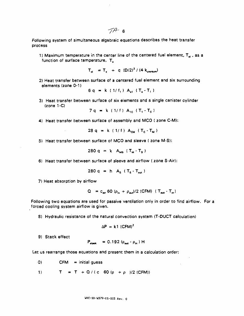
Following system of simultaneous algebraic equations describes the heat transferprocess
1) Maximum temperature in the center line of the centered fuel element, Td , as afunction of surface temperature, T*
Td - Tx + q (D/2)2 / (4 k^ . ^ )
2} Heat transfer between surface of a centered fuel element and six surroundingelements (zone 0-1)
6 q = k ( 1/f, ) Axl ( T x - T , }
3) Heat transfer between surface of six elements and a single canister cylinder(zone 1-C)
7 q - k { 1/f ) A1C (T , - T c )
4) Heat transfer between surface of assembly and MCO ( zone C-M):
28 q = k ( 1 / f ) A c ( T C - T M )
5) Heat transfer between surface of MCO and sleeve { zone M-S}:
280 q = k AMS ( TM - Ts )
6) Heat transfer between surface of sleeve and airflow ( zone S-Air):
280 q = h As ( Ts - Tout )
7) Heat absorption by airflow
Q - c^f 60 (PiB + P-ut)/2 (CFM) ( T ^ - Tin)Following two equations are used for passive ventilation only in order to find airflow. For aforced cooling system airflow is given.
8) Hydraulic resistance of the natural convection system (T-DUCT calculation)
AP = kl (CFM)2
9) Stack effect
P ^ = 0.192 <Pout-p i n)H
Let us rearrange those equations and present them in a calculation order:
0) CFM = initial guess1) T = T + Q / ( c 6 0 ( p + p )/2 (CFM))
UHC-SD-W379-ES-003 Rev. 0

2) AP = k1 (CFM)
3) Pwut - 1.75E-7TaM - 0.000166 TM + 0.086
pin = 1.75E-7T2in - 0.000166 Tin + 0.086
4) P^c, = 0.192 <P a u t -p i n )H
If AP = Ptttclt , follow to the next calculation. Other vice change the initial guess andrepeat iterations
5) T3 = T ^ + n4 q / (hSA As)
6) To = Ts + n3 q / (hcs Aos)
7) Tc - To + n 2 q / ( k (1 / f ) Aco)
8) T t - Tc + n, q / (k ( 1 / f ) A1C)
9) T, a T, + n x q / {k ( 1/f, ) A, )
10) T^ - Tx + qx (D/2)2 / (4 k , , , ^ )
WHC-SD-U379-ES-003 Rev. 0
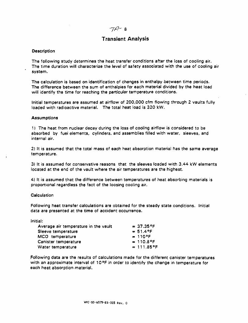
Transient Analysis
Description
The following study determines the heat transfer conditions after the loss of cooling air.The time duration will characterize the level of safety associated with the use of cooling airsystem.
The calculation is based on identification of changes in enthalpy between time periods.The difference between the sum of enthalpies for each material divided by the heat loadwill identify the time for reaching the particular temperature conditions.
Initial temperatures are assumed at airflow of 200,000 cfm flowing through 2 vaults fullyloaded with radioactive material. The total heat load is 320 kW.
Assumptions
1) The heat from nuclear decay during the loss of cooling airflow is considered to beabsorbed by fuel elements, cylinders, and assemblies filled with water, sleeves, andinternal air.
2) It is assumed that the total mass of each heat absorption material has the same averagetemperature.
3) It is assumed for conservative reasons that the sleeves loaded with 3.44 kW elementslocated at the end of the vault where the air temperatures are the highest.
4) It is assumed that the difference between temperatures of heat absorbing materials isproportional regardless the fact of the loosing cooling air.
Calculation
Following heat transfer calculations are obtained for the steady state conditions. Initialdata are presented at the time of accident occurrence.
Initial:Average air temperature in the vault = 37.35°FSleeve temperature » 51.4°FMCO temperature = 110°FCanister temperature « 110.8°FWater temperature = 111.85°F
Following data are the results of calculations made for the different canister temperatureswith an approximate interval of 10°F in order to identify the change in temperature foreach heat absorption material.
WHC-SD-U379-ES-003 Rev. 0

Period 1:Average air temperature in the vault = 41.75°FSleeve temperature = 62.6°FMCO temperature = 121.2°FCanister temperature = 122.0°FWater temperature = 123°F
Period 2:Average air temperature in the vault = 46.35 °FSleeve temperature = 72.6°FMCO temperature = 131.2°FCanister temperature - 132.0°FWater temperature = 133°F
Period 3:Average air temperature in the vault = 51.2°FSleeve temperature = 82.6°FMCO temperature - 141.2°FCanister temperature = 142.0°FWater temperature = 143°F
Period 4:Average air temperature in the vault = 56.1 °FSleeve temperature = 92.6°FMCO temperature = 151.2°FCanister temperature = 152.0°Fwater temperature = 153°F
Period 5:Average air temperature in the vault - 61.6°FSleeve temperature = 102.7°FMCO temperature = 161.3°FCanister temperature = 162.1°FWater temperature = 163°F
Period 6:Average air temperature in the vault = 66.1 °FSleeve temperature = 112.6°FMCO temperature * 171.2°FCanister temperature = 172.0°Fwater temperature = 173°F
Heat load due to nuclear decay from the entire fuel elements is calculated as:
Q = 3 2 0 x 3 4 1 3 = 1,092,160 Btu/h
The difference between enthalpies is calculated as:
WHC-SD-U379-ES-003 Rev. 0

10
Elements: AE. = m. c. nm (T,2 - T.,)
Cylinders: AEe = mc ce no (Tc2 - Tcl)
Assemblies: AEm - mm cm nm (Tm2 - Tml)
Sleeves: AE, - m, c, n, (T,2 - T,,}
Water in MCO: AEW = mw cw nw (Tw2 - Twl)
Air in the vaults: AE, = m. c, n. {T.2 - Tm1)
where:
m = material mass, Ibc - specific heat, Btu/lb-°Fn = number of elements
T, , T2 ~ temperatures at different periods,°F
Following masses are calculated for a single sleeve:
Elements: m. = 51 .18x280 = 14330 1b
Cylinders: mc = (n Dc Le + 2 n Dc2 / 4) <s0 pc nc
= n (0.68 x 2.2 + 2 x 0.682/4) 0.021 x 490 x 40 = 2233 Ib
Assemblies: mm - (it Dm 1^, + 4 n Dm2 / 4} am pm nm
= « (2x2.33 + 2x2 2 /4 ) 0.031 x 490 x 10 = 3178 Ib
Sleeves: m, = * D, L, CT, p. = n 2.42 x 36 x 0.041 x 490 = 5498 Ib
Water: mw = n Dm2 L , crw pw - L (m/p)
= (( :t 2.382 / 4 x 36) - 14330/1190 - 2233/490 -5498/490) 62-4 « 7843 Ib
Following mass is calculated for the entire storage:
Air: m. = ((603/12 x 2/3) x 447/12 x 133) p. = 11618 1b
Specific heat is calculated as:
Uranium elements: c. = 0.027 Btu/lb-°F
Stainless steal, Cor-ten: c. = cc = cm = c, = 0.11 Btu/lb-°F
WHC-SD-W379-ES-003 Rev. 0

Water: cw « 1.0 Btu/lb-°F
Air: c. = 0.24 Btu/!b-°F
Total enthalpy:ZAE = AE, + AEC + AEm + AE, + AEW + AE.
Approximate time difference for temperatures at time index 1 to reach temperatures attime index 2 is calculated as:
t = SAE / Q
WHC-SD-U379-ES-003 Rev. 0

Tfi 12
CFD MODELING
The PHOENICS (Parabolic, Hyperbolic or Elliptic Numerical Integration Code Series) is acomputer program that simulates fluid flow, heat transfer, and other related phenomena.This simulation is based on mathematical derivation from established physical principles.The basic capabilities provided by PHOENICS include:
- menu driven interface-- one-, two-, or three-dimensional in Cartesian, cylindrical-polar or body fitted
coordinats-- steady-state or transient analysis-- single phase or two-phase media analysis-- compressible or incompressible flow- subsonic, supersonic or transonic flow
The PHOENICS solves the equations for flows, turbulence, mass and heat transfer by acontrol volume method based on finite element approach. In the present problem, the flowis mostly turbulent and also under buoyancy effect of natural convection. This problem isgoverned by the Navier-Stokes equations representing the conservation of mass,momentum and energy.
PHOENICS has many limitations and restrictions. First, the realism of its simulationscannot exceed that of the assumptions on which its use is based. Secondly, a simulationproduced by PHOENICS has an accuracy that depends upon the amount of computer timethat its user has been willing or able to spend. Finally, fluid dynamic phenomena beingwhat they are, it cannot be guaranteed that PHOENICS will provide a converged solution toevery problem without user's making special settings of solution-control switches.
CHAM company, the author of PHOENICS, stated that the code "is very well validatedand developed from over 10 years of commercial use (EasyFlow, release 2.01, page 1)."
There are a number of different simulations performed for this project using PHOENICS,including vault airflow and temperature distribution (CFD/Model), analyses of airflow
.around the building (Site Model), and study of entry device effect (T-Entry Inlet Model).
The details of PHOENICS simulation technique will be described using the CFD/Model.
Assumptions and Limitations
Finite volume method requires that the space be divided into discrete elements. Thehigh-.Vequency and spatially very small fluctuations of turbulent flow variables cannot bequantified directly. Assumptions must be made for these unknown turbulence correlations.The ;* ;st compromise between acceptable computer time and accuracy of the simulation ofturL- .nt flow phenomena is the k-c turbulent model, that consists of two additional
ntial equations for the turbulent kinetic energy (k) and the dissipation rate.
UHC-SD-W379-ES-003 Rev. 0

13
For all analyzed models flow in the vault under designed conditions are turbulent{Re > 3000).
Main Equations and Numerical Solution
Steady state turbulent flow in the vault can be described by conservation equations. Thegoverning equations can be written in terms of cartesian tensors.
Continuity equation:
where,u = component of mean velocity, m/sx » coordinates, mi, j » directions
Momentum equation:
d , , 1 3P d ,. , dui 8u
where,p = density, kg/m3
P • pressure, Pag = gravity acceleration, m/s2
Vt + V
v.rr» vt/ vi a effective, turbulent, and laminar kinematicviscosity, m2/s
The turbulent kinematic viscosity is
where,ln « mixing length, meters
Turbulent kinetic energy equation is:
• « » - •
where,"K • kinetic energy of turbulence, m:/s21 = generation rate of turbulence energy, m2/s2
= dissipation rate of turbulent kinetic energy, mVsJ
• effective Prandtl numbers in turbulent model
UHC-SD-W379-ES-003 Rev. 0

14
dxj 6x; dxj
Turbulent dissipation rate equation is:
where,Cu, Clf C2 * empirical constants,o, • effective Prandtl numbers in turbulent model
For the inlet boundary conditions, the air velocity distribution componentis in z-direction.
The finite-domain technique, used by PHOENICS, combines the features of themethod of Patankar S.V. and Spalding D.B. {1972, "A Calculation Procedure forHeat, Mass and Momentum Transfer in Parabolic Flows," Int.J. Heat and MassTransfer, 21, London, England, 1565-1579}. The calculated space area isdiscretized into finite intervals and the variables are computed only at afinite number of locations called "grid-points." The variables are connectedwith each other by algebraic equations.
Internally, PHOENICS solves sets of algebraic equations that represent theconsequences of:
$ integrating the differential equations over the finite volume of acomputational cell over a finite time
$ approximating the resulting volume, area and time averages by way ofinterpolation assumptions
It is assumed that, in convection terms, all fluid properties are uniformover cell faces,- the timely new values are supposed to prevail throughout thetime interval.
For each dependent variable there are as many algebraic equations as thereare cells in the integration domain. Thus, there are a set of (NX x NY x NZ)algebraic equations for each dependent variable. PHOENICS solves them in aniterative manner, the object of which is to reduce the imbalance between theleft and right sides of every equation to a magnitude that is small enough tobe neglected. Iterations are needed because the equations, though linear inappearance, are non-linear in general. In each iteration cycle, thecoefficients and sources are assumed as constants. On the next iteration, thecoefficients and sources are updated from the latest values of the auxiliaryand dependent variables, and the linear equations reassembled and solved.Buoyancy sources are included in the appropriate momentum equation.
Modal Setup
Simulating a real problem requires to setup the model. This is one of themost important steps for obtaining a right solution. Necessary dimension ofthe problem has to be selected. It must be considered, that 3-dimensionalmodel with many regions o*:ten makes the solution of a problem very difficultbecause of increased running time and convergency problems. Therefore, ifrequirement to the accuta y is moderate, 2-dimensional model should.beselected. Symmetry in a adel can be efficiently utilized by reducing modelsize on symmetrical line' However, in many cases of fluid flow,nonsymmetrical airflow - tern must be selected even in a field that hasgeometrical symmetry. " example, airflow in a narrow cave with vertical
UHC-SD-U379-ES-003 Rev. 0

symmetry is nonsymmetric.PHOENICS allows to choose between 3 different coordinate options:
cartesian, cylindrical-polar, and body-fitted-
M«sh Generation
PHOENICS allows to generate a mesh automatically by specifying the gridfor each coordinate. Input of extents (sizes) and number of cells allowB tovisualize the geometry and make necessary correction prior to a run.Sensitive areas, where more accurate results are desired, need more cells.Also, distance between cells can be set as exponential function. This isoften used to get "closer look." to the areas where more accurate solution isnecessary.
Analysis Type, Properties, and Boundary Conditions
PHOENICS requires to specify the analysis type including hydraulic regime,heat transfer, flow regime (parabolic or elliptic), number of flow phases (oneor two), steady-state or transient analysis.
PHOENICS has a number of physical properties that must be selectedincluding density, laminar and turbulent viscosity, mixing-length, specificheat, and thermal conductivity.
Boundary conditions are the most important and complicated part of inputdata. They include inlets, outlets, walls, internal plates, obstructions,gravity, and heat sources. There is an opportunity to identify externalrelative pressure at outlet. Heat flux or temperature can be defined forwalls as well as for obstructions. Walls allow to calculate airflowresistance as well. One useful option is obstruction porosity between 0(solid) and 1 (fully open). Gravity force can be defined for buoyancycalculations, where the strength of buoyancy exists by using Bussinesqapproximation associated with reference temperature and expansion coefficient.Volumetric heat sources can be defined in several ways: from separate screen,as a part of obstructions entry, or as a part of walls entry. There is anindication received from CHAM of North America (PHOENICS's author, letter ofSeptember 3, 1991), that volumetric heat source used as input must be dividedby specific heat.
Solution Monitoring and Printout Control
PHOENICS has very extensive interactive capability for solution control.This control includes the initial value of dependent variables, termination ofthe calculations, relaxation of individual dependent variables, solutionoption for each dependent variable and the terms included in the equations.The program provides three different ways of under-relaxation: linear,automatic and false time-step. There is an opportunity to limit residuals byterminating the iterations for each dependent variable when residual value isreached.
During the calculation, converging process is monitored interactively (seeFig.A.51). Calculation can be interrupted any time and parameter type and/orthe value can be changed. A graph and a table of current values are shown forboth the hot area value and for the total residual for each variable. Goodconverging process is the one which shows that the upper plot stabilizesoscillations and the lower plot shows continuous decrease of residuals.
Color graphic results can be displayed by a post-processor using modulePHOTON. This program has its own Is iguage that: allows to display any cross-sections, variables, vectors in for*: of color fields and color vectors.
Program Verification and Validation
Verification and Validation proceou has been performed in accordance withDesign Control Procedures Manual tion 4 "Calculations", and section 9"Computer Code Validation and Veri ation"). Following steps are conducted;
WHC-SO-W379-ES-003 Rev. 0

-- Available CFD commercial programs were studied and the most efficient,that is PHOENICS, has been selected. The cover page of the program hasbeen signed by the Project Engineer and preapproved by WHC
-- The PHOENICS introductory course, given by CHAM of North America, wascompleted by the originator
-- Computer Code Summary has been filled. Project Classi-fication isassigned to Class IIIB "Off-the Shelf Design Aid-third party supported."Program validation includes: history of acceptance/ use and analysis of datain literature. As follow from the list of publications (see A.7.5.1)PHOENICS has been intensively checked and verified by many independentreviewers
-- Many sample test problems were run by the originator prior of using theprogram
-- A complete description of model is included into this report
- - The checked and the independent reviewer have verified that the modelis a reasonable representation of the process or physicalphenomenon of interest and outputs are reasonable.
Numerical evaluation including manual calculation has already been used andexplained for the AF/Model (see FDI calculation E350-HV-1802) . Similarevaluation for the CFD/Model is impossible due to a huge number of calculationand program complication. Logical way of verification includes data analyzingand referencing to respectable publications. Comparing to a similar programand/or to che tesc data are other ways for verificacion. However, we do notbelieve that similar data exist due to the unique configuration and conditionsof canister storage building. There are a number of similar programs, such asFLUENT, FIDAP, FLOTRAN. However, if the results of programs are different,there is no answer which program is correct, since there is no test data.Therefore, the most valuable sources to evaluate such a large system asPHOENICS are respectable publications for similar problems and engineeringjudgment from a highly qualified and experienced engineer.
As stated by CHAM of North America, PHOENICS is the industrie's first full-capability computational fluid dynamics software package for PC. There areover 350 installation of PHOENICS throughout the world. PHOENICS referencesincludes a list of publications that shows large number of applications wherePHOENICS has been successfully used for solving many fluid mechanics and heattransfer problems.
Geometry
Figure AlSa presents the 2-dimensional simulation model. A cross-sectionthrough the vertical symmetry axis in the center of vault is modeled.
UHC-SD-W379-ES-003 Rev. 0

7ft' 17Inlet1 1
Outlett I
7'«2.l3m UPorosity
region
13f— 8 ' —H42.44m 3.96m
1.22m
— 96'-29.3m
-18 -14' —5.S9m 4.2 7m
Figure AlSa
Inlet air opening is located at the upper-left part of the model. Outletopening is located at the upper-right part of the model. The middle part ofthe vault is occupied by sleeves. Airflow pressure loss in this part of thevault is simulated by using porosity factor. PHOENICS is not capable ofsimulating anisotropic porosity that would have some advantages for thespecific air flow pattern of space occupied by sleeves. Airflow regime isturbulent since, for maximum loads, Reynolds number is above 3000. Wallsurfaces are assumed adiabatic (conservative approach), however hydraulicresistances of walls are taken into consideration. Because of assumptionssuch as 2-dimensional simulation and porosity, temperatures in this simulationwill be used as relative values only. The results of simulation will allow tocalculate flow pattern in the vault and discover hot areas where temperaturesare higher due to the buoyancy effect. The reference air temperatures are atinlet and/or outlet. All dimensions used in PHOENICS are in SI units.
For the model under consideration cartesian grid is selected. This gridconsists of cells formed by intersection of planes of constant z and planes ofconstant y. A rectangular grid was constructed using interactive preprocessorEasyFlow. Y-direction is divided into 6 regions with physical dimensionsshown on Figure 7. Each region has been divided into different number ofcells. Z-direction is divided into 3 regions with equal spacing betweencells.
Properties
Air density and laminar viscosity are assumed to be 1.01 kg/m3 and 2.1E-5mJ/s respectively. Turbulent viscosity is calculated by the program itself aswell as the mixing length. Air specific heat is 1004 }/>.g-°C and air thermalconductivity is 0.0263 w/m-"C. There is no need of using variable propertiessince the buoyancy effect is calculated by Bussinesq approximation with airexpansion coefficient.
Boundary Condition*
Boundary conditions include: one inlet, one outlet,gravity, and heat sources.
Inlet is located in the HIGH face Z-region #3, Y-r.-,of S3,000 cfm, inlet velocity is calculated for 2 vaul
, obstructions,
-i #1. Using airflowas
WHC-SD-W379-ES-003 Rev. 0

-m- isV - (6x<gJl?g) (2/3) " 77-
where:6x(8x2l.5) is the total air entry area for 3 vaults, ft2
The direction of air at inlet opening is -Z (see Fig.7). Turbulent intensityis recommended by PHOENICS (see EasyFlow manual, p.6-84) as 2% or 0.02. Inletair temperature assumed is 115°F • 46.06°C. Outlet and wall boundaries andobstructions are as shown in Fig.7. Since we are using constant density andconsidering buoyancy effect, Bussinesq approximation has been input. Forreference temperature of 25®C the air volume expansion coefficient ispaO.Ot^G'C1. This coefficient is the reciprocal of the absolute temperaturefor an ideal gas or 1/(273+25)•0.00336°C"1 (see PHOENICS EasyFlow Manual, p.6-96). Gravity acceleration is taken for negative Z-direction as -9.81 m/s2.
Effective vault volume is calculated as
Vol. • 96 x 36 x (3 x 50) • 518,400 ft3 - 14,679 m1.
Vault volume occupied by sleeves (3 vaults) is
Vol3 = 22 rows x 10 columns x 3 vaults x K/4 x 3! x 36 . 167,949 ft3 = 4755 m3
Volumetric heat flux is calculated as energy divided by volume and byspecific heat considering only 2 vaults:
w . S 270 x 1000 , , ;Wv " (Vol . ) C p " 14679 x 2 / 3 X 1004 " ° * 2 7 5 W / m
where:270 is total decay energy dissipated from canisters in Kw, and1004 is air specific heat in j/kg-°C.
Airflow resistance of the vault is simulated as porosity. Porositycoefficient is calculated as following expression (the same for 2 vaults with440 sleeves as for 3 vaults with 660 sleeves)
1 - Vol./Vol. = 1 - 167,949/518,400 » 0.67
-Interpretation of Results
The results of PHOENICS modeling are presented in Figures 8 through 13.
Mostly convergency residuals are decreasing. Temperature in Hot Area valueplot is increasing by 0.007* only.
On the right side of the screen the scale of temperatures is displayed. It iseasy to find temperature in a region starting from the white cell .see 53degree). Temperature fields show that higher air temperatures are in a widearea below the ceiling. Velocity vectors and thermal regions are t-hown onFig.14.
There are four major flow regions:
Region 1. The beginning of the stream where entered air is me .ig downcreating first entry vertex
WHC-SD-U379-ES-003 Rev. 0
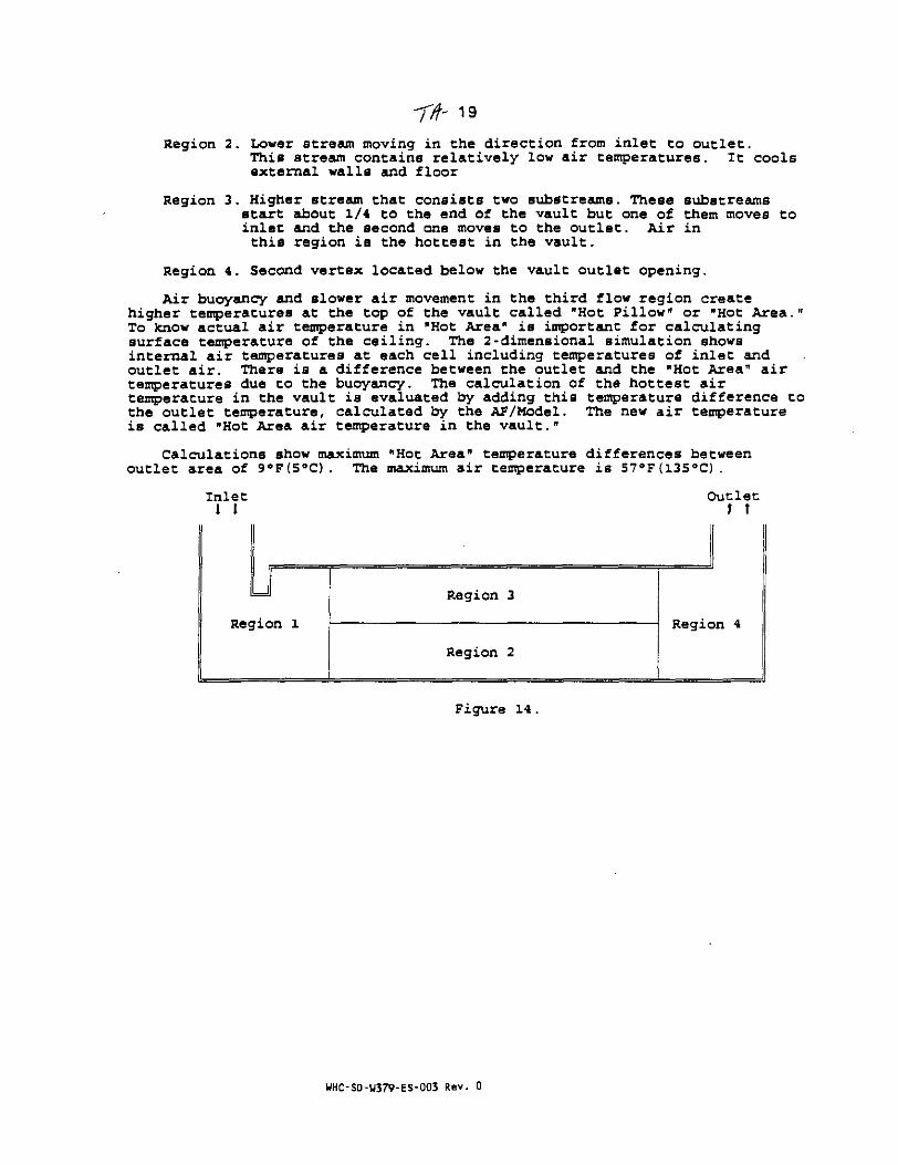
Region 2. Lower stream moving in the direction from inlet to outlet.This stream contains relatively low air temperatures. It coolsexternal walls and floor
Region 3. Higher stream that consists two substreatms. These substreamsstart about 1/4 to the end of the vault but one of them moves toinlet and the second one moves to the outlet. Air inthis region is the hottest in the vault.
Region 4. Second vertex located below the vault outlet opening.
Air buoyancy and slower air movement in the third flow region createhigher temperatures at the top of the vault called "Hot Pillow" or "Hot Area."To know actual air temperature in "Hot Area" is important for calculatingsurface temperature of the ceiling. The 2-dimensional simulation showsinternal air temperatures at each cell including temperatures of inlet andoutlet air. There is a difference between the outlet and the "Hot Area" airtemperatures due to the buoyancy- The calculation of the hottest airtemperature in the vault is evaluated by adding this temperature difference tothe outlet temperature, calculated by the AF/Model. The new air temperatureis called "Hot Area air temperature in the vault."
Calculations show maximum "Hot Area" temperature differences betweenoutlet area of 9°F(5°C). The maximum air temperature is 57°F(13S°C).
Inlet1 t
Outlett t
uRegion 1
Region 3
Region 2
Region 4
Figure 14.
WHC-SD-W379-ES-003 Rev. 0

7/^20Calculation Tables and Figures
1. Forced ventilation, water in MCOs, air between MCOs and sleeve, sleeve is located atthe end of the vault, inlet temperature is 35°F, total load is 320 kW. Calculation isconducted for different cooling airflows in the range between 10,000 and 500,000cfm. The calculations are presented in Tables 2 through 28. The results arepresented in Figure 2 and Table 1.
The results show that after 200,000 cfm the increase of airflow moderately effectingthe canister temperature.
2. Similar calculation for inlet air temperature of 50°F presented in Tables 29 through 55and in Figure 4.
3. Forced ventilation, air in MCOs, air between MCOs and sleeve. Sleeve is located atthe end of the vault, inlet temperature is 35 °F, total load is 320 kW. Calculation isconducted for different cooling airflows in the range between 50,000 and 500,000cfm. The calculations are presented in Tables 56 through 65. The results arepresented in Figure 5.
The results show that after 200,000 cfm the increase of airflow moderately effectingthe canister temperature. The substitution of water between MCOs and sleeve by airincreasing the canister temperature approximately by 60°F.
4. Table 66 shows the inlet (supply} air temperature that makes the temperature ofnuclear material equal 100°F. As show it is -37.3°F. This temperature is absolutelyimpractical.
5. Natural convection, air in MCOs. air between MCOs and sleeve, sleeve is located atthe end of the vault, inlet temperature is 115°F, total load is 270 kW (decreased dueto no heat load from constructions). Calculation is conducted to identify thetemperature of nuclear material. The results in Table 67 show the temperature between254 and 269°F.
6. The calculation of transient heat transfer is shown in Tables 68. The calculations inTables 69 through 75 are made in order to identify the differences betweentemperatures when Tcanister has 10°F of increment.
The results of calculation are shown in Figure 6.
7. The results of CFD modeling are presented in Figures 8 through 14.
WHC-SD-W379-ES-003 Rev. 0
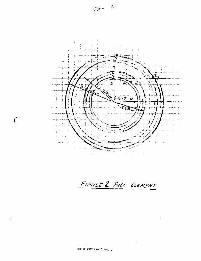
r
WHC-SD-W379-ES-OO3 Rev. 0
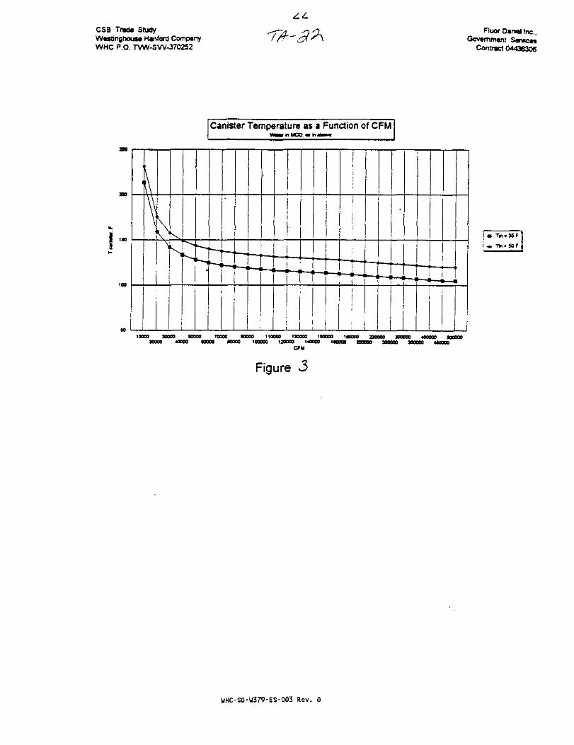
CSB Trad* StudyWestinghouse Hanford CompsnyWHC P.O. TVW-SW-370252
Fluor Daniel Inc.,Government Services
Contnct 04436306
Canister Temperature as a Function of CFM
sS • — • z —-.
t—I 1—1
_ _
1—1
—
1—1 1—1-1—1
—
1—1
>—-—,
11!
• —
•—i
«—
i—i
• — ,
"—i
• — .
i—i
• —
•—i i—i i
loooo wow MQoo 70000 torn 110000 130000 laoooo i « o o aooog3DO00 40000 tOOOO 10000 100000 130000 140000 W O O O 2D0000
CFU2MOO0 3MOO0 4U000
Figure 3
WHC-SD-W379-ES-003 Rev. 0
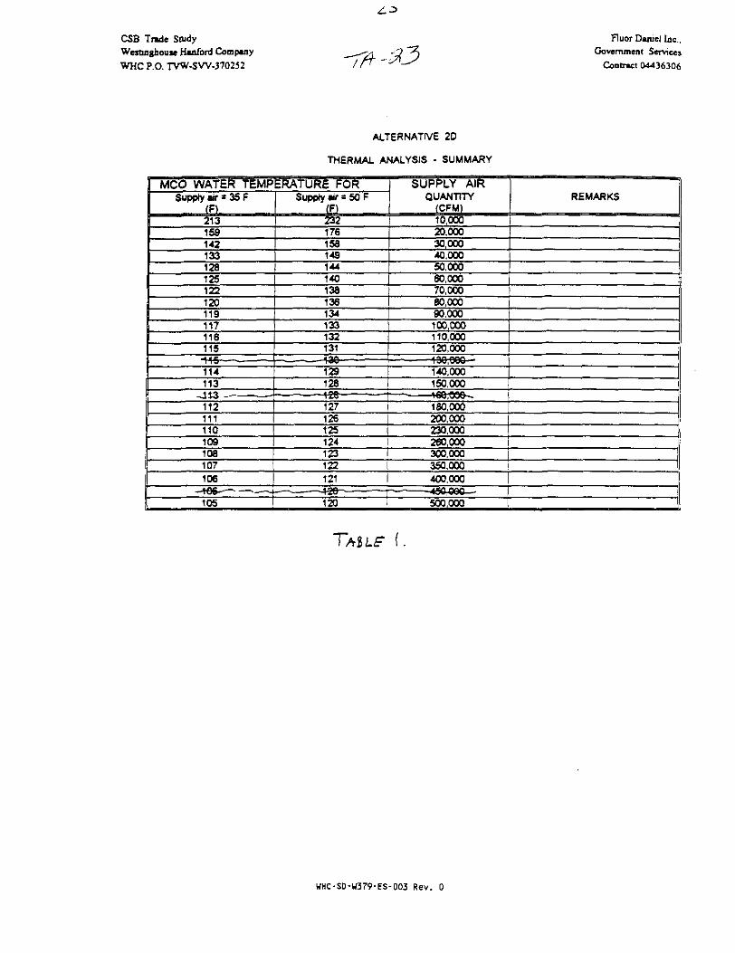
CSB Trade StudyWemnghouse Hanford CompanyWHC P.O. TVW-SW-370252
Fluor Daniel Inc..Government Services
Contract 04436306
ALTERNATIVE 2D
THERMAL ANALYSIS - SUMMARY
MCO WATER TEMPERATURE FORSupply w * 35 F
IF)213159142133128125122120119117116115
114113
112111110109108107106
105
Supply air = 50 F(F)232176153149144140138136134133132131
129126
127126125124123122121
120
SUPPLY AIRQUANTITY
(CFM)10,00020.00030,00040,00050.00060.000
REMARKS
70.000 t I60,00090,000100,000110,000120,000
140.000150,000
180,000200.000230,000260,000300,000350,000400.000
500,000
TAIL? i.
HHC-SD-U379-ES-003 Rev. 0
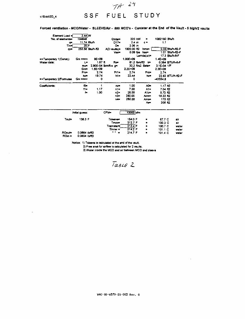
c:\Sidd\2D 4 S S F
21
F U E L S T U D Y
Forced ventilation - MCO/Water - SLEEVE/AJr • 880 MCO'* - Canister at the End of the Vault - 5 hlgh/2 vaults
Element Load ^_'No. of elements-
q %Tirw"qx»
->Tempormry 1 (Const)Water data:
•>Temporary 2(Formula3
Coefficients:
3.44 |W104846
11.74 Btu/h35 F
253.58 Btu/h-R3
Grx • — > 9E+09L" 1.87
mu- 2.90E-04Grx- 1.5E+O9Pnc- 2.74hx» 19.74
Gnt — > 0
ID- 1« - 1.17
f- 1.00
Initial guess:
Tout-
ROout-ROin>
138.3 F
0.0664 Ib/ft30.0604 Ib/R3
Qtotal-D17-
D"A(2 vaults)"
Vain*
ft Ro-lbm/ft-$ gm
P T I -
h i -
nx»n i -n2-n >
CFM- f
Tsleeve-Tmco-
TcanisterJTinner"
• • >
3202.4
2.061920.00
0.09
1.00E+0981-232-2
2.2E+O92.74
22.440
1.007.00
28.00280.00280.00
tcWininfQfp«
m
C "
hms- |hsa«
Lamda(ur)-
IbnVfD k-ft/s2
10000 icfm
154.0212.7213.4214.2214.7
FFFFF
Stfa-
Pre-he-
A0-A1-
Alc-Acm-Ams-
As-
1092160 Stu/h1.1
0.33lBHi/h-H2-F1.01 Btu/h-lB-F17.3 Btu*-ft-F
1.4E+090.344 BTU/h-ft-F
3.1E-04 1/F2.3E+09
2.7422.82 BTU/h-fQ-F
-43554.8
1.17 ftt7.04 fG5.72 ft2
18.33 R2170 ia208 KZ
87.7 C air100.3 C air100.7 C water101.1 C water101.4 C water
Node*: 1} Tsleeve is calculated at th* end of me vault2) Free area for airflow is calculated for 2 vaults.3) Water inside the MCO and air between MCO and sleeve
L
WHC-SD-W379-ES-003 Rev. 0

e:\Sidd\20_4 S S F F U E L S T U D Y
Forced ventilation - MCO/Wattr - SLEEVEMIr - MO MCO's - Canister at the End of Hit Vault - S Mgh/2 vaults
Element Load * 3.44 |W'No. of elements* 104846
q- 11.74 Btu/hTITH 35 IFqx- 253.56 Btu/Mt3
•>Temporary 1 (Const) Grx • » • » 9E+09Water data: L- 1.67
mu- 2.90E-O4Got- 15E+09Pne 2.74ta- 19.74
•>Temporary 2{Fofmula* Gnt • « • > 0
Coefficients: fl> 1f i - 1.17
f- 1.00
Initial guess:
Tout- 84.4 F
ROout- 0.0732 Ib/fOROin • 0.0604 Ib/ft3
Qtotar-D17-D»
A<2 vaults)-Vair*
ft Ro-IbnVft-a g»
Pr1»h i *
ruen i -n2-n >rv4*
CFM- f
T s l e * ^Tmeo"
TcanisteHTinner"
" * m
320 kW2.4 in
2.06 m1920.00 ft2
0.17 fpsLam
1.0OE+09
c«
hms- |hsa»d»(ur>-
61J2 Ibnvit3 k-32.2 Wt2
22E+092.74
22 440
1.007.00
28.00280.00280.00
20000 dm
99.8 F158.4 F159.2 IF159.9 F160.4 F
Beti>
Prc«hc-
A0-A1-
A1c-Acm"Am**
As-
1092160 Btu/h1.1
0.33!Btu/h-ft2-F1.03 3tu/h-ft2-P17.3 B&Vh-ft-f
1.4E+O90.384 BTU/h-ft-F
3.1E-O4 1/F2-3E+O9
2.7422.82 BTU/h-ft2-F
•32548.7
1.17 H27.04 (125.72 ft2
18.33 ft2170 «2208 It2
37.6 C air70.2 C air70.6 C water71.0 C water71.3 C water
Notie*: 1) TstMva is calculated at tha *nd of th« vault2) FT— araa for airflow is calculated for 2 vaults.3) Watar insidt tht MCO and air between MCO and sleeve
/MIS' 3
WHC-SD-U379-ES-003 Rev. 0

c:\Sidd\2D 4 S S F F U E L S T U D Y
Forced ventilation - MCO/Wattr - SLEEVE/Air • 880 MCO's - Canister at the End of tn« Vault - 5 hlgh/2 vaults
Element Load j'No. of elements*
q»Tin«£
V
•>Temporary1 (Const)Water data:
3.44 jW104446
11.74 Btu/h35 IF
253.58 Btu/h-ft3
GrxL-
mu-
Pnchx-
Gnt • • • >
Qtetal-D17-
r>A<2 vaute)-
Vain-
1.87 ft Ro-2.9OE-O4 IbfTvtt-i g-1.56*09
2.74 Pr1>19.74 ht«
C -
hms-hsa-
320 kW2.4 in
2.06 in1920.00 It2
026 fpsLamda(ur)*
1.00E*09ST2 ibmTO k-32.2 fUtZ O*t—
2.16E-K)92.74 Prc-
22.44 he-
1092160 Btu/h1.1
0:33]8tu/h-H2-F1.04^72 Bluftwft-F
1.4E*090.384 BTU/h-ft-F
3.1E-O4 1/F2.3E*O9
2.7422.82 BTU/h-fC-F
-29054 8
Co*ff)ci«nts: (D-f 1 -f-
11.171.00
nx»rt1-n2«n >n4«
1.007.00
28.00280.00280.00
A0-A1«
A1c-ACTTI"
AmsaAs-
1.17 fl27.04)125.72(12
18-33 ft2170 92208 ta
Initial guess:
Tout- 67.4 F
CFM" 30000 dm
Tmco»82.6 F
141.2 F
TinnwROoirt*ROin-
0.0756 Ib/R30.0804 lb/fE3
14T01F142.7 F143.2 F
28.1 C60.6 C61.0 C61.4 C61.7 C
airairwaterwatarwater
Notice: 1) Tsleeve is calculated at the end of the vauJt2) Free area for airflow is calculated for 2 vaults.3) Water inside the MCO and air between MCO and sleeve
cur
UHC-SD-U379-FS-003 Rev. 0

c:\Sidd\2D 4 S S F F U E L S T U D Y
Forced ventilation - MCO/Watar - SLEEVE/Air - 880 MCO's • Canister at tti« End of th« Vault • 5 hlgh/2 vaults
Element Load "£'No. of elements-
3.44 W104346
11.74 Btu/h35lF
253.S8 Btu/h-IQ
Qtottl-D17-
OA(2 vauto)-
Vain-
•>Tempofiry 1 (Const)Water data:
G r t — > 0E+O9L- 1.87 ft Ro"
mift 2.90E-04 Ibnvn-t g-Qno 1.5E+09Pnt« 2.74 Pri«hx- 19.74 h i -
•>Tamponuy 2fFonnulas Qrx •
320 kW •2.4 in c «
2.06 in1920.00 fa hms- [
0.35 fps hsa-Lamda(ur)*
1.00E+0981J Ibm/ID k*32.2 rVs2 B r t -
2.16E*O92.74 Pre-
22.44 hc-0
1092160 Btu/h1.1
1.0617.3
1.4E*090.384 BU«h-«-F
3.1 E-04 1/F2.3E-M39
2.7422.82 BTU/WQ-F
-27321.1
Cocflleitnts: ID-f i -f-
11.171-00
rot"n 1 -n2-n>r»4-
1.007 .X
28.00280.00280.00
A0-A 1 -
A1c«Acm-Am>-
A*-
1.17 ft27.04 R25.72 1t2
18 33 IC170 (t2208 ft2
Initial gu*»s:
Tout- 59.1 F
ROout- 0.0768 IWQROm • 0.0804 IMt3
CFM- 400001dm
Tsl—vTmco-
74.0 F132.6 F133.4 F
Tinn«r 134.2 F134.7 F
23.3 C55.9 C56.3 C56.7 C57.0 C
airairwatirwaterwater
Notice: 1) Tsieeve is calculated at the end ofthe vault2) Free area for airflow ts calculated for 2 vautts.3) Water inside the MCO and air between MCO and sleeve
WHC-SD-W379-ES-003 Rev.

c:\Sidd\2D 4 S S F F U E L S T U D Y
Forcad vtntilatJon - MCO/Wattr - SLEEVE/AJr - 880 MCO'» - Canfsttr at the End of ttia Vault - 5 hlgh/2 vaults
Elamant Load ^_'No. of atamans-
3.44 |W104646
11.74 Btu/h351F
QtotiHD17-
D-253.56 Btu/h-JU
Vaim
c •
hsa-
•> Temporary 1 (Const)Watardata:
G«—> 9G+09L- 1.87 ft Ro-
mu- 2.906-04 Ibm/R-s o«Gnc 1^6+08Poc 2.74 . Pri-hx- 19.74 h1-
•>Tamporary 2(Formulas Gnt'
320 kW2.4 in
2.06 in1820.00 ft2
0.43 fpsUmda(ur)*
1.00E+098 U IbflVTO k-322 K%2 BUM
2.16E*092.74 Pre-
22.44 he-0
1092160 Stum1.1
1.08 Btu/h-ft2-F17.3 Btu/h-tt-F
1.4E+090.364 BTU/h-ft-F
3.1E-04 1/F2.36*09
2.7422.62 BTU/h-fl2-F
-26273.4
Coafflcwnts: (O-
n«f»
11.171.00
nx-n i -n2-n >n4>
1.007.00
28.00260.00280.00
A0-A1«
A1oAcm»Ams*
As»
1.17 R27.04 R25.72 ta
18.33 ft2170 H2208 «2
Initial guass:
Tout- 54.2 F
CFM- 50000 icfm
Tslaava-Tmco"
Tcanistar^Tlnnar"
66.9 P127.5 F
ROout-ROin-
0.0775 fb/R30.0804 Ibm3
129.0 F129.5 F
20.5 C53.0C53.4 C53.8 C54.1 C
airaifwatarwatarwatar
Notica: 1) Tslaava is caleulatad at tha and of tha vault2) Fra« araa for airflow is calculated for 2 vaults.3) Watar insid* tha MCO and sir batwaan MCO and slaava
WHC-SD-W379-ES-003 Rev. 0

c:\Sidd\2D_4 S S F F U E L S T U D Y
Forced ventilation • MCO/Water - SLEEVE/AIr - «S0 MCO's - Canister at ttt« End of the Vault - 5 high/2 vaults
Elamant Load H 3.44 JW'No. of atamants* 104646
q- 11.74 Btu/h•^n^ 35 IFqx- 253.58 Btu/h-«3
•>Tamponjry 1 (Const) Grx • » • > 9E+O9Water data: L- 1.87
mu> 2.906-04Gnc 1.5E+09Prx- 2.74hx> 19,74
•>Tarfiponwy 2{Formulaa Grx*—> 0
Coafficiants: ID- 1f i - 1.17
f- 1.00
Initial guass:
Tout- 51.0 F
ROout" 0.0780 Ib/tO
QtotaC017«
D-A(2 vaults)-
Vain
ft Ro-
Pr1«h1«
nx"n1"n2"n3-rv4-
CFAd-
T»laava»Tmco-
Tcanistar^Tinnar-
* " m
3202.4
2.061920.00
0.52
1.00E+0961232^
2.16E+092.74
22.440
1.007.00
28.00280.00280.00
60000
85.4124.0
kWininft2<P»
•c»
Urns- |lisa>
L«m4a(ur}-
Ibm/R3 k-
cfhi
FF
124.8 IF125.5126.0
FF
Bate-
Prc«h o
A0-A1-
A1C-Acm-Ams«
As>
1092160 Btu/h1.1
0.33IBtum-«2-F1.10 Btum-rt2-F17.3 BtWh-lt-F
1.4E+090.384 BTU/h-ft-F
3.1E-04 1/F2.3E+O9
2,7422.82 BTU/h-«2-F
-255644
1.17 IB7.04 ta5.72 ft2
18.33 ft2170 fl2208 fa
18.5 C air51.0 C air51.5 C water51.9 C water52.2 C water
ROm > 0.0804 Ib/ft3
Notea: 1) Tslaava i» calculated at tha and of lha vautt2) Fraa araa for airflow is calculated for 2 vaults.3) Water insida tha MCO and air batwaan MCO and slaava
7
UHC-SD-W379-ES-003 Rev. 0
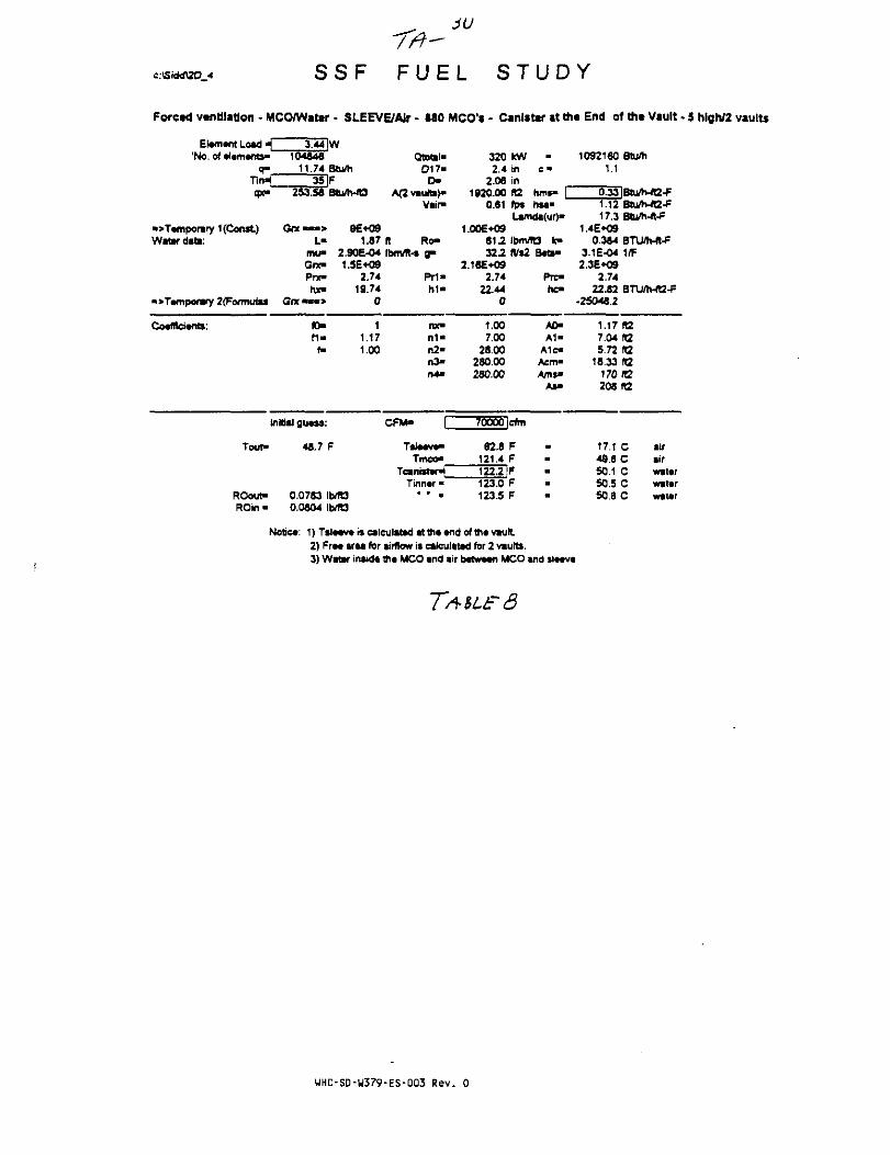
CfiidrfSO 4 S S F F U E L S T U D Y
Forced ventilation - MCO/Watei
Efamant Load ^_'No. of aiamants-
qm
T i n ^cpc»
•>T«mporary 1 (Const)Water data:
• > T a r n p o n r y 2<Forrnutas
Coafftciants:
10464611.74
35253.56
Gne»««>L-
mu>GncPnc
hx-GfX«">
(0-f1«
f-
Initial guass:
Tout -
ROout -ROin«
48.7
0.07830.0804
- SLEEVE/AJr - 880
wBtu/hFBtu/rWD
96*091.87
2.9OE-O41.5E+09
2.7419.74
0
11.171.00
F
MOb/ra
Qtotal-D17-
D-Aavautts)-
Vair-
ft Ro-IbrnVft-s g"
Pri -h i "
nx-n1"n2-n >n4>
CFM- |
Tslaava-Tmco"
TcanwtartTinnar -
* * •
MCO's - Canister at the End of the Vault - 5 hlgh/2 vaults
3202.4
2.061920.00
0.61
1.00E+09612.32.2
2.16E+092.74
22.440
1.007.00
28 00230 00250.00
70000
62.8121.4
IcWininfC2*P»
•
c«
rims- |hsa"
Lamda(ur)-
Ibm/ft/s2
cfm
FF
122.2 |F123.0123.5
FF
It3 k-Bate>
Pre«he"
A0-A1-
Alc-Aem-Ams»
As>
1092160 Btu/h1.1
0.33 IBtu/h-ft2-F1.12 Btu/h-re-F17.3 Btu/h-ft-F
1.4E*090.364 BTLVh-ft-F
3.1E-04 1/F2.3E*09
2.7422.82 BTU/h-rt2-F
-25046.2
1.17(127.04 tG5.72 ra
18.33 ft2170 «2208112
17.1 C air49.6 C air50.1 C water50.5 C watar50.8 C water
Notica: 1) Tslaava is calculated attna and of tha vault2) Fraa araa for airflow is ealculatad for 2 vaults.3) Water inside tha MCO and air batwaan MCO and slaava
UHC-SD-W379-ES-003 Rev. 0

c:\Sidd\2D_4 S S F F U E L S T U D Y
Forced ventilation - MCCWWattr - SLEEVE/AIr - 880 MCO's - CanlittT at tht End of th« Vault - 5 high/2 vaults
Etarnant Load __ 3.441W'No. of ataman*- 104846
q« 11.74TirH 35tpe 2S3.S6
•>Tamporary 1 (Const) Grx • • " >Watar data: L-
mu-Grx»Prx-hx-
•>Tamporary 2(Formulas Grx • • • >
Coafllciants: fO>f 1 -
f-
Inrtial guaia:
Tout- 46.9
ROout- 0.0786ROin - 0.0804
Btu/hFBtu/hJB
9E+091.87
2.90E-041.5E*09
2.7419.74
0
11.171.00
F
b/Tt3bffi3
Qtotat"D17-
D-A(2 vautts)-
Vair-
ft Ro-Ibm/fUs gm
Pr1-h1«
nx»n 1 -n2-n3-n4-
CFM-
Tslaav*«Tmco"
TcamstanTinnar •
• - a
3202.4
2.061920.00
0.69
1.00E+0961232.2
2.16E+O92.74
22.440
1.007.00
28.00280.00280.00
kwininft2fps
•
c«
hms- |hsa*
Lamda(ur)-
IbrVfD k-ft/i2
SOOOOIcfm
60.9119.5120.3121.0121.5
FFFFF
Prc-hc-
A0-A 1 -
A1c*AcnvAms«
As-
1092160 Btuftt1.1
0.33IBtum-ft2-F1.14 Btu/MC-F17.3 Btu/Mt^
1.4E*O90.384 BTUrtWt-F
3.1 £-04 1/F2.3E*O9
2.7422.82 BTU/MB-F
•24652
1.17 IB7.04(05.72 IQ
18.33 fl2170 fQ203 02
16.0 C air48.6 C air49.0 C watar49.4 C wvtar49.7 C watar
Notica: 1) T S I M V * is catculatad attha widof th« vault2) Fra* araa for airflow is calculated for 2 vaults.3) Watar insida tha MCO and air b*twa«n MCO and slaav*
WHC-S0-W379-ES-003 Rev. 0

c:\Sidd\2D 4 S S F F U E L S T U D Y
Forced ventilation - MCO/Wattr • SLEEVE/Air - 880 MCO's • Canister at the End of tne Vault - 5 high/2 vaults
Element Load «j'No. of *l*m«nts*
3.44 |W10454a
11.74 Btu/hQtertal-
017-£>
253.56
•>Tampofiry 1(Contt)Water data:
G « •L-
mu*G r x -
Pnc-
hx-
Vair-
96*091.87 It Ro»
2.906-04 tbnvn-t g-1.56*09
2.74 Pri-19.74 h1-
320 kW •2.4 in c •
2.06 in1920.00 ft2 hms"
0.78 fps hta-
1092160 Btum1.1
0.33^Btu/h-ft2-F
•>Tampowy 2(Formul» Gnt
1.006+096 1 ^ Ibm/fO km32.2 ft/»2 8*ti«
2.166*092.74 Pre-
22.44 he-
17.3 atuftt-tt-F1.46*09
0.344 BTU/h-ft^3.16-04 1/F2.36*09
2.7422.82 BTU/M2-F
-24333.9
CoaffSciafrta: fO-ft-
f-
1t.t71.00
nx»n l -n2-n >o4-
1.007.00
28.00280.00280.00
A0-A 1 -
Alc-Acm-Ams-
As«
1-17 fO7.04 «25.72 112
18.33 rt2170(12208 IQ
initiMl gu*s»:
Tout- 45.6 F
ROouf 0.07880.0604
CFM- 90000 lefm
Tslaava-Tmeo-
59.3 F1t7.9 F
Tinnar118-71F119.5 F120.0 F
15.2 C47.7 C48.1 C48.5 C48.8 C
airairwatwwattrwater
1)Tsl«av*iscalculatadatth**ndofthavautt.2) Ff«« araa for airflow is calculated for 2 vaults.3) Water insKtt th* MCO and air bttw—n MCO and sl—v
tO
WHC-SD-W379-ES-003 Rev.

c:\Sidd\2D 4 S S F F U E L S T U D Y
Forced ventilation - MCO/Water - SLEEVE/Alr - 880 MCO's • Canister at the End of tfi« Vault - 5 high/2 vaults
Element Load • £'No. of demerits*
0"T l n ^gx-
•>Temporary 1 (Const.)Water data:
•>Tefflponwy 2(Formulas
Coefficient:
3.44 |W104846
11.74 Btu/h35 F
253.58 BtuflMO
Grx—<•> 9E+09L- 1.67
mu" 2.90E-04Got- 1.5E+09Pnc- 2.74hx- 19.74
Gnt • • - » 0
ID- 1f t * t.T7
f» 1.00
Initial guess:
Tout"
ROout-ROin«
44.5 F
0.0790 1MB0.0804 1bfft3
Qtotaf-017«
OA(2v»oB»)-
Vair-
ft Ro«Ibmffl-t 9*
Prt-h1"
nx«n l -n2-n3-n4»
CFM- p
T*l*eve-Tmco*
TcanistertTinner •
• • *
320 l£W2.4 in
2.06 in1920.00 fS
0.87 fpsi *fMjLeVTII
1.00E*09
•e •
hms" |hsa"t4m/4 irl^aatur/"
61J Ibm/rt3 IC"Z2.2tllt2
2.16E+092.74
22.440
1.007.00
28.00280.0028000
100000 Icfm
580 F119.5 P117.4 IP118.2 F118.7 F
Beta*
Prc-hc-
A0-A1-
A1c-Acm*Ams>
* * "
1092^60 Btttfh1.1
0.33|Btu4>-ft2-F1.17 BtuftvfQ-F
1.4E*090.3*4 BTU/h-ft-F
3.1E-O4 I f f2.3EKI9
2.7422.62 BTU/h-«2-F
•24074.2
1.17 IB7.04(125.72 fC2
18.33(12170 (t2208. ft2
14.4 C air47.0 C air47.4 C water47.8 C water48.1 C water
Notice: 1) Tsleeve is calculated at Vie tnd of the vault2) Free area for airflow is calculated for 2 vaults.3) Water insid* ttt* MCO tnd w between MCO xnd sleeve
tl >
WHC-SD-W379-ES-0Q3 Rev. 0
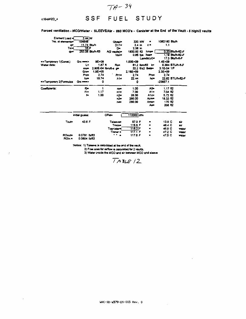
S S F F U E L S T U D Y
Forced ventilation • MCO/Watar - SLEEVE/AJr - SSO MCO's - Canister at the End of tht Vault - 5 hlgh/2 vaults
Element Load •(."No. of eietnente*
3.44 W104346
11.74 Btu/h351F
253.58 Btu/WO
Qtotal*D17-t>
A(2 vaults)*Vair*
•>Temporary 1 (Const)Water date:
•>Tamporary 2(Formulas Grx >
Gn — > 9E+O9L- 1.S7 ft Ro-
mu- 2.90E-04 fbm/ft-s g-Grx- 15E+09Pnt« 2.74 ' Prl"hx- 19.74 h1«
320 kW •2.4 in c «
2.06 in1920.00 «2 hms-
0.95 fps h t t -Lamda(ur)a
1.00E+09S1J Ibmflt3 k-322 (Vs2 B«ti"
Pre-
1092160 Btu/h1.1
2.7422.44
0
1.19 Btu/h-fl2-F17.3 Btu/h-A-F
1.4E+090.364 BTLWh-n-F
3.1E-04 1/F2.3E+Q9
2.7422.82 BTU/h-«2-F
•23857.1
Coefficients: (0-f 1 -
f»
11.171.00
nx«m»n2-n3-n4-
1.007.00
28.00280.00280.00
A0-A1-
A1e-Acm"Am$»
As-
i.i7 ie7.04 R25.72 «2
18.33 f!2170 92208 «2
Initial guess:
Tout- 43.6 P
CFM- 110000lcfm
Tmco"
TinnerROout>ROin-
0.0791 Ib/R30.0604 Ibrft3
57.0 F118.8 F
TTeDF117.1 F117.6 F
13.8 C46.4 C46.8 C472 C47.5 C
airairwaterwaterwater
Notice: 1 )Tsieeve is calculated at fee end of the vault2) Free area for airflow is calculated for 2 vaults.3} Water inside the MCO and air between MCO and sleeve
/Z.
WHC-SD-W379-ES-003 Rev. 0

c:\Sidd\2D 4 S S F F U E L S T U D Y
Forcad vantilation - MCO/Watar - SLEEVE/Alr - JSO MCO's - Canlstar at tha End of tha Vault • 5 hlgh/2 vaults
Element Load 1 3.44 |W'No. of elements- 104846
q- 11.74 Btu/hTirH 35 |Fqx- 253.58 Btu/MO
• > Temporary 1 {Const) Gnc « > 9E+09Water data: L- 1.87
mu- 2.90E-04Gnc- 1.5E+09Pnc 2.74hx- 19.74
• » Temporary 2(Formutas Gnc " • > 0
Coefficient; fO" 1f i - 1.17
f" 1.00
Initial guess:
Tout- 42.9 F
ROout- 0.0792 1MBROin - 0.0804 Ib/fO
Qtotat—0 1 7 -
OA<2 vautts)-
Vair-
(t Ro-Ibtn/ft-s g»
Pr1 -h i -
nx-n1-n2-n3*n4->
CFM« f~
Tsieeve-Tmco-
Tcanister^Tinner-
* * a
3202.4
2.061920.00
1.04
1.XE+0961.232.2
2.16E+O92.74
22.440
1-007.00
26.00280.00280.00
120000
56.0114.6
kWininfC2fps
•C "
hms-hsa-
Lamda(ur)-
IbnVRS tc-fl/s.
cfm
FF
115-4|F116.2116.7
FF
Beta-
Pre-hc-
A0-A 1 -
A1c-Acm-Ams-
As-
1092160 Btum1.1
Q.33!BtU/h-ft2-F^2^ atu/h-«-F17.3 Otiflhit-F
1.4E+090.384 BTUm-ft-F
3.1E-04 1/F2.3E+O9
2.7422.82 BTU/h-ft2-F
-23669.1
1.17 ft27.04 ft25.72 ft2
18.33 KZ170 ft2208 ft2
13.3 C aif45.9 C air46.3 C water46.7 C water47.0 C water
Notice: 1) Tsleeve is calculated i t the end of the vault2) Free area for airflow is calculated for 2 vaults.3) Water inside the MCO and air between MCO and sleeve
TAILS
UHC-SD-U379-ES-003 Rev. 0

c:\Sidd\2D 4 S S F F U E L S T U D Y
Forced ventilation - MCO/Water - SLEEVE/Air • 880 MCO's - Canister at ttit End of th* Vault - 5 high/2 vaults
Element Load * 3.44 W"No. of elements- 104846
q- 11.74 Btu/hTin^ 35 IFqx- 253.58 Btu/h-«3
•>Temporary 1 (Const) Grx «—> 9E+09Water data: L- 1.87
mu- 2.90E-04Grx- 1.5E+09Prx- 2.74hx- 19.74
•>Tempofary 2(Fonnutas G« •« •> 0
Coefficient: K> 1fl« 1.17f- 1.00
Initial guess:
Tout- 42.3 F
ROout- 0.0793 Ib/KJROm * 0.0804 IMG
Qtotei*D17-D-
A(2 vaults)-Vair-
ft Ro-Ibmflt-* g>
Pr1-h i -
ruont«n2-n >n4>
CFM- [~
Ts laevTmco"
TcantsterJTinner-
" " a
3202.4
2.061820.00
1.13
1.00E+09612322
2.16E+092.74
22.440
1.007.00
26.00280.00280.X
kWininK2fps
•
c -
hms> |h*a«
Lamda(ur)-
Ibm/fO k"ft/s2
130000!cfm
552113.8114.6115.4115.9
FFFFF
8etv
Prc-hc-
A0-A1"
A1c-Acm-Arns"
As-
1092160 Btum1.1
0.33IBtu/h-ft2-F123 Btu/h-ft2-F17 3 BtUh-ft-F
1.4E*090.384 BTLWh-ft-F
3.1E-O4 1/F23E+-09
2.7422.82 BTU/h-ft2-F
-235052
1.17(127.04 ft25.72 ft2
18.33*2170(12208 ft2
12.9 C air45.4 C air45.8 C water46.3 C water46.5 C water
Notica: 1 }Tsla«vt is calculated at tha and of 1h« vault2) Fra* araa for airflow is calculated for 2 vaults.3) Water inside the MCO and air between MCO and sleeve
UHC-SD-W379-ES-003 Rev. 0

37
c:\Sidd\2D 4 S S F F U E L S T U D Y
Forced ventilation - MCO/Water - SLEEVE/Air • 880 MCO's - Canister at the End of the Vault - 5 hlgh/2 vaults
Element Load ^'No. of elements*
q-Tin-[qpc-
•>Tamporary 1 (Const)Water data:
10484611.74 Btu/h
35lF253.58 8tu/h-ft3
Qtotat-D17-
r>A<2 vaults)-
Vair-
c *
hmamhsa>
•> Temporary 2{Formulas Grx'
Grx — > 9E+09L- 1.87 ft Ro-
mu- 2.90E-O4 Ibm/R-s g -Grx* 1.5E*09PTX- 2.74 Pr1«hx- 19.74 h i -
0
320 kW2.4 in
2.06 in1920.00 ft2
1.22 fps
Lamda(ur)"1.00E+09
S1.2 IbrrVKJ k-32.2 Ws2 B«te-
2.16E+092.74 Prc-
22.44 ho0
10921601.1
0l3|Btu/h-ft2-F1.25 Btu/WB-F17.3
14E*O90.384 STU/h-n-F
3.1E-04 1/F2.3E*09
2.7422.82 8TU/h-ft2-F
-23360.3
Coefficients: fO"f i *f-
11.171.00
FIX*
0 1 -n2-n3>n4-
1.007.00
28.00280.00280.00
A0*A 1 -
A1c-Acm-Ams-
As*
1.17 R27.04 It25.72 ft2
18.33 112170(12208 fC
Initial guws:
Tout" 41.8 F
CFM- 140000 cfm
Tmco-TcanisttnT
Tinnar«
54.5 F113.1 F113.9 F
ROout- 0.0794ROin • 0.0804 Ib/K3
114.6 F115.2 F
12.5 C45.0 C45.5 C45.9 C46.1 C
airairwatarwatarwater
Notice 1)T»toav» is ealcuiatad «ttha and ofthavault2) Fra« araa for airflow is calculated for 2 vaults.3) Water inside lha MCO and air between MCO and sleeve
TA VLJT /}
UHC-SD-W379-ES-003 Rev. 0

c:\Sidd\2D 4 S S F F U E L S T U D Y
Forced ventilation - MCO/Wat*r - SLEEVE/AIr - 880 MCO's - Canister at the End of the Vault - 5 hlgh/2 vaults
Elamant Load «T*No, of aianwnts-
V
•>T»moonuy 1 (Const)Water data:
->Tampormry 2(Formulas
Coafficwnts:
3.44 W10*646
11.74 Btu/h35 IF
253.58 Btu/MO
Gix—-> 96+09L- 1.87
mu- 2.906-04Got- 1.5E+Q9Pnc 2.74hx- 19.74
Gnc—•> 0
fO- 1M - 1.17
f- 1.00
fnitiaJ guass:
Tou^
ROout*ROin*
41.3 F
0.0794 IMO0.0804 Ibfl3
OtDtSl-017-
OAC vaults)-
Vair-
ft Ro-ibmfll-s g-
P r i -M -
« ( •n 1 -n2«n >n4-
CFM- f~
Tsla«va«Tmco-
Tcanotsr^Tinnsf-
• • •
3202.4
2.061920.00
1.30
1.00E+0961.2122
2.16E+032.74
22.440
1.007.00
28.00280.00280.00
150000
53.9112.5
KWininK2fp»
c -
hms" |hsa-
Lamda(ur)-
IbrMO k»fl/»2
cfm
FF
113.3 |F114.0114.5
FF
BMi-
FTC-
hc-
A0-A1«
A1c-Aem-Ams-
As*
1092180 Btu/h1.1
0.33|BWh-ft2-F1.26 Btu/twfQ-F17.3 BUh-n-F
1.4E+O90.384 BTU/h-ft-F
3.1E-04 1/F2.3E+09
2.7422.82 BTUrtv«2-F
-23230.8
1.17 fO7.04 R25.72 f£2
18.33 fG170 ft2206 R2
12.1 C air44.7 C air4S.1 C watsr45.5 C watar45.8 C water
Note*: 1) T S I M V * is calculated at th« «nd of th« vautl2) Fr«« arta for airflow is calculated for 2 vaults.3) Watar insid* th« MCO and lir batwaan MCO and slatvt
* I
UHC-SD-U379-ES-003 Rev. 0

c:\Sidd\2D 4 S S F F U E L S T U D Y
Forced ventilation - MCO/Water • SLEEVE/AIr - 880 MCO'i - Canister at tht End of the Vault - 5 hlgh/2 vaults
Et*m«nt Load H 3.44 jW'No. of •laments- 104846
q» 11.74Tin>i 35qx- 253.56
->T«mporary 1 (Const) Gnc • — >Water data: L-
mu"Grx"Pne«hx-
•>Temporsry 2(Formulss Grx • • • >
Coefficients: CO"f1»
f-
Initial guess
Tout- 40.9
ROoiit" 0.0795ROm > 0.0804
Btu/hF8tu/h-rt3
9E*091.87
2.90E-041.5E+O9
2.7419.74
0
11.171.00
F
b/fObft3
Qtotal*D17«D-
A<2 vsurts)-Vair*
ft Ro-Ibin/Tt-s fl"
Pr1-M -
nx-n 1 -n2-n3-n4*
CFM- (~
Tsltevw*Tmco"
Tcanister-jTmnt •
3202.4
2.061920.00
1.39
1.00E+096 U32-2
2.16E+092.74
22.440
1.007.00
28.00260.00280.00
160000
53.3111.9
kWininR2fps
C "
hms" |hsa-
Lamda(ur)*
Ibm/R3 k-ft/s;
cftn
FF
112.7IF113.4113.9
FF
B«ta-
Pre-hc-
A0-A T
A1c-Aem*Ams«
As-
10921601.1
Btu/h
0.33|Btu/h-«2-F1.2617.3
1.4E+090.364
3.1E-042.3E+09
2.7422.82
-23113.9
1.177.045.72
18.33170208
11.844.344.845.245.5
Btu/h-R2-FBtu/h-ft-F
BTU/h-ft-F1/F
BTU/tvfG-F
(12ft2ft2ft2iaK2
C airC airC waterC waterC water
Notice 1 ) T S I * « V « is calculated at th*«nd of the vault2) Fr«« area for airflow is calculated for 2 vaults.3) Water insid* th« MCO and air b«tw«*n MCO and sl«*v«
WHC-SD-W379-ES-003 Rev. 0
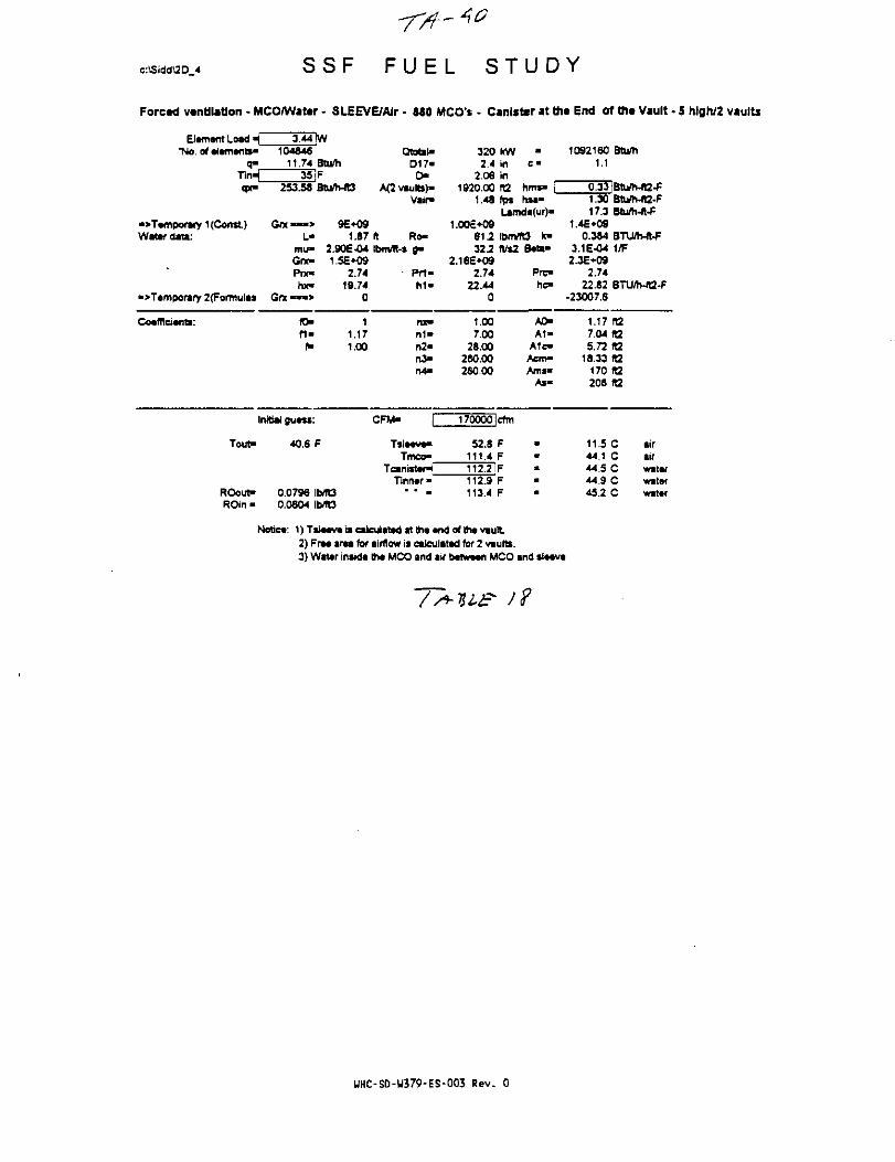
c:\Sidd\2D 4 S S F F U E L S T U D Y
Forced ventilation - MCO/Wattr - SLEEVBAIr - 580 MCO's - Canister at th* End of tti« Vault - 5 hlgh/2 vaults
Element Load _ 3.44 [W'No. of elements- 104846
11.74 Btu/h
qx- 253.58 Btu/n-fG
QtobND17«
D"A(2 vsults)-
Vair-
320 kWc "
• > Temporary 1 (Const)Water da«:
•>T»mporary 2(Formulas Gnc >
Got — - > 9E+09L- 1.87 It Ro»
mu- 2.90E-04 ibmfl-s fl-Gnc 1.5E+09Prx- 2.74 Prt'hx- 19.74 h i -
0
2.4 in2.06 in
1920.00 ft2 hms- [1.49 fps hsa-
Ljmd«(ur)«1.00£*09
612 IbmrfO k-32.2 (Vs2 8«ta-
2.16E*092.74 Prc-
22.44 he-0
1092160 Btu/h1.1
0.33 Btu/h-ft2-F1.30 Btu/MB-F17.3 BtuAt-ft-F
1.4£*090.3*4 BTUh-ft-F
3.1E-04 1/F2.3E+09
2.7422.82 BTU/h-«2-F
-23007.6
Coefficient: f O
n-1
1.171.00
nx»n1—o2*o3—n4>
1.007.00
28.00280.00280.00
A0-A1-
A1c-Acm-Ams«
As-
1.17 ta7.04 fa5.72 ta
18.33 ft2170 K2208 It2
Initial guess:
Tout- 40.6 F
CFM- 170000 cfm
Tmco-anisttpTinner
52.8 F111.4 F
ROout"ROin«
0.0796 IMt30.0804 IME3
2J112.9 F113.4 F
11.5 C4-4.1 C44.5 C44.9 C45.2 C
airairwaterwaterwater
Notice: 1) Tsleeve is calculated at the end of the vault2) Free area for airflow is caJculated for 2 vaults.3) Water inside the MCO and air between MCO and sleeve
UHC-S0-U379-ES-003 Rev. 0
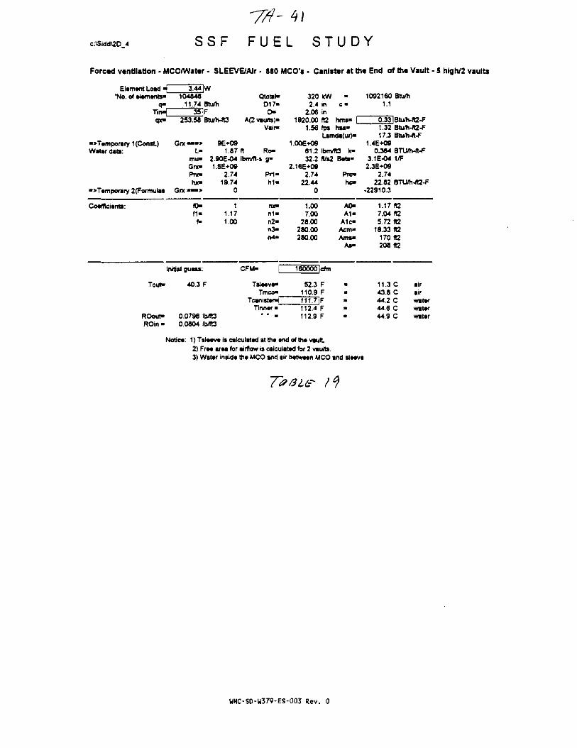
c:\Sidd\2D 4 S S F F U E L S T U D Y
Forced ventilation - MCO/Wattr - SLEEVE/AIr • 880 MCO's • Canister at the End of tht Vault - 5 high/2 vaults
Element Load *i 3.44 JW'No. of elements- 104846
q- 11.74 Btu/hTirH 35 Fqx» 253.58 Bturti-fO
•>Temporary 1 (Const) Grx ™ > 9E+09Water data: L- 1.87
mu- 2.90E-04Grx- 1.5E+09Pre- 2.7'4hx» 19.74
•>Temporary 2(Formuias Grx •» •> 0
Coefficients: CO- 1M- 1,17
f- 1,00
Initial guess:
Tout- 40.3 F
ROout> 0.0796 Ib/TOROin - 0.0804 Ib/R3
Qtotal"D17-D-
A(2 vaults)"Vsir*
ft Ro-Ibmffl-s g-
Pr i -M «
nx-n 1 -n2-n >n4>
CFM-
Tsleeve-Tmco-
TcanistenJTinner «
• • •
3202.4
2.061920.00
1.56
1.006+0981.232.2
2.16E+092.74
22.440
1.007.00
26.00280.00280.00
180000
52.3110.9
kWinin10fps
•
c«
hms- |nsa-
Lamda(ur)-
lbm/ft3 k-(t/s2
cfm
FF
111.7JF112.4112.9
FF
Beoi-
Prc-hc-
A0-A1-
A1c«Acm-Ams«
As-
••a
a
*
1092160 Btu/h1.1
0.33!Btum-ft2-F1.32 Btu/h<A2-F17.3 Btu/h-ft-F
1.4E+O90.384 BTU/h-ft-F
3.1E-04 1/F2.3E+09
2.7422.62 BTU/h-ft2-F
•22910.3
1.17(07.04 R25.72 fl2
18.33 ft2170 ft2208 ta
11.3 C air43.8 C air44.2 C water44.6 C water44.9 C water
Notice: 1) Tsleeveis calculated at the end ofthe vault2) Free area for airflow is calculated for 2 vaults.3) Water inside the MCO and air between MCO and sleeve
UHC-SD-W379-ES-003 Rev. 0

c:\Sidd\2D 4 S S F S T U D Y
Forced vantffatfon - MCO/Water - SLEEVE/AJr - 860 MCO's - Canlsttr at th« End of tfw Vault - 5 high/2 vaults
Elamant Load ^'No.
T44IW104646
11.74 Stu/h35F
q x - 2 5 3 . 5 6 Btu/h-ft3
Qtotal"0 1 7 -
D-A(2 vauta)-
Vair-hms-hsa-
•>Tamporary 1 (Const)Watar data:
•>Tamporary 2(Formukas
Gnt - « • * 9E+09L- 1.87 It Ro-
mu- 2.90E-04 IbrtVYt-s fl»Grx« 1 5E+09Prx» 2.74 PM«hx« 19.74 h i -
G(X"«-> 0
320 WV2.4 in
2.06 in1920.00 «2
1.65 fp»Lamda(ur)-
1.00E+O961.2 Ibm/TO fc"322 (t/s2 Bad-
2.16E*092.74 P r ^
22.44 hc-0
1092160 Btu/h1.)
0:33|Btu/h-ft2-f1.3417.3
0.3643.1E-04 1/F2.3E-KJ9
2.7422.62 BTU/h-«2^
-22820.5
Cotfficwn*: 10-f Uf-
11.171.00
nx»Hi ™
n3-rv4>
1.007.00
26.00280.00260.00
A0-A1"
A1c-Acm*Ama-
As-
1.17 IK7.04 ia5.72 IB
16.33 It2170 It2206 1)2
Initial guass:
Tout- 40.0 F
ROout-ROin-
CFM- 190000lcfm
Tmeo-Tcanistar*"
Tinn«r *0.07960.0804 Ib/ft3
51.8 F110.S F
TTTHF112.0 F112.5 F
11.0 C43.5 C44.0 C44.4 C44.7 C
airairwaterwatarwater
Noticr. 1) Tslacva is calculated at th« «nd of th* vault2) Fraa araa for airflow is calculated for 2 vaub.3) Water insida tha MCO and air b«twa«n MCO and slaava
za
UHC-SD-W379-ES-003 Rev. 0

S S F F U E L S T U D Y
Forced ventilation - MCO/Wattr - SLEEVBAlr - S80 MCO's - Canister at tht End of th« Vault - 5 hlgh/2 vaults
Elemant Load \_ 3.44 IW'No. of elements- 104846
q« 11.74Tin-( 35qx> 253.58
•>Temporary 1 (Const) G n « n >Water data: L«
mu«Giv*Prx-to*
«>Temporary 2(Formulas Grx • • • >
Coefficients: fO*f i -
Initial guasi:
Tout" 39.7
ROout- 0.0797ROin - 0.0804
Btu/hFBtu/h-fQ
9E+091.87
2.90E-041.5E+0S
2.7419.74
0
11.171.00
F
b/Tt3b/ft3
Ototst-D17-0-
A(2 vaults)-Vai f
ft Ro-Ibm/ft-s 8"
Frl-M -
nx-n1>n2-n3-n4»
CFM- (~
Tsleeve>Tmco"
TcanisteHTinner •
3202.4
2.061920.00
1.74
1.00E*09612322
2.16B+O92.74
22.440
1.00.7.0028.00
280.00280.00
200000
51.4110.0
kWininft2fps
•
hms* |hsa-
Lamda(ur)-
Ibm/ft3 fc-ft/s2
crtn
FF
110.8 IF111.6112.1
FF
Beta**
Prc*hc-
A0-A1»
A1c-Acm*Ams"
As-
10921601.1
0.331.3517.3
1.4E+O90.384
3.1E-042JE*O9
2.7422.82
-22737.3
1.177.045.72
18.33170208
10.843.343.744 244.4
Btum
Btum-lt2-F8tu/h-ft2-fBtunvn-F
BTUftvfl-F1/F
BTU/h-fB-F
ft2ft2ft2fQft2ft2
C airC airC watarC watarC water
Notica: 1)Tsla«va is calculated atthaandofthavault2) Ft— araa for airflow is ealculatad for 2 vaults.3) Watsf insida Iha MCO and air b«tw*en MCO and sieeva
£ 2/
UHC-SD-W379-ES-003 Rev. 0

c:\Sidd\2D 4 S S F F U E L S T U D Y
Forcad ventilation - MCO/Wator - Stova/Alr - 880 MCO's - Canister at th« End of th< Vault - 5 hlgh/2 vaults
Element Load «Q'No. of dements"
q j -
qx»
•oTemporary 1 (Const)Water data:
•>Temporiry 2(Formulas
Coefficients:
3.44 [W104846
11.74 8tu/h50 |F
253.56 Btu/h-fO
Gfx • *»> 9E+09L- 1.87
mu- 2.90E-O4Gne 1.5E+09Pnc 2.74hx" 19.74
G r x — » 0
fT> 1« - 1.17
f- 1.00
Initial guess:
Tout"
ROout-ROin»
54.2 F
0.0775 IbfflS0.0781 Ib/ft3
QtotaHD17-
D-A(2 vautts)-
Vatr-
It Ro-IbnVR-s g-
F T 1 -h 1 -
nx"n1»n2-n3-n4m
CFM- f
Tsleeve-Tmco-
Tcanister^Tinn«r •
* " B
3202.4
2.061920.00
2.00
1.00E+096 1 ^322
2.16E+O92.74
22.440
1.007.00
28.00280.00280.00
230000
65.5124.1124.9125.6126.1
kwininft2fpa
C "
hms> |hsa«
Lamda(ur)«
ibnvTC) k»K%2
cfm
FFFFF
Beta*
Pre-hc"
A0-A 1 -
A1c»Acm-Ams"
A»-
10921601.1
0.331.4117.3
1.4E+080.384
3.1E-042.3E+09
2.7422.82
-25586.7
1.177.045.72
18.331702Q8
18.651.151.552.052.2
Btu/h
iBtu/h-fB-FBtu/h4Q-FBtu/h-ft-F
BTUrtWt-F1/F
STU/h-fQ-F
ft2A2faR2(t2ft2
C airC airC waterC waterC water
Notic*: 1)TSJMV« is calculated at tfiacnd of th« vault2) FrM ar*a for airflow is calculated for 2 vaults.3) Water inside the MCO and air between MCO and sleeve
Table ZZ
WHC-SD-U379-ES-003 Rev. 0

c:\Sidd\2D 4
-fit'**S S F F U E L S T U D Y
Forced van til a don - MCO/Watar . Sl«av«/Ajr - 880 MCO's - Canister at th* End of ttia Vault - 5 high/2 vaults
Elam«ntLoad4 3.44 [W'No. of •lamants- 104846
q- 11.74 Btu/hTirH 50 |F(pc- 253.58 S U M O
->Tamporary 1 (Const) Gnc««« 9E*09Watar data: L> 1.87
mu- 2.90E-04GfX- 1.5E+09PTX" 2.74rot" 19.74
•>Tamporary 2(rTormuias Gn •« •> 0
Coafflciants: fO" 1f i - 1.17f- 1.00
Initial guass:
Tout* 53.7 F
ROouf 0.077S IMt3ROin- 0.0781 IhffB
Qtotah*D17-D-
A<2 vaults}-Vair-
ft Ro-Ibmitt-s g>
h i -
nx-n1-n2*n3-M -
CFM- f
Tsiaava>Tmco-
Teanistar^Tinnar •
• • •
3202.4
2.061920.00
2.26
1.OOE-H3961.232.2
2.16E+092.74
22.440
1.007.00
26.00280.00280.00
260000
64.6123.2124.0124.7125.2
kWininft2fpa
•
c -
hma» \hsa*
Lamda(ur)-
ibm/fO k>ffs2
cfm
FFFFF
Bate-
Prc-hc-
A OA1«
A1c-Acm«Am»«
As-
10921601.1
1.4617.3
1.4E*090.384
3.1E-042.3E+09
2.7422.32
-25401.7
1.177.045.72
18.33170208
18.150.651.051.551.7
Btu/h
iBtuftv-fB-FBm/tl-ft2-FBtu/h-frF
BTU/h-«-F1 ^
BTU/h-ft2-F
R2ft2ft2ft2A2ft2
C airC airC watarC watarC watar
Notiea: 1)Tslaavaiseaiculatadatthaand of thavautt2) Fraa araa for airflow is calculated for 2 vauttt.3) Watar insida tha MCO and air batwaan MCO and slaava
Table
HHC-S0-W379-ES-003 Rev. 0

c:\Sidd\2D_4 S S F F U E L S T U D Y
Forced ventilation • MCO/Water - Slt*v«/AJr • 880 MCO's • C*nlst«r at th« End of tfi* Vault - 5 hlgh/2 vaults
Element Load * 3.44 !W'No. of elements' 104046
q» 11.74 Btu/hTkH 50 IFqx- 253.58 Btu/h-fD
->Temporary 1 (Const) Gnc»™> 96+09Water data: L" 1.87
mu- 2.90E-O4One- 1.5E+09Pne 2.74hx- 19.74
->Temporary 2(Formulas Grx«»-> 0
Coefficients: fl> 1f 1 - 1.17
f- 1.00
Initial guess:
Tout- 53.2 F
ROout- 0.0777 Ib/fOROin« 0.0781 Ib/fO
Qtotal-D17-D-
A(2 vaults)-Vain»
ft Ro-Ibm/ft-s B"
- Prt-h i "
nx"n1"n2-n3«n4>
CFM- P
Tala««.Tmco*
Tcanister^Tinner"
* " «
3202.4
2.001920.X
2.60
i.ooe*o96 1 ^322
2.16E-KS2.74
22.440
1.007.X
28.X280.X280.X
300X0
63.6122.2122.9123.7124.2
kWininfl2rps
•C "
hms« |hsi"
Lamda(ur)B
IbnVfU k>
cfm
FFFFF
Setaa
Pre-he-
A0-A1»
A1e«Acm«Am$-
As-
1092160 Btu/h1.1
0.33|Btu/h-lt2-F1.54 Btu/h-ia-F17.3Bturti-ft-F
1.4E+090.384 BTU/h-ft-F
3.1E-04 1/F2.3E-KJ9
2.7422.82 BTLVh-ft2-F
-25197.1
1.17(127.04 fQ5.72 R2
18.33(12170 ft2208 fl2
17.5 C air50.0 C air50.5 C water50.9 C water51.2 C water
Node*: 1}Tsl*v4isealculatodatth«*ndof»«vault.2) Fr#« area for airflow is calculatad for 2 vaulb.3) WaMr inside th* MCO and air bMwMn MCO and sl««va
Table
UHC-SD-U379-ES-003 Rev. 0

c:\Sidd\2D_4 S S F F U E L S T U D Y
Forced ventilation - MCO/Water • Sleeve/AJr - 880 MCO's • Canister at the End of the Vault - 5 hlgh/2 vaults
Element Load \_'No. of elements"
VT t n ^qx-
• > Temporary 1 (Const)Water data:
•>Temporsry 2(Formulas
Coefficients:
3.44 IW104846
11.74 Btum50 |F
253.58 Btu/h-IB
Gnc«sa> 9E+09L- 1.87
mo- 2.90E-04Gnc 1.5E+09Pnc- 2.74hx- 19.74
G r x — > 0
(0- 1H - 1.17
f- 1.00
Initial guess:
Tout"
ROout-ROin*
52.8 F
0.0777 Ib/ft30.0781 IWB
Qtotal-D17«
OA(2 vaults)-
Vair-
ft Ro-Ibm/ft-s g-
Pr1«rt1«
nx«m«n2-n >rt4»
CFM- |~
Tsle»«-Tmco-
Teanister^Tinner •
• • •
3202.4
2.061920.00
3.04
1.00E+09617327
2.16E-O92.74
22.440
1.007.00
28.00280.00280.00
350000
62.5121.1121.9122.71237
kWininfC2fps
•c -
hms« |hsa>
Lamda(ur)"
tbm1t3 k-ft/s2
Cfm
FFFFF
Bebi>
FTC-hc-
A0-A 1 -
A 1 oAem-Ams«
As-
10921601.1
1.6317.3
1.4E+090.384
3.1 E-042.3E+09
2.7422.82
•24965.8
1.177.045.72
18.33170208
16.949.549.950.350.6
Btu/h
|Btu/h-ft2-FBtu/h-R2-FBtu/Mt-F
BTUm-tt-F1/F
BTUm-fl2-F
fO.92TO.faIt2R2
C airC airC waterC watarC water
Nobca: 1) Ttltavais calculated at tha and of the vault2) Fr*a araa for airflow is calculated for 2 vaulti.3) Watar inside the MCO and air between MCO and sleeve
Table
WHC-SD-W379-ES-003 Rev. 0
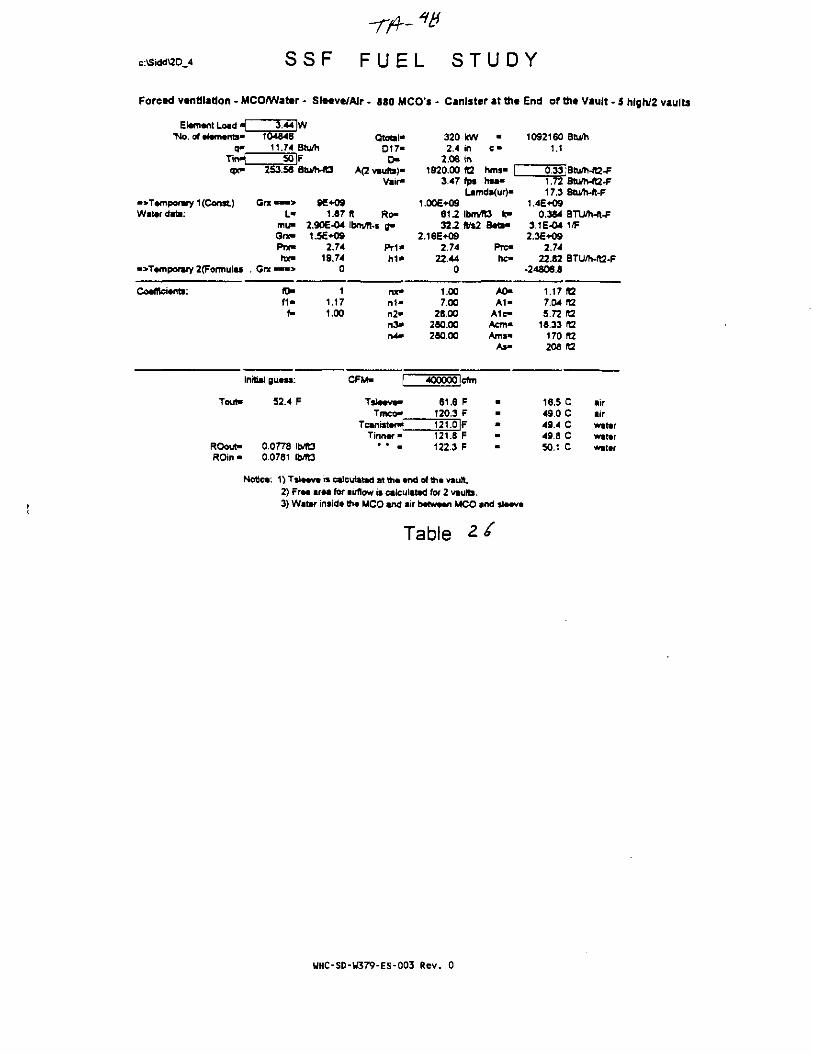
c:\Sidd\2D_4 S S F F U E L S T U D Y
Forced ventilation - MCO/Water - Sleeve/Air- 880 MCO's - Canister at the End of the Vault-5 hfgh/2 vaults
Element Load H 3.44 IW'No. of elements' 104046
a- 11.74 Btu/hTirH 50 IFqx» 253.58 Btu/h-A3
-> Temporary 1 (Const) Grx — • > 9E+09Water data: L" 1.67
mu- 2.90E-04Grx» 1.5E+09Prx- 2.74hx- 19.74
•>TemponMY 2(Foimulaj . Gnt«*"> 0
Coefficients: fO- 1f1« 1.17
f- 1.00
Initial guess:
Tout" 52.4 F
ROouf 0.0778 Ib/ft3ROin- 0.0781 |b/ft3
Qtotal-017«r>
A(2 vaults)*Vair-
ft Ro-ibm/ft-s B«
Pr1*h i *
nx»n i -n2»n3*n4*
CFM- f
Tsleeve"Tmco"
Tcantster^Tinner •
" * •
320 kW2.4 in
2.06 in1920.00 ft2
3.47 fps
•
C "
hms«hsa*
Lamd*(ur)-1.006+09
612 IbrrvYO k-322 fl/s2
2.16E*O92.74
22.440
1.007.00
28.00260.00280.00
400000 Icfm
61.6 F120.3 F121.0 IF121.8 F122.3 F
Bed-
Prc«hc-
A0«A1-
A1c-Acm»Am*"
As-
10921601.1
0.331.7217.3
1.4E+090.384
3.1E-042.3E+09
2.7422.82
•24806.8
1.177.045.72
16.33170208
16.549.049.449.850.1
Btu/h
:Btu/h-«2-FBtu/h-ft2-FBtu/h-ft-F
8TU/h-ft-F1/F
BTU/h-ft2-F
nzrararaft2ra
C airC airC waterC waterC water
Notice. 1)Ts1eeveiscalculitadatthe»ndofthevault2) Free area for airflow is calculated for 2 vaults.3) Water inside the MCO and sir between MCO and sleeve
Table
WHC-SD-U379-ES-003 Rev. 0
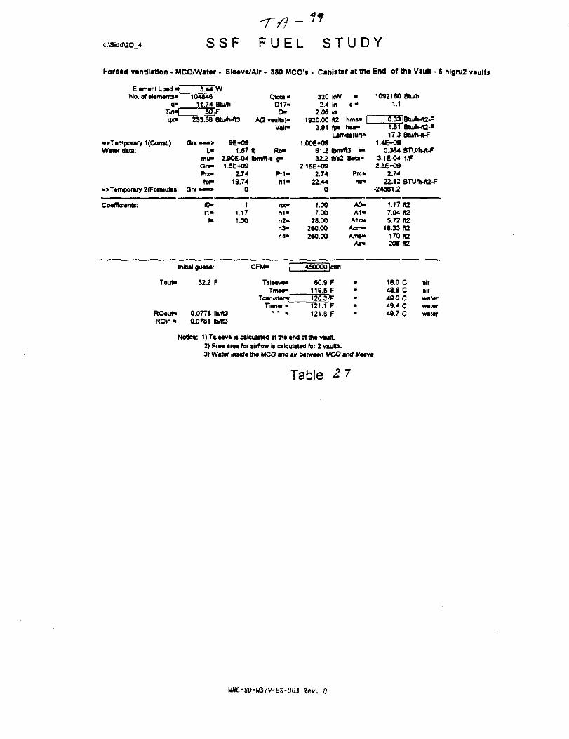
c:\Sidd\2D 4 S S F F U E L S T U D Y
Forced ventilation - MCO/Water • Sle«v«/Air - SSO MCO's - Canister at the End of the Vault - S hJgh/2 vaults
Element Load ^_ 3.44 |W'No. of elements- 104846
q- 11.74TirH 50qx- 253.58
"Temporary 1 (Const) Gix -« •>Water data: >
mu>Gcc-P T X -
hx«"Temporary 2(Fonnutas Gnt «•«>
Coefficients: ff>M -
( •
Initial guess
Tout* 522
ROout» 0.0778ROin * 0.0781
Btu/hFStuarts
9E+091.87
2.90E-O41.5E+O9
2.7419.74
0
1.171.00
F
b/ft3b/ft3
Qtatal-017-
CKA(2 vaults)-
Vtir-
ft Ro-IbfMt-s g-
Pr i -h 1 -
nx-n1«n2-n3«n4>
CFM- |~
Tsleeve*Tmco"
Tcanisten*Tinner"
* • *
3202.4
2 061920.00
3.91
1.00E+09610.32.2
2.16E+092.74
22.440
1.007.00
28.00280.00280.00
450000
60.9119.5(20.3121.1121.5
kW -in c«i(\ft2 nirts*fps hsa-Lifnda(ur)*
Ibnvtt3 k-ft/s2 Beta-
Pre*hc-
AO*A1*
A1c-AetrH*Ams«
As*
cfm
FFF -F •F -
1092160 Btu/h1.1
0.33IBtu/h-R2^1.81 BtWh-fC-F17.3 Btu/h-ft-f
1.4E*090.384 BTWMt-f
3.1E-04 1/F2.3E+09
2.7422.82 BTU/hJt2-F
-246612
1.17(127.04(t25.72 ft2
18.33 fa170(12208 itZ
16.0 C air48.6 C air49.0 C water49.4 C water49.7 C water
Notict: 1) Tsleev* is calculated at the end of the vauft2) Free area for airflow is calculated for 2 vaults.3) Water inside the MCO and tit between MCO and sleeve
Table
WHC-SD-W3r9-E5-003 Rev. 0

c:\Sid<i\2D_4
F o r e . d
S S F F U E L S T U D Y
s l w . W f - muan. e — — - - — * — " — -
•No. 01 elements- 10484611.74 Btu/h
Tin-[qx-
.>Tempoiary 1 (Const)Water data:
«>Temporary 2(Formulas
Coefficients:
~50]F253.58 Btu/h-«3
Qtotai"D 1 >
D-B)»
Vair-
G n ( « . > 9E+09L . 1.87 ft R»
m u - 2.90E-04 IbnVft-s 8"
hx- 1974 K
Grx—» °
320 KW -2.4 in c •
2.06 in1920.00 R2 hms- L
4.34 fps h » "Umd«(uf)-
1.00E+0961.2 Ibm/TO Ic"32.2 W B
2.16E-092.74
22.440
1092180 Btu/h1.1
17.31.4E*09
0.384 BTU/h-«-F3.1E-04 1/F2.3E*O9
22.82-24529.3
(0-11-
(-
11.171.00 n2«
n >n4-
1.007.00
28.00280.00280.00
A0>A1-
A1c-Aem«Ams«
As-
1.17 «27.04 «25.72(12
18.33 «2170 «2208 ft2
Tout" 51.9
Tinner1
15.7 C462 C48.7 C49.1 C49.4 C
•irairwmttfwaterwater
ROout«ROin-
0.0778 IMt30.0781 IMt3
Notice: 1) Tsleeve is calculated at the «nd of the vault2) Free area for airflow is calculated tor 2 vaults.3) Water inside th* MCO and air between MCO and sleeve
Table 2 1
WHC-SD-W379-ES-003 Rev. 0

c:\Sidd\2D_4 S S F F U E L S T U D Y
Forced ventilation - MCO/Water - Slt«v«/AJr - 880 MCO's - Canlst*r at th* End of the Vault - 5 hfgh/2 vaults
Element Load H 3.44JW'No. of elements* 104946
q- 11.74 Btu/hTinH 50 IFqx- 253.56 Btu/h-«3
•>TemporaiY 1 (Const) Grx • • - > 9E+09Water date: L- 1.87
mu» 2.90E-04Gno 1.5E+09PTX- 2.74hx» 19.74
•>Temporary 2(Formulas Grx«"«> 0
Coefffciente: f0» 1f 1 - 1.17
f- 1.00
Initial guess:
Tout- 1565 F
RObut- 0.0643 Ib/R3R a n - 0.0781 Ib/ta
Qtotel-D17-
r>A(2 vaults)"
Vnr-
ft Ro-Ibmfl-s g*
P r i *hi*
nx*n i -n2-n3-rv4-
CFM- P
T^tev^Tmco-
Tcantsten^Tinner-
3202.4
2.061920.00
0.09
1.00E+09612322
2.16E+O92.74
22.440
1.007.00
26.00260.X280.00
10000
1722230.9231.6232.3232.8
kWininft2rp*Lam
•
c -
hms- |hsa*da(ur)-
IbnVftJ *c—tt/i2
cfni
FFFFF
Bcta*
Prc-hc-
A0-A 1 -
A1c-Aem>Ams»
As-
1092160 BtUh1.1
0.33|BtuAi-ft2-F1.01 Btu/h-ft2-F17.3 Btu/h-ft-F
1.4E+090364 BTU/h-ft-F
3.1 E-W 1/F2.3E+09
2.7422.82 BTU/h-IB-F
-47237
1.17 «27.04 R25.72 «2
16.33 ft2170 «2206 (12
77.8 C air110.3 C air110.8 C water1112 C water111.5 C water
Notice: 1) T S I M V * is calculated at th«*nd of th* vault2) Fr*a ama for airflow is calculated for 2 vaults.3) Water insid* th* MCO and air b«WHn MCO and S I M V *
Table
T canister as a function of CFMWarn id MCO. Air in Sl«*v*
• Tin * 35 P
•» Tin* 50 P
T00W 30000 S0000 70000 WOOO20000 40000 <0000 MOOD 1CW*
130000 190000 1T0OO0 190000» 0 140000 160000 160000 200000
HHC-SD-W379-ES-003 Rev. 0

c:\SiddttD_4 S S F F U E L S T U D Y
Forced ventilation - MCO/Wattr • SI««v«/AJr - 880 MCO's - Canister at ttit End of th« Vault - 5 hlgh/2 vaults
Element Load ^ 3.44 |W'No. of elements- 104846
q- 11.74 BturtiT i H 50 |Fqx- 253.M Btu/h-ft3
•>Temporary 1 (Const.) Got — > 96+09Water dab: L- 1.87
mu- 2.90E-04Gnc- 1.5E+O9Prx- 2.74hx> 19.74
->Temporary 2(Fomiuias Got ™ > 0
Coefficients: ID- 1f i - 1.17f- 1.00
Initial gueaa:
Tout- 100.8 F
ROout- 0.0710 Ib/lt3
Qtotal-D17-D-
A(2 vaults)-Vair-
ft Ro-Ibm/ft-s jp
Pri"h 1 -
nx"n 1 -n2*n3>n4-
CFM- |"
Tstowa-Tmco-
Tcantster^Tinner-
• * •
3202.4
2.061920.00
0,17
1.00E+09$-\2122
2.16E+092.74
22.440
1.007.00
26.00280.00280.X
20000
116.3174.9
kWininftZfp.
m
e -
hms- |hsa-
Lamda(ur)-
bm/RS k-Ks2
cfm
FF
175.7 IF176.4176.9
FF
BetiB
Pre-no-
A0-A 1 -
A 1 cAcm-An»-
As-
10921601.1
0.331.0317 J
1.4E+090.3*4
3.1E-042.3E+09
2.7422.82
-35891.6
1.177.045.72
16.33
Btu/h
8Ui/lvfl2-FBtufli-n-F
BTUflvft-F1/F
BTU/h-ft2-F
ft2ft2raft2
170 R2206
46.879.379.780.280.4
1t2
C airC airC waterG waterC water
ROin - 0.0781
Notic*: 1)Tsl«*v« is calculated atfta tnd of In* vautl2) Frtt ar«a few airflow » calculated for 2 vaults.3) Water insidt tht MCO and air between MCO and sleeve
Table 30
WHC-SD-U379-ES-003 Rev. 0
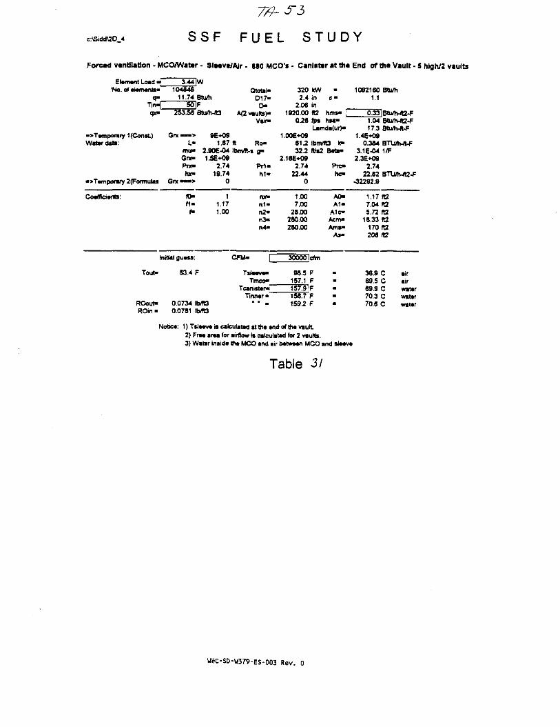
c:Stdd\2D_4 S S F F U E L ST UD
Forcad ventilation - MCO/Wattr • SI«*vt/AJr - 880 MCO's - Canister at th«
Element Load _'No. of elements*
q-Tin^]
•^Temporary 1 (Const.)Water date:
•> Temporary 2(Formulas
Coefficients:
3.44 IW104846
11.74 BtU/h50 |F
253.58 Btu/h-ft3
Grx — > 8E+O9L- 1.87
mu- 2.90E-O4G n - 1.5E+09Prx- 2.74roc- 19.74
Grx-—> 0
(0- 1f i - 1.17
f- 1.00
Initial guess:
Tou^
ROout-ROin-
83.4 F
0.0734 Ib/TE30.0781 IMO
Qtotat-017-
D*A(2 vaults}*
Vair-
ft Ro-Ibm/R-s fl"
P r i -h i -
we-n1*n2-n3-rv4-
CFM- \~
Tsteeve-Tmco-
Tcanister^Tinner •
• • •
320 kW2.4 in
2.06 in1920.00 ft2
026 fp%
-hms« |hsa-
Lamda<ur)-1.0OE+O9
612 Ibm/fES k*322 ft/s2
2.16E-KJ92.74
22.440
1.007.00
28.00260.00280.00
300001 cfm
96.5 F157.1 F157.9 F158.7 F1592 F
Beta-
PTC-rtc-
A0-A 1 -
Alc-Acm-Ams«
As-
Y
End of the Vault - 5 hlgh/2 vaults
10921601.1
0.331.0417.3
1.4E+O90.384
3.1E-O42.3E+O9
2.7422.82
•32292.9
1.177.045.72
18.33170208
36.969.569.970.370.6
Btu/h
IBtu/r>-ft2*FBtufh4t2^BtLth-ft-F
BTU/h-ft-F1/F
BTU/h-«2-F
ratara
rara
C airC airC waterC wtterC water
Notiea: 1) Tsf*«v« is calculated it th« and of th* vault2) FrM ar*a for airflow is calculated for 2 vautts.3) Water inside the MCO and air b « w « i UCO and sl««v*
Table 3/
WHC-SD-W379-ES-003 Rev. 0

c:\Stdd\2D_4 S S F F U E L S T U D Y
Forced vwittlatton - MCOAHatw - SlMvtfAir • MO MCO's - Canister i t tm End of * • Vault - 5 hlgn/2 vaults
Element Load H 3.44 JW'No. of elements" 104846
q- 11.74 atu/hTinH 50 IFqx> 253.58 BtWrMQ
">T*mporary 1 (Const) Got • — > 96*09Water data: L- 1.87
mu- 2.90E-04Gne 1.5E+09Prx- 2.74hx> 19.74
•> Temporary 2(Formulas Gnt • — > 0
Coefficient*: !0» 1f1« 1.17
*• 1.X
Initial guess:
Tou^ 74.8 F
ROout- 0.0746 IMt3ROin - 0.0761 1MQ
QtotahD17-D-
Aavautts)-Vair-
It Ro-lbm/lt*s a-
Prt-M -
nx»M -r»2-r»3-n4-
CFM-
Ttteeve"Tmco-
Tcantster"Tinner"
* " »
3202.4
2.061920.00
0.35
1.00E*096 U32.2
2.16E*092.74
23.440
1.007.00
28.0028000280.00
40000
89.7148.3149.1149.9150.4
kWininft2fps
*C "
hms* |hsa-
L*mda<ur)-
Ibirvtl/s2
rfm
FFFFF
«3 k-B«ta>
Prc-hc*
A0-A 1 -
A1c-Acm"Am*"
As-
1092160 Btu/h1.1
0.33|Btu/h-R2-F1.06 Bftj/h-ft2-f17.3 Bhj/Mt-F
1.4E+090.384 BTUMt-P
3.1E-04 1/F2.3E+O9
2.7422.62 BJU/MS-f
•30506.4
1.17(07.04 925.72 «2
18.33 IC170 ft2208 It2
32.0 C aiT64.6 C air65.0 C water65.4 C water65.7 C water
Notice: 1) Tsleeve is calculated at the end of the vaufL2} Free area for airflow is calculated for 2 vaults.3} Water inside the MCO and ait between MCO and *leeve
Table 3 Z.
WHC-SD-U379-ES-003 Rev. 0
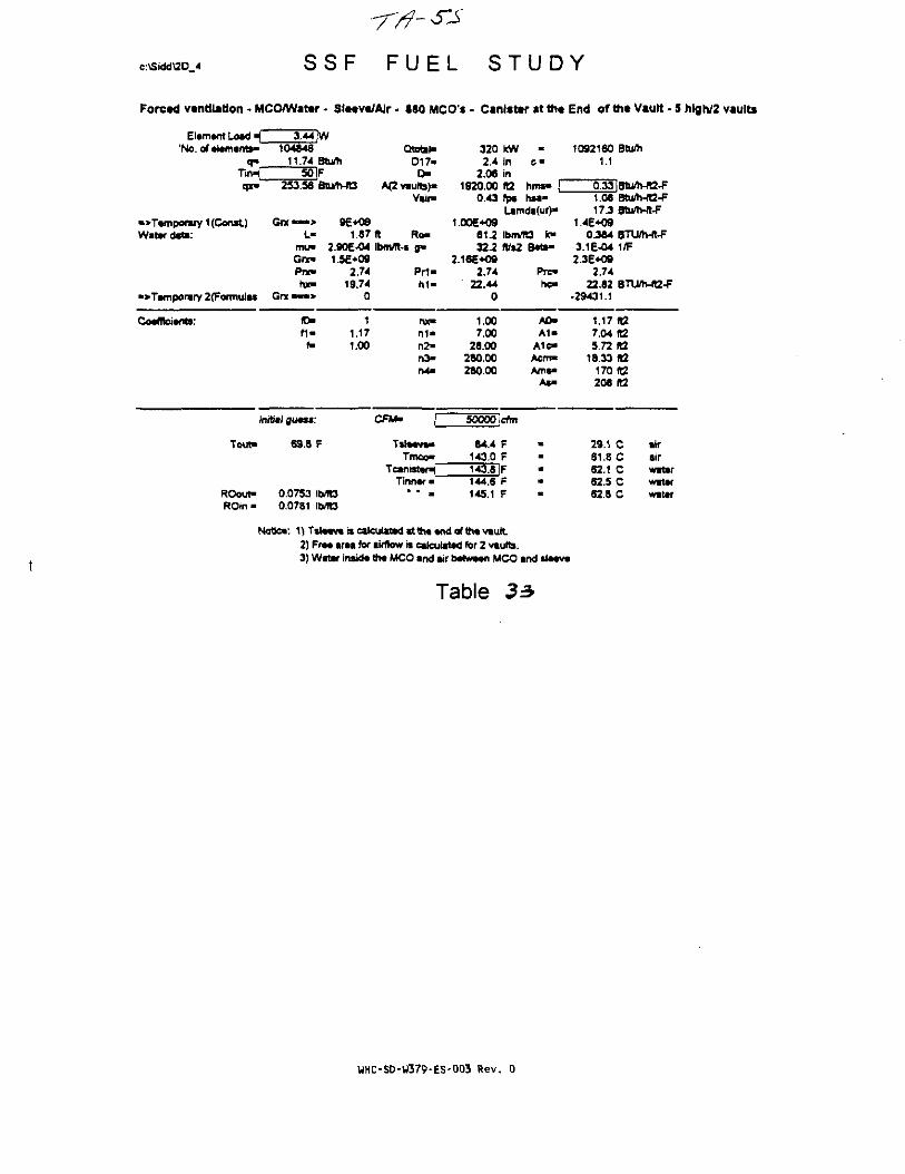
c:\Sidd\2D_4 S S F F U E L S T U D Y
Forced ventilation - MCO/Water - SlMve/Alr - 880 MCO's - Canister at the End of the Vault • 5 hlgh/2 vaults
Element Load _'No. of elements*
3.44 [W104846
11.74 Btu/ri50 IF
Qtotal-D17-
r>qx- 253.58 Btuft-ft3
V»ir-
•>Temporary 1 (Const)Water date:
>T«mporary 2(Fofmulas
G r x — > 9E+09L- 1.87(1 Ro-
mu- 2.90E-04 Ibmffi-s g*Gnc- 1.5E+09Pnt- 2.74 Pr1«hx- 19.74 h i -
320 kW •2.4 In c •
2.06 in1920.00 (Q hms» [
0.43 fps nsa-Lamda(ur)"
1.00E+O9612 Ibm/Tta k>322 fl/*2 B«ta-
2.16E+O92.74 Pre-
22.44 he-0
1092160 Btu/h1.1
1.08 Btu/h-ft2-F17J Stum-It^
1.4E+090 M4 BVJtMl-F
3.1E-04 1/F2.3E+O9
2.7422.82 BTU/h-«2-F
-29431.1
Coefficients: (D-f 1 -f-
11.171.00
nx-m-n2-n3-n4>
1.007.00
28.00280.00280.00
AO-A 1 -
A1c-Acm-Ams-
As-
1.17 Ifi7.04 ft25.72 (12
18.33 ta170 ft2208 (t2
Initial guess:
Tout- 69.8 F
CFM- 50000 cfm
Tslaeva-Troeo-
84.4 F143.0 F143.8 F
TinnwROout-ROtn-
0.0753 IMC30.0781 Ib/ft3
144.6 F145.1 F
29.1 C61.5 C62.1 C62.5 C62.8 C
iirairwaterwaterwater
1)TslMv«iscalcuixMdstth««ndQfth«vautL2) fr— araa for airflow is calculated for 2 vsutb.3) Watar insida th* MCO and air tMhvMn MCO and sl*«v«
Table 33
WHC-SD-U379-ES-003 Rev. 0

c:\Sidd\2D_4 S S F F U E L S T U D Y
Forced ventilation - MCO/Water - St«*ve/Air - 680 MCO's - Canister at the End of the Vault - 5 hlgh/2 vaults
Elamant Load «{_'No. of alamanb"
q>T i n ^qx-
•>Tamporaiy 1 (Const)Water data:
«>Tampon«y 2(Fomiulas
CoafReianti:
3.44 |W104846
11.74 Btu/h50 IF
253.58 Btu/h-JO
Gnt — > 9E+09L- 1.87
mu- 2.90E-04Gnt- 1.5E+09Pnc- 2-74hie 19.74
Grx>«> 0
fO- 1f i - 1.17f- 1.00
Initial guass:
TouH
ROout-ROin*
66.4 F
0.0757 IbvTO0.0781 lb/R3
Qtotal"D17-o
A(2vault»)-Vair«
ft Ro-IbrMt-s g*
pn«h i -
nx-n i -n2-n >n4-
CFM- p
Tmco"TanisterW
Ttnnar •* * •
320 kW2.4 in
2.06 in1920.00 ft2
0.52 fps
•
hms" |hsa*
Lamda(ur)-1.006*09
61J Ibm/(t3 tc>32-2 (Vs2
2.16E*O92.74
22.440
1.007.00
28.00280.00280.00
60000 Icfm
SO.&F139.4 F140.2 F141.0 F141.5 F
Bati*
Pro*hc>
A0-A1-
A1c-Acm«Ams>
As>
10921601.1
0.321.1017.3
1.4E+090.364
3.1E-042.36*09
2.7422.62
-28702.8
1.177.045.72
18.33170208
27.159.660.160.560.8
Stu/h
|Btu/h-ft2-FBtu/h-ft2-FBtu/Wt-F
STLUh-ft-F1/F
BTU/h-ft2-F
ft2ft2ft2raran
C airC airC waterC watarC water
Notiea: 1) Tslawa is calculated at tha and of th« vault2) Fra« araa for airftow is calculated for 2 vaults.3) Watar insida tha MCO and air batwaan MCO and slaava
Table 54
WHC-SD-W379-ES-003 Rev. 0
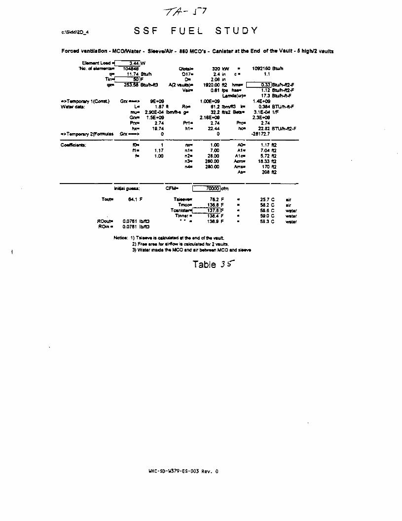
c:\StddU0_4 SSF FUEL STUDY
Forced ventilation - MCO/Wata
Elwnant Load _ 3.44
- Sle«v«/Alr - 880 MCO's - Canlsttv at th«
w'Na.of*l«m«nts« 104846
a- 11.74 Btu/hTinH 50 pqx- 253.58 Btu/h-fO
">T«mpor»ry 1 (Const) Gnt • — > 9E+09Water date: L- 1.87
mu- 2.90E-04Gne 1.5E+09Pnc 2.74hx- 19.74
• > Temporary 2(Formulas Grx • — > 0
Coafffcivnts: fO" 1f i - 1.17f- 1.00
Initial guass:
Tout" 64.1 F
ROout- 0.0761 Ib/R3ROin • 0.0781
Qtotat"D17-
D-A(2vauta)"
Vair-
A Ro>Ibm/ft-s ga
Priah1-
nx"n1*n2"n3»n4-
CFM- f
Tslaava*Tmco"
Teanister^Tmnar •
* * a
3202.4
2.061920.00
0.61
1.00E+09617327
2.16E+092.74
22.440
1.007,00
28 00280.00280.00
kw •in c"inft2 hn»" |fps hsa*Lamda(ur)a
Ibm/ltS k"
Prc"hc-
A0-A1"
A1c"
As-
70000 Icfm
78.2136.6
FF
137.8IF138.4138.9
F -F
End of tt» Vault - 5 hlgh/2 vaults
10921601.1
Btu/h
0.33IBtu/Mt2-F1.1217.3
1.4E+090.384
3.1E-042.3E+09
2.7422.82
-28172.7
1.177.045.72
18.33170208
25.758 253 659.059.3
Btu/h-fQ-FBtu/h-ft-F
BTU/h-ft-F1/F
BTU/h-fl2-F
R2ft2iaIt2fl2fB
C airC airC waterC waterC water
Notica: 1) T S I M V * is calculated at ft* *nd of the vault2) ft9m i r u tor airflow is calculated for 2 vaults.3) Water inside th« MCO and air tMtwtan MCO and S IMV*
Table 3
WHC-SD-W379-ES-003 Rev. 0

c:\Sidd\2D 4
7/ r - -^
S S F F U E L S T U D Y
Forced ventilation • MCO/Water - SlMveJAir • 880 MCO's - Canister at tfit End of the Vault - 5 hlgh/2 vaults
Element Load 4 T441W'No. of elements- 104846
q- 11.74Tinaf 50qx- 253.56
•>T*mporary 1 (Const) Grx - • * >Water data: L«
mu«Gnt*Pnt-hx-
•>Temponwy 2(Fomiula* Grx • • • >
Coefficients: (0-f i -
Initial guess
Tout" 62.3
ROouf 0.0763ROin • 0.0781
Btu/hFBtu/h-ftS
9E+091.67
2.9OE-041.55*09
2.7419.74
0
11.171.00
F
b/R3b/A3
Qtstal*D17-
OA<2 vaults)-
Vair-
ft Ro-ibm/ft-s a*
. Pr1«h i -
nx-n1«n2-n3-n4«
CFM- f"
Tsie*«-Tmco"
Tcanisten^Tinner *
* * —
3202.4
2.061920.00
0.69
1.00E+0961.2322
2.16E+O92.74
22.440
1.007.00
28.00280.W280.00
60000
762134.8135.S136.4136.9
kWinin
rafps
•c«
runs- |hsa*
Lamda(ur>>
IbnvTO k>tt/s2
cfrn
FFFFF
Beta-
Prc"hc-
A0-A 1 -
A1c-Acm»Ams«
As-
10921601.1
0.331.1417.3
1.4E+090.364
3.1E-042JE+O9
2.7422.82
-27766.1
Btu/h
Btu/h-fQ-F8tu/h-ft2-FBtu/h-ft-F
BTU/h-ft-F1/F
BTU/h-ft2-F
1.17 «27.045.72
18.33170208
24.557.157.557.9562
ft2fGtoraIt2
C airC airC waterC waterC water
Notice: 1) Tsl«*v« is calculated at the end of the vault2) Free area for airflow is calculated for 2 vaults.3) Water inside the MCO and air between MCO and sleeve
Table 3<f
WHC-SD-W379-ES-003 Rev. 0

c:\Sidd\2D_4 S S F F U E L ST UD
Forctd ventilation • MCO/Water - SlMvc/Alr - 880 MCO's - Canister at tfit
El*m*nt Load ^ _'No. of *l*m*nS«
q-Tln-Tqx-
•>T*fnporary 1 (Const)Water data:
">Tamporary 2(Formul»
Co*fl!ci«n&;
3.44 IW104846
11.74 BtU/h50 |F
253.56 Btu/h-ft3
Grx >•"> 9E*09L- 1.87
mu> 2.90E-04Grx- 1.5E+09Prx- 2.74hx- 19.74
G r x — » 0
fO- 1f 1 - 1.17
f- 1.X
Initial gu«ss:
Tout"
ROout*ROin*
60.9 F
0.0765 IWt30.0781 Ib/fO
QtoteJ-D17-
D-A(2 vaults)"
Vair-
ft Ro-Ibm/rt-s g"
P i i -h1"
nx»n 1 -n2"n3-n4>
CFM- f
TsJ«*v*"Tmco"
Tcanistan^Tinn*r«
• • •
320 kW2.4 in
2.06 in1920.X fa
0.78 rps
•
C "
nms* |hsa-
Lamda(ur)-1.00E+09
61.2 IbnVTO to32.2 ftVs2
2.16E+O92.74
22.440
1.007.X
28.X280.00280.X
900001dm
74.6 F133.2 F134.0 IF134.8 F135.3 F
B«ti"
Prc-hc-
A0-A 1 -
A1c«Aem"Ams"
As-
Y
End of the Vault - 5 hlgh/2 vaults
10921601.1
Btu/h
0.33|Btu/h-ft2-F1.1517.3
1.4E+090JS64
3.1E-042.3E+09
2.7422.82
-27441.9
1.177.045.72
18.33170208
23.756.256.6S7.057.3
Btu/h-fQ-F8tU/h-ft-F
BTU/h-«-F1/F
BTUh-»t2-F
faKZR2ft2rt2ft2
C airC airC watarC watarC water
Note*: 1)TsJ««v«tseatculat*datttw«rKlofth«vaurt2) Ft99 »n* for airflow ts calculated for 2 vaults.3) Water insid* th* MCO and air b«tw»*n MCO and S I M V *
Table 3 7
WHC-SD-W379-ES-003 Rev. 0

c:\Sidd\2D 4 S S F F U E L S T U D Y
Forced ventilation - MCO/Water - Sleeve/Air • 880 MCO's - Canister at the End of the Vault - 5 hlgh/2 vaults
Element Load H 3.44 |W'No. of elements- 104646
q» 11.74 Buft\TirH SO IFqx- 253.56 8turh-lt3
•>Temportry 1 (Const) Grx —••>Water data: L«
96+091.67
mu- 2.90E-04Grx- 1PtX"hx-
•>Temporary 2(Formulas Grx • » >
Coefficients: fO-M -
f-
Initial guess:
Tout- 59 8 F
ROout- 0.0767 Ib/rOROin- 0.0781 Ib/ft3
5E+092.74
19.740
11.171.00
Qtota.1*O17«r>
A(2 vaults)-Vtir-
« Ro-Ibrnflt-* g -
Prt-hi«
nx»n i -n2«n >n4-
CFM- f
T l J # # w ,Tmco*
Tcantster^Tmner •
" " •
3202.4
2.061920.00
0.87
1.006+0961X32.2
2.16E+092.74
22.440
1.007.00
28.00260.00280.00
100000
73.3131.9
kwininrt2ft*
—C "
rims* |rise-
Lamda(ur)"
IbnVfQ k-ft/s3
cfm
FF
132.7 IF133.5134.0
FF
Beta*
Pre-hc-
A0-A 1 -
A1c-Acm-Ams-
As"
10921601.1
Btu/h
0.33|Btum-A2-f1.1717.3
1.46+090J64
3.1E-042.3E+09
2.7422.82
-27175.5
1.177.045.72
18.33170208
22.955.555.956.356.6
Btu/n-ft2-FBWh-ft-F
BVJIMt-f1/F
BTUm-«2-F
ft2
taft2fCta
C airC airC waterC waterC water
Notice: 1) Tsleeve is calculated at the end of the vault2) Free area for airflow is calculated for 2 vaults.3) Water inside the MCO and air between MCO and sleeve
Table 3t
UHC-SD-U379-ES-003 Rev. 0

' • ' '
c:\Sidd\2D 4 S S F F U E L S T U D Y
Forced variation - MCO/Watar - SlMV*/Alr - 880 MCO1! • Canister at tha End of tha Vault - 5 hlgh/2 vaults
Elamant Load -[_'No. of damants*
Tln-£qx-
•>Tamporary 1 (Const)Water data:
•>Tamponwy 2(Formulas
Coafllciants:
3.44 |W104046
11.74 Blu/h50 |F
25358 BtuflvW
Gn<—> 9E+09L- 1.87
mu- 2.90E-04Gnc 1.5E+09Pnc 2.74hx- 19.74
O n e — > 0
10- 1f l - 1.17
f» 1.00
Initial guass:
Tout-
ROout*ROIna
58.9 F
0.0768 Ibfltt0.0781 !b/ft3
QtDtal-D17-
r>A<2 vaults)-
Vaif-
ft Ro-Ibmflt-t g*
Pri"h t -
nx"n i -n2-n3-n4>
CFM- P
TslaavTmco"
TcanistarHTinnar -
• ' a
3202.4
2.061920.00
0.95
1.006*0961232.2
2.16E+O92.74
22.440
1.007.00
28.00280.00280.00
110000
72.2130.8131.6132.3132.9
kWininft2*P»
-C "
hms» |has-
Lamda(ur)a
Ibm/TO k»ft/s2
cfm
FFFFF
Bata-
Pre-he-
A0-A 1 -
A1c-Aem-Ams"
As-
1092160 Btu/h1.1
0.33IBtu/Mt2-F1.19 B&jm^Q-F17.3 Btu/h-ft-F
1.4E+090.3S4 BTU/b-ft-f
3.1 E-04 1/F2.3EHJ9
2.7422.82 BTU/WG-F
-26951.3
1.17 «7.04 ft25.72 ft2
16.33 ItZ17Q «2208 fC
22.3 C air54.3 C air5S.3 C wttar55.7 C watar56.0 C watar
Nottca: 1)Tslaavaisealeulatodattha«ndofthavault2) Fraa aru for airflow is ealeutatad for 2 vaults.3) Watar insida tha MCO and air batwaan MCO and slaava
Table 39
WHC-SD-W379-ES-003 Rev. 0
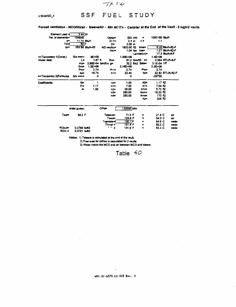
c:\SiddSD_4 S S F F U E L S T U D Y
Forced ventilation . MCO/Wattr • Sl«*v«/Air - 880 MCO'* . Canister at the End of tht Vault - 5 hlgh/2 vaults
Element Load m"No. of •foments* 104846
11.74 Btu/h501F
qx- 2S3.5e Btu/MO
Qtotat*D17-
D-A(2 vaute)-
Vair-
320 kW2.4 in
2.06 in1920.00 TO.
1.04 fps
1092160 Btu/h1.1
hms-risa-
•>Temponwy 1 (Const)Water dato:
•>Tamponry 2(Fonnula» Grx <
Grx —•> 96+09L- 1.87 ft Ro-
mu- 2.906-04 lbm/ft-s g*>Gno 1.5E+O9PTX- 2.T4 P r i -
me- 19.74 h i -0
1.006+0981^32.2
2.1«E+O92.74
22.440
Lamda(ur)-
IbmTO k-
Pre-h o
Btu/h-ft2-f17.3 Btu*-ft-F
1.4E*090.364 BTU/h-ft-F
3.1E-04 1/F2.3E+O9
2.7422.82 BTU/h-ft2-F
-26759
Cocfficianti: (0-
f«
11.171.00
nx"n1«n2-n >tV*M
1.007.00
28.00280.00280.00
A0-A1-
A1c"Acm«Ams«
As-
1.17 fO7.04 R2S.72 ft2
18.33 «2170 ft2208 02
Initial guess:
Tout- 58.2 F
CFM- 120000 cfm
TiJ—v-Tmco"
71.3 F129.9 F
Tinnaf •ROout"ROin«
0.07690.0781
130.7 IF131.4 F131.9 F
21.8 C54.3 C54.8 C55.2 C55.4 C
airairwatarwatarwater
Notice: 1) Tsleeve is calculated at the end ofthe viult2) Free area for airflow n calculated for 2 vaults.3) Water inside the MCO and atr between MCO and sleeve
Table
WHC-SD-W379-ES-003 Rev. 0

c:\Sidd\2D 4
T/f 6i
S S F F U E L S T U D Y
Forced ventilation • MCO/wattr - SI*€V«/AJr - 880 MCO's - Canister at th«
Elamant Load _'No. of «l«fli*nts>
q*_T i r t^qx-
•>Tamporary 1 (Const)Water daB:
->T«mporary 2(Formula$
Coefficients:
3.44 |W104646
11.74 Btu/hSOF
253.58 Btu/WO
Grx • — > 9E+O9L« 1.87
mu- 2.90E-O4Got- 1.5E+09P « - 2.74hx« 19.74
Gnt • - • > 0
fl> 1f i - 1.17
f- 1.M
Initial guass:
TouN
ROout"ROin«
57.5 F
0.0770 IMO0.0781 ib/fO
Qtotal-D17-
0 -A(2 vaults)-
Vair-
(t Ro-lbm/1t-» a»
P r i -h i -
nx"n 1 -n2-n >n4-
CFM- P
Tsl*av*>Tmco"
TcanisteHTinnar •
* " a
3202.4
2.061920.00
1.13
1.00E+O981.232.2
2.18E-KJ92.74
22.440
t.oo7.00
28.X280.00280.00
130000
70.4129.0
kwininft2Ips
•
hms- |hsa-
Lamda<ur)"
lbnVR3 k»fVs2
cfm
FF
129.8 |F130.6131.1
FF
Bataa
Pre-hc-
A0-A1-
A1c-Aenv*Ams»
A 5 -
End or th« Vault - 5 hlgh/2 vaults
1092160 Btu/h1.1
0.33IBtu/h-n2-F123 Btu/h-ft2-F17.3 Btu/h-ft-F
1.4E*O90.364 BTD/h-ft-F
3.1E-04 1/F2.3E*O9
2.7422.82 BTU/h-ie-F
•26591.4
1.17 IB7.04 ft25.72 ft2
16.33 KZ170 12206 ft2
21.3 C air53.9 C air54.3 C water54.7 C water55.0 C water
Notiea: 1) Tslaava is calculated atthaend oflh» vault2) Fra* araa for airflow is calculated for 2 vaults.3) Water insida tht MCO and air batwtan MCO and S I M V *
Table 4(
UHC-SD-U379-ES-003 Rev. 0
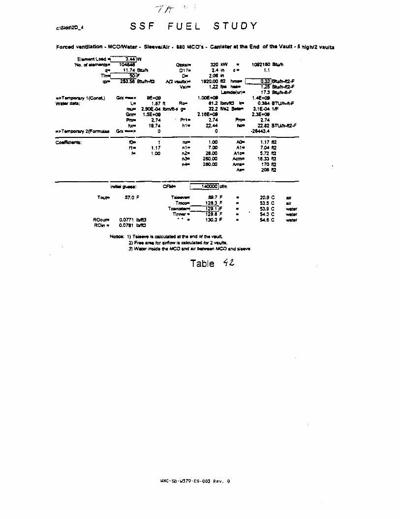
T/t ' '
S S F F U E L S T U D Y
Foread ventilation - MCOSWatar - SlMv«/Alr • ISO MCO's - Canister at th« End of tin Vault • 5 hlgn/2 vaults
Elament Load _'No. of atamentt»
<*-104946
11.74 Stu/hQtotaN
017-0 -
A(2 vaults}"
•» Temporary 1 (Const)Water d t t :
•»Tafnponry 2(Formulu Gn
253.58 Btu/MQ
— » 96*09L- 1.87 ft Ro-
mu- 2.90E-04 Ibmit-* g-Gra- 1.5E+O9fnc 2.74 • Pr\*hx- 19.74 hi"
—> o
320 kW -2.4 in c •
2.0S in1920.00 ft2 h r a - [
1J2 fp* haa-Lamda(ur)*
1092160 Stu/h1.1
6 1 ^ Ibm/R3 k-222 Hl%2 Bata-
he"
1.25 BtuVh-A2-f17.3 Sttjh-frF
1.4E+090.364 BTUflWt-F
3.1E-04 1/F
2.7422.44
0
2.7422.82 8TU/h-R2-f
-26443.4
Coaflteianta: fO-« •
r>
11.171.00
n1»n2-n3-M -
1.X7.00
28.00280.00280.00
A0-A1«
A1c«Aem«Am**
As-
1.17 (Q7.04)12S.72R2
18.33 «2170 H2208 It2
Initial guess:
Tout- 57.0 F
140000lefm
Tiiaava"Tmco»
TinnarROouf"ROin"
0.0771 IbflO0.0781 Ib/ftS
89.7 F128.3 F
jFF
130.3 F
129.1
20.9 C53.5 C53.9 C54.3 C54.6 C
airairwatafwatarwataf
f obca: 1) Taiaave is calculatad at th« and of tjia vault.2) Fra« araa for airflow is calculatad for 2 vaults.3) Watar insida (ha MCO and air b«tw*an MCO and slaava
Table
WHC-S0-W379-ES-003 Rev. 0

c:\Sidd\2D 4 S S F F U E L S T U D Y
Forcvd vtnttlatfon - MCO/Watar - Slccvt/Air - 880 MCO's . Canister at tht End of tht Vault - 5 hlgh/2 vaults
Element Load _"No. o( «i*m*ms>
q»
• > Temporary 1 (Const)Water data:
•">T»mporary 2(F«mul*s
Coefficients:
3.44 |W104846
11.74 Btu/h50 |F
253.58 Bbifa-tO
Qnt*~> 9€*09L- 1.87
mu* 2.90E-04Grx- 1.5E+09Pne 2.74hx- 19.74
Gnc*™> 0
to- 1M« 1.17
f* 1.00
Initial guess:
Tout-
ROout-ROin*
56.5 F
0.0772 Ib/RS0.0781 Ib/TO
Qtotil-D17«
D-A<2 vaults)-
Vair-
ft Ro-Ibm/ft-s a -
pn-h1«
rue"n 1 -n2"rt3»r>4«
CFM- f
Tmco"Tcanisten^
Tinner«• • •
3202.4
2.061920.00
1.30
1.00E+Q961.232.2
2.1SE-H392.74
22.440
1.007.00
28.00280.00260.00
150000
69.0127.7128.4129.2129.7
KWinin
rafps
•
c«
rims* |r iw-
Lamda(ur)a
Ibm/fO k"ft/s;
cfm
FFFFF
Beti"
Prc-h o
A0»A1-
A l oAem>Amsa
As-
1092160 Btufh1.1
0.33JBtu^vft2-F1.26 Btu/Mt2-F17.3 Btu/h-ft-F
1.4E+090.384 BTU/h-ft-F
3.1E-O4 1/F2.3E-H»
2.7422.82 BTU/WQ-F
-2631U
1.17 «27.04 fl25.72 fI2
18.33 H2170 ft2206 «2
206 C air53.1 C air53.S C water53.9 C watar54.2 C water
Note*: 1)TslMv*)inlculaMatih**n(lof1h»vault2) Fr«« i rM fof airflow is calculated for 2 vaults.3) Water insids th« MCO and air kMtw*«n MCO »nd si««v»
Table
WHC-SD-U379-ES-003 Rev. 0
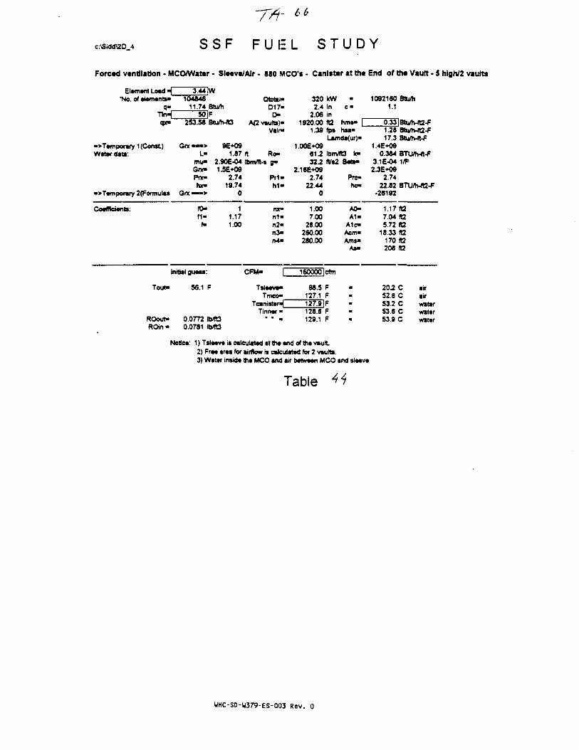
c:\Sidd\2D 4 S S F F U E L S T U D Y
Forced ventilation • MCO/Watar - Sle«vc/AIr • 880 MCO's - Canister at ttie
Element Load 4_ 3.44JW'No. of etemento- 104846
q- 11.74 Btu/hTlrH SO |Fqx- 253.58 Btu/h-R3
•>Temporafy 1 (Const) Grx • — > 9E+O9Wattfdata: L- 1.87
mu- 2.90E-04Gix- 1.5E+09Pnc- 2.74hx- 19.74
•>Temporary 2(Formulas Orx —•> 0
Coefficients: (0- 1f 1 - 1.17
f- 1.X
Initial guess:
Tout- 56.1 F
ROout- 0.0772 IMt3
Qtotai-D17-
t >A(2 vaults)"
Vain"
ft Ro-tbnVft-J g-
Pr1-M -
nx-n 1 -n2-n3-n4-
CFM" |~"
Tsleeve-Tmco-
TcanisteHTinner •
• " •
3202.4
2.061920.00
1.39
1.XE+0961.2222
2.16E+O92.74
22 440
1.X7.00
28.0028O.X280.X
160000
68.5127.1127.9128.6129.1
kWinin1Qfps
c«
hms» |hsa-
Lamda(ur)a
Ibm/rt3 )(•KVs2
cfrn
FFFFF
Seta-
Pre-hc-
AO-A1"
A1C«Acm*Ams>
As-
End of the Vault • 5 high/2 vaults
1092160 8tu/h1.1
0.33|Btuft-ft2-F1.28 Btu/h-ft2-F17.3 Btu/h-«-F
1.4E+090.384 BTU/h-ft-F
3.1E-04 1/F2JE+09
2.7422.82 BTU/h-«2-F
-26192
1.17 «27.04 ft25.72 ft2
18.33 ft2170 (t2208 R2
20.2 C air52.8 C air53.2 C water53.6 C water539 C water
ROin« 0.0781 Ib1t3
Notice: 1) Tsleeve is calculated at the end of the vault2) Free area for airflow is calculated for 2 vauRs.3) Water inside the MCO and air between MCO tnd sleeve
Tabie
WHC-SD-W379-ES-003 Rev. 0

c:\Sidd\2D 4 S S F
77? 67
F U E L S T U D Y
Forced ventilation - MCO/Water - SleeveSAIr - 880 MCO's - Canister at the End of the Vault - 5 high/2 vaults
Element Load H 3.44'No. of elements- 104846
q« 11.74Tin^ 50qx> 253.58
"Temporary 1 (Const) G r x « » >Water data: L-
mu-Grx-Prx-r w
•>Tempomry 2(Formulas Grx — • >
Coefficients: fO-f1"f-
Initial guess.
Tout- 55.7
ROout* 0.0773ROin • 0.0781
W
Btu/hF9tu/h-ft3
9E+091.87
2.90E-041.5E+09
2.7419.74
0
11.171.X
F
b/TDb/fO
Qtotat-017-
OA(2 vaults)"
Vair-
ft Ro-ibnVfl-s g*
Prt-h 1 -
nx-n 1 -rt2-n >n4-
CFM- |~
Tsleeve-Tmco"
Tcanister*Tinner*
• • a
3202.4
2.061920.X
1.48
1.00E+O981-232.2
2.16E+092.74
22.440
1.007.00
28.X280.X280.X
17XW
67.9126.5127.3128.1128.6
kWininft2fps
•c
rims- |hsa-
Lamda(ur)"
Ibm/R3 k-fVs2
cfin
FFFFF
Beta-
Prc-hc-
A0-A 1 -
A1c-Aem-Ams-
As«
1092160 Btu^i1.1
0.33 Btu/h-ft2-F1.30 Btu/tvA2-F17.3 Btu/h-ft-F
1.4E+O90.384 BTLVh-ft-F
3.1E-04 1/F2.36*09
2.7422.82 BTU/Wt2-F
•26083.6
1.17 «27.04 ft25.72 «2
18.33 R2170 ft2208 ft2
19.9 C air52.5 C air52.9 C water53.3 C water53.6 C water
Notice: i)Tsleevt is cateulaMd at the end of the vault2) Free area for airflow is calculated for 2 vaults.3) Water inside the MCO and air between MCO and sleeve
Table
WHC-SD-W379-ES-003 Rev.O

c:\Sidd\2D 4 S S F F U E L S T U D Y
Forced ventilation - MCO/Wattr - SlMvWAJr • 880 MCO'i - Canister at th« End of th« Vault - 8 hlgh/2 vaults
Elanwit Load H 3.44 IW'No. of alamants- 104846
q- 11.74 3tu/hTirH 50 |Fqx- 253.58 Btu/h-B
•>Tamporary 1 {Const) Grx • — > 96+09Watardati: L- 1.87
mu- 2.906-04Got" 1.56*09Pne» 2.74hx- 19.74
•>Tamporary 2(Formulas Got • - • > 0
CotfRciants: fO- 1f1» 1.17
f- 1.00
Initial guass:
Tout" 55.4 F
ROout" 0.0773 Ib/Tt3ROin* 0.0781 IMO
QtotaND17«
OA(2 vaults)"
Vak>
ft Ro-Ibm/ft-i g»
Pr i -h i "
nx-ni"n2-n3-n4>
CFM- |~
Talaava"Tmco-
Tcanistaf^Tinnar"
* * •
3202.4
2.061920.00
1.56
1.006*0961-232.2
216E+O92.74
22.440
1.X7.00
26.X280.00280.X
180000
67.4126.0126.8127.fi128.1
kWininKZIps
•
C "
hms" |hsa*
Lamda(ur)-
IbnvTO k"ft/s2
cfrn
FFcrFF
Bati-
Pre-hc-
A0-A1"
A1C«Aem"Ams"
As-
10921601.1
1J217J
1.4E+090.384
3.1E-042.36*09
2.7422.82
-25984 4
1.177.045.72
18.33170206
19.752.252.653.053.3
Btu/h
BtuAUt2-FBtu/h-ft2-FBtu/rvft-F
BTU/h-ft-F1/F
BTLWv«2-F
ft2(t2ft2raft2ft2
C airC airC waterC waterC water
Nobca: 1) Tsl«»va i* calculatad attha and ofthavault2) Fr«« art* for airflow is calculated for 2 vaults.3) Water tnaida tha MCO and air batvnon MCO and »l**v*
Table
UHC-SD-W379-ES-003 Rev. 0

6 7
e:\Sidd\2D_4 S S F F U E L S T U D Y
Forced ventilation - MCO/Water - Sleevt/AJr - 880 MCO's - Canister at tha End of the Vault - 5 high/2 vaults
EiamantLoadH 3.44 |W"No. of atamants- 104846
q- 11.74 BturtlTin-i 50 IFqx- 253.56 Btu/h-fEJ
•>Tamporary 1 (Const) G« — > 9E+09Wat * datr L- 1.87
mw 2.906-04Grx- 1.5E+O9Pnc 2.74hx- 19.74
•>Tamporary 2(Formulas Got • » • > 0
Coafflctanb: N> 1f i - 1.17
f- 1.00
Initial guass:
Tout- 55.1 F
ROout- 0.0774 IMS
Qtotml-D17"
r>A(2vaults)-
Vair-
ft Ro-Ibm/Ita g»
Prt-h1«
nx«n1«n2-rt3>r>4-
CFM- f
Tslatva-Tmco"
Tcwistan^Tlnnar"
" • •
3202.4
2.061920.00
1.65
1.00E+09612322
2.16E+092.74
22.440
1.007.00
26.00280.00260.00
190000
67.0125.6126.4127.1127.6
kWinInH2fps
•
hmv |ha**
Lamdi(ur)*
IbmTO k"ftf»2
cfni
FFFFF
Bata«
Prc-
A0-A1-
A1c«Aem«Ams-
A»-
1092160 8tuni1.1
0.33!Btu/h-ft2-F1.34 3bJMt2-F17.3 Btu/h-fl-F
1.4E+090 J84 BTU/h-ft-F
3.1E-04 1/F2JE+O9
2.7422.62 BVJ/Ma-F
-25693
1.17 IG7.04 ft25.72 fl2
16.33 ft2170(12208 ft2
19.4 C air51.9 C air52.4 C water52.8 C wit*r53.1 C witar
ROin • 0.0781 Ib/TO
Notica: 1)Tsla«va iscafcuiatad at tha and of tha vautt.2) Fraa araa for airflow is calculated for 2 vaults.3) Wttar insida tha MCO and air batwtart MCO and sla«v«
Table
WHC-SD-W379-ES-003 Rev. 0

voe:\Siddl2D 4 S S F F U E L S T U D Y
Forced ventilation • MCO/Water - SlMv«/Alr - 880 MCO'i - Canister at ttw End of tht Vault - S hlgh/2 vaults
Element Load « 3.44 fW"No. of element*- 104846
q- 11.74TirH 50qx* 253.58
•>Temponwy 1 (Const) Gre • — >Water data: >
mu»One*Pnc-hx»
•>Tempomry 2(Formulas Grx • « • >
Coefficients: R>n-f-
InrfiaU guess:
Tout- 54.9
ROout- 0.0774ROin • 0.0781
Btu/hFBtu/h-«3
9E+091.87
2.90E-041.5E+O9
2.7419.74
0
11.171.00
F
M OM O
QtotahD17-
OM2 vaults)-
Vaim
ft Ro-Ibm/ft-s fl"
P r i -h i -
nx"n 1 *n2-n3-n4-
CFM-
Tsleeve"Tmco"
Tcanwtef*Tinner*
" • •
3202 4
2.061920.X
1.74
1.00E*O9
3222.16E+09
2.7422.44
0
1.007 .X
28.X260.X260.X
20COO0
66.6125.2
kWininR2fp»
•c •
hnw" |hsa-
Lamda(ur)a
ibmiO k"Ws2
cfm
FF
126.0 IF126.7127.2
FF
S«t i -
Pre-he-
A0-A 1 -
A 1 oAcm*Ams*
As-
10921601.1
0.331J517.3
1.4E+080.384
3.1 E-042.36*09
2.7422.82
•25808.3
1.177.045.72
16.33170208
19.251.752-252.652.8
Btum
Btu/Mt2-FBtu/MQ-F8tu/h-ft-F
BTU/h-ft-f1/F
BTU/h-fB-F
faraft2R2ra«2
C airC airC waterC waterC water
Notice: 1) Tsleeve is calculated at the end of the vmult2) Free area for airflow is calculated for 2 vaults.3) Water inside the MCO and air between MCO and sleeve
Table
WHC-SD-U379-ES-003 Rev. 0

c:\Sidd\2D_4 S S F F U E L S T U D Y
Forced ventilation - MCO/Water • SlMvt/AJr - 880 MCO's - Canister at tht End of tht Vault • 5 hfgh/2 vaults
Element Load _'No. of elements-
3^4|W104646
11.74 Btu/h35iF
qx- 25358 BturtWD
Qtotal"D17-
D-AQvaulb)-
Vain> hsa-
•>Temporary 1(Con«t)Water date:
GrxL-
mu-Got"Pnchx-
•>T*mponiry 2(Fonnutas Gnc « • •>
9€*091.87 ft
2 JOE-041.5E*0S
2.7419.74
0
Ro-i a«
Pri"
320 kW2.4 in
2.06 in1920.00 ft2
2.00 fp*Lamda(ur)-
1.0Oe*O96M It-rvTCJ k-32^tVs2 B M ^
2.16E+O92.74 Prc"
22.44 hc-0
1092160 Btu/h1.1
a33lBtu/n-fl2-F1.41 Btum-ft2-P17.3 BUhA-F
1.4E*090.384 BTUyh-ft-F
3.1E-O4 1/F2.3E*O9
2.7422.82 BTU/h-ft2-F
-22519.4
Coefficients:f i -
f»
11.171.00
nx"n 1 -n2"n >n4>
1.007.00
28.00280.00280.00
A OA1>
A1c-Acm«Ams"
As-
1.17 fQ7.04 ft25.72 «2
18.33 R2170 ft2208 (12
Initial guess:
Tout- 39.1 F
CFM- 230000 lefm
Tmco-Tcanister>{[
Tinner-
50.4 F109.0 F
ROout- 0.0798ROin - 0.0804 Ib/R3
1O9.aiF110.5 F111.0 F
102 C42.7 C43.2 C43.6 C43.8 C
airairwaterwaterwater
Notice 1) TsJwv* is calculated at th« and erfttw vault2) Fr«« ar«a for airflow is calculated for 2 vaults.3) Water insid* th* MCO and air bstw*«n MCO and sla«v«
Table 19
WHC-SD-U379-ES-003 Rev. 0

c:\Sidd\2D 4 S S F F U E L S T U D Y
Forced ventilation • MCO/Water - Sleeve/Air - 880 MCO's - Canister at the End of the Vault - 5 high/2 vaults
Element toad •(_*No. of elements*
3.44 fW104846
11.74 Btu/h3SlF
«p(- 253.58 Btum-ftS
Qtettl-D17-
O-A<2 vaults)-
Vair-
• > Temporary 1 (Const)Water data:
•>Tamporary 2(Formulas One«
Gnc—» 9E+09L- 1.87 ft Ro-
mu- 2.90E-04 Ibm/ft-s (pGno 1.5E+09Pnc- 2.74 Prt'tw 19.74 hi"
• • •> 0
320 kW -2.4 in c •
2.06 in1920.00 ta hrns- [
2^6 fps hsa-Lamda(ur)>
1.006*096 1 2 IbmAS k-32-2 ft i2 BatB-
2.16E-O92.74 Pre-
22.44 hc-0
1092160 Btu/h1.1
1.46 Btu/h-A2-F17.3 Btu/h-ft-F
1.4E+090J84 BTU/h-ft-F
3.1E-04 1/F2.3E*09
2.7422.62 BTU/Ti-rt2-F
-22337.5
Co«fRei«nti:f i -
11.171.00
ftt"n 1 -n2-n3«rO-
1.007.00
26.00260.00280.00
A0-A1«
A1c«Acm-Ams>
As-
1.17 ta7.04 (t25.72 It2
16.33 ft2170 92208 ft2
Initial guess:
Tout" 38.6 F
CFM- 260000 cftn
TsliTmco"
TcanistaHITinner"
ROout*ROtn*
0.0798 Ib/R30.0804 \bm
49.5 F108.1 F108.9 IF109.8 F110.1 F
9.7 C42.2 C42.7 C43.1 C43.4 C
airairwitarwaterwater
Notice: 1) Tsleeve is calculated at the end of the vault2) Free area tor airflow is calculated for 2 vaults.3) Water inside the MCO and air between MCO and sleeve
Table TO
WHC-SD-W379-ES-003 Rev. 0

c:\Sidd\2D_4 S S F F U E L S T U D Y
Forced ventilation - MCO/Water - Sl#«v*/Alr - 880 MCO'* • Canlsttr at the End of tti« Vault - 5 high; 2 vaults
Element Load >£_"No. of elements'
q-
T i n ^qx-
•>Temporary 1 (Const)Water data:
•>Temporary 2(Formutas
Coefficients:
3.44 IW104846
11.74 Btu/h35 |F
253.56 BtWh-fO
Grx — > 9E+09L- 1.87
mu- 2.9OE-O4Gnt- 1.5E+09Fix- 2.74hx- 19.74
O n e — » 0
ID- 1f l - 1.17f- 1.X
Initial guess:
Tout-
ROout-ROtn-
38.2 F
0.0799 Ib/R30.0804 lbVfC3
QtotaND17-D-
A(2vauits)-Vair-
ft Ro-Ibm/ft-s g -
M -
nx-n1-n >n3-n4-
CFM- f
Tsleeve-Tmco-
Tcanister^Tinner-
• • >
3202.4
2.061920.X
2.60
1.00E+0961.2322
2.16E+O92.74
22.440
1.X7.X
28.X280.X280.X
300000
46.5107.1107.9108.6109.1
kWinintafps
•c«
hms- |hsa-
Lamda(ur)-
1brMt3 k—rVs2
cfm
FFFFF
B«a-
Pre-hc-
A0-A1-
A1c-Acm-Ams-
As-
1092160 Btum1.1
0.33|Btu/h-A2-F1.54 BbVrvft2-F17.3 Btuftvft-F
1.4E+O90.364 STU/h-ft-F
3.1E-04 1/F2.3E+O9
2.7422.82 STU/h-fB-F
•22134.6
1.17(127.04 TO.5.72 (t2
18.33 B2170 ft2208 ft2
9.1 C air41.7 C air42.1 C water42.5 C water42.8 C water
Notice: 1)Tsleevetsalcu!atadattheendof1hevault2) Free area for airflow is calculatad for 2 vaults.3) Water inside the MCO and air between MCO and sJeeve
Table Si
UHC-S0-W379-ES-003 Rev. 0

c:\Sidd\2D_4 S S F F U E L S T U D Y
Forctd vtntllitlon - MCO/Water - SlMV«/Air - ItO MCO'i - Canister at ttie End of th« Vault - 5 hlgh/2 vaults
ElamantLoadH 3.44 fW'No.ofalamanb- 104846
0- 11.74 Btu/hThH 35|Fqx- 253.58 Btu/h-«3
•>Tamporary t(Const) Orx — > 9E+09Water data: L- 1.87
mu- 2.90E-04Gr*« 1-5E+Q9Pw- 2.74hx- 19.74
•>Tamporary 2(Fomujtas Gnc • » • > 0
Coaffieiants: ID- 1f1» 1.17f« 1.00
Initial guass:
Tout- 37.7 F
ROout- 0.0800 1MBROin - 0.0604 IIVR3
Qtotal-D17-
oA(2 vault*)-
Vair-
(t Ro-lbnVft-s o"
Pii-M -
nx>n1«n2-n >n4>
CFM- f
Tsla«va*>Tmco-
Tcantstar^Tinnar*
• • -
3202.4
2.06192000
3.04
1.00E+0981-232.2
2.16E*092.74
22.440
1.007.00
26.00280.00280.00
350000
47.4106.0
kWininIt2fp*
•
c«
hms» |hsa>
Lamda(ur)>
IboVTD k"fV«2
cfm
FF
106.8IF107.6108.1
FF
Bati*
Prc-"hc-
A0-A1-
A1c-Acm»Ams>
As-
10921601.1
0.331.6317.3
1.4E+O90.364
3.1E-042.3E+09
2.7422.82
•21926-2
Btu/h
Btu/h-ft2-FBtu/h-ft2-FBtu/h-R-f
BTU/h-ft-F1/F
8TUVh-«2-F
i.t7 ie7.045.72
18.33170208
8.641.141.541.942.2
(t2ft2ttzft2ft2
C airC airC waterC waterC water
Nottea: 1)Tslaavarsea)cutatadatth««ndo(thavault2) Fraa araa for airflow m eaJculatad for 2 vaults.3) Watar insida tha MCO and air batwtan MCO and sla«v«
Table st
WHC-SD-W379-ES-003 Rev. 0
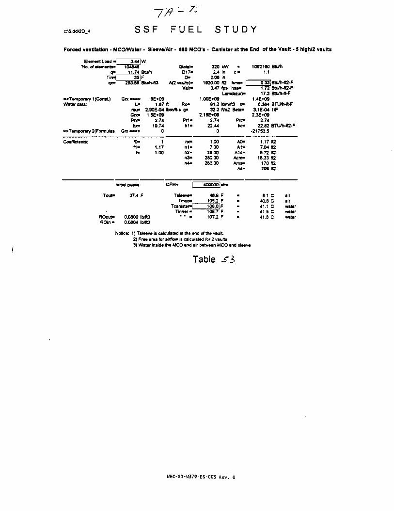
c:\Sldd\20 4
- 7J
S S F F U E L S T U D Y
Forctd ventilation • MCO/Water • SIt*veVAIr - 880 MCO's • Canister at tilt End of the Vault - 5 hlgh/2 vaults
Element Load -| 3.44JW•No. of elements- 104846
o- 11.74 BlumTinH 35 |Fqx- 253.56 Btu/h-ft3
•>Tempomry 1 (Const) G r x ~ > 9E*09Water data: L« 1.87
mu- 2.90E-04Gne 1.5E+09Pnc 2.74hx- 19.74
• > Temporary 2(Formulis Grx • * * > 0
Coefficients: 10- 1f 1 - 1.17
f- 1.00
Initial guess:
Tout* 37.4 F
ROout* 0.0800 IMt3ROin - 0.0604 Ib/ft3
Qtotal-D17«
O*A(2 vaults)*
Vair-
ft Ro-tbm/ft-s ga
Pr1*h i *
nx»n 1 -n2-n3«n4*
CFM- |~
Tsieeve*Tmco-
Teamster^Tinner •
* • m
3202.4
2.061920.00
3.47
1.00E+0961.232^
2.16E*O92.74
22.440
1.007,00
28.00280.00280.00
400000
46.6105.2106.0106.7107.2
kWininft2fps
•
C "
hms* |hsa*
Lamda(ur)*
IbnvTO k*rV*2
cfm
FFFFF
Beta*
Prc-hc*
A0-A1-
A1c-Acm«Ams-
As-
10921601.1
0.331.7217.3
1.4E+090.3»4
3.1 E-042.3E*O9
2.7422.82
•21753.5
1.177.045.72
18.33170208
8.140.841.141.541.8
Btu/h
3tu/h-ft2-FBum-it-F
BUWb-ft-F1/F
8TU/h-«2-F
TO.fCft2ft2ft2ft2
C airC airC waterC waterC water
Notice: 1) Tsleeve is calculated atthe end oftheviult2) Free area for airflow is calculated for 2 vaults.3) Water inside the MCO and air between MCO and sleeve
Table si
UHC-SD-W379-ES-003 Rev. 0

-TA- 7 a
c:\Sidd\2D_4 S S F F U E L S T U D Y
Forced ventilation - MCO/Water - SIt«v«/Alr - 880 MCO's • Canister at tht End of the Vault - 5 hfgh/2 vaults
Ei.m.nt Load -| 3.44'No.of»l»nwitt« 104846
q- 11.74Tirv-, 35qx- 253.56
->T»mpcmry 1 (Const) Got — • >Water date: L-
mu»Grx«Pnchx-
•>T«mporary 2(Formula» Gra — • >
Cocfficianb: f0»f1»f«
Initial gu*«s
Tout* 37.1
ROout- 0.0601ROin - 0.0804
W
Btu/hFBtu/Mt3
9E*091.87
2.90E-041.5E+09
2.7419.74
0
11.171.00
F
WOb/R3
QtotX-D17-
D-A(2 vaufb)-
Vair*
ft Ro-Ibm/ft-s g>
PM*h i *
nx«n 1 -n2a
n >f>4*
CFM- [~~
T s ( - v ^Tmco*
Tcanist*r>|Tinnar •
• ' m
3202.4
2.061920.00
3.91
1.00E+0961.2222
2.16E+092.74
22.440
1.007.00
28.00280 00280.00
450000
45.9104.5105.2106.0106.5
KWininK2fps
•
C "
hms- |h«a"
Lantda(ur)»
IbnVIVs2
cnn
FFFFF
t3 k»B«te"
Prc-hc-
A0-A 1 -
Alc-Acm»Ams>
A»-
10921601.1
Btu/h
0.33|Btum-ft2-F1.8117.3
1.4E+090.364
3.1E-042.3E+09
2.7422.82
-21605.1
1.177.045.72
18.33170
8tu/Mt2-FBtu/Mt-F
BTUflv*-F1/F
BTU/h-«2-F
R2R2«292R2
208 02
7.740.240.741.141.3
C airC airC waterC waterC water
Notica: 1) Tsla«v« is calculated at th« *nd of th« vault2) Fr«« ar*« for tiiftow is calculated for 2 viutts.3) Water Insida th* MCO and air b«tw*«n MCO and S IMV*
Table
WHC-SD-W379-ES-003 Rev. 0

c:\Sidd\2D_4 S S F F U E L S T U D Y
Forced ventilation - MCO/Water - Slecve/AJr - 880 MCO's • Canister at ttit End of the Vault - 5 hlgh/2 vaults
Element Load •£'No. of elements'
3.44 W104046
11.74 Btu/hTinW_qx-
35 F253.56 Bbi/h-R3
Qtotal-017-
D-A<2 vaults)"
Vair-hms-hsa-
•>Temporary 1 (Const)Water data:
Grx — > 9E+09L- 1.87 ft Ro-
mu> 2.90E-O4 Ibm/ft-s g-Gnt- 1.5E+09Pnc 2.74 Pri-hx- 19.74 M -
•>Tamporary 2(Formutas Gnc •
320 kW2.4 in
2.06 in1920.00 R2
4.34 fpsLamd«(ur)"
1.00E+0961.2 Ibmm3 k-222 ft/s2 B«a-
2.16E*O92.74 Prc*
22.44 hc-0
1092160 Stum1.1
1.90 BtWh-ft2-F17.3 Btuftv^t^1
1.4E-HW0.384 BTU/h-fl-f
3.1E-04 1/F2.3E+09
2.7422.82 BTU/h-fC-F
-21477J
Coefficients: IO>
f-
11.171.00
nx»n 1 -n2-n >n4-
1.007.00
28.00280.00280.00
A0-A 1 -
A1c«Aon-Am*«
As-
1.17 fO7.04 ft25.72 «2
18.33 KZ170 ft2208 ft2
initiaJ guess:
Tout- 36.9 F
CFM- 500000 cfm
Tmco-45^ F
103.8 F
TinntrROout-ROin •
0.0801 ibm30.0804 IMG
104.6 IF105.4 F105.9 F
7.3 C39.9 C40.3 C40.7 C41.0 C
airairwaterwaterwater
Notice: 1)Tsl««v* is calculated at the and of th« vault2) Free area for airflow is calculated for 2 vaults.3) Water tnsidt the MCO and air between MCO and sleeve
Table
WHC-SD-W379-ES-003 Rev. 0
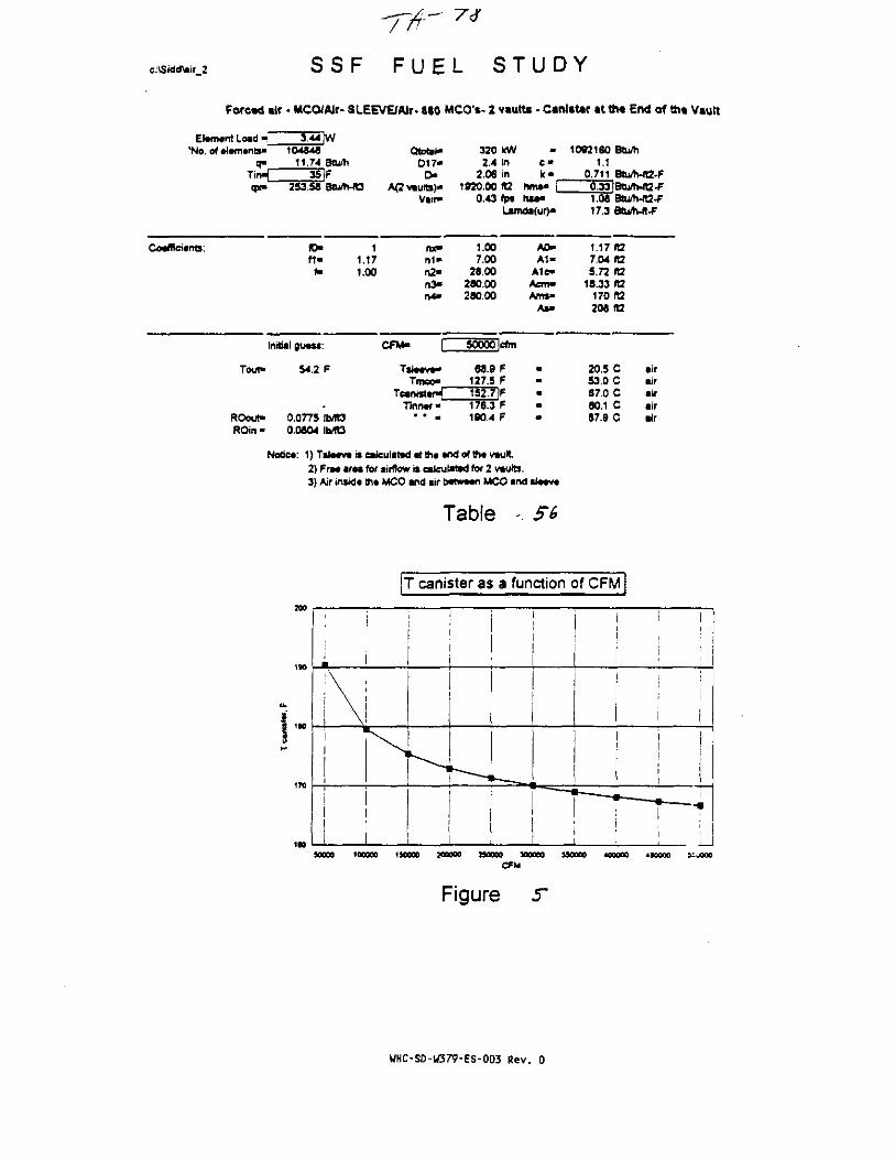
c:\Sidd\air 2 S S F F U E L S T U D Y
Forcad ilr • MCO/Wr- SLEEVE/Wr- « 0 MCO'*- 2 vauttt - Canister at ttw End of th« Vault
El»m«nt Load J'No. of *i«rnants-
q-Tin-qx-
Coafficisnts:
Tout*
ROout*ROin -
3.44 |W104846
11.74 8tU/h35 |F
253.58 Btu/h-IO
JO- 1ft- 1.17
f- 1.00
nrtial guass:
54.2 F
0.0775 IMO0.0804 IMt3
Qtofc*-0 1 7 -
D-A(2 v iu t t ) *
Varr-
nx*n i -n2*n >n4*
CFM- T
TslMva^Tmca-
TeanntarHTinnaf •
• • •
320 IcW2.4 in
2.06 in1920.00 «2
0.43 (psU n
1.007.00
28.00280.X280.00
50000 !tfm
66.9 F127.5 F152.7 IF176.3 F190.4 F
•
c«k -
hms« |hsa-
tda<ur>>
A0-Al -
AlC-Aem«Ams-
As«
1092160 Btufti1.1
0.711 Btu/h-IQ-F0.33 tBtu/1vft2-F1.08 Btu/Mt2-F17.3 BtWh-ft-F
1.17 (O7.04 ft25.72 fD
18.33 ft2170 ft2208 ftZ
20.5 C air53.0 C air67.0 C air80.1 C air67.9 C air
Notict: 1}Tsl«*vtrscaieulat»d atth« and ofth* vault2) Fra* araa for airflow is calculated for 2 vaults.3} Air insida ma MCO and air bctwaan MCO and ti««v*
Table
T canister as a function of CFM
\
I ,*• 1
SO0O0 100000 1SOO0O IO0000 SOOO0 300000 JSOOOO 400000 4SOOO0
CPM
Figure 5*
UHC-SO-U379-ES-003 Rev. 0

c:\Sidd\air 2 S S F F U E L S T U D Y
Foread air - MCO/AJr- SLEEVE/AIr- 880 MCO1*- 2 vaults • Canister at tha End of tha Vault
Element Load •'No. of elements-
Tin"qx-
CoefTiciertts:
Tout"
ROout*
3.44 ]W104846
11.74 Btu/h35 |F
253.58 Btum-fC3
f 1 - 1.17f- 1.00
Initial guess:
44.5 F
0.0790 IMQ0.0804 IMt3
Qtotat-D17-D-
A<2vaulli)aVsir-
n4-
CFM- \Z
Tsleeve-Tmco-
Tcanistan^Tinner"
• • •
320 kW2.4 in
2.06 in1920.00 ta
•
C "k -
hms* f0.87 fpa hsa-
Lamda(ur)-
1.007.00
28.00280.00280.00
100000 Icftn
58.0 F116.6 F141.9 IF165.5 F179.5 F
A0-A 1 -
A1c>ACTTl"Ams-
As-
•
i
i
10921801.1
0.7110.331.1717 J
1.177.045.72
18.33170208
14.447.061.074.181.9
Stum
Btu/h-ft2-FBtu/MB-F8tu/h-ft2-F
A2taft2(t2ft2fC2
C airC airC airC airC air
Notjca; 1) Tslaava is calculated at tha and of tha vault2) Free area for airflow is calculated for 2 vaub.3) Air inside the MCO and air between MCO and sleeve
Table MtSl
UHC-SD-W379-ES-003 Rev. 0
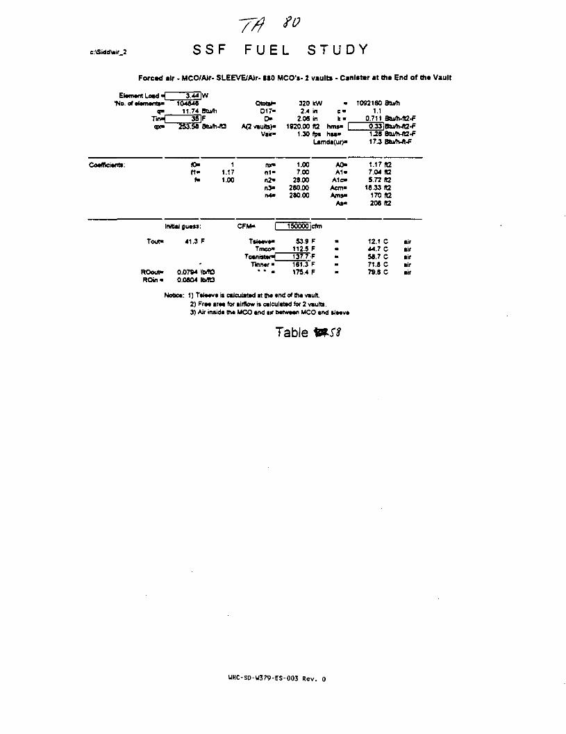
c:\SiddWr_2
77? ">S S F F U E L S T U D Y
Foread air - MCO/AJr- SLEEVE/AJr- 880 MCO's- 2 vaults - Canister at tha End of the Vault
Element Load •{_"No. of element*-
3.44 W104846
11.74 Btu/h35
qx- 253.58
Qtotal-017-
r>A(2 vaults)-
Vair-
320 kW2.4 in
2.06 in1920.00 tt2
1.30 fp*
c -k -
hrrw- |hsa-
Lamda(ur)-
1092160 Stu/h1.1
0.7110M|Btu/h-ft2-F
Coefficients: fO-f i -f-
11.171.00
0 1 -r»2-n>r»4-
1.007.00
28.00280.00280.00
A0-A 1 -
A1c-Acm-Anw-
As-
1.17 ft27.04 fl25.72 R2
18.33 ft2170(12206 ft2
Initial guess:
Tout- 41.3 F
ROout- 0.0794 ib/fOROin • 0.0804
CFM- 150000 cfm
Tmco"53 9 F
112.5 F137.7 F
Tinner 161.3 F175.4 F
Notice: 1) Tsieevt iscaicutatod atthc end oftheviulL2) Free area for airflow rs calculated for 2 vtutts.3) Air inside the MCO and air between MCO and sleeve
12.144.758.771.879.S
CCC
cc
airairairairair
Table mst
UHC-SD-W379-ES-003 Rev. 0

c:\Stdd\air 2 S S F F U E L S T U D Y
Forced air • MCO/AJr- SLEEVE/AIr- 880 MCO's- 2 vaults - Canlstar at the End of th« Vault
Element Load • ( _"No. of elements'
Cp(-
Coemcients;
3.44 |W104846
11.74 Btu/h35 IF
253.58 Btu/h-R3
ID- 1f t - 1.17
f- 1.00
Initial guess:
Tout"
ROout"ROin-
39.7 F
0.0797 ib/TB0.0004 lb/TC3
Qtotat-017 -
D-A(2 vaulto)-
Vair-
nx-
n>n4>
CFM- [2
Tmco*T c a n « a r ^
Tinner"" • a
3202.4
2.061920.00
1.74
1.007.00
28.00260.00280.00
200000
51.4110.0135.3158.9172.9
kWininR2
M
c *k -
hma- ffps hsa-Lamda(ur)-
cfm
FFFFF
A0-A 1 -
A1c"Acin"Am»*
As*
•
I
*
10921601.1
0.7110.331.35
1.177.045.72
15.33170208
10.843.357.370.476.2
Btu/h
Btu/h-fl2-FBtu/h-JQ-FBtu/h-ft2-F
ft2R2fl2ft2fC2«2
C airC airC airC airC air
1)Tti««v«iseateulatad«ttr«an<iofttNav«utt2) Fr*« araa for airflow is calculated for 2 vauta.3) Air tnsida th« MCO and air b«(w*an MCO and *l*ava
Table
UHC-SD-W379-ES-003 Rev. 0

c:\Sidd\air 2 S S F F U E L S T U D Y
Forctd air - MCO/Alr- SLEEVE/Air- 880 MCO's- 2 vaults - Canister at the End of ttia Vault
Elwrwnt Load _'No. of •iamants*
3.44 W104646
11.74 Btu/h3SiF
253.58 Btu/h-ft3
Qtoat- 320 kW - 1092160 Btu/TiD17« 2.4 in c - 1.1f> 2.06 in k« 0.711 BtU/Mg-F
A(2vauta)- 1920.00 «2 hma- I 0.33 IBtu/h-ft2-FVair- 2.17 tp% hsa>
Lamda<ur)a 17.3
Coefficients: ID-f i -f-
11.171.00
nx». n1»
n2-n >r*4-
1.007.00
26.00280.00260.00
A0-A1>
A1c-Acm«Ams"
As-
1.17(12' 7.04 R2
5.72 RZ18.33 H2
170 ft2208 (12
Initial 0u«ss:
Tout- 38.8 F
CFM- 250000 Irtm
TalaavfTmco"
49.7 F106.4 F133.6 IF
ROout"ROin-
0.0798 \WQ0.0604 Ib/R3
171.3 F
Notio*: 1)Tsl*av«iscalculat*datth« tnd of tha vault2) Fr«« arm for airflow is calculated for 2 vaults.3) Air insida the MCO and ur b*tw*«n MCO and si««v«
9.8 C42.4 C56.4 C69.5 C77.3 C
airairairairair
Table «60
WHC-SD-H379-ES-003 Rev. 0
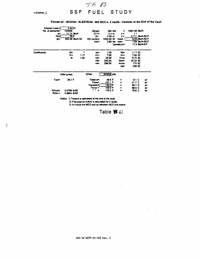
c:\Siddfcir_2 S S F F U E L S T U D Y
Forced air - MCO/Alr- SLEEVE/AJr- 880 MCO's- 2 vaults - CanJsttr i t th« End of ttit Vault
Element Load _'No. of element-
T i n ^V
Coefficients:
3.44JW104846
11.74 8tu/h35 F
253.56 Btum-ft3
(D- 1f i - 1.17
N 1.00
Initial guess:
Tout-
ROout-ROin*
36.2 F
0.07991Mt30.0604 Ibntt
Qtotal-017-0-
A(2 vaults)-Viir-
nx-n 1 -
n3-n4-
CFM- Q
Tsleeve-Tmco-
Tcww»ter^_Tinner*
• • >
320 KW2.4 in
2.06 in1920.X ft2
fi-le*
hms* I"2.60 fps hsa-
Lamda(ur)*
1.X7.X
28.X280.X26O.X
300000 |cfm
46.5 F107.1 F132.3 IF155.9 F170.0 F
A0-A 1 -
A1c-Acm"
As-
10921601.1
0.711
1.5417.3
1.177.045.72
18.33170206
9.141.755.768.876.6
Btu/h
BtuflBtuflv«2-FBtu^-ft2-F
02taft2
K2ft2
CCccc
airairairairair
Notiea: 1) Tsl««v» is calculated at ttw •nd of th« vault2) Fra« araa for airflow is calculated for 2 vauKi.3) Air insid* th* MCO and air b«tw*«n MCO and sl««v*
Table
WHC-SD-U379-ES-003 Rev. 0

c:\Sidd\air_2 S S F F U E L S T U D Y
Forced air - MCO/AJr- SLEEVE/AIr- 880 MCO's- 2 vaulU • Canister at ttit End of th« Vault
Elwntnt Load *_'No. of •l»m«nts«~
3 44 W104846
11.74 Btu/h3TIF
253.58 Btii/h-fQ
Qtotjl- 320 kW - 1092160 Btu/hD17" 2.4 in c« 1.1
r > 2.06 in k • 0.711 BPi/h-ft2-FA(2«ute)- 1920.MH2 h r w I O33iBtu/h-ft2-F
Vair- 3.04 fps hsa*Lamda(ur)-
1.63 Btu^vJQ-F17 J Btu/Mt-F
Co*ffici«nb:f i -
11.171.00
nx"n i -n2-n3-n4>
1.007.00
28.00280 00280.00
A0>A1«
A1c-Aem«Am»»
As-
1.17 ft27.04 «25.72 IB
18.33 R2170 ft2208 ft2
Initiaf guass:
Touf 37.7 F
CFM- 350000 dm
Tsl»*v»-Tmco-
Tcantstsn^Tinn#r«
ROout"ROin«
0.0800 te«30.0804 (MO
47.4 F106.0 F
13T31F154.9 F168.9 F
Nottec: 1) TSJMV* iscaleuiittd itth* and ofth*v*ult2) FrM ir*a for airflow is calculated for 2 vaults.3) Air insid* tht MCO and air b*tw««n MCO and S I M V *
8.6 C41.1 C55.1 C58-2 C76.0 C
airair•irairair
Table
WHC-SD-W379-ES-003 Rev. 0

c:\Sidd\air 2 S S F F U E L S T U D Y
Forctd air - MCO/AJr- SLEEVE/Air- 880 MCO's* 2 vaults - Canister at tti* End of the Vault
El*m*nt Load ^_"No. of *l*m*nts«
3 44IW104*46
11.74 Btu/h3SlF
qx» 253.56 Btu/WtS
QtotiND17-D"
A<2 vaults)*Vair»
320 tcW2.4 In
2.06 in1920.00 «2
3.47 (ps
Ic-hms" [hsa-
1092160 BtWh1.1
0.711 Btu/h-lg-F0.33lBtu/h-ft2-F1.7217J
Co«ffici«nb: fO-f 1 -
f»
t1.171.00
TO"n 1 -n2-n >n4-
1.007.00
28.00280.00280.00
A0-A 1 -
Alc-Acm»Ams>
As-
1.17 fG7.04 fC5.72 «2
18.33 R2170 ft2208 IB
Initial gu«ss:
Tout- 37.4 F
CFM> 400000 cfm
Tsl<Tmco«
46 8 FF
T30~4lF
ROout«ROin •
0.0600 IMt30.0804 \blKS
154.0 F168.1 F
Notiea: 1) Tsl««v« is ealeulatad at tti* tnd of th* vault.2) Fr** araa for airflow is calculated for 2 vaults.3) Air insid* th* MCO and air b*tw*n MCO and sl**v*
6.1 C40.6 C54.6 C67.7 C75.5 C
airairairairair
Table
UHC-SD-U379-ES-003 Rev. 0

c:\Skldiair 2 S S F F U E L S T U D Y
Forctd air - MCO/AJr- SLEEVE/Air- 880 MCO'*- 2 vaults • Canister at tht End of the Vault
Element Load - 3.44 IW•No. of elements- 104646
q- 11.74 Btu/hTirH 35 IFcpt- 253.56 Btu/h-ft3
Coefficients: ID- 1H - 1.17
f- 1.00
Initial guess:
Tout- 37.1 F
ROout- 0.0601 *lb/mROin - 0.0604 Ib/TO
Qtetel-D17-
D-A(2vaults>-
Vair>
nx-
n2-n3>
CFM- C
Tmco-Tcanwtef-L_
Tinner-* " •
320 kW2.4 in
2.06 in1920.00 ft2
•
C -k>
hms" C3.91 fp» hsa-
Lamda(ur)-
1.007.M
28.00280.00260.00
450000 Icfm
45.9 F104.5 F129.7 IF153.3 F167.4 F
A0-
Ale-Acm-Ams-
As-
1
t
I
I
I
1092160 Sbi/h1.1
0.711 Btum-R2-F0.33IBtu/h-ft2-F1.61 Btum-ft2-F17J Btu/h-ft-F
1.17 ta7.04 ft25.72 tt2
16.33 ft2170(12206 ft2
7.7 C air402 C air54 2C air67.3 C air75.1 C air
Notice: 1) T S I M V * is calculated at th«tnd of thavauft.2) Fra* araa for airflow is calculated for 2 viglts.3) Air inside the MCO and air between MCO and sleeve
Table
UHC-SD-W379-ES-003 Rev. 0

c:\Sidd\air 2 S S F
-77/F U E L S T U D Y
Forcad air - MCO/AJr- SLEEVE/AIr- 880 MCO's- 2 vaults • Canister at the End of m« Vault
Eltnwit Load -(_ 3.44JW'No. of •(•m.nts- 104846
0" 11.74 Blu/hTirt^ 35 ]Fcpr- 253.58 Btu/h-ft3
Coefficients: 10" 1f i - 1.17f» 1.00
Initial gu«w:
Tout- 36.9 F
ROout" 0.0801 1b/ft3ROin • 0.0804 1MB
Qtotal-017-D>
A{2 vaults)'Vair-
rcc-rt1«n2-n >rv4-
CFM« P
Tsl—vTmco"
Teanisttr^Tkinar •
* * •
320 kW2.4 in
2.06 in1920.00 ft2
4.34 fpiLarr
1.007.00
28.00280.00280.00
500000 Icfm
45.2 F103.6 F129.1 F152.6 F166.7 F
-C "
k -hms" |hsa-
ida(ur>-
A0-A1«
A 1 C -
Acm-Ams>
As-
1092160 Btu/Ii1.1
0.711 Btum-fG-F0.33 iBtu/h-R2-F1.90 Btu/h-fQ-F
1.17 fO7.04 ft25.72 ft2
16.33 ft2170 «2208 K2
7.3 C air39.9 C air53.9 C air67.0 C air74.6 C air
: 1) TSIMVB is caleulaM at th« •ndofth* vault2) Fr— i r M for airflow is calculated for 2 vauto.3) Air insid* th« MCO and air bwwMA MCO and sl*«va
Table
UHC-SD-U379-ES-003 Rev. 0

c:\Stdd\air_2 S S F F U E L S T U D Y
Forctd air - MCO/AJr- SLEEVDAlr- 880 MCO1*- 2 vaults - Canister at th« End of the Vault
Element Load 4__*No. of elements-
q>T i n ^V
Coefficients:
3.44 |W104646
11.74 Btu/h•37.3 |F
253.56 Btu/Mt3
fO- 1tl« 1.17
f« 1.00
Initial guess:
Tout-
ROout"ROin«
-33.2 F
-0.0917 IWQ0.0924 IbmS
Qtotal-D17-
OA<2 vaults)-
Vair-
ruom-n2-n3*
CFM* p
Tsleeve*Trneo*
TcanisteHTinner*
• • •
320 lew2.4 in
2.06 in1920 oo ra
1.74 fpsLam
1.007.00
26.00260.00260.00
200000 Icftn
-21.5 F37.1 F62.4 F65.9 F
100.0 F
•C "
k"hms> |htaa
A0-A1"
A1C-Acm"Anw«
As>
10921601.1
0.7110.331.3517.3
1.177.045.72
18.33170206
-29.72.8
16.829.937.8
Btu/h
Btu/h-ft2-FBtu/h-R2-FBtu/h-ft2-FBtu/h-ft-P
ft2ft2ft2ft2ft2KZ
C airC airC airC airC air
Notice: 1}T$le«ve is calculated at the end of th« vault.2) Free area for airflow is calculated for 2 vaults.3) Air inside the MCO and air between MCO and sleeve
Table 66
WHC-SD-W379-ES-003 Rev. 0

c:\Siddfcir 4 S S F F U E L . S T U D Y
Natural convection - MCO/AJr- SLEEVE/Air- 880 MCO's- 2 vaults - Canister at th« End of the Vault
Element Load _"No. of •lem*nt*»
Tin^"
Coefficient:
3.44 [W104846
11.74 Btu/h115 |F
253.58 Btu/h-ftt184 ft
ID- 1M- 1.17f" 1.00.
Initial guasa:
Tout"dP-
Pstaek"ddP"
ROout"ROin •
132.5 F0.0761 in.WG0.0759 m.WG0.0X2-0.0671 IMt30.0692 lbvTt3
Qtetal-017-D-
A(2 vaults)-Vair-K 1 -
nx«
n2-
C F M ^
Tmeo-TcmnMmrm
Tinner*
2702.4
2.061920.X
0.472.65E-11
1.X7.X
28.X280.00280.X
53600
147.1205.7230.9254.5268.6
kWinin
ra
•
e -k-
im*« j ~
Lamda(ur)-
efm
FFFFF
AO-A1-
A1c-
As-
•a
•
921510 Btu/h1.1
0.711 Btu/h-rQ-F0.33|Btu/h-R2-F1.09 3tu/h-ft2-F17.3 Btu/h-ft-F
1.17 fO7.04 ft25.72 ft2
18.33 ra170 ta208 ft2
63.9 C air96.4 C air
110.4 C air123.5 C air131.3 C air
Notic*: 1) Tsl«*va recalculated atth*«nd of th* vault2) Fr*« i r u for airflow is calculated for 2 vaults.3) Air insid* th* MCO and lir b*tw**n MCO ind sl**va4) T*n canisters p*r sl**v*5) Total h*at load du« to nuclear decay onry. No heat from stxuctures.
Table 67
WHC-S0-U379-ES-003 Rev. 0
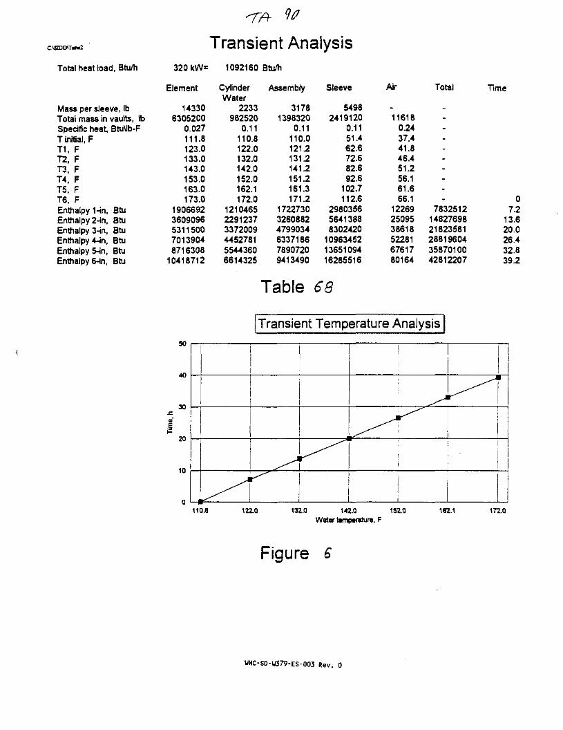
C:\SDD\Tniw2
Total heat load, Btu/h
Mass per sleeve, IbTotal mass in vaults, IbSpecific heat, Btu\lb-FT initial, FT1, FT2, FT3, FT4, FT5, FT6, FEnthalpy 1-in, BtuEnthalpy 2-in, BtuEnthalpy 3-in, BtuEnthalpy 4-in, BtuEnthalpy 5-in, BtuEnthalpy 6-in, Btu
320 kW=
Element
143306305200
0.027111.8123.0133.0143.0153.0163.0173.0
19066923609096531150070139048716308
10418712
1092160
CylinderWater
2233982520
0.11110.8122.0132.0142.0152.0162.1172.0
121046522912373372009445278155443606614325
^1 K 1 \l IW
Btu/h
Assembly
31781398320
0.11110.0121.2131.2141.2151.2161.3171.2
172273032608824799034633718678907209413490
II ¥ MIW
Sleeve
54982419120
0.1151.462.672.682.692.6
102.7112.6
298035656413888302420
109634521365109416285516
Table 68
Air
-11618
0.2437.441.846.451.256.161.666.1
122692509538618522816761780164
Total
----------
78325121482769821823581288196043587010042812207
Time
07.2
13.620.026.432.839.2
Transient Temperature Analysis
40
30
20
10
(1
i
1
1
110.8 122.0 132.0 142.0 152.0Water tamptrature, F
162.1 172.0
Figure £
UHC-SD-W379-ES-003 Rev. 0
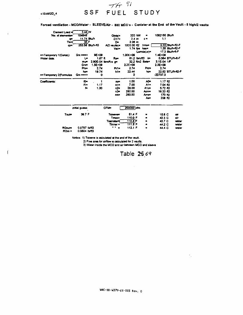
c:\Sidd\2D_4 SSF-Tfir
F U E! L"57
S T U D Y
Forced vantflatton . MCO/Water • SLEEVE/AIr - 880 MCO s - Canister at th« End of * • Vault - 5 high/2 vaults
Etomtfit Load * 3.44 jW'No.ofAJamants* 104846
a- 11.74 Btu/hT H 35 jFqx* 253.56 Btu/h-R3
•>Tamponry 1 (Const) G« • • • > 9E*09Watar dato: L- 1.87
mu- 2.90E-04Gno 1.5E+09Prx- 2.74hx- 19.74
•>Tamporary 2(Formula$ Grx —-> 0
Coafficiants.' 1^m , 1f i " 1.17
f- 1.X
Initial guass:
Tou^ 39.7 F
ROout- 0.0797 iMt3ROin - 0.0604 !Wt3
Qtotal>D17-
OA(2 vaub)>
Vair-
ft Ro-Ibmfl-t a"
FT1-h i -
nx"n i -fi2"n3>n4-
CFM- f
Ttltwi*Tmoo"
TeanMaHTinnar"
• • •
3202.4
2.061920.X
1.74
1.XE+0981.232.2
22E+OS2.74
22.440
1.X7.X
28.X26O.X260.X
200000
51.4110.0110.8111.8112.1
kWinin1t2fps
•
ifflS* |hsa*
Lamda(ur)-
ItHWTO k-ft/s2
efm
FFFFF
B*t>"
Pru-hc-
A0-A1-
A1c-Acm«Am$»
As»
10921601.1
0.331.3517.3
1.46*090.364
3.1 E-042.3E-O9
2.7422.82
-22737.3
1.177.045.72
16.33170206
10.643.343.744.244.4
Btu/h
Btu/h-R2-Ffltu/h-«2-FBtufft-ft-F
BTU/n-lt-F1/F
BTU/h-«2-F
K2(12ratarata
C airC airC watarC watarC wattr
Note*: 1) Tsla«va is eaJeulatad tt 1h« «nd of th« vault2) Fra« araa for aifflow n ealculatad for 2 vaute.3) Watar insid* tha MCO and air batwacn MCO and sl—v
Table 25 61
UHC-SD-W379-ES-003 Rev.

c:\Sidd\2D_4 SSF FUEL STUDY
Forced vtnUlatfon - MCQ/Water - SLEEVE/Air - 840 MCO's - CanlsW at t h * End of t h * Vault - 5 htgh/2 vaults
EJorrwnt Load M"No. of »l»mant*»
3 44 jW10404S
11.74 Btufti35|F
Qtot«l«D U -
D-qx- 253.58 Btu/h-IO
"Temporary 1 {Const)Water data:
GrxL-
Gnt-Pre-hx-
>Tampor«ry 2(Formulas Grx • • • >
Vnr-
1.87 fl Ro-2.90E-04 Ibmm-t g-1.5E*09
2.74 Prt«19.74 hi-
320 kW -2.4 in e •
2.06 in1920.X «2 nrM- [
0.62 fps hM-Lamda(uf)-
1.00E+O961J lbnVR3 k-327 fti2 B«t»
2-2E*092.74 PTO-
22.44 he-
1092160 Btu/h1.1
1.12 Btu/h-112-F17 J
1.4E+090.384
3.1E-042.36*09
2.7422.82
-29004.4
Co«fAci*nt3:f i -
11.171.00
rw«n i -n2-n >n4-
1.007.00
28.00280.0028O.X
A 1 -A1e-
Aem*Ams»
As-
1.17 1127.04 H25.72 tt
18.33 (t2170 «2206 IT3
InrttaJ BUMS.'
Tout- 48.5 F
CFM- TTOOOjcfm
Tmco"Tcantstar^
Tinn«r"
62.6 F121J F
ROout-ROin"
0.0784 Ib/R30.0804 IMt3
12T01F12T7F123.3 F
17.0 C49.5 C50.0 C50.4 C50.fi C
airairwatarwatarwatar
Nobca: 1) Tsia«v* is calculated atlhaand of thavault2) Fra« araa for airflow is calculated for 2 vmutts.3) Water insJd* tha MCO and air batWMn MCO and sl*«v«
Table 2£7<?
WHC-SD-W379-ES-003 Rev. 0

.e:\Sidd\2D 4 SSF FUEL STUDY
Foretd vantllatlon • MCO/Watar - SLEEVE/AIr - i«0 MCO'i - Canlstar at Bit End of Bit Vault • S hlgh/2 vaults
Element Load i 3.44 [W*No. of element*" 104646
9* 11.74 Btu/hTin^ 35 IFqx- 253.58 Btu/h-ft3
"Temporary 1 (Const) On •» •> 96+09Water date: L- 1.87
mu> 2.90E-04Gno 1.5£*O9Prx- 2.74hxm 19.74
•>Tamponiy 2(Fofmuias Gra •« •> 0
Coefficients: n > 1f i - 1.17f- 1.00
InitiaJ guess:'
Tout- 57.7 F
ROout- 0.0770 IMt3ROin - 0.0804 Ib-TO
Qtotat-D17«
r>A<2vBulti)*
Vair>
ft Ro-tbnVTt-s g-
PT1-M "
nx-M -n2*n3-n4-
CFM- f
Tsia^a-Tmeo"
Teanbter^Tlnnef •
• • a.
320 kW2.4 In
2.06 in1920.00 1t2
0.37 fps
•
C "
hms" |hsa-
Lamda(ur)-1.00E+09
612 IbmTO k-322 ft*2
23E+Q92.74
22.440
1.007.00
26.00260.00280.00
42400 Icfrn
72.6 F131.2 F132.0 F132.7 F133.2 F
B«t»
Prc-hc-
AO-A 1 -
A1c«Acm-Am*-
1092160 Btum1.1
0.33|BtuAt-A2-F1.07 Btu/Ma-f17 2 Btu/h-ft-F
1.4E+090M4 BTU/h-ft-f
3.1E-O4 1/F2.3E+09
2.7422.62 BTU/h-lt2-F
-27025.6
1.17 Itt7.04 ft25.72 n
16.33 ft2170 fl2208 ft2
22.5 C air55.0 C air55.5 C water55.9 C water56.2 C water
Notica: 1) T*Ja«va is ealeutatad at tha and of th* vault2) Fra« i r n for airflow is calculated for 2 vautb.3) Water insid« tha MCO and air b«tw««n MCO and S I M V I
Table
UHC-SD-W379-ES-003 Rev. 0
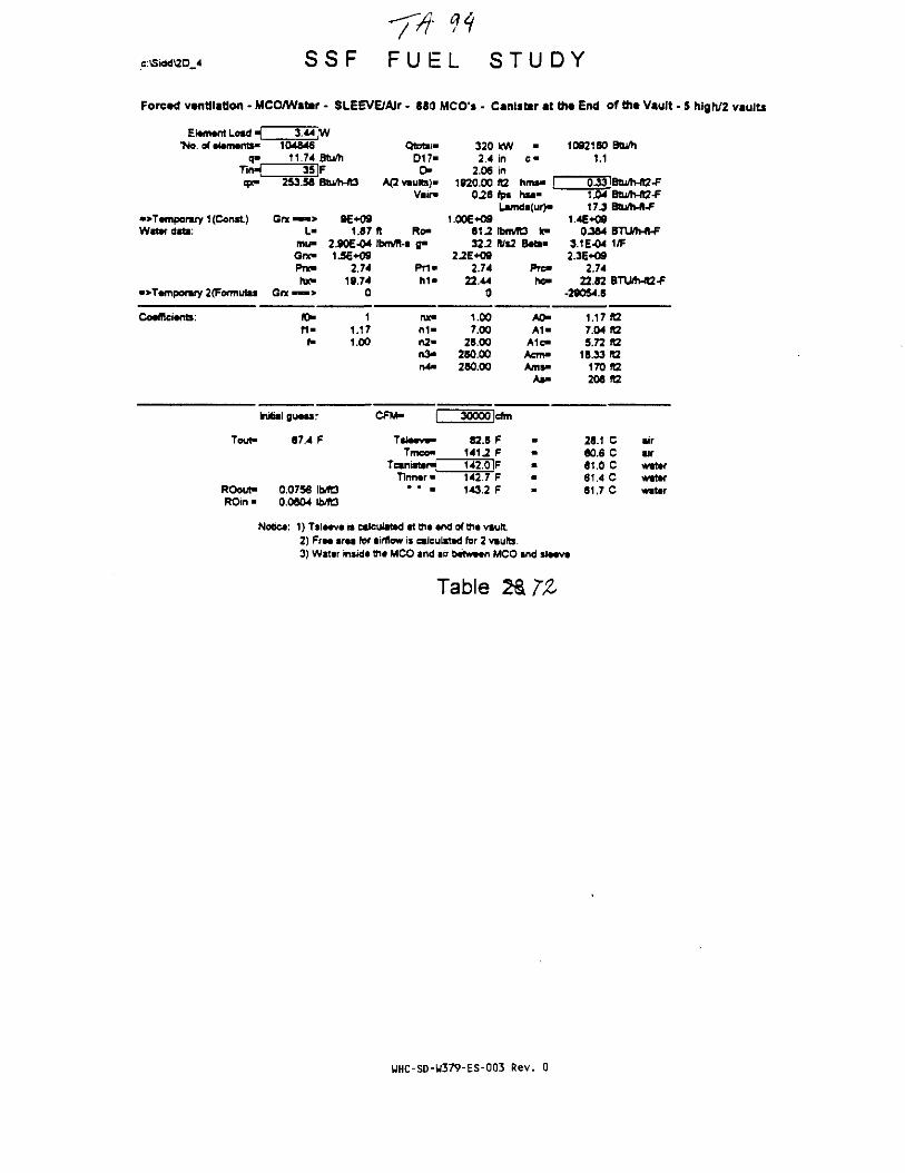
c:\Sidd\2D 4 S S F S T U D Y
ForcKt ventilation - MCO/Water - SLEEVE/AIr - 880 MCO's - Canlsttr at th* End of th« Vault - $ high/2 vaults
EtoAMflt Load \_*No. of •iarrwntS"
T i n ^qx-
•>T«mponwy 1 (Const)Water data:
•>T«mporary 2(Formulis
Co«fRci«fib:
3.44 JW104646
11.74 Btu/h35 IF
2S3.5A Btu/h-ft3
Grx — • > 9E+09L- 1.87
mu- 2.90E-04Grx» 1.56*09Pnt- 2.74hx- 19.74
G n — > 0
fO» 1f i - 1.17f- 1.00
Initial guaur
Tout"
ROout"ROin-
67.4 F
0.0756 \MO0.0S04 IMC3
Qtrtii-D17-
r>A(2 vaults)'
Vair*
ft Ro-tbm/TI-s a"
P r i -h 1 -
ruc«n1-n2-n >rO-
CFM- f
TS1MV«>
Tmeo"TetnisWrJ
Tlnn«r •* • •
3202.4
2.061920.00
0.26
1.006^0961232.2
2.2E+092.74
22.440
1.007.00
28.00260.00260.00
30000
82.61412142.0142.7143.2
kWininft2fp»
•
e-
hms« |hsa-
Lamdi(ur)"
IbrMO k"K%2
cffn
FFFFF
B«ti>
PTC-rtc-
A0-A1«
A1e-Acm«Arns*
As-
1092160 Btu/h1.1
0.33|BtuAvft2-F1.04 Btu/Mt2-F17JBtUh<ft-F
1.4E*O90J84 BTUh-n-F
3.1E-04 1 ^2.3E*O9
2.7422.82 BTU/h-(t2-F
•29054.6
1.17 ra7.04 ft25.72 ft2
18.33(12170 ft2206 It2
26.1 C air60.6 C aJr81.0 C water61.4 C wattr61.7 C water
Notet: 1) TS IMV* is calculated at th*«nd of th«vautt2) FfM traa for airflow is calculated for 2 vaults.3) Water insid* ttia MCO and air b*twt«n MCO and sl*«v«
Table
UHC-SD-W379-ES-003 Rev. 0
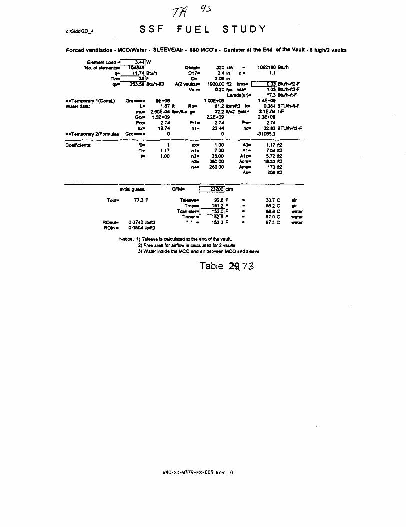
c:\Sidd\2D_4 S S F F U E L S T U D Y
Forced ventilation • MCO/Wattr • SLEEVE/AIr - 880 MCO'i - Canister at th« End of th* Vault - 5 hlgh/2 vaults
Element Load <"No. of elements*
q*T i n ^qx»
"Temporary 1 (Const)Water date:
•>Temporary 2 (Formulas
CoeffieienB:
3-44 |W104646
11.74 Btu/h35 IF
253.56 Btu/MQ
One— > 8t -
mu> 2.9I
e«o91.87
3£-O4One 1£E*09Prx-roe
Gnca»>
ro-f1"
1m
Initial guess:
Tout"
ROout-ROtrt"
77 J F
0.0742 !bu1»30.0604 IMQ
2.7419.74
0
11.171.00
Ototel-D17-
OA(2vaults>«
Vair-
ft Ro-Ibm/ft-s a-
P r i -M -
nx"n1"n2«i t >n4>
CFM- f
Tsleeve*Tmco-
TcanistenTinner"
• ' a
3202.4
2.061920.00
0.20
1.00E+09t\2322
2^E+092.74
22.440
1.007.00
26 00280.00280 00
23200
92.6151.2
152.8153.3
kWininK2tp»
•
C "
hms" |hM"
Lamd*(ur>-
bmft/si
STT\
FFFFF
its k>B*ti"
Pre-he-
A0-A1"
A1c-Acm>Ams*
As>
10921601.1
0.331.0317J
14E*<»0.3S4
3.1E-042.36 *O9
2.7422.82
•31095J
1.177.045.72
16.33170208
33.766266.S67.057.3
Stum
Btu/h-A2-FERu/h-A2.FStu/h-ft-F
BTUh-«-F1/F
BTU/h-ft2-F
ft2K2tata
to.
C airC lirC waterC waterC water
Notice: 1) T S I M V * is calcultttd i t th« «nd of the viult.2) FrM ir«a for airflow is calculated for 2 vaub.3) Water insid* th* MCO ind air between MCO and sleeve
Table
WHC-SD-W379-ES-003 Rev. 0

c:\Sidd\2D_4 S S F F U E L S T U D Y
Forced vtntilaflon - MCO/Wattr - SLEEVE/AIr • 880 MCO1* • Canister at th« End of ttit Vault - 5 hfgh/2 vaults
Element toad H 3.44 |W'Ho. of elements- 104846
q- 11.74 Btu/hTirH 35 IFq*> 253.56 BturtvM
«>Temporary t (Const) Grx — > 9E+O9Water date: L- 1.87
mu> 2.90E-04Gnr- 1.5E+09Pnc 2.74hx- 19.74
•> Temporary 2(Formutas Grx — » 0
Coefficients: 10- 1f l« 1.17
f- 1.00
Initial guess:
Touf 87.2 F
ROout- 0.0729 lb^3
QtotaND17-
t >A(2 vauRs)-
Vair>
ft Ro-IbmAl-s B"
Pn-h i -
nx-n1»n2-n >n4>
CFM- f
TllMW-Tmco"
Tcantster^Tinner-
* * •
3202.4
2.06
kWinin
1920.X «20.16
1.00E+096 U322
Z2E+092.74
22.440
1.X7.X
28.X280.X280.X
fp*
•
c-
hms-hsa-
Lamda(ur)"
IbmTO k»ftrs2
18950 Icftn
102.7161.3162.1162.8163.3
FFFFF
Beta-
Pre-hc-
A0-A1"
A1c-Acm-Ams>
As«
10921601.1
0.331.0217.3
1.4E+090.384
3.1E-042.3E-KJ9
2.7422.82
•33136.3
1.17
Btu/h
|Btu/h-ft2<FBtU/h-fQ-FBtu/h-ft-F
BTU/h-ft-FUP
BTUftvfl2-F
ft27.04 (t25.72
18.33170208
39-271.872.272.672.9
(t2ft2rt2ft2
C airC airC waterC waterC water
ROin • 0.0804
Notice 1) TS IMV* is calculated at th» «nd of th« vault2) FrM araa for airflow is calculated for 2 vaults.3) Water instd* th« MCO and air bttWMn MCO and S IMV*
Table
WHC-SD-W379-ES-003 Rev. 0

c:\Sidtf2D 4 S S F F U E L S T U D Y
Forced ventilation - MCO/Water - SLEEVE/Air - 860 MOO's - Canister at the End of the Vault • 5 hlgh/2 vaults
E!*m*nt Load - (_'No. of ti*m«nts>
d " _T i r>^qx-
•> Temporary 1 (Const)Water date:
»T*mporary 2(Formulas
Co«flfd«nts:
3.44 |W104846
11.74 Btu/h35 IF
253.56 8tu/h-ft3
Gnc — > 9E+09L- 1.67
mil- 2.90E-04Gnc" 1.5E+09Prx- 2.74hx- 19.74
O r e — > 0
fO- 1f 1 - 1.17
f- 1.00
Initial gu*ss:
Tout"
ROout-ROin«
97.1 F
0.0715 Ib/fO0.0804 IMQ
QiateN017-
o-A(2 vaults)-
Vail*
ft Ro-tbnvH-i 8*
Pr i -h 1 -
nx"n 1 -n2«nS*r»4-
CFM-
Tsi««v»-Tmeo"
Tcanistar*Tlnnar •
" • a
320 kW2.4 in
2.06 in1920.00 RZ
0.14 fpa
•
C "
hnw |hsa*
Laxnda<ur)"1.006*09
612 Ibm/R3 k-322 AV»2
22E*O92.74
22.440
1.007.00
26.00260.00260.00
16060 Icfm
112.6 F1712 F172.0 IF172.8 F173.3 F
B«ta-
Pre-hc-
A0-A1-
A1c«Acm«Ams-
A S -
10921601.1
0.331.0217 2
1.4E+090.364
3.1E-042.3E-H39
2.7422.62
-35151.9
1.177.045.72
16.33170206
44.777.377.778.178.4
Btu/h
B1u/h-ft2-FBtu/h-ft2-FBQi/h-ft-F
BTUftvft-F1/F
BTU/Mt2-F
ft2KZKZtafQft2
C airC airC waterC waterC water
Notica: 1) Tslaava is calculated at tht and of the vautt.2) Fra* traa for airflow is calculated for 2 vaults.3) Water insida th« MCO and air batwawi MCO and sla«v«
Table H IS
UHC-SD-W379-ES-003 Rev. 0

PROBLEMLIBRARY
DEFINEPROBLEM
PREPAREINPUT
GRAPHICRESULTS
RETURNTO DOS
EasyFlofi 2.01
FILENAME :
DESCRIPTION :
ACTIVE PROBLEMSSFJZD2 UflULTS. 20 CASE. 270 KM £*1S INLEt •„«-
REUIEM RESULTS
This post processor allows you to graphically review
the results of your CFD analysis. You can display any
solved or stored dependent variable results as colored
contour plots or as a colored filled contour plots at
any plane of interest. velocities can be shoun as
color coded vectors at any plane. This step runs the
PHOTON progran. Refer to PHOTON User Manual TR140.
Select Option and Press <Return>
WHC-SD-W379-ES-003 Rev. 0

Uieupoint:Up uector:
Command?
1.G0 O.QQG -B.254E-05B.254E-B5 0.127E-B5 1.OB
2 UAULTS, 2D CASE, 27B KW, 115 IMLET PHOEMICS
r 9UHC-SD-W379-ES-003 Rev. 0

rvTri'T^^TtSasa
Z.62 m/s.2 UAULTS, ZD CASE, 27Q KW, 115 IMLET
UHC-SD-W379-ES-003 Rev. 0
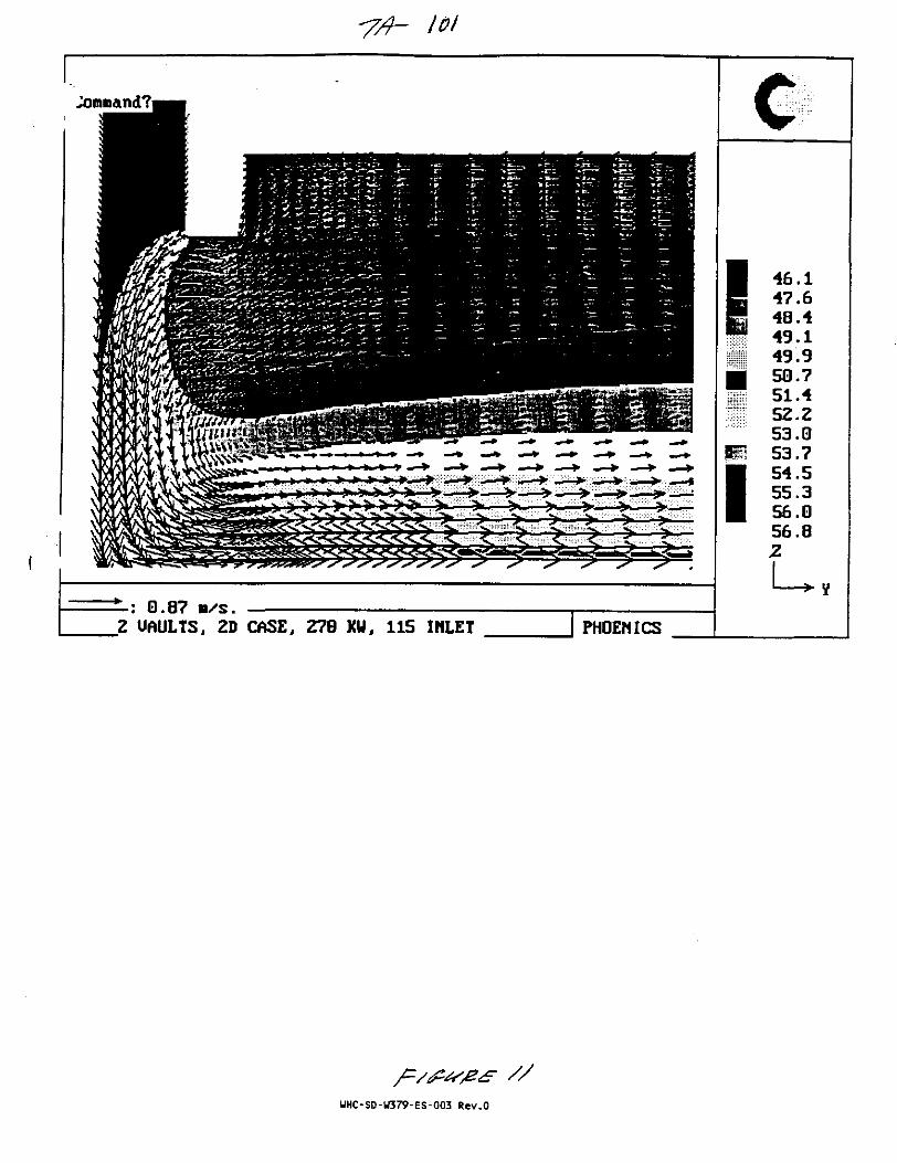
*7/h 101
Z UAULTS, ZD CASE, 279 XU, 115 INLET
//
UHC-SD-U379-ES-003 Rev.O

Z UAULTS, 2D CASE, 270 KU, 115 IHLET
WHC-SD-W379-ES-003 Rev. 0
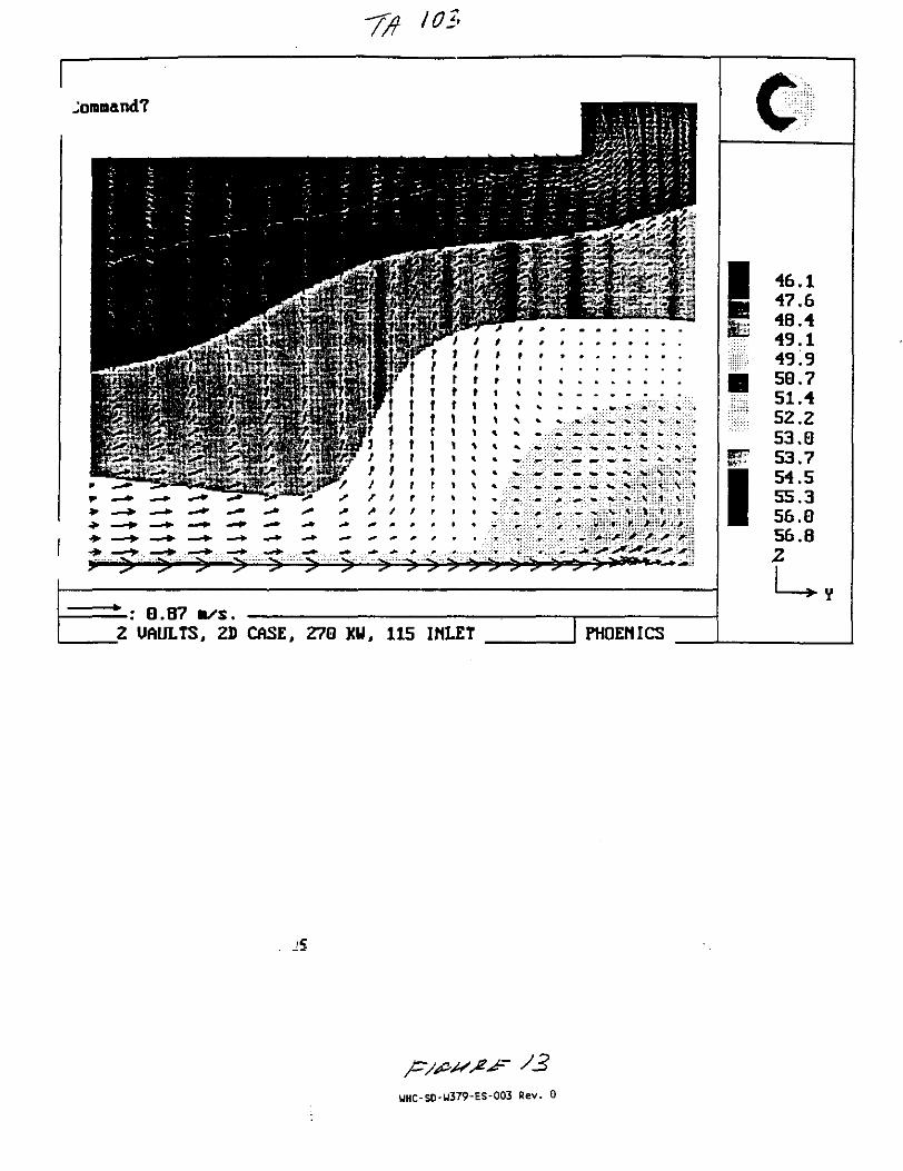
IOS
G.B7 n/s.Z UAULTS, 2D CASE, 270 KU, 115 INLET
UHC-SD-U379-ES-003 Rev. 0

"T
PRINCIPLES OFHEAT TRANSFER
Frank KreithUniversity of Colorado and National Conference of StateDenver, Colorado
Mark S. BohnNational Renewable Energy LaboratoryGolden, Colorado
Property ofIrvine Tech. Info Cenf
Fluor Daniel
WEST PUBl HING COMPANY
ST. PAUL MEW YORK LOS ANGELES
UP- la-

d ,;c
iar to [he rvsult obiainisi ;:>r:lation (see r::.q. (2.2D). In ijr
mMly by simplifying th gfn ieids
co \-
Won-- 'vhi: I we deduce ths.t, to satisfy :he boundary condition dTjdr •- Oat r = 0,the .:£inst.ir:i of integration C : must be zero, Another integration yields thelemp"-*ratu e: distribution
To satisfy the condition that the temperature at the outer surface, r = ro, is^ ) + To. The temperature distribution is therefore
The maximum temperature at r ~ 0, 7 ^ , is
71.. = z + i
In dimensionless form Eq. (2.50) becomes
T(r) - T
T - T \r
(2.50)
(2.51)
(2.52)
For a hollow cylinder with uniformly distributed heat sources and specifiedsurface temperatures, the boundary conditions are
T = 7* at r « r, (inside surface)
T * 7i at r = /•„ (outside surface)
It is left as an exercise to verify that for this case the temperature distribution isgiven by
4A
If a solid cylinder is immersed in a fluid at a specified temperature Tv andthe convection heat transfer coefficient at the surface is specified and denoted byhn the surface terr.perature at ra is not known a priori. The boundary conditionfor this case requires that the heat conduction from the cylinder equal the rateof convection at the surface, or
dr , . , . ' * *
Using this condi m to evaluate the constants of integration yields for the di-mensionless tern ature distribution
7". 4AC7(2.54)
UHC-SD-W379-ES-003 Rev. 0

TABLE 12 Metallic Elements'
Element
AluminumAntimonyBerylliumBismuth'
Boron'Cadmium'
1 CesiumChromiumCotwH'Copper•~er?n*niuinilOMIHafniumIndiumIridiumIronLeadLithiumMagnesiumManganese
200 K-73°C
23730.2
3019.7
52 5993368
I I I12241396.8
327244897
15)9436688.1
1597.17
Thermal Coodwilt l ly
273 K
<r°c3TF
23625 5
21882
31797 536 1948
104401
6673182)3837
14883535579.2
157768
400 KI27°C261°F
600 K327"C62I"F
x 0.5777-<Bm/hrft
240212
161
18794.7
1
87384.8
39243.2
31222.374.5
14469.433872 1
153
232182
126
11.3
805
38327.3
304 .21.3
13854.7312
149
k ( W / n K)»
BOOK527"C981 °F
°F)
220168
107
81
71.3
371198
29220.8
13243.3
146
1000 K727°CIJ4I°F
89
6.3
65.3
357174
278207
12632.6
1200 K•27°CI7»I°F
73
52
62.4
34217.4
262209
12028.2
Properties al 293 K or 20°C or 68SF
P(fcB/m1)
x * - 2 4 3 x l 0 *•Mlb./f t1)
2,7026,6841.8509,7802,5008.6501.8737,1608,8628.9335.360
19.30013,2807.300
22.5007,870
11,340534
1.7407,290
x 2.388 x I0~4
- ( B l u / l b . °F
896208
1750124
1047231230440389383
129
134452129
33911017486
k(W/mk)
x 0.5777-<Btu/hrf l*F)
236246
2057.9
286973691.4
100399616
31623 1822
14781 1
35.377.4
1567.78
• x 10*
(m'/s)
x 3.874 x 10*
-(ft1/*)
97.517.763.36 51
10.948.583629.0290
1166
126.9
48.822824.1
42788222
MeltingTemperature
<K)
911904
1550545
2573594302
2118176513561211133624954)0
2?!61810601454923
1517
\
I X1 -I1
O N
Mercury'MolybdenumNklclNiotuuin
28.914310652 6
13994M l
134801*« i
12665 5
11867.4, . • .
112718
10576
13,54610,2408.9O0

lolybdcnumci
j iumPalladiumPlatinumPotassiumRheniumRhodiumRubidiumSiliconSilverSodiumTantalumTin'Titanium'Tungsten'Uranium'VanadiumZincZirconium'
14310652675.572.4
10451
15458 9
264403138575
73324.5
19725.1315
123252
1399453 3
755715
10448 6
151583
168428135574682224
18227313
122232
1348015527557165246 1
146
98 9420
57862 2204
162296321
116216
12665.5582755730
44.2136
61.9405
58.6
19 413934342
10520.7
11867.461375.575.5
44 1127
422389
594
19712838.8363
216
11271864475.578 6
44 6121
312374
60 2
207121439386
237
10576167.5
826
45.7115
257358
61
221154941.2
25.7
i * -
8.57012.02021.450
86021.10012.4501.5302.330
10.500971
l6,b005,7504,500
19,3,0019.070}^6.100
7.1406.570
251446270247133741137248348703234
1206138227611134113")502385272
1389153675.571.4
103481
150582
15342713357.567022.0
17927431.4
12122.8
53.7229232254250
161.6166486
109.3934
173.8113.625 151.380
69212710.3
44012.8
2)428831726
274118252042
33734532233
31216851234371
3269505
1953365314072192693
2125
* Purity for all dements exceeds 99%.* The eipccled percent errors in the thermal conductivity values arc approximately within ± 5% of the true values near room temperature and wilhin about± 10% at other temperatures.' Fur crystalline materials, the values are given for the polycrysialline materials.Source E.ft.G. Eckerl and R M Drake. Analysis "/ / ' « " and Muss Transfer, McGraw-Hill. New York, 1972; K- Raznjcvic, Handbook of ThermodynamicTables and Charts. 3d cd.. McGraw-Hill, New York, 1976; Y.S Touloukian, cd , Thermophysital Properties of Matter, IFI/Plcnum, New York, 1970.

l°8
1989 ASHRAE HANDBOOK
FUNDAMENTALS
I-P Edition
American Society of Heating, Refrigerating and Air Conditioning Engineers, Inc.1791 Tullie Circle, N.E., Atlanta, GA 30329
404-636-8400
UHC-SD-W379-ES-003 Rev. 0

'09
r
3.8
This useful relationship gives a rough idea of the ipectral energydistribution from a black surface; 257* of the energy :is radiatedat wavelengths shorter than the maximum, and 7.17a is radiatedat wavelengths longer than the maximum.
Actual Radiation
Substances and surfaces diverge variously from the Stefan-Bolumann and Planck Laws. Wb and WH are the maximumemissive powers at a surface temperature. Actual surfaces emit andabsorb less readily and are called nonbtack. The emissive powerof a nonblack surface, at temperature T, radiating to thehemispherical region above it is written as:
W m tWb~ tqT* (36)where c is called the hemispherical emittance. The term emittanceconforms to physical and electrical terminology; the suffix "ance"denotes a property of a piece of material as it exists. The ending"ivity" denotes a property of the bulk material independent ofgeometry or surface condition. Thus, eraittance, reflectance, ab-sorptance, and transmittance refer to actual pieces of material.Emissivity, reflectivity, absorptivity, and transmissivity refer toproperties of materials which are optically smooth and thickenough to be opaque.
The emittance is a function of the material, the condition of itssurface, and the temperature of the surface. Table 3 lists selectedvalues; Siegel and Howell (1981) have more extensive lists.
The monochromatic emissive power of a nonblack surface issimilarly written as:
tx(Cxk-i/eci'lT- I) (37)
where e, is the monochromatic hemispherical emittance. Therelationship between t and ct is given by:
or
[Jo
(l/flD (\WujttlJ 0
(38)
If tL does not depend on A, then, from Equation (38), t - £t.Surfaces with this characteristic are called gray. Gray-surfacecharacteristics are often assumed in calculations. Several classesof surfaces approximate this condition in some regions of the spec-
1989 Fundamentals Handbook
tmm. The simplicity is desirable, but care must be exercised,especially if temperatures are high. Assumption of grayness issometimes made, because of the absence of information relatingi a n d A
When radiant enej-gy falls on a surface, it can be absorbed,reflected or transmitted through the material. Therefore, from theFirst Law of Thermodynamics:
a + T + Q « 1 (39)
where« • fraction of incident radiation absorbed or absorptanctT - fraction of incident radiation transmitted or (ransmitfanceQ - fraction of incident radiation reflected or reflectance
If the material is opaque, as most solids are in the infrared, T - 0and a + c • 1. For a black surface, a - I, Q • 0 and T - 0.Platinum black and gold black have absorptances of about 98%in the infrared, which is as black as any actual surface is. Anydesired degree of blackness can be simulated by a small hole in alarge enclosure. Consider a ray of radiant energy entering theopening. It will undergo many internal reflections and be almostcompletely absorbed before it has a reasonable probability of pass-ing back out the opening.
Certain flat black paints also exhibit emittances of 98^o overa wide range of conditions. They provide a much more durablesurface than gold or platinum black and are frequently used onradiation instruments and as standard reference in emittance orreflectance measurements.
Kirthhoffs law, relating emittance and absorptance of any opa-que surface from thermodynamic considerations, states that forany surface where the incident radiation is independent of angleor where the surface is diffuse, cx * ak. If the surface is gray, orthe incident radiation is from a black surface at the same temper-ature, then also c m a, but many surfaces are not gray. For mostsurfaces listed in Table 3, absorptance for solar radiation is dif-ferent than emittance for low temperature level radiation. This isbecause the wavelength distributions are different in the two cases,and £t varies with wavelength.
The foregoing discussion relates to total hemispherical radia-tion from surfaces. Energy distribution over the hemisphericalregion above the surface also has an important effect on the rateof heat transfer in various geometric arrangements.
Tablt 3 Emittaom ind Absorptances for t Few Surfaces*Total Normal Emittanct*
Class
23
4567S9
1011
Sarfacw At SO to 100 «F Ar 1000 °F
A small hole in a Urge box. sphere, furnace, or enclosure 0.97 to 0.99Black nonmetallic surfaces such as asphalt, carbon, slate, paint, paper.. 0.90 to 0.98Red brick and tile, concrete and stOQe*£uay steel and iro"ri>dark paints . ...
(red, brawn, green, etc) '.' '.' ^0.85 to 0.9$,-%Uow and buff, brick and stone, firebrick, fire day TTI5 ioQ.95White or light cream brick, tile, paint or paper, plaster, whitewash 0.85 to 0.9SWindow glass 0.90Bright aluminum paint; silt or bronze paint 0.4O to 0.60Dull brass, copper, or aluminum; galvanized sieet polished iron 0.20 to 0.30Polished brass, copper, monel metal 0.02 to 0.05Highly polished aluminum, tin plate, nickel, chromium 0.02 to 0.04Selective surfaces- -~-~._ , - - s
painless Keel wire mesh" 0.23 to 0.2^wlfite palnTebTsurface"! 0.92""Copper treated with solution of NaClOz snd NaOH 0.13Copper, nickel, tnd aluminum plate with CuO coating 0.09 to 0.2)
Absorptaace forSolar Radiation
0.97 to 0.990.90 to 0.98
0.75 to 0.900.70 to 0.850.60 to 0.75
0.30 to 0.50O.OS to 0.150.05 to 0.10
0.97 to 0.990.85 to 0.9S
0.65 to 0.800.50 to 0.700.30 to 0.50
c0.30 to 0.500,40 to 0.650.30 to 0.500.10 to 0.40
0.63 to 0.860.23 to 0.49
0.870.08 to 0.93
a See also Chapter 37, McAdamt (1954) *nd Si««l and Howeil (I9SI).b Hemispherical and normal emittance are noi equal in many cawi. The hemispher-ical emitunce mxy be at much ai 30% i/eater Tor polished reflecton lo 7f» lower Tornonconductors.
eAb*orbi * 10 *O** depending upon us innsmuiance
UHC-SD-W379-ES-003 Rev. 0

22.2 1989 Fundamentals Hamibocl
laboratory test conditions. Air gaps in ihese types of iiisuationsystems can seriously degrade thermal performance as a result ofair movement due to both natural and forced convection. Sabineetal. (1975) found the tabular values are not necessarily additivefor multiple-layer, low-cmittance airspaces, and tests on actualconstructions should be conducted to accurately determine ther-mal resistance values.
Values for foil insulation products supplied by manufacturersmust also be used with caution because they apply only to systemsthat are identical to the configuration in which the product wastested. In addition, surface oxidation, dust accumulation, andother factors that change the condition of the low-cmittance sur-face can reduce the thermal effectiveness of these insulationsystems. Deterioration results from contaa with several types ofsolutions, either acidic or- basic (eg., wet cement mortar or thepreservatives found in decay-resistant lumber). Polluted en-vironments may cause rapid and severe material degradation.However, site inspections show a predominance of well-preservedinstallations and only a small number of cases in which rapid andsevere deterioration has occurred.
CALCULATING OVERALL THERMALRESISTANCES
Relatively small conductive elements within an insulating layeror thermal bridges can substantially reduce the average thermalresistance of a component. Examples include wood and metalstuds in frame walls, concrete webs in concrete masonry walls, andmetal ties or other elements in insulated wall panels. The follow-ing examples illustrate how to calculate R-values and U-factors forcomponents containing thermal bridges.
The following conditions are assumed in calculating the designR-values:(1) Equilibrium or steady-state heat transfer, disregarding effects
of heat storage; , . "j
(2) Surrounding surfaces at ambient air temperature;(3) Exterior wind velocity of 15 mph for winter (surface * thR .
0.17 °F • ft: • h/Btu) and 7.5 mph for summer (surfare with I= 0.25"F-ft^h/Btu); and
(4) Surface emittance of ordinary building materials is 0.90.
Table 1 Surface Conductances, Blu/h-ft :-°F,tod Resistances, "F-fl^h/Btu, for Air'**11
PosiUos ofSurf ice
STILL AIRHorizontalSloping— 45*VerticalSloping—45"Horizontal
MOVING AIR
15-mph Wind(for winter)
7.5-mph Wind(for summer)
Directionof H « l
Flow
UpwardUpwardHorizontalDownwardDownward
(Any Position)
Any
Any
Surface Erailtaoce, **
NOB-reflectivct »
hi
(1.63;1.601.461.321.08
h9
6.00
4.00
0.90
R
0.610.620.6S0.760.92
R
0.17
0.25
",
0.910.880.740.600.37
h,
Reflective
0.20
ft
1.101.141.351.672.70
R
0 7$0.730.590.450.22
s.tsft
1 1 :I.T71,702,274.55
X
v •No surface ha* boih an airspace resistance value and a surface rename* vatae.No airspace value exists for any surface facing an airspace of leu than 0.3 m.
"For ventilated attics or spaces above ceilin|j under summer condition* ftmfio* down), see Table 5.
cConducunoes are for surfaces of the sated emittance facing virtual bUckbo*Tsurroundings at the same temperature as the ambient air. Values are based OBa surface-air temperature difference of 10 "F and for surface temperature of 70*F.
a See Chapter 3 for more detailed information, especially Tables 5 and 6. iadsee Figure I for additional data.
eCondensaie can have a significant impact on surface emittance (see TaUc 3).
Table 2 Thermal Resistances of Plane Airspaces ***, T • f t2 • h/Btu ,,.TJ ' H
PositionA*vl
Airspace
Horiz.
45*Slope
Vertical
45*Slope
Horii.
Direction Airspacevl
HealFlow
Up
Up
Horiz.
Down
Down
TcmpAT
90SOSO00
-SO- 5 0
90J 50
f 50/ 0
/ 0- 5 0- 5 0 ^
905050
+• 00
- 5 0-50
90
\ X
v o\ . 0X-50- 5 0
90
so300o
- 5 0
•viuv.
Oiff.',"F10301020102010
10301020102010
10301020102010
10301020102010
10301020102010
0.03
1131.621131.731101.69104
1441062.531202.63108162
1471371662.821931903.20
1481641671911943.163-26
2.481661671941963.253.28
0.5-ln. Airspace1
Effective Emiitaace, E**0.05
1031.571051.701041.66100
1311.9B1441141342.04136
134146-1541721821823.10
1341321551101833.073.16
1341541551831853.153.18
0J
Ml1.291.601.451.701.491.75
1.651.561.831.761031.78117
1.671.841.88114120135154
1.671.871.891191211521 5 8
1.671.881.89120122158160
OJ
0.990.961.111.121.271.231.40
1-061.101-221.301.441.421.66
1.061-231.241.501J31.761.87
1.061.241.251.521.531.861.89
1.061-241.25M31.531.891.90
042
0.730.750.840.911.001.041.16
0.760.130.901.021.101.171.33
0.770.900.911-13US1.391.46
0.770.910.921.151.151.451.47
0.770.910.921.151.161.471.47
0.031341.711301.831231.77116
2.961.991902.13172103153
3.501913.703.143.771903.72
3J33.433.8!3.754.123.784.35
3JS3.773.844.184.234.604.71
0.75-in. Airspace'
Effective Emiltance, £ * *0.05
1221.661211.792.161.74111
1781.92173107162101147
3.241773.463.023.391833.60
3.273-233J73.573.913.634.18
3.293.323.593.964.024.414.51
0.2
1.611.351.70L521.781.551.84
1.881.521001.721081.76110
1081011352.32164136187
1102.242.401632.812.903.22
2.10- 138
2.412.832.873.363.42
0.51.040.991.161.161.311.271.46
1.151.081.291.281.471.411.62
1.221.301.431.581.731.77104
1.221.391.451.72I.SO2.05121
1.221.441.451.811.821282J0
uxO7J0i7T
or0.93ISC1JT
uooilocuainU6IJ0
OS40MUK1.MIM1J91J*
OS4Offimu tIJD1.57\M015IJB1.0S1J0
uLafL7I
WHC-S0-W379-ES-003 Rev. 0
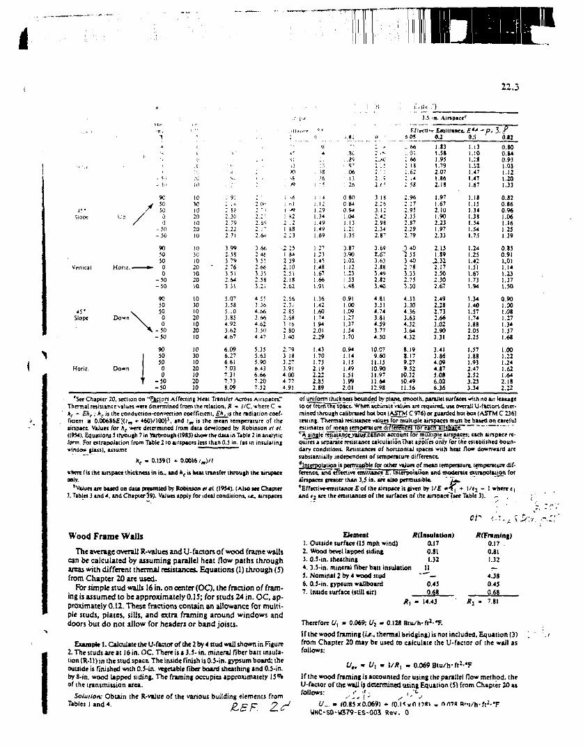
•22.3
Alnpicc '
Sloe*
45*Slope
Horiz.
Honz.
Down
Down
9C• 5 0
5000
-50- 5 0
9050JO
• 0
0- 5 0- 5 0
905030
00
-JO- 5 0
9030JO00
-50-50
10w1020!02010
10301020102010
10JO1020102010
10301020102010
: at2.102 792.222.71
3 99
3~792 763 J l2.6*3 J l
5.073.585.103-854.923.624.67
6.096.276 617.037.317.738.09
3 «.2M-3 5!2.663.352.583.21
4 553 364.663 664.623.504 47
J.35J.635.906.436.667.207.52
13
39
.51
.18
.62
.56J l.35.68
J.I6
:.so3.40
2.793.18
3.r3.914.004.774.9!
1.121.291.34M 9I *91.69
1.231.451.481.671.66L9I
1.361.421.601.741-942.012.29
1.431.701.732.192.222.852.89
.0613
: 26
0 800 840.941.041.131.211.35
3-870.901.021.121.23.1.33r.48
0.911.001.091.271.371.541.70
0.941.141.151.49\.S\l.W2.01
2. <;i.e
3. is
2.422.982.J4
3.692.S73.632.883.492-823.40
4.813.514.743.814.593.77i-30
10.079.60
11.1510.9011.9711-6412.98
OK. 66
0166IS
.62
58
.9617
2952.35:.s72.292.79
J 401553.402.783.332.753.30
4.333.304.363.634.323.644.32
8.198.179.279.52
10.3210.4911.56
9.1
1.831.581.951.792.07
I.S6
2. IS
1.971.672.101.902.231.972.33
2.15LS9
.2.322.172.J02.302.67
2.492.282.732.663.022.903.31
3.413.864.094.875.086.026.36
0JI i).I2
1.131.10i.::s1.121.471.471.67
1.181.151.341.381.541.541.75
1.241.2S1.421.511.671.731.94
1.341.401.571.741.882.052.25
1.571.881.932.472.523-25334
0.800.84CI.931.031.121.201.33
0.820.860.961.06.16.25.39
0.850.91.01.14.23.37.50
0.90.00.08.27M.37,68
.00
.22
.24
.621.642.182.22
*See Chapier 20, section on "Factors Affecting H«i Transfer Across Airspaces."Thermalrwmanet values were determined from [fierelation, j? =• //C, where C -kt - Eh,; h, is i he conduction-convection coefficient, fA. 15 the radian on coef-ficient a Q.OQ6$6El(tm * 460)/100)J, and im is the mean temperature of (heairspace. Values for hc were determined from data developed by Robinson tt at.(1954). Equation! 5 through 7 in ftrbrouth (1983) show the data in Table 2 in analyticterm. For extrapolation from Table 2 to airspaces lets than 0.5 in. (as in insulating«indo* glass), luumc " " — — — —
he - 0.159(1 + 0.0016/,,)//
there /is the airspace thickness in in., and he is heat transfer through ihe airspaceonly.
^Values are based on data prevented ay Robinson cr«/. (1954). (Alto see Chapter3. Tables 3 and 4, and Chapter 59). Values apply for ideal conditions, UL, Airspaces
of uniform thickness bounded by plane, smooth, parallel surfaces with no air leakageto or fromThTipace. When accurate values are required, use overall U-factors deter-mined ihrough calibrated hot bos (A5TM C 976) or guarded hot bo* (ASTM C 236)testing. Thermal resistance values for multiple airspaces must be based on carefulestimates of mean tcmperaturc'dii'jere'nccs tor eacn airspace! "'A single resmancevaiuf .cannot account lor multiple airspaces: each airspace re-quires a separate resistance calculation That applies only for the established boun-dary conditions. Resistances of horizontal spaces with heal flow downward aresubstantially independent of temperature difference.
Interpolation is permissjbje for other values of mean temperature, temperature dif-ference, and effective emictanct;£". Interpolation and moderate extrapolation forairspace* greater than 3.5 in. «re also permissible. " ~i^,'Effeetive^miiiancefof the lirtpace is given by ME ••¥j +• l/<2 - 1 where «|and f i are the emitunces of the surfaces of the ainpaceTsee Table 3). ^ .
Of
Wood Frame Walls
The average overall R-vaiues and U-faaors of wood frame wallscan be calculated by assuming parallel heat flow paths throughareas with different thermal resistances. Equations (1) through (5)from Chapter 20 are used.
For simple stud wails 16 in. on center (OC). the fraction of fram-ing is assumed to be approximately 0.15; for studs 24 in. OC, ap-proximately 0.12. These fractions contain an allowance for multi-ple studs, plates, sills, and extra framing around windows anddoors but do not allow for headers or band joists.
Example J. Calculate the U-factor of the 2 by 4 stud wall shown in Figure2. The studs are ai 16 in. OC. There is a 3.5- in. mineral fiber ban insula-tion (R-ll) in the stud space. The inside finish is O.J-in. gypsum board; theouuide is finished with 0.5-in. vegetable fiber board sheathing and 0.5-in.by S-in. wood lapped siding. The framing occupies approximately 13^*of the transmission area.
Solution: Obtain the R-vaJuc of the various building elements fromTables land 4.
Element A(Insuiaiion) #(Framing)1. Outside surface (15 mph wind) 0.17 0.17 .2. Wood bevel lapped siding 0.81 0.813.0.5-in. sheathing 1.32 1.324. 3.5-in. mineral fiber bait insulation 11 —5. Nominal 2 by 4 wood stud '— 4.386.0.5-in. gypsum wallboird 0.45 0.457. inside surface (still air) 0.68 0.68
Jt, - 14.43 ' tf2 - 7.81
Therefore t/, - 0.069; Uz - 0.128 Bni/h'ft2***
If the wood framing (le., thermal bridging) is not included. Equation (3)from Chapter 20 may be used to calculate the U-factor of the wall asfollows:
U4r - £/, - 1/*, . 0.069 Btu/h-ft2-*F
If the wood framing is accounted for using ihe parallel flow method, theU-factor of the will jj determined using Equation (5) from Chapter 20 asfollows: .' >' • , "<-
U.. - fO.85xO.069) + fO.I5vn i ?»UHC-SD-U379-ES-003 Rev. 0
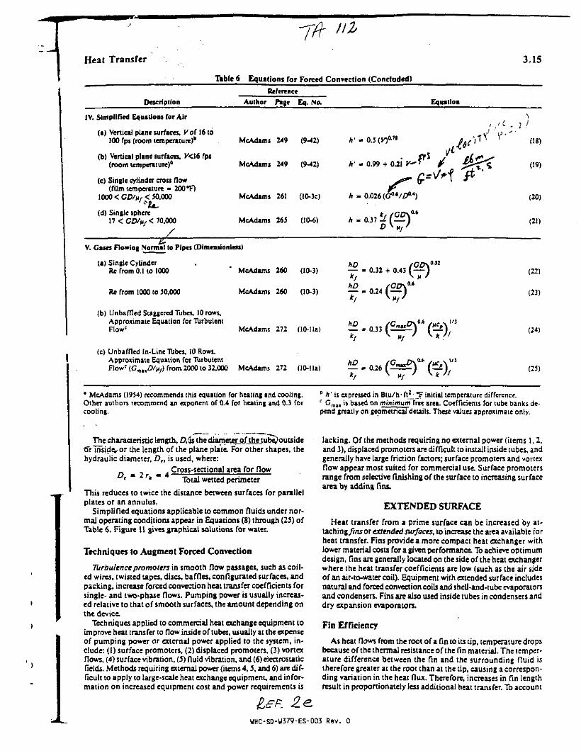
Heat Transfer 3.15
Table 6 Equations for Forced Convection (Concluded)
Reference
Description Author Pige Eq. No. Equation
IV. Simplified Equations for Air
(i) Vertical plane surfaces, Kof 16 to100 fps (room temperature)*
(b) Vertical plane surfaces, K<16 fps(room temperature)6
(c) Single cylinder cross flow(film temperature - 200 *F)
1000 < CD/fi, < 50.000
(d) Single sphere17 < CD/ftf < 70,000
1
McAdami 249 (9-42)
McAdams 249 (9-42)
McAdams 261 (10-3O
McAdams 265 (10-6)
A' « 0.99 + 0.21 C-*
(18)
(19)
(20)
(21)
V. Gases Flowing Normal to Pipes (Dimeosionless)
(a) Single Cylinder ,Re from 0.1 to 1000 ' McAdams 260 (10-3)
Re from 1000 to 50,000 McAdams 260 (10-3)
— - 0.32 + 0.4343 O f )
— - 0.24 (
(b) Unbaffled Staggered Tubes. 10 rows.Approximate Equation for TurbulentFlow' McAdams 272 (10-Ila) ^£. 0.33 (S=£)" ( ^
(c) Unbaffled In-Line Tubes, 10 Rows,Approximate Equation for TurbulentFlowc <Gm,,Z?/M/) from-2000 to 32.000 McAdams 272 (10-lla) « . 0.26
(22)
(23)
(24)
C5)
* McAdams (1954) recommends this equation for heating and cooling. ° h' is expressed in Btu/h• ft2 T initial temperature difference.Other authors recommend an exponent of 0.4 for heating and 0.3 for e Cmu is based on minimum free area. Coefficients for tube banks de-cooling, pend greatly on geometrical details. These values approximate only.
The characteristic length, D.is the diameter of the tube^outside•ffrTnside, or the length of the plane plate. For other shapes, thehydraulic diameter, Df, is used, where:
Cross-sectional area for flow' * * " Total wetted perimeter
This reduces to twice the distance between surfaces for parallelplates or an annulus.
Simplified equations applicable to common fluids under nor-mal operating conditions appear in Equations (8) through (25) ofTable 6. Figure 11 gives .graphical solutions for water.
Techniques to Augment Forced Convection
TUrbulence promoters in smooth flow passages, such as coil-ed wires, twisted tapes, discs, baffles, configurated surfaces, andpacking, increase forced convection heat transfer coefficients forsingle- and two-phase flows. Pumping power is usually increas-ed relative to that of smooth surfaces, the amount depending onthe device.
Techniques applied to commercial heat exchange equipment toimprove heat transfer to flow inside of tubes, usually at the expenseof pumping power or external power applied to the system, in-clude: (I) surface promoters, (2) displaced promoters, (3) vortexflows, (4) surface vibration, (5) fluid vibration, and (6) electrostaticfields. Methods requiring external power (items 4,5, and 6) are dif-ficult to apply to large-scale heat exchange equipment, and infor-mation on increased equipment cost and power requirements is
lacking. Of the methods requiring no external power (items 1, 2,and 3), displaced promoters are difficult to install inside tubes, andgenerally have large friction factors; surface promoters and vortexflow appear most suited for commercial use. Surface promotersrange from selective finishing of the surface to increasing surfacearea by adding fins.
EXTENDED SURFACE
Heat transfer from a prime surface can be increased by at-laching/ins or extended surfaces, to increase the area available forheat transfer. Fins provide a more compact heat exchanger withlower material costs for a given performance. To achieve optimumdesign, fins are generally located on the side of the heat exchangerwhere the heat transfer coefficients are low (such as the air sideof an air-to-water coil). Equipment with extended surface includesnatural and forced convection coils and shell-and-tube evaporatorsand condensers. Fins are also used inside tubes in condensers anddry expansion evaporators.
Fin Efficiency
As heat flows from the root of a fin to its tip, temperature dropsbecause of the thermai resistance of the fin material. The temper-ature difference between the fin and the surrounding fluid istherefore greater at the root than at the tip, causing a correspon-ding variation in the heat flux. Therefore, increases in fin lengthresult in proportionately less additional heat transfer. To account
WHC-SD-U379-ES-003 Rev. 0


