Embed Size (px)
Citation preview
Edition 07/2004 ♦ English translation 02/2009 Page 1 of 31
DEUTSCHER KALIBRIERDIENST
Guideline DKD-R 5-7
Calibration of Climatic Chambers
DKD-R 5-7 ♦ Calibration of Climatic Chambers
Edition 07/2004 ♦ English translation 02/2009 Page 2 of 31
Published by the Accreditation Body of the Deutscher Kalibrierdienst (DKD) in cooperation with its Technical Committee “Temperature and Humidity”. Copyright © 2004 by DKD English translation 02/2009 The document and all its parts are protected by copyright. Any unauthorized use outside the narrow limits set by the Copyright Act is inadmissible and liable to prosecution. This applies in particular to copies, translations, microfilming and storage and processing in electronic systems. Deutscher Kalibrierdienst (DKD) The DKD consists of the Accreditation Body and independent calibration laboratories of in-dustrial enterprises, research institutes, technical authorities, inspection and testing institutes. The laboratories are accredited and supervised by the Accreditation Body. They calibrate measuring instruments and material measures within the scope of accreditation. The DKD calibration certificates issued by them prove traceability to national standards as required in the ISO 9000 family and ISO/IEC 17025. Calibrations carried out by DKD laboratories ensure that the user can rely on measurement results, increase the customers' confidence and competitiveness on the national and interna-tional markets and serve as a metrological basis for the inspection of measuring and test equipment within the framework of quality assurance measures. Publications: see Internet Address: Deutscher Kalibrierdienst Akkreditierungsstelle Bundesallee 100, 38116 Braunschweig POB 33 45, 38023 Braunschweig Germany Telephone (office): + 49 05 31 5 92-19 01 Fax: + 49 05 31 5 92-19 05 Email: [email protected] Internet: www.dkd.eu
DKD-R 5-7 ♦ Calibration of Climatic Chambers
Edition 07/2004 ♦ English translation 02/2009 Page 3 of 31
Contents Preface........................................................................................................................................ 4 1 Scope .................................................................................................................................. 4 2 Symbols and abbreviations................................................................................................. 5 3 Definitions.......................................................................................................................... 6 4 Objectives of calibration .................................................................................................... 7 5 Requirements for climatic chamber (calibratability) ......................................................... 8 6 Calibration methods ........................................................................................................... 9 7 Calibration procedures ..................................................................................................... 10
7.1 Arrangement of measuring locations ....................................................................... 10 7.1.1 Calibration for useful volume by method (A) or (B) ....................................... 10 7.1.2 Calibration for measuring locations by method (C)......................................... 11
7.2 Determination of spatial inhomogeneity .................................................................. 11 7.2.1 Temperature inhomogeneity ............................................................................ 11 7.2.2 Humidity inhomogeneity.................................................................................. 11
7.3 Determination of temporal instability ...................................................................... 12 7.4 Determination of radiation effect ............................................................................. 12 7.5 Determination of loading effect ............................................................................... 14
7.5.1 Active loading with power dissipation............................................................. 15 7.6 Humidity calibration ................................................................................................ 15
8 Uncertainty contributions................................................................................................. 16 8.1 Spatial inhomogeneity inhominhom ; hT δδ .............................................................. 16
8.2 Temporal instability instabinstab ; hT δδ ................................................................... 17
8.3 Radiation effect radiationTδ .................................................................................... 17
8.4 Loading effect loadload ; hT δδ .............................................................................. 18
8.5 Influence of ambient conditions envenv ; hT δδ .................................................... 18
8.6 Resolution of indicators resres ; hT δδ .................................................................. 19
8.7 Measurement error of standard measuring devices stdstd ; hT δδ ......................... 19
9 Calibration result .............................................................................................................. 19 10 Literature ...................................................................................................................... 20 Annex A – Measurement uncertainty budget (example) ......................................................... 21 Annex B – Specimens for the statement of calibration results of a climatic chamber by method (A) or (B)..................................................................................................................... 27 Annex C – Specimens for the statement of calibration results for a measuring location in the climatic chamber by method (C) ........................................................................................ 29 Annex D – Supplement to the calibration certificate for climatic chambers ........................... 31
DKD-R 5-7 ♦ Calibration of Climatic Chambers
Edition 07/2004 ♦ English translation 02/2009 Page 4 of 31
Preface DKD Guidelines are application documents to the requirements of DIN EN ISO/IEC 17025:2005. DKD Guidelines describe technical and organizational processes serving the calibration laboratories as examples when laying down internal procedures and regulations. DKD Guidelines can become integral parts of the quality management documentation of cali-bration laboratories. By application of the Guidelines equal treatment of the devices to be calibrated at the various calibration laboratories is supported and the continuity and verifiabil-ity of the work of the calibration laboratories is enhanced.
The DKD Guidelines should not impede the further development of calibration procedures and sequences. Deviations from the Guidelines and new procedures are admissible in agree-ment with the Accreditation Body should this be advisable for technical reasons.
The Guideline was prepared by the Technical Committee “Temperature and Humidity” in cooperation with the PTB and adopted by the Advisory Board of the DKD. With its publica-tion it will become binding for all DKD calibration laboratories unless these have compiled separate procedural instructions which have been approved by the Accreditation Body. 1 Scope This Guideline lays down minimum requirements for the calibration procedure and for the determination of the measurement uncertainty in the calibration of climatic chambers. It is applicable to the calibration of climatic chambers for air temperature and relative air hu-midity or only for air temperature. It also applies to the calibration of individual measuring locations in climatic chambers; in this case, the complete climatic chamber is considered not to be calibrated.
DKD-R 5-7 ♦ Calibration of Climatic Chambers
Edition 07/2004 ♦ English translation 02/2009 Page 5 of 31
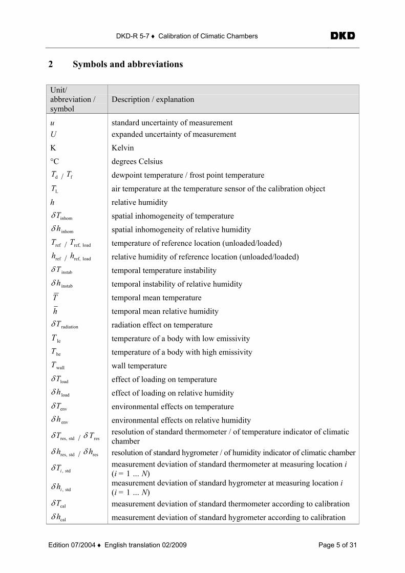
2 Symbols and abbreviations
Unit/ abbreviation / symbol
Description / explanation
u standard uncertainty of measurement U expanded uncertainty of measurement
K Kelvin
°C degrees Celsius
dT / fT dewpoint temperature / frost point temperature
LT air temperature at the temperature sensor of the calibration object
h relative humidity
inhomTδ spatial inhomogeneity of temperature
inhomhδ spatial inhomogeneity of relative humidity
refT / load ref,T temperature of reference location (unloaded/loaded)
refh / load ref,h relative humidity of reference location (unloaded/loaded)
instabTδ temporal temperature instability
instabhδ temporal instability of relative humidity
T temporal mean temperature
h temporal mean relative humidity
radiationTδ radiation effect on temperature
leT temperature of a body with low emissivity
heT temperature of a body with high emissivity
wallT wall temperature
loadTδ effect of loading on temperature
loadhδ effect of loading on relative humidity
envTδ environmental effects on temperature
envhδ environmental effects on relative humidity
stdres,Tδ / resTδ resolution of standard thermometer / of temperature indicator of climatic chamber
stdres,hδ / reshδ resolution of standard hygrometer / of humidity indicator of climatic chamber
std,iTδ measurement deviation of standard thermometer at measuring location i (i = 1 … N)
std,ihδ measurement deviation of standard hygrometer at measuring location i (i = 1 … N)
calTδ measurement deviation of standard thermometer according to calibration
calhδ measurement deviation of standard hygrometer according to calibration
DKD-R 5-7 ♦ Calibration of Climatic Chambers
Edition 07/2004 ♦ English translation 02/2009 Page 6 of 31
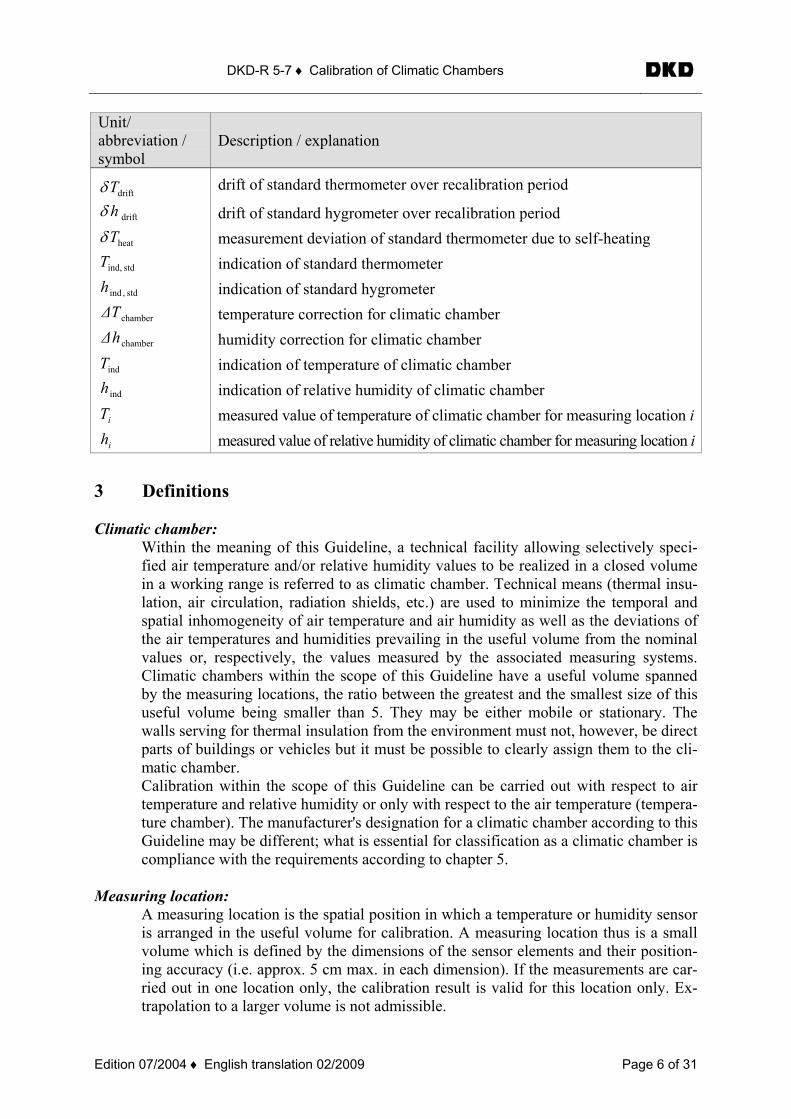
Unit/ abbreviation / symbol
Description / explanation
driftTδ drift of standard thermometer over recalibration period
drifthδ drift of standard hygrometer over recalibration period
heatTδ measurement deviation of standard thermometer due to self-heating
stdind,T indication of standard thermometer
std,indh indication of standard hygrometer
chamberT∆ temperature correction for climatic chamber
chamberh∆ humidity correction for climatic chamber
indT indication of temperature of climatic chamber
indh indication of relative humidity of climatic chamber
iT measured value of temperature of climatic chamber for measuring location i
ih measured value of relative humidity of climatic chamber for measuring location i
3 Definitions Climatic chamber:
Within the meaning of this Guideline, a technical facility allowing selectively speci-fied air temperature and/or relative humidity values to be realized in a closed volume in a working range is referred to as climatic chamber. Technical means (thermal insu-lation, air circulation, radiation shields, etc.) are used to minimize the temporal and spatial inhomogeneity of air temperature and air humidity as well as the deviations of the air temperatures and humidities prevailing in the useful volume from the nominal values or, respectively, the values measured by the associated measuring systems. Climatic chambers within the scope of this Guideline have a useful volume spanned by the measuring locations, the ratio between the greatest and the smallest size of this useful volume being smaller than 5. They may be either mobile or stationary. The walls serving for thermal insulation from the environment must not, however, be direct parts of buildings or vehicles but it must be possible to clearly assign them to the cli-matic chamber. Calibration within the scope of this Guideline can be carried out with respect to air temperature and relative humidity or only with respect to the air temperature (tempera-ture chamber). The manufacturer's designation for a climatic chamber according to this Guideline may be different; what is essential for classification as a climatic chamber is compliance with the requirements according to chapter 5.
Measuring location: A measuring location is the spatial position in which a temperature or humidity sensor is arranged in the useful volume for calibration. A measuring location thus is a small volume which is defined by the dimensions of the sensor elements and their position-ing accuracy (i.e. approx. 5 cm max. in each dimension). If the measurements are car-ried out in one location only, the calibration result is valid for this location only. Ex-trapolation to a larger volume is not admissible.
DKD-R 5-7 ♦ Calibration of Climatic Chambers
Edition 07/2004 ♦ English translation 02/2009 Page 7 of 31
Useful volume: The useful volume of a climatic chamber is the partial volume of the climatic chamber spanned by the measuring locations of the sensors used for calibration. According to the arrangement of the measuring locations, the useful volume can considerably differ from the total volume of the chamber. The calibration of the chamber is basically valid only for this useful volume. The minimum requirements for the position of the meas-uring location according to this Guideline must be fulfilled (see chapter 5 and clause 7.1). If the calibration is performed only in individual isolated measuring locations which do not span a volume, only the locations but not the chamber and its useful volume are considered to be calibrated (see calibration method (C)).
Reference measuring location:
The reference measuring location is the position in the useful volume for which the difference between air temperature and air humidity and the indicated values is stated. In most cases, the geometrical centre of the useful volume is selected as reference lo-cation. At customer's request, other definitions for the reference measuring location are also possible. The position of the reference measuring location must be stated in the calibration certificate.
4 Objectives of calibration The calibration of a climatic chamber serves to determine the deviation of the climatological characteristics of air temperature and relative humidity in those parts of the chamber volume which are provided for use or in individual points of the chamber volume from the values displayed by the indicators of the chamber1. Besides these deviations, additional properties such as inhomogeneities, stabilities, etc. are frequently determined to characterize the cham-ber and potential effects on the test material placed in the chamber. These results on the one hand are of great interest to the user of the chamber as they describe its properties during use and on the other hand are necessary for determining the measurement uncertainty of the cali-bration results. The objectives of calibration thus are the following:
• Calibration of the indication for temperature and relative humidity by comparison with the values for air temperature and air humidity as measured in the useful space using reference devices (statement of the deviations or corrections).
• Determination of the uncertainty of temperature and relative humidity in calibration, and determination of the uncertainty for use under defined conditions.
• At the customer's request, the calibration can include a test for compliance with user tolerances under defined conditions and/or technical specifications.
• At the customer's request, the calibration can be performed in individual measuring locations only. In this case, however, some uncertainty components will not be deter-mined and not be taken into account. The result then will be valid only for these loca-tions, not however for the complete chamber (→ calibration method C).
1 Note: As an alternative to the difference between indication and reference value (standard), it is also possible to
state the necessary correction for the indication.
DKD-R 5-7 ♦ Calibration of Climatic Chambers
Edition 07/2004 ♦ English translation 02/2009 Page 8 of 31
The calibration does not furnish complete information about the climatological quantities (temperature and relative humidity) at the surface or even in the volume of the load placed in the climatic chamber for testing. The determination of the body temperature or material hu-midity of the load to be tested requires the use of calibrated thermometers and/or hygrometers in the load to be tested. 5 Requirements for climatic chamber (calibratability) Within the meaning of this Guideline, climatic chambers are capable of being calibrated only if they meet the following requirements:
• Availability of sensors for air temperature/air humidity with the associated indicators as components of the climatic chamber.
• Availability of control systems for the quantities to be calibrated as components of the climatic chamber.
• Availability of the manufacturer's technical specifications. • Availability of technical documents on the sensor category; further information about,
for example, the position and specifications of the sensors, characteristics of the insu-lation as well as kind of temperature stabilization and humidification is desirable.
• Atmospheric pressure in the useful space (i.e. pressure equalization with the environ-ment is ensured).
• For operation in one temperature or humidity range, the calibration needs to be carried out at least three temperatures or relative humidities, respectively, from the range of use in question. Calibration for only one temperature or humidity point (nominal value) from the working range of the chamber is admissible but confines the calibra-tion result to this working point (this is to be stated in the calibration certificate).
• If dissipation losses occur in the useful volume (i.e. if the loading leads to heat input or heat being permanently dissipated into the air), this influence must be determined within the scope of the uncertainty contribution of the loading effect (for details, see clause 7.5).
As to the maximum working and calibration ranges, this Guideline makes a distinction be-tween climatic chambers with and without active air circulation (forced convection) in the useful space. In both cases, the climatic chamber must have an active heating and/or cooling.
a) Climatic chambers with air circulation systems:
- The maximum air temperature range extends from -90 °C to 500 °C. Calibrations for the relative humidity are possible and reasonable only in adequate partial ranges.
- For the spatial number of measuring locations for the calibration of the useful vol-ume, the following requirements are valid (deviations being possible for the calibra-tion of individual measuring locations (see chapter 6, method (C) and clause 7.1.2): For useful volumes < 2000 ℓ, at least nine measuring locations according to the re-quirements of DIN EN 60068-3-5:2002 are to be selected, i.e. the measuring loca-tions form the corner points and the spatial centre of a cuboid spanning the useful volume. For useful volumes ≥ 2000 ℓ, the measuring locations must span a cubic lattice with a lattice constant of max. 1 m (i.e. the greatest spacing of neighbouring meas-uring locations is 1 m).
DKD-R 5-7 ♦ Calibration of Climatic Chambers
Edition 07/2004 ♦ English translation 02/2009 Page 9 of 31
- The air throughput should ensure that the whole air volume is circulated once within 30 s. For evidence the manufacturer's specification will be sufficient.
b) Climatic chambers without air circulation systems:
- The maximum air temperature range extends from -90 °C to 350 °C. - The maximum useful volume is limited to 2000 ℓ. - Without air circulation, the temperature equalization is hampered considerably.
The resulting prolonged stabilization times must be taken into account. The meas-urements may be carried out only after the temperatures in all measuring locations no longer show systematic variations for at least 30 min. The remaining temporal variations must not exceed the temporal instability stated and taken into account in the measurement uncertainty.
- The number of measuring locations in the space for the calibration of the useful volume complies with the requirements of DIN EN 60068-3-5:2002, i.e. meas-urements must be made in at least nine locations.
- The effect of loading on the spatial homogeneity should be determined by meas-urements in the unloaded and in the loaded state in at least one measuring location using a typical load of the user or using test bodies. The loading should simulate the maximum impairment to the spatial equalization of temperature and is to be described in the calibration certificate. Unless otherwise required by the customer, the load corresponds at least to 40 % of the useful volume.
- Calibration of the relative humidity is not admissible. - Active loading with heat dissipation or heat input is not admissible.
6 Calibration methods For the calibration of indicating devices of a climatic chamber, the following three, essentially different, methods can be used (the measurements relating always to air temperature and rela-tive humidity):
(A) The calibration relates to the useful volume spanned by the measuring locations in the unloaded climatic chamber. As to the number and position of measuring locations, the minimum requirements are valid (see chapter 5). The calibration therefore covers:
• the determination of the indication correction or of the deviation between measurement at the reference location and indication,
• the determination of the spatial inhomogeneity in the empty useful volume, • the determination of the temporal instability in the empty useful volume, • the determination of the radiation effect (for air temperature measurement only), • the determination of the loading effect in the measuring location by compari-
son of loaded and empty useful volume, at customer's request.
(B) The calibration relates to the useful volume spanned by the measuring locations in the loaded climatic chamber. The loading can be realized according to the user's typical application or by filling at least 40 % of the useful volume with test bodies. For the in-dividual investigations and uncertainty components, the regulations for method (A)
DKD-R 5-7 ♦ Calibration of Climatic Chambers
Edition 07/2004 ♦ English translation 02/2009 Page 10 of 31
are valid. The influence of the loading itself is determined by an additional measure-ment in a central measuring location in the empty state. The calibration therefore cov-ers:
• the determination of the indication correction or of the deviation between measurement at the reference location and indication, in the loaded state,
• the determination of the spatial inhomogeneity in the loaded useful volume, • the determination of the temporal instability in the loaded useful volume, • the determination of the radiation effect, • the determination of the loading influence for the reference measuring location
by comparison of loaded and empty useful volume.
(C) The calibration relates to the individual measuring locations in the climatic chamber which do not span a useful volume. The calibration therefore covers:
• the determination of the indication correction or of the difference between measurement at the measuring location and indication,
• the determination of the temporal instability in the measuring location, • the determination of the radiation effect in the measuring location, • the determination of the loading influence in the measuring location by com-
parison of loaded and empty useful volume, at customer's request. 7 Calibration procedures 7.1 Arrangement of measuring locations
7.1.1 Calibration for useful volume by method (A) or (B)
As a rule, calibrations are to be carried out through measurements in several locations in the useful volume (methods (A) and (B)). Up to a chamber volume of 2000 ℓ, the requirements for the number and spatial position of the measuring points must be laid down in analogy to DIN EN 60068 part 3-5, i.e. the measuring locations form the corner points and the spatial centre of a cuboid which spans the useful volume. For greater useful volumes, the measuring locations are to be arranged in the useful volume in the form of a cubic lattice with a maxi-mum lattice constant of 1 m (i.e. the maximum spacing of neighbouring measuring locations is 1 m). At the customers' request, other positions are also possible but it must be ensured that the useful volume is enclosed by the volume spanned by the measuring points, that the maxi-mum spacing of neighbouring measuring locations does not exceed 1 m and that the spatial extreme values of the climatological quantities for the useful volume are determined. The choice of alternative measuring locations, e.g. in analogy to DIN 12880 part 2 is possible if they are described in the calibration certificate and the stated conditions are complied with as minimum requirements. The calibration result is valid only for the volume spanned by the measuring points. Spatial interpolation of the measurement values is admissible only for the useful volume enclosed by the measuring points. The measurement uncertainty stated is composed of the maximum val-ues of the individual contributions. It is valid for the total useful volume. Interpolation of the uncertainty contributions is not admissible. Extrapolations of the measurement results beyond the volume spanned by the measuring locations are not admissible. The dimensions of the total chamber volume and the selected position of the measuring points must be given in the calibration certificate in a sketch.
DKD-R 5-7 ♦ Calibration of Climatic Chambers
Edition 07/2004 ♦ English translation 02/2009 Page 11 of 31
7.1.2 Calibration for measuring locations by method (C)
Calibrations in individual locations in the useful volume only (method (C)) are admissible only at the customer's specific request. In this case, the calibration result is valid only for the measuring locations investigated and this is to be stated in the calibration certificate. As cali-bration item "measuring location(s) in the climatic chamber" is to be stated. The contribu-tion of the local spatial inhomogeneity in the measuring locations must be determined for each measuring location using two thermometers arranged with a spacing of approx. 2 cm to 5 cm (at least a spacing in accordance with the active sensor length has to be selected). One of these thermometers is arranged in the position defined for the statement of the calibration result (measuring location) and the other one at the necessary distance (the measurement result from this thermometer serves only to determine the local spatial inhomogeneity and does not ex-plicitly enter into the calibration result). If the emissivity of the two thermometers is signifi-cantly different, this measurement can also serve to determine the radiation effect. The differ-ence determined between the temperatures of the two thermometers is, however, used in full for the local inhomogeneity, therefore additional radiation effects are then contained in this contribution. To eliminate the influence of radiation on the determination of the local inho-mogeneity in the measuring location, two identical thermometers with low emissivity ar-ranged 2 cm to 5 cm from each other as well as a third thermometer with high emissivity would have to be used.2 In the calibration for more than one measuring location according to method (C) (without a useful volume being spanned), the use of two thermometers in one measuring location can be dispensed with if the uncertainty contribution due to the local inhomogeneity and the posi-tioning accuracy is adequately estimated from the difference of the thermometers for the indi-vidual measuring locations. The procedure is to be described in the calibration certificate. The dimensions of the total chamber volume and the position selected for the measuring points must be given in the calibration certificate in a sketch. 7.2 Determination of spatial inhomogeneity
7.2.1 Temperature inhomogeneity
The spatial inhomogeneity is determined as the maximum deviation of the temperature of a corner or wall measuring location according to DIN EN 60068-3-5 or DIN 50011-12, respec-tively, from the reference location (in most cases in the centre of the useful volume). It is to be determined for all calibration temperatures. The spatial inhomogeneity is investigated only in calibrations for a useful volume by method (A) or (B) (see clause 7.1.1). In calibrations according to method (C), only the local inhomogeneity is determined to estimate the uncer-tainty contribution due to inhomogeneity (see clause 7.1.2). 7.2.2 Humidity inhomogeneity
The spatial inhomogeneity is determined as the maximum deviation of the relative humidity of a corner or wall measuring location according to DIN EN 60068-3-5 or DIN 50011-12, respectively, from the relative humidity of the reference measuring location (in most cases in the centre of the useful volume). It is to be determined for all calibration humidities. For empty climatic chambers, due to the strong air circulation, the absolute humidity in the useful volume can be assumed to be homogeneous. The spatial inhomogeneity of the relative humid-ity can then be calculated from the inhomogeneity of the air temperature. This will not apply 2 Note: If the measurement is carried out with only two thermometers, the uncertainty contribution becomes
potentially greater but the expenditure is smaller than for the procedure using three thermometers to make up.
DKD-R 5-7 ♦ Calibration of Climatic Chambers
Edition 07/2004 ♦ English translation 02/2009 Page 12 of 31
if there are water vapour sources or sinks in the useful volume, if effective mixing of the use-ful volume is not ensured or if leaks lead to air being exchanged with the environment. The spatial inhomogeneity is investigated only in calibrations for a useful volume using method (A) or (B), respectively. 7.3 Determination of temporal instability The temporal instability for air temperature and air humidity is determined from the registra-tion of the temporal variation of temperature or relative humidity, respectively, over a period of time of at least 30 min after steady-state conditions have been reached. Steady-state condi-tions are considered to be reached when systematic variations of temperature or relative hu-midity are no longer measured. For climatic chambers without air circulation, measurements may be carried out only after 30 min after stability has been reached. For the measurement of the temporal instability, at least 30 measurement values are to be re-corded in 30 min at more or less constant time intervals. The measurement needs to be per-formed at least for the centre of the useful volume or for the reference measuring location, respectively, and for each calibration temperature and calibration humidity. The temporal instability is to be investigated for all calibration methods. 7.4 Determination of radiation effect At air temperatures in the climatic chamber differing from ambient temperature, the inner wall of the chamber always has a temperature which deviates from the air temperature. Under these conditions, however, bodies in the useful volume do not achieve the air temperature due to the heat exchange by radiation. This is valid both for the user's loads and for the thermome-ters used for calibration. The difference between the air temperature to be determined and the temperature of a thermometer depends on the emissivity of the thermometer surface, dimen-sion (diameter ≥ 4 mm) and position of the sensor, speed of air at the sensor, and on the dif-ference between air and wall temperature. The radiation effect increases with increasing dif-ference. In addition, this influence increases more than proportionally to the absolute tempera-ture. At the customer's request, the influence of the radiation on the deviation of the temperature of a body from the air temperature can also be determined using a test body typical of the cus-tomer, a thermometer with low emissivity or with a radiation shield being used to measure the air temperature and a thermometer introduced into the test body serving to measure the body temperature. This method then replaces the determination of the radiation effect. It must be described in the certificate and restricts the result to these typical conditions. It also is most suitable for customers who always store similar bodies in the useful volume.
DKD-R 5-7 ♦ Calibration of Climatic Chambers
Edition 07/2004 ♦ English translation 02/2009 Page 13 of 31
The radiation can be estimated by one of the four following procedures:
1. The determination of the radiation effect can take place by measurement of the tem-perature in the centre of the useful volume using a thermometer with as high an emissivity (i.e. ε > 0,6) and a thermometer with as low an emissivity (i.e. ε < 0,15) as possible. One advisable arrangement is the use of a thermometer with a polished nickel surface (low emissivity) as well as of a thermometer with a Teflon surface (high emissivity); other realizations of the thermometer pairs with significantly dif-ferent emissivity - such as reflecting coatings with gold or blackened surfaces - are possible. The emissivity of both thermometer surfaces must be known with suffi-cient accuracy. Especially for the realization of the low emissivity, oxidation or roughness of the surface must be avoided. The thermometer with low emissivity in-dicates approximately the air temperature in the chamber. The air temperature is obtained by extrapolation to the emissivity ε = 0. The difference ascertained be-tween the two thermometers is a measure of the radiation effect if wall temperature and air temperature are not identical.
2. The air temperature can also be measured with a thermometer protected from the
wall influence using a radiation shield. This radiation shield must be ventilated or, by its arrangement and design, allow the thermometer to be adequately exposed to the circulated air. With the radiation shield mounted, the thermometer approxi-mately measures the air temperature and, after removal of the radiation shield, the “radiation temperature”, i.e. the temperature under the influence of radiation. The difference ascertained between the two measurements is a measure of the radiation effect if the wall temperature deviates from the air temperature.
3. A measurement of the wall temperature and an approximate measurement of the air
temperature using a thermometer with low emissivity (see 1.) or a thermometer with radiation shield (see 2.) allows the maximum radiation effect to be estimated.
4. For temperatures from 0 °C to 50 °C, the radiation effect need not be metrologically
determined and can be assumed to make a maximum contribution of 0,3 K to the measurement uncertainty. Should the difference between ambient temperature and air temperature (in the climatic chamber) during calibration exceed 30 K, the radia-tion effect is in any case to be determined according to 1 to 3.3
Procedures 1 and 2 are aimed at as safe as possible a measurement of the real air temperature. They do not serve to estimate the radiation effect on the temperature of a body in the useful volume. Procedure 3 allows, however, in addition to the determination of the air temperature, a worst-case estimate of the deviation of the temperature of a body in the useful volume from the air temperature. The actual temperature of a test load placed in the useful volume can, however, be determined with as small an uncertainty as possible only using a calibrated thermometer in the test load.
3 Note: Procedure 4 is based only on an estimate of the radiation effect as a contribution to the measurement
uncertainty, which is, however, admissible only if the stated conditions are met. At the expense of an associ-ated uncertainty contribution potentially estimated greater, the expenditure is thus reduced.
DKD-R 5-7 ♦ Calibration of Climatic Chambers
Edition 07/2004 ♦ English translation 02/2009 Page 14 of 31
Under the conditions stated, procedure 4 furnishes an estimate for the radiation effect on the measurement uncertainty. In calibration methods (A) to (C), the radiation effect is to be taken into account. The measurements with the smallest emissivity (ε < 0,15) are stated as result. A correction of the measurement results for the radiation effect to ε = 0 is not made but possible if requested by the customer (to be noted in the calibration certificate). 7.5 Determination of loading effect Climatic chambers are normally calibrated in the empty state (method (A)). At the customer's request, they can, however, be loaded for calibration (method (B)). The load is to be described in the calibration certificate, and the calibration result is valid only for these particular condi-tions. This procedure will be advisable in particular if the customer always operates the test item with similar load and if this arrangement differs significantly from an empty chamber. Especially for climatic chambers without forced air circulation, the spatial distribution of the temperature can be strongly influenced by the load. In this case, the loading effect should therefore be investigated for all calibration temperatures for the reference measuring location. In the case of calibration by method (B), the calibration result relates to the loaded state. The contribution of the load to the measurement uncertainty is taken into account. (A calibration is carried out at least for the reference measuring location with and without load, and the maxi-mum difference is taken as the half-width of a rectangularly distributed uncertainty contribu-tion.) In the case of calibration by method (A) or (C), the calibration result always relates to the unloaded state. If the loading effect is investigated at the customer's request, the contribution obtained is allowed for in the measurement uncertainty. If, however, the loading effect is not investigated, it is to be stated in the calibration certificate that the influence of the load is not contained in the measurement uncertainty. This statement is to be highlighted, for example by printing it in bold. It may be omitted only if a calibration is performed at least for the refer-ence measuring location with and without load and the maximum difference is qualified as the half-width of a rectangularly distributed uncertainty contribution. The investigation of the loading effect can be performed with a customer-specific load or us-ing a test load, the volume of the latter amounting at least to 40 % of the useful volume. The load selected is to be described in the calibration certificate.
DKD-R 5-7 ♦ Calibration of Climatic Chambers
Edition 07/2004 ♦ English translation 02/2009 Page 15 of 31
Including the load measurement, the following measurements are to be carried out. In this case it is a prerequisite that the reference measuring location be situated in the centre of the useful volume (standard).
Calibration method Unloaded Loaded Measuring
locations Reference measuring
location Measuring locations
Reference measuringlocation
A x - (x) B - x x C - - (x)
= reference measurement (correction or deviation from the indication as result in the
calibration certificate) x = measurement (to determine uncertainty contributions and additional information in
the calibration certificate) (x) = at customer's request 7.5.1 Active loading with power dissipation In the case of active loading of the climatic chamber with power dissipation, the total power dissipation within the volume of the climatic chamber must not exceed 10 % of the power needed for heating or cooling (the smallest value of both is decisive). The power must be gen-erated almost uniformly over the useful volume; otherwise, only proportionately smaller power dissipation is admissible for smaller spatial sections (weighting of the temperature con-trolling power of the chamber by the ratio of heat source volume to useful volume). The in-fluence of the power dissipation on the spatial temperature distribution must be determined within the scope of the uncertainty contributions of the loading effect. This is carried out by determination of the loading effect with and without power dissipation (heat sources switched on and off). The difference ascertained is added to the uncertainty contribution from the load (see clause 8.4). In calibrations by method (B), the load must be active during the calibration. 7.6 Humidity calibration
For the calibration of the relative humidity in a climatic chamber with air circulation, it is pos-sible to determine the absolute humidity or the dewpoint Td or frost point Tf, respectively, in the centre of the useful volume and to calculate the spatial distribution of the relative humid-ity on the basis of the distribution measured for the air temperature. This procedure should be documented in the calibration certificate, and the resulting contributions to the uncertainty must be calculated (for the spatial temperature inhomogeneity, the uncertainty of the tempera-ture measurement must be taken into account). This procedure may, however, be applied only if the prerequisites according to clause 7.2.2 are fulfilled. As an alternative, the humidity distribution in the useful volume can also be determined by measurements of the relative humidity in the measuring locations in analogy to the determina-tion of the temperature distribution. The temporal stability is to be determined for the relative humidity in the reference measuring location. More detailed investigations are not covered by this Guideline.
DKD-R 5-7 ♦ Calibration of Climatic Chambers
Edition 07/2004 ♦ English translation 02/2009 Page 16 of 31
8 Uncertainty contributions The uncertainty to be stated is composed of the uncertainty of the measurement of tempera-ture and relative humidity using the reference measuring devices, the uncertainties arising from the indicating devices of the climatic chamber, the contributions of the temporal and spatial distributions in the useful volume as well as the loading effects. As climatic chambers serve to realize defined air temperatures and air humidities, the uncer-tainty assigned to the generated air temperatures and air humidities should be stated in the calibration certificate. The temperature of test pieces in the useful volume may significantly deviate from the air temperature. When the climatic chamber is used, the customer can in most cases determine the temperature of the test pieces with smaller uncertainties using a calibrated thermometer. The temperature of defined test bodies and the uncertainty assigned to them can be stated at the customer's request, exactly specifying the measurement conditions and the test bodies. Should it not be possible to determine individual influences on the calibration result and the uncertainty of the latter, their maximum possible contribution to the measurement uncertainty must be estimated and taken into account. It should be stated in the calibration certificate that the respective influence has only been estimated in the stated uncertainty. The basis/source for this estimate is to be stated. Spatial interpolations of the uncertainty contributions are not admissible. It must generally be pointed out that the uncertainties depend on the conditions of use. The measurement conditions for the calibration are therefore to be described as completely as pos-sible. Unless the conditions of use of the customer vary strongly, the conditions of calibration should be agreed upon before the calibration to come as close as possible to the conditions of use at the customer's. 8.1 Spatial inhomogeneity inhominhom ; hT δδ
The spatial inhomogeneity is determined as the maximum deviation of the relative humidity or temperature of a corner or wall measuring location according to DIN EN 60068-3-5 or DIN 50011-12, respectively, from the reference measuring location (in most cases in the centre of the useful volume). It is equivalent to the half-width of a rectangularly distributed contribu-tion with the expected value 0.
i
i
hhMaxh
TTMaxT
−≤
−≤
refinhom
refinhom
δ
δ
For the associated standard uncertainties the following equations are obtained:
i
i
hhMaxhu
TTMaxTu
−×=
−×=
refinhom
refinhom
31)(
31)(
δ
δ
The spatial inhomogeneity is to be allowed for in calibration methods (A) to (C) and for all calibration temperatures and humidities. In methods (A) and (B) it is valid for each point of the total useful volume and in method (C) only for the respective measuring locations. The results for inhomTδ and inhomhδ are stated in the calibration certificate (see Annexes B and C).
DKD-R 5-7 ♦ Calibration of Climatic Chambers
Edition 07/2004 ♦ English translation 02/2009 Page 17 of 31
8.2 Temporal instability instabinstab ; hT δδ
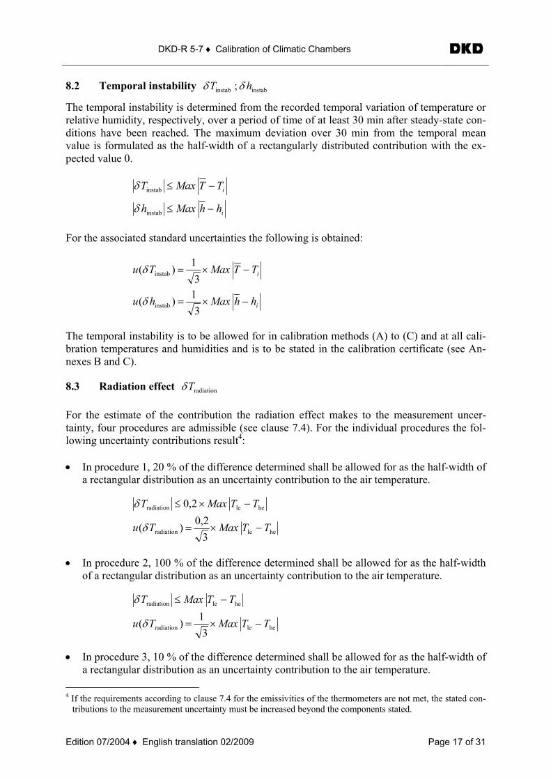
The temporal instability is determined from the recorded temporal variation of temperature or relative humidity, respectively, over a period of time of at least 30 min after steady-state con-ditions have been reached. The maximum deviation over 30 min from the temporal mean value is formulated as the half-width of a rectangularly distributed contribution with the ex-pected value 0.
i
i
hhMaxh
TTMaxT
−≤
−≤
instab
instab
δ
δ
For the associated standard uncertainties the following is obtained:
i
i
hhMaxhu
TTMaxTu
−×=
−×=
31)(
31)(
instab
instab
δ
δ
The temporal instability is to be allowed for in calibration methods (A) to (C) and at all cali-bration temperatures and humidities and is to be stated in the calibration certificate (see An-nexes B and C).
8.3 Radiation effect radiationTδ For the estimate of the contribution the radiation effect makes to the measurement uncer-tainty, four procedures are admissible (see clause 7.4). For the individual procedures the fol-lowing uncertainty contributions result4: • In procedure 1, 20 % of the difference determined shall be allowed for as the half-width of
a rectangular distribution as an uncertainty contribution to the air temperature.
heleradiation 2,0 TTMaxT −×≤δ
heleradiation 32,0)( TTMaxTu −×=δ
• In procedure 2, 100 % of the difference determined shall be allowed for as the half-width of a rectangular distribution as an uncertainty contribution to the air temperature.
heleradiation TTMaxT −≤δ
heleradiation 31)( TTMaxTu −×=δ
• In procedure 3, 10 % of the difference determined shall be allowed for as the half-width of a rectangular distribution as an uncertainty contribution to the air temperature.
4 If the requirements according to clause 7.4 for the emissivities of the thermometers are not met, the stated con-
tributions to the measurement uncertainty must be increased beyond the components stated.
DKD-R 5-7 ♦ Calibration of Climatic Chambers
Edition 07/2004 ♦ English translation 02/2009 Page 18 of 31
wallleradiation 1,0 TTMaxT −×≤δ
wallleradiation 31,0)( TTMaxTu −×=δ
• In procedure 4, 0,3 K is allowed for as the half-width of a rectangular distribution as an uncertainty contribution to the air temperature.
K3,0radiation ≤Tδ
3K3,0)( radiation =Tu δ
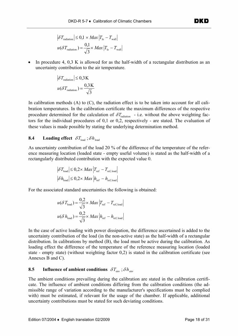
In calibration methods (A) to (C), the radiation effect is to be taken into account for all cali-bration temperatures. In the calibration certificate the maximum differences of the respective procedure determined for the calculation of radiationTδ - i.e. without the above weighting fac-tors for the individual procedures of 0,1 or 0,2, respectively - are stated. The evaluation of these values is made possible by stating the underlying determination method. 8.4 Loading effect loadload ; hT δδ
As uncertainty contribution of the load 20 % of the difference of the temperature of the refer-ence measuring location (loaded state - empty useful volume) is stated as the half-width of a rectangularly distributed contribution with the expected value 0.
load ref,refload
loadref,refload
2,0
2,0
hhMaxh
TTMaxT
−×≤
−×≤
δ
δ
For the associated standard uncertainties the following is obtained:
loadref,refload
loadref,refload
32,0)(
32,0)(
hhMaxhu
TTMaxTu
−×=
−×=
δ
δ
In the case of active loading with power dissipation, the difference ascertained is added to the uncertainty contribution of the load (in the non-active state) as the half-width of a rectangular distribution. In calibrations by method (B), the load must be active during the calibration. As loading effect the difference of the temperature of the reference measuring location (loaded state - empty state) (without weighting factor 0,2) is stated in the calibration certificate (see Annexes B and C). 8.5 Influence of ambient conditions envenv ; hT δδ
The ambient conditions prevailing during the calibration are stated in the calibration certifi-cate. The influence of ambient conditions differing from the calibration conditions (the ad-missible range of variation according to the manufacturer's specifications must be complied with) must be estimated, if relevant for the usage of the chamber. If applicable, additional uncertainty contributions must be stated for such deviating conditions.
DKD-R 5-7 ♦ Calibration of Climatic Chambers
Edition 07/2004 ♦ English translation 02/2009 Page 19 of 31
8.6 Resolution of indicators resres ; hT δδ
The resolution of the indicators for temperature and relative humidity enters as rectangularly distributed uncertainty contribution. The smallest resolution is 0,5 digit. This is the half-width of a rectangularly distributed contribution with the expectation 0. 8.7 Measurement error of standard measuring devices stdstd ; hT δδ
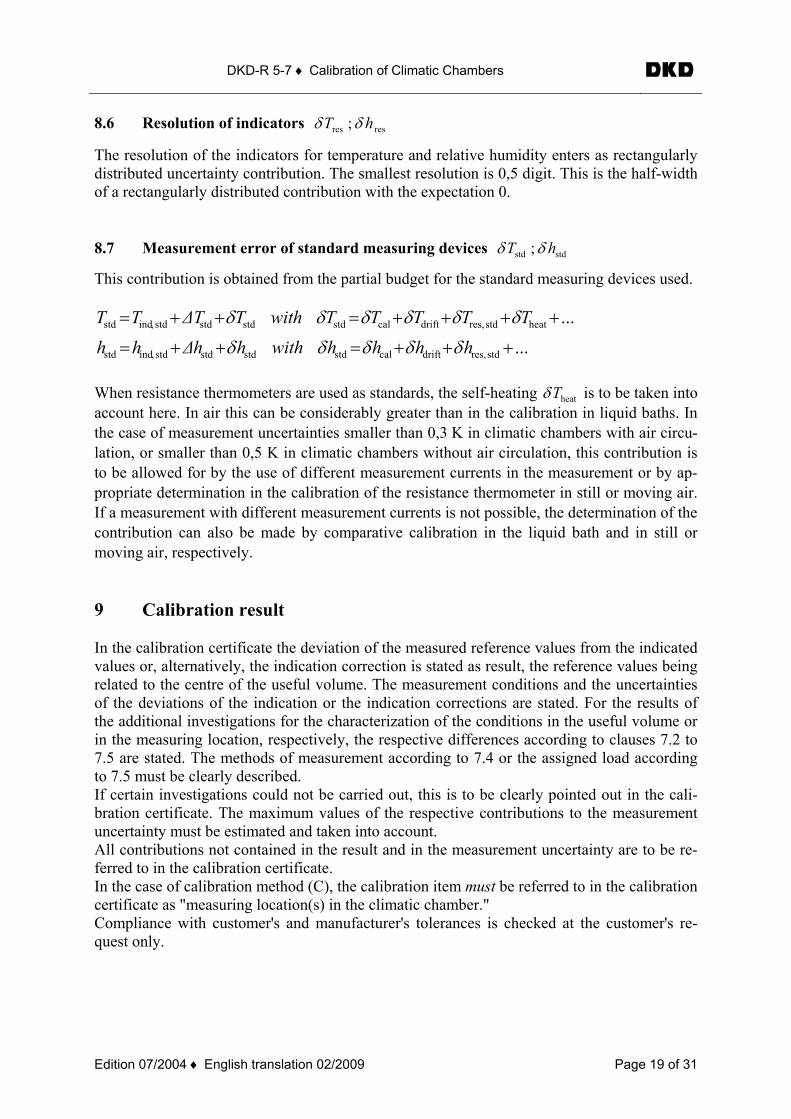
This contribution is obtained from the partial budget for the standard measuring devices used.
...
...
stdres,driftcalstdstdstdstd,indstd
heatstdres,driftcalstdstdstdstd,indstd
+++=++=
++++=++=
hhhhwithhh∆hh
TTTTTwithT∆TTT
δδδδδ
δδδδδδ
When resistance thermometers are used as standards, the self-heating heatTδ is to be taken into account here. In air this can be considerably greater than in the calibration in liquid baths. In the case of measurement uncertainties smaller than 0,3 K in climatic chambers with air circu-lation, or smaller than 0,5 K in climatic chambers without air circulation, this contribution is to be allowed for by the use of different measurement currents in the measurement or by ap-propriate determination in the calibration of the resistance thermometer in still or moving air. If a measurement with different measurement currents is not possible, the determination of the contribution can also be made by comparative calibration in the liquid bath and in still or moving air, respectively. 9 Calibration result In the calibration certificate the deviation of the measured reference values from the indicated values or, alternatively, the indication correction is stated as result, the reference values being related to the centre of the useful volume. The measurement conditions and the uncertainties of the deviations of the indication or the indication corrections are stated. For the results of the additional investigations for the characterization of the conditions in the useful volume or in the measuring location, respectively, the respective differences according to clauses 7.2 to 7.5 are stated. The methods of measurement according to 7.4 or the assigned load according to 7.5 must be clearly described. If certain investigations could not be carried out, this is to be clearly pointed out in the cali-bration certificate. The maximum values of the respective contributions to the measurement uncertainty must be estimated and taken into account. All contributions not contained in the result and in the measurement uncertainty are to be re-ferred to in the calibration certificate. In the case of calibration method (C), the calibration item must be referred to in the calibration certificate as "measuring location(s) in the climatic chamber." Compliance with customer's and manufacturer's tolerances is checked at the customer's re-quest only.
DKD-R 5-7 ♦ Calibration of Climatic Chambers
Edition 07/2004 ♦ English translation 02/2009 Page 20 of 31
A complete calibration result consists of the following components: (for examples, see Annexes B and C)
• correction or deviation of the indication for the temperature in the reference measuring location (methods (A) and (B)) or indication correction(s) for the individual measuring location(s) (method (C)),
• correction or deviation of the indication for the relative humidity in the reference measuring location (methods (A) and (B)) or indication correction(s) for the individual measuring location(s) (method (C)),
• uncertainty for the temperature indication, • uncertainty for the indication of the relative humidity, • detailed results of investigations such as:
o homogeneity, stability, radiation effect, wall temperature, etc. • conformity for temperature5 • conformity for relative humidity6 • conditions of measurement
The calibration certificate is accompanied by an information sheet (see Annex D) stating the specific influence and error sources in practical application. This sheet is an integral part of the calibration certificate and is numbered as the last page of the calibration certificate. 10 Literature
• DIN EN 60068-1 Environmental testing – Part 1: General and guidance • DIN EN 60068-2 (all parts) Environmental testing • DIN EN 60068-3-5:2002 Environmental testing – Part 3-5: Supporting docu-
mentation and guidance, Confirmation of the perform-ance of temperature chambers
• DIN EN 60068-3-6:2002 Environmental testing – Part 3-6: Supporting docu-mentation and guidance, Confirmation of the perform-ance of temperature/humidity chambers
• DIN EN 60068-3-7:2002 Environmental testing – Part 3-7: Supporting docu-mentation and guidance; Measurements in temperature chambers for tests A and B (with load)
• DIN 50011 part 12 :1987 Artificial climates in technical applications; air-temperature as a climatological quantity in control-led-atmosphere test installations
• DIN 12880 (parts 1 and 2) Climatic chambers
5 at customer's request only 6 at customer's request only
DKD-R 5-7 ♦ Calibration of Climatic Chambers
Edition 07/2004 ♦ English translation 02/2009 Page 21 of 31
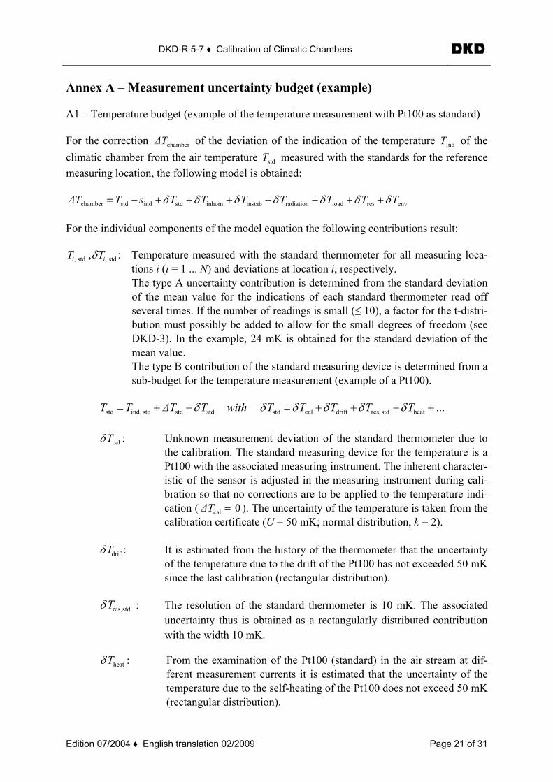
Annex A – Measurement uncertainty budget (example) A1 – Temperature budget (example of the temperature measurement with Pt100 as standard) For the correction chamber∆T of the deviation of the indication of the temperature IndT of the climatic chamber from the air temperature stdT measured with the standards for the reference measuring location, the following model is obtained:
envresloadradiationinstabinhomstdindstdchamber TTTTTTTsT∆T δδδδδδδ +++++++−= For the individual components of the model equation the following contributions result:
std,std, , ii TT δ : Temperature measured with the standard thermometer for all measuring loca-tions i (i = 1 ... N) and deviations at location i, respectively. The type A uncertainty contribution is determined from the standard deviation of the mean value for the indications of each standard thermometer read off several times. If the number of readings is small (≤ 10), a factor for the t-distri-bution must possibly be added to allow for the small degrees of freedom (see DKD-3). In the example, 24 mK is obtained for the standard deviation of the mean value. The type B contribution of the standard measuring device is determined from a sub-budget for the temperature measurement (example of a Pt100).
...heatstdres,driftcalstdstdstdstd,indstd ++++=++= TTTTTwithT∆TTT δδδδδδ
calTδ : Unknown measurement deviation of the standard thermometer due to the calibration. The standard measuring device for the temperature is a Pt100 with the associated measuring instrument. The inherent character-istic of the sensor is adjusted in the measuring instrument during cali-bration so that no corrections are to be applied to the temperature indi-cation ( 0cal =T∆ ). The uncertainty of the temperature is taken from the calibration certificate (U = 50 mK; normal distribution, k = 2).
driftTδ : It is estimated from the history of the thermometer that the uncertainty of the temperature due to the drift of the Pt100 has not exceeded 50 mK since the last calibration (rectangular distribution).
stdres,Tδ : The resolution of the standard thermometer is 10 mK. The associated uncertainty thus is obtained as a rectangularly distributed contribution with the width 10 mK.
heatTδ : From the examination of the Pt100 (standard) in the air stream at dif-ferent measurement currents it is estimated that the uncertainty of the temperature due to the self-heating of the Pt100 does not exceed 50 mK (rectangular distribution).
DKD-R 5-7 ♦ Calibration of Climatic Chambers
Edition 07/2004 ♦ English translation 02/2009 Page 22 of 31
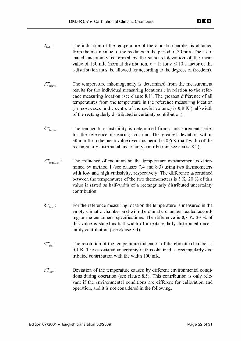
indT : The indication of the temperature of the climatic chamber is obtained from the mean value of the readings in the period of 30 min. The asso-ciated uncertainty is formed by the standard deviation of the mean value of 130 mK (normal distribution, k = 1; for n ≤ 10 a factor of the t-distribution must be allowed for according to the degrees of freedom).
inhomTδ : The temperature inhomogeneity is determined from the measurement results for the individual measuring locations i in relation to the refer-ence measuring location (see clause 8.1). The greatest difference of all temperatures from the temperature in the reference measuring location (in most cases in the centre of the useful volume) is 0,8 K (half-width of the rectangularly distributed uncertainty contribution).
instabTδ : The temperature instability is determined from a measurement series for the reference measuring location. The greatest deviation within 30 min from the mean value over this period is 0,6 K (half-width of the rectangularly distributed uncertainty contribution; see clause 8.2).
radiationTδ : The influence of radiation on the temperature measurement is deter-mined by method 1 (see clauses 7.4 and 8.3) using two thermometers with low and high emissivity, respectively. The difference ascertained between the temperatures of the two thermometers is 5 K. 20 % of this value is stated as half-width of a rectangularly distributed uncertainty contribution.
loadTδ : For the reference measuring location the temperature is measured in the empty climatic chamber and with the climatic chamber loaded accord-ing to the customer's specifications. The difference is 0,8 K. 20 % of this value is stated as half-width of a rectangularly distributed uncer-tainty contribution (see clause 8.4).
resTδ : The resolution of the temperature indication of the climatic chamber is 0,1 K. The associated uncertainty is thus obtained as rectangularly dis-tributed contribution with the width 100 mK.
envTδ : Deviation of the temperature caused by different environmental condi-tions during operation (see clause 8.5). This contribution is only rele-vant if the environmental conditions are different for calibration and operation, and it is not considered in the following.
DKD-R 5-7 ♦ Calibration of Climatic Chambers
Edition 07/2004 ♦ English translation 02/2009 Page 23 of 31
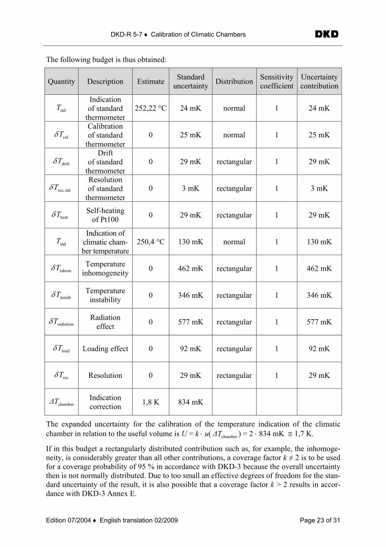
The following budget is thus obtained:
Quantity Description Estimate Standard uncertainty Distribution Sensitivity
coefficient Uncertainty contribution
stdT Indication of standard
thermometer 252,22 °C 24 mK normal 1 24 mK
calTδ Calibration of standard
thermometer 0 25 mK normal 1 25 mK
driftTδ Drift
of standard thermometer
0 29 mK rectangular 1 29 mK
stdres,Tδ Resolution of standard
thermometer 0 3 mK rectangular 1 3 mK
heatTδ Self-heating of Pt100 0 29 mK rectangular 1 29 mK
indT Indication of
climatic cham-ber temperature
250,4 °C 130 mK normal 1 130 mK
inhomTδ Temperature inhomogeneity 0 462 mK rectangular 1 462 mK
instabTδ Temperature instability 0 346 mK rectangular 1 346 mK
radiationTδ Radiation effect 0 577 mK rectangular 1 577 mK
loadTδ Loading effect 0 92 mK rectangular 1 92 mK
resTδ Resolution 0 29 mK rectangular 1 29 mK
chamber∆T Indication correction 1,8 K 834 mK
The expanded uncertainty for the calibration of the temperature indication of the climatic chamber in relation to the useful volume is U = k ⋅ u( chamber∆T ) = 2 ⋅ 834 mK ≅ 1,7 K.
If in this budget a rectangularly distributed contribution such as, for example, the inhomoge-neity, is considerably greater than all other contributions, a coverage factor k ≠ 2 is to be used for a coverage probability of 95 % in accordance with DKD-3 because the overall uncertainty then is not normally distributed. Due to too small an effective degrees of freedom for the stan-dard uncertainty of the result, it is also possible that a coverage factor k > 2 results in accor-dance with DKD-3 Annex E.
DKD-R 5-7 ♦ Calibration of Climatic Chambers
Edition 07/2004 ♦ English translation 02/2009 Page 24 of 31
A2 – Budget for the relative humidity (example of the humidity measurement using capaci-
tive humidity sensors as standard): For the correction chamber∆h of the deviation of the indication of the relative humidity indh of the climatic chamber from the relative humidity stdh
Stdh
measured with the standards for the ref-erence measuring location, the following model is obtained:
envresloadinstabinhomstdindstdchamber hhhhhhhh∆h δδδδδδ ++++++−= For the individual components of the model equation the following contributions result:
stdstd , hh δ : relative humidity measured with the standard hygrometer for all measuring locations i (i = 1 ... N) The type A uncertainty contribution is determined from the standard deviation of the mean value for the indications of each humidity sensor read off several times. If the number of the readings is small (≤ 10), a factor for the t-distribu-tion must possibly be added to allow for the small degrees of freedom (see DKD-3). In the example, 0,14 % relative humidity is obtained as the standard deviation of the mean value of the readings. The contribution of the standard measuring device is determined from a sub-budget for the humidity measurement (example; capacitive humidity sensor).
...stdres,driftcalstdstdstdstd,indstd +++=++= hhhhwithhh∆hh δδδδδ
calhδ : unknown measurement deviation of the standard hygrometer due to calibration. For each measuring location i the standard measuring device for the relative humidity is a hygrometer based on a capacitive sensor for relative humidity. The correction of the sensor ( .r.F%5,0cal −=hδ ) is determined for the calibra-tion and, together with the uncertainty, taken from the calibration certificate. (U = 0,7 %; normal distribution, k = 2)
drifthδ : It is estimated from the history of the hygrometers that the uncertainty of the humidity measurement due to the drift has not exceeded 1,0 % relative humid-ity since the last calibration (rectangular distribution).
stdres,hδ : The resolution of the relative humidity of the standard hygrometer is 0,1 %. The associated uncertainty thus is obtained as rectangularly distributed contri-bution with the width 0,1 %.
indh : The indication for the relative humidity in the climatic chamber is obtained from the mean value of the readings over the period of 30 min. The associated uncertainty is formed by the standard deviation of the mean value of - in the example – 0,24 % (normal distribution, k = 1; in the case of ≤ 10, a factor for the t-distribution according to the degrees of freedom must be allowed for).
DKD-R 5-7 ♦ Calibration of Climatic Chambers
Edition 07/2004 ♦ English translation 02/2009 Page 25 of 31
inhomhδ : The humidity inhomogeneity is determined from the measurement results for the individual measuring locations i in relation to the reference measuring loca-tion (see clause 8.1). The greatest difference of all relative humidities from the relative humidity in the reference measuring location (in most cases the centre of the useful volume) is 1,8 % (half-width of the rectangularly distributed un-certainty contribution).
instabhδ : The humidity instability is determined from a measurement series for the refer-
ence measuring location. The greatest deviation within 30 min from the mean value over this period is 1,2 % (half-width of the rectangularly distributed un-certainty contribution, see clause 8.2).
loadhδ : For the reference measuring location the relative humidity is measured with the
climatic chamber empty and loaded in a defined way according to the cus-tomer's specifications (method B). The difference is 2,2 %. 20 % of this value is taken as half-width of a rectangularly distributed uncertainty contribution (see clause 8.4).
reshδ : The resolution of the indication of the relative humidity of the climatic cham-
ber is 1,0 %. The associated uncertainty is obtained as rectangularly distributed contribution with the width 1,0 %.
envhδ : Deviation of relative humidity caused by different environmental conditions
during operation (see clause 8.5). This contribution is only relevant if the envi-ronmental conditions are different for calibration and operation, and it is not considered in the following.
DKD-R 5-7 ♦ Calibration of Climatic Chambers
Edition 07/2004 ♦ English translation 02/2009 Page 26 of 31
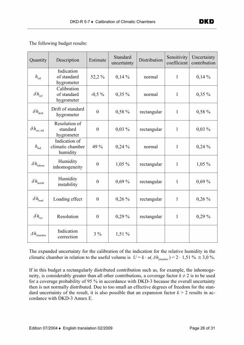
The following budget results:
Quantity Description Estimate Standard uncertainty Distribution Sensitivity
coefficient Uncertaintycontribution
stdh Indication of standard hygrometer
52,2 % 0,14 % normal 1 0,14 %
calhδ Calibration of standard hygrometer
-0,5 % 0,35 % normal 1 0,35 %
drifthδ Drift of standard hygrometer 0 0,58 % rectangular 1 0,58 %
stdres,hδ Resolution of
standard hygrometer
0 0,03 % rectangular 1 0,03 %
indh Indication of
climatic chamber humidity
49 % 0,24 % normal 1 0,24 %
inhomhδ Humidity inhomogeneity 0 1,05 % rectangular 1 1,05 %
instabhδ Humidity instability 0 0,69 % rectangular 1 0,69 %
loadhδ Loading effect 0 0,26 % rectangular 1 0,26 %
reshδ Resolution 0 0,29 % rectangular 1 0,29 %
chamberh∆ Indication correction 3 % 1,51 %
The expanded uncertainty for the calibration of the indication for the relative humidity in the climatic chamber in relation to the useful volume is U = k ⋅ u( chamberh∆ ) = 2 ⋅ 1,51 % ≅ 3,0 %. If in this budget a rectangularly distributed contribution such as, for example, the inhomoge-neity, is considerably greater than all other contributions, a coverage factor k ≠ 2 is to be used for a coverage probability of 95 % in accordance with DKD-3 because the overall uncertainty then is not normally distributed. Due to too small an effective degrees of freedom for the stan-dard uncertainty of the result, it is also possible that an expansion factor k > 2 results in ac-cordance with DKD-3 Annex E.
DKD-R 5-7 ♦ Calibration of Climatic Chambers
Edition 07/2004 ♦ English translation 02/2009 Page 27 of 31
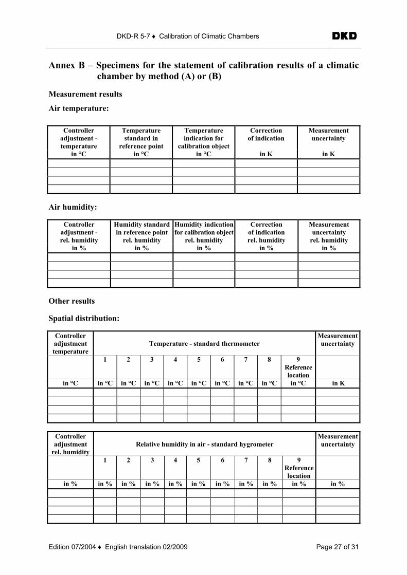
Annex B – Specimens for the statement of calibration results of a climatic chamber by method (A) or (B)
Measurement results
Air temperature:
Controller adjustment - temperature
Temperature standard in
reference point
Temperature indication for
calibration object
Correction of indication
Measurement uncertainty
in °C in °C in °C in K in K
Air humidity:
Controller adjustment - rel. humidity
Humidity standard in reference point
rel. humidity
Humidity indicationfor calibration object
rel. humidity
Correction of indication rel. humidity
Measurement uncertainty
rel. humidity in % in % in % in % in %
Other results Spatial distribution:
Controller adjustment temperature
Temperature - standard thermometer
Measurementuncertainty
1 2 3 4 5 6 7 8 9 Reference location
in °C in °C in °C in °C in °C in °C in °C in °C in °C in °C in K
Controller adjustment
rel. humidity
Relative humidity in air - standard hygrometer
Measurementuncertainty
1 2 3 4 5 6 7 8 9 Reference location
in % in % in % in % in % in % in % in % in % in % in %
DKD-R 5-7 ♦ Calibration of Climatic Chambers
Edition 07/2004 ♦ English translation 02/2009 Page 28 of 31
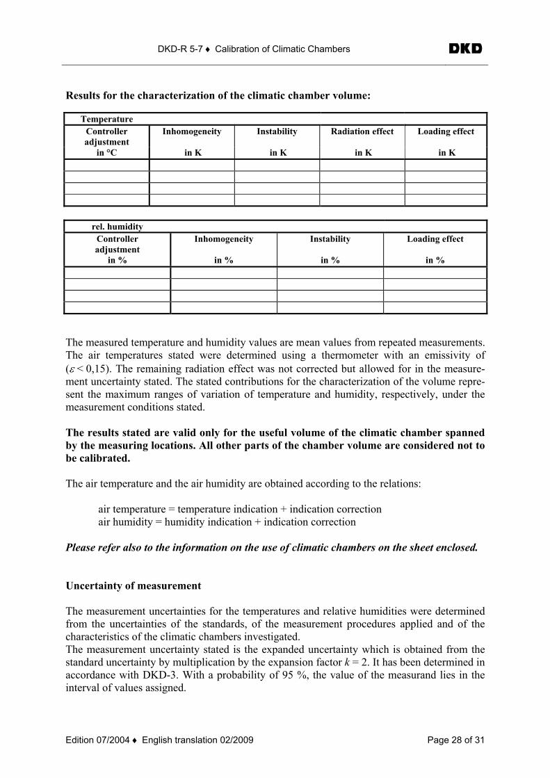
Results for the characterization of the climatic chamber volume:
Temperature Controller adjustment
Inhomogeneity Instability Radiation effect Loading effect
in °C in K in K in K in K
rel. humidity
Controller adjustment
Inhomogeneity Instability Loading effect
in % in % in % in %
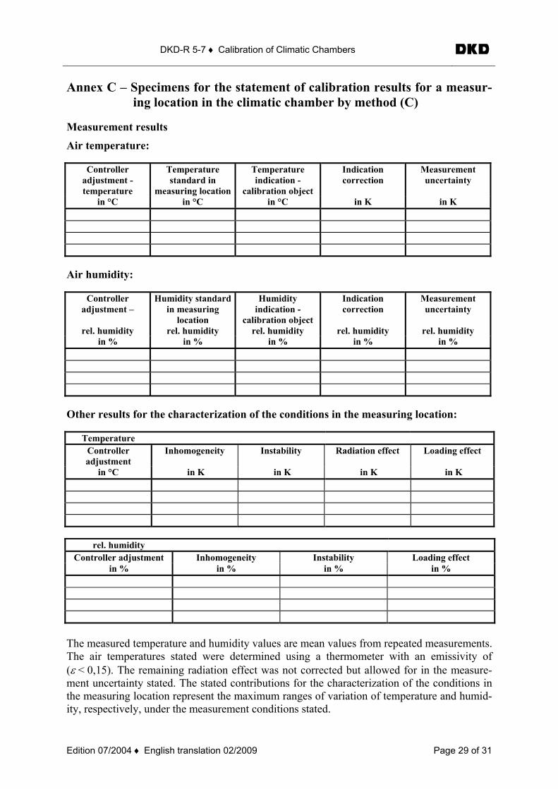
The measured temperature and humidity values are mean values from repeated measurements. The air temperatures stated were determined using a thermometer with an emissivity of (ε < 0,15). The remaining radiation effect was not corrected but allowed for in the measure-ment uncertainty stated. The stated contributions for the characterization of the volume repre-sent the maximum ranges of variation of temperature and humidity, respectively, under the measurement conditions stated. The results stated are valid only for the useful volume of the climatic chamber spanned by the measuring locations. All other parts of the chamber volume are considered not to be calibrated. The air temperature and the air humidity are obtained according to the relations: air temperature = temperature indication + indication correction air humidity = humidity indication + indication correction Please refer also to the information on the use of climatic chambers on the sheet enclosed. Uncertainty of measurement The measurement uncertainties for the temperatures and relative humidities were determined from the uncertainties of the standards, of the measurement procedures applied and of the characteristics of the climatic chambers investigated. The measurement uncertainty stated is the expanded uncertainty which is obtained from the standard uncertainty by multiplication by the expansion factor k = 2. It has been determined in accordance with DKD-3. With a probability of 95 %, the value of the measurand lies in the interval of values assigned.
DKD-R 5-7 ♦ Calibration of Climatic Chambers
Edition 07/2004 ♦ English translation 02/2009 Page 29 of 31
Annex C – Specimens for the statement of calibration results for a measur-ing location in the climatic chamber by method (C)
Measurement results
Air temperature:
Controller adjustment - temperature
Temperature standard in
measuring location
Temperature indication -
calibration object
Indication correction
Measurement uncertainty
in °C in °C in °C in K in K
Air humidity:
Controller adjustment –
rel. humidity
Humidity standardin measuring
location rel. humidity
Humidity indication -
calibration objectrel. humidity
Indication correction
rel. humidity
Measurement uncertainty
rel. humidity
in % in % in % in % in %
Other results for the characterization of the conditions in the measuring location:
Temperature Controller adjustment
Inhomogeneity Instability Radiation effect Loading effect
in °C in K in K in K in K
rel. humidity
Controller adjustment Inhomogeneity Instability Loading effect in % in % in % in %
The measured temperature and humidity values are mean values from repeated measurements. The air temperatures stated were determined using a thermometer with an emissivity of (ε < 0,15). The remaining radiation effect was not corrected but allowed for in the measure-ment uncertainty stated. The stated contributions for the characterization of the conditions in the measuring location represent the maximum ranges of variation of temperature and humid-ity, respectively, under the measurement conditions stated.
DKD-R 5-7 ♦ Calibration of Climatic Chambers
Edition 07/2004 ♦ English translation 02/2009 Page 30 of 31
The results stated are valid only for the measuring location or the volume of a cube of max. 5 cm edge length in the centre of which the measuring location is situated. All other parts of the chamber volume are considered not to be calibrated. The air temperature and the air humidity in the measuring location are obtained according to the relations: air temperature = temperature indication + indication correction air humidity = humidity indication + indication correction Please refer also to the information on the use of climatic chambers on the sheet enclosed. Uncertainty of measurement The measurement uncertainties for the temperatures and relative humidities were determined from the uncertainties of the standards, of the measurement procedures applied and of the characteristics of the climatic chambers investigated. The measurement uncertainty stated is the expanded uncertainty which is obtained from the standard uncertainty by multiplication by the expansion factor k = 2. It has been determined in accordance with DKD-3. With a probability of 95 %, the value of the measurand lies in the interval of values assigned.
DKD-R 5-7 ♦ Calibration of Climatic Chambers
Edition 07/2004 ♦ English translation 02/2009 Page 31 of 31
Annex D – Supplement to the calibration certificate for climatic chambers
Information on the calibration and use of climatic chambers
General
Unless stated otherwise in the calibration certificate, the calibration is valid only for the air tempera-ture in the empty useful volume of the climatic chamber. Under conditions of measurement other than those stated, considerable deviations (up to several Kel-vin) from the calibration value can in part be reckoned with. Radiation effects
When climatic chambers are used in the temperature range above room temperature, the temperature of the walls of many models is lower than that of the air. Due to radiation losses, the air temperature then is higher than the temperature of a thermometer or test object in the useful space. Also, the temperature of the thermometer and that of an object (→ “Object in the useful volume”) in the climatic chamber can differ considerably. Especially if the emissivity or emittance (ε) of the object differs from that of the thermometer, great differences are to be reckoned with. According to the law of radiation, the influence of this effect increases overproportionally at higher temperatures. Below room temperature, the effect is inverse but the impact is considerably smaller and often negligible. According to the model of the climatic chamber, differences of several Kelvin are possible above 150 °C. Object in the useful volume
Objects in the useful volume will in general not assume the air temperature prevailing during calibra-tion because 1) the conditions of loading - unless exactly simulated for the calibration - influence or change the
temperature field in the useful volume, 2) position, size and material of the object are in general not in conformity with the characteristics of
the thermometer used for the calibration of the climatic chamber, and 3) in qualitative but not in quantitative terms, the object and the thermometer are subjected to compa-
rable → radiation effects. Relative humidity in the useful volume
The distribution of the relative humidity in the useful volume may change considerably if there are water vapour sources or sinks in the useful volume, if effective mixing of the useful volume is not ensured or if leaks lead to air being exchanged with the environment. Uncertainty of measurement
The measurement uncertainty stated is valid only if the measurement conditions documented in the specific case are complied with. It is valid for the temperature or humidity indication of the climatic chamber in relation to the temperature or relative humidity of the air in the climatic chamber in a de-fined position or for a defined volume. Only if the state of loading, the measuring location(s) and the useful volume, respectively, are identi-cal and if the thermometer characteristics are similar (ε < 0,2) can the calibration value be reproduced within the measurement uncertainty stated. The remaining radiation effect of the standard used, related to the climatic chamber calibrated here, was determined and allowed for in the measurement uncertainty. Unless expressly stated in the cali-bration certificate, a correction for this effect was not applied.


![DKD and ISO calibration of temperature sensors. Fluid ...3-point DKD calibration ZC0013 Measurement points [ C] 65, 85,123 Measurement uncertainty [K] 0.1 5-point DKD calibration 20,](https://img.dokumen.tips/doc/110x75/611b11cf3846564b00111d67/dkd-and-iso-calibration-of-temperature-sensors-fluid-3-point-dkd-calibration.jpg)