SUPPLEMENTARY INFORMATIONdoi: 10.1038/nmat2877
nature materials | www.nature.com/naturematerials 1
1
Supplementary Information
DNA-controlled assembly of an NaTl lattice structure from gold and protein nanoparticles
Petr Cigler,1,† Abigail K. R. Lytton-Jean2,†, Daniel G. Anderson2,3,
M.G. Finn1,*, and Sung Yong Park4,* 1Department of Chemistry and The Skaggs Institute for Chemical Biology, The Scripps Research
Institute, 10550 N. Torrey Pines Rd., La Jolla, CA 92037, USA 2David H. Koch Institute for Integrative Cancer Research; 3Department of Chemical
Engineering and Harvard-MIT Division of Health Sciences & Technology, 77 Massachusetts Ave., Cambridge, MA 02139, USA
4Department of Biostatistics and Computational Biology, University of Rochester Medical Center, Rochester, 601 Elmwood Ave., NY 14642, USA
† These authors contributed equally to this work
Chemical syntheses of Qβ-DNA conjugate Chemicals were obtained from Fisher Scientific or Sigma-Aldrich. All solvents were dried
by passage through activated alumina columns, unless otherwise specified. TLC was performed on silica (Merck). Compound 1 was prepared as described by Chang and coworkerss1. Aminohexylated, HPLC grade DNA (CG-3), was obtained from IDT (USA). THPTA was prepared according the procedure described by Finn and coworkers27. Qβ capsids were prepared and decorated by azide-terminated linkers as described previously25,26,s2.
A. Fluorescent heterobifunctional BODIPY-based spacer
NNB
Cl
FF
a)
b) NNB
HN
FF
c)
NNB
N
FF
O CO2H
1 2 3 Figure S1. Synthesis of BODIPY-linker. a) KI, acetone; b) propargylamine; c) succinyl anhydride, DMAP, pyridine.
1) Synthesis of 8-propargylaminomethyl-2,6-diethyl-4,4-difluoro-1,3,5,7-tetramethyl-4-bora-3a,4a-diaza-s-indacene (compound 2 in Figure S1) Compound 1 (1.00 g, 2.84 mmol) was dissolved in 150 mL of dry acetonitrile under argon.
Potassium iodide (1.18 g, 7.09 mmol, 2.5 eq) was added and the reaction mixture was refluxed for 15 min. After cooling to room temperature, propargylamine (1.56 g, 28.4 mmol, 10 equiv)
Supplementary InformatIon for:
Dna-controlleD aSSembly of a natl lattIce Structure from golD nanopartIcleS anD proteIn nanopartIcleS

2 nature materials | www.nature.com/naturematerials
SUPPLEMENTARY INFORMATION doi: 10.1038/nmat2877
2
was added and the solution was refluxed until the violet spot of the iodo derivative disappeared from the TLC (ca. 30 min.).
The solvents were then removed under vacuum to dryness. The solids were dissolved in dichloromethane and extracted twice by water. The organic layer was dried with anhydrous MgSO4 and evaporated under vacuum. The yield was practically quantitative and the crude product was used directly for the next reaction step.
MS (ESI): [M – F]+ 353.2, [MH]+ 373.2, [MNa]+ 394.1; TLC (dichlomethane): Rf = 0.17 (bright, orange fluorescent spot). 2) Synthesis of Compound 3
Compound 2 obtained from previous reaction was dissolved in 10 mL of dry dichloromethane. Succinic anhydride (1.42 g, 14.1 mmol), a catalytic amount of 4-(dimethylamino)pyridine (69 mg, 0.57 mmol), and dry pyridine (4.2 mL) were added and the reaction mixture was stirred at room temperature overnight. The solvents were evaporated under vacuum to dryness. The crude product was chromatographed on silica using gradient (2 – 10% of MeOH in dichloromethane).
Yield: 0.44 g (33 %); TLC (dichlomethane): Rf = 0.12 (bright, orange fluorescent spot). 1H NMR (CDCl3): δ 1.00 (t, 6H), 2.15 (s, 1H), 2.18 (s, 6H), 2.35 (q, 2H), 2.48 (s, 6H), 2.96 (t, 2H), 3.06 (t, 2H), 3.98 (s, 2H), 4.89 (s, 2H). MS (ESI): [M – F]+ 452.2, [MNa]+ 494.2; Fluorescence spectra (in methanol): λ(excitation) = 540 nm, λ(emission) = 553 nm.
B. Preparation of Qβ-DNA conjugates 1) Synthesis of BODIPY-DNA conjugates
Figure S2. Synthesis of BODIPY-DNA conjugate.
EDC•HCl
H2NO A10 AAGACGAATATTTAACAA
5' 3'3 +
NNB
N
FF
O
CG-3
NH
OO A10 AAGACGAATATTTAACAA
5' 3'
NEt3N
O
O
HO
SO3NaDMSO/aq base
BoDIPY-DNA conjugate
Compound 3 (25 mg, 52 μmol) was dissolved in dry DMSO (327 μL). EDC hydrochloride (23.8 mg, 125 μmol) and triethylamine (12.5 mg, 125 μmol) were dissolved in dry DMSO (123 μL). The solutions were combined and gently mixed for 15 min. The solution was then diluted to 3.0 mL with dry DMSO and N-hydroxysulfosuccinimide (67 mg, 312 μmol) was added. After 15 min. of gentle mixing, an ice-cold solution of CG-3 (11 mg, 1.25 μmol) in 2900 μL of 0.25 M carbonate buffer (pH = 8.5) was added in small parts while cooling the reaction tube with ice.
After addition of all DNA, the reaction mixture was incubated for 15 min, after which a new portion of EDC hydrochloride (23.8 mg, 125 μmol) and 150 μL of 3.3% solution of NaOH (125 μmol) were added. At this point, the solution became slightly turbid. After 3.5 h, the reaction mixture was diluted with 54 mL of water and centrifuged at 3500 rpm. The supernatant

nature materials | www.nature.com/naturematerials 3
SUPPLEMENTARY INFORMATIONdoi: 10.1038/nmat2877
3
was lyophilized, dissolved in 20 mL of water and purified by gel permation chromatography on NAP-25 columns. The combined fractions of eluate were diluted to 35 mL. Acetate buffer (3 M, pH = 5.3, 3.5 mL) and absolute ethanol (105 mL) were added and the solution was chilled at –80 °C for 4 h. The resulting suspension was centrifuged (14 000 rpm, 30 min) at low temperature, the supernatant removed and the precipitated solid was rapidly and gently washed with 1 mL of –80 °C absolute ethanol.
The conjugate (Figure S2) was dissolved in water to approx. 1.5 mM solution and its specific concentration was determined by UV spectrophotometry. The purity of the conjugate was checked by HPLC and the stock solution was stored at 4°C. MALDI-TOF mass spectrometry: (M + H+) calculated, 9288; found 9289. 2) Synthesis of Qβ-DNA conjugates
The icosahedral Qβ virus-like protein nanoparticle (VLP) is approximately 28 nm in diameter and is composed of 180 identical proteins, each of which displays four amino groups accessible on the outer surface25,26,s2. The surface amino groups were acylated using an excess of azide-containing N-hydroxysuccinimide linker 1 (Figure 3c in the main text). The BODIPY-DNA-alkyne conjugate described above was then coupled to the particle-displayed azide groups using the copper(I)-catalyzed azide-alkyne cycloaddition (CuAAC) click reactions3.
Degassed aqueous solutions of reagents were sequentially mixed at room temperature according to Table S1. The reaction mixture was bubbled with nitrogen for at least one minute between each addition. After the last reagent was added, the Falcon tube was closed, sealed by Parafilm, and gently agitated for 8 h. The resulting crude conjugate was purified on a Sepharose 6000 GPC column and concentrated by membrane centrifugation. The degree of derivatization of the particles was estimated using UV-vis spectroscopy and ICP AES (quantifying boron from the BODIPY dye). Both techniques gave values of 190±20 DNA chains per VLP, representing a more densely arrayed set of oligonucleotide connectors on the icosahedral surface than we achieved in our earlier work, which relied on standard lysine acylation or thiol alkylation chemistry24.
Reagent Stock conc. Volume [μL] Final conc. THPTA 50 mM 71.5 2.0 mM
Sodium ascorbate 500 mM 22.7 6.3 mM CuSO4 50 mM 22.7 0.63 mM
HEPES buffer (pH = 7.9) 0.1 M 653 36 mM NaCl 1 M 450 0.25 M
BODIPY-DNA conjugate 1.3 mM 343 0.25 mM Azide groups on Qβ-azide 0.98 mM 228 0.125 mM
Table S1. List of Regents for Synthesis of Qβ-DNA conjugates

4 nature materials | www.nature.com/naturematerials
SUPPLEMENTARY INFORMATION doi: 10.1038/nmat2877
4
Synthesis of DNA-linked nanoparticle crystals 10 -30 nm gold nanoparticles (AuNPs) modified with synthetic oligonucleotides (5’HS-
A10-AAG ACG AAT ATT TAA CAA 3’) were prepared according to literature proceduress4. Linker-A is complementary to the DNA immobilized on the Qβ VLP surface (region 1)
and has a dangling end composed of four bases (5’CGCG 3’) (region 2, Figure S5a). To direct the assembly of Qβ VLPs into a close-packed FCC structure, DNA linker-A was added to the Qβ VLPs above the melting temperature of region 1 followed by slow cooling to room temperature (10 min/1 °C), Figure S5a. Alternatively, by simulating a binary system, the Qβ VLPs and AuNPs were assembled into a non-close packed NaTl structure. This was achieved by utilizing different linker sequences and hybridization temperatures. When linker-X was employed, containing a non-self-complementary dangling end (5’ AAAGGAA 3’), a second linker-Y with a complementary dangling end (5’TTCCTTT 3’), was required to achieve particle assembly, Figures 1c and S6. Therefore, because AuNPs hybridized to linker-X (AuNP-X) can only bind to Qβ VLPs hybridized to linker-Y (Qβ-VLP-Y), a two component system could be simulated. The interconnecting DNA can be described as containing two regions, where region 1 melts at ~55 °C and region 2 melts at ~40 °C. Therefore, region 2 can be thermally addressed while region 1 remains intact. This allowed us to create a binary system where AuNPs have Linker-X and Qβ VLPs have Link-Y hybridized to the surface. In an analogous fashion, decreasing the temperature of the system effectively increases the attractive force between the nanoparticles, inducing the formation of a different crystal phase. Therefore, by employing the correct choice of DNA linkers and hybridization temperature, programmable colloidal crystallization can be achieved without chemically altering the initial DNA-modified nanoparticles. NaTl structure modeling
As in Figure 1b in the main text, we tailored the sequences around the nanoparticles such that only the end part (sticky ends) are single strands, DNA hybridization of the sticky ends causes the nanoparticles aggregate. Hence, all other interaction other than this DNA hybridization of the sticky ends can be categorized to core particle interaction. In atomic crystals, when binary interactions reach to the next nearest neighbour in the b.c.c. lattice20, some combinations of atoms are able to form a NaTl (B32) structure19 (Figure 2a in the main text). In this arrangement, all particles remain on a b.c.c. lattice, but the relative positions of each particle type are different, and form two independent but interpenetrating diamond structures of each particle type. To understand the form of such putative NaTl structures more rigorously, we consider the binding energy of a perfect and infinite b.c.c. lattice composed of a crystalline array of binary particles, assuming that the range of interactions reach the next nearest neighbour sites, and write the binding energy of the CsCl ( CsClU ) and NaTl ( NaTlU ) structures as:
)68(21 s
nnnonnCsCl UUU ,
)644(21 o
nnnsnn
onnNaTl UUUU , where nnU and nnnU represent the interaction energy of
nearest neighbour and next nearest neighbours, respectively. The superscripts s and o indicate the interaction between the same (s) or different (o) types of particles. While the binding energy of each type of particle may be different, we ignore such differences for simplicity. To avoid instability in the system such as phase separation behaviour, o
nnU should be smaller than snnU .
nature materials | www.nature.com/naturematerials 5
SUPPLEMENTARY INFORMATIONdoi: 10.1038/nmat2877
5
Thus, without the next nearest neighbour interaction, the CsCl structure is always lower in energy than the analogous NaTl structure. However, introducing the next nearest neighbour interactions can change the situation20. When the condition
03322 snnn
onnn
snn
onnCsClNaTl UUUUUUU is satisfied, the NaTl structure is more
stable. A reasonable example of this situation would arise if we set ,UU onn
,0.0 UU snn ,0.0 UU s
nnn and UU onnn 7.0 . One note on the binding energy comparison is that
this argument not only holds at zero temperature but also even at finite temperature since the entropy difference between two state are minimal, since both states are based on b.c.c. structure.
Phase diagram of an equiradial binary system with the next nearest neighbour interactions at zero temperature
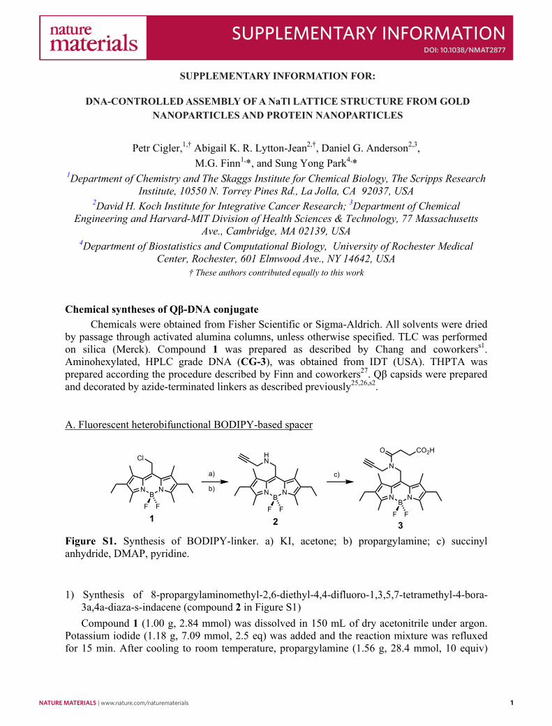
It is possible for the interaction between the same types of particles to make the binding energy of a substitutionally disordered face-centred cubic (s.d.f.c.c.) structure lower than that of the CsCl structure. To obtain the phase boundary, we compared the binding energy of each phase. The binding energy of CsCl and NaTl structure are shown above. For s.d.f.c.c. structure, we only need to consider the number of nearest neighbours of the each type of particle. In this phase, the total number of nearest neighbours is 12. For the different type of nearest neighbour particles, the number is slightly smaller than 8, so that we can denote it as 8-Δ. Then, the binding energy of s.d.f.c.c. per particle up to the length of the next nearest neighbour of a b.c.c. lattice is given by
))4()8((21 s
nnonnsdFCC UUU . With this binding energy, we can determine the zero-
temperature phase boundaries between this phase and the other phases, shown in Figure S3. To accurately consider the number 8-Δ, we can use the following method. One remark is that at high temperatures, the s.d.f.c.c. phase is more stable than the b.c.c. phase, as already studied in Ref. 17. However, in the experimental conditions used here, it was demonstrated that a bcc phase (CsCl) was more stable than the fcc phase, when we only used AuNPs17. Moreover, in the zero temperature phase diagram, there is a region where both CsCl and NaTl phases are more stable than the f.c.c. phase and that the NaTl is more stable than the CsCl. Thus, if we can observe the CsCl structure in the experimental condition, we can reasonably expect that there is a region where the NaTl phase is the equilibrium phase.
Figure S3. Phase diagram of an equiradial binary system showing the next nearest neighbour interactions at zero temperature. We assume that the concentration of the two components is the same.

6 nature materials | www.nature.com/naturematerials
SUPPLEMENTARY INFORMATION doi: 10.1038/nmat2877
6
Estimation of the number of nearest neighbour particles of different kind in a realistic s.d.f.c.c. phase
First, we prepared a configuration of an f.c.c. structure with small disorder, as in Refs 17, s5. An s.d.f.c.c. crystalline structure is a disordered phase, so in the colloidal system, it is more natural to consider a structure with small positional disorders, instead of a perfect Face-Centred Cubic (f.c.c.) structure. With an optimization method in Supporting Information of Ref. 17, we can generate an s.d.f.c.c. phase. The average number of AB nearest neighbours per particle in the cluster is 7.927; this is very slightly smaller than the number of AB nearest neighbours per particle in a CsCl cluster (= 8). Hence, if we assume that the averaged number of double stranded DNA linkages between each DNA-linked nanoparticle pair within each cluster is the same, and that interactions other than DNA hybridization do not significantly affect the binding of nanoparticles, we can conclude that the CsCl cluster is slightly more energetically favoured than the substitutionally-disordered f.c.c. cluster. Here, we set 8-Δ=7.927. Theoretical Calculation of Scattering intensity and Structure Factor
To theoretically calculate structure factors of several nanoparticle crystal structures, we applied a simplified Debye formula for spherical scatters to the real-space configurations of finite-size nanoparticle crystals17,s6,s7: the scattering intensity )(qI is defined by
N
i
N
i
N
ij ij
ijjii qr
qrqFqFqIqI
1
1
1 1
sin)()(2)()( , where the individual form factor 2)()( qFqI ii .
If we assume that all individual form factors are the same, the scattering factor
))(/()()( qNIqIqS i is
1
1 1
sin21)(N
i
N
ij ij
ij
qrqr
NqS .
However, if the system is binary, it is not appropriate to define the scattering factor as outlined as above. One way to deal with this problem is to use an approximation: we can use the fact that in the system we consider, gold nanoparticles are the dominant scatterers, and thus we can define the scattering factor in a similar way: )(/)(2)(/)()( qNIqIqIqIqS gold
ii , where
2)()( qFqI goldgold . Hence, the scattering factor )(qS can be approximated to
1
1 1
sin)(ˆ)(ˆ41)(
N
i
N
ij ij
ijji qr
qrqFqF
NqS , where )(/)()(ˆ qFqFqF goldii .
In the manuscript, we used a more accurate method: First, we separately measured the individual form factors of gold nanoparticles ( 2)()( qFqI goldgold ) and virus capsids
( 2)()( qFqI virusvirus ). Instead of calculating the structure factor, we calculate the scattering intensity for this binary system by using the measured form factor and the simplified Debye formula. One free parameter in the calculation of scattering intensities is the inter-particle distance. For the consistency, we used experimentally determined inter-particle distances in the main text. For the virus-capsids-only case, which we will discuss in this supporting information, we can still use the structure factor.

nature materials | www.nature.com/naturematerials 7
SUPPLEMENTARY INFORMATIONdoi: 10.1038/nmat2877
7
In order to calculate the scattering intensity or structure factor, it is necessary to provide the configuration of nanoparticle aggregates. For perfect crystals, we can easily obtain the real-space configurations from their basis vectors. For finite b.c.c. aggregates, we also used Dissipative Particle Dynamics (DPD) simulation21,22. Also, we can use this DPD simulation to investigate the change of scattering intensities of the system during the aggregation process. A brief summary is in the Supporting Information of Ref. 17. First, we assume that particles (typically, N= 100-1000) have the same size. Half of the particles were assigned to type A and the other half to type B. The interaction potential between particle pairs of different type was considered as an attractive potential, and the interaction between particle pairs of the same type was assumed to be a repulsion interaction. (A more detailed discussion on the interaction follows in the next section.) We performed the simulation until the most particles became a single aggregate. During the aggregation process, we calculated the scattering intensity of the aggregates at a given simulation time.
The calculated scattering intensity is represented as a CsCl structure in Figure 2d of the main text. For an NaTl structure, we used the method in the main text. The resulting scattering intensity is presented in Figure 2c of the main text. In the calculation, we assumed that there are two particle types and all particles in each type are identical. We measured the individual form factor of both types using small-angle X-ray scattering experiment. The scattering intensity from the simulation resembles the experimentally determined scattering intensity, where the single domain size is estimated to be small.
Interaction potential between DNA-linked nanoparticles
In the DPD simulation, we need to provide the interaction potential between DNA-linked nanoparticles. As we discussed in the main text, the DNA interaction is somewhat different from the usual colloidal interaction, since it is based on direct contact. There are some studies to estimate the interaction between DNA-linked nanoparticles9,15,s8, but systems they used are not identical to the system used in here, preventing us from directly applying their results to our system. Under this circumstance, we should use some approximated potential based on the experimental result in Ref. 15. One way to approximate the potential is to use a soft-core repulsion, (which is commonly used in DPD simulation), and a harmonic potential to mimic the attraction between complementary DNA strands. This choice is generally the first-order approximation of the actual interaction potential near the binding region since the interaction force is approximated linearly. Another way to get a simple analytical form of the interaction potential is to use a Lennard-Jones–like potential. The repulsive interaction between particle pairs of the same type was assumed to be 12r repulsion, while we assume the attraction potential between particle pairs of the different type was analogous to the Lennard-Jones
potential
612
4)(rr
rV . This choice is relatively close to the experimental results in
Ref. 15 and easy to handle. In the DPD simulation, we explored several different choices of the interaction potential -
including the two choices outlined above. In fact, all choices yielded simulation results that were very similar – and all supported the same conclusion, which is presented in the main text. For the Lennard-Jones-like potential, we used 0.1 and .5.4 With these parameters, we can get CsCl-type morphologies. To create NaTl-type order, we re-assign the particle types of particles

8 nature materials | www.nature.com/naturematerials
SUPPLEMENTARY INFORMATION doi: 10.1038/nmat2877
8
using an optimization technique23. Thus, the second step is not related to DPD simulation at all, and the position and the size of aggregates is not changed in this optimization technique. The only thing has been changed in the internal assignment of particle types. For this optimization, we used the same interactions as we considered in the zero-temperature phase diagram. And thus, the phase boundary between CsCl and NaTl structure from this reassignment procedure will be the same as in the zero-temperature phase diagram. A reasonable example of NaTl order can arise if we set ,UU o
nn ,0.0 UU snn ,0.0 UU s
nnn and UU onnn 7.0 . After simulating the
aggregation process, we obtained the average inter-particle distance between the nearest neighbour pair of particles in an aggregate, and rescaled this inter-particle distance to match the experimental values.
Small-Angle X-ray Scattering (SAXS) Experiments
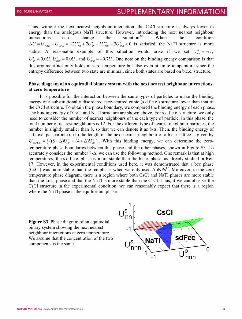
The SAXS experiments were performed at the Dupont-Northwestern-Dow Collaborative Access Team (DND-CAT) Sector 5 and BESSRC-CAT Sector 12 of the Advanced Photon Source (APS), Argonne National Laboratory. We used either flow-cell or capillary tubes to place the sample in aqueous solution. We controlled the temperature within a 0.1oC resolution with temperature controlling systems. The experimental setup was the same as our previous publication17. The beam size for the experiment was a 23.03.0 mm beam. We detected scattered radiation using a CCD area detector. By averaging the two-dimensional scattering data azimuthally, we obtained the one-dimensional profiles of scattered intensity as a function of the scattering vector, )/sin4( q , where the scattering angle, 2 . For the calibration, we used silver behenate. Standard data correction procedures, e.g., dark current subtraction and absorption correction, were applied. When we use AuNPs, scattering from DNA, buffer and capillary tube is negligible compared to that from electron dense gold, but the buffer data were nonetheless used for reducing the solution sample data to scattering representative of the particles alone. However, scattering from DNA is not negligible as compared to that from virus capsids. In Figure S4, we present the scattering intensity of several VLPs with different surface DNA linkers, including unmodified VLPs: 1) unmodified Qβ VLPs, 2) Qβ VLPs with surface DNA strands, 3) Qβ particles with surface strands and f.c.c. linkers at high temperature above the melting temperature. We note that the samples we analyzed for cases 1 and 3 were at much higher concentration than the samples for case 2, due to the sample preparation process. Unlike a DNA-linked AuNP system in which gold nanoparticles dominantly contribute to the SAXS pattern, the contribution from Qβ particles in this system does not outweigh the contribution from DNA around the particle surface. The result shows that after modifying the surface of a virus capsid with DNA strands (cases 2 and 3), the form factor of a VLP is changed significantly.
nature materials | www.nature.com/naturematerials 9
SUPPLEMENTARY INFORMATIONdoi: 10.1038/nmat2877
9
Figure S4. The scattering intensity of several VLPs with different surface DNA linkers: 1) unmodified Qβ particles (red), 2) Qβ particles with surface DNA strands (green), 3) Qβ particles with surface strands and f.c.c. linkers at high temperature above the melting temperature of the sticky ends of attached DNA strands (blue).
Formation of face-centred cubic crystalline structure using DNA-linked VLPs only Here we demonstrate that VLPs alone can be assembled into a crystalline structure using
DNA as the assembler. We created close-packed single-crystalline domains using the single-component VLP system (Figure S5). This was achieved by combining the VLP and linker-A (Figure S5a) above the melting temperature ( mT ) of region 2 (~44 °C) followed by slow cooling (~0.25 °C/min) to room temperature, to ensure that crystal formation was thermodynamically and not kinetically controlled. The two-dimensional SAXS pattern for this system clearly indicates a face-centred cubic (f.c.c.) structure (Figure S5b). In Figure S5c, the averaged )(qS , determined by integration and normalization based on the q value from the first ring, is in agreement with the theoretical f.c.c. structure (green line). In addition to the peak position, the relative peak heights are also consistent with the theoretical calculations. The size of single-crystal domains was estimated to be approximately 570nm from the first ring in the scattering pattern using the Scherrer formulas6,s7. The average inter-particle distance was also determined from the position of the first peak, which in q space is placed at VLPd/6 , where VLPd is the distance between the virus capsid centres. This gave an inter-particle distance between the f. c. c. nanoparticle crystals of 56.6 nm, which falls within the range of the predicted inter-particle distance (55.0 – 63.2 nm) that is based on the length of the DNA linkers.

10 nature materials | www.nature.com/naturematerials
SUPPLEMENTARY INFORMATION doi: 10.1038/nmat2877
10
Figure S5. DNA-directed nanoparticle crystallization using DNA-linked virus capsids. a. Scheme of the crystallization method (Single-component assembly system) Here, nanoparticles are assembled using one DNA sequence, linker-A. b. SAXS pattern of f.c.c structure using the single-component system. c. Integrated data from b; these data reveal a formation of small single-crystalline face-centred cubic (f.c.c) domains. The x-axis is normalized to the first ring.
Prediction of Inter-particle Distance
The above single-component system contains 84 DNA base pairs and 24 free bases between two linked particles. The free DNA bases on the surface of the AuNP are more flexible and can lie down on the surface17. If the length of the DNA is calculated, assuming 10 DNA base pairs have a length of ~3.4 nm, this is equivalent to ~28.6 nm if only the duplex portion is considered and ~36.7 nm if the length of the free DNA bases are included. To determine the centre-to-centre inter-particle distance, the average diameter of each VLP including surface conjugated molecules must also be considered; this was estimated to 26.5 nm, thus yielding an overall range of 55.0-63.2 nm. The binary system of DNA-linked VLP and DNA-linked AuNP (diameter 10 nm) contains 76 DNA base pairs and 23 free bases. This equates to a range of 44.1-51.9 nm for centre-to-centre inter-particle spacing based on the above calculations. Similarly, for 15 and 20 nm AuNPs, the inter-particle distance is estimated to a range of 42.9-49.7 nm and 45.4-52.2nm, respectively.

nature materials | www.nature.com/naturematerials 11
SUPPLEMENTARY INFORMATIONdoi: 10.1038/nmat2877
11
Figure S6. Scheme of the crystallization method with actual DNA sequences.
Design and measurement of the aspect ratio of the systems
In Figure S6, we present the DNA sequences we used for creating NaTl structures. 10 DNA base pairs usually have a length of ~3.4 nm. However, for the DNA strands between AuNPs, the value is somewhat shorter than this18,s9. It is likely that the free DNA bases near the gold surface are more flexible and have the potential to lie down on the gold surface17. For DNA-linked AuNPs, we calculate the effective radius if only the duplex portion is considered, but for DNA-linked VLPs, we include the length of surface DNA strands, since we expect the free DNA bases may not lie down on the surface of VLPs.
For experimental measurement of the aspect ratio, we utilized the inter-particle distance between DNA-linked VLPs using DNA-linked VLPs only. When we use the same sequence as the binary systems in the main text (still keeping the aspect ratio of binary particles to one), the inter-particle distance between DNA-linked VLPs was measured to be 45.5 nm. Hence, we estimated the effective radius of DNA-linked VLPs to be 22.8 nm. To estimate the effective radius of DNA-linked AuNPs, we simply subtract it from the inter-particle distances we measured. For 10, 15, and 20 nm AuNPs, the measured inter-particle distance was 45.8, 44.9, and 47.8 nm, respectively, and thus the effective radius of the DNA-linked AuNPs was estimated to be 23.0, 22.1, and 25.0 nm, respectively. From this, we derived the aspect ratios, which we presented in the main text. References
s1 Miller, E. W., Zeng, L., Domaille, D. W. & Chang, C. J. Preparation and use of Coppersensor-1, a synthetic fluorophore for live-cell copper imaging. Nat. Protocols 1, 824-827 (2006).
s2 Strable, E., Prasuhn, D. E., Udit, A. K., Brown, S., Link, A. J., Ngo, J. T., Lander, G., Quispe, J., Potter, C. S., Carragher, B., Tirrell, D. A. & Finn, M. G. Unnatural Amino Acid Incorporation into Virus-Like Particles. Bioconjugate Chem. 19, 866--875 (2008).

12 nature materials | www.nature.com/naturematerials
SUPPLEMENTARY INFORMATION doi: 10.1038/nmat2877
12
s3 Gupta, S. S., Kuzelka, J., Singh, P., Lewis, W. G., Manchester, M. & Finn, M. G. Accelerated Bioorthogonal Conjugation: A Practical Method for the Ligation of Diverse Functional Molecules to a Polyvalent Virus Scaffold. Bioconjugate Chem. 16, 1572--1579 (2005).
s4 Hurst, S. J., Lytton-Jean, A. K. R. & Mirkin, C. A. Maximizing DNA Loading on a Range of Gold Nanoparticle Sizes. Anal. Chem. 78, 8313--8318 (2006).
s5 Donev, A., Torquato, S., Stillinger, F. H. & Connelly, R. A linear programming algorithm to test for jamming in hard-sphere packings. J. Comput. Phys. 197, 139--166 (2004).
s6 Guiner, A. & Fournet, G. Small-Angle Scattering of X-Rays. (Wiley, 1955). s7 Cullity, B. D. Elements of X-Ray Diffraction. 2nd Ed., (Addison-Wesley, 1978). s8 Zhang, Z., Keys, A. S., Chen, T. & Glotzer, S. C. Self-Assembly of Patchy Particles into
Diamond Structures through Molecular Mimicry. Langmuir 21, 11547--11551 (2005). s9 Park, S. J., Lazarides, A. A., Storhoff, J. J., Pesce, L. & Mirkin, C. A. The structural
characterization of oligonucleotide-modified gold nanoparticle networks formed by DNA hybridization. J. Phys. Chem. B 108, 12375--12380 (2004).
Recommended