J-3 Cub 25 ARF
Assembly Manual

�
Introduction
The Piper J-3 Cub is an all-time favorite among aviation enthusiasts everywhere. Classic lines and predictable flight performance are just a few of the Cub’s trademarks. The 25-size J-3 Cub from E-flite™ is the first of its size for E-flite. The name Piper J-3 Cub .25 ARF implies the power of a .25 glow engine, but it is designed specifically for electric operation. This aircraft has been designed from the start for the E-flite Power 25 Outrunner BL motor. It uses balsa and plywood construction and is covered with genuine UltraCote®. Using a scale of approximately 1/7, the J-3 Cub spans 62 inches delivering excellent presentation and performance to budget-minded pilots.
You can fly with either a 10-cell Ni-MH battery, or a 3-cell Li-Po for increased performance and duration. An optional set of scale fiberglass floats is also available (EFLA500). All it takes is five minutes to change from landing gear to floats to enjoy those afternoons on the lake. Change back to the standard landing gear and you can be shooting touch-and-go’s at the local flying field, the choice is yours. Either way we believe you will fall in love with the relaxing flight performance of the E-flite J-3 Cub.
Table of ContentsIntroduction.................................................................2Contents.of.Kit/Parts.Layout..........................................3Specifications..............................................................3Covering.Colors..........................................................3Required.Electronics.&.Accessories................................4Outrunner.(Direct.Drive).Motor.Setup.............................4Required.Tools.and.Adhesives.......................................4Optional.Accessories...................................................5Warning.....................................................................5Before.Starting.Assembly..............................................5Note.on.Lithium.Polymer.Batteries..................................5Using.the.Manual........................................................5Limited.Warranty.Period...............................................5Landing.Gear.Installation..............................................8Motor.and.Cowling.Installation...................................12Radio.Installation.......................................................16Wing.Assembly.........................................................18Tail.Installation...........................................................30Linkage.Installation.....................................................34Final.Assembly..........................................................44Center.of.Gravity./.Battery.Installation.........................47Control.Throws..........................................................48Flying.Notes..............................................................492006.Official.AMA...........National.Model.Aircraft.Safety.Code.................50

�
Large Replacement Parts:EFL4001 Wing w/AileronsEFL4002 FuselageEFL4003 Tail SetEFL4004 Landing GearEFL4005 CowlingEFL4009 Tailwheel Assembly
Small Replacement Parts:EFL4006 Windshield/Window SetEFL4007 Pushrod SetEFL4008 Main Wheels
Covering ColorsCub Yellow HANU884Black HANU874
Contents of Kit/Parts Layout
SpecificationsWingspan: 62 in (1575mm)Length: 35.5 in (900mm)Wing Area: 552 sq in (35.5 sq dm)Weight w/o Battery: 3.2 lb (1.45 kg)
4.5 lb w/Floats (2.0 kg)Weight w/Battery: 4 lb (1.8 kg)
5.3 lb w/Floats (2.4 kg)

�
Required Electronics & Accessories
Complete Radio SystemJSP16000** JR SPORT™ 6-Channel Radio System
Or Purchase SeparatelyJSP30600 RS600 6-Channel Receiver w/o CrystalJRPXFR** FM Receiver CrystalJSP20040 MN48 Mini Servo (4)JSP98020 6" Y-HarnessJSP98110 6" Servo Extension (2)JRPA212 Long Servo Arm (2)
Outrunner Motor SetupEFLA4025A Power 25 BL Outrunner Motor, 870KvEFLA312B 40-Amp Brushless Speed ControlAPC12060E Electric Propeller, 12 x 6ETHP42003S2PPL 4200 3S2P, 11.1V Li-Po, 13 GAEFLC3005 Celectra™ 1–3 Cell Li-Po Charger
OrEFLB4010 1800mAh Ni-MH, 10-Cell
Required Tools and Adhesives
ToolsSmall Phillips Screwdriver (EFLA257 - included with EFLA250)Hex Wrench: 7/64" (EFLA251 - included with EFLA250)
Drill T-pinsRuler Felt-tipped penString SquareTape PliersHobby scissors Side cuttersSandpaper Rubbing alcoholPaper towel/tissue Masking tapePetroleum jelly Hobby knifeDrill bit: 1/16" (1.5mm), 5/64" (2mm),
3/32" (2.5mm), 1/8" (3mm)Adhesives
Thin CA 6-Minute Epoxy (HAN8000)Medium CA 30-Minute Epoxy (HAN8002)Canopy glueThreadlock

�
Optional AccessoriesEFLA110 Power MeterEFLA500 Float Set, 25-Size
Warning
An RC aircraft is not a toy! If misused, it can cause serious bodily harm and damage to property. Fly only in open areas, preferably at AMA (Academy of Model Aeronautics) approved flying sites, following all instructions included with your radio.
Keep loose items that can get entangled in the propeller away from the prop, including loose clothing, or other objects such as pencils and screwdrivers. Especially keep your hands away from the propeller.
Before Starting Assembly
Before beginning the assembly of your J-3 Cub, remove each part from its bag for inspection. Closely inspect the fuselage, wing panels, rudder and stabilizer for damage. If you find any damaged or missing parts, contact the place of purchase.
Note on Lithium Polymer Batteries
Lithium Polymer batteries are significantly more volatile than alkaline or Ni-Cd/ Ni-MH batteries used in RC applications. All manufacturer’s instructions and warnings must be followed closely. Mishandling of Li-Po batteries can result in fire. Always follow the manufacturer’s instructions when disposing of Lithium Polymer batteries.
Using the Manual
This manual is divided into sections to help make assembly easier to understand, and to provide breaks between each major section.
Remember to take your time and follow the directions.
Limited Warranty Period
Horizon Hobby, Inc. guarantees this product to be free from defects in both material and workmanship at the date of purchase.

�
As Horizon Hobby, Inc. has no control over use, setup, final assembly, modification or misuse, no liability shall be assumed nor accepted for any resulting damage or injury. By the act of use, setup or assembly, the user accepts all resulting liability.
If you as the purchaser or user are not prepared to accept the liability associated with the use of this product, you are advised to return this product immediately in new and unused condition to the place of purchase.
Safety PrecautionsThis is a sophisticated hobby product and not a toy. It must be operated with caution and common sense and requires some basic mechanical ability. Failure to operate this product in a safe and responsible manner could result in injury or damage to the product or other property. This product is not intended for use by children without direct adult supervision.
The product manual contains instructions for safety, operation and maintenance. It is essential to read and follow all the instructions and warnings in the manual, prior to assembly, setup or use, in order to operate correctly and avoid damage or injury.
Limited Warranty & Limits of LiabilityPursuant to this Limited Warranty, Horizon Hobby, Inc. will, at its option, (i) repair or (ii) replace, any product determined by Horizon Hobby, Inc. to be defective. In the event of a defect, these are your exclusive remedies.
This warranty does not cover cosmetic damage or damage due to acts of God, accident, misuse, abuse, negligence, commercial use, or modification of or to any part of the product. This warranty does not cover damage due to improper installation, operation, maintenance, or attempted repair by anyone other than an authorized Horizon Hobby, Inc. service center. This warranty is limited to the original purchaser and is not transferable. In no case shall Horizon Hobby’s liability exceed the original cost of the purchased product and will not cover consequential, incidental or collateral damage. Horizon Hobby, Inc. reserves the right to inspect any and all equipment involved in a warranty claim. Repair or replacement decisions are at the sole discretion of Horizon Hobby, Inc. Further, Horizon Hobby reserves the right to change or modify this warranty without notice.
REPAIR OR REPLACEMENT AS PROVIDED UNDER THIS WARRANTY IS THE EXCLUSIVE REMEDY OF THE CONSUMER. HORIZON HOBBY, INC. SHALL NOT BE LIABLE FOR ANY INCIDENTAL OR CONSEQUENTIAL DAMAGES.

�
Questions, Assistance, and RepairsYour local hobby store and/or place of purchase cannot provide warranty support or repair. Once assembly, setup or use of the product has been started, you must contact Horizon Hobby, Inc. directly. This will enable Horizon to better answer your questions and service you in the event that you may need any assistance.
Questions or AssistanceFor questions or assistance, please direct your email to [email protected], or call 877.504.0233 toll free to speak to a service technician.
Inspection or RepairsIf your product needs to be inspected or repaired, please call for a Return Merchandise Authorization (RMA). Pack the product securely using a shipping carton. Please note that original boxes may be included, but are not designed to withstand the rigors of shipping without additional protection. Ship via a carrier that provides tracking and insurance for lost or damaged parcels, as Horizon Hobby, Inc. is not responsible for merchandise until it arrives and is accepted at our facility. Include your complete name, address, phone number where you can be reached during business days, RMA number, and a brief summary of the problem. Be sure your name, address, and RMA number are clearly written on the shipping carton.
Warranty Inspection and RepairsTo receive warranty service, you must include your original sales receipt verifying the proof-of-purchase date. Providing warranty conditions have been met, your product will be repaired or replaced free of charge. Repair or replacement decisions are at the sole discretion of Horizon Hobby.

Landing Gear Installation
Required Parts• Fuselage • Landing gear• Hub cap (2) • Tie wrap (6)• Inner wheel hub (2) • Outer wheel hub (2)• 4mm wheel collar (2) • 3mm setscrew (2)• Landing gear strap (4)• Landing gear fairing (2)• 2
1/2" (63mm) foam wheel (2)• 2mm x 15mm sheet metal screw (8)• 2mm x 10mm sheet metal screw (8)
Required Tools and Adhesives• Phillips screwdriver • Hex wrench (included in kit)• Side cutter
Note:.The.fuselage.is.designed.to.accept.either.the.standard.landing.gear.or.optional.floats..Changing.from.landing.gear.to.floats.requires.less.than.5.minutes..Refer.to.the.manual.included.with.your.floats.for.proper.installation.
Non-Warranty RepairsShould your repair not be covered by warranty and the expense exceeds 50% of the retail purchase cost, you will be provided with an estimate advising you of your options. You will be billed for any return freight for non-warranty repairs. Please advise us of your preferred method of payment. Horizon Hobby accepts money orders and cashiers checks, as well as Visa, MasterCard, American Express, and Discover cards. If you choose to pay by credit card, please include your credit card number and expiration date. Any repair left unpaid or unclaimed after 90 days will be considered abandoned and will be disposed of accordingly.
Electronics and engines requiring inspection or repair should be shipped to the following address (freight prepaid):
Horizon Service Center 4105 Fieldstone Road
Champaign, Illinois 61822
All other products requiring inspection or repair should be shipped to the following address (freight prepaid):
Horizon Product Support 4105 Fieldstone Road
Champaign, Illinois 61822
8

1. Place the landing gear in position with the larger diameter wire to the front of the fuselage. Secure the gear using four landing gear straps and eight 2mm x 10mm sheet metal screws.
2. Slide the inner wheel hub onto the landing gear. (The holes in the inner hub do not go through the hub.) Slide a 4mm wheel collar onto the landing gear and secure it using a 3mm setscrew. Use threadlock when tightening the setscrew onto the flat spot of the landing gear.
9

3. Press the 2 1/2" (63mm) foam wheel onto
the inner hub. Press the outer wheel hub into the wheel. Complete the assembly using four 2mm x 15mm sheet metal screws.
4. Press the hub cap into the outer wheel hub.
10

5. Attach the landing gear fairing to the landing gear using three tie straps. Trim the excess strap side cutters.
6. Repeat Steps 2 through 5 to complete the landing gear installation.
11

1. Prepare the outrunner motor by attaching the X-mount to the motor using screws supplied with the motor.
Motor and Cowling Installation
Required Parts• Fuselage• Cowling• Hook and loop straps (2)• 6-32 x 1/2" socket head screw (4)• 2mm x 10mm sheet metal screw (4)• Propeller adapter• 12 x 6 electric propeller (APC12060E)• Brushless outrunner motor• Electronic speed control• Battery
Required Tools and Adhesives• Hex wrench: 7/64"• Drill• Drill bit: 1/16" (1.5mm), 1/8" (3mm)
Note:.It.is.very.important.to.be.sure.the.propeller.is.balanced.before.installing.it.onto.the.motor.
12

2. Attach the motor to the firewall using four 6-32 x 1/2" socket head screws included with the J-3 Cub.
Note:.The.firewall.has.been.prepared.to.mount.the.E-flite™.Power.25.brushless.motor..It.may.be.necessary.to.remove.the.blind.nuts.and.drill.new.mounting.holes.for.other.motor.choices.
3. Attach the motor to the speed control. Secure the speed control in the fuselage using hook and loop material so it will not move during flight.
Note:.Ensure.you.mount.the.speed.control.with.the.label.towards.the.fuselage.sidewall..This.will.assure.maximum.cooling.for.the.speed.control.
13
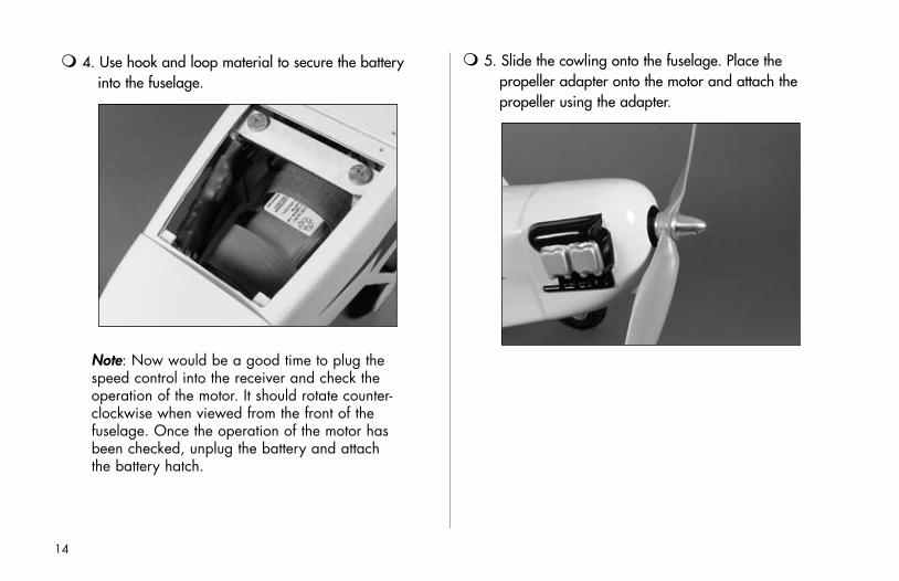
4. Use hook and loop material to secure the battery into the fuselage.
Note:.Now.would.be.a.good.time.to.plug.the.speed.control.into.the.receiver.and.check.the.operation.of.the.motor..It.should.rotate.counter-clockwise.when.viewed.from.the.front.of.the.fuselage..Once.the.operation.of.the.motor.has.been.checked,.unplug.the.battery.and.attach.the.battery.hatch.
5. Slide the cowling onto the fuselage. Place the propeller adapter onto the motor and attach the propeller using the adapter.
14

6. Position the cowling so it lines up with the propeller and adapter. Allow for 1/8” (3mm) clearance between the propeller and cowl. Drill four 1/16" (1.5mm) holes for the cowl mounting screws. Enlarge the holes in the cowling only using a 1/8" (3mm) drill bit. Secure the cowling using four 2mm x 10mm sheet metal screws.
15

Note:.The.servo.openings.in.the.fuselage.are.set.up.for.the.JR.SPORT®.(MN48).Mini.Servos.
2. Center the servo in the servo opening. Use a 1/16" (1.5mm) drill bit to drill the locations for the servo mounting screws.
Radio Installation
Required Parts• Fuselage• Receiver• Mini Servo (2)• 6" Y-harness
Required Tools and Adhesives• Drill • Drill bit: 1/16" (1.5mm)
1. Install the servo grommets and brass eyelets on the rudder and elevator servos following the instructions provided with the servos or radio system.
16

3. Secure the servo using the screws provided with the servo. Repeat Step 2 for the remaining servo.
4. Plug the rudder, elevator and speed control into the receiver, as well as the aileron Y-harness. Use hook and loop to secure the receiver in the fuselage. Route the antenna wire through the tube in the fuselage.
Note:.Do.not.cut.the.receiver.antenna.wire..as.it.will.greatly.reduce.the.range.of.your..radio.system.
17

Wing Assembly
Required Parts• Clevis (2) • Clevis retainer (2)• Pushrod wire keeper (2) • CA hinge (6)• Mini Servo (2) • 6" servo extension(2)• Cub yellow covering strip• Wing panel (left and right)• Aileron (left and right)• Plywood wing joiner (2)• Aileron servo cover (left and right)• 3/4" x 3/8" x 3/8"
(19mm x 10mm x 10mm) servo block (4)• Control horn w/backplate (2)• 2mm x 20mm screw (4)• 2mm x 10mm sheet metal screw (8)• 4" (100mm) linkage wire (2)• Long Servo Arm (JRPA212) (2)
Required Tools and Adhesives• 6-minute epoxy • Phillips screwdriver• Thin CA • T-pins• Drill • Felt-tipped pen• 30-minute epoxy• Drill bit: 1/16" (1.5mm), 5/64" (2mm)• String • Masking tape
1. Place a T-pin in the center of three hinges.
18

2. Drill a 1/16" (1.5mm) hole in the hinge center of both the aileron and wing.
3. Place the hinges in the aileron.
19

4. Slide the aileron and wing together. Remove the T-pins. There should be a 1/64" (.4mm) gap between the aileron and wing. Make sure the aileron can move freely without binding.
Note:.The.aileron.has.a.block.installed.for..the.aileron.control.horn.to.mount.to..Make..sure.this.block.is.located.on.the.inboard.side..of.the.wing.
5. Deflect the aileron and apply thin CA to each of the hinges. Make sure to saturate each hinge. Apply CA to both the top and bottom of the hinges.
Note:.Do.not.use.accelerator.in.the.hinging.process..The.CA.must.be.allowed.to.soak.into.each.hinge.naturally.
20

6. Install the grommets and brass eyelets into the aileron servo. Attach a 6" (152mm) servo extension, securing it with thread or a commercially available clip. Center the servo and install a long servo arm onto the servo.
7. Check to make sure you are using the correct servo hatch for the wing panel. Simply place the hatch in position to make sure the opening for the servo horn aligns.
21

8. Position the servo onto the servo hatch with the servo arm centered in the slot. Use a felt-tipped pen to mark the locations for the servo mounting blocks.
9. Use 6-minute epoxy to glue two 3/4" x 3/8" x 3/8" (19mm x 10mm x 10mm) servo blocks to the servo hatch. Allow the epoxy to fully cure before moving to the next step.
22

10. Place the servo into position between the mounting blocks. Mark the location for the servo mounting screws using a felt-tipped pen.
Note:.The.servo.should.not.rest.against.the.hatch.to.isolate.it.from.vibrations.
11. Use a 1/16" (1.5mm) drill bit to drill the holes in the servo mounting blocks for the screws. Secure the servo using the screws provided with the servo.
Note:.Make.sure.the.servo.is.centered.before.it.is.completely.mounted.and.trim.the.servo.arm.as.shown.
23

13. Secure the servo hatch to the wing using four 2mm x 10mm sheet metal screws.
12. Pass the servo lead from the servo opening to the hole in the root of the wing.
Note:.A.weight.tied.to.a.string.can.be..used.first,.then.tied.to.the.servo.lead.to..pull.it.through.
24

14. Slide a clevis retainer onto a clevis, then thread the clevis onto a 4" (100mm) linkage wire. Thread the clevis on at least 12 turns to start.
15. Remove the backplate from a control horn. Snap the clevis to the horn and position the horn so the holes are aligned with the hinge line and the pushrod is aligned with the servo arm. Use a felt-tipped pen to mark the locations for the control horn screws.
25

16. Use a 5/64" (2mm) drill bit to drill the locations for the control horn screws.
17. Attach the control horn using two 2mm x 20mm screws and the control horn backplate.
26

Note:.Turn.on.the.transmitter.and.verify.all.trims.and.sub-trims.are.centered..Next,.plug.in.the.aileron.servo.and.verify.it.is.centered.for.the.following.steps.
18. Mark the pushrod where it crosses the control horn using a felt-tipped pen.
19. Bend the pushrod wire 90 degrees at the mark made in the last step. Drill a 5/64" (2mm) hole in the servo arm and pass the wire through the hole. Secure the wire using a pushrod wire keeper. Cut the excess wire using side cutters.
20. Repeat Steps 1 through 19 for the remaining aileron and servo.
27

21. Apply a thin coat of 6-minute epoxy to one side of a wing joiner. Use clamps to hold a second joiner to the first until the epoxy fully cures.
22. Once the epoxy has had time to cure, sand any excess epoxy from the joiner. Test fit the joiner into one wing panel. Sand the joiner if necessary so the joiner fits properly.
28
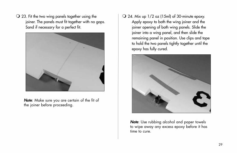
23. Fit the two wing panels together using the joiner. The panels must fit together with no gaps. Sand if necessary for a perfect fit.
Note:.Make.sure.you.are.certain.of.the.fit.of.the.joiner.before.proceeding.
24. Mix up 1/2 oz (15ml) of 30-minute epoxy. Apply epoxy to both the wing joiner and the joiner opening of both wing panels. Slide the joiner into a wing panel, and then slide the remaining panel in position. Use clips and tape to hold the two panels tightly together until the epoxy has fully cured.
Note:.Use.rubbing.alcohol.and.paper.towels..to.wipe.away.any.excess.epoxy.before.it.has.time.to.cure.
29
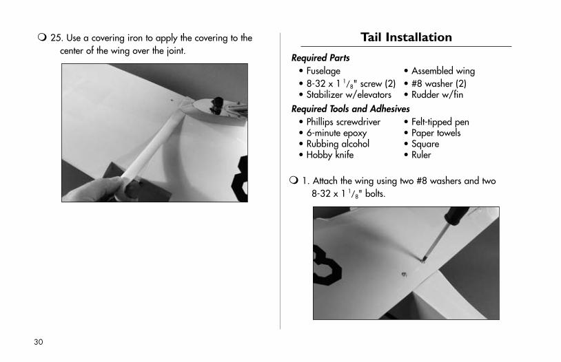
25. Use a covering iron to apply the covering to the center of the wing over the joint.
Tail Installation
Required Parts• Fuselage • Assembled wing• 8-32 x 1
1/8" screw (2) • #8 washer (2)• Stabilizer w/elevators • Rudder w/fin
Required Tools and Adhesives• Phillips screwdriver • Felt-tipped pen• 6-minute epoxy • Paper towels• Rubbing alcohol • Square• Hobby knife • Ruler
1. Attach the wing using two #8 washers and two 8-32 x 1
1/8" bolts.
30

Note:.It.may.be.necessary.to.lightly.sand..the.tab.at.the.front.of.the.wing.to.get.the..wing.to.fit.
2. Slide the stabilizer into the slot at the rear of the fuselage. Center the stabilizer as shown.
3. Check that the wing and stabilizer are parallel. Lightly sand the opening in the fuselage if adjustments are required.
31

4. Measure from each tip of the stabilizer to a point at the forward center of the fuselage. Adjust the stabilizer so both measurements are equal.
5. Once the stabilizer has been carefully aligned, use a felt-tipped pen to trace the outline of the fuselage onto the stabilizer.
32

6. Mark the stabilizer so you know which is top and bottom. Remove the stabilizer and use a hobby knife with a new blade to cut the covering 1/16" (1.5mm) inside the lines drawn in the last step.
Note:.Do.not.cut.into.the.wood.as.it.will.weaken.the.stabilizer..A.soldering.iron.or.hot.knife.can.be.used.instead.of.a.hobby.knife.
7. Slide the stabilizer partially into the fuselage. Apply a thin layer of 6-minute epoxy onto the exposed wood of the stabilizer, both top and bottom. Slide the stabilizer into the fuselage and clean up any excess epoxy using a paper towel and rubbing alcohol.
33

8. Attaching the fin is basically the same as installing the stabilizer, except for checking that the fin is perpendicular to the stabilizer using a square. Remember to mark and remove the covering from the bottom of the fin before using epoxy to secure it to the fuselage
Linkage Installation
Required Parts• Fuselage • 4mm wheel collar (2)• Clevis (3) • Clevis retainer (3)• Tail wheel assembly • 1" (25mm) tail wheel• 2mm wheel collar • 3mm setscrew• 3mm x 6mm screw (2) • Pushrod wire keeper (2)• 25
5/8" (650mm) pushrod wire (3)• Control horn w/backplate (3)• 2mm x 12mm screw (6) • CA hinges (9)
Required Tools and Adhesives• Phillips screwdriver • Felt-tipped pen• 6-minute epoxy • Petroleum jelly• Pliers • Side cutter• Drill• Drill bit: 5/64" (2mm), 3/32" (2.5mm)
Note:.If.you.plan.on.installing.floats.permanently.to.your.J-3.Cub,.you.may.skip.Steps.1.though.5,.starting.at.Step.6..The.tail.wheel.can.be.left.in.position.if.you.plan.on.using.both.the.landing.gear.and.floats..Refer.to.your.float.manual.for.proper.installation.
34

1. Locate the tail wheel assembly and apply petroleum jelly to the wire above and below the nylon mount. This helps prevent epoxy from binding the tail gear.
2. Use 6-minute epoxy to glue the nylon mount into the fuselage.
35

3. Drill a 3/32" (2.5mm) hole into the rudder 1
1/16" (27mm) up from the bottom of the rudder. Verify this measurement by holding the rudder in position against the fuselage.
4. Cut a slot from the hole to the bottom of the rudder. The slot will house the nylon mount when the rudder is installed.
36

5. Attach the tail wheel using the 2mm wheel collar and the 3mm setscrew.
6. Slide a clevis retainer onto a clevis, then thread the clevis onto a 25
5/8" (650mm) pushrod wire. Slide the pushrod wire into the opening as shown.
7. Place T-pins in three of the CA hinges. Slide the hinges into the rudder, and then slide the rudder into position. Use tape to hold the rudder in position. DO NOT glue the hinges or tail wheel until instructed to do so.
37

8. Remove the backplate from a control horn. Snap the clevis onto the control horn, and hold it against the rudder and mark the location for the horn.
9. Remove the rudder and drill the two locations using a 5/64" (2mm) drill. Mount the horn using two 2mm x 12mm screws and the control horn backplate.
10. Roughen the tail gear wire with sandpaper. Use 6-minute epoxy on the tail gear wire to glue into the rudder.
38

11. Remove the T-pins from the hinges and use thin CA to glue them in place. Allow the epoxy and CA to cure before continuing to the next step.
12. Snap the clevis onto the control horn and use tape to hold the rudder centered. Mark the pushrod where it crosses the servo horn using a felt-tipped pen.
Note:.Ensure.the.radio.is.turned.on.with..the.trims.and.sub-trims.centered.and.the..servos.are.centered.
39
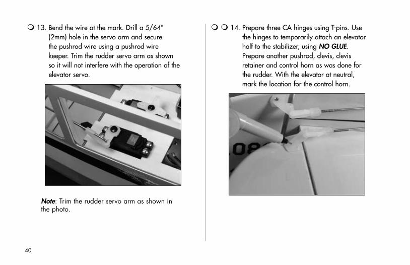
13. Bend the wire at the mark. Drill a 5/64" (2mm) hole in the servo arm and secure the pushrod wire using a pushrod wire keeper. Trim the rudder servo arm as shown so it will not interfere with the operation of the elevator servo.
Note:.Trim.the.rudder.servo.arm.as.shown.in.the.photo.
14. Prepare three CA hinges using T-pins. Use the hinges to temporarily attach an elevator half to the stabilizer, using NO GLUE. Prepare another pushrod, clevis, clevis retainer and control horn as was done for the rudder. With the elevator at neutral, mark the location for the control horn.
40

15. Drill the holes for the control horn in the elevator. Attach the control horn using two 2mm x 12mm screws.
16. Position the elevator back onto the stabilizer and use thin CA to glue the hinges.
17. Prepare two wheel collars by threading 3mm x 6mm screws into them. Slide the wheel collars onto the elevator pushrod.
41

18. Center the elevator and mark the pushrod. Bend the pushrod and attach it to the elevator servo arm using a pushrod wire keeper. Trim the elevator servo arm as shown in the photo.
Note:.Ensure.the.radio.is.turned.on.with..the.trims.and.sub-trims.centered.and.the..servos.are.centered.
19. Repeat Step 14 through 16 to attach the remaining elevator half. Pass the pushrod through the wheel collars when installing the pushrod.
Note:.It.may.be.necessary.to.trim.the.length.of.the.pushrod.wire.
42
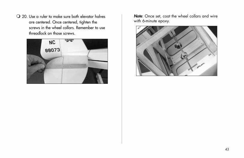
20. Use a ruler to make sure both elevator halves are centered. Once centered, tighten the screws in the wheel collars. Remember to use threadlock on those screws.
Note:.Once.set,.coat.the.wheel.collars.and.wire.with.6-minute.epoxy.
43
Final Assembly
Required Parts• Fuselage • Wing• Front windshield • Side window (right and left)• Wing strut (right and left)• 2mm x 10mm sheet metal screws (6)
Required Tools and Adhesives• Phillips screwdriver • Hobby scissors• Felt-tipped pen • Sandpaper• Canopy glue • Masking tape
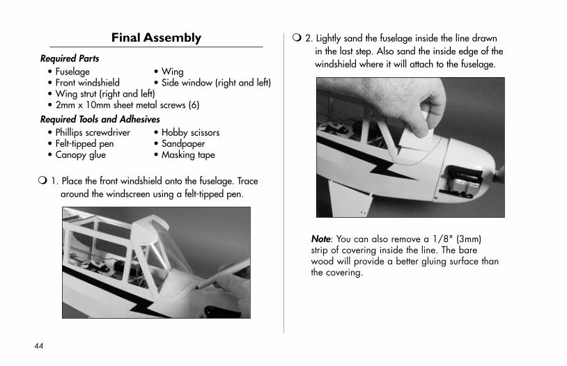
1. Place the front windshield onto the fuselage. Trace around the windscreen using a felt-tipped pen.
2. Lightly sand the fuselage inside the line drawn in the last step. Also sand the inside edge of the windshield where it will attach to the fuselage.
Note:.You.can.also.remove.a.1/8".(3mm)..strip.of.covering.inside.the.line..The.bare..wood.will.provide.a.better.gluing.surface.than.the.covering.
44

3. Apply a thin bead of canopy glue around the outer edge of the front windshield. Position the windshield on the fuselage and use tape to hold it until the glue has cured.
4. Use hobby scissors to trim out the side windows. Trim the windows so there is a 1/16" (1.5mm) lip to glue the windows to the fuselage sides.
45

5. After sanding the edges of the windows, use canopy glue to secure them to the inside of the fuselage. Use tape to hold them in position until the glue fully cures.
6. Attach the wing to the fuselage. Place the struts so the arrow on the strut is facing up and is pointing towards the front of the plane. Secure the strut using three 2mm x 10mm sheet metal screws.
7. Repeat Step 6 for the remaining wing strut.
46

Center of Gravity / Battery Installation
An important part of preparing the aircraft for flight is properly balancing the model.
Caution: Do not inadvertently skip this step!
The recommended Center of Gravity (CG) location for the J-3 Cub is 2
5/8" (66mm) back from the leading edge. The range for the Center of Gravity is 2
1/2"–2 3/4".(63mm–70mm) behind the leading edge.
47
Control Throws
The amount of control throw should be adjusted as closely as possible using mechanical means, rather than making large changes electronically at the radio. By moving the position of the clevis at the control horn toward the outermost hole, you will decrease the amount of control throw of the control surface. Moving it toward the control surface will increase the amount of throw. Moving the pushrod wire at the servo arm will have the opposite effect: Moving it closer to center will decrease throw, and away from center will increase throw. Work with a combination of the two to achieve the closest or exact control throws listed.
High Rate Low Rate
Aileron. 3/4".up,.3/4".down. 1/2".up,.1/2".down
Elevator. 5/8".up,.5/8".down. 3/8".up,.3/8".down
Rudder. 1 3/8".right,.1
3/8".left. 1".right,.1".right
Note:.The.above.throws.are.a.good.starting.point.for.most.flight.conditions.
Exponential Settings
High Rate Low Rate
Aileron. 20%. 10%
Elevator. 20%. 10%
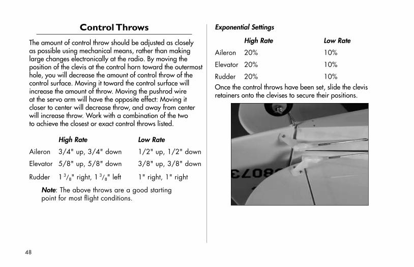
Rudder. 20%. 10%Once the control throws have been set, slide the clevis retainers onto the clevises to secure their positions.
48

Flying the J-3 Cub is a pleasure. Takeoffs are easy as well as landings. Loops and rolls are as easy as pushing the control stick in the desired direction with the control throws listed in the manual. Flight times of 17 minutes with the recommended Li-Po battery are common with landing gear, and 15 minutes when equipped with floats. Using the Ni-MH battery option will provide shorter flight times of 9 minutes but at a very reduced battery cost. Float flying with the Ni-MH pack should be limited to areas where there are no obstructions around the lake. Climb out performance is increased with the Li-Po power system over the Ni-MH power system.
When flying from floats there are a few flight parameters to be aware of. Because of the inertia generated below the centerline, the aircraft can depart during certain harsh maneuvers. Whenever the aircraft is put into a very steep bank angle (70–80 degrees) and you pull hard on the elevator, the aircraft will snap to the left. If you are in a right-hand turn it will snap out of the turn and to the left. If you are in a left-hand turn, it will tuck even tighter into the turn. During taxiing on floats, it is recommended to hold full up elevator to minimize the amount of splash from the floats. During takeoff, hold half up elevator as you accelerate to minimize the splash and to keep the floats from digging into the water. We recommend low rate rudder for takeoff when using floats.
Flying Notes
49

GENERAL
1) I will not fly my model aircraft in sanctioned events, air shows or model flying demonstrations until it has been proven to be airworthy by having been previously, successfully flight tested.
2) I will not fly my model higher than approximately 400 feet within 3 miles of an airport without notifying the airport operator. I will give right-of-way and avoid flying in the proximity of full-scale aircraft. Where necessary, an observer shall be utilized to supervise flying to avoid having models fly in the proximity of full-scale aircraft.
3) Where established, I will abide by the safety rules for the flying site I use, and I will not willfully or deliberately fly my models in a careless, reckless and/or dangerous manner.
4) The maximum takeoff weight of a model is 55 pounds, except models flown under Experimental Aircraft rules.
5) I will not fly my model unless it is identified with my name and address or AMA number on or in the model. (This does not apply to models while being flown indoors.)
6) I will not operate models with metal-bladed propellers or with gaseous boosts, in which gases other than air enter their internal combustion engine(s); nor will I operate models with extremely hazardous fuels such as those containing tetranitromethane or hydrazine.
RADIO CONTROL
1) I will have completed a successful radio equipment ground range check before the first flight of a new or repaired model.
2) I will not fly my model aircraft in the presence of spectators until I become a qualified flier, unless assisted by an experienced helper.
�0
2006 Official AMA National Model Aircraft Safety Code

3) At all flying sites a straight or curved line(s) must be established in front of which all flying takes place with the other side for spectators. Only personnel involved with flying the aircraft are allowed at or in front of the flight line. Intentional flying behind the flight line is prohibited.
4) I will operate my model using only radio control frequencies currently allowed by the Federal Communications Commission. (Only properly licensed Amateurs are authorized to operate equipment on Amateur Band frequencies.)
5) Flying sites separated by three miles or more are considered safe from site-to-site interference, even when both sites use the same frequencies. Any circumstances under three miles separation require a frequency management arrangement, which may be either an allocation of specific frequencies for each site or testing to determine that freedom from interference exists. Allocation plans or interference test reports shall be signed by the parties involved and provided to AMA Headquarters.
Documents of agreement and reports may exist between (1) two or more AMA Chartered Clubs, (2) AMA clubs and individual AMA members not associated with AMA Clubs, or (3) two or more individual AMA members.
6) For Combat, distance between combat engagement line and spectator line will be 500 feet per cubic inch of engine displacement. (Example: .40 engine = 200 feet.); electric motors will be based on equivalent combustion engine size. Additional safety requirements will be per the RC Combat section of the current Competition Regulations.
7) At air shows or model flying demonstrations, a single straight line must be established, one side of which is for flying, with the other side for spectators.
8) With the exception of events flown under AMA Competition rules, after launch, except for pilots or helpers being used, no powered model may be flown closer than 25 feet to any person.
9) Under no circumstances may a pilot or other person touch a powered model in flight.
�1
2006 Official AMA National Model Aircraft Safety Code

8�29
© 2006 Horizon Hobby, Inc. 4105 Fieldstone Road
Champaign, Illinois 61822 (877) 504-0233
www.horizonhobby.com www.E-fliteRC.com
Recommended